
TA810 - Fax Yeastar - Free user manual and instructions
Find the device manual for free TA810 Yeastar in PDF.


| Product Type | Analog VoIP Gateway with Fax Support |
| Model | TA810 |
| FXO Ports | 8 |
| VoIP Protocols | SIP (RFC3261), IAX2 |
| Codecs | G.711 a-law/μ-law, G.722, G.723, G.726, G.729A/B, GSM, ADPCM |
| Echo Cancellation | ITU-T G.168 LEC |
| Management Interface | Web-based GUI (HTTP/HTTPS) |
| Network Interfaces | 1x 10/100 Ethernet (LAN) |
| Power Supply | 12V DC, 1A (typical) |
| Mounting | Desktop or rack-mountable (bracket optional) |
| Fax Support | T.38 fax relay and G.711 fax pass-through |
| Call Routing | IP-to-Port, Port-to-IP, Port-to-Port, with flexible dial patterns |
| Security | Firewall, IP blacklist, TLS/SRTP, AMI access control |
| Auto Provisioning | PNP, DHCP, TFTP/HTTP |
| Dimensions (approx.) | 200 x 140 x 35 mm |
Frequently Asked Questions - TA810 Yeastar
User questions about TA810 Yeastar
0 question about this device. Answer the ones you know or ask your own.
Ask a new question about this device
Download the instructions for your Fax in PDF format for free! Find your manual TA810 - Yeastar and take your electronic device back in hand. On this page are published all the documents necessary for the use of your device. TA810 by Yeastar.
USER MANUAL TA810 Yeastar
natural_image
Abstract logo composed of four colored oval shapes (blue, green, orange) arranged in a flower-like pattern on white background.Yeastar
natural_image
Stack of three black USB flash drives with control buttons, no visible text or symbols on the drives themselves.TA410/TA810
User Manual
Sales Tel: +86-592-5503309
E-mail: sales@yeastar.com
Support Tel: +86-592-5503301
E-mail: support@yeastar.com
Web: http://www.yeastar.com
Version: 41.19.0.17
Revised: January 25, 2016
Copyright
Copyright 2006-2015 Yeastar Information Technology Co., Ltd. All rights reserved.
No parts of this publication may be reproduced or transmitted in any form or by any means, electronic or mechanical, photocopying, recording, or otherwise, for any purpose, without the express written permission of Yeastar Information Technology Co., Ltd. Under the law, reproducing includes translating into another language or format.
Declaration of Conformity

Hereby, Yeastar Information Technology Co., Ltd. declares that TA410/810 is in conformity with the essential requirements and other relevant provisions of the CE, FCC.
Warranty
The information in this document is subject to change without notice.
Yeastar Information Technology Co., Ltd. makes no warranty of any kind with regard to this guide, including, but not limited to, the implied warranties of merchantability and fitness for a particular purpose. Yeastar Information Technology Co., Ltd. shall not be liable for errors contained herein nor for incidental or consequential damages in connection with the furnishing, performance or use of this guide.
WEEE Warning

In accordance with the requirements of council directive 2002/96/EC on Waste of Electrical and Electronic Equipment (WEEE), ensure that at end-of-life you separate this product from other waste and scrap and deliver to the WEEE collection system in your country for recycling.
Contents
About This Guide....5
Getting Started....6
Accessing Web GUI....6
Web Configuration Panel....7
Application Description 7
FXO Port Settings....11
FXO Port Settings....11
Port Group 15
VoIP Settings....17
VoIP Trunk 17
Trunk Group....19
SIP Settings 20
IAX Settings 25
Routes Settings 26
IP->Port....26
Port->IP/Port 28
Blacklist....31
Callback Settings 31
Gateway Settings....33
General Preferences....33
Audio Settings 34
Custom Prompts....34
Advanced Settings 35
Tone Zone Settings....35
DTMF Settings....36
Network Preferences....37
LAN Settings....37
Service 38
VLAN Settings....39
VPN Settings....39
DDNS Settings....40
Static Route....41
Security Center 43
Security Center 43
Alert Settings....44
AMI Settings....46
Certificates 47
Firewall Rules 48
IP Blacklist 50
System Preferences....52
Password Settings 52
Date and Time....52
Auto Provision Settings....53
Firmware Update ....55
Upgrade through HTTP 55
Upgrade through TFTP 56
Backup and Restore 57
Reset and Reboot....57
Status 59
Port/Trunk Status 59
Network status 60
System Info 61
Reports......62
Call Logs 62
System Logs 62
Packet Tool 63
Port Monitor Tool....63
About This Guide
Yeastar TA410/810 Analog VoIP Gateways are cutting-edge products that connect legacy telephones, fax machines and PBX systems with IP telephony networks and IP-based PBX systems. Featuring rich functionalities and easy configuration, TA410/810 is ideal for small and medium enterprises that wish to integrate a traditional phone system into IP-based system. TA410/810 helps them to preserve previous investment on legacy telephone system and reduce communication costs significantly with the true benefits of VoIP.
Audience
This manual will help you learn how to operate and manage your TA410/810 FXO Analog VoIP Gateway. In this guide, we describe every detail on the functionality and configuration of TA410/810. We begin by assuming that you are interested in TA410/810 and familiar with networking and other IT disciplines.
Safety when working with electricity

- Do not open the device when the device is powered on.
- Do not work on the device, connect or disconnect cables when lightning strikes.
Features Highlights
4/8 FXO ports
▶ Fully compliant with SIP and IAX2
▶ Flexible calling rules
- Configurable VoIP Server templates
➢ Codec: G711 a/u-law, G722, G723, G726, G729A/B, GSM, ADPCM
➢ Echo Cancellation: ITU-T G.168 LEC
Web-based GUI for easy configuration and management
Excellent interoperability with a wide range of IP equipment
Check the TA410/810 Installation Guide here: http://www.yeastar.com/downloadFile/Yeastar_TA_Series_Installation_Guide_en.pdf
For more information, please click: http://www.yeastar.com/Products.html/Analog-VoIP-Gateways
Getting Started
In this chapter, we guide you through the basic steps to start with a new TA410/810:
- Accessing Web GUI
• Web Configuration Panel
• Application Description
Accessing Web GUI
The TA410/810 attempts to contact a DHCP server in your network to obtain valid network settings (e.g., the IP address, subnet mask, default gateway address and DNS address) by default.
Please enable DHCP Server in your network to obtain the TA410/810 IP address.
Also note that since version 41.19.0.23 the default IP address has been changed to a static IP: 192.168.5.150. In this situation, one IP address within segment 192.168.5.0/255.255.255.0 requires to be added in network settings for your computer. So that you could access the IP address 192.168.5.150.
After entering the IP address in the web browser, users will see a log-in screen.
Check the default settings below:
Username: admin
Password: password
VoIP Analog Gateway for Cost Reduction
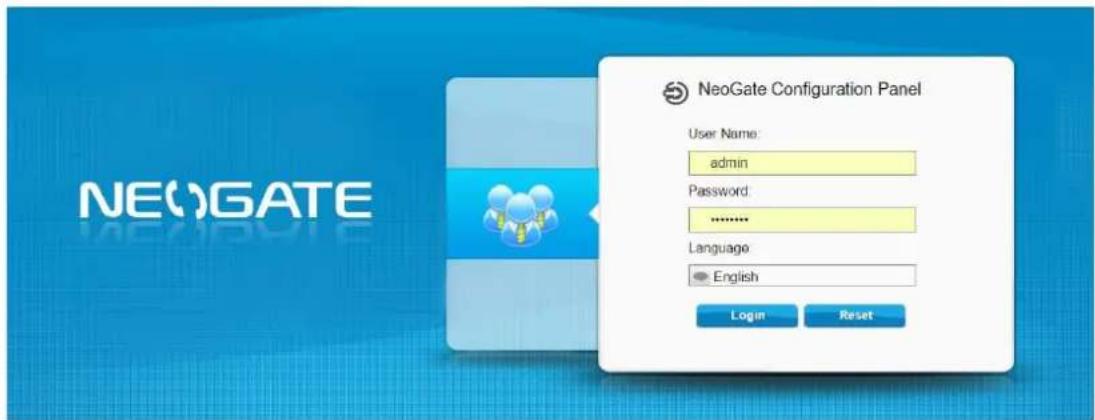
Figure 2-1 TA410/810 Login page
Web Configuration Panel
There are 4 main sections on the Web Configuration Panel for users to check the TA410/810's status and configure it.
- Status: check System Status, Port Status, Trunk Status, Network Status and check call logs, system logs.
- System: configure Network Settings, Security related Settings, System Date and Time, Password, Backup and Restore, etc.
• Gateway: configure FXO ports, gateway settings and SIP settings, etc. - Logout: log out TA410/810.
Note:
After saving the changes, remember to click the “Apply changes” button on the upper right corner of the Web GUI to make the changes take effect.
Application Description
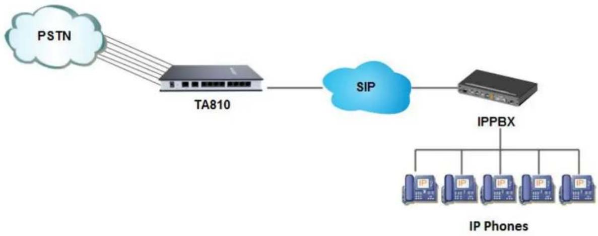
Connect IPPBX and TA FXO Gateway
YeastarTA FXO gateway is a solution to extend FXO ports for your IPPBX.
Two modes are available for you to connect IPPBX and TA FXO gateway, we call them VoIP mode and SPS (Service Provider SIP)/SPX (Service Provider IAX) mode.
Three modes are available for you to connect your SIP server and TA410/810 gateway. We call them SIP Account Mode, VoIP Mode and SPS (Service Provider SIP) Mode. You can choose any one of the 3 modes to connect your SIP server and TA410/810. SPS Mode is recommended.
Account Mode:
Create one SIP account on TA410/810, and take the SIP account to register one SIP trunk on your SIP server. Then TA410/810 and your SIP server are connected by the account.
➢ Calls from SIP to PSTN
1) Create one outbound route on your SIP sever, and select the SIP trunk you have registered just now.
2) Configure a "IP->Port" route on TA410/810, choose the SIP account in the field "Call Source", and choose a PSTN trunk or PSTN trunk group in the field "Call Destination".
3) Make a call from your SIP Server and the call should match the outbound
route dial rules.
Calls from PSTN to SIP
1) Create an inbound route on your SIP server, and select the SIP trunk you have registered just now.
2) Configure a "Port->IP" route on TA410/810, choose a PSTN trunk or PSTN trunk group in the field "Call Source", and choose the SIP account in the filed "Call Destination".
3) When a call comes to PSTN trunk on TA410/810, the call will be routed to the destination of the SIP server inbound route.
Register SIP account on IP phone
With account mode, you can directly take the SIP account to register on your SIP phone or softphone; then make calls from softphone though PSTN trunk on TA410/810 and receive incoming calls on your SIP phone or softphone. In this way, you don't have to set up any SIP server.
VoIP Mode
Take a SIP account from your SIP server, and register it on TA410/810 as a VoIP trunk. In this way, TA410/810 and your SIP server are connected.
Calls from SIP to PSTN
1) Configure a IP-> Port route on TA410/810; choose the VoIP trunk in the field "Call Source", and choose PSTN trunk in the field "Call Destination". Enable Two-stage Dialing on the route.
2) Make a call from your SIP server, dial the SIP account number which is registered on TA410/810. You will hear a dial tone, then dial the external number out through PSTN trunk.
Calls from PSTN to SIP
1) Configure a Port->IP route on TA410/TA810, choose PSTN trunk in the field "Call Source", and choose the SIP trunk in the field "Call Destination".
2) When an incoming call reaches PSTN trunk on TA410/810, you will hear a dial tone, then dial an extension number of the SIP server.
SPS Mode (Recommended)
Create a Service Provider SIP trunk on TA410/810 to connect to your SIP server. Add another Service Provider SIP trunk on your SIP server, connecting to TA410/810.
Calls from SIP to PSTN
1) Create one outbound route on your SIP sever, and select the SIP trunk you have created just now.
2) Configure a IP->Port route on TA410/810, choose the SPS trunk in the field "Call Source", and choose PSTN trunk in the field "Call Destination".
3) Make a call from your SIP Server and the call should match the outbound route dial rules.
Calls from PSTN to SIP
1) Configure a Port->IP route on TA410/810, choose PSTN trunk in the field "Call Source", and choose the SPS trunk in the field "Call Destination".
2) Create one inbound route on your SIP server and select the SIP trunk created just now.
3) When an incoming call reaches PSTN trunk on TA41/810, You will hear a dial tone, then dial an extension number of the SIP Server, it will be routed to the destination of the SIP server inbound route.
Note: if you want the call to go directly to the destination number of your SIP server, you don't have to create an inbound route on SIP server, instead set a Hotline number on TA410/810 route.
flowchart
graph LR
    PSTN[" PSTN "] --> TA810[" TA810 "]
    TA810 --> SIP["SIP"]
    SIP --> IPPhone[" IP Phones "]
    IPPhone --> IPPBX[" IPPBX "]
Figure 2-2 Connect IPPBX and TA FXO Gateway
For incoming calls from the PSTN to TA410/810, TA410/810 will forward the call to a configured SIP extension or to an inbound destination of IPPBX like IVR.
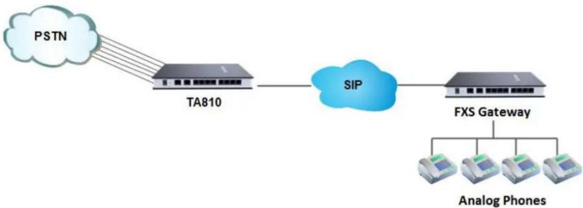
Connect TA FXO Gateway and FXS Gateway
TA FXO gateway can be connected to a FXS gateway using SPS/SPX Mode. Imagine this, the FXO gateway is set up in Site A, and the FXS gateway in Site B. People in Site B can make and receive calls using the local PSTN lines (which is connected to Site A's provider). With this solution, you can call a local number using a local PSTN line wherever you are.
flowchart
graph LR
    PSTN[" PSTN "] --> TA810[" TA810 "]
    TA810 --> SIP["SIP"]
    SIP --> FXSGateway[" FXS Gateway "]
    FXSGateway --> AnalogPhone1[" Analog Phones "]
    FXSGateway --> AnalogPhone2[" Analog Phones "]
    FXSGateway --> AnalogPhone3[" Analog Phones "]
Figure 2-3 Connect TA FXO Gateway and FXS Gateway
FXO Port Settings
This chapter explains how to configure FXO port on TA410/810, go to Gateway→Port List→Port List page to configure the FXO ports.
- FXO Port Settings
- Port Group
FXO Port Settings
Click "Edit" button to configure the FXO port.
1) General Settings
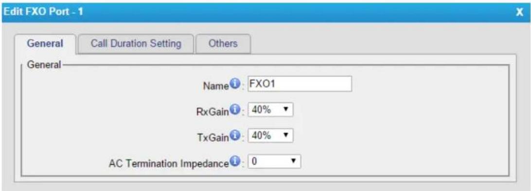
Figure 3-1 FXO Port General Settings
Table 3-1 Description of FXO Port General Settings
| Items | Description |
| Name | The trunk Name. |
| RX Gain | The receive volume.The default setting is 40%. |
| TX Gain | The transmit volume.The default setting is 40%. |
| Select the impedance of the analog line connected to the FXO port. Here is the impedance value for the settings:0 - 600 Ohm ( North American )1 - 900 Ohm2 - 270 Ohm + (750 Ohm || 150nF) and 275 Ohm + (780 Ohm || 150nF)3 - 220 Ohm + (820 Ohm || 120nF) and 220 Ohm + (820 Ohm || 115nF) | |
| AC Termination Impedance | 4 - 370 Ohm + (620 Ohm || 310nF)5 - 320 Ohm + (1050 Ohm || 230nF)6 - 370 Ohm + (820 Ohm || 110nF)7 - 275 Ohm + (78 Ohm || 150 nF)8 - 120 Ohm + (820 Ohm || 110 nF)9 - 350 Ohm + (1000 Ohm || 210nF)10 - 0 Ohm + (900 Ohm || 30nF)11 - 600 Ohm + 2.16 uF12 - 900 Ohm + 1 uF13 - 900 Ohm + 2.16 uF14 - 600 Ohm + 1 uF15 - Global complex impedance |
2) Call Duration Settings
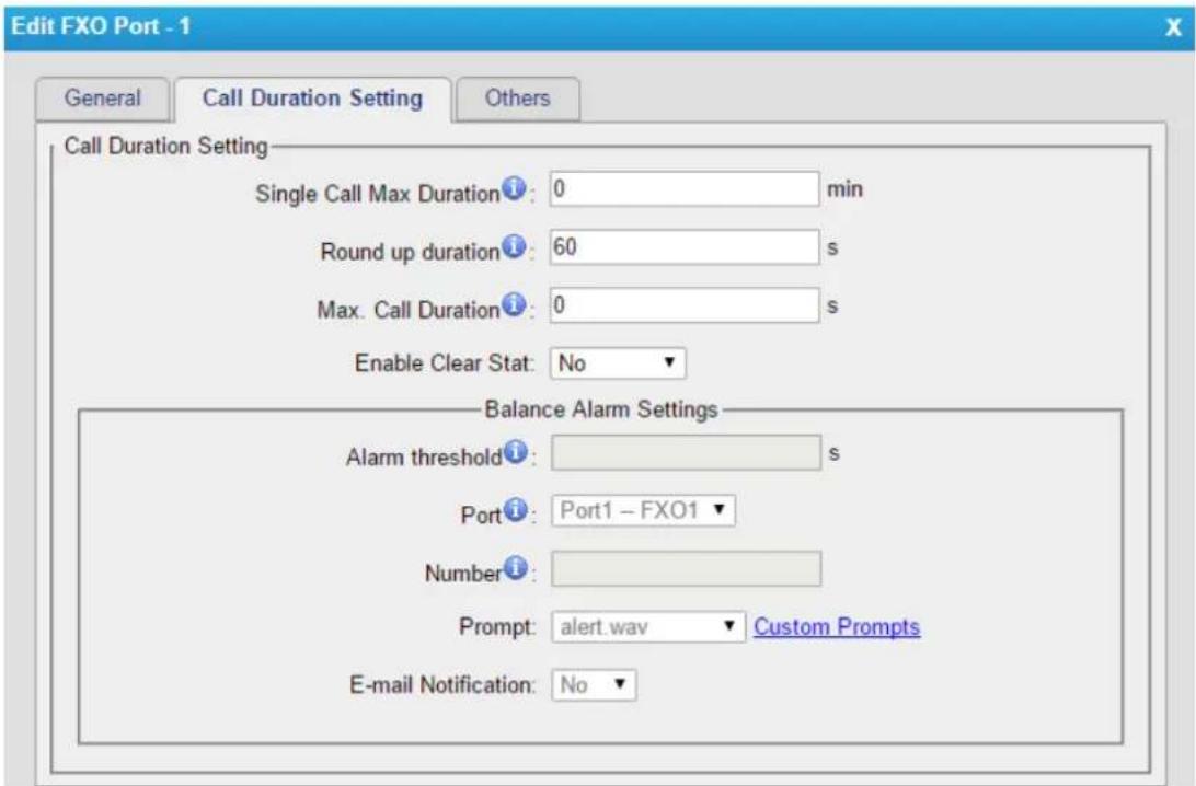
Figure 3-2 FXO Port Call Duration Setting
Table 3-2 Description of FXO Port Call Duration Settings
| Items | Description |
| Single CallMax Duration(min) | Configure the duration of each call, it's 0 by default, which means no limit. |
| Round up Duration | Once the value of Billing Unit is changed, the “Round Up Duration” will be cleared, “Call Duration” will also change accordingly. |
| Max. Call Duration(min) | Defines the maximum number of billing unit called within a month through the trunk. To disable this limitation set the value at 0. |
| Enable Clear Stat. | The date to clean the duration status each month. |
| Balance Alarm Settings | When Max. Call Duration(min) is configured a 0 (nolimit), this feature is disabled. |
| Alarm threshold(min) | Cofigure the time duration when TA410/810 will send the alarm message. The value must be less than “Max Call Duration”. |
| Port | Choose the port to dial the alarm call. |
| Number | The number to receive the alarm call. |
| Prompt | The prompt played during the alarm call,you can customize the prompts as your wish. |
| The email address to receive the alarm email.Note: please make sure SMTP test is successful in “Email settings” page before configuring this. |
3) Other Settings
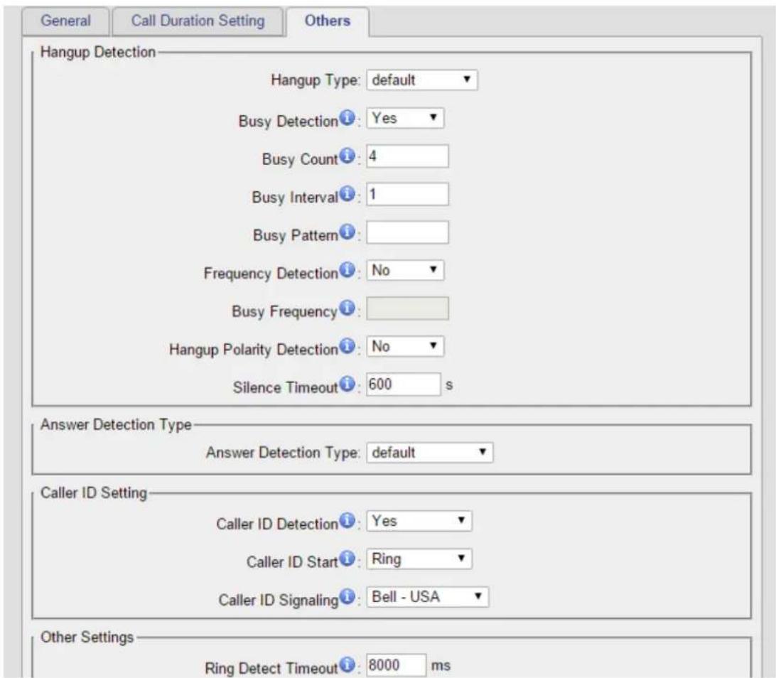
Figure 3-3 FXO Port Other Settings
Table 3-3 Description of FXO Port Other Settings
| Hangup Detection | |
| Hangup Type | Select which kind of hangup type will be used to detect the call and hang up. |
| Busy Detection | Enable or disable Busy Detection. It is used for detecting farend hangup or busy signal. |
| Busy Count | If Busy Detection is enabled, it is also possible to specify how many busy tones to wait for before hanging up. The default is 4, but better results can be achieved if this setting is set as 6 or 8. Higher value requires more time for detection, but lower the probability that a false detection may occur. |
| Busy Interval | Set the busy detection interval. |
| Busy Pattern | If Busy Detection is enabled, you need to specify the cadence of the busy signal. If a busy pattern is not specified, the system will accept any repeating sound-silence pattern as a busy signal. If a busy pattern is specified, then the system will check the length of the sound and the silence patterns, which will further reduce the chance of a false positive. |
| Frequency Detection | Enable or disable Frequency Detection, it is used for frequency detection. |
| Busy Frequency | If Frequency Detection is enabled, you must specify the local frequency. |
| Hangup Polarity Detection | Enable or disable Polarity Detection. The call will be considered as “hang up” on a polarity reversal. |
| Silence Timeout | Define the ring out value for this port. |
| Answer Detection Type | |
| Answer Detection Type | Answer Detection settings are configured for accurate billing. Select which type to detect the call as answered.1) Default.TA410/810 will start to charge once you grab the PSTN trunk to call out, whether the call is answered or not.2) Polarity Detection: If the PSTN line supports polarity, you can choose "Polarity detection". When the callee answers the call, the provider will send a polarity signal, and the TA410/810 starts to bill.3) Ring back Tone: If you choose this option, TA410/810 will charge the call according to PSTN ring back tone detection. When the "ring duration" or the "ring interval duration" detected on TA410/810 is larger than the standard or custom parameters, the call is detected as ANSWERED.*Standard parameters: when you configure the "Tone Zone Settings" you get the country's standard tone parameters. |
| Custom Ring Tone | Enable or disable Custom Ring Tone. If the custom ring tone is enabled, you need to configure the following settings according to the ringback signal. |
| Max Ring Duration | Max duration of the ring tone. |
| Max Ring Interval Duration | Max pause between the two ring tones. |
| Min Ring Detection | Enable Min Ring Detection, which is useful for complex situations, like when jitter or noise occurs on the PSTN line. Generally it is disabled. |
| Min Ring Duration | Min duration of the received tone. |
| Min Ring Interval Duration | Min pause between the two received tones. |
| Caller ID Setting | |
| Caller ID Detection | Enable or disable caller ID detection. |
| Caller ID Start | This option allows one to define the start of a caller ID signal. Ring: start to detect when a ring is received Polarity: start to detect when a polarity reversal is started Before Ring: start to detect before a ring tone |
| Caller ID Signaling | This option defines the type of caller ID signaling to use. Bell-USA: US standard V23-UK: UK standard V23-Japan: Japanese standard V23-Japan Pure: Japanese standard DTMF: DTMF signal Please check with your PSTN service provider to configure Caller ID Settings. If you don't know how to configure, please contact Yeastar support. |
| Other Settings | |
| Ring Detect Timeout | There should be a timeout to determine if there is a hang up before the line is answered. Range from 3000 to 8000. Default is 8000 ms. |
Port Group
Port group is a feature that allows you to define specific PSTN trunks to a group. A trunk group can be used in a route. When a call is coming or going through the route, an available trunk would be selected in the trunk group. There are two ring strategies supported for Port Group:
- Round-Robin: select the next available port in line.
- Least Used: select the port that is least used.
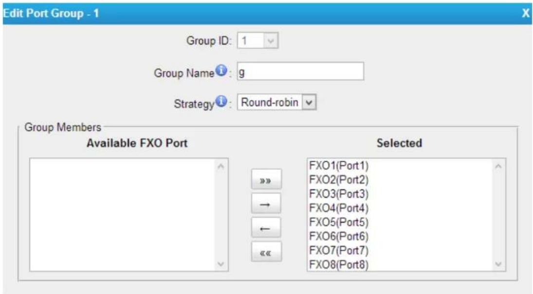
Figure 3-4 Port Group
VoIP Settings
To integrate with other IPPBX, we need to configure the VoIP settings in TA FXO Gateway to set up VoIP trunk (SIP and IAX). In this chapter, we introduce the following settings:
- VoIP Trunk
- Trunk Group
- SIP Settings
- IAX Settings
VoIP Trunk
There are 3 types of trunks listed in this page, Account, Trunk and Service Provider.
Figure 4-1 VoIP Trunk
1) Account
It's an SIP account created in TA410/810 so that the other devices can register SIP trunk at their side using these information.
Figure 4-2 Account
Table 4-1 Description of Account Settings
| Trunk Type | Choose the type of trunk, “Account”. |
| Name | Define the name. |
| Account | Define the Account number. |
| Password | Set a password for this account. |
2) VoIP Trunk
It's a SIP trunk configured in TA410/810 to register to the SIP provider, please make sure this trunk works properly in advance with provider before configuring TA410/TA810.
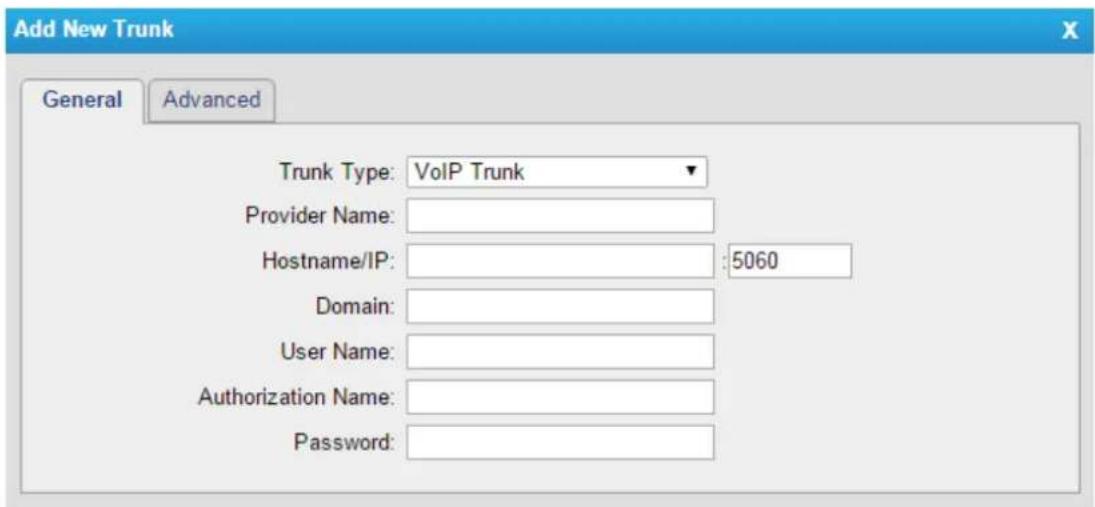
Figure 4-3 VoIP Trunk Settings
Table 4-2 Description of VoIP Trunk Settings
| Items | Description |
| Trunk Type | Choose the type of trunk, “VoIP Trunk”. |
| Provider Name | A unique label to help you identify this trunk when listed in outbound rules, incoming rules etc. E.g. “yeastar”. |
| Hostname/IP | Service provider’s hostname or IP address.Note: 5060 is the standard port number used by SIP protocol. Don’t change this part if it is not required. |
| Domain | VoIP provider’s server domain name or IP address. |
| User Name | User name of SIP account provided from the SIP Server provider. |
| Authorization Name | Authorization Name of SIP account provided from the SIP Server provider. |
| Password | Password of the SIP account. |
3) Service Provider
This is service provider trunk (peer to peer mode) which authorized using IP address only.
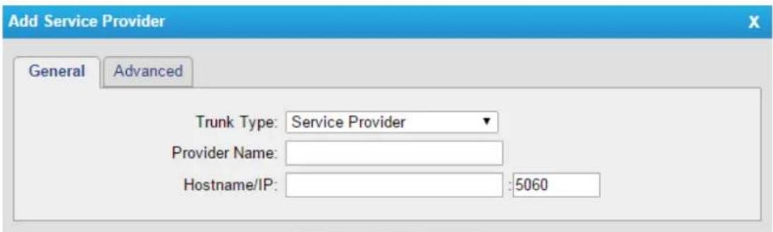
Figure 4-4 Service Provider Trunk Settings
Table 4-3 Description of Service Provider Trunk Settings
| Items | Description |
| Trunk Type | Choose the type of trunk, “Service Provider”. |
| Provider Name | A unique label to help you identify this trunk when listed in outbound rules, incoming rules etc. E.g. “yeastar”. |
| Hostname/IP | Service provider’s hostname or IP address.Note: 5060 is the standard port number used by SIP protocol. Don’t change this part if it is not required. |
Trunk Group
Trunk group is a feature that allows you to define specific SIP trunks to a group. A trunk group can be used in a route. When a call is coming or going through the route, an available trunk would be selected in the trunk group.
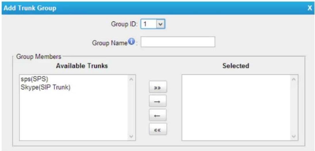
Figure 4-5 Trunk Group
SIP Settings
It is wise to leave the default setting as provided on this page. However, for a few fields, you need to change them to suit your situation.
1) General
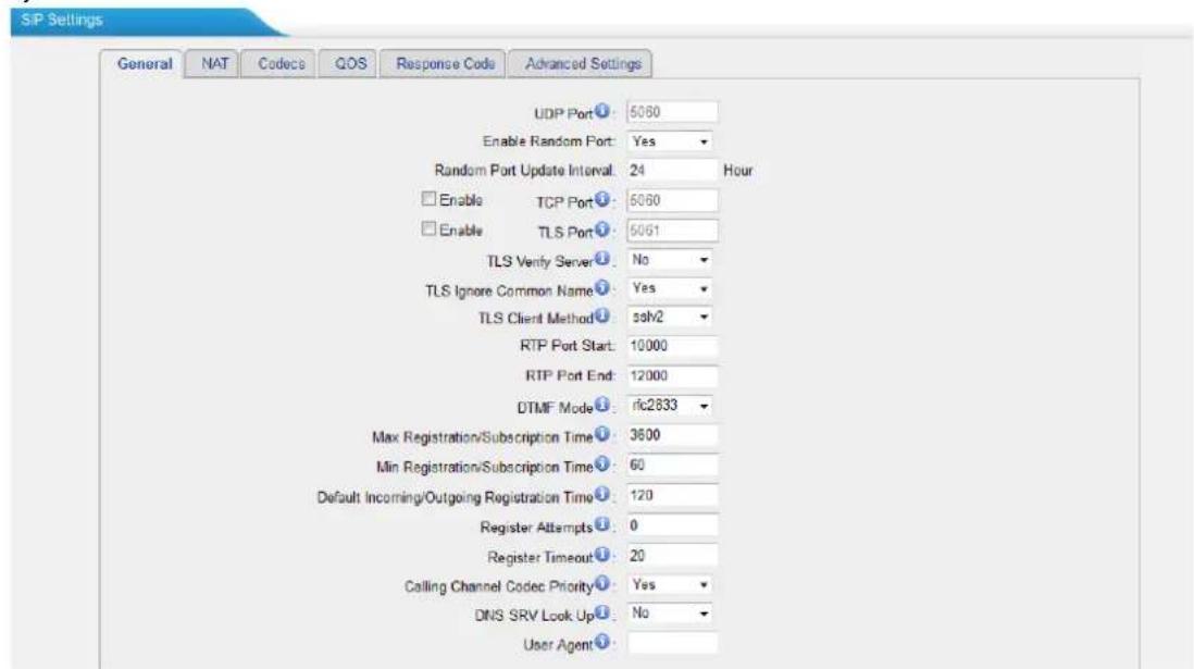
Figure 4-6 SIP General Settings
Table 4-4 Description of SIP General Settings
| Items | Description |
| UDP Port | Port used for SIP registrations. The default is 5060. |
| Enable Random Port | Enable or Disable Random SIP port. |
| Random Port Update Interval | Set the Random Port Update Interval. |
| TCP Port | Port used for SIP registrations. The default is 5060. |
| TLS Port | Port used for SIP registrations. The default is 5061. |
| TLS Verify Server | When using TA FXO Gateway as a TLS client, whether or not to verify server's certificate. It is “No” by default. |
| TLS Verify Client | When using TA FXO Gateway as a TLS server, whether or not to verify client's certificate. It is “No” by default. |
| TLS Ignore Common Name | Set this parameter as “No”, then common name must be the same with IP or domain name. |
| TLS Client Method | When using TA FXO Gateway as TLS client, specify the protocol for outbound TLS connections. You can select it as tlsv1, sslv2 or sslv3. |
| RTP Port Start | Beginning of the RTP port range. |
| RTP Port End | End of the RTP port range. |
| DTMF Mode | Set the default mode for sending DTMF. Default setting:rfc2833 |
| Max Registration/Subscription Time | Maximum duration (in seconds) of a SIP registration. The default is 3600 seconds. |
| Min Registration/Subscription Time | Minimum duration (in seconds) of a SIP registration. The default is 60 seconds. |
| Default Incoming/Outgoing Registration Time | Default Incoming/Outgoing Registration Time: the default duration (in seconds) of incoming/outgoing registration. |
| Register Attempts | The number of SIP REGISTER messages to send to a SIP Registrar before giving up. The default is 0 (no limit). |
| Register Timeout | Number of seconds to wait for a response from a SIP Registrar before classifying the register has timed out. The default is 20 seconds. |
| Calling Channel Codec Priority | Once enabled, when dialing out via SIP/SPS trunks, the codec of calling channel will be selected preferentially. If not, TA FXO Gateway will follow the priority order in your SIP/SPS trunks. |
| Video Support | Support SIP video or no. The default is yes. |
| Max Bit Rate | Configure the max bit rate for video stream. The default: 384kb/s. |
| DNS SRV Look Up | Please enable this option when your SIP trunk contains more than one IP address. |
| User Agent | To change the user agent parameter of asterisk, the default is “TA FXO Gateway”; you can change it if needed. |
2) NAT
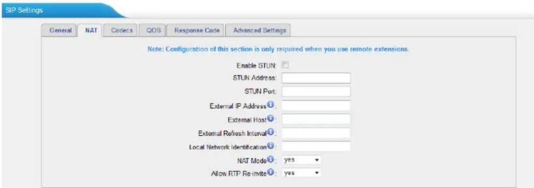
Figure 4-7 NAT Settings
Table 4-5 Description of SIP NAT Settings
| Items | Description |
| Enable STUN | STUN (Simple Traversal of UDP through NATs) is a protocol for assisting devices behind a NAT firewall or router with their packet routing. |
| STUN Address | The STUN server allows clients to find out their public address, the type of NAT they are behind and the internet side port associated by the NAT with a particular local port. This information is used to set up UDP communication between the client and the VOIP provider and so establish a call. |
| External IP Address | The IP address that will be associated with outbound SIP messages if the system is in a NAT environment. |
| External Host | Alternatively you can specify an external host, and the system will perform DNS queries periodically.This setting is only required when your public IP address is not static. It is recommended that a static public IP address is used with this system.Please contact your ISP for more information. |
| External Refresh Interval | Used to identify the local network using a network number/subnet mask pair when the system is behind a NAT or firewall.Some examples of this are as follows:“192.168.0.0/255.255.0.0”: All RFC 1918 addresses are local networks;“10.0.0.0/255.0.0.0”: Also RFC1918;“172.16.0.0/12”:Another RFC1918 with CIDR notation;“169.254.0.0/255.255.0.0”: Zero conf local network.Please refer to RFC1918 for more information. |
| NAT Mode | Global NAT configuration for the system; the options for this setting are as follows:Yes = Use NAT. Ignore address information in the SIP/SDP headers and reply to the sender's IP address/port.No = Use NAT mode only according to RFC3581.Never = Never attempt NAT mode or RFC3581 support.Route = Use NAT but do not include rport in headers. |
| Allow RTP Reinvite | By default, the system will route media steams from SIP endpoints through itself. Enabling this option causes the system to attempt to negotiate the endpoints to route packets to each other directly, bypassing the system. It is not always possible for the system to negotiate endpoint-to-endpoint media routing. |
3) Codecs
We can choose the allowed codec in TA410/810, a codec is a compression or decompression algorithm that used in the transmission of voice packets over a network or the Internet. For more information about codec, you can refer to this page: http://en.wikipedia.org/wiki/List_of_codec
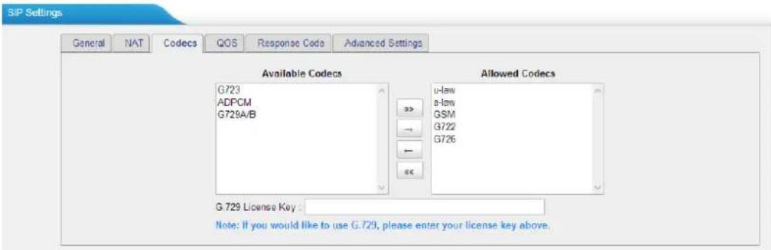
Figure 4-8 Codecs
If you want to use codec G729, we recommend buying a license key and input it here.
4) Qos
QoS (Quality of Service) is a major issue in VoIP implementations. The issue is how to guarantee that packet traffic for a voice or other media connection will not be delayed or dropped due interference from other lower priority traffic. When the network capacity is insufficient, QoS could provide priority to users by setting the value.

Figure 4-9 Qos
Note: It's recommended that you configure the QoS in your router or switch instead of TA FXO Gateway side.
5) Response Code
You can change the response code on TA FXO Gateway to the one you want before sending it to the VoIP server. It helps the VoIP server understands better the exact call status, like busy, no response and others.

Figure 4-10 Response Code
Note: we don't recommend configuring this if you are not familiar with the code of call status from the VoIP server.
6) Advanced Settings

Figure 4-11 SIP Advanced Settings
Table 4-6 Description of SIP Advanced Settings
| Items | Description |
| Call ID Field | Where to get the caller ID in SIP packet. |
| DID Field | Where to get the DID in SIP packet. |
| 180 Ringing | It is set when the telecom provider needs. Usually it is not needed. |
| Remote Party ID | Whether to send Remote-Party-ID on SIP header or not. Default: no. |
| Allow Guest | Whether to allow anonymous registration extension or not. Default: no. It's recommended that it is disabled for security reason. |
| Pedantic | Enable pedantic parameter. Default: no. |
| Alwaysauthreject | If enabled, when TA FXO Gateway rejects “Register” or “Invite” packets, TA FXO Gateway always respond the packets using “SIP404 NOT FOUND”. It's recommended that it is enabled for security reason. |
| OPTIONS Response 200 | If set to yes, the response to an OPTIONS is always 200OK. |
| Session-timers | Enable session-timer mode, default: yes. If you find the call is cut off every 15 minutes every time, please disable this. |
| Session-expires | The max refresh interval |
| Session-minse | The min refresh interval, which mustn't be shorter than 90s. |
| Session-refresher | Choose the session-refresher, the default is Uas. |
IAX Settings
IAX is the Internal Asterisk Exchange protocol, you can connect to TA FXO Gateway or register IAX trunk to another IAX server. It's supported by the asterisk-based IPPBX.
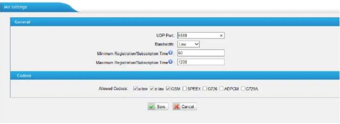
Figure 4-12 IAX Settings
Table 4-7 Description of IAX Settings
| Items | Description |
| UDP Port | Port used for IAX2 registrations. Default is 4569. |
| Bandwidth | Low/medium/high with this option you can control which codec to be used. |
| Minimum Registration Time/Subscription Time | Minimum duration (in seconds) of an IAX2 registration. Default is 60 seconds |
| Maximum Registration Time/Subscription Time | Maximum duration (in seconds) of an IAX2 registration. Default is 1200 seconds. |
| Codecs | Enable the codec you want for IAX communication. |
Routes Settings
After connecting Yeastar TA410/810 gateway with the VoIP server, you need to configure the routes settings on TA410/810 to route the calls through the gateway. In this chapter, we introduce the following sections:
- IP->Port
- Port->IP/Port
- Blacklist
- Callback Settings
IP->Port
Configure IP->Port routes to control calls from your SIP server to TA410/810 FXO ports.
Click "Edit" to check the route details, there are two modes for you.
1) Simple Mode
Choose "Yes" for Simple Mode, the simple mode configuration page appears as below.
Figure 5-1 Simple Mode Route
Table 5-1 Description of Simple Mode Route
| Route Name | Define the route name. |
| Call Source | Choose the trunk or trunk group for the incoming calls. |
| Call Destination | Choose the trunk or trunk group to route the incoming calls to. |
Hotline
Dial the number directly, The dial pattern is ignored.
2) Detail Mode
Choose "No" for Simple Mode, you will see the detailed configuration page as the following picture shows. Detailed settings for Match Incoming Calls and Handle Matched Incoming Calls are provided in Detailed Mode.
Figure 5-2 Detailed Mode Route
Table 5-2 Description of Match Incoming Calls Settings
| Call Source | Choose the trunk or trunk group for the incoming calls. |
| Inbound Caller Pattern | Match the prefix of caller ID for incoming calls. |
| DID Number | Define the expected DID Number if this trunk passes DID on incoming calls. Leave this field blank to match calls with any or no DID info. You can also use pattern matching to match a range of numbers. |
| DID Associated Number | Define the extension for DID number. You can input number and “-”in this field, and the format can be xxx or xxx-xxx. The count of the number must be only one or equal the count of the DID number. |
Table 4-13 Description of Handle Matched Incoming Calls Settings
| Items | Description |
| Call Destination | Choose the trunk or trunk group to route the incoming calls to. |
| Hotline | Direct number to the SIP Server. The parameter is ignored if a SIP Account is selected on this route. |
| Two-stage Dialing | Enable or Disable Two-stage Dialing. |
| Outbound Dial Pattern | Outbound calls that match this dial pattern will use this outbound route. |
| Strip | Allows the user to specify the number of digits that will be stripped from the front of the phone number before the call is placed. For example, if users must press 0 before dialing a phone number, one digit should be stripped from the dial string before the call is placed. |
| Prepend | These digits will be prepended to the phone number before the call is placed. For example, if a trunk requires 10-digit dialing, but users are more comfortable with 7-digit dialing, this field could be used to prepend a 3-digit area code to all 7-digit phone numbers before calls are placed. |
Port->IP/Port
Port->IP/Port routes are used to control incoming calls to PSTN trunks on TA410/810 and route the calls to your SIP server or another PSTN trunk on TA410/810.
Click "Edit" to check the route details. there are two modes for you.
TA410/810 User Manual
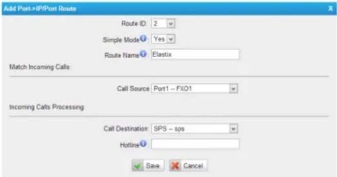
Figure 5-3 Simple Mode Route
Table 5-3 Description of Simple Mode Route
| Items | Description |
| Route Name | Define the route name. |
| Call Source | Choose the trunk or trunk group for the incoming calls. |
| Call Destination | Choose the trunk or trunk group to route the incoming calls to. |
| Hotline | Dial the number directly. The dial pattern is ignored. |
2) Detail Mode
Choose "No" for Simple Mode, you will see the detailed configuration page as the following picture shows. Detailed settings for Match Incoming Calls and Handle
Figure 5-4 Detailed Mode Route
Table 5-4 Description of Match Incoming Calls Settings
| Call Source | Choose the trunk or trunk group for the incoming calls. |
| Inbound Caller Pattern | Match the prefix of caller ID for incoming calls. |
| Enable Callback | Wether to enable callback feature. |
Table 5-5 Description of Handle Matched Incoming Calls Settings
| Call Destination | Choose the trunk or trunk group to route the incoming calls to. |
| Hotline | Direct number to the SIP Server. The parameter is ignored if a SIP Account is selected on this route. |
| Outbound Dial Pattern | Outbound calls that match this dial pattern will use this outbound route. |
| Strip | Allows the user to specify the number of digits that will be stripped from the front of the phone number before the call is placed. For example, if users must press 0 before dialing a phone number, one digit should be stripped from the dial string before the call is placed. |
| Prepend | These digits will be prepended to the phone number before |
the call is placed. For example, if a trunk requires 10-digit dialing, but users are more comfortable with 7-digit dialing, this field could be used to prepend a 3-digit area code to all 7-digit phone numbers before calls are placed.
Blacklist
Blacklist is used to block an incoming or outgoing call. If the number of incoming or outgoing call is listed in the number blacklist, the caller will hear the following prompt:
"The number you have dialed is not in service. Please check the number and try again". The system will then disconnect the call.
You can add a number with the type: inbound, outbound or both.
Figure 5-5 Blacklist
Callback Settings
1) If you'd like to use callback feature, please make sure it's enabled on the IP->Port or Port->IP/Port route setting panel.
2) No callback rules needed to be set if the trunk supports call back with the caller ID directly.
3) Add Callback numbers, then callback will work for the added callback numbers. Tick "Allow All Numbers", callback feature will work for all numbers.
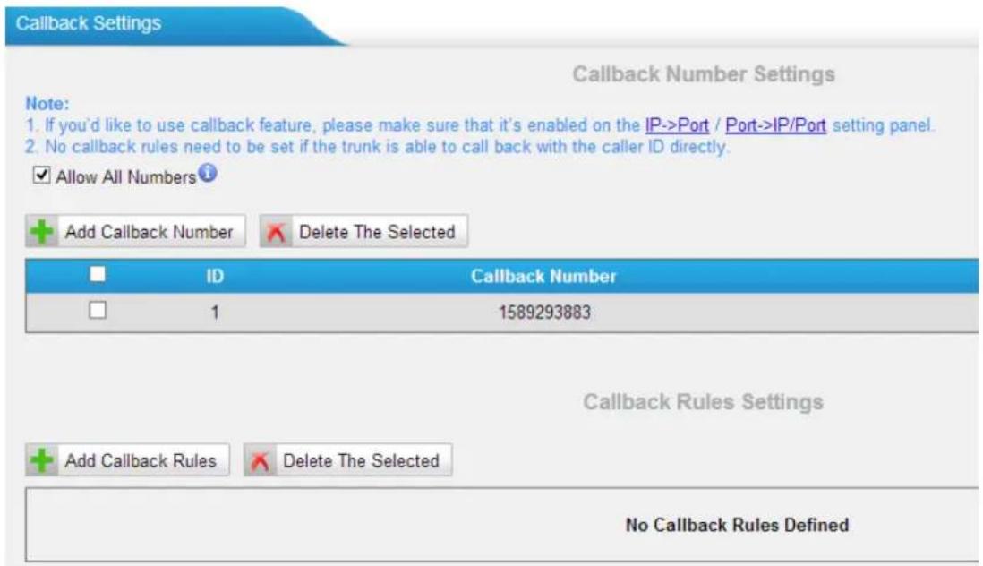
Figure 5-6 Callback Settings
Gateway Settings
This chapter explains Gateway settings, which can be applied globally to TA410/810. The gateway settings can be configured under Gateway→ Gateway Settings.
- General Preferences
General Preferences
General Preferences
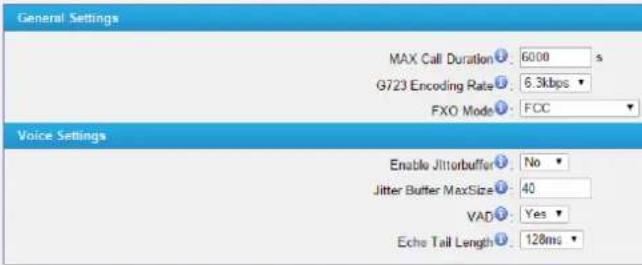
Figure 6-1 General Preferences
Table 6-1 General Preferences
| General Settings | |
| MAX Call Duration | The absolute maximum amount of time permitted for a call. A setting of 0 disables the timeout. |
| G723 Encoding Rate | Set the G723 encoding rate. |
| FXO Mode | Select country to set the On Hook Speed, Ringer Impedance, Ringer Threshold, Current Limiting, TIP/RING voltage adjustment, Minimum Operational Loop Current, and AC Impedance as predefined for your country's analog line characteristics. The default setting is "FCC". |
| Voice Settings | |
| Enable Jitter buffer | Forces the use of a jitter buffer on the received side of a SIP channel. The call quality will be improved if this option is enabled. |
| Jitter Buffer MaxSize | Max length of the jitter buffer in milliseconds. Default: 40. |
| VAD | Voice Activity Detection. |
| Echo Tail Length | In some cases, the echo canceller doesn't train quickly enough and there is echo at the beginning of the call which then quickly fades out. |
Audio Settings
This chapter explains prompt settings on TA410/810.
- Custom Prompts
Custom Prompts
We can upload the prompts in this page; you can also download it and save it as a backup.
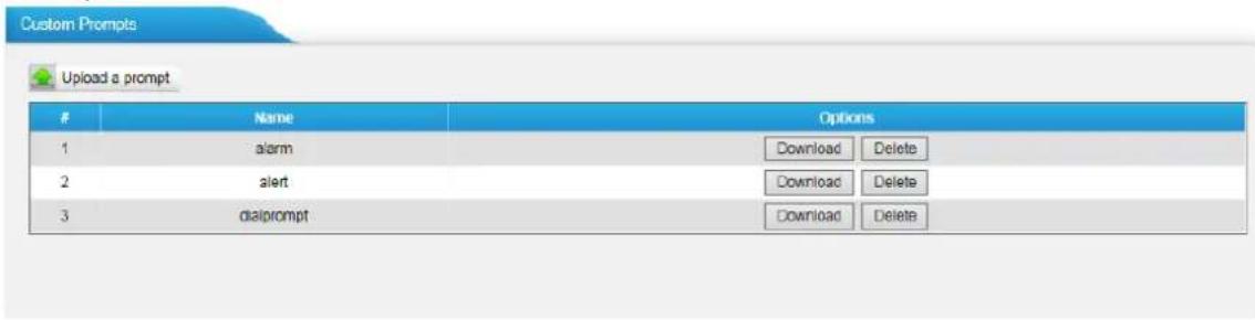
Figure 7-1 Custom Prompts
The administrator can upload prompts by doing the following:
1 )Click "Upload Prompt".
2) Click "Browse" to choose the desired prompt.
3) Click "Upload" to upload the selected prompt.
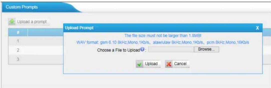
Figure 7-2 Upload A Prompt
Note: The file size must not be larger than 1.8 MB, and the file must be WAV format:
GSM 6.10 8 kHz, Mono, 1 Kb/s;
Alaw/Ulaw 8 kHz, Mono, 1 Kb/s;
PCM 8 kHz, Mono, 16 Kb/s.
Advanced Settings
This chapter explains SIP settings and Distinctive Ringtones.
- Tone Zone Settings
DTMF Settings
Tone Zone Settings
Advanced ring tones for all the FXO ports can be configured on this page. There are pre-grogrammed tone zone settings for some countries and regions. Users can simply find and select thier country to get tone zone settings for the gateway.
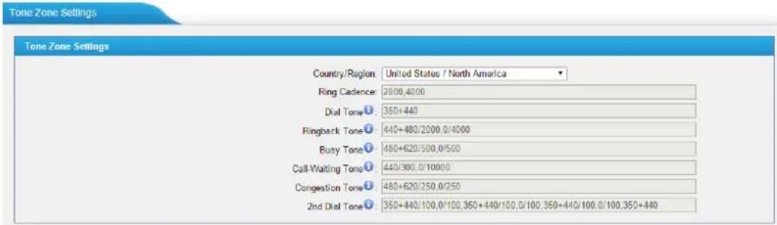
Figure 8-1 Tone Zone Settings
Users may also configure the tone zone according to the national standard by selecting "User custom for Tone Zone". Please refer to the document below and configure the tone zone settings on TA FXO Gateway:
http://www.itu.int/ITU-T/inr/forms/files/tones-0203.pdf
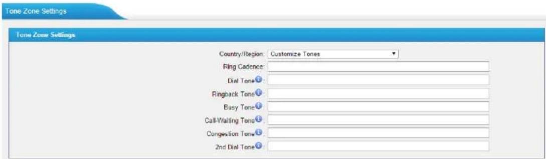
Figure 8-2 Customize Tones
Table 8-1 Description of Tone Zone Settings
| Items | Description |
| Country/Region | Choose the country to get pre-programmed tone zone settings or choose "User custom for Tone Zone" to configure the settings manually. |
| Ring Cadence | Configuration option for all FXO ports ring cadence for allincoming calls. |
| Dial Tone | Prompt tone of off-hook dial tone. |
| Ringback Tone | The tone sent to caller when ringing is on. |
| Busy Tone | Used for busy line prompt. |
| Call-Waiting Tone | Used for notification in call waiting. |
| Congestion Tone | Used to indicate that an invalid code has been dialed, or that all circuits (trunks) are busy and/or the call is unroutable. |
| 2nd Dial Tone | Used for the second stage dial tone. |
DTMF Settings
DTMF signal sent from TA410/810 to the receiver can be set on this page.
Digit Length and Dial Pause Between Digit: 100.100 (ms)
Default Digit Volume: -10,-10 (dB)
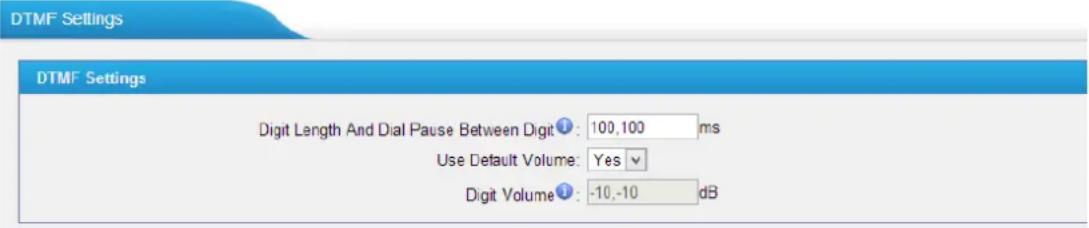
Figure 8-3 DTMF Settings
Network Preferences

This chapter explains network settings on TA410/810. Click the main menu
the top of the Web GUI to check the network settings.
• LAN Settings
• Service
- VLAN Settings
- VPN Settings
- DDNS Settings
- Static Route
LAN Settings
After successfully logging in the TA410/810 Web GUI for the first time, users could go System→Network Preferences→LAN Settings to configure the network for TA410/810.
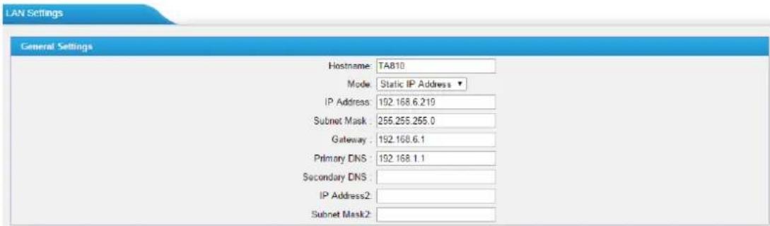
Figure 9-1 LAN Settings
Table 9-1 LAN Settings
| Items | Description |
| Hostname | Set the host name for TA410/810. |
| Mode | Choose the network mode:Static IP AddressDHCPPPPoE |
| IP Address | Set the IP Address for TA410/810. |
| Subnet Mask | Set the subnet mask for TA410/810. |
| Gateway | Set the gateway for TA410/810. |
| Primary DNS | Set the primary DNS for TA410/810. |
| Secondary DNS | Set the secondary DNS for TA410/810. |
| IP Address2 | Set the second IP Address for TA410/810. |
| Subnet Mask2 | Set the second subnet mask for TA410/810. |

Figure 9-2 DHCP Mode
Select DHCP mode to get network automatically from the local network.

Figure 9-3 PPPoE
Fill in user name and password to access the Internet via PPPoE.
Service
The administrator can manage all the access methods on TA on the "Service" page.

Figure 9-4 Service Settings
Table 9-2 Description of Service Settings
| Items | Description |
| SSH | By using SSH, you can log in to TA410/810 and run commands. It's disabled by default. We don't recommend enabling it if not needed.The default port for SSH is 8022. |
| FTP | FTP access;The default port is 21. |
| HTTP | HTTP web access;The default port is 80. |
| HTTPS | HTTPS web access, it is disabled by default, and you can enable it to get safer web access. |
VLAN Settings
VLAN (Virtual Local Area Network) is a group of hosts with a common set of requirements, which communicate as if they were attached to the same broadcast domain, regardless of their physical location.
A VLAN is a broadcast domain created by switches. This means the VLAN is configured on switches, layer 3 switches. Note that some of the switches don't support VLAN.
Note:
TA410/810 acts as a VLAN client, a 3-layer switch is needed.
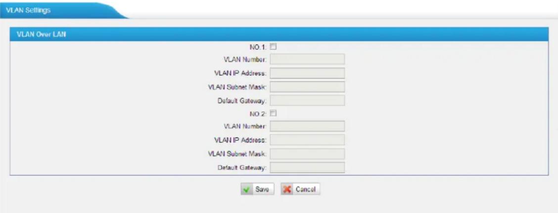
Figure 9-5 VLAN Settings
Please follow the steps below to set up VLAN on TA410/810.
Step1. Create VLANs on your switch.
Step2. Allocate a VLAN ID and IP address for TA410/810.
Step3. Configure VLAN settings page on TA410/810.
VPN Settings
A virtual private network (VPN) is a method of computer networking typically using the public internet that allows users to privately share information between remote locations, or between a remote location and a business' home network. A VPN can provide secure information transport by authenticating users, and encrypting data to prevent unauthorized persons from reading the information transmitted. The VPN can be used to send any kind of network traffic securely. TA410/810 supports OpenVPN.
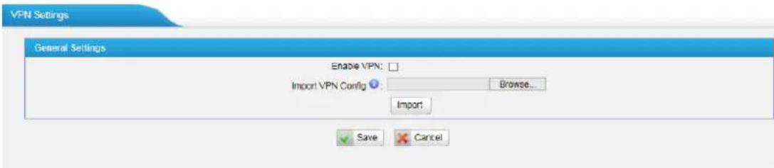
Figure 9-6 VPN Settings
- Enable VPN
Enable VPN feature.
- Import VPN Config
Import configuration file of OpenVPN.
Notes:
-
Uncomment "user" and "group" in the "config" file. You can get the config package from the OpenVPN provider.
-
TA410/810 works as VPN client mode only.
DDNS Settings
DDNS(Dynamic DNS) is a method/protocol/network service that provides the capability for a networked device, such as a router or computer system using the Internet Protocol Suite, to notify a Domain Name System (DNS) name server to change, in real time, the active DNS configuration of its configured hostnames, addresses or other information.
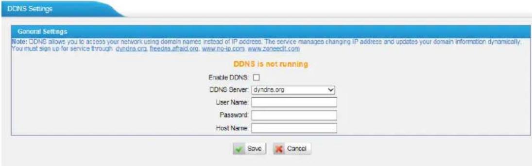
Figure 9-7 DDNS Settings
Table 9-3 Description of DDNS Settings
| Items | Description |
| DDNS Server | Select the DDNS server you sign up for service. |
| User Name | User name the DDNS server provides you. |
| Password | User account's password. |
Host Name The host name you have got from the DDNS server
Note: DDNS allows you to access your network using domain names instead of IP address. The service manages changing IP address and updates your domain information dynamically. You must sign up for service through dyndns.org, freedns.afraid.org, www.no-ip.com, www.zoneedit.com.
Static Route
TA FXO Gateway will have more than one Internet connection in some situations but it has only one default gateway. You will need to set some Static Route for TA FXO Gateway to force it to go out through different gateway when accessing to different internet.
The default gateway priority of TA FXO Gateway from high to low is VPN/VLAN → LAN port.
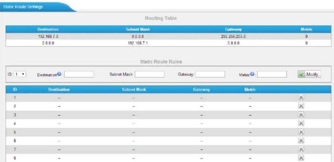
Figure 9-8 Static Route
1) Route Table
The current route rules of TA FXO Gateway.
2) Static Route Rules
You can add new static route rules here.
Table 9-4 Description of Static Route Settings
| Items | Description |
| Destination | The destination network to be accessed to by TA FXO Gateway. |
| Subnet Mask | Specify the destination network portion. |
| Gateway | Define which gateway TA FXO Gateway will go through when accessing the destination network. |
| Metric | The cost of a route is calculated by using what are called routingmetric. Routing metrics are assigned to routes by routing protocols to provide measurable statistic which can be used to judge how useful (how low cost) a route is. |
| Interface | Define which internet port to go through. |
Security Center
This chapter describes how to secure your TA410/810. It is strongly recommended that users configure firewall and other security options on TA410/810 to prevent the attack fraud and the system failure or calls loss.
• Security Center
- Alert Settings
- AMI Settings
- Certificates
- Firewall Rules
- IP Blacklist
Security Center
All the security settings including Firewall, Service, Port Settings in TA410/810 are displayed in Security Center. Users could rapidly check and configure the relevant security settings here.
1) Firewall
In the "Firewall" tab, users could check firewall configuration and alert settings. By clicking the relevant button, you can enter the configuration page directly.
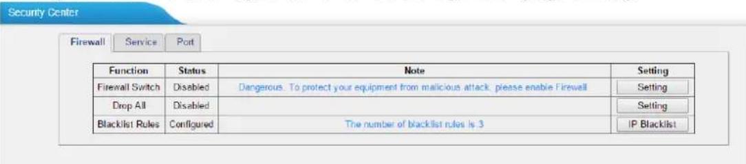
Figure 10-1 Security Center—Firewall
2) Service
In "Service" tab, you can check AMI/SSH status. For AMI/SSH, you can enter the according page by clicking the button in "Setting" column.
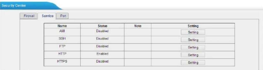
Figure 10-2 Security Center—Service
3) Port
In "Port" tab, you can check SIP port and HTTP port. You can also enter the relevant page by clicking the button in "Setting" column.
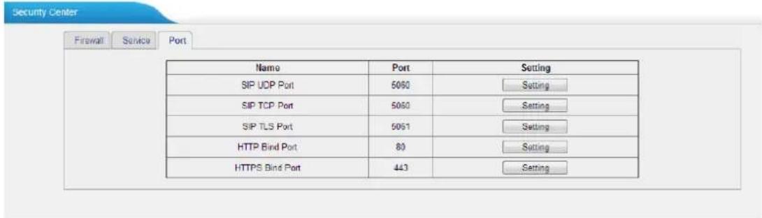
Figure 10-3 Security Center—Port
Alert Settings
If the device is under attack, the system will alert users via call or E-mail. The attack modes include IP attack and Web Login.
- IPATTACK
When the system is attacked by IP address, the firewall will add the IP to auto IP Blacklist and notify the user if it matches the protection rule.
- WEBLOGIN
Web Login Alert Notification: entering the wrong password consecutively for five times when logging in TA FXO Gateway Web interface will be deemed as an attack, the system will limit the IP login within 10 minutes and notify the user.
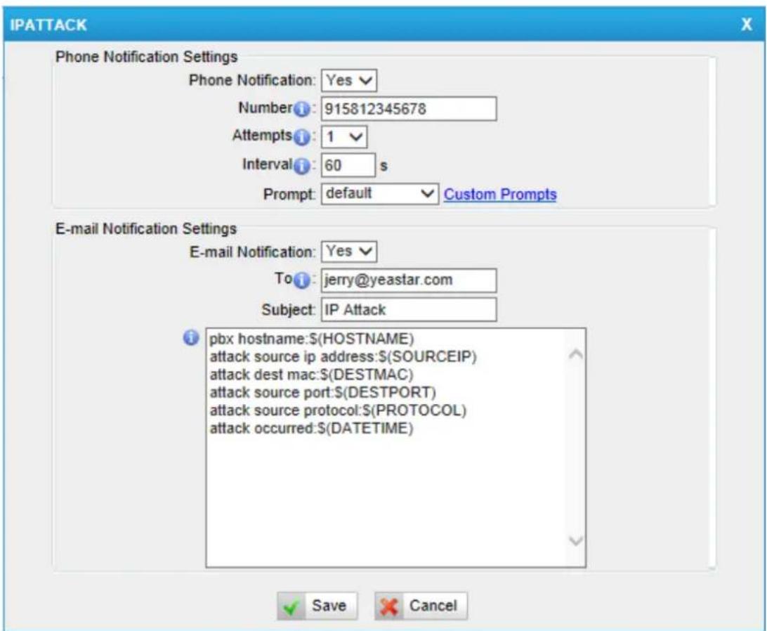
Figure 10-4 Alert Settings
Table 10-1 Description of Alert Settings
| Phone Notification Settings | |
| PHONENotification | Whether to enable phone notification or not. |
| Number | The numbers could be set for alert notification; users can setup multiple extension and outbound phone numbers.Please separate them by “;”.Example: “500;9911”, if the extension has configured Follow Me Settings, the call would go to the forwarded number directly. |
| Attempts | The attempts to dial a phone number when there is no answer. |
| Interval | The interval between each attempt to dial the phone number.Must be longer than 3 seconds, the default value is 60 seconds. |
| Prompt | Users will hear the prompt while receiving the phone notification. |
| Email Notification Settings | |
| E-mailNotification | Whether to enable E-mail Notification or not. |
| Recipient's Name | The recipients for the alert notification, and multiple email addresses are allowed, please separate them by “;”.E.g. jerry@yeastar.com;jason@yeastar.com,456@sina.com |
| Subject | The subject of the alert email. |
| Email Content | Text content supports predefined variables. Variable names and corresponding instructions are as follows:gateway hostname:$(HOSTNAME)attack source ip address:(SOURCEIP)attack dest mac:(DESTMAC)attack source port:(DESTPORT)attack source protocol:(PROTOCOL)attack occurred:$(DATETIME) |
AMI Settings
The Asterisk Manager Interface (AMI) is a system monitoring and management interface provided by Asterisk. It allows live monitoring of events that occur in the system, as well enabling you to request that Asterisk perform some action. The actions that are available are wide-ranging and include things such as returning status information and originating new calls. Many interesting applications have been developed on top of Asterisk that take advantage of the AMI as their primary interface to Asterisk.
There are two main types of messages on the Asterisk Manager Interface: manager events and manager actions.
The 3 ^rd party software can work with TA410/810 using AMI interface. It is disabled by default. If necessary, you can enable it.
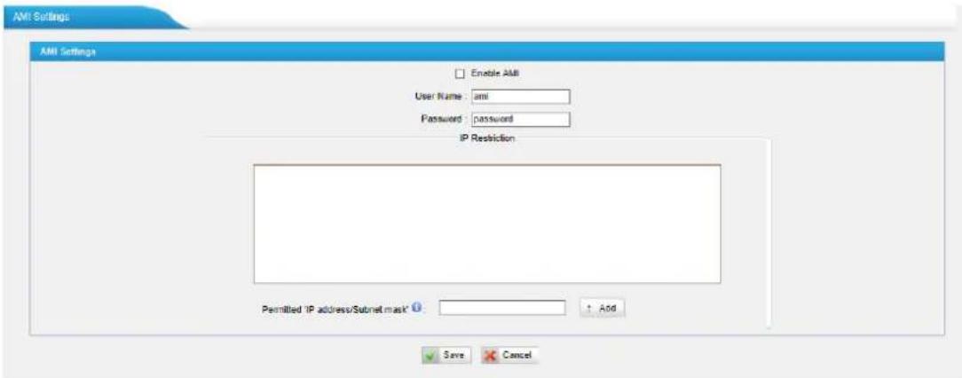
Figure 10-5 AMI Settings
• User Name, Password & Port
After enabling AMI, you can use this username and password to log in TA410/810. The default port is 5038.
- Permitted "IP address/Subnet mask"
You can set which IP is allowed to log in TA410/810 AMI interface.
Certificates
TA410/810 supports TLS transport, you can configure FXO port with TLS transport. To use TLS, you should upload certificates first.
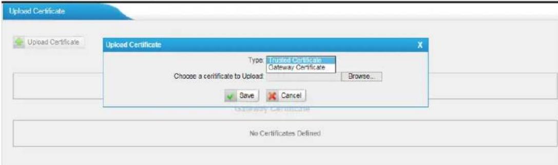
Figure 10-6 Upload Certificate
- Trusted Certificate
This certificate is a CA certificate. When selecting "TLS Verify Client" as "Yes", you should upload a CA. The relevant VoIP provider should also have this certificate.
- Gateway Certificate
This certificate is server certificate. No matter selecting "TLS Verify Client" as "Yes" or "NO", you should upload this certificate to TA410/810. If the VoIP provider enables "TLS Verify server", you should also upload the relevant CA certificate on the VoIP provider.
Firewall Rules
Firewalls are used to prevent unauthorized Internet users from accessing private networks connected to the Internet, especially intranets. All messages entering or leaving the intranet pass through the firewall, which examines each message and blocks those that do not meet the specified security criteria.
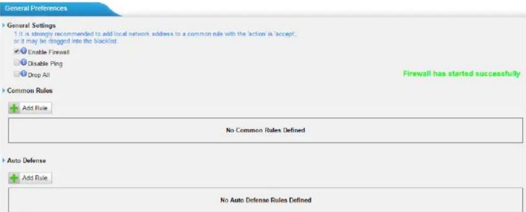
Figure 10-7 Firewall Settings
1) General Settings
Table 10-2 Description of Firewall General Settings
| Items | Description |
| Enable Firewall | Enable the firewall to protect the device. |
| Disable Ping | Enable this item to drop net ping from remote hosts. |
| Drop All | When you enable “Drop All” feature, the system will drop all packets or connection from other hosts if there are no other rules defined. To avoid locking the devices, at least one “TCP” accept common rule must be created for port used for SSH access, port used for HTTP access and port sued for CGI access. |
2) Common Rules
There is no default rule; you can create one as required.
Figure 10-8 Common Rules
Table 10-3 Description of Common Rules
| Name | A name for this rule, e.g. “HTTP”. |
| Description | Simple description for this rule. E.g. accept the specific host to access the Web interface for configuration. |
| Protocol | The protocols for this rule. |
| Port | Initial port should be on the left and end port should be on the right.The end port must be equal to or greater than start port.The IP address for this rule. The format of IP address is: IP/mask |
| IP | E.g. 192.168.5.100/255.255.255.255 for IP 192.168.5.100E.g. 192.168.5.0/255.255.255.0 for IP from 192.168.5.0to 192.168.5.255. |
| MAC Address | The format of MAC Address is XX:XX:XX:XX:XX:XX, X means 0~9 or A~F in hex, the A~F are not case sensitive.Accept: Accept the access from remote hosts. |
| Action | Drop: Drop the access from remote hosts.Ignore: Ignore the access. |
Note: the MAC address will be changed when it's a remote device, so it will not be working to filter using MAC for remote devices.
3) Auto Defense
Figure 10-9 Auto Defense
Table 10-4 Description of Auto Defense
| Items | Description |
| Port | The port you want to auto defense, for example, 8022. |
| Protocol | Select the protocol. You can select UDP or TCP. |
| Rate | The maximum packets or connections can be handled per unit time. For example, if you configure it as below: Port: 8022Protocol: TCPRate: 10/minThen, it means maximum 10 TCP connections can be handled in 1 minute. The 11^th connection will be dropped. |
IP Blacklist
You can set some packets accept speed rules here. When an IP address, which hasn't been accepted in common rules, sends packets faster than the allowed speed, it will be set as a black IP address and be blocked automatically.
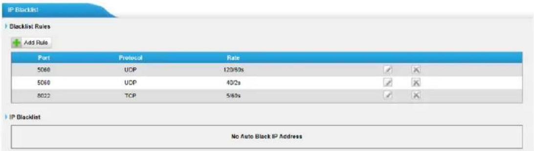
Figure 10-10 IP Blacklist Settings Page
1) Blacklist rules
We can add the rules for IP blacklist rate as demanded.
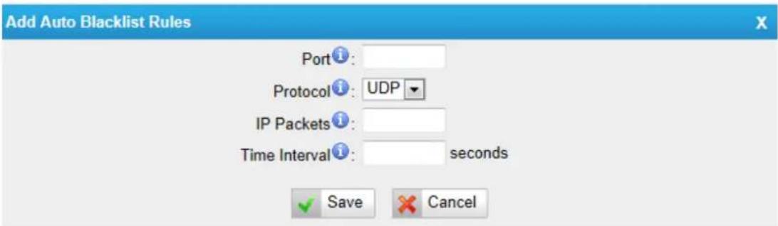
Figure 10-11 Add Blacklist Rule
Table 10-5 Description of Auto Blacklist Rules
| Items | Description |
| Port | Auto defense port |
| Protocol | Auto defense protocol. TCP or UDP. |
| IP Packets | Allowed IP packets number in the specific time interval. |
| Time interval | The time interval to receive IP packets. For example, IP packets 90, time interval 60 means 90 IP packets are allowed in 60 seconds. |
2) IP blacklist
The blocked IP address will display here, you can edit or delete it as you wish.
System Preferences
This chapter describes system maintenance settings including the followings:
- Password Settings
- Date and Time
• Auto Provision Settings - Firmware Update
- Backup and Restore
- Reset and Reboot
Password Settings
It is highly recommended to change the system's password after first login. Go to System→System Preferences→Password Settings to change the password.
- Enter the old password first.
- Enter a new password and retype the new password to confirm. The password complexity will be detected, which will help users to set a strong password and make TA410/810 safer. A strong password is comprised of letters, numbers and characters.
- Save the changes, the user will be automatically logged out.
- Log in TA410/810 using the new password.

Figure 11-1 Password Settings
Date and Time
Please adjust the time of TA410/810 (including the time zone) consistent with your local time. Go to System→System Preferences→Date and Time to configure the system date and time.
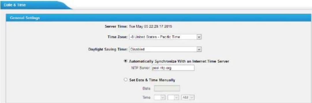
Figure 11-2 Date and Time
- Time Zone
Select your current and correct time zone on TA410/810.
• Daylight Saving Time
The option is disabled by default. Enable it when necessary.
• Automatically Synchronize with an Internet Time Server
TA410/810 will adjust its internal clock to a central network server. Please note the TA410/810 should be able to access to the Internet if you choose this method.
- Set Date & Time Manually
Enter the time using the numbers on your keyboard.
Note: you have to reboot the system to make the changes take effect.
Auto Provision Settings
Three methods are supported for Auto Provision: PNP, DHCP and you can manually configure a server URL to get the configuration file from the server. Go to System→System Preferences→Auto Provision Settings to configure.

Figure 11-3 Auto Provision Methods
PNP and DHCP modes work along with MyPBX "TA Provisioning". Firstly, users need to configure TA410/810 on MyPBX "TA Provisioning" page. Then TA410/810 will find and get the configuration file from MyPBX during boots up.
In PNP mode, you just need to place the TA410/810 in the same IP range network with MyPBX, then you can find the TA410/810 and provision it on MyPBX "TA Provisioning" page.
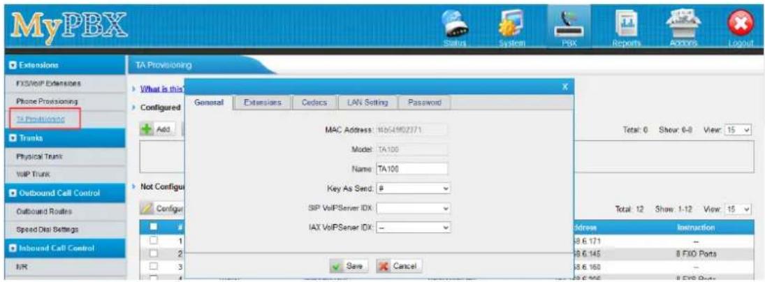
Figure 11-4 MyPBX TA Provisioning
If you use DHCP mode to do auto provision, you should enable DHCP Server on MyPBX to make it as a DHCP server. (System→Network Preferences→DHCP Server).
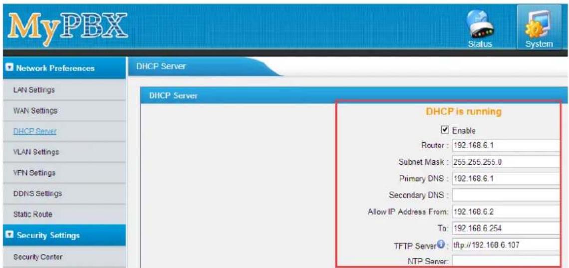
Figure 11-5 Set MyPBX as a DHCP Server
Then select DHCP mode on LAN settings page to make TA410/810 as a DHCP client.

Figure 11-6 Set TA410/810 as a DHCP Client
Another way to do auto provision is to download configuration file from the configured server URL. Fill in the URL, user name, password, and set the time, TA410/810 will get the configuration file from the server automatically and regularly.
Note: if there is no user name and password for the server, leave these fields blank.
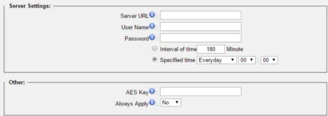
Figure 11-7 Server Address
- AES Key
If the configuration file is encrypted by AES key, you need to fill the key in this field.
- Always Apply
With No, it will compare the current configuration file with the last updated one, if the contents are the same no update will be applied. With Yes, it will always apply the updated configuration file.
Firmware Update
TA410/810 can be upgraded to a new firmware version via network or locally. Users could upgrade firmware via HTTP or TFTP. Please go to System→System Preferences→Firmware Update to do upgrade.
Notes:
- If "Reset configuration to Factory Defaults" is enabled, the system will be restored to factory default settings.
- When updating the firmware, please don't turn off the power. Or the system will be damaged.
- If you are trying to upgrade through HTTP, please make sure that your TA410/810 is able to visit external network, or it cannot access Yeastar website to get the firmware file, causing the upgrade fail.
Upgrade through HTTP
On the Firmware Upgrade page, choose HTTP URL.
Step1. Enter the download link of the firmware file.
Note: the HTTP URL should be a BIN file download link.
Step2. Click "Start" to upgrade.
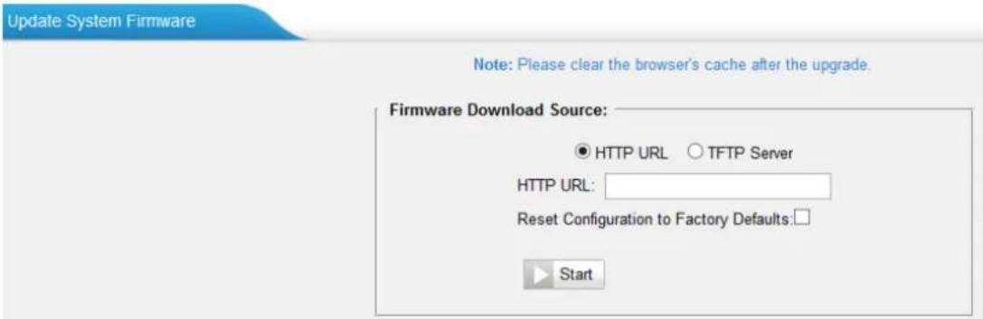
Figure 11-8 Upgrade through HTTP
Upgrade through TFTP
Step1. Download firmware file from Yeastar website.
Step2. Create a tftp Server (For example, tftpd on Windows).
1) Install tftpd32 software on computer.
Download link: http://tftpd32.jounin.net/tftpd32_download.html
2) Configure tftpd32.
On option "Current Directory", click "Browse" button, choose the firmware file (BIN file) upgraded patch.
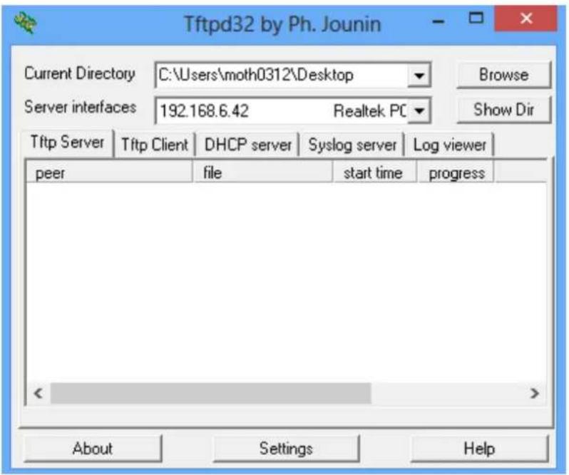
Figure 11-9 Configure Tftpd32
Step3.Logon the TA410/810's Web page and go to System→System Preferences→Firmware Update, choose "TFTP Server".
1) TFTP Server: fill in IP address of tftpd32 server (your PC's IP address).
2) File Name: enter the name of firmware update. It should be a BIN file name.
3) Click "Start" to upgrade.
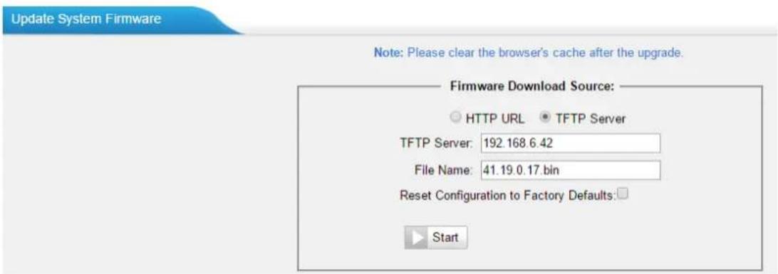
Figure 11-10 Upgrade through HTTP
Backup and Restore
TA410/810 provides Backup and Restore feature, which allows you to create a complete backup of TA410/810 configurations to a file.
Notes:
-
When you have updated the firmware version, it's not recommended to restore using an old package.
-
Backup from an earlier version cannot be restored on TA410/810 of a later version.
-
Create a New Backup
Click to create a new backup. - Upload a Backup
Click to upload a backup. - Restore
To restore TA410/810 configuration data, upload the backup file to TA410/810 and click. Reboot the system to take effect.
Please note the current configurations will be OVERWRITTEN with the backup data.
| # | Name | Time | Options | ||
| 1 | backup_2015may9_174120.tar | Sat May 09 1:41:58 2015 | |||
Figure 11-11 Restore Backup
Reset and Reboot
Users could reset and reboot the system under System→System Preferences→Reset and Reboot.
Reset and Reboot Options
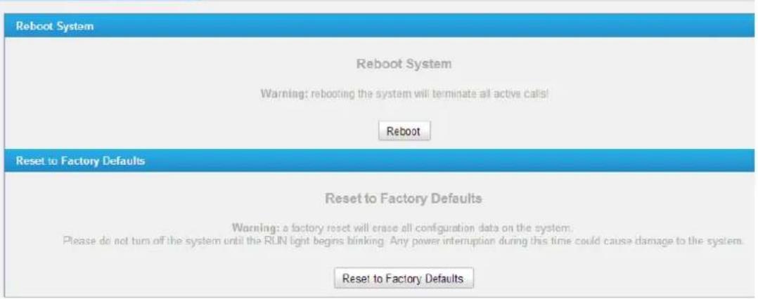
Figure 11-12 Reset and Reboot
Status
Users could check the system status on Status→System Status, where FXO Port and trunk Status, Network Status and System Info can be checked.
- Port/Trunk Status
• Network Status - System Info
Port/Trunk Status
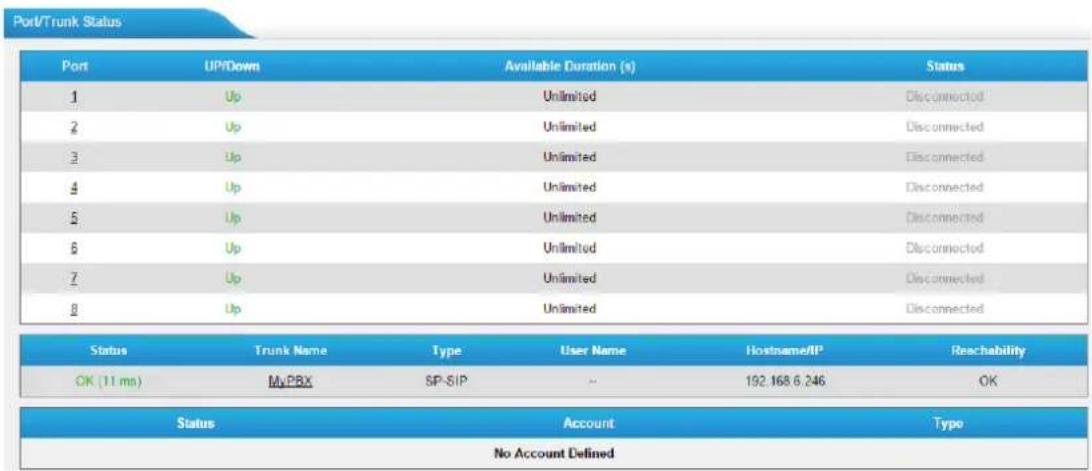
Figure 12-1 Port/Trunk Status
FXO Port Status
Table 12-1 Description of FXO Port Status
| Up/Down | |
| Up | The FXO module works well. |
| Down | The FXO module is broken. |
| Available Duration (s) | |
| The available duration of this PSTN trunk. | |
| Status | |
| Idle | The FXO port is idle. |
| Busy | The FXO port is busy. |
| Disconnect | There is no line connected to the FXO port. |
VoIP Trunk Status
1) SIP/IAX Type
Table 12-2 Description of SIP/IAX Trunk Status
| Registered | Successful registration, trunk is ready for use. |
| Unregistered | Trunk registration failed. |
| Request Sent | Registering. |
| Waiting for Authentication | Wrong password. |
2) SP-SIP/IAX Type
Table 12-3 Description of SP-SIP/IAX Trunk Status
| OK | Successful registration, trunk is ready for use. |
| Unreachable | The trunk is unreachable. |
| Failed | Trunk registration failed. |
3) VoIP Account
Table 12-4 Description of VoIP Account Status
| Registered | The account is registered successfully on the SIP server. |
| Unregistered | Trunk registration failed. |
Network status
In this page, the IP address of LAN port will appear with their status.
Figure 12-2 Network Status
If your VLAN or VPN are configured, you can check the status in this page also.
System Info
In this page, we can check the hardware/firmware version, or the disk usage of TA FXO Gateway.
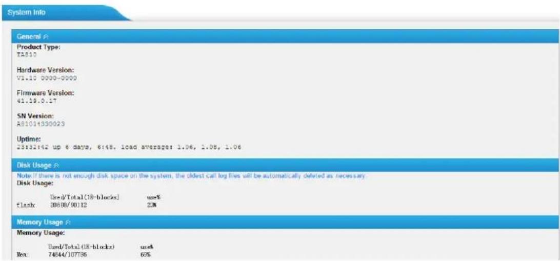
Figure 12-3 System Info
Reports
Users could check the call logs, system logs on Status→Reports page, and use the packet Tool and Port Monitor Tool to capture debug logs from TA410/810.
- Call Logs
- System Logs
- Packet Tool
- Port Monitor Tool
Call Logs
The call log captures all call details, including call time, caller number, callee number, call type, call duration, etc. An administrator can search and filter call data by call date, caller/callee, trunk, duration, billing duration, status, or communication type.
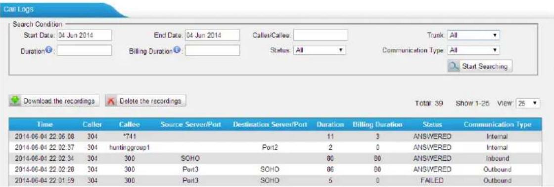
Figure 13-1 Call Logs
System Logs
You can download and delete the system logs of TA410/810.
- Enable Hardware Log Save the information of hardware; (up to 4 log files)
- Enable Normal Log Save the prompt information; (up to 16 log files)
- Enable Web Log Save the history of web operations (up to 2 log files)
- Enable Debug Log Save debug information (up to 2 log files)
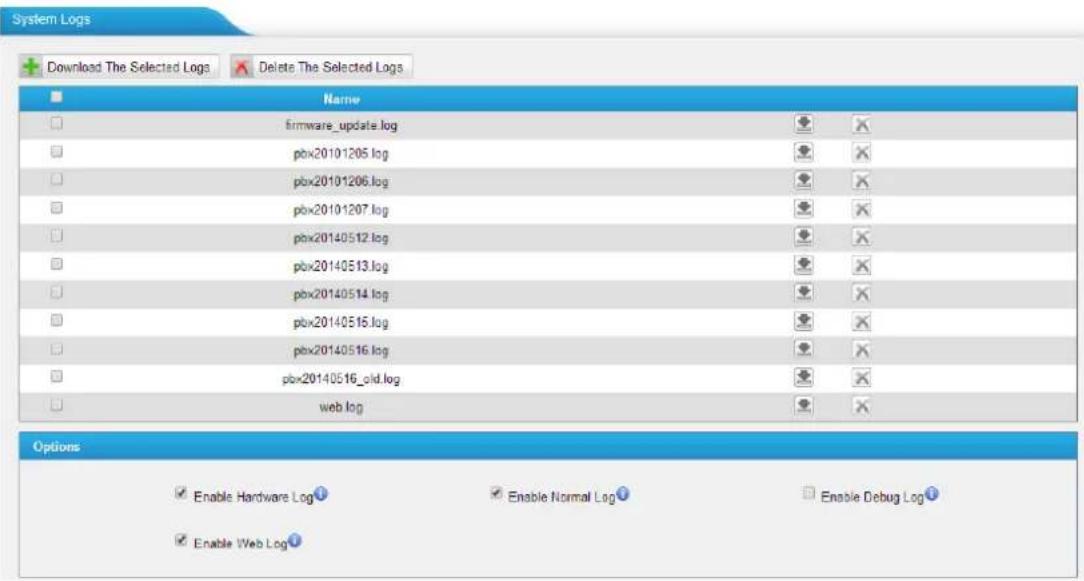
Figure 13-2 System Logs
Packet Tool
This feature is used to capture packets for technician. Integrate packet capture tool "Wireshark" in TA410/810. Users also could specify the destination IP address and port to get the packets.

Figure 13-3 Packet Tool
• IP
Specify the destination IP address to get the packets.
- Port
Specify the destination Port to get the packets.
Port Monitor Tool
This tool is used to debug a FXO port. Select a FXO port and click "Start" to monitor the FXO port, stop monitoring by clicking "Stop" button.

Figure 13-4 Port Monitor Tool
- Yeastar
- User Manual
- Copyright
- Declaration of Conformity
- Warranty
- WEEE Warning
- Contents
- About This Guide....5
- Getting Started....6
- FXO Port Settings....11
- VoIP Settings....17
- Routes Settings 26
- Gateway Settings....33
- Audio Settings 34
- Advanced Settings 35
- Network Preferences....37
- Security Center 43
- System Preferences....52
- Status 59
- Reports......62
- About This Guide
- Audience
- Safety when working with electricity
- Features Highlights
- Getting Started
- Accessing Web GUI
- Web Configuration Panel
- Note:
- Application Description
- Connect IPPBX and TA FXO Gateway
- Account Mode:
- ➢ Calls from SIP to PSTN
- Calls from PSTN to SIP
- Register SIP account on IP phone
- VoIP Mode
- Calls from SIP to PSTN
- SPS Mode (Recommended)
- Connect TA FXO Gateway and FXS Gateway
- FXO Port Settings
- 1) General Settings
- 2) Call Duration Settings
- 3) Other Settings
- Port Group
- VoIP Settings
- VoIP Trunk
- 1) Account
- 2) VoIP Trunk
- 3) Service Provider
- Trunk Group
- SIP Settings
- 1) General
- 2) NAT
- 3) Codecs
- 4) Qos
- 5) Response Code
- 6) Advanced Settings
- IAX Settings
- Routes Settings
- IP->Port
- 1) Simple Mode
- 2) Detail Mode
- Port->IP/Port
- Blacklist
- Callback Settings
- Gateway Settings
- General Preferences
- Audio Settings
- Custom Prompts
- Name Options
- Advanced Settings
- Tone Zone Settings
- DTMF Settings
- Network Preferences
- LAN Settings
- Service
- VLAN Settings
- VPN Settings
- - Enable VPN
- - Import VPN Config
- Notes:
- DDNS Settings
- Static Route
- Security Center
- 1) Firewall
- 2) Service
- 3) Port
- Alert Settings
- - IPATTACK
- - WEBLOGIN
- AMI Settings
- • User Name, Password & Port
- - Permitted "IP address/Subnet mask"
- Certificates
- - Trusted Certificate
- - Gateway Certificate
- Firewall Rules
- 2) Common Rules
- IP Blacklist
- 1) Blacklist rules
- 2) IP blacklist
- System Preferences
- Password Settings
- Date and Time
- - Time Zone
- • Daylight Saving Time
- • Automatically Synchronize with an Internet Time Server
- - Set Date & Time Manually
- Auto Provision Settings
- - AES Key
- - Always Apply
- Firmware Update
- Upgrade through HTTP
- Upgrade through TFTP
- Backup and Restore
- Reset and Reboot
- Status
- Port/Trunk Status
- FXO Port Status
- VoIP Trunk Status
- 1) SIP/IAX Type
- 2) SP-SIP/IAX Type
- 3) VoIP Account
- Network status
- System Info
- Reports
- Call Logs
- System Logs
- Packet Tool
- Port Monitor Tool
Brand : Yeastar
Model : TA810
Category : Fax