PVS0605 - Uncategorized AVMATRIX - Free user manual and instructions
Find the device manual for free PVS0605 AVMATRIX in PDF.


User questions about PVS0605 AVMATRIX
0 question about this device. Answer the ones you know or ask your own.
Ask a new question about this device
Download the instructions for your Uncategorized in PDF format for free! Find your manual PVS0605 - AVMATRIX and take your electronic device back in hand. On this page are published all the documents necessary for the use of your device. PVS0605 by AVMATRIX.
USER MANUAL PVS0605 AVMATRIX
2. Connections ...... 2
2.1 Interfaces....2
2.2 Specification....3
3. Control Panel 5
3.1 Description ....5
3.2 Keyboard Button....6
4. Operation Instruction....9
4.1 Multiview Output Layout....9
4.2 T-Bar Calibration 9
4.3 PGM PVW Switching....10
4.3.1 PGM, PVW Channel Selection 10
4.3.2 Transition Control.... 11
4.3.3 FTB (Fade to Black) 12
4.3.4 Source Selection of Channel 5 and Channel 6 12
4.3.5 USB Media Player.... 12
4.4 Transition Effects.... 13
4.4.1 MIX Transition 13
4.5.2 WIPE Transition 13
4.4.2 FADE Transition.... 13
4.5 PIP and POP 14
4.6 Chroma Key 15
4.7 Luma Key 15
5. Camera Remote Control 16
5.1 Camera Setting.... 16
5.2 RS-422 Interface Define.... 16
6.Main Menu Settings 17
6.1 SDI PGM/AUX and Multiview Output Format 17
6.2 Audio Mixer Settings.... 17
6.2.1 Audio Description.... 17
6.2.2 Audio Mode....17
6.3 System Settings.... 18
6.3.1 Language 19
6.3.2 Clock....19
6.3.3 Clock Time Setting.... 19
6.4 Network Settings 19
6.4.1 Network 19
6.4.2 Netmask 19
6.4.3 Gateway 19
6.5 Video Record 19
6.5.1 Basic Specification.... 19
6.5.2 SD Card Install and Uninstall 20
6.5.3 Recording Control 20
6.5.4 Recording Settings 20
1.Brief Introduction
1.1 Overview
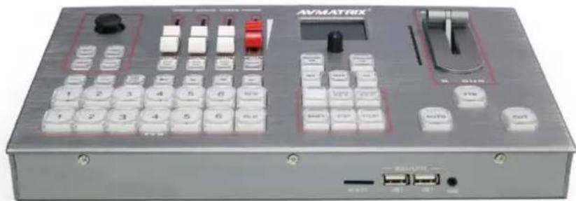
The video switcher is an all-in-one 6-channel video switcher that allows video switching, audio mixing, and video recording.
natural_image
Exterior view of a silver AVMATRIX audio workstation instrument with control knobs and buttons (no readable text or symbols beyond branding)1.2 Main Features
- 6 channel inputs: 4xSDI and 2xDVI-I/HDMI/VGA/USB player inputs
● 2xSDI & 1xHDMI PGM outputs, 1xSDI AUX output, 1xSDI & 1xHDMI multiview outputs
● Input format auto-detected and PGM/AUX output format selectable
● Remote PTZ camera control: Visca & Pelco protocol
● T-Bar/ AUTO/ CUT transitions and MIX/ FADE/ WIPE effects
● Luma Key/ Chroma Key for virtual studio - PIP/ POP window size and position adjustable
● Record PGM video to SD card, up to 1080p60
● Audio mixer: TRS audio & SDI, HDMI, USB embedded audio
2. Connections
2.1 Interfaces
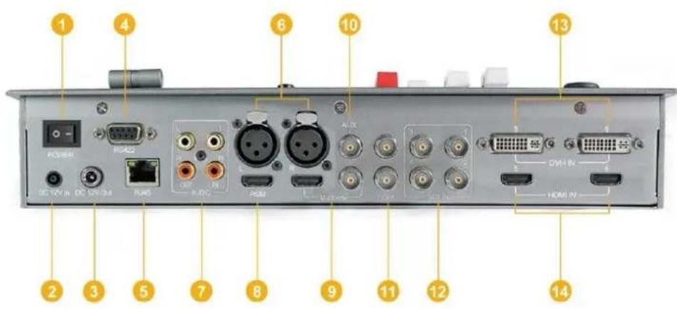
text_image
1 2 3 4 5 6 7 8 9 10 11 12 13 14 DC 12V in DC 5V/CM4 RUNS HDMI AUX VDDI VDDI VDDI DVH-IN HDMI-VI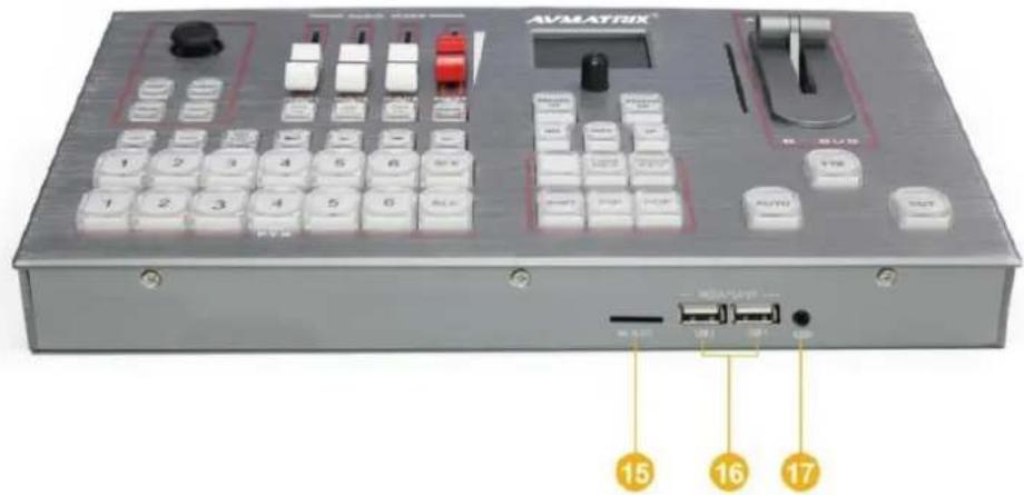
text_image
AVLATRIK 15 16 17| 1 | Power Switch | 10 | 1×SDI AUX Output |
| 2 | 12V DC Power Input | 11 | 2×SDI PGM Outputs |
| 3 | 12V DC Power Output | 12 | 4×SDI Inputs |
| 4 | RS422 for Camera Remote Control | 13 | 2×DVI-I(VGA) Input |
| 5 | RJ45 For Sync Time & Firmware Upgrade | 14 | 2×HDMI Input |
| 6 | XLR Balanced Audio(L/R) Input | 15 | 1×SD Slot for Record |
| 7 | RCA Stereo Audio(L/R) Input/ Output | 16 | 2×USB INPUT for Video/ Image Media Player |
| 8 | 1×HDMI PGM Output | 17 | Earphone |
| 9 | 1×HDMI and 1×SDI Multiview Output |
2.2 Specification
| Inputs | Video Inputs | SDI×4, HDMI/DVI-I/VGA/USB×2 |
| Bit Rate | 270Mbps~3Gbps | |
| Return Loss | >15dB, 5MHz~3GHz | |
| Signal Amplitude | 800mV±10% (SDI/HDMI/DVI/VGA) | |
| Impedance | 75Ω (SDI/VGA), 100Ω (HDMI/DVI) | |
| SDI Input Format | 1080p 60/59.94/50/30/29.97/25/24/23.981080psF 30/29.97/25/24/23.981080i 60/59.94/50720p 60/59.94/50/30/29.97/25/24/23.98625i 50 PAL, 525i 59.94 NTSC | |
| HDMI Input Format | 4K 60/50/30, 2K 60/50/301080p 60/59.94/50/30/29.97/25/24/23.98/23.9761080i 50/59.94/60720p 60/59.94/50/30/29.97/25/24/23.98576i 50, 576p 50 | |
| DVI-I/ VGA Input Format | 1920×1080 60Hz/ 1680×1050 60Hz/1600×1200 60Hz/ 1600×900 60Hz/1440×900 60Hz/ 1366×768 60Hz/1360×768 60Hz/ 1 280×1024 60Hz/1280×960 60Hz/ 1280×800 60Hz/1280×768 60Hz/ 1280×720 60Hz/1152×864 60Hz/ 1024×768 60Hz/640×480 60Hz | |
| SDI Video Rate | Auto detection, SD/HD/3G-SDI | |
| SDI Compliance | SMPTE 259M/ SMPTE 292M/ SMPTE 424M | |
| Bit Rate | 270Mbps~3Gbps | |
| Color Space and Precision | SDI: YUV 4:2:2, 10-bit;HDMI: RGB 444 8/10/12bit; YUV 444 8/10/12bit;YUV 422 8/10/12bit | |
| Outputs | PGM Outputs | 2×HD/3G-SDI; 1×HDMI Type A |
| AUX Output | 1×HD/3G-SDI | |
| PGM Output Format | 1080p 50/60/30/25/241080i 50/60 | |
| Multiview Output | 1×HD/3G-SDI; 1×HDMI Type A | |
| Multiview Output Format | 1080p 60 | |
| Return Loss | >15dB 5MHz~3GHz | |
| Signal Amplitude | 800mV±10% (SDI/HDMI/DVI-I/VGA) | |
| Impedance | SDI: 75Ω; HDMI: 100Ω | |
| DC Offset | 0V±0.5V | |
| Audio | Audio Input | 1×TRS(L/R), 50Ω1×XLR(L/R), 50Ω |
| Audio Output | 1×TRS(L/R), 50Ω;1×3.5mm Earphone×1, 100Ω | |
| Others | LAN | RJ45 |
| SD Card Slot | 1 | |
| Power | DC 12V In, 2A; DC12V Out | |
| Consumption | ≤24W | |
| Operation Temperature | -20°C~60°C | |
| Storage Temperature | -30°C~70°C | |
| Operation Humidity | 20%~70%RH | |
| Storage Humidity | 0%~90%RH | |
| Dimension | 322.4×19.7×57.8cm | |
| Weight | Net Weight: 1.9kg, Gross Weight: 3.7kg | |
| Warranty | 2 Year Limited | |
| Accessories | Accessories | 1×Power Supply (DC12V 5A),1×RS422 Connector, 1×User Manual |
3. Control Panel
3.1 Description
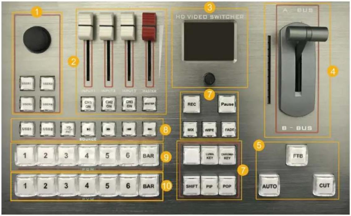
text_image
1 2 3 HD VIDEO SWITCHER 4 A BUS USER1 USER2 INPUT1 INPUT2 INPUT3 MASTER CH1 ON CH2 ON CH3 ON MASTER USB1 USB2 VD PIC REC Pause MIX WIPE FADE B - BUS SOURCE 1 2 3 4 5 6 BAR PGH LUMA KEY CHROMA KEY SHIFT PIP POP FTB AUTO CUT 1 2 3 4 5 6 BAR PVM| 1 | Camera Control |
| 2 | Audio Mixer |
| 3 | Menu Control and Display |
| 4 | T-bar Manual Transition |
| 5 | Auto, Cut, FTB |
| 6 | Transition Effects, MIX, WIPE, DP |
| 7 | Luma Key, Chroma Key, PIP, POP, SHIFT |
| 8 | USB Media Player Control |
| 9 | Program Row |
| 10 | Preview Row |
3.2 Keyboard Button
| ■ Camera ControlCAM1 and CAM2 buttons are for Camera 1, Camera 2.ZOOM IN and ZOOM OUT to adjust the size of the picture.Press the button, the button LED will be turned on to indicate that the manual mode is enabled. Then the camera can be controlled via the Joystick. | 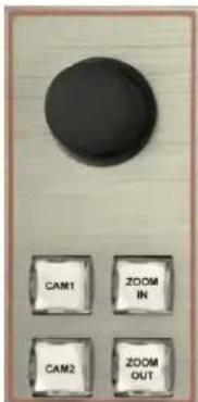 |
| ■ Audio MixerCH1 ON / CH2 ON / CH3 ON buttons are for SDI1 / SDI2 / SDI3 / SDI4/ VIDEO5 / VIDEO6 / XLR / RCA / MIC audio source selection. Master for output the mixing audio to program.The audio faders are for adjusting the audio volume. | 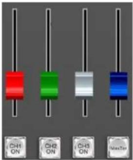 |
| ■ Menu ControlThe LCD screen for showing the menu content and working status. The button for menu setting.Rotate the knob clockwise or counterclockwise to adjust the menu and increase and decrease the value.Press the button to select the menu option. | 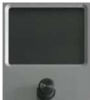 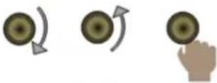 |
| ■ T-Bar Manual Transition SystemUser can do the transition from the current program source to the selected preview source. The selected transition effects will work meantime. When the T-Bar has travelled from B-BUS to A-BUS the transition between sources is complete. The T-Bar has indicators next to it which light when the transition is complete. | 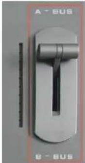 |
| ■ CUT and AUTO TakeCUT performs a simple immediate switch between Program and Preview. The selected transition WIPE, MIX or FADE is not used.AUTO performs an automated switch between Program and Preview. The selected transition WIPE, MIX or FADE will also be used. | 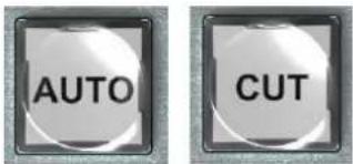 |
| ■ PGM PVW Channel SelectionPGM row is for selecting the signal source for program.Selected PGM button turns on the red LED.PVW row is for selecting the signal source for preview.Selected PVW button will turns on the Green LED.BLK button is for immediate switching the signal source of Program and preview to Black. | 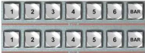 |
| ■ FTBFade To Black, press this button it will fade the current video program source to black. The button will flash to indicate that it's active.When press the button again it acts in reverse from complete black to the currently selected program video source, and button stop flashing. | 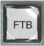 |
| ■ Transition EffectsMIX:Pressing this button selects a basic A/B Dissolve for the next transition. When button LED turns on it is active.WIPE:WIPE is a transition from one source to another and is achieved by replacing the current source by another source.This WIPE effect is produced by then moving the T-Bar manually or by pressing the AUTO button.FADE:It is a transition from one source to another with fade gradually transition effect. | 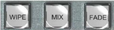 |
| ■ Luma KeyLuma key consists of one video source containing the video image that will be stacked on top of the background.All the black areas defined by the luminance in the video signal will be made transparent so that the background can be revealed underneath.Therefore, the final composition does not retain any black from the graphic because all the black parts have been cut out of the image. |  |
| ■ Chroma KeyIn a chroma key two images are combined using a special technique and a color from one image is removed, revealing another image behind it. Chroma key is commonly used for weather broadcasts, where the meteorologist appears to be standing in front of a large map. In the studio the presenter is standing in front of a blue or green background. This technique is also referred to as color keying, color-separation overlay, green screen, or blue screen. |  |
| ■ PIP and POPPIP, Picture in Picture. The program is display on the full screen, at same time the preview source will be displayed in the program window as an inset window. The size and location of the inset window can be adjusted from the menu.POP, Picture outside Picture. This is the same function as PIP only this allows you to see the program source and preview source side by side. |  |
| ■ SHIFTThe SHIFT button is an alternate function key. When press the SHIFT button with 5/6 buttons from PVW row, the signal source of the channel 5/6 will be selected from DVI / VGA / USB.USB signal source comes from two USB media players. |  |
| ■ USB Media Player ControlThe video switcher is coming with two USB ports for paying the USB media, including video and picture.Press USB1 or USB2 button to select the one which you want to manage. The VD/PIC button is for switching the media format between video and picture. The default setting is video format.There are Play / Pause, Fast Forward, Fast Backward, NEXT and BACK buttons to control the media source from USB.The Fast Forward support max 32 times speed to play the video. NEXT will be active after double pressing. |   |
4. Operation Instruction
4.1 Multiview Output Layout
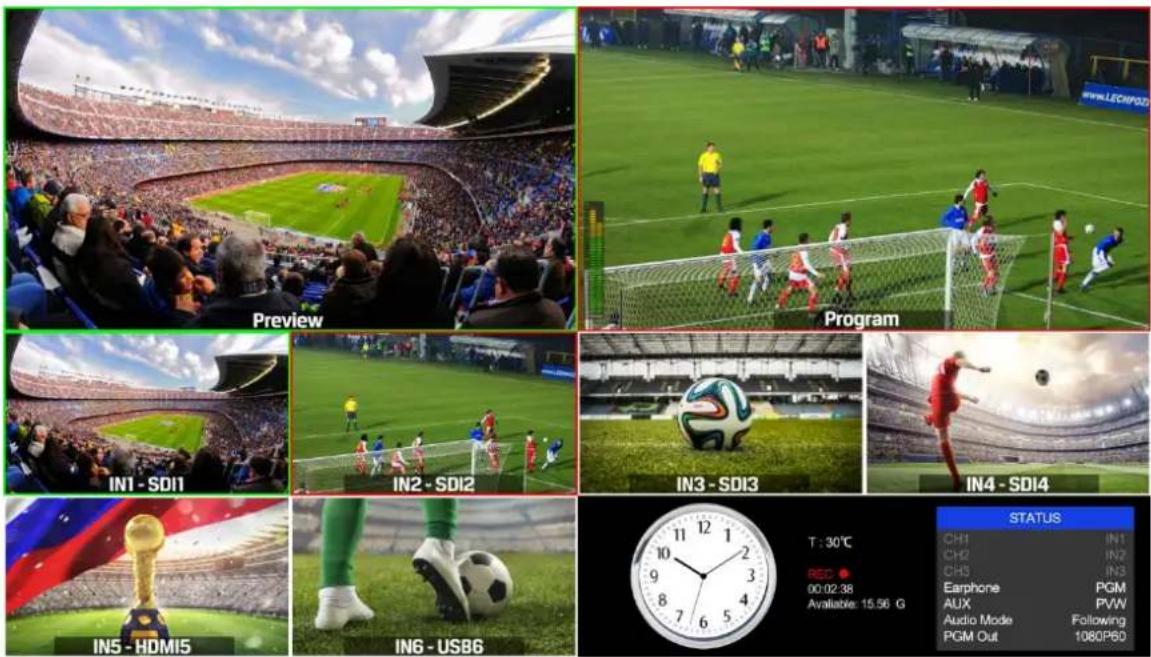
1) PGM and PVW as Preview and Program displayed as following image. The level meter of PGM audio is shown only in multiview. SDI/HDMI PGM out is without any overlays.
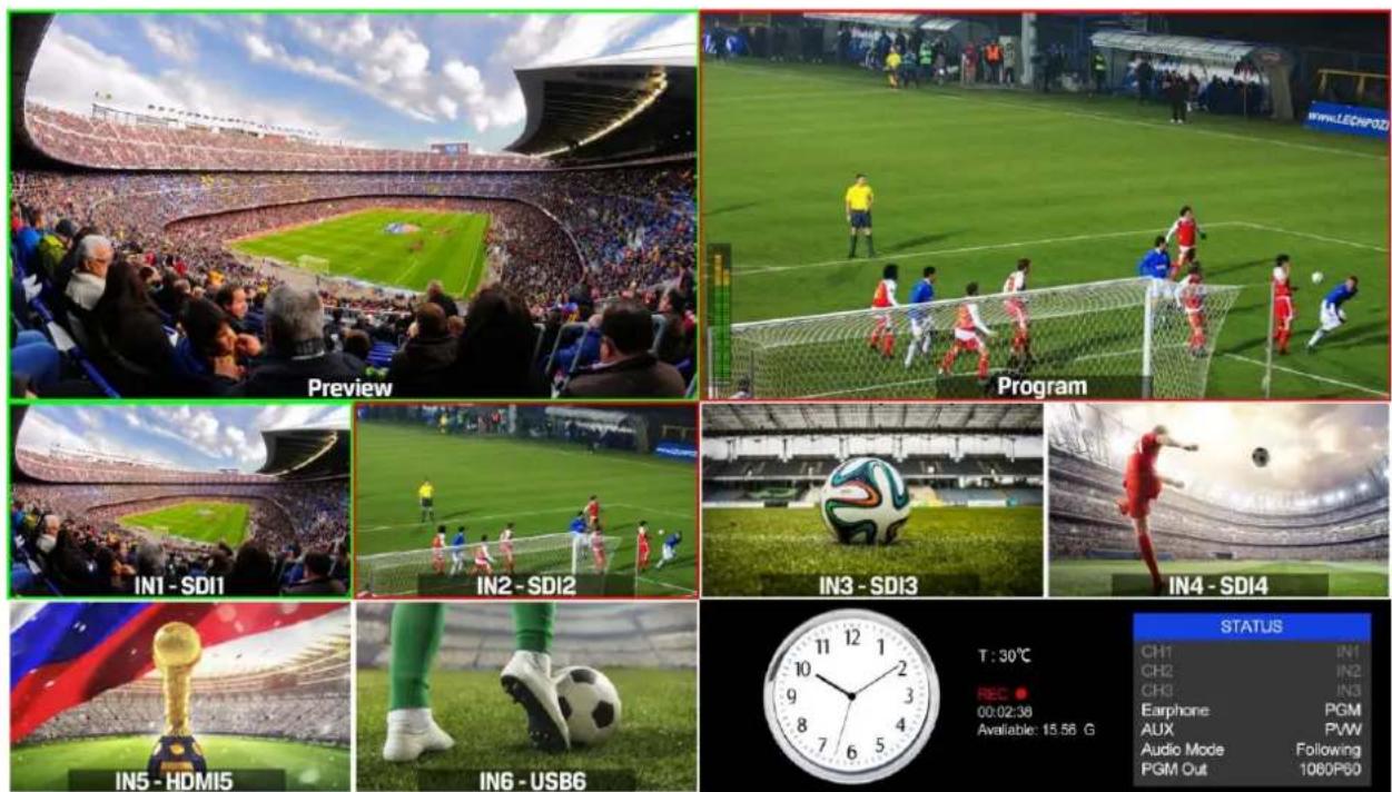
2) The following 6 windows come from the 6 input signals. The signal source of window 5 and 6 can be selected from HDMI, DVI, VGA, USB.
natural_image
Interior view of a large stadium during a match, showing the field and crowd (no visible text or symbols)
natural_image
Golden trophy on a soccer field with national flag background (no text or symbols on trophy or field)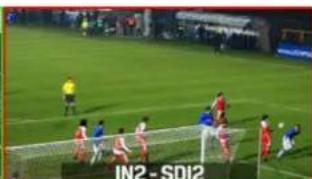
natural_image
Soccer match in progress on a green field with players and goal net (no visible text or symbols)
natural_image
Close-up of a soccer player's legs and foot on grass, wearing green pants and white boots (no visible text or symbols)
natural_image
Soccer ball on a grass field with stadium seating in the background (no visible text or symbols)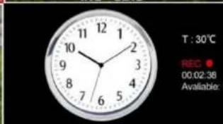
text_image
T : 30°C REC 00:02:38 Available:
natural_image
Soccer player in red mid-air during a shot, stadium background with no visible text or symbols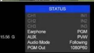
text_image
STATUS CH1 IN1 CH2 IN2 CH3 IN3 Earphone PGM AUX PWW Audio Mode Following PGM Out 1080P603) The lower right corner displays the menu and status information. The CH1, CH2, CH3 are the channel selection of the 3 audio sources for audio mixer. There is a real-time Digital clock / Analog clock displayed beside the menu.
4.2 T-Bar Calibration
The T-Bar of the video switcher may happen to misalignment, when the origin of the coordinates offset the T-Bar calibration is necessary before using.
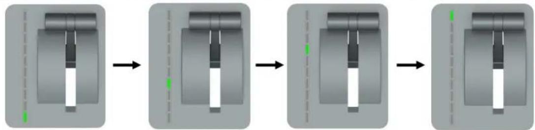
1) Power off the video switcher and press button 1 and 2 of PVW at same time. KEEP pressing the buttons until all calibration process finish.

text_image
1 2 3 4 5 6 BAR PWN2) Turn on the video switcher, then the LED indicators will be turn on from bottom to top.
flowchart
graph LR
    A["Component Position"] --> B["Assembly Step 1"]
    B --> C["Assembly Step 2"]
    C --> D["Assembly Step 3"]
    D --> E["Final Assembly"]
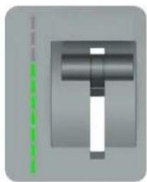
3) Adjust the T-Bar to A-BUS or B-BUS until all LED indicators turn on. Below image is an example of the LED indicators status when switching the T-Bar from B-BUS to A-BUS.
natural_image
Pure mechanical component diagram without any text, numbers, or symbols4) Then the T-Bar calibration is finished, and you can release the button 1 and 2.
4.3 PGM PVW Switching
4.3.1 PGM, PVW Channel Selection
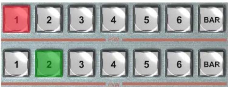
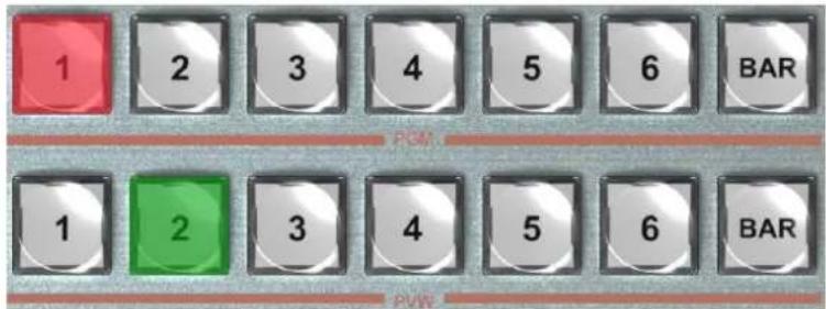
Below 1-6 buttons from PGM and PVW are corresponding with the 6 windows in the below of the multiview layout. The selected button from PGM turns on to red LED, and the selected button from PVW turns on to green LED.
text_image
1 2 3 4 5 6 BAR 1 2 3 4 5 6 BARThe selected PGM source will circled in red border, while the selected PVW source will be circled in green border.
text_image
Preview Program IN1 - SDI1 IN2 - SDI2 IN3 - SDI3 IN4 - SDI4 IN5 - HDMI5 ING - USB6 T : 30°C REC 00:02.38 Available: 15.56 G STATUS CH1 IN1 CH2 IN2 CH3 IN3 Earphone PGM AUX PVW Audio Mode Following PGM Out 1080P60For example, switching the PGM source to SDI 1 and PVW source to SDI 2. The button selection as below image. The default sources of PVW and PGM are SDI 1 and SDI 2 when the first turn the video switch on. When operating the AUTO or T-Bar transition, the selection from PGM row and PVW row is invalid, both LED indicators will turn red.
text_image
1 2 3 4 5 6 BAR PCM 1 2 3 4 5 6 BAR PWM4.3.2 Transition Control
There are two transition control types for this video switcher: Transition without effects and Transition with effects.
1) Transition without Effects

CUT performs a simple immediate switch between Preview and Program views. This is no delay seamless switching and the selected transition effect WIPE, MIX or FADE is not used.
2) Transition with Effects

AUTO performs an automated switch between Preview & Program views. The speed of the transition is set by the menu. The selected transition WIPE, MIX or FADE will also be used.
T-Bar transition effect performs same as AUTO, but speed depends on the speed of the manual switch.
4.3.3 FTB (Fade to Black)

Press FTB button it will fade the current video Program source to black. The button will flash to indicate that it's active. When press the button again it acts in reverse from complete black to the currently selected Program video source, and button stop flashing. FTB is usually used for emergency condition.

natural_image
Nighttime soccer match in progress on a field with players near the goal (no visible text or signage)
natural_image
Soccer match in progress on a field with players near the goal (no visible text or signage)
natural_image
Nighttime soccer match in progress on a field with players near the goal (no visible text or signage)
natural_image
Completely black image with no visible content or text.Note: When the PGM window display black and keep black even after transition, please check if the FTB button flashing. Press the button again when it is flashing to stop black.
4.3.4 Source Selection of Channel 5 and Channel 6
Press the button IN5 / IN6 to cyclic switch the video source between HDMI, DVI, VGA and USB. The default format is HDMI. The switcher will save your last format choice when power on again.
4.3.5 USB Media Player
1) USB Media Player Setup
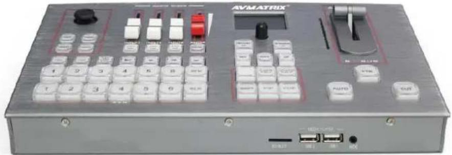
Plug in the USB disk input the USB port in the side panel as below image:
natural_image
Exterior view of a silver AVMATRIX audio workstation instrument with control buttons and ports (no readable text or symbols beyond branding)
Setup the video source of channel 5 or 6 to USB as point 4.3.4, then manage the USB media play from the control panel.
Press USB5 or USB6 button to select the one which you want to manage. The VIDEO/IMAGE button is for switching the media format between video and picture. The default setting is video format when the video switcher power on.
There are Play/Pause, Fast Forward, NEXT and BACK buttons to control the media source from USB. The Fast Forward and Fast Backward support max 32 times speed to play the video.

text_image
USB5 USB6 VIDEO IMAGE2) Video Format Supporting
| FLV | MPEG4(Divx), AVC(H264), FLV1 | MP4 | MPEG4(Divx), MPEG4(Xvid), AVC(H264)HEVC(H265) |
| AVI | MPEG4(Divx), MPEG4(Xvid),AVC(H264), HEVC(H265), MPEG2 | MKV | MPEG4(Divx), MPEG4(Xvid), AVC(H264)HEVC(H265) |
| MPG | MPEG1 | MOV | MPEG4(Divx), AVC(H264), HEVC(H265) |
3) Image format support: BMP, JPEG, PNG.
4.4 Transition Effects
4.4.1 MIX Transition
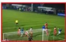
Pressing the MIX button selects a basic A/B Dissolve for the next transition. When button LED turns on it is active. Then use T-Bar or AUTO to operate the transition. The MIX transition effect as below
natural_image
Soccer match in progress on a green field, players near the goal and barriers (no visible text or signage)
natural_image
Outdoor sports scene with players on a goal and spectators in the background (no visible text or symbols)
natural_image
Interior view of a stadium with a large green field and crowd gathered (no visible text or signage)
natural_image
Panoramic view of a large stadium during a match, with spectators watching from the rim (no visible text or signage)WIPE is a transition from one source to another and is achieved by replacing the current source by
another source. Press the WIPE button and the LED turns on then it is active. There are total 9
WIPE selections wiping start from different directions. Such as if choosing , then use T-Bar or AUTO to operate the transition, the WIPE effect as following:
natural_image
Outdoor soccer match in progress on a green field, players near the goal and barriers (no visible text or signage)
natural_image
Soccer match scene with players on the field and spectators watching from a goal (no visible text or signage)
natural_image
Composite image showing a stadium with crowd and crowd, no visible text or symbols
natural_image
Panoramic view of a large stadium during a match, featuring a green field and crowd (no visible text or signage)INV button is an alternative button. Press it first and then press a Direction button, the WIPE will start from an inverse direction.
4.4.2 FADE Transition
Fade is a transition from one source to another with fade gradually transition effect. Press the FADE

button and use T-Bar or AUTO to operate the FADE transition.
4.5 PIP and POP
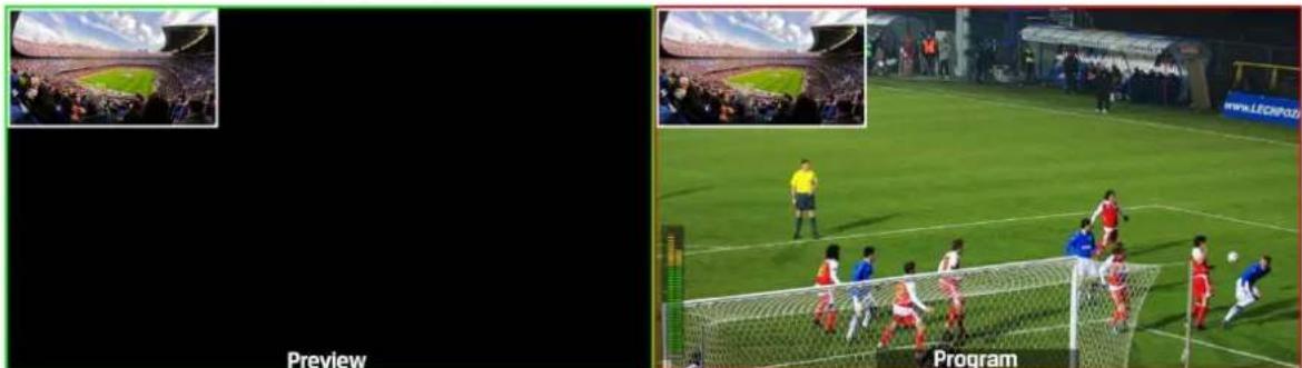
When the T-Bar located at B-BUS to active the PIP/POP, there will be a small image display on the top left corner of the PVW window as following image:
natural_image
Two-panel image showing a soccer match: left panel shows stadium crowd; right panel shows player in goal with goal net and team in front (no readable text or symbols)Press button 1-6 from PVW row to switch the video source of PIP/POP.
When press PIP/POP button the menu will get into an interface as below image. The window size, position and border of PIP can be set from menu by the knob.
| Main Menu | Secondary Menu | Option | Default |
| PIP | Window | 1 | 1 |
| H Position | 0 | 0 | |
| V Position | 0 | 0 | |
| Size | Small/ Medium /Large | Small | |
| Border Enable | On/ Off | On | |
| Border Width | 2~7 | 2 | |
| Border Color | White/ Red/ Blue/ Green | White | |
| Exit | |||
| POP | Window | 1~2 | 1 |
| H Position | 0 | 0 | |
| V Position | 0 | 270 | |
| Size | |||
| Border Enable | On/Off | On | |
| Border Width | 2~7 | 2 | |
| Border Color | White/ Red/ Blue/ Green | White | |
| Exit |
4.6 Chroma Key
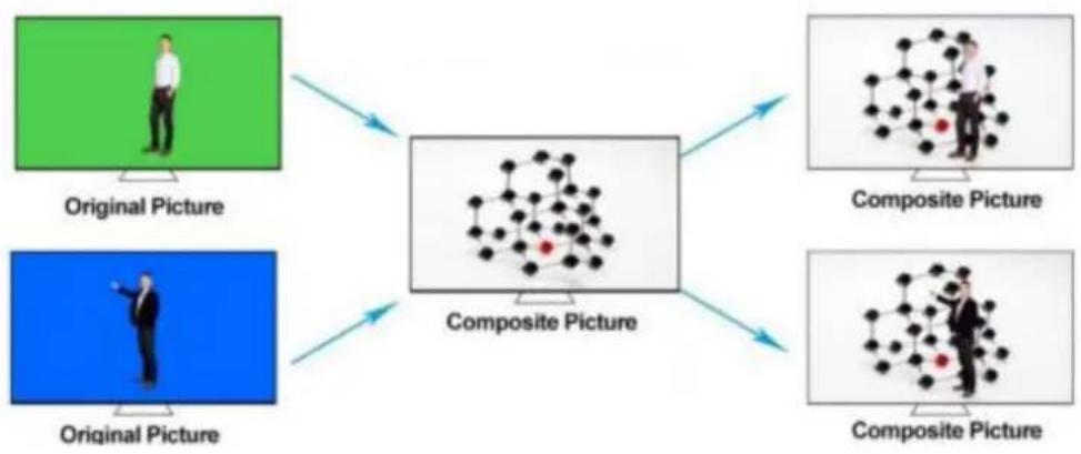
Turn on the Chroma Key, a color from the key source will be removed, revealing another background image behind it. Chroma Key is usually used for virtual studio, such as weather broadcasts, where the meteorologist appears to be standing in front of a large map. In the studio the presenter is standing in front of a blue or green background.
flowchart
graph TD
    A["Original Picture"] --> C["Composite Picture"]
    B["Original Picture"] --> C["Composite Picture"]
    D["Original Picture"] --> C["Composite Picture"]
    E["Composite Picture"] --> C["Composite Picture"]
    F["Composite Picture"] --> C["Composite Picture"]
    C --> G["Composite Picture"]
    style A fill:#90EE90
    style B fill:#90EE90
    style D fill:#90EE90
    style E fill:#90EE90
    style F fill:#90EE90
1) Switching a video with blue or green background to PVW window, and turn on the Chroma Key. Then go to the Key menu to configure the value of Chroma Key. Using CUT, AUTO, or T-Bar to switch the image to overlay in the PGM window.
2) When you press Chroma Key button, indicator turns on and menu go to the key setting interface as below image. The KEY background can be switch between Green and Blue. The color gamut of the Chroma Key can be set from the menu by the knob.
| Main Menu | Secondary Menu | Option | Default |
| CHROMA KEY | KEY | ChromaKey | ChromaKey |
| Background | Blue/Green | Blue | |
| Level | 0-64 | 16 | |
| Exit |
4.7 Luma Key
flowchart
graph TD
    A["Original Picture"] --> B["PVW"]
    B --> C["Composite Picture"]
    A --> D["Original Picture"]
    D --> C
    style A fill:#f9f,stroke:#333
    style B fill:#ccf,stroke:#333
    style C fill:#cfc,stroke:#333
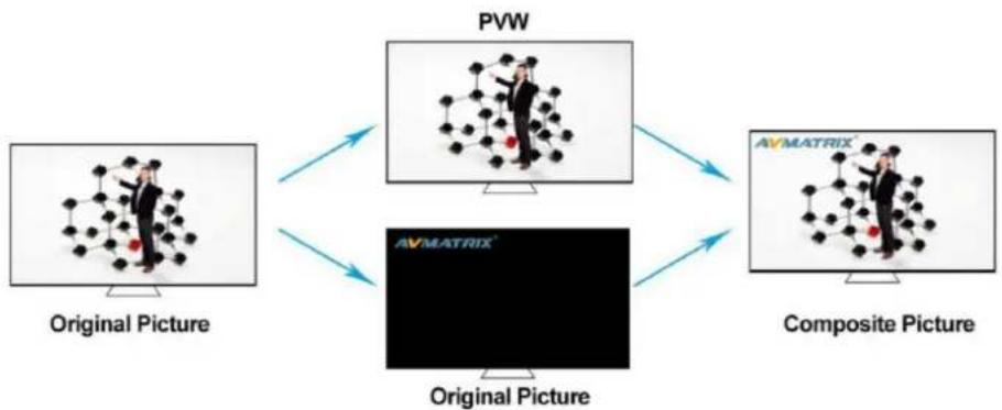
When turn on the Luma Key, all the black areas defined by the luminance in the video signal will be made transparent so that the background can be revealed underneath. Therefore, the final composition does not retain any black from the graphic because all the black parts have been cut out of the image. This function is often used for subtitle overlay of virtual studio.
Switching a video with black background and white font subtitle to PVW and turn on the Luma Key. Then go to the Key menu to configure the value of Luma Key. Using CUT, AUTO, or T-Bar to switch the subtitle to overlay in the PGM window.
5. Camera Remote Control
5.1 Camera Setting
After the camera connected with the switcher through RS-422, the zoom of the lens can be realized by pressing the buttons, and the camera holder can be controlled by the Joystick.
CAM1 and CAM2 buttons are for Camera 1, Camera 2. Press the button, the button LED will be turned on to indicate that the manual mode is enabled. Then the camera can be controlled via the Joystick.
ZOOM IN and ZOOM OUT buttons to focus the camera lens.
| Main Menu | Secondary Menu | Option | Default |
| CAMERA | Addr | 1-16 | 1 |
| Protocol | PELCO D/PELCO P/VISCA | PELCO D | |
| Rate | 300/600/1200/2400/4800/9600/14400/19200/38400/57600/115200 | 9600 | |
| Exit |
5.2 RS-422 Interface Define
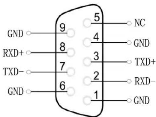
The video switcher is equipped with a 9-pin DB9 interface for camera control, the PIN definition are defined as below. The PIN not defined here is reserved, with no function now.
text_image
GND RXD+ TXD- GND 9 8 7 6 5 4 3 2 1 NC GND TXD+ RXD- GND6. Main Menu Settings
When STATUS menu is not selected, press the MENU button to go to main menu directly. In case one of the items is selected (see below), rotate the MENU button rotate anticlockwise to exit the choice, then press the MENU button to go to the main menu.
| Main Menu | Secondary Menu | Option | Default |
| STATUS | CH1 | IN1/IN2/IN3/IN4/IN5/IN6/PGM/XLR_IN/RCA_IN | IN1 |
| CH2 | IN1/IN2/IN3/IN4/IN5/IN6/PGM/XLR_IN/RCA_IN | IN2 | |
| CH3 | IN1/IN2/IN3/IN4/IN5/IN6/PGM/XLR_IN/RCA_IN | IN3 | |
| Earphone | IN1/IN2/IN3/IN4/IN5/IN6/PGM/XLR_IN/RCA_IN | PGM | |
| AUX | PGM/PVW | PGM | |
| Audio Mode | Mixing/Follow | Mixing | |
| PGM Out | 1080P30/1080P25/1080P24/1080P60/1080P50/1080I60/1080I50 | 1080P30 |
6.1 SDI PGM/AUX and Multiview Output Format
The output format of multiview is fixed at 1080p60, and for PGM output can be set by the knob. Except PVW and PGM output, there is a AUX for choice, you can quickly select the auxiliary output between PVW and PGM via Menu knob. It is default as PGM after reset. There are resolution 1080P50/60/30/25/24Hz, 1080I50/60Hz selectable for SDI/HDMI PGM and AUX outputs.
6.2 Audio Mixer Settings
6.2.1 Audio Description
This video switcher is coming with 2 channel L/R analog audio input and SDI embedded audio.
6.2.2 Audio Mode
1) Mixing Mode
Rotary and press the knob button to set audio mode as mixing. Press CH1/ CH2/ CH3 button to enable the mixing audio mode, total 3 channels for mixing. The audio source can be select from IN1/ IN2/ IN3/ IN4/ IN5/ IN6/ PGM/ XLR_IN/ RCA_IN.
2) Following Mode
After that the video switcher will remember your last choice. Press Master button to enable the following mode audio control. When the audio is in Following mode the audio is coming from the embedded audio of Program video source. Adjust the master fader to control the audio volume.
2) Earphone
Press LISTEN button and use a 3.5mm earphone to monitor an assigned audio, PGM audio as the default. Press LISTEN button cyclically to assign one channel audio as the audio source.
6.3 System Settings
| Main Menu | Secondary Menu | Option | Default |
| System Settings | Language | English/中文 | English |
| Brightness | 10~100 | 50 | |
| Status | Always/Dim/off | Always | |
| Backlit Time | 5~60 | 50 | |
| Clock | Analog/Digital | Analog | |
| Reset | |||
| Return | |||
| Network Settings | IP Acquisition | Static/Dynamic | Dynamic |
| IP | 192.168.1.215 | ||
| Netmask | 255.255.255.0 | ||
| Gateway | 192.168.1.1 | ||
| Save | |||
| Return | |||
| Record Settings | Encoding | VBR | VBR |
| Level | Low/Medium/High/Ultra High | Medium | |
| Return | |||
| Device Info | Version | 22-11-15-2c-10-10-06-6b-11-00 | 22-11-15-2c-10-10-06-6b-11-00 |
| Return | |||
| Exit |
6.3.1 Language
Access to system settings from the menu to switch the system language between English and Chinese.
6.3.2 Clock
Access to system settings from the menu to switch the real-time clock shown in Analog or Digital.

natural_image
Analog wall clock showing 10:30 (no text or symbols beyond hour and minute hands)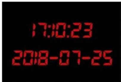
text_image
17:00:23 2018-07-256.3.3 Clock Time Setting
Connect video switcher to a PC and download a time control software from AVMATRIX official website www.avmatrix.net/download/ Open the software and click Scan to search and connect the device, then the clock time will be changed to same time to the PC's time.
6.4 Network Settings
6.4.1 Network
There are two ways to acquire the IP: Dynamic (IP configured by router) and Static (set IP freely by yourself). Select the method you need by knob menu. The default setting is Dynamic.
Dynamic: Connecting the video switcher with a router with DHCP features, then it will auto obtain an IP address automatically. Make sure that the video switcher and PC are in the same local area network.
Static: Select static IP when the PC is without DHCP. Connect the video switcher with PC via network cable, set the PC's IP address to the same IP range as video switcher (the video switcher's default IP address 192.168.1.215), or set the video switcher's IP address to the same IP range as PC's IP address.
6.4.2 Netmask
Set the Netmask. The default setting is 255.255.255.0.
6.4.3 Gateway
Set the Gateway according to current IP address. Save the configuration when network setting finish.
6.5 Video Record
6.5.1 Basic Specification
| Record Video Source | PGM |
| Record Storage | SD Card (class 10) |
| SD Card Format | Max 64GB (file system format exFAT/ FAT32) |
| Record Video Format | H.264 (mp4) |
| Record Video Resolution | 1080p 60/50/30/25/24hz, 1080i 60/50hz |
6.5.2 SD Card Install and Uninstall
- Install SD card:
First, format SD card to exFAT/ FAT32 file system format. Install Plug and press the SD card into the slot from the side of video switcher. Wait 3 sec, the LED indicator beside it will turn on.
- Uninstall SD card:
Press the card to take it out. Use a card reader to play or copy the video files in a computer.
6.5.3 Recording Control
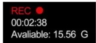
Press REC button start recording. Meantime, the key indicator turns on. During recording, press PAUSE button the recording pause, and press PAUSE button again recording continue. Press REC button, recording stops and save the video file to SD card. Record video resolution is same to SDI PGM output resolution. The recording status shown beside the menu, including information of REC mark, recording time, available storage.
text_image
REC 00:02:38 Available: 15.56 GNote:
- The record file will be saved to SD card only after pressing the REC button to stop recording. Otherwise, the record file might be corruption.
- In case the switcher is power off during record, the record file might be corruption.
- If you want to change the PGM output resolution during recording, please stop recording and save the file first, then new record the video in new resolution. Otherwise, the record video files in SD card will be abnormal.
6.5.4 Recording Settings
Access to the recording settings in main menu, and set the encoding format of the recording between VBR and CBR. User can also choose the video recording quality they need, there is Ultra High, High, Medium, Low for choice.