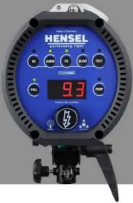
Expert D 250 Speed - Lighting Hensel - Free user manual and instructions
Find the device manual for free Expert D 250 Speed Hensel in PDF.


User questions about Expert D 250 Speed Hensel
0 question about this device. Answer the ones you know or ask your own.
Ask a new question about this device
Download the instructions for your Lighting in PDF format for free! Find your manual Expert D 250 Speed - Hensel and take your electronic device back in hand. On this page are published all the documents necessary for the use of your device. Expert D 250 Speed by Hensel.
USER MANUAL Expert D 250 Speed Hensel
natural_image
Exterior view of a black and silver professional D.500 light bulb with digital display (no text or symbols on body)USER MANUAL //
WWW.HENSEL.DE
HENSEL
PERFORMING LIGHT
VISIT
INDUSTRIAL LIGHT
Distribution and duplication of this documentation is not permitted unless specifically authorized. Violation of this may result in payment of damages.
All rights, including rights created by patent grant or registration of a utility model or design, are reserved (DIN ISO 16016).
Subject to technical changes. Errors and omissions excepted. The listed data are guideline values and not to be regarded as guaranteed values in a legal sense. Values can deviate due to tolerances of construction parts.
03/2015
For Your Safety
This device was developed according to the latest standards of technology and manufactured, with greatest care and testing, from high-quality material.
However, its use can result in bodily injury and property damage.
Please note the general safety guidelines and warnings that precede each use when operating this device. Please read all of the enclosed instructions.
Please note the warnings in the documents and on the device.
Only use the device when it is in proper condition. Be aware of safety precautions and possible danger.
Keep this document available with the device.
Safety Precautions and Warning Notices
The warning notices are marked with the following danger icons and signal words according to severity:
| Danger icon | Signal word | Explanation |
 | DANGER | Warning of danger which can lead to major or fatal injuries if disregarded. |
 | WARNING | Warning of danger which can lead to major or fatal injuries if disregarded. |
 | CAUTION | Warning of danger which can lead to injuries if precautions are disregarded. |
 | CAUTION | Warning of danger which can lead to property damage if disregarded. |
Structure of Warning Notices
Warning notices are indicated by separation lines above and below. They are structured according to the following principle:
SIGNAL WORD

Type and Source of Danger
Explanations of the type and source of danger
• Measures to avert danger
Basic Safety Instructions
Safety Hints Pertaining to Emitted Optical Radiation
Electrical power is changed inside the flash tube to intensive optical radiation:
- Do not flash directly into eyes from a short distance because the emitted intensive optical radiation can cause eye and skin damage.
- Do not look directly into flash reflector; the flash may be accidentally triggered.
- In case of damage to skin or eyes caused by intensive optical radiation consult a physician immediately.
Working in Potentially Explosive Rooms
Working in potentially explosive rooms and environments is prohibited because small sparks develop upon triggering the flash.
- Never work in potentially explosive environments.
- Do not work near flammable material.
- Do not store flammable material in direct vicinity of flash generators and flash lamps to avoid fire hazards.
Ozone Formation
Closed rooms must be ventilated frequently to prevent excessive ozone formation which can result from to the use of strong flash units.
Protecting Equipment from Moisture and Splash Water
Flash units need to be protected from moisture, wetness and splash water. Therefore, please do not place containers with liquids on the flash units.
Connecting Accessories
Do not connect accessories from other manufacturers, even if these look similar or identical.
Not in Use During Dust Development
Equipment that is not in use when doing work that results in strong dust development needs to be covered with suitable dust protection.
Safety Hints Pertaining to the Electrical System
Contact with the flash generator's capacitor voltage is life threatening. Therefore, opening the housing and repairs may only be done by authorized customer service personnel:
- Never open the device – high voltage, risk of death!
- The unit may only be connected to a power supply with working equipment grounding conductor.
- Use only lamp plugs with flawless contacts. Burned down or corroded plug contacts may cause a fire.
- Defective plugs may lead to defective plug sockets.
- To prevent damages, avoid leading cables across floors. If this cannot be avoided, make sure that the cable is not damaged by vehicles, ladders, etc. Damaged cables and housings need to be replaced immediately by authorized customer service personnel.
Explosion of Flash Tube
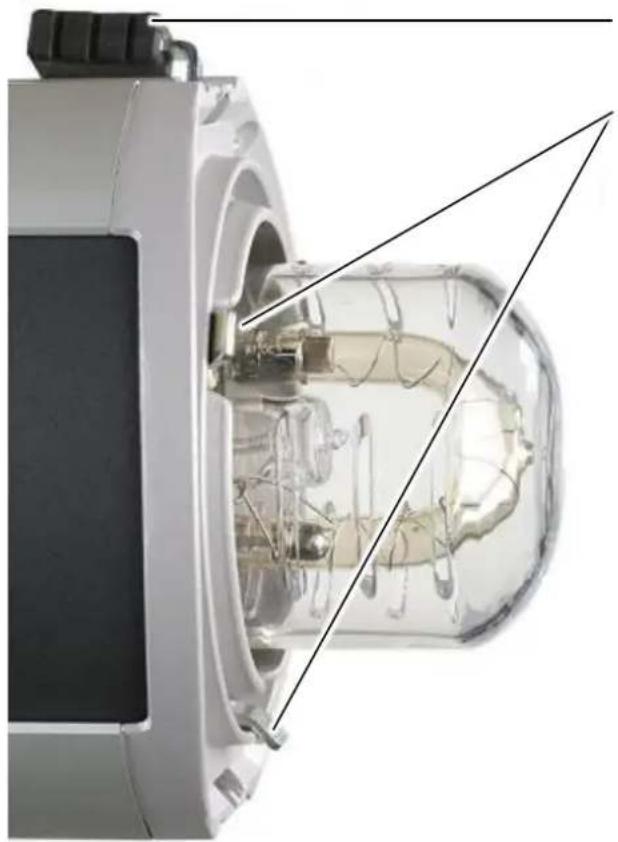
The flash tube is filled with xenon gas. There is negative pressure inside the flash tube. Plasma develops during flashing due to electrical energy being changed to radiation. This plasma development then causes positive pressure inside the flash tube. At the same time, the glass tube is exposed to strong mechanical forces. Minimal defects of the fused quartz glass, visually impossible to notice, may possibly lead to the explosion of the flash tube.
- In case the flash tube explodes, there is a danger of tiny glass particles flying around. The user of this equipment needs to make sure to protect himself by the use a safety glass dome.
- The flash tube can only explode during the flash process. Therefore, the flash head should never be directed at a person during flashing.
User Manual Expert D 250 Speed / D 500 / D 1000
- Immediately disconnect the flash head from the generator if the flash tube becomes damaged. Electrodes carry high voltage!
- Flash tubes must only be changed by authorized and trained personnel.
- The flash tube must only be changed after the device is disconnected from the power supply and is completely discharged.
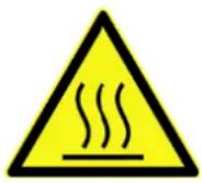
Risk of Burns from Reflector and Flash Unit
After flashing there is a risk of burns caused by the reflector and the flash unit due to hot parts on the housing or infrared heat radiation.
Preface
Dear customer,
By purchasing a compact flash unit of the Expert D product family you have selected a high quality and high performance product.
Below, we want to give you some details and hints on how to use this unit that will ensure successful and productive work with it in the coming years. Observing the information below entitles you to guarantee adjustments, prevents damages, and extends the operational life of the unit.
HENSEL-VISIT made all efforts to produce a safe and high-quality piece of equipment while observing all current rules and regulations. Stringent quality checks ensure our high quality standard even in large-scale production. Please do your part and treat the equipment with the necessary care.
In case of questions regarding the use of this equipment, feel free to call us any time.
Safety Precautions and Warning Notices.... 3
Structure of Warning Notices 4
Basic Safety Instructions .... 5
Safety Hints Pertaining to Emitted Optical Radiation...... 5
Working in Potentially Explosive Rooms 5
Ozone Formation 5
Protecting Equipment from Moisture and Splash Water ..... 5
Connecting Accessories.... 5
Not in Use During Dust Development....6
Safety Hints Pertaining to the Electrical System 6
Explosion of Flash Tube 6
Risk of Burns from Reflector and Flash Unit....7
Preface 8
Description 14
Normal Use....15
Following the Instructions 15
Technical Data 16
Equipment Description.... 18
User Panel 20
Scope of Delivery.... 21
Preparing for Initial Use 22
Remove Transport Cap 22
Inserting Halogen Lamp for Modeling Light 23
Mounting Glass Safety Dome 25
Power Supply 26
Switch On....26
Test Flash....28
User Manual Expert D 250 Speed / D 500 / D 1000
Test the Modeling Light 29
Stand Mounting.... 30
Mounting to Ceiling or Pantograph 33
Repositioning Tilting Bracket and Handle.... 37
Mounting a Reflector.... 38
Removing a Reflector 40
Modeling Light 42
Mode FULL 42
Mode PROP 43
Turn off the Modeling Light 43
Automatic Modeling Light reduction AUTORED 44
Performance Output Adjustment 46
Manual Flash Trigger.... 47
Flash Check....48
Synchronization.... 49
Synchronization via Cord 49
Synchronization via Slave 49
Synchronization via Radio Remote Trigger 50
Activate Built-in Radio Receiver 50
Selecting Radio Channel 51
Daily Flash Counter 52
Reseting the Daily Flash Counter 52
PM Mode (in connection with Power Max L) 53
Activate PM Mode.... 53
Deactivate PM Mode....54
Exchange the Safety Glass Dome 55
Switch Off and Unplug the Mains Cord 56
Removing a Reflector 56
Removing Old or Broken Safety Glass Dome 57
User Manual Expert D 250 Speed / D 500 / D 1000
Mount a New Safety Glass Dome.... 58
Mounting a Reflector.... 59
Connect the Mains Cord and Switch On....60
Replacing Flash Tube....61
Switch Off and Unplug the Mains Cord 62
Removing a Reflector 63
Remove Safety Glass Dome 64
Remove Broken Flash Tube 64
Mount a New Flash Tube 65
Correct Assembly....65
False Assembly....65
Mount Safety Glass Dome 66
Mounting a Reflector....67
Connect the Mains Cord and Switch On....68
Test Flash....69
Replace the Halogen Lamp for Modeling Light....70
Switch Off and Unplug the Mains Cord 71
Removing a Reflector 71
Remove Safety Glass Dome 72
Removing Halogen Lamp....73
Inserting Halogen Lamp....73
Mount Safety Glass Dome 75
Mounting a Reflector....76
Connect the Mains Cord and Switch On....77
Test the Modeling Light 78
Replacing Fuses of Modeling Light 79
Switch Off and Unplug the Mains Cord 79
Exchange of Fuses 79
Connect the Mains Cord and Switch On.... 80
User Manual Expert D 250 Speed / D 500 / D 1000
Preparation for Storage or Transport 81
Switch Off and Unplug the Mains Cord 81
Removing a Reflector 82
Mount the Transport Cap 83
Cleaning 84
Maintenance Plan....85
Periodic Inspections 85
Disposal 85
Error Codes 86
Hot Error – Unit is Overheated.... 86
E1 Charging Error 87
E2 Discharging Error 87
E3 Temperature Error 88
E4 Ignition Error – Unit does Not Flash.... 88
E6 ZD Error....89
Updating Software....90
Customer Service 90
Accessories 91
Glass safety dome 91
Flash tubes....91
Halogen lamp for modeling light 91
Fuses....91
Radio trigger....91
Reflectors and softboxes....91
Additional accessories....91
Contact Information 92
Declaration of Conformity....93
Warranty 94
Limits of Liability 94
Description
The Expert D 250 Speed, Expert D 500 and Expert D 1000 are powerful compact flash units. Extremely fast flash recycle times and short flash duration hallmark this unit which can be used worldwide thanks to multi voltage. A bright, proportional modeling light which can be adjusted, high-quality performance electronics and the EH reflector connector are all housed in a solid housing made from aluminum profiles and metal side panels.
A built-in radio receiver for Hensel Strobe Wizard Plus and free- mask allow full remote control of this unit's functions like triggering, output regulation, and modeling light.
This manual describes the compact flash units together, Expert D 250 Speed, Expert D 500 and Expert D 1000. The features and operation are identical; the only difference is the performance. Please see „Technical Data“.
Normal Use
The compact flash units Expert D 250 Speed, Expert D 500 und Expert D 1000 are intended for professional use inside the studio. It is only to be used with the accessories described in this manual and approved by Hensel-Visit.
Following the Instructions
Following the instruction manual and all other pertinent documents is part of the intended use.
Technical Data
| Unit type | Expert D 250 Speed | Expert D 500 | Expert D 1000 |
| Article number | 8390 | 8350 | 8360 |
| Listed performance output | 250 J | 500 J | 1000 J |
| Lead aperture ^1 | 1 m = 642 m = 32 | 1 m = 902 m = 45 | 1 m = 1282 m = 64 |
| Min. flash duration ^2 | 1/10.000 sat 64 Ws | 1/5.600 sat 125 Ws | 1/3.000 sat 250 Ws |
| Max. flash duration ^2 | 1/4.000 s | 1/2.000 s | 1/1.500 s |
| Min. recharge time | 0,04 s | 0,11 s | 0,14 s |
| Max. recharge time | 0,2 s | 0,5 s | 1,0 s |
| Flash performance adjustment | 9 f-stop | 8 f-stop | |
| Weight | ca. 3,1 kg | ca. 3,4 kg | ca. 3,9 kg |
| Overall dimensions,L x B x H in cm | 33x13,1x19,7 | 35x13,1x19,7 | 38,5x13,1x19,7 |
| Glass safety dome | 9454638, clear | ||
| Flash tube | 9450420, plug-in style, single coated | ||
| Modeling light | 300 W/G6.35/115 V bzw. 300W/G6.35/230V | ||
| Modeling light adjustment | Off / full / proportional / autored | ||
| Sync socket/voltage | 6,3 mm socket, Mono / 5 VDC | ||
| Bulit in radio receiver | StrobeWizard Plus and freemask | ||
| Fuses | F 4 A H, 5 x 20 mm | ||
| Input voltage | Multivoltage 90 – 230 V | ||
| Reflector connector | Quick-change automatic for EH (10 cm) | ||
| Additional features | Thermical check of performance electronics | ||
| Daily flash counter, reset function | Yes | ||
| Built-in fan | Yes | ||
| Slave, switchable | Yes | ||
| Flash check, switchable | Yes | ||
| Modeling light stand-by | Autored | ||
| Internat power dump when reducing output | APD | ||
| Display | 7-segment for flash energy/daily flash counter/channel display/autored/Error code | ||
| Control surface | Imprinted foil with keys, fluorescent, Hensel user logic | ||
| Technical modification expected.The listed data are standard values which may deviate depending on component tolerances. | |||
Equipment Description
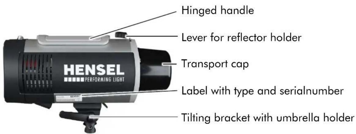
text_image
Hinged handle Lever for reflector holder Transport cap HENSEL PERFORMING LIGHT Label with type and serialnumber Tilting bracket with umbrella holder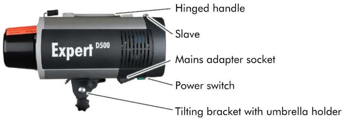
text_image
Hinged handle Slave Mains adapter socket Power switch Expert D500 Tilting bracket with umbrella holder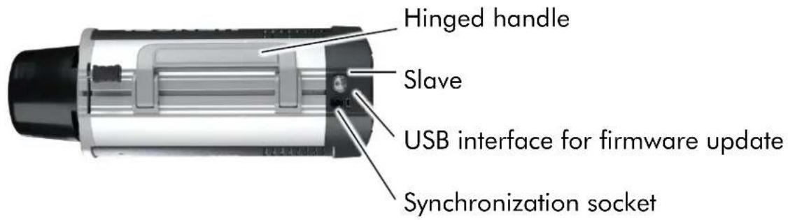
text_image
Hinged handle Slave USB interface for firmware update Synchronization socket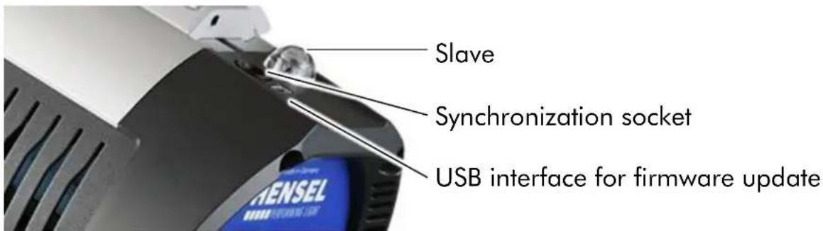
text_image
Slave Synchronization socket USB interface for firmware updateUser Manual Expert D 250 Speed / D 500 / D 1000
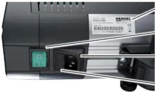
text_image
MENSIL Exper 0.500 Exper 0.500 147THQ30102201Label with type and serial number
Power switch
Mains adapter socket
Fuse and spare fuses
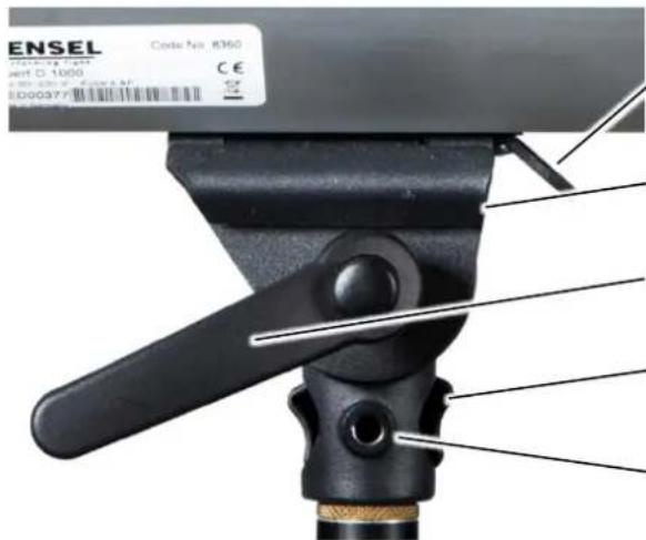
text_image
ENSEL Code No: 8360 SOMING TYPE ent D.1000 € € SD00377 SD00377 2000 2000 2000 2000 2000 2000 2000 2000 2000 2000 2000 2000 2000 2000 2000 2000 2000 2000 2000 2000 2001 2001 2001 2001 2001 2001 2001 2001 2001 2001 2001 2001 2001 2001 2001 2001 2001 2001 2001 2001 2002 2002 2002 2002 2002 2002 2002 2002 2002 2002 2002 2002 2002 2002 2002 2002 2003 2003 2003 2003 2003 2003 2003 2003 2003 2003 2003 2003 2003 2003 2003 2003 2003 2003 2003 2003 2004 2004 2004 2004 2004 2004 2004 2004 2004 2004 2004 2004 2004 2004 2004 2004 2004 2004 2019Mounting link for safety rope
Umbrella holder
Locking screw tilting bracket
Locking device stand mounting
Optional safety screw for suspended mounting
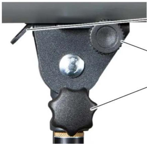
natural_image
Close-up of a mechanical component with a globe on its surface, showing structural details (no text or symbols)Mounting link for safety rope
Locking device umbrella holder
Locking device stand mounting
User Panel
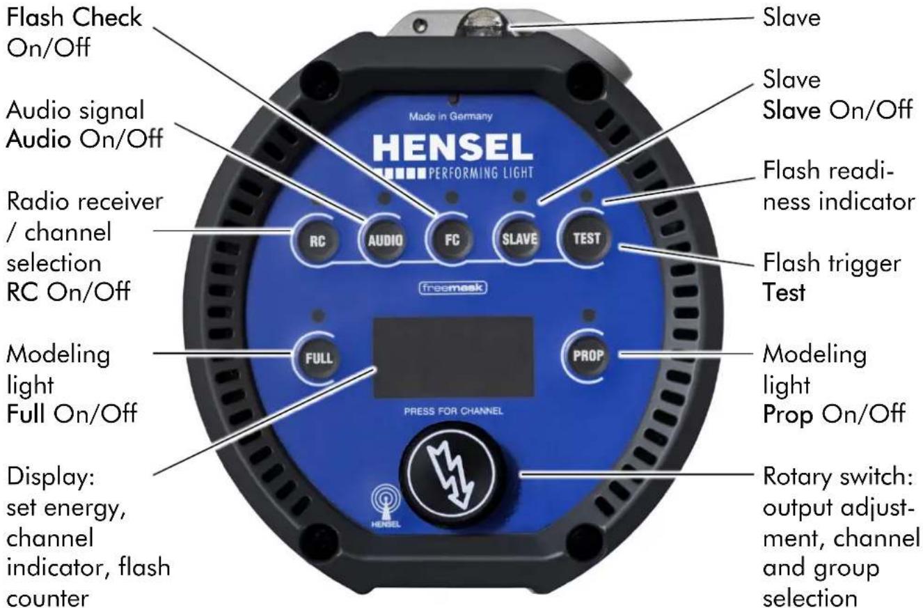
text_image
Flash Check On/Off Audio signal Audio On/Off Radio receiver / channel selection RC On/Off Modeling light Full On/Off Display: set energy, channel indicator, flash counter Made in Germany HENSEL PERFORMING LIGHT RSCEAMASK FULL PROP PRESS FOR CHANNEL Slave Slave Slave On/Off Flash readiness indicator Flash trigger Test Modeling light Prop On/Off Rotary switch: output adjustment, channel and group selectionScope of Delivery
The standard scope of delivery includes:
• 1 Expert D 250 Speed or Expert D 500 or Expert D 1000
• 1 Flash tube single coated, plug-in style
- 1 Transport cap
• 1 Glass safety dome, separately packed
- 1 Modeling light (according to customer requirement), separately packed
• 1 Cable set: mains and sync cord
- 1 User Manual
Preparing for Initial Use
Remove Transport Cap
CAUTION
Risk of fire when using with transport cap

Heat which may cause fire develops during the flash process.
- Remove transport cap before use.
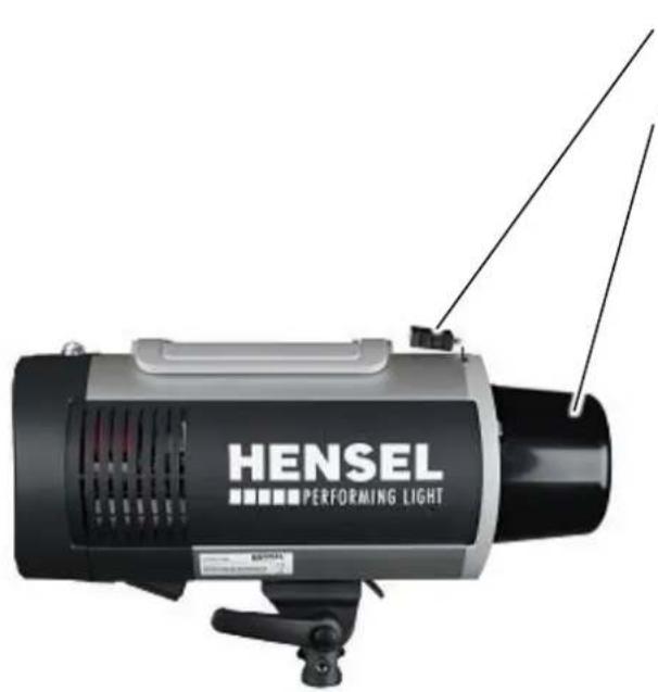
text_image
HENSEL PERFORMING LIGHTLever for reflector holder
Transport cap
- Press the locking mechanism of the reflector holder against the spring tension until reaching the end stop.
- Pull out the transport cap straight from the holder and keep it for future usage.
- Carefully returning the locking mechanism of the reflector into its standard position with the help of the spring tension.
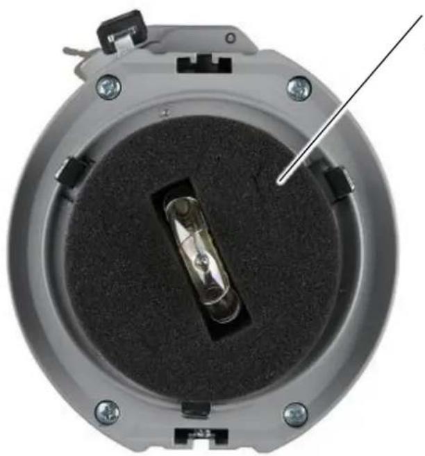
natural_image
Top-down view of a mechanical component with a central transparent cylindrical part and a metal rod inserted (no text or symbols visible)Protection of the flash tube during transport
• To remove the foam, pull it straight over the flash tube.
Inserting Halogen Lamp for Modeling Light
- Before replacing the halogen lamp, switch off the unit and disconnect it from its power supply.
- The modeling light has to match the voltage of the power supply.
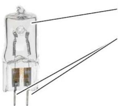
natural_image
Close-up of a small incandescent light bulb with internal circuitry and two wires extending outward (no text or symbols visible)Halogen lamp
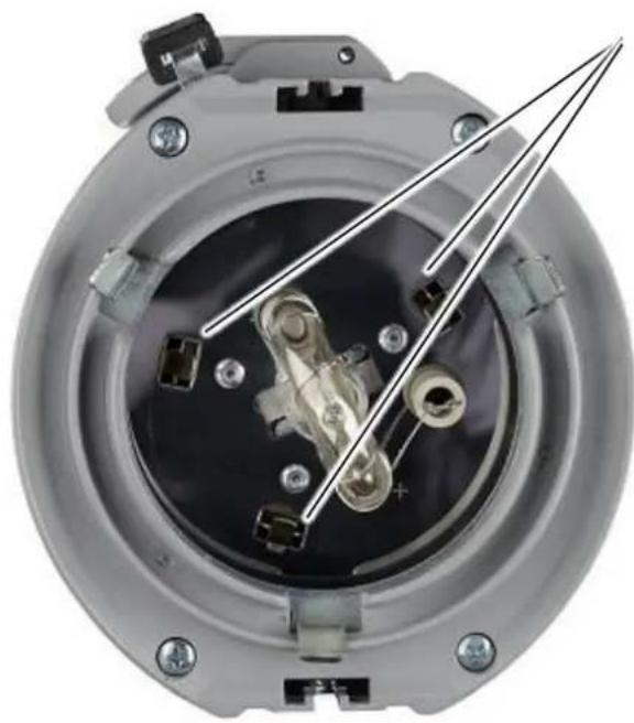
Pins
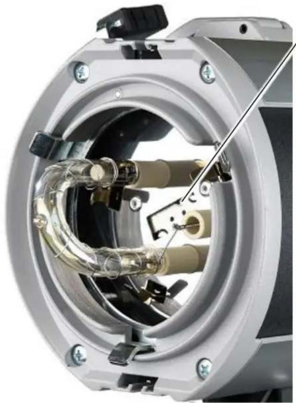
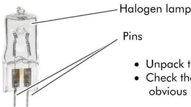
- Unpack the halogen lamp.
- Check the halogen lamp for obvious cracks in the glass.
natural_image
Cross-sectional view of a mechanical device showing internal components and a tool inserted (no visible text or symbols)Lamp socket for modeling light
- Place the pins into the lamp socket.
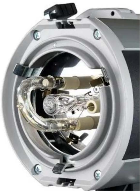
natural_image
Cross-sectional view of a mechanical device showing internal components and housing (no visible text or symbols)- Push the lamp carefully into place by alternating the pressure on the pins until contacting the end stop.
Mounting Glass Safety Dome
Please unpack the glass safety dome and check it for obvious damages. If you find damages on the glass safety dome please contact your dealer, see paragraph "Addresses".
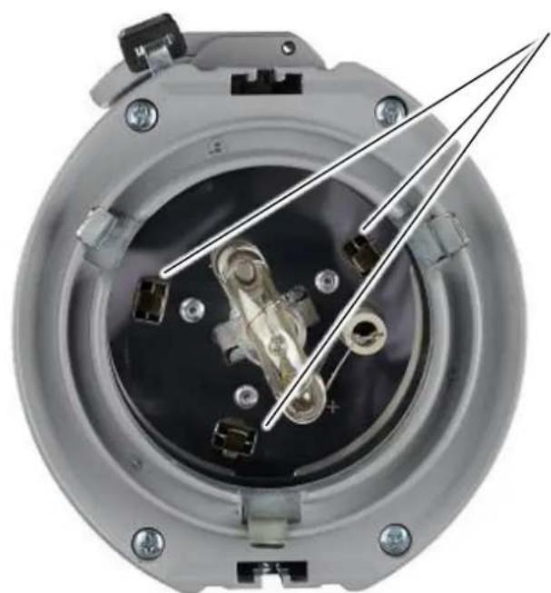
natural_image
Close-up of a mechanical component with internal components and mounting holes (no visible text or symbols)Springs holding the glass safety dome
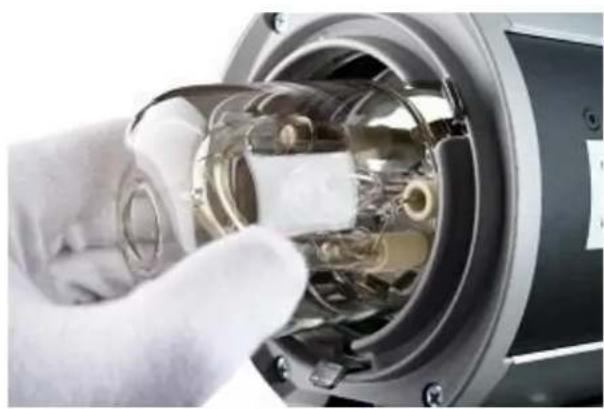
natural_image
Close-up of a gloved hand inserting a transparent cylindrical device into a mechanical housing (no visible text or symbols)- Tilt the safety dome slightly and insert it into one of the three springs.
- Then use gentle pressure to insert the safety dome first into the second spring.
- And then into the third spring until it locks into place.
Power Supply
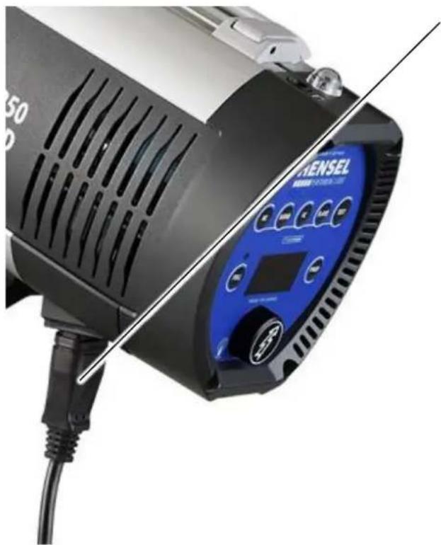
natural_image
Close-up of a black and white studio lighting fixture with a blue digital display and cable, no visible text or symbols.Mains cord
- Plug the mains cord into the mains adapter socket of the compact flash unit.
- Connect the mains cord with the mains supply socket.
Switch On
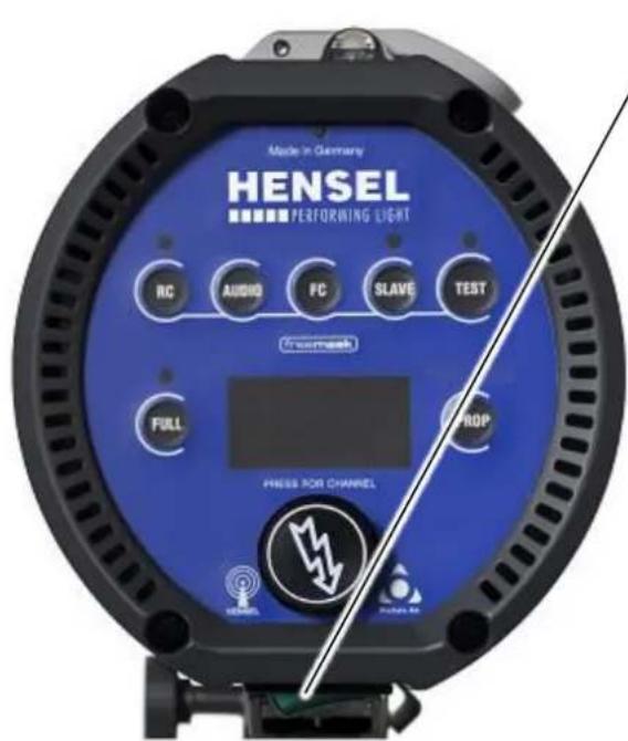
text_image
Made in Germany ENSEL PERFORMING LIGHT RC AUDIO FC SLAVE TEST Frempass FULL PROP PRESS FOR CHANNELPower switch
- Turn the unit on by pressing the power switch.
User Manual Expert D 250 Speed / D 500 / D 1000
The fan starts turning and spins at maximum speed for a short period of time. After this the speed of the fan is controlled by the temperature inside the unit.
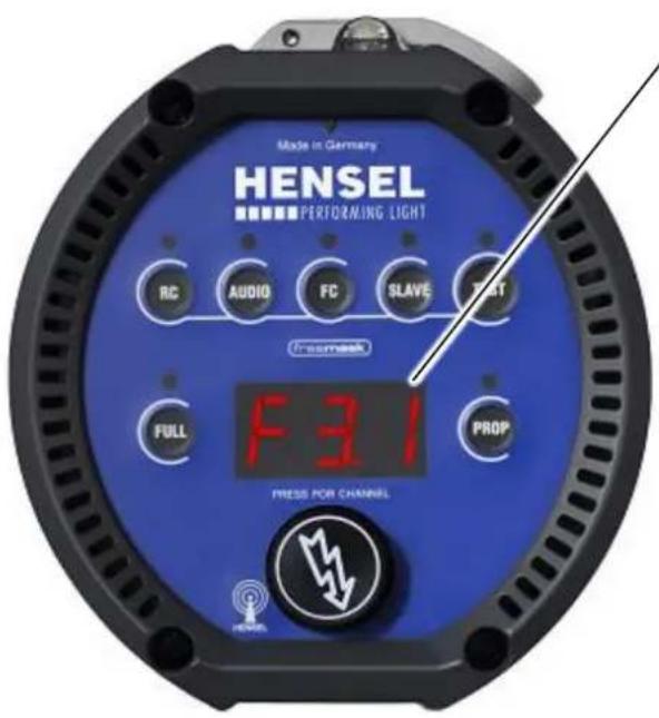
text_image
Made in Germany ENSEL PERFORMING LIGHT RC AUDIO FC SLAVE Fresmack FULL PROP FRESS FOR CHANNELDisplay
After powering on, the first thing displayed is the version of the firmware.
Now electrical energy is fed to the capacitors where it is stored.
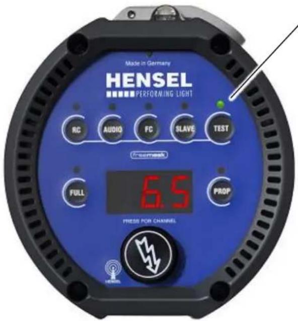
text_image
Made in Germany ENSEL PERFORMING LIGHT RC AUDIO FC SLAVE TEST Foresh FULL PROP PRESS FOR CHANNELFlash readiness indicator
If the flash readiness indicator turns green the set energy is stored inside the unit.
The compact flash unit is now ready for use.
Test Flash
WARNING
Danger of eye and skin injuries due to optical radiation
An intensive optical radiation develops during the flash process which can harm unprotected eyes or skin.
- Do not flash into the face from short distances.
text_image
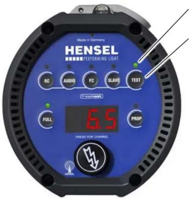
Made in Germany HENSEL PERFORMING LIGHT RC AUDIO FC SLAVE TEST ICOMASK 6.5 FULL PROP PRESS FOR CHANNELFlash readiness indicator
Key TEST
If the flash readiness indicator above the key TEST turns green, the unit is ready for use.
• To trigger a flash, press the key TEST once.
Test the Modeling Light
WARNING
Danger of eye and skin injuries due to optical radiation
An intensive optical radiation develops during the flash process which can harm unprotected eyes or skin.
- Do not flash into the face from short distances.
text_image
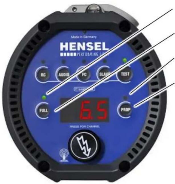
Made in Germany HENSEL PERFORMING UNIT RC AUDIO FC SLAV testing TEST PRESSOR 6.5 FULL PROP PRESS FOR CHANNELIndicator for FULL mode
Key FULL
Indicator for PROP mode
Key PROP
If one of both indicators is green, then the modeling light is turned on.
If none of both indicators is green, press the key FULL. The indicator above the button turns green and the modeling light is turned to maximum brightness.
If none of both indicators (FULL or PROP) is green, please check the halogen lamp for the modeling light for defects.
Stand Mounting
WARNING
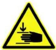
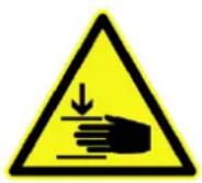
Danger of bruising
When opening the locking screw of the tilting bracket you are in danger of bruising your hands and fingers.
- When opening the screw of the tilting bracket, hold the flash unit with the other hand to avert unwanted motion.
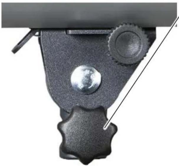
The flash unit can be attached to a stand mounting or pantograph via the tilting bracket. The tilting bracket allows the rotation of the flash unit of 360^ and a tilting angle of approximately 180^ .
natural_image
Close-up of a mechanical device with a metallic knob and gear mechanism (no visible text or symbols)Locking device, stand mounting
- Loosening the locking device stand mounting by turning it a few times.
- Please make sure that you don't turn it loose completely.
natural_image
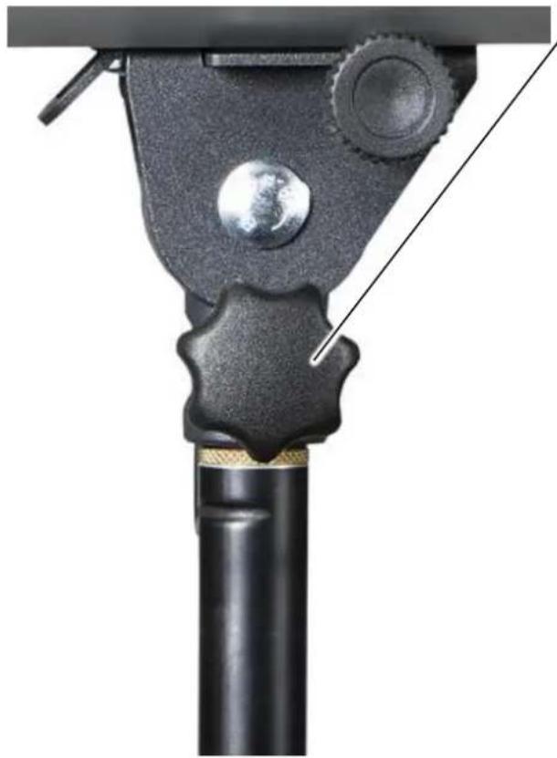
Close-up of a mechanical clamp or lever mechanism with a black shaft and circular components (no text or symbols visible)Locking device, stand mounting
- Put the flash unit on the stand mounting and tighten the locking device stand mounting.
- For rotating the flash unit on the stand mounting loosen the locking device stand mounting, turn the flash unit and tighten the locking device.
natural_image
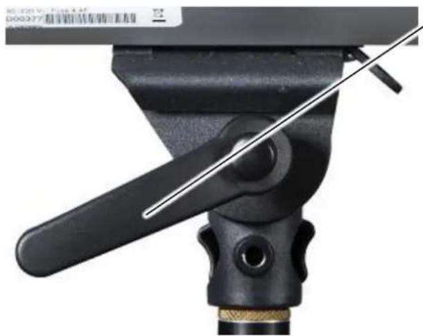
Close-up of a black mechanical clamp or lever assembly with a diagonal line, no visible text or symbols.Locking screw, tilting bracket
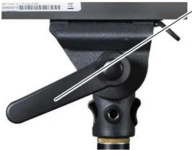
- For tilting of the flash unit, loosen the locking screw of the tilting bracket.
If the tilting bracket's locking screw cannot be opened or closed far enough and you keep bumping against the housing, lift up (pull) the locking screw by pressing down on the axis of the locking screw.
The locking screw's serration loosens and you can turn the grip into a more favorable position for further opening and closing of the locking screw.
natural_image
Close-up of a black mechanical device with a diagonal tool inserted, no visible text or symbolsLocking screw, tilting bracket
- Tilt the flash unit into the desired position and tighten the locking screw of the tilting bracket again.
If the tilting bracket's locking screw cannot be opened or closed far enough and you keep bumping against the housing, lift up (pull) the locking screw by pressing down on the axis of the locking screw.
The locking screw's serration loosens and you can turn the grip into a more favorable position for further opening and closing of the locking screw.
Mounting to Ceiling or Pantograph
WARNING

Danger from falling objects
The fastening of ceiling mounted flash units can come loose and equipment could fall down.
- Use an additional safety screw on the tilting bracket.
- Use a safety rope for additional protection.
WARNING
Danger of bruising
When opening the locking screw of the tilting bracket you are in danger of bruising your hands and fingers.
- When opening the screw of the tilting bracket, hold the flash unit with the other hand to avert unwanted motion.
The flash unit can be attached to a stand mounting or pantograph via the tilting bracket. The tilting bracket allows the rotation of the flash unit of 360^ and a tilting angle of approximately 180^ .
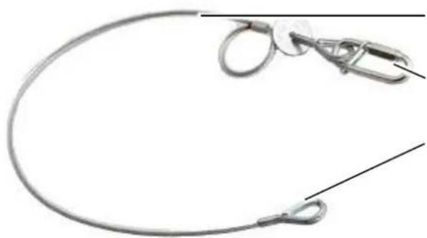
Secure the equipment with a back-up support when attaching it to ceilings or pantographs. Use the tilting bracket's safety screw and secure the device additionally with a safety rope.
Suitable safety ropes can be purchased from Hensel-Visit, see „Accessories“ and www.hensel.de.

natural_image
Close-up of a mechanical robotic arm with black components and a diagonal tool inserted (no visible text or symbols)Locking device, stand mounting
- Loosening the locking device stand mounting by turning it a few times.
- Please make sure that you don't turn it loose completely.
- Insert the tilting bracket of the flash unit into the stud of the pantograph or the boom.
- Tighten the locking device stand mounting.
natural_image
Close-up of a mechanical clamp or bracket assembly with a bolt and nut, no visible text or symbolsSafety screw for suspended mounting
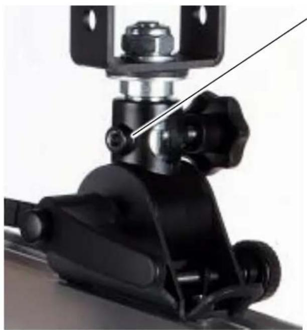
- Use an additional safety screw:
• Art.-No. 9979839 Screw hexagonal M6x16 DIN 933 ISO 4017 vz
• Art.-No. 9997919 Nut M6 DIN 934 ISO 4032
natural_image
Close-up of a metallic medical wire with attached clips and a pointed tip, shown against a plain white background (no text or symbols)Safety rope artikelnumber 7690
Spring safety hook
Rope thimble
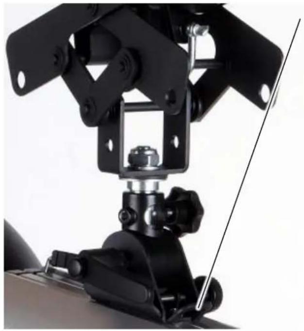
natural_image
Close-up of a mechanical robotic arm with black components and a diagonal tool (no visible text or symbols)Mounting link for safety rope
- Pull the safety rope through a suitable opening of the pantograph.
- Fix the spring safety hook in the mounting link for the safety rope at the tilting bracket.
- Insert the rope thimble in the spring safety hook.
- Close the spring safety hook and tighten it.
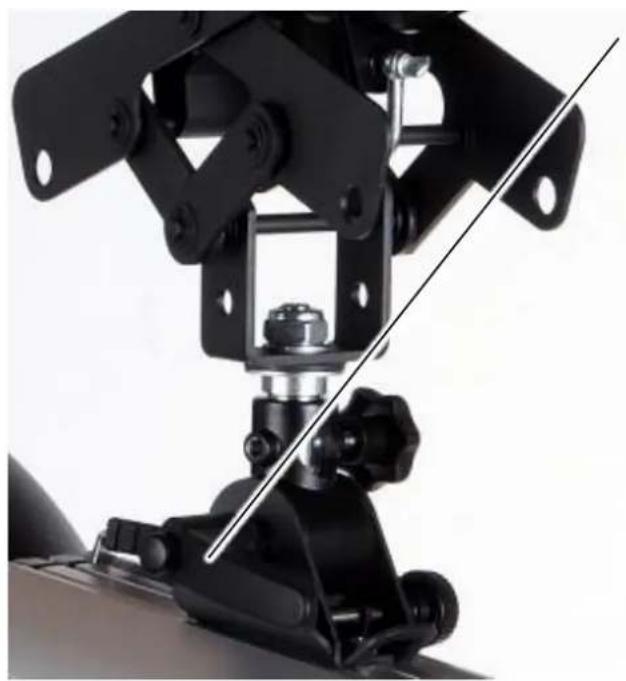
natural_image
Close-up of a mechanical assembly with black components and a diagonal line indicating alignment (no text or symbols visible)Locking screw, tilting bracket
- For tilting of the flash unit, loosen the locking screw of the tilting bracket.
If the tilting bracket's locking screw cannot be opened or closed far enough and you keep bumping against the housing, lift up (pull) the locking screw by pressing down on the axis of the locking screw.
The locking screw's serration loosens and you can turn the grip into a more favorable position for further opening and closing of the locking screw.
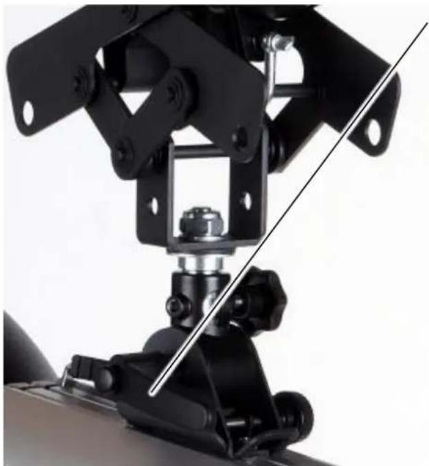
natural_image
Close-up of a mechanical assembly with black components and a diagonal line indicating alignment (no text or symbols visible)Locking screw, tilting bracket
- Tilt the flash unit into the desired position and tighten the locking screw of the tilting bracket again.
If the tilting bracket's locking screw cannot be opened or closed far enough and you keep bumping against the housing, lift up (pull) the locking screw by pressing down on the axis of the locking screw.
The locking screw's serration loosens and you can turn the grip into a more favorable position for further opening and closing of the locking screw.
Repositioning Tilting Bracket and Handle
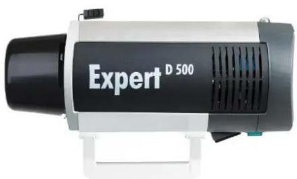
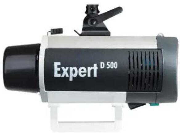
The position of the tilting bracket and the handle can be swapped. This lets you mount the flash unit in an overhead location like a ceiling.
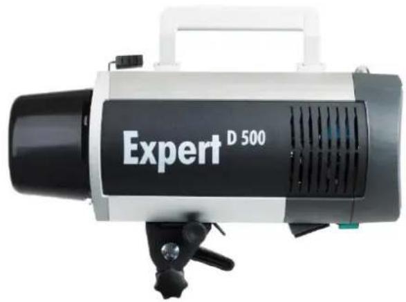
natural_image
Exterior view of a black and white D 500 light bulb (no additional text or symbols visible)- Loosen the two crosshead screws on the tilting bracket.
- Slide the tilting bracket forward along the guide rail of the housing.
- Put the tilting bracket aside until you have removed the handle.
natural_image
Exterior view of a white and black D 500 light bulb device (no additional text or symbols visible)- Loosen the two crosshead screws on the handle.
- Slide the handle forward along the guide rail of the housing.
- Insert the handle into the guide rail on the opposite side of the housing.
- Tighten fast the two screws of the handle.
natural_image
Exterior view of a D 500 light bulb (no additional text or symbols visible)- Insert the tilting bracket into the guide rail on the opposite side of the housing.
- Tighten fast the two screws of the handle.
Mounting a Reflector
CAUTION
Risk of burns from reflector and flash unit
Heat which may cause burns develops at the head during the flash process.
- Before removing the reflector allow reflector and flash unit to cool-off.
- Allow flash unit to cool off.
CAUTION

Glass safety dome may get damaged
When mounting a reflector the glass safety dome can be damaged.
- Do not touch the glass safety dome with the reflector.
- While mounting a reflector place the flash unit on a stand.
- Place the reflector evenly on the flash unit.
- When mounting a reflector hold it with one hand.
CAUTION

The system may become damaged if external products are used.
The system may become damaged when components are changed or accessories are connected.
- Only use original parts and HENSEL-VISIT accessories.
natural_image
Cross-sectional diagram of a mechanical device showing internal components and structural lines (no text or symbols)Lever of the reflector holder
Fingers
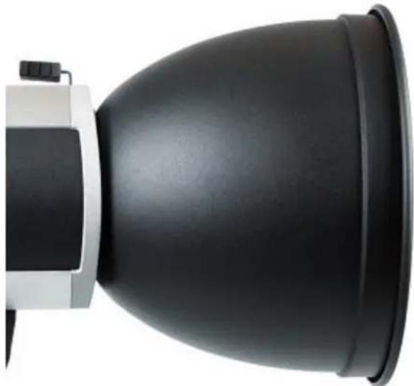
- Press the locking mechanism of the reflector holder against the spring tension until reaching the end stop.
- Put the reflector onto the unit and make sure that the 3 fingers are inside the reflector.
natural_image
Close-up of a black and white headlight bulb with a flat panel, no visible text or symbols.- Hold the reflector with one hand while carefully returning the locking mechanism of the reflector into its standard position with the help of the spring tension.
- Check the correct mounting of the reflector.
Removing a Reflector
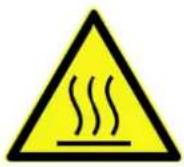
CAUTION
Risk of burns from reflector and flash unit
Heat which may cause burns develops at the head during the flash process.
- Before removing the reflector allow reflector and flash unit to cool-off.
- Allow flash unit to cool off.
CAUTION

Glass safety dome may get damaged
When mounting a reflector the glass safety dome can be damaged.
- Do not touch the glass safety dome with the reflector.
- While mounting a reflector place the flash unit on a stand.
- Place the reflector evenly on the flash unit.
- When mounting a reflector hold it with one hand.
natural_image
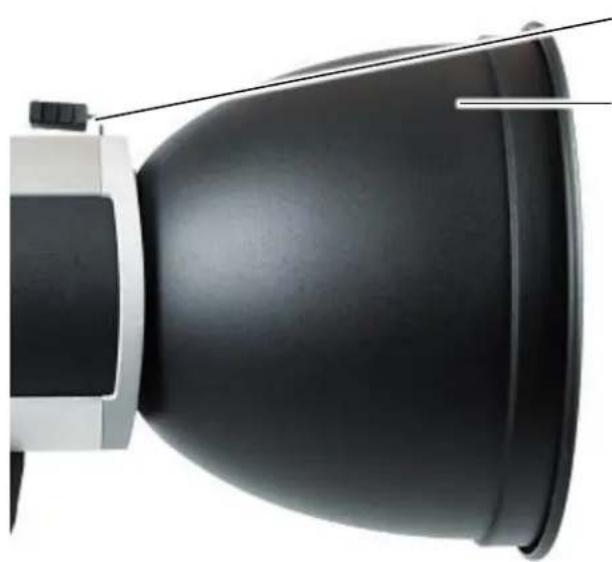
Close-up of a black dome-shaped object with a white base and light cable, no visible text or symbols.Lever of the reflector holder
Reflector
- Hold the reflector with one hand.
- With the other hand, press the locking mechanism of the reflector holder against the spring tension until reaching the end stop.
natural_image
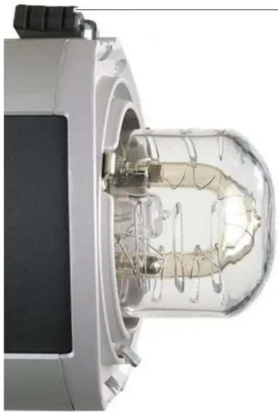
Cross-sectional view of a mechanical device with internal components and transparent casing (no visible text or symbols)Lever of the reflector holder
- Remove the reflector from the unit and put it aside.
- Carefully return the locking mechanism of the reflector into its standard position with the help of the spring tension.
Modeling Light
The modeling light is switched on by using the key FULL or PROP:
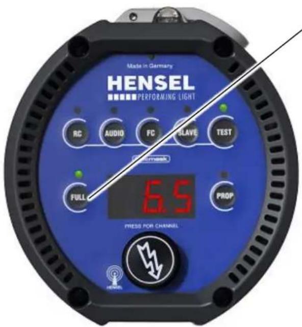
Mode FULL: The modeling light is set at full power.
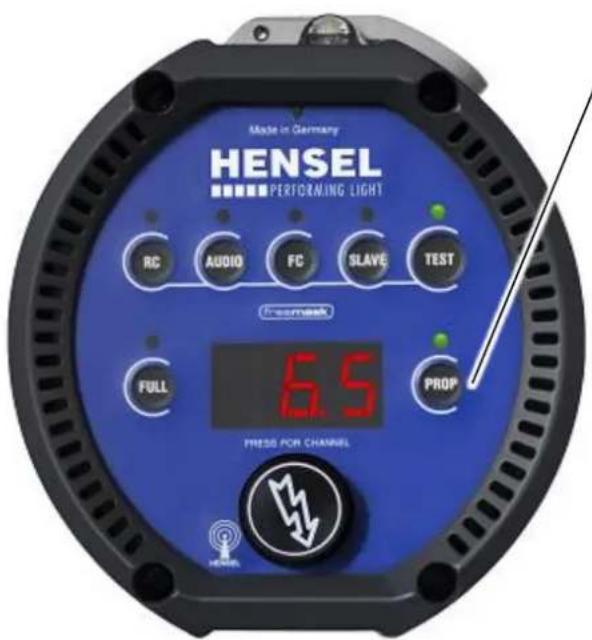
Mode PROP: The light output (brightness) of the modeling light is proportional to the flash output.
Mode FULL
The modeling light is set at full power, independent of the flash output.
text_image
Made in Germany ENSEL PERFORMING LIGHT RC AUDIO FC SLAVE TEST FULL PROP 6.5 PRESS FOR CHANNELKey FULL
- Press the key FULL, to turn the modeling light to full power.
- The indicator above the key turns green.
Mode PROP
The light output (brightness) of the modeling light is proportional to the flash output.
text_image
Made in Germany HENSEL PERFORMING LIGHT RC AUDIO FC SLAVE TEST Fremest 6.5 FULL PROP PRESS FOR CHANNELKey PROP
- Press the key PROP, the brightness of the modeling light is now proportional to the flash output.
- The indicator above the key turns green.
Turn off the Modeling Light
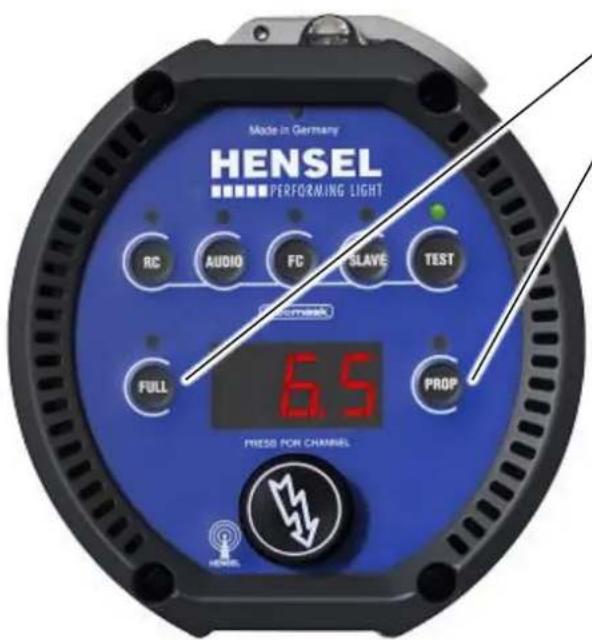
You can turn off the modeling light completely by either deactivating the FULL or PROP mode by pressing the respective key.
text_image
Made in Germany HENSEL PERFORMING LIGHT RC AUDIO FC SLAVE TEST 6.5 FULL PROP PRESS FOR CHANNELKey FULL
Key PROP
- Press the key FULL or the key PROP, to switch off the modeling light.
- If both indicators above the keys FULL and PROP are dark, the modeling light is turned off.
Automatic Modeling Light reduction AUTORED
The compact flash unit's modeling light is equipped with an energy saving mode. This conserves energy and extends the lamp's operating life. After a preselected time of 35 min in the FULL mode the modeling light is automatically reduced to level 9.
When set on PROP mode, this happens when the flash output setting is between 9.1 and 10.
The original output is restored when you touch any key.
text_image
Made in Germany ENSEL PERFORMING LIGHT RC AUDIO FC SLAVE TEST Current FULL PROP 6.5 PRESS FOR CHANNELRotary switch
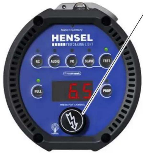
- Press the digital switch twice in fast sequence (double-click).
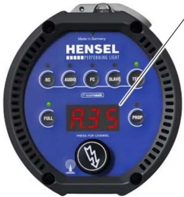
text_image
Made in Germany HENSEL PERFORMING LIGHT RC AUDIO FC SLAVE TEM Inconnex FULL PROP 8.35 PRESS FOR CHANNELDisplay
The display shows the selected switch-off time for ca. 3 s.
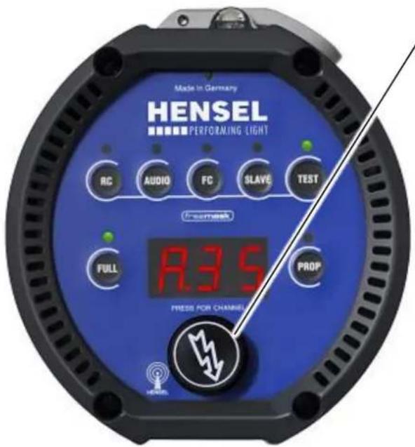
text_image
Made in Germany ENSEL PERFORMING LIGHT RC AUDIO FC SLAVE TEST F-Comex FULL R.35 PROP PRESS FOR CHANNELSRotary switch
- Adjust the time by turning the rotary switch in 1 minute increments up to a maximum of 90 minutes.
- A setting of „--“ causes the function to switch off.
Performance Output Adjustment
The rotary switch adjusts the flash output over an output range of 9 f-stops (Expert D 250 Speed), from 2.0 (lowest output), and over an output range of 8 f-stops (Expert D 500 / D 1000), from 3.0 (lowest output) to 10 (maximum output):
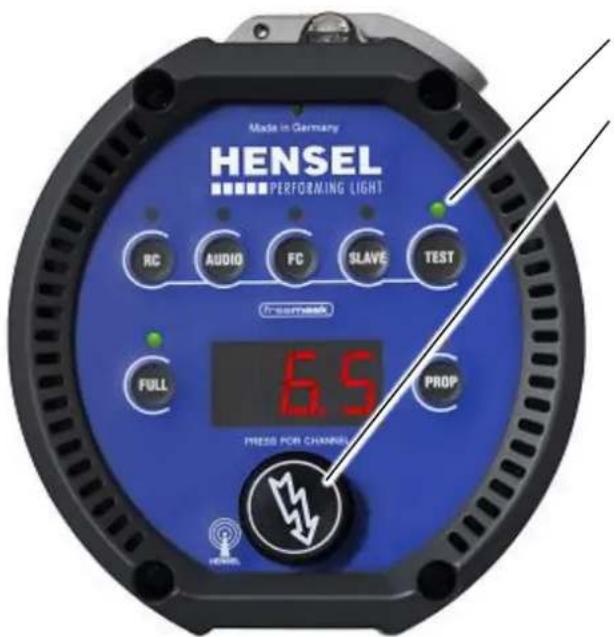
text_image
Made in Germany HENSEL PERFORMING LIGHT RC AUDIO FC SLAVE TEST inserink 6.5 FULL PROP PRESS FOR CHANNELFlash readiness indicator
Rotary switch
- The rotary switch adjusts the flash output in steps of 0.1 f-.
- Turning it counter-clockwise reduces the output in steps of 0.1 f-stops.
- The power dump takes a moment. The flash readiness indicator lights up to indicate restored flash readiness.
When the performance output is reduced, the stored energy is reduced via the internal APD-Function ^3 .
Manual Flash Trigger
WARNING
Danger of eye and skin injuries due to optical radiation
An intensive optical radiation develops during the flash process which can harm unprotected eyes or skin.
- Do not flash into the face from short distances.
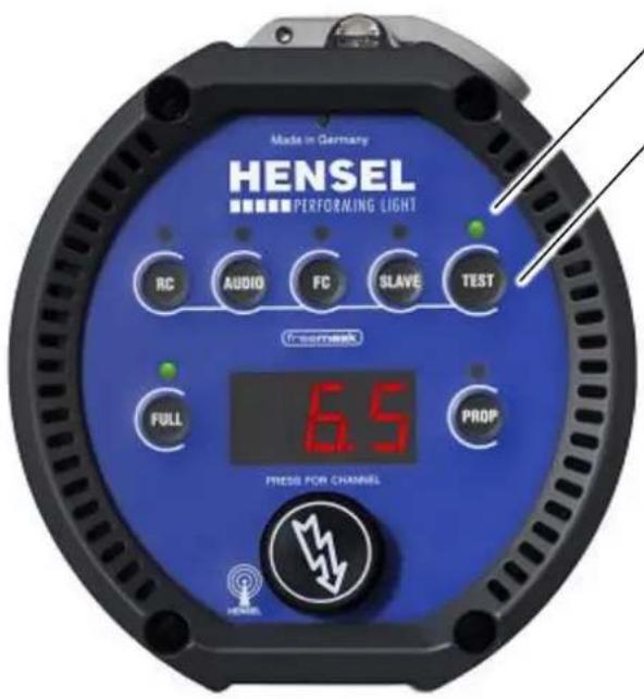
text_image
Made in Germany ENSEL PERFORMING LIGHT RC AUDIO FC SLAVE TEST FRESH FULL 6.5 PROP PRESS FOR CHANNELFlash readiness indicator
Key TEST
If the flash readiness indicator above the key TEST turns green, the unit is ready for use.
- To trigger a flash, press the key TEST once.
Flash Check
The compact flash unit is equipped with a visual flash readiness indicator called Flash Check. When this function is activated, the modeling light shuts off after flashing and turns on again when the flash readiness is restored.
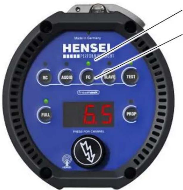
text_image
Made in Germany ENSEL PERFORMANCE RIGHT RC AUDIO FC SLAVE TEST InseMeck 6.5 FULL PROP PRESS FOR CHANNELIndicator for Flash Check Key FC
- Activate Flash Check with the FC key. The LED indicator turns green.
• To deactivate Flash Check press the key FC again.
Synchronization
Synchronization between compact flash unit and camera can be optionally achieved via sync cord, the built-in slave, or a built-in radio receiver.
Synchronization via Cord
The synchronization process uses the latest semiconductor technology and warrants reliable triggering of the flash unit even when older camera models with mechanical contacts are used. The lower voltage of the sync plug ensures safe and reliable operation, also with the use of modern digital cameras.
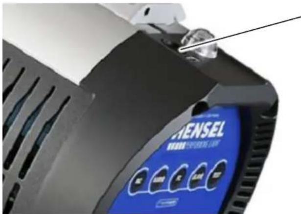
text_image
ENSEL WELL SPINNING LIMESynchronization socket
- Plug the 6.3 mm jack into the synchronization socket of the compact flash unit.
- Connect the other end of the sync cord to the camera's sync socket. Please consult the user manual of your camera.
Synchronization via Slave
The built-in slave triggers the flash when light from another flash is detected (slave mode).
The slave is an impulse photo cell. It only triggers the flash when the striking light is brighter than the ambient light.
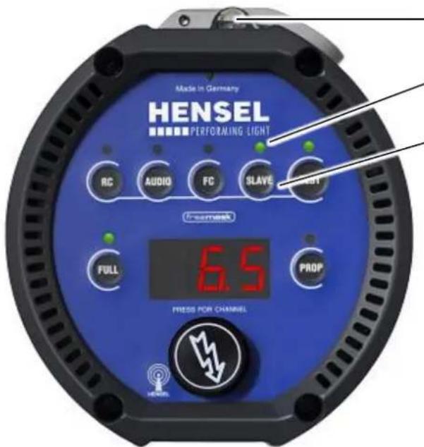
text_image
Made in Germany HENSEL PERFORMING LIGHT RC AUDIO FC SLAVE START Enerink 6.5 FULL PROP PRESS FOR CHANNELSlave
Indicator for SLAVE Mode
Key SLAVE
• To activate the SLAVE mode press the key SLAVE.
- The active setting is indicated via LED above the key SLAVE.
Synchronization via Radio Remote Trigger
The compact flash unit is equipped with radio receivers for the HENSEL Strobe Wizard plus and the HENSEL freemask system.
The optional radio remote triggers Strobe Wizard Plus and freemask are used to conveniently synchronize the camera and flash unit via radio remote control.
Please have a look at the user manual of the radio remote trigger.
Activate Built-in Radio Receiver
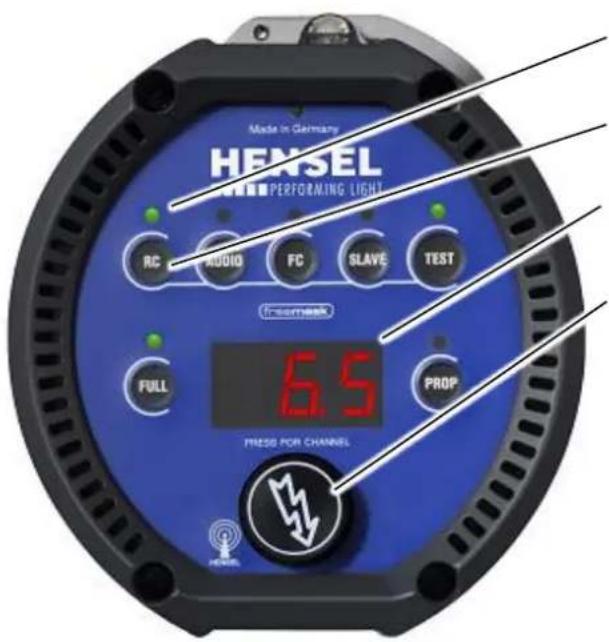
text_image
Made in Germany HENSEL PERFORMING LIGHT RC AUDIO FC SLAVE TEST Incomerck FULL PROP PRESS FOR CHANNELIndicator for RC
Key RC
Display
Rotary switch
- Briefly press the key RC until the LED above the key lights up green, or press the rotary switch to turn on the radio receiver.
Selecting Radio Channel
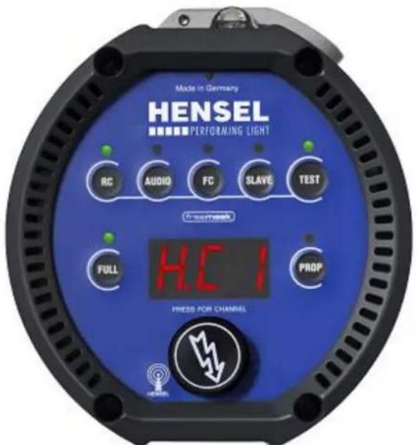
text_image
Made in Germany ENSEL PERFORMING LIGHT RC AUDIO FC SLAVE TEST Presensek H.C.I FULL PROP PRESS FOR CHANNEL- Press the key RC for approx. 2 s to switch the channels of the radio receiver.
- The display 5 is now blinking and shows the setting.
- Turning the rotary switch within 3 s lets you set the desired channel.
- Approximately 3 s after a key was last pressed, the channel is saved and the display stops blinking.
After the channel „H.C1“ come the channels „H.C2“ and „H.C3“ of Strobe Wizard Plus, directly after them the channels „H.F1“, „H.F2“ and „H.F3“ of the freemask receiver.
Daily Flash Counter
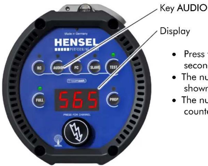
text_image
Made in Germany HENSEL PERFORMING LIGHT RC AUDIO FC SLAVE TEST Ireemask FULL PROP 565 PRESS FOR CHANNEL Key AUDIO Display Press t second The nu shown The nu counteReseting the Daily Flash Counter
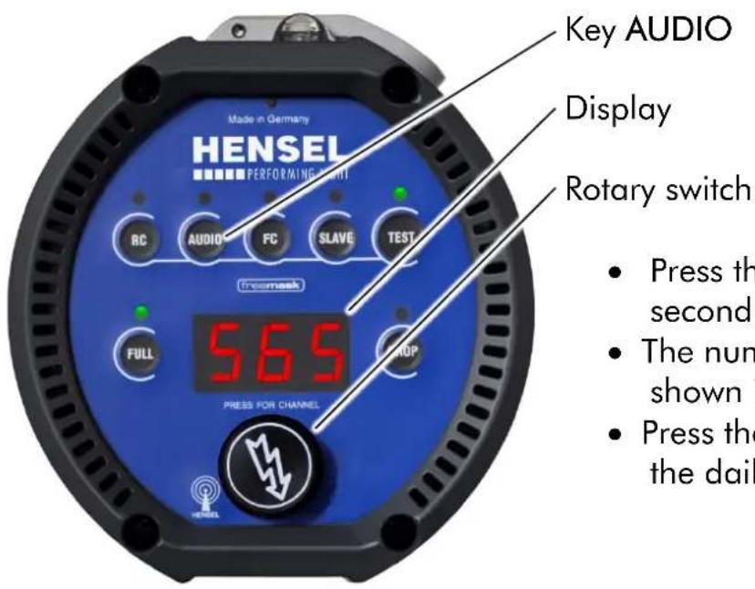
text_image
Key AUDIO Display Rotary switch HENSEL Made in Germany PERFORMING LIGHT RC AUDIO FC SLAVE TEST Tromesk FULL 565 DROP PRESS FOR CHANNEL- Press the key AUDIO for one second.
- The number of flashes is shown in the display.
- The number range of the flash counter goes up to 999.
PM Mode (in connection with Power Max L)
Hallmarks of the compact flash units of the Expert D series are their especially short flash duration times and fast recycling times - also when operated with a Power Max L. This results in a comparatively high power draw. In order to guarantee optimum functioning, the Expert D must be switched to a special mode when used in connection with a Power Max L.
In this mode, the modeling light is set to 100W and the „Flash Check" function, which turns off the modeling light after flashing and turns it back on as soon as the unit has recharged and is ready to flash again, is activated.
Activate PM Mode
text_image
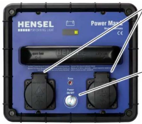
HENSEL PERFORMING LIGHT Power Max Mandatory CE Square fuse HENSEL Power ON/OFF Error Power ON/OFFMains socket
- Connect the compact flash unit to one of the power jacks on the Power Max L.
Power switch
- Switch the Power Max L on via the power switch.
text_image
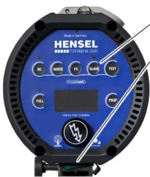
Made in Germany ENSEL PERFORMING LIGHT RC AUDIO FC SLAVE TEST freemask FULL PROP PRESS FOR CHANNELKey SLAVE
Power switch
- Switch the compact flash unit via the power switch.
- Press the key SLAVE until you hear a beep tone.
text_image
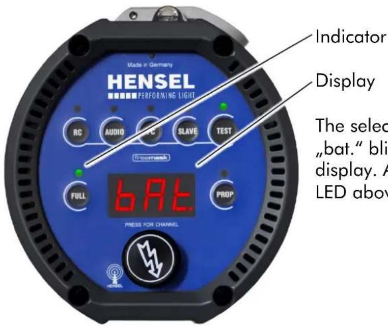
Made in Germany HENSEL PERFORMING LIGHT RC AUDIO SLAVE TEST Fremesh FULL PROP BAT. PRESS FOR CHANNEL Indicator Display The select "bat." bli display. A LED aboveThe selected flash output and „bat.“ blink alternately in the display. Additionally, the indicator LED above the key FULL blinks.
The Expert D compact flash units stay in this mode once it is activated, even after they are switched off. No damage occurs if the Expert D are operated on a normal power supply when in Power Max mode
Deactivate PM Mode
text_image
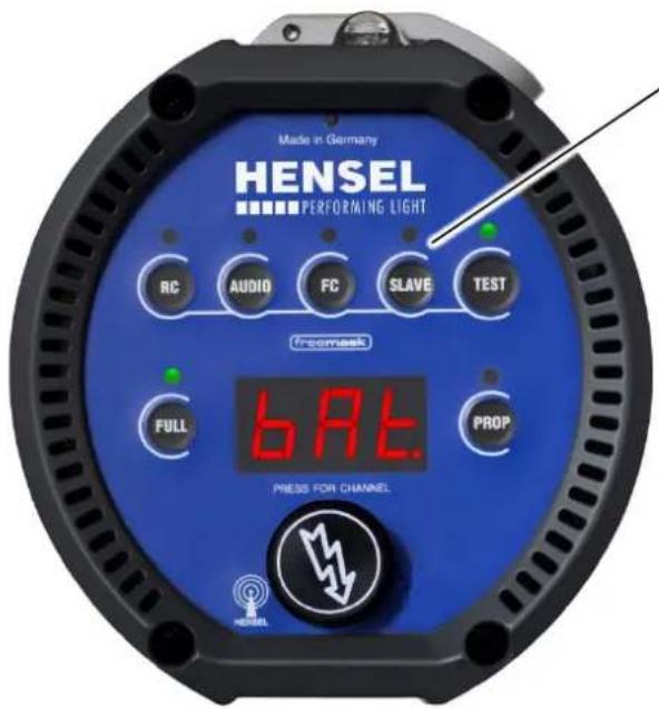
Made in Germany ENSEL PERFORMING LIGHT RC AUDIO FC SLAVE TEST incomask FULL 6.97. PROP PRESS FOR CHANNELKey SLAVE
- Press the key SLAVE until you hear a beep tone.
The PM mode is deactivated.
Exchange the Safety Glass Dome
CAUTION
Risk of burns from reflector and flash unit
Heat which may cause burns develops at the head during the flash process.
- Before removing the reflector allow reflector and flash unit to cool-off.
- Allow flash unit to cool off.
CAUTION

Glass safety dome may get damaged
When mounting a reflector the glass safety dome can be damaged.
- Do not touch the glass safety dome with the reflector.
- While mounting a reflector place the flash unit on a stand.
- Place the reflector evenly on the flash unit.
- When mounting a reflector hold it with one hand.
CAUTION

The halogen lamp or flash tube can burst due to oily residues on the glass parts.
Avoid touching the flash tube with bare hands to prevent its contamination with oily residue.
- Use cotton gloves to change the halogen lamp or the flash tube.
- Carefully clean after touching the glass parts.
Switch Off and Unplug the Mains Cord
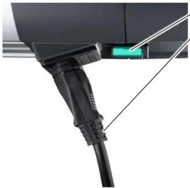
natural_image
Close-up of a black V23 connector with a green indicator light, no visible text or symbolsPower switch
Mains cord
- Turn the unit off by pressing the power switch.
- Unplug the mains cord from the mains supply socket.
- Unplug the mains cord from the mains adapter socket of the compact flash unit.
Removing a Reflector
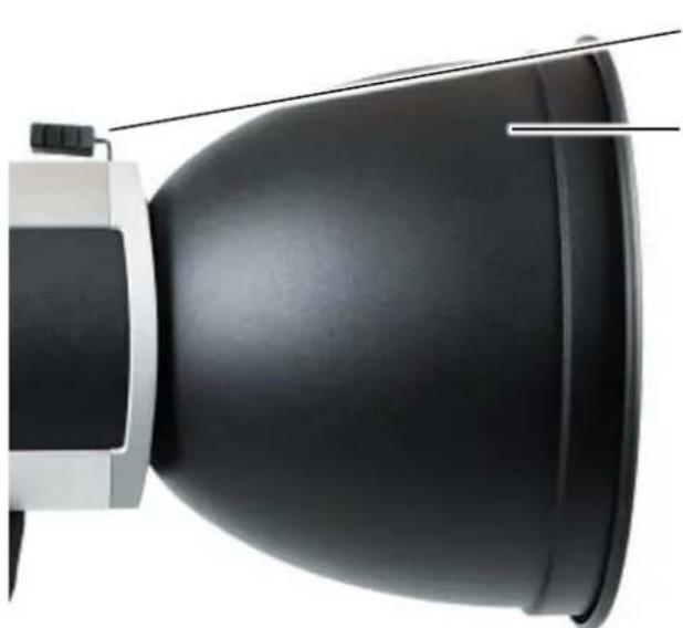
natural_image
Close-up of a black dome-shaped object with a white base and control panel, no visible text or symbols.Lever of the reflector holder
Reflector
- Hold the reflector with one hand.
- With the other hand, press the locking mechanism of the reflector holder against the spring tension until reaching the end stop.
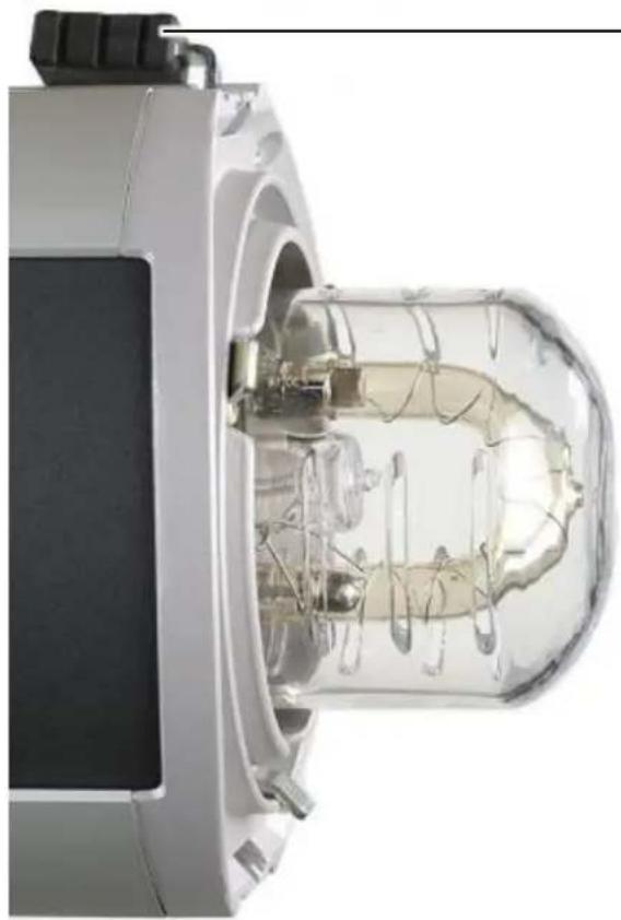
natural_image
Cross-sectional view of a mechanical device with internal components and transparent casing (no visible text or symbols)Lever of the reflector holder
- Remove the reflector from the unit and put it aside.
- Carefully return the locking mechanism of the reflector into its standard position with the help of the spring tension.
Removing Old or Broken Safety Glass Dome
natural_image
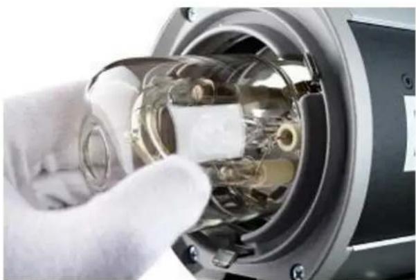
Close-up of a gloved hand inserting a transparent cylindrical device into a mechanical housing (no visible text or symbols)The safety dome snaps into place via three pre-installed springs
- Tilt the safety dome slightly so that it is released one by one from the mounting springs.
- Pull the safety dome lightly from the third spring and remove it completely.
Mount a New Safety Glass Dome
Please unpack the glass safety dome and check it for obvious damages. If you find damages on the glass safety dome please contact your dealer, see paragraph "Addresses".
natural_image
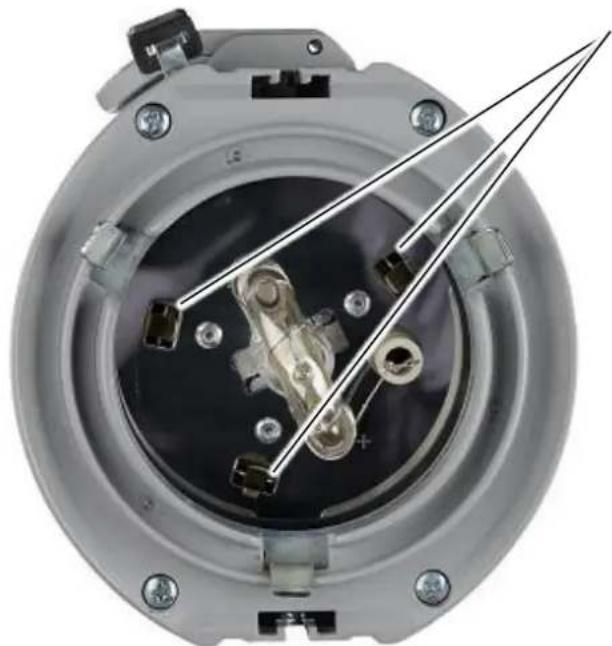
Close-up of a mechanical component with internal components and mounting holes (no visible text or symbols)Springs holding the glass safety dome
natural_image
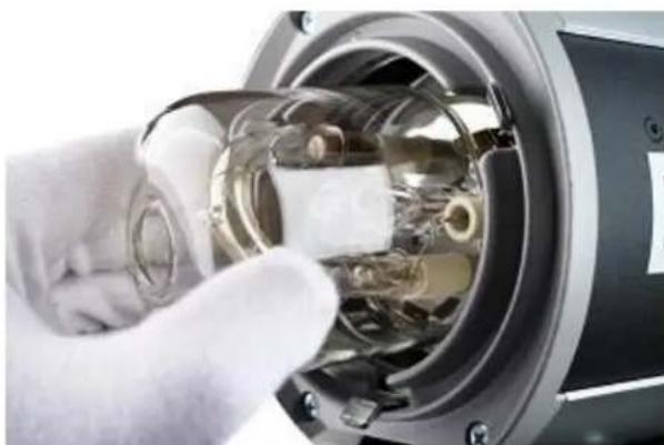
Close-up of a gloved hand inserting a transparent plastic component into a mechanical device (no visible text or symbols)- Tilt the safety dome slightly and insert it into one of the three springs.
- Then use gentle pressure to insert the safety dome first into the second spring.
- And then into the third spring until it locks into place.
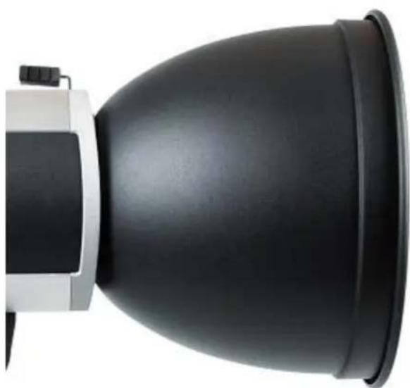
Mounting a Reflector
natural_image
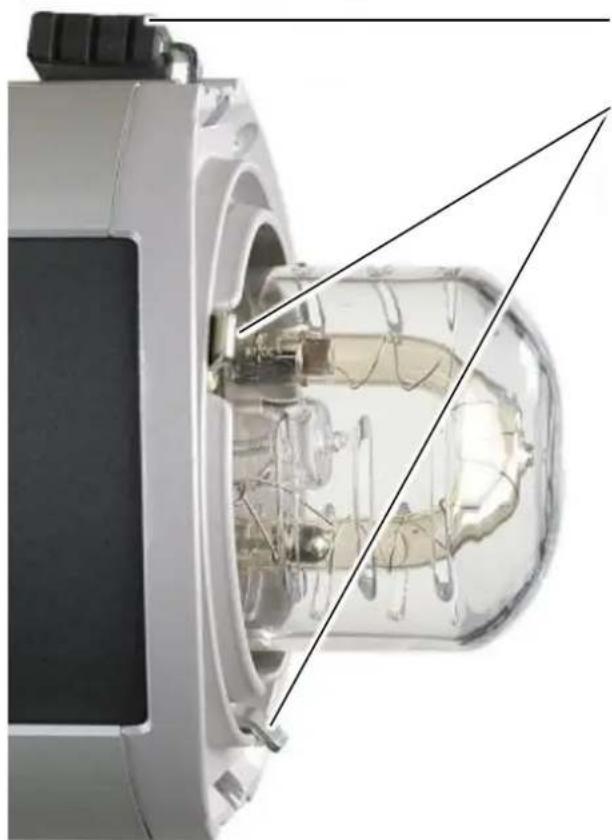
Cutaway view of a mechanical device showing internal components and structural lines (no text or symbols)Lever of the reflector holder
Fingers
- Press the locking mechanism of the reflector holder against the spring tension until reaching the end stop.
- Put the reflector onto the unit and make sure that the 3 fingers are inside the reflector.
natural_image
Close-up of a black and white optical device with a dome-shaped lens (no text or symbols visible)- Hold the reflector with one hand while carefully returning the locking mechanism of the reflector into its standard position with the help of the spring tension.
- Check the correct mounting of the reflector.
Connect the Mains Cord and Switch On
natural_image
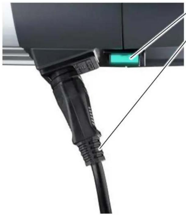
Close-up of a black V23 connector with a green indicator light, no visible text or symbolsPower switch
Mains cord
- Plug the mains cord into the mains adapter socket of the flash unit.
- Plug the mains cord into the mains supply socket
- Turn the unit on by pressing the power switch.
Replacing Flash Tube
DANGER
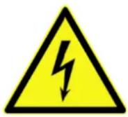
Risk of electric shock from defective flash tube
If the glass tube of the flash tube is defective, the electrodes may become exposed and cause an electric shock when touched.
- Switch off system via the power switch.
- Open the trolley and disconnect the power cable from the generator.
CAUTION
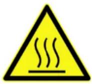
Risk of burns from reflector and flash unit
Heat which may cause burns develops at the head during the flash process.
- Before removing the reflector allow reflector and flash unit to cool-off.
- Allow flash unit to cool off.
CAUTION

Glass safety dome may get damaged
When mounting a reflector the glass safety dome can be damaged.
- Do not touch the glass safety dome with the reflector.
- While mounting a reflector place the flash unit on a stand.
- Place the reflector evenly on the flash unit.
- When mounting a reflector hold it with one hand.
CAUTION
The halogen lamp or flash tube can burst due to oily residues on the glass parts.

Avoid touching the flash tube with bare hands to prevent its contamination with oily residue.
- Use cotton gloves to change the halogen lamp or the flash tube.
- Carefully clean after touching the glass parts.
Switch Off and Unplug the Mains Cord
natural_image
Close-up of a black V8 connector with a green indicator light on the cable (no text or symbols visible)Power switch
Mains cord
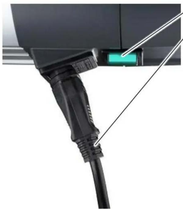
- Turn the unit off by pressing the power switch.
- Unplug the mains cord from the mains supply socket.
- Unplug the mains cord from the mains adapter socket of the compact flash unit.
Removing a Reflector
natural_image
Close-up of a black dome-shaped object with a white base and light cable, no visible text or symbols.Lever of the reflector holder
Reflector
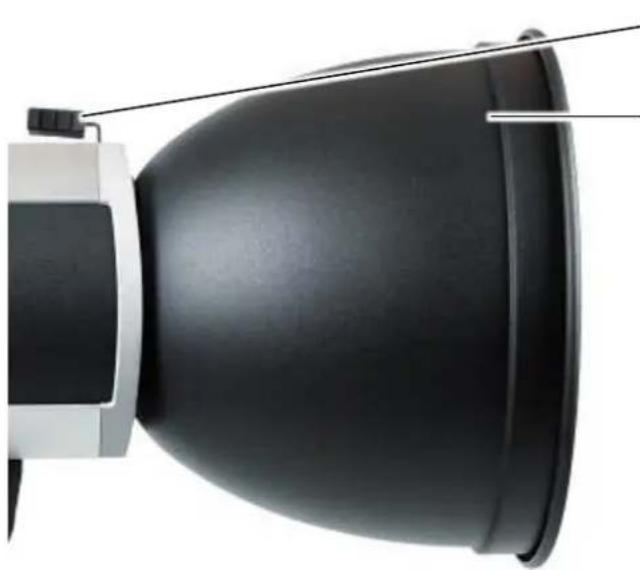
- Hold the reflector with one hand.
- With the other hand, press the locking mechanism of the reflector holder against the spring tension until reaching the end stop.
natural_image
Close-up of a transparent cylindrical device with internal components, possibly a scientific instrument or sensor array (no visible text or symbols)Lever of the reflector holder
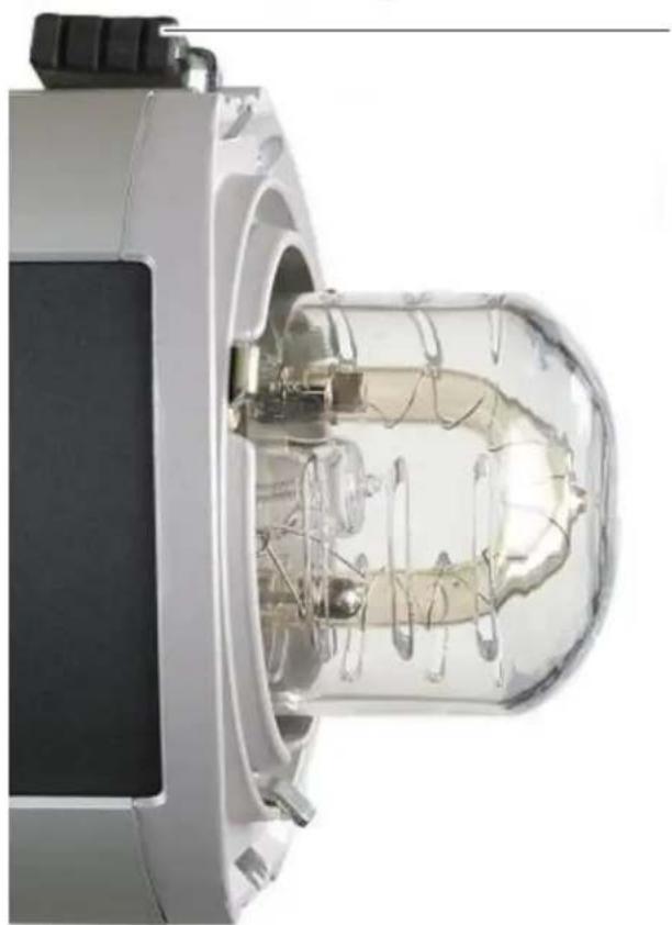
- Remove the reflector from the unit and put it aside.
- Carefully return the locking mechanism of the reflector into its standard position with the help of the spring tension.
Remove Safety Glass Dome

natural_image
Close-up of a gloved hand inserting or adjusting a transparent cylindrical device into a mechanical housing (no visible text or symbols)The safety dome snaps into place via three pre-installed springs
- Tilt the safety dome slightly so that it is released one by one from the mounting springs.
- Pull the safety dome lightly from the third spring and remove it completely.
Remove Broken Flash Tube
natural_image
Close-up of a mechanical testing setup with chains and a central pipe fitting (no visible text or symbols)Ignition wire
Connecting pin
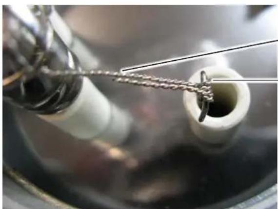
- Unwind the ignition wire from the connecting pin.
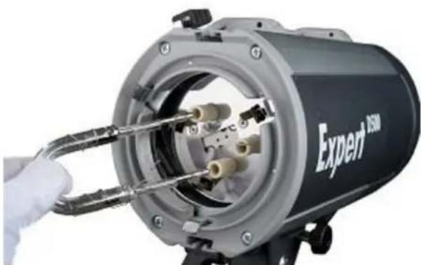
natural_image
Close-up of a mechanical device with a hand holding a tool, showing internal components and no visible text or symbols.- Carefully pull the flash tube from the plug base.
- Remove all glass debris if necessary.
Mount a New Flash Tube
- Unpack the flash tube.
- Check the glass body of the flash tube for obvious cracks and defects.
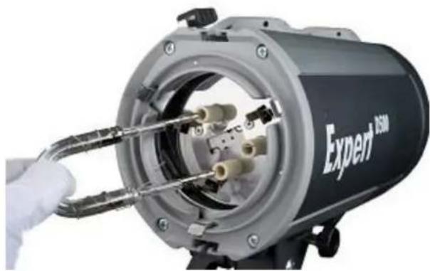
natural_image
Close-up of a mechanical device with a gloved hand inserting wires into a housing (no visible text or symbols)- Place the flash tube on the plug base and carefully push the flash tube in until reaching the end stop.
- Pull the flash tube out again approximately 0.5 mm so that the glass body can expand upon warming.
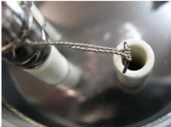
Correct Assembly
natural_image
Close-up of a metal chain being inserted into a white cylindrical container (no text or symbols visible)- Wrap the ignition wire onto the connecting pin and afterwards onto itself facing the glass body.
- If the remaining ignition wire is too long, it can be cut with a caliper.
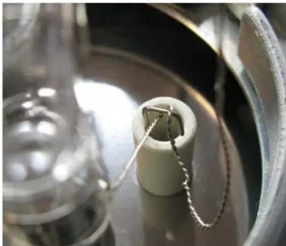
False Assembly
natural_image
Close-up of a mechanical component with a metallic ring and attached wire, no visible text or symbols- If the ignition wire is wrapped loosely onto the connecting pin the unit might not flash properly.
- If the ignition wire is not wrapped onto itself facing the glass body, the ignition voltage flows via the metal parts of the unit to the protecting earth.
Mount Safety Glass Dome
natural_image
Close-up of a mechanical component with internal components and a metallic tool (no visible text or symbols)Springs holding the glass safety dome
natural_image
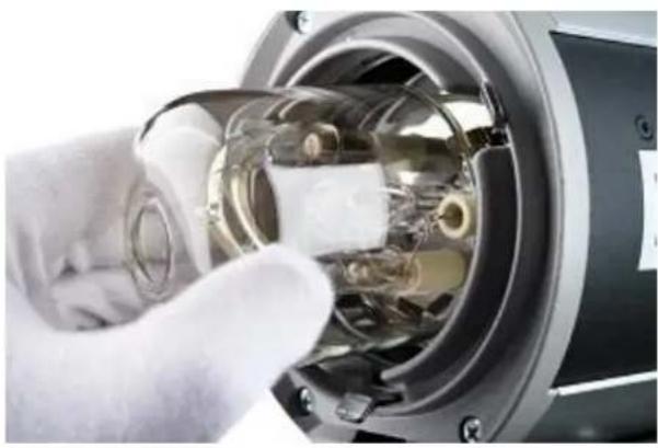
Close-up of a gloved hand inserting a transparent cylindrical device into a mechanical component (no visible text or symbols)- Tilt the safety dome slightly and insert it into one of the three springs.
- Then use gentle pressure to insert the safety dome first into the second spring.
- And then into the third spring until it locks into place.
Mounting a Reflector
natural_image
Cross-sectional diagram of a mechanical device showing internal components and structural lines (no text or symbols)Lever of the reflector holder
Fingers
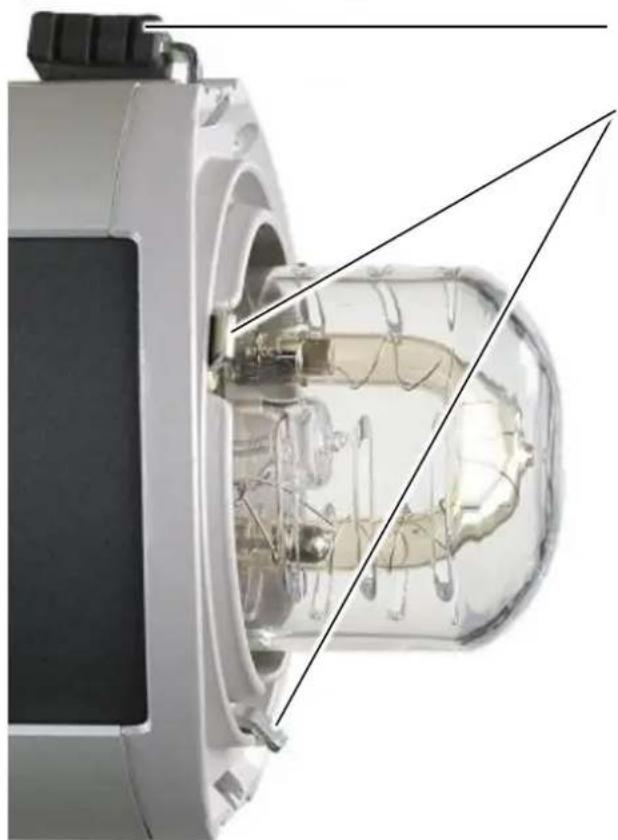
- Press the locking mechanism of the reflector holder against the spring tension until reaching the end stop.
- Put the reflector onto the unit and make sure that the 3 fingers are inside the reflector.
natural_image
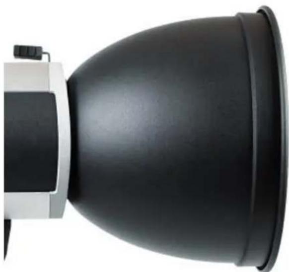
Close-up of a black and white optical device with a dome-shaped lens (no text or symbols visible)- Hold the reflector with one hand while carefully returning the locking mechanism of the reflector into its standard position with the help of the spring tension.
- Check the correct mounting of the reflector.
Connect the Mains Cord and Switch On
natural_image
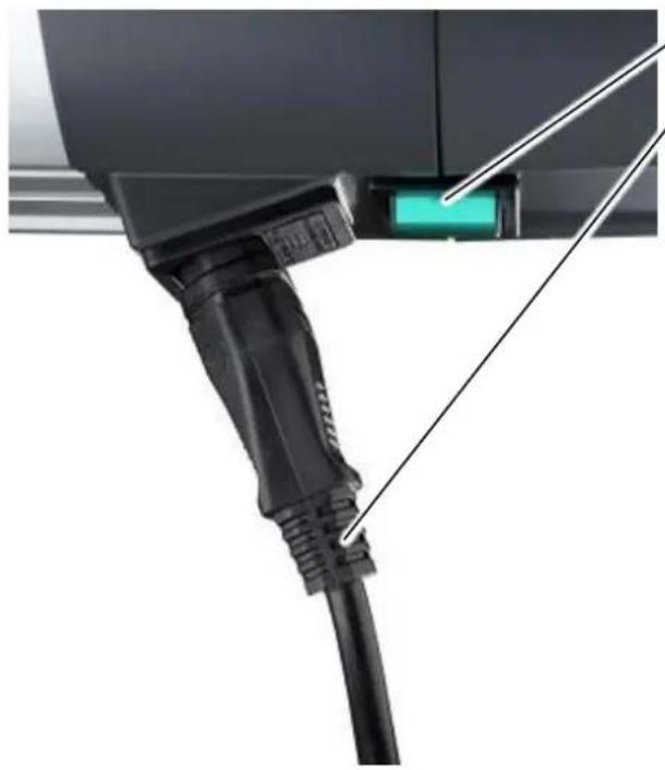
Close-up of a black V23 connector with a green indicator light, no visible text or symbolsPower switch
Mains cord
- Plug the mains cord into the mains adapter socket of the flash unit.
- Plug the mains cord into the mains supply socket
- Turn the unit on by pressing the power switch.
Test Flash
WARNING
Danger of eye and skin injuries due to optical radiation
An intensive optical radiation develops during the flash process which can harm unprotected eyes or skin.
- Do not flash into the face from short distances.

text_image
Made in Germany HENSEL PERFORMING LIGHT RC AUDIO FC SLAVE TEST Fresenack 6.5 FULL PROP PRESS FOR CHANNELFlash readiness indicator
Key TEST
If the flash readiness indicator above the key TEST turns green, the unit is ready for use.
• To trigger a flash, press the key TEST once.
Replace the Halogen Lamp for Modeling Light
CAUTION
Risk of burns from reflector and flash unit
Heat which may cause burns develops at the head during the flash process.
- Before removing the reflector allow reflector and flash unit to cool-off.
- Allow flash unit to cool off.
CAUTION

Glass safety dome may get damaged
When mounting a reflector the glass safety dome can be damaged.
- Do not touch the glass safety dome with the reflector.
- While mounting a reflector place the flash unit on a stand.
- Place the reflector evenly on the flash unit.
- When mounting a reflector hold it with one hand.
CAUTION

The halogen lamp or flash tube can burst due to oily residues on the glass parts.
Avoid touching the flash tube with bare hands to prevent its contamination with oily residue.
- Use cotton gloves to change the halogen lamp or the flash tube.
- Carefully clean after touching the glass parts.
Switch Off and Unplug the Mains Cord
natural_image
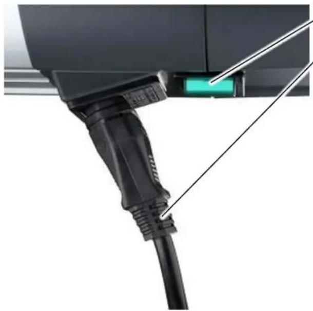
Close-up of a black V24 connector with a green indicator light, no visible text or symbolsPower switch
Mains cord
- Turn the unit off by pressing the power switch.
- Unplug the mains cord from the mains supply socket.
- Unplug the mains cord from the mains adapter socket of the compact flash unit.
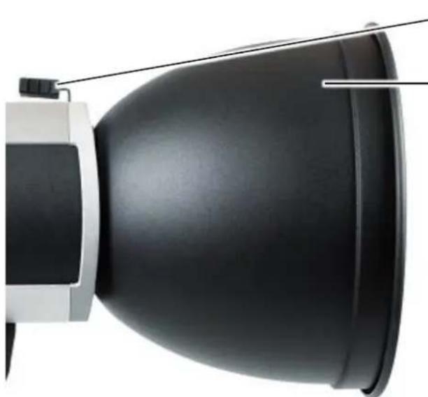
Removing a Reflector
natural_image
Close-up of a black dome-shaped object with a white base and cable, no visible text or symbolsLever of the reflector holder
Reflector
- Hold the reflector with one hand.
- With the other hand, press the locking mechanism of the reflector holder against the spring tension until reaching the end stop.
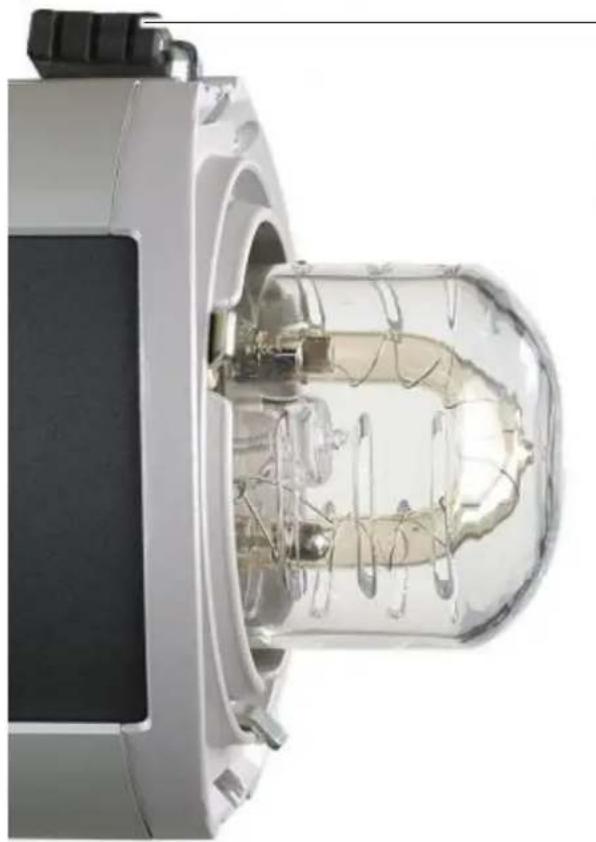
natural_image
Close-up of a transparent cylindrical device with internal components, showing internal structure and wiring (no visible text or symbols)Lever of the reflector holder
- Remove the reflector from the unit and put it aside.
- Carefully return the locking mechanism of the reflector into its standard position with the help of the spring tension.
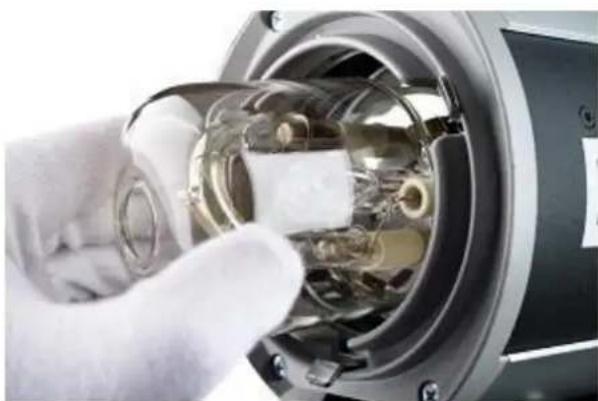
Remove Safety Glass Dome
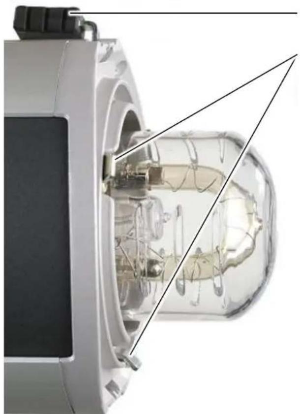
natural_image
Close-up of a gloved hand inserting a transparent plastic component into a mechanical device (no visible text or symbols)The safety dome snaps into place via three pre-installed springs
- Tilt the safety dome slightly so that it is released one by one from the mounting springs.
- Pull the safety dome lightly from the third spring and remove it completely.
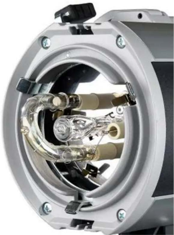
Removing Halogen Lamp
natural_image
Cross-sectional view of a mechanical device showing internal components and wiring (no visible text or symbols)- Carefully pull the lamp from its plug connector.
Inserting Halogen Lamp
text_image
Halogen lamp Pins • Unpack the • Check the obvious c- Unpack the halogen lamp.
- Check the halogen lamp for obvious cracks in the glass.
natural_image
Cross-sectional view of a mechanical device showing internal components and a tool inserted (no visible text or symbols)Lamp socket for modeling light
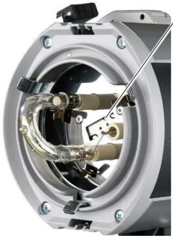
- Place the pins into the lamp socket.

natural_image
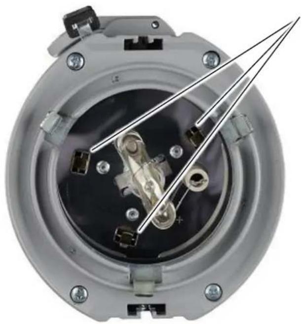
Cross-sectional view of a mechanical device showing internal components and wiring (no visible text or symbols)- Push the lamp carefully into place by alternating the pressure on the pins until contacting the end stop.
Mount Safety Glass Dome
natural_image
Close-up of a mechanical component with internal components and mounting holes (no visible text or symbols)Springs holding the glass safety dome
natural_image
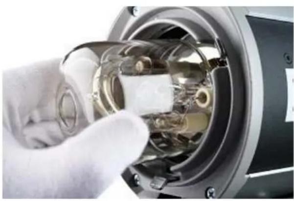
Close-up of a gloved hand inserting a transparent plastic component into a mechanical device (no visible text or symbols)- Tilt the safety dome slightly and insert it into one of the three springs.
- Then use gentle pressure to insert the safety dome first into the second spring.
- And then into the third spring until it locks into place.
Mounting a Reflector
natural_image
Cross-sectional diagram of a mechanical device showing internal components and structural lines (no text or symbols)Lever of the reflector holder
Fingers
- Press the locking mechanism of the reflector holder against the spring tension until reaching the end stop.
- Put the reflector onto the unit and make sure that the 3 fingers are inside the reflector.
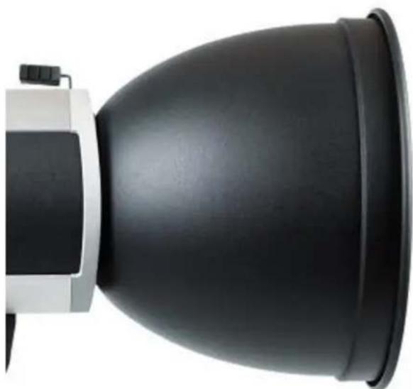
natural_image
Close-up of a black and white optical device with a dome-shaped lens (no text or symbols visible)- Hold the reflector with one hand while carefully returning the locking mechanism of the reflector into its standard position with the help of the spring tension.
- Check the correct mounting of the reflector.
Connect the Mains Cord and Switch On
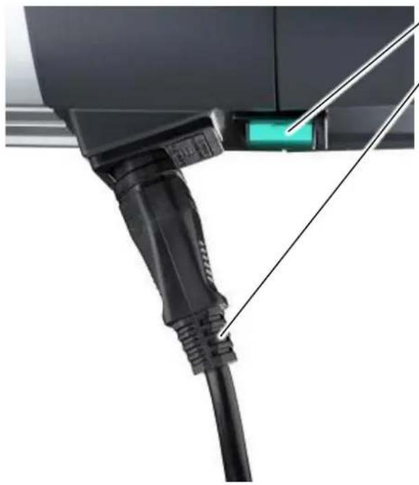
natural_image
Close-up of a black V23 connector with a green indicator light, no visible text or symbolsPower switch
Mains cord
- Plug the mains cord into the mains adapter socket of the flash unit.
- Plug the mains cord into the mains supply socket
- Turn the unit on by pressing the power switch.
Test the Modeling Light
WARNING
Danger of eye and skin injuries due to optical radiation
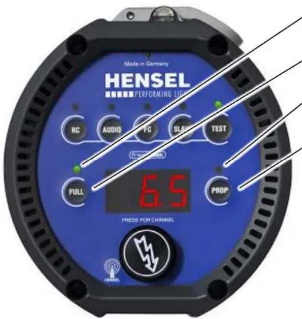
An intensive optical radiation develops during the flash process which can harm unprotected eyes or skin.
- Do not flash into the face from short distances.
text_image
Made in Germany HENSEL PERFORMING LINE RC AUDIO FC SLAW TEST FROM 2008 FULL PROP 6.5 PRESS FOR CHANNELIndicator for FULL mode
Key FULL
Indicator for PROP mode
Key PROP
If one of both indicators is green, then the modeling light is turned on.
If none of both indicators is green, press the key FULL. The indicator above the button turns green and the modeling light is turned to maximum brightness.
If none of both indicators (FULL or PROP) is green, please check the halogen lamp for the modeling light for defects.
Replacing Fuses of Modeling Light
DANGER
Danger of electric shock
Danger of electric shock exists during installation and removal of system components.
- Switch off the system and pull the plug.
Switch Off and Unplug the Mains Cord
natural_image
Close-up of a black automotive plug with a green indicator light, no visible text or symbolsPower switch
Mains cord
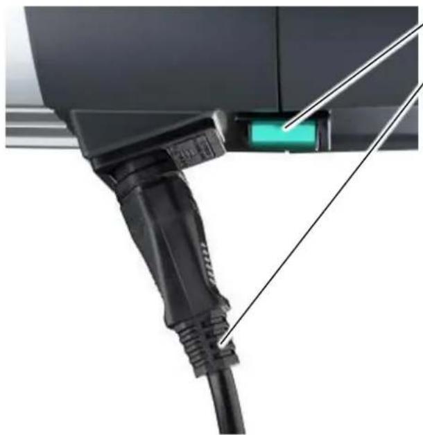
- Turn the unit off by pressing the power switch.
- Unplug the mains cord from the mains supply socket.
- Unplug the mains cord from the mains adapter socket of the compact flash unit.
Exchange of Fuses
natural_image
Close-up of a mechanical component with a green internal component and a diagonal line indicating alignment or assembly (no visible text or symbols)Safety drawer
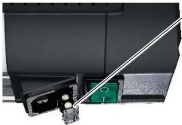
- Open the safety drawer with a small screwdriver and pull it out.
- Inside the drawer are two fuses.
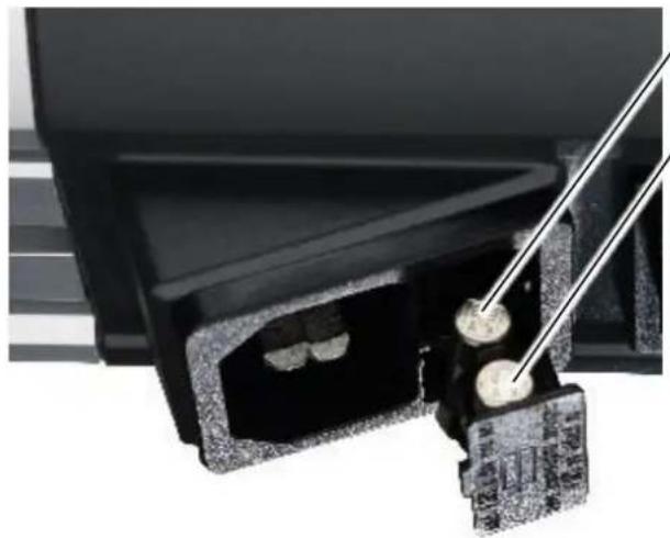
natural_image
Close-up of a black mechanical component with a metal tool inserted, showing internal components and a separate bracket (no visible text or symbols)Fuse a
Fuse b
- Remove the defective fuse a.
• Take out the spare fuse b and insert it into the rear holder. - Carefully push the drawer back into the housing until it locks into place.
Connect the Mains Cord and Switch On
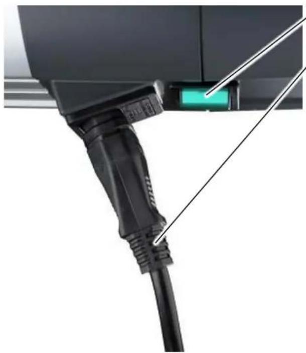
natural_image
Close-up of a black cable with a green indicator light connected to a terminal panel (no visible text or symbols)Power switch
Mains cord
- Plug the mains cord into the mains adapter socket of the flash unit.
- Plug the mains cord into the mains supply socket
- Turn the unit on by pressing the power switch.
Preparation for Storage or Transport
CAUTION
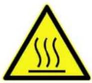
Risk of burns from reflector and flash unit
Heat which may cause burns develops at the head during the flash process.
- Before removing the reflector allow reflector and flash unit to cool-off.
- Allow flash unit to cool off.
CAUTION

Glass safety dome may get damaged
When mounting a reflector the glass safety dome can be damaged.
- Do not touch the glass safety dome with the reflector.
- While mounting a reflector place the flash unit on a stand.
- Place the reflector evenly on the flash unit.
- When mounting a reflector hold it with one hand.
Switch Off and Unplug the Mains Cord
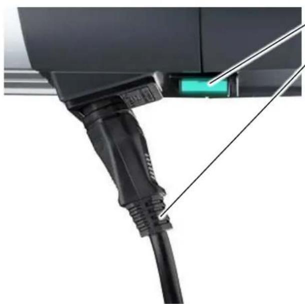
natural_image
Close-up of a black electric vehicle charging plug with a green indicator light (no text or symbols visible)Power switch
Mains cord
- Turn the unit off by pressing the power switch.
- Unplug the mains cord from the mains supply socket.
- Unplug the mains cord from the mains adapter socket of the compact flash unit.
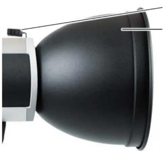
Removing a Reflector
natural_image
Close-up of a black dome-shaped object with a white base and cable, no visible text or symbolsLever of the reflector holder
Reflector
- Hold the reflector with one hand.
- With the other hand, press the locking mechanism of the reflector holder against the spring tension until reaching the end stop.
natural_image
Close-up of a transparent cylindrical device with internal components, no visible text or symbolsLever of the reflector holder
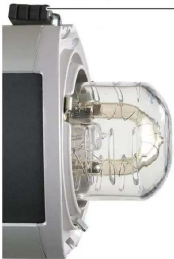
- Remove the reflector from the unit and put it aside.
- Carefully return the locking mechanism of the reflector into its standard position with the help of the spring tension.
Mount the Transport Cap

natural_image
Cross-sectional view of a mechanical device with internal components and a highlighted section (no visible text or symbols)Lever for reflector holder
Fingers
- Press the locking mechanism of the reflector holder against the spring tension until reaching the end stop.
- Put the transport cap onto the unit and make sure that the 3 fingers are inside the wholes of the transport cap.
natural_image
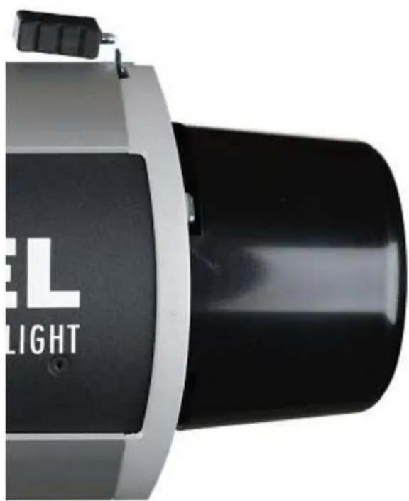
Close-up of a black and silver industrial device with 'EL LIGHT' branding (no additional text or symbols visible)- Hold the transport cap with one hand while carefully returning the locking mechanism of the reflector into its standard position with the help of the spring tension.
- Check the secure mounting of the transport cap.
Cleaning
DANGER

Danger of electric shock
Danger of electric shock exists during installation and removal of system components.
- Switch off the system and pull the plug.
CAUTION

Risk of injury from broken glass
The glass tube may break during cleaning.
- Wear gloves and safety goggles.
- If the flash tube cannot be cleaned, it must be changed.
The Flash unit needs little maintenance by the user. The outside of the equipment must be cleaned periodically of dust and dirt to ensure electric safety.
Maintenance Plan
Clean the system regularly as described in the section 'Cleaning'.
Periodic Inspections
National safety regulations require that electric systems and devices be inspected and maintained in regular intervals. Devices and accessories must be checked regularly for operational safety. An annual inspection of the system insures the safety of the user and retains the value of the equipment.
Disposal
The packaging materials must be separated for recycling. Obsolete or defective equipment must be turned in to recycling facilities.
Error Codes
text_image
Made in Germany ENSEL PERFORMING LIGHT RC AUDIO FC SLAVE TEN Freesink 6.5 FULL PROP PRESS FOR CHANNELDisplay
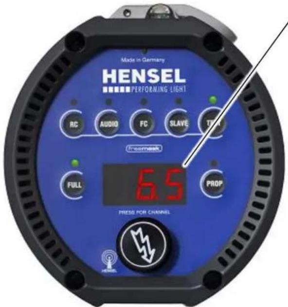
In case of an error, an error code is shown in display. In this case proceed as follows:
- Switch off the unit.
- Wait a few seconds.
- Switch the unit on again.
If the error code persists, check if the problem can be remedied according to the following list or contact customer service and state the error code, see paragraph „Customer service points“.
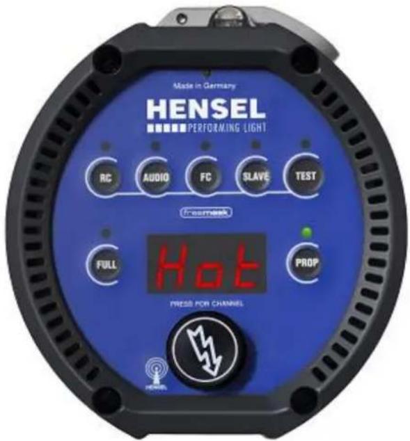
Hot Error – Unit is Overheated
text_image
Made in Germany ENSEL PERFORMING LIGHT RC AUDIO FC SLAVE TEST Foornesk FULL Hot PROP PRESS FOR CHANNELIn case of this problem, the modeling light shuts off, the fan blows at full speed and the unit stops flashing.
- Keep the unit switched on so that the fan continues to cool the flash unit.
Possible causes can be extensive flashing, high ambient temperatures with full modeling light, covered core ducts, unsuitable reflectors or a defective fan.
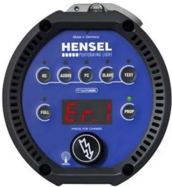
E1 Charging Error
text_image
Made in Germany ENSEL PERFORMING LIGHT RC AUDIO FC SLAVE TEST Inconink Full Er.1 PROP PRESS FOR CHANNELTime out error while charging the unit. Possible cause: Flash tube might still glow after the flash.
This error code signifies substantial error. These problems can only be fixed by customer service.
- Switch off the unit immediately.
- Send the unit to the nearest customer service with indication of the error code.
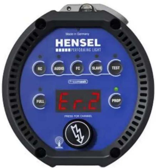
E2 Discharging Error
text_image
Made in Germany ENSEL PERFORMING LIGHT RC AUDIO FC SLAVE TEST Erc2 FULL PROP PRESS FOR CHANNELTime out error while discharging the unit.
This error code signifies substantial error. These problems can only be fixed by customer service.
- Switch off the unit immediately.
- Send the unit to the nearest customer service with indication of the error code.
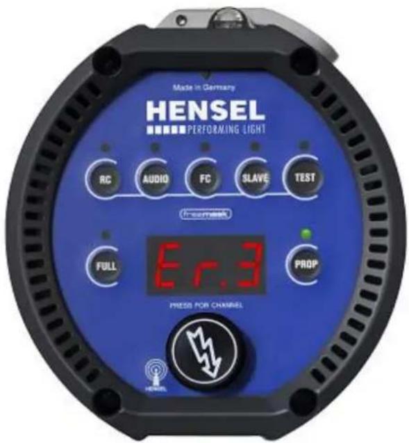
E3 Temperature Error
text_image
Made in Germany ENSEL PERFORMING LIGHT RC AUDIO FC SLAVE TEST Incomet Full Er.3 PROP PRESS FOR CHANNELCapacitors are overheated.
This error code signifies substantial error. These problems can only be fixed by customer service.
- Switch off the unit immediately.
- Send the unit to the nearest customer service with indication of the error code.
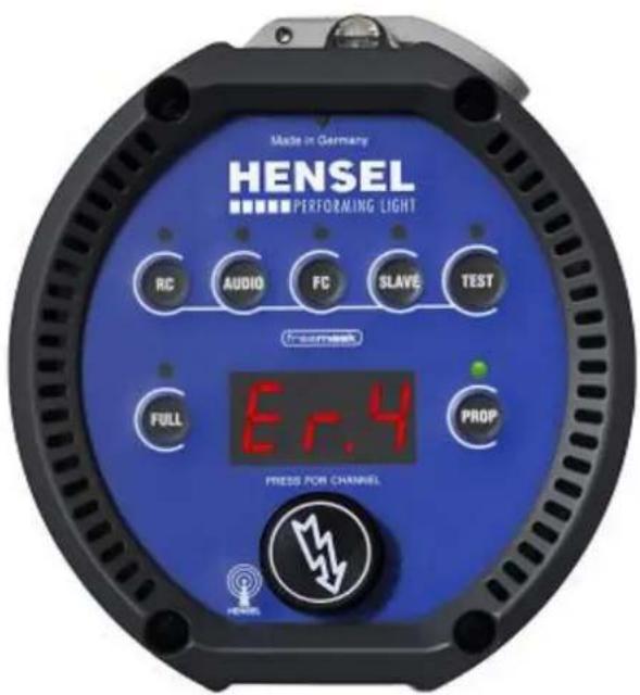
E4 Ignition Error – Unit does Not Flash
text_image
Made in Germany ENSEL PERFORMING LIGHT RC AUDIO FC SLAVE TEST INSMESK Full Er.4 PROP PRESS FOR CHANNELUnit does not flash. This error message disappears on its own after a short period of time.
You may need to replace the flash tube or send the unit in for service.
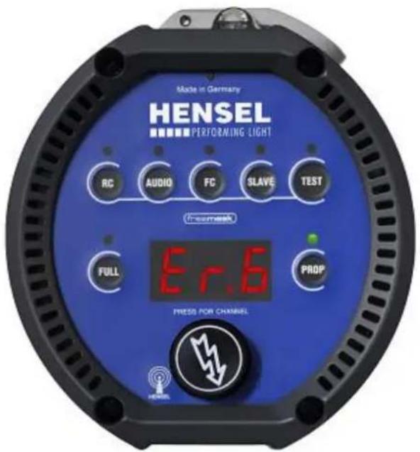
E6 ZD Error
text_image
Made in Germany HENSEL PERFORMING LIGHT RC AUDIO FC SLAVE TEST Fremesk Erf.6 FULL PROP PRESS FOR CHANNELThis error code signifies substantial error. These problems can only be fixed by customer service.
- Switch off the unit immediately.
- Send the unit to the nearest customer service with indication of the error code.
Updating Software
If necessary, the compact flash unit's software can be updated via the USB interface.
Contact your customer service center.
Customer Service
Keep the original packing material in case shipment becomes necessary. It provides maximum protection during transport.
If shipment to our customer service department becomes necessary, send the equipment to the below listed address for repairs and include a description of the problem:
| Description | Article number |
| Clear, uncoated | 9454660 |
| Clear, uncoated | 9454638 |
| Clear, single-coated | 9454637 |
| Matt, uncoated | 9454639 |
Flash tubes
| Description | Article number |
| plug-in, single-coated | 9450420 |
Halogen lamp for modeling light
| Description | Article number |
| 300 W / 230 V | 128 |
| 300 W / 115 V | 1280 |
Fuses
| Description | Article number |
| Safety fuses F 4 A H | 9412400 |
Radio trigger
| Description | Article number |
| Strobe Wizard Plus transmitter | 3950 |
| Freemask transmitter | 3955 |
Reflectors and softboxes
All reflectors and softboxes with small connector diameter (10 cm) for the EH unit series.
Additional accessories
| Description | Articlenumber |
| Safety rope | 7690 |
Additional information about accessories can be found on the Internet page: http://www.hensel.de
Contact Information
In case of questions concerning the shipment for repair reasons, for orders, or for questions about the equipment please contact us at:
Declaration of Conformity
| Manufacturer: | HENSEL Studiotechnik GmbH & Co.KGRobert-Bunsen-Str. 397076 WürzburgGermany |
| Owner of Certification: | HENSEL Studiotechnik GmbH & Co.KGRobert-Bunsen-Str. 397076 WürzburgGermany |
| Test Report: | of August 12, 2010 |
| Product: | EXPERT D 500, EXPERT D 1000 |
| Description: | Emission and Interference Resistance |
| Standards: | EN 61000-6-2:2005EN 61000-6-3:2007 |
This declaration of conformity is made by the above mentioned manufacturer according to article 10, paragraph 1, of the governing EU- directives 2004/108/EC referring to electromagnetic compatibility and safety for bringing the statutory instruments of the Member States into lines with each other. This declaration does not make any statement according to requirements of other provisions concerning the electromagnetic compatibility and safety.
Description: Low Voltage Directive
| Standards: | EN 60065:2002+A1:2006+Cor.:2007+A11:2008 |
| EN 60598-1:2008+A11:2009 | |
| EN 60598-2-9:1989+A1:1994 |
This declaration of conformity is made by the above mentioned manufacturer according to article 10, paragraph 1, of the Governing EU- directives 2006/95/EC referring to electrical items for usage within specified voltage limits.
This declaration of conformity is the result of testing samples of the products submitted, in accordance with the provisions of the relevant specific standards.
Date: August 12, 2010

text_image
Manufacturer E. Stumpf Managing Director - HENSEL Studiotechnik GmbH & Co.KGWarranty
For new VISIT or HENSEL equipment, we grant end-consumers a warranty period of 24 months from the date of invoice and 12 months for distributor products. Flash tubes, lamps, safety caps for glass tubes, rechargeable batteries, batteries, cables and plugs are not included in the warranty (unless the fault verifiably existed already at the time of delivery).
The warranty adjustment applies only if the equipment is used as intended and according to the information in the instruction manual.
In case of unauthorized modifications or unauthorized repairs, the warranty claim expires.
The sales receipt or the delivery slip is proof of warranty. For equipment which was purchased abroad, the warranty that is valid in the respective country applies.
Limits of Liability
We are not liable for bodily harm or property damage incurred due to improper use and resulting from using the equipment contrary to the information in the instruction manual. We are also not liable for consequential damage (loss of compensation etc.) which may be caused by a defect of our equipment.
HENSEL
PERFORMING LIGHT