
XL25U - Vidéo-projecteur MITSUBISHI - Free user manual and instructions
Find the device manual for free XL25U MITSUBISHI in PDF.


| Type of product | DLP Video Projector |
| Dimensions | 10.2 x 7.9 x 3.5 inches (259 x 201 x 89 mm) |
| Weight | 6.6 lbs (3.0 kg) |
| Power supply | AC 100-240V, 50/60Hz, 350W |
| Lamp life | Up to 2000 hours (standard mode), up to 5000 hours (eco mode) |
| Resolution | XGA (1024 x 768) |
| Brightness | 2500 ANSI lumens |
| Contrast ratio | 2000:1 |
| Projection lens | Manual zoom and focus |
| Input ports | VGA, S-Video, composite video, audio in |
| Output ports | VGA out, audio out |
| Speakers | 2W mono |
| Keystone correction | Manual vertical ±20° |
| Aspect ratio | 4:3 native, compatible with 16:9 |
| Remote control | Included |
| Ceiling mount | Compatible (mount not included) |
| Cleaning | Use a soft dry cloth for lens and exterior. Avoid liquids or abrasive cleaners. |
| Safety | Do not look directly into the lens. Keep ventilation openings unobstructed. |
| Spare parts | Replacement lamp (VLT-XL25U) and air filter available |
| Reparability | User-replaceable lamp and filter |
| General information | Designed for business and education presentations |
Frequently Asked Questions - XL25U MITSUBISHI
User questions about XL25U MITSUBISHI
0 question about this device. Answer the ones you know or ask your own.
Ask a new question about this device
Download the instructions for your Vidéo-projecteur in PDF format for free! Find your manual XL25U - MITSUBISHI and take your electronic device back in hand. On this page are published all the documents necessary for the use of your device. XL25U by MITSUBISHI.
USER MANUAL XL25U MITSUBISHI
The lightning flash with arrowhead symbol, within an equilateral triangle, is intended to alert the user to the presence of uninsulated “dangerous voltage” within the product’s enclosure that may be of sufficient magnitude to constitute a risk of electric shock.

The exclamation point within an equilateral triangle is intended to alert the user to the presence of important operating and maintenance (servicing) instructions in the literature accompanying the appliance.
WARNING:
TO PREVENT FIRE OR SHOCK HAZARD, DO NOT EXPOSE THIS APPLIANCE TO RAIN OR MOISTURE.
CAUTION:
TO PREVENT ELECTRIC SHOCK, DO NOT USE THIS (POLARIZED) PLUG WITH AN EXTENSION CORD, RECEPTACLE OR OTHER OUTLET UNLESS THE BLADES CAN BE FULLY INSERTED TO PREVENT BLADE EXPOSURE.
NOTE:
SINCE THIS PROJECTOR IS PLUGGABLE EQUIPMENT, THE SOCKET-OUTLET SHALL BE INSTALLED NEAR THE EQUIPMENT AND SHALL BE EASILY ACCESSIBLE.
WARNING
Use the attached specified power supply cord. If you use another power-supply cord, it may cause interference with radio and television reception.
Use the attached RGB cable, RS-232C cable with this equipment so as to keep interference within the limit of a FCC Class B device.
This apparatus must be grounded.
DO NOT LOOK DIRECTLY INTO THE LENS WHEN PROJECTOR IS IN THE POWER ON MODE.
When using the projector in Europe COMPLIANCE NOTICE
This LCD - Video Projector complies with the requirements of the EC Directive 89/336/EEC “EMC Directive” as amended by Directive 93/68/EEC and 73/23/EEC “Low Voltage Directive” as amended by Directive 93/68/EEC.
The electro-magnetic susceptibility has been chosen at a level that gains proper operation in residential areas, on business and light industrial premises and on small-scale enterprises, inside as well as outside of the buildings. All places of operation are characterised by their connection to the public low voltage power supply system.
WARNING
Use the attached RGB cable or RS-232C cable with this equipment so as to keep interference within the limits of a EN55022 Class B. Use the shielded D-SUB/5 BNC cable with this equipment so as to keep interference within the limits of a EN55022 Class B. Please follow WARNINGS instructions.
Important safeguards ....4
Overview 6
Using the remote control ....8
Battery installation 8
Installation 9
Basic connections ...... 10
Projector + AV equipment.... 10
Projector + DVD player or HDTV decoder 10
Projector + personal computer 11
Preparing the projector for operation 12
To operate projector power ON.... 13
Menu operation 15
Picture adjustment.... 18
Advanced feature for presentation 20
Expand 20
PinP (Picture in Picture) 20
Still 20
Mouse remote control 21
Lamp replacement 22
Maintenance 23
Troubleshooting 24
Indicators 25
Specifications 26
Kensington Lock 26
Connectors 27
Dimensional drawings 27
What's included in the box.... 27
Replacement part 27
Specification of RGB signals in each computer mode of the projector 28
Trademark, Registered trademark
Windows 98 and Windows 95 are registered trademarks of Microsoft in the U.S. and other countries.
Macintosh is registered trademark of Apple Computer Inc.
IBM and PS/2 are trademarks or registered trademarks of International Business Machines Corporation.
MicroSaver and Kensington are registered trademarks of Kensington Technology Group.
Other brand or product names are trademarks or registered trademarks of their respective holders.
Please read all these instructions regarding your LCD projector and retain them for future reference. Follow all warnings and instructions marked on the LCD projector.
- Read instructions
All the safety and operating instructions should be read before the appliance is operated.
- Retain instructions
The safety and operating instructions should be retained for future reference.
- Warnings
All warnings on the appliance and in the operating instructions should be adhered to.
- Instructions
All operating instructions must be followed.
- Cleaning
Unplug this projector from the wall outlet before cleaning it. Do not use liquid aerosol cleaners. Use a damp soft cloth for cleaning.
- Attachments and equipment
Never add any attachments and/or equipment without the approval of the manufacturer as such additions may result in the risk of fire, electric shock or other personal injury.
- Water and moisture
Do not use this projector near water or in contact with water.
- Accessories
Do not place this projector on an unstable cart, stand, tripod, bracket or table. Use only with a cart, stand, tripod bracket, or table recommended by the manufacturer or sold with the projector. Any mounting of the appliance should follow the manufacturer's instructions and should use a mounting accessory recommended by the manufacturer.

natural_image
Symbolic illustration of a person pushing a large cart through a circular frame (no text or symbols)An appliance and cart combination should be moved with care. Quick stops, excessive force and uneven surfaces may cause the appliance and cart combination to overturn.
- Ventilation
Slots and openings in the cabinet are provided for ventilation, ensuring reliable operation of the projector and to protect it from overheating. Do not block these openings or allow them to be blocked by placing the projector on a bed, sofa, rug, or bookcase. Ensure that there is adequate ventilation and that the manufacturer's instructions have been adhered to.
- Power sources
This projector should be operated only from the type of power source indicated on the marking label. If you are not sure of the type of power, please consult your appliance dealer or local power company.
- Power-cord protection
Power-supply cords should be routed so that they are not likely to be walked on or pinched by items placed upon or against them. Pay particular attention to cords at plugs, convenience receptacles, and points where they exit from the appliance. Do not put the power cord under a carpet.
- Overloading
Do not overload wall outlets and extension cords as this can result in a fire or electric shock.
- Objects and liquids
Never push objects of any kind through openings of this projector as they may touch dangerous voltage points or short-out parts that could result in a fire or electric shock. Never spill liquid of any kind on the projector.
- Servicing
Do not attempt to service this projector yourself. Refer all servicing to qualified service personnel.
- Damage requiring service
Unplug this projector from the wall outlet and refer servicing to qualified service personnel under the following conditions:
(a) If the power-supply cord or plug is damaged.
(b) If liquid has been spilled, or objects have fallen into the projector.
(c) If the projector does not operate normally after you follow the operating instructions. Adjust only those controls that are covered by the operating instructions. An improper adjustment of other controls may result in damage and may often require extensive work by a qualified technician to restore the projector to its normal operation.
(d) If the projector has been exposed to rain or water.
(e) If the projector has been dropped or the cabinet has been damaged.
(f) If the projector exhibits a distinct change in performance - this indicates a need for service.
- Replacement parts
When replacement parts are required, be sure that the service technician has used replacement parts specified by the manufacturer or parts having the same characteristics as the original part. Unauthorized substitutions may result in fire, electric shock or other hazards.
- Safety check
Upon completion of any service or repair to this projector, ask the service technician to perform safety checks determining that the projector is in a safe operating condition.
WARNING:
Unplug immediately if there is something wrong with your projector.
Do not operate if smoke, strange noise or odor comes out of your projector. It might cause fire or electric shock. In this case, unplug immediately and contact your dealer.
Never remove the cabinet.
This projector contains high voltage circuitry. An inadvertent contact may result in an electric shock. Except as specifically explained in the Owner's Guide, do not attempt to service this product yourself. Please contact your dealer when you want to fix, adjust or inspect the projector.
Do not modify this equipment.
It can lead to fire or electric shock.
If you break or drop the cabinet.
Do not keep using this equipment if you break or drop it. Unplug the projector and contact your dealer for inspection. It may lead to fire if you keep using the equipment.
Do not face the projector lens to the sun.
It can lead to fire.
Use correct voltage.
If you use incorrect voltage, it can lead to fire.
Do not place the projector on uneven surface.
Place the projection on a leveled and stable surface only. Please do not place equipment on unstable surfaces.
Do not look into the lens when it is operating.
It may hurt your eyes. Never let children look into the lens when it is on.
Do not turn off the main power abruptly or unplug the projector during operation.
It can lead to lamp breakage, fire, electric shock or other trouble. It is best to wait for the fan to turn off before turning main power off.
Do not touch Air outlet grille and Bottom plate which becomes hot.
Do not touch them or put other equipment in front of Air outlet grille. The heated Air outlet grille and Bottom plate may cause injury or damage to other equipment. Also, do not set the projector on the desk which is easily affected by heat.
Clean the air-filter once a month.
Clean the air-filter frequently. If the filter or ventilation slots become clogged with dirt or dust, the temperature inside of the projector may rise and cause some troubles, such as damage of inside parts, and shortening the life of panel.
Do not look into the air outlet grille when projector is operating.
Heat, dust etc. may blow out of it and hurt your eyes.
Place of installation
For safety's sake, refrain from setting the projector at any place subjected to high temperature and high humidity. Please maintain an operating temperature, humidity, and altitude as specified below.
- Operating temperature: between +41°F (+5°C) and +95°F (+35°C)
- Operating humidity: between 30 and 90%
- Never put any heat-producing device under the projector so that the projector does not overheat.
- Do not attach the projector to a place that is unstable or subject to vibration.
- Do not install the projector near any equipment that produces a strong magnetic field. Also refrain from installing near the projector any cable carrying a large current.
- Place the projector on a solid, vibration free surface: otherwise it may fall, causing serious injury to a child or adult, and serious damage to the product.
- Do not stand the projector: it may fall, causing serious injury and damage to the projector.
- Slanting the projector more than ±15^ (right and left or front and rear) may cause trouble or explosion of the lamp.
- Do not place the projector near air-conditioning unit or heater to avoid hot air to the exhaust and ventilation hole of the projector.
COMPLIANCE NOTICE OF FCC
This equipment has been tested and found to comply with the limits for a Class B digital device, pursuant to Part 15 of the FCC Rules. These limits are designed to provide reasonable protection against harmful interference in a residential installation. This equipment generates, uses and can radiate radio frequency energy and, if not installed and used in accordance with the instructions, may cause harmful interference to radio communications. However, there is no guarantee that interference will not occur in a particular installation. If this equipment does cause harmful interference to radio or television reception, which can be determined by turning the equipment off and on, the user is encouraged to try to correct the interference by one or more of the following measures:
- Reorient or relocate the receiving antenna.
- Increase the separation between the equipment and receiver.
- Connect the equipment into an outlet on a circuit different from that to which the receiver is connected.
- Consult the dealer or an experienced radio / TV technician for help.
Changes or modifications not expressly approved by Mitsubishi could void the user's authority to operate this equipment.
COMPLIANCE NOTICE OF INDUSTRY CANADA
This Class B digital apparatus complies with Canadian ICES-003.
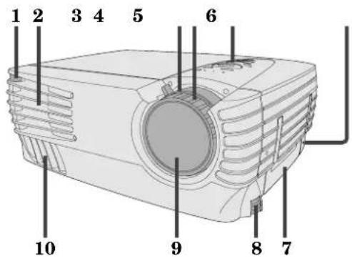
Control panel
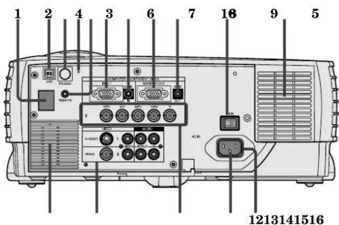
Rear panel
1 Remote control sensor (Front)
2 Air outlet grille
3 Zoom
4 Focus
5 Control panel
6 Kensington Security Lock Standard connector
7 Easy-carry handle
8 Foot adjustment buttons (Left/Right)
9 Lens
10 Air outlet grille
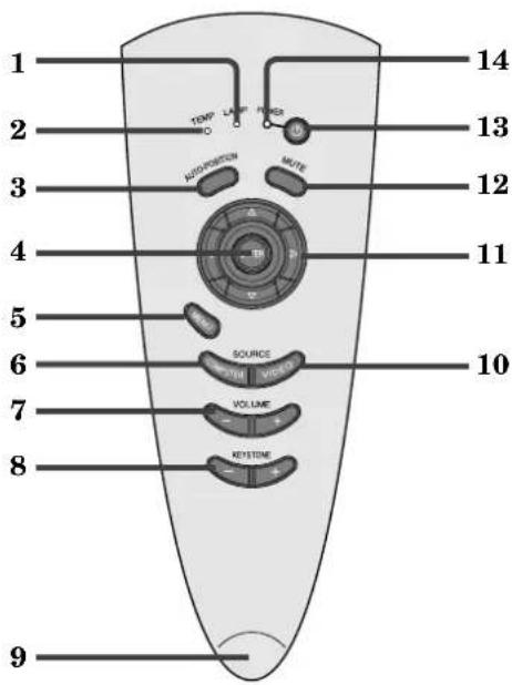
1 LAMP indicator
2 TEMP (temperature) indicator
3 AUTO POSITION button
4 ENTER button
5 MENU button
6 COMPUTER button
7 VOLUME (+, -) buttons
8 KEYSTONE (+, -) buttons
9 RIS sensor
10 VIDEO button
11 Direction buttons
12 MUTE button (Audio/Video)
13 POWER button
14 POWER indicator
1 Remote control sensor (Rear)
2 USB terminal
3 RS-232C (DIN 8P) terminal
4 Reset button
5 Wired remote control (REMOTE) jack
6 COMPUTER / COMPONENT VIDEO IN 1 terminal (D-SUB mini 15P)
7 COMPUTER AUDIO IN jack
8 MONITOR OUT terminal (D-SUB mini 15P)
9 AUDIO OUT jack
10 Main power
I:ON
O:OFF
11 Air inlet grille
12 Power jack
13 Ground terminal
14 COMPUTER / COMPONENT VIDEO IN 2 terminal ( R/PR, G/Y, B/PB, H/HV, V )(BNC)
15 Video/audio input terminals
16 Speaker
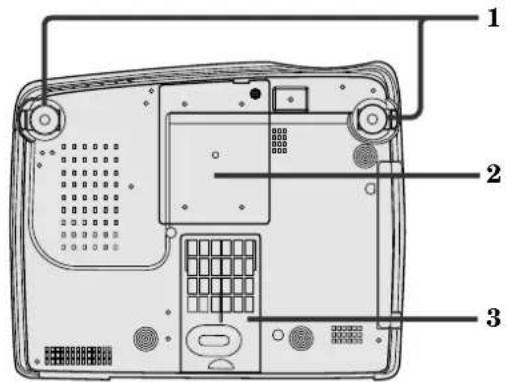
Bottom side
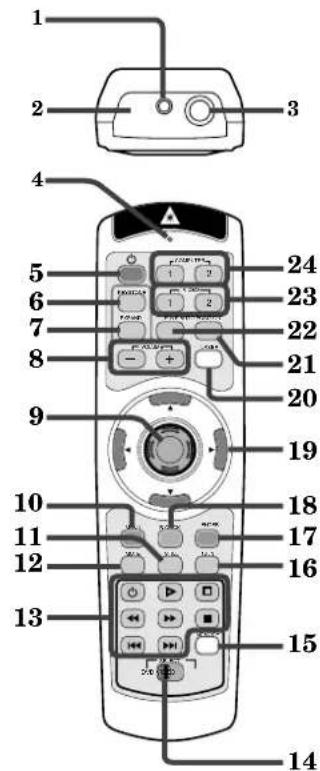
Remote control
natural_image
Pure diagram of a vertical container with a side knob and label '25' (no text or symbols beyond basic labels)1 Adjustment foot (Left/Right)
2 Lamp cover
3 Air inlet grille/Filter cover
Caution:
Do not replace the lamp immediately after using the projector because the lamp has got extremely hot.
1 Laser aperture
2 Transmission window
3 Wired remote control jack
4 Indicator
5 POWER button
6 KEYSTONE button
7 EXPAND button
8 + , - (VOLUME) buttons
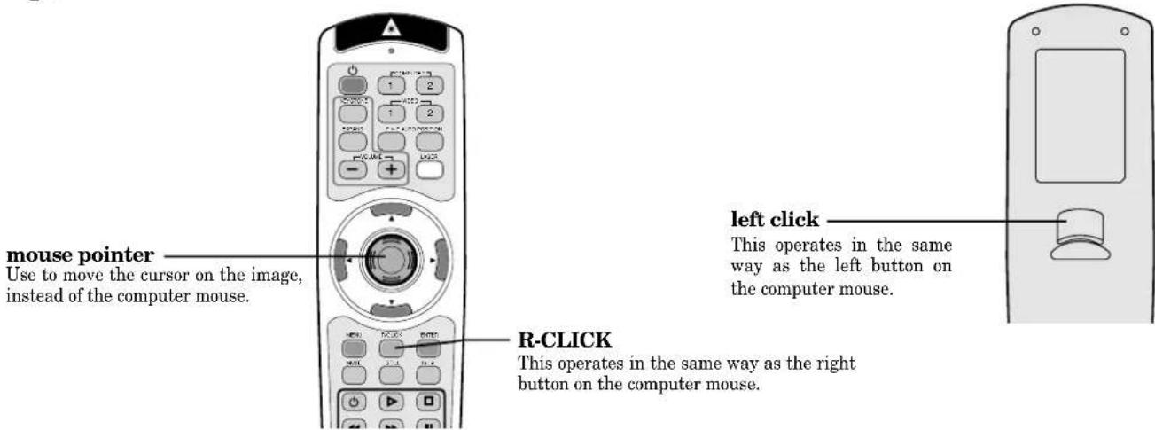
9 Mouse pointer
10 MENU button
11 STILL button
12 MUTE button (Audio/Video)
13 Programmable buttons
14 SELECT switch
15 MEMORY button
16 16:9 button
17 ENTER button
18 R-CLICK button (For mouse)
19 Direction buttons
20 LASER button
21 AUTO POSITION button
22 PinP button
23 VIDEO 1, 2 button
24 COMPUTER 1, 2 button
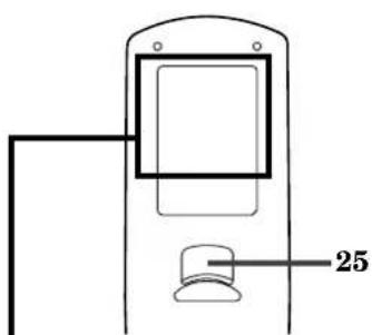
25 Left click button (For mouse)
- The + and - buttons are used in the KEYSTONE adjustment and the EXPAND mode in addition to the volume control.
- Pressing the LASER button emits a laser beam. Even when you keep holding down the LASER button, it is emitted only one minute. To keep emitting it longer, press the LASER button again.
- You can disable the LASER button to prevent laser radiation due to misuse of the button.
How to disable the LASER button
While holding the LASER button down, press the ▼ button three times.
- To enable the LASER button, while holding the LASER button down, press the ▲ button three times.
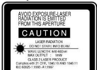
About the laser beam
This remote control is a Class 2 laser product. (Max. output: 1 mW, Wavelength: 640-660 nm)
Beam Divergence : 6m distance about 10.0mm x 10.0mm (±6.0mm)
CAUTION :
- Pressing the LASER button on the remote control emits a laser beam. Do not look into the laser beam directly. Do not point the laser beam at anyone. Looking at the laser beam directly may damage eyesight.
- Use of controls or adjustments or procedures other than those specified herein may result in hazardous radiation exposure.
Battery installation
Use two AA size batteries.
-
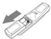
Remove the back cover of the remote control by pushing the battery compartment door in the direction of the arrow.
-
Load the batteries making sure that they are positioned correctly (+ to +, and - to -).
-
Replace the back cover.
1
2
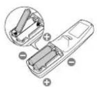
3
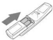
Important:
- Do not use a new battery with an old one.
- Load batteries in the correct position.
- Do not heat, take apart, or throw batteries into fire.
- Do not try to recharge batteries. Do not use rechargeable batteries.
- If the solution of batteries comes in contact with your skin or clothes, rinse with water. If the solution comes in contact with your eyes, rinse them with water and then consult your doctor.
Operation area (for wireless control system)
The range for operation is about 10 m (about 32 feet) when the remote control points to the projector. The distance to the screen back to the projector must be less than 7 m (about 23 feet). Depending on the type of the screen, the distance will be different.

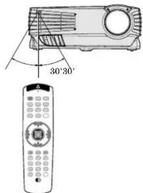
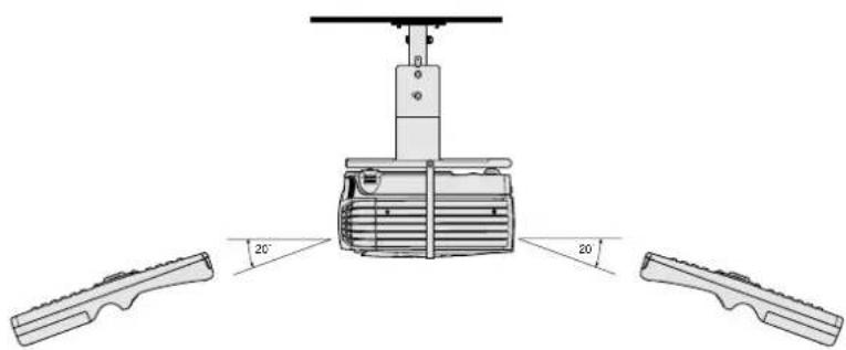
natural_image
Technical diagram of a mechanical device with three angled components and a central housing (no text or symbols)Important:
Avoid the direct sunlight or fluorescent light to the remote control sensor. Also keep the distance of more than 2m (6.5") between the remote control sensor and fluorescent lamp on the remote control may not work correctly.
Using the wired remote control
Attached remote control for this projector can be used as a wired remote control with remote control cable. Wired remote control is useful for operating in a distance or outside of the operating area.
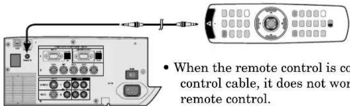
- When you need a longer cable, use a pin-pin cable.
- When using the wired remote control, the laser beam may be darker. It is normal.
Orientation of the projector
Picture size can be set by changing the distance between the screen and the projector.
Front projection
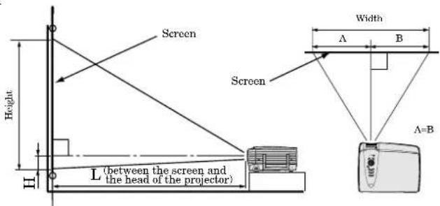
To find the approximate distance between the projector and screen: Multiply the width of the screen x 1.8 (min.), Multiply the width of the screen x 2.3 (max.).
• Refer to the chart for recommended distances in maximum zoom and minimum zoom.
| Screen | Distance from screen (L) / (approximate) | Height projected image (H) | |||||||||
| Diagonal size Width Height | Maximum zoom (WIDE) | Minimum zoom (TELE) | |||||||||
| (inch) | (cm) | (inch) | (cm) | (inch) | (cm) | (inch) | (m) | (inch) | (m) | (inch) | (cm) |
| 40" | 102 | 32" | 81 | 24" | 61 | 55" | 1.4 | 71" | 1.8 | 1.2" | 3.0 |
| 60" | 152 | 48" | 122 | 36" | 91 | 84" | 2.1 | 107" | 2.7 | 1.8" | 4.6 |
| 80" | 203 | 64" | 163 | 48" | 122 | 114" | 2.9 | 144" | 3.7 | 2.4" | 6.1 |
| 100" | 254 | 80" | 203 | 60" | 152 | 143" | 3.6 | 181" | 4.6 | 3.0" | 7.6 |
| 150" | 381 | 120" | 305 | 90" | 229 | 215" | 5.5 | 272" | 6.9 | 4.5" | 11.4 |
| 200" | 508 | 160" | 406 | 120" | 305 | 288" | 7.3 | 364" | 9.3 | 6.0" | 15.2 |
| 250" | 635 | 200" | 508 | 150" | 381 | 361" | 9.2 | - | - | 7.5" | 19.1 |
| 300" | 762 | 240" | 610 | 180" | 457 | 434" | 11.0 | - | - | 9.0" | 22.9 |
- The above numbers are approximate, and may be slightly different from the actual measurements.
Front projection, ceiling mount
For ceiling mount, you need the ceiling mount kit. Ask a specialist for installation. For more details, consult your dealer.
- This warranty does not cover damage caused by the use of any unrecommended ceiling mount kit and the installation of the ceiling mount kit at an improper location.
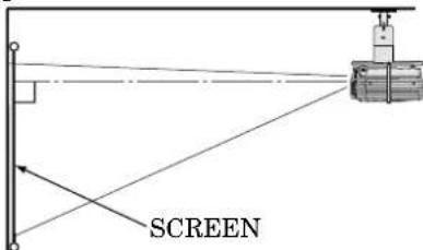
- When using the ceiling mount, set IMAGE REVERSE in the INSTALLATION menu to MIRROR INVERT. See Page 16.
- Projected images may appear darker when the unit is used as a ceiling installation than when it is used in the tabletop position. This does not signify a product malfunction.
Rear projection
Ask a specialist for installation. For more details, consult your dealer.
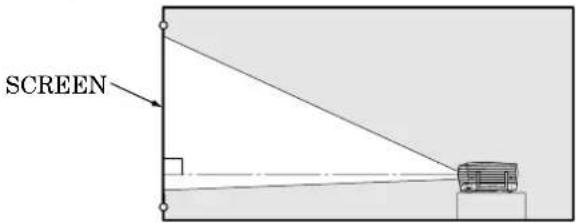
- For rear projection, set IMAGE REVERSE in the INSTALLATION menu to MIRROR. See Page 16.
Caution:
- Placing the projector on a carpet reduces ventilation from the fan at the bottom and might cause problems. Place a hard board or similar item under the projector to facilitate ventilation of the unit.
- Place the projector more than 50 cm (20 in.) from the wall to prevent blocking the intake, exhaust slots and ventilation of this projector because hot air comes out of it.
- Do not use the projector under the following circumstances, which may cause fire or electric shock.
• in a dusty or humid place
- while the projector is lying sideways or upside down
- near a heater
• in a kitchen or oily, smoky or damp place
• in direct sunlight
• with high temperature, such as a closed car
- where the temperature is lower than 41^ (+5^) or higher than 95^ (35^) .
Important:
- Do not put stress on the lens, as this may cause damage.
This projector can be connected with various devices such as a VCR, video camera, videodisc player, and personal computer that have analog RGB output connectors.
Important:
- Make sure that the connected device is turned off before starting connection.
- Plug in the projector and the connected devices firmly, and unplug them by holding and pulling out their power plugs, not by pulling the power cords.
- When the projector and the connected devices are located too close to each other, the projected image may be affected by their interference.
- See the owner's guide of each device for details about their connections.
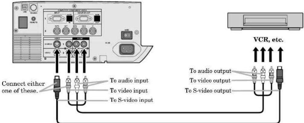
Projector + AV device
Important:
- Connect the video and audio plugs of the AV cable to the proper terminals matching their colors respectively.
- The S-video signal takes priority over the video signal. When you input both the S-video signal and the normal video signal at the same time, the normal video signal is ignored.
- When the connected AV device uses a BNC connector for its video output, connect it to the VIDEO IN2 (BNC) terminal. When both the VIDEO IN2 (BNC) terminal and the VIDEO IN2 (RCA) terminal are engaged at the same time, the image supplied to the VIDEO IN2 (RCA) terminal takes priority.
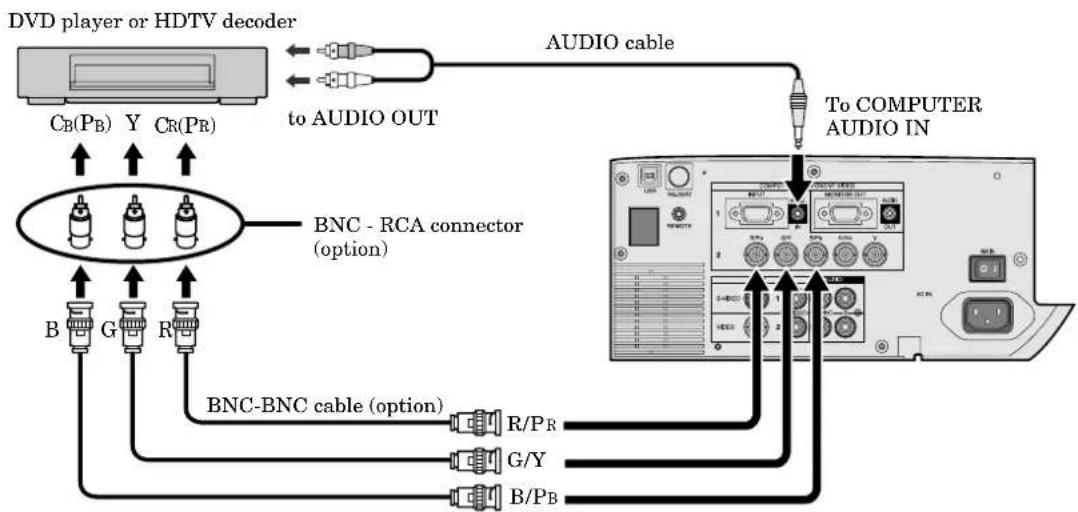
Projector + DVD player or HDTV decoder
Some DVD players have an output connector for 3-line fitting (Y, C B , C R ). When connecting such a DVD player with this projector, use the COMPUTER/COMPONENT VIDEO 2 IN terminal.
flowchart
graph TD
    A["DVD player or HDTV decoder"] -->|to AUDIO OUT| B["AUDIO cable"]
    A --> C["BNC - RCA connector (option)"]
    C --> D["To COMPUTER AUDIO IN"]
    C --> E["BNC-BNC cable (option)"]
    E --> F["R/PR"]
    E --> G["G/Y"]
    E --> H["B/PB"]
    C --> I["B"]
    C --> J["G"]
    C --> K["R"]
- The terminals' names Y, P_B , and Pr are examples of a case where a HDTV decoder is connected.
- The terminals' names are different depending on the connected devices.
- Use BNC-BNC cables for connection.
- The image may not be projected correctly with some DVD players.
- When connecting a HDTV decoder having RGB output terminals, set the COMPUTER INPUT to RGB in the SIGNAL menu.
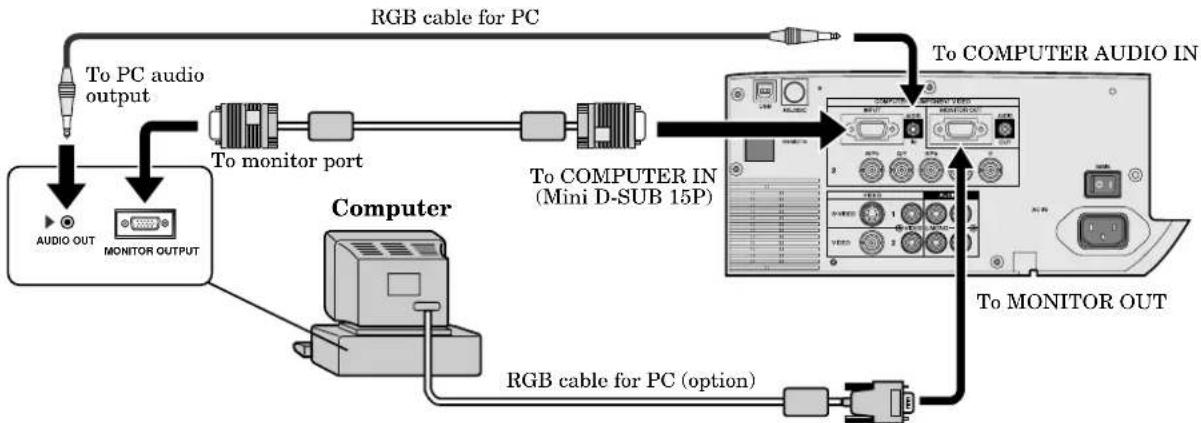
Projector + Computer
For the computer with a Mini D-SUB 15P connectors
flowchart
graph TD
    A["Computer"] -->|To monitor port| B["Monitor output"]
    B -->|To PC audio output| C["Audio OUT"]
    C -->|RGB cable for PC| D["PC"]
    D -->|To COMPUTER AUDIO IN| E["Mini D-SUB 15P"]
    E -->|To Computer Audio IN| F["PC"]
    F -->|To Monitor OUT| G["Output"]
    G -->|RGB cable for PC (option)| H["Monitor output"]
When outputting to both the compute's monitor and the projector.
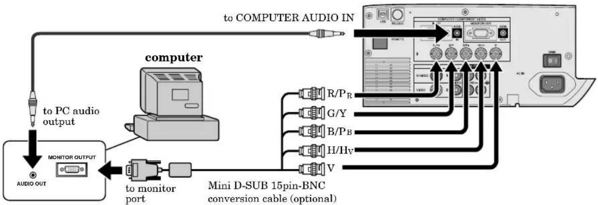
For using the COMPUTER/COMPONENT VIDEO IN 2 (BNC) terminals
flowchart
graph TD
    A["computer"] -->|to PC audio output| B["Monitor OUTPUT"]
    B --> C["to monitor port"]
    C --> D["Mini D-SUB 15pin-BNC conversion cable (optional)"]
    D --> E["Computer"]
    E --> F["to COMPUTER AUDIO IN"]
    F --> G["PC/USB Interface"]
    style A fill:#f9f,stroke:#333
    style E fill:#ccf,stroke:#333
Important:
- When you use a longer RGB cable instead of the provided cable, the picture quality may deteriorate.
- Some computers may require additional connectors or analog RGB output adapters to be connected with this projector. Contact your dealer for further information.
- This projector uses a stereo pin jack for its audio input. Check the type of the audio output terminal of the connected computer and prepare a proper cable for connection. Some computers may not have the audio output terminal.
For Macintosh
- If your Macintosh has no video port, a monitor output adapter is required. Contact your dealer for further information.
- Some Macintoshes may require a MAC adapter for the RGB cable for connection with this projector. Contact your dealer for further information.
About DDC™
The COMPUTER/COMPONENT VIDEO IN 1 terminal of this projector complies with the DDC1/2B standard. When a computer supporting this standard is connected to this terminal, the computer will automatically load the information from this projector and prepare for output of appropriate images.
- After connecting a computer supporting this standard to this terminal, turn on the projector's main power switch first, and then boot up the computer.
- You may need to install the DDC driver, depending on the computer you use. In this case, you need to download the driver from our Web site. Contact your dealer or Mitsubishi sales office for further information.
Getting ready for projection
- Attach the provided power cord to the projector.
- Plug the power cord in the wall outlet.
- Remove the lens cap.
Warning:
- Do not look into the lens directly when the projector is "ON."
- The lens cap is for protecting the lens. If you leave the lens cap on the lens with the projector turned on, it may be deformed. Remove the lens cap when you turn on the projector.
- The power cords for use in the U.S. and Europe are included with this projector. Use the appropriate one for your country.
- This projector uses the power plug of three-pin grounding type. Do not take away the grounding pin from the power plug. If the power plug doesn't fit your wall outlet, ask an electrician to change the wall outlet.
- The provided power cord for the U.S. is rated at 120 V. Never connect this cord to any outlet or power supply using other voltages or frequencies than rated. If you use a power supply using other voltage than rated, prepare an appropriate power cord separately.
- Use 100-240 V AC 50/60 Hz to prevent fire or electric shock.
- Do not place any objects on the power cord and keep the projector away from heat sources to prevent damage to the power cord. If the power cord gets damaged, contact your dealer for replacement because it may cause fire or electric shock.
- Do not modify or alter the power cord. If the power cord is modified or altered, it may cause fire or electric shock.
Caution:
- Plug in the power cord firmly, and unplug it by holding and pulling out the power plug, not by pulling the power cord.
- Do not plug in or out the power cord with your hand wet. It may cause electric shock.
Adjusting the angle of projection
For the best projection, project the image on a flat screen installed at 90 degrees to the floor. If necessary, tilt the projector using the two adjustment feet on the bottom of the projector.
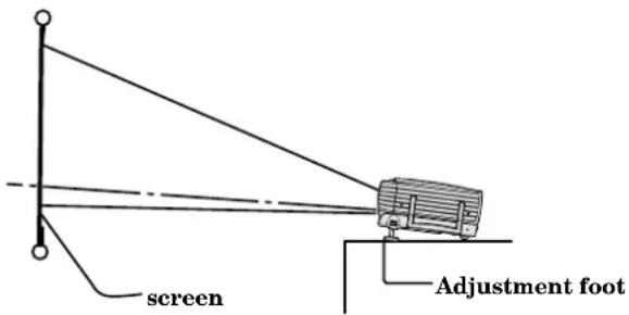
- Tilt up the project to the appropriate angle.
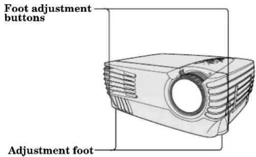
- Press the foot adjustment buttons next to the adjustment feet, and the adjustment feet will come out.
- Release the buttons to lock the adjustment feet to that position.
- Rotate the adjustment feet for fine adjustment.
After using the projector
- Put the adjustment feet back into the projector by pressing the foot adjustment buttons.
• Install the screen on a flat wall at 90 degrees to the floor.
- Position the projector so that it projects an image filling the screen as illustrated on page 9.
- Keep an appropriate distance from the projector to the screen according to the screen size chart on page 9.
- The image becomes trapezoid shape when the screen or project is not level. Use KEYSTONE button and + or - buttons on the remote control or KEYSTONE + or - buttons on the control panel to adjust, however, the circumference of the image may not be focused.
Important:
- Slanting the projector more than ±15^ (right and left or front and rear) may cause trouble or explosion of the lamp. You can tilt the projector up to 7 degrees using the adjustment feet only.
- The image may not be projected in a shape of a regular rectangle or with its aspect ratio of 4:3, depending on the installation conditions of the projector and the screen.
- When the keystone adjustment is carried out, the adjustment value is indicated. Note that this value doesn't mean a projection angle.
- The allowable range of the adjustment value in the keystone adjustment will vary depending on the installation conditions.
- Turn on the equipment connected to the projector.
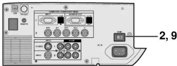
- Put the projector into standby mode by pressing the main power switch. The POWER indicator lights up red.
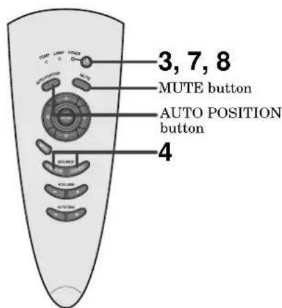
- Turn the projector on by pressing the POWER button. The light source lamp starts warming up, eventually turning completely on.
- When the light source lamp does not light up, wait until the LAMP indicator is turned off, then press the POWER button again.
- If the main power switch to the unit is turned off within two minutes of turning off the light source lamp, power will not be applied to the lamp for one minute when the next time the main unit power switch is turned on. When this happens, the indicator lamp will blink for one minute.
| condition\indicator | LAMP | POWER |
| stand-by | - | red |
| when light source lamp is on | green | green |
| light source lamp held off temporarily | - | red |
Important:
- A darkened image may be seen right after pressing the POWER button due to warming up of this projector. While warming up, no other commands can be accepted.
• After the power is turned on or the LAMP MODE is changed, the screen may flicker before the lamp operation becomes stable. This is due to the characteristics of the lamp, not a failure of the lamp. -
When the lamp indicator is blinking red, the service life of the lamp is about to end. Replace the lamp. See pages 22 and 25.
-
The picture might not be of optimum performance in extreme hot or cold conditions. (The projector is not malfunctioning.)
- Select the desired external input source by using the COMPUTER 1,2 or VIDEO1,2 button on the remote control or the COMPUTER or VIDEO button on the control panel.
- Pressing the VIDEO button on the control panel repeatedly will select VIDEO IN 1 and VIDEO IN 2.
- Pressing the COMPUTER button on the control panel repeatedly will select COMPUTER IN 1 and COMPUTER IN 2.
- The projector automatically selects the appropriate signal format. The selected signal format is displayed on the screen.
- The COMPUTER or VIDEO buttons do not work when MENU is displayed. At this time, the prohibition mark (Q) appears on the screen.
- When selecting the COMPUTER input, the image may flicker. Press the ◀ or ▶ button to adjust the image.
- The intensity of the lamp will be STANDARD for 2 minutes regardless of the setting of the LAMP MODE when the lamp turns on.
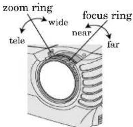
- Adjust the image size with the zoom ring by turning it.
- Adjust the focus with the focus ring by turning it.
Turning off the projector
- Press the POWER button.
The message “POWER OFF? YES : PRESS AGAIN” appears on the screen.
- To exit this mode, press any button except the POWER button. (Some buttons on the remote control don't work for exit from this mode.)
- Press the POWER button again.
The light source lamp will go out. Though the light source lamp will go out at this second press of the POWER button, the exhaust fan continues to operate for another 120 seconds to cool down the lamp and LCD panel. In this case, the lamp indicator will go out.
- Turn off the main power switch, and the POWER indicator will go out.
- In cases where the main power switch is accidentally turned off when either the intake/exhaust fan or the power source lamp is in operation, allow the unit to cool down for 10 minutes with the power turned off. Repeat step 3 when turning on the power source lamp. If the lamp does not turn on immediately, repeat this step two or three times. Replace the lamp if it should still fail to turn on.
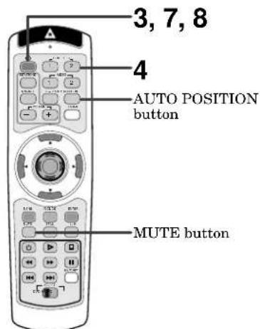
AUTO POSITION button
When the image isn't projected in the right position with COMPUTER selected as the image source, follow the steps below.
- Project a bright image such as the "Trash" window on the full screen.
- When the screen saver is running, turn it off.
- Press the AUTO POSITION button.
- If the image is still not in the right position, adjust the image position using the SIGNAL menu.
Volume from the speaker
Press the volume + or - buttonto change the volume from the speaker.
The volume control bar will appear on the screen.
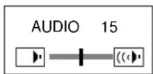
- The volume control bar will disappear about 4 seconds after releasing the volume buttons.
- The volume buttons don't work while the MENU selection bar or the MENU is being displayed.
- When a high-level audio signal, such as a DVD audio signal, is supplied to the COMPUTER AUDIO IN terminal, the output from the speaker may be distorted.
AV mute
The image and audio signals are temporarily muted by pressing the MUTE button. To bring them back to their normal level, press the MUTE button again.
- The audio from the AUDIO OUT jack is also muted by pressing the MUTE button.
- If the MUTE MODE in the INSTALLATION menu is set to LOGO, the splash screen will appear by pressing the MUTE button. Please contact your dealer or Mitsubishi sales office for further information.
- You can alter the splash screen freely. Please contact your dealer or Mitsubishi sales office for further information.
- The lamp mode becomes “LOW” during muting. Therefore, the display of LOGO will darken, which isn’t a failure.
- Muting will be cancelled in 3 hours automatically for the purpose of protecting devices. However, when the mute mode has been set to “LOGO,” muting won’t be cancelled.
ANAMORPHIC mode
When playing DVD discs containing data of letterboxed image, press the 16:9 button. Exit the ANAMORPHIC mode, by pressing the 16:9 button again.
Caution:
- When you have finished using this projector, wait 120 seconds for the exhaust fans to stop. Then turn off the main switch and unplug the power cord from the wall outlet, for safety purposes.
- The lamp cannot be turned on again for 60 seconds after it was turned off for precautionary purposes. It will take another 60 seconds before the lamp indicator goes off. If you want to turn on the projector again, wait until the indicator is off, and then press the POWER button.
- The exhaust fan rotates faster as the temperature around the projector rises.
- When the temperature around the projector rises too high, the sign “TEMPERATURE!!” blinks red on the screen. If the temperature stays too high, the lamp will be go out automatically.
Installation other device's remote commands
You can install other device's remote commands in the remote control of this projector.
How to install
- Set the SELECT switch of the remote control of this projector to DVD or VIDEO, depending on the device you use.
- Place the remote control of this projector and that of the other device with their transmission windows 2-5 cm apart.
-
Press the MEMORY button.
-
The MEMORY button will blink red.
-
To cancel the installation, press the MEMORY button again.
-
Press any programmable button on the remote control of this projector.
-
The MEMORY button will stop blinking and stay on.
-
When no button is pressed for 6 seconds after step 3 and 4, the MEMORY button will go out automatically.
• See page 8 for the programmable buttons. -
Hold down the button on the other device's remote control whose command you want to install until the MEMORY button start blinking.
-
When the MEMORY button blinks six times and then goes out, the function has been installed successfully.
- When the MEMORY button doesn't blink before going out, the installation has failed.
-
To continue to install other functions, repeat step 3 to 5.
-
Some special commands are not memorized, depending on the type of the remote control.
- Do not install any remote commands of other devices including air conditioners than video devices.
How to use the installed functions
- Set the SELECT switch of the remote control of this projector to DVD or VIDEO, depending on the device you use.
- Press the programmable button in which the desired remote command has been installed.
flowchart
graph TD
    A["IMAGE"] --> B["CONTRAST"]
    A --> C["BRIGHTNESS"]
    A --> D["sRGB"]
    A --> E["COLOR MATRIX *1"]
    A --> F["COLOR TEMP. *1"]
    A --> G["COLOR"]
    A --> H["TINT *2"]
    A --> I["SHARPNESS"]
    A --> J["GAMMA MODE"]

    K["INSTALLATION"] --> L["RIS"]
    K --> M["AUTO POWER ON"]
    K --> N["AUTO POWER OFF"]
    K --> O["SPLASH SCREEN"]
    K --> P["BACK COLOR"]
    K --> Q["MUTE MODE"]
    K --> R["LAMP MODE"]
    K --> S["IMAGE REVERSE"]

    T["FEATURE"] --> U["MENU POSITION"]
    T --> V["EXPAND MODE"]
    T --> W["FRAME POSI."]
    T --> X["VIDEO SIGNAL"]
    T --> Y["SCART INPUT *3"]
    T --> Z["ANAMORPHIC"]
    T --> AA["3D CineView *4"]
    T --> AB["LANGUAGE"]
    T --> AC["RESET ALL"]

    AD["SIGNAL"] --> AE["MEMORY CALL"]
    AD --> AF["HORIZ POSITION"]
    AD --> AG["VERT POSITION"]
    AD --> AH["FINE SYNC. *3"]
    AD --> AI["TRACKING *3"]
    AD --> AJ["COMPUTER INPUT *3"]
    AD --> AK["HOLD *3"]

    AL["DISPLAY"] --> AM["± 30"]
    AL --> AN["± 30"]
    AL --> AO["ON , OFF"]
    AL --> AP["VIDEO"]
    AL --> AQ["COMPUTER"]
    AL --> AR["USER ▼"]
    AL --> AS["OFF"]
    AL --> AT["STANDARD"]
    AL --> AU["HIGH"]
    AL --> AV["LOW"]
    AL --> AW["USER ▼"]

    AX["DISPLAY"] --> AY["± 10"]
    AX --> AZ["± 10"]
    AX --> BA["± 10"]

    BB["INSTALLATION"] --> BC["1, 2, 3, OFF"]
    BB --> BD["ON , OFF"]
    BB --> BE["OFF, 5, 10, 15, 30, 60 min"]
    BB --> BF["ON , OFF"]

    BG["FEATURE"] --> BH["1 (Upper left), 2 (Lower right)"]
    BG --> BI["(The item can not be selected when the source is selected to COMPUTER)"]

    BJ["SIGNAL"] --> BK["AUTO, NTSC, PAL, SECAM, 4.43NTSC, PAL-M, PAL-N, PAL-60"]
    BJ --> BL["ON , OFF"]

    BM["DISPLAY"] --> BN["OFF, CENTER, UPPER, LOWER"]
    BM --> BO["ON , OFF"]

    BP["Signal"] --> BQ["AUTO, USER1, USER2"]
    BP --> BR["0 - 999 *5"]
    BP --> BS["0 - 999 *5"]

    BT["DISPLAY"] --> BU["RGB, YCBn/YPBPh"]
    BT --> BV["AUTO"]

    BW["DISPLAY"] --> BX["ON ▼"]
    BW --> BY["OFF"]

    BZ["SIGNAL"] --> CA["BEGIN END -1 -99 1 -99"]

    CB["DISPLAY"] --> CD["CLAMP POSITION*3 0 - +63 *5"]
    CB --> CE["CLAMP WIDTH *3 1 - 63 *5"]

    CF["SIGNAL"] --> CG["MEMORIZE ▼ DELETE ▼ DEFAULT ▼"]

    DH["DISPLAY"] --> DI["HORIZ, PIXELS *3 0 - 9999 *5"]
    DH --> DJ["VERT LINES *3 0 - 9999 *5"]

    DK["DISPLAY"] --> DL["VERT SYNC. AUTO, ON, OFF"]
* 1: The item can not be selected when the sRGB is set to ON.
* 2: The item can not be selected with certain signals.
* 3: The item can not be selected when the selected source is VIDEO or S-VIDEO.
* 4: The item can be selected only when the selected source is VIDEO or S-VIDEO or the inputted signal is TV50 or TV60.
* 5: Setting range is different with certain signals.
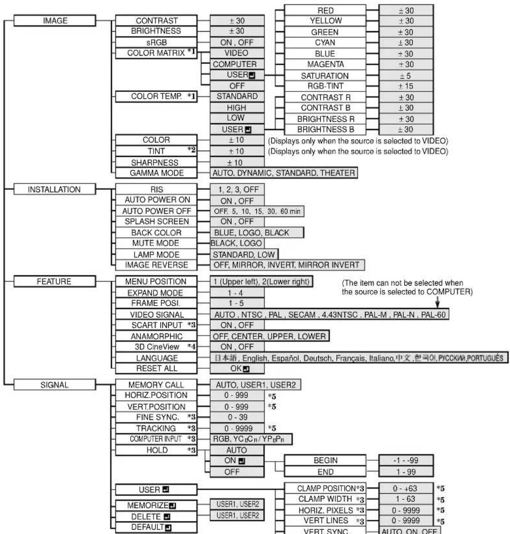
Basic operation
Several settings can be adjusted using Menu. EXAMPLE: Auto power off time setting
- Press the MENU button.
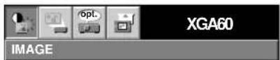
- Press the ◀ or ▶ button to select the INSTALLATION menu.
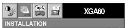
- Press the ENTER button (or ▼ button).
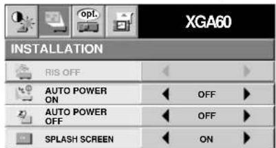
- Press the ▲ or ▼ button to select AUTO POWER OFF.

- Press the ◀ or ▶ button to adjust auto power off time.

-
Exit the menu system by pressing the MENU button several times.
-
If the menu operation is not working, press the RESET button on the terminal board using a suitable sharp object, push gently.
- The settings with mark, you should press the ENTER button after selecting.
① IMAGE
CONTRAST ...... Adjusts the picture contrast. The contrast becomes higher as the number increases.
BRIGHTNESS .....Adjusts the image brightness. The image becomes brighter as the number increases.
sRGB ......Select ON to display an image emphasizing on the color reproducibility.
- When sRGB is ON, COLOR MATRIX, COLOR TEMP. and GAMMA COLLECTION can't be adjusted.
COLOR MATRIX .... Adjusts the color balance in each color of the image. See page 18. COLOR TEMP.... Adjusts the color temperature. See page 18.
COLOR ....Adjusts the color intensity of the image. (Available only when VIDEO is selected as the source.)
TINT ....Adjusts the color balance of the image. The color balance of the image shifts green as the number increases and shifts to purple as the number decreases. (Available only when VIDEO is selected as the source.)
- When the TV50 (PAL, SECAM) signal is inputted, TINT can't be adjusted.
SHARPNESS ...... Adjusts the image sharpness. The image sharpness rises as the number increases.
GAMMA MODE ... When AUTO is selected, the appropriate gamma mode is automatically selected depending on the input signal. For normal use, select AUTO. Select DYNAMIC for computer sources. Select STANDARD for sport scenes and video sources. Select THEATER for projecting film sources.
| XGA60 | ||
| IMAGE | ||
| CONTRAST | 0 | |
| BRIGHTNESS 0 | ||
| sRGB | OFF | |
| COLOR MATRIX | COMPUTER | |
| COLOR TEMP. | STANDARD | |
| COLOR | 0 | |
| TINT | 0 | |
| S | 0SHARPNESS | |
| GAMMA MODE | AUTO | |
② INSTALLATION
RIS ....Adjusts the sensitivity of the function (RIS) which automatically adjusts the brightness and contrast of the image depending on the degree of the light in the room. When using this projector in a room where the light and shade varies slightly, select 1. When using this projector in a norually lighted room, select 2. When using this projector in a room where the light and shade varies greatly, select 3.When you select OFF, RIS won't operate.
- When the sensitivity is adjusted in a large amount, the image may be displayed solid white. Adjust the sensitivity depending on the operating environment and images to be displayed.
AUTO POWER ON ..... Select ON to boot up the projector automatically by turning on an externally connected power switch such as a breaker even when the main power switch of the projector is off. Use this setting when the projector is hanging from the ceiling.
- The projector will be in the stand-by mode when the lamp is off. Use the remote control to turn on the lamp.
AUTO POWER OFF .... Set the time elapsed before the projector enters into the stand-by mode when there is no signal inputted from the selected source.
SPLASH SCREEN .....Select ON to display the splash screen when the power is turned ON.
- The splash screen can be changed. For more details, please consult your dealer.
BACK COLOR..... Use to select the background, BLUE, BLACK or LOGO, which will be displayed when there is no signal inputted from the selected source. When the LOGO is selected, the splash screen will be displayed.
MUTE MODE ..... Use to select the background, BLACK or LOGO, which will be displayed when the MUTE button is pressed. When the LOGO is selected, the splash screen will be displayed.
LAMP MODE ..... Use to change the brightness of the lamp. When LOW is selected, the image will become darker, though the power will be saved, operating sound will be reduced.
- The intensity of the lamp will be STANDARD for 2 minutes regardless of the setting of the LAMP MODE when the lamp turns on.
- When the LAMP MODE is changed, the screen may flicker. This is not a failure of the lamp.
IMAGE REVERSE ..... Use to reverse or invert the projected image. Select MIRROR in rear projection. Select MIRROR, INVERT in rear projection with the projector hanging from the ceiling.
- When no signal is supplied for 6 hours with BACK COLOR set to BLACK, it changes to BLUE automatically for the purpose of protecting the projector.
- When you continue projection for a long time with BACK COLOR or MUTE set to LOGO, an after-image may persist on the screen.
- When the signal is lost during muting with MUTE set to LOGO, AUTO POWER OFF is ignored even though it is active.
③ FEATURE
MENU POSITION ..... Use to select the position of the menu on the screen, □(upper left) or □(lower right).
EXPAND MODE .. Select the mode for enlarging screen. See page 20.
FRAME POSI. ..... Sets the position of sub screen. See page 20.
VIDEO SIGNAL ... When AUTO is selected, the appropriate video format is automatically selected depending on the input signal. If the image isn't displayed correctly, select the desired video format manually.
SCART ...... Select ON when connecting with a device equipped with the SCART terminal that can output RGB signal. SCART terminal is used mainly in Europe. Select OFF normally.
ANAMORPHIC .... Select the desired position, UPPER, CENTER or LOWER when playing DVD discs containing data of letterboxed images.
3D Cine View ...... Select OFF to disable the line-doubler. Select ON normally.
| XGA60 | |
| FEATURE | |
| MENU POSITION | 1. ▶ |
| EXPAND MODE | 1. ▶ |
| FRAME POSI. | 3. ▶ |
| VIDEO SIGNAL | AUTO ▶ |
| SCART INPUT | OFF ▶ |
| ANAMORPHIC | OFF ▶ |
| 3D CineView | ON ▶ |
| LANGUAGE | English ▶ |
| RESET ALL | OK ▶ |
LANGUAGE ..... Use to select the language used in the menus. (日本語 / English / Español / Deutsch / Français / Italiano / 中文 / meaning РУССКИЙ PORTUGUÊS
RESET ALL ...... Use to reset the MENU settings (except LANGUAGE).
- When SCART is set to ON, nothing is output to the external monitor.
- When SCART is set to ON, normal computer signals are not projected.
- Use SCART-BNC (or SCART-Mini D-SUB 15P) cable (option), when connecting with AV device equipped with the SCART terminal.
- Some AV devices equipped with the SCART terminal may not be compatible with the projector.
- When VIDEO SIGNAL is set to AUTO, the image may not be projected with correct colors. Change the setting of VIDEO SIGNAL depending on the input signal in such cases.
- When 3D Cine View is switched from OFF to ON, you can check the motion detection operation about three seconds. The buttons on the remote control don't work during this period, which isn't a failure.
- When the LANGUAGE in FEATURE menu is set to English and NTSC video format is selected, the brightness is decreased 15 points by set-up cancel function for U.S. (The indicated value is not changed.) The image becomes darker, but this is not a failure of the projector.
④ SIGNAL
MEMORY CALL ...... Use to select AUTO, USER 1 or USER 2. See below.
HORIZ. POSITION ..... Use to adjust the horizontal position of the image.
VERT. POSITION ..... Use to adjust the vertical position of the image.
FINE SYNC. .... Use to synchronize the projector with PC input signals so that the image is not blurred.
TRACKING ...... Use to avoid image noise such as wide stripes.
COMPUTER INPUT ..... The unit adjusts itself automatically when connected to a DVD player with a component video output (Y, C_B , C_R ). In the case (Y, P_B , P_R ). In the case the projector is connected to equipment that includes RGB output terminal, adjust to RGB mode.
HOLD ....Adjusts the image when flagging occurs near the top of the screen.
| XGA60 | |||
| SIGNAL | |||
| MEMORY CALL | AUTO | ||
| HORIZ. POSITION | 0 | ||
| VERT. POSITION | 0 | ||
| FINE SYNC. | 0 | ||
| TRACKING | 0 | ||
| COMPUTER INPUT | RGB | ||
| HOLD | AUTO | ||
| USER | MEMORIZE | DELETE | DEFAULT |
⑤ SIGNAL - USER (Normally, there is no need for adjustments.)
CLAMP POSITION/
CLAMP WIDTH .... If you use something similar, the brighter colors of the projected image may become blurred. In this case, adjust CLAMP POSITION or CLAMP WIDTH.
HORIZ.PIXELS .... Use to adjust the width of the image. The image size grows wider as the number increases. (Adjust to the horizontal pixels of the input signal for normal setting.)
VERT.LINES ..... Use to adjust the height of the image. The image size grows higher as the number increases. (Adjust to the vertical lines of the input signal for normal setting.)
VERT.SYNC. ..... Use to adjust the image when its motion does not run smoothly. Select AUTO for normal setting.
SHUTTER(U) ..... Use to adjust the image when the noise etc. appears on top part of image.
SHUTTER(L) ...... Use to adjust the image when the noise etc. appears on bottom part of image.
SHUTTER(LS) ..... Use to adjust the image when the noise etc. appears on left side of image.
SHUTTER(RS) ..... Use to adjust the image when the noise etc. appears on right side of image.
| SIGNAL-USER | |||
| CLAMP POSITION | ◀ | 0 | ▶ |
| CLAMP WIDTH | ◀ | 0 | ▶ |
| HORIZ. PIXELS | ◀ | 0 | ▶ |
| VERT. LINES | ◀ | 0 | ▶ |
| VERT. SYNC. | ◀ | AUTO | ▶ |
| SHUTTER(U) | ◀ | 0 | ▶ |
| SHUTTER(L) | ◀ | 0 | ▶ |
| SHUTTER(LS) | ◀ | 0 | ▶ |
| SHUTTER(RS) | ◀ | 0 | ▶ |
- When the setting of the SIGNAL-USER menu is changed, the image may not be displayed correctly. In this case, select DEFAULT in the SIGNAL menu, and press the ENTER button.
User memory for signal setting
This projector can memorize the maximum of 2 signal menu settings.
Memorizing the setting
- Select MEMORIZE in the SIGNAL menu, and press the ENTER button.
- Press the ◀ or ▶ button to select the memory which you wish to record (USER 1 or USER 2).
- Press the ENTER button.
- Any buttons are ineffective about 3 seconds of recording setting. Wait for recording to have been completed before operating the buttons.
Select the user setting
Select MEMORY CALL in SIGNAL menu, and press the ◀ or ▶ button to select the memory (USER 1 or USER 2).
Reset the recorded setting
- Select DELETE ☐n the SIGNAL menu, and press the ENTER button.
- Press the ◀ or ▶ button to select the memory which you wish to reset (USER 1 or USER 2).
- Press the ENTER button. The recorded setting will be reset.
- Any buttons are ineffective about 3 seconds of resetting the recorded setting. Wait for resetting to have been completed before operating the buttons.
Adjusting the image
You can adjust the picture by using the IMAGE menu.
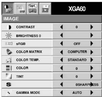
To control the level of white-to-black in the image: Adjust CONTRAST in IMAGE menu. Press the ▶ button to increase the contrast and the ◀ button to reduce it.
To control the light level of the image :
Adjust BRIGHTNESS in IMAGE menu. Press the ▶ button to lighten the image and the ◀ button to darken the image.
To determine the intensity of the color :
Adjust COLOR in IMAGE menu. Press the ▶ button to increase the amount of color in the image and the ◀ button to decrease it.
To adjust the red-green color balance of the image :
Adjust TINT in IMAGE menu. Press the ▶ button to increase the amount of green in the image and the ◀ button to increase the amount of red in the image.
To adjust the detail and clarity of the image :
Adjust SHARPNESS in IMAGE menu. Press the button to make the picture seem sharper and the button to make it softer.
Color matrix
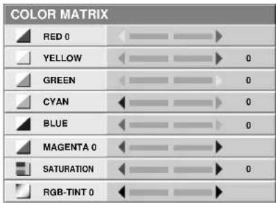
This feature adjusts the color balance in each color of RGB (Red, Green, Blue), and their neutral colors (yellow, cyan, magenta) by using Color correction adjustment. Use Color correct adjustment when emphasizing a specific color, or when only a certain color balance is not correctly adjusted.
- Select COLOR MATRIX in IMAGE menu.
- Press the ◀ or ▶ button to select USER
- Press the ENTER button.
-
Press the ▲ or ▼ button to select the desired color.
-
If you wish to adjust the color intensity of the image, select SATURATION.
-
If you wish to adjust the all color balance of the image, select TINT.
-
Press the ◀ or ▶ button to adjust the color balance of the color.
- Repeat steps 4 and 5 for more adjustments.
- Exit the menu system by pressing the MENU button several times.
- When using the setting which has been already prepared, select desired position VIDEO or COMPUTER in step 2. When the source is selected to VIDEO or S-VIDEO, VIDEO will be selected automatically. When the source is selected to COMPUTER, COMPUTER will be selected automatically.
- When not using Color matrix adjustment, select OFF in step 2.
Color temperature
- Select COLOR TEMP in IMAGE menu.
- Press the ◀ or ▶ button to select USER 📁.
- Press the ENTER button.
| COLOR TEMP.-USER | ||
| CONTRAST R | 0 | |
| CONTRAST B 0 | ||
| BRIGHTNESS R 0 | ||
| BRIGHTNESS B 0 | ||
- Press the ▲ or ▼ button to select the desired item.
- Press the ◀ or ▶ button to adjust the item.
- Repeat steps 4 and 5 for more adjustments.
- Exit the menu system by pressing the MENU button several times.
About color temperature
There are different kinds of white color. Color temperature is a way to show the differences. The white, which temperature is low, becomes reddish white. When the color temperature is higher, the white becomes more bluish. This projector sets this color temperature by changing the numbers of contrast blue and red.
To set the color temperature high:
Set the contrast B (Blue) number high, and the contrast R (Red) number low.
To set the color temperature low:
Set the contrast B (Blue) number low, and the contrast R (Red) number high.
Adjustment from personal computer
Although this projector sets proper signal systems automatically for the image signal from personal computers, it cannot be applied to some of personal computers. In this case, press the AUTO POSITION button. If the images are still not projected correctly, use the MENU display to adjust the projected images.
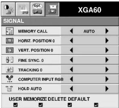
Image moved to right or left :
Adjust HORIZ. POSITION in SIGNAL menu. Press the ▶ button to move the image to left. Press the ◀ button to move the image to right.
Image moved to up or down :
Adjust VERT. POSITION in SIGNAL menu. Press the ▶ button to move the image to upward. Press the ◀ button to move the image to down.
Image flickers / Image is out of focus : Adjust FINE SYNC. in SIGNAL menu.
| SIGNAL-USER | |||
| CLAMP POSITION | ◀ | 0 | ▶ |
| CLAMP WIDTH | ◀ | 0 | ▶ |
| HORIZ. PIXELS | ◀ | 0 | ▶ |
| VERT. LINES | ◀ | 0 | ▶ |
| VERT. SYNC. | ◀ | AUTO | ▶ |
| SHUTTER(U) | ◀ | 0 | ▶ |
| SHUTTER(L) | ◀ | 0 | ▶ |
| SHUTTER(LS) | ◀ | 0 | ▶ |
| SHUTTER(RS) | ◀ | 0 | ▶ |
Wide strips appear :
Adjust CLAMP POSITION or CLAMP WIDTH of each menu in SIGNAL - USER menu.
Noise appears on right or left side of image :
Adjust SHUTTER (LS), SHUTTER (RS) or HORIZ. PIXELS of the menu in SIGNAL - USER menu.
Noise appears on top or bottom part of image: Adjust SHUTTER (U), SHUTTER (L) or VERT. LINES of the menu in SIGNAL - USER menu.
Top part of image curves :
Change the setting of HOLD in SIGNAL menu. Select ON ▼press the ENTER button and adjust BEGIN or END for image which top part is the least curved.
Image does not move naturally :
Adjust VERT. SYNC. of the menu in SIGNAL - USER menu. Select AUTO for normal setting. curved. Select AUTO for normal setting.
- Do not change each menu setting in USER menu for normal setting.
Simple adjustment method
- Select HORIZ. POSITION in SIGNAL menu.
- Press the ◀ or ▶ button to adjust the horizontal start position (the left side of image).
- Select TRACKING in SIGNAL menu.
- Press the ◀ or ▶ button to adjust the horizontal end position (the right side of image).
- Repeat steps 1 to 4 for fine adjustment.
- Select VERT. POSITION in SIGNAL menu.
- Press the ◀ or ▶ button to adjust the vertical start position (the top end of image).
Expand
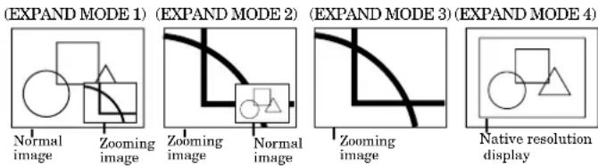
By pressing the EXPAND button on the remote control, you can magnify the detailed image of the picture. You can also view the screen displaying the picture as its original size (native resolution display).
Setting the Expand mode
- Press the MENU button.
- Press the ◀ or ▶ to select the FEATURE menu.
- Press the ENTER button.
- Press the ▲ or ▼ button to select EXPAND MODE or FRAME POSI.
- Press the ◀ or ▶ to set the EXPAND MODE or FRAME POSI.
- Press the MENU button twice to exit the menu system.
EXPAND MODE
FRAME POSI.
(FRAME POSI. (FRAME POSI. 5)
1-4)
Using the Expand mode
-
Press the EXPAND button.
-
You can magnify different areas of the active picture by pressing the ▲, ▼, ◀, ► button.
-
You can change the magnification of the zoomed area by pressing the + or - button.
-
Press the EXPAND button twice on the remote control. The normal screen display will appear on the screen.
- Display enlargement does not work with video input or S-video input.
- In EXPAND mode, you cannot adjust the zoom/focus and the volume.
- The Expand mode may not function depending on the input signal. For more details, refer to page 28 or 29.
REAL screen display
- During REAL mode, Press the ◀ or ▶ buttons for fine adjustment.
- During REAL mode, the ▲ and ▼ buttons are not working. At this time, the prohibition mark (Q appears on the screen.
- The expanding rate cannot be changed by pressing either the + or - button.
Picture in Picture (PinP)
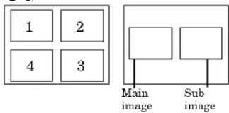
One of the special features of this unit is the picture-in-picture (PinP) mode. PinP allows you to view different sources at the same time.
Using the PinP mode
-
Press the PinP button on the remote control.
-
When the image from VIDEO IN or S-VIDEO IN terminal is displayed on the screen, the image from COMPUTER IN terminal is displayed as sub-image.
-
When the image from COMPUTER IN terminal is displayed on the screen, the image from VIDEO IN or S-VIDEO IN terminal is displayed as sub-image.
-
If necessary, select the desired external input source of the image by using the VIDEO or COMPUTER button.
To switch Main image and Sub image
- Press the ▲ or ▼ buttons on the remote control.
To change frame position
- Press the ◀ or ▶ buttons on the remote control.
FRAME POSI.
(FRAME POSI. (FRAME POSI. 5)
1-4)
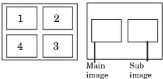
-
Press the PinP button on the remote control. The sub image will be disappear.
-
Adjusting contrast, brightness, tint or color is not available in PinP mode.
- In PinP mode, both Main image and Sub image are displayed with their frames skipped.
- In PinP mode, the audio of the Main image is outputted.
- In PinP mode, the images may not move smoothly.
- The PinP mode may not function depending on the input signal. For more details, refer to page 28 or 29.
- The UXGA signal isn't displayed as a sub image.
Still
How to stop the picture temporarily (still picture).
- Press the STILL button on the remote control. The picture will freeze temporarily.
To resume picture activity.
- Press the STILL button on the remote control again.
Mouse remote control
By connecting to personal computer through the USB or PS/2 port, you can operate your computer with the projector remote control.
Projector + computer with USB connector
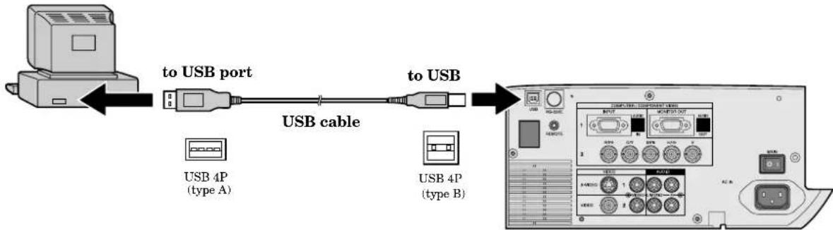
flowchart
graph LR
    A["Computer"] -->|to USB port| B["USB port"]
    B -->|USB cable| C["USB cable"]
    C --> D["Computer Interface"]
    subgraph Device Type1
        E["USB 4P (type A)"]
        F["USB 4P (type B)"]
    end
- You can use the mouse remote control function with a computer supporting USB only. If your system is Windows® 98 or higher, your computer supports USB in standard. If your system is Windows® 95 or lower, please contact your dealer. If your computer is Macintosh® with USB port, you can use this function.
- When the lamp is turned ON, the computer connected with the USB cable may not work correctly. In this case, restart the projector and the computer. If possible, you should disconnect the USB cable when the lamp is turned ON.
Projector + computer with PS/2 connector
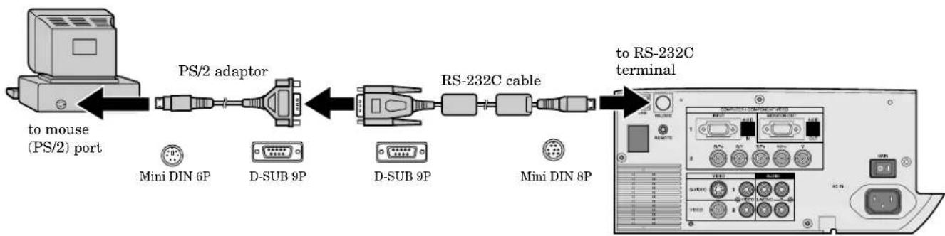
flowchart
graph LR
    A["to mouse (PS/2) port"] --> B["PS/2 adaptor"]
    B --> C["RS-232C cable"]
    C --> D["to RS-232C terminal"]
    subgraph PS/2 adaptor
        E["Mini DIN 6P"]
        F["D-SUB 9P"]
        G["D-SUB 9P"]
        H["Mini DIN 8P"]
    end
- Turn off computer and the projector before connecting with PS/2 port. When connecting the computer with the projector when the personal computer is on, the remote control does not work as a mouse. In that case, restart the personal computer.
- When the projector is connected with USB terminal and RS-232C terminal at the same time, only the terminal which the projector recognizes first will work.
- When you use the RS-232C cable together with an extension cable, the function may not work correctly.
Operation
The lamp is designed to project the image on the LCD panels. When the lamp no longer functions, replace it with a new one.
Caution:
- Do not remove the lamp immediately after using the projector, you may get burned because of the high temperature of the lamp.
- When you replace the lamp, press the power button to power off, then wait for 120 seconds in stand-by mode to allow the lamp and LCD panels to cool. Turn off the main switch, unplug the power cord from the outlet, and wait one hour so that the lamp is cooled to the touch.
- Do not remove the lamp except for replacement. Careless treatment can cause injury or fire.
- Do not touch the lamp element directly. It may break and cause you to injure or burn yourself.
- Be sure not to drop the lamp lid screw into the projector. Also be sure not to insert metal or any flammable objects, it may cause fire or electric shock. If any objects are inserted, please unplug and contact your dealer.
• Install the lamp securely, failure may cause a fire. - If the light bulb part breaks, some small glass fragments may fall out through the small cooling grill, and sticks to the inside of projector or the lamp box. When taking the lamp out, make sure to turn over the projector and hold the handle of the lamp box to avoid injury from the glass fragments.
-
Never shake the lamp or hold it in front of your face after removing the lamp box. The glass fragments may fall out and cause injuries to your eyes and so on.
-
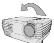
Reverse the projector gently.
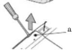
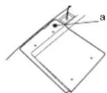
- Loosen the screws of the lamp lid (a) using a Phillips screwdriver (+), and remove the lid.
- Remove the lamp cover in the direction of the arrow as indicated.
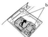
- Loosen screws (b) using a Phillips screwdriver (+), and remove them.
- Pull up the handle.
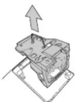
- Hold onto the projector by the handle as you pull out the lamp.
- Pull the lamp out of the projector slowly. Should the light bulb be broken, glass fragments will spill out if the lamp is pulled out too quickly.
- Once the lamp has been removed, do not spill liquid on it, place it near flammable objects or where children can touch it. Otherwise, it will cause injury or fire.
- Insert the new lamp securely into the projector body in the right direction.
- Put the handle back to the holding point.
- Make sure that the handle is locked.
- Tighten up the screws (b) using a Phillips screwdriver (+).
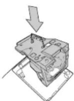
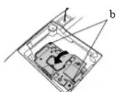
- Tighten up the screws of the lamp lid using a Phillips screwdriver (+).
How to reset the operation time meter
Plug in the power cord, switch on the projector, and reset lamp time by pressing the ◀, ▶ and POWER buttons on the contro panel simultaneously.
Important:
- If the 3 buttons was not pressed at the same time, the lamp time may not be reset.
- Please confirm the TEMP indicator illuminates about 2 seconds and the lamp time has been reset.
- The projector will not turn on if you do not secure the lamp lid.
- You must reset the operation time meter after you replace the lamp.
- Do not reset the operation time meter unless the lamp has been replaced.
Caution:
- Do not spill liquid on the lamp or place it near flammable objects or where children can touch it. Otherwise, it could cause injury or fire.
- Be sure that the projector guide is firmly inserted between the right and left lamp guides.
Interval of the lamp replacement
The interval of the lamp replacement about 1,500 hours of consecutive use. Replacement span may differ according to operating environment, and may be shorter than 1,500 hours. Decreases in luminescence and/or color brightness will indicate that the light source lamp needs to be replaced. When lamp operation time exceeds 1,000 hours ^1 , the indicator will flash alternately between green and red (while the lamp is in operation; when the lamp is not in operation, the indicator will appear red only) and the lamp replacement message will appear on the screen for one minute every time the power is turned on. When the lamp has been used for about 1,400 hours ^1 , the replacement message (LAMP:>1400H) will appear on the screen for one minute every time 10 hours after. When the lamp has been used for about 1,500 hours ^1,2 , the projector will automatically shut off for safety and the power indicator light will be red. The projector cannot be used until the lamp has been replaced and operation timer has been reset.
Caution:
- The lamp is fragile. If broken, be careful not to cut yourself with glass fragments.
- The replacement span of the lamp depends on the environment. For replacement lamps, please contact your dealer.
The projector automatically shuts off when the lamp is used up in about 1,500 hours ^*1,*2 and cannot be used until the lamp is replaced and the internal timer is reset.
^1 When LAMP MODE of the INSTALLATION menu is set to STANDARD.
^2) When LAMP MODE is set to LOW, the duration will be extended maximum up to 2,000 hours.
Caution:
Be sure to turn off the projector and unplug the power cord from the wall outlet before you perform any maintenance on the projector.
Cleaning the air-filter
Clean the air-filter frequently (about once a month). If the filter or ventilation slots become clogged with dirt or dust, the temperature inside of the projector may rise and cause some troubles, such as damage of inside parts, and shortening the life of panel.
- When the temperature inside of the projector rises, the TEMP indicator blinks in red, and the power will be shut off to be stand-by which LAMP indicator is turned off.
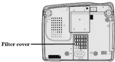
- To remove the filter cover, slide the cover in the direction of the arrow.
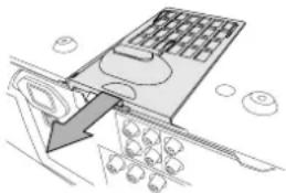
natural_image
Diagram of a computer monitor with an arrow pointing to a screen, showing no text or symbols.-
Remove the air-filter from the filter cover.
-
Wash the air-filter or change to the new filter.
- Use water or a mild detergent diluted with water to clean the filter. Rinse the filter thoroughly and let it dry completely.
- Attach the air-filter to the filter cover.
- Attach the air-filter so that it is retained by the four holders on the filter cover. Then spread the air-filter flat on the filter cover by pressing it. (Make sure that the filter is catching on the protrusions, which prevent displacement of the air-filter.)
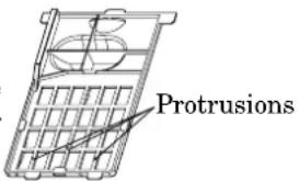
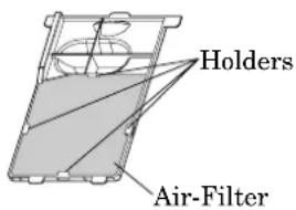
- Attach the filter cover to the projector.
- Make sure that the air-filter is attached correctly without displacement.
Important:
- If the filter is damaged or becomes extremely dirty, change to the provided new filter. If you wish to another new filter, contact your dealer for replacement.
- The power will not turn on if the air-filter cover is improperly installed.
Caution:
Be sure to use the projector with an air-filter. If not, dust may get inside the projector, causing a fire or a breakdown.
Cleaning the projector and the ventilation slots
Use a soft cloth to clean the projector and the ventilation slots. When the slots become dirty, wipe them with a soft cloth dampened with a diluted mild detergent, and then wipe them with a dry cloth.
To protect the surface of the projector from fading or deteriorating:
- Do not spray insecticide on or inside the projector.
- Do not use benzine or thinner to clean it.
- Do not let rubber or plastic materials come into contact with the projector.
Cleaning the lens
Use a standard lens-cleaning brush or a piece of lens tissue dampened with lens cleaning fluid. The lens surface is fragile. Use only recommended, nonabrasive lens-cleaning materials. Do not touch the lens with your fingers.
The following offers solutions to some of the common problems you may encounter. We suggest that you consult this chart before contacting your dealer.
| PROBLEMS | CAUSE | POSSIBLE SOLUTIONS |
| The power is off. | The air inlet slots, outlet slots or air filter is clogged with dust or some objects.POWER indicator does not light up.Power cord is unplugged from the outlet.Power cord is disconnected from the projector.The main switch is turned off.The lamp lid is open.POWER indicator blinks red.The projector has been turned on again too soon after having been turned off.When the power switch was turned off while the fan was running, during or after lamp operation.The room temperature is too high.(Does the LAMP indicator show an unusual condition?)Lamp is no longer working.POWER indicator blinks between red and green.The filter cover is not closed.When the LAMP indicator or the TEMP indicator is either on or blinking, the main unit requires repairs. | Remove the object.Plug the power cord into the outlet.Insert the power cord into the projector.Turn the main switch on.Close the lamp lid.Wait for the lighting sequence.Turn the power switch on and off several times.Refer to "Indicators" on page 25.Replace the lamp with a new one.Close the cover correctly.Contact your dealer. |
| No picture appears on the screen. | Lens is covered by lens cap.When the LAMP indicator or the TEMP indicator is either on or blinking, the main unit requires repairs.The equipment connected to this projector is not turned on.Hookup is not made correctly with other equipment.The input source is not selected correctly. | Take the lens cap off.Replace the lamp with a new one.Turn on the connected equipment.Confirm the hookup.Select the correct source according to the equipment connected to this projector. |
| The image is turned off. | The air inlet slots, outlet slots or air filter is clogged with dust or some objects.(In this case, the TEMP indicator does not light up.) | Remove the object and turn off the main power switch. After about 10 minutes, Turn the projector on. |
| The image is distorted. | The projector is not at a right angle to the screen. | Adjust the angle of the projector to make a right angle to the screen. See page 12. |
| The image is dark. | Brightness, tint and color are not adjusted correctly. | Adjust brightness, tint and color correctly. |
| The image is blurred. | The projecting distance is beyond the focused area Lens is dirty.Screen size exceeds screen size specifications.Brightness and contrast are not adjusted correctly.FINE adjustment is not made correctly.Tracking is not adjusted.The projector is not at a right angle to the screen. | Adjust the projecting distance. See page 9.Clean lens.Reduce screen size to within 40" to 300".Adjust brightness, contrast.Make FINE adjustment.Adjust tracking.Adjust the angle of the projector to make a right angle to the screen. See page 12. |
| The afterimage remains. | When a stationary image is projected for a long time, its afterimage may persist on the screen. This is not a failure, and the afterimage will disappear in a few minutes. | |
| Red, blue or green dots are viewed on the text of image. | It is normal. | |
| The image is distorted on the screen and noise is heard. | The cable for connection with other equipment is not plugged securely into the terminal.The projector is installed too close to other equipment. | Plug the connecting cable securely into the terminal. See pages 10-11.Install the projector far away from other equipment. |
| No sound is heard. | Volume is not turned up.Connection to other equipment is not made correctly. | Turn up the volume.Check connections. See pages 10-11. |
| Nothing is displayed on the PC monitor. | The PC monitor is not turned on. | Turn on the monitor. |
| Warm air comes out of the exhaust vents. | This is typical of the LCD projector. | |
| Adjustments cannot be made. | The operation is incorrectly made due to noise or interference. | Press the reset button on the Terminal board.See page 15. |
| is displayed. | This mark is displayed when an invalid operation is executed (for example, when the COMPUTER or VIDEO button is pressed while the menu is displayed). This is not failure. | |
The projector has three indicators each of which shows the working condition of the projector.
The following offers solutions to possible problems. If a problem persists, turn the projector off and consult your dealer.
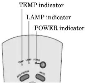
Normal condition
| POWER | LAMP | TEMP | CONDITION Notes | |
| Steady red | ○ | ○OffOff | Stand-by | |
| Steady green | ○=○Blinking green | ○Off | Lamp stand-by (about for 1 minute) The power button | cannot be used to switch OFF. |
| Steady green | Steady green | ○Off | The POWER is ON. (Normal condition) |
Abnormal condition
| POWER | LAMP | TEMP | CONDITION POSSIBLE SOLUTIONS | |
| Steady greenSteady red | Steady greenOff | Blinking redOff | Unusual temperatureThe ventilation slits or air filter is clogged with dust or debris.The room temperature is too high.The filter is dirty. | Remove the object from the ventilation slits.Relocate the projector to a cooler place.Clean the filter. |
| Steady red | Blinking green | Off | The protection circuit is working or the lamp is in an abnormal condition.(The indicators operate as shown on the left at the time of power-off, too.In this case, they are'nt indicating an abnormal condition.) | Wait until the LAMP indicator is turned off, then press the POWER button.If the above operation is not effective, replace the lamp. |
| Steady green | Blinking green/red | Off | Lamp duration warning. (Lightning duration total about 1,000 hours*.When the POWER is ON.) | Replace the lamp.Exchange with a new lamp if the same problem recurs. |
| Steady red | Blinking red | Off | Lamp duration warning. (Lightning duration total about 1,000 hours*.When the POWER is OFF.) | |
| Steady red | Steady red | Off | Lamp duration warning. (Lightning duration total about 1,500 hours*.) | |
| Blinking green/red | Off | Off | The lamp or filter cover is not closed. | Close the cover correctly. |
| Blinking green/red | Steady or orBlinking | SteadyBlinking | Abnormal. Contact your dealer. |
*) When LAMP MODE of the INSTALLATION menu is set to STANDARD. When it is set to LOW, the duration will be extended
Specifications
| Type | LCD projector | |
| Model | XL30U|XL25U|SL25U | |
| Rated power supply | AC100 - 240V, 50 / 60Hz | |
| Rated input | 3.7 A | |
| LCD panels | XL30U/XL25U | SL25U |
| 1.0-inch LCD panel: 3 pieces (for R, G, B)Pixels 1,024 · 768 = 786,432 pixelsTotal 2,359,296 pixelsActive pixel rate: 99.99 % or more (each panel) | 1.0-inch LCD panel: 3 pieces (for R, G, B)Pixels 800 · 600 = 480,000pixelsTotal 1,440,000 pixelsActive pixel rate: 99.99 % or more (each panel) | |
| Colors | 16,770,000 colors | |
| Projection lens | F 1.7 - 2.2 f = 37 - 46 mm | |
| Light source lamp | 270 W SHP | |
| Picture size | 40 - 300 inch (aspect ratio 4:3) | |
| PC compatibility | Resolution : 640 x 400 - 1024 x 768 + Compressed 1600 x 1200 (XL30U/XL25U)640 x 400 - 800 x 600 + Compressed 1280 x 1024 (SL25U)Sync on Green available | |
| Video compatibility | NTSC / NTSC 4.43 / PAL (including PAL-M, N) / SECAM, PAL-60DVD (Component) / HDTV (1080i) / 720p / (525p) | |
| Audio output | 3 W Mono | |
| Speaker | Round type (8Ω 3W) · 1 | |
| S-video input | Luminance signal: 1.0 Vp-p 75Ω (negative sync.)Chroma signal: 0.286 Vp-p 75Ω (burst signal) | |
| Video input | 1.0 Vp-p 75Ω (negative sync.) | |
| Audio inputs | 350 mVrms, 10kΩ or more | |
| Analog RGB input(mini D-SUB 15P/BNC) | RGB: 0.7Vp-p 75Ω (negative sync.)YPBR(YCBCR): Y:1.0Vp-p (negative sync.) PBPR(CBCR):0.7Vp-pHD/CS : TTL level (positive or negative)VD : TTL level (positive or negative) | |
| PC audio input | 350 mVrms, 10kΩ or moreø3.5mm stereo mini jack | |
| Control connector | Serial (Mini DIN 8 pin female connector) RS-232C standardsUSB terminal for Mouse, Wired remote terminal | |
| Outside dimensions | 380 · 157 · 307 mm(width · height · depth)Legs and lens are included. | |
| Weight | Approx. 5.9kg | |
| Length of power cord | 114 inch (2.9m) | |
| Temperature, humidity(performance guarantee) | +41°F (+5°C) - +95°F (+35°C), 30~90% | |
Kensington Lock
This projector has a Kensington Security Standard connector for use with a Kensington MicroSaver Security System. Refer to the information that came with the Kensington System for instructions on how to use it to secure the projector. Please contact to Kensington Technology Group as shown below.
Kensington Technology Group
2855 Campus Drive
San Mateo, CA 94403, U.S.A.
Phone : (650)572-2700 Fax : (650)572-9675
Connectors
RS-232C (Mini DIN 8P)
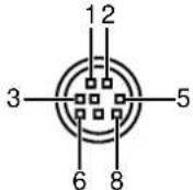
| PIN No. | NAME | I/O |
| 1 | TXD | IN |
| 2 | RTS | IN |
| 3 | DTR | IN |
| 4 | GND | - |
| 5 | CTS / 5V | IN/OUT |
| 6 | DCD / CLOCK | OUT |
| 7 | RXD | OUT |
| 8 | RI / DATA | OUT |
COMPUTER IN/OUT (Mini D-SUB 15P)
| PIN No. | SPEC |
| 1 | R(RED)/Cr |
| 2 | G(GREEN)/Y |
| 3 | B(BLUE)/Cr |
| 4 | GND |
| 5 | GND |
| 6 | GND |
| 7 | GND |
| 8 | GND |
| 9 | - |
| 10 | GND |
| 11 | GND |
| 12 | DDC Data |
| 13 | HD/CS |
| 14 | VD |
| 15 | DDC Clock |
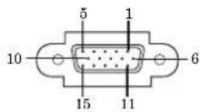
Dimensional drawings (mm)
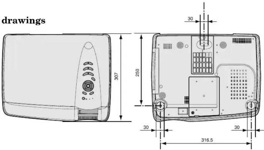
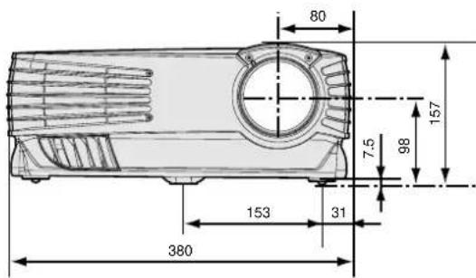
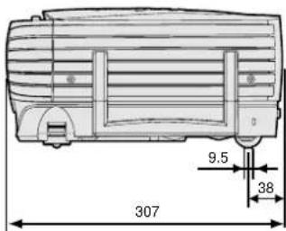
What's included in the box
2 AC power cord 246C383-10
246C383-20
1 Audio/Video cable 246C381-10
1 RGB cable for PC 246C448-10
1 RS-232C cable 246C447-10
1 PS/2 adapter 246C449-10
1 USB cable (For XL30U only) 246C450-10
1 Filter 620D085-10
1 Remote control 939P916-10
1 Remote control cable 246C424-10
1 User manual 871D360-10
1 Quick reference card 857D037-10
2 Battery for remote -
Replacement part
(Option / Not included in the box)
Spare marcury lamp 499B030-10
(VLT-XL30LP)
Specification of RGB signals in each computer mode of the projector (For XL30U/XL25U)
| Signal mode resolution horizontal (H x V) frequency (kHz) frequency (Hz) | |||||
| TV60 | - | 15.73 | 59.94 | 1024 x 768 | - |
| TV50 | - | 15.63 | 50.00 | 1024 x 768 | - |
| 1080i | - | 33.75 | 60.00 | 1024 x 576 | - |
| 525p | - | 31.47 | 59.54 | 1024 x 768 | - |
| 625p | - | 31.25 | 50.00 | 1024 x 768 | - |
| 720p | - | 45.00 | 60.00 | 1024 x 576 | - |
| PC98 | 640 x 400 | 24.82 | 56.42 | 1024 x 640 | 640 x 400 |
| CGA70 | 640 x 400 | 31.47 | 70.09 | 1024 x 640 | 640 x 400 |
| CGA84 | 640 x 400 | 37.86 | 84.14 | 1024 x 640 | 640 x 400 |
| CGA85 | 640 x 400 | 37.86 | 85.08 | 1024 x 640 | 640 x 400 |
| VGA60 | 640 x 480 | 31.47 | 59.94 | 1024 x 768 | 640 x 480 |
| VGA72 | 640 x 480 | 37.86 | 72.81 | 1024 x 768 | 640 x 480 |
| VGA75 | 640 x 480 | 37.50 | 75.00 | 1024 x 768 | 640 x 480 |
| VGA85 | 640 x 480 | 43.27 | 85.01 | 1024 x 768 | 640 x 480 |
| VGA120 | 640 x 480 | 61.89 | 120.17 | 1024 x 768 | 640 x 480 |
| SVGA56 | 800 x 600 | 35.16 | 56.25 | 1024 x 768 | 800 x 600 |
| SVGA60 | 800 x 600 | 37.88 | 60.32 | 1024 x 768 | 800 x 600 |
| SVGA72 | 800 x 600 | 48.08 | 72.19 | 1024 x 768 | 800 x 600 |
| SVGA75 | 800 x 600 | 46.88 | 75.00 | 1024 x 768 | 800 x 600 |
| SVGA85 | 800 x 600 | 53.67 | 85.06 | 1024 x 768 | 800 x 600 |
| SVGA95 | 800 x 600 | 59.97 | 94.89 | 1024 x 768 | 800 x 600 |
| SVGA120 | 800 x 600 | 77.11 | 119.93 | 1024 x 768 | 800 x 600 |
| XGA43i | 1024 x 768 | 35.52 | 86.96 | 1024 x 768 | - |
| XGA60 | 1024 x 768 | 48.36 | 60.00 | 1024 x 768 | 1024 x 768 |
| XGA70 | 1024 x 768 | 56.48 | 70.07 | 1024 x 768 | 1024 x 768 |
| XGA75 | 1024 x 768 | 60.02 | 75.03 | 1024 x 768 | 1024 x 768 |
| XGA85 | 1024 x 768 | 68.68 | 85.00 | 1024 x 768 | 1024 x 768 |
| XGA120 | 1024 x 768 | 98.58 | 119.78 | 1024 x 768 | 1024 x 768 |
| SXGA70a | 1152 x 864 | 63.85 | 70.01 | 1024 x 768 | 1024 x 768 |
| SXGA75a | 1152 x 864 | 67.50 | 75.00 | 1024 x 768 | 1024 x 768 |
| SXGA85a | 1152 x 864 | 77.49 | 85.06 | 1024 x 768 | 1024 x 768 |
| SXGA60b | 1280 x 960 | 60.00 | 60.00 | 1024 x 768 | 1024 x 768 |
| SXGA75b | 1280 x 960 | 75.00 | 75.00 | 1024 x 768 | 1024 x 768 |
| SXGA85b | 1280 x 960 | 85.94 | 85.00 | 1024 x 768 | 1024 x 768 |
| SXGA43i | 1280 x 1024 | 46.43 | 86.87 | 1024 x 768 | - |
| SXGA60 | 1280 x 1024 | 63.98 | 60.02 | 1024 x 768 | 1024 x 768 |
| SXGA75 | 1280 x 1024 | 79.98 | 75.03 | 1024 x 768 | 1024 x 768 |
| SXGA85 | 1280 x 1024 | 91.15 | 85.02 | 1024 x 768 | 1024 x 768 |
| MAC13 | 640 x 480 | 35.00 | 66.67 | 1024 x 768 | 640 x 480 |
| MAC16 | 832 x 624 | 49.72 | 74.55 | 1024 x 768 | 832 x 624 |
| MAC19 | 1024 x 768 | 60.24 | 75.02 | 1024 x 768 | 1024 x 768 |
| MAC21 | 1152 x 870 | 68.59 | 74.96 | 1024 x 768 | 1024 x 768 |
| HP75 | 1024 x 768 | 62.94 | 74.93 | 1024 x 768 | 1024 x 768 |
| HP72 | 1280 x 1024 | 78.13 | 72.00 | 1024 x 768 | 1024 x 768 |
| SUN66a | 1152 x 900 | 61.85 | 66.00 | 1024 x 768 | 1024 x 768 |
| SUN76a | 1152 x 900 | 71.81 | 76.64 | 1024 x 768 | 1024 x 768 |
| SUN66 | 1280 x 1024 | 71.68 | 66.68 | 1024 x 768 | 1024 x 768 |
| SUN76 | 1280 x 1024 | 81.13 | 76.11 | 1024 x 768 | 1024 x 768 |
| SGI72 | 1280 x 1024 | 76.92 | 72.30 | 1024 x 768 | 1024 x 768 |
| SGI76 | 1280 x 1024 | 82.01 | 76.00 | 1024 x 768 | 1024 x 768 |
| IBM60 | 1280 x 1024 | 63.42 | 60.00 | 1024 x 768 | 1024 x 768 |
| UXGA | 1600 x 1200 | 75.00 | 60.00 | 1024 x 768 | - |
*1: The Expand mode and the PinP mode don't function with this signal.
- When the EXPAND MODE of FEATURE menu is set to real screen display, by pressing the EXPAND button on the remote control, it will switch to the screen displaying the picture as its original size (real screen display). In the real screen display, pictures will be black-framed when picture resolution is lower than 1,024 x 768.
Important:
- Some computers may not be compatible with the projector.
-
The projector's maximum resolution is 1,024 x 768 pixels. It may not display correctly for the pictures of higher resolutions than 1,024 x 768.
-
The picture with a SYNC on G (Green) signal may jitter.
- The picture with a SYNC on G (Green) signal may be tinged with green.
- If the resolution and frequency of your computer are not shown on the table, change the resolution of your computer. You may find the compatible resolution and frequency.
- Set the COMPUTER INPUT in SIGNAL menu to RGB, when inputting the HDTV signal as RGB signal.
- In case of the SXGA, the right side of the image may not appear. In this case, adjust the TRACKING in the SIGNAL menu.
Specification of RGB signals in each computer mode of the projector (For SL25U)
| Signal mode resolution horizontal Vertical Normal mode Real mode(H x V) frequency (kHz) frequency (Hz) (H x V) | |||||
| TV60 | - | 15.73 | 59.94 | 800 x 600 | - |
| TV50 | - | 15.63 | 50.00 | 800 x 600 | - |
| 1080i | - | 33.75 | 60.00 | 800 x 450 | - |
| 525p | - | 31.47 | 59.54 | 800 x 600 | - |
| 625p | - | 31.25 | 50.00 | 800 x 600 | - |
| 720p | - | 45.00 | 60.00 | 800 x 450 | - |
| PC98 | 640 x 400 | 24.82 | 56.42 | 800 x 500 | 640 x 400 |
| CGA70 | 640 x 400 | 31.47 | 70.09 | 800 x 500 | 640 x 400 |
| CGA84 | 640 x 400 | 37.86 | 84.14 | 800 x 500 | 640 x 400 |
| CGA85 | 640 x 400 | 37.86 | 85.08 | 800 x 500 | 640 x 400 |
| VGA60 | 640 x 480 | 31.47 | 59.94 | 800 x 600 | 640 x 480 |
| VGA72 | 640 x 480 | 37.86 | 72.81 | 800 x 600 | 640 x 480 |
| VGA75 | 640 x 480 | 37.50 | 75.00 | 800 x 600 | 640 x 480 |
| VGA85 | 640 x 480 | 43.27 | 85.01 | 800 x 600 | 640 x 480 |
| VGA120 | 640 x 480 | 61.89 | 120.17 | 800 x 600 | 640 x 480 |
| SVGA56 | 800 x 600 | 35.16 | 56.25 | 800 x 600 | 800 x 600 |
| SVGA60 | 800 x 600 | 37.88 | 60.32 | 800 x 600 | 800 x 600 |
| SVGA72 | 800 x 600 | 48.08 | 72.19 | 800 x 600 | 800 x 600 |
| SVGA75 | 800 x 600 | 46.88 | 75.00 | 800 x 600 | 800 x 600 |
| SVGA85 | 800 x 600 | 53.67 | 85.06 | 800 x 600 | 800 x 600 |
| SVGA95 | 800 x 600 | 59.97 | 94.89 | 800 x 600 | 800 x 600 |
| SVGA120 | 800 x 600 | 77.11 | 119.93 | 800 x 600 | 800 x 600 |
| XGA43i | 1024 x 768 | 35.52 | 86.96 | 800 x 600 | - |
| XGA60 | 1024 x 768 | 48.36 | 60.00 | 800 x 600 | 800 x 600 |
| XGA70 | 1024 x 768 | 56.48 | 70.07 | 800 x 600 | 800 x 600 |
| XGA75 | 1024 x 768 | 60.02 | 75.03 | 800 x 600 | 800 x 600 |
| XGA85 | 1024 x 768 | 68.68 | 85.00 | 800 x 600 | 800 x 600 |
| SXGA70a | 1152 x 864 | 63.85 | 70.01 | 800 x 600 | - |
| SXGA75a | 1152 x 864 | 67.50 | 75.00 | 800 x 600 | - |
| SXGA85a | 1152 x 864 | 77.49 | 85.06 | 800 x 600 | - |
| SXGA60b | 1280 x 960 | 60.00 | 60.00 | 800 x 600 | - |
| SXGA75b | 1280 x 960 | 75.00 | 75.00 | 800 x 600 | - |
| SXGA43i | 1280 x 1024 | 46.43 | 86.87 | 800 x 600 | - |
| SXGA60 | 1280 x 1024 | 63.98 | 60.02 | 800 x 600 | - |
| SXGA75 | 1280 x 1024 | 79.98 | 75.03 | 800 x 600 | - |
| MAC13 | 640 x 480 | 35.00 | 66.67 | 800 x 600 | 640 x 480 |
| MAC16 | 832 x 624 | 49.72 | 74.55 | 800 x 600 | 800 x 600 |
| MAC19 | 1024 x 768 | 60.24 | 75.02 | 800 x 600 | 800 x 600 |
| MAC21 | 1152 x 870 | 68.59 | 74.96 | 800 x 600 | - |
| HP75 | 1024 x 768 | 62.94 | 74.93 | 800 x 600 | 800 x 600 |
| HP72 | 1280 x 1024 | 78.13 | 72.00 | 800 x 600 | - |
| SUN66a | 1152 x 900 | 61.85 | 66.00 | 800 x 600 | - |
| SUN76a | 1152 x 900 | 71.81 | 76.64 | 800 x 600 | - |
| SUN66 | 1280 x 1024 | 71.68 | 66.68 | 800 x 600 | - |
| SUN76 | 1280 x 1024 | 81.13 | 76.11 | 800 x 600 | - |
| SGI72 | 1280 x 1024 | 76.92 | 72.30 | 800 x 600 | - |
| SGI76 | 1280 x 1024 | 82.01 | 76.00 | 800 x 600 | - |
| IBM60 | 1280 x 1024 | 63.42 | 60.00 | 800 x 600 | - |
*1 : The Expand mode and the PinP mode don't function with this signal.
- When the EXPAND MODE of FEATURE menu is set to real screen display, by pressing the EXPAND button on the remote control, it will switch to the screen displaying the picture as its original size (real screen display). In the real screen display, pictures will be black-framed when picture resolution is lower than 800 x 600.
Important:
- Some computers may not be compatible with the projector.
- The projector's maximum resolution is 800 x 600 pixels. It may not display correctly for the pictures of higher resolutions than 800 x 600.
-
The picture with a SYNC on G (Green) signal may jitter.
-
The picture with a SYNC on G (Green) signal may be tinged with green.
- If the resolution and frequency of your computer are not shown on the table, change the resolution of your computer. You may find the compatible resolution and frequency.
- Set the COMPUTER INPUT in SIGNAL menu to RGB, when inputting the HDTV signal as RGB signal.
MITSUBISHI
LCD Projector
XL30U / XL25U / SL25U
This projector can be controlled by connecting a personal computer with RS-232C terminal.
PC-controllable functions :
- Turning the power ON or OFF
- Changing input signals
- Inputting commands by pressing the buttons on the control panel and remote control
- Menu setting
Connection
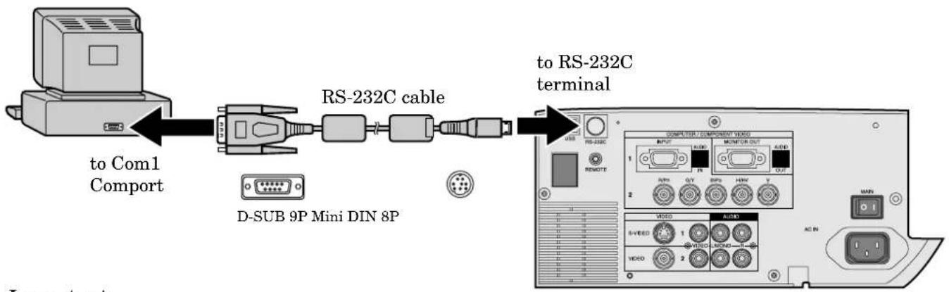
flowchart
graph LR
    A["Computer"] -->|to Com1 Comport| B["RS-232C cable"]
    B --> C["RS-232C terminal"]
    B --> D["D-SUB 9P Mini DIN 8P"]
    D --> E["Computer / Component Wizard"]
    E --> F["OUTPUT"]
    E --> G["MONITOR OUT"]
    E --> H["OUTPUT"]
    E --> I["OUTPUT"]
    E --> J["OUTPUT"]
    E --> K["OUTPUT"]
    E --> L["OUTPUT"]
    E --> M["OUTPUT"]
    E --> N["OUTPUT"]
    E --> O["OUTPUT"]
    E --> P["OUTPUT"]
    E --> Q["OUTPUT"]
    E --> R["OUTPUT"]
    E --> S["OUTPUT"]
    E --> T["OUTPUT"]
    E --> U["OUTPUT"]
    E --> V["OUTPUT"]
    E --> W["OUTPUT"]
    E --> X["OUTPUT"]
    E --> Y["OUTPUT"]
    E --> Z["OUTPUT"]
    E --> AA["OUTPUT"]
    E --> AB["OUTPUT"]
    E --> AC["OUTPUT"]
    E --> AD["OUTPUT"]
    E --> AE["OUTPUT"]
    E --> AF["OUTPUT"]
    E --> AG["OUTPUT"]
    E --> AH["OUTPUT"]
    E --> AI["OUTPUT"]
    E --> AJ["OUTPUT"]
    E --> AK["OUTPUT"]
    E --> AL["OUTPUT"]
    E --> AM["OUTPUT"]
    E --> AN["OUTPUT"]
    E --> AO["OUTPUT"]
    E --> AP["OUTPUT"]
    E --> AQ["OUTPUT"]
    E --> AR["OUTPUT"]
    E --> AS["OUTPUT"]
    E --> AT["OUTPUT"]
    E --> AU["OUTPUT"]
    E --> AV["OUTPUT"]
    E --> AW["OUTPUT"]
    E --> AX["OUTPUT"]
    E --> AY["OUTPUT"]
    E --> AZ["OUTPUT"]
Important:
- Make sure that your computer and projector are turned off before connection.
- Turn on the projector after the computer is started up. (If you do not follow this instruction, the Comport may not function.)
- Adapters may be necessary depending on the PC connected to this projector. Contact your dealer for details.
1) Interface
| PROTOCOL RS-232C |
| BAUD RATE 9600 [bps] |
| DATA LENGTH 8 [bits] |
| PARITY BIT NONE |
| STOP BIT 1 [bit] |
| FLOW CONTROL NONE |
This projector uses RXD, TXD and GND lines for RS-232C control. For RS-232C cable, the reverse type cable should be used.
2) Control command diagram
The command consists of the address code, function code, data code, and end code. The length of the command varies among the functions.
| Address code Function code Data code End code | ||||
| HEX 30h 30h Function Data 0Dh | ||||
| ASCII | '0' '0' | Function Data | ||
[Address code] 30h 30h (In ASCII code, '0' '0') fixed.
[Function code] A code of each fixed control move.
[Data code] A code of each fixed control data (number) and not always indicated.
[End code] 0Dh (In ASCII code, '☐') fixed.
3) Control sequence
(1) Send the command from the personal computer to the projector. (The commands shall be sent at intervals of at least 400ms.)
(2) The projector will send a return command 400ms* after it receives an end code. If the command is not received correctly, the projector will not send the return command.
(3) The personal computer checks the command and confirms if the sent command has been executed or not.
(4) This projector sends various codes other than the return code. When having a control sequence by RS-232C, reject other codes from the personal computer.
* : The sending time of return command may delay depending on the (operating conditions) during changing the input signal, etc.
[Example] When turning the power ON (Figures and symbols enclosed in quotation marks are ASCII codes.):
| Sending commands Status code from Description from the PC, etc. the projector | ||
| 30 30 21 0D Command for POWER ON '0' '0'!' [←] | ||
| 30 30 21 0D Command receipt confirmation '0' '0'!' [←(Command echo back) |
- Any commands will not be executed for 10 seconds after the power is turned on.
4) Operation commands
The operation commands are used for the basic operation setting of this projector. They may not be executed while the signals are changed. The operation commands have no data codes.
| Operation | ASCII HEX | Note | |||
| POWER ON | ! | 21h | This command will not be executed for 1 minute after the power is turned off. | ||
| POWER OFF " | 22h | This command will not be executed for 1 minute after the power is turned on. | |||
| INPUT COMPUTER 1 | _r1 | 5Fh | 72h | 31h | This command will not be executed in Stand-by mode or the MUTE is executed. |
| INPUT COMPUTER 2 | _r2 | 5Fh | 72h | 32h | This command will not be executed in Stand-by mode or the MUTE is executed. |
| INPUT VIDEO 1 | _v1 | 5Fh | 76h | 31h | This command will not be executed in Stand-by mode or the MUTE is executed. |
| INPUT VIDEO 2 | _v2 | 5Fh | 76h | 32h | This command will not be executed in Stand-by mode or the MUTE is executed. |
[Example] When setting the input signal to COMPUTER 1 (Figures and symbols enclosed in quotation marks are ASCII codes.):
| Sending commands Status code from Description from the PC, etc. the projector | ||
| 30 30 5F 72 31 0D Command '0' '0'_'r' '1' ☑ signal to COMPUTER 1 | for setting the input | |
| 30 30 5F 72 31 0D Command receipt confirmation '0' '0'_'r' '1' ☑' | (Command echo back) | |
5) Volume commands (Not executable in stand-by mode, while the Splash screen is projected or the MUTE is executed.)
The volume commands are used for the volume setting of this projector with the value.
| ITEM | ASCII | HEX | VALUE |
| VOLUME | VL | 56h 4Ch | 00 - 31 |
How to set the grade
Use the ASCII codes to set the grade for setting data. Please refer to the table below for the HEX code.
| ASCII | '0' | '1' | '2' | '3' | '4' | '5' | '6' | '7' | '8' | '9' |
| HEX | 30h | 31h | 32h | 33h | 34h | 35h | 36h | 37h | 38h | 39h |
[Example] When setting the volume to 15 (standard value) (Figures and symbols enclosed in quotation marks are ASCII codes.):
| Sending commands Status code from Description from the PC, etc. the projector | ||
| 30 30 56 4C 31 35 0D'0' '0' 'V' 'L' '1' '5' [IMAGE] | Command for setting the volume | |
| 30 30 56 4C 31 35 0D'0' '0' 'V' 'L' '1' '5' [IMAGE] | Command receipt confirmation(Command echo back) | |
6) Keystone commands (Not executable in stand-by mode, while the Splash screen is projected or the MUTE is executed.)
The keystone commands are used for the keystone setting of this projector with the value. The value will vary depending on the installation conditions, etc.)
| ITEM | ASCII | HEX | VALUE |
| KEYSTONE KS 4 | Bh 53h | ± 30 |
How to set the grade
Use the ASCII codes to set the grade for setting data. Please refer to the table below for the HEX code.
| ASCII | '+' | '-' | '0' | '1' | '2' | '3' | '4' | '5' | '6' | '7' | '8' | '9' |
| HEX | 2Bh | 2Dh | 30h | 31h | 32h | 33h | 34h | 35h | 36h | 37h | 38h | 39h |
7) Mute commands (Not executable in stand-by mode or while the Splash screen is projected.)
The mute commands are used for the mute setting of this projector with the 0(30h) and 1(31h).
| ITEM | ASCII | HEX | VALUE |
| MUTE | MUTE 4Dh 55h 54h 45h | 0 (OFF), 1 (ON) | |
8) Remote commands
Some remote control operations can be achieved by the remote command codes. The remote commands have no data codes.
| Button's name on remote | ASCII HEX | |
| + VOLUME r06 72h | 30h 36h | |
| - VOLUME r07 72h | 30h 37h | |
| KEYSTONE r43 72h | 34h 33h | |
| EXPAND | r02 72h 30h | 32h |
| PinP | r04 72h 30h | 34h |
| MUTE | ra6 72h 61h | 36h |
| ▲r53 72h 35h 33h | ||
| ▼r2b 72h 32h 62h | ||
| ◀r4f | 72h 34h 66h | |
| ▶r59 72h 35h 39h | ||
| MENU | r54 72h 35h | 34h |
| ENTER | r10 72h 31h | 30h |
| AUTO POSITION | r09 72h 30h | 39h |
| STILL | ra4 72h 61h | 34h |
| 16 : 9 | re2 | 72h 65h 32h |
[Example] When displaying the MENU selection bar (Figures and symbols enclosed in quotation marks are ASCII codes.):
| Sending commands Status code from Descriptionfrom the PC, etc. the projector | ||
| 30 30 72 35 34 0D Command operating the same'0' '0' 'r' '5' '4' [→] as the MENU button | ||
| 30 30 72 35 34 0D Command receipt confirmation'0' '0' 'r' '5' '4' [→] | (Command echo back) | |
9) Reading command diagram
The projectors operating status, such as POWER-ON / OFF and the currently selected input terminal, can be monitored.
| ASCII | HEX | |||
| Function | Data (Receive) | Function | Data (Receive) | |
| POWER ON | vP | 1 | 76h 50h | 31h |
| POWER OFF vP | 0 | 76h 50h | 30h | |
| INPUT COMPUTER 1 | vI | r1 | 76h 49h | 72h 31h |
| INPUT COMPUTER 2 | vI | r2 | 76h 49h | 72h 32h |
| INPUT VIDEO 1 | vI | v1 | 76h 49h | 76h 31h |
| INPUT VIDEO 2 | vI | v2 | 76h 49h | 76h 32h |
The PC sends the command without attaching the data code to it. On the other hand, the projector attaches to the received command it's current operating status as the data code and send it back to the PC.
[Example ] When checking the currently selected input terminal (when the INPUT VIDEO 1 is being selected):
| Sending commands Status code from Description from the PC, etc. the projector | ||
| 30 30 76 49 0D'0' '0' 'v' 'T' [IMAGE] | Command for checking the input terminal | |
| 30 30 76 49 76 31 0D'0' '0' 'v' 'T' 'v' '1' [IMAGE] | Check result (VIDEO 1) | |
10) Menu setting commands (Not executable in stand-by mode, while the Splash screen is projected or the MUTE is executed.)
The menu setting commands are used for the menu setting of this projector. If the personal computer sends the command without attaching the data code, the projector attaches to the received command it's current setting value as the data code and send it back to the PC.
| ITEM ASCII HEX VALUE | ||||||
| CONTRAST *1 | P | 50h | ±30±30±30 (R from G+Main data+B from G) | |||
| BRIGHTNESS *1 | Q | 51h | ±30±30±30 (R from G+Main data+B from G) | |||
| sRGB | SRGB | 53h | 52h | 47h | 42h | 0 (OFF), 1 (ON) |
| COLOR MATRIX (MODE) | CMT | 43h | 4Dh | 54h | 1 (VIDEO), 2 (COMPUTER), 3 (USER), 4 (OFF) | |
| COLOR MATRIX (R, G, B) | MRGB | 4Dh | 52h | 47h | 42h | ±30±30±30 (R+G+B) |
| COLOR MATRIX (Y, C, M) | MYCM | 4Dh | 59h | 43h | 4Dh | ±30±30±30 (Y+C+M) |
| COLOR MATRIX (SATURATION) | MSAT | 4Dh | 53h | 41h | 54h ±05 | |
| COLOR MATRIX (RGB-TINT) | MT | 4Dh | 54h | ±20 | ||
| COLOR TEMP. | A | 41h | 1 (STANDARD), 2 (HIGH), 3 (LOW), 4 (USER) | |||
| COLOR | T 54h ±10 | |||||
| TINT | S | 53h | ±10 | |||
| SHARPNESS | R | 52h | ±10 | |||
| GAMMA MODE | GS | 47h | 53h | 0 (DYNAMIC), 1 (STANDARD), 2 (THEATER), 3 (AUTO) | ||
| RIS | AI | 41h | 49h | 0 (OFF), 1 (1), 2 (2), 3 (3) | ||
| AUTO POWER ON | APON | 41h | 50h | 4Fh | 4Eh | 0 (OFF), 1 (ON) |
| AUTO POWER OFF | APOF | 41h | 50h | 4Fh | 46h | 00 (OFF), 05, 10, 15, 30, 60 |
| SPLASH SCREEN | SS | 53h | 53h | 0 (OFF), 1 (ON) | ||
| BACK COLOR | BB | 42h | 42h | 0 (BLACK), 1 (BLUE), 2 (LOGO) | ||
| MUTE MODE | MM | 4Dh | 4Dh | 0 (BLACK), 1 (LOGO) | ||
| LAMP MODE | LM | 4Ch | 4Dh | 0 (STANDARD), 1 (LOW) | ||
| IMAGE REVERSE | IR | 49h | 52h | 0 (OFF), 1 (MIRROR), 2 (INVERT), 3 (MIRROR, INVERT) | ||
| MENU POSITION | MP | 4Dh | 50h | 0 (Upper left), 1 (Lower right) | ||
| EXPAND MODE | EX | 45h | 58h | 1 - 4 | ||
| FRAME POSITION | FM | 46h | 4Dh | 1 - 5 | ||
| VIDEO SIGNAL | VS | 56h | 53h | 0 (AUTO), 1 (NTSC), 2 (PAL), 3 (SECAM), 4 (4.43NTSC), 5 (PAL-M), 6 (PAL-N), 7 (PAL-60) | ||
| SCART | SRT | 53h | 52h | 54h | 0 (OFF), 1 (ON) | |
| ANAMORPHIC | SC | 53h | 43h | 0 (OFF), 1 (CENTER), 2 (UPPER), 3 (LOWER) | ||
| 3D CineView | LD | 4Ch | 44h | 0 (OFF), 1 (ON) | ||
| LANGUAGE | LG | 4Ch | 47h | 0 (日本語), 1 (English), 2 (Español), 3 (Deutsch), 4 (Français), 5 (Italiano),6 (中文), 7 (한국어), 8 (РУССКИЙ), 9 (PORTUGUÊS) | ||
| RESET ALL | RSTALL | 52h | 53h | 54h | 4Ch | 4Ch |
| MEMORY CALL | MMC | 4Dh | 4Dh | 43h | 0 (AUTO), 1 (USER1), 2 (USER2) | |
| HORIZ. POSITION | HP | 48h | 50h | + (increase), - (decrease) | ||
| VERT. POSITION | VP | 56h | 50h | + (increase), - (decrease) | ||
| FINE SYNC. | FN | 46h | 4Eh | 00 - 39 | ||
| TRACKING | TRK | 54h | 52h | 4Bh | + (increase), - (decrease) | |
| COMPUTER INPUT | CIN | 43h | 49h | 4Eh | 0 (RGB), 1 (YCBCR/YPBPR) | |
| HOLD | HLD | 48h | 4Ch | 44h | 0 (AUTO), 1 (ON), 2 (OFF) | |
| HOLD BEGIN | HLB | 48h | 4Ch | 42h | -01 - -99 | |
| HOLD END | HLE | 48h | 4Ch | 45h | 01 - 99 | |
| CLAMP POSITION | CLP | 43h | 4Ch | 50h | 00 - 63 | |
| CLAMP WIDTH | CLW | 43h | 4Ch | 57h | 01 - 63 | |
| HORIZ. PIXELS | HPL | 48h | 50h | 4Ch | 0000 - 9999 | |
| VERT. LINES | VLN | 56h | 4Ch | 4Eh | 0000 - 9999 | |
| VERT. SYNC. | VSC | 56h | 53h | 43h | 0 (AUTO), 1 (ON), 2 (OFF) | |
| SHUTTER (U) | SHU | 53h | 48h | 55h | 000 - 383 (000-299 : For SL25U) | |
| SHUTTER (L) | SHL | 53h | 48h | 4Ch | 000 - 383 (000-299 : For SL25U) | |
| SHUTTER (LS) | SHLS | 53h | 48h | 4Ch | 53h | 000 - 510 (000-398 : For SL25U) |
| SHUTTER (RS) | SHRS | 53h | 48h | 52h | 53h | 000 - 510 (000-398 : For SL25U) |
*1) When sRGB is ON, only the main data are effective.
- Some commands are not executed depending on the input signal. The operational restrictions same as those on the menu setting are applied. Refer to “Menu operation” in the User Manual for more details.
How to set the grade
Use the ASCII codes to set the grade for setting data. Please refer to the table below for the HEX code.
| ASCII | '+' | '-' | '0' | '1' | '2' | '3' | '4' | '5' | '6' | '7' | '8' | '9' |
| HEX 2Bh | 2Dh | 30h | 31h | 32h | 33h | 34h | 35h | 36h | 37h | 38h | 39h |
[Example 1] When setting the AUTO POWER ON to ON. (Figures and symbols enclosed in quotation marks are ASCII codes.):
| Sending commands from the PC, etc. the projector | Status code from Description | |
| 30 30 41 50 4F 4E 31 0D '0' '0' 'A' 'P' 'O' 'N' '1' | Command for setting the AUTO POWER ON to ON | |
| 30 30 41 50 4F 4E 31 0D '0' '0' 'A' 'P' 'O' 'N' '1' ' |
The data code of CONTRAST and BRIGHTNESS consists of the difference data between R and G, the main data, and the difference data between B and G.
[Example 2] When setting the difference data between R and G to +10, the main data to 0, and the difference data between B and G to -5. (Figures and symbols enclosed in quotation marks are ASCII codes.):
| Sending commands Status code from the PC, etc. the projector | from Description | |
| 30 30 50 2B 31 30 2B 30 30 2D 30 35 0D Command for setting the '0' '0' 'P'+' '1' '0'+' '0' '0' '-' '0' '5' [IMAGE] picture control | ||
| 30 30 50 2B 31 30 2B 30 30 2D 30 35 0D C '0' '0' 'P'+' '1' '0'+' '0' '0' '-' '0' '5' [IMAGE] | command receipt confirmation (Command echo back) |
[Example 3] When checking the TINT setting (when the TINT is set to +10). (Figures and symbols enclosed in quotation marks are ASCII codes.):
| Sending commands from the PC, etc. the projector | Status code from Description | |
| 30 30 53 0D'0' '0' 'S' [IMAGE] | Command for checking the TINT setting | |
| 30 30 53 2B 31 30 0D'0' '0' 'S' '+''1' '0' [IMAGE] | Check result (+10) |
- WARNING:
- CAUTION:
- NOTE:
- WARNING
- DO NOT LOOK DIRECTLY INTO THE LENS WHEN PROJECTOR IS IN THE POWER ON MODE.
- When using the projector in Europe COMPLIANCE NOTICE
- Trademark, Registered trademark
- Unplug immediately if there is something wrong with your projector.
- Never remove the cabinet.
- Do not modify this equipment.
- If you break or drop the cabinet.
- Do not face the projector lens to the sun.
- Use correct voltage.
- Do not place the projector on uneven surface.
- Do not look into the lens when it is operating.
- Do not turn off the main power abruptly or unplug the projector during operation.
- Do not touch Air outlet grille and Bottom plate which becomes hot.
- Clean the air-filter once a month.
- Do not look into the air outlet grille when projector is operating.
- Place of installation
- COMPLIANCE NOTICE OF FCC
- COMPLIANCE NOTICE OF INDUSTRY CANADA
- Bottom side
- Remote control
- About the laser beam
- CAUTION :
- Battery installation
- Important:
- Operation area (for wireless control system)
- Using the wired remote control
- Orientation of the projector
- Front projection, ceiling mount
- Rear projection
- Projector + AV device
- Projector + DVD player or HDTV decoder
- Projector + Computer
- For the computer with a Mini D-SUB 15P connectors
- For using the COMPUTER/COMPONENT VIDEO IN 2 (BNC) terminals
- For Macintosh
- About DDC™
- Getting ready for projection
- Adjusting the angle of projection
- After using the projector
- Turning off the projector
- AUTO POSITION button
- Volume from the speaker
- AV mute
- ANAMORPHIC mode
- Installation other device's remote commands
- How to install
- How to use the installed functions
- Basic operation
- ① IMAGE
- ② INSTALLATION
- ③ FEATURE
- ④ SIGNAL
- ⑤ SIGNAL - USER (Normally, there is no need for adjustments.)
- User memory for signal setting
- Memorizing the setting
- Select the user setting
- Reset the recorded setting
- Adjusting the image
- To control the light level of the image :
- To determine the intensity of the color :
- To adjust the red-green color balance of the image :
- To adjust the detail and clarity of the image :
- Color matrix
- Color temperature
- About color temperature
- Adjustment from personal computer
- Image moved to right or left :
- Image moved to up or down :
- Wide strips appear :
- Noise appears on right or left side of image :
- Top part of image curves :
- Image does not move naturally :
- Simple adjustment method
- Expand
- Setting the Expand mode
- Using the Expand mode
- REAL screen display
- Picture in Picture (PinP)
- Using the PinP mode
- Still
- Mouse remote control
- How to reset the operation time meter
- Interval of the lamp replacement
- The projector automatically shuts off when the lamp is used up in about 1,500 hours *1,*2 and cannot be used until the lamp is replaced and the internal timer is reset.
- Cleaning the air-filter
- Cleaning the projector and the ventilation slots
- Cleaning the lens
- Kensington Lock
- Connectors
- What's included in the box
- Replacement part
- (Option / Not included in the box)
- MITSUBISHI
- LCD Projector
- XL30U / XL25U / SL25U
- PC-controllable functions :
- Connection
- 1) Interface
- 2) Control command diagram
- 3) Control sequence
- 4) Operation commands
- How to set the grade
Brand : MITSUBISHI
Model : XL25U
Category : Vidéo-projecteur