
UD8850U - Projector MITSUBISHI - Free user manual and instructions
Find the device manual for free UD8850U MITSUBISHI in PDF.


| Product Type | Video Projector |
| Brand | Mitsubishi |
| Model | UD8850U |
| Display Technology | DLP |
| Native Resolution | WUXGA (1920 x 1200) |
| Brightness | 8000 lumens (typical) |
| Contrast Ratio | 3000:1 |
| Lens Shift | Vertical & horizontal |
| Lamp Type | UHP lamp |
| Lamp Life | Up to 2000 hours (normal mode) |
| Input Compatibility | HDMI, DVI-D, VGA, composite, S-Video |
| Network Connectivity | Ethernet (RJ-45) |
| Power Consumption | 850 W (max) |
| Dimensions (W x D x H) | 490 x 450 x 190 mm (approx.) |
| Weight | 20 kg (approx.) |
| Noise Level | 38 dB (normal mode) |
| Operating Temperature | 0°C to 35°C |
| Cleaning | Use a soft, dry cloth. Clean air filter every 100 hours. |
| Safety | Do not look into lens. Ensure proper ventilation. |
| Spare Parts | Lamp module, air filter, remote control available from authorized dealers. |
| Repairability | Service by qualified technicians only; use genuine parts. |
Frequently Asked Questions - UD8850U MITSUBISHI
User questions about UD8850U MITSUBISHI
0 question about this device. Answer the ones you know or ask your own.
Ask a new question about this device
Download the instructions for your Projector in PDF format for free! Find your manual UD8850U - MITSUBISHI and take your electronic device back in hand. On this page are published all the documents necessary for the use of your device. UD8850U by MITSUBISHI.
USER MANUAL UD8850U MITSUBISHI
This User Manual is important to you.
Please read it before using your projector.

CAUTION
RISK OF ELECTRIC SHOCK DO NOT OPEN

CAUTION: TO REDUCE THE RISK OF ELECTRIC
SHOCK, DO NOT REMOVE COVER (OR BACK)
NO USER-SERVICEABLE PARTS INSIDE
REFER SERVICING TO QUALIFIED SERVICE
PERSONNEL.

The lightning flash with arrowhead symbol within an equilateral triangle is intended to alert the user to the presence of uninsulated “dangerous voltage” within the product’s enclosure that may be of sufficient magnitude to constitute a risk of electric shock.

The exclamation point within an equilateral triangle is intended to alert the user to the presence of important operating and maintenance (servicing) instructions in the literature accompanying the appliance.
WARNING:
TO PREVENT FIRE OR SHOCK HAZARD, DO NOT EXPOSE THIS APPLIANCE TO RAIN OR MOISTURE.
CAUTION:
TO PREVENT ELECTRIC SHOCK, DO NOT USE THIS (POLARIZED) PLUG WITH AN EXTENSION CORD, RECEPTACLE OR OTHER OUTLET UNLESS THE BLADES CAN BE FULLY INSERTED TO PREVENT BLADE EXPOSURE.
NOTE:
SINCE THIS PROJECTOR IS PLUGGABLE EQUIPMENT, THE SOCKET-OUTLET SHALL BE INSTALLED NEAR THE EQUIPMENT AND SHALL BE EASILY ACCESSIBLE.
WARNING
Use the attached specified power supply cord. If you use another power supply cord, it may cause interference with radio and television reception.
CAUTION
Not for use in a computer room as defined in the Standard for the Protection of Electronic Computer/Data Processing Equipment, ANSI/NFPA 75.
This apparatus must be grounded.
DO NOT LOOK DIRECTLY INTO THE LENS WHEN THE PROJECTOR IS IN THE POWER ON MODE.
Contents
Important safeguards....4
Preparing your projector....6
Using the remote control....9
Setting up your projector....11
Viewing computer images....18
Viewing video images....25
Menu operation....30
Adjusting projected images....43
Initial network settings....51
Lamp relay....55
Advanced features 57
Replacing the lamp 64
Maintenance....66
Automatic cleaning filter....67
Troubleshooting....69
Indicators....73
Specifications....74
Trademark, Registered trademark
- DLP™, Digital Micromirror Device, DMD and BrilliantColor™ are all trademarks of Texas Instruments.
- HDMI, the HDMI logo and High-Definition Multimedia Interface are trademarks or registered trademarks of HDMI Licensing LLC.
- Microsoft, Windows and Windows Vista are either registered trademarks or trademarks of Microsoft Corporation in the United States and/or other countries.
• Mac is a registered trademark of Apple Inc. - The trademark of PJLink is trademark applied for registration or registered trademark in Japan, the United States, and other countries and areas.
- Crestron RoomView Connected is a trademark of Crestron Electronics, Inc.
• Other brand or product names are trademarks or registered trademarks of their respective holders.
Please read all these instructions regarding your projector and retain them for future reference. Follow all warnings and instructions marked on the projector.
1. Read instructions
All the safety and operating instructions should be read before the appliance is operated.
2. Retain instructions
The safety and operating instructions should be retained for future reference.
3. Warnings
All warnings on the appliance and in the operating instructions should be adhered to.
4. Instructions
All operating instructions must be followed.
5. Cleaning
Unplug this projector from the wall outlet before cleaning it. Do not use liquid aerosol cleaners. Use a damp soft cloth for cleaning.
6. Attachments and equipment
Never add any attachments and/or equipment without the approval of the manufacturer as such additions may result in the risk of fire, electric shock or other personal injury.
7. Water and moisture
Do not use this projector near water or in contact with water.
8. Accessories
Do not place this projector on an unstable cart, stand, tripod, bracket or table. Use only with a cart, stand, tripod bracket, or table recommended by the manufacturer or sold with the projector. Any mounting of the appliance should follow the manufacturer's instructions and should use a mounting accessory recommended by the manufacturer.

An appliance and cart combination should be moved with care. Quick stops, excessive force and uneven surfaces may cause the appliance and cart combination to overturn.
9. Ventilation
Slots and openings in the cabinet are provided for ventilation, ensuring reliable operation of the projector and to protect it from overheating. Do not block these openings or allow them to be blocked by placing the projector on a bed, sofa, rug, or bookcase. Ensure that there is adequate ventilation and that the manufacturer's instructions have been adhered to.
10. Power sources
This projector should be operated only from the type of power source indicated on the marking label. If you are not sure of the type of power, please consult your appliance dealer or local power company.
11. Power-cord protection
Power-supply cords should be routed so that they are not likely to be walked on or pinched by items placed upon or against them. Pay particular attention to cords at plugs, convenience receptacles, and points where they exit from the appliance. Do not put the power cord under a carpet.
12. Overloading
Do not overload wall outlets and extension cords as this can result in a fire or electric shock.
13. Objects and liquids
Never push objects of any kind through openings of this projector as they may touch dangerous voltage points or short-out parts that could result in a fire or electric shock. Never spill liquid of any kind on the projector.
14. Servicing
Do not attempt to service this projector by yourself. Refer all servicing to qualified service personnel.
15. Damage requiring service
Unplug this projector from the wall outlet and refer servicing to qualified service personnel under the following conditions:
(a) If the power-supply cord or plug is damaged.
(b) If liquid has been spilled, or objects have fallen into the projector.
(c) If the projector does not operate normally after you follow the operating instructions. Adjust only those controls that are covered by the operating instructions. An improper adjustment of other controls may result in damage and may often require extensive work by a qualified technician to restore the projector to its normal operation.
(d) If the projector has been exposed to rain or water.
(e) If the projector has been dropped or the cabinet has been damaged.
(f) If the projector exhibits a distinct change in performance - this indicates a need for service.
16. Replacement parts
When replacement parts are required, be sure that the service technician has used replacement parts specified by the manufacturer or parts having the same characteristics as the original part. Unauthorized substitutions may result in fire, electric shock or other hazards.
17. Safety check
Upon completion of any service or repair to this projector, ask the service technician to perform safety checks determining that the projector is in a safe operating condition.
WARNING:
Unplug immediately if there is something wrong with your projector.
Do not operate if smoke, strange noise or odor comes out of your projector. It might cause fire or electric shock. In this case, unplug immediately and contact your dealer.
Never remove the cabinet.
This projector contains high voltage circuitry. An inadvertent contact may result in an electric shock. Except as specifically explained in the User Manual do not attempt to service this product by yourself. Please contact your dealer when you want to fix, adjust or inspect the projector.
Do not modify this equipment.
It can lead to fire or electric shock.
Do not keep using the damaged projector.
If the projector is dropped and the cabinet is damaged, unplug the projector and contact your dealer for inspection. It may lead to fire if you keep using the damaged projector.
Be sure to unplug the power cord from the wall outlet if the projector is fractured or deformed.
Otherwise, it may result in fire or electric shock. Ask your dealer for repair.
Do not face the projector lens to the sun.
It can lead to fire.
Use correct voltage.
If you use incorrect voltage, it can lead to fire.
Do not connect multiple electrical appliances to a single wall outlet.
It can lead to fire.
Do not extend the power cord.
It can lead to fire.
Do not place the projector on uneven surface.
Place the projection on a leveled and stable surface only. Please do not place equipment on unstable surfaces.
Do not look into the lens when it is operating.
It may hurt your eyes. Never let children look into the lens when it is on.
Do not touch the exhaust vents and bottom plate, which become hot.
Do not touch them or put other equipment in front of the exhaust vents. The exhaust vents and bottom plate, when heated, may cause injury or damage to other equipment. Also, do not set the projector on the desk which is easily affected by heat.
Do not look into the exhaust vents when projector is operating.
Heat, dust, etc. may blow out of them and hurt your eyes.
Do not insert your fingers in the space between the lens and the cabinet.
The lens may shift causing injury or damage to the projector.
Do not block the intake and exhaust vents.
If they are blocked, heat may be generated inside the projector, causing deterioration in the projector quality and fire.
Do not use flammable solvents (benzene, thinner, etc.) and flammable aerosols near the projector.
Flammable substances may ignite causing fire or breakdown because the temperature inside the projector rises very high while the lamp is illuminating.
Do not use the projector with condensation on it.
It can lead to breakdown or other failure.
Place of installation
For safety's sake, refrain from setting the projector at any place subjected to high temperature and high humidity. Please maintain an operating temperature, humidity, and altitude as specified below.
- Operating temperature:
For use in the STANDARD mode, the allowable operating temperature is +41°F (+5°C) to +104°F (+40°C). For use in the HIGH ALTITUDE mode (see page 13), the allowable operating temperature is +41°F (+5°C) to +95°F (+35°C), which allows floor installation or ceiling installation only.
• Operating humidity: between 30% and 90%
- Never put any heat-producing device under the projector so that the projector does not overheat.
- Do not attach the projector to a place that is unstable or subjected to vibration.
- Do not install the projector near any equipment that produces a strong magnetic field. Also refrain from installing near the projector any cable carrying a large current.
- Place the projector on a solid, vibration free surface; otherwise it may fall, causing serious injury to a child or adult, and serious damage to the product.
- Do not stand the projector; it may fall, causing serious injury and damage to the projector.
- Slanting the projector more than ± 10° (right and left) may cause trouble or explosion of the lamp.
- Do not place the projector near air-conditioning unit, heater, or humidifier to avoid hot or moist air to the exhaust and ventilation hole of the projector.
- Do not place the projector in the following places. Otherwise, a short circuit, heat generation, or melting of the power cord coating may occur, causing fire, electric shock, product failure, or deformation.
• Outdoors or non air-conditioned place
- Place where a gas such as a hydrogen sulfide is generated (i.e. hot spring)
- Place where there is too much salt such as near the coast
- We don't recommend using the projector at an altitude of 2700 meters or higher (When using the product at an altitude of 2000 to 2700 meters above the sea level, set the HIGH ALTITUDE MODE to HIGH ALTITUDE.). Use at an altitude of 2700 meters or higher may affect the projector's life.
Do not place a container containing water or other liquid on the projector.
If water spills on or enters the projector, it may result in fire or electric shock.
Do not put any object that is heavy or larger than the outer frame on the projector.
Otherwise, the object may fall losing its balance and cause injury.
Do not subject the projector to strong shocks or vibrations. Do not handle the projector roughly.
The projector may be damaged, resulting in fire or electric shock.
Upon Continuous Operation
Please ensure to power off at least for 1 hour once every 7 days of continuous use.
Checking accessories
The following accessories are provided with this projector. Check to be sure that all of the accessories are packed in the package.
■ Cable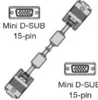 Computer cable(246C597-20) Computer cable(246C597-20) | ■ Power supply parts Power cord (two)(246C684-10, 246C383-20) Power cord (two)(246C684-10, 246C383-20) |
■ Remote control parts  Remote control (290P188-30) R6 (size-AA)battery (two) Remote control (290P188-30) R6 (size-AA)battery (two) | ■ OthersLens cap (attached to the projector)Terminal coverLamp replacement trayPower cord holderCD-ROMSafety Manual/Quick Start upMitsubishi logo plate |
Important:
• The attached power cords are to be used exclusively for this product. Never use them for other products.
1

3
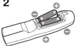
2
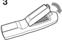
Inserting the batteries into the remote control
- Remove the rear lid of the remote control.
- Check the polarity (+), (-) of the batteries, and set them correctly, inserting their (-) side first.
- If the battery is inserted from the (+) side first, inserting the (-) side is difficult because the coil spring end hits on the battery side. If the battery is forced to insert in this way, the outer label of the battery may get ripped and it may cause a short-circuit and heating.
- Attach the rear lid.
Important:
• Use two size-AA batteries (R6).
- Replace the 2 batteries with new ones when the remote control is slow to operate.
Removing the batteries from the remote control
Remove the back lid of the remote control and take out the batteries.
Caution:
• Use of a battery of wrong type may cause explosion.
• Only Carbon-Zinc or Alkaline-Manganese Dioxide type batteries should be used.
- Dispose of used batteries according to your local regulations.
- Before you dispose of the batteries, insulate them by placing insulation tape on the positive (+) and negative (-) terminals. If you dispose of the batteries together with other conductive objects such as a metal piece, they may short out, resulting in fire or explosion.
- Batteries may explode if misused. Do not recharge, disassemble, or heat the batteries, or put them into fire or water.
- Be sure to handle the batteries according to the instructions.
- Load the batteries with its positive (+) and negative (-) sides correctly oriented as indicated on the remote control.
- Keep batteries out of reach of children and pets. If children swallow the battery, see a doctor immediately.
- Remove the batteries, if the remote control is not used for a long time.
- Do not combine a new battery with an old one.
- If the solution of batteries comes in contact with your skin or clothes, rinse with water. If the solution comes in contact with your eyes, rinse them with water and then consult your doctor.
- Do not carry or store the batteries together with metallic ballpoint pens, necklaces, coins, or hairpins. Otherwise, they may short out, causing explosion or liquid leakage and resulting in fire or injury.
- Do not store the batteries where they are exposed to direct sunlight or subjected to high temperature and high humidity. High temperature and high humidity may cause corrosion or liquid leakage.
Overview
The illustrations of the control area and terminal panel in this manual show those of UD8900U.

Caution:
Do not replace the lamp immediately after using the projector because the lamp would be extremely hot and it may cause burns.
1 Indicators
2 Intake vent/Filter cover
3 Exhaust vent
4 Lens
5 Remote control sensor (front)
6 Mitsubishi logo plate position (Put the plate according to the installation orientation.)
7 Intake vent
8 Control area
9 Terminal panel
10 Remote control sensor (rear)
11 Exhaust vent
12 Lamp cover
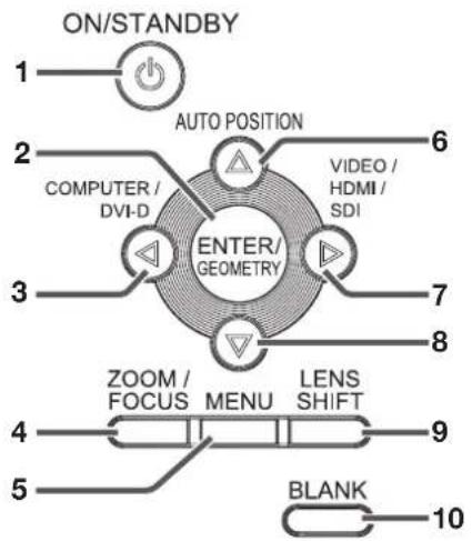
Control area
Terminal panel

1 POWER button (ON/STANDBY)
The status is changed between ON and STANDBY.
2 ENTER/GEOMETRY button
3 COMPUTER/DVI-D/◄ button
4 ZOOM/FOCUS button
5 MENU button
6 AUTO POSITION/▲ button
7 For UD8900U:
VIDEO/HDMI/SDI/▶ button
For UD8850U:
VIDEO/HDMI/▶ button
8 ▼ button
9 LENS SHIFT button
10 BLANK button
1 VIDEO IN terminal (BNC)
2 S-VIDEO IN terminal
3 COMPUTER/COMPONENT VIDEO IN-1 terminal (mini D-SUB 15-pin)
4 COMPUTER/COMPONENT VIDEO IN-2 terminals (R/P R , G/Y, B/P B , H/HV, V) (BNC)
5 HDMI IN terminal (HDMI 19-pin)
6 COMPUTER/COMPONENT VIDEO DVI-D IN (HDCP) terminal (DVI-D 24-pin)
7 SDI IN terminal (for UD8900U only)
8 LAN terminal
9 REMOTE1 IN terminal (D-SUB 9-pin female)
10 SERIAL IN and OUT terminals (D-SUB 9-pin male)
11 REMOTE 2 IN and OUT terminals
12 Kensington Security Lock Standard connector
13 Power jack
14 Power cord holder slot
Indicators
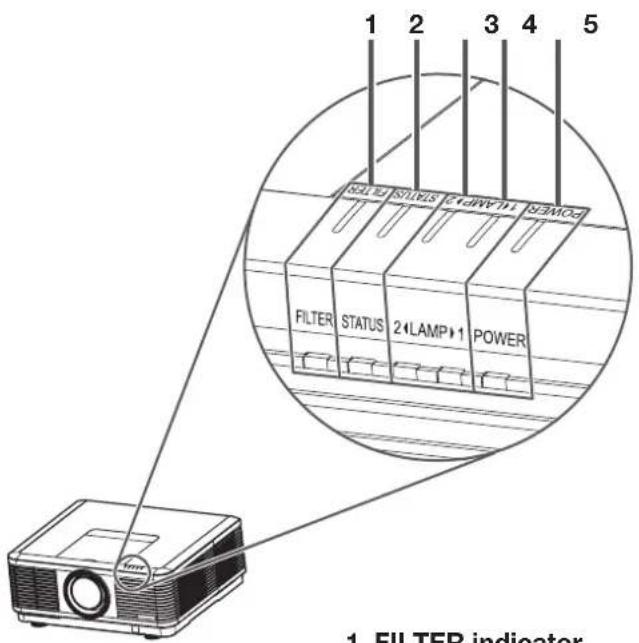
1 FILTER indicator
2 STATUS indicator
3 LAMP 2 indicator
4 LAMP 1 indicator
5 POWER indicator
Remote control

Bottom side

1 Lock bar (SECURITY ANCHOR)
- Attach a chain, etc. to this lock bar to anchor the projector.
2 Adjustment feet
1 Indicator
2 POWER button (ON/STANDBY)
The status is changed between ON and STANDBY.
3 COMPUTER 1, 2 buttons
4 MENU button
5 BLANK button
6 ZOOM/FOCUS button
7 ID button
8 MAGNIFY button *1
9 PinP/SPLIT button 2
10 CE (Color Enhancer) button
11 TEST PATTERN button
12 AUTO POSITION button
13 SDI button 4
14 HDMI button
15 VIDEO button
16 S-VIDEO button
17 DVI-D(HDCP) button
18 ENTER button
19 ▲, ▼, ◀, ► buttons
20 ASPECT button
21 LENS SHIFT button
22 GEOMETRY button
23 NUM button
24 + , - buttons
25 FREEZE button
26 SUPER RESOLUTION button
27 ALL button
28 Number (0 to 9) buttons 4
29 Wired remote control jack
Operational range of the remote control
Front of projector

Rear of projector

- Keep the remote control sensor out of direct sunlight or fluorescent lamp light.
- Keep the remote control sensor at least 2 m (6 feet) away from fluorescent lamps. Otherwise, the remote control may malfunction.
- If there is an inverter-operated fluorescent lamp near the remote control, the remote control operation may become unstable.
- When you use the remote control too close to the remote control sensor, the remote control may not work correctly.
- When the terminal cover is attached, remote control may not work properly from behind the projector.
You can control the projector by the remote control signals reflected on the screen. However, the remote control distance may be restricted by the light reflection loss due to the screen characteristics.
Reception angle
Vertical directions

Vertical directions (ceiling mount)

Using the wired remote control
Attached remote control for this projector can be used as a wired remote control with remote control cable. Wired remote control is useful for operating in a distance or outside of the operating area.
![graph TD A["Remote 2 IN"] --> B["Oscilloscope"] C["Remote 2 OUT"] --> B B --> D["Remote 2 IN"] style A fill:#f9f,stroke:#333 style C fill:#f9f,stroke:#333 style B fill:#ccf,stroke:#333](/content/2026/05/1024347/images/cf13364c4c9ba068272ac11b0cbb1eb7c804dfced9a0c76ae4e3a7267ef0131d.jpg)
- For connection, use the pin-pin cable of 3.5 stereo type, which is commercially available. However, some cable may not work correctly.
- When REMOTE 2 OUT terminal on this projector is connected to the REMOTE 2 IN terminal on the other projector, the two projectors can be controlled together by using the remote control.
- When the remote control is connected with remote control cable, it does not work as a wireless remote control.
- When using the remote control as wired for a long time period, remove the batteries from it. (Dispose of the removed batteries according to the cautions on page 6.)
Setting the ID number of the remote control
You can control multiple projectors collectively or individually using one remote control by setting the ID number (CONTROLLER ID) of the remote control.
To control multiple projectors using the remote control, you need to select the projector's ID number (PROJECTOR ID) with the remote control in advance. ID numbers should be two-digit numbers "01" to "63" or "ALL." Other numbers cannot be used.
- For setting the ID number of the projector, see page 62.
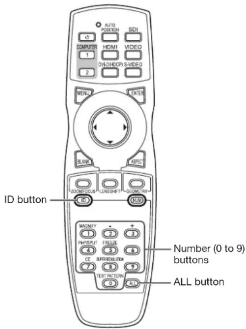
Setting by the remote control alone
- While holding down the ID button on the remote control, press the number buttons (0 to 9) to set a two-digit ID number.
Or, while holding down the ID button on the remote control, press the ALL button.
- You cannot set the ID number by pressing the number buttons (0 to 9) or the ALL button unless pressing them while holding down the ID button on the remote control.
- You can set the CONTROLLER ID using the remote control alone. When you set the ID with the remote control directed to the projector, you can see the setting status on the screen.
Setting by using the projector
- Carry out the procedure described in "Setting by the remote control alone" with the remote control directed to the projector.
- The ID setting dialog box is displayed on the upper right area of the screen.
| PROJECTOR ID XX | |
| CONTROLLER ID(01 - 63/ALL) | YY → ZZ |
XX: Shows the ID number of the projector.
(When the PROJECTOR ID is "ALL," "ALL" is displayed.)
YY: Shows the current CONTROLLER ID. (When the CONTROLLER ID is "ALL," "ALL" is displayed.)
ZZ: Shows the CONTROLLER ID to be changed. (When the CONTROLLER ID is "ALL," "ALL" is displayed.)
- Before a CONTROLLER ID is entered, ** is displayed. When you press a number button (0 to 9), the left digit of the ID number is entered first.
When the CONTROLLER ID setting has succeeded:
| PROJECTOR ID XX | |
| CONTROLLER ID(01 - 63/ALL) | YY → ZZCOMPLETE |
"COMPLETE" is displayed under the CONTROLLER ID number you entered.
- The ID setting dialog box automatically disappears after it is displayed for about 5 seconds.
- By pressing any button other than the ID button, number buttons (0 to 9), and ALL button while the ID setting dialog box is being displayed, you can cancel the dialog box.
When the CONTROLLER ID setting has failed:
| PROJECTOR ID XX | |
| CONTROLLER ID(01 - 63/ALL) | YY → ZZERROR |
"ERROR" is displayed under the CONTROLLER ID number you entered.
- The ID setting dialog box automatically disappears after it is displayed for about 5 seconds.
- By pressing any button other than the ID button, number buttons (0 to 9), and ALL button while the ID setting dialog box is being displayed, you can cancel the dialog box.
Important:
- ID numbers should be two-digit numbers "01" to "63." The other numbers are invalid.
- When the PROJECTOR ID number is any of "01" to "63," you can control the projector by matching the CONTROLLER ID with the PROJECTOR ID number or setting it to "ALL."
- When the PROJECTOR ID number is "ALL," you can control the projector using the remote control regardless of the CONTROLLER ID number.
- When the PROJECTOR ID number is uncertain, you can control the projector regardless of the ID number by setting the CONTROLLER ID to "ALL."
Before setting up
Before setting up the projector, check the operating environment.
If the environmental requirements are not satisfied, the projector may break down or fail.
Setup environment
The allowable operating temperature varies depending on the HIGH ALTITUDE mode setting.
For use in the STANDARD mode, the allowable operating temperature is +41°F (+5°C) to +104°F (+40°C).
For use in the HIGH ALTITUDE mode (see page 13), the allowable operating temperature is +41°F (+5°C) to +95°F (+35°C), which allows floor installation or ceiling installation only.
Setting up the screen
Install the screen perpendicularly to the projector. If the screen can not be installed in such a way, adjust the projection angle of the projector. (See page 14.)
- Install the screen and projector so that the projector's lens is placed at the same height and horizontal position of the screen center.
- Do not install the screen where it is exposed to direct sunlight or lighting. Light directly reflecting on the screen makes the projected images whitish and hard to view.
Screen size and projection distance
Refer to the following table to determine the screen size and projection distance.
• For the aspect ratio setting, see page 24.
• The figures in the tables are approximate and may be slightly different from the actual measurements.
- The lens shift height and width show distances from the factory default position.
- For the projection distance of the option lenses, see the tables on pages 78 to 79.
Front projection

Front projection, ceiling mounting
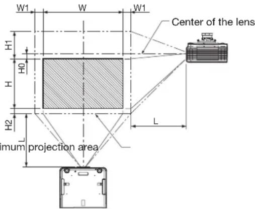
When the aspect ratio is "FULL" (Display at 1920 x 1200 pixels)
| Size of the projected image (16:10) Projection distance (L) Lens shift height Lens shift width | |||||||||||||||||
| Diagonal size | Width (W) Height (H) | Shortest (Wide) | Longest (Tele) | Standard (H0) | Movement distance (H1) | Movement distance (H2) | Movement distance (W1) | ||||||||||
| inch | cm inch | cm inch | cm inch | m inch | m | inch cm | inch cm | inch cm inch | cm | ||||||||
| 40 | 102 | 34 | 86 | 21 | 54 | 55 | 1.4 | 76 | 1.9 | 0 | 0 | 10 | 26 | 4 | 10 | 3 | 8 |
| 60 | 152 | 51 | 129 | 32 | 81 | 83 | 2.1 | 115 | 2.9 | 0 | 0 | 15 | 39 | 6 | 15 | 5 | 12 |
| 80 | 203 | 68 | 172 | 42 | 108 | 112 | 2.8 | 154 | 3.9 | 0 | 0 | 21 | 52 | 8 | 20 | 7 | 17 |
| 100 | 254 | 85 | 215 | 53 | 135 | 141 | 3.6 | 193 | 4.9 | 0 | 0 | 26 | 66 | 10 | 25 | 8 | 21 |
| 150 | 381 | 127 | 323 | 79 | 202 | 213 | 5.4 | 291 | 7.4 | 0 | 0 | 39 | 98 | 15 | 37 | 12 | 31 |
| 200 | 508 | 170 | 431 | 106 | 269 | 285 | 7.2 | 389 | 9.9 | 0 | 0 | 52 | 131 | 20 | 50 | 16 | 42 |
| 250 | 635 | 212 | 538 | 132 | 337 | 356 | 9.1 | - | - | 0 | 0 | 65 | 164 | 24 | 62 | 20 | 52 |
| 300 | 762 | 254 | 646 | 159 | 404 | 428 | 10.9 | - | - | 0 | 0 | 77 | 197 | 29 | 75 | 25 | 62 |
When the aspect ratio is "16:9" (Display at 1920 x 1080 pixels)
| Size of the projected image (16:9) | Projection distance (L) Lens shift height Lens shift width | ||||||||||||||||
| Diagonal size | Width (W) Height (H) | Shortest (Wide) | Longest (Tele) | Standard (H0) | Movement distance (H1) | Movement distance (H2) | Movement distance (W1) | ||||||||||
| inch | cm inch | cm inch | cm inch | m inch | m | inch cm | inch cm | inch cm inch | cm | ||||||||
| 40 | 102 | 35 | 89 | 20 | 50 | 56 | 1.4 | 78 | 2.0 | 1 | 3 | 11 | 27 | 4 | 10 | 3 | 9 |
| 60 | 152 | 52 | 133 | 29 | 75 | 86 | 2.2 | 118 | 3.0 | 2 | 4 | 16 | 40 | 6 | 15 | 5 | 13 |
| 80 | 203 | 70 | 177 | 39 | 100 | 115 | 2.9 | 158 | 4.0 | 2 | 6 | 21 | 54 | 8 | 20 | 7 | 17 |
| 100 | 254 | 87 | 221 | 49 | 125 | 145 | 3.7 | 198 | 5.0 | 3 | 7 | 27 | 67 | 10 | 26 | 8 | 21 |
| 150 | 381 | 131 | 332 | 74 | 187 | 219 | 5.6 | 299 | 7.6 | 4 | 11 | 40 | 101 | 15 | 38 | 13 | 32 |
| 200 | 508 | 174 | 443 | 98 | 249 | 293 | 7.4 | 399 | 10.1 | 6 | 14 | 53 | 135 | 20 | 51 | 17 | 43 |
| 250 | 635 | 218 | 553 | 123 | 311 | 366 | 9.3 | - | - | 7 | 18 | 66 | 168 | 25 | 64 | 21 | 53 |
- Depending on the installation conditions, warm air that is emitted from the exhaust vents may flow into the intake vent, causing the projector to display “TEMPERATURE!!” and then stop projecting images.
Setup adjustment
How to turn on the projector
When you have to turn on the projector for setup adjustment, see the following pages:
- Plugging the power cord (page 19)
• Turning on the power (page 21)
• Turning off the power (page 22)
Adjusting the position of the projected image
Adjust the focus.
If the projected image is out of the screen after the adjustment, adjust the projector position or the lens position using the lens shift function.
- Press the ZOOM/FOCUS button to display the ZOOM/FOCUS menu.
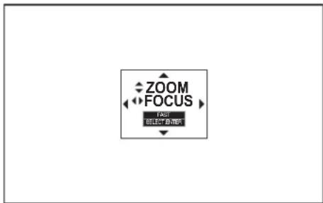
- Adjust with the ◀ or ▶ button to get a fine picture.
- When the ENTER button is pressed while the ZOOM/FOCUS menu is displayed, the adjustment mode is switched between FAST and STEP. When FAST is selected, the speed of focus controlled by the ◀ or ▶ button becomes fast, and it becomes slow when STEP is selected.
- Press the LENS SHIFT button.
- The LENS SHIFT menu appears at the center of the screen.

-
Press the ▲, ▼, ◀ or ▶ button to move the image position.
-
When the ▼ button is pressed, the image moves down.
- When the ▲ button is pressed, the image moves up.
- When the ▶ button is pressed, the image moves to the right.
-
When the ◀ button is pressed, the image moves to the left.
-
When the ENTER button is pressed while the LENS SHIFT menu is displayed, the shift mode can be switched between FAST and STEP. When FAST is selected, the lens shifts in a large amount with the ▲, ▼, ◀ or ▶ button, and it shifts in a small amount when STEP is selected.
- When the ZOOM/FOCUS menu or the LENS SHIFT menu is displayed while no video signal is input to the projector, a crosshatch appears on the entire screen.
- Be careful not to be caught in the opening in the lens while the lens is moving.
- While the lens shift is working, the screen may flicker.
- When the TEST PATTERN button on the remote control is pressed, the test pattern is displayed. Each time you press the TEST PATTERN button, the display switches in the order of “cross hatch (red)” → “cross hatch (green)” → “cross hatch (blue)” → “100% white” → “100% black” → “horizontal color bars” → “vertical color bars” → “normal screen” → ... When you press the ZOOM/FOCUS button or LENS SHIFT button at this time, you can adjust the zoom, focus, or lens shift with the test pattern displayed.
Changing the AUTO POWER OFF setting
The AUTO POWER OFF function of this projector is enabled by default.
Change the AUTO POWER OFF setting as necessary. (See page 35.)
To change the AUTO POWER OFF setting:
(See page 31 for menu setting.)
- Display the INSTALLATION 2 menu.
- Select AUTO POWER OFF by pressing the ▲ or ▼ button.

- Select your desired item by pressing the ◀ or ▶ button.
Setting HIGH ALTITUDE MODE
- Set HIGH ALTITUDE MODE in the INSTALLATION 1 menu according to the altitude at which you use the projector. The default setting is STANDARD.
- Select STANDARD when using the projector at an altitude from 0 to 2000 meters.
- Select HIGH ALTITUDE when using the projector at an altitude from 2000 to 2700 meters.
Important:
- If you select STANDARD when using the projector at an altitude higher than 2000 meters, the projector may break down or fail.
- When you use the projector in the HIGH ALTITUDE mode, only floor installation and ceiling installation are allowed.
(See page 31 for menu setting.)
- Display the INSTALLATION 1 menu.
- Select HIGH ALTITUDE MODE by pressing the ▲ or ▼ button.

- Press the ENTER button.

- Select STANDARD □ or HIGH ALTITUDE □y pressing the ◀ or ▶ button.
- Press the ENTER button.
Setting IMAGE REVERSE
- Set IMAGE REVERSE in the INSTALLATION 1 menu according to the orientation of the projector. The default setting is OFF.
- Select OFF for the combination of floor installation and front projection.
- Select MIRROR INVERT for the combination of ceiling installation and front projection.
- Select MIRROR for the combination of floor installation and rear projection.
- Select INVERT for the combination of ceiling installation and rear projection.
(See page 31 for menu setting.)
- Display the INSTALLATION 1 menu.
- Select IMAGE REVERSE by pressing the ▲ or ▼ button.

- Select OFF, MIRROR, INVERT or MIRROR INVERT by pressing the ◀ or ▶ button.
Correcting skewed or distorted image
For the best projection, project images on a flat screen installed at 90 degrees to the floor. If necessary, tilt the projector using the two adjustment feet on the bottom of the projector.
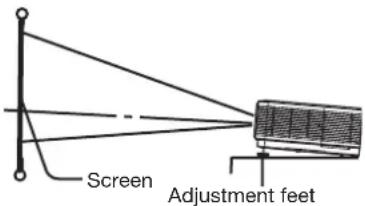
- Tilt up the projector to the appropriate angle.
- Rotate the adjustment feet for fine adjustment.
Important:
- Don't transport the projector with its adjustment feet extended. Otherwise the adjustment feet may be damaged.
When fine streaks are seen on projected images
This is due to interference with the screen surface and is not a malfunction. Replace the screen or displace the focus a little. (See page 12 for focus adjustment.)
When the projected image is distorted:
When the projected image is distorted, carry out any of the KEYSTONE, CORNERSTONE, and CURVED-mode adjustments to correct the distortion. When the image distorts in a trapezoid shape, use the KEYSTONE-mode adjustment. For fine adjustment of the image shape, use the CORNERSTONE-mode adjustment. To adjust the image projected on a curved surface, use the CURVED-mode adjustment. When you press the ENTER/GEOMETRY button on the projector or the GEOMETRY button on the remote control, the menu switches in the order of KEYSTONE, CORNERSTONE, CURVED, regular display, KEYSTONE...
Adjustment using the KEYSTONE mode:
When the screen and the projector are not placed perpendicularly to each other, projected images become trapezoidal. If you cannot place them perpendicularly to each other, press the ENTER/GEOMETRY button on the projector or the GEOMETRY button on the remote control to display the KEYSTONE mode and then press the ▲, ▼, ◀ or ▶ button to correct the distortion.

Every time you press the BLANK button, the adjustment menu changes as follows:
KEYSTONE → RESET → KEYSTONE ...
KEYSTONE menu
You can correct the distortion vertically or horizontally focusing on the screen center.
In the following cases (for front projection):
![graph TD A["User Profile 1"] -->|Press the button.| B["User Profile 2"] B -->|Press the button.| C["User Profile 3"] C -->|Press the button.| D["User Profile 4"] D -->|Press the button.| B](/content/2026/05/1024347/images/48d752bbdbca85db8ad5f55ceabe986ebf5a327e0a9edff32a7c56fdbfb75bcb.jpg)
When you press the ◀ or ▶ button in the RESET mode, the distortion correction is reset.
Important:
- For proper KEYSTONE-mode adjustment results, reset the lens to the factory-adjusted position using LENS SHIFT RESET in the INSTALLATION 1 menu before carrying out KEYSTONE-mode adjustment. (See page 34.)
- When the KEYSTONE-mode adjustment is carried out, the adjustment value is indicated. Note that this value doesn't mean a projection angle.
-
When the KEYSTONE-mode adjustment takes effect, the resolution decreases. In addition, stripes may appear or straight lines may bend in images with complicated patterns. They are not due to product malfunctions.
-
When the KEYSTONE-mode adjustment is performed, the displayed image may be distorted.
- Depending on the installation conditions of the projector and the screen, a perfect rectangular image and the proper aspect ratio may not be obtained. Slight distortion can be corrected by the CORNERSTONE-mode adjustment.
- Noise may appear on the screen during the KEYSTONE-mode adjustment because of the type of the video signal being projected and the setting values of the KEYSTONE-mode adjustment. In such cases, set the KEYSTONE-mode adjustment values in the range where the image is displayed without noise.
- When you carry out the KEYSTONE-mode adjustment and the CURVED-mode adjustment in combination, the adjustment range becomes narrower than that in the case where you carry out these adjustments individually. When setting the KEYSTONE-mode adjustment value to 11 or larger, you cannot use the CURVED-mode adjustment.
- When carrying out the KEYSTONE-mode adjustment while the option lens is in use, you may not be able to obtain a perfectly rectangular image or the correct aspect ratio. Slight distortion can be corrected by the CORNERSTONE-mode adjustment.
Adjustment using the CORNERSTONE mode:
Use this adjustment for fine adjustment of the image shape. You can use this adjustment for adjusting the image displayed in the edge blending mode (see page 36), too. For adjustment, press the ENTER/GEOMETRY button on the projector or the GEOMETRY button on the remote control to display the CORNERSTONE mode and then press the ▲, ▼, ◀ or ▶ button.

Every time you press the BLANK button, the adjustment menu changes as follows:
You can adjust the horizontal or vertical position of the selected corner.
Example: Adjustment of the upper left corner position (UPPER LEFT)
![graph TD A["Press the button."] --> B["Press the button."] B --> C["Press the button."] C --> D["Press the button."] D --> E["Press the button."] E --> F["Press the button."] F --> G["Press the button."]](/content/2026/05/1024347/images/8da389ed618b981258e1fcc85d367f22e1b154c781a4d27e4b753b0bbbcb46d0.jpg)
When you press the ◀ or ▶ button in the RESET mode, the distortion correction is reset.
Important:
- When the CORNERSTONE-mode adjustment takes effect, the resolution decreases. In addition, stripes may appear or straight lines may bend in images with complicated patterns. They are not due to product malfunctions.
- When the CORNERSTONE-mode adjustment is performed, the displayed image may be distorted.
- Noise may appear on the screen during the CORNERSTONE-mode adjustment because of the type of the video signal being projected and the setting values of the CORNERSTONE-mode adjustment. In such cases, set the CORNERSTONE-mode adjustment values in the range where the image is displayed without noise.
- Large distortion of the image shape or aspect ratio may not be corrected by the CORNERSTONE -mode adjustment.
Adjustment using the CURVED mode
To adjust images projected on a curved surface, press the ENTER/GEOMETRY button on the projector or the GEOMETRY button on the remote control to display the CURVED mode, and then press the ▲, ▼, ◀ or ▶ button to correct the distortion.
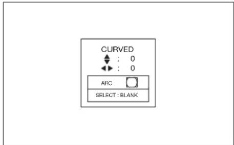
Every time you press the BLANK button, the adjustment menu changes as follows: ARC → HORIZ. ORIGIN → VERT. ORIGIN → RESET → ARC...
ARC menu
You can correct the arc vertically or horizontally focusing on the screen center.
![graph TD A["User Button"] -->|Press the button.| B["User Button"] B -->|Press the button.| C["User Button"] C -->|Press the button.| D["User Button"] D -->|Press the button.| E["User Button"]](/content/2026/05/1024347/images/b165cf69b3a1d56329886dcaf1d995300b0b2dab4d6b1c196c560a6f30e30ef0.jpg)
HORIZ. ORIGIN or VERT. ORIGIN menu
When the CURVED-mode adjustment has excessive effect on either top or bottom or either right or left side of the screen, adjust the horizontal or vertical position of the origin to the horizontal or vertical arc. Without the arc adjustment, the image shape won't change.
Adjusting the origin to the horizontal arc
- When the horizontal arc adjustment is negative (-) (or the ARC is adjusted in the ▼ direction)
![graph TD A["User icon"] -->|Press the button.| B["Central Button"] B -->|Press the button.| C["User icon"] C -->|Press the button.| D["User icon"] D -->|Press the button.| E["User icon"] E -->|Press the button.| F["User icon"]](/content/2026/05/1024347/images/ef0cb72affda0507080925f4ff03b943b3d9127f251c87cfb7d2d44e3628fc9c.jpg)
- When the horizontal arc adjustment is positive (+) (or the ARC is adjusted in the ▲ direction)
![graph TD A["Press the button."] --> B["Press the button."] B --> C["Press the button."] C --> D["Press the button."] D --> E["Press the button."] E --> F["Press the button."] F --> G["Press the button."]](/content/2026/05/1024347/images/f9cbb63fe55111fd458989b6ae944c89b563731bf8820bdfbdbe375355a7f3f3.jpg)
Adjusting the origin to the vertical arc
- When the vertical arc adjustment is negative (-) (or the ARC is adjusted in the direction)
![graph TD A["User icon"] -->|Press the button.| B["User icon"] B -->|Press the button.| C["User icon"] C -->|Press the button.| D["User icon"] D -->|Press the button.| E["User icon"] E -->|Press the button.| F["User icon"]](/content/2026/05/1024347/images/a7f0a69aa63f04f2af1d577e9dfa6750d0ded73ff139fa865dadedb5979020fe.jpg)
- When the vertical arc adjustment is positive (+) (or the ARC is adjusted in the ▶ direction)
![graph TD A["Press the button."] --> B["Press the button."] B --> C["Press the button."] C --> D["Press the button."] D --> E["Press the button."] E --> F["Press the button."] F --> G["Press the button."]](/content/2026/05/1024347/images/a07453822c50300e312d4e5e28d2ad2f66990f622d9371a8866b23193358b8aa.jpg)
When you press the ◀ or ▶ button in the RESET mode, the distortion correction is reset.
Important:
- When the CURVED-mode adjustment takes effect, the resolution decreases. In addition, stripes may appear or straight lines may bend in images with complicated patterns. They are not due to product malfunctions.
- When the CURVED-mode adjustment is performed, the displayed image may be distorted.
- Depending on the installation conditions of the projector and the screen or the correction amount of the CURVED-mode adjustment, you may not obtain a complete rectangular screen or the correct aspect ratio. Slight distortion can be corrected by the CORNERSTONE-mode adjustment.
- Noise may appear on the screen during the CURVED-mode adjustment because of the type of the video signal being projected and the setting values of the CURVED-mode adjustment. In such cases, set the CURVED-mode adjustment values in the range where the image is displayed without noise.
- When you carry out the KEYSTONE-mode adjustment and the CURVED-mode adjustment in combination, the adjustment range becomes narrower than that in the case where you carry out these adjustments individually. When setting the arc setting value of the CURVED-mode adjustment to 31 or larger, you cannot use the KEYSTONE-mode adjustment.
- When carrying out the CURVED-mode adjustment while the option lens is in use, you may not be able to obtain a perfectly rectangular image or the correct aspect ratio. Slight distortion can be corrected by the CORNERSTONE-mode adjustment.
Front projection, ceiling mounting
For ceiling mounting, you need the ceiling mount kit designed for this projector. Ask a specialist for installation. For details, consult your dealer.
- The warranty on this projector does not cover any damage caused by use of any non-recommended ceiling mount kit or installation of the ceiling mount kit in an improper location.

- When using the projector mounted on the ceiling, set IMAGE REVERSE in the INSTALLATION 1 menu to MIRROR INVERT. See page 34.
- When the projector is mounted on the ceiling, images may appear darker than those projected in the case of tabletop mounting. This isn't a product malfunction.
- Ask your installation specialist to provide a breaker. When you do not use the projector, be sure to shut down the main power by the breaker.
- Do not install the projector where the exhaust vents are exposed to air emitted by an air conditioning. Such installation may cause a breakdown.
- Do not install the projector near a fire alarm because it emits hot air from its exhaust vents.
Caution:
• Installation must be done by a qualified professional.
When the projector is installed on the ceiling using the ceiling mount kit, it is recommended to hold the mount kit and the projector using metal bars or wires in addition to the mount kit fixing screws to prevent the projector from falling due to an earthquake or other cause. For that purpose, use metal bars, wires, or screws that bear a load of at least 200 kgf. When using metal wires, secure one end to the adjustment foot of the projector and the other end to the mount kit. In this case, make sure that no electrical current is flowing in the mount kit due to current leakage or other cause.
Rear projection
Ask a specialist for installation. For details, consult your dealer.

- For rear projection, set IMAGE REVERSE in the INSTALLATION 1 menu to MIRROR. See page 34.
Caution:
- Placing the projector directly on a carpet impairs ventilation by the fans, causing damage or failure. Put a hard board under the projector to facilitate ventilation.
- Place the projector at least 50 cm (or 20 inches) away from the wall to prevent the intake vents and the exhaust vents that emit hot air from being blocked.
- Do not use the projector in the following locations and manners, which may cause fire or electric shock.
• In a dusty or humid place.
- In a sideways position, or with the lens facing down.
- Near a heater.
• In an oily, smoky, or damp place such as a kitchen.
• In direct sunlight.
- Where the temperature rises high, such as in a closed car.
- Where the temperature is lower than +41°F (or +5°C) or higher than +104°F (or +40°C).
• For use in the HIGH ALTITUDE mode
• Where the temperature is lower than +41°F (or +5°C) or higher than +95°F (or +35°C).
- For use in other than floor installation and ceiling installation.
- Keep foliage plants and pets away from the projector. The temperature around the exhaust vents and that of the cabinet on the top of the exhaust vents become high. Take special care for small children.
Important:
- We don't recommend using the projector at an altitude of 2700 meters or higher (When using the product at an altitude of 2000 to 2700 meters above the sea level, set the HIGH ALTITUDE MODE to HIGH ALTITUDE.). Use at an altitude of 2700 meters or higher may affect the projector's life.
A. Connecting the projector to a computer
Preparation:
• Make sure that the power of the projector and that of the computer are turned off.
- When connecting the projector to a desktop computer, disconnect the computer cable that is connected to the monitor.

For analog connection:
(For using the COMPUTER/COMPONENT VIDEO IN-1 terminal.)
- Connect one end of the supplied computer cable to the COMPUTER/COMPONENT/VIDEO IN-1 terminal of the projector.
- Connect the other end of the computer cable to the monitor port of the computer.
- When viewing images supplied from an analog-connected computer, press the COMPUTER 1 button on the remote control.

For analog connection:
(For using the COMPUTER/COMPONENT VIDEO IN-2 terminal.)
- Connect one end of a commercially available BNC cable to the COMPUTER/COMPONENT VIDEO IN-2 terminal of the projector.
- Connect the other end of the BNC cable to the 5 BNC terminals of the monitor port of the computer.
- When viewing images supplied from an analog-connected computer, press the COMPUTER 2 button on the remote control.

For digital connection:
-
Connect one end of a commercially available DVI cable to the COMPUTER/COMPONENT VIDEO DVI-D IN (HDCP) terminal of the projector.
-
Connect the other end of the DVI cable to the DVI terminal of the computer.
-
When viewing images supplied from a digital-connected computer, press the DVI-D (HDCP) button on the remote control.
-
Turn on the power of the projector before starting the computer.
-
Additional devices, such as a conversion connector and an analog RGB output adapter, are required depending on the type of the computer to be connected.
• Use of a long cable may decrease the quality of projected images.
• Images may not be projected correctly, depending on the type of the connected computer. - When DVI-D signal is input, some signal setting menus are unavailable.
• Also read the instruction manual of the equipment to be connected. - Contact your dealer for details of connection.
About DDC
The COMPUTER/COMPONENT VIDEO IN-1 terminal of this projector complies with the DDC1/2B standard and the COMPUTER/COMPONENT VIDEO DVI-D IN (HDCP) terminal complies with the DDC2B standard. When a computer supporting this standard is connected to this terminal, the computer will automatically load the information from this projector and prepare for output of appropriate images.
- After connecting a computer supporting this standard to this terminal, plug the power cord of the projector in the wall outlet first, and then boot up the computer.
B. Plugging the power cord
- In order to ensure the safety in case of trouble with the projector, use an electrical outlet having an earth leakage breaker to supply the power to the projector. If you do not have such outlet, ask your dealer to install it.

-
Plug the attached power cord into the power cord inlet of this projector. Fix the power cord to the projector with the power cord holder.
-
Plug the other end of the power cord into a power outlet.
- The power cords for use in the U.S. and Europe are included with this projector. Use the appropriate one for your country.
- This projector uses the power plug of 3-pin grounding type. Do not take away the grounding pin from the power plug. If the power plug doesn't fit your wall outlet, ask an electrician to change the wall outlet.
- The provided power cord for the U.S. is rated at 120 V. Never connect this cord to any outlet or power supply using other voltages or frequencies than rated. If you use a power supply using other voltage than rated, prepare an appropriate power cord separately.
• Use 100-240 V AC 50/60 Hz to prevent fire or electric shock.
- Do not place any objects on the power cord or do not place the projector near heat sources to prevent damage to the power cord. If the power cord should be damaged, contact your dealer for replacement because it may cause fire or electric shock.
- Do not modify or alter the power cord. If the power cord is modified or altered, it may cause fire or electric shock.
Caution:
- Plug in the power cord firmly. When unplugging, hold and pull the power plug, not the power cord.
- Do not plug in or out the power cord with your hand wet. It may cause electric shock.
- When you move the projector, turn off the power, unplug the power cord from the wall outlet, and then remove the connected cords. Otherwise, the power cord may be damaged, resulting in fire or electric shock.
- If dust or metallic substance is on or around the pins of the power plug, unplug the power cord and clean it using a dry cloth. If you continue to use the projector without cleaning, it may result in fire or electric shock. Clean the power plug periodically at least once a year.
- Be sure to unplug the power cord from the wall outlet if the projector will not be used for a long period of time. Otherwise, it may cause fire.

Attaching the power cord holder:
To reduce the risk of accidental disconnection of the power cord from the projector, attach the supplied power cord holder to hold it.
Important:
- Once the power cord holder is attached to the projector, it cannot be removed.
- If you apply an excessive force, the power cord holder may be damaged.
- Insert the tip of the power cord holder into the slot with the clamper facing toward the power cord.
- Put the power cord in the clamper, and push the clamper in the direction of the arrow to lock it.
- Slide the clamper toward the plug.
C. Installing the terminal cover
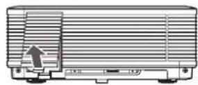
This projector includes a terminal cover. If necessary, install the terminal cover to the projector.


-
Fit two hooks of the terminal cover into the projector.
-
Tighten the attachment screws (a) firmly.

You can use the buttons on the operation panel by removing the door of the terminal cover.
- Remove the door (b) of the terminal cover.

Important:
- Don't carry the projector by the terminal cover.
- When the terminal cover is attached, remote control may not work properly from behind the projector.
D. Projecting images
Preparation:
- Remove the lens cap.

- Confirm the POWER indicator lights up red.
- If the projector was turned off before the lamp was cooled down sufficiently last time, the fan may start rotating and the POWER button may not work after the power cord is plugged. (The LAMP indicator blinks green.) After the fan stops rotating, press the POWER button to turn back on the POWER indicator.
-
Turn on the power of the connected computer.
-
Press the POWER button.
• It may take about 2 minutes for the lamp to light up.
• The lamp fails to light up on rare occasions. In such a case, wait for a few minutes and then try again.
- Do not cover the lens with the lens cap while the lamp is on.
- After the POWER button is pressed, the image may flicker before the lamp becomes stable. This is not a product malfunction.
- The lamp operation becomes stable in 1 minute after the power is turned on and then the lamp mode selected in the menu is activated. During the activation, displayed images may be disturbed.
- The projector starts warming up when the POWER button is pressed. During the warm-up process, images may appear dark and no commands are accepted.
- By blinking red, the LAMP indicator indicates that the lamp should be replaced soon. Replace the lamp when the LAMP indicator blinks red. (See page 73.)
-
Press the ZOOM/FOCUS button to display the ZOOM/FOCUS menu.
-
Adjust with the ◀ or ▶ button to get a fine picture.
- When the ENTER button is pressed while the ZOOM/FOCUS menu is displayed, the adjustment mode is switched between FAST and STEP. When FAST is selected, the speed of focus controlled by the ◀ or ▶ button becomes fast, and it becomes slow when STEP is selected.
- Select an input source.
- Press the COMPUTER/DVI-D button on the projector or the COMPUTER 1, COMPUTER 2 or DVI-D(HDCP) button on the remote control that is corresponding to the terminal in use.
- The input source is switched from COMPUTER 1 to COMPUTER 2 to DVI at every press of the COMPUTER/DVI-D button on the projector.
- The projector automatically selects the appropriate signal format. The selected signal format is displayed on the screen.
• You cannot change the input source while the menu is being displayed.
- Though it may take some time before an image is displayed on the screen depending on the type of the input signal, such symptom is not a malfunction.
- Images may not be projected in the correct position, depending on the type of the input signal. In such a case, press the AUTO POSITION button. (See page 23.)
- When COMPUTER 1 or COMPUTER 2 is chosen as the source, images supplied from the computer may flicker. Press the ◀ or ▶ button on the remote control to reduce flicker, if it occurs. (Fine adjustment)
-
Adjust the position of the projector to keep an appropriate projection distance with which images are projected in their specified sizes.
-
Adjust the position of the projector so that the projector and the screen are perpendicular to each other. (See page 11.)
- When the projector cannot be positioned perpendicularly to the screen, adjust the projection angle. (See page 14.)
-
Press the ZOOM/FOCUS button to display the ZOOM/FOCUS menu.
-
Adjust with the ▲ or ▼ button to get an approximate size.
- When the ENTER button is pressed while the ZOOM/FOCUS menu is displayed, the adjustment mode is switched between FAST and STEP. When FAST is selected, the speed of zoom controlled by the ▲ or ▼ button becomes fast, and it becomes slow when STEP is selected.
-
Press the LENS SHIFT button. The LENS SHIFT menu appears at the center of the screen.
-
Press the ▲ or ▼ button to adjust the vertical position and ◀ or ▶ button to adjust the horizontal position of the displayed image.
- When the image is not displayed within the screen, adjust the projection angle. In addition, perform the keystone adjustment, if necessary. (See page 14.)
Repeat steps 4, 5 and 9 to 12, if necessary.
Important:
• Focus, zoom and lens shift adjustment is possible in the normal picture mode only.
- When a 16:9 image is kept displayed for a long time before displaying 4:3 image, the afterimages of the black bars may appear on the 4:3 image screen. Consult your dealer in this case.
To stop projecting:
- Press the POWER button.
• A confirmation message is displayed.
- To cancel the procedure, leave the projector for a while or press any button except the POWER button.
- Press the POWER button again.
- The lamp goes out and the projector goes into a standby mode. In this standby mode, the LAMP indicator blinks green.
-
Wait about 2 minutes for the LAMP indicator to be turned off.
-
During this period of 2 minutes in the standby mode, the intake fan and exhaust fan rotate to cool the lamp.
• The air outlet fans rotate faster as the temperature around the projector rises. -
Though the fans make loud sounds during cooling, such symptom is not a malfunction.
-
Unplug the power cord from the outlet.
• The POWER indicator will go out.
- If the power cord should be unplugged accidentally while either the air inlet fan or the air outlet fans are operating or the lamp is on, allow the projector to cool down for 10 minutes with the power off. To light the lamp again, press the POWER button. If the lamp doesn't light up immediately, press the POWER button a few minutes later. If it should still fail to light up, replace the lamp.
• Cover the lens with the lens cap to protect it from dust.
- If necessary, disconnect the cables from the computer after unplugging the power cord.
Direct Power OFF
You can turn off this projector just by unplugging the power cord without pressing the POWER button.
- Don't shut down the projector while the LAMP indicator is blinking after the lamp lights up because the lamp's life may be shortened.
- Don't turn the projector back on right after shutting it down because the lamp's life may be shortened. (Wait about 10 minutes before turning the projector back on.)
- Before shutting down the projector, be sure to close the menu screen. If you shut down the projector without closing the menu, the setting data of the menu may not be saved.
- If you shut down the projector while controlling the projector using the network function, the application software such as ProjectorView may fail. The data such as the operating time and temperature display may not be changed. In such a case, close the browser and then start up again.
- Don't shut down the projector while the filter is rolling (while the FILTER indicator is blinking green).
Blanking the screen temporarily (BLANK)
The video signal is temporarily muted when the BLANK button is pressed. The screen turns black. You will hear a mechanical shutter sound inside the projector. To cancel muting, press the BLANK button again.
AUTO POSITION button
When the image supplied from the computer is displaced, carry out the following procedure.
- Project a bright image containing as many texts and characters as possible.
- When the screen saver has been enabled, disable it.
- Press the AUTO POSITION button.
The projector automatically makes optimum positional settings for the input signal.
- If the projected image is still displaced even after pressing the AUTO POSITION button several times, refer to the procedure to adjust computer images. (See pages 47 and 48.)
- When you carry out this procedure with a dark image, the image may be displaced.
When connecting to a notebook computer:
When the projector is connected to a notebook computer, images may not be projected in some cases. In such cases, set the computer so that it can output signals externally. The setting procedure varies depending on the type of the computer. See the instruction manual of your computer.
Example of the setting procedure for external output
Press the [Fn] key and any of the keys [F1] to [F12] at the same time. (The key to be pressed depends on the type of the computer you use.)
Setting of the resolution
If the resolution of the computer doesn't match with that of the projector, projected images may be obscured. Ensure that their resolutions are the same (see page 75). For the method to change the output resolution of the computer, contact the manufacturer of the computer.
Setting the screen size
Change the setting of the SCREEN according to the type of the screen to be used.
(See page 31 for menu setting.)
-
Display the INSTALLATION 2 menu.
-
Select SCREEN by pressing the ▲ or ▼ button.
-
Select your desired aspect ratio by pressing the ◀ or ▶ button.
• You can select the aspect ratio from 16:10, 16:9, and 4:3.
To cancel the menu:
- Press the MENU button.

Setting the aspect ratio
You can change the aspect ratio of the input video signal (or the ratio of width to height of the image). Change the setting according to the type of the screen to be used or your preference.
How to change the settings:
With the remote control:
-
Press the ASPECT button.
-
Every time the ASPECT button is pressed, the aspect mode changes from NORMAL to 16:9, to NATIVE, to FULL, to USER and back to NORMAL.
- When 16:9 is selected by SCREEN, 16:9 cannot be selected.
• The following table shows the image display patterns depending on the settings.
When SCREEN is 16:10:
| Setting 16:9 | NORMAL | NATIVE FULL | ||
| Input signal | Input video signal is displayed at the max height (1200 pixels) or max width (1920 pixels) of the panel while its aspect ratio is maintained. | Regardless of the type of input signal, image is displayed at 16:9 aspect ratio (1920 x 1080 pixels). Select to expand squeezed (or horizontally compressed) images such as DVD images to 16:9. | Input video signal is displayed at its original pixel size. (When the pixel size is larger than the panel size, only the center part of the image is displayed.) | Regardless of the type of input signal, image is displayed at the full panel size (1920 x 1200 pixels). |
| UXGA signal 1600 x 1200 (4:3) |  1600 x 1200 1600 x 1200 |  1920 x 1080 1920 x 1080 |  1600 x 1200 1600 x 1200 | 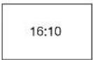 1920 x 1200 1920 x 1200 |
| WUXGA signal 1920 x 1200 (16:10) | 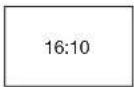 1920 x 1200 1920 x 1080 1920 x 1200 1920 x 1200 1920 x 1200 1920 x 1080 1920 x 1200 1920 x 1200 |  |  | 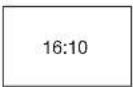 |
| 1080p signal 1920 x 1080 (16:9) |  1920 x 1080 1920 x 1080 | 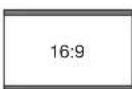 1920 x 1080 1920 x 1080 |  1920 x 1080 1920 x 1080 |  1920 x 1200 1920 x 1200 |
With the SIGNAL menu:
(See page 31 for menu setting.)
- Display the SIGNAL menu.
- Select ASPECT by pressing the ▲ or ▼ button.
- Select your desired aspect ratio by pressing the ◀ or ▶ button.
To cancel the menu:
- Press the MENU button.

Important:
- In such cases as when you keep projecting images in the narrower area than the screen for a long time and then change the mode to FULL, the masking areas may remain as afterimage around the displayed image. Consult your dealer in this case.
- If you change the screen setting, the aspect setting is automatically changed to NORMAL. Therefore, in such a case, set the desired aspect ratio again.
A. Connecting the projector to video equipment
Preparation:
- Make sure that the power of the projector and that of the video equipment are turned off.
Connecting to a video player, etc.
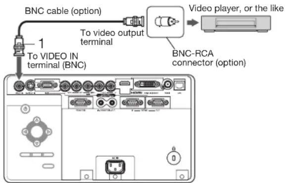
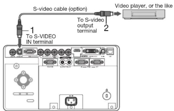
- Connect one end of a commercially available BNC cable to the VIDEO IN terminal of the projector.
- Connect the other end of the BNC cable to the video output terminal of the video equipment.
When the video equipment is equipped with the S-video output terminal, make the connection as follows:
- Connect one end of a commercially available S-video cable to the S-VIDEO IN terminal of the projector.
- Connect the other end of the S-video cable to the S-video output terminal of the video equipment.
• Also read the instruction manual of the equipment to be connected.
- Contact your dealer for details of connection.
When a TV tuner or VCR is connected:
When you use this projector with a TV tuner or VCR connected, no image may appear or a message of "NO SIGNAL" may appear on the screen when you change the channel via any channel that is not being received. In such a case, set the channels of the TV tuner or VCR again. To avoid such symptom, use the TV tuner or VCR with its channel skip function (that is a function not to display channels that are not being received) enabled.
Projector + DVD player or HDTV decoder
Some DVD players have an output connector for 3-line fitting (Y, CB , CR ). When connecting such DVD player with this projector, use the COMPUTER/COMPONENT VIDEO IN-2 terminals.

- The terminal's names Y, PB , and PR are given as examples of when a HDTV decoder is connected.
- The terminal's names vary depending on the connected devices.
• Use BNC cables for connection.
• Image may not be projected correctly with some DVD players. - If colors aren't displayed correctly when the projector is connected to a high-definition video device having R, G, and B output terminals, set COMPUTER INPUT to RGB in the SIGNAL menu. (See page 39.)
Connecting to video equipment having a HDMI terminal or DVI-D terminal
You can project high-quality images by connecting the COMPUTER/COMPONENT VIDEO DVI-D IN (HDCP) terminal of this projector to video equipment having a HDMI output terminal or DVI-D terminal. In addition, this projector supports HDCP and is able to receive encrypted digital video data that are output from DVD players.
- HDCP (High-bandwidth Digital Content Protection), developed by Intel Corporation, is a method to encrypt digital video data for the purpose of copy protection.
- HDMI (High-Definition Multimedia Interface) is fully backward compatible with computers, displays and consumer electronics devices incorporating the DVI standards.
- This projector can be linked with video devices equipped with HDMI output terminal or DVI-D output terminal. However, with some of them, this projector may not display any image or not operate correctly.
- If this projector doesn't display any image or not operate correctly, see the operation manual of the video device for its connection.
- Use of a long cable may decrease the quality of projected images.
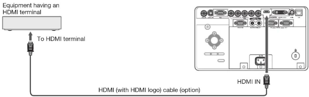
Connection (for video equipment having an HDMI terminal)
• Use a commercially available HDMI (with HDMI logo) cable.
• Some cables may not be connected correctly depending on the size and shape of their connectors.
- When HDMI is selected as the input source, settings of FINE SYNC., TRACKING, HOLD, etc. are unavailable.
Connection (for video equipment having a DVI-D terminal)
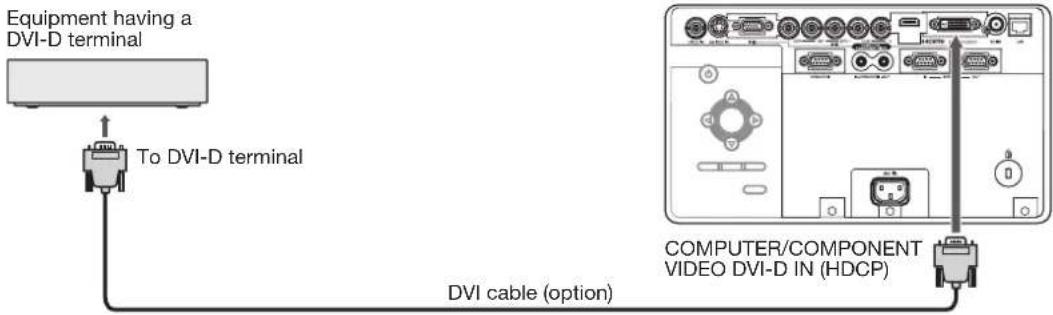
- For connection to the DVI-D terminal, use a commercially available DVI cable.
• Some cables may not be connected correctly depending on the size and shape of their connectors. - When DVI is selected as the input source, settings of FINE SYNC., TRACKING, HOLD, etc. are unavailable.
When you connect this projector and a digital device (such as a DVD player) via the HDMI IN or COMPUTER/COMPONENT VIDEO DVI-D IN (HDCP) terminal, black color may appear dark and deep, depending on the type of the connected device.
- This depends on the black level setting of the connected device. There are 2 kinds of methods to digitally transfer image data, in which different black level settings are employed respectively. Therefore, the specifications of the signals output from DVD players differ, depending on the type of the digital data transfer method they use.
- Some DVD players are provided with a function to switch the methods to output digital signals. When your DVD player is provided with such function, set it as follows.
EXPAND or ENHANCED → NORMAL
• See the users guide of your DVD player for details.
- When your digital device does not have such function, set INPUT LEVEL to ENHANCED in the ADVANCED MENU of the IMAGE menu of this projector, or adjust the black color by viewing the image.
B. Plugging in the power cord
Plug the power cord in the same way as in the case of "Viewing computer images." (See page 19.)
C. Installing the terminal cover
If necessary, install the terminal cover to the projector in the same way as in the case of "Viewing computer images." (See page 20.)
D. Projecting images
Preparation:
- Remove the lens cap.
- Confirm the POWER indicator lights up red.
- If the projector was turned off before the lamp was cooled down sufficiently last time, the fan may start rotating and the POWER button may not work after the power cord is plugged. (The LAMP indicator blinks green.) After the fan stops rotating, press the POWER button to turn back on the POWER indicator.
-
Turn on the power of the connected video equipment.
-
Press the POWER button.
• It may take about 2 minutes for the lamp to light up.
• The lamp fails to light up on rare occasions. In such a case, wait for a few minutes and then try again.
- Do not cover the lens with the lens cap while the lamp is on.
- After the POWER button is pressed, the image may flicker before the lamp becomes stable. This is not a product malfunction.
- The lamp operation becomes stable in 1 minute after the power is turned on and then the lamp mode selected in the menu is activated. During the activation, displayed images may be disturbed.
- The projector starts warming up when the POWER button is pressed. During the warm-up process, images may appear dark and no commands are accepted.
- By blinking red, the LAMP indicator indicates that the lamp should be replaced soon. Replace the lamp when the LAMP indicator blinks red. (See page 73.)
-
Press the ZOOM/FOCUS button to display the ZOOM/FOCUS menu.
-
Adjust with the ◀ or ▶ button to get a fine picture.
- When the ENTER button is pressed while the ZOOM/FOCUS menu is displayed, the adjustment mode is switched between FAST and STEP. When FAST is selected, the speed of focus controlled by the ◀ or ▶ button becomes fast, and it becomes slow when STEP is selected.
- Select an input source.
- For UD8900U:
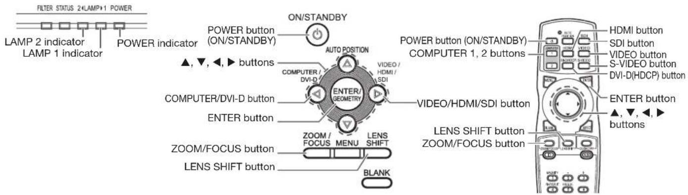
Press the VIDEO/HDMI/SDI button on the projector or the VIDEO, S-VIDEO, HDMI or SDI button on the remote control that is corresponding to the terminal in use. The input source is switched between VIDEO, S-VIDEO, HDMI and SDI at every press of the VIDEO/HDMI/SDI button on the projector.
- For UD8850U:
Press the VIDEO/HDMI button on the projector or the VIDEO, S-VIDEO or HDMI button on the remote control that is corresponding to the terminal in use. The input source is switched between VIDEO, S-VIDEO and HDMI at every press of the VIDEO/HDMI button on the projector.
• You cannot change the input source while the menu is being displayed.
- Though it may take some time before an image is displayed on the screen depending on the type of the input signal, such symptom is not a malfunction.
• Some images become easier to view when the setting of aspect ratio is changed. (See page 24.)
- When projecting images from a DVD player that is connected to the COMPUTER/COMPONENT VIDEO DVI-D IN (HDCP) terminal, press the COMPUTER/DVI-D button on the projector to select DVI or press the DVI-D (HDCP) button on the remote control.
- When projecting images from a DVD player that is connected to the COMPUTER/COMPONENT VIDEO IN-1 or COMPUTER/COMPONENT VIDEO IN-2 terminal, press the COMPUTER/DVI-D button on the projector or the COMPUTER 1 or COMPUTER 2 button on the remote control.
- Adjust the position of the projector to keep an appropriate projection distance with which images are projected in their specified sizes.
- Adjust the position of the projector so that the projector and the screen are perpendicular to each other. (See page 11.)
- When the projector cannot be positioned perpendicularly to the screen, adjust the projection angle. (See page 14.)
-
Press the ZOOM/FOCUS button to display the ZOOM/FOCUS menu.
-
Adjust with the ▲ or ▼ button to get an approximate size.
- When the ENTER button is pressed while the ZOOM/FOCUS menu is displayed, the adjustment mode is switched between FAST and STEP. When FAST is selected, the speed of zoom controlled by the ▲ or ▼ button becomes fast, and it becomes slow when STEP is selected.
-
Press the LENS SHIFT button. The LENS SHIFT menu appears at the center of the screen.
-
Press the ▲ or ▼ button to adjust the vertical position and ◀ or ▶ button to adjust the horizontal position of the displayed image.
- When the image is not displayed within the screen, adjust the projection angle. In addition, perform the keystone adjustment, if necessary. (See page 14.)
Repeat steps 4, 5 and 9 to 12, if necessary.
Important:
• Focus, zoom and lens shift adjustment is possible in the normal picture mode only.
To stop projecting:
- Press the POWER button.
• A confirmation message is displayed.
- To cancel the procedure, leave the projector for a while or press any button except the POWER button.
- Press the POWER button again.
- The lamp goes out and the projector goes into a standby mode. In this standby mode, the LAMP indicator blinks green.
-
Wait about 2 minutes for the LAMP indicator to be turned off.
-
During this period of 2 minutes in the standby mode, the intake fan and exhaust fan rotate to cool the lamp.
• The air outlet fans rotate faster as the temperature around the projector rises.
• Though the fans make loud sounds during cooling, such symptom is not a malfunction. -
Unplug the power cord from the outlet.
• The POWER indicator will go out.
- If the power cord should be unplugged accidentally while either the air inlet fan or the air outlet fans are operating or the lamp is on, allow the projector to cool down for 10 minutes with the power off. To light the lamp again, press the POWER button. If the lamp doesn't light up immediately, press the POWER button a few minutes later. If it should still fail to light up, replace the lamp.
• Cover the lens with the lens cap to protect it from dust.
Direct Power OFF
You can turn off this projector just by unplugging the power cord without pressing the POWER button.
- Don't shut down the projector while the LAMP indicator is blinking after the lamp lights up because the lamp's life may be shortened.
- Don't turn the projector back on right after shutting it down because the lamp's life may be shortened. (Wait about 10 minutes before turning the projector back on.)
- Before shutting down the projector, be sure to close the menu screen. If you shut down the projector without closing the menu, the setting data of the menu may not be saved.
- If you shut down the projector while controlling the projector using the network function, the application software such as ProjectorView may fail. The data such as the operating time and temperature display may not be changed. In such a case, close the browser and then start up again.
- Don't shut down the projector while the filter is rolling (while the FILTER indicator is blinking green).
Setting the aspect ratio
You can change the aspect ratio of the input video signal (or the ratio of width to height of the image). Change the setting according to the type of the input video signal. (See page 24.)
You can make various settings using the displayed menus.
Following 8 menus are displayed.
IMAGE menu (page 32) INSTALLATION 1 menu (page 34)
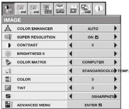
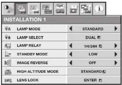
INSTALLATION 2 menu (page 35)

MULTI-SCREEN menu (page 36)
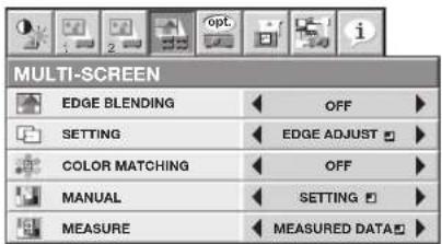
FEATURE menu (page 37)

SIGNAL menu (page 39)
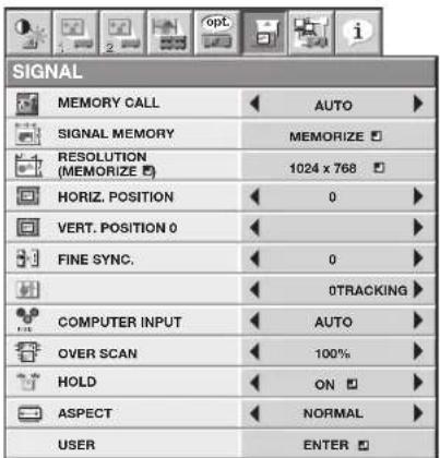
NETWORK menu (page 41) INFORMATION menu (page 42)


How to set the menus
1. Press the MENU button.
• The menu selection bar is displayed.
Selectable menus are displayed by icons. (The menu icon being selected is displayed on a blue background.)

- Press the ◀ or ▶ button to select a menu to use.
- Press the ENTER button (or ▼ button).
• The selected menu is displayed.
The item being selected is displayed in red letters.
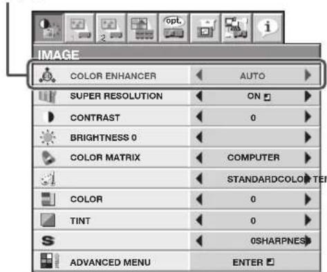
- Press the ▲ or ▼ button to select an item to adjust.

- Set the selected item by pressing the ◀ or ▶ button.
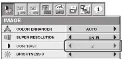
- To cancel the menu, press the MENU button several times.
Important:
- When an item marked with “ 📁s selected, pressing the ENTER button makes its value effective or displays another screen for further setting.
- When the MENU button doesn't function, unplug the power cord from the wall outlet. Wait about 10 minutes, plug the power cord in, and try again.
- The menus and screens shown in this manual may be different from those of the actual projector.
IMAGE menu
![graph TD A["COLOR ENHANCER"] --> B["AUTO"] C["SUPER RESOLUTION"] --> D["ON"] E["CONTRAST"] --> F["0"] G["BRIGHTNESS 0"] --> H["0"] I["COLOR MATRIX"] --> J["COMPUTER"] K["STANDARDCOLOR TEMP."] --> L["0"] M["COLOR"] --> N["0"] O["TINT"] --> P["0"] Q["0SHARPNES"] --> R["0"] S["ADVANCED MENU"] --> T["EN…](/content/2026/05/1024347/images/ea8f762f3f10adef1ed50f698482120da588eda876c2acdd27b6d6be8c063283.jpg)
ITEM SETTING FUNCTION
| COLOR ENHANCER AUTO Select to optimize the settings automatically depending on the input signal. (Select this option for normal use.) | ||
| PRESENTATION Select to make the displayed image look bright and crisp. STANDARD Select to make the displayed image look natural. THEATER This option, suitable for viewing movies, makes the displayed image look soft and smooth. sRGB Select to give priority to the color reproducibility. CLEAR BASE Select to obtain the color close to that of the X-ray film (clear base). | ||
| BLUE BASE | Select to obtain the color close to that of the X-ray film (blue base). | |
| USER | Select to set the gamma curve, BrilliantColorTM or dynamic contrast. (See page 44.) | |
| MULTI-SCREEN | You can set the gamma curve and BrilliantColorTM in the multi-screen application. | |
| SUPER RESOLUTION | ON / OFF | Use to emphasize the fineness of the image. (See page 45.) |
| CONTRAST | ±30 | Use to adjust the contrast of the projected image. (See page 43.) |
| BRIGHTNESS | ±30 | Use to adjust the brightness of the projected image. (See page 43.) |
| COLOR MATRIX | COMPUTER / VIDEO | Use to adjust the predetermined tone of each color. |
| FLAT | Use to disable COLOR MATRIX. | |
| USER | Use to emphasize only certain colors or to correct the tonal deviation of only certain colors. (See page 45.) | |
| COLOR TEMP. | STANDARD / LOW / HIGH | Select from the predetermined color temperatures. |
| USER | Use to adjust the color temperature to a desired value. (See page 43.) | |
| COLOR | ±10 | Use to adjust the color thickness of the projected image. (See page 43.) |
| TINT | ±10 | Use to adjust the color tint of the projected image. (See page 43.) |
| SHARPNESS | ±5 | Use to adjust the sharpness of the projected image. (See page 43.) |
| ADVANCED MENU | ENTER the ADVANCED MENU is displayed for the following settings. | |
| NOISE REDUCTION | ON / OFF | Use to reduce noise and roughness in the image when noisy video signal is input. |
| CTI | ON / OFF | Use to correct smeared color boundaries. |
| INPUT LEVEL | ±5 | For analog signal input: The input level of video signal differs among devices to be connected. High input level causes solid white in displayed image and low input level causes displayed image to get dark. Use this menu to adjust the input level of analog video signal. |
| AUTO / ENHANCED / NORMAL | For digital signal input: AUTO: The proper setting is automatically selected. (Selectable only when HDMI signal is input.) ENHANCED: Select when solid black occurs. NORMAL: Select when grayish black occurs. (See page 27.) | |
| CLOSED CAPTION | OFF | Does not display captions. |
| CC1 / CC2 | Displays captions. | |
| DEMO MODE | ALL | Use to demonstrate the effect of SUPER RESOLUTION, COLOR MATRIX, and DYNAMIC CONTRAST. |
| DYNAMIC CONTRAST | Use to demonstrate the effect of DYNAMIC CONTRAST. | |
| SUPER RESOLUTION | Use to demonstrate the effect of SUPER RESOLUTION. | |
| COLOR MATRIX | Use to demonstrate the effect of COLOR MATRIX. | |
- When COLOR ENHANCER is sRGB, CLEAR BASE or BLUE BASE, COLOR TEMP., COLOR, TINT and COLOR MATRIX can't be adjusted.
- You can set MULTI-SCREEN in the COLOR ENHANCER menu only when EDGE BLENDING is ON or COLOR MATCHING is MANUAL or MEASURE. In this case, you cannot set any other items than MULTI-SCREEN.
• This product is not in compliance with DICOM Part 14. Do not use this product for actual medical diagnosis. - When the setting of COLOR ENHANCER is changed, the displayed image may be disturbed.
- The effect obtained when SUPER RESOLUTION is ON varies depending on the type and resolution of the input image. In addition, the vertical line of the colored characters may be blurred.
- When the COMPUTER1, COMPUTER2, DVI, HDMI or SDI (for UD8900U only) is selected as the input source, COLOR and TINT can't be adjusted.
• TINT is available only when the NTSC signal is input. - INPUT LEVEL is unavailable when the digital signal is supplied from the YCCR/YPBPR terminal of the connected device.
- Captions are not displayed while information about the menu or input signal selection is being displayed on the screen.
- The closed caption function displays text information included in the NTSC signal, which is mainly used for TV broadcasting in North America.
INSTALLATION 1 menu
![graph TD A["INSTALLATION 1"] --> B["LAMP MODE"] A --> C["LAMP SELECT"] A --> D["LAMP RELAY"] A --> E["STANDBY MODE"] A --> F["IMAGE REVERSE"] A --> G["HIGH ALTITUDE MODE"] A --> H["LENS LOCK"] B --> I["STANDARD"] C --> J["DUAL"] D --> K["1H/24H"] E --> L["LOW"] F --> M["OFF"] G --> N["STANDARD"] H -…](/content/2026/05/1024347/images/f8e7977855044fcbd1a0248fbc78abeb98797b08b56c19093a4a63840040efcf.jpg)
ITEM SETTING FUNCTION
LAMP MODE STANDARD Select this option when you want to view images in a well-lit room.
LOW Select to moderate the intensity of the lamp. The operating sound is reduced and the lamp lifetime becomes longer.
LAMP SELECT DUAL LAMP 1 a LAMP 2 illuminate.
SINGLE The lamp with shorter operation time is automatically selected at power-on.
LAMP 1 📁 LAMP 1 illuminates. (When it is broken or dead, LAMP 2 illuminates automatically.)
LAMP 2 📁 LAMP 2 illuminates. (When it is broken or dead, LAMP 1 illuminates automatically.)
LAMP RELAY DUAL: OFF The LAMP RELAY doesn't work.
1H/24H / Use to set the lamp relay interval. (See page 55.)
2H/1W
SINGLE:OFF The LAMP RELAY doesn't work.
24H / Use to set the lamp relay interval. (See page 56.)
1 WEEK
STANDBY MODE STANDARD Select this option when you control the projector via the LAN, REMOTE 1 IN, and SERIAL OUT terminal during power standby.
LOW Select this option when you don't control the projector via the LAN, REMOTE
1 IN, and SERIAL OUT terminal during power standby. This option disables the LAN, REMOTE 1 IN, and SERIAL OUT terminal and reduces the power consumption during the power standby.
IMAGE REVERSE OFF Select when viewing images from the front with the projector installed on the floor.
MIRROR Select when viewing images projected from the behind of the screen with the projector installed on the floor.
INVERT Select when viewing images projected from the behind of the screen with the projector installed on the ceiling.
MIRROR INVERT Select when viewing images from the front with the projector installed on the ceiling.
HIGH ALTITUDE MODE STANDARD Select this option for normal use.
HIGH ALTITUDE Select this option for use at an altitude of 2000 to 2700 meters above the sea level.
LENS LOCK ENTER The LENS LOCK menu is displayed for the following settings.
ZOOM/FOCUS LOCK ON / OFF Use to enable or cancel the FOCUS LOCK and ZOOM LOCK.
LENS SHIFT LOCK ON/OFF Use to enable or cancel the LENS SHIFT LOCK.
LENS SHIFT RESET OK Use to reset the position of the lens to the factory setting.
- Regardless of the setting of LAMP MODE, the STANDARD lamp mode is activated by default whenever the projector is turned on. When LAMP MODE has been set to LOW, the lamp mode changes from STANDARD to LOW about 1 minute after turn-on.
- When the ambient operating temperature is high, the brightness of the lamp isn't changed by switching the lamp mode.
- When the lamp mode is switched, the projected image may flicker.
- Frequent switching of the lamp mode may damage the lamp.
- When using the projector for a long time, set LAMP RELAY.
- While the lamps are being warmed up, an icon 🎨 is displayed to the right of the INSTALLATION 1 menu bar. While the icon is being displayed, you cannot set LAMP SELECT and LAMP RELAY. And an icon 🎨 is displayed while the operating ambient temperature is high. While the icon is being displayed, the lamp may not brighten even when you change the LAMP MODE to STANDARD.
• After you switch the lamps and the newly selected lamp turns on, you cannot turn off the projector for approx. 1 minute.
INSTALLATION 2 menu
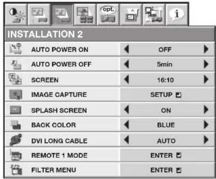
ITEM SETTING FUNCTION
| AUTO POWER ON ON / OFF When ON is chosen, the projector is automatically turn on when the power cord is plugged in the wall outlet. Choose ON when using the projector mounted on the ceiling.The projector is in the stand-by mode when the lamp is off. Use the remote control to turn on the lamp. | ||
| AUTO POWER OFF OFF / 5min-8hour When no video signal is input and no operation is made, the projector automatically turns off after the selected time period. A dialog is displayed 5 minutes before the projector turns off. | ||
| SCREEN 16:10 Select this setting when using a 16:10 screen.16:9 Select this setting when using a 16:9 screen.4:3 Select this setting when using a 4:3 screen. | ||
| IMAGE CAPTURE SETUP Use to capture the screen for the splash screen. (See page 57.) | ||
| SPLASH SCREEN ON / OFF Choose ON to display the splash screen when the power is turned on.The splash screen can be changed. (See page 57.) | ||
| BACK COLOR | BLUE / BLACK / IMAGE | Use to select the background from among BLUE, BLACK and IMAGE, which will be displayed when there is no signal input from the source. When IMAGE is selected, the splash screen will be displayed. |
| DVI LONG CABLE | AUTOMANUAL | Select this option for normal use.Use to adjust the amount of transmission signal correction when a long DVI cable is used. |
| REMOTE 1 MODE | ENTER | Select when controlling the projector by a control panel connected to the REMOTE 1 IN terminal. (See page 63.) |
| PIN 1 | GND | Unchangeable. (Fixed.) |
| PIN 2 | POWER / NONE | Select POWER or NONE. |
| PIN 3 | COMPUTER 1 | You can assign COMPUTER 1, COMPUTER 2, VIDEO, S-VIDEO, DVI, HDMI, |
| PIN 4 | COMPUTER 2 | SDI (for UD8900U only), or NONE to each pin. Though the assignment can be duplicated, the pins so assigned become invalid and their settings are displayed with asterisks at both ends (like “*COMPUTER 1**”). |
| PIN 5 | VIDEO | |
| PIN 6 | S-VIDEO | |
| PIN 7 | DVI | |
| PIN 8 | BLANK / NONE | Select BLANK or NONE. |
| PIN 9 | ON/OFF | Unchangeable. (Fixed.) |
| RESET | OK | Settings are reset to the defaults. |
| FILTER MENU | ENTER | The filter menu for the following settings is displayed. |
| CLEANUP PERIOD | 24H / 1 WEEK / OFF | You can set the filter cleaning interval. (See page 67.) |
| MANUAL CLEANUP | OK | Select this option to clean the filter immediately. |
- You can't set IMAGE CAPTURE and SPLASH SCREEN when PASSWORD FUNCTION in the FEATURE menu has been set to SPLASH ID SCREEN to enable the password lock.
- When you set BACK COLOR to IMAGE and display the splash screen (startup screen) for a long time of period, the after-image may remain on the screen. Consult your dealer in this case.
- Don't adjust the lens frequently with BACK COLOR set to IMAGE.
- When STANDBY MODE in the INSTALLATION 1 menu is LOW, you cannot select REMOTE 1 MODE.
MULTI-SCREEN menu

ITEM SETTING FUNCTION
EDGE BLENDING OFF Select when using the projector alone.
ON Select when using the projector to configure the multi-screen consisting of multiple projectors.
The following settings in the SETTING become enabled to make the overlapped area of the displayed images unnoticeable.
SETTING EDGE ADJUST Use to make the overlapped area of the screens unnoticeable in the multi-screen application. Use this setting to select the edges to be overlapped or to set the overlapped areas. (See page 49.)
BLACK LEVEL ☑ the multi-screen application, the black level in the areas where images are overlapped will become bright. So, use this setting to adjust the black level in non-overlapped areas. (See page 49.)
BRIGHT UNIFORMITY Use to correct non-uniformity in the screen brightness of the single CORRECTION projector to facilitate edge blending. (See page 49.)
RESET se to reset the values of EDGE ADJUST, BLACK LEVEL and BRIGHT UNIFORMITY CORRECTION to the defaults.
COLOR MATCHING OFF Select this option when the projector is used alone.
MANUAL Select this option when adjusting colors while viewing the screen to correct color variations among the projectors.
MEASURE Select this option when adjusting colors using a measuring instrument to correct color variations among the projectors.
MANUAL SETTING The test signal is displayed. Make adjustment so that the color tones of each image match among the adjoining projectors. (See page 50.) RESET is to reset the value of SETTING in the MANUAL to the default.
MEASURE MEASURED DATA The test signal is displayed. Measure the brightness and chromaticity of each image using a measuring instrument (chroma meter) and enter the measurement values. (See page 50.)
TARGET DATA Use to set the target chromaticity value of each color. (See page 50.)
RESET → se to reset the values of MEASURED DATA and TARGET DATA i the MEASURE to the defaults.
- When EDGE BLENDING is ON or COLOR MATCHING is MANUAL or MEASURE, COLOR ENHANCER in the IMAGE menu is set to MULTI-SCREEN. In this case, you cannot set any other items than MULT-SCREEN.
- The edge blending function can be used with non-directional screens. If you use a directional screen, the areas where images are overlapped seem discontinuous depending on the viewing angle.
- The target chromaticity value entered for TARGET DATA in the MEASURE menu is just for guidance. If the obtained result doesn't match with the colors displayed on the adjoining projectors, adjust the value while viewing the screens.
FEATURE menu
![graph LR A["PROJECTOR ID"] --> B["GROUP ID"] B --> C["PASSWORD FUNCTION"] C --> D["MENU POSITION"] D --> E["CINEMA MODE"] E --> F["LANGUAGE"] F --> G["ADVANCED MENU"] G --> H["RESET ALL"] I["ALL"] --> J["1."] K["A"] --> L["OUTPUT"] M["1."] --> N["AUTO"] O["English"] --> P["ENTER"] Q["OK"] --> R["OK"…](/content/2026/05/1024347/images/66eef4647ad35ffaac2b00f741b774604f2b6c1734141ae455c2d9846afdde6e.jpg)
| ITEM | SETTING | FUNCTION |
| PROJECTOR ID | ALL | Select this option to control the projector regardless of the ID number. (See page 62.) |
| GROUP ID | 01 to 63A to Z | Use to set the ID number (two-digit number). (See page 62.)Use to set the ID number for controlling multiple projectors by groups for monitoring and control via the SERIAL terminal. (See page 62.) |
| PASSWORD FUNCTION | DISPLAY INPUT /MENU ACCESS /SPLASH ID SCREEN | Use to enable or cancel the password lock. See page 58 for details. |
| MENU POSITION | 1 (upper left) / 2 (lower right) /3 (center) | Use to change the position of the menu. |
| CINEMA MODE | AUTO | The film mode will be automatically activated when a film source signal is input.Select AUTO for normal use.When flicker occurs on the screen, frame dropping or other incorrect display occurs, or jaggies on slanting lines are remarkable, select either FILM or VIDEO, which improves the symptom better. |
| LANGUAGE | FILMVIDEO日本語 / English / Español /Deutsch / Français / Italiano /中文 / 한국어 / РУССКИЙ /PORTUGUÊS / SVENSKA /POLSKI / Nederlands/ Norsk /اللغة العربية / Türkçe /ภาษาไทย /Bahasa Indonesia / Melayu /Tiếng Việt | Fixed to the film mode.The film mode will not be activated.Use to select the language used in the menus. |
| ADVANCED MENUVIDEO SIGNAL | ENTER AUTO / NTSC / PAL / SECAM / 4.43NTSC / PAL-M / PAL-N /PAL-60 | The ADVANCED MENU is displayed for the following settings.When AUTO is selected, the appropriate video format is automatically selected depending on the input signal. If the image isn't displayed correctly, select the desired video format manually. |
| SETUP | AUTOOFF3.75% / 7.5% | Select to change the SETUP mode automatically.Select to make black lighter.Select to make black thicker.When 7.5% is chosen, the brightness is decreased by the set-up cancel function for the U.S. Choose OFF when the image is dark. |
| SCART INPUT | ON / OFF | Choose ON when connecting the projector with a device equipped with the SCART terminal that can output RGB signal. SCART terminal is used mainly in Europe. Choose OFF normally. (Available only for the input signal from the COMPUTER/COMPONENT VIDEO IN-1 terminal.) |
| LAMP WARNING | STANDARDSHORT TERM | When the lamp operating time exceeds 3000 hours with LAMP MODE set to LOW, a warning dialog is displayed.When the lamp operating time exceeds 3800 hours with LAMP MODE set to LOW, a warning dialog is displayed. |
| HIDE OSD | OFFON | Select this option for normal use.The no-signal dialog, input dialog, SCART warning dialog, auto power-off dialog, lamp warning dialog, and abnormal temperature dialog aren't displayed. |
FEATURE menu (continued)
ITEM SETTING FUNCTION
LAMP 1 TIME RESET OK The LAMP 1 operation time is reset to 0.
LAMP 2 TIME RESET OK The LAMP 2 operation time is reset to 0.
FILTER TIME RESET OK Theater operation time is reset to 0.
RESET ALL OK The menu settings are reset to the factory defaults (except the
LANGUAGE, PASSWORD FUNCTION, IMAGE CAPTURE, SCREEN, and NETWORK settings).
• CINEMA MODE can be adjusted only when a TV60, TV50, 480i, 576i or 1080i signal is being displayed.
- When SCART INPUT is set to ON, normal computer signals aren't projected.
- Use a commercially available SCART-Mini D-SUB 15-pin cable when connecting this projector with an AV device equipped with the SCART terminal.
• Some AV devices equipped with the SCART terminal aren't compatible with this projector.
- The RESET ALL process may take some time to complete.
- You cannot carry out RESET ALL for approx. 2 minutes after the lamp switching or the lamp relay operation.
SIGNAL menu
| SIGNAL | |
| MEMORY CALL | AUTO |
| SIGNAL MEMORY | MEMORIZE |
| RESOLUTION(MEMORIZE) | 1024 x 768 |
| HORIZ. POSITION | 0 |
| VERT. POSITION 0 | |
| FINE SYNC. | 0 |
| 0TRACKING | |
| COMPUTER INPUT | AUTO |
| OVER SCAN | 100% |
| HOLD | ON |
| ASPECT | NORMAL |
| USER | ENTER |
| SIGNAL | |
| RESOLUTION (MEMORIZE) | |
| VERTICAL FREQUENCY | 60.00 Hz |
| HORIZONTAL FREQUENCY | 48.36 KHz |
| HORIZ. PIXELS | 1024 |
| VERT. LINES | 768 |
| EXECUTE | OK |
| CANCEL | OK |
| SIGNAL | ||
| USER | ||
| CLAMP POSITION | 1 | |
| CLAMP WIDTH | 1 | |
| VERT. SYNC. AUTO | ||
| LPF | OFF | |
| SHUTTER(U) | 0 | |
| SHUTTER(L) | 0 | |
| SHUTTER(LS) | 0 | |
| SHUTTER(RS) | 0 | |
| ITEM | SETTING | FUNCTION |
| MEMORY CALL | Use to select the setting of SIGNAL MEMORY already saved. Impossible to select if no setting has been saved. (See page 46.) | |
| AUTO | AUTO is selected by default. It optimizes the signal format automatically depending on the type of video signal supplied from the computer. | |
| 1-xxx -8-xxx | Use to select the SIGNAL MEMORY already saved. The memory number relevant to the input signal is displayed. Press the ENTER button to clear the setting already saved. | |
| SIGNAL MEMORY | MEMORIZE | The settings in the SIGNAL menu can be saved. (See page 46.)Up to 8 settings can be saved. You can select the memory number. For example, when you save the signal setting of 720p50 to the memory 1, the memory name is displayed as 1-720p50.When the settings are already memorized in the selected number, the settings will be overwritten. |
| RESOLUTION (MEMORIZE) | The current resolution is displayed. To change the current setting, press the ENTER button to display the RESOLUTION (MEMORIZE) menu. The new setting can be saved to MEMORY. | |
| VERTICAL FREQUENCY | - | The vertical frequency of the currently projected video signal is displayed. |
| HORIZONTAL FREQUENCY | - | The horizontal frequency of the currently projected video signal is displayed. |
| HORIZ. PIXELS | 640-1920 | The number of horizontal pixels of the currently projected video signal is displayed. When you change the current setting, select EXECUTE, and then press the ENTER button, the image is automatically adjusted according to the resolution you set. The adjustment result can be saved to MEMORY. |
| VERT. LINES | 350-1200 | The number of vertical lines of the currently projected video signal is displayed. When you change the current setting, select EXECUTE, and then press the ENTER button, the image is automatically adjusted according to the resolution you set. The adjustment result can be saved to MEMORY. |
| EXECUTE | OK | Press the ENTER button to start the automatic adjustment. At the completion of the automatic adjustment, a message is displayed and you can save the adjustment result to MEMORY. |
| CANCEL | OK | The process to change the current resolution is canceled and the SIGNAL menu is displayed. |
| HORIZ. POSITION | 0-999 | Use to adjust the horizontal position of the projected image. |
| VERT. POSITION | 0-999 | Use to adjust the vertical position of the projected image. |
| FINE SYNC. | 0-31 | Use to eliminate flickering or blur, if appears, viewing the projected image. |
| TRACKING | 0-9999 | Use to eliminate vertical wide stripes, if appears, viewing the projected image. |
| COMPUTER INPUT | AUTO | The proper setting is automatically selected. |
| RGB | Select this option when connecting the projector to high definition video equipment having R, G, and B output terminals. | |
| YCB CR / YPB PR | Select this option when connecting the projector to a DVD player or other device having Y, CB and CR (or Y, PB , and PR ) component video output terminals. | |
| OVER SCAN | 100%-90% | Use to adjust the display area of projected image. |
| HOLD | OFF / ON | Use to adjust the image when flagging occurs near the top of the screen. |
ITEM SETTING FUNCTION
| ASPECT NORMAL Input video signal is displayed at the max height (1200 pixels) or max width(1920 pixels) of the panel while its aspect ratio is maintained.When SCREEN is 16:9, the input video signal is displayed at the max height (1080 pixels) or max width (1920 pixels) of the panel.When SCREEN is 4:3, the input video signal is displayed at the max height (1200 pixels) or max width (1600 pixels) of the panel. | ||
| 16:9 Regardless of the type of input signal, image is displayed at 16:9 aspect ratio.Select to expand squeezed (or horizontally compressed) images such as DVD images to 16:9. | ||
| NATIVE Input video signal is displayed at its original pixel size. | ||
| FULL Select to project images in full size (1920 x 1200 pixels) irrespective of type of input signal.When SCREEN is 16:9, images are displayed at 1920x1080 pixels.When SCREEN is 4:3, images are displayed at 1600x1200 pixels. | ||
| USER Displays the detailed settings. (See page 45.) | ||
| USER ENTER The USER menu is displayed for the following adjustments. | ||
| CLAMP POSITION 1-255 Use to correct solid white or solid black in the projected image. | ||
| CLAMP WIDTH | 1-63 | Use to correct solid black in the projected image. |
| VERT. SYNC. | AUTO / OFF | Use to adjust the image when its motion doesn't run smoothly. Select AUTO for normal use. |
| LPF | ON / OFF | Use to select whether or not to enable the LPF. (See page 48.) |
| SHUTTER(U) | 0-259 Use to adjust the image when noise appears on the top part of the image. | |
| SHUTTER(L) | 0-259 | Use to adjust the image when noise appears on the bottom part of the image. |
| SHUTTER(LS) | 0-311 Use to adjust the image when noise appears on the left half of the image. | |
| SHUTTER(RS) | 0-311 | Use to adjust the image when noise appears on the right half of the image. |
| Though horizontal strips may appear on the enlarged projected image, such symptom is not a malfunction.When you change the horizontal or vertical position to a large extent, noise may appear.The adjustable range of the vertical position varies depending on the type of the input signal. Though the image may stay in the same position even when the setting value is changed, such symptom is not a malfunction.When you increase the setting value of OVER SCAN, noise may appear on the screen.When 16:9 is selected by SCREEN, you cannot set ASPECT to 16:9.ASPPECT-USER setting supports the COMPUTER1, COMPUTER2, DVI, and HDMI terminals only. Therefore, you cannot select USER for other terminals.See pages 47 and 48 for the detailed setting procedure. | ||
Important:
- You can set the IMAGE menu and the SIGNAL menu only when the signal is supplied.
NETWORK menu
![graph LR A["NETWORK"] --> B["PROJECTOR NAME"] A --> C["NETWORK CERTIFICATION"] A --> D["NETWORK PASSWORD"] A --> E["IP CONFIG"] A --> F["CONTROL SYSTEM"] A --> G["NETWORK RESET"] A --> H["NETWORK RESTART"] A --> I["IP CONFIG"] I --> J["DHCP"] I --> K["IP ADDRESS"] I --> L["SUBNET MASK"] I --> M["DEF…](/content/2026/05/1024347/images/ecc30bf4ce637394f00e34ee7e3f70520ae5b5c73c94967d9e8c9a5a8009a234.jpg)
| ITEM | SETTING | FUNCTION |
| PROJECTOR NAME | *****... | Set the name to identify the projector. Enter up to 15 characters (alphabets or numeric characters). (See page 51.) |
| NETWORK CERTIFICATION | ON / OFF | Select whether to enable the network certification or not. Select ON for normal use. (See page 51.) |
| NETWORK PASSWORD | ENTER | Set the password for Web control or PJLinkTM certification. (See page 51.) |
| IP CONFIG | ENTER | Select this setting for IP Configuration. (See page 52.) |
| DHCP | ON | Select this setting when you obtain IP CONFIG automatically by DHCP server. |
| OFF | Select this setting when you set IP CONFIG manually. | |
| IP ADDRESS | ***.***.***.*** | Press the ENTER button to set IP ADDRESS. When DHCP is set to ON, you cannot change this setting. |
| SUBNET MASK | ***.***.***.*** | Press the ENTER button to set SUBNET MASK. When DHCP is set to ON, you cannot change this setting. |
| DEFAULT GATEWAY | ***.***.***.*** | Press the ENTER button to set DEFAULT GATEWAY. When DHCP is set to ON, you cannot change this setting. |
| MAC ADDRESS | xx-xx-xx-xx-xx-xx | Displays MAC ADDRESS. |
| SAVE SETTINGS | OK | Saves the IP CONFIG settings. When the IP CONFIG is not changed, you cannot select SAVE SETTINGS. |
| CONTROL SYSTEM | STANDARD | Select this setting when using ProjectorView Global+ or ProjectorView. (See pages 53 and 60.) |
| AMX | Select when using a controller made by AMX. (See pages 53 and 60.) | |
| CRESTRON | Select this setting when using the controller or software of Crestron Electronics, Inc. (See pages 53 and 60.) | |
| NETWORK RESET | OK | Resets the Network Setting. (See page 54.) |
| NETWORK RESTART | OK | Press the ENTER button to restart the network function. |
INFORMATION menu

ITEM DESCRIPTION
| LAMP 1 TIME (LOW) | This item shows the lamp operation time calculated based on that the LAMP MODE of LAMP 1 is LOW.When the LAMP MODE is STANDARD, this item shows a longer lamp operating time than the actual time.When the lamp operating time is 0 to 10 hours, “0H” is displayed. The lamp operating time exceeding 10 hours is indicated by the actual hours.When the lamp operating time reaches 3000 hours, the bar turns to yellow. When it reaches 3800 hours, the bar turns to red.The icon displayed to the right of the bar shows the lamp status.Yellow: On, Red: End of lamp life or error such as illumination failure, Black: Off |
| LAMP 2 TIME (LOW) | This item shows the lamp operation time calculated based on that the LAMP MODE of LAMP 2 is LOW.When the LAMP MODE is STANDARD, this item shows a longer lamp operating time than the actual time.When the lamp operating time is 0 to 10 hours, “0H” is displayed. The lamp operating time exceeding 10 hours is indicated by the actual hours.When the lamp operating time reaches 3000 hours, the bar turns to yellow. When it reaches 3800 hours, the bar turns to red.The icon displayed to the right of that the bar shows the lamp status.Yellow: On, Red: End of lamp life or error such as illumination failure, Black: Off |
| NEXT LAMP RELAY | The next lamp relay time is displayed. |
| FILTER TIME | The filter operation time is displayed. |
| SERIAL NUMBER | The serial number of the projector is displayed. |
| INPUT | Indicates the name of the terminal to which the currently projected video signal is being input. |
| RESOLUTION | Indicates the resolution of the currently projected video signal. |
| VERTICAL FREQUENCY | Indicates the vertical frequency of the currently projected video signal. |
| HORIZONTAL FREQUENCY | Indicates the horizontal frequency of the currently projected video signal. |
| SYNC. TYPE | Indicates the type of the sync signal for the currently projected video signal. |
- NEXT LAMP RELAY isn't displayed when LAMP RELAY is OFF or LAMP SELECT is LAMP 1 or LAMP 2 in the INSTALLATION 1 menu.
To adjust the brightness (CONTRAST and BRIGHTNESS):
You can make adjustments for the brightness of the projected image using the menu. (See page 31 for menu setting.)
- Display the IMAGE menu.
- Select CONTRAST or BRIGHTNESS by pressing the ▲ or ▼ button.
- Adjust the selected item by pressing the ◀ or ▶ button.
To cancel the menu:
- Press the MENU button.
CONTRAST
Select to adjust the contrast of the image. Every time the ▶ button is pressed, the image becomes brighter and more defined. Every time the ◀ button is pressed, the image becomes darker and less defined.
BRIGHTNESS
Every time the ▶ button is pressed, the image becomes brighter. Every time the ◀ button is pressed, the image becomes darker.
To adjust the color (COLOR and TINT):
You can adjust the color of the projected image using the menu.
(See page 31 for menu setting.)
- Display the IMAGE menu.
- Select COLOR or TINT by pressing the ▲ or ▼ button.
• COLOR or TINT is unavailable when COMPUTER1, COMPUTER2, DVI or HDMI is selected as the input source.
• TINT is available only when the NTSC signal is input.
- Adjust the selected item by pressing the ◀ or ▶ button.
To cancel the menu:
- Press the MENU button.
COLOR
Use to adjust the color thickness of the projected image. Every time the ▶ button is pressed, the color becomes thicker. Every time the ◀ button is pressed, the color becomes lighter.
TINT
Use to adjust the tint of the projected image. Every time the ▶ button is pressed, the image appears more greenish. Every time the ◀ button is pressed, the image appears more reddish.
To sharpen or soften the projected image (SHARPNESS):
You can adjust the sharpness of the projected image using the menu.
(See page 31 for menu setting.)
- Display the IMAGE menu.
- Select SHARPNESS by pressing the ▲ or ▼ button.
- Adjust the selected item by pressing the ◀ or ▶ button.
To cancel the menu:
- Press the MENU button.
To adjust the tone of white (COLOR TEMP.):
You can select a preset color temperature (white tone) using the menu. (See page 31 for menu setting.)
- Display the IMAGE menu.
- Select COLOR TEMP. by pressing the ▲ or ▼ button.
- Select your desired color temperature by pressing the ◀ or ▶ button.
To cancel the menu:
- Press the MENU button.
To adjust the tone of white (To customize the color temperature):
To customize (and store) the color temperature to your preference, carry out the following procedure. (See page 31 for menu setting.)
- Select COLOR TEMP. in the IMAGE menu.
- Press the ◀ or ▶ button to select USER 📁
- Press the ENTER button.
- Press the ▲ or ▼ button to select the desired item.
- Press the ◀ or ▶ button to adjust the selected item.
- Repeat steps 4 and 5 for optimum adjustment results.
| COLOR TEMP.-USER | ||
| CONTRAST R | 0 | |
| CONTRAST G | 0 | |
| CONTRAST B | 0 | |
| BRIGHTNESS R | 0 | |
| BRIGHTNESS G | 0 | |
| BRIGHTNESS B | 0 | |
To cancel the menu:
- Press the MENU button.
To enable the stored color temperature:
- Set COLOR TEMP. to USER 📂 in the IMAGE menu.
About color temperature
Color temperature is a way to show the differences in white. White of which temperature is low appears reddish. When the color temperature rises, white appears bluish. For example, you can change the color temperature using the following procedures.
To raise the color temperature: Increase the CONTRAST B (blue) and decrease the CONTRAST R (red).
To reduce the color temperature: Decrease the CONTRAST B (blue) and increase the CONTRAST R (red).
- If you set all of CONTRAST R, G, and B to negative values, the original brightness of the image can't be obtained even when you maximize CONTRAST in the IMAGE menu.
Color Enhancer
You can set the user-defined balance between the brightness and hue using the menu.
(See page 31 for menu setting.)
With the IMAGE menu:
- Display the IMAGE menu.
- Select COLOR ENHANCER by pressing the ▲ or ▼ button.
- Select USER ▲ or MULTI-SCREEN ▼y pressing the ◀ or ▶ button.
Important:
- You can set MULTI-SCREEN only when EDGE BLENDING is ON or COLOR MATCHING is MANUAL or MEASURE in the MULTI-SCREEN menu.
- Press the ENTER button.
• The detailed menu for the color enhancer is displayed. - Select an item you want to set by pressing the ▲ or ▼ button.
GAMMA mode
Use this item to set the gamma optimally.
When USER is selected:
DYNAMIC .....Select when viewing images supplied from the computer.
NATURAL .....Select when viewing images supplied from the video device.
DETAIL ......Select when viewing images of which brightness should be kept relatively low, such as movies and music performance.
When MULTI-SCREEN is selected:
• 1.8/2.0/2.2 Select the gamma characteristics from 1.8th, 2.0th, and 2.2nd power.
BrilliantColor™
Use this item to make the colors having medium brightness such as yellow and skin tone look natural. Press the ◀ button to decrease the value to lessen the effect. Press the ▶ button to increase the value to heighten the effect. (BrilliantColor™ doesn't work at value 0.)
DYNAMIC CONTRAST
Use this item to sharpen the images by improving the contrast.
When you set the larger value, this function works more effective, and when you set the smaller value, it works less effective.
This function does not work when this item is set to OFF.
- Select a setting value by pressing the ◀ or ▶ button.
- For more enhanced color reproduction, set BrilliantColor™ to 0. The white portion of the color wheel will be disabled and you can reproduce true-to-life images.
Important:
- You can adjust Color Enhancer also by pressing the CE button on the remote control.
With the remote control:
- Press the CE button on the remote control.
A window for color enhancer adjustment appears on the upper right of the screen.
- Press the ◀ or ▶ button to select USER ▶ or MULTI-SCREEN .
- Press the ENTER button.
- Press the ▲ or ▼ button to select GAMMA MODE, BrilliantColor™ or DYNAMIC CONTRAST.
- Press the ◀ or ▶ button to adjust the selected item.

When USER is selected:

When MULTI-SCREEN is selected:

Adjusting the fineness of the image (SUPER RESOLUTION):
You can adjust the fineness of the image using the menu.
(See page 31 for menu setting.)
With the IMAGE menu:
- Display the IMAGE menu.
- Select SUPER RESOLUTION by pressing the ▲ or ▼ button.
- Press the ◀ or ▶ button to select ON 📁
- Press the ENTER button.
- Make adjustment using the ◀ or ▶ button.

Important:
- When you make SUPER RESOLUTION adjustment, the colors of the menu may be obscured, but this is not a failure.
- You can adjust SUPER RESOLUTION also by pressing the SUPER RESOLUTION button on the remote control.
With the remote control:
-
Press the SUPER RESOLUTION button on the remote control.
A window for SUPER RESOLUTION adjustment appears on the upper right of the screen. -
Press the ◀ or ▶ button to select ON 📂
- Press the ENTER button.
- Make adjustment using the ◀ or ▶ button.
Adjusting the tone of each color (COLOR MATRIX):
You can adjust the tone of each color using the menu. (See page 31 for menu setting.)
- Display the IMAGE menu.
- Select COLOR MATRIX by pressing the ▲ or ▼ button.
- Press the ◀ or ▶ button to select USER 📁
- Press the ENTER button.
- Select an item you want to set using the ▲ or ▼ button.
• To set COLOR MATRIX that is used as the base, select BASE.
- If you want to adjust the saturation of all colors of the image, select SATURATION.
- If you want to adjust the balance of all colors of the image, select RGB-TINT.
-
Press the ◀ or ▶ button to adjust the color balance of the selected color.
-
Repeat steps 5 and 6 for optimum adjustment results.
-
When the input signal is VIDEO or COMPUTER, the items in the COLOR MATRIX-USER menu are automatically set to the predetermined values. You can change these values manually.
• To disable the COLOR MATRIX adjustment, select FLAT in step 3. - When you make COLOR MATRIX adjustment, the colors of the menu will change, but this is not a failure.

Adjusting the detailed setting of ASPECT :
You can adjust the detailed setting of ASPECT using the menu.
(See page 31 for menu setting.)
- Display the SIGNAL menu.
-
Select ASPECT by pressing the ▲ or ▼ button.
-
Press the ◀ or ▶ button to select USER 📁
- ASPECT-USER setting supports the COMPUTER1, COMPUTER2, DVI, and HDMI terminals only. Therefore, you cannot select USER for other terminals.
-
Press the ENTER button.
-
Select an item you want to set using the ▲ or ▼ button.
ZOOM(H)
The horizontal image size is adjusted using the center of the image as the base point. The setting range is 50% to 500%.

ZOOM(V)
The vertical image size is adjusted using the center of the image as the base point. The setting range is 50% to 500%.
HORIZ. POSITION
Use to adjust the horizontal position of the projected image. The setting range is -999 to +999.
VERT. POSITION
Use to adjust the vertical position of the projected image. The setting range is -999 to +999.
RASTER POSITION(H)
When the supplied image is not projected on the entire display area, the horizontal location of the projected image can be adjusted within the area. The setting range is -960 to +960.
RASTER POSITION(V)
When the supplied image is not projected on the entire display area, the vertical location of the projected image can be adjusted within the area. The setting range is -540 to +540.
RESET
Press the ENTER button to reset the USER settings.
Important:
- Noise may appear on the screen depending on the combination of the type of the video signal being projected and the setting values of the ZOOM(H), ZOOM(V), HORIZ. POSITION, VERT. POSITION, RASTER POSITION(H), and RASTER POSITION(V). In such cases, set these values in the range where the image is displayed without noise.
Saving the setting in the SIGNAL MEMORY:
You can save the settings of the SIGNAL menu using the SIGNAL MEMORY.
- You can save multiple signal settings for one signal format and switch the method according to use.
Up to 8 settings can be saved. (See page 31 for menu setting.)
[Example]
| AUTO | Memory number in the SIGNAL MEMORY | ||||||
| 1-720p50 2-720p50 3-1080i60 4-xxx ●●● 8-xxx | |||||||
| SIGNAL menu ANY SIGNAL 720p50 720p50 1080i60 - - | |||||||
To save the setting in the SIGNAL MEMORY:
- Display the SIGNAL menu.
- Select SIGNAL MEMORY while AUTO is selected in the MEMORY CALL by pressing the ▲ or ▼ button.
- Select MEMORIZE 📋 and press the ENTER button.
- Select your desired memory number by pressing the ◀ or ▶ button.
- Press the ENTER button to save the memory.
- To save the new setting, select a new memory number. The memory number of the MEMORY CALL changes to a new one after saving the setting.
- When the setting in the selected memory number is changed, the changed setting is automatically saved.
To select the saved memory by the MEMORY CALL:
You can call up and switch the setting saved in the SIGNAL MEMORY.
- Display the SIGNAL menu.
- Select MEMORY CALL by pressing the ▲ or ▼ button.
- Select your desired memory number by pressing the ◀ or ▶ button.
- Only the memory number relevant to the input signal can be selected.
- When the same signal is input on the next time, the selected memory number is still memorized.
How to adjust the computer image
This projector automatically selects a proper signal format according to the type of video signal supplied from the computer. However, video signals from the computer may not be projected correctly depending on the types of the computer and images to be projected. In such a case, make adjustment according to the flowchart below.
![graph TD A["When the size and position of the computer image are not correct."] --> B["Project a bright computer image containing as many texts and characters as possible. Note) Disable the screen saver if it is active."] B --> C["Press the AUTO POSITION button."] C --> D["Settings are automatically…](/content/2026/05/1024347/images/e80c58145747dbe77832c98daa8c3206c1c450112b69f72a89ee76f8a99f8152.jpg)
How to adjust the image supplied from the computer using the menu:
Carry out the following procedures according to the symptoms.
Wide strips appear. .... Adjust TRACKING in the SIGNAL menu.
The projected image flickers.
The projected image is blurred. ....Adjust FINE SYNC. in the SIGNAL menu.
The projected image is displaced horizontally. ....Adjust HORIZ. POSITION in the SIGNAL menu. Every time the
◀ button is pressed, the image moves to the right. Every time the ▶ button is pressed, the image moves to the left.
The projected image is displaced vertically....Adjust VERT. POSITION in the SIGNAL menu. Every time the
◀ button is pressed, the image moves down. Every time the
▶ button is pressed, the image moves up.
The top part of the image flags. ...... Change the setting of HOLD in the SIGNAL menu. Select ON ▶ press the ENTER button, and adjust BEGIN or END to minimize the flagging.
A solid black or solid white appears in the image. ...... Adjust CLAMP POSITION or CLAMP WIDTH in the SIGNAL - USER menu.
The motion doesn't run smoothly. ....Adjust VERT. SYNC. in the SIGNAL - USER menu. Select AUTO for normal use.
Noise appears on the right or left half of the image. .....Adjust SHUTTER(LS) or SHUTTER(RS) in the SIGNAL - USER menu.
Noise appears on the top or bottom part of the image. .....Adjust SHUTTER(U) or SHUTTER(L) in the SIGNAL - USER menu.
-
Display the SIGNAL menu.
-
Press the ▲ or ▼ button to select an item to adjust.
-
Adjust the selected item by pressing the ◀ or ▶ button.
To cancel the menu:
- Press the MENU button.
- Do not change the settings of the SIGNAL menu in normal use.
Simple method to adjust the image position
To adjust the horizontal position:
- Align the left edge of the image with the left side of the screen by adjusting HORIZ. POSITION. Then, align the right edge of the image with the right side of the screen by adjusting TRACKING.
- Repeat step 1 above to complete the adjustment of the horizontal position.
To adjust the vertical position:
- Align the upper edge of the image with the upper side of the screen by adjusting VERT. POSITION.
LPF (Progressive filter)
You can select whether or not to enable the LPF.
Vertical or horizontal streak noise may appear on the projected image, depending on the type of the DVD player or game console you use. In such a case, you can reduce such streak noise by enabling the LPF. However, projected images become softened slightly.
Adjusting the image displayed on the multi-screen
You can configure a multi-screen display using multiple projectors.
You can make the joints of the images displayed on the projectors unnoticeable and adjust the differences in the brightness and the color tint of them.
Important:
- Depending on the installation condition, the projected image may fluctuate due to the effect of the exhausted wind. In such a case, open up the space between the projectors so that the image doesn't fluctuate (approximately 70 cm or more).
Making the joints unnoticeable
You can make the joints of the images projected on the projectors unnoticeable using the menu settings. (See page 31 for menu setting.)
- Display the MULTI-SCREEN menu.
- Select EDGE BLENDING by pressing the ▲ or ▼ button.

-
Select ON by pressing the ◀ or ▶ button.
-
Select SETTING by pressing the ▲ or ▼ button.

-
Select EDGE ADJUST ▼ by pressing the ◀ or ▶ button.
-
Press the ENTER button.
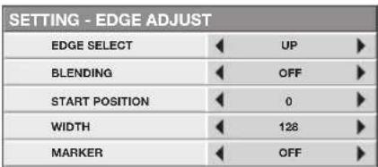
- Select an item you want to set by pressing the ▲ or ▼ button.
EDGE SELECT
Select the joint you want to adjust from UP, LOW, LEFT, and RIGHT.
BLENDING
When you select ON, the joint selected by EDGE SELECT becomes unnoticeable.
START POSITION
Set the position to start the edge adjustment.
When UP or LOW is selected: 0 to 270
When LEFT or RIGHT is selected: 0 to 480
WIDTH
Set the width of the overlap of the joint selected by EDGE SELECT.
When UP or LOW is selected: 4 to 524
When LEFT or RIGHT is selected: 4 to 944
- The setting range of START POSITION and WIDTH vary depending on their setting values.
MARKER
When you select ON, a marker for easily locating the overlap of the joint is displayed.
- Select a setting value by pressing the ◀ or ▶ button.
Repeat steps 7 to 8, if necessary.
-
Press the MENU button once.
-
Select BLACK LEVEL ▼ by pressing the ◀ or ▶ button.

- Press the ENTER button.
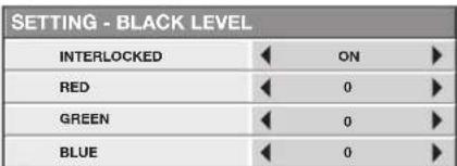
-
Select an item you want to set by pressing the ▲ or ▼ button.
-
Adjust the black level in areas other than the overlapped areas.
-
When you set INTERLOCKED to ON, you can adjust RED, GREEN, and BLUE simultaneously. When you set it to OFF, you can adjust RED, GREEN, and BLUE separately.
-
Select a setting value by pressing the ◀ or ▶ button.
Repeat steps 12 to 13, if necessary.
-
Press the MENU button once.
-
Select BRIGHT UNIFORMITY CORRECTION by pressing the ◀ or ▶ button.
- When EDGE BLENDING is ON, the brightness of the projected images is made even.

- Press the ENTER button.
- The BRIGHT UNIFORMITY CORRECTION dialog box and the correction position marker are displayed.
BRIGHT UNIFORMITY CORRECTION dialog box

Correction position marker
- Every time you press the ENTER button, the BRIGHT UNIFORMITY CORRECTION dialog box shows POSITION and LEVEL alternately.
POSITION
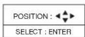
Press the ▲, ▼, ◀, or ▶ button to move the correction position marker.
LEVEL
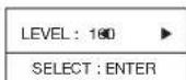
Press the ◀, or ▶ button to adjust the correction amount.
- Cancel the BRIGHT UNIFORMITY CORRECTION dialog box.
Press any button other than the ▲, ▼, ◀, or ▶, and ENTER buttons to clear the dialog box.
Or, the dialog box disappears in 10 seconds after the last use.
To cancel the menu:
- Press the MENU button.
Adjusting the color variations
You can adjust the variations in the colors of the images displayed on multiple projectors using the menu settings.
(See page 31 for menu setting.)
Adjustment while viewing the screen
-
Display the MULTI-SCREEN menu.
-
Select COLOR MATCHING by pressing the ▲ or ▼ button.

-
Select MANUAL by pressing the ◀ or ▶ button.
-
Select MANUAL by pressing the ▲ or ▼ button.

-
Select SETTING ▼ by pressing the ◀ or ▶ button.
-
Press the ENTER button.
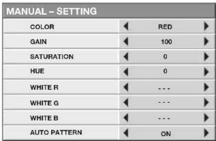
- Select an item you want to set by pressing the ▲ or ▼ button.
- Select the color you want to adjust using COLOR.
- When you set AUTO PATTERN to ON, the test pattern of each color is displayed.
- Select a setting value by pressing the ◀ or ▶ button.
Repeat steps 7 to 8, if necessary.
Adjustment using a chroma meter
-
Display the MULTI-SCREEN menu.
-
Select COLOR MATCHING by pressing the ▲ or ▼ button.

- Select MEASURE by pressing the ◀ or ▶ button.
Set the measured brightness and the chromaticity coordinates:
- Select MEASURE by pressing the ▲ or ▼ button.

-
Select MEASURED DATA ▶ by pressing the ◀ or ▶ button.
-
Press the ENTER button.
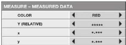
- Select an item you want to set by pressing the ▲ or ▼ button.
- Select the color you want to adjust using COLOR.
- Select a setting value by pressing the ◀ or ▶ button.
- You can enter numbers by pressing the number buttons (0 to 9) while holding down the NUM button on the remote control.
Repeat steps 7 to 8, if necessary.
Important:
- The color tone may not be displayed correctly depending on the setting value. Set the value within the proper range.
Set the target values of the brightness and chromaticity coordinates:
- Select MEASURE by pressing the ▲ or ▼ button.

-
Select TARGET DATA by pressing the ◀ or ▶ button.
-
Press the ENTER button.
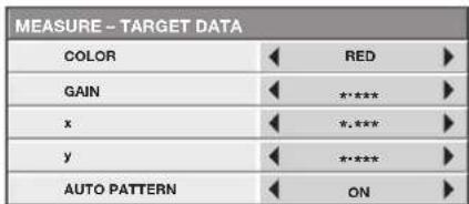
- Select an item you want to set by pressing the ▲ or ▼ button.
- Select the color you want to adjust using COLOR.
- When you set AUTO PATTERN to ON, the test pattern of each color is displayed.
- Select a setting value by pressing the ◀ or ▶ button.
- You can enter numbers by pressing the number buttons (0 to 9) while holding down the NUM button on the remote control.
Repeat steps 7 to 8, if necessary.
Important:
- The color tone may not be displayed correctly depending on the setting value. Set the value within the proper range.
Resetting the settings
- You can reset the SETTING, MANUAL, and MEASURE settings to the factory defaults.
-
Display the MULTI-SCREEN menu.
-
Select SETTING, MANUAL or MEASURE by pressing the ▲ or ▼ button.
-
Select RESET ▼ by pressing the ◀ or ▶ button.
-
Press the ENTER button.
You can set the network of the projector using the menu.

Setting Projector Name
(See page 31 for menu setting.)
-
Display the NETWORK menu.
-
Press the ▲ or ▼ button to select PROJECTOR NAME.

- Press the ENTER button.
• PROJECTOR NAME screen appears.
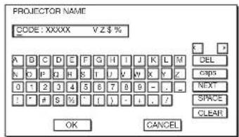
- Press the direction buttons to move the key cursor, select the characters or marks to enter, and press the ENTER button.
- Projector Name can be set using up to 15 characters including alphabets (capital/small), numeric characters, or marks.
← key: ...... Shifting the position of enter cursor to the left for each character.
→ key: ...... Shifting the position of enter cursor to the right for each character.
DEL key: ...... Deleting the character in the position of enter cursor for each character.
caps/CAPS key: Switching an alphabet character to CAPITAL or small.
NEXT/PREV key: Switching the marks listed on the fourth line.
SPACE key: ..... Inserting a space in the position of enter cursor.
CLEAR key: ..... Deleting all the entered characters.
- You can enter numbers by pressing the number buttons (0 to 9) while holding down the NUM button on the remote control.
- When selecting OK, the setting is completed as the name stored. However, when selecting CANCEL, the setting is completed without storing.
- The display returns the NETWORK menu after selecting OK or CANCEL.
• It may take some time to reflect the settings.
Enabling or disabling the network certification
You can select whether or not to certify the network communication using the network password.
• For details, contact your dealer.
(See page 31 for menu setting.)
-
Display the NETWORK menu.
-
Press the ▲ or ▼ button to select NET WORK CERTIFICATION.

- Press the ENTER button.
• Confirmation dialog appears.

-
Press the◀ or ▶ button to select ON □or OFF □
-
Press the ENTER button.
• To cancel the setting, press the MENU button.
• It may take some time to reflect the settings.
Network Password Settings
(See page 31 for menu setting.)
-
Display the NETWORK menu.
-
Press the ▲ or ▼button to select NETWORK PASSWORD.

- Press the ENTER button.
• CURRENT NETWORK PASSWORD screen appears.

- Press the direction buttons to move the key cursor, select the characters or marks to enter, and press the ENTER button.
- Password can be set using up to 32 characters including alphabets (capital/small) or numeric characters.
← key: ...... Shifting the position of enter cursor to the left for each character.
→ key: ...... Shifting the position of enter cursor to the right for each character.
DEL key: ...... Deleting the character in the position of enter cursor for each character.
caps/CAPS key: Switching an alphabet character to CAPITAL or small.
CLEAR key: ..... Deleting all the entered characters.
-
You can enter numbers by pressing the number buttons (0 to 9) while holding down the NUM button on the remote control.
• The default password is "admin". -
Select OK, and NEW NETWORK PASSWORD screen appears if the entered password is correct.
- If the entered password is not correct, CURRENT NETWORK PASSWORD screen appears again.
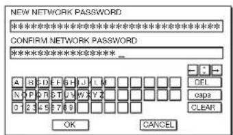
- Enter the NEW NETWORK PASSWORD and CONFIRM NETWORK PASSWORD.
- Password can be set using up to 32 characters including alphabets (capital/small) or numeric characters.
← key: ...... Shifting the position of enter cursor to the left for each character.
→ key: ...... Shifting the position of enter cursor to the right for each character.
key: ...... Shifting the position of enter cursor between NEW NETWORK PASSWORD and CONFIRM NETWORK PASSWORD.
DEL key: ...... Deleting the character in the position of enter cursor for each character.
caps/CAPS key: Switching an alphabet character to CAPITAL or small.
CLEAR key: ..... Deleting all the entered characters.
- You can enter numbers by pressing the number buttons (0 to 9) while holding down the NUM button on the remote control.
-
When NEW NETWORK PASSWORD and CONFIRM NETWORK PASSWORD are matched, the setting is completed after changing the NETWORK PASSWORD.
-
When you select OK and the passwords you entered are matched, the setting change dialog is displayed. After the dialog disappears, the NETWORK menu is displayed.
- When you select CANCEL, the NETWORK menu is displayed without changing the password.
- If the entered content is not matched, NEW NETWORK PASSWORD screen appears again after an error dialog is displayed.
- The password for the web control software of CRESTRON cannot be changed with this setting.
• It may take some time to reflect the settings.
IP Settings
(See page 31 for menu setting.)
- Display the NETWORK menu.
- Press the ▲ or ▼ button to select IP CONFIG.

- Press the ENTER button.
• IP CONFIG menu appears.

Setting or Clearing DHCP
- Display the IP CONFIG menu.
- Press the ▲ or ▼ button to select DHCP.

-
Press the ◀ or ▶ button to select ON or OFF.
-
When setting DHCP to ON, IP ADDRESS, SUBNET MASK, and DEFAULT GATEWAY cannot be set. If you set those settings, set DHCP to OFF and perform the IP settings as the following procedures.
- Until the execution of SAVE SETTINGS, the change is not saved.
IP Address Settings
- Display the IP CONFIG menu.
- Press the ▲ or ▼ button to select IP ADDRESS.

- Press the ENTER button.
• IP ADDRESS screen appears.

- Press the direction buttons to move the key cursor, select the numbers to enter, and press the ENTER button.
- Set the numeric value within the range from 0 to 255. However, set the numeric value for the final octet within the range from 1 to 254.
← key: Shifting the position of enter cursor to the left.
→ key: Shifting the position of enter cursor to the right.
DEL key: Deleting the character in the position of enter cursor for each character.
CLEAR key: Deleting all the entered characters.
- You can enter numbers by pressing the number buttons (0 to 9) while holding down the NUM button on the remote control.
- When selecting OK, the setting is completed as the IP ADDRESS stored temporarily. However, when selecting CANCEL, the setting is completed without storing.
- When the setting you entered is correct, the IP CONFIG menu is displayed. If the entered content is not correct, the IP CONFIG menu is displayed after an error dialog is displayed.
- Until the execution of SAVE SETTINGS, the change is not saved.
Subnet Mask Settings
-
Display the IP CONFIG menu.
-
Press the ▲ or ▼ button to select SUBNET MASK.

- Press the ENTER button.
• SUBNET MASK screen appears.
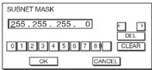
- Enter the Subnet Mask.
- Refer to IP Address Settings for the detail of entering.
- When selecting OK, the setting is completed as the Subnet Mask stored temporarily. However, when selecting CANCEL, the setting is completed without storing.
- When the setting you entered is correct, the IP CONFIG menu is displayed. If the entered content is not correct, the IP CONFIG menu is displayed after an error dialog is displayed.
- Until the execution of SAVE SETTINGS, the change is not saved.
Default Gateway Settings
-
Display the IP CONFIG menu.
-
Press the ▲ or ▼ button to select DEFAULT GATEWAY.

- Press the ENTER button.
• DEFAULT GATEWAY screen appears.

- Enter the Default Gateway.
- Refer to IP Address Settings for the detail of entering.
- When selecting OK, the setting is completed as the Default Gateway stored temporarily. However, when selecting CANCEL, the setting is completed without storing.
- When the setting you entered is correct, the IP CONFIG menu is displayed. If the entered content is not correct, the IP CONFIG menu is displayed after an error dialog is displayed.
- Until the execution of SAVE SETTINGS, the change is not saved.
Saving IP CONFIG Settings
-
Display the IP CONFIG menu.
-
Press the ▼ button to select SAVE SETTINGS.

- Press the ENTER button.
- The setting change dialog is displayed. After the dialog disappears, the NETWORK menu is displayed.
• It may take some time to reflect the settings.
Setting the control system
Set the control system.
(See page 31 for menu setting.)
-
Display the NETWORK menu.
-
Press the ▲ or ▼ button to select CONTROL SYSTEM.

- Press the ENTER button.

- Press the◀ or ▶ button to select STANDARD ▶ AMX ▶ or CRESTRON ▶
STANDARD
Select this setting when using ProjectorView Global+ or ProjectorView (see page 60), or RS-232C commands via LAN terminal.
AMX
Select this setting when using the controller of AMX. (See page 60.)
CRESTRON
Select this setting when using the controller or software of Crestron Electronics, Inc. (See page 60.)
Important:
- PJLink™ works regardless of the setting of CONTROL SYSTEM.
- Press the ENTER button.
• It may take some time to reflect the settings.
Initialization of Network Settings
(See page 31 for menu setting.)
- Display the NETWORK menu.
- Press the ▲ or ▼ button to select NETWORK RESET.
| NETWORK RESET | OK |
- Press the ENTER button.
• Confirmation dialog appears.
-
Press the ENTER button again, and the Network Settings can be initialized (except for IP CONFIG).
-
To cancel the initialization, press the MENU button.
- Alert E-mail setting is also reset. For details about Alert E-mail function, see “LAN control UTILITY operation manual” in the CD-ROM.
• It may take some time to reflect the settings.
How to Use Network Function
- When connecting a computer and projector with LAN, configure the both IP Addresses in the same network group.
If connecting in different network group, be sure to use a router. As for the settings of a router, ask the network administrator.
- Configure the IP CONFIG correctly. If the settings are not correct, the communication may be unavailable. For the detail, consult the network administrator.
- Depending on the settings of standby mode of the projector, LAN function may be unavailable. See page 34 for the detail of standby mode.
Glossary
For more detail of the glossary below, refer to the technical book that is commercially available.
| Term Description | |
| DHCP | Abbreviation for Dynamic Host Configuration Protocol. This protocol automatically assigns IP Address to networked devices. |
| IP Address | Numerical address to identify networked computers. |
| Subnet Mask | A numeric value to define the number of bits used for a network address of a divided network (or subnet) in an IP Address. |
| Default Gateway | A server (or router) to communicate across networks (subnets) that are divided by Subnet Mask. |
| MAC Address | Abbreviation for Media Access Control Address. MAC Address is a unique ID number assigned to each network adapter. And this is based on which data are sent and received between network adapters. |
Using the lamp relay function, you can project images continuously. The lamp relay function automatically rests or switches the lamps. The lamp relay is performed when LAMP SELECT in the INSTALLATION 1 menu is set to DUAL or SINGLE.
Setting the lamp relay interval
When LAMP SELECT is set to DUAL:
Either of the lamps is automatically put to rest. (See page 31 for menu setting.)
-
Display the INSTALLATION 1 menu.
-
Select LAMP SELECT by pressing the ▲ or ▼ button.
| LAMP SELECT | DUAL |
-
Press the ENTER button.
-
Select DUAL by pressing the ◀ or ▶ button.
| LAMP SELECT | |
| LAMP SELECT | DUAL |
-
Press the ENTER button.
-
Select LAMP RELAY by pressing the ▲ or ▼ button.
| LAMP RELAY | 1H/24H |
- Select 1H/24H 📁 or 2H/1W 📁 by pressing the ◀ or ▶ button.
1H/24H ☐.....Select this setting when the lamp is operated at a specified time of the day. During the continuous projection, LAMP 1 or LAMP 2 is automatically turned off for 1 hour in 24 hours. After the interval is set, the lamps are turned off for 1 hour alternately at the specified interval.
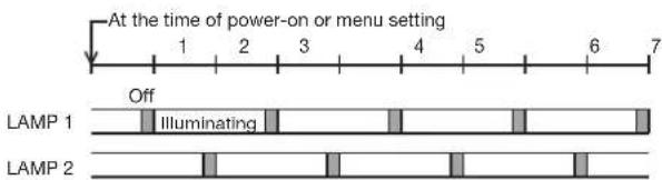
2H/1W ☐.....During the continuous projection, LAMP 1 or LAMP 2 is automatically turned off for 2 hours in a week. After the interval is set, the lamps are turned off for 2 hours alternately at the specified interval.

-
Press the ENTER button.
-
When you select 1H/24H or 2H/1W, the box to set the lamp relay interval is displayed.
- When the projector is turned off, the setting is cleared and the projector resumes operation from the time of the power-on or menu setting shown in the preceding step.
1H/24H

2H/1W

- Move the key cursor using the direction buttons to select the number you want to enter and then press the ENTER button.
• Maximum interval
1H/24H . 23H (23 hours)
2H/1W .☐.. 6D 22H (6 days and 22 hours)
← key: Shifting the position of enter cursor to the left for each character. → key: Shifting the position of enter cursor to the right for each character.
DEL key: Deleting the character in the position of enter cursor for each character.
CLEAR key: Deleting all the entered characters.
- You can enter the value by pressing the number buttons (0 to 9) while holding down the NUM button on the remote control.
- When the value you entered meets the following conditions, an error dialog box is displayed at the screen center.
- The value has been cleared by DEL or CLEAR and left blank.
- The value you entered is out of the setting range.
1H/24H . 24H or over
2H/1W .6D 23H or over
- The value of each item is out of the setting range.
D....7 or over (2H/1W ▼ only) H....24 or over
-
When selecting OK, the setting is completed as the lamp-switching interval stored. However, when selecting CANCEL, the setting is completed without storing.
-
The display returns the LAMP RELAY menu after selecting OK or CANCEL.
- The setting you made is applied to NEXT LAMP RELAY in the INFORMATION menu.
Important:
- When you use the projector continuously, the lamp relay may not be performed on time due to errors of the clock function.
- Immediately after the power-on, during the lamp selection, or during the lamp relay operation, you cannot change the setting of LAMP SELECT and LAMP RELAY.
- In the case of continuous projection, the lamps may deteriorate earlier unless they are turned off for 1 hour per week.
- When using this projector continuously for a long time of period, enable LAMP RELAY.
- The brightness and color tint vary at the time of lamp switching.
When LAMP SELECT is set to SINGLE:
The lamps are automatically switched and used alternately. (See page 31 for menu setting.)
-
Display the INSTALLATION 1 menu.
-
Select LAMP SELECT by pressing the ▲ or ▼ button.

-
Press the ENTER button.
-
Select SINGLE ▼ by pressing the ◀ or ▶ button.

-
Press the ENTER button.
-
Select LAMP RELAY by pressing the ▲ or ▼ button.

- Select 24H □ or 1 WEEK □ by pressing the ◀ or ▶ button.
24H ..... The lamps are switched to each other every day.

1 WEEK ☐. The lamps are switched to each other every week.

- Press the ENTER button.
- When you select 24H or 1 WEEK the box to set the lamp relay interval is displayed.
24H

1 WEEK
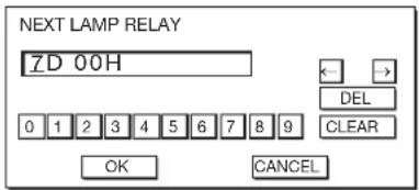
- Move the key cursor using the direction buttons to select the number you want to enter and then press the ENTER button.
• Maximum interval
24H ..... 24H (24 hours)
1 WEEK .7D 00H (7 days and 00 hours)
← key: Shifting the position of enter cursor to the left for each character. → key: Shifting the position of enter cursor to the right for each character.
DEL key: Deleting the character in the position of enter cursor for each character.
CLEAR key: Deleting all the entered characters.
- You can enter the value by pressing the number buttons (0 to 9) while holding down the NUM button on the remote control.
- When the value you entered meets the following conditions, an error dialog box is displayed at the screen center.
- The value has been cleared by DEL or CLEAR and left blank.
- The value you entered is out of the setting range.
24H ..... 25H or over
1 WEEK .7D 01H or over
- The value of each item is out of the setting range.
D ...... 8 or over (1 WEEK ☐ only)
H 25 or over
- When selecting OK, the setting is completed as the lamp-switching interval stored. However, when selecting CANCEL, the setting is completed without storing.
- The display returns the LAMP RELAY menu after selecting OK or CANCEL.
- The setting you made is applied to NEXT LAMP RELAY in the INFORMATION menu.
Important:
- When you use the projector continuously, the lamp relay may not be performed on time due to errors of the clock function.
- Immediately after the power-on, during the lamp selection, or during the lamp relay operation, you cannot change the setting of LAMP SELECT and LAMP RELAY.
- In the case of continuous projection, the lamps may deteriorate earlier unless they are turned off for 1 hour per week.
- When using this projector continuously for a long time of period, enable LAMP RELAY.
- The brightness and color tint vary at the time of lamp switching.
Changing the image displayed at the startup
You can display your desired image as the startup screen (or splash screen). By setting the menu, you can use such image instead of the background image that is displayed when no video signal is supplied.
Important:
- You can't set IMAGE CAPTURE when PASSWORD FUNCTION in the FEATURE menu has been set to SPLASH ID SCREEN to enable the password lock.
- You can't set IMAGE CAPTURE when the component video signal is inputted.
Setting procedure
(See page 31 for menu setting.)
- Press the COMPUTER button to select the image supplied to the COMPUTER/COMPONENT VIDEO IN terminal.
- Display your desired image.
- Display the INSTALLATION 2 menu.
- Select IMAGE CAPTURE by pressing the ▲ or ▼ button.
- Press the ENTER button.
• The setting menu will be displayed.

Set the background color
(Set the background color only when you set the image size to x1 or x4.)
- Select BACK COLOR by pressing the ▲ or ▼ button.
- Select your desired color for the background (GRAY, RED, GREEN, BLUE, BLACK, WHITE, RED50%, GREEN50%, or BLUE50%) by pressing the ◀ or ▶ button.
Set the image size
- Select SIZE by pressing the ▲ or ▼ button.
- Select x1, x4, or FULL by pressing the ◀ or ▶ button.

x1
x4

FULL
Capture the image
- Select CAPTURE by pressing the ▲ or ▼ button.
-
Press the ENTER button.
-
A red frame appears. (The size of the red frame is 640 x 400 pixels.)
- The image within the outer edges of the red frame is captured.
- The captured image is displayed in the NATIVE mode automatically.
![graph TD A["CAPTURE: ENTER + ENTER CANCEL: MENU"] --> B["OUTPUT: Triangle"] B --> C["Final GUI"]](/content/2026/05/1024347/images/582ed3788e4556feb9165d05f65948e12e14bf7ffbce22ad2d57344fea1bc794.jpg)
-
Adjust the size of the image to be captured so that such image stays within the red frame.
-
Press the ▲, ▼, ◀ or ▶ button to move the red frame.
- You can't move the red frame outside the screen.
- Press the MENU button to cancel the procedure.

- Press the ENTER button twice.
• Image capture will start.

- When the image capture completes, the captured image will be displayed for 1 second.
Important:
- You can't change the new startup screen back to the original startup screen. (Even when you select RESET ALL in the FEATURE menu, the factory default screen isn't available any longer.) When you want to change the startup screen again, capture another image.
- The captured image will be displayed from the next startup. If the captured image isn't displayed, make sure that the setting of SPLASH SCREEN in the INSTALLATION 2 menu isn't OFF. (See page 35.)
- When BACK COLOR in the INSTALLATION 2 menu is set to IMAGE, the captured image will be displayed while no signal is supplied.
- When no video signal is supplied, the projector takes some time to display the captured image.
- Some images can't be captured correctly because of their signal type.
- When SIZE of CUSTOM IMAGE CAPTURE is FULL and the size of the captured image is different from that of the projection screen being used, the displayed image is cropped and the background color is visible. In such a case, capture images at the current projection size.
Password function
This projector is equipped with the password function that is designed for prevention of wrong operation by children and restriction on operation by other than specified users. The password function has 3 modes as follows.
DISPLAY INPUT ...... When the projector is turned on, the startup screen (or splash screen) will appear and stay on the screen until the password is entered. When the password is entered, the startup screen will switch to the regular operation screen.
MENU ACCESS ...... All the buttons except for the POWER button on the projector are disabled. (The buttons on the remote control are enabled.) You can use this mode as a measure of prevention of wrong operation by children and restriction on operation by other than specified users.
SPLASH ID SCREEN ... IMAGE CAPTURE and SPLASH SCREEN in the INSTALLATION 2 menu become unavailable. SPLASH SCREEN will be set to ON automatically.
To enable the password function:
- Display the FEATURE menu.
- Press the ▲ or ▼ button to select PASSWORD FUNCTION.
- Press the ◀ or ▶ button to change the mode among DISPLAY INPUT ▼ MENU ACCESS □ and SPLASH ID SCREEN ▼
- When the password has already been set, the mode won't be changed. In such cases, press the ENTER button to cancel the password function and try again.
- Press the ENTER button.
- The screen for setting the password function will appear.

- Press the ENTER button.
- The screen for entering a password will appear.

- Enter a 4 - 8 digit password using the ▲, ▶, ▼ and ◀ buttons.
(▲=1, ▶=2, ▼=3, ◀=4)
- You can enter the value by pressing the number buttons (1 to 4) while holding down the NUM button on the remote control.
- Press the ENTER button.
- To cancel the procedure, press the MENU button.
-
Enter the password again for confirmation using the same steps.
-
Press the ENTER button.
-
If the entered passwords don't match, an error message will appear.
- To cancel the procedure, press the MENU button.
To cancel the password function:
- Display the FEATURE menu.
- Press the ▲ or ▼ button to select PASSWORD FUNCTION.
- Press the ENTER button.
- The screen for canceling the password function will appear.

- Press the ENTER button.
- The screen for entering the password will appear.

- Enter a 4 - 8 digit password using the ▲, ▶, ▼ and ◀ buttons.
(▲=1, ▶=2, ▼=3, ◀=4)
- You can enter the value by pressing the number buttons (1 to 4) while holding down the NUM button on the remote control.
-
Press the ENTER button.
-
If you enter a wrong password, an error message will appear.
- To cancel the procedure, press the MENU button.
Important:
- Disable the password by pressing the MENU and ENTER buttons on the projector at the same time about 3 seconds.
Split
You can split the screen in two and display a computer image on the left screen and a video image on the right screen.

Left screen Right screen
To use the split mode:
-
Press the SPLIT button on the remote control.
-
The screen is split in two and the left and right screens display the following images:
- Left screen: Image supplied to the last selected input source, COMPUTER1, COMPUTER2, DVI, HDMI or SDI (for UD8900U only)
-
Right screen: Image supplied to the last selected input source, VIDEO or S-VIDEO
-
When you press the SPLIT button again, the screen is displayed in the normal mode.
- Also, when you press the MENU button or change the input source, the screen is displayed in the normal mode.
- In the split mode, the picture quality settings of the input source in the normal mode to be displayed on the left screen are reflected on the entire screen.
- When no signal is input, a blue screen is displayed.
- When you input an interlace signal to the left screen, the displayed image may shake up and down slightly, but this is not a malfunction.
- When you display 60-Hz and 50-Hz video signals at the same time, motion images may not be displayed properly. In this case, set VERT.SYNC. of USER in the SIGNAL menu to OFF for the left screen. (See page 40.)
- When BACK COLOR of the INSTALLATION 2 menu is set to IMAGE, you cannot use the split mode unless a video signal is being input.
- Displaying the screen split in two may take some time depending on the signal.
To change the input source of the left or right screen:
- To change the input source of the left screen, press the ◀ button on the remote control.
- To change the input source of the right screen, press the ▶ button on the remote control.
Freeze
To stop the motion in the image temporarily (or to display a still image):
Press the FREEZE button on the remote control.
• The image will freeze temporarily.
To resume the motion in the image:
Press the FREEZE button on the remote control again.
Important:
- Do not display a still picture for a long time because the afterimages may persist on the screen.
Supervising and controlling by computer
You can supervise and control the projector's operation using a personal computer via a LAN.
Major functions
ProjectorView Global+
Batch projector controlling / supervising application software
- Batch operation of stand-alone projector / multiple projectors
- Scheduling function to turn ON/OFF for each day of the week
- Checking each condition of the projector and detecting a theft
- Setting of the projector's IP CONFIG
- Startup of the controlling / supervising tool (ProjectorView) using the Web browser
- Activating Visual PA2 to display the specified characters on the projector's screen
- Projector's Text Speech function to read aloud messages displayed on the Visual PA2 window
ProjectorView
The controlling /supervising tool using the Web browser
• Controlling and supervising a single projector
- Setting of the projector's network function
- Setting of the Alert E-mail service of the projector
AMX Device Discovery
The projector is monitored and controlled by the controller system of AMX.
Crestron RoomView Connected™
The projector is monitored and controlled by the controller system and software of Crestron Electronics, Inc.
PJLink™
This projector supports standard protocol PJLink™ for projector control and you can control and monitor projector's operations using the same application among projectors of different models and different manufacturers.
About ProjectorView Global+ and ProjectorView
- For details, see "LAN control UTILITY operation manual" in the CD-ROM.
About AMX Device Discovery
- This is a technology suggested by AMX to facilitate configuration of the control system of AMX and its target devices. To use this technology, it is necessary to set CONTROL SYSTEM in the NETWORK menu. (See pages 41 and 53.)
For details, see the website of AMX. URL http://www.amx.com/
About Crestron RoomView Connected™
- This is a technology suggested by Crestron Electronics, Inc. to facilitate configuration of the control system of Crestron and its target devices. To use this technology, it is necessary to set CONTROL SYSTEM in the NETWORK menu. (See pages 41 and 53.)
For details, see the website of Crestron Electronics, Inc.
URL http://www.crestron.com
URL http://www.crestron.com/getroomview/
Important:
- When you set CONTROL SYSTEM to CRESTRON in the NETWORK menu, the web control for Crestron is enabled. For such control, Adobe Flash Player should be installed in advance. You can download Adobe Flash Player from the website of Adobe Systems Incorporated.
- When you set CONTROL SYSTEM to CRESTRON in the NETWORK menu, you cannot use the control by ProjectorView Global+, which is the software supplied with the projector.
About PJLink™
- To use PJLink™ function, the PJLink™ application software is required.
- To use this function, set the network certification properly according to the setting of the network application to be used. (See page 51.)
- For the specifications of PJLink™, access to the Web site of Japan Business Machine and Information System Industries Association (JBMIA). (http://pjlink.jbmia.or.jp/english)
- This projector is fully compliant to the specifications of JBMIA PJLink™ Class 1. It supports all the commands defined by PJLink™ Class 1, and the compliance has been verified with the PJLink™ standard specifications Version 1.0.
Important:
- For the commands for PJLink™, see the table on the next page.
- The control may not be performed correctly or the monitoring data may not be obtained correctly in the following conditions:
- During standby
- During zoom/focus adjustment
- During lens shift adjustment
- During input source switching
- During auto position execution
- During BLANK
• During command processing
- Before the splash screen disappears after the power is turned on.
- During zoom/focus adjustment, lens shift adjustment, BLANK, etc., it may take approx. 5 seconds to receive a response to a command.
• Use 1 controller to control/monitor 1 projector. - For how to control/monitor using PJLink™, see the operation manual of the PJLink™ application you use.
- When you monitor the projector's operating state using this function by issuing inquiry commands successively, issue an inquiry command after receiving the response to the previous inquiry command from the projector.
Connection
For details of the connection, see “LAN control UTILITY operation manual” in the CD-ROM.
When STANDBY MODE of the INSTALLATION 1 menu of the projector is set to LOW, the network function is disabled. To enable the network function, set STANDBY MODE to STANDARD. (See page 34.)
Configure the initial network settings first.
You can configure the initial settings using the projector menu (see pages 51 to 54) or ProjectorView Global+ or ProjectorView. For details of ProjectorView Global+ and ProjectorView, see “LAN control UTILITY operation manual” in the CD-ROM.
Using the User Manual
The User Manual for LAN Control Utility is prepared in the Portable Document Format (PDF) in the CD-ROM.
Opening the User Manual:
- Load the CD-ROM into the CD-ROM drive.
- Open CD-ROM "PROJECTOR."
- Double-click on "MANUAL_LAN.HTML" within the CD-ROM. A language selection list for the User Manual will be displayed.
- Move the mouse pointer to the desired language and click.
PJLink™ supported commands
The table below shows commands to control the projector using the PJLink TM protocol.
| Command Description Remark (Parameter) | ||
| POWR Power control 0 = Standby | 1 = Power on | |
| POWR? Inquiry about the power state 0 = Standby | 1 = Power on2 = Cooling down3 = Warming up | |
| INPT Input switching 11 = COMPUTER1 12 = COMPUTER2 | ||
| INPT? Inquiry about input switching | 21 = VIDEO 22 = S-VIDEO31 = HDMI 32 = DVI33 = SDI (for UD8900U only) | |
| AVMT | Mute control | 30 = Video mute disable31 = Video mute enable |
| AVMT? | Inquiry about the mute state | |
| ERST? | Inquiry about the error state | 1st byte: Fan error, 0 or 22nd byte: Lamp error, 0 to 23rd byte: Temperature error, 0 or 24th byte: Cover open error, 0 or 25th byte: Filter error, 0 or 26th byte: Other error, 0 or 20 to 2 mean as follows:0 = No error detected, 1 = Warning, 2 = Error |
| LAMP? | Inquiry about the lamp state | 1st value (1 to 5 digits): Cumulative LAMP 1 operating time (This item shows a lamp operating time (hour) calculated based on that LAMP MODE is LOW.)2nd value: 0 = Lamp off, 1 = Lamp on3rd value (1 to 5 digits): Cumulative LAMP 2 operating time (This item shows a lamp operating time (hour) calculated based on that LAMP MODE is LOW.)4th value: 0 = Lamp off, 1 = Lamp on |
| INST? Inquiry about the available inputs The following value is returned.“11 12 21 22 31 32 33” | ||
| NAME? | Inquiry about the projector name | The projector name set on the NETWORK menu or the ProjectorView Setup window is returned. |
| INF1? | Inquiry about the manufacturer name | “MITSUBISHI” is returned. |
| INF2? | Inquiry about the model name | “UD8900U” or “UD8850U” is returned. |
| INF0? | Inquiry about other information | No other information is available. No parameter is returned. |
| CLSS? | Inquiry about the class information | “1” is returned. |
- This projector is fully compliant to the specifications of JBMIA PJLink™ Class 1. It supports all the commands defined by PJLink™ Class 1, and the compliance has been verified with the PJLink™ standard specifications Version 1.0.
Monitoring and control using SERIAL terminal
Using the SERIAL terminal, you can monitor and control multiple projectors collectively or individually.
• For details, contact your dealer.
![graph TD A["Computer"] --> B["RS-232C cable (option)"] B --> C["To RS-232C terminal"] C --> D["RS-232C cable (option) to RS-232C cable (option)"] D --> E["To SERIAL IN"] D --> F["To SERIAL OUT"] D --> G["To SERIAL IN"] D --> H["To SERIAL OUT"] D --> I["To SERIAL IN"]](/content/2026/05/1024347/images/892736c71140030d51fd43999bf8ab00a92a1f61cad076dae3ea08e290a39533.jpg)
- See also the instruction manuals of the devices to be connected.
Connection
- Make sure that the power supplies of the projector and the computer are off.
- Connect one end of a commercially available RS-232C cable to the SERIAL IN terminal on the projector to be connected to the computer.
- Connect the other end of the RS-232C cable to the serial port on the computer.
- Connect one end of an RS-232C cable to the SERIAL OUT terminal on the projector that is connected to the computer.
- Connect the other end of the RS-232C cable to the SERIAL IN terminal on the second projector.
- For the connection of the second and later projectors, connect their SERIAL OUT terminals and the SERIAL IN terminals using RS-232C cables.
Important:
- In a system using a serial divider, don't connect the projectors as above.
To monitor and control the projectors collectively or individually, it is necessary to assign PROJECTOR IDs or GROUP IDs to them.
Setting PROJECTOR IDs
You can monitor and control multiple projectors individually.
PROJECTOR IDs should be two-digit numbers "01" to "63" or "ALL." The other numbers cannot be used.
- The default PROJECTOR ID is ALL.
- By assigning the same PROJECTOR ID to multiple projectors, you can monitor and control those projectors collectively.
(See page 31 for menu setting.)
- Display the FEATURE menu.
- Select PROJECTOR ID by pressing the ▲ or ▼ button.

- Set the PROJECTOR ID by pressing the ◀ or ▶ button.
Important:
- To monitor and control the projectors individually, assign different PROJECTOR IDs to them.
- By assigning ALL, you can monitor and control the projectors regardless of the ID numbers.
Setting GROUP IDs
By dividing the projectors into groups, you can monitor and control them collectively by groups.
GROUP IDs should be A to Z. You can create up to 26 groups.
• The default GROUP ID is A.
(See page 31 for menu setting.)
- Display the FEATURE menu.
- Select GROUP ID by pressing the ▲ or ▼ button.

- Set the GROUP ID by pressing the ◀ or ▶ button.
Important:
- When you want to monitor and control the projectors by groups, set a different GROUP ID.
• For details, contact your dealer.
Control by a control panel, etc.
When installing the projector in a place where the remote control signals cannot reach the projector, you can control the projector using a control panel or other device connected to the REMOTE 1 IN terminal.

Controllable functions
- Switching between remote control and external control
- Switching input signals
• Power-on and power-off
• BLANK-on and BLANK-off
Important:
- To control the projector using a control panel, set STANDBY MODE in the INSTALLATION 1 menu to STANDARD. When it is LOW, you cannot control the projector.
Connection
- Make sure that the power supplies of the projector and control panel are off.
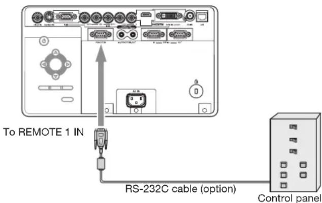
- Connect one end of an RS-232C cable to the REMOTE 1 IN terminal on the projector.
- Connect the other end of the RS-232C cable to the control panel.
Pin functions (defaults)
REMOTE 1 IN (D-SUB 9-pin)
| Pin No. | Signal Open (H) | Short (L) | |
| 1 GND – GND | |||
| 2 POWER OFF ON | |||
| 3 Input – | COMPUTER1 | ||
| 4 Input – | COMPUTER2 | ||
| 5 Input – VIDEO | |||
| 6 Input – | S-VIDEO | ||
| 7 Input – | DVI | ||
| 8 | BLANK | OFF ON | |
| 9 | ON/OFF | Valid (Remote control) | Invalid (External contact control) |
- You can change the functions of PIN 2 to PIN 8 using REMOTE 1 MODE in the INSTALLATION 2 menu. See page 35.
Important:
- To reset the pin functions to the defaults, set REMOTE 1 MODE in the INSTALLATION 2 to RESET.
Contact control
By short-circuiting Pin No. 1 and Pin No. 9, you can control the projector using a control panel or other device.
- When you short-circuit Pin No. 1 and Pin No. 9, the following functions cannot be used:
• POWER and BLANK of the remote control and the projector
- RS-232C commands and network functions corresponding to the above-mentioned functions
- REMOTE 1 MODE, AUTO POWER ON and AUTO POWER OFF in the INSTALLATION 2 menu.
• STANDBY MODE in the INSTALLATION 1 menu.
Input switching control
By short-circuiting any of Pin No. 3 to Pin No. 7, you can switch the input using a control panel or other device.
- When short-circuiting any of Pin No. 3 to Pin No. 7, you cannot use the following functions.
- POWER, BLANK, COMPUTER 1, COMPUTER 2, VIDEO, S-VIDEO, DVI, HDMI, and SDI (for UD8900U only) of the remote control and the projector
- RS-232C commands and network functions corresponding to the above-mentioned functions
POWER control
By short-circuiting or open-circuiting Pin No. 2, you can turn on or off the power using a control panel or other device.
BLANK control
By short-circuiting or open-circuiting Pin No. 8, you can turn on or off the BLANK function using a control panel or other device.
This projector is equipped with 2 lamps to project images. This lamp is a consumable. It may burn out or its brightness may decrease during use. In such cases, replace the lamp with a new one as soon as possible. Be sure to replace the lamp with a new lamp separately sold that is exclusive to this projector. Contact your dealer for purchase of the lamp.
Spare lamp VLT-XD8600LP
Warning:
- Be careful not to drop the lamp fixing screws into the inside of the projector. Don't put a metal piece or flammable object into the projector. Using the projector with any foreign object present inside may result in electric shock or fire. When you can't remove the foreign object from the inside, contact your dealer for removal.
- Do not touch the lamp with bare hands or give a shock to the lamp. Attach the lamp properly. Improper handling may cause explosion.
- Be sure to install the lamp securely. When the lamp isn't installed properly, it won't illuminate. Improper installation may also result in fire.
- Don't shake the removed lamp or don't lift it above your face. You may be injured in your eye by flying or falling glass fragments.
- Don't replace the lamp immediately after use because the lamp cover is very hot. You may get burned. Turn off the power using the POWER button. After the lamp goes out, wait about 2 minutes until the intake and exhaust fans for cooling the lamp stop rotating. Then unplug the power cord, and wait at least 1 hour to allow the lamp to cool down enough to the touch.
Interval of lamp replacement
The recommended interval of lamp replacement is about 4000 hours 12 of consecutive use. Such interval differs depending on the operating environment and may be shorter than 4000 hours 12 . Decrease in luminescence and/or color brightness indicates that the lamp needs to be replaced. When the lamp operation time exceeds 3000 hours 1 , the indicator will blink alternately between green and red (while the lamp is lit; when the lamp is not lit, the indicator will be lit red only) and the lamp replacement message will appear on the screen for 1 minute every time the lamp is turned on. When the lamp has been used for about 3800 hours 1 , the replacement message (LAMP REPLACEMENT) will appear on the screen for 1 minute every 20 hours 1 thereafter. When the lamp operation time exceeds 4000 hours 1*2 , the projector automatically shuts off.
*1: Duration when LAMP MODE of the INSTALLATION 1 menu is set to LOW. When it is set to STANDARD, this duration will be shorted.
*2: When LAMP MODE is set to STANDARD, this duration will be shorted to 2000 hours.
Caution:
- Don't remove the lamp for any purpose other than replacement. Unnecessary removal of the lamp may result in a breakdown.
- This projector uses a high-pressure mercury lamp as the light source. The high-pressure mercury lamp may explode or fail to illuminate permanently
because of an impact, scratch, or deterioration through use. The period of time until explosion or permanent failure to illuminate varies considerably from lamp to lamp, depending on operation conditions. Therefore, the lamp may explode soon after the start of use.
- The possibility of explosion of the lamp increases if you use it beyond its replacement period. When the instruction of lamp replacement appears, replace it with a new one immediately even if the lamp is still lighting normally.
- When the high-pressure mercury lamp explodes, glass fragments will scatter inside or outside the lamp box and the gas charged inside the lamp will diffuse inside or outside the projector. The gas inside the lamp contains mercury. Be careful not to breathe it or avoid it from entering your eye or mouth. If you should breathe it or if it should enter your eye or mouth, see a doctor immediately.
- In the event that the high-pressure mercury lamp exploded, glass fragments may have been scattered inside the projector. Ask your dealer to replace the lamp and to inspect the inside of the projector. When you clean or replace the lamp by yourself, be sure to hold the handle of the lamp. You may get injured by glass fragments.
- When removing the lamp from the ceiling-mounted projector, use the lamp replacement tray packed with the projector or option lamp to prevent glass fragments from scattering.
- Be sure to use the lamp exclusive to this projector, VLT-XD8600LP. Use of other lamps may cause a failure of the projector.
Before replacing the lamp
- Check which indicator (for LAMP 1 or LAMP 2) is illuminating or blinking.

- For the statuses of the indicators urging you to replace the lamps, see page 73.
- Replace the lamp indicated by the illuminating/ blinking indicator using the following procedure.
- When both indicators are illuminating or blinking, replace both lamps at the same time.
To replace the lamp:
- Unplug the power cord from the outlet or appliance inlet.
- Loosen two screws (a) that are securing the lamp cover using a Phillips screwdriver and remove the lamp cover (b) from the projector.

- Loosen two screws (c) that are securing the lamp box to be removed using a Phillips screwdriver.
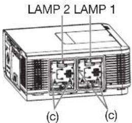
-
Pull the handle.
-
Pull out the lamp box by the handle while holding the projector.
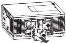
- Pull the lamp box out of the projector slowly. When the lamp is broken, glass fragments may be scattering by quickly pulling out the lamp box.
- Do not spill liquid on the removed lamp box or do not place it near any flammable object or where children can reach to prevent injury or fire.
- Load a new lamp box securely into the projector in the right orientation.
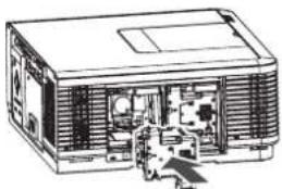
- Put the handle back to the original position.
• Make sure that the handle is locked.
- Tighten two screws (c) of the new lamp box tightly using a Phillips screwdriver.

• Make sure that the screws are tightened firmly.
- Insert the lamp cover (b) into the projector and tighten two screws (a) on the lamp cover firmly using a Phillips screwdriver.
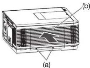
- You cannot turn on the projector without attaching the lamp cover.
Reset of the lamp operation time Reset the lamp operating time of the newly installed lamp.
You can reset the lamp operation time using the menu. (See page 31 for menu setting.)
-
Plug the power cord into the wall outlet.
-
Press the POWER button.
-
Display the FEATURE menu.
-
Select ADVANCED MENU by pressing the ▲ or ▼ button.
| ADVANCED MENU | ENTER |
-
Press the ENTER button.
-
Select LAMP 1 TIME RESET or LAMP 2 TIME RESET by pressing the ▲ or ▼ button.
| LAMP 1 TIME RESET | OK ☐ |
| LAMP 2 TIME RESET | OK ☐ |
- Press the ENTER button.
• The confirmation dialog appears.
EXECUTE LAMP 1 TIME RESET?
- Reset by pressing the ENTER button.
- When the lamp operating time isn't reset, press the MENU button.
Important:
- Make sure that the LAMP indicator blinks twice and the lamp operation time is reset successfully.
- When the operation times of both lamps have exceeded 4000 hours*, you can operate the projector only for 3 minutes after turning on the power. During this time, carry out steps 12 to 17 to reset the lamp operation times.
- The projector doesn't turn on if the lamp cover isn't attached securely.
- Be sure to reset the lamp operation time whenever you replace the lamp.
- Do not reset the lamp operation time unless you replace the lamp.
- The lamp is fragile. If it is broken, be careful not to cut yourself with glass fragments.
*: When LAMP MODE is set to STANDARD, this duration will be shorted to 2000 hours.
Caution:
- This projector uses a lamp that contains mercury. Disposal of the lamp or the projector with the lamp may be regulated due to environmental considerations. For disposal or recycling information, please contact your local authorities or the Electronic Industries Alliance: www.eiae.org. (For the U.S. only.)
When removing the lamp from the ceiling-mounted projector
When removing the lamp from the ceiling-mounted projector, use the lamp replacement tray packed with the projector or option lamp to prevent glass fragments from scattering.
- Assemble the lamp replacement tray according to the procedure shown on it.
-
Follow steps 1 to 4 on pages 64 and 65.
-
Attach the lamp replacement tray to the projector as shown in the figure.
-
Secure the lamp replacement tray on the projector using the tape packed with the tray.
-
Pull out the lamp box to be removed by the handle while holding the projector.
-
Hold the lamp replacement tray to prevent glass fragments from scattering.
-
Don't put the lamp directly on the lamp replacement tray because it may fall.
-
Detach the lamp replacement tray together with the removed lamp.
-
Follow steps 6 to 17 on page 65.
Important:
- When the projector is installed at other setting angles, replace the lamp referring to "To replace the lamp."


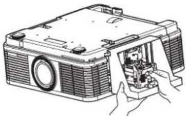
Maintenance
Warning:
- Do not use flammable solvents (benzene, thinner, etc.) and flammable aerosols when cleaning the projector body and lens. Flammable substances may ignite causing fire or breakdown while the lamp is illuminating.
Caution:
- Be sure to turn off the lamp and unplug the power cord from the wall outlet before you perform any maintenance on the projector.
- Ask your dealer for annual cleaning of the inside of the projector. If you continue to use the projector with dust inside, it may result in fire or malfunction.
- Do not put any foreign object into the filter unit. It may cause malfunction.
Cleaning of the projector and the vents
Use a soft cloth to clean the projector and the vents. When the vents become dirty, wipe them with a soft cloth dampened with diluted mild detergent, and then wipe them with a dry cloth.
- Clean the inside of the terminal cover frequently as dust is apt to be collected.
To protect the surface of the projector from fading or deteriorating:
- Do not spray insecticide on or inside the projector.
• Do not use benzine or thinner to clean it. - Do not let rubber or plastic materials contact with projector.
Cleaning of the lens
Use a standard lens-cleaning brush or a piece of lens tissue dampened with lens cleaning fluid. The lens surface is fragile. Use only recommended, nonabrasive lens-cleaning materials. Do not touch the lens with your fingers.
This projector is equipped with an automatic cleaning filter. The burdensome filter cleaning is automatically carried out.
- When the power of the projector is on, the filter is cleaned after the designated time elapses.
- When the cumulative operation time since the last cleaning of the automatic cleaning filter exceeds the designated time, the filter is cleaned automatically after you turn off the projector by pressing the POWER button.
Important:
- When the cumulative operation time has exceeded the designated time and you run the projector continuously for 24 hours after turning on the power, the automatic cleaning filter works while the projector is operating.
Setting the cleaning interval
You can set the cleaning interval of the automatic cleaning filter using the menu.
(See page 31 for menu setting.)
- Display the INSTALLATION 2 menu.
- Select FILTER MENU by pressing the ▲ or ▼ button.

-
Press the ENTER button.
-
Select CLEANUP PERIOD by pressing the ▲ or ▼ button.

- Select 24H ▼ or 1 WEEK ▼ by pressing the ◀ or ▶ button.
24H .....The filter is cleaned about every 24 hours.
1 WEEK .....The filter is cleaned about every 168 hours.
- Press the ENTER button.
- When you select 24H or 1 WEEK the box to set the cleaning interval is displayed.
24H

1 WEEK
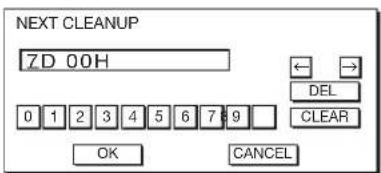
- Move the key cursor using the direction buttons to select the number you want to enter and then press the ENTER button.
• Maximum interval 24H ..... 24H (about 24 hours)
1 WEEK .7D 00H (about 168 hours)
← key: Shifting the position of enter cursor to the left for each character.
→ key: Shifting the position of enter cursor to the right for each character.
DEL key: Deleting the character in the position of enter cursor for each character.
CLEAR key: Deleting all the entered characters.
- You can enter the value by pressing the number buttons (0 to 9) while holding down the NUM button on the remote control.
- When the value you entered meets the following conditions, an error dialog box is displayed at the screen center for 3 seconds.
- The value has been cleared by DEL or CLEAR and left blank.
- The value you entered is out of the setting range.
24H ..... 25H or over
1 WEEK .7D 01H or over
- The value of each item is out of the setting range.
D...... 8 or over (1 WEEK ▼ only)
H.... 25 or over
- Select OK to accept the interval you entered and exit the menu, or select CANCEL to exit the menu without saving the setting.
- When you select OK or CANCEL, the CLEANUP PERIOD menu is displayed.
How to clean the automatic cleaning filter
Check the amount of dust through the dust check window of the filter cover and clean it, if necessary. Before cleaning the filter, be sure to unplug the power cord from the outlet.
- When the dust box of the automatic cleaning filter is filled up with dust, the cleaning ability decreases. If you use the projector in such a state, the filter is covered by the dust and the temperature inside the product abnormally rises, damaging the internal parts and components and affecting the panel's lifetime, resulting in a breakdown.
- When the temperature inside the projector is abnormally high, the projector may automatically turn off and go into the standby mode where the light source lamps are off to protect the internal parts and components.
- Loosen the screw (a) that is securing the filter cover using a Phillips screwdriver and remove the filter cover (b) from the projector.

Dust check window
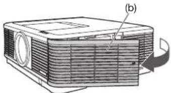
- Remove the automatic cleaning filter.
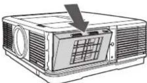
- Remove the dust box from the automatic cleaning filter and get rid of the dust from it.
- Suck dirt and dust from the automatic cleaning filter and projector using a vacuum cleaner.
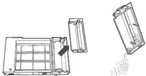
- Attach the dust box to the automatic cleaning filter.

- Attach the automatic cleaning filter.
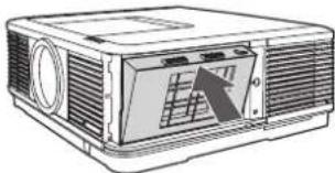
- Insert the filter cover (b) into the projector and tighten the screw (a) on the filter cover firmly using a Phillips screwdriver.

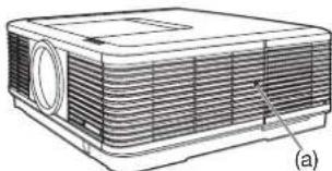
Before asking for repair of the projector, check the following. If the symptom persists, stop using the projector, be sure to unplug the power plug, and then contact your dealer.
No image appears on the screen.
| Problem Solution | ||||||
| Power can not be turned on. | Check whether the indicators are on or off and how they are lightning. | |||||
| POWER LAMP 1 LAMP 2 STATUS FILTER Solution | ||||||
| Off Off Off Off | Off Off Off | Off Off | Off | Connect the power cord to the projector.Plug the power cord into a wall outlet. | ||
| Steady red | Off Off Off | Off Off | Off | If any objects are blocking the intake or exhaust vents, remove them and carry out the following. Unplug the power cord from the wall outlet.1. Make sure that the projector has cooled off. 2. Plug the power cord into a wall outlet.3. 4. Press the POWER button. | ||
| Off Off | Blinking orange | Off | If any objects are blocking the intake or exhaust vents, remove them. Don't expose the exhaust vents to hot air emitted from a heating appliance. Check whether the filter is dirty or not.→ Clean the filter. (See page 68.) | |||
| Blinking green* | Off Off | Wait until the LAMP indicators stop blinking green and then press the POWER button. If you unplug the power cord while the fan is rotating, the lamp may not turn on about 2 minutes when you plug the power cord next time. The lamp can't turn on again for 2 minutes after it goes out. Press the POWER button several times. | ||||
| Steady red* | Off Off | Replace the light source lamp indicated by the illuminating indicator. (The time for replacing the light source lamp has come.) | ||||
| Blinking red/green | Off Off | Steady*orBlinking* | Attach the lamp cover, filter cover, and color wheel replacement cover. Unplug the power cord from the wall outlet and contact your dealer. | |||
| *: Status of either or both of the indicators. | ||||||
| No image appears on the screen. | Press the BLANK button to cancel BLANK.Check that the lens cap is removed.It may take about 2 minutes for the lamp to light up.The lamp fails to light up on rare occasions. In such a case, wait for a few minutes and then try again.If the projector was turned off before the lamp was cooled down sufficiently last time, the fan may start rotating and the POWER button may not work after the power cord is plugged. After the fan stops rotating, press the POWER button to turn back on the POWER indicator.Set SCART INPUT in the FEATURE menu to OFF. (See page 37.)Check that the intake vent is clean. Check that the cables connected to the external devices are not broken.When an extension cable is being used, replace it with the supplied cable for check. When images are displayed correctly, add an RGB signal amplifier to the extension cable. | |||||
| Power turns off. | This problem may occur when the intake vent and/or exhaust vents are blocked. (In such a case, the STATUS indicator brinks orange.)→ Remove the objects blocking the intake vent and/or exhaust vents and then carry out the following procedure.Wait for the intake fan and/or exhaust fan to stop. (Wait until the STATUS indicator goes out.)Unplug the power cord from the wall outlet.Wait about 10 minutes.Plug the power cord into a wall outlet.Press the POWER button.When the LAMP indicator is steady red, it is indicating that the lamp should be replaced. Replace the lamp that is being indicated by the indicator.Check that AUTO POWER OFF has been set to OFF.If the lamp has deteriorated, it may go out after a while it illuminates. | |||||
| The screen for entering the password appears. | PASSWORD FUNCTION in the FEATURE menu has been set to DISPLAY INPUT to enable the password lock.→ Enter the password or contact the person in charge of management of the projector. (See page 58.) | |||||
| “NO SIGNAL” is displayed. | Turn on the power of the connected device, or check whether there is something wrong with the connected device.Check whether the external device output signals. (Check this especially when the external device is a notebook computer.)Check that the cable connected to the external device isn’t defective.Check that the projector is connected to the external device using the correct terminalsCheck that the connected device is correctly selected as the input source.When an extension cord is being used, replace it with the supplied cable and check whether images are projected correctly. If images are projected correctly, use an RGB signal amplifier along with the extension cord. | |||||
Images are not displayed correctly.
| Problem Solution | |
| Projected images are shaking.Projected images are displaced.The edge of the projected images is not displayed. | Check that the cable connected to the external device isn't intermittent.Connect the cable's plug with the external device's connector firmly.Project an image containing many characters such as a help menu and press the AUTO POSITION button.Some computers output out-of-spec signals on rare occasion. Adjust the SIGNAL menu. (See pages 39 and 40.)Check whether there is a wind that blows the exhausted air from the projector to the direction of the projection lens. |
| Projected images are distorted. | Adjust the projector and the screen so that they are perpendicular to each other. (See page 14.) |
| Projected images are dark. | Adjust BRIGHTNESS and CONTRAST in the IMAGE menu. (See page 43.)Replace the lamp. (See page 64.)Decrease the temperature when the ambient temperature is high and the warning is displayed. |
| Projected images are blurred. | Adjust the focus. (See page 12.)Clean the lens.Press the◄ or ► button on the remote control to eliminate flicker.Adjust TRACKING and FINE SYNC. in the SIGNAL menu. (See page 48.)Adjust BRIGHTNESS and CONTRAST in the IMAGE menu. (See page 43.)Adjust the projector and the screen so that they are perpendicular to each other. (See page 14.) |
| White dots are seen on projected images.Black dots are seen on projected images. | This symptom is normal for a DLPTM projector and is not a malfunction. (A very small number of pixels may stay lit or out, but such symptom is not a malfunction. Pixels of 99.99% or more are effective.) |
| Rainbow effect is seen on projected images. | This is due to color breaking noise that occurs in a DLPTM system and is not a malfunction. |
| Fine streaks are seen on projected images. | This is due to interference with the screen surface and is not a malfunction. Replace the screen or displace the focus a little.Vertical or horizontal streak noise may appear on the projected image, depending on the type of the DVD player or game console you use. In such a case, you can reduce such streak noise by enabling the LPF. |
| Projected images become wavy. | Connect the plugs of the cables to external devices securely.Keep the projector away from devices that emit interfering radio waves.When the keystone adjustment is carried out, the image may not be displayed correctly depending on the type of input signal. This isn't a product malfunction. In this case, readjust the keystone so that the amount of keystone correction is as small as possible. |
| Hue is not appropriate. | If RGB/YCbCr output setting on the external device does not match with COMPUTER INPUT setting in the SIGNAL menu on the projector, the entire screen may become reddish or greenish.If the setting of COMPUTER INPUT in the SIGNAL menu is inconsistent with the RGB/ YCbCr output setting of the external device even when the input source is other than COMPUTER (for example, when the input source is HDMI), the entire image appears reddish or greenish.→ Check that COMPUTER INPUT in the SIGNAL menu is set correctly.Check that the cables connected to the external devices are not broken. |
| Tint in projected images is incorrect. | Check that COMPUTER INPUT in the SIGNAL menu is correctly set. (See page 39.)Check that the cable connected to the external device isn't broken. |
| Different color tint. • | When comparing images projected by two projectors, tints in the displayed images may be different because of variation between their optical components. This is not a malfunction.When comparing the image projected by this projector with those displayed on the television or PC monitor, tints in the displayed images may be different because of difference in the range of color reproducibility. This is not a malfunction. |
| Only the motion areas in the images supplied from the computer aren't displayed. | This is caused by the computer being used. Contact the manufacturer of your computer. |
| Projected images are obscured. | Match the output resolution of your computer with the resolution of the projector. For the method to change the output resolution of the computer, contact the manufacturer of your computer. (See page 75.)Some images and texts appear obscured during the keystone adjustment. In such cases, use the projector without applying the keystone adjustment. (See page 14.)When SUPER RESOLUTION is ON, the displayed image may be obscured. Set it to OFF. (See page 45.) |
| Noise appears around the image. | In some images such as DVD, noise may appear around the recorded image. In this case, decrease the setting value of OVER SCAN in the SIGNAL menu or adjust the setting value of SHUTTER in the USER menu of the SIGNAL menu. (See page 40.) |
| The resolution setting on the computer is different from that displayed in INFORMATION menu on the projector. | On the computer, display the images containing many characters such as a text document so that the screen becomes bright as much as possible, and then press the AUTO POSITION button.Perform RESOLUTION (MEMORIZE) in the SIGNAL menu. (See page 39.)Depending on the computer, the images may be output in the different resolution from the setting. In such a case, consult the computer manufacturer. |
| The projected images have blown-out highlights or blocked-up shadows. | Adjust the input level of ADVANCED MENU in the IMAGE menu.Set COLOR ENHANCER in the IMAGE menu to the setting such as STANDARD and sRGB. |
| Images of WXGA signal are not displayed correctly. | Make adjustment according to “How to adjust the computer image” on page 47. |
Others
| Problem Solution | |
| The exhaust vents emit warm air. | This air comes out after cooling the inside of the projector. You may feel hot, but this is not a malfunction. |
| The menu can’t be used. | The microcomputers inside the projector may be wrongly operating because of noise.→Press the POWER button to turn off the lamp, wait for about 2 minutes and unplug the power cord from the wall outlet. Wait about 10 minutes, plug the power cord in, and try again.You cannot select (or set) grayed-out items. Whether items can be selected or not depends on the presence of an input signal at the time when the menu is displayed, the type of such input signal, and other conditions. |
| “TEMPERATURE!!” is displayed. | This indication appears when the ambient temperature rises high. When the ambient temperature stays high, the lamp goes out.→ Eliminate any causes of the rise in the ambient temperature.This indication appears when the intake or exhaust vents are blocked. When they are kept blocked, the lamp goes out.→ Remove the objects blocking the intake or exhaust vents. |
| The mark appears. • | This mark appears when ineffective operation is carried out. This isn’t a product malfunction. |
| The remote control doesn’t function easily or at all. | Check that the batteries are loaded in the remote control or the batteries are not weak. (See page 6.)Check that the remote control sensor isn’t exposed to direct sunlight or fluorescent light. (See page 9.)Use the remote control within its operation range. (See page 9.)Use the remote control at least 10 cm away from the projector.Check that the CONTROLLER ID matches with the PROJECTOR ID. (See pages 10 and 62.)Check that the projector isn’t controlled by a control panel or other device that is connected to the REMOTE 1 IN terminal. (See page 63.)When the terminal cover is attached, remote control may not work properly from behind the projector.→ Remove the terminal cover. |
| The buttons on the projector (except for the POWER button) don’t function. | PASSWORD FUNCTION in the FEATURE menu has been set to MENU ACCESS to enable the password lock.→ Cancel the password lock or contact the person in charge of management of the projector. (See page 58.)Check that the projector isn’t controlled by a control panel or other device that is connected to the REMOTE 1 IN terminal. (See page 63.) |
| Abnormal sound is heard. | Because the color wheel spins at a high speed, metallic sounds may be heard in rare occasions. Such symptom is not a malfunction. |
| FOCUS/ZOOM doesn’t work.Lens shift doesn’t work. | Check that LENS LOCK in the INSTALLATION 1 menu isn’t ON. (See page 34.) |
If the following problem occurs after the lamp is replaced, check the following first.
| Problem Solution | |
| The projector does not turn on. | • Fit the lamp cover securely. (See pages 64 and 65.) |
| The LAMP indicator illuminates red. | • Reset the lamp operating time of the newly installed lamp. (See page 65.) |
Kensington Lock
This projector has a Kensington Security Standard connector for use with Kensington MicroSaver Security System. Refer to the information that came with the Kensington System for instructions on how to use it to secure the projector. Please contact Kensington Technology Group below.
Kensington Technology Group
2855 Campus Drive
San Mateo, CA 94403, U.S.A.
Phone: +1- (650)572-2700 Fax: +1- (650)572-9675
This projector has 5 indicators, each of which shows the operation condition of the projector.
The following offer solutions to possible problems. If these problems persist, turn the projector off and consult your dealer.

■ POWER, STATUS, and FILTER: The current condition is indicated.
| POWER STATUS FILTER CONDITION POSSIBLE SOLUTION | |||||
| Normal condition | [TRWT]Stel | ### | ### | Power standby or cooling | |
| ### | ### | ### | The power is on (Normal condition) The lamp condition is indicated by the LAMP indicators. | ||
| ### | ### | Automatic cleaning filter is working. Don't turn off the power before the indicators go out. | |||
| Abnormal condition | Bred | Off Off | (7473) | Any of the lamp cover, filter cover, and color wheel replacement cover2 is open.The automatic cleaning filter unit isn't mounted. | Close all the covers.Mount the automatic cleaning filter unit. (See page 68.) |
 | Abnormal Contact your dealer. | ||||
| S### | ### | ### | The automatic cleaning filter isn't working correctly. | ||
| ###or###Steady green | ### | ### | Abnormal temperatureThe vents are clogged with dust or dirt.The room temperature is high.The filter is dirty. | Clean the vents.Relocate the projector to a cooler place.Clean the filter. (See page 68.) | |
*1: Status of either or both of the indicators.
*2: You can replace it with a separately sold color wheel. (See page 74.)
■LAMP 1, LAMP 2: The condition of each lamp is indicated.
| LAMP 1 / LAMP 2 | CONDITION | POSSIBLE SOLUTION | |
| Normal condition | When the lamp is illuminating, it is in the warmup mode. (You cannot turn off the power.)When the lamp is off, it is in the cooling mode. (You cannot turn on the power.) | ||
| Steady green | The lamp is illuminating. | ||
| Replacement | Lamp operation time warning. (Total lamp operation time reached 3000 hours 3 .) | Replace the light source lamp indicated by the illuminating or blinking indicator.Change with a new lamp if this problem recurs. | |
| Steady red | Lamp operation time warning. (Total lamp operation time reached 4000 hours 3*4 .) | ||
| Abnormal condition | The protection circuit is working or the lamp is in an abnormal condition.When only one lamp fails:In the case that LAMP SELECT is set to DUAL, only the normal lamp illuminates (the intensity of one lamp is obtained).In the case that LAMP SELECT is set to SINGLE, LAMP 1, or LAMP 2, only the normal lamp illuminates (the lamp isn't switched). | When both indicators blink, wait until the indicators stop blinking and then press the POWER button. If the light source lamps don't illuminate even after you perform the above operation several times, unplug the power cord from the wall outlet and contact your dealer.To illuminate the failed lamp again when either indicator blinks, turn off the power and wait until the indicator stops blinking and then press the POWER button. If the light source lamp doesn't illuminate even after you perform the above operation several times, unplug the power cord from the wall outlet and contact your dealer. |
*3: Duration when LAMP MODE of the INSTALLATION 1 menu is set to LOW. When it is set to STANDARD, this duration will be shorted.
*4: When LAMP MODE is set to STANDARD, this duration will be shorted up to 2000 hours.
The specifications and outside appearance of the projector are subject to change without prior notice.
| Type DLPTM projector | ||
| Model UD8900U/UD8850U | ||
| Display technology 0.67-inch Single chip DMD | Pixel 1920 x 1200 = 2304000 pixels | |
| Projection lens F 2.0 - 2.4 f= 24.5 - 33.1 mm | ||
| Light-source lamp 350 W x 2 | ||
| Image size (projection distance) 40" min. to 300" max. (projection distance 1.4 to 10.9 m) | ||
| Maximum resolution Computer signal Maxi | mum resolution: 1920 x 1200 dotsPanel resolution: 1920 x 1200 dots | |
| Computer/component video input [Signal type] [Terminal type] [Line] Analog RGB Mini D-SUB 15-pin 1 Analog RGB 5 BNC 1 Digital RGB DVI-D 24-pin 1 | ||
| Video input | [Signal type] [Terminal type] [Line] Video input BNC 1 S-video input S 1 | |
| HDMI input | [Signal type] [Terminal type] [Line] HDMI HDMI 19-pin 1 | |
| SDI input*1 | [Signal type] [Terminal type] [Line] SDI BNC 1 | |
| Control terminal/others | SERIAL IN/OUT (D-SUB 9-pin male) RS-232C standards, LAN (RJ-45), REMOTE 1 IN (D-SUB 9-pin female), REMOTE2 IN/OUT (Stereo mini jack (ø3.5)) | |
| Operating temperatures | +41°F (+5°C) to +104°F (+40°C): (Standard altitude mode)+41°F (+5°C) to +95°F (+35°C): (High altitude mode: Floor installation/ceiling installation) | |
| Rated voltage | AC 100 - 240 V, 50/60 Hz | |
| Power consumption | 9.3 A, 910 WDuring standby: AC 100 - 120 V: 2 W (when STANDBY MODE is STANDARD) 0.2 W (when STANDBY MODE is LOW) AC 220 - 240 V: 2 W (when STANDBY MODE is STANDARD) 0.3 W (when STANDBY MODE is LOW) | |
| Dimensions (not including protrusion) | 490 mm (W) x 201 mm (H) x 421 mm (D) (projector only)490 mm (W) x 201 mm (H) x 506 mm (D) (including the terminal cover) | |
| Weight | 16 kg (projector only), 16.5 kg (including the terminal cover) | |
| Others | S-video input | Luminance signal: Vp-p=1.0 V 75 Ω (negative sync)Chrominance signals: Vp-p=0.286 V 75 Ω (burst signal) |
| Video input | Vp-p=1.0 V 75 Ω (negative sync) | |
| Component video input | YCBCR : Vp-p=1.0 V 75 Ω (Y) (negative sync)Vp-p=0.7 V 75 Ω ( CB , CR ) | |
| Analog input | RGB: Vp-p=0.7 V 75 Ω (negative sync) YCBCR : Vp-p=1.0 V (Y) (negative sync) Vp-p=0.7 V ( CB , CR )HD/CS: TTL-level (negative or positive polarity)VD: TTL-level (negative or positive polarity) | |
| Digital input (DVI) | DVI-D interface (TMDS single link) with HDCP | |
| Digital input (HDMI) | HDMI interface (TMDS single link) | |
| Digital input (SDI)*1 | SDI interface: SD-SDI ( YCBCR 4:2:2 10 bits) HD-SDI ( YPBPR 4:2:2 10 bits) 3G-SDI ( YPBPR 4:2:2 10 bits) | |
Replacement part (option/not included in the box)
Spare lamp: VLT-XD8600LP
Option lenses: OL-XD8000EZ, OL-XD2000SZ, OL-XD2000LZ, OL-XD2000TZ, OL-XD8000UZ, OL-XD2000FR
Option color-wheel: CW-FC5
*1: For UD8900U only.
Important:
- Ask a trained specialist for mounting or replacing the option lens or the option color-wheel. For details, contact your dealer.
Specification of RGB signals in each computer mode of the projector
| Signal mode | Resolution (H x V) | Horizontal frequency (kHz) | Vertical frequency (Hz) | Normal mode (H x V) | Native mode (H x V) | Plug and Play *3 | ||
| COMPUTER / COMPONENT VIDEO IN-1 terminal | COMPUTER / COMPONENT DVI-D IN (HDCP) terminal | HDMI IN terminal | ||||||
| TV60, 480i (525i) 720 | x 480 15.73 59.94 | 1600 x 1200 | -*1,*2 | |||||
| TV50, 576i (625i) 720 | x 576 15.63 50.00 | 1600 x 1200 | -*1,*2 | |||||
| 1080i60 (1125i60) 19 | 20 x 1080 33.75 60.00 | 1920 x 1080 | - | ○ | ○ | |||
| 1080i50 (1125i50) 19 | 20 x 1080 28.13 50.00 | 1920 x 1080 | - | ○ | ○ | |||
| 480p (525p) 720 x 480 | 31.47 59.94 | 1600 x 1200 | - | ○ | ○ | |||
| 576p (625p) 720 x 576 | 31.25 50.00 | 1600 x 1200 | - | ○ | ○ | |||
| 720p60 (750p60) 12 | 80 x 720 45.00 60.00 | 1920 x 1080 | - | ○ | ○ | |||
| 720p50 (750p50) 12 | 80 x 720 37.50 50.00 | 1920 x 1080 | - | ○ | ○ | |||
| 1080p60 (1125p60) | 1920 x 1080 67.50 60.00 | 1920 x 1080 | - | ○ | ○ | |||
| 1080p50 (1125p50) | 1920 x 1080 56.25 50.00 | 1920 x 1080 | - | ○ | ○ | |||
| CGA70 640 x 400 31 | .47 70.09 | 1920 x 1200 | 640 x 400 | |||||
| CGA84 640 x 400 37 | .86 84.13 | 1920 x 1200 | 640 x 400 | |||||
| CGA85 640 x 400 37 | .86 85.08 | 1920 x 1200 | 640 x 400 | |||||
| VGA60 640 x 480 31 | .47 59.94 | 1600 x 1200 | 640 x 480 | ○ ○ | ○ | |||
| VGA72 640 x 480 37 | .86 72.81 | 1600 x 1200 | 640 x 480 | ○ | ||||
| VGA75 640 x 480 37 | .50 75.00 | 1600 x 1200 | 640 x 480 | ○ | ||||
| VGA85 640 x 480 43 | .27 85.01 | 1600 x 1200 | 640 x 480 | |||||
| SVGA56 800 x 600 35 | .16 56.25 | 1600 x 1200 | 800 x 600 | ○ | ||||
| SVGA60 800 x 600 37 | .88 60.32 | 1600 x 1200 | 800 x 600 | ○ ○ | ○ | |||
| SVGA72 800 x 600 48 | .08 72.19 | 1600 x 1200 | 800 x 600 | ○ | ||||
| SVGA75 800 x 600 46 | .88 75.00 | 1600 x 1200 | 800 x 600 | ○ | ||||
| SVGA85 800 x 600 53 | .67 85.06 | 1600 x 1200 | 800 x 600 | |||||
| SVGA95 800 x 600 59 | .97 94.89 | 1600 x 1200 | 800 x 600 | |||||
| XGA60 | 1024 x 768 48 | .36 60.00 | 1600 x 1200 | 1024 x 768 | ○ ○ | ○ | ||
| XGA70 | 1024 x 768 56 | .48 70.07 | 1600 x 1200 | 1024 x 768 | ○ | |||
| XGA75 | 1024 x 768 60 | .02 75.03 | 1600 x 1200 | 1024 x 768 | ○ | |||
| XGA85 | 1024 x 768 68 | .68 85.00 | 1600 x 1200 | 1024 x 768 | ||||
| SXGA70a | 1152 x 864 63 | .85 70.01 | 1600 x 1200 | 1152 x 864 | ||||
| SXGA75a | 1152 x 864 67 | .50 75.00 | 1600 x 1200 | 1152 x 864 | ||||
| SXGA85a | 1152 x 864 77 | .49 85.06 | 1600 x 1200 | 1152 x 864 | ||||
| WXGA60 | 1280 x 768 47 | .78 59.87 | 1920 x 1152 | 1280 x 768 | ○ | ○ | ||
| WXGA60a 1280 x 80 | 49.70 59.81 | 1920 x 1200 | 1280 x 800 | ○ ○ | ○ | |||
| WXGA60b | 1360 x 768 47 | .71 60.02 | 1920 x 1085 | 1360 x 768 | ||||
| WXGA60c 1366 x 768 | 47.71 59.79 | 1920 x 1080 | 1366 x 768 | ○ ○ | ○ | |||
| WXGA+60 | 1440 x 900 55 | .94 59.89 | 1920 x 1200 | 1440 x 900 | ○ ○ | ○ | ||
| WXGA++60 | 1600 x 900 60 | .00 60.00 | 1920 x 1080 | 1600 x 900 | ||||
| SXGA60b | 1280 x 960 60 | .00 60.00 | 1600 x 1200 | 1280 x 960 | ○ ○ | ○ | ||
| SXGA75b | 1280 x 960 75 | .00 75.00 | 1600 x 1200 | 1280 x 960 | ||||
| SXGA85b | 1280 x 960 85 | .94 85.00 | 1600 x 1200 | 1280 x 960 | ||||
| SXGA60 | 1280 x 1024 63 | .98 60.02 | 1500 x 1200 | 1280 x 1024 | ○ ○ | ○ | ||
| SXGA75 | 1280 x 1024 79 | .98 75.02 | 1500 x 1200 | 1280 x 1024 | ○ | |||
| SXGA85 | 1280 x 1024 91 | .15 85.02 | 1500 x 1200 | 1280 x 1024 | ||||
| SXGA+60 | 1400 x 1050 63 | .98 60.02 | 1600 x 1200 | 1400 x 1050 | ||||
| 1400 x 1050 65 | .32 59.98 | 1600 x 1200 | 1400 x 1050 | ○ ○ | ○ | |||
| SXGA+75 | 1400 x 1050 82 | .28 74.87 | 1600 x 1200 | 1400 x 1050 | ||||
| WSXGA+60 | 1680 x 1050 65 | .29 59.95 | 1920 x 1200 | 1680 x 1050 | ||||
| MAC13 | 640 x 480 35 | .00 66.67 | 1600 x 1200 | 640 x 480 | ○ | |||
| MAC16 | 832 x 624 49 | .72 74.55 | 1600 x 1200 | 832 x 624 | ○ | |||
| MAC19 | 1024 x 768 60 | .24 75.02 | 1600 x 1200 | 1024 x 768 | ||||
| HP75 | 1024 x 768 62 | .94 74.92 | 1600 x 1200 | 1024 x 768 | ||||
| HP72 | 1280 x 1024 78 | .13 72.00 | 1500 x 1200 | 1280 x 1024 | ||||
| SUN66a | 1152 x 900 61 | .85 66.00 | 1536 x 1200 | 1152 x 900 | ||||
| SUN76a | 1152 x 900 71 | .81 76.64 | 1536 x 1200 | 1152 x 900 | ||||
| SUN66 1280 x 1024 | 71.68 66.68 | 1500 x 1200 | 1280 x 1024 | |||||
| SUN76 1280 x 1024 | 81.13 76.11 | 1500 x 1200 | 1280 x 1024 | |||||
| SGI72 | 1280 x 1024 76 | .92 72.30 | 1500 x 1200 | 1280 x 1024 | ||||
| SGI76 | 1280 x 1024 82 | .01 76.00 | 1500 x 1200 | 1280 x 1024 | ||||
| UXGA60 | 1600 x 1200 75 | .00 60.00 | 1600 x 1200 | 1600 x 1200 | ○ ○ | ○ | ||
| WUXGA60 1920 x 1200 | 74.04 59.95 | 1920 x 1200 | 1920 x 1200 | ○ ○ | ○ | |||
*1: The SPLIT mode and IMAGE CAPTURE in the INSTALLATION 2 menu don't function with these signals.
*2: COMPUTER/COMPONENT VIDEO DVI-D IN (HDCP) terminal and HDMI IN terminal aren't supported.
*3: Signals marked with ○ in the Plug and Play column are described in EDID (extended display identification data) of the projector.
Signals described in the Signal mode column can be input regardless of the ○ mark in the Plug and Play column.
For signals not marked with ○ in the Plug and Play column, the resolution may not be supported even when it is supported on the computer.
Specification of RGB signals in each computer mode of the projector (continued)
Important:
- Some computers aren't compatible with the projector.
- The projector's maximum resolution is 1920 x 1200 pixels. It may not display images of higher resolutions than 1920 x 1200 correctly.
• Images with SYNC on G (Green) signal may jitter. - Images with SYNC on G (Green) signal may be tinged with green.
- If the resolution and frequency of your computer aren't shown on the table, find the compatible resolution and frequency by changing the resolution of your computer.
- TV60 and TV50 are equivalent to 480i and 576i respectively. When these signals are supplied to the VIDEO IN or S-VIDEO IN terminal, the signal mode is indicated as TV60 or TV50. When they are supplied to the COMPUTER/COMPONENT VIDEO IN terminals, the signal mode is indicated as 480i or 576i.
Available signal system for SDI (for UD8900U only)
| SD-SDI 480i | |
| 576i | |
| HD-SDI 720/50p | |
| 720/60p | |
| 1080/50i | |
| 1080/60i | |
| 1080/24p | |
| 3G-SDI 1080/50p | |
| 1080/60p |
• The signal format supports 1/1.001.
- This projector doesn't support 480p signals from video devices having 4 lines (R, G, B, CS*) or having 5 lines (R, G, B, H, V).
* : Composite Sync
NATIVE mode
When moire patterns or lines of uneven thickness appear on the projected image, these symptoms may be improved by displaying it in its original image size (NATIVE mode). To display the image in the NATIVE mode, set ASPECT of the SIGNAL menu to NATIVE. (See page 31 for menu setting.)
- For signals that are larger than the panel resolution, only their center part is displayed in the NATIVE mode. The area exceeding the panel resolution isn't displayed.
- In the NATIVE mode, images are black-framed when the image resolution is lower than the panel resolution.
- In the NATIVE mode, some signals may be displayed with a black frame even when they have a higher resolution than the panel resolution.
Connectors
SERIAL IN/OUT
(D-SUB 9-pin)

| Pin No. | Name I/O | |
| 1 -- | ||
| 2 TXD IN | ||
| 3 RXD OUT | ||
| 4 -- | ||
| 5 GND - | ||
| 6 -- | ||
| 7 -- | ||
| 8 -- | ||
| 9 -- |
COMPUTER/COMPONENT VIDEO IN-1 (Mini D-SUB 15-pin)

| Pin No. | Spec. | Pin No. | Spec. |
| 1 R(RED)/P n/Cn | 9 DDC 5V | ||
| 2 G(GREEN)/Y 10 GND | |||
| 3 B(BLUE)/P p/Cp | 11 GND | ||
| 4 GND 12 DDC Data | |||
| 5 GND 13 HD/CS | |||
| 6 GND 14 VD | |||
| 7 GND 15 DDC Clock | |||
| 8 GND | |||
COMPUTER/COMPONENT VIDEO DVI-D IN (HDCP) (DVI-D 24-pin)
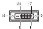
| Pin No. | Spec. | Pin No. | Spec. |
| 1 TMDS DATA 2- | 13 | - | |
| 2 | TMDS DATA 2+ | 14 | +5V Power |
| 3 | TMDS DATA 2 Shield | 15 | Ground (for +5V) |
| 4 | - | 16 | Hot Plug Detect |
| 5 | - | 17 | TMDS DATA 0- |
| 6 | DDC Clock | 18 | TMDS DATA 0+ |
| 7 | DDC Data | 19 | TMDS DATA 0 Shield |
| 8 | - | 20 | - |
| 9 TMDS DATA 1- | 21 | - | |
| 10 | TMDS DATA 1+ | 22 | TMDS Clock Shield |
| 11 | TMDS DATA 1 Shield | 23 | TMDS Clock+ |
| 12 | - | 24 TMDS Clock- | |
HDMI IN
(HDMI 19-pin)

| Pin No. | Spec. | Pin No. | Spec. |
| 1 | TMDS Data2+ | 11 | TMDS Clock Shield |
| 2 | TMDS Data2 Shield | 12 | TMDS Clock- |
| 3 | TMDS Data2- | 13 | CEC |
| 4 | TMDS Data1+ | 14 | - |
| 5 | TMDS Data1 Shield | 15 | SCL |
| 6 | TMDS Data1- | 16 | SDA |
| 7 | TMDS Data0+ | 17 | DDC Ground |
| 8 | TMDS Data0 Shield | 18 | +5 V Power |
| 9 | TMDS Data0- | 19 | Hot Plug Detect |
| 10 | TMDS Clock+ |
Dimension drawings (unit: mm)
Without terminal cover


With terminal cover
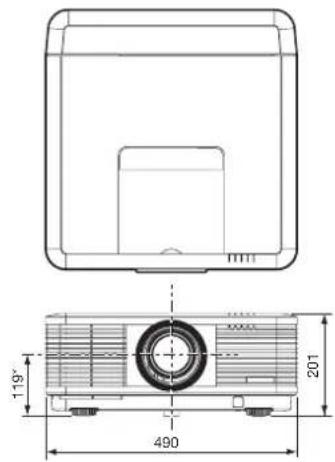
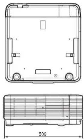
*: Factory-defaults
Specification of the attached lens
With ultra short throw zoom lens (OL-XD8000EZ)
F No. F2.4
Focal distance f = 11.4 - 14.2 mm
Zoom/focus Electrical drive
Picture size 40 inch (86 cm X 54 cm) - 300 inch (646 cm X 404 cm)
| Screen size (16:10) Projection distance (L) Lens shift height | Lens shift width (W1) | ||||||||||||||||
| Diagonal size | Width (W) | Height (H) | Shortest (Wide) | Longest (Tele) | H1 H2 | ||||||||||||
| inch | cm inch | cm inch | cm inch | m inch | m inch | m inch | ch cm inch | inch cm | inch cm | inch cm | |||||||
| 40 | 102 34 | 86 21 | 54 25 | 0.6 32 | 0.8 10 | 26 4 | 10 3 8 | ||||||||||
| 60 | 152 51 | 129 32 | 81 39 | 1.0 49 | 1.2 1 | 5 39 6 | 15 5 | 12 | |||||||||
| 80 | 203 68 | 172 42 | 108 52 | 1.3 65 | 1.7 | 21 52 | 8 20 7 | 17 | |||||||||
| 100 | 254 85 | 215 53 | 135 65 | 1.7 82 | 2.1 | 26 66 | 10 25 | 8 21 | |||||||||
| 150 | 381 | 127 | 323 | 79 | 202 | 98 | 2.5 | 123 | 3.1 | 39 | 98 | 15 | 37 | 12 | 31 | ||
| 200 | 508 | 170 | 431 | 106 | 269 | 131 | 3.3 | 165 | 4.2 | 52 | 131 | 20 | 50 | 16 | 42 | ||
| 250 | 635 | 212 | 538 | 132 | 337 | 165 | 4.2 | 206 | 5.2 | 65 | 164 | 24 | 62 | 20 | 52 | ||
| 300 | 762 | 254 | 646 | 159 | 404 | 198 | 5.0 | 248 | 6.3 | 77 | 197 | 29 | 75 | 25 | 62 | ||
- The above numbers are approximate, and may be slightly different from the actual measurements.

With short throw zoom lens (OL-XD2000SZ)
F No. F2.0 - 2.4
Focal distance f = 19.6 - 26.5 mm
Zoom/focus Electrical drive
Picture size 40 inch (86 cm X 54 cm) - 300 inch (646 cm X 404 cm)
| Screen size (16:10) Projection distance (L) Lens shift height | Lens shift width(W1) | ||||||||||||||||
| Diagonal size | Width (W) H | Height (H) | Shortest(Wide) | Longest(Tele) | H1 H2 | ||||||||||||
| inch | cm inch | cm inch | cm inch | m inch | m inch | m inch | cm inch | cm inch | cm inch | inch cm | |||||||
| 40 | 102 34 | 86 21 | 54 42 | 1.1 59 | 1.5 10 | 26 4 | 10 3 8 | ||||||||||
| 60 | 152 51 | 129 32 | 81 65 | 1.6 90 | 2.3 15 | 39 6 | 15 5 | 12 | |||||||||
| 80 | 203 68 | 172 42 | 108 87 | 2.2 | 121 | 3.1 | 21 52 | 8 20 7 | 17 | ||||||||
| 100 | 254 | 85 | 215 | 53 | 135 | 110 | 2.8 | 152 | 3.9 | 26 | 66 | 10 | 25 | 8 | 21 | ||
| 150 | 381 | 127 | 323 | 79 | 202 | 167 | 4.2 | 229 | 5.8 | 39 | 98 | 15 | 37 | 12 | 31 | ||
| 200 | 508 | 170 | 431 | 106 | 269 | 224 | 5.7 | 307 | 7.8 | 52 | 131 | 20 | 50 | 16 | 42 | ||
| 250 | 635 | 212 | 538 | 132 | 337 | 281 | 7.1 | - | - | 65 | 164 | 24 | 62 | 20 | 52 | ||
| 300 | 762 | 254 | 646 | 159 | 404 | 338 | 8.6 | - | - | 77 | 197 | 29 | 75 | 25 | 62 | ||
- The above numbers are approximate, and may be slightly different from the actual measurements.
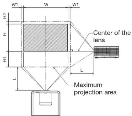
With long throw zoom lens (OL-XD2000LZ)
F No. F2.1 - 2.4
Focal distance f = 32.4 - 40.5 mm
Zoom/focus Electrical drive
Picture size 40 inch (86 cm X 54 cm) - 300 inch (646 cm X 404 cm)
| Screen size (16:10) Projection distance (L) Lens shift height | Lens shift width (W1) | ||||||||||||||
| Diagonal size | Width (W) Height (H) | Shortest (Wide) | Longest (Tele) | H1 H2 | |||||||||||
| inch cm | inch | cm inch | cm inch | m inch | m inch | ch cm | inch cm | inch cm | |||||||
| 40 | 102 | 34 | 86 | 21 | 54 | - | - | 89 | 2.3 | 10 | 26 | 4 | 10 | 3 | 8 |
| 60 | 152 | 51 | 129 | 32 | 81 | 107 | 2.7 | 137 | 3.5 | 15 | 39 | 6 | 15 | 5 | 12 |
| 80 | 203 | 68 | 172 | 42 | 108 | 146 | 3.7 | 185 | 4.7 | 21 | 52 | 8 | 20 | 7 | 17 |
| 100 | 254 | 85 | 215 | 53 | 135 | 184 | 4.7 | 233 | 5.9 | 26 | 66 | 10 | 25 | 8 | 21 |
| 150 | 381 | 127 | 323 | 79 | 202 | 279 | 7.1 | 353 | 9.0 | 39 | 98 | 15 | 37 | 12 | 31 |
| 200 | 508 | 170 | 431 | 106 | 269 | 374 | 9.5 | 473 | 12.0 | 52 | 131 | 20 | 50 | 16 | 42 |
| 250 | 635 | 212 | 538 | 132 | 337 | 470 | 11.9 | 592 | 15.0 | 65 | 164 | 24 | 62 | 20 | 52 |
| 300 | 762 | 254 | 646 | 159 | 404 | 565 | 14.4 | 712 | 18.1 | 77 | 197 | 29 | 75 | 25 | 62 |
- The above numbers are approximate, and may be slightly different from the actual measurements.
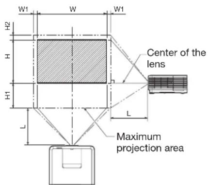
With tele throw zoom lens (OL-XD2000TZ)
F No. F2.2 - 2.7
Focal distance f = 40.7 - 65.1 mm
Zoom/focus Electrical drive
Picture size 40 inch (86 cm X 54 cm) - 300 inch (646 cm X 404 cm)
| Screen size (16:10) Projection distance (L) Lens shift height | Lens shift width (W1) | ||||||||||||||
| Diagonal size | Width (W) Height (H) | Shortest (Wide) | Longest (Tele) | H1 H2 | |||||||||||
| inch | cm inch | cm inch | cm inch | m inch | m inch | cm inch | cm inch | inch cm | |||||||
| 40 | 102 | 34 | 86 | 21 | 54 | - | - | 151 | 3.8 | 10 | 26 | 4 | 10 | 3 | 8 |
| 60 | 152 | 51 | 129 | 32 | 81 | 139 | 3.5 | 229 | 5.8 | 15 | 39 | 6 | 15 | 5 | 12 |
| 80 | 203 | 68 | 172 | 42 | 108 | 187 | 4.8 | 308 | 7.8 | 21 | 52 | 8 | 20 | 7 | 17 |
| 100 | 254 | 85 | 215 | 53 | 135 | 235 | 6.0 | 386 | 9.8 | 26 | 66 | 10 | 25 | 8 | 21 |
| 150 | 381 | 127 | 323 | 79 | 202 | 355 | 9.0 | 581 | 14.8 | 39 | 98 | 15 | 37 | 12 | 31 |
| 200 | 508 | 170 | 431 | 106 | 269 | 475 | 12.1 | 776 | 19.7 | 52 | 131 | 20 | 50 | 16 | 42 |
| 250 | 635 | 212 | 538 | 132 | 337 | 595 | 15.1 | 972 | 24.7 | 65 | 164 | 24 | 62 | 20 | 52 |
| 300 | 762 | 254 | 646 | 159 | 404 | 716 | 18.2 | 1167 | 29.6 | 77 | 197 | 29 | 75 | 25 | 62 |
- The above numbers are approximate, and may be slightly different from the actual measurements.

With ultra tele throw zoom lens (OL-XD8000UZ)
F No. F2.8
Focal distance f = 64.5 - 125.5 mm
Zoom/focus Electrical drive
Picture size 60 inch (129 cm X 81 cm) - 300 inch (646 cm X 404 cm)
| Screen size (16:10) Projection distance (L) Lens shift height | Lens shift width(W1) | ||||||||||||||
| Diagonal size | Width(W) | Height(H) | Shortest(Wide) | Longest(Tele) | H1 H2 | ||||||||||
| inch | cm inch | cm inch | cm inch | m inch | m inch | cm inch | inch cm | inch cm | |||||||
| 60 | 152 | 51 | 129 | 32 | 81 | 234 | 5.9 | 447 | 11.4 | 15 | 39 | 6 | 15 | 5 | |
| 80 | 203 | 68 | 172 | 42 | 108 | 309 | 7.8 | 594 | 15.1 | 21 | 52 | 8 | 20 | 7 | |
| 100 | 254 | 85 | 215 | 53 | 135 | 384 | 9.8 | 740 | 18.8 | 26 | 66 | 10 | 25 | ||
| 150 | 381 | 127 | 323 | 79 | 202 | 573 | 14.5 | 1107 | 28.1 | 39 | 98 | 15 | 37 | ||
| 200 | 508 | 170 | 431 | 106 | 269 | 761 | 19.3 | 1473 | 37.4 | 52 | 131 | 20 | 50 | ||
| 250 | 635 | 212 | 538 | 132 | 337 | 950 | 24.1 | - | 65 | 164 | 24 | 62 | 20 | ||
| 300 | 762 | 254 | 646 | 159 | 404 | 1138 | 28.9 | - | 77 | 197 | 29 | 75 | 25 | ||
- The above numbers are approximate, and may be slightly different from the actual measurements.

With rear projection short throw lens (OL-XD2000FR)
F No. F2.4
Focal distance f = 11.5 mm
Focus Electrical drive
Picture size 40 inch (86 cm X 54 cm) - 150 inch (323 cm X 202 cm)
| Screen size (16:10) | Projection distance (L) | ||||||
| Diagonal size | Width (W) | Height (H) | |||||
| inch | cm | inch | cm | inch | cm | inch | m |
| 40 | 102 | 34 | 86 | 21 | 54 | 25 | 0.6 |
| 60 | 152 | 51 | 129 | 32 | 81 | 39 | 1.0 |
| 80 | 203 | 68 | 172 | 42 | 108 | 52 | 1.3 |
| 100 | 254 | 85 | 215 | 53 | 135 | 66 | 1.7 |
| 150 | 381 | 127 | 323 | 79 | 202 | 99 | 2.5 |
- The above numbers are approximate, and may be slightly different from the actual measurements.
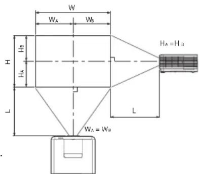
- The adjustable angle in the keystone adjustment with the lens differs from that with the UD8900U/UD8850U lens.
- In the keystone adjustment with the lens, the proper aspect ratio may not be obtained.
- Lens shifting is not available for the OL-XD2000FR (horizontal and vertical are set at 1:1).
- The lens movable range shows distances from the factory default position.


- CAUTION
- WARNING
- NOTE
- CONTENTS
- TRADEMARK, REGISTERED TRADEMARK
- READ INSTRUCTIONS
- RETAIN INSTRUCTIONS
- WARNINGS
- INSTRUCTIONS
- CLEANING
- ATTACHMENTS AND EQUIPMENT
- WATER AND MOISTURE
- ACCESSORIES
- VENTILATION
- POWER SOURCES
- POWER-CORD PROTECTION
- OVERLOADING
- OBJECTS AND LIQUIDS
- SERVICING
- DAMAGE REQUIRING SERVICE
- REPLACEMENT PARTS
- SAFETY CHECK
- UNPLUG IMMEDIATELY IF THERE IS SOMETHING WRONG WITH YOUR PROJECTOR
- NEVER REMOVE THE CABINET
- DO NOT MODIFY THIS EQUIPMENT
- DO NOT KEEP USING THE DAMAGED PROJECTOR
- BE SURE TO UNPLUG THE POWER CORD FROM THE WALL OUTLET IF THE PROJECTOR IS FRACTURED OR DEFORMED
- DO NOT FACE THE PROJECTOR LENS TO THE SUN
- USE CORRECT VOLTAGE
- DO NOT CONNECT MULTIPLE ELECTRICAL APPLIANCES TO A SINGLE WALL OUTLET
- DO NOT EXTEND THE POWER CORD
- DO NOT PLACE THE PROJECTOR ON UNEVEN SURFACE
- DO NOT LOOK INTO THE LENS WHEN IT IS OPERATING
- DO NOT TOUCH THE EXHAUST VENTS AND BOTTOM PLATE, WHICH BECOME HOT
- DO NOT LOOK INTO THE EXHAUST VENTS WHEN PROJECTOR IS OPERATING
- DO NOT INSERT YOUR FINGERS IN THE SPACE BETWEEN THE LENS AND THE CABINET
- DO NOT BLOCK THE INTAKE AND EXHAUST VENTS
- DO NOT USE FLAMMABLE SOLVENTS (BENZENE, THINNER, ETC.) AND FLAMMABLE AEROSOLS NEAR THE PROJECTOR
- DO NOT USE THE PROJECTOR WITH CONDENSATION ON IT
- PLACE OF INSTALLATION
- DO NOT PLACE A CONTAINER CONTAINING WATER OR OTHER LIQUID ON THE PROJECTOR
- DO NOT PUT ANY OBJECT THAT IS HEAVY OR LARGER THAN THE OUTER FRAME ON THE PROJECTOR
- DO NOT SUBJECT THE PROJECTOR TO STRONG SHOCKS OR VIBRATIONS. DO NOT HANDLE THE PROJECTOR ROUGHLY
- UPON CONTINUOUS OPERATION
- CHECKING ACCESSORIES
- IMPORTANT
- INSERTING THE BATTERIES INTO THE REMOTE CONTROL
- REMOVING THE BATTERIES FROM THE REMOTE CONTROL
- OVERVIEW
- CONTROL AREA
- TERMINAL PANEL
- OPERATIONAL RANGE OF THE REMOTE CONTROL
- RECEPTION ANGLE
- USING THE WIRED REMOTE CONTROL
- SETTING THE ID NUMBER OF THE REMOTE CONTROL
- SETTING BY THE REMOTE CONTROL ALONE
- SETTING BY USING THE PROJECTOR
- BEFORE SETTING UP
- SETUP ENVIRONMENT
- SETTING UP THE SCREEN
- SCREEN SIZE AND PROJECTION DISTANCE
- SETUP ADJUSTMENT
- HOW TO TURN ON THE PROJECTOR
- ADJUSTING THE POSITION OF THE PROJECTED IMAGE
- CHANGING THE AUTO POWER OFF SETTING
- TO CHANGE THE AUTO POWER OFF SETTING
- SETTING HIGH ALTITUDE MODE
- SETTING IMAGE REVERSE
- CORRECTING SKEWED OR DISTORTED IMAGE
- WHEN FINE STREAKS ARE SEEN ON PROJECTED IMAGES
- WHEN THE PROJECTED IMAGE IS DISTORTED
- ADJUSTMENT USING THE KEYSTONE MODE
- KEYSTONE MENU
- ADJUSTMENT USING THE CORNERSTONE MODE
- ADJUSTMENT USING THE CURVED MODE
- ARC MENU
- HORIZ. ORIGIN OR VERT. ORIGIN MENU
- FRONT PROJECTION, CEILING MOUNTING
- REAR PROJECTION
- CONNECTING THE PROJECTOR TO A COMPUTER
- PREPARATION
- FOR ANALOG CONNECTION
- FOR DIGITAL CONNECTION
- ABOUT DDC
- PLUGGING THE POWER CORD
- ATTACHING THE POWER CORD HOLDER
- INSTALLING THE TERMINAL COVER
- PROJECTING IMAGES
- TO STOP PROJECTING
- DIRECT POWER OFF
- BLANKING THE SCREEN TEMPORARILY (BLANK)
- AUTO POSITION BUTTON
- WHEN CONNECTING TO A NOTEBOOK COMPUTER
- EXAMPLE OF THE SETTING PROCEDURE FOR EXTERNAL OUTPUT
- SETTING OF THE RESOLUTION
- SETTING THE SCREEN SIZE
- SETTING THE ASPECT RATIO
- HOW TO CHANGE THE SETTINGS
- WITH THE REMOTE CONTROL
- WITH THE SIGNAL MENU
- CONNECTING THE PROJECTOR TO VIDEO EQUIPMENT
- CONNECTING TO A VIDEO PLAYER, ETC
- WHEN THE VIDEO EQUIPMENT IS EQUIPPED WITH THE S-VIDEO OUTPUT TERMINAL, MAKE THE CONNECTION AS FOLLOWS
- WHEN A TV TUNER OR VCR IS CONNECTED
- PROJECTOR + DVD PLAYER OR HDTV DECODER
- CONNECTING TO VIDEO EQUIPMENT HAVING A HDMI TERMINAL OR DVI-D TERMINAL
- CONNECTION (FOR VIDEO EQUIPMENT HAVING AN HDMI TERMINAL)
- CONNECTION (FOR VIDEO EQUIPMENT HAVING A DVI-D TERMINAL)
- WHEN YOU CONNECT THIS PROJECTOR AND A DIGITAL DEVICE (SUCH AS A DVD PLAYER) VIA THE HDMI IN OR COMPUTER/COMPONENT VIDEO DVI-D IN (HDCP) TERMINAL, BLACK COLOR MAY APPEAR DARK AND DEEP, DEPENDING ON THE TYPE OF THE CONNECTED DEVICE
- PLUGGING IN THE POWER CORD
- HOW TO SET THE MENUS
- PRESS THE MENU BUTTON
- ITEM SETTING FUNCTION
- INSTALLATION 2 MENU
- MULTI-SCREEN MENU
- FEATURE MENU (CONTINUED)
- INFORMATION MENU
- TO ADJUST THE BRIGHTNESS (CONTRAST AND BRIGHTNESS)
- TO CANCEL THE MENU
- CONTRAST
- BRIGHTNESS
- TO ADJUST THE COLOR (COLOR AND TINT)
- COLOR
- TINT
- TO SHARPEN OR SOFTEN THE PROJECTED IMAGE (SHARPNESS)
- TO ADJUST THE TONE OF WHITE (COLOR TEMP.)
- TO ADJUST THE TONE OF WHITE (TO CUSTOMIZE THE COLOR TEMPERATURE)
- TO ENABLE THE STORED COLOR TEMPERATURE
- ABOUT COLOR TEMPERATURE
- COLOR ENHANCER
- WITH THE IMAGE MENU
- GAMMA MODE
- BRILLIANTCOLOR™
- DYNAMIC CONTRAST
- ADJUSTING THE FINENESS OF THE IMAGE (SUPER RESOLUTION)
- ADJUSTING THE TONE OF EACH COLOR (COLOR MATRIX)
- ADJUSTING THE DETAILED SETTING OF ASPECT
- ZOOM(H)
- ZOOM(V)
- HORIZ. POSITION
- VERT. POSITION
- RASTER POSITION(H)
- RASTER POSITION(V)
- RESET
- SAVING THE SETTING IN THE SIGNAL MEMORY
- TO SAVE THE SETTING IN THE SIGNAL MEMORY
- TO SELECT THE SAVED MEMORY BY THE MEMORY CALL
- HOW TO ADJUST THE COMPUTER IMAGE
- HOW TO ADJUST THE IMAGE SUPPLIED FROM THE COMPUTER USING THE MENU
- SIMPLE METHOD TO ADJUST THE IMAGE POSITION
- TO ADJUST THE HORIZONTAL POSITION
- TO ADJUST THE VERTICAL POSITION
- LPF (PROGRESSIVE FILTER)
- ADJUSTING THE IMAGE DISPLAYED ON THE MULTI-SCREEN
- MAKING THE JOINTS UNNOTICEABLE
- EDGE SELECT
- BLENDING
- START POSITION
- WIDTH
- MARKER
- POSITION
- LEVEL
- ADJUSTING THE COLOR VARIATIONS
- ADJUSTMENT WHILE VIEWING THE SCREEN
- ADJUSTMENT USING A CHROMA METER
- RESETTING THE SETTINGS
- SETTING PROJECTOR NAME
- ENABLING OR DISABLING THE NETWORK CERTIFICATION
- NETWORK PASSWORD SETTINGS
- IP SETTINGS
- SETTING OR CLEARING DHCP
- IP ADDRESS SETTINGS
- SUBNET MASK SETTINGS
- DEFAULT GATEWAY SETTINGS
- SAVING IP CONFIG SETTINGS
- SETTING THE CONTROL SYSTEM
- STANDARD
- AMX
- CRESTRON
- INITIALIZATION OF NETWORK SETTINGS
- HOW TO USE NETWORK FUNCTION
- GLOSSARY
- SETTING THE LAMP RELAY INTERVAL
- WHEN LAMP SELECT IS SET TO DUAL
- WHEN LAMP SELECT IS SET TO SINGLE
- CHANGING THE IMAGE DISPLAYED AT THE STARTUP
- SETTING PROCEDURE
- SET THE BACKGROUND COLOR
- SET THE IMAGE SIZE
- CAPTURE THE IMAGE
- PASSWORD FUNCTION
- TO ENABLE THE PASSWORD FUNCTION
- TO CANCEL THE PASSWORD FUNCTION
- SPLIT
- TO USE THE SPLIT MODE
- TO CHANGE THE INPUT SOURCE OF THE LEFT OR RIGHT SCREEN
- FREEZE
- SUPERVISING AND CONTROLLING BY COMPUTER
- MAJOR FUNCTIONS
- PROJECTORVIEW GLOBAL
- PROJECTORVIEW
- AMX DEVICE DISCOVERY
- CRESTRON ROOMVIEW CONNECTED™
- PJLINK™
- ABOUT PROJECTORVIEW GLOBAL+ AND PROJECTORVIEW
- ABOUT AMX DEVICE DISCOVERY
- ABOUT CRESTRON ROOMVIEW CONNECTED™
- ABOUT PJLINK™
- CONNECTION
- USING THE USER MANUAL
- OPENING THE USER MANUAL
- PJLINK™ SUPPORTED COMMANDS
- MONITORING AND CONTROL USING SERIAL TERMINAL
- SETTING PROJECTOR IDS
- SETTING GROUP IDS
- CONTROL BY A CONTROL PANEL, ETC
- CONTROLLABLE FUNCTIONS
- PIN FUNCTIONS (DEFAULTS)
- CONTACT CONTROL
- INPUT SWITCHING CONTROL
- POWER CONTROL
- BLANK CONTROL
- INTERVAL OF LAMP REPLACEMENT
- BEFORE REPLACING THE LAMP
- TO REPLACE THE LAMP
- RESET OF THE LAMP OPERATION TIME RESET THE LAMP OPERATING TIME OF THE NEWLY INSTALLED LAMP
- WHEN REMOVING THE LAMP FROM THE CEILING-MOUNTED PROJECTOR
- MAINTENANCE
- CLEANING OF THE PROJECTOR AND THE VENTS
- CLEANING OF THE LENS
- SETTING THE CLEANING INTERVAL
- HOW TO CLEAN THE AUTOMATIC CLEANING FILTER
- KENSINGTON LOCK
- REPLACEMENT PART (OPTION/NOT INCLUDED IN THE BOX)
- SPECIFICATION OF RGB SIGNALS IN EACH COMPUTER MODE OF THE PROJECTOR (CONTINUED)
- NATIVE MODE
- CONNECTORS
- DIMENSION DRAWINGS (UNIT: MM)
- SPECIFICATION OF THE ATTACHED LENS
- WITH ULTRA SHORT THROW ZOOM LENS (OL-XD8000EZ)
- WITH SHORT THROW ZOOM LENS (OL-XD2000SZ)
- WITH LONG THROW ZOOM LENS (OL-XD2000LZ)
- WITH TELE THROW ZOOM LENS (OL-XD2000TZ)
- WITH ULTRA TELE THROW ZOOM LENS (OL-XD8000UZ)
- WITH REAR PROJECTION SHORT THROW LENS (OL-XD2000FR)
Brand : MITSUBISHI
Model : UD8850U
Category : Projector