
WD390U-EST - Vidéo-projecteur MITSUBISHI - Free user manual and instructions
Find the device manual for free WD390U-EST MITSUBISHI in PDF.


| Product Type | Short-throw DLP Projector |
| Brand | Mitsubishi |
| Model | WD390U-EST |
| Display Technology | DLP 0.55" DMD |
| Native Resolution | WXGA (1280 x 800) |
| Brightness | 3000 ANSI Lumens |
| Contrast Ratio | 2000:1 |
| Lamp Type | 230W UHP |
| Lamp Life (Eco Mode) | 6000 hours |
| Throw Ratio | 0.5:1 |
| Keystone Correction | Vertical +/- 15° |
| Inputs | HDMI, VGA, S-Video, Composite, RCA Audio |
| Outputs | Monitor Out, Audio Out |
| Built-in Speaker | 10W Mono |
| Dimensions (W x D x H) | 326 x 249 x 117 mm (12.8 x 9.8 x 4.6 in) |
| Weight | 4.8 kg (10.6 lbs) |
| Power Consumption | 280W (Max) |
| Noise Level (Eco Mode) | 29 dB |
| Cleaning | Use soft cloth; clean filter every 500 hours |
| Safety | Do not look into lens; ensure proper ventilation |
Frequently Asked Questions - WD390U-EST MITSUBISHI
User questions about WD390U-EST MITSUBISHI
0 question about this device. Answer the ones you know or ask your own.
Ask a new question about this device
Download the instructions for your Vidéo-projecteur in PDF format for free! Find your manual WD390U-EST - MITSUBISHI and take your electronic device back in hand. On this page are published all the documents necessary for the use of your device. WD390U-EST by MITSUBISHI.
USER MANUAL WD390U-EST MITSUBISHI
NO USER-SERVICEABLE PARTS INSIDE
REFER SERVICING TO QUALIFIED SERVICE
PERSONNEL.
The lightning flash with arrowhead symbol within an equilateral triangle is intended to alert the user to the presence of uninsulated “dangerous voltage” within the product’s enclosure that may be of sufficient magnitude to constitute a risk of electric shock.

The exclamation point within an equilateral triangle is intended to alert the user to the presence of important operating and maintenance (servicing) instructions in the literature accompanying the appliance.
WARNING:
TO PREVENT FIRE OR SHOCK HAZARD, DO NOT EXPOSE THIS APPLIANCE TO RAIN OR MOISTURE.
CAUTION:
TO PREVENT ELECTRIC SHOCK, DO NOT USE THIS (POLARIZED) PLUG WITH AN EXTENSION CORD, RECEPTACLE OR OTHER OUTLET UNLESS THE BLADES CAN BE FULLY INSERTED TO PREVENT BLADE EXPOSURE.
NOTE:
SINCE THIS PROJECTOR IS PLUGGABLE EQUIPMENT, THE SOCKET-OUTLET SHALL BE INSTALLED NEAR THE EQUIPMENT AND SHALL BE EASILY ACCESSIBLE.
WARNING
Use the attached specified power supply cord. If you use another power supply cord, it may cause interference with radio and television reception.
CAUTION
The attached power cord is to be used exclusively for this product. Never use it for other products.
This apparatus must be grounded.
DO NOT LOOK DIRECTLY INTO THE LENS WHEN THE PROJECTOR IS IN THE POWER ON MODE.
Contents
Important safeguards....4
Overview....6
Remote control....8
Installation 9
Basic connections....11
Preparation 14
Basic operation 16
Menu operation....20
Image adjustment....30
Network settings 33
Advanced display utilities....38
Advanced features 54
Lamp replacement 58
Troubleshooting....60
Indicators....65
Specifications....66
Trademark, Registered trademark
- DLP™, Digital Micromirror Device, DMD, and BrilliantColor™ are all trademarks of Texas Instruments.
- HDMI, the HDMI logo and High-Definition Multimedia Interface are trademarks or registered trademarks of HDMI Licensing LLC.
- Microsoft, Windows, Windows Vista, Windows Server, MultiPoint, Excel, and PowerPoint are either registered trademarks or trademarks of Microsoft Corporation in the United States and/or other countries.
• Mac, Mac OS, OS X, Finder, and Apple Store are trademarks of Apple Inc.
• Intel and Pentium are trademarks of Intel Corporation in the U.S. and/or other countries. - PowerPC is a trademark of International Business Machines Corporation, registered in many jurisdictions worldwide.
- IOS is a trademark or registered trademark of Cisco in the U.S. and other countries and is used under license.
- Android and Google are trademarks of Google Inc.
• MirrorOp, MirrorOp Receiver, and WiFi-Doc are registered trademarks, trademarks, or trade names of AWIND Inc.
• Wi-Fi is a registered trademark of the Wi-Fi Alliance. - The trademark of PJLink is trademark applied for registration or registered trademark in Japan, the United States, and other countries and areas.
- Crestron RoomView Connected is a trademark of Crestron Electronics, Inc.
- Other brand or product names are trademarks or registered trademarks of their respective holders.
Please read all these instructions regarding your projector and retain them for future reference. Follow all warnings and instructions marked on the projector.
1. Read instructions
All the safety and operating instructions should be read before the appliance is operated.
2. Retain instructions
The safety and operating instructions should be retained for future reference.
3. Warnings
All warnings on the appliance and in the operating instructions should be adhered to.
4. Instructions
All operating instructions must be followed.
5. Cleaning
Unplug this projector from the wall outlet before cleaning it. Do not use liquid aerosol cleaners. Use a damp soft cloth for cleaning.
6. Attachments and equipment
Never add any attachments and/or equipment without the approval of the manufacturer as such additions may result in the risk of fire, electric shock or other personal injury.
7. Water and moisture
Do not use this projector near water or in contact with water.
8. Accessories
Do not place this projector on an unstable cart, stand, tripod, bracket or table. Use only with a cart, stand, tripod bracket, or table recommended by the manufacturer or sold with the projector. Any mounting of the appliance should follow the manufacturer's instructions and should use a mounting accessory recommended by the manufacturer.

natural_image
Symbolic icon of a person climbing a ladder inside a circle (no text or symbols)An appliance and cart combination should be moved with care. Quick stops, excessive force and uneven surfaces may cause the appliance and cart combination to overturn.
9. Ventilation
Slots and openings in the cabinet are provided for ventilation, ensuring reliable operation of the projector and to protect it from overheating. Do not block these openings or allow them to be blocked by placing the projector on a bed, sofa, rug, or bookcase. Ensure that there is adequate ventilation and that the manufacturer's instructions have been adhered to.
10. Power sources
This projector should be operated only from the type of power source indicated on the marking label. If you are not sure of the type of power, please consult your appliance dealer or local power company.
11. Power-cord protection
Power-supply cords should be routed so that they are not likely to be walked on or pinched by items placed upon or against them. Pay particular attention to cords at plugs, convenience receptacles, and points where they exit from the appliance. Do not put the power cord under a carpet.
12. Overloading
Do not overload wall outlets and extension cords as this can result in a fire or electric shock.
13. Objects and liquids
Never push objects of any kind through openings of this projector as they may touch dangerous voltage points or short-out parts that could result in a fire or electric shock. Never spill liquid of any kind on the projector.
14. Servicing
Do not attempt to service this projector by yourself. Refer all servicing to qualified service personnel.
15. Damage requiring service
Unplug this projector from the wall outlet and refer servicing to qualified service personnel under the following conditions:
(a) If the power-supply cord or plug is damaged.
(b) If liquid has been spilled, or objects have fallen into the projector.
(c) If the projector does not operate normally after you follow the operating instructions. Adjust only those controls that are covered by the operating instructions. An improper adjustment of other controls may result in damage and may often require extensive work by a qualified technician to restore the projector to its normal operation.
(d) If the projector has been exposed to rain or water.
(e) If the projector has been dropped or the cabinet has been damaged.
(f) If the projector exhibits a distinct change in performance - this indicates a need for service.
16. Replacement parts
When replacement parts are required, be sure that the service technician has used replacement parts specified by the manufacturer or parts having the same characteristics as the original part. Unauthorized substitutions may result in fire, electric shock or other hazards.
17. Safety check
Upon completion of any service or repair to this projector, ask the service technician to perform safety checks determining that the projector is in a safe operating condition.
WARNING:
Unplug immediately if there is something wrong with your projector.
Do not operate if smoke, strange noise or odor comes out of your projector. It may cause fire or electric shock. In this case, unplug immediately and contact your dealer.
Never remove the cabinet.
This projector contains high voltage circuitry. An inadvertent contact may result in an electric shock. Except as specifically explained in User Manual, do not attempt to service this product by yourself. Please contact your dealer when you want to fix, adjust, or inspect the projector.
Do not modify this equipment.
It can lead to fire or electric shock.
Do not keep using the damaged projector.
If the projector is dropped and the cabinet is damaged, unplug the projector and contact your dealer for inspection. It may lead to fire if you keep using the damaged projector.
Be sure to unplug the power cord from the wall outlet if the projector is fractured or deformed.
Otherwise, it may result in fire or electric shock. Ask your dealer for repair.
Do not face the projector lens to the sun.
It can lead to fire.
Use correct voltage.
If you use incorrect voltage, it can lead to fire.
Do not place the projector on uneven surface.
Place the projection on a leveled and stable surface only.
Do not look into the lens when it is operating.
It may hurt your eyes. Never let children look into the lens when it is on.
Do not put any objects immediately in front of the lens while the lamp is on.
The lens and the objects get hot and can cause fire or breakdown.
Do not unplug the power cord during operation.
It can lead to lamp breakage, fire, electric shock or other trouble.
Do not touch the exhaust vents and bottom plate.
Do not touch them or put other equipment close to the exhaust vents because they become hot during operation. The heated exhaust vents and bottom plate may cause injury or damage to other equipment. Also, do not put the projector on a desk that is easily affected by heat.
Do not look into the exhaust vents when projector is operating.
Heat, dust, etc. may blow out of them and hurt your eyes.
Do not block the intake and exhaust vents.
If they are blocked, heat may be generated inside the projector, causing deterioration in the projector quality and fire.
Do not use flammable solvents (benzene, thinner, etc.) and flammable aerosols near the projector.
Flammable substances may ignite causing fire or breakdown because the temperature inside the projector rises very high while the lamp is illuminating.
Do not use the projector with condensation on it.
It can lead to breakdown or other failure.
Place of installation
For safety's sake, do not use the projector at any place subjected to high temperature and high humidity.
Please maintain an operating temperature, humidity, and altitude as specified below.
- Operating temperature: between +41°F (+5°C) and +95°F (+35°C)
- Operating humidity: between 30% and 90%
- Never put any heat-producing device under the projector to prevent the projector from being overheated.
- Do not install the projector at a place that is unstable or subject to vibration.
- Do not install the projector near any equipment that produces a strong magnetic field. Also refrain from installing the projector near any cable carrying a large amount of current.
- Place the projector on a solid, vibration-free surface. Otherwise it may fall, causing serious injury or damage.
- Do not stand the projector on its end. It may fall, causing serious injury or damage.
- Slanting the projector more than ±10^ (right and left) or ±15^ (front and rear) may cause trouble or explosion of the lamp.
- Do not place the projector near air-conditioning unit, heater, or humidifier to avoid hot or moist air to the exhaust and ventilation hole of the projector.
-
Do not place the projector in the following places. Otherwise, a short circuit, heat generation, or melting of the power cord coating may occur, causing fire, electric shock, product failure, or deformation.
-
Outdoors or non air-conditioned place
- Place where a gas such as a hydrogen sulfide is generated (i.e. hot spring)
- Place where there is too much salt such as near the coast
- Be sure to use this projector at an altitude of less than 1500 meters.
Do not place a container containing water or other liquid on the projector.
If water spills on or enters the projector, it may result in fire or electric shock.
Do not put any object that is heavy or larger than the outer frame on the projector.
Otherwise, the object may fall losing its balance and cause injury.
Do not subject the projector to strong shocks or vibrations. Do not handle the projector roughly.
The projector may be damaged, resulting in fire or electric shock.
When removing the lamp from the ceiling-mounted projector
Be sure to use the lamp replacement attachment designed specifically for this projector when replacing the lamp with a new one. Lamp fragments may fall from the inside if the lamp were broken.
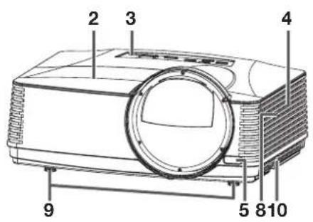
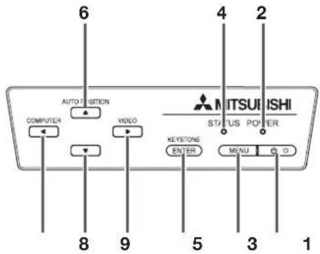
Control panel
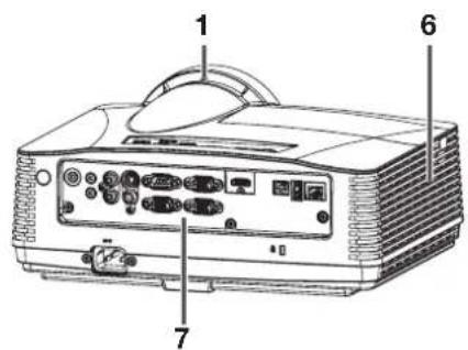
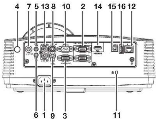
Terminal panel
1 FOCUS ring
2 Lamp cover
3 Control panel
4 Intake vent
5 Remote control sensor (front)
6 Exhaust vent
7 Terminal panel
8 Speaker
9 Adjustment feet
10 Lock bar
Caution:
- Do not replace the lamp immediately after using the projector because the lamp would be extremely hot and it may cause burns.
1 POWER button (ON/STANDBY)
The status is changed between ON and STANDBY.
2 POWER indicator
3 MENU button
4 STATUS indicator
5 KEYSTONE/ENTER button
6 AUTO POSITION/▲ button
7 COMPUTER/◄ button
8 ▼ button
9 VIDEO/▶ button
1 Power jack
2 COMPUTER/COMPONENT VIDEO IN terminals (1, 2) (mini D-SUB 15-pin)
3 MONITOR OUT terminal (mini D-SUB 15-pin)
4 Remote control sensor (rear)
5 AUDIO IN-1 terminal (mini jack)
6 AUDIO IN-2 terminal (mini jack)
7 AUDIO OUT terminal (mini jack)
8 S-VIDEO terminal
9 VIDEO terminal
10 SERIAL (RS-232C) terminal (D-SUB 9-pin)
11 Kensington Lock
12 LAN terminal (RJ-45)
13 AUDIO IN-3 terminals (L, R)
14 HDMI terminal (HDMI 19-pin)
15 USB-B terminal
16 USB-A terminal
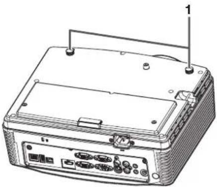
Bottom side
natural_image
Line drawing of a portable electronic device with ports and cables (no text or symbols)1 Adjustment feet
Remote control
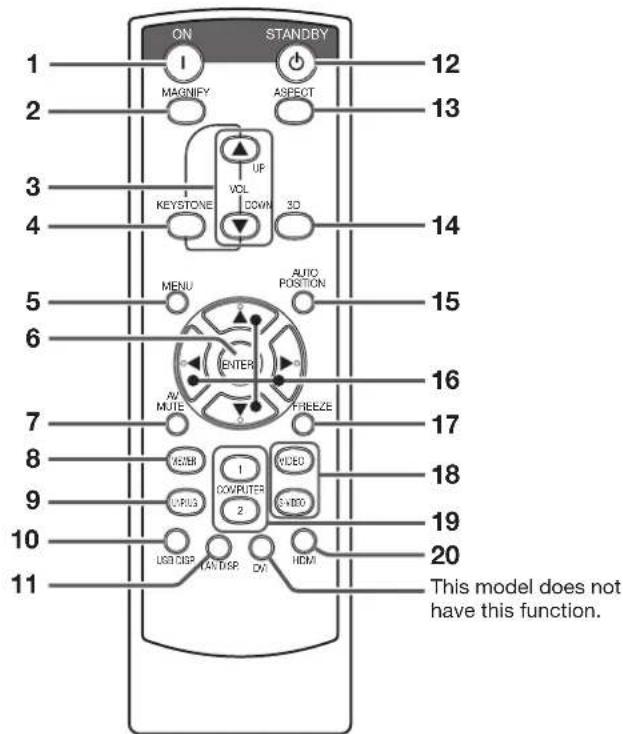
1 ON button
2 MAGNIFY button
3 VOLUME UP, DOWN buttons
4 KEYSTONE button
5 MENU button
6 ENTER button
7 AV (Audio/Video) MUTE button
8 VIEWER button
9 UNPLUG button
10 USB DISP. button
11 LAN DISP. button
12 STANDBY button
13 ASPECT button
14 3D button
15 AUTO POSITION button
16 ▲, ▼, ◀, ▶ buttons
17 FREEZE button
18 VIDEO, S-VIDEO buttons
19 COMPUTER (1, 2) buttons
20 HDMI button
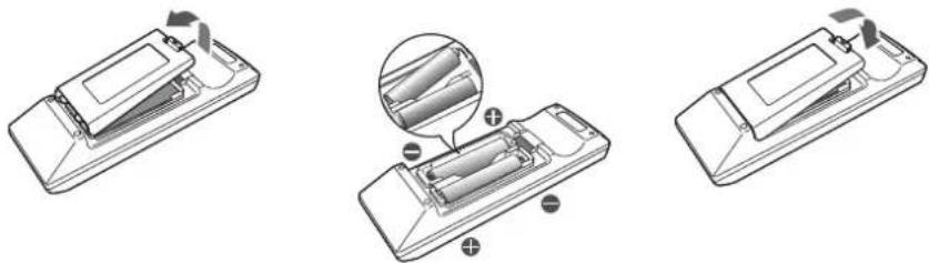
Battery installation
Use two (AA, R6) size batteries.
Inserting the batteries into the remote control
- Remove the back cover of the remote control by pushing the battery compartment door in the direction of the arrow.
- Load the batteries making sure that they are positioned correctly (+ to +, and - to -).
- Load the batteries from - spring side, and make sure to set them tightly.
- Replace the back cover.
natural_image
Three technical line drawings of a battery pack assembly, showing internal components and mounting points (no text or symbols)Removing the batteries from the remote control
Remove the back cover of the remote control and take out the batteries.
Caution:
- Use of a battery of wrong type may cause explosion.
- Only Carbon-Zinc or Alkaline-Manganese Dioxide type batteries should be used.
- Dispose of used batteries according to your local regulations.
- Before you dispose of the batteries, insulate them by placing insulation tape on the positive (+) and negative (-) terminals. If you dispose of the batteries together with other conductive objects such as a metal piece, they may short out, resulting in fire or explosion.
- Batteries may explode if misused. Do not recharge, disassemble, or heat the batteries, or put them into fire or water.
- Be sure to handle the batteries according to the instructions.
- Load the batteries with its positive (+) and negative (-) sides correctly oriented as indicated on the remote control.
- Keep batteries out of reach of children and pets. If children swallow the battery, see a doctor immediately.
- Remove the batteries, if the remote control is not used for a long time.
- Do not combine a new battery with an old one.
- If the solution of batteries comes in contact with your skin or clothes, rinse with water. If the solution comes in contact with your eyes, rinse them with water and then consult your doctor.
- Do not carry or store the batteries together with metallic ballpoint pens, necklaces, coins, or hairpins. Otherwise, they may short out, causing explosion or liquid leakage and resulting in fire or injury.
- Do not store the batteries where they are exposed to direct sunlight or subjected to high temperature and high humidity. High temperature and high humidity may cause corrosion or liquid leakage.
Operation range (of the remote control)
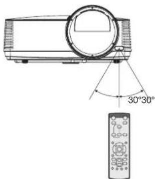
The maximum operation distance of the remote control is about 10 m (or about 32 feet) when the remote control is pointed at the remote control sensor of the projector. When the remote control is pointed to the screen, the distance from the remote control to the projector via the screen should be 5 m or less. However, the operation distance varies depending on the type of the screen used.
Reception angle (horizontal) Reception angle (vertical)
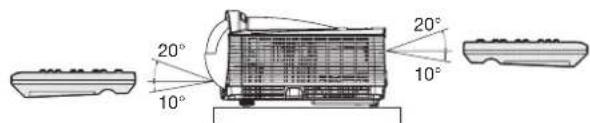
Reception angle (vertical), ceiling mount
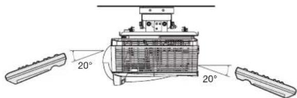
Important:
- Do not expose the remote control sensor to direct sunlight or fluorescent. Keep a distance at least 2 m (6.5 feet) between the remote control sensor and the fluorescent light to ensure correct operation of the remote control. Inverted fluorescent light, if located near the projector, may interfere the remote control.
- When you use the remote control too close to the remote control sensor, the remote control may not work correctly.
Screen size and projection distance
Refer to the following tables to determine the screen size and projection distance.
- The figures in the tables are approximate and may be slightly different from the actual measurements.
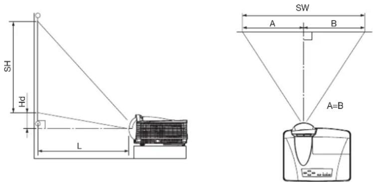
| Screen size (16:10) | Projection distance: L | Hd | ||||||
| Diagonal size Width: | SW Height: SH | |||||||
| inch cm inch cm inch cm | inch m inch cm | |||||||
| 70 178 59 151 37 94 22 | 0.56 4.6 12 | |||||||
| 80 203 68 172 42 108 25 | 0.64 5.3 13 | |||||||
| 100 254 85 215 53 135 32 | 0.82 | 6.6 17 | ||||||
| 120 305 102 258 64 162 | 39 | 0.99 | 7.9 20 | |||||
| 150 381 127 323 79 202 | 49 | 1.25 | 9.9 25 | |||||
| 180 457 153 388 95 242 | 60 | 1.51 | 11.9 30 | |||||
When the aspect ratio of the screen is 4:3
When the aspect ratio of the screen is 4:3, the positional relation between the projected image and the screen is as shown on the right. Refer to the following table for installation.
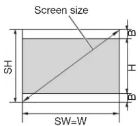
When the aspect ratio of the image is 16:10 (WXGA)
| Screen size (4:3) Size of the projected image (16:10) | Projection distance: L | Hd | |||||||||||||||||
| Diagonal size | Width: SW Height: SH Diagonal size Width: W Height: H | ||||||||||||||||||
| inch | cm | inch | cm | inch | cm | inch | cm | inch | cm | inch | cm | inch | cm | inch | cm | inch | m | inch | cm |
| 70 | 178 | 56 | 142 | 42 | 107 | 66 | 168 | 56 | 142 | 35 | 89 | 3.5 | 9 | 20 | 0.52 | 4.4 | 11 | ||
| 80 | 203 | 64 | 163 | 48 | 122 | 75 | 192 | 64 | 163 | 40 | 102 | 4.0 | 10 | 24 | 0.60 | 5.0 | 13 | ||
| 100 | 254 | 80 | 203 | 60 | 152 | 94 | 240 | 80 | 203 | 50 | 127 | 5.0 | 13 | 30 | 0.77 | 6.3 | 16 | ||
| 120 | 305 | 96 | 244 | 72 | 183 | 113 | 288 | 96 | 244 | 60 | 152 | 6.0 | 15 | 37 | 0.93 | 7.5 | 19 | ||
| 150 | 381 | 120 | 305 | 90 | 229 | 142 | 359 | 120 | 305 | 75 | 191 | 7.5 | 19 | 46 | 1.18 | 9.4 | 24 | ||
| 180 | 457 | 144 | 366 | 108 | 274 | 170 | 431 | 144 | 366 | 90 | 229 | 9.0 | 23 | 56 | 1.43 | 11.3 | 29 | ||
When the aspect ratio of the image is 16:9
| Screen size (4:3) | Size of the projected image (16:9) | Projection distance: L | Hd | ||||||||||||||
| Diagonal size | Width: SW Height: SH Diagonal | size Width: W Height: H | Black space: B | ||||||||||||||
| inch | cm | inch | cm | inch | cm | inch | cm | inch | cm | inch | cm | inch | cm | inch | m | inch | cm |
| 70 | 178 | 56 | 142 | 42 | 107 | 64 | 163 | 56 | 142 | 32 | 80 | 5.3 | 13 | 20 | 0.51 | 6.1 | 16 |
| 80 | 203 | 64 | 163 | 48 | 122 | 73 | 187 | 64 | 163 | 36 | 91 | 6.0 | 15 | 23 | 0.59 | 7.0 | 18 |
| 100 | 254 | 80 | 203 | 60 | 152 | 92 | 233 | 80 | 203 | 45 | 114 | 7.5 | 19 | 29 | 0.75 | 8.8 | 22 |
| 120 | 305 | 96 | 244 | 72 | 183 | 110 | 280 | 96 | 244 | 54 | 137 | 9.0 | 23 | 36 | 0.91 | 10.5 | 27 |
| 150 | 381 | 120 | 305 | 90 | 229 | 138 | 350 | 120 | 305 | 68 | 171 | 11.3 | 29 | 45 | 1.15 | 13.1 | 33 |
| 180 | 457 | 144 | 366 | 108 | 274 | 165 | 420 | 144 | 366 | 81 | 206 | 13.5 | 34 | 55 | 1.39 | 15.8 | 40 |
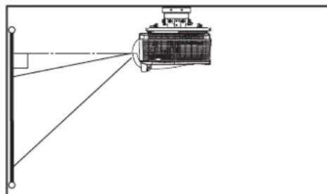
Front projection, ceiling mounting
For ceiling mounting, you need the ceiling mount kit designed for this projector. Ask a specialist for installation. For details, consult your dealer.
- The warranty on this projector does not cover any damage caused by use of any non-recommended ceiling mount kit or installation of the ceiling mount kit in an improper location.
natural_image
Diagram of a mechanical device with a beam and alignment lines, no text or symbols present- When using the projector mounted on the ceiling, set Image Reverse in the Installation menu to Mirror Invert. See page 26.
- When the projector is mounted on the ceiling, images may appear darker than those projected in the case of tabletop mounting. This isn't a product malfunction.
Ceiling mount installation
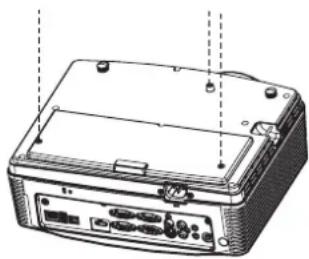
If you wish to install the projector using a ceiling mount, please use the screw holes as the illustration shows.
Important:
- Screws are not included. Please obtain the appropriate screws for your type of ceiling. (M4 diameter)
- It is recommended that you keep a reasonable space between the bracket and the projector to allow for proper heat distribution.
natural_image
Line drawing of a device rear panel with buttons and ports, no text or symbols presentCaution:
• Installation must be done by a qualified professional.
When the projector is installed on the ceiling using the ceiling mount kit, it is recommended to hold the mount kit and the projector using a metal bar or wire in addition to the mount kit fixing screws to prevent the projector from falling due to an earthquake or other cause. For that purpose, use a metal bar, wire, or screw that bears a load of at least 55 kgf. When using a metal wire, secure one end to a screw hole marked with an arrow on the rear terminal panel and the other end to the mount
kit. (Don't use screw holes without arrow marks.) In this case, make sure that the screw is inserted in the projector at least 5 mm. The length of the screw should be 20 mm or shorter. Also make sure that no electrical current is flowing in the mount kit due to current leakage or other cause.
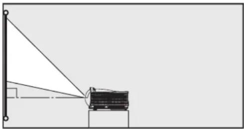
Rear projection
Ask a specialist for installation. For details, consult your dealer.
natural_image
Simple line drawing of a truck-mounted device mounted on a stand, with no text or symbols present.- For rear projection, set Image Reverse in the Installation menu to Mirror. See page 26.
Caution:
- Placing the projector directly on a carpet impairs ventilation by the fans, causing damage or failure. Put a hard board under the projector to facilitate ventilation.
- Place the projector at least 50 cm (or 20 inch) away from the wall to prevent the intake vents and the exhaust vents that emit hot air from being blocked.
- Do not use the projector in the following locations and manners, which may cause fire or electric shock.
• In a dusty or humid place.
• In a sideways or upside-down position. - Near a heater.
- In an oily, smoky, or damp place such as a kitchen.
• In direct sunlight. - Where the temperature rises high, such as in a closed car.
- Where the temperature is lower than +41°F (or +5°C) or higher than +95°F (or +35°C).
- Keep foliage plants and pets away from the projector. The temperature around the exhaust vents and that of the cabinet on the top of the exhaust vents become high. Take special care for small children.
Important:
- Do not apply force to the lens, because the lens may be damaged.
- Be sure to use this projector at an altitude of less than 1500 meters.
This projector can be connected with various devices such as a VCR, video camera, videodisc player, and personal computer that have analog RGB output connectors.
Important:
• Make sure that the connected device is turned off before starting connection.
- Plug in the power cords of the projector and the connected devices firmly. When unplugging, hold and pull the plug. Do not pull the cord.
- When the projector and the connected devices are located too close to each other, the projected image may be affected by their interference.
- See the owner's guide of each device for details about its connections.
Projector + AV device
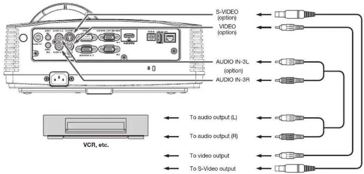
Important:
- Match the colors of the video and audio plugs on the Audio cable with those of the terminals.
- Speaker output is mono.
Projector + DVD player or HDTV decoder
Some DVD players have an output connector for 3-line fitting (Y, C_B, C_R). When connecting such DVD player with this projector, use the COMPUTER/COMPONENT VIDEO IN terminal.
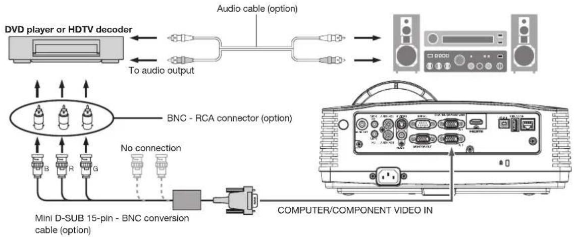
Important:
- The terminal's names Y, P_B , and P_R are given as examples of when a HDTV decoder is connected.
- The terminal's names vary depending on the connected devices.
- Use a mini D-SUB 15-pin - BNC conversion cable for connection.
• Image may not be projected correctly with some DVD players. - When connecting a HDTV decoder having RGB output terminals, set Computer Input to RGB in the Signal menu.
Connection (for video equipment having an HDMI terminal)
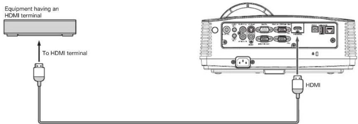
HDMI (with HDMI logo) cable (option)
Important:
• Use a commercially available HDMI (with HDMI logo) cable.
- You don't have to connect any cable for audio input. You can input video and audio using an HDMI cable only.
- When HDMI audio isn't output, it may be output by turning off the power of the video equipment with the projector and the video equipment connected to each other and then turning back on the power.
- Some cables may not be connected correctly depending on the size and shape of their connectors.
When you connect this projector and a Digital device (such as a DVD player) via the HDMI terminal, black color may appear dark and deep, depending on the type of the connected device.
- This depends on the black level setting of the connected device. There are two kinds of methods to digitally transfer image data, in which different black level settings are employed respectively. Therefore, the specifications of the signals output from DVD players differ, depending on the type of the digital data transfer method they use.
- Some DVD players are provided with a function to switch the methods to output digital signals. When your DVD player is provided with such function, set it as follows.
EXPAND or ENHANCED → NORMAL
• See the users guide of your DVD player for details.
- Set Input Level in the Picture menu depending on the device to be used.
Projector + Computer
For computer with Mini D-SUB
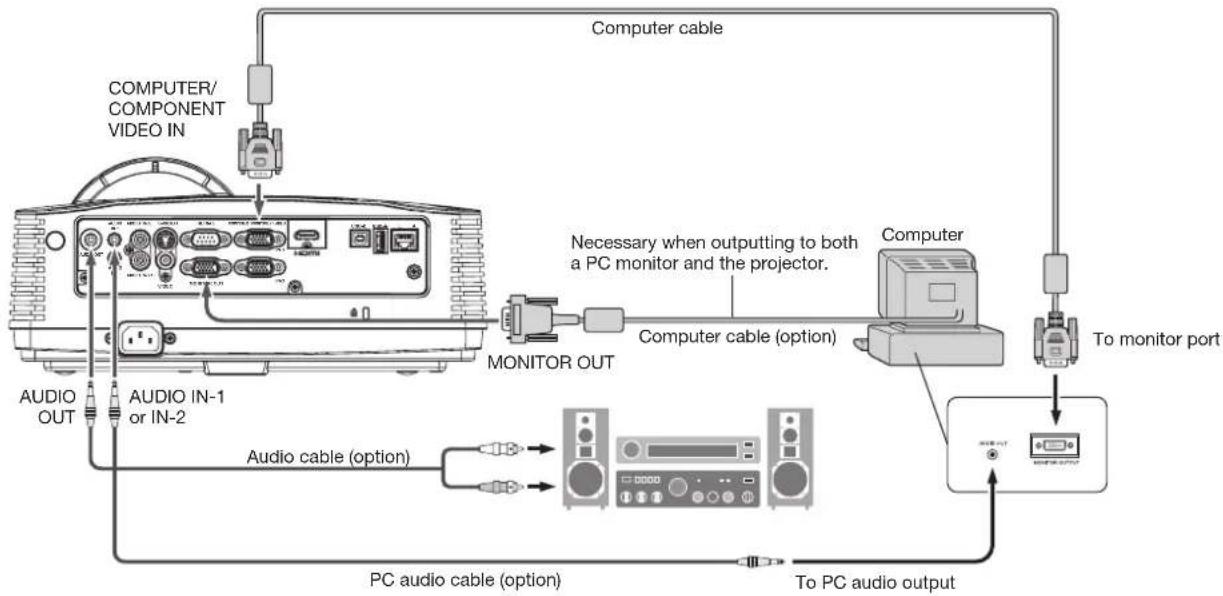
flowchart
graph TD
    A["COMPUTER/COMPONENT VIDEO IN"] --> B["Computer cable"]
    B --> C["Computer"]
    C --> D["To monitor port"]
    D --> E["PC audio cable (option)"]
    E --> F["To PC audio output"]
    G["AUDIO OUT"] --> H["AUDIO IN-1 or IN-2"]
    H --> I["Monitor OUT"]
    I --> J["Computer cable (option)"]
    J --> K["Necessary when outputting to both a PC monitor and the projector."]
    K --> L["Computer"]
For analog connection:
- Connect one end of the supplied computer cable to the COMPUTER/COMPONENT VIDEO IN terminal (1, 2) of the projector.
- Connect the other end of the computer cable to the monitor port of the computer.
For monitor connection:
Connect the computer cable from the monitor to the MONITOR OUT terminal of the projector.
- Images may not be displayed correctly depending on the type of the input signal. See the instruction manual of the monitor.
- Signals are coming from the COMPUTER/COMPONENT VIDEO IN-1 terminal of the projector.
- When the Standby Mode in the Installation menu is set to Monitor Out, the MONITOR OUT terminal outputs signals during standby mode.
Important:
- When you use a longer computer cable instead of the provided cable, the image may not be projected correctly.
- Some computers require additional connectors or analog RGB output adapters to be connected with this projector. Contact your dealer for further information.
- This projector uses stereo mini jack for its audio input. Check the type of the audio output terminal of the connected computer and prepare a proper cable for connection. Some computers don't have the audio output terminal.
- Speaker output is mono.
- When the audio cable is connected to the AUDIO OUT terminal, the speaker output is muted.
For Mac computers
- If your Mac computer has no video port, a monitor output adapter is required. Contact your dealer for further information.
- Some Mac computers require a MAC adapter for the computer cable for connection with this projector. Contact your dealer for further information.
About DDC
The COMPUTER/COMPONENT VIDEO IN-1 terminal of this projector complies with the DDC 1/2B standard. When a computer supporting this standard is connected to this terminal, the computer will automatically load the information from this projector and prepare for output of appropriate images.
- After connecting a computer supporting this standard to this terminal, plug the power cord of the projector in the wall outlet first, and then boot up the computer.
Preparation for projection
- Attach the provided power cord to the projector.
- Plug the power cord in the wall outlet.
- Remove the lens cap.
Warning:
- Do not look into the lens directly when the projector is on.
- The lens cap is for protecting the lens. If you leave the lens cap on the lens with the projector turned on, it may be deformed because of heat build-up. Remove the lens cap when you turn on the projector.
- One of power cords for the U.S., Europe, U.K., Australia, and South Korea is provided appropriately.
- This projector uses the power plug of three-pin grounding type. Do not remove the grounding pin from the power plug. If the power plug doesn't fit your wall outlet, ask an electrician to change the wall outlet.
- In case that the power cord for the U.S. is provided with this projector, never connect this cord to any outlet or power supply using other voltages or frequencies than rated. If you want to use a power supply using other voltage than rated, prepare an appropriate power cord separately.
- Use 100-240 V AC 50/60 Hz to prevent fire or electric shock.
- Do not place any objects on the power cord or do not place the projector near heat sources to prevent damage to the power cord. If the power cord should be damaged, contact your dealer for replacement because it may cause fire or electric shock.
- Do not modify or alter the power cord. If the power cord is modified or altered, it may cause fire or electric shock.
Caution:
- Plug in the power cord firmly. When unplugging, hold and pull the power plug, not the power cord.
- Do not plug in or out the power cord with your hand wet. It may cause electric shock.
- When you move the projector, turn off the power, unplug the power cord from the wall outlet, and then remove the connected cords. Otherwise, the power cord may be damaged, resulting in fire or electric shock.
- If dust or metallic substance is on or around the pins of the power plug, unplug the power cord and clean it using a dry cloth. If you continue to use the projector without cleaning, it may result in fire or electric shock. Clean the power plug periodically at least once a year.
- Be sure to unplug the power cord from the wall outlet if the projector will not be used for a long period of time. Otherwise, it may cause fire.
Important:
- When Standby Mode in the Installation menu is set to LAN, Speaker Out, or Monitor Out, the fans rotate at very low speed during standby after plugging the power cord (with 5 second high speed rotation at the beginning) and after turning off the lamp. This is to cool down the projector operating various functions during standby and is not a malfunction. (When Standby Mode is set to Low, the fans stop during standby.)
Adjustment of the projection angle
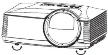
For the best projection, project images on a flat screen installed at 90 degrees to the floor. If necessary, tilt the projector using the two adjustment feet on the bottom of the projector.
Using the adjustment feet (front)
- Tilt up the projector to the appropriate angle.
- Rotate the adjustment feet (front) for fine adjustment.
natural_image
Line drawing of a projector with a circular lens and side blades (no text or symbols)Important:
- Install the screen on a flat wall at 90 degrees to the floor.
- Slanting the projector more than ± 10^ (right and left) or ± 15^ (front and rear) may cause trouble or explosion of the lamp. You can tilt the projector up to 8 degrees using the adjustment feet only.
- Images may not be projected in a shape of a regular rectangle or with its aspect ratio 4:3, depending on the installation conditions of the projector and the screen.
When projected images are distorted to a trapezoid
When Auto Keystone in the Installation menu is set to On, this projector automatically corrects vertical keystone distortion. For fine adjustment, press the KEYSTONE button on the projector or the remote control to display Keystone, and adjust the image by pressing the ▲, ▼ button (or VOLUME ▲, ▼ button on the remote control).
In the following cases:

Press the ▼ button. Press the
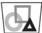
▲ button.
Important:
- The automatic keystone adjustment may not be carried out correctly because of the ambient temperature and the installation conditions of the projector and the screen. In such cases, correct the keystone manually.
- When the projector is projecting images where acceleration is present, such as in a vehicle and aircraft, the automatic keystone adjustment may not function correctly. In such a case, set Auto Keystone in the Installation menu to Off and correct the keystone manually.
- You can correct the vertical keystones. However, their adjustment ranges are limited in such correction.
- When the keystone adjustment is carried out, the adjustment value is indicated. Note that this value doesn't mean a projection angle.
- The allowable range of the adjustment value in the keystone adjustment varies depending on the installation condition, input signal and aspect settings in MENU.
- When the keystone adjustment takes effect, the MAGNIFY mode and the Overscan function cannot be used.
- When the keystone adjustment takes effect, the resolution decreases. In addition, stripes may appear or straight lines may bend in images with complicated patterns. They are not due to product malfunctions.
- Noise may appear on the screen during the keystone adjustment because of the type of the video signal being projected and the setting values of the keystone adjustment. In such cases, set the keystone adjustment values in the range where the image is displayed without noise.
- When the keystone adjustment is carried out, the image may not be displayed correctly because of the type of input signal.
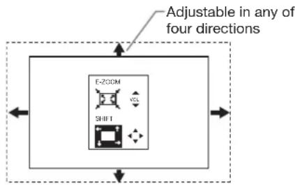
When entire projected image isn't displayed within the screen (E-Zoom/Shift)
To adjust the projected image size and position, use E-Zoom/Shift in the Installation menu.
(See page 21 for menu setting.)
- Display the Installation menu.
- Press the ▲ or ▼ button to select E-Zoom/Shift.

- Press the ENTER button.
- The E-ZOOM/SHIFT menu appears at the center of the screen.
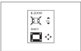
-
Press the VOLUME ▲ or ▼ button to adjust the projected image size.
-
Every time the VOLUME ▲ button is pressed, the projected image becomes larger.
- Every time the VOLUME ▼ button is pressed, the projected image becomes smaller.
- Projected image is a maximum as factory default.
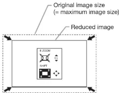
-
Press the ▲, ▼, ◀ or ▶ button to move the projected image position.
-
Every time the ▲ button is pressed, the projected image moves up.
- Every time the ▼ button is pressed, the projected image moves down.
- Every time the ◀ button is pressed, the projected image moves to the left.
- Every time the ▶ button is pressed, the projected image moves to the right.
Important:
- When you reduce the projected image using the E-Zoom/Shift function, the resolution decreases. In addition, stripes may appear or straight lines may bend in images with complicated patterns.
Power-on
- Turn on the device connected to the projector first.
- Plug the power cord in the wall outlet.
• The POWER indicator lights up.
- If the power cord is unplugged from the wall outlet before the projector is cooled down completely after use, the fans may start rotating when the power cord is plugged in next time and the POWER button may not function. In this case, wait for the fans to stop and press the POWER button to light the indicator.
-
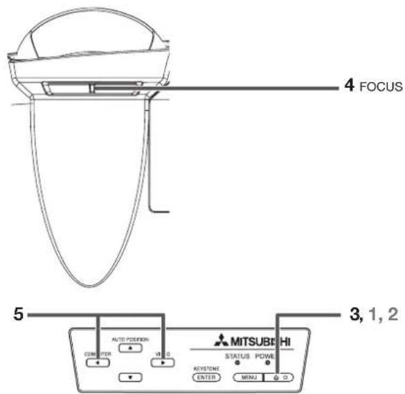
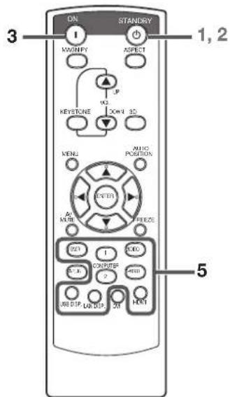
Press the POWER button on the control panel or the ON button on the remote control.
-
It may take about one minute for the lamp to light up.
- The lamp occasionally fails to light up. Wait a few minutes and try to light the lamp again.
- After the POWER button is pressed, the image may flicker before the lamp becomes stable. This is not a product malfunction.
- Regardless of the setting of Lamp Mode in the Installation menu, the Standard lamp mode is activated by default whenever the projector is turned on. The Lamp Mode is set to either Standard or Low depending on the setting last selected, and you cannot switch the Lamp Mode in about one minute after the lamp is on.
| Indicator Condition | STATUS POWER |
| Stand-by - Red | |
| When the lamp is on. Green Green |
Important:
- If the lamp exceptionally turned off due to the power interruption or voltage drop, it can happen that the lamp does not turn on even if you switch again the power supply on. In that case, please pull the electric cord out of the consent and put it again in the consent about 10 minutes later.
-
Do not cover the lens with the lens cap while the lamp is on.
-
The projector starts warming up when the POWER button is pressed. During the warm-up process, images may appear dark and no commands are accepted.
- By blinking red, the STATUS indicator indicates that the lamp should be replaced soon. Replace the lamp when the STATUS indicator blinks red. (See page 60 and 65.)
- Images may not be projected with good quality in an extremely hot or cold environment. (This is not a product malfunction.)
-
In order to ensure the safety in case of trouble with the projector, use an electrical outlet having an earth leakage breaker to supply the power to the projector. If you do not have such outlet, ask your dealer to install it.
-
Adjust the focus by turning the focus ring.
-
Choose your desired external input source using the COMPUTER, HDMI, LAN DISP., USB DISP., VIEWER, VIDEO, or S-VIDEO button.
-
The input source is switched between Computer1, Computer2, HDMI, LAN Display, USB Display, and PC Less Presentation at every press of the COMPUTER button on the control panel.
- The input source is switched between Video and S-Video at every press of the VIDEO button on the control panel.
- When pressing the COMPUTER (1 or 2), HDMI, LAN DISP., USB DISP., VIEWER, VIDEO, or S-VIDEO button on the remote control, the input source switches directly as the button pressed.
- You cannot change the input source while the menu is being displayed.
- When Computer is chosen as the source, images supplied from the computer may flicker. Press the ◀ or ▶ button on the remote control to reduce flicker, if it occurs.
- To avoid permanently imprinting a fixed image onto your projector, please do not display the same stationary images for long period.
When fine streaks are seen on projected images
This is due to interference with the screen surface and is not a malfunction. Replace the screen or displace the focus a little.
Power-off
Use the following procedure to turn off the projector. The lamp may deteriorate if the projector is powered off and on repeatedly within 30 minutes after the lamp is lighted.
- Press the POWER button on the control panel or the STANDBY button on the remote control.
- The message "Power Off? Press ⬇again" appears on the screen.
- To cancel, press any button except the POWER button.
(Some buttons on the remote control don't function for cancel.)
- Press the POWER button on the control panel or the STANDBY button on the remote control within 10 seconds again.
- The lamp will go out and the STATUS indicator will start blinking.
-
Wait about 90 seconds for the STATUS indicator to be turned off.
-
Unplug the power cord.
• The POWER indicator will go out.
- If the power cord should be unplugged accidentally while either the STATUS indicator is blinking or the lamp is on, allow the projector to cool down for 10 minutes with the power off. To light the lamp again, press the POWER button (or ON button). If the lamp doesn't light up immediately, repeat pressing the POWER button (or ON button) two or three times. If it should still fail to light up, replace the lamp.
Important:
- The tip of the projection lens of the projector protrudes. Therefore, be sure to put the lens cap on the lens for protection when carrying the projector.
- When storing the projector in the carrying case, the lens should face up.
Direct Power OFF
You can turn off this projector just by unplugging the power cord without pressing the POWER button.
- Don't shut down the projector while the STATUS indicator is blinking after the lamp lights up because the lamp's life may be shortened.
- Don't turn the projector back on right after shutting it down because the lamp's life may be shortened. (Wait about 10 minutes before turning the projector back on.)
- Before shutting down the projector, be sure to close the menu screen. If you shut down the projector without closing the menu, the setting data of the menu may not be saved.
- If you shut down the projector while controlling the projector using the network function, the application software such as ProjectorView may fail. For details, see "User Manual of LAN Control Utility" contained in the CD-ROM.
AUTO POSITION button
When the image isn't projected in the right position with Computer selected as the input source, follow the procedure below.
- Project a bright image such as the "Recycle Bin" window on the full screen.
- If the screen saver is running, turn it off.
- Press the AUTO POSITION button.
- If the image is still not in the right position, adjust the image position using the Signal menu. See page 24.
Volume from the speaker
Press the VOLUME ▲ or ▼ button to change the volume from the speaker.
The volume control bar will appear on the screen.

- The volume control bar will disappear about 10 seconds after the VOLUME button is released.
- The VOLUME buttons don't function while the menu is being displayed.
- When a high-level audio signal, such as a DVD audio signal, is supplied to the AUDIO IN terminal, the output from the speaker may be distorted.
You can change the volume also by using the Volume setting in the Audio menu.
(See page 21 for menu setting.)
- Display the Audio menu.
- Select Volume by pressing the ▲ or ▼ button.
- Adjust the volume by pressing the ◀ or ▶ button.
- Press the MENU button to exit the menu.
AV mute
The video and audio signals are temporarily muted when the AV MUTE button is pressed. To cancel muting, press the AV MUTE button again.
Setting the aspect ratio
You can change the aspect ratio of the input video signal (or the ratio of width to height of the image). Change the setting according to the type of the input video signal.
With the remote control:
- Press the ASPECT button.
- Every time the ASPECT button is pressed, the aspect mode changes from Normal to 16:9, to Full, and back to Normal.
With the Picture menu:
(See page 21 for menu setting.)
-
Display the Picture menu.
-
Select Aspect Ratio by pressing the ▲ or ▼ button.
| Aspect Ratio | ← | Normal | → |
- Select your desired aspect ratio by pressing the ◀ or ▶ button.
To cancel the menu:
- Press the MENU button.
Important:
- When a 16:9 image is kept displayed for a long time before displaying 4:3 image, the afterimages of the black bars may appear on the 4:3 image screen. Consult your dealer in this case.
Caution:
- The lamp can't be lit again for one minute after turned off for safety purpose. It will take another one minute for the STATUS indicator to go out. If you want to turn on the projector again, wait until the indicator goes out, and then press the POWER button.
- The exhaust fans rotate faster as the temperature around the projector rises.
- When the temperature around the projector rises high, the sign "Temperature!!" blinks red on the screen. If the temperature stays high, the lamp will go out automatically.
Important:
- Do not display a still picture for a long time because the afterimages may persist on the screen.
When connecting to a laptop computer:
When this projector is connected to a laptop computer, there may be times when images may not be projected. When it occurs, set the computer so that it can output signals externally. The procedure varies across computers in use. See the instruction manual of your computer.
Watching 3D content
You can enjoy 3D content with this projector. In order to watch 3D content, you need to have the following items:
• Field-sequential 3D video contents
- DLP™ Link™ active 3D glasses
(Field-sequential: The system which displays alternately the image for the left eye and the right eye.)
| 3D image Format | |||
| Page flipping (Field sequential) | Top & bottom CheckerboardSide by sid | ||
| L R | L R | RL F L FLR P F RL P L RL P L RL P L RL P L | |
| Not supported Not supportedNot supp | |||
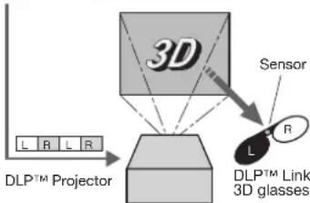
The shutter timing of the 3D glasses is controlled by being synchronized with switching of right and left 3D image which is detected by the sensor of glasses.
Play the field-sequential 3D video contents on a computer or DVD player, and then, connect the cable with the projector.
Go to the Picture menu (or press the 3D button on the remote control) and set the 3D option to On. (See page 22.)
Put on the 3D glasses to watch the contents.
If the contents are not projected correctly, go to the Picture menu, and switch the 3D Sync Invert option to On.
Important:
- You cannot project the 3D content from the input source LAN Display, USB Display, and PC Less Presentation.
- If the viewing distance is nearer than the recommended distance, it will cause physical discomfort and eye fatigue.
- Watch the contents in front of the screen, not at big angle. If you are viewing the screen at big angle, you may not be able to view 3D contents correctly.
- If you are not viewing 3D contents correctly, check to see if the 3D glasses are powered on or adequately charged. See the instruction manual of the 3D glasses for more information.
- There are personal differences in viewing the 3D images. For persons with myopia, hypermetropia, astigmatism or left and right sights, please wear glasses to correct them then wear the 3D glasses.
- The picture seems misplaced at the start of projecting the 3D images, however, this is not a malfunction.
- With the 3D option set to On, contents displayed on the projector appear darker. It is normal and does not mean the projector is malfunctioning.
- The following features cannot be used when viewing 3D contents on the projector:
- Keystone adjustment
-
MAGNIFY mode
-
It may occur that the image may not be enough 3D image because setting such as fluorescent lighting may occur loss of synchronism of glasses.
- 3D image may not appear on the screen depending on the PC performance such as graphics board, memory, or CPU.
- The signals specified in the table on page 68 can be displayed with viewing 3D contents on the projector. If a different signal is inputted, the projector shows no 3D contents even with the 3D option set to On in the Picture menu.
- If DVD is run by 480p signals, 3D image may not be displayed correctly depending on the DVD player.
- When 3D image is projected on the screen in 120Hz or using certain type of playback software of PC, the image may not appear on the screen.
- 3D image may not be displayed properly depending on the settings, functions, or manner of connection of the DVD player.
Caution:
Notes on danger to public health during watching 3D image
- Stop viewing the 3D image immediately if you feel tired, discomfort, or any other abnormality. It may cause you to feel unwell if continuing to watch the 3D image in such cases. Please take the necessary rest, do not continue watch the 3D image for a long time. Stop using the 3D glasses if you can clearly see double images when viewing 3D content. Prolonged use may cause eyesight fatigue.
- The following people need to refrain from use as with 2D image.
• a photosensitive patient
• a patient with heart disease
• a person in poor physical condition
- a sleepy person
• a very tired person
- a drunk person
- children
- When watching 3D movies, take an appropriate break after watching a movie. When watching 3D content on interactive devices such as 3D games or computers, take an appropriate break every 30-60 minutes. Prolonged use may cause eyesight fatigue.
- When you feel uncomfortable, stop viewing 3D images and playing 3D games until you are restored. If necessary, consult a doctor. Also, stop driving a car until you are restored (for about 2 hours). The period to restore varies with the individual.
- As a guide, 3D glasses should not be used by children younger than 5 - 6 years old. As it is difficult to judge younger children's reactions to fatigue or discomfort, their physical condition may deteriorate suddenly. When this product is being used by a child, the parent or guardian should check to ensure that the child's eyes are not becoming tired.
- When viewing the pictures that roll over and shake or many dynamic pictures, if you feel uncomfortable, please look at another place.
- When viewing contents with movements such as rotation, or horizontal or vertical oscillation, you may feel as if you are actually moving. If such a feeling results in discomfort, look away from the screen.
- When using the 3D glasses, be careful not to strike the screen or other people by mistake. As the images are in 3D, you may mistake the distance from the screen, causing to strike the screen which may result in injury. When using the 3D glasses, do not place breakable objects near the glasses. You may move by mistaking the 3D objects you are viewing as the real objects, causing damages to surrounding objects that may lead to injury.
- When using the 3D glasses, make sure your eyes are on an approximate horizontal level. If you suffer from myopia (short sightedness), hyperopia (far-sightedness), astigmatism, or have eyesight differences between the left and right eyes, please use corrective glasses or other such methods to correct your eyesight before putting on the 3D glasses.
- When you view the 3D images, keep a distance from the screen of about three times the effective height of the screen.
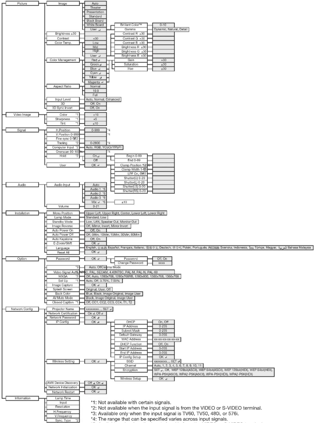
You can make various settings using the displayed menus.
flowchart
graph TD
    A["Picture"] --> B["Image"]
    B --> C["Auto"]
    B --> D["Theater"]
    B --> E["Presentation"]
    B --> F["Standard"]
    B --> G["Black Board"]
    B --> H["White Board"]
    H --> I["Brilliant Color™"]
    I --> J["0-10"]
    I --> K["Gamma"]
    K --> L["Dynamic, Natural, Detail"]
    B --> M["Brightness ±30"]
    M --> N["Contrast"]
    M --> O["Color Temp."]
    O --> P["Low"]
    O --> Q["Mid"]
    O --> R["High"]
    O --> S["User"]
    S --> T["Red"]
    S --> U["Green"]
    S --> V["Blue"]
    S --> W["Cyan"]
    S --> X["Yellow"]
    S --> Y["Magenta"]
    Y --> Z["Aspect Ratio"]
    Z --> AA["Normal"]
    Z --> AB["Full"]
    Z --> AC["Input Level"]
    AC --> AD["3D"]
    AC --> AE["3D Sync Invert"]
    AF["Video Image"] --> AG["Color"]
    AG --> AH["+1"]
    AG --> AI["+5"]
    AG --> AJ["Tint"]
    AJ --> AK["+10"]
    AF --> AL["Signal"]
    AL --> AM["H.Position"]
    AL --> AN["V.Position 0-999"]
    AL --> AO["Fine sync 0-3ff2"]
    AL --> AP["Tracking"]
    AP --> AQ["+2"]
    AL --> AR["Computer Input"]
    AR --> AS["Overscan 90-100"]
    AL --> AT["Hold"]
    AT --> AU["User"]
    AU --> AV["Audio Input"]
    AV --> AW["Audio 1 *6"]
    AV --> AX["Audio 2 *6"]
    AV --> AY["Audio 3 *6"]
    AV --> AZ["Mix +*6"]
    AV --> BA["Volume 0-21"]
    BB["Audio"] --> BC["Audio Input"]
    BC --> BD["Auto"]
    BD --> BE["Audio 1 *6"]
    BD --> BF["Audio 2 *6"]
    BD --> BG["Audio 3 *6"]
    BD --> BH["Mix +*6"]
    BI["Installation"] --> BJ["Menu Position"]
    BJ --> BK["Lamp Mode"]
    BJ --> BL["Standby Mode"]
    BJ --> BM["Image Reverse"]
    BJ --> BN["Auto Power On"]
    BJ --> BO["Auto Power Off"]
    BJ --> BP["Auto Keystone"]
    BJ --> BQ["E-Zoom/Shift"]
    BJ --> BR["Language"]
    BR --> BS["Reset All"]
    BT["Option"] --> BU["Password"]
    BU --> BV["OK"]
    BW["Network Config"] --> BX["Projector Name"]
    BX --> BY["Network Certification"]
    BX --> BZ["Network Password"]
    BX --> CA["IP Config"]
    CA --> CB["DHCP"]
    CB --> CC["On, Off"]
    CB --> DD["IP Address"]
    CB --> DE["Subnet Mask"]
    CB --> FD["Default Gateway"]
    CB --> DG["MAC Address"]
    CB --> DH["DHCP Function"]
    CB --> DI["Start IP Address"]
    CB --> DJ["End IP Address"]
    CB --> DK["IP Config Setup"]
    BE --> DL["DHSID"]
    DL --> DM["SSID"]
    DL --> DE
    BE --> DN["Channel"]
    DN --> DD
    BE --> DO["Encryption"]
    DO --> DP["Wireless Setup"]
    DP --> Q["OK"]

    RQ["Information"] --> RQ1["Lamp Time"]
    RQ1 --> RQ2["Input"]
    RQ1 --> RQ3["Resolution"]
    RQ1 --> RQ4["H.Frequency"]
    RQ1 --> RQ5["V.Frequency"]
    RQ1 --> RQ6["Sync, Type *2"]


    style AF fill:#f9f,stroke:#333
*1: Not available with certain signals.
*2: Not available when the input signal is from the VIDEO or S-VIDEO terminal.
*3: Available only when the input signal is TV60, TV50, 480i, or 576i.
*4: The range that can be specified varies across input signals.
*5: Available only when the input signal is from the VIDEO or S-VIDEO terminal.
*6: Audio 1, Audio 2, Audio 3, and Mix ← cannot be selected when the input source is HDMI input.
How to set the menus
1. Press the MENU button.
• The Main Menu appears on the screen.
The item being selected is displayed in red letters on a blue background.
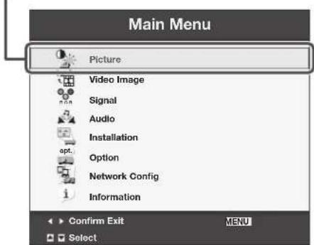
- Press the ▲ or ▼ button to select a menu to use.
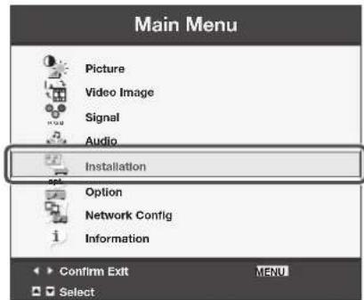
- Press the ENTER button (or ▶ button).
• The selected menu is displayed.
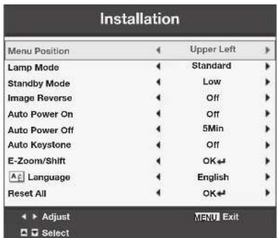
- Press the ▲ or ▼ button to select an item to adjust.
- Set the selected item by pressing the ◀ or ▶ button.
- To cancel the menu, press the MENU button several times.
Important:
- When an item marked with “” is selected, pressing the ENTER button makes its value effective or displays another screen for further setting.
- When the MENU button doesn't function, unplug the power cord from the wall outlet. Wait about 10 minutes, plug the power cord in, and try again.
- The menus and screens shown in this manual may be different from those of the actual projector.
Menu items
Set the following items provided in the respective menus.
Picture menu
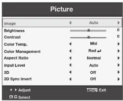
ITEM SETTING FUNCTION
| Image Auto Automatically sets an optimal color balance based on the input signal. Use this setting for most cases. | ||
| Theater Makes projected images soft and smooth. Best suited for movies. | ||
| Presentation Makes projected images bright and crisp. | ||
| Standard Makes projected images look natural. | ||
| Black Board | Reproduces natural color tones when images are projected directly onto a black board. | |
| White Board | Reproduces natural color tones when images are projected directly onto a white board. | |
| User ↓ | Use to set Gamma or BrilliantColorTM. (See page 31.) | |
| Brightness ±30 Adjusts the brightness of projected images. (See page 30.) | ||
| Contrast ±30 Adjusts the contrast of projected images. (See page 30.) | ||
| Color Temp. 4 options Adjusts the color temperature. (See page 30.) | ||
| Color Management | Red ↓/ Green ↓/Blue ↓/ Cyan ↓/Yellow ↓/ Magenta ↓ | You can change to any desired color by adjusting each of Gain, Saturation and Hue of six different colors. (See page 31.) |
| Aspect Ratio Normal Automatically sets the aspect ratio in relative to the input signal. Use this setting for most cases. | ||
| 16:9 Select to expand squeezed (or horizontally compressed) images such as DVD images to 16:9. | ||
| Full Select this setting when you want to project images in the full screen. | ||
| Input Level | Auto /Normal /Enhanced | For HDMI signal input:Auto: The proper setting is automatically selected.Normal: Select when grayish black occurs.Enhanced: Select when solid black occurs.(See page 12.) |
| 3D | Off / On | Set to On/Off of 3D display. |
| 3D Sync Invert | Off / On | Switches the order of the image for left eye and for right eye. |
- When Image is switched, projected images may be distorted.
Video Image menu
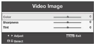
ITEM SETTING FUNCTION
Color ±10 Adjusts the color tone of projected images. (See page 30.) You cannot select
this setting when the Computer1, Computer2 or HDMI is selected as the input source.
Sharpness ±5 Adjusts the sharpness of projected images. (See page 30.)
Tint ±10 Adjusts the color tint of projected images. (See page 30.) You can select this
setting only when NTSC is selected as the input signal.
- You cannot adjust Tint when the TV50 (PAL, SECAM) signal is inputted.
- When Computer1, Computer2 or HDMI is selected, Tint does not work.
Signal menu
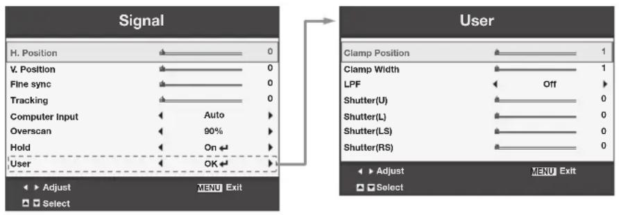
ITEM SETTING FUNCTION
| H. Position 0-999 Select this setting to adjust the horizontal position of projected images.V. Position 0-999 Select this setting to adjust the vertical position of projected images.Fine sync 0-31 Select this setting to eliminate flickering or blurs, if they appear, when you are | ||
| Tracking 0-2800 | viewing projected images.Select this setting to eliminate vertical wide stripes, if they appear, when you are viewing projected images. | |
| Computer Input Auto Automatically sets the appropriate setting. | ||
| RGB Select this setting when you connect the projector to high definition video equipment having R, G, and B output terminals. | ||
| YCbCr/YPbPr | Select this setting when you connect the projector to a DVD player or other device having Y, CB, and CR (or Y, PB, and PR) component video output terminals. | |
| Overscan 100%-90% Hold Off / On | Use this setting to adjust the display area of projected images.Use this setting to adjust projected images when flagging occurs in the upper area of the screen. | |
| User OK | The Signal-User menu is displayed for the following adjustments. | |
| Clamp Position | 1-255 | Use this setting to correct solid white or solid black that appears in projected images. |
| Clamp Width | 1-63 | Use this setting to correct solid black that appears in projected images. |
| LPF | On / Off | Select this setting to enable or disable LPF. |
| Shutter(U) | 0-20 | Use this setting to adjust projected images when noise appears in the top part of the image. |
| Shutter(L) | 0-20 | Use to adjust the image when noise appears on the bottom part of the image. |
| Shutter(LS) | 0-20 | Use this setting to adjust projected images when noise appears in the left half of the image. |
| Shutter(RS) | 0-20 | Use this setting to adjust projected images when noise appears in the right half of the image. |
• Horizontal strips may appear in the enlarged projected image, though these conditions are not a malfunction.
- When you change the value of the horizontal or vertical position drastically, noise may appear.
- The adjustable range of the vertical position varies depending on the type of the input signal. The image may be stationary even when the value is changed. These conditions are not a malfunction.
- Shutter does not work correctly during keystone adjustment.
- When you increase the value of Overscan, noise may appear on the screen.
- When the keystone adjustment takes effect, the Overscan function cannot be used.
Important:
- You can set the Picture, Signal, and Signal-User menus only when the signal is inputted.
Audio menu
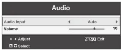
ITEM SETTING FUNCTION
| Audio Input Auto Selects Audio 1 when the input source is Computer1, selects Audio 2 when the input source is Computer2, selects Audio 3 when the input source is Video/S-Video, and selects HDMI when the input source is HDMI. | |
| Audio 1 / Audio 2 / Audio 3 | Selects audio input. |
| Mix ↓ | Selects mix signal of Audio 1 and Audio 2. You can change the balance of Audio 1/Audio 2 using Mix ↓ |
Volume 0-21 Adjusts the volume of the audio from the speaker.
- In Audio Input, HDMI audio is selected when the input source is HDMI input. The audio of Audio 1, Audio 2, Audio 3, and Mix cannot be selected.
Installation menu
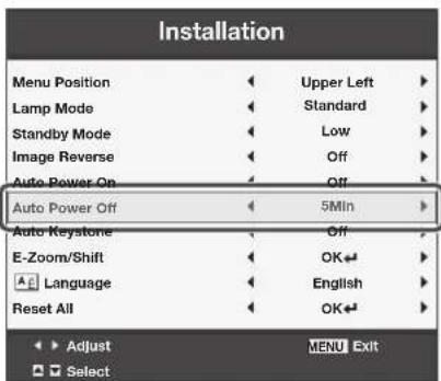
| Installation | ||
| Menu Position | ◀ | Upper Left ▶ |
| Lamp Mode | ◀ | Standard ▶ |
| Standby Mode | ◀ | Low ▶ |
| Image Reverse | ◀ | Off ▶ |
| Auto Power On | ◀ | Off ▶ |
| Auto Power Off | ◀ | 5Min ▶ |
| Auto Keystone | ◀ | Off ▶ |
| E-Zoom/Shift | ◀ | OK ← ▶ |
| Language | ◀ | English ▶ |
| Reset All | ◀ | OK ← ▶ |
ITEM SETTING FUNCTION
Menu Position 5 options Use this setting to change the position of the menu on the screen.
Lamp Mode Standard Select this option when you want to view images in a well-lit room.
Low Select to moderate the intensity of the lamp. The operating sound is reduced and the lamp lifetime becomes longer.
- When this mode is switched, projected images may flicker.
- If this mode is frequently switched, the lamp may be deteriorated.
Standby Mode Low Select this option when you don't use the LAN control, speaker output and monitor output during power standby. This option disables them and reduces the power consumption during the power standby.
LAN Select this option when you control the projector via the LAN during power standby.
Speaker Out Select this option when you want to output audio from the speaker during power standby.
Monitor Out Select this option when you want to output video signal from the MONITOR
OUT terminal in addition to the audio from the speaker during power standby.
Image Reverse Off Select this setting when you want to view images from the front with the projector set on the floor.
Mirror Select this setting when you want to view images from behind the screen with the projector set on the floor.
Invert Select this setting when you want to view images from behind the screen with the projector set at the ceiling.
Mirror Invert Select this setting when you want to view images from the front with the projector set at the ceiling.
Auto Power On Off / On When this mode is set to On, the lamp is automatically lit when the power cord is plugged in the wall outlet. Select On when you set the projector at the ceiling.
- When the lamp is off, the projector is in standby. Use the remote control to turn on the lamp.
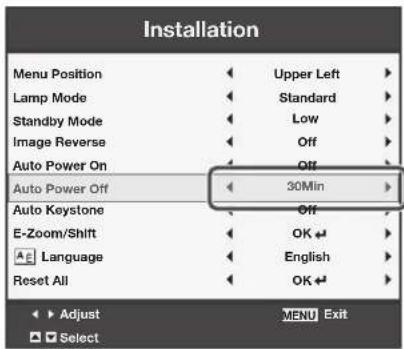
Auto Power Off Off / 5-60 Min Selects a desired timer setting until the projector enters the standby mode when there is no signal input from the source.
Auto Keystone Off / On Select Auto Keystone function. E-Zoom/Shift OK ↓ Displays the E-ZOOM/SHIFT menu for size and position adjustment of the projected image.
Language 18 languages Selects a desired language for the menu. Reset All OK ↓ Resets all menu settings except for Password and Language to the default.
- Regardless of the setting of Lamp Mode in the Installation menu, the Standard lamp mode is activated by default whenever the projector is turned on. The Lamp Mode is set to either Standard or Low depending on the setting last selected, and you cannot switch the Lamp Mode in about one minute after the lamp is on.
- When the Standby Mode is set to Speaker Out or Monitor Out, the audio selected with Audio Input in the Audio menu is output during standby mode. However, no audio is output when the last selected input was HDMI.
- During standby mode, you cannot change the audio input and the volume from the speaker.
- When Standby Mode is set to LAN, Speaker Out, or Monitor Out, the fans rotate at very low speed during standby after plugging the power cord (with 5 second high speed rotation at the beginning) and after turning off the lamp. This is to cool down the projector operating various functions during standby and is not a malfunction. When Standby Mode is set to Low, the fans stop during standby.
Option menu
| Option | ||
| Password | ◀ | OK ◀ ▶ |
| Cinema Mode | ◀ | Auto ▶ |
| Video Signal | ◀ | Auto ▶ |
| WXGA | ◀ | Off ▶ |
| Set Up | ◀ | Auto ▶ |
| Image Capture | ◀ | OK ◀ ▶ |
| Splash Screen | ◀ | Original ▶ |
| Back Color | ◀ | Blue ▶ |
| AV Mute Mode | ◀ | Black ▶ |
| Closed Caption | ◀ | Off ▶ |
ITEM SETTING FUNCTION
Password OK Use this setting to activate or deactivate the password lock.
Cinema Mode Auto / Off Select Auto to automatically activate the film mode when the input
video signal is a video signal from a film.
Video Signal 8 options Select Auto to automatically set the appropriate video format in
relative to the input signal. If projected images aren't displayed correctly, select a desired video format manually.
WXGA Off / Auto / 1280 x 768 / Select the appropriate format when the input signal is a WXGA 1280 x 768RB / 1280 x 800 / video signal and the Auto mode does not display images properly. 1360 x 768 / 1366 x 768 Select Off when the input signal is other than a WXGA video signal.
Set Up Auto Select this setting to automatically change the Set Up mode.
Off Select this setting to lower the density of black. Use this setting when images are dark.
3.75% / 7.50% Select this setting to increase the density of black.
- When 7.50% is set, the brightness is decreased by the setup cancel function for the U.S.
Image Capture OK Use to capture the screen for the splash screen. (See page 54.)
| Splash Screen | Original | Displays the original image for the splash screen when the projector is powered on. |
| User | Displays the image captured for the splash screen when the projector is powered on. | |
| Off | Displays no splash screen when the projector is powered on. | |
| Back Color | Blue / Black | Displays blue or black background while no signal is inputted. |
| Image Original | Displays the original image for the splash screen while no signal is inputted. | |
| Image User | Displays the image captured for the splash screen while no signal is inputted. | |
| AV Mute Mode Black | Displays black background when the AV MUTE button is pressed. | |
| Image Original | Displays the original image for the splash screen when the AV MUTE button is pressed. | |
| Image User | Displays the image captured for the splash screen when the AV MUTE button is pressed. | |
| Closed Caption | Off Does not display captions. CC1 / CC2 / CC3 / CC4 / T1 / T2 | Displays captions. |
- You can select Cinema Mode only when the input signal is a TV60, TV50, 480i, or 576i video signal.
- Captions are not displayed while information about the menu, volume setting, or input signal selection is being displayed on the screen.
- The closed caption function displays text information included in the NTSC signal, which is mainly used for TV broadcasting in North America.
Network Config menu
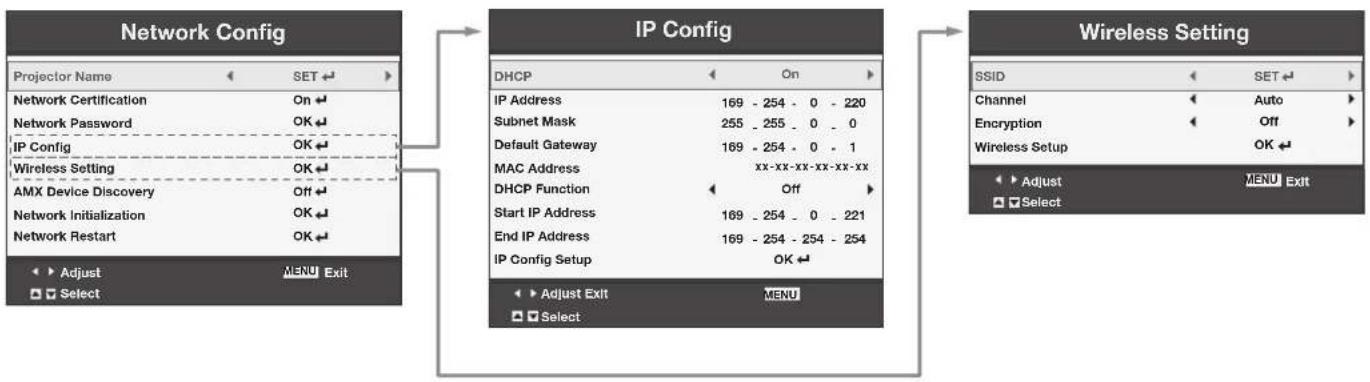
flowchart
graph TD
    A["Network Config"] --> B["IP Config"]
    B --> C["Wireless Setting"]

    subgraph_A["Network Config"]
        A1["Projector Name"] --> A2["SET"]
        A3["Network Certification"] --> A4["On"]
        A5["Network Password"] --> A6["OK"]
        A7["IP Config"] --> A8["OK"]
        A9["Wireless Setting"] --> A10["OK"]
        A11["AMX Device Discovery"] --> A12["Off"]
        A13["Network Initialization"] --> A14["OK"]
        A15["Network Restart"] --> A16["OK"]
    end

    subgraph_B["IP Config"]
        B1["DHCP"] --> B2["On"]
        B3["IP Address"] --> B4["169 - 254 - 0 - 220"]
        B5["Subnet Mask"] --> B6["255 - 255 - 0 - 0"]
        B7["Default Gateway"] --> B8["169 - 254 - 0 - 1"]
        B9["MAC Address"] --> B10["xx-xx-xx-xx-xx-xx"]
        B11["DHCP Function"] --> B12["Off"]
        B13["Start IP Address"] --> B14["169 - 254 - 0 - 221"]
        B15["End IP Address"] --> B16["169 - 254 - 254 - 254"]
        B17["IP Config Setup"] --> B18["OK"]
    end

    subgraph_C["Wireless Setting"]
        C1["SSID"] --> C2["SET"]
        C3["Channel"] --> C4["Auto"]
        C5["Encryption"] --> C6["Off"]
        C7["Wireless Setup"] --> C8["OK"]
        C9["Adjust"] --> C10["MENU Exit"]
        C11["Select"] --> C12
    end
ITEM SETTING FUNCTION
| Projector Name xxxxxxxx... Displays Projector Name. Displays Projector Name in blank when | ||
| SET ↓ | Projector Name is not set.Set Projector Name. Enter up to 15 character alphabets (capital/small),numeric characters, or marks. | |
| Network Certification | On ↓/ Off ↓ | Select whether to enable the network certification or not. Select On fornormal use. |
| Network Password OK Set the password for the certification of PJLink, ProjectorView Global+and RS-232C. | ||
| IP Config | OK Select this setting for IP Configuration. (See page 34.) | |
| DHCP | On / Off | Use this setting when you obtain IP Config automatically by DHCPserver. |
| IP Address | xxx-xxx-xxx-xxx | Displays IP Address. |
| Subnet Mask xxx-xxx-xxx-xxx Displays Subnet Mask. | ||
| Default Gateway xxx-xxx-xxx-xxx Displays Default Gateway. | ||
| MAC Address | xx-xx-xx-xx-xx-xx Displays MAC Address. | |
| DHCP Function | On / Off | Use this setting when using the projector as a DHCP server. |
| Start IP Address xxx-xxx-xxx-xxx Displays Start IP Address. | ||
| End IP Address xxx-xxx-xxx-xxx Displays End IP Address. | ||
| IP Config Setup | OK Set the IP configuration. | |
| Wireless Setting | OK Select this setting for wireless configuration. (See page 36.) | |
| SSID | xxxxxxxx... Displays SSID. | |
| SET ↓ | Set SSID. Enter up to 32 character alphabets (capital/small), numericcharacters, or marks. | |
| Channel | Auto / 1 / 2 / 3 / 4 / 5 /6 / 7 / 8 / 9 / 10 / 11 | Select the wireless channel. |
| Encryption | SET ↓/ Off /WEP 128bit(ASCII) /WEP 64bit(ASCII) /WEP 128bit(HEX) /WEP 64bit(HEX) /WPA-PSK(ASCII) /WPA2-PSK(ASCII) /WPA-PSK(HEX) /WPA2-PSK(HEX) | Select the wireless encrypted communication. |
| Wireless Setup | OK Set the wireless configuration. | |
| AMX Device Discovery | Off ↓/ On ↓ | Use this setting when using an AMX controller. |
| Network Initialization | OK Initializes network setting. | |
| Network Restart | OK Restarts network function. | |
Information menu
Information
| Lamp Time | 2000H |
| Input | Computer1 |
| Resolution | 1024x768 |
| H. Frequency | 60.00 kHz |
| V. Frequency | 60.00 Hz |
| Sync. Type | 3Wire |
ITEM DESCRIPTION
| Lamp Time | This menu shows a lamp operating time (hour) calculated assuming that Lamp Mode is Low. ·When the Lamp Mode is Standard, this menu shows a longer lamp operating time than the actual time. (See page 59 for the interval of lamp replacement.) |
| Input | Indicates the name of the terminal to which the currently projected video signal is being inputted. |
| Resolution | Indicates the resolution of the currently projected video signal. |
| H. Frequency | Indicates the horizontal frequency of the currently projected video signal. |
| V. Frequency | Indicates the vertical frequency of the currently projected video signal. |
| Sync. Type | Indicates the type of the sync signal for the currently projected video signal. |
To adjust the brightness (Contrast and Brightness):
You can make adjustments for the brightness of the projected image using the menu.
(See page 21 for menu setting.)
- Display the Picture menu.
- Select Contrast or Brightness by pressing the ▲ or ▼ button.
- Adjust the selected item by pressing the ◀ or ▶ button.
To cancel the menu:
- Press the MENU button.
Contrast
Select to adjust the contrast of the image. Every time the ▶ button is pressed, the image becomes brighter and more clearly defined. Every time the ◀ button is pressed, the image becomes darker and less clearly defined.
Brightness
Every time the ▶ button is pressed, the image becomes brighter. Every time the ◀ button is pressed, the image becomes darker.
To adjust the color (Color and Tint):
You can adjust the color of the projected image using the menu.
(See page 21 for menu setting.)
- Display the Video Image menu.
- Select Color or Tint by pressing the ▲ or ▼ button.
- Color and Tint is selectable only when the input signal is Video.
-
Tint is selectable only when the NTSC or 4.43NTSC signal is inputted.
-
Adjust the selected item by pressing the ◀ or ▶ button.
To cancel the menu:
- Press the MENU button.
Color
Use to adjust the color density of the projected image. Every time the ▶ button is pressed, the color becomes darker. Every time the ◀ button is pressed, the color becomes lighter.
Tint
Use to adjust the tint of the projected image. Every time the ▶ button is pressed, the image appears more greenish. Every time the ◀ button is pressed, the image appears more reddish.
To sharpen or soften the projected image (Sharpness):
You can adjust the sharpness of the projected image using the menu.
(See page 21 for menu setting.)
- Display the Video Image menu.
- Select Sharpness by pressing the ▲ or ▼ button.
- Adjust the selected item by pressing the ◀ or ▶ button.
To cancel the menu:
- Press the MENU button.
To adjust the tone of white (Color Temp.):
You can select a preset color temperature (white tone) using the menu.
(See page 21 for menu setting.)
- Display the Picture menu.
- Select Color Temp. by pressing the ▲ or ▼ button.
- Select your desired color temperature by pressing the ◀ or ▶ button.
To cancel the menu:
- Press the MENU button.
To adjust the tone of white (To customize the color temperature):
To set (and store) a user-defined color temperature, perform the following procedure.
(See page 21 for menu setting.)
- Select Color Temp. in the Picture menu.
- Press the ◀ or ▶ button to select User ↓
- Press the ENTER button.
- The Color Temp. User menu appears.
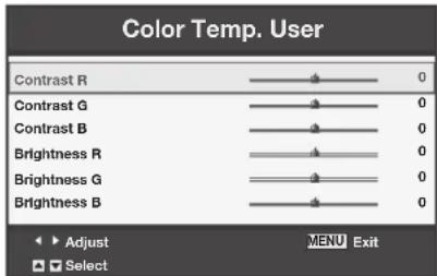
-
Press the ▲ or ▼ button to select the desired item.
-
Press the ◀ or ▶ button to adjust the selected item.
-
Repeat steps 4 and 5 for optimum adjustment results.
To cancel the menu:
- Press the MENU button.
To enable the stored color temperature:
- Set Color Temp. to User ← in the Picture menu.
About color temperature
There are different variations in white color. Color temperature is a way to show these variations in white. When the temperature is low, white appears reddish. When the temperature rises, white appears bluish. For example, you can change the temperature using the following procedures.
To raise the temperature: Increase Contrast B (blue) and decrease Contrast R (red).
To reduce the temperature: Decrease Contrast B (blue) and increase Contrast R (red).
- If you set Contrast R, G, and B to negative values, the brightness of the image can't retain the original even when you maximize the value of Contrast in the Picture menu.
Image
You can set user-defined values for the brightness and hue using the menu. (See page 21 for menu setting.)
- Display the Picture menu.
- Select Image by pressing the ▲ or ▼ button.
- Select User ← by pressing the ◀ or ▶ button.
- Press the ENTER button.
• The Image User menu appears.
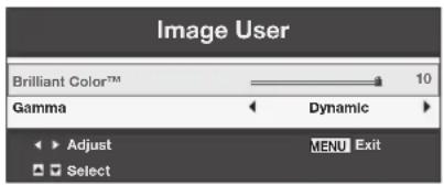
- Select a setting you want to set.
Gamma
Use this setting to set an optimal gamma value and modulation of lamp power. The level of brightness can be adjusted for subdued colors.
Dynamic .....Select when viewing crisp, clear images in a brightly lit room or strong daylight. The level of brightness is adjusted to higher levels.
Natural ......Select when viewing images of which colors are more faithfully reproduced. The level of brightness and vividness is adjusted to optimal levels.
Detail ...... Select when viewing images of which brightness should be kept relatively low, such as movies and music video clips.
BrilliantColor™
Use this setting to make colors with medium brightness, such as yellow and the skin tone appear natural. Press the ◀ button to decrease the value to lessen the effect. Press the ▶ button to increase the value to heighten the effect. (BrilliantColor™ has no effect at value 0.)
- Select a value by pressing the ◀ or ▶ button.
- For more enhanced color reproduction, set BrilliantColor™ to 0. The white area of the color wheel is disabled, and you can reproduce true-color images.
Color Management
You can individually adjust the tone of red, green, blue, cyan, yellow and magenta using the menu.
- Display the Picture menu.
- Press the ▲ or ▼ button to select Color Management.
- Press the ◀ or ▶ button to select a color to be adjusted: Red, Green, Blue, Cyan, Yellow or Magenta.
- Press the ENTER button.
- The Color Management menu for the selected color appears on the screen.
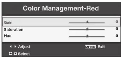
- Press the ▲ or ▼ button to select an item to be adjusted: Gain, Saturation or Hue.
- Press the ◀ or ▶ button to adjust the item.
To cancel the menu:
- Press the MENU button.
How to adjust the computer image
This projector automatically and properly projects video signals being inputted from the computer. However, some video signals may not be projected, depending on the type of the computer. When it occurs, press the AUTO POSITION button. (See page 17.) When the signal is still not projected properly, adjust the projected image using the Signal menu.
How to adjust the image supplied from the computer using the menu:
Perform the following procedures when the following conditions occur.
When wide strips appear.
..... Adjust Tracking in the Signal menu.
When the projected image flickers.
When the projected image is blurred.
..... Adjust Fine sync in the Signal menu.
When the projected image is displaced horizontally.
..... Adjust H.Position in the Signal menu. Every time the ◀ button is pressed, the image moves to the right. Every time the ▶ button is pressed, the image moves to the left.
When the projected image is displaced vertically.
..... Adjust V.Position in the Signal menu. Every time the ◀ button is pressed, the image moves down. Every time the ▶ button is pressed, the image moves up.
When the top part of the image flags.
..... Change the setting of Hold in the Signal menu. To select On ↩ press the ENTER button, and Adjust Begin or End to minimize the flagging.
A solid black or solid white appears in the image.
..... Adjust Clamp Position or Clamp Width in the Signal-User menu.
Noise appears in the right or left half of the image.
..... Adjust Shutter(LS) or Shutter(RS) in the Signal-User menu.
Noise appears in the top or bottom part of the image.
..... Adjust Shutter(U) or Shutter(L) in the Signal-User menu.
-
Display the Signal menu.
-
Press the ▲ or ▼ button to select a setting to adjust.
-
Adjust the selected setting by pressing the ◀ or ▶ button.
To cancel the menu:
- Press the MENU button.
- Do not change the settings of the Signal menu for ordinary use.
Simple method to adjust the image position
To adjust the horizontal position:
-
Align the left edge of the image with the left side of the screen by adjusting H.Position. Then, align the right edge of the image with the right side of the screen by adjusting Tracking.
-
Repeat step 1 to complete the adjustment of the horizontal position.
To adjust the vertical position:
- Align the upper edge of the image with the upper side of the screen by adjusting V.Position.
LPF (Progressive filter)
You can select to enable or disable the LPF. This option is set to Off normally.
Vertical or horizontal streaks may appear in the projected image, depending on the type of the DVD player, game console or computer in use. If this occurs, reduce noise by enabling the LPF. Projected images appear slightly faint.
You can set the network of the projector using the menu.
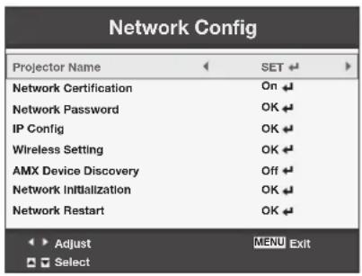
Setting Projector Name
(See page 21 for menu setting.)
- Display the Network Config menu.
- Press the ▲ or ▼ button to select Projector Name.

- Press the ◀ or ▶ button to select SET ↓
- Press the ENTER button.
• The PROJECTOR NAME screen appears.
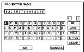
- Press the ▲, ▼, ◀, and ▶ buttons to move the key cursor to select the characters or marks to enter, and press the ENTER button.
- Projector Name can be set using up to 15 characters including alphabets (capital/small), numeric characters, or marks.
← key: Shifting the position of enter cursor to the left for each character.
→ key: Shifting the position of enter cursor to the right for each character.
DEL key: Deleting the character in the position of enter cursor for each character.
caps/CAPS key: Switching an alphabet character to CAPITAL or small.
NEXT/PREV key: Switching the marks.
SPACE key: Inserting a space in the position of enter cursor.
CLEAR key: Deleting all the entered characters.
-
Select OK to complete the setting with the name stored. Select CANCEL to complete the setting without storing.
-
The display returns to the Network Config menu after selecting OK or CANCEL.
- It may take some time to reflect the setting.
Enabling or disabling the network certification
You can select whether or not to certify the network communication using the network password.
(See page 21 for menu setting.)
- Display the Network Config menu.
- Press the ▲ or ▼ button to select Network Certification.

- Press the ENTER button.
• Certification dialog appears.
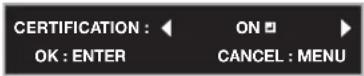
- Press the ◀ or ▶ button to select ON ←or OFF ↙
-
Select the item to set, and press the ENTER button.
-
To cancel the setting, press the MENU button.
- It may take some time to reflect the setting.
Network Password settings
(See page 21 for menu setting.)
- Display the Network Config menu.
- Press the ▲ or ▼button to select Network Password.

- Press the ENTER button.
- The CURRENT NETWORK PASSWORD screen appears.
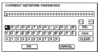
- Press the ▲, ▼, ◀, and ▶ buttons to move the key cursor to select the characters or marks to enter, and press the ENTER button.
- Password can be set using up to 32 characters including alphabets (capital/small) or numeric characters.
← key: Shifting the position of enter cursor to the left for each character.
→ key: Shifting the position of enter cursor to the right for each character.
DEL key: Deleting the character in the position of enter cursor for each character.
caps/CAPS key: Switching an alphabet character to CAPITAL or small.
CLEAR key: Deleting all the entered characters.
- The default password is "admin".
- Select OK, and NEW NETWORK PASSWORD screen appears if the entered password is correct.
- If the entered password is not correct, the CURRENT NETWORK PASSWORD screen appears again.
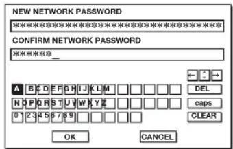
- Enter the NEW NETWORK PASSWORD and CONFIRM NETWORK PASSWORD.
- Password can be set using up to 32 characters including alphabets (capital/small) or numeric characters.
← key: Shifting the position of enter cursor to the left for each character.
→ key: Shifting the position of enter cursor to the right for each character.
key: Shifting the position of enter cursor between NEW NETWORK PASSWORD and CONFIRM NETWORK PASSWORD.
DEL key: Deleting the character in the position of enter cursor for each character.
caps/CAPS key: Switching an alphabet character to CAPITAL or small.
CLEAR key: Deleting all the entered characters.
- When NEW NETWORK PASSWORD and CONFIRM NETWORK PASSWORD are matched, the setting is completed after changing the Network Password.
- If the entered content is not matched, NEW NETWORK PASSWORD screen appears again after an error dialog is displayed.
- It may take some time to reflect the settings.
IP Config settings
(See page 21 for menu setting.)
-
Display the Network Config menu.
-
Press the ▲ or ▼ button to select IP Config.

- Press the ENTER button.
• The IP Config menu appears.
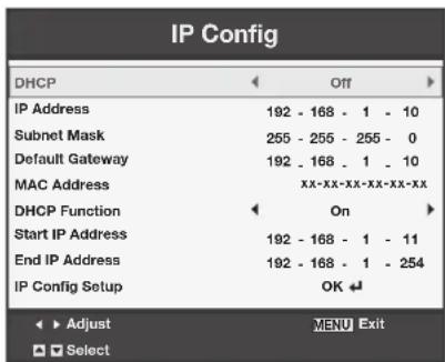
- The default setting of each item is as follows:
| DHCP | Off |
| IP Address | 192.168.1.10 |
| Subnet Mask | 255.255.255.0 |
| Default Gateway | 192.168.1.10 |
| DHCP Function | On |
| Start IP Address | 192.168.1.11 |
| End IP Address | 192.168.1.254 |
Setting or clearing DHCP
- Display the IP Config menu.
- Press the ▲ or ▼ button to select DHCP.

-
Press the ◀ or ▶ button to select On or Off.
-
To cancel the setting, press the MENU button.
- When DHCP is set to On, IP Address, Subnet Mask, Default Gateway, and DHCP Function cannot be set. If you want to set these settings, set DHCP to Off and perform the IP settings as follows.
IP Address settings
- Display the IP Config menu.
- Press the ▲ or ▼ button to select IP Address.

- Press the ENTER button.
• The first octet is selected.

- Press the ▲ or ▼ button to select the numeric value.
- Press the ◀ or ▶ button to select the octet.
• The second or final octet is selected.

-
Press the ENTER button.
-
To cancel the setting, press the MENU button.
- Set the numeric value within the range from 0 to 255. However, set the numeric value for the final octet within the range from 1 to 254.
Subnet Mask settings
- Display the IP Config menu.
- Press the ▲ or ▼ button to select Subnet Mask.

- Press the ENTER button.
• The first octet is selected.
Subnet Mask
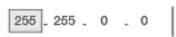
- Press the ▲ or ▼ button to select the numeric value.
- Press the ◀ or ▶ button to select the octet.
- The second or final octet is selected.
Subnet Mask
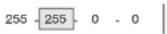
-
Press the ENTER button.
-
To cancel the setting, press the MENU button.
- Set the numeric value within the range from 0 to 255. However, set the numeric value for the final octet within the range from 0 to 254.
Default Gateway settings
- Display the IP Config menu.
- Press the ▲ or ▼ button to select Default Gateway.

- Press the ENTER button.
• The first octet is selected.
Default Gateway
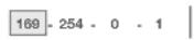
- Press the ▲ or ▼ button to select the numeric value.
- Press the ◀ or ▶ button to select the octet.
• The second or final octet is selected.
Default Gateway

-
Press the ENTER button.
-
To cancel the setting, press the MENU button.
- Set the numeric value within the range from 0 to 255. However, set the numeric value for the final octet within the range from 1 to 254.
Setting or clearing DHCP Function
- Display the IP Config menu.
- Press the ▲ or ▼ button to select DHCP Function.

-
Press the ◀ or ▶ button select On or Off.
-
To cancel the setting, press the MENU button.
- When DHCP Function is set to Off, Start IP Address and End IP Address cannot be set. If you want to set these settings, set DHCP Function to On and perform the IP settings as follows.
Start IP Address setting
- Display the IP Config menu.
- Press the ▲ or ▼ button to select Start IP Address.

- Press the ENTER button.
• The first octet is selected.
Start IP Address 169
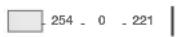
- Press the ▲ or ▼ button to select the numeric value.
- Press the ◀ or ▶ button to select the octet.
• The second or final octet is selected.
Start IP Address 169
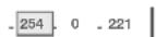
- Press the ENTER button.
- Set the numeric value within the range from 0 to 255. However, set the numeric value for the final octet within the range from 2 to 254. Moreover, set the numeric value larger than IP address in the same subnet class.
End IP Address setting
- Display the IP Config menu.
- Press the ▲ or ▼ button to select End IP Address.

- Press the ENTER button.
• The first octet is selected.
End IP Address
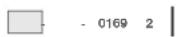
- Press the ▲ or ▼ button to select the numeric value.
- Press the ◀ or ▶ button to select the octet.
• The second or final octet is selected.
End IP Address
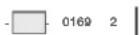
- Press the ENTER button.
- Set the numeric value within the range from 0 to 255. However, set the numeric value for the final octet within the range from 3 to 254. Moreover, set the numeric value larger than Start IP address in the same subnet class.
IP Config Setup setting
- Display the IP Config menu.
- Press the ▲ or ▼ button to select IP Config Setup.

- Press the ENTER button.
- Confirmation dialog appears.
- If the ENTER button is pressed again, the IP Config setting will be reflected.
- It may take some time to reflect the setting.
Wireless Setting
(See page 21 for menu setting.)
- Display the Network Config menu.
- Press the ▲ or ▼ button to select Wireless Setting.

- Press the ENTER button.
• The Wireless Setting menu appears.
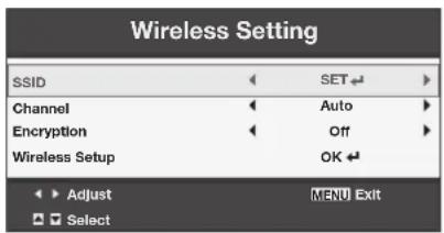
SSID setting
- Display the Wireless Setting menu.
- Press the ▲ or ▼button to select SSID.

- Press the◀ or ▶ button to select SET ←
- Press the ENTER button.
• The SSID screen appears.
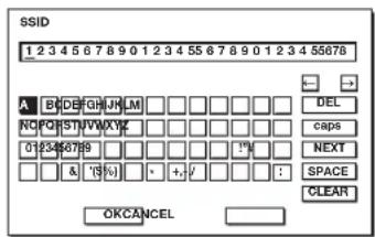
- Press the ▲, ▼, ◀, and ▶ buttons to move the key cursor to select the characters or marks to enter, and press the ENTER button.
- SSID can be set using up to 32 characters including alphabets (capital/small) or numeric characters.
← key: Shifting the position of enter cursor to the left for each character. → key: Shifting the position of enter cursor to the right for each character.
DEL key: Deleting the character in the position of enter cursor for each character.
caps/CAPS key: Switching an alphabet character to CAPITAL or small.
NEXT/PREV key: Switching the marks.
SPACE key: Inserting a space in the position of enter cursor.
CLEAR key: Deleting all the entered characters.
- The default SSID is "MITSUBISHI Projector".
- Select OK to complete the setting with the SSID stored. Select CANCEL to complete the setting without storing.
- The display returns to the Wireless Setting menu after selecting CANCEL.
Channel setting
- Display the Wireless Setting menu.
- Press the ▲ or ▼button to select Channel.

- Press the ◀ or ▶ button to select Auto or 1 to 11.
- To cancel the setting, press the MENU button.
Encryption setting
- Display the Wireless Setting menu.
- Press the ▲ or ▼button to select Encryption.

- Press the ◀ or ▶ button to select SET ↓
- Press the ENTER button.
- Encryption dialog appears.
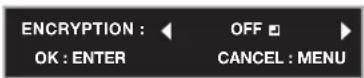
- Press the ◀ or ▶ button to select OFF ←or another encryption.
- Select the item to set, and press the ENTER button.
• The KEY screen appears.
- The keypad on the KEY screen varies depending on the selected Encryption setting.
- To cancel the setting, press the MENU button.
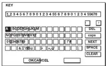
- Press the ▲, ▼, ◀, and ▶ buttons to move the key cursor to select the characters or marks to enter, and press the ENTER button.
- KEY can be set using up to 64 characters including alphabets (capital/small) or numeric characters.
← key: Shifting the position of enter cursor to the left for each character.
→ key: Shifting the position of enter cursor to the right for each character.
DEL key: Deleting the character in the position of enter cursor for each character.
caps/CAPS key: Switching an alphabet character to CAPITAL or small.
NEXT/PREV key: Switching the marks.
SPACE key: Inserting a space in the position of enter cursor.
CLEAR key: Deleting all the entered characters.
-
Select OK to complete the setting with the Encryption and KEY stored. Select CANCEL to complete the setting without storing.
-
The display returns to the Wireless Setting menu after selecting CANCEL.
- The number of characters of KEY varies depending on the Encryption setting.
• WEP 128bit(ASCII): 13 chars
• WEP 64bit(ASCII): 5 chars
• WEP 128bit(HEX): 26 digits
• WEP 64bit(HEX): 10 digits
• WPA-PSK(ASCII): 8-63 chars
• WPA2-PSK(ASCII): 8-63 chars
• WPA-PSK(HEX): 64 digits
• WPA2-PSK(HEX): 64 digits
- If the entered content is outside character number range, the KEY screen appears again after an error dialog is displayed.
Wireless Setup setting
- Display the Wireless Setting menu.
- Press the ▲ or ▼ button to select Wireless Setup.

- Press the ENTER button.
• Confirmation dialog appears. - If the ENTER button is pressed again, the Wireless Setting will be reflected.
- It may take some time to reflect the setting.
Enabling or disabling the AMX Device Discovery
Select this setting when using the AMX controller.
(See page 21 for menu setting.)
- Display the Network Config menu.
- Press the ▲ or ▼ button to select AMX Device Discovery.

- Press the ENTER button.
• AMX dialog appears.
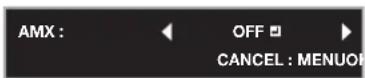
- Press the ◀ or ▶ button to select ON ← or OFF ↙
- Select the item to set, and press the ENTER button.
- To cancel the setting, press the MENU button.
- It may take some time to reflect the setting.
Initialization of network settings
(See page 21 for menu setting.)
- Display the Network Config menu.
- Press the ▲ or ▼ button to select Network Initialization.

- Press the ENTER button.
• Network Initialization dialog appears.
4. If the ENTER button is pressed again, the network settings will be initialized.
- It may take some time to initialize the settings.
Restart of network function
(See page 21 for menu setting.)
- Display the Network Config menu.
- Press the ▲ or ▼ button to select Network Restart.

- Press the ENTER button.
• Network Restart dialog appears. - If the ENTER button is pressed again, the network function will be restarted.
- It may take some time to restart the function.
How to use network function
- When connecting a computer and projector with LAN, configure the both IP Addresses in the same network group.
If connecting in different network group, be sure to use a router. As for the settings of a router, ask the network administrator.
- Configure the IP Config correctly. If the settings are not correct, the communication may be unavailable. For the detail, consult the network administrator.
- Depending on the settings of Standby Mode of the projector, LAN function may be unavailable. See page 26 for the detail of Standby Mode.
Glossary
For more detail of the glossary below, refer to the technical book that is commercially available.
| Term Description | |
| DHCP | Abbreviation for Dynamic Host Configuration Protocol. This protocol automatically assigns IP Address to networked devices. |
| IP Address | Numerical address to identify networked computers. |
| Subnet Mask | A numeric value to define the number of bits used for a network address of a divided network (or subnet) in an IP Address. |
| Default Gateway | A server (or router) to communicate across networks (subnets) that are divided by Subnet Mask. |
| MAC Address | Abbreviation for Media Access Control Address. MAC Address is a unique ID number assigned to each network adapter. And this is based on which data are sent and received between network adapters. |
Thin client
Projecting the desktop screen of a remote computer connected via a network onto the projector, you can remotely control the remote computer through the projector.
To use the thin client function, you need to install the software "ThinClient.exe" contained in the attached CD-ROM.
Supported OS's are as follows:
• Windows XP (except Home Edition)
- Windows Vista (except Home Basic and Home Premium)
• Windows 7 (except Starter and Home Premium)
• Windows Server 2008 R2
• Windows MultiPoint Server
Important:
- License terms for Windows XP, Windows Vista and Windows 7 do not permit simultaneous operation by multiple users.
- To use the thin client function with Windows Server 2008 R2 or Windows MultiPoint Server, a Client Access License (CAL) is required. For details, see "Client Access License (CAL)" on page 42.
- Computer audio cannot be output from the projector.
Preparation for using Remote Desktop
The thin client function utilizes the standard Microsoft Remote Desktop function. To use the Remote Desktop function, perform the following preparations on the computer.
Important:
- For the following preparations, log on to the computer using the administrator account.
1. Creating a user account
Important:
- You must configure a password for the user account. Do not use double-byte characters for the user account name and password.
2. Configuring Remote Desktop users
Configure the Remote Desktop users as follows.
In Windows Vista, Windows 7, Windows Server 2008 R2 or Windows MultiPoint Server
- Select [Start]-[Control Panel].
- In Windows Vista, select [System and Maintenance]. Otherwise, select [System and Security].
- When using Classic View in Windows Vista, double-click the System icon and go to step 4.
- Select [System].
4. Click [Remote settings].
![Control Panel Home Device Manager Remote settings System protection Advanced system settings View basic information about your computer Windows edition Windows 7 Professional Copyright © 2009 Microsoft Corporation. All rights reserved. Service Pack 1 Get more features with a new edition of Windows 7 System Rating: 3.0 Your Windows Experience Index needs to be refreshed Processon: Init(R) Core(TM)2 Due CPU PB400 @ 2.26GHz, 2.27 GHz Installed memory (RAM): 2.00 GB [1.87 GB usable] System type: 22-bit Operating System Pen and Touch: No Pen or Touch Input is available for this Display Computer name, domain, and workgroup settings Computer name: Win7Pro-E Change settings Full computer name: Win7Pro-E](/content/2026/05/816782/images/afe1593820ac64a51329926d7dcaf798f83d32db7e5bb7ef07822e946fb4af0a.jpg)
- Select [Allow connections from computers running any version of Remote Desktop (less secure)].
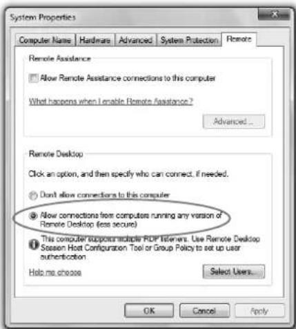
6. Click [Select Users...].
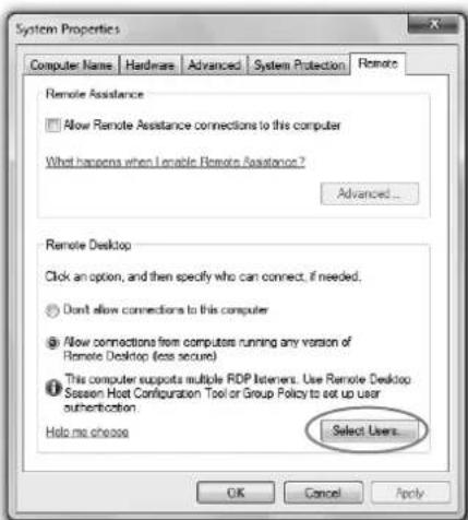
- The "Remote Desktop Users" window is displayed.
7. Click [Add...].
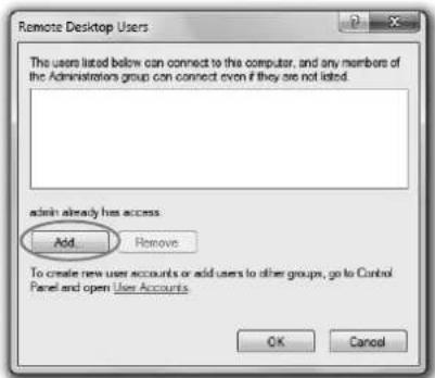
- The "Select Users" window is displayed.
- Enter the user account name configured in the "1. Creating a user account" (see page 38) in the textbox and click [OK].
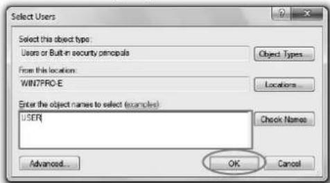
- The "Remote Desktop Users" window is displayed.
9. Click [OK].
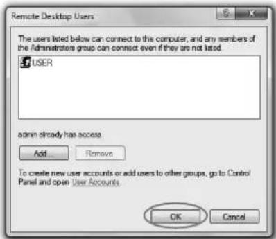
- The "System Properties" window is displayed. Click [OK].
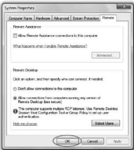
In Windows XP
- Select [Start]-[Control Panel].
- Click [Performance and Maintenance].
- When using Classic View, double-click the System icon and go to step 4.
- Click [System].
- The "System Properties" window is displayed.
-
Click the [Remote] tab and check the [Allow users to connect remotely to this computer] checkbox.
-
Click [Select Remote Users...].
- The "Remote Desktop Users" window is displayed.
- Perform steps 7-10 in the section "■ In Windows Vista, Windows 7, Windows Server 2008 R2 or Windows MultiPoint Server."
3. Configuration of Windows Firewall
Configure Windows Firewall as follows.
■ In Windows 7, Windows Server 2008 R2 or Windows MultiPoint Server
- Select [Start]-[Control Panel].
- Select [System and Security].
- Select [Allow a program through Windows Firewall]. The "Allowed Programs" window is displayed.
- Check the [Remote Desktop] checkbox and the [Home/Work (Private)] and [Public] checkboxes on the same line, and click [OK].
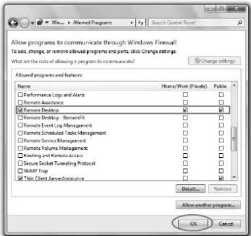
In Windows Vista
- Select [Start]-[Control Panel].
-
Select [Allow a program through Windows Firewall].
-
When using Classic View, double-click the Windows Firewall icon and select [Allow a program through Windows Firewall] on the upper left of the window.
-
The "Windows Firewall Settings" window is displayed.
-
Click the [Exceptions] tab, check the [Remote Desktop] checkbox and click [OK].
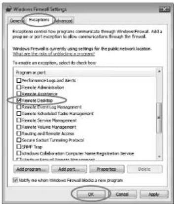
In Windows XP
- Select [Start]-[Control Panel].
- Click [Network and Internet Connections].
- When using Classic View, double-click the Windows Firewall icon and go to step 4.
- Select [Windows Firewall].
- The "Windows Firewall" window is displayed.
- Click the [Exceptions] tab, check the [Remote Desktop] checkbox and click [OK].
Installation of software
Installing Thin Client
Before starting installation, be sure to read "ReadMe.txt" contained in the CD-ROM.
- Copy "ThinClient.exe" contained in the TOOLS folder of CD-ROM to the hard disk of your computer.
-
Double-click "ThinClient.exe" on the hard disk, and start up the installer of the Thin Client.
-
Follow the on-screen instructions to install the software.
-
When the "Windows Security Alert" window is displayed during installation, proceed as follows:
-
In Windows XP or Windows Vista, click [Unblock].
-
In Windows 7, click [Allow access].
-
When the installation has been completed, restart the computer.
When deleting ThinClient (Uninstallation)
- Select [Start]-[All Programs]-[Thin Client]-[Uninstall Thin Client].
- Follow the on-screen instructions to uninstall the software.
Connection
Connect the projector and the computer using a commercially available LAN cable. Connect a USB mouse and USB keyboard to the USB-A terminal on the projector.
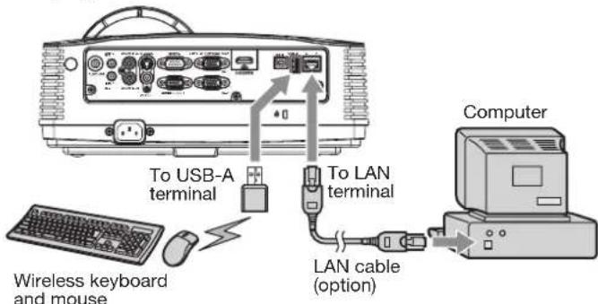
Important:
- On Thin Client, use both a keyboard and mouse. We recommend a commercially available wireless keyboard and wireless mouse intended for a computer with wireless receiver.
- Wired LAN connection is recommended for communication with the computer.
- For wired LAN connection, use a category-5 LAN cable. Both straight-through and crossover cables can be used.
- The USB-A terminal on this projector is compatible with USB 2.0.
- Supported USB devices are standard USB HID devices with power consumption less than 5V/500mA or wireless LAN modules.
- When using a USB hub, you are recommended to use the one with external power supply.
- Some USB hubs cannot be used depending on the specifications.
Operation
Selecting a LAN Display input
-
Press the LAN DISP. button on the remote control or the COMPUTER button on the projector.
-
Each time you press the COMPUTER button, the input source is switched between Computer1, Computer2, HDMI, LAN Display, USB Display and PC Less Presentation.
- When the LAN Display input is selected, the splash screen for LAN Display appears on the screen.
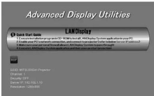
Connecting the projector to the computer
For the following operation, use the USB device such as a mouse or keyboard connected to the projector.
Important:
- The following key assignment is applied to any keyboard connected to the projector.
![F1 F2 F3 F4 F5 F6 F7 F8 F9 F10 F11 F12 - 1 2 3 4 5 6 7 8 9 10 Inb Q E R T Y U I O P [ ] Cups Lock A S D F G H U K L : * Enter Shift Z X C V B N M < ? Shift Ctrl Win Key Alt Alt Win Key Menu Ctrl Inb Range PgUp NumLk / * - Del End Pin 7 8 9 + 4 5 6 1 2 3 < ↓ → 0 Enter](/content/2026/05/816782/images/b5c200864fa7d79c24007d12eabde0484a304aef94efffa7edd4fb29431c29ca.jpg)
2. Click the RDP icon "RDP".
- "Waiting to search Thin Client server ..." is displayed. Then the logon window appears.
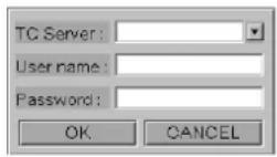
Important:
- In [TC Server], the name of the computer where ThinClient.exe has been installed will be displayed.
- If the subnet of the computer is different, the computer name will not be displayed in [TC Server].
- To close the logon window, click [CANCEL] or press the ESC key on the keyboard.
- The computer name may not be displayed just after startup of the computer. In that case, click [CANCEL] or press the ESC key on the keyboard to close the logon window, wait for a while and then click the RDP icon again.
3. Enter the following in the textboxes and click [OK].
- [TC Server]: Enter the computer name (or IP address).
- [User name]: Enter the user account name.
• [Password]: Enter the password.
Important:
- Double-byte characters cannot be used.
- “Waiting to connect ...” is displayed and the connection process will start. It may take some time to display the desktop screen depending on the network congestion. Wait for a while until the desktop screen appears.
- When connecting to a computer with different subnet, enter the IP address in [TC Server].
- If the message saying “This computer is not allow to remote desktop.” is displayed, the Remote Desktop users setting may not have been enabled yet. Make the setting again, following the procedure of “Preparation for using Remote Desktop” (page 38).
-
If you enter a wrong User name or Password, "The projector could not log on. Make sure your User name and Password are correct." will be displayed.
-
If you connect to a computer installed with Windows XP, Windows Vista or Windows 7 that any other user has already logged on, "Another user is currently logged on to this computer." will be displayed.
- If you connect to a computer with Windows Server 2008 R2 or Windows MultiPoint Server and try logging on to a user account where any other user has already logged on, "Another user is currently logged on to this computer." will be displayed.
4. When the projector logs on to the computer, the desktop screen of the user account is displayed.
- You can operate the computer using the USB device such as a mouse or keyboard connected to the projector.
Disconnecting the projector from the computer
For the following operation, use the USB device such as a mouse or keyboard connected to the projector.
Important:
- When the remote session is disconnected without ending the session, the programs running on the computer are kept active. So you will be able to resume the program session disconnected the next time you establish connection.
■ When using Windows XP
To disconnect without ending the session:
- Select [Start]-[Disconnect].
- Click [Disconnect].
To disconnect with ending the session:
- Select [Start]-[Log Off].
- Click [Log Off].
■ When using Windows Vista
To disconnect without ending the session:
- Select [Start]-[X].
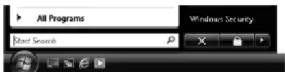
- Lock function of Remote Desktop cannot be used with this projector. When [Lock] is selected, the remote session is disconnected without ending the session.
To disconnect with ending the session:
- Click [Start], select the ▶ button and click [Log Off].
■ When using Windows 7, Windows Server 2008 R2 or Windows MultiPoint Server
To disconnect without ending the session:
- Click [Start], select the ▶ button and click [Disconnect].
- Lock function of Remote Desktop cannot be used with this projector. When [Lock] is selected, the remote session is disconnected without ending the session.
To disconnect with ending the session:
- Select [Start]-[Log Off].
Client Access License (CAL)
An application allowing multiple users to share a single operation system requires the standard Microsoft Windows server licenses. In addition to Windows Server Client Access License, Remote Desktop Services Client Access License (RDS CAL) is necessary for each end user or each device to access Windows server. When using Windows Multipoint Server, Windows MultiPoint Server 2011 CAL is also necessary. For details of Microsoft multiple user licenses, see the Microsoft website.
1. When the host computer OS is Windows XP, Windows Vista or Windows 7
For Windows XP, Windows Vista and Windows 7, only a single projector can run the thin client function. While using the desktop of host computer, you cannot use the thin client function on the projector.
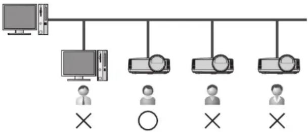
flowchart
graph TD
    A["Computer"] --> B["Monitor"]
    B --> C["Client 1"]
    B --> D["Client 2"]
    B --> E["Client 3"]
    B --> F["Client 4"]
    B --> G["Client 5"]
    B --> H["Client 6"]
    style A fill:#f9f,stroke:#333
    style B fill:#ccf,stroke:#333
    style C fill:#cfc,stroke:#333
    style D fill:#fcc,stroke:#333
    style E fill:#cff,stroke:#333
    style F fill:#ffc,stroke:#333
    style G fill:#cfc,stroke:#333
    style H fill:#fcc,stroke:#333
2. When the host computer OS is Windows Server 2008 R2
Windows Server requests Client Access License (CAL). To access the host computer from a thin client computer or projector, two types of CAL are necessary: "Windows Server CAL" and "Windows Remote Desktop Service (RDS) CAL". "Windows Server CAL" offers two types of license system.
User CAL
With User CAL, you purchase CALs according to the number of users regardless of the number of thin client computers or projectors. User CAL is, therefore, recommended in the case that the number of system administrators or operators who operate thin client computers or projectors at multiple sites is smaller than that of the thin client computers or projectors.
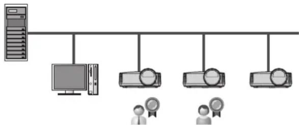
flowchart
graph TD
    A["Server"] --> B["Monitor"]
    B --> C["Client 1"]
    B --> D["Client 2"]
    B --> E["Client 3"]
    B --> F["Client 4"]
E.g., when two users operate four devices
In the example above, the following licenses are necessary.
• Windows Server CAL (User CAL) x 2
- Windows RDS CAL x 2
Device CAL
With Device CAL, you purchase CALs according to the number of devices accessing to the host, regardless of the number of users who access the host via thin client computer or projector. Therefore Device CAL is recommended for the case that multiple operators share a thin client computer or projector.
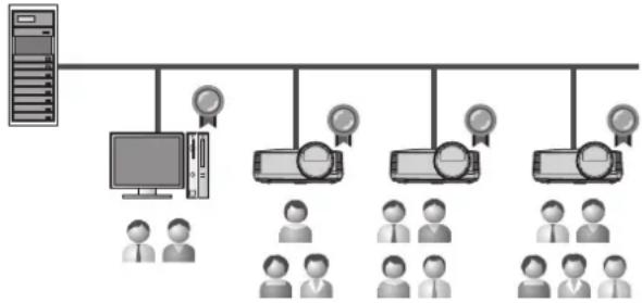
flowchart
graph TD
    A["Server"] --> B["Client"]
    B --> C["User Group 1"]
    B --> D["User Group 2"]
    B --> E["User Group 3"]
    B --> F["User Group 4"]
    B --> G["User Group 5"]
    B --> H["User Group 6"]
    B --> I["User Group 7"]
    B --> J["User Group 8"]
    B --> K["User Group 9"]
    B --> L["User Group 10"]
    B --> M["User Group 11"]
    B --> N["User Group 12"]
    B --> O["User Group 13"]
    B --> P["User Group 14"]
    B --> Q["User Group 15"]
    B --> R["User Group 16"]
    B --> S["User Group 17"]
    B --> T["User Group 18"]
    B --> U["User Group 19"]
    B --> V["User Group 20"]
E.g., when six users operate four devices
In the example above, the following licenses are necessary.
• Windows Server CAL (Device CAL) x 4
• Windows RDS CAL x 4
3. When the host computer OS is Windows MultiPoint Server
The concept of Windows MultiPoint Server is basically the same as that of Windows Server 2008 R2. It requires Windows MultiPoint Server CAL instead of Windows RDS CAL. Therefore, Windows Server CAL and Windows MultiPoint Server CAL are necessary for each user or device. When you use the desktop of host computer as one of computer terminals, Windows MultiPoint Server will also request a Windows Server CAL and Windows MultiPoint Server CAL for the desktop of host computer.
(Example 1)
When two users operate four computers or projectors as well as the desktop of host computer
• Windows Server CAL (User CAL) x 2
• Windows MultiPoint Server CAL x 2
(Example 2)
When six users operate four computers or projectors as well as the desktop of host computer
• Windows Server CAL (Device CAL) x 4
• Windows MultiPoint Server CAL x 4
USB Display
You can project the computer images inputted via a USB connection.
Supported OS's are as follows:
- Windows XP
- Windows Vista
- Windows 7
• Windows Server 2008 R2
• Windows MultiPoint Server
• Mac OS X 10.5 or later
Important:
- You need to install the driver only when using MAC OS X.
• Mac computers based on the PowerPC processors are not supported. - Only 1-to-1 screen projection is supported.
- Moving images cannot be displayed.
Connection
Connect the projector and the computer using a commercially available USB cable.
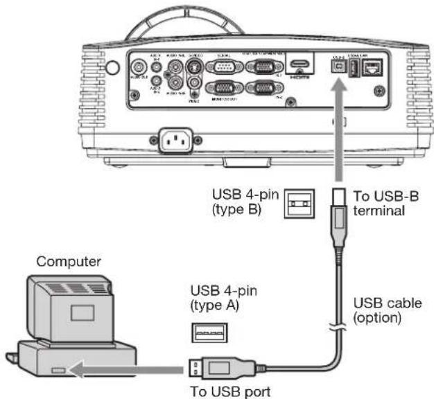
Important:
- The USB-B terminal on this projector is compatible with USB 2.0.
- Do not use a USB hub between the projector and the computer.
Installation of driver
When using Mac OS X, install the driver after connecting the projector and the computer using a USB cable for the first time. Once you have installed the driver, you don't need to install it again.
Installing USB Display driver
- Via the Finder, open [USB_DISPLAY] and double-click [USB Display.pkg].
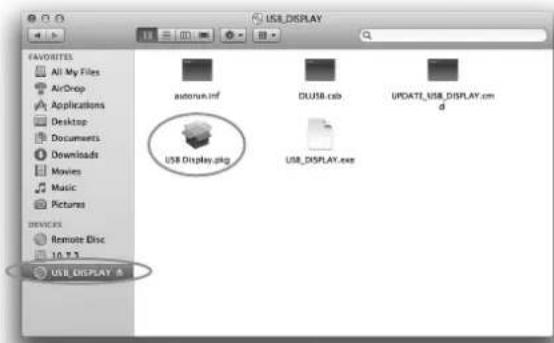
- Follow the on-screen instructions to install the driver.
When deleting USB Display driver (Uninstallation)
- Via the Finder, open the [Applications] folder and double-click the [USB Display] folder.
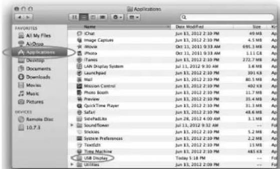
- Double-click [UninstallVendorSpecificType05].
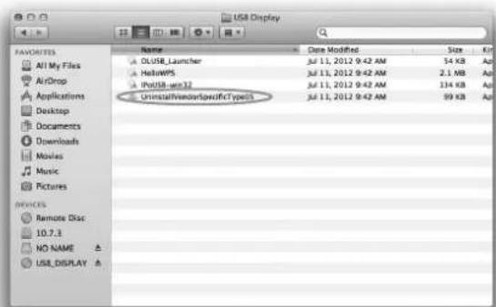
- Follow the on-screen instructions to uninstall the driver.
Operation
Starting USB Display projection
-
Select a USB Display input by pressing the USB DISP. button on the remote control or the COMPUTER button on the projector.
-
Each time you press the COMPUTER button, the input source is switched between Computer1, Computer2, HDMI, LAN Display, USB Display and PC Less Presentation.
- When the USB Display input is selected, the splash screen for USB Display appears on the screen.
- When the computer is connected to the projector, the computer image is automatically displayed on the screen.
Ending USB Display projection
■ When using Windows XP, Windows Vista, Windows 7, Windows Server 2008 R2 or Windows MultiPoint Server
3. Unplug the USB cable from the projector.
- It is not necessary to "Safely Remove Hardware" on the computer or to press the UNPLUG button on the remote control.
■ When using Mac OS X
- On the computer, open the Finder and click "▲" on the right of [USB_DISPLAY] to unmount the projector.
- Unplug the USB cable from the projector.
Important:
- When the image is projected, the computer resolution will be changed according to the projector model and will be automatically recovered after unplugging the USB cable.
LAN Display
You can project the computer images inputted via a wired or wireless LAN.
You can also perform the following during the LAN Display projection:
- 4-to-1 split screen projection Images from up to 4 computers can be projected split on 1 projector screen.
- Remote desktop
Connecting an input device such as a mouse or keyboard to the USB-A terminal on the projector enables the following computer operations from the projector.
• Showing local files of the computer
- Operating the application software
• Showing server files on the network
• Browsing of the internet
- SidePad
Computer images are transferred to the tablet computer and you can operate the computer from the tablet computer.
To use the LAN Display function, you need to install the software “LAN Display System” contained in the attached CD-ROM.
Supported OS's are as follows:
- Windows XP
- Windows Vista
- Windows 7
• Windows Server 2008 R2
• Windows MultiPoint Server
• Mac OS X 10.5 or later
Important:
- Mac computers based on the PowerPC processors are not supported.
- Remote desktop cannot be performed during 4-to-1 split screen projection.
Installation of software
Installing LAN Display System
Before starting installation, be sure to read "ReadMe.txt" contained in the CD-ROM.
■ When using Windows XP, Windows Vista, Windows 7, Windows Server 2008 R2 or Windows MultiPoint Server
- Copy "LAN Display System_v201.exe" contained in the TOOLS folder of CD-ROM to the hard disk of your computer.
- Double-click "LAN Display System_v201.exe" on the hard disk, and start up the installer of the LAN Display System.
- Follow the on-screen instructions to install the software.
- When the installation has been completed, LAN Display System is automatically executed.
■ When using Mac OS X
-
Copy "LAN Display System_v201.dmg" contained in the TOOLS folder of CD-ROM to the hard disk of your computer.
-
Double-click "LAN Display System_v201.dmg" on the hard disk.
• The volume is mounted.
- Drag and drop "LAN Display System" and "SidePadLite" into the [Applications] folder.
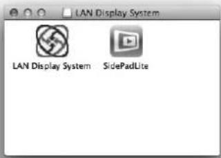
When deleting LAN Display System (Uninstallation) Important:
- When uninstalling LAN Display System, it should be ended in advance. If the application continues operating, uninstallation cannot be performed normally.
■ When using Windows XP, Windows Vista, Windows 7, Windows Server 2008 R2 or Windows MultiPoint Server
-
Select [Start]-[All Programs]-[LAN Display System]-[Uninstall].
-
Follow the on-screen instructions to uninstall the software.
■ When using Mac OS X
-
Open the [Applications] folder.
-
Drag and drop "LAN Display System" and "SidePadLite" to the trash.
Connection
Connect the projector and the computer either by using a commercially available LAN cable or USB wireless LAN adapter.
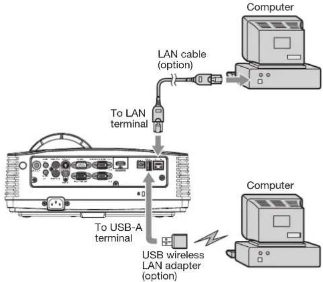
flowchart
graph TD
    A["Computer"] --> B["LAN cable (option)"]
    B --> C["To LAN terminal"]
    C --> D["To USB-A terminal"]
    D --> E["USB wireless LAN adapter (option)"]
Important:
- For wired LAN connection, use a category-5 LAN cable. Both straight-through and crossover cables can be used.
- The USB-A terminal on this projector is compatible with USB 2.0.
- When using a USB hub, you are recommended to use the one with external power supply.
- Some USB hubs cannot be used depending on the specifications.
- Some USB wireless LAN adapters cannot be used depending on the specifications.
- IP address, subnet mask, default gateway values are the same for both wired LAN and wireless LAN.
- Data are not filtered between wired LAN and wireless LAN interface.
Projection
Selecting a LAN Display input
-
Press the LAN DISP. button on the remote control or the COMPUTER button on the projector.
-
Each time you press the COMPUTER button, the input source is switched between Computer1, Computer2, HDMI, LAN Display, USB Display and PC Less Presentation.
- When the LAN Display input is selected, the splash screen for LAN Display appears on the screen.
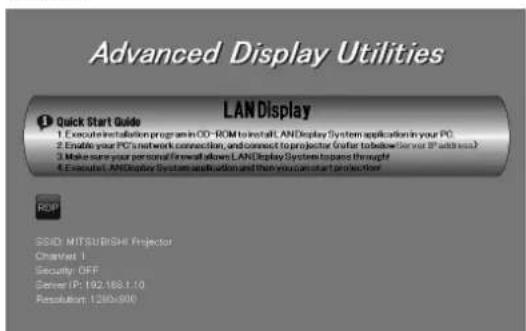
Starting the LAN Display System
- Click the LAN Display System icon "to execute the program.
- The program starts to search for projectors automatically.
- During searching for projectors, Searching icon is displayed.
- When a projector is found, the computer logs in to the projector automatically and the computer image is projected. The main user interface appears on the computer screen.
- When multiple projectors are found, the following window appears on the computer screen.
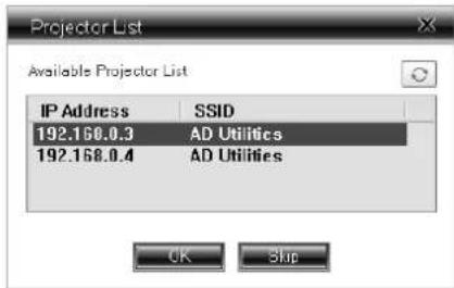
Select a projector and click [OK]. The computer logs in to the projector and the computer image is projected.
Important:
- If the computer resolution is higher than 1280 x 800, a confirmation dialog for changing the computer resolution is displayed. When [OK] is selected, the computer resolution will be changed according to the projected image. When [Cancel] is selected, the computer resolution will not be changed and the projected image size will be smaller than the screen size. The computer resolution will be automatically recovered after the LAN Display System is ended.
Operating the LAN Display System
- Click the buttons on the main user interface to operate the projection.
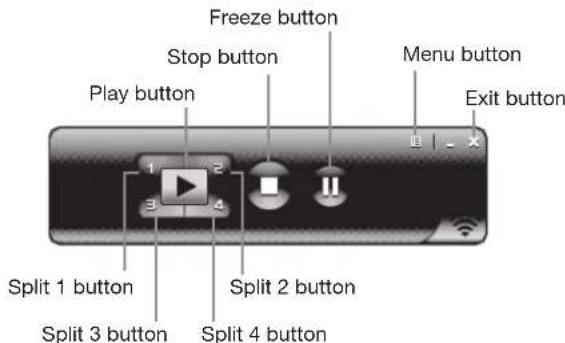
- Play button:
Projects the image in full screen.
- Split 1-4 buttons:
Click either of the buttons to project the image on relevant split screen.
- Stop button:
Stops the projection.
- Freeze button:
Freezes the projected image.
- Menu button:
Displays the menu window. (See the next step for details.)
- Exit button:
Exits the LAN Display System.
- Click the Menu button on the main user interface to display the menu window and select functions.
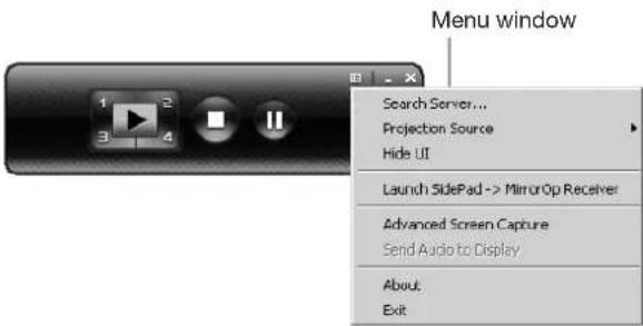
- Search Server
Searches for the projectors on the network. If this function is selected, the LAN Display projection will quit automatically.
• Projection Source*
Chooses the computer screen to be projected, main screen or virtual extended screen which is activated by computer's virtual display function.
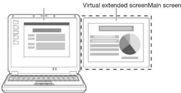
Important:
• Virtual display function is only supported by Windows XP.
- To project a virtual extended screen, the attached Virtual display driver must be installed.
- Hide UI*
Hides or displays the main user interface on the projected image.
- Launch SidePad (or Stop SidePad) -> MirrorOp Receiver
Launches (or stops) SidePad.
• Advanced Screen Capture*
Enables or disables balloon tips and pop-up windows.
- About
Displays the version information of the LAN Display System.
- Exit
Exits the LAN Display System.
Important:
- The items marked with “*” are not available for Mac OS X.
- When “Advanced Screen Capture” is enabled, the computer mouse cursor may blink.
Ending the LAN Display projection
- Click the Exit button on the main user interface or the menu window to exit the LAN Display System.
- In case of the wireless LAN communication, unplug the USB wireless LAN adapter from the projector. Before unplugging, be sure to press the UNPLUG button on the remote control and select [Yes] on the screen by pressing the ◀ or ▶ button and then ENTER button.
Important:
- Do not switch the input source to USB Display or PC Less Presentation during the wireless LAN communication. If switched, the communication will be disconnected.
- During wireless LAN communication, the projector cannot communicate with the access point.
- Only infrastructure mode is available to wireless LAN communication. Adhoc mode is not available.
Installing the virtual display driver
To project a virtual extended screen, install the Virtual display driver as follows.
- Double-click "Virtual display driver.exe" contained in "C:¥Program Files¥LAN Display System", and start up the installer of the Virtual display driver.
- The Setup window is displayed. Click [Next] and operate according to the instructions on the window.
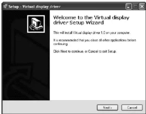
- When the installation has been completed, restart the computer.
Using remote desktop
Connect an USB device such as a mouse or keyboard to the USB-A terminal on the projector. While the computer images are projected with the LAN Display, the computer can be operated with the device.
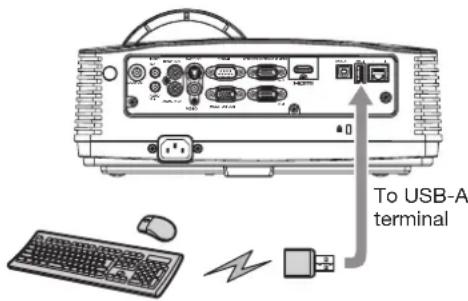
Important:
- The USB-A terminal on this projector is compatible with USB 2.0.
- Supported USB device is standard USB HID device with power consumption less than 5V/500mA.
- When using a keyboard and mouse together, we recommend a commercially available wireless keyboard and wireless mouse intended for a computer with wireless receiver.
- When using a USB hub, you are recommended to use the one with external power supply.
- Some USB hubs cannot be used depending on the specifications.
Using SidePad function
While computer images are projected with the LAN Display, you can operate the computer from the tablet computer.
To use the SidePad function, you need to install the free software "MirrorOp Receiver" to the tablet computer.
Supported OS's of MirrorOp Receiver are as follows:
- iOS 3.2 or later
- Android 2.1 or later
Installation of software
-
Download the MirrorOp Receiver from the Internet to the tablet computer.
-
Connect to Apple Store to download the software for iOS.
- Connect to Google Play to download the software for Android.
- The communication fee to connect to Apple Store or Google Play will be borne by the customer.
Connection
Connect the projector, computer and tablet computer to the same network using a commercially available USB wireless LAN adapter, etc.
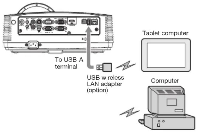
Important:
- Do not use a USB hub for connection.
- Some USB wireless LAN adapters cannot be used depending on the specifications.
Starting SidePad
- On the tablet computer, tap the MirrorOp Receiver icon "☐" to turn on MirrorOp Receiver.
- The MirrorOp Receiver startup screen is displayed.
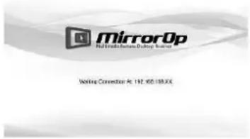
- On the computer, click the Menu button on the main user interface to display the menu window and select [Launch SidePad -> MirrorOp Receiver].
- Computer images are transferred to the tablet computer and you can operate the computer from the tablet computer.
Important:
- If more than one tablet computer running MirrorOp Receiver exist in the same network, the device selection screen appears. Select the tablet computer where to transfer the computer images.
Ending SidePad
- On the computer, click the Menu button on the main user interface to display the menu window and select [Stop SidePad -> MirrorOp Receiver].
- Pressing the Home button on the tablet computer also turns off the SidePad.
PC Less Presentation
You can project JPEG images and the PtG contents stored in the USB device such as a USB flash drive without using a computer.
Also, you can perform effective presentation of them using the AutoRun function and the slideshow function.
To create PtG contents, you need to install the software "PtG Converter-Lite" contained in the attached CD-ROM.
Important:
• Supported USB Flash drive format is FAT32.
- Only one logical partition in USB Flash drive is supported.
- Supported USB device is standard USB mass storage device with power consumption less than 5V/500mA.
• JPG file preview limitation:
- File size: 10 MB or less
• Pixel: 40 megapixel (24 bits) or less
• Dimension: 8192*6144 or less - File Name: ASCII characters are supported.
- Thumbnail:
file thumbnail (obtained from EXIF) is supported.
- PtG file preview limitation:
- File Name: ASCII characters are supported.
- Thumbnail: file thumbnail is supported.
- PC Less Presentation does not support the following image:
• Extended DCT-based process
- Lossless process
• Hierarchical process
- Progressive scan
- Input format of YUV4:1:1, gray level with 16x16 pixels MCU
• Decoded image width less than 64 pixels for YUV4:2:0/4:2:2 and 32 pixels for YUV4:4:4
• Decoded height less than 32 pixels
• Source images of 12-bits per sample
Installation of PtG Converter-Lite
About PtG Converter-Lite
PtG Converter-Lite is a software which converts PPT files created by Microsoft Office PowerPoint into PtG files that can be projected by PC Less Presentation. Pause/page marks and animations contained in the PPT files are also converted.
Features
- Converting up to 20 pages of PPT
- Converting into 800 x 600 / 1024 x 768 / 1280 x 800*16bpp PtG
System requirement
- CPU:
Intel ^® Pentium ^® M processor 1.5 GHz or above
- Memory:
256 MB or more (recommended)
- OS:
Windows XP, Windows Vista and Windows 7
- Microsoft Office:
Microsoft Office 2003, Microsoft Office 2007 and Microsoft Office 2010
Installing PtG Converter-Lite
Before starting installation, be sure to read "ReadMe.txt" contained in the CD-ROM. Copy "PtG Converter-Lite_v200.exe" contained in the TOOLS folder of CD-ROM to the hard disk of your computer.
- Double-click "PtG Converter-Lite_v200.exe", and start up the installer of the PtG Converter-Lite.
- Follow the on-screen instructions to install the software.
When deleting PtG Converter-Lite (Uninstallation) Important:
-
When uninstalling PtG Converter-Lite, it should be ended in advance. If the application continues operating, uninstallation cannot be performed normally.
-
Select [Start]-[All Programs]-[PtG Converter]-[Uninstall].
-
Follow the on-screen instructions to uninstall the software.
- Logs and setting files are automatically deleted.
Conversion of a PPT file to PtG file using the PtG Converter-Lite
- Click the PtG Converter-Lite icon "to execute the program.
PPT conversion buttonMenu bar
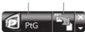
- Menu bar
Right-click to open the menu.
- Output Resolution :
Selects the resolution of the PtG file after the conversion.
• Max Circle Animation:
Selects the max time of animation. - About:
Displays the software version information. - Exit:
Exits the PtG Converter-Lite.
- PPT conversion button:
Starts the conversion from the PPT file to the PtG file.
- Click the PPT conversion button.
• The file selection screen appears.
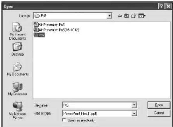
- Select the PPT file you want to convert, and click [Open].
- The screen for specifying the file destination and name appears.
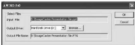
- Set the file destination and the name.
- The converted file is stored in the same folder as original file by default.
- The name of the converted file is the same as original file's by default.
-
Click [OK] to start conversion.
-
When the conversion has been completed, click [OK].
Important:
- All the animation effects available on a computer display can be converted. However, the followings are not supported.
- Animation effects with the timer setting or the repeat setting
- Animation effects taking 60 seconds or more in a single movement
- Pages having more than 3 second downtime setting
• VBA object embedded files
- OLE object embedded files
Connection
Connect a USB device to the USB-A terminal on the projector.
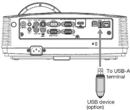
Important:
- The USB-A terminal on this projector is compatible with USB 2.0.
- Do not use a USB hub for the connection.
Performing the PC Less Presentation Selecting a PC Less Presentation input
- Press the VIEWER button on the remote control or the COMPUTER button on the projector.
- Each time you press the COMPUTER button, the input source is switched between Computer1, Computer2, HDMI, LAN Display, USB Display and PC Less Presentation.
- When the PC Less Presentation input is selected, the PC Less Presentation screen appears.
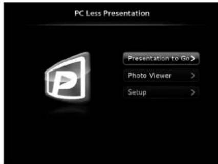
Setting up
- Press the ▲ or ▼ button on the remote control to select Setup and press the ENTER button.
• The Setup screen appears.
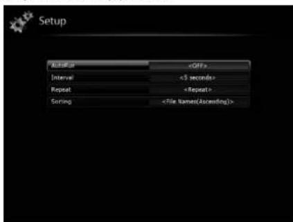
- Press the ▲ or ▼ button to select a setting item and press the ◀ or ▶ button to change the setting.
- AutoRun:
Enables or disables the AutoRun and slideshow function.
| AutoRun Slideshow | ||
| OFF Disables. | Disables. | |
| PtG Enables for PtG files. | Enables for all files. | |
| Photo Enables for JPEG files. | Enables for all files. | |
- Interval:
Sets the interval for PtG pause mark or photo slideshow to 5/10/30/60/300 seconds.
- Repeat:
Enables or disables the repeat execution of AutoRun and slideshow function for photo files and PtG file.
- Sorting:
Sets the file sorting rule to File Name (Ascending), File Name (Descending), Time (New to Old) or Time (Old to New).
- To return to the PC Less Presentation screen, press the ENTER button.
Displaying PtG file
- Press the or button on the remote control to select Presentation to Go and press the ENTER button.
- The file selection screen appears.
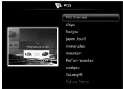
-
Press the or button to select a file or folder you want to display and press the ENTER button.
-
If you select a folder, the underlying le names are displayed. Then, select a file.
• An image on page 1 is displayed on the screen. -
Change the page by pressing the , or button.
• button: to previous page
- button: to next page
- button: to next pause
- Press the button to quit the display.
- The screen goes back to the le selection screen.
Displaying JPEG file
- Press the or button on the remote control to select Photo Viewer and press the ENTER button.
• The file selection screen appears.
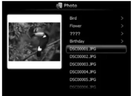
-
Press the or button to select a file or folder you want to display and press the ENTER button.
-
If you select a folder, the underlying le names are displayed. Then, select a file.
-
The image of the selected le is displayed on the screen.
-
Change the file by pressing the , or button.
-
button: to previous file
- button: to next file
-
button: to next file
-
Press the button to quit the display.
- The screen goes back to the le selection screen.
Displaying with AutoRun function
- Create an "AUTORUN" folder in the root directory of the USB device using a computer or other.
- Save a PtG file or JPEG files in the AUTORUN folder.
Important:
- The AutoRun function supports single PtG file only. The PtG file located on the top by sorting is played if multiple PtG files exists in AUTORUN folder.
- Connect the USB device to the USB-A terminal.
- The les speci ed by the AutoRun setting (PtG or Photo) are played back automatically.
- Press the ENTER button to start or pause the playback.
-
Press the , or button to change the file to be played back.
-
button: to previous page/previous file
-
button: to next page/next file
• button: to next pause/next file -
Press the button to quit the AutoRun display.
- The screen goes back to the le selection screen.
Displaying with slideshow function
- Press the or button on the remote control to select Presentation to Go or Photo Viewer and press the ENTER button.
- The file selection screen appears.
-
Press the or button to select a file or folder you want to display and press the ENTER button.
-
If you select a folder, the underlying le names are displayed. Then, select a file.
- When a PtG le is selected, the le is displayed with the slideshow.
-
When a JPEG le is selected, all the les in the same folder as the JPEG file exists are displayed with the slideshow.
-
Press the ENTER button to start or pause the playback.
-
Press the , or button to change the file to be played back.
-
button: to previous page/previous file
-
button: to next page/next file
• button: to next pause/next file -
Press the button to quit the slideshow.
- The screen goes back to the le selection screen.
Ending the PC Less Presentation
Unplug the USB device from the projector. Before unplugging, be sure to press the UNPLUG button on the remote control and select [Yes] on the screen by pressing the or button and then ENTER button.
WiFi-Doc
Via a wireless LAN, you can transfer the images of the Microsoft PowerPoint, Word, Excel, PDF or TXT format stored in the tablet computer to the projector and project them controlling with the tablet computer.
To use WiFi-Doc, you need to install the free software "WiFi-Doc (Bundle Version)" to the tablet computer.
Supported OS's of WiFi-Doc (Bundle Version) are as follows:
- iOS 4.2 or later
- Android 2.1 or later
Installation of software
-
Download the WiFi-Doc (Bundle Version) from the Internet to the tablet computer.
-
Connect to Apple Store to download the software for iOS.
- Connect to Google Play to download the software for Android.
- The communication fee to connect to Apple Store or Google Play will be borne by the customer.
Connection
Connect the projector and the tablet computer using a commercially available USB wireless LAN adapter.
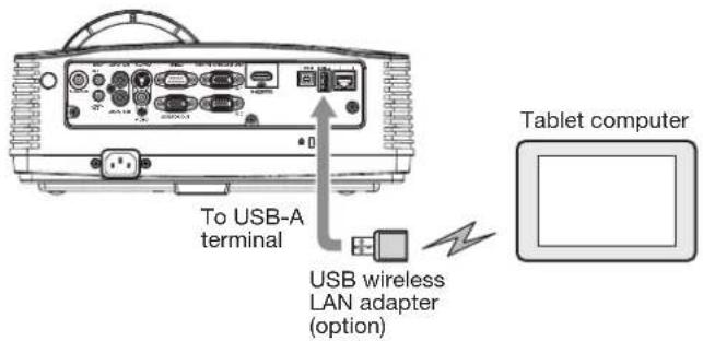
Important:
- Do not use a USB hub for connection.
- Some USB wireless LAN adapters cannot be used depending on the specifications.
Wireless network setting on the tablet computer
- Turn on the tablet computer and tap the [Settings] icon.
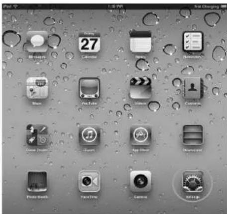
- Turn on Wi-Fi.
- Access points will be listed on the screen.
- Tap the projector's SSID.
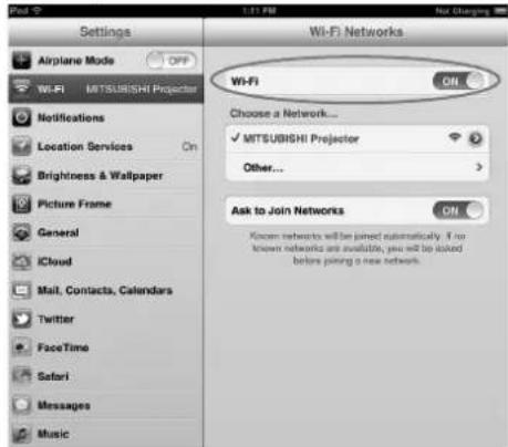
Projection
Selecting a LAN Display input
-
Press the LAN DISP. button on the remote control or the COMPUTER button on the projector.
-
Each time you press the COMPUTER button, the input source is switched between Computer1, Computer2, HDMI, LAN Display, USB Display and PC Less Presentation.
- When the LAN Display input is selected, the splash screen for LAN Display appears on the screen.
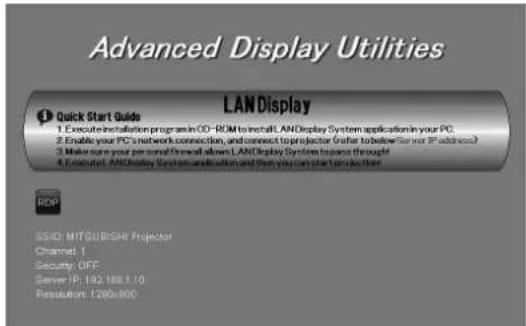
Starting WiFi-Doc
■ When using iOS
- On the tablet computer, tap the WiFi-Doc icon to turn on WiFi-Doc.

- The program starts to search for projectors. When projectors are found, their SSID's are displayed.
- Select a projector for projection by tapping its SSID.
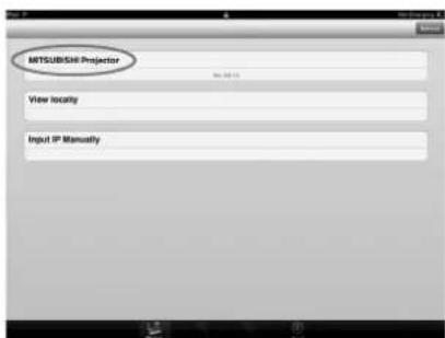
- Select a file to be projected by tapping its name.
• The image of the selected file is displayed.
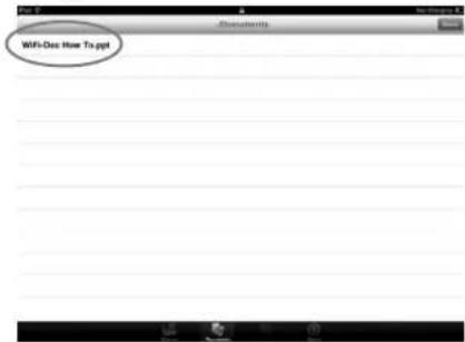
- Operate the image by touching the tablet screen.
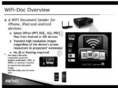
- Flick the screen to move to the previous or next page.
- Pinch the screen for zooming in or out.
- Tap the screen to display the status bar and the thumbnails of the pages. (See below.)
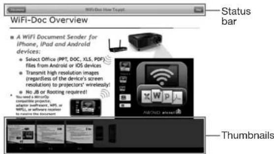
- Tap [../Documents] to return to the file selection screen.
- Tap [Play] or [Stop] to start or stop the projection.
- Tap a thumbnail to select the page to be projected.
■ When using Android
- On the tablet computer, tap the WiFi-Doc icon "to turn on WiFi-Doc."
- The program starts to search for projectors. When projectors are found, their SSID's are displayed.
- Select a projector for projection by tapping its SSID.
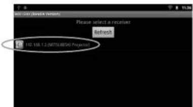
- Select a file to be projected by tapping its name.
• The image of the selected file is displayed.
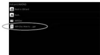
- Operate the image by touching the tablet screen.
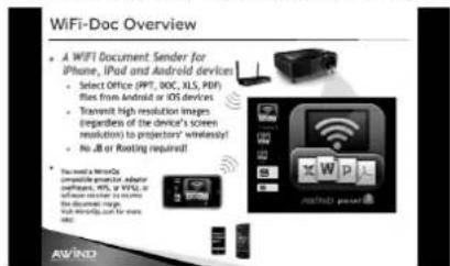
- Flick the screen to move to the previous or next page.
- Pinch the screen for zooming in or out.
- Tap the screen to display the status bar and the thumbnails of the pages. (See below.)
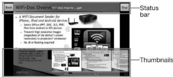
- Tap [Back] to return to the file selection screen.
- Tap [Play] or [Stop] to start or stop the projection.
- Tap a thumbnail to select the page to be projected.
Important:
- Starting projection from another tablet computer stops the projection from the current tablet computer and the “▶” mark will appear in the middle of the screen. Tapping the “▶” mark will start projection from the tablet computer again.
Ending WiFi-Doc
- Turn off WiFi-Doc on the tablet computer.
Displaying a user-defined image during startup or muting
You can display your desired image as the startup screen (or splash screen). Using the menu, you can also use it as the background that is displayed while the video is muted or no signal is inputted.
Important:
- You can capture the computer images from the Computer1, Computer2, HDMI, LAN Display, USB Display, and PC Less Presentation input sources.
Procedure
(See page 21 for menu setting.)
- Select the input source Computer1, Computer2, or HDMI.
- Display your desired image.
- Display the Option menu.
- Select Image Capture by pressing the ▲ or ▼ button.

-
Press the ENTER button.
-
When the capture starts, the captured image will be displayed.
- When you press ENTER button once, any button doesn't function until the capture completes.
- When image resolution is lower than XGA (1024 x 768), the image is captured by adjusting its resolution to XGA.
- When image resolution is higher than XGA (1024 x 768), the image area of XGA is only captured.
Important:
- The captured images will be deleted at the same time as pressing the ENTER button. If you pressed ENTER button wrongly, try to capture the same images again.
- The captured image is displayed from the next startup when Splash Screen in the Option menu is set to User. If the captured image isn't displayed, check to see if Splash Screen in the Option menu is set to Off. (See page 27.)
- To display the captured image while the video is muted, set AV Mute Mode in the Option menu to Image User. (See page 27.)
- When Back Color in the Option menu is set to Image User, the captured image is displayed while no signal is inputted.
- Some images can't be captured correctly because of their signal type.
Freeze
To stop the motion in the image temporarily (or to display a still image):
Press the FREEZE button on the remote control.
• The image freezes temporarily.
To resume the motion in the image:
Press the FREEZE button on the remote control again.
Important:
- Do not keep displaying a still picture for an extended period of time, as the afterimages may linger on the screen.
Magnify
By pressing the MAGNIFY button on the remote control, you can magnify the image to view the details.
- The MAGNIFY mode doesn't function with some input signals. For details, see page 68.
- The MAGNIFY mode doesn't work with video or S-video signal.
- The MAGNIFY mode doesn't work when the keystone adjustment takes effect.
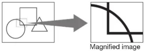
To use the MAGNIFY mode:
-
Press the MAGNIFY button.
-
You can select the area to be magnified by pressing the ▲, ▼, ◀ or ▶ button on the remote control.
-
You can change the magnification of the selected area by pressing the VOLUME ▲ or ▼ button.
-
Press the MAGNIFY button again to exit the MAGNIFY mode.
- The regular operation screen will appear.
Important:
- In the MAGNIFY mode, you can't adjust the volume.
Password lock
This projector provides the password lock function that is intended to prevent wrong operations by children and set controlled access for specified users. If the password lock is enabled, when the projector is turned on, the startup screen (or splash screen) will appear and stay on the screen until the password is entered. When the password is entered, the startup screen will switch to the regular operation screen.
To set a password:
(See page 21 for menu setting.)
-
Display the Option menu.
-
Press the ▲ or ▼ button to select Password.

- Press the ENTER button.
- The Password menu appears.
![Password Password Off Change Password [ **** ] Adjust Confirm Select](/content/2026/05/816782/images/4f79843ae4e6e9afdf6bd64f324b899ed301ae79dba23fe792bb177e966733d9.jpg)
-
Press the ▲ or ▼ button to select Change Password.
-
Press the ENTER button.
- The screen for entering a new password appears.
![Password Password Off New Password [ ]](/content/2026/05/816782/images/32d12deddc70256d9b72b2c2b432e931cfe9678e61c4378c67411ebf9890137e.jpg)
- When the password has already been set, the screen for entering the old password appears instead. In such a case, enter the old password using the same operation as in next step and press the ENTER button. Then the screen for entering a new password appears.
- Enter a 4 digit password using the ▲, ▶, ▼ and ◀ buttons.
$$ (\triangle = 1, \nabla = 2, \blacktriangleleft = 3, \blacktriangleright = 4) $$
- To cancel the procedure, press the MENU button.
-
Press the ENTER button.
-
Press the MENU button to exit the menu.
To enable or disable password lock:
(See page 21 for menu setting.)
- Display the Option menu.
- Press the ▲ or ▼ button to select Password.
- Press the ENTER button.
• The Password menu appears.
- Press the ▲ or ▼ button to select Password.

-
Press the ◀ or ▶ button to select On or Off.
-
Press the MENU button to exit the menu.
Important:
- To disable the password lock when the screen for entering the password is displayed, press the MENU and ENTER buttons on the projector at the same time.
Supervising and controlling by computer
You can supervise and control the projector's operation using a personal computer via a LAN network.
Major functions
ProjectorView Global+
Batch projector controlling / supervising application software
- Batch operation of stand-alone projector / multiple projectors
- Scheduling function to turn ON/OFF for each day of the week
- Checking each condition of the projector and detecting a theft
- Setting of the projector's IP Config
- Activating Visual PA2 to display the specified characters on the projector's screen
- Projector's Text Speech function to read aloud messages displayed on the Visual PA2 window
AMX Device Discovery
The projector is monitored and controlled by the controller system of AMX.
Crestron RoomView Connected™
The projector is monitored and controlled by the controller system and software of Crestron Electronics, Inc.
PJLink™
This projector supports standard protocol PJLink™ for projector control and you can control and monitor projector's operations using the same application among projectors of different models and different manufacturers.
About ProjectorView Global+
- For details, see “LAN control UTILITY operation manual” in the CD-ROM.
About AMX Device Discovery
- This is a technology suggested by AMX to facilitate configuration of the control system of AMX and its target devices.
For details, see the website of AMX.
URL http://www.amx.com/
About Crestron RoomView Connected™
- This is a technology suggested by Crestron Electronics, Inc. to facilitate configuration of the control system of Crestron and its target devices.
For details, see the website of Crestron Electronics, Inc.
URL http://www.crestron.com
URL http://www.crestron.com/getroomview/
About PJLink™
- To use PJLink™ function, the PJLink™ application software is required.
- To use this function, set the network certification properly according to the setting of the network application to be used. (See page 33.)
- For the specifications of PJLink™, access to the Web site of Japan Business Machine and Information System Industries Association (JBMIA). (http://pjlink.jbmia.or.jp/english)
- This projector is fully compliant to the specifications of JBMIA PJLink™ Class 1. It supports all the commands defined by PJLink™ Class 1, and the compliance has been verified with the PJLink™ standard specifications Version 1.0.
Important:
- For the commands for PJLink™, see the table on the next page.
- The control may not be performed correctly or the monitoring data may not be obtained correctly in the following conditions:
- During standby
- During input source switching
- During auto position execution
- During AV mute
- During command processing
-
Before the splash screen disappears after the power is turned on.
-
During AV mute, etc., it may take approx. 5 seconds to receive a response to a command.
- Use 1 controller to control/monitor 1 projector.
- For how to control/monitor using PJLink™, see the operation manual of the PJLink™ application you use.
- When you monitor the projector's operating state using this function by issuing inquiry commands successively, issue an inquiry command after receiving the response to the previous inquiry command from the projector.
Connection
For details of the connection, see “LAN control UTILITY operation manual” in the CD-ROM.
When Standby Mode of the Installation menu of the projector is set to Low, the LAN network is disabled. To enable the LAN network, set Standby Mode to LAN. (See page 26.)
Configure the initial network settings first.
You can configure the initial settings using the projector menu (see pages 33 to 37) or ProjectorView Global+. For details of ProjectorView Global+, see “LAN control UTILITY operation manual” in the CD-ROM.
Using the User Manual
The User Manual for LAN Control Utility is prepared in the Portable Document Format (PDF) in the CD-ROM.
Opening the User Manual:
- Load the CD-ROM into the CD-ROM drive.
- Open CD-ROM "PROJECTOR."
- Double-click on "MANUAL_LAN.HTML" within the CD-ROM. A language selection list for the User Manual will be displayed.
- Move the mouse pointer to the desired language and click.
PJLink™ supported commands
The table below shows commands to control the projector using the PJLink™ protocol.
| Command Description Remark (Parameter) | ||
| POWR Power control 0 = Standby | 1 = Power on | |
| POWR ? Inquiry about the power state | 0 = Standby1 = Power on2 = Cooling down3 = Warming up | |
| INPT Input switching 11 = Computer1 12 = Computer2 | 21 = Video 22 = S-Video31 = HDMI41 = PC Less Presentation 42 = USB Display51 = LAN Display | |
| INPT ? Inquiry about input switching | ||
| AVMT Mute control 30 = Video and audio mute disable | 31 = Video and audio mute enable | |
| AVMT ? | Inquiry about the mute state | |
| ERST ? | Inquiry about the error state | 1st byte: Fan error, 0 or 22nd byte: Lamp error, 0 to 23rd byte: Temperature error, 0 or 24th byte: Cover open error, 0 or 25th byte: Always 06th byte: Other error, 0 or 20 to 2 mean as follows:0 = No error detected, 1 = Warning, 2 = Error |
| LAMP ? | Inquiry about the lamp state | 1st value (1 to 5 digits): Cumulative lamp operating time (This item shows a lamp operating time (hour) calculated based on that Lamp Mode is Low.)2nd value: 0 = Lamp off, 1 = Lamp on |
| INST ? | Inquiry about the available inputs | The following value is returned.“11 12 21 22 31 41 42 51” |
| NAME ? | Inquiry about the projector name | The projector name set on the Network Config menu or the Crestron RoomView Setup window is returned. |
| INF1 ? | Inquiry about the manufacturer name | “MITSUBISHI” is returned. |
| INF2 ? | Inquiry about the model name | “WD390” is returned. |
| INFO ? | Inquiry about other information | No other information is available. No parameter is returned. |
| CLSS ? | Inquiry about the class information | “1” is returned. |
- This projector is fully compliant to the specifications of JBMIA PJLink™ Class 1. It supports all the commands defined by PJLink™ Class 1, and the compliance has been verified with the PJLink™ standard specifications Version 1.0.
This projector is equipped with a lamp to project images. This lamp is a consumable. It may burn out or its brightness may decrease during use. In such cases, replace the lamp with a new one as soon as possible. Be sure to replace the lamp with a new lamp separately sold that is exclusive to this projector. Contact your dealer for purchase of the lamp.
Spare lamp for WD390U-EST: VLT-XD560LP
Caution:
- Do not remove the lamp immediately after using the projector. You may get burned because the lamp is very hot after use.
- Before replacing the lamp, press the POWER button to turn off the lamp and wait for two minutes for lamp to cool down. Unplug the power cord from wall outlet and wait one hour for the lamp to cool down completely.
- Do not remove the lamp except for replacement. Careless handling can cause injury or fire.
- Do not touch the lamp with bare hands or give a shock to the lamp. Attach the lamp properly. Improper handling may cause explosion.
- Be sure not to drop the lamp lid screw into the projector. Also be sure not to put metal or any flammable objects inside because it may cause fire or electric shock. If any objects should fall inside, unplug and contact your dealer.
• Install the lamp securely to prevent failure and fire. - If the lamp should break, small glass fragments may fall out through the vents and some may remain inside of the projector or the lamp box. When taking the lamp box out, be sure to turn over the projector and hold the handle of the lamp box to avoid injury due to the glass fragments.
- If the lamp should break, never shake the lamp box or hold it in front of your face after removing it. The glass fragments may fall out and cause injury to your eyes.
- When removing the lamp from the ceiling-mounted projector, use the lamp replacement attachment packed with the projector or option lamp to prevent glass fragments from scattering.
- Be sure to use the lamp dedicated to this projector, VLT-XD560LP for WD390U-EST. Use of other lamps may cause a failure of the projector.
A) When the projector is placed on the table
Make sure that the projector is securely held in place.
- Remove the cover (a) of the screw fixing the lamp cover with a fingernail. If it is difficult to remove it with a fingernail, use a finetipped tool such as flathead screwdriver.
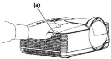
natural_image
Technical line drawing of a projector with labeled component (a), no text or symbols present- Remove the screw (b) and slide the lamp cover (c) for removal.
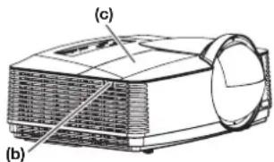
- Loosen the two screws (d) of the lamp unit, and then pull out the lamp unit (f) by the handle (e).
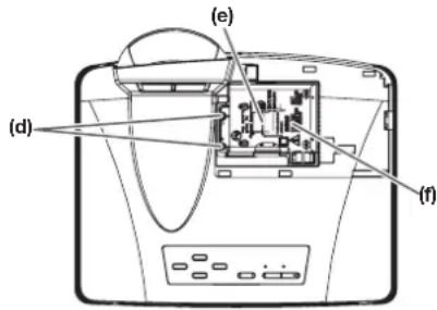
- When replacing the lamp, do not loosen the screws other than two screws (d). It may cause the failure of projector.
- Pull the lamp unit out of the projector slowly. If it is pulled out quickly, the lamp may break, scattering glass fragments.
-
Do not spill liquid on the removed lamp unit or do not place it near any flammable object or where children can reach to prevent injuries or fire.
-
Insert the new lamp unit, and secure it with two screws firmly.
- Secure the lamp cover with screw (b) back again, and mount the cover (a).
Caution:
- Make sure that the lamp cover is secured firmly. Otherwise, the POWER indicator flashes red and green, disallowing the projector to be powered on.
B) When the projector is mounted to the ceiling
When removing the lamp unit from the projector mounted to the ceiling, never fail to use the lamp replacement attachment to protect yourself from glass fragments and so on.
- Contact your dealer when replacing the lamp unit with the projector mounted to the ceiling.
- Remove the lamp cover referring to the procedure 1 and 2 of "A) When the projector is placed on the table".
Caution:
- When opening the lamp cover to replace the lamp of the ceiling-mounted projector, pay careful attention because glass fragments may exist inside the lamp cover.
- When replacing the lamp, do not loosen the screws other than two screws (d). It may cause the failure of projector.
- Fold the three taping portions (g) of the lamp replacement attachment along the folding line as shown in the figure.
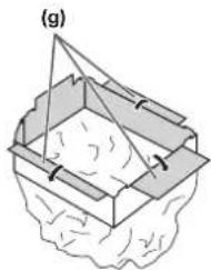
natural_image
Diagram of a 3D container with internal structure and arrows indicating direction (no text or symbols)- Fit the lamp replacement attachment to the edge of the lamp cover attachment part on the projector (h) and fix the three taping portions (g) with the tape included in the lamp replacement attachment.
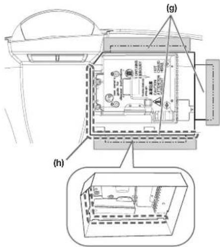
- Pull out the lamp unit (f) in the bag by the handle (e).
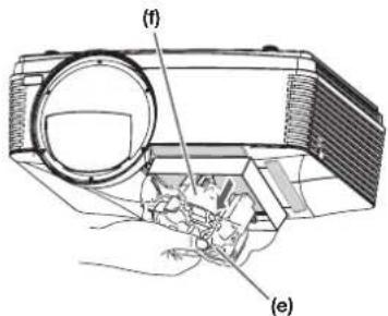
- Remove the tape fixing the lamp replacement attachment, and remove the lamp replacement attachment with the lamp unit remaining in the bag.
Caution:
- Pull the lamp unit out of the projector slowly. If it is pulled out quickly, the lamp may break, scattering glass fragments.
- Do not spill liquid on the removed lamp unit or do not place it near any flammable object or where children can reach to prevent injuries or fire.
-
Insert the new lamp unit, and secure it with two screws firmly.
-
Secure the lamp cover with screw (b) back again, and mount the cover (a).
Caution:
- Make sure that the lamp cover is secured firmly. Otherwise, the POWER indicator flashes red and green, disallowing the projector to be powered on.
Reset of the lamp operation time
Plug in the power cord, and reset the lamp operation time by keep pressing the ◀, ▶, and POWER buttons on the control panel at the same time.
Important:
- Unless these three buttons are pressed at the same time, the lamp operation time isn't reset.
- Make sure that the STATUS indicator is lit twice and the lamp operation time is reset successfully.
- The projector doesn't turn on if the lamp cover isn't attached securely.
- Be sure to reset the lamp operation time whenever you replace the lamp.
- Do not reset the lamp operation time unless you replace the lamp.
Caution:
- The lamp is fragile. If it is broken, be careful not to cut yourself with glass fragments.
- Contact your dealer for a new lamp.
Interval of lamp replacement
The recommended interval of lamp replacement is about 6000 hours ^12 of consecutive use. Such interval differs depending on the operating environment and may be shorter than 6000 hours ^12 .
Decrease in luminescence and/or color brightness indicates that the lamp needs to be replaced. When the lamp operation time exceeds 4500 hours ^1 , the indicator will blink alternately between green and red (while the lamp is lit; when the lamp is not lit, the indicator will be lit red only) and the lamp replacement message will appear on the screen for one minute every time the lamp is turned on. When the lamp has been used for about 5700 hours ^1 , the replacement message (Lamp Replacement) will appear on the screen for one minute every 30 hours ^1 thereafter.
When the lamp operation time exceeds 6000 hours ^+1+2 , the projector automatically shuts off and can't be used until the lamp is replaced and the lamp operation time is reset.
*1: Duration when Lamp Mode of the Installation menu is set to Low. When it is set to Standard, this duration will be shorted.
*2: When Lamp Mode is set to Standard, this duration will be shorted to 3000 hours.
Important:
- Do not open the lamp cover when the projector is set at a ceiling or a high place. Lamp fragments may fall from the inside if the lamp were broken. Please contact your dealer when you need to replace the lamp with a new one.
Caution:
- This projector uses a lamp that contains mercury. Disposal of the lamp or the projector with the lamp may be regulated due to environmental considerations. For disposal or recycling information, please contact your local authorities or the Electronic Industries Alliance: www.eiae.org. (For the U.S. only.)
Before asking for repair of the projector, check the following. If the symptom persists, stop using the projector, be sure to unplug the power plug, and then contact your dealer.
No image appears on the screen.
| Problem Solution | |||
| Power can not be turned on. | Check whether the indicators are on or off and how they are lightning. | ||
| POWER STATUS Solution | |||
| Off Off | ○ | Connect the power cord to the projector.Plug the power cord into a wall outlet. | |
 | Off | If any objects are blocking the intake or exhaust vents, remove them and carry out the following.1. Unplug the power cord from the wall outlet.2. Make sure that the projector has cooled off.3. Plug the power cord into the wall outlet.4. Press the POWER button. | |
E  | If any objects are blocking the intake or exhaust vents, remove them.Don't expose the exhaust vents to hot air emitted from a heating appliance. | ||
I  | After the STATUS indicator stops blinking, press the POWER button.If you unplug the power cord while the fan is rotating, the lamp may not turn on about 1 minute when you plug the power cord next time.The lamp can't turn on again for 1 minute after it goes out.Press the POWER button several times. | ||
S  | Replace the lamp. (The lamp is at the end of its life.) | ||
 blinkingred/green blinkingred/green | Off | Attach the lamp cover on the top. | |
 un un | Unplug the power cord from the wall outlet and contact your dealer. | ||
| No image appears on the screen. | Cancel the AV mute by pressing the AV MUTE button.Check that the lens cap is removed.It may take about 1 minute for the lamp to light up.The lamp fails to light up on rare occasions. In such a case, wait for a few minutes and then try again.If the projector was turned off before the lamp was cooled down sufficiently last time, the fan may start rotating and the POWER button may not work after the power cord is plugged. Press the POWER button to turn back on the POWER indicator.Check that the intake vent is clean.Check that the lamp cover is closed. (See page 58 or 59.)Check that the cables connected to the external devices are not broken.When an extension cable is being used, replace it with the supplied cable for check. When images are displayed correctly, add an RGB signal amplifier to the extension cable. | ||
| Power turns off. | This problem may occur when the intake vent and/or exhaust vents are blocked. (In such a case, the STATUS indicator brinks orange.)→ Remove the objects blocking the intake vent and/or exhaust vents and then carry out the following procedure.Wait for the intake fan and/or exhaust fan to stop. (Wait until the STATUS indicator goes out.)Unplug the power cord from the wall outlet.Wait about 10 minutes.Plug the power cord into the wall outlet.Press the POWER button.When the STATUS indicator is steady red, it is indicating that the lamp should be replaced. Replace the lamp in this case.Check that Auto Power Off has been set to Off.If the lamp has deteriorated, it may go out after a while it illuminates. | ||
| The screen for entering the password appears. | Password in the Password menu has been set to On to enable the password lock.→ Enter the password or contact the person in charge of management of the projector. (See page 55.) | ||
| “No signal” is displayed. | Turn on the power of the connected device, or check whether there is something wrong with the connected device.Check whether the external device output signals. (Check this especially when the external device is a notebook computer.)Check that the cable connected to the external device isn’t defective.Check that the projector is connected to the external device using the correct terminals.Check that the connected device is correctly selected as the input source.When an extension cord is being used, replace it with the supplied cable and check whether images are projected correctly. If images are projected correctly, use an RGB signal amplifier along with the extension cord. | ||
Images are not displayed correctly.
| Problem Solution | |
| Projected images are shaking.Projected images are displaced. | Check that the cable connected to the external device isn't intermittent.Connect the cable's plug with the external device's connector firmly.Press the AUTO POSITION button.Some computers output out-of-spec signals on rare occasion. Adjust the Signal menu. (See page 24.)When the input signal is a WXGA video signal, confirm the setting selected in WXGA in the Option menu.When the input signal is other than a WXGA video signal, select Off in WXGA in the Option menu. |
| Projected images are distorted. | Adjust the projector and the screen so that they are perpendicular to each other. (See page 9.) |
| Projected images are dark. | Adjust Brightness and Contrast in the Picture menu. (See page 30.)Replace the lamp. (See page 58.) |
| Projected images are blurred. | Adjust the focus. (See page 16.)Clean the lens.Press the◄ or ► button on the remote control to eliminate flicker.Adjust Tracking and Fine sync in the Signal menu. (See page 24.)Adjust Brightness and Contrast in the Picture menu. (See page 30.)Adjust the projector and the screen so that they are perpendicular to each other. (See page 9.) |
| Afterimages persist on the screen. | This phenomenon is improved by keeping projecting an evenly bright image. (Such “image burn-in” phenomenon where afterimages persist on the screen may occur if a stationary image is kept displayed on the screen for a long time.) |
| White dots are seen on projected images.Black dots are seen on projected images. | This phenomenon is normal for a DLP ^TM projector and is not a malfunction. (A very small number of pixels may visibly or invisibly be persistent all the time, but they are not a sign of system malfunctions. Over 99.99% of the pixels are effective.) |
| Fine streaks are seen on projected images. | This is due to interference with the screen surface and is not a malfunction. Replace the screen or displace the focus a little.Vertical or horizontal streak noise may appear on the projected image, depending on the type of the DVD player, game console or computer you use. In such a case, you can reduce such streak noise by enabling the LPF. |
| Projected images become wavy. | Connect the plugs of the cables to external devices securely.Keep the projector away from equipment generating interfering radio waves.When the keystone adjustment is carried out, the image may not be displayed correctly because of the type of input signal. This isn't a product malfunction. In this case, readjust the keystone so that the amount of keystone correction is as small as possible. |
| Hue is not appropriate. | Check that the cables connected to the external devices are not broken. |
| Tint in projected images is incorrect. | Check that Computer Input in the Signal menu is correctly set. (See page 24.)Check that the cable connected to the external device isn’t broken. |
| Different color tint. | When comparing images projected by two projectors, tints in the displayed images may be different because of variation between their optical components. This is not a malfunction.When comparing the image projected by this projector with those displayed on the television or PC monitor, tints in the displayed images may be different because of difference in the range of color reproducibility. This is not a malfunction. |
| Only the motion areas in the images supplied from the computer aren’t displayed. | This is caused by the computer being used. Contact the manufacturer of your computer. |
| Projected images are obscured. | Match the output resolution of your computer with the resolution of the projector. For the method to change the output resolution of the computer, contact the manufacturer of your computer. (See page 68.)Some images and texts appear obscured during the keystone adjustment. In such cases, use the projector without applying the keystone adjustment. (See page 15.) |
| Noise appears around the image. | In some images such as DVD, noise may appear around the recorded image. In this case, decrease the setting value of Overscan of the Signal menu. (See page 24.) |
| Projected images are flickering. | After the POWER button or ON button on the remote has been pressed, or the Lamp Mode setting has changed, images may be flickering until the lamp lights stably. This is an expected behavior.When selecting the input signal, Auto Position, and Image, the projected image may be flickering temporarily. This is not a product malfunction. |
| Projector images are twitching. | Projector may be vibrating. Set Auto Keystone to Off or lower the VOLUME ▼ button of the Remote control. |
Others
| Problem Solution | |
| The exhaust vents emit warm air. | This air comes out after cooling the inside of the projector. You may feel hot, but this is not a malfunction. |
| No audio is output. Check that the volume isn’t set to low.Check the Audio Input setting.When the external device is connected with an HDMI cable, set the audio output of the device to PCM output. | |
| The menu can’t be used. | The microcomputers inside the projector may be wrongly operating because of noise.→Press the POWER button to turn off the lamp and unplug the power cord from the wall outlet. Wait about 10 minutes, plug the power cord in, and try again. |
| “Temperature!!” is displayed. | This indication appears when the ambient temperature rises high. When the ambient temperature stays high, the lamp goes out.→Eliminate any causes of the rise in the ambient temperature.This indication appears when the intake or exhaust vents are blocked. When they are kept blocked, the lamp goes out.→Remove the objects blocking the intake or exhaust vents. |
| The Qmark appears. | This mark appears when ineffective operation is carried out. This isn’t a product malfunction. |
| The remote control doesn’t function easily or at all. | Check that the batteries are loaded in the remote control or the batteries are not weak. (See page 8.)Check that the remote control sensor isn’t exposed to direct sunlight or fluorescent light. (See page 8.)Use the remote control within its operation range. (See page 8.)Use the remote control at least 10 cm away from the projector. |
| The fans sound during standby. | When Standby Mode in the Installation menu is set to LAN, Speaker Out, or Monitor Out, the fans rotate at very low speed during standby after plugging the power cord (with 5 second high speed rotation at the beginning) and after turning off the lamp. This is to cool down the projector operating various functions during standby and is not a malfunction. |
| Abnormal sound is heard. | Because the color wheel spins at a high speed, metallic sounds may be heard in rare occasions. Such symptom is not a malfunction. |
| Images are not 3D.* Use commercially available 3D glasses supporting the DLPTM LinkTM system.No 3D glasses are supplied with the projector. | Is 3D in the Picture menu set to On?→ Set 3D to On.View 3D images from the front of the screen. At an angle to the screen, you may not be able to view proper 3D images.Is there any obstacle between the 3D glasses and the screen? Or, is there any sticker or label over the sensor of the 3D glasses?→ The 3D glasses work by receiving signals of the images being viewed. Check that there is no obstacle between the 3D glasses and the screen.Are you viewing images from a very close distance?→ Viewing images from a very close distance may not obtain the 3D effect. View images from a proper distance.The 3D glasses may become out of sync due to fluorescent light. Turn off the fluorescent light.Are the 3D glasses turned off?→ Turn on the 3D glasses.Is the 3D format of the displayed image supported by the projector?→ The projector supports only 3D images of the page flipping format/field sequential format (that displays the left eye images and the right eye images sequentially).Use 3D images of these formats.The signals listed in the table on page 68 can be displayed in 3D format. You cannot view other signals in 3D format even when you set 3D in the Picture menu to On.You may not obtain the 3D effect depending on the capabilities of your computer (including the graphic board, memory, and CPU).You cannot view 3D images when the LAN Display, USB Display, or PC Less Presentation input source is selected. |
| There is something wrong with the 3D images.* Use commercially available 3D glasses supporting the DLPTM LinkTM system.No 3D glasses are supplied with the projector. | Depending on the 3D image status, you may feel something wrong with the 3D images.→ Switch the 3D Sync. Invert setting of the projector to check whether or not such feeling is eliminated.The 3D glasses may become out of sync due to fluorescent light. Turn off the fluorescent light.View 3D images from the front of the screen. At an angle to the screen, you may not be able to view proper 3D images. |
| The 3D glasses don’t turn on.* Use commercially available 3D glasses supporting the DLPTM LinkTM system.No 3D glasses are supplied with the projector. | Are the batteries of the 3D glasses still working?→ If the 3D glasses don’t activate even when you turn on the power switch, replace or charge the batteries of the 3D glasses. For details, see the user manual of the 3D glasses. |
If the following problem occurs after the lamp is replaced, check the following first.
| Problem Solution | |
| The projector does not turn on. | Fit the lamp cover securely. (See page 58 or 59.)Reset the lamp operating time. (See page 59.) |
| The STATUS indicator blinks. | Reset the lamp operating time. (See page 59.) |
Maintenance
Warning:
- Do not use flammable solvents (benzene, thinner, etc.) and flammable aerosols when cleaning the projector body and lens. Flammable substances may ignite causing fire or breakdown while the lamp is illuminating.
Caution:
- Be sure to turn off the lamp and unplug the power cord from the wall outlet before you perform any maintenance on the projector.
- Ask your dealer for annual cleaning of the inside of the projector. If you continue to use the projector with dust inside, it may result in fire or malfunction.
Cleaning of the projector and the vents
Use a soft cloth to clean the projector and the vents. When the vents become dirty, wipe them with a soft cloth dampened with diluted mild detergent, and then wipe them with a dry cloth.
To protect the surface of the projector from fading or deteriorating:
- Do not spray insecticide on or inside the projector.
- Do not use benzin or thinner to clean it.
- Do not let rubber or plastic materials contact with projector.
Cleaning of the lens
Remove dust or dirt using the commercially available lens care products (such as cleaning paper or cloth for lens and blower brush).
- Since the lens surface is sensitive, do not scrub it with a solid object or tap on it.
- Do not wipe the lens with lens cleaner or solvent containing alcohol. Doing so may cause wipe marks or peel off the lens coating and the focus performance may be affected.
- Make sure to clean the lens after the lamp is turned off and the lens is cooled sufficiently.
Kensington Lock
This projector has a Kensington Security Standard connector for use with Kensington MicroSaver Security System. Refer to the information that came with the Kensington System for instructions on how to use it to secure the projector. Please contact Kensington Technology Group below.
Kensington Technology Group
2855 Campus Drive
San Mateo, CA 94403, U.S.A.
Phone: +1- (650)572-2700 Fax: +1- (650)572-9675
This projector has two indicators, each of which shows the operation condition of the projector.
The following offer solutions to possible problems. If these problem persist, turn the projector off and consult your dealer.
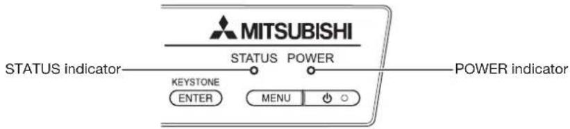
Normal condition
| POWER STATUS CONDITION NOTE | |||
 Steady red Steady red | ○Off | Stand-by | |
  | Lamp stand-by for power-off The power cannot | be turned on by pressing the POWER button. | |
 Steady green Steady green |   | Lamp stand-by for power-on The power cannot | be turned off by pressing the POWER button. |
[077A] | The power is on. (Normal condition) | ||
Abnormal condition
| POWER STATUS CONDITION POSSIBLE SOLUTION | ||||
| [20H6]Steady greenOfSteady red | [A30T]E  | Abnormal temperatureThe vents are clogged with dust or dirt.The room temperature is high. | Clean the vents.Relocate the projector to a cooler place. | |
| [65R1]Steady red Blinking green | [2AK2] | The protection circuit is working or the lamp is in an abnormal condition. | Wait until the STATUS indicator goes out, then press the POWER button.If the above solution is not effective, replace the lamp. | |
| [8CE2]Steady green Blinking green/red | [40AC] | The lamp operation time exceeds the time elapsed until the lamp lifetime notice while the power is on. (See page 59.) | Replace the lamp.Change with a new lamp if this problem recurs. | |
 Steady red Blinking red Steady red Blinking red |  | The lamp operation time exceeds the time elapsed until the lamp lifetime notice while the power is off. (See page 59.) | ||
 Steady red Steady red Steady red Steady red |  | The lamp operation time exceeds the time elapsed until the lamp lifetime. (See page 59.) | ||
| [BHXD]Blinking green/red | [44AC]Off | The lamp cover isn't closed. Close the cover correctly. | ||
| [1-266]Blinking green/red | [A9CB] Blinking Blinking | Abnormal. Contact your dealer. | ||
Specifications
| Type DLP ^TM projector | |
| Model WD390U-EST | |
| Rated power supply 100 - 240 V AC, 50/60 Hz | |
| Power consumption 3.4 A | During standby: 0.5 W (when Standby Mode is Low) |
| Display Technology 0.65-inch single chip Digital Micromirror Device (DMD)Pixels: 1280 x 800 = 1024000 pixels | |
| Colors 16770000 colors | |
| Projection lens F 2.7, f = 5.4 mm | |
| Light source lamp 230 W | |
| Picture size 70-180 inch (aspect ratio 16:10) | |
| PC compatibility Resolution: 640 x 480 (Expand) - 1280 x 800 (Real) - 1600 x 1200 (Compress)Sync on Green available | |
| Video compatibility NTSC/NTSC 4.43/PAL (including PAL-M, N)/SECAM/PAL-60Component Video (DVD/HDTV) (480i, 576i, 480p, 576p, 1080i, 720p, 1080p) | |
| Speaker 10 W mono x 1 | |
| S-video input Luminance signal: 1.0 Vp-p 75 Ω (negative sync.)Chroma signal: 0.286 Vp-p 75 Ω (burst signal) | |
| Video input | 1.0 Vp-p 75 Ω (negative sync.) |
| Audio input | 350 mVrms, 10 kΩ or more |
| Analog RGB input RGB: 0.7 Vp-p 75 Ω (negative sync.)YP _B PR/YCB _R :Y: 1.0 Vp-p (negative sync.)PBPR/CBCR: 0.7 Vp-pHD/CS: TTL level (positive or negative)VD: TTL level (positive or negative) | |
| HDMI input | HDMI 19-pinHDMI interface (TMDS single link) (only PCM audio is supported) |
| Control connector | SERIAL terminal (RS-232C), LAN terminal (RJ-45) |
| Outside dimensions | 325 x 113 x 258 mm (width x height x depth) (not including protrusion) |
| Weight | Approx. 4.1 kg |
| Temperature, humidity (performance guaranteed) | +41°F (+5°C) - +95°F (+35°C), 30 - 90% |
- The specifications and outside appearance of the projector are subject to change without prior notice.
Connectors
COMPUTER/COMPONENT VIDEO IN, MONITOR OUT (Mini D-SUB 15-pin)
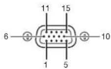
HDMI (HDMI 19-pin)
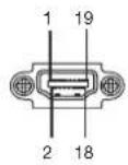
SERIAL (D-SUB 9-pin)
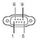
COMPUTER/COMPONENT VIDEO IN
| Pin No. Spec. | |
| 1 R (RED)/C | H |
| 2 G (GREEN)/Y | |
| 3 B (BLUE)/Cr | |
| 4 GND | |
| 5 GND | |
| 6 GND | |
| 7 GND | |
| 8 GND | |
| 9 DDC 5V | |
| 10 GND | |
| 11 GND | |
| 12 DDC Data | |
| 13 HD/CS | |
| 14 VD | |
| 15 DDC Clock | |
MONITOR OUT
| Pin No. Spec. | |
| 1 R (RED)/C | R |
| 2 G (GREEN)/Y | |
| 3 B (BLUE)/ C_D | |
| 4 | - |
| 5 GND | |
| 6 GND | |
| 7 GND | |
| 8 GND | |
| 9 | - |
| 10 GND | |
| 11 | - |
| 12 | - |
| 13 HD/CS | |
| 14 VD | |
| 15 | - |
| Pin No. | Spec. |
| 1 | TMDS Data 2 + |
| 2 | TMDS Data 2 Shield |
| 3 | TMDS Data 2 - |
| 4 | TMDS Data 1 + |
| 5 | TMDS Data1 Shield |
| 6 | TMDS Data 1 - |
| 7 | TMDS Data 0 + |
| 8 | TMDS Data 0 Shield |
| 9 | TMDS Data 0 - |
| 10 | TMDS Clock + |
| 11 | TMDS Clock Shield |
| 12 | TMDS Clock - |
| 13 | CEC |
| 14 | - |
| 15 | SCL |
| 16 | SDA |
| 17 | DDC Ground |
| 18 | +5 V Power |
| 19 | Hot Plug Detect |
| Pin No. | Name I/O | |
| 1 | - | - |
| 2 | TXD | IN |
| 3 | RXD | OUT |
| 4 | - | - |
| 5 | GND | - |
| 6 | - | - |
| 7 | - | - |
| 8 | - | - |
| 9 | - | - |
Dimension drawings (unit: mm)
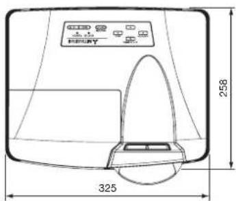
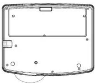
natural_image
Top-down schematic of a device casing with mounting holes and a central panel (no text or symbols)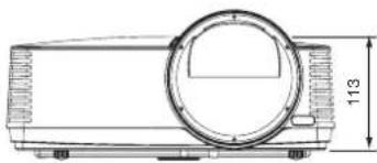
natural_image
Technical line drawing of a cylindrical mechanical component with a circular top and side flange, dimension标注 113 (no text or symbols)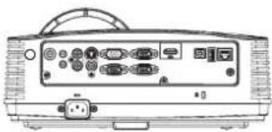
natural_image
Line drawing of a projector rear panel with ports and connectors (no text or symbols)What's included in the box
| AC power cord* | for the U.S. | 02552-0312-00 | Remote control |
| for Europe | 02552-0310-00 | Safety Manual/Quick Start up | |
| for the U.K. | 02552-0311-00 | CD-ROM | |
| for Australia | 02552-0309-00 | Battery (2) | |
| for South Korea | 02552-0310-00 | Lens cap | |
| Computer cable | J2552-0072-05 | Lamp replacement attachment |
* One of power cords for the U.S., Europe, U.K., Australia, and South Korea is provided appropriately.
Replacement part (option/not included in the box)
Spare lamp: VLT-XD560LP
Supported input signals
| Signal mode | Resolution (H x V) | Horizontal frequency (kHz) | Vertical frequency (Hz) | Normal mode (H x V) | Plug and Play4 | |
| COMPUTER/ COMPONENT VIDEO IN-1 terminal | HDMI terminal | |||||
| TV60, 480i (525i) 720 x 480 | 15.73 59.94 10 | 66 x 800 *2 *3 | ||||
| TV50, 576i (625i) 720 x 576 | 15.63 50.00 10 | 66 x 800 *2 | ||||
| 1080i 60 (1125i 60) 1920 | x 1080 33.75 60.0 | 1280 x 720 | ○ | |||
| 1080i 50 (1125i 50) 1920 | x 1080 28.13 50.0 | 1280 x 720 | ○ | |||
| 480p (525p) 720 x 480 31 | .47 59.94 1066 x | 800 | ○ | |||
| 576p (625p) 720 x 576 31 | .25 50.00 1066 x | 800 | ○ | |||
| 720p 60 (750p 60) 1280 x | 720 45.00 60.00 | 1280 x 720 | ○ | |||
| 720p 50 (750p 50) 1280 x | 720 37.50 50.00 | 1280 x 720 | ○ | |||
| 1080p 60 (1125p 60) 1920 | x 1080 67.50 60.00 | 1280 x 720 | ○ | |||
| 1080p 50 (1125p 50) 1920 | x 1080 56.25 50.00 | 1280 x 720 | ○ | |||
| CGA84 640 x 400 37.86 | 84.13 1280 x 800 | |||||
| CGA85 640 x 400 37.86 | 85.08 1280 x 800 | |||||
| VGA60 | 640 x 480 31 | 47 59.94 1066 x 800 | ○ | ○ | ||
| VGA72 | 640 x 480 37 | 86 72.81 1066 x 800 | ○ | |||
| VGA75 | 640 x 480 37.50 | 75.00 1066 x 800 | ○ | |||
| VGA85 | 640 x 480 43 | 85.01 1066 x 800 | ||||
| SVGA56 | 800 x 600 35 | 16 56.25 1066 x 800 | ○ | |||
| SVGA60 | 800 x 600 37 | 88 60.32 1066 x 800 | ○ | ○ | ||
| SVGA72 | 800 x 600 48 | 872.19 1066 x 800 | ○ | |||
| SVGA75 | 800 x 600 46 | 88 75.00 1066 x 800 | ○ | |||
| SVGA85 | 800 x 600 53 | 87 85.06 1066 x 800 | ||||
| XGA60 | 1024 x 768 48 | 36 60.00 1066 x 800 | ○ | ○ | ||
| XGA70 | 1024 x 768 56 | 48 70.07 1066 x 800 | ○ | |||
| XGA75 | 1024 x 768 60 | 02 75.03 1066 x 800 | ○ | |||
| HP75 | 1024 x 768 62 | 94 74.92 1066 x 800 | ||||
| XGA85 | 1024 x 768 68 | 68 85.00 1066 x 800 | ||||
| XGA120 | 1024 x 768 97 | 55 119.99 1066 x 800 | ○ | ○ | ||
| SXGA70a | 1152 x 864 63 | 85 70.01 1066 x 800 | ||||
| SXGA75a | 1152 x 864 67 | 50 75.00 1066 x 800 | ||||
| SXGA85a | 1152 x 864 77 | 49 85.06 1066 x 800 | ○ | |||
| WXGA60 | 1280 x 768 47 | 77 59.87 1280 x 768 | ○ | |||
| WXGA60a | 1280 x 800 49 | 70 59.81 1280 x 800 | ○ | ○ | ||
| WXGA60b | 1360 x 768 47 | 71 60.01 1280 x 724 | ||||
| WXGA60c | 1366 x 768 47 | 71 59.79 1280 x 720 | ○ | ○ | ||
| WXGA120a | 1280 x 800 10 | 1.56 | 119.91 1280 x 800 | ○ | ○ | |
| SXGA60b | 1280 x 960 60 | 00 60.00 1066 x 800 | ○ | |||
| SXGA75b | 1280 x 960 75 | 00 75.00 1066 x 800 | ○ | |||
| SXGA85b | 1280 x 960 85 | 94 85.00 1066 x 800 | ||||
| SXGA60 | 1280 x 1024 63 | 98 60.02 1000 x 800 | ○ | |||
| SXGA75 | 1280 x 1024 79 | 98 75.02 1000 x 800 | ○ | |||
| SXGA85 | 1280 x 1024 91 | 15 85.02 1000 x 800 | ||||
| SUN66a | 1152 x 900 61 | 85 66.00 1024 x 800 | ||||
| SUN76a | 1152 x 900 71 | 81 76.64 1024 x 800 | ||||
| SUN66 | 1280 x 1024 71 | 68 66.68 1000 x 800 | ||||
| SUN76 | 1280 x 1024 81 | 13 76.11 1000 x 800 | ||||
| SGI72 | 1280 x 1024 76 | 92 72.30 1000 x 800 | ||||
| SGI76 | 1280 x 1024 82 | 01 76.00 1000 x 800 | ||||
| WXGA+60 | 1440 x 900 55 | 94 59.89 1280 x 800 | ○ | ○ | ||
| SXGA+60 | 1400 x 1050 65 | 32 59.98 1066 x 800 | ○ | ○ | ||
| SXGA+75 | 1400 x 1050 82 | 28 74.87 1066 x 800 | ||||
| UXGA60 | 1600 x 1200 75 | 00 60.00 1066 x 800 | ○ | ○ | ||
| MAC13 | 640 x 480 35 | 66.67 1066 x 800 | ○ | |||
| MAC16 | 832 x 624 49 | 72 74.55 1066 x 800 | ○ | |||
| MAC19 | 1024 x 768 60 | 24 75.02 1066 x 800 | ||||
*1: When you input the signals WXGA60, WXGA60a, WXGA60b, or WXGA60c, select the supported image size from WXGA of the Option menu.
*2: The MAGNIFY mode is not supported.
*3: The signals can be displayed with viewing 3D contents on the projector.
*4: Signals marked with ○ in the Plug and Play column are described in EDID (extended display identification data) of the projector. Signals described in the Signal mode column can be input regardless of the ○ mark in the Plug and Play column. For signals not marked with ○ in the Plug and Play column, the resolution may not be supported even when it is supported on the computer.
Important:
- Some computers aren't compatible with the projector.
- The projector's maximum resolution is 1280 x 800 pixels. It may not display images of higher resolutions than its maximum resolution correctly.
• Images with SYNC on G (Green) signal may jitter. - Images with SYNC on G (Green) signal may be tinged with green.
- If the resolution and frequency of your computer aren't shown on the table, find the compatible resolution and frequency by changing the resolution of your computer.
- Set Computer Input in the Signal menu to RGB when inputting the HDTV signal as RGB signal.
- TV60 and TV50 are equivalent to 480i and 576i respectively. When these signals are supplied to the VIDEO or S-VIDEO terminal, the signal mode is indicated as TV60 or TV50. When they are supplied to the COMPONENT terminal, the signal mode is indicated as 480i or 576i.

- WARNING:
- CAUTION:
- NOTE:
- WARNING
- CAUTION
- Contents
- Trademark, Registered trademark
- Read instructions
- Retain instructions
- Warnings
- Instructions
- Cleaning
- Attachments and equipment
- Water and moisture
- Accessories
- Ventilation
- Power sources
- Power-cord protection
- Overloading
- Objects and liquids
- Servicing
- Damage requiring service
- Replacement parts
- Safety check
- Unplug immediately if there is something wrong with your projector.
- Never remove the cabinet.
- Do not modify this equipment.
- Do not keep using the damaged projector.
- Be sure to unplug the power cord from the wall outlet if the projector is fractured or deformed.
- Do not face the projector lens to the sun.
- Use correct voltage.
- Do not place the projector on uneven surface.
- Do not look into the lens when it is operating.
- Do not put any objects immediately in front of the lens while the lamp is on.
- Do not unplug the power cord during operation.
- Do not touch the exhaust vents and bottom plate.
- Do not look into the exhaust vents when projector is operating.
- Do not block the intake and exhaust vents.
- Do not use flammable solvents (benzene, thinner, etc.) and flammable aerosols near the projector.
- Do not use the projector with condensation on it.
- Place of installation
- Do not place a container containing water or other liquid on the projector.
- Do not put any object that is heavy or larger than the outer frame on the projector.
- Do not subject the projector to strong shocks or vibrations. Do not handle the projector roughly.
- When removing the lamp from the ceiling-mounted projector
- Battery installation
- Inserting the batteries into the remote control
- Removing the batteries from the remote control
- Operation range (of the remote control)
- Important:
- Screen size and projection distance
- When the aspect ratio of the screen is 4:3
- Front projection, ceiling mounting
- Ceiling mount installation
- Rear projection
- Projector + DVD player or HDTV decoder
- Connection (for video equipment having an HDMI terminal)
- When you connect this projector and a Digital device (such as a DVD player) via the HDMI terminal, black color may appear dark and deep, depending on the type of the connected device.
- Projector + Computer
- For computer with Mini D-SUB
- For analog connection:
- For monitor connection:
- For Mac computers
- About DDC
- Preparation for projection
- Adjustment of the projection angle
- Using the adjustment feet (front)
- When projected images are distorted to a trapezoid
- In the following cases:
- When entire projected image isn't displayed within the screen (E-Zoom/Shift)
- Power-on
- When fine streaks are seen on projected images
- Power-off
- Direct Power OFF
- AUTO POSITION button
- Volume from the speaker
- AV mute
- Setting the aspect ratio
- With the remote control:
- With the Picture menu:
- To cancel the menu:
- When connecting to a laptop computer:
- Watching 3D content
- Go to the Picture menu (or press the 3D button on the remote control) and set the 3D option to On. (See page 22.)
- Notes on danger to public health during watching 3D image
- How to set the menus
- Press the MENU button.
- Menu items
- Picture menu
- Video Image menu
- ITEM SETTING FUNCTION
- Audio menu
- Installation menu
- Option menu
- Information menu
- To adjust the brightness (Contrast and Brightness):
- Contrast
- Brightness
- To adjust the color (Color and Tint):
- Color
- Tint
- To sharpen or soften the projected image (Sharpness):
- To adjust the tone of white (Color Temp.):
- To adjust the tone of white (To customize the color temperature):
- To enable the stored color temperature:
- About color temperature
- Image
- Gamma
- BrilliantColor™
- Color Management
- How to adjust the computer image
- How to adjust the image supplied from the computer using the menu:
- Simple method to adjust the image position
- To adjust the horizontal position:
- To adjust the vertical position:
- LPF (Progressive filter)
- Setting Projector Name
- Enabling or disabling the network certification
- Network Password settings
- IP Config settings
- Setting or clearing DHCP
- IP Address settings
- Subnet Mask settings
- Default Gateway settings
- Setting or clearing DHCP Function
- Start IP Address setting
- End IP Address setting
- IP Config Setup setting
- Wireless Setting
- SSID setting
- Channel setting
- Encryption setting
- Wireless Setup setting
- Enabling or disabling the AMX Device Discovery
- Initialization of network settings
- Restart of network function
- How to use network function
- Glossary
- Thin client
- Preparation for using Remote Desktop
- Creating a user account
- Configuring Remote Desktop users
- In Windows Vista, Windows 7, Windows Server 2008 R2 or Windows MultiPoint Server
- Click [Remote settings].
- Click [Select Users...].
- Click [Add...].
- Click [OK].
- In Windows XP
- Configuration of Windows Firewall
- ■ In Windows 7, Windows Server 2008 R2 or Windows MultiPoint Server
- In Windows Vista
- Installation of software
- Installing Thin Client
- When deleting ThinClient (Uninstallation)
- Connection
- Operation
- Selecting a LAN Display input
- Connecting the projector to the computer
- Click the RDP icon "RDP".
- Enter the following in the textboxes and click [OK].
- When the projector logs on to the computer, the desktop screen of the user account is displayed.
- Disconnecting the projector from the computer
- ■ When using Windows XP
- To disconnect without ending the session:
- To disconnect with ending the session:
- ■ When using Windows Vista
- ■ When using Windows 7, Windows Server 2008 R2 or Windows MultiPoint Server
- Client Access License (CAL)
- When the host computer OS is Windows XP, Windows Vista or Windows 7
- When the host computer OS is Windows Server 2008 R2
- User CAL
- Device CAL
- When the host computer OS is Windows MultiPoint Server
- (Example 1)
- (Example 2)
- USB Display
- Installation of driver
- Installing USB Display driver
- When deleting USB Display driver (Uninstallation)
- Starting USB Display projection
- Ending USB Display projection
- LAN Display
- Installing LAN Display System
- ■ When using Windows XP, Windows Vista, Windows 7, Windows Server 2008 R2 or Windows MultiPoint Server
- ■ When using Mac OS X
- When deleting LAN Display System (Uninstallation) Important:
- Projection
- Starting the LAN Display System
- Operating the LAN Display System
- - About
- - Exit
- Ending the LAN Display projection
- Installing the virtual display driver
- Using remote desktop
- Using SidePad function
- Starting SidePad
- Ending SidePad
- PC Less Presentation
- Installation of PtG Converter-Lite
- About PtG Converter-Lite
- Features
- System requirement
- Installing PtG Converter-Lite
- When deleting PtG Converter-Lite (Uninstallation) Important:
- Conversion of a PPT file to PtG file using the PtG Converter-Lite
- Performing the PC Less Presentation Selecting a PC Less Presentation input
- Setting up
- Displaying PtG file
- Displaying JPEG file
- Displaying with AutoRun function
- Displaying with slideshow function
- Ending the PC Less Presentation
- WiFi-Doc
- Wireless network setting on the tablet computer
- Starting WiFi-Doc
- ■ When using iOS
- ■ When using Android
- Ending WiFi-Doc
- Displaying a user-defined image during startup or muting
- Procedure
- Freeze
- To stop the motion in the image temporarily (or to display a still image):
- To resume the motion in the image:
- Magnify
- To use the MAGNIFY mode:
- Password lock
- To set a password:
- To enable or disable password lock:
- Supervising and controlling by computer
- Major functions
- ProjectorView Global+
- AMX Device Discovery
- Crestron RoomView Connected™
- PJLink™
- About ProjectorView Global+
- About AMX Device Discovery
- About Crestron RoomView Connected™
- About PJLink™
- Using the User Manual
- Opening the User Manual:
- PJLink™ supported commands
- A) When the projector is placed on the table
- B) When the projector is mounted to the ceiling
- Reset of the lamp operation time
- Interval of lamp replacement
- Maintenance
- Cleaning of the projector and the vents
- To protect the surface of the projector from fading or deteriorating:
- Cleaning of the lens
- Kensington Lock
- Connectors
- Dimension drawings (unit: mm)
- What's included in the box
- Replacement part (option/not included in the box)
Brand : MITSUBISHI
Model : WD390U-EST
Category : Vidéo-projecteur