
C610DN - Printer OKI - Free user manual and instructions
Find the device manual for free C610DN OKI in PDF.


User questions about C610DN OKI
0 question about this device. Answer the ones you know or ask your own.
Ask a new question about this device
Download the instructions for your Printer in PDF format for free! Find your manual C610DN - OKI and take your electronic device back in hand. On this page are published all the documents necessary for the use of your device. C610DN by OKI.
USER MANUAL C610DN OKI
text_image
OKI OKI C51Q User's Guide
natural_image
Two white HP printers side by side, no visible text or labels on the devices themselves.PREFACE
Every effort has been made to ensure that the information in this document is complete, accurate, and up-to-date. The manufacturer assumes no responsibility for the results of errors beyond its control. The manufacturer also cannot guarantee that changes in software and equipment made by other manufacturers and referred to in this guide will not affect the applicability of the information in it. Mention of software products manufactured by other companies does not necessarily constitute endorsement by the manufacturer.
While all reasonable efforts have been made to make this document as accurate and helpful as possible, we make no warranty of any kind, expressed or implied, as to the accuracy or completeness of the information contained herein.
The most up-to-date drivers and manuals are available from:
http://www.okiprintingsolutions.com
07105601 Iss. 1; Copyright © 2009. All rights reserved.
Oki is a registered trademark of Oki Electric Industry Company, Ltd.
Oki Printing Solutions is a registered trademark of Oki Data Corporation.
Energy Star is a trademark of the United States Environmental Protection Agency.
Microsoft, MS-DOS and Windows are registered trademarks of Microsoft Corporation.
Apple, Macintosh, Mac and Mac OS are registered trademarks of Apple Computer.
Other product names and brand names are registered trademarks or trademarks of their proprietors.


As an Energy Star Program Participant, the manufacturer has determined that this product meets the Energy Star guidelines for energy efficiency.
This product complies with the requirements of the Council Directives 2004/108/EC (EMC) and 2006/95/EC (LVD) and 1999/5/ EC (R&TTE), as amended where applicable on the approximation of the laws of the member states relating to electromagnetic compatibility, low voltage and radio & telecommunications terminal equipment
The following cables were used to evaluate this product to achieve EMC directive 2004/108/EC compliance and configurations other than this may affect that compliance.
| CABLE TYPE LENGTH(METRE) | CORE SHIELD | |
| Power 1.8 | × | |
| USB 5.0 | ×√ | |
| Parallel (C711 only) 1.8 | ×√ | |
| LAN 15.0 | × | |
EMERGENCY FIRST AID
Take care with toner powder:
If swallowed, give small amounts of cold water and seek medical attention. DO NOT attempt to induce vomiting.

If inhaled, move the person to an open area for fresh air. Seek medical attention.
If it gets into the eyes, flush with large amounts of water for at least 15 minutes keeping eyelids open. Seek medical attention.
Spillages should be treated with cold water and soap to help reduce risk of staining skin or clothing.
MANUFACTURER
Oki Data Corporation,
4-11-22 Shibaura, Minato-ku,
Tokyo 108-8551,
Japan
IMPORTER TO THE EU/AUTHORISED REPRESENTATIVE
Oki Europe Limited (trading as OKI Printing Solutions)
Blays House
Wick Road
Egham
Surrey, TW20 0HJ
United Kingdom
For all sales, support and general enquiries contact your local distributor.
ENVIRONMENTAL INFORMATION

text_image
www.okiprintingsolutions.com OKICONTENTS
Preface 2
Emergency first aid ....3
Manufacturer....3
Importer to the EU/authorised representative. . . . . . . . . . . . . . . . . . . . . . . . . . . . 3
Environmental information ....3
Contents 4
Notes, cautions and warnings .....6
About this guide 7
Documentation suite 7
On-line usage 8
Printing pages. 8
Introduction 9
Printer overview 10
Front view 10
Rear view 12
Changing the display language .....13
Getting started 13
Power saving mode .....13
Switching off. 13
Paper recommendations....14
Cassette trays. 14
Multi purpose tray 15
Face down stacker....15
Face up stacker....15
Duplex unit....15
Loading paper 16
Cassette trays. 16
Multi purpose tray 19
Operation 20
Menu functions .....21
Operator panel: 21
How to change the settings - user . . . . . . . . . . . . . . . . . . . . . . . . . . . . . . . . . . . . . . . . . . . . . . . . . . . . . . . . . 22
How to change the settings - administrator .....22
Configuration menu 23
Print information menu 24
Shutdown menu 24
Print secure job. 25
Menus 26
Admin setup . . . . . . . . . . . . . . . . . . . . . . . . . . . . . . . . . . . . . . . . . . . . . . . . . . . . . . . . . . 30
Calibration 40
Boot menu 41
Maintenance 47
Replacing consumable items 47
Toner cartridge replacement . . . . . . . . . . . . . . . . . . . . . . . . . . . . . . . . . . . . . . . . . . . . . . . . . . . . . . . . . . 47
Image drum replacement . . . . . . . . . . . . . . . . . . . . . . . . . . . . . . . . . . . . . . . . . . . . . . . . . . . . . . . . . . 50
Replacing the transfer belt unit . . . . . . . . . . . . . . . . . . . . . . . . . . . . . . . . . . . . . . . . . . . . . . . . . . . . . . . . . . . 53
Fuser replacement....55
Cleaning the LED head. 57
Installing upgrades ....58
Duplex unit. 58
Memory upgrade....59
SD card....62
Additional paper tray(s) 64
Setting the driver device options. . . . . . . . . . . . . . . . . . . . . . . . . . . . . . . . . . . . . . . . . . . . . . . . . . . . . . . . . . . . . . . . 65
Windows 65
Mac OS X 65
Storage cabinet. 66
Troubleshooting 67
Major printer components and paper path 67
Paper sensor error codes . . . . . . . . . . . . . . . . . . . . . . . . . . . . . . . . . . . . . . . . . . . . . . . . . . . . . . . . . . . . . . . . . 68
Clearing paper jams 69
Specifications 75
Index 76
Oki contact details....77
NOTES, CAUTIONS AND WARNINGS
NOTE
A note provides additional information to supplement the main text.
CAUTION!
A caution provides additional information which, if ignored, may result in equipment malfunction or damage.
WARNING!
A warning provides additional information which, if ignored, may result in a risk of personal injury.
For the protection of your product, and in order to ensure that you benefit from its full functionality, this model has been designed to operate only with genuine original toner cartridges. Any other toner cartridge may not operate at all, even if it is described as "compatible", and if it does work, your product's performance and print quality may be degraded.
Use of non-genuine products may invalidate your warranty.
Specifications subject to change without notice. All trademarks acknowledged.
NOTE
Images used in this manual may include optional features that your product does not have installed.
DOCUMENTATION SUITE
This guide is part of a suite of online and printed documentation provided to help you become familiar with your product and to make the best use of its many powerful features. The documentation is summarised below for reference and is found on the manuals DVD unless indicated otherwise:
Installation Safety booklet: provides information for safe use of your product.
This is a paper document that is packaged with the product and should be read before setting up your machine.
Set-up guide: describes how to unpack, connect and turn on your product.
This is a paper document that is packaged with the product.
User's Guide: helps you become familiar with your product and make the best use of its many features. Also included are guidelines for troubleshooting and maintenance to ensure that it performs at its best. Additionally, information is provided for adding optional accessories as your printing needs evolve.
Network Guide: helps you become familiar with the functionality of the built in network interface card.
Printing Guide: helps you become familiar with the many features of the driver software supplied with your product.
Barcode Printing Guide: helps you become familiar with your product's built in barcode printing feature.
Security Guide: helps you become familiar with your product's security features.
Installation Guides: accompany consumable items and optional accessories to describe how to install them.
These are paper documents that are packaged with the consumables and optional accessories.
On-line Help: on-line information accessible from the printer driver and utility software.
ON-LINE USAGE
This guide is intended to be read on screen using Adobe Reader. Use the navigation and viewing tools provided in Adobe Reader.
There are many cross-references within this book, each highlighted as blue text. When you click on a cross-reference the display will instantly jump to the part of the manual containing the referenced material.
By using the button in Adobe Reader, you can navigate directly back to where you were before.
You can access specific information in two ways:
In the list of bookmarks down the left hand side of your screen, click on the topic of interest to jump to the required topic. (If the bookmarks are not available, use the "Contents" on page 4.)
In the list of bookmarks, click on Index to jump to the Index. (If the bookmarks are not available, use the "Contents" on page 4.) Find the term of interest in the alphabetically arranged index and click on the associated page number to jump to the page containing the term.
PRINTING PAGES
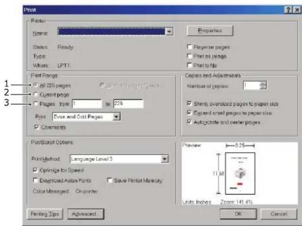
The whole manual, individual pages, or sections may be printed. The procedure is:
-
From the toolbar, select File > Print (or press the Ctrl + P keys).
-
Choose which pages you wish to print:
(a) All pages, (1), for the entire manual.
(b) Current page, (2), for the page at which you are looking.
text_image
Print Plants Name: Properties Status: Ready Type: Width: LPT1 Reverse pages Print as pages Print to page Print Ranges All 250 pages Current page Pages from 1 to 226 Print: Oven and Odd Pages Comments Copies and Adjustments Number of copies: 1 Shirts oversized pages to paper size Expand small pages to paper size Autojiote and center pages PostScript Options PrintMethod: Language Level 3 Optimize for Speed Download Active Points Save Paper Memory Color Managed: On printer Preview 8.25 Units Inches Zoom 141.4% Printing Tips Advanced OK Cancel(c) Pages from and to, (3), for the range of pages you specify by entering their page numbers.
(d) Click OK.
INTRODUCTION
Congratulations on choosing this colour printer. Your new printer is designed with advanced features to give you clear, vibrant colour prints and crisp black and white pages at high speed on a range of print media for the office.
Your printer includes these features:
ProQ2400, multi-level technology produces subtler tones and smoother gradations of colour to lend photographic quality to your documents.
600 x 600, 1200 x 600 dpi (dots per inch) and ProQ2400 print resolution for high quality image production showing the finest detail.
Internet Protocol version 6 (IPv6).
Single Pass colour Digital LED technology for high speed processing of your printed pages.
PostScript 3, PCL 5C, PCL 6 and Epson FX emulations for industry standard operation and wide compatibility with most computer software.
10Base-T and 100Base-TX network connection lets you share this valuable resource among users on your office network.
Photo Enhance mode to improve printouts of photographic images (Windows PCL driver only).
"Ask Oki" – a user-friendly function for Windows that provides a direct link from your printer driver screen to a dedicated web site specific to the exact model you are using. This is where you'll find all the advice, assistance and support you could need to help you get the best possible results from your Oki printer.
Template Manager utility for Windows enables the design and print of business cards, banners, labels with ease.
Additionally, the following optional features are also available:
Automatic two-sided (duplex) printing for economical use of paper and compact printing of larger documents (standard on dn models).
Additional paper tray for loading a further 530 sheets to minimise operator intervention, or different paper stocks for letterhead stationery, alternative paper sizes or other print media.
Additional memory allows printing of more complex pages. For example, high resolution banner printing.
SD card for storage of overlays, macros and downloadable fonts, and automatic collation of multiple copies of multipage documents and the download of ICC Profiles.
Storage Cabinet.
PRINTER OVERVIEW
FRONT VIEW
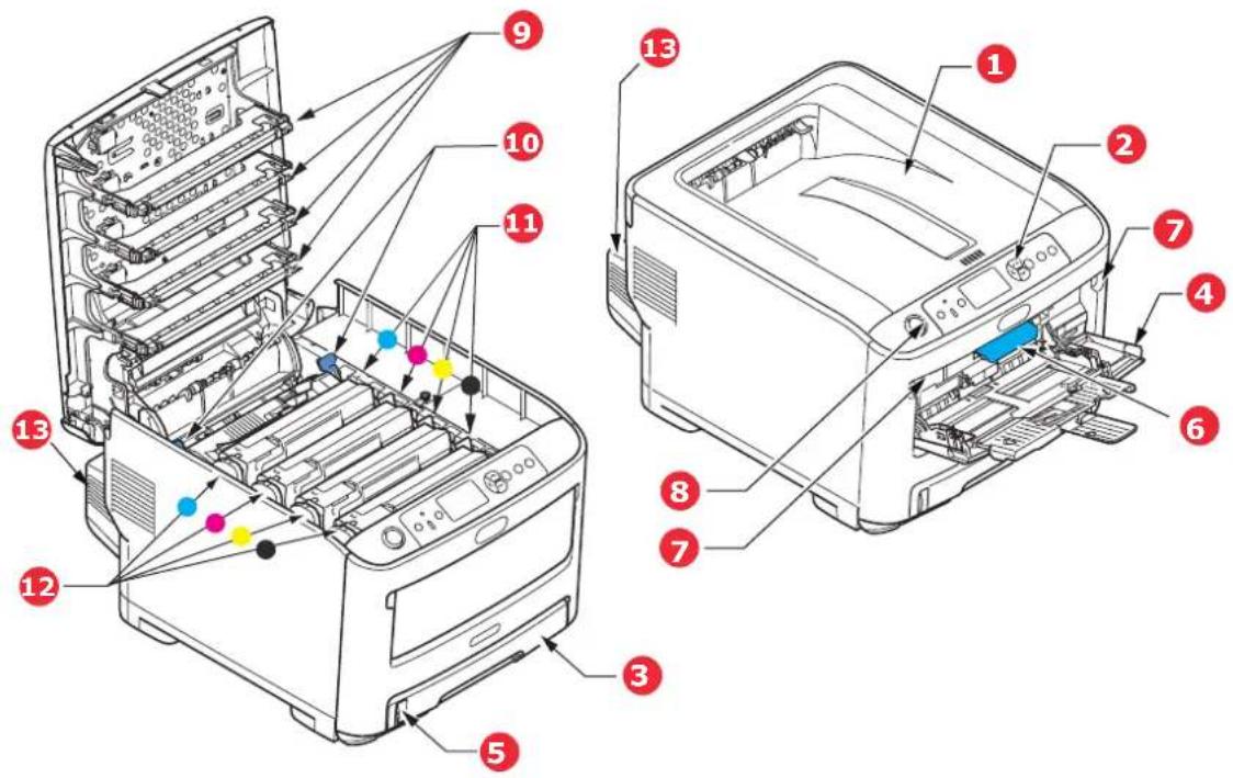
C610
text_image
Technical diagram of a printer internal structure with numbered components for identification-
Output stacker, face down. Standard printed copy delivery point. Holds up to 250 sheets at 80g/m².
-
Operator panel. Menu driven operator controls and LCD panel ^a .
-
Paper tray. Standard paper tray. Holds up to 300 sheets of 80g/m^2 paper.
-
Multi purpose tray. Used for feeding heavier paper stocks, envelopes and other special media. Also for manual feeding of single sheets when required.
-
Paper level indicator.
- Front cover release lever.
- Multi-purpose tray release recess.
- Top cover release button.
- LED heads.
- Fuser release levers.
- Toner cartridges (C,M,Y,K).
- ID units (C,M,Y,K).
- Duplex unit (when fitted).
a. The display language can be changed to show different languages. (see "Changing the display language" on page 13).
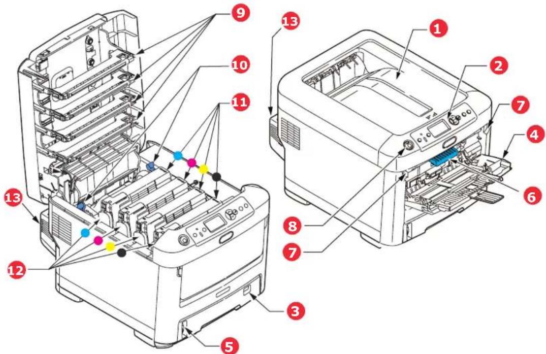
C711
text_image
Technical diagram of a printer internal structure with numbered components and color-coded parts-
Output stacker, face down. Standard printed copy delivery point. Holds up to 350 sheets at 80g/m².
-
Operator panel. Menu driven operator controls and LCD panel ^4 .
-
Paper tray. Standard paper tray. Holds up to 530 sheets of 80g/m^2 paper.
-
Multi purpose tray. Used for feeding heavier paper stocks, envelopes and other special media. Also for manual feeding of single sheets when required.
-
Paper level indicator.
- Front cover release lever.
- Multi-purpose tray release recess.
- Top cover release button.
- LED heads.
- Fuser release levers.
- Toner cartridges (C,M,Y,K).
- ID units (C,M,Y,K).
- Duplex unit (when fitted).
Used for feeding heavier paper stocks, envelopes and other special media. Also for manual feeding of single sheets when required.
a. The display language can be changed to show different languages. (see "Changing the display language" on page 13).
REAR VIEW
This view shows the connection panel, the rear output stacker and the location of the optional duplex (two-sided printing) unit.
C610
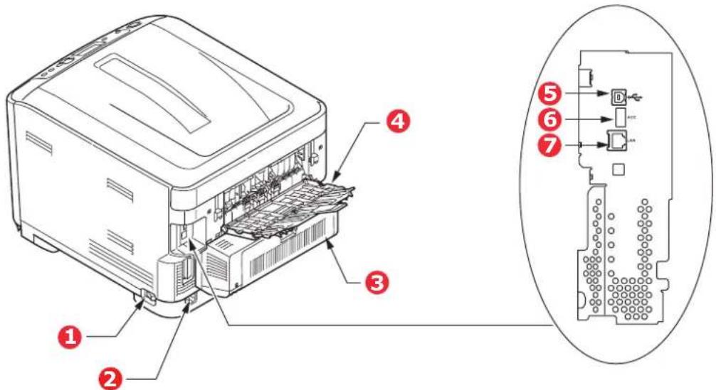
text_image
Technical diagram of a computer with numbered components and an exploded view showing internal structure with labeled ports.-
ON/OFF switch.
-
USB interface.
-
AC power socket.
-
ACC interface (host USB).
-
Duplex unit (when fitted).
-
Network interface. ^a
-
Rear, face up stacker.
a. The Network Interface may have a protective "plug" which must be removed before connection can be made.
C711
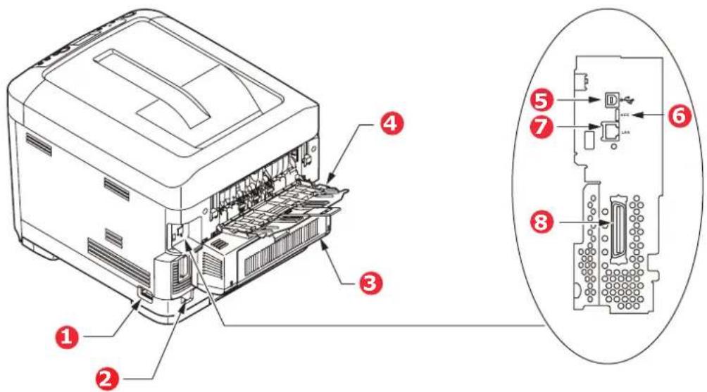
text_image
Technical diagram of a printer internal structure with numbered components and labeled parts-
ON/OFF switch.
-
USB interface.
-
AC power socket.
-
ACC interface (host USB).
-
Duplex unit (when fitted).
-
Network interface. ^a
-
Rear, face up stacker.
-
Parallel interface.
a. The Network Interface may have a protective "plug" which must be removed before connection can be made.
When the rear paper stacker is folded down paper exits the printer through the rear of the printer and is stacked here face up. This is mainly used for heavy print media. When used in conjunction with the multi purpose feed tray, the paper path through the printer is essentially straight. This avoids bending the paper around curves in the paper path and enables feeding of up to 250g/m^2 media.
CHANGING THE DISPLAY LANGUAGE
The default language used by your machine for display messages is English. If required, this can be changed using the Panel Language Set-up utility.
GETTING STARTED
POWER SAVING MODE
If you do not use the machine for a while, it will enter the power saving mode to control the power consumption of the device. To cancel or initiate power saving mode, press the Power Save / Wake Up button on the control panel.
NOTE
If your machine is connected locally (via USB or parallel*), when it transitions to Sleep mode its status is viewed as off-line. To use the printer in this state, you must press the Power Save / Wake Up button to exit sleep mode.
*C711 only.
SWITCHING OFF
CAUTION!
If you have an SD card fitted, always follow the correct shutdown procedure to ensure that no data is lost.
- Press the Enter button on the control panel to enter the menu.
- Press the Menu down button and scroll to the Shutdown menu.
- Press the Enter button.
- Press the Enter button to continue.
- Press the Enter button to execute.
- At the prompt, turn the power switch OFF.
PAPER RECOMMENDATIONS
Your printer will handle a variety of print media, including a range of paper weights and sizes, labels and envelopes. This section provides general advice on choice of media, and explains how to use each type.
The best performance will be obtained when using standard 75\~90g/m ^2 paper designed for use in copiers and laser printers. Suitable types are:
M-Real Data Copy Everyday 80g/m²
Color Copy by Mondi 90g/m²
Use of heavily embossed or very rough textured paper is not recommended.
Pre-printed stationery can be used, but the ink must not offset when exposed to the high fuser temperatures used in the printing process.
Envelopes
CAUTION!
Envelopes should be free from twist, curl or other deformations. They should also be of the rectangular flap type, with glue that remains intact when subjected to hot roll pressure fusing used in this type of printer. Window envelopes are not suitable.
Labels
CAUTION!
Labels should also be of the type recommended for use in copiers and laser printers, in which the base carrier page is entirely covered by labels. Other types of label stock may damage the printer due to the labels peeling off during the printing process.
Recommended type is Avery White Label types 7162, 7664, 7666 (A4), or 5161 (Letter).
CASSETTE TRAYS
SIZE DIMENSIONS WEIGHT (G/M²)
| A6a | 105 x 148mm Light 64 - 74g/m2 | |
| A5 | 148 x 210mm | Medium Light 75 - 82g/m2 |
| B5 | 182 x 257mm | Medium 83 - 104g/m2 |
| Executive | 184.2 x 266.7mm | Heavy 105 - 120g/m2 |
| A4 | 210 x 297mm | Ultra heavy1 121 - 188g/m2 |
| Letter 215.9 x 279.4mm | Ultra heavy2 189 - 220g/m2 | |
| Legal 13in. 216 x 330mm | Ultra heavy3 221 - 250g/m2 | |
| Legal 13.5in. | 216 x 343mm | C610: Tray 1: 64 - 120g/m2 |
| Legal 14in. 216 x 356mm | Tray 3/3: 64 - 220g/m2 | |
a. C711: A6 printing from the MP Tray only.
If you have identical paper stock loaded in another tray (2nd or 3rd tray if you have one, or multi purpose tray) you can set the printer to automatically switch to the other tray when the current tray runs out of paper. When printing from Windows applications, this function
is enabled in the driver settings. When printing from other systems, this function is enabled in the Print Menu. (See "Menu functions" on page 21.)
MULTI PURPOSE TRAY
The multi purpose tray can handle the same sizes as the cassette trays but in weights up to 250g/m^2 . For very heavy paper stock use the face up (rear) paper stacker. This ensures that the paper path through the printer is almost straight.
The multi purpose tray can feed paper widths from 76mm to 215.9mm and lengths from 127.0mm to 1320mm (banner printing).
For paper lengths exceeding 356mm (Legal 14in.) use paper stock between 90g/m ^2 and 128g/m ^2 and the face up (rear) paper stacker.
Use the multi purpose tray for printing on envelopes. Up to 10 envelopes can be loaded at one time, subject to a maximum stacking depth of 10mm.
FACE DOWN STACKER
C610: The face down stacker on the top of the printer can hold up to 250 sheets of 80g/m^2 standard paper, and can handle paper stocks up to 188g/m^2 .
C711: The face down stacker on the top of the printer can hold up to 350 sheets of 80g/m ^2 standard paper, and can handle paper stocks up to 188g/m ^2 .
Pages printed in reading order (page 1 first) will be sorted in reading order (last page on top, facing down).
FACE UP STACKER
The face up stacker at the rear of the printer should be opened and the tray extension pulled out when required for use. In this condition paper will exit via this path, regardless of driver settings.
The face up stacker can hold up to 100 sheets of 80g/m^2 standard paper, and can handle stocks up to 250g/m^2 .
Always use this stacker and the multi purpose feeder for paper stocks heavier than 188g/m^2 .
DUPLEX UNIT
This option provides automatic two-sided printing on the same range of paper sizes as tray 2 (i.e. all cassette sizes except A6), using paper stocks from:
C610: 64 - 120g/m²
C711: 64 - 220g/m²
NOTE:
The duplex unit comes as standard with dn models.
LOADING PAPER
NOTE
For illustrative purposes, the C711 printer has been shown. If you have a C610
printer, the principle is the same with any exceptions noted.
CASSETTE TRAYS
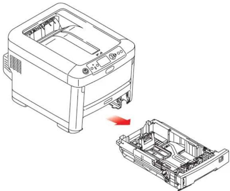
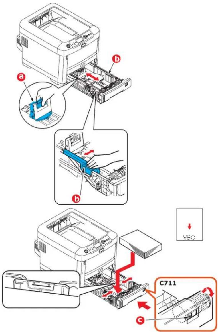
- Remove the paper tray from the printer.
natural_image
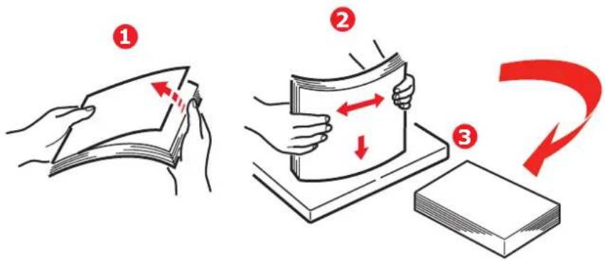
Line drawing of a printer with internal components and a red arrow indicating a disassembly or repair process (no text or symbols present)- Fan the paper to be loaded at the edges (1) and in the middle (2) to ensure that all sheets are properly separated, then tap the edges of the stack on a flat surface to make it flush again (3).
text_image
Illustration showing three-step folding process: folding paper, folding paper with red arrows indicating movement, and folding paper with red curved arrow indicating rotation.- Load paper (letter headed paper face down and top edge towards the front of the printer), as shown.
text_image
a b b C711 cAdjust the rear stopper (a) and paper guides (b) to the size of paper being used.
CAUTION!
C711 ONLY: IMPORTANT: Set paper size dial (c) to the size of paper being used (A4 in the above example).
To prevent paper jams:
Do not leave space between the paper and the guides and rear stopper.
Do not overfill the paper tray. Capacity depends on the type of paper stock.
Do not load damaged paper.
Do not load paper of different sizes or types at the same time.
Close the paper tray gently.Do not pull the paper tray out during printing (except as described below for the 2nd tray).
NOTE
If you have two trays and you are printing from the 1st (upper) tray, you can pull out the 2nd (lower) tray during printing to reload it. However, if you are printing from the 2nd (lower) tray, do not pull out the 1st (upper) tray. This will cause a paper jam.
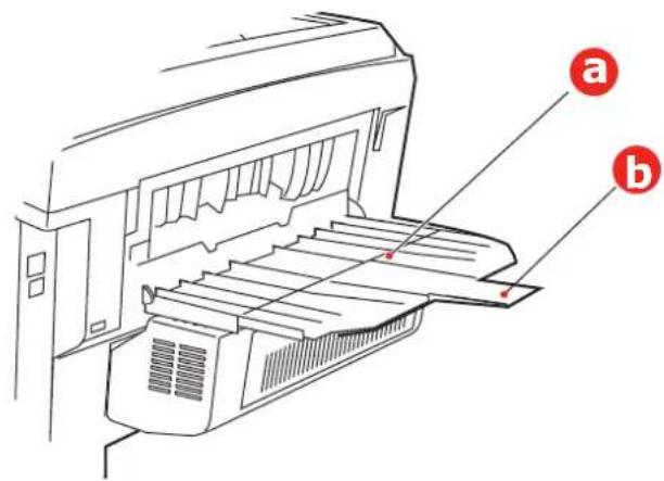
For face down printing, make sure the face up (rear) stacker (a) is closed (the paper exits from the top of the printer). Stacking capacity is approximately 250 sheets for the C610 and 350 sheets for the C711, depending on paper weight.
For face up printing, make sure the face up (rear) stacker (a) is open and the paper support (b) is extended. Paper is stacked in reverse order and tray capacity is approximately 100 sheets, depending on paper weight.
Always use the face up (rear) stacker for heavy paper (card stock, etc.).
text_image
Technical diagram of a printer with labeled parts (a) and (b), showing internal structure and component layout.CAUTION!
Do not open or close the rear paper exit while printing as it may result in a paper jam.
MULTI PURPOSE TRAY
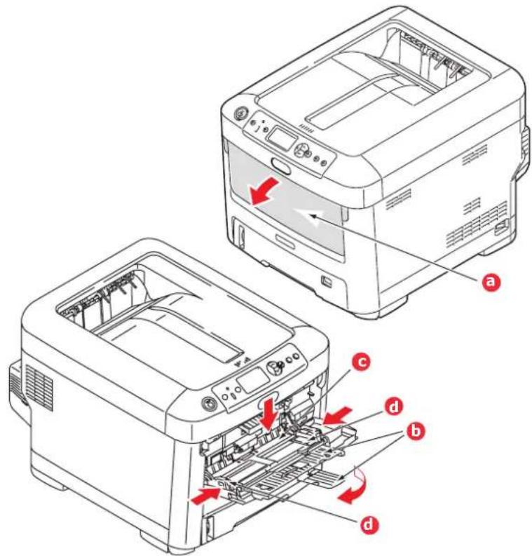
- Open the multi purpose tray (a).
- Fold out the paper supports (b).
text_image
Technical diagram of a printer with labeled parts and directional arrows indicating internal components- Press gently down on the paper platform (c) to ensure it is latched down.
- Load the paper and adjust the paper guides (d) to the size of paper being used.
For single-sided printing on headed paper load the paper into the multi purpose tray with pre-printed side up and top edge into the printer.
For two-sided (duplex) printing on headed paper load the paper with pre-printed side down and top edge away from the printer. (Optional duplex unit must be installed for this function.)
Envelopes should be loaded face up with top edge to the left and short edge into the printer. Do not select duplex printing on envelopes.
Do not exceed the paper capacity of about 100 sheets or 10 envelopes. Maximum stacking depth is 10mm.
-
Press the tray latch button inwards to release the paper platform, so that the paper is lifted and gripped in place.
-
Set the correct paper size for the multi purpose tray in the Media Menu (see "Menu functions" on page 21).
OPERATION
For full details of how to use the machine and any optional accessories to print jobs efficiently and effectively, please refer to the Printing Guide and the Barcode Guide.
For full details of how to access and use the printer security features, please refer to the Security Guide.
MENU FUNCTIONS
This section lists the menus accessed via the controls on the printer's operator panel and displayed in the LCD window.
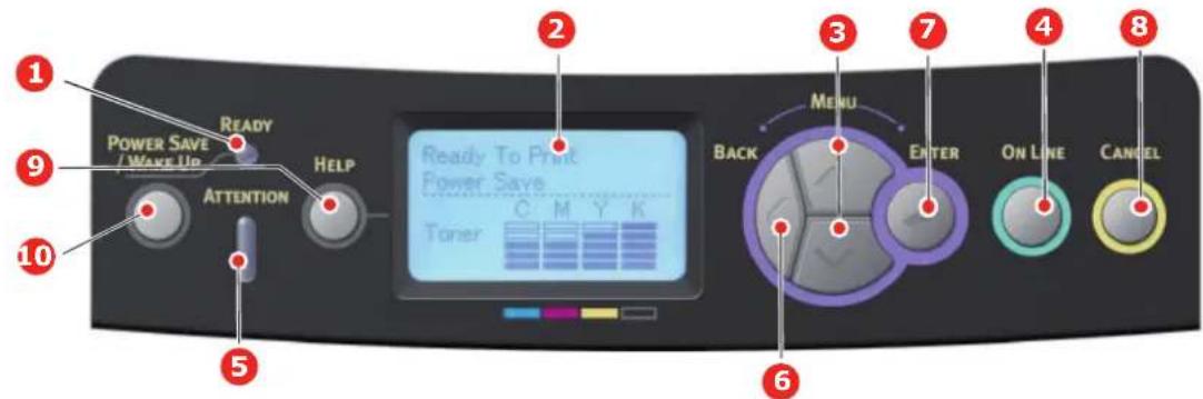
OPERATOR PANEL:
text_image
1 2 3 4 5 6 7 8 9 READY POWER SAVE / WAKE UP HELP ATTENTION Ready To Print Power Save Toner C M Y K BACK MENU ENTER ON LINE CANCEL| 1. Ready LED ON: | Ready to receive data.BLINKING: Processing data.OFF: Offline. | 2. Display Displays the printer status and any error messages. |
| 3. Menu Scroll Buttons | Enters the Menu mode. In Menu mode, forwards or reverses the menu item displayed.Press for 2 secs. or longer to jump from top to bottom. | 4. On Line Button Switches between ONLINE and OFFLINE.Exits the menu and goes ONLINE when pressed in the Menu mode.Scrolls the HELP screen.Forces printing on the paper currently loaded when pressed with "WRONG PAPER" or "WRONG PAPER SIZE" displayed. |
| 5. Attention LED ON: | A warning occurs.Printing may be possible (e.g low toner).BLINKING: An error occurs.Printing not possible (e.g. toner empty).OFF: Normal condition. | 6. Back Button Returns to the previous higher level menu item.Pressing this button for more than 4 seconds initiates the printer shutdown procedure, select Yes to continue or No to abort. |
| 7. Enter Button | In the ONLINE or OFFLINEmode: enters the Menu mode.In the Menu mode:determines the setting selected. | 8. Cancel Button Deletes the data being printed or received when pressed for two seconds or longer.Deletes the data when pressed for two seconds or longer with WRONG PAPER SIZE, RUN OUT OF PAPER, TRAY 1 IS OPEN, or TRAY 1 IS NOT FOUND is displayed.Exits the menu and goes ONLINE when pressed in the Menu mode. |
| 9. Help Button Provides advice when an error such as incorrect paper size occurs. | 10. Power Save/Wake Up ButtonPressing this button switches the machine into sleep or wake-up mode. Refer to "Power saving mode" on page 13. | |
HOW TO CHANGE THE SETTINGS - USER
It should be noted that many of these settings can be, and often are, overridden by settings in the printer drivers. However, several of the driver settings can be left at "Printer Setting", which will then default to the settings entered in these printer menus.
Where applicable, factory default settings are shown in bold type in the following tables.
In the normal operating condition, known as "standby," the printer's LCD window will show Ready to Print. In this condition, to enter the menu system, press the up and down Menu buttons on the operator panel to move up and down through the list of menus until the menu you wish to view is displayed. Then proceed as follows:
-
Press Enter to enter the menu.
-
Use the up and down MENU buttons on the control panel to scroll through the menus. When the item you want to change is displayed, press Enter to view the sub-menus for that item.
-
Use the up and down MENU buttons to move up and down through the sub-menu items. When the item you want to change is displayed press Enter to display the setting.
-
Use the up and down MENU buttons to move up and down through the available settings for the sub-menu item. When the item you want to change is displayed press Enter to display the setting. An asterisk (*) will appear next to the setting, indicating that this setting is currently in effect.
-
Do one of the following:
Press Back again to move up to the list of menus;
or...
Press On Line or Cancel to exit from the menu system and return to standby.
HOW TO CHANGE THE SETTINGS - ADMINISTRATOR
You can set whether to ENABLE or DISABLE each category in the user menu.
Disabled categories are not displayed in the User's menu. Only a system administrator can change these settings.
-
Turn OFF the printer. Turn ON the printer while pressing the Enter button. When Boot Menu appears, take your finger off the button.
-
Press the Enter button.
-
At the Enter Password prompt, enter the Admin password:
(a) Using the up and down MENU buttons, scroll to the required letter/digit.
(b) Press the Enter button to input and move to the next letter/digit.
(c) Repeat steps (a) and (b) until all letters/digits are entered.
Enter your 4 to 9 digit password.
(The default password is aaaaaa).
-
Press the Enter button.
-
Press the up or down MENU button until the "category" you want to change is displayed.
-
Press the Enter button.
-
Press the up or down MENU button until the "item" you want to change is displayed.
-
Press the Enter button.
-
Using the up or down MENU button, identify the parameter as required.
-
Press the Enter button to enter an asterisk (*) on the right side of the setting selected.
-
Press the On Line button to switch to online. The machine will automatically reboot.
CONFIGURATION MENU
| ITEM ACTION EXPLANATION | ||
| Tray Coun t Tray1 | Tray 2*Tray 3*MP Tray*Note: Only available when optional trays are present | Select an item to display the total number of pages printed from the relevant tray. |
| Supplies Life Cyan Drum | Magenta DrumYellow DrumBlack DrumBeltFuserCyan TonerMagenta TonerYellow TonerBlack Toner | Select item to display the percentage of a consumable remaining. |
| Network Printer Name | Short Printer NameIPv4 AddressSubnet MaskGateway AddressMAC AddressNetwork FW VersionWeb Remote VersionIPv6 Address(Local)IPv6 Address(Global) | Displays the full printer name.Displays an abbreviated version.Displays the IPv4 Address of the network.Displays the Subnet Mask of the network.Displays the Gateway Address of the network.Displays the MAC Address of the printer.Displays the Network firmware revision.Displays the Web remote version.Displays the IPv6 Address(Local) of the network. ^a Displays the IPv6 Address(Global) of the network. ^a |
| System Serial Number | Asset NumberLot NumberCU VersionPU VersionTot a l Mem o ryFlash MemorySD CardDate and Time | Displays information for these items. |
a. Display condition: IP Version is IP v4+v6 or IP v6.
PRINT INFORMATION MENU
This menu provides a quick method of listing various items stored within the printer.
| ITEM ACTION EXPLANATION | ||
| Configuration Execute Select execute to print out a configuration report. | ||
| Network Execute Scroll down to this parameter and select execute to print out Network information. | ||
| Demo Page DEMO1 Execute Scroll down to this parameter and select execute to print out a demonstration page. | ||
| File List | Execute | Scroll down to this parameter and select execute to print out a list of job files.(displayed only if FileSystem is installed). |
| PS Font List Execute Scroll down to this parameter and select execute to print out a Postscript emulation typeface list. | ||
| PCL Font List Execute Scroll down to this parameter and select execute to print out a PCL font list. | ||
| IBM PPR Font List | Execute | Scroll down to this parameter and select execute to print out an IBM PPR font list. |
| EPSON FX Font List | Execute | Scroll down to this parameter and select execute to print out an Epson FX emulation font list. |
| Usage Report | Execute | Scroll down to this parameter and select execute to print out a list of colour and mono pages printed. |
| Error Log | Execute | Scroll down to this parameter and select execute to print out the error log. |
| Color Profile List | Execute | Scroll down to this parameter and select execute to print out a list of colour profiles. |
SHUTDOWN MENU
This item should always be selected before switching the printer off, to ensure that no data is lost.
| ITEM SETTINGS | EXPLANATION | |
| Shutdown Start | Execute | Performs controlled shutdown of the printer. Only power the printer off when the display indicates that shutdown is complete. |
NOTE:
This menu only displays if the optional SD card is installed.
| ITEM ACTION EXPLANATION | ||
| Encrypted Job Not Found | PrintDelete | Used for printing an encrypted authentication print job (Encrypted Job) stored in the SD card.After inputting a password, "Searching Job" is displayed until a job appropriate for the password is found.(Searching time increases in proportion to the number of jobs stored in the SD card, and the printer may take up to 20 sec.)The search can be cancelled by holding down the Cancel button.Not Found will be displayed where a file, which could be printed is not available.The following message will appear if a printable file is available.Encrypted JobPrintDeleteA set of all jobs will be printed if Print is selected and the Enter button is pressed.The following message will appear if Delete is selected:Are You Sure?YesNoThe display will return to the source menu if No is selected.All jobs will be deleted if Yes is selected.Print jobs with encrypted authentication stored in the SD card are deleted by a delete method specified by the driver after printing or a delete instruction from the menu. |
| Stored Job Not Found | PrintDelete | Used to print out a stored job in the SD card.Not Foundwill be displayed where a file, which could be printed is not available.The following message will appear if a printable file is available.Stored JobPrintDeleteWhenPrintis selected,Set Collating Amountis displayed and the number of pages to print can be specified.Specify the number of pages to print and press theEnterbutton.The following message will appear ifDeleteis selected:Are You Sure?YesNoIfNois selected, the display will return to the previous menu.IfYesis selected, all jobs will be deleted. |
MENUS
| ITEM ACTION EXPLANATION | ||
| Tray Configuration Paper FeedDefault: Tray 1 | Select tray. Select by scroll and Enter button. | |
| Auto Tray SwitchDefault: On | Switches Auto ON/OFF. Select by scroll and Enter button. | |
| Tray SequenceDefault: Down | Selects Tray sequence Down/Up/Paper feed Tray. Select by scroll and Enter button. | |
| Unit of MeasurementDefault: millimeter | Selects UOM Inches or millimeter. Select by scroll and Enter button. | |
| Tray1 ConfigDefault:Paper Size:C610 A4/A5/A6/B5/Legal14/Legal13.5/Legal13/Letter/Executive/CustomC711 Cassette/CustomMedia Type: Plain/Letterhead/Bond/Recycled/CardStock/Rough/Glossy/USER TYPE 1-5Media Weight: Light/MediumLight/Medium/Heavy/UltraHeavy1/UltraHeavy2 | Configure Paper Size/Media Type/Media Weight. Select by scroll and Enter button.USER TYPE 1 to 5 are displayed only if registered in the host PC. | |
| Tray Configuration (cont.) | MPTray Config Configure Paper Size/Media Type/MediaWeight/Tray Usage. Select by scroll and Enter button.Paper Size: A4/A5/A6/B5/Legal14/Legal13.5/Legal13/Letter/Executive/Custom/Com-9Envelope/Com-10 Envelope/MonarchEnvelope/DLEnvelope/C5/Index CardMedia Type: Plain/Letterhead/Films/Labels/Bond/Recycled/CardStock/Rough/Glossy/USERTYPE 1-5Media Weight: Light/MediumLight/Medium/Heavy//UltraHeavy1/UltraHeavy2/UltraHeavy3Tray Usage: When Mismatching/Do Not Use | USERTYPE 1 to 5 are displayed only if registered in the host PC.Paper weight 189 250g/m^2 Sets MPTray usage.When Mismatching: if paper mismatch occurs, paper is requested from the MPTray instead of the specified tray.Do Not Use: sets MPTray unavailable both in Auto Tray Select and Auto Tray Switch. |
| Tray 2 Config *Tray 3 Config * | *Note: only present if option installed. | |
| System Adjust Power | Save TimeDefault: 30 | Select from 1/2/3/4/5/10/15/30/60/120/180 Minutes.Select by scroll and Enter button. |
| Sleep TimeDefault: 10 | Select from 1/2/3/4/5/10/15/30/60/120/180 Minutes.Select by scroll and Enter button. | |
| Clearable WarningDefault: ONLINE | Select from: ONLINE/Job. Select by scroll and Enter button. PS job only. | |
| Auto ContinueDefault: Off | Select from On/Off. Select by scroll and Enter button. | |
| Manual TimeoutDefault: 60 | Select from Off/30 seconds/60 seconds.Select by scroll and Enter button. | |
| Wait TimeoutDefault: 40 | Select from Off/5/10/20/30/40/50/60/90/120/150/180/210/240/270/300 seconds. Select by scroll and Enter button. | |
| Low TonerDefault: Continue | Select action to take when toner sensor indicates low toner. Select from Continue/Stop. Select by scroll and Enter button. | |
| Jam RecoveryDefault: On | Select from On/Off. Select by scroll and Enter button. | |
| Error ReportDefault: Off | Select from On/Off. Select by scroll and Enter button. | |
| Print Position AdjustDefault: 0.00 | Select from X Adjust/Y Adjust/Duplex X Adjust/Duplex Y adjust. Select by scroll and Enter button. Define measurement. | |
| Paper Black Setting-2/-1/0/+1/+2Default: 0 | Used for fine adjustment of the black print on paper. | |
| Paper Color Setting-2/-1/0/+1/+2Default: 0 | Used for fine adjustment of the colour print on paper. | |
| Films Black Setting-2/-1/0/+1/+2Default: 0 | Used for fine adjustment of the black print on films. | |
| Films Color Setting-2/-1/0/+1/+2Default: 0 | Used for fine adjustment of the colour print on films. | |
| SMR Setting+3/+2/+1/0/-1/-2/-3/Default: 0 | To correct variations in print results caused by temperature/humidity conditions and difference in print density/frequency.Change the setting when print quality is uneven. | |
| BG Setting+3/+2/+1/0/-1/-2/-3/Default: 0 | To correct variations in print results caused by temperature/humidity conditions and difference in print density/frequency.Change the setting when background is dark. | |
| ITEM ACTION EXPLANATION | ||
| System Adjust (cont.) | Drum CleaningDefault: Off | Sets whether to rotate the drum in idle prior to printing in order to reduce horizontal white lines.Be warned that this will shorten the ID life by as much as this rotation. Select by scroll and Enter button. |
| Hex Dump Execute | Prints out data received from the host PC in the hexadecimal Dump. Turning off the power supply switch restores Normal Mode. | |
ADMIN SETUP
| ITEM SETTINGS EXPLANATION | ||||
| Enter Password | xxxxxxxxxx Enter | a password to gain entry to the Admin Setup menu.Password should be from 6 to 12 digits of alpha/numeric characters (or mix)The default value is "aaaaaa" | ||
| Network Setup | TCP/IP Enable | Disable | Sets TCP/IP Protocol.Enable: TCP/IP Protocol is available.Disable: TCP/IP Protocol is not available. | |
| IP Version IP | v4IP v4+v6IP v6 | Set up the IP version.Operates with IPv4 for IPv4 (not valid with IPv6).Operates with both IPv4 and IPv6 for IPv4+v6.Operates with IPv6 for IPv6 (not valid with IPv4).There is only IPv4 and IPv4+v6 as normal value.From this stage, if IPv6 only is set from UI, for example Telnet, "IPv6" appears as the value of IP Version on the operation panel. "IPv6" will disappear from the value if "IP v4" or "IP v4+v6" is selected.Display Condition: TCP/IP should be enabled. | ||
| NetBEUI Enable | Disable | Sets Enable/Disable of NETBEUI Protocol. | ||
| NetBIOS over TCP | EnableDisable | Sets Enable/Disable of NetBIOS over TCP protocol.Display Conditions:> TCP/IP should be enabled.> IP Version is not IPv6. | ||
| NetWare Enable | Disable | Sets Enable/Disable of NetWare Protocol. | ||
| EtherTalk Enable | Disable | Sets Enable/Disable of EtherTalk Protocol. | ||
| Frame Type Auto802.2802.3Ethernet IISNAP | Auto | Sets the frame type.Display Condition: Netware should be enabled. | ||
| IP Address Set | AutoManual | Sets the IP Address setting method.Display Conditions:> TCP/IP should be enabled.> IP Version is not IPv6. | ||
| IPv4 Address | xxx.xxx.xxx.xxx S | Sets the IP Address.Display Conditions:> TCP/IP should be enabled.> IP Version is not IPv6. | ||
| Subnet Mask | xxx.xxx.xxx.xxx Sets | the Subnet Mask.Display Conditions:> TCP/IP should be enabled.> IP Version is not IPv6. | ||
| ITEM | SETTINGS | EXPLANATION | ||
| Network Setup (cont.) | Gateway Address | xxx.xxx.xxx.xxx S | Sets the Gateway (default router) address.0.0.0.0 means that there is no router.Display Conditions:> TCP/IP should be enabled.> IP Version is not IPv6. | |
| Web Enable | Disable | Sets Enable/Disable of Web.Enable: Web/IPP is available.Disable: Web/IPP is not available.Display Condition: TCP/IP should be enabled. | ||
| Telnet Enable | Disable | Sets Enable/Disable of Telnet.Enable: Telnet is available.Disable: Telnet is not available.Display Condition: TCP/IP should be enabled. | ||
| FTP Enable | Disable | Sets Enable/Disable of FTP.Enable: FTP is available.Disable: FTP is not available.Display Condition: TCP/IP should be enabled. | ||
| IPSec Enable | Disable | Sets Enable/Disable of IPSec. Enable via the web.Enable: IPSec is available.Disable: IPSec is not available. | ||
| SNMP Enable | Disable | Sets Enable/Disable of SNMP.Enable: SNMP is available.Disable: SNMP is not available.Display Condition: TCP/IP or NetWare should be enabled. | ||
| Network Scale | NormalSmall | When Normal is selected, the network can work effectively even when it is connected to a HUB that has a spanning tree feature. However, printer start up time gets longer when computers are connected with two or three small LANs.When Small is selected, computers can cover from two or three small LANs to a large LAN, but may not work effectively when the network is connected to a HUB with a spanning tree feature. | ||
| Hub Link Setting | Auto Negotiate100Base-TX Full100Base-TX Half10Base-T Full10Base-T Half | Sets a method to link to a HUB. When Auto is set, a connection method to a HUB is selected automatically and attempts to connect.If another method is selected, attempts to connect to a HUB only by the selected connection method. | ||
| Factory Defaults? | Execute | Specifies whether to initialize the network factory default settings for the Network. | ||
| Print Setup Personality Auto | PostScriptPCLXPSIBM PPREPSON FX | Selects a printer language. | ||
| Copies | 1- 999 | Selects the number of copies.This setting is disabled for Local Print except for Demo Page. | ||
| Duplex | On/Off | Specifies duplex print (option) if a duplex unit is installed and enabled | ||
| ITEM SETTINGS EXPLANATION | |||
| Print Setup (cont.) | Binding Long | EdgeShort Edge | Specifies Binding in duplex printing.Display Condition: a duplex unit is installed and enabled.Refer to "Duplex" on page 31. |
| Media Check | EnableDisable | Sets whether the printer checks the matching of printed data size and that of the tray. Only standard sizes are checked. | |
| Resolution 600dpi600x1200dpi600dpi multi-level | Sets default resolution. | ||
| Toner Save Mode | On/Off | This function works effectively only if the data input is color RGB data. This setting is valid in PS and PCL, but does not take effect in the following cases.(1) PS: If Color Matching is set OFF.(2) PS: If any setting other than ASIC Color Matching is set.(3) PS: CMYK data when Ink Simulation Mode is used (valid in any other cases except Case (1) and Case (2) above as long as data is RGB).(4) PCL binary data (Color/Monochrome). | |
| Mono-Print Speed | AutoColor SpeedNormal Speed | Sets the monochrome print speed. Prints at the most appropriate speed for page process if Auto is set.Prints always at the color print speed if Color is set.Prints always at the monochrome print speed if Normal is set. | |
| Default Orientation | PortraitLandscape | Specifies print orientation.Not valid for PS (valid only for PCL/ IBMPPR/EPSONFX/HP-GL2). | |
| Form Length 5 | lines~64 lines~128 lines | Sets the number of lines that can be printed on a pageNot valid for PS (valid only for PCL/HP-GL2).Default values listed to the left are for Letter/A4. In practice, however, they change according to the size of paper loaded in the tray. | |
| Edit Size Cassette Size/A4/A5/A6/B5/Legal14/Legal13/Letter/Executive/Custom/Com-9Envelope/Com-10 Envelope/MonarchEnvelope/DLEnvelope/C5/Index Card | Sets the size of an area to draw when the host PC does not specify the size via the paper edit size designating command (Not valid for PS - only for PCL). | ||
| Trapping Off | NarrowWide | Sets trapping. | |
| ITEM | SETTINGS | EXPLANATION | |
| Print Setup (cont.) | X Dimension 64 mm~210 mm~216 mm | Specifies paper width of Custom paper as a default value. Sets a paper size at right angles to the paper run direction. | |
| Y Dimension 127 mm~297 mm~1321 mm | Specifies paper length of Custom paper as a default value. Sets a paper size in the same direction as the paper run direction. | ||
| PS Setup Network Protocol | ASCII/RAW | Specifies PS communication protocol mode of data from NIC port.(In RAW mode, Ctrl-T is invalid). PS models only. | |
| Parallel Protocol* | ASCII/RAW | ||
| USB Protocol | ASCII/RAW | ||
| PCL Setup | Font Source | Resident | Specifies the location of PCL default font. |
| Font Number | IO ~ I90 Sets the | PCL font number.The valid range of this variable changes depending on the FONT SOURCE setting at the time. If the default font is set for FONT SOURCE, the number starts at 0. If it is not, the number starts at 1. The maximum value is equal to the number of fonts installed in FONT SOURCE. | |
| Font Pitch 0.44 | CPI~10.00 CPI~99.99 CPI | Width of the PCL default font in characters per inch (CPI). Default font is fixed-pitch, scalable font.The value of pitch is displayed down to the second decimal place.Displayed only when the font selected in Font Number is a fixed-spacing, scalable font. | |
| Font Height 4.00 point~12.00 point~999.75 point | Height of the PCL default font. The value is displayed down to the second decimal place (in 0.25 point increments).Displayed only when the font selected in Font Number is a proportional-spacing, scalable font. | ||
| Symbol Set | PC-8 | Sets the symbol set of PCL (see machine operator panel for complete list). | |
| ITEM SETTINGS EXPLANATION | ||||
| PCL Setup (cont.) | A4 Print Width | 78 column80 column | Sets the number of characters for A4 paper.Auto LF.This is for 10-CPI characters when Auto CR/LF Mode is set to OFF.This menu is enabled only when A4 paper is selected in the menu that sets the print width of A4 paper in portrait orientation.Usually, such A4 paper print width is set slightly narrower than 8 inches (about 7.93 inches).This setting cannot print 80 10-cpi characters (only prints up to 78 10-cpi characters). 80 characters set at A4 Print Width widen the right and left margins.A PCL command selects or selects/deselects Auto CR/LF mode. | |
| White Page Skip | On/Off | Sets whether to eject a page without any data to print (blank page) upon reception of FF command (OCH) in PCL Mode. OFF: Ejecting. | ||
| CR Function | CR/CR+LF | Sets action when CR code is received in PCL.CR: Carriage ReturnCR+LF: Carriage Return and Line Feed | ||
| LF Function | LF/LF+CR | Sets action when LF code is received in PCL.LF: Line FeedLF+CR: Line Feed and Carriage Return | ||
| Print Margin Normal1/5 inch1/6 inch | Sets a non-printable area of paper.The width of the area along the right and left sides of paper (left and right sides depend on paper orientation).NORMAL: PCL emulation compatible, approximately 1/4~1/4.3INCH (depending on paper) is outside the printable area. | |||
| True Black | On/Off Sets whether to use Composite Black (cmyk mixed) or Pure Black (K only) for the black (100%) in image data.OFF: Mode using Composite BlackON: Mode using Pure Black(PCL only) | |||
| Pen Width Adjust | On/Off When minimum width is specified in PCL, sometimes a 1-dot line, looks broken.With PEN WIDTH Adjust set to ON, when the minimum width is specified, the line width will be emphasized so as to look wider than a 1-dot line.With PEN WIDTH Adjust set to OFF, the line will appear as before. | |||
| Tray ID#Tray 2 | 1 ~ 5 ~ 59 | Sets the # to specify Tray 2 for the paper feed destination command (ESC&I#H) in PCL5e emulation.(Displayed only if Tray 2 is installed). | ||
| Tray 3 | 1 ~ 20 ~ 59 | Sets the # to specify Tray 3 for the paper feed destination command (ESC&I#H) in PCL5e emulation.(Displayed only if Tray 3 is installed). | ||
| MPTray | 1 ~ 4 ~ 59 | Sets the # to specify the MP tray for the paper feed destination command (ESC&I#H) in PCL5e emulation. | ||
| ITEM | SETTINGS | EXPLANATION | ||
| IBM PPR Setup | Character Pitch | 10 CPI12 CPI17 CPI20 CPIProportional | Specifies character pitch in IBM PPR emulation. | |
| Font Condense | 12CPI to 20CPI12CPI to 12CPI | Specifies 12CPI pitch for Condense Mode. | ||
| Character Set | SET-2SET-1 | Sets a character set. | ||
| Symbol Set | IBM-437 Sets the | Symbol Set for IBM PPR (see machine operator panel for complete list). | ||
| Letter O Style | Enable/Disable | Specifies the style that replaces ø (9B) and ¥ (9D) with ø (ou) and ∅ (zero). | ||
| Zero Character | Normal/Slashed | Specifies the style of 0(zero). SLASHED: SLASH ZERO | ||
| Line Pitch 6/8 | LPI Sets line space. | |||
| White Page Skip | On/Off | Sets whether to eject a blank sheet. Available only when simplex is set. | ||
| CR Function | CR/CR+LF | Sets action when CR code is received. | ||
| LF Function | LF/LF+CR | Sets action when LF code is received. | ||
| Line Length | 80/136 column | Specifies the number of characters per line. | ||
| Form Length | 11/11.7/12 inch | Specifies the length of paper. | ||
| TOF Position | 0.0/0.1/~1.0 inch | Sets the position from the top edge of paper. | ||
| Left Margin | 0.0/0.1/~1.0 inch | Sets the amount to shift the horizontal print start position to the right. | ||
| Fit to Letter | Enable/Disable | Sets the printing mode that can fit print data, equivalent to 11 inches (66 lines), in the LETTER-size printable area. | ||
| Text Height | Same/Diff | Sets height of a character.SAME: Regardless of CPI, same heightDIFF: According to CPI, character heights vary. | ||
| EPSON FX Setup | Character Pitch | 10 CPI/12 CPI/17 CPI20 CPI/Proportional | Specifies character pitch in Epson FX emulation. | |
| Character Set | SET-2SET-1 | Sets a character set. | ||
| Symbol Set | IBM-437 | Sets the Symbol Set for Epson FX Emulation.(see machine operator panel for complete list). | ||
| Letter O Style | Enable/Disable | Specifies the style that replaces ø (9B) and ¥ (9D) with ø(ou) and ∅ (zero). | ||
| Zero Character | Normal/Slashed S | Specifies the style of 0(zero). SLASHED: SLASH ZERO | ||
| Line Pitch 6/8 | LPI Sets line space. | |||
| White Page Skip | On/Off | Sets whether to eject a blank sheet. Available only when simplex is set. | ||
| CR Function | CR/CR+LF | Sets action when CR code is received. | ||
| Line Length | 80/136 column | Specifies the number of characters per line. | ||
| Form Length | 11/11.7/12 inch | Specifies the length of paper. | ||
| TOF Position | 0.0/0.1/~1.0 inch | Sets the position from the top edge of paper. | ||
| Left Margin | 0.0/0.1/~1.0 inch | Sets the amount to shift the horizontal print start position to the right. | ||
| Fit to Letter | Enable/Disable | Sets the printing mode that can fit print data, equivalent to 11 inches (66 lines), in the LETTER-size printable area. | ||
| Text Height | Same/Diff | Sets height of a character.SAME: Regardless of CPI, same heightDIFF: According to CPI, character heights vary. | ||
| Color Setup Ink Simulation | OffSWOPEuroscaleJapan | The machine has its own process simulation engine which simulates standard colors in the printer.This function is available only with PS language jobs. | ||
| CMY 100% Density | Enable/Disable | Enable/Disable 100% output against the CMY100% TRC compensation. Ordinarily, the TRC compensation function holds control for the appropriate print density; thus 100% output is not always possible.Selecting ENABLE will enable 100% output in any individual color. The actual print, including the TRC compensation function is limited to an appropriate area. This function is for special purposes such as specification in CMYK color reduction in PS. | ||
| ITEM SETTINGS EXPLANATION | |||
| Memory Setup | Receive Buffer Size | Auto0.5 megabyte1 megabyte2 megabyte4 megabyte8 megabyte16 megabyte32 megabyte | Sets the size of receive buffer |
| Resource Save | AutoOff0.5 megabyte1 megabyte2 megabyte4 megabyte8 megabyte16 megabyte32 megabyte | Sets the size of resource saving area. | |
| Flash Memory Setup | Initialize Execute | Initialize Initializes Resident FLASH.When the Enter button is pressed, the following confirmation message appears.Are You Sure? Yes/NoIf No is selected, the previous menu display resumes.If Yes is selected, the following confirmation message displays.Execute Now? Yes/NoIf No is selected, the previous menu display resumes. At this time, the request to execute FLASH initialization is put into the memory and initialization will be executed at power cycle.If Yes is selected, shutdown takes place, and FLASH is initialized at power Off/On cycle. | |
| ITEM SETTINGS EXPLANATION | |||
| SD Card Setup | This item is displayed only if the SD card (option) is installed. | ||
| Initialize Execute Initializes the SD | Card to the factory default setting.Machine performs partition-division, and initializes each partition.When this menu is executed, the following confirmation message appears.Are You Sure? Yes/NoIf No is selected, you will return to the previous menu.If Yes is selected, the following confirmation message appears.Execute Now? Yes/NoIf No is selected, you will return to the previous menu.The request to execute SD Card initialization is put into the memory and initialization will be executed at the next power cycle.If Yes is selected, shutdown takes place, and the SD Card is initialized at power Off/On cycle. | ||
| Resize Partition | PCL nn%/Common mm%/PSII%/> | Specifies the size of partition. Specifies a size by ratio to the whole SD Card in % (1% unit).nn,mm,ll: 1 - 98 and nn+mm+ll=100The sizes are displayed in the partition list and can be changed by selecting the partition size to be changed. IfApplyis selected, the following confirmation message appears.Are You Sure? Yes/NoIf No is selected, you will return to the previous menu.If Yes is selected, the following confirmation message appears.Execute Now? Yes/NoIf No is selected, you will return to the previous menu.The request to execute the partition size change request is put into the memory and the SD Card initialization and partition size change will be executed at next power cycle.If Yes is selected, shutdown takes place. SD Card initialization and partition size change will be executed at Power Off/On cycle. (If one partition size is modified, the others are also modified.) If any partition size is modified, Initialization of SD Card needs to be executed as well.If a previously used SD Card is installed, SD Card initialization also takes place. If an SD Card, which has been used before, is installed, the layout of this menu may be different from that of each partition. (The previously used layout will be displayed.) | |
| Format Partition | PCLCommonPS | Formats a specified partition.When theEnterbutton is pressed, the following confirmation message appears.Are You Sure? Yes/NoIf No is selected, you will return to the previous menu.If Yes is selected, the following confirmation message appears.Execute Now? Yes/NoIf No is selected, you will return to the previous menu.The request to execute partition formatting is put into the memory and formatting will be executed at next power cycle.If Yes is selected, shutdown takes place and the partition is formatted at power Off/On cycle. | |
| System setup | Near Life Status | Enable/Disable Set | LCD panel control at the time of near-life warning for drum, fuser and belt. Enable: Display a near-life warning. Disable: Do not display a near-life warning. |
| Near Life LED | Enable/Disable | Controls the settings of the Attention LED when near end of life warning of toner, drum, fuser, or belt occurs. Attention LED is lit when enabled, not lit if disabled. (Displays LCD message.) The temporary recovery by opening and closing of the cover in Life error is not included. | |
| Time Setup Date | Format mm/dd/yyyy | dd/mm/yyyy yyyy/mm/dd | Set desired date format. |
| Time Zone -13:00 ~ 0:00 ~ +13:00 | Enter the time zone for your country in relation to GMT. Set in quarter units within the range. Use the Menu up/down buttons to increment/decrement and press the Enter button to set and proceed to the next digit. | ||
| Daylight Saving | On Off | Enable/disable daylight saving setting. | |
| Time Setting 01/01/2000 00:00 ~ 01/01/2009 00:00 ~ 31/12/2091 23:59 | Set current date and time. Display format follows the settings selected in Date Format. | ||
| Change Password | New Password | xxxxxxxxxxxxx Sets a new password to enter Admin Setup menu From 6 to 12 alpha/numeric digits can be entered. | |
| Verify password | xxxxxxxxxxxxx Forces the User to input the new password to enter Admin Setup. From 6 to 12 alpha/numeric digits can be entered. | ||
| Settings Reset | Settings | Execute Resets EEPROM of CU. Resets User menu to the factory default. If Execute is selected, exits from the menu. | |
| Save Settings | Execute Saves menus currently set. With this function, the menus with which operation was last performed are saved, and overwrites with the menus that were previously saved. When the Enter button is pressed, the following confirmation message appears. Are You Sure? Yes/No When No is selected, the preceding menus are restored. When Yes is selected, the current menu settings are saved and this menu is exited. | ||
| ITEM SETTINGS EXPLANATION | |||
| Settings (cont.) | Restore Settings | Execute Changes to the menu setting saved.When theEnterbutton is pressed, the following confirmation message appears.Are You Sure? Yes/NoIfNois selected, the previous menu display resumes.IfYesis selected, changes to the menu settings are saved and this menu is exited.Display Condition: The menu settings are saved. | |
CALIBRATION
| ITEM SETTINGS EXPLANATION | |||
| Auto Density Mode | On/Off Selects wh | ether density adjustment and TRC compensation is automatically performed.On: Density adjustment is automatically run under the engine-specified conditions, and reflected in TRC compensation.Off: The printer does not voluntarily run density adjustment. | |
| Adjust Density Execute If Execute is selected, the printer will immediately adjust density and reflect it in TRC compensation.This adjustment must be executed when the printer is idling. It can become invalid if executed in any other state. | |||
| Adjust Registration | Execute When this menu is selected, the printer performs AutoAdjust Registration.This adjustment must be executed when the printer is idling. | ||
| Print Tuning Pattern | Execute Prints the pattern for the user to adjust TRC.Ordinarily, this function is not needed because TRC is automatically adjusted to the recommended levels through density adjustment and TRC compensation.Adjustment results will be reflected as offset values (addition) to the corrections through the Adjust Density/TRC Compensation function. | ||
| Cyan/Magenta/Yellow/Black Tuning | Highlight -3,-2,-1, 0,+1,+2,+3 , | Adjusts HIGHLIGHT (light area) of the TRC.+ = Darker- = Lighter | |
| Mid-Tone -3,-2,-1, 0,+1,+2,+3 , | Adjusts MID-TONE area of the TRC.+ = Darker- = Lighter | ||
| Dark -3,-2,-1, 0,+1,+2,+3 , | Adjusts DARK area of the TRC.+ = Darker- = Lighter | ||
| Cyan/Magenta/Yellow/Black Darkness | -3,-2,-1, 0,+1,+2,+3 , | Adjusts the engine density. | |
BOOT MENU
This menu should only be changed by the System Administrators. In order to gain access to this menu, follow the instructions in "How to change the settings - administrator" on page 22.
This menu is in ENGLISH only (default settings in bold type).
Parallel Setup
NOTE
This menu item is applicable to the C711 only.
This menu controls the operation of the printer's Parallel data interface.
| ITEM SETTINGS EXPLANATION | ||
| Enter Password xxxxxxxxxxxxxxxx Enter a password to | access the Boot menu.Password should be from 6 to 12 digits of alpha/numeric characters (or mix)The default value is “aaaaaa” | |
| Parallel | Enable / Disable | Enables or disables the parallel port. |
| Bi-Direction | Enable / Disable | ENABLE/DISABLE the bi-directional capability of the parallel interface. |
| ECP | Enable / Disable | Extended Capabilities Port, enables/disables this function. |
| Ack Width | Narrow/Medium/Wide | Sets ACK width for compatible reception.= 0.5μs= 1.0μs= 3.0μs |
| Ack / Busy Timing Ack | in Busy / Ack while Busy | ACK IN BUSY: BUSY=LOW-> The end of ACK pulse.ACK WHILE BUSY: BUSY=LOW -> The centre of ACK pulse. |
| I-Prime 3μsec/50μsec | Disable | 3 microseconds: Enabled with the 3μs nInit signal.50 microseconds: Enabled with the 50μs nInit signal. |
| Offline Receive | Enable / Disable | To Enable/disable of this function. When set to Enable, the interface retains a receive possible state even when switching to Offline. Interface sends the BUSY signal only when the receive buffer is full or a service call occurs. |
USB Setup
This menu controls the operation of the printer's USB data interface.
| ITEM SETTINGS EXPLANATION | ||
| USB Enable / Disable | ENABLES / DISABLES the USB port. | |
| Speed | 480 / 12 Mbps | Selects the interface speed. After setting change the menu, the printer restarts on exit. |
| Soft Reset | Enable / Disable | Enables or disables the SOFT RESET command. |
| Offline Receive Enable / | Disable OFFLINE RECEIVE. | |
| Serial Number | Enable / Disable | Specifies whether to ENABLE or DISABLE a USB serial number.The USB serial number is used to identify the USB device connected to your PC. |
When you have changed any settings in the USB menu, turn the printer OFF, then ON again.
Security Setup
NOTE
This menu only displays if the optional SD card is installed.
| ITEM SETTINGS | EXPLANATION | |
| Job Limitation | OffEncrypted Job | Job limitation mode control.Jobs other than specified ones are rejected. |
| Make Secure SD Card | Execute | SD Card encoding function is made effective.Formation of the cipher key and encoding function (security mode) information is turned on. At the same time, it initializes the SD card.After execution, the following confirmation messages will appear.Are You Sure?YesNoIf No is selected, the display will return to the previous menu.If Yes is selected, the printer will be automatically rebooted and the encoding function will become effective.Display Conditions:SD Card is installed, SD Card encoding function invalidity and Storage Setup > Enable Initialization > Yes |
| Make Normal SD Card | Execute | SD Card encoding function is set to invalid.Deletion of the cipher key and encoding function (security mode) information is turned off. At the same time, it initializes the SD card.After execution, the following confirmation messages will appear.Are You Sure?YesNoIf No is selected, the display will return to the previous menu.If Yes is selected, the printer will be automatically rebooted and the encoding function will become invalid.Display Conditions:SD Card is installed, SD Card encoding function invalidity and Storage Setup > Enable Initialization > Yes |
| Reset Cipher Key | Execute Resets a cipher | her key to be used on an encrypted SD card.When this processing is done, all data stored on the SD card cannot be restored.After execution, the following confirmation messages will appear.Are You Sure?YesNoIf Nois selected, the display will return to the previous menu.If Yesis selected, the printer will be automatically rebooted and the resetting of the cipher key will be executed.Display Conditions:>SD Card implementation>An encrypted SD card function is enabled. |
NOTE
This menu only displays if the optional SD card is installed.
| ITEM SETTINGS EXPLANATION | ||
| Check File System Execute Resolves mismatch between actual memory anddisplayed memory available in a file system. Performsadministration data (FAT information) recovery. Performsrecovery only for an SD Card. | ||
| Check All Sectors Execute Performs recovery of defective SD Card sectorinformation and a file system mismatch mentionedabove. | ||
| Enable SD Card No | Yes | Even if a machine is inoperable at installation because ofa faulty SD Card, the machine can be made operable bysetting this parameter toNo(ignores the existence ofthe SD Card).When No is set, access to the SD Card results inFAILbecause the SD Card is regarded as not attached.After setting change and exit from the menu, the printerwill restart. |
| Erase SD Card Execute | Deletion of all data stored in the SD Card. DoD 5220.22-M sanitizing formula is used for clearing the card. Themachine will restart after changing setup. The followingmessage appears after pressing the Enter button.Are You Sure?YesNoIfNOis selected, you will be returned to the sourcemenuIfYesis selected the procedure for clearing disk willstart immediately after the machine reboots.If theCancelbutton is held down during erasing, thefollowing confirmation messages will appear todiscontinue processing.Do You Wish to Cancel?YesNoIfNOis selected, the procedure will continue. IfYESisselected, the procedure will discontinue. | |
| Enable Initialization No | Yes | Prevents a setting change accompanying initialization ofBlock Device (SD Card, FLASH). |
Power setup
| ITEM SETTINGS EXPLANATION | ||
| Peak Power Control NormalLow | Sets Peak Power Control level. | |
| Power Save Enable | Disable | Sets Enable/Disable of Power Save Mode.If Power Save is disabled, pressing the Power Save / Wake Up button on the control panel will manually override this setting. |
| Sleep Enable | Disable | Sets Enable/Disable of Sleep Mode. |
| USB Host Power Off | On | Set power supply for USB-HOST of the whole power save mode.When Off, suppress power supply.When On, do normal power supply. |
Language setup
| ITEM SETTINGS EXPLANATION | |
| Language Initialize Execute Initialises the message | file loaded in FLASH.When you press theEnterbutton, the following message, requesting confirmation, will appear,Are You Sure?YesNoIfNOis selected, you will be returned to the source menu.The procedure for clearing the disk will start immediately after the menu and rebooting. |
Print statistics
| ITEM SETTINGS EXPLANATION | ||
| Enter Password **** | Enters a password to enter Print Statistics menu. The default value is "0000". The password for entry to Print Statistics is different from the password for entry to Functions-Admin Setup. "Print Statistics" category is not shown when Print Statistics function is not supported. | |
| Usage Report | Enable/Disable | Enables/Disables the printing of the Usage Report. When changing a setting value, the printer is rebooted. |
| Group Counter | Enable/Disable | Specifies if the Group counter is displayed in the Usage Report Print. Enable: Displayed, Disable: Not displayed. Conditions for display: Enable must be selected in Print Statistics > Usage Report. |
| Supplies Report | Enable/Disable | Indication of frequency of consumable exchange/non indication is set.When Enable is set, also the maintenance counter is indicated in together.Conditions for display:Enable must be selected in Print Statistics > Usage Report. |
| Reset Main Counter Execute The main counter is reset. | When it executes, the below-mentioned verification message is indicated.Are You Sure?YesNoWhen No is selected, it returns to original menu indication. When Yes is selected, the main counter zero is cleared, the menu is passed through.Conditions for display:Enable must be selected in Print Statistics > Usage Report. | |
| Reset Group Counter Execute The group counter is reset. | When it executes, the below-mentioned verification message is indicated.Are You Sure?YesNoWhen No is selected, it returns to original menu indication. When Yes is selected, the group counter zero is cleared, the menu is passed through.Conditions for display:Enable must be selected in Print Statistics > Usage Report.Enable must be selected in Print Statistics > Group counter Report. | |
| Reset Supplies Counter | Execute Frequency of consumable exchange is reset.(As for maintenance counter it is not reset,)Are You Sure?YesNoWhen No is selected, it returns to original menu indication. When Yes is selected, frequency of consumable exchange zero is cleared, the menu is passed through.Conditions for display:Enable must be selected in Print Statistics > Usage Report.Enable must be selected in Print Statistics > Supplies Report. | |
| Change Password Changes the password. | Enable must be selected in Print Statistics > Usage Report. | |
| New Password **** Sets a new password to enter Print Statistics menu. | ||
| Verify Password **** Re-enter new password set to enter Print Statistics set in New Password for confirmation. | ||
NOTE
For illustrative purposes, the C711 printer has been shown. If you have a C610
printer, the principle is the same.
REPLACING CONSUMABLE ITEMS
Only use genuine original consumables to ensure the best quality and performance from your hardware. Non original products may adversely affect your printer's performance and invalidate your warranty.
TONER CARTRIDGE REPLACEMENT
NOTE
When the LCD display indicates TONER LOW, or if print appears faded, first open the top cover and try tapping the cartridge a few times to evenly distribute the toner powder. This will enable you to obtain the best "yield" from your toner cartridge.
CAUTION!
To avoid toner wastage and possible toner sensor errors, do not change the toner cartridge(s) until "TONER EMPTY" is displayed.
The toner used in this printer is a very fine dry powder. It is contained in four cartridges: one each for cyan, magenta, yellow and black.
Have a sheet of paper handy so that you have somewhere to place the used cartridge while you install the new one.
Dispose of the old cartridge responsibly, inside the pack that the new one came in. Follow any regulations, recommendations, etc., which may be in force concerning waste recycling.
If you do spill any toner powder, lightly brush it off. If this is not enough, use a cool, damp cloth to remove any residue.
Do not use hot water, and never use solvents of any kind. They will make stains permanent.
WARNING!
If you inhale any toner or get it in your eyes, drink a little water or bathe your eyes liberally in cold water. Seek medical attention immediately.
- Press the cover release and open the printer's top cover fully.
WARNING
If the printer has been powered on, the fuser will be hot. This area is clearly labelled. Do not touch.
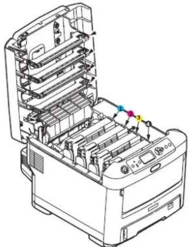
- Note the positions of the four cartridges.
natural_image
Technical line drawing of an open printer with internal compartments and a color-coded component (no text or symbols)-
Cyan cartridge 2. Magenta cartridge
-
Yellow cartridge 4. Black cartridge
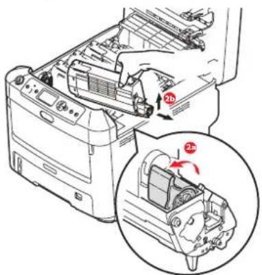
(a) Pull the coloured toner release lever on the cartridge to be replaced fully towards the front of the printer.
text_image
Technical diagram showing a printer's internal structure with labeled parts and a magnified view highlighting the component '2b'.(b) Lift the right-hand end of the cartridge and then draw the cartridge to the right to release the left-hand end as shown, and withdraw the toner cartridge out of the printer.
-
Put the cartridge down gently onto a piece of paper to prevent toner from marking your furniture.
-
Clean the top of the ID unit with a clean, lint free cloth.
natural_image
Illustration of a printer's internal structure with a hand inserting a component, showing no text or symbols.-
Remove the new cartridge from its box but leave its wrapping material in place for the moment.
-
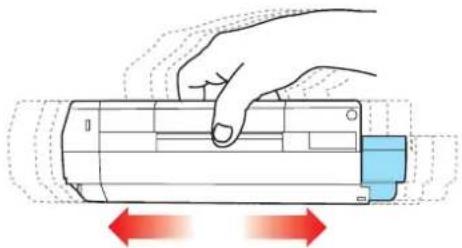
Gently shake the new cartridge from end to end several times to loosen and distribute the toner evenly inside the cartridge.
natural_image
Illustration of a hand pressing down on a cylindrical device with red directional arrows indicating motion (no text or symbols)- Remove the wrapping material and peel off the adhesive tape from the underside of the cartridge.
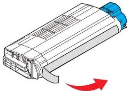
natural_image
Diagram of a battery pack with blue insulation and red arrow indicating rotation (no text or symbols)-
Holding the cartridge by its top centre with the coloured lever to the right, lower it into the printer over the image drum unit from which the old cartridge was removed.
-
Insert the left end of the cartridge into the top of the image drum unit first, pushing it against the spring on the drum unit, then lower the right end of the cartridge down onto the image drum unit.
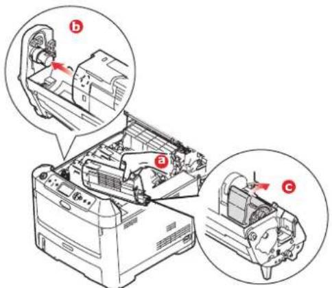
text_image
Technical diagram of a printer with labeled parts (a, b, c) showing internal components and directional arrows indicating assembly or operation.-
Pressing gently down on the cartridge to ensure that it is firmly seated, push the coloured lever towards the rear of the printer. This will lock the cartridge into place and release toner into the image drum unit.
-
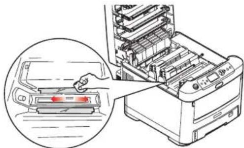
Gently wipe the LED head surface with a clean, lint free cloth.
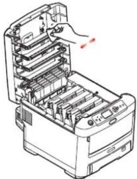
natural_image
Line drawing of a printer's internal structure with a hand inserting a component (no text or symbols visible)- Finally, close the top cover and press down firmly at both sides so that the cover latches closed.
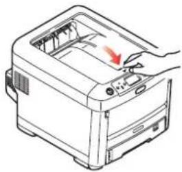
natural_image
Illustration of a printer with a hand operating the top panel (no text or symbols visible)IMAGE DRUM REPLACEMENT
CAUTION!

Static sensitive devices, handle with care.
The printer contains four image drums: cyan, magenta, yellow and black.
- Press the cover release and open the printer's top cover fully.
WARNING!
If the printer has been powered on, the fuser will be hot. This area is clearly labelled. Do not touch.
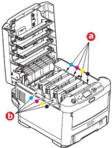
- Note the positions of the four toner cartridges (a) and image drums (b). It is essential that they go back in the same order.
text_image
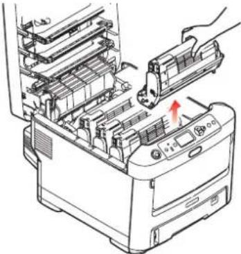
Diagram of a printer's internal structure with labeled parts (a) and (b), showing color-coded components and connection points.- Holding it by its top centre, lift the image drum, complete with its toner cartridge, up and out of the printer.
natural_image
Illustration of a printer's internal structure with a hand inserting a component (no text or symbols visible)- Put the assembly down gently onto a piece of paper to prevent toner from marking your furniture and to avoid damaging the green drum surface.
CAUTION!
The green image drum surface at the base of the ID unit is very delicate and light sensitive. Do not touch it and do not expose it to normal room light for more than 5 minutes. If the drum unit needs to be out of the printer for longer than this, please wrap the cartridge inside a black plastic bag to keep it away from light. Never expose the drum to direct sunlight or very bright room lighting.
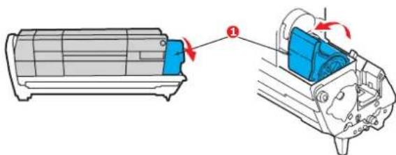
- With the coloured toner release lever (1) to the right, pull the lever towards you. This will release the bond between the toner cartridge and the image drum unit.
text_image
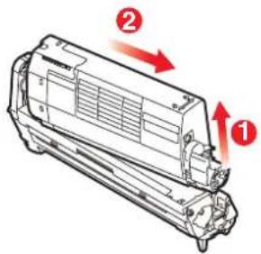
Diagram showing airflow or ventilation process of an air conditioner unit with labeled component 1- Lift the right-hand end of the toner cartridge (1) and then draw the cartridge to the right to release the left-hand end as shown (2), and withdraw the toner cartridge out of the image drum cartridge. Place the cartridge on a piece of paper to avoid marking your furniture.
text_image
Technical diagram of a vehicle air vent with numbered components and directional arrows indicating flow or movement.- Take the new image drum cartridge out of its packaging and place it on the piece of paper where the old cartridge was placed. Keep it the same way round as the old unit. Pack the old cartridge inside the packaging material for disposal.
NOTE:
Follow instructions that come with the new image drum for additional information such as the removal of packaging material, etc.
- Place the toner cartridge onto the new image drum cartridge as shown. Push the left end in first, and then lower the right end in. (It is not necessary to fit a new toner cartridge at this time unless the remaining toner level is very low.)
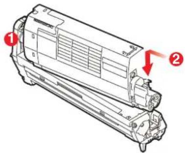
text_image
Technical diagram of a mechanical component with numbered callouts and red arrows indicating features- Push the coloured release lever away from you to lock the toner cartridge onto the new image drum unit and release toner into it.
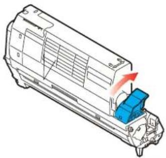
natural_image
Technical line drawing of a mechanical component with a blue component and red directional arrow (no text or symbols)- Holding the complete assembly by its top centre, lower it into place in the printer, locating the pegs at each end into their slots in the sides of the printer cavity.
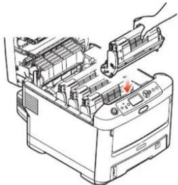
natural_image
Illustration of a printer's internal structure with a hand inserting a component (no text or symbols visible)- Finally, close the top cover and press down firmly at both sides so that the cover latches closed.
NOTE:
If you need to return or transport your printer for any reason, please make sure you remove the image drum unit beforehand and place in the bag provided. This is to avoid toner spillage.
REPLACING THE TRANSFER BELT UNIT
The belt unit is located under the four image drums.
Switch off the printer and allow the fuser to cool for about 10 minutes before opening the cover.
- Press the cover release and open the printer's top cover fully.
WARNING!
If the printer has been powered on, the fuser will be hot. This area is clearly labelled. Do not touch.
- Note the positions of the four toner cartridges (a) and image drums (b). It is essential that they go back in the same order.
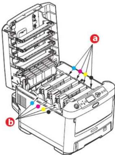
text_image
Technical diagram of a printer with labeled components and connection points, showing internal structure and color-coded connectors.- Lift each of the image drum units out of the printer and place them in a safe place away from direct sources of heat and light.
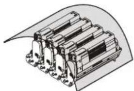
natural_image
Technical illustration of a multi-layered electrical component with mounting flanges (no text or symbols)CAUTION!
The green image drum surface at the base of each cartridge is very delicate and light sensitive. Do not touch it and do not expose it to normal room light for more than 5 minutes. If the drum unit needs to be out of the printer for longer than this, please wrap the cartridge inside a black plastic bag to keep it away from light. Never expose the drum to direct sunlight or very bright room lighting.
- Locate the two fasteners (a) at each side of the belt and the lifting bar (b) at the front end.

text_image
Diagram of a printer's internal structure with labeled parts (a, b, c) and directional arrows indicating process flow or movement.-
Turn the two fasteners 90^ to the left. This will release the belt from the printer chassis.
-
Pull the lifting bar (b) upwards so that the belt tilts up towards the front, and withdraw the belt unit (c) from the printer.
-
Lower the new belt unit into place, with the lifting bar at the front and the drive gear towards the rear of the printer. Locate the drive gear into the gear inside the printer by the rear left corner of the unit, and lower the belt unit flat inside the printer.
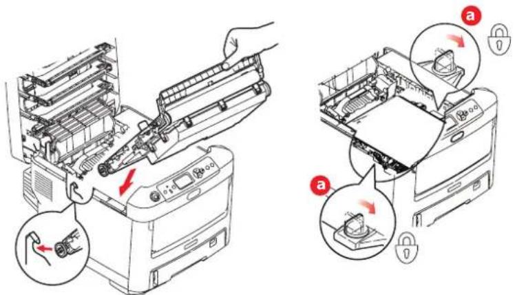
text_image
Technical diagram showing printer assembly process with labeled parts and directional arrows indicating movement or assembly steps.-
Turn the two fasteners (a) 90^ to the right until they lock. This will secure the belt unit in place.
-
Replace the four image drums, complete with their toner cartridges, into the printer in the same sequence as they came out: cyan (nearest the rear), magenta, yellow and black (nearest the front).
-
Finally, close the top cover and press down firmly at both sides so that the cover latches closed.
FUSER REPLACEMENT
The fuser is located inside the printer just behind the four image drum units.
WARNING
If the printer has recently been powered on, some fuser components will be very hot. Handle the fuser with extreme care, holding it only by its handle, which will only be mildly warm to the touch. A warning label clearly indicates the area. If in doubt, switch the printer off and wait at least 10 minutes for the fuser to cool before opening the printer cover.
-
Press the cover release and open the printer's top cover fully.
-
Identify the fuser handle (a) on the top of the fuser unit.
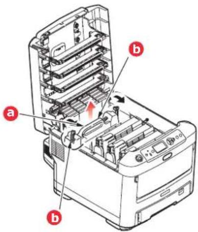
text_image
Technical diagram of a printer with labeled parts (a, b) and internal structure, showing internal components and assembly.-
Pull the two fuser retaining levers (b) towards the front of the printer so that they are fully upright.
-
Holding the fuser by its handle (a), lift the fuser straight up and out of the printer. If the fuser is still warm, place it on a flat surface which will not be damaged by heat.
-
Remove the new fuser from its packaging and remove the transit material.
-
Holding the new fuser by its handle, make sure that it is the correct way round. The retaining levers (b) should be fully upright, and the two locating lugs (c) should be towards you.
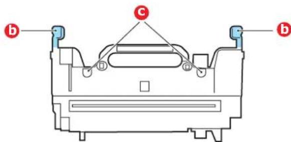
text_image
b C b-
Lower the fuser into the printer, locating the two lugs (c) into their slots in the metal partition which separates the fuser area from the image drums.
-
Push the two retaining levers (b) towards the rear of the printer to lock the fuser in place.
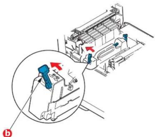
natural_image
Technical diagram of a mechanical assembly with a magnified inset showing a tool interacting with a component (no text or symbols present)- Finally, close the top cover and press down firmly at both sides so that the cover latches closed.
CLEANING THE LED HEAD
Clean the LED heads when printing does not come out clearly, has white lines or when text is blurred.
There is no need to switch off the printer to clean the lens.
- Press the cover release and open the printer's top cover fully.
- Gently wipe the LED head surface with a clean, lint free cloth.
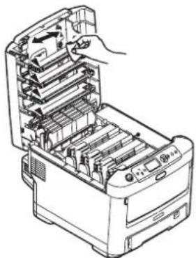
natural_image
Technical line drawing of a printer's internal structure showing internal components and a hand holding the top part (no text or symbols present)CAUTION!
Do not use methyl alcohol or other solvents on the LED head as damage to the lens surface will occur.
- Close the top cover and press down firmly at both sides so that the cover latches closed.
INSTALLING UPGRADES
NOTE
For illustrative purposes, the C711 printer has been shown. If you have a C610 printer, the principle is the same.
This section explains how to install optional equipment into your printer. This includes:
duplex (two-sided printing) unit
additional RAM memory
SD card
additional paper tray(s)
cabinet
DUPLEX UNIT
The duplex unit adds the function of two-sided printing, using less paper and making large documents easier to handle. It also enables booklet printing, which uses even less paper and makes large documents even easier to handle.
The duplex unit slides straight into the rear of the printer and requires no tools to install.
- Unpack the new unit and remove any transit material from it.
- Switch the printer off. It is not necessary to disconnect the AC power cable.
- Ensure that the unit is the right way up, as shown, and push it into the slot behind the rear panel. The panel will swing inwards as you push the unit into it. Push the unit all the way in until it stops and latches home.
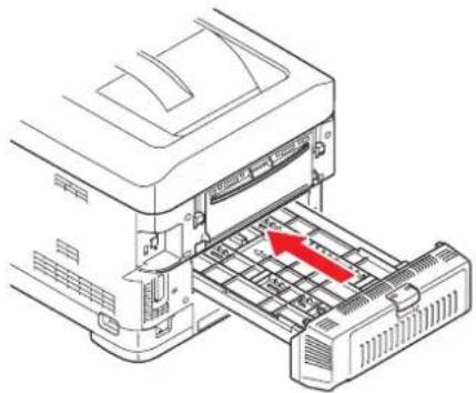
natural_image
Diagram of a printer with a red arrow indicating a loading or movement process (no text or symbols present)-
Switch the printer on and wait for it to warm up (about 1 minute).
-
Print a menu map as follows:
(a) Press the Enter button.
(b) Press the Menu down button, then the Enter button to select the Print Information menu.
(c) Select Configuration with the Enter button.
(d) Press the Enter button once more to execute the Configuration menu.
(e) When the Configuration map is printed, press Online to exit the menu system.
-
Examine the first page of the menu map.
-
Near the top of the page, between the two horizontal lines, you will see the current printer configuration. This list should indicate that the duplex unit is now installed.
All that remains is to adjust the printer driver to make full use of the new features ("Setting the driver device options" on page 65).
MEMORY UPGRADE
The basic printer model comes equipped with 256MB of main memory. This can be upgraded with an additional memory board of 256MB or 512MB, giving a maximum total memory capacity of 768MB.
- Switch the printer off and disconnect the AC power cable.
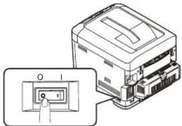
text_image
Technical diagram showing a printer with labeled ports and an inset view of the port's internal structure.- Press the cover release and open the printer's top cover fully.
WARNING!
If the printer has been powered on recently, the fuser will be hot. This area is clearly labelled. Do not touch.
- Pull down the MP Tray using the depressions. Lift the front cover release lever and lower the front cover.
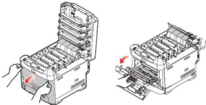
natural_image
Technical line drawing of two industrial machines with internal components and red directional arrows indicating assembly or operation (no text or symbols present)-
Loosen the screw (a) securing the right-hand side cover.
-
Lift the edge of the side cover slightly and pull the cover away from the printer at the top. Lift the cover slightly to detach it from the printer. Place it safely to one side.
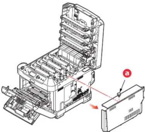
natural_image
Technical line drawing of an open industrial machine with internal components and a close-up view of the base panel (no text or symbols)-
Carefully remove the new memory board from its wrapping. Try to handle the board only by its short edges, avoiding contact with any metal parts as far as possible. In particular, avoid touching the edge connector.
-
Notice that the memory board has a small cutout in the edge connector, which is closer to one end than the other.

natural_image
Isometric line drawing of a rectangular electronic component with three square holes and a base plate (no text or symbols)-
Identify the RAM expansion slot in the printer.
-
If the RAM expansion slot already contains a memory upgrade board, that board will have to be removed before you can install the new one. To remove it, proceed as follows, otherwise skip to step 10.
(a) Release retaining clips and pull the board out of the slot.
(b) Place the removed memory board in the antistatic bag which originally contained the new memory board.
-
Hold the new memory board by its short edges, so that the edge connector faces in towards the RAM expansion slot, and the small cutout is closer to the rear of the printer.
-
Gently push the board into the RAM expansion slot until it latches in and will not go any further.
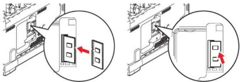
natural_image
Two technical diagrams showing a device being inserted into a rack, with arrows indicating the process (no text or symbols present)-
Locate the retaining clips at the bottom of the side cover into their rectangular holes near the bottom of the printer.
-
Close the top of the side cover up to the printer and refit the securing screw loosened in step 4.
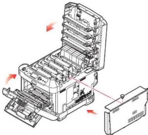
natural_image
Technical line drawing of a mechanical device with internal components and red directional arrows indicating motion (no text or symbols)-
Close the front cover, and close the top cover, pressing down firmly at each side to latch it closed.
-
Reconnect the AC power cable and switch the printer on.
-
When the printer is ready, print a menu map as follows:
(a) Press the Enter button.
(b) Press the Menu down button then the Enter button to select the Print Information menu.
(c) Select Configuration with the Enter button.
(d) Press the Enter button once more to execute the Configuration menu.
(e) When the Configuration map is printed, press On Line to exit the menu system.
- Examine the first page of the menu map.
Near the top of the page, between the two horizontal lines, you will see the current printer configuration. This list contains the figure for total memory size.
This should indicate the total memory now installed.
SD CARD
The optional SD card enables collating of printed pages and can be used to store overlays and macros, fonts, and secure or proof documents waiting to be printed.
- Switch the printer off and disconnect the AC power cable.
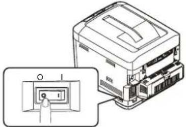
natural_image
Technical line drawing of a printer with an inset showing a button (no text or symbols present)- Press the cover release and open the printer's top cover fully.
WARNING!
If the printer has been powered on recently, the fuser will be hot. This area is clearly labelled. Do not touch.
- Pull down the MP Tray using the depressions. Lift the front cover release lever and lower the front cover.
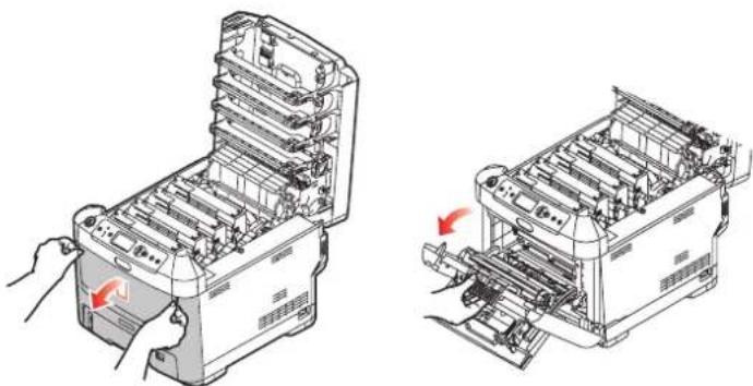
natural_image
Technical line drawing of two views of a printer's internal structure, showing front and side views with no text or symbols.- Loosen the screw (a) securing the right-hand side cover. Lift the edge of the side cover slightly and pull the cover away from the printer at the top. Lift the cover slightly to detach it from the printer. Place it safely to one side.
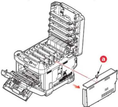
natural_image
Technical line drawing of a printer internal structure with a close-up view showing internal components (no text or symbols)- Notice that the SD card has one chamfered corner.
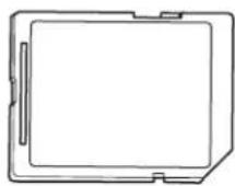
- Gently push the SD card into the slot as shown.
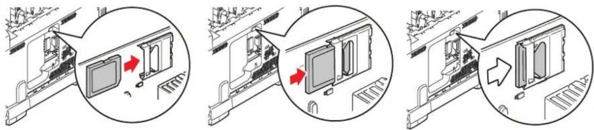
text_image
Technical diagram showing three stages of a device assembly with arrows indicating process steps-
Locate the retaining clips at the bottom of the side cover into their rectangular holes near the bottom of the printer.
-
Close the top of the side cover up to the printer and refit the securing screw loosened in step 4.
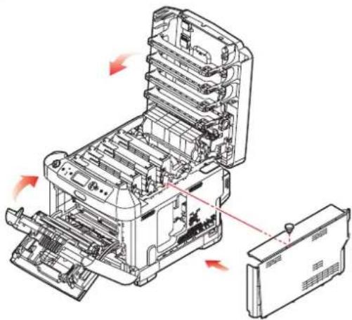
natural_image
Technical line drawing of an open industrial machine with internal components and directional arrows indicating assembly (no text or symbols present)-
Close the front cover and the top cover, pressing down firmly at each side to latch it closed.
-
Reconnect the AC power cable and switch the printer on.
-
When the printer is ready, print a menu map as follows:
(a) Press the Enter button.
(b) Press the Menu down button then the Enter button to select the Print Information menu.
(c) Select Configuration with the Enter button.
(d) Press the Enter button once more to execute the Configuration menu.
(e) When the Configuration map is printed, press On Line to exit the menu system.
- Examine the first page of the menu map. This should now indicate that the SD card is installed.
ADDITIONAL PAPER TRAY(S)
- Switch the printer off and disconnect the AC power cable.
- Place additional paper tray(s) on desired location.
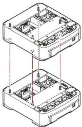
natural_image
Technical line drawing of two stacked electronic devices with internal components and mounting holes (no text or symbols)- Observing safety rules for lifting and, using locating guides, place printer on top of the additional paper tray(s).
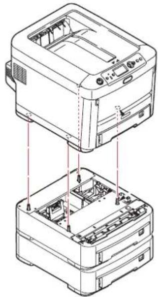
natural_image
Technical line drawing of a printer with internal components and red dashed lines indicating assembly or disassembly (no text or symbols present)- Re-connect the AC power cable and switch the printer ON.
All that remains is to adjust the printer driver to make full use of the new features ("Setting the driver device options" on page 65).
SETTING THE DRIVER DEVICE OPTIONS
Once your new upgrade has been installed, you may need to update the printer driver so that the additional features are available to your applications.
Accessories such as additional paper trays will only be usable if the printer driver on your computer knows they are there.
In some cases the hardware configuration of your machine is automatically detected when the driver is installed. However, it is advisable to at least check whether all of the available hardware features are listed in the driver.
This procedure is essential if you subsequently add extra hardware features to your machine after the drivers have been installed and set up.
Remember that if your machine is shared between users on different computers, the driver must be adjusted on each user's machine.
WINDOWS
- Access the driver's Properties window.
(a) Open the Printers window (called "Printers and Faxes" in Windows XP) via the Start Menu or from the Windows Control Panel.
(b) Right-click the icon for this machine, and choose Properties from the pop-up menu.
- Select the Device Options tab.
In the Windows XP PostScript driver the tab may be called Device Settings.
- Set the options for any devices you have just installed.
- Click OK to close the window and save your changes.
MAC OS X
Snow Leopard (Mac OS X 10.6) and Leopard (Mac OS X 10.5)
- Open the Mac OS X Print & Fax Preferences.
- Ensure your machine is selected.
- Click Options & Supplies.
- Click Driver.
- Select all hardware options appropriate to your machine and click OK.
Tiger (Mac OS X 10.4)
- Open the Mac OS X Print & Fax Preferences.
- Ensure your machine is selected.
- Click Printer Setup....
- Click the menu and choose Installable Options....
- Select all hardware options appropriate to your machine and click Apply Changes....
Panther (Mac OS X 10.3)
- Open the Mac OS X Print & Fax Preferences.
- Click Printing.
- Click Set Up Printers....
- Ensure your machine is selected and click Show Info...
- Click the menu and choose Installable Options....
- Select all hardware options appropriate to your machine and click Apply Changes....
STORAGE CABINET
Instructions for installing the Storage Cabinet are supplied with the cabinet.
TROUBLESHOOTING
Provided that you follow the recommendations in this guide on the use of print media, and you keep the media in good condition prior to use, your printer should give years of reliable service. However, paper jams occasionally do occur, and this section explains how to clear them quickly and simply.
Jams can occur due to paper misfeeding from a paper tray or at any point on the paper path through the printer. When a jam occurs, the printer immediately stops, and the Attention LED on the control panel informs you of the event. If printing multiple pages (or copies), do not assume that, having cleared an obvious sheet, others will not also be stopped somewhere along the path. These must also be removed in order to clear the jam fully and restore normal operation.
MAJOR PRINTER COMPONENTS AND PAPER PATH
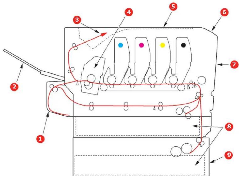
text_image
Technical diagram of a mechanical or electrical component with numbered parts and directional arrows indicating flow or movement.- Duplex unit (if fitted). 6. Operator panel.
- Face-up stacker. 7. Front cover.
- Paper exit. 8. Paper tray.
- Fuser unit 9. Additional paper tray (if fitted)
- Top cover.
PAPER SENSOR ERROR CODES
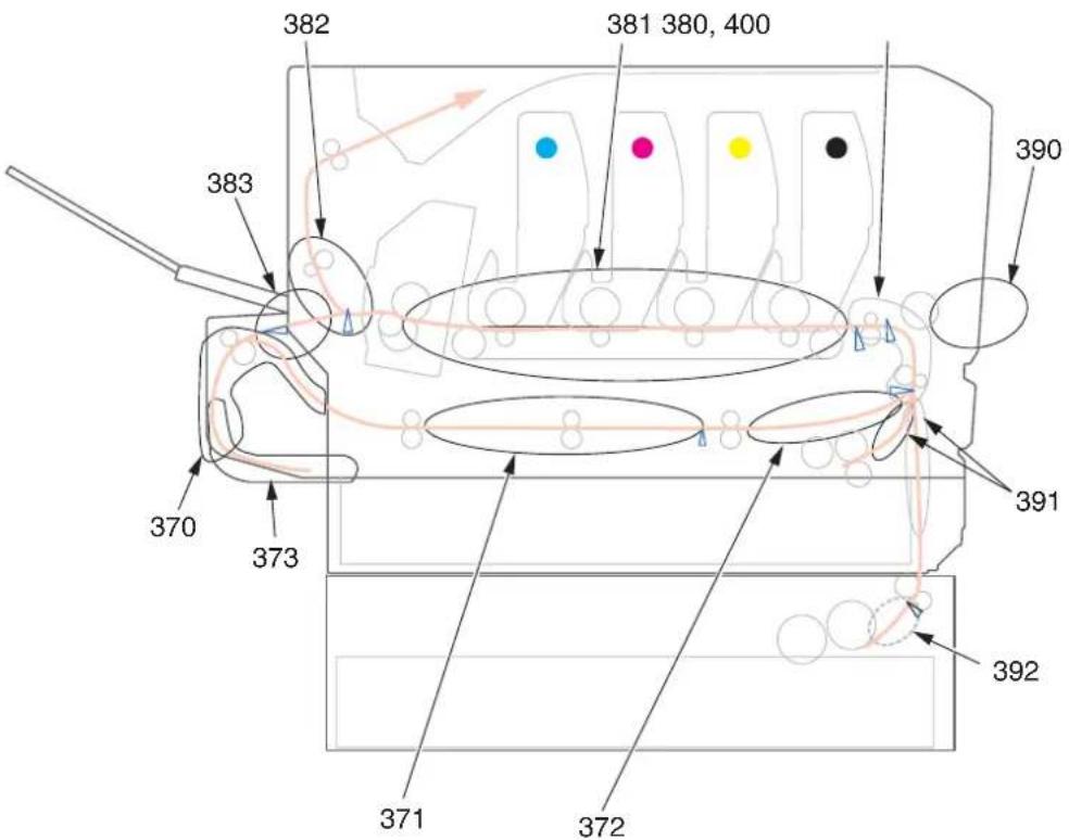
text_image
382 381 380, 400 383 370 373 390 391 392 371 372| CODE # LOCATION CODE # LOCATION | |||
| 370 | Duplex unita | 382 Paper exit | |
| 371 | Duplex unita | 383 | Duplex unita |
| 372 | Duplex unita | 390 MP Tray | |
| 373 | Duplex unita | 391 Paper Tray | |
| 380 Paper feed 392 | 2ndPaper traya | ||
| 381 Paper path 400 Paper size | |||
a. If fitted.
CLEARING PAPER JAMS
NOTE
For illustrative purposes, the C711 printer has been shown. If you have a C610 printer, the principle is the same.
-
If a sheet is well advanced out of the top of the printer, simply grip it and pull gently to draw it fully out. If it does not remove easily, do not use excessive force. It can be removed from the rear later.
-
Press the cover release and open the printer's top cover fully.
WARNING!
If the printer has been powered on, the fuser will be hot. This area is clearly labelled. Do not touch.
- Note the positions of the four toner cartridges (a) and image drums (b). It is essential that they go back in the same order.
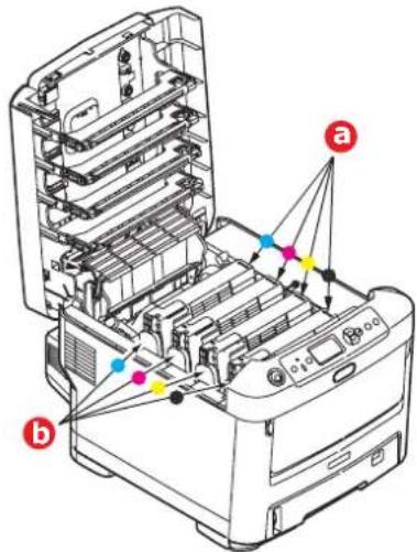
text_image
Technical diagram of a printer with labeled parts (a) and (b), showing internal structure and connection points.It will be necessary to remove the four image drums to gain access to the paper path.
- Holding it by its top centre, lift the image drum, complete with its toner cartridge, up and out of the printer.
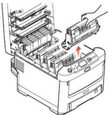
natural_image
Diagram of a printer's internal structure showing internal components and a hand inserting a component (no text or symbols visible)- Put the assembly down gently onto a piece of paper to prevent toner from marking your furniture and to avoid damaging the green drum surface, and cover.
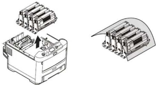
natural_image
Technical line drawing of a printer with internal components and a separate view showing internal structure (no text or symbols)CAUTION!
The green image drum surface at the base of the Image Drum is very delicate and light sensitive. Do not touch it and do not expose it to normal room light for more than 5 minutes. If the drum unit needs to be out of the printer for longer than this, please wrap the cartridge inside a black plastic bag to keep it away from light. Never expose the drum to direct sunlight or very bright room lighting.
-
Repeat this removal procedure for each of the remaining image drum units.
-
Look into the printer to check whether any sheets of paper are visible on any part of the belt unit.
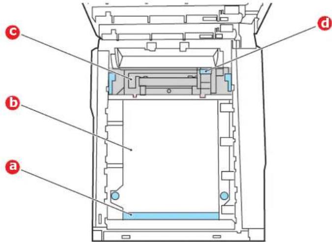
text_image
c b a dCAUTION!
Do not use any sharp or abrasive objects to separate sheets from the belt. This may damage the belt surface.
(a) To remove a sheet with its leading edge at the front of the belt (a), carefully lift the sheet from the belt and pull it forwards into the internal drum cavity and withdraw the sheet.
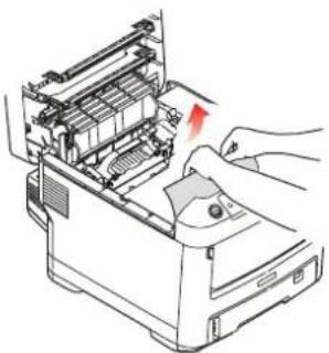
natural_image
Illustration of hands operating a computer with a red arrow indicating a component (no text or symbols present)(b) To remove a sheet from the central area of the belt (b), carefully separate the sheet from the belt surface and withdraw the sheet.
(c) To remove a sheet just entering the fuser (c), separate the trailing edge of the sheet from the belt, push the fuser pressure release lever (d) towards the front and down to release the fuser's grip on the sheet, and withdraw the sheet
through the drum cavity area. Then allow the pressure release lever to rise again.
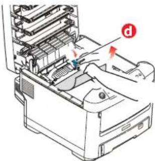
natural_image
Illustration of a printer's internal structure with no visible text or symbolsNOTE
If the sheet is well advanced into the fuser (only a short length is still visible), do not attempt to pull it back.
(d) To remove a sheet in the fuser, push the two retaining levers (e) towards the rear of the printer to release the fuser. Withdraw the fuser unit using the handle (f).
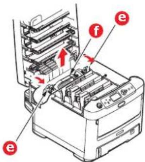
text_image
Diagram of a printer internal structure with labeled parts (e, f) and directional arrows indicating movement or assembly.(e) Press release lever (g) and pull the trapped paper from the fuser.
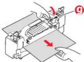
text_image
Diagram showing hands operating a machine with a red arrow indicating direction, labeled with number ①(f) Replace fuser unit into the machine and move locking levers (e) toward the rear of the machine.
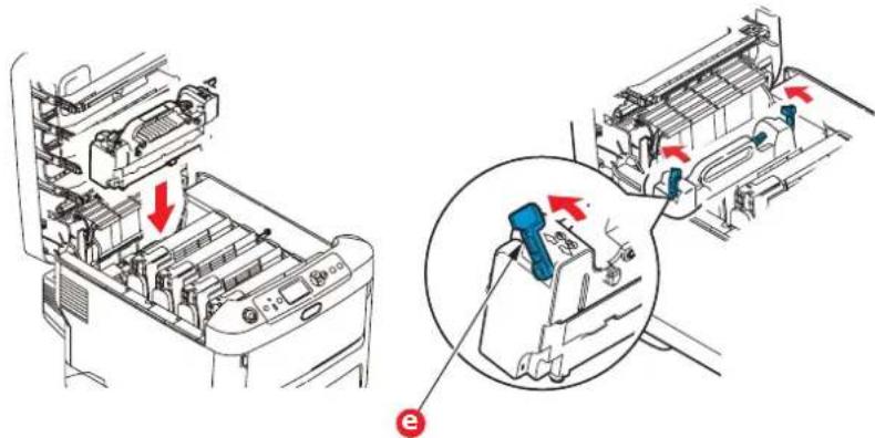
natural_image
Technical diagram showing internal components of a car air conditioner unit with red arrows indicating direction (no text or labels present)- Starting with the cyan image drum unit nearest the fuser, replace the four image drums into the drum cavity, making sure to locate them in the correct order.
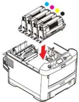
natural_image
Diagram of a printer with internal components and a red arrow indicating a process (no text or symbols present)Holding the complete assembly by its top centre, lower it into place in the printer, locating the pegs at each end into their slots in the sides of the printer cavity.
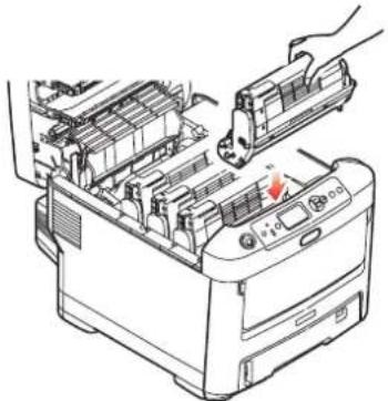
natural_image
Illustration of a printer's internal structure being inserted, showing no text or symbols-
Lower the top cover but do not press down to latch it closed yet. This will protect the drums from excessive exposure to room lighting while you check the remaining areas for jammed sheets.
-
Open the rear exit tray (h) and check for a sheet of paper in the rear path area (i).

text_image
Diagram of an air conditioner unit with labeled parts i and h, showing internal structure and airflow path.Pull out any sheets found in this area.
If the sheet is low down in this area and difficult to remove, it is probably still gripped by the fuser. In this case raise the top cover, reach around and press down on the fuser pressure release lever (d).
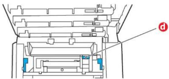
text_image
Technical diagram of a mechanical assembly with labeled component 'd'-
If you are not using the rear exit tray, close it once any paper has been removed from this area.
-
If a duplex unit is fitted, lift lever (j) and lower the duplex unit cover and pull out any sheets found in this area. Close the duplex unit cover
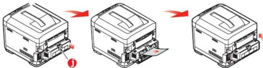
text_image
Diagram showing three-step printer operation with red arrows indicating process flow, labeled with number 'j'- Pull down the MP Tray using the depressions. Lift the front cover release lever and lower the front cover.
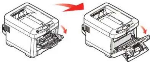
natural_image
Two views of a printer showing internal structure and external assembly, with red arrows indicating process direction (no text or symbols)- Check inside the cover for sheets in this area and remove any that you find, then close the cover.
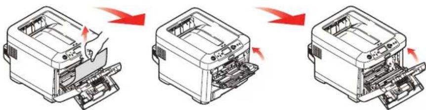
text_image
Diagram illustrating the process of printer printing and disassembly, showing three stages with red arrows indicating removal or change.- Pull out the paper tray and ensure that all paper is stacked properly, is undamaged, and that the paper guides are properly positioned against the edges of the paper stack. When satisfied, replace the tray.
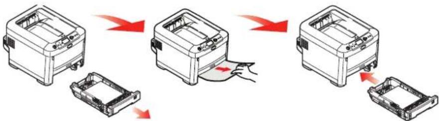
flowchart
graph TD
    A["Printer with receipt"] --> B["Printer with disassembly"]
    B --> C["Printer with disassembly"]
    C --> D["Printer with disassembly"]
- Finally, close the top cover and press down firmly so that the cover latches closed. When the jam has been cleared, if Jam Recovery is set to ON in the System Adjust Menu, the printer will attempt to reprint any pages lost due to paper jams.
SPECIFICATIONS
C610 - N31193B
C711 - N31194B
| ITEM SPECIFICATION | |
| Dimensions | C610: 435 x 547 x 340mm (W x D x H) without duplex unitC711: 435 x 547 x 389mm (W x D x H) without duplex unit |
| Weight C610: 26Kg approx. (without duplex unit)C711: 27.6Kg approx. (without duplex unit) | |
| Power supply 220 to 240VAC @ 50/60 Hz ± 2% | |
| Power consumption Operating: 1200 max.; 600 W av. (25°C)Stand-by: 100 W av. (25°C)Power saving: 15 W max.Sleep: approx. 1W (25°C) | |
| Operating environment | Operating 10 to 32 °C/20 to 80% RH(optimum 25 °C wet, 2 °C dry)Off: 0 to 43 °C/10 to 90% RH(optimum 26.8 °C wet, 2 °C dry) |
| Print environment 30 to | 73% RH @ 10 °C; 30 to 54% RH @ 32 °C10 to 32 °C @ 30% RH; 10 to 27 °C @ 80% RHColour 17 to 27 °C @ 50 to 0% RH |
| Noise(Sound pressure level) | Operating: 54dB(A)Standby: 37dB(A) |
INDEX
B
Belt
how to replace.... 53
C
Cleaning the LED head...... 57
D
Duplex
how to install.... 58
paper size and weight limits 15
E
Envelopes
loading 19
F
Fuser
how to replace.... 55
I
Image drum
how to replace.... 50
M
Maintenance menu...... 41
Major printer components and paper path.... 67
Menu functions.... 21
Menus
factory default settings..... 22
how to use.... 21
USB menu.... 42
Multi purpose tray
how to use.... 19
paper metrics 15
0
Operator Panel.... 21
P
Paper
jam clearing 67
jam, error codes.... 68
loading cassette trays ..... 16
loading letterhead 17
recommended types...... 14
supported sheet sizes..... 14
Printer overview.... 10
S
SD Card
how to install.... 62
Switching off correctly ..... 24
T
Toner
how to replace.... 47
U
Upgrades
additional paper tray(s).... 64
duplex.... 58
memory 59
SD card.... 62
storage cabinet...... 66
OKI CONTACT DETAILS
Oki Systems (UK) Limited
550 Dundee Road
Slough Trading Estate
Slough, SL1 4LE
Tel:44 (0) 1753 819819
Fax:44 (0) 1753 819899
http://www.oki.co.uk
Oki Systems Ireland Limited
The Square Industrial Complex
Tallaght, Dublin 24, Ireland
Tel:+353 1 4049590
Fax:+353 1 4049591
http://www.oki.ie
OKI Systems - Northern Ireland
40 Sydenham Park
Belfast, BT4 1PW
Tel:+44 (0)28 90 20 1110
http://www.oki.ie
Technical Support for all Ireland:
Tel:+353 1 4049570
Fax:+353 1 4049555
E-mail: tech.support@oki.ie
Oki Data Corporation
4-11-22 Shibaura, Minato-ku, Tokyo
108-8551, Japan
Tel:(81) 3 5445 6158
Fax:(81) 3 5445 6189
http://www.okidata.co.jp
Oki Data (Singapore) Pte. Ltd.
78 Shenton Way, #09-01,
Singapore 079120
Tel:(65) 6221 3722
Fax:(65) 6421 1688
http://www.okidata.com.sg
Oki Systems (Thailand) Ltd.
956 Udomvidhya Building 6th Floor,
Rama IV Rd., Bangkok 10500,
Thailand
Tel:(662) 636 2535
Fax:(662) 636 2536
http://www.okisysthai.com
Oki Hong Kong Limited
Suite 1909, Tower3,
China Hong Kong City,
33 Canton Rd., Tsimshatsui,
Kowloon, Hong Kong
Tel:(852) 2736 0130
Fax:(852) 2376 3725
The IPL Group
63-85 Victoria Street
Beaconsfield NSW 2015, Australia
Tel:(61) 2 9690 8200
Fax:(61) 2 9690 8300
http://www.oki.com.au
Comworth Systems Ltd.
10 Constellation Drive Mairangi Bay,
Auckland, New Zealand
Tel:(64) 9 477 0500
Fax:(64) 9 477 0549
http://www.comworth.co.nz
OKIEUROPELIMITED
Blays House
Wick Road
Egham
Surrey, TW20 0HJ
United Kingdom
Tel: +44 (0) 208 219 2190
Fax: +44 (0) 208 219 2199
WWW.OKIPRINTINGSOLUTIONS.COM