MULTI V PQDSB - Water pump LG - Free user manual and instructions
Find the device manual for free MULTI V PQDSB LG in PDF.


User questions about MULTI V PQDSB LG
0 question about this device. Answer the ones you know or ask your own.
Ask a new question about this device
Download the instructions for your Water pump in PDF format for free! Find your manual MULTI V PQDSB - LG and take your electronic device back in hand. On this page are published all the documents necessary for the use of your device. MULTI V PQDSB by LG.
USER MANUAL MULTI V PQDSB LG
Dry contact for communication
Owner's & installation manual
Models: PQDSBC
IMPORTANT
- Please read this manual completely before installing the product.
- Installation work must be performed in accordance with the national wiring standards by authorized personnel only.
- Please retain this installation manual for future reference after reading it thoroughly.
TABLE OF CONTENTS
■Safety Precautions 3\~4
■Name of each part ....5
■Installation Method 6\~7
Installation inside of the indoor unit....6
Installation outside of the indoor unit ....7
■Setting and using method 8\~18
-
Power supply and indoor unit connection....8
-
Setting of Contact Signal Input 9
-
Setting the desired temperature ....10
-
Control mode setting....11
-
Indoor unit monitoring ....15
Safety Precautions
To prevent injury to the user or other people and property damage, the following instructions must be followed.
■ Incorrect operation due to ignoring instruction will cause harm or damage. The seriousness is classified by the following indications.

WARNING
This symbol indicates the possibility of death or serious injury.

CAUTION
This symbol indicates the possibility of injury or damage.
■Meanings of symbols used in this manual are as shown below.


Be sure not to do.
Be sure to follow the instruction.

WARNING
■During installation
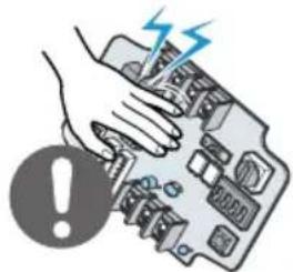
Do not touch the board when the power is connected.
- It can cause a fire, electric shock, explosion, injury and problem to the product.
natural_image
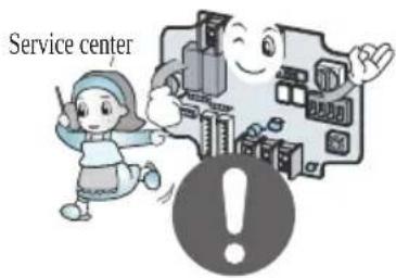
Illustration of a hand pressing a component with a warning symbol (no text or labels)Always request for installation of the product to the service center or the installation service provider.
- It can cause a fire, electric shock, explosion and injury.
text_image
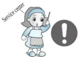
Service centerWhen reinstalling the previously installed product, request for service to the service center or the installation service provider.
- It can cause a fire, electric shock, explosion and injury.
text_image
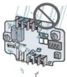
Service centerDo not install the product where it can be exposed to rain.
- It can cause problems to the product.
text_image
Diagram of a vehicle electrical switch with no visible text or symbolsDo not install the product in a humid location.
- It can cause problems to the product.
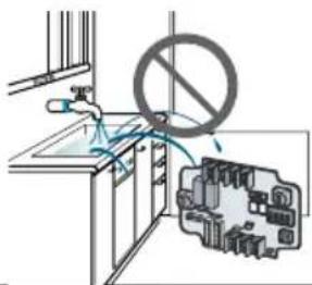
text_image
Diagram showing a kitchen sink with a crossed-out electrical circuit board and a prohibition symbol above it.■During use
Do not modify or extend the power cord.
- It can cause a fire and electric shock.
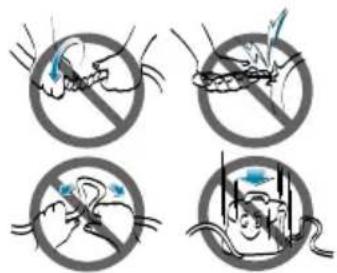
text_image
Four circular icons showing a hand holding a small object, with no text or symbols present.Do not use any flaming devices near the product.
- It can cause a fire.
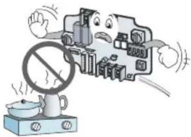
natural_image
Cartoon illustration of a computer monitor with a sad face and a 'no sign' symbol, next to a steaming cup (no text or symbols present)Do not use any heating devices near the power cord.
- It can cause a fire and electric shock.
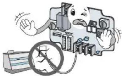
natural_image
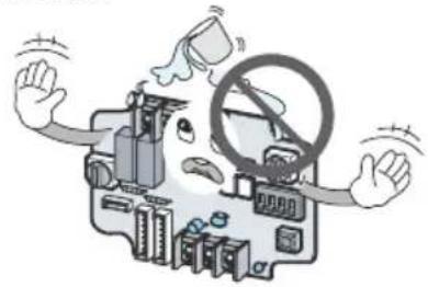
Cartoon illustration of a damaged electrical circuit board with a warning symbol (no text or labels)- It can cause an electric shock and problem to the product.
natural_image
Illustration of a person working on a device with a steering wheel and headboard, surrounded by hands (no text or symbols)When the product is submersed in water, always request for service to the service center or the installation service provider.
- It can cause a fire and electric shock.
text_image
Service centerMake the children and the elderly use the product with the help of a guardian.
- It can cause a safety accident and problems to the product.

natural_image
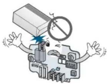
Illustration of a child and an adult interacting with a large cartoon-style building, with an exclamation mark symbol nearby (no text or symbols present)Do not give impact to the product.
- It can cause problems to the product.
natural_image
Cartoon illustration of a person reacting to a device with a prohibition symbol above, surrounded by electronic components (no text or symbols present)Name of each part
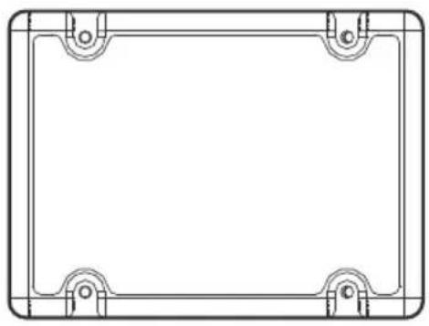
natural_image
Pure technical line drawing of a rectangular frame with corner brackets and mounting holes (no text or symbols)(Front case)
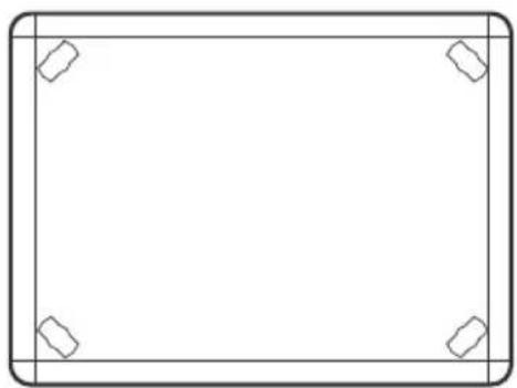
natural_image
Empty rectangular frame with corner markers (no text or symbols)(Rear case)
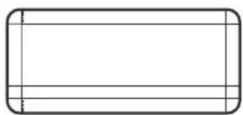
natural_image
Simple rectangular outline with rounded corners and horizontal lines inside (no text or symbols)(Top)
text_image
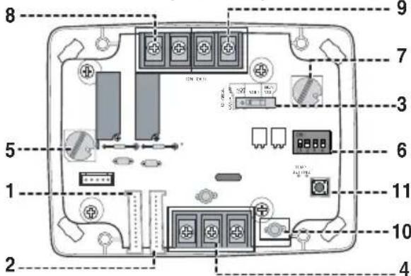
8 9 7 3 5 6 11 10 2 4(Internal PCB board)
natural_image
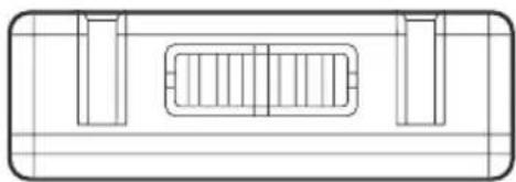
Pure technical line drawing of a rectangular component with internal slots and supports (no text or symbols)(Side) (Side)
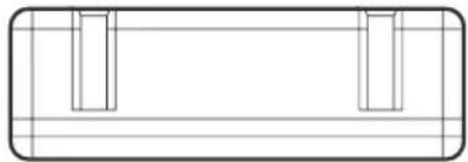
natural_image
Pure technical drawing of a rectangular frame with internal vertical slots, no text or symbols presentDRY CONTACT FOR COMMUNICATION (DRY\_CONTACT FOR COMMUNICATION)
- CN_INDOOR : Connect communication wire between indoor unit and Dry contact for communication and supply power to Dry contact for communication
- CN_PI485 : PI485 connector
- CHANGE_OVER_SW : Switch to select voltage (5V-12V) of contact point
- CN_CONTROL : Contact point signal input
- CONTROL_MODE_SW : Switch to select the control mode
- SETTING_SW : Switch to select whether to use set function of Dry contact for communication
- TEMP_SETTING : Switch to set the desired temperature of the indoor unit
- CN_OUT (O1, O2) : Connector to show whether the indoor unit is operating
- CN_OUT (E3, E4) : Connector to show whether there is an error with the indoor unit
- DISPLAY_LED : LED to display the status of the Dry contact for communication
- RESET_SW : Reset switch
Installation Method
Installation inside of the indoor unit
① Loose 4 screws anchoring PCB and then separate the rear case and PCB
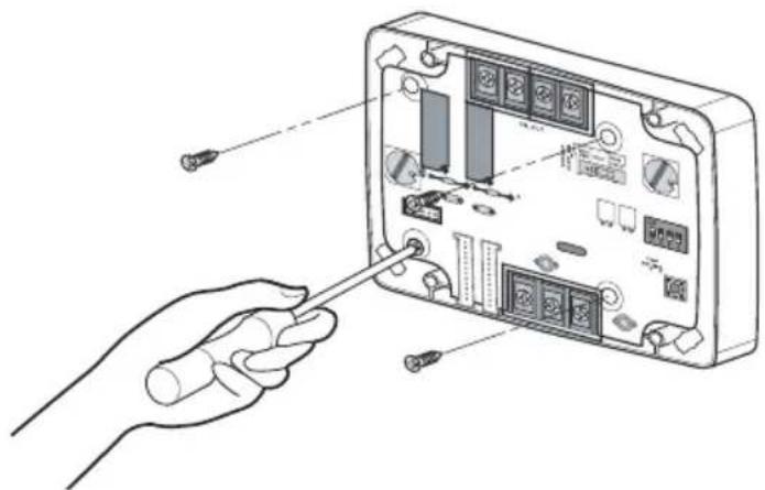
natural_image
Illustration of a hand inserting a screwdriver into an electronic device panel (no text or symbols visible)② Connect the connection wires according to the instructions. (Please refer to Setting and Using Method)
③ Perform the switch setting according to switch setting method. (Please refer to Setting and Using Method)
④ Fix PCB on suitable space inside of the indoor unit.
CAUTION
- Install the product on flat surface and install anchoring screws at more than 2 places. Otherwise the central controller may not be anchored properly.
- Do not tighten anchoring screws too tightly. It may cause deformation of the case.
- Do not deform the case at random. It may cause malfunction of the central controller.
Installation outside of the indoor unit
① Anchor the rear case of Dry Contact for communication on the installation surface at holes using anchor screws.
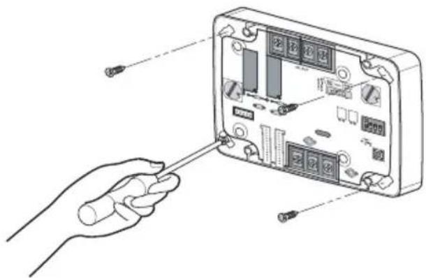
natural_image
Illustration of a hand inserting a cable into an electronic device panel (no text or symbols visible)② Please cut the pole which is located in side of the front case properly.
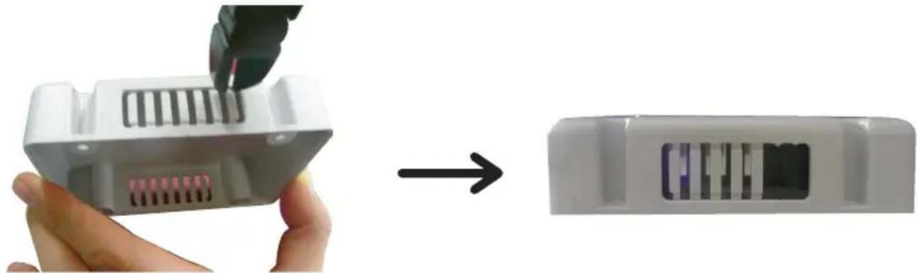
natural_image
Close-up of a white plastic electronic device being processed, showing internal structure before and after assembly (no text or symbols visible)③ Connect connection wires according to the instructions. (Reference to Setting and Using Method) Then, connect wire to PCB after going through hole of ②
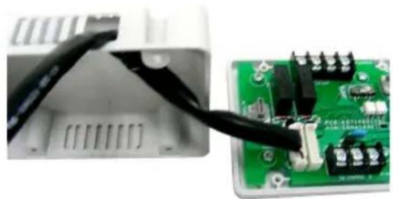
natural_image
Close-up of a white electronic device with black cable inserted into a green circuit board (no visible text or symbols)④ Perform the switch setting according to switch setting method. (Reference to Setting and Using Method)
⑤ Join the front case and the rear case, anchor the front case at holes using anchor screws.
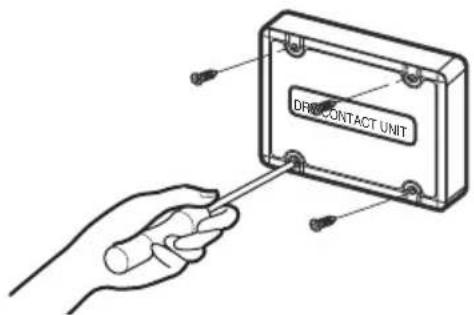
text_image
DRFOCONTACT UNITCAUTION
- Install the product on flat surface and install anchoring screws at more than 2 places. Otherwise the central controller may not be anchored properly.
- Do not tighten anchoring screws too tightly. It may cause deformation of the case.
- Do not deform the case at random. It may cause malfunction of the central controller.
Setting and using method
You must press the RESET switch when you are completed with all the settings to reflect the settings.
1. Power supply and indoor unit connection
■ When using the Dry contact for communication independently
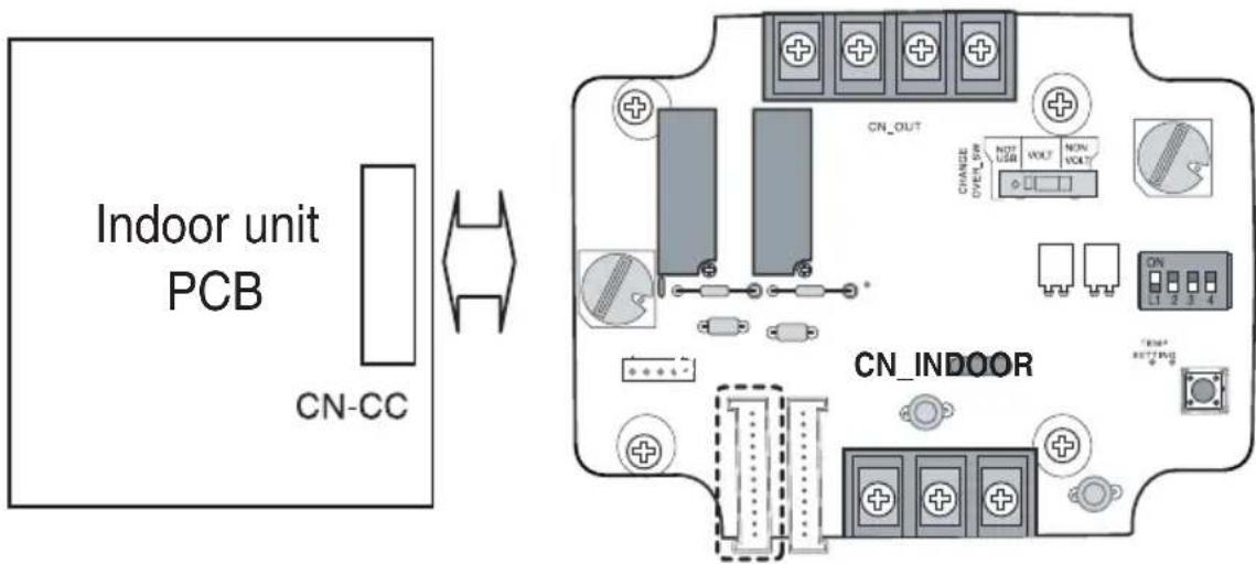
text_image
Indoor unit PCB CN-CC CN_OUT CHANGE OVEROUT NON VOLT NON VOLT CN_INDOOR TEMP SETTING■When using with the central controller (Only when the indoor unit PCB is a non-communication model)
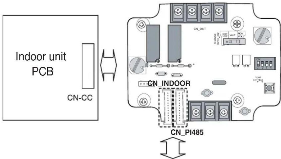
text_image
Indoor unit PCB CN-CC CN_OUT CHANGE ON/OFF VOLT NON VOLT CN_INDOOR CN_PI485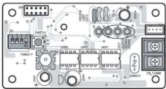
text_image
Circuit board diagram with labeled components including connectors, switches, and power connectionsPI485: Connect to central controller
2. Setting of Contact Signal Input
■For no power contact point signal input
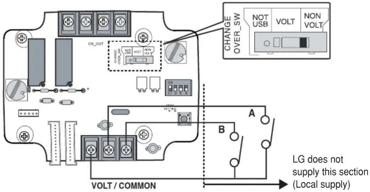
text_image
CN_OUT CHANGE OVER_SW NOT USB VOLT NON VOLT ON L1 2 3 4 CHANGE OVER_SW NOT USB VOLT NON VOLT A B LG does not supply this section (Local supply) VOLT / COMMON■For power contact point signal input
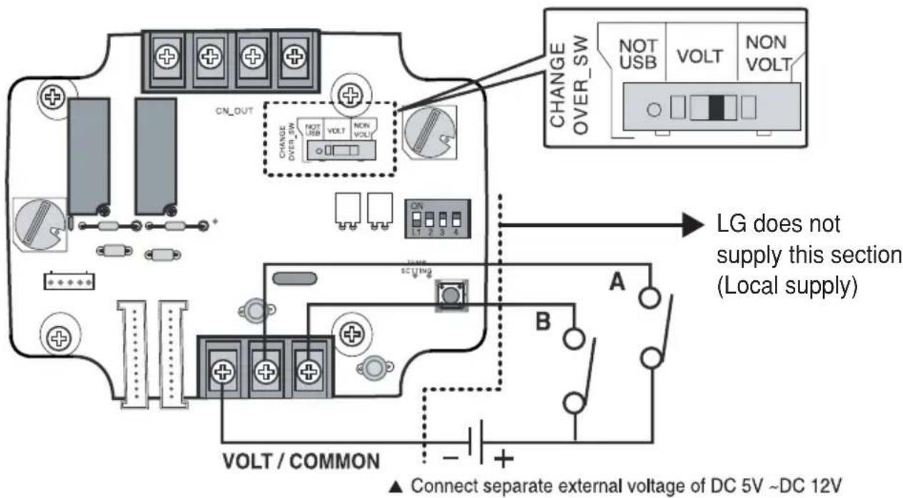
text_image
CHANGE OVER_SW NOT USB VOLT NON VOLT CN_OUT CHANGE OVER_SW NOT USB VOLT NON VOLT ON L1 2 3 4 LVMS SCITING A B VOLT / COMMON ▲ Connect separate external voltage of DC 5V ~DC 12V LG does not supply this section (Local supply)3. Setting the desired temperature
■When setting the desired temperature of the Dry contact for communication
: When operating the indoor unit, set the desired temperature according to the TEMP_SW setting. When the indoor unit is unlocked, the desired temperature can be reset by other controller
1) Turn on the TEMP_SETTING switch of SETTING_SW.
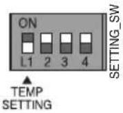
2) Use the TEMP_SW to set the temperature as shown below.
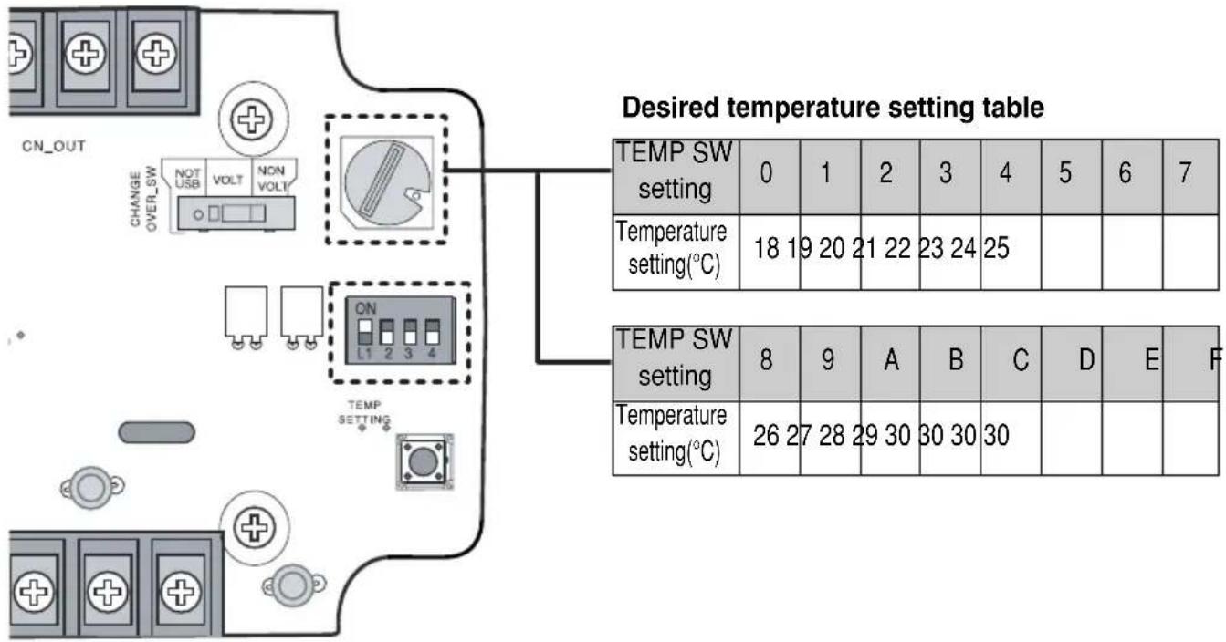
text_image
CN_OUT CHANGE OVER_SW NOT USB VOLT NON VOLT ON L1 2 3 4 TEMP SETTING Desired temperature setting table TEMP SW setting 0 1 2 3 4 5 6 7 Temperature setting(°C) 18 19 20 21 22 23 24 25 TEMP SW setting 8 9 A B C D E F Temperature setting(°C) 26 27 28 29 30 30 30■When not using the desired temperature setting of Dry contact for communication
1) Turn off the TEMP_SETTING switch of SETTING_SW.
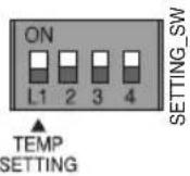
When operating the indoor unit initially in Dry contact for communication, set the desired temperature to 18°C.
4. Control mode setting
■Use the CONTROL\_MODE\_SW to set the control mode you want from 0\~D.
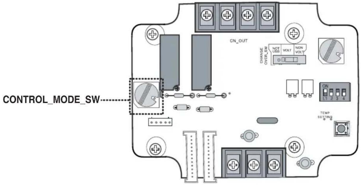
text_image
CONTROL_MODE_SW CN_OUT CHANGE OVER_SW NOT USB VOLT NON VOLT ON L1 2 3 4 TEMP SETTINGIndoor control priority
Central control > Dry contact for communication > Wired/Wireless remote controller, indoor unit button
- Dry contact for communication controls the indoor unit according to the applicable mode when there is a change in input of A and B.
■Description of each control mode
1) Cancel mode for use of dry contact for communication
| CONTROL_MODE S/W | Input A Input B Operating mode | |
| 0 | OFF OFF | The indoor unit cannot be controlled through the Dry contact for communicationNo change in indoor unit condition |
| ON OFF | ||
| OFF ON | ||
| ON ON | ||
Set this when the Dry contact for communication is connected but not used.
2) General mode
| CONTROL_MODE S/W | Input A Input B Operating mode | |
| 1 | OFF OFF | Indoor unit stopped, locked |
| ON OFF | Indoor unit prior operating condition maintained, unlocked | |
| OFF ON | Indoor unit stopped, locked | |
| ON ON | Indoor unit stopped, locked | |
| 2 | OFF OFF | Indoor unit stopped, locked |
| ON OFF | Indoor unit operating, unlocked | |
| OFF ON | Indoor unit stopped, locked | |
| ON ON | Indoor unit stopped, locked | |
| 3 | OFF OFF | Indoor unit stopped, locked |
| ON OFF | Indoor unit stopped, locked | |
| OFF ON | Indoor unit prior operating condition maintained, unlocked | |
| ON ON | Indoor unit operating, unlocked | |
| 4 | OFF OFF | Indoor unit stopped, locked |
| ON OFF | Indoor unit stopped, locked | |
| OFF ON | Indoor unit prior operating condition maintained, unlocked | |
| ON ON | Indoor unit prior operating condition maintained, unlocked | |
| 5 | OFF OFF | Indoor unit prior operating condition maintained, locked |
| ON OFF | Indoor unit prior operating condition maintained, locked | |
| OFF ON | Indoor unit prior operating condition maintained, locked | |
| ON ON | Indoor unit prior operating condition maintained, unlocked | |
| 6 | OFF OFF | Indoor unit prior operating condition maintained, locked |
| ON OFF | Indoor unit prior operating condition maintained, locked | |
| OFF ON | Indoor unit prior operating condition maintained, locked | |
| ON ON | Indoor unit operating, unlocked | |
3) Fan level setting mode
| CONTROL_MODE S/W | Input A Input B Operating mode | |
| 7 | OFF OFF | Indoor unit operating at low level, locked |
| ON OFF | Indoor unit operating at low level, unlocked | |
| OFF ON | Indoor unit stopped, locked | |
| ON ON | Indoor unit stopped, locked | |
| 8 | OFF OFF | Indoor unit operating at low level, locked |
| ON OFF | Indoor unit operating at low level, unlocked | |
| OFF ON | Indoor unit stopped, locked | |
| ON ON | Indoor unit prior operating condition maintained, unlocked | |
When the indoor unit is operating in Dry contact for communication, the fan level can be changed by other controller when the fan level is set to low level and the indoor is in unlocked condition.
4) Power save mode
| CONTROL_MODE S/W | Input A Input B Operating mode | |
| 9 | OFF OFF | Indoor unit operating in power save mode, locked |
| ON OFF | Indoor unit operating in power save mode, unlocked | |
| OFF ON | Indoor unit stopped, locked | |
| ON ON | Indoor unit operating not in power save mode, unlocked | |
| A | OFF OFF | Indoor unit operating in power save mode, locked |
| ON OFF | Indoor unit operating in power save mode, unlocked | |
| OFF ON | Indoor unit stopped, locked | |
| ON ON | Indoor unit stopped, locked | |
When setting 9, A mode, the TEMP_SETTING must always be set to ON.
Power save mode: Adjust the set temperature to +3°C for cooling and -3°C for heating.
5) Compressor stop mode
| CONTROL_MODE S/W | Input A Input B Operating mode | ||
| B | OFF OFF | Indoor unit operating (Compressor in stop mode), locked | |
| ON OFF | Indoor unit prior operating condition maintained(Compressor not in stop mode), unlocked | ||
| OFF ON | Indoor unit stopped, locked | ||
| ON ON | Indoor unit stopped, locked | ||
Compressor stop mode: The compressor is stopped during cool/heat operation.
6) Operating mode selection mode
| CONTROL_MODE S/W | Input A Input B Operating mode | |
| C | OFF OFF | Indoor unit stopped, unlocked |
| ON OFF | Indoor unit in cool/high operation, unlocked | |
| OFF ON | Indoor unit in heat/high operation, unlocked | |
| ON ON | Indoor unit in fan/high operation, unlocked | |
| D | OFF OFF | Indoor unit stopped, locked |
| ON OFF | Indoor unit in cool/high operation, locked | |
| OFF ON | Indoor unit in heat/high operation, locked | |
| ON ON | Indoor unit in fan/high operation, locked | |
Power save mode: Adjust the set temperature to +3°C for cooling and -3°C for heating.
5. Indoor unit monitoring
■Monitoring whether the indoor unit is operating: Refer to below and connect to the control device that you want to control.
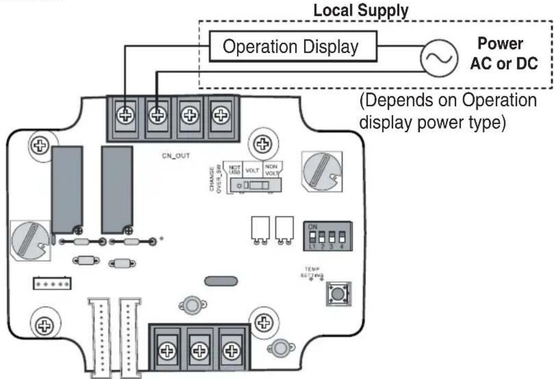
text_image
Local Supply Operation Display Power AC or DC (Depends on Operation display power type) CN_OUT CHANGE OVER_SW NOT USES VOLT NON VOLT CN 1 2 3 4 TEMP SETTING■Monitoring indoor unit error: Refer to below and connect to the control device that you want to control.
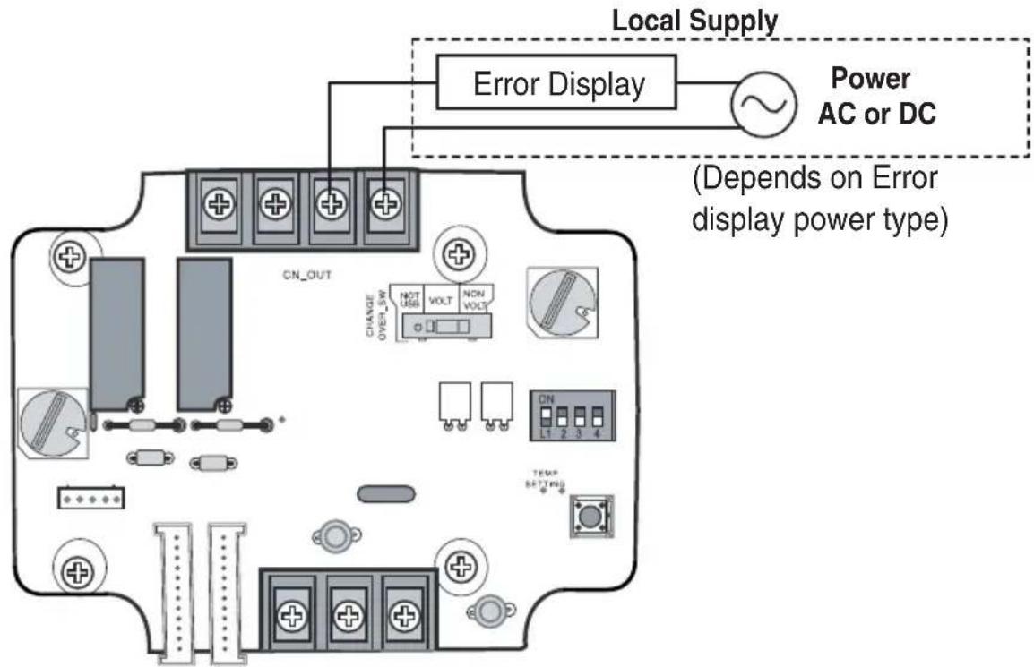
text_image
Local Supply Error Display Power AC or DC (Depends on Error display power type) CN_OUT CHANGE OVER_SW NOT USB VOLT NON VOLT ON L1 2 3 4 TEMP SETTING