
FV1408S4V - Washing machine LG - Free user manual and instructions
Find the device manual for free FV1408S4V LG in PDF.


| Product Type | Front loading washing machine |
| Dimensions (W x D x H) | 600 mm x 560 mm x 850 mm |
| Weight | 62 kg |
| Power Supply | 220 V ~, 50 Hz |
| Max Power Consumption | 2100 W |
| Wash Capacity | 7 / 8 / 9 kg |
| Water Pressure Range | 0.1 - 1.0 MPa (1.0 - 10.0 kgf/cm²) |
| Control Type | Electronic |
| Spin Speed Options | No, 400, 800, 1000, 1200, 1400 rpm |
| Temperature Options | Cold, 20°C, 30°C, 40°C, 60°C, 95°C |
| Wash Programs | Cotton, Cotton+, Mixed Fabric, Easy Care, Silent Wash, Allergy Care, Baby Steam Care, Delicates, Hand/Wool, Sportswear, Quick 30, Duvet, Tub Clean, Download Cycle |
| Motor Technology | Inverter Direct Drive (Brushless DC) |
| Wash Technology | 6 Motion, Turbo Wash, Intelligent Wash System |
| Smart Features | WiFi (Smart ThinQ 3.0), Tag On (NFC), Smart Diagnosis™ |
| Child Lock | Yes |
| Auto Restart | Yes |
| Delay End | 3 to 19 hours |
| Tub Clean Cycle | Yes |
| Door Lock | PTC + Solenoid |
| Water Level Control | Pressure sensor |
| Energy Consumption (Wash) | 2000 W |
| Energy Consumption (Spin) | 490 W |
| Drain Motor Power | 20 W |
| Wash Heater Power | 2000 W |
Frequently Asked Questions - FV1408S4V LG
User questions about FV1408S4V LG
0 question about this device. Answer the ones you know or ask your own.
Ask a new question about this device
Download the instructions for your Washing machine in PDF format for free! Find your manual FV1408S4V - LG and take your electronic device back in hand. On this page are published all the documents necessary for the use of your device. FV1408S4V by LG.
USER MANUAL FV1408S4V LG
WASHING MACHINE SERVICE MANUAL
CAUTION
READ THIS MANUAL CAREFULLY TO DIAGNOSE PROBLEMS CORRECTLY BEFORE OFFERING SERVICE.
BEFORE SERVICING THE WASHING MACHINE, UNPLUG THE POWER CORD TO AVOID THE RISK OF AN ELECTRIC SHOCK.
WHEN SERVICING INTERNAL PARTS, USE ONLY SERVICE PARTS SUPPLIED FROM LG.
AFTER SERVICING THE ELECTRIC WIRE, INSURE THAT INSULATION TAPE IS APPLIED TO PREVENT AN ELECTRICAL SHORT.
MODEL : FV1408S4V
CONTENTS
- SPECIFICATIONS .... 3
- FEATURES & TECHNICAL EXPLANATION .... 4
- PARTS IDENTIFICATION 6
- INSTALLATION 7
- OPERATION 12
- WIRING DIAGRAM / PCB LAYOUT 17
- TROUBLESHOOTING....19
7-1. BEFORE PERFORMING SERVICE 19
7-2. LOAD TEST MODE 19
7-3.HOW TO CHECK THE WATER LEVEL FREQUENCY 20
7-4. ERROR DISPLAY 21
7-5. TROUBLESHOOTING WITH ERROR 23
- IE (Water Inlet Error) 24
- UE (Unbalanced Error) 25
- OE (Water Outlet Error) 26
- FE (Over Flow Error) 28
- PE (Pressure Sensor S/W Error) 29
- dE2 (Door open Error).... 31
- dE1 (Door switch Error).... 31
- tE (Thermistor (Heating) Error) 33
-
LE (Motor Lock Error) 36
-
TROUBLESHOOTING WITHOUT ERROR CODES 38
-
Power Failure or no power 38
• Vibration & Noise during spin 39 - Detergent & Softener does not flow in 40
- Water Leak 41
-
Before using the Tag On function 43
-
PART INSPECTION 45
9-1. FILTER ASSEMBLY (LINE FILTER) 45
9-2.DOOR LOCK SWITCH ASSEMBLY 46
9-3. STATOR ASSEMBLY 48
-
DISASSEMBLY INSTRUCTIONS 49
-
EXPLODED VIEW AND PART LIST 57
1. SPECIFICATION
| ITEM | Refer to 1 page | |
| POWER SUPPLY | 220V ~,50Hz | |
| PRODUCT WEIGHT | 62kg | |
| ELECTRICITY CONSUMPTION | WASHING | 2000 W |
| SPIN | 490 W | |
| DRAIN MOTOR | 20 W | |
| WASH HEATER | 2000 W | |
| REVOLUTION SPEED | WASH | 46 rpm |
| SPIN | 0041 / 0021 / 000 | |
| 0021 / 0011 / 000 | ||
| OPERATION WATER PRESSURE | 0.1 ~ 1.0 MPa (1.0 kgf / cm2 ~ 10.0 kgf / cm2) | |
| CONTROL TYPE | Electronic | |
| WASH CAPACITY | Refer to the Rating Label | |
| DIMENSION | 600mm x 560mm x 850mm | |
| WASH PROGRAM | Cotton, Cotton+, Mixed Fabric, Easy Care, Silent Wash, Allergy Care/Hygiene Baby Steam Care/Baby CareDelicates, Hand/Wool, Sportswear, Quick 30, Duvet, Tub Clean, Download Cycle | |
| RINSE | Normal, Rinse+ | |
| DOOR SWITCH TYPE | PTC+Solenoid | |
| WATER LEVEL | by Pressure Sensor S/W | |
| RESERVATION | From 3 hours to 19 hours | |
| SENSING LAUNDRY AMOUNT | Adapted | |
| FUZZY LOGIC | Adapted | |
| DISPLAY REMAINING TIME | Adapted | |
| ERROR DIAGNOSIS | 13 items | |
| POWER AUTO OFF | Adapted | |
| CHILD LOCK | Adapted | |
| AUTO RESTART | Adapted | |
| TIME SAVE | Adapted | |
| SMART | WiFi (Smart ThinQ 3.0) | |
1 / 008 / 004 / ni
1 / 008 / 004 / ni
WARNING
- To reduce the risk of personal injury, adhere to all industry recommended safety procedures including the use of long sleeved gloves and safety glasses.
Failure to follow all of the safety warnings in this manual could result in property damage, personal injury or death.
2-1. Product Features

■ Inverter Direct Drive system
The advanced Brushless DC motor directly drives the drum without belt and pulley.

6 Motion
Washer is able to perform various drum actions or a combination of different actions depending on the wash program selected. Combined with a controlled spin speed and the ability of the drum to rotate both left and right, the wash performance of the machine is greatly improved, giving you perfect results every time.

■ Turbo Wash
Wash the laundries in 1 hour with energy and water saving.
Tag on
This is a function that may use Diagnosis, Download Course, Washing Coach, One Touch Washing, etc. when you touch the Tag On logo of the washing machine by using your smartphone with NFC.

■ More economical with Intelligent Wash system
Intelligent Wash System detects the size of load and water temperature, and then determines the optimum water level and washing time to minimize energy and water consumption.
Child Lock
The Child Lock prevents children from pressing any button to change the settings during operation.
■ Low noise speed control system
By sensing the amount of load and balance, it evenly distributes load to minimize the spinning noise level.
■ Auto Restart
Auto Restart allows the program to restart all by itself in case of power failure. It does from the stage where it stopped.

SmartDiagnosis™
Should you experience any technical difficulty with your washing machine, it has the capability of transmitting data by phone to the Customer Information Center. The call center agent records the data transmitted from your machine and uses it to analyze the issue, providing a fast and effective diagnosis.
Smart Diagnosis™
2-2. DETERMINE WASHING TIME BY FUZZY LOGIC
To get the best washing performance optimal time is determined by sensing the water temperature, selected washing temperature and laundry amount.
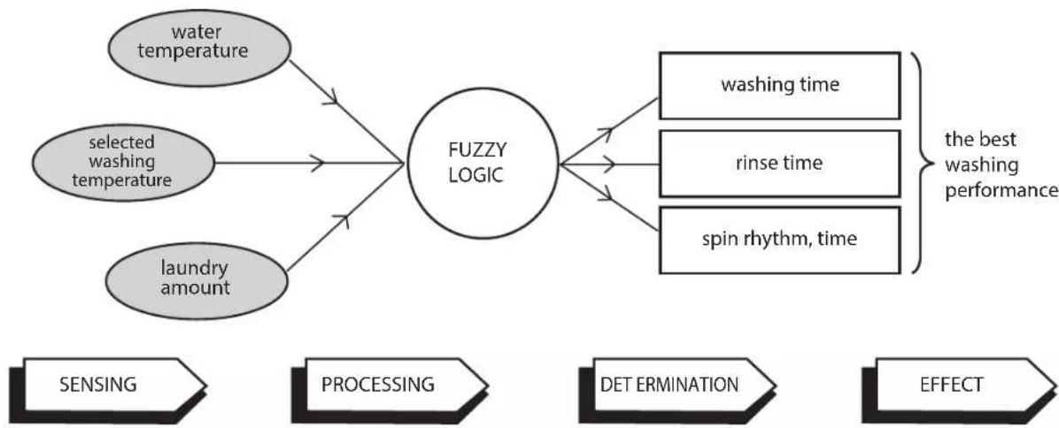
flowchart
graph TD
    A["water temperature"] --> C["FUZZY LOGIC"]
    B["selected washing temperature"] --> C
    D["laundry amount"] --> C
    C --> E["washing time"]
    C --> F["rinse time"]
    C --> G["spin rhythm, time"]
    E --> H["the best washing performance"]
    F --> H
    G --> H
    I["SENSING"] --> J["PROCESSING"]
    K["DET ERMINATION"] --> L["EFFECT"]
2-3. WATER LEVEL CONTROL
● This model adopts a pressure sensor which can sense the water level in the tub.
● Water supply is stopped when the water level reach the preset level, then washing program proceeds.
● Spinning does not proceed until the water in the tub reduces to a certain level.
2-4. THE DOOR CAN NOT BE OPENED
● While program is operating.
● While Door Lock light is on.
3.PARTS IDENTIFICATION
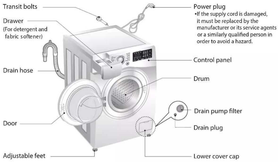
text_image
Transit bolts Drawer (For detergent and fabric softener) Drain hose Door Adjustable feet Power plug • If the supply cord is damaged, it must be replaced by the manufacturer or its service agents or a similarly qualified person in order to avoid a hazard. Control panel Drum Drain pump filter Drain plug Lower cover cap■ Name : Front loading washing machine
■ Power supply : 220 V\~
■ Size : 600 mm (W) X 560 mm (D) X 850 mm (H)
■ Weight: 62 kg
Max.Watt:2100W
0.45 W (The off-mode, The left-on mode)
■ Wash capacity : 7 / 8 / 9 kg
■ Permissible water pressure : 0.1 - 1.0 MPa (1.0 - 10.0 kgf / cm ^2 )
* The appearance and specifications may vary without notice to improve the quality of the unit.
■ Accessories
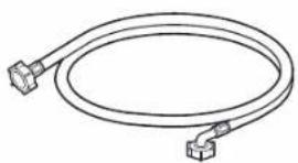
natural_image
Line drawing of a coiled electrical cable with two connectors (no text or symbols)Inlet hose
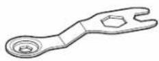
Spanner
INSTALLATION
The appliance should be installed as follows.
1 Check the conditions of installation area.
1. Check level ground.

On raised foundations or upper level homes, the vibrations can be caused by the type of flooring. It may be necessary to move the machine to a different area in the home or have the floor reinforced to properly support the operation of the unit.
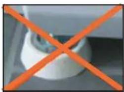
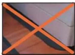
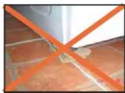
2. Check for humidity or any foreign objects under the feet.
Clean the floor, there should be no foreign objects under the feet.
If the unit has foreign objects underneath the feet, this will prevent the unit from being leveled properly and will cause vibrations and slipping.
Remove any foreign objects, if any from underneath the machine and level unit properly.
See below for examples of foreign objects.
natural_image
Close-up of a white mechanical component with an orange X mark, no visible text or symbolsPurchased stopper
natural_image
Close-up of a white wall corner with an orange X mark overlay, no text or symbols present.Carpet Paper Laminated
natural_image
Close-up of tiled floor with orange diagonal lines crossing through the ceiling (no text or symbols visible)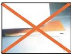
natural_image
Orange X-shaped symbol on a light background, no text or symbols presentpaper
2 Open the box and check appliance condition.
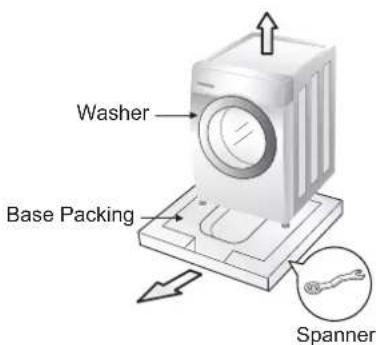
text_image
Washer Base Packing Spanner
This leveling (or spanner) wrench must be used to remove the shipping bolts and level the unit. This should be kept for future use.
3 Use spanner to remove transit bolts.
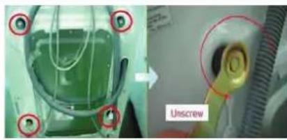
natural_image
Medical procedure image showing a green liquid container being inserted into a device, with a labeled 'Unscrew' component (no text or symbols beyond label)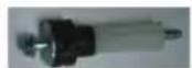
X 4 EA
※ Without removal of transit bolts ▶ Spin noise and shaking.
4 Confirm the distance between the appliance and the wall.
More than 2cm
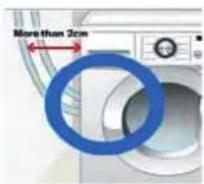
※ If the distance is less than 2cm, the water supply hose will kink or fold.
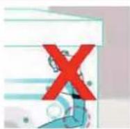
5 The tap connection and hose connection must be parallel.
1. Normal Tap without thread & screw type inlet hose.
- Uncrew the fixing screw to attach the tap.
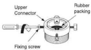
text_image
Upper Connector Rubber packing Fixing screwPush the connector up till the rubber packing is in tight contact with the tap. Then tighten the 4 screws.
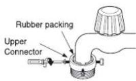
text_image
Rubber packing Upper ConnectorPush the water supply hose vertically upwards so that the rubber packing within in the hose can adhere completely to the tap and then tighten it by screwing it to the right.
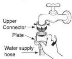
text_image
Upper Connector Plate Water supply hose2. Normal Tap without thread & one touch type inlet hose (Single inlet models)
- Untighten the upper connector screw.
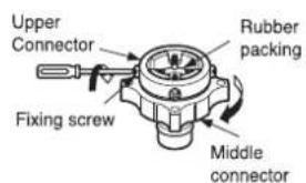
text_image
Upper Connector Rubber packing Fixing screw Middle connectori In case the diameter of the tap is large remove the guide plate.
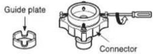
Push the upper connector up till the rubber packing is in tight contact with the tap. Then tighten the 4 screws.
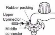
i Turn the middle connector not to have water leaked.
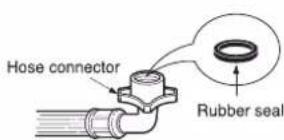
i Make sure that the rubber seal is inside the hose connector.
text_image
Hose connector Rubber sealConnect the water supply hose to the middle connector, pushing the plate down.
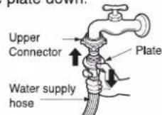
To separate the water supply hose from the middle connector shut off the tap. Then pull the inlet hose down, pushing the plate down.
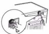
i Make sure that there are no kinks in the hose and that it is not crushed.
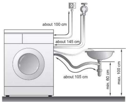
6 Connect Drain Hose.
If the drain hose is not installed properly, the unit will not drain properly.
This allows water to back flow into the unit which can cause odors.
Refer to Owner Manual for proper drain hose installation.
The odor could also be coming from the home's drain to which the drain hose is attached.
text_image
about 100 cm about 145 cm about 105 cm min. 60 cm max. 100 cm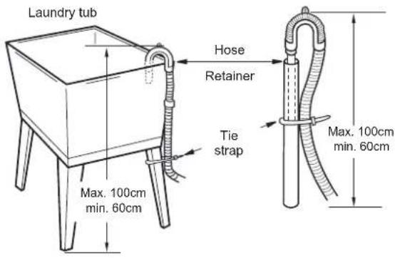
text_image
Laundry tub Hose Retainer Tie strap Max. 100cm min. 60cm Max. 100cm min. 60cm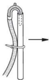
natural_image
Diagram of a rope tied with a bent tube, showing a directional arrow (no text or symbols)In this type of drain hose installation, the odor could be coming from the standpipe.
This odor can come up the drain hose and into the unit.
Pour a cup or two of bleach or vinegar down the home drain
and let it sit for 24 hours before running another cycle.
This will help eliminate odor from the home drain.
If a cycle is started too soon after doing this, it will not help the issue.
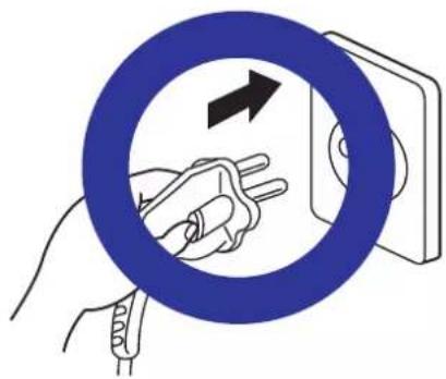
7 Connect power plug.
Connect the power plug to the wall outlet. Avoid connecting several electric devices, it may be the cause of a fire.
natural_image
Illustration of a hand holding a tool inside a blue circular ring, with an arrow indicating direction (no text or symbols)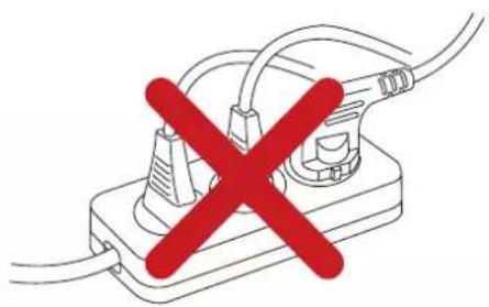
natural_image
Simple line drawing of a plug with a red X mark indicating prohibition (no text or symbols)8 Check the horizontality with a level (Gage).
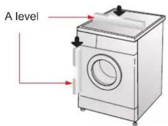
Step 1
If washing machine legs are loose or not Screwed in, then tighten with the spanner wrench. Using the level, level the washing machine from front to back and side to side.
text_image
A level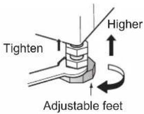
text_image
Tighten Higher Adjustable feetStep 2
Use the spanner wrench to adjust Legs until level and try the Diagonal test.
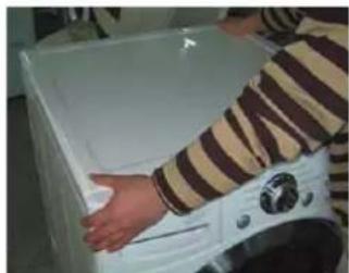
Diagonal test
natural_image
Person using a washing machine in a kitchen (no visible text or symbols)※ How to perform a diagonal test:
Place your right hand on the back, right corner and your left hand on the front, left corner of the unit, then attempt to rock the unit from corner to corner.
Then, move your right hand to the front, right side and your left hand to the back, left corner and attempt to rock the unit from corner to corner.
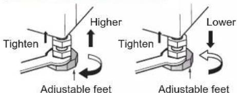
If the unit is level, it will not rock. However, if the unit is not level, it will rock. If the unit rocks, it will be necessary to adjust the leveling feet of the unit. Adjust the foot under the hand that is on the front of the machine.
text_image
Tighten Higher Adjustable feet Lower Tighten Adjustable feet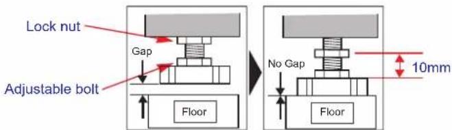
text_image
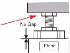
Lock nut Gap Adjustable bolt Floor No Gap 10mm FloorLower the foot until there is no gap between floor and foot.
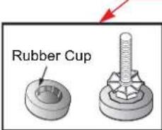
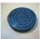
And only use adjustment rubber when difference at the leg adjustment is more than 10mm.
text_image
Rubber Cup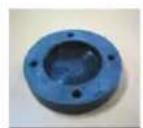
4620ER4002A
(Black)
for Tile floors
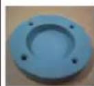
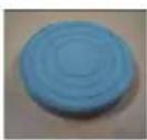
4620ER4002B
(Gray)
for Wooden floors
Step 3
Perform a Rinse and Spin with some clothing in the machine.
To do this, put 2\~3kg of clothing in the unit, turn on the unit, Select the Rinse+Spin and then start. When the unit reaches the spin cycle, watch for vibrations. If the unit is vibrating, make small adjustments to the leg until they subside. (Repeat step 2)
Step 4
Tighten the lock nut against the base of the machine to lock the position leg.
Tighen the lock nut
text_image
No Gap Floor9 Test operation
1 Preparation for washing.
text_image
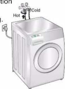
Hot Cold- Connect the power plug to the outlet.
- Connect the inlet hose.
2 Press the power button.
3 Press the START/PAUSE button.

natural_image
Hand pressing a button with a play symbol (no text or numbers visible)· In case of Coloreds program.
6 Check the water heating.

natural_image
Illustration of a white washing machine with a circular vent and wavy lines on the front panel (no text or symbols)- Touch the Temp and Medic Rinse button simultaneously and the present temperature will be displayed. Page 20
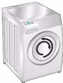
5 Check automatic reverse turn.
natural_image
Illustration of a white front-loading washing machine with a circular button on the side (no text or symbols visible)- Check if the drum rotates clockwise and counterclockwise.
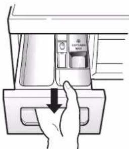
4 Check the water supply.
natural_image
Hand pressing down on a mechanical component with a downward arrow (no text or symbols visible)- Check if water is supplied through the detergent dispenser.
7 Check the drain and spin functions.
· Turn power off and then power on.
- Select the spin rpm
- Press the START PAUSE button.
- Check the spin and drain functions.
8 Turn power off and open the door.
· Turn power off and then power on.
- Listen for a click to determine if the door is unlocking.
9 Water removal.
natural_image
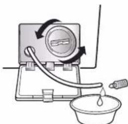
Simple line drawing of a water pump with a bucket and fan, no text or symbols present- If SVC is needed during check, remove the remaining water by pulling out the hose cap.
How to use washer
■ Control panel
text_image
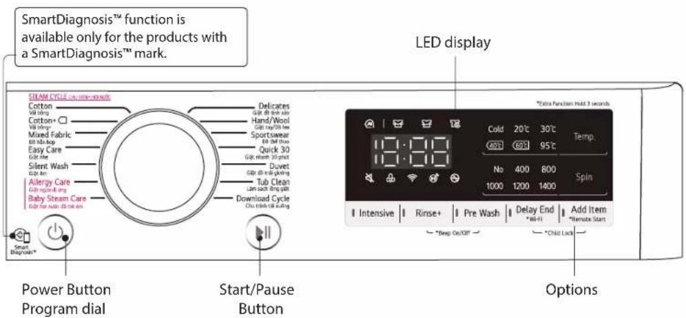
SmartDiagnosis™ function is available only for the products with a SmartDiagnosis™ mark. STILAM CYCLE: 30 min-seconds Cotton Vill drying Cotton+ □ Vill drying* Mixed Fabric Bil tab-top Easy Care Gill tube Silent Wash Gill tube Allergy Care Gill tube fastening Baby Steam Care Gill tube fastening Power Button Program dial Start/Pause Button LED display *Extra Function Hold 3 seconds 12:00 Cold 20°C 30°C Temp. CALT 60°F 95°C No 400 800 Spin 1000 1200 1400 Download Cycle Chu tubs/Bill cooling Intensive Rinse+ Pre Wash Delay End Add Item *Stop On/Off *Chid Lock OptionsPower
- Press the Power button to turn power on and off.
• To cancel the Time Delay function, the power button should pressed.
Program Dial
- Programs are available according to the laundry type.
- Lamp will light up to indicate selected program.
Start/Pause
- This Start/Pause button is used to start wash cycle or pause the wash cycle.
If temporary stop of wash cycle is needed, touch the Start/Pause button.
When in Pause, the power is turned off automatically after 4 minutes.
LED display
- The display shows the settings, estimated time remaining, options, and status messages for your washer. The display will remain on through the cycle.
Options
• This allows you to select an additional cycle and will light when selected.
- Use this buttons to select the desired cycle options for the selected cycle.
How to use washer
■ Options
- Intensive): If the laundry is normal and heavily soiled, "Intensive" option is effective.
- Rinse + (☐): Add rinse once.
- Dealy End :
You can set a time delay so that the washing machine will start automatically and finish after a specified time interval.
NOTE
- The delay time is the time to the end of the programme, not the start. The actual running time may vary due to water temperature, wash load and other factors.
-
Touch the Power button.
-
Select a cycle.
-
Touch the Time Delay button and set time required.
-
Touch the Start/Pause button.
How to use washer
Temp.
By touching the Temp. button the water temperature can be selected.
- Cold
- 20°C, 30°C, 40°C, 60°C, 95°C
Water temperature can be selected according to the program.
Pre Wash ( [T] )
If the laundry is heavily soiled, "Pre Wash" course is effective.
- Touch the Power button.
- Select a cycle.
- Touch the Pre Wash button.
- Touch the Start/Pause button.
Spin
touching 'Spin' button repeatedly.

- Touch the Power button.
- Touch the Spin button to select RPM.
- Touch the Start/Pause.
Wrinkle Care
yb detceles eb nac level deep washing programme reduces wrinkles by steaming after spin.
- Press the Power button.
- Select a cycle
- Press the Wrinkle Care button for 3 seconds.
- Press the Start/Pause button.
NOTE
When you select "No Spin", it will still rotate for a short time with low speed to drain quickly.
How to use washer
■ Child Lock
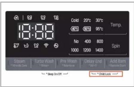
Select this function to lock the buttons on the control assembly to prevent tampering. "Child Lock" can be set only during the washing cycle.
text_image
18:00 Cold 20°C 30°C 40°C 60°C 95°C No 400 800 1000 1200 1400 Temp. Spin Steam Turbo Wash Pre Wash Delay End Add Item *Wise Safe *Brap *Non-None *VF-FI *Remove Start *Beep On/Off *Child LockLocking the control panel
- Touch and hold the Child Lock button for 3 seconds.
- A beeper will sound, and 'will appear on the LED display. When the child lock is set, all buttons are locked except the Power button.
NOTE
Turning off the power will not reset the child lock function. You must deactivate child lock before you can access any other functions.
text_image
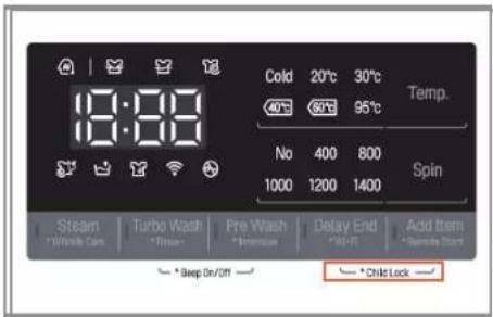
18:00 Cold 20°C 30°C Temp. 40°C 60°C 95°C No 400 800 Spin 1000 1200 1400 Steam Turbo Wash Fre Wash Delay End Add Item *Wrista Care *Rice *Minimum *All-R *Remove Start *Deep On/Off *Child LockUnlocking the control panel
- Touch and hold the Child Lock button for 3 seconds.
- A beeper will sound and the remaining time for the current programme will reappear on the LED display.
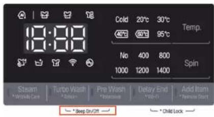
■ Beep On / Off
The Beep on/off function can be set only during the washing cycle.
text_image
19:00 Cold 20°C 30°C 40°C 60°C 95°C Temp. No 400 800 1000 1200 1400 Spin Steam Turbo Wash Pre Wash Delay End Add Item * Winner Care * Store * Postcare * Live-F * Newer Start * Deep Div/Off * Child Lock- Touch the Power button.
- Touch the Start/Pause button.
- Touch and hold the Temp. and Rinse button simultaneously for three seconds to set Beep on/off function.
Once the Beep on/off function is set, the setting is memorized even after the power is turned off.
NOTE
If you want to turn the Beeper off, simply repeat this process.
How to use washer
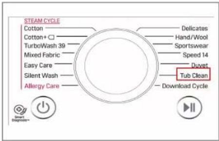
■ Tub Clean
Tub Clean is a special cycle to clean the inside of the washing machine.
A higher water level is used in this cycle at higher spin speed. Perform this cycle regularly.
text_image
STEAM CYCLE Cotton Cotton+ TurboWash 39 Mixed Fabric Easy Care Silent Wash Allergy Care Delicates Hand/Wool Sportswear Speed 14 Duvet Tub Clean Download Cycle Smart Diagneter- Remove any clothing or items from the washer and close the door.
- Open the dispenser drawer and add Anti limescale(e.g. Calgon) to the main wash compartment.
- Close the dispenser drawer slowly.
- Power On and select the Tub Clean. Then _c will be displayed on the display.
- Touch the Start/Pause button to start.
- After the cycle is complete, leave the door open to allow the washer door opening, flexible gasket and door glass to dry.
NOTE
Do not add any detergent to the detergent compartments.
Excessive suds may generate and leak from the washer.
CAUTION
If there is a child, be careful not to leave the door open for too long.
■ Door Lock & Detecting
text_image
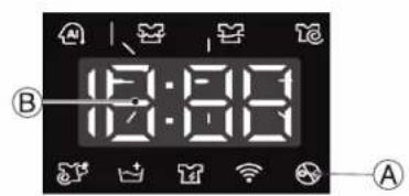
12:30 ② 12:30 ①Ⓐ "Door Lock" - For safety reasons, the door will lock while machine is in use and the "Door Lock" icon will light up. You can safely open the door after the "Door Lock" icon turns off.
⑧ While "Detecting" is shown on the display the washing machine rotates slowly and detects how much laundry is loaded in the drum.
It will take a short time.
6. WIRING DIAGRAM / PCB LAYOUT
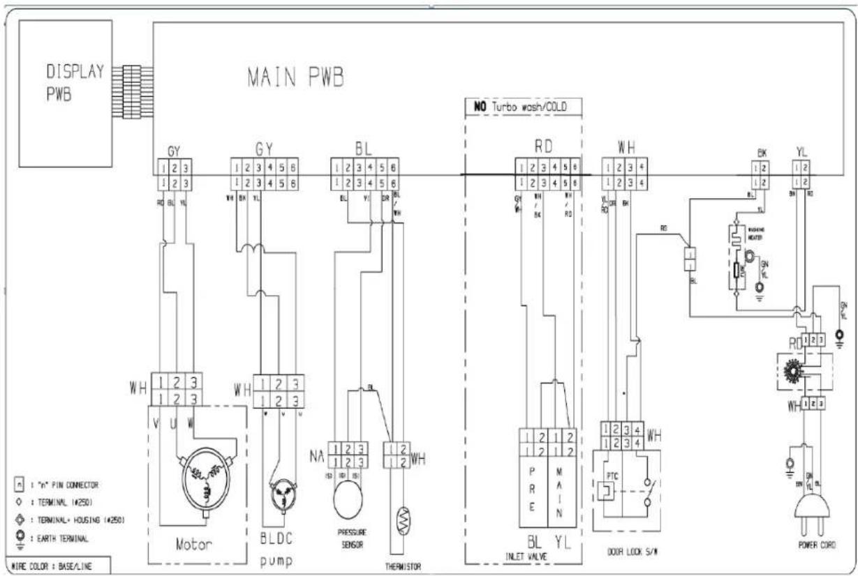
■ Wiring Diagram
text_image
DISPLAY PWB MAIN PWB GY 1 2 3 1 2 3 RD BL YL WH 1 2 3 1 2 3 V U W Motor BLDC pump BL 1 2 3 1 2 3 HA 1 2 3 1 2 3 Pressure SENSOR NA 1 2 3 1 2 3 R0 1 2 3 THERMISTOR RD 1 2 3 4 5 6 1 2 3 4 5 6 GH 1 2 3 4 5 6 WL RD BR WL INLET VALVE BL YL WH 1 2 3 4 1 2 3 4 P R E M A N PTC 1 2 3 4 WH DOOR LOCK S/W BK 1 2 1 2 RD WASING HEATER ON YL RL DN PL POWER CORD N : "N" PIN CONNECTOR ◇ : TERMINAL (4250) ◇ : TERMINAL + HOUSING (4250) ○ : EARTH TERMINAL MIRE COLOR : BASE/LINE■ PCB Layout (Main)
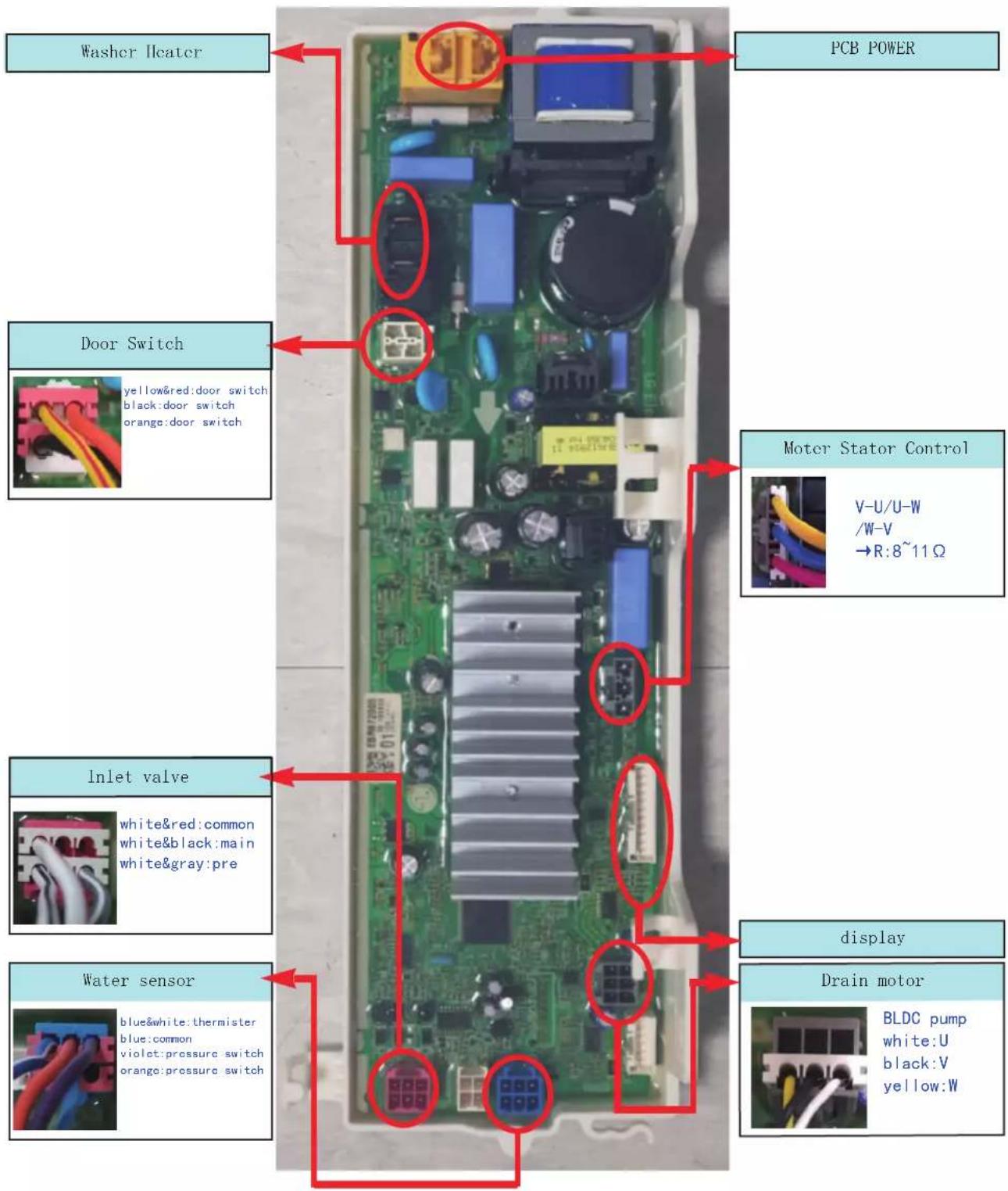
text_image
Washer Heater PCB POWER Door Switch yellow&red:door switch black:door switch orange:door switch Motor Stator Control V-U/U-W /W-V →R:8~11Ω Inlet valve white&red:common white&black:main white&gray:pre Water sensor blue&white:thermister blue:common violet:pressure switch orange:pressure switch display Drain motor BLDC pump white:U black:V yellow:W7. TROUBLESHOOTING
7-1. CHECK BEFORE SERVICE
① Before servicing ask the customer what the trouble is.
② Check the adjustments. (Power supply :220-240V\~, Removal of transit bolts etc..)
③ Check the troubles referring to the troublesome oting.
④ Decide service steps referring to disassembly instructions.
⑤ Then, service and repair.
⑥ After servicing, operate the appliance to see whether it works OK or NOT
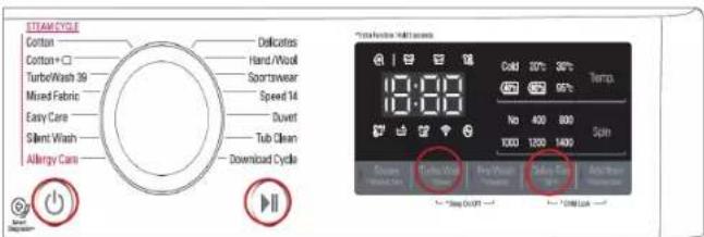
text_image
STEAM/Cycle Cotton Cotton+☐ TurboWash 39 Mixed Fabric Easy Care Silent Wash Allergy Care Delicates Hand/Wool Sportswear Speed 14 Duvert Tub Clean Download Cycle Temperature/Maximize 10:00 Cold 20°C 30°C Temp. No 400 800 SpH 1000 1200 1400 Close Close Close Close Close Close Off * DUM/LGA7-2. LOAD TEST MODE
① Turn on, and touch 'Rinse+' and 'Delay End' at the same time in 1 second.
② The washer must be empty and the controls must be in the off state.
③ Press Power with above two buttons pressed and then buzzer will sound.
④ Press the Start/Pause button repeatedly to cycle through the test modes
| Display StatusNumbers Check Point Remark | |||
| 0 | Turns on all light and locks the door. | PGM Version Information | |
| 1 | Tumble clockwise | rpm(42~50) | |
| 2 | Low speed spin | rpm (60) | |
| 3 | High speed spin | rpm (130~140) | |
| 4 | Inlet valve for prewash turns on. | Water level frequency | |
| 5 | Inlet valve for main wash turns on. | Water level frequency | |
| 6 | Inlet valve for hot water turns on. | Water level frequency | For Hot&Cold Model |
| 7 | Inlet valve for atomizing turn on. | Water level frequency | |
| 8 | Tumble counterclockwise | rpm | |
| 9 | Heater turns on for 3 sec. | Water temperature | |
| 10 | Drain pump turns on. | Water level frequency | |
| 11 | Off | - | |
7-3. HOW TO CHECK THE WATER LEVEL FREQUENCY
Touch the Spin and RINSE+ button simultaneously.
Keeping touch, the digits indicate the water level frequency.
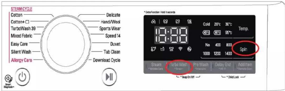
text_image
STEAM CYCLE Cotton Delicate Cotton+ □ Hand/Wool TurboWash 39 Sports Wear Mixed Fabric Speed 14 Easy Care Duvet Silent Wash Tub Clean Allergy Care Download Cycle * Extra Function : Held 3 seconds 18:00 Cold 20°C 30°C Temp. 40°C 60°C 95°C No 400 800 Spin 1000 1200 1400 Steam Turbo Wash Pre Wash Delay End Add Item * Washing Gas * Batch Stop * New Test * Deep On Off * Child Lock7-4. ERROR DISPLAY
- If you press the Start/Pause button in error condition, any error except will disappear and the machine will change into the pause status.
- In case of ( \text{PE}_\text{,} \text{, if the error is not resolved within 20 sec., and in case of all other errors, if the error is not resolved within 4 min., the power will turn off automatically and the error only will blink. But in the case of ( FE_\text{,} \text{, the power will not turn off.} )
| ERROR SYMPTOM CAUSE | |||
| 1 | WATER INLET ERROR |  | Not reached the water level(248) within 10 minutes after water supplied or not reached to the preset water level within 25 minutes. Page 24 |
| 2 | WATER OUTLET ERROR | 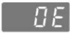 | Not fully drained within 10 minutes. Page 26 |
| 3 | OVERFLOW ERROR |  | Water is overflowing (under 21.3kHz).※ If " " is displayed, the drain pump operates to drain the water automatically. Page 28 |
| 4 | PRESSURE SENSOR S/W ERROR | 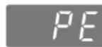 | The pressure sensor switch is out of order. Page 29 |
| 5 | DOOR OPEN ERROR | 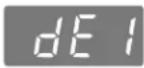 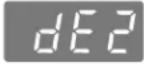 | In case of operating the reservation function or the other function with door opened. Close the door, then the error display is resolved.The door switch is out of order. Page 31 |
| 6 | UNBALANCE ERROR |  | The appliance is tilted.Laundry is gathered to one side. Page 25 |
| 7 | THERMISTOR(HEATING) ERROR |  | The THERMISTOR is out of order. Page 33 |
| 8 | MOTOR LOCKED ERROR |  | The connector in the LEAD WIREASSEMBLY is not connected to the connector of STATOR ASSEMBLY.Reconnect or repair the connector.Page 36 |
| 9 | POWER FAILURE |  | The washer experienced a power failurePress the start/pause button |
| 10 | NFC MODULE ERROR |  | The connector in the DISPLAY PCB ASSEMBLY is not connected to the connector of NFC PCB ASSEMBLY.Reconnect or repair the connector.The NFC HARNESS between the NFC PCB ASSEMBLY and DISPLAY PCB ASSEMBLY is cut (open circuited).Replace the DISPLAY PCB ASSEMBLY.The NFC PCB ASSEMBLY is out of order/defective.Replace the NFC PCB ASSEMBLY.* nC is displayed only in the first screen of the Load Test Mode. |
| 11 | NFC VERSION ERROR |  | NFC version is not matched.Replace the NFC PCB ASSEMBLY.* nU is displayed only in the first screen of the Load Test Mode. |
7-5. TROUBLESHOOTING WITH ERROR
| Symptom Check Point | |
| 1.INLET VACNeck Electric ERROR | Wiring.2.Check Inlet valve's Resistance.3.Check Inlet valve clogged.4.Voltage of the inlet valve's connector.-Valve running : 12Vdc ± 5% |

text_image
Pre wash Main wash
natural_image
Red plastic container with multiple compartments, no visible text or symbols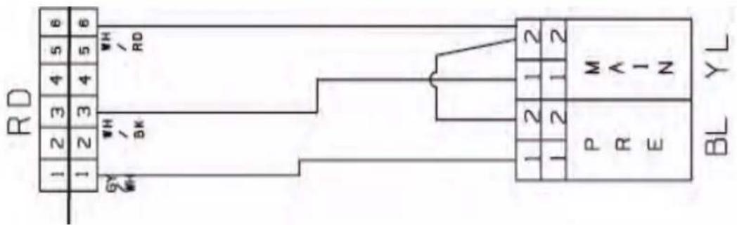
text_image
RD 1 2 3 4 5 6 1 2 3 4 5 6 WH RD WH BK 1 2 1 2 1 2 1 2 P M R ∧ - N E BL YLWater Inlet Error (IE)
[Note] Environmental safety check list
-
No water tap leakage or freeze
-
No entanglement of water supply hose.
-
No water shortage.
-
No water supply hose leakage
-
The inlet filter is not cloggeed.
Is the water tap closed?
YES
Check the Water tap and open it fully.

NO
When there is water in the tub, is the water level frequency over 26.0khz?
YES
Check the Air Chamber and the Tube (clogged) Check the water level frequency again, if it is over 26.2KHz, replace the Pressure switch.
NO
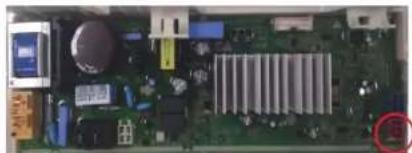
Is the Connector connected correctly to the Main PCB and the Inlet Valve? is the Harness alright?
natural_image
Close-up of an electronic circuit board with various components and a highlighted connection point (no readable text or symbols)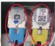
NO
Reconnect or repair the Connector. Or replace the Harness.
YES
Is the resistance of each Inlet valve within 3.5 \~4.5 kΩ
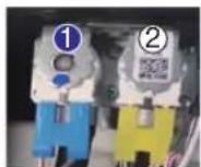
① Pre Valve
② Main Valve
NO
Replace the Inlet Valve.
YES
When the washing machine is started, is the inlet valve operating?
NO
Replace the Main PCB.
Unbalanced Error (UE)
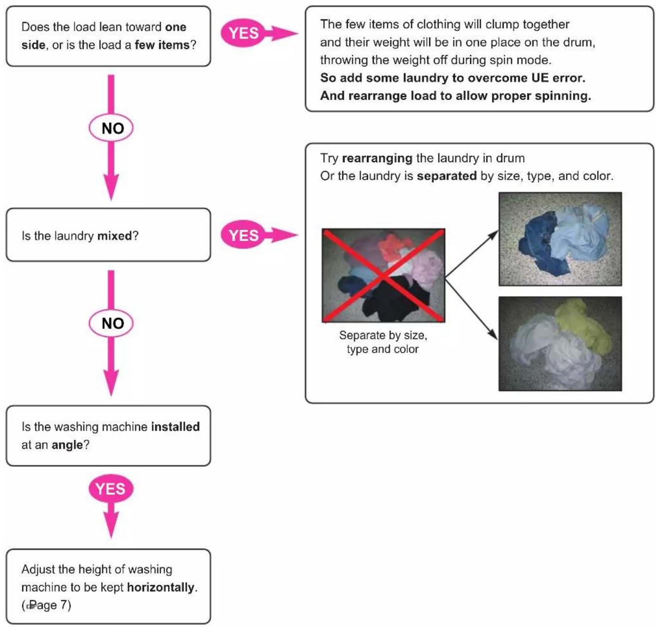
flowchart
graph TD
    A["Does the load lean toward one side, or is the load a few items?"] --> B{NO}
    B --> C["Is the laundry mixed?"]
    C --> D{NO}
    D --> E["Is the washing machine installed at an angle?"]
    E --> F{YES}
    F --> G["Adjust the height of washing machine to be kept horizontally. (Page 7)"]

    H["The few items of clothing will clump together and their weight will be in one place on the drum, throwing the weight off during spin mode.<br>So add some laundry to overcome UE error.<br>And rearrange load to allow proper spinning."] --> I["Yes"]
    J["Try rearranging the laundry in drum<br>Or the laundry is separated by size, type, and color."] --> K["Separate by size, type and color"]
    K --> L["Image 1"]
    K --> M["Image 2"]
Water Outlet Error (OE)
Is the drain hose kinked?

Check drain hose for kink and straighten the Hose.
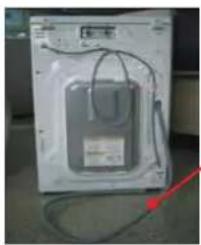
natural_image
Exterior view of a white washing machine casing with visible wiring and a red arrow pointing to the side (no text or symbols)Drain Hose
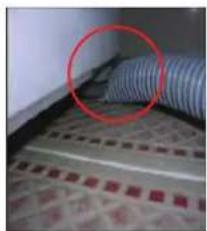
natural_image
Close-up of a blue coiled cable with a red circle highlighting its position, placed on a textured surface (no visible text or symbols)
Is the Pump filter clogged?

Check & Clean Pump Filter.
This kind of accumulation on the drain filter not only prevents proper drainage, but also will promote bacteria growth and cause odors.
This drain filter should be cleaned once a month.

Next Page
* How to disassemble and clean pump filter
Open the Cover by coin or finger(only new model)
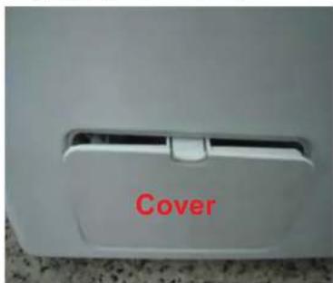
text_image
CoverDrain water by removing the hose cap.
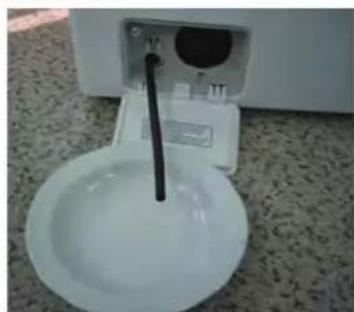
natural_image
White appliance with a straw inserted into a bowl on a textured floor (no visible text or symbols)Disassemble the pump filter by turning the filter cap counterclockwise.
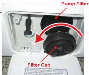
text_image
Pump Filter Filter CapFilter clogged by foreign objects Assemble & the set cap
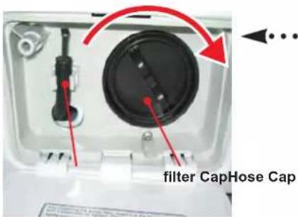
text_image
filter CapHose Cap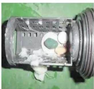
natural_image
Interior view of a mechanical component with visible internal structure and surrounding debris (no text or symbols)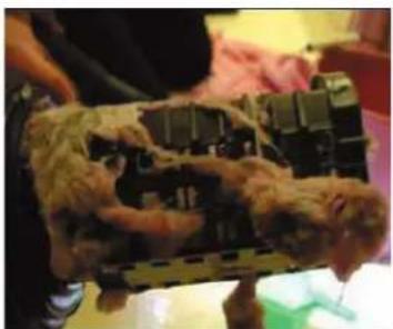
natural_image
Person holding a model of an animal-like object with visible internal structures (no text or symbols)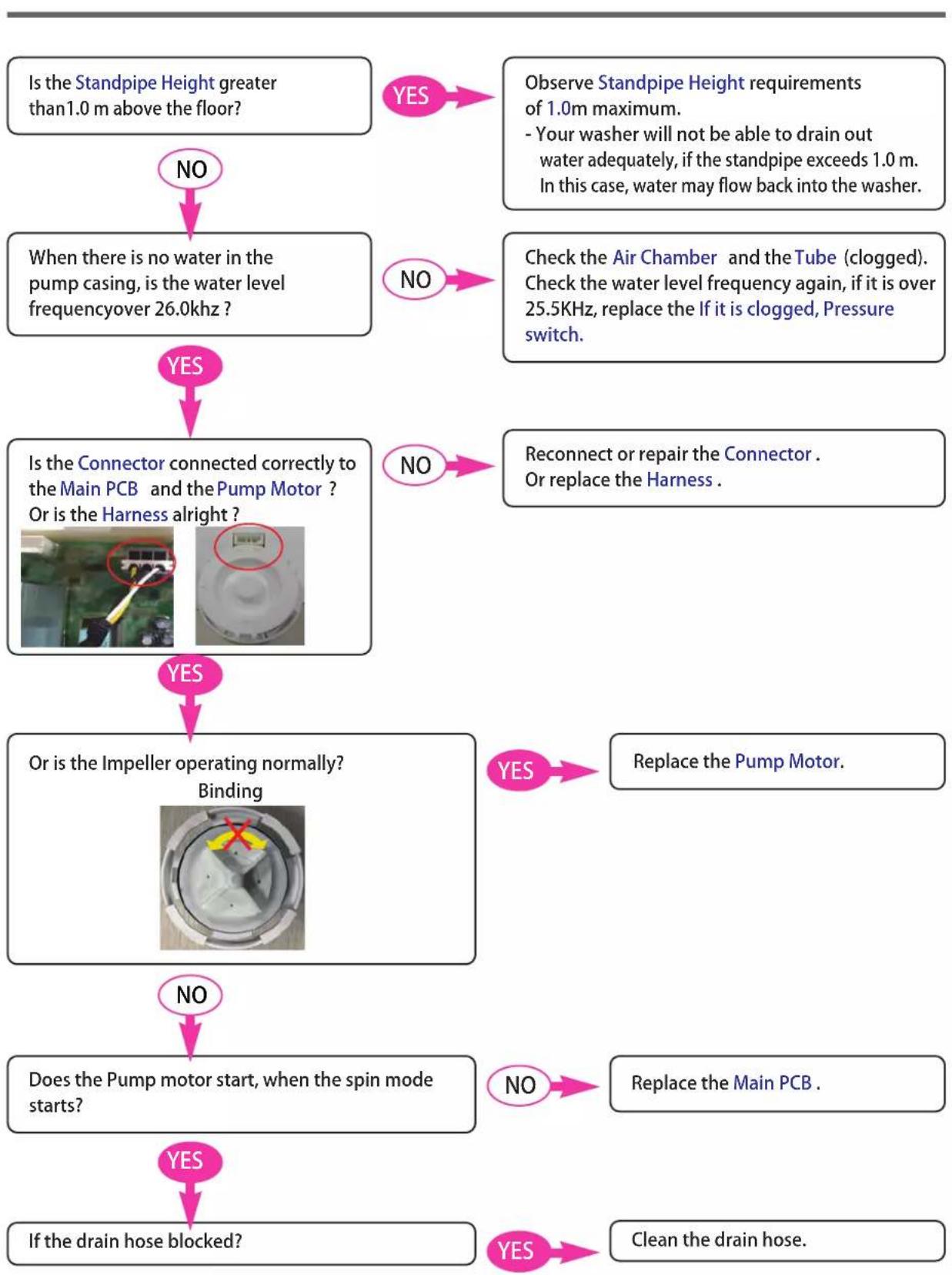
flowchart
graph TD
    A["Is the Standpipe Height greater than 1.0 m above the floor?"] -->|NO| B["When there is no water in the pump casing, is the water level frequency over 26.0kHz?"]
    B -->|YES| C["Is the Connector connected correctly to the Main PCB and the Pump Motor ? Or is the Harness alright?"]
    B -->|NO| D["Check the Air Chamber and the Tube (clogged). Check the water level frequency again, if it is over 25.5KHz, replace the If it is clogged, Pressure switch."]
    C -->|YES| E["Or is the Impeller operating normally? Binding"]
    C -->|NO| F["Reconnect or repair the Connector . Or replace the Harness ."]
    E -->|YES| G["Does the Pump motor start, when the spin mode starts?"]
    E -->|NO| H["Replace the Pump Motor."]
    G -->|YES| I["If the drain hose blocked?"]
    G -->|NO| J["Replace the Main PCB ."]
    H -->|YES| K["Clean the drain hose."]
FE (Overflow Error)
Power off for 10sec. Then power on.
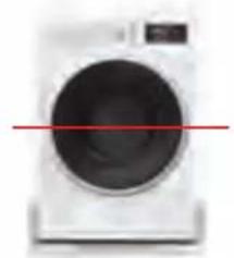
Is the water level over reference line and is the water level f requency under 21.3kHz?
natural_image
Front view of a white washing machine with a red horizontal line indicating a measurement or threshold (no visible text or symbols)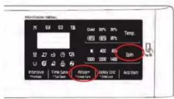
text_image
Control Panel Status 75 62 58 100 20% 30% Temp -850 0.05 90°C 400 800 Spin 1000 1200 1400 Internal Time Gain Pulse Rate Pulse Rate Reset Item Pulse+ Delay Grid Reset Use* Water level frequency
- Touch and Hold 'Spin' & 'Rinse+' simultaneously.
NO
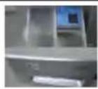
Is water continuously coming into the drawer?
YES
Drain out the water and then check the Air Chamber and the Tube (clogged).
YES
NO
Replace the Main PCB.
If FE is displayed again, then replace the Pressure Switch.
Replace the Inlet Valve assembly.
If FE is displayed again, then replace the Main PCB.
Pressure Sensor S/W Error (PE)
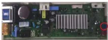
Is the Connector connected correctly to the Main PCB and the Pressure Switch? Is the Harness alright?
natural_image
Close-up of an electronic circuit board with various components and a highlighted circular component (no visible text or symbols)NO
Reconnect or repair the Connector. Or replace the Harness.
YES
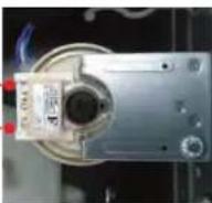
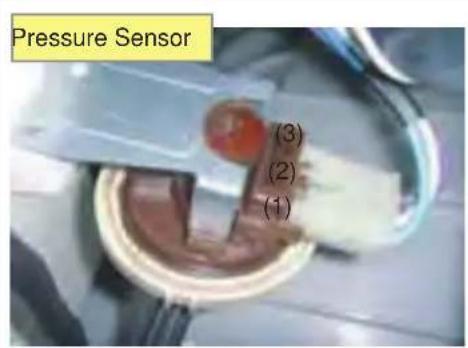
Is the resistance of the Pressure Switch out of range?
[Pin1 \~ Pin3]
→21\~23
YES
Replace the Pressure Switch.
NO
Is the air chamber and the tube clogged?
YES
Check air chamber and remove foreign material.
NO
Replace the Main PCB.
| Symptom Check Point | |
| 1.PRESSURESENSORERROR(PE) | 1.Check Electric Wiring.2.Check Pressure sensor's Resistance.3.Check Air Chamber and Tubeclogged. |
text_image
Pressure Sensor (3) (2) (1)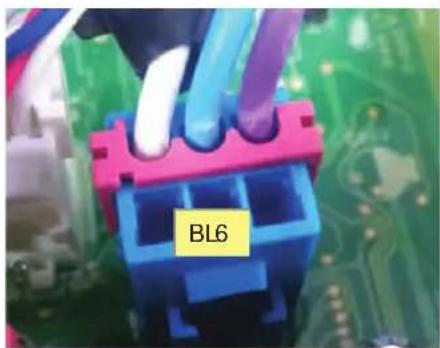
text_image
BL6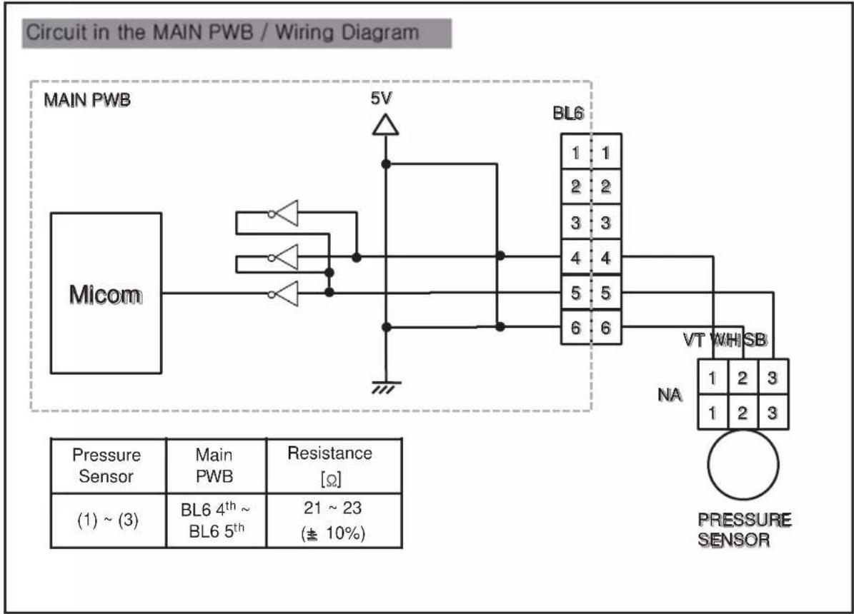
flowchart
graph TD
    A["Micom"] --> B["5V"]
    B --> C["BL6"]
    C --> D["VT"]
    D --> E["WHSB"]
    E --> F["Pressure Sensor"]
    F --> G["Main PWB"]
    F --> H["Resistance [Ω"]]
    G --> I["(1) ~ (3)"]
    H --> J["(21 ~ 23 (± 10%))"]
    style A fill:#f9f,stroke:#333
    style B fill:#ccf,stroke:#333
    style C fill:#cfc,stroke:#333
    style D fill:#fcc,stroke:#333
    style E fill:#cff,stroke:#333
    style F fill:#ffc,stroke:#333
    style G fill:#cfc,stroke:#333
    style H fill:#cfc,stroke:#333
    style I fill:#fff,stroke:#333
    style J fill:#fff,stroke:#333
    style_K["MAIN PWB"] --> L["Micom"]
    style_M["Pressure Sensor"] --> N["Main PWB"]
    style_O["Resistance [Ω"]] --> P["(1) ~ (3)"]
    style_Q["Pressure Sensor"] --> R["Main PWB"]
    style_S["Resistance [Ω"]] --> T["(21 ~ 23 (± 10%))"]
    style_U["Pressure Sensor"] --> V["Main PWB"]
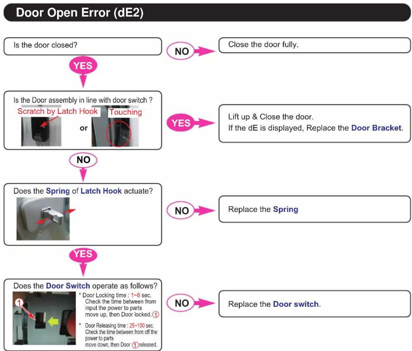
flowchart
graph TD
    A["Is the door closed?"] --> B{YES}
    B --> C["Is the Door assembly in line with door switch ?<br>Scratch by Latch Hook or Touching"]
    C --> D{NO}
    D --> E["Does the Spring of Latch Hook actuate?"]
    E --> F{YES}
    F --> G["Does the Door Switch operate as follows?\n* Door Locking time : 1~8 sec. Check the time between from input the power to parts move up, then Door locked. ①<br>* Door Releasing time : 25~100 sec. Check the time between from off the power to parts move down, then Door ① released."]
    G --> H{NO}
    H --> I["Replace the Spring"]
    I --> J["Close the door fully."]
    J --> K["Yes"]
    K --> L["Lift up & Close the door.<br>If the dE is displayed, Replace the Door Bracket."]
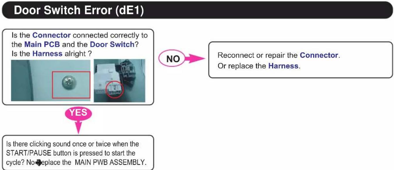
flowchart
graph TD
    A["Is the Connector connected correctly to the Main PCB and the Door Switch? Is the Harness alright ?"] --> B{NO}
    B -->|Yes| C["Is there clicking sound once or twice when the START/PAUSE button is pressed to start the cycle? No replace the MAIN PWB ASSEMBLY."]
    B -->|No| D["Reconnect or repair the Connector. Or replace the Harness."]
| Symptom Check Point | |
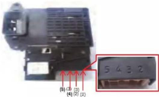
| 1. DOOR OPEN ERROR(dE) | 1.Check Electric Wiring.2.Check latch hook sping.(Cracked)3.Check Door switch's Resistance.4.Check Voltage of Door switch's connector. |
text_image
5 4 3 2 (5) (3) (3) (4) (2) (2)Circuit in the MAIN PWB / Wiring Diagram
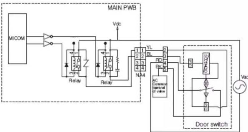
flowchart
graph TD
    A["MICOM"] --> B["Resistor"]
    B --> C["Relay"]
    C --> D["Main PWB"]
    D --> E["Valve"]
    E --> F["AC Common terminal of valve"]
    F --> G["Door switch"]
    G --> H["Vac"]
    D --> I["RLay"]
    I --> J["Main PWB"]
    J --> K["Vdc"]
    style A fill:#f9f,stroke:#333
    style D fill:#ccf,stroke:#333
    style G fill:#cfc,stroke:#333
| Door switch (Type2) | Result Remark | |
| (2) ~ (4) 700 | ~1500 Ω | At 77 (25 ) |
| (3) ~ (4) | 90~120Ω | At 77 (25 ) With Latch |
| Infinity Without Latch | ||
| (4) ~ (5) Infinity | ||
| (2) ~ (4) 230 | Vac Voltage Input | |
Thermistor (Heating) Error (tE)
Is the Connector connected correctly to the Main PCB and the Thermistor and the Heater? Is the Harness alright?
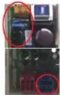
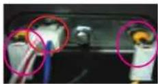
Heater for Washing
YES
Reconnect or repair the Connector. Or replace the Harness.
NO
Is the resistance of the Thermistor out of range 44 \~ 53 K at 25°C? (Page 17)
YES
Replace the Thermistor.
NO
Is the resistance of the Heater out of range 24.5 \~ 28.5 (for Washing) ? (Page 19)
YES
Replace the Heater.
NO
Replace the Main PCB.
[Note] Thermistor Spec
| SPEC | Temp | Resistance (kΩ) | ||
| MIN | STD MAX | |||
| 30°C | 36.35 39 | 45 42.72 | ||
| 40°C | 24.20 26 | 05 27.97 | ||
| 60°C | 11.43 12 | 12 12.82 | ||
| 70°C | 8.088 8.5 | 14 8.940 | ||
| 95°C | 3.544 3.7 | 91 4.045 | ||
| 105°C | 2.617 2.8 | 16 3.023 | ||
| Symptom Check Point | |
| 1. HEA TING ERROR(tE) | 1. Check Electric Wiring.2. Check Heater's Resistance.3. Check Thermistor's Resistance.4. Water Leaked into the Thermistor's Connector. |
Wash Heater
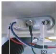
natural_image
Close-up of a small electronic device with wires and connectors, labeled (2), no visible text or symbols on the main subject.(i)
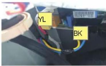
text_image
YL BKCircuit in the MAIN PWB
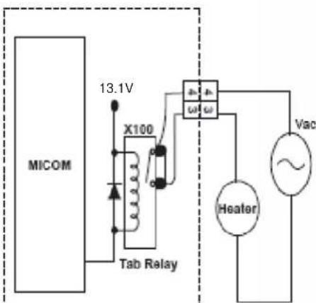
text_image
MICOM 13.1V X100 Tab Relay Heater VacHeater driving circuit
| Heater | Main PWB | Resistance [Ω] |
| Wash Heater (1) ~ (2) | BK 3 ^th ~ YL 3 ^th | 12 ~ 18 |

text_image
Wash Thermistor (1) (2)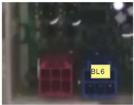
text_image
BL6| Thermistor | Main PWB | Resistance [kΩ] | Remarks °F (°C) |
| Wash Thermistor (1) ~ (2) | NA3 4th~ NA3 5th | 39.5 86(30) | |
| 26.1 104(40) | |||
| 12.1 140(60) | |||
| 8.5 158(70) | |||
| 3.8 203(95) | |||
| 2.8 221(105) | |||
Motor Locked Error (LE)
[Pre Check]
- Gentle wash cycles, such as Perm Press, Delicates, Hand Wash, and Wool/Silk should only be used for smaller loads. Because these cycles are more gentle in tumbling and spinning, putting too much in the drum can register an issue with the motor. Remove items, reset unit and test with a Rinse/Spin cycle.
Press the Power button & Start / Pause button.
Does the Drum stop when the start/pause button is pressed to start the cycle?
Or Sometimes does the Drum rotate weakly (under 15rpm)?
YES
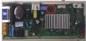
Is the Connector connected correctly to the Main PCB and the Motor?
Is the Harness alright?
natural_image
Close-up of an electronic circuit board with visible components and a red circle highlighting a specific area (no text or symbols)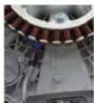
NO
Reconnect or repair the Connector. Or replace the Harness.
YES
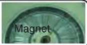
Disassemble the Rotor.
Is the Magnet of rotor cracked or broken?
YES
Replace the Rotor.
NO
Is the resistance the same between Stator points?
※ V\~U / U\~W / W\~V : 8\~11Ω


NO
Replace the Stator.
YES
Replace the Main PCB.
| Symptom Check Point |
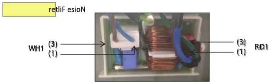
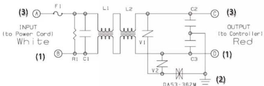
| 1. NO POWER 1.Check Electric Wiring.2.Check the Customer's outlet.3.Check Noise Filter.4.Check LED on in Main PWB |
text_image
retliF esioN WH1 (3) (1) RD1 (3) (1)Circuit in the MAIN PWB / Wiring Diagram
text_image
(3) INPUT (to Power Cord) White (1) A F1 L1 L2 C2 C OUTPUT (to Controller) Red (1) B R1 C1 V1 C3 D (2) (2) V2 DA53-362M| Noise Filter | Resistance [Ω] |
| WH1 (1) ~ RD1 (3) 0 | |
| WH1 (3) ~ RD1 (1) 0 |
8. TROUBLESHOOTING WITHOUT ERROR CODES
PF (Power Failure or no power)
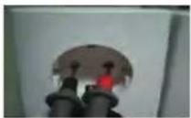
Is the Power Plug connected firmly to the power outlet? And is the supply voltage 220\~240V AC?
NO
Reconnect Power Plug firmly. Check the fuse or reset the circuit breaker.
YES
Is Multi-plug socket used?

YES
Don't use Multi-plug socket. Use Single Plug socket for washing machine.
NO
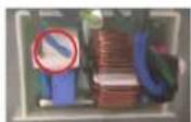
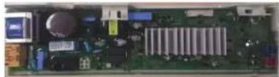
Is the Connector connected correctly to the Main PCB and the Noise Filter? Is the Harness alright?
Noise Filter
natural_image
Interior view of an electronic circuit board with various components (no visible text or labels)PCB
NO
Reconnect or repair the Connector. Or replace the Harness.
YES
Is Red LED ON while power supplied?
NO
Check and replace Main PCB.
YES
Is the connectors connected Correctly to the Display PCB?
Main PCB
Noise Filter
YES
Check connectors otherwise. Replace Display PCB.
Vibration & Noise During Spin
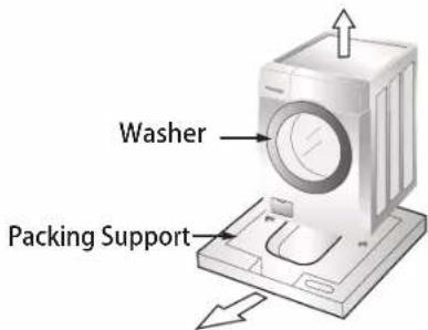
Have all the Transit Bolts been removed?
text_image
Washer Packing SupportNO
Remove the Transit Bolts
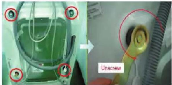
natural_image
Medical procedure image showing a device with red circles highlighting a component and a labeled 'Unscrew' (no text or symbols on main subject)YES
Refer to INSTALLATION . (Page 7)
Detergent & Softener does not flow in
Is water supplied?
NO

Refer to [Water Inlet Error (IE)]
(page 23)
YES
Is detergent & softener put in the correct compartment of the drawer?
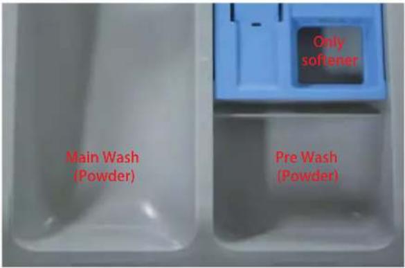
text_image
Main Wash (Powder) Only softener Pre Wash (Powder)NO

Put it in the Correct Position.
※ Reference (Amount of Detergent & Softener)
YES
Is the Detergent caked or hardened?
Detergent
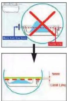
text_image
Main Plate Grey Sensor Lower Line Screen Lower LineNO!!
Softener
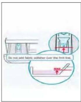
text_image
Do not add fabric adhesive over the limit line. MAXYES
Clean the drawer and dispenser.

※ Check point
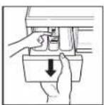
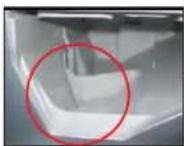
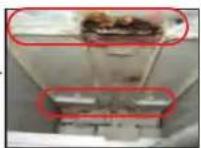
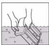
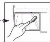
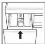
Water Leak
1. Water Leak from Dispenser
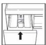
Is the Dispenser Tray Damaged or warped?
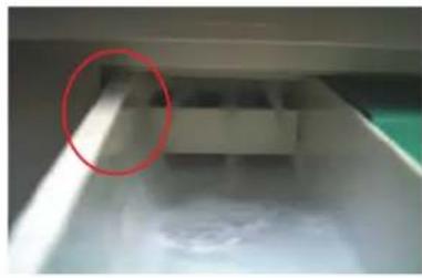
natural_image
Interior view of a storage or warehouse with a highlighted circular area (no visible text or symbols)YES
Replace the Dispenser Tray.
NO
Is detergent & softener put in the correct compartment of the drawer?
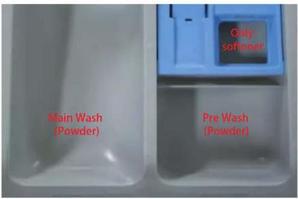
text_image
Main Wash (Powder) Only softener Pre Wash (Powder)NO
Put it in the Correct Position.
YES
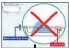
Is the Detergent caked or hardened?
※ Reference (Amount of Detergent & Softener)
Detergent
Softener
NO!!
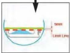
text_image
5mm Limit Line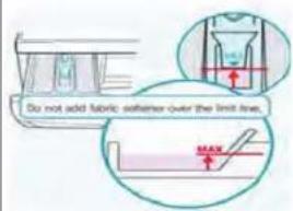
text_image
Do not add fabric softener over the limit line. MAXYES
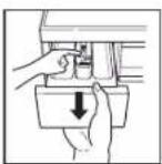
Clean the drawer and dispenser.

※ Check point
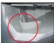
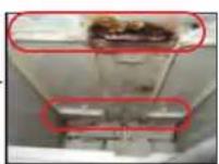
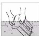
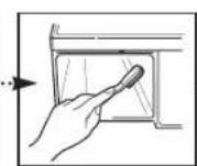
2. Water Leak from Dispenser
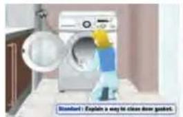
Are the gasket (seal) and door cleaned regularly?

Is the door or gasket damaged?

Clean the periphery of Gasket and Door regularly.
natural_image
Exterior view of a washing machine with a handbag and cloth, no visible text or symbols on the main subject.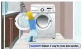
natural_image
Illustration of a person cleaning a washing machine (no text or symbols visible)
Replace the damaged parts.
3. Unknown – Water on Floor
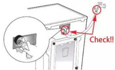
Are the inlet hoses loose or cracked/split?
text_image
Check!!
Replace the Inlet Hoses.

Is the washer horizontal?

Adjust the height of washing machine to be kept horizontally. (Page 7)

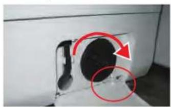
Are the drain filter and manual drain hose open?

Turn the filter cap clockwise to close.
natural_image
Close-up of a car vent with red arrows indicating direction and a circled area, no visible text or symbolsBefore using the Wi-fi function
Application Installation
Search for the LG Smart ThinQ application from the Google Play Store on a smart phone. Follow instructions to download and install the application.
Product Registration
1 Run the LG Smart ThinQ application on a smart phone.
2 Create an account and sign in.
3 Select Register.
4 Select Front Load Washer.
5 Follow the instruction on the smart phone.
NOTE
- To verify the Wi-Fi connection, check the Wi-Fi icon(💡) on the control panel is lit.
- LG Smart ThinQ is not responsible for any network connection problems or any faults, malfunctions, or errors caused by network connection.
- The machine supports 2.4 GHz Wi-Fi networks only.
- If the appliance is having trouble connecting to the Wi-Fi network, it may be too far from the router. Purchase a Wi-Fi repeater (range extender) to improve the Wi-Fi signal strength.
- The Wi-Fi connection may not connect or may be interrupted because of the home network environment.
- The network connection may not work properly depending on the internet service provider.
- The surrounding wireless environment can make the wireless network service run slowly.
- The application is subject to change for appliance improvement purposes without notice to users.
Using the Wi-Fi Function
Communicate with the appliance from a smart phone using the convenient smart features.
Using the Application
1 Select the appliance in the application.
2 Select the menu on the upper right side to access settings and features.
Washer Cycle
Set or download any perferred cycle and operate by remote control.
Tub Clean Coach
Check the appropriate Tub Clean period by washing frequency.
Energy Monitoring
Check the energy consumption of the recently used cycles and monthly average.
Smart Diagnosis
This function provides useful information for diagnosing and solving issues with the appliance based on the pattern of use.
Settings
Various functions are available.
Push Alert
Turn on the Push Alerts to receive appliance status notifications. The notifications are triggered even if the LG Smart ThinQ application is off.
Open Source Software Notice Information
To obtain the source code under GPL, LGPL, MPL, and other open source licenses, that is contained in this product, please visit http://opensource.lge.com.
In addition to the source code, all referred license terms, warranty disclaimers and copyright notices are available for download.
LG Electronics will also provide open source code to you on CD-ROM for a charge covering the cost of performing such distribution (such as the cost of media, shipping, and handling) upon email request to opensource@lge.com. This offer is valid for three (3) years from the date on which you purchased the product.
Declaration of Conformity CE
Hereby, LG Electronics European Shared Service Center B.V., declares that this Washing machine is compliant with the essential requirements and other relevant provisions of Directive 1999/5/EC. The complete Declaration of Conformity may be requested through the following postal address:
LG Electronics European Shared Service Center B.V.
Krijgsman 1
1186 DM Amstelveen
The Netherlands
or can be requested at our dedicated DoC website: http://www.lg.com/global/support/cedoc/cedoc#
This device is a 2.4 GHz wideband transmission system, intended for use in all EU member states and EFTA countries.
For consideration of the user, this device should be installed and operated with a minimum distance of 20 cm between the device and the body.
Wireless LAN Module Specifications
| Model LCW-004 | |
| Frequency Range | 2412~2472 MHz |
| Output Power (Max.) | IEEE 802.11 b : 17.82 dBm |
| IEEE 802.11 g : 17.72 dBm | |
| IEEE 802.11 n : 16.61 dBm | |
Using the Smart Diagnosis™ Function
Should you experience any problems with the appliance, it has the capability of transmitting data to a smart phone using the LG Smart ThinQ application or via the phone to the LG Customer Information Centre.
Smart Diagnosis ^™ can not be activated unless the appliance is turned on by pressing the Power button. If the appliance is unable to turn on, then troubleshooting must be done without using Smart Diagnosis ^™ .
Smart Diagnosis™ Using a Smart Phone
1 Open the LG Smart ThinQ application on the smart phone.
2 Select the appliance and then the menu on upper right side.
3 Select the Smart Diagnosis, then press Start Smart Diagnosis button.
NOTE
- If the diagnosis fails several times, use the following instructions.
4 Select the Try Again or Audible Diagnosis.
5 Follow the instructions on the smart phone.
6 Keep the phone in place until the tone transmission has finished. View the diagnosis on the phone.
Smart Diagnosis™ Through the Customer Information Centre
1 Press the Power button to turn on the washing machine. Do not press any other buttons or turn the programme knob.
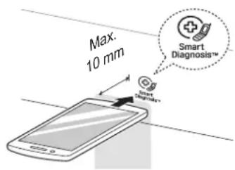
2 When instructed to do so by the call center, place the mouthpiece of your phone close to the Power button.
text_image
Max. 10 mm Smart Diagnosis™ Smart Diagnosis™3 Press and hold the Temp. button for 3 seconds, while holding the phone mouthpiece to the icon or Power button.
4 Keep the phone in place until the tone transmission has finished. Time remaining for data transfer is displayed.
- For best results, do not move the phone while the tones are being transmitted.
- If the call centre agent is not able to get an accurate recording of the data, you may be asked to try again.
5 Once the countdown is over and the tones have stopped, resume your conversation with the call centre agent, who will then be able to assist you using the information transmitted for analysis.
NOTE
- The Smart Diagnosis™ function depends on the local call quality.
- The communication performance will improve and you can receive better service if you use the home phone.
- If the Smart Diagnosis™ data transfer is poor due to poor call quality, you may not receive the best Smart Diagnosis™ service.
9. Part inspection
▲ WARNING
When Resistance (Ohm) checking the Component, be sure to turn the power off, and do voltage discharge sufficiently.
9-1. FILTER ASSEMBLY (LINE FILTER)
| Wiring diagram | Circuit in the MAIN PWB / Wiring Diagram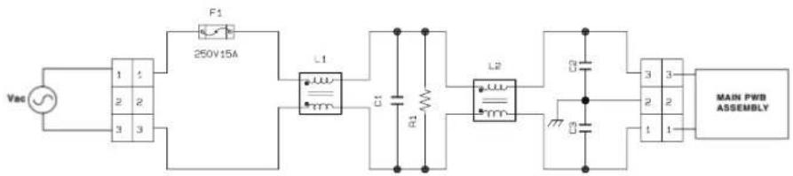 |
| Test points and Result | 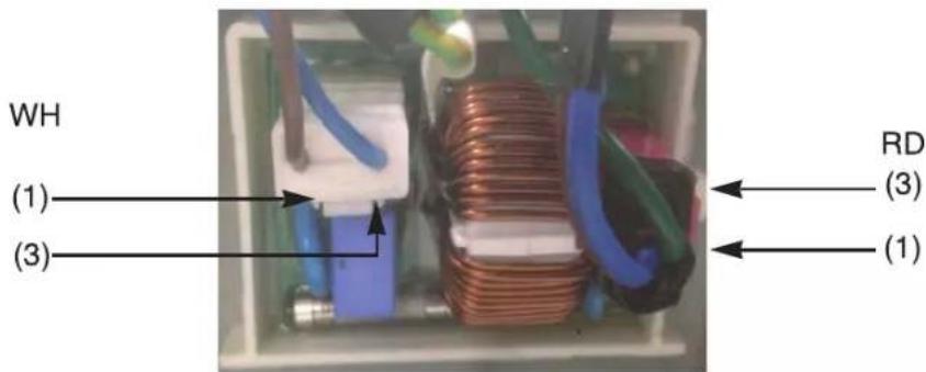 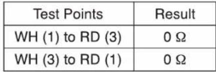 |
9-2. DOOR LOCK SWITCH ASSEMBLY
| Wiring diagram | Circuit in the MAIN PWB / Wiring Diagram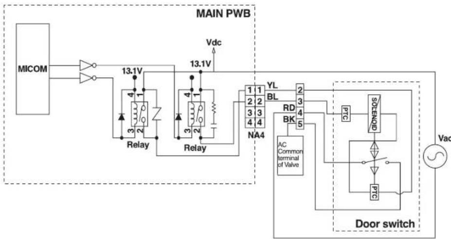 | ||
| Function | The Door Lock Switch Assembly consists of a Heating PTC, a Bimetal, a Protection PTC, and a Solenoid. It locks the door during a wash cycle.1. Operation for door closing- After the system turns on, PTC heating starts up through terminal 2~4's authorizing the power on.- After PTC heating starts up and before solenoid operation is driven, force the system to the off position through CAM.⇒ Door close- Authorizing one impulse through terminal 3~4 (PTC & solenoid) will make the door lock.- Door lock is detected when switches in terminal 4~5 are set closed.⇒ CAM rotation will forcibly clear off the connection.The maximum, allowable number of impulse authorizations is 2.⇒ Upon the third authorization of the impulse, the position of CAM goes back to the door-open position.- Authorizing the impulse occurs in 4.5 seconds upon input for max performance and two authorization processes are allowed at most.⇒ Normal operation period of PTC heating: 1.5 – 5 seconds.(Defects from the development process.)2. Operation for door opening- With a temporary stop, door automatically opens by CAM rotations after authorizing the impulse from the terminal 3 ~ 4 and the power turns off – maximum of 3 times of the authorizing period.- Upon the fourth authorization of the impulse, the position of CAM goes back to the door-close position. | ||
| Test points | 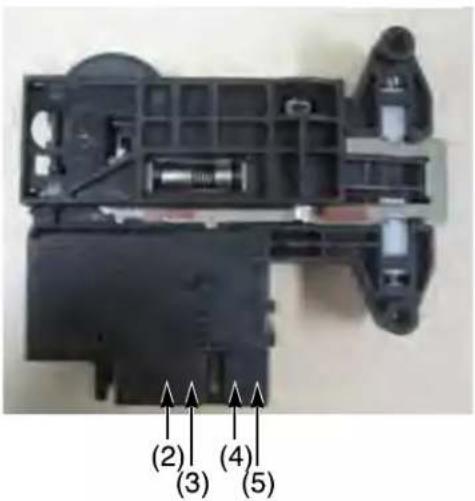 | ||
| Result | |||
| Test Points | Result | Remarks | |
| (2) to (4) | 700-1500 Ω | At 77°F (25°C) | |
| (3) to (4) | 60-90 Ω | At 77°F (25°C) | |
| (4) to (5) | Infinity | ||
| (2) to (4) | 120 Vac | Voltage Input | |
9-3. STATOR ASSEMBLY
| Wiring diagram | Circuit in the MAIN PWB / Wiring Diagram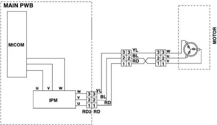 | |
| Function | The DD motor can be driven from stopped to maximum speed in infinite steps in either direction.There are 36 poles on the stator; 12 permanent magnets spaced around the rotor.There are no brushes to wear out. Unlike a more traditional brushless motor, the rotor surrounds the stator rather than being attached to it. | |
| Test points (Windings) | 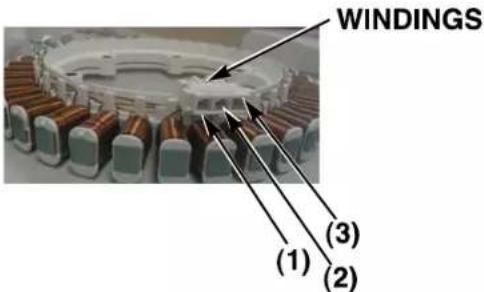 | |
| Result (Windings) | Test Points | Result |
| (1) to (2) | 5-15 Ω | |
| (2) to (3) | 5-15 Ω | |
| (3) to (1) | 5-15 Ω | |
10. DISASSEMBLY INSTRUCTIONS
* Remove the power cord from the outlet before disassembling or repairing the unit.
CONTROL PANEL ASSEMBLY
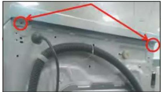
Screws
natural_image
Close-up of a mechanical component with coiled tubing and a red annotation arrow pointing to a specific area (no text or symbols visible)
natural_image
Two-panel photo showing a white microwave oven and a black appliance on a stand, both without any visible text or symbols.
natural_image
Two-panel image showing a person operating a device near a window, and another close-up of a device with red buttons (no visible text or symbols)
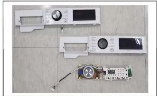
natural_image
Top-down view of three white plastic washing machines on a tiled floor, one with a digital display and the other with a circuit board (no visible text or symbols)
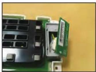
natural_image
Close-up of a computer motherboard with a green circuit board and a small inset showing a white plastic component (no visible text or symbols)① Unfasten the screws from the parts displayed in the fig.
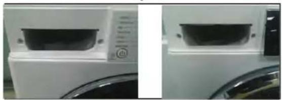
② Disassemble the top plate assembly by sliding it back and then lifting it up.
③ Pull the drawer panel assembly out.
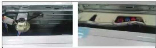
④ Unfasten the screws from the parts displayed in the fig.
⑤ Unfasten the screws from the parts displayed in the fig.
⑥ Disconnect the wiring connectors between the multi harness and the control panel assembly.
⑦ Disassemble the control panel assembly.
⑧ Disassemble the display PCB assembly from the control panel assembly by unfastening the screws.
⑨ Disassemble the NFC supporter.
⑩ Disconnect the wiring connector between the Display PCB assembly and the NFC PCB assembly.
PWB ASSEMBLY(MAIN)

natural_image
Interior view of a vehicle chassis showing exposed components and wiring (no visible text or symbols)① Unscrew two screw of the PWB
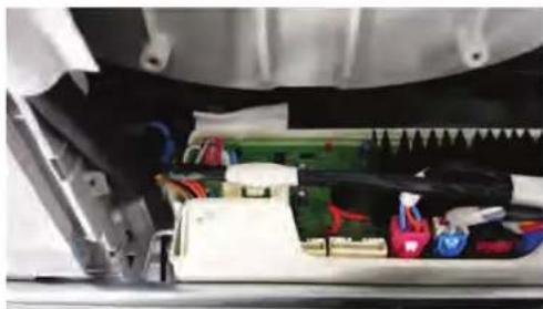
natural_image
Close-up of a mechanical assembly with visible wiring and components (no text or symbols)② First Disassembly atomizing hose from the PWB and Pull the PWB assembly in direction of red arrow
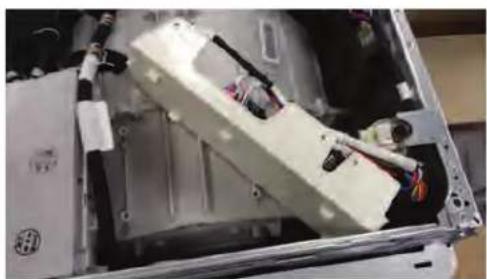
natural_image
Interior view of an open computer case with visible wiring and components (no text or symbols)③ Disassembly PWB like the picture
DISPENSER ASSEMBLY
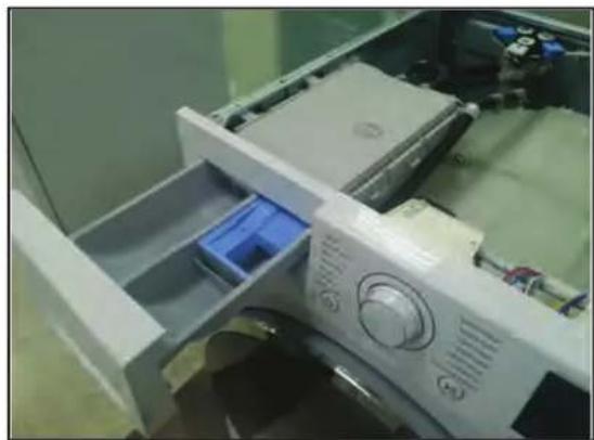
natural_image
Interior view of a washing machine with plastic tray and control panel (no visible text or symbols)① The plate assembly(Top) are disassembled.
② Pull the drawer to arrow direction.
③ Two screws are unscrewed.
④ Clamp
⑤ Cutting cable ties and the ventilation hose are disassembly on the dispenser
INLET VALVE
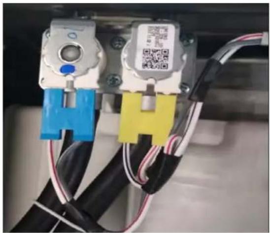
natural_image
Close-up of two mechanical components with blue, yellow, and black connectors and wiring (no visible text or symbols)DOOR

natural_image
Close-up of a white mechanical component with two red circles highlighting a specific part, adjacent to a circular opening (no text or symbols visible)① Disconnect the wiring connector.
② Remove the valve by two screws of the valve holder.
※ When reconnecting the connector
| VALVE 1(PRE-WASH) | WHITE/BLACK-BLACKor GRAY-BLACK |
| VALVE 2(NORMAL-WASH) | GRA Y/BLACK |
• Rating : 12V
- Resistant: 3.5\~4.5
① Open the door completely.
② Remove the three screws from the hinge.
※ When removing the Door Assembly, it is necessary to hold the Bracket that is inner of the Cabinet Cover.
Removing method of remained water
Pull it out from hose.
※ First, prepare a bucket to put in the remained water.
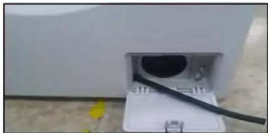
natural_image
White electrical outlet with black cable inserted into a wall socket (no visible text or symbols)CAP(REMAING HOSE)
CABINETCOVER

natural_image
Close-up of a washing machine drawer with a blue plastic tray and control knob (no visible text or symbols)① The plate assembly(Top) is disassembled.
② Pull out the drawer and unscrew 2 screws.
③ Lift the side the Control Panel Assembly and pull it out
natural_image
Interior view of a white electrical outlet with a black circular component inserted (no visible text or symbols)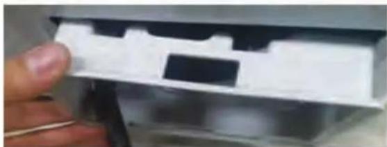
natural_image
Close-up of a hand holding a white plastic electronic component with a black rectangular slot (no visible text or symbols)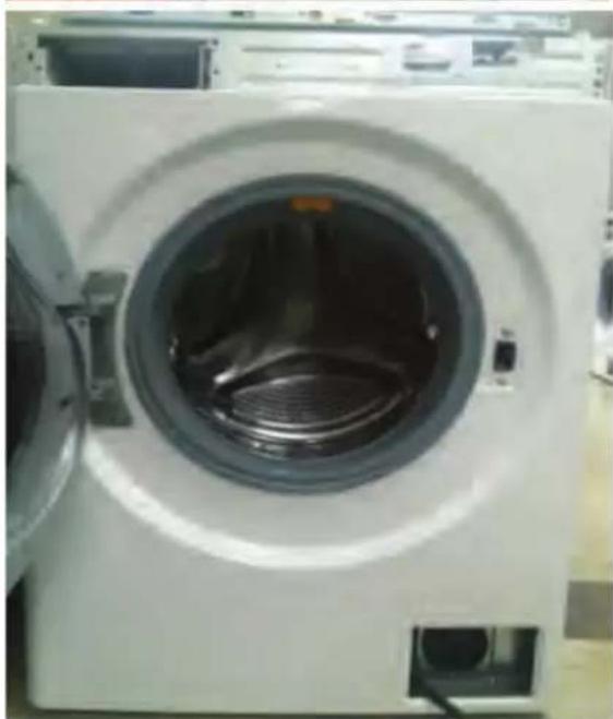
natural_image
Front view of a white washing machine with a closed lid and vented glass (no visible text or symbols)① Two screws are unscrewed.
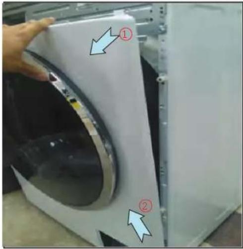
② Push out PANEL ASSEMBLY, CONTROL after Push the hook(①, ②) below.
③ Unscrew the screws from the lower cover.
② Disassembly cap cover and pump case.
③ Unscrew the screw from the CABINET COVER.
④ Remove gasket clamp and release gasket from cabinet cover.
text_image
Photo of a hand holding a white washing machine with numbered annotations pointing to the front panel.SWITCH ASSY, DOOR LOCK
natural_image
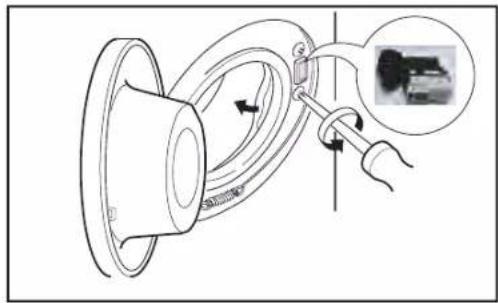
Diagram of a speaker with a cable being inserted, showing motion direction and component detail (no text or symbols)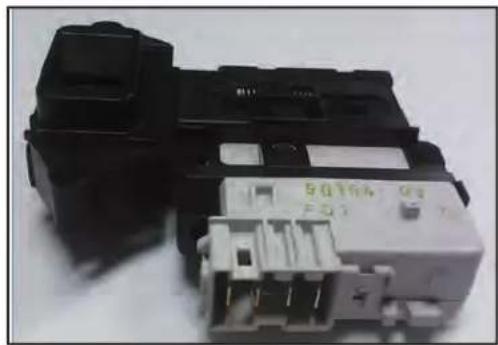
natural_image
Close-up of a black and white electronic component with no visible text or symbols on its body.④ Lift and separate the cabinet cover.
NOTE: When assembling the CABINET COVER, connect the Door S/W connector.
① Two screws are unscrewed and disassembly cabinet cover.
② The Door Lock S/W is disconnected from the wiring connector and the strap.
- Just check cut-off.
- Check the operating time.
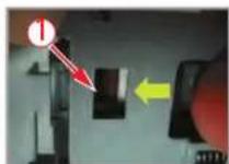
* Door Locking time : 1\~8 sec. Check the time between from input the power to parts move up, then Door locked.
* Door Releasing time: 25\~100 sec. Check the time between from off the power to parts① move down, then Door released.
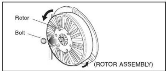
ROTOR ASSEMBLY, STATOR ASSEMBLY, FRICTION DAMPER
text_image
Rotor Bolt (ROTOR ASSEMBLY)
text_image
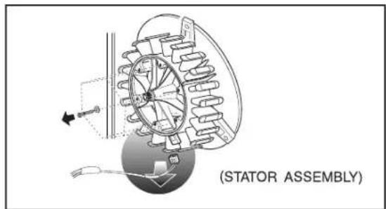
(STATOR ASSEMBLY)
text_image
Friction Damper Hinge (Damper) (FRICTION DAMPER)① Remove the back cover.
② After loosening the bolt, Rotor, pull out the rotor.
① Remove the 6 bolts from the stator.
② Disconnect the 2 connectors.
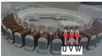
Motor Stator
natural_image
3D rendering of a mechanical assembly with copper and brown components, no visible text or symbols$$ V \sim U (8 \sim 1 1) $$
$$ U \sim W (8 \sim 1 1) $$
$$ W \sim V (8 \sim 1 1) $$
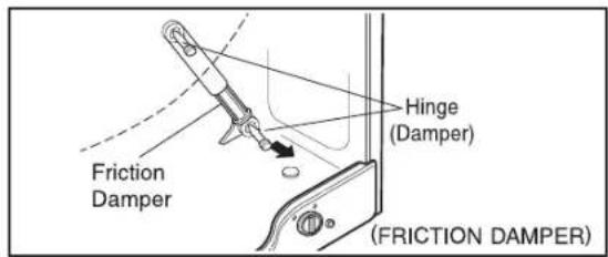
① Remove the hinges (Damper) at the Tub.
② The Hinge(Damper) at the base is pulled off by pressing on the snaps at the sharp end.
③ The hinge at the base is pulled off. (In directions of the arrow)
PUMP
natural_image
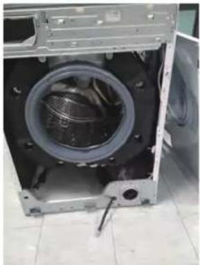
Interior view of a large washing machine with visible internal components and wiring (no text or symbols)① Disassembly Top Plate, Control Panel, Drawer Panel Assembly, Cabinet Cover Assembly, Lower Cover Assembly
text_image
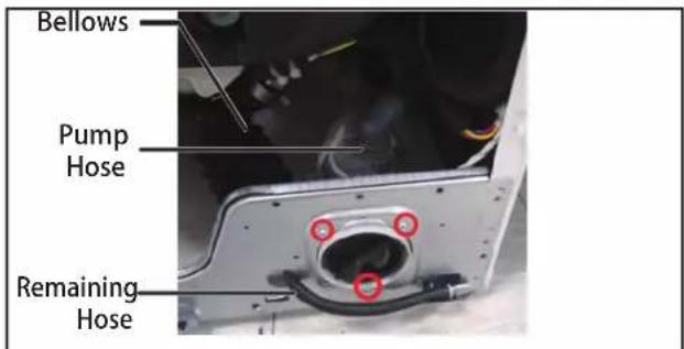
Bellows Pump Hose Remaining Hose④ Remove pump outlet hose.
⑤ Remove tub pump bellows.
⑥ Remove cap(Remaining Hose).
⑦ Disconnect the wiring.
⑧ Three screws are unscrewed from the cabinet.
⑨ Remove the pump to arrow direction.
• Rating : 26V
• Resistant : 3.46\~3.98 Ω
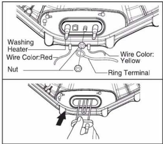
HEATER
text_image
Washing Heater Wire Color:Red Nut Wire Color: Yellow Ring Terminal① Loosen the nut.
② Remove washing heater by pulling out.
• Rating : 230V 2000W
• Resistant: 24.5\~28.5 Ω
CAUTION
When assembling the washing heater, insert the heater to heater clip on the bottom of tub and check the position of wire color.
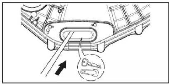
WHEN FOREIGN OBJECT STUCK BETWEEN DRUM AND TUB
natural_image
Technical diagram of a mechanical component with an arrow indicating a tool or connection point (no text or symbols present)① Remove washing heater.
② Remove the foreign object(wire,coin,etc) by inserting long bar in the hole.
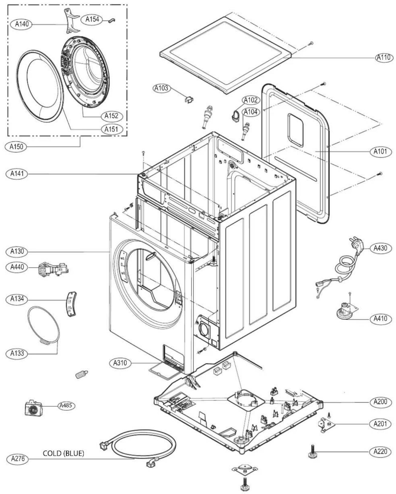
11. EXPLODED VIEW AND PARTLIST
11 - 1.
THE PARTLIST OF CABINET ASSEMBLY
text_image
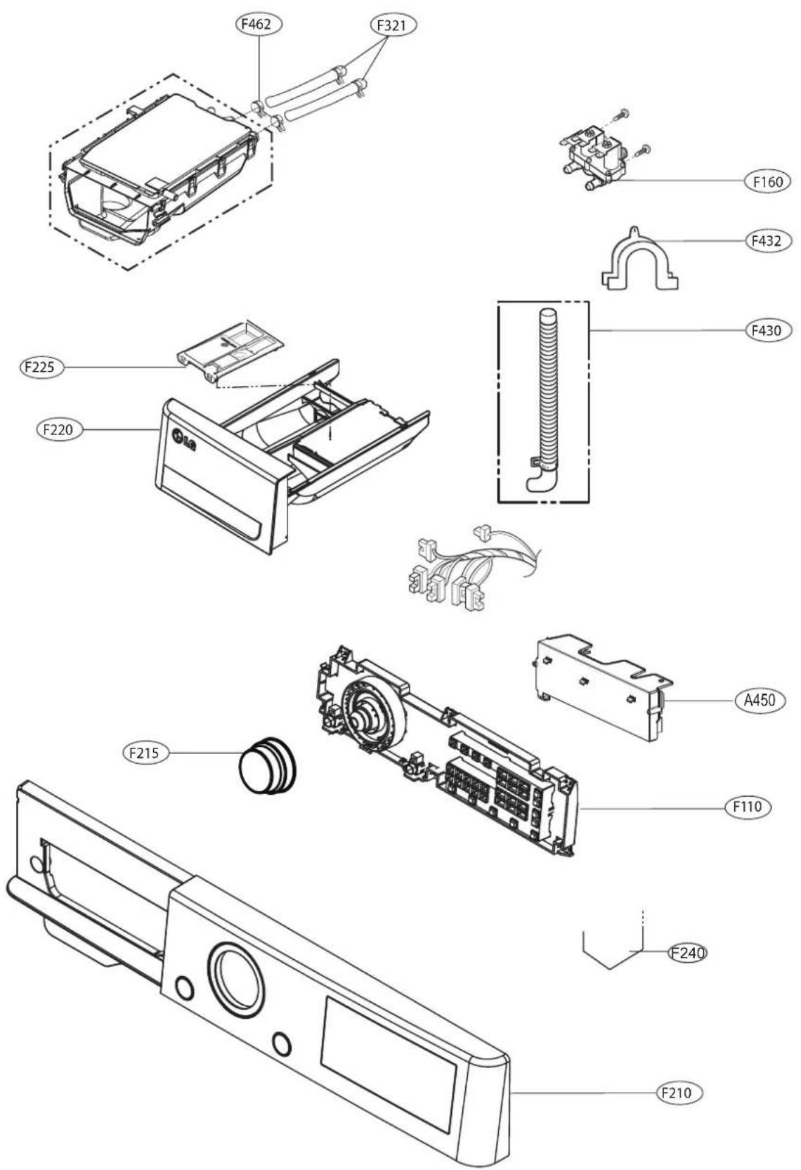
Exploded view diagram of a washing machine with labeled parts and exploded views11-2. THE EXPLODED VIEW OF CONTROL PANEL & DISPENSER ASSEMBLY
text_image
Exploded view diagram of a device's internal components with labeled parts such as F160, F432, and A450.11-3 THE EXPLODED VIEW OF DRUM & TUB ASSEMBLY
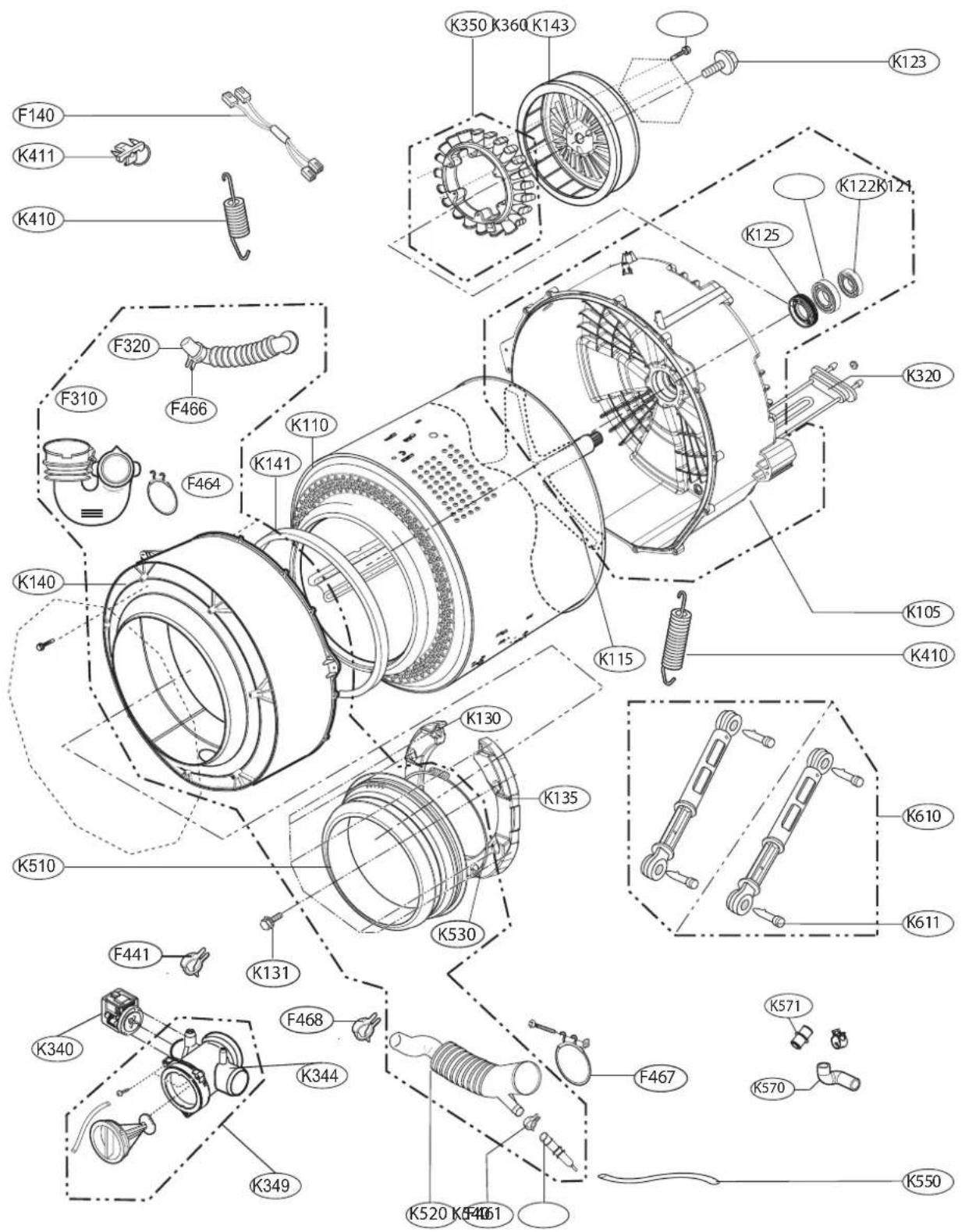
text_image
Exploded view diagram of a mechanical assembly with labeled components such as springs, gears, and motors
LG