
Mighty - Grill MASPORT - Free user manual and instructions
Find the device manual for free Mighty MASPORT in PDF.


| Product Type | Gas Grill |
| Brand | Masport |
| Model | Mighty |
| Fuel Type | Liquid Propane (LP) |
| Main Burners | 3 Stainless Steel Burners |
| BTU Output | 30,000 BTU (approx.) |
| Cooking Area | 600 sq. in. (approx.) |
| Dimensions (L x W x H) | 54 x 24 x 45 inches (approx.) |
| Weight | 65 lbs (approx.) |
| Ignition Type | Electronic Push-Button Ignition |
| Material | Powder-Coated Steel Body, Stainless Steel Burners |
| Temperature Gauge | Built-in Lid Thermometer |
| Cleaning | Removable Grease Tray and Drip Pan |
| Safety Features | Safety Latch on Lid, Stable Legs with Locking Casters |
| Spare Parts Availability | Replacement Grates, Burners, and Thermometer Available |
| Assembly Required | Yes (Tools Included) |
| Warranty | Limited Lifetime Warranty on Burners, 5 Years on Other Parts |
Frequently Asked Questions - Mighty MASPORT
User questions about Mighty MASPORT
0 question about this device. Answer the ones you know or ask your own.
Ask a new question about this device
Download the instructions for your Grill in PDF format for free! Find your manual Mighty - MASPORT and take your electronic device back in hand. On this page are published all the documents necessary for the use of your device. Mighty by MASPORT.
USER MANUAL Mighty MASPORT
natural_image
Exterior view of a Masport gas stove with open doors and internal components (no visible text or symbols)Barbecues
MASPORT 4/6 BURNER 210 SERIES
OWNER'S MANUAL
Please read these instructions carefully before assembly, to reduce risk of fire, burn hazard or other injury.
Keep these instructions in a safe place for future use.
This manual covers a range of barbecues which include: Graphite, Elite, Elite Plus, Mighty, Equip, Supreme, Supreme Plus, Deluxe, Deluxe Plus, Grande, Super Grande and Rear Burner Models.
CONTENTS
INTRODUCTION 3
SAFETY INFORMATION 3
SYMBOLS IN THIS OWNER'S MANUAL 3
IMPORTANT SAFETY INFORAMTION 3
WARRANTY INFORMATION 4
DISPOSAL OF PACKAGING 5
IMAGES 5
ASSEMBLY INSTRUCTIONS FOR BBQ WITHOUT CONDIMENT DRAWER 6
ASSEMBLY INSTRUCTIONS FOR BBQ WITH CONDIMENTS DRAWER & OTHER FEATURES 13
INSERTING/CHANGING THE BATTERY 22
FAT AWAY DISCHARGE FUNCTION - GRILL AND PLATE ORIENTATION 23
FOR MODELS WITH ROTISSERIE - ASSEMBLY INSTRUCTIONS 24
NATURAL GAS CONVERSION 25
LEAK TESTING 25
INSTALLATION 25
OPERATION 26
TROUBLESHOOTING 30
PARTS LIST 31
FASTENER KITS 34
OPTIONAL EXTRAS 35
CARE AND MAINTENANCE 36
TECHNICAL DATA 39
INTRODUCTION
This product has many leaures for making its use more pleasant and enjoys. Safety, performance, and dependability have been given too priority in the design of this product making it easy to maintain and operate.
The product is only intended for use outdoors. It is intended for browning light debris including leaves, grass and other garden residues. It is intended to vacuum and much light debris as above and collect in the debris bag. It is not designed to suck or vacuum water or other liquid.
SAFETY INFORMATION
Keep the instructions in a safe place for future use.
WARNING: DO NOT OPERATE THIS BBQ BEFORE IT HAS BEEN ASSEMBLED CORRECTLY AND YOU HAVE READ AND UNDERSTOOD THESE INSTRUCTIONS.
READ These instructions are intended as a general guide and do not supersede national or local codes in any way. Contact local authorities for clarity of laws relating to the operation of this appliance.
SYMBOLS IN THIS OWNER'S MANUAL
Possible hazard or hazardous situation. Not observing this instruction can lead to injuries or cause damage to property.
i Important information on proper handling. Not observing this instruction can lead to faults in the BBQ.
User information. This information helps you to use all the functions correctly.
Failure to follow these instructions could result in fire or explosion which could cause property damage, personal injury or death.
Accessible parts may be very hot. Keep young children away from the hot appliance at all times (even while cooling down).
Some parts of this grill may have sharp edges especially as mentioned in this manual Wear suitable protective gloves if necessary.
Assembled parts sealed by the manufacturer must not be altered by the user. Any modification of the appliance by unauthorised persons may be dangerous.
WARNING! FOR OUTDOOR USE ONLY
WARNING: To reduce the risk of fire, burn hazard or other injury, read the instructions carefully and be sure your appliance is properly installed and assembled.
DANGER! If you small gas: 1. Shut cell gas to the appliance. 2. Extinguish any open flames. 3. Open lid. 4. If solar continues, keeps away from the appliance and immediately call your gas supplier or your fire department.
WARNING! TO INSTALLER: Test operation of the appliance and instruct the user before leaving. Ensure the appliance is commissioned correctly before handing away to the user.
WARNING! The grill head is heavy and will require two or more people to fill and position onto the grill can enter assembly.
WARNING! Do not by lighting this appliance without first reading the "LIGHTING INS. RUCHON" section of this manual.
WARNING! Conversion to natural gas only done by authorized persons.
WARNING! Always keep the electrical components in or situation.
IMPORTANT SAFETY INFORMATION
Please need and understand this manual fully before assembly and use.
- The Manufacturer's Warranty may be volced by the incorrect use of this product.
- The Manufacturer or Irish Agents can accept no liability for the unsuitability of, or any damage to, food that is cooked on the appliance.
- Use the correctly specified fuel with this barbecue. Check with your dealer for the specific use for which this barbecue has been designed.
OWNER'S MANUAL
• The operator must understand all the safety requirements
- If we have any claims regarding these restrictions, expect
your local dealer for cardikator before you use your barbasie.
- The unit must be correctly assembled before use. Failure to follow the manual's instructions could result in serious damage or injury.
PERSONAL SAFETY
- The use of alcohol, prescription or non-prescription drugs may impair the consumer's ability to properly assemble or safely operate this barbecue.
- The barbecue should be carefully checked for operational use every time before use.
- Never try to move the barbecue when it is on, or before it has had time to cool down.
- The person operating this barbouts should pay constant attention to the food being cooked.
- Do not leave the barbecue unattended when it is slight. The person should remain at the barbecue at all times when it is a light cooking.
THIRD PARTY SAFETY
- The operator is responsible for the safety of all third parties while the barbecue is in use.
- Onlookers should be kept a safe distance away from the barbecue when Use in use.
- Keep children and animals well away while the barbecue is in use and while it is tooing down.
LOCATION
- Do not use indoors. Barbecue units are designed for OUTDOOR US- CN Y.
- Use in a weather-protected area, preferably under shelter.
- Ensure that the barbecue is on an even and secure surface before opening. Use the oester looks if I had to lock the wheels in place.
- Do not use within one metre of any flammable surface of structure.
BURN AWARENESS
- Paris at the barbecus do get extremely hot and could cause serious burns - touch test, the surface before applying a fire grip.
- The hood handles can become hot! Always wear cooling gloves and long sleeves when handling nor components.
- It is cooking with the hood closed, so very careful opening the hood, a sudden rush of hot air could burn an unprotected arm.
GAS AWARENESS
- Ensure all gas couplings and hoses are in good condition and have been correctly filled.
- Look test: all gas lines and connections before use.
- Do not store flammable materials near this barbosis.
- Do not store spars LPG cylinders under or near this barbecue.
- Do not place or use aerosols near this barbecue.
- Do not store or use gasoline or other fermeable vapours or liquids in the vicinity of this barbass.
- Ensure that the gas is turned OFF at the cylinder after use and while the barbecue is unaltered.
- When turning off the barbecue, shut off the gas at the supply source before turning off all the burner controls.
• Do not scan over appliance with lighting.
• Do not use exchange with any cover up.
- Do not use ploetic or class uterols on the splice.
• Do not analyze control variables
• Do you feel you are able to use a report?
- Do not modify the constructions of the appliance or the size of any bumer, injector office or any other components
- Do not observe any ventilation of the appliance.
- Do not allow the Iodala gas supply house or any electrical card to come in contact with any heated surface of the appliance.
- Do not use charcoal or any other solid fuel in this appliance
- Do not disconnect any gas things while the appliance is in use
- Do not use a rusty or denoted gas cylinder with a damaged gas valve.
- Do not fill the gas cylinder beyond 50% capacity.
- Do not store gas cylinders below ground level. UIPG is heavier than air. Should a leak occur, the gas will collect and sound grate due to presence of a flame or electric spark.
- Do not place articles on or against this appliance.
ELECTRICAL AWARENESS
• Symbol LC 2047-51/2 (X30-2) Case I equipment.
- This appliance is no intended for use by persons including children with reduced physical, sensory or mental capabilities, or lack of experience and know edges, unless they have been given supervisor or instruction concerning use or the appliance by a person responsible for their safety.
• Children should be supervised to ensure they do not pay with the spolence.
- If the supply cord is damaged, it must be replaced by the manufacturer, its service agent or similarly qualified persons in order to avoid a hazard.
- BRCs with Grill Lights & USB ports run on AC power. It is IMPORTANT to ensure the car is taken to the location of the H2O. See section in this manual which refers to "section".
• Turn over OFF when it is used.
- avoid using in set conditions.
- If an external lead is being used, ensure that it is correctly rated and meets current safety certification requirements.
- Ensure the power is turned OFF before disconnecting and disconnecting any components on the BBQ.
- Ensure power leads are kept away from any hot cents of the HIO.
- Do not place the power lead where hot all or fat can drop onto the lead.
FOR YOUR SAFETY AND OTHERS
If you need go:
- Shut off the gas supply to the barbecue.
- Extinguish any open fame (jardes, cigarettes, etc.)
- Clear the area to allow the urbanized gas to disisperse
- He aware of the reason for the gas smell, address this before continuing. Should the gas colour come from the LPG cylinder, immediately contact the fire department from an elevated safe distance.
- Connecting the gas cylinder to the barbecue, refer to their section in the manual.
- Look testing, refers to that section in the manual.
SAFETY EQUIPMENT
- When cooking with oil/gas, the oxidizing materials should be readily accessible.
- In the event of an oil-greeze fire do not attempt to extinguish with water or alcohol. Use type 45 dry chemicals: fire extinguisher or another fire with dry, sand or baking soda.
RAIN HAZARD
In the scent of rain while cooking with oilgrass, turn all the gas supply and all burners, cover the barbecue as soon as possible. Move people/animals away from around the barbecue. Do no attempt to move the barbecue until it has cooled end can safely be moved.
WARRANTY INFORMATION
WARRANTY
Refer to the warranty supplied with this BBQ. Should any port fall due to defective workmanship or faulty materials within the specification posted from the date of purchase, Miscoort will replace or repair the defective port free of charge. Refer to the warranty for details. Do not use a BBQ that is unsafe.
LPG CYLINDER
The cylinder manufacturer/distributor is responsible for the safety and performance of the LPG cylinder. This is not included in the Mascot BBQ warranty. Do not use a cylinder that is unsafe.
DISPOSAL OF PACKAGING
Remove all proactive packaging including any protective lim from stainless steel surfaces.
Make sure you properly dispose of, or maybe the packaging material where possible to comply with applicable waste disposal laws in your area.
IMAGES
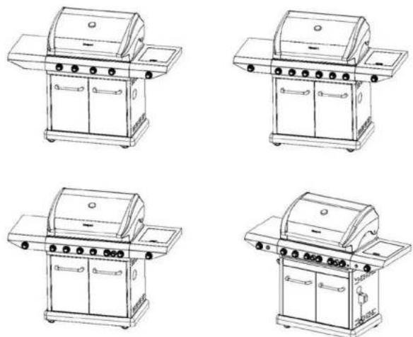
NOTE:
The following pages contain assembly instructions for various marks options. Please ensure you identify your HBO model so that the correct instructions can be tobacco.
When resembling the cabinet, leave all of the screw loose until completely assembled, then tighten all screws.
ASSEMBLY INSTRUCTIONS FOR BBQ WITHOUT CONDIMENT DRAWER
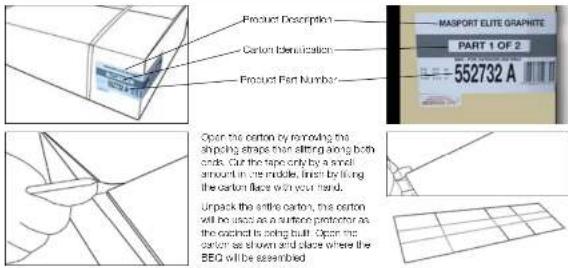
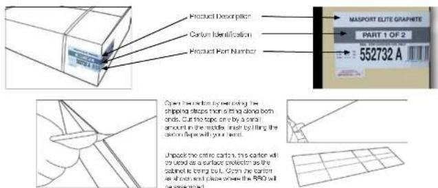
text_image
Product Description MASCPORT ELITE GRAPHITE PART 1 OF 2 552732 A Carton Identification Product Part Number Open the carton by removing the shipping shape that sitting along both ends. Cut the tape only by a small amount in the middle, then by fixing the carton flace with your hand. Unpack the entire carton, the carton will be used as a surface protector as the cleaned to being built. Open the carton as shown and place where the BEQ will be assembled.
NOTE:
Let them in the bracket after every screw helps you learn by the item number from the parts list on page 6, from the last order k1.
Tools needed for assembly: Crosshead screwdriver, 10mm AF Spanner
Open the asterisk kit, place to one side. 4 pcs screw (SS) M6x12 (item c) & 4 pcs litre washer (item d) for liquid assembly.
Before commencing assembly, open the cartons and lay all of the components on the floor. Familiarise them against the parts list on page 21, as some of these instructions refer to this parts list.


When assembling the barbecue, ensure it is sitting on a flat surface.
- Assemble *p::Front skin (len 2) to the Base tray (len 1) using 2pcs Screw V6x12 (main a) from the ladder kit,
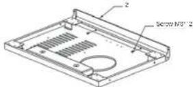
- Assemble I po Left skirt [item 8] to the Base tray using Spce Screw M6× 2 [item a] and I po Screw M5' 10 [item a] from the fastener kit

- Axsomele Tpc High skin (Item 4) to the Nano tray using Does Screw Vb×12 (from a) and Too Screw Mb*10 (from c) from the laserer c).
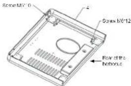
text_image
Screw M6'10 Screw M6'12 Rear of the horbouts- Assemble 4pcr Castors (item 5) to the Bsee tray using 16pcr Screw MG×12 item a) from the fastener kit.

NO11
Assemble the casters and lock the rear castors before assembling the cabinet.
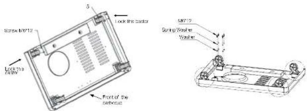
text_image
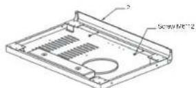
Lock 20.9 cathode Lock the ticker 5 Front of the cathode M812 Spring Washer WasherLocking the rear castors will steady the base. Fashion the case with the looks facing upwards.

NOTE
Here on going forward keep the screws loose until the cabinet structure is complete. This will greatly assist with positioning the panes. Tighten all screws when cabinet is assembled.
- Assemble the Left panel from G and Right panel from T to the Base rey using Apcs Screw Mix 12 (from a) from the taxonor kt
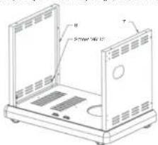
text_image
8 9 Power 100 Ω 7- Assemble the back panel (item d) using spcs Screw Max12 (item a) from the laserer kl.
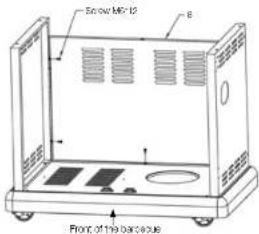
text_image
Snow MFC Front of the barbecueNOTE
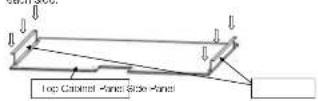
Assemble the side panels before assembling the top panel on the cabinet then assemble this auto-assembly on the barbecue.
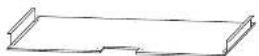
Step 1. Assemble the side panels (item 37) to the top cabinet panel (item 36) using 3 xM6 x12 screws (item a) each side.
Step 2. Step 2 - Assemble this panel sub assembly to the rear panel of the cabinet using 3 xM5 x12 screws item at
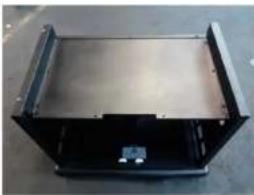
natural_image
Exterior view of a black metal enclosure or enclosure with visible internal components (no text or symbols)Step 3. Insert the top front panel with the side panel extension inside the panel as shown to provide the strength.
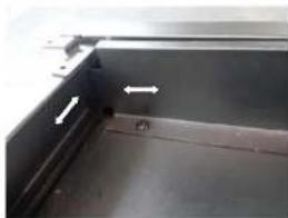
natural_image
Close-up of a metallic panel with two white arrows pointing to a component (no text or symbols visible)Step 4. Assemble the door panel to the side panels of the cabinet using 2 xM6 x12 (lcm a) screws each side. Keep the screws loose.
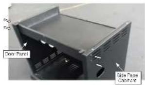
text_image
Door Panel Slide Panel ColormentStep 5. Assemble the door panel and the top cabinet pane using 4 xM6 x12 screws (item at). Keep the screws loose.
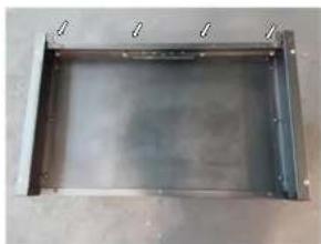
natural_image
Metal enclosure with mounting holes and internal structure (no text or symbols visible)Step 6. Once all the parts mentioned above are assembled lighten all the screws.
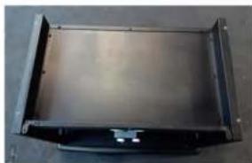
natural_image
Metallic rectangular frame with rounded corners and a small central feature, no visible text or symbols.- Assemble Left door (item 10) and Right door (item 11) using 4 pcs Screw M5x12 (item s), 4 Handle brackets (item 12) and 2 Handles (item 13), then assemble the door assemblies as the picture.
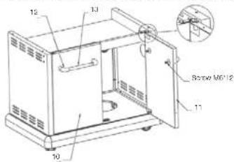
text_image
12 13 Bottom MD12 11 10[NO TEXT]
Note!
To keep screw slot against screwdriver pass screw through ribbon of plastic, hold both together, assemble screw to handle, remove plastic, and re-use for other three screws.
[Unreadable]
Note!
Once the buttons has been fully assembled, and the doors open and close correctly with clean clearances top and bottom, and side to side, the screws can now be fully tightened.
PREPARING THE HOOD / GRILL ASSEMBLY
Open the head carlon and remove the warning rack (item 25)
Lift up and out the coiswrene corner packing.
Remove the protective layer from the hood.
I open all sides with a knife taking care not to damage the hood or grill in the process.
- Open the carton walls outwards and letter. Remove the polyethylene packing from beneath the grill.
Open the head and remove in order:
- Packard cartons (palm are empty and used as a gap fill) and any polysyltrans packaging
• Griffith, then boplate - Remove the level of cardboard
- Remove extra feature options if any. Some specific cerrocue models include some extra feature terms.
- At the rear you will locate the crp tray item 15; remove this, (It is packed in the reverse). This may require the removal of the 2x step Screw item 6.
- The Hood / Grill is now ready to be filled onto the cabinet. This is a large and heavy assembly which requires two persons to lift it safely into position.
- 1) Assemble the hood and grill assembly (from 14) to the cabinet trolley with 4pcs Screw (SS) V6'12 (item c) and 4pcs fibre washer (from c) from the (assener s).
2) In some barbecue models the knobs are not filled to the pH then assemble 6 pos knob (item 15) to the valve shall on the body
assembly, as per the illustration below
3) If the rear bumper knob is not fitted to the grill ascerricle 1 x knob - Rear bumper (item 34) to the Rear bumper valve shaft.
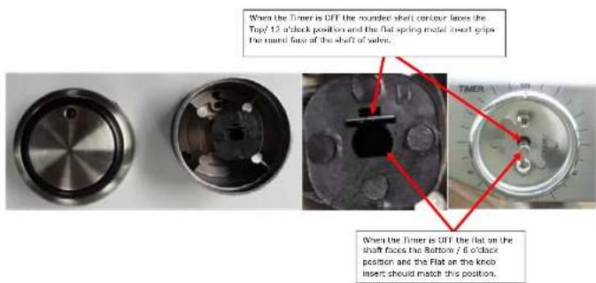
text_image
When the Timer is OFF the rounded shell contour loses the Top/12 ofack position and the flat spring metal insert grips the round face of the shaft of sale. When the Timer is OFF the flat on the shaft faces the Bottom / 6 ofack position and the Flat on the knob insert should match this position.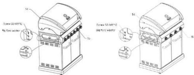
text_image
14 Screw GS M8'12 Big 10c washer 15 Screw GS M8'12 Big 10c washer 16- Loose the 3 Screws (item 2), remove the 4 in & 5 in screws, then ascendle the heel shred (term 30) and let hand side shell (term 16) to the appliance with Spice Screw (SS) MS-12 item by. Level the top of the tube and secure. If the timer knob is not fitted then, if one notch (item 1) on the sheet of the timer on the side table. Rotor to the timer action for contact operating procedure.
text_image
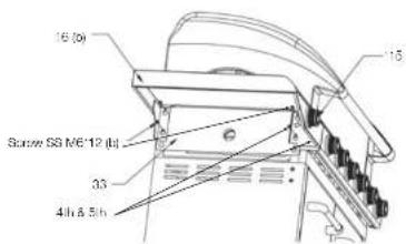
16 (b) Screw 58 M€ 12 (h) 33 4h & 5h 15- Looseen fully but do no remove 4 screws (item b) as shown. Remove two screws 5 & 6, lower the side table over the screw heads. Fasten the four screws to secure the side table. Reft screws 5 & 6, screw 6 seoured the facia which may require frontal pressure to align this role. Level the top of the table and secure.
text_image
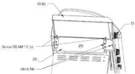
16 lb Screw 35 MB*12 (p) 30 4th & 5th 15- 1) Remove all packaging from the side burner prior to filling the right and side burner table to the GDO. Prepare the GDO prior to filling the side table refer to previous instructions. Then assemble the side burner assembly item 17 as described in step 15. If the knot (item 15) has not been filled then assemble the knob (item 15) to the valve shaft on side burner assembly (item 17), and make sure the rod point on the switch is on the upper direction. 2) Connect the side burner house to the main manifold, and lighten carefully.
text_image
Save to M01Note!
Before operating this appliance for the first time LEAK TEST ALL JOINTS.
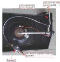
text_image
Engine for the main component Type end to the main component mounted. Type end with regulator contained by base plate. Regulator
text_image
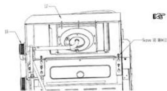
Main bearing (mashed) Pose for the main bearing (mashed) combined forming condensate Regulator and calnoid to the jas, butter by marking, interdiameter- Put the Crp tray (Item 18), Gross cup (Item 19) into the grill body and 2pass Stop screw (from e) (pass step screws will be on the assembly already to the rear of the grill body to secure the crp tray.
NOTE
Some barbecue models require the stepped screws (item e) are removed to insert the drip tray. Once the tray is positioned correctly, refill step screw (item e).
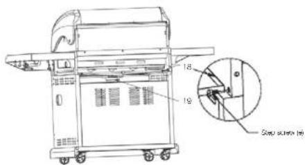
text_image
18 18 Step screen (in)ASSEMBLY INSTRUCTIONS FOR BBQ WITH CONDIMENTS DRAWER & OTHER FEATURES
text_image
Product Description Carton Identification Product Part Number MASPORT ELITE GRAPHETE PART 1 OF 2 552732 A Open the carton by removing the shipping strips thin sitting along both ends. Cut the top line by a small amount in the middle line by filling the section paper with your items. Unpack the entire carton, this carton will be used as a surface projector as the carton is being cut. Open the carton as of next and place on the RSO will be assembled.NOTE.
Letters in the bracket after every screw, helps you identify the iron number from the parks list on page 6, from the lastener list.
Tools needed for assembly: Crosshead screwdriver, 10mm AT Spanner
Open the lastener of, place to one side. 4 pcs screw (SS) M6x12 (lam b) & 4 pcs flare washer (lam c) for Food Assembly
Before commencing assembly, open the cartons and lay all of the components on the foot. Familiarise them against the parts list on page 21, as some of these instructions refer to this parts list.
NOTE
When assembling the barbecue, ensure it is sitting on a 1st surface.
- Assemble lpc from sort (from 2) to the Base tray (from 1) using 20cs Screw V6x 12 (from a) from the laston kft.
- Assemble 1pc Bell skin, item 3) to the Base ray using 3pcs Screw Mb*12 (item a) and 1pc Screw Mb*10 (item c) from the lastener kL.
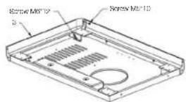
- Assembled Ipc Right shift (Item 4) to the Base tray using Spcs Screw Mix 12 (Item a) and Ipc Screw Vx' 10 (Item c) from the tractor kit.
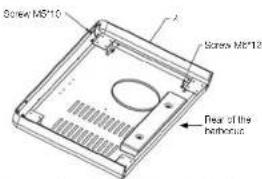
text_image
Screw M5*10 Screw M5*12 Rear of the nathronus- Assemble 4pcs Castors (item S) to the Base tray using 16pcs Screw M8x12 (item a) from the Iseler kit.

NOTE
Assemble the casters and lock the rear casters before assembling the cabinet
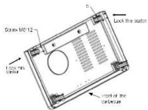
text_image
Screw M6-12 Lock the sater Lock its sater Front of the part/sole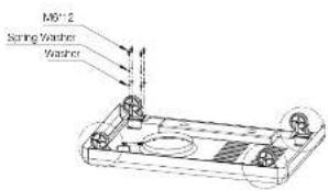
text_image
M6" 2 Spring Washer WasherI using the motor castors will steady the base. Position the base with the lacks facing outwards.

NOTE
Here on going forward keep the screws loose until the cabinet structure is complete. This will greatly assist with positioning the panels. Tighten all screws when cabinet is assembled.
- Assemble the Left panel (Item 6) and Right panel (Item 7) to the Base tray using 4pce Screw M6×12 (Item 8) from the fastener kit.
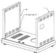
natural_image
Technical line drawing of a laptop chassis with ventilation grilles and mounting holes (no text or symbols)- Assembled the Back panel from Rx using Spea Screw Mix x 12 (from a) from the fastener kit.
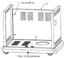
text_image
Below M9'12 5 Front of the barbecue- Assemble the side panels before assembling the top panel on the cabinet, then assemble this sub assembly on the barbecue.
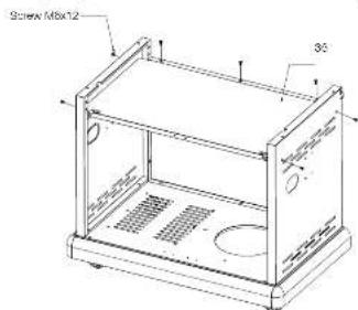
text_image
Screw M8x12 35°B. Axenicle the size panels before assembling the top pane on the cabinet then axenicle this sub-assembly on the barbecue.
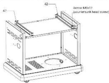
text_image
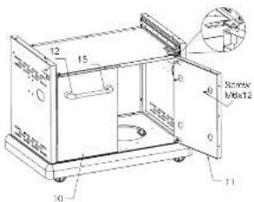
42 Scorso M10x12 (counterstunk head store)B. Assemblc I all door (from 10) and Right door (from 11) using 4 pcs Screw V6×12 (from a), 4 Handle brackets (ent 12) and 5 Handles (from 13), then assemblc the door assemblc as pictured.
text_image
12 15 16 0 0 Screw H8x12 30 11NOTE.
To compact the still rigid screw, it is a piece screw through expansion of plastic, holds from together, assemble screw to handle, remove plastic and re-use for the other three screws.
NOTE
Once the cabinet has been fully assembled, and the doors open and close correctly with even clearness top and bottom ends side-to-shop, the screws can now be fully tightened.
- Assemble left door (Item 10) and Right door (Item 11) using Apes Screw Mix12 (Item a), 4 Handle blowers (Item 12) and 2 Handles (Item 13). from assemblage the door assemblers as pictured.
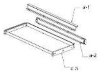
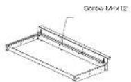
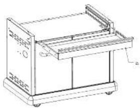
natural_image
Technical line drawing of a mechanical device with handle and wheels (no text or symbols)REPARING THE HOOD / GRILL ASSEMBLY
Open the hood canan and remove the warming rack (from 23)
I'm up and cut the polymers corner packing.
- Remove the protective layer from the food. - Our open slide with a knife tip/soo was not to damage the area of all in the process.
- Open the carton walls outwors and flatten. Remove the polystyrene packing from benzene the grill. Open the hood and remove in order:
- Packon cartons (some are empty and used as a gas filter; and any polysylurene packaging
- Griffal, then folgate
- Remove the layer of cardboard
- Remove extra feature options if any. Some specific barbecue models include some extra feature items.
- At the rear you will locate the trip tray (them 18) remove this, if it is pedied in the reverse. This may require the removal of the 2x step. Screws (them si
-
The Hood / Grill is now ready to be filled onto the cabinet. This is a large and heavy assembly which requires two persons to lift it safely into position.
-
If in some barbecue modes the knobs are not fixed to the grill than assemble 5 pcs each from. By to the valve shaft on the body assembly, as per the luration below.
2) If the rear burner knob is not thus to the grill assemble 1 x knob. Rear turnor (Ierr 34) to the Rear turnor valve shall.
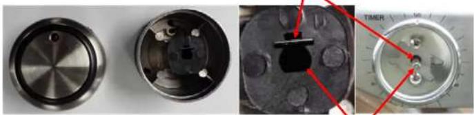
When the Timer is OFF the rounded shaft contour faces the Top/12 o'clock position and the flat spring metal insert grips the round face of the shaft of valve.
natural_image
Close-up of three mechanical components: a metallic knob, a close-up of a circular component with pins, and a dial with red indicator lights (no visible text or symbols)When the Timer is OFF the flat on the shaft faces the Bottom / 6 o'clock position and the Flat on the knob insert should match this position.
- Assemble the grill body onto the trolley by using 4pos Screw M4x12, and then assemble the bottle cener on the left side cener by using 2pos M4x12.

natural_image
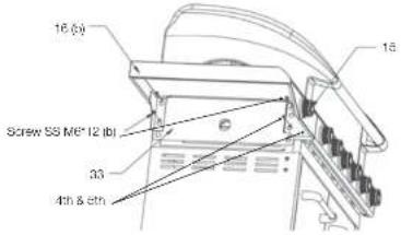
Technical line drawing of two identical gas stove cabinets with side-mounted fans and doors, shown from front and side views (no text or labels)- I couldn the 4 Storox (from op, remove the 4th & two storox, then ascomicks the heat shield (from 50) and left hand skin shelf (from 16) to the appliance with grass Screw (68) MR*12 (Item by). Level the top of the table and secure. It is the timer knob is not tinted then. If one knock (from 16) on the sheet or the timer on the slide table. Refer to the timer section for correct operating procedure.
text_image
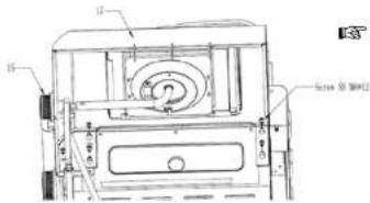
16 (a) 18 Screw 'SS M6' 12 (b) 33 4th & stn- Remove all packaging from the side burner prior to filling the Right Hand side Burnor table to the BDC. Prepare the 330 prior to filling the sole table, refer to previous instructions. Then assemble the Side burner assembly (item 17) as described in step 13. If the knob (item 15) has not been fitted then assemble the knob (item 16) to the valve shaft on side burner assembly (item 17), and make sure the red point on the knob is on the upper floor. 2) Connect the side burner how to the main manifold, and lighten carefully.
text_image
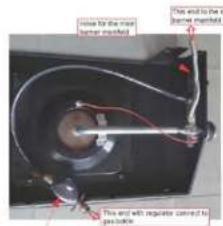
Technical diagram of a mechanical device with labeled components and annotationsNOTE! Before operating this appliance for the first time LEAK TEST ALL JOINTS.
text_image
How to be the top top level manifold. This end to be in top level manifold. This end will require close to possible.Regulator
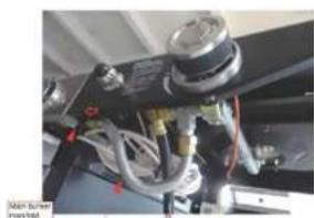
natural_image
Close-up of mechanical components with no visible text or symbolsPlease for the main burner man/fold connect turning classifier Regulator and correct to the gas bottle by turning, assist/choose
- Put the Drip tray (item 18), Grease cup (item 19) into the grill body and 2pcs Step screw (item 6) - (the step screws will be on the assembly already) to the rear of the grill body to secure the drip tray.

NOTE
Some barbecue models require the supood screws (item 6) are removed to insert the drip tray. Once the tray is positioned correctly, refill step screw (item 6).
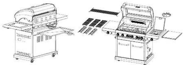
natural_image
Technical line drawings of two industrial machine units with no visible text or symbols- Insert the wire plug of transformer into the bottom of the transformer connector. And then assen the nut by turning dockwise. The lead from the Transformer to the light is to be rolled on the outside of the 380 Cabinet, it is designed to be just long enough in length to do the wall be too short. I routed on the inside of the Cabinet.
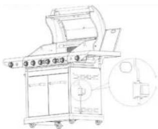
natural_image
Technical line drawing of a mechanical device with control panel and mounting bracket (no text or symbols)- Insert the wiring plug of USB into the USB port (all included in your model of BDC).
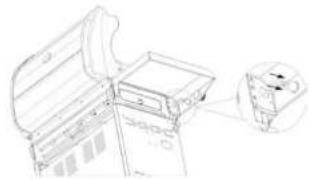
natural_image
Technical line drawing of a mechanical assembly with a magnified inset showing a component detail (no text or symbols)- Connecting the ignition wire/ wires to the electronic module

NOTE
-
The rear burner valves operate with the electronic ignition.
-
All the side burner valves operate with the integrated ignition.
Check the diagram of module to determine the 320 ignition type
-
If the module has only one pin i.e. connecting single wire then Fear burner operates with electronic ignition
-
If the module has multiple pins for connecting the wire then Rear burner and Main burners operate with electronic
ignition.
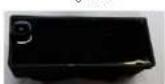
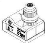
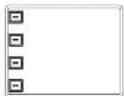
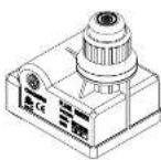
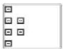

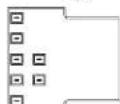
Single Pin Electronic module
text_image
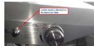
Is Splice marks checked on the body size tableFollow the diagram to connect the wire between the electronic module and the electrode.
Connect the load wire with the electronic ignition as shown below. Make sure that the wire is elapsed right.
SINGLE PIN ELECTRONIC MODULE:
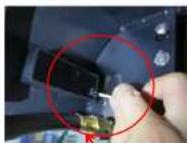
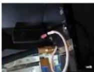
Connect the lead wire with his electronic grillon, no
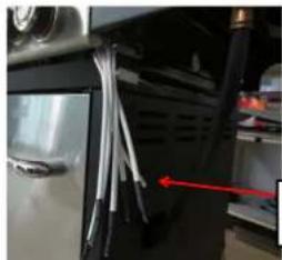
4/6/7 Pin Electronic Module:
natural_image
Close-up of a mechanical device with attached wires and a red arrow pointing to a component (no visible text or symbols)Total 7 parts of the leads wire for all main burners and near burnet.
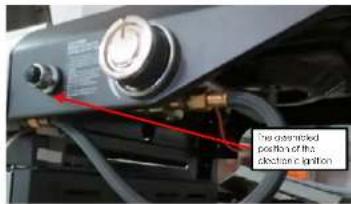
text_image
The electric shock option of the electric optiony
- Connect the end wire with the ignition as shown below. No sequence is required, make sure that the wire is securely clipped.
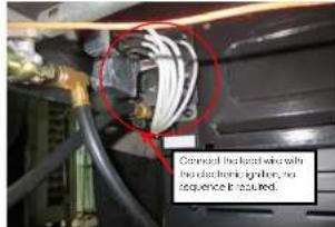
text_image
Commercial electrical warning with electrochemical, ignition, no sequence is required.
NOTE:
Make sure that the wires are securely positioned on each end and routed through the wire clips.
The BBQ body works as an earth for the electronic module. Make sure that the side table is assembled tightly and forms the complete circuit. If not, the ignition spark will not occur.
CAUTION: Al wire must be properly raised enough wire clips.
Verify the ignition system of your HRQ made before connecting the regulator to the gas cylinder
- Integrated ignition valve - Push in then turn the knot an clockwise to H. Test each burner to bear a clicking sound with spark. It indicates the valve
s filled with integrated onion.
- Electronic ignition - Install the battery in the electronic module fitted on the FH side table. Make sure the battery is in good condition and the battery, clearly is correct. Push the button to hear a continuous clicking sound with spark.
I listen & look for the sparks at all the humers' individually and make sure that all the valves are functioning smooth by turning them
"ON" (by
pushing the control knob in and turning an clockwise and "OH" by pushing the control knob in and turning a clockwise.
INSERTING/CHANGING THE BATTERY
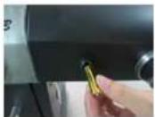
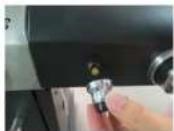
Uncrew the pulse cap assembly: insert the battery as shown. Replace the pulse cap assembly. For single pin modules 1 X/AA battery is required for the replacement, and for 4 X/77 pin modules 1 X AA battery is required for the replacement.
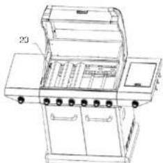
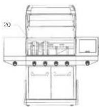
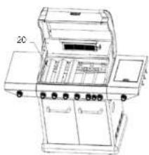
- Place the Home tumor (20) to the positions as in the pictures.
text_image
206 BURNER BBQS
text_image
204 BURNER BBQS
text_image
20RB BURNER BBQS
21 Place the Cooking grill [2] - Cooking plate (23), Deep dish (35) - my if applicable and Warming neck (23) to the same body as in the diagrams.

NOTE
The cooking plate and deep dish must not be used at the same time. The barbecue is designed to operate safely with approx 34% of the cooking surface being on an open grill.
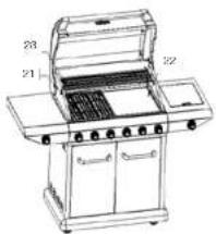
natural_image
Line drawing of a 30-degree portable grill with labeled doors and doors (no text or symbols beyond labels)
text_image
Technical line drawing of a 3rd-5th-tiered grill with labeled components and internal compartments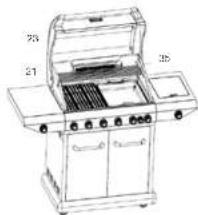
text_image
73 21 25FAT AWAY DISCHARGE FUNCTION - GRILL AND PLATE ORIENTATION
For correct Fat Away Discharge function, install the grill and plate draining the excess fats & oil towards rge back of the BBQ as shown in the below photos.
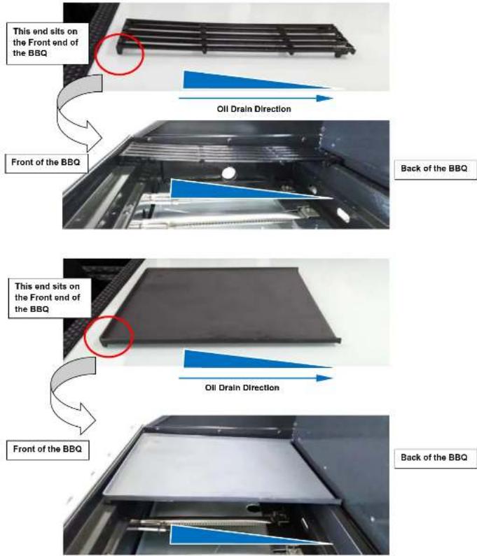
text_image
This end sits on the Front end of the BBQ Oil Drain Direction Front of the BBQ Back of the BBQ This end sits on the Front end of the BBQ Oil Drain Direction Front of the BBQ Back of the BBQFOR MODELS WITH ROTISSERIE - ASSEMBLY INSTRUCTIONS
Tools needed for assembly
Onboard screwdriver, 10mm A/F spanner, 2x8mm A/F Spanners
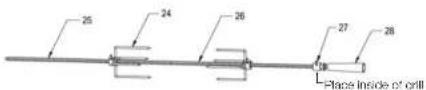
- Assemble the Prong (24), the Rod-A (25), the Rod-B (26) and the Guide (27), the Polissere handle (28) together as in the diagram.

NOF
Rotissarle Rod 25 is threaded UH, assemble by turning rod anti-clockwise. Tighten with 8mm A/F Spencers. This connection must remain scanner light.
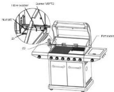
Assemble the Motor holder (23) to the appliance with 2pcs Screw M6-10 (ja), 2 fibre washer (ji) and 2pcs Nut M6 (fi) as the diagram. Place for battery (31) into the Motor (50). Assemble the Motor and Box side to the appliance as the picture.

NOTE
Take note of the battery + - positions prior to filling the batteries.

NOTE
There is an option to use a mains adaptor (not stocked). Requires: Mains adaptor 240 volt >3 volt DC 3 millamps or greater.
text_image
Time washer Screw M8/12 Nut M8 20 30 Ferraser
NOTE
For 210 models without a Rottisserie, there is an option to purchase 559218 Rottisserie Set-210.
NATURAL GAS CONVERSION
The 210 Series of BBQ has the option of being converted to natural gas. The conversion must be actioned by a certified agent using a Macord NG conversion kit.
The certifying agent (usually a gasifier or gas slumber) will update the information on the data prior to keeping the barbecue compliant with local regulations.
LEAK TESTING
When to Test: The BBQ gas bottle, regulator & have assembly should be checked for leaks, using the soapy water leak test, every time you recommend your regulator to the BBQ gas bottle. You should also test after any long period of non-use, such as at the beginning of BBQ season.
What to use: You will need a soapy water solution to check for any leaks. Mixing liquid hand soap with water will work, there (do not use any other household cleaning products).
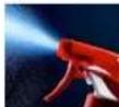
How to Test: Put some scappy water in a spray bottle or a dish. Turn on the gas bottle but do not turn on the BBQ. Next, spray the entire valve, regulator and hose assembly with the scappy water including where the hose connects to the BBQ. Automatically, you can apply the scappy water with a pant brush, basing brush.
Bubble will form if there is a gas leak and you may also smell the gas. If you find a leak, turn off the gas bottle immediately!
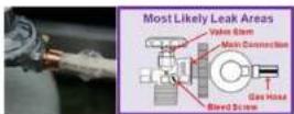
Do not turn back on or attempt to use the BBQ if a gas leak has been detected, contact your local BBQ Dealer for repair.
INSTALLATION
This barbecue is for outdoor use only and should be placed in a well-ventilated area. Take care to ensure that the minimum clearance guidelines are followed:
Minimum clearances:
From sides: 450mm; From neck: 450mm From above (vertical): 1620mm
Keep this barbecue sway from any flammable material! This appliance shall only be used in an above-ground open air situation with natural ventilation, without stagnant areas, where gas leakage and products of combustion are rapidly dispersed by wind and natural convection. This barbecue is not designed for marine use.
Any enclosure in which the spolence is used shall comply with one of the following:
- An enclosure with walls on all sides, but at least, one permanent opening at ground level and no overhead cover.
- Within a partial enclosure that includes an overhead cover and no more than two walls.
- Within a partial enclosure that includes an overhead cover and more than two walls, the following shall copy:
a. at least 25% of the total wall area is completely open and unrestricted
b. at least 60% of the remaining wall area is open and unrestricted 4. In the case of balconies, at least 20% of the total of the side, back and front wall areas shall be and remain open and unrestricted.
See following diagrams for further illustration:
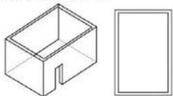
FIG.0F F1-0. ITCOOR AREA-FXAND F1
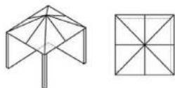
FOLDF2-OUTDOOR AREA-FXAND F2
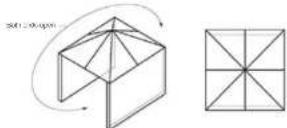
FIGURE F3-OCTOOR AREA-EXAMPLES
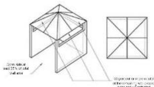
text_image
Open section and 25% of total cross-section Vertical section on top section of horizontal section with cross-section and 25% of total cross-sectionFIGURE 4 OUTDOOR AREA EXAMPLE 4
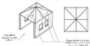
text_image
Conventional and 20% of AD (45m)TIGHLIS OJ DOOR AHLA LXXX PULO
OTHER PRECAUTIONS
Do not obstruct any or the ventilation openings in the hazardous body. Also, position the gas supply cylinder inside the cabinet, in the cylinder base pouring hole, should you need to change the gas cylinder, confirm that the cylinder is off, and that there are no suitability for ignition. The cylinder has been placed on the surface of the cylinder. If you do not take it to report that gas heats and consumes it is free or any setting or tone. The note should drag freely with no berus, folate, or kinks, which could obstruct free flow of gas. Asset from the connection point, no part of the hose should touch, and not barbecue seats. Inspect the notes before use. In the hose is damaged, it must be exposed with a hose suitable for use with LUPG and meet its normal standards for the country of use. The pipe is also closed and is necessary to ensure the air quality of the manufacturer's best conditions not to serve flare up may be experienced due to lack of airflow around the remote, thus working manufacturer's warranty.
The barbecue is designed for LP gas use only. Bottle sizes or 4.8kg or greater are recommended for use with the barbecue. Suitable LPG regulators must have an outlet pressure of 2.75 kPa. You must have the proper regulator and both in order for the barbecue to operate satisfy and efficiency. Please consult your local gas dealer for the most suitable gas cylinders. Please note the regulator supplied with this barbecue of an approved type. The men who took them up to 5/8" x 16. For more information on pipe sizing, please refer to ARIN75 5001-AD9301 for details.
The gas cylinder must always be scored or used in an upright position.
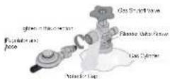
FIXING THE GAS REGULATOR TO THE CYLINDER
Confirm all barbecue control knce are in the oil position. Hand-lighter the regulator supplied with this barbecue to the gas cylinder by screwing in an anti-clockwise direction.
DO NOT OVERTIGHTEN!
As the regulator is fitted with a soft nose, it should only be tightened s. further 1/4 turn after resistance is first felt.
OPERATION
Warning!
Before processing, we certain you understand the safety information contained in this manual.
This barbecue is not designed to be used with more than 66% of the cooking area as a solid plate. Full coverage of plates will cause excessive build-up of heat and damage the barbecue.

WARNING!
Before processing, be certain you understand the safety information contained in this manual.
This barbecue is not designed to be used with more than 86% of the cooking area as a solid plate. Full coverage of plates will cause excessive build-up of heat and damage the barbecue.

NOTE
Before using the barbecue for the first time, the barbecue must be ill and burning for 30 minutes on the "low" setting.

IMPORTANT:
The regulator supplied with the BDO may incorporate an Excess Flow Control Safety Device. The Excess Flow Control will activate to prevent gas flow should a regulator malfunction occur. It is important that the BDO processor understands that all gas valves on the BDO are closed in the OFF position prior to opening the gas cylinder valve.
If the EBC valves are open prior to opening the cylinder valve, the Excess Flow Control will be convivated and prevent the HBC from being ill. In rise, close the HBC valves and gas cylinder valve, wait for 1 minute and use correct lighting procedure as detailed below.
MAIN BURNER AND SIDE BURNER LIGHTING
(INTEGRATED IGNITION)
-
Open the lid before giving the barbecue
-
Check at the kioss are in the "OFF" position
-
(Over the pre-convulsion) is at the pre-charge
-
The valves fixed to this BHD include a safety fixture. The valve must be depressed before turning. This feature prevents acceleration, activation of the knob.
-
From the "OFF" position, push in then turn control end and-
c. otherwise to the "HI" position until how a "click" sound
-
Repeat step 4, 3-4 times until the corner is ill
-
If the corner fails to light, turn off and wait for 5 minutes, then begin turn step 4.
-
Once a burner is lit, similarly light the remaining burners.
-
Turn the knee and clockwise to adjust the heal from High-medium Low to your heal requirement.
MAIN BURNER LIGHTING (ELECTRONIC IGNITION)
-
Open the lid before lighting the barbecue
-
Check all the keys are in the "OH" post on
-
Open the gas can be used in the gas cylinder
- Operate gas wave in conductors with the electronic motion cross
button on the side bumper table
- From the "OFF" position, push in then turn control each and
conocise to the 'HI position
- Keep the knob pushed-in at the "H" position for 4 seconds whist
pressing the electronic ignition push button
-
Repeat step 4, 5-4 times until the corner is lit.
-
If the further falls to light, turn on and wait for 6 minutes, then begin from step 4.
-
Turn the knob and thickness to adjust the heat from high-medium - Low to your heat requirement.
FOR MANUAL IGNITION (MAIN BURNER)
-
Light a 30mm barbecue match and bold adjacent to the lighter pole at the right end of the barbecue. (Fig. 1)
-
Turn the right hand gas control knob to the high position. The current will light from the match.
-
Once the right burner is lit, the current next to it can be turned on and
will light of the air buffer. Repeat until all humors are alight. 4. Each buffer can be adjusted. Turn the knob anticlockwise to adjust the heat from High - medium - Low to your heat requirement.
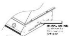
Fig. 1
FOR MANUAL LIGHTING (SIDE BURNER)
- Turn all knabs to "OH" then open the L tank valve. Always keep your face and body as far from the grill as possible when lighting.
-
Have safe or quick
-
Puen in and then turn control knob anticlockwise to high position.
-
Place a lit match near the burner until the burner ignites.
-
If buffer falls to light, turn off and wait a minute, then try
-
again. If burner still does no. light, after repeated attempts, call
- your local dealer for assistance
REAR BURNER LIGHTING (ELECTRONIC IGNITION)
-
Open the lid before lighting the barbecue
-
Check all the keys are in the "OFF" position
-
Open the gas control valve at the gas cylinder
- Decorate gas, rear pressure valve in combination with the electronic
magenta cash bulation on ice sales buffer labie
b. Train the "CH" position, push in then turn control knob and
cockwise to the "H" position
- Keep the knock cushion in at the "H" position for 4 seconds whilst
crossing the electronic ignition such burden
-
Repeat the steps from beginning, 3-4 times until the corner is it.
-
Once the rear burner has ignited keep the knob pushed-in at the "HI" position until the rear burner ceraxia clava and
-
Repeat the steps from bushing, 3/2 times until the buffer is it
-
If the burner tels to light, turn off and wait for 5 minutes, then reset
the steps from beginning
- Turn the knob anticlockwise to adjust the next from High - medium - Low to your next requirement.

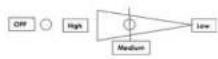

IMPORTANT:
Keep a spray bottle of supply water near the gas supply valve and check the connections before each use.

WARNING!
- Do not light the girl's colour of gas is present.
- It is important to ensure that all control valves, including the gas cylinder are turned off after use.

NOTE
When using the rear burner and rollover use 1 or 2 of the main corners at the low heat setting in a little extra heat is required.

WARNING!
Do not use the rear humors in combination with main humors on high heat selling when the food is closed.

WARNING!
Caution/Danger: Extreme care is required when cooking with hood in closed position. Frequent checks must be undertaken for the heat and temperature to ensure safe cooking.
Too much heat can cause fire.
TURNING OFF A BURNER
Flush In then turn each burner control knob clockwise to the 'CH' position.
When you have finished using your barbecue, turn off the gas at the bottle. Push in and then turn all the control valves fully clockwise to the "OFF" position. Well until the barbecue is sufficiently cool before replacing
the barbecue lid or opening its head. Once cooked, a protective cover should always be tired to the barbecue to protect your investment from the elements when not in use.
TIMER
the BBQ TVH-R is located on the Side Table. The TVH-R will give an audible sound when a pre-set time is activation.
The timer is purely a mechanical device worked by an internal soil spring. The soil spring works both the timer and the finger and requires adequate winding up to work correctly. It setting for a period of less than sixty minutes the timer should not be wound clockwise hall a turn to the sixty minute graduation, then back to the desired time.
Clockwise
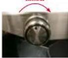
The timer has a maximum setting of 120 minutes with graduation markings at 5 minutes intervals. The timer is purely a time indicator and should not be used for accurate time measurement. DO NOT leave the BBQ unsharded when cooking, due frequently check the items being cooked.
The below actions will damage the internal workings of the TIVER beyond repair.
DO NOT force the timer knob clockwise more than one full turn and DO NOT force the timer knob and clockwise past the 120 minutes. "Top" graduation mark as this will damage the timer.
WARMING RACK
Warning racks are a convenient way to keep closest load warm or to warm items such as bread rolls. Also check that your warning rack is properly fitted before use.
GRILL COOKING
The burners heat up the flame tams underneath the grill, which in turn heats the food on the grill. The natural louses produced during cooking fall onto the flame tams below and vaporise. The subsequent rising smoke relies the load, as it travers upwards, incaring that unique barbecue flavour.
FLAT PLATE / FLAT-RIBBED PLATE / DEEP DISH
(WHERE SUPPLIED)
The burners heat the griddle plate directly, which then cooks the food on contact. These allow for the cooking of smaller items, such as seafood, which could fall through the suoess of a grill. They are also suitable for cooking items that require high-temperature-short-duration cooking, such as vegetables and smaller cuts of fish. Similarly, these can be used in exactly the same way as a griddle in the kitchen, for seating steers, cooking eggs, etc.
DO NOT use both the plate and deep dish at the same time. The will cause your RHD to crossbar and could cause a fire.
COOKING AND USE OF HOOD
Barbecues equipped with a roasting hood give the option of cooking with hood closed to form an 'won' for roasting too, such as joints of meat, whose chickens, etc.
Do not cook with the hood down at a high temperature for 100 periods of time.

WARNING!
Cooking with the hood closed and the burners on high creates a fire risk.
When the hood is closed, a large amount of neat is trapped inside the barbecue. Thus, it is IMPORTANT to make sure that all the burners are turned to the low position to prevent burning of the food and damaging the barbecue. Avoid filling the hood unnecessarily as neat is lost every time the hood is opened. Use the temperature gauge to check the nest of the barbecue.
USB PORT
Some HBO's have a USB port installed, this is to allow for the use of smaller appliances and has limited capacity. It may not power appliances which require a high power draw.

WARNING!
DO NOT PUT YOUR USB port supported gadgets on HOT BBQ SURFACES
For satisfy reasons, barbecue plates and grills will not cook as not towards the front of the barbecue.
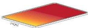
The slightly lower temperature at the front can easily be overcome by rotating the food being cooked around the percoose plate or grill.
SMOKER DRAWER USAGE
The smoking of meat and other food is a personal taste and may take some experimenting to get this function working to your preference, however; these are some guides on the basic use of the smoker drawer.
- Full smoker drawer cut from dashboard and place flavoured awrdust when BRC is cold.
- Heat BBQ up to normal cooking temperature and at approx 140 - 150°C, the sawcock will start giving off smoke.
- Use the two burrs next to the smoker drawer to heat the BBQ.
- Use flavoured sawdust as opposed to palots. Place toc inside BBQ and cook.

WARNING!
DO NOT attempt to sdo sewdust to smoker driver when BBQ is hot.
Cooking at too high a temperature can cause the sandust to colon fire.
FLARE-UP CONTROL
Flare-ups occur when meat is bebecued, and to taste and juice fall upon the terms temers. The smoke from some faro-up helps give cooked meat to be constricted there, our excessive fare up will result in meat being burned. To control fare up, it is advisable to him away excess tall from meat and poultry before grilling.
Also, the burners should always be placed on the low setting during cooking. Finally, extinguish bare ups by applying baking soda or salt
directly onto the same times. Always protect your hands when handling anything near the cooking surface of the barbecue.
If e for the should occur in the drip tray, turn all knobs to the off position, turn off the gas at the bottle, and wait for the fire to go out. Do not pull out the drip tray or course with water.
COOKING USING OPTIONAL ACCESSORIES
ROTISSEIE COOKING (OPTIONAL)
-
Carefully remove the cast iron cocking surfaces and the warning rack from the barbecue.
-
Place the same latens to the centre of the barbecue body. It is over this area, and the nest will be cured.
-
Slide one of the apt forks onto the apt roe and tighten its thumb, serve in secure it into a piece, insert my pointed end of the apt rod, into the meat being cooked and slide the meat towards the centre of the rod. Make sure the fork is fully into the meas. Slide the other fork onto the roe, into the mees, and tighten the thumb screw once in place. For ocimal rotisserie cooking, food must be closed securely onto the middle of the apt rod and balanced on that the arms could relaxate deeply without interference from any barbecue surakes. Any loose sections of meas should be secured, so they do not hang down and interfere with the rotation of the apt roo.
-
Insert the pointed end of the spill rod into the motor, lay the other end of the spill rod, plus the composite bracket.
b. Light the barbecue.
-
Turn on the rotisere motor to begin rotisere cocking. The hood has been designed so that it may be closed during rotisere cocking.
-
Always cook foods on the lowest flame setting to avoid burning or swallowing.
-
DO NOT ALLOW YOUR BARBECUE TO OVERHEAT. A BARBECUE SHOULD NEVER BE LEFT UNATTENDED WHILE OCKING?
-
If cooking with mozzarella using indirect meal (not using burners directly under meal - over style cooking), a baking dish (not supplied on some modest) can be placed under the food to catch tails and places.
-
If your model of BEQ is fixed with the smoker drawer, use two smaller aluminum foil oven trays, (one on other side of the smoker drawer) to collect the opening box.
INFRARED REAR BURNER & ROTISSERIE (OPTIONAL)
The following text in the source image is illegible due to extreme pixelation and noise. No characters can be confidently identified.
You will need to remove both grill plate and solid plate, also the flame carners and wanning rack. Place chess in a sale place for later re-assembly. Place a ceiling dish (not supplied) onto the burners. The dish should be large and deep enough to capture the excess pressure as it falls from the floor.
Centrally secure the food with the rollassere prongs, turning the rollassere rod by hand to test for balance, adjust the food position if required. Inser, pointed end of rod into the motor, test that everything is turning correctly.
Using the Rear Burner for roasting on a barbecue can be different depending on our preferences. A suggestion might be to use 1-3 of the man burners to cook the roast, and then use the Rear Burner towards the end of the cooking to "brown up" the roast. Using the Rear Burner by itself to do the cooking can take a long time depending on the size of the roast.

WARNING!
DO NOT use the rear burner in combination with main burners on right heat setting when the roof is closed.

WARNING!
Caution/Danger: Extreme case is required when cooking with head in closed position. Frequent checks must be undertaken for the heat and temperature to ensure safe cooking.
Too much heat can cause fire.
EXTERNAL BBQ SMOKING FUNCTION,
Some BBQ has have a 25mm crack out filled in to the grill body, this gives the option to using a screwdriver. While this lab open to form a hole. One of the many strover units available on the market can then be installed the hole may need to be made larger for some installations.
INTERCHANGEABLE COOKING SYSTEM (OPTIONAL)
Preparing your barbecue for pizza cooking:
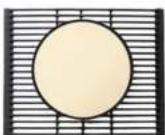
Remove the round grill or plate insert.
Season the pizza stone with olive oil. Place the stone into a cold oven or cold BBQ and slowly raise the temperature to 180°C for 20 minutes.

NOTE
Do not place a cold pizza stone into a hot environment. This could cause the stone to creep due to uneven temperatures.

NOTE
Do not wash the pipe stone with any clearing agent. Flush any crumbs off the surface, do not gauge or cut into the surface during clearing.

NOTE
Do not remove the llarre carriers from the HBC. These should be positioned under the pizza store.

NOUS
Do not use the pizza slice as a calling table.

NOTE
When using the rear burner and rotless are use 1 or 2 of the main burners at the low heat setting in a little extra heat is required.

NOTE
When using the rear burner and rollscere use 1 or 2 of the main corners at the low heat setting in a little extra heat is required.

NOTE
When using the rear burner and rollscere use 1 or 2 of the main corners at the low heat setting for a little extra heat is required.

NOTE
When using the rear burner and rollover use 1 or 2 of the main burrs at the low heat setting it a little extra heat is required.

NOTE
When using the rear burner and rollizene use 1 or 2 of the main corners at the low heel setting if a little extra heel is required.

NOTE:
Do pre heat the HBG to around 200°C - 245°C prior to cooking the pizza.

NOTE:
Do spread a little flour or cornmeal to stop the pizza sliding to the alone.

NOTE:
Do keep things away from the pizza edge, looks up is may spoil the pizza store.

NOTE
Do transfer your stones to the stone with a pizza paddle (not supplied). Remove the pizza from the stone to the table board for cutting.

NOTE:
Do lower the burners directly under the stone, this will allow the pizza to cook more every.

NOTE:
Do check after 10 minutes by raising the head slightly, he aware of a possible heat rush coming from within as you fill the head.

NOTE
Do not remove the pizza stone from the BRC with oven rolls directly after cooking. The pizza stone reaches a very high temperature, wait for the pizza stone to cool naturally.

NOTE:
Do lighty of the pizza stone after each cooking session.
FOR BBQ'S WITH THE KEBAB COOKING OPTION
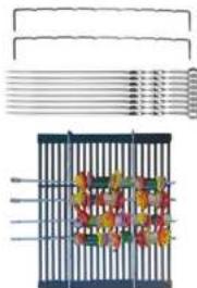
PREPARING YOUR BARBECUE FOR KEBAB COOKING (OPTIONAL)
natural_image
Illustration of a metal fence containing colorful floral patterns (no text or symbols)Insert the kebsb racks into the holes provided in the grill plate.

NOII:
Keep meal chunky to grip the kebab skewers.

NOTE.
Looseily pack the meat for even cooking, some loose will turn better if two skewers are used.

NOTE:
Wash hands frequently foranging raw rests between cooking sessions
TROUBLESHOOTING
BEFORE CALLING FOR SERVICE
If the grill does not function properly, use the following checklist before contacting your dealer for service.
APPLIANCE APPROVED OUTDOOR USE ONLY
USL ONLY THE 5/6" x 18 GAS CONNECTION HOSE AND REGULATOR PROVIDED!
If a replacement is necessary, please contact either our Mascort Customer Service Department or your local dealer.
The use of unauthorised parts can create unsafe conditions and environment.
Enter to your Passport warranty card for warranty information.
STORAGE OF THE GRILL
- Clean the BBQ
2 Store the BBQ purchases in a dry well-velated area and out of reach of children when I P tank is connected to the gdl.
- Store the BBQ incouts ONLY after the LP tank is turned off and removed, the LP tank must be stored outdoors, out of reason of children. NEVER
store the tank in a building, garage or any other enclosed area.
- If using a cover for your barbecue, check your BBQ every few weeks.
CHECKLIST
| Prockers Possible Cause Solutions | ||
| Burner won't light after cushing and turning the knobs | Electrode deposited with cooling residues Use clear | |
| Electrode damaged Reprice | ||
| Electrode wire are loose or discounted. Reconnected or replace with new Electronic assembly with valves | ||
| Online blocked Check the online for blockage | ||
| Wire is shifting ensure connotations are tight | ||
| Replace with new electronic assembly with valves | ||
| Burner can't light by match No gas Open | the LP tank valve | |
| Gas flow is not smooth Clear burner tubes | ||
| Incorrect assembly between burner and valve Tie-assemble | ||
| Yellow or orange lamps, with gas colour | Incomplete conduction | |
| Low heat with kinds in "high" position | Gas hose cont or linked | |
| lumber or online blocked | ||
| Low gas pressure | ||
| Grill not prohated | ||
| Flame up | Excessive water fat | |
| Over high temperature | ||
| Grease deposit | ||
| Flame out | Over high winds | |
| Flame ring | Over high gas pressure | |
| Flashclock | Burner pot, blocked | |
| Grease fire | Grease accumulated in food |
PARTS LIST
For illustration purposes only, some Parts are slightly different shape depending on the model of BBG.
| 1. Base tray x 1pc | 2. Front skirt x 1pc | 3. Left skirt x 1pc | 4. Right skirt x 1pc |
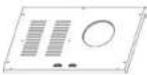 | 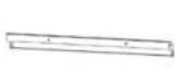 | 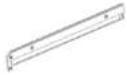 | 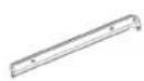 |
| 5. Cursor x 4pcs | 6. Left panel x 1pc | 7. Right panel x 1pc | 8. Back panel x 1pc |
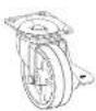 | 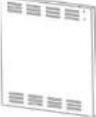 | 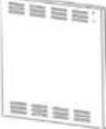 | 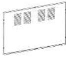 |
| 9. Transom x 1pc | 10. Left door x 1pc | 11. Right door x 1pc | 12. Handle bracket x 4pcs |
| Level | 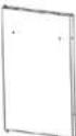 | 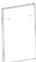 |  |
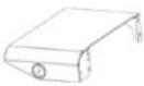
| 13. Door handle x 2pcs | 14. Hood and Body Assembly x 1pc | 15. Knob x 6 or 8 pcs | 16. Side sheet x 1pc (Timer Show) |
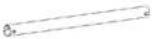 | 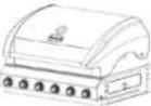 |  |  |
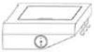
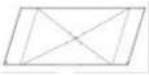
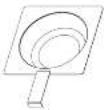
| 17. Side numer assembly x 1pc | 18. Drp tray x 1pc | 19. Grease cup x 1pc | 20. Flame tamer |
 |  |  | 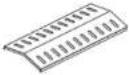 |
| 21. Cook grill x 3pc 22. Cook plate x 1pc 23. Warming rack x 1pc | 24. Prong x 2pcs | ||
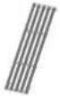 |  | 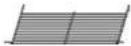 | 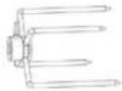 |
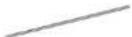
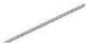
| 25. Roc-A x 1pc 26. Rad-H x 1pc 27. Guide x 1pc 28. Hotssante | Handle x 1pc | ||
 |  | 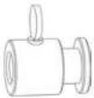 | 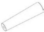 |
| 29. Motor heater x 1pc 30. Motor x 1pc 31. Battery x 2pcs 32. Computer weight x 1pc | |||
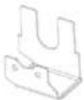 | 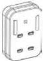 |  |  |
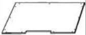
| 33. Heat Shield 31. Knob - Roa burner (Functional) | 35. Doop Dish (Drain Kitato) | 36. Top Cabinet Panel x 1pc | |
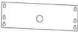 |  | 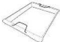 |  |
| 37. Drawer 38. Drawer inner panel 39. Drawer Handle 40. Drawer front panel | |||
 |  |  |  |
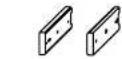
| 41. Slides 42. Drawer holder 43. Smoker drawer cover 44. Stinker drawer | |||
 |  |  |  |
| [SIGNATURE] Items 24-31 are for barbocues fitted with a rollescire | |||
PARTS LIST (CONTINUED)
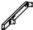
| 45. Left side of smoker drawer | 46. Right side of smoker drawer | 47. Wiring for the Drill body lights | 48. Spark pin |
 |  |  |  |
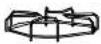
| 43. USB port | 50. Cooking limor | 51. Trivet | 52. Transformer |
 |  |  | (T23A) |
| 53. Cast ran side burner | |||
 | |||
| a. Screw M6*12 43pcs | b. Screw (SS) M6*12 14pcs | c. Big fibre washer 6pcs | d. Screw M5*10 2pcs |
 (Screw (SS) M6*12 - 43pcs for Super Brands 210 & Super Brands MH2 210 & Super Brands MW2 MWQs) (Screw (SS) M6*12 - 43pcs for Super Brands 210 & Super Brands MH2 210 & Super Brands MW2 MWQs) |  |  |  |
| f. Nut M6 4pcs | g. Screw (Black) M6*40 2pcs | h. Washer 2pcs | |
 | (ZTK4) |  |
FASTENER KITS
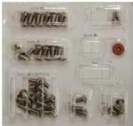
natural_image
Collection of small mechanical components and parts in transparent plastic containers, no visible text or symbols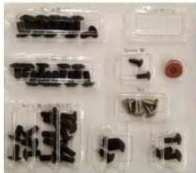
natural_image
Collection of small electronic components or connectors arranged in a grid, no visible text or symbolsOnly one Hotener Kit is supplied per barbecue. The kil type depends upon the model of barbecue.
This Owner's manual is used for various 210 series barbecue models. The parts illustrated in this manual may have slight variations to the home supplied with any one specific model.
OPTIONAL EXTRAS
| 547137 Interchangeable Cooking SystemIncludes the following items:559231 - Kebab Rack (each) x2547136 - Grill (390 x 485) x1559761 - Kebab Skewers x8559762 - Pizza Stone x1547134 - Grill Insert, Round x1547135 - Plate Insert, Round x1547223 - Handle-Grill Inseart x1 | 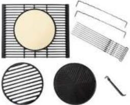 |
| 559765 Grill - Matt P/E 390 x 485 with kebab option547139 Grill - Gloss P/E 390 x 485 with kebab option | 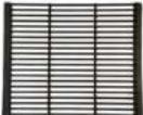 |
| 555231 Kebab Rack (each) | |
| 559761 Kebab Skewer (each) | |
| 559218 Rotisserie Set 210Includes the following items:559297 - Progs x2559223 - Rod-550 x1559224 - Rod-400 [Handle End] x1559239 - Motor x1559494 - Bracket / Fasteners x1559497 - Alignment Collar x1559768 - Handle x1 |  |
| 559520 Grill Gloss P/E 390 x 485559219 Grill C/I 390 x 485559640 Grill Matt P/E 390 x 485547141 Grill Gloss P/E FADS 130 x 485 | 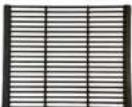 |
| 559521 Plate Gloss P/E 390 x 485559220 Plate C/I 390 x 485559641 Plate Matt P/E 390 x 485547140 Plate Gloss P/E FADS 395 x 485 | 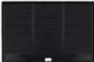 |
| 559672 Deep Dish P/C 385 x 480 | 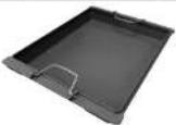 |
CARE AND MAINTENANCE
Regularly clean your barbecue between uses and especially after extended periods of storage. Ensure the barbecue and its components are sufficiently cool before cleaning. Do not leave the barbecue exposed to outside weather conditions or stored in damp, most areas.
- Never close the barbecue with water when its surfaces are hot. - Never handle hot pants with unprotected hands.
Whilst our products are made to the highest standards and all cars is taken to make them as weather proof as possible, we cannot accept responsibility for rust occurring on exposed metal parts unless this is a result of faulty manufacture of parts.
In order to extend the life and maintain the condition of your barbecue, we strongly recommend that the unit is covered when not in use, especially during the winter months.
STAINLESS STEEL CARE AND CLEANING ADVICE
Cleariness and stainless steel are closely related. Stainless steel performs best when clean - cleanliness is essential for maximum resistance to corrosion and to maintain the good looks and life of your BBQ.
TYPES OF SURFACE CONTAMINANTS
Fingerprints and Stains
Footprints and mild strains resulting from normal use are the most
common surface contaminants. They can be removed with a glass cleaner or with a soft-eg. This should be followed by a thorough warm water
three.
Dirt
Live any surface that is exposed to the environment especially in coastal areas, stainless steel can get dirty. Cleaning with warm water with or without a gentle detergent is sufficient. Next in order are mild non-
These can be used with warm water, nylon brittle crushes, sconges, or clean clothes. Carbon steel brushes or steel wool should be avoided as they may have particles embedded on the surface which can lead to FUSING. Cleaning should always be followed by rinsing in clear hot water.
Grease
Grease may soil stainless steel surfaces in food preparation. These soils may be mildly corrosive if left or may not show the surface to maintain possibly, and so regular removal is a necessity for the appearance.
TYPES OF CLEANERS AND METHODS
Consider the possibility of scratching and the potential for post-clearing corrosion caused by no completely removed cleaners. Avoid using abrasive cleaners unless absolutely necessary.
CLEAN WATER AND WIPE
A soft coch and clean warm water should always be the first choice for mild stains and lose dirt and soles. A final rinse with clean water and a dry wipe will complete the process and eliminates the possibility of water stains.
HOUSEHOLD CLEANERS
Household cleaners fall into two otagas: detergent (non-abractive) and abrasive cleaners. Abrasive cleaners are more effective but introduce the possibility of scratching the surface. A neutral cleaner low in chloride is essential. The cleaning method generally employed with these cleaners is to apply them to the stainless surface and follow by cloth wiping in the direction of the grain or polish it has prior across them. The cleaned surface should be thoroughly rinsed with clean water and wiped dry with a solid cloth if water streaming is a consideration.
CARE OF STAINLESS STEEL IN YOUR BBQ
Your HBC features Stainless Steel components. All Stainless Steel grades require a level of care and protection to retain their appearance. Stainless Stocks are not immune to cancer and neither are they maintain this, contrary to ocular public perception. Even the highest marine grades of Stainless Steel require frequent clearing to avoid ocular on and other corrosive issues.
Modern tastes dictate that your IHG features Stainless Steel with a brushed finish. This brushed finish is attained by running Stainless Steel sheets through an abrasive process that removes the mirror finish and leaves the brushed finish. Brushed-finlin Stainless Steel requires frequent cleaning and care, to maintain its quality of appearance. Without adequate care it is realistic to expect that it will show signs of corrosion in time.
Stainless steel is definitely not a maintenance-free material. Cleanliness and Stainless Steel are closely related.
The cleaner stainless steel can be kept while in storage or during use, the greater the assurance of optimum corrosion resistance. In order to maintain the good looks and life of your BBQ, follow these summary tips on the care of stainless steel.
- When new or when cleaned and dried, we recommend the owner apply a thin cost of Olive Oil to stainless steel surfaces which should then be polished in. The Olive Oil will help greatly in protecting the stainless steel from corrosive contaminants and assisting removal of finger prints and other marks, keeping the appearance of the stainless steel in new condition. The Olive Oil coating also moves further polishing easier.
• Use clean soft clothes or sponges to clean your girl.
• Carbon steel brushes or steel von should now be used.
- Do routine clearing of exposed surfaces.
• After cleaning, rinse thoroughly with water.
- Cleaning with choice-containing ceregents must be avoided
• On polished tines, rushing or wrping should be done in the
direction of the polish lines, NO across them.
- Care must be taken when cleaning the fascia. Printed information may be erased with heavy cleaning.
CAST IRON COOKING SURFACES
Before cooking with the grill, 1st plate or deep dish (if supplied with your BBQ clean there with hot empty water to remove any oil or rescue from the packaging or manufacturing process. Wash with clean water and of the plates dry naturally. Prior to lighting your BBQ place room back into the BBQ. Then after lighting your BBQ, let the plates warm up slowly over a period of 30 minutes, during this time increasing the rest.
You will notice slight vapors rest from the plates, this is natural as restless are burned oil. Turn of your BDO to allow the plate to cool slightly. The plates can now be prepared with the addition of cooking oil. Take care that the plates are not at a temperature where adding the oil will cause a hazard. Brush the oil over the plate, allowing the oil to be absorbed into the surface. Allow the plate to fully cool, then remove any excess oil, the BDO is now ready. Steps the above to keep the plate and grill in a ready condition after each BDO session.
PORCELAIN ENAMEL COOKING SURFACES
Porcelain Enamel surfaced items should be removed with care and should not be cleaned with an abrasive cleaner or scratchy cleaning item. Surfaces will crack or chip if hit or dropped. Porcelain Enamel surfaces should NOT be regarded as 'non-silks', use of cooking oil is required as normal. Food will likely stick to an overheaters or un filled enamel surface. The surface will be more easily cleaned by first stacking overnight.
BURNER MAINTENANCE
Provided that they are operating conicity, in normal usage, burning on the rescue after cooking will keep the humers clean. The humers should be removed and cleaned annually, or whenever heavy built-up is found, to ensure that there are no signs of blockages placebo, injections in other the humer portfolios, the primary all-list, or the neck of the stainless steel humers. Use a pile cleaner to wear destructions.
When refitting the humers, he careful to check they are positioned as follows. The neck of the humer fits over the valve outlet, the top taps of the gas collector boxes fit over the top surfaces of the humers.
BURNER MAINTENANCE AND REPLACEMENT
Both the stainless steel burrs and tams lances do have a refined operating lesson. These products are often exposed to cooking marriages and extreme meal in an area of the barbecue which can be neglected during regular cleaning.
Replacement cards are available from your local barbecue cafe.
SPIDER AND INSECT WARNING!
Spiders and incoers can nest in the burners of the grill and cause the gas to flow from the front of the burner. This is a very dangerous condition, which can cause a fire to occur, thereby damaging the grill and making it unsafe to operate.
WHEN TO LOOK FOR SPIDERS
You should respect the corners at least once a year or immediately after any of the following conditions occur:
- The smell of gas in conjunction with the humor times appearing yellow.
b. The HRC does not reach temperature.
-
The BEG heats unevenly.
-
The corners make popping noises.
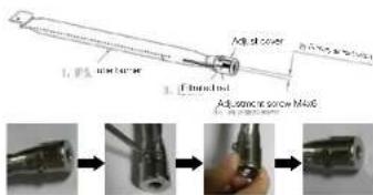
PRIMARY AIR INLET WIDTH REQUIREMENT:
For 4 menu barbeces:
Width for each side: 5.5–6.5mm
Total width for tanoides: 11-13mm
For 6 haver barbeaves:
Width for each side: 2-2.5mm
Total width for two sides: 4-5mm
HOW TO ADJUST:
For example: change the tube burner from 4E to 6B, need too adjust the primary air inlet width according to the pictures below.
text_image
1. PLS 2004 2. Filled Ind Adj. 2004 2005 Adj. 2004 2006Step1 Step2 Step3 Step4
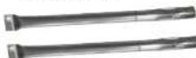
758345 Burner - 2 pack 210 Series.
759569 Flame Tamers - 2 pack 210 Series.
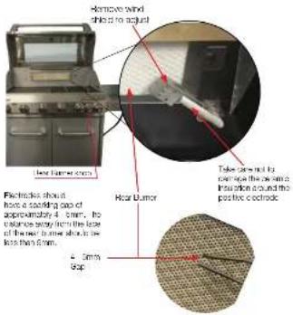
ELECTRODE SETTING
text_image
Remove wind ships to adjust Less frame cross Electrics should have a carding gap of approximately 4 cm, the valence band from the lock of the next frame should be less than 5 cm. Rear Lumor Take one end to remove the wall into location around the positive electrode. 400000 Top
NOTE:
Cooking with the rear burner allows the food to "self baste" as it is turned, any excess juices will fall into the baking dish.
Your RHO is safe to use with the food closed however the internal temperature must be checked. Cooking with the rear burner is designed to be a slow cooking process, this allows the food to be subsequent. External temperatures and breeze will affect the internal temperature, as a guide this should be around 165°C to 180°C.

NOTE:
Vegetables and herbs can be placed into the baking dish, these items will cook/lover the lops at the same time.

NOTE:
When using the rear burner and rolleserie use 1 or 2 of the main burners at the low host setting it a little extra host is required.

WARNING!
DO NOT use the ear tumor in combination with man burries on high heel ceiling when the food is closed.

WARNING!
Caution/Danger: Historic care is required when cooking with hood in closed position. Frequent checks must be undertaken for the heat and temperature to ensure safe cooking.
Too much heat can cause fire.
DRIP TRAY
After every time, check the drip tray, drip pan, and toll pan for lat build up. Failure to maintain these areas could result in a lat line or excessive flare up. This can severely damage your barbecue and is not covered by the warranty.
BARBECUE BODY

WARNING!
Not clearing the barbecue can pose a fire risk!
Regularly remove excess gresse or fat from the barbecue body with a soft plastic or wooden scraper. It is not necessary to remove all the gresse from the body. If you need to clean fully, use hot soapy water and a corn, or nylon bristles brush only. Remove cooling surfaces and burners before full cleaning. Do not immense the gas controls or manifolds in water. Creek burner operation after carefully refilling into body.
FIXINGS
All screws and bolts, etc. should be checked and lightened on a regular bolt.
END OF THE COOKING SESSION
After each cooking session, turn the BHD turns to the "HGH" position and burn off for 5 minutes. This procedure will turn oil feed rescue, thus making cleaning easier.
STORAGE
Store your barbecue in a cool dry place. Cover the burners with aluminium foil in order to prevent insects or other debris from collecting in burner holes. A protective cover should always be fitted to the barbecue to protect your investment from the elements when not in use. If the barbecue is to be stored indoors, the gas bottle must be disconnected and left outside. The gas bottle should always be stored outside, in a dry, well-ventilated area, away from any source of heat or ignition. Do not let children tampar with the bottle.
To protect your investment it is recommended that BBQs are protected by a suitable BBQ cover. But please note that prior to using a protective cover, the BBQ should always be cool, cleaned of any surface contaminant or dirt and be thoroughly dry. Failure to follow this information can load to a BBQ cover being a corrosion brocer rather than a protective tool.

NOTE:
If leaving your BBQ covered for long periods, occasionally check for corrosion and insect habitat. Of surfaces for extra protection.
SERIAL NUMBER
The serial number of your barbecue is located on the inside of the cabinet either on the right hand door or the side panel. If you do require any further assistance with your barbecue from your local dealer or Masport, please have this serial number handy as it will quickly allow us to identify the barbecue.
APPLIANCE DETAILS
| Width Depth | Height | ||
| BBQ 1600mm 60 | 0mm 1250mm | ||
| Cooking Area 90 | 0mm 480mm |
TECHNICAL DATA
| Name Model | IAPMO Approval | Injector (mm) | Pressure (kPa) | Inp/Burn (MJ/h) | Total (MJ/t) | ||
| BBQ MASPSUPER GRANDE | BG6286BS-WS-RB | GMK10178 | ULPG: | BBQ 0.92S/B 0.92R/B 0.98 | 2.75 | 6 x 11.701 x 10.991 x 12.70 | 93.89 |
| NG: | BBQ 1.36S/BR/B 1.621.68 | 1.00 | 6 x 9.601 x 12.801 x 12.70 | 83.10 | |||
| BBQ MASPEQUIP | BG6286BS-WS-RB | GMK10178 | ULPG: | BBQ 0.92S/BR/B 0.98 | 2.75 | 6 x 11.701 x 10.991 x 12.70 | 93.89 |
| NG: | BBQ 1.38S/BR/B 1.621.68 | 1.00 | 6 x 9.601 x 12.801 x 12.70 | 83.10 | |||
| BBQ MASP MIGHTY | BG6286BE-WS | GMK10178 | ULPG: | BBQ 0.92S/B 0.92 | 2.75 | 6 x 11.701 x 10.99 | 81.19 |
| NG: | BBQ 1.38S/BR/B 1.62 | 1.00 | 6 x 9.601 x 12.80 | 70.40 | |||
| Gas Supply Pressure, ULPGMin: 2.70kPa; Max: 3.45kPA Gas Supply Pressure, NG: 1.13 KpaGas Type: NZ: Universal LPG or NG Complies to:AUS: ULPG or NG Standard AS/NZS 5263.1.7 | |||||||
| Minimum Clearance :From Top of BBQ: 1000mm, From Sides: 430mm, From Rear : 430mm | |||||||
| Distributed byMASPORT LIMITED | Read the instructions before using the appliance   USE OUTDOOR ONLYWARNING: Parts of this appliance may be very hot, keep young children away CHART GROUPFor storage and cylinder exchange, disconnect hose at the cylinder only, do not disconnect hose from the appliance. USE OUTDOOR ONLYWARNING: Parts of this appliance may be very hot, keep young children away CHART GROUPFor storage and cylinder exchange, disconnect hose at the cylinder only, do not disconnect hose from the appliance. | ||||||
| MASPORT LIMITED320 TI Pakau Drive, East Tamad,Auckland 2013, New Zealand | |||||||
| MASPORT AUSTRALIA PTY LIMITED27 Commercial Drive, DandongSouth, Victoria 3175, Australia | |||||||
maintained by:
CHANT GROUP
| Name Model | IAPMO Approval | Injector (mm) | Pressure (kPa) | Inp/Burn (MJ/h) | Total (MJ/h) | |
| BBG MASP COMMANDER | BG6286BS-WS-RB GMK10178 | ULPG: | BBQ 0.92S/B 0.92R/B 0.98 | 2.75 | 6 x 11.701 x 10.991 x 12.70 | 93.89 |
| NG: | BBQ 1.38S/B 1.02R/B 1.68 | 1.00 | 6 x 9.601 x 12.801 x 12.70 | 93.10 | ||
| BBG MASP GRAPHITE RBW | BG6284BS-WS-RRB GMK10178 | ULPG: | BBQ 1.10S/B 0.92R/B 0.98 | 2.75 | 4 x 17.501 x 10.991 x 12.70 | 93.69 |
| NG: | BBQ 1.60S/B 1.62R/B 1.68 | 1.00 | 4 x 13.001 x 12.801 x 12.70 | 77.50 | ||
| BBG MASP SUPREME RBW / SUPREME PLUS RBW | BG6288DS-WS-RD GMK10178 | ULPG: | BBQ 0.92S/B 0.92R/B 0.98 | 2.75 | 6 x 11.701 x 10.991 x 12.70 | 93.89 |
| NG: | BBQ 1.38S/B 1.62R/B 1.68 | 1.00 | 6 x 9.601 x 12.801 x 12.70 | 93.10 | ||
| BBG MASP SUPREME W 210 | BG6288BS-WS GMK10178 | ULPG: | BBQ 0.92S/D 0.92 | 2.75 | 6 x 11.701 x 10.99 | 91.19 |
| NG: | BBQ 1.38S/B 1.62 | 1.00 | 6 x 9.601 x 12.80 | 70.4 | ||
| BBG MASP ELITE W210 | BG6284BS-WS GMK10178 | ULPG: | BBQ 1.10S/B 0.92 | 2.75 | 4 x 17.501 x 10.99 | 80.99 |
| NG: | BBQ 1.60S/B 1.62 | 1.00 | 4 x 13.001 x 12.80 | 64.80 | ||
| Gas Supply Pressure, ULPGMin: 2.70kPa; Max: 3.45kPaGas Type: NZ: Universal LPG or NGAUS: ULG or NG | Gas Supply Pressure, NG: 1.13 kPaComplies to:Standard AS/NZS 5263.1.7 | |||||
| Minimum Clearance :From Top of BBQ: 1000mm, From Sides: 430mm, From Rear : 430mm | ||||||
| Distributed by MASPORT LIMITED | [CBHH]Read the instructions before using the appliance USE OUTDOOR ONLY WARNING: Parts of this appliance may be very hot, keep young children away Manufactured by ORNT GROUP | |||||
| MASPORT LIMITED320 Ti Rakau Drive, East Tamaki, Auckland2013, New Zealand | ||||||
| MASPORT AUSTRALIA PTY LIMITED27 Commercial Drive, Dandenong South, Victoria 31/5, Australia | ||||||
| For storage and cylinder exchange, disconnect hose at the cylinder only, do not disconnect hose from the appliance. | ||||||
Masport®
Masport Limited
320 Ti Rakau Drive, East Tamaki,
Auckland 2013
New Zealand
P: 0800 627 767
Masport Australia Pty Limited
27 Commercial Drive, Dandenong South
Victoria 3175
Australia
P: 1300 366 225