GKPv 6540 - Fridge LIEBHERR - Free user manual and instructions
Find the device manual for free GKPv 6540 LIEBHERR in PDF.


User questions about GKPv 6540 LIEBHERR
0 question about this device. Answer the ones you know or ask your own.
Ask a new question about this device
Download the instructions for your Fridge in PDF format for free! Find your manual GKPv 6540 - LIEBHERR and take your electronic device back in hand. On this page are published all the documents necessary for the use of your device. GKPv 6540 by LIEBHERR.
USER MANUAL GKPv 6540 LIEBHERR
natural_image
Technical line drawing of two open refrigerator units with internal compartments and control panel (no text or symbols)GKpv 6540
GKpv 1440
BKPv 6520
BKPv 6570
BKPv 8420
BKPv 8470
7085 159-02
Content
Priority of warnings....12
Safety instructions and warnings 12
Symbols on the appliance....13
Intended use....13
Foreseeable incorrect use....13
Declaration of conformity 13
Noise emissions from the appliance .... 13
Climate rating 13
Description of the appliance....14
Setting up 14
Levelling the appliance....14
Electrical connection....14
Appliance dimensions....15
Equipment 15
Operating and control elements....16
Switching the appliance on and off 16
Setting the temperature....16
Temperatur display mode....16
Humidity function (Models BKPv only)....16
SuperCool 16
Door open alarm....17
Setting the delay time for the door open alarm....17
Deactivating the audible warning signal function.... 17
Alarm test....17
Alarm messages .... 18
Adjusting the alarm parameters .... 18
Resetting the parameters to factory settings .... 18
Storage....18
Defrosting....18
Activating the defrost function manually ....18
Setting the display indication for the defrost phase .... 18
Cleaning....19
Malfunctions....19
Possible error messages in the display....19
Disposal notes....19
Shutting your appliance down....19
Changing over door hinges GKPv 65.. / BKPv 84....20
Priority of warnings
| ⚠ DANGER | identifies a situation involving direct danger which, if not obviated, may result in death or severe bodily injury. |
| ⚠ WARNING | identifies a dangerous situation which, if not obviated, may result in death or severe bodily injury. |
| ⚠ CAUTION | identifies a dangerous situation which, if not obviated, may result in minor or medium bodily injury. |
| NOTICE | identifies a dangerous situation which, if not obviated, may result in damage to property. |
| Note | identifies useful information and tips. |
Safety instructions and warnings
- WARNING: do not seal ventilation openings on the appliance housing or enclosure.
- WARNING: only use the mechanical devices or other aids recommended by the manufacturer to help speed up the defrosting process.
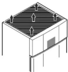
natural_image
Isometric diagram of a rectangular structure with internal grid pattern and directional arrows (no text or symbols)- WARNING: do not damage the refrigerant circuit.
- WARNING: do not use any electrical devices in the refrigerator compartment which do not comply with the design recommended by the manufacturer.
- WARNING: the mains cable must not be damaged while installing the appliance.
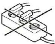
- WARNING: multi-sockets or distributor strips and other electronic devices (such as halogen transformers) must not be positioned and operated at the rear of appliances.
- WARNING: this appliance must be secured as described in the operating instructions to rule out any potential risks due to its instability.
- This appliance can be used by children of 8 years old and over, and also by persons with restricted physical, sensory or mental capacity or lack of experience and knowledge, if they are supervised or have been instructed on safe use of the appliance and understand the resulting risks. Children must not be allowed to play with the appliance. Cleaning and user maintenance must not be carried out by children without supervision.
- Do not store any explosive substances, such as aerosol containers with flammable propellant gas, inside the appliance.
- To prevent injury and damage to property, the appliance should only be installed by two people.
- After unpacking it, check the appliance for signs of damage. Contact the supplier if it is damaged. Do not connect the appliance to the mains power supply.
- Avoid prolonged skin contact with cold surfaces (e.g. chilled/frozen products). If necessary, take safety action (e.g. gloves).
- All repairs and work on the appliance may only be carried out by customer service personnel or other trained personnel. The same applies to changing the mains power cable.
- Only carry out repair and other work on the appliance when the mains plug has visibly been disconnected.
- Only install, connect and dispose of the appliance as described in these operating instructions.
- In the event of a fault, pull out the plug or switch off the fuse.
- When disconnecting the appliance from the mains, pull on the plug. Do not pull on the cable.
- Ensure that food which has been stored for too long is not consumed. Dispose of food which has been stored for too long properly.
- Do not allow naked flames or ignition sources to enter the appliance.
- Alcoholic drinks or other vessels containing alcohol should be sealed tightly for storage.
Symbols on the appliance
 | The symbol can be located on the compressor. It refers to the oil in the compressor and indicates the following danger: swallowing or inhaling can be fatal. This is only relevant for recycling. There is no danger in normal operation. |
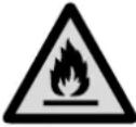 | Warning about inflammable substances. |
 | A sticker to this effect may be applied to the rear of the appliance. It refers to the foampadded panels in the door and/or the housing. This is only relevant for recycling. Do not remove the sticker. |
Intended use
The appliance is suited only for cooling food.
This appliance may be used to display food and drink in retail sales outlets. It is suitable for commercial use, for example in restaurants, canteens, hospitals and in commercial businesses such as bakeries, butchers' shops, supermarkets, etc.
This professional refrigeration appliance is designed for storing chilled food. It is not designed for the presentation of food or for the removal of food by customers.
The appliance is designed for use in enclosed rooms. All other types of use are not permitted.
Foreseeable incorrect use
Do not use the appliance for the following applications:
- Storage and cooling of medicines, blood plasma, laboratory preparations or similar substances and products subject to the Medical Devices Directive 2007/47/EC.
- Use in potentially explosive atmospheres.
- Use outdoors or in areas where it is exposed to splash water or damp conditions.
Incorrect use of the appliance will result in damaging or spoiling the goods stored in it.
Declaration of conformity
The refrigerant circuit has been tested for leaks. The appliance complies with the relevant safety regulations and EU Directives 2006/42/EG, 2014/30/EU, 2009/125/EG and 2011/65/EU.
Noise emissions from the appliance
The noise level while the appliance is operating is below 70 dB(A) (relative noise level 1 pW).
Climate rating
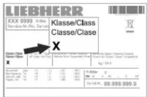
The climate rating indicates at what room temperature the appliance may be operated to achieve full cooling capacity and what the maximum humidity level in the area around the appliance may be to ensure that no condensation forms on the exterior housing.
text_image
LIEBHERR XXX 9999 Indus Service-No. No. Service Klasse/Class Classe/Clase X Class/Class Classe X Description: Klasse/Class Classe/Clase kg / 24 h Balance: 0 Net Charge: 0 Date: 16-03-2017 Balance: 0 Balance: 0 Balance: 0 Balance: 0 Balance: 0 Balance: 0 Balance: 0 Balance: 0 Balance: 0 Balance: 0 Balance: 0 Balance: 0 Balance: 0 Balance: 0 Balance: 0 Balance: 0 Balance: 0 Balance: 0 Balance: 0 Balance: 0 Balance: 16-03-2017 Balance: 16-03-2018 Balance: 16-03-2019 Balance: 16-03-2020 Balance: 16-03-2021 Balance: 16-03-2022 Balance: 16-03-2023 Balance: 16-03-2024 Balance: 16-03-2025 Balance: 16-03-2026 Balance: 16-03-2027 Balance: 16-03-2028 Balance: 16-03-2029 Balance: 16-03-2030 Balance: 16-03-2031 Balance: 16-03-2032 Balance: 16-03-2033 Balance: 16-03-2034 Balance: 16-03-2035 Balance: 16-03-2036 Balance: 16-03-2037 Balance: 16-03-2038 Balance: 16-03-2039 Balance: 16-03-2040 Balance: 16-03-2041 Balance: 16-03-2042 Balance: 16-03-2043 Balance: 16-03-2044 Balance: 16-03-2045 Balance: 16-03-2046 Balance: 16-03-2047 Balance: 16-03-2048 Balance: 16-03-2049 Balance: 16-03-2050 Balance: 16-03-2051 Balance: 16-03-2052 Balance: 16-03-2053 Balance: 16-03-2054 Balance: 16-03-2055 Balance: 16-03-2056 Balance: 16-03-2057 Balance: 16-03-2058 Balance: 16-03-2059 Balance: 16-03-2060 Balance: 16-03-2061 Balance: 16-03-2062 Balance: 16-03-2063 Balance: 16-03-2064 Balance: 16-03-2065 Balance: 16-03-2066 Balance: 16-03-2067 Balance: 16-03-2068 Balance: 16-03-2069 Balance: 16-03-2070 Balance: 16-03-2071 Balance: 16-03-2072 Balance: 16-03-2073 Balance: 16-03-2074 Balance: 16-03-2075 Balance: 16-03-2076 Balance: 16-03-2077 Balance: 16-03-2078 Balance: 16-03-2079 Balance: 16-03-2080 Balance: 16-03-2081 Balance: 16-03-2082 Balance: 16-03-2083 Balance: 16-03-2084 Balance: 16-03-2085 Balance: 16-03-2086 Balance: 16-03-2087 Balance: 16-03-2088 Balance: 16-03-2089 Balance: 16-03-2090 Balance: 16-99.999.999.9The climate rating is indicated on the type plate.
| Climate rating | Max. room temperature | Max. relative humidity |
| 3 25 °C 60% | ||
| 4 30 °C 55% | ||
| 5 40 °C 40% | ||
| 7 35 °C 75% |
The minimum room temperature at the place of installation is 10^ C.
Description of the appliance
GKpv 1440
text_image
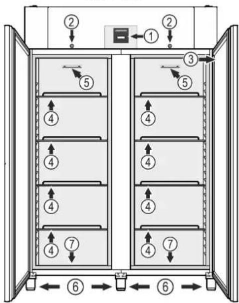
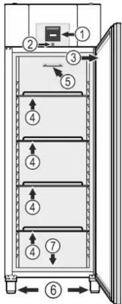
Diagram of a refrigerator interior with numbered compartments and directional arrows indicating flow or movement.GKpv 6540, BKPv 6520, BKPv 6570, BKPv 8420, BKPv 8470
text_image
Technical diagram of a refrigerator with numbered compartments and directional arrows indicating flow or movement.(1) Operating and control elements
(2) Lock
(3) Type plate
(4) Grid shelves
(5) Stacking mark
(6) Stellfüße
(7) Adjustable-height feet
NOTICE
The maximum load per grid shelf is 60 kg.
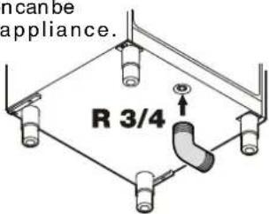
Cleaning water drain opening
A drain hose with an R3/4 connection can be fitted to the underside of the appliance.
The water which collects in the interior during cleaning can be drained off in this way.
An angled connector is supplied with the appliance.
text_image
ancane appliance. R 3/4Setting up
- Do not place the appliance in direct sunlight or near cookers, radiators and similar sources of heat.
- Do not place heat-emitting appliances, e.g. microwave oven, toaster, etc., on top of the appliance.
- The more coolant there is in the appliance, the larger the room in which the appliance is installed must be. If the room is too small, any leak may create a flammable mixture of gas and air. For each 8 g of coolant the installation space must be at least 1 m ^3 . Information on the coolant is on the model plate inside the appliance.
- There must be a gap of at least 30 cm between the upper edge of the appliance and the ceiling.
Levelling the appliance
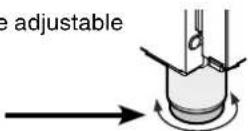
Compensate floor unevenness using the adjustable feet.
To alter the height, rotate the bottom section of the respective adjustable foot.
WARNING
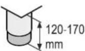
The height of the foot can be adjusted from 120 mm to 170 mm.
Do not set the adjustable foot to a height greater than 170 mm! The bottom section of the adjustable foot can become loose and the appliance may then tip over.
This can lead to serious or even fatal injuries.
NOTICE
The appliance must be aligned horizontally and vertically. If the appliance is not level, the main body of the appliance can be deformed and the door will not close properly.
Electrical connection
Only operate the appliance with alternating current (AC).
The permissible voltage and frequency are indicated on the type plate. The position of the type plate is shown in the section entitled Description of the appliance.
The socket must be properly earthed and protected by a fuse. The tripping current of the fuse must be between 10 A and 16 A.
The socket must not be situated behind the appliance and must be easily accessible.
Do not connect the appliance using an extension cable or extension socket.
Do not use stand-alone inverters (conversion of direct current to alternating current/three-phase current) or energy-saving plugs. Risk of damage to the electronic control system!
Appliance dimensions
GKpv 6540
BKPv 6520, BKPv 6570
BKPv 8420, BKPv 8470
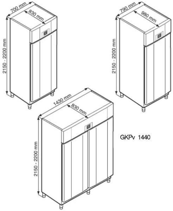
text_image
700 mm 830 mm 2150 - 2200 mm 790 mm 980 mm 2150 - 2200 mm 1430 mm 830 mm 2150 - 2200 mm GKPv 1440Equipment
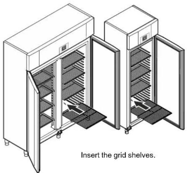
natural_image
Technical line drawing of two industrial storage cabinets with internal shelves and doors, labeled 'Insert the grid shelves' (no other text or symbols)Safety lock
The lock is equipped with a safety mechanism.
Locking the appliance
- Insert the key as shown by arrow 1.
- Turn the key 180^ (2).
To unlock the appliance, the same procedure must be repeated in the same order.
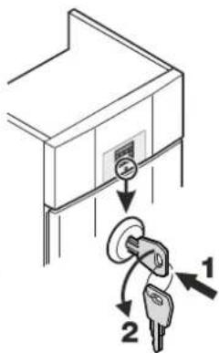
text_image
Diagram showing a key inserted into a lock with labeled parts 1 and 2, indicating a lock mechanism.GKpv 1440 equipment
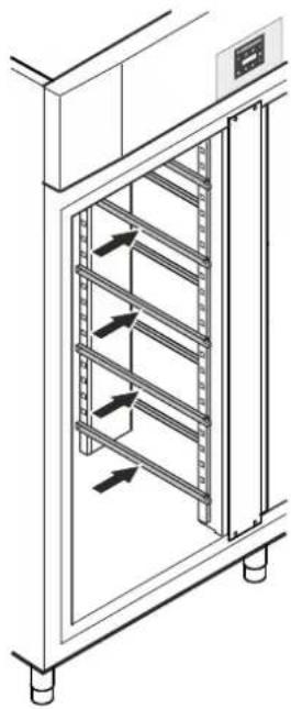
Fit the supplied shelf rails to the right and left of the vertical bar.

natural_image
Diagram of a beam supported by two vertical supports, showing force directions (no text or symbols)Suspend the rails at the desired height, by inserting into the rear clip-in strip first and then clipping in at the front.
natural_image
Technical line drawing of a multi-level rack cabinet with directional arrows indicating flow or movement (no text or symbols)Intermediate shelves
natural_image
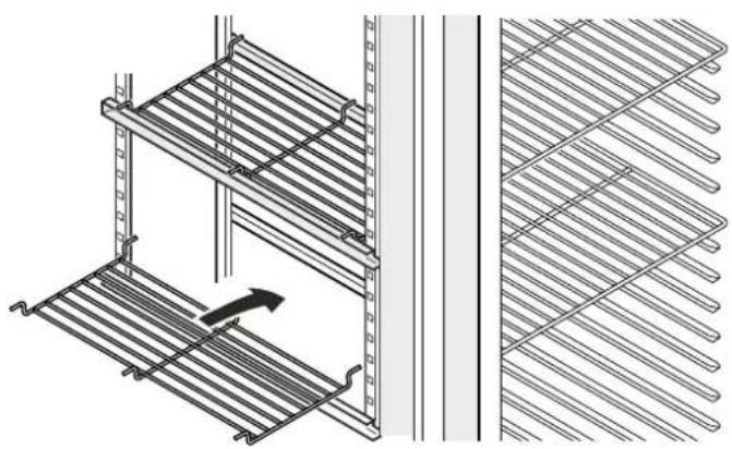
Technical line drawing of a shelving unit with metal racks and a directional arrow indicating movement (no text or symbols)Place the supplied intermediate shelves onto the shelf rails.
NOTICE
The maximum load per intermediate shelf is 20 kg.
BKPv equipment
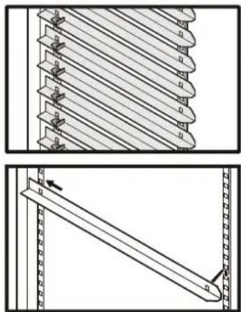
The BKPv series is equipped with L-shaped support rails to accommodate baking trays.
Depending on the height of the goods to be stored, you can adjust the position of the support rails in intervals of 27.5 mm.
First slide bars into the rear clip-in upright at the desired height and then hang in position at the front.
natural_image
Technical diagram showing two mechanical assembly steps: top view of a multi-layered rack with clamps, bottom view of a tilted rectangular component with arrows indicating motion (no text or symbols)Operating and control elements
text_image
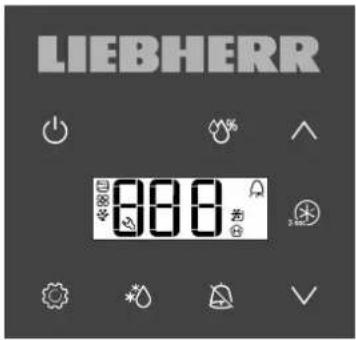
LIEBHERR 800On/Off button (switching the appliance on and off)
Humidity function (Models BKPv only)
∧∨ Selection buttons
SuperCool button
Audible alarm Off button
* Defrost button (for manually activating the defrost function)
Enter button
Symbols in the display
Compressor is running
LED flashing - refrigeration unit switches on after a delay. The compressor will start automatically after the pressure in the refrigerant circuit has equalised.
Fan is running
Appliance is defrosting
SuperCool is activated
Alarm function
The appliance has suffered a fault. Contact the customer service department.
Switching the appliance on and off
Connect the appliance to the mains. Display = OFF
Switching the appliance on
Press (for approx. 5 seconds. Display = ON
Switching the appliance off
Press (or approx. 5 seconds. Display = OFF
Setting the temperature
Press for 1 second. The temperature display flashes.
To increase the temperature (warmer): press button ∧.
To reduce the temperature (colder): press button √.
Press 📍 again. The desired temperature setting is saved.
Note
The temperature in the warmest area of the interior may be higher than the temperature setting.
If the door is left open for a lengthy period, the temperature in the appliance's compartments may rise dramatically.
Temperatur display mode
The temperature display can be switched between degrees Celsius and degrees Fahrenheit. Factory setting is degrees Celsius.
Press ☑ for 5 seconds. Display = 25
Press 📋 display = |
Use button or to select the desired setting.
$$ 0 = ^ {\circ} \mathrm{C} 1 = ^ {\circ} \mathrm{F} $$
Press ⚙. Display = √5
Press 🔒 for 5 seconds.
The electronic control system will switch back to normal operating mode.
Humidity function (Models BKPv only)
Certain foods must be stored in a humid atmosphere (e.g. baked goods). To prevent such foods from drying out, the humidity function must be activated.
Press ⚙% for 2 seconds. Display = ⚡rH=
Use buttons ∧∨ to select the desired humidity setting.
$$ \text { } \otimes r H _ {\text { }} = \text { high } \quad \text { } \otimes r H _ {\text { }} = \text { medium } \quad \text { } \otimes r H _ {\text { }} = \text { low } $$
Press ⚙. The electronic control system will switch back to normal operating mode.
SuperCool
Use SuperCool, to rapidly cool large amounts of food. When SuperCool is activated, the appliance operates with maximum cooling performance.
Activating SuperCool
Press for 3 seconds. Display = c c b
Place the fresh food in the appliance.
The electronic control system will automatically switch back to normal operating mode.
Prematurely deactivating SuperCool
Press for 5 seconds. Display = cc E
Door open alarm
When the door is opened, the LED lights up and the temperature display begins to flash.
When the door has been left open for more than 240 seconds, the LED A begins to flash, and the temperature indication flash alternately in the display.
The audible warning signal sounds (unless the audible warning signal function has been deactivated).
If the door has to stay open for longer in order to insert items to be cooled, cancel the audible warning signal by pressing button
Setting the delay time for the door open alarm
The time before the audible warning signal sounds after the door has been opened can be adjusted.
Press ☑ for 5 seconds. Display = ↗5
Press until appears in the display.
Press ⚙️. Display = | Setting range = 1 - 5 minutes.
Use button ∨ or ∧ to select the desired setting.
Press Ⓞ. Display = d8d
Press 📄 for 5 seconds.
The electronic control system will switch back to normal operating mode.
Deactivating the audible warning signal function
The audible warning signal function can be completely deactivated if necessary.
Press △ for 5 seconds. Display = ↗5
Press until appears in the display.
Press Ⓐ. Display = []
Use button ∨ or ∧ to select the desired setting.
0 = audible warning signal function activated
1 = audible warning signal function deactivated
Press ⚙. Display = H4
Press for 5 seconds.
The electronic control system will switch back to normal operating mode.
Alarm test
This test checks the function of the internal and any external connected alarm device.
The appliance does not stop its refrigerating function during this test.
Press ⚠ + √ for 5 seconds.
- The display will change to a temperature value of 0.2^ below the set upper alarm limit.
- The temperature value will now rise by 0.1^ every 2 seconds.
- When the upper alarm limit is reached, HIO will appear in the display. An external alarm unit connected to the floating alarm output will now be activated.
- The temperature value will continue to rise up to 0.2^ above the upper alarm limit.
- The same process will take place automatically for the lower alarm limit. LIO will appear in the display.
The LED will be lit during the test.
The electronic control system will automatically switch back to normal operating mode.
Cancelling the test prematurely
Press 📄 for 5 seconds.
Note
If the values of the upper and lower alarm limit (AL and AH in the section entitled "Adjusting the alarm parameters") are set to 0, H -- and L will appear in the display during this test.
Alarm messages
1. LED flashes in the display
If 📋 appears in the display, the appliance has a fault. Consult your nearest customer service point.
2. LED 🔒 flashes in the display; the display reads HI or LO
The interior is too warm (HI) or too cold (LO).
The audible warning signal sounds (unless the audible warning signal function has been deactivated).
Adjusting the alarm parameters
The alarm limits (difference to the set temperature) and the alarm delay (delay until alarm sounds) can be adjusted.
Press ⚠ for 5 seconds. Display = 15
Press until appears in the display.
RL = Lower alarm limit
Press ⚙. Display = temperature difference in °C
Use button ∨ or ∧ to select the desired setting.
Set positive values only.
Press Display = RL
Press △ Display = Upper alarm limit
Press ⚙. Display = temperature difference in °C
Use button ∨ or ∧ to select the desired setting.
Set positive values only.
Press Display = RH
Press ▲ Display = Ad
Press 📍 display = alarm delay in minutes
Use button ∨ or ∧ to select the desired setting.
Press ⚙. Display = Rd
Press for 5 seconds.
The electronic control system will switch back to normal operating mode.
Resetting the parameters to factory settings
The alarm limits and sensor calibration values can be reset to the factory settings using this function.
Pull out the mains plug.
Keep △ pressed and connect the mains plug.
Display = bnl
Press Display = Std
The electronic control system will switch back to normal operating mode.
Storage
The grid shelves can be moved to accommodate different height bottles or packages.
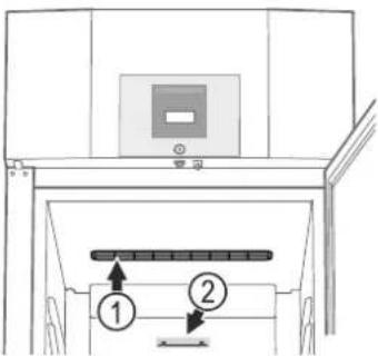
(1) The ventilation slots on the inside must not be covered!
text_image
Technical diagram showing a device with labeled components, including a control panel and two numbered parts.(2) Stacking mark

Only load the top shelf up to the stacking mark. This is important so as to ensure that the air can circulate properly and the temperature is even throughout the interior.
NOTICE
Store raw meat or fish in clean sealed containers on the bottom shelf of the refrigerator/freezer compartment so that it cannot come into contact with any other food or drip liquid onto it.
A failure to follow these instructions may result in the food being spoilt.
Defrosting
The refrigerator compartment defrosts automatically.
Activating the defrost function manually
If the door has been left slightly open for a long time, a layer of ice may form in the interior and on the cooling plate. The defrost function can then be activated manually.
Press
* for 3 seconds. Display = ⚙ dFb
The electronic control system will automatically switch back to normal operating mode.
Display = dFE
Setting the display indication for the defrost phase
Press for 5 seconds. Display = 15
Press until appears in the display.
Press ⚙. Display = |
Use button or to select the desired setting.
0 = Symbol ⚙ + alternating display of and the current temperature in the interior of the appliance.
1 = Symbol ⚙️ + temperature before the start of the defrost phase.
2 = Symbol + dEF
Press ⚙. Display = d6
Press for 5 seconds. The electronic control system will switch back to normal operating mode.
Cleaning
WARNING
Before cleaning, always disconnect the appliance from the mains. Pull out the plug or switch off the fuse.
Surfaces which may come into contact with food and accessible drain systems must be cleaned at regular intervals.
CAUTION
Risk of damage to the appliance components and risk of injury due to hot steam.
Do not use steam cleaning equipment to clean the appliance.
- Clean the inside, equipment parts and outer walls with lukewarm water and a little detergent. Do not use chemical solvents or any cleaning agents containing sand or acid.
- To avoid short-circuits, ensure no cleaning water penetrates into the electrical components when cleaning the appliance.
• Dry all parts well with a cloth. - Use a commercially available stainless-steel cleaning agent for stainless-steel appliances.
- Do not damage or remove the type plate on the inside of the appliance. It is very important for servicing purposes.
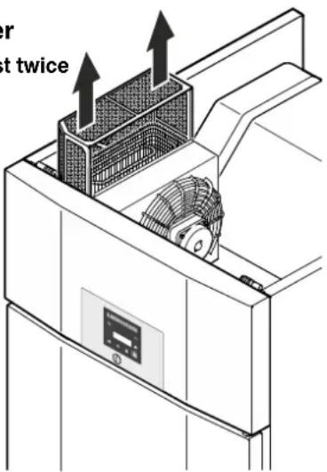
Cleaning the dust filter
Clean the dust filter at least twice per year!
Remove the plug!
- Remove the dust filter by lifting upwards.
- Clean the dust filter with water and detergent.
- Reinstall the dust filter.
text_image
er st twiceMalfunctions
You may be able to rectify the following faults by checking the possible causes yourself:
• Appliance does not function:
– Is the appliance switched on?
– Is the plug correctly fitted in the mains socket?
– Is the fuse intact?
• The temperature is not low enough:
- Is the temperature setting correct (see "Setting the temperature")?
- Does the separately installed thermometer show the correct reading?
- Is the ventilation system working properly?
- Is the appliance set up too close to a heat source?
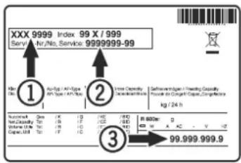
If none of the above causes apply and you cannot rectify the fault yourself, contact the nearest customer service department stating the type designation ①, service number ② and appliance number ③ as indicated on the type plate.
text_image
XXX 9999 Index 99 X / 999 Serv./ No./Service: 9999999-99 ① ② ③ 99.999.999.9The position of the type plate is shown in the section entitled Description of the appliance.
Possible error messages in the display
| Error code | Error Action | |
| E0, E1, E2, rE | Temperature sensor defective | Contact the customer service department |
| EE, EF E | Electronic control system error | Contact the customer service department |
| dOr Ap | Appliance door open for too long | Close appliance door |
| HI Temperature inside appliance too high (too warm) | Check that the door has been closed properly. If the temperature does not drop, contact the customer service department. | |
| LO | Temperature inside appliance too low (too cold) | Contact the customer service department |
Disposal notes
The appliance contains reusable materials and should be disposed of properly - not simply with unsorted household refuse. Appliances which are no longer needed must be disposed of in a professional and appropriate way, in accordance with the current local regulations and laws.
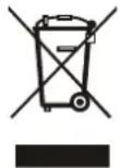
Do not damage the refrigerant circuit of an appliance that is no longer needed during its disposal.
This appliance contains inflammable gases in the refrigerant circuit and insulation foam.
Your local council or a waste disposal contractor can provide information about how to dispose of the appliance correctly.
Shutting your appliance down
If the appliance is left empty for a lengthy period, it must be switched off, defrosted, cleaned and dried and the door is to be left open to prevent mould formation.
Door hinges should only be changed by a trained expert.
Changing the door hinges must be done by two people.
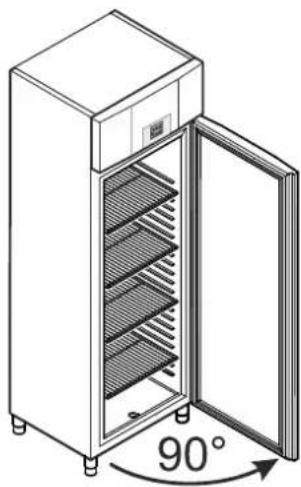
natural_image
Line drawing of a stainless steel refrigerator with 90-degree angle indicator (no text or symbols on the cabinet itself)1. Open door by about 90°.
Important note
The door must be opened 90° before the lower hinge bracket is removed.
This will hold the self-closing mechanism that is integrated into the door in the required position for installation.

WARNING!
If the door is removed and reinstalled in the closed position, this will lead to destruction of the self-closing mechanism on the first opening of the door.
text_image
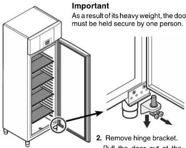
Important As a result of its heavy weight, the door must be held secure by one person. 2. Remove hinge bracket. Pull the door out at theImportant
As a result of its heavy weight, the door must be held secure by one person.
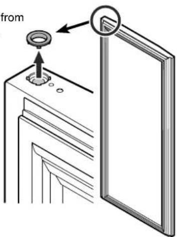
3. Remove bearing ring from upper door mounting.
text_image
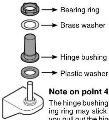
from4. Remove the hinge components from the hinge bracket.
text_image
→ Bearing ring → Brass washer → Hinge bushing → Plastic washer Note on point 4 The hinge bushing ring may stick you pull out the hingNote on point 4
The hinge bushing with brass washer and bearing ring may stick in the door mounting when you pull out the hinge bracket and, in this case, must be removed from it.
text_image
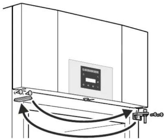
Diagram showing airflow or ventilation system between a cabinet with control panel and valve, labeled in Chinese.- Transfer the upper hinge bracket and covers to the opposite side.
text_image
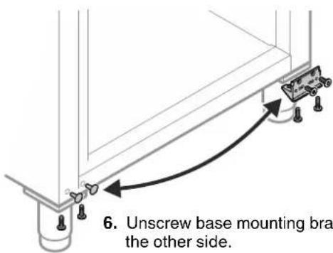
6. Unscrew base mounting bra the other side.- Unscrew base mounting bracket and attach on the other side.
natural_image
Simple line drawing of a rectangular panel with a curved arrow indicating rotation (no text or symbols)-
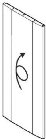
Turn the door by 180^ .
-
Insert the bearing ring and hinge bushing in the upper door mounting.

text_image
end per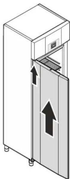
natural_image
Illustration of a cabinet with open door and internal compartments, showing upward arrows indicating movement (no text or symbols)- Keeping door open at 90^ , suspend in top square pin.
WARNING!
It is essential that the door is open at an angle of 90^ during installation.
If the door is installed in the closed position, this will lead to destruction of the self-closing mechanism on the first opening and closing of the door.
Important
As a result of its heavy weight, the door must be held secure by one person.
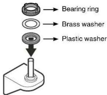
- Fit the hinge components on the hinge bracket.
text_image
Bearing ring Brass washer Plastic washer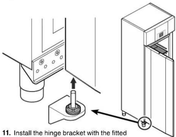
text_image
11. Install the hinge bracket with the fitted- Install the hinge bracket with the fitted hinge components in the lower door mounting.
natural_image
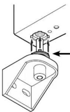
Technical diagram of a mechanical component with an arrow indicating assembly or force (no text or symbols present)Note on point 11
The tabs on the bearing ring must fit into the recesses of the door mounting during installation.
If necessary, gently rotate the upper ring.
text_image
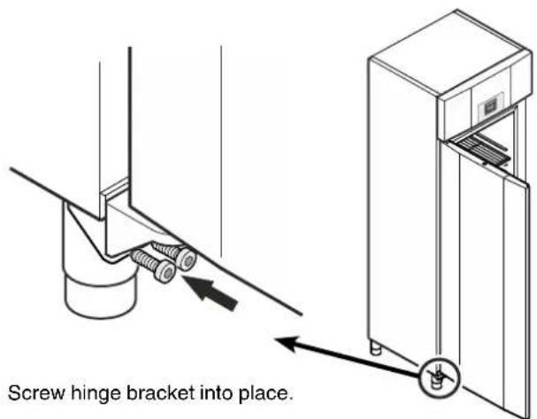
Screw hinge bracket into place.- Screw hinge bracket into place.