
AVW-6555 - Whiteboard Avocor - Free user manual and instructions
Find the device manual for free AVW-6555 Avocor in PDF.


| Product Type | 65-inch Interactive Whiteboard / UHD LED Display |
| Brand | Avocor |
| Model | AVW-6555 |
| Resolution | 3840 x 2160 @ 60 Hz (4K UHD) |
| Touch Technology | High-speed inGlass™ touch; up to 20 touch points and 4 passive pens (Windows) |
| Dimensions (W x H x D) | 61.7 x 40.9 x 4.4 in (1568 x 1039 x 111.5 mm) |
| Weight (Net) | 49 kg (108 lbs) |
| Power Supply | AC 100-240V, 50/60Hz, max 3.0A |
| Power Consumption (Max) | 220 W |
| Backlight | Direct LED |
| Brightness | 350 cd/m² |
| Contrast Ratio | 4000:1 |
| Video Inputs | 2 x HDMI 2.0, 1 x DisplayPort 1.2, 1 x Type C |
| Audio Output | Built-in speakers 2 x 30W (4Ω), SPDIF out, Audio out |
| Microphone | 4 beam-forming linear array, far field, SSP, AEC, ANS, DRC, EQ |
| Camera | HD 1080P 30fps CMOS with 6-element aspherical glass lens |
| Control Connectivity | RS-232, Ethernet (RJ45), USB 3.0 HUB, Touch USB, IR |
| Operating Temperature | 0°C to 40°C (32°F to 104°F) |
| Storage Temperature | -20°C to 60°C (-4°F to 140°F) |
| Wall Mount Pattern | 600 x 400 mm (VESA), M8 screws |
| Cleaning | Wipe with soft, dry cloth. Do not use alcohol, solvents, or ammonia. Unplug before cleaning. |
| Safety | Do not install in high temperature/humidity; maintain 10 cm ventilation; carry with at least 2 people; use approved wall mount. |
| Spare Parts & Repairability | No user-serviceable parts. Contact qualified service personnel for repairs. Warranty does not cover improper use. |
| General Information | OSD languages: English, French, Spanish, German, Dutch, Swedish, Portuguese, Danish, Italian. Supports Azure IoT services. Includes remote control, cables, touch stylus. |
Frequently Asked Questions - AVW-6555 Avocor
User questions about AVW-6555 Avocor
0 question about this device. Answer the ones you know or ask your own.
Ask a new question about this device
Download the instructions for your Whiteboard in PDF format for free! Find your manual AVW-6555 - Avocor and take your electronic device back in hand. On this page are published all the documents necessary for the use of your device. AVW-6555 by Avocor.
USER MANUAL AVW-6555 Avocor
Model AVW-6555 Installation and Operation Manual
COPYRIGHT AND TRADEMARKS:
© Copyright 2019. This document contains proprietary information protected by copyright, trademark and other intellectual property laws. All rights are reserved. No part of this manual may be reproduced by any mechanical, electronic or other means, in any form, without our prior written permission.
The trademarks reproduced in this document and used on the products are either owned or licensed by us, or by their respective holders. You may not reproduce or use the trademarks without our prior written consent.
Important Safety Instructions
• Before using this display, please read this user manual thoroughly to help protect against property damage and to ensure your personal safety and the safety of others.
• Be sure to observe the following instructions.
• For your safety, be sure to observe the warnings located in this manual.
- For installation or adjustment, please follow the instructions in this manual and refer all servicing to qualified service personnel.
Safety Precautions
• If smoke or a peculiar smell comes from the display, remove the power plug from the outlet immediately.
• Failure to do so may result in fire or electrical shock. Contact your dealer for inspection.
- If the display has been turned on but there isn't a picture, remove the power plug from the outlet immediately.
• Failure to do so may result in fire or electrical shock. Contact your dealer for inspection.
- If water is spilled or objects are dropped inside the display, remove the power plug from the outlet immediately.
• Failure to do so may result in fire or electrical shock. Contact your dealer for inspection.
• If the display is dropped or the cabinet is damaged, remove the power plug from the outlet immediately.
• Failure to do so may result in fire or electrical shock. Contact your dealer for inspection.
• To turn off the power of the display, press "O" on the main power switch at side of display.
- The power standby/on indicator will go off and the display cannot to be turned on/off by using the POWER button on the remote control. (To turn on/off the display by the remote control, press the main power switch again and light the power standby/on indicator.)
When turning off the display by pressing the POWER button on the remote control, the main power of the display is not turned off completely.
◆ To disconnect power completely, remove the power plug from the outlet.
- If the power cord or plug is damaged or becomes hot, turn off the main power switch of the display, make sure the power plug has cooled down and remove the power plug from the outlet.
- If the display is still used in this condition, it may cause fire or electrical shock. Contact your dealer for replacement.
Installation
• Don't install in a high-temperature environment.
If the display is used in high-temperature or in direct sunlight, it may cause the case or other parts to become distorted or damaged, resulting in overheating or electrical shock.
• Don't install in a high-humidity environment.
◆ This may cause overheating or electrical shock.
- Don't install near any heat sources such as radiators, heat registers, stoves, or other apparatus that produce heat.
◆ This may cause fire or electrical shock.
• Don't overload outlets or cables beyond electrical capacity.
- Don't use extension cords as it may cause fire or electrical shock.
- Don't insert the power plug into an outlet other than 100\~240V AC.
◆ This may cause fire or electrical shock.
- Don't use a damaged power plug or worn outlet.
- Don't insert an improper power plug it may cause fire or electric shock.
• Don't place the display on an unstable shelf or surface.
◆ The display may fall, causing injury. Please install on a horizontal, stable, level surface.
• Don't place objects on the display.
◆ If the display is covered or the vents are blocked, the display could overheat and cause a fire.
◆ If metal or liquid gets into the display, it may cause fire or electrical shock.
Do not put heavy objects on the display as they may fall, causing injury.
◆ Please keep a 10 cm minimum distance between the display and the wall for sufficient ventilation.
- Don't move the display when it is connected to the power cord and AV cables.
When moving the display, make sure to remove the power plug and cables from the outlet or source.
When unpacking or carrying the display, at least 2 people are needed. Make sure the display is carried upright.
◆ Transport the display upright. Avoid placing the display face up or down.
◆ Handle the display gently. Do not drop.
Use
- If you encounter a problem during installation, please contact your dealer for assistance. Don't repair or open the display by yourself.
• Failure to do so may result in fire or electrical shock. Contact your dealer for inspection. -
Protect and correctly use the power cord/plug.
-
Don't pinch the power cord/plug between hard surfaces.
- Don't step on the power cord/plug.
Before inserting the power plug into the wall outlet, connect the power cord to the display. - Don't operate the display with a damaged power cord or it may damage the display.
• Using extension cords (not recommended)
If an extension cord must be used, ensure the voltage rating exceeds the max power consumption of the display. If the voltage rating is less than the display, it will cause the extension cord to overheat.
- If there is thunder or lightning, don't touch the display or the power plug.
This may cause an electric shock.
• Don't use any kind of liquid on the display.
- If liquid is spilled on the display, remove the power and ask qualified service personnel to check the display.
- If the liquid gets on the display's screen, please clean it with a dry and soft cloth immediately.
- Don't use any harsh chemical on the display.
• If metal or liquid gets into the display, it may cause a fire or an electrical shock.
- Don't install or remove the power plug with wet hands.
• If the display will not be used for a long period of time, unplug the display.
This may cause premature wear of electrical components or fire.
- Don't apply excessive pressure on the LCD panel. This may cause personal injury or panel damage.
• Don't push or shake the display.
◆ This may cause damage or injury.
• If the glass of the display panel is broken, liquid may escape. Please don't touch the liquid.
If liquid get into your eyes or touches your skin, wash with the clean water and seek medical attention immediately.
• Precautions with the remote control batteries
◆ Please only use approved AAA type batteries.
◆ Please be sure to insert batteries by matching the + and -.
- Don't recharge, heat, disassemble, short or throw batteries into a fire.
- Don't mix a new battery with a used one.
- Don't mix different types of batteries together (only use the specified type). it may cause burn and injury.
Cleaning
• If dust has collected on the power plug, remove the plug from the outlet and clean off the dust.
◆ Dust build-up may cause a fire.
• Take off the power plug before cleaning.
◆ Failure to do so may result in electrical shock or damage.
• Cleaning the surface of the display
When the surface of the display becomes dirty, please wipe the surface lightly with a soft clean cloth.
◆ If the surface requires additional cleaning, lightly moisten the cloth.
Do not to let any kind of liquid enter the display as it may cause electrical shock or damage.
Do not clean the display with alcohol, solvents or ammonia, as this could damage the display.
Warnings
Use
• Do not use the display lying flat on its back.
- Transport the display upright with proper packaging. Avoid placing the display face up or down. Be careful not to bump into the display.
- Do not send a static (non-moving) image to the display, or it may cause image 'burn-in' or image retention.
- "Burn in" and/or image retention is not covered under warranty.
• Make sure to change the image on the display periodically. It is recommended to turn off the display for at least 6 hours after 18 hours of usage in a 24 hour period to help avoid image retention
Exemptions
- This product isn't warranted for any damage caused by natural disaster (such as earthquake, thunder, etc.), fire, acts by third parties, accidents, owner's intentional misuse and fault, or use in other improper conditions.
- This product isn't warranted for incidental damages (such as profit loss or interruption in business, modification or erasure of record data, etc.) caused by use or inability to use of this product.
- This product isn't warranted for any damage caused by inappropriate operation, or from not following the user manual.
- This product isn't warranted for any damage caused by misuse or malfunction through simultaneous use of this product and the connected equipment or software.
- This product isn't warranted for any damage caused by neglect of the instructions described about installation.
- This product isn't warranted for any damage caused by improper installation.
- This product isn't warranted for any damage caused by disassembly, modification or repair by non-authorised service center or people.
Compliance Information
DECLARATION OF CONFORMITY:
AVOCOR hereby declares that the Product's Model Numbers:
AVW-6555
Conform with the provisions of:
- FCC:
FCC CFR Title 47 Part 15 Subpart B Class A, CISPR 22
ANSI C63.4
ICES-003
CE:
EN 55032
EN 55024
EN 61000-3-2
EN 61000-3-3
• cTUVus:
UL 60950-1
CAN/CSA-C22.2 No. 60950-1
CB:
IEC 60950-1
CEC:
California Code of Regulations, Title 20:Division 2, Chapter 4, Article 4, Sections 1601-1609
PSB:
IEC60950-1
FCC PART 15:
This equipment has been tested and found to comply with the limits for a Class A digital device, pursuant to part 15 of the FCC Rules. These limits are designed to provide reasonable protection against harmful interference when the equipment is operated in a commercial environment. This equipment generates, uses, and can radiate radio frequency energy and, if not installed and used in accordance with the instruction on manual, may cause harmful interference to radio communications. Operation of this equipment in a residential area is likely to cause harmful interference in which case the user will be required to correct the interference at his own expense.
CAUTION
Any changes or modifications not expressly approved by the grantee of this device could void the user's authority to operate the equipment.
INDUSTRY CANADA (ICES-003):
CAN ICES-3 (A)/NMB-3(A)
PRODUCT DISPOSAL:
The Product contains small amounts of tin, lead and/or mercury. Disposal of these materials may be regulated due to environmental considerations.
DISPOSAL OF OLDELECTRICAL AND ELECTRONIC EQUIPMENT (Applicable throughout the European Union and other European countries with separate collection programs)

This symbol found on your product or on its packaging, indicates that this product should not be treated as household waste when you wish to dispose of it. Instead, it should be handed over to an applicable collection point for the recycling of electric al and electronic equipment. By ensuring this product is disposed of correctly, you will help prevent potential negative consequences to the environment and human health, which could otherwise be caused by inappropriate disposal of this product.
The recycling of materials will help to conserve natural resources. This symbol is only valid in the European Union. If you wish to discard this product, please contact your local authorities or dealer and ask for the correct method of disposal.
Notes
Table of Contents
Important Safety Instructions 3
Safety Precautions....3
Installation....4
Use....5
Cleaning 6
Warnings 7
Use....7
Exemptions 7
Compliance Information 8
Table of Contents 11
List of Figures....13
1. Introduction....15
About This Manual....15
Target Audience....15
Textual and Graphic Conventions....15
Using This Manual....16
Description, Features and Benefits ....17
Key Features and Benefits 17
Touch Capability....17
Parts List....17
2. Controls and Functions....18
Display at a Glance 18
Input Panel....22
Remote Control Unit....24
3. Installation 26
Remote Control 26
Notes on Batteries 26
Notes on Remote Control Operation....26
Quick Setup....27
Installation Considerations....27
Ambient Light....27
Ambient Temperature 27
Ventilation 28
Mountingthe Display....28
ConnectionstotheDisplay....29
Connecting a Control System or PC....29
ConnectingSource Componentsto the Display....31
Turning on the Power 33
Changing the OSD Language ....34
Enabling the Touch Screen 34
Software Installation....35
4. Operation 39
Usingthe On-ScreenMenus 39
Input Menu....41
Display Settings 43
Audio Menu 44
Basic Settings....45
Revision Date: 5/31/2019 11
Advanced Settings......46
Information 49
5. Maintenance and Troubleshooting....50
Maintenance....50
Troubleshooting....50
6. External Control....53
Serial Communications ....53
RS232 Connection and Port Configuration....53
Command and Response Format....53
Command and Response Examples....54
Serial Command List....54
Using Discrete IR Codes ....59
IR Command Protocol....59
IR Control Code List....59
7. Specifications 60
Supported Timings 61
Overall Dimensions....63
Appendix I: Moving and Carrying Notice 66
Moving the Display....66
Carrying the Display....66
Appendix II: Installing a Wall Mount....67
Appendix III: Installing a NUC VESA Adapter....68
Appendix IV: Wall Mount Safety Notes 69
Appendix V: Azure IoT Settings....71
Check the IP Address of IoT device 71
Log in to IoT Module....72
Configure Network Settings....72
Modify Admin Setup 73
Update IoT Module Firmware 74
Setup Azure IoT Service....75
View the Sensor Status....76
Configures Sensor Timer Setup 76
List of Figures
FIGURE 2-1. DISPLAY FRONT/ SIDE / REAR VIEW....18
FIGURE 2-2. DISPLAY INPUT PANEL VIEW 22
FIGURE 2-3. DISPLAY REMOTE CONTROL UNIT 24
FIGURE 3-1. VENTILATION REQUIREMENTS FOR ENCLOSURE MOUNTING....28
FIGURE 3-2. RS-232 CONTROL SYSTEM CONNECTION....29
FIGURE 3-3. ETHERNET CONNECTION....30
FIGURE 3-4. DISPLAYPORT SOURCE CONNECTION .... 31
FIGURE 3-5. HDMI SOURCE CONNECTIONS ...... 32
FIGURE 3-6. TYPE C SOURCE CONNECTIONS....33
FIGURE 3-7. TOUCH SCREEN CONTROLLER (USB) CONNECTION 34
FIGURE 4-1. OSD MENU STRUCTURE....40
FIGURE 7-1. AVW-6555 DISPLAY DIMENSIONS (INCH) 63
FIGURE 7-2. AVW-6555 DISPLAY DIMENSIONS (MM)....64
Notes
1. Introduction
About This Manual
This Owner's Manual describes how to install, set up and operate the AVOCOR Series LED Display.
Throughout this manual, the AVOCOR Series LED Display is referred to as the "display".
Target Audience
The manufacturer has prepared this manual to help installers and end users get the most out of the display.
The manufacturer has made every effort to ensure that this manual is accurate as of the date it was printed. However, because of ongoing product improvements and customer feedback, it may require updating from time to time.
Textual and Graphic Conventions
Text Conventions: The following conventions are used in this manual, in order to clarify the information and instructions provided:
- Remote and built-in keypad button identifiers are set in upper-case bold type; for example, "Press EXIT to return to the previous menu."
- Computer input (commands you type) and output (responses that appear on-screen) is shown in monospace (fixed-width) type; for example: "To change the aspect ratio to Letterbox, type 07 00 02 41 53 50 03 08
" - All keys with functional names are initial-capped, set in bold type and enclosed in angle brackets. These keys are the following:
, , , and . indicates that you may press either the EXIT or OK key on your keyboard if it has both keys.
• In addition to these conventions, underlining, bold face and / or italics are occasionally used to highlight important information, as in this example:

NOTE A carriage return must be used after each command or string.
Graphic Conventions: These symbols appear in numerous places throughout the manual, to emphasise points that you must keep in mind to avoid problems with your equipment or injury:

TIP
TIPS highlight time saving short cuts and helpful guidelines for using certain features.

NOTE
NOTES emphasize text with unusual importance or special significance. They also provide supplemental information.

CAUTION
CAUTIONS alert users that a given action or omitted action can degrade performance or cause a malfunction.

WARNING
WARNINGS appear when a given action or omitted action can result in damage to the equipment, or possible non-fatal injury to the user.

DANGER!
DANGER appears when a given action can cause severe injury or death.
Using This Manual
Use the following table to locate the specific information you need in this manual.
| If you need... | ... Turn to page: |
| General information about the AVOCOR Series LED Display | 17 |
| Installation instructions | 26 |
| First-time configuration instructions | 33 |
| Advanced configuration instructions | 46 |
| Troubleshooting tips | 50 |
| Product specifications | 60 |
Description, Features and Benefits
The AVOCOR AVW-6555 Display is an ultra-high definition touch display that supports a full 3840x2160@60Hz(4K) resolution and can display 8 bits, 1.07 billion colors.
It combines ultra-high resolution and unparalleled image quality with configurable I/O in a large-format display for room-scale collaboration.
Key Features and Benefits
The display offers these key features and benefits:
• Up to 3840x2160 @60 Hz(4K) resolution
• High-speed InGlass™ touch sensing for up to 20 points and 4 passive pens (for Windows system)
• Single cable connectivity with Type C
• Diverse video connectivity including (2) HDMI 2.0 inputs, DisplayPort 1.2 input with HDCP
• Multiple control connectors including RS-232, USB 2.0/3.0, Touch USB and LAN connections
MIC array
• Full-range stereo speaker module integrated with premium conference camera
• Compliance with windows 7/8/10, and Mac OS
• Azure IoT services support
• Long lifetime with high reliability
Touch Capability
• Precise, highly responsive touch technology optimized for Windows inking
• High touch sensitivity – no pressure required
• Any touch: finger, gloved hand or pointer
• Calibrated easily by provided software tools
• Compliant with Windows 7 Pro & Ultimate/8/10 and Mac OS 10.10, 10.11, 10.12.1
• Supports 4 passive pens and 2 erasers in Windows system
• One USB cable for easy Plug-and-Play operation
Parts List
Your display is shipped with the following items. If any items are missing or damaged, please contact your dealer or Customer Service.
• AVOCOR UHD LED Display
• Remote Control Unit and Batteries
• AC Power Cord (US, UK, Europe, AU&NZ)
• 2 Touch Stylus
- 5 Cable Clips
• USB Cable - 3 Metres
• HDMI Cable - 3 Metres
• Type C Cable - 1.8 Metres
• VESA Adapter Plate and screws - 75x75mm; 100x100mm
• Quick User Guide (QSG)
2. Controls and Functions
Display at a Glance
Figure 2-1 shows the key display components, and the paragraphs that follow describe them.
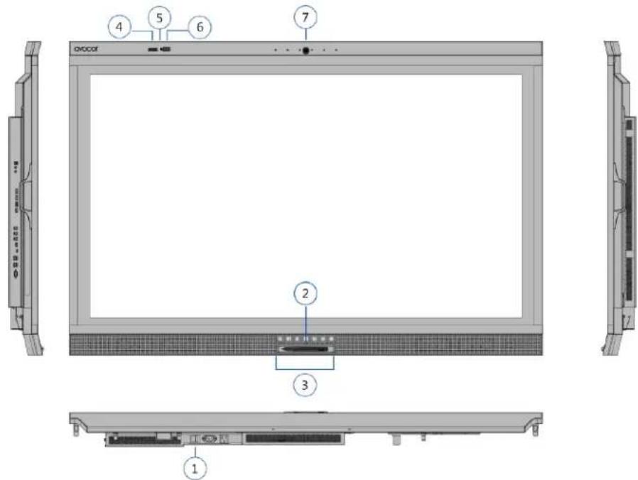
Figure 2-1. Display Front/ Side /Rear View
1. MAIN POWER SWITCH
Connects or disconnects the display panel from the AC power source.
2. Status LED
Solid green: display on, input detected
Blinking orange: display on, no input detected
Solid orange: display in power saving mode
Off: main power switched off
3. KEYPAD

natural_image
Row of seven gray rectangular icons representing media and audio control functions (no text or symbols)The keyboard allows the user to turn on the display, change sources, access the Windows start me nu and adjust the audio settings. The keypad operates as follows:
POWER

Press the button to turn on/off the monitor screen.
SOURCE

Press the button to select a media source.
Press and hold the button to go through the input sources.
Release button when desired source is selected.
MICROPHONE MUTE

Press the button to mute/unmute the microphone. (PC must be able to support this function)
WINDOWS

Press the button to activate Windows start menu
VOLUME MUTE

Press the button to mute/unmute the volume.
VOLUME DOWN
/ UP


Press these two buttons to lower or increase the volume.
Press and hold the button to continuously lower or increase the volume.
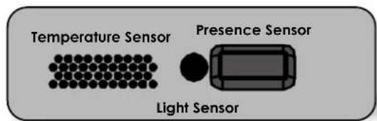
4. Temperature Sensor
Measures the room temperature and displays the data both in °C & °F on the OSD - information menu. Temperature data is also reported to the Azure IoT service.
5. Light Sensor
Senses the ambient lighting condition and shows the illumination data on the OSD - information menu Light sensor data is also reported to the Azure IoT servicel.
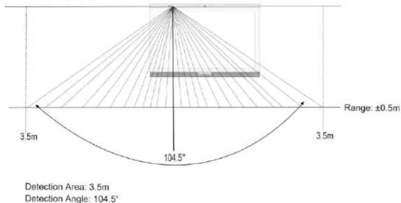
6. Presence Sensor
Detects movement in a scanned area, for angle coverage and detection range, see the following figures:
X-direction
Sensing angle: 104.5 degrees
Sensing distance: 3.5 meters
Y-direction
Sensing angle: 44.2 degrees
Sensing distance: 3.5 meters
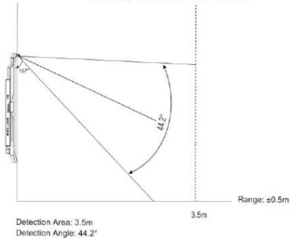
The light gray areas indicate where PIR sensor will not be able to detect motions.
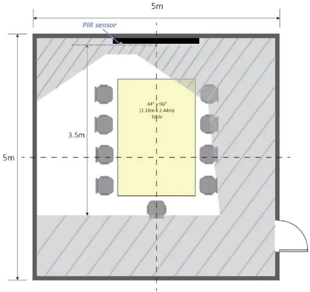
The display will wake up or go into power saving (sleep) mode automatically. The presence data shows on the OSD - information menu.
If no movement is detected, the sensor starts timing and go into power saving (sleep) mode after 5 minutes (minimum) and which is adjustable from 5, 10, 15, 30, 60 & 120 minutes.
The presence sensor data is also reported to the Azure IoT service.
7. Camera Status LED
White: camera power on
Off: camera power off
Input Panel
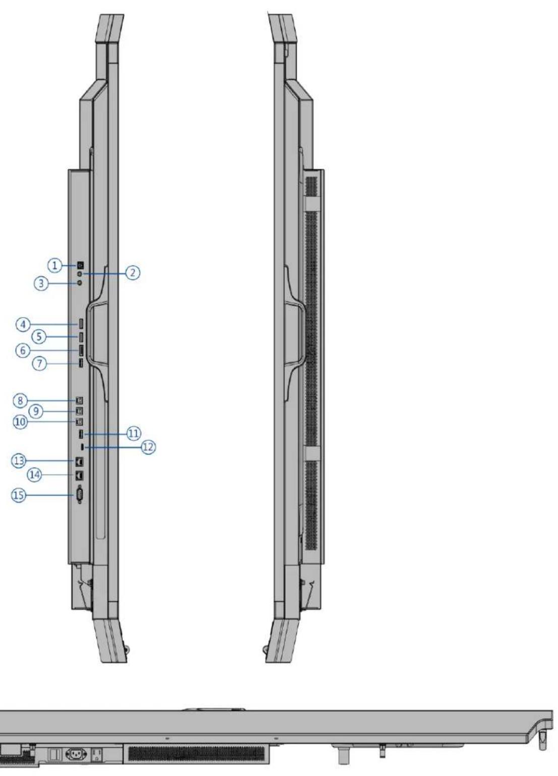
Figure 2-2 shows the display input panel.

natural_image
Technical line drawing of a device rear panel with internal components and connectors (no text or symbols)Figure 2-2. Display Input Panel View
| No. | Connector |
| 1 | SPDIFConnects external and powered digital speakers or audio receiver/amplifier. |
| 2 | Audio OutConnects external, powered speakers or an external audio receiver/amplifier. |
| 3 | IRConnects an IR Extender cable from this input. |
| 4 | HDMI 3HDCP-compliant HDMI 2.0 digital video input for connecting HDMI sources. |
| 5 | HDMI 2HDCP-compliant HDMI 2.0 digital video input for connecting HDMI sources. |
| 6 | DisplayPortDisplayPort 1.2 and DisplayPort-HDCP 1.1 compliant, SD/HD input for connecting SDTV, EDTV or HDTV component video sources. |
| 7 | Service PortA standard USB Type A connector for connecting a USB stick for firmware upgrade. Can also be used to power low voltage devices like a Miracast dongle. |
| 8,9,10 | Touch USB HUB 3.0 inType-B USB 3.0 port for connecting touch and media sources to the display for ports 4,5 & 6. |
| 11 | HUB USB 3.0Standard USB 3.0 type A connectors for connecting external media, keyboard, keyboard or mouse. |
| 12 | Type CType C USB port for connecting DisplayPort, USB, Power Delivery and Ethernet. |
| 13 | Ethernet InAn RJ-45 connector for interfacing with a PC or home theater automation/control system via a Cat 5 cable. |
| 14 | Ethernet OutAn RJ-45 connector for interfacing with a PC or home theater automation/control system via a Cat 5 cable. |
| 15 | RS232CA female, 9-pin D-sub connector for interfacing with a PC or home theatre automation/control system. |
Remote Control Unit
Figure 2-3 shows the display remote control, and Table 2-1 describes its functionality.
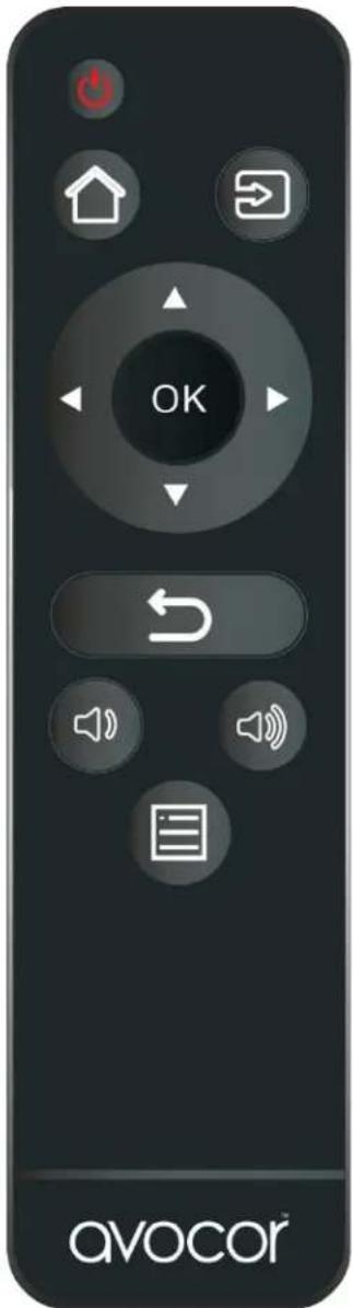
Figure 2-3. Display Remote Control Unit
Table 2-1. Remote Control Button Descriptions
| Button | Description |
 | PowerTurns the display screen on and off |
 | Home (default setting: DispalyPort1)Home source can be selected in OSD menu – Display Settings on page 43. |
 | SourceSelects a media source |
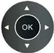 | Navigation arrowsNavigates through submenus and settings |
| OKConfirms the selection | |
 | ExitExits the OSD menu |
 | Volume downTurns down the volume - when AVW-6555 HDMI audio source is selected in your pc, laptop or personal devices (under Sound settings) |
 | Volume upTurns up the volume - when AVW-6555 HDMI audio source is selected in your pc, laptop or personal devices (under Sound settings) |
 | MenuOpens the OSD menu |
Hot keys for lock and unlock the remote control and built-in keypad
(power and source switch buttons only)
- Lock:
To lock the remote control and built-in keypad, press OK, OK, S, S, OK and S on the remote control. (This will not lock RS232 and Power On control.) - Unlock:
To unlock the remote control and built-in keypad, press , , OK OK OK OK and on the remote control.

NOTE Volume buttons setting on the remote control is only available when "AVW-6555 HDMI" audio source selected in your pc, laptop or personal devices, not available for other USB audio sources.
3. Installation

NOTE Installation must be performed by a qualified custom video installation specialist.
Remote Control
To install batteries in the remote control:
- Press down the tab on the cover and pull the cover up.
- Insert the included batteries. Ensure that the polarities correctly match the and markings inside the battery component.
- Insert the lower tab of the cover into the opening, and press down the cover until it clicks in place.
Notes on Batteries
Make sure that the battery polarities are correct when installing the batteries.
• Do not mix an old battery with a new one or different types of batteries.
- If you will not use the remote control for a long time, remov e the batteries to avoid damage from battery leakage.
• Do not expose batteries to excessive heat such as from sunshine, fire or the like.
Notes on Remote Control Operation
• Make sure that there is nothing obstructing the infrared beam between the remote control and the IR receiver on the display.
- If the effective range of the remote control decreases, or it stops working, replace the batteries with new ones.
- The remote control may fail to operate if the infrared remote sensor is exposed to bright sunlight or fluorescent lighting.
- Ambient conditions may possibly impede the operation of the remote control. If this happens, point the remote control at the display, and repeat the operation.
Quick Setup
Table 3-1 gives a quick overview of the display installation process. The sections following this one provide detailed instructions.
Table 3-1. Installation Overview
| Step | Procedure | For DetailsRefer to page... |
| 1 | Mount the display(s) on a wall (optional) | 28 |
| 2 | Connect other external equipment to the display (optional): Automation/control system (RS232, Ethernet) | 29 |
| 3 | Connect signal sources to the display | 31 |
| 4 | Apply power to the display | 33 |
| 5 | Change the OSD language (optional) | 34 |
| 6 | Perform touch screen-specific installation and configuration tasks (AVOCOR): Connect touch screen controller host computer to the display | 35 |
| 7 | Display calibration - adjust the following for each input:Aspect ratioBrightnessContrastColor temperature and white balanceColor levelTintInput position | 41 |
Installation Considerations
Proper installation of your display will ensure a satisfying viewing experience. Whether a display is installed temporarily or permanently, the following should be taken into account to ensure the best performance of the display.
Ambient Light
In general, minimise or eliminate light sources directed at the screen. Contrast ratio in your images will be noticeably reduced if light directly strikes the screen, such as when a shaft of light from a window or floodlight falls on the image. Images may then appear washed out and less vibrant. Direct sunlight may affect touch operation.
Ambient Temperature
Keep the ambient temperature constant and below 40^ C ( 104^ F). Keep the display away from heating and/or air conditioning vents.
Ventilation
If you are mounting the display in an enclosure, leave sufficient space on all sides between it and surrounding objects, as shown in Figure 3-1. This allows heat to disperse, maintaining the proper operating temperature.
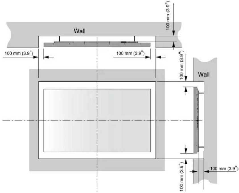
Figure 3-1. Ventilation Requirements for Enclosure Mounting
Mounting the Display
You can mount the display on a wall.
If you do decide to wall-mount the display, ensure that the wall-mount bracket is installed according to the instructions included with it. The wall must be capable of supporting a redundant weight factor three (3) times the weight of the display, or be reinforced.
We recommend that this be done by a custom installation specialist.

NOTE
To safely mount the display on a wall:
- Use only the approved wall-mount kit designed for the display.
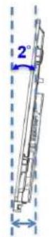
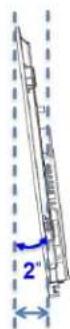
• Make sure the tilt degree of the wall does not exceed 2 degrees.
For more information of wall mount installation, refer to Appendix II: Installing a Wall Mount on page 67.
Connections to the Display
Proceed as follows to connect the display to your video sources, external controller(s) – if present – and AC power.
When connecting your equipment:
• Turn off all equipment before making any connections.
• Use the correct signal cables for each source.
- For best performance and to minimise cable clutter, use high-quality cables that are only as long as necessary to connect two devices. ( Please use the cables that are provided in the packaging box.)
• Ensure that the cables are securely connected. Tighten the thumbscrews on connectors that have them.
Connecting a Control System or PC
RS-232 Connection
Use a straight-through RS-232 cable with a 9-pin male connector to connect a PC or control/ automation system (if present) to the RS-232 port on the display; see Figure 3-2.
For more information about using this connection, refer to External Control on page 53.
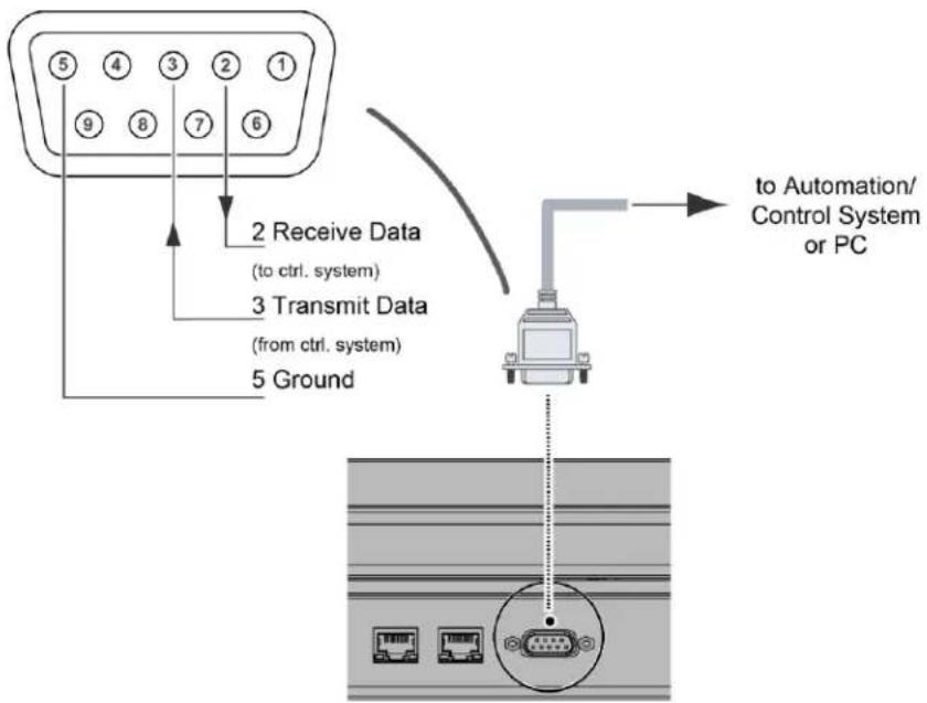
Figure 3-2. RS-232 Control System Connection

NOTE
The RS-232 connection may vary with different control system. If there is any problem regarding the connection, please contact our customer service for further assistance.
Ethernet Connection
Use a standard Ethernet cable with an RJ-45 male connector to connect a PC or control/automation system (if present) to the Ethernet port on the display.
For more information about using this connection, refer to External Control on page 53.
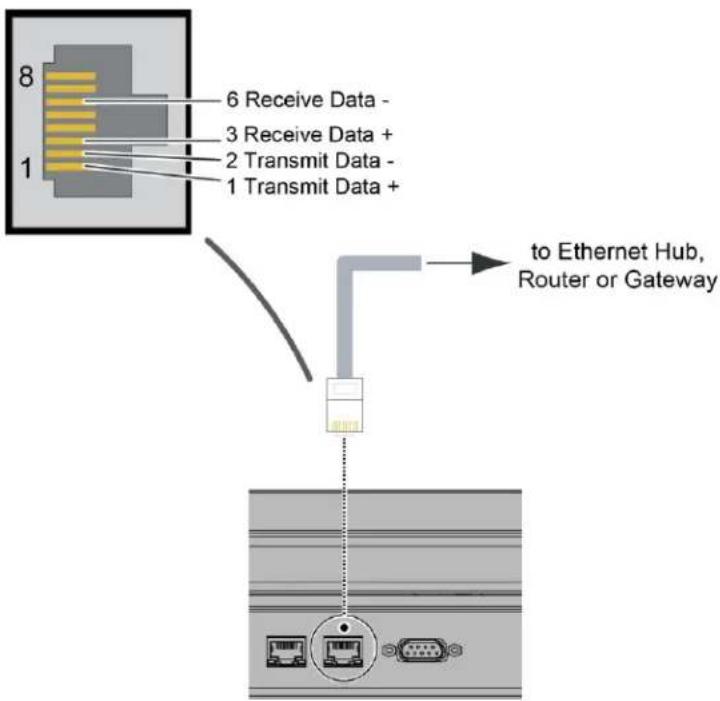
Figure 3-3. Ethernet Connection
Connecting Source Components to the Display
Connect your video sources to the display as shown and described in the sections that follow.
DisplayPort Source Connection: See Figure 3-4.
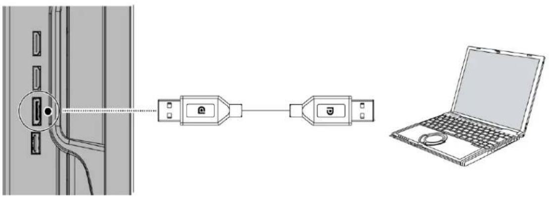
Figure 3-4. DisplayPort Source Connection
HDMI Source Connections: See Figure 3-5.

NOTE
This display supports the VESA Display Data Channel (DDC) standard. This standard provides "Plug and Play" capability; the display and a VESA DDC-compatible computer communicate their setting requirements, allowing for quick and easy setup.
For Plug and Play to work correctly, you must turn on the display before you turn on the connected computer.
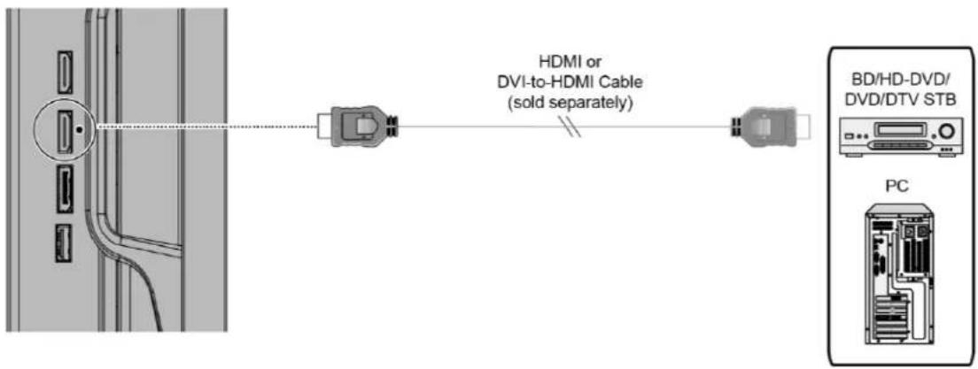
Figure 3-5. HDMI Source Connections
Type C Source Connection:
Connect a personal laptop to the Type C input as shown in Figure 3-6.

NOTE
Refer to Supported Timings on page 61 for a list of compatible input signals.
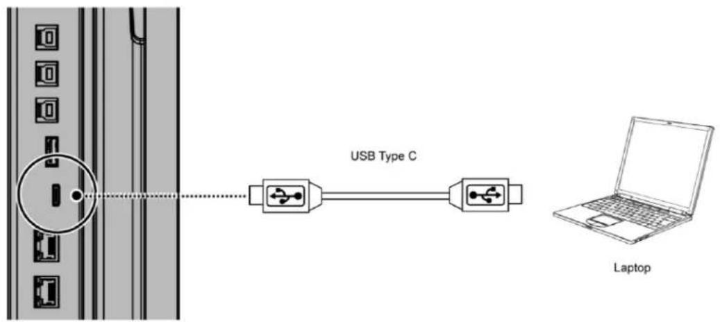
Figure 3-6. Type C Source Connections
Turning on the Power
- Turn on your source components.
- Plug the female end of the supplied power cord into the AC receptacle on the side of the display (AC 100V \~ 240V). See Figure 2-2.
- Connect the other end to your AC power source.
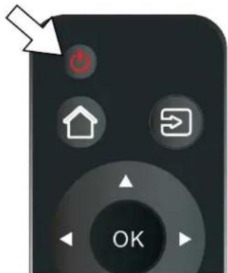
- Turn on the main power switch at the side of the display (see Figure 2-1). The power indicator lights orange to indicate that the display is in "standby" mode.
- Press the power button ( ) on the remote control to turn on the display or press the power button ( ) the keypad.
- After a brief warm-up period, the display will display an image.

NOTE
If there's no input signal for a period, the display will automatically go into power saving (sleep) mode.
Changing the OSD Language
The display OSD language is initially set to English, but can also display the menus in different languages.
To change the OSD language:
- Press MENU.
- Select Basic Settings from the Main Menu.
-
Select OSD Language from the Basic Settings Menu.
-
Press of to select the desired language and press OK. The change takes effect immediately.
Enabling the Touch Screen
Before setting up your display to support touch screen capability, ensure that:
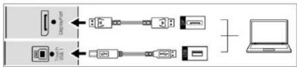
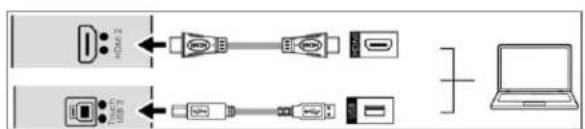
- Your computer is turned on and connected to the display using Type C or the provided USB cable (for DispalyPort and HDMI source connections). Make sure connect the cable to the display by following the corresponding indicating dots on I/O ports. See Figure 3-7.
- The video output from the computer is connected to a video input on the display. See Figure 3-4, Figure 3-5 or Figure 3-6.
• The display is turned on.
• Using the Remote Control push the source button and select the source you connected or press the Source Button on the KEYPAD to select the source.
Type C connection

DisplayPort connection
flowchart
graph LR
    A["Device 1"] -->|USB| B["Device 2"]
    C["Device 3"] -->|USB| D["Device 4"]
    B --> E["Laptop"]
HDMI2 connection
HDMI3 connection
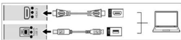
Figure 3-7. Touch Screen Controller (Type C, USB) Connection

NOTE
If the touch screen is not working, please turn off your computer or the display and enabling the touch screen again following the steps above.
Software Installation
This driver is not needed for any touch functionality, but is needed in order to perform firmware upgrade.
Automatic Driver Installation
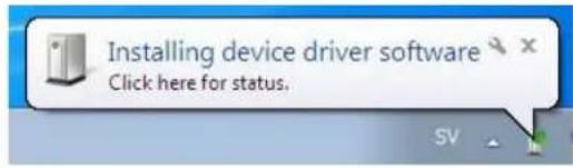
If the automatic driver installation starts, please allow it to run until completion in order to not disrupt the automatic process. Note that the icon may be hidden in the notification area, and that the procedure may take several minutes.

Clicking on the pop-up ballon at this point would show
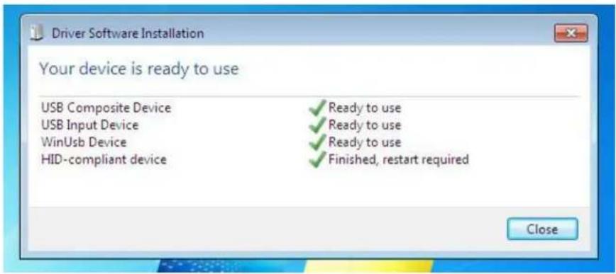
Fully expanded, the view in the Device Manager should look like this (View --> Devices by connection):
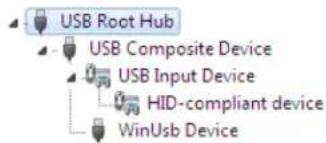
If the automatic installation fails to find the driver, or if automatic driver installation is disabled, or if there is no Internet connection, this is what you will typically see when connecting a FlagFrog touch device.

Clicking on the pop-up balloon would show
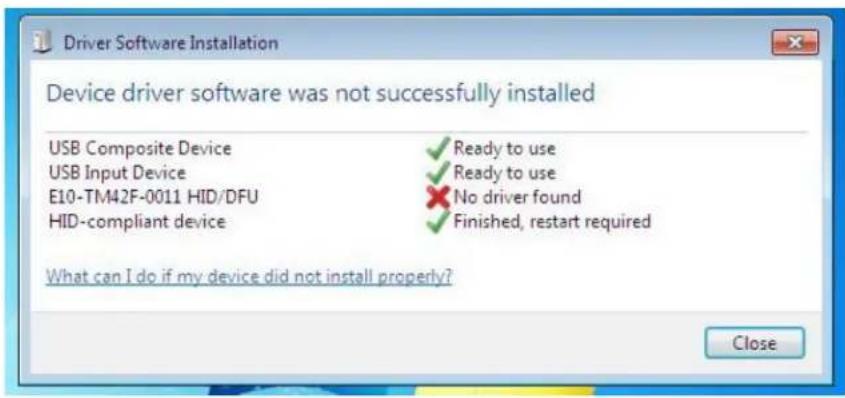
In the Device Manager, the view would be (again, use View --> Devices by connection):
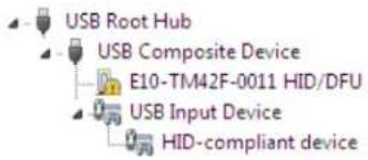
In this case, please proceed with Manual Driver Insatllation.
Manual Driver Installation
If the automatic driver installation failed for any of the reasons listed above, or if you would like to install the driver without having a FlatFrog touch device connected to the computer, the driver can be installed manually.
The driver provided with this upgrade package was downloaded from http://catalog.update.microsoft.com (requires Internet Explorer) and is called "Microsoft – Other hardware – WinUsb Device" (version 1.1.0.0 from 2012-08-30).
Manual Driver Installation - Device Connected
- Extract the firmware upgrade .zip file (right-click --> Extract all...) to the Desktop.
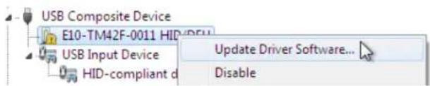
- Open the Device Manager and locate the "HID/DFU" device with the yellow exclamation mark.
- Right-click and select "Update Driver Software..."
- Select "Browse my computer for driver software" and select the extracted folder from step 1 and follow the instructions.
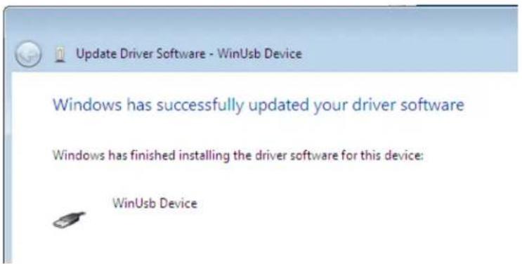
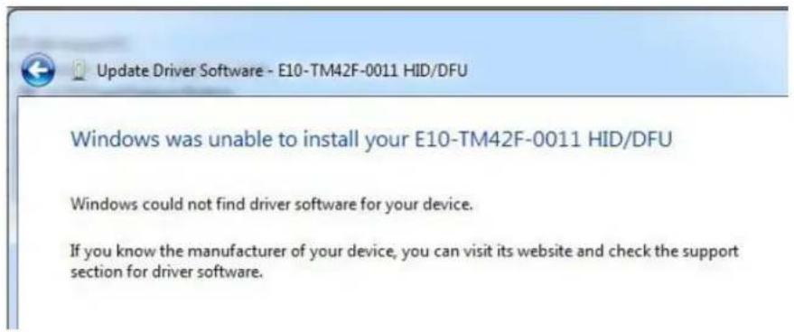
- If step 4 was unsuccessful, then Windows failed to automatically associate the driver with the device.
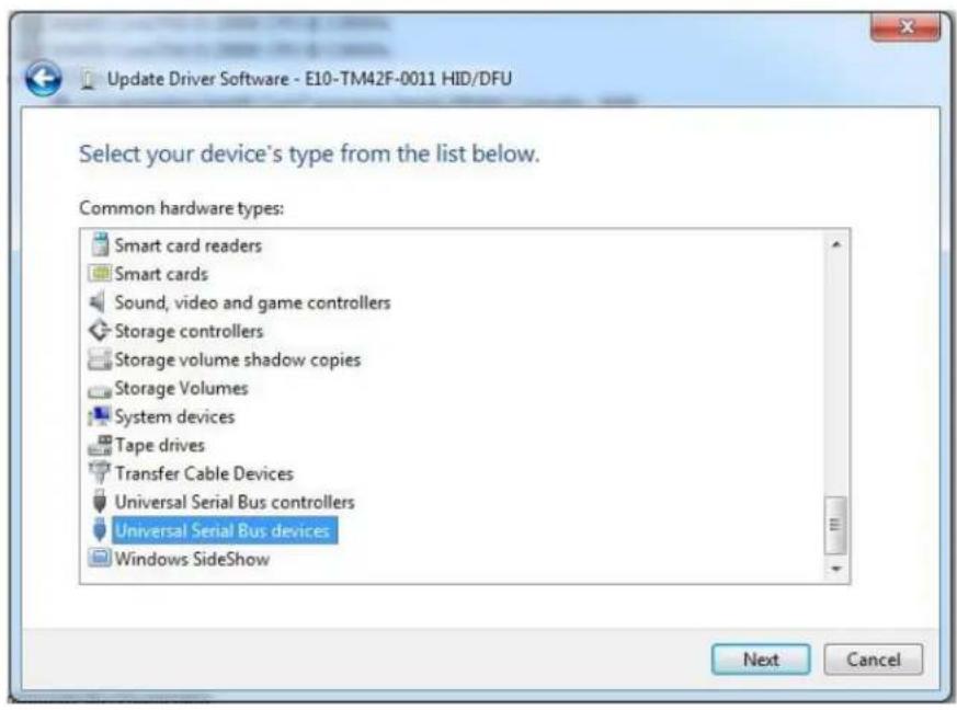
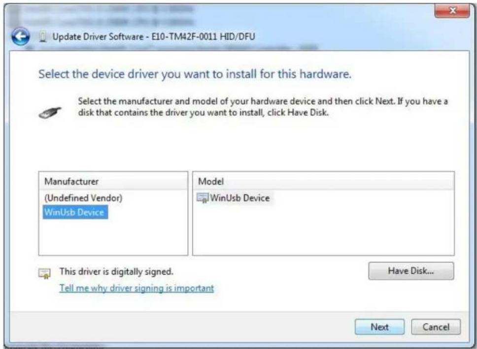
- Choose "Let me pick from a list if device drivers on my computer" in step 4, scroll all the way down to "Universal Serial Bus devices" and click Next.
- Select the WinUsb device driver, and click Next. (If the WinUsb device driver is not in the list, please follow the steps under "Manual Driver Installation - Device Not Connected" first).
Manual Driver Installation - Device Not Connected
- Extract the firmware upgrade .zip file (right-click --> Extract all...) to the Desktop.
- Navigate to the "support" folder.
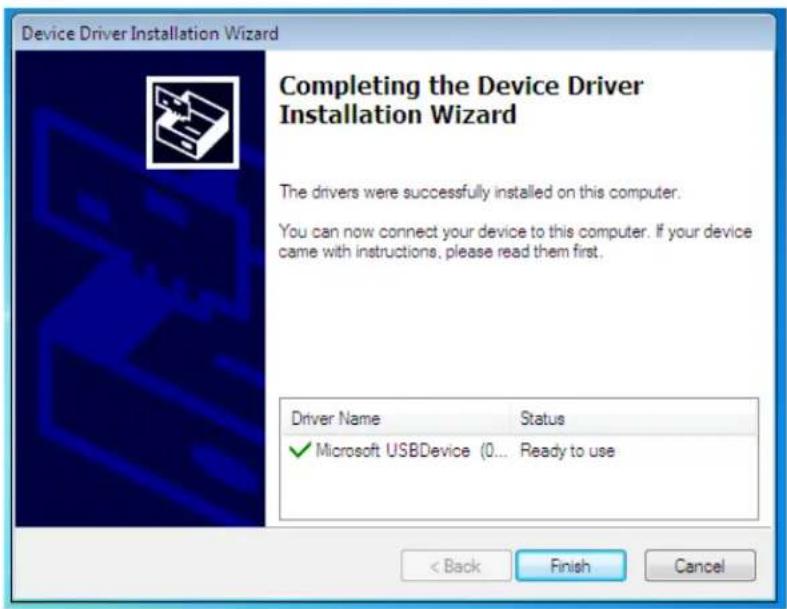
- Right-click on the install_driver.bat file and select "Run as administrator" and follow the instructions.
4. Operation
Using the On-Screen Menus
To display the on-screen menus, press MENU on the remote control (Figure 2-3) or built-in keypad (Figure 2-1).
To select a sub-menu, use the and buttons to highlight it. Then, press to enter that sub-menu.
To select a menu item, use the and buttons to highlight it. Then, press or to adjust that setting and press OK.
The OSD menus are arranged hierarchically, as shown in Figure 4-1. The default values appear in bold type. Depending on the selected input source and signal characteristics, some menu options may not be available.
| Main Menu | SubMenu | Value |
| Image Settings | Scheme | User, Vivid, Cinema, Game, Sport |
| Brightness | 0, 1, 2, ..., 50, ...,100 | |
| Contrast | 0, 1, 2, ..., 50, ...,100 | |
| Sharpness | 0, 1, 2, ..., 50, ...,100 | |
| Saturation | 0, 1, 2, ..., 50, ...,100 | |
| Hue | 0, 1, 2, ..., 50, ...,100 | |
| Backlight | 0, 1, 2, ..., 50, ..., 80, ...,100 | |
| Color Temp & Gamma | Color Temp: 5000K; 6500K; 7500K; 9300K; User | |
| Gamma: 2.2; off | ||
| HDMI RGB Range | Auto; 0-255; 16-235 | |
| Display Settings | Input Source | DisplayPort1; HDMI2; HDMI3; Type C |
| Aspect Ratio | 16:9; 4:3; Auto; Point To Point; Letterbox | |
| OverScan | 0% ~ 10% | |
| Source Renaming | Rename the input source. | |
| No Source Default | DisplayPort1; HDMI2; HDMI3; Type C | |
| Home Source | DisplayPort1; HDMI2; HDMI3; Type C | |
| Audio | Volume | 0 ~ 100 (70) |
| Treble | -10 ~ 10 (0) | |
| Bass | -10 ~ 10 (0) | |
| Balance | -10 ~ 10 (0) | |
| Internal Speaker | On; Off | |
| Basic Settings | Horizontal Pos. | 0 ~ 100 (50) |
| Vertical Pos. | 0 ~ 100 (50) | |
| OSD Transparency | 0 ~ 4 (0) | |
| OSD Timeout | 5 ~ 60 seconds (30) | |
| OSD Language | English; French; Spanish; German; Dutch; Swedish; Portuguese; Danish; Italian | |
| Splash Screen | Off; Default; User | |
| Splash Screen Download | Yes; No | |
| Power LED | On; Off | |
| RTC & Schedule | User Mode; Workday Mode; Everyday Mode | |
| Adv. Settings | Smart Switch | On; Off |
| Presence Detection | Off; 5 mins; 10 mins; 15 mins; 30 mins, 60 mins; 120 mins | |
| Wake Up from Sleep | No; Yes; Never Sleep | |
| EDID Switch | 1080p; 4K2K@30; 4K2K@60 | |
| Touch Input Mapping | Auto; USB Touch 1; USB Touch 2; USB Touch 3 | |
| Game Mode | On; Off | |
| USB Settings | On; Off(Touch USB, HID USB, Audio USB, External USB, LAN USB) | |
| Network Configuration | - | |
| Telemetry Interval | 1 ~ 60 seconds (5) | |
| Firmware Update (USB) | Yes; No | |
| IoT Firmware Update | Yes; No | |
| Restore Factory Default | Yes; No | |
| Information | Source | Shows the Name of Input Source |
| Resolution | Shows the Current Resolution | |
| Temperature | Show the Temperature in °C and °F | |
| Ambient Light | Show the Ambient Light in Lux | |
| Presence | Show the Presence Detection status (Yes / No) | |
| IoT Status | Show the IoT connection status | |
| Model Name | AVW-6555 | |
| Firmware Version | Shows the Firmware Version of the Monitor | |
| Serial Number | Shows the Serial Number of the Monitor |

NOTE Default settings appear in bold type.
Figure 4-1. OSD Menu Structure
Input Menu
This menu is used for making common image adjustments.
Image Settings
| Scheme | User |
| Brightness | 50 |
| Contrast | 50 |
| Sharpness | 50 |
| Saturation | 50 |
| Hue | 50 |
| Backlight | 80 |
| Gamma & Color Temp. | > |
| HDMI RGB Range | 0~255 |
| Scheme | |
| Press ◀ or ▶ to select one of the follows:Options:User, Vivid, Cinema, Game, Sport;Default:User | |
| Brightness | |
| Increase or decrease the brightness of picture.Press ◀ or ▶ to select the desired level, and then press OK.Range:0~100;Default:50 | |
| Contrast | |
| Increase or decrease the contrast of picture.Press ◀ or ▶ to select the desired level, and then press OK.Range:0~100;Default:50 | |
| Saturation | |
| Adjust the brilliance and brightness.Press ◀ or ▶ to select the desired level, and then press OK.Range:0~100;Default:50Note: This function is not available when displaying PC or graphics sources | |
| Hue | |
| Increase or decrease the green hue.Press ◀ or ▶ to select the desired level, and then press OK.Range:0~100;Default:50Note: This function is not available when displaying PC or graphics sources | |
| Backlight | |
| Increase or decrease the intensity of the LCD backlight.Press ◀ or ▶ to select the desired level, and then press OK.Range:0~100;Default:80 | |
| Color Temp & Gamma | |
| Set Color Temperature and Gamma. See next page. | |
| HDMI RGB Range | |
| Select an RGB range for the HDMI input.Options:Auto, 0-255, 16-235;Default:0~255Note: This function is only available when connect HDMI or Type C source. | |
Color Temperature Settings
Color Temp & Gamma
| Gamma | 2.2 |
| Color Temperature | 9300K |
| Red Gain | 50 |
| Green Gain | 50 |
| Blue Gain | 50 |
| Red Offset | 50 |
| Green Offset | 50 |
| Blue Offset | 50 |
| Gamma | |
| Select gamma curveOptions: Off, 2.2; Default: 2.2 | |
| Color Temperature | |
| Select a color temperature or select User to make RGB adjustments.Options: User, 5000K, 6500K, 7500K and 9300K; Default: 9300K | |
| Red Gain | |
| Set Color Temperature to “User Mode” to adjust this setting.Range: 0~100; Default: 50 | |
| Green Gain | |
| Set Color Temperature to “User Mode” to adjust this setting.Range: 0~100; Default: 50 | |
| Blue Gain | |
| Set Color Temperature to “User Mode” to adjust this setting.Range: 0~100; Default: 50 | |
| Red Offset | |
| Set Color Temperature to “User Mode” to adjust this setting.Range: 0~100; Default: 50 | |
| Green Offset | |
| Set Color Temperature to “User Mode” to adjust this setting.Range: 0~100; Default: 50 | |
| Blue Offset | |
| Set Color Temperature to “User Mode” to adjust this setting.Range: 0~100; Default: 50 | |
Display Settings
This menu is used for making general display settings.
Display Settings
| Input Source | Type-C |
| Aspect Ratio | Auto |
| Over Scan | 0 % |
| Source Renaming | > |
| No-Source Default | DisplayPort1 |
| HOME Source | DisplayPort1 |
| Input Source | |
| Select the main input sourceOptions: HDMI 2; HDMI 3; DisplayPort; Type CDefault: Type C | |
| Aspect Ratio | |
| Select aspect ratioPress ▶ or ▶ to select the aspect ratio, and then press OK.Range: 16:9; 4:3; Auto; Point To Point; LetterboxDefault: Auto | |
| OverScan | |
| Adjust the overscan of the image.Press ▶ or ▶ to select the desired level, and then press OK.Range: 0% ~ 10%; Default: 0% | |
| Source Renaming | |
| Rename the input source.Press OK to select the input source you want to rename. Using ▲ or ▼ to change the character and ▶ or ▶ to move forward/back a position. Then press OK button to save the name. | |
| No-Source Default | |
| Select the Input Source when all input source is no signalOptions: HDMI 2; HDMI 3; DisplayPort1; Type CDefault: DisplayPort1 | |
| HOME Source | |
| Select the Input Source for HOME keyOptions: HDMI 2; HDMI 3; DisplayPort1; Type CDefault: DisplayPort1 | |
Audio Menu
This menu is used for adjusting volume settings.
| Audio Settings | ||
 | Volume | 70 |
| Bass | 0 | |
| Treble | 0 | |
 | Balance | 0 |
| Speaker | On | |
 | ||
 | ||
| Volume | |
| Adjust the sound. Press ◀ or ▶ to select the desired level, and then press OK.Range: 0~100; Default: 70 | |
| Bass | |
| Adjust the sound in low tones (bass). Press ◀ or ▶ to select the desired level, and then press OK.Range: -10~10; Default: 0 | |
| Treble | |
| Adjust the sound in high tones (treble). Press ◀ or ▶ to select the desired level, and then press OK.Range: -10~10; Default: 0 | |
| Balance | |
| Adjust the balance of the left and right speakers. Press ◀ or ▶ to select the desired level, and then press OK.Range: -10~10; Default: 0 | |
| Speaker | |
| Turn the internal speaker on or offDefault: On | |

NOTE This menu option is only available when "AVW-6555 HDMI" audio source selected in your pc, laptop or personal devices, not available for other USB audio sources.
Basic Settings
This menu is used to make basic settings.
Basic Settings
| Horizontal Pos. | 50 |
| Vertical Pos. | 50 |
| OSD Transparency | 0 |
| OSD Timeout | 30 Seconds |
| OSD Language | English |
| Splash Screen | Default |
| Splash Screen Download | > |
| Power LED | On |
| RTC & Schedule | > |
| Horizontal Pos. | |
| Adjust the horizontal position of the OSD menu. Press ◀ or ▶ to select the desired level, and then press OK.Range: 0~100; Default: 50 | |
| Vertical Pos. | |
| Adjust the vertical position of the OSD menu. Press ◀ or ▶ to select the desired level, and then press OK.Range: 0~100; Default: 50 | |
| OSD Transparency | |
| Adjust the transparency of the OSD menu. Press ◀ or ▶ to select the desired level, and then press OK.Range: 0~4; Default: 0 | |
| OSD Timeout | |
| Adjust the time in seconds before the OSD menu disappears. Press ◀ or ▶ to select the desired level, and then press OK.Options: 5s~60s; Default: 30s | |
| OSD Language | |
| Select the OSD language:Options: English; French; Spanish; German; Dutch; Swedish; Portuguese; Danish: Italian: Default: Enalish | |
| Splash Screen | |
| Select whether a splash screen appears when the monitor is powered upOptions: Off; Default; User; Default: Default | |
| Splash Screen Download | |
| Change the user splash screen image by plugging a thumb drive into Service portOptions: Yes, NoNote: The file name must be named as "userlogo.jpg", in 3840x2160 or 1920x1080 pixels and less than 1MB.Press Yes to load the splash screen image you want to use. After loaded the image, go to Splash Screen setting and change to "User" then press OK | |
| Power LED | |
| Enable or disable the status LEDOptions: On, Off; Default: On | |
| RTC & Schedule | |
| Set the internal clock of the display, and to power on and off the display at preset times if desired.Options: User, Workday, Everyday; Default: User | |
Advanced Settings
This menu is used to make advanced settings.
| Smart Switching | On |
| Presence Detection | 120 Minutes |
| Wake Up From Sleep | Yes |
| EDID Switch | > |
| Touch Input Mapping | Auto |
| Game Mode | On |
| USB Settings | > |
| Network Configuration | > |
| Telemetry Interval | 5 Seconds |
| Adv. Settings | |
| Firmware Update(USB) | > |
| IoT Firmware Update | > |
| Restore Factory Default | > |
| Smart Switch | |
| Detect input and switch source automaticallyOptions: Off, On; Default: On | |
| Presence Detection | |
| Enable presence detection functionOptions: Off, 5 mins, 10 mins, 15 mins, 30 mins, 60 mins & 120 minsDefault: 120 mins | |
| Wake Up From Sleep | |
| Options: No, Yes; Never SleepDefault: YesNote: The display wakes up when input HDMI, DisplayPort & Type C & RS232 command. | |
| EDID Switch | |
| Select EDID (Extended Display Identification Data) of the DisplayPort, HDMI 2~3, Type C inputs. Options: 1080p, 4K2K@30, 4K2K@60; Default: 4K2K@60Note: Use the 1080p setting for the broadest support of lower resolution sources. Use 4K2K setting to support high resolution sources such as 3840x2160. | |
| Touch Input Mapping | |
| Select one of the touch connections or choose auto detection. Options: Auto, USB Touch 1, USB Touch 2, USB Touch 3; Default: Auto | |
| Game Mode | |
| Select Game modeOptions: On, Off; Default: On | |
| USB Settings | |
| Configures USB settings, including Touch USB, HID USB, Audio USB, External USB, LAN USBOptions: On, Off; Default: On | |
| Network Configuration | |
Configures the display's RS232 and Ethernet communication ports.
For more settings, see Network Configuration on page 48
| Telemetry Interval | |
| Configures the frequency of sending out sensors data to IoT I web server. Options: 1s~60s; Default: 5s | |
| Firmware Update (USB) | |
| Plug in the USB flash drive and select Yes to proceed with firmware update. To start updating firmware, select Yes to continue. Options: No, Yes; Default: Yes | |
| IoT Firmware Update | |
| Plug in the USB flash drive and select Yes to process with IoT firmware update. To start updating IoT firmware, select Yes to continue Options: No, Yes | |
| Restore Factory Default | |
| Restore all settings to their default value. Options: No, Yes Note: To reset network connection to default must go to Network Configuration - Load Default and select Yes to restore. | |
Wake Up from Sleep
By default, the display will enter power saving (Sleep Mode) if no signal is received for 5 minutes. Normally, the Type C, RS-232, DisplayPort, and HDMI inputs are inactive in Sleep Mode, to save power.
To change the behavior of Sleep Mode, change the "Wake up from Sleep" setting in the "Adv. Setup" menu.
- Digital, RS232, Ethernet – The RS-232, DisplayPort, HDMI and Type C inputs stay active when the display is in sleep mode. The display will wake up when it receives a signal at either of the DisplayPort, HDMI, Type C or RS-232 inputs, or via LAN connection.
Network Configuration
This menu configures the display's RS232 and Ethernet communication ports.
| Network Configuration | |
| Dynamic IP | Enable |
| IP Address | 000.000.000.000 |
| Netmask | . . . |
| Gateway | . . . |
| DNS | . . . |
| Save Settings | > |
| Refresh | > |
| Load Default | > |
| MAC Address | 00:00:00:00:00:00 |
| Dynamic IP | |
| Enable or disable Dynamic IP modeOptions: Enable; Disable; Default: Enable | |
| IP Address | |
| Display dynamic IP or the static IP address of the display's Ethernet portDefault: 0.0.0.0 | |
| Netmask | |
| Set the subnet mask address.Default: 0.0.0.0 | |
| Gateway | |
| Set the Gateway mask address.Default: 0.0.0.0 | |
| DNS | |
| Set the DNS mask address.Default: 0.0.0.0 | |
| Save Settings | |
| Save the network settings and apply to device. | |
| Refresh | |
| Refresh dynamic IP information. | |
| Load Default | |
| Load default communication settingsOptions: No, Yes | |
| MAC Address | |
| Display the MAC address of the device. | |
Information
This read-only menu provides information on the active source, sensor data, IoT connection status the latest firmware version, and the serial number.
Information


Type-C
3840x2160@60Hz
Temperature
AmbientLight
Presence
IoT Status
AVW-6555
SN
79(F) / 26(C)
260 lux
No
Connecting
V1.00/V02/10
XXXXXXXXXXXXXX
| Source | |
| Show the Name of Input Source | |
| Resolution | |
| Show the Current Resolution | |
| Temperature | |
| Display room temperature data both in °C and °F | |
| Ambient Light | |
| Display room brightness data in lux | |
| Presence | |
| Display proximity statusDetected: Yes; undetected: No | |
| IoT Status | |
| Display IoT connection statusStatus: connecting: connected | |
| Model Name | |
| AVW-6555 | |
| Firmware Version | |
| Show the Firmware Version of the Monitor | |
| Serial Number | |
| Show the Serial Number of the Monitor | |
5. Maintenance and Troubleshooting
Maintenance
The AVOCOR Series LED Displays does not require any routine maintenance other than occasional cleaning with a non-abrasive cloth. There are no user-serviceable or replaceable parts. Unless you are a qualified, factory-trained technician, do not attempt to repair or replace any system component yourself. You will void the product warranty if you do so.
Troubleshooting
Table 5-1 provides some general guidelines for troubleshooting problems you may encounter with the AVOCOR Series LED Display. If the suggested solutions fail to resolve the problem or if you encounter an issue not described here, please contact your dealer.
Table 5-1. Troubleshooting Chart
| Symptom | Possible Cause(s) | Solution |
| The display does not turn on. | The display is not plugged in or the AC outlet is not active.The main power switch is off.The remote control batteries have run out. | Ensure that the display is plugged in and that the AC outlet is active.Set the main power switch (see Figure 2-1) to the on position.Replace the batteries. |
| The display is on and menus appear, but there is no picture. | Incorrect source selection.Source component is not turned on.Source component is connected incorrectly or not at all. | Select the correct source.Turn on the source component.Check connections from the source component to the display. |
| The remote control does not work. | The remote control batteries have run out.The buttons are locked. | Replace the batteries.Unlock the buttons by pressing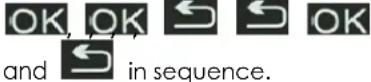 |
| Image geometry is incorrect. | Incorrect aspect ratio selection. | Select a different aspect ratio. |
| The display is jittery or unstable. | Poor-quality or improperly connected source.The horizontal or vertical scan frequency of the input signal may be out of range for the display. | Ensure that the source is properly connected and of adequate quality for detection.Correct at the source. |
| Image is too bright and / or lacks definition in the bright areas of the image. | Contrast is set too high. | Decrease the contrast setting. |
| Image appears “washed out” and / or dark areas appear too bright. | Brightness is set too high. | Decrease the brightness setting. |
| Image is too dark. | Brightness and / or Backlight are set too low. | Increase the brightness and / or backlight settings. |
| Images from an HDMI source do not display. | The resolution and frequency of the video card in the computer are not compatible with the display.HDMI cable from source to display is either defective or too long. | Select a compatible resolution and vertical frequency (refer to Supported Timings on page 61).Try a known-good and / or shorter HDMI cable. |
| Computer images do not display correctly. | The resolution and frequency of the video card in the computer are not compatible with the display | Select a compatible resolution and vertical frequency (refer to Supported Timings on page 61). |
| Touch screen doesn't work. | Multi-touch controller host computer is not connected correctly.Host computer hardware or OS incompatibility. | See Figure 3-7.Refer to Enabling the Touch Screen on page 34. |
Should you require assistance with a suspected hardware fault, please contact the support line below. You will require your unit serial number. The operator will attempt to diagnose any fault and will take action as appropriate.
avocor™
Warranty Support UK & EMEA. Tel +44 (0) 1276 804 654 - service@avocor.co.uk US & ROW. Tel. 858-268-7999 - service@avocor.com
6. External Control
In addition to using the display keypad or remote control unit, you can control the display using a serial (RS232) link to send Hexadecimal commands and receive responses to those commands. (ASCII is not accepted/used)
You also use discrete infrared (IR) control codes to program a third-party remote control unit. For more information, refer to Using Discrete IR Codes on page 59.
Serial Communications
The display uses a simple text-based control protocol to take requests from control devices and to provide responses to such devices. This section describes how to send control messages over a serial link between the display and an automation/control system or a PC running a terminal emulation program such as Windows® HyperTerminal or Tera Term.
RS232 Connection and Port Configuration
Connect your control system or PC to the RS232 input of the display as shown in Figure 3-2.
Configure the RS232 controller or PC serial port as follows: no parity, 8 data bits, 1 stop bit and no flow control. Set the baud rate to 115200, to match that of the display RS232 port.
Command and Response Format
Commands sent from an automation/control system or PC to the display must have the following format:
[STX] [IDT] [TYPE] [CMD] ([VALUE] or [REPLY]) [ETX]
Where:
• [STX] indicates the start of the command data (07).
• [IDT] is the display ID.
• [TYPE] is the command type:
00 = return to host (response from the LCD panel)
01 = read / action
02 = write
• [VALUE] is the parameter setting for the command.
- [REPLY] is the parameter setting for the command, acknowledged by the display in its response to a command.
• [ETX] indicates the end of the command data (always 08).
Command and Response Examples
Here are some examples of Hexadecimal serial commands and their responses:
Table 6-1. Serial Command/ Response Examples
| Description | Command sent to LCD Panel | Response Received from LCD Panel |
| Turn LCD panel power off. | 07 01 02 50 4F 57 00 08 | 07 01 00 50 4F 57 00 08 |
| Turn LCD panel power on. | 07 01 02 50 4F 57 01 08 | 07 01 00 50 4F 57 01 08 |
| Request LCD panel power status. | 07 01 01 50 4F 57 08 | 07 01 00 50 4F 57 XX 08(XX = 0 when off or 1 when on) |
| Set the LCD panel contrast to 30 (1E hex). | 07 01 02 43 4F 4E 1E 08 | 07 01 00 43 4F 4E 1E 08 |
| Reset the LCD panel display settings. | 07 01 02 41 4C 4C 00 08 | 07 01 00 41 4C 4C 00 08 |
| Request LCD panel serial number. | 07 01 01 53 45 52 08 | 07 01 00 53 45 52 S(0)...S(12) 08S(0) ...S(12) = the serial number in ASCII |
| Request LCD panel firmware version. | 07 01 01 47 56 45 08 | 07 01 00 47 56 45 S(0)...S(5) 08S(0)...S(5) = the firmware version in ASCII |
Serial Command List
Table 6-2 lists all supported commands.
Table 6-2. Serial Commands
| Main Item | Control Item | Type | CMD (HEX) | Value (HEX) | Reply (HEX) | Content | CMD (ASCII) |
| Power Control and Input Source | Power Control | W/R | 50 4F 57 (Note) | 0 | 0 | Off (soft power) | POW |
| 1 | 1 | On (soft power) | |||||
| Input Source | W/R | 4D 49 4E | 9 | 9 | HDMI 2 | MIN | |
| 0A | 0A | HDMI 3 | |||||
| 0D | 0D | DisplayPort1 | |||||
| 0E | 0E | Type C | |||||
| Display Adjustment | Display Adjustment | W/R | 42 52 49 | 00~64 | 00~64 | Back Light Brightness | BRI |
| W/R | 42 52 4C | 00~64 | 00~64 | Digital Brightness Level | BRL | ||
| W/R | 42 4C 43 | 0 | 0 | Off (Back Light) | BLC | ||
| 1 | 1 | On (Back Light) | |||||
| W/R | 43 4F 4E | 00~64 | 00~64 | Contrast | CON | ||
| W/R | 48 55 45 | 00~64 | 00~64 | Hue | HUE | ||
| W/R | 53 41 54 | 00~64 | 00~64 | Saturation | SAT | ||
| W/R | 55 53 52 | 00~64 | 00~64 | Red Gain (mapping 0~100) | USR | ||
| W/R | 55 53 47 | 00~64 | 00~64 | Green Gain (mapping 0~100) | USG | ||
| W/R | 55 53 42 | 00~64 | 00~64 | Blue Gain (mapping 0~100) | USB | ||
| W/R | 55 4F 52 | 00~64 | 00~64 | Red Offset (mapping 0~100) | UOR | ||
| W/R | 55 4F 47 | 00~64 | 00~64 | Green Offset (mapping 0~100) | UOG | ||
| W/R | 55 4F 42 | 00~64 | 00~64 | Blue Offset (mapping 0~100) | UOB | ||
| Display Adjustment | Display Adjustment | W/R | 43 4F 54 | 0 | 0 | User | COT |
| 1 | 1 | 6500K | |||||
| 2 | 2 | 9300K | |||||
| 6 | 6 | 5000K | |||||
| 7 | 7 | 7500K | |||||
| W/R | 47 41 43 | 0 | 0 | Gamma Off | GAC | ||
| 1 | 1 | Gamma 2.2 | |||||
| Sharpness | W/R | 53 48 41 | 00~64 | 00~64 | Sharpness | SHA | |
| Other Control | Scaling | W/R | 41 53 50 | 0 | 0 | Main Window Aspect Ratio Native(PointToPoint) | ASP |
| 1 | 1 | Full Screen (16:9) | |||||
| 2 | 2 | Pillarbox (4:3) | |||||
| 3 | 3 | Letterbox | |||||
| 4 | 4 | Auto | |||||
| W/R | 5A 4F 4D | 00~0A | 00~0A | Adjust overscan ratio | ZOM | ||
| Other Control | W | 52 43 55 | 0 | 0 | MENU Key | RCU | |
| 1 | 1 | INFO Key | |||||
| 2 | 2 | UP Key | |||||
| 3 | 3 | DOWN Key | |||||
| 4 | 4 | LEFT Key | |||||
| 5 | 5 | RIGHT Key | |||||
| 6 | 6 | OK Key | |||||
| 7 | 7 | EXIT Key | |||||
| 0A | 0A | HDMI2 Key | |||||
| 0B | 0B | HDMI3 Key | |||||
| 17 | 17 | SCALING Key | |||||
| 18 | 18 | FREEZE Key | |||||
| 19 | 19 | MUTE Key | |||||
| 1A | 1A | BRIGHT Key | |||||
| 1B | 1B | CONTRAST Key | |||||
| 1D | 1D | VOLUME+ Key | |||||
| 1E | 1E | VOLUME- Key | |||||
| 21 | 21 | Type C Key | |||||
| Other Control | Other Control | W | 41 4C 4C | 0 | 0 | Reset all | ALL |
| W/R | 4B 4C 43 | 0 | 0 | Un-lock keys | KLC | ||
| 1 | 1 | Lock keys | |||||
| R | 53 45 52 | 13 bytes | Read Serial Number | SER | |||
| R | 4D 4E 41 | 13 bytes | Read Model Name | MNA | |||
| R | 47 56 45 | 6 bytes | Read Firmware Version | GVE | |||
| R | 52 54 56 | Current value | Read RS232 table Version | RTV | |||
| W | 47 56 53 | 0 | [00]+5 byte | Querying main scaler version | GVS | ||
| Audio | W/R | 56 4F 4C | 00~64 | 00~64 | volume | VOL | |
| W/R | 42 41 53 | 00~14 | 00~14 | Bass (-10~10) | BAS | ||
| W/R | 54 52 45 | 00~14 | 00~14 | Treble (-10~10) | TRE | ||
| W/R | 42 41 4C | 00~14 | 00~14 | Bass (-10~10) | BAL | ||
| W/R | 49 4E 53 | 0 | 0 | Internal Speaker Off | INS | ||
| 1 | 1 | Internal Speaker On | |||||
| W/R | 4D 55 54 | 0 | 0 | Mute Off | MUT | ||
| 1 | 1 | Mute On | |||||
| Scheme selection | W/R | 53 43 4D | 0 | 0 | User | SCM | |
| 1 | 1 | Sport | |||||
| 2 | 2 | Game | |||||
| 3 | 3 | Cinema | |||||
| 4 | 4 | Vivid | |||||
| Other Control | EcoMode WakeUpFromSleep | W/R | 57 46 53 | 0 | 0 | No | WFS |
| 1 | 1 | Yes | |||||
| 2 | 2 | Never Sleep | |||||
| RTC | W/R | 52 54 59 | 00~63 | 00~63 | Set Real time Year | RTY | |
| W/R | 52 54 4D | 01~0C | 01~0C | Set Real time Month | RTM | ||
| W/R | 52 54 44 | 01~1F | 01~1F | Set Real time Day | RTD | ||
| W/R | 52 54 48 | 00~17 | 00~17 | Set Real time Hour | RTH | ||
| W/R | 52 54 4E | 00~3B | 00~3B | Set Real time Minute | RTN | ||
| W/R | 54 4D 53 | 0 | 0 | Same Settings On All (Everyday) | TMS | ||
| 1 | 1 | Same Settings On Work Days (Workday) | |||||
| 2 | 2 | User | |||||
| W/R | 41 45 4E | 1 | 1 | Sunday Alarm Enable | AEN | ||
| 2 | 2 | Monday Alarm Enable | |||||
| 4 | 4 | Tuesday Alarm Enable | |||||
| Other Control | RTC | W/R | 41 45 4E | 8 | 8 | Wednesday Alarm Enable | AEN |
| 10 | 10 | Thursday Alarm Enable | |||||
| 20 | 20 | Friday Alarm Enable | |||||
| 40 | 40 | Saturday Alarm Enable | |||||
| W/R | 41 45 46 | 1 | 1 | Sunday Alarm Disable | AEF | ||
| 2 | 2 | Monday Alarm Disable | |||||
| 4 | 4 | Tuesday Alarm Disable | |||||
| 8 | 8 | Wednesday Alarm Disable | |||||
| 10 | 10 | Thursday Alarm Disable | |||||
| 20 | 20 | Friday Alarm Disable | |||||
| 40 | 40 | Saturday Alarm Disable | |||||
| W/R | 4E 4E 48 | 00~17 | 00~17 | Monday On Hour | NNH | ||
| W/R | 4E 4E 4D | 00~3B | 00~3B | Monday On Minute | NNM | ||
| W/R | 4E 46 48 | 00~17 | 00~17 | Monday Off Hour | NFH | ||
| W/R | 4E 46 4D | 00~3B | 00~3B | Monday Off Minute | NFM | ||
| W/R | 45 4E 48 | 00~17 | 00~17 | Tuesday On Hour | ENH | ||
| W/R | 45 4E 4D | 00~3B | 00~3B | Tuesday On Minute | ENM | ||
| W/R | 45 46 48 | 00~17 | 00~17 | Tuesday Off Hour | EFH | ||
| W/R | 45 46 4D | 00~3B | 00~3B | Tuesday Off Minute | EFM | ||
| W/R | 44 4E 48 | 00~17 | 00~17 | Wednesday On Hour | DNH | ||
| W/R | 44 4E 4D | 00~3B | 00~3B | Wednesday On Minute | DNM | ||
| W/R | 44 46 48 | 00~17 | 00~17 | Wednesday Off Hour | DFH | ||
| W/R | 44 46 4D | 00~3B | 00~3B | Wednesday Off Minute | DFM | ||
| W/R | 55 4E 48 | 00~17 | 00~17 | Thursday On Hour | UNH | ||
| W/R | 55 4E 4D | 00~3B | 00~3B | Thursday On Minute | UNM | ||
| W/R | 55 46 48 | 00~17 | 00~17 | Thursday Off Hour | UFH | ||
| W/R | 55 46 4D | 00~3B | 00~3B | Thursday Off Minute | UFM | ||
| W/R | 49 4E 48 | 00~17 | 00~17 | Friday On Hour | INH | ||
| W/R | 49 4E 4D | 00~3B | 00~3B | Friday On Minute | INM | ||
| W/R | 49 46 48 | 00~17 | 00~17 | Friday Off Hour | IFH | ||
| W/R | 49 46 4D | 00~3B | 00~3B | Friday Off Minute | IFM | ||
| W/R | 54 4E 48 | 00~17 | 00~17 | Saturday On Hour | TNH | ||
| W/R | 54 4E 4D | 00~3B | 00~3B | Saturday On Minute | TNM | ||
| W/R | 54 46 48 | 00~17 | 00~17 | Saturday Off Hour | TFH | ||
| W/R | 54 46 4D | 00~3B | 00~3B | Saturday Off Minute | TFM | ||
| W/R | 53 4E 48 | 00~17 | 00~17 | Sunday On Hour | SNH | ||
| W/R | 53 4E 4D | 00~3B | 00~3B | Sunday On Minute | SNM | ||
| W/R | 53 46 48 | 00~17 | 00~17 | Sunday Off Hour | SFH | ||
| W/R | 53 46 4D | 00~3B | 00~3B | Sunday Off Minute | SFM | ||
| Other Control | Power LED | W/R | 4C 45 44 | 0 | 0 | Off | LED |
| 1 | 1 | On | |||||
| HDMI RGB Color Range | W/R | 48 43 52 | 0 | 0 | Auto Detect | HCR | |
| 1 | 1 | Full Range | |||||
| 2 | 2 | Limited Range | |||||
| Touch Control | W/R | 54 4F 43 | 0 | 0 | Auto | TOC | |
| 2 | 2 | USB Touch 1 | |||||
| 3 | 3 | USB Touch 2 | |||||
| 4 | 4 | USB Touch 3 | |||||
| OSD Control | Transparency | W/R | 4F 53 54 | 00~04 | 00~04 | OSD Transparency | OST |
| H Position | W/R | 4F 53 48 | 00~64 | 00~64 | OSD H Position | OSH | |
| V Position | W/R | 4F 53 56 | 00~64 | 00~64 | OSD V Position | OSV | |
| OSD Language | W/R | 4F 53 4C | 0 | 0 | English | OSL | |
| 1 | 1 | French | |||||
| 2 | 2 | German | |||||
| 3 | 3 | Dutch | |||||
| 08 | 08 | Danish | |||||
| 0D | 0D | Italian | |||||
| 0E | 0E | Swedish | |||||
| 0F | 0F | Portuguese | |||||
| 10 | 10 | Spanish | |||||
| OSD Timeout | W/R | 4F 53 4F | 05~3C | 05~3C | OSD Timeout (5, 10, 20, 30, 60 sec) | OSO |

NOTE The command is valid on Power saving/ off mode (The setting of "Wake Up from Sleep" must be "Yes").
Using Discrete IR Codes
The display accepts commands in the form of infrared (IR) signals that conform to the NEC protocol. Each display remote control button has an IR control code associated with it.
You can use these codes to program a third-party, "universal" remote control unit to work with the display. These third-party products usually come with a computer software application for this purpose. For more information, consult the documentation provided with the remote control unit.
IR Command Protocol
The IR control codes have the following characteristics:
Each code consists of the following:
- A leader pulse (a modulated pulse of 9 ms followed by a non-modulated pulse of 4.5 ms);
- 16 address bits (also called a "custom code"): eight (8) bits for the address followed by the logical inverse of the address. The custom code for the display is 16559 decimal (0x40AF, binary 01000000 10101111).
- 16 data bits: eight (8) bits for the command followed by the logical inverse of the command
- An end pulse (a modulated pulse of 0.56 ms, similar to the modulated pulse in the '0' and '1' bits). The end of the modulated pulse constitutes the end of the data transmission.
The carrier frequency is 38 kHz, with the modulated pulses having a 33% duty cycle.
Commands are sent at a maximum rate of 9 Hz.
For example, here is the NEC control code for the POWER button on the display remote control unit:
| Hex | 40 | AF | 1C | E3 |
| Binary | 01000000 | 10101111 | 00011100 | 11100011 |
| Function | Cust. Code Byte 1 | Cust. Code Byte 2 | Command | Command (Logical Inverse) |
IR Control Code List
Table 6-3 lists the IR control codes for the display.
Table 6-3. Infrared (IR) Control Codes
| No. | Customer Code | Data Code | Function |
| 1 | 40AF | 1CE3 | POWER |
| 2 | 40AF | 15EA | TYPE C |
| 3 | 40AF | 0FF0 | SOURCE |
| 4 | 40AF | 02FD | UP |
| 5 | 40AF | 01FE | LEFT |
| 6 | 40AF | 03FC | RIGHT |
| 7 | 40AF | 19E6 | DOWN |
| 8 | 40AF | 12ED | OK |
| 9 | 40AF | 05FA | EXIT |
| 10 | 40AF | 1BF4 | Volume - |
| 11 | 40AF | 1DE2 | Volume + |
| 12 | 40AF | 0EF1 | MENU |
7. Specifications
Table 7-1 lists the signal types supported by each input on the AVW-6555 display.
| PANEL | |
| Diagonal Size (Inch) | 65" |
| Backlight | Direct LED |
| Aspect Ratio | 16:9 |
| Input Resolution | 3840 x 2160 @ 60 Hz |
| Response Time | 8 (ms) |
| Brightness | 350 (cd/m2) |
| Contrast Ratio | 4000:1 |
| Viewing Angle | 178° (H) / 178° (V) |
| Supported Colors | 1.07 billion colors |
| Display Orientation | Landscape compatible |
| TOUCH SYSTEM | |
| Interface | Touch USB |
| Touch | High-resolution inGlassTM touch; Up to 20 points |
| Glass | Chemically strengthened glass with G2&AF finish; |
| Supported Operating System | Windows 7 Pro, Ultimate/ 8, 8.1 / 10; Mac OS 10.10, 10.11, 10.12.1 |
| AUDIO | |
| Built-in Speakers | 4Ω / 2 x 30W |
| Microphone | 4 beam-forming, linear array, Far field, SSP, AEC, ANS, DRC, EQ |
| Camera | |
| Resolution | 6 element aspherical glass lens, HD 1080P 30fps CMOS, AE/AWB, AF, AGC, |
| AZURE SMART SPACES DATA | |
| Sensors | Temperature (-5~45 °C, ±3 °C), Brightness (0~3000 lux), Presence(3.5±0.5M) |
| CONNECTIVITY | |
| Connections | 2 x HDMI 2.0 / 1 x DisplayPort 1.2 / 1 x Type C |
| Audio | Audio In / Audio Out / SPDIF Out |
| Control | 1 x USB 3.0 HUB / 3 x Touch USB 3.0 / RS232 / Ethernet/ IR |
| PHYSICAL SPECIFICATIONS | |
| Dimensions | 61.7 x 40.9 x 4.4 (in) / 1,568 x 1039 x 111.5(mm) |
| Weight | Net: 49 kg / Gross: 69.5 kg |
| Wall Mount | 23.6 x 15.7 (in) / 600 x 400(mm) |
| MiniPC Mount | 75 x 75, 100 x 100 (mm) / 2.9 x 2.9, 3.9 x 3.9 (in) |
| Fanless Design | Yes |
| OSD FUNCTIONS | |
| OSD Languages | English, French, Spanish, German, Dutch, Swedish, Portuguese, Danish, Italian |
| Source Auto Detect Function | Yes |
| POWER | |
| Power Supply | AC100-240V (Worldwide), Max 3.0A, 50/60Hz / Type C Max 60W |
| Maximum Power Consumption | 220 W |
| AC off | <0.5 W |
| ENVIRONMENTAL | |
| Operating Temperature | 0 °C ~ 40 °C |
| Storage Temperature | -20 °C ~ 60 °C |
| Humidity | 35% ~ 85% |
Supported Timings
Table 7-2 lists the signal types supported by each input on the display.
Table 7-2. Supported Timings By Input
Figure 7-1 shows the display dimensions of AVW-6555 (all dimensions are in inches).
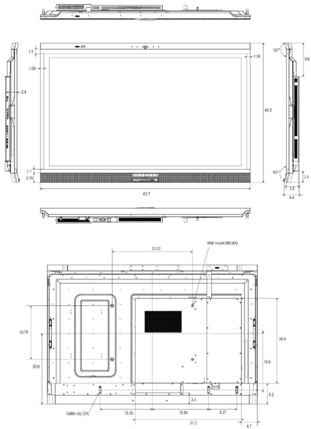
Figure 7-1. AVW-6555 Display Dimensions (inch)
Figure 7-2 shows the display dimensions of AVW-6555 (all dimensions are in millimeters).
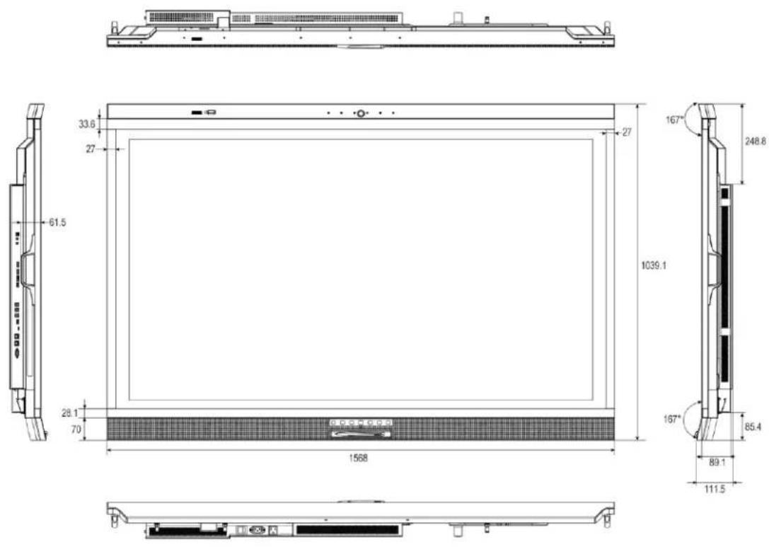
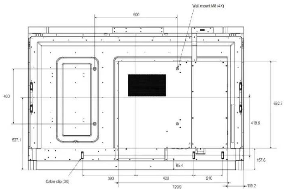
Figure 7-2. AVW-6555 Display Dimensions (mm)
Notes
Appendix I: Moving and Carrying Notice
Moving the Display
Moving the display requires at least two people. Attempting to move the display with one person may result in dropping the display and/or serious injury. When moving a display in its shipping carton, lift the carton using the white handles.
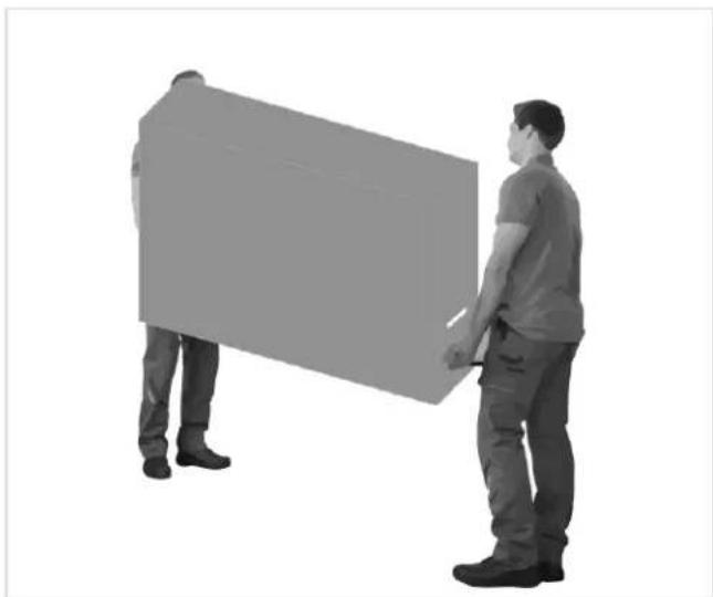
natural_image
Two people standing beside a large rectangular object, possibly a vehicle or container, in grayscale (no text or symbols visible)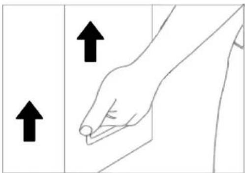
natural_image
Line drawing of a hand holding a small object, with two arrows pointing upward (no text or symbols)Carrying the Display
This display is heavy; please follow proper lifting technique, as pictured below. Failure to do so may cause injury.
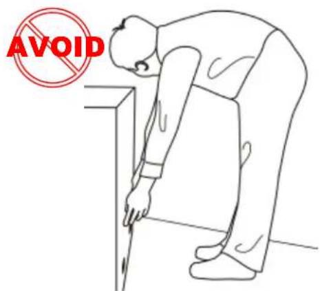
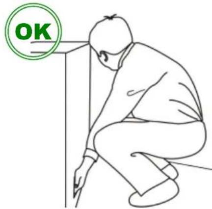
Appendix II: Installing a Wall Mount
Follow the manual instructions for the type of mount you have selected. Refer all servicing to qualified service personnel.
Moving the display requires at least two people. Make sure you use the handles in the back of the display while lifting or moving the display, to avoid touching the front panel during the move.
Before installing, please make sure the wall is strong enough to hold the necessary weight of the display and the mount.
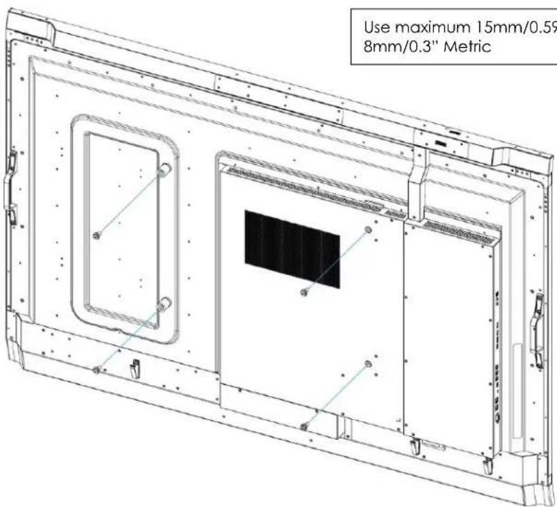
Step1. Keep the display facing the ground and place it on a flat object.
Step2. Remove the screws (M8*15) from the back of the display.
Step3. Align the wall brackets with the mounting holes and attach the brackets to the display using the screws removed in Step 2.
Caution: Longer screws will damage the display.

NOTE
To safely mount the display on a wall:
- Use only the approved wall-mount kit designed for the display.
• Make sure the tilt degree of the wall does not exceed 2 degrees.
Rear Tilt
32mm
Forward Tilt
32mm
Appendix III: Installing a NUC VESA Adapter
Follow the steps below to install a NUC or Backpack modules using the VESA Adapter.
Step 1 To install the VESA Adapter. Attach the supplied VESA adapter plate to the back of the display, making sure the plate and the mounting holes align.
Step 2 Secure the plate in position with the four provided screws (size M4*6).
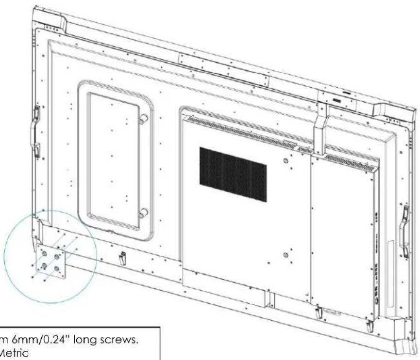
Use maximum 6mm/0.24" long screws. 4mm/0.16" Metric

NOTE
- The VESA adapter plate is compatible for NUC's or Backpacks that have VESA mounting patterns of 75 x 75 and 100 x 100.
Appendix IV: Wall Mount Safety Notes
- Please make sure if the bracket is fixed to the solid wall / solid pillar for fear of falling due to heavy weight.
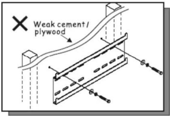
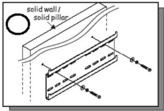
- After assembling, please don't pull or shake violently.
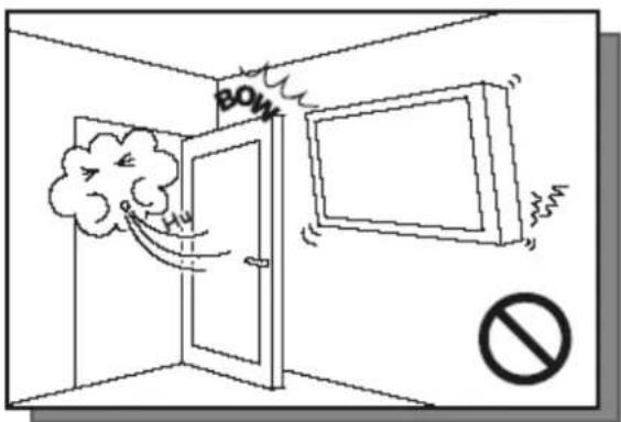
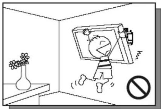
natural_image
Cartoon illustration of a child running inside a room with a TV and a 'no' symbol (no text or symbols present)- Please don't install the bracket directly under the sunshine or humidity / high temperature places for fear that the quality is effected.
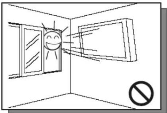
natural_image
Simple line drawing of a window with a smiling face and light rays, no text or symbols present.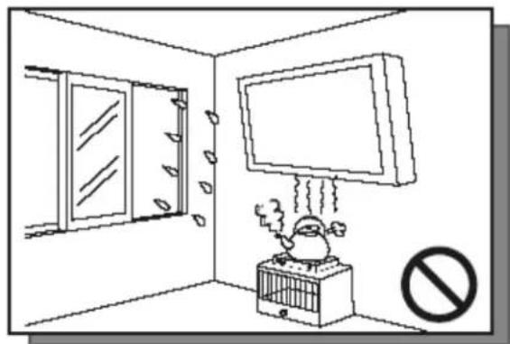
natural_image
Cartoon illustration of a bird in a cage emitting exhaust from a TV, with a 'no' symbol indicating no pollution or prohibition (no text present)4.
Installing the bracket over 10 cm from each wall side and being vertical to the ground is the suggested installing position.
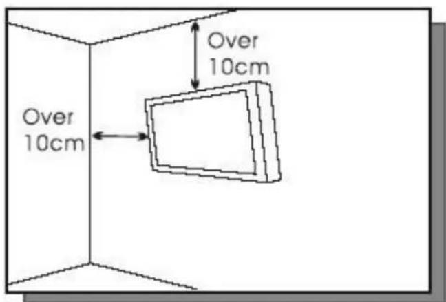
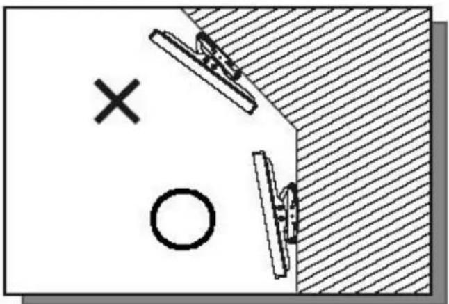
natural_image
Simple diagram showing a cross and circle on a diagonal surface with diagonal hatching (no text or symbols)5.
Please make sure to hang on the mounting hooks firmly.
6.
The flat screen must be put in the mid of the bracket for fear of slope.
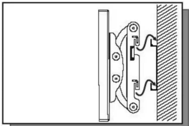
natural_image
Technical line drawing of a mechanical clamp or bracket assembly mounted on a wall, with no visible text or symbols.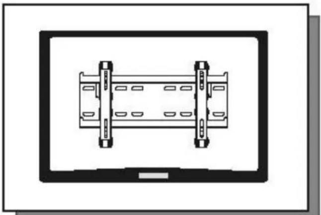
natural_image
Top-down schematic of a mechanical assembly with two vertical supports and a central rectangular component (no text or symbols)Appendix V: Azure IoT Settings
Check the IP Address of IoT device
- Enter OSD menu then go to Adv. Settings and select Network Configuration.
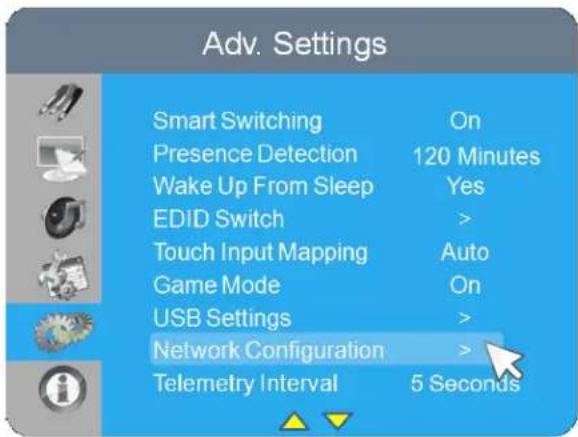
- Configure network settings, you can select Dynamic IP to Disable or Enable, the default setting is Enable
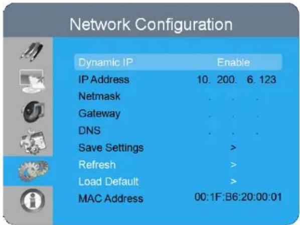
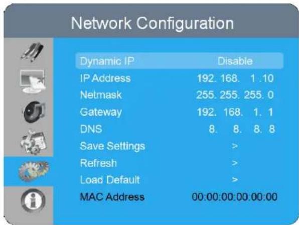
- Once the network setup is done, the IP and MAC address will be shown on Network Configuration menu.
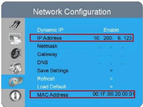
Log in to IoT Module
- Open a browser, insert the IP address and press Enter, the Login window will pop up.
- Enter the username and password then click the LOGIN button.
• Default Username: admin
• Default Password: system

Configure Network Settings
- When Enable DHCP is "On": all the columns of Network Setup are unable to edit.
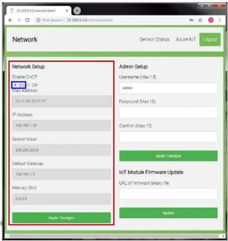
Revi
- When Enable DHCP is "Off": You can change the IP Address, Subnet Mask, Default Gateway and Primary DNS in Network Setup; Any changes that you make are automatically synchronized to OSD – Network Configurations.
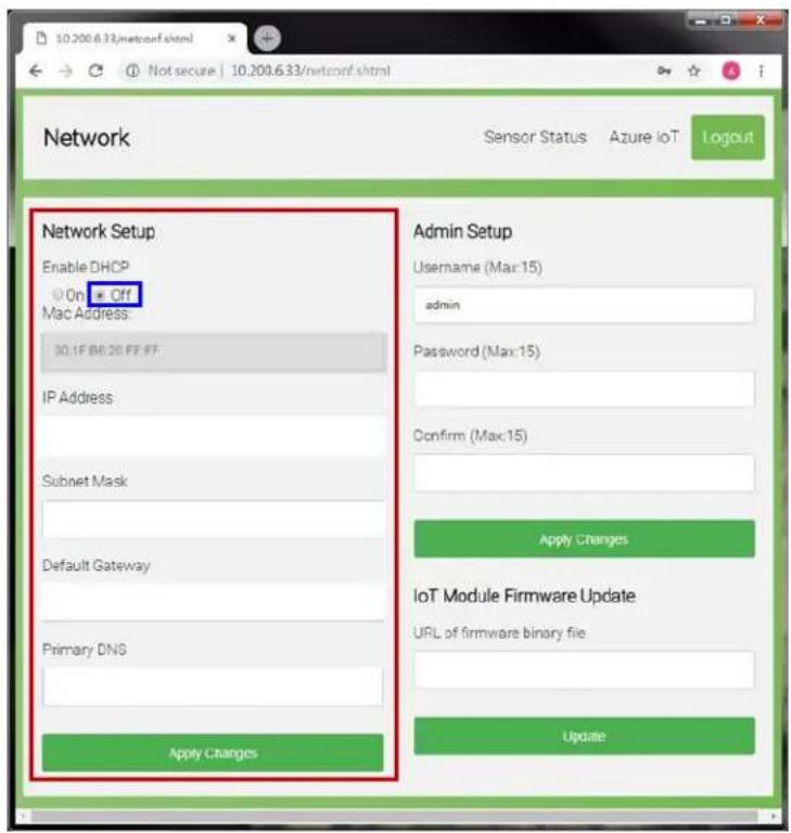
Modify Admin Setup
To change the default username and password and click Apply Changes to save.
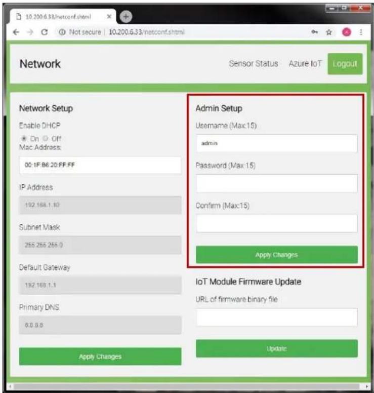
Update IoT Module Firmware
You can update the IoT Module Firmware by inserting the firmware file URL here.
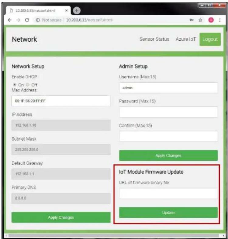
Setup Azure IoT Service
To connect the IoT device to Azure Service, user MUST:
- Go to Microsoft Azure website to create an Azure account.
For more details, see Microsoft Azure New Account Setup
- Create an IoT hub and register a new device identity in the IoT hub.
Copy the device's Connection string-primary key to use it on IoT Module later.
For more information, see Microsoft Azure IoT Hub Setup and Device Registration
- Go back to IoT Module then paste the Device Connection String and click Apply Changes to enable secure access to the IoT hub.
- After completing all the above setups, you can check the sensor data in any device if you log in to Azure IoT service.
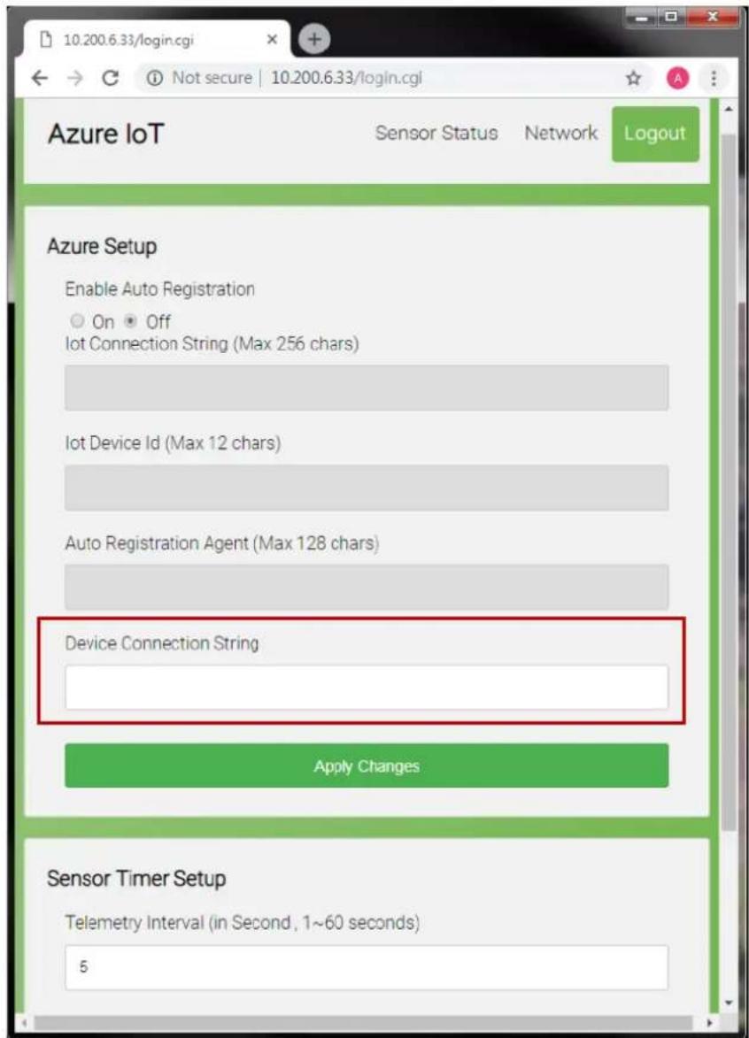
View the Sensor Status
In this page you can check the sensor status and the general information of the display.
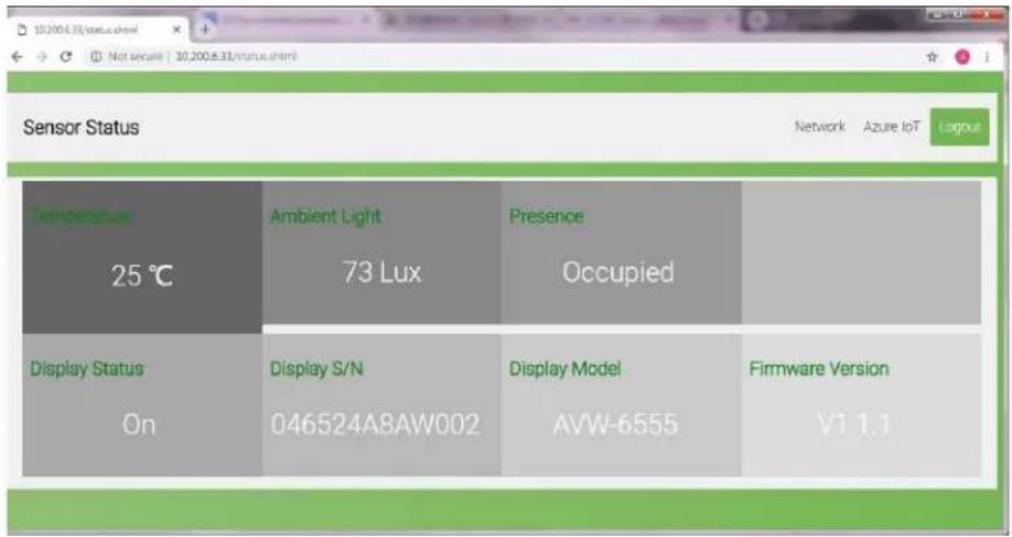
Configures Sensor Timer Setup
To change Sensor Telemetry Interval (range from 1\~60 seconds).
Any changes that you save are automatically synchronized to OSD - Adv. Settings
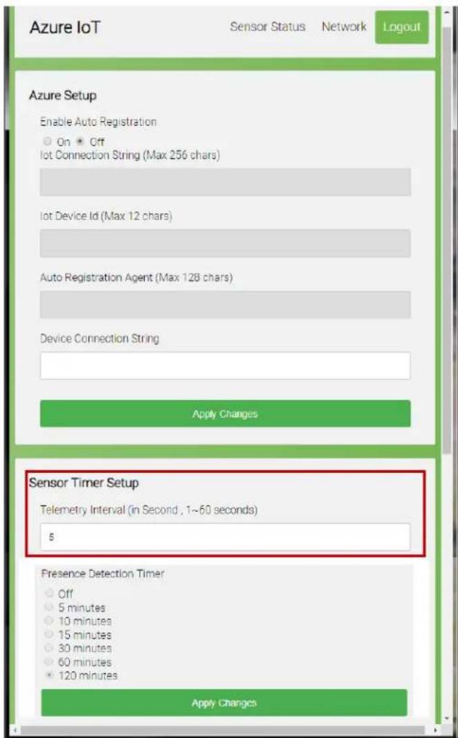
Note: Presence Detection Timer is for display only, you can edit on OSD menu - Adv. Settings

- COPYRIGHT AND TRADEMARKS:
- Important Safety Instructions
- Safety Precautions
- Installation
- Use
- Cleaning
- Warnings
- Exemptions
- Compliance Information
- DECLARATION OF CONFORMITY:
- AVW-6555
- FCC PART 15:
- CAUTION
- INDUSTRY CANADA (ICES-003):
- PRODUCT DISPOSAL:
- DISPOSAL OF OLDELECTRICAL AND ELECTRONIC EQUIPMENT (Applicable throughout the European Union and other European countries with separate collection programs)
- Notes
- Table of Contents
- Important Safety Instructions 3
- Warnings 7
- Compliance Information 8
- Table of Contents 11
- List of Figures....13
- Introduction....15
- Controls and Functions....18
- Installation 26
- Operation 39
- Maintenance and Troubleshooting....50
- External Control....53
- Specifications 60
- Appendix I: Moving and Carrying Notice 66
- Appendix II: Installing a Wall Mount....67
- Appendix III: Installing a NUC VESA Adapter....68
- Appendix IV: Wall Mount Safety Notes 69
- Appendix V: Azure IoT Settings....71
- List of Figures
- Introduction
- About This Manual
- Target Audience
- Textual and Graphic Conventions
- TIP
- NOTE
- WARNING
- DANGER!
- Using This Manual
- Description, Features and Benefits
- Key Features and Benefits
- Touch Capability
- Parts List
- Controls and Functions
- Display at a Glance
- MAIN POWER SWITCH
- Status LED
- KEYPAD
- POWER
- SOURCE
- MICROPHONE MUTE
- WINDOWS
- VOLUME MUTE
- VOLUME DOWN
- Temperature Sensor
- Light Sensor
- Presence Sensor
- Camera Status LED
- Input Panel
- Remote Control Unit
- Hot keys for lock and unlock the remote control and built-in keypad
- Installation
- Remote Control
- Notes on Batteries
- Notes on Remote Control Operation
- Quick Setup
- Installation Considerations
- Ambient Light
- Ambient Temperature
- Ventilation
- Mounting the Display
- Connections to the Display
- Connecting a Control System or PC
- RS-232 Connection
- Ethernet Connection
- Connecting Source Components to the Display
- Type C Source Connection:
- Turning on the Power
- Changing the OSD Language
- Enabling the Touch Screen
- Software Installation
- Automatic Driver Installation
- Manual Driver Installation
- Manual Driver Installation - Device Connected
- Manual Driver Installation - Device Not Connected
- Operation
- Using the On-Screen Menus
- Input Menu
- Color Temperature Settings
- Display Settings
- Audio Menu
- Basic Settings
- Advanced Settings
- Wake Up from Sleep
- Network Configuration
- Information
- Maintenance and Troubleshooting
- Maintenance
- Troubleshooting
- avocor™
- External Control
- Serial Communications
- RS232 Connection and Port Configuration
- Command and Response Format
- Command and Response Examples
- Serial Command List
- Using Discrete IR Codes
- IR Command Protocol
- IR Control Code List
- Specifications
- Supported Timings
- Appendix I: Moving and Carrying Notice
- Moving the Display
- Carrying the Display
- Appendix II: Installing a Wall Mount
- Appendix III: Installing a NUC VESA Adapter
- Appendix IV: Wall Mount Safety Notes
- 4.
- 5.
- 6.
- Appendix V: Azure IoT Settings
- Check the IP Address of IoT device
- Log in to IoT Module
- Configure Network Settings
- Modify Admin Setup
- Update IoT Module Firmware
- Setup Azure IoT Service
- View the Sensor Status
- Configures Sensor Timer Setup
Brand : Avocor
Model : AVW-6555
Category : Whiteboard