
FLEX 35 BL - Camcorder ARRI - Free user manual and instructions
Find the device manual for free FLEX 35 BL ARRI in PDF.


| Product Type | 35mm Motion Picture Camera |
| Brand | ARRI |
| Model | FLEX 35 BL |
| Lens Mount | ARRI Steel Bayonet |
| Film Format | 35 mm |
| Power Supply | 12 V DC battery (recommended 5 Ah) |
| Frame Rates (Standard) | 24 or 25 fps crystal-controlled |
| Frame Rates (Variable) | 5–30 fps with VS 35 BL accessory |
| High Speed Operation | Up to 100 fps with 36 V supply |
| Sync System | Crystal sync and Pilotone (50/60 Hz) |
| Filter Stages | 3×3" and 4×4" in filter holder |
| Matte Box | Standard for fixed lenses, universal housing available |
| Magazine Type | Detachable, 400 ft (approx.) |
| Ground Glass | Interchangeable, etched markings |
| Weight (approx.) | About 10 kg (body only) |
| Maintenance | Lubricate cam shaft every 60,000 ft (normal speed); clean film channel with soft swabs |
| Safety | Only use non-metal tools for cleaning; disconnect power before servicing |
| Repairability | Replaceable fuses (15 A and 0.75 A), signal lamps, aperture plate |
| General Information | Professional sync sound film camera used in cinema |
Frequently Asked Questions - FLEX 35 BL ARRI
User questions about FLEX 35 BL ARRI
0 question about this device. Answer the ones you know or ask your own.
Ask a new question about this device
Download the instructions for your Camcorder in PDF format for free! Find your manual FLEX 35 BL - ARRI and take your electronic device back in hand. On this page are published all the documents necessary for the use of your device. FLEX 35 BL by ARRI.
USER MANUAL FLEX 35 BL ARRI
natural_image
Black-and-white photo of a vintage flatbed radio with mounted lenses and a rectangular base (no visible text or symbols)INSTRUCTION MANUAL
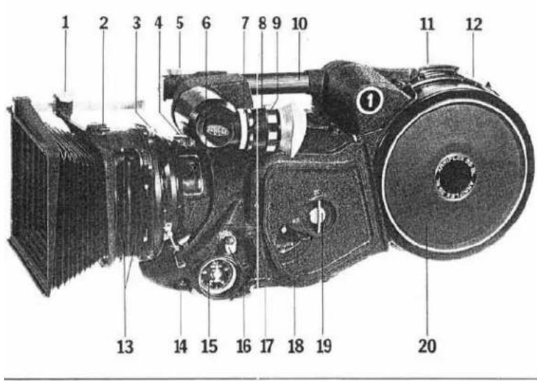
Fig. 1
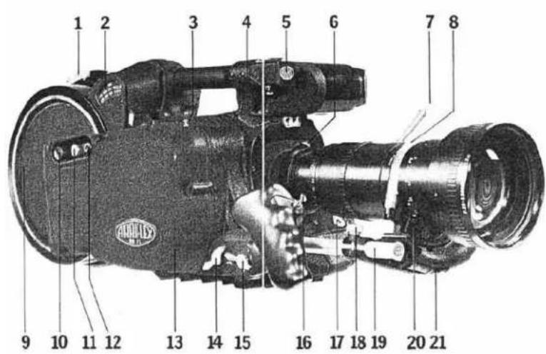
Fig. 2
1 Lock screw for matte box beam
2 Release latch for matte box
3 Handle and lock for f/stop ring
4 Lock release for universal lens housing
5 Thumb screw for standard matte box
6 Window to view lens settings
7 Knurled lock ring for eyepiece
8 Lock-ring for diopter adjustment
9 Diopter adjustment for eyepiece
10 Camera carrying handle
11 Loop length marking for magazine threading
12 Magazine cover lock, take-up side
13 Filter stages
14 Focusing handle
15 Tachometer
16 Reset button for footage counter
17 Film plane marker
18 Lever for manual shutter advance
19 Camera door lock
20 Magazine cover, take-up side
1 Magazine cover lock, supply side
2 Supply footage indicator
3 Tape hook
4 Release button for standard matte box
5 Plug for matte box receptacle
6 Lens release lever
7 Zoom handle
8 Steel band for zoom lens support
9 Magazine cover, supply side
10 Mode selector switch
11 Fuse holder
12 Volume control for "out of sync" warning
13 Camera mechanism cover
14 Lock screw for zoom lens support
15 Lock screw for hand grip
16 Camera start/stop switch
17 Locating bushings for universal lens housing
18 Thumb screw for support adjustment
19 Zoom support rod
20 Bayonet adapter for support
21 Zoom support base
Contents Page
Magazine loading 3/4
Camera threading 4/5
Aperture plate replacement 6
Ground glass replacement 6/7
Mounting lenses without housing 7
Mounting lens support brackets 8
Standard matte box for fixed lenses 8
Universal housing for fixed lenses 10
Focus and f/stop scales 10
Filters 11
Camera power connection 11
Electronic/electrical features 11/12/13
Camera speed selection 13
Pilotone and start marking system 13/14
Electronic accessories 14/15/16
Preventive maintenance and minor service:
Cleaning of aperture plate and film channel 16
Lubrication of film transport mechanism 16/17
Other lubrication points 17/18
Replacing signal lamps 18
Replacement of electrical fuses 20/21
Maintenance of the magazine 21/22
Magazine guide rollers for high speed operation 22
Removal of the camera mechanism cover 22
Checking drive belt tension 22
Adjusting of the drive belts 22/24/25
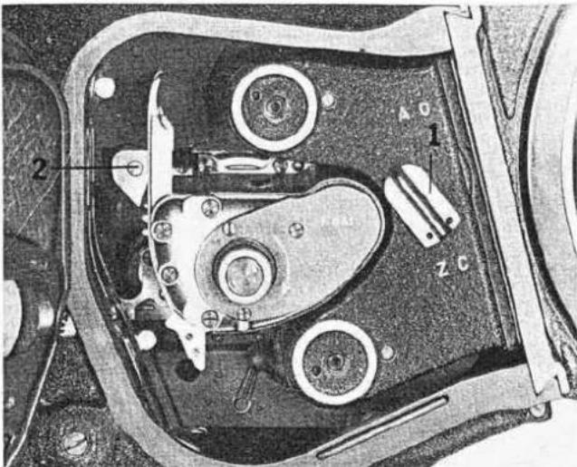
Fig. 3
Fig. 4
natural_image
Close-up of hands using a tape measure to adjust or install a mechanical component (no visible text or symbols)Magazine loading
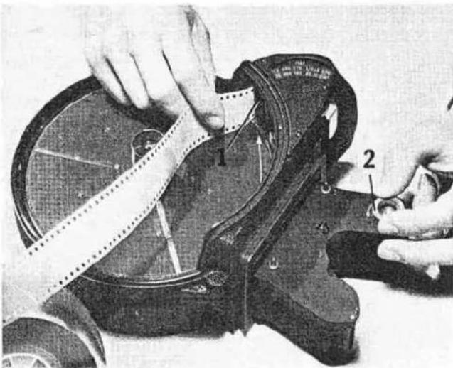
To detach the magazine from the camera body, turn the camera door lock (fig. 1/19) counter clockwise and open camera door. Turn magazine lock (Fig. 3/1) counter clockwise to the "AO" position. Slide magazine out of the dovelail guides toward you. For loading, lay the magazine with the take-up side (Fig. 1/20) down. Remove the magazine cover by slightly lifting and sliding the magazine lock (Fig. 2/1) in the direction of the arrow marked "A". Swing film counter arm out towards the perimeter of the magazine casting where it will lock into position. Feed the beginning of the film roll into the slot (Fig. 4/1) between the loop guide and the idler roller as marked by the long arrow in the magazine supply compartment.
Note: Use film wound "emulsion in" and feed off the core counterclockwise. When using "short ends", make sure the head of the roll is cut clean, preferably through the perforation.
Push the film gently into the slot until the resistance of the sprocket teeth is felt. Film should feed freely, and by turning the drive coupling (Fig. 4/2) counterclockwise continue feeding until the film exits from the supply compartment of the magazine throat. After ascertaining that the film is properly fed, put the film roll on to the supply core and close the cover. Lock it securely by sliding the cover lock (Fig. 2/1) forward towards the throat. When magazine cover is properly mounted, film counter arm will release automatically.
Once the film is fed through the supply throat and the magazine cover is securely fastened, the remaining loading can be performed in the light.
Remove magazine cover of supply side. Transport the film via the drive coupling (Fig. 4/2) until the exiting piece is long enough (9") to reach the loop length indicator (Fig. 1/11). The proper loop length is measured by simply laying the film back over the loop chamber and feeding until it reaches the index mark. Then insert the film into the slit in the take-up throat, engaging the film on the take-up sprocket by gently rocking the drive coupling. Once properly engaged, the film will exit through the loop guide on the take-up side where it is now fastened to the collapsible core in the proper manner.
Note: When feeding the film into the take-up throat make sure that the overall length of the loop is conserved as measured against the loop length indicator. Ascertain that the locking lever of the collapsible core (Fig. 15/1) is securely locked. Advance the film by hand via the drive coupling until several revolutions of the collapsible core confirm proper film winding without "dishing". Then attach and lock magazine cover.
Camera threading
Make sure camera is placed in a secure position so that both hands are free to attach the magazine and to thread the camera.
To open the film channel, pull the release lever (Fig. 5/2) out towards the door casting with your left index finger. This releases the mechanism lock and allows you to slide the film transport mechanism back toward the magazine opening.
Note: Pull the lever only for the initial releasing of the transport mechanism, than let it return to its original position. The film transport mechanism will encounter its first stop after an approximately 34 " wide gap has been created between aperture plate and back plate. If the release lever is now pulled once more, the mechanism can be slid back further by an additional 14 " to facilitate cleaning. However, in this position it is not possible to mount a magazine to the camera body because the magazine throat will hit the film transport mechanism.
With the film channel open, turn the knurled inching knob (Fig. 5/1) until its red index mark is in line with the index on the mechanism plate above it. If this is done properly, the transport claws should extend approximately 1/16'' (2 mm) out of the back plate.
Hold the loaded magazine with the right hand and slide it into the dovetail mount on the rear of the camera, by engaging the steel rail (Fig. 5/3) with the matching steel guide on the magazine. At the same time, with the left hand, guide the film loop into the open film channel. Seat the magazine properly and lock it in place by pushing in, and turning the magazine lock (Fig. 3/1) clockwise to position "ZC." Arrange the film in the open film channel so the top loop corresponds with the loop indicator on the mechanism plate. A locating pin (Fig. 5/4) holds the film in the desired position by engaging a perforation. Once the proper loop distribution has been achieved, slide the
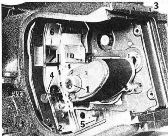
Fig. 5
film transport mechanism forward, making sure the index lines on the inching knob are matched, until an audible "click" indicates the secure locking of the transport mechanism. If all this is done properly, the film will automatically engage the four pulldown pins of the transport mechanism. The locating pin is automatically retreated when the film channel is closed.
Activate the buckle switch (Fig. 5/5) by swinging it counter-clockwise into the "on" position. It is advisable to assure proper film transport by turning the manual inch-ing knob while the camera door is still open. Only after this is done, lock the camera door. The digital footage counter in front of the camera door can be reset with the grooved push button (Fig. 1/16) located just above the Tachometer. The inching lever (Fig. 1/18) below the camera door lock is for the manual advance of the mirror-shutter when no power is attached to the camera. With power attached, the mirror-shutter will automatically stop in the viewing position every time the camera is turned off.
Note: Whenever the ARRIFLEX 35 BL camera is stored without a magazine, the magazine opening cover should be in its place to close up the camera housing.
Aperture plate replacement
To remove the aperture plate for exchange or replacement, the magazine should first be detached from the camera head. Then open film channel all the way as described previously. As a safety measure, remove the lens and advance the mirror-shutter with the manual inching knob (Fig. 5/1) until it is away from the aperture area.
To unlock the aperture plate, push vertically up against the rim of the aperture (Fig. 5/6) or the cut-out on the lower edge of the aperture plate. Once the aperture plate is pushed up by approximately 1/16'' ( 112 mm), slant its lower end back towards the transport mechanism. Retrieve the aperture plate from the film channel without scratching or damaging any part in the process.
Before mounting the aperture plate make sure no dirt or dust has accumulated on the back or on its seat in the casting.
To reinsert the aperture plate, reverse the described procedure by engaging the upper edge with the spring loaded prongs and push vertically up until the plate lies parallel against the front casting. Then let it slide down to engage the retaining wedges.
Ground glass replacement
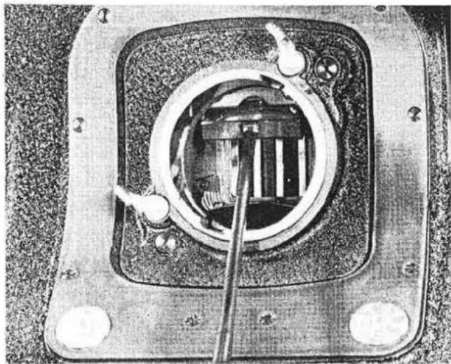
The ground glass image area in the ARRIFLEX 35 BL displays the full aperture. The markings for different composition areas are etched directly onto the ground glass and are available for all popular formats. To retrieve the ground glass, first remove the lens and advance the mirror shutter away from the aperture area so it is protected against scratching. Engage the small eyelet on the ground glass frame (Fig. 6) with an appropriate instrument and pull down slightly until the frame is released. Be sure to have a good grip on the ground glass holder so it will not drop and get chipped or scratched. Before inserting a ground glass, ascertain that the ground glass and the ground glass frame are absolutely clean, since improper seating might impair the sharpness and parallax adjustment of the finder. After the ground glass has been inserted into the frame and seated, pull it forward gently to make sure it is positioned properly.
natural_image
Close-up of a mechanical component with internal wiring and a tool inserted (no visible text or symbols)Fig. 6
Note: All ground glasses on the ARRIFLEX 35 BL are precision mounted and are readily interchangeable from camera to camera. To insure that the ground glass is indeed properly sealed in its holder, check with a short focal length lens (16, 24 mm) against infinity before commencing shooting.
Mounting of lenses without lens housing
The ARRIFLEX 35 BL is equipped with the "ARRI Steel Bayonet" lens mount. Therefore, virtually all ARRIFLEX mounted lenses can be used on the camera, providing they are designed to cover the 35 mm format. Caution is necessary when using lenses of extremely short focal length which might have been especially adapted for the ARRIFLEX 35 II C, since they might touch and damage the mirror shutter in the ARRIFLEX 35 BL.
Heavy zoom and tele lenses can be used on the ARRI-FLEX 35 BL only when supporting them on the available lens support brackets. If not properly supported, they will sag and compress the camera sound insulation material, possibly raising the camera noise level considerably.
Mounting of lens support brackets
To attach the lens support bracket, remove the camera hand grip and mount in its place (Fig. 2/14) the extension which contains both the lens support bracket receptacle and the hand grip mount. Refit the handgrip to the bracket.
Attach to the zoom lens either the bracket with the steel band (Fig. 2/8), or a similar screw-on bracket. This bracket has a bayonet lock arrangement which corresponds in its rotational angle with that of the ARRI bayonet lens mount. Thus, once the bracket has been aligned, slide the zoom lens into the lens mount of the camera while at the same time sliding it into the keyway of the zoom support base (Fig. 2/21). Then twist the lens to the right until it is securely locked in the camera lens mount and in the support base.
The support base (Fig. 2/21) of the bracket can be moved along the support rod (Fig. 2/19) so it can be aligned for various lens types. Very heavy zoom lenses, for example the Angénieux 20—120 or the Cooke 20—100, require a special heavy duty support arm which will fit the standard support rod.
Standard matte box for fixed lenses
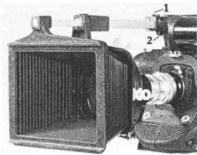
This matte box is very practical when using fixed focal length lenses from 16 mm to approximately 150 mm. The matte box has two filter holders adaptable for three or four inch filters. The rear filter stage, intended for graduated or polarizing filters, is rotatable. To mount the matte box, simply remove the blind cap at the end of the camera handle casting (Fig. 2/5) and slide the square runner of the matte box into the square opening. The knurled thumb screw (Fig. 7/1) serves to lock the square runner. After the rear frame of the matte box has been positioned and the square runner is locked, pull the front frame out to the desired position and lock it with the knurled screw on top of the rear frame. To remove the matte box, unlock the knurled thumb screw on the handle casting and push the button on the underside of the casting (Fig. 7/2) to release the square runner.
natural_image
Technical illustration of an electric motor with labeled parts (1 and 2), showing internal structure and housing (no text or symbols beyond labels)Fig. 7
Fig. 8
natural_image
Cross-sectional diagram of a mechanical component showing internal components and labeled parts (no text or symbols present)9
Universal housing for fixed lenses
The universal lens housing is designed to keep camera noise emission to an absolute minimum for critical sync sound filming. At the same time it serves as a follow focus device and a filter stage.
To mount the universal lens housing on the camera, the lens must be removed first. Engage the lens housing into the two locating bushings (Fig. 2/17) tilting it down slightly. Once seated, swing it up and press it against the face of the camera until it locks in the spring loaded latch (Fig. 1/4 & Fig. 19/3). To mount a lens, open the filter door by unlocking the swivel latch (Fig. 19/1), turn the focusing ring to infinity (Fig. 1/14) and flip the iris follower (Fig. 8/1) forward. Now the lens with its focusing ring, also set at infinity, can be entered into the lens housing, simultaneously engaging the rubber padded followers of the focusing ring (Fig. 8/2) and the camera lens mount. With one hand, activate the scissor-like grip (Fig. 19/2) for the lens locking mechanism. Make absolutely certain that the lens is seated correctly and the lens locks are engaged properly. After the lens is securely mounted, turn the f/slop follower (Fig. 8/1) until it meets with the coupling wedge on the front ring of the lens and engage it.
Focus and f/stop scales
As mentioned, the universal lens housing serves more than one function. Among others, it is a follow focus device for two-man camera operation. For this, interchangeable distance and f/stop scales can be mounted on the housing, matching exactly each fixed focal length lens. For utmost accuracy, all scales are marked with the serial number of their corresponding lens. When changing a lens, simply select the appropriate set of scales and slide them into the slots (Fig. 19/4) of the focus and diaphragm rings until they "click" into place.
Note: Up to camera serial number 35060, these scales are fastened to spring-loaded hooks on the lens housing. In addition to the pre-marked scales, blank white scales for random marking are also available.
Wherever the circumstances allow, both focusing and diaphragm setting of the lens can be checked through a small window in the lens housing (Fig. 1/6). Lenses not equipped with the special diaphragm coupling ring can be used, but require opening of the filter door for changing of the f/stop setting.
Filters
The universal lens housing serves as a filter stage for fixed focal length lenses and can accept one 3 x 3" and two 4 x 4" filters.
In order to get minimum camera noise, it is recommended that either a 3 x 3" filter or the clear optical flat, delivered with the camera, is mounted in the 3 x 3" filter stage. To reach this stage, open the lens housing and flip down the filter holder. After inserting the filter, simply swing the holder back up until it locks, and close the door. The standard three stage filter holder can be used for all fixed focal length lenses from 16 mm to 85 mm except for the 18 mm Cooke series III. This lens, because of its extended mechanical construction, requires a special two-stage filter holder which accepts only two 4 x 4" filters. To mount it, remove the matte box by releasing its snap lock (Fig. 1/2), open the housing swivel latch (Fig. 19/1) and depress both ends of the filter hinge until the holder can be disengaged. Remount the replacement holder in the reverse order. A special polarizing filter can be used in both filter holders except when the 18 mm Cooke is being used.
Camera power connection
Connect the camera to a 12 volt battery with the proper battery cable (Type KCU or KCUSp). To insert the four-pin Cannon plug on the flange receptacle, the locking latch should be pointing upward so that the raised guide wedge engages the guide slot in the receptacle. Only batteries of a reasonably large capacity (recommended 5 Ah) should be used. The battery voltage should never drop below 10.5 volts or exceed 16 volts.
Note: Batteries which have either a dead cell, or due to age or misuse do not reach their full capacity, should not be used with the ARRIFLEX 35 BL camera. A sure indication of insufficient battery voltage is when the camera either does not reach speed, or sounds the "out of sync" warning buzzer while running.
Electronic/electrical features
Once the camera is connected to the power supply, and the bridge plug (Fig. 9/4 a) is in place, it is advisable to
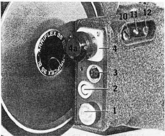
Fig. 9
check all camera functions for proper operation. For this, turn mode selector switch (Fig. 9/10) to position "L" (lamp check) and activate camera switch (Fig. 2/16). Camera should now run unless the buckle switch (Fig. 5/5) is in the "OFF" position. If this is so, move it forward into the "ON" position.
Running the camera, with the mode selector in position "L", two indicator lamps should be visible in the finder area. In the center of the finder, the bright, white, full frame start mark lamp should be visible, and in the lower right corner, the red "out of sync" warning light. At the same time, (from camera No. 35026 on) an acoustical "out of sync" monitor should deliver a buzzer signal whose volume can be regulated by the volume control knob (Fig. 9/12). The edge marking lamp for the automatic start mark system can be checked by opening the film channel which should show the illuminated pin hole to the right of the aperture.
The mode selector switch (Fig. 9/10) must now be turned to the desired fps/Hz (frames per second/frequency) combination. The "out of sync" monitor will only be active for approximately 500 ms after the camera is switched "ON", as well as immediately after switching it "OFF" while the camera is coasting to a stop. The "out of sync" warning buzzer has a double potentiometer for the volume of the warning buzzer, and simultaneous adjustment of the start marking signal.
| Position of Volume Knob: | Start Marker: | "Out of Sync" Warning: |
| 0 | 0 | 0 |
| 1/4 turn | loud | low |
| 1/2 turn | loud | medium |
| full turn | loud | loud |
If the camera buckle-switch is tripped during a take, the warning buzzer will sound until the problem is corrected and the buckle-switch returned to its "ON" position so the camera mirror-shutter can pulse back to the viewing position. It is advisable that proper function of the buckle-switch is checked by simply tripping it by hand, before running the camera with film.
From camera No. 35080 on, a blinking running light is installed in the rear plate of the camera.
Camera speed selection
The ARRIFLEX 35 BL, without any additional accessories, is equipped to run crystal controlled at 24 or 25 frames per second. The desired combination of speed and Pilotone frequency is selected with the mode selector switch (Fig. 9/10).
With the variable speed attachment (VS 35 BL), fixed speeds (24/25 fps) as well as variable speeds from approximately 5 fps to 30 fps can be obtained. (Refer to page 14)
Pilotone and start marking system
The ARRIFLEX 35 BL is equipped with a crystal controlled drive system and can therefore, in conjunction with any appropriately equipped sync sound recorder, be used for wireless double system sync sound recording. However, for those instances where it might be necessary to use a conventional Pilotone cable set-up, the camera is also equipped with the standard Pilotone system.
When selecting a camera speed on the mode selector switch (Fig. 9/10) it is important to ascertain that the combination of speed and Pilotone frequency is indeed the desired one. Frame rate and frequency combinations are as follows: 25/50, 24/50, 24/60.
The Pilotone output is provided via the 5-pin flange
mounted receptacle (Fig. 9/3) and is wired the same way as all Pilotone connectors on other ARRIFLEX cameras. The Pilotone voltage conforms to the standard 1V_eff / 60 ohm. The Pilotone frequency is derived from the motor feed back circuit and is a direct indication of camera speed.
The ARRIFLEX 35 BL is also equipped with the standard start mark system which, through pin 3 of the Pilotone receptacle, delivers the 12 volt DC current for the operation of a start mark oscillator in the recorder. Simultaneously, during the run up of the camera, the full frame start mark lamp in the aperture will fog the film. Once the camera has reached sync sound speed, both the 12 volt DC and the fogging lamp are switched off, and the Pilotone frequency is delivered through pins 1 and 2. Pilotone cables for the most popular recorders are available from stock.
KPN 1 (15 feet) and KPN 1L (30 feet) are suitable for use with all ARRIFLEX cameras in conjunction with the ARRIVOX-TANDBERG, the Nagra 3 and the Uher "Report Pilot 1000" and "1200".
KPN 4 (15 feet) and KPN 4L (30 feet) is suited for all ARRI-FLEX cameras in connection with the Nagra 4.
KPS 1 (15 feet) is suited for ARRIFLEX cameras in connection with the Stellavox SM 5 and SP 7. (All cables for Stellavox recorders are special order items.)
Electronic accessories
Several important and useful power accessories are available für the ARRIFLEX 35 BL, most of which are attached via the flange receptacle (Fig. 9/2) on top of the rear connector board.
A) Remote control/panhandle switch
The panhandle switch (Type RCS) makes it possible to switch the camera "ON" and "OFF" from a convenient position when operating off a tripod.
B) Variable speed control
A variable speed control for the lower framing rates (5—30 fps) is available for the ARRIFLEX 35 BL. It employs a clamping arrangement similar to the one on the panhandle switch so it can be fastened in a convenient position. The variable speed control (Type VS 35 BL) contains a remote camera "ON/OFF" switch as well as a
selector for variable speed or crystal controlled fixed speeds.
C) External sync input
With the external synchronizer (Type EXS) it is possible to synchronize the camera from external sources such as pre-recorded Pilotones, Pilotone signals from other cameras or any other external signal source which conforms to the current and frequency requirements of the camera. This includes, for example, the synchronization of the camera with a television signal through a suitable circuit.
D) Multi-camera synchronization
To run two ARRIFLEX 35 BL cameras in synchronization with each other requires a special cable type KSY. This cable also allows for the remote start and stop of the secondary, the "slaved" camera, from the primary sync camera.
High speed accessory
The ARRIFLEX 35 BL can be operated at speeds of up to 100 frames per second. For this, the camera requires a 36 volt operating current which can either be derived from three 12 volt batteries or one special 36 volt battery. The high-speed attachment fits in place of the bridge plug (Fig. 9/4a) in the flange mounted receptacle (Fig. 9/4).
It is important that whenever the high-speed cable is connected to this plug, all other power connections via the standard battery cable are disconnected to prevent damage to the circuit or the power source.
Emergency operation
If the electronic motor control circuit of the ARRIFLEX 35 BL fails, a special emergency cable (Type KCN) can be connected to the receptacle (Fig. 9/4) in place of the bridge plug. This cable is wired so the 12 volt current from the battery is fed direct to the motor, bypassing all the control circuits. A potentiometer on the cable allows for speed adjustments according to the Tachometer. In this manner, the camera motor runs as a "wild" motor and synchronous sound takes are not possible.
Converter power supplies
A) For the stationary, indoor operation up to 30 fps of the ARRIFLEX 35 BL it is possible to use a converter
power supply instead of rechargeable batteries. Should this be desirable, a power supply of 12 volt/10 amp rating is required. Start-up currents of up to 15 amp are possible and thus should not overload the circuit. Except for high speed operation through the proper cable and connectors, the maximum supply voltage of 16 volts should never be exceeded.
B) For the stationary, indoor operation up to 100 fps of the ARRIFLEX 35 BL using a high-speed cable, a power supply of 36 volt/10 amp rating is required. Start-up currents of up to 15 amps should not overload the circuit. In both cases the ARRI mains unit NG4 or a similar DC stabilizer of another make can be recommended, but the maximum permissible supply voltage should never be exceeded.
Preventive maintenance and minor service
Cleaning of aperture plate and film channel
To clean the film channel of the ARRIFLEX 35 BL, slide the transport movement back to its end stop as described in previous paragraphs. It is advisable to retract the registration pins during cleaning to avoid damaging them.
Note: To clean the film channel, NEVER use any metal tools. Soft cotton swabs or lens cleaning cloth are the only recommended cleaning utensils. Should it be necessary, a mild solution of 50/50 water and alcohol can be used to remove emulsion deposits from the aperture plate.
Lubrication of the film transport mechanism
Both the pull down and registration cams of the ARRI-FLEX 35 BL are equipped with a reservoir lubrication system. Oil wicks are positioned inside both cam shafts which can be loaded through small holes in the center of the shaft. To gain access to these lubrication points, remove the magazine from the camera and pull the cover (Fig. 10/1) off the mechanism. If necessary use a small screwdriver and carefully pry it loose. By rotating the inching knob (Fig. 10/2) the lubrication access holes can be brought into a convenient position. Only high grade low temperature oil (PDB38) should be used as a lubricant. The amount of oil that should be applied depends entirely on the saturation of the wicks. In general, very small quantities of oil are required to load the reservoir,
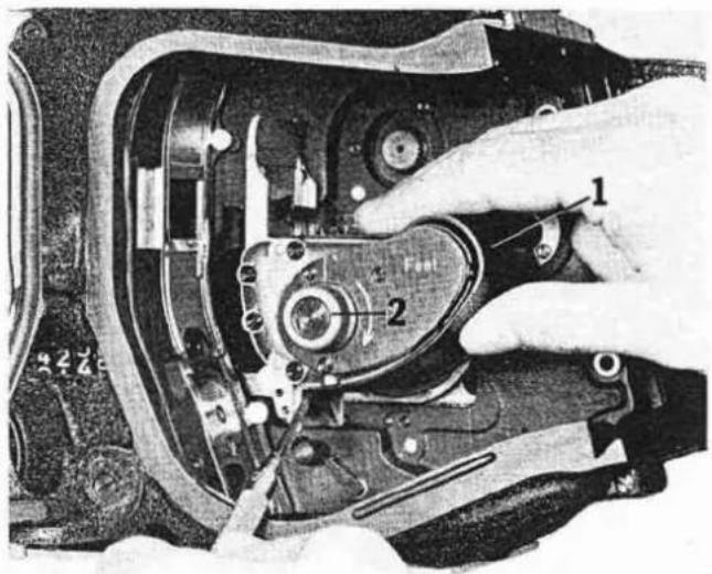
Fig. 10
and "drop oilers" or syringe type oilers are best used to apply it.
The cam shaft reservoir should be checked and lubricated at intervals of approximately 60,000 feet if the camera has been operated at normal speed, and every 6000 or 8000 feet if the camera has been used at high speeds.
Never over oil the reservoirs, feed only as much oil as the wicks can easily absorb. All excess oil will be thrown off the cams owing to the centrifugal forces during running, and can splatter into the film compartment.
Other lubrication points
In addition to the two oil reservoirs in the cam shafts the two phenolic transport and two registration cam followers should be lubricated with a thin film of oil. Here, lubrication is best applied with a small, soft brush. All excess oil must be removed with a clean, lint-free cloth.
The parallel slide to which the transport mechanism and the drive motor are mounted is made up of two precision steel guides, one dovetail shaped, the other a flat rail. Inside the guide rails, small round cavities are filled with a high grade, low temperature grease. If the
slide tightens up, small amounts of oil of the same type used in the reservoirs of the cam shaft should be applied. From time to time the dovelail guide of the camera magazine opening should be cleaned. After cleaning, apply a light film of high grade grease (ARRI special grease) and remove the excess with a clean lint-free cloth.
The same cleaning and lubricating procedure is recommended for the following parts of the camera and magazines: the lock wedge on the magazine lock; the three bayonet clips on each magazine cover and their counterparts, the locking latches on the magazine; the lock wedges on the camera door and their receptacles on the camera housing; the 3/s" tripod screw; the locking screw of the camera handle and the threads of the electrical connectors on the rear of the camera.
A minute amount of oil should be applied to the hinges of the camera door whenever necessary.
Preventive maintenance of this type is also recommended for all camera accessories, the lens housing, the zoom support, etc., etc. Equipment care of this nature should be a conscientious process of cleaning, checking and lubricating. It should be done at regular intervals and every time before the equipment is stored for long periods.
Replacing signal lamps
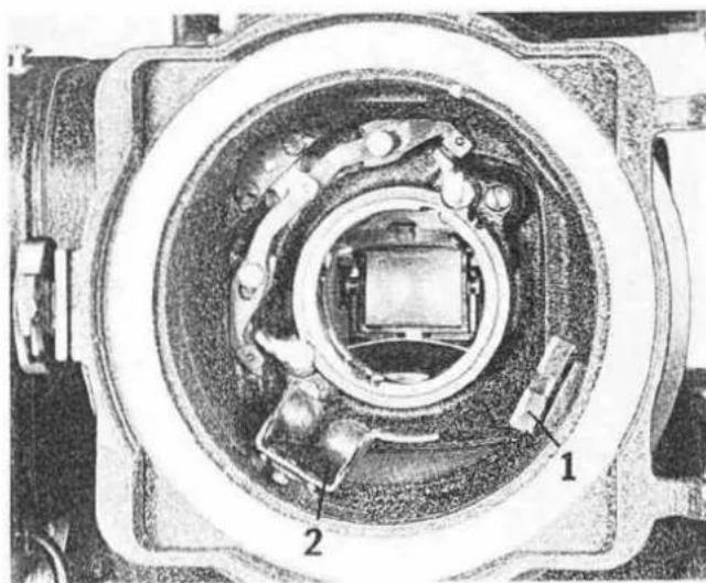
To replace any of the signal lamps, slide back the transport movement, rotate the mirror shutter out of the aperture area and remove the aperture plate. Then pull out the lamp carrier using a metal hook (Fig. 11) or any other suitable tool.
Caution: Pull only with a short stroke so the lamp carrier and the tool do not hit and damage the back pressure plate in case it suddenly releases.
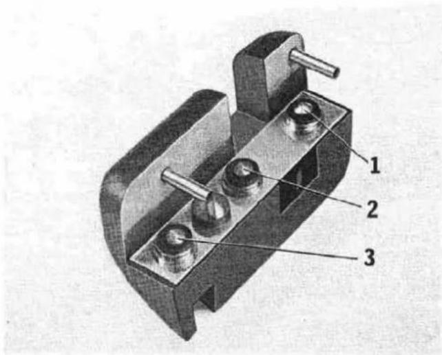
After removal of the carrier, pull the contact block off the two locating pins on the carrier, making the lamps accessible (Fig. 12).
1 = "Out of sync" monitor lamp (red glass).
2 = Full frame fog lamp.
3 = Edge fog lamp.
Replace lamps as required. When re-inserting the lamp carrier, make sure everything is seated properly to insure good electrical contact. When the carrier is back in place, re-insert the aperture plate and test the lamps for proper function (refer to lamp test in earlier paragraph).
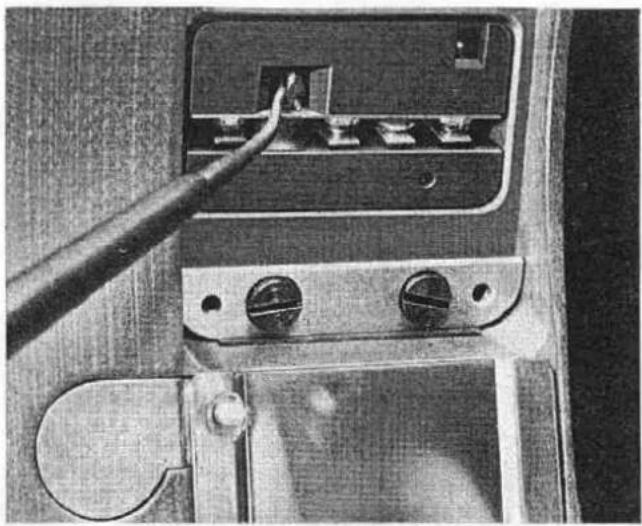
natural_image
Close-up of a mechanical switch or connector with a tool inserted, showing no visible text or symbols.Fig. 11
Fig. 12
natural_image
Close-up of a printed circuit board with visible traces, pads, and connectors (no readable text or symbols)Fig. 13
natural_image
Close-up of an electronic circuit board with components and wiring (no readable text or symbols)Fig. 14
Replacement of electrical fuses
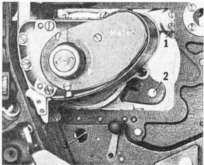
The camera circuit is protected with two fuses, one a 15 amp power fuse, the other a 0.75 amp fuse for the power supply of the drive control circuit. To gain access to the 15 amp power fuse, the camera mechanism cover (Fig. 2/13) must be removed.
Caution: Before removing the mechanism cover, always disconnect all power supplies to the camera. To be absolutely safe, there should be no cable connected to any of the sockets on the rear connector plate.
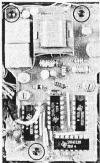
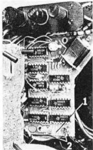
After the mechanism cover has been removed, unscrew the printed circuit plate No. 4 (Fig. 13) and swing out of the way so the fuse (Fig. 14/1) is accessible. With a screwdriver, loosen two cylinder head screws (Fig. 14/2), remove the defective fuse and replace it with a new one of the same rating (miniature glass tube fuse 15 amp, 32 volt).
From camera No. 35060 onwards, the 15 amp fuse can be replaced without removing the printed circuit board No. 4.
After the fuse has been replaced and the red insulated power leads are securely fastened, remount the printed circuit plate No. 4. Before the mechanism cover is put
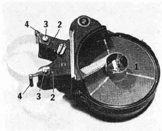
Fig. 15
back on, make sure none of the wires are squeezed between any electrical components. Then carefully re-position the mechanism cover, sliding it over the rear connector plate, again watching carefully that no wires are pinched or damaged in the process.
The other fuse, a 0.75 amp miniature plug-in fuse, is located under the cap between the mode selector and the "out of sync" volume control. To replace it, simply unscrew the fuse cap and plug in a replacement (micro fuse 0.75 amp 125 volt) fuse of the same type and rating (Fig. 9/11).
Up to camera No. 35020 this fuse is a 1/2 amp Pico fuse, located in the lower left portion of printed circuit No. 3.
Maintenance of the magazine
To gain access to the magazine throat, loosen the two self retaining, reset screws (Fig. 15/2) in the throat cover. Pull the cover off straight and parallel to the magazine dovetail guide. Clean out the interior of the throat casting with a soft, clean brush. Slide the throat cover back on and fasten it with the two screws.
Caution: Never clean the magazine sprockets with anything other than a brush. Under no circumstances use
any metal tools to clean the sprockets. Do not try to disassemble the magazine any further than described, or remove any sprockets.
Magazine guide rollers for high speed operation from 60 fps to 100 fps
When using the ARRIFLEX 35 BL magazines for high speed operation, it is essential that they be equipped with high speed guide rollers as shown in Fig. 15. To attach the guide rollers, simply fasten the arms marked "top" and "bottom" in their appropriate location by engaging the locating pin in the corresponding hole and fastening them with the knurled thumb screws (Fig. 15/3).
Removal of the camera mechanism cover
To inspect the camera mechanism, to replace the fuses, or to adjust the drive belts, it is necessary to remove the mechanism cover (Fig. 2/13). To do so, loosen the seven self-retaining screws around its perimeter and slide the cover off its groove around the rear connector plate. Before remounting the mechanism cover, be sure the hard rubber gasket around the cut-out for the mode selector is in place. Also be certain that the gasket around the perimeter of the cover is in good order and seals tightly, otherwise the camera noise level could rise substantially.
Checking drive belt tension
To check drive belt tension, the mechanism cover must be removed. The tension is correct when both the main drive belt and the magazine drive belt can be deflected by approximately 18 of an inch. To test this, use a screw-driver or any other suitable object and press against the drive belts at the positions marked A and B in Fig. 16. Insufficient tension on the main drive belt can be detected by braking the tension roller (Fig. 16/1) with a finger; in this case the belt would ride up on the teeth of the drive wheel (Fig. 16/4).
Caution: The drive belt must have sufficient tension to clear the mounting flange for the tension roller (Fig. 17/1).
Adjusting of the drive belts
Note: The following paragraph describes work which should not be performed in the field. It should only be
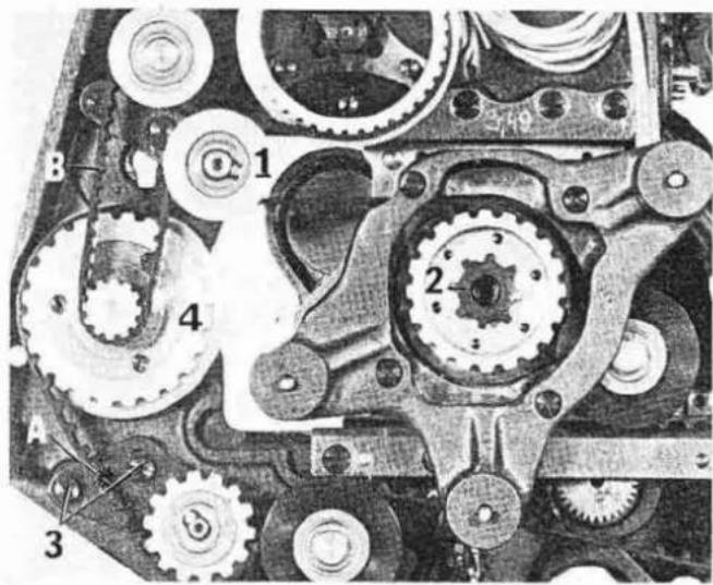
Fig. 16
Fig. 17
23
performed by knowledgeable service technicians with the proper tools. Unless performed by an authorized ARRIFLEX service agency it will void whatever guarantees might be valid for the camera at the time.
To adjust the tension of the drive belt proceed as follows. For the main drive belt, after removing the mechanism cover, loosen two screws (Fig. 16/3) which are holding the tension arm in position. Then, with one finger, carefully press the tension arm until the belt has the desired tension, hold it there, and retighen the screws. When the screws are securely fastened, test the belt tension as described in the previous paragraph.
The magazine drive belt is adjusted in a similar fashion by adjusting tension roller No. 1 (Fig. 16).
Caution: If during this adjustment the main drive belt leaves any of the drive couplings, e.g. the movement, the mirror shutter, etc., the timing of the camera must be rechecked and if necessary readjusted.
To adjust the timing of the camera, the motor must be removed from its mount. To do this, open the camera door and loosen the two chromed screws (Fig. 17/2, 3), then open the film channel and loosen the third screw (Fig. 3/2) located forward of, and slightly above, the transport mechanism.
Note: All three screws are self-retaining and should not be completely removed from the motor carrier.
When the three screws are loosened, pull the motor off its coupling and lay it, attached to its cable harness, next to the camera body. Note the rubber coupling which connects the motor to the film transport mechanism. When reassembling the drive, this rubber coupling must engage the motor and its corresponding flange (Fig. 16/2) on the film transport mechanism.
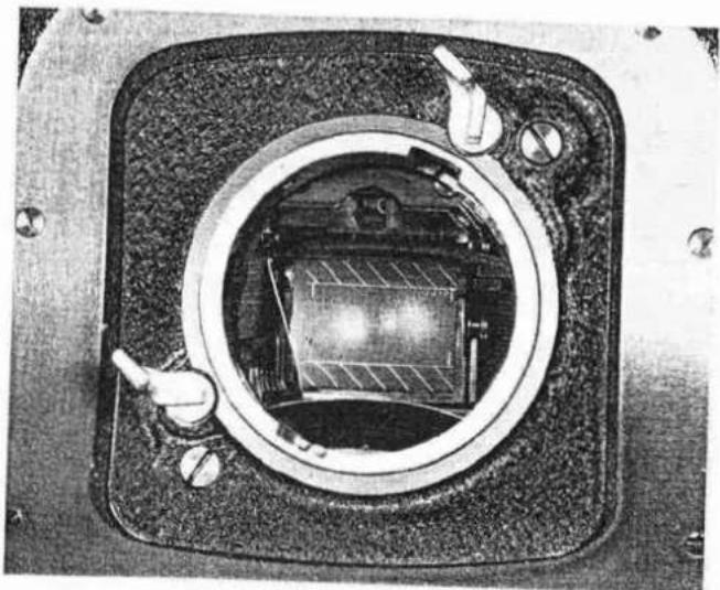
Make sure the drive belt is properly engaged with all drive members. Check and realign the drive belt as necessary until the timing between the shutter and the claws is correct. Proper timing is obtained when the right edge of the mirror shutter, rotating clockwise, just covers the upper right edge of the aperture plate (looking from the lens side) and the index marks on the transport mechanism are lined up (with the film channel closed). When proper belt tension and timing are correct, remount the motor as follows.
natural_image
Close-up of a mechanical component with circular frame and central internal structure (no visible text or symbols)Fig. 18
ARRI advertising department. Technical information and specifications are without obligation. Modifications reserved. The information covered herein may be reproduced only with our written authorization.
Printed in West Germany · WA HD 097308
Move the film transport mechanism back to the loading position and turn the inching knob until the mirror shutter is in the position shown in Fig. 18. Then, attach power supply to the camera, hold the motor with one hand and pulse the motor with the camera switch. This is to insure that the camera will later always stop with the mirror shutter in the viewing position. Once this is done, engage the motor via the rubber coupling with the film transport mechanism. Fasten the motor lock screw (Fig. 3/2) located in front of the claw mechanism. Then, slide the film transport mechanism forward and fasten the two remaining motor lock screws (Fig. 17/2, 3).
Important: After the motor has been attached, and before remounting the camera mechanism cover, test the transport mechanism slide for proper operation. It is important that the motor does not pinch any cables or other parts which are in contact with the camera housing. The motor should have a minimum distance from all other components of no less than 116 of an inch. The electric cable harness attached to the motor should move freely and bend without kinking or squeezing when the slide is moved back and forth.
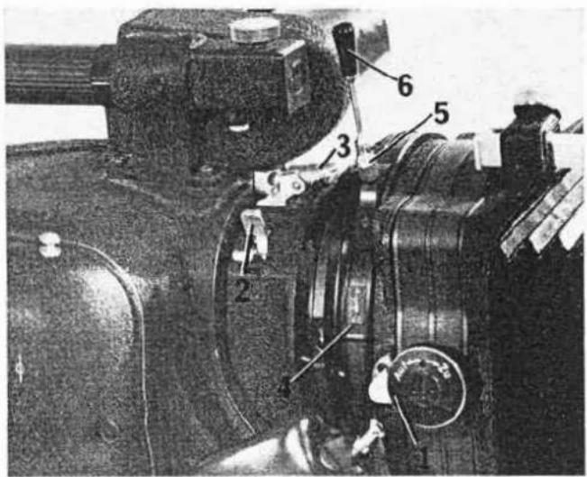
Fig. 19
Fig. 19
1 Swivel latch for filter door
2 Lens release latches
3 Lock/release for universal lens housing
4 Mounting grooves for scales
5 F/stop adjustment and lock knob
6 Focus handle
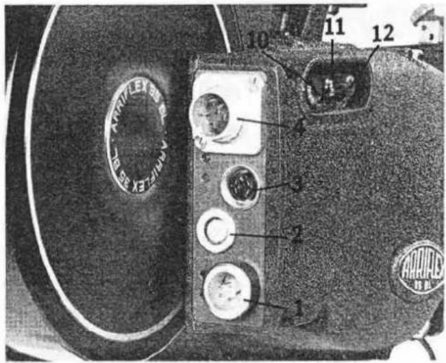
Fig. 20
1 Flange receptacle for power cable
2 Flange receptacle for various electronic systems
3 Pilotone outlet
4 Flange receptacle for bridge plug, high speed and emergency operation cable
10 Mode selector switch
11 Fuse holder
12 Volume control for "out of sync" buzzer
Fig. 20
- Contents Page
- Magazine loading
- Camera threading
- Aperture plate replacement
- Ground glass replacement
- Mounting of lenses without lens housing
- Mounting of lens support brackets
- Standard matte box for fixed lenses
- Universal housing for fixed lenses
- Focus and f/stop scales
- Filters
- Camera power connection
- Electronic/electrical features
- Camera speed selection
- Pilotone and start marking system
- Electronic accessories
- Preventive maintenance and minor service
- Cleaning of aperture plate and film channel
- Lubrication of the film transport mechanism
- Other lubrication points
- Replacing signal lamps
- Replacement of electrical fuses
- Maintenance of the magazine
- Magazine guide rollers for high speed operation from 60 fps to 100 fps
- Removal of the camera mechanism cover
- Checking drive belt tension
- Adjusting of the drive belts
- Fig. 19
- Fig. 20
Brand : ARRI
Model : FLEX 35 BL
Category : Camcorder