
Z9NA-D6C - Server ASUS - Free user manual and instructions
Find the device manual for free Z9NA-D6C ASUS in PDF.


| Product Type | Server Motherboard |
| Form Factor | SSI CEB (12" x 10.5") |
| CPU Support | Dual Intel Xeon E5-2600/2600 v2 series, LGA2011 |
| Chipset | Intel C602 |
| Memory | 8 x DDR3 DIMM slots, ECC, up to 256 GB |
| Expansion Slots | 2 x PCIe 3.0 x16, 2 x PCIe 3.0 x8, 1 x PCIe 2.0 x4 |
| Storage | 2 x SATA 6 Gb/s, 4 x SATA 3 Gb/s; Intel RSTe RAID 0/1/5/10 |
| Network | 2 x Intel I210 Gigabit LAN |
| Power Connectors | 24-pin ATX, 2 x 8-pin EPS12V |
| Operating Temperature | 0°C to 40°C |
| Non-Operating Temperature | -40°C to 70°C |
| Weight | Approximately 1.2 kg (board only) |
| Dimensions | 30.48 cm x 26.67 cm (12" x 10.5") |
| Power Supply | Not included; requires ATX12V or EPS12V PSU (recommended 500W+) |
| Main Functions | High-performance computing, virtualization, data center applications |
| Maintenance | Regular dust removal; ensure proper cooling and fan operation |
| Safety | Handle with ESD precautions; disconnect power before servicing |
| Spare Parts & Repairability | Parts available from ASUS distributors; repairable by qualified technicians |
| General Information | Supports IPMI 2.0, AMI UEFI BIOS, ASMB6-iKVM module optional |
Frequently Asked Questions - Z9NA-D6C ASUS
User questions about Z9NA-D6C ASUS
0 question about this device. Answer the ones you know or ask your own.
Ask a new question about this device
Download the instructions for your Server in PDF format for free! Find your manual Z9NA-D6C - ASUS and take your electronic device back in hand. On this page are published all the documents necessary for the use of your device. Z9NA-D6C by ASUS.
USER MANUAL Z9NA-D6C ASUS
Copyright © 2012 ASUSTeK COMPUTER INC. All Rights Reserved.
No part of this manual, including the products and software described in it, may be reproduced, transmitted, transcribed, stored in a retrieval system, or translated into any language in any form or by any means, except documentation kept by the purchaser for backup purposes, without the express written permission of ASUSTeK COMPUTER INC. ("ASUS").
Product warranty or service will not be extended if: (1) the product is repaired, modified or altered, unless such repair, modification of alteration is authorized in writing by ASUS; or (2) the serial number of the product is defaced or missing.
ASUS PROVIDES THIS MANUAL "AS IS" WITHOUT WARRANTY OF ANY KIND, EITHER EXPRESS OR IMPLIED, INCLUDING BUT NOT LIMITED TO THE IMPLIED WARRANTIES OR CONDITIONS OF MERCHANTABILITY OR FITNESS FOR A PARTICULAR PURPOSE. IN NO EVENT SHALL ASUS, ITS DIRECTORS, OFFICERS, EMPLOYEES OR AGENTS BE LIABLE FOR ANY INDIRECT, SPECIAL, INCIDENTAL, OR CONSEQUENTIAL DAMAGES (INCLUDING DAMAGES FOR LOSS OF PROFITS, LOSS OF BUSINESS, LOSS OF USE OR DATA, INTERRUPTION OF BUSINESS AND THE LIKE), EVEN IF ASUS HAS BEEN ADVISED OF THE POSSIBILITY OF SUCH DAMAGES ARISING FROM ANY DEFECT OR ERROR IN THIS MANUAL OR PRODUCT.
SPECIFICATIONS AND INFORMATION CONTAINED IN THIS MANUAL ARE FURNISHED FOR INFORMATIONAL USE ONLY, AND ARE SUBJECT TO CHANGE AT ANY TIME WITHOUT NOTICE, AND SHOULD NOT BE CONSTRUED AS A COMMITMENT BY ASUS. ASUS ASSUMES NO RESPONSIBILITY OR LIABILITY FOR ANY ERRORS OR INACCURACIES THAT MAY APPEAR IN THIS MANUAL, INCLUDING THE PRODUCTS AND SOFTWARE DESCRIBED IN IT.
Products and corporate names appearing in this manual may or may not be registered trademarks or copyrights of their respective companies, and are used only for identification or explanation and to the owners' benefit, without intent to infringe.
Contents
Contents .... iii
Notices ...... viii
Federal Communications Commission Statement ...... viii
Canadian Department of Communications Statement ...... viii
REACH ...... viii
Safety information ix
Electrical safety ix
Operation safety ix
About this guide ....x
How this guide is organized ....x
Where to find more information ....x
Conventions used in this guide ......xi
Typography ....xi
Z9NA-D6 series specifications summary ..... xii
Chapter 1: Product introduction
1.1 Welcome! 1-3
1.2 Package contents 1-3
1.3 Serial number label 1-4
1.4 Special features 1-4
1.4.1 Product highlights 1-4
1.4.2 Innovative ASUS features 1-6
Chapter 2: Hardware information
2.1 Before you proceed 2-3
2.2 Motherboard overview 2-4
2.2.1 Placement direction 2-4
2.2.2 Screw holes 2-4
2.2.3 Motherboard layout 2-5
2.2.4 Layout contents 2-7
2.3 Central Processing Unit (CPU) 2-9
2.3.1 Installing the CPU 2-9
2.3.2 Intel LGA1356 Socket 2-10
2.4 System memory 2-13
2.4.1 Overview 2-13
Contents
2.4.2 Memory Configurations 2-13
2.5 Expansion slots 2-16
2.5.1 Installing an expansion card 2-16
2.5.2 Configuring an expansion card 2-16
2.5.3 PCI Express x16 slot (x16 link) 2-17
2.5.4 PCI Express x8 slot (x8 link) 2-17
2.5.5 PCI Express x8 slot (x4 link) 2-17
2.5.6 PCI Express x1 slot (x1 link) 2-17
2.5.7 PIKE slots 2-17
2.5.8 Installing an ASUS PIKE RAID card (Optional) 2-18
2.5.9 Installing ASMB6 management board 2-19
2.5.10 Installing the audio card 2-19
2.6 Onboard LEDs 2-20
2.7 Jumpers 2-22
2.8 Connectors 2-26
2.8.1 Rear panel connectors 2-26
2.8.2 Internal connectors 2-27
Chapter 3: Powering up
3.1 Starting up for the first time 3-3
3.2 Powering off the computer 3-4
3.2.1 Using the OS shut down function 3-4
3.2.2 Using the dual function power switch 3-4
Chapter 4: BIOS setup
4.1 Managing and updating your BIOS 4-3
4.1.1 ASUS CrashFree BIOS 3 utility 4-3
4.1.2 ASUS EZ Flash 2 Utility 4-4
4.1.3 BUPDATER utility.... 4-5
4.2 BIOS setup program 4-7
4.2.1 BIOS menu screen 4-8
4.2.2 Menu bar 4-8
4.2.3 Menu items 4-9
4.2.4 Submenu items 4-9
4.2.5 Navigation keys 4-9
4.2.6 General help 4-9
Contents
4.2.7 Configuration fields 4-9
4.2.8 Pop-up window 4-9
4.2.9 Scroll bar 4-9
4.3 Main menu 4-10
4.3.1 System Date [Day xx/xx/xxxx] 4-10
4.3.2 System Time [xx:xx:xx] 4-10
4.4 Advanced menu 4-11
4.4.1 CPU Configuration 4-12
4.4.2 CPU Power Management Configuration 4-14
4.4.3 Chipset Configuration 4-16
4.4.4 PCH SATA Configuration 4-22
4.4.5 PCH SCU Configuration 4-23
4.4.6 PCI Subsystem Settings 4-23
4.4.7 USB Configuration 4-27
4.4.8 Trusted Computing 4-28
4.4.9 ACPI Settings 4-29
4.4.10 WHEA Configuration 4-30
4.4.11 APM setting 4-30
4.4.12 Serial Port Console Redirection 4-31
4.4.13 Onboard LAN Configuration 4-34
4.4.14 ME Subsystem 4-34
4.4.15 Onboard Devices Configuration 4-35
4.4.16 Runtime Error Logging 4-35
4.5 Server Mgmt menu 4-36
4.5.1 System Event Log 4-37
4.5.2 BMC network configuration 4-38
4.6 Event Logs menu 4-39
4.6.1 Change Smbios Event Log Settings 4-39
4.7 Boot menu 4-41
4.8 Monitor menu 4-43
4.9 Security menu 4-44
4.10 Tool menu 4-45
4.11 Exit menu 4-46
Contents
Chapter 5: RAID configuration
5.1 Setting up RAID 5-3
5.1.1 RAID definitions 5-3
5.1.2 Installing hard disk drives 5-4
5.1.3 Setting the RAID item in BIOS 5-4
5.1.4 RAID configuration utilities 5-4
5.2 LSI Software RAID Configuration Utility 5-5
5.2.1 Creating a RAID set 5-6
5.2.2 Adding or viewing a RAID configuration 5-12
5.2.3 Initializing the virtual drives 5-13
5.2.4 Rebuilding failed drives 5-17
5.2.5 Checking the drives for data consistency 5-19
5.2.6 Deleting a RAID configuration 5-22
5.2.7 Selecting the boot drive from a RAID set 5-23
5.2.8 Enabling WriteCache 5-24
5.3 Intel ^® Rapid Storage Technology enterprise SCU/SATA Option ROM Utility 5-25
5.3.1 Creating a RAID set 5-27
5.3.2 Creating a Recovery set 5-28
5.3.3 Deleting a RAID set 5-30
5.3.4 Resetting disks to Non-RAID 5-31
5.3.5 Exiting the Intel ^® Rapid Storage Technology utility ..... 5-32
5.3.6 Rebuilding the RAID 5-32
5.3.7 Setting the Boot array in the BIOS Setup Utility 5-34
5.4 Intel ^® Rapid Storage Technology enterprise Utility (Windows) 5-35
5.4.1 Creating a RAID set 5-36
5.4.2 Change Volume Type 5-38
5.4.3 Delete volume 5-39
5.4.4 Preferences 5-40
Chapter 6: Driver installation
6.1 RAID driver installation 6-3
6.1.1 Creating a RAID driver disk 6-3
6.1.2 Installing the RAID controller driver 6-6
6.2 Intel ^ chipset device software installation 6-16
6.3 Intel @ Network Connections Software installation.... 6-19
6.4 VGA driver installation.... 6-22
6.5 Intel ^ C600 Series Chipset SCU SATA RAID Drivers ...... 6-25
6.6 Intel ^® Rapid Storage Technology enterprise 3.0 installation . 6-26
6.7 Intel ^® WG82574L Gigabit Adapters Driver installation ...... 6-29
6.8 Management applications and utilities installation 6-33
6.8.1 Running the support DVD 6-33
6.8.2 Drivers menu 6-33
6.8.3 Utilities menu 6-34
6.8.4 Make disk menu 6-34
6.8.5 Contact information 6-34
Appendix: Reference information
A.1 Z9NA-D6 block diagram ......A-3
ASUS contact information .... 1
Notices
Federal Communications Commission Statement
This device complies with Part 15 of the FCC Rules. Operation is subject to the following two conditions:
• This device may not cause harmful interference, and
- This device must accept any interference received including interference that may cause undesired operation.
This equipment has been tested and found to comply with the limits for a Class B digital device, pursuant to Part 15 of the FCC Rules. These limits are designed to provide reasonable protection against harmful interference in a residential installation. This equipment generates, uses and can radiate radio frequency energy and, if not installed and used in accordance with manufacturer's instructions, may cause harmful interference to radio communications. However, there is no guarantee that interference will not occur in a particular installation. If this equipment does cause harmful interference to radio or television reception, which can be determined by turning the equipment off and on, the user is encouraged to try to correct the interference by one or more of the following measures:
- Reorient or relocate the receiving antenna.
- Increase the separation between the equipment and receiver.
- Connect the equipment to an outlet on a circuit different from that to which the receiver is connected.
- Consult the dealer or an experienced radio/TV technician for help.

The use of shielded cables for connection of the monitor to the graphics card is required to assure compliance with FCC regulations. Changes or modifications to this unit not expressly approved by the party responsible for compliance could void the user's authority to operate this equipment.
Canadian Department of Communications Statement
This digital apparatus does not exceed the Class B limits for radio noise emissions from digital apparatus set out in the Radio Interference Regulations of the Canadian Department of Communications.
This class B digital apparatus complies with Canadian ICES-003.
REACH
Complying with the REACH (Registration, Evaluation, Authorization, and Restriction of Chemicals) regulatory framework, we publish the chemical substances in our products at ASUS REACH website at http://csr.asus.com/english/REACH.htm.
Safety information
Electrical safety
- To prevent electrical shock hazard, disconnect the power cable from the electrical outlet before relocating the system.
- When adding or removing devices to or from the system, ensure that the power cables for the devices are unplugged before the signal cables are connected. If possible, disconnect all power cables from the existing system before you add a device.
- Before connecting or removing signal cables from the motherboard, ensure that all power cables are unplugged.
- Seek professional assistance before using an adapter or extension cord. These devices could interrupt the grounding circuit.
- Make sure that your power supply is set to the correct voltage in your area. If you are not sure about the voltage of the electrical outlet you are using, contact your local power company.
- If the power supply is broken, do not try to fix it by yourself. Contact a qualified service technician or your retailer.
Operation safety
- Before installing the motherboard and adding devices on it, carefully read all the manuals that came with the package.
- Before using the product, make sure all cables are correctly connected and the power cables are not damaged. If you detect any damage, contact your dealer immediately.
- To avoid short circuits, keep paper clips, screws, and staples away from connectors, slots, sockets and circuitry.
- Avoid dust, humidity, and temperature extremes. Do not place the product in any area where it may become wet.
- Place the product on a stable surface.
- If you encounter technical problems with the product, contact a qualified service technician or your retailer.

DO NOT throw the motherboard in municipal waste. This product has been designed to enable proper reuse of parts and recycling. This symbol of the crossed out wheeled bin indicates that the product (electrical and electronic equipment) should not be placed in municipal waste. Check local regulations for disposal of electronic products.

DO NOT throw the mercury-containing button cell battery in municipal waste. This symbol of the crossed out wheeled bin indicates that the battery should not be placed in municipal waste.
About this guide
This user guide contains the information you need when installing and configuring the motherboard.
How this guide is organized
This user guide contains the following parts:
• Chapter 1: Product introduction
This chapter describes the features of the motherboard and the new technologies it supports.
• Chapter 2: Hardware information
This chapter lists the hardware setup procedures that you have to perform when installing system components. It includes description of the switches, jumpers, and connectors on the motherboard.
• Chapter 3: Powering up
This chapter describes the power up sequence and ways of shutting down the system.
• Chapter 4: BIOS setup
This chapter tells how to change system settings through the BIOS Setup menus. Detailed descriptions of the BIOS parameters are also provided.
• Chapter 5: RAID configuration
This chapter provides instructions for setting up, creating, and configuring RAID sets using the available utilities.
• Chapter 6: Driver installation
This chapter provides instructions for installing the necessary drivers for different system components.
- Appendix: Reference information
This appendix includes additional information that you may refer to when configuring the motherboard.
Where to find more information
Refer to the following sources for additional information and for product and software updates.
1. ASUS websites
The ASUS website provides updated information on ASUS hardware and software products. Refer to the ASUS contact information.
2. Optional documentation
Your product package may include optional documentation, such as warranty flyers, that may have been added by your dealer. These documents are not part of the standard package.
Conventions used in this guide
To make sure that you perform certain tasks properly, take note of the following symbols used throughout this manual.

DANGER/WARNING: Information to prevent injury to yourself when trying to complete a task.

CAUTION: Information to prevent damage to the components when trying to complete a task.

IMPORTANT: Instructions that you MUST follow to complete a task.

NOTE: Tips and additional information to help you complete a task.
Typography
Bold text Indicates a menu or an item to select.
Italics Used to emphasize a word or a phrase.
Example:
Example:
Command Means that you must type the command exactly as shown, then supply the required item or value enclosed in brackets.
Example: At the DOS prompt, type the command line:
format A:/S
Z9NA-D6 series specifications summary
| Model Name Z9NA-D6 Z9NA-D6C | |||
| Processor / System Bus | 2 * LGA 1356 | ||
| Intel® Xeon® processor E5-2400 product family | |||
| QPI 6.4 / 7.2 / 8.0 GT/s | |||
| Core Logic | Intel® C602-A PCH | ||
| Form Factor | 12"x 9.9" | ||
| ASUS Features FAN speed control | V | ||
| Rack Ready (Rack and Pedestal dual use) | V | ||
| Rack Optimized (Dedicated for Rack) | - | ||
| ASWM Enterprise | V | ||
| Memory Total Slots | 6 (3-channel per CPU, 3 DIMM per CPU) | ||
| Voltage | 1.5V/1.35V | ||
| Capacity | Maximum up to 192GB | ||
| Memory Type | DDR3 800/1066/1333/1600 RDIMM DDR3 1066/1333 ECC UDIMM/ Non-ECC UDIMM DDR3 1066/1333 LR-DIMM | ||
| Memory Size* | 1 GB, 2GB, 4GB, 8GB, 16GB, 32GB * (RDIMM) 1 GB, 2GB, 4GB, 8GB * (UDIMM) 8 GB, 16GB, 32GB * (LRDIMM) | ||
| Expansion Slots (follow SSI Location #) | Total PCI/PCI-X/ PCI-E Slots | 6 | |
| Slot Location 1 | 1 * PCI-E5 x1 (X1 Gen2 Link), from C602 PCH; MIO supported | ||
| Slot Location 2 | 1 * PCI-E4 x8 (X4 Gen2 Link), from C602 PCH | ||
| Slot Location 3 | 1 * PCI-E3 x8 (X8 Gen3 Link), from CPU 2 | ||
| Slot Location 4 | 1 * PCI-E2 x8 (X8 Gen3 Link), from CPU 2 | ||
| Slot Location 5 | - | ||
| Slot Location 6 | 1 * PCI-E1 x16 (X16 Gen3 Link), from CPU 1 | ||
| Slot Location 7 | - | ||
| Additional Slot 1 | 1* PIKE Slot for Storage expansion (Gen3 supported) | ||
(continued on the next page)
Z9NA-D6 series specifications summary
| Model Name Z9NA-D6 Z9NA-D6C | |||
| Storage SATA Controller | Intel® C602-A:4 SATA 3Gb/s ports; 2 SATA 6Gb/s portsIntel® RSTe (for Windows only)(Support software RAID 0, 1, 10 & 5)LSI® MegaRAID (for Linux/Windows)(Support software RAID 0, 1, 10)4 SATA 3Gb/s portsIntel® RSTe (for Windows only)(Support software RAID 0, 1, 10 & 5 for all SATA ports) | Intel® C602-A:4 SATA 3Gb/s ports; 2 SATA 6Gb/s portsIntel® RSTe (for Windows only)(Support software RAID 0, 1, 10 & 5) | |
(continued on the next page)
Z9NA-D6 series specifications summary
| Model Name Z9NA-D6 Z9NA-D6C | |||
| Management Solution | Software | ASWM Enterprise | |
| Out of Band Remote Management | Optional ASMB6-iKVM for KVM-over-Internet | - | |
| Environment | Operation temperature: 10°C ~ 35°CNon operation temperature: -40°C ~ 70°CNon operation humidity: 20% ~ 90% ( Non condensing) | ||
*Refer to ASUS Server AVL for latest update.
** Minimum requirement of ATX Power supply:1) 470W 2) All +12V output ≥ 20A
***Specifications are subject to change without notice.
This chapter describes the motherboard features and the new technologies it supports.
Product
introduction
Chapter summary
1
1.1 Welcome! 1-3
1.2 Package contents 1-3
1.3 Serial number label 1-4
1.4 Special features 1-4
1.1 Welcome!
Thank you for buying an ASUS® Z9NA-D6 Series motherboard!
The motherboard delivers a host of new features and latest technologies, making it another standout in the long line of ASUS quality motherboards!
Before you start installing the motherboard, and hardware devices on it, check the items in your package with the list below.
1.2 Package contents
Check your motherboard package for the following items.
Z9NA-D6 Series
| Standard Gift Box Pack | Standard Bulk Pack | ||
| Cables | SATA 6G cable | 2 | -- |
| SATA 3G cable | 8 (Z9NA-D6)4 (Z9NA-D6C) | -- | |
| SATA DOM USB power cable | 1 | -- | |
| Accessories IO shield | 1 | 1 | |
| Application CD | Support CD | 1 | 1 |
| ASWM Enterprise SDVD | 1 | 1 | |
| Documentation User Guide | 1 | 1 | |
| Packing Qty. | 1pc per carton 10pcs per carton | ||
If any of the above items is damaged or missing, contact your retailer.
| Optional items Description |
| PIKE 2108 LSI 8-port SAS2 6G HW RAID card |
| PIKE 2008/IMR LSI 8-port SAS2 6G RAID card |
| PIKE 2008 LSI 8-port SAS2 6G RAID card |
| ASMB6-iKVM Remote management solution provides KVM over IP solution |
1.3 Serial number label
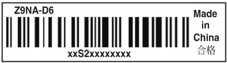
Before requesting support from the ASUS Technical Support team, you must take note of the motherboard's serial number containing 12 characters xxS2xxxxxxxxx shown as the figure below. With the correct serial number of the product, ASUS Technical Support team members can then offer a quicker and satisfying solution to your problems.
text_image
Z9NA-D6 xxS2xxxxxxxxx Made in China 合格1.4 Special features
1.4.1 Product highlights
Latest Processor Technology
The motherboard supports the latest Intel Xeon ^® processor E5-2400 product family in LGA 1356 package with integrated memory controller to support 3 channel (6 DIMM prt CPU) DDR3 memory. Intel Xeon ^® processor E5-2400 product family supports Intel QuickPath Interconnect (QPI) with a system bus of up to 8.0GT/s.
Optimized Intel ^® Turbo Boost Technology
Optimized Intel® Turbo Boost Technology further optimizes the processor's performance and automatically allows it to run faster than the marked frequency if it is operating below power, temperature, and current limits.
Intel® Hyper Threading
The thread-level parallelism on each processor makes more efficient use of the processor resources, higher processing throughout and improved performance on today's multi-threaded software.
Intel ^® EM64T
The motherboard supports Intel ^® processors with the Intel ^® EM64T (Extended Memory 64 Technology). The Intel ^® EM64T feature allows your computer to run on 64-bit operating systems and access larger amounts of system memory for faster and more efficient computing.
DDR3 memory support
The Z9NA-D6 supports DDR3 memory that features data transfer rates of 1600/1333/1066 MHz to meet the higher bandwidth requirements of server and workstation applications. The 3-channel DDR3 architecture boosts system performance, eliminating bottlenecks with peak bandwidth of up to 52GB/s. This voltage reduction limits the power consumption and heat generation of DDR3 which makes it an ideal memory solution. Also, the motherboard can support LR-DIMM (Load reduced DIMM) which uses a specially designed buffer to reduce the data load to a single load and can increase overall server system memory capacity.
PCIe 3.0
The motherboard supports the latest PCIe 3.0 device, which doubles the delivered bandwidth of PCIe 2.0. This enhances system performance while still providing backward compatibility to PCIe 2.0.
Intel® 82574L Gigabit LAN Solution
This motherboard features the built-in dual server class Intel ^® Gigabit LAN ports, which helps reduce CPU usage, thus increasing throughput to achieve highly-reliable network connections, outstanding performance, and better support for diverse operating systems.
Intel ^® 82574L chipset is VMware-certified to support the virtualization technology.
Enhanced Intel SpeedStep Technology (EIST)
The Enhanced Intel SpeedStep Technology (EIST) intelligently manages the CPU resources by automatically adjusting the CPU voltage and core frequency depending on the CPU loading and system speed or power requirement.
Serial ATA II technology
The motherboard supports the Serial ATA II 3 Gb/s technology through the Serial ATA interface and Intel® C602 chipset. The Serial ATA II specification provides twice the bandwidth of the current Serial ATA products with a host of new features, including Native Command Queuing (NCQ), Power Management (PM) Implementation Algorithm, and Hot Swap. Serial ATA allows thinner, more flexible cables with lower pin count and reduced voltage requirements.
Serial ATA III technology
The motherboard supports the Serial ATA III technology through the Serial ATA interface and Intel ^® C602 chipset, delivering up to 6Gb/s data transfer rates. Additionally, get enhanced scalability, faster data retrieval, double the bandwidth of current bus systems.
USB 2.0 technology
The motherboard implements the Universal Serial Bus (USB) 2.0 specification, dramatically increasing the connection speed from the 12 Mbps bandwidth on USB 1.1 to a fast 480 Mbps on USB 2.0. USB 2.0 is backward compatible with USB 1.1.
Temperature, fan, and voltage monitoring
The CPU temperature is monitored to prevent overheating and damage. The system fan rotations per minute (RPM) is monitored for timely failure detection. The chip monitors the voltage levels to ensure stable supply of current for critical components.
1.4.2 Innovative ASUS features
ASUS Fan Speed control technology
The ASUS Fan Speed control technology smartly adjusts the fan speeds according to the system loading to ensure quiet, cool, and efficient operation.
PIKE (Proprietary I/O Kit Expansion)
PIKE is an on-demand upgrade kit for users. This ASUS unique feature enables users to choose their preferred I/O solutions. ASUS provides multiple SAS solutions for different segments and purposes and PIKE saves lots of validation efforts and hardware cost for end users.
ASUS MIO Audio card
Enjoy high-end sound quality! The ASUS MIO audio card is a discrete 8-channel high definition audio (High Definition Audio previously codenamed Azalia) CODEC that offers the clearest high quality audio output, jack-sensing feature, retasking functions, and multi-streaming technology that simultaneously send different audio streams to different destinations.
This chapter lists the hardware setup procedures that you have to perform when installing system components. It includes description of the jumpers and connectors on the motherboard.
Hardware information
Chapter summary
2
2.1 Before you proceed 2-3
2.2 Motherboard overview 2-4
2.3 Central Processing Unit (CPU) 2-9
2.4 System memory 2-13
2.5 Expansion slots 2-16
2.6 Onboard LEDs 2-20
2.7 Jumpers 2-22
2.8 Connectors 2-26
2.1 Before you proceed
Take note of the following precautions before you install motherboard components or change any motherboard settings.

- Unplug the power cord from the wall socket before touching any component.
- Use a grounded wrist strap or touch a safely grounded object or a metal object, such as the power supply case, before handling components to avoid damaging them due to static electricity.
- Hold components by the edges to avoid touching the ICs on them.
- Whenever you uninstall any component, place it on a grounded antistatic pad or in the bag that came with the component.
- Before you install or remove any component, ensure that the power supply is switched off or the power cord is detached from the power supply. Failure to do so may cause severe damage to the motherboard, peripherals, and/or components.
Standby Power LED (SB\_PWR1)
The motherboard comes with a standby power LED. The green LED lights up to indicate the system AC power cable plug or not. This is a reminder that you should shut down the system and unplug the power cable before removing or plugging in any motherboard component. The illustration below shows the location of the onboard LED.

text_image
Z9NA-D6 Onboard LED SB_PWR1 ON Standy Power OFF Powered Off2.2 Motherboard overview
Before you install the motherboard, study the configuration of your chassis to ensure that the motherboard fits into it.
To optimize the motherboard features, we highly recommend that you install it in an ATX 2.2 compliant chassis.

Ensure to unplug the chassis power cord before installing or removing the motherboard. Failure to do so can cause you physical injury and damage motherboard components!
2.2.1 Placement direction
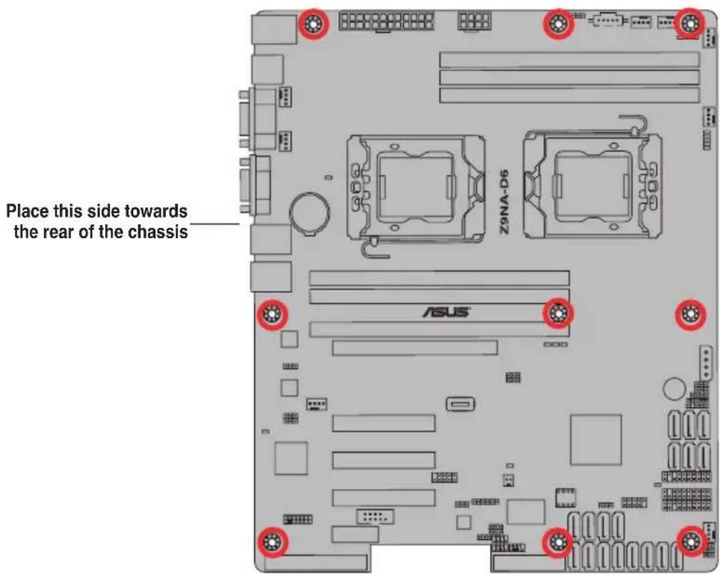
When installing the motherboard, ensure that you place it into the chassis in the correct orientation. The edge with external ports goes to the rear part of the chassis as indicated in the image below.
2.2.2 Screw holes
Place nine (9) screws into the holes indicated by the circles to secure the motherboard to the chassis.

DO NOT overtighten the screws! Doing so can damage the motherboard.
text_image
Place this side towards the rear of the chassis Z9NA-D6 ASUS2.2.3 Motherboard layout
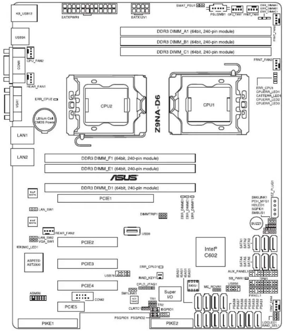
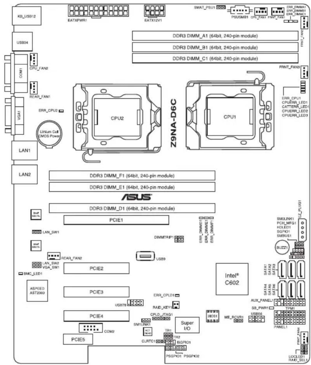
Z9NA-D6
text_image
KB_USB12 USB34 COM1 CPU_FAN2 REAR_FAN1 VGA1 ERR_CPU2 Lithium Coil CMOS Power LAN1 LAN2 DDR3 DIMM_A1 (64bit, 240-pin module) DDR3 DIMM_B1 (64bit, 240-pin module) DDR3 DIMM_C1 (64bit, 240-pin module) Z9NA-D6 CPU2 CPU1 FRNT_FAN3 ERR_CPU1 CPUERR_LED1 CATTERR_LED1 CPUERR_LED2 CPUERR_LED3 DDR3 DIMM_F1 (64bit, 240-pin module) DDR3 DIMM_E1 (64bit, 240-pin module) ASUS® DDR3 DIMM_D1 (64bit, 240-pin module) PCIE1 PINER_FAN2 VGA_SW1 ASPEED AST2300 ASME8 PCIE2 PCIE3 PCIE4 COM2 PCIE5 PCIE7# USB7# USB7# USB7# USB7# USB7# USB7# USB7# USB7# USB7# USB7# USB7# USB7# USB7# USB7# USB7# USB7# USB7# USB7# USB7# USB7# USB7# USB7# USB7# USB7# USB7# USB7# USB7# USB7# USB7# USB7# USB7# USB7# USB7# USB6# COM2 PCIE5 PCIE4 PCIE3 PCIE2 PCIE1 PCIE0_JTAG1 CPU0_JTAG1 CPU0_JTAG1 CPU0_JTAG1 CPU0_JTAG1 CPU0_JTAG1 CPU0_JTAG1 CPU0_JTAG1 CPU0_JTAG1 CPU0_JTAG1 CPU0_JTAG1 CPU0_JTAG1 CPU0_JTAG1 CPU0_JTAG1 CPU0_JTAG1 CPU0_JTAG1 CPU0_JTAG1 CPU0_JTAG2 CPU0_JTAG2 CPU0_JTAG2 CPU0_JTAG2 CPU0_JTAG2 CPU0_JTAG2 CPU0_JTAG2 CPU0_JTAG2 CPU0_JTAG2 CPU0_JTAG2 CPU0_JTAG2 CPU0_JTAG2 CPU0_JTAG2 CPU0_JTAG2 CPU0_JTAG2 CPU0_JTAG2 CPU0_JTAG2 CPU0-JTAG1 CPU0-JTAG1 CPU0-JTAG1 CPU0-JTAG1 CPU0-JTAG1 CPU0-JTAG1 CPU0-JTAG1 CPU0-JTAG1 CPU0-JTAG1 CPU0-JTAG1 CPU0-JTAG1 CPU0-JTAG1 CPU0-JTAG1 CPU0-JTAG1 CPU0-JTAG1 CPU0-JTAG1 CPU0-JTAG1 CPU0JTAG1 CPU0JTAG1 CPU0JTAG1 CPU0JTAG1 CPU0JTAG1 CPU0JTAG1 CPU0JTAG1 CPU0JTAG1 CPU0JTAG1 CPU0JTAG1 CPU0JTAG1 CPU0JTAG1 CPU0JTAG1 CPU0JTAG1 CPU0JTAG1 CPU0JTAG1 CPU0JTAG1 CUPIE1 CUPIE2 CUPIE3 CUPIE4 CUPIE5 CUPIE6 CUPIE7 CUPIE8 CUPIE9 CUPIE10 CUPIE11 CUPIE12 CUPIE13 CUPIE14 CUPIE15 CUPIE16 CUPIE17 CUPIE18 CUPIE19 CUPIE20 CUPIE21 CUPIE22 CUPIE23 CUPIE24 CUPIE25 CUPIE26 CUPIE27 CUPIE28 CUPIE29 CUPIE30 CUPIE31 CUPIE32 CUPIE33 CUPIE34 CUPIE35 CUPIE36: Digital Module 64bit, 240-pin module) DDR3 DIMM_A1 (64bit, 240-pin module) DDR3 DIMM_B1 (64bit, 240-pin module) DDR3 DIMM_C1 (64bit, 240-pin module) DDR3 DIMM_F1 (64bit, 240-pin module) DDR3 DIMM_E1 (64bit, 240-pin module) DDR3 DIMM_D1 (64bit, 240-pin module) DDR3 DIMM_E1 (64bit, 240-pin module) DDR3 DIMM_F1 (64bit, 240-pin module) DDR3 DIMM_E1 (64bit, 240-pin module) DDR3 DIMM_F1 (64bit, 240-pin module) DDR3 DIMM_E1 (64bit, 240-pin module) DDR3 DIMM_F1 (64bit, 240-pin module) DDR3 DIMM_E1 (64bit, 24O pin module) DDR3 DIMM_F1 (64bit, 24O pin module) DDR3 DIMM_E1 (64bit, 24O pin module) DDR3 DIMM_F1 (64bit, 24O pin module) DDR3 DIMM_E1 (64bit, 24O pin module) DDR3 DIMM_F1 (64bit, 24O pin module) DDR3 DIMM_E1 (64bit, 24O pin module) DDR3 DIMM_F1 (58bit, 24O pin module) DDR3 DIMM_E1 (58bit, 24O pin module) DDR3 DIMM_F1 (58bit, 24O pin module) DDR3 DIMM_E1 (58bit, 24O pin module) DDR3 DIMM_F1 (58bit, 24O pin module) DDR3 DIMM_E1 (58bit, 24O pin module) DDR3 DIMM_F1 (58bit, 24O pin module) DDRT_PSUU I DCCDCDCDCDCDCDCDCDCDCDCDCDCDCDCDCDCDCDCDCDCDCDCDCDCDCDCDCDCDCDCDCDCDCDCDCDCDCDCDCDCDCDCDCDCDCDCDCDCDCDCDCDCDCDCDCDCDCDCDCDCDCDCDCDCDCDCDCDCDCDCDCDCDCDCDCDCDCDCDCDCDCDCDCDCDCDCDCDCDCDCDCDCDCDCDCDCDCDCDCDCDCCPCPCPCPCPCPCPCPCPCPCPCPCPCPCPCPCPCPCPCPCPCPCPCPCPCPCPCPCPCPCPCPCPCPCPCPCPCPCPCPCPCPCPCPCPCPCPCPCPCPCPCPCPCPCPCPCPCPCPCPCPCPCPCPCPCPCPCPCPCPCPCPCPCPCPCPCPCPCPCPCPCPCPCPCPCPCPCPCPCPCPCPCPCPCPCPCPCPCPCPCPPLCPLDIPICPLDIPICPLDIPICPLDIPICPLDIPICPLDIPICPLDIPICPLDIPICPLDIPICPLDIPICPLDIPICPLDIPICPLDIPICPLDIPICPLDIPICPLDIPICPLDIPICPLDIPICPLDIPICPLDIPICPLDIPICPLDIPICPLDIPICPLDIPICPLDIPICPLDIPIPCPLDIPICPLDIPICPLDIPICPLDIPICPLDIPICPLDIPICPLDIPICPLDIPICPLDIPICPLDIPICPLDIPICPLDIPICPLDIPICPLDIPICPLDIPICPLDIPICPLDIPICPLDIPICPLDIPICPLDIPICPLDIPICPLDIPICPLDIPICPLDIPICPLDIP ICPLDIP ICPLDIP ICPLDIP ICPLDIP ICPLDIP ICPLDIP ICPLDIP ICPLDIP ICPLDIP ICPLDIP ICPLDIP ICPLDIP ICPLDIP ICPLDIP ICPLDIP ICPLDIP ICPLDIP ICPLDIP ICPLDIP ICPLDIP ICPLDIP ICPLDIP ICPLDIP ICPLDIP ICPLDIP I CPTA B S T A T A T A T A T A T A T A T A T A T A T A T A T A T A T A T A T A T A T A T A T A T A T A T A T A T A T A T A T A T A T A T A T A T A T A T A T A T A T A T A T A T A T A T A T A T A T A T A T A T A TZ9NA-D6C
flowchart
graph TD
    subgraph Memory_Trajectory
        A["KB_USB12"] --> B["USB34"]
        C["COM1"] --> D["CPU_FAN2"]
        E["VGA1"] --> F["REAR_FAN1"]
        G["LINUM Cell CMOS Power"] --> H["CPU2"]
        I["LAN1"] --> J["LAN2"]
    end

    subgraph Digital_Trajectory
        K["Z9NA-D6C"] --> L["CPU1"]
        M["CPU2"] --> N["DDR3 DIMM_A1 (64bit, 240-pin module)"]
        O["CPU2"] --> P["DDR3 DIMM_B1 (64bit, 240-pin module)"]
        Q["CPU2"] --> R["DDR3 DIMM_C1 (64bit, 240-pin module)"]

    end

    subgraph External_Trajectory
        S["ASUS"] --> T["DDR3 DIMM_F1 (64bit, 240-pin module)"]
        U["PCIE1"] --> V["DDR3 DIMM_E1 (64bit, 240-pin module)"]
        W["PCIE2"] --> X["DDR3 DIMM_D1 (64bit, 240-pin module)"]
        Y["PCIE3"] --> Z["DDR3 DIMM_D2 (64bit, 240-pin module)"]

        AA["PCIE1"] --> AB["DRAM1"]
        AC["DRAM2"] --> AD["DRAM2"]
        AE["DRAM3"] --> AF["DRAM3"]
        AG["DRAM4"] --> AH["DRAM4"]
        AI["DRAM5"] --> AJ["DRAM5"]
        AK["DRAM6"] --> AL["DRAM6"]
        AM["DRAM7"] --> AN["DRAM7"]
        AO["DRAM8"] --> AP["DRAM8"]
        AQ["DRAM9"] --> AR["DRAM9"]
        AS["DRAM10"] --> AT["DRAM10"]
        AU["DRAM11"] --> AV["DRAM11"]
        AW["DRAM12"] --> AX["DRAM12"]
        AY["BUZZ1"] --> AZ["SMDLINK1"]
        BA["SATA1"] --> BB["PCH_MFG1"]
        BC["SATA2"] --> BD["HOLED1"]
        BE["SATA3"] --> BF["SGPXD1"]
        BG["SATA4"] --> BH["SATM6"]
        BI["AUX PANEL1"] --> BJ["S8_PWR1"]
        BK["TPM1"] --> BL["PANEL1"]
        BM["PANEL2"] --> BN["PANEL1"]
        BO["PANEL3"] --> BP["PANEL2"]
        BQ["PANEL4"] --> BR["SPLD_JTAG1"]
        BS["PANEL5"] --> BT["SMI LINK1"]
        BU["PANEL6"] --> BV["NCL LINK1"]
        BW["PANEL7"] --> BX["NCL LINK1"]
        BY["PANEL8"] --> BZ["NCL LINK1"]
        CA["PANEL9"] --> CB["NCL LINK1"]
        CC["PANEL10"] --> CD["NCL LINK1"]
        DE["PANEL11"] --> DF["NCL LINK1"]
        DG["PANEL12"] --> DH["NCL LINK1"]
        DI["PANEL13"] --> DJ["NCL LINK1"]
        DK["PANEL14"] --> DL["NCL LINK1"]
        DN["PANEL15"] --> DE
        DB["PANEL16"] --> DE
    end

    subgraph External_Trajectory
        E
        F
        G
        H
        I
        J
        K
        L
        M
        N
        O
        P
        Q
        R
        S
        T
        U
        V
        W
        X
        Y
        Z
        AA
        AB
        AC
        AD
        AE
        AF
        AG
        AH
        AI
        AJ
        AK
        AL
        AM
        AN
        AO
        AP
        AQ
        AR
        AS
    end

    subgraph External_Trajectory
        S
        T
        U
        V
        W
        X
        Y
    end

    subgraph External_Trajectory
        AA
        AB
        AC
        AD
        AE
        AF
    end
2.2.4 Layout contents
Slots/Sockets Page
| 1. CPU sockets | 2-9 |
| 2. DDR3 sockets | 2-13 |
| 3. PCI Express x8 / PCI Express x16 slots | 2-16 |
| Onboard LEDs | Page |
| 1. Baseboard Management Controller (BMC_LED1) | 2-20 |
| 2. CPU Warning LED (ERR_CPU1/2) | 2-20 |
| 3. CATT Error LED (CATTERR_LED1) | 2-21 |
Jumpers Page
| 1. Clear RTC RAM (CLRTC1) 2-22 | ||
| 2. VGA controller setting (3-pin VGA_SW1) 2-23 | ||
| 3. LAN controller setting (3-pin LAN_SW1/ LAN_SW2) 2-23 | ||
| 4. LSI MegaRAID or Intel RSTe selection jumper (3-pin RAID_SEL1) | 2-24 | |
| 5. ME firmware force recovery setting (3-pin ME_RCVR1) | 2-24 | |
| 6. DDR3 thermal event setting (3-pin DIMMTRIP1) | 2-25 | |
| 7. PMBus1.2 PSU select jumper (3-pin SMART_PSU1) | 2-25 | |
Rear panel connectors Page
| 1. PS/2 keyboard/mouse port 2-26 |
| 2. USB 2.0 ports 1 and 2 2-26 |
| 3. USB 2.0 ports 3 and 4 2-26 |
| 4. COM port 2-26 |
| 5. Video Graphics Adapter port 2-26 |
| 6. LAN 1 (RJ-45) port 2-26 |
| 7. LAN 2 (RJ-45) port 2-26 |
Internal connectors Page
| 1. Serial ATA 6.0/3.0 Gb/s connectors(7-pin SATA6G 1-2 [Blue]; 7-pin SATA3G 3-6 [Black]) | 2-27 |
| 2. SATA connectors-ISAS connectors(7-pin ISAS1-4 [Gray]) | 2-27 |
| 3. SAS connectors(7-pin PSAS1-8 [Blue]) | 2-28 |
| 4. Hard disk activity LED connector (4-pin HDLED1) | 2-28 |
| 5. USB connectors (10-1 pin USB56, USB78; A-Type USB9) | 2-29 |
| 6. CPU, front and rear fan connectors(4-pin CPU_FAN1-2, FRNT_FAN1-4, REAR_FAN1-2) | 2-29 |
| 7. Serial General Purpose Input/Output connectors(8-1 pin PSGPIO 1/2, ISGPIO1, SGPIO1) | 2-30 |
| 8. Serial port connectors (10-1 pin COM2) | 2-31 |
| 9. TPM connector (20-1-pin TPM1) | 2-31 |
| 10. 24+8-pin EATX power connectors (24-pin EATXPWR1, 8-pin EATX12V1) | 2-32 |
| 11. Power Supply SMBus (5-pin PSUSMB1) | 2-33 |
| 12. 4-pin Power Connector (4-pin EZ_PLUG1) | 2-33 |
| 13. System panel connector (20-1 pin PANEL1) | 2-34 |
| 14. Auxiliary panel connector (20-2 pin AUX_PANEL1) | 2-35 |
2.3 Central Processing Unit (CPU)
The motherboard comes with a surface mount LGA1356 socket designed for the Intel ^® Xeon E5-2400 family processor.

- Upon purchase of the motherboard, ensure that the PnP cap is on the socket and the socket contacts are not bent. Contact your retailer immediately if the PnP cap is missing, or if you see any damage to the PnP cap/socket contacts/motherboard components. ASUS will shoulder the cost of repair only if the damage is shipment/transit-related.
- Keep the cap after installing the motherboard. ASUS will process Return Merchandise Authorization (RMA) requests only if the motherboard comes with the cap on the LGA1356 socket.
- The product warranty does not cover damage to the socket contacts resulting from incorrect CPU installation/removal, or misplacement/loss/incorrect removal of the PnP cap.
2.3.1 Installing the CPU
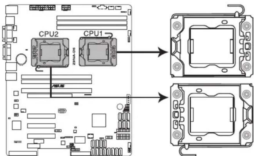
text_image
CPU2 ZDNA-D6 CPU1 ASUSZ9NA-D6 CPU LGA1356 Socket

Before installing the CPU, ensure that the socket box is facing toward you and the load lever is on your left.
2.3.2 Intel LGA1356 Socket
- Locate the CPU socket on the motherboard.
- Press the load lever with your thumb (A), then move it to the left (B) until it is released from the retention tab.

To prevent damage to the socket pins, do not remove the PnP cap unless you are installing a CPU.
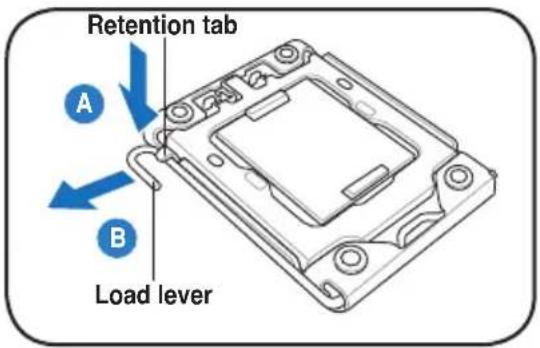
text_image
Retention tab A B Load lever- Lift the load lever in the direction of the arrow to a 135^ angle (C), then lift the load plate with your thumb and forefinger to a 100^ angle (D).
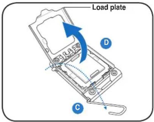
text_image
Load plate D C- Remove the PnP cap from the CPU socket.
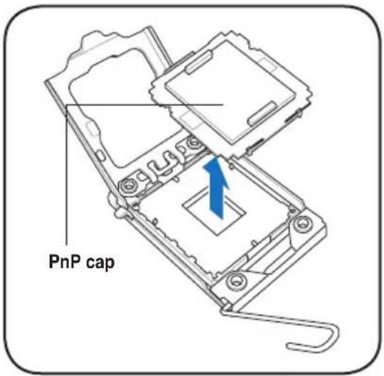
text_image
PnP cap- Position the CPU over the socket, ensuring that the gold triangle is on the bottom-left corner of the socket, and then fit the socket alignment key into the CPU notch.

text_image
Gold triangle mark CPU notch Alignment key
The CPU fits in only one correct orientation. DO NOT force the CPU into the socket to prevent bending the connectors on the socket and damaging the CPU!
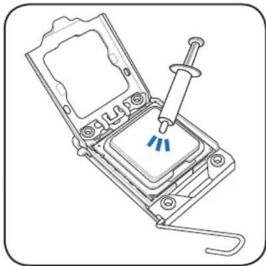
- Apply some Thermal Interface Material to the exposed area of the CPU that the heatsink will be in contact with, ensuring that it is spread in an even thin layer.
Some heatsinks come with pre-applied thermal paste. If so, skip this step.

The Thermal Interface Material is toxic and inedible. DO NOT eat it. If it gets into your eyes or touches your skin, wash it off immediately, and seek professional medical help.
natural_image
Technical line drawing of a mechanical assembly with a screwdriver inserted into a component (no text or symbols)- Close the load plate (E), and then push the load lever (F) until it snaps into the retention tab.
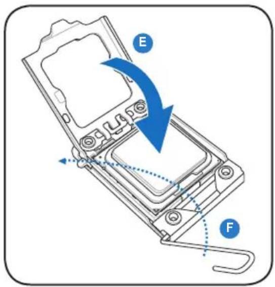
text_image
E F- Connect the CPU fan cable to the connector on the motherboard labeled CPU_FAN1 / CPU_FAN2.
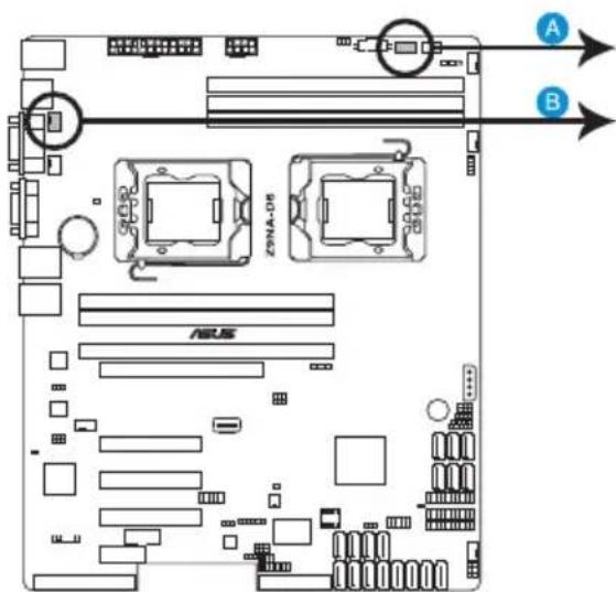
text_image
A B ZONA-06 ASUS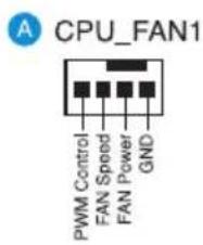
text_image
CPU_FAN1 PWM Control FAN Speed FAN Power GND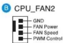
Z9NA-D6 CPU FAN connectors

DO NOT forget to connect the CPU fan connector! Hardware monitoring errors can occur if you fail to plug this connector.
2.4 System memory
2.4.1 Overview
The motherboard comes with three (per CPU) Double Data Rate 3 (DDR3) Dual Inline Memory Modules (DIMM) sockets.
A DDR3 module has the same physical dimensions as a DDR2 DIMM but is notched differently to prevent installation on a DDR2 DIMM socket. DDR3 modules are developed for better performance with less power consumption.
The figure illustrates the location of the DDR3 DIMM sockets:
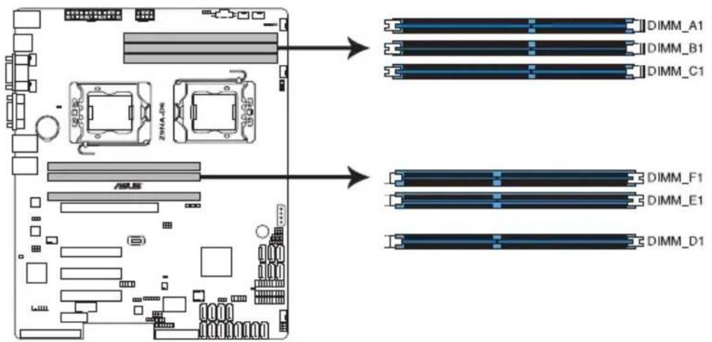
text_image
DIMM_A1 DIMM_B1 DIMM_C1 ASLS DIMM_F1 DIMM_E1 DIMM_D1Z9NA-D6 240-pin DDR3 DIMM sockets
2.4.2 Memory Configurations
You may install 1GB, 2GB, 4GB, 8GB, 16GB and 32GB* RDIMMs or 1GB, 2GB, 4GB and 8GB* with ECC/Non-ECC UDIMMs or 8GB, 16GB and 32GB* LR-DIMMs into the DIMM sockets using the memory configurations in this section.
| 1 CPU Configuration (must on CPU1) | |||
| DIMM_A1 | DIMM_B1 | DIMM_C1 | |
| 1 DIMMs | X | ||
| 2 DIMMs | X | X | |
| 3 DIMMs | XXX | ||

• *Refer to ASUS Server AVL for latest update.
• Install the DIMMS starting from slot A1 (CPU1) and D1 (CPU2).
- Always install DIMMs with the same CAS latency. For optimum compatibility, it is recommended that you obtain memory modules from the same vendor.
| 2 CPU Configuration | ||||||
| DIMM_A1 | DIMM_B1 | DIMM_C1 | DIMM_D1 | DIMM_E1 | DIMM_F1 | |
| 1 DIMMs | X | |||||
| 2 DIMMs | X | X | ||||
| 4 DIMMs | XXX | X | ||||
| 6 DIMMs | XXX | XXX | ||||
2.4.3 Installing a DIMM on a single clip DIMM socket
- Unlock a DIMM socket by pressing the retaining clip outward.
- Align a DIMM on the socket such that the notch on the DIMM matches the DIMM slot key on the socket.
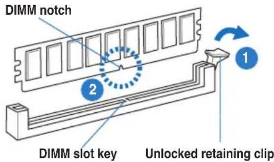
text_image
DIMM notch 2 1 DIMM slot key Unlocked retaining clip
A DIMM is keyed with a notch so that it fits in only one direction. DO NOT force a DIMM into a socket in the wrong direction to avoid damaging the DIMM.
- Hold the DIMM by both of its ends, then insert the DIMM vertically into the socket. Apply force to both ends of the DIMM simultaneously until the retaining clip snaps back into place, and the DIMM cannot be pushed in any further to ensure proper sitting of the DIMM.
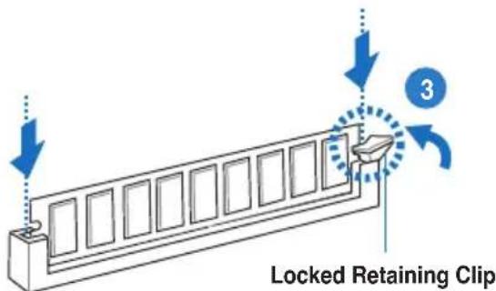
text_image
Locked Retaining Clip 3
Always insert the DIMM into the socket VERTICALLY to prevent DIMM notch damage.
- To install two or more DIMMs, refer to the user guide bundled in the motherboard package.
- Refer to the user guide for qualified vendor lists of the memory modules.
Removing a DIMM from a single clip DIMM socket
- Press the retaining clip outward to unlock the DIMM.
- Remove the DIMM from the socket.
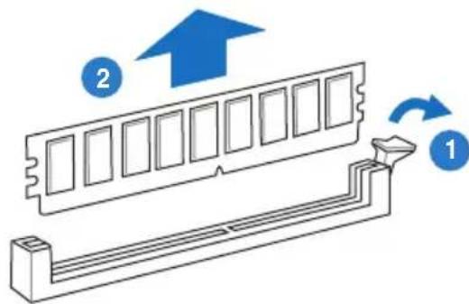
text_image
Diagram showing a RAM module with two labeled components (1 and 2) and directional arrows indicating flow or movement.
Support the DIMM lightly with your fingers when pressing the retaining clips. The DIMM might get damaged when it flips out with extra force.
2.5 Expansion slots
In the future, you may need to install expansion cards. The following subsections describe the slots and the expansion cards that they support.

Ensure to unplug the power cord before adding or removing expansion cards. Failure to do so may cause you physical injury and damage motherboard components.
2.5.1 Installing an expansion card
To install an expansion card:
- Before installing the expansion card, read the documentation that came with it and make the necessary hardware settings for the card.
- Remove the system unit cover (if your motherboard is already installed in a chassis).
- Remove the bracket opposite the slot that you intend to use. Keep the screw for later use.
- Align the card connector with the slot and press firmly until the card is completely seated on the slot.
- Secure the card to the chassis with the screw you removed earlier.
- Replace the system cover.
2.5.2 Configuring an expansion card
After installing the expansion card, configure it by adjusting the software settings.
- Turn on the system and change the necessary BIOS settings, if any. See Chapter 4 for information on BIOS setup.
- Assign an IRQ to the card. Refer to the tables on the next page.
- Install the software drivers for the expansion card.

When using PCI cards on shared slots, ensure that the drivers support “Share IRQ” or that the cards do not need IRQ assignments. Otherwise, conflicts will arise between the two PCI groups, making the system unstable and the card inoperable.
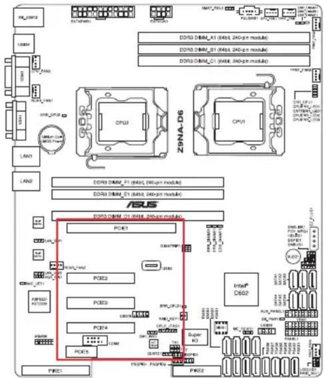
2.5.3 PCI Express x16 slot (x16 link)
The onboard PCIE 1 (slot location 6) provides one x16 Gen3 link to CPU1. These slots support VGA cards and various server class high performance add-on cards.
2.5.4 PCI Express x8 slot (x8 link)
The onboard PCIE 2 (slot location 4) and 3 (slot location 3) provide one x8 Gen3 link to CPU2. These slots support various server class high performance add-on cards.
2.5.5 PCI Express x8 slot (x4 link)
The onboard PCIE 4 (slot location 2) provides one x4 Gen2 link to Intel C602 PCH. This slot supports various server class high performance add-on cards.
2.5.6 PCI Express x1 slot (x1 link)
The onboard PCIE 5 (slot location 1) provides one x1 Gen2 link to Intel C602 PCH.
text_image
DDR3 DIMM_A1 (4bit, 240-pin module) DDR3 DIMM_B1 (4bit, 240-pin module) DDR3 DIMM_C1 (4bit, 240-pin module) CPU2 CPU1 Z9NA-D6 DDR3 DIMM_F1 (4bit, 240-pin module) DDR3 DIMM_C1 (4bit, 240-pin module) ASUS® DDR3 DIMM_C1 (4bit, 240-pin module) PCI61 PCI62 PCI63 PCI64 PCI65 PCI66 PCI67 PCI68 PCI69 PCI70 PCI71 PCI72 PCI73 PCI74 PCI75 PCI76 PCI77 PCI78 PCI79 PCI80 PCI81 PCI82 PCI83 PCI84 PCI85 PCI86 PCI87 PCI88 PCI89 PCI90 PCI91 PCI92 PCI93 PCI94 PCI95 PCI96 PCI97 PCI98 PCI99 PCI100 PCI101 PCI102 PCI103 PCI104 PCI105 PCI106 PCI107 PCI108 PCI109 PCI110 PCI111 PCI112 PCI113 PCI114 PCI115 PCI116 PCI117 PCI118 PCI119 PCI120 PCI121 PCI122 PCI123 PCI124 PCI125 PCI126 PCI127 PCI128 PCI129 PCI130 PCI131 PCI132 PCI133 PCI134 PCI135 PCI136 PCI137 PCI138 PCI139 PCI140 PCI141 PCI142 PCI143 PCI144 PCI145 PCI146 PCI147 PCI148 PCI149 PCI150 PCI151 PCI152 PCI153 PCI154 PCI155 PCI156 PCI157 PCI158 PCI159 PCI160 PCI161 PCI162 PCI163 PCI164 PCI165 PCI166 PCI167 PCI168 PCI169 PCI170 PCI171 PCI172 PCI173 PCI174 PCI175 PCI176 PCI177 PCI178 PCI179 PCI180 PCI181 PCI182 PCI183 PCI184 PCI185 PCI186 PCI187 PCI188 PCI189 PCI190 PCI191 PCI192 PCI193 PCI194 PCI195 PCI196 PCI197 PCI198 PCI199 PCI200| PCIE 1 (slot location 6) | 1 x PCI-E x 16 (Gen3 x16 link) |
| PCIE 2 (slot location 4) | 1 x PCI-E x 8 (Gen3 x8 link) |
| PCIE 3 (slot location 3) | 1 x PCI-E x 8 (Gen3 x8 link) |
| PCIE 4 (slot location 2) | 1 x PCI-E x 8 (Gen2 x4 link) |
| PCIE 5 (slot location 1) | 1 x PCI-E x 1 (Gen2 link) |
2.5.7 PIKE slots
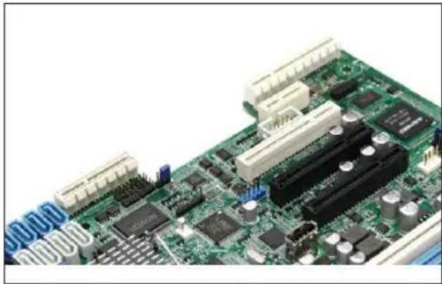
The PIKE slot allows you to choose and change your preferred SAS solution easily. Install an optional ASUS PIKE RAID card based on your needs.
2.5.8 Installing an ASUS PIKE RAID card (Optional)
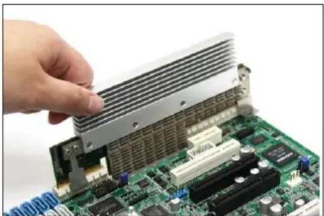
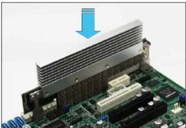
Follow the steps below to install an optional ASUS PIKE RAID card on your motherboard.
- Locate the PIKE RAID card slot on the motherboard.
natural_image
Close-up of a green printed circuit board with various electronic components and connectors (no visible text or symbols)- Align the golden fingers of the PIKE RAID card with the PIKE RAID card slot.
natural_image
Close-up of a hand inserting a heatsink into a green computer motherboard (no visible text or symbols)- Insert the PIKE RAID card into the PIKE RAID card slot. Ensure that it is completely seated on the PIKE RAID card slot.
natural_image
Close-up of a computer motherboard with a blue downward arrow indicating compression or cooling process (no text or symbols visible)
Please refer to Chapter 2.8.2 for SAS connector location.
2.5.9 Installing ASMB6 management board
Follow the steps below to install an optional ASMB6 management board on your motherboard.
- Locate the ASMB6 header on the motherboard.
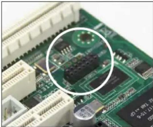
natural_image
Close-up of a green printed circuit board with visible components and a magnified circular detail (no readable text or symbols)- Orient and press the ASMB6 management card in place.
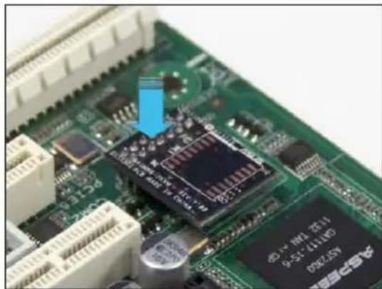
natural_image
Close-up of a green printed circuit board with integrated circuits and capacitors (no readable text or symbols)2.5.10 Installing the audio card
-
Locate the PCIE5 card slot on the motherboard and align the golden fingers of the audio card with the PCIE5 card slot.
-
Insert the audio card into the PCIE5 card slot. Ensure that it is completely seated on the card slot.
-
Secure the audio card to the chassis with a screw.
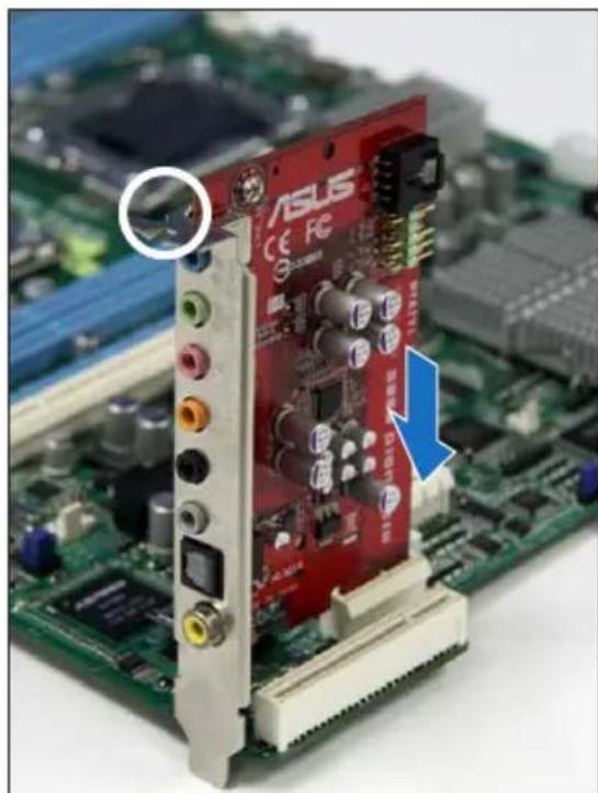
natural_image
Close-up of a red ASUS CPU board with visible components and a blue arrow pointing to a component (no text or symbols on the board)2.6 Onboard LEDs
1. Baseboard Management Controller LED (BMC\_LED1)
The BMC LED works with the ASUS ASMB6 management device and indicates its initiation status. When the PSU is plugged and the system is OFF, ASUS ASMB6 management device starts system initiation for about one (1) minute. The BMC LED blinks after system initiation finishes.
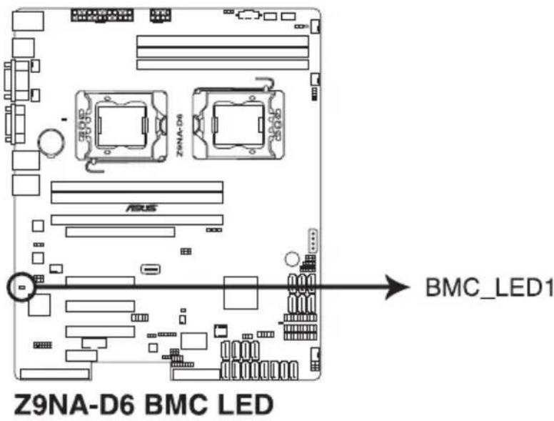
text_image
Z9NA-D6 BMC LED BMC_LED12. CPU warning LED (ERR\_CPU1/2)
The CPU warning LEDs light up to indicate that an impending failure of the corresponding CPU.
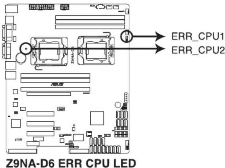
text_image
Z9NA-D6 ERR CPU LED ERR_CPU1 ERR_CPU2
The warning LEDs function only when you install the ASUS ASMB6.
3. CATT Error LED (CATTERR\_LED1)
Indicates that the system has experienced a fatal or catastrophic error and cannot continue to operate.
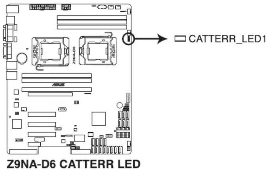
text_image
Z9NA-D6 CATTERR LED CATERR_LED12.7 Jumpers
1. Clear RTC RAM (CLRTC1)
This jumper allows you to clear the Real Time Clock (RTC) RAM in CMOS. You can clear the CMOS memory of date, time, and system setup parameters by erasing the CMOS RTC RAM data. The onboard button cell battery powers the RAM data in CMOS, which include system setup information such as system passwords.
To erase the RTC RAM:
- Turn OFF the computer and unplug the power cord.
- Move the jumper cap from pins 1–2 (default) to pins 2–3. Keep the cap on pins 2–3 for about 5–10 seconds, then move the cap back to pins 1–2.
- Plug the power cord and turn ON the computer.
- Hold down the
key during the boot process and enter BIOS setup to re-enter data.

Except when clearing the RTC RAM, never remove the cap on CLRTC jumper default position. Removing the cap will cause system boot failure!

If the steps above do not help, remove the onboard battery and move the jumper again to clear the CMOS RTC RAM data. After the CMOS clearance, reinstall the battery.
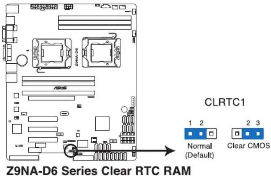
text_image
Z9NA-D6 Series Clear RTC RAM CLRTC1 Normal (Default) 2 3 Clear CMOS2. VGA controller setting (3-pin VGA\_SW1)
This jumper allows you to enable or disable the onboard VGA controller. Set to pins 1–2 to activate the VGA feature.
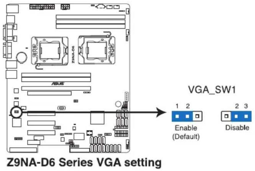
text_image
Z9NA-D6 Series VGA setting VGA_SW1 1 2 Enable (Default) 2 3 Disable3. LAN controller setting (3-pin LAN\_SW1/ LAN\_SW2)
These jumpers allow you to enable or disable the onboard Intel® 82574L Gigabit LAN controllers. Set to pins 1-2 to activate the Gigabit LAN feature.
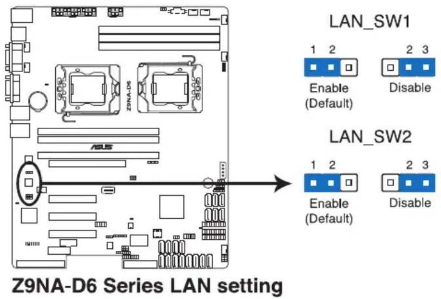
text_image
Z9NA-D6 Series LAN setting LAN_SW1 1 2 Enable (Default) 2 3 Disable LAN_SW2 1 2 Enable (Default) 2 3 Disable4. LSI MegaRAID or Intel RSTe selection jumper (3-pin RAID\_SEL1)
This jumper allows you to select the PCH SATA RAID mode to use LSI MegaRAID software or Intel® Rapid Storage Technology enterprise 3.0 RAID. Place the jumper caps over pins 1–2 if you want to use the LSI MegaRAID software RAID Utility (default); otherwise, place the jumper caps to pins 2–3 to use the Intel® Rapid Storage Technology Enterprise Option ROM Utility.
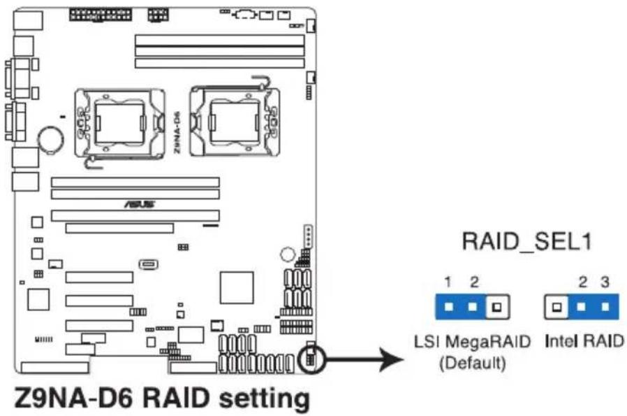
text_image
Z9NA-D6 RAID setting RAID_SEL1 LSI MegaRAID (Default) Intel RAID5. ME firmware force recovery setting (3-pin ME\_RCVR1)
This jumper allows you to force Intel Management Engine (ME) boot from recovery mode when ME become corrupted.
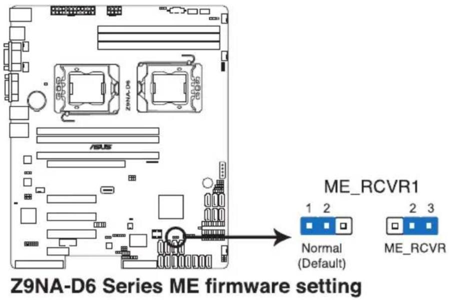
text_image
Z9NA-D6 Series ME firmware setting ME_RCVR1 1 2 Normal (Default) 2 3 ME_RCVR6. DDR3 thermal event setting (3-pin DIMMTRIP1)
This jumper allows you to enable/disable DDR3 DIMM thermal sensing event pin.
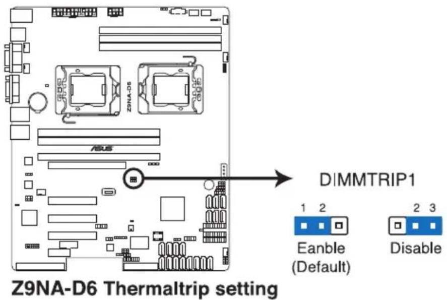
text_image
Z9NA-D6 Thermaltrip setting DIMMTRIP1 1 2 Eanble (Default) 2 3 Disable7. PMBus 1.2 PSU select jumper (3-pin SMART\_PSU1)
This jumper allows you to select PSU PMBus version, Set to pins 1-2 for PMBus, set to pins 2-3 for Others.
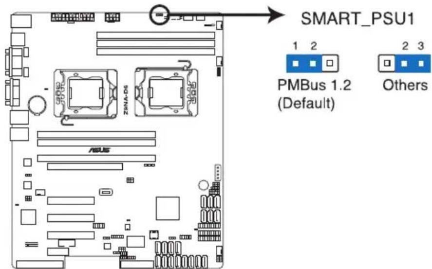
text_image
SMART_PSU1 1 2 PMBus 1.2 (Default) Others ZSNA-D6 ASUSZ9NA-D6 PMBus 1.2 PSU setting
2.8 Connectors
2.8.1 Rear panel connectors
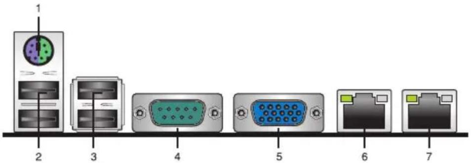
text_image
1 2 3 4 5 6 7- PS/2 keyboard/mouse port. This port is for a PS/2 keyboard and mouse.
- USB 2.0 ports 1 and 2. These two 4-pin Universal Serial Bus (USB) ports are available for connecting USB 2.0 devices.
- USB 2.0 ports 3 and 4 These two 4-pin Universal Serial Bus (USB) ports are available for connecting USB 2.0 devices.
- COM port.
- Video Graphics Adapter port. This port is for a VGA monitor or other VGA-compatible devices.
- LAN 1 (RJ-45) port. This port allows Gigabit connection to a Local Area Network (LAN) through a network hub. Refer to the table below for the LAN port LED indications.
- LAN 2 (RJ-45) port. This port allows Gigabit connection to a Local Area Network (LAN) through a network hub. Refer to the table below for the LAN port LED indications.
LAN port LED indications
| Activity/Link LED Speed LED | |||
| Status Description Status Description | |||
| OFF No link OFF 10 Mbps connection | |||
| Green Linked Orange 100 Mbps connection | |||
| Blinking Data activity Green | 1 Gbps connection | ||
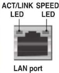
text_image
ACT/LINK SPEED LED LED LAN port2.8.2 Internal connectors
- Serial ATA 6.0/3.0 Gb/s connectors (7-pin SATA6G_1-2 [Blue]; 7-pin SATA3G_3-6 [Black])
These connectors connect to Serial ATA 6.0Gb/s or 3.0 Gb/s hard disk drives and optical disc drives via Serial ATA 6.0Gb/s or 3.0 Gb/s signal cables.
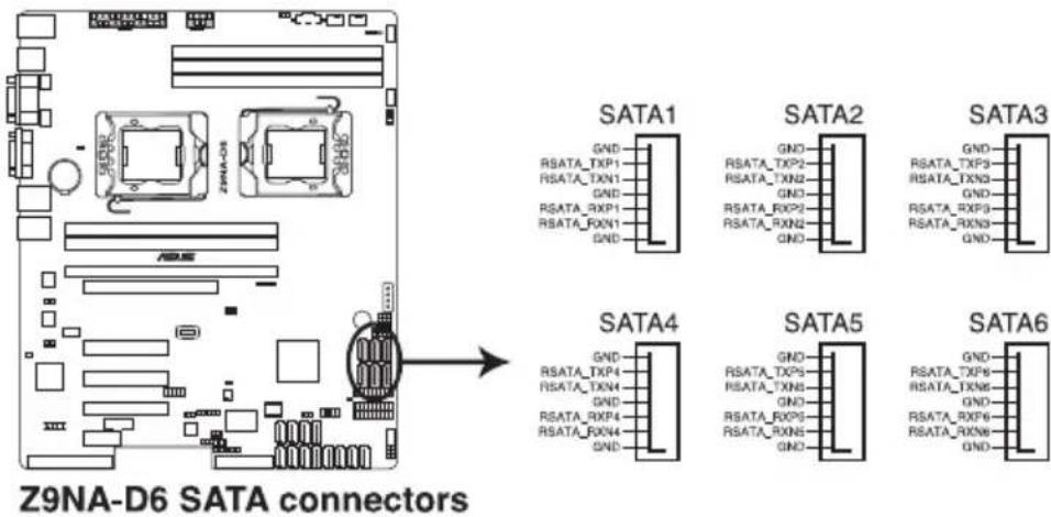
text_image
Z9NA-D6 SATA connectors SATA1 GND RSATA_TXP1 RSATA_TXN1 GND RSATA_RXP1 RSATA_RXN1 GND SATA2 GND RSATA_TXP2 RSATA_TXN2 GND RSATA_RXP2 RSATA_RXN2 GND SATA3 GND RSATA_TXP3 RSATA_TXN3 GND RSATA_RXP3 RSATA_RXN3 GND SATA4 GND RSATA_TXP4 RSATA_TXN4 GND RSATA_RXP4 RSATA_RXN4 GND SATA5 GND RSATA_TXP5 RSATA_TXN5 GND RSATA_RXP5 RSATA_RXN5 GND SATA6 GND RSATA_TXP6 RSATA_TXN6 GND RSATA_RXP6 RSATA_RXN6 GND- SATA connectors — ISAS connectors (7-pin ISAS1-4 [Gray])
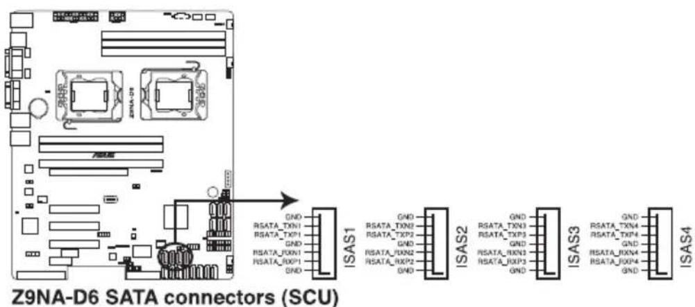
Supported by Intel C602 PCH, ISAS 1-4 connectors connect to Serial ATA 3.0 Gb/s hard disk drives and optical disk drives via Serial ATA 3.0 Gb/s signal cables.

The actual data transfer rate depends on the speed of SATA hard disks installed.
text_image
Z9NA-D6 SATA connectors (SCU) ISAS1 GND RSATA_TXN1 RSATA_TXP1 GND RSATA_RXN1 RSATA_RXP1 GND ISAS2 GND RSATA_TXN2 RSATA_TXP2 GND RSATA_RXN2 RSATA_RXP2 GND ISAS3 GND RSATA_TXN3 RSATA_TXP3 GND RSATA_RXN3 RSATA_RXP3 GND ISAS43. SAS connectors (7-pin PSAS1-8 [Blue])
Supported by the ASUS® PIKE Card, these connectors are for the SAS signal cables for SAS hard disk drives that allows up to 6Gb/s of data transfer rate.
If you installed SAS hard disk drives, you can create a RAID 0, RAID 1, RAID 10, or RAID 5 configuration.
![ASUS Z9NA-D6C - SAS connectors (7-pin PSAS1-8 [Blue]) - 1](/content/2026/05/815256/images/9931065f76336a95ae2bf45e093b384bd4e3e2ee73ffe74e312c59553811727d.jpg)
text_image
Z9NA-D6 SAS connectors (PIKE)![ASUS Z9NA-D6C - SAS connectors (7-pin PSAS1-8 [Blue]) - 2](/content/2026/05/815256/images/cf97b4291363a458ab32b4b2b2975444025e45b835a4c47ce62a53179933aae0.jpg)
The actual data transfer rate depends on the speed of SAS hard disks installed.
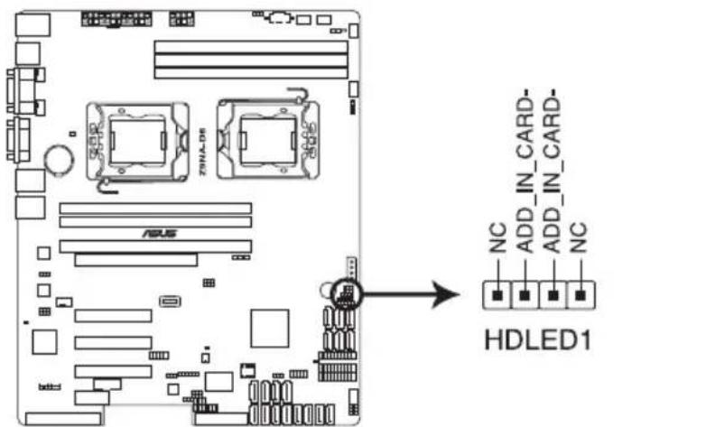
4. Hard disk activity LED connector (4-pin HDLED1)
This LED connector is for the storage add-on card cable connected to the SATA or SAS add-on card. The read or write activities of any device connected to the SATA or SAS add-on card causes the front panel LED to light up.
text_image
75N/A-DS ADUS NC ADD_IN_CARD- ADD_IN_CARD- NC HDLED1Z9NA-D6 Storage card activity LED connector
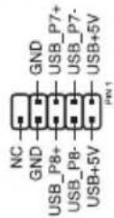
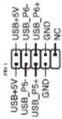
5. USB connectors (10-1 pin USB56, USB78; A-Type USB9)
These connectors are for USB 2.0 ports. Connect the USB module cables to connectors USB34 and USB56, then install the modules to a slot opening at the back of the system chassis. These USB connectors comply with USB 2.0 specification that supports up to 480 Mbps connection speed.

text_image
USB9 A B CZ9NA-D6 USB 2.0 connectors
B USB78
USB56
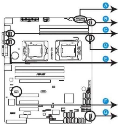
6. CPU, front and rear fan connectors
(4-pin CPU\_FAN1-2, FRNT\_FAN1-4, REAR\_FAN1-2)
The fan connectors support cooling fans. Connect the fan cables to the fan connectors on the motherboard, ensuring that the black wire of each cable matches the ground pin of the connector.

- DO NOT forget to connect the fan cables to the fan connectors. Insufficient air flow inside the system may damage the motherboard components.
• These are not jumpers! DO NOT place jumper caps on the fan connectors! - All fans feature the ASUS Fan Speed Control technology.
text_image
A B C D E F G ZENA-05 ASUSZ9NA-D6 FAN connectors
A CPU_FAN1
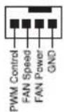
FRNT_FAN1
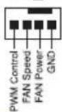
B FRNT_FAN2
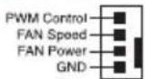
CPU_FAN2

FRNT_FAN3
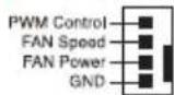
E REAR_FAN1
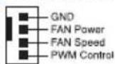
F REAR_FAN2
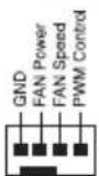
G FRNT_FAN4
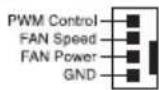
7. Serial General Purpose Input/Output connectors (8-1 pin PSGPIO 1/2, ISGPIO1, SGPIO1)
The SGPIO 1 connectors are used for the Intel Rapid Storage Technology Enterprise SGPIO interface that controls the LED pattern generation, device information and general purpose data.

• The PSGPIO 1/2 connectors are used for PIKE card.
- The ISGPIO 1 connector is for SATA connectors-ISAS connectors.
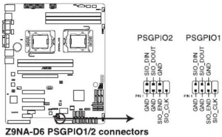
text_image
Z9NA-D6 PSGPIO1/2 connectors PSGPIO2 PSGPIO1 SIO_DIN SIO_DOUT GND PN1 GND GND SIO_END SIO_CLK PN1 GND GND SIO_END SIO_CLK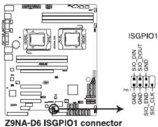
text_image
Z9NA-D6 ISGPIO1 connector ISGPIO1 SIO_DIN SIO_DOUT GND PIN 1 GND GND SIO_END SIO_CLK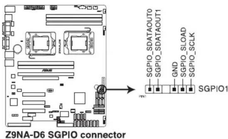
text_image
Z9NA-D6 SGPIO connector SGPIO_SDATAOUT0 SGPIO_SDATAOUT1 GND SGPIO_SLOAD SGPIO_SCLK PGN1 SGPIO18. Serial port connectors (10-1 pin COM2)
These connectors are for the serial (COM) ports. Connect the serial port module cable to one of these connectors, then install the module to a slot opening at the back of the system chassis.
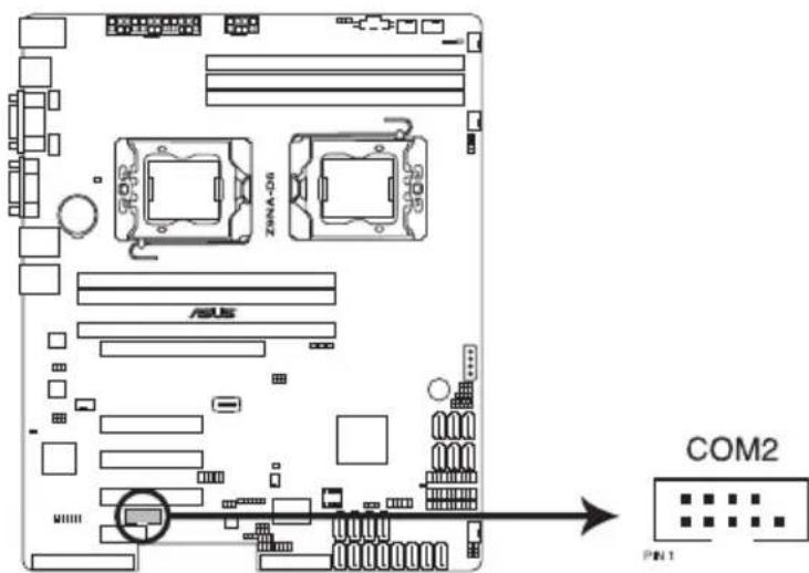
text_image
ZWA-D6 ASUS COM2 PIN 1Z9NA-D6 Serial port connector
9. TPM connector (20-1 pin TPM1)
This connector supports a Trusted Platform Module (TPM) system, which can securely store keys, digital certificates, passwords, and data. A TPM system also helps enhance network security, protects digital identities, and ensures platform integrity.
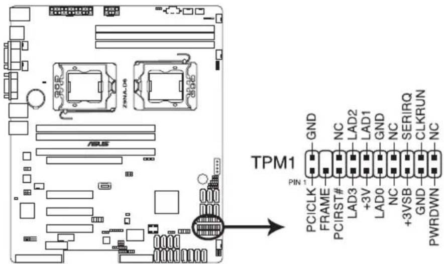
text_image
TPM1 PIN 1 GND NC LAD2 LAD1 GND NC SERIRQ CLKRUN PWRDWN PCICLK FRAME PCIRST# LAD3 +3V LAD0 NC +3VSB GND PWRDWNZ9NA-D6 TPM connector
10. 24+8-pin EATX power connectors (24-pin EATXPWR1, 8-pin EATX12V1)
These connectors are for the SSI or ATX power supply plugs. The power supply plugs are designed to fit these connectors in only one orientation. Find the proper orientation and push down firmly until the connectors completely fit.

- DO NOT forget to connect the 24+8-pin power plugs; otherwise, the system will not boot up.
- Use of a PSU with a higher power output is recommended when configuring a system with more power-consuming devices. The system may become unstable or may not boot up if the power is inadequate.
- Ensure that your power supply unit (PSU) can provide at least the minimum power required by your system (470W or above; 12V1 ≥ 20A).
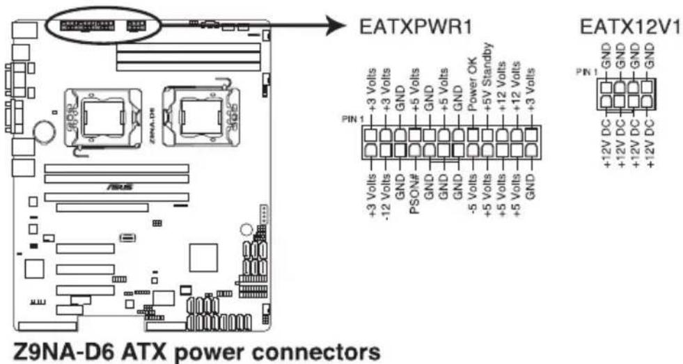
text_image
Z9NA-D6 ATX power connectors EATXPWR1 EATX12V1 +3 Volts +3 Volts GND +5 Volts GND +5 Volts GND +5 Volts GND +5 V Standby +12 Volts +12 Volts +3 Volts +3 Volts +3 Volts +3 Volts +3 Volts +3 Volts +3 Volts +3 Volts +3 Volts +3 Volts +3 Volts +3 Volts +3 Volts +3 Volts +3 Volts +3 Volts +3 Volts +3 Volts +3 Volts +3 Volts +5 Volts +5 Volts +5 Volts +5 Volts +5 Volts +5 Volts +5 Volts +5 Volts +5 Volts +5 Volts +5 Volts +5 Volts +5 Volts +5 Volts +5 Volts +5 Volts +5 Volts +5 Volts +5 Volts +5 Volts +3 Volts +3 Volts GND GND GND GND GND GND GND GND GND GND GND11. Power Supply SMBus connector (5-pin PSUSMB1)
This connector allows you to connect SMBus (System Management Bus) to the power supply unit to read PSU information. Devices communicate with an SMBus host and/or other SMBus devices using the SMBus interface.
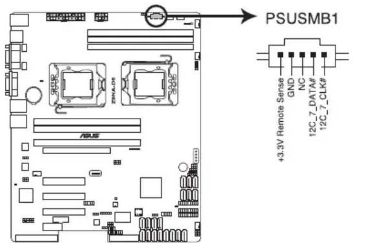
text_image
ZSNA-DS ASUS PSUSMB1 +3.3V Remote Sense GND NC 12C_7_DATA# 12C_7_CLK#Z9NA-D6 Power supply SMBus connector
12. 4-pin Power Connector (4-pin EZ\_PLUG1)
This 4-pin connector is for 5V power of certain SATA DOM (Disk on Module) device, when using an appropriate cable. You can also use this 4-pin connector to connect the PSU to enhance power by 12V.
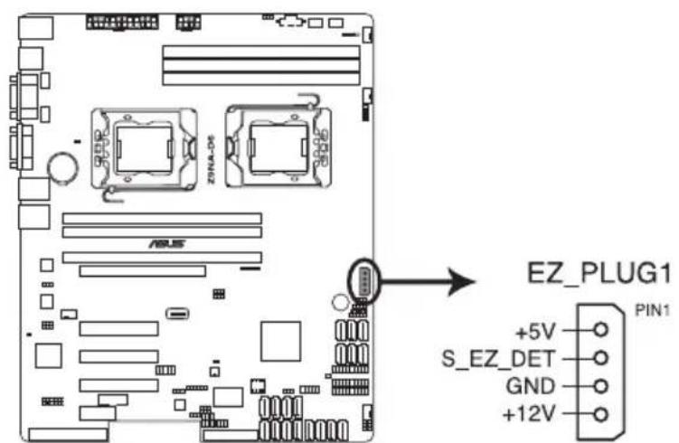
text_image
ZINA-DS ASUS EZ_PLUG1 +5V S_EZ_DET GND +12V PIN1Z9NA-D6 4-pin power connector
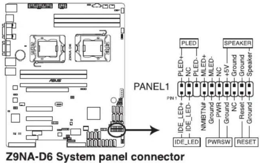
13. System panel connector (20-1 pin PANEL1)
This connector supports several chassis-mounted functions.
text_image
Z9NA-D6 System panel connector PANEL1 PLED+ NC PLED- MLED+ MLED- NC +5V Ground Ground Speaker- PIN 1 IDE_LED+ IDE_LED- NMBTN# Ground PWR Ground NC Reset Ground Ground IDE_LED PWRSW RESET(1) System power LED (3-pin PLED)
This 3-pin connector is for the system power LED. Connect the chassis power LED cable to this connector. The system power LED lights up when you turn on the system power, and blinks when the system is in sleep mode.
(2) System warning speaker (4-pin SPEAKER)
This 4-pin connector is for the chassis-mounted system warning speaker. The speaker allows you to hear system beeps and warnings.
(3) Hard disk drive activity LED (2-pin HDDLED)
This 2-pin connector is for the HDD Activity LED. Connect the HDD Activity LED cable to this connector. The HDD LED lights up or flashes when data is read from or written to the HDD.
(4) Power button/soft-off button (2-pin PWRSW)
This connector is for the system power button. Pressing the power button turns the system on or puts the system in sleep or soft-off mode depending on the BIOS settings. Pressing the power switch for more than four seconds while the system is ON turns the system OFF.
(5) Reset button (2-pin RESET)
This 2-pin connector is for the chassis-mounted reset button for system reboot without turning off the system power.
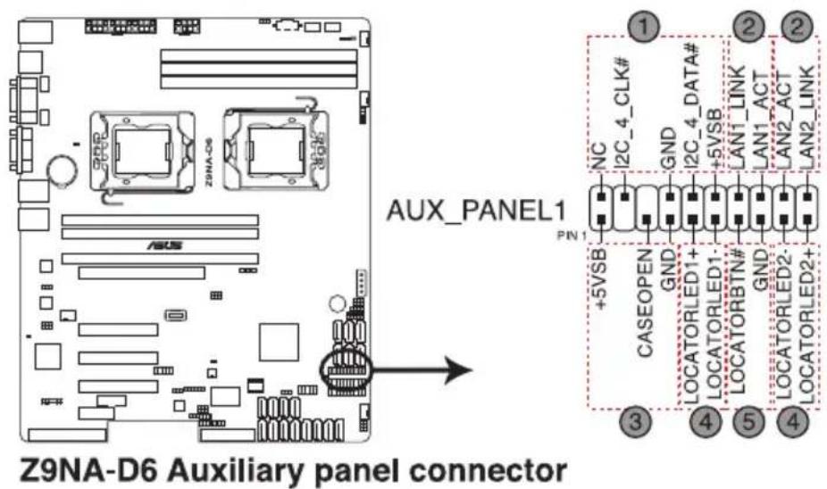
14. Auxiliary panel connector (20-2 pin AUX\_PANEL1)
This connector is for additional front panel features including front panel SMB, locator LED and switch, chassis intrusion, and LAN LEDs.
text_image
AUX PANEL1 PIN 1 NC I2C_4_CLK# GND 2C_4_DATA# +5VSB LAN1_LINK LAN1_ACT LAN2_ACT LAN2_LINK +5VSB CASEOPEN GND LOCATORLED1+ LOCATORLED1- LOCATORBTN# GND LOCATORLED2- LOCATORLED2+ 3 4 5 4 Z9NA-D6 Auxiliary panel connector(1) Front panel SMB (6-1 pin FPSMB)
These leads connect the front panel SMBus cable.
(2) LAN activity LED (2-pin LAN1_LED, LAN2_LED)
These leads are for Gigabit LAN activity LEDs on the front panel.
(3) Chassis intrusion (4-1 pin CHASSIS)
These leads are for the intrusion detection feature for chassis with intrusion sensor or microswitch. When you remove any chassis component, the sensor triggers and sends a high-level signal to these leads to record a chassis intrusion event. The default setting is short CASEOPEN and GND pin by jumper cap to disable the function.
(4) Locator LED (2-pin LOCATORLED1 and 2-pin LOCATORLED2)
These leads are for the locator LED1 and LED2 on the front panel.
Connect the Locator LED cables to these 2-pin connector. The LEDs will light up when the Locator button is pressed.
(5) Locator Button/Swich (2-pin LOCATORBTN)
These leads are for the locator button on the front panel. This button queries the state of the system locator.
This chapter describes the power up sequence, and ways of shutting down the system.
Powering up
Chapter summary
3
3.1 Starting up for the first time 3-3
3.2 Powering off the computer 3-4
3.1 Starting up for the first time
- After making all the connections, replace the system case cover.
- Be sure that all switches are off.
- Connect the power cord to the power connector at the back of the system chassis.
- Connect the power to a power outlet that is equipped with a surge protector.
- Turn on the devices in the following order:
a. Monitor
b. External storage devices (starting with the last device on the chain)
c. System power
- After applying power, the system power LED on the system front panel case lights up. For systems with ATX power supplies, the system LED lights up when you press the ATX power button. If your monitor complies with “green” standards or if it has a “power standby” feature, the monitor LED may light up or switch between orange and green after the system LED turns on.
The system then runs the power-on self-test or POST. While the tests are running, the BIOS beeps or additional messages appear on the screen. If you do not see anything within 30 seconds from the time you turned on the power, the system may have failed a power-on test. Check the jumper settings and connections or call your retailer for assistance.
- At power on, hold down the
key to enter the BIOS Setup. Follow the instructions in Chapter 4.
3.2 Powering off the computer
3.2.1 Using the OS shut down function
If you are using Windows ^® 2008 Server:
- Click the Start button, move the cursor to the triangle on the right of Log off, and then click Shut Down.
- From the Shutdown Event Tracker, select the option that best describes why you want to shut down the computer.
- Ensure that the Planned check box is checked.
- If necessary, key in comments.
- Click OK.
3.2.2 Using the dual function power switch
While the system is ON, pressing the power switch for less than four seconds puts the system to sleep mode or to soft-off mode, depending on the BIOS setting.
This chapter tells how to change the system settings through the BIOS Setup menus. Detailed descriptions of the BIOS parameters are also provided.
BIOS setup
Chapter summary
4
4.1 Managing and updating your BIOS 4-3
4.2 BIOS setup program 4-7
4.3 Main menu 4-10
4.4 Advanced menu 4-11
4.5 Server Mgmt menu 4-36
4.6 Event Logs menu 4-39
4.7 Boot menu 4-41
4.8 Monitor menu 4-43
4.9 Security menu 4-44
4.10 Tool menu 4-45
4.11 Exit menu 4-46
4.1 Managing and updating your BIOS
The following utilities allow you to manage and update the motherboard Basic Input/Output System (BIOS) setup:
- ASUS CrashFree BIOS 3 (To recover the BIOS using a bootable USB flash disk drive when the BIOS file fails or gets corrupted.)
- ASUS EZ Flash 2 (Updates the BIOS using a USB flash disk.)
- BUPDATER utility (Updates the BIOS in DOS mode using a bootable USB flash disk drive.)
Refer to the corresponding sections for details on these utilities.

Save a copy of the original motherboard BIOS file to a bootable USB flash disk drive in case you need to restore the BIOS in the future. Copy the original motherboard BIOS using the BUPDATER utility.
4.1.1 ASUS CrashFree BIOS 3 utility
The ASUS CrashFree BIOS 3 is an auto recovery tool that allows you to restore the BIOS file when it fails or gets corrupted during the updating process. You can update a corrupted BIOS file using a USB flash drive that contains the updated BIOS file.

Prepare a USB flash drive containing the updated motherboard BIOS before using this utility.
Recovering the BIOS from a USB flash drive
To recover the BIOS from a USB flash drive:
-
Insert the USB flash drive with the original or updated BIOS file to one USB port on the system.
-
The utility will automatically recover the BIOS. It resets the system when the BIOS recovery finished.

DO NOT shut down or reset the system while recovering the BIOS! Doing so would cause system boot failure!

The recovered BIOS may not be the latest BIOS version for this motherboard. Visit the ASUS website at www.asus.com to download the latest BIOS file.
4.1.2 ASUS EZ Flash 2 Utility
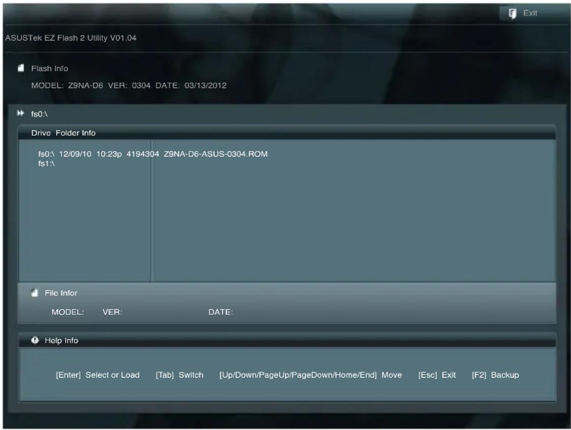
The ASUS EZ Flash 2 Utility feature allows you to update the BIOS without having to use a DOS-based utility.
Before you start using this utility, download the latest BIOS from the ASUS website at www.asus.com.
To update the BIOS using EZ Flash 2 Utility
- Insert the USB flash disk that contains the latest BIOS file to the USB port.
- Enter the BIOS setup program. Go to the Tool menu to select ASUS EZ Flash 2 Utility and press
to enable it.
text_image
ASUSTek EZ Flash 2 Utility V01.04 Flash Info MODEL: Z9NA-D6 VER: 0304 DATE: 03/13/2012 fs0\. Drive Folder Info fs0:\ 12/09/10 10:23p 4194304 Z9NA-D6-ASUS-0304.ROM fs1\ File Infor MODEL: VER: DATE: Help Info [Enter] Select or Load [Tab] Switch [Up/Down/PageUp/PageDown/Home/End] Move [Esc] Exit [F2] Backup- Press
to switch to the Drive field. - Press the Up/Down arrow keys to find the USB flash disk that contains the latest BIOS, and then press
. - Press
to switch to the Folder Info field. - Press the Up/Down arrow keys to find the BIOS file, and then press
to perform the BIOS update process. Reboot the system when the update process is done.

- This function can support devices such as a USB flash disk with FAT 32/16 format and single partition only.
- DO NOT shut down or reset the system while updating the BIOS to prevent system boot failure!

Ensure to load the BIOS default settings to ensure system compatibility and stability. Press
4.1.3 BUPDATER utility

The succeeding BIOS screens are for reference only. The actual BIOS screen displays may not be the same as shown.
The BUPDATER utility allows you to update the BIOS file in DOS environment using a bootable USB flash disk drive with the updated BIOS file.
Updating the BIOS file
To update the BIOS file using the BUPDATER utility:
- Visit the ASUS website at www.asus.com and download the latest BIOS file for the motherboard. Save the BIOS file to a bootable USB flash disk drive.
- Copy the BUPDATER utility (BUPDATER.exe) from the ASUS support website at support.asus.com to the bootable USB flash disk drive you created earlier.
- Boot the system in DOS mode, then at the prompt, type:
BUPDATER /i [filename].ROM
where [filename] is the latest or the original BIOS file on the bootable USB flash disk drive, then press
A:>BUPDATER /i [file name].ROM
The utility verifies the file, then starts updating the BIOS file.
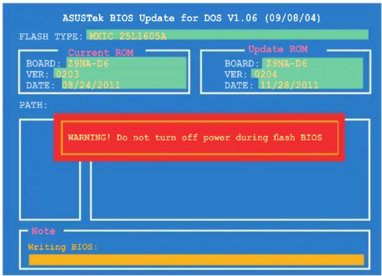
text_image
ASUSTek BIOS Update for DOS V1.06 (09/08/04) FLASH TYPE: MXIC 25L1605A Current ROM BOARD: Z9NA-D6 VER: 0203 DATE: 08/24/2011 Update ROM BOARD: Z9NA-D6 VER: 0204 DATE: 11/28/2011 PATH: WARNING! Do not turn off power during flash BIOS Note Writing BIOS:
DO NOT shut down or reset the system while updating the BIOS to prevent system boot failure!
- The utility returns to the DOS prompt after the BIOS update process is completed. Reboot the system from the hard disk drive.
The BIOS update is finished! Please restart your system.
C:\>
4.2 BIOS setup program
This motherboard supports a programmable firmware chip that you can update using the provided utility described in section 4.1 Managing and updating your BIOS.
Use the BIOS Setup program when you are installing a motherboard, reconfiguring your system, or prompted to "Run Setup." This section explains how to configure your system using this utility.
Even if you are not prompted to use the Setup program, you can change the configuration of your computer in the future. For example, you can enable the security password feature or change the power management settings. This requires you to reconfigure your system using the BIOS Setup program so that the computer can recognize these changes and record them in the CMOS RAM of the firmware chip.
The firmware chip on the motherboard stores the Setup utility. When you start up the computer, the system provides you with the opportunity to run this program. Press during the Power-On Self-Test (POST) to enter the Setup utility; otherwise, POST continues with its test routines.
If you wish to enter Setup after POST, restart the system by pressing
The Setup program is designed to make it as easy to use as possible. Being a menu-driven program, it lets you scroll through the various sub-menus and make your selections from the available options using the navigation keys.
- The default BIOS settings for this motherboard apply for most conditions to ensure optimum performance. If the system becomes unstable after changing any BIOS settings, load the default settings to ensure system compatibility and stability. Press
and select Yes to load the BIOS default settings. - The BIOS setup screens shown in this section are for reference purposes only, and may not exactly match what you see on your screen.
- Visit the ASUS website (www.asus.com) to download the latest BIOS file for this motherboard.
4.2.1 BIOS menu screen
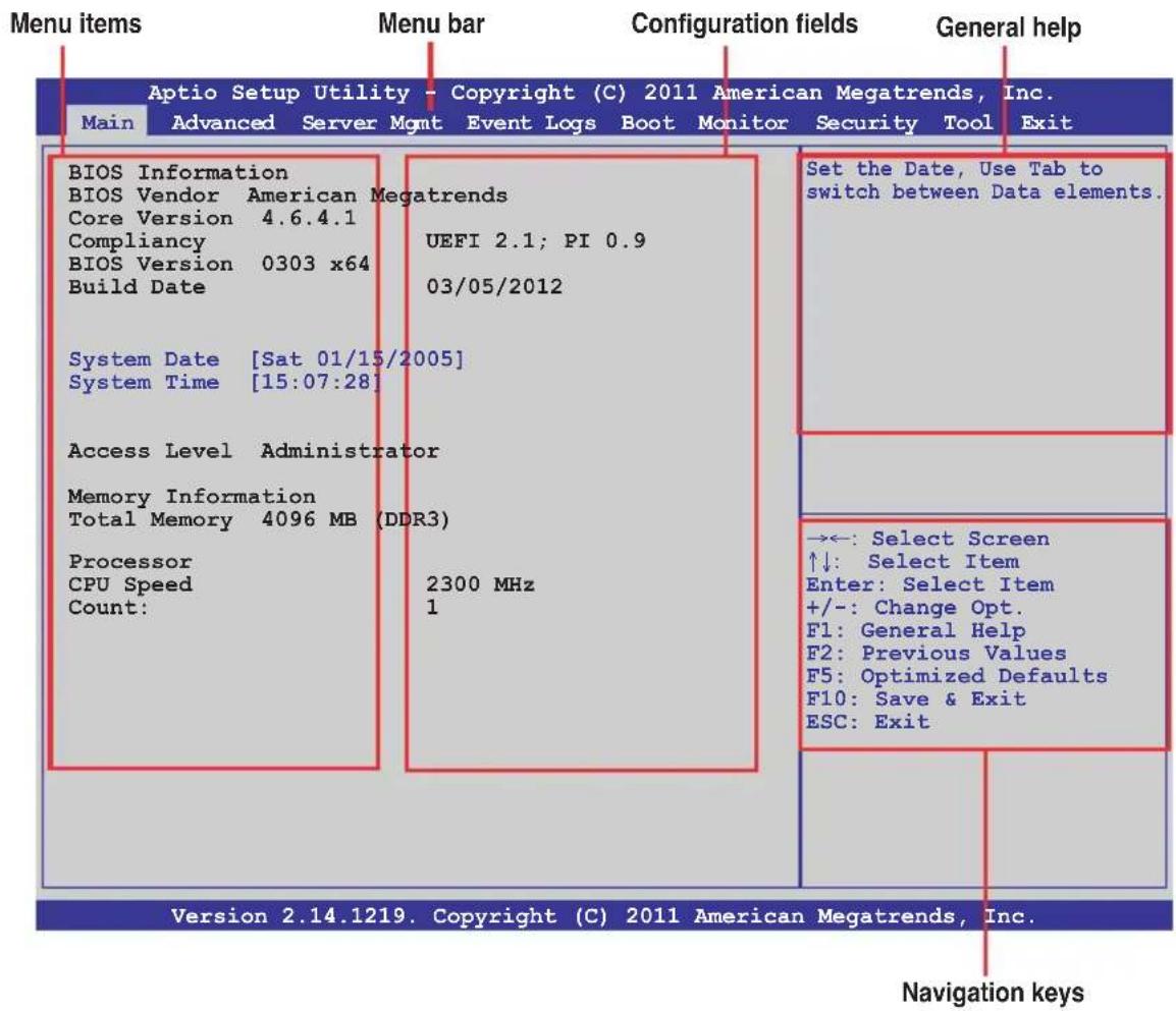
text_image
Menu items Main Advanced Server Mgmt Event Logs Boot Monitor Security Tool General help Aptio Setup Utility - Copyright (C) 2011 American Megatrends, Inc. BIOS Information BIOS Vendor Core Version Compliance BIOS Version Build Date System Date [Sat 01/15/2005] System Time [15:07:28] Access Level Administrator Memory Information Total Memory 4096 MB (DDR3) Processor CPU Speed Count: 2300 MHz 1 Set the Date, Use Tab to switch between Data elements. →←: Select Screen ↑↓: Select Item Enter: Select Item +/-: Change Opt. F1: General Help F2: Previous Values F5: Optimized Defaults F10: Save & Exit ESC: Exit Version 2.14.1219. Copyright (C) 2011 American Megatrends, Inc. Navigation keys4.2.2 Menu bar
The menu bar on top of the screen has the following main items:
Main For changing the basic system configuration
Advanced For changing the advanced system settings
Server Mgmt For changing the Server Mgmt settings
Event Logs For changing the event log settings
Boot For changing the system boot configuration
Monitor For displaying the system temperature, power status, and changing the fan settings
Security For changing the security settings
Tool For configuring options for special functions
Exit For selecting the exit options
To select an item on the menu bar, press the right or left arrow key on the keyboard until the desired item is highlighted.
4.2.3 Menu items
The highlighted item on the menu bar displays the specific items for that menu. For example, selecting Main shows the Main menu items.
The other items (Event Logs, Advanced, Monitor, Boot, Tool, and Exit) on the menu bar have their respective menu items.
4.2.4 Submenu items
A solid triangle before each item on any menu screen means that the item has a submenu. To display the submenu, select the item and press
4.2.5 Navigation keys
At the bottom right corner of a menu screen are the navigation keys for the BIOS setup program. Use the navigation keys to select items in the menu and change the settings.
4.2.6 General help
At the top right corner of the menu screen is a brief description of the selected item.
4.2.7 Configuration fields
These fields show the values for the menu items. If an item is user-configurable, you can change the value of the field opposite the item. You cannot select an item that is not user-configurable.
A configurable field is enclosed in brackets, and is highlighted when selected. To change the value of a field, select it and press
4.2.8 Pop-up window
Select a menu item and press
4.2.9 Scroll bar
A scroll bar appears on the right side of a menu screen when there are items that do not fit on the screen. Press the Up/Down arrow keys or
4.3 Main menu
When you enter the BIOS Setup program, the Main menu screen appears. The Main menu provides you an overview of the basic system information, and allows you to set the system date, time, language, and security settings.
| Main Advanced Server Mgmt Event Logs Boot Monitor Security Tool Exit | |
| BIOS Information BIOS Vendor American Megatrends Core Version 4.6.4.1 Compliancy UEFI 2.1; PI 0.9 BIOS Version 0303 x64 Build Date 03/05/2012 System Date [Sat 01/15/2005] System Time [15:07:28] Access Level Administrator Memory Information Total Memory 4096 MB (DDR3) Processor CPU Speed 2300 MHz Count: 1 | Set the Date, Use Tab to switch between Data elements. →←: Select Screen ↑↓: Select Item Enter: Select Item +/-: Change Opt. F1: General Help F2: Previous Values F5: Optimized Defaults F10: Save & Exit ESC: Exit |
| Version 2.14.1219. Copyright (C) 2011 American Megatrends, Inc. | |
4.3.1 System Date [Day xx/xx/xxxx]
Allows you to set the system date.
4.3.2 System Time [xx:xx:xx]
Allows you to set the system time.
4.4 Advanced menu
The Advanced menu items allow you to change the settings for the CPU and other system devices.

Take caution when changing the settings of the Advanced menu items. Incorrect field values can cause the system to malfunction.
| Aptio Setup Utility - Copyright (C) 2011 American Megatrends, Inc. | |
| Main Advanced Server Mgmt Event Logs Boot Monitor Security Tool Exit | |
| Front Panel Type [AC97] | Front Panel Type |
| CPU Configuration CPU Power Management Configuration Chipset Configuration PCH SATA Configuration PCH SCU SAS Configuration PCI Subsystem Settings USB Configuration Trusted Computing ACPI Settings WHEA Configuration APM Serial Port Console Redirection Onboard LAN Configuration ME Subsystem Onboard Devices Configuration Runtime Error Logging | →←: Select Screen ↑↓: Select Item Enter: Select Item +/-: Change Opt. F1: General Help F2: Previous Values F5: Optimized Defaults F10: Save & Exit ESC: Exit |
Version 2.14.1219. Copyright (C) 2011 American Megatrends, Inc.
Front Panel Type [AC97]
Allows you to set the front panel audio connector (AAFP) mode to legacy AC'97 or high-definition audio depending on the audio standard that the front panel audio module supports.
[HD] Sets the front panel audio connector (AAFP) mode to high definition audio.
[AC97] Sets the front panel audio connector (AAFP) mode to legacy AC'97
4.4.1 CPU Configuration
| CPU Configuration ►Socket 1 CPU Information Socket 2 Not Present CPU Speed 2300 MHz 64-bit Supported Hyper Threading [Enabled] Active Processor Core [All] Limit CPUID Maximum [Disabled] Execute Disable Bit [Enabled] Server Class [Custom] Hardware Prefetcher [Enabled] Adjacent Cache Line Prefetch [Enabled] DCU Streamer Prefetcher [Enabled] DCU IP Prefetcher [Enabled] Intel Virtualization Technology [Enabled] Local APIC Mode [Auto] | Socket specific CPU Information |
| →←: Select Screen ↑↓: Select Item Enter: Select Item +/-: Change Opt. F1: General Help F2: Previous Values F5: Optimized Defaults F10: Save & Exit ESC: Exit | |
| Version 2.14.1219. Copyright (C) 2011 American Megatrends, Inc. | |
Socket 1 CPU Information
Enter to view socket so specific CPU Information.
| Socket 1 CPU Information Intel(R) Xeon(R) CPU E5-2470 2.30GHz CPU Signature 206d6 Microcode Patch 613 Max CPU Speed 2300 MHz Min CPU Speed 1200 MHz Processor Cores 8 Intel HT Technology Supported Intel VT-X Technology Supported | |
| →←: Select Screen ↑↓: Select Item Enter: Select Item +/-: Change Opt. F1: General Help F2: Previous Values F5: Optimized Defaults F10: Save & Exit ESC: Exit | |
| Version 2.14.1219. Copyright (C) 2011 American Megatrends, Inc. | |
Hyper Threading [Enabled]
Allows you to enable or disable the Intel Hyper-Threading Technology function.
When disabled, only one thread per activated core is enabled.
Configuration options: [Disabled] [Enabled]
Active Processor Cores [All]
Configuration options: [All] [1] [2] [3] [4] [5] [6] [7]
![ASUS Z9NA-D6C - Active Processor Cores [All] - 1](/content/2026/05/815256/images/cf68cdf05ef10c63643bbc57029574f9a52276b99213491eac9c06f46113f402.jpg)
Configuration code numbers vary with CPU models.
Limit CPUID Maximum [Disabled]
Setting this item to [Enabled] allows legacy operating system to boot even without support for CPUs with extended CPUID functions.
Configuration options: [Disabled] [Enabled]
Execute Disable Bit [Enabled]
XP can prevent certain classes of malicious buffer overflow attacks when combined with a supporting OS (Windows Server 2003 SP1, Windows XP SP2, SuSE Linux 9.2, Redhat Enterprise 3 Update 3). Configuration options: [Disabled] [Enabled]
Server Class [Custom]
Use Intel recommended prefetch settings.
Configuration options: [Enterprise] [High Performance(HPC)] [Custom]
Hardware Prefetcher [Enabled]
This Item allows you to turn on/off the mid level cache(L2) streamer prefetcher.
Configuration options: [Disabled] [Enabled]
Adjacent Cache Line Prefetch [Enabled]
This Item allows you to turn on/off prefetching of adjacent cache lines.
Configuration options: [Disabled] [Enabled]
DCU Streamer Prefetcher [Enabled]
This Item allows you to enable/disable L1 data prefetcher.
Configuration options: [Disabled] [Enabled]
DCU IP Prefetcher [Enabled]
This Item allows you to enable/disable prefetch of next L1 line based upon sequential load history.
Configuration options: [Disabled] [Enabled]
Intel Virtualization Technology [Enabled]
When enabled, a VMM can utilize the additional hardware capabilities provided by Vanderpool Technology.
Configuration options: [Disabled] [Enabled]
Local APIC mode [Auto]
Allows you to select APIC mode.
Configuration options: [Auto][x2APIC] [xAPIC]
4.4.2 CPU Power Management Configuration
| CPU Power Management Configuration Power Technology [Custom] EIST [Enabled] Turbo Mode [Enabled] P-STATE Coordination [HW ALL] CPU C3 Report [Disabled] CPU C6 Report [Enabled] CPU C7 Report [Disabled] Package C State limit [C6] Energy Performance [Balanced Performance] Factory long duration power limit 95 Watts Long duration power limit 0 Factory long duration maintained 1000 ms Long duration maintained 0 Recommended short duration power1 1.2 * Long Duration Short duration power limit 0 | This item allows you to enabled power management features. |
| →←: Select Screen ↑↓: Select Item Enter: Select Item +/-: Change Opt. F1: General Help F2: Previous Values F5: Optimized Defaults F10: Save & Exit ESC: Exit |
Version 2.14.1219. Copyright (C) 2011 American Megatrends, Inc.
Power Technology [Custom]
This item allows you to enable power management features.
Configuration options: [Disabled] [Energy Efficient] [Custom]
EIST [Enabled]
This item allows you to enable/disable Intel SpeedStep.
Configuration options: [Disabled] [Enabled]
Turbo Mode [Enabled]
Configuration options: [Disabled] [Enabled]
P-STATE Coordination [HW\_ALL]
This item allows you to change P-STATE Coordination type.
Configuration options: [HW_ALL] [SW_ALL] [SW_ANY]
CPU C3 Report [Disabled]
This item allows you to enable/disable CPU C3(ACPI C2) report.
Configuration options: [Disabled] [Enabled]
CPU C6 Report [Enabled]
This item allows you to enable/disable CPU C6(ACPI C3) report.
Configuration options: [Disabled] [Enabled]
CPU C7 Report [Disabled]
This item allows you to enable/disable CPU C7(ACPI C3) report.
Configuration options: [Disabled] [Enabled]
Package C State limit [C6]
This item allows you to set package C State limit.
Configuration options: [C0] [C2] [C6] [C7] [No Limit]
Energy Performance [Balanced Performance]
This item allows you to optimize between performance and power savings.
Configuration options: [Performance] [Balanced Performance] [Balanced Energy]
[Energy Efficient]
Factory long duration power limit 95 Watts
Long duration power limit 0
Allows you to set long duration power limit in watts. Use the <+> and <-> keys to adjust the value.
Factory long duration maintained 1000 ms
Long duration maintained 0
Allows you to set time window which the long duration power is maintained. Use the <+> and <-> keys to adjust the value.
Recommended short duration power1 1.2 \* Long Duration
Short duration power limit 0
Allows you to set short duration power limit in watts. Use the <+> and <-> keys to adjust the value.
4.4.3 Chipset Configuration
| Aptio Setup Utility - Copyright (C) 2011 American Megatrends, Inc. Advanced | |
| QPI ConfigurationMemory ConfigurationCPU II0 Bridge ConfigurationPCH ConfigurationIntel(R) VT for Directed I/O Configuration | QPI Configuration Page |
QPI Configuration
| Aptio Setup Utility - Copyright (C) 2011 American Megatrends, Inc. Advanced | |
| Current QPI Link Speed FastCurrent QPI Link Freq 8.0 GT/sIsoc [Enabled]QPI Link Speed Mode [Fast]QPI Link Frequency Select [Auto]QPI Link0s [Disabled]QPI Link0p [Disabled]QPI Link1 [Enabled] | Enable/Disable Isoc |
Isoc [Enabled]
Configuration options: [Disabled] [Enabled]
QPI Link Speed Mode [Fast]
This item allows you to select the QPI link speed as either the fast mode or slow mode.
Configuration options: [Slow] [Fast]
QPI Link Frequency Select [Auto]
This item allows for selecting the QPI link frequency
Configuration options: [Auto] [6.4 GT/s] [7.2 GT/s (Fast Mode Only)] [8.0 GT/s (Fast Mode Only)]
QPI Link0s [Disabled]
Configuration options: [Disabled] [Enabled]
QPI Link0p [Disabled]
Configuration options: [Disabled] [Enabled]
QPI Link1 [Enabled]
Configuration options: [Disabled] [Enabled]
Memory Configuration
Aptio Setup Utility - Copyright (C) 2011 American Megatrends, Inc. Advanced
| Compatibility RID | [Enabled] |
| Memory Configuration | |
| Total Memory | 4096 MB (DDR3) |
| Current Memory Mode | Independent |
| Currently Memory Speed | 1333 MHz |
| Mirroring | Not Possible |
| Sparing | Not Possible |
| Memory Mode | [Independent] |
| Numa | [Enabled] |
| DDR Speed | [Auto] |
| Channel Interleaving | [Auto] |
| Rank Interleaving | [Auto] |
| Patrol Scrub | [Disabled] |
| Demand Scrub | [Enabled] |
| Data Scrambling | [Enabled] |
| Device Tagging | [Disabled] |
| Thermal Throtting | [CLTT] |
| Enable High Temp. | [Disabled] |
| Allow 2x Refresh | [Enabled] |
| Altitude | [300 M] |
| Memory HOT sensor support | [Enabled] |
| DIMM Information | |
Support for Compatibility Revision ID(CRID) Functionality mentioned in Sandybridge bios spec
→←: Select Screen ↑↓: Select Item Enter: Select Item +/-: Change Opt. F1: General Help F2: Previous Values F5: Optimized Defaults F10: Save & Exit ESC: Exit
Version 2.14.1219. Copyright (C) 2011 American Megatrends, Inc.
Compatibility RID [Enabled]
Support for compatibility revision ID (CRID) functionality mentioned in Sandybridge BIOS spec. Configuration options: [Enabled] [Disabled]
Memory Mode [Independent]
Select the mode for memory initialization.
Configuration options: [Independent] [Mirroring] [Lock Step] [Sparing]
Numa [Enabled]
Allows to Enable/Disable Numa.
Configuration options: [Enabled] [Disabled]
![ASUS Z9NA-D6C - Numa [Enabled] - 1](/content/2026/05/815256/images/052dc0d75efd6e4a16ffac3d7f64dc1130f89661718ecaf45f16aa6b3ec6dd54.jpg)
Numa appears when you install two CPUs.
DDR Speed [Auto]
Force DDR speed. Configuration options: [Auto] [Force DDR3 800] [Force DDR3 1066] [Force DDR3 1333] [Force DDR3 1600] [Force DDR3 1866]
Channel Interleaving [Auto]
Select different channel interleaving setting.
Configuration options: [Auto] [1 Way] [2 Way] [3 Way] [4 Way]
Rank Interleaving [Auto]
Select different rank interleaving setting.
Configuration options: [Auto] [1 Way] [2 Way] [4 Way] [8 Way]
Patrol Scrub [Disabled]
Allows you to Enable/Disable Patrol Scrub.
Configuration options: [Disabled] [Enabled]
Demand Scrub [Enabled]
Allows you to Enable/Disable demand scrubbing feature.
Configuration options: [Enabled] [Disabled]
Data Scrambling [Enabled]
Allows you to Enable/Disable data scrambling.
Configuration options: [Enabled] [Disabled]
Device Tagging [Disabled]
Allows you to Enable/Disable device tagging.
Configuration options: [Enabled] [Disabled]
Thermal Throtting [CLTT]
Configuration options: [Disabled] [0LTT] [CLTT]
Enable High Temp [Disabled]
Configuration options: [Disabled] [Enabled]
Allow 2x Refresh [Enabled]
Configuration options: [Disabled] [Enabled]
Altitude [300 M]
The system altitude above the sea level in meters.
Configuration options: [Auto] [300 M] [900 M] [1500 M] [3000 M]
Memory Hot sensor support [Enabled]
Configuration options: [Disabled] [Enabled]
DIMM Information
| Aptio Setup Utility - Copyright (C) 2011 American Megatrends, Inc. Advanced | |
| CPU1 DIMM Information | |
| Dimm_A1 Present 1024 MB(DDR3) | |
| Dimm_B1 Not Present | |
| Dimm_C1 Not Present | |
| CPU2 DIMM Information | |
CPU IIO Bridge Configuration
| Aptio Setup Utility - Copyright (C) 2011 American Megatrends, Inc. Advanced | |
| Intel(R) I/OAT [Disabled] DCA Support Enabled VGA Priority [Offboard] TargetVGA VGA From CPU 0 | Enables/Disables Intel(R) I/O Acceleration Technology (I/OAT). |
| →←: Select Screen ↑↓: Select Item Enter: Select Item +/-: Change Opt. F1: General Help F2: Previous Values F5: Optimized Defaults F10: Save & Exit ESC: Exit | |
| Version 2.14.1219. Copyright (C) 2011 American Megatrends, Inc. | |
Intel(R) I/OAT [Disabled]
Allows you to Enable/Disable Intel I/O acceleration technology.
Configuration options: [Disabled] [Enabled]
VGA Priority [offboard]
Allows you to decide priority between onboard and 1st offboard video device found.
Configuration options: [Onboard] [Offboard]
PCH Configuration
| Aptio Setup Utility - Copyright (C) 2011 American Megatrends, Inc. Advanced | |
| Name Patsburg Stepping 05 (C0 Stepping) SB Chipset Configuration PCH Compatibility RID [Disabled] Gbe Controller [Disabled] Deep Sx [Disabled] SCU devices [Enabled] Onboard SATA RAID Oprom [Enabled] Audio Configuration Azalia HD Audio [Enabled] | Support for PCH Compatibility Revision ID(CRID) functionality. |
| High Precision Event Timer Configuration High Precision Timer [Enabled] | →←: Select Screen ↑↓: Select Item Enter: Select Item +/-: Change Opt. F1: General Help F2: Previous Values F5: Optimized Defaults F10: Save & Exit ESC: Exit |
Version 2.14.1219. Copyright (C) 2011 American Megatrends, Inc.
PCH Compatibility RID [Disabled]
Support for PCH compatibility.
Configuration options: [Disabled] [Enabled]
GbE Controller [Disabled]
Configuration options: [Disabled] [Enabled]
![ASUS Z9NA-D6C - GbE Controller [Disabled] - 1](/content/2026/05/815256/images/4dcb83be4f12f448c444d0b646eb574544b095bcc711ae5592f342c789d6a695.jpg)
The following item appears only when you set GbE Controller to [Enabled].
Wake on Lan from S5 [Enabled]
Configuration options: [Disabled] [Enabled]
Deep Sx [Disabled]
Configuration options: [Disabled] [Enabled in S5] [Enabled in S4 and S5]
![ASUS Z9NA-D6C - Deep Sx [Disabled] - 1](/content/2026/05/815256/images/b23662a0af3bc3f56359a9d6484d6756f041f3593d33e24e61b80600aa88b573.jpg)
Mobile platforms support deep S4/S5 in DC only and desktop platforms support deep S4/S5 in AC only.
SCU devices [Enabled]
Allows you to enable/disable Patsburg SCU devices.
Configuration options: [Enabled] [Disabled]
Onboard SATA RAID Oprom [Enabled]
Allows you to enable/disable onboard SATA RAID option rom if Launch Storage Oprom is enabled. Configuration options: [Disabled] [Enabled]
Audio Configuration
Azalia HD Audio [Enabled]
Allows you to enable/disable Azalia HD Audio.
Configuration options: [Disabled] [Enabled]
High Precision Event Timer Configuration High Precision Timer [Enabled]
Allows you to enable/disable High Precision Event Timer.
Configuration options: [Disabled] [Enabled]]
Intel(R) VT for Directed I/O Configuration
| Aptio Setup Utility - Copyright (C) 2011 American Megatrends, Inc.Advanced | ||
| Intel (R) VT-d | [Disabled] | Enables or Disables BIOS ACPI Auto Configuration. |
Intel(R) VT-d [Disabled]
Allows you to enable or disable Intel VT-d.
Configuration options: [Enabled] [Disabled]
![ASUS Z9NA-D6C - Intel(R) VT-d [Disabled] - 1](/content/2026/05/815256/images/17ea50f01b8a9865dc96735f1e2ac781e90861d7717806a2a3bb1d8986e5d7db.jpg)
The following item appears only when you set Intel(R) VT-d to [Enabled].
Coherency Support [Disabled]
Allows you to enable/disable VT-d Engine Coherency support.
Configuration options: [Disabled] [Enabled]
ATS Support [Disabled]
Allows you to enable/disable VT-d Engine address translation services (ATS)
support. Configuration options: [Disabled] [Enabled]
4.4.4 PCH SATA Configuration
| SATA Port1 Not Present SATA Port2 Not Present SATA Port3 Not Present SATA Port4 Not Present SATA Port5 Not Present SATA Port6 Not Present | (1)IDE Mode. (2)AHCI Mode. (3)RAID Mode. |
| SATA Mode [AHCI Mode] S.M.A.R.T. Status Check [Enabled] | |
| Aggressive Link Power Management [Enabled] | |
| Port1 Staggered Spin-up [Disabled] Port2 Staggered Spin-up [Disabled] Port3 Staggered Spin-up [Disabled] Port4 Staggered Spin-up [Disabled] Port5 Staggered Spin-up [Disabled] Port6 Staggered Spin-up [Disabled] | →←: Select Screen ↑↓: Select Item Enter: Select Item +/-: Change Opt. F1: General Help F2: Previous Values F5: Optimized Defaults F10: Save & Exit ESC: Exit |
| Version 2.14.1219. Copyright (C) 2011 American Megatrends, Inc. | |
SATA Mode [AHCI Mode]
Allows you to set the SATA configuration.
Configuration options: [Disabled] [IDE Mode] [AHCI Mode] [RAID Mode]
![ASUS Z9NA-D6C - SATA Mode [AHCI Mode] - 1](/content/2026/05/815256/images/b9a03ced87346fedb0325b539fa3612f6a25bdc94896f56322de7f1c14bc7e31.jpg)
- If you want to use the Serial ATA hard disk drives as Parallel ATA physical storage devices, set this item to [IDE Mode].
- If you want the Serial ATA hard disk drives to use the Advanced Host Controller Interface (AHCI), keep the default setting [AHCI Mode]. The AHCI allows the onboard storage driver to enable advanced Serial ATA features that increases storage performance on random workloads by allowing the drive to internally optimize the order of commands.
- If you want to create RAID sets with LSI MegaRAID utility, or Intel® Rapid Storage Technology Enterprise from the Serial ATA hard disk drives, set this item to [RAID Mode].
S.M.A.R.T. Status Check [Enabled]
S.M.A.R.T. (Self-Monitoring, Analysis and Reporting Technology) is a monitor system. When read/write of your hard disk errors occur, this feature allows the hard disk to report warning messages during the POST.
Configuration options: [Enabled] [Disabled]
Aggressive Link Power Management [Enabled]
Configuration options: [Enabled] [Disabled]
Port 1/2/3/4/5/6 Staggered Spin-up [Disabled]
AHCI supports staggered spin-up.
Configuration options: [Enabled] [Disabled]
4.4.5 PCH SCU Configuration
This item automatically detects and displays Device 1-4.
| Device1 Not Present Device2 Not Present Device3 Not Present Device4 Not Present | In case of multiple Option ROMs (Legacy and EFI Compatible), specifies what PCI option ROM to lanuch. |
| →←: Select Screen ↑↓: Select Item Enter: Select Item +/-: Change Opt. F1: General Help F2: Previous Values F5: Optimized Defaults F10: Save & Exit ESC: Exit | |
| Version 2.14.1219. Copyright (C) 2011 American Megatrends, Inc. | |
4.4.6 PCI Subsystem Settings
| PCI Bus Driver Version V 2.05.00 PCI Option ROM Handling PCI ROM Priority [EFI Compatible ROM] PCI Common Settings PCI Latency Timer [32 PCI Bus Clocks] VGA Palette Snoop [Disabled] PERR# Generation [Disabled] SERR# Generation [Disabled] Load RT32 Image [Enabled] PCI Express Settings PCIE Slot Option Rom Configuration | In case of multiple Option ROMs (Legacy and EFI Compatible), specifies what PCI option ROM to lanuch. |
| →←: Select Screen ↑↓: Select Item Enter: Select Item +/-: Change Opt. F1: General Help F2: Previous Values F5: Optimized Defaults F10: Save & Exit ESC: Exit | |
| Version 2.14.1219. Copyright (C) 2011 American Megatrends, Inc. | |
PCI ROM Priority [EFI Compatible ROM]
In case of multiple option roms (Legacy and EFI Compatible), specifies what PCI option rom to lanuch.Configuration options: [Legacy ROM] [EFI Compatible ROM]
PCI Latency Timer [32 PCI Bus Clocks]
The value is programmed into PCI latency timer register.
Configuration options: [32 PCI Bus Clocks] [64 PCI Bus Clocks] [96 PCI Bus Clocks] [128 PCI Bus Clocks] [160 PCI Bus Clocks] [192 PCI Bus Clocks] [224 PCI Bus Clocks] [248 PCI Bus Clocks]
VGA Palette Snoop [Disabled]
Enables or disables VGA pallette registers snooping.
Configuration options: [Disabled] [Enabled]
PERR# Generation [Disabled]
Enables or disables PCI device to generate PERR#.
Configuration options: [Disabled] [Enabled]
SERR# Generation [Disabled]
Enables or disables PCI device to generate SERR#.
Configuration options: [Disabled] [Enabled]
Load RT32 Image [Enabled]
Enables or disables RT32 image loading.
Configuration options: [Disabled] [Enabled]
PCI Express Settings
| PCI Express Link Register Settings ASPM Support [Disabled] WARNING: Enabling ASPM may cause some PCI-E device to fail | Enables or DisablesPCI Express Device Relaxed Ordering. |
| ->←: Select Screen ↑↓: Select Item Enter: Select Item +/-: Change Opt. F1: General Help F2: Previous Values F5: Optimized Defaults F10: Save & Exit ESC: Exit | |
| Version 2.14.1219. Copyright (C) 2011 American Megatrends, Inc. | |
PCI Express Link Register Settings
ASPM Support [Disabled]
Allows you to set the ASPM level.
Configuration options: [Disabled] [Auto] [Force L0s]
[Force L0s] Force all links to L0s state.
[Auto] BIOS auto configure.
[Disabled] Disabled ASPM.
PCIE Slot Option Rom Configuration
| Legacy OpROM Support Launch Storage OpROM [Enabled] | Enables or disables boot option for legacy mass storage device with option ROM. |
| PCIE1 Option Rom [Enabled] PCIE2 Option Rom [Enabled] PCIE3 Option Rom [Enabled] PCIE4 Option Rom [Enabled] PCIE5 Option Rom [Enabled] PIKE Option Rom [Enabled] | |
| ->←: Select Screen ↑↓: Select Item Enter: Select Item +/-: Change Opt. F1: General Help F2: Previous Values F5: Optimized Defaults F10: Save & Exit ESC: Exit | |
| Version 2.14.1219. Copyright (C) 2011 American Megatrends, Inc. | |
Launch Storage 0pROM [Enabled]
Enables or disables boot option for legacy mass storage device with option ROM.
Configuration options: [Disabled] [Enabled]
PCIE1 Option Rom [Enabled]
Configuration options: [Disabled] [Enabled]
PCIE2 Option Rom [Enabled]
Configuration options: [Disabled] [Enabled]
PCIE3 Option Rom [Enabled]
Configuration options: [Disabled] [Enabled]
PCIE4 Option Rom [Enabled]
Configuration options: [Disabled] [Enabled]
PCIE5 Option Rom [Enabled]
Configuration options: [Disabled] [Enabled]
PIKE Option Rom [Enabled]
Configuration options: [Disabled] [Enabled]
4.4.7 USB Configuration
| Optio Setup Utility - Copyright (C) 2011 American Megatrends, Inc. Advanced | |
| USB Configuration USB Devices: 1 Drive, 2 Hubs Legacy USB Support [Enabled] EHCI Hand-off [Disabled] USB hardware delays and time-outs USB transfer time-out [20 sec] Device reset time-out [20 sec] | Enabled Legacy USB support. AUTO option disables legacy support if no USB devices are connected. DISABLE option will keep USB devices available only for EFI applications. |
| Mass Storage Devices: USB Ports Configuration | →←: Select Screen ↑↓: Select Item Enter: Select Item +/-: Change Opt. F1: General Help F2: Previous Values F5: Optimized Defaults F10: Save & Exit ESC: Exit |
Version 2.14.1219. Copyright (C) 2011 American Megatrends, Inc.
Legacy USB Support [Enabled]
This item enables or disables Legacy USB device support.
Configuration options: [Enabled] [Disabled] [Auto]
EHCI Hand-off [Disabled]
This is a workaround for OSes without EHCl ownership change should be claimed by EHCl driver.
Configuration options: [Disabled] [Enabled]
USB Hardware Delays and Time-outs
USB transfer time-out [20 sec]
This item sets the time-out value for control, bulk, and interrupt transfer.
Configuration options: [1 sec] [5 sec] [10 sec] [20 sec]
Device reset time-out [20 sec]
USB mass storage device Start Unit command time-out.
Configuration options: [10 sec] [20 sec] [30 sec] [40 sec]
USB Ports Configuration
| Aptio Setup Utility - Copyright (C) 2011 American Megatrends, Inc. Advanced | |
| EHCI Controller 1 [Enabled] EHCI Controller 2 [Enabled] | Enable/Disable (EHCI) Support. |
| USB Port #1 [Enabled] USB Port #2 [Enabled] USB Port #3 [Enabled] USB Port #4 [Enabled] USB Port #5 [Enabled] USB Port #6 [Enabled] USB Port #7 [Enabled] USB Port #8 [Enabled] USB Port #9 [Enabled] USB Port #10 [Enabled] USB Port #11 [Enabled] USB Port #12 [Enabled] USB Port #13 [Enabled] USB Port #14 [Enabled] | →←: Select Screen ↑↓: Select Item Enter: Select Item +/-: Change Opt. F1: General Help F2: Previous Values F5: Optimized Defaults F10: Save & Exit ESC: Exit |
Version 2.14.1219. Copyright (C) 2011 American Megatrends, Inc.
EHCI Controller 1/2 [Enabled]
Allows you to enable or disable USB 2.0 (EHCI) Support. If we disable the EHCI Controller in BIOS > South Bridge > USB configuration, the USB device will all disable in OS.
Configuration options: [Disabled] [Enabled]
USB Port 1/2/3/4/5/6/7/8/9/10/11/12/13/14 [Enabled]
Allows you to enable or disable USB ports.
Configuration options: [Disabled] [Enabled]
4.4.8 Trusted Computing
| Aptio Setup Utility - Copyright (C) 2011 American Megatrends, Inc. Advanced | |
| Configuration TPM SUPPORT [Enabled] Current Status Information No Security Device Found | Enables or Disables BIOS support for security device. O.S. will not show Security Device. TCG EFI protocol and INT1A interface will not be available. |
TPM SUPPORT [Enabled]
Allows you to enable or disable the TPM support.
Configuration options: [Disabled] [Enabled]
4.4.9 ACPI Settings
| Aptio Setup Utility - Copyright (C) 2011 American Megatrends, Inc. Advanced | |
| ACPI Settings Enable ACPI Auto Configuration [Disabled] | Enables or Disables BIOS ACPI Auto Configuration. |
| Enabled Hibernation [Enabled] ACPI Sleep State [S1 (CPU Stop Clock)] Lock Legacy Resources [Disabled] | |
Enable ACPI Auto Configuration [Disabled]
Allows you to enable or disable BIOS ACPI Auto Configuration.
Configuration options: [Disabled] [Enabled]
![ASUS Z9NA-D6C - Enable ACPI Auto Configuration [Disabled] - 1](/content/2026/05/815256/images/99f47bae780d977d29e71b0ff2ef2849533babb9d40ca6eb830c50186b2b5edd.jpg)
The following item appears only when you set Enabled ACPI Auto Configuration to [Disabled].
Enable Hibernation [Enabled]
Enables or disables system ability to Hibernate (OS/S4 sleep state). This option may be not effective with some OS.
Configuration options: [Disabled] [Enabled]
ACPI Sleep State [S1 (CPU Stop Clock)]
Allows you to set the ACPI Sleep State.
Configuration options: [Suspend Disabled] [S1 (CPU Stop Clock)] [S3 (Suspend to RAM)]
Lock Legacy Resources [Disabled]
Allows you to enable or disable Lock Legacy Resources.
Configuration options: [Disabled] [Enabled]
4.4.10 WHEA Configuration
| Aptio Setup Utility - Copyright (C) 2011 American Megatrends, Inc. Advanced | |
| WHEA Support [Enabled] | Enable or disable Windows Hardware Error Architecture. |
WHEA Support [Enabled]
Allows you to enable or disable the Windows Hardware Error Architecture support. Configuration options: [Disabled] [Enabled]
4.4.11 APM setting
| Aptio Setup Utility - Copyright (C) 2011 American Megatrends, Inc. Advanced | |
| Restore AC Power Loss [Last State]Power On By PCIE [Disabled]Power On By Ring [Disabled]Power On By RTC [Disabled] | Specify what state to go to when power is re-applied after a power failure (G3 state). |
Restore AC Power Loss [Last State]
When set to [Power Off], the system goes into off state after an AC power loss. When set to [Power On], the system will reboot after an AC power loss. When set to [Last State], the system goes into either off or on state, whatever the system state was before the AC power loss.
Configuration options: [Power Off] [Power On] [Last State]
Power On By PCIE [Disabled]
[Disabled] Disables the PCIE devices from generating a wake event.
[Enabled] Enables the PCIE devices to generate a wake event.
Power On By Ring [Disabled]
[Disabled] Disables the Ring devices from generating a wake event.
[Enabled] Enables the Ring devices to generate a wake event.
Power On By RTC [Disabled]
[Disabled] Disables RTC from generating a wake event.
[Enabled] When set to [Eanbled], the items RTC Alarm Date (Days) and Hour/Minute/Second will become user-configurable with set values.
4.4.12 Serial Port Console Redirection
| Aptio Setup Utility - Copyright (C) 2011 American Megatrends, Inc. Advanced | |
| COM1 Console Redirection [Disabled] ► Console Redirection Settings | Consloe Redirection Enable or Disable. |
| COM2 Console Redirection [Enabled] ► Console Redirection Settings | |
| Serial Port for Out-of-Band Management/Windows Emergency Management Services (EMS) Console Redirection [Disabled] ► Console Redirection Settings | →←: Select Screen ↑↓: Select Item Enter: Select Item +/-: Change Opt. F1: General Help F2: Previous Values F5: Optimized Defaults F10: Save & Exit ESC: Exit |
| Version 2.14.1219. Copyright (C) 2011 American Megatrends, Inc. | |
COM1
Console Redirection [Disabled]
Enables or disables the console redirection feature.
Configuration options: [Disabled] [Enabled]
![ASUS Z9NA-D6C - Console Redirection [Disabled] - 1](/content/2026/05/815256/images/5090b73ae5c3d59fe10be499a3562376f0e70fcaddaf0855dc67a73cff713927.jpg)
The following item appears only when you set Console Redirection to [Enabled].
Console Redirection Settings
This item becomes configurable only when you enable the Console Redirection item. The settings specify how the host computer and the remote computer (which the user is using) will exchange data. Both computers should have the same or compatible settings.
Terminal Type [VT-UTF8]
Allows you to set the terminal type.
[VT100] ASCII char set.
[VT100+] Extends VT100 to support color, function keys, et.
[VT-UTF8] Uses UTF8 encoding to map Unicode chars onto 1 or more bytes
[ANSI] Extended ASCII char set
Bits per second [57600]
Selects serial port transmission speed. The speed must be matched on the other side. Long or noisy lines may require lower speeds.
Configuration options: [9600] [19200] [38400] [57600] [115200]
Data Bits [8]
Configuration options: [7] [8]
Parity [None]
A parity bit can be sent with the data bits to detect some transmission errors.
[Mark] and [Space] parity do not allow for error detection.
[None] No parity bit
[Even] parity bit is 0 if the num of 1's in the data bits is even
[Odd] parity bit is 0 if num of 1's in the data bits is odd
[Mark] parity bit is always 1
[Space] parity bit is always 0
Stop Bits [1]
Stop bits indicate the end of a serial data packet. (A start bit indicates the beginning.) The standard setting is 1 stop bit. Communication with slow devices may require more than 1 stop bit. Configuration options: [1] [2]
Flow Control [Hardware RTS/CTS]
Flow control can prevent data loss from buffer overflow. When sending data, if the receiving buffers are full, a “stop” signal can be sent to stop the data flow. Once the buffers are empty, a “start” signal can be sent to re-start the flow. Hardware flow control uses two wires to send start/stop signals.
Configuration options: [None] [Hardware RTS/CTS]
Recorder Mode [Disabled]
With this mode enabled only text will be sent. This is to capture Terminal data.
Configuration options: [Disabled] [Enabled]
Legacy OS Redirection Resolution [80x24]
Configures the number of rows and columns supported on legacy OS.
Configuration options: [80x24] [80x25]
COM2
Console Redirection [Enabled]
Enables or disables the console redirection feature.
Configuration options: [Disabled] [Enabled]
Console Redirection Settings
Please refer to the description of the Console Redirection Settings item under COM1 for details.
Serial Port for Out-of-Band Management/ Windows Emergency Management Services (EMS)
Console Redirection [Disabled]
Enables or disables the console redirection feature.
Configuration options: [Disabled] [Enabled]
![ASUS Z9NA-D6C - Console Redirection [Disabled] - 1](/content/2026/05/815256/images/e3f39376889dc2c28aaf6d425e7454fc97ac5a7041e7a0827bc8eaa130ae2276.jpg)
The following item appears only when you set Console Redirection to [Enabled].
Console Redirection Settings
Out-of-Band Mgmt Port [COM1]
Microsoft Windows Emergency Management Services (EMS) allow for remote management of a Windows Server OS through a serial port.
Configuration options: [COM1] [COM2]
Terminal Type [VT-UTF8]
Microsoft Windows Emergency Management Services (EMS) allow for remote management of a Windows Server OS through a serial port.
Configuration options: [VT100] [VT100+] [VT-UTF8] [ANSI]
Bits per second [115200]
Microsoft Windows Emergency Management Services (EMS) allow for remote management of a Windows Server OS through a serial port.
Configuration options: [9600] [19200] [57600] [115200]
Flow Control [None]
Microsoft Windows Emergency Management Services (EMS) allow for remote management of a Windows Server OS through a serial port.
Configuration options: [None] [Hardware RTS/CTS] [Software Xon/Xoff]
4.4.13 Onboard LAN Configuration
| Aptio Setup Utility - Copyright (C) 2011 American Megatrends, Inc. Advanced | |
| Onboard LAN ConfigurationINTEL W82574L OpROM1 [PXE]INTEL W82574L OpROM2 [PXE] | Launch INTEL W82574L OpROM |
INTEL W82574L OpROM1 [PXE]
This item launched INTEL W82574L OpROM1.
Configuration options: [Disabled] [PXE] [iSCSI]
INTEL W82574L OpROM2 [PXE]
This item launched INTEL W82574L OpROM2.
Configuration options: [Disabled] [PXE] [iSCSI]
4.4.14 ME Subsystem
| Aptio Setup Utility - Copyright (C) 2011 American Megatrends, Inc. Advanced | |
| Intel ME Subsystem ConfigurationME BIOS Interface Version 1.2ME Version 2.1.5.73ME FW Status Value: 0xf0345ME FW State : SPS ME FW ActiveME FW Operation State: M0 without UMAME FW Error Code: No ErrorME Ext FW Status value: 0x3900a101BIOS Booting Mode: Performance OptimizedCores Disabled: 0ME FW SKU Information: SiEn | ME Subsystem Help. |
| →←: Select Screen↑↓: Select ItemEnter: Select Item+/-: Change Opt.F1: General HelpF2: Previous ValuesF5: Optimized DefaultsF10: Save & ExitESC: Exit | |
| Version 2.14.1219. Copyright (C) 2011 American Megatrends, Inc. | |
4.4.15 Onboard Devices Configuration
| Aptio Setup Utility - Copyright (C) 2011 American Megatrends, Inc. Advanced | |
| Serial Port 1 Configuration Serial Port 2 Configuration | Set Parameters of serial Port 1(COM1). |
Serial Port 1/2 Configuration
| Aptio Setup Utility - Copyright (C) 2011 American Megatrends, Inc. Advanced | |
| Serial Port Configuration Serial Port [Enabled] Device Settings I0=3F8h; IRQ=4 Device Mode [Standard Serial Po...] | Enable or Disable Serial Port(COM). |
Serial Port [Enabled]
Allows you to enable or disable the serial port.
Configuration options: [Disabled] [Enabled]
Device Mode [Standard Serial Port Mode]
Allows you to change the serial port mode.
Configuration options: [Standard Serial Port Mode]
4.4.16 Runtime Error Logging

text_image
Aptio Setup Utility - Copyright (C) 2011 American Megatrends, Inc. Advanced Runtime Error Logging Support [Disabled]Runtime Error Logging Support [Disabled]
This item allows you to enable or disable Runtime Error Logging Support.
Configuration options: [Disabled] [Enabled]
![ASUS Z9NA-D6C - Runtime Error Logging Support [Disabled] - 1](/content/2026/05/815256/images/8a2f80e2581ab9a71412e00c76c1cf9c42e1c73234ad63183d4d0b04d243468d.jpg)
The following item appears only when you set Runtime Error Logging Support to [Enabled].
PCI Error Logging Support [Disabled]
Allows you to enable or disable PCI Error Logging.
Configuration options: [Disabled] [Enabled].
4.5 Server Mgmt menu
The Server Mgmt menu displays the server mgmt status, and allows you to change the settings.
The Server Mgmt menu appears only when you install ASMB card on the motherboard.
| Aptio Setup Utility - Copyright (C) 2011 American Megatrends, Inc. | |
| Main Advanced Server Mgmt Event Logs Boot Monitor Security Tool Exit | |
| BMC Firmware: x.xx O/S Watchdog Timer [Disabled] O/S Wtd Timer Timeout [10 minutes] O/S Wtd Timer Policy [Reset] ►System Event Log ►BMC network configuration | Wait for BMC response for specified timeout In PILOTII, BMC starts at the same time when BIOS starts during AC power ON. It takes around 30 seconds to initialize Host to BMC interfaces. |
| →←: Select Screen ↑↓: Select Item Enter: Select Item +/-: Change Opt. F1: General Help F2: Previous Values F5: Optimized Defaults F10: Save & Exit ESC: Exit | |
Version 2.14.1219. Copyright (C) 2011 American Megatrends, Inc.
O/S Watchdog Timer [Disabled]
If enabled, starts a BIOS timer which can only be shut off by Intel Management Software after the OS loads. Helps determine that the OS successfully loaded or follows the O/S Boot Watchdog Timer Policy.
Configuration options: [Enabled] [Disabled]
O/S Wtd Timer Timeout [10 minutes]
Allows you to configure the length of the O/S Boot Watchdog Timer. Not available if O/S Boot Watchdog Timer is disabled.
Configuration options: [5 minutes] [10 minutes] [15 minutes] [20 minutes]
O/S Wtd Timer Policy [Reset]
Allows you to configure how the system should respond if the OS Boot Watchdog Timer expires. Not available if O/S Boot Watchdog Timer is disabled.
Configuration options: [Do Nothing] [Reset] [Power Down]
4.5.1 System Event Log
| Aptio Setup Utility - Copyright (C) 2011 American Megatrends, Inc.Server Mgm | |
| Enabling/Disabling OptionsSEL Components [Disabled]Erasing SettingsErase SEL [No]When SEL is Full [Do Nothing]Note: All values changed here do not take effect until computer is restarted. | Change this to enable or disable all features of system Event Logging during boot. |
| →←: Select Screen↑↓: Select ItemEnter: Select Item+/-: Change Opt.F1: General HelpF2: Previous ValuesF5: Optimized DefaultsF10: Save & ExitESC: Exit | |
| Version 2.14.1219. Copyright (C) 2011 American Megatrends, Inc. | |
SEL Components [Disabled]
Allows you to enable or disable all features of system Event Logging during boot. Configuration options: [Disabled] [Enabled]
![ASUS Z9NA-D6C - SEL Components [Disabled] - 1](/content/2026/05/815256/images/e4b8a1720fb213804db54096a582287379e9ae976c3183b9648a93073f7803e1.jpg)
- The following items appears only when you set [Enabled].
- All values changed here do not take effect until computer is restarted.
Erase SEL [No]
Allows you to choose options for erasing SEL.
Configuration options: [No] [Yes, On next reset] [Yes, On every reset]
When SEL is Full [Do Nothing]
Allows you to choose options for reactions to a full SEL.
Configuration options: [Do Nothing] [Erase Immediately]
4.5.2 BMC network configuration
| BMC network configuration Lan1 Lan1 IP Address in BMC: 000.000.000.000 Lan1 Subnet Mask in BMC: 000.000.000.000 Lan1 Gateway Address in BMC: 000.000.000.000 Lan1 MAC Address in BMC: 00.00.00.00.00.00 Lan1 Address Source in BMC: Static Mode Configuration Address source [Previous State] | Select to configure LAN channel parameters statically or dynamically (by BIOS or BMC). Unspecified option will not modify any BMC network parameters during BIOS phase | |
| →←: Select Screen ↑↓: Select Item Enter: Select Item +/-: Change Opt. F1: General Help F2: Previous Values F5: Optimized Defaults F10: Save & Exit ESC: Exit | ||
Configuration Address source [Previous State]
Select to configure LAN channel parameters statically or dynamically (by BIOS or BMC). Unspecified option will not modify any BMC network parameters during BIOS phase.
Configuration options: [Previous State] [Static Mode] [DHCP Mode]
![ASUS Z9NA-D6C - Configuration Address source [Previous State] - 1](/content/2026/05/815256/images/492b1f571832a4ce8b182bcda8a008c28197271fa3e9429a77819ed932db74f3.jpg)
The following items appears only when you set Configuration Address source to [Static Mode].
Station IP address [0.0.0.0]
Allows to input Station IP address.
Subnet mask [0.0.0.0]
Allows to input Subnet mask.
Gateway IP address [0.0.0.0]
Allows to input Gateway IP address.
4.6 Event Logs menu
The Event Logs allows you to change or view the event log settings.
| Aptio Setup Utility - Copyright (C) 2011 American Megatrends, Inc. Main Advanced Server Mgmt Event Logs Boot Monitor Security Tool Exit | |
| Change Smbios Event Log Settings View Smbios Event Log View System Event Log | Press <Enter> to change the Smbios Event Log configuration. |
| ->←: Select Screen ↑↓: Select Item Enter: Select Item +/-: Change Opt. F1: General Help F2: Previous Values F5: Optimized Defaults F10: Save & Exit ESC: Exit | |
| Version 2.14.1219. Copyright (C) 2011 American Megatrends, Inc. | |
4.6.1 Change Smbios Event Log Settings
Press
| Aptio Setup Utility - Copyright (C) 2011 American Megatrends, Inc. Event Lo | |
| Enabling/Disabling Options Smbios Event Log [Enabled] Erasing Settings Erase Event Log [No] When Log is Full [Do Nothing] Smbios Event Log Standard Settings Log System Boot Event [Disabled] MECI 1 METW 60 Custom Option Log OEM Codes [Enabled] Convert OEM Codes [Disabled] Note: All values changed here do not take effect until computer is restarted. | Change this to enable or disable all features of Smbios Event Logging during boot. |
| →←: Select Screen ↑↓: Select Item Enter: Select Item +/-: Change Opt. F1: General Help F2: Previous Values F5: Optimized Defaults F10: Save & Exit ESC: Exit | |
| Version 2.14.1219. Copyright (C) 2011 American Megatrends, Inc. | |

All values changed here do not take effect until computer is restarted.
Enabling/Disabling Options
Smbios Event Log [Enabled]
Change this to enable or disable all features of Smbios Event Logging during boot.Configuration options: [Disabled] [Enabled]
Erasing Settings
Erase Event Log [No]
Choose options for erasing Smbios Event Log. Erasing is done prior to any logging activation during reset.
Configuration options: [No] [Yes, Next reset] [Yes, Every reset]
When Log is Full [Do Nothing]
Allows you to choose options for reactions to a full Smbios Event Log.
Configuration options: [Do Nothing] [Erase Immediately]
Smbios Event Log Standard Settings
Log System Boot Event [Disabled]
Allows you to choose options to enable/disable logging of System boot event.
Configuration options: [Enabled] [Disabled]
MECI [1]
Multiple Event Count Increment (MECI). The number of occurrences of a duplicate event that must pass before the multiplt-event counter associated with the log entry is updated, specified as a numeric value in the range 1 to 255.
METW [60]
Mutiple Event Time Windows (METW). The number of minutes which must pass between duplicate log entries which utilize a multiple-event counter. The value ranges from 0 to 99 minutes.
Custom Options
Log OEM Codes [Enabled]
Enable or disable the logging of EFI Status Codes as OEM Codes (if not already converted to legacy).
Configuration options: [Disabled] [Enabled]
Convert OEM Codes [Disabled]
Enable or disable the converting of EFI Status Codes to Standard Smbios Types (Not all may be translated).
Configuration options: [Disabled] [Enabled]
View Smbios Event Log
Press
View System Event Log
Press
4.7 Boot menu
The Boot menu items allow you to change the system boot options.
| Aptio Setup Utility - Copyright (C) 2011 American Megatrends, Inc. Main Advanced Server Mgmt Event Logs Boot Monitor Security Tool Exit | |
| Boot Configuration Setup Prompt Timeout 1 Bootup NumLock State [On] Full Screen Logo [Enabled]CSM16 Module Version 07.68 GateA20 Active [Upon Request] Option ROM Messages [Force BIOS] Interrupt 19 Capture [Enabled] Boot Device Seeking [Endless PXE] UEFI Boot [Disabled]Boot Option Priorities Boot Option #1 [IBA GE Slot 0600 v...] Boot Option #2 [AMI Virtual Floppy...] Floppy Drive BBS Priorities Network Device BBS Priorities CD/DVD ROM Drive BBS Priorities Hard Drive BBS Priorities | Number of seconds to wait for setup activation key. 65535(0xFFFF) means indefinite waiting. |
| →←: Select Screen ↑↓: Select Item Enter: Select Item +/-: Change Opt. F1: General Help F2: Previous Values F5: Optimized Defaults F10: Save & Exit ESC: Exit | |
| Version 2.14.1219. Copyright (C) 2011 American Megatrends, Inc. | |
Setup Prompt Timeout [xx]
Use the <+> and <-> keys to adjust the number of seconds to wait for setup activation key.
Bootup NumLock State [On]
Allows you to select the power-on state for the NumLock.
Configuration options: [Off] [On]
Full Screen Logo [Enabled]
Allows you to enable or disable the full screen logo display feature.
Configuration options: [Disabled] [Enabled]
![ASUS Z9NA-D6C - Full Screen Logo [Enabled] - 1](/content/2026/05/815256/images/1aa35c2a79ee57d35aabea12271cf004a443a1a9c36b5fe0e4321f1baba94ed0.jpg)
Set this item to [Enabled] to use the ASUS MyLogo2 ^™ feature.
CSM16 Module Version
GateA20 Active [Upon Request]
[Upon Request] GA20 can be disabled using BIOS services.
[Always] Do not allow disable GA20; this option is useful when any RT code is executed above 1MB.
Option ROM Messages [Force BIOS]
Allows you to set the display mode for Options ROM.
Configuration options: [Force BIOS] [Keep Current]
Interrupt 19 Capture [Enabled]
Allows Option ROMs to trap interrupt 19.
Configuration options: [Disabled] [Enabled]
Boot Device Seeking [Endless PXE]
[Endless PXE] Continuous seek remote boot image until boot image found or user abort (press Ctrl+Alt+Del).
[Normal] Seek remote boot image once then stop.
These items specify the boot device priority sequence from the available devices. The number of device items that appears on the screen depends on the number of devices installed in the system.
![ASUS Z9NA-D6C - Boot Device Seeking [Endless PXE] - 1](/content/2026/05/815256/images/7707bbb97749f547dbeeb268ea5e5d9acbfa1fb8a6697d48de9ef66ac0240e23.jpg)
- To select the boot device during system startup, press
when ASUS Logo appears. - To access Windows OS in Safe Mode, please press
after POST.
Set the booting order of network devices.
Boot Option #1/#2/#3/#4 [SATA P2: ASUS ...]
Configuration options: [SATA P2: ASUS ...] [SATA P3: WDC WD80...]
[AMI Virtual Floppy...] [IBA GE Slot 0700 v...]
CD/DVD ROM Drive BBS Priorities
Hard Drive BBS Priorities
Floppy Drive BBS Priorities
Network Device BBS Priorities
These items appear only when you connect SATA ODD or hard drive to the
SATA ports and allow you to set the booting order of the SATA devices.
4.8 Monitor menu
The Monitor menu displays the system temperature/power status, and allows you to change the fan settings.
| Aptio Setup Utility - Copyright (C) 2011 American Megatrends, Inc. | |||||||
| Main | Advanced | Server | Mgmt | Event Logs | Boot | Monitor | Security Tool Exit |
| CPU1 Temperature 53.2°C/127.4°F | |||||||
| CPU2 Temperature N/A | |||||||
| TR1 Temperature 35.1°C/95.3°F | |||||||
| TR2 Temperature 36.3°C/97.3°F | |||||||
| CPU FAN1 Speed 5133 RPM | |||||||
| CPU FAN2 Speed N/A | |||||||
| FRNT FAN1 Speed N/A | |||||||
| FRNT FAN2 Speed N/A | |||||||
| FRNT FAN3 Speed N/A | |||||||
| FRNT FAN4 Speed N/A | |||||||
| REAR FAN1 Speed N/A | |||||||
| REAR FAN2 Speed N/A | |||||||
| +VTT CPU +1.060V | |||||||
| VCORE1 +1.056V | |||||||
| VCORE2 N/A | |||||||
| +VDDQ_CPU1 N/A | ->←: Select Screen ↑↓: Select Item Enter: Select Item +/-: Change Opt. F1: General Help F2: Previous Values F5: Optimized Defaults F10: Save & Exit ESC: Exit | ||||||
| +VDDQ_CPU2 N/A | |||||||
| +5VSB +4.966V | |||||||
| +5V +4.979V | |||||||
| +12V +11.712V | |||||||
| +3.3V +3.264V | |||||||
| VBAT +3.282V +3.3VSB +3.270V | |||||||
| FAN Speed Control [Generic Mode] | |||||||
Version 2.14.1219. Copyright (C) 2011 American Megatrends, Inc.
CPU 1/2; TR1 1/2 Temperature [xxx°C/xxx°F]
The onboard hardware monitor automatically detects and displays the CPU and motherboard component temperatures.
CPU FAN1/2 Speed; FRNT FAN1-4 Speed; REAR FAN1/2 Speed [xxxx RPM] or [N/A]
The onboard hardware monitor automatically detects and displays the speed of CPU fans, front fans, and rear fan in rotations per minute (RPM). If the fan is not connected to the motherboard, the field shows N/A.
+VTT_CPU Voltage, VCORE1/2 Voltage, +VDDQ_CPU1 Voltage, +VDDQ_CPU2 Voltage, +5VSB Voltage, +5V Voltage, +12V Voltage, +3.3V Voltage, VBAT Voltage, +3.3VSB Voltage
The onboard hardware monitor automatically detects the voltage output through the onboard voltage regulators.
FAN Speed Control [Generic Mode]
Allows you to configure the ASUS Smart Fan feature that smartly adjusts the fan speeds for more efficient system operation.
Configuration options: [Generic Mode] [High Speed Mode] [Full Speed Mode]
4.9 Security menu
The Security menu items allow you to change the system security settings.
| Aptio Setup Utility - Copyright (C) 2011 American Megatrends, Inc.Main Advanced Server Mgmt Event Logs Boot Monitor Security Tool Exit | |
| Password DescriptionIf ONLY the Administrator's password is set,then this only limits access to Setup and isonly asked for when entering SetupIf ONLY the User's password is set, then thisis a power on password and must be entered toboot or enter Setup. In Setup the User willhave Administrator rightsThe password length must br in the following range:Minimum length 3Maximum length 20Administrator PasswordUser Password | Set Setup AdministratorPassword |
If you have forgotten your BIOS password, erase the CMOS Real Time Clock (RTC) RAM to clear the BIOS password. See section 2.6 Jumpers for information on how to erase the RTC RAM.
Administrator Password
If you have set an administrator password, we recommend that you enter the administrator password for accessing the system. Otherwise, you might be able to see or change only selected fields in the BIOS setup program.
To set an administrator password:
- Select the Administrator Password item and press
. - From the Create New Password box, key in a password, then press
. - Confirm the password when prompted.
To change an administrator password:
- Select the Administrator Password item and press
. - From the Enter Current Password box, key in the current password, then press
. - From the Create New Password box, key in a new password, then press
. - Confirm the password when prompted.
To clear the administrator password, follow the same steps as in changing an administrator password, but press
User Password
If you have set a user password, you must enter the user password for accessing the system.
To set a user password:
- Select the User Password item and press
. - From the Create New Password box, key in a password, then press
. - Confirm the password when prompted.
To change a user password:
- Select the User Password item and press
. - From the Enter Current Password box, key in the current password, then press
. - From the Create New Password box, key in a new password, then press
. - Confirm the password when prompted.
To clear the user password, follow the same steps as in changing a user password, but press
4.10 Tool menu
The Tool menu items allow you to configure options for special functions. Select an item then press
| Aptio Setup Utility - Copyright (C) 2011 American Megatrends, Inc. | |
| Main Advanced Server Mgmt Event Logs Boot Monitor Security Tool Exit | |
| ASUS EZ Flash 2 Utility | Be used to update BIOS |
ASUS EZ Flash 2 Utility
Allows you to run ASUS EZ Flash BIOS ROM Utility when you press
4.11 Exit menu
The Exit menu items allow you to save or discard your changes to the BIOS items.
| Discard Changes & Exit Save Changes & Reset Discard Changes & Reset Restore Defaults Boot Override AMI Virtual Floppy0 1.00 IBA GE Slot 0600 v1376 IBA GE Slot 0700 v1376 Launch EFI Shell from filesystem device | Exit system setup without saving any changes. |
| →←: Select Screen ↑↓: Select Item Enter: Select Item +/-: Change Opt. F1: General Help F2: Previous Values F5: Optimized Defaults F10: Save & Exit ESC: Exit |
Version 2.14.1219. Copyright (C) 2011 American Megatrends, Inc.

Pressing
Discard Changes & Exit
This option allows you to exit the Setup program without saving your changes. When you select this option or if you press
Save Changes & Reset
Once you are finished making your selections, choose this option from the Exit menu to ensure the values you selected are saved. When you select this option or if you press
Discard Changes & Reset
This option allows you to reset the Setup program without saving your changes. When you select this option, a confirmation window appears. Select Yes to discard changes and reset.
Restore Defaults
This option allows you to restore/load defaults values for all the setup options. When you select this option or if you press
Boot Override
These items displays the available devices. The device items that appears on the screen depends on the number of devices installed in the system. Click an item to start booting from the selected device.
Launch EFI Shell from filesystem device
This item is for launching the EFI Shell application from one of the available filesystem devices.
This chapter provides instructions for setting up, creating, and configuring RAID sets using the available utilities.
RAID
configuration
Chapter summary
5
5.1 Setting up RAID 5-3
5.2 LSI Software RAID Configuration Utility 5-5
5.3 Intel ^® Rapid Storage Technology enterprise SCU/SATA Option ROM Utility 5-25
5.4 Intel ^® Rapid Storage Technology enterprise Utility (Windows) 5-35
5.1 Setting up RAID
The motherboard supports the following RAID solutions:
• LSI MegaRAID software RAID Configuration Utility with RAID 0, RAID 1, and RAID 10 support (for both Linux and Windows OS).
• Intel Rapid Storage Technology enterprise SCU / SATA Option ROM Utility with RAID 0, RAID 1, RAID 10, and RAID 5 support (for Windows OS only).
5.1.1 RAID definitions
RAID 0 (Data striping) optimizes two identical hard disk drives to read and write data in parallel, interleaved stacks. Two hard disks perform the same work as a single drive but at a sustained data transfer rate, double that of a single disk alone, thus improving data access and storage. Use of two new identical hard disk drives is required for this setup.
RAID 1 (Data mirroring) copies and maintains an identical image of data from one drive to a second drive. If one drive fails, the disk array management software directs all applications to the surviving drive as it contains a complete copy of the data in the other drive. This RAID configuration provides data protection and increases fault tolerance to the entire system. Use two new drives or use an existing drive and a new drive for this setup. The new drive must be of the same size or larger than the existing drive.
RAID 1E (Enhanced RAID 1) has a striped layout with each stripe unit having a secondary (or alternate) copy stored on a different disk. You can use three or more hard disk drives for this configuration.
RAID 10 is data striping and data mirroring combined without parity (redundancy data) having to be calculated and written. With the RAID 10 configuration you get all the benefits of both RAID 0 and RAID 1 configurations. Use four new hard disk drives or use an existing drive and three new drives for this setup.
RAID 5 stripes both data and parity information across three or more hard disk drives. Among the advantages of RAID 5 configuration include better HDD performance, fault tolerance, and higher storage capacity. The RAID 5 configuration is best suited for transaction processing, relational database applications, enterprise resource planning, and other business systems. Use a minimum of three identical hard disk drives for this setup.

- If you want to boot the system from a hard disk drive included in a created RAID set, copy first the RAID driver from the support DVD to a floppy disk before you install an operating system to the selected hard disk drive.
- Please refer to chapter 2 for how to select the RAID configuration utility. Move the jumper to choose between LSI MegaRAID and Intel® Rapid RAID.
5.1.2 Installing hard disk drives
The motherboard supports Serial ATA for RAID set configuration. For optimal performance, install identical drives of the same model and capacity when creating a disk array.
To install the SATA hard disks for RAID configuration:
- Install the SATA hard disks into the drive bays following the instructions in the system user guide.
- Connect a SATA signal cable to the signal connector at the back of each drive and to the SATA connector on the motherboard.
- Connect a SATA power cable to the power connector on each drive.
5.1.3 Setting the RAID item in BIOS
You must set the RAID item in the BIOS Setup before you can create a RAID set from SATA hard disk drives attached to the SATA connectors supported by Intel ^® C602 chipset. To do this:
- Enter the BIOS Setup during POST.
- Go to the Advanced Menu > PCH SATA Configuration, then press
. - Set SATA Modeto [RAID Mode]
- Press
to save your changes and exit the BIOS Setup.

Refer to Chapter 4 for details on entering and navigating through the BIOS Setup.
5.1.4 RAID configuration utilities
Depending on the RAID connectors that you use, you can create a RAID set using the utilities embedded in each RAID controller. For example, use the LSI Software RAID Configuration Utility or the Intel® Rapid Storage Technology if you installed Serial ATA hard disk drives on the Serial ATA connectors supported by the Intel® C602 chipset.
Refer to the succeeding section for details on how to use the RAID configuration utility.
5.2 LSI Software RAID Configuration Utility
The LSI MegaRAID software RAID configuration utility allows you to create RAID 0, RAID 1, or RAID 10 set(s) from SATA hard disk drives connected to the SATA connectors supported by the motherboard southbridge chip.
To enter the LSI MegaRAID software RAID configuration utility:
- Turn on the system after installing all the SATA hard disk drives.
- During POST, the LSI MegaRAID software RAID configuration utility automatically detects the installed SATA hard disk drives and displays any existing RAID set(s). Press
+ to enter the utility.
LSI MegaRAID Software RAID BIOS Version A.10 09231523R
LSI SATA RAID Found at PCI Bus No:00 Dev No:1F
Device present at Port 0 ST3160812AS 152114MB
Device present at Port 1 ST3160812AS 152114MB
Device present at Port 2 ST3160812AS 152114MB
Device present at Port 3 ST3160812AS 152114MB
Press Ctrl-M or Enter to run LSI Software RAID Setup Utility.
- The LSI MegaRAID software RAID configuration utility automatically configures to RAID 1 when the SATA to RAID Mode is enabled.
- The RAID setup screens shown in this section are for reference only and may not exactly match the items on your screen due to the controller version difference.
-
When you create RAID sets with the LSI MegaRAID software RAID configuration utility, the boot priority of the SATA optical drive has to be manually adjusted. Otherwise, the system will not boot from the connected SATA ODD.
-
The utility main window appears. Use the arrow keys to select an option from the Management Menu and then press
. Refer to the Management Menu descriptions on the next page.
At the bottom of the screen is the legend box. The keys on the legend box allow you to navigate through the setup menu options or execute commands. The keys on the legend box vary according to the menu level.
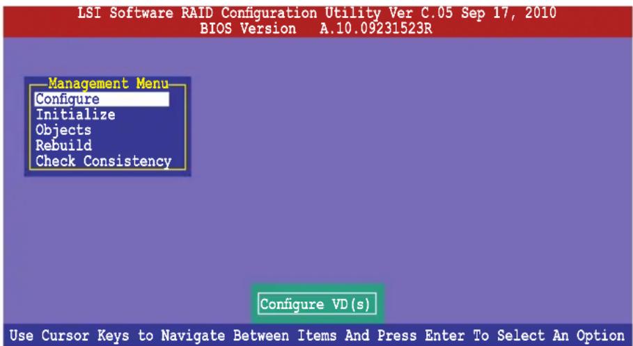
text_image
LSI Software RAID Configuration Utility Ver C.05 Sep 17, 2010 BIOS Version A.10.09231523R Management Menu Configure Initialize Objects Rebuild Check Consistency Configure VD(s) Use Cursor Keys to Navigate Between Items And Press Enter To Select An Option| Menu Description | |
| Configure | Allows you to create RAID 0, RAID 1 or RAID 10 set using the Easy Configuration or the New Configuration command. This menu also allows you to view, add, or clear RAID configurations or select the boot drive |
| Initialize | Allows you to initialize the virtual drives of a created RAID set |
| Objects | Allows you to initialize virtual drives or change the virtual drive parameters |
| Rebuild | Allows you to rebuild failed drives |
| Check Consistency | Allows you to check the data consistency of the virtual drives of a created RAID set |
5.2.1 Creating a RAID set
The LSI Software RAID Configuration Utility allows you to create a RAID 0, RAID 1, or RAID 10 set using two types of configurations: Easy and New.
In Easy Configuration, the virtual drive parameters are set automatically.
In New Configuration, you manually set the virtual drive parameters.
Using Easy Configuration
To create a RAID set using the Easy Configuration option:
- From the Management Menu, select Configure > Easy Configuration and then press
.
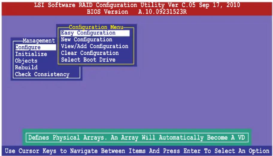
text_image
LSI Software RAID Configuration Utility Ver C.05 Sep 17, 2010 BIOS Version A.10.09231523R Configuration Menu Easy Configuration New Configuration View/Add Configuration Clear Configuration Select Boot Drive Management Configure Initialize Objects Rebuild Check Consistency Defines Physical Arrays. An Array Will Automatically Become A VD Use Cursor Keys to Navigate Between Items And Press Enter To Select An Option- The ARRAY SELECTION MENU displays the available drives connected to the SATA ports. Use the up/down arrow keys to select the drives you want to include in the RAID set, and then press
. When selected, the drive indicator changes from READY to ONLIN A[X]-[Y], where X is the array number, and Y is the drive number.
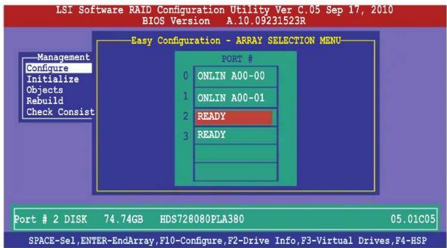
text_image
LSI Software RAID Configuration Utility Ver C.05 Sep 17, 2010 BIOS Version A.10.09231523R Easy Configuration - ARRAY SELECTION MENU Management Configure Initialize Objects Rebuild Check Consist PORT # 0 ONLIN A00-00 1 ONLIN A00-01 2 READY 3 READY Port # 2 DISK 74.74GB HDS728080PLA380 05.01C05 SPACE-Sel,ENTER-EndArray,F10-Configure,F2-Drive Info,F3-Virtual Drives,F4-HSP
- The information of the selected hard disk drive displays at the bottom of the screen.
- You need at least two identical hard disk drives when creating a RAID 1 set.
-
You need at least four identical hard disk drives when creating a RAID 10 set.
-
Select all the drives required for the RAID set, and then press
to configure array setting. - Press
to select the configurable array.
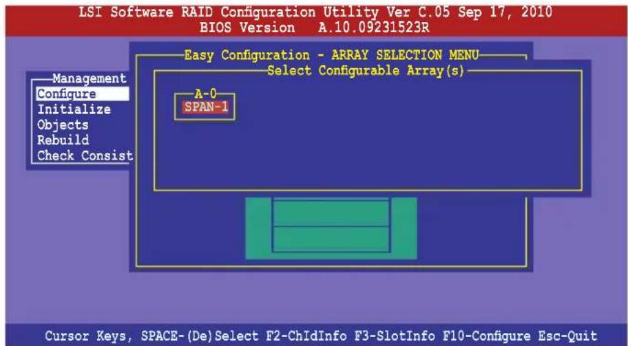
text_image
LSI Software RAID Configuration Utility Ver C.05 Sep 17, 2010 BIOS Version A.10.09231523R Easy Configuration - ARRAY SELECTION MENU Select Configurable Array(s) A-0 SPAN-1 Management Configure Initialize Objects Rebuild Check Consist Cursor Keys, SPACE-(De)Select F2-ChIdInfo F3-SlotInfo F10-Configure Esc-Quit- Press
again, the virtual drive information appears including a Virtual Drive menu that allows you to change the virtual drive parameters.
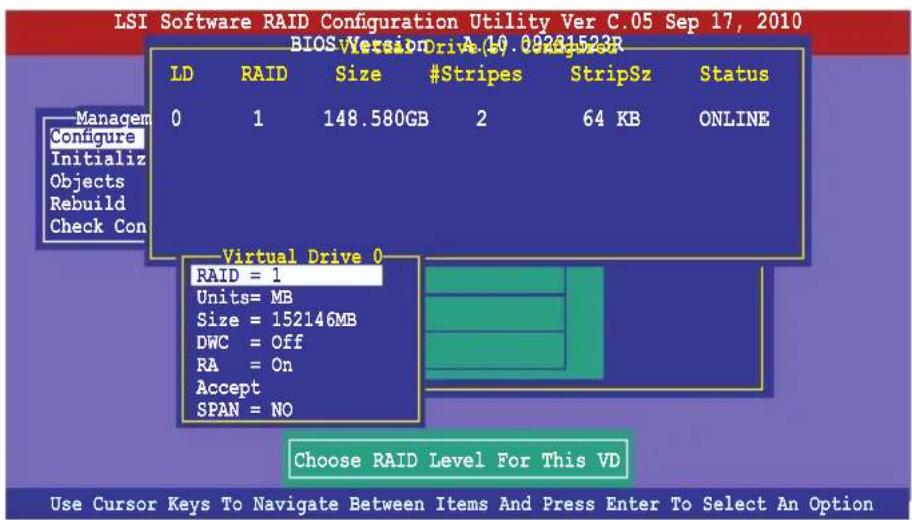
text_image
LSI Software RAID Configuration Utility Ver C.05 Sep 17, 2010 BIOS Version Drive A:10.09231523R LD RAID Size #Stripes StripSz Status 0 1 148.580GB 2 64 KB ONLINE Manage Configure Initialize Objects Rebuild Check Con Virtual Drive 0 RAID = 1 Units= MB Size = 152146MB DWC = Off RA = On Accept SPAN = NO Choose RAID Level For This VD Use Cursor Keys To Navigate Between Items And Press Enter To Select An Option- Select RAID from the Virtual Drive sub-menu, and then press
. - Select the RAID level from the menu, and then press
.

text_image
LSI Software RAID Configuration Utility Ver C.05 Sep 17, 2010 BIOS Version A 10 09231523R LD RAID Size #Stripes StripSz Status 0 1 148.580GB 2 64 KB ONLINE Managem Configure Initializ Objects Rebuild Check Con Virtual Drive 0 RAID Level RAID = 1 RAID 0 Units= MB RAID 1 Size = 152146MB DWC = Off RA = On Accept SPAN = NO Choose RAID Level For This VD Use Cursor Keys To Navigate Between Items And Press Enter To Select An Option- Select Units from the Virtual Drive sub-menu, and then press
. - Select the units for virtual drive size from the menu, and then press
.
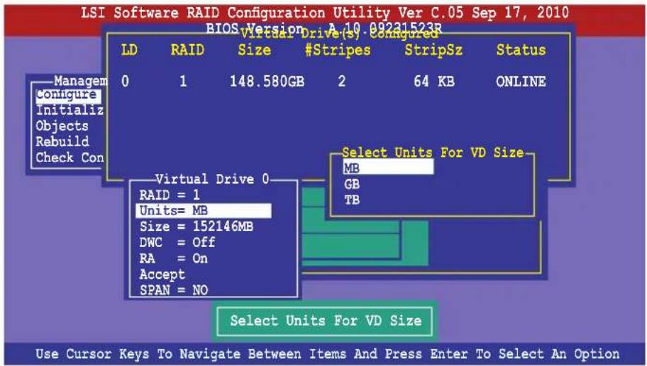
text_image
LSI Software RAID Configuration Utility Ver C.05 Sep 17, 2010 BIOS Version A 10 09231523R LD RAID Size #Stripes StripSz Status 0 1 148.580GB 2 64 KB ONLINE Managem configure Initialize Objects Rebuild Check Con Virtual Drive 0 RAID = 1 Units= MB Size = 152146MB DWC = Off RA = On Accept SPAN = NO Select Units For VD Size MB GB TB Select Units For VD Size Use Cursor Keys To Navigate Between Items And Press Enter To Select An Option- When creating a RAID 1 or a RAID 10 set, select DWC from the Virtual Drive menu, and then press
.
When creating a RAID 0 set, proceed to step 12.
- Select On to enable the Disk Write Cache setting, and then press
.
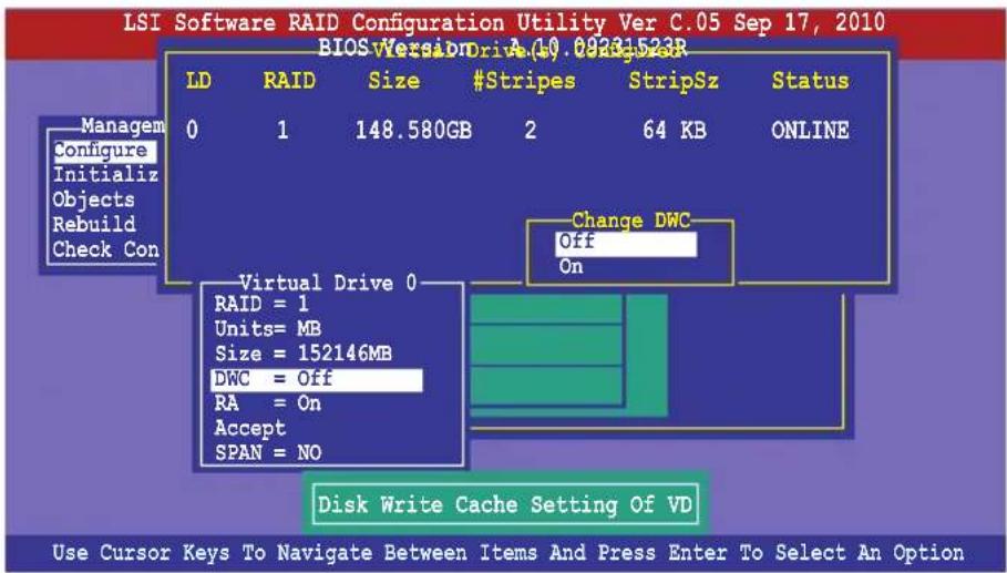
text_image
LSI Software RAID Configuration Utility Ver C.05 Sep 17, 2010 BIOS Version Drive A.10.09231523R LD RAID Size #Stripes StripSz Status 0 1 148.580GB 2 64 KB ONLINE Managem Configure Initialize Objects Rebuild Check Con Change DWC Off On Virtual Drive 0 RAID = 1 Units= MB Size = 152146MB DWC = Off RA = On Accept SPAN = NO Disk Write Cache Setting Of VD Use Cursor Keys To Navigate Between Items And Press Enter To Select An Option
Enabling DWC can improve the performance, but with the risk of data loss.
- When finished setting the selected virtual drive configuration, select Accept from the menu, and then press
.
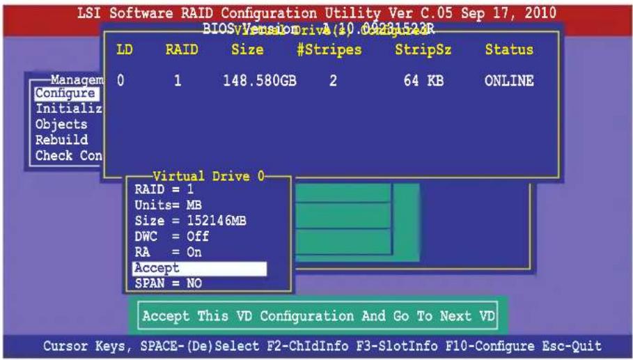
text_image
LSI Software RAID Configuration Utility Ver C.05 Sep 17, 2010 BIOSvVersion Drive(10.06231523R) LD RAID Size #Stripes StripSz Status 0 1 148.580GB 2 64 KB ONLINE Managem Configure Initialize Objects Rebuild Check Con Virtual Drive 0 RAID = 1 Units= MB Size = 152146MB DWC = Off RA = On Accept SPAN = NO Accept This VD Configuration And Go To Next VD Cursor Keys, SPACE-(De)Select F2-ChIdInfo F3-SlotInfo F10-Configure Esc-Quit- Follow step 2 to 12 to configure additional virtual drives.
- Press
to finish RAID configuration. When prompted to save configuration, select Yes from the menu, and then press .
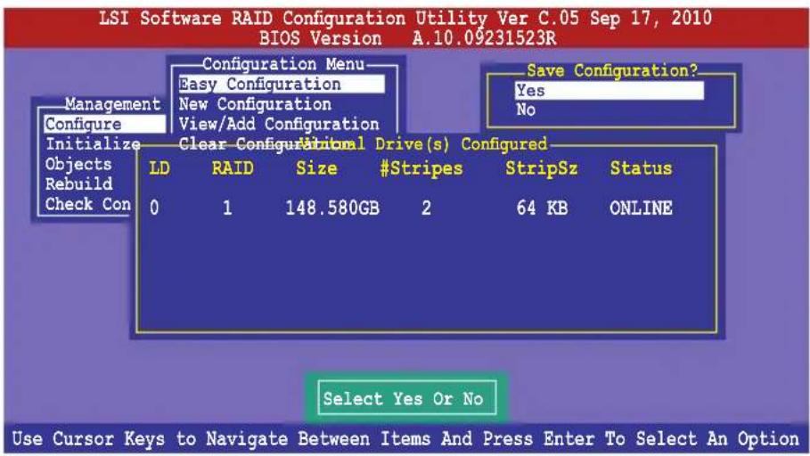
text_image
LSI Software RAID Configuration Utility Ver C.05 Sep 17, 2010 BIOS Version A.10.09231523R Configuration Menu Easy Configuration New Configuration View/Add Configuration Management Configure Initialize Clear Configur#rial Drive(s) Configured Objects Rebuild Check Con LD RAID Size #Stripes StripSz Status 0 1 148.580GB 2 64 KB ONLINE Save Configuration? Yes No Select Yes Or No Use Cursor Keys to Navigate Between Items And Press Enter To Select An OptionUsing New Configuration

When a RAID set already exists, using the New Configuration command erases the existing RAID configuration data. If you do not want to delete the existing RAID set, use the View/Add Configuration command to view or create another RAID configuration.
To create a RAID set using the New Configuration option
- From the Management Menu, select Configure > New Configuration, and then press
.
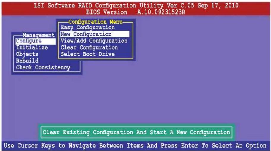
text_image
LSI Software RAID Configuration Utility Ver C.05 Sep 17, 2010 BIOS Version A.10.09231523R Configuration Menu Easy Configuration New Configuration View/Add Configuration Clear Configuration Select Boot Drive Management Configure Initialize Objects Rebuild Check Consistency Clear Existing Configuration And Start A New Configuration Use Cursor Keys to Navigate Between Items And Press Enter To Select An Option- Follow step 2 to 9 of the previous section: Using Easy Configuration.
- Select Size from the Virtual Drive menu, and then press
. - Key-in the desired virtual drive size, and then press
.
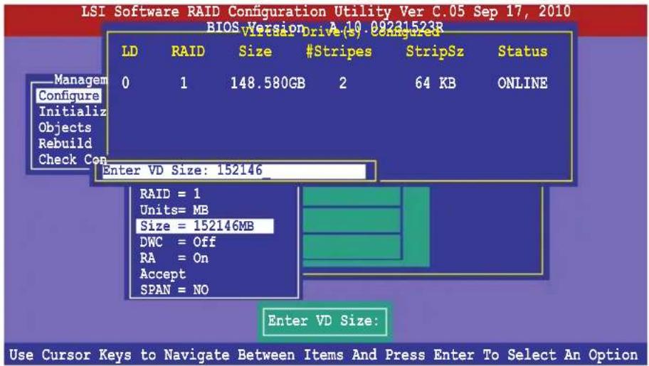
text_image
LSI Software RAID Configuration Utility Ver C.05 Sep 17, 2010 BIOS Version A(10.09231523R) LD RAID Size #Stripes StripSz Status 0 1 148.580GB 2 64 KB ONLINE Enter VD Size: 152146_ RAID = 1 Units= MB Size = 152146MB DWC = Off RA = On Accept SPAN = NO Enter VD Size: Use Cursor Keys to Navigate Between Items And Press Enter To Select An Option- Follow step 10 to 14 of the previous section: Using Easy Configuration to create the RAID set.
5.2.2 Adding or viewing a RAID configuration
You can add a new RAID configuration or view an existing configuration using the View/Add Configuration command.
Adding a new RAID configuration
To add a new RAID configuration:
- From the Management Menu, select Configure > View/Add Configuration, and then press
.
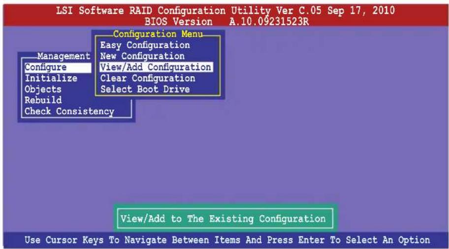
text_image
LSI Software RAID Configuration Utility Ver C.05 Sep 17, 2010 BIOS Version A.10.09231523R Configuration Menu Easy Configuration New Configuration View/Add Configuration Clear Configuration Select Boot Drive Management Configure Initialize Objects Rebuild Check Consistency View/Add to The Existing Configuration Use Cursor Keys To Navigate Between Items And Press Enter To Select An Option- The ARRAY SELECTION MENU displays the available drives connected to the SATA ports. Select the drive(s) you want to include in the RAID set, then press
. When selected, the drive indicator changes from READY to ONLIN A[X]-[Y], where X is the array number, and Y is the drive number.
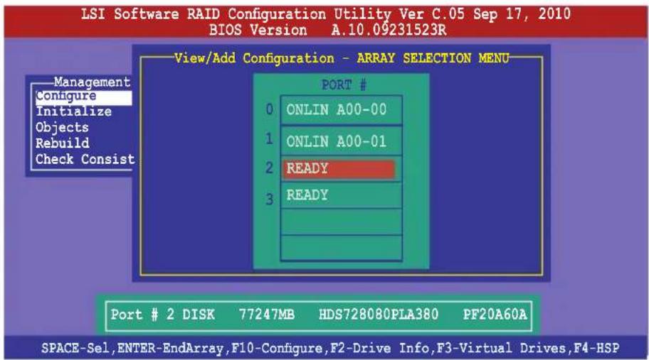
text_image
LSI Software RAID Configuration Utility Ver C.05 Sep 17, 2010 BIOS Version A.10.09231523R View/Add Configuration - ARRAY SELECTION MENU Management Configure Initialize Objects Rebuild Check Consist PORT # 0 ONLIN A00-00 1 ONLIN A00-01 2 READY 3 READY Port # 2 DISK 77247MB HDS728080PLA380 PF20A60A SPACE-Sel,ENTER-EndArray,F10-Configure,F2-Drive Info,F3-Virtual Drives,F4-HSP
The information of the selected hard disk drive displays at the bottom of the screen.
- Follow step 3 to 12 of section 5.2.1 Creating a RAID set: Using Easy Configuration to add a new RAID set.
5.2.3 Initializing the virtual drives
After creating the RAID set(s), you must initialize the virtual drives. You may initialize the virtual drives of a RAID set(s) using the Initialize or Objects command on the Management Menu.
Using the Initialize command
To initialize the virtual drive using the Initialize command
- From the Management Menu, select Initialize, and then press
.
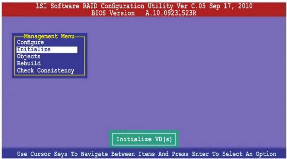
text_image
LSI Software RAID Configuration Utility Ver C.05 Sep 17, 2010 BIOS Version A.10.09231523R Management Menu Configure Initialize Objects Rebuild Check Consistency Initialize VD(s) Use Cursor Keys To Navigate Between Items And Press Enter To Select An Option- The screen displays the available RAID set(s) and prompts you to select the virtual drive to initialize. Use the arrow keys to select the virtual drive from the Virtual Drive selection, and then press
.
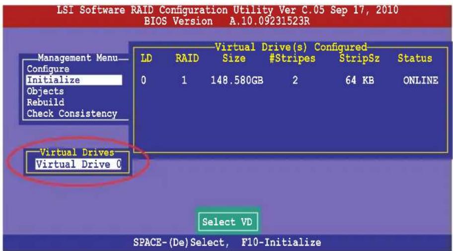
text_image
LSI Software RAID Configuration Utility Ver C.05 Sep 17, 2010 BIOS Version A.10.09231523R Management Menu Configure Initialize Objects Rebuild Check Consistency Virtual Drives Virtual Drive C Virtual Drive(s) Configured LD RAID Size #Stripes StripSz Status 0 1 148.580GB 2 64 KB ONLINE Select VD SPACE-(De)Select, F10-Initialize- Press
to start initialization. When prompted, select Yes from the Initialize? dialog box, and then press .

text_image
LSI Software RAID Configuration Utility Ver C.05 Sep 17, 2010 BIOS Version A.10.09231523R Management Menu Configure Initialize Objects Rebuild Check Consistency Virtual Drive(s) Configured LD RAID Size #Stripes StripSz Status 0 1 148.580GB 2 64 KB ONLINE Initialize? Yes No Virtual Drives Virtual Drive 0 Init Will Destroy Data On Selected VD(s) SPACE-(De)Select, F10-Initialize
Initializing a virtual drive erases all data on the drive.
- A progress bar appears on screen. If desired, press
to abort initialization. When initialization is completed, press .
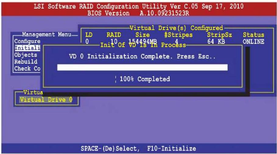
text_image
LSI Software RAID Configuration Utility Ver C.05 Sep 17, 2010 BIOS Version A.10.09231523R Management Menu— Configure initiali Objects Rebuild Check Co Virtual Drive(s) Configured LD RAID Size #Stripes StripSz Status 0 10 154494MB 4 64 KB ONLINE Init Of VD Is In Process VD 0 Initialization Complete. Press Esc.. 100% Completed Virtual Virtual Drive 0 SPACE-(De)Select, F10-InitializeUsing the Objects command
To initialize the virtual drives using the Objects command
- From the Management Menu, select Objects > Virtual Drive, and then press
.
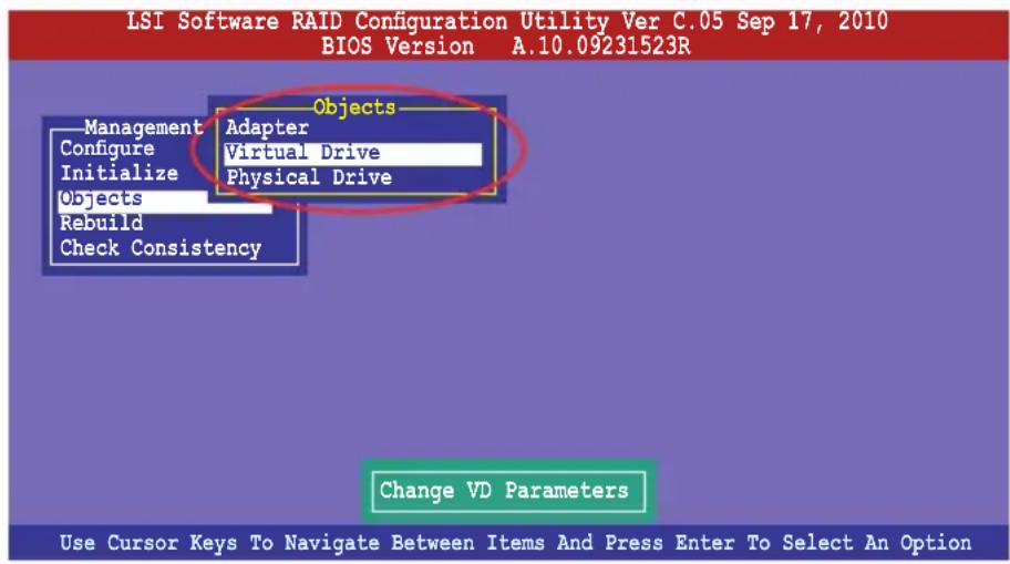
text_image
LSI Software RAID Configuration Utility Ver C.05 Sep 17, 2010 BIOS Version A.10.09231523R Management Adapter Configure Virtual Drive Initialize Physical Drive Objects Rebuild Check Consistency Objects Change VD Parameters Use Cursor Keys To Navigate Between Items And Press Enter To Select An Option- Select the virtual drive to initialize from the Virtual Drives sub-menu, and then press
.
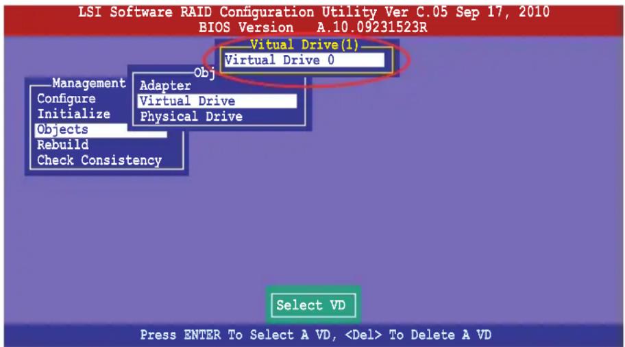
text_image
LSI Software RAID Configuration Utility Ver C.05 Sep 17, 2010 BIOS Version A.10.09231523R Virtual Drive(1) Virtual Drive 0 Management Obj Configure Adapter Initialize Virtual Drive Objects Physical Drive Rebuild Check Consistency Select VD Press ENTER To Select A VD,- Select Initialize from the pop-up menu, and then press
to start initialization.
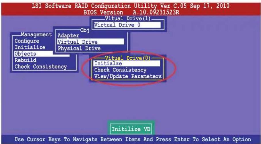
text_image
LSI Software RAID Configuration Utility Ver C.05 Sep 17, 2010 BIOS Version A.10.09231523R Virtual Drive(1) Virtual Drive 0 Obj Management Configure Initialize Objects Rebuild Check Consistency Adapter Virtual Drive Physical Drive Virtual Drive(0) Initialize Check Consistency View/Update Parameters Initialize VD Use Cursor Keys To Navigate Between Items And Press Enter To Select An Option- When prompted, press the
to select box, and then press . Yes from the Initialize? dialog
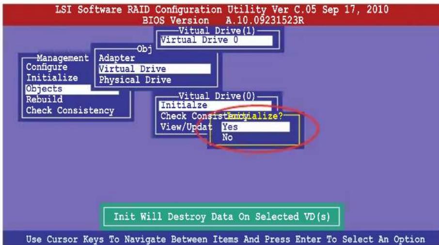
flowchart
graph TD
    A["Init Will Destroy Data On Selected VD(s)"] --> B["BUOS Version A.10.09231523R"]
    B --> C["BUOS Version 0: Virtual Drive 0"]
    B --> D["BUOS Version 0: Virtual Drive 0"]
    C --> E["BUOS Version 0: Virtual Drive 0"]
    D --> F["BUOS Version 0: Virtual Drive 0"]
    E --> G["BUOS Version 0: Virtual Drive 0"]
    F --> H["BUOS Version 0: Virtual Drive 0"]
    G --> I["BUOS Version 0: Virtual Drive 0"]
    H --> J["BUOS Version 0: Virtual Drive 0"]
    I --> K["BUOS Version 0: Virtual Drive 0"]
    J --> L["BUOS Version 0: Virtual Drive 0"]
    K --> M["BUOS Version 0: Virtual Drive 0"]
    L --> N["BUOS Version 0: Virtual Drive 0"]
    M --> O["BUOS Version 0: Virtual Drive 0"]
    N --> P["BUOS Version 0: Virtual Drive 0"]
- A progress bar appears on screen. If desired, press
to abort initialization. When initialization is completed, press .
5.2.4 Rebuilding failed drives
You can manually rebuild failed hard disk drives using the Rebuild command in the Management Menu.
To rebuild a failed hard disk drive
- From the Management Menu, select Rebuild, and then press
.
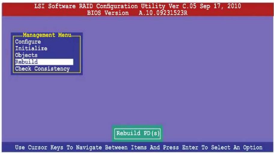
text_image
LSI Software RAID Configuration Utility Ver C.05 Sep 17, 2010 BIOS Version A.10.09231523R Management Menu Configure Initialize Objects Rebuild Check Consistency Rebuild PD(s) Use Cursor Keys To Navigate Between Items And Press Enter To Select An Option- The PHYSICAL DRIVES SELECTION MENU displays the available drives connected to the SATA ports. Select the drive you want to rebuild, and then press
.
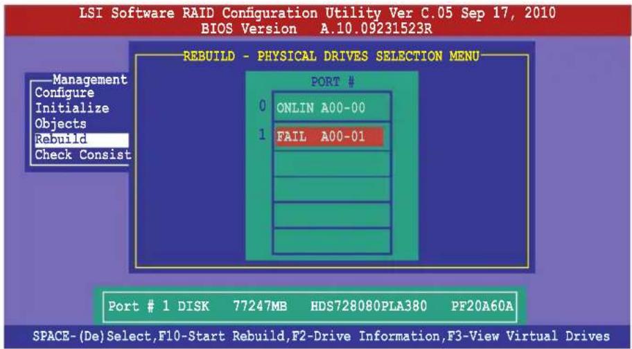
text_image
LSI Software RAID Configuration Utility Ver C.05 Sep 17, 2010 BIOS Version A.10.09231523R REBUILD - PHYSICAL DRIVES SELECTION MENU Management Configure Initialize Objects Rebuild Check Consist PORT # 0 ONLIN A00-00 1 FAIL A00-01 Port # 1 DISK 77247MB HDS728080PLA380 PF20A60A SPACE-(De)Select,F10-Start Rebuild,F2-Drive Information,F3-View Virtual Drives- After selecting the drive to rebuild, press
. When prompted, press to rebuild the drive.
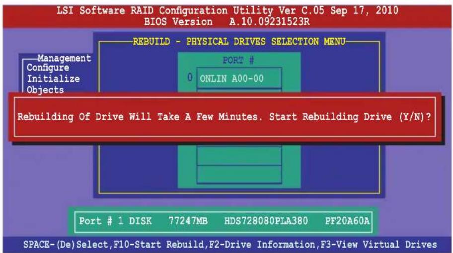
text_image
LSI Software RAID Configuration Utility Ver C.05 Sep 17, 2010 BIOS Version A.10.09231523R REBUILD - PHYSICAL DRIVES SELECTION MENU Management Configure Initialize Objects PORT # 0 ONLIN A00-00 Rebuilding Of Drive Will Take A Few Minutes. Start Rebuilding Drive (Y/N)? Port # 1 DISK 77247MB HDS728080PLA380 PF20A60A SPACE-(De)Select,F10-Start Rebuild,F2-Drive Information,F3-View Virtual Drives- When rebuild is complete, press any key to continue.
5.2.5 Checking the drives for data consistency
You can check and verify the accuracy of data redundancy in the selected virtual drive. The utility can automatically detect and/or detect and correct any differences in data redundancy depending on the selected option in the Objects > Adapter menu.

The Check Consistency command is available only for virtual drives included in a RAID 1 or RAID 10 set.
Using the Check Consistency Command
To check data consistency using the Check Consistency command
- From the Management Menu, select Check Consistency, and then press
.
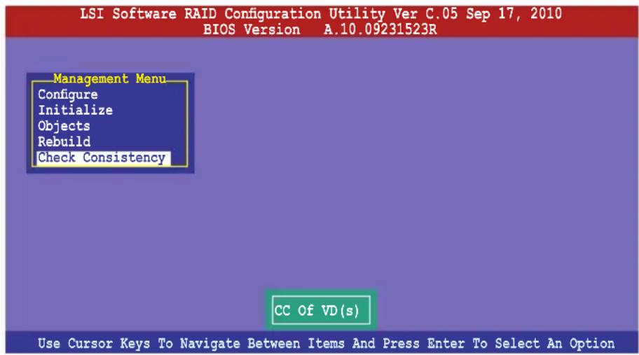
text_image
LSI Software RAID Configuration Utility Ver C.05 Sep 17, 2010 BIOS Version A.10.09231523R Management Menu Configure Initialize Objects Rebuild Check Consistency CC Of VD(s) Use Cursor Keys To Navigate Between Items And Press Enter To Select An Option- The screen displays the available RAID set(s) and prompts you to select the virtual drive to check. Press
to select the virtual drive from the Virtual Drive sub-menu, and then press .
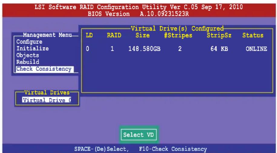
text_image
LSI Software RAID Configuration Utility Ver C.05 Sep 17, 2010 BIOS Version A.10.09231523R Management Menu Configure Initialize Objects Rebuild Check Consistency Virtual Drives Virtual Drive 0 Virtual Drive(s) Configured LD RAID Size #Stripes StripSz Status 0 1 148.580GB 2 64 KB ONLINE Select VD SPACE-(De)Select, F10-Check Consistency- When prompted, use the arrow keys to select Yes from the Consistency Check? dialog box, and then press
.
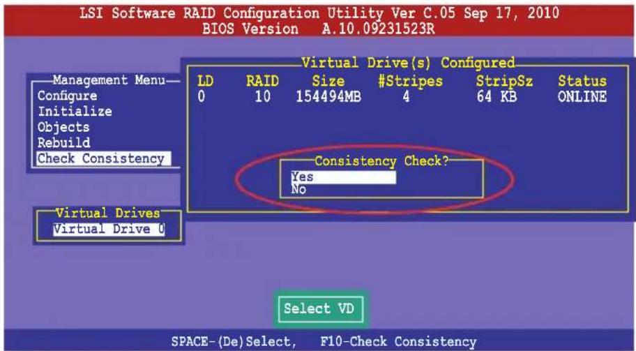
text_image
LSI Software RAID Configuration Utility Ver C.05 Sep 17, 2010 BIOS Version A.10.09231523R Management Menu— Configure Initialize Objects Rebuild Check Consistency Virtual Drives Virtual Drive 0 Virtual Drive(s) Configured LD RAID Size #Stripes StripSz Status 0 10 154494MB 4 64 KB ONLINE Consistency Check? Yes No Select VD SPACE-(De)Select, F10-Check ConsistencyA progress bar appears on screen.
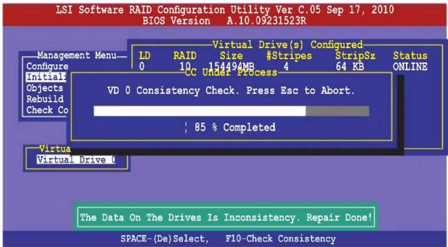
text_image
LSI Software RAID Configuration Utility Ver C.05 Sep 17, 2010 BIOS Version A.10.09231523R Management Menu— Configure Initials Objects Rebuild Check Co Virtual Drive(s) Configured LD RAID Size #Stripes StripSz Status 0 10 154494MB 4 64 KB ONLINE CC Under Process VD 0 Consistency Check. Press Esc to Abort. 85 % Completed Virtual Virtual Drive 0 The Data On The Drives Is Inconsistency. Repair Done! SPACE-(De)Select, F10-Check Consistency- While checking the disk consistency, press
to display the following options.
- Stop - Stops the consistency check. The utility stores the percentage of disk checked, and when you restart checking, it continues from the last percentage completed rather than from zero percent.
- Continue - Continues the consistency check.
-
Abort - Aborts the consistency check. When you restart checking, it continues from zero percent.
-
When checking is complete, press any key to continue.
Using the Objects command
To check data consistency using the Objects command
- From the Management Menu, select Objects, and then select Virtual Drive from the sub-menu.
- Use the arrow keys to select the virtual drive you want to check, and then press
. - Select Check Consistency from the pop-up menu, and then press
. - When prompted, use the arrow keys to select Yes from the dialog box to check the drive.
- When checking is complete, press any key to continue.
5.2.6 Deleting a RAID configuration
To delete a RAID configuration
- From the Management Menu, select Configure > Clear Configuration, and then press
.
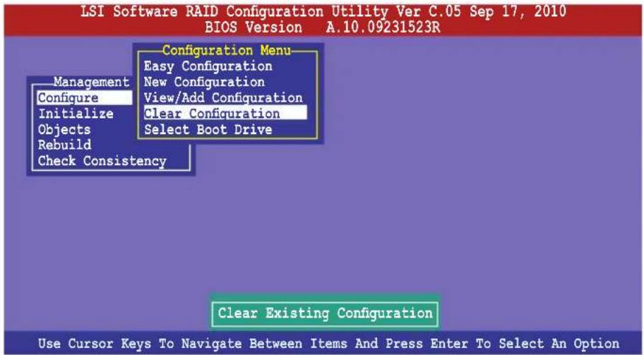
text_image
LSI Software RAID Configuration Utility Ver C.05 Sep 17, 2010 BIOS Version A.10.09231523R Configuration Menu Easy Configuration New Configuration View/Add Configuration Clear Configuration Select Boot Drive Management Configure Initialize Objects Rebuild Check Consistency Clear Existing Configuration Use Cursor Keys To Navigate Between Items And Press Enter To Select An Option- When prompted, use the arrow keys to select Yes from the Clear Configuration? dialog box, and then press
.
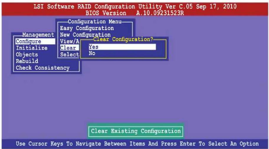
text_image
LSI Software RAID Configuration Utility Ver C.05 Sep 17, 2010 BIOS Version A.10.09231523R Configuration Menu Easy Configuration New Configuration View/A Clear Configuration? Configure Clear Yes Initialize Clear Objects Select No Rebuild Check Consistency Management Clear Existing Configuration Use Cursor Keys To Navigate Between Items And Press Enter To Select An OptionThe utility clears all the current array(s).
- Press any key to continue.
5.2.7 Selecting the boot drive from a RAID set
You must have created a new RAID configuration before you can select the boot drive from a RAID set. See section 5.2.1 Creating a RAID set: Using New Configuration for details.
To select the boot drive from a RAID set
- From the Management Menu, select Configure >Select Boot Drive, and then press
.
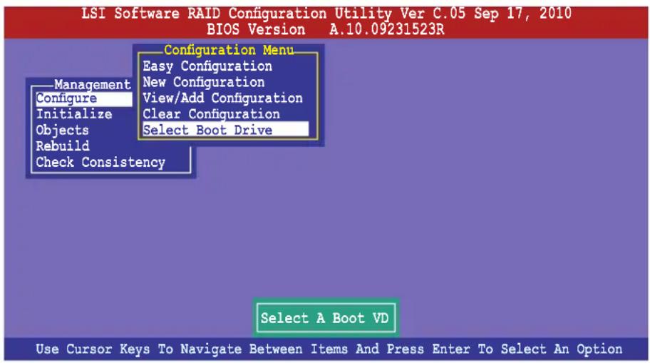
text_image
LSI Software RAID Configuration Utility Ver C.05 Sep 17, 2010 BIOS Version A.10.09231523R Configuration Menu Easy Configuration New Configuration View/Add Configuration Clear Configuration Select Boot Drive Management Configure Initialize Objects Rebuild Check Consistency Select A Boot VD Use Cursor Keys To Navigate Between Items And Press Enter To Select An Option- When prompted, use the arrow keys to select the bootable virtual drive from the list, then press
.
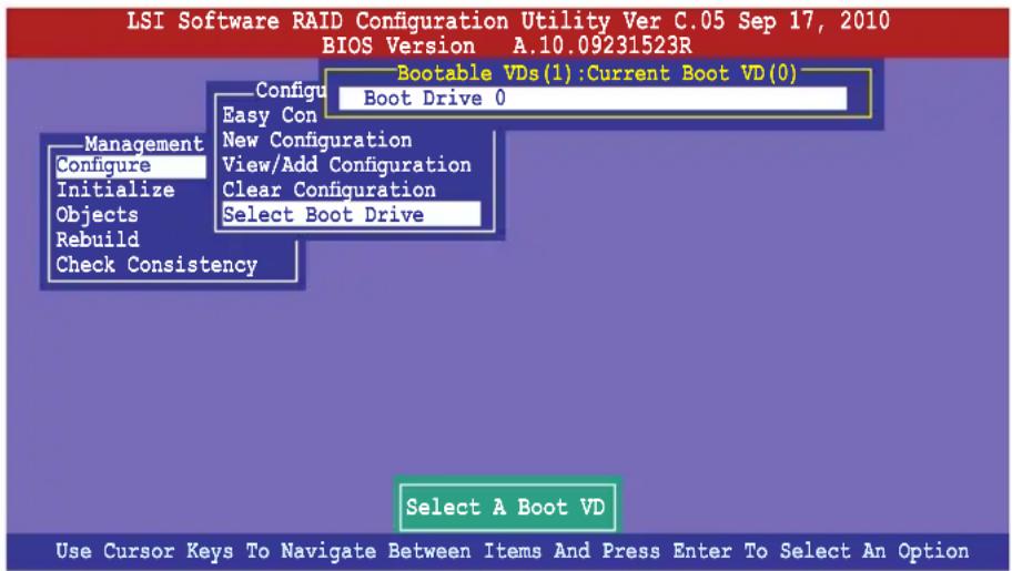
text_image
LSI Software RAID Configuration Utility Ver C.05 Sep 17, 2010 BIOS Version A.10.09231523R Bootable VDs(1):Current Boot VD(0) Configure Easy Con Boot Drive 0 New Configuration View/Add Configuration Clear Configuration Select Boot Drive Management Configure Initialize Objects Rebuild Check Consistency Select A Boot VD Use Cursor Keys To Navigate Between Items And Press Enter To Select An Option- The virtual drive is selected as boot drive. Press any key to continue.
5.2.8 Enabling WriteCache
You may manually enable the RAID controller's WriteCache option after creating a RAID set to improve the data transmission performance.

When you enable WriteCache, you may lose data when a power interruption occurs while transmitting or exchanging data among the drives.
The WriteCache function is recommended for RAID 1 and RAID 10 sets.
To enable WriteCache
-
From the Management Menu, select Objects > Adapter, select an existing adapter, and then press
to display the adapter properties. -
Select Disk WC, and then press
to turn on the option.
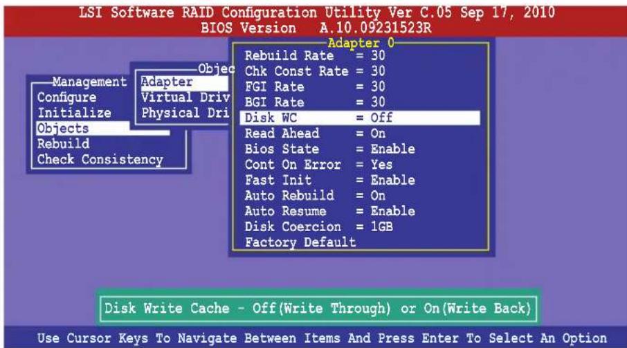
text_image
LSI Software RAID Configuration Utility Ver C.05 Sep 17, 2010 BIOS Version A.10.09231523R Adapter 0 Rebuild Rate = 30 Chk Const Rate = 30 FGI Rate = 30 BGI Rate = 30 Disk WC = Off Read Ahead = On Bios State = Enable Cont On Error = Yes Fast Init = Enable Auto Rebuild = On Auto Resume = Enable Disk Coercion = 1GB Factory Default Disk Write Cache - Off(Write Through) or On(Write Back) Use Cursor Keys To Navigate Between Items And Press Enter To Select An Option-
From the Management Menu, select Objects > Virtual Drive, select an existing adapter and press
. Select View/Update Parameters and press to display the adapter properties. -
Select Disk WC, and then press
to turn on the option.
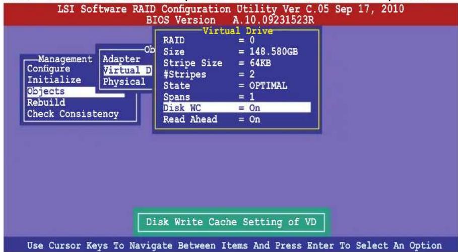
text_image
LSI Software RAID Configuration Utility Ver C.05 Sep 17, 2010 BIOS Version A.10.09231523R Virtual Drive RAID = 0 Size = 148.580GB Stripe Size = 64KB #Stripes = 2 State = OPTIMAL Spans = 1 Disk WC = On Read Ahead = On Disk Write Cache Setting of VD Use Cursor Keys To Navigate Between Items And Press Enter To Select An Option- When finished, press any key to continue.
5.3 Intel ^® Rapid Storage Technology enterprise SCU/SATA Option ROM Utility
The Intel ^® Rapid Storage Technology enterprise SCU / SATA Option ROM utility allows you to create RAID 0, RAID 1, RAID 10 (RAID 1+0), and RAID 5 set(s) from Serial ATA hard disk drives that are connected to the Serial ATA connectors supported by the Southbridge.
To use onboard SATA ports:
- Install all the Serial ATA hard disk drives.
-
Turning on the system. During POST, press, Del. to enter BIOS. Go to Advanced Menu > PCH SATA Configuration> SATA Mode, then press
. -
Set SATA Modeto RAID Mode and save, then reboot system.
-
During POST, press
To use SCU SATA ports:
- Install all the SATA hard disk drives.
- Confirm all the SATA hard disk drives you installed are correctly displayed, then reboot system.
- During POST, press
To enter the Intel® Rapid Storage Technology enterprise SCU Option ROM utility:
- Install all the Serial ATA hard disk drives.
- Turn on the system.
- During POST, press
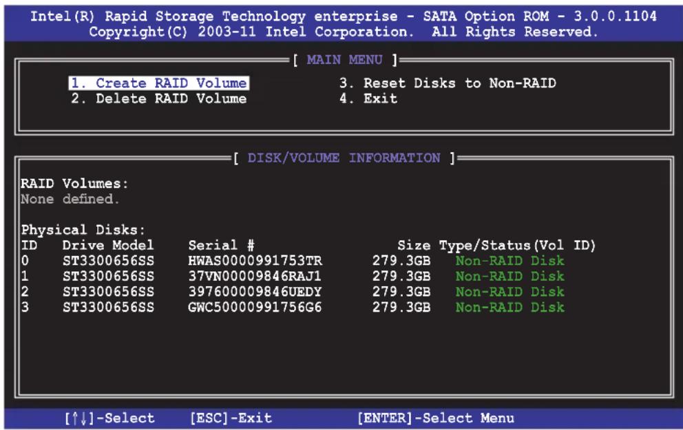
text_image
Intel(R) Rapid Storage Technology enterprise - SATA Option ROM - 3.0.0.1104 Copyright(C) 2003-11 Intel Corporation. All Rights Reserved. [ MAIN MENU ] 1. Create RAID Volume 3. Reset Disks to Non-RAID 2. Delete RAID Volume 4. Exit [ DISK/VOLUME INFORMATION ] RAID Volumes: None defined. Physical Disks: ID Drive Model Serial # Size Type/Status(Vol ID) 0 ST3300656SS HWAS0000991753TR 279.3GB Non-RAID Disk 1 ST3300656SS 37VN00009846RAJ1 279.3GB Non-RAID Disk 2 ST3300656SS 397600009846UEDY 279.3GB Non-RAID Disk 3 ST3300656SS GWC50000991756G6 279.3GB Non-RAID Disk [↑↓]-Select [ESC]-Exit [ENTER]-Select MenuThe navigation keys at the bottom of the screen allow you to move through the menus and select the menu options.

The RAID BIOS setup screens shown in this section are for reference only and may not exactly match the items on your screen.
The utility supports maximum four hard disk drives for RAID configuration.
5.3.1 Creating a RAID set
To create a RAID set
- From the utility main menu, select 1. Create RAID Volume and press
. The following screen appears.
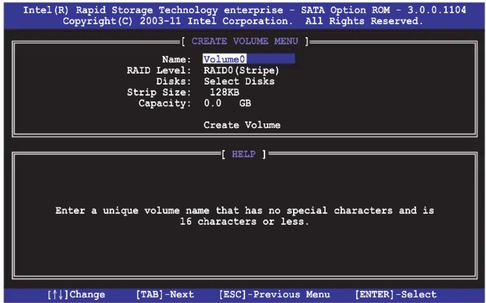
text_image
Intel(R) Rapid Storage Technology enterprise - SATA Option ROM - 3.0.0.1104 Copyright(C) 2003-11 Intel Corporation. All Rights Reserved. [ CREATE VOLUME MENU ] Name: Volume0 RAID Level: RAID0(Stripe) Disks: Select Disks Strip Size: 128KB Capacity: 0.0 GB Create Volume [ HELP ] Enter a unique volume name that has no special characters and is 16 characters or less. [↑↓]Change [TAB]-Next [ESC]-Previous Menu [ENTER]-Select- Enter a name for the RAID set and press
. - When the RAID Level item is selected, press the up/down arrow key to select a RAID level to create, and then press
. - When the Disks item is selected, press
to select the hard disk drives you want to include in the RAID set. The SELECT DISKS screen appears.
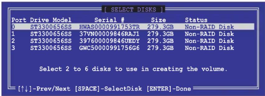
text_image
[ SELECT DISKS ] Port Drive Model Serial # Size Status 0 ST3300656SS HWAS0000991753TR 279.3GB Non-RAID Disk 1 ST3300656SS 37VN00009846RAJ1 279.3GB Non-RAID Disk 2 ST3300656SS 397600009846UEDY 279.3GB Non-RAID Disk 3 ST3300656SS GWC50000991756G6 279.3GB Non-RAID Disk Select 2 to 6 disks to use in creating the volume. [↑↓]-Prev/Next [SPACE]-SelectDisk [ENTER]-Done-
Use the up/down arrow key to select a drive, and then press
to select. A small triangle marks the selected drive. Press after completing your selection. -
Use the up/down arrow keys to select the stripe size for the RAID array (for RAID 0, 10 and 5 only), and then press
. The available stripe size values range from 4 KB to 128 KB. The following are typical values:
RAID 0: 128KB
RAID 10: 64KB
RAID 5: 64KB

We recommend a lower stripe size for server systems, and a higher stripe size for multimedia computer systems used mainly for audio and video editing.
- When the Capacity item is selected, enter the RAID volume capacity that you want and press
. The default value indicates the maximum allowed capacity. - When the Create Volume item is selected, press
. The following warning message appears.
WARNING: ALL DATA ON SELECTED DISKS WILL BE LOST.
Are you sure you want to create this volume? (Y/N):
- Press
to create the RAID volume and return to the main menu, or to go back to the CREATE VOLUME menu.
5.3.2 Creating a Recovery set
To create a recovery set:
- From the utility main menu, select 1. Create RAID Volume and press
. The following screen appears.
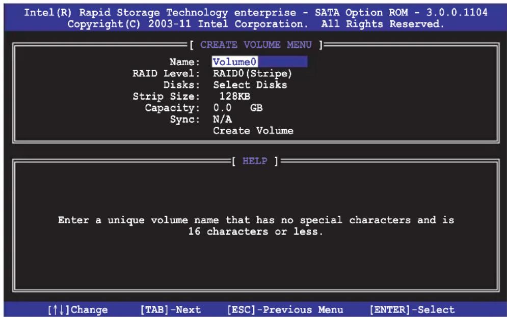
text_image
Intel(R) Rapid Storage Technology enterprise - SATA Option ROM - 3.0.0.1104 Copyright(C) 2003-11 Intel Corporation. All Rights Reserved. [ CREATE VOLUME MENU ] Name: Volume0 RAID Level: RAID0(Stripe) Disks: Select Disks Strip Size: 128KB Capacity: 0.0 GB Sync: N/A Create Volume [ HELP ] Enter a unique volume name that has no special characters and is 16 characters or less. [↑↓]Change [TAB]-Next [ESC]-Previous Menu [ENTER]-Select- Enter a name for the recovery set and press
. - When the RAID Level item is selected, press the up/down arrow keys to select Recovery, and then press
. - When the Disks item is selected, press
to select the hard disk drives you want to include in the recovery set. The SELECT DISKS screen appears.
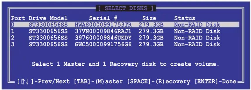
text_image
[ SELECT DISKS ] Port Drive Model Serial # Size Status 0 ST3300656SS HWAS0000991753TR 279.3GB Non-RAID Disk 1 ST3300656SS 37VN00009846RAJ1 279.3GB Non-RAID Disk 2 ST3300656SS 397600009846UEDY 279.3GB Non-RAID Disk 3 ST3300656SS GWC50000991756G6 279.3GB Non-RAID Disk Select 1 Master and 1 Recovery disk to create volume. [↑↓] -Prev/Next [TAB] - (M)aster [SPACE] - (R)ecovery [ENTER] -Done- Use the up/down arrow keys to select a drive, press
to select a Master disk, and then press to select a Recovery disk. A small triangle marks the selected drive. Press after completing your selection. - When the Sync item is selected, use the up/down arrow keys to select a sync option that you want and press
. - When the Create Volume item is selected, press
. The following warning message appears.
WARNING: ALL DATA ON SELECTED DISKS WILL BE LOUT. Are you sure you want to create this volume? (Y/N):
- Press
to create the recovery set and return to the main menu, or to go back to the CREATE VOLUME menu.

If a recovery set is created, you cannot add more RAID sets even when you have more non-RAID disks installed in your system.
5.3.3 Deleting a RAID set

Take caution when deleting a RAID set. You will lose all data on the hard disk drives when you delete a RAID set.
To delete a RAID set:
- From the utility main menu, select 2. Delete RAID Volume and press
. The following screen appears.
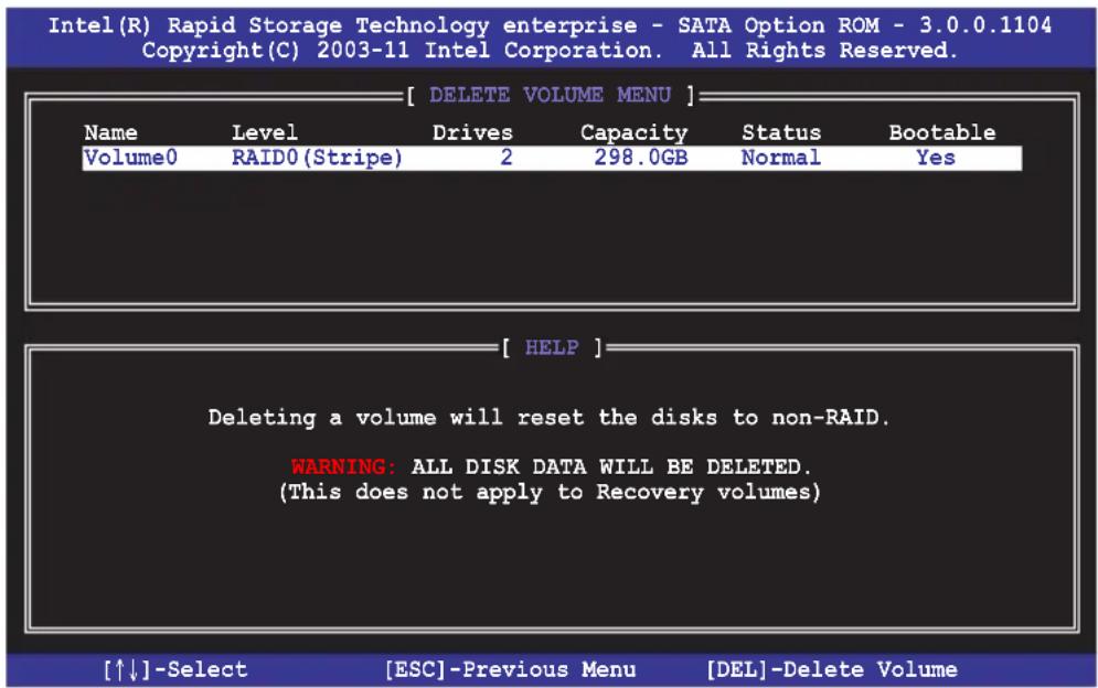
text_image
Intel(R) Rapid Storage Technology enterprise - SATA Option ROM - 3.0.0.1104 Copyright(C) 2003-11 Intel Corporation. All Rights Reserved. [ DELETE VOLUME MENU ] Name Level Drives Capacity Status Bootable Volume0 RAID0 (Stripe) 2 298.0GB Normal Yes [ HELP ] Deleting a volume will reset the disks to non-RAID. WARNING: ALL DISK DATA WILL BE DELETED. (This does not apply to Recovery volumes) [↑↓]-Select [ESC]-Previous Menu [DEL]-Delete Volume- Use the up/down arrow keys to select the RAID set you want to delete, and then press
. The following warning message appears.
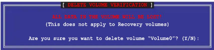
text_image
[ DELETE VOLUME VERIFICATION ] ALL DATA IN THIS VOLUME WILL BE LOST! (This does not apply to Recovery volumes) Are you sure you want to delete volume "Volume0"? (Y/N):- Press
to delete the RAID set and return to the utility main menu, or press to return to the DELETE VOLUME menu.
5.3.4 Resetting disks to Non-RAID

Take caution before you reset a RAID volume hard disk drive to non-RAID. Resetting a RAID volume hard disk drive deletes all internal RAID structure on the drive.
To reset a RAID set hard disk drive:
- From the utility main menu, select 3. Reset Disks to Non-RAID and press
. The following screen appears.
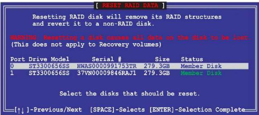
text_image
[ RESET RAID DATA ] Resetting RAID disk will remove its RAID structures and revert it to a non-RAID disk. WARNING: Resetting a disk causes all data on the disk to be lost. (This does not apply to Recovery volumes) Port Drive Model Serial # Size Status 0 ST3300656SS HWAS0000991753TR 279.3GB Member Disk 1 ST3300656SS 37VN00009846RAJ1 279.3GB Member Disk Select the disks that should be reset. [↑↓] -Previous/Next [SPACE]-Selects [ENTER]-Selection Complete- Use the up/down arrow keys to select the RAID set drive(s) you want to reset, and then press
to select. - Press
to reset the RAID set drive(s). A confirmation message appears. - Press
to reset the drive(s) or press to return to the utility main menu.
5.3.5 Exiting the Intel ^® Rapid Storage Technology utility
To exit the utility:
- From the utility main menu, select 4. Exit, and then press
. The following warning message appears.

text_image
[ CONFIRM EXIT ] Are you sure you want to exit? (Y/N):- Press
to exit or press to return to the utility main menu.
5.3.6 Rebuilding the RAID

This option is only for the RAID 1 set.
Rebuilding the RAID with other non-RAID disk
If any of the SATA hard disk drives included in the RAID 1 array failed, the system displays the status of the RAID volume as “Degraded” during POST. You can rebuild the RAID array with other installed non-RAID disks.
To rebuild the RAID with other non-RAID disk:
- At the prompt, press
+ to enter the Intel Rapid Storage Technology option ROM utility. - If there is a non-RAID SATA Hard Disk available, the utility will prompt to rebuild the RAID. Press
, and then use up/down arrow keys to select the destination disk or press to exit.
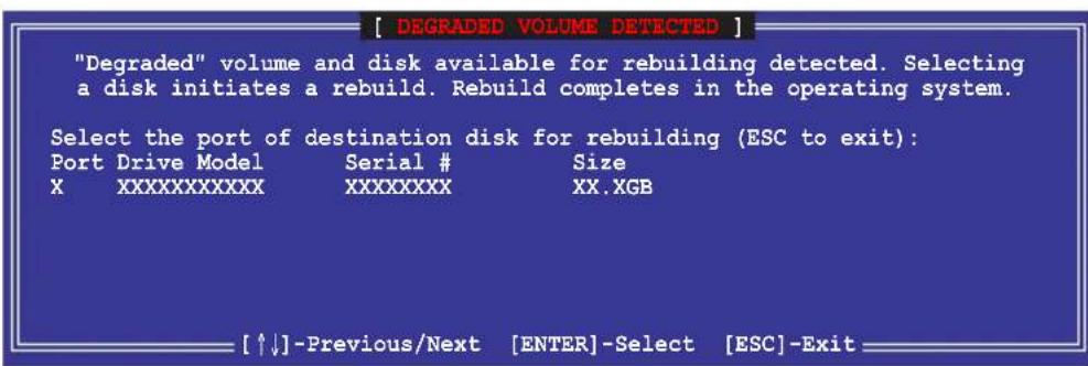
text_image
[ DEGRADED VOLUME DETECTED ] "Degraded" volume and disk available for rebuilding detected. Selecting a disk initiates a rebuild. Rebuild completes in the operating system. Select the port of destination disk for rebuilding (ESC to exit): Port Drive Model Serial # Size XXXXXXXXXXXXX XXXXXXXXX XX.XGB [↑↓]-Previous/Next [ENTER]-Select [ESC]-Exit
Select a destination disk with the same size as the original hard disk.
- The utility immediately starts rebuilding after the disk is selected. The status of the degraded RAID volume is changed to "Rebuild".
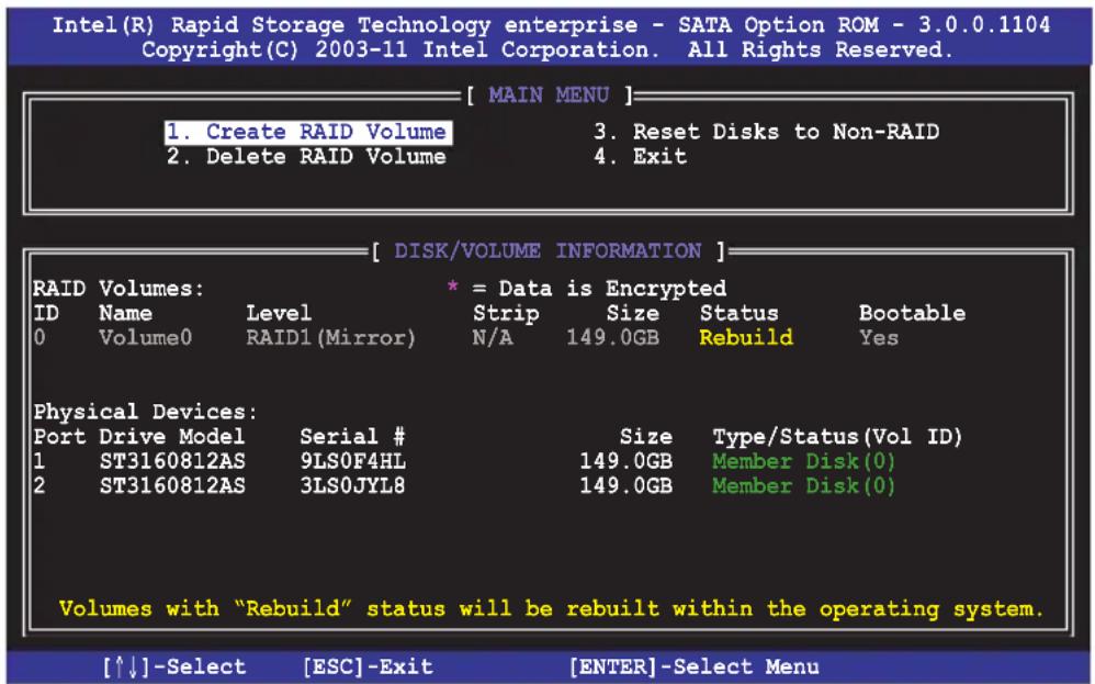
text_image
Intel(R) Rapid Storage Technology enterprise - SATA Option ROM - 3.0.0.1104 Copyright(C) 2003-11 Intel Corporation. All Rights Reserved. [ MAIN MENU ] 1. Create RAID Volume 3. Reset Disks to Non-RAID 2. Delete RAID Volume 4. Exit [ DISK/VOLUME INFORMATION ] RAID Volumes: * = Data is Encrypted ID Name Level Strip Size Status Bootable 0 Volume0 RAID1 (Mirror) N/A 149.0GB Rebuild Yes Physical Devices: Port Drive Model Serial # 1 ST3160812AS 9LS0F4HL Size Type/Status(Vol ID) 2 ST3160812AS 3LS0JYL8 149.0GB Member Disk(0) Volumes with "Rebuild" status will be rebuilt within the operating system. [↑↓]-Select [ESC]-Exit [ENTER]-Select Menu- Exit Intel Rapid Storage Technology and reboot the system.
- Under Microsoft ^ Windows OS, select Start > Programs > Intel Rapid Storage > Intel Rapid Storage Console or click the Intel Rapid Storage Technology tray icon to load the Intel Rapid Storage Manager utility.
- From the View menu, select Advanced Mode to display the details of the Intel Rapid Storage Console.
- From the Volumes view option, select RAID volume to view the rebuilding status. When finished, the status is changed to "Normal".
Rebuilding the RAID with a new hard disk
If any of the SATA hard disk drives included in the RAID array failed, the system displays the status of the RAID volume as “Degraded” during POST. You may replace the disk drive and rebuild the RAID array.
To rebuild the RAID with a new hard disk:
- Remove the failed SATA hard disk and install a new SATA hard disk of the same specification into the same SATA Port.

Select a destination disk with the same size as the original hard disk.
- Reboot the system and then follow the steps in section Rebuilding the RAID with other non-RAID disk.
5.3.7 Setting the Boot array in the BIOS Setup Utility
You can set the boot priority sequence in the BIOS for your RAID arrays when creating multi-RAID using the Intel® Rapid Storage Technology.
To set the boot array in the BIOS:

Set at least one of the arrays bootable to boot from the hard disk.
- Reboot the system and press
to enter the BIOS setup utility during POST. - Go to the Boot menu and select the boot option priority.
- Use up/down arrow keys to select the boot priority and press
. See section 4.7 Boot menu for details. - From the Exit menu, select Save Changes & Exit, then press
. - When the confirmation window appears, select Yes, then press
.
5.4 Intel ^® Rapid Storage Technology enterprise Utility (Windows)
The Intel ^® Rapid Storage Technology enterprise utility allows you to create RAID 0, RAID 1, RAID 10 (RAID 1+0), and RAID 5 set(s) from Serial ATA hard disk drives that are connected to the Serial ATA connectors supported by the Southbridge.
Before you using Intel® Rapid Storage Technology enterprise utility, you need to change BIOS setting first:
- Enter the BIOS Setup during POST.
-
Go to the Advanced Menu > Chipset Configuration > PCH Configuration > Onboard SAS Oprom, then press
. -
Set Onboard SAS Oprom to [Enabled].
-
Press
to save your changes and exit the BIOS Setup.

You need to manually install the Intel® Rapid Storage Technology enterprise utility on a Windows® operating system. Please refer to the installation instructions in Chapter 6.
To enter the Intel® Rapid Storage Technology enterprise utility under Windows operating system:
- Turn on the system to windows desktop.
- Click the Intel® Rapid Storage Technology enterprise icon to display the main menu.
Your storage system is configured for data protection, increased performance and optimal data storage capacity. You can further optimize your storage system by creating additional volumes.
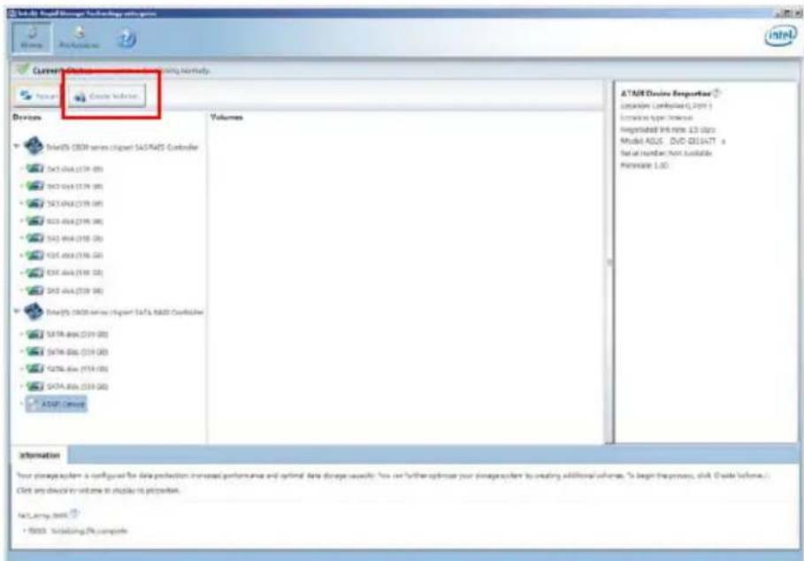
text_image
SQL Server Management Technology configuration Current: SQL Server Management Technology Current Version: Device Volume AT&T Eric Engine Portugal Comparison (C:\Users\1.0\ms) Location in type: Internal Registered link notes: 12 clips Model ADUS - DVD QDIAATT - a Serial number: Not Available Parameters: LDO SelectOS CBOB series (Chipset SAGTA/DS Controller) Select OS A64 (379 GB) Select OS A64 (379 GB) Select OS A64 (379 GB) Select OS A64 (379 GB) Select OS A64 (379 GB) Select OS A64 (379 GB) Select OS A64 (379 GB) Select OS A64 (379 GB) Select OS A64 (379 GB) SelectOS CBOB series (Chipset SAGA / R&D Controller) Select OS A64 (379 GB) Select OS A64 (379 GB) Select OS A64 (379 GB) SELECT OS A64 (379 GB) SELECT OS A64 (379 GB) SELECT OS A64 (379 GB) SELECT OS A64 (379 GB) SELECT OS A64 (379 GB) SELECT OS A64 (379 GB) SELECT OS A64 (379 GB) SELECT OS A64 (379 GB) SELECT OS A64 (379 GB) SELECTOS CBOB Your storage system is configured for data protection, increased performance and optimal data storage usage. You can further optimize your storage system to creating additional solutions. To begin the process, click 'Create Volume... Click any device to volume to display its procedure. Net_Large_Dsnk * RSDS - Including PK complete
You can click Rescan to re-scan any attached hard disks.
5.4.1 Creating a RAID set
To create a RAID set
- From the utility main menu, select Create Volume and select volume type.
- Then click Next.
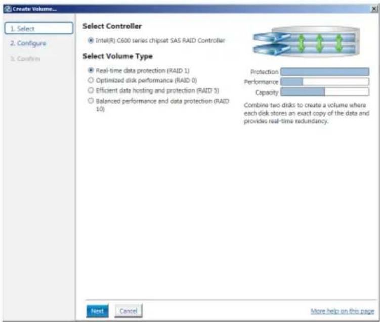
text_image
Create Volume... 1. Select 2. Configure 3. Confirm Select Controller Intel(R) C600 series chipset SAS RAID Controller Select Volume Type Real-time data protection (RAID 1) Optimized disk performance (RAID 0) Efficient data hosting and protection (RAID 3) Balanced performance and data protection (RAID 10) Protection Performance Capacity Combine two disks to create a volume where each disk stores an exact copy of the data and provides real-time redundancy. Next Cancel More help on this page- Enter a name for the RAID set, then select the array disks.
- Select Volume Size tab, you can drag the bar to decide the volume size.
- Then click Next.
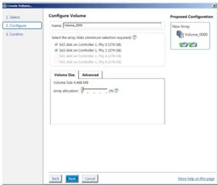
text_image
Create Volume... 1. Select 2. Configure 3. Confirm Configure Volume Name: Volume_0000 Select the array disks (minimum selection required) ✓ SAS disk on Controller 1, Phy 0 (279 GB) ✓ SAS disk on Controller 1, Phy 2 (279 GB) SAS disk on Controller 1, Phy 4 (279 GB) SAS disk on Controller 1, Phy 6 (279 GB) Proposed Configuration New Array Volume_0000 Volume Size Advanced Volume Size 4,46B MB Array allocation 2% Back Next Cancel More help on this page
- If you hard disk with existing data and you don't want to keep data from one of the selected disks, choose NO in next column (If displayed).
-
If you want to Enable volume write-back cache or Initialize volume, you can click Advanced tab to select.
-
Confirm volume creation, than click Create Volume to continue.
This process could take a while depending on the number and size of the disks. You can continue using other applications during this time.
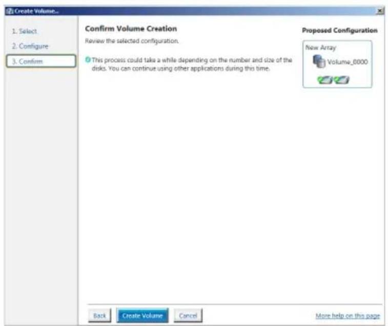
text_image
Create Volume... 1. Select 2. Configure 3. Confirm Confirm Volume Creation Review the selected configuration. This process could take a while depending on the number and size of the disks. You can continue using other applications during this time. Proposed Configuration New Array Volume_0000 Back Create Volume Cancel More help on this pageWhen display Volume Ceation Complete message, you can click OK to finish.

text_image
Volume Creation Complete The volume was created successfully. ● You still need to partition your new volume using Windows Disk Management* before adding any data. More help OK
You still need to partition your new volume using Windows Disk Management before adding any data.
When you are finished, you will see the following screen in Volumes field and you can change related items in the Volume Properties field.
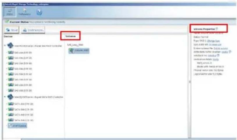
text_image
2.04.01 Rapid Storage Technology Universe Current Status: Vialc Options & Retrieval History Volume Volume Universe Volume Universe Volume Universe Volume Universe Volume Universe Volume Universe Volume Universe Volume Universe Volume Universe Volume Universe Volume Universe Volume Universe Volume Universe Volume Universe Volume Universe Volume Universe Volume Universe Volume Universe Volume Universe Volume Universe Volume Universe Volume Universe Volume Universe Volume Universe Volume Universe Volume Universe Volume Universe Volume Universe Volume Universe Volume Universe Volume Universe Volume Universe Volume Universe Volume Universe5.4.2 Change Volume Type
When you are finished to create a RAID set, you can view or change related items in the Volume Properties field.
According to the following steps to change the type in Volume Properties:
- Click the SATA array items you want to change in Volumes field.
2 From the Volume Properties field, select Type:RAID 1 Change type.
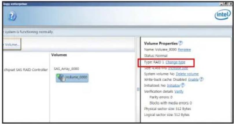
text_image
logy enterprise System is functioning normally. Volume... Volume Properties Name: Volume_0000 Rename Status: Normal Type: RAID 1 Change type Size: 4,006 Mb Increase size System volume: No Delete volume Write-back cache: Disabled Enable ? Initialized: No Initialize ? Verification details Verify Parity errors: 0 Blocks with media errors: 0 Physical sector size: 512 Bytes Logical sector size: 512 Bytes-
You can change the Name, Select the new volume type, and Select additional disks to include in the new volume if needed.
-
Then select the Data stripe size for the RAID array (for RAID 0, 10 and 5 only), and then click OK. The available stripe size values range from 4 KB to 128 KB. The following are typical values:
RAID 0: 128KB
RAID 10: 64KB
RAID 5: 64KB
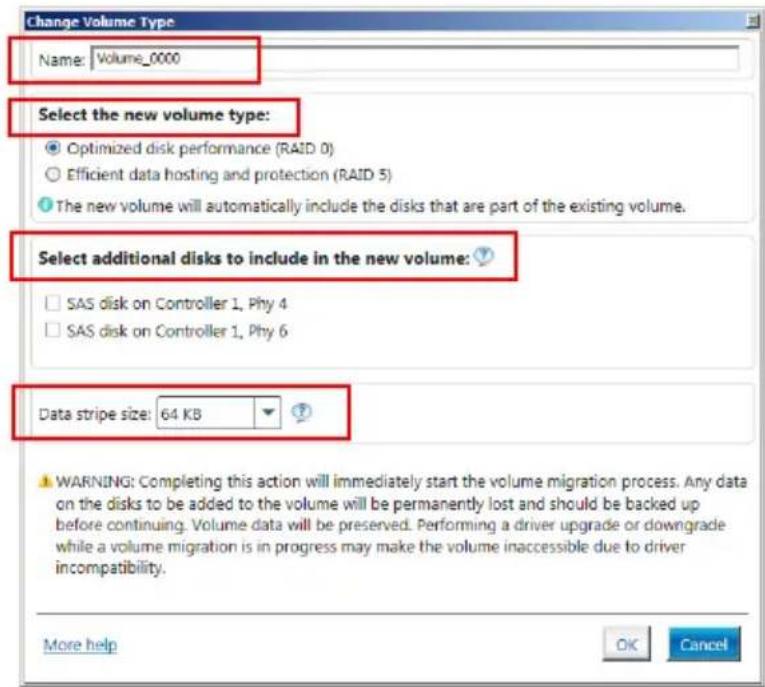
text_image
Change Volume Type Name: Volume_0000 Select the new volume type: Optimized disk performance (RAID 0) Efficient data hosting and protection (RAID 5) The new volume will automatically include the disks that are part of the existing volume. Select additional disks to include in the new volume: SAS disk on Controller 1, Phy 4 SAS disk on Controller 1, Phy 6 Data stripe size: 64 KB WARNING: Completing this action will immediately start the volume migration process. Any data on the disks to be added to the volume will be permanently lost and should be backed up before continuing. Volume data will be preserved. Performing a driver upgrade or downgrade while a volume migration is in progress may make the volume inaccessible due to driver incompatibility. More help OK Cancel
We recommend a lower stripe size for server systems, and a higher stripe size for multimedia computer systems used mainly for audio and video editing.
5.4.3 Delete volume

Take caution when deleting a volume. You will lose all data on the hard disk drives. Back up data before continuing.
To delete a volume:
- From the utility main menu, select the volume (exp. Volume_0000) in Volumes field you want to delete.
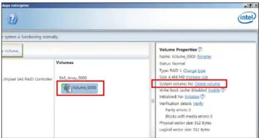
text_image
Volume enterprise intel System is functioning normally. Volume... Volumes SAS_Array_0000 Volume_0000 Chipset SAS RAID Controller Volume Properties Name: Volume_0000 Rename Status: Normal Type: RAID 1 Change type Size: 4.468 MB Increase size System volume: No Delete volume Write-back cache: Disabled Enable Initialized: No Initialize Verification details Verify Parity errors: 0 Blocks with media errors: 0 Physical sector size: 512 Bytes Logical sector size: 512 Bytes- Then select Delete volume in Volume Properties field. The following screen appears.
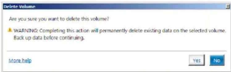
text_image
Delete Volume Are you sure you want to delete this volume? WARNING: Completing this action will permanently delete existing data on the selected volume. Back up data before continuing. More help Yes No- Click Yes to delete the volume and return to the utility main menu, or click No to return to the main menu.
5.4.4 Preferences
System Preferences
Allow you set to show the notification area icon and show system information, warning, or errors here.

text_image
Intel® Rapid Storage Technology enterprise Home Preferences System E-mail System Preferences ✓ Show the notification area icon Show the following notifications: ✓ Storage system information ✓ Storage system warnings ✓ Storage system errors >>> watchhelp on this pageE-Mail Preferences
Allow you set to sent e-mail of the following events:
Storage system information
Storage system warnings
Storage system errors
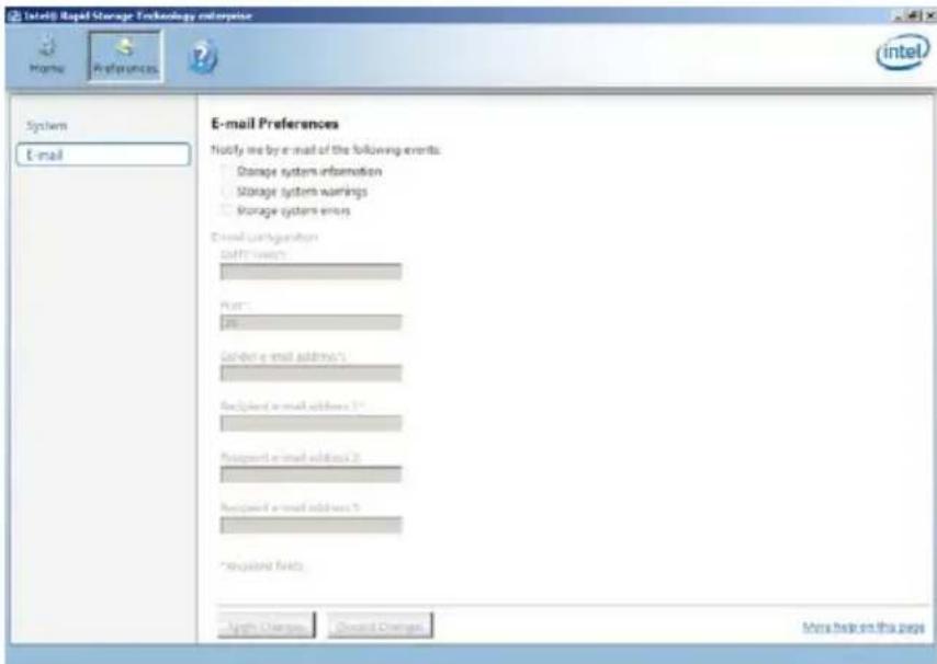
text_image
Intel® Rapid Storage Technology enterprise Home Preferences System E-mail E-mail Preferences Notify me by e-mail of the following events: Storage system information Storage system warnings Storage system errors Email configuration Delin's (e-mail) Print: Print Download e-mail address: Received e-mail address 1 Received e-mail address 2 Received e-mail address 3 * acquired fields Alpha Changes Dividend Changes More help on this pageThis chapter provides the instructions for installing the necessary drivers for different system components.
6 Driver installation
Chapter summary
6.1 RAID driver installation 6-3
6.2 Intel ^ chipset device software installation 6-16
6.3 Intel @ Network Connections Software installation.... 6-19
6.4 VGA driver installation.... 6-22
6.5 Intel ^ C600 Series Chipset SCU SATA RAID Drivers ...... 6-25
6.6 Intel ^® Rapid Storage Technology enterprise 3.0 installation . 6-26
6.7 Intel ^® WG82574L Gigabit Adapters Driver installation ...... 6-29
6.8 Management applications and utilities installation 6-33
6.1 RAID driver installation
After creating the RAID sets for your server system, you are now ready to install an operating system to the independent hard disk drive or bootable array. This part provides the instructions on how to install the RAID controller drivers during OS installation.
6.1.1 Creating a RAID driver disk

The system does not include a floppy drive. You have to use a USB floppy drive when creating a SATA RAID driver disk.
If you have created RAID sets with the LSI Software RAID configuration utility, the boot priority of the SATA optical disk drive has to be manually adjusted. Otherwise, the system will not boot from the connected SATA ODD.
A floppy disk with the RAID driver is required when installing Windows ^® XP / Server 2003 or Linux operating system on a hard disk drive that is included in a RAID set. You can create a RAID driver disk in DOS (using the Makedisk application in the support DVD).
To create a RAID driver disk in DOS environment
- Place the motherboard support DVD in the optical drive.
- Restart the computer, and then enter the BIOS Setup.
- Select the optical drive as the first boot priority to boot from the support DVD. Save your changes, and then exit the BIOS Setup.
- Restart the computer. The Makedisk menu appears.
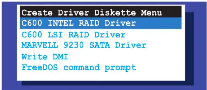
text_image
Create Driver Diskette Menu C600 INTEL RAID Driver C600 LSI RAID Driver MARVELL 9230 SATA Driver Write DMI FreeDOS command prompt- Use the arrow keys to select the type of RAID driver disk you want to create and press
to enter the sub-menu.
C600 INTEL RAID Driver
| C600 INTEL RAID Driver |
| Windows 32 bit (AHCI / AHCI RAID) |
| Windows 64 bit (AHCI / AHCI RAID) |
| Windows 32 bit (SCU RAID) |
| Windows 64 bit (SCU RAID) |
| Back |
| Exit |
LSI 2008 SAS2 Driver
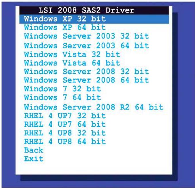
text_image
LSI 2008 SAS2 Driver Windows XP 32 bit Windows XP 64 bit Windows Server 2003 32 bit Windows Server 2003 64 bit Windows Vista 32 bit Windows Vista 64 bit Windows Server 2008 32 bit Windows Server 2008 64 bit Windows 7 32 bit Windows 7 64 bit Windows Server 2008 R2 64 bit RHEL 4 UP7 32 bit RHEL 4 UP7 64 bit RHEL 4 UP8 32 bit RHEL 4 UP8 64 bit Back Exit- Locate the RAID driver and place a blank, high-density floppy disk to the floppy disk drive.
- Press
. - Follow screen instructions to create the driver disk.
To create a RAID driver disk in Windows ^® environment
- Start Windows ^® .
- Place the motherboard support DVD into the optical drive.
- Go to the Make disk menu, and then select the type of RAID driver disk you want to create.
- Insert a floppy disk into the USB floppy disk drive.
- Follow succeeding screen instructions to complete the process.
Write-protect the floppy disk to avoid computer virus infection.
To create a RAID driver disk in Red Hat® Enterprise Linux server environment
- Insert a blank formatted high-density floppy disk to the USB floppy disk drive.
- Type dd if=XXX.img of=/dev/fd0 to decompress the file into the floppy disk from the following path in the support DVD:
For LSI MegaRAID Driver
\Drivers\C600 LSI RAID\Driver\makedisk/Linux
- Eject the floppy disk.
6.1.2 Installing the RAID controller driver
During Windows® Server 2008 OS installation
To install the RAID controller driver when installing Windows® Server 2008 OS
-
Boot the computer using the Windows ^ Server 2008 OS installation disc. Follow the screen instructions to start installing Windows Server 2008.
-
When prompted to choose a type of installation, click Custom (advanced).
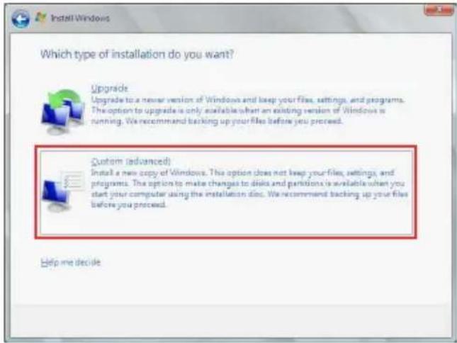
text_image
Which type of installation do you want? Upgrade Upgrade to a newer version of Windows and keep your files, settings, and programs. The option to upgrade is only available when an existing version of Windows is running. We recommend backing up your files before you proceed. Custom (advanced) Install a new copy of Windows. This option does not keep your files, settings, and programs. The option to make changes to disks and partitions is available when you start your computer using the installation disk. We recommend backing up your files before you proceed.- Click Load Driver.
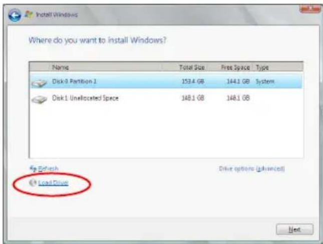
text_image
Where do you want to install Windows? Name Total Size Free Space Type Disk 9 Partition 1 153.4 GB 144.1 GB System Disk 1 Unallocated Space 148.1 GB 148.1 GB Load Drive Drive options (advanced) Next- A message appears, reminding you to insert the installation media containing the driver of the RAID controller driver. If you have only one optical drive installed in your system, eject the Windows OS installation disc and replace with the motherboard Support DVD into the optical drive. Click Browse to continue.
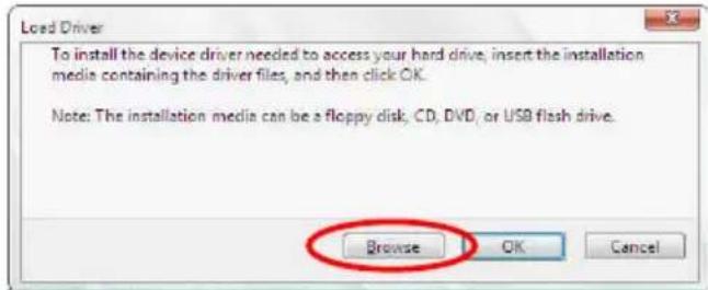
text_image
Loaded Driver To install the device driver needed to access your hard drive, insert the installation media containing the driver files, and then click OK. Note: The installation media can be a floppy disk, CD, DVD, or USB flash drive. Browse OK Cancel- Locate the driver in the corresponding folder of the Support DVD, and then click OK to continue.
- Select the RAID controller driver you need from the list and click Next.
- When the system finishes loading the RAID driver, replace the motherboard Support DVD with the Windows Server installation disc. Select the drive to install Windows and click Next.
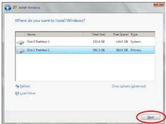
text_image
Where do you want to install Windows? Name Total Size Free Space Type Disk 0 Partition 1 153.4 GB 144.0 GB System Disk 1 Partition 1 582.3 GB 584.9 GB Primary Refresh Drive options (advanced) Load Driver Next- Setup then proceeds with the OS installation. Follow screen instructions to continue.
Red Hat® Enterprise Linux OS 5.6
To install the LSI MegaRAID controller driver when installing Red Hat ^® Enterprise OS:
-
Boot the system from the Red Hat ^® OS installation CD.
-
At the boot:, type linux dd noprobe=ata1 noprobe=ata2..., then press
.

The number of ata varies with the hard disk drive number you have when building a RAID set. For example, if you want to build a RAID set with 6 hard disk drives, type command line: linux dd noprobe=ata1 noprobe=ata2 noprobe=ata3 noprobe=ata4 noprobe=ata5 noprobe=ata6.
- To install or upgrade in graphical mode, press the <ENTER> key.
- To install or upgrade in text mode, type: linux text <ENTER>.
- Use the function keys listed below for more information.
[F1-Main] [F2-Options] [F3-General] [F4-Kernel] [F5-Rescue]
boot: linux dd noprobe=ata1 noprobe=ata2
- Select Yes using the
key when asked if you have the driver disk, then press .
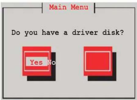
text_image
Main Menu Do you have a driver disk? Yes No- Insert the Red Hat ^ Enterprise RAID driver disk to the USB floppy disk drive, select OK, then press
.

text_image
Insert Driver Disk Insert your driver disk into /dev/fd0 and press "OK" to continue. OK BackThe drivers for the RAID card are installed to the system.
- When asked if you will load additional RAID controller drivers, select No, then press
.
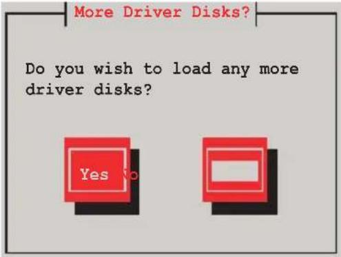
text_image
More Driver Disks? Do you wish to load any more driver disks? Yes No-
Follow the onscreen instructions to finish the OS installation.
-
When the installation is completed, DO NOT click Reboot. Press
+ + to switch to the command-line interface from graphic user interface. -
Type the following commands when using a Legacy floppy.
mkdir /mnt/driver
mount /dev/fd0 /mnt/driver
cd /mnt/driver
sh replace_ahci.sh
reboot
Red Hat® Enterprise Linux OS 6.1
To install the LSI MegaRAID controller driver when installing Red Hat ^® Enterprise OS:
- Boot the system from the Red Hat ^® OS installation CD.
- Press
to edit options.
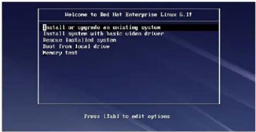
text_image
Welcome to Red Hat Enterprise Linux 6.1f Install or upgrade an existing system Install system with basic video driver Rescue installed system Boot from local drive Memory test Press [Tab] to edit options- Entering the following command at the boot: linux dd blacklist=isci blacklist=ahci nodmraid, then press
.
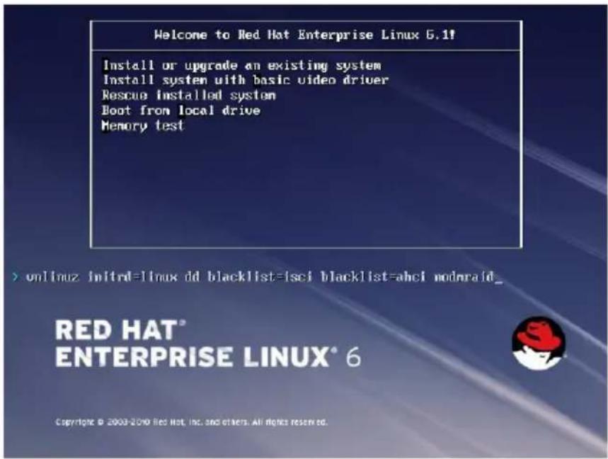
text_image
Welcome to Red Hat Enterprise Linux 6.1# Install or upgrade an existing system Install system with basic video driver Rescue installed system Boot from local drive Memory test > unlinux initrd=linux dd blacklist=isci blacklist=ahci modnraid_ RED HAT® ENTERPRISE LINUX® 6 Copyright © 2003-2010 Red Hat, Inc. and others. All rights reserved.- Select Yes using the
key when asked if you have the driver disk, then press .
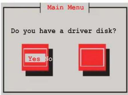
text_image
Main Menu Do you have a driver disk? Yes No- You have multiple devices which could serve as source for a driver disk. Choose one you like to use and select OK, then press
.
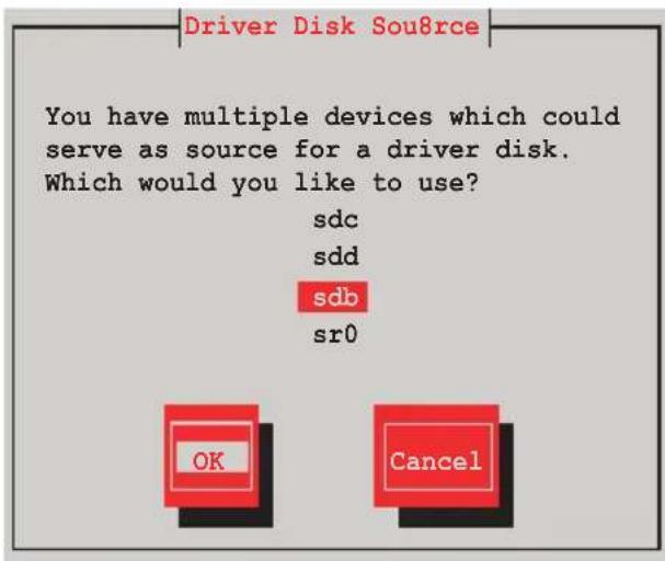
text_image
Driver Disk Sou8rce You have multiple devices which could serve as source for a driver disk. Which would you like to use? sdc sdd sdb sr0 OK Cancel- Insert the Red Hat ^ Enterprise RAID driver disk to the USB floppy disk drive, select OK, then press
.
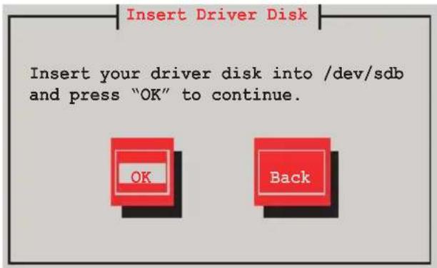
text_image
Insert Driver Disk Insert your driver disk into /dev/sdb and press "OK" to continue. OK BackThe drivers for the RAID card are installed to the system.
- When asked if you will load additional RAID controller drivers, select No, then press
.
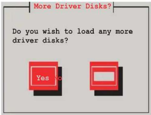
text_image
More Driver Disks? Do you wish to load any more driver disks? Yes No- Follow the onscreen instructions to finish the OS installation.
Preparing the Linux Driver
Ensure that there is another computer with a Linux-based OS to create the RAID driver. When creating the RAID driver, you may refer to the examples below which uses a 64bit SUSE Linux system to create a 64bit RAID driver for SUSE11 sp1.
- Copy the image file into the Linux system.
Example: megasr-15.00.0120.2012-1-sles11-ga-x86_64.img
- Create a folder.
Example: image
- Mount the image file into the image folder using this command format:
mount -o loop [image file name] image
Example: mount -o loop megasr-15-15.00.0120.2012-1-sles11-ga-x86_64.img image
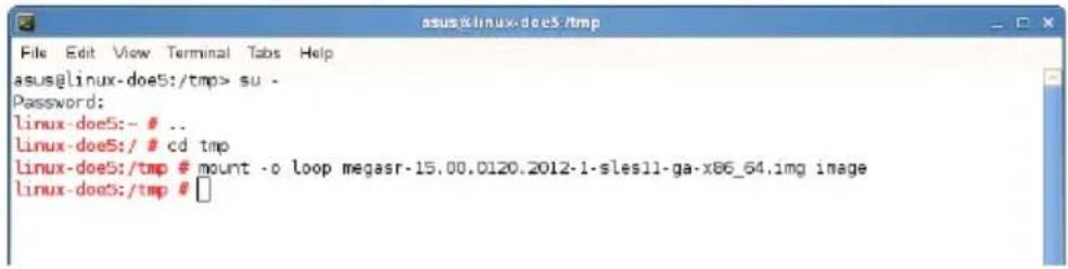
text_image
asus@linux-doe5:/tmp File Edit View Terminal Tabs Help asus@linux-doe5:/tmp> su - Password: linux-doe5:- # .. linux-doe5:/ # cd tmp linux-doe5:/tmp # mount -o loop megasr-15.00.0120.2012-1-slesll-ga-x86_64.img image linux-doe5:/tmp #- Copy the contents of the image directory, labeled as 01, into a FAT32 USB drive.
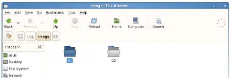
text_image
Image - File Browser File Edit View Go Bookmarks Tabs Help Back Forward Up Stop Reload Home Computer Search tmp image 02 Places asus Desktop File System Network 01 02- Rename the 01 folder to CD Image.
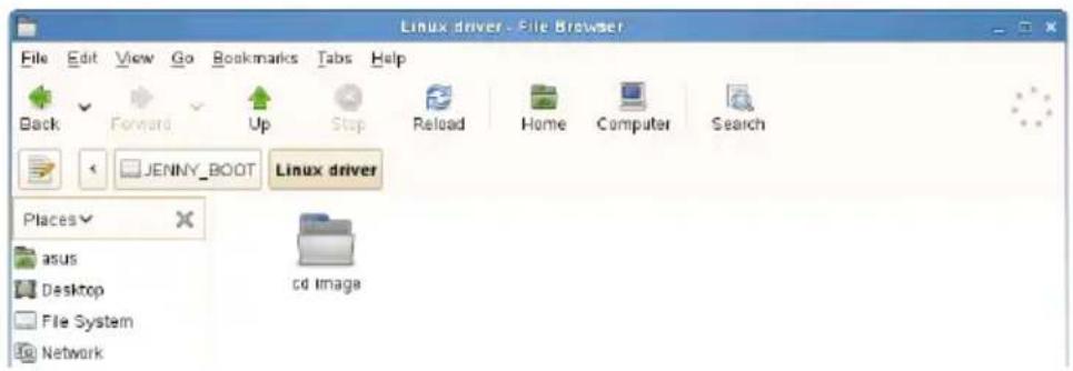
text_image
Linux driver - File Browser File Edit View Go Bookmarks Tabs Help Back Forward Up Stop Reload Home Computer Search JENNY_BOOT Linux driver Places asus Desktop File System Network cd ImageInstalling SUSE Linux 11 OS
To install the LSI MegaRAID controller driver when installing SUSE Linux Enterprise Server OS:
- Boot the system from the SUSE OS installation CD.
- Use the arrow keys to select Installation from the Boot Options menu.
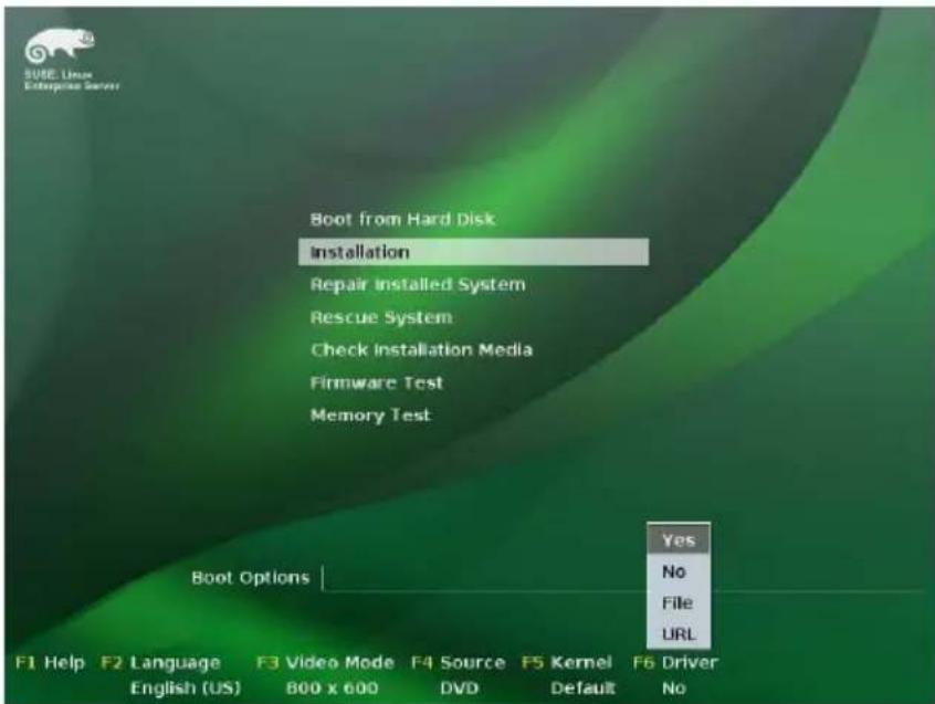
text_image
SUSE Linux Enterprise Server Boot from Hard Disk Installation Repair Installed System Rescue System Check Installation Media Firmware Test Memory Test Boot Options Yes No File URL F1 Help F2 Language F3 Video Mode F4 Source F5 Kernel F6 Driver English (US) 800 x 600 DVD Default No- Press
, then select Yes from the menu. Press .
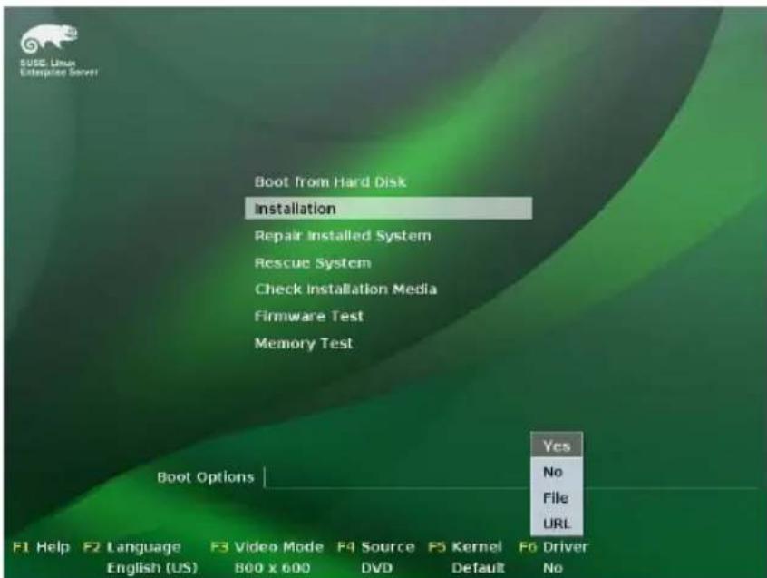
text_image
SUSE Linux Enterprise Server Boot From Hard Disk Installation Repair Installed System Rescue System Check Installation Media Firmware Test Memory Test Boot Options Yes No File URL F1 Help F2 Language F3 Video Mode F4 Source F5 Kernel F6 Driver English (US) 800 x 600 DVD Default No- Use the USB drive to provide the third-party driver during the OS installation. Type the command brokenmodules=ahci in Boot Options field, and press
.
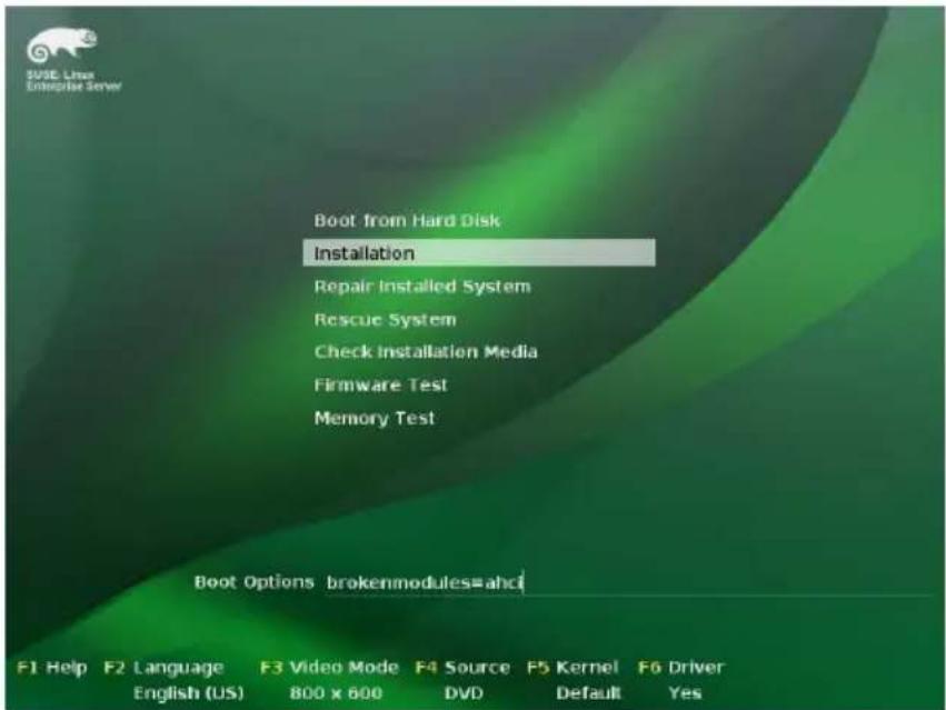
text_image
SUSE Linux Enterprise Server Boot from Hard Disk Installation Repair Installed System Rescue System Check Installation Media Firmware Test Memory Test Boot Options brokenmodules=ahc F1 Help F2 Language F3 Video Mode F4 Source F5 Kernel F6 Driver English (US) 800 x 600 DVD Default Yes- When below screen appears, select the USB floppy disk drive (sda) as the driver update medium. Select OK, then press
.
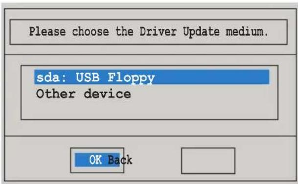
text_image
Please choose the Driver Update medium. sda: USB Floppy Other device OK Back- Select Back and follow the onscreen instructions to finish the installation.
6.2 Intel ^® chipset device software installation
This section provides the instructions on how to install the Intel ^® chipset device software on the system.
You need to manually install the Intel ^® chipset device software on a Windows operating system.
To install the Intel ^® chipset device software:
- Restart the computer, and then log on with Administrator privileges.
- Insert the motherboard/system support DVD to the optical drive. The support DVD automatically displays the Drivers menu if Autorun is enabled in your computer.
If Autorun is NOT enabled in your computer, browse the contents of the support DVD to locate the file ASSETUP.EXE from the BIN folder. Double-click the ASSETUP.EXE to run the support DVD.
- Click the item Intel Chipset Device Software from the menu.
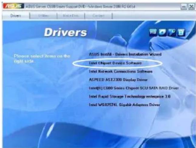
text_image
ASUS Server OS300 Series Support DVD - Windows Server 2000 RCS41 Drivers Please select items on the right side. ASUS InsAlb - Drivers Installation Wizard Intel Chipset Device Software Intel Network Connections Software ASPEED AST2300 Display Driver Intel[R] C560 Series Chipset SCU SATA RAID Driver Intel Rapid Storage Technology enterprise 3.0 Intel WGB2574L Gigabit Adapters Driver- The Intel(R) Chipset Device Software window appears. Click Next to start installation.
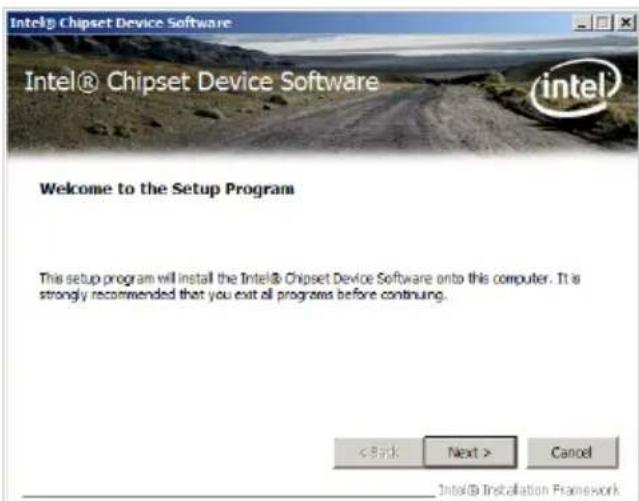
text_image
Intel® Chipset Device Software Intel® Chipset Device Software intel Welcome to the Setup Program This setup program will install the Intel® Chipset Device Software onto this computer. It is strongly recommended that you exit all programs before continuing. < Back Next > Cancel Intel® Installation Framework- Select Yes to accept the terms of the License Agreement and continue the process.
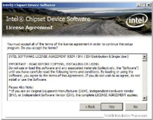
text_image
Intel® Chipset Device Software License Agreement You must accept all of the terms of the license agreement in order to continue the setup program. Do you accept the terms? INTEL SOFTWARE LICENSE AGREEMENT (OEM / IHV / ISV Distribution & Single User) IMPORTANT - READ BEFORE COPYING, INSTALLING OR USING. Do not use or load this software and any associated materials (collectively, the "Software") until you have carefully read the following terms and conditions. By loading or using the Software, you agree to the terms of this Agreement. If you do not wish to so agree, do not install or use the Software. Please Also Note: * If you are an Original Equipment Manufacturer (OEM), Independent Hardware Vendor (IHV), or Independent Software Vendor (ISV), this complete LICENSE AGREEMENT applies; < Back Yes No Intel® Installation Framework- Read the Readme File Information and press Next to continue the installation.
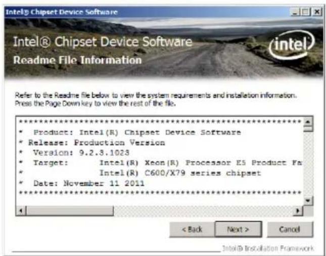
text_image
Intel® Chipset Device Software Readme File Information Refer to the Readme file below to view the system requirements and installation information. Press the Page Down key to view the rest of the file. ********************************************************************** * Product: Intel(R) Chipset Device Software * Release: Production Version * Version: 9.2.3.1023 * Target: Intel(R) Xeon(R) Processor E5 Product Fa * Intel(R) C600/X79 series chipset * Date: November 11 2011 ********************************************************************** < Back Next > Cancel Intel® Installation Framework- After completing the installation, click Next to complete the setup process.
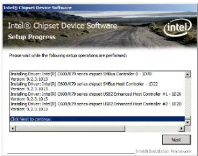
text_image
Intel® Chipset Device Software Setup Progress Please wait while the following setup operations are performed: Installing Driver: Intel(R) C600/X79 series chipset SMBus Controller 0 - 1070 Version: 9.2.3.1013 Installing Driver: Intel(R) C600/X79 series chipset SMBus Host Controller - 1D22 Version: 9.2.3.1013 Installing Driver: Intel(R) C600/X79 series chipset USB2 Enhanced Host Controller #1 - 1026 Version: 9.2.3.1013 Installing Driver: Intel(R) C600/X79 series chipset USB2 Enhanced Host Controller #2 - 1020 Version: 9.2.3.1013 Click Next to continue. Next Intel® Installation Framework- Select Yes, I want to restart my computer now and click Finish to restart your computer before using the program.
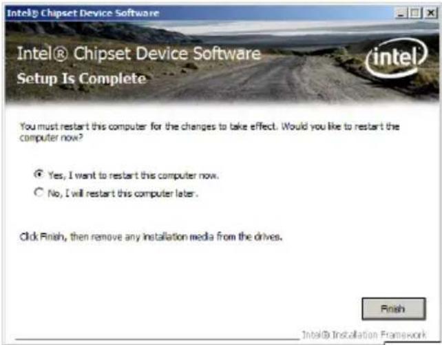
text_image
Intel® Chipset Device Software Setup Is Complete You must restart this computer for the changes to take effect. Would you like to restart the computer now? ● Yes, I want to restart this computer now. ○ No, I will restart this computer later. Click Finish, then remove any installation media from the drives. Finish Intel® Installation Framework6.3 Intel @ Network Connections Software installation
This section provides the instructions on how to install the Intel ^® Network Connections Software on the system.
You need to manually install the Intel ^® Network Connections Software on a Windows ^® operating system. To install the Intel ^® Network Connections Software:
- Restart the computer, and then log on with Administrator privileges.
- Insert the motherboard/system support DVD to the optical drive. The support DVD automatically displays the Drivers menu if Autorun is enabled in your computer.
- Windows ^ automatically detects the LAN controllers and displays a New Hardware Found window. Click Cancel to close this window.
-
If Autorun is NOT enabled in your computer, browse the contents of the support DVD to locate the file ASSETUP.EXE from the BIN folder. Double-click the ASSETUP.EXE to run the DVD.
-
Click the Intel® Network Connections Software to begin installation.
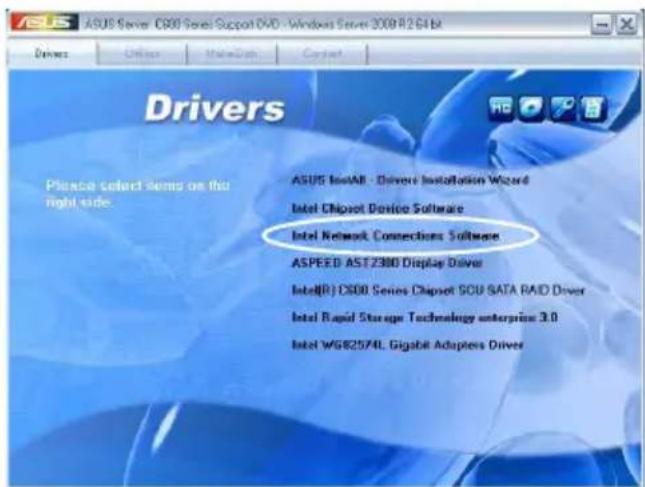
text_image
ASUS Server O800 Series Support DVD - Windows Server 3000 R264 BL Drivers Please select items on this right side. ASUS InletAll - Driver Installation Wizard Intel Chipset Device Software Intel Network Connections Software ASPEED AST 2380 Display Driver Intel(R) CX800 Series Chipset SOU SATA RAID Driver Intel Rapid Storage Technology enterprise 3.0 Intel WGB2574L Gigabit Adapters Driver- Click Install Drivers and Software option to begin installation.
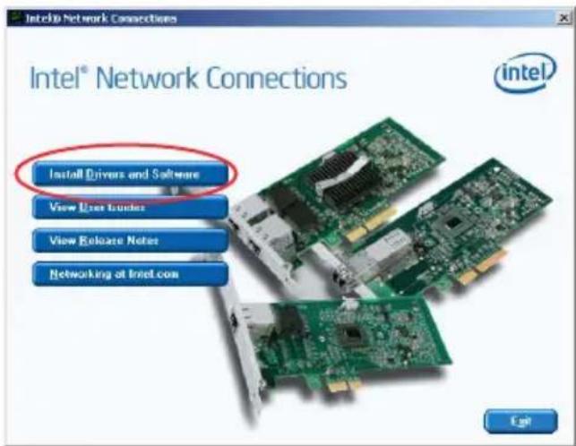
text_image
Intel® Network Connections Install Drivers and Software View User Truckies View Release Notes Networking at Intel.com- Click Next when the Intel(R) Network Connections—InstallShield Wizard window appears.
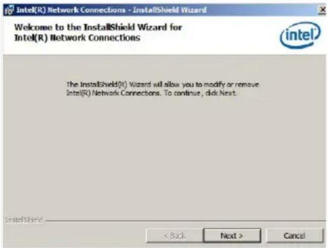
text_image
Intel(R) Network Connections - InstallShield Wizard Welcome to the InstallShield Wizard for Intel(R) Network Connections The InstallShield(R) Wizard will allow you to modify or remove Intel(R) Network Connections. To continue, click Next. < Back Next > Cancel- Select Modify and then click Next to continue.
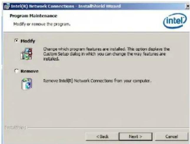
text_image
Intel(R) Network Connections - InstallShield Wizard Program Maintenance Modify or remove the program. Intel® Modify Change which program features are installed. This option displays the Custom Setup dialog in which you can change the way features are installed. Remove Remove Intel(R) Network Connections from your computer. InstallShield < Back Next > Cancel- Click the Intel(R) PROSet for Windows Device Manager box, and then click Next to start the installation.
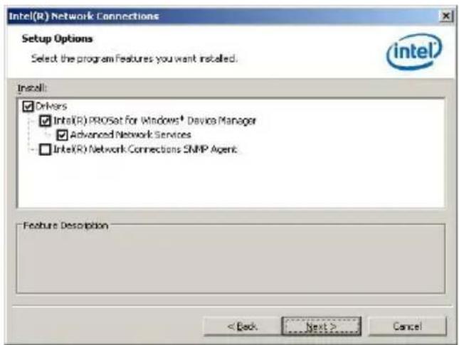
text_image
Intel(R) Network Connections Setup Options Select the program Features you want installed. Install: ✓ Drivers ✓ Intel(R) PROSat for Windows® Device Manager ✓ Advanced Network Services □ Intel(R) Network Connections SNMP Agent Feature Description < Back Next > Cancel- Follow the screen instructions to complete installation.
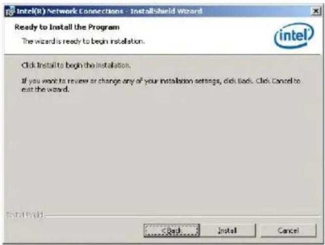
text_image
Intel(R) Network Connections - InstallShield Wizard Ready to Install the Program The wizard is ready to begin installation. Click Install to begin the installation. If you want to review or change any of your installation settings, click Back. Click Cancel to exit the wizard. InstallShield < Back Install Cancel- When finished, press Finish to continue.
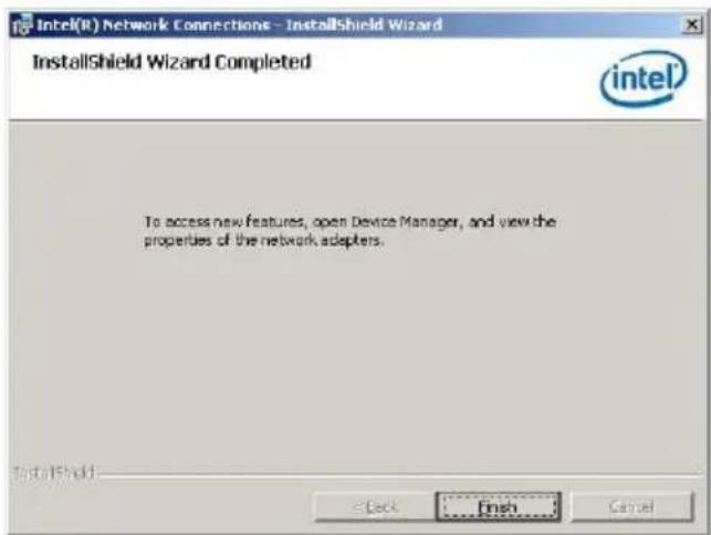
text_image
Intel(R) Network Connections - InstallShield Wizard InstallShield Wizard Completed intel To access new features, open Device Manager, and view the properties of the network adapters. InstallShield < Back Finish Cancel6.4 VGA driver installation
This section provides the instructions on how to install the ASPEED Video Graphics Adapter (VGA) driver.
You need to manually install the ASPEED VGA driver on a Windows® operating system.
To install the ASPEED VGA driver:
- Restart the computer, and then log on with Administrator privileges.
- Insert the motherboard/system support DVD to the optical drive. The support DVD automatically displays the Drivers menu if Autorun is enabled in your computer.
If Autorun is NOT enabled in your computer, browse the contents of the support DVD to locate the file ASSETUP.EXE from the BIN folder. Double-click the ASSETUP.EXE to run the support DVD.
- Click the ASPEED AST2300 Display Driver to begin installation.
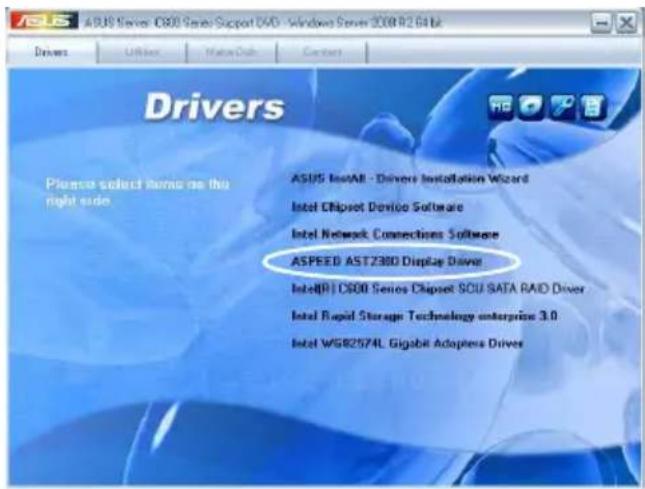
text_image
ASUS Server - 3800 Series/Support DVD - Windows Server 2008 R2.64 bit Drivers Please select items on this right side ASUS Install - Drivers Installation Wizard Intel Chipset Device Software Intel Network Connections Software ASPEED AST2300 Display Driver Intel(R) C800 Series Chipset SOU SATA RAID Driver Intel Rapid Storage Technology enterprise 3.0 Intel WGB2574L Gigabit Adapters Driver- When the ASPEED Graphics installation wizard appears, click Next to start the installation.
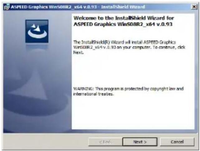
text_image
ASPEED Graphics WinS08R2_x64 v.0.93 - InstallShield Wizard Welcome to the InstallShield Wizard for ASPEED Graphics WinS08R2_x64 v.0.93 The InstallShield(R) Wizard will install ASPEED Graphics WinS08R2_x64 v.0.93 on your computer. To continue, click Next. WARNING: This program is protected by copyright law and international treaties. < Back Next > Cancel- Toggle I accept the terms in the license agreement and click Next to continue.

text_image
ASPEED Graphics Win508R2_x64 v.0.93 - InstallShield Wizard License Agreement Please read the following license agreement carefully. To add your own license text to this dialog, specify your license agreement file in the Dialog editor. 1. Navigate to the User Interface view. 2. Select the LicenseAgreement dialog. 3. Choose to edit the dialog layout. 4. Once in the Dialog editor, select the Memo ScrollableText control. 5. Set FileName to the name of your license agreement RTP file. After you build your release, your license text will be displayed in the License Agreement dialog. I accept the terms in the license agreement I do not accept the terms in the license agreement Print < Back Next > Cancel- Enter the user information and click Next to continue.
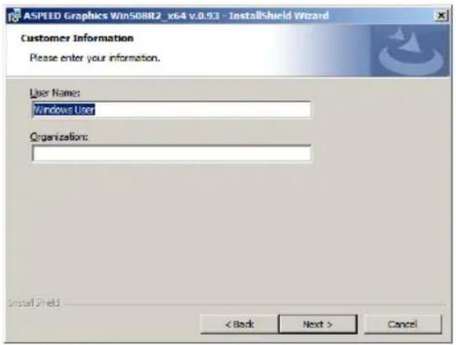
text_image
ASPEED Graphics Win568R2_x64 v.0.93 - InstallShield Wizard Customer Information Please enter your information. User Name: Windows User Organization: InstallShield < Back Next > Cancel- Select a setup type and click Next to continue.
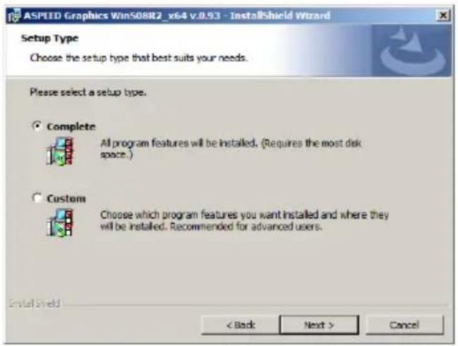
text_image
ASPIED Graphics WinS08R2_v64 v.0.93 - InstallShield Wizard Setup Type Choose the setup type that best suits your needs. Please select a setup type. Complete All program features will be installed. (Requires the most disk space.) Custom Choose which program features you want installed and where they will be installed. Recommended for advanced users. InstallShield < Back Next > Cancel- Click Install to start driver installation.
text_image
ASPEED Graphics Win508R2_x64 v.0.9.3 - installShield Wizard Ready to Install the Program The wizard is ready to begin installation. Click Install to begin the installation. If you want to review or change any of your installation settings, click Back. Click Cancel to exit the wizard. InstallShield < Back Install Cancel- When the installation completes, click Finish to restart your computer before using the program.
text_image
ASPEED Graphics WinS08R2_x64 v.0.93 - InstallShield Wizard InstallShield Wizard Completed The InstallShield Wizard has successfully installed ASPEED Graphics WinS08R2_x64 v.0.93. Click Finish to exit the wizard. < Back Finish Cancel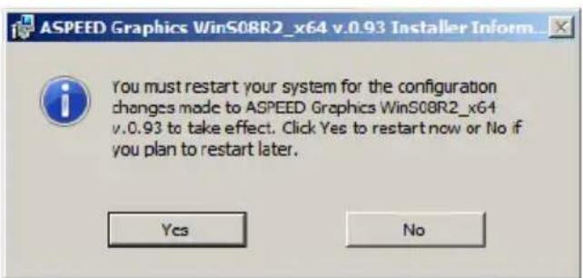
text_image
ASPEED Graphics WinS08R2_x64 v.0.93 Installer Inform You must restart your system for the configuration changes made to ASPEED Graphics WinS08R2_x64 v.0.93 to take effect. Click Yes to restart now or No if you plan to restart later. Yes No6.5 Intel ^® C600 Series Chipset SCU SATA RAID Drivers
This section provides the instructions on how to install the Intel® C600 Series Chipset SCU SATA RAID Driverson the system.
You need to manually install the Intel® C600 Series Chipset SCU SATA RAID Drivers on a Windows operating system.
To install the drivers:
- Restart the computer, and then log on with Administrator privileges.
- Insert the motherboard/system support DVD to the optical drive. The support DVD automatically displays the Drivers menu if Autorun is enabled in your computer.

If Autorun is NOT enabled in your computer, browse the contents of the support DVD to locate the file ASSETUP.EXE from the BIN folder. Double-click the ASSETUP.EXE to run the support DVD.
- Click the item Intel® C600 Series Chipset SCU SATA RAID Drivers from the menu, and then follow the onscreen instructions to complete the installation.
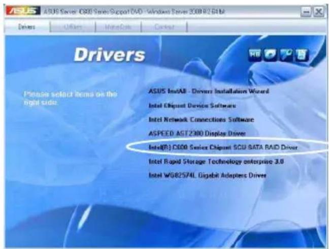
text_image
ASUS Server 3.08 HDG G163 Drivers Please select items on the right side. ASUS Install - Drivers Installation Wizard Intel Chipset Device Software Intel Network Connections Software ASPEED AST2900 Display Driver Intel(R) CS00 Series Chipset 500 SATA RAID Driver Intel Rapid Storage Technology enterprise 3.0 Intel WGB2574L Gigabit Adapters Driver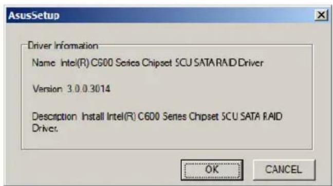
text_image
AsusSetup Driver Information Name: Intel(R) C600 Series Chipset 5CU SATA RAID Driver Version: 3.0.0.3014 Description: Install Intel(R) C600 Series Chipset 5CU SATA RAID Driver: OK CANCEL6.6 Intel ^® Rapid Storage Technology enterprise 3.0 installation
This section provides the instructions on how to install the Intel® Rapid Storage Technology enterprise 3.0 on the system.
You need to manually install the Intel® Rapid Storage Technology enterprise 3.0 utility on a Windows® operating system.
To install the Intel® Rapid Storage Technology enterprise 3.0 utility:
- Restart the computer, and then log on with Administrator privileges.
- Insert the motherboard/system support DVD to the optical drive. The support DVD automatically displays the Drivers menu if Autorun is enabled in your computer.
If Autorun is NOT enabled in your computer, browse the contents of the support DVD to locate the file ASSETUP.EXE from the BIN folder. Double-click the ASSETUP.EXE to run the support DVD.
- Click the Intel® Rapid Storage Technology enterprise 3.0 to begin installation.
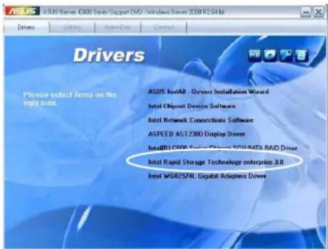
text_image
ASUS Server - DSO Server Support DVD - Windows Server 2008 R2.61 kit Drivers Please select items on the right side. ASUS Install - Driverz Installation Wizard Intel Chipset Device Software Intel Network Connections Software ASPEED AST2300 Display Driver InstallR1-DSO Server Chipset SOU4TA RAID Driver Intel Rapid Storage Technology enterprise 3.0 Intel WDR2574L Gigabit Adapters Driver- When the Welcome to the Setup Program appears, click Next to start the installation.
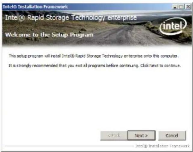
text_image
Intel® Installation Framework Intel® Rapid Storage Technology enterprise Welcome to the Setup Program This setup program will install Intel® Rapid Storage Technology enterprise onto this computer. It is strongly recommended that you exit all programs before continuing. Click Next to continue.- Read the Warning message and click Next to continue.
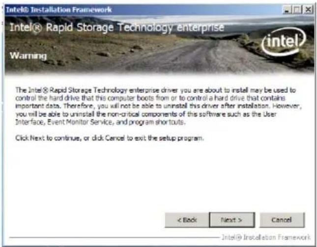
text_image
Intel® Installation Framework Intel® Rapid Storage Technology enterprise Warning The Intel® Rapid Storage Technology enterprise driver you are about to install may be used to control the hard drive that this computer boots from or to control a hard drive that contains important data. Therefore, you will not be able to uninstall this driver after installation. However, you will be able to uninstall the non-critical components of this software such as the User Interface, Event Monitor Service, and program shortcuts. Click Next to continue, or click Cancel to exit the setup program. < Back Next > Cancel Intel® Installation Framework- Read the License Agreement and click Yes to continue.
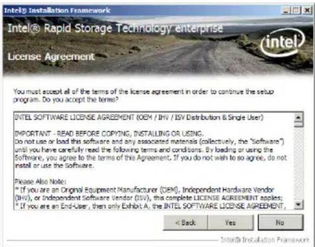
text_image
Intel® Installation Framework Intel® Rapid Storage Technology enterprise License Agreement You must accept all of the terms of the license agreement in order to continue the setup program. Do you accept the terms? INTEL SOFTWARE LICENSE AGREEMENT (OEM / IHV / ISV Distribution & Single User) IMPORTANT - READ BEFORE COPYING, INSTALLING OR USING. Do not use or load this software and any associated materials (collectively, the "Software") until you have carefully read the following terms and conditions. By loading or using the Software, you agree to the terms of this Agreement. If you do not wish to so agree, do not install or use the Software. Please Also Note: * If you are an Original Equipment Manufacturer (OEM), Independent Hardware Vendor (IHV), or Independent Software Vendor (ISV), this complete LICENSE AGREEMENT applies; * If you are an End-User, then only Exhibit A, the INTEL SOFTWARE LICENSE AGREEMENT, < Back Yes No Intel® Installation Framework- Read the Readme File Information and click Next to continue.
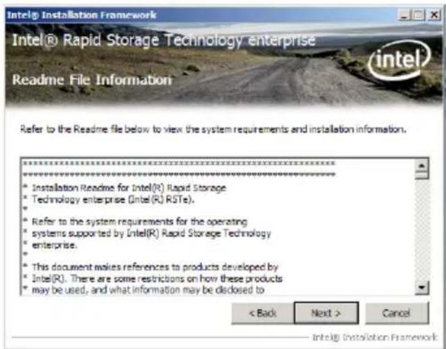
text_image
Intel® Installation Framework Intel® Rapid Storage Technology enterprise Readme File Information Refer to the Readme file below to view the system requirements and installation information. ***** Installation Readme for Intel(R) Rapid Storage Technology enterprise (Intel(R) RSTe). Refer to the system requirements for the operating systems supported by Intel(R) Rapid Storage Technology enterprise. This document makes references to products developed by Intel(R). There are some restrictions on how these products may be used, and what information may be disclosed to < Back Next > Cancel Intel® Installation Framework- After completing the installation, click Next to complete the setup process.
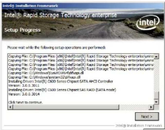
text_image
Intel® Installation Framework Intel® Rapid Storage Technology enterprise Setup Progress Please wait while the following setup operations are performed: Copying File: C:\Program Files (x86)\Intel\Intel(R) Rapid Storage Technology enterprise\unins\ Copying File: C:\Program Files (x86)\Intel\Intel(R) Rapid Storage Technology enterprise\unins\ Copying File: C:\Program Files (x86)\Intel\Intel(R) Rapid Storage Technology enterprise\unins\ Copying File: C:\Program Files (x86)\Intel\Intel(R) Rapid Storage Technology enterprise\unins\ Copying File: C:\Windows\System32\dfixapi.dll Copying File: C:\Windows\system32\dfixapi.dll Installing Driver: Intel(R) C600 Series Chipset SATA AHCI Controller Version: 3.0.0.3011 Installing Driver: Intel(R) C600 Series Chipset SAS RAID (SATA mode) Version: 3.0.0.3014 Click Next to continue. Next > Intel® Installation Framework- Select Yes, I want to restart my computer now and click Finish to restart your computer before using the program.
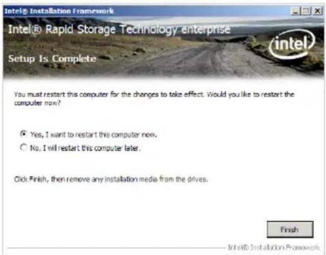
text_image
Intel® Installation Framework Intel® Rapid Storage Technology enterprise Setup Is Complete You must restart this computer for the changes to take effect. Would you like to restart the computer now? Yes, I want to restart this computer now. No, I will restart this computer later. Click Finish, then remove any installation media from the drives. Finish Intel® Installation Framework6.7 Intel ^® WG82574L Gigabit Adapters Driver installation
This section provides the instructions on how to install Intel ^® 82574L Gigabit Adapters Driver.
To install the Intel®WG82574L Gigabit Adapters Driver on a Windows® OS:
- Restart the computer, and then log on with Administrator privileges.
- Insert the motherboard/system support DVD to the optical drive. The DVD automatically displays the Drivers menu if Autorun is enabled in your computer.

If Autorun is NOT enabled in your computer, browse the contents of the support DVD to locate the file AUTORUN.EXE and double-click the AUTORUN.EXE and follow step 4 to run the installation.
3. Click Intel®WG82574L Gigabit Adapters Driver.
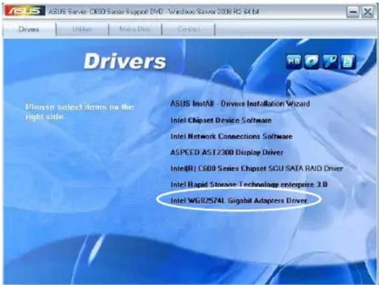
text_image
ASUS Server C800 Series Support DVD - Windows Server 2008 R2 64 bit Drivers Please select items on the right side. ASUS Install - Drivers Installation Wizard Intel Chipset Device Software Intel Network Connections Software ASPEED AST2300 Display Driver Intel(R) C600 Series Chipset SCU SATA RAID Driver Intel Rapid Storage Technology enterprise 3.0 Intel WG82574L Gigabit Adapters Driver- When the Intel® Network Connections – InstallShield Wizard window appears, click Next to start the installation.
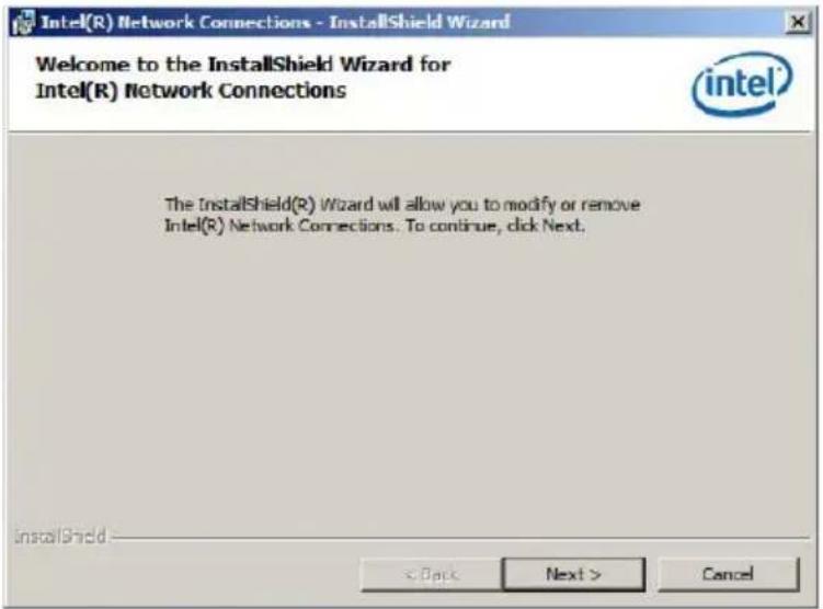
text_image
Intel(R) Network Connections - InstallShield Wizard Welcome to the InstallShield Wizard for Intel(R) Network Connections intel The InstallShield(R) Wizard will allow you to modify or remove Intel(R) Network Connections. To continue, click Next. InstallShield < Back Next > Cancel- Select Modify and then click Next to continue.

text_image
Intel(R) Network Connections - InstallShield Wizard Program Maintenance Modify or remove the program. Modify Change which program features are installed. This option displays the Custom Setup dialog in which you can change the way features are installed. Remove Remove Intel(R) Network Connections from your computer. InstallShield < Back Next > Cancel- Select the programs you want to install and click Next to continue.
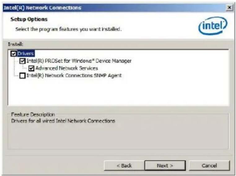
text_image
Intel(R) Network Connections Setup Options Select the program features you want installed. Install: ✓ Drivers ✓ Intel(R) PROSet for Windows® Device Manager ... ✓ Advanced Network Services ☐ Intel(R) Network Connections SNMP Agent Feature Description Drivers for all wired Intel Network Connections < Back Next > Cancel- Click Install to start the installation.
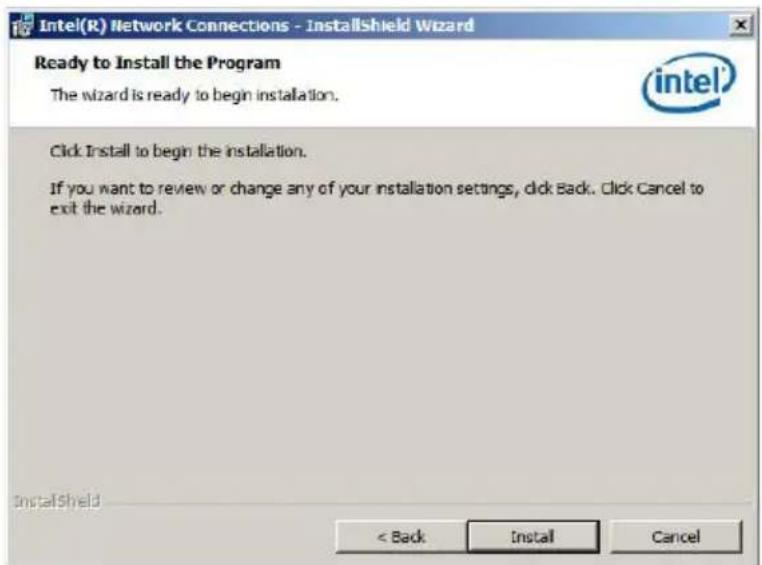
text_image
Intel(R) Network Connections - InstallShield Wizard Ready to Install the Program The wizard is ready to begin installation. Click Install to begin the installation. If you want to review or change any of your installation settings, click Back. Click Cancel to exit the wizard. InstallShield < Back Install Cancel- The programs you select are being installed.
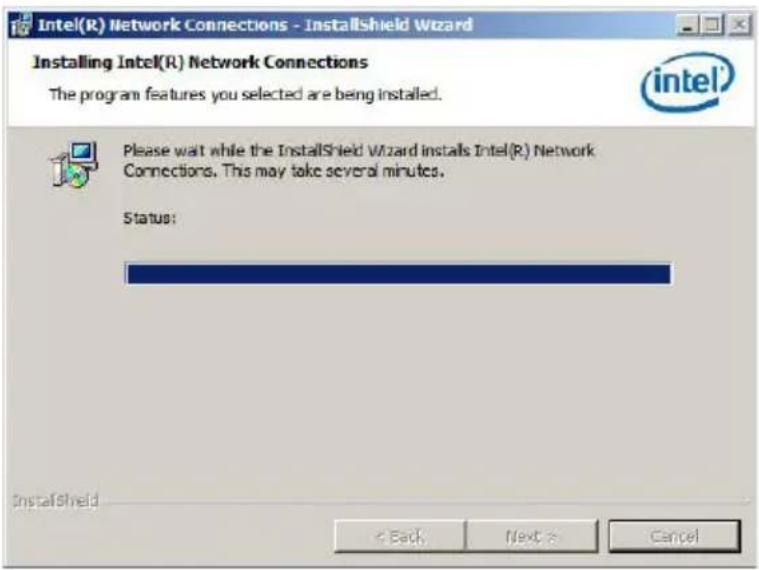
text_image
Intel(R) Network Connections - InstallShield Wizard Installing Intel(R) Network Connections The program features you selected are being installed. Please wait while the InstallShield Wizard installs Intel(R) Network Connections. This may take several minutes. Status: InstallShield < Back Next > Cancel- Click Finish to finish the installation.
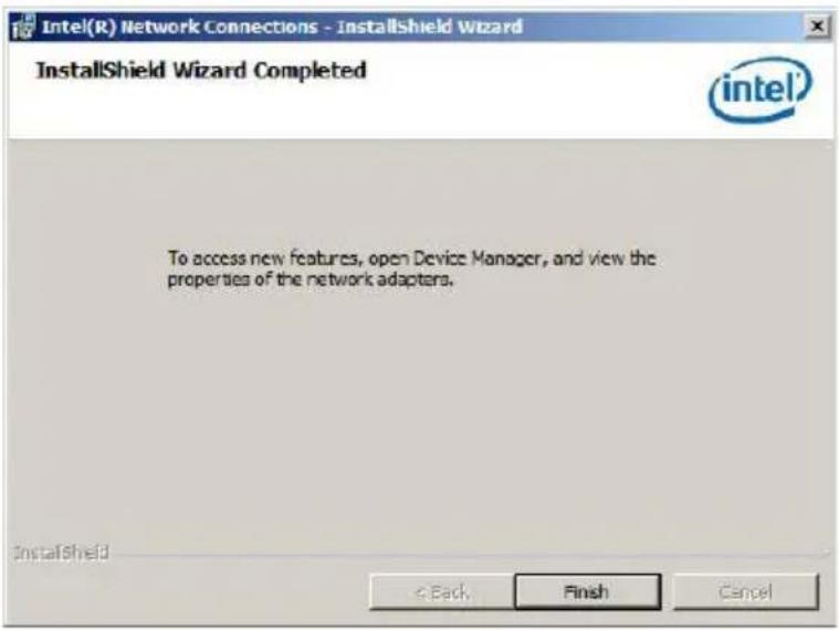
text_image
Intel(R) Network Connections - InstallShield Wizard InstallShield Wizard Completed intel® To access new features, open Device Manager, and view the properties of the network adapters. InstallShield < Back Finish Cancel- Restart your computer before using the program.
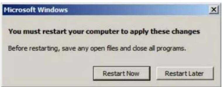
text_image
Microsoft Windows You must restart your computer to apply these changes Before restarting, save any open files and close all programs. Restart Now Restart Later6.8 Management applications and utilities installation
The support DVD that came with the motherboard package contains the drivers, management applications, and utilities that you can install to avail all motherboard features.
The contents of the support DVD are subject to change at any time without notice. Visit the ASUS website (www.asus.com) for updates.
6.8.1 Running the support DVD
Place the support DVD to the optical drive. The DVD automatically displays the Drivers menu if Autorun is enabled in your computer.

If Autorun is NOT enabled in your computer, browse the contents of the support DVD to locate the file ASSETUP.EXE from the BIN folder. Double-click the ASSETUP.EXE to run the support DVD.
6.8.2 Drivers menu
The Drivers menu shows the available device drivers if the system detects installed devices. Install the necessary drivers to activate the devices.

The screen display and driver options vary under different operating system versions.
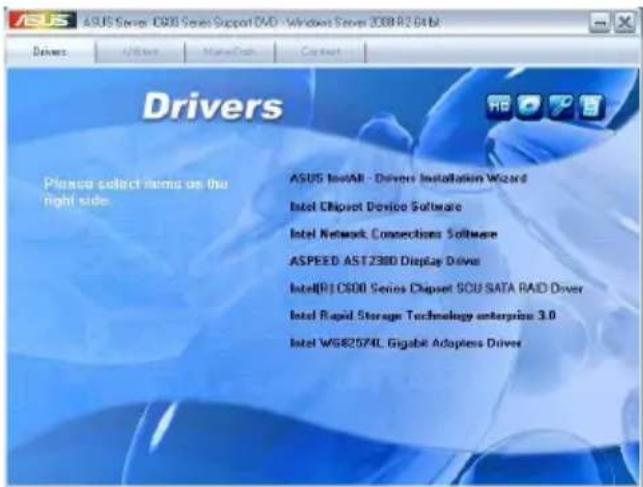
text_image
ASUS Series 6.000 Series Support DVD - Windows Server 2008 R2 6.0 Drivers Please select items on the right side. ASUS InstAll - Drivers Installation Wizard Intel Chipset Device Software Intel Network Consections Software ASPEED AST 2380 Display Driver IntelR1C500 Series Chipset SOU SATA RAID Driver Intel Rapid Storage Technology enterprise 3.0 Intel W6R2574L Gigabit Adapten Driver6.8.3 Utilities menu
The Utilities menu displays the software applications and utilities that the motherboard supports. Click an item to install.
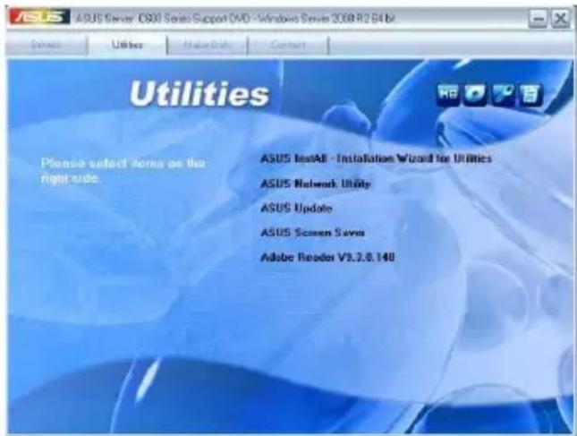
text_image
ASUS Server O900 Service Support DVD - Windows Server 2008 R12 B4 Drive Utiliser Help Date Contact Utilities Please select terms on the right side. ASUS Install - Installation Wizard for Utilities ASUS Network Utility ASUS Update ASUS Screen Save Adobe Reader V3.3.0.1486.8.4 Make disk menu
The Make disk menu contains items to create the Intel RAID driver disks.
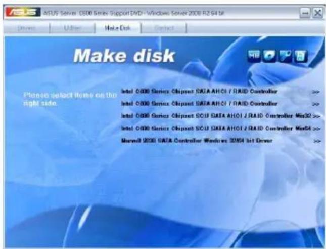
text_image
Make disk Pitch-on select links on the right side. Intel 000 Series Chipset SATA AHCI / RAID Controller >> Intel 000 Series Chipset SATA AHCI / RAID Controller >> Intel 000 Series Chipset SOU SATA AHCI / RAID Controller Mas32 >> Intel 000 Series Chipset SOU SATA AHCI / RAID Controller Mas4 >> Marvell 9200 SATA Controller Windows 2004 bit Driver >>6.8.5 Contact information
Click the Contact tab to display the ASUS contact information. You can also find this information on the inside front cover of this user guide.
text_image
ASUSTeK COMPUTER INC Address: 15 U-Te Road,Petroo, Taipei; Taiwan (1239) Telephone: +888-2-2964-3417 Fax: +88-2-2800-2798 Email: info@asus.com.tw Web site: http://www.asus.com.tw Technical Support: Telephone: +88-21-38429111 FAX: +88-21-59169722; ed. 9101# Online Support: http://support.asus.com/techserv/chase.aspx ASUSTeK COMPUTER INC (Taiwan) ASUSTeK COMPUTER INC (China) ASUS COMPUTER INTERNATIONAL (America) ASUS COMPUTER GmbH(Germany & Austria)This appendix includes additional information that you may refer to when configuring the motherboard.
Reference information
Appendix summary
A
A.1 Z9NA-D6 block diagram ......A-3
A.1 Z9NA-D6 block diagram
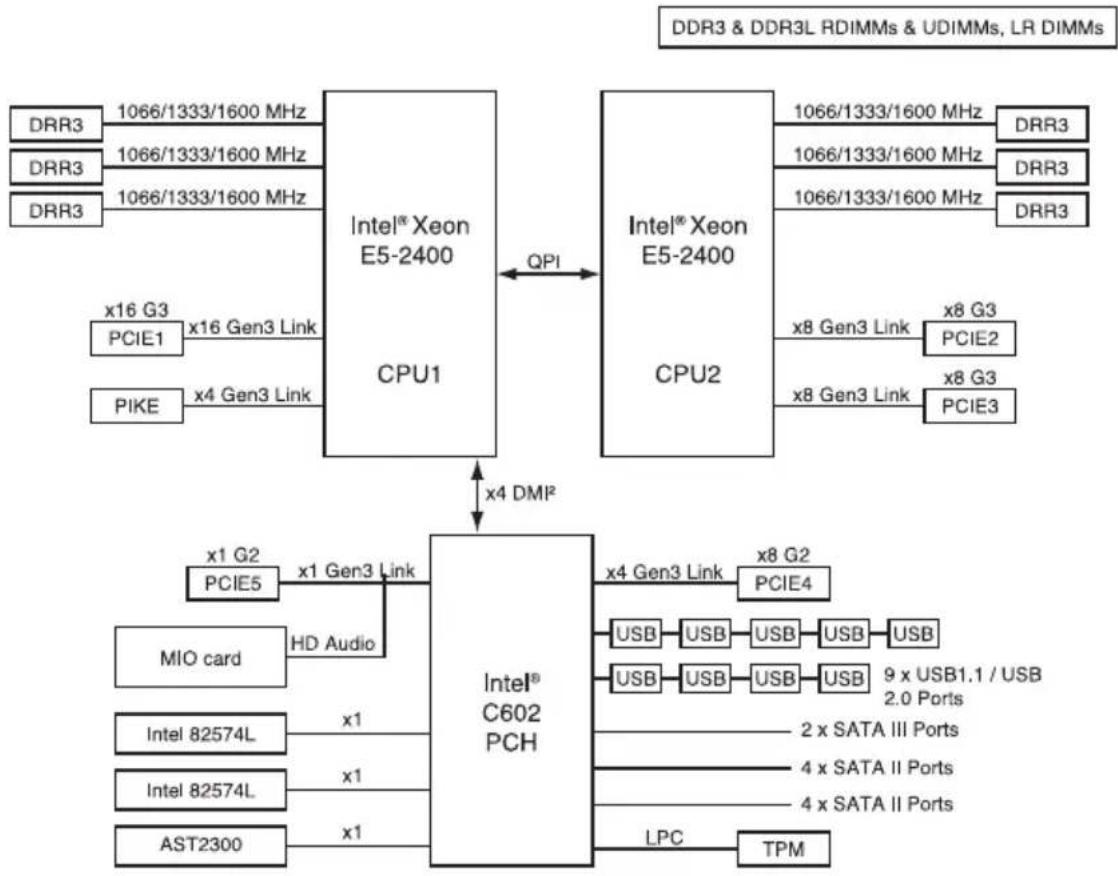
flowchart
graph TD
    subgraph Intel® Xeon E5-2400
        A["CPU1"] -->|QPI| B["CPU2"]
        C["CPU1"] -->|x16 G3 PCIE1 x16 Gen3 Link PIKE x4 Gen3 Link| D["Intel® C602 PCH"]
    end

    subgraph Intel® Xeon E5-2400
        E["CPU2"] -->|x8 Gen3 Link x8 G3 PCIE2 x8 G3 PCIE3| F["Intel® C602 PCH"]
    end

    D --> G["MIO card HD Audio"]
    D --> H["Intel 82574L x1"]
    D --> I["Intel 82574L x1"]
    D --> J["AST2300 x1"]
    D --> K["LPC TPM"]
    style D fill:#f9f,stroke:#333
    style E fill:#ccf,stroke:#333
ASUS contact information
ASUSTeK COMPUTER INC. (Taiwan)
Address 15 Li-Te Road, Peitou, Taipei, Taiwan 11259
Telephone +886-2-2894-3447
Fax +886-2-2890-7798
E-mail info@asus.com.tw
Address No.508, Chundong Road, Xinzhuang Industrial Zone,
Minhang District, Shanghai, China.
Telephone +86-21-5442-1616
Fax +86-21-5442-0099
Web site http://www.asus.com.cn
Technical Support
Telephone +86-21-3407-4610 (800-820-6655)
Online Support http://support.asus.com/techserv/techserv.aspx
ASUS COMPUTER INTERNATIONAL (America)
Address 800 Corporate Way, Fremont, CA 94539, USA
Fax +1-510-608-4555
Web site http://usa.asus.com
Technical Support
Support fax +1-812-284-0883
General support +1-812-282-2787
Online support http://support.asus.com/techserv/techserv.aspx
ASUS COMPUTER GmbH (Germany and Austria)
Address Harkort Str. 21-23, D-40880 Ratingen, Germany
Fax +49-2102-959911
Web site http://www.asus.de
* EUR 0.14/minute from a German fixed landline; EUR 0.42/minute from a mobile phone.
EC Declaration of Conformity
We, the undersigned,
| Manufacturer: | ASUSTek COMPUTER INC. |
| Address, City: | No. 150, LI-TE RD., PEITOU, TAIPEI 112, TAIWAN R.O.C. |
| Country: | TAIWAN |
| Authorized representative in Europe: | ASUS COMPUTER GmbH |
| Address, City: HARKORT STR. 21-23, 40880 R | RATINGEN |
| Country: | GERMANY |
| Product name: Motherboard | |
| Model name: Z9NA-D6, Z9NA-D6C |
conform with the essential requirements of the following directives:
2004/108/EC-EMC Directive
| EN 55022:2010 | EN 55024:2010 |
| EN 61000-3-2:2006+A1:2009+A2:2009 | EN 61000-3-3:2008 |
| EN 55013:2001+A1:2003+A2:2006 | EN 55020:2007 |
1999/5/EC-R &TTE Directive
| EN 300 328 V1.7.1(2006-10) | EN 301 489-1 V1.8.1(2008-04) |
| EN 300 440-1 V1.4.1(2008-05) | EN 301 489-3 V1.4.1(2002-08) |
| EN 300 440-2 V1.2.1(2008-03) | EN 301 489-4 V1.3.1(2002-08) |
| EN 301 511 V9.0.2(2003-03) | EN 301 489-7 V1.3.1(2005-11) |
| EN 301 908-1 V3.2.1(2007-05) | EN 301 489-9 V1.4.1(2007-11) |
| EN 301 908-2 V3.2.1(2007-05) | EN 301 489-17 V2.1.1(2009-05) |
| EN 301 893 V1.4.1(2005-03) | EN 301 489-24 V1.4.1(2007-09) |
| EN 302 544-2 V1.1.1(2009-01) | EN 302 326-2 V1.2.2(2007-06) |
| EN 50360:2001 | EN 302 326-3 V1.3.1(2007-09) |
| EN 50371:2002 | EN 301 357-2 V1.3.1(2006-05) |
| EN 50385:2002 | EN 302 623 V1.1.1(2009-01) |
2006/95/EC-LVD Directive
| EN 60950-1:2006+ A11:2009EN 60950-1 / A12:2011 | EN 60065:2002+A1:2006+A11:2008EN 60065:2002 / A12:2011 |
| 2009/125/EC-ErP Directive | |
| Regulation (EC) No. 1275/2008EN 62301:2005Regulation (EC) No. 642/2009EN 62301:2005 | Regulation (EC) No. 278/2009EN 62301:2005Ver. 111121 |

(EC conformity marking)
Position: CEO
Name: Jerry Shen

Signature :
Declaration Date: Mar. 29, 2012 Year to begin affixing CE marking:2012
DECLARATION OF CONFORMITY
Per FCC Part 2 Section 2. 1077(a)

Responsible Party Name: Asus Computer International
, CA 94539.
Phone/Fax No: (510)739-3777/(510)608-4555
hereby declares that the product
Product Name : Motherboard
Model Number : Z9NA-D6, Z9NA-D6C
Conforms to the following specifications:
☒ FCC Part 15, Subpart B, Unintentional Radiators
☐ FCC Part 15, Subpart C, Intentional Radiators
☐ FCC Part 15, Subpart E, Intentional Radiators
Supplementary Information:
This device complies with part 15 of the FCC Rules. Operation is subject to the following two conditions: (1) This device may not cause harmful interference, and (2) this device must accept any interference received, including interference that may cause undesired operation.
Representative Person's Name : Steve Chang / President

Date : Mar. 29, 2012
Signature :