
RC+ 6.0 - Software EPSON - Free user manual and instructions
Find the device manual for free RC+ 6.0 EPSON in PDF.


| Type de produit | Software development environment for EPSON robots |
| Version | RC+ 6.0 (Ver.6.2) |
| Compatibilité du contrôleur | Compatible with RC620 controller; also supports RC520, RC420 via compatibility mode |
| Robots supportés | SCARA (including RS series), 6-axis robots, additional axes (S, T) |
| Langage de programmation | SPEL+ (SPEL^+) with command reference and examples |
| Nombre de tâches | Up to 32 tasks (background tasks: up to 16) |
| Multimanipulateur | Up to 16 robots (robot numbers 1-16) |
| Entrées/Sorties | Supports I/O ports, memory I/O, fieldbus I/O, RS-232 and TCP/IP communication |
| Fonctions principales | Point-to-point, linear, circular, and arch motion commands; continuous path; conveyor tracking; force sensing; palletizing; safety I/O; error handling; parallel processing |
| Entretien et nettoyage | Not applicable (software only) |
| Sécurité | Emergency stop monitoring, safety door input, teach mode, low power mode, safeguard recovery |
| Pièces détachées et réparabilité | Not applicable (software; updates available via EPSON) |
| Informations générales | Manufacturer: SEIKO EPSON CORPORATION; Language: English; Manual pages: 725 |
Frequently Asked Questions - RC+ 6.0 EPSON
User questions about RC+ 6.0 EPSON
0 question about this device. Answer the ones you know or ask your own.
Ask a new question about this device
Download the instructions for your Software in PDF format for free! Find your manual RC+ 6.0 - EPSON and take your electronic device back in hand. On this page are published all the documents necessary for the use of your device. RC+ 6.0 by EPSON.
USER MANUAL RC+ 6.0 EPSON
Thank you for purchasing our robot products.
This manual contains the information necessary for the correct use of the Manipulator.
Please carefully read this manual and other related manuals before installing the robot system.
Keep this manual handy for easy access at all times.
WARRANTY
The robot and its optional parts are shipped to our customers only after being subjected to the strictest quality controls, tests, and inspections to certify its compliance with our high performance standards.
Product malfunctions resulting from normal handling or operation will be repaired free of charge during the normal warranty period. (Please ask your Regional Sales Office for warranty period information.)
However, customers will be charged for repairs in the following cases (even if they occur during the warranty period):
- Damage or malfunction caused by improper use which is not described in the manual, or careless use.
- Malfunctions caused by customers' unauthorized disassembly.
- Damage due to improper adjustments or unauthorized repair attempts.
- Damage caused by natural disasters such as earthquake, flood, etc.
Warnings, Cautions, Usage:
- If the robot or associated equipment is used outside of the usage conditions and product specifications described in the manuals, this warranty is void.
- If you do not follow the WARNINGS and CAUTIONS in this manual, we cannot be responsible for any malfunction or accident, even if the result is injury or death.
- We cannot foresee all possible dangers and consequences. Therefore, this manual cannot warn the user of all possible hazards.
TRADEMARKS
Microsoft, Windows, and Windows logo are either registered trademarks or trademarks of Microsoft Corporation in the United States and/or other countries. Other brand and product names are trademarks or registered trademarks of the respective holders.
TRADEMARK NOTATION IN THIS MANUAL
Microsoft® Windows® XP Operating system
Microsoft® Windows® Vista Operating system
Microsoft® Windows® 7 Operating system
Throughout this manual, Windows XP, Windows Vista, and Windows 7 refer to above respective operating systems. In some cases, Windows refers generically to Windows XP, Windows Vista, and Windows 7.
NOTICE
No part of this manual may be copied or reproduced without authorization.
The contents of this manual are subject to change without notice.
Please notify us if you should find any errors in this manual or if you have any comments regarding its contents.
INQUIRIES
Contact the following service center for robot repairs, inspections or adjustments.
If service center information is not indicated below, please contact the supplier office for your region.
Please prepare the following items before you contact us.
- Your controller model and its serial number
- Your manipulator model and its serial number
- Software and its version in your robot system
- A description of the problem
SERVICE CENTER
MANUFACTURER
SEIKO EPSON CORPORATION
Toyoshina Plant
Factory Automation Systems Dept.
6925 Toyoshina Tazawa,
Azumino-shi, Nagano, 399-8285
JAPAN
TEL : +81-(0)263-72-1530
FAX : +81-(0)263-72-1495
SUPPLIERS
North & South America EPSON AMERICA, INC.
Factory Automation/Robotics
18300 Central Avenue
Carson, CA 90746
USA
Factory Automation Division
Factory Automation Division
EPSON China Co., Ltd
7F, Jinbao Building No. 89 Jinbao Street
Dongcheng District, Beijing,
China, 100005
TEL : +86-(0)-10-8522-1199
FAX : +86-(0)-10-8522-1120
Taiwan
Factory Automation Division
EPSON Taiwan Technology & Trading Ltd.
14F, No.7, Song Ren Road, Taipei 110
Taiwan, ROC
Southeast Asia India
Epson Singapore Pte Ltd.
Factory Automation System
1 HarbourFrontPlace, #03-02
HarbourFront Tower one, Singapore 098633
TEL : +65-(0)-6586-5696
FAX : +65-(0)-6271-3182
Korea
EPSON Korea Co, Ltd.
Marketing Team (Robot Business)
11F Milim Tower, 825-22
Yeoksam-dong, Gangnam-gu, Seoul, 135-934
Korea
TEL: +82-(0)-2-3420-6692
FAX: +82-(0)-2-558-4271
Japan
Factory Automation Systems Department
Nishi-Shinjuku Mitsui Bldg. 6-24-1
Nishishinjuku, Shinjuku-ku, Tokyo, 160-8324
JAPAN
TEL: +81-(0)3-5321-4161
SAFETY PRECAUTIONS
Installation of robots and robotic equipment should only be performed by qualified personnel in accordance with national and local codes. Please carefully read this manual and other related manuals when using this software.
Keep this manual in a handy location for easy access at all times.
 WARNING WARNING | ■ This symbol indicates that a danger of possible serious injury or death exists if the associated instructions are not followed properly. |
 CAUTION CAUTION | ■ This symbol indicates that a danger of possible harm to people or physical damage to equipment and facilities exists if the associated instructions are not followed properly. |
TABLE OF CONTENTS
Summary of SPEL+ Commands 1
System Management Commands ....1
Robot Control Commands ....1
Torque Commands ....5
Input / Output Commands ....5
Point Management Commands ....7
Coordinate Change Commands ....7
Program Control Commands 8
Program Execution Commands 8
Pseudo Statements ......9
File Management Commands 9
Fieldbus Commands....10
Numeric Value Commands ....10
String Commands ....10
Logical Operators .... 11
Variable Commands ...... 11
Security Commands ....11
Conveyor Tracking Commands ....11
Force Sensing Commands....12
DB Commands 12
PG Commands 12
SPEL + Language Reference 13
SPEL + Error Messages 622
Precaution of EPSON RC+ 5.0 Compatibility 691
Overview 691
General Differences 692
Compatibility List of Commands 694
EPSON RC+ 6.2.0 List of New Commands ....702
EPSON RC+ 6.1.0 List of New Commands ....702
EPSON RC+ 6.0.0 List of New Commands ....702
Commands from EPSON RC+ Ver.4.*
(Not supported in EPSON RC+ 5.0) ....702
Precaution of EPSON RC+ Ver.4.* Compatibility 703
Overview 703
General Differences 704
Compatibility List of Commands 706
List of New Commands 715
Summary of SPEL+ Commands
The following is a summary of SPEL+ commands.
System Management Commands
Reset Resets the controller.
SysConfig Displays controller setup.
SysErr Returns the latest error status or warning status.
Date Sets the system date.
Time Sets system time.
Date$ Returns the system date as a string.
Time$ Returns system time as a string.
Hour Displays / returns controller operation time.
Stat Returns controller status bits.
CtrlInfo Returns controller information.
RobotInfo Returns robot information.
RobotInfo$ Returns robot text information.
TaskInfo Returns task information.
TaskInfo$ Returns task text information.
DispDev Sets the current display device.
EStopOn Return the Emergency Stop status.
CtrlDev Returns the current control device number.
Cls Clears the EPSON RC+ 6.0 Run, Operator, or Command window text area.
Clears the TP print panel.
Toff Turns off execution line display on the LCD.
Ton Specifies a task which shows a execution line on the LCD.
SafetyOn Returns the Safety Door open status.
Eval Executes a Command window statement from a program and returns the error status.
Shutdown Shuts down EPSON RC+ and optionally shuts down or restarts Windows.
SetLCD Sets or displays how the controller's LCD panel displays data.
TeachOn Returns the Teach mode status.
WindowsStatus Returns the Windows startup status.
Robot Control Commands
AtHome Returns if the current robot orientation is Home position or not.
Calib Replaces the current arm posture pulse values with the current CalPIs values.
CalPIs Specifies and displays the position and orientation pulse values for calibration.
Hofs Returns the offset pulses used for software zero point correction.
MCal Executes machine calibration for robots with incremental encoders.
MCalComplete Returns status of MCal.
MCordr Specifies and displays the moving joint order for machine calibration Mcal. Required only for robots with incremental encoders.
Power Sets / returns servo power mode.
Motor Sets / returns motor status.
SFree Removes servo power from the specified servo axis.
SLock Restores servo power to the specified servo axis.
SyncRobots Start the reserved robot motion.
Jump Jumps to a point using point to point motion.
Jump3 Jumps to a point using 3D gate motion.
Jump3CP Jumps to a point using 3D motion in continuous path.
Arch Sets / returns arch parameters for Jump motion.
LimZ Sets the upper Z limit for the Jump command.
Sense
JS Returns status of Sense operation.
JT Returns the status of the most recent Jump command for the current robot.
Go Moves the robot to a point using point to point motion.
Pass Executes simultaneous four joint Point to Point motion, passing near but not through the specified points.
Pulse Moves the robot to a position defined in pulses.
BGo Executes Point to Point relative motion, in the selected local coordinate system.
BMove Executes linear interpolation relative motion, in the selected local coordinate system.
TGo Executes Point to Point relative motion, in the current tool coordinate system.
TMove Executes linear interpolation relative motion, in the selected tool coordinate system.
Till Specifies motion stop when input occurs.
TillOn Returns the current Till status.
!...! Process statements during motion.
Speed Sets / returns speed for point to point motion commands.
Accel Sets / returns acceleration and deceleration for point to point motion.
Inertia Specifies or displays the inertia settings of the robot arm.
Weight Specifies or displays the weight settings of the robot arm.
Arc Moves the arm using circular interpolation.
Arc3 Moves the arm in 3D using circular interpolation.
Move Moves the robot using linear interpolation.
Curve Defines the data and points required to move the arm along a curved path. Many data points
can be defined in the path to improve precision of the path.
CV Move Performs the continuous spline path motion defined by the Curve instruction.
SpeedS Sets / returns speed for linear motion commands.
AccelS Sets / returns acceleration and deceleration for linear motion.
SpeedR Sets / returns speed for tool rotation.
AccelR Sets / returns acceleration and deceleration for tool rotation.
AccelMax Returns maximum acceleration value limit available for Accel.
Brake Turns brake on or off for specified joint of the current robot.
Home Moves robot to user defined home position.
HomeClr Clears the home position definition.
HomeDef Returns status of home position definition.
HomeSet Sets user defined home position.
Hordr Sets motion order for Home command.
InPos Checks if robot is in position (not moving).
CurPos Returns current position while moving.
TCPSpeed Returns calculated current tool center point velocity.
Pallet Defines a pallet or returns a pallet point.
Fine Sets positioning error limits.
QP Sets / returns Quick Pause status.
QPDeceIR Sets the deceleration speed of quick pause for the change of tool orientation during the CP motion.
QPDecelS Sets the deceleration speed of quick pause in the CP motion.
CP Sets CP (Continuous Path) motion mode.
Box Specifies and displays the approach check area.
BoxClr Clears the definition of approach check area. BoxDef Returns whether Box has been defined or not.
Plane Specifies and displays the approach check plane.
PlaneClr Clears (undefines) a Plane definition.
PlaneDef Returns the setting of the approach check plane.
InsideBox Displays a prompt in a dialog box, waits for the operator to input text or choose a button, and returns the contents of the box.
InsidePlane Returns the check status of the approach check plane.
GetRobotInsideBox Returns a robot which is in the approach check area.
GetRobotInsidePlane Returns a robot which is in the approach check plane.
Find Specifies or displays the condition to store coordinates during motion.
FindPos Returns a robot point stored by Fine during a motion command.
PosFound Returns status of Find operation.
WaitPos Waits for robot to decelerate and stop at position before executing the next statement while path motion is active.
Robot Selects the current robot.
RobotModel$ Returns the robot model name.
RobotName$ Returns the robot name.
RobotSerial$ Returns the robot serial number.
RobotType Returns the robot type.
TargetOK Returns a status indicating whether or not the PTP (Point to Point) motion from the current position to a target position is possible.
JRange Sets / returns joint limits for one joint.
Range Sets limits for all joints.
XYLim Sets or displays the permissible XY motion range limits for the robot.
XYLimClr Clears the XYLim definition.
XYLimDef Returns whether XYLIM has been defined or not.
XY Returns a point from individual coordinates that can be used in a point expression.
Dist Returns the distance between two robot points.
PTPBoost Specifies or displays the acceleration, deceleration and speed algorithmic boost parameter for small distance PTP (point to point) motion.
parameter for small distance PTP (point to point) motion.
PTPBoostOK Returns whether or not the PTP (Point to Point) motion from a current position to a target position is a small travel distance.
PTPTime Returns the estimated time for a point-to-point motion command without executing it.
CY Sets / returns the Y axis coordinate of a point.
CZ Sets / returns the Z axis coordinate of a point.
CU Sets / returns the U axis coordinate of a point.
CV Sets / returns the V axis coordinate of a point.
CW Sets / returns the W axis coordinate of a point.
CR Sets / returns the R axis coordinate of a point.
CR Sets / returns the R axis coordinate of a point.
CS Sets / returns the S axis coordinate of a point.
CT Sets / returns the T axis coordinate of a point.
PIs Returns the pulse value of one joint.
Agl Returns joint angle at current position.
PAgl Return a joint value from a specified point.
JA Returns a robot point specified in joint angles.
AgIToPIs Converts robot angles to pulses.
DegToRad Converts degrees to radians.
RadToDeg Converts radians to degrees.
Joint Displays the current position for the robot in joint coordinates.
JTran Perform a relative move of one joint.
PTran Perform a relative move of one joint in pulses.
RealPIs Returns the pulse value of the specified joint.
RealPose Returns the current position of the specified robot.
PPIs Return the pulse position of a specified joint value from a specified point.
LJM Function Returns the point data with the orientation flags converted to enable least joint motion when moving to a specified point based on the reference point.
AutoLJM Sets the Auto LJM
AutoLJM Function Returns the state of the Auto LJM
AvoidSingularity Sets the Singularity avoiding function
AvoidSingularity Function Returns the state of the Singularity avoiding function
SingularityAngle Sets the singularity neighborhood angle for the singularity avoiding function
SingularityAngle Function Returns the singularity neighborhood angle for the singularity avoiding function
SingularitySpeed Sets the singularity neighborhood speed for the singularity avoiding function
SingularitySpeed Function Returns the singularity neighborhood speed for the singularity avoiding function
AbortMotion Aborts a motion command and puts the running task in error status.
Align Function Returns point data converted to align robot orientation with the nearest coordinate axis in local coordinate system.
AlignECP Function Returns point data converted to align robot orientation with a nearest coordinate axis in ECP coordinate system.
SoftCP Sets / displays SoftCP motion mode.
SoftCP Function Returns the status of SoftCP motion mode.
Here Teach a robot point at the current position.
Displays current robot position data.
Torque Commands
TC Returns the torque control mode setting and current mode.
TCSpeed Specifies the speed limit in the torque control.
TCLim Specifies the torque limit of each joint for the torque control mode.
RealTorque Returns the current torque instruction value of the specified joint.
ATCLR Clears and initializes the average torque for one or more joints.
ATRQ Displays the average torque for the specified joint.
PTCLR Clears and initializes the peak torque for one or more joints.
PTRQ Displays the peak torque for the specified joint.
OLAccel Sets up the automatic adjustment of acceleration/deceleration that is adjusted
OLRate Display overload rating for one or all joints for the current robot.
Input / Output Commands
On Turns an output on.
Off Turns an output off.
Oport Reads status of one output bit.
Sw Returns status of input.
In Reads 8 bits of inputs.
InW Returns the status of the specified input word port.
InBCD Reads 8 bits of inputs in BCD format.
InReal Reads an input data of 2 words (32 bits) as a floating-point data (IEEE754 compliant) of 32 bits.
Out Sets / returns 8 bits of outputs.
OutW Simultaneously sets 16 output bits.
OpBCD Simultaneously sets 8 output bits using BCD format.
OutReal Output the output data of real value as the floating-point data (IEEE754 compliant) of 32 bits to the output port 2 words (32 bits).
MemOn Turns a memory bit on.
MemOff Turns a memory bit off.
MemSw Returns status of memory bit.
MemIn Reads 8 bits of memory I/O.
MemOut Sets / returns 8 memory bits.
MemInW Returns the status of the specified memory I/O word port. Each word port contains 16 memory I/O bits.
MemOutW Simultaneously sets 16 memory I/O bits.
Wait Wait for condition or time.
TMOut Sets default time out for Wait statement.
Tw Returns the status of the Wait condition and Wait timer interval.
Input Receives input data from the display device and stores it in a variable(s).
Print Displays characters.
Line Input Inputs a string from the current display window.
on current disp
Input # Allows string or numeric data to be received from a file,
communications port, or
database and stored in one or more variables.
Print # Outputs data to the specified file, communications port, database,
or device.
Line Input # Reads data of one line from a file, communication port, database,
or the device.
Lof Checks whether the specified RS-232 or TCP/IP port has any lines of data in its buffer.
SetIn For Virtual IO, sets specified input port (8 bits) to the specified value.
SetInW For Virtual IO, sets specified input word (16 bits) to the specified value.
SetSw For Virtual IO, sets specified input bit to the specified value.
SetInW For Virtual IO, sets the specified input word (16 bits) to the specified value.
IONumber Returns the I/O number of the specified I/O label.
SetSw For Virtual IO, sets specified input bit to the specified value.
IOLabel$ Returns the I/O label for a specified input or output bit, byte, or word.
IONumber Returns the I/O number of the specified I/O label.
SetCom Sets or displays parameters for RS-232C port.
OpenCom Function Acquires the task number that executes OpenCom.
CloseCom Close the RS-232C port that has been opened with OpenCom.
SetCom Sets or displays parameters for RS-232C port.
ChkCom Returns number of characters in the reception buffer of a communication port.
OpenNet Open a TCP/IP network port.
OpenNet Function Acquires the task number that executes OpenNet.
CloseNet Close the TCP/IP port previously opened with OpenNet.
SetNet Sets parameters for a TCP/IP port.
ChkNet Returns number of characters in the reception buffer of a network port
WaitNet Wait for TCP/IP port connection to be established.
Read Reads characters from a file or communications port.
ReadBin Reads binary data from a file or communications port.
Write Writes characters to a file or communication port without end of line terminator.
WriteBin Writes binary data to a file or communications port.
InputBox Displays a prompt in a dialog box, waits for the operator to input text or choose a button, and returns the contents of the box.
MsgBox Displays a message in a dialog box and waits for the operator to choose a button.
RunDialog Runs an EPSON RC+ 6.0 dialog from a SPEL + program.
LatchEnable Enable / Disable the latch function for the robot position by the R-I/O input.
LatchState Function Returns the latch state of robot position using the R-I/O.
LatchPos Function Returns the robot position latched using the R-I/O input signal.
SetLatch Sets the latch function of the robot position using the R-I/O input.
Point Management Commands
ClearPoints Clears all point data in memory.
LoadPoints Loads point data from a file in memory.
SavePoints Saves point data to a file in memory.
ImportPoints Imports a point file into the current project for the specified robot.
P# Defines a specified point.
PDef Returns the definition status of a specified point.
PDel Deletes specified position data.
PLabel Defines a label for a specified point.
PLabel\$ Returns the point label associated with a point number.
PNumber Returns the point number associated with a point label.
PList Displays point data in memory for the current robot.
PLocal Sets the local attribute for a point.
Coordinate Change Commands
Arm Sets / returns current arm.
ArmSet Defines an arm.
ArmDef Returns status of arm definition.
ArmClr Clears an arm definition.
Tool Sets / returns the current tool number.
TLSet Defines or displays a tool coordinate system.
TLDef Returns status of tool definition.
TLCIr Clears a tool definition.
ECP Sets / returns the current ECP number
ECPSet Defines or displays an external control point.
ECPDef Returns status of ECP definition.
ECPCIr Clears an ECP definition.
Base Defines and displays the base coordinate system.
Local Define a local coordinate system.
LocalDef Returns status of local definition.
LocalClr Clears (undefines) a local coordinate system.
Elbow Sets / returns elbow orientation of a point.
Hand Sets / returns hand orientation of a point.
Wrist Sets / returns wrist orientation of a point.
J4Flag Sets / returns the J4Flag setting of a point.
J6Flag Sets / returns the J6Flag orientation of a point.
J1Flag Sets / returns the J1Flag setting of a point.
J2Flag Sets / returns the J2Flag orientation of a point.
J1Angle Returns the J1Angle attribute of a point.
VxCalib Creates the calibration data.
VxCalDelete Deletes the calibration data.
VxCallInfo Returns the calibration completion status / calibration data.
VxCalLoad Loads the calibration data from the file.
VxCalSave Saves the calibration data to the file.
VxTrans Converts the pixel coordinates to the robot coordinates and returns the converted point data.
Program Control Commands
Function Declare a function.
For...Next Executes one or more statements for a specific count.
GoSub Execute a subroutine.
Return Returns from a subroutine.
GoTo Branch unconditionally to a line number or label.
Call Call a user function.
If..Then..Else..EndIf Conditional statement execution
Else Used with the If instruction to allow statements to be executed when the condition used with the If instruction is False. Else is an option for the If/Then instruction.
Select ... Send Executes one of several groups of statements, depending on the value of an expression.
Do...Loop
Do...Loop
construct.
Declare Declares an external function in a dynamic link library (DLL).
Trap Specify a trap handler.
OnErr Defines an error handler.
Era Returns robot joint number for last error.
| Erf | Returns the function name for last error. |
| Erl | Returns line number of error. |
| Err | Returns error number. |
| Ert | Returns task number of error. |
| ErrMsg | Returns error message. |
| Signal | Sends a signal to tasks executing WaitSig. |
| SyncLock | Synchronizes tasks using a mutual exclusion lock. |
| SynUnlock | Unlocks a sync ID that was previously locked with SyncLock. |
WaitSig Waits for a signal from another task.
ErrorOn Returns the error status of the controller.
Error Generates a user error.
EResume Resumes execution after an error-handling routine is finished.
PauseOn Returns the pause status.
Exit Exits a loop construct or function.
Program Execution Commands
| Xqt | Execute a task. |
| Pause | Pause all tasks that have pause enabled. |
| Cont | Resumes the controller after a Pause statement has been executed and continues the execution of all tasks. |
| Halt | Suspend a task. |
| Quit | Quits a task. |
| Resume | Resume a task in the halt state. |
| MyTask | Returns current task. |
| TaskDone | Returns the completion status of a task. |
| TaskState | Returns the current state of a task. |
| TaskWait | Waits to for a task to terminate. |
Restart Restarts the current main program group.
Recover Executes safeguard position recovery and returns status.
RecoverPos Returns the position where a robot was in when safeguard was open.
StartMain Executes the main function from a background task.
Pseudo Statements
define Defines a macro.
ifdef ... #endif Conditional compile.
ifndef ... #endif Conditional compile.
include Include a file.
undef Undefines an identifier previously defined with #define.
File Management Commands
Dir Displays the contents of the specified directory.
ChDir Changes and displays the current directory.
ChDisk Sets the object disk for file operations.
MkDir Creates a subdirectory on a controller disk drive.
RmDir Removes an empty subdirectory from a controller disk drive.
RenDir Rename a directory.
FileDateTime$ Returns the date and time of a file.
FileExists Checks if a file exists.
FileLen Returns the length of a file.
FolderExists Checks if a folder exists.
Type Displays the contents of the specified file.
Del Deletes one or more files.
Copy Copies a file to another location.
Rename Renames a file.
AOpen Opens file in the appending mode.
BOpen Opens file in binary mode.
ROpen Opens a file for reading.
Uopen Opens a file for read/write access.
WOpen Opens a file for writing.
Input # Allows string or numeric data to be received from a file,
communications port, or database and stored in one or more variables.
Print # Outputs data to the specified file, communications port, database, or device.
Line Input # Reads data of one line from a file, communication port, database, or the device.
Read Reads characters from a file or communications port.
ReadBin Reads binary data from a file or communications port.
Write Writes characters to a file or communication port without end of line terminator.
WriteBin Writes binary data to a file or communications port.
Seek Changes position of file pointer for a specified file.
Close Closes a file.
Eof Returns end of file status.
ChDrive Changes the current disk drive for file operations.
CurDir$ Returns a string representing the current directory.
CurDrive$ Returns a string representing the current drive.
CurDisk$ Returns a string representing the current disk.
Flush Writes a file's buffer into the file.
Fieldbus Commands
FbusIO GetBusStatus Returns the status of the specified Fieldbus.
FbusIO_GetDeviceStatus Returns the status of the specified Fieldbus device.
FbusIO_SendMsg Sends an explicit message to a Fieldbus device and returns the reply.
Numeric Value Commands
Ctr Return the value of a counter.
CTReset Resets a counter.
Tmr Returns the value of a timer.
TmReset Resets a timer to 0.
Sin Returns the sine of an angle.
Cos Returns cosine of an angle.
Tan Returns the tangent of an angle.
| Acos | Returns | arccosine. |
| Asin | Returns | arcsine. |
| Atan | Returns | arctangent. |
Atan2 Returns arctangent based on X, Y position.
Sqr Returns the square root of a number.
Abs Returns the absolute value of a number.
Sgn Returns the sign of a number.
Int Converts a real number to an integer.
BCIr Clear one bit in a number and return the new value
BSet Sets a bit in a number and returns the new value.
BTst Returns the status of 1 bit in a number.
Fix Returns the integer portion of a real number.
Hex Returns a string representing a specified number in hexadecimal format.
Randomize Initializes the random-number generator.
Redim Redimension an array at run-time.
Rnd Return a random number.
UBound Returns the largest available subscript for the indicated dimension of an array.
String Commands
Asc Returns the ASCII value of a character.
Chr$ Returns the character of a numeric ASCII value.
Left$ Returns a substring from the left side of a string.
Mid$ Returns a substring.
Right$ Returns a substring from the right side of a string.
Len Returns the length of a string.
LSet$ Returns a string padded with trailing spaces.
RSet$ Returns a string padded with leading spaces.
Space$ Returns a string containing space characters.
Str$ Converts a number to a string.
Val Converts a numeric string to a number.
LCase$ Converts a string to lower case.
UCase$ Converts a string to upper case.
LTrim$ Removes spaces from beginning of string.
RTrim$ Removes spaces from end of string.
Trim$ Removes spaces from beginning and end of string.
ParseStr Parse a string and return array of tokens.
FmtStr$ Format a number or string.
InStr Returns position of one string within another.
Tab$ Returns a string containing the specified number of tabs
characters.
Logical Operators
And: Performs logical and bitwise AND operation.
Or: Or operator.
LShift: Shifts bits to the left.
Mod: Modulus operator.
Not: Not operator.
RShift: Shifts bits to the right.
Xor: Exclusive Or operator.
Mask: Performs bitwise AND operation in Wait statements.
Variable commands
Boolean: Declares Boolean variables.
Byte: Declares byte variables.
Double: Declares double variables.
Global: Declares global variables.
Integer: Declares integer variables.
Long Declares long integer variables.
Real Declares real variables.
String Declares string variables.
Security Commands
GetCurrentUser\$ Returns the current EPSON RC+ user.
Login Log into EPSON RC+ 6.0 as another user.
Conveyor Tracking Commands
Cnv_AbortTrack Aborts tracking motion to a conveyor queue point.
Cnv_Downstream Returns the downstream limit for the specified conveyor.
Cnv_Fine Function Returns the current Cnv_Fine setting.
Cnv_Fine Sets the value of Cnv_Fine for one conveyor.
Cnv_Mode Sets the mode of the specified conveyor.
Cnv_Mode Function Returns the mode of the specified conveyor.
Cnv_Name\$ Function Returns the name of the specified conveyor.
Cnv_Number Function Returns the number of a conveyor specified by name.
Cnv_OffsetAngle Sets the offset value for the conveyor queue data.
Cnv_OffsetAngle Function Returns the offset value of the conveyor queue data.
| Cnv_Point Function Returns a robot point in the specified conveyor's coordinate system derived from sensor coordinates. | |
| Cnv_PosErr Function Returns deviation in current tracking position compared to tracking target. | |
| Cnv_Pulse Function Returns the current position of a conveyor in pulses. | |
| Cnv_QueAdd Adds a robot point to a conveyor queue. | |
| Cnv_QueGet Function Returns a point from the specified conveyor's queue. | |
| Cnv_QueLen Function Returns the number of items in the specified conveyor's queue. | |
| Cnv_QueList Displays a list of items in the specified conveyor's queue. | |
| Cnv_QueMove Moves data from upstream conveyor queue to downstream conveyor queue. | |
| Cnv_QueReject Sets and displays the queue reject distance for a conveyor. | |
| Cnv_QueReject Function Returns the current part reject distance for a conveyor. | |
| Cnv_QueRemove Removes items from a conveyor queue. | |
| Cnv_QueUserData Sets and displays user data associated with a queue entry. | |
| Cnv_QueUserData Function Returns the user data value associated with an item in a conveyor queue. | |
| Cnv_RobotConveyor Function Returns the conveyor being tracked by a robot. | |
| Cnv_Speed Function Returns the current speed of a conveyor. | |
| Cnv_Trigger Latches current conveyor position for the next Cnv_QueAdd statement. | |
| Cnv_Upstream Returns the upstream limit for the specified conveyor. |
Force Sensing Commands
| Force_Calibrate | Sets zero offsets for all axes for the current force sensor. |
| Force_ClearTrigger | Clears all trigger conditions for the current force sensor. |
| Force_GetForces Returns the forces and torques for all force sensor axes in an array. | |
| Force_GetForce Function | Returns the force for a specified axis. |
| Force_Sensor | Sets the current force sensor for the current task. |
| Force_Sensor Function | Returns the current force sensor for the current task. |
| Force_SetTrigger | Sets the force trigger for the Till command. |
DB Commands
| CloseDB | Close the database that has been opened with the OpenDB command and releases the file number. |
| OpenDB | Opens a database or Excel workbook. |
| SelectDB | Searches the data in the table in an opened database. |
PG Commands
| PG_FastStop Stop the PG axes immediately. | |
| PG_LSpeed | Sets the pulse speed of the time when the PG axis starts accelerating and fishishes decelating. |
| PG_Scan | Starts the continuous spinning motion of the PG robot axes. |
| PG_SlowStop | Stops slowly the PG axis spinning continuously. |
SPEL+ Language Reference
This section describes each SPEL+ command as follows:
| Syntax | Syntax describes the format used for each command. For some commands, there is more than one syntax shown, along with a number that is referenced in the command description. Parameters are shown in italics. |
| Parameters | Describes each of the parameters for this command. |
| Return Values | Describes any values that the command returns. |
| Description | Gives details about how the command works. |
| Notes | Gives additional information that may be important about this command. |
| See Also | Shows other commands that are related to this command. Refer to the Table of Contents for the page number of the related commands. |
| Example | Gives one or more examples of using this command. |
SYMBOLS
This manual uses the following symbols to show what context the command can be used in:

May be used from the command window.

May be used as a statement in a SPEL+ program.

May be used as a Function in a SPEL+ program.
!...! Parallel Processing
Processes input/output statements in parallel with motion.


Syntax
Parameters
| motion cmd | Any valid motion command included in the following list: Arc, Arc3, Go, Jump, Jump3, Jump3CP, Move, BGo, BMove, TGo, TMove. |
| statements | Any valid parallel processing I/O statement(s) which can be executed during motion. (See table below) |
Description
Parallel processing commands are attached to motion commands to allow I/O statements to execute simultaneously with the beginning of motion travel. This means that I/O can execute while the arm is moving rather than always waiting for arm travel to stop and then executing I/O. There is even a facility to define when within the motion that the I/O should begin execution. (See the Dn parameter described in the table below.)
The table below shows all valid parallel processing statements. Each of these statements may be used as single statements or grouped together to allow multiple I/O statements to execute during one motion statement.
| Dn | Used to specify %travel before the next parallel statement is executed. n is a percentage between 0 and 100 which represents the position within the motion where the parallel processing statements should begin. Statements which follow the Dn parameter will begin execution after n% of the motion travel has been completed.When used with the Jump, Jump3, and Jump3CP commands, %travel does not include the depart and approach motion. To execute statements after the depart motion has completed, include D0 (zero) at the beginning of the statement.Dn may appear a maximum of 16 times in a parallel processing statement. |
| On / Off n | Turn Output bit number n on or off. |
| MemOn / MemOff n Turns memory I/O bit number n on or off. | |
| Out p,dOpBCD p,qOutW p,d | Outputs data d to output port p. |
| MemOut p, dMemOutW p,d | Outputs data d to memory I/O port p |
| Signal s Generates synchronizing signal. | |
| Wait t | Delays for t seconds prior to execution of the next parallel processing statement. |
| WaitSig s | Waits for signal s before processing next statement. |
| Wait Sw(n) = j | Delays execution of next parallel processing statement until the input bit n is equal to the condition defined by j. (On or Off) |
| Wait MemSw(n) = j | Delays execution of the next parallel processing statement until the memory I/O bit n is equal to the condition defined by j. (On or Off) |
| Wait other conditions | Wait other than the above two patterns is available. Refer to Wait Statement for details. |
| Print Prints data to the display device. | |
| Print # Prints data to the specified communications port. | |
| External functions Executes the external functions declared with Decrare statement. | |
Notes
When Motion is Completed before All I/O Commands are Complete
If, after completing the motion for a specific motion command, all parallel processing statement execution has not been completed, subsequent program execution is delayed until all parallel processing statements execution has been completed. This situation is most likely to occur with short moves with many I/O commands to execute in parallel.
When the Till statement is used to stop the arm before completing the intended motion
If Till is used to stop the arm at an intermediate travel position, the system considers that the motion is completed. The next statement execution is delayed until the execution of all parallel processing statements has been completed.
When the AbortMotion statement or Trap is used to stop the arm before completing the motion
After the arm stops at an intermediate travel position, D statement cannot be executed.
Specifying n near 100% can cause path motion to decelerate
If a large value of n is used during CP motion, the robot may decelerate to finish the current motion. This is because the position specified would normally be during deceleration if CP was not being used. To avoid deceleration, consider placing the processing statement after the motion command. For example, in the example below, the On 1 statement is moved from parallel processing during the jump to P1 to after the jump.
CP On
Jump P1 !D96; On 1!
Go P2
CP On
Jump P1
On 1
Go P2
The Jump statement and Parallel Processing
It should be noted that execution of parallel processing statements which are used with the Jump statement begins after the rising motion has completed and ends at the start of falling motion.
The Here statement and Parallel Processing
You cannot use both of the Here statement and parallel processing in one motion command like this: Go Here :Z(0) ! D10; MemOn 1 !
Be sure to change the program like this:
P999 = Here
Go P999 Here :Z(0) ! D10; MemOn 1 !
See Also
Arc, Arc3, Go, Jump, Jump3, Jump3CP, Move, BGo, BMove, TGo, TMove
!...! Parallel Processing Example
The following examples show various ways to use the parallel processing feature with Motion Commands:.
Parallel processing with the Jump command causes output bit 1 to turn on at the end of the Z joint rising travel and when the 1st, 2nd, and 4th axes begin to move. Then output bit 1 is turned off again after 50% of the Jump motion travel has completed.
Function test
Jump P1 !D0; On 1; D50; Off 1!
Fend
Parallel processing with the Move command causes output bit 5 to turn on when the joints have completed 10% of their move to the point P1. Then 0.5 seconds later turn output bit 5 off.
Function test2
Move P1 !D10; On 5; Wait 0.5; Off 5!
Fend
#define
Defines identifier to be replaced by specified replacement string.
S
Syntax
define identifier [(parameter, [parameter ])] string
Parameters
| identifier | Keyword defined by user which is an abbreviation for the string parameter. Rules for identifiers are as follows:- The first character must be alphabetic while the characters which follow may be alphanumeric or an underscore (_).- Spaces or tab characters are not allowed as part of the identifier . |
| parameter | Normally used to specify a variable (or multiple variables) which may be used by the replacement string. This provides for a dynamic define mechanism which can be used like a macro. A maximum of up to 8 parameters may be used with the #define command. However, each parameter must be separated by a comma and the parameter list must be enclosed within parenthesis. |
| string | This is the replacement string which replaces the identifier when the program is compiled. Rules regarding replacement strings are as follows:- Spaces or tabs are allowed in replacement strings.- Identifiers used with other #define statements cannot be used as replacement strings.- If the comment symbol (') is included, the characters following the comment symbol will be treated as a comment and will not be included in the replacement string.- The replacement string may be omitted. In this case the specified identifier is replaced by "nothing" or the null string. This actually deletes the identifier from the program |
Description
The #define instruction causes a replacement to occur within a program for the specified identifier. Each time the specified identifier is found, the identifier is replaced with the replacement string prior to compilation. However, the source code will remain with the identifier rather than the replacement string. This allows code to become easier to read in many cases by using meaningful identifier names rather than long, difficult to read strings of code.
The defined identifier can be used for conditional compiling by combining with the #ifdef or #ifndef commands.
If a parameter is specified, the new identifier can be used like a macro.
Notes
Using #define for variable declaration or label substitutions will cause an error:
It should be noted that usage of the #define instruction for variable declaration will cause an error.
See Also
#ifdef, #ifndef
#define Example
' Uncomment next line for Debug mode.
' #define DEBUG

Input #1, A$
#ifdef DEBUG
    Print "A= ", A
#endif
Print "The End"

#define SHOWVAL(x) Print "var = ", x
Integer a
a = 25

SHOWVAL(a)
#ifdef...#else...#endif
Provides conditional compiling capabilities.
S
Syntax
#ifdef identifier
..put selected source code for conditional compile here.
[#else
...put selected source code for false condition here.]
endif
Parameters
identifier
Keyword defined by the user which when defined allows the source code defined between #ifdef and #else or #endif to be compiled. Thus the identifier acts as the condition for the conditional compile.
Description
ifdef...#else...#endif allows for the conditional compiling of selected source code. The condition as to whether or not the compile will occur is determined based on the identifier. #ifdef first checks if the specified identifier is currently defined by #define. The #else statement is optional.
If defined, and the #else statement is not used, the statements between #ifdef and #endif are compiled. Otherwise, if #else is used, then the statements between #ifdef and #else are compiled.
If not defined, and the #else statement is not used, the statements between #ifdef and #endif are skipped without being compiled. Otherwise, if #else is used, then the statements between #else and #endif are compiled.
See Also
define, #ifndef
#ifdef Example
A section of code from a sample program using #ifdef is shown below. In the example below, the printing of the value of the variable Awill be executed depending on the presence or absence of the definition of the #define DEBUG pseudo instruction. If the #define DEBUG pseudo instruction was used earlier in this source, the Print A line will be compiled and later executed when the program is run. However, the printing of the string "The End" will occur regardless of the #define DEBUG pseudo instruction.
' Uncomment next line for Debug mode.
' #define DEBUG
Input #1, A$
#ifdef DEBUG
    Print "A= ", A
#endif
Print "The End"
#ifndef...#endif
Provides conditional compiling capabilities.
S
Syntax
ifndef identifier
..Put selected source code for conditional compile here.
[#else
...put selected source code for true condition here.]
endif
Parameters
identifier
Keyword defined by the user which when Not defined allows the source code defined between #ifndef and #else or #endif to be compiled. Thus the identifier acts as the condition for the conditional compile.
Description
This instruction is called the "if not defined" instruction. #ifndef...#else...#endif allow for the conditional compiling of selected source code. The #else statement is optional.
If defined, and the #else statement is not used, the statements between #ifndef and #endif are not compiled. Otherwise, if #else is used, then the statements between #else and #endif are compiled.
If not defined, and the #else statement is not used, the statements between #ifndef and #endif are compiled. Otherwise, if #else is used, then the statements between #else and #endif are not compiled.
Notes
Difference between #ifdef and #ifndef
The fundamental difference between #ifdef and #ifndef is that the #ifdef instruction compiles the specified source code if the identifier is defined. The #ifndef instruction compiles the specified source code if the identifier is not defined.
See Also
define, #ifdef
#ifndef Example
A section of code from a sample program using #ifndef is shown below. In the example below, the printing of the value of the variable A$ will be executed depending on the presence or absence of the definition of the #define NODELAY pseudo instruction. If the #define NODELAY pseudo instruction was used earlier in this source, the Wait 1 line will not be compiled along with the rest of the source for this program when it is compiled (i.e., submitted for running). If the #define NODELAY pseudo instruction was not used (i.e., NODELAY is not defined) earlier in this source, the Wait 1 line will be compiled and later executed when the program is run. The printing of the string "The End" will occur regardless of the #define NODELAY pseudo instruction.
' Comment out next line to force delays.
define NODELAY 1
Input #1, A$
ifndef NODELAY
Wait 1
endif
Print "The End"
#include
Includes the specified file into the file where the #include statement is used.
S
Syntax
include "fileName.INC"
Parameters
fileName fileName must be the name of an include file in the current project. All include files have the INC extension. The filename specifies the file which will be included in the current file.
Description
include inserts the contents of the specified include file with the current file where the #include statement is used.
Include files are used to contain #define statements and global variable declarations.
The #include statement must be used outside of any function definitions.
An include file may contain a secondary include file. For example, FILE2 may be included within FILE1, and FILE3 may be included within FILE2. This is called nesting.
See Also
define, #ifdef, #ifndef
#include Example
Include File (Defs.inc)
#define DEBUG 1
#define MAX_PART_COUNT 20
Program File (main.prg)
#include "defs.inc"
Function main
    Integer i
    Integer Parts(MAX_PART_COUNT)
Fend
#undef
Undefines an identifier previously defined with #define.
s
Syntax
undef identifier
Parameters
identifier Keyword used in a previous #define statement.
See Also
define, #ifdef, #ifndef
AbortMotion
Aborts a motion command and puts the running task in error status.
This command is for the experienced user and you need to understand the command specification before use.
s
Syntax
AbortMotion {robotNumber | All}
Parameters
robotNumber Robot number that you want to stop the motion for.
All Aborts motion for all robots.
Description
Depending on the robot status when AbortMotion is executed, the result is different as follows.
In each case, hook an error and handle the error processing with OnErr to continue the processing.
Error 2999 can use the constant ERROR_DOINGMOTION.
Error 2998 can use the constant ERROR_NOMOTION.
When the robot is executing the motion command
The robot promptly pauses the arm motion immediately and cancels the remaining motions.
Error 2999 (ERROR_DOINGMOTION) occurs in the task which was running the motion command for the robot.
For the following motion commands, the robot directly moves to the next position from the point where it was paused.
When the robot has been paused immediately
When AbortMotion is executed, the remaining motion is canceled.
Error 2999 (ERROR_DOINGMOTION) occurs in the task which was running the motion command for the robot when specifying the Cont statement.
For the following motion commands, the robot directly moves to the next position from the point where it was paused.
When the robot is in WaitRecover status (Safeguard Open)
When AbortMotion is executed, the remaining motion is canceled.
The following motions can be selected with the Recover command flags.
When executing "Recover robotNumber, WithMove", the robot motors turn on and the recovery motion is executed.
When Cont is executed, error 2999 (ERROR_DOINGMOTION) occurs in the task which was running the motion command for the robot.
For the following motion commands, the robot directly moves to the next position from the point where it was paused.
When executing "Recover robotNumber, WithoutMove", the robot motors turn on.
When Cont is executed, error 2999 (ERROR_DOINGMOTION) occurs in the task which was running the motion command for the robot.
For the following motion commands, the robot directly moves to the next position from the point where it was paused, without the recovery motion.
When the robot is executing commands other than motion commands
Error 2998 (ERROR_NOMOTION) occurs in the task which was previously running the motion command for the robot. When the task is waiting with Wait or Input commands, the task is aborted promptly and error 2998 occurs.
When executing a motion command with CP On and a program has no more motion commands, error 2998 occurs even if the robot is running.
When the robot is not running from a program (task)
An error occurs.
See Also
OnErr, Recover, Till
AbortMotion Example
When memory I/O #0 turns on, AbortMotion is executed and the robot goes back to the home position.
Function main
    Motor On
    Xqt sub, NoEmgAbort
    OnErr GoTo errhandle

    Go P0
    Wait Sw(1)
    Go P1

    Quit sub
    Exit Function

errstart:
    Home
    Quit sub
    Exit Function

errhandle:
    Print Err
    If Err = ERROR_DOINGMOTION Then
    Print "Robot is moving" ' Executing Go P0 or Go P1
    EResume errstart
    ElseIf Err = ERROR_NOMOTION Then
    Print " Robot is not moving " ' Executes Wait Sw(1)
    EResume errstart
    EndIf

    Print "Error Stop" ' Other error occurs
    Quit All
Fend

Function sub
    MemOff 0
    Wait MemSw(0)
    AbortMotion 1
    MemOff 0
Fend
Abs Function
Returns the absolute value of a number.

Syntax
Abs(number)
Parameter
number Any valid numeric expression.
Return Values
The absolute value of a number.
Description
The absolute value of a number is its unsigned magnitude. For example, Abs(-1) and Abs(1) both return 1.
See Also
Atan, Atan2, Cos, Int, Mod, Not, Sgn, Sin, Sqr, Str$, Tan, Val
Abs Function Example
The following examples are done from the command window using the Print instruction.
> print abs(1)
1
> print abs(-1)
1
> print abs(-3.54)
3.54
>
Accel Statement
Sets (or displays) the acceleration and deceleration rates for the point to point motion instructions Go, Jump and Pulse.
Syntax
(1) Accel accel, decel [, departAccel, departDecel, approAccel, approDecel ] (2) Accel
Parameters
accel Integer expression 1 or more representing a percentage of maximum acceleration rate.
decel Integer expression 1 or more representing a percentage of the maximum deceleration rate.
departAccel Depart acceleration for Jump. Valid Entries are 1 or more. Optional. Available only with Jump command.
departDecel Depart deceleration for Jump. Valid Entries are 1 or more. Optional. Available only with Jump command.
approAccel Approach acceleration for Jump. Valid Entries are 1 or more. Optional. Available only with Jump command.
approDecel Approach deceleration for Jump. Valid entries are 1 or more. Optional. Available only with Jump command.
Return Values
When parameters are omitted, the current Accel parameters are displayed.
Description
Accel specifies the acceleration and deceleration for all Point to Point type motions. This includes motion caused by the Go, Jump and Pulse robot motion instructions.
Each acceleration and deceleration parameter defined by the Accel instruction may be an integer value 1 or more. This number represents a percentage of the maximum acceleration (or deceleration) allowed. Usually, the maximum value is 100. However, some robots allow setting larger than 100. Use AccelMax function to get the maximum value available for Accel.
The Accel instruction can be used to set new acceleration and deceleration values or simply to print the current values. When the Accel instruction is used to set new accel and decel values, the first 2 parameters (accel and decel) in the Accel instruction are required.
The optional departAccel, departDecel, approAccel, and approDecel parameters are effective for the Jump instruction only and specify acceleration and deceleration values for the depart motion at the beginning of Jump and the approach motion at the end of Jump.
The Accel value initializes to the default values (low acceleration) when any one of the following conditions occurs:
Controller Startup Motor On SFree, SLock, Brake Reset, Reset Error Stop button or QuitAll stops tasks
Notes
Executing the Accel command in Low Power Mode (Power Low)
If Accel is executed when the robot is in low power mode (Power Low), the new values are stored, but the current values are limited to low values.
The current acceleration values are in effect when Power is set to High, and Teach mode is OFF.
Accel vs. AccelS
It is important to note that the Accel instruction does not set the acceleration and deceleration rates for straight line and arc motion. The AccelS instruction is used to set the acceleration and deceleration rates for straight line and arc type moves.
Accel setting larger than 100
Usually, the maximum value is 100. However, some robots allow setting larger than 100.
In general use, Accel setting 100 is the optimum setting that maintains the balance of acceleration and vibration when positioning. However, you may require an operation with high acceleration to shorten the cycle time by decreasing the vibration at positioning. In this case, set the Accel to larger than 100. Except in some operation conditions, the cycle time may not change by setting Accel to larger than 100.
See Also
AccelR, AccelS, Go, Jump, Jump3, Power, Pulse, Speed, TGo
Accel Statement Example
The following example shows a simple motion program where the acceleration (Accel) and speed (Speed) is set using predefined variables.
Function acctest
    Integer slow, accslow, decslow, fast, accfast, decfast

    slow = 20 'set slow speed variable
    fast = 100 'set high speed variable
    accslow = 20 'set slow acceleration variable
    decslow = 20 'set slow deceleration variable
    accfast = 100 'set fast acceleration variable
    decfast = 100 'set fast deceleration variable

    Accel accslow, decslow
    Speed slow
    Jump pick
    On gripper
    Accel accfast, decfast
    Speed fast
    Jump place
    .
    .
    .
Fend
Set the Z joint downward deceleration to be slow to allow a gentle placement of the part when using the Jump instruction. This means we must set the Zdnd parameter low when setting the Accel values.
>Accel 100,100,100,100,100,35
>Accel
    100    100
    100    100
    100    35
>
Accel Function
Returns specified acceleration value.
Syntax
Accel(paramNumber)
Parameter
paramNumber Integer expression which can have the following values:
1: acceleration specification value 2: deceleration specification value 3: depart acceleration specification value for Jump 4: depart deceleration specification value for Jump 5: approach acceleration specification value for Jump 6: approach deceleration specification value for Jump
Return Values
Integer 1% or more
See Also
Accel Statement
Accel Function Example
This example uses the Accel function in a program:
Integer currAccel, currDecel
' Get current accel and decel
currAccel = Accel(1)
currDecel = Accel(2)
Accel 50, 50
SRVJump pick
' Restore previous settings
Accel currAccel, currDecel
AccelMax Function
Returns maximum acceleration value limit available for Accel.
Syntax
AccelMax(maxValueNumber)
Parameter
maxValueNumber Integer expression which can have the following values:
1: acceleration maximum value 2: deceleration maximum value 3: depart acceleration maximum value for Jump 4: depart deceleration maximum value for Jump 5: approach acceleration maximum value for Jump 6: approach deceleration maximum value for Jump
Return Values
Integer 1% or more
See Also
Accel
AccelMax Function Example
This example uses the AccelMax function in a program:
' Get maximum accel and decel Print AccelMax(1), AccelMax(2)
AccelR Statement
Sets or displays the acceleration and deceleration values for tool rotation control of CP motion.
Syntax
(1) AccelR accel, [decel] (2) AccelR
Parameters
accel Real expression in degrees / second 2 (0.1 to 5000).
decel Real expression in degrees / second 2 (0.1 to 5000).
Return Values
When parameters are omitted, the current AccelR settings are displayed.
Description
AccelR is effective when the ROT modifier is used in the Move, Arc, Arc3, BMove, TMove, and Jump3CP motion commands.
The AccelR value initializes to the default values when any one of the following conditions occurs:
Controller Startup
Motor On
SFree, SLock, Brake
Reset, Reset Error
Stop button or QuitAll stops tasks
See Also
Arc, Arc3, BMove, Jump3CP, Power, SpeedR, TMove
AccelR Statement Example
AccelR 360, 200
AccelR Function
Returns specified tool rotation acceleration value.
Syntax
AccelR(paramNumber)
Parameter
paramNumber Integer expression which can have the following values:
1: acceleration specification value 2: deceleration specification value
Return Values
Real value in degrees / second 2
See Also
AccelR Statement
AccelR Function Example
Real currAccelR, currDecelR
' Get current accel and decel
currAccelR = AccelR(1)
currDecelR = AccelR(2)
AccelS Statement
Sets the acceleration and deceleration rates for the Straight Line and Continuous Path robot motion instructions such as Move, Arc, Arc3, Jump3, etc.
Syntax
(1) AccelS accel, [decel], [departAccel], [departDecel], [approAccel], [approDecel] (2) AccelS
Parameters
accel Real expression represented in mm/sec 2 units to define acceleration and deceleration values for straight line and continuous path motion. If decel is omitted, then accel is used to specify both the acceleration and deceleration rates.
decel Optional. Real expression represented in mm/sec^2 units to define the deceleration.
departAccel Optional. Real expression for depart acceleration value for Jump3, Jump3CP.
departDecel Optional. Real expression for depart deceleration value for Jump3, Jump3CP.
approAccel Optional. Real expression for approach acceleration value for Jump3, Jump3CP.
approDecel Optional. Real expression for approach deceleration value for Jump3, Jump3CP.
Valid entries range of the parameters
| accel / decel | departAccel / departDecelapproAccel / approDecel |
| 0.1 to 25000 0.1 to 25000 | |
(mm/sec^2)
Return Values
Displays Accel and Decel values when used without parameters.
Description
AccelS specifies the acceleration and deceleration for all interpolated type motions including linear and curved interpolations. This includes motion caused by the Move and Arc motion instructions.
The AccelS value initializes to the default values when any one of the following conditions occurs:
Controller Startup
Motor On
SFree, SLock, Brake
Reset, Reset Error
Stop button or QuitAll stops tasks
Notes
Executing the AccelS command in Low Power Mode (Power Low):
If AccelS is executed when the robot is in low power mode (Power Low), the new values are stored, but the current values are limited to low values.
The current acceleration values are in effect when Power is set to High, and Teach mode is OFF.
Accel vs. AccelS:
It is important to note that the AccelS instruction does not set the acceleration and deceleration rates for point to point type motion. (i.e. motions initiated by the Go, Jump, and Pulse instructions.) The Accel instruction is used to set the acceleration and deceleration rates for Point to Point type motion.
See Also
Accel, Arc, Arc3, Jump3, Jump3CP, Power, Move, TMove, SpeedS
AccelS Example
The following example shows a simple motion program where the straight line/continuous path acceleration (AccelS) and straight line/continuous path speed (SpeedS) are set using predefined variables.
Function acctest
    Integer slow, accslow, fast, accfast

    slow = 20 'set slow speed variable
    fast = 100 'set high speed variable
    accslow = 200 'set slow acceleration variable
    accfast = 5000 'set fast acceleration variable
    AccelS accslow
    SpeedS slow
    Move P1
    On 1
    AccelS accfast
    SpeedS fast
    Jump P2
    .
    .
    .
Fend
AccelS Function
Returns acceleration or deceleration for CP motion commands.
Syntax
AccelS(paramNumber)
Parameters
paramNumber Integer expression which can have the following values:
1: acceleration value 2: deceleration value 3: depart acceleration value for Jump3, Jump3CP 4: depart deceleration value for Jump3, Jump3CP 5: approach acceleration value for Jump3, Jump3CP 6: approach deceleration value for Jump3, Jump3CP
Return Values
Real value from 0 - 5000 mm/sec/sec
See Also
AccelS Statement, Arc3, SpeedS, Jump3, Jump3CP
AccelS Function Example
Real savAccelS
savAccelS = AccelS(1)
Acos Function
Returns the arccosine of a numeric expression.

Syntax
Acos(number)
Parameters
number: Numeric expression representing the cosine of an angle.
Return Values
Real value, in radians, representing the arccosine of the parameter number.
Description
Acos returns the arccosine of the numeric expression. Values range is from -1 to 1. The value returned by Acos will range from 0 to PI radians. If number is < -1 or > 1, an error occurs.
To convert from radians to degrees, use the RadToDeg function.
See Also
Abs, Asin, Atan, Atan2, Cos, DegToRad, RadToDeg, Sgn, Sin, Tan, Val
Acos Function Example
Function acostest
    Double x
    x = Cos(DegToRad(30))
    Print "Acos of ", x, " is ", Acos(x)
Fend
Agl Function
Returns the joint angle for the selected rotational joint, or position for the selected linear joint.

Syntax
AgI(jointNumber)
Parameters
jointNumber
Integer expression representing the joint number. Values are from 1 to the number of joints on the robot. The additional S axis is 8 and T axis is 9.
Return Values
The joint angle for selected rotational joint or position for selected linear joints.
Description
The AgI function is used to get the joint angle for the selected rotational joint or position for the selected linear joint.
If the selected joint is rotational, AgI returns the current angle, as measured from the selected joint's 0 position, in degrees. The returned value is a real number.
If the selected joint is a linear joint, AgI returns the current position, as measured from the selected joint's 0 position, in mm. The returned value is a real number.
If an auxiliary arm is selected with the Arm statement, Agl returns the angle (or position) from the standard arm's 0 pulse position to the selected arm.
See Also
PAgl, PIs, PPIs
Agl Function Example
The following examples are done from the command window using the Print instruction.
> print agl(1), agl(2)
17.234 85.355
AgIToPIs Function
Converts robot angles to pulses.

Syntax
AgIToPIs(j1, j2, j3, j4 [, j5, j6 ], [j7], [j8, j9])
Parameters
j1 - j6 Real expressions representing joint angles. j7 Real expression representing the joint #7 angle. For the Joint type 7-axis robot. j8 Real expression representing the additional S axis angle. j9 Real expression representing the additional T axis angle.
Return Values
A robot point whose location is determined by joint angles converted to pulses.
Description
Use AgIToPIs to create a point from joint angles.
Note
Assignment to point can cause part of the joint position to be lost.
In certain cases, when the result of AgIToPIs is assigned to a point data variable, the arm moves to a joint position that is different from the joint position specified by AgIToPIs.
For example:
P1 = AglToPls(0, 0, 0, 90, 0, 0)
Go P1 ' moves to AglToPls(0, 0, 0, 0, 0, 90) joint position
Similarly, when the AgIToPIs function is used as a parameter in a CP motion command, the arm may move to a different joint position from the joint position specified by AgIToPIs.
Move AglToPls(0, 0, 0, 90, 0, 0) ' moves to AglToPls(0, 0, 0, 0, 0, 90) joint position
When using the AgIToPIs function as a parameter in a PTP motion command, this problem does not occur.
See Also
Agl, JA, PIs
AgIToPIs Function Example
Go AglToPls(0, 0, 0, 90, 0, 0)
Align Function
Returns the point data converted to align the robot orientation (U, V, W) at the specified point in the tool coordinate system with the nearest axis of the specified local coordinate system.

Syntax
(1) Align (Point, [localNumber])
Parameters
Point The point data.
localNumber The local coordinate system number to be a reference for the alignment of orientation. If omitted, the base coordinate system is used.
Description
While operating the 6-axis robot, the robot orientation may have to be aligned with an axis of the specified local coordinate system without changing the tool coordinate system position (origin) defined with the point data.
Align Function converts the orientation data (U,V,W) of the specified point data and aligns with the nearest axis of the specified local coordinate system.
For robots except the 6-axis robot, it returns a specified point.
See Also
AlignECP Function, LJM Function
Align Function Example
Move Align(P0) ROT
P1 = Align(P0, 1)
Move P1 ROT
AlignECP Function
Returns the point data converted to align the robot orientation (U, V, W) at the specified point in the tool coordinate system with the nearest axis of the specified ECP coordinate system.

Syntax
(2) AlignECP (Point, ECPNumber)
Parameters
Point The point data.
ECPNumber
The ECP coordinate system number to be a reference for the alignment of orientation.
Description
While operating the 6-axis robot, the robot orientation may have to be aligned with an axis of the specified local coordinate system without changing the tool coordinate system position (origin) defined with the point data.
AlignECP Function converts the orientation data (U,V,W) of the specified point data and aligns with the nearest axis of the specified local coordinate system.
For robots except the 6-axis robot, it returns a specified point.
See Also
Align Function, LJM Function
AlignECP Function Example
Move AlignECP(P0) ROT
P1 = AlignECP(P0, 1)
Move P1 ROT
And Operator
Operator used to perform a logical or bitwise And of 2 expressions.
Syntax
result = expr1 And expr2
Parameters
expr1, expr2 For logical And, any valid expression which returns a Boolean result. For bitwise And, an integer expression.
result For logical And, result is a Boolean value. For bitwise And, result is an integer.
Description
A logical And is used to combine the results of 2 or more expressions into 1 single Boolean result. The following table indicates the possible combinations.
| expr1 | expr2 | result |
| True | True | True |
| True | False | False |
| False | True | False |
| False | False | False |
A bitwise And performs a bitwise comparison of identically positioned bits in two numeric expressions and sets the corresponding bit in result according to the following table:
| If bit in expr1 is And bit in expr2 is The result is | ||
| 0 | 0 | 0 |
| 0 | 1 | 0 |
| 1 | 0 | 0 |
| 1 | 1 | 1 |
See Also
LShift, Mask, Not, Or, RShift, Xor
And Operator Example
Function LogicalAnd(x As Integer, y As Integer)
    If x = 1 And y = 2 Then
    Print "The values are correct"
EndIf
Fend

Function BitWiseAnd()
    If (Stat(0) And &H800000) = &H800000 Then
    Print "The enable switch is open"
EndIf
Fend

>print 15 and 7
7
>
AOpen Statement
Opens file in the appending mode.
S
Syntax
AOpen fileName As #fileNumber
Close #fileNumber
Parameters
| fileName | String expression that specifies valid path and file name. If specifying only a file name, the file must be in the current directory. See ChDisk for the details. |
| fileNumber | Integer expression representing values from 30 - 63. |
Description
Opens the specified file and identifies it by the specified file number. This statement is used for appending data to the specified file. If the specified file is not found, create a new file. The specified fileNumber identifies the file while it is open and cannot be used to refer to a different file until the current file is closed. fileNumber is used by other file operations such as Print#, Write, Flush, and Close.
Use the Close statement to close the file and release the file number.
It is recommended that you use the FreeFile function to obtain the file number so that more than one task are not using the same number.
Note
Do not use a network path, otherwise an error occurs.
File write buffering
File writing is buffered. The buffered data can be written with Flush statement. Also, when closing a file with Close statement, the buffered data can be written.
See Also
Close, Print #, BOpen, ROpen, UOpen, WOpen, FreeFile, Flush
AOpen Statement Example
Integer fileNum, i

FileNum = FreeFile
WOpen "TEST.TXT" As #fileNum
For i = 0 To 100
    Print #fileNum, i
Next I
Close #fileNum

.....
.....
.....
FileNum = FreeFile
AOpen "TEST.TXT" As #FileNum
For i = 101 to 200
    Print #FileNum, i
Next i
Close #FileNum
Arc, Arc3 Statements
Arc moves the arm to the specified point using circular interpolation in the XY plane.
Arc3 moves the arm to the specified point using circular interpolation in 3 dimensions.
These two commands are available for SCARA robots (including RS series) and 6-axis robots.
Syntax
(1) Arc midPoint, endPoint [ROT] [CP] [searchExpr] [...!] [SYNC] (2) Arc3 midPoint, endPoint [ROT] [ECP] [CP] [searchExpr] [...!] [SYNC]
Parameters
midPoint Point expression. The middle point (taught previously by the user) which the arm travels through on its way from the current point to endPoint.
endPoint Point expression. The end point (taught previously by the user) which the arm travels to during the arc type motion. This is the final position at the end of the circular move.
ROT Optional. Decides the speed/acceleration/deceleration in favor of tool rotation.
ECP Optional. External control point motion. This parameter is valid when the ECP option is enabled.
CP Optional. Specifies continuous path motion.
searchExpr Optional. A Till or Find expression.
Till | Find
Till Sw(expr) = {On | Off}
Find Sw(expr) = {On | Off}
!...! Parallel processing statements may be used with the Arc statement. These are optional. (Please see the Parallel Processing description for more information.)
SYNC Reserves a motion command. The robot will not move until SyncRobots is executed.
Description
Arc and Arc3 are used to move the arm in a circular type motion from the current position to endPoint by way of midPoint. The system automatically calculates a curve based on the 3 points (current position, endPoint, and midPoint) and then moves along that curve until the point defined by endPoint is reached. The coordinates of midPoint and endPoint must be taught previously before executing the instruction. The coordinates cannot be specified in the statement itself.
Arc and Arc3 use the SpeedS speed value and AccelS acceleration and deceleration values. Refer to Using Arc3 with CP below on the relation between the speed/acceleration and the acceleration/deceleration. If, however, the ROT modifier parameter is used, Arc and Arc3 use the SpeedR speed value and AccelR acceleration and deceleration values. In this case SpeedS speed value and AccelS acceleration and deceleration value have no effect.
Usually, when the move distance is 0 and only the tool orientation is changed, an error will occur. However, by using the ROT parameter and giving priority to the acceleration and the deceleration of the tool rotation, it is possible to move without an error. When there is not an orientational change with the ROT modifier parameter and movement distance is not 0, an error will occur.
Also, when the tool rotation is large as compared to move distance, and when the rotation speed exceeds the specified speed of the manipulator, an error will occur. In this case, please reduce the speed or append the ROT modifier parameter to give priority to the rotational speed/acceleration/deceleration.
When ECP is used (Arc3 only), the trajectory of the external control point corresponding to the ECP number specified by ECP instruction moves circular with respect to the tool coordinate system. In this case, the trajectory of tool center point does not follow a circular line.
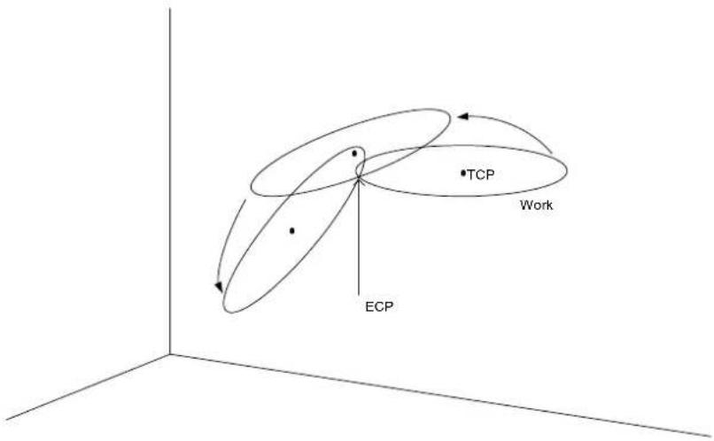
Setting Speed and Acceleration for Arc Motion
SpeedS and AccelS are used to set speed and acceleration for the Arc and Arc3 instructions. SpeedS and AccelS allow the user to specify a velocity in mm/sec and acceleration in mm/sec^2.
Notes
Arc Instruction works in Horizontal Plane Only
The Arc path is a true arc in the Horizontal plane. The path is interpolated using the values for endPoint as its basis for Z and U. Use Arc3 for 3 dimensional arcs.
Range Verification for Arc Instruction
The Arc and Arc3 statements cannot compute a range verification of the trajectory prior to the arc motion. Therefore, even for target positions that are within an allowable range, en route the robot may attempt to traverse a path which has an invalid range, stopping with a severe shock which may damage the arm. To prevent this from occurring, be sure to perform range verifications by running the program at low speeds prior to running at faster speeds.
Suggested Motion to Setup for the Arc Move
Because the arc motion begins from the current position, it may be necessary to use the Go, Jump or other related motion command to bring the robot to the desired position prior to executing Arc or Arc3.
Using Arc, Arc3 with CP
The CP parameter causes the arm to move to the end point without decelerating or stopping at the point defined by endPoint. This is done to allow the user to string a series of motion instructions together to cause the arm to move along a continuous path while maintaining a specified speed throughout all the motion. The Arc and Arc3 instructions without CP always cause the arm to decelerate to a stop prior to reaching the end point.
Potential Errors
Changing Hand Attributes
Pay close attention to the HAND attributes of the points used with the Arc instruction. If the hand orientation changes (from Right Handed to Left Handed or vice-versa) during the circular interpolation move, an error will occur. This means the arm attribute (/L Lefty, or /R Righty) values must be the same for the current position, midPoint and endPoint points.
Attempt to Move Arm Outside Work Envelope
If the specified circular motion attempts to move the arm outside the work envelope of the arm, an error will occur.
See Also
!Parallel Processing!, AccelS, Move, SpeedS
Arc Example
The diagram below shows arc motion which originated at the point P100 and then moves through P101 and ends up at P102. The following function would generate such an arc:
Function ArcTest
Go P100
Arc P101, P102
Fend
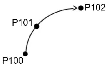
Tip
When first trying to use the Arc instruction, it is suggested to try a simple arc with points directly in front of the robot in about the middle of the work envelope. Try to visualize the arc that would be generated and make sure that you are not teaching points in such a way that the robot arm would try to move outside the normal work envelope.
Arch Statement
Defines or displays the Arch parameters for use with the Jump, Jump3, Jump3CP instructions.
Syntax
(1) Arch archNumber, departDist, approDist (2) Arch archNumber (3) Arch
Parameters
archNumber Integer expression representing the Arch number to define. Valid Arch numbers are (0-6) making a total of 7 entries into the Arch table. (see default Arch Table below)
departDist: The vertical distance moved (Z) at the beginning of the Jump move before beginning horizontal motion. (specified in millimeters)
approDist: The vertical distance required (as measured from the Z position of the point the arm is moving to) to move in a completely vertical fashion with all horizontal movement complete. (specified in millimeters)
Return Values
Displays Arch Table when used without parameters.
The Arch table of the specified Arch number will be displayed when only the Arch number is specified.
Description
The primary purpose of the Arch instruction is to define values in the Arch Table which is required for use with the Jump motion instruction. The Arch motion is carried out per the parameters corresponding to the arch number selected in the Jump C modifier. (To completely understand the Arch instruction, the user must first understand the Jump instruction.)
The Arch definitions allow the user to "round corners" in the Z direction when using the Jump C instruction. While the Jump instruction specifies the point to move to (including the final Z joint position), the Arch table entries specify how much distance to move up before beginning horizontal motion (riseDist) and how much distance up from the final Z joint position to complete all horizontal motion (fallDist). (See diagram below)
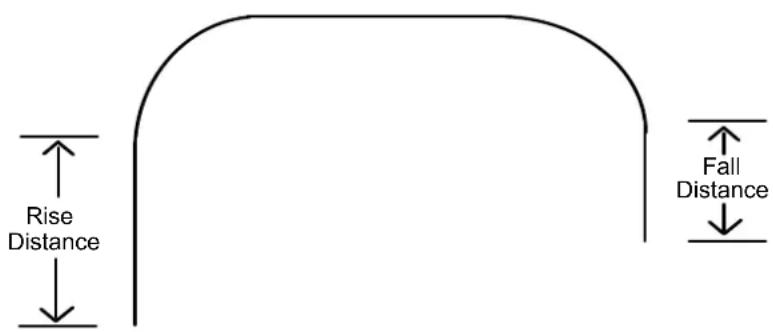
There are a total of 8 entries in the Arch Definition Table with 7 of them (0-6) being user definable. The 8th entry (Arch 7) is the default Arch which actually specifies no arch at all which is referred to as Gate Motion. (See Gate Motion diagram below) The Jump instruction used with the default Arch entry (Entry 8) causes the arm to do the following:
1) Begin the move with only Z-joint motion until it reaches the Z-Coordinate value specified by the LimZ command. (The upper Z value) 2) Next move horizontally to the target point position until the final X, Y and U positions are reached. 3) The Jump instruction is then completed by moving the arm down with only Z-joint motion until the target Z-joint position is reached.
Gate Motion (Jump with Arch 7)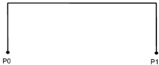
Arch Table Default Values:
| Arch Number | Depart Distance | Approach Distance |
| 0 | 30 | 30 |
| 1 | 40 | 40 |
| 2 | 50 | 50 |
| 3 | 60 | 60 |
| 4 | 70 | 70 |
| 5 | 80 | 80 |
| 6 | 90 | 90 |
Notes
Jump Motion trajectory changes depending on motion and speed
Jump motion trajectory is comprised of vertical motion and horizontal motion. It is not a continuous path trajectory. The actual Jump trajectory of arch motion is not determined by Arch parameters alone. It also depends on motion and speed.
Always use care when optimizing Jump trajectory in your applications. Execute Jump with the desired motion and speed to verify the actual trajectory.
When speed is lower, the trajectory will be lower. If Jump is executed with high speed to verify an arch motion trajectory, the end effector may crash into an obstacle with lower speed.
In a Jump trajectory, the depart distance increases and the approach distance decreases when the motion speed is set high. When the fall distance of the trajectory is shorter than expected, lower the speed and/or the deceleration, or change the fall distance to be larger.
Even if Jump commands with the same distance and speed are executed, the trajectory is affected by motion of the robot arms. As a general example, for a SCARA robot the vertical upward distance increases and the vertical downward distance decreases when the movement of the first arm is large. When the vertical fall distance decreases and the trajectory is shorter than expected, lower the speed and/or the deceleration, or change the fall distance to be larger.
Another Cause of Gate Motion
When the specified value of the Rising Distance or Falling Distance is larger than the actual Z-joint distance which the robot must move to reach the target position, Gate Motion will occur. (i.e. no type Arch motion will occur.)
Arch values are Maintained
The Arch Table values are permanently saved and are not changed until either the user changes them.
See Also
Jump, Jump3, JumpCP
Arch Example
The following are examples of Arch settings done from the command window.
> arch 0, 15, 15
> arch 1, 25, 50
> jump p1 c1
> arch
    arch0 = 15.000    15.000
    arch1 = 25.000    50.000
    arch2 = 50.000    50.000
    arch3 = 60.000    60.000
    arch4 = 70.000    70.000
    arch5 = 80.000    80.000
    arch6 = 90.000    90.000
>
Arch Function
Returns arch settings.
Syntax
Arch(archNumber, paramNumber)
Parameters
archNumber Integer expression representing arch setting to retrieve parameter from (0 to 6).
paramNumber 1: depart distance
2: approach distance
Return Value
Real number containing distance.
See Also
Arch statement
Arch Function Example
Real archValues(6, 1)
Integer i
' Save current arch values
For i = 0 to 6
    archValues(i, 0) = Arch(i, 1)
    archValues(i, 1) = Arch(i, 2)
Next i
Arm Statement
Selects or displays the arm number to use.
Syntax
(1) Arm armNumber (2) Arm
Parameters
armNumber
Optional integer expression. Valid range is from 0 to 15. The user may select up to 16 different arms. Arm 0 is the standard (default) robot arm. Arms 1 through 15 are auxiliary arms defined by using the ArmSet instruction. When omitted, the current arm number is displayed.
Return Values
When the Arm instruction is executed without parameters, the system displays the current arm number.
Description
Allows the user to specify which arm to use for robot instructions. Arm allows each auxiliary arm to use common position data. If no auxiliary arms are installed, the standard arm (arm number 0) operates. Since at the time of delivery the arm number is specified as 0, it is not necessary to use the Arm instruction to select an arm. However, if auxiliary arms are used, they must first be defined with the ArmSet instruction.
The auxiliary arm configuration capability is provided to allow users to configure the proper robot parameters for their robots when the actual robot configuration is a little different from the standard robot. For example, if the user mounted a 2nd orientation joint to the 2nd robot link, the user will probably want to define the proper robot linkages for the new auxiliary arm that is formed. This will allow the auxiliary arm to function properly under the following conditions:
- Specifying that a single data point be moved through by 2 or more arms.
- Using Pallet
- Using Continuous Path motion
- Using relative position specifications
- Using Local coordinates
For SCARA robots (including RS series) with rotating joints used with a Cartesian coordinate system, joint angle calculations are based on the parameters defined by the ArmSet parameters. Therefore, this command is critical if any auxiliary arm or hand definition is required.
Notes
Arm 0
Arm 0 cannot be defined or changed by the user through the ArmSet instruction. It is reserved since it is used to define the standard robot configuration. When the user sets Arm to 0, this means to use the standard robot arm parameters.
Arm Number Not Defined
Selecting auxiliary arm numbers that have not been defined by the ArmSet command will result in an error.
See Also
ArmClr, ArmSet, ECPSet, TLSet
Arm Statement Example
The following examples are potential auxiliary arm definitions using the ArmSet and Arm instructions. ArmSet defines the auxiliary arm and Arm defines which Arm to use as the current arm. (Arm 0 is the default robot arm and cannot be adjusted by the user.)
From the command window:
> ArmSet 1, 300, -12, -30, 300, 0
> ArmSet
    arm0 250 0 0 300 0
    arm1 300 -12 -30 300 0
> Arm 0
> Jump P1 'Jump to P1 using the Standard Arm Config
> Arm 1
> Jump P1 'Jump to P1 using auxiliary arm 1
Arm Function
Returns the current arm number for the current robot.
Syntax
Arm
Return Values
Integer containing the current arm number.
See Also
Arm Statement
Arm Function Example
Print "The current arm number is: ", Arm
ArmClr Statement
Clears (undefines) an arm definition.
Syntax
ArmClr armNumber
Parameters
armNumber
Integer expression representing which of 15 arms to clear (undefine). (Arm 0 is the default arm and cannot be cleared.)
See Also
Arm, ArmSet, ECPSet, Local, LocalClr, Tool, TLSet
ArmClr Example
ArmClr 1
ArmDef Function
Returns arm definition status.
Syntax
ArmDef (armNumber)
Parameters
armNumber Integer expression representing which arm to return status for.
Return Values
True if the specified arm has been defined, otherwise False.
See Also
Arm, ArmClr, ArmSet, ECPSet, Local, LocalClr, Tool, TLCIr, TLSet
ArmDef Example
Function DisplayArmDef(armNum As Integer)
    Integer i
    If ArmDef(armNum) = False Then
    Print "Arm ", ArmNum, "is not defined"
    Else
    Print "Arm ", armNum, " Definition:"
    For i = 1 to 5
    Print ArmSet(armNum, i)
    Next i
    EndIf
Fend
ArmSet Statement
Specifies and displays auxiliary arms.
Syntax
(1) ArmSet armNumber, link2Dist, joint2Offset, zOffset, [link1Dist], [orientAngOffset] (2) ArmSet armNumber (3) ArmSet
Parameters
armNumber Integer expression: Valid range from 1-15. The user may define up to 15 different auxiliary arms.
SCARA Robots (including RS series)
paramNumber Description
1 Horizontal distance from joint #2 to orientation center (mm) 2 Joint #2 angle offset (degree) 3 Height offset (mm) 4 Horizontal distance from joint #1 to joint #2 (mm) 5 Orientation joint angle offset in degrees.
Return Values
When the ArmSet instruction is initiated without parameters, the system displays all the auxiliary arm numbers and parameters.
The specified arm numbers and parameters will be displayed when only the arm number is specified.
Description
Allows the user to specify auxiliary arm parameters to be used in addition to the standard arm configuration. This is most useful when an auxiliary arm or hand is installed to the robot. When using an auxiliary arm, the arm is selected by the Arm instruction.
The link1Dist and orientAngOffset parameters are optional. If they are omitted, the default values are the standard arm values.
The auxiliary arm configuration capability is provided to allow users to configure the proper robot parameters for their robots when the actual robot configuration is a little different than the standard robot. For example, if the user mounted a 2nd orientation joint to the 2nd robot link, the user will probably want to define the proper robot linkages for the new auxiliary arm which is formed. This will allow the auxiliary arm to function properly under the following conditions:
- Specifying that a single data point be moved through by 2 or more arms.
- Using Pallet
- Using Continuous Path motion
- Using relative position specifications
- Using Local coordinates
For SCARA robots (including RS series) with rotating joints used with a Cartesian coordinate system, joint angle calculations are based on the parameters defined by the ArmSet parameters. Therefore, this command is critical if any auxiliary arm or hand definition is required.
Notes
Arm 0
Arm 0 cannot be defined or changed by the user. It is reserved since it is used to define the standard robot configuration. When the user sets Arm to 0 this means to use the standard robot arm parameters.
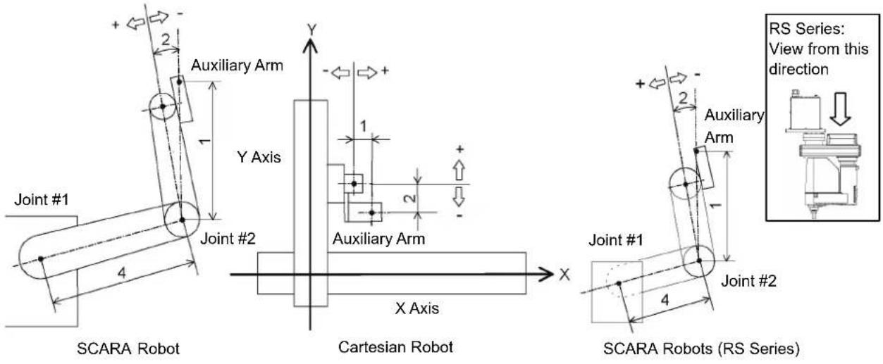
See Also
Arm, ArmClr
ArmSet Statement Example
The following examples are potential auxiliary arm definitions using the ArmSet and Arm instructions. ArmSet defines the auxiliary arm and Arm defines which Arm to use as the current arm. (Arm 0 is the default robot arm and cannot be adjusted by the user.)
From the command window:
> ArmSet 1, 300, -12, -30, 300, 0
> ArmSet
Arm 0: 125.000, 0.000, 0.000, 225.000, 0.000
Arm 1: 300.000, -12.000, -30.000, 300.000, 0.000
> Arm 0
> Jump P1 'Jump to P1 using the Standard Arm Config
> Arm 1
> Jump P1 'Jump to P1 using auxiliary arm 1
ArmSet Function
Returns one ArmSet parameter.
Syntax
ArmSet(armNumber, paramNumber)
Parameters
armNumber Integer expression representing the arm number to retrieve values for.
paramNumber Integer expression representing the parameter to retrieve (0 to 5), as described below.
SCARA Robots (including RS series)
paramNumber Value Returned
1 Horizontal distance from joint #2 to orientation center (mm) 2 Joint #2 angle offset (degree) 3 Height offset (mm) 4 Horizontal distance from joint #1 to joint #2 (mm) 5 Orientation joint angle offset in degrees.
Return Values
Real number containing the value of the specified parameter, as described above.
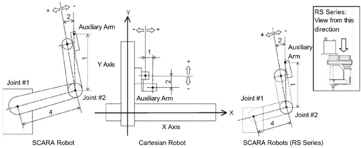
See Also
ArmClr, ArmSet Statement
ArmSet Function Example
Real x
x = ArmSet(1, 1)
Asc Function
Returns the ASCII value of the first character in a character string.

Syntax
Asc(string)
Parameters
string Any valid string expression of at least 1 character in length.
Return Values
Returns an integer representing the ASCII value of the 1st character in the string sent to the ASC function.
Description
The Asc function is used to convert a character to its ASCII numeric representation. The character string sent to the ASC function may be a constant or a variable.
Notes
Only the First Character ASCII Value is Returned
Although the Asc instruction allows character strings larger than 1 character in length, only the 1st character is actually used by the Asc instruction. Asc returns the ASCII value of the 1st character only.
See Also
Chr, InStr, Left, Len, Mid, Right, Space, Str, Val
Asc Function Example
This example uses the Asc instruction in a program and from the command window as follows:
Function asctest
    Integer a, b, c
    a = Asc("a")
    b = Asc("b")
    c = Asc("c")
    Print "The ASCII value of a is ", a
    Print "The ASCII value of b is ", b
    Print "The ASCII value of c is ", c
Fend
From the command window:
>print asc("a")
97
>print asc("b")
98
>
Asin Function
Returns the arcsine of a numeric expression.

Syntax
Asin(number)
Parameters
number Numeric expression representing the sine of an angle.
Return Values
Real value, in radians, representing the arc sine of the parameter number.
Description
Asin returns the arcsine of the numeric expression. Values range is from -1 to 1. The value returned by Asin will range from -PI / 2 to PI / 2 radians. If number is < -1 or > 1, an error occurs.
To convert from radians to degrees, use the RadToDeg function.
See Also
Abs, Acos, Atan, Atan2, Cos, DegToRad, RadToDeg, Sgn, Sin, Tan, Val
Asin Function Example
Function asintest
    Double x
    x = Sin(DegToRad(45))
    Print "Asin of ", x, " is ", Asin(x)
Fend
AtHome Function
Returns if the current robot is in its Home position or not.

Syntax
AtHome
Return Values
True if the current robot is in its Home position, otherwise False.
Description
The AtHome function returns if the current robot is in its Home position or not. To register the Home position, use HomeSet command or Robot Manager. To move to the Home position, use the Home command.
See Also
Home, HomeClr, HomeDef, HomeSet, Hordr, MCalComplete
Atan Function
Returns the arctangent of a numeric expression.

Syntax
Atan(number)
Parameters
number Numeric expression representing the tangent of an angular value.
Return Values
Real value, in radians, representing the arctangent of the parameter number.
Description
Atan returns the arctangent of the numeric expression. The numeric expression (number) may be any numeric value. The value returned by Atan will range from -PI to PI radians.
To convert from radians to degrees, use the RadToDeg function.
See Also
Abs, Acos, Asin, Atan2, Cos, DegToRad, RadToDeg, Sgn, Sin, Tan, Val
Atan Function Example
Function atantest
    Real x, y
    x = 0
    y = 1
    Print "Atan of ", x, " is ", Atan(x)
    Print "Atan of ", y, " is ", Atan(y)
Fend
Atan2 Function
Returns the angle of the imaginary line connecting points (0,0) and (X,Y) in radians.

Syntax
Atan2(X, Y)
Parameters
| X | Numeric expression representing the X coordinate. |
| Y | Numeric expression representing the Y coordinate. |
Return Values
Numeric value in radians (-PI to +PI).
Description
Atan2(X, Y) returns the angle of the line which connects points (0, 0) and (X, Y). This trigonometric function returns an arctangent angle in all four quadrants.
See Also
Abs, Acos, Asin, Atan, Cos, DegToRad, RadToDeg, Sgn, Sin, Tan, Val
Atan2 Function Example
Function at2test
Real x, y
Print "Please enter a number for the X Coordinate:"
Input x
Print "Please enter a number for the Y Coordinate:"
Input y
Print "Atan2 of ", x, ", ", y, " is ", Atan2(x, y)
Fend
ATCLR Statement
Clears and initializes the average torque for one or more joints.
Syntax
ATCLR [j1], [j2], [j3], [j4], [j5], [j6], [j7], [j8], [j9]
Parameters
j1-j9
Optional. Integer expression representing the joint number. If no parameters are supplied, then the average torque values are cleared for all joints.
The additional S axis is 8 and T axis is 9.
Description
ATCLR clears the average torque values for the specified joints.
You must execute ATCLR before executing ATRQ.
See Also
ATRQ, PTRQ
ATCLR Statement Example
> atclr
> go p1
> atrq 1
0.028
> atrq
0.028 0.008
0.029 0.009
0.000 0.000
>
ATRQ Statement
Displays the average torque for the specified joint.
Syntax
ATRQ [jointNumber]
Parameters
jointNumber
Optional. Integer expression representing the joint number.
The additional S axis is 8 and T axis is 9.
Return Values
Displays current average torque values for all joints.
Description
ATRQ displays the average RMS (root-mean-square) torque of the specified joint. The loading state of the motor can be obtained by this instruction. The result is a real value from 0 to 1 with 1 being maximum average torque.
You must execute ATCLR before this command is executed.
This instruction is time restricted. You must execute ATRQ within 60 seconds after ATCLR is executed. When this time is exceeded, error 4030 occurs.
See Also
ATCLR, ATRQ Function, PTRQ
ATRQ Statement Example
> atclr
> go p1
> atrq 1
0.028
> atrq
0.028 0.008
0.029 0.009
0.000 0.000
>
ATRQ Function
Returns the average torque for the specified joint.

Syntax
ATRQ (jointNumber)
Parameters
jointNumber Integer expression representing the joint number. The additional S axis is 8 and T axis is 9.
Return Values
Real value from 0 to 1.
Description
The ATRQ function returns the average RMS (root-mean-square) torque of the specified joint. The loading state of the motor can be obtained by this instruction. The result is a real value from 0 to 1 with 1 being maximum average torque.
You must execute ATCLR before this function is executed.
This instruction is time restricted. You must execute ATRQ within 60 seconds after ATCLR is executed. When this time is exceeded, error 4030 occurs.
See Also
ATRQ Statement, PTCLR, PTRQ Statement
ATRQ Function Example
This example uses the ATRQ function in a program:
Function CheckAvgTorque
    Integer i

    Go P1
    ATCLR
    Go P2
    Print "Average torques:"
    For i = 1 To 4
    Print "Joint ", i, " = ", ATRQ(i)
    Next i
Fend
AutoLJM Statement
Sets the Auto LJM function.

Syntax
AutoLJM { On | Off }
Parameter
On | Off On: Enables the Auto LJM.
Off: Disables the Auto LJM.
Description
AutoLJM is available for the following commands.
Arc, Arc3, Go, Jump3, Jump3CP, Move
When AutoLJM is On, the manipulator operates with a least joint motion, just like using the LJM function, whether the LJM function is applied to the position data to be passed to each command or not. For example, to get the same effect as Go LJM(P1), you can write a program as follows.
AutoLJM On
Go P1
AutoLJM Off
Since AutoLJM can enable LJM within a particular section of a program, it is not necessary to edit each motion command.
When AutoLJM is Off, the LJM function is only enabled when it is applied to the position data to be passed to each motion command.
In any of the following cases, AutoLJM has the setting specified in the controller settings (factory default: Off).
Controller startup
Reset
All task stop
Motor On
Switching the Auto / Programming operation mode
Notes
Double application of AutoLJM and LJM function
If the LJM function is applied to the point data to be passed to the motion command while AutoLJM is On, LJM will be doubly applied at the command execution.
For Move LJM(P1, Here) and Move LJM(P1), enabling AutoLJM will not affect the motion. However, if AutoLJM is enabled for Move LJM(P1, P0), the motion completion positions of Move LJM(LJM(P1, P0), Here) with AutoLJM enabled and the one of Move LJM(P1, P0) without AutoLJM enabled may be different.
It is recommended to write a program so as not to duplicate AutoLJM and LJM functions.
AutoLJM Usage Precaution
You can set the AutoLJM function to be enabled at the controller startup by setting the controller preferences. However, if AutoLJM is enabled at all times by controller preferences or commands, this function automatically adjusts the posture of the manipulator to reduce the motion distance, even when you intended to move the joint widely. Therefore, it is recommended to create a program to apply the LJM function only when necessary by using the LJM function or the AutoLJM command.
See Also
AutoLJM Function, LJM Function
AutoLJM example
AutoLJM On
Go P1
Go P2
AutoLJM Off
AutoLJM Function
Returns the state of the AutoLJM.
F
Syntax
AutoLJM
Return Values
0 = Auto LJM OFF
1 = Auto LJM ON
See Also
AutoLJM
AutoLJM Function Example
If AutoLJM = Off Then
    Print "AutoLJM is off"
End If
AvoidSingularity Statement
Sets the singularity avoiding function.
S
Syntax
AvoidSingularity { 1 | 0 }
Parameter
1 | 0 1: Enables the singularity avoiding function. 0: Disables the singularity avoiding function.
Description
AvoidSingularity is available for the following commands: Move, Arc, Arc3.
A singularity avoiding function is to prevent acceleration errors when the vertical 6-axis robot approaches the singularity in CP motion by passing a different trajectory and returning to the original trajectory after passing the singularity. This function is only applicable for the wrist singularity. Since the singularity avoiding function is usually set to "1: Enabled" at the controller startup, it is not necessary to change the setting. If you do not want a singularity avoidance to ensure compatibility with software which does not support the singularity avoiding function, or to avoid a trajectory gap, disable the function.
If the AvoidSingularity parameter is changed, this function remains enabled until the next controller startup.
At the controller startup, AvoidSingularity has the setting specified in the controller setting (factory default: 1).
Notes
Condition setting of singularity neighborhood
To determine whether the manipulator approaches the singularity neighborhood, angle of Joint #5 and angular velocity of Joint #4 are used. By default, Joint #5 angle is set to ±5 degrees, and Joint #4 angle is set to ±10% with respect to the maximum joint velocity. To change these settings, use SingularityAngle and SingularitySpeed commands.
See Also
AvoidSingularity Function, SingularityAngle, SingularitySpeed
AvoidSingularity Example
AvoidSingularity 0 'Disables the singularity avoidance and operate the manipulator
Move P1
Move P2
AvoidSingularity 1
AvoidSingularity Function
Returns the state of AvoidSingularity.

Syntax
AvoidSingularity
Return values
0 = Singularity avoiding function disabled
1 = Singularity avoiding function enabled
See also
AvoidSingularity
AvoidSingularity Function Example
If AvoidSingularity = Off Then
    Print "AvoidSingularity is off"
End If
Base Statement
Defines and displays the base coordinate system.
Syntax
(1) Base pCoordinateData (2) Base pOrigin, pXaxis, pYaxis, [ { X | Y } ]
Parameters
| pCoordinateData | Point data representing the coordinate data of the origin and direction. |
| pOrigin | Integer expression representing the origin point using robot coordinate system. |
| pXaxis | Integer expression representing a point along the X axis using robot coordinate system if X alignment is specified. |
| pYaxis | Integer expression representing a point along the Y axis using robot coordinate system if Y alignment is specified. |
| X|Y | Optional. If X alignment is specified, then pXaxis is on the X axis of the new coordinate system and only the Z coordinate of pYaxis is used. If Y alignment is specified, then pYaxis is on the Y axis of the new coordinate system and only the Z coordinate of pXaxis is used. If omitted, X alignment is assumed. |
Description
Defines the robot base coordinate system by specifying base coordinate system origin and rotation angle in relation to the robot absolute coordinate system.
To reset the Base coordinate system to default, execute the following statement. This will make the base coordinate system the same as the robot absolute coordinate system.
Base XY(0, 0, 0, 0)
Notes
Changing the base coordinate system affects all local definitions
When base coordinates are changed, all local coordinate systems must be re-defined.
See Also
Local
Base Statement Example
Define base coordinate system origin at 100 mm on X axis and 100 mm on Y axis
Base XY(100, 100, 0, 0)
BCIr Function
Clear one bit in a number and return the new value

Syntax
BCIr (number, bitNum)
Parameters
number Specifies the numeric value to clear the bit by an expression or numeric value.
bitNum Specifies the bit (integer from 0 to 31) to be cleared by an expression or numeric value.
Return Values
Returns the new value of the specified numeric value (integer).
See Also
BSet, BTst
BCIr Example
flags = BClr(flags, 1)
BGo Statement
Executes Point to Point relative motion, in the selected local coordinate system.
Syntax
BGo destination [CP] [searchExpr] [!...!] [SYNC]
Parameters
destination The target destination of the motion using a point expression.
CP Optional. Specifies continuous path motion.
searchExpr Optional. A Till or Find expression.
Till | Find
Till Sw(expr) = {On | Off}
Find Sw(expr) = {On | Off}
!...! Optional. Parallel Processing statements can be added to execute I/O and other commands during motion.
SYNC Reserves a motion command. The robot will not move until SyncRobots is executed.
Description
Executes point to point relative motion, in the selected local coordinate system that is specified in the destination point expression.
If a local coordinate system is not specified, relative motion will occur in local 0 (base coordinate system).
Arm orientation attributes specified in the destination point expression are ignored. The manipulator keeps the current arm orientation attributes. However, for a 6-Axis manipulator, the arm orientation attributes are automatically changed in such a way that joint travel distance is as small as possible.
The Till modifier is used to complete BGo by decelerating and stopping the robot at an intermediate travel position if the current Till condition is satisfied.
The Find modifier is used to store a point in FindPos when the Find condition becomes true during motion.
When Till is used and the Till condition is satisfied, the manipulator halts immediately and the motion command is finished. If the Till condition is not satisfied, the manipulator moves to the destination point.
When Find is used and the Find condition is satisfied, the current position is stored. Please refer to Find for details.
When parallel processing is used, other processing can be executed in parallel with the motion command.
The CP parameter causes acceleration of the next motion command to start when the deceleration starts for the current motion command. In this case the robot will not stop at the destination coordinate and will continue to move to the next point.
See Also
Accel, BMove, Find, !.....! Parallel Processing, Point Assignment, Speed, Till, TGo, TMove, Tool
BGo Example
> BGo XY(100, 0, 0, 0) 'Move 100mm in X direction
'(in the local coordinate system)

Function BGoTest

Speed 50
Accel 50, 50
Power High

P1 = XY(300, 300, -20, 0)
P2 = XY(300, 300, -20, 0) /L
Local 1, XY(0, 0, 0, 45)

GoP1
Print Here
BGo XY(0, 50, 0, 0)
Print Here

Go P2
Print Here
BGo XY(0, 50, 0, 0)
Print Here

BGo XY(0, 50, 0, 0) /1
Print Here

Fend

[Output]
X: 300.000 Y: 300.000 Z: -20.000 U: 0.000 V: 0.000 W: 0.000 /R /0
X: 300.000 Y: 350.000 Z: -20.000 U: 0.000 V: 0.000 W: 0.000 /R /0
X: 300.000 Y: 300.000 Z: -20.000 U: 0.000 V: 0.000 W: 0.000 /L /0
X: 300.000 Y: 350.000 Z: -20.000 U: 0.000 V: 0.000 W: 0.000 /L /0
X: 264.645 Y: 385.355 Z: -20.000 U: 0.000 V: 0.000 W: 0.000 /L /O
BMove Statement
Executes linear interpolation relative motion, in the selected local coordinate system
Syntax
BMove destination [ROT] [CP] [searchExpr] [!...!] [SYNC]
Parameters
destination The target destination of the motion using a point expression.
ROT Optional. :Decides the speed/acceleration/deceleration in favor of tool rotation.
CP Optional. Specifies continuous path motion.
searchExpr Optional. A Till or Find expression.
Till | Find
Till Sw(expr) = {On | Off}
Find Sw(expr) = {On | Off}
!...! Optional. Parallel Processing statements can be added to execute I/O and other commands during motion.
SYNC Reserves a motion command. The robot will not move until SyncRobots is executed.
Description
Executes linear interpolated relative motion, in the selected local coordinate system that is specified in the destination point expression.
If a local coordinate system is not specified, relative motion will occur in local 0 (base coordinate system).
Arm orientation attributes specified in the destination point expression are ignored. The manipulator keeps the current arm orientation attributes. However, for a 6-Axis manipulator, the arm orientation attributes are automatically changed in such a way that joint travel distance is as small as possible.
BMove uses the SpeedS speed value and AccelS acceleration and deceleration values. Refer to Using BMove with CP below on the relation between the speed/acceleration and the acceleration/deceleration. If, however, the ROT modifier parameter is used, BMove uses the SpeedR speed value and AccelR acceleration and deceleration values. In this case SpeedS speed value and AccelS acceleration and deceleration value have no effect.
Usually, when the move distance is 0 and only the tool orientation is changed, an error will occur. However, by using the ROT parameter and giving priority to the acceleration and the deceleration of the tool rotation, it is possible to move without an error. When there is not an orientational change with the ROT modifier parameter and movement distance is not 0, an error will occur.
Also, when the tool rotation is large as compared to move distance, and when the rotation speed exceeds the specified speed of the manipulator, an error will occur. In this case, please reduce the speed or append the ROT modifier parameter to give priority to the rotational speed/acceleration/deceleration.
The Till modifier is used to complete BMove by decelerating and stopping the robot at an intermediate travel position if the current Till condition is satisfied.
The Find modifier is used to store a point in FindPos when the Find condition becomes true during motion.
When Till is used and the Till condition is satisfied, the manipulator halts immediately and the motion command is finished. If the Till condition is not satisfied, the manipulator moves to the destination point.
When Find is used and the Find condition is satisfied, the current position is stored. Please refer to Find for details.
When parallel processing is used, other processing can be executed in parallel with the motion command.
Notes
Using BMove with CP
The CP parameter causes the arm to move to destination without decelerating or stopping at the point defined by destination. This is done to allow the user to string a series of motion instructions together to cause the arm to move along a continuous path while maintaining a specified speed throughout all the motion. The BMove instruction without CP always causes the arm to decelerate to a stop prior to reaching the point destination.
See Also
AccelS, BGo, Find, !.....! Parallel Processing, Point Assignment, SpeedS, TGo, Till, TMove, Tool
BMove Example
> BMove XY(100, 0, 0, 0) 'Move 100mm in the X
'direction (in the local coordinate system)

Function BMoveTest

Speed 50
Accel 50, 50
SpeedS 100
AccelS 1000, 1000
Power High

P1 = XY(300, 300, -20, 0)
P2 = XY(300, 300, -20, 0) /L
Local 1, XY(0, 0, 0, 45)

Go P1
Print Here
BMove XY(0, 50, 0, 0)
Print Here

Go P2
Print Here
BMove XY(0, 50, 0, 0)
Print Here

BMove XY(0, 50, 0, 0) /1
Print Here

Fend

[Output]
X: 300.000 Y: 300.000 Z: -20.000 U: 0.000 V: 0.000 W: 0.000 /R /O
X: 300.000 Y: 350.000 Z: -20.000 U: 0.000 V: 0.000 W: 0.000 /R /O
X: 300.000 Y: 300.000 Z: -20.000 U: 0.000 V: 0.000 W: 0.000 /L /O
X: 300.000 Y: 350.000 Z: -20.000 U: 0.000 V: 0.000 W: 0.000 /L /O
X: 264.645 Y: 385.355 Z: -20.000 U: 0.000 V: 0.000 W: 0.000 /L /O
Boolean Statement
Declares variables of type Boolean. (1 byte whole number).
s
Syntax
Boolean varName [(subscripts)], [varName [(subscripts)]...]
Parameters
varName Variable name which the user wants to declare as type Boolean.
subscripts Optional. Dimensions of an array variable; up to 3 dimensions may be declared. The subscripts syntax is as follows
(ubound1, [ubound2], [ubound3])
ubound1, ubound2, ubound3 each specify the maximum upper bound for the associated dimension.
The elements in each dimension of an array are numbered from 0 and the available number of array elements is the upper bound value + 1.
When specifying the upper bound value, make sure the number of total elements is within the range shown below:
Local variable 2000
Global Preserve variable 4000
Global variable and module variable 100000
Description
Boolean is used to declare variables as type Boolean. Variables of type Boolean can contain one of two values, False and True. Local variables should be declared at the top of a function. Global and module variables must be declared outside of functions.
See Also
Byte, Double, Global, Integer, Long, Real, String
Boolean Statement Example
Boolean partOK
Boolean A(10) 'Single dimension array of boolean
Boolean B(10, 10) 'Two dimension array of boolean
Boolean C(5, 5, 5) 'Three dimension array of boolean
partOK = CheckPart()
If Not partOK Then
    Print "Part check failed"
EndIf
BOpen Statement
Opens file in binary mode.

Syntax
BOpen fileName As #fileNumber
:
Close #fileNumber
Parameters
fileName String expression that specifies valid path and file name. If specifying only a file name, the file must be in the current directory. See ChDisk for the details.
fileNumber Integer expression representing values from 30 - 63.
Description
Opens the specified file and identifies it by the specified file number. This statement is used for accessing the specified file in binary mode. If the specified file is not found, it will create a new file. If the file exists, it will read and write the data from the beginning. Use the ReadBin and WriteBin commands to read and write data in binary mode.
Note
Do not use a network path, otherwise an error occurs.
The specified fileNumber identifies the file while it is open and cannot be used to refer to a different file until the current file is closed. fileNumber is used by other file operations such as ReadBin, WriteBin, Seek, Eof, Flush, and Close.
The read/write position (pointer) of the file can be changed using the Seek command. When switching between read and write access, use Seek to reposition the file pointer.
Use the Close statement to close the file and release the file number.
It is recommended that you use the FreeFile function to obtain the file number so that more than one task are not using the same number.
See Also
Close, AOpen, FreeFile, ReadBin, ROpen, UOpen, WOpen, WriteBin
BOpen Example
Integer fileNum, i

fileNum = FreeFile
BOpen "TEST.DAT" As #fileNum
For i = 0 To 100
    WriteBin #fileNum, i
Next i

Flush #fileNum
Seek #fileNum, 10
ReadBin #fileNum, i
Print "data = ", i
Close #fileNum
Box Statement
Specifies and displays the approach check area.
Syntax
(1) Box AreaNum, [robotNumber], minX, maxX, minY, maxY, minZ, maxZ (2) Box AreaNum, [robotNumber] (3) Box
Parameters
AreaNum: Integer expression representing the area number from 1 to 15.
| robotNumber | Optional. Integer expression that specifies which robot you want to configure. If omitted, the current robot number is used. |
| minX | The minimum X coordinate position which can be set to the approach check area. |
| maxX | The maximum X coordinate position which can be set to the approach check area. |
| minY | The minimum Y coordinate position which can be set to the approach check area. |
| maxY | The maximum Y coordinate position which can be set to the approach check area. |
| minZ The minimum Z coordinate position which can be set to the approach check area. | |
| maxZ | The maximum Z coordinate position which can be set to the approach check area. |
Return Values
When Syntax (2) is used, the area setting of the specified area is displayed.
When Syntax (3) is used, the area settings for all area numbers of the current robot are displayed.
Description
Box is used to set the approach check area. The approach check area is for checking approaches of the robot end effector in the approach check area. The position of the end effector is calculated by the current tool. The approach check area is set on the base coordinate system of the robot and is between the specified maximum and minimum X, Y, and Z.
When the approach check area is used, the system detects approaches in any motor power status during the controller is ON.
You can also use GetRobotInsideBox function or InsideBox function to get the result of the approach check. GetRobotInsideBox function can be used for wait condition of Wait command. You can provide the check result to the I/O by setting the remote output setting.
When several robots use one area, you should define the area from each robot coordinate system.
![graph LR A["Robot 1"] --> B["Box1"] B --> C["Robot 2"] D["Upper limit of axes X, Y, Z"] --> E["Robot 1"] F["Lower limit of axes X, Y, Z"] --> G["Robot 2"]](/content/2026/05/815116/images/f578540955cd166d1908f3303b1ad00d53ca26ca658936ef914029161382d361.jpg)
Configure the Box 1 from Robot 1 position
Box 1, 1, 100, 200, 0, 100, 0, 100
Lower limit of axes X, Y, Z is (100,0,0) and upper limit is (200,100,100)
Configure the Box 1 from Robot 2
Box 1, 2, -200, -100, 0, 100, 0, 100
Lower limit of axes X, Y, Z is (-200, 0, 0) and upper limit is (-100, 100, 100)
Notes
Turning Off Approach Check Area by Coordinate Axis
You can turn off the approach check area of each coordinate axis. To turn off only the Z axis, define the minZ and maxZ to be 0. For example: Box 1, 200, 300, 0, 500, 0, 0.
In this case, it checks if the robot end effector is in the XY dimensional area.
Default Values of Approach Check Area
The default values for the Box statement are "0, 0, 0, 0, 0, 0". (Approach Check Area Checking is turned off.)
Tool Selection
The approach check is executed for the current tool. When you change the tool, the approach check may display the tool approach from inside to outside of the area or the other way although the robot is not operating.
Additional Axis
For the robot which has the additional ST axis (including the running axis), the approach check plane to set doesn't depend on the position of additional axis, but is based on the robot base coordinate system.
Tip
Set Box Statement from Robot Manager
EPSON RC+ 6.0 has a point and click dialog box for defining the approach check area. The simplest method to set the Box values is by using the Box page on the Robot Manager.
See Also
BoxClr, BoxDef, GetRobotInsideBox, InsideBox, Plane
Box Statement Example
These are examples to set the approach check area using Box statement.
Box 1, -200, 300, 0, 500, -100, 0
Box
Box 1: -200.000, 300.000, 0.000, 500.000, -100.000, 0.000
Box Function
Returns the specified approach check area.

Syntax
Box(AreaNum, [robotNumber], limit)
Parameters
AreaNum Integer expression representing the area number from 1 to 15.
robotNumber Optional. Integer expression that specifies which robot you want to configure. If omitted, the current robot number is used.
limit Integer expression that specifies which limit to return.
1: Lower limit 2: Upper limit
Return Values
When you select 1 for limit, the point contains the lower limit of the X, Y, Z coordinates. When you select 2 for limit, the point contains the upper limit of the X, Y, Z coordinates.
See Also
Box, BoxClr, BoxDef, GetRobotInsideBox, InsideBox
Box Function Example
P1 = Box(1, 1)
P2 = Box(1, 2)
BoxClr Statement


Syntax
BoxClr AreaNum [,robotNumber]
Parameters
AreaNum Integer expression representing the area number from 1 to 15.
robotNumber Optional. Integer expression that specifies which robot you want to configure. If omitted, the current robot number is used.
See Also
Box, BoxDef, GetRobotInsideBox, InsideBox
BoxClr Function Example
This example uses the BoxClr function in a program.
Function ClearBox
    If BoxDef(1) = True Then
    BoxClr 1
    EndIf
Fend
BoxDef Function
Returns whether a Box has been defined or not.

Syntax
BoxDef(AreaNum) [, robotNumber]
Parameters
AreaNum: Integer expression representing an area number from 1 to 15. robotNumber: Integer expression representing a robot number you want to configure. If omitted, the current robot will be specified.
Return Values
True if the approach check area is defined for the specified area number, otherwise False.
See Also
Box, BoxClr, GetRobotInsideBox, InsideBox
BoxDef Function Example
This example uses the BoxDef function in a program.
Function ClearBox
    If BoxDef(1) = True Then
    BoxClr 1
    EndIf
Fend
Brake Statement
Turns brake on or off for specified joint of the current robot.

Syntax
Brake status, jointNumber
Parameters
status The keyword On is used to turn the brake on. The keyword Off is used to turn the brake off.
jointNumber The joint number from 1 to 6.
Description
The Brake command is used to turn brakes on or off for one joint of the 6-axis robot. It can only be executed as a command command. This command is intended for use by maintenance personnel only. When the Brake statement is executed, the robot control parameter is initialized.
See Motor On for the details.

■ Use extreme caution when turning off a brake. Ensure that the joint is properly supported, otherwise the joint can fall and cause damage to the robot and personnel.
Before releasing the brake, be ready to use the emergency stop switch so that you can immediately press it. When the controller is in emergency stop status, the motor brakes are locked. Be aware that the robot arm may fall by its own weight when the brake is turned off with Brake command.
See Also
Motor, Power, Reset, SFree, SLock
Brake Example
> brake on, 1
> brake off, 1
Brake Function
Returns brake status for specified joint.

Syntax
Brake (jointNumber)
Parameters
jointNumber Integer expression representing the joint number. Values are from 1 to the number of joints on the robot.
Return Values
0 = Brake off, 1 = Brake on.
See Also
Brake Statement
Brake Example
If Brake(1) = Off Then
    Print "Joint 1 brake is off"
End If
BSet Function
Sets a bit in a number and returns the new value.

Syntax
BSet (number, bitNum)
Parameters
number Specifies the value to set the bit with an expression or numeric value.
bitNum Specifies the bit (integer from 0 to 31) to be set by an expression or numeric value.
Return Values
Returns the bit set value of the specified numeric value (integer).
See Also
BCIr, BTst
BSet Example
flags = BSet(flags, 1)
BTst Function
Returns the status of 1 bit in a number.

Syntax
BTst (number, bitNum)
Parameters
number Specifies the number for the bit test with an expression or numeric value.
bitNum Specifies the bit (integer from 0 to 31) to be tested.
Return Values
Returns the bit test results (integer 1 or 0) of the specified numeric value.
See Also
BClr, Bset
BTst Example
If BTst(flags, 1) Then
    Print "Bit 1 is set"
End If
Byte Statement
Declares variables of type Byte. (2 byte whole number).
S
Syntax
Byte varName [(subscripts)] [, varName [(subscripts)]...]
Parameters
varName Variable name which the user wants to declare as type Byte.
subscripts Optional. Dimensions of an array variable; up to 3 dimensions may be declared. The subscripts syntax is as follows
(ubound1, [ubound2], [ubound3])
ubound1, ubound2, ubound3 each specify the maximum upper bound for the associated dimension.
The elements in each dimension of an array are numbered from 0 and the available number of array elements is the upper bound value + 1.
When specifying the upper bound value, make sure the number of total elements is within the range shown below:
Local variable 2000
Global Preserve variable 4000
Global variable and module variable 100000
Description
Byte is used to declare variables as type Byte. Variables of type Byte can contain whole numbers ranging in value from -128 to +127. Local variables should be declared at the top of a function. Global and module variables must be declared outside of functions.
See Also
Boolean, Double, Global, Integer, Long, Real, String
Byte Example
The following example declares a variable of type Byte and then assigns a value to it. A bitwise And is then done to see if the high bit of the value in the variable test_ok is On (1) or Off (0). The result is printed to the display screen. (Of course in this example the high bit of the variable test_ok will always be set since we assigned the variable the value of 15.)
Function Test
    Byte A(10) 'Single dimension array of byte
    Byte B(10, 10) 'Two dimension array of byte
    Byte C(5, 5, 5) 'Three dimension array of byte
    Byte test_ok
    test_ok = 15
    Print "Initial Value of test_ok = ", test_ok
    test_ok = (test_ok And 8)
    If test_ok <> 8 Then
    Print "test_ok high bit is ON"
    Else
    Print "test_ok high bit is OFF"
    EndIf
Fend
Calib Statement
Replaces the current arm posture pulse values with the current CalPIs values.
Syntax
Calib joint1, [joint2], [joint3], [joint4], [joint5], [joint6], [joint7], [joint8], [joint9]
Parameters
joint
Integer number from 1-9 that specifies the joint number to calibrate. While normally only one joint may need calibration at a time, up to all nine joints may be calibrated with the Calib command at the same time. Additional S axis is 8 and T axis is 9.
Description
Automatically calculates and specifies the offset (Hofs) value. This offset is necessary for matching the origin for each robot joint motor to the corresponding robot mechanical origin.
The Calib command should be used when the motor pulse value has changed. The most common occurrence for use is after changing a motor. Normally, the calibration position pulse values would match the CalPIs pulse values. However, after maintenance operations such as changing the motors, these two sets of values will no longer match, and therefore calibration becomes necessary.
Calibration may be accomplished by moving the arm to a desired calibration position, and then executing the Calib command. By executing Calib, the calibration position pulse value is changed to the CalPIs value, (the correct pulse value for the calibration position)
In order to perform a proper calibration, Hofs values must be determined. To have Hofs values automatically calculated, move the arm to the desired calibration position, and execute Calib. The controller automatically calculates Hofs values based on the calibration pulse values and on the CalPIs pulse values.
Notes
Use caution when using the Calib command
Calib is intended to be used for maintenance purposes only. Execute Calib only when necessary. Executing Calib causes the Hofs value to be replaced. Because unintended Hofs value changes can cause unpredictable robot motion, use caution in executing Calib only when necessary.
Potential Errors
No Joint Number Specified Error
If the joint number is not specified with the Calib command, an error will occur.
See Also
CalPIs, Hofs
Calib Example
Example from the monitor window.
> CalPls 'Display current CalPls values
65523 43320
-1550 21351
> Pulse 'Display current Pulse values
65526 49358
1542 21299
> Calib 2 'Execute calibration for joint 2 only
> Pulse 'Display (changed) Pulse values
65526 43320
-1542 21299
>
Call Statement
Calls a user function.
S
Syntax
Call funcName [(argList)]
Parameters
funcName The name of a Function which is being called.
argList
Optional. List of arguments that were specified in the Function declaration.
For the argument, use the following syntax:
[ByRef] varName [( )], or numerical expression
ByRef Optional. Specify ByRef when you refer to the variable to be seen by the calling function. In this case, the argument change in a function can be reflected to the variable of the calling side. You can change the values received as a reference.
Description
The Call instruction causes the transfer of program control to a function (defined in Function...Fend). This means that the Call instruction causes program execution to leave the current function and transfer to the function specified by Call. Program execution then continues in that function until an Exit Function or Fend instruction is reached. Control is then passed back to the original calling function at the next statement after the Call instruction.
You may omit the Call keyword and argument parentheses. For example, here is a call statement used with or without the Call keyword:
Call MyFunc(1, 2)
MyFunc 1, 2
You can call an external function in a dynamic link library (DLL). For details, refer to Declare Statement.
To execute a subroutine within a function, use GoSub...Return.
You can specify a variable as an argument. Specifying the ByRef parameter, you can reflect the change of argument in the function to the variable of the calling side.
When specifying the ByRef parameter, you need to specify ByRef as well for the argument list of the function definition (Function statement) and DLL function definition (Declare statement).
ByRef is necessary when giving an array variable as an argument.
See Also
Function, GoSub
Call Statement Example
<File1: MAIN.PRG>
Function main
Call InitRobot
Fend
<File2: INIT.PRG>
Function InitRobot
    If Motor = Off Then
    Motor On
    EndIf
    Power High
    Speed 50
    Accel 75, 75
Fend
CalPIs Statement
Specifies and displays the position and orientation pulse values for calibration.
Syntax
(1) CalPIs j1Pulses, j2Pulses, j3Pulses, j4Pulses, [j5Pulses, j6Pulses], [j7Pulses], [j8Pulses, j9Pulses] (2) CalPIs
Parameters
j1Pulses: First joint pulse value. This is a long integer expression. j2Pulses: Second joint pulse value. This is a long integer expression. j3Pulses: Third joint pulse value. This is a long integer expression. j4Pulses: Fourth joint pulse value. This is a long integer expression. j5Pulses: Optional. Fifth joint pulse value. This is a long integer expression. j6Pulses: Optional. Sixth joint pulse value. This is a long integer expression. j7Pulses: Optional. Seventh joint pulse value. This is a long integer expression. j8Pulses: Optional. Eighth joint pulse value. This is a long integer expression. j9Pulses: Optional. Ninth joint pulse value. This is a long integer expression.
Return Values
When parameters are omitted, displays the current CalPIs values.
Description
Specifies and maintains the correct position pulse value(s) for calibration.
CalPIs is intended to be used for maintenance, such as after changing motors or when motor zero position needs to be matched to the corresponding arm mechanical zero position. This matching of motor zero position to corresponding arm mechanical zero position is called calibration.
Normally, the calibration position pulse values match the CalPIs pulse values. However, after performing maintenance operations such as changing motors, these two sets of values no longer match, and therefore calibration becomes necessary.
Calibration may be accomplished by moving the arm to a certain calibration position and then executing Calib. By executing Calib, the calibration position pulse value is changed to the CalPIs value (the correct pulse value for the calibration position).
Hofs values must be determined to execute calibration. To have Hofs values automatically calculated, move the arm to the desired calibration position, and execute Calib. The controller automatically calculates Hofs values based on calibration position pulse values and on the CalPIs values.
Notes
CalPIs Values Cannot be Changed by cycling power
CalPIs values are not initialized by turning main power to the controller off and then on again. The only method to modify the CalPIs values is to execute the Calib command.
See Also
Calib, Hofs
CalPIs Function
Returns calibration pulse value specified by the CalPIs Statement.

Syntax
CalPIs(joint)
Parameters
joint Integer expression representing a robot joint number or 0 to return CalPIs status. The additional S axis is 8 and T axis is 9.
Return Values
Integer value containing number of calibration pulses. When joint is 0, returns 1 or 0 depending on if CalPIs has been executed.
See Also
CalPIs
CalPIs function Example
This example uses the CalPIs function in a program:
Function DisplayCalPlsValues
    Integer i

    Print "CalPls Values:"
    For i = 1 To 4
    Print "Joint ", i, " CalPls = ", CalPls(i)
    Next i
Fend
ChDir Statement
Changes and displays the current directory.

Syntax
(1) ChDir pathName (2) ChDir
Parameter
pathName
String expression representing the name of the new default path.
See ChDisk for the details.
Description
(1) Changes to the specified directory by specifying the parameter. (2) When the parameter is omitted, the current directory is displayed. This is used to display the current directory when it is not known.
ChDir is available only with the PC disk.
When the power is ON, the root directory will be the current directory if no project is open, and if a project is open, the project directory will be the current directory.
If you change the drive with ChDrive, the root directory will be the current directory.
See Also
ChDrive, Dir, ChDisk, CurDir$
ChDir Example
The following examples are done from the command window.
> ChDir \
> ChDir.. 'Change current directory to the root directory
' Change current directory to parent dir
> Cd \TEST\H55 'Change current directory to \H55 in \TEST
> Cd 'Display current directory
A:\TEST\H55
ChDisk Statement
Sets the object disk for file operations.
Syntax
ChDisk PC|USB|RAM
Parameters
PC Folders (such as Hard disk) on the Windows Part
USB USB memory on the Real Part
RAM Memory on the Real Part
Description
Specifies which disk to use for file operations. Default is PC disk.
The RC620 controller supports the following disks as the object of file operations.
| PC Folders | on the Windows PartThe initial setting is PC and normally you don't have to change the setting from PC.Accesses to the files on the project folders. |
| USB USB | memory connected to the controller memory portThis is useful to exchange files when you don't use the Windows Part (RC+). |
| RAM Temporary files on the memoryThese files are not saves when you turn off the controller.This is useful to save the data temporary. | |
Some of the SPEL + commands change the object of the file operations according to the ChDisk setting. Also, the ChDisk setting is available only with the PC disk for some commands.
| ChDiskChDriveChDirdon’t affect... | CurveCVMoveLoadPointsSavePointsImportPoints file name | Object is always the project folders.File name can be specified.If path is specified, an error occurs. |
| ChDiskdon’t affect... | Access, Excel file name of OpenDBImportPoints source pathVLoadModelVSaceImageVSaveModel | Object is always the Windows folders.If only file name is specified, it can be affected by the current drive and folder.You can also specify a full path. |
| Executable when ChDisk is PC | ChDirDirFolderExistsMkDirRenDirRmDir | If you execute without setting ChDisk to PC, an error occurs.If only file name and directory name are specified, it can be affected by the current drive and folder.You can also specify a full path.USB and RAM have no idea of directory. |
| Executable when ChDisk is USB or RAM | CopyDelFileDataTimeFileExistFileLenAOpen, BOpen, ROpen, UOpen,WOpenRenameType | When ChDisk is PC:If only file name and directory name are specified, it can be affected by the current drive and folder.You can also specify a full path.When ChDisk is USB or RAM:Only file name can be specified and if a path is specified, an error occurs. |
| Special | Declare | See Declare for the details.Any specified file name can be accepted.It cannot be affected by the current drive and folder |
How to decide a full path when ChDisk is PC is as follows:
| Only file name “abc.txt” C | Current drive + Current directory + | Specified file name“C:\EpsonRC60\Projects\ProjectName\abc.txt” |
| Full path without a drive “\abc.txt” Current drive + S | Specified full path“C:\abc.txt” | |
| Full path with a drive “d:\abc.txt” Specified full path | “d:\abc.txt” | |
| Drive is a network folder | “k:\abc.txt” | If the “k” drive is network folder, an error occurs.This will be supported by the following version. |
| Network path “\Epson\data\abc.txt” If a network path is specified, an error occurs.This will not be supported in the future version. | ||
You can have one ChDisk setting per controller.
If you want to set more than one disk as a system, take a exceptional control to switch the ChDisk setting.
See Also
ChDir, ChDrive, Dir, CurDisk\$
ChDisk Example
Examples from the Command window.
ChDisk PC
ChDrive Statement
Changes the current disk drive for file operations.

Syntax
ChDrive drive
Parameters
drive String expression or literal containing a valid drive letter.
Description
ChDrive is available only with the PC disk.
When the power is turned on, the "C" drive will be the current drive if a project is closed. If a project is open, the drive of the opened project will be the current drive.
See ChDisk for the details.
See Also
ChDir, ChDisk, CurDrive$
ChDrive Statement Example
The following examples are done from the command window.
ChDrive d
ChkCom Function
Returns number of characters in the reception buffer of a communication port

Syntax
ChkCom ( portNumber As Integer )
Parameters
portNumber Integer value that specifies the RS-232C port number
Real Part 1 \~ 8
Windows Part 1001 \~ 1002
Return Values
Number of characters received (integer).
If the port cannot receive characters, the following negative values are returned to report the current port status:
-2 Port is used by another task -3 Port is not open
See Also
CloseCom, OpenCom, Read, Write
ChkCom Example
Integer numChars
numChars = ChkCom(1)
ChkNet Function
Returns number of characters in the reception buffer of a network port

Syntax
ChkNet ( portNumber As Integer )
Parameters
portNumber TCP/IP port number (201 ~ 216)
Return Values
Number of characters received (integer).
If the port cannot receive characters, the following negative values are returned to report the current port status:
-1 Port is open but communication has not been established -2 Port is used by another task -3 Port is not open
See Also
CloseNet, OpenNet, Read, Write
ChkNet Example
Integer numChars
numChars = ChkNet(201)
Chr$ Function
Returns the character specified by a numeric ASCII value.

Syntax
Chr$(number)
Parameters
number An integer expression between 1 and 255.
Return Values
Returns a character that corresponds to the specified ASCII code, as given by the value of number.
Description
Chr$ returns a character string (1 character) having the ASCII value of the parameter number. When the number specified is outside the range 1-255, an error will occur.
See Also
Asc, Instr, Left, Len, Mid, Right, Space, Str$, Val
Chr$ Function Example
The following example declares a variable of type String and then assigns the string "ABC" to it. The Chr$ instruction is used to convert the numeric ASCII values into the characters "A", "B", and "C". The &H means the number following is represented in hexadecimal form. (&H41 means Hex 41)
Function Test
String temp$
temp= Chr(&H41) + Chr(&H42) + Chr(&H43)
Print "The value of temp = ", temp$
Fend
ClearPoints Statement
Erases the robot position data memory.

Syntax
ClearPoints
Description
ClearPoints initializes the robot position data area. Use this instruction to erase point definitions which reside in memory before teaching new points.
See Also
Plist, LoadPoints, SavePoints
ClearPoints Statement Example
The example below shows simple examples of using the ClearPoints command (from the command window). Notice that no teach points are shown when initiating the Plist command once the ClearPoints command is given.
>P1=100,200,-20,0/R
>P2=0,300,0,20/L
>plist
P1=100,200,-20,0/R
P2=0,300,0,20/L
>clearpoints
>plist
>
Close Statement
Closes a file that has been opened with AOpen, BOpen, ROpen, UOpen, or WOpen.
S
Syntax
Close #fileNumber
Parameters
fileNumber Integer expression whose value is from 30 - 63.
Description
Closes the file referenced by file handle fileNumber and releases it.
See Also
AOpen, BOpen, Flush, FreeFile, Input #, Print #, ROpen, UOpen, WOpen
Close Example
This example opens a file, writes some data to it, then later opens the same file and reads the data into an array variable.
Integer fileNumber, i, j

fileNumber = FreeFile
WOpen "TEST.DAT" As #fileNum
For i = 0 To 100
    Print #fileNum, i
Next i
Close #fileNum

FileNum = FreeFile
ROpen "TEST.DAT" As #fileNum
For i = 0 to 100
    Input #fileNum, j
    Print j
Next i
Close #fileNum
CloseCom Statement
Close the RS-232C port that has been opened with OpenCom.
S
Syntax
CloseCom #portNumber | All
Parameters
portNumber RS-232C port number to close.
Real Part 1 \~ 8
Windows Part 1001 \~ 1002
If All is specified, the task will close all the open RS-232C port.
See Also
ChkCom, OpenCom
CloseCom Statement Example
CloseCom #1
CloseDB Statement
Close the database that has been opened with the OpenDB command and releases the file number.
Syntax
CloseDB #fileNumber
Parameters
fileNumber Database number specified with OpenDB from 501 \~ 508
Description
CloseDB closes the database and Excel book, and releases the database number.
See Also
OpenDB,SelectDB, Input #, Print #
CloseDB Example
Refer to OpenDB use example
CloseNet Statement
Close the TCP/IP port previously opened with OpenNet.

Syntax
CloseNet #portNumber | All
Parameters
portNumber: TCP/IP port number to close (201 ~ 216)
If All is specified, the task will close all open TCP/IP ports.
See Also
ChkNet, OpenNet
CloseNet Statement Example
CloseNet #201
Cls Statement
Clears the EPSON RC+ 6.0 Run, Operator, or Command window text area.
Also clears the TP print panel.
Syntax
(1) Cls #deviceID (2) Cls
Parameters
Parameters
deviceID 21 RC+
24 TP
When deviceID is omitted, the display device is cleared.
Description
CIs clears the current EPSON RC+ Run or Operator window text area, depending on where the program was started from.
If CIs is executed from a program that was started from the Command window, the command window text area is cleared.
When deviceID is omitted, the display of the current display device is cleared.
Cls Example
If this example is run from the Run window or Operator window, the text area of the window will be cleared when CIs executes.
Function main
    Integer i

    Do
    For i = 1 To 10
    Print i
    Next i
    Wait 3
    Cls
    Loop
Fend
Cnv AbortTrack Statement
Aborts tracking motion to a conveyor queue point.
s
Syntax
Cnv_AbortTrack [ stopZheight ]
Parameters
stopZheight
Optional. Real expression that specifies the Z position the robot should move to after aborting the track.
Description
When a motion command to a conveyor queue point is in progress, Cnv_AbortTrack can be executed to abort it.
If stopZHeight is specified, the robot will move up to this value only if the Z axis position at the time of abort is below stopZHeight and will then be decelerated to a stop.
If stopZHeight is omitted, the robot is decelerated to a stop without the depart motion in the Z direction.
Note
This command will only work if the Conveyor Tracking option is active.
See Also
Cnv_RobotConveyor Statement
Cnv_AbortTrack Statement Example
' Task to monitor robot whose part being tracked has gone downstream
Function WatchDownstream
    Robot 1
    Do
    If g_TrackInCycle And Cnv_QueLen(1, CNV_QUELEN_DOWNSTREAM) > 0 Then
    ' Abort tracking for current robot and move robot Z axis to 0
    g_AbortTrackInCycle = TRUE
    Cnv_AbortTrack 0
    g_AbortTrackInCycle = FALSE
    EndIf
    Wait .01
Loop
Fend
Cnv Downstream Function
Returns the downstream limit for the specified conveyor.

Syntax
Cnv_Downstream (conveyorNumber)
Parameters
conveyorNumber Integer expression representing the conveyor number (1 to 16)
Return Values
Real value in millimeters.
Note
This command will only work if the Conveyor Tracking option is active.
See Also
Cnv_Upstream
Cnv_Downstream Statement Example
Print "Downstream limit: ", Cnv_Downstream(1)
Cnv Fine Statement
Sets the value of Cnv_Fine for one conveyor.
S
Syntax
Cnv_Fine conveyorNumber [, fineValue]
Parameters
conveyorNumber Integer expression representing the conveyor number.
fineValue Optional. Real expression that specifies the distance at which tracking is completed in millimeters. A value of 0 means that Cnv_Fine is not used. If omitted, the current Cnv_Fine setting is displayed.
Description
After confirming the tracking operation is complete, specify the distance from the part that is acceptable for the next command. When specifying 0, the Cnv_Fine setting will not be used and the next command will be accepted when the motion command is complete.
The default value of 0 mm is automatically set when the following conditions occur:
Conveyor is created.
Controller is started.
Note
This command will only work if the Conveyor Tracking option is active.
See Also
Cnv_Fine Function
Cnv_Fine Statement Example
Cnv_Fine 1, 5
Cnv Fine Function
Returns the current Cnv_Fine setting.
F
Syntax
Cnv_Fine(conveyorNumber)
Parameters
conveyorNumber Integer expression representing the conveyor number (1 to 16).
Return Values
Real value of Cnv_Fine in millimeters.
Note
This command will only work if the Conveyor Tracking option is active.
See Also
Cnv_Fine Statement
Cnv_Fine Function Example
Real f
f = Cnv_Fine(1)
Cnv LPulse Function
Returns the pulse value latched by the conveyor trigger.
F
Syntax
Cnv_LPulse (conveyorNumber)
Parameters
conveyorNumber Integer expression that specifies the conveyor number (1 to 16)
Description
Returns the latest conveyor pulses latched by the hardware trigger wires or Cnv_Trigger.
Return Values
Long value that contains the latched pulses of the specified conveyor.
Note
This command will only work if the Conveyor Tracking option is active.
See Also
Cnv_Trigger, Cnv_Pulse
Cnv_LPulse function Example
Print "Latched conveyor position: ", Cnv_LPulse(1)
Cnv Mode
Sets the tracking mode for the conveyor tracking.
s
Syntax
Cnv_Mode (conveyorNumber, modeNumber)
Parameter
conveyorNumber Integer expression that specifies the conveyor number (1 \~ 16)
modeNumber 0: Picking quantity-priority mode
1: Picking accuracy-priority mode
Description
Sets the tracking mode for the conveyor tracking.
Cnv_Mode is only available for the linear conveyors.
Set the tracking mode before starting the conveyor tracking. If the mode is not selected, or if the conveyor speed is 350 mm/sec or more, the picking quantity-priority mode will be set.
Picking quantity-priority mode: Although this mode is inferior in picking accuracy to the picking accuracy-priority mode, it takes less time to catch up with the moving work pieces. Therefore, this mode is suitable for the conveyor systems in which space between the work pieces is narrow or the fast-speed conveyor systems.
Picking accuracy-priority mode: Although this mode takes longer time to catch up with the work pieces compared to the picking quantity-priority mode, this improves the picking accuracy. Therefore, this mode is suitable for the conveyor systems for small work pieces.
Note
This command will only work if the Conveyor Tracking option is active.
See Also
Cnv_Mode Function
Cnv_Mode Example
Cnv_Mode 1, 1
Cnv Mode Function
Returns the tracking mode of the conveyor tracking.
F
Syntax
Cnv_Mode (conveyorNumber)
Parameter
conveyorNumber Integer expression that specifies the conveyor number (1 ~ 16)
Return Values
Integer expression 0 or 1.
0: Picking quantity-priority mode
1: Picking accuracy-priority mode
Note
This command will only work if the Conveyor Tracking option is active.
See Also
Cnv_Mode
Cnv_Mode Function Example
Print Cnv_Mode (1)
Cnv Name$ Function
Returns the name of the specified conveyor.
F
Syntax
Cnv_Name$ (conveyorNumber)
Parameters
conveyorNumber Integer value from 1 ~ 16 representing the conveyor number.
Return Values
A string containing the conveyor name.
Note
This command will only work if the Conveyor Tracking option is active.
See Also
Cnv_Number
Cnv_Name$ Function Example
Print "Conveyor 1 Name: ", Cnv_Name$(1)
Cnv Number Function
Returns the number of a conveyor specified by name.
F
Syntax
Cnv_Number (conveyorName)
Parameters
conveyorName String expression representing the conveyor name.
Return Values
Integer conveyor number.
Note
This command will only work if the Conveyor Tracking option is active.
See Also
Cnv_Name$
Cnv_Number Function Example
Integer cnvNum
cnvNum = Cnv_Number("Main Conveyor")
Cnv_OffsetAngle
Sets the offset value for the conveyor queue data.

Syntax
Cnv_OffsetAngle conveyorNumber [, offsetAngle]
Parameters
conveyorNumber Integer value from 1 to 16 representing the conveyor number.
offsetAngle Real value representing the offset value for the conveyor queue data (unit: degree). Optional. If omitted, the current offset is displayed.
Description
Sets the offset value for the conveyor queue data.
Cnv_OffsetAngle is available for the circular conveyor.
Conveyor Tracking may have tracking delay according to the conveyor speed. If the tracking delay is occurred, the robot handles the parts in the wrong position moved by the tracking delay.
Cnv_OffsetAngle gives the offset value to the queue in order to move the robot back to the correct position.
Note
This command will only work if the Conveyor Tracking option is active.
See Also
Cnv_OffsetAngle Function
Cnv_OffsetAngle Example
Cnv_OffsetAngle 1, 5
Cnv_OffsetAngle Function
Returns the offset value of the conveyor queue data.

Syntax
Cnv_OffsetAngle (conveyorNumber)
Parameters
conveyorNumber Integer value from 1 to 16 representing the conveyor number.
Return Values
Integer value (unit: degree).
Note
This command will only work if the Conveyor Tracking option is active.
See Also
Cnv_OffsetAngle
Cnv_OffsetAngle Function Example
Real offsetAngle
offsetAngle = Cnv_OffsetAngle (1)
Cnv Point Function
Returns a robot point in the specified conveyor's coordinate system derived from sensor coordinates.
F
Syntax
Cnv_Point (conveyorNumber, sensorX, sensorY [, sensorU])
Parameters
conveyorNumber Integer expression representing the conveyor number.
sensorX Real expression for the sensor X coordinate.
sensorY Real expression for the sensor Y coordinate.
sensorU Optional. Real expression for the sensor U coordinate.
Return Values
Robot point in conveyor coordinate system.
Description
The Cnv_Point function must be used to create points that can be added to a conveyor queue. For vision conveyors, sensorX and sensorY are the vision coordinates from the camera. For sensor conveyors, sensorX and sensorY can be 0, since this is the origin of the conveyor's coordinate system.
Note
This command will only work if the Conveyor Tracking option is active.
See Also
Cnv_Speed
Cnv_Point Function Example
Boolean found
Integer i, numFound
Real x, y, u

Cnv_Trigger 1
VRun FindParts
VGet FindParts.Part.NumberFound, numFound
For i = 1 To numFound
    VGet FindParts.Part.CameraXYU(i), found, x, y, u
    Cnv_QueAdd 1, Cnv_Point(1, x, y)
Next i
Cnv PosErr Function
Returns deviation in current tracking position compared to tracking target.

Syntax
Cnv_PosErr (conveyorNumber)
Parameters
conveyorNumber: Integer expression representing the conveyor number.
Return Values
Real value in millimeters.
Note
This command will only work if the Conveyor Tracking option is active.
See Also
Cnv_MakePoint
Cnv_PosErr Function Example
Print "Conveyor 1 position error: ", Cnv_PosErr(1)
Cnv Pulse Function
Returns the current position of a conveyor in pulses.

Syntax
Cnv_Pulse (conveyorNumber)
Parameters
conveyorNumber: Integer expression representing the conveyor number.
Return Values
Long value of current pulses for specified conveyor.
Note
This command will only work if the Conveyor Tracking option is active.
See Also
Cnv_Trigger, Cnv_LPulse
Cnv_Pulse Function Example
Print "Current conveyor position: ", Cnv_Pulse(1)
Cnv QueAdd Statement
Adds a robot point to a conveyor queue.
Syntax
Cnv_QueAdd conveyorNumber, pointData [, userdata]
Parameters
conveyorNumber Integer expression that specifies the number of the conveyor to use.
pointData The robot point to add to the conveyor queue.
userData Optional. Real expression used to store user data along with the point.
Description
pointData is added to the end of the specified conveyor's queue. It is registered together with the currently latched conveyor pulse position.
If the distance between pointData and the previous point in the queue is at or below that specified by Cnv_QueReject, the point data will not be added to the queue, and no error will occur.
The maximum queue data value is 1000.
Note
This command will only work if the Conveyor Tracking option is active.
See Also
Cnv_RobotConveyor Statement
Cnv_QueAdd Statement Example
Boolean found
Integer i, numFound
Real x, y, u

Cnv_Trigger 1
VRun FindParts
VGet FindParts.Part.NumberFound, numFound
For i = 1 To numFound
    VGet FindParts.Part.CameraXYU(i), found, x, y, u
    Cnv_QueAdd 1, Cnv_Point(1, x, y)
Next i
Cnv QueGet Function
Returns a point from the specified conveyor's queue.
F
Syntax
Cnv_QueGet(conveyorNumber [, index ] )
Parameters
conveyorNumber Integer expression representing the conveyor number.
index Optional. Integer expression representing the index of the queue data to retrieve.
Return Values
A robot point in the specified conveyor's coordinate system.
Description
Use Cnv_QueGet to retrieve points from the conveyor queue. When queNumber is omitted, the first point in the queue is returned. Otherwise, the point from the specified queNumber is returned.
Cnv_QueGet does not delete the point from the queue. Instead, you must use Cnv_QueRemove to delete it.
To track a part as the conveyor moves, you must use Cnv_QueGet in a motion command statement. For example:
Jump Cnv_QueGet(1) ' this tracks the part
You cannot assign the result from Cnv_QueGet to a point and then track it by moving to the point.
P1 = Cnv_QueGet(1)
Jump P1 ' this does not track the part
When you assign the result from Cnv_QueGet to a point, the coordinate values correspond to the position of the part when the point assignment was executed.
Note
This command will only work if the Conveyor Tracking option is active.
See Also
Cnv_QueLen, Cnv_QueRemove
Cnv_QueGet Function Example
' Jump to the first part in the queue and track it
Jump Cnv_QueGet(1)
On gripper
Wait .1
Jump place
Off gripper
Wait .1
Cnv_QueRemove 1
Cnv QueLen Function
Returns the number of items in the specified conveyor's queue.
F
Syntax
Cnv_QueLen(conveyorNumber [, paramNumber])
Parameters
conveyorNumber Integer expression representing the conveyor number. paramNumber Optional. Integer expression that specifies which data to return the length for.
Symbolic constant Value Meaning
CNV_QUELEN_ALL 0 Returns total number of items in queue. CNV_QUELEN_UPSTREAM 1 Returns number of items upstream. CNV_QUELEN_PICKUPAREA 2 Returns number of items in pickup area. CNV_QUELEN_DOWNSTREAM 3 Return number of items downstream.
Return Values
Integer number of items.
Description
Cnv_QueLen is used to find out how many items are available in the queue. Typically, you will want to know how many items are in the pick up area.
You can also use Cnv_QueLen as an argument to the Wait statement.
Note
This command will only work if the Conveyor Tracking option is active.
See Also
Cnv_QueGet
Cnv_QueLen Function Example
Do
    Do While Cnv_QueLen(1, CNV_QUELEN_DOWNSTREAM) > 0
    Cnv_QueRemove 1, 0
Loop
    If Cnv_QueLen(1, CNV_QUELEN_PICKUPAREA) > 0 Then
    Jump Cnv_QueGet(1, 0) CO
    On gripper
    Wait .1
    Cnv_QueRemove 1, 0
    Jump place
    Off gripper
    Jump idlePos
    EndIf
Loop
Cnv QueList Statement
Displays a list of items in the specified conveyor's queue.
s
Syntax
Cnv_QueList conveyorNumber, [ numOfItems ]
Parameters
conveyorNumber Integer expression representing the conveyor number.
numOfItems Optional. Integer expression to specify how many items to display. If omitted, all items are displayed.
Note
This command will only work if the Conveyor Tracking option is active.
See Also
Cnv_QueGet
Cnv_QueList Statement Example
Cnv_QueList 1
Cnv QueMove Statement
Moves data from upstream conveyor queue to downstream conveyor queue.
S
Syntax
Cnv_QueMove conveyorNumber, [ index ], [ userdata ]
Parameters
conveyorNumber Integer value from 1 to 16 representing the conveyor number.
index Optional. Integer expression that specifies the index of the queue to move. (The first item in the queue is index #0.)
userData Optional. Real expression used to store user data along with the item.
Description
Cnv_QueMove is used to move one or more items from a conveyor queue to its associated downstream conveyor queue. If index is specified, the first item (index #0) of the queue is moved.
Note
This command will only work if the Conveyor Tracking option is active.
See Also
Cnv_QueGet
Cnv_QueMove Statement Example
Cnv_QueMove 1
Cnv_QueReject Statement
Sets and displays the queue reject distance for a conveyor.
S
Syntax
Cnv_QueReject conveyorNumber [, rejectDistance]
Parameters
conveyorNumber Integer expression representing the conveyor number.
rejectDistance Optional. Real expression specifying the minimum distance between parts allowed in the queue in millimeters. If omitted, the current rejectDistance is displayed.
Description
Use Cnv_QueReject to specify the minimum distance between parts to prevent double registration in the queue. As parts are scanned by the vision system, they will be found more than once, but they should only be registered once. Cnv_QueReject helps the system filter out double registration.
Note
This command will only work if the Conveyor Tracking option is active.
See Also
Cnv_QueReject Function
Cnv_QueReject Statement Example
Cnv_QueReject 1, 20
Cnv_QueReject Function
Returns the current part reject distance for a conveyor.
F
Syntax
Cnv_QueReject (conveyorNumber)
Parameters
conveyorNumber Integer expression representing the conveyor number.
Return Values
Real value in millimeters.
Note
This command will only work if the Conveyor Tracking option is active.
See Also
Cnv_QueReject Statement
Cnv_QueReject Function Example
Real rejectDist
RejectDist = Cnv_QueReject(1)
Cnv QueRemove Statement
Removes items from a conveyor queue.
s
Syntax
Cnv_QueRemove conveyorNumber [, index | All ]
Parameters
conveyorNumber Integer expression representing the conveyor number.
index Optional. Integer expression specifying the index of the first item to remove or specify All to remove all.
Description
Use Cnv_QueRemove to remove one or more items from a conveyor queue. Typically, you remove items from the queue after you are finished with the data.
Note
This command will only work if the Conveyor Tracking option is active.
See Also
Cnv_QueAdd Statement
Cnv_QueRemove Statement Example
Jump Cnv_QueGet(1)
On gripper
Wait .1
Jump place
Off gripper
Wait .1

' Remove the data from the conveyor
Cnv_QueRemove 1
Jump Cnv_QueGet(1)
On gripper
Wait .1
Jump place
Off gripper
Wait .1

' Remove the data from the conveyor
Cnv_QueRemove 1
Cnv QueUserData Statement
Sets and displays user data associated with a queue entry.
s
Syntax
Cnv_QueUserData conveyorNumber, [ index ], [ userdata ]
Parameters
conveyorNumber Integer expression representing the conveyor number.
index Optional. Integer expression specifying the index of the item number in the queue.
userdata Optional. Real expression specifying user data.
Description
Cnv_QueUserData is used to store your own data with each item in a conveyor queue. User data is optional. It is not necessary for normal operation.
Note
This command will only work if the Conveyor Tracking option is active.
See Also
Cnv_QueUserData Function
Cnv_QueUserData Statement Example
Cnv_QueUserData 1, 1, angle
Cnv QueUserData Function
Returns the user data value associated with an item in a conveyor queue.

Syntax
Cnv_QueUserData (conveyorNumber [, index])
Parameters
conveyorNumber Integer expression representing the conveyor number. index Optional. Integer expression specifying the index of the item number in the queue.
Return Values
Real value.
Note
This command will only work if the Conveyor Tracking option is active.
See Also
Cnv_QueUserData Statement
Cnv_QueUserData Function Example
' Add to queue
Cnv_QueAdd 1, Cnv_Point(1, x, y), angle
' Remove from queue
angle = Cnv_QueUserData(1) ' default to queue index of 0
Jump Cnv_QueGet(1) :U(angle)
Cnv_QueRemove 1
Cnv_RobotConveyor Function
Returns the conveyor being tracked by a robot.

Syntax
Cnv_RobotConveyor [( robotNumber) ]
Parameters
robotNumber: Integer expression representing the robot number.
Return Values
Integer conveyor number. 0 = no conveyor being tracked.
Description
When using multiple robots, you can use Cnv_RobotConveyor to see which conveyor a robot is currently tracking.
Note
This command will only work if the Conveyor Tracking option is active.
See Also
Cnv_MakePoint Statement
Cnv_RobotConveyor Function Example
Integer cnvNum
cnvNum = Cnv_RobotConveyor(1)
Cnv_Speed Function
Returns the current speed of a conveyor.

Syntax
Cnv_Speed (conveyorNumber)
Parameters
conveyorNumber Integer expression representing the conveyor number.
Return Values
For straight conveyors, a real value in millimeters per second. For circular conveyors, a real value in degrees per second.
Note
This command will only work if the Conveyor Tracking option is active.
See Also
Cnv_Pulse
Cnv_Speed Statement Example
Print "Conveyor speed: ", Cnv_Speed(1)
Cnv_Trigger Statement
Latches current conveyor position for the next Cnv_QueAdd statement.

Syntax
Cnv_Trigger conveyorNumber
Parameters
conveyorNumber Integer expression representing the conveyor number.
Description
Cnv_Trigger is a software trigger command that must be used if there is no hardware trigger wired to the PG board for the conveyor encoder.
Note
This command will only work if the Conveyor Tracking option is active.
See Also
Cnv_QueAdd
Cnv_Trigger Statement Example
Boolean found
Integer i, numFound
Real x, y, u

Cnv_Trigger 1
VRun FindParts
VGet FindParts.Part.NumberFound, numFound
For i = 1 To numFound
    VGet FindParts.Part.CameraXYU(i), found, x, y, u
    Cnv_QueAdd 1, Cnv_Point(1, x, y)
Next i
Cnv_Upstream Function
Returns the upstream limit for the specified conveyor.

Syntax
Cnv_Upstream (conveyorNumber)
Parameters
conveyorNumber Integer expression representing the conveyor number.
Return Values
Real value in millimeters.
Note
This command will only work if the Conveyor Tracking option is active.
See Also
Cnv_Downstream
Cnv_Upstream Function Example
Print "Upstream limit: ", Cnv_Upstream(1)
Cont Statement
Resumes the controller after a Pause statement has been executed and continues the execution of all tasks.

This command is for the experienced user and you need to understand the command specification before the use.
Syntax
Cont
Description
To execute the Cont statement from a program, you need to set the [Enable advanced task commands] checkbox in Setup | System Configuration | Controller | Preferences page. However, even if this preference is enabled, you cannot execute the Cont statement from a task executed by Trap SGClose.
The Cont command resumes the controller tasks paused by the Pause statement or safeguard open and continues all tasks execution. It has the same function as the button on the Run Window, Operator Window, and the Continue Remote input.
If you execute the Cont command during WaitRecover status (waiting for the recover after safeguard open), it will turn on all the robot motors and execute the recover motion. Then, the program will be resumed.
If you just want to turn on motors and execute recover motion, use the Recover command.
CAUTION
■ When executing Cont command from a program, you must understand the command specification and confirm that the system has the proper conditions for the Cont command. Improper use such as continuous execution of a command within a loop may deteriorate the system safety.
See Also
Pause, Recover
Cont Example
Function main
    Xqt 2, monitor, NoPause
    Do
    Jump P1
    Jump P2
    Loop
Fend

Function monitor
    Do
    If Sw(pswitch) = On then
    Pause
    Wait Sw(pswitch) = Off and Sw(cswitch) = On
    Cont
    End If
    Loop
Fend
Copy Statement
Copies a file to another location.

Syntax
Copy source, destination
Parameters
| source | Pathname and filename of the source location of the file to copy.See ChDisk for the details. |
| destination | Pathname and filename of the destination to copy the specified source file to.See ChDisk for the details. |
Description
Copies the specified source filename to the specified destination filename.
The same pathname and filename may not be specified for both source and destination files. An error occurs if the destination already exists.
Note
Do not use a network path, otherwise an error occurs.
Wildcard characters (*, ?) are not allowed in specified filenames.
When used in the Command window, quotes and comma may be omitted.
See Also
ChDir, Dir, MkDir
Copy Command Example
The following example is done from the Command window.
> copy TEST.DAT TEST2.DAT
> Copy TEST.DAT c: 'NG
!! Error: 7203 Access is denied.
> Copy TEST.DAT c:\ 'OK
>
Cos Function
Returns the cosine of a numeric expression.

Syntax
Cos(number)
Parameters
number Numeric expression in Radians.
Return Values
Numeric value in radians representing the cosine of the numeric expression number.
Description
Cos returns the cosine of the numeric expression. The numeric expression (number) must be in radian units. The value returned by the Cos function will range from -1 to 1.
To convert from degrees to radians, use the DegToRad function.
See Also
Abs, Atan, Atan2, Int, Mod, Not, Sgn, Sin, Sqr, Str$, Tan, Val
Cos Function Example
The following example shows a simple program which uses Cos.
Function costest
    Real x
    Print "Please enter a value in radians"
    Input x
    Print "COS of ", x, " is ", Cos(x)
Fend
The following examples use Cos from the Command window.
Display the cosine of 0.55:
>print cos(0.55)
0.852524522059506
>
Display cosine of 30 degrees:
>print cos(DegToRad(30))
0.866025403784439
>
CP Statement
Sets CP (Continuous Path) motion mode.
Syntax
CP { On | Off }
Parameters
On | Off The keyword On is used to enable path motion. The keyword Off is used to disable CP mode.
Description
CP (Continuous Path) motion mode can be used for the Arc, Arc3, Go, Jump, Jump3, Jump3CP, and Move robot motion instructions.
When CP mode is On, each motion command executes the next statement as deceleration starts. Continuous path motion will continue regardless of whether the CP parameter is specified in each
motion command or not.
When CP is Off, this function is active only when the CP parameter is specified in each motion command.
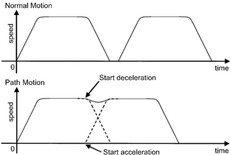
When CP is On, path motion will continue without full deceleration between two CP motions (Arc, Arc3, Jump3, Jump3CP, Move), or two PTP motions (Go, Jump). In contrast, full deceleration will occur between a CP motion and a PTP motion.
CP will be set to Off in the following cases
Controller Startup
Motor On
SFree, SLock, Brake
Reset, Reset Error
Stop button or QuitAll stops tasks
See Also
CP Function, Arc, Move, Go
CP Statement Example
CP On Move P1 Move P2 CP Off
CP Function
Returns status of path motion.

Syntax CP
Return Values
0 = Path motion off, 1 = Path motion on.
See Also
CP Statement
CP Function Example
If CP = Off Then
    Print "CP is off"
End If
Ctr Function
Returns the counter value of the specified Hardware Input counter.

Syntax
Ctr(bitNumber)
Parameters
bitNumber
Number of the Hardware Input bit set as a counter. Only 16 counters can be active at the same time.
Return Values
The current count of the specified Hardware Input Counter. (Integer expression from 0-65535)
Description
Ctr works with the CTReset statement to allow Hardware inputs to be used as counters.
Each time a hardware input specified as a counter is switched from the Off to On state that input causes the counter to increment by 1.
The Ctr function can be used at any time to get the current counter value for any counter input. Any of the Hardware Inputs can be used as counters. However, only 16 counters can be active at the same time.
Counter Pulse Input Timing Chart
High (ON)
Low (OFF)
4 msec or longer
4 msec or longer
See Also
CTReset
Ctr Function Example
The following example shows a sample of code which could be used to get a hardware input counter value.
CTReset 3 'Reset counter for input 3 to 0
On 0 'Turn an output switch on
Wait Ctr(3) >= 5
Off 0 'When 5 input cycles are counted for Input 3 turn
'switch off (output 0 off)
CTReset Statement
Resets the counter value of the specified input counter and enables the input to be a counter input.
Syntax
CTReset(bitNumber)
Parameters
bitNumber
Number of the input bit set as a counter. This must be an integer expression representing a valid input bit. Only 16 counters can be active at the same time.
Description
CTReset works with the CTR function to allow inputs to be used as counters. CTReset sets the specified input bit as a counter and then starts the counter. If the specified input is already used as a counter, it is reset and started again.
Notes
Turning Off Power and Its Effect on Counters
Turning off main power releases all counters.
Using the Ctr Function
Use the Ctr Function to retrieve current Hardware Input counter values.
See Also
Ctr
CTReset Example
The following example shows a sample of code which could be used to get a hardware input counter value.
CTReset 3 'Reset Counter 3 to 0
On 0 'Turn an output switch on
Wait Ctr(3) >= 5
Off 0 'When 5 input cycles are counted for Input 3 turn
'switch off (output 0 off)
CtrlDev Function
Returns the current control device number.

Syntax
CtrlDev
Return Values
21 Self 22 Remote I/O
See Also
CtrlInfo Function
CtrlDev Function Example
Print "The current control device is: ", CtrlDev
CtrlInfo Function
Returns controller information.

Syntax
CtrlInfo (index)
Parameters
index
Integer expression that represents the index of the information to retrieve.
Description
The following table shows the information that is available from the CtrlInfo function:
| Index | Bit | Value | Description |
| 0 N/A | Obtained for comp | atibility.Use index 9 to get the firmware version of the controller. | |
| 1 | Controller status | ||
| 0 | &H1 | Ready state | |
| 1 | &H2 | Start state | |
| 2 | &H4 | Pause state | |
| 3-7 | Undefined | ||
| 8 | &H100 | Estop state | |
| 9 | &H200 | Safeguard open | |
| 10 | &H400 | Error state | |
| 11 &H | 800 Critical error state | ||
| 12 | &H1000 | Warning | |
| 13 &H | 2000 WaitRecover state (Waiting for recover from safeguard open) | ||
| 14 &H | 4000 Recover state (Recovering from the safeguard open) | ||
| 15-31 | Undefined | ||
| 2 | 0 | &H1 | Enable switch is on |
| 1-31 | Undefined | ||
| 3 | 0 | &H1 | Teach mode circuit problem detected |
| 1 | &H2 | Safeguard circuit problem detected | |
| 2 | &H4 | Estop circuit problem detected | |
| 3-31 | Undefined | ||
| 4 | N/A | 0 - Normal mode1 - Dry run mode | |
| 5 | N/A | Control device:21 - RC+22 - Remote | |
| 6 N/A | Number of defined robots | ||
| 7 | N/A | Operation mode:0 - Program mode1 - Auto mode | |
| 8 | N/A | Undefined | |
| 9 | N/A | Firmware version of the ControllerMajor No.*1000000 + Minor No.*10000 + Rev No.*100 + Build No.(Example) Version 1.6.2.4 is 1060204 | |
| 10 | N/A | SMART status of hard disk0 : SMART status is normal1 : SMARTstatus is not normalIf SMART status is not normal, the hard disk can be broken. You need to backup the data promptly and replace the harddisk with new one.When using the RAID option, you cannot use the SMART status, it always returns that it is normal. | |
Return Values
Long value of the desired data
See Also
RobotInfo, TaskInfo
CtrlInfo Function Example
Print "The controller version: ", CtrlInfo(6)
CurDir$ Function
Returns a string representing the current directory.
F
Syntax
CurDir$
Return Values
A string that includes the current drive and path.
See Also
ChDir, CurDrive, CurDisk
CurDir$ Function Example
Print "The current directory is: ", CurDir$
CurDisk$ Function
Returns a string representing the current disk.
F
Syntax
CurDisk$
Return Values
A string that contains the current disk letter.
See Also
ChDisk, CurDir, CurDrive
CurDisk$ function Example
Print "The current disk is: ", CurDisk$
CurDrive$ Function
Returns a string representing the current drive.

Syntax
CurDrive$
Return Values
A string that contains the current drive letter.
See Also
ChDrive, CurDir, CurDisk
CurDrive$ Function Example
Print "The current drive is: ", CurDrive$
CurPos Function
Returns the current target position of the specified robot.

Syntax
CurPos
Return Values
A robot point representing the current target position of the specified robot.
See Also
InPos, FindPos, RealPos
CurPos Function Example
Function main
Xqt showPosition
Do
Jump P0
Jump P1
Loop
Fend
Function showPosition
Do
P99 = CurPos
Print CX(P99), CY(P99)
Loop
Fend
Curve Statement
Defines the data and points required to move the arm along a curved path. Many data points can be defined in the path to improve precision of the path.
S
Syntax
Curve fileName, closure, mode, numAxes, pointList
Parameters
fileName A string expression for the name of the file in which the point data is stored. The specified fileName will have the extension .crv appended to the end, so no extension is to be specified by the user. When the Curve instruction is executed, the file will be created.
You cannot specify a file path, and fileName doesn't have any effect from ChDisk. See ChDisk for details.
closure Specifies whether or not the defined Curve is Closed or left Open at the end of the curved motion. This parameter must be set to one of two possible values, as shown below.
C - Closed Curve
O - Open Curve
When specifying the open curve, the Curve instruction creates the data to stop the arm at the last point of the specified point series. When specifying the closed curve, the Curve instruction creates the data required to continue motion through the final specified point and then stop motion after returning the arm to the starting point of the specified point series for the Curve instruction.
mode Specifies whether or not the arm is automatically interpolated in the tangential direction of the U-Axis. It can also specify the ECP number in the upper four bits.
| Mode Setting | Tangential Correction | ECP Number | |
| Hexadecimal | Decimal | ||
| &H00 | 0 | No | 0 |
| &H10 | 16 | 1 | |
| &H20 | 32 | 2 | |
| ... | ... | ... | |
| &HA0 | 160 | 10 | |
| &HB0 | 176 | 11 | |
| &HC0 | 192 | 12 | |
| &HD0 | 208 | 13 | |
| &HE0 | 224 | 14 | |
| &HF0 | 240 | 15 | |
| &H02 | 2 | Yes | 0 |
| &H12 | 18 | 1 | |
| &H22 | 34 | 2 | |
| ... | ... | ... | |
| &HA2 | 162 | 10 | |
| &HB2 | 178 | 11 | |
| &HC2 | 194 | 12 | |
| &HD2 | 210 | 13 | |
| &HE2 | 226 | 14 | |
| &HF2 | 242 | 15 | |
When specifying tangential correction, Curve uses only the U-Axis coordinate of the starting point of the point series. Tangential correction continuously maintains tool alignment tangent to the curve in the XY plane. It is specified when installing tools such as cutters that require continuous tangential alignment. When specifying a closed curve (using the closure parameter) with Automatic Interpolation in the tangential direction of the U-Axis, the U-Axis rotates 360 degrees from the start point. Therefore, before executing the CVMove instruction, set the U-Axis movement range using the Range instruction so the 360-degree rotation of the U-Axis does not cause an error.
When using ECP, specify the ECP number in the upper four bits.
When generating a curve considering the additional axis position included in the point data, specify the ninth bit as 1. For example, when using no orientation offset or ECP and generating a curve considering the additional axis position, specify &H100.
When generating a curve for the additional axis, join the continuous point data of S axis and T axis separately from the robot coordinate system.
However, if the additional axis consists of the PG axis, it doesn't generate a curve with the continuous point but creates the data to move to the final point.
numAxes Integer number 2, 3, 4, or 6 which specifies the number of axes controlled during the curve motion as follows:
2 - Generate a curve in the XY plane with no Z Axis movement or U Axis rotation.
3 - Generate a curve in the XYZ space with no U axis rotation.
4 - Generate a curve in the XYZ space with U-Axis rotation.
6 - Generate a curve in the XYZ space with U, V, and W axes rotation (6-Axis robots only).
The axes not selected to be controlled during the Curve motion maintain their previous encoder pulse positions and do not move during Curve motion.
pointList { point expression | P(start:finish) } [, output command ] ... This parameter is actually a series of Point Numbers and optional output statements either separated by commas or an ascended range of points separated by a colon. Normally the series of points are separated by commas as shown below:
Curve "MyFile", O, 0, 4, P1, P2, P3, P4
Sometimes the user defines a series of points using an ascending range of points as shown below:
Curve "MyFile", O, 0, 4, P(1:4)
In the case shown above the user defined a curve using points P1, P2, P3, and P4. output command is optional and is used to control output operation during curve motion. The command can be On or Off for digital outputs or memory outputs. Entering an output command following any point number in the point series causes execution of the output command when the arm reaches the point just before the output command. A maximum of 16 output commands may be included in one Curve statement. In the example below, the "On 2" command is executed just as the arm reaches the point P2, then the arm continues to all points between and including P3 and P10.
Curve "MyFile", C, 0, 4, P1, P2, ON 2, P(3:10)
Description
Curve creates data that moves the manipulator arm along the curve defined by the point series pointList and stores the data in a file on the controller. The CVMove instruction uses the data in the file created by Curve to move the manipulator in a continuous path type fashion.
The curve file is stored in the compact flush inside of the controller. Therefore, Curve starts writing into the compact flush. Frequent writing into the compact flush will shorten the compact flush lifetime. We recommend using Curve only for saving the point data.
Curve calculates independent X, Y, Z, U, V, W coordinate values for each point using a cubic spline function to create the trajectory. Therefore, if points are far apart from each other or the orientation of the robot is changed suddenly from point to point, the desired trajectory may not be realized.
It is not necessary to specify speeds or accelerations prior to executing the Curve instruction. Arm speed and acceleration parameters can be changed anytime prior to executing CVMove by using the SpeedS or AccelS instructions.
Points defined in a local coordinate system may be used in the series to locate the curve at the desired position. By defining all of the specified points in the point series for the Curve instruction as points with local attributes, the points may be changed as points on the local coordinate system by the Local instruction following the Curve instruction.
Note
Use tangential correction when possible
It is recommended that you use tangential correction whenever possible, especially when using CVMove in a continuous loop through the same points. If you do not use tangential correction, the robot may not follow the correct path at higher speeds.
Open Curve Min and Max Number of Points Allowed
Open Curves may be specified by using from 3 to 200 points.
Closed Curve Min and Max Number of Points Allowed
Closed Curves may be specified by using from 3 to 50 points.
Potential Errors
Attempt to Move Arm Outside Work Envelope
The Curve instruction cannot check the movement range for the defined curve path. This means that a user defined path may cause the robot arm to move outside the normal work envelope. In this case an "out of range" error will occur.
See Also
AccelS Function, Arc, CVMove, ECP, Move, SpeedS
Curve Statement Example
The following example designates the free curve data file name as MYCURVE.CVT, creates a curve tracing P1-P7, switches ON output port 2 at P2, and decelerates the arm at P7.
Set up curve
curve "mycurve", O, 0, 4, P1, P2, On 2, P(3:7)
Move the arm to P1 in a straight line
jump P1
Move the arm according to the curve definition called mycurve
cvmove "mycurve"
CVMove Statement
Performs the continuous spline path motion defined by the Curve instruction.
s
Syntax
CVMove fileName [CP] [searchExpr] [SYNC]
Parameters
fileName String expression for the file name. This file must be previously created by the Curve instruction and stored on a PC hard disk. You cannot specify a file path and fileName doesn't have any effect from ChDisk. See ChDisk for the details.
CP Optional. Specifies continuous path motion after the last point.
searchExpr Optional. A Till or Find expression.
Till | Find
Till Sw(expr) = {On | Off}
Find Sw(expr) = {On | Off}
SYNC Reserves a motion command. A robot will not move until the SyncRobots gives instructions.
Description
CVMove performs the continuous spline path motion defined by the data in the file fileName, which is located in the controller memory. The file must be previously created with the Curve command.
Multiple files may exist at the same time on the system. If there is no file name extension, then CVT is assumed.
The user can change the speed and acceleration for the continuous path motion for CVMove by using the SpeedS and AccelS instructions.
When the Curve instruction has been previously executed using points with Local definitions, you can change the operating position by using the Local instruction.
When executing CVMove, be careful that the robot doesn't collide with peripheral equipment. When you attempt to change the hand orientation of the 6-axis robot between adjacent points suddenly, due to the nature of cubic spline function, the 6-axis robot may start changing its orientation from the previous and following points and move in an unexpected trajectory. Verify the trajectory thoroughly prior to a CVMove execution and be careful that the robot doesn't collide with peripheral equipment.
Specify points closely each other and at equal interval. Do not change the hand orientation between adjacent points suddenly.
The CP parameter causes acceleration of the next motion command to start when the deceleration starts for the current motion command. In this case the robot will not stop at the destination coordinate and will continue to move to the next point.
See Also
AccelS Function, Arc, Curve, Move, SpeedS, Till, TillOn
CVMove Statement Example
The following example designates the free curve data file name as MYCURVE.CVT, creates a curve tracing P1-P7, switches ON output port 2 at P2, and decelerates the arm at P7.
Set up curve
curve "mycurve", O, 0, 4, P1, P2, On 2, P(3:7)
Move the arm to P1 in a straight line
jump P1
Move the arm according to the curve definition called mycurve
cvmove "mycurve"
CX, CY, CZ, CU, CV, CW, CR, CS, CT Statements
Sets the coordinate value of a point data.
CV, CW are for only 6-axis robots.
CR is only for Joint type robots.
CS, CT are only for robots with additional axes.
Syntax
CX(point) = value
CY(point) = value
CZ(point) = value
CU(point) = value
CV(point) = value
CW(point) = value
CR(point) = value
CS(point) = value
CT(point) = value
Parameters
point Pnumber or P(expr) or point label.
value Real expression representing the new coordinate value in millimeters.
See Also
CX, CY, CZ, CU, CV, CW, CR, CS, CT Functions
CX, CY, CZ, CU, CV, CW, CR, CS, CT Statements Example
CX(pick) = 25.34
CX, CY, CZ, CU, CV, CW, CR, CS, CT Functions
Retrieves a coordinate value from a point
CV, CW functions are only for 6-axis robots.
CS, CT are only for robots with additional axes.
F
Syntax
| CX (point) |
| CY (point) |
| CZ (point) |
| CU (point) |
| CV (point) |
| CW (point) |
| CR (point) |
| CS (point) |
| CT (point) |
Parameters
point Point expression.
Return Values
Returns the specified coordinate value. The return values for CX, CY, CZ are real numbers in millimeters. The return values for CU, CV, CW are real numbers in degrees.
Return values of CS, CT functions: Real values in mm or deg. It depends on the additional axis setting.
Description
Used to retrieve an individual coordinate value from a point.
To obtain the coordinate from the current robot position, use Here for the point parameter.
See Also
Point expression
CX, CY, CZ, CU, CV, CW, CR, CS, CT Statements
CX, CY, CZ, CU, CV, CW, CR, CS, CT Functions Example
The following example extracts the X axis coordinate value from point "pick" and puts the coordinate value in the variable x.
Function cxtest
    Real x
    x = CX(pick)
    Print "The X Axis Coordinate of point 'pick' is", x
Fend
Date Statement
Displays the date.

Syntax
Date
Return Values
The current date is displayed.
See Also
Time, Date$
Date Example
Example from the command window.
> Date
2009/08/01
Date$ Function
Returns the system date.
F
Syntax
Date$
Return Values
A string containing the date in the format yyyy/mm/dd.
See Also
Date, Time, Time$
Date$ Function Example
Print "Today's date: ", Date$
Declare Statement
Declares an external function in a dynamic link library (DLL).
S
Syntax
Declare funcName, dllFile, [ alias ] [, (argList)] As type
Parameters
funcName The name of the function as it will be called from your program.
| dllFile | The path and name of the library file. This must be a literal string (characters delimited by quotation marks). You may also use a macro defined by #define. If there is no path specified, then RC+ will look for the file in the current project directory. If not found, then it is assumed that the file is in the Windows system32 directory. The file extension can be omitted, but is always assumed to be .DLL. |
| alias | Optional. The actual name of the function in the DLL or the function index. The name is case sensitive. The alias must be a literal string (characters delimited by quotation marks). If you use an index, you must use a # character before the index. If omitted, a function name specified by funcName can be used as a name of function in DLL. |
arglist Optional. List of the DLL arguments. See syntax below.
type Required. You must declare the type of function.
The arglist argument has the following syntax:
[ {ByRef | ByVal} ] varName [( )] As type
ByRef Optional. Specify ByRef when you refer to the variable to be seen by the calling function. In this case, the argument change in a function can be reflected to the variable of the calling side. You can change the values received as a reference.
ByVal Optional. Specify ByVal when you do not want any changes in the value of the variable to be seen by the calling function. This is the default.
varName Required. Name of the variable representing the argument; follows standard variable naming conventions. If you use an array variable as argument, you must specify ByRef.
type Required. You must declare the type of argument.
Description
Use Declare to call DLL functions from the current program. Declare must be used outside of functions.
The Declare statement checks that the DLL file and function exist at compile time.
Passing Numeric Variables ByVal
SPEL: Declare MyDLLFunc, "mystuff.dll", "MyDLLFunc", (a As Long) As Long VC++ long _stdcall MyDllFunc(long a);
Passing String Variables ByVal
SPEL: Declare MyDLLFunc, "mystuff.dll", "MyDLLFunc", (a$ As String) As Long VC++ long _stdcall MyDllFunc(char *a);
Passing Numeric Variables ByRef
SPEL: Declare MyDLLFunc, "mystuff.dll", "MyDLLFunc", (ByRef a As Long) As Long
VC++ long _stdcall MyDllFunc(long *a);
Passing String Variables ByRef
SPEL: Declare MyDLLFunc, "mystuff.dll", "MyDLLFunc", (ByRef a$ As String) As Long
VC++ long _stdcall MyDllFunc(char *a);
When you pass a string using ByRef, you can change the string in the DLL. Maximum string length is 255 characters. You must ensure that you do not exceed the maximum length.
Passing Numeric Arrays ByRef
SPEL: Declare MyDLLFunc, "mystuff.dll", "MyDLLFunc", (ByRef a() As Long) As Long
VC++ long _stdcall MyDllFunc(long *a);
Returning Values from DLL Function
The DLL function can return a value for any data type, including String. However, for a string, you must return a pointer to a string allocated in the DLL function. And the function name must end in a dollar sign, as with all SPEL+ string variables and functions. Note that the alias doesn't have a dollar sign suffix.
For example:
Declare ReturnLong, "mystuff.dll", "ReturnLong", As Long
Declare ReturnString$, "mystuff.dll", "ReturnString", As String
Function main
Print "ReturnLong = ", ReturnLong
Print "ReturnString= ", ReturnString
Fend
See Also
Function...Fend
Declare Example
' Declare a DLL function. Since there is no path specified,
' the file can be in the current project directory or in
' the Windows system32 directory

Declare MyDLLTest, "mystuff.dll", "MyDLLTest" As Long

Function main
    Print MyDLLTest
Fend

' Declare a DLL function with two integer arguments
' and use a #define to define the DLL file name

#define MYSTUFF "mystuff.dll"

Declare MyDLLCall, MYSTUFF, "MyTestFunc", (var1 As Integer, var2 As Integer) As Integer

' Declare a DLL function using a path and index.

Declare MyDLLTest, "c:\mydlls\mystuff.dll", "#1" As Long
DegToRad Function
Converts degrees to radians.
Syntax
DegToRad(degrees)
Parameters
degrees Real expression representing the degrees to convert to radians.
Return Values
A double value containing the number of radians.
See Also
ATan, ATan2, RadToDeg Function
DegToRad Function Example
s = Cos( DegToRad(x) )
Del Statement
Deletes one or more files.

Syntax
Del fileName
Parameters
fileName
The path and name of the file(s) to delete. The filename should be specified with an extension. See ChDisk for the details.
Description
Deletes the specified file(s).
Del Example
Example from the command window.
> Del TEST.PTS ' Deletes the point file from the current directory.
> Del c : TEST.PTS ' NG
!! Error: 7213 The file specified by path does not exist.
> Del c : \TEST.PTS ' OK
Dir Statement
Displays the contents of the specified directory.

Syntax
(1) Dir (2) Dir [ filename As String ] (3) Dir [ fileName ]
Parameters
filename Path name of the file to search for.
fileName File name to search for. The filename and extension may contain wildcard characters (*, ?).
Description
(1) If the parameter is omitted, it is like making a file name as *.* and all files in the current directory are displayed. (2) All files in the specified directory are displayed. (3) The specified file is displayed. If the file path is omitted, the file in the current directory is displayed.
See ChDisk for the details of path.
Dir command works similar to the dir command in DOS and displays filename, directory name, file size and date for specified directories and files.
Note
This statement is executable only with the PC disk.
See Also
ChDir, ChDrive, ChDisk
Dir Command Example
Examples from the Command window.
> Dir ' Displays all files in the current directory.
> Dir c:\TEST ' Displays all files in the directory "C:\TEST"
> Dir TEST.* ' Displays the file "TEST" in the current directory
> Dir *.DAT ' Displays the file extension is ".DAT" in the current directory.
DispDev Statement
Sets the current display device.
s
Syntax
DispDev (deviceID)
Parameters
deviceID The device ID for the desired display device.
21
Self
24 TP
The following parameters are also available.
21
DEVID_SELF
24 DEVID_TP
See Also
DispDev Function
DispDev Statement Example
DispDev DEVID_TP
DispDev Function
Returns the current display device.

Syntax
DispDev
Return Values
Integer value containing the deviceID.
21 Self
24 TP
See Also
DispDev Statement
DispDev Function Example
Print "The current display device is ", DispDev
Dist Function
Returns the distance between two robot points.

Syntax
Dist (point1, point2)
Parameters
point1, point2 Specifies two robot point expressions.
Return Values
Returns the distance between both points (real value in mm).
Description
Even if you are using the additional axis, only the robot travel distance is returned. It doesn't include the travel distance of additional axis while you use the additional axis as running axis. For the Joint type robot, the return value of this function means nothing.
See Also
CU, CV, CW, CX, CY, CZ
Dist Function Example
Real distance
distance = Dist(P1, P2)
Do...Loop Statement
Repeats a block of statements while a condition is True or until a condition becomes True.
S
Syntax
Do [ { While | Until } condition ] [statements]
[Exit Do] [statements]
Loop
Or, you can use this syntax:
Do
[statements]
[Exit Do] [statements]
Loop [ { While | Until } condition ]
The Do Loop statement syntax has these parts:
Part Description
| condition | Optional. Numeric expression or string expression that is True or False. If condition is Null, condition is treated as False. |
| statements | One or more statements that are repeated while, or until, condition is True. |
Description
Any number of Exit Do statements may be placed anywhere in the Do...Loop as an alternate way to exit a Do...Loop. Exit Do is often used after evaluating some condition, for example, If...Then, in which case the Exit Do statement transfers control to the statement immediately following the Loop.
When used within nested Do...Loop statements, Exit Do transfers control to the loop that is one nested level above the loop where Exit Do occurs.
See Also
For...Next, Select...Send
Do Example
Do While Not Lof(1)
Line Input #1, tLine$
Print tLine$
Loop
Double Statement
Declares variables of type Double. (8 byte double precision number).
s
Syntax
Double varName [(subscripts)] [, varName [(subscripts)]...]
Parameters
varName Variable name which the user wants to declare as type Double.
subscripts Optional. Dimensions of an array variable; up to 3 dimensions may be declared. The subscripts syntax is as follows
(ubound1, [ubound2], [ubound3])
ubound1, ubound2, ubound3 each specify the maximum upper bound for the associated dimension.
The elements in each dimension of an array are numbered from 0 and the available number of array elements is the upper bound value + 1.
When specifying the upper bound value, make sure the number of total elements is within the range shown below:
Local variable 2000
Global Preserve variable 4000
Global variable and module variable 100000
Description
Double is used to declare variables as type Double. Local variables should be declared at the top of a function. Global and module variables must be declared outside of functions.
Valid number of digits for Double is 14.
See Also
Boolean, Byte, Global, Integer, Long, Real, String
Double Example
The following example shows a simple program which declares some variables using Double.
Function doubletest
    Double var1
    Double A(10) 'Single dimension array of double
    Double B(10, 10) 'Two dimension array of double
    Double C(5, 5, 5) 'Three dimension array of double
    Double arrayvar(10)
    Integer i
    Print "Please enter a Number:"
    Input var1
    Print "The variable var1 = ", var1
    For i = 1 To 5
    Print "Please enter a Number:"
    Input arrayvar(i)
    Print "Value Entered was ", arrayvar(i)
    Next i
Fend
ECP Statement
Selects or displays the current ECP (external control point).
Syntax
(1) ECP ECPNumber (2) ECP
Parameters
ECPNumber
Optional. Integer expression from 0-15 representing which of 16 ECP definitions to use with subsequent motion instructions. ECP 0 makes the ECP selection invalid.
Return Values
Displays current ECP when used without parameters.
Description
ECP selects the external control point specified by the ECP number (ECPNumber).
Note
This command will only work if the External Control Point option is active.
Power Off and Its Effect on the ECP Selection
Turning main power off clears the ECP selection.
See Also
ECPSet
ECP Statement Example
>ecpset 1, 100, 200, 0, 0
>ecp 1
ECP Function
Returns the current ECP (external control point) number.
Syntax
ECP
Return Values
Integer containing the current ECP number.
Note
This command will only work if the External Control Point option is active.
See Also
ECP Statement
ECP Function Example
Integer savECP
savECP = ECP
ECP 2
Call Dispense
ECP savECP
ECPCIr Statement
Clears (undefines) an external control point.
Syntax
ECPCIr ECPNumber
Parameters
ECPNumber
Integer expression representing which of the 15 external control points to clear (undefine). (ECP0 is the default and cannot be cleared.)
Note
This command will only work if the External Control Point option is active.
See Also
Arm, ArmClr, ArmSet, ECPSet, Local, LocalClr, Tool, TLSet
ECPClr Example
ECPClr 1
ECPDef Function
Returns ECP definition status.
Syntax
ECPDef (ECPNumber)
Parameters
ECPNumber
Integer expression representing which ECP to return status for.
Return Values
True if the specified ECP has been defined, otherwise False.
See Also
Arm, ArmClr, ArmSet, ECPSet, Local, LocalClr, Tool, TLClr, TLSet
ECPDef Example
Function DisplayECPDef(ecpNum As Integer)
    If ECPDef(ecpNum) = False Then
    Print "ECP ", ecpNum, "is not defined"
    Else
    Print "ECP ", ecpNum, ": ",
    Print ECPSet(ecpNum)
    EndIf
Fend
ECPSet Statement
Defines or displays an external control point.
Syntax
(1) ECPSet ECPNum, ECPPoint (2) ECPSet ECPNum (3) ECPSet
Parameters
ECPNum Integer number from 1-15 representing which of 15 external control points to define. ECPPoint Pnumber or P(expr) or point label or point expression.
Return Values
When parameters are omitted, displays the current ECPSet definitions. When only the ECP number is specified, displays the specified ECPSet definitions.
Description
Defines an external control point.
Note
This command will only work if the External Control Point option is active.
ECPSet Example
ECPSet 1, P1 ECPSet 2, 100, 200, 0, 0
ECPSet Function
Returns a point containing the external control point definition for the specified ECP.

Syntax
ECPSet(ECPNumber)
Parameters
ECPNumber
Integer expression representing the number of the ECP to retrieve.
Return Values
A point containing the ECP definition.
Note
This command will only work if the External Control Point option is active.
See Also
ECPSet Statement
ECPSet Function Example
P1 = ECPSet(1)
Elbow Statement
Sets the elbow orientation of a point.
Syntax
(1) Elbow point, [value]
(2) Elbow
Parameters
point: Pnumber or P(expr) or point label.
value: Integer expression.
1 = Above (/A)
2 = Below (/B)
Return Values
When both parameters are omitted, the elbow orientation is displayed for the current robot position. If value is omitted, the elbow orientation for the specified point is displayed.
See Also
Elbow Function, Hand, J4Flag, J6Flag, Wrist
Elbow Statement Example
Elbow P0, Below
Elbow pick, Above
Elbow P(myPoint), myElbow
P1 = 0.000, 490.000, 515.000, 90.000, -40.000, 180.000
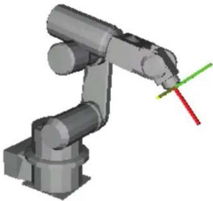
Elbow P1, Above Go P1
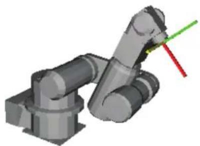
Elbow P1, Below Go P1
Elbow Function
Returns the elbow orientation of a point.

Syntax
Elbow [(point)]
Parameters
point Optional. Point expression. If point is omitted, then the elbow orientation of the current robot position is returned.
Return Values
1 Above (/A) 2 Below (/B)
See Also
Elbow Statement, Hand, Wrist, J4Flag, J6Flag
Elbow Function Example
Print Elbow(pick)
Print Elbow(P1)
Print Elbow
Print Elbow(P1 + P2)
Eof Function
Returns end of file status.

Syntax
Eof (fileNumber)
Parameters
fileNumber Integer number from 30 ~ 60 or expression representing the file number to check.
Return Values
True if file pointer is at end of file, otherwise False.
Description
Eof is functional only if the file is opened for reading mode.
An error occurs if the file was opened with the AOpen or WOpen statements.
See Also
Lof
Eof Example
Integer fileNum
String data$
fileNum = FreeFile
UOpen "TEST.DAT" As #fileNum
Do While Not Eof(fileNum)
    Line Input #fileNum, data$
    Print "data = ", data$
Loop
Close #fileNum
Era Function
Returns the joint number for which an error occurred.

Syntax
Era[(taskNum)]
Parameters
taskNum
Integer expression representing a task number from 0 to 32.
Task number omission or 0 specifies the current task.
Return Values
The joint number that caused the error in the range 0-6 as described below:
0 - The current error was not caused by a servo axis. 1 - The error was caused by joint number 1 2 - The error was caused by joint number 2 3 - The error was caused by joint number 3 4 - The error was caused by joint number 4 5 - The error was caused by joint number 5 6 - The error was caused by joint number 6 7 - The error was caused by joint number 7 8 - The error was caused by joint number 8 (additional S axis) 9 - The error was caused by joint number 9 (additional T axis)
Description
Era is used when an error occurs to determine if the error was caused by one of the robot joints and to return the number of the joint which caused the error. If the current error was not caused by any joint, Era returns zero.
See Also
Erl, Err, ErrMsg$, Ert, OnErr, Trap
Era Function Example
Function main
    OnErr Goto eHandler
    Do
    Call PickPlace
    Loop
    Exit Function
eHandler:
    Print "The Error code is ", Err
    Print "The Error Message is ", ErrMsg$(Err)
    errTask = Ert
    If errTask > 0 Then
    Print "Task number in which error occurred is ", errTask
    Print "The line where the error occurred is Line ", Erl(errTask)
    If Era(errTask) > 0 Then
    Print "Joint which caused the error is ", Era(errTask)
    EndIf
    EndIf
Fend
EResume Statement
Resumes execution after an error-handling routine is finished.
S
Syntax
EResume [{ label | Next }]
Description
EResume
If the error occurred in the same procedure as the error handler, execution resumes with the statement that caused the error. If the error occurred in a called procedure, execution resumes at the Call statement in the procedure containing the error handler.
EResume Next
If the error occurred in the same procedure as the error handler, execution resumes with the statement immediately following the statement that caused the error. If the error occurred in a called procedure, execution resumes with the statement immediately following the Call statement that last in the procedure containing the error handler.
EResume { label }
If the error occurred in the same procedure as the error handler, execution resumes at the statement containing the label.
See Also
OnErr
EResume Statement Example
Function main
    Integer retry

    OnErr GoTo eHandler
    Do
    RunCycle
    Loop
    Exit Function

eHandler:
    Select Err
    Case MyError
    retry = retry + 1
    If retry < 3 Then
    EResume ' try again
    Else
    Print "MyError has occurred ", retry, " times
    EndIf
    Send
    Fend
Erf$ Function
Returns the name of the function in which the error occurred.

Syntax
Erf$ [taskNumber]
Parameters
taskNumber
Integer expression representing a task number from 0 to 32.
Task number omission or 0 specifies the current task.
Return Values
The name of the function where the last error occurred.
Description
Erfis used with OnErr. Erf returns the function name in which the error occurred. Using Erf$ combined with Err, Ert, Erl and Era the user can determine much more about the error which occurred.
See Also
Era, Erl, Err, ErrMsg$, Ert, OnErr
Erf$ Function Example
The following example shows a simple program using the Ert function to determine which task the error occurred in along with; Erf$: the name of the function the error occurred in; Erl: the line number where the error occurred; Era: if a joint caused the error....
Function main
    OnErr Goto eHandler
    Do
    Call PickPlace
    Loop
    Exit Function
eHandler:
    Print "The Error code is ", Err
    Print "The Error Message is ", ErrMsg$(Err)
    errTask = Ert
    If errTask > 0 Then
    Print "Task number in which error occurred is ", errTask
    Print "Function at which error occurred is ", Erf$(errTask)
    Print "The line where the error occurred is Line ", Erl(errTask)
    If Era(errTask) > 0 Then
    Print "Joint which caused the error is ", Era(errTask)
    EndIf
    EndIf
Fend
Erl Function
Returns the line number in which the error occurred.

Syntax
Erl[(taskNumber)]
Parameters
taskNumber
Integer expression representing a task number from 0 ~ 32.
Task number omission or 0 specifies the current task.
Return Values
The line number where the last error occurred.
Description
Erl is used with OkErr. Erl returns the line number in which the error occurred. Using Erl combined with Err, Ert and Era the user can determine much more about the error which occurred.
See Also
Era, Erf\, Err, ErrMsg\, Ert, OnErr
Erl Function Example
The following example shows a simple program using the Ert function to determine which task the error occurred in along with; Erl: where the error occurred; Era: if a joint caused the error....
Function main
    OnErr Goto eHandler
    Do
    Call PickPlace
Loop
Exit Function
eHandler:
    Print "The Error code is ", Err
    Print "The Error Message is ", ErrMsg$(Err)
    errTask = Ert
    If errTask > 0 Then
    Print "Task number in which error occurred is ", errTask
    Print "The line where the error occurred is Line ", Erl(errTask)
    If Era(errTask) > 0 Then
    Print "Joint which caused the error is ", Era(errTask)
    EndIf
    EndIf
Fend
Err Function
Returns the most recent error status.

Syntax
Err [(taskNumber)]
Parameters
taskNumber
Optional. Integer expression representing a task number from 0 \~ 32. 0 specifies the current task.
Return Values
Returns a numeric error code in integer form.
Description
Err allows the user to read the current error code. This, along with the SPEL+ Error Handling capabilities, allows the user to determine which error occurred and react accordingly. Err is used with OnErr.
To get the controller error, use the SysErr function.
See Also
Era, Erf, Erl, ErrMsg, EResume, Ert, OnErr, Return, SysErr
Err Example
The following example shows a simple utility program which checks whether points P0-P399 exist. If the point does not exist, then a message is printed on the screen to let the user know this point does not exist. The program uses the CX instruction to test each point for whether or not it has been defined. When a point is not defined, control is transferred to the error handler and a message is printed on the screen to tell the user which point was undefined.
Function errtest
    Integer i, errnum
    Real x

    OnErr GoTo eHandle
    For i = 0 To 399
    x = CX(P(i))
    Next i
    Exit Function

'
'
'
'
'
'
'
'
'
'
'
'
'
'
'
'
'
'
'
'
'
'
'
'
'
'
'
'
'
'
'
'
'
'
'
'
'
'
'
'
'
'
'
'
'
'
'
'
'
'
'
ErrMsg$ Function
Returns the error message which corresponds to the specified error number.

Syntax
ErrMsg$(errNumber, langID)
Parameters
errNumber Integer expression containing the error number to get the message for.
langID Optional. Integer expression containing the language ID based on the following values.
0 - English
1 - Japanese
2 - German
3 - French
If omitted, English is used.
Return Values
Returns the error message which is described in the Error Codes table.
See Also
Era, Erl, Err, Ert, OnErr, Trap
ErrMsg$ Example
The following example shows a simple program using the Ert function to determine which task the error occurred in, along with: Erl: where the error occurred; Era: if a joint caused the error....
Function main
    OnErr Goto eHandler
    Do
    Call PickPlace
Loop
Exit Function
eHandler:
    Print "The Error code is ", Err
    Print "The Error Message is ", ErrMsg$(Err)
    errTask = Ert
    If errTask > 0 Then
    Print "Task number in which error occurred is ", errTask
    Print "The line where the error occurred is Line ", Erl(errTask)
    If Era(errTask) > 0 Then
    Print "Joint which caused the error is ", Era(errTask)
    EndIf
    EndIf
Fend
Error Statement
Generates a user error.
S
Syntax
(1) Error taskNumber, errorNumber (2) Error errorNumber
Parameters
taskNumber Optional. Integer expression representing a task number from 0 to 32. 0 specifies the current task.
errorNumber Integer expression representing a valid error number. User error numbers range from 8000 to 8999.
Description
Use the Error statement to generate system or user defined errors. You can define user error labels and descriptions by using the User Error Editor in the EPSON RC+ 6.0 development environment.
See Also
Era, Erl, Err, OnErr
Error Statement Example
#define ER_VAC 8000
If Sw(vacuum) = Off Then
    Error ER_VAC
End If
ErrorOn Function
Returns the error status of the controller.

Syntax
ErrorOn
Return Values
True if the controller is in error status, otherwise False.
Description
The ErrorOn function is used only for NoEmgAbort task (special task using NoEmgAbort at Xqt) and background task.
See Also
ErrorOn, SafetyOn, SysErr, Wait, Xqt
ErrorOn Function Example
The following example shows a program that monitors the controller error and switches the I/O On/Off according to the error number when error occurs.
Notes
Forced Flag
This program example uses the Forced flag for On/Off commands.
Be sure that the I/O outputs change during an error, or at Emergency Stop or Safety Door Open when designing the system.
After Error Occurrence
As in this program, finish the task promptly after completing the error handling.
Function main
Xqt ErrorMonitor, NoEmgAbort
:
:
Fend
Function ErrorMonitor
Wait ErrorOn
If 4000 < SysErr Then
Print "Motion Error = ", SysErr
Off 10, Forced
On 12, Forced
Else
Print "Other Error = ", SysErr
Off 11, Forced
On 13, Forced
EndIf
Fend
Ert Function
Returns the task number in which an error occurred.
Syntax
Ert
Return Values
The task number in which the error occurred.
Description
Ert is used when an error occurs to determine in which task the error occurs. The number returned will be between 1 and 32.
See Also
Era, Erl, Err, ErrMsg$, OnErr, Trap
Ert Function Example
The following example shows a simple program using the Ert function to determine which task the error occurred in, along with Erl: where the error occurred, Err: what error occurred, and Era: if a joint caused the error.
Function main
    OnErr Goto eHandler
    Do
    Call PickPlace
    Loop
    Exit Function
eHandler:
    Print "The Error code is ", Err
    Print "The Error Message is ", ErrMsg$(Err)
    errTask = Ert
    If errTask > 0 Then
    Print "Task number in which error occurred is ", errTask
    Print "The line where the error occurred is Line ", Erl(errTask)
    If Era(errTask) > 0 Then
    Print "Joint which caused the error is ", Era(errTask)
    EndIf
    EndIf
Fend
EStopOn Function
Returns the Emergency Stop status.

Syntax
EstopOn
Return Values
True if the status is Emergency Stop, otherwise False.
Description
The EStopOn function is used only for the NoEmgAbort task (a special task using NoEmgAbort at Xqt).
See Also
ErrorOn, SafetyOn, Wait, Xqt
EstopOn Function Example
The following example shows a program that monitors the Emergency Stop and switches the I/O On/Off when an Emergency Stop occurs.
Notes
Forced Flag
This program example uses the Forced flag for On/Off commands.
Be sure that the I/O outputs change during an error, or at Emergency Stop or Safeguard Open when designing the system.
Error Handling
As in this program, finish the task promptly after completing the error handling.
Outputs OFF during Emergency Stop
As in this program example, when the task executes I/O On/Off after the Emergency Stop, uncheck the [Controller]-[Preferences]-[Outputs off during emergency stop] check box. If this check box is checked, the execution order of turning off by the controller and turning on using the task are not guaranteed.
Function main
Xqt EStopMonitor, NoEmgAbort
:
:
Fend
Function EStopMonitor
Wait EStopOn
Print "EStop !!!"
Off 10, Forced
On 12, Forced
Fend
Eval Function
Executes a Command window statement from a program and returns the error status.

Syntax
Eval( command [, reply$] )
Parameters
command
A string expression containing a command you want to execute.
reply$ Optional. A string variable that contains the reply from the command.
If the command is in the error status, it will return "!Error: error code".
If the reply is over 255 characters, the extra characters will be truncated.
Return Values
The error code returned from executing the command.
Even if the command execution results in an error, the function itself will not be an error. Also, the system log doesn't record it.
When the command is completed successfully, it returns 0.
Description
You can execute any command (executable commands from Command window) from communication port such as TCP/IP by using Eval. It takes more time to execute this function than by using a normal statement.
Use the replyparameter to retrieve the reply from the command. For example, if the command was "Print Sw(1)", then reply would be a "1" or "0".
See Also
Error Codes
Eval Function Example
This example shows how to execute a command being read over RS-232. After the command is executed, the error code is returned to the host. For example, the host could send a command like "motor on".
Integer errCode
String cmd$
OpenCom #1
Do
    Line Input #1, cmd$
    errCode = Eval(cmd$)
    Print #1, errCode
Loop
Exit Statement
Exits a loop construct or function.

Syntax
Exit { Do | For | Function }
Description
The Exit statement syntax has these forms:
| Statement | Description |
| Exit Do | Provides a way to exit a Do...Loop statement. It can be used only inside a Do...Loop statement.Exit Do transfers control to the statement following the Loop statement.When used within nested Do...Loop statements, Exit Do transfers control to the loop that is one nested level above the loop where Exit Do occurs. |
| Exit For | Provides a way to exit a For loop. It can be used only in a For...Next loop.Exit For transfers control to the statement following the Next statement. When used within nested For loops, Exit For transfers control to the loop that is one nested level above the loop where Exit For occurs. |
| Exit Function | Immediately exits the Function procedure in which it appears. Execution continues with the statement following the statement that called the Function. |
See Also
Do...Loop, For...Next, Function...Fend
Exit Statement Example
For i = 1 To 10
    If Sw(1) = On Then
    Exit For
    EndIf
    Jump P(i)
Next i
FbusIO GetBusStatus Function
Returns the status of the specified Fieldbus.
Syntax
FbusIO_GetBusStatus(busNumber)
Parameters
busNumber
Integer expression representing the Fieldbus system number. This number must be 16. This is the ID for the bus connected to the Fieldbus master board on the PC side of the controller.
Return Values
0 - OK
1 - Disconnected 2 - Power off
Description
FbusIO_GetBusStatus can be used to verify the general status of the Fieldbus.
Note
This command will only work if the Fieldbus Master option is active.
See Also
FbusIO_GetDeviceStatus, FbusIO_SendMsg
FbusIO_GetBusStatus Function Example
Long sts
sts = FbusIO_GetBusStatus(16)
FbusIO GetDeviceStatus Function
Returns the status of the specified Fieldbus device.
Syntax
FbusIO_GetDeviceStatus(busNumber, deviceID)
Parameters
| busNumber | Integer expression representing the Fieldbus system number. This number must be 16. This is the ID for the bus connected to the Fieldbus master board on the PC side of the controller. |
| deviceID | Integer expression representing the Fieldbus ID of the device. |
Return Values
0 - OK
1 - Disconnected 2 - Power off 3 - Synchronization error. Device is booting, or has incorrect baud rate.
Description
FbusIO_GetDeviceStatus can be used to verify the general status of a Fieldbus device.
Note
This command will only work if the Fieldbus Master option is active.
See Also
FbusIO_GetBusStatus, FbusIO_SendMsg
FbusIO_GetDeviceStatus Function Example
Long sts
sts = FbusIO_GetDeviceStatus(1, 10)
FbusIO_SendMsg Statement
Sends an explicit message to a Fieldbus device and returns the reply.
Syntax
FbusIO_SendMsg busNumber, deviceID, msgParam, sendData(), recvData()
Parameters
| busNumber | Integer expression representing the Fieldbus system number. This number must be 16. This is the ID for the bus connected to the Fieldbus master board on the PC side of the controller. |
| deviceID | Integer expression representing the Fieldbus ID of the device. |
| msgParam | Integer expression for the message parameter. Not used with DeviceNet. |
| sendData | Array of type Byte containing data that is sent to the device. This array must be dimensioned to the number of bytes to send. If there are no bytes to send, specify 0. |
| recvData | Array of type Byte that contains the data received from the device. This array will automatically be redimensioned to the number of bytes received. |
Description
FBusIO_SendMsg is used to query one Fieldbus device. Refer to the device manufacturer for information on messaging support.
Note
This command will only work if the Fieldbus Master option is active.
See Also
FbusIO_GetBusStatus, FbusIO_GetDeviceStatus
FbusIO_SendMsg Statement Example
' Send explicit message to DeviceNet device
Byte sendData(5)
Byte recvData(0)
Integer i

sendData(0) = &HOE ' Command
sendData(1) = 1 ' Class
sendData(3) = 1 ' Instance
sendData(5) = 7 ' Attribute
' msgParam is 0 for DeviceNet
FbusIO_SendMsg 1, 1, 0, sendData(), recvData()
' Display the reply
For i = 0 to UBound(recvData)
    Print recvData(i)
Next i

' Send message to Profibus device
Byte recvData(0)
Integer i

' msgParam is the service number
FbusIO_SendMsg 16, 1, 56, 0, recvData()
' Display the reply
For i = 0 to UBound(recvData)
    Print recvData(i)
Next i
FileDateTime$ Function
Returns the date and time of a file.
F
Syntax
FileDateTime$ ( filename )
Parameters
fileName
A string expression containing the file name to check. The drive and path can also be included.
If only file name is specified, the file in the current directory is displayed.
See ChDisk for the details.
Note
Do not use a network path, otherwise an error occurs.
Return Values
Returns the date and time of the last update in the following format:
m/d/yyyy hh:mm:ss
See Also
FileExists, FileLen
FileDateTime$ Function Example
String myPath$
myPath$ = "c:\TEST\TEST.DAT"

If FileExists(myPath$) Then
    Print "Last access date and time: ", FileDateTime(myPath)
    Print "Size: ", FileLen(myPath$)
EndIf
FileExists Function
Checks if a file exists.
F
Syntax
FileExists ( filename )
Parameters
fileName
A string expression containing the file name to check. The drive and path can also be included.
If only the file name is specified, the file is checked in the current directory.
See ChDisk for the details.
Note
Do not use a network path, otherwise an error occurs.
Return Values
True if the file exists, False if not.
See Also
FolderExists, FileLen, FileDateTime$
FileExists Function Example
String myPath$
myPath$ = "c:\TEST\TEST.DAT"

If FileExists(myPath$) Then
    Print "Last access date and time: ", FileDateTime(myPath)
    Print "Size: ", FileLen(myPath$)
EndIf
FileLen Function
Returns the length of a file.
F
Syntax
FileLen ( filename )
Parameters
fileName
A string expression containing the file name to check. The drive and path can also be included.
If only the file name is specified, the file is checked in the current directory.
See ChDisk for the details.
Note
Do not use a network path, otherwise an error occurs.
Return Values
Returns the number of bytes in the file.
See Also
FileDateTime$, FileExists
FileLen Function Example
String myPath$
myPath$ = "c:\TEST\TEST.DAT"

If FileExists(myPath$) Then
    Print "Last access date and time: ", FileDateTime(myPath)
    Print "Size: ", FileLen(myPath$)
EndIf
Find Statement
Specifies or displays the condition to store coordinates during motion.
Syntax
Find [condition]
Parameters
condition The following functions and operators are available.
Functions: Sw, In, InW, Oport, Out, OutW, MemSw, MemIn, MemW, Ctr
Operators: And, Or, Xor
Find Sw(5) = On
Find Sw(5) = On And Sw(6) = Off
Input status specified as a trigger
[Event] comparative operator ( =, <>, >=, >, <, <=) [Integer expression]
The following functions and variables can be used in the Event:
Functions: Sw, In, InW, Oport, Out, OutW, MemSw, MemIn, MemInW, Ctr, GetRobotInsideBox, GetRobotInsidePlane
Variables: Byte, Integer, Long global preserve variable, Global variable, module variable
In addition, using the following operators you can specify multiple event conditions.
Operator: And, Or, Xor
Example: Trap 1, Sw(5) = On Call TrapFunc
Trap 1, Sw(5) = On And Till(6) = Off, Call TrapFunc
Description
The Find statement can be used by itself or as a modifier of a motion command.
The Find condition must include at least one of the functions above.
When variables are included in the Find condition, their values are computed when setting the Find condition. No use of variable is recommended. Otherwise, the condition may be an unintended condition. Multiple Find statements are permitted. The most recent Find condition remains current.
When parameters are omitted, the current Find definition is displayed.
Notes
Find Setting at Main Power On
At power on, the Find condition is:
Find Sw(0) = On 'Input bit 0 is on
Use of PosFound Function to Verify Find
Use the PosFound function to verify if the Find condition has been satisfied after executing a motion command using the Find modifier.
Use Variables in Event Condition Expression
- Available variables are Integer type (Byte, Integer, Long)
- Array variables are not available.
- Local variables are not available.
- If a variable value cannot satisfy the event condition for more than 0.01 second, the system cannot retrieve the change in variables.
- Up to 64 variables can be waited on in one system (including those used in event condition expressions such as Wait). If it exceeds 64, an error occurs during the project build.
- If you try to transfer a variable that is being waited on as a reference with Byref, an error occurs.
- When a variable is included in the right side member of the event condition expression, the value is calculated when starting the motion command. We recommend not using variables in an integer expression to avoid making unintended conditions.
See Also
FindPos, Go, Jump, PosFound
Find Statement Example
Find Sw(5) = On
Go P10 Find
If PosFound Then
    Go FindPos
Else
    Print "Cannot find the sensor signal."
EndIf
FindPos Function
Returns a robot point stored by Fine during a motion command.

Syntax
FindPos
Return Values
A robot point that was stored during a motion command using Find.
See Also
Find, Go, Jump, PosFound, CurPos, InPos
FindPos Function Example
Find Sw(5) = On
Go P10 Find
If PosFound Then
    Go FindPos
Else
    Print "Cannot find the sensor signal."
EndIf
Fine Statement
Specifies and displays the positioning accuracy for target points.
Syntax
(1) Fine axis1, axis2, axis3, axis4, [axis5, axis6], [axis7], [axis8, axis9]
(2) Fine
Parameters
| axis1 | Integer expression ranging from (0-65535) which represents the allowable positioning error for the 1st joint. |
| axis2 | Integer expression ranging from (0-65535) which represents the allowable positioning error for the 2nd joint. |
| axis3 | Integer expression ranging from (0-65535) which represents the allowable positioning error for the 3rd joint. |
| axis4 | Integer expression ranging from (0-65535) which represents the allowable positioning error for the 4th joint. |
| axis5 | Optional. Integer expression ranging from (0-65535) which represents the allowable positioning error for the 5th joint. |
| axis6 | Optional. Integer expression ranging from (0-65535) which represents the allowable positioning error for the 6th joint. |
| axis 7 | Optional. Integer expression ranging from (0-65535) which represents the allowable positioning error for the 7th joint. Only for the Joint type 7-axis robot. |
| axis 8 | Optional. Integer expression ranging from (0-65535) which represents the allowable positioning error for the 7th joint. Only for the additional S axis. |
| axis 9 | Optional. Integer expression ranging from (0-65535) which represents the allowable positioning error for the 7th joint. Only for the additional T axis. |
Return Values
When used without parameters, Fine displays the current fine values for each axis.
Description
Fine specifies, for each joint, the allowable positioning error for detecting completion of any given move.
This positioning completion check begins after the CPU has completed sending the target position pulse to the servo system. Due to servo delay, the robot will not yet have reached the target position. This check continues to be executed every few milliseconds until each joint has arrived within the specified range setting. Positioning is considered complete when all axes have arrived within the specified ranges. Once positioning is complete program control is passed to the next statement, however, servo system keeps the control of the robot target position.
When relatively large ranges are used with the Fine instruction, the positioning will be confirmed relatively early in the move, and executes the next statement.
The default Fine settings depend on the robot type. Refer to your robot manual for details.
Notes
Cycle Times and the Fine Instruction
The Fine value does not affect the acceleration or deceleration control of the manipulator arm. However, smaller Fine values can cause the system to run slower because it may take the servo system extra time (a few milliseconds) to get within the acceptable position range. Once the arm is located within the acceptable position range (defined by the Fine instruction), the CPU executes the next user instruction.
Initialization of Fine (by Motor On, SLock, SFree)
Any time the following commands are used the Fine value is initialized to default values: SLock, SFree, Motor instructions.
Make sure that you reset Fine values after one of the above commands execute.
Potential Errors
If Fine positioning is not completed within about 2 seconds, Error 4024 will occur. This error normally means the servo system balance needs to be adjusted. (Call your distributor for assistance)
See Also
Accel, AccelR, AccelS, Arc, Go, Jump, Move, Speed, SpeedR, SpeedS, Pulse
Fine Statement Example
The examples below show the Fine statement used in a program function, and used from the monitor window.
Function finetest
    Fine 5, 5, 5, 5 'reduce precision to +/- 5 Pulse
    Go P1
    Go P2
Fend
> Fine 10, 10, 10, 10
>
> Fine
10, 10, 10, 10
Fine Function
Returns Fine setting for a specified joint.

Syntax
Fine(joint)
Parameters
joint Integer expression representing the joint number for which to retrieve the Fine setting. The additional S axis is 8 and T axis is 9.
Return Values
Real value.
See Also
Accel, AccelS, Arc, Go, Jump, Move, Speed, SpeedS, Pulse
Fine Function Example
This example uses the Fine function in a program:
Function finetst
Integer a
a = Fine(1)
Fend
Fix Function
Returns the integer portion of a real number.

Syntax
Fix(number)
Parameters
number: Real expression containing the number to fix.
Return Values
An integer value containing the integer portion of the real number.
See Also
Int
Fix Function Example
>print Fix(1.123)
1
>
Flush
Writes a file's buffer into the file.
Syntax
Flush #fileNumber
Parameters
fileNumber: Integer value from 30 to 63 or expression
Description
Writes a file's buffer into the specified file.
Flush cannot be used if the file was opened with ROpen.
Flush Example
Integer fileNum, i

fileNum = FreeFile
UOpen "TEST.DAT" As #fileNum
For i = 0 To 100
    Print #fileNum, i
Next i

Flush #fileNum
Close #fileNum
FmtStr$ Function
Format a numeric expression.

Syntax
FmtStr$ (numeric expression, strFormat)
Parameters
numeric expression: Numeric expression to be formatted. strFormat: Format specification string.
Return Values
A string containing the formatted expression.
Description
Use FmtStr$ to format a numeric expression into a string.
Numeric Format Specifiers
Format a numeric expression.
Character Description
None: Display the number with no formatting.
(0) Digit placeholder. Display a digit or a zero. If the expression has a digit in the position where the 0 appears in the format string, display it; otherwise, display a zero in that position. If the number has fewer digits than there are zeros (on either side of the decimal) in the format expression, display leading or trailing zeros. If the number has more digits to the right of the decimal separator than there are zeros to the right of the decimal separator in the format expression, round the number to as many decimal places as there are zeros. If the number has more digits to the left of the decimal separator than there are zeros to the left of the decimal separator in the format expression, display the extra digits without modification.
(#) Digit placeholder. Display a digit or nothing. If the expression has a digit in the position where the # appears in the format string, display it; otherwise, display nothing in that position. This symbol works like the 0 digit placeholder, except that leading and trailing zeros aren't displayed if the number has the same or fewer digits than there are # characters on either side of the decimal separator in the format expression.
(.) Decimal placeholder. In some locales, a comma is used as the decimal separator. The decimal placeholder determines how many digits are displayed to the left and right of the decimal separator. If the format expression contains only number signs to the left of this symbol, numbers smaller than 1 begin with a decimal separator. To display a leading zero displayed with fractional numbers, use 0 as the first digit placeholder to the left of the decimal separator. The actual character used as a decimal placeholder in the formatted output depends on the Number Format recognized by your system.
(.) Thousand separator. In some locales, a period is used as a thousand separator. The thousand separator separates thousands from hundreds within a number that has four or more places to the left of the decimal separator. Standard use of the thousand separator is specified if the format contains a thousand separator surrounded by digit placeholders (0 or #). Two adjacent thousand separators or a thousand separator immediately to the left of the decimal separator (whether or not a decimal is specified) means "scale the number by dividing it by 1000, rounding as needed." For example, you can use the format string "##0," to represent 100 million as 100. Numbers smaller than 1 million are displayed as 0. Two adjacent thousand separators in any position other than immediately to the left of the decimal separator are treated simply as specifying the use of a thousand separator. The actual character used as the thousand separator in the formatted output depends on the Number Format recognized by your system.
See Also
Left\, Right\, Str\$
FmtStr\$ Example
Function SendDateCode
String d, f
f= FmtStr(10, "000.00")
OpenCom #1
Print #1, f$
CloseCom #1
Fend
FolderExists Function
Checks if a folder exists.

Syntax
FolderExists(pathName)
Parameters
pathName
A string expression containing the path of the folder to check. The drive can also be included. See ChDisk for the details.
Note
This function is executable only with the PC disk.
Return Values
True if the folder exists, False if not.
See Also
FileExists, MkDir
FolderExists Function Example
If Not FolderExists("c:\TEST") Then MkDir "c:\TEST"
EndIf
For...Next Statement
The For...Next instructions are used together to create a loop where instructions located between For and Next are executed multiple times as specified by the user.

Syntax
For var = initValue To finalValue [Step increment]
statements
Next [var]
Parameters
| var | The counting variable used with the For...Next loop. This variable is normally defined as an integer but may also be defined as a Real variable. |
| initValue | The initial value for the counter var. |
| finalValue | The final value of the counter var. Once this value is met, the For...Next loop is complete and execution continues starting with the statement following the Next instruction. |
| increment | An optional parameter which defines the counting increment for each time the Next statement is executed within the For...Next loop. This variable may be positive or negative. However, if the value is negative, the initial value of the variable must be larger than the final value of the variable. If the increment value is left out the system automatically increments by 1. |
statements Any valid SPEL + statements can be inserted inside the For...Next loop.
Description
For...Next executes a set of statements within a loop a specified number of times. The beginning of the loop is the For statement. The end of the loop is the Next statement. A variable is used to count the number of times the statements inside the loop are executed.
The first numeric expression (initValue) is the initial value of the counter. This value may be positive or negative as long as the finalValue variable and Step increment correspond correctly.
The second numeric expression (finalValue) is the final value of the counter. This is the value which once reached causes the For...Next loop to terminate and control of the program is passed on to the next instruction following the Next instruction.
Program statements after the For statement are executed until a Next instruction is reached. The counter variable (var) is then incremented by the Step value defined by the increment parameter. If the Step option is not used, the counter is incremented by 1 (one).
The counter variable (var) is then compared with the final value. If the counter is less than or equal to the final value, the statements following the For instruction are executed again. If the counter variable is greater than the final value, execution branches outside of the For...Next loop and continues with the instruction immediately following the Next instruction.
Notes
Negative Step Values:
If the value of the Step increment (increment) is negative, the counter variable (var) is decremented (decreased) each time through the loop and the initial value must be greater than the final value for the loop to work.
Variable Following Next is Not Required:
The variable name following the Next instruction may be omitted. However, for programs that contain nested For...Next loops, it is recommended to include the variable name following the Next instruction to aid in quickly identifying loops.
When a variable comes out of the loop, the value is not a final value.
Function forsample
Integer i
For i = 0 To 3
Next
Print i ' Displays 4
Fend
See Also
Do...Loop
For...Next Example
Function fornext
    Integer counter
    For counter = 1 to 10
    Go Pctr
    Next counter

    For counter = 10 to 1 Step -1
    Go Pctr
    Next counter
Fend
Force Calibrate Statement
Sets zero offsets for all axes for the current force sensor.
s
Syntax
Force_Calibrate
Parameters
On | Off
Torque Control can be either On or Off.
Description
You should call Force_Calibrate for each sensor when your application starts. This will account for the weight of the components mounted on the sensor.
Note
This command will only work if the Force Sensing option is active.
See Also
Force_Sensor Statement
Force_Calibrate Statement Example
Force_Calibrate
Force_ClearTrigger
Clears all trigger conditions for the current force sensor.
Syntax
Force_ClearTrigger
Description
Use Force_ClearTrigger to clear all conditions for the current force sensor's trigger.
Note
This command will only work if the Force Sensing option is active.
See Also
Force_Sensor Statement
Force_ClearTrigger Statement Example
Force_ClearTrigger
Force GetForces Statement
Returns the forces and torques for all force sensor axes in an array.
Syntax
Force_GetForces array()
Syntax
Parameters
array() Real array with upper bound of 6.
Return Values
The array elements are filled in as follows:
| Axis | Constant | Value |
| X Force | FORCE_XFORCE 1 | |
| Y Force | FORCE_YFORCE 2 | |
| Z Force | FORCE_ZFORCE 3 | |
| X Torque | FORCE_XTORQUE 4 | |
| Y Torque | FORCE_YTORQUE 5 | |
| Z Torque | FORCE_ZTORQUE 6 |
Description
Use Force_GetForces to read all force and torque values at once.
Note
This command will only work if the Force Sensing option is active.
See Also
Force_GetForce Statement
Force_GetForces Statement Example
Real fValues(6)
Force_GetForces fValues()
Force_GetForce Function
Returns the force for a specified axis.

Syntax
Force_GetForce (axis)
Parameters
axis Integer expression representing the axis.
| Axis | Constant | Value |
| X Force | FORCE_XFORCE 1 | |
| Y Force | FORCE_YFORCE 2 | |
| Z Force | FORCE_ZFORCE 3 | |
| X Torque | FORCE_XTORQUE 4 | |
| Y Torque | FORCE_YTORQUE 5 | |
| Z Torque | FORCE_ZTORQUE 6 |
Return Values
Returns a real value.
Description
Use Force_GetForce to read the current force setting for one axis. The units are determined by the type of force sensor.
Note
This command will only work if the Force Sensing option is active.
See Also
Force_GetForces
Force_GetForce Function Example
Print Force_GetForce(1)
Force Sensor Statement
Sets the current force sensor for the current task.
S
Syntax
Force_Sensor sensorNumber
Parameters
sensorNumber Integer expression representing the sensor number.
Description
When using multiple force sensors on the same system, you must set the current force sensor before using other force sensing commands.
If your system has only one sensor, then you don't need to use Force_Sensor because the default sensor number is 1.
Note
This command will only work if the Force Sensing option is active.
See Also
Force_Sensor Function
Force_Sensor Statement Example
Force_Sensor 1
Force Sensor Function
Returns the current force sensor for the current task.

Syntax
Force_Sensor
Description
Force_Sensor returns the current sensor number for the current task. When a task starts, the sensor number is automatically set to 1.
Note
This command will only work if the Force Sensing option is active.
See Also
Force_Sensor Statement
Force_Sensor Function Example
var = Force_Sensor
Force_SetTrigger Statement
Sets the force trigger for the Till command.

Syntax
Force_SetTrigger axis, Threshold, CompareType
Parameters
axis Integer expression containing the desired force sensor axis.
Axis Constant Value
X Force FORCE_XFORCE 1
Y Force FORCE_YFORCE 2
Z Force FORCE_ZFORCE 3
X Torque FORCE_XTORQUE 4
Y Torque FORCE_YTORQUE 5
Z Torque FORCE_ZTORQUE 6
Threshold Real expression containing the desired threshold in units for the sensor being used.
CompareType Comparison Constant Value
Less than or equal FORCE_LESS 0
Greater than or equal FORCE_GREATER 1
Description
To stop motion with a force sensor, you must set the trigger for the sensor, then use Till Force in your motion statement.
You can set the trigger with multiple axes. Call Force_SetTrigger for each axis. To disable an axis, set the threshold at 0.
Note
This command will only work if the Force Sensing option is active.
See Also
Force_Calibrate
Force_SetTrigger Statement Example
'Set trigger to stop motion when force is less than -1 on Z axis.
Force SetTrigger 3, -1, 0
SpeedS 3
Accels 5000
FreeFile Function
Returns / reserves a file number that is currently not being used.
Syntax
FreeFile
Return Values
Integer between 30 and 63.
See Also
AOpen, BOpen, ROpen, UOpen, WOpen, Close
FreeFile Function Example
Integer fileNum, i, j

fileNum = FreeFile
WOpen "TEST.DAT" As #fileNum
For i = 0 To 100
    Print #fileNum, i
Next i
Close #fileNum

fileNum = FreeFile
ROpen "TEST.DAT" As #fileNum
For i = 0 to 100
    Input #fileNum, j
    Print "data = ", j
Next i
Close #fileNum
Function...Fend Statement
A function is a group of program statements which includes a Function statement as the first statement and an Fend statement as the last statement.

Syntax
Function funcName [(argList)] [As type] statements
Fend
Parameters
| funcName | The name which is given to the specific group of statements bound between the Function and Fend instructions. The function name must contain alphanumeric characters and may be up to 64 characters in length. Underscores are also allowed. |
| argList | Optional. List of variables representing arguments that are passed to the Function procedure when it is called. Multiple variables are separated by commas. |
The arglist argument has the following syntax:
[ {ByRef | ByVal} ] varName [ ( ) ] As type
| ByRef | Optional. Specify ByRef when you refer to the variable to be seen by the calling function. In this case, the argument change in a function can be reflected to the variable of the calling side. |
| ByVal | Optional. Specify ByVal when you do not want any changes in the value of the variable to be seen by the calling function. This is the default. |
| varName | Required. Name of the variable representing the argument; follows standard variable naming conventions. If you use an array variable as argument, you should specify ByRef. |
| As type | Required. You must declare the type of argument. |
Return Values
Value whose data type is specified with the As clause at the end of the function declaration.
Description
The Function statement indicates the beginning of a group of SPEL+ statements. To indicate where a function ends we use the Fend statement. All statements located between the Function and Fend statements are considered part of the function.
The Function...Fend combination of statements could be thought of as a container where all the statements located between the Function and Fend statements belong to that function. Multiple functions may exist in one program file.
See Also
Call, Fend, Halt, Quit, Return, Xqt
Function...Fend Example
The following example shows 3 functions which are within a single file. The functions called task2 and task3 are executed as background tasks while the main task called main executes in the foreground.
Function main
Xqt 2, task2 'Execute task2 in background
Xqt 3, task3 'Execute task3 in background
'....more statements here
Fend
Function task2
Do
On 1
On 2
Off 1
Off 2
Loop
Fend
Function task3
Do
On 10
Wait 1
Off 10
Loop
Fend
GetCurrentUser$ Function
Returns the current EPSON RC+ user.
Syntax
GetCurrentUser$
Return Values
String containing the current user logID.
Note
This command will only work if the Security option is active.
See Also
LogIn Statement
GetCurrentUser$ Function Example
String currUser$
currUser= GetCurrentUser
GetRobotInsideBox Function
Returns a robot which is in the approach check area.

Syntax
GetRobotInsideBox ( AreaNum )
Parameters
AreaNum
Integer value (1 ~ 15) representing the approach check area you want to return the status for.
Return Values
Return the robot that is in the approach check area specified with AreaNum in bit.
Bit 0 : Robot 1 ...... Bit 15 : Robot 16
If the robot doesn't configure the approach check area, bit is always 0.
For example, Robot 1, Robot 3 are in the approach check area, bit 0, bit 2 will be On and 3 will be returned.
See Also
Box, InsideBox
GetRobotInsideBox function Example
The following program uses the GetRobotInsideBox function.
Wait for the status that no robots are in the approach check area.
Function WaitNoBox
Wait GetRobotInsideBox(1) = 0
Wait for the status that Robot 2 is only one in the approach check area.
Function WaitForInBoxRobot2
Wait GetRobotInsideBox(1) = &H2
The following program uses the GetRobotInsideBox function in the parallel processing of the motion command. When a robot is in the specific approach check area while it is running, it turns ON the I/O. One robot is connected to the controller in this case.
Function Main
    Motor On
    Power High
    Speed 30; Accel 30, 30

    Go P1 !D0; Wait GetRobotInsideBox(1) = 1; On 1!
Fend
Note
D0 must be described.
GetRobotInsidePlane Function
Returns a robot which is in the approach check plane.
Syntax
GetRobotInsidePlane ( PlaneNum )
Parameters
PlaneNum
Integer value (1 \~ 15) representing the approach check plane you want to return the status for.
Return Values
Returns the number of the robot that is in the approach check plane specified with PlaneNum in bit.
Bit 0: Robot 1 ...... Bit 15: Robot 16
If the robot doesn't configure the approach check plane, it always returns bit 0.
For example, if Robot 1 and Robot 3 are in the approach check plane, bits 0 and 2 will be On, and 3 will be returned.
See Also
InsidePlane, Plane
GetRobotInsidePlane function Example
The following program uses the GetRobotInsidePlane function.
Wait for the status that no robots are in the approach check plane.
Function WaitNoPlane
Wait GetRobotInsidePlane(1) = 0
Wait for the status that Robot 2 is the only one in the approach check plane.
Function WaitInPlaneRobot2
Wait GetRobotInsidePlane(1) = &H2
The following program uses the GetRobotInsidePlane function in the parallel processing of the motion command. When a robot is in the specific approach check plane while it is running, it turns ON the I/O. One robot is connected to the controller in this case.
Function Main
Motor On
Power High
Speed 30; Accel 30, 30
Go P1 !D0; Wait GetRobotInsidePlane(1) = 1; On 1!
Fend
Note
D0 must be described.
Global Statement
Declares variables with the global scope. Global variables can be accessed from anywhere.
s
Syntax
Global [ Preserve ] dataType varName [(subscripts)] [, varName [(subscripts)], ...]
Parameters
| Preserve | If Preserve is specified, then the variable retains its values. The values are cleared by project changes. If Preserve is omitted, the variable doesn't retain its values. |
| dataType | Data type including Boolean, Integer, Long, Real, Double, Byte, or String. |
| varName Variable name. Names may be up to 32 characters in length. | |
| subscripts | Optional. Dimensions of an array variable; up to 3 dimensions may be declared. The subscripts syntax is as follows(ubound1, [ubound2], [ubound3]) |
| ubound1, ubound2, ubound3 each specify the maximum upper bound for the associated dimension. | |
| The elements in each dimension of an array are numbered from 0 to the upper bound value. | |
| The total available number of array elements for global variables is 10000 for strings and 100000 for all other types. | |
| The total available number of array elements for global preserve variables is 400 for strings and 4000 for all other types. | |
| To calculate the total elements used in an array, use the following formula.(If a dimension is not used, substitute 0 for the ubound value.)total elements = (ubound1 + 1) * (ubound2 + 1) * (ubound3 + 1) | |
Description
Global variables are variables which can be used in more than 1 file within the same project. They are cleared whenever a function is started from the Run window or Operator window unless they are declared with the Preserve option.
When declared in Preserve option, the variable retains the value at turning off the controller.
Global Preserve variables can be used with the VB Guide option.
It is recommended that global variable names begin with a "g_" prefix to make it easy to recognize globals in a program. For example:
Global Long g_PartsCount
See Also
Boolean, Byte, Double, Integer, Long, Real, String
Global Statement Example
The following example shows 2 separate program files. The first program file defines some global variables and initializes them. The second file then uses these global variables.
FILE1 (MAIN.PRG)
Global Integer status1
Global Real numsts
Function Main
Integer I
status1 = 10
The following example shows 2 separate program files. The first program file defines some global variables and initializes them. The second file then also uses these global variables.
FILE1 (MAIN.PRG)
Global Integer g_Status
Global Real g_MaxValue
Function Main
g_Status = 10
g_MaxValue = 1.1
.
.
a
FILE2 (TEST.PRG)
Function Test
    Print "status1 = , g_Status
    Print "MaxValue = , g_MaxValue
    .
    .
Fend
Go Statement
Moves the arm using point to point motion from the current position to the specified point or X,Y,Z,U,V,W position. The Go instruction can move any combination of 1-6 joints at the same time.
Syntax
Go destination [CP] [LJM [orientationFlag]] [searchExpr] [...!] [SYNC]
Parameters
destination The target destination of the motion using a point expression.
CP Optional. Specifies continuous path motion.
LJM Optional. Convert the target destination using LJM function.
orientationFlag Optional. Specifies a parameter that selects an orientation flag for LJM function.
searchExpr Optional. A Till or Find expression.
Till | Find
Till Sw(expr) = {On | Off}
Find Sw(expr) = {On | Off}
Optional. Parallel Processing statements can be added to execute I/O and other commands during motion.
SYNC Reserves a motion command. The robot will not move until SyncRobots is executed.
Description
Go simultaneously moves all joints of the robot arm using point to point motion. The destination for the Go instruction can be defined in a variety of ways:
- Using a specific point to move to. For example: Go P1.
- Using an explicit coordinate position to move to. For example: Go XY(50, 400, 0, 0).
- Using a point with a coordinate offset. For example: Go P1 +X(50).
- Using a point but with a different coordinate value. For example: Go P1 :X(50).
The path is not predictable because each joint interpolates between the current point and the target point. Be careful of the interference with peripherals.
The Speed instruction determines the arm speed for motion initiated by the Go instruction. The Accel instruction defines the acceleration.
With CP parameter, the arm can accelerate for the next motion command while the arm starts decelerating to a stop. In this case, the arm is not positioned at the target point.
With LJM parameter, the arm moves to the point into where the target point is converted using LJM function, with the current point as reference point.
Go LJM (P1, Here, 1)
can be
At this point, the original point data P1 does not change.
The LJM parameter is available for the 6-axis and RS series robots.
When using orientationFlag with the default value, it can be omitted.
Go P1 LJM
Notes
Difference between Go and Move
The Move instruction and the Go instruction each cause the robot arm to move. However, the primary difference between the 2 instructions is that the Go instruction causes point to point motion whereas the Move instruction causes the arm to move in a straight line. The Go instruction is used when the user is primarily concerned with the orientation of the arm when it arrives on point. The Move instruction is used when it is important to control the path of the robot arm while it is moving.
Difference between Go and Jump
The Jump instruction and the Go instruction each cause the robot arm to move in a point to point type fashion. However, the JUMP instruction has 1 additional feature. Jump causes the robot end effector to first move up to the LimZ value, then in a horizontal direction until it is above the target point, and then finally down to the target point. This allows Jump to be used to guarantee object avoidance and more importantly to improve cycle times for pick and place motions.
Proper Speed and Acceleration Instructions with Go
The Speed and Accel instructions are used to specify the speed and acceleration of the manipulator during motion caused by the Go instruction. Pay close attention to the fact that the Speed and Accel instructions apply to point to point type motion (like that for the Go instruction) while linear and circular interpolation motion uses the SpeedS and AccelS instructions.
Using Go with the Optional Till Modifier
The optional Till modifier allows the user to specify a condition to cause the robot to decelerate to a stop at an intermediate position prior to completing the motion caused by the Go instruction. If the Till condition is not satisfied, the robot travels to the target position. The Go with Till modifier can be used in 2 ways as described below:
(1) Go with Till Modifier
Checks if the current Till condition becomes satisfied. If satisfied, this command completes by decelerating and stopping the robot at an intermediate position prior to completing the motion caused by the Go instruction.
(2) Go with Till Modifier, Sw(Input bit number) Modifier, and Input Condition
This version of the Go with Till modifier allows the user to specify the Till condition on the same line with the Go instruction rather than using the current definition previously defined for Till. The condition specified is simply a check against one of the inputs. This is accomplished through using the Sw instruction. The user can check if the input is On or Off and cause the arm to stop based on the condition specified. This feature works almost like an interrupt where the motion is interrupted (stopped) once the Input condition is met. If the input condition is never met during the robot motion then the arm successfully arrives on the point specified by destination.
Using Go with the Optional Find Modifier
The optional Find modifier allows the user to specify a condition to cause the robot to record a position during the motion caused by the Go instruction. The Go with Find modifier can be used in 2 ways as described below:
(1) Go with Find Modifier: Checks if the current Find condition becomes satisfied. If satisfied, the current position is stored in the special point FindPos.
(2) Go with Find Modifier, Sw(Input bit number) Modifier, and Input Condition: This version of the Go with Find modifier allows the user to specify the Find condition on the same line with the Go instruction rather than using the current definition previously defined for Find. The condition specified is simply a check against one of the inputs. This is accomplished through using the Sw instruction. The user can check if the input is On or Off and cause the current position to be stored in the special point FindPos.
Go Instruction Always Decelerates to a Stop
The Go instruction always causes the arm to decelerate to a stop prior to reaching the final destination of the move.
Potential Errors
Attempt to Move Outside of Robots Work Envelope
When using explicit coordinates with the Go instruction, you must make sure that the coordinates defined are within the robots valid work envelope. Any attempt to move the robot outside of the valid work envelope will result in an error.
See Also
!...! Parallel Processing, Accel, Find, Jump, Move, Pass, Pn= (Point Assignment), Pulse, Speed, Sw, Till
Go Example
The example shown below demonstrates a simple point-to-point move between points P0 and P1, and then moves back to P0 in a straight line. Later in the program, the arm moves in a straight line toward point P2 until input #2 turns on. If input #2 turns on during the move, the arm decelerates to a stop before arriving at point P2, and the next program instruction is executed.
Function sample
Integer i

Home
Go P0
Go P1
For i = 1 to 10
    Go P(i)
Next i
Go P2 Till Sw(2) = On
If Sw(2) = On Then
    Print "Input #2 came on during the move and"
    Print "the robot stopped prior to arriving on"
    Print "point P2."
Else
    Print "The move to P2 completed successfully."
    Print "Input #2 never came on during the move."
EndIf
Fend

Some syntax examples from the command window are shown below:

>Go Here +X(50) ' Move only in the X direction 50 mm from the current position
>Go P1 ' Simple example to move to point P1
>Go P1 :U(30) ' Move to P1 but use +30 as the position for the U joint to move to
>Go P1 /L ' Move to P1 but make sure the arm ends up in lefty position
>Go XY(50, 450, 0, 30) ' Move to position X=50, Y=450, Z=0, U=30

<Another Coding Example>
Till Sw(1) = Off And Sw(2) = On ' Specifies Till conditions for inputs 1 & 2
Go P1 Till ' Stop if current Till condition
' defined on previous line is met
Go P2 Till Sw(2) = On ' Stop if Input Bit 2 is On
Go P3 Till ' Stop if current Till condition defined on
' previous line is met
GoSub...Return
GoSub transfers program control to a subroutine. Once the subroutine is complete, program control returns to the line following the GoSub instruction that initiated the subroutine.
S
Syntax
GoSub {label}
{ label: }
statements
Return
Parameters
label
When the user specifies a label, the program execution jumps to the line on which this label resides. The label can be up to 32 characters in length. However, the first character must be an alphabetic character (not numeric).
Description
The GoSub instruction causes program control to branch to the user specified statement label. The program then executes the statement on that line and continues execution through subsequent line numbers until a Return instruction is encountered. The Return instruction then causes program control to transfer back to the line which immediately follows the line which initiated the GoSub in the first place. (i.e. the GoSub instruction causes the execution of a subroutine and then execution returns to the statement following the GoSub instruction.) Be sure to always end each subroutine with Return. Doing so directs program execution to return to the line following the GoSub instruction.
Potential Errors
Branching to Non-Existent Statement
If the GoSub instruction attempts to branch control to a non-existent label then an Error 3108 will be issued.
Return Found Without GoSub
A Return instruction is used to "return" from a subroutine back to the original program which issued the GoSub instruction. If a Return instruction is encountered without a GoSub having first been issued then an Error 2383 will occur. A stand alone Return instruction has no meaning because the system doesn't know where to Return to.
See Also
GoTo, OnErr, Return
GoSub Statement Example
The following example shows a simple function which uses a GoSub instruction to branch to a label and execute some I/O instructions then return.
Function main
    Integer var1, var2

    GoSub checkio 'GoSub using Label
    On 1
    On 2
    Exit Function

checkio: 'Subroutine starts here
    var1 = In(0)
    var2 = In(1)
    If var1 = 1 And var2 = 1 Then
    On 1
    Else
    Off 1
    EndIf
    Return 'Subroutine ends here
Fend
GoTo Statement
The GoTo instruction causes program control to branch unconditionally to a designated statement label.
s
Syntax
GoTo {label}
Parameters
label Program execution will jump to the line on which the label resides. The label can be up to 32 characters. However, the first character must be an alphabetic character (not numeric).
Description
The GoTo instruction causes program control to branch to the user specified label. The program then executes the statement on that line and continues execution from that line on. GoTo is most commonly used for jumping to an exit label because of an error.
Notes
Using Too Many GoTo's
Please be careful with the GoTo instruction since using too many GoTo's in a program can make the program difficult to understand. The general rule is to try to use as few GoTo instructions as possible. Some GoTo's are almost always necessary. However, jumping all over the source code through using too many GoTo statements is an easy way to cause problems.
See Also
GoSub, OnErr
GoTo Statement Example
The following example shows a simple function which uses a GoTo instruction to branch to a line label.
Function main
    If Sw(1) = Off Then
    GoTo mainAbort
    EndIf
    Print "Input 1 was On, continuing cycle"
    .
    Exit Function
mainAbort:
    Print "Input 1 was OFF, cycle aborted!"
Fend
Halt Statement
Temporarily suspends execution of a specified task.
s
Syntax
Halt taskIdentifier
Parameters
taskIdentifier
Task name or integer expression representing the task number.
A task name is the function name used in an Xqt statement or a function started from the Run window or Operator window. If an integer expression is used, the range is from 1 to 16 for normal tasks and from 257 to 261 for trap tasks.
Description
Halt temporarily suspends the task being executed as specified by the task name or number.
To continue the task where it was left off, use Resume. To stop execution of the task completely, use Quit. To display the task status, click the Task Manager Icon on the EPSON RC+ Toolbar to run the Task manager.
Halt also stops the task when the specified task is NoPause task, NoEmgAbort task (special task using NoPause or NoEmgAbort at Xqt), trap tasks, or the background tasks.
However, stopping these tasks needs enough consideration. Normally, Halt is not recommended for the special task.
See Also
Quit, Resume, Xqt
Halt Statement Example
The example below shows a function named "flicker" that is started by Xqt, then is temporarily stopped by Halt and continued again by Resume.
Function main
Xqt flicker 'Execute flicker function
Do
Wait 3 'Execute task flicker for 3 seconds
Halt flicker
Wait 3 'Halt task flicker for 3 seconds
Resume flicker
Loop
Fend
Function flicker
Do
On 1
Wait 0.2
Off 1
Wait 0.2
Loop
Fend
Hand Statement
Sets the hand orientation of a point.
Syntax
(1) Hand point, [Lefty | Righty]
(2) Hand
Parameters
point Pnumber or P(expr) or point label.
Lefty | Righty Hand orientation.
Return Values
When both parameters are omitted, the hand orientation is displayed for the current robot position. If Lefty | Righty is omitted, the hand orientation for the specified point is displayed.
See Also
Elbow, Hand Function, J4Flag, J6Flag, Wrist, J1Flag, J2Flag
Hand Statement Example
Hand P0, Lefty
Hand pick, Righty
Hand P(myPoint), myHand
P1 = -364.474, 120.952, 469.384, 72.414, 1.125, -79.991
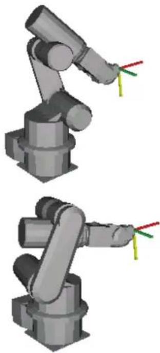
Hand P1, Righty Go P1
Hand P1, Lefty Go P1
Hand Function
Returns the hand orientation of a point.

Syntax
Hand [(point)]
Parameters
point Optional. Point expression. If point is omitted, then the hand orientation of the current robot position is returned.
Return Values
1 Righty (/R) 2 Lefty (/L)
See Also
Elbow, Wrist, J4Flag, J6Flag, J1Flag, J2Flag
Hand Function Example
Print Hand(pick)
Print Hand(P1)
Print Hand
Print Hand(P1 + P2)
Here Statement
Teach a robot point at the current position.
S
Syntax
Here point
Parameters
point Pnumber or P(expr) or point label.
Note
The Here statement and Parallel Processing
You cannot use both of the Here statement and parallel processing in one motion command like this: Go Here :Z(0) ! D10; MemOn 1 !
Be sure to change the program like this:
P999 = Here
Go P999 Here :Z(0) ! D10; MemOn 1 !
See Also
Here Function
Here Statement Example
Here P1
Here pick
Here Function
Returns current robot position as a point.

Syntax
Here
Return Values
A point representing the current robot position.
Description
Use Here to retrieve the current position of the current manipulator.
See Also
Here Statement
Here Function Example
P1 = Here
Hex$ Function
Returns a string representing a specified number in hexadecimal format.
Syntax
Hex$(number)
Parameters
number Integer expression.
Return Values
Returns a string containing the ASCII representation of the number in hexadecimal format.
Description
Hexreturns a string representing the specified number in hexadecimal format. Each character is from 0-9 or A-F. Hex is especially useful for examining the results of the Stat function.
See Also
Str$, Stat, Val
Hex$ Function Example
> print hex$(stat(0))
A00000
> print hex$(255)
FF
Hofs Statement
Displays or sets the offset pulses between the encoder origin and the home sensor.


Syntax
(1) Hofs j1Pulses, j2Pulses, j3Pulses, j4Pulses, [j5pulses, j6pulses], [j7pulses], [j8pulses, j9pulses] (2) Hofs
Parameters
| j1Pulses | Integer expression representing joint 1 offset pulses. |
| j2Pulses | Integer expression representing joint 2 offset pulses. |
| j3Pulses | Integer expression representing joint 3 offset pulses. |
| j4Pulses | Integer expression representing joint 4 offset pulses. |
| j5Pulses | For 6 axis robots. Integer expression representing joint 5 offset pulses. |
| j6Pulses | For 6 axis robots. Integer expression representing joint 6 offset pulses. |
| j7Pulses | For 7 axis robots. Integer expression representing joint 7 offset pulses. |
| j8Pulses | For additional S axis. Integer expression representing joint 8 (additional S axis) offset pulses. |
| j9Pulses | For additional T axis. Integer expression representing joint 9 (additional T axis) offset pulses. |
Return Values
Displays current Hofs values when used without parameters.
Description
Hofs displays or sets the home position offset pulses. Hofs specifies the offset from the encoder 0 point (Z phase) to the mechanical 0 point.
Although the robot motion control is based on the zero point of the encoder mounted on each joint motor, the encoder zero point may not necessarily match the robot mechanical zero point. The Hofs offset pulse correction pulse is used to carry out a software correction to the mechanical 0 point based on the encoder 0 point.
Note
Hofs Values SHOULD NOT be Changed unless Absolutely Necessary
The Hofs values are correctly specified prior to delivery. There is a danger that unnecessarily changing the Hofs value may result in position errors and unpredictable motion. Therefore, it is strongly recommended that Hofs values not be changed unless absolutely necessary.
To Automatically Calculate Hofs Values
To have Hofs values automatically calculated, move the arm to the desired calibration position, and execute Calib. The controller then automatically calculates Hofs values based on the CalPIs pulse values and calibration position pulse values.
Saving and Restoring Hofs
Hofs can be saved and restored using the Save and Load commands in the [System Configuration] dialog-[Robot]-[Calibration] from the System Configuration menu.
See Also
Calib, CalPIs, Home, Hordr, MCal, SysConfig
Hofs Statement Example
These are simple examples on the monitor window that first sets the joint 1 home offset value to be -545, the joint 2 home offset value to be 514, and the joint 3 and the joint 4 Home offset values to be both 0. It then displays the current home offset values.
> hofs -545, 514, 0, 0
> hofs
-545, 514, 0, 0
>
Hofs Function
Returns the offset pulses used for software zero point correction.

Syntax
Hofs(jointNumber)
Parameters
jointNumber
Integer expression representing the joint number to retrieve the Hofs value for. The additional S axis is 8 and T axis is 9.
Return Values
The offset pulse value (integer value, in pulses).
See Also
Calib, CalPIs, Home, Hordr, MCal, SysConfig
Hofs Function Example
This example uses the Hofs function in a program:
Function DisplayHofs
    Integer i

    Print "Hofs settings:"
    For i = 1 To 4
    Print "Joint ", i, " = ", Hofs(i)
    Next i
Fend
Home Statement
Moves the robot arm to the user defined home position.
Syntax
Home
Description
Executes low speed Point to Point motion to the Home (standby) position specified by HomeSet, in the homing order defined by Hordr.
Normally, for SCARA robots (including RS series), the Z joint (J3) returns first to the HomeSet position, then the J1, J2 and J4 joints simultaneously return to their respective HomeSet coordinate positions. The Hordr instruction can change this order of the axes returning to their home positions.
Note
Home Status Output:
When the robot is in its Home position, the controller's system Home output is turned ON.
Potential Errors
Attempting to Home without HomeSet Values Defined
Attempting to Home the robot without setting the HomeSet values will result in an Error 2228 being issued.
See Also
HomeClr, HomeDef, HomeSet, Hordr
Home Example
The Home instruction can be used in a program such as this:
Function InitRobot
    Reset
    If Motor = Off Then
    Motor On
    EndIf
    Home
Fend

Or it can be issued from the Command window like this:
> home
>
HomeClr Function
Clears the home position definition.

Syntax
HomeClr
See Also
HomeDef, HomeSet
HomeClr Function Example
This example uses the HomeClr function in a program:
Function ClearHome
    If HomeDef = True Then
    HomeClr
    EndIf
Fend
HomeDef Function
Returns whether home position has been defined or not.

Syntax
HomeDef
Return Values
True if home position has been defined, otherwise False.
See Also
HomeClr, HomeSet
HomeDef Function Example
This example uses the HomeDef function in a program:
Function DisplayHomeSet
Integer i
If HomeDef = False Then
    Print "Home is not defined"
Else
    Print "Home values:"
    For i = 1 To 4
    Print "J", i, " = ", HomeSet(i)
    Next i
End If
Fend
HomeSet Statement
Specifies and displays the Home position.
Syntax
(1) HomeSet j1Pulses, j2Pulses, j3Pulses, j4Pulses, [j5Pulses, j6Pulses], [j7Pulses], [j8Pulses, j9Pulses]
(2) HomeSet
Parameters
j1Pulses The home position encoder pulse value for joint 1.
j2Pulses The home position encoder pulse value for joint 2.
j3Pulses The home position encoder pulse value for joint 3.
j4Pulses The home position encoder pulse value for joint 4.
j5Pulses Optional for 6-axis robots. The home position encoder pulse value for joint 5.
j6Pulses Optional for 6-axis robots. The home position encoder pulse value for joint 6.
j7Pulses Optional for Joint type 7-axis robots. The home position encoder pulse value for joint 7.
j8Pulses Optional for additional S axis. The home position encoder pulse value for joint 8 (additional S axis).
j9Pulses Optional for additional T axis. The home position encoder pulse value for joint 9 (additional T axis).
Return Values
Displays the pulse values defined for the current Home position when parameters are omitted.
Description
Allows the user to define a new home (standby) position by specifying the encoder pulse values for each of the robot joints.
Notes
Home Command Does Not Calibrate the Robot:
This note pertains to incremental encoder robots only.
While the HomeSet command sets the Home position encoder values, it is very important to remember that the Home command does not calibrate the robot. The Mcal command is used to calibrate the robot. (When main power is first turned on the robot must be calibrated using Mcal.)
Verinit and its Effect on HomeSet Values:
Executing Verinit deletes the current HomeSet values.
Potential Errors
Attempting to Home without HomeSet Values Defined:
Attempting to Home the robot without setting the HomeSet values will result in an Error 143 being issued.
Attempting to Display HomeSet Values without HomeSet Values Defined:
Attempting to display home position pulse values without HomeSet values defined causes an Error 143.
See Also
Home, Hordr, Mcal, PIs
HomeSet Example
The following examples are done from the monitor window:
> homeset 0,0,0,0 'Set Home position at 0,0,0,0
> homeset
    0 0
    0 0
> home 'Robot homes to 0,0,0,0 position
Using the PIs function, specify the current position of the arm as the Home position.
> homeset Pls(1), Pls(2), Pls(3), Pls(4)
HomeSet Function
Returns pulse values of the home position for the specified joint.

Syntax
HomeSet(jointNumber)
Parameters
jointNumber Integer expression representing the joint number to retrieve the HomeSet value for. The additional S axis is 8 and T axis is 9.
Return Values
Returns pulse value of joint home position. When jointNumber is 0, returns 1 when HomeSet has been set or 0 if not.
See Also
HomeSet Statement
HomeSet Function Example
This example uses the HomeSet function in a program:
Function DisplayHomeSet
Integer i
If HomeSet(0) = 0 Then
    Print "HomeSet is not defined"
Else
    Print "HomeSet values:"
    For i = 1 To 4
    Print "J", i, " = ", HomeSet(i)
    Next i
End If
Fend
Hordr Statement
Specifies or displays the order of the axes returning to their Home positions.
Syntax
(1) Hordr step1, step2, step3, step4, [step5], [step6], [step7], [step8], [step9]
(2) Hordr
Parameters
| step1 | Bit pattern that defines which joints should home during the 1st step of the homing process. |
| step2 | Bit pattern that defines which joints should home during the 2nd step of the homing process. |
| step3 | Bit pattern that defines which joints should home during the 3rd step of the homing process. |
| step4 | Bit pattern that defines which joints should home during the 4th step of the homing process. |
| step5 | Bit pattern that defines which joints should home during the 5th step of the homing process. |
| step6 | Bit pattern that defines which joints should home during the 6th step of the homing process. |
| step7 | Bit pattern that defines which joints should home during the 7th step of the homing process. |
| step8 | Bit pattern that defines which joints should home during the 8th step of the homing process. |
| step9 | Bit pattern that defines which joints should home during the 9th step of the homing process. |
Return Values
Displays current Home Order settings when parameters are omitted.
Description
Hordr specifies joint motion order for the Home command. (i.e. Defines which joint will home 1st, which joint will home 2nd, 3rd, etc.)
The purpose of the Hordr instruction is to allow the user to change the homing order. The homing order is broken into 4, 6, or 9 separate steps, depending on robot type. The user then uses Hordr to define the specific joints which will move to the Home position during each step. It is important to realize that more than one joint can be defined to move to the Home position during a single step. This means that all joints can potentially be homed at the same time. For SCARA robots (including RS series, 4 axis robots), it is recommended that the Z joint normally be defined to move to the Home position first (in Step 1) and then allow the other joints to follow in subsequent steps.
The Hordr instruction expects that a bit pattern be defined for each of the steps. Each joint is assigned a specific bit. When the bit is set to 1 for a specific step, then the corresponding joint will home. When the bit is cleared to 0, then the corresponding axis will not home during that step. The joint bit patterns are assigned as follows:
| Joint: | 1 | 2 | 3 | 4 | 5 | 6 | 7 | 8 | 9 |
| Bit Number: | bit 0 bit 1 bit 2 bit 3 bit 4 bit 5 bit 6 bit 7 bit 8 | ||||||||
| Binary Code: | &B0001 | &B0010 | &B0100 | &B1000 | &B10000 | &B100000 | &B10000000 | &B1000000000 | |
See Also
Home, HomeSet
Hordr Statement Example
Following are some command window examples for SCARA robots (including RS series, 4 axis robots):
This example defines the home order as J3 in the first step, J1 in second step, J2 in third step, and J4 in the fourth step. The order is specified with binary values.
>hordr &B0100, &B0001, &B0010, &B1000
This example defines the home order as J3 in the first step, then J1, J2 and J4 joints simultaneously in the second step. The order is specified with decimal values.
>hordr 4, 11, 0, 0
This example displays the current home order in decimal numbers.
> hordr
4, 11, 0, 0
>
Hordr Function
Returns Hordr value for a specified step.
Syntax
Hordr(stepNumber)
Parameters
stepNumber Integer expression representing which Hordr step to retrieve.
Return Values
Integer containing the Hordr value for the specified step.
See Also
Home, HomeSet
Hordr Function Example
Integer a
a = Hordr(1)
Hour Statement
Displays the accumulated controller operating time.

Syntax
Hour
Description
Displays the amount of time the controller has been turned on and running SPEL. (Accumulated Operating Time) Time is always displayed in units of hours.
See Also
Time
Hour Example
The following example is done from the Command window:
> hour
2560
>
Hour Function
Returns the accumulated controller operating time.

Syntax
Hour
Return Values
Returns accumulated operating time of the controller (real number, in hours).
See Also
Time
Hour Function Example
Print "Number of controller operating hours: ", Hour
If...Then...Else...EndIf Statement
Executes instructions based on a specified condition.
s
Syntax
(1) If condition Then stmtT1
[ElseIf condition Then] stmtT1
[Else] stmtF1
EndIf
(2) If condition Then stmtT1 [; stmtT2...] [Else stmtF1 [; stmtF2...]]
Parameters
condition Any valid test condition which returns a True (any number besides 0) or False result (returned as a 0). (See sample conditions below)
stmtT1 Executed when the condition is True. (Multiple statements may be put here in a blocked If...Then...Else style.)
stmtF1 Executed when the condition is False. (Multiple statements may be put here in a blocked If...Then...Else style.)
Description
(1) If...Then...Else executes stmtT1, etc. when the conditional statement is True. If the condition is False then stmtF1, etc. are executed. The Else portion of the If...Then...Else instruction is optional. If you omit the Else statement and the conditional statement is False, the statement following the EndIf statement will be executed. For blocked If...Then...Else statements the EndIf statement is required to close the block regardless of whether an Else is used or not. (2) If...Then...Else can also be used in a non blocked fashion. This allows all statements for the If...Then...Else to be put on the same line. Please note that when using If...Then...Else in a non blocked fashion, the EndIf statement is not required. If the If condition specified in this line is satisfied (True), the statements between the Then and Else are executed. If the condition is not satisfied (False), the statements following Else are executed. The Else section of the If...Then...Else is not required. If there is no Else keyword then control passes on to the next statement in the program if the If condition is False.
The logical output of the conditional statement is any number excluding 1 when it is True, and 0 when it is false.
Notes
Sample Conditions:
a = b : a is equal to b
a < b : b is larger than a
a >= b : a is greater than or equal to b
a <> b : a is not equal to b
a > b : b is smaller than a
a <= b : a is less than or equal to b
Logical operations And, Or and Xor may also be used.
True in the Conditions:
Constant True is -1 and the type is Boolean, so you need to be careful when using it in a comparing condition with other type variable.
Function main
    Integer i
    i = 3
    If i = True Then
    Print "i=TRUE"
    EndIf
Fend
When you execute the program above, "i=TRUE" is displayed.
The judgement of condition including the Boolean type is done with "0" or "non-0".
If the value of "i" is not "0", it is considered that the condition is established and "i=TRUE" is displayed.
See Also
Else, Select...Case, Do...Loop
If/Then/Else Statement Example
The following example shows a simple function which checks an input to determine whether to turn a specific output on or off. This task could be a background I/O task which runs continuously.
Function main
    Do
    If Sw(0) = 1 Then On 1 Else Off 1
    Loop
Fend
The following example shows a simple function which checks a few inputs and prints the status of these inputs.
If Sw(0) = 1 Then Print "Input0 ON" Else Print "Input0 OFF"
    If Sw(1) = 1 Then
    If Sw(2) = 1 Then
    Print "Input1 On and Input2 ON"
    Else
    Print "Input1 On and Input2 OFF"
    EndIf
Else
    If Sw(2) = 1 Then
    Print "Input1 Off and Input2 ON"
    Else
    Print "Input1 Off and Input2 OFF"
    EndIf
EndIf
If x = 10 And y = 3 Then GoTo 50
If test <= 10 Then Print "Test Failed"
If Sw(0) = 1 Or Sw(1) = 1 Then Print "Everything OK"
ImportPoints Statement
Imports a point file into the current project for the specified robot.
Syntax
ImportPoints sourcePath, filename, [robotNumber]
Parameters
| sourcePath | String expression containing the specific path and file to import into the current project. The extension can be .PTS or .PNT (EPSON RC+ 3.x and 4.x format). See ChDisk for the details. |
| fileName | String expression containing the specific file to be imported to in the current project for the current robot The extension must be .PTS.You cannot specify a file path and fileName doesn't have any effect from ChDisk.See ChDisk for the details. |
| robotNumber | Optional. Integer expression that specifies which robot the point file should be associated with. If robotNumber = 0, then the point file is imported as a common point file. If robotNumber is omitted, the current robot number is used. |
Description
ImportPoints copies a point file into the current project and adds it to the project files for the specified robot. The point file is then compiled and is ready for loading using the LoadPoints command. If the file already exists for the current robot, it will be overwritten and recompiled.
The point data is stored in the compact flash inside of the controller. Therefore, ImportPoints starts writing into the compact flash. Frequent writing into the compact flash will shorten the compact flash lifetime. We recommend using ImportPoints only for saving the point data.
Potential Errors
File Does Not Exist
If sourcePath does not exist, an error will occur.
A Path Cannot be Specified
If fileName contains a path, an error will occur.
Point file for another robot.
If fileName is a point file for another robot, an error will occur.
See Also
Dir, LoadPoints, Robot, SavePoints
ImportPoints Statement Example
Function main
    Robot 1
    ImportPoints "c:\mypoints\model1.pts", "robot1.pts"
    LoadPoints "robot1.pts"
Fend
In Function
Returns the status of the specified byte port. Each port contains 8 input channels.

Syntax
In(byteportNumber)
Parameters
byteportNumber: Integer number representing one eight-bit port (one byte).
Return Values
Returns an integer value between 0 and 255. The return value is 8 bits, with each bit corresponding to 1 input channel.
Description
In provides the ability to look at the value of 8 input channels at the same time. The In instruction can be used to store the status of the 8 I/O channels into a variable, or it can be used with the Wait instruction to wait until a specific condition involving more than 1 I/O channel is met.
Since 8 channels are checked at a time, the return values range from 0 to 255. Please review the chart below to see how the integer return values correspond to individual input channels.
Input Channel Result (Using Byte port #0)
| Return Value | 7 | 6 | 5 | 4 | 3 | 2 | 1 | |||||||||||||||||||||||||||||||||||||||||||||||||||||||||||||||||||||||||||||||||||||||||||||||||||||||||||||||||||||||||||||||||||||||||||||||||||||||||||||||||||||||||||||||||||||||||||||||||||||||||||||||||||||||||||||||||||||||||||||||||||||||||||||||||||||||||||||||||||||||||||||||||||||||||||||||||||||||||||||||||||||||||||||||||||||||||||||||||||||||||||||||||||||||||||||||||||||||||||||||||||||||||||||||||||||||||||||||||||||||||||||||||||||||||||||||||||||||||||||||||||||||||||||||||||||||||||||||||||||||||||||||||||||||||||||||||||||||||||||||||||||||||||||||||||||||||||||||||||||||||||||||||||||||||||||||||||||||||||||||||||||||||||||||||||||||||||||||||||||||||||||||||||||
| 1 | Off Off Off Off Off Off Off Off Off Off Off Off Off Off Off Off Off Off Off Off Off Off Off Off Off Off Off Off Off Off Off Off Off Off Off Off Off Off Off Off Off Off Off Off Off Off Off Off Off Off Off Off Off Off Off Off Off Off Off Off Off Off Off Off Off Off Off Off Off Off Off Off Off Off Off Off Off Off Off Off Off Off Off Off Off Off Off Off Off Off Off Off Off Off Off Off Off Off Off Off Off On On On On On On On On On On On On On On On On On On On On On On On On On On On On On On On On On On On On On On On On On On On On On On On On On On On On On On On On On On On On On On On On On On On On On On On On On On On On On On On On On On On On On On On On On On On On On On On On On On On On | Off Off Off Off Off Off Off Off Off Off Off Off Off Off Off Off Off Off Off Off Off Off Off Off Off Off Off Off Off Off Off Off Off Off Off Off Off Off Off Off Off Off Off Off Off Off Off Off Off Off Off Off Off Off Off Off Off Off Off Off Off Off Off Off Off Off Off Off Off Off Off Off Off Off Off Off Off Off Off Off Off Off Off Off Off Off Off Off Off Off Off Off Off Off Off Off Off Off On On | Off Off Off Off Off Off Off Off Off Off Off Off Off Off Off Off Off Off Off Off Off Off Off Off Off Off Off Off Off Off Off Off Off Off Off Off Off Off Off Off Off Off Off Off Off Off Off Off Off Off Off Off Off Off Off Off Off Off Off Off Off Off Off Off Off Off Off Off Off Off Off Off Off Off Off Off Off Off Off Off Off Off Off Off Off Off Off Off Off Off Off Off Off Off Off Off On | Off Off Off Off Off Off Off Off Off Off Off Off Off Off Off Off Off Off Off Off Off Off Off Off Off Off Off Off Off Off Off Off Off Off Off Off Off Off Off Off Off Off Off Off Off Off Off Off Off Off Off Off Off Off Off Off Off Off Off Off Off Off Off Off Off Off Off Off Off Off Off Off Off Off Off Off Off Off Off Off Off Off Off Off Off Off Off Off Off Off Off Off Off Off Off Off Off On | Off Off On | Off Off On | Off Off On | Off Off On | Off Off On | Off Off On | Off Off On | Off Off On | Off Off On | Off Off On | Off Off On | Off Off On | Off Off On | Off Off On | Off Off On | Off Off On | Off Off On | Off Off On | Off Off On | Off Off On | Off Off On | Off Off On | Off Off On | Off Off On | Off Off On | On On | On On | On On | On On | On On | On On | On On | On On | On On | On On | On On | On On | On On | On On | On On | On On | On On | On On | On On | On On | On On | On On | On On | On On | On On | On On | On On | On On | On On | On On | On On | On On | On On | On Un | On Un | On Un | On Un | On Un | On Un | On Un | On Un | On Un | On Un | On Un | On Un | On Un | On Un | On Un | On Un | On Un | On Un | On Un | On Un | On Un | On Un | On Un | On Un | On Un | On Un | On Un | On Un | On Un | On Un | On Un | On Un | On Un | On Un | ||||||||||||||||||||||||||||||||||||||||||||||||||||||||||||||||||||||||||||||||||||||||||||||||||||||||||||||||||||||||||||||||||||||||||||||||||||||||||||||||||||||||||||||||||||||||||||||||||||||||||||||||||||||||||||||||||||||||||||||||||||||||||||||||||||||||||||||||||||||||||||||||||||||||||||||||||||||||||||||||||||||||||||||||||||||||||||||||||||||||||||||||||||||||||||||||||||||||||||||||||||||||||||||||||||||||||||||||||||||||||||||||||||||||||||||||||||||||||||||||||||||||||||||||||||||||||||||||||||||||||||||||||||||||||||||||||||||||||||||||||||||||||||||||||||||||||||||||||||||||||||
| 5 | Off Off Off Off Off Off Off Off Off Off Off Off Off Off Off Off Off Off Off Off Off Off Off Off Off Off Off Off Off Off Off Off Off Off Off Off Off Off Off Off Off Off Off Off Off Off Off Off Off Off Off Off Off Off Off Off Off Off Off Off Off Off Off Off Off Off Off Off Off Off Off Off Off Off Off Off Off Off Off Off Off Off Off Off Off Off Off Off Off Off Off Off Off Off Off Off Off Off Non | Off Off Off Off Off Off Off Off Off Off Off Off Off Off Off Off Off Off Off Off Off Off Off Off Off Off Off Off Off Off Off Off Off Off Off Off Off Off Off Off Off Off Off Off Off Off Off Off Off Off Off Off Off Off Off Off Off Off Off Off Off Off Off Off Off Off Off Off Off Off Off Off Off Off Off Off Off Off Off Off Off Off Off Off Off Off Off Off Off Off Off Off Off Off Off Off Off Off Fos | Off Off Off Fos | Off Fos | Off Fos | Off Fos | Off Fos | Off Fos | Off Fos | Off Fos | Off Fos | Off Fos | Off Fos | Off Fos | Off Fos | Off Fos | Off Fos | Off Fos | Off Fos | Off Fos | Off Fos | Off Fos | Off Fos | Off Fos | Off Fos | Off Fos | Off Fos | Off Fos | Fos | Off Fos | Off Fos | Off Fos | Off Fos | Off Fos | Off Fos | Off Fos | Off Fos | Off Fos | Off Fos | Off Fos | Off Fos | Off Fos | Off Fos | Off Fos | Off Fos | Off Fos | Off Fos | Off Fos | Off Fos | Off Fos | Off Fos | Off Fos | Off Fos | Off Gos | Off Fos | Off Fos | Off Fos | Off Fos | Off Fos | Off Fos | Off Fos | Off Fos | Off Fos | Off Fos | Off Fos | Off Fos | Off Fos | Off Fos | Off Fos | Off Fos | Off Fos | Off Fos | Off Fos | Off Fos | Off Fos | Off Fos | Off Fos | Off Fos | Off Tons | Off Tons | Off Tons | Off Tons | Off Tons | Off Tons | Off Tons | Off Tons | Off Tons | Off Tons | Off Tons | Off Tons | Off Tons | Off Tons | Off Tons | Off Tons | Off Tons | Off Tons | Off Tons | Off Tons | Off Tons | Off Tons | Off Tons | Off Tons | Off Tons | Off Tont | Off Tont | Off Tont | Off Tont | Off Tont | Off Tont | Off Tont | Off Tont | Off Tont | Off Tont | Off Tont | Off Tont | Off Tont | Off Tont | Off Tont | Off Tont | Off Tont | Off Tont | Off Tont | Off Tont | Off Tont | Off Tont | Off Tont | Off Tont | Off Tont | Off TPont | Off Tont | Off Tont | Off Tont | Off Tont | Off Tont | Off Tont | Off Tont | Off Tont | Off Tont | Off Tont | Off Tont | Off Tont | Off Tont | Off Tont | Off Tont | Off Tont | Off Tont | Off Tont | Off Tont | Off Tont | Off Tont | Off Tont | Off Tont | Off Tont | Off TMont | Off Tont | Off Tont | Off Tont | Off Tont | Off Tont | Off Tont | Off Tont | Off Tont | Off Tont | Off Tont | Off Tont | Off Tont | Off Tont | Off Tont | Off Tont | Off Tont | Off Tont | Off Tont | Off Tont | Off Tont | Off Tont | Off Tont | Off Tont | Off Tont | Off TONT | Off TONT | Off TONT | Off TONT | Off TONT | Off TONT | Off TONT | Off TONT | Off TONT | Off TONT | Off TONT | Off TONT | Off TONT | Off TONT | Off TONT | Off TONT | Off TONT | Off TONT | Off TONT | Off TONT | Off TONT | Off TONT | Off TONT | Off TONT | Off TONT | Off TNT | Off TNT | Off TNT | Off TNT | Off TNT | Off TNT | Off TNT | Off TNT | Off TNT | Off TNT | Off TNT | Off TNT | Off TNT | Off TNT | Off TNT | Off TNT | Off TNT | Off TNT | Off TNT | Off TNT | Off TNT | Off TNT | Off TNT | Off TNT | Off TNT | Off TINT | Off TNT | Off TNT | Off TNT | Off TNT | Off TNT | Off TNT | Off TNT | Off TNT | Off TNT | Off TNT | Off TNT | Off TNT | Off TNT | Off TNT | Off TNT | Off TNT | Off TNT | Off TNT | Off TNT | Off TNT | Off TNT | Off TNT | Off TNT | Off TNT | Off TANT | Off TNT | Off TNT | Off TNT | Off TNT | Off TNT | Off TNT | Off TNT | Off TNT | Off TNT | Off TNT | Off TNT | Off TNT | Off TNT | Off TNT | Off TNT | Off TNT | Off TNT | Off TNT | Off TNT | Off TNT | Off TNT | Off TNT | Off TNT | Off TNT | Off TNET | Off TNT | Off TNT | Off TNT | Off TNT | Off TNT | Off TNT | Off TNT | Off TNT | Off TNT | Off TNT | Off TNT | Off TNT | Off TNT | Off TNT | Off TNT | Off TNT | Off TNT | Off TNT | Off TNT | Off TNT | Off TNT | Off TNT | Off TNT | Off TNT | Off TENT | Off TNT | Off TNT | Off TNT | Off TNT | Off TNT | Off TNT | Off TNT | Off TNT | Off TNT | Off TNT | Off TNT | Off TNT | Off TNT | Off TNT | Off TNT | Off TNT | Off TNT | Off TNT | Off TNT | Off TNT | Off TNT | Off TNT | Off TNT | Off TNT | Off TN | Off TNT | Off TNT | Off TNT | Off TNT | Off TNT | Off TNT | Off TNT | Off TNT | Off TNT | Off TNT | Off TNT | Off TNT | Off TNT | Off TNT | Off TNT | Off TNT | Off TNT | Off TNT | Off TNT | Off TNT | Off TNT | Off TNT | Off TNT | Off TNT | Off T NT | Off TNT | Off TNT | Off TNT | Off TNT | Off TNT | Off TNT | Off TNT | Off TNT | Off TNT | Off TNT | Off TNT | Off TNT | Off TNT | Off TNT | Off TNT | Off TNT | Off TNT | Off TNT | Off TNT | Off TNT | Off TNT | Off TNT | Off TNT | Off TNT | Off T N | Off TNT | Off TNT | Off TNT | Off TNT | Off TNT | Off TNT | Off TNT | Off TNT | Off TNT | Off TNT | Off TNT | Off TNT | Off TNT | Off TNT | Off TNT | Off TNT | Off TNT | Off TNT | Off TNT | Off TNT | Off TNT | Off TNT | Off TNT | Off TNT | Off TMT | Off TNT | Off TNT | Off TNT | Off TNT | Off TNT | Off TNT | Off TNT | Off TNT | Off TNT | Off TNT | Off TNT | Off TNT | Off TNT | Off TNT | Off TNT | Off TNT | Off TNT | Off TNT | Off TNT | Off TNT | Off TNT | Off TNT | Off TNT | Off TNT | Off TNS | Off TNT | Off TNT | Off TNT | Off TNT | Off TNT | Off TNT | Off TNT | Off TNT | Off TNT | Off TNT | Off TNT | Off TNT | Off TNT | Off TNT | Off TNT | Off TNT | Off TNT | Off TNT | Off TNT | Off TNT | Off TNT | Off TNT | Off TNT | Off TNT | Off THT | Off TNT | Off TNT | Off TNT | Off TNT | Off TNT | Off TNT | Off TNT | Off TNT | Off TNT | Off TNT | Off TNT | Off TNT | Off TNT | Off TNT | Off TNT | Off TNT | Off TNT | Off TNT | Off TNT | Off TNT | Off TNT | Off TNT | Off TNT | Off TNT | Off TNV | Off TNT | Off TNT | Off TNT | Off TNT | Off TNT | Off TNT | Off TNT | Off TNT | Off TNT | Off TNT | Off TNT | Off TNT | Off TNT | Off TNT | Off TNT | Off TNT | Off TNT | Off TNT | Off TNT | Off TNT | Off TNT | Off TNT | Off TNT | Off TNT | Off TNU | Off TNT | Off TNT | Off TNT | Off TNT | Off TNT | Off TNT | Off TNT | Off TNT | Off TNT | Off TNT | Off TNT | Off TNT | Off TNT | Off TNT | Off TNT | Off TNT | Off TNT | Off TNT | Off TNT | Off TNT | Off TNT | Off TNT | Off TNT | Off TNT | Off TNN | Off TNT | Off TNT | Off TNT | Off TNT | Off TNT | Off TNT | Off TNT | Off TNT | Off TNT | Off TNT | Off TNT | Off TNT | Off TNT | Off TNT | Off TNT | Off TNT | Off TNT | Off TNT | Off TNT | Off TNT | Off TNT | Off TNT | Off TNT | Off TNT | Off TNY | Off TNT | Off TNT | Off TNT | Off TNT | Off TNT | Off TNT | Off TNT | Off TNT | Off TNT | Off TNT | Off TNT | Off TNT | Off TNT | Off TNT | Off TNT | Off TNT | Off TNT | Off TNT | Off TNT | Off TNT | Off TNT | Off TNT | Off TNT | Off TNT | Off TNA | Off TNT | Off TNT | Off TNT | Off TNT | Off TNT | Off TNT | Off TNT | Off TNT | Off TNT | Off TNT | Off TNT | Off TNT | Off TNT | Off TNT | Off TNT | Off TNT | Off TNT | Off TNT | Off TNT | Off TNT | Off TNT | Off TNT | Off TNT | Off TNT | Off TNE | Off TNT | Off TNT | Off TNT | Off TNT | Off TNT | Off TNT | Off TNT | Off TNT | Off TNT | Off TNT | Off TNT | Off TNT | Off TNT | Off TNT | Off TNT | Off TNT | Off TNT | Off TNT | Off TNT | Off TNT | Off TNT | Off TNT | Off TNT | Off TNT | Off TAT | Off TNT | Off TNT | Off TNT | Off TNT | Off TNT | Off TNT | Off TNT | Off TNT | Off TNT | Off TNT | Off TNT | Off TNT | Off TNT | Off TNT | Off TNT | Off TNT | Off TNT | Off TNT | Off TNT | Off TNT | Off TNT | Off TNT | Off TNT | Off TNT | Off TAnt | Off TNT | Off TNT | Off TNT | Off TNT | Off TNT | Off TNT | Off TNT | Off TNT | Off TNT | Off TNT | Off TNT | Off TNT | Off TNT | Off TNT | Off TNT | Off TNT | Off TNT | Off TNT | Off TNT | Off TNT | Off TNT | Off TNT | Off TNT | Off TNT | Off TCTT | Off TNT | Off TNT | Off TNT | Off TNT | Off TNT | Off TNT | Off TNT | Off TNT | Off TNT | Off TNT | Off TNT | Off TNT | Off TNT | Off TNT | Off TNT | Off TNT | Off TNT | Off TNT | Off TNT | Off TNT | Off TNT |
0
Input Channel Result (Using Byte port #2)
| Return Value 23 | 22 21 | 20 19 | 18 17 | 16 | ||||
| 3 | Off | Off | Off | Off | Off On | On | ||
| 7 | Off | Off | Off | Off | On On | On | ||
| 32 | Off | Off | On | Off | Off Off | Off | ||
| 255 | On | On | On | On | On On | On |
See Also
InBCD, MemIn, MemOff, MemOn, MemSw, Off, On, OpBCD, Oport, Out, Sw, Wait
In Function Example
For the example below, let's assume that input channels 20, 21, 22, and 23 are all connected to sensory devices such that the application should not start until each of these devices is returning an On signal indicating everything is OK to start. The program example gets the 8 input channels status of byte port 2 and makes sure that channels 20, 21, 22, and 23 are each On before proceeding. If they are not On (i.e., returning a value of 1), an error message is given to the operator and the task is stopped.
In the program, the variable "var1" is compared against the number 239 because in order for inputs 20, 21, 22, and 23 to all be On, the result of In(2) will be 240 or larger. (We don't care about Inputs 16, 17, 18, and 19 in this case, so any values between 240-255 will allow the program to proceed.)
Function main
    Integer var1
    var1 = In(2) 'Get 8 input channels status of byte port 2
    If var1 > 239 Then
    Go P1
    Go P2
    'Execute other motion statements here
    ..
    '.
    Else
    Print "Error in initialization!"
    Print "Sensory Inputs not ready for cycle start"
    Print "Please check inputs 20,21,22, and 23 for"
    Print "proper state for cycle start and then"
    Print "start program again"
    EndIf
Fend
We cannot set inputs from the command window, but we can check them. For the examples shown below, we will assume that the Input channels 1, 5, and 15 are On. All other inputs are Off.
> print In(0)
34
> print In(1)
128
> print In(2)
0
InBCD Function
Returns the input status of 8 inputs using BCD format. (Binary Coded Decimal)

Syntax
InBCD(portNumber)
Parameters
portNumber Integer number representing one eight bit port (one byte).
Return Values
Returns as a Binary Coded Decimal (0-9), the input status of the input port (0-99).
Description
InBCD simultaneously reads 8 input lines using the BCD format. The portNumber parameter for the InBCD instruction defines which group of 8 inputs to read where portNumber = 0 means inputs 0-7, portNumber = 1 means inputs 8-15, etc.
The resulting value of the 8 inputs is returned in BCD format. The return value may have 1 or 2 digits between 0 and 99. The 1st digit (or 10's digit) corresponds to the upper 4 outputs of the group of 8 outputs selected by portNumber. The 2nd digit (or 1's digit) corresponds to the lower 4 outputs of the group of 8 outputs selected by portNumber.
Since valid entries in BCD format range from 0-9 for each digit, every I/O combination cannot be met. The table below shows some of the possible I/O combinations and their associated return values assuming that portNumber is 0.
Input Settings (Input number)
| Return | Value | 7 | 6 | 5 | 4 | 3 | 2 | 1 | |
| 01 | Off | Off | Off | Off | Off | Off | Off | On | |
| 02 | Off | Off | Off | Off | Off | Off | On | Off | |
| 03 | Off | Off | Off | Off | Off | Off | On | On | |
| 08 | Off | Off | Off | Off | On | Off | Off | Off | |
| 09 | Off | Off | Off | Off | On | Off | Off | On | |
| 10 | Off | Off | Off | On | Off | Off | Off | Off | |
| 11 | Off | Off | Off | On | Off | Off | Off | On | |
| 99 | On | Off | Off | On | On | Off | Off | On |
0
Notice that the Binary Coded Decimal format only allows decimal values to be specified. This means that through using Binary Coded Decimal format it is impossible to retrieve a valid value if all inputs for a specific port are turned on at the same time when using the InBCD instruction. The largest value possible to be returned by InBCD is 99. In the table above it is easy to see that when 99 is the return value for InBCD, all inputs are not on. In the case of a return value of 99, inputs 0, 3, 4, and 7 are On and all the others are Off.
Notes
Difference between InBCD and In
The InBCD and In instructions are very similar in the SPEL + language. However, there is one major difference between the two. This difference is shown below:
- The InBCD instruction uses the Binary Coded Decimal format for specifying the return value format for the 8 inputs. Since Binary Coded Decimal format precludes the values of &HA, &HB, &HC, &HD, &HE or &HF from being used, all combinations for the 8 inputs cannot be satisfied.
- The In instruction works very similarly to the InBCD instruction except that In allows the return value for all 8 inputs to be used. (i.e. 0-255 vs. 0-99 for InBCD) This allows all possible combinations for the 8 bit input groups to be read.
See Also
In, MemOff, MemOn, MemOut, MemSw, Off, On, OpBCD, Oport, Out, Sw, Wait
InBCD Example
Some simple examples from the Command window are as follows:
Assume that inputs 0, 4, 10, 16, 17, and 18 are all On (The rest of the inputs are Off).
> Print InBCD(0)
11
> Print InBCD(1)
04
> Print InBCD(2)
07
>
Inertia Statement
Specifies load inertia and eccentricity for current robot.

Syntax
Inertia [loadInertia], [eccentricity]
Inertia
Parameters
loadInertia Optional. Real expression that specifies total moment of inertia in kgm 2 around the center of the end effector joint, including end effector and part.
eccentricity Optional. Real expression that specifies eccentricity in mm around the center of the end effector joint, including end effector and part.
Return Values
When parameters are omitted, the current Inertia parameters are displayed.
Description
Use the Inertia statement to specify the total moment of inertia for the load on the end effector joint. This allows the system to more accurately compensate acceleration, deceleration, and servo gains for the end effector joint. You can also specify the distance from the center of the end effector joint to the center of gravity of the end effector and part using the eccentricity parameter.
See Also
Inertia Function
Inertia Statement Example
Inertia 0.02, 1
Inertia Function
Returns inertia parameter value.

Syntax
paramNumber Integer expression which can have the following values:
0: Causes function to return 1 if robot supports inertia parameters or 0 if not.
1: Causes function to return load inertia in kgm2. 2: Causes function to return eccentricity in mm.
Return Values
Real value of the specified setting.
See Also
Inertia Statement
Inertia Function Example
Real loadInertia, eccentricity
loadInertia = Inertia(1)
eccentricity = Inertia(2)
InPos Function
Returns the position status of the specified robot.

Syntax
InPos
Return Values
True if position has been completed successfully, otherwise False.
See Also
CurPos, FindPos, WaitPos
InPos Function Example
Function main
    P0 = XY(0, -100, 0, 0)
    P1 = XY(0, 100, 0, 0)

    Xqt MonitorPosition
    Do
    Jump P0
    Wait .5
    Jump P1
    Wait .5
    Loop

Fend

Function MonitorPosition
    Boolean oldInPos, pos
    Do
    Pos = InPos
    If pos <> oldInPos Then
    Print "InPos = ", pos
    EndIf
    oldInPos = pos
    Loop

Fend
Input Statement
Receives input data from the display device and stores it in a variable(s).
Syntax
Input varName [, varName, varName,...]
Parameters
varName
Variable name. Multiple variables can be used with the Input command as long as they are separated by commas.
Description
Input receives data from the display device and assigns the data to the variable(s) used with the Input instruction.
When executing the Input instruction, a (?) prompt appears at the display device. After inputting data press the return key (Enter) on the keyboard.
Notes
Rules for Numeric Input
When inputting numeric values and non-numeric data is found in the input other than the delimiter (comma), the Input instruction discards the non-numeric data and all data following that non-numeric data.
Rules for String Input
When inputting strings, numeric and alpha characters are permitted as data.
Other Rules for the Input Instruction
- When more than one variable is specified in the instruction, the numeric data input intended for each variable has to be separated by a comma (",") character.
- Numeric variable names and string variable names are allowed. However, the input data type must match the variable type.
Potential Errors
Number of variables and input data differ
For multiple variables, the number of input data must match the number of Input variable names. When the number of the variables specified in the instruction is different from the number of numeric data received from the keyboard, an Error 2505 will occur.
See Also
Input #, Line Input, Line Input #, Print, String
Input Statement Example
This is a simple program example using Input statement.
Function InputNumbers
    Integer A, B, C

    Print "Please enter 1 number"
    Input A
    Print "Please enter 2 numbers separated by a comma"
    Input B, C
    Print "A = ", A
    Print "B = ", B, "C = ", C
Fend
A sample session of the above program running is shown below: (Use the Run menu or F5 key to start the program)
Please enter 1 number
?-10000
Please enter 2 numbers separated by a comma
?25.1, -99
-10000
25.1 -99
B = 25.1 C = -99
>
Input # Statement
Allows string or numeric data to be received from a file, communications port, or database and stored in one or more variables.


Syntax
Input #portNumber, varName [, varName, varName,...]
Parameters
portNumber
The ID number that specifies a file, communication port, database, or device. The File number can be specified in ROpen, WOpen, and AOpen statements. Communication port number can be specified in OpenCom (RS-232C) and OpenNet (TCP/IP) statements. The database number can be specified in OpenDB statement.
Device ID is: 21 RC+ 24 TP
varName Variable name to receive the data.
Description
The Input # instruction receives numeric or string data from the device specified by handle, and assigns the data to the variable(s).
Notes
Rules for Numeric Input
When inputting numeric values and non-numeric data is found in the input other than the delimiter (comma), the Input instruction discards the non-numeric data and all data following that non-numeric data.
Rules for String Input
When inputting strings, numeric and alpha characters are permitted as data.
Maximum data length
This command can handle up to 256 bytes. However, if the target is the database, it can handle up to 4096 bytes.
Other Rules for the Input Instruction
- When more than one variable is specified in the instruction, the numeric data input intended for each variable has to be separated by a comma (",") character or blank ("").
- When more than one string variable or both of numeric variable and string variable is specified, the numeric data has to be separated by a comma (“,”) character or blank (“”).
- The input data type must match the variable type.
The following programs are examples to exchange the string variable and numeric variable between the controllers using a communication port.
Sending end (Either pattern is OK.)
Print #PortNum, "$Status", "InData, OutData"
Print #PortNum, "$Status", "", "InData, OutData"
Receiving end
Input #PortNum, Response$, InData, OutData
Potential Errors
Number of variables and input data differ
When the number of variables specified in the instruction is different from the number of numeric data received from the device, an Error 30 will occur.
See Also
Input, Line Input, Line Input #, Print #
Input # Statement Example
This function shows some simple Input # statement examples.
Function GetData
    Integer A
    String B$
OpenCom #1
Print #1, "Send"
Input #1, A 'Get a numeric value from Port#1
Input #1, B$ 'Get a string from Port#1
CloseCom #1
Fend
InputBox Statement
Displays a prompt in a dialog box, waits for the operator to input text or choose a button, and returns the contents of the box.
Syntax
InputBox prompt, title, default, data$
Parameters
| prompt | String expression displayed as a message in the dialog box. |
| title | String expression displayed in the title bar of the dialog box. |
| default | String expression displayed in the text box as the default response. If no default is desired, use an empty string (""). |
| data$ | A string variable which will contain what the operator entered. If the operator clicks Cancel, this string will be "@". |
Description
InputBox displays the dialog and waits for the operator to click OK or Cancel. data is a string that contains what the operator typed in.
See Also
MsgBox
InputBox Statement Example
This function shows an InputBox example.
Function GetPartName$ As String
String prompt, title, data$
prompt$ = "Enter part name:"
title$ = "Sample Application"
InputBox prompt, title, "", data$
If data$ <> "@" Then
    GetPartName= data
EndIf
Fend
The following picture shows the example output from the InputBox example code shown above.
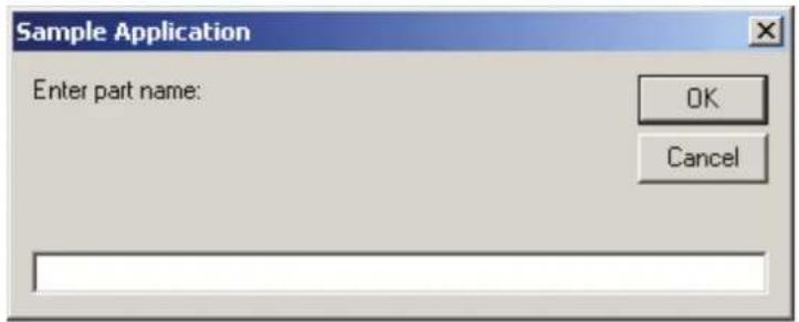
InReal Function
Returns the input data of 2 words (32 bits) as the floating-point data (IEEE754 compliant) of 32 bits.

Syntax
InReal(WordPortNumber)
Parameter
WordPortNumber Integer expression representing the I/O Input Word.
Return Values
Returns the input port status in Real type number.
Description
From the input word port specified by the word port number, retrieve the 2 input word values as IEEE754 Real type value. Input word label can be used for the word port number parameter. InReal Function cannot be used for the Wait command, or the condition of Till, Find, Sense.
See Also
In, InW, InBCD, Out, OutW, OpBCD, OutReal
InW Function Example
Real realVal
realVal = InReal(0)
InsideBox Function
Returns the check status of the approach check area.

Syntax
InsideBox(AreaNum [, robotNumber | All])
Parameters
AreaNum Integer expression from 1 to 15 representing which approach check area to return status for.
robotNumber Integer value that contains the robot number you want to search.
If omitted, the current robot will be specified.
If you specify All, True is returned if one robot is in the check area.
Return Values
True if the robot end effector approaches the specified approach check area, otherwise False.
Note
You can use the Wait statement with InsideBox to wait for the result of the InsideBox function in EPSON RC+ 5.0, however you cannot in EPSON RC+ 6.0. In this case, use the GetRobotInsideBox function instead of the InsideBox function.
See Also
Box, BoxClr, BoxDef, GetRobotInsideBox, InsidePlane
InsideBox Function Example
InsideBox function Example
The following program checks whether Robot 1 is in the check area (Box 3) or not.
Function PrintInsideBox
    If InsideBox(3,1) = True Then
    Print "Inside Box3"
    Else
    Print "Outside Box3"
    Endif
Fend
InsidePlane Function
Returns the check status of the approach check plane.

Syntax
InsidePlane(PlaneNum [, robotNumber | All])
Parameters
PlaneNum: Integer expression from 1 to 15 representing which approach check plane to return status for.
robotNumber: Integer value that contains the robot number you want to search.
If omitted, the current robot will be specified.
If you specify All, True is returned if one robot is in the check area.
Return Values
True if the robot end effector approaches the specified approach check plane, otherwise False.
See Also
InsideBox, GetRobotInsidePlane, Plane, PlaneClr, PlaneDef
Note
You can use the Wait statement with InsidePlane to wait for the result of the InsidePlane function in EPSON RC+ 5.0, however you cannot in EPSON RC+ 6.0.
In this case, use the GetRobotInsidePlane function instead of the InsidePlane function.
InsidePlane Function Example
This is an example to check Robot 1 is in the check plane (Plane 3).
Function PrintInsidePlane
    If InsidePlane(3,1) = True Then
    Print "Inside Plane3"
    Else
    Print "Outside Plane3"
    Endif
Fend
InStr Function
Returns position of one string within another.
F
Syntax
InStr(string, searchString)
Parameters
string String expression to be searched.
searchString String expression to be searched for within string.
Return Values
Returns the position of the search string if the location is found, otherwise -1.
See Also
Mid$
Instr Function Example
Integer pos
pos = InStr("abc", "b")
Int Function
Converts a Real number to Integer. Returns the largest integer that is less than or equal to the specified value.
F
Syntax
Int(number)
Parameters
number A real number expression.
Return Values
Returns an Integer value of the real number used in number.
Description
Int(number) takes the value of number and returns the largest integer that is less than or equal to number.
Note
For Values Less than 1 (Negative Numbers)
If the parameter number has a value of less than 1 then the return value has a larger absolute value than number. (For example, if number = -1.35 then -2 will be returned.)
See Also
Abs, Atan, Atan2, Cos, Mod, Not, Sgn, Sin, Sqr, Str\$, Tan, Val
Int Function Example
Some simple examples from the Command window are as follows:
> Print Int(5.1)
5
> Print Int(0.2)
0
> Print Int(-5.1)
-6
>
Integer Statement
Declares variables of type Integer. (2 byte whole number).
Syntax
Integer varName [(subscripts)] [, varName [(subscripts)]...]
Parameters
varName Variable name which the user wants to declare as type integer.
subscripts Optional. Dimensions of an array variable; up to 3 dimensions may be declared. The subscripts syntax is as follows
(ubound1, [ubound2], [ubound3])
ubound1, ubound2, ubound3 each specify the maximum upper bound for the associated dimension.
The elements in each dimension of an array are numbered from 0 and the available number of array elements is the upper bound value + 1.
When specifying the upper bound value, make sure the number of total elements is within the range shown below:
Local variable 2000
Global Preserve variable 4000
Global variable and module variable 100000
Description
Integer is used to declare variables as type integer. Variables of type integer can contain whole numbers with values from -32768 to 32767. Local variables should be declared at the top of a function. Global and module variables must be declared outside of functions.
See Also
Boolean, Byte, Double, Global, Long, Real, String
Integer Statement Example
The following example shows a simple program that declares some variables using Integer.
Function inttest
    Integer A(10) 'Single dimension array of integer
    Integer B(10, 10) 'Two dimension array of integer
    Integer C(5, 5, 5) 'Three dimension array of integer
    Integer var1, arrayvar(10)
    Integer i
    Print "Please enter an Integer Number"
    Input var1
    Print "The Integer variable var1 = ", var1
    For i = 1 To 5
    Print "Please enter an Integer Number"
    Input arrayvar(i)
    Print "Value Entered was ", arrayvar(i)
    Next i
Fend
InW Function
Returns the status of the specified input word port. Each word port contains 16 input bits.

Syntax
InW(WordPortNum)
Parameters
WordPortNum Integer expression representing the I/O Input Word.
Return Values
Returns the current status of inputs (long integers from 0 to 65535).
See Also
In, Out, OutW
InW Function Example
Long word0
word0 = InW(0)
IOLabel\$ Function
Returns the I/O label for a specified input or output bit, byte, or word.

Syntax
IOLabel\$(IOType, IOWidth, portNumber)
Parameters
IOType Integer expression representing the type of I/O.
0 - Input
1 - Output
2 - Memory
IOWidth Integer expression representing the width of the port: 1(bit), 8 (byte), or 16 (word).
portNumber Integer expression representing the bit, byte, or word port number to return the label for.
Return Values
String containing the label.
See Also
PLabel\$, IONumber
IOLabel\$ Function Example
Integer i
For i = 0 To 15
    Print "Input ", i, ": ", IOLabel$(0, 1, i)
Next i
IONumber Function
Returns the I/O number of the specified I/O label.

Syntax
IONumber(IOlabel)
Parameters
IOlabel: String expression that specifies the standard I/O or memory I/O label.
Return Values
Returns the I/O port number (bit, byte, word) of the specified I/O label. If there is no such I/O label, an error will be generated.
See Also
IOLabel$
IONumber Function Example
Integer IObit
IObit = IONumber("myIO")
IObit = IONUmber("Station" + Str$(station) + "InCycle")
J1Angle Statement
Sets the J1Angle attribute of a point.
Syntax
(1) J1Angle point, [Step] (2) J1Angle
Parameters
point: Pnumber or P(expr) or point label.
Step: Optional. Real value that specifies the set value.
Description
The J1Angle attribute can be used for the RS robot series. It specifies the angle of the Joint 1 when both X and Y coordinate values of a point are "0" (singularity). For other robot series points, J1Angle has no meaning.
If Step is omitted, the J1Angle value for the specified point will be displayed.
If both parameters are omitted, the J1Angle value of the current robot position will be displayed.
See Also
Hand, J1Angle function, J1Flag, J2Flag
J1Angle Example
J1Angle P0, 10.0
J1Angle P(mypoint), 0.0
J1Angle Function
Returns the J1Angle attribute of a point.
Syntax
J1Angle [( point )]
Parameters
point
Point
expression
Optional. If omitted, returns the J1Angle setting of the current robot position.
Return Values
Returns the angle of Joint 1 when both X and Y coordinate values of a point are “0” (singularity) in a real value. The J1Angle attribute can be used for the RS series.
See Also
Hand, J1Flag, J2Flag
J1Angle function Example
Print J1Angle(pick)
Print J1Angle P1) (Print J1Angle
J1Flag Statement
Specifies the J1Flag attribute of a point.
Syntax
(1) J1Flag point, [value] (2) J1Flag
Parameters
point Pnumber or P(expr) or point label.
value Optional. Integer expression. 0 (/J1F0) J1 range is -90 to +270 degrees
1 (/J1F1) J1 range is from -270 to -90 or +270 to +450 degrees
Return Values
The J1Flag attribute specifies the range of values for joint 1 for one point. If value is omitted, the J1Flag value for the specified point is displayed. When both parameters are omitted, the J1Flag value is displayed for the current robot position.
See Also
Hand, J1Flag Function, J2Flag
J1Flag Statement Example
J1Flag P0, 1
J1Flag P(mypoint), 0
J1Flag Function
Returns the J1Flag attribute of a point.

Syntax
J1Flag [(point)]
Parameters
point Optional. Point expression. If point is omitted, then the J1Flag setting of the current robot position is returned.
Return Values
0 /J1F0
1 /J1F1
See Also
Hand, J1Flag Statement, J2Flag
J1Flag Function Example
Print J1Flag(pick)
Print J1Flag(P1)
Print J1Flag
Print J1Flag(Pallet(1, 1))
J2Flag Statement
Sets the J2Flag attribute of a point.
Syntax
(1) J2Flag point, [value] (2) J2Flag
Parameters
point Pnumber or P(expr) or point label.
value Optional. Integer expression. 0 (/J2F0) J2 range is -180 to +180 degrees
1 (/J2F1) J2 range is from -360 to -180 or +180 to +360 degrees
Return Values
The J2Flag attribute specifies the range of values for joint 2 for one point. If value is omitted, the J2Flag value for the specified point is displayed. When both parameters are omitted, the J2Flag value is displayed for the current robot position.
See Also
Hand, J1Flag, J2Flag Function
J2Flag Statement Example
J2Flag P0, 1
J2Flag P(mypoint), 0
J2Flag Function
Returns the J2Flag attribute of a point.

Syntax
J2Flag [(point)]
Parameters
point Optional. Point expression. If point is omitted, then the J2Flag setting of the current robot position is returned.
Return Values
0 /J2F0
1 /J2F1
See Also
Hand, J1Flag, J2Flag Statement
J2Flag Function Example
Print J2Flag(pick)
Print J2Flag(P1)
Print J2Flag
Print J2Flag(P1 + P2)
J4Flag Statement
Sets the J4Flag attribute of a point.
Syntax
(1) J4Flag point, [value] (2) J4Flag
Parameters
point Pnumber or P(expr) or point label.
value Optional. Integer expression. 0 (/J4F0) J4 range is -180 to +180 degrees
1 (/J4F1) J4 range is from -360 to -180 or +180 to +360 degrees
Return Values
The J4Flag attribute specifies the range of values for joint 4 for one point. If value is omitted, the J4Flag value for the specified point is displayed. When both parameters are omitted, the J4Flag value is displayed for the current robot position.
See Also
Elbow, Hand, J4Flag Function, J6Flag, Wrist
J4Flag Statement Example
J4Flag P0, 1
J4Flag P(mypoint), 0
J4Flag Function
Returns the J4Flag attribute of a point.

Syntax
J4Flag [(point)]
Parameters
point Optional. Point expression. If point is omitted, then the J4Flag setting of the current robot position is returned.
Return Values
0 /J4F0
1 /J4F1
See Also
Elbow, Hand, Wrist, J4Flag Statement, J6Flag
J4Flag Function Example
Print J4Flag(pick)
Print J4Flag(P1)
Print J4Flag
Print J4Flag(Pallet(1, 1))
J6Flag Statement
Sets the J6Flag attribute of a point.
Syntax
(1) J6Flag point, [value] (2) J6Flag
Parameters
point Pnumber or P(expr) or point label.
value Integer expression. Range is 0 - 127 (/J6F0 - /J6F127). J6 range for the specified point is as follows:
(-180 * (value+1) < J6 <= 180 * value) and (180 * value < J6 <= 180 * (value+1))
Return Values
The J6Flag attribute specifies the range of values for joint 6 for one point. If value is omitted, the J6Flag value for the specified point is displayed. When both parameters are omitted, the J6Flag value is displayed for the current robot position.
See Also
Elbow, Hand, J4Flag, J6Flag Function, Wrist
J6Flag Statement Example
J6Flag P0, 1
J6Flag P(mypoint), 0
J6Flag Function
Returns the J6Flag attribute of a point.

Syntax
J6Flag [(point)]
Parameters
point Optional. Point expression. If point is omitted, then the J6Flag setting of the current robot position is returned.
Return Values
j1 - j9 Real expressions representing joint angles.
For linear joints, specifies in units of mm.
j5 and j6 are for the 6-axis robot and Joint type 6-axis robot.
j7 is for the Joint type 7-axis robot.
j8 and j9 are for the additional ST axis.
Return Values
A robot point whose location is determined by the specified joint angles.
Description
Use JA to specify a robot point using joint angles.
When the points returned from JA function specify a singularity of the robot, the joint angles of the robot do not always agree with the joint angles supplied to the JA function as arguments during the execution of a motion command for the points. To operate the robot using the joint angles specified for the JA function, avoid a singularity of the robot.
For example:
go ja(0,0,0,90,0,-90)
where
| WORLD: | X: | 0.000 mm | Y: | 655.000 mm | Z: | 675.000 mm | U: | 0.000 deg | V: | -90.000 deg | W: | -90.000 deg |
| JOINT: | 1: | 0.000 deg | 2: | 0.000 deg | 3: | 0.000 deg | 4: | 0.000 deg | 5: | 0.000 deg | 6: | 0.000 deg |
| PULSE: | 1: | 0 pls | 2: | 0 pls | 3: | 0 pls | 4: | 0 pls | 5: | 0 pls | 6: | 0 pls |
go ja(0,0,0,90,0.001,-90)
where
| WORLD: | X: | -0.004 mm | Y: | 655.000 mm | Z: | 675.000 mm | U: | 0.000 deg | V: | -90.000 deg | W: | -89.999 deg |
| JOINT: | 1: | 0.000 deg | 2: | 0.000 deg | 3: | 0.000 deg | 4: | 90.000 deg | 5: | 0.001 deg | 6: | -90.000 deg |
| PULSE: | 1: | 0 pls | 2: | 0 pls | 3: | 0 pls | 4: | 2621440 pls | 5: | 29 pls | 6: | -1638400 pls |
See Also
JA Function Example
P 1 0 = JA (6 0, 3 0, - 5 0, 4 5)
Go JA (1 3 5, 9 0, - 5 0, 9 0)
P 3 = JA (0, 0, 0, 0, 0, 0)
Joint Statement
Displays the current position for the robot in joint coordinates.

Syntax
Joint
See Also
Pulse, Where
Joint Statement Example
joint
JOINT: 1: -6.905 deg 2: 23.437 deg 3: -1.999 mm 4: -16.529 deg
JRange Statement
Defines the permissible working range of the specified joint in pulses.
Syntax
JRange jointNumber, lowerLimit, upperLimit
Parameters
| jointNumber | Integer expression between 1 ~ 9 representing the joint for which JRange will be specified.The additional S axis is 8 and T axis is 9. |
| lowerLimit | Long integer expression representing the encoder pulse count position for the lower limit range of the specified joint. |
| upperLimit | Long Integer expression representing the encoder pulse count position for the upper limit range of the specified joint. |
Description
Defines the permissible working range for the specified joint with upper and lower limits in encoder pulse counts. JRange is similar to the Range command. However, the Range command requires that all joint range limits be set while the JRange command can be used to set each joint working limits individually thus reducing the number of parameters required. To confirm the defined working range, use the Range command.
Notes
Lower Limits Must Not Exceed Upper Limits:
The Lower limit defined in the JRange command must not exceed the Upper limit. A lower limit in excess of the Upper limit will cause an error, making it impossible to execute a motion command.
Factors Which can Change JRange:
Once JRange values are set they remain in place until the user modifies the values either by the Range or JRange commands. Turning controller power off will not change the JRange joint limit values.
Maximum and Minimum Working Ranges:
Refer to the specifications in the Robot manual for maximum working ranges for each robot model since these vary from model to model.
See Also
Range, JRange Function
JRange Statement Example
The following examples are done from the Command window:
JRange 2, -6000, 7000 'Define the 2nd joint range
JRange 1, 0, 7000 'Define the 1st joint range
JRange Function
Returns the permissible working range of the specified joint in pulses.

Syntax
JRange(jointNumber, paramNumber)
Parameters
jointNumber Specifies reference joint number (integer from 1 to 9) by an expression or numeric value.
The additional S axis is 8 and T axis is 9.
paramNumber Integer expression containing one of two values:
1: Specifies lower limit value. 2: Specifies upper limit value.
Return Values
Range setting (integer value, pulses) of the specified joint.
See Also
Range, JRange Statement
JRange Function Example
Long i, oldRanges(3, 1)
For i = 0 To 3
    oldRanges(i, 0) = JRange(i + 1, 1)
    oldRanges(i, 1) = JRange(i + 1, 2)
Next i
JS Function
Jump Sense detects whether the arm stopped prior to completing a Jump, Jump3, or Jump3CP instruction which used a Sense input or if the arm completed the move.

Syntax JS
Return Values
Returns a True or a False.
True : When the arm was stopped prior to reaching its target destination because a Sense Input condition was met JS returns a True.
False : When the arm completes the normal move and reaches the target destination as defined in the Jump instruction JS returns a False.
Description
JS is used in conjunction with the Jump and Sense instructions. The purpose of the JS instruction is to provide a status result as to whether an input condition (as defined by the Sense instruction) is met during motion caused by the Jump instruction or not. When the input condition is met, JS returns a True. When the input condition is not met and the arm reaches the target position, JS returns a False.
JS is simply a status check instruction and does not cause motion or specify which Input to check during motion. The Jump instruction is used to initiate motion and the Sense instruction is used to specify which Input (if any) to check during Jump initiated motion.
Note
JS Works only with the most Recent Jump, Jump3, Jump3CP Instruction:
JS can only be used to check the input check of the most recent Jump instruction (which is initiated by the Sense instruction). Once a second Jump instruction is initiated, the JS instruction can only return the status for the second Jump instruction. The JS status for the first Jump is gone forever. So be sure to always do any JS status check for Jump instructions immediately following the Jump instruction to be checked.
See Also
JT, Jump, Jump3, Jump3CP, Sense
JS Function Example
Function SearchSensor As Boolean
    Sense Sw(5) = On

    Jump P0
    Jump P1 Sense
    If JS = TRUE Then
    Print "Sensor was found"
    SearchSensor = TRUE
    EndIf
Fend
JT Function
Returns the status of the most recent Jump, Jump3, or Jump3CP instruction for the current robot.

Syntax JT
Return Values
JT returns a long with the following bits set or clear:
Bit 0: Set to 1 when rising motion has started or rising distance is 0. Bit 1: Set to 1 when horizontal motion has started or horizontal distance is 0. Bit 2: Set to 1 when descent motion has started or descent distance is 0. Bit 16: Set to 1 when rising motion has completed or rising distance is 0. Bit 17: Set to 1 when horizontal motion has completed or horizontal distance is 0. Bit 18: Set to 1 when descent motion has completed or descent distance is 0.
Description
Use JT to determine the status of the most recent Jump command that was stopped before completion by Sense, Till, abort, etc.
See Also
JS, Jump, Jump3, Jump3CP, Sense, Till
JT Function Example
Function SearchTill As Boolean
    Till Sw(5) = On
    Jump P0
    Jump P1 Till
    If JT And 4 Then
    Print "Motion stopped during descent"
    SearchTill = TRUE
    EndIf
Fend
JTran Statement
Perform a relative move of one joint.
S
Syntax
JTran jointNumber, distance
Parameters
jointNumber Integer expression representing which joint to move.
The additional S axis is 8 and T axis is 9.
distance Real expression representing the distance to move in degrees for rotational joints or millimeters for linear joints.
Description
Use JTran to move one joint a specified distance from the current position.
See Also
Go, Jump, Move, Ptran
JTran Statement Example
JTran 1, 20
Jump Statement
Moves the arm from the current position to the specified destination point using point-to-point motion by first moving in a vertical direction up, then horizontally, and then finally vertically downward to arrive at the final destination point.
Syntax
Jump destination [CarchNumber] [LimZ zLimit] [CP] [searchExpr] [!...!] [SYNC]
Parameters
| destination | The target destination of the motion using a point expression. |
| archNumber | Optional. The arch number (archNumber) specifies which Arch Table entry to use for the Arch type motion caused by the Jump instruction. archNumber must always be proceeded by the letter C. (Valid entries are C0-C7.) |
| zLimit | Optional. This is a Z limit value which represents the maximum position the Z joint will travel to during the Jump motion. This can be thought of as the Z Height Ceiling for the Jump instruction. Any valid Z joint Coordinate value is acceptable. |
CP Optional. Specifies continuous path motion.
searchExpr Optional. A Sense, Till, or Find expression.
Sense | Till | Find
Sense Sw(expr) = {On | Off}
Till Sw(expr) = {On | Off}
Find Sw(expr) = {On | Off}
!...! Optional. Parallel Processing statements can be added to the Jump instruction to cause I/O and other commands to execute during motion.
SYNC Reserves a motion command. The robot will not move until SyncRobots is executed.
Description
Jump moves the arm from the current position to destination using what is called Arch Motion. Jump can be thought of as 3 motions in 1. For example, when the Arch table entry defined by archNumber is 7, the following 3 motions will occur.
1) The move begins with only Z-joint motion until it reaches the Z joint height calculated by the Arch number used for the Jump command. 2) Next the arm moves horizontally (while still moving upward in Z) towards the target point position until the upper Z Limit (defined by LimZ) is reached. Then the arm begins to move downward in the Z direction (while continuing X, Y and U joint motion) until the final X, Y and U joint positions are reached. 3) The Jump instruction is then completed by moving the arm down with only Z-joint motion until the target Z-joint position is reached.
The coordinates of destination (the target position for the move) must be taught previously before executing the Jump instruction. The coordinates cannot be specified in the Jump instruction itself. Acceleration and deceleration for the Jump is controlled by the Accel instruction. Speed for the move is controlled by the Speed instruction.
archNumber Details
The Arch for the Jump instruction can be modified based on the archNumber value optionally specified with the Jump instruction. This allows the user to define how much Z to move before beginning the X, Y, and U joint motion. (This allows the user to move the arm up and out of the way of parts, feeders and other objects before beginning horizontal motion.) Valid archNumber entries for the Jump instruction are between C0-C7. The Arch table entries for C0-C6 are user definable with the Arch instruction. However, C7 is a special Arch entry which always defines what is called Gate Motion. Gate Motion means that the robot first moves Z all the way to the coordinate defined by LimZ before beginning any X, Y, or U joint motion. Once the LimZ Z limit is reached, X, Y and U joint motion begins.
After the X, Y, and U joints each reaches its final destination position, then the Z joint can begin moving downward towards the final Z joint coordinate position as defined by destination (the target point). Gate Motion looks as follows:
![graph TD A["Origin Pt."] --> B["LIMZ"] B --> C["Destination Pt. Pend"]](/content/2026/05/815116/images/2d0aa87dd081e3533fbf682df35872156a2c2cb768c136f155f3fa3b8b7d5859.jpg)
LimZ Details
LimZ zLimit specifies the upper Z coordinate value for the horizontal movement plane in the current local coordinate system. The specified arch settings can cause the X, Y, and U joints to begin movement before reaching LimZ, but LimZ is always the maximum Z height for the move. When the LimZ optional parameter is omitted, the previous value specified by the LimZ instruction is used for the horizontal movement plane definition.
It is important to note that the LimZ zLimit height limit specification is the Z value for the local robot coordinate system. It is not the Z value for Arm or Tool. Therefore take the necessary precautions when using tools or hands with different operating heights.
Sense Details
The Sense optional parameter allows the user to check for an input condition or memory I/O condition before beginning the final Z motion downward. If satisfied, this command completes with the robot stopped above the target position where only Z motion is required to reach the target position. It is important to note that the robot arm does not stop immediately upon sensing the Sense input modifier.
![graph TD A["Check for a condition"] --> B["Command complete"] B --> C["Target position"]](/content/2026/05/815116/images/aa2ba059a9a7509fc9e723474cc3f358924e914c55dd2c2ac5bd391af18c432c.jpg)
The JS or Stat commands can then be used to verify whether the Sense condition was satisfied and the robot stopped prior to its target position or that the Sense condition was not satisfied and the robot continued until stopping at its target position.
Till Details
The optional Till qualifier allows the user to specify a condition to cause the robot to decelerate to a stop prior to completing the Jump. The condition specified is simply a check against one of the I/O inputs or one of the memory I/O. This is accomplished through using either the Sw or MemSw function. The user can check if the input is On or Off and cause the arm to decelerate and stop based on the condition specified.
The Stat function can be used to verify whether the Till condition has been satisfied and this command has been completed, or the Till condition has not been satisfied and the robot stopped at the target position.
Notes
Jump cannot be executed for 6-axis robots
Use Jump3 or Jump3CP for 6-axis robots.
Jump Motion trajectory changes depending on motion and speed
Jump motion trajectory is comprised of vertical motion and horizontal motion. It is not a continuous path trajectory. The actual Jump trajectory of arch motion is not determined by Arch parameters alone. It also depends on motion and speed.
Always use care when optimizing Jump trajectory in your applications. Execute Jump with the desired motion and speed to verify the actual trajectory.
When speed is lower, the trajectory will be lower. If Jump is executed with high speed to verify an arch motion trajectory, the end effector may crash into an obstacle with lower speed.
In a Jump trajectory, the depart distance increases and the approach distance decreases when the motion speed is set high. When the fall distance of the trajectory is shorter than the expected, lower the speed and/or the deceleration, or change the fall distance to be larger.
Even if Jump commands with the same distance and speed are executed, the trajectory is affected by motion of the robot arms. As a general example, for a SCARA robot the vertical upward distance increases and the vertical downward distance decreases when the movement of the first arm is large. When the vertical fall distance decreases and the trajectory is shorter than the expected, lower the speed and/or the deceleration, or change the fall distance to be larger.
Omitting archNumber Parameter
If the archnum optional parameter is omitted, the default Arch entry for use with the Jump instruction is C7. This will cause Gate Motion, as described above.
Difference between Jump and Jump3, Jump3CP
The Jump3 and Jump3CP instructions can be used for 6-axis robots. On the other hand, the Jump instruction cannot be used for 6-axis robots. For SCARA robots (including RS series), using the Jump instruction shortens the joint motion time for depart and approach motion. The depart and approach motions in Jump3 can be executed along the Z axis and in other directions.
Difference between Jump and Go
The Go instruction is similar to Jump in that they both cause Point to Point type motion, however there are many differences. The most important difference is that the Go instruction simply causes Point to Point motion where all joints start and stop at the same time (they are synchronized). Jump is different since it causes vertical Z movement at the beginning and end of the move. Jump is ideal for pick and place type applications.
Decelerating to a Stop With the Jump Instruction
The Jump instruction always causes the arm to decelerate to a stop prior to reaching the destination point.
Proper Speed and Acceleration Instructions with Jump:
The Speed and Accel instructions are used to specify the speed and acceleration of the robot during Jump motion. Pay close attention to the fact that Speed and Accel apply to point to point type motion (Go, Jump, Etc.). while linear and circular interpolated motion instructions such as Move or Arc use the SpeedS and AccelS instructions. For the Jump instruction, it is possible to separately specify speeds and accelerations for Z joint upward motion, horizontal travel including U joint rotation, and Z joint downward motion.
Pass function of Jump
When the CP parameter is specified for Jump with 0 downward motion, the Jump horizontal travel does not decelerate to a stop but goes on smoothly to the next PTP motion.
When the CP parameter is specified for a PTP motion command right before a Jump with 0 upward motion, the PTP motion does not decelerate to a stop but connects smoothly with the Jump horizontal travel.
This is useful when you want to replace the horizontal travel of Jump (a PTP motion) with several PTP motions.
(Example)
Go P1
Jump P2 :Z(-50) C0 LimZ -50 CP
Go P3 :Z(0) CP
Jump P4 C0 LimZ 0
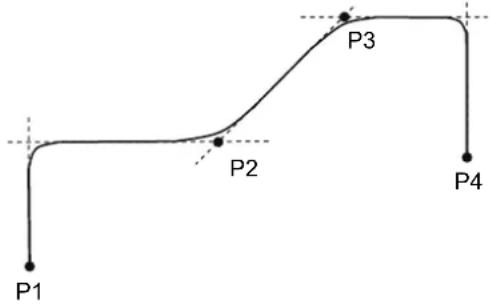
Potential Errors
LimZ Value Not High Enough
When the current arm position of the Z joint is higher than the value set for LimZ and a Jump instruction is attempted, an Error 4005 will occur.
See Also
Accel, Arc, Arch, Go, JS, JT, LimZ, Point Expression, Pulse, Sense, Speed, Stat, Till
Jump Statement Example
The example shown below shows a simple point to point move between points P0 and P1 and then moves back to P0 using the Jump instruction. Later in the program the arm moves using the Jump instruction. If input #4 never goes high then the arm starts the approach motion and moves to P1. If input #4 goes high then the arm does not execute the approach motion.
Function jumptest
Home
Go P0
Go P1
Sense Sw(4) = On
Jump P0 LimZ -10
Jump P1 LimZ -10 Sense 'Check input #4
If Js(0) = 1 Then
    Print "Input #4 came on during the move and"
    Print "the robot stopped prior to arriving on"
    Print "point P1."
Else
    Print "The move to P1 completed successfully."
    Print "Input #4 never came on during the move."
EndIf
Fend

> Jump P10+X50 C0 LimZ-20 Sense !D50;On 0;D80;On 1!
Jump3, Jump3CP Statements
3D gate motion. Jump3 is a combination of two CP motions and one PTP motion. Jump3CP is a combination of three CP motions.
Syntax
(1) Jump3 depart, approach, destination [CarchNumber] [CP] [LJM [orientationFlag]] [searchExpr] [...] [SYNC] (2) Jump3CP depart, approach, destination [ROT] [CarchNumber] [CP] [LJM [orientationFlag]] [searchExpr] [...] [SYNC]
Parameters
depart The departure point above the current position using a point expression.
approach The approach point above the destination position a point expression.
destination The target destination of the motion using a point expression.
ROT Optional. Decides the speed/acceleration/deceleration in favor of tool rotation.
archNumber Optional. The arch number (archNumber) specifies which Arch Table entry to use for the Arch type motion caused by the Jump instruction. archNumber must always be preceded by the letter C. (Valid entries are C0-C7.)
CP Optional. Specifies continuous path motion.
LJM Optional. Convert the target destination using LJM function.
orientationFlag Optional. Specifies a parameter that selects an orientation flag for LJM function.
searchExpr Optional. A Sense, Till or Find expression.
Sense | Till | Find
Sense Sw(expr) = {On | Off}
Till Sw(expr) = {On | Off}
Find Sw(expr) = {On | Off}
!...! Optional. Parallel Processing statements can be added to the Jump instruction to cause I/O and other commands to execute during motion.
SYNC Reserves a motion command. The robot will not move until SyncRobots is executed.
Description
Moves the arm from the current position to the destination point with 3D gate motion. 3D gate motion consists of depart motion, span motion, and approach motion. The depart motion from the current position to the depart point is always CP motion. The span motion from the depart point to the start approach point is PTP motion in Jump3, and CP motion in Jump3CP.
The approach motion from the starting approach point to the target point is always CP motion.
![graph TD A["Current position"] --> B["Depart point"] B --> C["Approach point"] C --> D["Destination point"] B -->|Depart motion CP| A C -->|Approach motion CP| C style A fill:#000,stroke:#000,color:#fff style B fill:#000,stroke:#000,color:#fff style C fill:#000,stroke:#000,color:#fff style D fill:#0…](/content/2026/05/815116/images/3598f74a80ebb22d82cefb7bc9bc644aa28b4019d4eda57647ebfb5c46a4096f.jpg)
Arch motion is achieved by specifying the arch number. The arch motion for Jump3, Jump3CP is as shown in the figure below. For arch motion to occur, the Depart distance must be greater than the arch upward distance and the Approach distance must be greater than the arch downward distance.
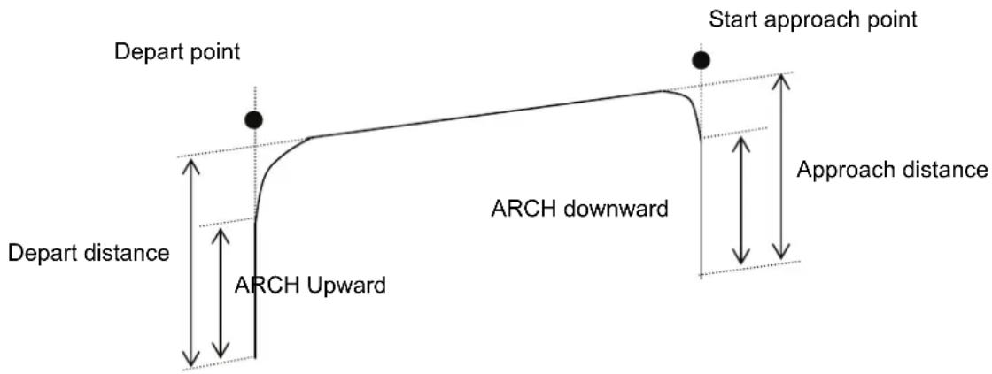
Jump3CP uses the SpeedS speed value and AccelS acceleration and deceleration values. Refer to Using Jump3CP with CP below on the relation between the speed/acceleration and the acceleration/deceleration. If, however, the ROT modifier parameter is used, Jump3CP uses the SpeedR speed value and AccelR acceleration and deceleration values. In this case, the SpeedS speed value and AccelS acceleration and deceleration values have no effect.
Usually, when the move distance is 0 and only the tool orientation is changed, an error will occur. However, by using the ROT parameter and giving priority to the acceleration and deceleration of the tool rotation, it is possible to move without an error. When there is no orientational change with the ROT modifier parameter and the movement distance is not 0, an error will occur.
Also, when the tool rotation is large compared to the move distance, and when the rotation speed exceeds the specified speed of the manipulator, an error will occur. In this case, please reduce the speed or append the ROT modifier parameter to give priority to the rotational speed/acceleration/deceleration.
Notes
LimZ does not affect Jump3 and Jump3CP
LimZ has no effect on Jump3 or Jump3CP since the span motion is not necessarily perpendicular to the Z axis of the coordinate system.
Jump3 span motion is PTP (point to point)
It is difficult to predict the Jump3 span motion trajectory. Therefore, be careful that the robot doesn't collide with peripheral equipment and that robot arms don't collide with the robot.
Using Jump3, Jump3CP with CP
The CP parameter causes the arm to move to the destination without decelerating or stopping at the point defined by the destination. This is done to allow the user to string a series of motion instructions together to cause the arm to move along a continuous path while maintaining a specified speed throughout all the motion. The Jump3 and Jump3CP instructions without CP always cause the arm to decelerate to a stop prior to reaching the point destination.
Pass function of Jump3
When the CP parameter is specified for Jump3 with 0 approach motion, the Jump3 span motion does not decelerate to a stop but goes on smoothly to the next PTP motion.
When the CP parameter is specified for a PTP motion command right before Jump3 with 0 depart motion, the PTP motion does not decelerate to a stop but connects smoothly with the Jump3 span motion.
This is useful when you want to replace the span motion of Jump3 (a PTP motion) with several PTP motions.
Pass function of Jump3CP
When the CP parameter is specified for Jump3CP with 0 approach motion, the Jump3CP span motion does not decelerate to a stop but goes on smoothly to the next CP motion.
When the CP parameter is specified for a CP motion command right before Jump3CP with 0 depart motion, the CP motion does not decelerate to a stop but connects smoothly with the Jump3CP span motion.
This is useful when you want to replace the span motion of Jump3CP (a CP motion) with several CP motions.
(Example 1)
Jump3 P1, P2, P2 CP
Go P3, P4 CP
Jump3 P4, P5, P5 + t1z(50)
(Example 2)
Jump3CP P1, P2, P2 CP
Move P3, P4 CP
Jump3CP P4, P5, P5+tlz(50)
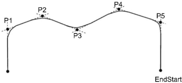
Using Jump3, Jump3CP with LJM
With the LJM parameter, the program using the LJM function can be simpler.
For example, the following four-line program
P11 = LJM(P1, Here, 2)
P12 = LJM(P2, P11, 2)
P13 = LJM(P3, P12, 2)
Jump3 P11, P12, P13
can be replaced with the one-line program.
Jump3 P1, P2, P3 LJM 2
The LJM parameter is available for 6-axis and RS series robots.
Jump3CP span motion is straight line (CP) motion and it cannot switch the wrist orientation along the way. Therefore, do not use the orientationFlag (LJM 1) of LJM function which is able to switch the wrist orientation.
Caution for Arch motion
Jump3 Motion trajectory changes depending on motion and speed
Jump3 motion trajectory is comprised of depart, span, and approach motions. It is not a continuous path trajectory. The actual Jump3 trajectory of arch motion is not determined by Arch parameters alone. It also depends on motion and speed.
Always use care when optimizing Jump3 trajectory in your applications. Execute Jump3 with the desired motion and speed to verify the actual trajectory.
When speed is lower, the trajectory will be lower. If Jump3 is executed with high speed to verify an arch motion trajectory, the end effector may crash into an obstacle with lower speed.
In a Jump3 trajectory, the depart distance increases and the approach distance decreases when the motion speed is set high. When the approach distance of the trajectory is shorter than the expected, lower the speed and/or the deceleration, or change the approach distance to be larger.
Even if Jump commands with the same distance and speed are executed, the trajectory is affected by motion of the robot arms.
Potential acceleration errors
When the majority of depart (approach) motion uses the same joint as the span motion
An acceleration error may occur during an arch motion execution by the Jump3 and Jump3CP commands. This error is issued frequently when the majority of the motion during depart or approach uses the same joint as the span motion. To avoid this error, reduce the acceleration/deceleration speed of the span motion using Accel command for Jump3 or using AccelS command for Jump3CP. Depending on the motion and orientation of the robot, it may also help to reduce the acceleration and deceleration of the depart motion (approach motion) using the AccelS command.
See Also
Accel, Arc, Arch, Go, JS, JT, Point Expression, Pulse, Sense, Speed, Stat, Till
Jump3 Statement Example
' 6 axis robot motion which works like Jump of SCARA robot
Jump3 Here :Z(100), P3 :Z(100), P3

' Depart and approach use Z tool coordinates
Jump3 Here -TLZ(100), P3 -TLZ(100), P3

' Depart uses base Z and approach uses tool Z
Jump3 Here +Z(100), P3 -TLZ(100), P3

' Example for the depart motion from P1 in Tool 1 and the approach
motion to P3 in Tool 2

Arch 0,20,20
Tool 1
Go P1

P2 = P1 -TLZ(100)
Tool 2
Jump3 P2, P3-TLZ(100), P3 C0
LatchEnable
This function does not work with EPSON RC+ 6.0 Ver.6.2.0.
Enable / Disable the latch function for the robot position by the R-I/O input.
Syntax
LatchEnable { On | Off }
Parameters
On | Off On : Enables the latch function of the robot position.
Off : Disables the latch function of the robot position.
Result
When the parameter is omitted, displays that the current latch function is ON or OFF.
Description
Enables / Disables the latch function for the robot position using the trigger input signals connected to the R-I/O. It latches the robot position with the first trigger input after you enable the latch function.
To repeatedly latch the robot position, execute LatchEnable Off and then execute LatchEnable On again. To use the command repeatedly, it needs at least 60 ms interval for the each command processing time but you do not need to consider the command executing time.
Note
Before enabling the latch function, set the trigger input port and trigger signal logic using SetLatch.
See Also
LatchPos Function, LatchState Function, SetLatch
LatchEnable Example
Function main
    SetLatch 24, SETLATCH_TRIGGERMODE_LEADINGEDGE
    LatchEnable On ' Enables the latch function
    Go P1
Wait LatchState = True ' Wait a trigger
Print LatchPos 'Display the latched position
    LatchEnable Off 'Disable the latch function
Fend
LatchState Function
This function does not work with EPSON RC+ 6.0 Ver.6.2.0.

Returns the latch state of robot position using the R-I/O.
Syntax
LatchState
Return Values
Returns True when the robot position has been latched, False when the latch is not finished.
When confirmed the latch completion, acquires the latched position information by LatchPos Function.
See Also
LatchEnable, LatchPos Function, SetLatch, Wait
LatchState Function Example
Function main
    SetLatch 24, SETLATCH_TRIGGERMODE_LEADINGEDGE
    LatchEnable On Enables the latch function
    Go P1
    Wait LatchState = True Wait a trigger
    Print LatchPos 'Display the latched position
    LatchEnable Off 'Disable the latch function
Fend
LatchPos Function
This function does not work with EPSON RC+ 6.0 Ver.6.2.0.

Returns the robot position latched using the R-I/O input signal.
Syntax
LatchPos
Return Values
Returns the robot position, according to the Tool and Arm settings at function call, latched using the R-I/O input signal in point data.
Executing this function needs approx. 15 msec for processing.
See Also
LatchEnable, LatchState Function, SetLatch
LatchPos Function Example
Function main
    SetLatch 24, SETLATCH_TRIGGERMODE_LEADINGEDGE
    LatchEnable On Enables the latch function
    Go P1
Wait LatchState = True ' Wait a trigger
    Print LatchPos ' Display the latched position
LatchEnable Off ' Disable the latch function
Fend
To assign the return value of LatchPos to the point data:
P2 = LatchPos
LCase$ Function
Returns a string that has been converted to lowercase.
F
Syntax
LCase$(string)
Parameters
string A valid string expression.
Return Values
The converted lower case string.
See Also
LTrim, Trim, RTrim, UCase
LCase$ Function Example
str$ = "Data"
str= LCase(str) ' str = "data"
Left$ Function
Returns a substring from the left side of a string expression.

Syntax
Left$(string, count)
Parameters
string String expression from which the leftmost characters are copied.
count The number of characters to copy from string starting with the leftmost character.
Return Values
Returns a string of the leftmost number characters from the character string specified by the user.
Description
Leftreturns the leftmost number characters of a string specified by the user. Left can return up to as many characters as are in the character string.
See Also
Asc, Chr, InStr, Len, Mid, Right, Space, Str$, Val
Left$ Function Example
The example shown below shows a program which takes a part data string as its input and parses out the part number, part name, and part count.
Function ParsePartData(DataInAs String, ByRef PartNum As String, ByRef PartName$ As String, ByRef PartCount As Integer)
Integer pos
String temp$
pos = Instr(DataIn$, ",")
PartNum= Left(DataIn$, pos - 1)
DataIn= Right(datain, Len(DataIn) - pos)
pos = Instr(DataIn$, ",")
PartName= Left(DataIn$, pos - 1)
PartCount = Val(Right(datain, Len(DataIn$) - pos))
Fend
Some other example results from the Left$ instruction from the Command window.
> Print Left$("ABCDEFG", 2)
AB
> Print Left$("ABC", 3)
ABC
Len Function
Returns the number of characters in a character string.
F
Syntax
Len(string)
Parameters
string
String
expression.
Return Values
Returns an integer number representing the number of characters in the string string which was given as an argument to the Len instruction.
Description
Len returns an integer number representing the number of characters in a string specified by the user. Len will return values between 0-255 (since a string can contain between 0-255 characters).
See Also
Asc, Chr, InStr, Left, Mid, Right, Space, Str, Val
Len Function Example
The example shown below shows a program which takes a part data string as its input and parses out the part number, part name, and part count.
Function ParsePartData(DataInAs String, ByRef PartNum As String, ByRef PartName$ As String, ByRef PartCount As Integer)
Integer pos
String temp$
pos = Instr(DataIn$, ",")
PartNum= Left(DataIn$, pos - 1)
DataIn= Right(datain, Len(DataIn) - pos)
pos = Instr(DataIn$, ",")
PartName= Left(DataIn$, pos - 1)
PartCount = Val(Right(datain, Len(DataIn$) - pos))
Fend
Some other example results from the Len instruction from the command window.
> ? len("ABCDEFG")
7
> ? len("ABC")
3
> ? len("")
0
>
LimZ Statement
Determines the default value of the Z joint height for Jump commands.
Syntax
(1) LimZ zLimit (2) LimZ
Parameters
zLimit
A coordinate value within the movable range of the Z joint.
Return Values
Displays the current LimZ value when parameter is omitted.
Description
LimZ determines the maximum Z joint height which the arm moves to when using the Jump instruction, wherein the robot arm raises on the Z joint, moves in the X-Y plane, then lowers on the Z joint. LimZ is simply a default Z joint value used to define the Z joint ceiling position for use during motion caused by the Jump instruction. When a specific LimZ value is not specified in the Jump instruction, the last LimZ setting is used for the Jump instruction.
Note
Resetting LimZ to 0
Restarting the controller, or executing the SFree, SLock, Motor On commands will initialize LimZ to 0.
LimZ Value is Not Valid for Arm, Tool, or Local Coordinates:
LimZ Z joint height limit specification is the Z joint value for the robot coordinate system. It is not the Z joint value for Arm, Tool, or Local coordinates. Therefore take the necessary precautions when using tools or end effectors with different operating heights.
LimZ does not affect Jump3 and Jump3CP
LimZ has no affect on Jump3 or Jump3CP since the span motion is not necessarily perpendicular to the Z axis of the coordinate system.
See Also
Jump
LimZ Statement Example
The example below shows the use of LimZ in Jump operations.
| Function main | ||
| LimZ | -10 | 'Set the default LimZ value |
| Jump | P1 | 'Move up to Z=-10 position for Jump |
| Jump | P2 LimZ -20 | 'Move up to Z=-20 position for Jump |
| Jump | P3 | 'Move up to Z=-10 position for Jump |
| Fend | ||
LimZ Function
Returns the current LimZ setting.

Syntax
LimZ
Return Values
Real number containing the current LimZ setting.
See Also
LimZ Statement
LimZ Function Example
Real savLimz
savLimz = LimZ
LimZ -25
Go pick
LimZ savLimZ
Line Input Statement
Reads input data of one line and assigns the data to a string variable.
Syntax
Line Input stringVar$
Parameters
stringVar$
A string variable name. (Remember that the string variable must end with the $ character.)
Description
Line Input reads input data of one line from the display device and assigns the data to the string variable used in the Line Input instruction. When the Line Input instruction is ready to receive data from the user, it causes a "?" prompt to be displayed on the display device. The input data line after the prompt is then received as the value for the string variable. After inputting the line of data press the [ENTER] key.
See Also
Input, Input #, Line Input#, ParseStr
Line Input Example
The example below shows the use of Line Input.
Function Main
String A$
Line Input A'Read one line input data into A
Print A$
Fend
Run the program above using the F5 key or the Run menu from the EPSON RC+ main screen. A resulting run session may be as follows:
?A, B, C
A, B, C
Line Input # Statement
Reads data of one line from a file, communication port, database, or the device.
Syntax
Line Input #portNumber, stringVar$
Parameters
portNumber The communications handle or the device ID. Communication handles can be specified in OpenCom (RS232) and OpenNet (TCP/IP) statements.
Device ID integers are as follows.
21 RC+
23 OP
24 TP
stringVarA string variable. (Remember that string variables must end with a character.)
Description
Line Input # reads string data of one line from the device specified with the portNumber parameter, and assigns the data to the string variable stringVar$.
See Also
Input, Input #, Line Input
Line Input # Example
This example receives the string data from the communication port number 1, and assigns the data to the string variable A$.
Function lintest
String a$
Print #1, "Please input string to be sent to robot"
Line Input #1, a$
Print "Value entered = ", a$
Fend
LJM Function
Returns the point data with the orientation flags converted to enable least joint motion when moving to a specified point based on the reference point.

Syntax
LJM (Point, [refPoint, [orientationFlag]])
Parameters
Point: Specifies point data.
refPoint: Specifies the reference point data. When this is omitted, the reference point is the current position (Here).
Specifies the reference point data. When this is omitted, the reference point is the current position (Here).
6-axis robot 1: Converts the wrist orientation (Wrist Flag), J4Flag or J6Flag. (default)
2: Converts the J4Flag or J6Flag.
RS series 1: Converts the hand orientation (Hand Flag), J1Flag or J2Flag. (default)
RS series 1: Converts the hand orientation (Hand Flag), J1Flag or J2Flag. (default)
2: Converts the hand orientation (Hand Flag), J1Flag or J2Flag.
Prevents the U axis from moving out of motion range at flag convert.
Description
When the 6-axis robot moves to a point calculated by such as pallet or relative offsets, the wrist part may rotate to an unintended direction. The point calculation above does not depend on robot models and results in motion without converting the required point flag.
LJM function can be used to convert the point flag to prevent the unintended wrist rotation.
In the same way, when the RS series robot moves to a point calculated by such as pallet or relative offsets, Arm #1 may rotate to an unintended direction. LJM function can be used to convert the point flag to prevent the unintended rotation of Arm #1.
In addition, the U axis of an RS series robot may go out of motion range when the orientation flag is converted, which will cause an error.
To prevent this error, the LJM function adjusts the U axis target angle so that it is inside the motion range. This is available when "2" is selected for orientationFlag.
Returns the specified point for all robots except the 6-axis and RS series robot.
Note
The reference point omission and Parallel Processing
You cannot use both of the parallel point omission and parallel processing in one motion command like this:
Go LJM(P10) ! D10; MemOn 1 !
Be sure to change the program like this:
P999 = Here
Go LJM(P10, P999) ! D10; MemOn 1 !
See Also
Pallet
LJM Function Example
Function main
Integer i, j
P0 = XY(300, 300, 300, 90, 0, 180)
P1 = XY(200, 280, 150, 90, 0, 180)
P2 = XY(200, 330, 150, 90, 0, 180)
P3 = XY(-200, 280, 150, 90, 0, 180)
Pallet 1, P1, P2, P3, 10, 10
Motor On
Power High
Speed 50; Accel 50, 50
SpeedS 1000; AccelS 5000
Go P0
P11 = P0 -TLZ(50)
For i = 1 To 10
For j = 1 To 10
'Specify points
P10 = P11 ' Dcpart point
P12 = Pallet(1, i, j) ' Target point
P11 = P12 -TLZ(50) ' Start approach point
' Converting each point to LJM
P10 = LJM(P10)
P11 = (P11, P10) LJM
P12 = LJM(P12, P11)
'Execute motion
Jump3 P10, P11, P12 C0
Next
Next
Fend
Function main2
P0 = XY(300, 300, 300, 90, 0, 180)
P1 = XY(400, 0, 150, 90, 0, 180)
P2 = XY(400, 500, 150, 90, 0, 180)
P3 = XY(-400, 0, 150, 90, 0, 180)
Pallet 1, P1, P2, P3, 10, 10
Motor On
Power High
Speed 50; Accel 50, 50
SpeedS 1000; AccelS 5000
Go P0
Do
' Specify points
P10 = Here -TLZ(50) ' Depart point
P12 = Pallet(1, Int(Rnd(9)) + 1, Int(Rnd(9)) + 1) ' Target point
P11 = P12 -TLZ(50) ' Start approach point
If TargetOK(P11) And TargetOK(P12) Then ' Point chacck
' Converting each point to LJM
P10 = LJM(P10)
P11 = LJM(P11, P10)
P12 = LJM(P12, P11)
'Execute motion
Jump3 P10, P11, P12 C0
EndIf
Loop
Fend
LoadPoints Statement
Loads a point file into the point memory area for the current robot.
Syntax
LoadPoints fileName [, Merge]
Parameters
| fileName | String expression containing the specific file to load into the current robot's point memory area. The extension must be .PTS. The file must exist in the current project for the current robot.You cannot specify a file path and fileName doesn't have any effect from ChDisk.See ChDisk for the details. |
| Merge | Optional. If supplied, then the current points are not cleared before loading the new points. Points in the file are added to the current points. If a point exists in the file, it will overwrite the point in memory. |
Description
LoadPoints loads point files from disk into the main memory area of the controller for the current robot.
Use Merge to combine point files. For example, you could have one main point file that includes common points for locals, parking, etc in the range 0 - 100. Then use Merge to load other point files for each part being run without clearing the common points. The range could be 101 - 999.
Potential Errors
A Path Cannot be Specified
If fileName contains a path, an error will occur. Only a file name in the current project can be specified.
File Does Not Exist
If fileName does not exist, an error will occur.
Point file not for the current robot
If fileName is not a point file for the current robot, the following error will be issued: Point file not found for current robot. To correct this, add the Point file to the robot in the Project editor, or execute SavePoints or ImportPoints.
See Also
Dir, ImportPoints, Robot, SavePoints
LoadPoints Statement Example
Function main
' Load common points for the current robot
LoadPoints "R1Common.pts"
' Merge points for part model 1
LoadPoints "R1Model1.pts", Merge
Robot 2
' Load point file for the robot 2
LoadPoints "R2Model1.pts"
Fend
Local Statement
Defines and displays local coordinate systems.
Syntax
(1) Local localNumber, (pLocal1 : pBase1), (pLocal2 : pBase2), [ { L | R }], [ BaseU ] (2) Local localNumber, pCoordinateData (3) Local localNumber, pOrigin, [pXaxis], [pYaxis], [ {X | Y} ] (4) Local localNumber
Parameters
| localNumber | The local coordinate system number. A total of 15 local coordinate systems (of the integer value from 1 to 15) may be defined. |
| pLocal1, pLocal2 | Point variables with point data in the local coordinate system. |
| pBase1, pBase2 | Point variables with point data in the base coordinate system. |
| L | R | Optional. Align local origin to left (first) or right (second) base points. |
| BaseU | Optional. When supplied, U axis coordinates are in the base coordinate system. When omitted, U axis coordinates are in the local coordinate system. |
| pCoordinateData | Point data representing the coordinate data of the origin and direction. |
| pOrigin | Integer expression representing the origin point using robot coordinate system. |
| pXaxis | Optional. Integer expression representing a point along the X axis using robot coordinate system if X alignment is specified. |
| pYaxis | Optional. Integer expression representing a point along the Y axis using robot coordinate system if Y alignment is specified. |
| X | Y | If X alignment is specified, then pXaxis lies on the X axis of the local. The Y axis and Z axis are calculated to be orthogonal to X in the plane that is created by the 3 local points. If Y alignment is specified, then pYaxis lies on the Y axis of the local. The X axis and Z axis are calculated to be orthogonal to Y in the plane that is created by the 3 local points. |
Description
(1) Local defines a local coordinate system by specifying 2 points, pLocal1 and pLocal2, contained in it that coincide with two points, pBase1 and pBase2, contained in the base coordinate system.
Example:
Local 1, (P1:P11), (P2:P12)
P1 and P2 are local coordinate system points. P11 and P12 are base coordinate system points.
If the distance between the two specified points in the local coordinate system is not equal to that between the two specified points in the base coordinate system, the XY plane of the local coordinate system is defined in the position where the midpoint between the two specified points in the local coordinate system coincides with that between the two specified points in the base coordinate system.
Similarly, the Z axis of the local coordinate system is defined in the position where the midpoints coincide with each other.
(2) Defines a local coordinate system by specifying the origin and axis rotation angles with respect to the base coordinate system.
Example:
Local 1, XY(x, y, z, u)
Local 1, XY(x, y, z, u, v, w)
Local 1, P1
(3) Defines a 3D local coordinate system by specifying the origin point, x axis point, and y axis point. Only the X, Y, and Z coordinates of each point are used. The U, V, and W coordinates are ignored. When the X alignment parameter is used, then pXaxis is on the X axis of the local and only the Z coordinate of pYaxis is used. When the Y alignment parameter is used, then pYaxis is on the Y axis of the local and only the Z coordinate of pXaxis is used.
Example:
Local 1, P1, P2, P3
Local 1, P1, P2, P3, X
Local 1, P1, P2, P3, Y
(4) Displays the specified local settings.
Using L and R parameters
While Local basically uses midpoints for positioning the axes of your local coordinate system as described above, you can optionally specify left or right local by using the L and R parameters.
Left Local
Left local defines a local coordinate system by specifying point pLocal1 corresponding to point pBase1 in the base coordinate system (Z axis direction is included.)
Right Local
Right local defines a local coordinate system by specifying point pLocal2 corresponding to point pBase2 in the base coordinate system. (Z axis direction is included.)
Using the BaseU parameter
If the BaseU parameter is omitted, then the U axis of the local coordinate system is automatically corrected in accordance with the X and Y coordinate values of the specified 4 points. Therefore, the 2 points in the base coordinate system may initially have any U coordinate values.
It may be desired to correct the U axis of the local coordinate system based on the U coordinate values of the two points in the base coordinate system, rather than having it automatically corrected (e.g. correct the rotation axis through teaching). To do so, supply the BaseU parameter.
See Also
ArmSet, Base, ECPSet, LocalCir, TLSet, Where
Local Examples
Here are some examples from the command window:
Left aligned local:
> p1 = 0, 0, 0, 0/1
> p2 = 100, 0, 0, 0/1
> p11 = 150, 150, 0, 0
> p12 = 300, 150, 0, 0
> local 1, (P1:P11), (P2:P12), L
> p21 = 50, 0, 0, 0/1
> go p21
Local defined with only the origin point:
> local 1, 100, 200, -20
Local defined with only the origin point rotated 45 degrees about the X axis:
> local 2, 50, 200, 0, 0, 45
3D Local with p2 aligned with the X axis of the local:
> local 3, p1, p2, p3, x
3D Local with p3 aligned with the Y axis of the local:
> local 4, p1, p2, p3, y
Local Function
Returns the local number of a point.

Syntax
Local(localNumber)
Parameters
localNumber
local coordinate system number (integer from 1 to 15) using an expression or numeric value.
Return Values
Specified local coordinate system data as point data.
See Also
Local Statement
Local Function Example
P1 = Local(1)
LocalClr Statement
Clears (undefines) a local coordinate system.
Syntax
LocalClr localNumber
Parameters
localNumber
Integer expression representing which of 15 locals (integer from 1 to 15) to clear (undefine).
See Also
Arm, ArmSet, ECPSet, Local, Tool, TLClr, TLSet
LocalClr Example
LocalClr 1
LocalDef Function
Returns local definition status.
Syntax
LocalDef (localCoordinateNumber)
Parameters
localCoordinateNumber Integer expression representing which local coordinate to return status for.
Return Values
True if the specified local has been defined, otherwise False.
See Also
Arm, ArmClr, ArmSet, ECPSet, Local, LocalClr, Tool, TLCIr, TLSet
LocalDef Example
Function DisplayLocalDef(localNum As Integer)
If LocalDef(localNum) = False Then
Print "Local ", localNum, "is not defined"
Else
Print "Local 1: ",
Print Local(localNum)
EndIf
Fend
Lof Function
Checks whether the specified RS-232 or TCP/IP port has any lines of data in its buffer.

Syntax
Lof (fileNumber As Integer)
Parameters
fileNumber
A Number specified with OpenCom (RS-232C) or OpenNet (TCP/IP) statement.
Return Values
The number of lines of data in the buffer. If there is no data in the buffer, Lof returns 0.
Description
Lof checks whether or not the specified port has received data lines. The data received is stored in the buffer irrespective of the Input# instruction.
You can wait for the return value of Lof function by executing Wait.
Note
When using PC COM port (1001, 1002), you cannot use Lof function with Wait command.
See Also
ChkCom, ChkNet, Input#, Wait
Lof Function Example
This Command window example prints out the number of lines of data received through communication port number 1.
>print lof(1)
5
>
LogIn Statement
Log into EPSON RC+ 6.0 as another user.
S
Syntax
LogIn logID, password
Parameters
logID String expression that contains user login id.
password String expression that contains user password.
Description
You can utilize EPSON RC+ 6.0 security in your application. For example, you can display a menu that allows different users to log into the system. Each type of user can have its own security rights. For more details on security, see the EPSON RC+ 6.0 User's Guide.
When you are running programs in the development environment, the user before programs are started will be restored after programs stop running.
When running the Operator Window in Auto Mode, the application is logged in as a guest user, unless Auto LogIn is enabled, in which case the application is logged in as the current Windows user if such user has been configured in the EPSON RC+ 6.0 system.
Note
This command will only work if the Security option is active.
See Also
GetCurrentUser$ Function
Login Statement Example
Integer errCode
errCode = LogIn("operator", "oprpass")
Long Statement
Declares variables of type long integer. (4 byte whole number).
s
Syntax
Long varName [(subscripts)] [, varName [(subscripts)]...]
Parameters
varName Variable name which the user wants to declare as type Long.
subscripts Optional. Dimensions of an array variable; up to 3 dimensions may be declared. The subscripts syntax is as follows
(ubound1, [ubound2], [ubound3])
ubound1, ubound2, ubound3 each specify the maximum upper bound for the associated dimension.
The elements in each dimension of an array are numbered from 0 and the available number of array elements is the upper bound value + 1.
When specifying the upper bound value, make sure the number of total elements is within the range shown below:
Local variable 2000
Global Preserve variable 4000
Global variable and module variable 100000
Description
Long is used to declare variables as type Long. Variables of type Long can contain whole numbers with values between -2,147,483,648 to 2,147,483,647. Local variables should be declared at the top of a function. Global and module variables must be declared outside of functions.
See Also
Boolean, Byte, Double, Global, Integer, Real, String
Long Statement Example
The following example shows a simple program which declares some variables as Longs using Long.
Function longtest
Long A(10) 'Single dimension array of long
Long B(10, 10) 'Two dimension array of long
Long C(5, 5, 5) 'Three dimension array of long
Long var1, arrayVar(10)
Long i
Print "Please enter a Long Number"
Input var1
Print "The Integer variable var1 = ", var1
For i = 1 To 5
Print "Please enter a Long Number"
Input arrayVar(i)
Print "Value Entered was ", arrayVar(i)
Next I
Fend
LSet$ Function
Returns the specified string with trailing spaces appended up to the specified length.

Syntax
LSet$ (string, length)
Parameters
string: String expression.
length: Integer expression for the total length of the string returned.
Return Values
Specified string with trailing spaces appended.
See Also
RSet, Space
LSet$ Function Example
temp$ = "123"
temp= LSet(temp, 10) ' temp = "123"
LShift Function
Shifts numeric data to the left by a user specified number of bits.

Syntax
LShift(number, shiftBits)
Parameters
number: Integer expression to be shifted.
shiftBits: The number of bits (integer from 0 to 31) to shift number to the left.
Return Values
Returns a numeric result which is equal to the value of number after shifting left shiftBits number of bits.
Description
LShift shifts the specified numeric data (number) to the left (toward a higher order digit) by the specified number of bits (shiftBits). The low order bits shifted are replaced by 0.
The simplest explanation for LShift is that it simply returns the result of number * 2 shiftBits.
Note
Numeric Data Type:
The numeric data number may be any valid numeric data type. LShift works with data types: Byte, Integer, Long, and Real.
See Also
And, Not, Or, RShift, Xor
LShift Function Example
Function lshiftst
Integer i
Integer num, snum
num = 1
For i = 1 to 10
Print "i =", i
snum = LShift(num, i)
Print "The shifted num is ", snum
Next i
Fend
Some other example results from the LShift instruction from the command window.
> Print LShift(2,2)
8
> Print LShift(5,1)
10
> Print LShift(3,2)
12
>
LTrim$ Function
Returns a string equal to specified string without leading spaces.

Syntax
LTrim$ (string)
Parameters
string
String
expression.
Return Values
Specified string with leading spaces removed.
See Also
RTrim, Trim
LTrim$ Function Example
str$ = " data "
str= LTrim(str) ' str = "data "
Mask Operator
Bitwise mask for Wait statement condition expression.
s
Syntax
The Mask operator is a bitwise And for Wait statement input condition expressions.
See Also
Wait
Mask Operator Example
' Wait for the lower 3 bits of input port 0 to equal 1 Wait In(0) Mask 7 = 1
MCal Statement
Executes machine calibration for robots with incremental encoders.

Syntax
MCal
Description
It is necessary to calibrate robots which have incremental encoders. This calibration must be executed after turning on the main power. If you attempt motion command execution, or any command which requires the current position data without first executing machine calibration, an error will occur.
Machine calibration is executed according to the moving joint order which is specified with the MCordr command. The default value of MCordr at the time of shipment differs from model to model, so please refer to the proper manipulator manual for details.
Potential Errors
Attempt to Execute a Motion Command without Executing MCal First
If you attempt to execute a motion command, or any command which requires the current position data (e.g., Plist* instruction) without first executing machine calibration, an error will occur.
Absolute Encoder Robots
Absolute encoder robots do not need MCAL.
Robot Installation Note
Z Joint Space Required for Homing
When the Z joint homes, it first moves up and then moves down and settles into the home position. This means it is very important to properly install the robot so that enough space is provided for the arm to home the Z joint. It is recommended that a space of 6 mm be provided above the upper limit. (Do not install tooling or fixtures within a 6 mm space above the robot so enough room is left for proper Z joint homing.)
See Also
Hofs, Home, Hordr, Mcorg, MCordr
MCal Example
The following example is done from the monitor window:
> Motor On
> Mcal
>
> Motor On
> Mcal
>
MCalComplete Function
Returns status of MCal.

Syntax
MCalComplete
Return Values
True if MCal has been completed, otherwise False.
See Also
MCal
MCalComplete Example
If Not MCalComplete Then
MCal
EndIf
MCordr Statement
Specifies and displays the moving joint order for machine calibration Mcal. Required only for robots with incremental encoders.

Syntax
(1) MCordr Step1, Step2, Step3, Step4, [Step5], [Step6], [Step7], [Step8], [Step9]
(2) MCordr
Parameters
| Step1 | Bit pattern that tells which axes should be calibrated during the 1st step of the Mcal process. Any number of axes between 0 to all 4 axes may calibrate during the 1st step. (see below for bit pattern definitions) |
| Step2 | Bit pattern that tells which axes should be calibrated during the 2nd step of the Mcal process. Any number of axes between 0 to all 4 axes may calibrate during the 2nd step. (see below for bit pattern definitions) |
| Step3 | Bit pattern that tells which axes should be calibrated during the 3rd step of the Mcal process. Any number of axes between 0 to all 4 axes may calibrate during the 3rd step. (see below for bit pattern definitions) |
| Step4 | Bit pattern that tells which axes should be calibrated during the 4th step of the Mcal process. Any number of axes between 0 to all 4 axes may calibrate during the 4th step. (see below for bit pattern definitions) |
| Step5 | Bit pattern that tells which axes should be calibrated during the 5th step of the Mcal process. Any number of axes between 0 to all 4 axes may calibrate during the 5th step. (see below for bit pattern definitions) |
| Step6 | Bit pattern that tells which axes should be calibrated during the 6th step of the Mcal process. Any number of axes between 0 to all 4 axes may calibrate during the 6th step. (see below for bit pattern definitions) |
| Step7 | Bit pattern that tells which axes should be calibrated during the 7th step of the Mcal process. Any number of axes between 0 to all 4 axes may calibrate during the 7th step. (see below for bit pattern definitions) |
| Step8 | Bit pattern that tells which axes should be calibrated during the 8th step of the Mcal process. Any number of axes between 0 to all 4 axes may calibrate during the 8th step. (see below for bit pattern definitions) |
| Step9 | Bit pattern that tells which axes should be calibrated during the 9th step of the Mcal process. Any number of axes between 0 to all 4 axes may calibrate during the 9th step. (see below for bit pattern definitions) |
Return Values
Displays current Machine Calibration Order when parameters are omitted.
Description
After the system is powered on, the Mcal instruction must be issued prior to any robot arm operation. When the Mcal instruction is issued, each of the 4 axes of the robot will move to their respective calibration positions.
Specifies joint motion order for the Mcal command. (i.e., defines which joint will home first, which joint will Mcal second, third, etc.)
The purpose of the MCordr instruction is to allow the user to change the homing order. The homing order is broken into 9 separate steps. The user then uses MCordr to define the specific axes which will move to the calibration position (done with the Mcal command) during each step. It is important to realize that more than one joint can be defined to move to the calibration position during a single step.
This means that all four axes can potentially be calibrated at the same time. However, it is recommended that the Z joint normally be defined to move to the calibration position first (in Step 1) and then allow the other axes to follow in subsequent steps. (See notes below)
The MCordr instruction expects that a bit pattern be defined for each of the 9 steps. Since there are 4 axes, each joint is assigned a specific bit. When the bit is high (1) (for a specific step), then the corresponding joint will calibrate. When the bit is low (0), then the corresponding joint will not calibrate during that step. The joint bit patterns are assigned as follows:
| Joint: | 1 | 2 | 3 | 4 | |
| Bit Number: | bit 0 bit 1 | bit 2 bit 3 | |||
| Binary Code: | &B000001 | &B000010 | &B000100 | &B001000 | |
| 5 6 7 8 9 | |||||
| bit 4 bit 5 | bit 6 bit 7 bit 8 | ||||
| &B010000 | &B100000 | &B1000000 | &B10000000 | &B100000000 | |
Notes
Difference Between MCordr and Hordr
While at first glance the Hordr and MCordr commands may appear very similar, there is one major difference which is important to understand. MCordr is used to define the Robot Calibration joint order (used with Mcal) while Hordr is used to define the Homing joint order (used with the Home command).
Default MCal Order (Factory Setting)
The default joint calibration order from the factory is that joint 3 will home in Step 1. Then joints 1, 2, and 4 will all home at the same time in step 2. (Steps 3 and 4 are not used in the default configuration.) The default MCordr values are as follows:
MCordr &B0100, &B1011, 0, 0
Z Joint should normally be calibrated first
The reason for moving the Z joint first (and by itself) is to allow the tooling to be moved above the work surface before beginning any horizontal movement. This will help prevent the tooling from hitting something in the work envelope during the homing process.
MCordr values are maintained
The MCordr Table values are permanently saved and are not changed until either the user changes them or the robot is redefined.
See Also
Mcal
MCordr Statement Example
Following are some monitor window examples:
This example defines the calibration order as J3 in the first step, J1 in second step, J2 in third step, and J4 in the fourth step. The order is specified with binary values.
>mcordr &B0100, &B0001, &B0010, &B1000
This example defines the calibration order as J3 in the first step, then J1, J2 and J4 joints simultaneously in the second step. The order is specified with decimal values.
>mcordr 4, 11, 0, 0
This example displays the current calibration order in decimal numbers.
>mcordr
4, 11, 0, 0
>
MCordr Function
Returns an MCordr parameter setting.

Syntax
MCordr (paramNumber)
Parameters
paramNumber
Specifies reference setting numbers (integers from 1 to 9) by an expression or numeric value.
Return Values
Returns binary values (integers) representing the joint of the specified setting number to execute machine calibration.
Description
Returns the joint motion order to execute machine calibration by Mcal.
See Also
Mcal
MCordr Function Example
This example uses the MCordr function in a program:
Integer a
a = MCordr(1)
MemIn Function
Returns the status of the specified memory I/O port. Each port contains 8 memory bits.

Syntax
MemIn(portNumber)
Parameters
portNumber Integer expression representing memory I/O bytes.
Return Values
Returns an integer value between 0-255. The return value is 8 bits, with each bit corresponding to 1 memory I/O bit.
Description
MemIn provides the ability to look at the value of 8 memory I/O bits at the same time. The MemIn instruction can be used to store the 8 memory I/O bit status into a variable or it can be used with the Wait instruction to Wait until a specific condition which involves more than 1 memory I/O bit is met.
Since 8 bits are retrieved at a time, the return value ranges from 0-255. Please review the chart below to see how the integer return values correspond to individual memory I/O bits.
Memory I/O Bit Result (Using Port #0)
| Return Value | 7 | 6 | 5 | 4 | 3 | 2 | 1 | |
| 1 | Off | Off | Off | Off | ||||
| 5 | Off | Off | Off | Off | ||||
| 1 5 | O | f f | O f f | O | f f O f f O n C | |||
| 255 | On | On | On | On | ||||
Memory I/O Bit Result (Using Port #31)
| Return Value | 255 | 254 | 253 | 252 | 251 | 250 | 249 | 248 | |
| 3 | Off | Off | Off | Off | Off | Off | On | On | |
| 7 | Off | Off | Off | Off | Off | On | On | On | |
| 32 | Off | Off | On | Off | Off | Off | Off | Off | |
| 255 | On | On | On | On | On | On | On | On | On |
Notes
Difference Between MemIn and MemSw
The MemSw instruction allows the user to read the value of 1 memory I/O bit. The return value from MemSw is either a 1 or a 0 which indicates that the memory I/O bit is either On or Off. MemSw can check each of the memory I/O bits individually. The MemIn instruction is very similar to the MemSw instruction in that it also is used to check the status of the memory I/O bits. However there is 1 distinct difference. The MemIn instruction checks 8 memory I/O bits at a time vs. the single bit checking functionality of the MemSw instruction. MemIn returns a value between 0-255 which tells the user which of the 8 I/O bits are On and which are Off.
See Also
In, InBCD, Off, MemOff, On, MemOn, OpBCD, Oport, Out, MemOut, Sw, MemSw, Wait
MemIn Example
The program example below gets the current value of the first 8 memory I/O bits and then makes sure that all 8 I/O are currently set to 0 before proceeding. If they are not 0 an error message is given to the operator and the task is stopped.
Function main
Integer var1
var1 = MemIn(0) 'Get 1st 8 memory I/O bit values
If var1 = 0 Then
Go P1
Go P2
Else
Print "Error in initialization!"
Print "First 8 memory I/O bits were not all set to 0"
EndIf
Fend
Other simple examples from the Command window are as follows:
> memout 0, 1
> print MemIn(0)
1
> memon 1
> print MemIn(0)
3
> memout 31,3
> print MemIn(31)
3
> memoff 249
> print MemIn(31)
1
>
MemInW Function
Returns the status of the specified memory I/O word port.
Each word port contains 16 memory I/O bits.
F
Syntax
MemInW(WordPortNum)
Parameters
WordPortNum Integer expression representing the I/O word port.
Return Values
Returns the current status of the memory I/O (long integers from 0 to 65535).
See Also
MemIn, MemOut, MemOutW
MemInW Function Example
Long word0
word0 = MemInW(0)
MemOff Statement
Turns Off the specified bit of the memory I/O.
Syntax
MemOff { bitNumber | memIOLabel }
Parameters
bitNumber Integer expression representing memory I/O bits.
memIOLabel Memory I/O label.
Description
MemOff turns Off the specified bit of memory I/O. The 256 memory I/O bits are typically excellent choices for use as status bits for uses such as On/Off, True/False, Done/Not Done, etc. The MemOn instruction turns the memory bit On, the MemOff instruction turns it Off, and the MemSw instruction is used to check the current state of the specified memory bit. The Wait instruction can also be used with the memory I/O bit to cause the system to wait until a specified memory I/O status is set.
Note
Memory outputs off
All memory I/O bits are turned off when the controller are restarted. They are not turned off by Emergency stop, safeguard open, program end, Reset command, or EPSON RC+ restart.
See Also
In, MemIn, InBCD, Off, On, MemOn, OpBCD, Oport, Out, MemOut, Sw, MemSw, Wait
MemOff Statement Example
The example shown below shows 2 tasks each with the ability to initiate motion instructions. However, a locking mechanism is used between the 2 tasks to ensure that each task gains control of the robot motion instructions only after the other task is finished using them. This allows 2 tasks to each execute motion statements as required and in an orderly predictable fashion. MemSw is used in combination with the Wait instruction to wait until the memory I/O #1 is the proper value before it is safe to move again. MemOn and MemOff are used to turn on and turn off the memory I/O for proper synchronization.
Function main
Integer I
MemOff 1
Xqt 2, task2
For i = 1 to 100
Wait MemSw(1) = Off
Go P(i)
MemOn 1
Next I
Fend
Function task2
Integer I
For i = 101 to 200
Wait MemSw(1) = On
Go P(i)
MemOff 1
Next I
Fend
Other simple examples from the command window are as follows:
> MemOn 1 'Switch memory I/O bit #1 on
> Print MemSw(1)
1
> MemOff 1 'Switch memory I/O bit #1 off
> Print MemSw(1)
0
MemOn Statement
Turns On the specified bit of the memory I/O.
Syntax
MemOn { bitNumber | memIOLabel }
Parameters
bitNumber Integer expression representing memory I/O bits.
memIOLabel Memory I/O label.
Description
MemOn turns on the specified bit of the robot memory I/O. The 256 memory I/O bits are typically used as task communication status bits. The MemOn instruction turns the memory bit On, the MemOff instruction turns it Off, and the MemSw instruction is used to check the current state of the specified memory bit. The Wait instruction can also be used with the memory bit to cause the system to wait until a specified status is set.
Note
Memory outputs off
All memory I/O bits are turned off when the controller is restarted. They are not turned off by Emergency stop, safeguard open, program end, Reset command, or EPSON RC+ restart.
See Also
In, MemIn, InBCD, Off, MemOff, On, OpBCD, Oport, Out, MemOut, Sw, MemSw, Wait
The example shown below shows 2 tasks each with the ability to initiate motion instructions. However, a locking mechanism is used between the 2 tasks to ensure that each task gains control of the robot motion instructions only after the other task is finished using them. This allows 2 tasks to each execute motion statements as required and in an orderly predictable fashion. MemSw is used in combination with the Wait instruction to wait until the memory I/O #1 is the proper value before it is safe to move again. MemOn and MemOff are used to turn on and turn off the memory I/O for proper synchronization.
Function main
Integer I
MemOff 1
Xqt 2, task2
For i = 1 to 100
Wait MemSw(1) = Off
Go P(i)
MemOn 1
Next I
Fend
Function task2
Integer I
For i = 101 to 200
Wait MemSw(1) = On
Go P(i)
MemOff 1
Next I
Fend
Other simple examples from the command window are as follows:
> memon 1
> print memsw(1)
1
> memoff 1
> print memsw(1)
0
MemOut Statement
Simultaneously sets 8 memory I/O bits.
Syntax
MemOut portNumber, outData
Parameters
portNumber Integer expression representing memory I/O bit port number. The portNumber selection corresponds to the following:
| Portnum | Outputs |
| 0 | 0-7 |
| 1 | 8-15 |
| . | . |
outData
Integer expression between 0-255 representing the output pattern for the output group selected by portNumber. If represented in hexadecimal form the range is from &H0 to &HFF. The lower digit represents the least significant digits (or the 1st 4 outputs) and the upper digit represents the most significant digits (or the 2nd 4 outputs).
Description
MemOut simultaneously sets 8 memory I/O bits using the combination of the portNumber and outData values specified by the user to determine which outputs will be set. The portNumber parameter specifies which group of 8 outputs to use where portNumber = 0 means outputs 0-7, portNumber = 1 means outputs 8-15, etc.
Once a portNumber is selected, a specific output pattern must be defined. This is done using the outData parameter. The outData parameter may have a value between 0-255 and may be represented in hexadecimal or integer format. (i.e. &H0-&HFF or 0-255)
The table below shows some of the possible I/O combinations and their associated outData values assuming that portNumber is 0, and 1 accordingly.
Output Settings When portNumber=0 (Output number)
| OutData | Value | 7 | 6 | 5 | 4 | 3 | 2 | 1 |
| 01 | Off | Off | Off | Off | Off | Off | Off | On |
| 02 | Off | Off | Off | Off | Off | Off | On | Off |
| 03 | Off | Off | Off | Off | Off | Off | On | On |
| 08 | Off | Off | Off | Off | On | Off | Off | Off |
| 09 | Off | Off | Off | Off | On | Off | Off | On |
| 10 | Off | Off | Off | On | Off | Off | Off | Off |
| 11 | Off | Off | Off | On | Off | Off | Off | On |
| 99 | Off | On | On | Off | Off | Off | On | On |
| 255 | On | On | On | On | On | On | On | On |
0
Output Settings When portNumber=1 (Output number)
| OutData | Value | 15 | 14 | 13 | 12 | 11 | 10 | 9 |
| 01 | Off | Off | Off | Off | Off | Off | Off | On |
| 02 | Off | Off | Off | Off | Off | Off | On | Off |
| 03 | Off | Off | Off | Off | Off | Off | On | On |
| 08 | Off | Off | Off | Off | On | Off | Off | Off |
| 09 | Off | Off | Off | Off | On | Off | Off | On |
| 10 | Off | Off | Off | On | Off | Off | Off | Off |
| 11 | Off | Off | Off | On | Off | Off | Off | On |
| 99 | Off | On | On | Off | Off | Off | On | On |
| 255 | On | On | On | On | On | On | On | On |
8
See Also
In, MemIn, InBCD, MemOff, MemOn, MemSw, Off, On, OpBCD, Oport, Out, Sw, Wait
MemOut Example
The example below shows main task starting a background task called iotask. The iotask is a simple task to toggle memory I/O bits 0 - 3 On and Off. The MemOut instruction makes this possible using only 1 command rather than turning each memory I/O bit on and off individually.
Function main
Xqt 2, iotask
Go P1
.
.
Fend
Function iotask
Do
Wait 1
MemOut 0, &HO
Wait 1
Loop
Fend
Other simple examples from the command window are as follows:
> MemOut 1,6 'Turns on memory I/O bits 9 & 10
> MemOut 2,1 'Turns on memory I/O bit 8
> MemOut 3,91 'Turns on memory I/O bits 24, 25, 27, 28, and 30
MemOutW Statement
Simultaneously se
Syntax
MemOutW wordPortNum, outputData
Parameters
wordPortNum Integer expression representing memory I/O words.
outputData Specifies output data (integers from 0 to 65535) using an expression or numeric value.
Description
Changes the current status of memory I/O port group specified by the word port number to the specified output data.
See Also
MemIn, MemInW, MemOut
MemOutW Example
MemOutW 0, 25
MemSw Function
Returns the status of the specified memory I/O bit.

Syntax
MemSw(bitNumber)
Parameters
bitNumber: Integer expression representing the memory I/O bit number.
Return Values
Returns a 1 when the specified bit is On and a 0 when the specified bit is Off.
Description
MemSw returns the status of one memory I/O bit. Valid entries for MemSw range from bit 0 to bit 511. MemOn turns the specified bit on and MemOff turns the specified bit Off.
See Also
In, MemIn, InBCD, MemOff, MemOn, Off, On, OpBCD, Oport, Out, Sw, Wait
MemSw Example
The example shown below shows 2 tasks each with the ability to initiate motion instructions. However, a locking mechanism is used between the 2 tasks to ensure that each task gains control of the robot motion instructions only after the other task is finished using them. This allows 2 tasks to each execute motion statements as required and in an orderly predictable fashion. MemSw is used in combination with the Wait instruction to wait until the memory I/O bit 1 is the proper value before it is safe to move again.
Function main
Integer I
MemOff 1
Xqt 2, task2
For i = 1 to 100
Wait MemSw(1) = Off
Go P(i)
MemOn 1
Next I
Fend
Function task2
Integer I
For i = 101 to 200
Wait MemSw(1) = On
Go P(i)
MemOff 1
Next I
Fend
Other simple examples from the Command window are as follows:
> memon 1
> print memsw(1)
1
> memoff 1
> print memsw(1)
0
Mid$ Function
Returns a substring of a string starting from a specified position.

Syntax
Mid$(string, position, [count])
Parameters
string Source string expression.
position The starting position in the character string for copying count characters.
count Optional. The number of characters to copy from string starting with the character defined by position. If omitted, then all characters from position to the end of the string are returned.
Return Values
Returns a substring of characters from string.
Description
Mid$ returns a substring of as many as count characters starting with the position character in string.
See Also
Asc, Chr, InStr, Left, Len, Right, Space, Str$, Val
Mid$ Function Example
The example shown below shows a program that extracts the middle 2 characters from the string "ABCDEFGHIJ" and the remainder of the string starting at position 5.
Function midtest
String basestr, m1, m2$
basestr$ = "ABCDEFGHIJ"
m1= Mid(basestr, (Len(basestr) / 2), 2)
Print "The middle 2 characters are: ", m1$
m2= Mid(basestr$, 5)
Print "The string starting at 5 is: ", m2$
Fend
MkDir Statement
Creates a subdirectory on a controller disk drive.

Syntax
MkDir dirName
Parameters
dirName String expression that defines the path and name of the directory to create. See ChDisk for the details.
Description
Creates a subdirectory in the specified path. If omitted, a subdirectory is created in the current directory.
Note
- This statement is executable only with PC disk
See Also
ChDir, ChDrive, Dir, RenDir, RmDir
MkDir Example
The following examples are done from the command window:
> MkDir \Data
> MkDir \Data\PTS
> MkDir \TEST1 \TEST2
Mod Operator
Returns the remainder obtained by dividing a numeric expression by another numeric expression.
Syntax
number Mod divisor
Parameters
number The number being divided (the dividend).
divisor The number which number is divided by.
Return Values
Returns the remainder after dividing number by divisor.
Description
Mod is used to get the remainder after dividing 2 numbers. The remainder is a whole number. One clever use of the Mod instruction is to determine if a number is odd or even. The method in which the Mod instruction works is as follows: number is divided by divisor. The remainder left over after this division is then the return value for the Mod instruction.
See Also
Abs, Atan, Atan2, Cos, Int, Not, Sgn, Sin, Sqr, Str\$, Tan, Val
Mod Operator Example
The example shown below determines if a number (var1) is even or odd. When the number is even the result of the Mod instruction will return a 0. When the number is odd, the result of the Mod instruction will return a 1.
Function modtest
....Integer var1, result
....Print "Enter an integer number:"
....Input var1
....result = var1 Mod 2
....Print "Result = ", result
....If result = 0 Then
....Print "The number is EVEN"
....Else
....Print "The number is ODD"
....EndIf
Fend
Some other example results from the Mod instruction from the Command window.
> Print 36 Mod 6
> 0
> Print 25 Mod 10
> 5
>
Motor Statement
Turns motor power for all axes on or off for the current robot.
Syntax
Motor ON | OFF
Parameters
ON | OFF The keyword ON is used to turn the Motor Power on. The keyword OFF is used to turn Motor Power Off.
Description
The Motor On command is used to turn Motor Power On and release the brakes for all axes. Motor Off is used to turn Motor Power Off and set the brakes.
In order to move the robot, motor power must be turned on.
After an emergency stop, or after an error has occurred that requires resetting with the Reset command, execute Reset, and then execute Motor On.
Motor On sets the robot control parameter as below:
| Power | Low |
| Fine | Default values |
| Speed | Default values |
| SpeedR | Default values |
| SpeedS | Default values |
| Accel | Default values |
| AccelS | Default values |
| AccelR | Default values |
| PTPBoost | Default values |
| LimZ | 0 |
See Also
Brake, Power, Reset, SFree, SLock
Motor Example
The following examples are done from the command window:
| > Motor On |
| > Motor Off |
Motor Function
Returns status of motor power for the current robot.

Syntax
Motor
Return Values
0 = Motors off, 1 = Motors on.
See Also
Motor Statement
Motor Function Example
If Motor = Off Then
Motor On
End If
Move Statement
Moves the arm from the current position to the specified point using linear interpolation (i.e., moving in a straight line) at a constant tool center point velocity.
Syntax
Move destination [ROT] [ECP] [CP] [searchExpr] [!...!] [SYNC]
Parameters
destination: The target destination of the motion, using a point expression.
ROT: Optional. Decides the speed/acceleration/deceleration in favor of tool rotation.
ECP: Optional. External control point motion. This parameter is valid when the ECP option is enabled.
CP: Optional. Specifies continuous path motion.
searchExpr: Optional. A Till or Find expression.
Till | Find
Till Sw(expr) = {On | Off}
Find Sw(expr) = {On | Off}
!...!: Optional. Parallel Processing statements can be added to execute I/O and other commands during motion.
SYNC: Reserves a motion command. The robot will not move until SyncRobots is executed.
Description
Move moves the arm from the current position to destination in a straight line. Move coordinates all axes to start and stop at the same time. The coordinates of destination must be taught previously before executing the Move instruction. Acceleration and deceleration for the Move is controlled by the AccelS instruction. Speed for the move is controlled by the SpeedS instruction. If the SpeedS speed value exceeds the allowable speed for any joint, power to all four joint motors will be turned off, and the robot will stop.
Move uses the SpeedS speed value and AccelS acceleration and deceleration values. Refer to Using Move with CP below on the relation between the speed/acceleration and the acceleration/deceleration. If, however, the ROT modifier parameter is used, Move uses the SpeedR speed value and AccelR acceleration and deceleration values. In this case SpeedS speed value and AccelS acceleration and deceleration value have no effect.
Usually, when the move distance is 0 and only the tool orientation is changed, an error will occur. However, by using the ROT parameter and giving priority to the acceleration and the deceleration of the tool rotation, it is possible to move without an error. When there is not an orientational change with the ROT modifier parameter and movement distance is not 0, an error will occur.
Also, when the tool rotation is large as compared to move distance, and when the rotation speed exceeds the specified speed of the manipulator, an error will occur. In this case, please reduce the speed or append the ROT modifier parameter to give priority to the rotational speed/acceleration/deceleration.
When ECP is used, the trajectory of the external control point corresponding to the ECP number specified by ECP instruction moves straight with respect to the tool coordinate system. In this case, the trajectory of tool center point does not follow a straight line.
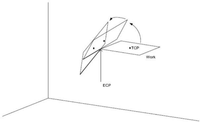
The optional Till qualifier allows the user to specify a condition to cause the robot to decelerate to a stop prior to completing the Move. The condition specified is simply a check against one of the inputs. This is accomplished through using the Sw instruction. The user can check if the input is On or Off and cause the arm to stop based on the condition specified. This feature works almost like an interrupt where the Move is interrupted (stopped) once the Input condition is met. If the input condition is never met during the Move then the arm successfully arrives on the point specified by destination. For more information about the Till qualifier see the Till command.
Notes
Move Cannot
Move cannot execute range verification of the trajectory prior to starting the move itself. Therefore, even for target positions that are within an allowable range, it is possible for the system to find a prohibited position along the way to a target point. In this case, the arm may abruptly stop which may cause shock and a servo out condition of the arm. To prevent this, be sure to perform range verifications at low speed prior to using Move at high speeds. In summary, even though the target position is within the range of the arm, there are some Moves which will not work because the arm cannot physically make it to some of the intermediate positions required during the Move.
Using Move with CP
The CP parameter causes the arm to move to destination without decelerating or stopping at the point defined by destination. This is done to allow the user to string a series of motion instructions together to cause the arm to move along a continuous path while maintaining a specific speed throughout all the motion. The Move instruction without CP always causes the arm to decelerate to a stop prior to reaching the point destination destination.
Proper Speed and Acceleration Instructions with Move
The SpeedS and AccelS instructions are used to specify the speed and acceleration of the manipulator during Move motion. Pay close attention to the fact that SpeedS and AccelS apply to linear and circular interpolated motion while point to point motion uses the Speed and Accel instructions.
Potential Errors
Attempt to Change Only Tool Orientation
Changing only tool orientation during the move is impossible. If this is attempted, an error will occur. In this case, use the ROT parameter.
Joint Overspeed Errors
When the motion requested results in the speed of one of the axes to exceed its maximum allowable speed an overspeed error occurs. In the case of a motor overspeed error, the robot arm is brought to a stop and servo power is turned off.
Attempt to Pass the Original Point (RS series)
It is impossible to operate the arm of RS series to pass near an original point. If attempted this, an overspeed error will occur. For the operation near an original point, take the following actions.
● Lower the speed of SpeedS ● Find a different path to prevent an original point - Use PTP motion such as Go command instead of Move command.
See Also
AccelS, Arc, CP, Go, Jump, Jump3, Jump3CP, SpeedS, Sw, Till
Move Statement Example
The example shown below demonstrates a simple point-to-point move between points P0 and P1, and then returns to P0 in a straight line. Later in the program, the arm moves in a straight line toward point P2 until input #2 turns on. If input #2 turns on during the move, the arm decelerates to a stop before reaching point P2, and the next program instruction is executed.
Function movetest
Home
Go P0
Go P1
Move P2 Till Sw(2) = On
If Sw(2) = On Then
Print "Input #2 came on during the move and"
Print "the robot stopped prior to arriving on"
Print "point P2."
Else
Print "The move to P2 completed successfully."
Print "Input #2 never came on during the move."
EndIf
Fend
This example uses Move with CP. The diagram below shows arc motion that starts at point P100 and then moves in a straight line through P101, at which point the arm begins to form an arc. The arc continues through P102 and on to P103. Next, the arm moves in a straight line to P104, where it finally decelerates to a stop. Note that the arm does not decelerate between each point until its final destination of P104. The following function would generate such motion.
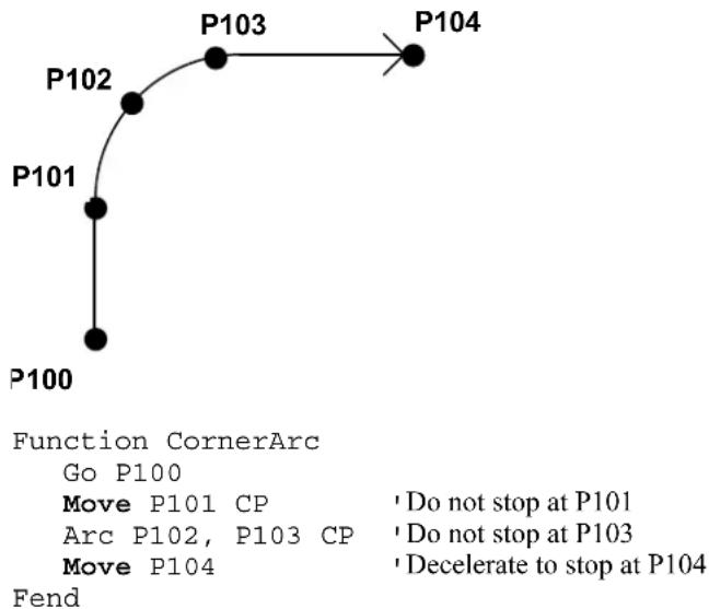
MsgBox Statement
Displays a message in a dialog box and waits for the operator to choose a button.
Syntax
MsgBox message\, [type], [title\], [answer]
Parameters
message\$: The message that will be displayed.
type: Optional. A numeric expression that is the sum of values specifying the number and type of buttons to display, the icon style to use, and the identity of the default button. EPSON RC+6.0 includes predefined constants that can be used for this parameter. The following table shows the values that can be used.
Symbolic constant Value Meaning
MB_OK 0 Display OK button only.
MB_OKCANCEL 1 Display OK and Cancel buttons.
MB_ABORTRETRYIGNORE 2 Display Abort, Retry, and Ignore buttons.
MB_YESNOCANCEL 3 Display Yes, No, and Cancel buttons.
MB_YESNO 4 Display Yes and No buttons.
MB_RETRYCANCEL 5 Display Retry and Cancel buttons.
| MB_ICONSTOP | 16 | Stop | sign. |
| MB_ICONQUESTION | 32 | Question | mark. |
| MB_ICONEXCLAMATION | 64 | Exclamation | mark. |
| MB_DEFBUTTON1 | 0 First button is default. | ||
| MB_DEFBUTTON2 | 256 | Second button is default. |
title$ Optional. String expression that is displayed in the title bar of the message box.
answer Optional. An integer variable that receives a value indicating the action taken by the operator. EPSON RC+ 6.0 includes predefined constants that can be used for this parameter. The table below shows the values returned in answer.
Symbolic constant Value Meaning
| IDOK | 1 OK button selected. |
| IDCANCEL | 2 Cancel button selected. |
| IDABORT | 3 Abort button selected. |
| IDRETRY | 4 Retry button selected. |
| IDYES | 6 Yes button selected. |
| IDNO | 7 No button selected. |
Description
MsgBox displays specified messages. If you want blank lines, use Chr(13)+Chr(10) in the message. See the example.
See Also
InputBox
MsgBox Example
This example displays a message box that asks the operator if he/she wants to continue or not. The message box will display two buttons: Yes and No. A question mark icon will also be displayed. After MsgBox returns (after the operator clicks a button), then the answer is examined. If it's no, then all tasks are stopped with the Quit command.
Function msgtest
String msg, title
Integer mFlags, answer
msg= "Operation complete" + Chr(13) + Chr$(10)
msg= msg + "Ready to continue?"
title$ = "Sample Application"
mFlags = MB_YESNO + MB_ICONQUESTION
MsgBox msg, mFlags, title, answer
If answer = IDNO then
Quit All
EndIf
Fend
A picture of the message box that this code will create is shown below.
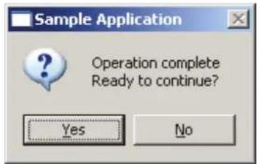
MyTask Function
Returns the task number of the current program.

Syntax
MyTask
Return Values
The task number of the current task. Valid entries are as below:
Normal task 1 \~ 32
Background tasks 65 \~ 80
Trap tasks 257 \~ 267
Description
MyTask returns the task number of the current program with a numeral. The MyTask instruction is inserted inside a specific program and when that program runs the MyTask function will return the task number that the program is running in.
See Also
Xqt
MyTask Function Example
The following program switches On and Off the I/O ports from 1 to 8.
Function main
Xqt 2, task 'Execute task 2.
Xqt 3, task 'Execute task 3.
Xqt 4, task 'Execute task 4.
Xqt 5, task 'Execute task 5.
Xqt 6, task 'Execute task 6.
Xqt 7, task 'Execute task 7.
Xqt 8, task 'Execute task 8.
Call task
Fend
Function task
Do
On MyTask
Off MyTask
Loop
Fend
'Switch On I/O port which has the same number as current task number
'Switch Off I/O port which has the same number as current task number
Next Statement
The For/Next instructions are used together to create a loop where instructions located between the For and Next instructions are executed multiple times as specified by the user.
Syntax
For var1 = initval To finalval [Step Increment] statements
Next var1
Parameters
| var1 | The counting variable used with the For/Next loop. This variable is normally defined as an integer but may also be defined as a Real variable. |
| initval | The initial value for the counter var1. |
| finalval | The final value of the counter var1. Once this value is met, the For/Next loop is complete and execution continues starting with the statement following the Next instruction. |
| Increment | An optional parameter which defines the counting increment for each time the Next statement is executed within the For/Next loop. This variable may be positive or negative. However, if the value is negative, the initial value of the variable must be larger than the final value of the variable. If the increment value is left out the system automatically increments by 1. |
statements Any valid SPEL+ statements can be inserted inside the For/Next loop.
Return Values
None
Description
For/Next executes a set of statements within a loop a specified number of times. The beginning of the loop is the For statement. The end of the loop is the Next statement. A variable is used to count the number of times the statements inside the loop are executed.
The first numeric expression (initial) is the initial value of the counter. This value may be positive or negative as long as the finalval variable and Step increment correspond correctly.
The second numeric expression (finalval) is the final value of the counter. This is the value which once reached causes the For/Next loop to terminate and control of the program is passed on to the next instruction following the Next instruction.
Program statements after the For statement are executed until a Next instruction is reached. The counter variable (var1) is then incremented by the Step value defined by the increment parameter. If the Step option is not used, the counter is incremented by one.
The counter variable (var1) is then compared with the final value (finalval). If the counter is less than or equal to the final value (finalval), the statements following the For instruction are executed again. If the counter variable is greater than the final value (finalval), execution branches outside of the For/Next loop and continues with the instruction immediately following the Next instruction.
Nesting of For/Next statements is supported up to 10 levels deep. This means that a For/Next Loop can be put inside of another For/Next loop and so on and so on until there are 10 "nests" of For/Next loops.
Notes
Negative Step Values
If the value of the Step increment (increment) is negative, the counter variable (var1) is decremented (decreased) each time through the loop and the initial value (initial) must be greater than the final value (finalval) for the loop to work.
See Also
For
For/Next Example
Function fornext
Integer ctr
For ctr = 1 to 10
Go Pctr
Next ctr
'
For ctr = 10 to 1 Step -1
Go Pctr
Next ctr
Fend
Not Operator
Performs the bitwise complement on the value of the operand.

Syntax
Not operand
Parameters
operand Integer expression.
Return Values
1's complement of the value of the operand.
Description
The Not function performs the bitwise complement on the value of the operand. Each bit of the result is the complement of the corresponding bit in the operand, effectively changing 0 bits to 1, and 1 bits to 0.
See Also
Abs, And, Atan, Atan2, Cos, Int, LShift, Mod, Or, RShift, Sgn, Sin, Sqr, Str$, Tan, Val, Xor
Not Operator Example
This is a simple Command window example on the usage of the Not instruction.
>print not(1)
-2
>
Off Statement
Turns Off the specified output and after a specified time can turn it back on.
Syntax
Off { bitNumber | outputLabel }, [ time ], [ parallel ] [,Forced]
Parameters
bitNumber Integer expression representing which Output to turn Off.
outputLabel Output label.
time Optional. Specifies a time interval in seconds for the output to remain Off. After the time interval expires, the Output is turned back on. The minimum time interval is 0.01 seconds and maximum time interval is 10 seconds.
parallel Optional. When a timer is set, the parallel parameter may be used to specify when the next command executes:
0 - immediately after the output is turned off
1 - after the specified time interval elapses. (default value)
Forced Optional. Usually omitted.
Description
Off turns off (sets to 0) the specified output.
If the time interval parameter is specified, the output bit specified by bitNumber is switched off, and then switched back on after the time interval elapses. If prior to executing Off, the Output bit was already off, then it is switched On after the time interval elapses.
The parallel parameter settings are applicable when the time interval is specified as follows:
1: Switches the output off, switches it back on after specified interval elapses, then executes the next command. (This is also the default value for the parallel parameter. If this parameter is omitted, this is the same as setting the parameter to 1.)
0: Switches the output off, and simultaneously executes the next command.
Notes
Output bits Configured as Remote Control output
If an output bit which was set up as a system output is specified, an error will occur. Remote control output bits are turned on or off automatically according to system status.
Outputs and When an Emergency Stop Occurs:
EPSON RC+ has a feature which causes all outputs to go off when an E-Stop occurs. This feature is set or disabled from Setup | Controller | Preferences.
Forced Flag
This flag is used to turn Off the I/O output at Emergency Stop and Safety Door Open from NoPause task or NoEmgAbort task (special task using NoPause or NoEmgAbort at Xqt).
Be sure that the I/O outputs change by Emergency Stop and Safety Door Open when designing the system.
See Also
In, InBCD, MemOn, MemOff, MemOut, MemSw, OpBCD, Oport, Out, Wait
Off Statement Example
The example shown below shows the main task starting a background task called iotask. The iotask is a simple task to turn discrete output bits 1 and 2 on and then off, wait 10 seconds, and then do it again.
Function main
Xqt 2, iotask
Go P1
.
.
.
Fend
Function iotask
Do
On 1
On 2
Off 1
Off 2
Wait 10
Loop
Fend
Other simple examples from the Command window are as follows:
> on 1
> off 1, 10 Turn Output 1 off, wait 10 secs, turn on again
> on 2
> off 2
OLAccel Statement
Sets up the automatic adjustment of acceleration/deceleration that is adjusted according to the overload rating.

Syntax
OLAccel {On | Off}
Parameters
On | Off On: Enables the automatic adjustment of acceleration/deceleration that is adjusted according to the overload rating.
Off: Disables the automatic adjustment of acceleration/deceleration that is adjusted according to the overload rating.
Description
OLAccel can be used to enable the automatic adjustment function of acceleration and deceleration that is adjusted according to the robot loading rate (OLRate). When OLAccel is On, the acceleration and deceleration are automatically adjusted in accordance with the robot loading rate at PTP motion commands. This is done to prevent the over load error by reducing the acceleration/deceleration automatically when the loading rate is exceeding a certain value at PTP motion. Heretofore, when users were executing motion with heavy duty that may cause over load error, users had to stop the robot by the program or adjust the speed and acceleration to prevent the error. OLAccel statement lessens these measures. However, this statement does not prevent over load error at all types of cycles. When the cycle has very heavy duty and load, the over load error may occur. In this case, users need to stop the robot or adjust the speed and acceleration. In some operation environments, the motor temperature may rise by operating the robot without over load error and result in over heat error.
This statement is unnecessary at proper load operation.
Use OLRate in the test cycle to check whether the over load error may occur or not.
The OLAccel value initializes to the default values (low acceleration) when any one of the following conditions occurs:
Controller Startup
Motor On
SFree, SLock, Brake
Reset, Reset Error
Stop button or QuitAll stops tasks
Notes
If OLAccel On is executed to a robot that does not support the automatic adjustment function of acceleration and deceleration, an error occurs.
See Also
OLAccel Function, OLRate
OLAccel Statement Example
>olrate on
>olrate
OLACCEL is ON
Function main
Motor On
Power High
Speed 100
Accel 100, 100
OLAccel On
Xqt 2, MonitorOLRate
Do
Jump P0
Jump P1
Loop
Fend
Function MonitorOLRate
Do
'Displays OLRate
OLRate
Wait 1
Loop
Fend
OLAccel Function
Returns the automatic adjustment setting.

Syntax
OLAccel
Return Values
Off = Automatic adjustment of acceleration/deceleration that is adjusted according to the overload rating is disabled. On = Automatic adjustment of acceleration/deceleration that is adjusted according to the overload rating is enabled.
See Also
OLAccel, OLRate
OLAccel Function Example
If OLAccel = Off Then
Print "OLAccel is off"
End If
OLRate Statement
Display overload rating for one or all joints for the current robot.
Syntax
OLRate [jointNumber]
Parameters
jointNumber Integer expression from 1 to 9.
The additional S axis is 8 and T axis is 9.
Description
OLRate can be used to check whether a cycle is causing stress on the servo system. Factors such as temperature and current can cause servo errors during applications with high duty cycles. OLRate can help to check if the robot system is close to having a servo error.
During a cycle, run another task to command OLRate. If OLRate exceeds 1.0 for any joint, then a servo error will occur.
Servo errors are more likely to occur with heavy payloads. By using OLRate during a test cycle, you can help ensure that the speed and acceleration settings will not cause a servo error during production cycling.
To get valid readings, you must execute OLRate while the robot is moving.
See Also
OLRate Function
OLRate Statement Example
>olrate
0.10000 0.20000
0.30000 0.40000
0.50000 0.60000
Function main
Power High
Speed 50
Accel 50, 50
Xqt 2, MonitorOLRate
Do
Jump P0
Jump P1
Loop
Fend
Function MonitorOLRate
Do
OLRate ' Display OLRate
Wait 1
Loop
Fend
OLRate Function
Returns overload rating for one joint for the current robot.

Syntax
OLRate(jointNumber)
Parameters
jointNumber Integer expression from 1 to 9.
The additional S axis is 8 and T axis is 9.
Return Values
Returns the OLRate for the specified joint. Values are between 0.0 and 2.0.
Description
OLRate can be used to check whether a cycle is causing stress on the servo system. Factors such as temperature and current can cause servo errors during applications with high duty cycles. OLRate can help to check if the robot system is close to having a servo error.
During a cycle, run another task to command OLRate. If OLRate exceeds 1.0 for any joint, then a servo error will occur.
Servo errors are more likely to occur with heavy payloads. By using OLRate during a test cycle, you can help ensure that the speed and acceleration settings will not cause a servo error during production cycling.
To get valid readings, you must execute OLRate while the robot is moving.
See Also
OLRate Statement
OLRate Function Example
Function main
Power High
Speed 50
Accel 50, 50
Xqt 2, MonitorOLRate
Do
Jump P0
Jump P1
Loop
Fend
Function MonitorOLRate
Integer i
Real olRates(4)
Do
For i = 1 to 4
olRates(i) = OLRate(i)
If olRate(i) > .5 Then
Print "Warning: OLRate(", i, ") is over .5"
EndIf
Next i
Loop
Fend
On Statement
Turns on the specified output and after a specified time can turn it back off.
Syntax
On { bitNumber | outputLabel }, [ time ], [ parallel ] [,Forced]
Parameters
bitNumber Integer expression representing which Output to turn On.
outputLabel Output label.
time Optional. Specifies a time interval in seconds for the output to remain On. After the time interval expires, the Output is turned back off. (Minimum time interval is 0.01 seconds)
parallel Optional. When a timer is set, the parallel parameter may be used to specify when the next command executes:
0 - immediately after the output is turned on
1 - after the specified time interval elapses. (default value)
Forced Optional. Usually omitted.
Description
On turns On (sets to 1) the specified output.
If the time interval parameter is specified, the output bit specified by outnum is switched On, and then switched back Off after the time interval elapses.
The parallel parameter settings are applicable when the time interval is specified as follows:
1: Switches the output On, switches it back Off after specified interval elapses, then executes the next command. (This is also the default value for the parallel parameter. If this parameter is omitted, this is the same as setting the parameter to 1.)
0: Switches the output On, and simultaneously executes the next command.
Notes
Output bits Configured as remote
If an output bit which was set up as remote is specified, an error will occur. Remote output bits are turned On or Off automatically according to system status. For more information regarding remote, refer to the EPSON RC+ User's Guide. The individual bits for the remote connector can be set as remote or I/O from the EPSON RC+ remote configuration dialog accessible from the setup menu.
Outputs and When an Emergency Stop Occurs
The Controller has a feature which causes all outputs to go off when an E-Stop occurs. This feature is set or disabled from one of the Option Switches. To configure this go to the Setup | Controller | Preferences.
Forced Flag
This flag is used to turn On the I/O output at Emergency Stop and Safety Door Open from NoPause task, NoEmgAbort task (special task using NoPause or NoEmgAbort at Xqt), or background tasks.
Be sure that the I/O outputs change by Emergency Stop and Safety Door Open when designing the system.
See Also
In, InBCD, MemOff, MemOn, Off, OpBCD, Oport, Out, Wait
On Statement Example
The example shown below shows main task start a background task called iotask. The iotask is a simple task to turn discrete output bits 1 and 2 on and then off, Wait 10 seconds and then do it again.
Function main
Xqt iotask
Go P1
.
.
.
Fend
Function iotask
Do
On 1
On 2
Off 1
Off 2
Wait 10
Loop
Fend
Other simple examples from the command window are as follows:
> on 1
> off 1, 10 Turn Output 1 off, wait 10 secs, turn on again
> on 2
> off 2
OnErr Statement
Sets up interrupt branching to cause control to transfer to an error handling subroutine when an error occurs. Allows users to perform error handling.
s
Syntax
OnErr GoTo {label | 0}
Parameters
label Statement label to jump to when an error occurs.
0 Parameter used to clear OnErr setting.
Description
OnErr enables user error handling. When an error occurs without OnErr being used, the task is terminated and the error is displayed. However, when OnErr is used it allows the user to "catch" the error and go to an error handler to automatically recover from the error. Upon receiving an error, OnErr branches control to the designated label specified in the EResume instruction. In this way the task is not terminated and the user is given the capability to automatically handle the error. This makes work cells run much smoother since potential problems are always handled and recovered from in the same fashion.
When the OnErr command is specified with the 0 parameter, the current OnErr setting is cleared. (i.e. After executing OnErr 0, if an error occurs program execution will stop)
See Also
Err, EResume
OnErr Example
The following example shows a simple utility program which checks whether points P0-P399 exist. If the point does not exist, then a message is printed on the screen to let the user know this point does not exist. The program uses the CX instruction to test each point for whether or not it has been defined. When a point is not defined control is transferred to the error handler and a message is printed on the screen to tell the user which point was undefined.
Function errDemo
Integer i, errNum
OnErr GoTo errHandler
For i = 0 To 399
temp = CX(P(i))
Next i
Exit Function
'
'**************************
' * Error Handler *
'**************************errHandler:
errNum = Err
' Check if using undefined point
If errNum = 7007 Then
Print "Point number P", i, " is undefined!"
Else
Print "ERROR: Error number ", errNum, " occurred while"
Print " trying to process point P", i, " !"
EndIf
EResume Next
Fend
OpBCD Statement
Simultaneously sets 8 output lines using BCD format. (Binary Coded Decimal)
Syntax
OpBCD portNumber, outData [,Forced]
Parameters
portNumber Integer expression representing I/O output bytes. Where the portNumber selection corresponds to the following outputs:
| PortNumber | Outputs |
| 0 | 0-7 |
| 1 | 8-15 |
| 2 | 16-23 |
| 3 | 24-31 |
| ... | ... |
outData Integer expression between 0-99 representing the output pattern for the output group selected by portNumber. The 2nd digit (called the 1's digit) represents the lower 4 outputs in the selected group and the 1st digit (called the 10's digit) represents the upper 4 outputs in the selected group.
Forced Optional. Usually omitted.
Description
OpBCD simultaneously sets 8 output lines using the BCD format. The standard and expansion user outputs are broken into groups of 8. The portNumber parameter for the OpBCD instruction defines which group of 8 outputs to use where portNumber = 0 means outputs 0-7, portNumber = 1 means outputs 8-15, etc.
Once a port number is selected (i.e., a group of 8 outputs has been selected), a specific output pattern must be defined. This is done in Binary Coded Decimal format using the outdata parameter. The outdata parameter may have 1 or 2 digits. (Valid entries range from 0 to 99.) The 1st digit (or 10's digit) corresponds to the upper 4 outputs of the group of 8 outputs selected by portNumber. The 2nd digit (or 1's digit) corresponds to the lower 4 outputs of the group of 8 outputs selected by portNumber.
Since valid entries in BCD format range from 0-9 for each digit, every I/O combination cannot be met. The table below shows some of the possible I/O combinations and their associated outnum values assuming that portNumber is 0.
Output Settings (Output number)
| Outnum | Value | 7 | 6 | 5 | 4 | 3 | 2 | 1 | |
| 01 | Off | Off | Off | Off | Off | Off | Off | On | |
| 02 | Off | Off | Off | Off | Off | Off | On | Off | |
| 03 | Off | Off | Off | Off | Off | Off | On | On | |
| 08 | Off | Off | Off | Off | On | Off | Off | Off | |
| 09 | Off | Off | Off | Off | On | Off | Off | On | |
| 10 | Off | Off | Off | On | Off | Off | Off | Off | |
| 11 | Off | Off | Off | On | Off | Off | Off | On | |
| 99 | On | Off | Off | On | On | Off | Off | On |
0
Notice that the Binary Coded Decimal format only allows decimal values to be specified. This means that through using Binary Coded Decimal format it is impossible to turn on all outputs with the OpBCD instruction. Please note that the maximum value for either digit for outnumber is 9. This means that the largest value possible to use with OpBCD is 99. In the table above it is easy to see that 99 does not turn all Outputs on. Instead it turns outputs 0, 3, 4, and 7 On and all the others off.
Notes
Difference between OpBCD and Out
The OpBCD and Out instructions are very similar in the SPEL + language. However, there is one major difference between the two. This difference is shown below:
- The OpBCD instruction uses the Binary Coded Decimal format for specifying an 8 bit value to use for turning the outputs on or off. Since Binary Coded Decimal format precludes the values of &HA, &HB, &HC, &HD, &HE or &HF from being used, all combinations for setting the 8 output group cannot be satisfied.
- The Out instruction works very similarly to the OpBCD instruction except that Out allows the range for the 8 bit value to use for turning outputs on or off to be between 0-255 (vs. 0-99 for OpBCD). This allows all possible combinations for the 8 bit output groups to be initiated according to the users specifications.
Output bits Configured as Remote:
If an output bit which was set up as remote is specified to be turned on by OpBCD, an error will occur. Remote output bits are turned On or Off automatically according to system status. For more information regarding remote, refer to the EPSON RC+ User's Guide. The individual bits for the remote connector can be set as remote or I/O from the EPSON RC+ remote configuration dialog accessible from the setup menu.
Outputs and When an Emergency Stop Occurs:
The Controller has a feature which causes all outputs to go off when an E-Stop occurs. This feature is set or disabled from one of the Option Switches. To configure this go to Setup | Controller | Preferences.
Forced Flag
This flag is used to turn On the I/O output at Emergency Stop and Safety Door Open from NoPause task, NoEmgAbort task (special task using NoPause or NoEmgAbort at Xqt), or background tasks.
Be sure that the I/O outputs change by Emergency Stop and Safety Door Open when designing the system.
See Also
In, InBCD, MemOff, MemOn, MemSw, Off, On, Oport, Out, Sw, Wait
OpBCD Function Example
The example shown below shows main task start a background task called iotask. The iotask is a simple task to flip flop between turning outputs 1 & 2 on and then outputs 0 and 3 on. When 1 & 2 are turned on, then 0 & 3 are also turned off and vice versa.
Function main
Xqt 2, iotask
Go P1
.
.
Fend
Function iotask
Do
OpBCD 0, 6
OpBCD 0, 9
Wait 10
Loop
Fend
Other simple examples from the command window are as follows:
> OpBCD 1,6 Turns on Outputs 1 and 2
> OpBCD 2,1 Turns on Output 8
> OpBCD 3,91 'Turns on Output 24, 28, and 31
OpenDB Statement
Opens a database or Excel workbook.
Syntax
OpenDB #fileNumber, { SQL | Accel | Eccel }, [ DBserverName As String ], {DBname As String | filename As String }
Parameters
fileNumber Integer number from 501 \~ 508
SQL | Accel | Eccel Selects a database type you want to open from [SQL], [Access], and [Excel].
DBserverName If you select [SQL], the SQL server name is specified.
If omitted, LOCAL server is specified. The SQL server on the network cannot be specified.
If you select [Access] or [Excel], the SQL server name is not specified.
DBname | filename If you select [SQL] as a database, a database name on the SQL server is specified.
If you select [Access], Access file name is specified.
If omitted the path of Access file name, it searches in the current folder.
See ChDisk for the details.
If you select [Excel], Excel file name is specified.
You can specify Excel 2007 book or Excel 97-2003 book file as Excel file.
If you omitted Excel file name, it searches in the current folder.
See ChDisk for the details.
Description
Opens the specified database using the specified file number.
The specified database must exist on the disk. Otherwise, it causes an error. The specified file number can be used to identify the database while it is open, but cannot be used to refer to a different database until you close the database with the CloseDB command. The file number is used with the database operation commands (SelectDB, Print#, Input#, CloseDB).
See Also
SelectDB, CloseDB, Input #, Print #
OpenDB Example
Using the SQL database
The following example uses the SQL Server 2000 sample database, Northwind, and loads the data from a table.
Integer count, i, eid
String Lastname, Firstname, Title$
OpenDB #501, SQL, "(LOCAL)", "Northwind"
count = SelectDB(#501, "Employees")
For i = 0 To count - 1
Input #501, eid, Lastname, Firstname, Title$
Print eid, ",", Lastname, ",", Firstname, ",", Title$
Next
CloseDB #501
Using Access database
The following example uses Microsoft Access 2007 sample database "Students" and loads the data from a table.
Integer count, i, eid
String Lastname, Firstname, dummy$
OpenDB #502, Access, "c:\MyDataBase\Students.accdb"
count = SelectDB(#502, "Students")
For i = 0 To count - 1
Input #502, eid, dummy, Lastname, Firstname$
Print eid, ",", Lastname, ",", Firstname
Next
CloseDB #502
Using Excel workbook
The following example uses Microsoft Excel workbook "StudentsList" and loads the data from a sheet.
Integer count, i, eid
String Lastname, Firstname
OpenDB #503, Excel, "c:\MyDataBase\Students.xls"
count = SelectDB(#503, "[Students$])"
For i = 0 To count - 1
Input #503, eid, Lastname, Firstname
Print eid, ",", Lastname, ",", Firstname
Next
CloseDB #503
OpenCom Statement
Open an RS-232 communication port.
s
Syntax
OpenCom #portNumber
Parameters
portNumber: Integer expression for the RS-232C port number to open.
The range of port numbers is:
Real: 1 to 8
Windows: 1001 to 1002
Description
You need to connect the specified RS-232C port to the controller.
See Also
ChkCom, CloseCom, SetCom
OpenCom Statement Example
Integer PortNo
PortNo = 1001
OpenCom #PortNo
Print #PortNo, "Data from COM1"
CloseCom #PortNo
OpenCom Function
Acquires the task number that executes OpenCom.
F
Syntax
OpenCom (portNumber)
Parameters
portNumber Integer expression for RS-232C port number.
The range of port number is:
Real Part 1 \~ 8
Windows Part 1001 \~ 1002
Description
Acquires the task number that executes OpenCom.
See Also
ChkCom, CloseCom, OpenCom, SetCom
OpenCom Function Example
Print OpenCom(PortNo)
OpenNet Statement
Open a TCP/IP network port.

Syntax
OpenNet #portNumber As { Client | Server }
Parameters
portNumber Integer expression for TCP/IP port number to open. Range is 201 - 216.
Description
OpenNet opens a TCP/IP port for communication with another computer on the network.
One system should open as Server and the other as Client. It does not matter which one executes first.
See Also
ChkNet, CloseNet, SetNet
OpenNet Statement Example
For this example, two controllers have their TCP/IP settings configured as follows:
Controller #1:
Port: #201
Host Name: 192.168.0.2
TCP/IP Port: 1000
Function tcpip
OpenNet #201 As Server
WaitNet #201
Print #201, "Data from host 1"
Fend
Controller #2:
Port: #201
Host Name: 192.168.0.1
TCP/IP Port: 1000
Function tcpip
String data$
OpenNet #201 As Client
WaitNet #201
Input #201, data$
Print "received '', data$, "' from host 1"
Fend
OpenNet Function
Acquires the task number that executes OpenNet.
F
Syntax
OpenNet (portNumber)
Parameters
portNumber Integer expression for TCP/IP port number. Range is 201 - 216.
Description
Acquires the task number that executes OpenNet.
See Also
ChkNet, CloseNet, OpenNet, SetNet
OpenNet Function Example
Print OpenNet(PortNo)
Oport Function
Returns the state of the specified output.

Syntax
Oport(outnum)
Parameters
outnum Integer expression representing I/O output bits.
Return Values
Returns the specified output bit status as either a 0 or 1.
0: Off status
1: On status
Description
Oport provides a status check for the outputs. It functions much in the same way as the Sw instruction does for inputs. Oport is most commonly used to check the status of one of the outputs which could be connected to a feeder, conveyor, gripper solenoid, or a host of other devices which works via discrete I/O. Obviously the output checked with the Oport instruction has 2 states (1 or 0). These indicate whether the specified output is On or Off.
Notes
Difference between Oport and Sw
It is very important for the user to understand the difference between the Oport and Sw instructions. Both instructions are used to get the status of I/O. However, the type of I/O is different between the two. The Sw instruction works inputs. The Oport instruction works with the standard and expansion hardware outputs. These hardware ports are discrete outputs which interact with devices external to the controller.
See Also
In, InBCD, MemIn, MemOn, MemOff, MemOut, MemSw, Off, On, OpBCD, Out, Sw, Wait
OPort Function Example
The example shown below turns on output 5, then checks to make sure it is on before continuing.
Function main
TMOut 10
OnErr errchk
Integer errnum
On 5 'Turn on output 5
Wait Oport(5)
Call mkpart1
Exit Function
errchk:
errnum = Err(0)
If errnum = 94 Then
Print "TIME Out Error Occurred during period"
Print "waiting for Oport to come on. Check"
Print "Output #5 for proper operation. Then"
Print "restart this program."
Else
Print "ERROR number ", errnum, "Occurred"
Print "Program stopped due to errors!"
EndIf
Exit Function
Fend
Other simple examples are as follows from the command window:
> On 1
> Print Oport(1)
1
> Off 1
> Print Oport(1)
0
>
Or Operator
Performs a bitwise or logical OR operation on two operands.
Syntax
expr1 Or expr2
Parameters
expr1, expr2 Integer or Boolean expressions.
Return Values
Bitwise OR value of the operands if the expressions are integers. Logical OR if the expressions are Boolean.
Description
For integer expressions, the Or operator performs the bitwise OR operation on the values of the operands. Each bit of the result is 1 if one or both of the corresponding bits of the two operands is 1. For Boolean expressions, the result is True if either of the expressions evaluates to True.
See Also
And, LShift, Mod, Not, RShift, Xor
Or Operator Example
Here is an example of a bitwise OR.
>print 1 or 2
3
Here is an example of a logical OR.
If a = 1 Or b = 2 Then
c = 3
End If
Out Statement
Simultaneously sets 8 output bits.
Syntax
Out portNumber, outData [,Forced]
Parameters
portNumber Integer expression representing I/O output bytes. The portNumber selection corresponds to the following outputs:
| Portnum | Outputs |
| 0 | 0-7 |
| 1 | 8-15 |
| ... | ... |
outData Integer number between 0-255 representing the output pattern for the output group selected by portNumber. If represented in hexadecimal form the range is from &H0 to &HFF. The lower digit represents the least significant digits (or the 1st 4 outputs) and the upper digit represents the most significant digits (or the 2nd 4 outputs).
Forced Optional. Usually omitted.
Description
Out simultaneously sets 8 output lines using the combination of the portNumber and outData values specified by the user to determine which outputs will be set. The portNumber parameter defines which group of 8 outputs to use where portNumber = 0 means outputs 0-7, portNumber = 1 means outputs 8-15, etc.
Once a portnum is selected (i.e. a group of 8 outputs has been selected), a specific output pattern must be defined. This is done using the outData parameter. The outData parameter may have a value between 0-255 and may be represented in Hexadecimal or Integer format. (i.e. &H0-&HFF or 0-255)
The table below shows some of the possible I/O combinations and their associated outData values assuming that portNumber is 0, and 1 accordingly.
Output Settings When portNumber=0 (Output number)
| OutData | Value | 7 | 6 | 5 | 4 | 3 | 2 | 1 | |
| 01 | Off | Off | Off | Off | Off | Off | Off | On | |
| 02 | Off | Off | Off | Off | Off | Off | On | Off | |
| 03 | Off | Off | Off | Off | Off | Off | On | On | |
| 08 | Off | Off | Off | Off | On | Off | Off | Off | |
| 09 | Off | Off | Off | Off | On | Off | Off | On | |
| 10 | Off | Off | Off | On | Off | Off | Off | Off | |
| 11 | Off | Off | Off | On | Off | Off | Off | On | |
| 99 | Off | On | On | Off | Off | Off | On | On | |
| 255 | On | On | On | On | On | On | On | On |
0
Output Settings When portNumber=1 (Output number)
| OutData | Value | 15 | 14 | 13 | 12 | 11 | 10 | 9 | ||
| 01 | Off | Off | Off | Off | Off | Off | Off | Off | On | |
| 02 | Off | Off | Off | Off | Off | Off | Off | On | Off | |
| 03 | Off | Off | Off | Off | Off | Off | Off | On | On | |
| 08 | Off | Off | Off | Off | On | Off | Off | Off | Off | |
| 09 | Off | Off | Off | Off | On | Off | Off | Off | On | |
| 10 | Off | Off | Off | On | Off | Off | Off | Off | Off | |
| 11 | Off | Off | Off | On | Off | Off | Off | Off | On | |
| 99 | Off | On | On | Off | Off | Off | Off | On | On | |
| 255 | On | On | On | On | On | On | On | On | On |
8
Notes
Difference between OpBCD and Out
The Out and OpBCD instructions are very similar in the SPEL + language. However, there is one major difference between the two. This difference is shown below:
- The OpBCD instruction uses the Binary Coded Decimal format for specifying 8 bit value to use for turning the outputs on or off. Since Binary Coded Decimal format precludes the values of &HA, &HB, &HC, &HD, &HE or &HF from being used, all combinations for setting the 8 output group cannot be satisfied.
- The Out instruction works very similarly to the OpBCD instruction except that Out allows the range for the 8 bit value to use for turning outputs on or off to be between 0-255 (vs. 0-99 for OpBCD). This allows all possible combinations for the 8 bit output groups to be initiated according to the users specifications.
Forced Flag
This flag is used to turn On the I/O output at Emergency Stop and Safety Door Open from NoPause task, NoEmgAbort task (special task using NoPause or NoEmgAbort at Xqt), or background tasks. Be sure that the I/O outputs change by Emergency Stop and Safety Door Open when designing the system.
See Also
In, InBCD, MemOff, MemOn, MemOut, MemSw, Off, On, Oport, Sw, Wait
Out Example
The example shown below shows main task start a background task called iotask. The iotask is a simple task to flip flop between turning output bits 0-3 On and then Off. The Out instruction makes this possible using only 1 command rather than turning each output On and Off individually.
Function main
Xqt iotask
Do
Go P1
Go P2
Loop
Fend
Function iotask
Do
Out 0, &HOF
Out 0, &HOO
Wait 10
Loop
Fend
Other simple examples from the command window are as follows:
Out 1,6 Turns on Outputs 9 & 10 Out 2,1 Turns on Output 8 Out 3,91 'Turns on Outputs 24, 25, 27, 28, and 30
Out Function
Returns the status of one byte of outputs.

Syntax
Out(portNumber)
Parameters
portNumber
Integer expression representing I/O output bytes. Where the portNumber selection corresponds to the following outputs:
| Portnum | Outputs |
| 0 | 0-7 |
| 1 | 8-15 |
| ... | ... |
Return Values
The output status 8 bit value for the specified port.
See Also
Out Statement
Out Function Example
Print Out(0)
OutReal Statement
The output data of real value is the floating-point data (IEEE754 compliant) of 32 bits. Set the status of output port 2 word (32 bits).
Syntax
OutReal WordPortNumber, OutputData [,Forced]
Parameters
WordPortNumber Integer expression representing I/O output words.
OutputData Specifies the integer expression representing the output data (Real type value).
Forced Optional. Normally omitted.
Description
Outputs the specified IEEE754 Real value to the output word port specified by word port number and the following output word port. Output word label can be used for the word port number parameter.
Note
Forced Flag
This flag is used to turn On the I/O output at Emergency Stop and Safety Door Open from NoPause task or NoEmgAbort task (special task initiated by specifying NoPause or NoEmgAbort at Xqt).
Carefully design the system because the I/O output changes by Emergency Stop and Safety Door Open.
See Also
In, InW, InBCD, InReal, Out, OutW, OpBCD, OutReal Function
OutReal Example
OutReal 0, 2.543
OutReal Function
Retrieve the output port status as the 32 bits floating-point data (IEEE754 compliant).

Syntax
OutReal (WordPortNumber)
Parameter
WordPortNumber Integer expression representing I/O output words.
Return Values
Returns the specified output port status in 32-bit floating-point data (IEEE754 compliant).
See Also
In, InW, InBCD, InReal, Out, OutW, OpBCD, OutReal
OutReal Function Example
Real rdata01
rdata01 = OutReal(0)
OutW Statement
Simultaneously sets 16 output bits.
Syntax
OutW wordPortNum, outputData [,Forced]
Parameters
wordPortNum Integer expression representing I/O output words.
outputData Specifies output data (integers from 0 to 65535) using an expression or numeric value.
Forced Optional. Usually omitted.
Description
Changes the current status of the user I/O output port group specified by the word port number to the specified output data.
Notes
Forced Flag
This flag is used to turn On the I/O output at Emergency Stop and Safety Door Open from NoPause task, NoEmgAbort task (special task using NoPause or NoEmgAbort at Xqt), or background tasks.
Be sure that the I/O outputs change by Emergency Stop and Safety Door Open when designing the system.
See Also
In, InW, Out
OutW Example
OutW 0, 25
OutW Function
Returns the status of one word (2 bytes) of outputs.

Syntax
OutW(wordPortNum)
Parameters
wordPortNum Integer expression representing I/O output words.
Return Values
The output status 16-bit value for the specified port.
See Also
OutW Statement
OutW Function Example
OutW 0, &H1010
PAgl Function
Return a joint value from a specified point.

Syntax
PAgl (point, jointNumber)
Parameters
point: Point expression.
jointNumber: Specifies the joint number (integer from 1 to 9) using an expression or numeric value. The additional S axis is 8 and T axis is 9.
Return Values
Returns the calculated joint position (real value, deg for rotary joint, mm for prismatic joint).
See Also
Agl, CX, CY, CZ, CU, CV, CW, CR, CS, CT, PPIs
PAgl Function Example
Real joint1
joint1 = PAg1(P10, 1)
Pallet Statement
Defines and displays pallets.
Syntax
Pallet [Outside,] [ palletNumber, Pi, Pj, Pk [,Pm ], columns, rows ]
Parameters
| Outside | Optional. Allow row and column indexes outside of the range of the specified rows and columns. |
| palletNumber | Pallet number represented by an integer number from 0 to 15. |
| Pi, Pj, Pk | Point variables which define standard 3 point pallet position. |
| Pm | Optional. Point variable which is used with Pi, Pj and Pk to define 4 point pallet. |
| columns | Integer expression representing the number of points on the Pi-to-Pj side of the pallet. Range is from 1-32767. |
| rows | Integer expression representing the number of points on the Pi-to-Pk side of the pallet. Range is from 1-32767. |
Return Values
Displays all defined pallets when parameters are omitted.
Description
Defines a pallet by teaching the robot, as a minimum, points Pi, Pj and Pk and by specifying the number of points from Pi to Pj and from Pi to Pk.
If the pallet is a well ordered rectangular shape, only 3 of the 4 corner points need to be specified. However, in most situations it is better to use 4 corner points for defining a pallet.
To define a pallet, first teach the robot either 3 or 4 corner points, then define the pallet as follows: A pallet defined with 4 points: P1, P2, P3 and P4 is shown below. There are 3 positions from P1-P2 and 4 positions from P1-P3. This makes a pallet which has 12 positions total. To define this pallet the syntax is as follows:
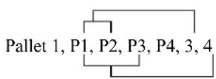
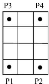
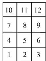
Points that represent divisions of a pallet are automatically assigned division numbers, which, in this example, begin at P1. These division numbers are also required by the Pallet Function.
When Outside is specified, row and column indexes outside of the range of rows and columns can be specified.
For example:
Pallet Outside 1, P1, P2, P3, 4, 5
Jump Pallet(1, -2, 10)
The Maximum Pallet Size
The total number of points defined by a specific pallet must be less than 32,767.
Incorrect Pallet Shape Definitions
Be aware that incorrect order of points or incorrect number of divisions between points will result in an incorrect pallet shape definition.
Pallet Plane Definition
The pallet plane is defined by the Z axis coordinate values of the 3 corner points of the pallet. Therefore, a vertical pallet could also be defined.
Pallet Definition for a Single Row Pallet
A single row pallet can be defined with a 3 point Pallet statement or command. Simply teach a point at each end and define as follows: Specify 1 as the number of divisions between the same point.
Pallet 2, P20, P21, P20, 5, 1 'Defines a 5 ×1 pallet
Additional Axes Coordinate Values
When the coordinate values of the 3 (or 4) points specified with the Pallet statement include the additional ST axis coordinate values, Pallet includes these additional coordinates in the position calculations. In the case where the additional axis is used as the running axis, the motion of the running axis is considered and calculated with the Pallet definition. You need to define a pallet larger than the robot motion range considering the position of the running axis. Even if you define additional axes that are not affected by the pallet definition, be careful of the positions of additional axes when defining the pallet.
See Also
Pallet Function
Pallet Statement Example
The following instruction from the command window sets the pallet defined by P1, P2 and P3 points, and divides the pallet plane into 15 equally distributed pallet point positions, with the pallet point number 1, the pallet point number 2 and the pallet point number 3 sitting along the P1-to-P2 side.
> pallet 1, P1, P2, P3, 3, 5
> jump pallet(1, 2) ' Jump to position on pallet
The resulting Pallet is shown below:
P3
13 14 15
10 11 12
7 8 9
4 5 6
1 2 3
P1 P2
Pallet Function
Specifies a position in a previously defined pallet.

Syntax
(1) Pallet (palletNumber, palletPosition) (2) Pallet ( palletNumber, column, row )
Parameters
| palletNumber | Pallet number represented by integer expression from 0 to 15. |
| PalletPosition | The pallet position represented by an integer from 1 to 32767. |
| column | The pallet column represented by an integer expression from -32768 to 32767. |
| row | The pallet row represented by an integer expression from -32768 to 32767. |
Description
Pallet returns a position in a pallet which was previously defined by the Pallet statement. Use this function with motion commands such as Go and Jump to cause the arm to move to the specified pallet position.
The pallet position number can be defined arithmetically or simply by using an integer.
Notes
Pallet Motion of 6-axis Robot
When the 6-axis robot moves to a point calculated by such as pallet or relative offsets, the wrist part may rotate to an unintended direction. The point calculation above does not depend on robot models and results in motion without converting the required point flag. LJM function prevents the unintended wrist rotation.
Pallet Motion of RS series
In the same way as the 6-axis, when the RS series robot moves to a point calculated by such as pallet or relative offsets, Arm #1 may rotate to an unintended direction. LJM function can be used to convert the point flag to prevent the unintended rotation of Arm #1. In addition, the U axis of RS series may go out of the motion range when the orientation flag is converted, and it causes an error. To prevent this error, LJM function adjusts the U axis target angle to inside the motion range. It is available when the orientation flag "2" is selected.
Additional Axes Coordinate Values
When the coordinate values of the 3 (or 4) points specified with the Pallet statement include the additional ST axis coordinate values, Pallet includes these additional coordinates in the position calculations. In the case where the additional axis is used as the running axis, the motion of the running axis is considered and calculated with the Pallet definition. You need to define a pallet larger than the robot motion range considering the position of the running axis. Even if you define additional axes that are not affected by the pallet definition, be careful of the positions of additional axes when defining the pallet.
See Also
LJM, Pallet
Pallet Function Example
The following program transfers parts from pallet 1 to pallet 2.
Function main
Integer index
Pallet 1, P1, P2, P3, 3, 5 'Define pallet 1
Pallet 2, P12, P13, P11, 5, 3 'Define pallet 2
For index = 1 To 15
Jump Pallet(1, index) 'Move to point index on pallet 1
On 1 'Hold the work piece
Wait 0.5
Jump Pallet(2, index) 'Move to point index on pallet 2
Off 1 'Release the work piece
Wait 0.5
Next I
Fend
Function main
Integer i, j
P0 = XY(300, 300, 300, 90, 0, 180)
P1 = XY(200, 280, 150, 90, 0, 180)
P2 = XY(200, 330, 150, 90, 0, 180)
P3 = XY(-200, 280, 150, 90, 0, 180)
Pallet 1, P1, P2, P3, 10, 10
Motor On
Power High
Speed 50; Accel 50, 50
SpeedS 1000; AccelS 5000
Go P0
P11 = P0 -TLZ(50)
For i = 1 To 10
For j = 1 To 10
'Specify points
P10 ' Depart point = P11
P12 = Pallet(1, i, j) ' Target point
P11 = P12 -TLZ(50) ' Start approach point
' Converting each point to LJM
P10 = LJM(P10)
P11 = LJM(P11, P10)
P12 = LJM(P12, P11)
' Execute motion
Jump3 P10, P11, P12 C0
Next
Next
Fend
Function main2
P0 = XY(300, 300, 300, 90, 0, 180)
P1 = XY(400, 0, 150, 90, 0, 180)
P2 = XY(400, 500, 150, 90, 0, 180)
P3 = XY(-400, 0, 150, 90, 0, 180)
Pallet 1, P1, P2, P3, 10, 10
Motor On
Power High
Speed 50; Accel 50, 50
SpeedS 1000; AccelS 5000
Go P0
Do
' Specify points
P10 = Here -TLZ(50) '
P12 = Pallet(1, Int(Rnd(9)) + 1, Int(Rnd(9)) + 1) 'Depart point
P11 = P12 -TLZ(50) '
If TargetOK(P11) And TargetOK(P12) Then ' 'Start approach point
' Converting each point to LJM
P10 = LJM(P10)
P11 = LJM(P11, P10)
P12 = LJM(P12, P11)
' Execute motion
Jump3 P10, P11, P12 C0
EndIf
Loop
Fend
ParseStr Statement / Function
Parse a string and return array of tokens.

Syntax
ParseStr inputString\, tokens\( ), delimiters\$ numTokens = ParseStr(inputString\, tokens\( ), delimiters\$)
Parameters
| inputString | String expression to be parsed. |
| tokens( ) | Output array of strings containing the tokens.The array declared by ByRef cannot be specified. |
| delimiters$ | String expression containing one or more token delimiters. |
Return Values
When used as a function, the number of tokens parsed is returned.
See Also
Redim, String
ParseStr Statement Example
String toks\$(0)
Integer i
ParseStr "1 2 3 4", toks\$( ), " "
For i = 0 To UBound(toks) Print "token ", i, " = ", toks\$(i)
Next i
Pass Statement
Executes simultaneous four joint Point to Point motion, passing near but not through the specified points.
Syntax
Pass point [, {On | Off | MemOn | MemOff} bitNumber [, point ... ]] [LJM [orientationFlag]]
Parameters
| point | P or P(exp)robpoint label.When the point data is continued and in the ascending order or the descending order, specify two point numbers binding with colon as P(1:5). |
| bitNumber | The I/O output bit or memory I/O bit to turn on or off. Integer number between 0 - 511 or output label. |
| LJM | Optional. Convert the depart point, approach point, and target destination using LJM function. |
| orientationFlag | Optional. Specifies a parameter that selects an orientation flag for LJM function. |
Description
Pass moves the robot arm near but not through the specified point series.
To specify a point series, use points (P0, P1, ...) with commas between points.
To turn output bits on or off while executing motion, insert an On or Off command delimited with commas between points. The On or Off is executed before the robot reaches the point immediately preceding the On or Off.
If Pass is immediately followed by another Pass, control passes to the following Pass without the robot stopping at the preceding Pass final specified point.
If Pass is immediately followed by a motion command other than another Pass, the robot stops at the preceding Pass final specified point, but Fine positioning will not be executed.
If Pass is immediately followed by a command, statement, or function other than a motion command, the immediately following command, statement or function will be executed prior to the robot reaching the final point of the preceding Pass.
If Fine positioning at the target position is desired, follow the Pass with a Go, specifying the target position as shown in the following example:
Pass P5; Go P5; On 1; Move P10
The larger the acceleration / deceleration values, the nearer the arm moves toward the specified point. The Pass instruction can be used such that the robot arm avoids obstacles.
With LJM parameter, the program using LJM function can be more simple.
For example, the following four-line program
P11 = LJM(P1, Here, 1)
P12 = LJM(P2, P11, 1)
P13 = LJM(P3, P12, 1)
Pass P11, P12, P13
can be... one-line program.
Pass P1, P2, P3 LJM 1
LJM parameter is available for 6-axis and RS series robots.
When using orientationFlag with the default value, it can be omitted.
Pass P1, P2, P3 LJM
See Also
Accel, Go, Jump, Speed
Pass Example
The example shows the robot arm manipulation by Pass instruction:
Function main
Jump P1
Pass P2 'Move the arm toward P2, and perform the next instruction before reaching P2.
On 2
Pass P3
Pass P4
Off 0
Pass P5
Fend
Pause Statement
Temporarily stops program execution for all tasks for which pause is enabled.
S
Syntax
Pause
Description
When the Pause is executed, program execution for all tasks with pause enabled (tasks that do not use NoPause or NoEmgAbort in Xqt command) is suspended. Also, if any task is executing a motion statement, it will be paused even if pause is not enabled for that task.
However, Pause cannot stop the background tasks.
Notes
QP and its Effect on Pause
The QP instruction is used to cause the arm to stop immediately upon Pause or to complete the current move and then Pause the program. See the QP instruction help for more information.
Pause Statement Example
The example below shows the use of the Pause instruction to temporarily stop execution. The task executes program statements until the line containing the Pause command. At that point the task is paused. The user can then click the Run Window Continue Button to resume execution.
Function main
Xqt monitor
Go P1
On 1
Jump P2
Off 1
Pause 'Suspend program execution
Go P40
Jump P50
Fend
PauseOn Function
Returns the pause status.

Syntax
PauseOn
Return Values
True if the status is pause, otherwise False.
Description
PauseOn function is used only for NoPause, NoEmgAbort task (special task using NoPause or NoEmgAbort at Xqt), and background tasks.
See Also
ErrorOn, EstopOn, SafetyOn, Xqt
PauseOn Function Example
The following example shows a program that monitors the controller pause and switches the I/O On/Off when pause occurs. However, when the status changes to pause by Safety Door open, the I/O does not turn On/Off.
Function main
Xqt PauseMonitor, NoPause
:
:
Fend
Function PauseMonitor
Boolean IsPause
IsPause = False
Do
Wait 0.1
If SafetyOn = On Then
If IsPause = False Then
Print "Saftey On"
IsPause = True
EndIf
ElseIf PauseOn = On Then
If IsPause = False Then
Print "InPause"
If SafetyOn = Off Then
Off 10
On 12
EndIf
IsPause = True
EndIf
Else
If IsPause = True Then
Print "OutPause"
On 10
Off 12
IsPause = False
EndIf
EndIf
Loop
Fend
PDef Function
Returns the definition status of a specified point.
F
Syntax
PDef (point)
Parameters
point An integer value or Pnumber or P(expr) or point label.
Cautions for compatibility
No variables can be specified for point parameter
To use variables, write PDef(P(varName)).
Return Values
True if the point is defined, otherwise False.
See Also
Here Statement, Pdel
PDef Function Example
If Not PDef(1) Then
Here P1
Endif
Integer i
For i = 0 to 10
If PDef(P(i)) Then
Print "P(";i;") is defined"
End If
Next
PDel Statement
Deletes specified position data.

Syntax
PDel firstPointNum, [lastPointNum]
Parameters
| firstPointNum | The first point number in a sequence of points to delete. firstPointNum must be an integer. |
| lastPointNum | The last point number in a sequence of points to delete. lastPointNum must be an integer. |
Description
Deletes specified position data from the controller's point memory for the current robot. Deletes all position data from firstPointNum up to and including lastPointNum. To prevent Error 2 from occurring, firstPointNum must be less than lastPointNum.
PDel Example
> p1=10,300,-10,0/L
> p2=0,300,-40,0
> p10=-50,350,0,0
> pdel 1,2 'Delete points 1 and 2
> plist
P10 = -50.000, 350.000, 0.000, 0.000 /R /0
> pdel 50 'Delete point 50
> pdel 100,200 'Delete from point 100 to point 200
>
PG_FastStop Statement
Stop the PG axes immediately.
Syntax
PG_FastStop
Description
The PG_FastStop stops the current PG robot immediately with no deceleration. To stop normally, use the PG_SlowStop statement.
See Also
PG_Scan, PG_SlowStop
PG_FastStop Example
The following program moves the PG axis for 10 seconds and stops it.
Function main
Motor On
PG_Scan 0
Wait 10
PG_FastStop ' Immediately stops the continuous motion Fend
PG_LSpeed Statement
Sets the pulse speed of the time when the PG axis starts accelerating and finishes decelerating.
S
Syntax
PG_LSpeed accelSpeed As Integer, [ decelSpeed As Integer ],
Parameters
speed Integer expression that contains the pulse speed (1 ~ 32767 pulse/second)
decalSpeed Integer expression that contains the pulse speed (1 ~ 32767 pulse/second)
Description
PG_LSpeed specifies the pulse speed when the PG axis starts accelerating and finishes decelerating. It is useful when setting the initial/ending speed of a stepping motor to higher within the range of max starting frequency to offer the best performance of motor, or setting the speed to lower to prevent the stepping motor from stepping out. The default is 300 pulse/second and do not change to use.
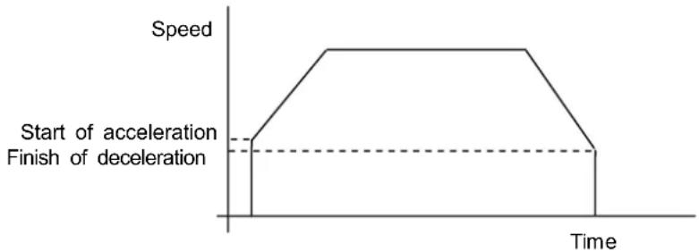
If omitted the finishing speed of deceleration, the speed set value is used.
The PG_LSpeed value initializes to the default values when any one of the following conditions occurs:
Controller Startup
Motor On
SFree, SLock, Brake
Reset, Reset Error
Stop button or QuitAll stops tasks
See Also
PG_LSpeed function
PG_LSpeed Example
You can use the PG_LSpeed in the command window or in the program. The following examples show both cases.
Function pglspeedst
Motor On
Power High
Speed 30;Accel 30,30
PG_LSpeed 1000
Go P0
Fend
To set the PG_LSpeed value from the command window.
> PG_LSpeed 1000,1100
>
PG_LSpeed Function
Returns the pulse speed at the time when the current PG axis starts accelerating and finishes decelerating.

Syntax
PG_LSpeed [(paramNumber)]
Parameters
paramNumber One of the numbers below that specifies the number of set value.
If omitted, 1 is used.
1: Pulse speed at acceleration starts 2: Pulse speed at deceleration finishes
Return Values
Integer value from 1 to 32767 in units of pulse/second.
See Also
PG_LSpeed
PG_LSpeed function Example
Integer savPGLSpeed
savPGLSpeed = PG_LSpeed(1)
PG Scan Statement
Starts the continuous spinning motion of the PG robot axes.
Syntax
PG_Scan direction As Integer
Parameters
direction Spinning direction
0: + (CW) direction
1: - (CCW) direction
Description
The PG_Scan starts the continuous spinning motion of the current PG robot.
To execute the continuous spinning motion, you need to enable the PG parameter continuous spinning by the robot configuration.
When the program execution task is completed, the continuous spinning stops.
See Also
PG_Scan, PG_FastStop
PG_Scan Example
The following example spins the PG axis for 10 seconds and stops it suddenly.
Function main
Motor On
Power High
Speed 10; Accel 10,10
PG_Scan 0
Wait 10
PG_SlowStop
Fend
PG_SlowStop Statement
Stops slowly the PG axis spinning continuously.
Syntax
PG_SlowStop
Description
PG_SlowStop decelerates the continuous spinning motion of the current PG robot and brings it to a stop.
See Also
PG_Scan, PG_FastStop
PG_SlowStop Example
The following example spins the PG axis for 10 seconds and stops it suddenly.
Function main
Motor On
PG_Scan 0
Wait 10
PG_SlowStop ' Stops suddenly the continuous spinning motion
Fend
PLabel Statement
Defines a label for a specified point.
Syntax
PLabel pointNumber, newLabel
Parameters
pointNumber: An integer expression representing a point number.
newLabel: A string expression representing the label to use for the specified point.
See Also
PDef Function, PLabel Function, PNumber Function
PLabel Statement Example
PLabel 1, "pick"
PLabel$ Function
Returns the point label associated with a point number.

Syntax
PLabel$(point)
Parameter
point: An integer value or Pnumber or P(expr) or point label.
Cautions for compatibility
No variables can be specified for point parameter
To use variables, write PLabel\$(P(varName)).
See Also
PDef Function, PLabel Statement, PNumber Function
PLabel\$ Function Example
Print PLabel$(1)
Print PLabel$(P(i))
Plane Statement
Specifies and displays the approach check plane.
Syntax
(1) Plane PlaneNum, [robotNumber], pCoordinateData (2) Plane PlaneNum, [robotNumber], pOrigin, pXaxis, pYaxis (3) Plane PlaneNum, [robotNumber] (4) Plane
Parameters
PlaneNum Integer value representing the plane number from 1 to 15.
robotNumber Integer values representing the robot number If omitted, the current robot is used.
pCoordinateData Point data representing the coordinate data of the approach check plane.
pOrigin Integer expression representing the origin point using the robot coordinate system.
pXaxis Integer expression representing a point along the X axis using the robot coordinate system if X alignment is specified.
pYaxis Integer expression representing a point along the Y axis using the robot coordinate system if Y alignment is specified.
Return Values
When using syntax (3), the setting of the specified plane is displayed.
When using syntax (4), the settings of all plane numbers for the current robot are displayed.
Description
Plane is used to set the approach check plane. The approach check plane is for checking whether the robot end effector is in one of the two areas divided by the specified approach check plane. The position of the end effector is calculated by the current tool. The approach check plane is set using the XY plane of the base coordinate system. The approach check plane detects the end effector when it approaches the area on the +Z side of the approach check plane.
When the approach check plane is used, the system detects approaches in any motor power status during the controller is ON.
The details of each syntax are as follows.
(1) Specifies a coordinate system to create the approach check plane using the point data representing the translation and rotation based on the base coordinate system, and sets the approach check plane.
Example:
Plane 1, XY(x, y, z, u, v, w)
Plane 1, P1
(2) Defines the approach check plane (XP coordinate) by specifying the origin point, point along the X axis, and point along the Y axis. Uses the X, Y, Z coordinates and ignores U, V, W coordinates. Calculates the Z axis in righty and sets the approach checking direction.
Example:
Plane 1, P1, P2, P3
(3) Displays the setting of the specified approach check plane.
(4) Displays all the approach check planes.
You can use the GetRobotInsidePlane function and the InsidePlane function to get the result of the approach check plane. The GetRobotInsidePlane function can be used as the condition for a Wait command. You can provide the detection result to the I/O by setting the remote output setting.
To use one plane with more than one robot, you need to define planes from each robot coordinate system.
![graph TD A["Approach check plane"] --> B["Robot 1"] A --> C["Robot 2"] B --> D["Coordinate system of approach check plane"] C --> D style A fill:#f9f,stroke:#333 style B fill:#ccf,stroke:#333 style C fill:#cfc,stroke:#333](/content/2026/05/815116/images/bd5e870a88a82119d7ae91064cf9a484a2ffe2fc964933bca8eb220a9ee92c00.jpg)
Notes
Tool Selection
The approach check is executed for the current tool. When you change the tool, the approach check may display the tool approach from inside to outside of the plane or the other way although the robot is not operating.
Additional axis
For the robot which has the additional ST axes (including the running axis), the approach check plane to set doesn't depend on the position of an additional axis, but is based on the robot base coordinate system.
See Also
Box, GetRobotInsidePlane, InsidePlane, PlaneClr, PlaneDef
Tip
Set Plane statement from Robot Manager
EPSON RC+ 6.0 has a point and click dialog box for defining the approach check plane. The simplest method to set the Plane values is by using the Plane page on the Robot Manager.
Plane Statement Example
These are examples to set the approach check plane using the Plane statement.
Check direction is the lower side of the horizontal plane that is -20 mm in the Z axis direction in the robot coordinate system:
> plane 1, xy(100, 200, -20, 90, 0, 180)
Approach check plane is the XY coordinate created by moving 50 mm in the X axis and 200 mm in the Y axis, rotating 45 degrees around the Y axis:
> plane 2, xy(50, 200, 0, 0, 45, 0)
Set the approach check plane using the tool coordinate system of the robot. (6-axis robot)
> plane 3, here
Plane Function
Returns the specified approach check plane.

Syntax
Plane(PlaneNum, [robotNumber])
Parameters
PlaneNum Integer expression representing the plane number from 1 to 15. robotNumber Integer values representing the robot number If omitted, the current robot is used.
Return Values
Returns coordinate data for the specified approach check plane.
See Also
GetRobotInsidePlane, InsidePlane, Plane, PlaneClr, PlaneDef
Plane Function Example
P1 = Plane(1)
PlaneClr Statement
Clears (undefines) a Plane definition.
Syntax
PlaneClr PlaneNum, [ robotNumber ]
Parameters
PlaneNum Integer expression representing the plane number from 1 to 15. robotNumber Integer value representing the robot number If omitted, the current robot is used.
See Also
GetRobotInsidePlane, InsidePlane, Plane, PlaneDef
PlaneClr Statement Example
PlaneClr 1
PlaneDef Function
Returns the setting of the approach check plane.

Syntax
PlaneDef (PlaneNum, [robotNumber])
Parameters
PlaneNum: Integer expression representing the plane number from 1 to 15.
robotNumber: Integer value representing the robot number.
If omitted, the current robot is used.
Return Values
True if approach detection plane is defined for the specified plane number, otherwise False.
See Also
GetRobotInsidePlane, Box, InsidePlane, Plane, PlaneClr
PlaneDef Function Example
Function DisplayPlaneDef(planeNum As Integer)
If PlaneDef(planeNum) = False Then
Print "Plane ", planeNum, "is not defined"
Else
Print "Plane 1: ",
Print Plane(PlaneNum)
EndIf
Fend
PList Statement
Displays point data in memory for the current robot.

Syntax
(1) PList (2) PList pointNumber (3) PList startPoint, (4) PList startPoint, endpoint
Parameters
| pointNumber | The number range is 0 to 999. |
| startPoint | The start point number. The number range is 0 to 999. |
| endPoint | The end point index. The number range is 0 to 999. |
Return Values
Point data.
Description
PList displays point data in memory for the current robot.
When there is no point data within the specified range of points, no data will be displayed. When a start point number is specified larger than the end point number, then an error occurs.
(1) PList
Displays the coordinate data for all points.
(2) PList pointIndex
Displays the coordinate data for the specified point.
(3) PList startPoint,
Displays the coordinate data for all points starting with startPoint.
(4) PList startPoint, endPoint
Displays the coordinate data for all points starting with startPoint and ending with endPoint.
PList Example
Display type depends on the robot type and existence of additional axes.
The following examples are for a Scara robot without additional axes.
Displays the specified point data:
>plist 1
P1 = XY(200.000, 0.000, -20.000, 0.000) /R /0
Displays the point data within the range of 10 and 20. In this example, only three points are found in this range.
> plist 10, 20
P10 = XY(290.000, 0.000, -20.000, 0.000) /R /0
P12 = XY(300.000, 0.000, 0.000, 0.000) /R /0
P20 = XY(285.000, 10.000, -30.000, 45.000) /R /0
>
Displays the point data starting with point number 10
> plist 10,
P10 = XY(290.000, 0.000, -20.000, 0.000) /R /0
P12 = XY(300.000, 0.000, 0.000, 0.000) /R /0
P20 = XY(285.000, 10.000, -30.000, 45.000) /R /0
P30 = XY(310.000, 20.000, -50.000, 90.000) /R /0
PLocal Statement
Sets the local attribute for a point.
Syntax
PLocal(point) = localNumber
Parameters
point: An integer value or Pnumber or P(expr) or point label.
Cautions for compatibility
No variables can be specified for the point parameter.
To use variables, write PLocal(P(varName)).
localNumber: An integer expression representing the new local number. Range is 0 to 15.
See Also
PLocal Function
PLocal Statement Example
PLocal(pick) = 1
PLocal Function
Returns the local number for a specified point.

Syntax
PLocal(point)
Parameters
point An integer value or Pnumber or P(expr) or point label.
Cautions for compatibility
No variables can be specified for point parameter
To use variables, write PLocal(P(varName)).
Return Values
Local number for specified point.
See Also
PLocal Statement
PLocal Function Example
Integer localNum
localNum = PLocal(pick)
PIs Function
Returns the current encoder pulse count for each joint at the current position.

Syntax
PIs(jointNumber)
Parameters
jointNumber The specific joint for which to get the current encoder pulse count. The additional S axis is 8 and T axis is 9.
Return Values
Returns a number value representing the current encoder pulse count for the joint specified by jointNumber.
Description
PIs is used to read the current encoder position (or Pulse Count) of each joint. These values can be saved and then used later with the Pulse command.
See Also
CX, CY, CZ, CU, CV, CW, Pulse
PIs Function Example
Shown below is a simple example to get the pulse values for each joint and print them.
Function plstest
Real t1, t2, z, u
t1 = pls(1)
t2 = pls(2)
z = pls(3)
u = pls(4)
Print "T1 joint current Pulse Value: ", t1
Print "T2 joint current Pulse Value: ", t2
Print "Z joint current Pulse Value: ", z
Print "U joint current Pulse Value: ", u
Fend
PNumber Function
Returns the point number associated with a point label.
Syntax
PNumber(pointLabel)
Parameters
pointLabel: A point label used in the current point file or string expression containing a point label.
See Also
PDef Function, PLabel$ Function
PNumber Function Example
Integer pNum
String pointName $
pNum = PNumber(pick)
pNum = PNumber("pick")
pointName$ = "place"
pNum = PNumber(pointName$)
Point Assignment
Defines a robot point by assigning it to a point expression.
Syntax
point = pointExpr
Parameters
point: Expression including numeric number or ( ) (parenthesis)
Pnumber
P(expr)
pointLabel Point label
pointExpr One of the following point data
P point number, Point label, Here, Pallet, Point data function (Here function, XY function, JA function, Pulse function, etc.)
Description
Define a robot point by setting it equal to another point or point expression.
See Also
Local, Pallet, PDef, PDel, Plist
Point Assignment Example
The following examples are done from the command window:
Assign coordinates to P1:
> P1 = 300,200,-50,100
Specify left arm posture:
> P2 = -400, 200, -80, 100/L
Add 20 to X coordinate of P2 and define resulting point as P3:
> P3 = P2 +X(20)
> plist 3
P3=-380,200,-80,100/L
Subtract 50 from Y coordinate of P2, substitute -30 for Z coordinate, and define the resulting point P4 as right arm posture:
>P4=P2 -Y(50) :Z(-30) /R
>plist 4
P4 = XY(-450,200,-30,100)/R
Add 90 to U coordinate of Pallet(3, 5), and define resulting point as P6:
> P5 = Here
> P6 = pallet(3,5) +U(90)
Point Expression
Specifies a robot point for assignment and motion commands.
Syntax
point [ { + | - } point ] [local] [hand] [elbow] [wrist] [j4flag] [j6flag] [j1flag] [j2flag] [relativeOffsets] [absoluteCoords]
Parameters
point The base point specification. This can be one of the following:
Pnumber
P(expr)
Here
Pallet(palletNumber, palletIndex)
pointLabel
XY(X,Y,Z,U,[V],[W])
JA(J1, J2, J3, J4, [J5], [J6])
Pulse(J1, J2, J3, J4, [J5], [J6])
local Optional. Local number from 1 to 15 preceded by a forward slash (/0 to /15) or at sign (@0 to @15). The forward slash means that the coordinates will be in the local. The at sign means that the coordinates will be translated into local coordinates.
hand Optional for SCARA robot (including RS series) and 6-axis robots. Specify /L or /R for lefty or righty hand orientation.
elbow Optional for 6-axis robots. Specify /A or /B for above or below orientation.
wrist Optional for 6-axis robots. Specify /F or /NF for flip or no flip orientation.
j4flag Optional for 6-axis robots. Specify /J4F0 or /J4F1.
j6flag Optional for 6-axis robots. Specify /J6F0 - /J6F127.
j1flag Optional for RS series. Specify /J1F0 or /J1F1.
j2flag Optional for RS series. Specify /J2F0 - /J2F127.
j1angle Optional for RS series. Specify /J1A (real value).
relativeOffsets Optional. One or more relative coordinate adjustments.
{+ | -} {X | Y | Z | U | V | W | R | S | T | ST } (expr)
The TL offsets are relative offsets in the current tool coordinate system.
{+ | -} {TLX | TLY | TLZ | TLU | TLV | TLW} (expr)
absoluteCoords Optional. One or more absolute coordinates.
: {X | Y | Z | U | V | W | R | S | T | ST } (expr)
Description
Point expressions are used in point assignment statements and motion commands.
Go P1 + P2
P1 = P2 + XY(100, 100, 0, 0)
Using relative offsets
You can offset one or more coordinates relative to the base point. For example, the following statement moves the robot 20 mm in the positive X axis from the current position:
Go Here +X(20)
If you execute the same statement again, the robot will move an additional 20 mm along the X axis, because this is a relative move.
You can also use relative tool offsets:
Go Here +TLX(20) - TLY(5.5)
When the 6-axis robot moves to a point calculated by such as pallet or relative offsets, the wrist part may rotate to an unintended direction. The point calculation above does not depend on robot models and results in motion without converting the required point flag.
LJM function prevents the unintended wrist rotation.
Go LJM(Here +X(20))
Using absolute coordinates
You can change one or more coordinates of the base point by using absolute coordinates. For example, the following statement moves the robot to the 20 mm position on the X axis:
Go Here :X(20)
If you execute the same statement again, the robot will not move because it is already in the absolute position for X from the previous move.
Relative offsets and absolute coordinates make it easy to temporarily modify a point. For example, this code moves quickly above the pick point by 10 mm using a relative offset for Z or 10 mm, then moves slowly to the pick point.
Speed fast
Jump pick +Z(10)
Speed slow
Go pick
This code moves straight up from the current position by specifying an absolute value of 0 for the Z joint:
LimZ 0
Jump Here : Z(0)
Using Locals
You can specify a local number using a forward slash or at sign. Each has a separate function.
Use the forward slash to mark the coordinates in a local. For example, adding a /1 in the following statement says that P1 will be at location 0,0,0,0 in local 1.
P1 = XY(0, 0, 0, 0) /1
Use the at sign to translate the coordinates into local coordinates.
For example, here is how to set the current position to P1:
P1 = Here @1
See Also
Go, LJM, Local, Pallet, Pdel, Plist, Hand, Elbow, Wrist, J4Flag, J6Flag, J1Flag, J2Flag
Point Expression Example
Here are some examples of using point expressions in assignments statements and motion commands:
P1 = XY(300,200,-50,100)
P2 = P1 /R
P3 = pick /1
P4 = P5 + P6
P(i) = XY(100, 200, CZ(P100), 0)
Go P1 -X(20) :Z(-20) /R
Go Pallet(1, 1) -Y(25.5)
Move pick /R
Jump Here :Z(0)
Go Here :Z(-25.5)
Go JA(25, 0, -20, 180)
pick = XY(100, 100, -50, 0)
P1 = XY(300,200,-50,100, -90, 0)
P2 = P1 /F /B
P2 = P1 +TLV(25)
PosFound Function
Returns status of Find operation.

Syntax
PosFound
Return Values
True if position was found during move, False if not.
See Also
Find
PosFound Function Example
Find Sw(5) = ON
Go P10 Find
If PosFound Then
Go FindPos
Else
Print "Error: Cannot find the sensor signal."
EndIf
Power Statement
Previously Called - Lp


Switches Power Mode to high or low and displays the current status.
Power Syntax
(1) Power { High | Low } (2) Power
Parameters
High | Low The setting can be High or Low. The default is Low.
Return Values
Displays the current Power status when parameter is omitted.
Description
Switches Power Mode to High or Low. It also displays the current mode status.
Low - When Power is set to Low, Low Power Mode is On. This means that the robot will run slow (below 250 mm/sec) and the servo stiffness is set light so as to remove servo power if the robot bumps into an object.
High - When Power is set to High, Low Power Mode is Off. This means that the robot can run at full speed with the full servo stiffness.
The following operations will switch to low power mode. In this case, speed and acceleration settings will be limited to the default value. The default value is described in the each manipulator specification table. See also the EPSON RC+ Users Guide: 2. Safety.
Conditions to cause Power Low:
Controller Startup
Motor On
SFree, SLock, Brake
Reset, Reset Error
Stop button or QuitAll stops tasks
Settings limited to the default value
Speed
Accel
SpeedS
AccelS
Notes
Low Power Mode (Power Low) and Its Effect on Max Speed:
In low power mode, motor power is limited, and the effective motion speed setting is lower than the default value. If, when in Low Power mode, a higher speed is specified from the Command window (directly) or in a program, the speed is set to the default value. If a higher speed motion is required, set Power High.
High Power Mode (Power High) and Its Effect on Max Speed:
In high power mode, higher speeds than the default value can be set.
See Also
Accel, AccelS, Speed, SpeedS
Power Example
The following examples are executed from the command window:
> Speed 50 'Specifies high speed in Low Power mode
> Accel 100, 100 'Specifies high accel
> Jump P1 'Moves in low speed and low accel
> Speed 'Display current speed values
Low Power Mode
50
50 50
> Accel 'Display current accel values
Low Power Mode
100 100
100 100
100 100
> Power High 'Set high power mode
> Jump P2 'Move robot at high speed
Power Function
Returns status of power.

Syntax
Power
Return Values
0 = Power Low, 1 = Power High.
See Also
Power Statement
Power Function Example
If Power = 0 Then
Print "Low Power Mode"
End If
PPIs Function
Return the pulse position of a specified joint value from a specified point.

Syntax
PPIs (point, jointNumber)
Parameters
| point | Point expression. |
| jointNumber | Expression or numeric value specifying the joint number (integer from 1 to 9)The additional S axis is 8 and T axis is 9. |
Return Values
Returns the calculated joint position (long value, in pulses).
See Also
Agl, CX, CY, CZ, CU, CV, CW, Pagl
PPIs Example
Long pulses1
pulses1 = PPls(P10, 1)
Print Statement
Outputs data to the current display window, including the Run window, Operator window, Command window, and Macro window.

Syntax
Print expression [, expression...] [, ]
Parameters
expression Optional. A number or string expression.
, (comma) Optional. If a comma is provided at the end of the statement, then a CRLF will not be added.
Return Values
Variable data or the specified character string.
Description
Print displays variable data or the character string on the display device.
An end of line CRLF (carriage return and line feed) is automatically appended to each output unless a comma is used at the end of the statement.
Notes
Make sure Print is used with Wait or a motion within a loop.
Tight loops (loops with no Wait or no motion) are generally not good, especially with Print.
The controller may freeze up in the worst case.
Be sure to use Print with Wait command or a motion command within a loop.
Do
Print "1234"
Loop
Do
Print "1234"
Wait 0.1
Loop
See Also
Print #
Print Statement Example
The following example extracts the U Axis coordinate value from a Point P100 and puts the coordinate value in the variable uvar. The value is then printed to the current display window.
Function test
Real uvar
uvar = CU(P100)
Print "The U Axis Coordinate of P100 is ", uvar
Fend
Print # Statement
Outputs data to the specified file, communications port, database, or device.
Syntax
Print #portNumber, expression [, expression...] [, ]
Parameters
portNumber ID number representing a file, communications port, database, or device. File number can be specified in ROpen, WOpen, and AOpen statements. Communications port number can be specified in OpenCom (RS232) and OpenNet (TCP/IP) statements.
Database number can be specified in OpenDB statement.
Device ID integers are as follows.
21 RC+
24 TP
28 LCD
expression A numeric or string expression.
, (comma) Optional. If a comma is provided at the end of the statement, then a CRLF will not be added.
Description
Print # outputs variable data, numerical values, or character strings to the communication port or the device specified by portNumber.
Note
Maximum data length
This command can handle up to 256 bytes.
However, if the target is a database, it can handle up to 4096 bytes.
Exchange variable data with other controller
- When more than one string variable or both of numeric variable and string variable is specified, a comma (“,”) character has to be added expressly to the string data.
Sending end (Either pattern is OK.)
Print #PortNum, "$Status,", InData, OutData
Print #PortNum, "$Status", "", InData, OutData
Receiving end
Input #PortNum, Response$, InData, OutData
File write buffering
File writing is buffered. The buffered data can be written with Flush statement. Also, when closing a file with Close statement, the buffered data can be written.
See Also
Input#, Print
Print # Example
The following are some simple Print # examples:
Function printex
String temp$
Print #1, "5" ' send the character "5" to serial port 1 temp$ = "hello"
Print #1, temp$
Print #2, temp$
Print #1 " Next message for port 1"
Print #2 " Next message for port 2"
Fend
PTCLR Statement
Clears and initializes the peak torque for one or more joints.
Syntax
PTCLR [j1], [j2], [j3], [j4], [j5], [j6], [j7], [j8], [j9]
Parameters
j1-j9
Optional. Integer expression representing the joint number. If no parameters are supplied, then the peak torque values are cleared for all joints.
The additional S axis is 8 and T axis is 9.
Description
PTCLR clears the peak torque values for the specified joints.
You must execute PTCLR before executing PTRQ.
See Also
ATRQ, PTRQ
PTCLR Statement Example
Specifies or displays the acceleration, deceleration and speed algorithmic boost parameter for small distance PTP (point to point) motion.
Syntax
(1) PTPBoost boost, [departBoost], [approBoost] (2) PTPBoost
Parameters
boost Integer expression from 0 - 100.
departBoost Optional. Jump depart boost value. Integer expression from 0 - 100.
approBoost Optional. Jump approach boost value. Integer expression from 0 - 100.
Return Values
When parameters are omitted, the current PTPBoost settings are displayed.
Description
PTPBoost sets the acceleration, deceleration and speed for small distance PTP motion. It is effective only when the motion distance is small. The PTPBoostOK function can be used to confirm whether or not a specific motion distance to the destination is small enough to be affected by PTPBoost or not.
PTPBoost does not need modification under normal circumstances. Use PTPBoost only when you need to shorten the cycle time even if vibration becomes larger, or conversely when you need to reduce vibration even if cycle time becomes longer.
When the PTPBoost value is large, cycle time becomes shorter, but the positioning vibration increases. When PTPBoost is small, the positioning vibration becomes smaller, but cycle time becomes longer. Specifying inappropriate PTPBoost causes errors or can damage the manipulator. This may degrade the robot, or sometimes cause the manipulator life to shorten.
The PTPBoost value initializes to its default value when any one of the following is performed:
Controller Startup
Motor On
SFree, SLock, Brake
Reset, Reset Error
Stop button or QuitAll stops tasks
See Also
PTPBoost Function, PTPBoostOK
PTPBoost Statement Example
PTPBoost 50, 30, 30
PTPBoost Function
Returns the specified PTPBoost value.

Syntax
PTPBoost(paramNumber)
Parameters
paramNumber Integer expression which can have the following values:
1: boost value 2: jump depart boost value 3: jump approach boost value
Return Values
Integer value from 0 - 100.
See Also
PTPBoost Statement, PTPBoostOK
PTPBoost Function Example
Print PTPBoost(1)
PTPBoostOK Function
Returns whether or not the PTP (Point to Point) motion from a current position to a target position is a small travel distance.

Syntax
PTPBoostOK(targetPos)
Parameters
targetPos Point expression for the target position.
Return Values
True if it is possible to move to the target position from the current position using PTP motion, otherwise False.
Description
Use PTPBoostOK to determine if the distance from the current position to the target position is small enough for PTPBoost to be effective.
See Also
PTPBoost
PTPBoostOK Function Example
If PTPBoostOK(P1) Then
PTPBoost 50
EndIf
Go P1
PTPTime Function
Returns the estimated time for a point to point motion command without executing it.

Syntax
(1) PTPTime(destination, destArm, destTool) (2) PTPTime(start, startArm, startTool, destination, destArm, destTool)
Parameters
start Point expression for the starting position. destination Point expression for the destination position. destArm Integer expression for the destination arm number. destTool Integer expression for the destination tool number. startArm Integer expression for the starting point arm number. startTool Integer expression for the starting point tool number.
Return Values
Real value in seconds.
Description
Use PTPTime to calculate the time it would take for a point to point motion command (Go). Use syntax 1 to calculate time from the current position to the destination. Use syntax 2 to calculate time from a start point to a destination point.
The actual motion operation is not performed when this function is executed. The current position, arm, and tool settings do not change.
If the position is one that cannot be arrived at or if the arm or tool settings are incorrect, 0 is returned.
If a robot includes an additional axis and it is the servo axis, the function will consider the motion time of the additional axis. If the additional axis is a PG axis, the motion time of the robot will be returned.
See Also
ATRQ, Go, PTRQ
PTPTime Function Example
Real secs
secs = PTPTime(P1, 0, 0, P2, 0, 1)
Print "Time to go from P1 to P2 is:", secs
Go P1
secs = PTPTime(P2, 0, 1)
Print "Time to go from P1 to P2 is:", secs
PTran Statement
Perform a relative move of one joint in pulses.
s
Syntax
PTran joint, pulses
Parameters
joint Integer expression representing which joint to move.
The additional S axis is 8 and T axis is 9.
pulses Integer expression representing the number of pulses to move.
Description
Use PTran to move one joint a specified number of pulses from the current position.
See Also
Go, JTran, Jump, Move
PTran Statement Example
PTran 1, 2000
PTRQ Statement
Displays the peak torque for the specified joint.
Syntax
PTRQ [jointNumber]
Parameters
jointNumber
Optional. Integer expression representing the joint number.
The additional S axis is 8 and T axis is 9.
Return Values
Displays current peak torque values for all joints.
Description
Use PTRQ to display the peak torque value for one or all joints since the PTCLR statement was executed.
Peak torque is a real number from 0 to 1.
See Also
ATRQ, PTCLR, PTRQ Function
PTRQ Statement Example
Returns the peak torque for the specified joint.
F
Syntax
PTRQ(jointNumber)
Parameters
jointNumber
Integer expression representing the joint number.
The additional S axis is 8 and T axis is 9.
Return Values
Real value from 0 to 1.
See Also
ATRQ, PTCLR, PTRQ Statement
PTRQ Function Example
This example uses the PTRQ function in a program:
Function DisplayPeakTorque
Integer i
Print "Peak torques:"
For i = 1 To 4
Print "Joint ", i, " = ", PTRQ(i)
Next i
Fend
Pulse Statement
Moves the robot arm using point to point motion to the point specified by the pulse values for each joint.
Syntax
(1) Pulse J1, J2, J3, J4, [J5, J6], [J7], [J8, J9] (2) Pulse
Parameters
J1 ~ J4
The pulse value for each of the first four joints. The pulse value has to be within the range defined by the Range instruction and should be an integer or long expression.
J5, J6 Optional. For 6-axis robots and Joint type 6-axis robots.
J7 Optional. For Joint type 7-axis robots.
J8, J9
Optional. For the additional axis.
Return Values
When parameters are omitted, the pulse values for the current robot position are displayed.
Description
Pulse uses the joint pulse value from the zero pulse position to represent the robot arm position, rather than the orthogonal coordinate system. The Pulse instruction moves the robot arm using Point to Point motion.
The Range instruction sets the upper and lower limits used in the Pulse instruction.
Note
Make Sure Path is Obstacle Free Before Using Pulse
Unlike Jump, Pulse moves all axes simultaneously, including Z joint raising and lowering in traveling to the target position. Therefore, when using Pulse, take extreme care so that the hand can move through an obstacle free path.
Potential Errors
Pulse value exceeds limit:
If the pulse value specified in Pulse instruction exceeds the limit set by the Range instruction, an error will occur.
See Also
Go, Accel, Range, Speed, PIs, Pulse Function
Pulse Statement Example
Following are examples on the Command window:
This example moves the robot arm to the position which is defined by each joint pulse.
> pulse 16000, 10000, -100, 10
This example displays the pulse numbers of the 1st to 4th axes of the current robot arm position.
> pulse
PULSE: 1: 27306 pls 2: 11378 pls 3: -3072 pls 4: 1297 pls >
Pulse Function
Returns a robot point whose coordinates are specified in pulses for each joint.

Syntax
Pulse (J1, J2, J3, J4, [J5, J6], [J7], [J8, J9])
Parameters
J1 \~ J4 The pulse value for joints 1 to 4. The pulse value must be within the range defined by the Range instruction and should be an integer or long expression.
J5, J6 Optional. For 6-axis robots and Joint type 6-axis robots.
J7 Optional. For Joint type 7-axis robots.
J8, J9 Optional. For the additional axis.
Return Values
A robot point using the specified pulse values.
See Also
Go, JA, Jump, Move, Pulse Statement, XY
Pulse Function Example
Jump Pulse(1000, 2000, 0, 0)
QP Statement
Switches Quick Pause Mode On or Off and displays the current mode status.
Syntax
(1) QP { On | Off }
(2) QP
Parameters
On | Off Quick Pause can be either On or Off.
Return Values
Displays the current QP mode setting when parameter is omitted.
Description
If during motion command execution either the Pause switch is pressed, or a pause signal is input to the controller, quick pause mode determines whether the robot will stop immediately, or will Pause after having executed the motion command.
Immediately decelerating and stopping is referred to as a "Quick Pause".
With the On parameter specified, QP turns the Quick Pause mode On. With the Off parameter specified, QP turns the Quick Pause mode Off.
QP displays the current setting of whether the robot arm is to respond to the Pause input by stopping immediately or after the current arm operation is completed. QP is simply a status instruction used to display whether Quick Pause mode is on or off.
Notes
Quick pause mode defaults to on after power is turned on:
The Quick Pause mode set by the QP instruction remains in effect after the Reset instruction. However, when the PC power or Drive Unit power is turned off and then back on, Quick Pause mode defaults to On.
QP and the Safe Guard Input:
Even if QP mode is set to Off, if the Safe Guard Input becomes open the robot will pause immediately.
See Also
Pause
QP Statement Example
This Command window example displays the current setting of whether the robot arm is to stop immediately on the Pause input. (i.e. is QP mode set On or Off)
> qp
QP ON
> qp on 'Sets QP to Quick Pause Mode
>
QPDecelR Statement
Sets the deceleration speed of quick pause for the change of tool orientation during the CP motion.
Syntax
(1) QPDeceIR QPDeceIR (2) QPDecelR
Parameters
Real value representing the deceleration speed of quick pause during the CP motion (deg/sec2).
Result
If the parameter is omitted, the current QPDeceIR set value will be displayed.
Description
QPDecelR statement is enabled when the ROT parameter is used in the Move, Arc, Arc3, BMove, TMove, and Jump3CP statements.
While quick pause is executed in these statements, a joint acceleration error may occur. This is because the deceleration speed of quick pause that is automatically set in a normal quick pause is over the joint allowable deceleration speed. Specifically, the error is likely to occur when the AccelR value in the CP motion is too high or jogging the robot near a singularity. In these cases, use the QPDecelR and set a lower quick pause deceleration speed. But if the setting is too low, the distance for quick pause will increase. Therefore, set the possible value. Normally, you don't need to set QPDecelR.
You cannot use values lower than the deceleration speed of orientation change in the CP motion set with QPDeceIR and AccelR. If you do, a parameter out of range error occurs.
Also, after you set QPDecelR, if a higher value than the set QP deceleration speed is set with the AccelR, the QPDecelR will automatically set the QP deceleration speed same as the deceleration speed set with the AccelR.
The QPDecelR Statement value initializes to the default max deceleration speed when any one of the following conditions occurs:
Controller Startup
Motor On
SFree, SLock, Brake
Reset, Reset Error
Stop button or QuitAll stops tasks
See Also
QPDecelR function, QPDecelS, AccelR
QPDecelR Example
The following program sets the QPDeceIR of the Move statement.
Function QPDecelTest
AccelR 3000
QPDecelR 4000
SpeedR 100
Move P1 ROT
:
Fend
QPDeceIR Function
Returns the set deceleration speed of quick pause for the change of tool orientation during the CP motion.
Syntax
QPDecelR
Return Values
Real value that contains the set deceleration speed of quick pause for the tool orientation change in the CP motion (deg/s2)
See Also
QPDecelR, QPDecelS function
QPDecelR function Example
Real savQPDecelR
savQPDecelR = QPDecelR
QPDecelS Statement
Sets the deceleration speed of quick pause in the CP motion.
Syntax
(1) QPDecelS QPDecelS [, departDecel, approDecel] (2) QPDecelS
Parameters
| QPDecelS | Real value that specifies the deceleration speed of quick pause in the CP motion. (mm/sec 2 ) |
| departDecel | Real value that specifies the deceleration speed of quick pause in the Jump3 depart motion (mm/sec 2 ) |
| approDecel | Real value that specifies the deceleration speed of quick pause in the Jump3 approach motion (mm/sec 2 ) |
Return Values
If the parameter is omitted, the current QPDecelS set value is displayed.
Description
While quick pause is executed in the CP motion, a joint acceleration error may occur. This is because the deceleration speed of quick pause that is automatically set in a normal quick pause is over the joint allowable deceleration speed. Specifically, the error is likely to occur when the AccelS value in the CP motion is too high or jogging the robot near a singularity. In these cases, use the QPDecelS and set a lower quick pause deceleration speed. But if the setting is too low, the distance for quick pause will increase. Therefore, set the possible value. Normally, you don't need to set QPDecelS.
You cannot use values lower than the deceleration speed of the CP motion set with AccelS. If you do, a parameter out of range error occurs.
Also, after you set QPDecelS, if a higher value than the set QP deceleration speed is set with the AccelS, the QPDecelS will automatically set the QP deceleration speed same as the deceleration speed set with the AccelS.
The QPDecelS Statement value initializes to the default max deceleration speed when any one of the following conditions occurs:
Controller Startup
Motor On
SFree, SLock, Brake
Reset, Reset Error
Stop button or QuitAll stops tasks
See Also
QPDecelS Function, QPDecelR, AccelS
QPDecelS Example
The following program sets the QPDecelS of the Move statement.
Function QPDecelTest
00 AccelS 30
QPDecelS 4000
SpeedS 100
Move P1
:
.
Fend
QPDecelS Function
Returns the set deceleration speed of quick pause during the CP motion.
Syntax
QPDecelS (paramNumber)
Parameters
paramNumber Integer expression specifying one of the following values.
1: Quick pause deceleration speed during the CP motion 2: Quick pause deceleration speed in depart motion during the Jump3 and Jump3CP 3: Quick pause deceleration speed in approach motion during the Jump3 and Jump3CP
Return Values
Real value representing the quick pause deceleration speed (mm/s2)
See Also
QPDecelS, QPDecelR function
QPDecelS function Example
Real savQPDecelS
savQPDecelS = QPDecelS(1)
Quit Statement
Terminates execution of a specified task or all tasks.
s
Syntax
Quit { taskIdentifier | All }
Parameters
taskIdentifier
Task name or integer expression representing the task number.
Task name is a function name used in an Xqt statement or a function started from the Run window or Operator window.
Task number range is:
Normal tasks : 1 \~ 32
Background task : 65 \~ 80
Trap tasks : 257 \~ 267
All Specifies this parameter if all tasks except the background task should be terminated.
Description
Quit stops the tasks that are currently being executed, or that have been temporarily suspended with Halt.
Quit also stops the task when the specified task is NoPause task, NoEmgAbort task (special task using NoPause or NoEmgAbort at Xqt), or the background tasks.
Quit All stops all tasks including the tasks above other than the background tasks.
Quit All sets the robot control parameter as below:
Robot Control parameter
Current robot Speed, SpeedR, SpeedS (Initialized to default values)
Current robot QPDecelR, QPDecelS (Initialized to default values)
Current robot LimZ parameter (Initialized to 0)
Current robot CP parameter (Initialized to Off)
Current robot SoftCP parameter (Initialized to Off)
Current robot Fine (Initialized to default values)
Current robot Power Low (Low Power Mode set to On)
Current robot PTPBoost (Initialized to default values)
Current robot TCLim, TCSpeed (Initialized to default values)
Current robot PgLSpeed (Initialized to default values)
See Also
Exit, Halt, Resume, Xqt
Quit Example
This example shows two tasks that are terminated after 10 seconds.
Function main
Xqt winc1 'Start winc1 function
Xqt winc2 'Start winc2 function
Wait 10
Quit winc1 'Terminate task winc1
Quit winc2 'Terminate task winc2
Fend
Function winc1
Do
On 1; Wait 0.2
Off 1; Wait 0.2
Loop
Fend
Function winc2
Do
On 2; Wait 0.5
Off 2; Wait 0.5
Loop
Fend
RadToDeg Function
Converts radians to degrees.
Syntax
RadToDeg(radians)
Parameters
radians Real expression representing the radians to convert to degrees.
Return Values
A double value containing the number of degrees.
See Also
ATan, ATan2, DegToRad Function
RadToDeg Function Example
s = Cos(RadToDeg(x))
Randomize Statement
Initializes the random-number generator.
S
Syntax
(1) Randomize seedValue (2) Randomize
Parameter
seedValue Specify a real value (0 or more) to be basis to retrieve a random number.
See Also
Rnd Function
Randomize Example
Function main
Real r
Randomize
Integer randNum
randNum = Int(Rnd(10)) + 1
Print "Random number is:", randNum
Fend
Range Statement
Specifies and displays the motion limits for each of the servo joints.
Syntax
(1) Range j1Min, j1Max, j2Min, j2Max, j3Min, j3Max, j4Min, j4Max, j5Min, j5Max, j6Min, j6Max, j7Min, j7Max, j8Min, j8Max, j9Min, j9Max
(2) Range
Parameters
| j1Min | The lower limit for joint 1 specified in pulses. |
| j1Max | The upper limit for joint 1 specified in pulses. |
| j2Min | The lower limit for joint 2 specified in pulses. |
| j2Max | The upper limit for joint 2 specified in pulses. |
| j3Min | The lower limit for joint 3 specified in pulses. |
| j3Max | The upper limit for joint 3 specified in pulses. |
| j4Min | The lower limit for joint 4 specified in pulses. |
| j4Max | The upper limit for joint 4 specified in pulses. |
| j5Min | Optional for 6-Axis robots and Joint type 6-axis robots. The lower limit for joint 5 specified in pulses. |
| j5Max | Optional for 6-Axis robots and Joint type 6-axis robots. The upper limit for joint 5 specified in pulses. |
| j6Min | Optional for 6-Axis robots and Joint type 6-axis robots. The lower limit for joint 6 specified in pulses. |
| j6Max | Optional for 6-Axis robots and Joint type 6-axis robots. The upper limit for joint 6 specified in pulses. |
| j7Min | Optional for Joint type 7-axis robots. The lower limit for joint 7 specified in pulses. |
| j7Max | Optional for Joint type 7-axis robots. The upper limit for joint 7 specified in pulses. |
| j8Min | Optional for the additional S axis. The lower limit for joint 8 specified in pulses. |
| j8Max | Optional for the additional S axis. The upper limit for joint 8 specified in pulses. |
| j9Min | Optional for the additional T axis. The lower limit for joint 9 specified in pulses. |
| j9Max | Optional for the additional T axis. The upper limit for joint 9 specified in pulses. |
Return Values
Displays the current Range values when Range is entered without parameters.
Description
Range specifies the lower and upper limits of each motor joint in pulse counts. These joint limits are specified in pulse units. This allows the user to define a maximum and minimum joint motion range for each of the individual joints. XY coordinate limits can also be set using the XYLim instruction.
The initial Range values are different for each robot. The values specified by this instruction remain in effect even after the power is switched off.
When parameters are omitted, the current Range values are displayed.
Potential Errors
Attempt to Move Out of Acceptable Range
If the robot arm attempts to move through one of the joint limits, an error will occur.
Axis Does Not Move
If the lower limit pulse is equal to or greater than the upper limit pulse, the joint does not move.
See Also
JRange, SysConfig, XYLim
Range Example
This simple example from the command window displays the current range settings and then changes them.
> range
-18205, 182045, -82489, 82489, -36864, 0, -46695, 46695
>
> range 0, 32000, 0, 32224, -10000, 0, -40000, 40000
>
Read Statement
Reads characters from a file or communications port.
s
Syntax
Read #portNumber, stringVar$, count
Parameters
portNumber ID number representing a file or communications port to read from. File number can be specified in ROpen, WOpen, and AOpen statements. Communication port number can be specified in OpenCom (RS-232C) or OpenNet (TCP/IP) statements.
stringVar$ Name of a string variable that will receive the character string.
count Maximum number of bytes to read.
See Also
ChkCom, ChkNet, OpenCom, OpenNet, Write
Read Statement Example
Integer numOfChars
String data$
numOfChars = ChkCom(1)
If numOfChars > 0 Then
Read #1, data$, numOfChars EndIf
ReadBin Statement
Reads binary data from a file or communications port.
S
Syntax
ReadBin #portNumber, var
ReadBin #portNumber, array(), count
Parameters
| portNumber | ID number representing a file or communications port to read from.File number can be specified in BOpen statement.Communication port number can be specified in OpenCom (RS-232C) or OpenNet (TCP/IP) statements. |
| var Name of a byte, integer, or long variable that will receive the data. | |
| array() | Name of a byte, integer, or long array variable that will receive the data. Specify a one dimension array variable. |
| count | Specify the number of bytes to read. The specified count has to be less than or equal to the number of array elements. |
See Also
Write, WriteBin
ReadBin Statement Example
Integer data
Integer dataArray(10)
numOfChars = ChkCom(1)
If numOfChars > 0 Then
ReadBin #1, data
EndIf
NumOfChars = ChkCom(1)
If numOfChars > 10 Then
ReadBin #1, dataArray(), 10
EndIf
Real Statement
Declares variables of type Real (4 byte real number).
s
Syntax
Real varName [(subscripts)] [, varName [(subscripts)]...]
Parameters
varName Variable name which the user wants to declare as type Real.
subscripts Optional. Dimensions of an array variable; up to 3 dimensions may be declared. The subscripts syntax is as follows
(ubound1, [ubound2], [ubound3])
ubound1, ubound2, ubound3 each specify the maximum upper bound for the associated dimension.
The elements in each dimension of an array are numbered from 0 and the available number of array elements is the upper bound value + 1.
When specifying the upper bound value, make sure the number of total elements is within the range shown below:
Local variable 2000
Global Preserve variable 4000
Global variable and module variable 100000
Description
Real is used to declare variables as type Real. Local variables should be declared at the top of a function. Global and module variables must be declared outside functions.
Number of valid digits are six digits for Real type.
See Also
Boolean, Byte, Double, Global, Integer, Long, String
Real Example
The following example shows a simple program which declares some variables using Real.
Function realtest
Real var1
Real A(10) ' Single dimension array of real
Real B(10, 10) ' Two dimension array of real
Real C(5, 5, 5) ' Three dimension array of real
Real arrayVar(10)
Integer i
Print "Please enter a Real Number:"
Input var1
Print "The Real variable var1 = ", var1
For i = 1 To 5
Print "Please enter a Real Number:"
Input arrayVar(i)
Print "Value Entered was ", arrayVar(i)
Next i
Fend
RealPIs Function
Returns the pulse value of the specified joint.

Syntax
RealPIs(jointNumber)
Parameters
jointNumber The specific joint for which to get the current pulse count. The additional S axis is 8 and T axis is 9.
Return Values
Returns an integer value representing the current encoder pulse count for the joint specified by jointNumber.
Description
RealPIs is used to read the current encoder position (or Pulse Count) of each joint. These values can be saved and then used later with the Pulse command.
See Also
CX, CY, CZ, CU, CV, CW, Pulse
RealPIs Function Example
Function DisplayPulses
Long joint1Pulses
joint1Pulses = RealPls(1)
Print "Joint 1 Current Pulse Value: ", joint1Pulses Fend
RealPos Function
Returns the current position of the specified robot.

Syntax
RealPos
Return Values
A robot point representing the current position of the specified robot.
Description
RealPos is used to read the current position of the robot.
See Also
CurPos, CX, CY, CZ, CU, CV, CW, RealPIs
RealPos Function Example
Function ShowRealPos
Print RealPos Fend
P1 = RealPos
RealTorque Function
Returns the current torque instruction value of the specified joint.

Syntax
RealTorque (jointNumber)
Parameters
jointNumber Specifies the joint number to acquire the torque instruction value using an expression or numeric value. The additional S axis is 8 and T axis is 9.
Return values
Returns the real value (0-1) representing the proportion in the maximum torque on current power mode.
See also
TC, TCSpeed, TCLim
RealTorque Function Example
Print "Current Z axis torque instruction value:", RealTorque(3)
Recover Statement
Executes safeguard position recovery and returns status.
This is for the experienced user and you need to understand the command specification before use.
Syntax
(1) Recover robotNumber | All (2) Recover robotNumber | All, WithMove | WithoutMove
Parameters
robotNumber Robot number that you want to execute recovery for. If omitted, all robots are executed recovery
All robots execute recovery. If omitted, same as All.
WithMove: A constant whose value is 0. Turns motor on and executes safeguard position recovery. If omitted, same as WithMove.
WithoutMove: A constant whose value is 1. Turns the robot motor on. Not usually used. Realizes the special recovery with AbortMotion.
Return Values
Boolean value. True if recover was completed, False if not.
Description
To execute Recover statement from a program, you need to set the [Enable advanced task commands] checkbox in the Setup menu | System Configuration | Controller | Preferences] page.
Recover can be used after the safeguard is closed to turn on the robot motors and move the robot back to the position it was in when the safeguard was open with low power PTP motion. After Recover has completed successfully, you can execute the Cont method to continue the cycle.
When more than one robot is used in the controller and All is specified, all robots are recovered.
See Also
AbortMotion, Cont, Recover function, RecoverPos
Recover Function Example
CAUTION
■ When executing the Recover command from a program, you must understand the command specification and confirm that the system has the proper conditions for this command. Improper use such as continuous execution of a command within a loop may deteriorate the system safety.
Recover Example
Function main
Xqt 2, monitor, NoPause
Do
Jump P1
Jump P2
Loop
Fend
Function monitor
Do
If Sw(SGOpenSwitch) = On then
Wait Sw(SGOpenSwitch) = Off and Sw(RecoverSwitch) = On
Recover All
EndIf
Loop
Fend
Recover Function
Executes safeguard position recovery and returns status.
F
This is for the experienced user and you need to understand the command specification before use.
Syntax
(1) Recover (2) Recover ( robotNumber | All ) (3) Recover ( robotNumber | All, WithMove | WithoutMove )
Parameters
robotNumber Robot number that you want to execute recovery for. If omitted, all robots are executed recovery
All All robots execute recovery If omitted, same as All.
WithMove A constant whose value is 0. Turns motor on and executes safeguard position recovery. If omitted, same as WithMove.
WithoutMove A constant whose value is 1. Turns the robot motor on. Not usually used. Realizes the special recovery with AbortMotion.
Return Values
Boolean value. True if recover was completed, False if not.
Description
To execute Recover statement from a program, you need to set the [Enable advanced task commands] checkbox in the Setup menu | System Configuration | Controller | Preferences] page.
Recover can be used after the safeguard is closed to turn on the robot motors and move the robot back to the position it was in when the safeguard was open with low power PTP motion. After Recover has completed successfully, you can execute the Cont method to continue the cycle.
When more than one robot is used in the controller and All is specified, all robots are recovered.
See Also
AbortMotion, Cont, Recover function, RecoverPos
Recover Function Example
CAUTION
When executing the Recover command from a program, you must understand the command specification and confirm that the system has the proper conditions for this command. Improper use such as continuous execution of a command within a loop may deteriorate the system safety.
See Also
AbortMotion, Cont, Recover, RecoverPos
Recover function Example
Boolean sts
Integer answer
sts = Recover
If sts = True Then
MsgBox "Ready to continue", MB_ICONQUESTION + MB_YESNO, "MyProject",
answer
If answer = IDYES Then
Cont
EndIf
EndIf
RecoverPos Function
Returns the position where a robot was in when safeguard was open.
This is for the experienced and you need to understand the command specification before use.
Syntax
RecoverPos ([ robotNumber])
Parameters
robotNumber Integer value that specifies a robot number
If omitted, the current robot number is used.
Return Values
Returns the position the specified robot was in when the safeguard was open.
In the case where the safeguard was not open or the robot has completed the recovery, the coordinates of the returned point data are 0.
Description
This function returns the robot recovery position when using the Cont or Recover commands.
See Also
AbortMotion, Cont, Recover, Recover function, RealPos
RecoverPos function Example
If the straight distance of recovery is less than 10 mm, it executes recovery. If more than 10 mm, it finishes the program.
If Dist(RecoverPos, RealPos) < 10 Then
Recover All
Else
Quit All
EndIf
Redim Statement
Redimension an array at run-time.
s
Syntax
| Preserve | Optional. Specifies to preserve the previous contents of the array. If omitted, the array will be cleared. |
| arrayName | Name of the array variable; follows standard variable naming conventions. The array must have already been declared. |
| subscripts | New dimensions of the array variable. You must supply the same number of dimensions as when the variable was declared. The syntax is as follows (dim1, [dim2], [dim3]) dim1, dim2, dim3 can be an integer expression from 0-2147483646. |
| subscripts | Optional. New dimensions of an array variable may be declared. You must supply the same number of dimensions as when the variable was declared. The subscripts syntax is as follows |
(ubound1, [ubound2], [ubound3])
ubound1, ubound2, ubound3 each specify the maximum upper bound for the associated dimension.
The elements in each dimension of an array are numbered from 0 and the available number of array elements is the upper bound value + 1.
When specifying the upper bound value, make sure the number of total elements is within the range shown below:
| Others than String | String | |
| Local variable 2000 200 | ||
| Global Preserve variable | 4000 | 400 |
| Global variable and module variable | 100000 | 10000 |
Description
Use Redim to change an array's dimensions at run time. Use Preserve to retain previous values. The array variable declared by Byref cannot use Redim.
Frequent Redim will decrease the speed of program execution. Especially, we recommend using the minimum of Redim for the global preserve variables.
See Also
UBound
Redim Statement Example
Integer i, numParts, a(0)
Print "Enter number of parts"
Input numParts
Redim a(numParts)
For i=0 to UBound(a)
a(i) = i
Next
' Redimension the array with 20 more elements
Redim Preserve a(numParts + 20)
' The first element values are retained
For i = 0 to UBound(a)
Print a(i)
Next
Rename Statement
Renames a file.
Syntax
Rename oldFileName, newFileName
Parameters
oldFileName String expression containing the path and name of the file to rename. See ChDisk for the details.
newFileName The new name to be given to the file specified by oldFileName. See ChDisk for the details.
Description
Changes name of specified file oldFileName to newFileName.
If path is omitted, Rename searches for oldFileName in the current directory.
Rename is only enabled when oldFileName and newFileName are specified in the same drive.
A file may not be renamed to a filename that already exists in the same path.
Wildcard characters are not allowed in either oldFileName or newFileName.
See Also
Copy
Rename Example
Example from the command window:
Rename A.PRG B.PRG
RenDir Statement
Rename a directory.

Syntax
Rendir oldDirName As String, newDirName As String
Parameters
oldDirName A string expression specifying the path and name of the directory to rename.
newDirName A string expression specifying the path and new name to be given to the directory specified by oldDir.
See ChDisk for the details of path.
Description
The same path used for oldDirName must be included for newDirName.
If both paths of the parameters above are omitted and directory name is only specified, the current directory is specified.
Wildcard characters are not allowed in either oldDirName or newDirName.
Notes
This statement is executable only with the PC disk.
See Also
Dir, MkDir
RenDir Command Example
RenDir "c:\mydata", "c:\mydata1"
Reset Statement
Resets the controller into an initialized state.
Syntax
(1) Reset (2) Reset Error
Description
Reset resets the items shown below.
Reset Error finishes all non-background tasks and resets the error status and robot control parameters. To execute the Reset Error statement from programs you need to set the [Enable advanced task commands] preference in the Setup | System Configuration | Controller | Preference page.
Emergency Stop Status (reset by Reset only)
Error status
Output Bits (reset by Reset only)
All Output Bits output set to Off except the I/O for Remote.
User can set Option Switch to turn this feature off.
Robot Control parameter
Current robot Speed, SpeedR, SpeedS (Initialized to default values)
Current robot QPDecelR, QPDecelS (Initialized to default values)
Current robot LimZ parameter (Initialized to 0)
Current robot CP parameter (Initialized to Off)
Current robot SoftCP parameter (Initialized to Off)
Current robot Fine (Initialized to default values)
Current robot Power Low (Low Power Mode set to On)
Current robot PTPBoost (Initialized to default values)
Current robot TCLim, TCSpeed (Initialized to default values)
Current robot PgLSpeed (Initialized to default values)
For servo related errors, Emergency Stop status, and any other conditions requiring a Reset, no command other than Reset will be accepted. In this case first execute Reset, then execute other processing as necessary.
For example, after an emergency stop, first verify safe operating conditions, execute Reset, and then execute Motor On.
Critical error state will not be canceled by Reset.
When critical error occurs, turn Off the controller and solve the cause of the error.
The Reset Statement cannot be executed from a background task or tasks started with the Trap Emergency or Trap Error. Emergency Stop status cannot be reset from programs.
Notes
Reset Outputs Preference
(Setup | System Configuration | Preferences page) If the "Reset turns off outputs" controller preference is on, then when the Reset instruction is issued, all outputs will be turned off. This is important to remember when wiring the system such that turning the outputs off should not cause tooling to drop or similar situations.
See Also
Accel, AccelS, Fine, LimZ, Motor, Off, On, PTPBoost, SFree, SLock, Speed, SpeedS
Reset Statement Example
Example from the command window.
>reset
>
Restart Statement
Restarts the current main program group.
This command is for the experienced user and you should understand the command specification before use.
s
Syntax
Restart
Description
Restart stops all tasks and re-executes the last main program group that was running. Background tasks continue to run.
All Trap settings are reset, and even if Restart stops tasks, it does not execute Trap Abort.
Restart resets the Pause status.
If you execute Restart during an error status, reset the error first using a method such as the Reset Error statement.
Restart cannot be used during Emergency Stop status as it causes an error. Emergency Stop status cannot be reset from programs.

■ When executing the Restart command from a program, you must understand the command specification and confirm that the system has the proper conditions for this command. Improper use such as continuous execution of a command within a loop may deteriorate system safety.
See Also
Quit, Reset, Trap, Xqt
Restart Statement Example
Function main
Trap Error Xqt eTrap
Motor On
Call PickPlac
Fend
Function eTrap
Wait Sw(ERresetSwitch)
Reset Error
Wait Sw(RestartSwitch)
Restart
Fend
Resume Statement
Continues a task which was suspended by the Halt instruction.
S
Syntax
Resume { taskIdentifier | All }
Parameters
taskIdentifier Task name or integer expression representing the task number. Task name is a function name used in an Xqt statement or a function started from the Run window or Operator window.
Task number range is:
Normal tasks: 1 to 32
Background tasks: 65 to 80
Trap tasks: 257 to 267
All: Specifies that all tasks should be resumed.
Description
Resume continues the execution of the tasks suspended by the Halt instruction.
See Also
Halt, Quit, Xqt
Resume Statement Example
This shows the use of the Resume instruction after the Halt instruction.
Function main
Xqt 2, flicker 'Execute flicker as task 2
Do
Wait 3 'Allow flicker to execute for 3 seconds
Halt flicker 'Halt the flicker task
Wait 3
Resume flicker 'Resume the flicker task
Loop
Fend
Function flicker
Do
On 1
Wait 0.2
Off 1
Wait 0.2
Loop
Fend
Return Statement
The Return statement is used with the GoSub statement. GoSub transfers program control to a subroutine. Once the subroutine is complete, Return causes program execution to continue at the line following the GoSub instruction that initiated the subroutine.
Syntax
Return
Description
The Return statement is used with the GoSub statement. The primary purpose of the Return statement is to return program control back to the instruction following the GoSub instruction which initiated the subroutine in the first place.
The GoSub instruction causes program control to branch to the user specified statement line number or label. The program then executes the statement on that line and continues execution through subsequent line numbers until a Return instruction is encountered. The Return instruction then causes program control to transfer back to the line which immediately follows the line which initiated the GoSub in the first place. (i.e. the GoSub instruction causes the execution of a subroutine and then execution Returns to the statement following the GoSub instruction.)
Potential Errors
Return Found Without GoSub
A Return instruction is used to "return" from a subroutine back to the original program which issued the GoSub instruction. If a Return instruction is encountered without a GoSub having first been issued then an error will occur. A stand alone Return instruction has no meaning because the system doesn't know where to Return to.
See Also
OnErr, GoSub, GoTo
Return Statement Example
The following example shows a simple function which uses a GoSub instruction to branch to a label called checkio and check the first 16 user inputs. Then the subroutine returns back to the main program.
Function main
Integer var1, var2
GoSub checkio
On 1
On 2
Exit Function
checkio: 'Subroutine starts here
var1 = In(0)
var2 = In(1)
If var1 <> 0 Or var2 <> 0 Then
Print "Message to Operator here"
EndIf
finished:
Return 'Subroutine ends here and returns to line 40
Fend
Right$ Function
Returns a substring of the rightmost characters of a string.

Syntax
Right$(string, count)
Parameters
string: String variable or character string of up to 255 characters from which the rightmost characters are copied.
count: The number of characters to copy from string, starting with the rightmost character.
Return Values
Returns a string of the rightmost count characters from the character string specified by the user.
Description
Rightreturns the rightmost count characters of a string specified by the user. Right can return up to as many characters as are in the character string.
See Also
Asc, Chr, InStr, Left, Len, Mid, Space, Str$, Val
Right$ Example
The example shown below shows a program which takes a part data string as its input and splits out the part number, part name, and part count.
Function SplitPartData(DataInAs String, ByRef PartNum As String, ByRef PartName$ As String, ByRef PartCount As Integer)
PartNum= Left(DataIn$, 10)
DataIn= Right(datain, Len(DataIn) - pos)
pos = Instr(DataIn$, ",")
PartName= Mid(DataIn$, 11, 10)
PartCount = Val(Right(dataIn, 5))
Fend
Some other example results from the Right$ instruction from the Command window.
> Print Right$("ABCDEFG", 2)
FG
> Print Right$("ABC", 3)
ABC
RmDir Statement
Removes an empty subdirectory from a controller disk drive.
Syntax
Rmdir dirName
Parameters
dirName String expression for the path and name of the directory to remove. If the directory name is specified without a path, then the subdirectory in the current directory is specified. See ChDisk for the details of path.
Description
Removes the specified subdirectory. Prior to executing Rmdir all of the subdirectory's files must be deleted.
The current directory or parent directory cannot be removed.
When executed from the Command window, quotes may be omitted.
Notes
- This statement is executable only with the PC disk.
Rmdir Example
Example from the command window:
RmDir \mydata
Rnd Function
Return a random number.

Syntax
Rnd(maxValue)
Parameters
maxValue Real expression that represents the maximum return value.
Return Values
Random real number from 0 to range.
Description
Use Rnd to generate random number values.
See Also
Int, Randomize
Rnd Function Example
Here's a Rnd example that generates a random number between 1 and 10.
Function main
Real r
Integer randNum
Randomize
randNum = Int(Rnd(9)) + 1
Print "Random number is:", randNum
Fend
Robot Statement
Selects the current robot.
s
Syntax
Robot number
Parameters
number Number of the desired robot. The value ranges from 1 to the number of installed robots.
Description
Robot allows the user to select the default robot for subsequent motion instructions.
On a system with one robot, the Robot statement does not need to be used.
See Also
Accel, AccelS, Arm, ArmSet, Go, Hofs, Home, HOrdr, Local, Move, Pulse, Robot function, Speed, SpeedS
Robot Example
Function main
Integer I
For I = 1 to 100
Robot 1
Go P(i)
Robot 2
Go P(i)
Next I
Fend
Robot Function
Returns the current robot number.

Syntax
Robot
Return Values
Integer containing the current robot number.
See Also
Robot Statement
Robot Function Example
Print "The current robot is: ", Robot
RobotInfo Function
Returns status information for the robot.

Syntax
RobotInfo(index)
Parameters
index Integer expression that represents the index of the information to retrieve.
Return Values
The specified information is returned as an integer.
Description
The information for each bit of the returned value is shown in the table below:
| Index | Bit | Value | Description |
| 0 | 0 | &H1 | Undefined |
| 1 &H2 | Resetable | error has occurred | |
| 2 &H4 | Non-reset | able error has occurred | |
| 3 &H8 | Motors are on | ||
| 4 &H10 | Current power is high | ||
| 5 | &H20 | Undefined | |
| 6 | &H40 | Undefined | |
| 7 | &H80 | Undefined | |
| 8 &H100 | Robot is halted | ||
| 9 &H200 | Robot not halted (executing motion or in quick pause) | ||
| 10 &H400 | Robot stopped by pause or safeguard | ||
| 11 | Undefined | ||
| 12 | Undefined | ||
| 13 | Undefined | ||
| 14 &H4000 | TILL condition was satisfied by preceding motion command | ||
| 15 &H8000 | SENSE condition was satisfied by preceding motion command | ||
| 16-31 | Undefined | ||
| 1 | 0 &H1 | Robot is tracking (Conveyor tracking) | |
| 1 &H2 | Robot is waiting for recovery motion (WaitRecover status) | ||
| 2 &H4 | Robot is being recovered | ||
| 3-31 | Undefined | ||
| 2 | 0 &H1 | Robot is at home position | |
| 1-31 | Undefined | ||
| 3 | 0 &H1 | Joint 1 servo is engaged | |
| 1 &H2 | Joint 2 servo is engaged | ||
| 2 &H4 | Joint 3 servo is engaged | ||
| 3 &H8 | Joint 4 servo is engaged | ||
| 4 &H10 | Joint 5 servo is engaged | ||
| 5 &H20 | Joint 6 servo is engaged | ||
| 6 &H40 | Joint 7 servo is engaged | ||
| 7 &H80 | S axis servo is engaged | ||
| 8 &H100 | T axis servo is engaged | ||
| 9-31 | Undefined | ||
| 4 | N/A | 0 - 32-1 | Number of tasks executing robot commands0 = command executing from command window or macro-1 = no task is using the manipulator |
| 5 | 0 &H | Joint 1 brake is on | |
| 1 &H | Joint 2 brake is on | ||
| 2 &H | Joint 3 brake is on | ||
| 3 &H | Joint 4 brake is on | ||
| 4 &H | Joint 5 brake is on | ||
| 5 &H | Joint 6 brake is on | ||
| 6 &H | Joint 7 brake is on | ||
| 7 &H | 80 S axis brake is on | ||
| 8 &H | 100 T axis brake is on | ||
| 9-31 | Undefined | ||
See Also
CtrlInfo, RobotInfo\$, TaskInfo
RobotInfo Function Example
If (RobotInfo(3) And &H1) = &H1 Then
Print "Joint 1 is locked"
Else
Print "Joint 1 is free"
EndIf
RobotInfo$ Function
Returns text information for the robot.

Syntax
RobotInfo$(index)
Parameters
index Integer expression that represents the index of the information to retrieve.
Return Values
A string containing the specified information.
Description
| Index | Description |
| 0 | Robot name |
| 1 | Model name |
| 2 | Default point file name |
| 3 | Undefined |
| 4 | Serial number of robot |
See Also
CtrlInfo, RobotInfo, TaskInfo
RobotInfo$ Function Example
Print "Robot Name: ", RobotInfo$(0)
RobotModel$ Function
Returns the robot model name.

Syntax
RobotModel$
Return Values
A string containing the model name. This is the name that is shown on the rear panel of the robot.
See Also
RobotType
RobotModel$ Example
Print "The robot model is ", RobotModel$
RobotName$ Function
Returns the robot name.

Syntax
RobotName$
Return Values
A string containing the robot name.
See Also
RobotInfo, RobotModel$
RobotName$ Example
Print "The robot name is ", RobotName$
RobotSerial$ Function
Returns the robot serial number.

Syntax
RobotSerial$
Return Values
A string containing the robot serial number.
See Also
RobotInfo, RobotName, RobotModel
RobotSerial$ Example
Print "The robot serial number is ", RobotSerial$
RobotType Function
Returns the robot type.
F
Syntax
RobotType
Return Values
1: Joint 2: Cartesian 3: SCARA 5: 6-AXIS 6: RS series
See Also
RobotModel\$
RobotType Example
If RobotType = 3 Then
Print "Robot type is SCARA"
End If
ROpen Statement
Opens a file for reading.
S
Syntax
ROpen fileName As #fileNumber
-
Parameters
fileName
A string expression containing the file name to read from, including the path. If only a file name is specified, a file in the current directory is specified. See ChDisk for details.
fileNumber: Integer expression from 30 to 63.
Description
Opens the specified fileName for reading and identifies it by the specified fileNumber. This statement is used to open and read data from the specified file.
Notes
- PC disk only.
- Do not specify a network path, otherwise an error occurs.
The fileNumber identifies the file as long as the file is open and until it is closed. The same file number cannot be used for other files.
The fileNumber is used for file operation commands (Input#, Read, Seek, Eof, Close).
The Close statement closes the file and releases the file number.
It is recommended that you use the FreeFile function to obtain the file number so that more than one task does not use the same number.
See Also
Close, Input #, AOpen, BOpen, UOpen, WOpen, FreeFile
ROpen Statement Example
Integer fileNum, i, j
fileNum = FreeFile
WOpen "TEST.DAT" As #fileNum
For i = 0 To 100
Print #fileNum, i
Next i
Close #fileNum
fileNum = FreeFile
ROpen "TEST.DAT" As #fileNum
For i = 0 to 100
Input #fileNum, j
Print "data = ", j
Next i
Close #fileNum
RSet$ Function
Returns the specified string with leading spaces added up to the specified length.

Syntax
RSet$ (string, length)
Parameters
string: String expression.
length: Integer expression for the total length of the string returned.
Return Values
Specified string with leading spaces appended.
See Also
LSet, Space
RSet$ Function Example
temp$ = "123"
temp= RSet(temp, 10) ' temp = " 123"
RShift Function
Shifts numeric data to the right by a user specified number of bits.

Syntax
RShift(number, shiftBits)
Parameters
number Numeric expression to be shifted.
shiftBits The number of bits (integer from 0 to 31) to shift number to the right.
Return Values
Returns a numeric result which is equal to the value of number after shifting right shiftbits number of bits.
Description
RShift shifts the specified numeric data (number) to the right (toward a lower order digit) by the specified number of bits (shiftBits). The high order bits shifted are replaced by 0.
The simplest explanation for RShift is that it simply returns the result of number / 2 shiftBits. (Number is divided by 2 shiftBit times.)
Notes
Numeric Data Type:
The numeric data (number) may be any valid numeric data type. RShift works with data types: Byte, Integer, and Real.
See Also
And, LShift, Not, Or, Xor
RShift Example
The example shown below shows a program which shows all the possible RShift values for an Integer data type starting with the integer set to 0.
Function rshiftst
Integer num, snum, i
num = 32767
For i = 1 to 16
Print "i =", i
snum = RShift(num, 1)
Print "RShift(32767, ", i, ") = ", snum
Next i
Fend
Some other example results from the RShift instruction from the command window.
> Print RShift(10,1)
5
> Print RShift(8,3)
1
> Print RShift(16,2)
4
RTrim$ Function
Returns a string equal to specified string without trailing spaces.
F
Syntax
RTrim$(string)
Parameters
string
String
expression.
Return Values
Specified string with trailing spaces removed.
See Also
LTrim, Trim
RTrim$ Function Example
str$ = " data "
str= RTrim(str) ' str = "..data"
EndIf
RunDialog Statement
Runs an EPSON RC+ 6.0 dialog from a SPEL+ program.
S
Syntax
(1) RunDialog dialogID (2) RunDialog DLG_ROBOTMNG, [robotAllowed]
Parameters
dialogID Integer expression containing a valid dialog ID. These values are predefined constants as shown below.
DLG_ROBOTMNG 100 Run the Robot Manager dialog
DLG_IOMON 102 Run I/O Monitor
DLG_VGUIDE 110 Run Vision Guide dialog
robotAllowed
This parameter is only available when DLG_ROBOTMNG is specified as dialog ID.
Specifies a robot that is available in the Robot Manager in bit value.
| Example | Set | vaule | bit15 | bit14 | ... | bit2 | bit1 |
| Robot 1 | &H0001 | Off | Off | Off | Off | ||
| Robot 2 | &H0002 | Off | Off | Off | On | ||
| Robot 1 and 2 | &H0003 | Off | Off | Off | On | On | |
| : | |||||||
| Robot 16 | &H1000 | On | Off | Off | Off | ||
bit0
On
Off
Off
Description
Use RunDialog to run EPSON RC+ 6.0 dialogs from a SPEL+ task. The task will be suspended until the operator closes the dialog.
When running dialogs that execute robot commands, you should ensure that no other tasks will be controlling the robot while the dialog is displayed, otherwise errors could occur.
See Also
InputBox, MsgBox
RunDialog Example
If Motor = Off Then
RunDialog DLG_ROBOTMNG
If Motor = Off Then
Print "Motors are off, aborting program"
Quit All
EndIf
EndIf
SafetyOn Function
Return the Safety Door open status.

Syntax
SafetyOn
Return Values
True if the Safety Door is Open, otherwise False.
Description
SafetyOn function is used only for NoPause task, NoEmgAbort task (special task using NoPause or NoEmgAbort at Xqt), and background tasks.
See Also
ErrorOn, EstopOn, PauseOn, Wait, Xqt
SafetyOn Function Example
The following example shows a program that monitors the Safety Door open and switches the I/O On/Off when Safety Door open occurs.
Notes
Forced Flag
This program example uses Forced flag for On/Off command.
Be sure that the I/O outputs change during error, or at Emergency Stop or Safety Door Open when designing the system.
Function main
Xqt SafetyOnOffMonitor, NoPause
:
:
Fend
Function SafetyOnOffMonitor
Do
Wait SafetyOn = On
Print "Saftey Open"
Off 10, Forced
On 12, Forced
Wait SafetyOn = Off
Print "Saftey Close"
On 10, Forced
Off 12, Forced
Loop
Fend
SavePoints Statement
Saves point data in main memory to a disk file for the current robot.
Syntax
SavePoints filename
Parameters
fileName
String expression containing the file into which points will be stored. The extension must be .PTS. You cannot specify a file path and fileName doesn't have any effect from ChDisk. See ChDisk for the details.
Description
SavePoints saves points for the current robot to the specified file in the current project directory. A .PTS extension must always be specified.
The SavePoints command will also add the point file to the project for the current robot if it did not already exist.
The point data is stored in the compact flush inside of the controller. Therefore, SavePoints starts writing into the compact flush. Frequent writing into the compact flush will shorten the compact flush lifetime. We recommend using SavePoints only for saving the point data.
Potential Errors
Out of Disk Space
If there is no space remaining an error will occur.
Point file for another robot.
If fileName is a point file for another robot, an error will occur
A Path Cannot be Specified
If fileName contains a path, an error will occur. Only a file name in the current project can be specified.
Bad File name
If a file name is entered which has spaces in the name, or other bad file name characteristics, an error will occur.
See Also
ImportPoints, LoadPoints
SavePoints Statement Example
ClearPoints
For i = 1 To 10
P(i) = XY(i, 100, 0, 0)
Next i
SavePoints "TEST.PTS"
Seek Statement
Changes position of file pointer for a specified file.
S
Syntax
Seek #fileNumber, pointer
Parameters
fileNumber Integer expression from 30 ~ 63
pointer Integer expression for the desired position to seek, starting from 0 to the length of the file.
See Also
BOpen, Read, ROpen, UOpen, Write, WOpen
Seek Statement Example
Integer fileNum
String data$
fileNumber = FreeFile
UOpen "TEST.DAT" As #fileNum
Seek #fileNum, 20
Read #fileNum, data$, 2
Close #fileNum
Select...Send Statement
Executes one of several groups of statements, depending on the value of an expression.
S
Syntax
Select selectExpr
Case caseExpr statements
[Case caseExpr statements]
[Default statements]
Send
Parameters
selectExpr Any numeric or string expression.
caseExpr Any numeric or string expression that evaluates to the same type as selectExpr.
statements One or more valid SPEL+ statements or multi-statements.
Description
If any one caseExpr is equivalent to selectExpr, then the statements after the Case statement are executed. After execution, program control transfers to the statement following the Send statement.
If no caseExpr is equivalent to selectExpr, the Default statements are executed and program control transfers to the statement following the Send statement.
If no caseExpr is equivalent to selectExpr and Default is omitted, nothing is executed and program control transfers to the statement immediately following the Send statement.
selectExpr and caseExpr may include constants, variables, and logical operators that use And, Or and Xor.
See Also
If...Then...Else
Select Example
Shown below is a simple example for Select...Send:
Function Main
Integer I
For i = 0 To 10
Select I
Case 0
Off 1; On 2; Jump P1
Case 3
On 1; Off 2
Jump P2; Move P3; On 3
Case 7
On 4
Default
On 7
Send
Next
Fend
SelectDB Statement
Searches the data in the table in an opened database.
Syntax
SelectDB (#fileNumber, TableName, SelectCondition, SortMethod)
Parameters
fileNumber Integer value from 501 \~ 508 representing the database number specified with the OpenDB statement
TableName Table name you want to search in
If the database type specified with #fileNumber is an Excel workbook, specify an Excel worksheet or named table
When specifying an Excel sheet, add \$ to end of the worksheet name and enclose the name with [].
When specifying an area with a name in an Excel worksheet, enclose the name with [].
SelectCondition: Conditions of the search.
AND, OR are available to specify the multiple conditions.
If omitted, all data in the table is searched.
SortMethod: Order to show searched data.
Specify Sort key and Sort order (ascending order [ASC] / descending order [DESC]).
If the Sort order is omitted, the ascending Sort key order is specified.
If the SortMethod is omitted, the order is decided by the opened database.
Return Values
Returns total numbers of rows.
Description
Sorts the data which meets the SelectCondition in the specified table of the opened database based on the Sort conditions.
You should execute SelectDB before reading / writing data with the Input# and Print# statements.
If the opened database is an Excel workbook, write a row name to use for the search in the first line of the worksheet and area defined with the name.
For Excel 2007 workbook, the worksheet name must be specified. You cannot access to area defined with the name.
See Also
OpenDB, CloseDB, Input #, Print #
SelectDB function Example
The following example uses the SQL server 2000 sample database, Northwind.
The Employees table is searched with the condition TitleOfCourtesy = Ms. with EmployeeID in descending order.
Integer count, i, eid
String Lastname, Firstname, Title$
OpenDB #501, SQL, "(LOCAL)", "Northwind"
count = SelectDB(#501, "Employees", "TitleOfCourtesy = 'Ms.'",
"EmployeeID DESC")
For i = 0 To count - 1
Input #501, eid, Lastname, Firstname, Title$
Print eid, ",", Lastname, ",", Firstname, ",", Title$
Next
CloseDB #501
Using Access database
The following example uses Microsoft Access 2007 sample database “Students” and loads the data whose ID is more than 10 from the table “Students” in the ID descending order.
Integer count, i, eid
String Lastname, Firstname, dummy$
OpenDB #502, Access, "c:\MyDataBase\Students.accdb"
count = SelectDB(#502, "Students", "ID > 10'", "ID")
For i = 0 To count - 1
Input #502, eid, dummy, Lastname, Firstname$
Print eid, ",", Lastname, ",", Firstname
Next
CloseDB #502
Using Excel workbook
The following example uses Microsoft Excel workbook “Students” and loads the data in worksheet “Student” whose Age is under 25 with the ID in ascending order.
Integer count, i, eid
String Lastname, Firstname
OpenDB #503, Excel, "c:\MyDataBase\Students.xls"
count = SelectDB(#503, "[Students$", "Age < 25", "ID ASC")
For i = 0 To count - 1
Input #503, eid, Lastname, Firstname
Print eid, ",", Lastname, ",", Firstname
Next
CloseDB #503
Sense Statement
Specifies and displays input condition that, if satisfied, completes the Jump in progress by stopping the robot above the target position.

Syntax
Sense [ condition ]
Parameters
condition
Input status specified as a trigger
[Event] comparative operator ( =, <>, >=, >, <, <=) [Integer expression]
The following functions and variables can be used in the Event:
Functions: Sw, In, InW, Oport, Out, OutW, MemSw, MemIn, MemInW, Ctr, GetRobotInsideBox, GetRobotInsidePlane
Variables: Byte, Integer, Long global preserve variable, Global variable, module variable
In addition, using the following operators you can specify multiple event conditions.
Operators: And, Or, Xor
Example: Sense Sw(5) = On
Sense Sw(5) = On And Sw(6) = Off
The following functions and operators may be used in the condition:
Functions: Sw, In, InW, Oport, Out, OutW, MemSw, MemIn, MemW, Ctr
Operators: And, Or, Xor
Example: Sense Sw(5) = On
Sense Sw(5) = On And Sw(6) = Off
Description
Sense is used to stop approach motion during a Jump, Jump3, and Jump3CP instructions. The Sense condition must include at least one of the functions above.
When variables are included in the Sense condition, their values are computed when setting the Sense condition. No use of variable is recommended. Otherwise, the condition may be an unintended condition. Multiple Sense statements are permitted. The most recent Sense condition remains current until superseded with another Sense statement.
Jump, Jump3, Jump3CP with Sense Modifier
Checks if the current Sense condition is satisfied. If satisfied, the Jump instruction completes with the robot stopped above the target position. (i.e. When the Sense Condition is True, the robot arm remains just above the target position without executing approach motion. When the Sense condition is False, the robot arm completes the full Jump instruction motion through to the target position.
When parameters are omitted, the current Sense definition is displayed.
Notes
Sense Setting at Main Power On
At power on, the initial Sense condition is:
Sense Sw(0) = On 'Robot does not execute downward motion when Input bit 0 is on
Use of JS and Stat to Verify Sense
Use JS or Stat to verify if the Sense condition has been satisfied after exacting a motion command using Sense modifiers.
To use a variables in the event condition expression
- Available variables are Integer type (Byte, Integer, Long)
- Array variables are not available
- Local variables are not available
- If a variable value cannot satisfy the event condition for more than 0.01 second, the system cannot retrieve the change in variables.
- Up to 64 can wait for variables in one system (including the ones used in the event condition expressions such as Wait). If it is over 64, an error occurs during the project build.
- If you try to transfer a variable waiting for variables as a reference with Byref, an error occurs.
- When a variable is included in the right side member of the event condition expression, the value is calculated when the motion command start. We recommend not using variables in an integer expression to avoid making unintended conditions.
See Also
In, JS, Jump, Jump3, Jump3CP, MemIn, MemSw, Stat, Sw
Sense Statement Example
This is a simple example on the usage of the Sense instruction.
Function test
.
.
TrySense:
Sense Sw(1) = Off 'Specifies the arm stops above the target when the input bit 1 is Off.
Jump P1 C2 Sense
If JS = True Then
GoSub ERRPRC 'If the arm remains stationary above the point specified,
GoTo TrySense 'then execute ERRPRC and go to TrySense.
EndIf
On 1; Wait 0.2; Off 1
.
.
Fend
> Sense Sw(1)=1 And MemSw(1)=1
> Sense Sw(0) Or (Sw(1) And MemSw(1))
SetCom Statement
Sets or displays parameters for RS-232C port.
s
Syntax
SetCom #portNumber, [baud], [dataBits], [stopBits], [parity], [terminator], [HWFlow],
[ SWFlow ], [ timeOut ]
Parameters
| portNumber | Integer value representing a RS-232C port number |
| Real Part 1 ~ 8 | |
| Windows Part 1001 ~ 1002 |
Specifies which to set parameters for. Valid values are 1-8.
baud Optional. Specifies the baud rate. Valid values are:
| 110 | 2400 | 19200 |
| 300 | 4800 | 38400 |
| 600 | 9600 | 56000 |
| 1200 | 14400 | 115200 |
| (Default: | ||
When using the Windows Part port, some data may drop at baud rates of 19200 or more.
| dataBits | Optional. Specifies the number of data bits per character. Valid values are 7 and 8. |
| stopBits | Optional. Specifies the number of stop bits per character. Valid values are 1 and 2. |
| parity | Optional. Specifies the parity. Valid values are O (Odd), E (Even), and N (None). |
| terminator | Optional. Specifies the line termination characters. Valid values are CR, LF, CRLF. |
| HWFlow | Optional. Specifies hardware control. Valid values are RTS and NONE. |
| SWFlow | Optional. Specifies software control. Valid values are XON and NONE. |
| timeOut | Optional. Specifies the maximum time for transmit or receive in seconds. If this value is 0, then there is no time out. |
Description
When all parameters are omitted, displays a communication port setting.
If several ports are used in communication at one time with more than 19200 baud rate, error 2929 or 2922 may occur. In this case, select a lower baud rate or avoid using several ports at one time.
When using the Windows Part port, some data may drop at baud rates of 19200 or more.
If any data drops, select a lower baud rate or use the Real Part port.
The parameter is stored to the Compact Flash inside the Controller. When you execute SetCom, the data is written to the Compact Flash. If data is written to the Compact Flash frequently, it may shorten the Compact Flash life. Using SetCom only when changing the parameter is recommended.
See Also
OpenCom, CloseCom, SetNet
SetCom Example
SetCom #1, 9600, 8, 1, N, CRLF, NONE, NONE, 0
SetCom #2, 4800
SetLatch Statement
This function does not work with EPSON RC+ 6.0 Ver.6.2.0.
Sets the latch function of the robot position using the R-I/O input.
Syntax
SetLatch { #portNumber, triggerMode}
Parameters
portNumber Port number of the R-I/O input port to connect the trigger input signal.
The table below shows the port numbers you can specify.
Specify the port number of the unit that the object robot is connected.
| Point | Port | |||
| Control Unit | INPUT 2 points 24, 25 | |||
| OUTPUT | - | - | ||
| Drive Unit 1 | INPUT 2 points 56, 57 | |||
| OUTPUT | - | - | ||
| Drive Unit 2 | INPUT 2 points 280, 281 | |||
| OUTPUT | - | - | ||
The following constants are defined as the port number.
| Constant | Port | Number |
| SETLATCH_PORT_CU_0 | 24 | |
| SETLATCH_PORT_CU_1 | 25 | |
| SETLATCH_PORT_DU1_0 | 56 | |
| SETLATCH_PORT_DU1_1 | 57 | |
| SETLATCH_PORT_DU2_0 | 280 | |
| SETLATCH_PORT_DU2_1 | 281 |
triggerMode
The trigger input signal logic to connect with the R-I/O. The logic can be specified with the following constants.
| Constant | Value | ||
| SETLATCH_TRIGGERMODE_TRAILINGEDGE | 0 | Negative | logic |
| SETLATCH_TRIGGERMODE_LEADINGEDGE | 1 | Positive logic | |
With the negative logic, it latches the robot position at the switch edge from the input signal High to Low.
With the positive logic, it latches the robot position at the switch edge from the input signal from Low to High.
Description
Sets the condition of the robot position latch using the R-I/O input signals. One robot cannot wait the trigger signals of several ports simultaneously.
Executing SetLatch needs approx. 40 msec for processing.
Note
If you specify a port number of the unit unrelated to the selected robot, the error "I/O input/output bit number is out of available range" occurs.
See Also
LatchEnable, LatchState Function, LatchPos Function
SetLatch Statement Example
Function main
SetLatch 24, SETLATCH_TRIGGERMODE_LEADINGEDGE ' Positive logic
LatchEnable On ' Enable the latch function
Go P1
Wait LatchState = True ' Wait a trigger
Print LatchPos 'Display the latched position
LatchEnable Off 'Disable the latch function
Fend
SetLCD Statement
Sets or displays how the controller's LCD panel displays data.
Syntax
SetLCD
SetLCD displayMode
SetLCD displayMode, Interval
Parameters
displayMode
Error message display method
0: Scroll the error message one letter at a time (Default)
1: Scroll the error message one line at a time
Interval
Integer value that specifies the display interval in units of millisecond.
Default: 500 millisecond
Description
When all parameters are omitted, displays the LCD setting.
The settings are stored in the Compact Flash inside the Controller. When you execute SetLCD, the data is written to the Compact Flash. If data is written to the Compact Flash frequently, it may shorten the Compact Flash life. Use SetLCD only when you need to change the setting is recommended.
SetCom Statement Example
setlcd
500
SetIn Statement
For Virtual IO, sets specified input port (8 bits) to the specified value.
Syntax
SetIn portNumber, value
Parameters
portNumber Integer expression representing the input port number. value Integer expression between 0 – 255 to set the specified port to.
Description
SetIn provides the ability to set up to 8 bits of virtual inputs at once.
See Also
SetSW, SetInW
SetIn Statement Example
setin 0, 1 ' Sets the first bit of port 0 to On.
SetInW Statement
For Virtual IO, sets specified input word (16 bits) to the specified value.
Syntax
SetInW portNumber, value
Parameters
portNumber Integer expression representing the input port number.
value Number between 0 - 65535 to set the specified word to.
Description
SetInW provides the ability to set up to 16 bits of virtual inputs at once.
See Also
SetSw, SetIn
SetInW Statement Example
setinw 0, 1 ' Sets the first bit of word 0 to On.
SetNet Statement
Sets parameters for a TCP/IP port.
s
Syntax
SetNet #portNumber, hostAddress, TCP_IP_PortNum, terminator, SWFlow, timeout
Parameters
portNumber Specifies which TCP/IP port to set parameters for. Valid values are 201 - 216.
hostAddress Specifies the host IP address.
TCP_IP_PortNum Specifies the TCP/IP port number for this node.
terminator Specifies the line termination characters. Valid values are CR, LF, CRLF.
SWFlow Specifies software control. Valid value is NONE.
timeOut Specifies the maximum time for transmit or receive in seconds. If this value is 0, then there is no time out.
Description
Parameter is stored to the Compact Flash inside the Controller. When you execute SetNet, the data is written to the Compact Flash. If a data is written to the Compact Flash frequently, it may shorten the Compact Flash life. Using SetNet only when changing the parameter is recommended.
See Also
OpenNet, CloseNet, SetCom
SetNet Statement Example
SetNet #201, "192.168.0.1", 2001, CRLF, NONE, 0
SetSw Statement
For Virtual IO, sets specified input bit to the specified value.
Syntax
SetSw bitNumber, value
Parameters
bitNumber Integer expression representing the input bit number. value Integer expression with a value of 0 (Off) or 1 (On).
Description
SetSw provides the ability to turn on or off one input bit.
See Also
SetIn, SetInW
SetSw Statement Example
setsw 2, on ' Sets the 2nd input bit to On.
SFree Statement
Removes servo power from the specified servo axis.
Syntax
SFree jointNumber [, jointNumber,...]
Parameters
jointNumber
An integer expression representing a servo joint number (1 \~ 9).
The additional S axis is 8 and T axis is 9.
Description
SFree removes servo power from the specified servo joints. This instruction is used for the direct teaching or the part installation by partially de-energizing a specific joint. To re-engage a joint execute the SLock instruction or Motor On.
SFree initializes the robot control parameter.
See Motor On for the details.
Notes
SFree Sets Some System Items back to Their Initial State:
SFree, for safety purposes, initializes parameters concerning the robot arm speed (Speed and SpeedS), acceleration (Accel and AccelS) and the LimZ parameter.
Notes
SFree and its Use with the Z Joint and U Joint for SCARA robots (including RS series)
The Z joint has electromagnetic brakes so setting SFree for the Z joint does not immediately allow the Z joint to be moved. To move the Z joint by hand requires the brake to be released continuously by pressing the brake release switch on the top of the robot arm.
Some model has electronic brake on the U joint. When the robot has the U joint electronic brake, setting SFree for the U joint does not immediately allow the U joint to be moved. To move the U joint by hand requires the brake to be released continuously by pressing the brake release switch on the top of the robot arm.
SFree is Not Valid with 6-Axis robots
All joints of the 6-axis robots have an electromagnetic brake. The brake can be released using the Brake command with the motor off. In the motor off state, SFree is not valid. If you execute SFree with the motor on, an electromagnetic brake will be on. You cannot move any joint by hand using SFree.
Executing motion commands while joints are in SFree state
Attempting to execute a motion command while in the SFree condition will cause an error in the controller's default state. However, to allow motion while 1 or more of the axes are in the SFree state, turn on the "Allow Motion with one or more axes free" controller preference. (This preference can be set from the Setup | Controller | Preferences EPSON RC+ 5.0.)
See Also
Brake, LimZ, Motor, SFree Function, SLock
SFree Statement Example
This is a simple example on the usage of the SFree instruction. The Motion with SFree controller preference must be enabled for this example to work.
Function GoPick
Speed pickSpeed
SFree 1, 2 'Release the excitation of J1 and J2,
'and control the Z and U joints for part installation.
Go pick
SLock 1, 2 'Restore the excitation of J1 and J2.
Fend
SFree Function
Returns SFree status for a specified joint.

Syntax
SFree(jointNumber)
Parameters
jointNumber Integer expression representing the joint number to check. The additional S axis is 8 and T axis is 9.
Return Values
True if the joint is free, False if not.
See Also
SFree Statement
SetFree Statement Example
If SFree(1) Then
Print "Joint 1 is free"
End If
Sgn Function
Determines the sign of the operand.

Syntax
Sgn(Operand)
Parameters
Operand
A numeric expression.
Return Values
1: If the operand is a positive value. 0: If the operand is a 0 -1: If the operand is a negative value.
Description
The Sgn function determines the sign of the numeric value of the operand.
See Also
Abs, And, Atan, Atan2, Cos, Int, Mod, Or, Not, Sin, Sqr, Str\$, Tan, Val, Xor
Sgn Function Example
This is a simple command window example on the usage of the Sgn function.
>print sgn(123)
1
>print sgn(-123)
-1
>
Shutdown Statement
Shuts down EPSON RC+ and optionally shuts down or restarts Windows.
S
Syntax
Shutdown [mode] [, Forced]
Parameters
mode Optional. An integer expression that represents the mode setting described below.
Symbolic constant Value Meaning
Mode omitted -1 Displays a dialog allowing the user to choose the shutdown option.
SHUTDOWN_ALL 0 Shuts down EPSON RC+ and Windows.
SHUTDOWN_RESTART 1 Shuts down EPSON RC+ and restarts Windows.
SHUTDOWN_EPSONRC 2 Shuts down EPSON RC+.
Forced Optional. Use to force a shutdown.
Description
Use ShutDown to shutdown RC+ and optionally shutdown or reboot Windows from your program.
You can force a shutdown by using the Forced parameter.
Note
If you shutdown with the Forced parameter while tasks are running, you could lose data.
Be sure to save data before shutdown.
See Also
Restart
Shutdown Statement Example
Shutdown 0 ' Shutdown EPSON RC+ and Windows
Shutdown Function
Shuts down EPSON RC+ and optionally shuts down or restarts Windows.

Syntax
Shutdown ([mode], [Forced])
Parameters
mode Optional. An integer expression that represents the mode setting described below.
Symbolic constant Value Meaning
Mode omitted -1 Displays a dialog allowing the user to choose the shutdown option.
SHUTDOWN_ALL 0 Shuts down EPSON RC+ and Windows.
SHUTDOWN_RESTART 1 Shuts down EPSON RC+ and restarts Windows.
SHUTDOWN_EPSONRC 2 Shuts down EPSON RC+.
Forced Optional. Use to force a shutdown.
Return Values
Returns the following integer values.
-1 When a dialog is displayed and the user selects Cancel.
0 If shutdown fails
1 If shutdown is successful
Description
Use ShutDown to shutdown RC+ and optionally shutdown or reboot Windows from your program. You can force a shutdown by using the Forced parameter.
Note
If you shutdown with the Forced parameter while tasks are running, you could lose data.
Be sure to save data before shutdown.
Shutdown Function Example
If Shutdown(SHUTDOWN_EPSONRC) = 1 Then
Print "Shutdown: OK"
Else
Print "Shutdown: NG"
EndIf
Signal Statement
Send a signal to tasks executing WaitSig.
Syntax
Signal signalNumber
Parameters
signalNumber: Signal number to transmit. Range is 0 to 63.
Description
Signal can be used to synchronize multi-task execution.
Previous signals issued before WaitSig is executed are ignored.
See Also
WaitSig
Signal Statement Example
Function Main
Xqt 2, SubTask
Call InitSys
Signal 1
Function SubTask
WaitSig 1
Sin Function
Returns the sine of a numeric expression.
F
Syntax
Sin(radians)
Parameters
radians Real expression in Radians.
Return Values
Numeric value representing the sine of the numeric expression radians.
Description
Sin returns the sine of the numeric expression. The numeric expression (radians) must be in radian units. The value returned by the Sin function will range from -1 to 1
To convert from radians to degrees, use the RadToDeg function.
See Also
Abs, Atan, Atan2, Cos, Int, Mod, Not, Sgn, Sqr, Str\$, Tan, Val
Sin Function Example
The following example shows a simple program which uses Sin.
Function sintest
Real x
Print "Please enter a value in radians:"
Input x
Print "Sin of ", x, " is ", Sin(x)
Fend
SingularityAngle Statement
Sets the singularity neighborhood angle necessary for the singularity avoiding function.

Syntax
SingularityAngle {Angle}
Parameter
Angle Specify the Joint #5 angle (real number equal to or greater than 0.1. Unit: deg) by a formula or a value for determining the wrist singularity neighborhood of the vertical 6-axis robot.
Result
Current SingularityAngle value will be displayed if the parameter is omitted.
Description
This command is enabled only when the singularity avoiding function is being used. Default is 5 deg. This command can be used to adjust the start position of the singularity avoidance. If a value smaller than the default is specified, avoidance motion starts at the point closer to the singularity. Usually, it is not necessary to change the parameter. This may be useful to reduce errors which occur when passing the singularity.
If SingularityAngle parameter is changed, the current setting is effective until the next controller startup.
See Also
AvoidSingularit, SingualrityAngle Function, SingularitySpeed
SingularityAngle Example
SingularityAngle 7.0 'Sets the singularity neighborhood angle at 7 degrees
SingularityAngle Function
Returns the SingularityAngle setting value.

Syntax
SingularityAngle
Return value
Returns the singularity neighborhood angle (Unit: deg).
See Also
AvoidSingularity, SingularityAngle, SingularitySpeed, SingularitySpeed Function
SingularityAngle Function Example
Real currSingularityAngle
currSingularityAngle = SingularityAngle
SingularitySpeed Statement
Sets the singularity neighborhood angular velocity necessary for the singularity avoiding function.
S
Syntax
SingularitySpeed {Angular velocity}
Parameter
Angular velocity
Specify the percentage of the Joint #4 angular velocity with respect to the maximum angular velocity (real number equal to or greater than 0.1. Unit: %) by a formula or a value for determining the wrist singularity neighborhood of the vertical 6-axis robot.
Result
Current SingularitySpeed value will be displayed if the parameter is omitted.
Description
This command is enabled only when the singularity avoiding function is being used.
Default is 10 %. This command can be used to adjust the start position of the singularity avoidance. If the value smaller than the default is specified, avoidance motion starts at the point closer to the singularity. Usually, it is not necessary to change the parameter. This may be useful to reduce errors which occur when passing the singularity.
If SingularitySpeed parameter is changed, the current setting is effective until the next controller startup.
See Also
AvoidSingularity Function, SingularityAngle, SingularitySpeed
SingularitySpeed Example
SingularitySpeed 30.0 'Sets the singularity neighborhood angular velocity at 30 %
SingularitySpeed Function
Returns the SingularitySpeed setting value.

Syntax
SingularitySpeed
Return Value
Returns the singularity neighborhood angular velocity (Unit: %).
See Also
SingularitySpeed, SingularityAngle, AvoidSingularity
SingularitySpeed Function Example
Real currSingularitySpeed currSingularitySpeed = SingularitySpeed
SLock Statement
Restores servo power from servo free condition for the specified servo axis.
Syntax
SLock jointNumber [, jointNumber,...]
Parameters
jointNumber
The servo joint number (1 \~ 9).
The additional S axis is 8 and T axis is 9.
Description
SLock restores servo power to the specified servo joint, which was de-energized by the SFree instruction for direct teaching or part installation.
If the joint number is omitted, all joints are engaged.
Engaging the 3rd joint (Z) causes the brake to release.
To engage all axes, Motor On may be used instead of SLock.
Executing SLock while in Motor Off state will cause an error.
SLock initializes the robot control parameter.
See Motor On for the details.
See Also
Brake, LimZ, Reset, SFree
SLock Example
This is a simple example on the usage of the SLock instruction. The Motion with SFree controller preference must be enabled for this example to work.
Function test
.
.
.
SFree 1, 2 'Release the excitation of J1 and J2,
' and control the Z and U joints for part installation.
Go P1
SLock 1, 2 'Restore the excitation of J1 and J2.
.
.
.
Fend
SoftCP Statement
Specifies the SoftCP motion mode.
s
Syntax
SoftCP { On | Off }
Parameters
On | Off: On is used to enable SoftCP motion mode. Off is used to disable SoftCP motion mode.
Description
SoftCP motion mode controls the vibration caused by CP motion with high acceleration/deceleration. Normal CP motion focuses on path-tracking and uniform-motion which increases the vibration when acceleration/deceleration is high. To reduce the vibration, acceleration/deceleration needs to be reduced with the SpeedS and AccelS commands. However, some applications don't necessarily require the high performance of path-tracking and uniform-motion but need CP motion with less vibration when acceleration/deceleration is high. SoftCP motion mode dampens the path-tracking and uniform-motion performance more than in the normal CP motion mode and reduces the vibration in CP motion with high acceleration/deceleration.
SoftCP motion mode applies to the following CP motion commands: Move, BMove, TMove, Arc, Arc3, CVMove, Jump3CP
If the vibration doesn't matter in the normal CP motion or the performances of path-tracking and uniform-motion are required, don't apply SoftCP motion mode.
SoftCP will be set to Off in the following cases: Controller startup, Reset, All task stop, Switching the Auto / Programming operation mode, Motor On, SFree, SLock
See Also
SoftCP Function
SoftCP Statement Example
SoftCP On Move P1 Move P2 SoftCP Off
SoftCP Function
Returns the status of SoftCP motion mode.
F
Syntax
SoftCP
Return Values
0 = SoftCP motion mode off, 1 = SoftCP motion mode on.
See Also
SoftCP Statement
SoftCP Function Example
If SoftCP = Off Then
Print "SoftCP is off"
End If
Space$ Function
Returns a string of space characters.

Syntax
Space$(count)
Parameters
count The number of spaces to put in the return string.
Return Values
Returns a string of count space characters.
Description
Spacereturns a string of count space characters as specified by the user. Space can return up to 255 characters (the maximum number of characters allowed in a string variable).
The Space$ instruction is normally used to insert spaces before, after, or between other strings of characters.
See Also
Asc, Chr, InStr, Left, Len, LSet, Mid, Right, RSet, Str$, Val
Space$ Function Example
> Print "XYZ" + Space$(1) + "ABC"
XYZ ABC
> Print Space$(3) + "ABC"
ABC
>
Speed Statement
Specifies or displays the arm speed for the point to point motion instructions Go, Jump and Pulse.
Syntax
(1) Speed percent, [departSpeed], [approSpeed]
(2) Speed
Parameters
| percent | Integer expression between 1-100 representing the arm speed as a percentage of the maximum speed. |
| departSpeed | Integer expression between 1-100 representing the depart motion speed for the Jump instruction. Available only with Jump command. |
| approSpeed | Integer expression between 1-100 representing the approach motion speed for the Jump instruction. Available only with Jump command. |
Return Values
Displays current Speed value when used without parameters.
Description
Speed specifies the arm speed for all point-to-point motion instructions. This includes motion caused by the Go, Jump, and Pulse robot motion instructions. The speed is specified as a percentage of maximum speed, with the range of acceptable values between 1-100. (1 represents 1% of the maximum speed and 100 represents 100% of maximum speed). Speed 100 represents the maximum speed possible.
Depart and approach speed values apply only to the Jump instruction. If omitted, each defaults to the percent value.
The speed value initializes to its default value when any one of the following is performed:
| Controller Startup |
| Motor On |
| SFree, SLock, Brake |
| Reset, Reset Error |
| Stop button or QuitAll stops tasks |
In Low Power Mode, the effective speed setting is lower than the default value. If a higher speed is specified directly (from the command window) or in a program, the speed is set to the default value. In High Power Mode, the motion speed setting is the value specified with Speed.
If higher speed motion is required, set high power mode using Power High and close the safety door. If the safety door is open, the Speed settings will be changed to their default value.
If Speed is executed when the robot is in low power mode, the following message is displayed. The following example shows that the robot will move at the default speed (5) because it is in Low Power Mode even though the speed setting value by Speed is 80.
> speed 80
> speed
Low Power Mode
80
80 80
>
See Also
Accel, Go, Jump, Power, Pass, Pulse, SpeedS
Speed Statement Example
Speed can be used from the command window or in a program. Shown below are simple examples of both methods.
Function speedtst
Integer slow, fast, i
slow = 10
fast = 100
For i = 1 To 10
Speed slow
Go P0
Go P1
Speed fast
Go P0
Go P1
Next i
Fend
From the command window the user can also set Speed values.
> Speed 100,100,50 'Z joint downward speed set to 50
> Speed 50
> Speed
Low Power State: Speed is limited to 5
50
50 50
>
Speed Function
Returns one of the three speed settings.

Syntax
Speed[(paramNumber)]
Parameters
paramNumber Integer expression which evaluates to one of the values shown below. When omitted, 1 will be taken as the specified number.
1: PTP motion speed 2: Jump depart speed 3: Jump approach speed
Return Values
Integer value from 1 to 100.
See Also
Speed Statement
Speed Function Example
Integer savSpeed
savSpeed = Speed(1)
Speed 50
Go pick
Speed savSpeed
Fend
SpeedR Statement
Sets or displays the tool rotation speed for CP motion when ROT is used.
Syntax
(1) SpeedR rotSpeed (2) SpeedR
Parameters
rotSpeed Real expression in degrees / second.
Valid entries range of the parameters: 0.1 to 1000
Return Values
When parameters are omitted, the current SpeedR setting is displayed.
Description
SpeedR is effective when the ROT modifier is used in the Move, Arc, Arc3, BMove, TMove, and Jump3CP motion commands.
The SpeedR value initializes to the default value (low speed) when any one of the following conditions occurs:
Controller Startup
Motor On
SFree, SLock, Brake
Reset, Reset Error
Stop button or QuitAll stops tasks
See Also
AccelR, Arc, Arc3, BMove, Jump3CP, Power, SpeedR Function, TMove
SpeedR Statement Example
SpeedR 200
SpeedR Function
Returns tool rotation speed value.
Syntax
SpeedR
Return Values
Real value in degrees / second
See Also
AccelR Statement, SpeedR Statement
SpeedR Function Example
Real currSpeedR
currSpeedR = SpeedR
SpeedS Statement
Specifies or displays the arm speed for use with the continuous path motion instructions such as Move, Arc, Arc3, Jump3, and Jump3CP.
Syntax
(1) SpeedS speed, [departSpeed], [approSpeed] (2) SpeedS
Parameters
speed: Real expression representing the CP motion speed in units of mm/sec.
departSpeed: Optional. Real expression representing the Jump3 depart speed in units of mm/sec.
approSpeed: Optional. Real expression representing the Jump3 approach speed in units of mm/sec.
Valid entries range of the parameters: 1 to 2000
Return Values
Displays current SpeedS value when used without parameters.
Description
SpeedS specifies the tool center point speed for use with all the continuous path motion instructions. This includes motion caused by the Move and Arc instructions.
SpeedS is specified in mm/sec, which represents a Tool Center Point velocity for the robot arm. The default value varies from robot to robot. See the robot manual for the default SpeedS values for your robot model. This is the initial SpeedS value set up automatically by the controller each time main power is turned on.
The SpeedS value initializes to its default value when any one of the following is performed:
Controller Startup
Motor On
SFree, SLock, Brake
Reset, Reset Error
Stop button or QuitAll stops tasks
In Low Power Mode, the effective SpeedS setting is lower than the default value. If a higher speed is specified directly (from the command window) or in a program, the speed is set to the default value. In High Power Mode, the motion SpeedS setting is the value of SpeedS.
If higher speed motion is required, set high power mode using Power High and close the safety door. If the safety door is open, the SpeedS settings will be changed to their default value.
See Also
AccelS, Arc, Jump3, Move, Speed
SpeedS Example
SpeedS can be used from the command window or in a program. Shown below are simple examples of both methods.
Function speedtst
Integer slow, fast, i
slow = 50
fast = 500
For i = 1 To 10
SpeedS slow
Go P0
Move P1
SpeedS fast
Go P0
Move P1
Next i
Fend
From the command window the user can also set SpeedS values.
> speeds 1000
> speeds 500
> speed 30 'set point to point speed
> go p0 'point to point move
> speeds 100 'set straight line speed in mm/Sec
> move P1 'move in straight line
SpeedS Function
Returns the current SpeedS setting.

Syntax
SpeedS [(paramNumber)]
Parameters
paramNumber Optional. Integer expression specifying which SpeedS value to return.
1: CP speed 2: Jump3 depart speed 3: Jump3 approach speed
Return Values
Real number, in mm/sec
See Also
SpeedS Statement
SpeedS Example
Real savSpeeds
savSpeeds = SpeedS
Print "Jump3 depart speed = ", SpeedS(2)
Sqr Function
Computes the non-negative square root value of the operand.

Syntax
Sqr(Operand)
Parameters
Operand A real expression.
Return Values
Square root value.
Description
The Sqr function returns the non-negative square root value of the operand.
Potential Errors
Negative operand
If the operand is or has a negative numeric value, an error will occur.
See Also
Abs, And, Atan, Atan2, Cos, Int, Mod, Not, Or, Sgn, Sin, Str$, Tan, Val, Xor
Sqr Function Example
This is a simple Command window example on the usage of the Sqr function.
>print sqr(2)
1.414214
>
The following example shows a simple program which uses Sqr.
Function sqrtest
Real x
Print "Please enter a numeric value:"
Input x
Print "The Square Root of ", x, " is ", Sqr(x)
Fend
ST Function
Returns the coordinate value of the specified additional axis in the point data.

Syntax
ST ( sValue As Real, tValue As Real )
Parameter
sValue Real value that specifies the S axis coordinate value tValue Real value that specifies the T axis coordinate value
Return Values
Coordinate values of the specified additional axis in the point data.
Description
This function is used when you are using the additional ST axes.
When using this function like Go ST(10,20), the additional axis will move to the specified coordinate but the manipulator will not move. If you want to move the manipulator as well, use like Go XY(60,30,-50,45):ST(10,20).
For the details of the additional axis, refer to EPSON RC+ Users Guide: 19. Additional Axis.
See Also
XY Function
ST Function Example
P 1 0 = ST (1 0, 2 0)
StartMain Statement
Executes the main function from a background task.
This command is for the experienced user and you need to understand the command specification before use.
s
Syntax
StartMain mainFuncname
Parameters
mainFuncname Main function name you want to execute (main \~ main63)
Description
To execute StartMain, you need to set the [Enable advanced task commands] preference in the Setup | System Configuration | Controller | Preferences page.
If a task is executed using the Xqt statement from a background task, the executed task becomes a background task. With StartMain, you can execute the main function as a non-background task from a background task.
If you have already executed the main function or execute StartMain from a non-background task, an error occurs.

■ When executing StartMain command from a program, you must understand the command specification and confirm that the system has the proper conditions for this command. Improper use such as continuous execution of a command within a loop may deteriorate the system safety.
See Also
Xqt
StartMain Example
Function bgmain
:
If Sw(StartMainSwitch) = On And Sw(ErrSwitch) = Off Then
StartMain main
EndIf
:
Fend
Stat Function
Returns the execution status information of the controller.

Syntax
Stat(address)
Parameters
address Defines which status bits to check.
Return Values
Returns a 4 byte value that presents the status of the controller. Refer to table below.
Description
The Stat instruction returns information as shown in the table below:
| Address Bit Controller Status Indicated When Bit is On | |||
| 0 | 0-15 | &H1 to &H8000 | Task (1~16) is being executed (Xqt) or in Halt State |
| 16 &H10000 | Task(s) is being executed | ||
| 17 | &H20000 | Pause condition | |
| 18 | &H40000 | Error Condition | |
| 19 | &H80000 | Teach mode | |
| 20 &H100000 | Emergency Stop Condition | ||
| 21 &H200000 | Low Power Mode (Power Low) | ||
| 22 &H400000 | Safe Guard Input is Closed | ||
| 23 &H800000 | Enable Switch is Open | ||
| 24 | &H1000000 | Undefined | |
| 25 | &H2000000 | Undefined | |
| 26-31 | Undefined | ||
| 1 | 0 | &H1 | Log of Stop above target position upon satisfaction of condition in Jump...Sense statement. (This log is erased when another Jump statement is executed). |
| 1 | &H2 | Log of stop at intermediate travel position upon satisfaction of condition in Go/Jump/Move...Till statement. (This log is erased when another Go/Jump/Move...Till statement is executed | |
| 2 | &H4 | Undefined | |
| 3 | &H8 | Log of stop at intermediate travel position upon satisfaction of condition in Trap statement | |
| 4 | &H10 | Motor On mode | |
| 5 | &H20 | Current position is home position | |
| 6 | &H40 | Low power state | |
| 7 | &H80 | Undefined | |
| 8 | &H100 | th Joint motor is on | |
| 9 | &H200 | rd Joint motor is on | |
| 10 | &H400 | nd Joint motor is on | |
| 11 | &H800 | st Joint motor is on | |
| 12 | &H1000 | th Joint motor is on | |
| 13 | &H2000 | th Joint motor is on | |
| 14 &H4000 | Axis T motor is on | ||
| 15 &H8000 | Axis S motor is on | ||
| 16 | &H10000 | th Joint motor is on | |
| 17-31 | Undefined | ||
| 2 | 0-15 | &H1 to &H8000 | Task (17~32) is being executed (Xqt) or in Halt State |
See Also
EStopOn Function, TillOn Function, PauseOn Function, SafetyOn Function
Stat Example
Function StatDemo
rbt1_sts = RShift((Stat(0) And &H070000), 16)
Select TRUE
Case (rbt1_sts And &H01) = 1
Print "Tasks are running"
Case (rbt1_sts And &H02) = 2
Print "Pause Output is ON"
Case (rbt1_sts And &H04) = 4
Print "Error Output is ON"
Send
Fend
Str$ Function
Converts a numeric value to a string and returns it.

Syntax
Str$(number)
Parameters
number Integer or real expression.
Return Values
Returns a string representation of the numeric value.
Description
Str$ converts a number to a string. Any positive or negative number is valid.
See Also
Abs, Asc, Chr, InStr, Int, Left, Len, Mid, Mod, Right, Sgn, Space$, Val
Str$ Function Example
The example shown below shows a program which converts several different numbers to strings and then prints them to the screen.
Function stretest
Integer intvar
Real realvar
'
intvar = -32767
Print "intvar = ", Str$(intvar)
'
realvar = 567.9987
Print "realvar = ", Str$(realvar)
'
Fend
Some other example results from the Str$ instruction from the command window.
> Print Str$(99999999999999)
1.000000E+014
> Print Str$(25.999)
25.999
String Statement
Declares variables of type String. (Character-string variables)
S
Syntax
String varName[(subscripts)] [, varName [(subscripts)]...]
Parameters
varName$ Variable name which the user wants to declare as type String.
subscripts Optional. Dimensions of an array variable; up to 3 dimensions may be declared. The subscripts syntax is as follows
(ubound1, [ubound2], [ubound3])
ubound1, ubound2, ubound3 each specify the maximum upper bound for the associated dimension.
The elements in each dimension of an array are numbered from 0 and the available number of array elements is the upper bound value + 1.
When specifying the upper bound value, make sure the number of total elements is within the range shown below:
Local variable 2000
Global Preserve variable 4000
Global variable and module variable 100000
Description
The String statement is used to declare variables of type String. String variables can contain up to 255 characters. Local variables should be declared at the top of a function. Global and module variables must be declared outside of functions.
String Operators
The following operators can be used to manipulate string variables:
+ Merges character strings together. Can be used in the assignment statements for string variables or in the Print instruction.
Example: name= fname + " " + lname$
= Compares character strings. True is returned only when the two strings are exactly equal, including case.
Example: If temp1$ = "A" Then GoSub test
< > Compares character strings. True is returned when one or more characters in the two strings are different.
Example: If temp1$ <> "A" Then GoSub test
Notes
Variable Names Must Include "$" Character:
Variables of type String must have the character "$" as the last character in the variable name.
See Also
Boolean, Byte, Double, Global, Integer, Long, Real
String Example
String password$
String A$(10) 'Single dimension array of string
String B$(10, 10) 'Two dimension array of string
String C$(5, 5, 5) 'Three dimension array of string
Print "Enter password:"
Input password$
If UCase(password) = "EPSON" Then
Call RunMaintenance
Else
Print "Password invalid!"
EndIf
Sw Function
Returns or displays the selected input port status. (i.e. Discrete User I/O)

Syntax
Sw(bitNumber)
Parameters
bitNumber Integer expression representing I/O input bits.
Return Values
Returns a 1 when the specified input is On and a 0 when the specified input is Off.
Description
Sw provides a status check for hardware inputs. Sw is most commonly used to check the status of one of the inputs which could be connected to a feeder, conveyor, gripper solenoid, or a host of other devices which works via discrete I/O. Obviously the input checked with the Sw instruction has 2 states (1 or 0). These indicate whether the device is On or Off.
See Also
In, InBCD, MemOn, MemOff, MemSw, Off, On, OpBCD, Oport, Out, Wait
Sw Function Example
The example shown below simply checks the discrete input #5 and branches accordingly. On is used instead of 1 for more clarity.
Function main
Integer i, feed5Ready
feed5Ready = Sw(5)
'Check if feeder is ready
If feed5Ready = On Then
Call mkpart1
Else
Print "Feeder #5 is not ready. Please reset and"
Print "then restart program"
EndIf
Fend
Other simple examples are as follows from the command window:
> print sw(5)
1
>
SyncLock Statement
Synchronizes tasks using a mutual exclusion lock.
S
Syntax
SyncLock syncID [, timeOut]
Parameters
syncID Integer expression representing signal number to receive. Range is from 0 to 63.
timeOut Optional. Real expression representing the maximum time to wait for lock.
Description
Use SyncLock to lock use of a common resource so that only one task at a time can use it. When the task is finished with the resource, it must call SyncUnlock to release the lock so other tasks can use it.
A task can only unlock a syncID that it previously locked.
A task must execute SyncUnlock to release the lock.
If the task is finished, then the lock it previously locked will be released.
When SyncLock is used a second consecutive time on the same signal number, an error occurs.
If the timeOut parameter is used, then the Tw function must be used to check if the lock was successful.
Notes
In EPSON RC+6.0, the lock is automatically released when the task is finished, while it is not in EPSON RC+5.0.
See Also
Signal, SyncLock, Tw, Wait, WaitPos
SyncLock Example
The following example uses SyncLock and SyncUnlock to allow only one task at a time to write a message to a communication port.
Function Main
Xqt Func1
Xqt Func2
Fend
Function Func1
Long count
Do
Wait .5
count = count + 1
LogMsg "Msg from Func1, " + Str$(count)
Loop
Fend
Function Func2
Long count
Do
Wait .5
count = count + 1
LogMsg "Msg from Func2, " + Str$(count)
Loop
Fend
Function LogMsg(msg$ As String)
SyncLock 1
OpenCom #1
Print #1, msg$
CloseCom #1
SyncUnlock 1
Fend
The following example uses SyncLock with an optional timeout. Tw is used to check if the lock was successful. By using a timeout, you can execute other code periodically while waiting to lock a resource.
Function MySyncLock(syncID As Integer)
Do
SyncLock syncID, .5
If Tw = 0 Then
Exit Function
EndIf
If Sw(1) = On Then
Off 1
EndIf
Loop
Fend
SyncUnlock Statement
Unlocks a sync ID that was previously locked with SyncLock.
s
Syntax
SyncUnlock syncID
Parameters
syncID Integer expression representing signal number to receive. Range is from 0 to 63.
Description
Use SyncUnlock to unlock a sync ID previously locked with SyncLock.
A task can only unlock a syncID that it previously locked.
See Also
Signal, SyncLock, Wait, WaitPos
SyncUnlock Example
Function Main
Xqt task
Xqt task
Xqt task
Xqt task
Fend
Function task
Do
SyncLock 1
Print "resource 1 is locked by task", MyTask
Wait .5
SyncUnlock 1
Loop
Fend
SyncRobots Statement
Start the reserved robot motion.
Syntax
SyncRobots robotNumber [, robotNumber] [, ...]
SyncRobots All
Parameters
robotNumber Integer expression that specifies a robot number you want to start the motion.
All All robots whose motion is reserved
Description
SyncRobots is used to start the robot motion reserved with the SYNC parameter of each motion command. The robots specified by the SyncRobots start to move in the same timing. This is more useful than synchronizing the normal multi-task programs by waiting for the I/O signal event because there is no effect of switching tasks. It can synchronize the robot motion start more precisely.
If a robot number is specified whose motion is not reserved, an error occurs.
See Also
SyncRobots function
SyncRobots Example
The example below uses the SYNC parameter of a motion command and SyncRobots to start the motions of two robots simultaneously.
Function Main
Xqt Func1
Xqt Func2
Do
Wait 0.1
If (SyncRobots And &H03) = &H03 Then
Exit Do
EndIf
Loop
SyncRobots 1,2
Fend
Function Func1
Robot 1
Motor On
Go P1 SYNC
Fend
Function Func2
Robot 2
Motor On
Go P1 SYNC
Fend
SyncRobots Function
Returns the status of a robot whose motion is reserved.

Syntax
SyncRobots
Return Values
Returns the robot motion in a bit, and if not reserved, 0 is returned.
bit 0: robotNumber 1
bit 1: robotNumber 2
:
bit 15: robotNumber 16
Description
The SyncRobots function checks the motion reservation status of the SYNC parameter of the robot motion commands. The status that SyncRobots checks is displayed in the bit status corresponding to the robot number. Each bit shows either the robot motion is reserved (1) or not (0). You can start the robot motion reserved using the SyncRobots statement.
See Also
SyncRobots
SyncRobots Function Example
The example below uses the SYNC parameter of a motion command and SyncRobots to start the motions of two robots simultaneously.
Function Main
Xqt Func1
Xqt Func2
Do
Wait 0.1
If (SyncRobots And &H03) = &H03 Then
Exit Do
EndIf
Loop
SyncRobots 1,2
Fend
Function Func1
Robot 1
Motor On
Go P1 SYNC
Fend
Function Func2
Robot 2
Motor On
Go P1 SYNC
Fend
SysConfig Command
Displays system configuration parameter.

Syntax
SysConfig
Return Values
Returns system configuration parameter.
Description
Display current configured value for system control data. When the robot and controller is received from the factory or after changing the configuration, it is a good idea to save this data. This can be done with Backup Controller from the Tools | Controller dialog.
The following data will be displayed. (The following data is for reference only since data will vary from controller to controller.)
Version:
Firmware 1, 0, 0, 0
Options:
External Control Point
VB Guide
HOUR: 414.634
Controller:
Serial #: 0001
ROBOT 1:
Name: Mnp01
Model: PS3-AS10
Serial #: 0001
Motor On Time: 32.738
Motor 1: Enabled, Power = 400
Motor 2: Enabled, Power = 400
Motor 3: Enabled, Power = 200
Motor 4: Enabled, Power = 50
Motor 5: Enabled, Power = 50
Motor 6: Enabled, Power = 50
ARCH 0, 30, 30
ARCH 1, 40, 40
ARCH 2, 50, 50
ARCH 3, 60, 60
ARCH 4, 70, 70
ARCH 5, 80, 80
ARCH 6, 90, 90
ARMSET 0, 0, 0, 0, 0, 0
HOFS 0, 0, 0, 0, 0, 0
HORDR 63, 0, 0, 0, 0, 0
RANGE -7427414, 7427414, -8738134, 2621440, -3145728, 8301227, -
5534152, 5534152, -3640889, 3640889, -6553600, 6553600
BASE 0, 0, 0, 0, 0, 0
WEIGHT 2, 0
INERTIA 0.1, 0
XYLIM 0, 0, 0, 0, 0, 0
' Extended I/O Boards:
' 1: Installed
' 2: Installed
' 3: None installed
' 4: None installed
' Fieldbus I/O Slave Board:
' Installed
' Type: PROFIBUS
' Fieldbus I/O Master Board:
' None installed
' RS232C Boards:
' 1: Installed
' 2: None installed
' PG Boards:
' 1: None installed
' 2: None installed
' 3: None installed
' 4: None installed
SysConfig Example
SysConfig
SysErr Function
Returns the latest error status or warning status.

Syntax
SysErr [(infoNo)]
Parameters
infoNo Optional. Integer number representing the error code or warning code to get.
0 : Error code (When the parameter is omitted, 0 is automatically selected.)
1 : Warning code
Return Values
An integer representing the error code or warning code of the controller.
Description
SysErr is used only for NoEmgAbort task (special task using NoEmgAbort at Xqt) and background tasks.
Error codes or warning codes of controller are the error codes or warning codes displayed on the LCD.
When there are no errors or warnings, the return value will be 0.
See Also
ErrMsg\$, ErrorOn, Xqt
SysErr Function Example
The following example shows a program that monitors the controller error and switches the I/O On/Off according to the error number when error occurs.
Notes
Forced Flag
This program example uses Forced flag for On/Off command.
Be sure that the I/O outputs change during error, or at Emergency Stop or Safety Door Open when designing the system.
After Error Occurrence
As this program, finish the task promptly after completing the error handling.
Function main
Xqt ErrorMonitor, NoEmgAbort
:
:
Fend
Function ErrorMonitor
Wait ErrorOn
If 4000 < SysErr Then
Print "Motion Error = ", SysErr
Off 10, Forced
On 12, Forced
Else
Print "Other Error = ", SysErr
Off 11, Forced
On 13, Forced
EndIf
Fend
Tab$ Function
Returns a string containing the specified number of tab characters.
F
Syntax
Tab$(number)
Parameters
number Integer expression representing the number of tabs.
Return Values
String containing tab characters.
Description
Tab$ returns a string containing the specified number of tabs.
See Also
Left, Mid, Right, Space
Tab$ Function Example
Print "X", Tab$(1), "Y"
Print
For i = 1 To 10
Print x(i), Tab$(1), y(i)
Next i
Tan Function
Returns the tangent of a numeric expression.

Syntax
Tan(radians)
Parameters
radians: Real expression given in radians.
Return Values
Real number containing the tangent of the parameter radians.
Description
Tan returns the tangent of the numeric expression. The numeric expression (radians) may be any numeric value as long as it is expressed in radian units.
To convert from radians to degrees, use the RadToDeg function.
See Also
Abs, Atan, Atan2, Cos, Int, Mod, Not, Sgn, Sin, Sqr, Str$, Val
Tan Function Example
Function tantest
Real num
Print "Enter number in radians to calculate tangent for:"
Input num
Print "The tangent of ", num, "is ", Tan(num)
Fend
The examples shown below illustrate some typical results obtained using the Tan instruction from the Command window.
> print tan(0)
0.00
> print tan(45)
1.6197751905439
>
TargetOK Function
Returns a status indicating whether or not the PTP (Point to Point) motion from the current position to a target position is possible.

Syntax
TargetOK(targetPos)
Parameters
targetPos: Point expression for the target position.
Return Values
True if it is possible to move to the target position from the current position, otherwise False.
Description
Use TargetOK to verify that a target position and orientation can be reached before actually moving to it. The motion trajectory to the target point is not considered.
See Also
CurPos, FindPos, InPos, WaitPos
TargetOK Function Example
If TargetOK(P1) Then
Go P1
EndIf
If TargetOK(P10 /L /F) Then
Go P10 /L /F
EndIf
TaskDone Function
Returns the completion status of a task.

Syntax
TaskDone (taskIdentifier)
Parameters
taskIdentifier
Task name or integer expression representing the task number.
Task name is a function name used in an Xqt statement or a function started from the Run window or Operator window.
Task number range is:
Normal tasks: 1 to 32
Background task: 65 to 80
Trap tasks: 257 to 267
Return Values
True if the task has been completed, False if not.
Description
Use TaskDone to determine if a task has completed.
See Also
TaskState, TaskWait
TaskDone Function Example
Xqt 2, conveyor
Do
.
Loop Until TaskDone(conveyor)
TaskInfo Function
Returns status information for a task.
F
Syntax
TaskInfo(taskIdentifier, index)
Parameters
taskIdentifier: Task name or integer expression representing the task number. A task name is the function name used in an Xqt statement or a function started from the Run window or Operator window. Specifying a task number: Normal tasks: 1 to 32 Background tasks: 65 to 80 Trap tasks: 257 to 267 index: Integer expression that represents the index of the information to retrieve.
Return Values
An integer containing the specified information.
Description
| Index | Description |
| 0 | Task number |
| 1 | 0 – Normal task, NoPause task, or NoEmgAbort task1 – Background task |
| 2 | Task type0 - Normal taskNothing specified in Xqt or start the task by Normal1 - NoPause taskSpecified NoPause in Xqt and start the task2 - NoEmgAbort taskSpecified NoEmgAbort in Xqt and start the task3 - Trap task4 - Background task |
| 3 | -1 - Specified task is not executing.1 - Specified task is executing.2 - Specified task is waiting for an event.3 - Specified task is paused or halted4 - Specified task is in quick pause state5 - Specified task is in error state |
| 4 Timeout has occurred during wait for event (same as TW) | |
| 5 Event wait time (milliseconds). | |
| 6 Current robot number selected by the task | |
| 7 Current robot number being used by the task | |
See Also
CtrlInfo, RobotInfo, TaskInfo
TaskInfo Function Example
If (TaskInfo(1, 3) <> 0 Then
Print "Task 1 is running"
Else
Print "Task 1 is not running"
EndIf
TaskInfo$ Function
Returns text information for a task.

Syntax
TaskInfo$( taskIdentifier, index)
Parameters
| taskIdentifier | Task name or integer expression representing the task number.A task name is the function name used in an Xqt statement or a function started from the Run window or Operator window.Specifying a task number:Normal tasks : 1 ~ 32Background tasks : 65 ~ 80Trap tasks : 257 ~ 267 |
| index | Integer expression that represents the index of the information to retrieve. |
Return Values
A string containing the specified information.
Description
The following table shows the information that can be retrieved using TaskInfo$:
| Index | Description |
| 0 | Task name |
| 1 Start date / time | |
| 2 Name of function currently executing | |
| 3 Line number in the program file that contains the function | |
See Also
CtrlInfo, RobotInfo, TaskInfo
TaskInfo$ Function Example
Print "Task 1 started: "TaskInfo$(1, 1)
TaskState Function
Returns the current state of a task.

Syntax
TaskState(taskIdentifier)
Parameters
taskIdentifier Task name or integer expression representing the task number. A task name is the function name used in an Xqt statement or a function started from the Run window or Operator window. Specifying a task number: Normal tasks : 1 \~ 32 Background tasks : 65 \~ 80 Trap tasks : 257 \~ 267
Return Values
0: Task not running 1: Task is running 2: Task is waiting for an event 3: Task has been halted 4: Task has been paused in QuickPause 5: Task in error condition
Description
Use TaskState to get status for a given task. You can specify task number or task name.
See Also
TaskDone, TaskWait
TaskState Function Example
If TaskState(conveyor) = 0 Then
Xqt 2, conveyor
EndIf
TaskWait Statement
Waits to for a task to terminate.
S
Syntax
TaskWait (taskIdentifier)
Parameters
taskIdentifier
Task name or integer expression representing the task number.
Task name is a function name used in an Xqt statement or a function started from the Run window or Operator window.
Task number range is:
Normal tasks: 1 ~ 32
Background task: 65 ~ 80
Trap tasks: 257 ~ 267
See Also
TaskDone, TaskState
TaskWait Statement Example
Xqt 2, conveyor
TaskWait conveyor
TC Statement
Returns the torque control mode setting and current mode.
Syntax
(1) TC { On | Off } (2) TC
Parameters
On | Off
On : Torque control mode ON
Off : Torque control mode OFF
Return Values
When the parameter is omitted, returns the current torque control mode.
Description
TC On/Off sets the torque control mode available/unavailable.
The torque control mode sets the motor output limit to generate constant force. This is used in pressing a hand to an object at constant force or making close contact and coordinated movement of the hand with an object.
Before setting the torque control available, configure the limits of torque control and speed control in TCLim and TCSpeed.
Under torque control, the robot moves to position to the target while an operation command is executed. When the robot contacts an object and the motor output reaches the torque control limit, the robot stops its operation and maintains constant torque.
In any of the following cases, torque mode becomes unavailable.
Controller Startup
Motor On
SFree, SLock, Brake
Reset, Reset Error
Stop button or QuitAll stops tasks
See Also
TCLim, TCSpeed
TC Example
Speed 5
Go ApproachPoint
1 Set the Z axis torque limit to 20%
TCLim -1, -1, 20, -1
1 Set the speed in torque control to 5%
TcSpeed 5
TC On
Go ContactPoint
Wait 3
Go ApproachPoint
TC Off
TCLim Statement
Specifies the torque limit of each joint for the torque control mode.
s
Syntax
TCLim [j1Torque limit, j2Torque limit, j3Torque limit, j4Torque limit, [j5Torque limit], [j6Torque limit], [j7Torque limit], [j8Torque limit], [j9Torque limit] ]
Parameters
| j1Torque limit | Specifies the proportion to the maximum momentary torque(1 to 100 / unit: %) using an expression or numeric value.-1: Disable the torque limit and turns the mode to normal position control. |
| j2Torque limit | Specifies the proportion to the maximum momentary torque(1 to 100 / unit: %) using an expression or numeric value.-1: Disable the torque limit and turns the mode to normal position control. |
| j3Torque limit | Specifies the proportion to the maximum momentary torque(1 to 100 / unit: %) using an expression or numeric value.-1: Disable the torque limit and turns the mode to normal position control. |
| j4Torque limit | Specifies the proportion to the maximum momentary torque(1 to 100 / unit: %) using an expression or numeric value.-1: Disable the torque limit and turns the mode to normal position control. |
| j5Torque limit | Option. Specifies the proportion to the maximum momentary torque(1 to 100 / unit: %) using an expression or numeric value.-1: Disable the torque limit and turns the mode to normal position control. |
| j6Torque limit | Option. Specifies the proportion to the maximum momentary torque(1 to 100 / unit: %) using an expression or numeric value.-1: Disable the torque limit and turns the mode to normal position control. |
| j7Torque limit | Option. Specifies the proportion to the maximum momentary torque(1 to 100 / unit: %) using an expression or numeric value.-1: Disable the torque limit and turns the mode to normal position control. |
| j8Torque limit | Option. Specifies the proportion to the S axis maximum momentary torque(1 to 100 / unit: %) using an expression or numeric value.-1: Disable the torque limit and turns the mode to normal position control. |
| j9Torque limit | Option. Specifies the proportion to the T axis maximum momentary torque(1 to 100 / unit: %) using an expression or numeric value.-1: Disable the torque limit and turns the mode to normal position control. |
Return values
When the parameters are omitted, returns the current torque limit.
Description
Setting to the torque limit becomes available at TC On.
When the limit value is too low, the robot doesn't work and operation command stops before the robot reaches the target position.
In any of the following cases, TCLim set value is initialized.
Controller Startup
Motor On
SFree, SLock, Brake
Reset, Reset Error
Stop button or QuitAll stops tasks
See Also
TC, TCLim Function, TCSpeed
TCLim Example
Speed 5
Go ApproachPoint
1 Set the Z axis torque limit to 20 %
TCLim -1, -1, 20, -1
1 Set the speed in torque control to 5 %
TcSpeed 5
TC On
Go ContactPoint
Wait 3
Go ApproachPoint
TC Off
TCLim Function
Returns the torque limit of specified joint.

Syntax
TCLim (jointNumber)
Parameters
jointNumber
Specifies the joint number to retrieve the torque limit from using an expression or numeric value.
The additional S axis is 8 and T axis is 9.
Return values
Returns the integer number representing the current torque limit (1 - 100). -1 means the torque limit is invalid.
See Also
TC, TCLim, TCSpeed
TCLim Function Example
Print "Current Z axis torque limit:", TCLim(3)
TCPSpeed Function
Returns the calculated current tool center point (TCP) speed.

Syntax
TCPSpeed
Return Values
Real value containing the calculated current tool center point speed in mm/second.
Description
Use TCPSpeed to get the calculated current speed of the tool center point in mm/second when executing a CP (Continuous Path) motion command. CP motion commands include Move, TMove, Arc, Arc3, CVMove, and Jump3CP. This is not the actual tool center point speed. It is the speed that the system has calculated for the tool center point at the time the function is called.
The motor compliance lag is excluded from the calculation.
If the robot is executing a PTP (Point to Point) motion command, this function returns 0.
Even if you are using the additional axis, only the robot travel distance is returned.
For example, it doesn't include the travel speed of additional axis while you use the additional axis as running axis.
See Also
AccelS, CurPos, InPos, SpeedS
TCPSpeed Function Example
Function MoveTest
Accels 4000, 4000
Speeds 200
Xqt ShowTCPSpeed
Do
Move P1
Move P2
Loop
Fend
Function ShowTCPSpeed
Do
Print "Current TCP speed is: ", TCPSpeed
Wait .1
Loop
Fend
TCSpeed Statement
Specifies the speed limit in the torque control.

Syntax
TCSpeed [speed]
Parameters
speed Specifies the proportion to the maximum speed (1 - 100 / unit: %) using an expression or numeric value.
Description
Under the torque control, the speed is limited to the TCSpeed setting despite of the speed settings of such as Speed command.
Error occurs if the speed goes over the limit in the torque control.
In any of the following cases, the TCSpeed set value is initialized to 100%.
Controller Startup
Motor On
SFree, SLock, Brake
Reset, Reset Error
Stop button or QuitAll stops tasks
See Also
TC, TCLim, TCSpeed Function
TCSpeed Example
Speed 5
Go ApproachPoint
' Set the Z axis torque limit to 20%
TCLim -1, -1, 20, -1
' Set the speed under torque control to 5%
TcSpeed 5
TC On
Go ContactPoint
Wait 3
Go ApproachPoint
TC Off
TCSpeed Function
Returns the speed limit in the torque control.

Syntax
TCSpeed
Return values
Returns the integer number (1 - 100) representing the current speed limit.
See Also
TC, TCSpeed, TCLim
TCSpeed Example
Integer var
var = TCSpeed
TeachOn Function
Returns the Teach mode status.

Syntax
TeachOn
Return Values
True if it is in the Teach mode, False if not.
Description
TeachOn function is only used in the background task.
See Also
ErrorOn, EstopOn, SafetyOn, Xqt
TeachOn function Example
The following example monitors the controller as it starts in Teach mode, and turns On/Off the I/O.
Function BGMain
Do
Wait 0.1
If TeachOn = True Then
On teachBit
Else
Off teachBit
EndIf
If SafetyOn = True Then
On safetyBit
Else
Off safetyBit
EndIf
If PauseOn = True Then
On PauseBit
Else
Off PauseBit
EndIf
Loop
Fend
TGo Statement
Executes Point to Point relative motion, in the current tool coordinate system.
Syntax
TGo destination [CP] [searchExpr] [!...!] [SYNC]
Parameters
destination: The target destination of the motion, specified using a point expression.
CP: Optional. Specifies continuous path motion.
searchExpr: Optional. A Till or Find expression.
Till | Find
Till Sw(expr) = {On | Off}
Find Sw(expr) = {On | Off}
!...!: Optional. Parallel Processing statements can be added to execute I/O and other commands during motion.
SYNC: Reserves a motion command. The robot will not move until SyncRobots is executed.
Description
Executes point-to-point relative motion in the current tool coordinate system.
Arm orientation attributes specified in the destination point expression are ignored. The manipulator keeps the current arm orientation attributes. However, for a 6-axis manipulator, the arm orientation attributes are automatically changed in such a way that joint travel distance is as small as possible.
The Till modifier is used to complete TGo by decelerating and stopping the robot at an intermediate travel position if the current Till condition is satisfied.
The Find modifier is used to store a point in FindPos when the Find condition becomes true during motion.
When Till is used and the Till condition is satisfied, the manipulator halts immediately and the motion command is finished. If the Till condition is not satisfied, the manipulator moves to the destination point.
When Find is used and the Find condition is satisfied, the current position is stored. Please refer to Find for details.
When parallel processing is used, other processing can be executed in parallel with the motion command.
The CP parameter causes acceleration of the next motion command to start when the deceleration starts for the current motion command. In this case the robot will not stop at the destination coordinate and will continue to move to the next point.
See Also
Accel, CP, Find, !.....! Parallel Processing, Point Assignment, Speed, Till, TMove, Tool
TGo Example
TGo XY(100, 0, 0, 0) 'Move 100mm in X direction (in the tool coordinate system) Function TGoTest
Speed 50
Accel 50, 50
Power High
Tool 0
P1 = XY(300, 300, -20, 0)
P2 = XY(300, 300, -20, 0) /L
Go P1
Print Here
TGo XY(0, 0, -30, 0)
Print Here
Go P2
Print Here
TGo XY(0, 0, -30, 0)
Print Here
Fend
[Output]
X: 300.000 Y: 300.000 Z: -20.000 U: 0.000 V: 0.000 W: 0.000 /R /0
X: 300.000 Y: 300.000 Z: -50.000 U: 0.000 V: 0.000 W: 0.000 /R /0
X: 300.000 Y: 300.000 Z: -20.000 U: 0.000 V: 0.000 W: 0.000 /L /0
X: 300.000 Y: 300.000 Z: -50.000 U: 0.000 V: 0.000 W: 0.000 /L /0
Till Statement
Specifies and displays event condition that, if satisfied, completes the motion command (Jump, Go, Move, etc.) in progress by decelerating and stopping the robot at an intermediate position.
Syntax
Till [ eventcondition ]
Parameters
eventcondition
Input status specified as a trigger
[Event] comparative operator ( =, <>, >=, >, <, <=) [Integer expression]
The following functions and variables can be used in the Event:
Functions : Sw, In, InW, Oport, Out, OutW, MemSw, MemIn, MemInW, Ctr, GetRobotInsideBox, GetRobotInsidePlane, Force
Variables: Byte, Integer, Long global preserve variable, Global variable, module variable
In addition, using the following operators you can specify multiple event conditions.
Operator: And, Or, Xor
Example: Till Sw(5) = On
Till Sw(5) = On And Till(6) = Off
Description
The Till statement can be used by itself or as a search expression in a motion command statement.
The Till condition must include at least one of the functions above.
When variables are included, their values are computed when setting the Till condition. No use of variable is recommended. Otherwise, the condition may be an unintended condition. Multiple Till statements are permitted. The most recent Till condition remains current until superseded.
When parameters are omitted, the current Till definition is displayed.
Notes
Till Setting at Main Power On
At power on, the Till condition is initialized to Till Sw(0) = On.
Use of Stat or TillOn to Verify Till
After executing a motion command which uses the Till qualifier there may be cases where you want to verify whether or not the Till condition was satisfied. This can be done through using the Stat function or the TillOn function.
To use a variable in the event condition expression
- Available variables are Integer type (Byte, Integer, Long)
- Array variables are not available
- Local variables are not available
- If a variable value cannot satisfy the event condition for more than 0.01 second, the system cannot retrieve the change in variables.
- Up to 64 can wait for variables in one system (including the ones used in the event condition expressions such as Wait). If it is over 64, an error occurs during the project build.
- If you specify Byref to a waiting variable on any function call, an error occurs.
- When a variable is included in the right side member of the event condition expression, the value is calculated when starting the motion command. We recommend not using variables in an integer expression to avoid making unintended conditions.
See Also
Find, Go, In, InW, Jump, MemIn, MemSw, Move, Stat, Sw, TillOn
Till Example
Shown below are some sample lines from programs using the Till instruction
Till Sw(1) = Off
Go P1 Till
Till Sw(1) = On And Sw(\$1) = On
Move P2 Till
Move P5 Till Sw(10) = On
Specifies Till condition (Input bit 1 off)
Stop if previous line condition is satisfied
Specify new Till condition
Stop if previous line condition satisfied
Stop if condition on this line is satisfied
TillOn Function
Returns the current Till status.

Syntax
TillOn
Return Values
True if the Till condition occurred in the previous motion command using Till.
Description
TillOn returns True if Till condition occurred.
TillOn is equivalent to ((Stat(1) And 2) <> 0).
See Also
EStopOn, SafetyOn, Sense, Stat, Till
TillOn Function Example
Go P0 Till Sw(1) = On
If TillOn Then
Print "Till condition occurred during move to P0"
EndIf
Time Statement
Displays the current time.

Syntax
Time
Description
Displays the current time in 24 hour format.
See Also
Date, Time\$
Time Example
Example from the command window:
Time
Time Function
Returns the controller accumulated operating time.

Syntax
Time(unitSelect)
Parameters
unitSelect An integer number ranging from 0-2. This integer specifies which unit of time the controller returns:
0: hours
1: minutes
2: seconds
Description
Returns the controller accumulated operating time as an integer.
See Also
Hour
Time Function Example
Shown below are a few examples from the command window:
Function main
Integer h, m, s
h = Time(0) 'Store the time in hours
m = Time(1) 'Store the time in minutes
s = Time(2) 'Store the time in seconds
Print "This controller has been used:"
Print h, "hours, ",
Print m, "minutes, ",
Print s, "seconds"
Fend
Time$ Function
Returns the current system time.

Syntax
Time$
Return Values
A string containing the current time in 24 hour format hh:mm:ss.
See Also
Date, Date$, Time
Time$ Example
Print "The current time is: ", Time$
TLCIr Statement
Clears (undefines) a tool coordinate system.
Syntax
TLCIr toolNumber
Parameters
toolNumber: Integer expression representing which of the 3 tools to clear (undefine). (Tool 0 is the default tool and cannot be cleared.)
See Also
Arm, ArmClr, ArmSet, ECPSet, Local, LocalClr, Tool, TLSet
TLCIr Example
TLC1r 1
TLDef Function
Returns tool definition status.
Syntax
TLDef (toolNumber)
Parameters
toolNumber: Integer expression representing which tool to return status for.
Return Values
True if the specified tool has been defined, otherwise False.
See Also
Arm, ArmClr, ArmSet, ECPSet, Local, LocalClr, Tool, TLCIr, TLSet
TLDef Example
Function DisplayToolDef(toolNum As Integer)
If TlDef(toolNum) = False Then
Print "Tool ", toolNum, "is not defined"
Else
Print "Tool ", toolNum, ": ",
Print TlSet(toolNum)
EndIf
Fend
TLSet Statement
Defines or displays a tool coordinate system.
Syntax
(1) TLSet toolNum, toolDefPoint (2) TLSet toolNum (3) TLSet
Parameters
toolNum Integer number from 1-15 representing which of 15 tools to define. (Tool 0 is the default tool and cannot be modified.)
toolDefPoint P number or P(expr) or point label or point expression.
Return Values
When parameters are omitted, displays all TLSet Definition.
When only the tool number is specified, displays specified TLSet Definition.
Description
Defines the tool coordinate systems Tool 1, Tool 2 or Tool 3 by specifying tool coordinate system origin and rotation angle in relation to the Tool 0 coordinate system (Hand coordinate system).
TLSet 1, XY(50,100,-20,30)
TLSet 2, P10 +X(20)
In this case, the coordinate values of P10 are referenced and 20 is added to the X value. Arm attribute and local coordinate system numbers are ignored.
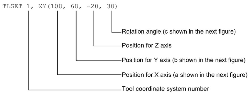
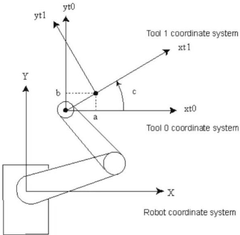
TISet for 6-Axis robots
The origin of Tool 0 is the flange side of the sixth joint. When all joints are at the 0 degree position, the Tool 0 coordinate system's X axis is aligned with the robot coordinate system's Z axis, the Y axis is aligned with the robot coordinate system's X axis, and the Z axis is perpendicular to the flange face, and is aligned with the robot coordinate system's Y axis, as shown in the figure below:
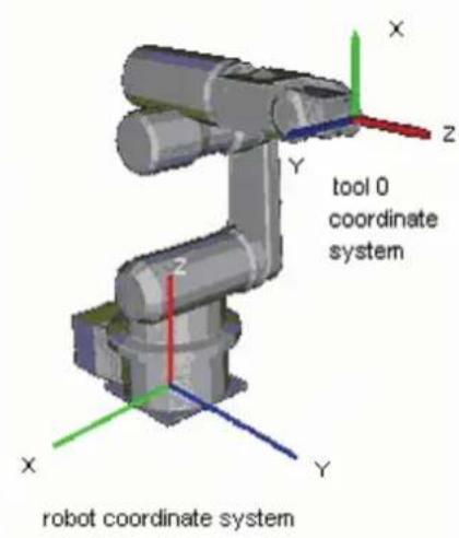
Tool 0 coordinate systems are defined for ceiling and wall mounted robots as shown in the figures below.
Ceiling mounting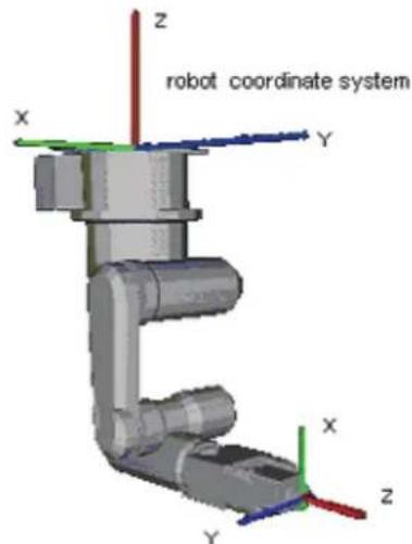
tool 0 coordinate system
tool 0 coordinate system
Notes
TLSet values are maintained
The TLSet values are preserved. Use TLCIr to clear a tool definition.
See Also
Tool, Arm, ArmSet, TLClr
TLSet Example
The example shown below shows a good test which can be done from the command window to help understand the difference between moving when a tool is defined and when no tool is defined.
TLSet 1, XY(100, 0, 0, 0) 'Define tool coordinate system for Tool 1 (plus 100 mm in x direction from hand coordinate system) Tool 1 'Selects Tool 1 as defined by TLSet TGo P1 'Positions the Tool 1 tip position at P1 Tool 0 'Tells robot to use no tool for future motion Go P1 'Positions the center of the U-Joint at P1
TLSet Function
Returns a point containing the tool definition for the specified tool.

Syntax
TLSet(toolNumber)
Parameters
toolNumber
Integer expression representing the number of the tool to retrieve.
Return Values
A point containing the tool definition.
See Also
TLSet Statement
TLSet Function Example
P1 = TLSet(1)
TMOut Statement
Specifies the number of seconds to wait for the condition specified with the Wait instruction to come true before issuing a timeout error.
Syntax
TMOut seconds
Parameters
seconds Real expression representing the number of seconds until a timeout occurs. Valid range is 0-2147483 seconds in 1 second intervals.
Description
TMOut sets the amount of time to wait (when using the Wait instruction) until a timeout error is issued. If a timeout of 0 seconds is specified, then the timeout is effectively turned off. In this case the Wait instruction waits indefinitely for the specified condition to be satisfied.
The default initial value for TMOut is 0.
See Also
In, MemSw, OnErr, Sw, TW, Wait
TMOut Example
TMOut 5 Wait MemSw(0) = On
TMove Statement
Executes linear interpolation relative motion, in the current tool coordinate system
Syntax
TMove destination [ROT] [CP] [searchExpr] [!...!] [SYNC]
Parameters
destination The target destination of the motion using a point expression.
ROT Optional. Decides the speed/acceleration/deceleration in favor of tool rotation.
CP Optional. Specifies continuous path motion.
searchExpr Optional. A Till or Find expression.
Till | Find
Till Sw(expr) = {On | Off}
Find Sw(expr) = {On | Off}
!...! Optional. Parallel Processing statements can be added to execute I/O and other commands during motion.
SYNC Reserves a motion command. The robot will not move until SyncRobots is executed.
Description
Executes linear interpolated relative motion in the current tool coordinate system.
Arm orientation attributes specified in the destination point expression are ignored. The manipulator keeps the current arm orientation attributes. However, for a 6-Axis manipulator, the arm orientation attributes are automatically changed in such a way that joint travel distance is as small as possible.
TMove uses the SpeedS speed value and AccelS acceleration and deceleration values. Refer to Using TMove with CP below on the relation between the speed/acceleration and the acceleration/deceleration. If, however, the ROT modifier parameter is used, TMove uses the SpeedR speed value and AccelR acceleration and deceleration values. In this case SpeedS speed value and AccelS acceleration and deceleration value have no effect.
Usually, when the move distance is 0 and only the tool orientation is changed, an error will occur. However, by using the ROT parameter and giving priority to the acceleration and the deceleration of the tool rotation, it is possible to move without an error. When there is not an orientational change with the ROT modifier parameter and movement distance is not 0, an error will occur.
Also, when the tool rotation is large as compared to move distance, and when the rotation speed exceeds the specified speed of the manipulator, an error will occur. In this case, please reduce the speed or append the ROT modifier parameter to give priority to the rotational speed/acceleration/deceleration.
The Till modifier is used to complete TMove by decelerating and stopping the robot at an intermediate travel position if the current Till condition is satisfied.
The Find modifier is used to store a point in FindPos when the Find condition becomes true during motion.
When Till is used and the Till condition is satisfied, the manipulator halts immediately and the motion command is finished. If the Till condition is not satisfied, the manipulator moves to the destination point.
When Find is used and the Find condition is satisfied, the current position is stored. Please refer to Find for details.
When parallel processing is used, other processing can be executed in parallel with the motion command.
Notes
Using TMove with CP
The CP parameter causes the arm to move to destination without decelerating or stopping at the point defined by destination. This is done to allow the user to string a series of motion instructions together to cause the arm to move along a continuous path while maintaining a specified speed throughout all the motion. The TMove instruction without CP always causes the arm to decelerate to a stop prior to reaching the point destination.
See Also
AccelS, CP, Find, !.....! Parallel Processing, Point Assignment, SpeedS, TGo, Till, Tool
TMove Example
> TMove XY(100, 0, 0, 0) 'Move 100mm in the X direction (in the tool coordinate system)
Function TMoveTest
Speed 50
Accel 50, 50
SpeedS 100
AccelS 1000, 1000
Power High
Tool 0
P1 = XY(300, 300, -20, 0)
P2 = XY(300, 300, -20, 0) /L
Go P1
Print Here
TMove XY(0, 0, -30, 0)
Print Here
Go P2
Print Here
TMove XY(0, 0, -30, 0)
Print Here
Fend
[Output]
X: 300.000 Y: 300.000 Z: -20.000 U: 0.000 V: 0.000 W: 0.000 /R /0
X: 300.000 Y: 300.000 Z: -50.000 U: 0.000 V: 0.000 W: 0.000 /R /0
X: 300.000 Y: 300.000 Z: -20.000 U: 0.000 V: 0.000 W: 0.000 /L /0
X: 300.000 Y: 300.000 Z: -50.000 U: 0.000 V: 0.000 W: 0.000 /L /O
Tmr Function
Timer function which returns the amount of time in seconds which has elapsed since the timer was started.

Syntax
Tmr(timerNumber)
Parameters
timerNumber Integer expression representing which of the 64 timers to check the time of. (0 \~ 63)
Return Values
Elapsed time for the specified timer as a real number in seconds. Timer range is from 0 - approx. 1.7E+31. Timer resolution is 0.001 seconds.
Description
Returns elapsed time in seconds since the timer specified was started.
Timers are reset with TmReset.
Real overhead
TmReset 0
overHead = Tmr(0)
See Also
TmReset
Tmr Function Example
TmReset 0 ' Reset Timer 0
For i = 1 To 10 ' Perform operation 10 times
GoSub Cycle
Next
Print Tmr(0) / 10 ' Calculate and display cycle time
TmReset Statement
Resets the timers used by the Tmr function.
s
Syntax
TmReset timerNumber
Parameters
timerNumber Integer expression from 0 to 63 specifies which of the 64 timers to reset.
Description
Resets and starts the timer specified by timerNumber.
Use the Tmr function to retrieve the elapsed time for a specific timer.
See Also
Tmr
TmReset Example
TmReset 0 ' Reset Timer 0
For i = 1 To 10 ' Perform operation 10 times
GoSub CYL
Next
Print Tmr(0)/10 ' Calculate and display cycle time
Toff Statement
Turns off execution line display on the LCD.
S
Syntax
Toff
Description
Execution line will not be displayed on the LCD.
See Also
Ton
Toff Example
Function main Ton MyTask
... Toff
Fend
Ton Statement
Specifies a task which shows an execution line on the LCD.
S
Syntax
Ton taskIdentifier
Ton
Parameters
taskIdentifier
Task name or integer expression representing the task number.
Task name is a function name used in an Xqt statement or a function started from the Run window or Operator window.
Task number range is:
Normal tasks : 1 \~ 32
Description
Execution line of task 1 is displayed in initial status.
Ton statement displays the specified task execution line on the LCD.
When taskIdentifier is omitted, the task execution line with Ton statement execution is displayed on the LCD.
See Also
Toff
Ton Example
Function main
Ton MyTask
...
Toff
Fend
Tool Statement
Selects or displays the current tool.
Syntax
(1) Tool toolNumber
(2) Tool
Parameters
toolNumber Optional. Integer expression from 0-15 representing which of 16 tool definitions to use with subsequent motion instructions.
Return Values
Displays current Tool when used without parameters.
Description
Tool selects the tool specified by the tool number (toolNum). When the tool number is 0, no tool is selected and all motions are done with respect to the center of the end effector joint. However, when Tool entry 1, 2, or 3 is selected motion is done with respect to the end of the tool as defined with the tool definition.
Note
Power Off and Its Effect on the Tool Selection
Turning main power off does not change the tool coordinate system selection.
See Also
TGo, TLSet, Tmove
Tool Statement Example
The example shown below shows a good test which can be done from the command window to help understand the difference between moving when a tool is defined and when no tool is defined.
>tlset 1, 100, 0, 0, 0
'Define tool coordinate system for
'Tool 1 (plus 100 mm in x direction
'from hand coordinate system)
>tool 1
>tgo p1
>tool 0
>go p1
'Selects Tool 1 as defined by TLSct
'Positions the Tool 1 tip position at P1
'Tells robot to use no tool for future motion
'Positions the center of the U-Joint at P1
Tool Function
Returns the current tool number.

Syntax Tool
Return Values
Integer containing the current tool number.
See Also
Tool Statement
Tool Function Example
Integer savTool
savTool = Tool
Tool 2
Go P1
Tool savTool
Trap Statement (User defined trigger)
Defines interrupts and what should happen when they occur.
With the Trap statement, you can jump to labels or call functions when the event occurs.
Trap statement has 2 types as below:
- 4 Traps that interrupts by the user defined input status
- 7 Traps that interrupts by the system status
Trap with user defined trigger is explained here.
Syntax
Trap trapNumber, ioCondition GoTo label
Trap trapNumber, ioCondition Call funcname
Trap trapNumber, ioCondition Xqt funcname
Trap trapNumber
Parameters
trapNumber Integer number from 1-4 representing which of 4 Trap numbers to use.
(SPEL + supports up to 4 active Trap interrupts at the same time.)
ioCondition Input status specified as a trigger
[Event] comparative operator ( =, <>, >=, >, <, <=) [Integer expression]
The following functions and variables can be used in the Event:
Functions: Sw, In, InW, Oport, Out, OutW, MemSw, MemIn, MemInW, Ctr, GetRobotInsideBox, GetRobotInsidePlane
Variables: Byte, Integer, Long global preserve variable, Global variable, module variable
In addition, using the following operators you can specify multiple event conditions.
Operators: And, Or, Xor
Example: Trap 1, Sw(5) = On Call, TrapFunc
Trap 1, Sw(5) = On And Till(6) = Off, Call TrapFunc
label: The label where program execution is to be transferred when Trap condition is satisfied.
funcName: The function that is executed when Call or Xqt when the Trap condition is satisfied.
The function with argument cannot be specified.
Note
The functionality of Trap Call in RC+ 4.x or before has been changed to Trap Xqt in RC+ 5.0.
The functionality of Trap GoSub in RC+ 4.x or before has been removed. Use Trap Call instead of Trap GoSub.
Description
A Trap executes interrupt processing which is specified by GoTo, Call, or Xqt when the specified condition is satisfied.
The Trap condition must include at least one of the functions above.
When variables are included in the Trap condition, their values are computed when setting the Trap condition. No use of variable is recommended. Otherwise, the condition may be an unintended condition.
Once the interrupt process is executed, its Trap setting is cleared. If the same interrupt process is necessary, the Trap instruction must execute it again.
To cancel a Trap setting simply execute the Trap instruction with only the trapNumber parameter. e.g. "Trap 3" cancels Trap #3.
When the Function that executed Trap GoTo ends (or exit), the Trap Goto will be canceled automatically.
When the declared task ends, Trap Call will be canceled.
Trap Xqt will be canceled when all tasks have stopped.
If GoTo is specified
The command being executed will be processed as described below, then control branches to the specified label.
- Any arm motion will pause immediately
- Waiting status by the Wait or Input commands will discontinue
- All other commands will complete execution before control branches
If Call is specified
After executing the same process as GoTo described above, then control branches to the specified line number or label.
Once the function ends, program execution returns to the next statement after the statement where program interruption occurred. Call statements cannot be used in the Trap processing function.
When an error occurs in the trap process function, error handling with OnErr will be invalid and an error will occur.
If Xqt is specified
Program control executes the specified function as an interrupt processing task. In this case, the task which executes the Trap command will not wait for the Trap function to finish and will continue to execute.
You cannot execute a task with an Xqt statement from an interrupt processing task.
Notes
For EPSON RC+4.x user
The Trap Call function of EPSON RC+ 4.x or before is replaced with Trap Xqt in EPSON RC+ 6.0. The Trap GoSub function of EPSON RC+ 4.x or before is removed in EPSON RC+ 6.0. Instead, use Trap Call.
To use variables in the event condition expression
- Available variables are Integer type (Byte, Integer, Long)
- Array variables are not available
- Local variables are not available
- If a variable value cannot satisfy the event condition for more than 0.01 second, the system cannot retrieve the change in variables.
- Up to 64 can wait for variables in one system (including the ones used in the event condition expressions such as Wait). If it is over 64, an error occurs during the project build.
- If you specify Byref to a waiting variable on any function call, an error occurs.
- When a variable is included in the right side member of the event condition expression, the value is calculated when setting the Trap condition. We recommend not using variables in an integer expression to avoid making unintended conditions.
See Also
Call, GoTo, Xqt
Trap Example
Error process defined by User
Sw(0) Input is regarded as an error input defined by user.
Function Main
Trap 1, Sw(0) = On GoTo EHandle ' Defines Trap
:
.
.EHandle:
On 31 'Signal tower lights
OpenCom #1
Print #1, "Error is issued"
CloseCom #1
Fend
Usage like multi-tasking
Function Main
Trap 2, MemSw(0) = On Or MemSw(1) = On Call Feeder
.
.
Fend
.
Function Feeder
Select TRUE
Case MemSw(0) = On
MemOff 0
On 2
Case MemSw(1) = On
MemOff 1
On 3
Send
' Re-arm the trap for next cycle
Trap 2, MemSw(0) = On Or MemSw(1) = On Call Feeder
Fend
Using global variable as event condition
Global Integer gi
Function main
Trap 1, gi = 5 GoTo THandle
Xqt sub
Wait 100
Exit Function
THandle:
Print "IN Trap ", gi
Fend
Function sub
For gi = 0 To 10
Print gi
Wait 0.5
Next
Fend
Trap (System status trigger)
Defines interrupts and what should happen when they occur.
With the Trap statement, you can jump to labels or call functions when the event occurs.
Trap statement has 2 types as below:
- 4 Traps that interrupts by the user defined input status
- 7 Traps that interrupts by the system status
Trap with system status triggers is explained here.
s
Syntax
Trap {Emergency | Error | Pause | SGOpen | SGClose | Abort | Finish} Xqt funcname
Trap {Emergency | Error | Pause | SGOpen | SGClose | Abort | Finish}
Parameters
Emergency: In the emergency stop status, executes the specified function.
Error: In the error status, executes the specified function.
Pause: In the pause status, executes the specified function.
SGOpen: When safeguard is open, executes the specified function.
SGClose: When safeguard is closed, executes the specified function.
Abort: When all tasks except the background tasks stop (such as when a statement corresponding to the Abort All is executed or the Pause button is pressed) by the user or system, executes the specified function.
Finish: When all tasks except the background tasks are completed, executes the specified function. It cannot be executed in the condition which executes the Trap Abort.
funcname: Function of interrupt processing task for which Xqt is executed when the system status is completed.
Functions with arguments cannot be specified.
Note
Trap *** Call function of EPSON RC+4.x or before is replaced to Trap *** Xqt in EPSON RC+ 5.0.
Description
When the system status completes, the specified interrupt processing task is executed.
Even if you execute an interrupt processing task, the Trap settings cannot be cleared.
To clear the Trap setting, omit the funcname and execute the Trap statement.
Example: Trap Emergency clears Trap Emergency
After all normal tasks are completed and the controller is in the Ready status, all Trap settings are cleared.
You cannot execute more tasks using the Xqt from an interrupt processing.
 CAUTION CAUTION | Forced flagYou can turn On/Off the I/O outputs even in the Emergency Stop status, Safuguard Open status, Teach mode, or error status by specifying the Forced flag to the I/O output statement such as On and Off statements.DO NOT connect the external devices which can move machines such as actuators with the I/O outputs which specifies the Forced flag. It is extremely dangerous and it can lead the external devices to move in the Emergency Stop status, Safuguard Open status, Teach mode, or error status.I/O outputs which specifies the Forced flag is supposed to be connected with the external device such as LED as the status display which cannot move machines. |
If Emergency is specified
When the Emergency Stop is activated, the specified function is executed in the NoEmgAbort task attribute.
The commands executable from the interrupt processing tasks can execute the NoEmgAbort task. When the interrupt processing of Emergency Stop is completed, finish the task promptly.
Otherwise, the controller cannot be in the Ready status. You cannot reset the Emergency Stop automatically by executing the Reset command from the interrupt processing task.
When the task executes I/O On/Off from the interrupt processing task, uncheck the Outputs off during emergency stop check box in the Controller | Preferences page. If this check box is checked, the execution order of turn Off by the controller and turn On using the task are not guaranteed.
If Error is specified
When the Emergency Stop is activated, the specified function is executed in the NoEmgAbort task attribute.
The commands executable from the interrupt processing tasks can execute the NoEmgAbort task.
When the interrupt processing of Emergency Stop is completed, finish the task promptly.
Otherwise, the controller cannot be in the Ready status.
If Pause is specified
When Pause is activated, the specified function is executed in the NoEmgAbort task attribute.
If SGOpen is specified
When the Safeguard is open, the specified function is executed in the NoEmgAbort task attribute.
If SGClose is specified
When the safeguard is closed and latched, the specified function is executed in the NoEmgAbort task attribute.
If you execute the Cont statement from the interrupt processing tasks, an error occurs.
If Abort is specified
All tasks except background tasks stop (such as when a statement corresponding to Abort All is executed or the Pause button is pressed) by the user or system, and the specified function is executed in the NoPause attribute.
When the interrupt processing of Pause is completed, finish the task promptly. Otherwise, the controller cannot be in the Ready status. Although a task executed with Trap Abort has an error, the Trap Error processing task is not executed.
If the Shutdown or Restart statements are aborted, processing tasks of neither Trap Abort nor Trap Finish are executed.
If Finish is specified
All tasks except background tasks stop (such as when a statement corresponding to Abort All is executed or the Pause button is pressed) by the user or system, and the specified function is executed in the NoPause attribute. It cannot be executed in the condition which executes the Trap Abort processing task.
When the shutdown and interrupt processing are completed, finish the tasks promptly. Otherwise, the controller cannot be in the Ready status.
See Also
Era, Erl, Err, Ert, ErrMsg\$, OnErr, Reset, Restart, Xqt
Trap Example
Function main
:
Trap Error Xqt suberr
:
Fend
Function suberr
Print "Error =", Err
On ErrorSwitch
Fend
Trim\$ Function
Returns a string equal to specified string without leading or trailing spaces.
F
Syntax
Trim\$(string)
Parameters
string
String
expression.
Return Values
Specified string with leading and trailing spaces removed.
See Also
LTrim, RTrim
Trim$ Function Example
str$ = " data "
str= Trim(str) ' str = "data"
TW Function
Returns the status of the Wait, WaitNet, and WaitSig commands.

Syntax TW
Return Values
Returns False if Wait condition is satisfied within the time interval. Returns True if the time interval has elapsed.
Description
The Timer Wait function TW returns the status of the preceding Wait condition with time interval with a False (Wait condition was satisfied) or a True (time interval has elapsed).
See Also
TMOut, Wait
TW Function Example
Wait Sw(0) = On, 5 'Wait up to 5 seconds for input bit 0 On
If TW = True Then
Print "Time Up" 'Display "Time UP" after 5 seconds
End If
Type Statement
Displays the contents of the specified file.

Syntax
Type fileName
Parameters
fileName
The path and name of the file to display. If path is omitted, the file in the current directory is specified. See ChDisk for the details.
Description
Type causes the specified file's contents to be displayed. Since only ASCII files can be displayed, be sure to specify only ASCII files. The purpose of Type is to display the contents of files, not to edit files.
See Also
Dir
Type Example
Example from the command window
> type test.dat
MyData Line 1
MyData Line 2
MyData Line 3
>
UBound Function
Returns the largest available subscript for the indicated dimension of an array.

Syntax
UBound ( SquarlyName [, dimension])
Parameters
arrayName
Name of the array variable; follows standard variable naming conventions.
dimension
Optional. Integer expression indicating which dimension's upper bound is returned. Use 1 for the first dimension, 2 for the second, and 3 for the third. If dimension is omitted, 1 is assumed.
See Also
Redim
UBound Function Example
Integer i, a(10)
For i=0 to UBound(a)
a(i) = i
Next
UCase$ Function
Returns a string that has been converted to uppercase.
F
Syntax
UCase$ (string)
Parameters
string
String
expression.
Return Values
The converted uppercase string.
See Also
LCase, LTrim, Trim, RTrim
UCase$ Example
str$ = "Data"
str= UCase(str) ' str = "DATA"
UOpen Statement
Opens a file for read/write access.
Syntax
UOpen fileName As #fileNumber
:
Close #fileNumber
Parameters
fileName String expression that specifies path and file name. If path is omitted, the file in the current directory is specified. See ChDisk for the details.
fileNumber Integer expression representing values from 30 ~ 63.
Description
Opens the specified file by the specified file number. This statement is used for writing and loading data in the specified file.
Note
Do not use a network path, otherwise an error occurs.
If the specified file does not exist on disk, the file will be created and the data will be written into it. If the specified file already exists on disk, the data will be written and read starting from the beginning of the existing data.
The read/write position (pointer) of the file can be changed using the Seek command. When switching between read and write access, you must use Seek to reposition the file pointer.
fileNumber identifies the file while it is open and cannot be used to refer to a different file until the current file is closed. fileNumber is used by other file operations such as Print#, Read, Write, Seek, and Close.
Close closes the file and releases the file number.
It is recommended that you use the FreeFile function to obtain the file number so that more than one task are not using the same number.
See Also
Close, Print #, Input#, AOpen, BOpen, ROpen, WOpen, FreeFile, Seek
UOpen Statement Example
Integer fileNum, i, j
fileNum = FreeFile
UOpen "TEST.DAT" As #fileNum
For i = 0 To 100
Print #fileNum, i
Next i
Close #fileNum
fileNum = FreeFile
UOpen "TEST.DAT" As #fileNum
Seek #fileNum, 10
Input #fileNum, j
Print "data = ", j
Close #fileNum
Val Function
Converts a character string that consists of numbers into their numerical value and returns that value.

Syntax
Val(string)
Parameters
string String expression which contains only numeric characters. The string may also contain a prefix: &H (hexadecimal), &O (octal), or &B (binary).
Return Values
Returns an integer or floating point result depending upon the input string. If the input string has a decimal point character, then the number is converted into a floating point number. Otherwise, the return value is an integer.
Description
Val converts a character string of numbers into a numeric value. The result may be an integer or floating point number. If the string passed to the Val instruction contains a decimal point, then the return value will be a floating point number. Otherwise, it will be an integer.
See Also
Abs, Asc, Chr, Int, Left, Len, Mid, Mod, Right, Sgn, Space, Str
Val Example
The example shown below shows a program which converts several different strings to numbers and then prints them to the screen.
Function ValDemo
String realstr, intstr
Real realsqr, realvar
Integer intsqr, intvar
realstr$ = "2.5"
realvar = Val(realstr$)
realsqr = realvar * realvar
Print "The value of ", realstr$, " squared is: ", realsqr
intstr$ = "25"
intvar = Val(intstr$)
intsqr = intvar * intvar
Print "The value of ", intstr$, " squared is: ", intsqr
Fend
Here's another example from the Command window.
> Print Val("25.999")
25.999
>
VxCalib Statement
Note: This command is only for use with external vision systems and cannot be used with Vision Guide.
Creates calibration data for an external vision system.
Syntax
(1) VxCalib CalNo (2) VxCalib CalNo, CamOrient, P(pixel_st : pixel_ed), P(robot_st : robot_ed) [, TwoRefPoints] (3) VxCalib CalNo, CamOrient, P(pixel_st : pixel_ed), P(robot_st : robot_ed), P(ref0) [,P(ref180)]
Parameters
CalNo Integer expression that specifies the calibration data number. The range is from 0 to 15; up to 16 calibrations may be defined.
CamOrient Integer expression that specifies the camera mounting direction using the following values: 1 to 3: Available only for syntax (2). 4 to 7: Available only for syntax (3). 1: Standalone 2: Fixed downward 3: Fixed upward 4: Mobile on Joint #2 5: Mobile on Joint #4 6: Mobile on Joint #5 7: Mobile on Joint #6
P(pixelst : pixeled) Specifies the pixel coordinates (X, Y only) using the continuous point data.
P(robot_st : robot_ed) Specifies the robot coordinates using the continuous point data. The robot coordinates must be set as TOOL: 0, ARM: 0.
TwoRefPoints Available for syntax (2). True, when using two measuring points. False, when using one measuring point. Specifying two measuring points makes the calibration more accurate. Optional. Default: False
P(ref0) Available for syntax (3). Specifies the robot coordinates of the reference point using the point data.
P(ref180) Available for syntax (3). Specifies the robot coordinates of the second reference point using the point data. Specifying two reference points makes the calibration more accurate. Optional.
Description
The VxCalib command calculates the vision calibration data for the specified calibration number using the specified camera orientation, pixel coordinates, robot coordinates, and reference points (Mobile camera only) given by the parameter.
When you specify only CalNo, the point data and other settings you defined are displayed (only from the Command Window).
The following figure shows the coordinate system of the pixel coordinates. (Units: pixel)
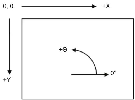
For the pixel coordinates and robot coordinates, set the top left position of the window as Point 1 and set the bottom right position as Point 9 according to the order in the table below. It is classified into the four categories by the parameter CamOrient and TwoRefPoints.
1) CamOrient = 1 to 3 (Standalone, Fixed Downward, Fixed Upward), TwoRefPoints = False
| Data order | Position | Pixel coordinates | Robot | coordinates |
| 1 | Top left | Detection coordinates 1 | Measuring point coordinates 1 | |
| 2 | Top center | Detection coordinates 2 | Measuring point coordinates 2 | |
| 3 | Top right | Detection coordinates 3 | Measuring point coordinates 3 | |
| 4 | Center right | Detection coordinates 4 | Measuring point coordinates 4 | |
| 5 | Center | Detection coordinates 5 | Measuring | |
| 6 | Center left | Detection coordinates 6 | Measuring point coordinates 6 | |
| 7 | Bottom left | Detection coordinates 7 | Measuring point coordinates 7 | |
| 8 | Bottom center | Detection coordinates 8 | Measuring point coordinates 8 | |
| 9 | Bottom right | Detection coordinates 9 | Measuring point coordinates 9 | |
2) CamOrient = 2 (Fixed Downward), TwoRefPoints = True
Note: When the tool is exactly defined, TwoRefPoints is not necessary and should be set to False.
By setting TwoRefPoints to True, two measuring points are used for each calibration position, which makes the calibration more accurate. 18 robot points with U axis: 0 degree / 180 degrees are required. After setting 1 to 9 measuring points coordinates, turn the U axis by 180 degrees and set the measuring point coordinates 10 to 18 where the hand (such as the rod) is positioned at the calibration target position.
| Data order | Position | Pixel coordinates | Robot coordinates | U axis |
| 1 Top left Detection coordinates 1 Measuring point coordinates 1 | 0 degrees | |||
| 2 Top center Detection coordinates 2 Measuring point coordinates 2 | ||||
| 3 Top right Detection coordinates 3 Measuring point coordinates 3 | ||||
| 4 Center right Detection coordinates 4 Measuring point coordinates 4 | ||||
| 5 | Center | Detection | coordinates 5 Measuring point coordinates 5 | |
| 6 Center left Detection coordinates 6 | Measuring point coordinates 6 | |||
| 7 Bottom left Detection coordinates 7 Measuring point coordinates 7 | ||||
| 8 | Bottom center | Detection coordinates 8 | Measuring point coordinates 8 | |
| 9 | Bottom right | Detection coordinates 9 | Measuring point coordinates 9 | |
| 10 Top left --- | Measuring point coordinates10 | 180 degrees | ||
| 11 | Top center | --- | Measuring point coordinates11 | |
| 12 | Top right | --- | Measuring point coordinates12 | |
| 13 | Center right | --- | Measuring point coordinates13 | |
| 14 | Center | --- | Measuring point coordinates14 | |
| 15 Center left --- | Measuring point coordinates15 | |||
| 16 | Bottom left --- | Measuring point coordinates16 | ||
| 17 | Bottom center | --- | Measuring point coordinates17 | |
| 18 | Bottom right | --- | Measuring point coordinates18 | |
3) CamOrient = 3 (Fixed Upward), TwoRefPoints = True
Note: When the tool is exactly defined, TwoRefPoints is not necessary and should be set to False.
By setting TwoRefPoints to True, two detection points are used, which makes the calibration more accurate. For only the pixel coordinates, 18 points of U axis: 0 degree / 180 degrees are required. After setting 1 to 9 detection coordinates at the each measuring point coordinates at 0 degrees, set the detection coordinates for points 10 to 18 at 180 degrees.
| Data order | Position Pixel coordinates | Robot coordinates U axis | |
| 1 Top left Detection coordinates 1 Measuring point coordinates 1 | 0 degrees coordinates 5 | ||
| 2 Top center Detection coordinates 2 Measuring point coordinates 2 | |||
| 3 Top right Detection coordinates 3 Measuring point coordinates 3 | |||
| 4 Center right Detection coordinates 4 Measuring point coordinates 4 | |||
| 5 | Center | Detection coordinates 5 Measuring point coordinates 5 | |
| 6 | Center left | Detection coordinates 6 | Measuring point coordinates 6 |
| 7 Bottom left Detection coordinates 7 Measuring point coordinates 7 | |||
| 8 | Bottom center | Detection coordinates 8 | Measuring point coordinates 8 |
| 9 | Bottom right | Detection coordinates 9 | Measuring point coordinates 9 |
| 10 Top left Detection coordinates 10 --- | 180 degrees | ||
| 11 | Top center Detection coordinates 11 --- | ||
| 12 | Top right Detection coordinates 12 --- | ||
| 13 | Center right Detection coordinates 13 --- | ||
| 14 | Center | Detection coordinates 14 --- | |
| 15 Center left Detection coordinates 15 --- | |||
| 16 | Bottom left Detection coordinates 16 --- | ||
| 17 | Bottom center | Detection coordinates 17 --- | |
| 18 | Bottom right | Detection coordinates 18 --- | |
4) CamOrient = 4 to 7
| Data order | Position | Pixel coordinates | Robot coordinates |
| 1 Top | left | Detection coordinates 1 | Measuring point coordinates 1 |
| 2 Top | center | Detection coordinates 2 | Measuring point coordinates 2 |
| 3 Top | right | Detection coordinates 3 | Measuring point coordinates 3 |
| 4 Center | right | Detection coordinates 4 | Measuring point coordinates 4 |
| 5 | Center | Detection coordinates 5 Measuring | |
| 6 | Center left | Detection coordinates 6 | |
| 7 Bottom left Detection coordinates 7 | measuring point coordinates 7 | ||
| 8 | Bottom center | Detection coordinates 8 | |
| 9 | Bottom right | Detection coordinates 9 | |
ing point coordinates 5
Notes
In addition to the tables above, specify the robot coordinates of the reference points.
Using the two reference points makes the calibration more accurate. In this case, it needs two points of U axis: 0 degree / 180 degrees.
After setting the first reference points coordinates, turn the U axis by 180 degrees and set the second reference points coordinates where the hand (such as the rod) is positioned at the calibration target position. When the tool is exactly defined, the two reference points are not necessary.
See Also
VxTrans Function, VxCallInfo Function, VxCalDelete, VxCalSave, VxCalLoad
VxCalib Statement Example
Function MobileJ2
Integer i
Double d(8)
Robot 1
LoadPoints MobileJ2.pts"
VxCalib 0, 4, P(21:29), P(1:9), P(0)
If (VxCalInfo(0, 1) = True) Then
For i = 0 To 7
d(i) = VxCalInfo(0, i + 2)
Next i
Print Calibration result: "
Print d(0), d(1), d(2), d(3), d(4), d(5), d(6), d(7)
P52 = VxTrans(0, P51, P50)
Print Coordinates conversion result: "
Print P52
SavePoints MobileJ2.pts"
VxCalSave MobileJ2.caa"
Else
Print Calibration failed"
EndIf
Fend
VxCalDelete Statement
Note: This command is only for use with external vision systems and cannot be used with Vision Guide.
Deletes the calibration data for an external vision system calibration.
Syntax
VxCalDelete CalNo
Parameters
CalNo Integer expression that specifies the calibration data number. The range is from 0 to 15; up to 16 calibrations may be defined.
Description
Deletes the calibration data defined by the specified calibration number.
See Also
VxCalib, VxTrans Function, VxCallInfo Function, VxCalSave, VxCalLoad
VxCalDelete Statement Example
VxCalDelete "MobileJ2.caa"
VxCalLoad Statement
Note: This command is only for use with external vision systems and cannot be used with Vision Guide.
Loads the calibration data for an external vision system calibration from a file.
Syntax
VxCalLoad FileName
Parameters
FileName Specifies the file name from which the calibration data is loaded using a string expression.
The file extension is .CAA. If omitted, .CAA is automatically added.
For extensions other than .CAA, they are automatically changed to .CAA.
Description
Loads the calibration data from the specified file in the current project.
See Also
VxCalib, VxTrans Function, VxCallInfo Function, VxCalDelete, VxCalSave
VxCalLoad Statement Example
VxCalLoad "MobileJ2.caa"
VxCallInfo Function
Note: This command is only for use with external vision systems and cannot be used with Vision Guide.
Returns the calibration completion status and the calibration data.
Syntax
VxCallInfo (CalNo, CalData)
Parameters
CalNo Integer expression that specifies the calibration data number. The range is from 0 to 15; up to 16 calibrations may be defined.
CalData Specifies the calibration data type to acquire using the integer values in the table below.
| CalData Calibration Data Type | |
| 1 | CalComplete |
| 2 X Avg Error [mm] | |
| 3 X Max error [mm] | |
| 4 X mm per pixel [mm] | |
| 5 | X tilt |
| 6 Y Avg error [mm] | |
| 7 Y Max error [mm] | |
| 8 Y mm per pixel [mm] | |
| 9 | Y tilt |
Return Value
Returns the specified calibration data. For CalData = 1, the data type is Boolean. For all other data, the data type is Double.
Description
You can check which calibration has defined calibration data. Also, you can retrieve the calibration data values.
See Also
VxCalib, VxTrans Function, VxCalDelete, VxCalSave, VxCalLoad
VxCallInfo Function Example
Print VxCallInfo(0, 1)
VxCalSave Statement
Note: This command is only for use with external vision systems and cannot be used with Vision Guide.
Saves the calibration data for an external vision system calibration to a file.
Syntax
VxCalSave FileName
Parameters
FileName Specifies the file name from which the calibration data is loaded using a string expression.
The extension is .CAA. If omitted, .CAA is automatically added.
For extensions other than .CAA, they are automatically changed to .CAA.
Description
Saves the calibration data with the specified file name. The file is saved in the current project. If the file name already exists, the calibration data is overwritten.
See Also
VxCalib, VxTrans Function, VxCallInfo Function, VxCalDelete, VxCallLoad
VxCalSave Statement Example
VxCalSave "MobileJ2.caa"
VxTrans Function
Note: This command is only for use with external vision systems and cannot be used with Vision Guide.
Converts pixel coordinates to robot coordinates and returns the converted point data.
Syntax
VxTrans (CalNo, P(pixel) [, P(camRobot)] ) As Point
Parameters
CalNo Integer expression that specifies the calibration data number. The range is from 0 to 15; up to 16 calibrations may be defined.
P(pixel) Specifies the vision pixel coordinates (X,Y,U only) using point data.
P(camRobot) Optional. For a mobile camera, this is the position where the robot was located when the image was acquired. If not specified, then the current robot position is used. The point should be in BASE: 0, TOOL: 0, ARM: 0.
Return Value
Returns the calculated robot coordinates using the point data.
Description
This command converts pixel coordinates to robot coordinates using the calibration data of the specified calibration number.
When using a mobile camera, specify P(camRobot) if the robot has been moved from the position where the image was acquired. Ensure that P(camRobot) is in BASE: 0, TOOL: 0, ARM: 0. The Joint #4 and Joint #6 angles of the set robot coordinates are used for the calculation.
See Also
VxCalib, VxCallInfo Function, VxCalDelete, VxCalSave, VxCallLoad
VxTrans Statement Example
P52 = VxTrans(0, P51, P50)
Wait Statement
Causes the program to wait for a specified amount of time or until the specified input condition (using MemSw or Sw) is met. (Oport may also be used in the place of Sw to check hardware outputs.) Also waits for the values of global variables to change.
s
Syntax
(1) Wait time (2) Wait input condition (3) Wait input condition, time
Parameters
time Real expression between 0 and 2,147,483 which represents the amount of time to wait when using the Wait instruction to wait based on time. Time is specified in seconds. The smallest increment is .01 seconds.
inputcondition The following syntax can be used to specify the input condition: [Event] Comparative operator (=, <>, >=, >, <, <=) [Integer expression]
The following functions and variables can be used in the Event.
Functions: AtHome, Sw, In, InW, Oport, Out, OutW, MemSw, MemIn, MemInW, Ctr, GetRobotInsideBox, GetRobotInsidePlane, MCalComplete, Motor, LOF, ErrorOn, SaftyOn, EstopOn, TeachOn, Cnv_QueLen, WindowsStatus, LatchState
Operators: Byte, Integer, Long global preserve variables, global variables, module variables
In addition, using the following operators you can specify multiple input conditions.
Operator: And, Or, Xor, Mask
Description
(1) Wait with Time Interval When used as a timer, the Wait instruction causes the program to pause for the amount of time specified and then continues program execution.
(2) Wait for Event Conditions without Time Interval
When used as a conditional Wait interlock, the Wait instruction causes the program to wait until specified conditions are satisfied. If after TMOut time interval has elapsed and the Wait conditions have not yet been satisfied, an error occurs. The user can check multiple conditions with a single Wait instruction by using the And, Mask, Or, or Xor instructions. (Please review the example section for Wait.)
(3) Wait with Event Condition and Time Interval
Specifies Wait condition and time interval. After either Wait condition is satisfied, or the time interval has elapsed, program control transfers to the next command. Use Tw to verify if the Wait condition was satisfied or if the time interval elapsed.
Notes
Specifying a Timeout for Use with Wait
When the Wait instruction is used without a time interval, a timeout can be specified which sets a time limit to wait for the specified condition. This timeout is set through using the TMOut instruction. Please refer to this instruction for more information. (The default setting for TMOut is 0 which means no timeout.)
Waiting for variable with Wait
- Available variables are Integer type (Byte, Integer, Long)
- Array variables are not available
- Local variables are not available
- If variables value cannot satisfy the event condition for more than 0.01 second, the change in variables may not be retrieved.
- Up to 64 can wait for variables in one system (including ones used in the event condition expressions such as Till). If it is over 64, an error occurs during the project build.
- If you specify Byref to a waiting variable on any function call, an error occurs.
- When a variable is included in the right side member of the event condition expression, the value is calculated when setting the Trap condition. We recommend not using variables in an integer expression to avoid making unintended conditions.
When Using PC COM port (1001,1002)
- You cannot use Lof Function for Wait instruction.
See Also
AtHome, Cnv_QueLen, Ctr, ErrorOn, EstopOn, GetRobotInsideBox, GetRobotInsidePlane, In, InW, LatchState, LOF, Mask, MCalComplete, MemIn, MemInW, MemSw
Motor, Oport, Out, OutW, SaftyOn, Sw, TeachOn, TMOut, WindowsStatus, Tw
Wait Example
The example shown below shows 2 tasks each with the ability to initiate motion instructions. However, a locking mechanism is used between the 2 tasks to ensure that each task gains control of the robot motion instructions only after the other task is finished using them. This allows 2 tasks to each execute motion statements as required and in an orderly predictable fashion. MemSw is used in combination with the Wait instruction to wait until the memory I/O #1 is the proper value before it is safe to move again.
Function main
Integer I
MemOff 1
Xqt !2, task2
For i = 1 to 100
Wait MemSw(1) = Off
Go P(i)
MemOn 1
Next I
Fend
Function task2
Integer i
For i = 101 to 200
Wait MemSw(1) = On
Go P(i)
MemOff 1
Next i
Fend
' Wait until input 0 turns on
Wait Sw(0) = On
' Wait 60.5 secs and then continue execution
Wait 60.5
' Wait until input 0 is off and input 1 is on
Wait Sw(0) = Off And Sw(1) = On
' Wait until memory bit 0 is on or memory bit 1 is on
Wait MemSw(0) = On Or MemSw(1) = On
' Wait one second, then turn output 1 on
Wait 1; On 1
' Wait for the lower 3 bits of input port 0 to equal 1
Wait In(0) Mask 7 = 1
' Wait until the global Integer type variable giCounter is over 10 Wait giCounter > 10 ' Wait ten seconds, until the global Long type variable glCheck is 30000 Wait glCheck = 30000, 10
WaitNet Statement
Wait for TCP/IP port connection to be established.
s
Syntax
WaitNet #portNumber [, timeOut]
Parameters
portNumber Integer expression for TCP/IP port number to connect. Range is 201 - 216. timeOut Optional. Maximum time to wait for connection.
See Also
OpenNet, CloseNet
WaitNet Statement Example
For this example, two controllers have their TCP/IP settings configured as follows:
Controller #1:
Port: #201
Host Name: 192.168.0.2
TCP/IP Port: 1000
Function tcpip
OpenNet #201 As Server
WaitNet #201
Print #201, "Data from host 1"
Fend
Controller #2:
Port: #201
Host Name: 192.168.0.1
TCP/IP Port: 1000
Function tcpip
String data$
OpenNet #201 As Client
WaitNet #201
Input #201, data$
Print "received '', data$, ''' from host 1"
Fend
WaitPos Statement
Waits for robot to decelerate and stop at position before executing the next statement while path motion is active.

Syntax
WaitPos
Description
Normally, when path motion is active (CP On or CP parameter specified), the motion command starts the next statement as deceleration starts.
Use the WaitPos command right before the motion to complete the deceleration motion and go on to the next motion.
See Also
Wait, WaitSig, CP
WaitPos Statement Example
Off 1
CP On
Move P1
Move P2
WaitPos ' wait for robot to decelerate
On 1
CP Off
WaitSig Statement
Waits for a signal from another task.
s
Syntax
WaitSig signalNumber [, timeOut]
Parameters
signalNumber Integer expression representing signal number to receive. Range is from 0 \~ 63. timeOut Optional. Real expression representing the maximum time to wait.
Description
Use WaitSig to wait for a signal from another task. The signal will only be received after WaitSig has started. Previous signals are ignored.
See Also
Wait, WaitPos, Signal
WaitSig Example
Function Main
Xqt SubTask
Wait 1
Signal 1
.
.
Fend
Function SubTask
WaitSig 1
Print "signal received"
.
Fend
Weight Statement
Specifies or displays the inertia of the robot arm.
Syntax
Weight payload Weight [, distance | S | T]
Weight
Parameters
payloadWeight The weight of the end effector to be carried in Kg unit.
distance The distance from the rotational center of the second arm to the center of the gravity of the end effector in mm unit. Valid only for SCARA robots (including RS series).
S Load weight against the additional S axis in kg to 2 decimal places)
T Load weight against the additional T axis in kg to 2 decimal places)
Return Values
Displays the current Weight settings when parameters are omitted.
Description
Specifies parameters for calculating Point to Point motion maximum acceleration. The Weight instruction specifies the weight of the end effector and the parts to be carried.
The Arm length (distance) specification is necessary only for SCARA robots (including RS series). It is the distance from the second arm rotation joint centerline to the hand/work piece combined center of gravity.
If the robot has the additional axis, the loads on the additional axis must be set with the S, T parameters.
If the equivalent value work piece weight calculated from specified parameters exceeds the maximum allowable payload, an error occurs.
Potential Errors
Weight Exceeds Maximum
When the equivalent load weight calculated from the value entered exceeds the maximum load weight, an error will occur.
Potential Damage to the Manipulator Arm
Take note that specifying a Weight hand weight significantly less than the actual work piece weight can result in excessive acceleration and deceleration. These, in turn, may cause severe damage to the manipulator.
Note
Weight Values Are Not Changed by Turning Main Power Off
The Weight values are not changed by turning power off.
See Also
Accel, Inertia
Weight Statement Example
This Weight instruction on the Command window displays the current setting.
> weight
2.000, 200.000
>
Sets the hand weight (3 kg) with the Weight statement
Weight 3.0
Sets the load weight on the additional S axis (3 kg) with the Weight statement
Weight 30.0, S
Weight Function
Returns a Weight parameter.

Syntax
Weight(paramNumber)
Parameters
paramNumber Integer expression containing one of the values below:
1: Payload weight 2: Arm length 3: Load on the additional S axis 4: Load on the additional T axis
Return Values
Real number containing the parameter value.
See Also
Inertia, Weight Statement
Weight Function Example
Print "The current Weight parameters are: ", Weight(1)
Where Statement
Displays current robot position data.

Syntax
Where [localNumber]
Parameters
localNumber Optional. Specifies the local coordinate system number. Local 0 is default.
See Also
Joint, PList, Pulse
Where Statement Example
The display type can be different depending on the robot type and existence of additional axes.
The following example is for Scara robot without the additional axis.
where
WORLD: X: 350.000 mm Y: 0.000 mm Z: 0.000 mm U: 0.000 deg V: 0.000 deg W: 0.000 deg
JOINT: 1: 0.000 deg 2: 0.000 deg 3: 0.000 mm 4: 0.000 deg
PULSE: 1: 0 pls 2: 0 pls 3: 0 pls 4: 0 pls
> local 1, 100,100,0,0
> where 1
WORLD: X: 250.000 mm Y:-100.000 mm Z: 0.000 mm U: 0.000 deg V: 0.000 deg W: 0.000 deg
JOINT: 1: 0.000 deg 2: 0.000 deg 3: 0.000 mm 4: 0.000 deg
PULSE: 1: 0 pls 2: 0 pls 3: 0 pls 4: 0 pls
WindowsStatus Function
Returns the Windows startup status.
F
Syntax
WindowsStatus
Return Values
Integer value representing the current Windows startup status. The Windows startup status is returned in a bit image and shows the following status.
| Function name System reservation RC+ enabled PC enabled | |||
| Bit number 15 ~ 2 1 | 0 | ||
| functions | (Frame grabber type) PC | PC file Vision GuideRS-232C Details of availableData base access VB GuideDLL call Fieldbus master | |
Description
This function is used to check the controller startup status when the controller configuration is set to "Independent mode". When the controller configuration is set to "Cooperative mode", programs cannot be started until both RC+ function and PC function turn available.
WindowsStatus function Example
Print "The current PC Booting up Status is: ", WindowsStatus
WOpen Statement
Opens a file for writing.
s
Syntax
WOpen fileName As #fileNumber
:
Close #fileNumber
Parameters
fileName A string expression containing the path and file name. If path is omitted, the file in the current directory is specified. See ChDisk for the details.
fileNumber Integer expression that specifies 30 \~ 63
Description
Opens the specified file using the specified fileNumber. This statement is used to open and write data to the specified file. (To append data refer to the AOpen explanation.)
If the specified filename does not exist on the disks current directory, WOpen creates the file and writes to it. If the specified filename exists, WOpen erases all of the data in the file and writes to it.
Note
Do not use a network path, otherwise an error occurs.
File write buffering
File writing is buffered. The buffered data can be written with Flush statement. Also, when closing a file with Close statement, the buffered data can be written.
fileNumber identifies the file while it is open and cannot be used to refer to a different file until the current file is closed. fileNumber is used by other file operations such as Print#, Write, Seek, and Close.
Close closes the file and releases the file number.
It is recommended that you use the FreeFile function to obtain the file number so that more than one task are not using the same number.
See Also
AOpen, BOpen, Close, Print#, ROpen, UOpen, FreeFile
WOpen Example
Integer fileNum, i, j
fileNum = FreeFile
WOpen "TEST.DAT" As #fileNum
For i = 0 To 100
Print #fileNum, i
Next i
Close #fileNum
fileNum = FreeFile
ROpen "TEST.DAT" As #fileNum
For i = 0 to 100
Input #fileNum, j
Print "data = ", j
Next i
Close #fileNum
Wrist Statement
Sets the wrist orientation of a point.
Syntax
(1) Wrist point, [Flip | NoFlip] (2) Wrist
Parameters
point Pnumber or P(expr) or point label. Flip | NoFlip Representing wrist orientation.
Return Values
When both parameters are omitted, the wrist orientation is displayed for the current robot position. If Flip | NoFlip is omitted, the wrist orientation for the specified point is displayed.
See Also
Elbow, Hand, J4Flag, J6Flag, Wrist Function
Wrist Statement Example
Wrist P0, Flip
Wrist P(mypoint), NoFlip
P1 = 320.000, 400.000, 350.000, 140.000, 0.000, 150.000
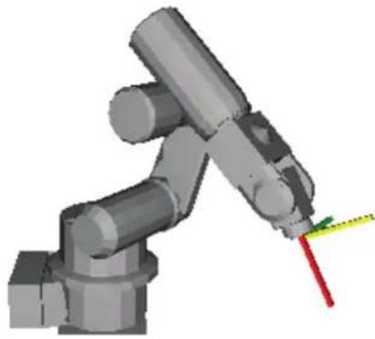
Wrist P1, NoFlip Go P1
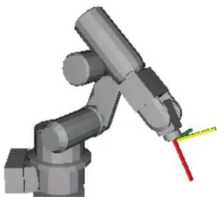
Wrist P1, Flip Go P1
Wrist Function
Returns the wrist orientation of a point.

Syntax
Wrist [(point)]
Parameters
point Optional. Pnumber or P(expr) or point label or point expression. If point is omitted, then the wrist orientation of the current robot position is returned.
Return Values
1 NoFlip (/NF)
2 Flip (/F)
See Also
Elbow, Hand, J4Flag, J6Flag, Wrist Statement
Wrist Function Example
Print Wrist(pick)
Print Wrist(P1)
Print Wrist
Print Wrist(P1 + P2)
Write Statement
Writes characters to a file or communication port without end of line terminator.

Syntax
Write #portNumber, string
Parameters
portNumber ID number that specifies the file or communications port. File number can be specified in ROpen, WOpen, AOpen statements. Communication port number can be specified in OpenCom (RS-232C) or OpenNet (TCP/IP) statements.
string String expression that will be written to the file.
Description
Write is different from Print in that it does not add an end of line terminator.
Note
File write buffering
File writing is buffered. The buffered data can be written with the Flush statement. Also, when closing a file with the Close statement, the buffered data can be written.
See Also
Print, Read
Write Example
OpenCom #1
For i = 1 to 10
Write #1, data$(i)
Next i
CloseCom #1
WriteBin Statement
Writes binary data to a file or communications port.
s
Syntax
WriteBin #portNumber, data
WriteBin #portNumber, array(), count
Parameters
portNumber ID number that specifies the file or communications port. File number can be specified in BOpen statements. Communication port number can be specified in OpenCom (RS-232C) or OpenNet (TCP/IP) statements.
data Integer expression containing the data to be written.
array() Name of a byte, integer, or long array variable that contains the data bytes to be written. Specify a one-dimensional array variable.
count Specifies the number of bytes to be written and must be less than or equal to the number of array elements.
See Also
ReadBin, Write
WriteBin Statement Example
Integer i, data(100)
OpenCom #1
For i = 0 To 100
WriteBin #1, i
Next I
WriteBin #1, data(), 100
CloseCom #1
Xor Operator
Performs the bitwise Xor operation (exclusive OR) on two expressions.
Syntax
result = expr1 Xor expr2
Parameters
expr1, expr2 A numeric value, or a variable name.
result An integer.
Description
The Xor operator performs the bitwise Xor operation on the values of the operands. Each bit of the result is the Xored value of the corresponding bits of the two operands.
| If bit in expr1 is And bit in expr2 is The result is | ||
| 0 | 0 | 0 |
| 0 | 1 | 1 |
| 1 | 0 | 1 |
| 1 | 1 | 0 |
See Also
And, LShift, Not, Or, Rshift
Xor Operator Example
>print 2 Xor 6
4
>
Xqt Statement
Initiates execution of a task from within another task.
s
Syntax
Xqt [taskNumber,] funcName [(argList)] [,Normal | NoPause | NoEmgAbort]
Parameters
| taskNumber | Optional. The task number for the task to be executed. The range of the task number is 1 to 32.For background tasks, specifies integer value from 65 ~ 80. |
| funcName | The name of the function to be executed. |
| argList | Optional. List of arguments that are passed to the function procedure when it is called. Multiple arguments are separated by commas. |
| taskType Optional. | Usually omitted.For background tasks, specifying a task type means nothing. |
| Normal Executes a normal task. | |
| NoPause | Executes a task that does not pause at Pause statement or Pause input signal occurrence or Safety Door Open. |
| NoEmgAbort | Executes a task that continue processing at Emergency Stop or error occurrence. |
Description
Xqt starts the specified function and returns immediately.
Normally, the taskNumber parameter is not required. When taskNumber is omitted, SPEL + automatically assigns a task number to the function, so you don't have to keep track of which task numbers are in use.
Notes
Task Type
Specify NoPause or NoEmgAbort as a task type to execute a task that monitors the whole controller. However, be sure to use these special tasks based on the understanding of the task motion using SPEL + or restriction of special tasks. For details of special tasks, refer to the section Special Tasks in the EPSON RC+ 5.0 User's Guide.
Background task
When executing Xqt in a background task, the generated task is also the background task. To execute the main function from a background task, use the StartMain statement. The details of the background task is explained in the EPSON RC+ 6.0 Users Guide manual: 6.20 Special Task.
Unavailable Commands in NoEmgAbort Task and background task
The following commands cannot be executed in NoEmgAbort task and background task.
| A | Accel | F | Find | Q | QP | V | VCal | ||
| AccelR | Fine | QP | DecelR | VcalPoints | |||||
| AccelS | G | Go | QP | DecelS | VCIs | ||||
| Arc | H | Home | R | Range | VCreateCalibration | ||||
| Arc3 | HomeClr | Reset *1 | VCreateObject | ||||||
| Arch | HomeSet | Restart *2 | VCreateSequence | ||||||
| Arm | Hordr | S | Sense | VDeleteCalibration | |||||
| ArmSet | I | Inertia | SFree | VDeleteObject | |||||
| ArmClr | J | JTran | SLock | VDeleteSequence | |||||
| B | Base | Jump | SoftCP | VGet | |||||
| BGo | Jump3 | Speed | VLoad | ||||||
| BMove | Jump3CP | SpeedR | VLoadModel | ||||||
| Box | JRange | SpeedS | VRun |
BoxClr L LimZ SyncRobots VSave Brake Local T TC VSavelmage C Cnv_AbortTrack LocalClr TGo VSaveModel Cnv_Fine M Mcal Till VSet Cnv_QueAdd MCordr TLSet VShowModel Cnv_QueMove Motor TLClr VStatsReset Cnv_QueReject Move TMove VStatsResetAll Cnv_QueUserData O OLAccel Tool VStatsSave Cnv_Trigger P Pass Trap VStasShow CP Pg_LSpeed VTeach Curve Pg_Scan VTrain CVMove Plane W WaitPos E ECP PlaneClr Weight ECPClr Power X Xqt *3 ECPSet PTPBoost XYLim Pulse
*1 Reset Error can be executed *2 Executable from the Trap Error processing task *3 Executable from the background tasks
See Also
Function/Fend, Halt, Resume, Quit, Startmain, Trap
Xqt Example Function main Xqt flash 'Start flash function as task 2 Xqt Cycle(5) 'Start Cycle function as task 3 Do Wait 3 'Execute task 2 for 3 seconds Halt flash 'Suspend the task Wait 3 Resume flash 'Resume the task Loop Fend Function Cycle(count As Integer) Integer i For i = 1 To count Jump pick On vac Wait .2 Jump place Off vac Wait .2 Next i Fend Function flash Do On 1 Wait 0.2 Off 1 Wait 0.2 Loop Fend
XY Function
Returns a point from individual coordinates that can be used in a point expression.

Syntax
XY (x, y, z, u, [v, w])
Parameters
x Real expression representing the X coordinate. y Real expression representing the Y coordinate. z Real expression representing the Z coordinate. u Real expression representing the U coordinate. v Optional for 6-Axis robots. Real expression representing the V coordinate. w Optional for 6-Axis robots. Real expression representing the W coordinate.
Return Values
A point constructed from the specified coordinates.
Description
When you don't use the additional ST axis, there are nothing in particular to be care of. You can move the manipulator to the specified coordinate with XY function like below: Go XY(60, 30, -50, 45)
When you use the additional ST axis, you need to be careful.
XY function returns the only robot point data, not including the additional axis.
If you use XY function like this: Go XY(60,30,-50,45), the manipulator will move to the specified coordinate but the additional axis will not move. If you want to move the additional axis as well, specify like this: Go XY(60,30,-50,45): ST(10,20).
For the details of additional axis, refer to EPSON RC+ Users Guide: 19. Additional Axis.
See Also
JA, Point Expression, ST Function
XY Function Example
P 1 0 = XY (6 0, 3 0, - 5 0, 4 5) + P 2 0
XYLim Statement
Sets or displays the permissible XY motion range limits for the robot.


Syntax
XYLim minX, maxX, minY, maxY, [minZ], [maxZ] XYLim
Parameters
| minX | The minimum X coordinate position to which the manipulator may travel. (The manipulator may not move to a position with the X Coordinate less than minX.) |
| maxX | The maximum X coordinate position to which the manipulator may travel. (The manipulator may not move to a position with the X Coordinate greater than maxX.) |
| minY | The minimum Y coordinate position to which the manipulator may travel. (The manipulator may not move to a position with the Y Coordinate less than minY.) |
| maxY | The maximum Y coordinate position to which the manipulator may travel. (The manipulator may not move to a position with the Y Coordinate greater than maxY.) |
| minZ | Optional. The minimum Z coordinate position to which the manipulator may travel. (The manipulator may not move to a position with the Z Coordinate less than minZ.) |
| maxZ | Optional. The maximum Z coordinate position to which the manipulator may travel. (The manipulator may not move to a position with the Z Coordinate greater than maxZ.) |
Return Values
Displays current XYLim values when used without parameters
Description
XYLim is used to define XY motion range limits. Many robot systems allow users to define joint limits but the SPEL+ language allows both joint limits and motion limits to be defined. In effect this allows users to create a work envelope for their application. (Keep in mind that joint range limits are also definable with SPEL.)
The motion range established with XYLim values applies to motion command target positions only, and not to motion paths from starting position to target position. Therefore, the arm may move outside the XYLim range during motion. (i.e. The XYLim range does not affect Pulse.)
Notes
Turning Off Motion Range Checking
There are many applications which don't require Motion Range limit checking and for that reason there is a simple method to turn this limit checking off. To turn motion range limit checking off, define the Motion Range Limit values for minX, maxX, minY, and maxY to be 0. For example XYLim 0, 0, 0, 0.
Default Motion Range Limit Values
The default values for the XYLim instruction are "0, 0, 0, 0". (Motion Range Limit Checking is turned off.)
Tip
Point & Click Setup for XYLim
EPSON RC+ 6.0 has a point and click dialog box for defining the motion range limits. The simplest method to set the XYLim values is by using the XYZ Limits page on the Robot Manager.
See Also
Range
XYLim Statement Example
This simple example from the command window sets and then displays the current XYLim setting:
> xylim -200, 300, 0, 500
> XYLim
-200.000, 300.000, 0.000, 500.000
XYLim Function
Returns point data for either upper or lower limit of XYLim region.

Syntax
XYLim(limit)
Parameters
limit Integer expression that specifies which limit to return.
Clears the XYLim definition.
Syntax
XYLimClr
See Also
XYLim, XYLimDef
XYLimClr Function Example
This example uses the XYLIMClr function in a program:
Function ClearXYLim
If XYLimDef = True Then
XYLimClr
EndIf
Fend
XYLimDef Function
Returns whether XYLim has been defined or not.

Syntax
XYLimDef
Return Values
True if XYLim has been defined, otherwise False.
See Also
XYLim, XYLimClr
XYLimDef Function Example
This example uses the XYLimDef function in a program:
Function ClearXYLim
If XYLimDef = True Then
XYLimClr
EndIf
Fend
SPEL + Error Messages
To get help for any SPEL + error, place the cursor on the error message in the run or command windows and press the F1 key.
| No. | Message | Remedy | Note 1 | Note 2 |
| 1 | Controller control program started. | |||
| 2 | Termination due to low voltage of the power supply. | |||
| 3 | Controller control program has completed. | Stores this log when the controller is rebooted from EPSON RC+ or TP1. | ||
| 4 | Preserve variables save area has been cleaned. | |||
| 5 Function Main started. | ||||
| 6 | Function Main started. Later same logs are skipped. | Skip the log "Function Main started." to prevent system history space run out. | ||
| 7 | Serial number has been saved. | |||
| 8 | System backup has been executed. | |||
| 9 | System restore has been executed. | |||
| 10 | Robot parameters have been initialized. | |||
| 11 | Offset pulse value between the encoder origin and the home sensor (HOFS) is changed. | Value after change | Value before change | |
| 17 | Message saving mode activated. Uncommon event. | |||
| 18 | Conversion of Robot Parameter file has been executed. | |||
| 19 | DU firmware has been installed. | |||
| 100 | Device connected to Controller. | |||
| 101 | Console device has changed. | 21:PC22:Remote23:OP1 | ||
| 102 | Display device has changed. | |||
| 103 | Working mode has changed. | |||
| 104 | Cooperative mode has changed. | |||
| 110 | Controller firmware has been installed. | 1:Setup2:Initialize3:Upgrade4:Recover | ||
| 111 | IP address has been restored. | May store this log when the controller firmware is installed. | ||
| 120 | RC+ connected to the Controller. | 1:Ethernet2:USB | ||
| 121 | TP connected to the Controller. | |||
| 122 | OP connected to the Controller. | |||
| 123 | RC+ disconnected from the Controller. | |||
| 124 | TP disconnected from the Controller. | |||
| 125 | OP disconnected from the Controller. | |||
| 126 | Working mode changed to AUTO. | |||
| 127 | Working mode changed to Program. | |||
| 128 | Working mode changed to Teach. | |||
| 501 | Trace history is active. | Effects system performance if trace history is active. | ||
| 502 | Memory has been initialized. | When this error occurs, the value of the Global Preserve variable will be initialized.Replace the CPU board battery.Replace the CPU board. | ||
| 503 | Found Hard disk error.You shuld replace the hard disk ASAP. | This is a warning of the hard disk failure. Replace the hard disk as soon as possible. | ||
| 504 | An Error occurred on a Background Task. | Make sure there are no problems in the system and continue the operation. | ||
| 511 | Battery voltage of the CPU board backup is lower than the allowed voltage. Replace the CPU board battery. | Replace the CPU board battery immediately. Keep the power to the controller ON as far as possible until you replace the battery. | 100 times of current value | 100 times of boundary value |
| 512 | 5V input voltage for the CPU board is lower than the allowed voltage. | If normal voltage is not generated by a 5V power supply alone, replace the power supply. | 100 times of current value | 100 times of boundary value |
| 513 | 24 V input voltage for the motor brake, encoder and fan is lower than the specified voltage. | If normal voltage is not generated by a 24V power supply alone, replace the power supply. | 100 times of current value | 100 times of boundary value |
| 514 | Internal temperature of the Controller is higher than the allowed temperature. | Stop the controller as soon as possible and check whether the ambient temperature of the controller is not high.Check whether the filter is not clogged up. | 100 times of current value | 100 times of boundary value |
| 515 | Rotating speed of the controller fan is below the allowed speed. (FAN1) | Check whether the filter is not clogged up. If the warning is not cleared after the controller is rebooted, replace the fan. | Current value | Boundary value |
| 516 | Rotating speed of the controller fan is below the allowed speed. (FAN2) | Check whether the filter is not clogged up. If the warning is not cleared after the controller is rebooted, replace the fan. | Current value | Boundary value |
| 517 | Internal temperature of the Controller is higher than the allowed temperature. | Stop the controller as soon as possible and check whether the ambient temperature of the controller is not high.Check whether the filter is not clogged up. | 100 times of current value | 100 times of boundary value |
| 521 | DU1 3.3V input voltage for the board is lower than the allowed voltage. | If normal voltage is not generated by 3.3V of Drive Unit 1 power supply alone, replace the power supply. | 100 times of current value | 100 times of boundary value |
| 522 | DU1 5V input voltage for the board is lower than the allowed voltage.0523: | If normal voltage is not generated by 5V of Drive Unit 1 power supply alone, replace the power supply. | 100 times of current value | 100 times of boundary value |
| 523 | DU1 24 V input voltage for the motor brake, encoder and fan is lower than the specified voltage. | If normal voltage is not generated by 24V of Drive Unit 1 power supply alone, replace the power supply. | 100 times of current value | 100 times of boundary value |
| 524 | DU1 Internal temperature of the Controller is higher than the allowed temperature. | Stop Drive Unit 1 as soon as possible and check whether the ambient temperature of Drive Unit 1 is not high. Check whether the filter is not clogged up. | 100 times of current value | 100 times of boundary value |
| 525 | DU1 Rotating speed of the controller fan is below the allowed speed. (FAN1) | Check whether the filter of Drive Unit 1 is not clogged up. If the warning is not cleared after the controller is rebooted, replace the fan. | Current value | Boundary value |
| 526 | DU1 Rotating speed of the controller fan is below the allowed speed. (FAN2) | Check whether the filter of Drive Unit 1 is not clogged up. If the warning is not cleared after the controller is rebooted, replace the fan. | Current value | Boundary value |
| 531 | DU2 3.3V input voltage for the board is lower than the allowed voltage. | If normal voltage is not generated by 3.3V of Drive Unit 2 power supply alone, replace the power supply. | 100 times of current value | 100 times of boundary value |
| 532 | DU2 5V input voltage for the board is lower than the allowed voltage. | If normal voltage is not generated by 5V of Drive Unit 2 power supply alone, replace the power supply. | 100 times of current value | 100 times of boundary value |
| 533 | DU2 24 V input voltage for the motor brake, encoder and fan is lower than the specified voltage. | If normal voltage is not generated by 24V of Drive Unit 2 power supply alone, replace the power supply. | 100 times of current value | 100 times of boundary value |
| 534 | DU2 Internal temperature of the Controller is higher than the allowed temperature. | Stop Drive Unit 2 as soon as possible and check whether the ambient temperature of Drive Unit 2 is not high. Check whether the filter is not clogged up. | 100 times of current value | 100 times of boundary value |
| 535 | DU2 Rotating speed of the controller fan is below the allowed speed. (FAN1) | Check whether the filter of Drive Unit 2 is not clogged up. If the warning is not cleared after the controller is rebooted, replace the fan. | Current value | Boundary value |
| 536 | DU2 Rotating speed of the controller fan is below the allowed speed. (FAN2) | Check whether the filter of Drive Unit 2 is not clogged up. If the warning is not cleared after the controller is rebooted, replace the fan. | Current value | Boundary value |
| 599 | Jogging attempted near singularity point. | |||
| 700 | Motor driver type does not match the current robot model. Check the robot model. Replace the motor driver. | Check the robot model. | ||
| 736 | Encoder has been reset. Reboot the controller. | Reboot the controller. | ||
| 737 | Low voltage from the encoder battery. Replace the battery with the controller ON. | Replace the battery for the robot with the controller ON. | ||
| 752 Servo alarm D. | ||||
| 1001 | Operation Failure.Command parameter is invalid. | |||
| 1002 | Requested data cannot be accessed. The data is not set up or the range is invalid. | Check whether the target I/O,variables, and tasks exist. | ||
| 1003 | The password is invalid | Enter the correct password. | ||
| 1004 | Cannot execute with unsupported version. | Use the correct version file. | ||
| 1005 | Cannot execute with invalid serial number. | Use the backup data for the same controller to restore the controller configuration. | ||
| 1006 | Cannot execute with invalid Robot model. | Use the backup data for the same controller to restore the controller configuration. | ||
| 1020 | Cannot execute in recovery mode. | Boot the controller as normal. | ||
| 1021 | Cannot execute due to controller initialization failure. | Restore the controller configuration. | ||
| 1022 | Cannot execute without the project being open. | Open a project. | ||
| 1023 | Cannot execute while the project is open. | Rebuild the project. | ||
| 1024 | Cannot activate from remote. | Enable the remote input. | ||
| 1025 | Execution in Teach mode is prohibited. | Change to the AUTO mode. | ||
| 1026 | Cannot execute in Teach mode except from TP. | Change to the AUTO mode. | ||
| 1027 | Cannot execute in Auto mode. | Change to the Program mode. | ||
| 1028 | Cannot execute in Auto mode except from the main console. | Change to the Program mode. | ||
| 1029 | Cannot execute from OP. | Enable the OP input. | ||
| 1030 | Does not allow Operation mode to be changed. | Change to the Auto mode with a console in the Program mode. | ||
| 1031 | Cannot execute while tasks are executing. | Stop the task and then execute. | ||
| 1032 | Cannot execute while the maximum number of tasks are executing. | Stop the task and then execute. | ||
| 1033 | Cannot execute during asynchronous motion command. | Execute after the motion ends. | ||
| 1034 | Asynchronous command stopped during operation. | The asynchronous command already stopped when the controller received a stop command. | ||
| 1035 | Cannot execute in Remote enable except from the Remote. | |||
| 1036 | Cannot execute in OP enable except from the OP. | |||
| 1037 | Execution is prohibited. | |||
| 1041 | Cannot execute during Emergency Stop status. | Cancel the Emergency Stop status. | ||
| 1042 | Cannot execute while the safeguard is open. | Close the safeguard. | ||
| 1043 | Cannot execute during error condition. | Cancel the error condition. | ||
| 1044 | Cannot execute when the remote pause input is ON. | Change the remote pause input to OFF. | ||
| 1045 | Input waiting condition is the only available condition to input. | The controller received an input while it was not in the Input waiting condition. | ||
| 1046 | Cannot execute during file transfer. | Execute after the file transmission. | ||
| 1047 | Cannot cancel the command executed from other devices. | Cancel the motion command from the device the command was issued from. | ||
| 1048 | Cannot execute after after low voltage was detected. | |||
| 1049 | Other devices are in program mode. | |||
| 1050 | Password is too long. | |||
| 1051 | Export Controller Status failed. | |||
| 1052 | Export Controller Status busy. | |||
| 1100 | File failure. Cannot access the file. | |||
| 1102 | File failure. Read and write failure of the registry | |||
| 1103 | File is not found. | Check whether the file exists. | ||
| 1104 | Project file was not found. | Rebuild the project. | ||
| 1105 | Object file was not found. | Rebuild the project. | ||
| 1106 | Point files were not found. | Rebuild the project. | ||
| 1107 | The program is using a feature that is not supported by the current controller firmware version. | |||
| 1108 | One or more source files are updated. Please build the project. | Rebuild the project. | ||
| 1109 | Not enough storage capacity. | Increase free space of the USB memory. | ||
| 1110 | File is not found. | |||
| 1111 | Conveyor file was not found. | |||
| 1120 | File failure. Setting file is corrupt. | Restore the controller configuration. | ||
| 1121 | File failure. Project file is corrupt. | Rebuild the project. | ||
| 1122 | File failure. Point file is corrupt. | Rebuild the project. | ||
| 1123 | File failure. I/O label file is corrupt. | Rebuild the project. | ||
| 1124 | File failure. User error file is corrupt. | Rebuild the project. | ||
| 1125 | File failure. Error message file is corrupt. | |||
| 1126 | File failure. Software option infomation is corrupt. | |||
| 1127 | File failure. Vision file is corrupt. | Rebuild the project. | ||
| 1128 | File failure. Backup information file is corrupt. | |||
| 1130 | Error message failure. No item is found in the error history. | |||
| 1131 | Cannot access the USB memory. | Insert the USB memory properly.When this error still occurs after the USB memory is inserted properly,the memory may be unrecognizable to controller. Insert another memory to check the operation. | ||
| 1132 | File failure.Failure to copy the file. | |||
| 1133 | File failure.Failure to delete the file. | |||
| 1134 | File failure.GUI Builder file is corrupt. | Rebuild the project. | ||
| 1140 | File failure tiersed to open the object file. | |||
| 1141 | File failure tiersed to open the project file. | |||
| 1142 | File failure tiersed to read the project file. | |||
| 1143 | File failure tiersed to open the condition save file. | |||
| 1144 | File failure tiersed to write the condition save file. | |||
| 1145 | File failure tiersed to open the conveyor file. | |||
| 1146 | File failure tiersed to read the conveyor file. | |||
| 1150 | File failure.Error history is invalid. | |||
| 1151 | File failure tiersed to map the error history. | |||
| 1152 | File failure tiersed to open the error history file. | |||
| 1153 | File failure tiersed to write the error history file. | |||
| 1155 | File failure tiersed to open the settings file. | Restore the controller configuration. | ||
| 1156 | File failure tiersed to save the settings file. | Restore the controller configuration. | ||
| 1157 | File failure tiersed to read the settings file. | Restore the controller configuration. | ||
| 1158 | File failure tiersed to write the settings file. | Restore the controller configuration. | ||
| 1160 | MCD failure tiersed to open the MCD file. | Restore the controller configuration. | ||
| 1161 | MCD failure tiersed to read the MCD file. | Restore the controller configuration. | ||
| 1162 | MCD failure tiersed to write the MCD file. | Restore the controller configuration. | ||
| 1163 | MCD failure tiersed to save the MCD file. | Restore the controller configuration. | ||
| 1165 | MPD failure tiersed to open the MPD file. | |||
| 1166 | MPD failure tiersed to read the MPD file. | |||
| 1167 | MPD failure. Failed to write the MPD file. | |||
| 1168 | MPD failure. Failed to save the MPD file. | |||
| 1170 | MPL failure. Failed to open the MPL file. | |||
| 1171 | MPL failure. Failed to read the MPL file. | |||
| 1172 | MPL failure. Failed to write the MPL file. | |||
| 1173 | MPL failure. Failed to save the MPL file. | |||
| 1175 | MAL failure. Failed to open the MAL file. | |||
| 1176 | MAL failure. Failed to read the MAL file. | |||
| 1177 | MAL failure. Failed to write the MAL file. | |||
| 1178 | MAL failure. Failed to save the MAL file. | |||
| 1180 | MTR failure. Failed to create the MTR file. | |||
| 1181 | PRM failure. Failed to replace the PRM file. | |||
| 1185 | File failure. Failed to open the backup information file. | |||
| 1186 | File failure. Failed to read the backup information file. | |||
| 1187 | File failure. Failed to write the backup information file. | |||
| 1188 | File failure. Failed to save the backup information file. | |||
| 1189 | The backup data was created by an old version. | Cannot restore the controller configuration in the specified procedure for using old backup data. Check the backup data. | ||
| 1190 | The backup data was created by a newer version. | |||
| 1191 | There is no project in the backup data. | |||
| 1192 | Cannot execute with invalid robot number. | |||
| 1193 | Cannot execute with invalid robot information. | |||
| 1200 | Compile failure. Check the compile message. | This error occurs during compilation from TP. Correct where the error occurred. | ||
| 1201 | Link failure. Check the link message. | This error occurs during compilation from TP. Correct where the error occurred. | ||
| 1500 | Communication error. | |||
| 1501 | Command did not complete in time. | Execute the command again after a while. Check the connection between the EPSON RC+6.0 and controller. | ||
| 1502 | Communication disconnection between RC+ and Controller. Re-establish communication. | Check the connection between the EPSON RC+6.0 and controller. | 1: | Communication timeout2: USB cable disconnection3: USB reception failure4: USB communication shutdown |
| 1503 | Disconnection while executing a task. | |||
| 1510 | Out of IP Address range. | |||
| 1550 | Communication failure. Ethernet initialization error. | |||
| 1551 | Communication failure. USB initialization error. | |||
| 1552 | Communication failure. Controller internal communication error. | |||
| 1553 | Communication failure. Invalid data is detected. | |||
| 1555 | Ethernet transmission error. | Check the connection between the EPSON RC+6.0 and controller. | ||
| 1556 | Ethernet reception error. | Check the connection between the EPSON RC+6.0 and controller. | ||
| 1557 | USB transmission error. | Check the connection between the EPSON RC+6.0 and controller. | ||
| 1558 | USB reception error. | Check the connection between the EPSON RC+6.0 and controller. | ||
| 1600 | Initialization failure. Failed to initialize OP. | |||
| 1603 | Timeout error occurred during communication with OP. | Check whether the cable is firmly connected. Replace the cable. | ||
| 1604 | Parity error occurred during communication with OP. | Check whether the cable is firmly connected. Replace the cable. | ||
| 1605 | Framing error occurred during communication with OP. | Check whether the cable is firmly connected. Replace the cable. | ||
| 1606 | Overrun error occurred during communication with OP. | Check whether the cable is firmly connected. Replace the cable. | ||
| 1607 | Checksum error occurred during communication with OP. | Check whether the cable is firmly connected. Replace the cable. | ||
| 1608 | Retry error occurred during communication with OP. | Check whether the cable is firmly connected. Replace the cable. | ||
| 1609 | OP cannot be connected. | Upgrade the controller software. Upgrade the OP firmware. | ||
| 1700 | Initialization failure. Failed to initialize TP. | |||
| 1701 | Initialization failure. Failed to initialize TP. | |||
| 1702 | Initialization failure. Failed to initialize TP. | |||
| 1703 | File failure. Failed to read the screen data file. | |||
| 1704 | Failed to read the setting file. | |||
| 1706 | Failed to open the TP port. | |||
| 1708 | Failed to read the key table for TP. | |||
| 1709 | Failed to change the language. | |||
| 1710 | Failed to make the screen. | |||
| 1800 | The controller is already connected to a RC+. | Only one RC+ can be connected to the controller. | ||
| 1802 | The command was attempted without being connected to a controller. | |||
| 1803 | Failed to read or write the file on the PC. | |||
| 1804 | Initialization failure. Failed to allocate memory on the PC. | |||
| 1805 | Connection failure. Check the controller startup and connection of the communication cable. | |||
| 1806 | Timeout during connection via Ethernet. | |||
| 1807 | Timeout during connection via USB. | |||
| 1808 | USB driver is not installed. | Failed to install EPSON RC+ 6.0. Install EPSON RC+ 6.0 again. | ||
| 1809 | Initialization failure. Failed to initialize PC daemon. | |||
| 1810 | PC daemon error. Uncommon error. | |||
| 1901 | Unsupported. Unsupported command was attempted. | |||
| 1902 | Unsupported. Unsupported parameter was specified. | |||
| 1903 | System error. | |||
| 2000 | Unsupported.Unsupported command was attempted. | Rebuild the project. | ||
| 2001 | Unsupported.Unsupported motion command was attempted. | Rebuild the project. | ||
| 2003 | Unsupported.Unsupported Function argument was specified. | Rebuild the project. | ||
| 2004 | Unsupported.Unsupported Function return value was specified. | Rebuild the project. | ||
| 2005 | Unsupported.Unsupported condition was specified. | Rebuild the project. | ||
| 2006 | Unsupported.Unsupported I/O command was specified. | Rebuild the project. | ||
| 2007 | Unsupported condition was specified. | |||
| 2008 | Unsupported.Unknown error number. | |||
| 2009 | Unsupported.Invalid Task number. | |||
| 2010 | Object file error.Build the project. Out of internal code range. | Rebuild the project. | ||
| 2011 | Object file error.Build the project. Function argument error. | Rebuild the project. | ||
| 2012 | Object file error.Build the project. Command argument error. | Rebuild the project. | ||
| 2013 | Object file error.Build the project. Cannot process the code. | Rebuild the project. | ||
| 2014 | Object file error.Build the project. Cannot process the variable type code. | Rebuild the project. | ||
| 2015 | Object file error.Build the project. Cannot process the string type code. | Rebuild the project. | ||
| 2016 | Object file error.Build the project. Cannot process the variable category code. | Rebuild the project. | ||
| 2017 | Object file error.Build the project. Cannot process because of improper code. | Rebuild the project. | ||
| 2018 | Object file error.Build the project. Failed to calculate the variable size. | Rebuild the project. | ||
| 2019 | Object file errorCannot process the variable wait.Build the project. | Rebuild the project. | ||
| 2020 | Stack table number exceeded.Function call or local variable is out of range. | Check whether no function is called infinitely. Reduce the Call function depth. | ||
| 2021 | Stack area size exceeded.Stack error. Function call or local variable is out of range. | If using many local variables,especially String type, replace them to global variables. | ||
| 2022 | Stack failure. Required data not found on the stack. | Rebuild the project. | ||
| 2023 | Stack failure. Unexpected tag found on the stack. | Rebuild the project. | ||
| 2024 | Stack area size exceeded. Local variable is out of range. | |||
| 2031 | System failure.Robot number is beyond the maximum count. | Restore the controller configuration. | ||
| 2032 | System failure.Task number compliance error. | Rebuild the project. | ||
| 2033 | System failure.Too many errors. | Remedy the errors occurring frequently. | ||
| 2040 | Thread failure.Failure to create the thread. | |||
| 2041 | Thread failure.Thread creation timeout. | |||
| 2042 | Thread failure.Thread termination timeout. | |||
| 2043 | Thread failure.Thread termination timeout. | |||
| 2044 | Thread failure.Daemon process timeout. | |||
| 2045 | Thread failure.Task continuance wait timeout. | |||
| 2046 | Thread failure.Task stop wait timeout. | |||
| 2047 | Thread failure.Task startup wait timeout. | |||
| 2050 | Object file operation failure.Object file size is beyond the allowable size. | Rebuild the project. | ||
| 2051 | Object file operation failureCannot delete the object file during execution. | Reboot the controller. | ||
| 2052 | Object file operation failureCannot allocate the memory for the object file. | Reboot the controller. | ||
| 2053 | Object file update.Updating the object file. | Perform the same processing after a while. Rebuild the project. | ||
| 2054 | Object file operation failure.Synchronize the project. Function ID failure. | Synchronize the files of the project.Rebuild the project. | ||
| 2055 | Object file operation failure.Synchronize the project. Local variable ID failure. | Synchronize the files of the project.Rebuild the project. | ||
| 2056 | Object file operation failure.Synchronize the project. Global variable ID failure. | Synchronize the files of the project.Rebuild the project. | ||
| 2057 | Object file operation failure.Synchronize the project. Global Preserve variable ID failure. | Synchronize the files of the project.Rebuild the project. | ||
| 2058 | Object file operation failure.Failed to calculate the variable size. | Synchronize the files of the project.Rebuild the project. | ||
| 2059 | Exceed the global variable areaCannot assign the Global variable area. | Reduce the number of Global variables to be used. | ||
| 2070 | SRAM failure.SRAM is not mapped. | Replace the CPU board. | ||
| 2071 | SRAM failureCannot delete when Global Preserve variable is in use. | Perform the same processing after a while. Rebuild the project. | ||
| 2072 | Exceed the backup variable area.Cannot assign the Global Preserve variable area. | Reduce the number of Global Preserve variables to be used. | Maximum size | The size you attempted to use |
| 2073 | SRAM failure.Failed to clear the Global Preserve variable area. | Rebuild the project. | ||
| 2074 | SRAM failure.Failed to clean up the Global Preserve variable save area. | Reboot the controller. | ||
| 2100 | Initialization failure.Failed to open the initialization file. | Restore the controller configuration. | ||
| 2101 | Initialization failure.Duplicated initialization. | |||
| 2102 | Initialization failure.Failed to initialize MNG. | |||
| 2103 | Initialization failure.Failed to create an event. | |||
| 2104 | Initialization failure.Failed to setup a priority. | |||
| 2105 | Initialization failure.Failed to setup the stack size. | |||
| 2106 | Initialization failure.Failed to setup an interrupt process. | |||
| 2107 | Initialization failure.Failed to start an interrupt process. | |||
| 2108 | Initialization failure.Failed to stop an interrupt process. | |||
| 2109 | Initialization failure.Failed to terminate MNG. | Reboot the controller. | ||
| 2110 | Initialization failure.Failed to allocate memory. | Reboot the controller. | ||
| 2111 | Initialization failure.Failed to initialize motion. | Restore the controller configuration. | ||
| 2112 | Initialization failure.Failed to terminate motion. | Reboot the controller. | ||
| 2113 | Initialization failure. Failed to map SRAM. | Replace the CPU board. | ||
| 2114 | Initialization failure. Failed to register SRAM. | Replace the CPU board. | ||
| 2115 | Initialization failure. Fieldbus board is beyond the maximum count. | |||
| 2116 | Initialization failure. Failed to initialize fieldbus. | |||
| 2117 | Initialization failure. Failed to terminate fieldbus. | |||
| 2118 | Initialization failure. Failed to open motion. | Restore the controller configuration. | ||
| 2119 | Initialization failure. Failed to initialize conveyor tracking. | Make sure the settings of conveyor and encoder are correct. | ||
| 2120 | Initialization failure. Failed to allocate the system area. | Reboot the controller. | ||
| 2121 | Initialization failure. Failed to allocate the object file area. | Reboot the controller. | ||
| 2122 | Initialization failure. Failed to allocate the robot area. | Reboot the controller. | ||
| 2123 | Initialization failure. Failed to create event. | Reboot the controller. | ||
| 2130 | MCD failure. Failed to open the MCD file. | Restore the controller configuration. | ||
| 2131 | MCD failure. Failed to map the MCD file. | Restore the controller configuration. | ||
| 2132 | PRM failure. PRM file cannot be found. | Restore the controller configuration. | ||
| 2133 | PRM failure. Failed to map the PRM file. | Restore the controller configuration. | ||
| 2134 | PRM failure. PRM file contents error. | Restore the controller configuration. | ||
| 2135 | PRM failure. Failed to convert the PRM file. | Reboot the controller. | ||
| 2136 | PRM failure. Failed to convert the PRM file. | Reboot the controller. | ||
| 2137 | PRM failure. Failed to convert the PRM file. | Reboot the controller. | ||
| 2140 | DU Init Error. Cannot use drive units. | |||
| 2141 | DU Init Error. Failed to initialize drive units. | Check the connection with drive units. | ||
| 2142 | DU Init Error. Failed to initialize drive units. | Check the connection with drive units. | ||
| 2143 | DU Init Error. Timeout during initialization of drive units. | Check the connection with drive units. | ||
| 2144 | DU Init Error. No data to download to drive units. | Reboot the control unit and drive units. | ||
| 2145 | DU Init Error. Failed to start communication with drive units. | Reboot the control unit and drive units. | ||
| 2146 | DU Init Error. Timeout when starting communication with drive units. | Reboot the control unit and drive units. | ||
| 2147 | DU Init Error. Failed to update the drive units software. | |||
| 2148 | DU Init Error. Failed to update the drive units software. | |||
| 2149 | DU Init Error. Failed to update the drive units software. | |||
| 2150 | Operation failure. Task number cannot be found. | |||
| 2151 | Operation failure. Executing the task. | |||
| 2152 | Operation failure. Object code size failure. | |||
| 2153 | Operation failure. Jog parameter failure. | |||
| 2154 | Operation failure. Executing jog. | |||
| 2155 | Operation failure. Cannot execute the jog function. | |||
| 2156 | Operation failure. Jog data is not configured. | |||
| 2157 | Operation failure. Failed to change the jog parameter. | |||
| 2158 | Operation failure. Failed to allocate the area for the break point. | |||
| 2159 | Operation failure. Break point number is beyond the allowable setup count. | |||
| 2160 | Operation failure. Failed to allocate the function ID. | |||
| 2161 | Operation failure. Failed to allocate the local variable address. | |||
| 2162 | Operation failure. Not enough buffer to store the local variable. | |||
| 2163 | Operation failure. Value change is available only when the task is halted. | |||
| 2164 | Operation failure. Failed to allocate the global variable address. | |||
| 2165 | Operation failure. Not enough buffer to store the global variable. | |||
| 2166 | Operation failure. Failed to obtain the Global Preserve variable address. | |||
| 2167 | Operation failure. Not enough buffer to store the Global Preserve variable. | |||
| 2168 | Operation failure.SRAM is not mapped. | |||
| 2169 | Operation failureCannot clear the Global Preserve variable when loading the object file. | |||
| 2170 | Operation failure.Not enough buffer to store the string. | |||
| 2171 | Operation failureCannot start the task after low voltage was detected. | |||
| 2172 | Operation failure.Duplicated remote I/O configuration. | |||
| 2173 | Remote setup errorCannot assign non-existing input number to remote function. | |||
| 2174 | Remote setup error.Cannot assign non-existing output number to remote function. | |||
| 2175 | Operation failure.Remote function is not configured. | |||
| 2176 | Operation failure.Event wait error. | |||
| 2177 | Operation failure.System backup failed. | |||
| 2178 | Operation failure.System restore failed. | |||
| 2179 | Remote setup error.Cannot assign same input number to some remote functions. | |||
| 2180 | Remote setup error.Cannot assign same output number to some remote functions. | |||
| 2190 | Cannot calculate because it was queue data. | Check the program. | ||
| 2191 | Cannot execute AbortMotion because robot is not running from a task. | If you don't operate the robot from a program, you cannot use AbortMotion. | ||
| 2192 | Cannot execute AbortMotion because robot task is already finished. | |||
| 2193 | Cannot execute Recover without motion because AbortMotion was not executed. | Execute AbortMotion in advance to execute Recover WithoutMove. | ||
| 2194 | Conveyor setting error. | Make sure the settings of conveyor and encoder are correct. | ||
| 2195 | Conveyor setting error. | Make sure the settings of conveyor and encoder are correct. | ||
| 2196 | Conveyor number is out of range. | Make sure the settings of conveyor and encoder are correct. | ||
| 2200 | Robot in use.Cannot execute the motion command when other tasks are using the robot. | The motion command for the robot cannot be simultaneously executed from more than one task. Review the program. | ||
| 2201 | Robot does not exist. | Check whether the robot setting is performed properly. Restore the controller configuration. | ||
| 2202 | Motion control module status failure. Unknown error was returned. | |||
| 2203 | Cannot clear local number '0'. | The Local number 0 cannot be cleared. Review the program. | ||
| 2204 | Cannot clear an arm while in use. The Arm cannot be cleared while it is in use. Check whether the Arm is not used. | The Arm number you attempted to clear | ||
| 2205 | Cannot clear arm number '0'. | The Arm number 0 cannot be cleared. Review the program. | ||
| 2206 | Cannot clear a tool while in use. The Tool cannot be cleared while it is in use. Check whether the Tool is not used. | The Tool number you attempted to clear | ||
| 2207 | Cannot clear tool number '0'. | The Tool number 0 cannot be cleared. Review the program. | ||
| 2208 | Cannot clear ECP '0'. | The ECP number 0 cannot be cleared. Review the program. | ||
| 2209 | Cannot clear an ECP while in use. | The ECP cannot be cleared while it is in use. Check whether the ECP is not used. | The ECP number you attempted to clear | |
| 2210 | Cannot specify '0' as the local number. | The command processing the Local cannot specify the Local number 0. Review the program. | ||
| 2216 | Box number is out of range. | |||
| 2217 | Box number is not defined. | |||
| 2218 | Plane number is out of range. | |||
| 2219 | Plane number is not defined. | |||
| 2220 | PRM failure. No PRM file data is found. | Reboot the controller. Restore the controller configuration. | ||
| 2221 | PRM failure. Failed to flash the PRM file. | Reboot the controller. Restore the controller configuration. | ||
| 2222 | Local number is not defined. | Check the Local setting. Review the program. | The specified Local number | |
| 2223 | Local number is out of range. | Available Local number is from 1 to 15. Review the program. | The specified Local number | |
| 2224 | Unsupported. MCOFS is not defined | |||
| 2225 | CalPIs is not defined. | Check the CalPIs setting. | ||
| 2226 | Arm number is out of range. | Available Arm number is from 0 to 3. Depending on commands, the Arm number 0 is not available. Review the program. | The specified Arm number | |
| 2227 | Arm number is not defined. | Check the Arm setting. Review the program. | The specified Arm number | |
| 2228 | Pulse for the home position is not defined. | Check the HomeSet setting. | ||
| 2229 | Tool number is out of range. | Available Tool number is from 0 to 3. Depending on commands, the Tool number 0 is not available. Review the program. | The specified Tool number | |
| 2230 | Tool number is not defined. Check the Tool setting. Review the program. | The specified Tool number | ||
| 2231 | ECP number is out of range. | Available Tool number is from 0 to 15. Depending on commands, the Tool number 0 is not available. Review the program. | The specified ECP number | |
| 2232 | ECP number is not defined. Check the ECP setting. Review the program. | The specified ECP number | ||
| 2233 | Axis to reset the encoder was not specified. | Be sure to specify the axis for encoder reset. | ||
| 2234 | Cannot reset the encoder with motor in the on state. | Turn the motor power OFF before reset. | ||
| 2235 | XYLIM is not defined. | Check the XYLIM setting. Review the program. | ||
| 2236 | PRM failure. Failed to set up the PRM file contents to the motion control status module. | Reboot the controller. Restore the controller configuration. | ||
| 2240 | Array subscript is out of user defined range. Cannot access or update beyond array bounds. | Check the array subscript. Review the program. | The dimensions exceeding the definition | The specified subscript |
| 2241 | Dimensions of array do not match the declaration. | Check the array's dimensions. Review the program. | ||
| 2242 | Zero '0' was used as a divisor. | Review the program. | ||
| 2243 | Variable overflow. Specified variable was beyond the maximum allowed value. | Check the variable type and calculation result. Review the program. | ||
| 2244 | Variable underflow. Specified variable was below the minimum allowed value. | Check the variable type and calculation result. Review the program. | ||
| 2245 | Cannot execute this command with a floating point number. | This command cannot be executed for Real or Double type. Review the program. | ||
| 2246 | Cannot calculate the specified value using the Tan function. | Check the specified value. Review the program. | The specified value | |
| 2247 | Specified array subscript is less than '0'. | Check the specified value. Review the program. | The specified value | |
| 2248 | Array failure. Redim can only be executed for an array variable. | You attempted to redimension the variable that is not array. Rebuild the project. | ||
| 2249 | Array failure. Cannot specify Preserve for other than a single dimension array. | Other than a single dimension array was specified as Preserve for Redim. Rebuild the project. | ||
| 2250 | Array failure. Failed to calculate the size of the variable area. | Rebuild the project. | ||
| 2251 | Cannot allocate enough memory for Redim statement. | Reduce the number of subscripts to be specified for Redim. Perform Redim modestly. | ||
| 2252 | Cannot allocate enough memory for ByRef. | Reduce the number of array's subscripts to be seen by ByRef. | ||
| 2253 | Cannot compare characters with values. | Check whether the string type and the numeric data type are not compared. Review the program. | ||
| 2254 | Specified data is beyond the array bounds. Cannot refer or update beyond the array bounds. | Check the number of array's subscripts and data. Review the program. | The number of array subscripts | The number of data to be referred or updated |
| 2255 | Variable overflow or underflow. Specified variable is out of value range. | The value that exceeds the range of Double type is specified. Review the program. | ||
| 2256 | Specified array subscript is beyond the maximum allowed range. | Reduce the number of subscripts to be specified. For available subscripts, see the online help. | ||
| 2260 | Task number is out of the available range. | For available task number, see the online help. Review the program. | The specified task number | |
| 2261 | Specified task number does not exist. | Review the program. | The specified task number | |
| 2262 | Robot number is out of the available range. | The available Robot number is 1. Review the program. | The specified robot number | |
| 2263 | Output number is out of the available range. The Port No. or the Device No. is out of the available range. | For available output number, see the online help. Review the program. | The specified output number | |
| 2264 | Command argument is out of the available range. Check the validation. Added data 1: Passed value. Added data 2: argument order. | For available range of argument, see the online help. Review the program. | The Added value | What number argument? |
| 2265 | Joint number is out of the available range. | Available Joint number is from 1 to 6. Review the program. | The specified joint number | |
| 2266 | Wait time is out of available range. | Available wait time is from 0 to 2147483. Review the program. | The specified wait time | |
| 2267 | Timer number is out of available range. | Available timer number is from 0 to 15. Review the program. | The specified timer number | |
| 2268 | Trap number is out of available range. | Available trap number is from 1 to 4. Review the program. | The specified trap number | |
| 2269 | Language ID is out of available range. | For available language ID, see the online help. Review the program. | The specified language ID | |
| 2270 | Specified D parameter value at the parallel process is out of available range. | Available D parameter value is from 0 to 100. Review the program. | The specified D parameter value | |
| 2271 | Arch number is out of available range. | Available arch number is from 0 to 7. Review the program. | The specified arch number | |
| 2272 | Device No. is out of available range. | The specified number representing a control device or display device is out of available range. For available device number, see the online help. Review the program. | The specified device number | |
| 2273 | Output data is out of available range. | Available output data value is from 0 to 255. Review the program. | Output data | What number byte data is out of range? |
| 2274 | Asin argument is out of available range. Range is from -1 to 1. | Review the program. | ||
| 2275 | Acos argument is out of available range. Range is from -1 to 1. | Review the program. | ||
| 2276 | Sqr argument is out of available range. | Review the program. | ||
| 2277 | Randomize argument is out of available range. | Review the program. | ||
| 2278 | Sin, Cos, Tan argument is out of available range. | Review the program. | ||
| 2280 | Timeout period set by the TMOut statement expired before the wait condition was completed in the WAIT statement. | Investigate the cause of timeout. Check whether the set timeout period is proper. | Timeout period | |
| 2281 | Timeout period set by TMOut statement in WaitSig statement or SyncLock statement expired. | Investigate the cause of timeout. Check whether the set timeout period is proper. | Signal number | Timeout period |
| 2282 | Timeout period set by TMOut statement in WaitNet statement expired. | Investigate the cause of timeout. Check whether the set timeout period is proper. | Port number | Timeout period |
| 2283 | Timeout. Timeout at display device setting. | Reboot the controller. | ||
| 2290 | Cannot execute a motion command. | Cannot execut the motion command after using the user function in the motion command. Review the program. | ||
| 2291 | Cannot execute the OnErr command. | Cannot execute OnErr in the motion command when using user function in the motion command. Review the program. | ||
| 2292 | Cannot execute an I/O command while the safeguard is open. Need Forced. | |||
| 2293 | Cannot execute an I/O command during emergency stop condition. Need Forced. | |||
| 2294 | Cannot execute an I/O command when an error has been detected. Need Forced. | |||
| 2295 | Cannot execute this command from a NoEmgAbort Task and Background Task. | |||
| 2296 | One or more source files are updated. Please build the project. | Rebuild the project. | ||
| 2297 | Cannot execute an I/O command in TEACH mode without the Forced parameter. | - | ||
| 2298 | Cannot continue execution in Trap SGClose process. | You cannot execute Cont and Recover statements with processing task of Trap SGClose. | ||
| 2299 | Cannot execute this command. Need the setting. | Enable the [enable the advance taskcontrol commands] from RC+ to execute the command. | ||
| 2300 | Robot in use. Cannot execute the motion command when other task is using the robot. | The motion command for the robot cannot be simultaneously executed from more than one task. Review the program. | Task number that is using the robot | |
| 2301 | Cannot execute the motion command when the Enable Switch is OFF. | |||
| 2302 | Cannot execute a Call statement in a Trap Call process. | Another function cannot be called from the function called by Trap Call. Review the program. | ||
| 2303 | Cannot execute a Call statement in a parallel process. | Review the program. | ||
| 2304 | Cannot execute an Xqt statement in a parallel process. | Review the program. | ||
| 2305 | Cannot execute a Call statement from the command window. | |||
| 2306 | Cannot execute an Xqt statement from the task started by Trap Xqt. | Review the program. | ||
| 2307 | Cannot execute this command while tasks are executing. | Check whether all tasks are completed. | ||
| 2308 | Cannot turn on the motor because of a critical error. | Find the previously occurring error in the error history and resolve its cause. Then, reboot the controller. | ||
| 2309 | Cannot execute a motion command while the safeguard is open. | Check the safeguard status. | ||
| 2310 | Cannot execute a motion command while waiting for continue. | Execute the Continue or Stop and then execute the motion command. | ||
| 2311 | Cannot execute a motion command during the continue process. | Wait until the Continue is complete and then execute the motion command. | ||
| 2312 | Cannot execute a task during emergency stop condition. | Check the emergency stop status. | ||
| 2313 | Cannot continue execution immediately after closing the safeguard. | Wait 1.5 seconds after the safeguard is open, and then execute the Continue. | ||
| 2314 | Cannot continue execution while the safeguard is open. | Check the safeguard status. | ||
| 2315 | Duplicate execution continue. | Wait until the Continue is completed. | ||
| 2316 | Cannot continue execution after an error has been detected. | Check the error status. | ||
| 2317 | Cannot execute the task when an error has been detected. | Reset the error by Reset and then execute the task. | ||
| 2318 | Cannot execute a motion command when an error has been detected. | |||
| 2319 | Cannot execute a I/O command during emergency stop condition. | |||
| 2320 | Function failure. Argument type does not match. | Rebuild the project. | ||
| 2321 | Function failure. Return value does not match to the function. | Rebuild the project. | ||
| 2322 | Function failure. ByRef type does not match. | Rebuild the project. | ||
| 2323 | Function failure. Failed to process the ByRef parameter. | Rebuild the project. | ||
| 2324 | Function failure. Dimension of the ByRef parameter does not match. | Rebuild the project. | ||
| 2325 | Function failure. Cannot use ByRef in an Xqt statement. | Rebuild the project. | ||
| 2326 | Cannot execute a Dll Call statement from the command window. | - | ||
| 2327 | Failed to execute a Dll Call. | - | ||
| 2328 | Cannot execute the task before connect with RC+. | You need to connect with RC+ before executing the task. | ||
| 2329 | Cannot execute a Eval statement in a Trap Call process. | Check the program. | ||
| 2330 | Trap failure. Cannot use the argument in Trap Call or Xqt statement. | Check the program. | ||
| 2331 | Trap failure. Failed to process Trap Goto statement. | Rebuild the project. | ||
| 2332 | Trap failure. Failed to process Trap Goto statement. | Rebuild the project. | ||
| 2333 | Trap failure. Trap is already in process. | Rebuild the project. | ||
| 2334 | Cannot execute a Eval statement in a Trap Finsh and Trap Abort process. | Check the program. | ||
| 2335 | Cannot continue execution and Reset Error in TEACH mode. | Check the program. | ||
| 2336 | Cannot use Here statemet with a parallel process. | Go Here :Z(0) ! D10; MemOn(1) ! is not executable. Change the program to: P999 = Here Go P999 Here :Z(0) ! D10; MemOn(1) ! | ||
| 2340 | Value allocated in InBCD function is an invalid BCD value. | Review the program. | Tens digit Units | digit |
| 2341 | Specified value in the OpBCD statement is an invalid BCD value. | Review the program. | The specified value | |
| 2342 | Cannot change the status for output bit configured as remote output. | Check the remote I/O setting. | I/O number | 1: bit, 2: byte, 3: word |
| 2343 | Output time for asynchronous output commanded by On or Off statement is out of the available range. | Review the program. | The specified time | |
| 2344 | I/O input/output bit number. is out of available range or the board is not installed. | Review the program. Check whether the expansion I/O board and Fieldbus I/O board are correctly detected. | Bit number | |
| 2345 | I/O input/output byte number is out of available range or the board is not installed. | Review the program.Check whether the expansion I/O board and Fieldbus I/O board are correctly detected. | Byte number | |
| 2346 | I/O input/output word No. is out of available range or the board is not installed. | Review the program.Check whether the expansion I/O board and Fieldbus I/O board are correctly detected. | Word number | |
| 2347 | Memory I/O bit number is out of available range. | Review the program. | Bit number | |
| 2348 | Memory I/O byte number is out of available range. | Review the program. | Byte number | |
| 2349 | Memory I/O word number is out of available range. | Review the program. | Word number | |
| 2350 | Command allowed only when virtual I/O mode is active. | The command can be executed only for virtual I/O mode. | ||
| 2360 | File failure.Failure to open the configuration file. | Restore the controller configuration. | ||
| 2361 | File failure.Failure to close the configuration file. | Restore the controller configuration. | ||
| 2362 | File failure.Failure to open the key of the configuration file. | Restore the controller configuration. | ||
| 2363 | File failure.Failure to obtain the string from the configuration file. | Restore the controller configuration. | ||
| 2364 | File failure.Failure to write in the configuration file. | Restore the controller configuration. | ||
| 2365 | File failure.Failure to update the configuration file. | Restore the controller configuration. | ||
| 2370 | The string combination exceeds the maximum string length. | The maximum string length is 255.Review the program. | Combined string length | |
| 2371 | String length is out of range. | The maximum string length is 255.Review the program. | The specified length | |
| 2372 | Invalid character is specified after the ampersand in the Val function. | Review the program. | ||
| 2373 | Illegal string specified for the Val function. | Review the program. | ||
| 2374 | String Failure. Invalid character code in the string. | Review the program. | ||
| 2380 | Cannot use '0' for Step value in For...Next. | Check the Step value. | ||
| 2381 | Relation between For...Next and GoSub is invalid. Going in or out of a For...Next using a Goto statement. | Review the program. | ||
| 2382 | Cannot execute Return while executing OnErr. | Review the program. | ||
| 2383 | Return was used without GoSub.Review the program. | Review the program. | ||
| 2384 | Case or Send was used without Select. Review the program. | Review the program. | ||
| 2385 | Cannot execute EResume while executing GoSub. | Review the program. | ||
| 2386 | EResume was used without OnErr.Review the program. | Review the program. | ||
| 2400 | Curve failure.Failed to open the Curve file. | Reboot the controller.Create a Curve file again. | ||
| 2401 | Curve failure.Failed to allocate the header data of the curve file. | Reboot the controller.Create a Curve file again. | ||
| 2402 | Curve failure.Failed to write the curve file. | Reboot the controller.Create a Curve file again. | ||
| 2403 | Curve failure.Failed to open the curve file. | Reboot the controller.Create a Curve file again. | ||
| 2404 | Curve failure.Failed to update the curve file. | Reboot the controller.Create a Curve file again. | ||
| 2405 | Curve failure.Failed to read the curve file. | Reboot the controller.Create a Curve file again. | ||
| 2406 | Curve failure.Curve file is corrupt. | Reboot the controller.Create a Curve file again. | ||
| 2407 | Curve failure.Specified a file other than the curve file. | Reboot the controller.Create a Curve file again. | ||
| 2408 | Curve failure.Version of the curve file is invalid. | Reboot the controller.Create a Curve file again. | ||
| 2409 | Curve failure.Robot number in the curve file is invalid. | Reboot the controller.Create a Curve file again. | ||
| 2410 | Curve failure.Cannot allocate enough memory for the CVMove statement. | Reboot the controller. | ||
| 2411 | Specified point data in the Curve statement is beyond the maximum count. | The maximum number of points specified in the Curve statement is 200. Review the program. | ||
| 2412 | Specified number of output commands in the Curve statement is beyond the maximum count. | The maximum number of output commands specified in the Curve statement is 16. Review the program. | ||
| 2413 | Curve failure. Specified internal code is beyond the allowable size in Curve statement. | Reboot the controller. | ||
| 2414 | Specified continue point data P(:)is beyond the maximum count. | The maximum number of points specified continuously is 200.Review the program. | Start point End point | |
| 2415 | Curve failureCannot create the curve file. | Reboot the controller.Create a Curve file again. | ||
| 2416 | Curve file does not exist. | Check whether the specified Curve file name is correct. | ||
| 2417 | Curve failure.Output command is specified before the point data. | Check whether no output command is specified before the point data. | ||
| 2430 | Error message failure.Error message file does not exist. | Reboot the controller. | ||
| 2431 | Error message failure.Failure to open the error message file. | Reboot the controller. | ||
| 2432 | Error message failure. Failed to obtain the header data of the error message file. | Reboot the controller. | ||
| 2433 | Error message failure. Error message file is corrupted. | Reboot the controller. | ||
| 2434 | Error message failure. Specified a file other than the error message file. | Reboot the controller. | ||
| 2435 | Error message failure. Version of the error message file is invalid. | Reboot the controller. | ||
| 2440 | File Error. File number is used. | Check the file number. | ||
| 2441 | File Error. Failed to open the file. | Make sure the file exists and you specified the file correctly. | ||
| 2442 | File Error. The file is not open. | Open the file in advance. | ||
| 2443 | File Error. The file number is being used by another task. | Check the program. | ||
| 2444 | File Error. Failed to close the file. | |||
| 2445 | File Error. File seek failed. | |||
| 2446 | File Error. All file numbers are being used. | |||
| 2447 | File Error. No read permission. | Use ROpen or UOpen that has read access to the file. | ||
| 2448 | File Error. No write permission. | Use WOpen or UOpen that has write access to the file. | ||
| 2449 | File Error. No binary permission. | Use BOpen that has binary access to the file. | ||
| 2450 | File Error. Failed to access the file. | |||
| 2451 | File Error. Failed to write the file. | |||
| 2452 | File Error. Failed to read the file. | |||
| 2453 | File Error. Cannot execute the commnad for current disk. | The specified command is not available in the current disk (ChDisk). | ||
| 2454 | File Error. Invalid disk. | |||
| 2455 | File Error. Invalid drive. | |||
| 2456 | File Error. Invalid folder. | |||
| 2460 | Database Error. The database number is already being used. | |||
| 2461 | Database Error. The database is not open. | |||
| 2462 | Database Error. The database number is being used by another task. | |||
| 2470 | Windows Communication Error. Invalid status. | |||
| 2471 | Windows Communication Error. Invalid answer. | |||
| 2472 | Windows Communication Error. Already initialized. | |||
| 2473 | Windows Communication Error. Busy. | |||
| 2474 | Windows Communication Error. No request. | |||
| 2475 | Windows Communication Error. Data buffer overflow. | |||
| 2476 | Windows Communication Error. Failed to wait for event. | |||
| 2477 | Windows Communication Error. Invalid folder. | Make sure the specified folder is correct. | ||
| 2478 | Windows Communication Error. Invalid error code. | |||
| 2500 | Specified event condition for Wait is beyond the maximum count. | The maximum number of event conditions is 8. Review the program. | ||
| 2501 | Specified bit number in the Ctr function was not setup with a CTReset statement. | Review the program. The specified | bit number | |
| 2502 | Task number is beyond the maximum count to execute. | The available number of the tasks that can be executed simultaneously is 16. Review the program. | ||
| 2503 | Cannot execute Xqt when the specified task number is already executing. | Review the program. | The specified task number | |
| 2504 | Task failure. Specified manipulator is already executing a parallel process. | Rebuild the project. | ||
| 2505 | Not enough data for Input statement variable assignment. | Check the content of communication data. Review the program. | ||
| 2506 | Specified variable for the Input statement is beyond the maximum count. | For OP, only one variable can be specified. For other devices, up to 32 variables can be specified. | ||
| 2507 | All counters are in use and cannot setup a new counter with CTReset. | The available number of the counters that can be set simultaneously is 16. Review the program. | ||
| 2508 | OnErr failure. Failed to process the OnErr statement. | Rebuild the project. | ||
| 2509 | OnErr failure. Failed to process the OnErr statement. | Rebuild the project. | ||
| 2510 | Specified I/O label is not defined. | The specified I/O label is not registered. Check the I/O label file. | ||
| 2511 | SyncUnlock statement is used without executing a previous SyncLock statement. Review the program. | Review the program. Signal | number | |
| 2512 | SyncLock statement was already executed. | The SyncLock statement cannot be executed for the second time in a row. Review the program. | Signal number | |
| 2513 | Specified point label is not defined. | The specified point label is not registered. Check the point file. | ||
| 2514 | Failed to obtain the motor on time of the robot. | Reboot the controller. | ||
| 2515 | Failed to configure the date or the time. | Check whether a date and time is set correctly. | ||
| 2516 | Failed to obtain the debug data or to initialize. | Reboot the controller. | ||
| 2517 | Failed to convert into date or time. | Check the time set on the controller. Reboot the controller. | ||
| 2518 | Larger number was specified for the start point data than the end point data . | Specify a larger number for the end point data than that for the start point data. | Start point End point | |
| 2519 | Specified the format for FmtStrcan not understand. | Check the format. | ||
| 2520 | File name is too long. | Check whether the specified point file name is correct. The maximum string length of the file name is 32. | ||
| 2521 | File path is too long. | Check whether the specified point file name is correct. | ||
| 2522 | File name is invalid. | Make sure you don't use improper characters for file name. | ||
| 2523 | The continue process was already executed. | |||
| 2524 | Cannot execute Xqt when the specified trap number is already executing. | |||
| 2525 | Password is invalid. | Check whether a password is set correctly. | ||
| 2526 | No wait terms. | |||
| 2527 | Too many variables used for global valuable wait. | |||
| 2528 | The variables cannot use global valuable wait. | |||
| 2529 | Cannot use Byref if the variables used for global variable wait. | |||
| 2530 | Too many point files. | |||
| 2531 | The point file is used by another robot. | |||
| 2532 | Cannot calculate the point position because there is undefined data. | |||
| 2533 | Error on INP or OUTP. | |||
| 2534 | No main function to start on Restart statement. | Without executing main function, Restart is called. | ||
| 2900 | Failed to open as server to the Ethernet port. | Check whether the Ethernet port is set properly. Check whether the Ethernet cable is connected properly. | ||
| 2901 | Failed to open as client to the Ethernet port. | Check whether the Ethernet port is set properly. Check whether the Ethernet cable is connected properly. | ||
| 2902 | Failed to read from the Ethernet port. | Check whether the port of communication recipient is not close. | ||
| 2904 | Invalid IP Address was specified. | |||
| 2905 | Ethernet failure. No specification of Server/Client. | |||
| 2906 | Ethernet port was not configured. | Check whether the Ethernet port is set properly. | Port number | |
| 2907 | Ethernet pot was already in use by another task. | A single port cannot be used by more than one task. | Port number | |
| 2908 | Cannot change the port parameters while the Ethernet port is open. | The port parameters cannot be changed while the port is open. | Port number | |
| 2909 | Ethernet port is not open. | To use the Ethernet port, execute the OpenNet statement. | Port number | |
| 2910 | Timeout reading from an Ethernet port. | Check the communication. | Timeout value | |
| 2911 | Failed to read from an Ethernet port. | Check the communication. | ||
| 2912 | Ethernet port was already open by another task. | A single port cannot be used by more than one task. | Port number | |
| 2913 | Failed to write to the Ethernet port. | Check whether the Ethernet port is set properly. Check whether the Ethernet cable is connected properly. | Port number | |
| 2914 | Ethernet port connection was not completed. | Check whether the port of communication recipient is open. | Port number | |
| 2915 | Data received from the Ethernet port is beyond the limit of one line. | The maximum length of a line is 255 bytes. | The number of bytes in a received line | |
| 2920 | RS-232C failure.RS-232C port process error. | Check whether the RS-232C board is correctly detected. | ||
| 2921 | RS-232C failure.Uncommon error. RS-232C port read process error. | |||
| 2922 | Failed to read from the RS-232C port. Overrun error. | Slow down data transfer or reduce data size. | ||
| 2926 | The RS-232C port hardware is not installed. | Check whether the RS-232C board is correctly detected. | Port number | |
| 2927 | RS-232C port is already open by another task. | A single port cannot be used by more than one task. | Port number | |
| 2928 | Cannot change the port parameters while the RS-232C port is open. | The port parameters cannot be changed while the port is open. | Port number | |
| 2929 | RS-232C port is not open. | To use the RS-232C port, execute the OpenCom statement. | Port number | |
| 2930 | Timeout reading from the RS-232C port. | Check the communication. | Timeout value | |
| 2931 | Failed to read from the RS-232C port. | Check the communication. | ||
| 2932 | RS-232C port is already open by another task. | A single port cannot be used by more than one task. | Port number | |
| 2933 | Failed to write to the RS-232C port. | Check the communication. | Port number | |
| 2934 | RS-232C port connection not completed. | |||
| 2935 | Data received from the RS-232C port is beyond the limit of one line. | The maximum length of a line is 255 bytes. | The number of bytes in a received line | |
| 2950 | Daemon failure. Failed to create the daemon thread. | |||
| 2951 | Daemon failure. Timeout while creating the daemon thread. | |||
| 2952 | TEACH/AUTO switching key input signal failure was detected. | Set the TP key switch to TEACH or AUTO properly. Check whether the TP is connected properly. | ||
| 2953 | ENABLE key input signal failure was detected. | Check whether the TP is connected properly. | ||
| 2954 | Relay weld was detected. | Overcurrent probably occurred due to short-circuit failure. Investigate the cause of the problem and take necessary measures and then replace the DPB. | ||
| 2955 | Temperature of regeneration resistor was higher than the specified temperature. | Check whether the filter is not clogged up and the fan does not stop.If there is no problem on the filter and fan, replace the regenerative module. | ||
| 2970 | MNG failure.Area allocate error. | |||
| 2971 | MNG failure.Real time check error. | |||
| 2972 | MNG failure.Standard priority error. | |||
| 2973 | MNG failure. Boost priority error. | |||
| 2974 | MNG failure. Down priority error. | |||
| 2975 | MNG failure. Event wait error. | |||
| 2976 | MNG failure. Map close error. | |||
| 2977 | MNG failure. Area free error. | |||
| 2978 | MNG failure. AddlOMem error. | |||
| 2979 | MNG failure. AddInPort error. | |||
| 2980 | MNG failure. AddOutPort error. | |||
| 2981 | MNG failure. AddInMemPort error. | |||
| 2982 | MNG failure.AddOutMemPort error. | |||
| 2983 | MNG failure. IntervalOutBit error. | |||
| 2984 | MNG failure. CtrReset error. | |||
| 2998 | AbortMotion attempted when robot was not moving | See Help for AbortMotion. | ||
| 2999 | AbortMotion attempted when robot was moving | See Help for AbortMotion. | ||
| 3000 | OBJ file size is large. TP1 may not be able to build this project. | |||
| 3001 | The number of variable which is using Wait command are near the maximum allowed. | |||
| 3002 | DLL file cannot be found. | |||
| 3003 | DLL function cannot be found. | |||
| 3050 | Main function is not defined. | Declare a Main function. | ||
| 3051 | Function does not exist. | Declare an unresolved function. | ||
| 3052 | Variable does not exist. | Declare an unresolved variable. | ||
| 3100 | Syntax error. | Correct the syntax error. | ||
| 3101 | Parameter count error. | The number of parameters is excess or deficiency. Correct the parameters. | ||
| 3102 | File name length is beyond the maximum allowed. | Shorten the file name. | ||
| 3103 | Duplicate function definition. | Change the function name. | ||
| 3104 | Duplicate variable definition ‘**’. | Change the variable name. | ||
| 3105 | Global and Global Preserve variables cannot be defined inside a function block. | Declare the Global and Global Preserve variables outside the function block. | ||
| 3106 | An undefined function was specified. | Specify a valid function name. | ||
| 3107 | Both While and Until for Do...Loop was specified. | The While/Until statement is specified for both Do statement and Loop statement. Delete either While/Until statement. | ||
| 3108 | Specified line number or label ‘**’ does not exist. | Set the line label. | ||
| 3109 | Overflow error. | The direct numerical specification overflows. Reduce the numeric value. | ||
| 3110 | An undefined variable was specified ‘**’. | There is an undefined variable. Declare the variable. | ||
| 3111 | Specified variable is not an array variable. | Specify the array variable. | ||
| 3112 | Cannot change the dimensions of the array variable. | |||
| 3113 | Specified elements of the array variable are beyond the maximum value. (Not in use) | |||
| 3114 | Specified Next variable does not match the specified For variable. | Correct the variable name. | ||
| 3115 | Cannot use a point expression in the first argument. | Specify a single point for the point flag setting. Do not specify a point expression. | ||
| 3116 | Array number of dimensions does not match the declaration. | Check the number of array dimensions. | ||
| 3117 | File cannot be found. | |||
| 3118 | Corresponding EndIf cannot be found. | The number of EndIf statements is not enough. Add the EndIf. | ||
| 3119 | Corresponding Loop cannot be found. | The number of Loop statements is not enough. Add the Loop. | ||
| 3120 | Corresponding Next cannot be found. | The number of Next statements is not enough. Add the Next. | ||
| 3121 | Corresponding Send cannot be found. | The number of Send statements is not enough. Add the Send. | ||
| 3122 | Cannot specify the second parameter. (Not in use) | |||
| 3123 | On/Off statements are beyond the maximum count. | An upper limit is set on the number of On/Off statements. Check the upper limit and correct the program. | ||
| 3124 | Point number is beyond the maximum count. | An upper limit is set on the available number of points. Check the upper limit and correct the program. | ||
| 3125 | Corresponding If cannot be found. | The number of EndIf statements is too many. Delete the unnecessary EndIf. | ||
| 3126 | Corresponding Do cannot be found. | The number of Loop statements is too many. Delete the unnecessary Loop. | ||
| 3127 | Corresponding Select cannot be found. | The number of Send statements is too many. Delete the unnecessary Send. | ||
| 3128 | Corresponding For cannot be found. | The number of Next statements is too many. Delete the unnecessary Next. | ||
| 3129 | '_' cannot be used as the first character of an identifier. | Change the first character of the identifier to an alphabetic character. | ||
| 3130 | Cannot specify Rot parameter. | |||
| 3131 | Cannot specify Ecp parameter. | |||
| 3132 | Cannot specify Arch parameter. | |||
| 3133 | Cannot specify LimZ parameter. | |||
| 3134 | Cannot specify Sense parameter. | |||
| 3135 | Invalid parameter is specified. | |||
| 3136 | Cannot use #include. | |||
| 3137 | Cannot specify the array variable subscript. | The array variable subscript cannot be specified. | ||
| 3138 | ByRef was not specified on Function declaration. | |||
| 3139 | Cannot execute the Xqt statement for a function that needs a ByRef parameter. | The Xqt statement cannot be executed for a function needing a ByRef parameter. Delete the ByRef parameter. | ||
| 3140 | Cannot execute the Redim statement for a ByRef variable. | |||
| 3141 | OBJ file is corrupt. | |||
| 3142 | OBJ file size is beyond the available size after compiling. | The compilation result exceeds the limit value. Divide the program. | ||
| 3143 | Ident length is beyond the available size. | |||
| 3144 | ' ** ' already used for a function name. | |||
| 3145 | ' ** ' already used for a Global Preserve variable. | |||
| 3146 | ' ** ' already used for a Global variable. | |||
| 3147 | ' ** ' already used for a Module variable. | |||
| 3148 | ' ** ' already used for a Local variable. | |||
| 3149 | ' ** ' already used for a I/O label. | |||
| 3150 | ' ** ' already used for a User Error label. | |||
| 3151 | Cannot use a function parameter. | Argument cannot be specified for the function that is executed by the Trap statement. | ||
| 3152 | Over elements value. | |||
| 3153 | Parameter type mismatch. | |||
| 3154 | ' ** ' is not Input Bit label. | |||
| 3155 | ' ** ' is not Input Byte label. | |||
| 3156 | ' ** ' is not Input Word label. | |||
| 3157 | ' ** ' is not Output Bit label. | |||
| 3158 | ' ** ' is not Output Byte label. | |||
| 3159 | ' ** ' is not Output Word label. | |||
| 3160 | ' ** ' is not Memory Bit label. | |||
| 3161 | ' ** ' is not Memory Byte label. | |||
| 3162 | ' ** ' is not Memory Word label. | |||
| 3163 | Too many function arguments. | |||
| 3164 | Cannot compare Boolean value. | |||
| 3165 | Cannot use Boolean value in the expression. | |||
| 3166 | Cannot compare between Boolean and expression. | |||
| 3167 | Cannot store Boolean value to the numeric variable. | |||
| 3168 | Cannot store numeric value to the Boolean variable. | |||
| 3169 | Undefined I/O label was specified. | |||
| 3170 | Invalid condition expression was specified. | |||
| 3171 | Cannot compare between numeric value and string. | |||
| 3172 | Cannot use keyword for the variable name. | |||
| 3173 | ' ** ' already used for a line label. | |||
| 3174 | Duplicate line number or label (**). | |||
| 3175 | Undefined Point label was specified. | |||
| 3176 | An undefined variable was specified. | |||
| 3177 | ' ** ' already used for a Point label. | |||
| 3178 | Cannot use the result number. | |||
| 3179 | String literal is beyond the available length. | |||
| 3180 | Cannot change a calibration property value with the VSet command. | |||
| 3181 | Array variable should be used with ByRef. | |||
| 3182 | Subscription was not specified. | |||
| 3183 | Parameter can not be omitted. | |||
| 3184 | RSRV parameter cannot use with tracking command. | |||
| 3185 | Cannot use Queue data. | |||
| 3186 | Combination between Queue and Point data does not match. | |||
| 3187 | Invalid Point flag value was specified. | |||
| 3188 | Call command cannot be used in parallel processing. | |||
| 3189 | Local variables cannot be used with the Wait command. | |||
| 3190 | Array variables cannot be used with the Wait command. | |||
| 3191 | Real variables cannot be used with the Wait command. | |||
| 3192 | String variables cannot be used with the Wait command. | |||
| 3193 | Vision object name is missing. | |||
| 3194 | Cannot use Boolean value for the timeout value. | |||
| 3195 | (not used) | |||
| 3196 | Fend is not there. | |||
| 3197 | Numeric variable name cannot use ''. | |||
| 3198 | String variable should has '$'. | |||
| 3199 | Invalid object is specified. | |||
| 3200 | Value is missing. | |||
| 3201 | Expected ', '. | |||
| 3202 | Expected ' ( '. | |||
| 3203 | Expected ') '. | |||
| 3204 | Identifier is missing. | |||
| 3205 | Point is not specified. | |||
| 3206 | Event condition expression is missing. | |||
| 3207 | Formula is missing. | |||
| 3208 | String formula is missing. | |||
| 3209 | Point formula is missing. | |||
| 3210 | Line label was not specified. | |||
| 3211 | Variable was not specified. | |||
| 3212 | Corresponding Fend cannot be found. | |||
| 3213 | Expected ': '. | |||
| 3214 | True/False was not specified. | |||
| 3215 | On/Off was not specified. | |||
| 3216 | High/Low was not specified. | |||
| 3217 | Input bit label was not specified. | |||
| 3218 | Input byte label was not specified. | |||
| 3219 | Input word label was not specified. | |||
| 3220 | Output bit label was not specified. | |||
| 3221 | Output byte label was not specified. | |||
| 3222 | Output word label was not specified. | |||
| 3223 | Memory bit label was not specified. | |||
| 3224 | Memory byte label was not specified. | |||
| 3225 | Memory word label was not specified. | |||
| 3226 | User error label was not specified. | |||
| 3227 | Function name was not specified. | |||
| 3228 | Variable type was not specified. | |||
| 3229 | Invalid Trap statement parameter. Use Goto, Call, or Xqt. | |||
| 3230 | Expected For/Do/Function. | |||
| 3231 | Above/Below was not specified. | |||
| 3232 | Righty/lefty was not specified. | |||
| 3233 | NoFlip/Flip was specified. | |||
| 3234 | Port number was not specified. | |||
| 3235 | String type variable was not specified. | |||
| 3236 | RS-232C port number was not specified. | |||
| 3237 | Network communication port number was not specified. | |||
| 3238 | Communication speed was not specified. | |||
| 3239 | Data bit number was not specified. | |||
| 3240 | Stop bit number was not specified. | |||
| 3241 | Parity was not specified. | |||
| 3242 | Terminator was not specified. | |||
| 3243 | Hardware flow was not specified. | |||
| 3244 | Software flow was not specified. | |||
| 3245 | None was not specified. | |||
| 3246 | Parameter 'O' or 'C' was not specified. | |||
| 3247 | NumAxes parameter was not specified. | |||
| 3248 | J4Flag value (0-1) was not specified. | |||
| 3249 | J6Flag value (0-127) was not specified. | |||
| 3250 | Array variable was not specified. | |||
| 3251 | String Array variable was not specified. | |||
| 3252 | Device ID was not specified. | |||
| 3253 | I/O type was not specified. | |||
| 3254 | I/O bit width was not specified. | |||
| 3255 | ByRef was not specified. | Although the ByRef is specified in the function declaration, no ByRef is specified for calling. | ||
| 3256 | Variable type was not specified. | |||
| 3257 | Condition expression does not return Boolean value. | |||
| 3258 | RS232C port number was not specified. | |||
| 3259 | Network communication port number was not specified. | |||
| 3260 | Language ID was not specified. | |||
| 3261 | Expected '.' | |||
| 3262 | Vision Sequence Name was not specified. | |||
| 3263 | Vision Sequence Name or Calibration Name was not specified. | |||
| 3264 | Vision Property Name or Result Name was not specified. | |||
| 3265 | Vision Property Name, Result Name or Object Name was not specified. | |||
| 3266 | Vision Calibration Property Name was not specified. | |||
| 3267 | Task type was not specified. | |||
| 3268 | Form name was not specified. | |||
| 3269 | Property Name or Control Name was not specified. | |||
| 3270 | Property Name was not specified. | |||
| 3271 | BackColorMode was not specified. | |||
| 3272 | BorderStyle was not specified. | |||
| 3273 | DropDownStyle was not specified. | |||
| 3274 | EventTaskType was not specified. | |||
| 3275 | ImageAlign was not specified. | |||
| 3276 | IOType was not specified. | |||
| 3277 | FormBorderStyle was not specified. | |||
| 3278 | ScrollBars was not specified. | |||
| 3279 | SizeMode was not specified. | |||
| 3280 | StartPosition was not specified. | |||
| 3281 | TextAlign was not specified. | |||
| 3282 | TextAlign was not specified. | |||
| 3283 | TextAlign was not specified. | |||
| 3284 | WindowState was not specified. | |||
| 3285 | J1FLAG was not specified. | |||
| 3286 | J2FLAG was not specified. | |||
| 3287 | robotID was not specified. | |||
| 3288 | robotID/All was not specified. | |||
| 3289 | areaID was not specified. | |||
| 3290 | File number was not specified. | |||
| 3291 | MemBlock ID was not specified. | |||
| 3292 | Database type was not specified. | |||
| 3293 | Disk type was not specified. | |||
| 3294 | Variable type was not specified. | |||
| 3295 | Conveyor area ID was not specified. | |||
| 3296 | Database file number was not specified. | |||
| 3297 | Vision calibration name was not specified. | |||
| 3298 | Vision object type ID was not specified. | |||
| 3299 | Shutdown mode ID was not specified. | |||
| 3300 | External definition symbol was included. (Not in use) | |||
| 3301 | Version of linked OBJ file does not match. | Not all project files are complied in the same version. Perform the rebuild. | ||
| 3302 | Linked OBJ file does not match the compiled I/O label. | The project configuration has been changed. Perform the rebuild. | ||
| 3303 | Linked OBJ file does not match the compiled user error label. | The project configuration has been changed. Perform the rebuild. | ||
| 3304 | Linked OBJ file does not match the compiled compile option. | The project configuration has been changed. Perform the rebuild. | ||
| 3305 | Linked OBJ file does not match the compiled link option. | The project configuration has been changed. Perform the rebuild. | ||
| 3306 | Linked OBJ file does not match the compiled SPEL option. | The project configuration has been changed. Perform the rebuild. | ||
| 3307 | Duplicate function. | The same function name is used for more than one file. | ||
| 3308 | Duplicate global preserve variable. | The same global preserve variable name is used for more than one file. | ||
| 3309 | Duplicate global variable. The same | global variable name is used for more than one file. | ||
| 3310 | Duplicate module variable. | The same module variable name is used for more than one file. | ||
| 3311 | File cannot be found. | |||
| 3312 | OBJ file is corrupt. | |||
| 3313 | The specified file name includes character(s) that cannot be used. | |||
| 3314 | Cannot open the file. | The file is used for other application. Quit the other application. | ||
| 3315 | ' ** ' is already used for the function name. | |||
| 3316 | ' ** ' is already used for the global preserve variable. | |||
| 3317 | ' ** ' is already used for the global variable. | |||
| 3318 | ' ** ' is already used for the module variable. | |||
| 3319 | Dimension of the array variable does not match the declaration. | |||
| 3320 | Return value type of the function does not match the declaration. | |||
| 3321 | ' ** ' is already used with function name. | |||
| 3322 | ' ** ' is already used with Global Preserve name. | |||
| 3323 | ' ** ' is already used with Global name. | |||
| 3324 | ' ** ' is already used with Module name. | |||
| 3325 | ' ** ' is already used with Local name. | |||
| 3326 | The number of parameters does not match the declaration. | |||
| 3327 | ByRef was not specified on Function declaration on parameter **. | |||
| 3328 | ByRef was not specified on parameter **. | |||
| 3329 | Parameter ** type mismatch. | |||
| 3330 | Linked OBJ file does not match the compiled Vision Project. | |||
| 3331 | OBJ file size is beyond the available size after linking. | The OBJ file size exceeds the limit value. Reduce the program. | ||
| 3332 | Variable '%s' is redefined. | |||
| 3333 | Linked OBJ file does not match the compiled GUI Builder Project. | |||
| 3334 | The number of variable which is using Wait command are beyond the maximum allowed. | |||
| 3335 | Call cannot use in the parallel processing. | |||
| 3400 | Dialog ID was not specified. | |||
| 3401 | Main function name was not specified. | |||
| 3402 | Vision object name was not specified. | |||
| 3403 | Recover mode ID was not specified. | |||
| 3404 | Trap condition was not specified. | |||
| 3405 | DialogResult was not specified. | |||
| 3406 | MsgBox_Type was not specified. | |||
| 3407 | Byte type array variable was not specified. | |||
| 3408 | Single array variable was not specified. | |||
| 3500 | Duplicate macro in #define statement. | Another macro with the same name has been defined. Change the macro name. | ||
| 3501 | Macro name was not specified. | |||
| 3502 | Include file name cannot be found. | |||
| 3503 | Specified include file is not in the project. | The include file that is not registered in the project configuration is specified. Add the include file to the project configuration. | ||
| 3504 | Parameter of the macro function does not match to the declared. | |||
| 3505 | Macro has a circular reference. | The macro has a circular reference. Correct the circular reference. | ||
| 3506 | #define, #ifdef, #ifndef, #else, #endif, #undef and variable declaration statements are only valid in an include file. | |||
| 3507 | Over #ifdef or #ifndef nesting level. | Reduce the nesting level to under the limited value. | ||
| 3508 | Cannot find corresponding #ifdef or #ifndef. | |||
| 3509 | No #endif found for #ifdef or #ifndef. | |||
| 3510 | Cannot obtain the macro buffer. | |||
| 3550 | Parameter for the macro function was not specified. | The macro declared as a macro function is called without argument. | ||
| 3600 | Tracking motion command cannot use Sense parameter. | |||
| 3602 | The specified motion command cannot use LJM parameter. | |||
| 3800 | Compile process aborted. | |||
| 3801 | Link process aborted. | |||
| 3802 | Compile process aborted. Compile errors reached the maximum count. | |||
| 3803 | Link process aborted. Link errors reached the maximum count. | |||
| 3804 | Specified command cannot be executed from the Command window. | |||
| 3805 | Specified command can only be executed from the Command window. | |||
| 3806 | Specified function cannot be executed from the Command window. | |||
| 3807 | Specified command cannot be executed in the Gripper function. | |||
| 3850 | File not found. | |||
| 3851 | Point file not found. | |||
| 3852 | I/O label file not found. | |||
| 3853 | User error label file not found. | |||
| 3900 | Uncommon error. Cannot obtain the internal communication buffer. | |||
| 3901 | Buffer size is not enough. | |||
| 3910 | Undefined command was specified. | |||
| 3911 | Cannot enter the file name in the file name buffer. | |||
| 3912 | Cannot obtain the internal buffer. | |||
| 3913 | Cannot set priority. | |||
| 3914 | Invalid ICode. | |||
| 3915 | Invalid ICode. | |||
| 3916 | Invalid ICode. | |||
| 3917 | Invalid ICode. | |||
| 3918 | Invalid ICode. | |||
| 3919 | Invalid ICode. | |||
| 3920 | Invalid ICode. | |||
| 3921 | Invalid ICode. | |||
| 4001 | Arm reached the limit of motion range. | Check the point to move, current point, and Range setting. | ||
| 4002 | Specified value is out of allowable range. | Review the setting parameters. | The parameter causing the error | |
| 4003 | Motion device driver failure.Communication error within the motion control module. | Reboot the controller.Initialize the controller firmware.Replace the controller. | ||
| 4004 | Motion device driver failure.Event waiting error within the motion control module. | Reboot the controller.Initialize the controller firmware.Replace the controller. | ||
| 4005 | Current point position is above the specified LimZ value. | Lower the Z axis. Increase the specified LimZ value. | ||
| 4006 | Target point position is above the specified LimZ value. | Lower the Z coordinate position of the target point. Increase the specified LimZ value. | ||
| 4007 | Coordinates conversion error. The end/mid point is out of the motion area. Jogging to the out of the motion area. | Check whether the coordinate out of the motion range is not specified. | ||
| 4008 | Current point position or specified LimZ value is out of motion range. | Change the specified LimZ value. | ||
| 4009 | Motion device driver failure.Timeout error within motion control module. | Reboot the controller.Initialize the controller firmware.Replace the controller. | ||
| 4010 | Specified Local coordinate was not defined. | Define the Local coordinate system. | Local | number |
| 4011 | Arm reached the limit of XY motion range specified by XYLim statement. | Check the area limited by the XYLim statement. | ||
| 4013 | Motion control module internal calculation error. | |||
| 4014 | MCAL was not completed. | Execute MCal. Make sure the MCOdr is set for the joint connected to the Pulse Generator Board. | ||
| 4016 | SFree statement was attempted for prohibited joint(s). | Due to robot mechanistic limitation, setting some joint(s) to servo free status is prohibited. Check the robot specifications. | ||
| 4018 | Communication error within the motion control module. Check sum error. | Reboot the controller.Initialize the controller firmware.Replace the controller. | ||
| 4021 | Point positions used to define the Local are too close. | Set the distance between points more than 1μm. | ||
| 4022 | Point coordinate data used to define the Local is invalid. | Match the coordinate data for the points to be specified. | ||
| 4023 | Cannot execute when the motor is in the off state. | Turn the motor power ON and then execute. | ||
| 4024 | Cannot complete the arm positioning using the current Fine specification. | Check whether the robot does not generate vibration or all parts and screws are secured firmly. Increase the Fine setting value. | ||
| 4025 | Cannot execute a motion command during emergency stop condition. | Clear the emergency stop condition and execute the motion command. | ||
| 4026 | Communication error within the motion control module. Servo I/F failure. | Reboot the controller. Initialize the controller firmware. Replace the controller. | ||
| 4028 | Communication error within the motion control module. Device driver status failure. | Reboot the controller. Initialize the controller firmware. Replace the controller. | ||
| 4030 | Buffer for the average torque calculation has overflowed. Shorten the time interval from Atclr to Atrq. | Shorten the time interval from Atclr to Atrq less than about two minutes. | ||
| 4031 | Cannot execute a motion command when the motor is in the off state. | Turn the motor power ON and then execute the motion command. | ||
| 4032 | Cannot execute a motion command when one or more joints are in SFree state. | Set all joints to the SLock state and execute the motion command. | ||
| 4033 | The specified command is not supported for the joints with Pulse Generator Board. | The specified command is not permitted for the joints with Pulse Generator Board. | ||
| 4034 | Specified command is not supported for this manipulator model. | Use the Jump3 and Jump3CP statements. | ||
| 4035 | Only the tool orientation was attempted to be changed by the CP statement. | Set a move distance between points. Use the ROT modifier, SpeedR statement, and AccelR statement. | ||
| 4036 | Rotation speed of tool orientation by the CP statement is too fast. | Decrease the setting values for the SpeedS and AccelS statements. Use the ROT modifier, SpeedR statement, and AccelR statement. | ||
| 4037 | The point attribute of the current and target point positions differ for executing a CP control command. | Match the point attribute. | ||
| 4038 | Two point positions are too close to execute the Arc statement. | Set the distance between points more than 1μm. | ||
| 4039 | Three point positions specified by the Arc statement are on a straight line. | Use the Move statement. | ||
| 4041 | Motion command was attempted to the prohibited area at the backside of the robot. | Check the robot motion range. | ||
| 4042 | Motion device driver failure. Cannot detect the circular format interruption. | Reboot the controller. Initialize the controller firmware. Replace the controller. | ||
| 4043 | Specified command is not supported for this manipulator model or this joint type. | |||
| 4044 | Curve failure. Specified curve form is not supported. | Create a Curve file again with the Curve statement. | ||
| 4045 | Curve failure. Specified mode is not supported. | Specify the Curve mode properly. Create a Curve file again with the Curve statement. | ||
| 4046 | Curve failure. Specified coordinate number is out of the allowable range. | The number of the available coordinate axes is 2, 3, 4, and 6. Create a Curve file again with the Curve statement. | ||
| 4047 | Curve failure. Point data was not specified. | Create a Curve file again with the Curve statement. | ||
| No. | Message | Remedy | Note 1 | Note 2 |
| 4048 | Curve failure. Parallel process was specified before the point designation. | Create a Curve file again with the Curve statement. | ||
| 4049 | Curve failure. Number of parallel processes is out of the allowable range. | Create a Curve file again with the Curve statement. | ||
| 4050 | Curve failure. Number of points is out of the allowable range. | The number of available point numbers differs according to the curve form. Check the number of points again. | ||
| 4051 | Curve failure. Local attribute and the point attribute of all specified points do not match. | Match the local and point flag for all the specified points. | ||
| 4052 | Curve failure. Not enough memory to format the curve file. | |||
| 4053 | Curve failure. Failed to format the curve file. | Review the point data. Check whether adjacent two points do not overlap on the specified point line. | ||
| 4054 | Curve failure. Curve file error | The Curve file is broken. Create a Curve file again with the Curve statement. | ||
| 4055 | Curve failure. No distance for curve file movement. | Review the point data. | ||
| 4056 | Curve failure. Point positions for the Curve statement are too close. | Set the distance between two points adjacent to the specified point more than 0.001 mm. | ||
| 4059 | Executed encoder reset command while the motor is in the on state. | Turn the motor power OFF. | ||
| 4060 | Executed an invalid command while the motor is in the on state. | Turn the motor power OFF. | ||
| 4061 | Specified parameter is in use. | You attempted to clear the currently specified Arm and Tool.Select other Arm and Tool and execute. | ||
| 4062 | Orientation variation is over 360 degrees. | You attempted to rotate the joint #J6 more than 360 degrees with a CP motion command. | ||
| 4063 | Orientation variation of adjacent point is over 90 degrees. | On the specified point line by the Curve statement, set the orientation variation of U, V, and W coordinate values between two adjacent points to under 90 degrees. | ||
| 4064 | Cannot execute the orientation correction automatically. | On the specified point line, a curve cannot be created by automatic orientation correction.Change the specified point line so that the joint #J6 orientation variation decreases. | ||
| 4065 | Attempt to revolve J6 one rotation with the same orientation in CP statement. | You attempted to rotate the joint #J6 more than 360 degrees with a CP motion command. You attempted to revolve the joint 6 one rotation with the same as motion start orientation.Change the target point so that the joint #J6 revolves less than one rotation. | ||
| 4066 | Motion command was attempted in the prohibited area depended on joint combination. | You attempted to move the joints to the robot's interference limited area. | ||
| 4068 | ROT modifier parameter was specified for the CP motion command without orientation rotation. | Delete the ROT from the CP motion command. | ||
| 4069 | Specified ECP without selecting ECP in CP statement. | Specify a valid ECP. | ||
| 4070 | Specified ECP number does not match the ECP number used in curve file creation. | Specify a valid ECP. | ||
| 4071 | Attempted motion command during electronic brake lock condition. | |||
| 4072 | Initialization failure. Hardware monitor was not initialized. | |||
| 4074 | Motor type does not match the current robot setting. | Check whether the specified robot model is connected. | ||
| 4075 | ECP Option is not active. | Enable the ECP option. | ||
| 4076 | Point positions used to define the Plane are too close. | Set the distance between points more than 1 μm. | ||
| 4077 | Point coordinate data used to define the Plane is invalid. | Match the coordinate data for the points to be specified. | ||
| 4078 | Only the additional ST axis was attempted to be changed by the CP statement. | Use PTP motion commands in order to move the additional axis only. | ||
| 4079 | Speed of additional ST axis by the CP statement is too fast. | Reduce the set values of SpeedS and AccelS. | ||
| 4080 | Cannot execute when the Enable Switch is OFF. | Turn the Enable Switch ON and then execute. | ||
| 4081 | Error was detected during operation. | |||
| 4082 | Pulse Generator Board error was detected during operation. | |||
| 4083 | MCAL did not complete in time. | Set PG parameter so that MCAL can complete within 120 seconds. | ||
| 4084 | Limit Sensor error was detected during operation. | |||
| 4099 | Servo error was detected during operation. | |||
| 4100 | Communication error in motion control module. Cannot calculate the current point or pulse. | Reboot the controller. Initialize the controller firmware. Replace the controller. | ||
| 4101 | Communication error in the motion control module. Cannot calculate the current point or pulse. | Reboot the controller. Initialize the controller firmware. Replace the controller. | ||
| 4103 | Initialization failure. Motion control module initialization error. | Reboot the controller. Initialize the controller firmware. Replace the controller. | ||
| 4104 | Positioning timeout of the joint connected to the Pulse Generator Board. | Cannot receive the positioning completion signal (DEND) from the servo motor connected to Pulse Generator Board. | ||
| 4105 | EMERGENCY connector connection failure. | |||
| 4106 | Drive unit failure. | |||
| 4150 | Redundant input signal failure of the emergency stop. | The input status of the redundant emergency stop input continuously differs for more than two seconds.Check whether no disconnection, earth fault, or short-circuit of the emergency stop input signal exits.Then reboot the controller. | ||
| 4151 | Redundant input signal failure of the safeguard. | The input status of the redundant emergency stop input continuously differs for more than two seconds.Check whether no disconnection, earth fault, or short-circuit of the emergency stop input signal exits.Then reboot the controller. | ||
| 4152 | Relay welding error of the main circuit. | A relay welding error was detected due to power system over current.Replace the controller.Replace the robot. | ||
| 4153 | Redundant input signal failure of the enable switch. | The input status of the redundant enable signal differs continuously for more than two seconds.Check the TP connector connection.Replace the TP.Replace the controller. | ||
| 4154 | Temperature of regeneration resistor was higher than the specified temperature. | |||
| 4180 | Manipulator initialization failure.Specified manipulator was is not found. | |||
| 4181 | Manipulator initialization failure.Specified manipulator was in use by another task. | |||
| 4182 | Manipulator initialization failure.Manipulator name is too long. | |||
| 4183 | Manipulator initialization failure.Manipulator data version error. | |||
| 4184 | Manipulator initialization failure.Duplication of single axis joint is assigned. | |||
| 4185 | Manipulator initialization failure.Specified axis is in use by the other manipulator. | |||
| 4186 | Manipulator initialization failure.Necessary hardware resource is not defined. | |||
| 4187 | Manipulator initialization failure.Communication error with the module: VSRCMNPK. | |||
| 4188 | Manipulator initialization failure.Joint angle interference matrix is invalid. | |||
| 4189 | Manipulator initialization failure.Communication error with the module: VSRCMC. | |||
| 4191 | Manipulator initialization failure. Physical-logical pulse transformation matrix is invalid. | |||
| 4192 | Manipulator initialization failure. Communication error with the servo module. | |||
| 4210 | RAS circuit detected the servo system malfunction. Reboot the controller. Measure the noise. Replace the controller. | |||
| 4211 | Servo CPU internal RAM failure. Reboot the controller. Measure the noise. Replace the DMB. | |||
| 4212 | RAM for the main and servo CPU communication failure. Reboot the controller. Measure the noise. Replace the DMB. | |||
| 4213 | Servo CPU internal RAM failure. Reboot the controller. Measure the noise. Replace the DMB. | |||
| 4214 | Initialization communication of main CPU and servo CPU failure. Reboot the Controller. Measure the noise. Replace DMB. | |||
| 4215 | Initialization communication of the main and servo CPU failure. Reboot the controller. Noise measure. Replace the DMB. | |||
| 4216 | Communication of the main and servo CPU failure. Reboot the controller. Measure the noise. Replace the DMB. | |||
| 4217 | Communication of the main and servo CPU failure. Reboot the controller. Measure the noise. Replace the DMB. | |||
| 4218 | Servo long time command overrun. | |||
| 4219 | Servo long time command check sum error. | |||
| 4220 | System watchdog timer detected the failure. Reboot the controller. Measure the noise. Replace the DMB. | |||
| 4221 | Drive unit check failure. | |||
| 4222 | RAM failure of the servo CPU. Reboot the controller. Measure the noise. Replace the DMB. | |||
| 4223 | Failure of duplicate circuit of the emergency stop or the safeguard. Check the wiring. | |||
| 4224 | Low voltage of the main circuit power supply is detected. Check the power supply voltage. Reboot the controller. | |||
| 4225 | Control relay contact of the main circuit power supply is welded. Replace the DPB. | |||
| 4230 | Servo real time status failure.Check sum error. | A data checksum error was detected in the controller.Check the short-circuit and improper connection of the peripheral equipment wiring. (Emergency, D-I/O, and Expansion I/O connectors)Replace the controller. | ||
| 4232 | Servo real time status failure. Free running counter error with the servo. | A free running counter error was detected in the controller.Check the short-circuit and improper connection of the peripheral equipment wiring. (Emergency, D-I/O, and Expansion I/O connectors)Replace the controller. | ||
| 4233 | Servo real time status failure.Communication error with the servo CPU. | A communication error was detected in the controller.Check the short-circuit and improper connection of the peripheral equipment wiring. (Emergency, D-I/O, and Expansion I/O connectors)Replace the controller. | ||
| 4240 | Irregular motion control interruption was detected.Interruption duplicate. | A interruption error was detected in the controller.Check the short-circuit and improper connection of the peripheral equipment wiring. (Emergency, D-I/O, and Expansion I/O connectors)Replace the controller. | ||
| 4241 | Over speed during low power mode was detected. | The robot over speed was detected during low power mode.Check the robot mechanism.(Smoothness, backlash, non-smooth motion, loose belt tension, brake)Check whether the robot does not interfere with peripheral equipment.(Collision, contact)Replace the motor driver.Replace the motor. (Motor and encoder failure)Check the short-circuit and improper connection of the peripheral equipment wiring. (Emergency, D-I/O, and Expansion I/O connectors) | ||
| 4242 | Improper acceleration reference was generated. | You attempted to operate the robot with the acceleration reference exceeding the specified value.For a CP motion, decrease the AccelS value. | ||
| 4243 | Improper speed reference is generated in the high power mode. | The robot over speed was detected during high power mode.Check the robot mechanism.(Smoothness, backlash, non-smooth motion, loose belt tension, brake)Check whether the robot does not interfere with peripheral equipment.(Collision, contact)Replace the motor driver.Replace the motor. (Motor and encoder failure)Check the short-circuit and improper connection of the peripheral equipment wiring. (Emergency, D-I/O, and Expansion I/O connectors) | ||
| 4250 | Arm reached the limit of motion range during the operation. | Check whether a CP motion trajectory is within the motion range. | ||
| 4251 | Arm reached the limit of XY motion range specified by XYLim during the operation. | Check the XYLim setting. | ||
| 4252 | Coordinate conversion error occurred during the operation. | Check whether a CP motion trajectory is within the motion range. | ||
| 4261 | The Arm reached the limit of motion range in conveyor tracking. | Place the conveyor inside the motion range. Meanwhile, allow the tracking range for the deceleration when switching from tracking motion to non-tracking. | ||
| 4262 | The Arm reached the limit of XY motion range in conveyor tracking. | |||
| 4263 | The Arm reached the limit of pulse motion range in conveyor tracking. | If error occurs during the shift from tracking motion, it may be prevented by increasing the accel speed to complete the tracking motion. | ||
| 4267 | Attempt to exceed the J4Flag attribute without indication. | You attempted to exceed the J4Flag attribute during motion without the J4Flag indication.Change the J4Flag for the target point. | ||
| 4268 | Attempt to exceed the J6Flag attribute without indication. | You attempted to exceed the J6Flag attribute during motion without the J6Flag indication.Change the J6Flag for the target point. | ||
| 4269 | Attempt to exceed the particular wrist orientation attribute without indication. | You attempted to exceed the particular wrist orientation attribute during motion without the Wrist indication.Change the Wrist attribute for the target point.Change the target point to avoid a particular wrist orientation. | ||
| 4270 | Attempt to exceed the particular arm orientation attribute without indication. | You attempted to exceed the particular hand orientation attribute during motion without the Hand indication.Change the Hand attribute for the target point.Change the target point to avoid a particular hand orientation. | ||
| 4271 | Attempt to exceed the particular elbow orientation attribute without indication. | You attempted to exceed the particular elbow orientation attribute during motion without the Elbow indication.Change the Elbow attribute for the target point.Change the target point to avoid a particular elbow orientation. | ||
| 4272 | Specified point flag is invalid. | For a CP motion command, the arm form at the target point is different from the point flag specified with the target point.Change the point flag for the target point. | ||
| 4273 | J6Flag switched during the lift motion in coveyor tracking | Adjust the Tool orientation so that J6Flag will not switch | ||
| 4274 | Manipulator motion did not match to J6Flag of the target point | For a CP motion command, the manipulator reached to the target point with J6Flag which differs from the one specified for the target point.Change J6Flag for the target point. | ||
| 4275 | Manipulator motion did not match to J4Flag of the target point | For a CP motion command, the manipulator reached to the target point with J4Flag which differs from the one specified for the target point.Change J4Flag for the target point. | ||
| 4276 | Manipulator motion did not match to ArmFlag of the target point | For a CP motion command, the manipulator reached to the target point with ArmFlag which differs from the one specified for the target point.Change ArmFlag for the target point. | ||
| 4277 | Manipulator motion did not match to ElbowFlag of the target point | For a CP motion command, the manipulator reached to the target point with ElbowFlag which differs from the one specified for the target point.Change ElbowFlag for the target point. | ||
| 4278 | Manipulator motion did not match to WristFlag of the target point | For a CP motion command, the manipulator reached to the target point with WristFlag which differs from the one specified for the target point.Change WristFlag for the target point. | ||
| 4291 | Data sending failure in motion network. | Check the connection of the cable for Drive Unit. | ||
| 4292 | Data receiving failure in motion network. | Check the connection of the cable for Drive Unit. | ||
| 4301 | The Pulse Generating Board detected a limit signal. | |||
| 4302 | The Pulse Generating Board detected an alarm signal. | |||
| 4401 | The specified conveyor number is illegal. | |||
| 4402 | The specified queue is full. | |||
| 4403 | Continue operation cannot be done in tracking motion. | Tracking motion cannot be continued after aborted/paused?. | ||
| 4404 | The specified queue data does not exist. | |||
| 4405 | The conveyor is not correctly initialized. | |||
| 4406 | The specified queue data is outside the set area. | |||
| 4407 | The encoder is not correctly assigned. | |||
| 4409 | The parameter of the conveyor instruction is invalid. | |||
| 4410 | The conveyor coordinates conversion error occurs. | |||
| 4411 | Communication error within the Conveyor Modules. | |||
| 4413 | Conveyor tracking starting error. | |||
| 4414 | Conveyor tracking cannot start after motion with CP ON. | Start the conveyor tracking using CP OFF. | ||
| 4415 | The setting of Diagonal Upstream Limit or Diagonal Downstream Limit is not appropriate. | |||
| 5000 | Servo control gate array failure.Check the DMB. | Check the short-circuit and improper connection of the peripheral equipment wiring. (Emergency and I/O connectors)Replace the DMB.Replace the additional axis unit. | ||
| 5001 | Disconnection of the parallel encoder signal. Check the signal cable connection or the robot internal wiring. | Check the M/C cable signal.Check the robot signal wiring.(Missing pin, disconnection, short-circuit)Replace the motor.Replace the DMB.Check the connector connection in the controller. (Loosening, connecting to the serial encoder terminal on the DMB)Check the model setting.Check the peripheral equipment wiring. (Emergency and I/O) | ||
| 5002 | Motor driver is not installed. Install the motor driver. Check the DMB or the motor driver. | Check whether the motor driver is mounted.Check the model setting and hardware setting.Replace the motor driver.Replace the DMB. | ||
| 5003 | Initialization communication failure of incremental encoder. Check the signal cable connection and the robot setting. | Check the model setting.Replace the motor.Replace the DMB. | ||
| 5004 | Initialization failure of absolute encoder. Check the signal cable connection or the robot setting. | Check the model setting.Replace the motor.Replace the DMB. | ||
| 5005 | Encoder division setting failure.Check the robot setting. | Check the model setting. | ||
| 5006 | Data failure during absolute encoder initialization. Check the signal cable connection, the controller, or the motor. | Replace the motor.Replace the DMB.Check the noise countermeasures. | ||
| 5007 | Absolute encoder multi-turn is beyond the maximum range. Reset the encoder. | Reset the encoder.Replace the motor. | ||
| 5008 | Position is out of the range. Reset the encoder. | Reset the encoder.Replace the DMB.Replace the motor. | ||
| 5009 | No response from the serial encoder. Check the signal cable connection, the motor, the DMB, or the encoder IF board. | Check the model setting. (Improperly setting of the parallel encoder model)Check the signal cable connection.Replace the DMB and encoder I/F board. | ||
| 5010 | Serial encoder initialization failure.Reboot the controller. Check the motor, the DMB, or the encoder IF board. | Check the robot configuration.Check the signal cable connection.Replace the DMB and encoder I/F board. | ||
| 5011 | Serial encoder communication failure. Reboot the controller. Check the motor, the DMB, or the encoder IF board. | Check the robot configuration. Check the signal cable connection. Replace the DMB and encoder I/F board. | ||
| 5012 | Servo CPU watchdog timer failure. Reboot the controller. Check the motor or the DMB. | Replace the DMB. Check the noise countermeasures. | ||
| 5013 | Current control circuit WDT failure. Reboot the controller. Check the controller. | Check the power cable connection. Check the 15V power supply and cable connection. Replace the DMB. Check the noise countermeasures. | ||
| 5015 | Encoder is reset. Reboot the controller. | Reboot the controller. | ||
| 5016 | Power supply failure of the absolute encoder. Replace the battery. Check the robot internal wiring. | Reset the encoder. Check the signal cable connection. | ||
| 5017 | Backup data failure of the absolute encoder. Reset the encoder. | Reset the encoder. Check the signal cable connection. | ||
| 5018 | Absolute encoder battery alarm. | Replace the battery. Check the signal cable connection. | ||
| 5019 | Position failure of the absolute encoder. Reset the encoder. Replace the motor. | Reset the encoder. Replace the motor. | ||
| 5020 | Speed is too high at controller power ON. Stop the robot and reboot the controller. | Reboot the controller. | ||
| 5021 | Absolute encoder overheat. | Lower the motion duty. Wait until the temperature of the encoder decreases. | ||
| 5032 | Servo alarm A. | |||
| 5040 | Motor torque output failure in high power state. Check the power cable connection, the robot, the driver or the motor. | Specify the Weight/Inertia setting. Check the load. Check the robot. (Smoothness, backlash, non-smooth motion, loose belt tension, brake) Check the interference with the peripheral equipment. (Collision, contact) Check the model setting. Check the power cable connection. Check the robot power wiring. (Missing pin, disconnection, short-circuit) Check the power supply voltage. (Low power supply voltage) Replace the motor driver. Replace the DMB. Replace the motor. | ||
| 5041 | Motor torque output failure in low power state. Check the power cable connection, robot, brake, driver, or motor. | Check the robot. (Smoothness, backlash, non-smooth motion, loose belt tension, brake)Check the interference with the peripheral equipment. (Collision, contact)Check the model setting.Check the power cable connection. Check the robot power wiring. (Missing pin, disconnection, short-circuit)Check the power supply voltage. (Low power supply voltage)Replace the motor driver.Replace the DMB.Replace the motor. | ||
| 5042 | Position error overflow in high power state. Check the power cable connection, the robot, the driver and the motor. | Specify the Weight/Inertia setting. Check the load. Check the robot. (Smoothness, backlash, non-smooth motion, loose belt tension, brake)Check the interference with the peripheral equipment. (Collision, contact)Check the model setting. Check the power cable connection. Check the robot power wiring. (Missing pin, disconnection, short-circuit)Check the power supply voltage. (Low power supply voltage)Replace the motor driver.Replace the DMB.Replace the motor. | ||
| 5043 | Position error overflow in low power state. Check the power cable connection, robot, brake, driver, or motor. | Check the robot. (Smoothness, backlash, non-smooth motion, loose belt tension, brake)Check the interference with the peripheral equipment. (Collision, contact)Check the model setting. Check the power cable connection. Check the robot power wiring. (Missing pin, disconnection, short-circuit)Check the power supply voltage. (Low power supply voltage)Replace the motor driver.Replace the DMB.Replace the motor. | ||
| 5044 | Speed error overflow in high power state. Check the power cable connection, robot, brake, driver, or motor. | Specify the Weight/Inertia setting.Check the load.Check the robot. (Smoothness, backlash, non-smooth motion, loose belt tension, brake)Check the interference with the peripheral equipment. (Collision, contact)Check the model setting.Check the power cable connection.Check the robot power wiring.(Missing pin, disconnection, short-circuit)Check the power supply voltage.(Low power supply voltage)Replace the motor driver.Replace the DMB.Replace the motor. | ||
| 5045 | Speed error overflow in low power state. Check the power cable connection, robot, brake, drive, or motor. | Check the robot. (Smoothness, backlash, non-smooth motion, loose belt tension, brake)Check the interference with the peripheral equipment. (Collision, contact)Check the model setting.Check the power cable connection.Check the robot power wiring.(Missing pin, disconnection, short-circuit)Check the power supply voltage.(Low power supply voltage)Replace the motor driver.Replace the DMB.Replace the motor. | ||
| 5046 | Over speed in high power state.Reduce SpeedS. Check the signal cable connection, robot, brake, driver or motor. | Reduce SpeedS of the CP motion.Change the orientation of the CP motion.Specify the Weight/Inertia setting.Check the load.Check the robot. (Smoothness, backlash, non-smooth motion, loose belt tension, brake)Check the interference with the peripheral equipment. (Collision, contact)Check the model setting.Check the power cable connection.Check the robot power wiring.(Missing pin, disconnection, short-circuit)Check the power supply voltage.(Low power supply voltage)Replace the motor driver.Replace the DMB.Replace the motor. | ||
| 5047 | Over speed in low power state.Check the signal cable connection, robot, brake, driver, or motor. | Check the motion in high power state.Check the robot. (Smoothness, backlash, non-smooth motion, loose belt tension, brake)Check the interference with the peripheral equipment. (Collision, contact)Check the model setting.Check the power cable connection.Check the robot power wiring.(Missing pin, disconnection, short-circuit)Check the power supply voltage.(Low power supply voltage)Replace the motor driver.Replace the DMB.Replace the motor. | ||
| 5048 | Over voltage of the main power circuit. Check the main power voltage or the regeneration module. | Specify the Weight/Inertia setting.Check the load.Check the robot. (Smoothness, backlash, non-smooth motion, loose belt tension, brake)Check the interference with the peripheral equipment. (Collision, contact)Check the model setting.Check the power cable connection.Check the robot power wiring.(Missing pin, disconnection, short-circuit)Check the power supply voltage.(Low power supply voltage)Replace the motor driver.Replace the DMB.Replace the motor. | ||
| 5049 | Over current of the motor driver.Check the power cable connection or the robot internal wiring. | Check the short-circuit and earth fault of the power line.Replace the motor driver.Replace the DMB. | ||
| 5050 | Over speed during torque control.Check the work motion speed range. | Check the motion speed during torque control. | ||
| 5051 | 15V PWM drive power supply failure. Reboot the controller.Replace the 15V power supply. | Check the 15V power supply and cable connection.Replace the motor driver.Replace the DMB. | ||
| 5054 | Overload of the motor. Decrease the motion duty and the Accel. | Lower the motion duty.Check the Weight/Inertia setting.Check the robot. (Backlash, large load, loose belt tension, brake) | ||
| 5055 | Overload of the motor. Decrease the operation duty and the Accel. | Lower the motion duty.Check the Weight/Inertia setting.Check the robot. (Backlash, large load, loose belt tension, brake) | ||
| 5072 | Servo alarm B. | |||
| 5080 | Motor is overloaded. Decrease the duty and the Accel. | Lower the motion duty.Check the Weight/Inertia setting.Check the robot. (Backlash, large load, loose belt tension, brake) | ||
| 5098 | High temperature of the encoder.Decrease the duty. Check the reduction gear unit of the robot. | Wait until the temperature of the encoder decreases.Lower the motion duty.Check the Weight/Inertia setting.Check the robot. (Backlash, large load, loose belt tension, brake) | ||
| 5099 | High temperature of the motor driver . Clean the controller fan filter. Check the ambient temperature. Decrease the duty. | Clean the cooling fan filter.Lower the motion duty.Check the Weight/Inertia setting.Lower the ambient temperature. | ||
| 5112 | Servo alarm C. | |||
| 7003 | The specified robot cannot be found. | |||
| 7004 | Duplicate allocation of the point data area. | |||
| 7006 | Specified point number cannot be found. Specify a valid point number. | Check the specified point number. | ||
| 7007 | Specified point number was not defined. Specify a teach point number. | Check whether point data is registered in the specified point. Perform the teaching. | ||
| 7010 | Cannot allocate the memory area for the pallet definition. | |||
| 7011 | Cannot free the memory area for the pallet definition. | |||
| 7012 | Specified pallet number cannot be found. Specify a valid pallet number. | Check the pallet number. | ||
| 7013 | Specified pallet is not defined. Specify a defined pallet or define the pallet. | Check whether the specified pallet is defined by the Pallet statement. Declare the pallet. | ||
| 7014 | Specified division number is beyond the pallet division number definition. Specify a valid division. | Check the specified division number. | ||
| 7015 | Specified coordinate axis number does not exist. | |||
| 7016 | Specified arm orientation number does not exist. | |||
| 7017 | Cannot allocate the required memory. | |||
| 7018 | Specified point label cannot be found. Specify a valid point label. | Check the specified point label. | ||
| 7019 | Parameter setup in the initialization file is invalid. | |||
| 7021 | Duplicate point label. Specified label name is already registered. Change the label name. | Change the point label. | ||
| 7022 | Specified local coordinate system is not defined. Specify a valid local coordinate system number. | Check the specified local number. Define the Local coordinate system. | ||
| 7023 | Specified string is not in the correct format. | |||
| 7024 | Point data memory area for the specified robot is not allocated. | |||
| 7026 | Cannot open the point file. Specify a valid point file name. | Check the point file name. Check whether the point file specified for the project exists. | ||
| 7027 | Cannot read the point data from the point file. | Create the point file again. | ||
| 7028 | Point area is allocated beyond the available point number. | |||
| 7029 | Specified point file name is not correct. Specify a valid point file name. | Check the file extension. | ||
| 7030 | Specified point label is beyond the maximum length. Specify a valid point label. | Change the point label. | ||
| 7031 | Description for the specified point is beyond the maximum length. Specify a valid description. | Change the comment. | ||
| 7032 | Point file is corrupted. Check sum error. | Create the point file again. | ||
| 7033 | Specified point file cannot be found. Specify a valid point file name. | |||
| 7034 | Cannot save the point file. | |||
| 7035 | Cannot save the point file. | |||
| 7036 | Cannot save the point file. | |||
| 7037 | Cannot save the point file. | |||
| 7038 | Cannot save the point file. | |||
| 7039 | Cannot save the point file. | |||
| 7040 | The point label is not correct. Specify a valid point point label. | |||
| 7041 | The point label is not correct. Specify a valid point point label. | |||
| 7042 | The pallet cannot be defined. | |||
| 7043 | Invalid a point file version. | |||
| 7101 | Communication error occur during transform. | The module is broken or the controller software is damaged.Restore the controller firmware. | 1 | |
| 2 | ||||
| 3 | ||||
| 4 | ||||
| 10 | ||||
| A communication data error was detected during communication.The communication cable has a problem. Check the communication cable and its related units. | 11 | |||
| 12 | ||||
| The module is broken or the controller software is damaged.Restore the controller firmware. | 13 | |||
| 14 | ||||
| 15 | ||||
| 7103 | Timeout error occurs during transform. | The module is broken or the controller software is damaged.Restore the controller firmware. | 1 | |
| 2 | ||||
| 3 | ||||
| A communication data error was detected during communication.The communication cable has a problem. Check the communication cable and its related units. | 4 | |||
| 7200 | Invalid argument. | Check the parameter. | ||
| 7201 | The system error occurred. | |||
| 7202 | There is not enough memory. | |||
| 7203 | Access is denied. | |||
| 7210 | Drive is not ready. | Set the device. | ||
| 7211 | The specified path is invalid. | Make sure the specified path exists. | ||
| 7212 | The specified path is already existing. | If the specified directory or file already exists, you cannot execute. | ||
| 7213 | The file specified by path does not exist. | Make sure the specified file exists. | ||
| 7214 | File size is too large. | Specify the file that is less than 2G bytes. | ||
| 7215 | The specified file is open. | The specified file number is already existing. Use another file number. | ||
| 7216 | The open mode is illegal. | Make sure you opened in reading or writing mode. | ||
| 7217 | There is no read data. | Make sure there are data to read. | ||
| 7230 | The specified connection is open. | The specified file number is already existing. Use another file number. | ||
| 7231 | A connection-level error occurred while opening the connection. | Check the access right of database. | ||
| 7232 | The connection is closed. | Use OpenDB and open the database. | ||
| 7233 | The data type not supported is included. | Convert the data into string or numeric value. | ||
| 7234 | Data size is too large. | Too large data in a line. Specify the query so that necessary field are only retrieved. | ||
| 7235 | The specified file type is not supported. | Check the type of Excel file. | ||
| 7236 | There is no selected data. | Make sure the data you retrieved exists. | ||
| 7250 | No bytes were available to read. | There are no retrieved data. Check the send program. | ||
| 7251 | The port is in an invalid state. | Check the decive setting for the specified port. | ||
| 7252 | The specified port is open. | Check the port number to open. | ||
| 7253 | The port is closed | Check the port number to close. | ||
| 7254 | The specified port is not | Check the port number to open. | ||
| 7255 | Timeout reading from the port. | Check the port timeout period and update to the appropriate setting. | ||
| 7256 | Timeout writing to the port. | Check the port timeout period and update to the appropriate setting. | ||
| 7260 | The checksum in project file is invalid. | Rebuild the project. | ||
| 7261 | Invalid function. | Check the function definition to call. | ||
| 7262 | Invalid parameters. | Check the function definition to call. | ||
| 7300 | Vision Communication.Server mode not supported. | |||
| 7302 | Vision Communication.Failed to read from the camera. | Check the connection with the camera. | ||
| 7303 | Vision Communication.Read data overflow. | |||
| 7304 | Vision Communication.Failed to open the Ethernet port. | |||
| 7305 | Vision Communication.Invalid IP address of camera. | Rebuild the project. Check the camera configuration. | ||
| 7306 | Vision Communication.No specification of Server/Client. | |||
| 7307 | Vision Communication.Failed to send to the camera. | Check the connection with the camera. | ||
| 7308 | Vision Communication.Camera version is old. | |||
| 7321 | Vision Communication.Camera setting has not been set. | Rebuild the project. Check the camera configuration. | ||
| 7322 | Vision Communication.Read timeout. | |||
| 7323 | Vision Communication.Read invalid data. | Check the connection with the camera. | ||
| 7324 | Vision Communication.Failed to send to the camera. | Check the connection with the camera. | ||
| 7325 | Vision Communication.Connection is not completed. | Check the connection with the camera. | ||
| 7326 | Vision Communication.Read data is too long. | |||
| 7327 | Vision Communication.Undefined vision sequence. | |||
| 7328 | Vision Communication.Camera setting has not been set. | Rebuild the project. Check the camera configuration. | ||
| 7329 | Vision Communication.Vis file is not found. | Rebuild the project. Check the camera configuration. | ||
| 7330 | Vision Communication.Failed to allocate memory. | |||
| 7341 | Vision Communication.Out of max camera number. | |||
| 7342 | Vision Communication.Invalid camera number. | |||
| 7343 | Vision Communication.VSet parameter is too long. | |||
| 7344 | Vision Communication:Too many parameters for VGet. | |||
| 7345 | Vision Communication.Not enough data for VGet statement variable assignment. | |||
| 7346 | Vision CommunicationCannot execute a Vision statement from the command window. | |||
| 7500 | Smart camera.Out of memory. | |||
| 7501 | Smart camera.Project does not exist. | |||
| 7502 | Smart camera.Project has not been set. | |||
| 7503 | Smart camera.Vision property or result not supported. | |||
| 7504 | Smart cameraCannot open project file. | |||
| 7505 | Undefined vision sequence. | |||
| 7506 | Undefined vision object. | |||
| 7507 | Smart camera.Critical error. | |||
| 7508 | Smart camera.Invalid command. | |||
| 7509 | Invalid vision property value. | |||
| 7510 | Invalid vision property. | |||
| 7511 | Vision model not trained. | |||
| 7512 | Undefined vision calibration. | |||
| 7513 | Vision model object not Self. | |||
| 7514 | Invalid vision result. | |||
| 7515 | Vision object not found. | |||
| 7516 | No vision calibration. | |||
| 7517 | Incomplete vision calibration. | |||
| 7518 | Smart cameraCannot connect with camera. | |||
| 7819 | Smart camera.Communication error. | |||
| 7520 | Window out of bounds. | |||
| 7521 | OCR font is invalid. | |||
| 7522 | The specified vision calibration already exists. | |||
| 7523 | The specified vision sequence already exists. | |||
| 7524 | The specified vision object already exists. | |||
| 7525 | Cannot load vision project. | |||
| 7526 | Cannot save vision project. | |||
| 7527 | Vision processor. Critical error. | |||
| 7528 | Image file not found. | |||
| 7529 | Camera does not exist. | |||
| 7530 | Acquisition failed. | |||
| 7600 | GUI Builder. Cannot execute a GUI Builder statement from the command window. | |||
| 7602 | GUI Builder. GSet parameter is too long. | |||
| 7603 | GUI Builder. Too many parameters for GGet. | |||
| 7604 | GUI Builder. Not enough data for GGet statement variable assignment. | |||
| 7610 | GUI Builder. The event task cannot be executed. System in pause state and EventTaskType is Normal. | |||
| 7611 | GUI Builder. The event task cannot be executed. Safeguard is open and EventTaskType is Normal. | |||
| 7612 | GUI Builder. The event task cannot be executed. Estop is active and EventTaskType is not NoEmgAbort. | |||
| 7613 | GUI Builder. The event task cannot be executed. System in error state and EventTaskType is not NoEmgAbort. | |||
| 7650 | GUI Builder. Invalid property. | |||
| 7651 | GUI Builder. Invalid form. | |||
| 7652 | GUI Builder. Invalid control. | |||
| 7653 | GUI Builder. The specified form is already open. | |||
| 7654 | GUI Builder. Event function does not exist. | |||
| 7700 | Security. Invalid user. | |||
| 7701 | Security. Invalid password. | |||
| 7702 | Security. Permission denied. | |||
| 7703 | Security. Option not active. | |||
| 7710 | Source and destination cannot be the same. | |||
| 7711 | Point file name is used by another robot. | |||
| 7800 | Data cannot be changed, because it is not data of PG axis. | |||
| 7801 | Invalid joint number is selected. | |||
| 7802 | The type of robot is invalid. | |||
| 7803 | The parameter is invalid. | |||
| 7804 | The number of robot is invalid. | |||
| 7805 | MCD failure. Failed to open the MCD file. | |||
| 7806 | MCD failure. Failed to read the MCD file. | |||
| 7807 | MCD failure. Failed to save the MCD file. | |||
| 7808 | MCD failure. Failed to create the MCD file. | |||
| 7809 | MCD failure. Failed to write the MCD file. | |||
| 7810 | MPL failure. Failed to open the MPL file. | |||
| 7811 | MPL failure. Failed to read the MPL file. | |||
| 7812 | MPL failure. Failed to write the MPL file. | |||
| 7815 | IFS failure. Failed to open the IFS file. | |||
| 7816 | IFS failure. Failed to read the IFS file. | |||
| 7817 | IFS failure. Failed to write the IFS file. | |||
| 7820 | MTR failure. Failed to create the MTR file. | |||
| 7821 | MTR failure. Failed to open the MTR file. | |||
| 7822 | MTR failure. Failed to read the MTR file. | |||
| 7823 | MTR failure. Failed to write the MTR file. | |||
| 7824 | MTR failure. Failed to save the MTR file. | |||
| 7825 | PRM failure. Failed to create the PRM file. | |||
| 7826 | PRM failure. Failed to open the PRM file. | |||
| 7827 | PRM failure. Failed to read the PRM file. | |||
| 7828 | PRM failure. Failed to write the PRM file. | |||
| 7829 | PRM failure. Failed to save the PRM file. | |||
| 7830 | File failure. Cannot access the file. | |||
| 7831 | The type of motor is invalid. | |||
| 7840 | Area allocate error. | |||
| 7900 | Fieldbus not installed | |||
| 7901 | Fieldbus invalid parameter | |||
| 7902 | Fieldbus line defect | |||
| 7903 | Fieldbus device not configured |
| No. | Message | Remedy | Note 1 | Note 2 |
| 7904 | Fieldbus invalid board | |||
| 7905 | Fieldbus connection denied | |||
| 7906 | Fieldbus invalid device configuration | |||
| 7907 | Fieldbus general error | |||
| 7908 | Fieldbus configuration error | |||
| 9001 | Emergency stop circuit failure was detected. Disconnection or other failure was found in one of the redundant inputs. | Check whether no disconnection, earth fault, or short-circuit of the emergency stop input signal exits. Then reboot the controller. | ||
| 9002 | Safeguard circuit failure was detected. Disconnection or other failure was found in one of the redundant inputs. | Check whether no disconnection, earth fault, or short-circuit of the safeguard input signal exits. Then reboot the controller. | ||
| 9003 | Initialization failure. Failed to initialize the firmware. | This is likely because of the controller hardware failure. Check the wiring is correct. If the error is not cleared after the controller is rebooted, contact us. | ||
| 9004 | Initialization failure. Failed to initialize the DU. Ccheck the DU power and the connection. | The number of set Drive Unit(s) disagrees with the number of recognized Drive Unit(s). Check the wirings of power supply and between Control Unit and Drive Unit are correct. If the error is not cleared after the controller is rebooted, contact us. | ||
| 9005 | Initialization failure. Failed to initialize the DU. Ccheck the connection. | This is likely because of the Drive Unit hardware failure. Check the wiring is correct. If the error is not cleared after the controller is rebooted, contact us. | ||
| 9011 | Battery voltage of the CPU board backup is lower than the specified voltage. Replace the CPU board battery. | |||
| 9012 | 5V input voltage for CPU board is lower than the specified voltage. | |||
| 9013 | 24 V input voltage for the motor brake, encoder and fan is lower than the specified voltage. | |||
| 9014 | Internal temperature of the Controller is higher than the specified temperature. | Stop the controller as soon as possible and check whether the ambient temperature of the controller is not high. Check whether the filter is not clogged up. | Current value | Boundary value |
| 9015 | Rotating speed of the controller fan is below the allowed speed. (FAN1) | Check whether the filter is not clogged up. If the warning is not cleared after the controller is rebooted, replace the fan. | Current value | Boundary value |
| 9016 | Rotating speed of the controller fan is below the allowed speed. (FAN2) | Check whether the filter is not clogged up. If the warning is not cleared after the controller is rebooted, replace the fan. | Current value | Boundary value |
| 9017 | Internal temperature of the Controller is higher than the specified temperature. | |||
| 9021 | DU1 3.3V input voltage for the board is lower than the allowed voltage. | |||
| 9022 | DU1 5V input voltage for the board is lower than the allowed voltage. | |||
| 9023 | DU1 24 V input voltage for the motor brake, encoder and fan is lower than the specified voltage. | |||
| 9024 | DU1 Internal temperature of the Controller is higher than the allowed temperature. | |||
| 9025 | DU1 Rotating speed of the controller fan is below the allowed speed. (FAN1) | |||
| 9026 | DU1 Rotating speed of the controller fan is below the allowed speed. (FAN2) | |||
| 9031 | DU2 3.3V input voltage for the board is lower than the allowed voltage. | |||
| 9032 | DU2 5V input voltage for the board is lower than the allowed voltage. | |||
| 9033 | DU2 24 V input voltage for the motor brake, encoder and fan is lower than the specified voltage. | |||
| 9034 | DU2 Internal temperature of the Controller is higher than the allowed temperature. | |||
| 9035 | DU2 Rotating speed of the controller fan is below the allowed speed. (FAN1) | |||
| 9036 | DU2 Rotating speed of the controller fan is below the allowed speed. (FAN2) | |||
| 9100 | Initialization failure. Failed to allocate memory. | Reboot the controller. | ||
| 9101 | Message queue has become full. | |||
| 9233 | The Fieldbus I/O driver is in an abnormal state. | The module is broken or the controller software is damaged. Restore the controller firmware. | ||
| 9234 | Fieldbus I/O driver initialization failure. | The module is broken or the controller software is damaged. Restore the controller firmware. | ||
| 9610 | RAS circuit detected a servo system malfunction. Reboot the controller. Check for noise. Replace the controller. | Check the noise countermeasures. Replace the DMB. | ||
| 9611 | Servo CPU internal RAM failure. Reboot the controller. Check for noise. Replace the DMB. | Check the noise countermeasures. Replace the DMB. | ||
| 9612 | RAM for the main and servo CPU communication failure. Reboot the controller. Check for noise. Replace the DMB. | Check the noise countermeasures. Replace the DMB. | ||
| 9613 | Servo CPU internal RAM failure. Reboot the controller. Check for noise. Replace the DMB. | Check the noise countermeasures. Replace the DMB. | ||
| 9614 | Initialization communication of main CPU and servo CPU failure. Reboot the Controller. Check for noise. Replace DMB. | Check the noise countermeasures. Replace the DMB. | ||
| 9615 | Initialization communication of the main and servo CPU failure. Reboot the controller. Check for noise. Replace the DMB. | Check the noise countermeasures. Replace the DMB. | ||
| 9616 | Communication of the main and servo CPU failure. Reboot the controller. Check for noise. Replace the DMB. | Check the noise countermeasures. Replace the DMB. | ||
| 9617 | Communication of the main and servo CPU failure. Reboot the controller. Check for noise. Replace the DMB. | Check the noise countermeasures. Replace the DMB. | ||
| 9618 | Servo long time command overrun. | Check the noise countermeasures. Replace the DMB. | ||
| 9619 | Servo long time command check sum error. | Check the noise countermeasures. Replace the DMB. | ||
| 9620 | System watchdog timer detected a failure. Reboot the controller. Check for noise. Replace the DMB. | Check the noise countermeasures. Replace the DMB. | ||
| 9621 | Drive unit check failure. | Check the noise countermeasures. Replace the DMB. | ||
| 9622 | RAM failure of the servo CPU. Reboot the controller. Check for noise. Replace the DMB. | Check the noise countermeasures. Replace the DMB. | ||
| 9623 | Failure of the redundant circuitry for the emergency stop or the safeguard. Check the wiring. | Check the noise countermeasures. Replace the DMB. | ||
| 9624 | Low voltage of the main circuit power supply was detected. Check the power supply voltage. Reboot the controller. | Check the noise countermeasures. Replace the DMB. | ||
| 9625 | Control relay contact of the main circuit power supply is welded closed. Replace the DPB. | Replace the DMB. | ||
| 9630 | Servo real time status failure. Check sum error. | Reboot the controller. Replace the DMB. Check the noise countermeasures. | ||
| 9632 | Servo real time status failure. Servo free running counter error | Reboot the controller. Replace the DMB. Check the noise countermeasures. | ||
| 9633 | Servo real time status failure. Servo CPU communication error. | Reboot the controller. Replace the DMB. Check the noise countermeasures. | ||
| 9640 | Irregular motion control interruption was detected. Interruption duplicate. | Reboot the controller. Replace the DMB. Check the noise countermeasures. | ||
| 9700 | Servo control gate array failure. Check the DMB. | Check the short-circuit and improper connection of the peripheral equipment wiring. (Emergency and I/O connectors) Replace the DMB. Replace the additional axis unit. | ||
| 9691 | Data sending failure in motion network. | Check the connection of the cable for Drive Unit. | ||
| 9692 | Data receiving failure in motion network. | Check the connection of the cable for Drive Unit. | ||
| 9701 | Disconnection of the parallel encoder signal. Check the signal cable connection or the robot internal wiring. | Check the M/C cable signal. Check the robot signal wiring. (Missing pin, disconnection, short-circuit) Replace the motor. (Encoder failure) Replace the DMB. (Detection circuit failure) Check the connector connection in the controller. (Loosening, connecting to the serial encoder terminal on the DMB) Check the model setting. (Improperly setting of the parallel encoder) Check the peripheral equipment wiring. (Emergency and I/O) | ||
| 9702 | Motor driver is not installed. Install the motor driver. Check the DMB or the motor driver. | Check whether the motor driver is mounted. Check the model setting and hardware setting. Replace the motor driver. Replace the DMB. | ||
| 9703 | Initialization communication failure of incremental encoder. Check the signal cable connection and the robot setting. | Check the model setting.Replace the motor. (Encoder failure)Replace the DMB. | ||
| 9704 | Initialization failure of absolute encoder. Check the signal cable connection or the robot setting. | Check the model setting.Replace the motor. (Encoder failure)Replace the DMB. | ||
| 9705 | Encoder division setting failure. Check the robot setting. | Check the model setting. | ||
| 9706 | Data failure at the absolute encoder initialization. Check the signal cable connection, the controller, or the motor. | Replace the motor. (Encoder failure)Replace the DMB.Check the noise countermeasures. | ||
| 9707 | Absolute encoder multi-turn is beyond the maximum range. Reset the encoder. | Reset the encoder.Replace the motor. (Encoder failure) | ||
| 9708 | Position is out of the range. Reset the encoder. | Reset the encoder.Replace the DMB.Replace the motor. (Encoder failure) | ||
| 9709 | No response from the serial encoder. Check the signal cable connection, the motor, the DMB, or the encoder IF board. | Check the model setting. (Improperly setting of the parallel encoder model)Check the signal cable connection.Replace the DMB and encoder I/F board. | ||
| 9710 | Serial encoder initialization failure. Reboot the controller. Check the motor, the DMB, or the encoder IF board. | Check the robot configuration.Check the signal cable.Replace the DMB and encoder I/F board. | ||
| 9711 | Serial encoder communication failure. Reboot the controller. Check the motor, the DMB, or the encoder IF board. | Check the robot configuration.Check the signal cable.Replace the DMB and encoder I/F board. | ||
| 9712 | Servo CPU watchdog timer failure. Reboot the controller. Check the motor or the DMB. | Replace the DMB.Check the noise countermeasures. | ||
| 9713 | Current control circuit WDT failure. Reboot the controller. Check the controller. | Check the power cable connection.Check the 15V power supply and cable connection.Replace the DMB.Check the noise countermeasures. | ||
| 9715 | Encoder is reset. Reboot the controller. | Reboot the controller. | ||
| 9716 | Power supply failure of the absolute encoder. Replace the battery to a new one. Check the robot internal wiring. | Reset the encoder.Check the signal cable connection. | ||
| 9717 | Backup data failure of the absolute encoder. Reset the encoder. | Reset the encoder.Check the signal cable connection. | ||
| 9718 | Absolute encoder battery alarm. | Replace the battery.Check the signal cable connection. | ||
| 9719 | Position failure of the absolute encoder. Reset the encoder. Replace the motor. | Reset the encoder.Replace the motor. (Encoder failure) | ||
| 9720 | Speed is too high at controller power ON. Stop the robot and reboot the controller. | Reboot the controller. | ||
| 9721 | Absolute encoder over heat. | Lower the motion duty.Wait until the temperature of the encoder decreases. | ||
| 9732 | Servo alarm A. | |||
| 10000 | Command aborted by user | |||
| 10001 | Command timeout. | |||
| 10002 | Bad point file line syntax | |||
| 10003 | Project could not be built. | |||
| 10004 | Cannot initialize Spel class instance. | |||
| 10005 | Cannot initialize parser. | |||
| 10006 | Cannot initialize wbproxy. | |||
| 10007 | Project does not exist. | |||
| 10008 | No project specified. | |||
| 10009 | Cannot open file. | |||
| 10010 | Cannot create file. | |||
| 10011 | File not found | |||
| 10012 | Option not enabled | |||
| 10013 | Cannot execute LoadPoints with Robot Manager open. | |||
| 10014 | Project cannot be locked. It is being used by another session. | |||
| 10015 | Project could not be synchronized. | |||
| 10016 | Drive not ready | |||
| 10017 | Invalid IP address | |||
| 10018 | Invalid IP mask | |||
| 10019 | Invalid IP gateway | |||
| 10020 | IP address or gateway cannot be the subnet address. | |||
| 10021 | IP address or gateway cannot be the broadcast address. | |||
| 10022 | Invalid DNS address | |||
| 10023 | Commands cannot be executed because the project build is not complete. | |||
| 10024 | Invalid task name. | |||
| 10100 | Command already in cycle. | |||
| 10101 | Command aborted by user. | |||
| 10501 | Connection aborted. | |||
| 10502 | Cannot connect with the SPEL controller board. | |||
| 10503 | Controller firmware is not compatible with this version of RC+. | |||
| 10600 | Frame grabber driver not installed. |
Precaution of EPSON RC+ 5.0 Compatibility
Overview
This section contains information for customers using EPSON RC+ 6.0 with RC620 Controller that have already used EPSON RC+ 5.0 with RC170/RC180.
EPSON RC+ 6.0 and EPSON RC+ 5.0 differ in such as hardware, adaptable manipulators, number of joint allowance, and software execution environment. Please read this section and understand the contents for the safe use of the Robot system.
EPSON RC+ 6.0 is an improved software that has compatibility with products before EPSON RC+ 6.0 and designed to innovate advanced software technologies. However, some parts do not have compatibility with EPSON RC+ 5.0 or have been deleted to specialize in the robot controller and for ease of use.
The following compatibility is indicated based on EPSON RC+ 5.0 compared to EPSON RC+ 6.0.
General Differences
General differences of EPSON RC+ 5.0 and EPSON RC+ 6.0 are as follows.
| Item | EPSON RC+ 6.0 | EPSON RC+ 5.0 |
| Number of task | Up to 32 tasks(Backgroundtask : Up to 16 tasks) | Up to 16 tasks |
| Type of task | Able to specify NoPouse taskAble to specify NoEmgAbort taskAble to specify Background task | Able to specify NoPouse taskAble to specify NoEmgAbort task |
| Special TRAPsuch as TRAP ERROR | Supported | Not supported |
| Task starts by TRAP number | Dedicated task number | Dedicated task number |
| Multi Manipulator | Supported | Not supported |
| Robot number | 1 to 16 | 1 |
| Number of significant figure for Real type | 6 digits | 6 digits |
| Number of significant figure for Double type | 14 digits | 14 digits |
| Array elements number | Other than string variableLocal variable 2,000Global variable 100,000Module variable 100,000Global Preserve variable 4,000 | Other than string variableLocal variable 1,000Global variable 10,000Module variable 10,000Global Preserve variable 1,000 |
| String variableLocal variable 200Global variable 10,000Module variable 10,000Global Preserve variable 400 | String variableLocal variable 100Global variable 1,000Module variable 1,000Global Preserve variable 100 | |
| Device number | 21:PC22:REMOTE24:TP28:LCD | 21:PC22:REMOTE23:OP24:TP |
| Control device | Remote I/OPC | Remote I/OPCOP1REMOTE Ethernet |
| Timer number range | 0 to 63 | 0 to 15 |
| Program capacity | 8 MB | 4 MB |
| Signal No rangefor SyncLock, SyncUnlock | 0 to 63 | 0 to 15 |
| Signal No rangefor WaitSig, Signal | 0 to 63 | 0 to 5 |
| Memory I/O port | 1024 | 256 |
| I/O port number | Common with EPSON RC+ 5.0 | |
| Port No of Ethernet | 201 to 206 | 201 to 208 |
| Remote I/O assignment | Default: -- | Assigned as default |
| Port No ofRS-232C communication | 1 to 8, 1001, 1002 | 1 to 8 |
| OpenCom execution ofRS-232C communication port | Optional | Mandatory |
| Input/output to files | Supported | Not supported |
| File number | 30 to 63 | Not supported |
| Access number for the database | 501 to 508 | Not supported |
| VisionGuide | Smart camera typeFrame grubber type | Smart camera type |
| Conveyor tracking | Supported | Not supported |
| PG robot | Supported | Not supported |
| OCR | Supported | Not supported |
| Security | Supported | Not supported |
| VBGuide | Supported | VBGuide Lite is supported |
| Fieldbus I/O | Use normal I/O commands | Use normal I/O commands |
| Fieldbus master | Response is not guaranteed | Not supported |
| Fieldbus slave | Response is guaranteed | Response is guaranteed |
| GUI Builder | Supported | Not supported |
| Group in the project | Supported | Not supported |
| Error number | Common with EPSON RC+ 5.0 |
Compatibility List of Commands
+ Function expansion / function changes have been made with upper compatibility.
- No changes.
! Pay attention. Function changes or syntax changes have been made.
!! Pay attention. Significant changes have been made.
| Command | Compatibility | Note | |
| A | Abs Function | - | |
| Accel Statement | - | ||
| Accel Function | - | ||
| AccelMax Statement | - | ||
| AccelR Statement | - | ||
| AccelR Function | - | ||
| AccelS Statement | - | ||
| AccelS Function | - | ||
| Acos Function | - | ||
| AgIToPls Function | - | ||
| Agl Function | - | ||
| AlignECP Function | - | ||
| Align Function | - | ||
| And Statement | - | ||
| Arc Statement | - | ||
| Arc3 Statement | - | ||
| Arch Statement | - | ||
| Arch Function | - | ||
| Arm Statement | - | ||
| Arm Function | - | ||
| ArmClr Statement | - | ||
| ArmDef Function | - | ||
| ArmSet Statement | - | ||
| ArmSet Function | - | ||
| Asc Function | - | ||
| Asin Function | - | ||
| Atan Function | - | ||
| Atan2 Function | - | ||
| ATCLR Statement | - | ||
| ATRQ Statement | - | ||
| ATRQ Function | - | ||
| B | Base Statement | - | |
| Base Function | - | ||
| BClr Function | - | ||
| BGo Statement | - | ||
| B | Move Statement | - | |
| Boolean Statement | - | ||
| Box Statement | + | Added the robot number designation | |
| Box Function | + | Added the robot number designation | |
| BoxClr Function | + | Added the robot number designation | |
| BoxDef Function | + | Added the robot number designation | |
| Brake Statement | - | ||
| Brake Function | - | ||
| BSet Function | - | ||
| BTst Function | - | ||
| Byte Statement | - | ||
| C | Call Statement | + | DLL function Call is supported |
| ChkCom Function | - | ||
| ChkNet Function | - | ||
| ChrFunction | - | ||
| ClearPoints Statement | - | ||
| CloseCom Statement | - | ||
| CloseNet Statement | - | ||
| Cls Statement | - | ||
| Cos Function | - | ||
| CP Statement | - | ||
| CP Function | - | ||
| CTReset Statement | - | ||
| Ctr Function | - | ||
| CtrlDev Function | ! | Changed device ID | |
| CtrlInfo Function | - | Changed the obtaining contents | |
| CurPos Function | - | ||
| Curve Statement | - | ||
| CVMove Statement | - | ||
| CX to CW Statement | + | Added CR, CS, CT | |
| CX to CW Function | + | Added CR, CS, CT | |
| D | Date Statement | ! | Only displays |
| Date Function | - | ||
| DegToRad Function | - | ||
| DispDev Statement | - | ||
| DispDev Function | - | ||
| Dist Function | - | ||
| Do...Loop Statement | - | ||
| Double Statement | - | ||
| E | ECP Statement | - | |
| ECP Function | - | ||
| ECPClr Statement | - | ||
| EcpDef Function | - | ||
| ECPSet Statement | - | ||
| ECPSet Function | - | ||
| Elbow Statement | - | ||
| Elbow Function | - | ||
| Era Function | - | ||
| Erase Statement | × | ||
| EResume Statement | - | ||
| ErfFunction | - | ||
| Erl Function | - | ||
| Err Function | - | ||
| ErrMsg Function | - | ||
| Error Statement | - | ||
| ErrorOn Function | - | ||
| Ert Function | - | ||
| EStopOn Function | - | ||
| Exit Statement | - | ||
| F Find Statement | - | ||
| FindPos Function | - | ||
| Fine Statement | - | ||
| Fine Function | - | ||
| Fix Function | - | ||
| FmtStrStatement | - | ||
| For...Next | - | ||
| Function...Fend | - | ||
| G Global Statement | - | ||
| Go Statement | + | *1 | |
| Gosub...Return | - | ||
| Goto Statement | - | ||
| H Halt Statement | - | ||
| Hand Statement | - | ||
| Hand Function | - | ||
| Here Statement | - | ||
| Here Function | - | ||
| Hex Function | - | ||
| Home Statement | - | ||
| HomeClr Statement | - | ||
| HomeDef Function | - | ||
| HomeSet Statement | - | ||
| HomeSet Function | - | ||
| HOrdr Statement | - | ||
| HOrdr Function | - | ||
| Hour Statement | - | ||
| Hour Function | - | ||
| I If...EndIf | - | ||
| In Function | - | ||
| InBCD Function | - | ||
| Inertia Statement | - | ||
| Inertia Function | - | ||
| InPos Function | - | ||
| Input Statement | - | ||
| Input# Statement | + | Added the device number | |
| InsideBox Function | ! | Added the designation of robot number and All Cannot use with Wait statement | |
| InsidePlane Function | ! | Added the designation of robot number and All Cannot use with Wait statement | |
| In | Str Function | - | |
| Int | Function | - | |
| Integer Statement | - | ||
| InW Function | - | ||
| IOLabelFunction | - | ||
| IONumber Function | - | ||
| ION | Number Function | - | |
| J | 1Flag Statement | - | |
| J1Flag Function | |||
| J2Flag Statement | |||
| J2 | Flag Function | ||
| J4Flag Statement | |||
| J4Flag Function | - | ||
| J6 | Flag Statement | - | |
| J6 | Flag Function | - | |
| JA | Function | - | |
| Joint | - | ||
| JRange | Statement | - | |
| JRange Function | - | ||
| JS Function | - | ||
| JT Function | - | ||
| JTran Statement | - | ||
| Jump Statement | + | *1 | |
| Jump3 Statement | + | *1 | |
| Jump3CP Statement | + | *1 | |
| L | LCase Function | - | |
| LeftFunction | - | ||
| Len Function | - | ||
| LimZ Statement | - | ||
| LimZ Function | - | ||
| Line Input Statement | - | ||
| Line Input# Statement | + | Added the device number | |
| LJM Function | - | ||
| LoadPoints | - | ||
| Local Statement | - | ||
| Local Function | - | ||
| LocalClr Statement | - | ||
| LocalDef Function | - | ||
| Lof Function | - | ||
| Long Statement | - | ||
| LSet Function | - | ||
| LShift Function | - | ||
| LTrimFunction | - | ||
| M | Mask Operator | - | |
| MemIn Function | - | ||
| MemInW Function | - | ||
| MemOff Statement | - | ||
| MemOn Statement | - | ||
| MemOut Statement | - | ||
| MemOutW Statement | - | ||
| MemSw Function | - | ||
| Mid Function | - | ||
| Mod Operator | - | ||
| Motor Statement | - | ||
| Motor Function | - | ||
| Move Statement | - | ||
| MyTask Function | - | ||
| N | Not Operator | - | |
| O | Off Statement | - | |
| OLAccel Statement | - | ||
| OLAccel Function | - | ||
| OLRate Statement | - | ||
| OLRate Function | - | ||
| On Statement | - | ||
| OnErr | - | ||
| OpBCD Statement | - | ||
| OpenCom Statement | - | ||
| OpenNet Statement | - | ||
| Oport Function | - | ||
| Or Operator | - | ||
| Out Statement | - | ||
| Out Function | - | ||
| OutW Statement | - | ||
| OutW Function | - | ||
| P | PAgl Function | - | |
| Pallet Statement | - | ||
| Pallet Function | - | ||
| ParsStr Statement | - | ||
| ParsStr Function | - | ||
| Pass Statement | + | *1 | |
| Pause Statement | - | ||
| PauseOn Function | - | ||
| PDef Function | - | ||
| PDel | - | ||
| PLabelFunction | - | ||
| PLabel Statement | - | ||
| Plane Statement | + | Added the robot number designation | |
| Plane Function | + | Added the robot number designation | |
| PlaneClr Statement | + | Added the robot number designation | |
| PlaneDef Function | + | Added the robot number designation | |
| PList Statement | ! | Changed te display type | |
| PLocal Statement | - | ||
| PL | Local Function | - | |
| Pls | Function | - | |
| PNumber Function | - | ||
| PosFound Function | - | ||
| Power Statement | - | ||
| Power Function | - | ||
| PPIs | Function | - | |
| Print Statement | - | ||
| Print# Statement | + | Changed the device number | |
| PTCLR Statement | - | ||
| PTPBoost Statement | - | ||
| PTPBoost Function | - | ||
| PTPBoostOK Function | - | ||
| PTPTime Function | - | ||
| PTran Statement | - | ||
| PTRQ Statement | - | ||
| PTRQ Function | - | ||
| Pulse Statement | - | ||
| Pulse Function | - | ||
| QP | QP Statement | - | |
| Quit Statement | - | ||
| R | RadToDeg Function | - | |
| Randomize Statement | - | ||
| Range Statement | - | ||
| Read Statement | - | ||
| ReadBin Statement | - | ||
| Real Statement | - | ||
| RealPIs Function | - | ||
| RealPos Function | - | ||
| RealTorque Statement | - | ||
| Redim Statement | - | ||
| Reset Statement | - | ||
| Resume Statement | - | ||
| Restart Statement | × | ||
| Return Statement | - | ||
| RobotInfo Function | + | Added the information | |
| RobotInfo Function | + | Added the display of default point file name | |
| RobotModelFunction | - | ||
| RobotName Function | - | ||
| RobotSerialFunction | - | ||
| RobotType Function | - | ||
| RSet Function | - | ||
| RShift Function | - | ||
| RTrimFunction | - | ||
| S | SafetyOn Function | - | |
| SavePoints Statement | - | ||
| Select...Send Statement | - | ||
| Sense Statement | - | ||
| SetCom Statement | - | ||
| SetInW Statement | - | ||
| SetIn Statement | - | ||
| SetNet Statement | - | ||
| SetSw Statement | - | ||
| SFree Statement | - | ||
| SFree Function | - | ||
| Sgn Function | - | ||
| Signal Statement | - | ||
| Sin Function | - | ||
| SLock Statement | - | ||
| SoftCP Statement | - | ||
| SoftCP Function | - | ||
| Space Function | - | ||
| Speed Statement | - | ||
| Speed Function | - | ||
| SpeedR Statement | - | ||
| SpeedR Function | - | ||
| SpeedS Statement | - | ||
| SpeedS Function | - | ||
| SPELCom_Event Statement | - | ||
| Sqr Function | - | ||
| Stat Function | + | Added the information | |
| StrFunction | - | ||
| String Statement | - | ||
| Sw Function | - | ||
| SyncLock Statement | ! | Error occurs by executing SyncLock repeatedly | |
| SyncUnlock Statement | - | ||
| SysConfig Statement | + | Added the information | |
| SysErr Function | + | Added the function to retrieve the warnings | |
| T | Tab Function | - | |
| Tan Function | - | ||
| TargetOK Function | - | ||
| TaskDone Function | - | ||
| TaskInfo Function | - | ||
| TaskInfoFunction | - | ||
| TaskState Statement | + | Added the display of background task | |
| TaskState Function | - | ||
| TaskWait Statement | - | ||
| TC Statement | - | ||
| TCLim Statement | - | ||
| TCLim Function | - | ||
| TCSpeed Statement | - | ||
| TCSpeed Function | - | ||
| TGo Statement | - | ||
| TillOn Function | - | ||
| Time Command | ! | Only displays | |
| Time Function | - | ||
| Time Function | - | ||
| TLClr Statement | - | ||
| TIDef Function | - | ||
| TLSet Statement | - | ||
| TLSet Function | - | ||
| TMOut Statement | - | ||
| TMove Statement | - | ||
| Tmr Function | - | ||
| TmReset Statement | - | ||
| Toff Statement | - | ||
| Ton Statement | - | ||
| Tool Statement | - | ||
| Tool Function | - | ||
| Trap Statement | ! | Added the Trap that interrupts the controller status | |
| TrimFunction | - | ||
| Tw Function | - | ||
| U | UBound Function | - | |
| UCase Function | - | ||
| V | Val Function | - | |
| W | Wait Statement | ! | Added the global variables and others as the wait condition |
| WaitNet Statement | - | ||
| WaitPos Statement | - | ||
| WaitSig Statement | - | ||
| Weight Statement | + | Added the designation of S, T | |
| Weight Function | + | Added the designation of S, T | |
| Where Statement | - | ||
| Wrist Statement | - | ||
| Wrist Function | - | ||
| Write Statement | - | ||
| WriteBin Statement | - | ||
| X | Xor Operator | - | |
| Xqt Statement | - | ||
| XY Function | - | ||
| XYLim Statement | - | ||
| XYLim Function | - | ||
| XYLimClr Statement | - | ||
| XYLimDef Statement | - | ||
| XYLimDef Function | - | ||
*1: LJM parameter will be supported by Ver.6.1 (Controller firmware Ver.6.2.0.0) or greater.
EPSON RC+ 6.2.0 List of New Commands
| Cnv_OffsetAngle | InReal Function | VxCalib |
| Cnv_OffsetAngle Function | LatchEnable | VxCalDelete |
| Force_Calibrate | LatchState Function | VxCalLoad |
| Force_GetForces | LatchPos Function | VxCalInfo Function |
| Force_GetForce Function | OpenCom Function | VxCalSave |
| Force_Sensor | OpenNet Function | VxTranse Function |
| Force_Sensor Function | OutReal | |
| Force_SetTrigger | OutReal Function |
EPSON RC+ 6.1.0 List of New Commands
AtHome Function EPSON RC+ 6.0.0 List of New Commands
| AbortMotion Statement | J1Angle Statement | RecoverPos Function |
| ChDisk Statement | J1Angle Function | Recover Statement |
| CloseDB Statement | OpenDB Statement | SelectDB Statement |
| CR Statement | PG_FastStop Statement | SetLCD Statement |
| CR Function | PG_LSpeed Statement | Shutdown Function |
| CS Statement | PG_LSpeed Function | StartMain Statement |
| CS Function | PG_Scan Statement | SyncRobots Statement |
| CT Statement | PG_SlowStop Statement | SyncRobots Function |
| CT Function | QPDECELR Statement | TeachOn Function |
| Flush Statement | QPDECELR Function | WindowsStatus Function |
| GetRobotInsideBox Function | QPDECELS Statement | |
| GetRobotInsidePlane Function | QPDECELS Function |
Commands from EPSON RC+ Ver.4.* (Not supported in EPSON RC+ 5.0)
| Aopen Statement | Cnv_QueUserData Function | Hofs Function |
| BOpen Statement | Cnv_RobotConveyor Function | ImportPoints Statement |
| Calib Statement | Cnv_Speed Function | InputBox Statement |
| CalPls Statement | Cnv_Trigger Statement | LogIn Function |
| ChDir Statement | Cnv_Upstream Function | MCalComplete Function |
| ChDrive Statement | Cont Statement | MCal Statement |
| Close Statement | Copy Statement | MCordr Statement |
| Cnv_AbortTrack Statement | CurDirFunction | MCordr Function |
| CnvDownstream Statement | CurDrive Function | MKDir Statement |
| Cnv_Fine Statement | Declare Statement | MsgBox Statement |
| Cnv_Fine Function | Del Statement | Recover Function |
| Cnv_NameFunction | Dir Statement | Rename Statement |
| CnvNumber Function | Eof Function | RenDir Statement |
| CnvPoint Function | Eval Function | Restart Statement |
| CnvPosErr Function | FbusIOGetBusStatus Function | RmDir Statement |
| CnvPulse Function | FbusIOGetDeviceStatus Function | Robot Statement |
| CnvQueAdd Statement | FbusIOSendMsg Statement | Robot Function |
| CnvQueGet Function | FileDateTime Function | ROpen Statement |
| Cnv_QueLen Function | FileExists Function | RunDialog Statement |
| Cnv_QueList Statement | FileLen Function | Seek Statement |
| Cnv_QueMove Statement | FolderExists Function | Shutdown Statement |
| Cnv_QueReject Statement | FreeFile Function | Type Statement |
| Cnv_QueReject Function | GetCurrentUser$ Statement | UOpen Statement |
| Cnv_QueRemove Statement | Hofs Statement | WOpen Statement |
| Cnv_QueUserData Statement |
Precaution of EPSON RC+ Ver.4.* Compatibility
Overview
This section contains information for customers using EPSON RC+ 6.0 with RC620 Controller that have already used EPSON RC+ Ver.4.* with RC520 or RC420.
EPSON RC+ 6.0 and EPSON RC+ Ver.4.* differ in such as hardware, adaptable manipulators, number of joint allowance, and software execution environment. Please read this section and understand the contents for the safe use of the Robot system.
EPSON RC+ 6.0 is an improved software that has compatibility with products before EPSON RC+ 6.0 and designed to innovate advanced software technologies. However, some parts do not have compatibility with EPSON RC+ Ver.4.* or have been deleted to specialize in the robot controller and for ease of use.
The following compatibility is indicated based on EPSON RC+ Ver.4.* compared to EPSON RC+ 6.0.
General Differences
General differences of EPSON RC+ Ver.4.* and EPSON RC+ 6.0 are as follows.
| Item | EPSON RC+ 6.0 | EPSON RC+ Ver.4.* |
| Number of task | Up to 32 tasks(Background task : Up to 16 tasks) | Up to 32 tasks |
| Type of task | Able to specify NoPouse taskAble to specify NoEmgAbort taskAble to specify Background task | Able to specify NoPouse task |
| Special TRAPsuch as TRAP ERROR | Supported | Supported |
| Task starts by TRAP number | Dedicated task number | Task number only using 1 to 32 |
| Multi manipulator | Supported | Supported |
| Robot number | 1 to 16 | 1 to 16 |
| Number of significant figure for Real type | 6 digits | 7 digits |
| Number of significant figure for Double type | 14 digits | 15 digits |
| Array elements number | Other than string variableLocal variable 2000Global variable 10,000,00Module variable 10,00,000Global Preserve variable 4,000 | As far as the memory remains |
| String variableLocal variable 200Global variable 10,000Module variable 10,000Global Preserve variable 400 | ||
| Line number | Not supported | Supported |
| Device number | 21:PC22:REMOTE24:TP28:LCD | 1:Controller2:REMOTE3:OP |
| Control device | Remote I/OPC | Remote I/OPCOP500RC |
| Timer number range | 0 to 63 | 0 to 63 |
| Program capacity | 8 MB | 4 MB |
| Signal No rangefor SyncLock, SyncUnlock | 0 to 63 | 1 to 32 |
| Signal No rangefor WaitSig, Signal | 0 to 63 | 0 to 127 |
| Memory I/O port | 1024 | 512 |
| I/O port number | Different with EPSON RC+ Ver.4.* | |
| Port No of Ethernet | 201 to 216 | 128 to 147 |
| Remote I/O assignment | Default: -- | Default: -- |
| Port No ofRS-232C communication | 1 to 8, 1001,1002 | 1 to 16 |
| OpenCom execution ofRS-232C communication port | Mandatory | Optional |
| Input/output to files | Supported | Supported |
| File number for the file access | 30 to 63 | 30 to 63 |
| Access number for the database | 501 to 508 | Not supported |
| VisionGuide | Smart camera typeFrame grubber type | Frame grubber type |
| Conveyor tracking | Supported | Supported |
| PG robot | Supported | Supported |
| OCR | Supported | Supported |
| Security | Supported | Supported |
| VBGuide | Supported | Supported |
| Fieldbus I/O | Use normal I/O commands | Use special commands |
| Fieldbus master | Response is not guaranteed | Response is not guaranteed |
| Fieldbus slave | Response is guaranteed | Response is not guaranteed |
| GUI Builder | Supported | Not supported |
| Group in the project | Not supported | Supported |
| Error number | Different with EPSON RC+ Ver.4.* |
Compatibility List of Commands
+ Function expansion / function changes have been made with upper compatibility.
- No changes.
! Pay attention. Function changes or syntax changes have been made.
!! Pay attention. Significant changes have been made.
× Deleted.
| Command | Compatibility | Note | |
| A | Abs Function | - | |
| Accel Statement | + | Able to specify more than 100 for some robots | |
| Accel Function | - | ||
| AccelR Statement | - | ||
| AccelR Function | - | ||
| AccelS Statement | - | ||
| AccelS Function | - | ||
| Acos Function | + | Argument range check has been added | |
| Agl Function | - | ||
| AglToPls Function | - | ||
| And Operator | - | ||
| AOpen Statement | × | ||
| Arc Statement | - | ||
| Arc3 Statement | - | ||
| Arch Statement | - | ||
| Arch Function | - | ||
| Arm Statement | - | ||
| Arm Function | - | ||
| ArmClr Statement | - | ||
| ArmSet Statement | - | ||
| ArmSet Function | - | ||
| Asc Function | - | ||
| Asin Function | + | Argument range check has been added | |
| Atan Function | - | ||
| Atan2 Function | - | ||
| ATCLR Statement | - | ||
| ATRQ Statement | - | ||
| ATRQ Function | - | ||
| B | Base Statement | - | |
| BClr Function | + | Argument range check has been added | |
| Beep Statement | × | ||
| BGo Statement | - | ||
| BMove Statement | - | ||
| Boolean Statement | - | ||
| BOpen Statement | - | ||
| Brake Statement | - | ||
| BSet Function | + | Argument range check has been added | |
| BTst Function | + | Argument range check has been added | |
| Byte Statement | - | ||
| C | Calib Statement | - | |
| Call Statement | - | ||
| CalPls Statement | - | ||
| CalPls Function | - | ||
| Chain Statement | × | ||
| ChDir Statement | - | ||
| ChDrive Statement | - | ||
| ChkCom Function | - | ||
| ChkNet Function | - | ||
| ChrFunction | - | ||
| Clear Statement | ! | Renamed to ClearPoints | |
| Close Statement | - | ||
| CloseCom Statement | - | ||
| CloseNet Statement | + | Able to specify All | |
| ClrScr Statement | ! | Remaned to ClsDevice ID can be spscified for arguments | |
| Cnv_** | - | ||
| Cont Statement | ! | Able to execute by the setting | |
| Copy Statement | - | ||
| Cos Function | - | ||
| CP Statement | - | ||
| CP Function | - | ||
| Ctr Function | - | ||
| CTReset Statement | - | ||
| CtrlDev Statement | × | ||
| CtrlDev Function | ! | Changed device ID | |
| CtrlInfo Function | !! | Changed the obtaining contents | |
| CurDir Function | - | ||
| CurDriveFunction | - | ||
| CurPos Function | - | ||
| Curve Statement | - | ||
| CVMove Statement | - | ||
| CX to CW Statement | + | Added CR, CS, CT | |
| CX to CW Function | + | Added CR, CS, CT | |
| D | Date Statement | ! | Only displays |
| Date Function | - | ||
| Declare Statement | ! | The processing is slow | |
| DegToRad Function | - | ||
| Del Statement | - | ||
| Dir Statement | - | ||
| Dist Function | - | ||
| Do...Loop Statement | - | ||
| Double Statement | ! | Significant figure is 14 digits | |
| E | EClr Statement | × | |
| ECP Statement | - | ||
| ECP Function | - | ||
| ECPClr Statement | - | ||
| ECPSet Statement | - | ||
| ECPSet Function | - | ||
| Elbow Statement | - | ||
| Elbow Function | - | ||
| ENctIO_**** | × | ||
| Eof Function | - | ||
| EPrint Statement | × | ||
| Era Function | - | ||
| Erase Statement | × | ||
| EResume Statement | - | ||
| ErfFunction | + | Able to omit the task number | |
| Erl Function | + | Able to omit the task number | |
| Err Function | - | ||
| ErrHist Statement | × | ||
| ErrMsg Function | ! | Argument has language ID | |
| Error Statement | + | Able to specify task number for arguments | |
| Ert Function | - | ||
| EStopOn Function | + | Able to specify Wait | |
| Eval Function | ! | Differences in the error output | |
| Exit Statement | - | ||
| F | FbusIO_**** | × | Normal I/O command available |
| FileDateTimeFunction | - | ||
| FileExists Function | - | ||
| FileLen Function | - | ||
| Find Statement | - | ||
| FindPos Function | - | ||
| Fine Statement | - | ||
| Fine Function | - | ||
| Fix Function | - | ||
| FmtStr Statement | !! | Function is limited significantly | |
| FoldrExist Function | - | ||
| For...Next | - | ||
| FreeFile Function | - | ||
| Function...Fend | - | ||
| G | GetCurrentUserFunction | - | |
| Global Statement | - | ||
| Go Statement | - | ||
| Gosub...Return | - | ||
| Goto Statement | - | ||
| H | Halt Statement | - | |
| Hand Statement | - | ||
| Hand Function | - | ||
| Here Statement | - | ||
| Here Function | - | ||
| Hex Function | - | ||
| Hofs Statement | - | ||
| Hofs Function | - | ||
| Home Statement | - | ||
| HomeSet Statement | - | ||
| HomeSet Function | - | ||
| HOrdr Statement | - | ||
| HOrdr Function | - | ||
| Hour Statement | - | ||
| Hour Function | - | ||
| HTest Statement | × | ||
| HTest Function | × | ||
| I If...EndIf | - | ||
| ImportPoints Statement | ! | Extension “.pnt” has changed to “.pts” | |
| In Function | - | ||
| In(n) Statement | × | Replaced to MemIn | |
| InBCD Function | - | ||
| Inertia Statement | - | ||
| Inertia Function | - | ||
| InPos Function | - | ||
| Input Statement | - | ||
| Input# Statement | + | Input is available from devices | |
| InputBox Statement | - | ||
| InStr Function | - | ||
| Int Function | - | ||
| Integer Statement | - | ||
| InW Function | - | ||
| InW(n) Statement | × | Replaced to MemInW | |
| IONumber Function | - | ||
| J | J4Flag Statement | - | |
| J4Flag Function | - | ||
| J6Flag Statement | - | ||
| J6Flag Function | - | ||
| JA Function | - | ||
| JRange Statement | - | ||
| JRange Function | - | ||
| JS Function | ! | Returns True/False | |
| JT Function | - | ||
| JTran Statement | - | ||
| Jump Statement | - | ||
| Jump3 Statement | - | ||
| Jump3CP Statement | - | ||
| K | Kill Statement | × | Replaced with Del |
| L | LCaseFunction | - | |
| Left Function | - | ||
| Len Function | - | ||
| LimZ Statement | - | ||
| LimZ Function | - | ||
| Line Input Statement | - | ||
| Line Input# Statement | + | Input is available from devices | |
| LoadPoints | ! | Extension “.pnt” has changed to “.pts” | |
| Local Statement | ! | Local number “0” is an error | |
| Local Function | ! | Local number “0” is an error | |
| LocalClr Statement | - | ||
| Lof Function | - | ||
| LogIn Statement | ! | Changed from a statement to a function | |
| Long Statement | - | ||
| LPrint Statement | × | ||
| LSetFunction | - | ||
| LShift Function | + | Argument range check has been added | |
| LTrim Function | - | ||
| M | Mask Operator | - | |
| MCal Statement | - | ||
| MCalComplete Function | - | ||
| MCofs Statement | × | ||
| MCofs Function | × | ||
| MCordr Statement | - | ||
| MCordr Function | - | ||
| Mcorg Statement | × | ||
| MemIn Function | - | ||
| MemInW Function | - | ||
| MemOff Statement | - | ||
| MemOn Statement | - | ||
| MemOut Statement | - | ||
| MemOutW Statement | - | ||
| MemSw Function | - | ||
| MidFunction | - | ||
| MKDir Statement | - | ||
| Mod Operator | - | ||
| Motor Statement | - | ||
| Motor Function | - | ||
| Move Statement | - | ||
| MsgBox Statement | - | ||
| MyTask Function | - | ||
| N | Not Operator | - | |
| O | Off Statement | - | |
| Off Statement | × | Replaced to MemOff | |
| OLRate Statement | - | ||
| OLRate Function | - | ||
| On Statement | - | ||
| OnStatement | × | Replaced to MemOn | |
| OnErr | - | ||
| OP_* | × | ||
| OpBCD Statement | - | ||
| OpenCom Statement | ! | OpenCom is mandatory | |
| OpenNet Statement | - | ||
| Oport Function | - | ||
| Or Operator | - | ||
| Out Statement | - | ||
| Out Function | - | ||
| Out Statement | × | Replaced to MemOut | |
| OutW Statement | - | ||
| OutW Function | - | ||
| OutWStatement | × | Replaced to MemOutW | |
| P | PAgl Function | - | |
| Pallet Statement | - | ||
| Pallet Function | - | ||
| ParsStr Statement | - | ||
| ParsStr Function | - | ||
| Pass Statement | + | Able to specify continuous point | |
| Pause Statement | - | ||
| PauseOn Function | - | ||
| PDef Function | - | ||
| PDel | + | Argument check has been added | |
| PLabel Function | - | ||
| PLabel Statement | - | ||
| PList | !! | Changed the display typeArgument check has been addedFunction of Plist* has been deleted | |
| PLocal Statement | - | ||
| PLocal Function | - | ||
| Pls Function | - | ||
| PNumber Function | - | ||
| Point Assignment | - | ||
| Point Expression | - | ||
| POrient Statement | × | ||
| POrient Function | × | ||
| PosFound Function | ! | Returns True/False | |
| Power Statement | - | ||
| Power Function | - | ||
| PPIs Function | - | ||
| Print Statement | ! | Outputs all flags at point outputSets the output digit number of Double type and Real type to significant figure | |
| Print# Statement | ! | Same as Print StatementEnables Print to each devices | |
| PTCLR Statement | - | ||
| PTPBoost Statement | - | ||
| PTPBoost Function | - | ||
| PTPBoostOK Function | ! | Returns True/False | |
| PTPTime Function | - | ||
| PTTran Statement | - | ||
| PTRQ Statement | - | ||
| PTRQ Function | - | ||
| Pulse Statement | - | ||
| Pulse Function | - | ||
| Q | QP Statement | - | |
| Quit Statement | - | ||
| R | RadToDeg Function | - | |
| Randomize Statement | + | Seed value can be specified | |
| Range Statement | - | ||
| Read Statement | - | ||
| ReadBin Statement | + | Able to read mauliple bytes to array variable | |
| Real Statement | ! | 6 digit significant figure | |
| Recover Statement | ! | Able to execute by the setting | |
| Redim Statement | ! | Element number is limitedArray called by reference cannot be executed | |
| Rename Statement | - | ||
| RenDir Statement | - | ||
| Reset Statement | - | ||
| Resume Statement | - | ||
| Restart Statement | - | ||
| Reset Statement | + | Added Reset Error | |
| Return Statement | - | ||
| RightFunction | - | ||
| RmDir Statement | - | ||
| Rnd Function | - | ||
| Robot Statement | + | Added the RS series | |
| Robot Function | - | ||
| RobotModel Function | - | ||
| RobotType Function | - | ||
| ROpen Statement | × | ||
| RSetFunction | - | ||
| RShift Function | + | Argument check has been added | |
| RTrim Function | - | ||
| RunDialog Statement | - | ||
| S | SafetyOn Function | + | Able to specify Wait |
| SavePoints Statement | ! | Extension (.pnt) has changed to (.pts) | |
| Seek Statement | - | ||
| Select...Send | - | ||
| Sense | - | ||
| SetCom Statement | ! | Cannot specify “56000” for the transfer rate Port with OpenCom cannot be executed | |
| SetNet Statement | - | ||
| SFree Statement | - | ||
| SFree Function | - | ||
| Sgn Function | - | ||
| Shutdown Statement | - | ||
| Signal Statement | - | ||
| Sin Function | - | ||
| SLock Statement | - | ||
| SpaceFunction | - | ||
| Speed Statement | - | ||
| Speed Function | + | Argument optional | |
| SpeedR Statement | - | ||
| SpeedR Function | - | ||
| SpeedS Statement | - | ||
| SpeedS Function | - | ||
| SPELComEventStatement | - | ||
| SPELComReturnStatement | × | ||
| Sqr Function | - | ||
| Stat Function | ! | Some information cannot be retrival | |
| Str Function | - | ||
| String Statement | - | ||
| Sw Function | - | ||
| Sw() Function | × | Replaced to MemSw | |
| SyncLock Statement | ! | Error occurs by executing SyncLock repeatedlyLock is released when the task is completed | |
| SyncUnlock Statement | - | ||
| T TabS Function | - | ||
| Tan Function | - | ||
| TargetOK Function | ! | Returns True/False | |
| TaskDone Function | - | ||
| TaskState Function | ! | 6 specified tasks do not return while Wait statement execution | |
| TaskWait Statement | - | ||
| TGo Statement | - | ||
| TillOn Function | - | ||
| Time Command | ! | Only displays | |
| Time Function | - | ||
| TimeS Function | - | ||
| TLClr Statement | - | ||
| TLSet Statement | - | ||
| TLSet Function | - | ||
| TMOut Statement | - | ||
| TMove Statement | - | ||
| Tmr Function | - | ||
| TmReset Statement | - | ||
| Tool Statement | - | ||
| Tool Function | - | ||
| Trap Statement | !! | Compatibility with Trap GotoTrap Gosub abolished and replaced to Trap CallTrap Call is renamed to Trap XqtAdded Trap Finish | |
| Trim Function | - | ||
| Tw Function | ! | Returns True/False | |
| Type Statement | - | ||
| U | UBound Function | - | |
| UCase$ Function | - | ||
| UOpen Statement | - | ||
| V | Val Function | - | |
| Ver Statement | × | Replaced to SysConfig | |
| Verinit Statement | × | ||
| W | Wait Statement | + | Added the global variables and others as the wait condition |
| WaitNet Statement | - | ||
| WaitPos Statement | - | ||
| WaitSig Statement | - | ||
| Weight Statement | + | Added the designation of S, T | |
| Weight Function | + | Added the designation of S, T | |
| Where Statement | ! | Coordinate value always displays 6-axis | |
| While..Wend | × | Replaced to Do...Loop | |
| WOpen Statement | - | ||
| Wrist Statement | - | ||
| Wrist Function | - | ||
| Write Statement | - | ||
| WriteBin Statement | + | Multiple bytes can be listed from the array variable | |
| X | Xor Operator | - | |
| Xqt Statement | + | Able to specify NoEmgAbort | |
| XY Function | - | ||
| XYLim Statement | - | ||
| XYLim Function | - | ||
| Z | ZeroFlg Function | × | |
List of New Commands
| AbortMotion Statement | EcpDef Function | P# Statement |
| AccelMax Function | EResume Statement | PauseOn Function |
| AglToPls Function | ErrorOn Function | PDef Function |
| Align Function | Error Statement | PDel Statement |
| AlignECP Function | EStopOn Function | PG_FastStop Statement |
| ArmDef Function | Exit Statement | PG_LSpeed Statement |
| ATCLR Statement | PG_LSpeed Function | |
| AtHome Function | FindPos Function | PG_Scan Statement |
| ATRQ Statement | Find Statement | PG_SlowStop Statement |
| ATRQ Function | Fix Function | PLabel Statement |
| Flush Statement | PLabelFunction | |
| BClr Function | PlaneClr Statement | |
| Box Statement | GetRobotInsideBox Function | PlaneDef Statement |
| Box Function | GetRobotInsidePlane | Plane Statement |
| BoxClr Function | FunctionHere Statement | Plane Function |
| BoxDef Function | Here Function | PList Statement |
| Brake Function | Hex Function | PLocal Statement |
| Bset Function | HomeClr Statement | PLocal Function |
| BTst Function | HomeDef Function | PNumber Function |
| PosFound Function | ||
| ChDisk Statement | InReal Function | PTCLR Statement |
| ChkCom Function | InsideBox Function | PTPBoostOK Function |
| ChkNet Function | InsidePlane Function | PTPTime Function |
| CloseCom Statement | InStr Function | PTran Statement |
| CloseDB Statement | IOLabelFunction | PTRQ Statement |
| CloseNet Statement | IONumber Function | PTRQ Function |
| Cls Statement | QPDECELR Statement | |
| CP Statement | J1Angle Statement | |
| CP Function | J1Angle Function | QPDECELR Function |
| CR Statement | JA Function | QPDECELS Statement |
| CR Function | Joint Statement | QPDECELS Function |
| CS Statement | JTran Statement | |
| CS Function | RadToDeg Function | |
| CT Statement | LatchEnable | Randomize Statement |
| CT Function | LatchState Function | ReadBin Statement |
| CtrlDev Function | LatchPos Function | Read Statement |
| Curve Statement | LJM Function | RealPls Function |
| CVMove Statement | LocalDef Function | RealPos Function |
| CnvOffsetAngle | RealTorque Function | |
| CnvOffsetAngle Function | MemInW Function | RecoverPos Function |
| MemOutW Statement | Recover Statement | |
| DegToRad Function | Redim Statement | |
| DispDev Statement | OLAccel Statement | Rnd Function |
| DispDev Function | OLAccel Function | RobotInfo Function |
| Dist Function | OpenCom Statement | RobotInfo Function |
| OpenCom Function | RobotModelFunction | |
| OpenDB Statement | RobotName Function | |
| OpenNet Statement | RobotSerial$ Function | |
| OpenNet Function | RobotType Function | |
| OutReal | ||
| OutReal Function |
SafetyOn Function SelectDB Statement SetCom Statement SetInW Statement SetIn Statement SetLCD Statement SetNet Statement SetSw Statement Shutdown Function SoftCP Statement SoftCP Function StartMain Statement SyncRobots Statement SyncRobots Function SysErr Function
Tab\$ Function TargetOK Function TaskDone Function TaskInfo Function TaskInfo\$ Function TaskState Statement TaskState Function TaskWait Statement TC Statement TCLim Statement TCLim Function TCSpeed Statement TCSpeed Function TeachOn Function TillOn Function TlDef Function Toff Statement Ton Statement
UBound Function VxCalib VxCalDelete VxCalLoad VxCalInfo Function VxCalSave VxTrans Function
WaitNet Statement WaitPos Statement Where Statement WindowsStatus Function WriteBin Statement Write Statement
XYLimClr Statement XYLimDef Statement XY Function
- WARRANTY
- TRADEMARKS
- TRADEMARK NOTATION IN THIS MANUAL
- NOTICE
- INQUIRIES
- SERVICE CENTER
- MANUFACTURER
- SEIKO EPSON CORPORATION
- SUPPLIERS
- EPSON CHINA CO., LTD
- TAIWAN
- EPSON TAIWAN TECHNOLOGY & TRADING LTD
- SOUTHEAST ASIA INDIA
- EPSON SINGAPORE PTE LTD
- KOREA
- EPSON KOREA CO, LTD
- JAPAN
- SAFETY PRECAUTIONS
- TABLE OF CONTENTS
- SUMMARY OF SPEL+ COMMANDS
- SPEL + LANGUAGE REFERENCE
- SPEL + ERROR MESSAGES
- PRECAUTION OF EPSON RC+ 5.0 COMPATIBILITY
- PRECAUTION OF EPSON RC+ VER.4.* COMPATIBILITY
- SYSTEM MANAGEMENT COMMANDS
- ROBOT CONTROL COMMANDS
- TORQUE COMMANDS
- INPUT / OUTPUT COMMANDS
- POINT MANAGEMENT COMMANDS
- COORDINATE CHANGE COMMANDS
- PROGRAM CONTROL COMMANDS
- PROGRAM EXECUTION COMMANDS
- PSEUDO STATEMENTS
- DEFINE DEFINES A MACRO
- IFDEF ... #ENDIF CONDITIONAL COMPILE
- IFNDEF ... #ENDIF CONDITIONAL COMPILE
- INCLUDE INCLUDE A FILE
- UNDEF UNDEFINES AN IDENTIFIER PREVIOUSLY DEFINED WITH #DEFINE
- FILE MANAGEMENT COMMANDS
- FIELDBUS COMMANDS
- NUMERIC VALUE COMMANDS
- STRING COMMANDS
- LOGICAL OPERATORS
- VARIABLE COMMANDS
- SECURITY COMMANDS
- CONVEYOR TRACKING COMMANDS
- SPEL+ LANGUAGE REFERENCE
- SYMBOLS
- PARALLEL PROCESSING
- SYNTAX
- PARAMETERS
- DESCRIPTION
- NOTES
- WHEN MOTION IS COMPLETED BEFORE ALL I/O COMMANDS ARE COMPLETE
- WHEN THE TILL STATEMENT IS USED TO STOP THE ARM BEFORE COMPLETING THE INTENDED MOTION
- WHEN THE ABORTMOTION STATEMENT OR TRAP IS USED TO STOP THE ARM BEFORE COMPLETING THE MOTION
- SPECIFYING N NEAR 100% CAN CAUSE PATH MOTION TO DECELERATE
- THE JUMP STATEMENT AND PARALLEL PROCESSING
- THE HERE STATEMENT AND PARALLEL PROCESSING
- SEE ALSO
- PARALLEL PROCESSING EXAMPLE
- DEFINE
- DEFINE IDENTIFIER [(PARAMETER, [PARAMETER ])] STRING
- IFDEF, #IFNDEF
- DEFINE EXAMPLE
- IFDEF...#ELSE...#ENDIF
- IFDEF IDENTIFIER
- ENDIF
- IFDEF...#ELSE...#ENDIF ALLOWS FOR THE CONDITIONAL COMPILING OF SELECTED SOURCE CODE. THE CONDITION AS TO WHETHER OR NOT THE COMPILE WILL OCCUR IS DETERMINED BASED ON THE IDENTIFIER. #IFDEF FIRST CHECKS IF THE SPECIFIED IDENTIFIER IS CURRENTLY DEFINED BY #DEFINE. THE #ELSE STATEMENT IS OPTIONAL
- DEFINE, #IFNDEF
- IFDEF EXAMPLE
- IFNDEF...#ENDIF
- IFNDEF IDENTIFIER
- DIFFERENCE BETWEEN #IFDEF AND #IFNDEF
- DEFINE, #IFDEF
- IFNDEF EXAMPLE
- DEFINE NODELAY
- IFNDEF NODELAY
- INCLUDE
- INCLUDE "FILENAME.INC
- INCLUDE INSERTS THE CONTENTS OF THE SPECIFIED INCLUDE FILE WITH THE CURRENT FILE WHERE THE #INCLUDE STATEMENT IS USED
- DEFINE, #IFDEF, #IFNDEF
- INCLUDE EXAMPLE
- PROGRAM FILE (MAIN.PRG)
- UNDEF
- UNDEF IDENTIFIER
- ABORTMOTION
- WHEN THE ROBOT IS EXECUTING THE MOTION COMMAND
- WHEN THE ROBOT HAS BEEN PAUSED IMMEDIATELY
- WHEN THE ROBOT IS IN WAITRECOVER STATUS (SAFEGUARD OPEN)
- WHEN THE ROBOT IS EXECUTING COMMANDS OTHER THAN MOTION COMMANDS
- WHEN THE ROBOT IS NOT RUNNING FROM A PROGRAM (TASK)
- ABORTMOTION EXAMPLE
- ABS FUNCTION
- PARAMETER
- RETURN VALUES
- ABS FUNCTION EXAMPLE
- ACCEL STATEMENT
- EXECUTING THE ACCEL COMMAND IN LOW POWER MODE (POWER LOW)
- ACCEL VS. ACCELS
- ACCEL SETTING LARGER THAN
- ACCEL STATEMENT EXAMPLE
- ACCEL FUNCTION
- ACCEL FUNCTION EXAMPLE
- ACCELMAX FUNCTION
- ACCELMAX FUNCTION EXAMPLE
- ACCELR STATEMENT
- ACCELR STATEMENT EXAMPLE
- ACCELR FUNCTION
- ACCELR FUNCTION EXAMPLE
- ACCELS STATEMENT
- EXECUTING THE ACCELS COMMAND IN LOW POWER MODE (POWER LOW)
- ACCELS EXAMPLE
- ACCELS FUNCTION
- ACCELS FUNCTION EXAMPLE
- ACOS FUNCTION
- ACOS FUNCTION EXAMPLE
- AGL FUNCTION
- AGL FUNCTION EXAMPLE
- AGITOPIS FUNCTION
- NOTE
- ASSIGNMENT TO POINT CAN CAUSE PART OF THE JOINT POSITION TO BE LOST
- AGITOPIS FUNCTION EXAMPLE
- ALIGN FUNCTION
- ALIGN FUNCTION EXAMPLE
- ALIGNECP FUNCTION
- ALIGNECP FUNCTION EXAMPLE
- AND OPERATOR
- AND OPERATOR EXAMPLE
- AOPEN STATEMENT
- FILE WRITE BUFFERING
- AOPEN STATEMENT EXAMPLE
- ARC, ARC3 STATEMENTS
- SETTING SPEED AND ACCELERATION FOR ARC MOTION
- ARC INSTRUCTION WORKS IN HORIZONTAL PLANE ONLY
- RANGE VERIFICATION FOR ARC INSTRUCTION
- SUGGESTED MOTION TO SETUP FOR THE ARC MOVE
- USING ARC, ARC3 WITH CP
- POTENTIAL ERRORS
- CHANGING HAND ATTRIBUTES
- ATTEMPT TO MOVE ARM OUTSIDE WORK ENVELOPE
- ARC EXAMPLE
- TIP
- ARCH STATEMENT
- JUMP MOTION TRAJECTORY CHANGES DEPENDING ON MOTION AND SPEED
- ANOTHER CAUSE OF GATE MOTION
- ARCH VALUES ARE MAINTAINED
- ARCH EXAMPLE
- ARCH FUNCTION
- RETURN VALUE
- ARCH FUNCTION EXAMPLE
- ARM STATEMENT
- ARM
- ARM NUMBER NOT DEFINED
- ARM STATEMENT EXAMPLE
- ARM FUNCTION
- ARMCLR STATEMENT
- ARMCLR EXAMPLE
- ARMDEF FUNCTION
- ARMDEF EXAMPLE
- ARMSET STATEMENT
- PARAMNUMBER DESCRIPTION
- ARMSET STATEMENT EXAMPLE
- ARMSET FUNCTION
- SCARA ROBOTS (INCLUDING RS SERIES)
- PARAMNUMBER VALUE RETURNED
- ARMSET FUNCTION EXAMPLE
- ASC FUNCTION
- ONLY THE FIRST CHARACTER ASCII VALUE IS RETURNED
- ASC FUNCTION EXAMPLE
- ASIN FUNCTION
- ASIN FUNCTION EXAMPLE
- ATHOME FUNCTION
- ATAN FUNCTION
- ATAN FUNCTION EXAMPLE
- ATAN2 FUNCTION
- ATAN2 FUNCTION EXAMPLE
- ATCLR STATEMENT
- ATCLR STATEMENT EXAMPLE
- ATRQ STATEMENT
- ATRQ STATEMENT EXAMPLE
- ATRQ FUNCTION
- ATRQ FUNCTION EXAMPLE
- AUTOLJM STATEMENT
- DOUBLE APPLICATION OF AUTOLJM AND LJM FUNCTION
- AUTOLJM USAGE PRECAUTION
- AUTOLJM EXAMPLE
- AUTOLJM FUNCTION
- AUTOLJM FUNCTION EXAMPLE
- AVOIDSINGULARITY STATEMENT
- CONDITION SETTING OF SINGULARITY NEIGHBORHOOD
- AVOIDSINGULARITY EXAMPLE
- AVOIDSINGULARITY FUNCTION
- AVOIDSINGULARITY FUNCTION EXAMPLE
- BASE STATEMENT
- CHANGING THE BASE COORDINATE SYSTEM AFFECTS ALL LOCAL DEFINITIONS
- BASE STATEMENT EXAMPLE
- BCIR FUNCTION
- BCIR EXAMPLE
- BGO STATEMENT
- BMOVE STATEMENT
- USING BMOVE WITH CP
- BOOLEAN STATEMENT
- BOOLEAN STATEMENT EXAMPLE
- BOPEN STATEMENT
- BOPEN EXAMPLE
- BOX STATEMENT
- TURNING OFF APPROACH CHECK AREA BY COORDINATE AXIS
- DEFAULT VALUES OF APPROACH CHECK AREA
- TOOL SELECTION
- ADDITIONAL AXIS
- SET BOX STATEMENT FROM ROBOT MANAGER
- BOX STATEMENT EXAMPLE
- BOX FUNCTION
- BOX FUNCTION EXAMPLE
- BOXCLR STATEMENT
- BOXCLR FUNCTION EXAMPLE
- BOXDEF FUNCTION
- BOXDEF FUNCTION EXAMPLE
- BRAKE STATEMENT
- BRAKE EXAMPLE
- BRAKE FUNCTION
- BSET FUNCTION
- BSET EXAMPLE
- BTST FUNCTION
- BTST EXAMPLE
- BYTE STATEMENT
- BYTE EXAMPLE
- CALIB STATEMENT
- USE CAUTION WHEN USING THE CALIB COMMAND
- NO JOINT NUMBER SPECIFIED ERROR
- CALIB EXAMPLE
- CALL STATEMENT
- CALL STATEMENT EXAMPLE
- CALPIS STATEMENT
- CALPIS VALUES CANNOT BE CHANGED BY CYCLING POWER
- CALPIS FUNCTION
- CALPIS FUNCTION EXAMPLE
- CHDIR STATEMENT
- CHDIR EXAMPLE
- CHDISK STATEMENT
- CHDISK EXAMPLE
- CHDRIVE STATEMENT
- CHDRIVE STATEMENT EXAMPLE
- CHKCOM FUNCTION
- CHKCOM EXAMPLE
- CHKNET FUNCTION
- CHKNET EXAMPLE
- CHR$ FUNCTION
- CHR$ FUNCTION EXAMPLE
- CLEARPOINTS STATEMENT
- CLEARPOINTS
- CLEARPOINTS STATEMENT EXAMPLE
- CLOSE STATEMENT
- CLOSE EXAMPLE
- CLOSECOM STATEMENT
- CLOSECOM STATEMENT EXAMPLE
- CLOSEDB STATEMENT
- CLOSEDB EXAMPLE
- CLOSENET STATEMENT
- CLOSENET STATEMENT EXAMPLE
- CLS STATEMENT
- CLS #DEVICEID (2) CLS
- CLS EXAMPLE
- CNV ABORTTRACK STATEMENT
- CNV_ABORTTRACK STATEMENT EXAMPLE
- CNV DOWNSTREAM FUNCTION
- CNV_DOWNSTREAM STATEMENT EXAMPLE
- CNV FINE STATEMENT
- CNV_FINE STATEMENT EXAMPLE
- CNV FINE FUNCTION
- CNV_FINE FUNCTION EXAMPLE
- CNV LPULSE FUNCTION
- CNV_LPULSE FUNCTION EXAMPLE
- CNV MODE
- CNV_MODE EXAMPLE
- CNV MODE FUNCTION
- CNV_MODE FUNCTION EXAMPLE
- CNV NAME$ FUNCTION
- CNV_NAME$ FUNCTION EXAMPLE
- CNV NUMBER FUNCTION
- CNV_NUMBER FUNCTION EXAMPLE
- CNV_OFFSETANGLE
- CNV_OFFSETANGLE EXAMPLE
- CNV_OFFSETANGLE FUNCTION
- CNV_OFFSETANGLE FUNCTION EXAMPLE
- CNV POINT FUNCTION
- CNV_POINT FUNCTION EXAMPLE
- CNV POSERR FUNCTION
- CNV_POSERR FUNCTION EXAMPLE
- CNV PULSE FUNCTION
- CNV_PULSE FUNCTION EXAMPLE
- CNV QUEADD STATEMENT
- CNV_QUEADD STATEMENT EXAMPLE
- CNV QUEGET FUNCTION
- CNV_QUEGET FUNCTION EXAMPLE
- CNV QUELEN FUNCTION
- CNV QUELIST STATEMENT
- CNV_QUELIST STATEMENT EXAMPLE
- CNV QUEMOVE STATEMENT
- CNV_QUEREJECT STATEMENT
- CNV_QUEREJECT FUNCTION
- CNV_QUEREJECT FUNCTION EXAMPLE
- CNV QUEREMOVE STATEMENT
- CNV_QUEREMOVE STATEMENT EXAMPLE
- CNV QUEUSERDATA STATEMENT
- CNV_QUEUSERDATA STATEMENT EXAMPLE
- CNV QUEUSERDATA FUNCTION
- CNV_QUEUSERDATA FUNCTION EXAMPLE
- CNV_ROBOTCONVEYOR FUNCTION
- CNV_ROBOTCONVEYOR FUNCTION EXAMPLE
- CNV_SPEED FUNCTION
- CNV_SPEED STATEMENT EXAMPLE
- CNV_TRIGGER STATEMENT
- CNV_TRIGGER STATEMENT EXAMPLE
- CNV_UPSTREAM FUNCTION
- CNV_UPSTREAM FUNCTION EXAMPLE
- CONT STATEMENT
- CONT
- CONT EXAMPLE
- COPY STATEMENT
- COPY COMMAND EXAMPLE
- COS FUNCTION
- COS FUNCTION EXAMPLE
- CP STATEMENT
- CP STATEMENT EXAMPLE
- CP FUNCTION
- CTR FUNCTION
- CTR FUNCTION EXAMPLE
- CTRESET STATEMENT
- TURNING OFF POWER AND ITS EFFECT ON COUNTERS
- USING THE CTR FUNCTION
- CTRESET EXAMPLE
- CTRLDEV FUNCTION
- CTRLDEV FUNCTION EXAMPLE
- CTRLINFO FUNCTION
- CTRLINFO FUNCTION EXAMPLE
- CURDIR$ FUNCTION
- CURDIR$ FUNCTION EXAMPLE
- CURDISK$ FUNCTION
- CURDISK$ FUNCTION EXAMPLE
- CURDRIVE$ FUNCTION
- CURDRIVE$ FUNCTION EXAMPLE
- CURPOS FUNCTION
- CURPOS FUNCTION EXAMPLE
- CURVE STATEMENT
- USE TANGENTIAL CORRECTION WHEN POSSIBLE
- OPEN CURVE MIN AND MAX NUMBER OF POINTS ALLOWED
- CLOSED CURVE MIN AND MAX NUMBER OF POINTS ALLOWED
- CURVE STATEMENT EXAMPLE
- CVMOVE STATEMENT
- CVMOVE STATEMENT EXAMPLE
- CX, CY, CZ, CU, CV, CW, CR, CS, CT STATEMENTS
- CX, CY, CZ, CU, CV, CW, CR, CS, CT FUNCTIONS
- CX, CY, CZ, CU, CV, CW, CR, CS, CT FUNCTIONS EXAMPLE
- DATE STATEMENT
- DATE$ FUNCTION
- DATE$ FUNCTION EXAMPLE
- DECLARE STATEMENT
- PASSING NUMERIC VARIABLES BYVAL
- PASSING STRING VARIABLES BYVAL
- DEGTORAD FUNCTION
- DEGTORAD FUNCTION EXAMPLE
- DEL STATEMENT
- DEL EXAMPLE
- DIR STATEMENT
- DIR COMMAND EXAMPLE
- DISPDEV STATEMENT
- DISPDEV STATEMENT EXAMPLE
- DISPDEV FUNCTION
- DISPDEV FUNCTION EXAMPLE
- DIST FUNCTION
- DIST FUNCTION EXAMPLE
- DO...LOOP STATEMENT
- DO EXAMPLE
- DOUBLE STATEMENT
- DOUBLE EXAMPLE
- ECP STATEMENT
- POWER OFF AND ITS EFFECT ON THE ECP SELECTION
- ECP STATEMENT EXAMPLE
- ECP FUNCTION
- ECP
- ECP FUNCTION EXAMPLE
- ECPCIR STATEMENT
- ECPCLR EXAMPLE
- ECPDEF FUNCTION
- ECPDEF EXAMPLE
- ECPSET STATEMENT
- ECPSET EXAMPLE
- ECPSET FUNCTION
- ECPSET FUNCTION EXAMPLE
- ELBOW STATEMENT
- ELBOW STATEMENT EXAMPLE
- ELBOW FUNCTION
- ELBOW FUNCTION EXAMPLE
- EOF FUNCTION
- EOF EXAMPLE
- ERA FUNCTION
- ERA FUNCTION EXAMPLE
- ERESUME STATEMENT
- ERESUME
- ERESUME NEXT
- ERESUME { LABEL }
- ERESUME STATEMENT EXAMPLE
- ERF$ FUNCTION
- ERF$ FUNCTION EXAMPLE
- ERL FUNCTION
- ERL FUNCTION EXAMPLE
- ERR FUNCTION
- ERR EXAMPLE
- ERRMSG$ FUNCTION
- ERRMSG$ EXAMPLE
- ERROR STATEMENT
- ERROR STATEMENT EXAMPLE
- ERRORON FUNCTION
- ERRORON FUNCTION EXAMPLE
- FORCED FLAG
- AFTER ERROR OCCURRENCE
- ERT FUNCTION
- ERT FUNCTION EXAMPLE
- ESTOPON FUNCTION
- ESTOPON FUNCTION EXAMPLE
- ERROR HANDLING
- OUTPUTS OFF DURING EMERGENCY STOP
- EVAL FUNCTION
- EVAL FUNCTION EXAMPLE
- EXIT STATEMENT
- EXIT STATEMENT EXAMPLE
- FBUSIO GETBUSSTATUS FUNCTION
- FBUSIO_GETBUSSTATUS FUNCTION EXAMPLE
- FBUSIO GETDEVICESTATUS FUNCTION
- FBUSIO_GETDEVICESTATUS FUNCTION EXAMPLE
- FBUSIO_SENDMSG STATEMENT
- FBUSIO_SENDMSG STATEMENT EXAMPLE
- FILEDATETIME$ FUNCTION
- FILEDATETIME$ FUNCTION EXAMPLE
- FILEEXISTS FUNCTION
- FILEEXISTS FUNCTION EXAMPLE
- FILELEN FUNCTION
- FILELEN FUNCTION EXAMPLE
- FIND STATEMENT
- FIND SETTING AT MAIN POWER ON
- USE OF POSFOUND FUNCTION TO VERIFY FIND
- USE VARIABLES IN EVENT CONDITION EXPRESSION
- FIND STATEMENT EXAMPLE
- FINDPOS FUNCTION
- FINDPOS
- FINDPOS FUNCTION EXAMPLE
- FINE STATEMENT
- CYCLE TIMES AND THE FINE INSTRUCTION
- INITIALIZATION OF FINE (BY MOTOR ON, SLOCK, SFREE)
- FINE STATEMENT EXAMPLE
- FINE FUNCTION
- FINE FUNCTION EXAMPLE
- FIX FUNCTION
- FIX FUNCTION EXAMPLE
- FLUSH
- FILENUMBER: INTEGER VALUE FROM 30 TO 63 OR EXPRESSION
- FLUSH EXAMPLE
- FMTSTR$ FUNCTION
- NUMERIC FORMAT SPECIFIERS
- CHARACTER DESCRIPTION
- FOLDEREXISTS FUNCTION
- FOLDEREXISTS FUNCTION EXAMPLE
- FOR...NEXT STATEMENT
- NEGATIVE STEP VALUES
- VARIABLE FOLLOWING NEXT IS NOT REQUIRED
- FORCE CALIBRATE STATEMENT
- FORCE_CALIBRATE STATEMENT EXAMPLE
- FORCE_CLEARTRIGGER
- FORCE GETFORCES STATEMENT
- FORCE_GETFORCES STATEMENT EXAMPLE
- FORCE_GETFORCE FUNCTION
- FORCE_GETFORCE FUNCTION EXAMPLE
- FORCE SENSOR STATEMENT
- FORCE_SENSOR STATEMENT EXAMPLE
- FORCE SENSOR FUNCTION
- FORCE_SETTRIGGER STATEMENT
- FORCE_SETTRIGGER STATEMENT EXAMPLE
- FREEFILE FUNCTION
- FREEFILE
- FUNCTION...FEND STATEMENT
- FUNCTION...FEND EXAMPLE
- GETCURRENTUSER$ FUNCTION
- GETCURRENTUSER$ FUNCTION EXAMPLE
- GETROBOTINSIDEBOX FUNCTION
- GETROBOTINSIDEBOX FUNCTION EXAMPLE
- GETROBOTINSIDEPLANE FUNCTION
- GETROBOTINSIDEPLANE FUNCTION EXAMPLE
- GLOBAL STATEMENT
- GLOBAL STATEMENT EXAMPLE
- FILE1 (MAIN.PRG)
- FILE2 (TEST.PRG)
- GO STATEMENT
- DIFFERENCE BETWEEN GO AND MOVE
- DIFFERENCE BETWEEN GO AND JUMP
- PROPER SPEED AND ACCELERATION INSTRUCTIONS WITH GO
- USING GO WITH THE OPTIONAL TILL MODIFIER
- GO WITH TILL MODIFIER
- GO WITH TILL MODIFIER, SW(INPUT BIT NUMBER) MODIFIER, AND INPUT CONDITION
- USING GO WITH THE OPTIONAL FIND MODIFIER
- GO INSTRUCTION ALWAYS DECELERATES TO A STOP
- GO EXAMPLE
- GOSUB...RETURN
- BRANCHING TO NON-EXISTENT STATEMENT
- RETURN FOUND WITHOUT GOSUB
- GOSUB STATEMENT EXAMPLE
- GOTO STATEMENT
- USING TOO MANY GOTO'S
- GOTO STATEMENT EXAMPLE
- HALT STATEMENT
- HALT STATEMENT EXAMPLE
- HAND STATEMENT
- HAND STATEMENT EXAMPLE
- HAND FUNCTION
- HAND FUNCTION EXAMPLE
- HERE STATEMENT
- HERE STATEMENT EXAMPLE
- HERE FUNCTION
- HERE FUNCTION EXAMPLE
- HEX$ FUNCTION
- HEX$ FUNCTION EXAMPLE
- HOFS STATEMENT
- HOFS VALUES SHOULD NOT BE CHANGED UNLESS ABSOLUTELY NECESSARY
- TO AUTOMATICALLY CALCULATE HOFS VALUES
- SAVING AND RESTORING HOFS
- HOFS STATEMENT EXAMPLE
- HOFS FUNCTION
- HOFS FUNCTION EXAMPLE
- HOME STATEMENT
- HOME
- HOME STATUS OUTPUT
- ATTEMPTING TO HOME WITHOUT HOMESET VALUES DEFINED
- HOME EXAMPLE
- HOMECLR FUNCTION
- HOMECLR FUNCTION EXAMPLE
- HOMEDEF FUNCTION
- HOMEDEF FUNCTION EXAMPLE
- HOMESET STATEMENT
- HOME COMMAND DOES NOT CALIBRATE THE ROBOT
- VERINIT AND ITS EFFECT ON HOMESET VALUES
- ATTEMPTING TO DISPLAY HOMESET VALUES WITHOUT HOMESET VALUES DEFINED
- HOMESET EXAMPLE
- HOMESET FUNCTION
- HOMESET FUNCTION EXAMPLE
- HORDR STATEMENT
- HORDR STATEMENT EXAMPLE
- HORDR FUNCTION
- HORDR FUNCTION EXAMPLE
- HOUR STATEMENT
- HOUR EXAMPLE
- HOUR FUNCTION
- IF...THEN...ELSE...ENDIF STATEMENT
- SAMPLE CONDITIONS
- TRUE IN THE CONDITIONS
- IF/THEN/ELSE STATEMENT EXAMPLE
- IMPORTPOINTS STATEMENT
- FILE DOES NOT EXIST
- A PATH CANNOT BE SPECIFIED
- POINT FILE FOR ANOTHER ROBOT
- IMPORTPOINTS STATEMENT EXAMPLE
- IN FUNCTION
- IN FUNCTION EXAMPLE
- INBCD FUNCTION
- DIFFERENCE BETWEEN INBCD AND IN
- INBCD EXAMPLE
- INERTIA STATEMENT
- INERTIA STATEMENT EXAMPLE
- INERTIA FUNCTION
- INERTIA FUNCTION EXAMPLE
- INPOS FUNCTION
- INPUT STATEMENT
- RULES FOR NUMERIC INPUT
- RULES FOR STRING INPUT
- OTHER RULES FOR THE INPUT INSTRUCTION
- NUMBER OF VARIABLES AND INPUT DATA DIFFER
- INPUT STATEMENT EXAMPLE
- INPUT # STATEMENT
- PORTNUMBER
- MAXIMUM DATA LENGTH
- INPUT # STATEMENT EXAMPLE
- INPUTBOX STATEMENT
- INPUTBOX STATEMENT EXAMPLE
- INREAL FUNCTION
- INW FUNCTION EXAMPLE
- INSIDEBOX FUNCTION
- INSIDEBOX FUNCTION EXAMPLE
- INSIDEPLANE FUNCTION
- INSIDEPLANE FUNCTION EXAMPLE
- INSTR FUNCTION
- INSTR FUNCTION EXAMPLE
- INT FUNCTION
- FOR VALUES LESS THAN 1 (NEGATIVE NUMBERS)
- INT FUNCTION EXAMPLE
- INTEGER STATEMENT
- INTEGER STATEMENT EXAMPLE
- INW FUNCTION
- IOLABEL\$ FUNCTION
- IOLABEL\$ FUNCTION EXAMPLE
- IONUMBER FUNCTION
- IONUMBER FUNCTION EXAMPLE
- J1ANGLE STATEMENT
- J1ANGLE EXAMPLE
- J1ANGLE FUNCTION
- J1ANGLE FUNCTION EXAMPLE
- J1FLAG STATEMENT
- J1FLAG STATEMENT EXAMPLE
- J1FLAG FUNCTION
- J1FLAG FUNCTION EXAMPLE
- J2FLAG STATEMENT
- J2FLAG STATEMENT EXAMPLE
- J2FLAG FUNCTION
- J2FLAG FUNCTION EXAMPLE
- J4FLAG STATEMENT
- J4FLAG STATEMENT EXAMPLE
- J4FLAG FUNCTION
- J4FLAG FUNCTION EXAMPLE
- J6FLAG STATEMENT
- J6FLAG STATEMENT EXAMPLE
- J6FLAG FUNCTION
- FOR EXAMPLE
- JA FUNCTION EXAMPLE
- JOINT STATEMENT
- JRANGE STATEMENT
- LOWER LIMITS MUST NOT EXCEED UPPER LIMITS
- FACTORS WHICH CAN CHANGE JRANGE
- MAXIMUM AND MINIMUM WORKING RANGES
- JRANGE STATEMENT EXAMPLE
- JRANGE FUNCTION
- JRANGE FUNCTION EXAMPLE
- JS FUNCTION
- JS WORKS ONLY WITH THE MOST RECENT JUMP, JUMP3, JUMP3CP INSTRUCTION
- JS FUNCTION EXAMPLE
- JT FUNCTION
- SYNTAX JT
- JT FUNCTION EXAMPLE
- JTRAN STATEMENT
- JTRAN STATEMENT EXAMPLE
- JUMP STATEMENT
- ARCHNUMBER DETAILS
- LIMZ DETAILS
- SENSE DETAILS
- TILL DETAILS
- JUMP CANNOT BE EXECUTED FOR 6-AXIS ROBOTS
- OMITTING ARCHNUMBER PARAMETER
- DIFFERENCE BETWEEN JUMP AND JUMP3, JUMP3CP
- DIFFERENCE BETWEEN JUMP AND GO
- DECELERATING TO A STOP WITH THE JUMP INSTRUCTION
- PROPER SPEED AND ACCELERATION INSTRUCTIONS WITH JUMP
- PASS FUNCTION OF JUMP
- LIMZ VALUE NOT HIGH ENOUGH
- JUMP STATEMENT EXAMPLE
- JUMP3, JUMP3CP STATEMENTS
- LIMZ DOES NOT AFFECT JUMP3 AND JUMP3CP
- JUMP3 SPAN MOTION IS PTP (POINT TO POINT)
- USING JUMP3, JUMP3CP WITH CP
- PASS FUNCTION OF JUMP3CP
- USING JUMP3, JUMP3CP WITH LJM
- CAUTION FOR ARCH MOTION
- JUMP3 MOTION TRAJECTORY CHANGES DEPENDING ON MOTION AND SPEED
- POTENTIAL ACCELERATION ERRORS
- WHEN THE MAJORITY OF DEPART (APPROACH) MOTION USES THE SAME JOINT AS THE SPAN MOTION
- JUMP3 STATEMENT EXAMPLE
- LATCHENABLE
- RESULT
- LATCHENABLE EXAMPLE
- LATCHSTATE FUNCTION
- LATCHSTATE FUNCTION EXAMPLE
- LATCHPOS FUNCTION
- LATCHPOS FUNCTION EXAMPLE
- LCASE$ FUNCTION
- LCASE$ FUNCTION EXAMPLE
- LEFT$ FUNCTION
- LEFT$ FUNCTION EXAMPLE
- LEN FUNCTION
- LEN FUNCTION EXAMPLE
- LIMZ STATEMENT
- RESETTING LIMZ TO
- LIMZ VALUE IS NOT VALID FOR ARM, TOOL, OR LOCAL COORDINATES
- LIMZ STATEMENT EXAMPLE
- LIMZ FUNCTION
- LIMZ FUNCTION EXAMPLE
- LINE INPUT STATEMENT
- LINE INPUT EXAMPLE
- LINE INPUT # STATEMENT
- LINE INPUT # EXAMPLE
- LJM FUNCTION
- THE REFERENCE POINT OMISSION AND PARALLEL PROCESSING
- LOADPOINTS STATEMENT
- POINT FILE NOT FOR THE CURRENT ROBOT
- LOADPOINTS STATEMENT EXAMPLE
- LOCAL STATEMENT
- EXAMPLE
- USING L AND R PARAMETERS
- LEFT LOCAL
- RIGHT LOCAL
- USING THE BASEU PARAMETER
- LOCAL EXAMPLES
- LOCAL FUNCTION
- LOCAL FUNCTION EXAMPLE
- LOCALCLR STATEMENT
- LOCALCLR EXAMPLE
- LOCALDEF FUNCTION
- LOCALDEF EXAMPLE
- LOF FUNCTION
- LOF FUNCTION EXAMPLE
- LOGIN STATEMENT
- LOGIN STATEMENT EXAMPLE
- LONG STATEMENT
- LONG STATEMENT EXAMPLE
- LSET$ FUNCTION
- LSET$ FUNCTION EXAMPLE
- LSHIFT FUNCTION
- NUMERIC DATA TYPE
- LSHIFT FUNCTION EXAMPLE
- LTRIM$ FUNCTION
- LTRIM$ FUNCTION EXAMPLE
- MASK OPERATOR
- MASK OPERATOR EXAMPLE
- MCAL STATEMENT
- MCAL
- ATTEMPT TO EXECUTE A MOTION COMMAND WITHOUT EXECUTING MCAL FIRST
- ABSOLUTE ENCODER ROBOTS
- ROBOT INSTALLATION NOTE
- Z JOINT SPACE REQUIRED FOR HOMING
- MCAL EXAMPLE
- MCALCOMPLETE FUNCTION
- MCALCOMPLETE EXAMPLE
- MCORDR STATEMENT
- DIFFERENCE BETWEEN MCORDR AND HORDR
- DEFAULT MCAL ORDER (FACTORY SETTING)
- Z JOINT SHOULD NORMALLY BE CALIBRATED FIRST
- MCORDR VALUES ARE MAINTAINED
- MCORDR STATEMENT EXAMPLE
- MCORDR FUNCTION
- MCORDR FUNCTION EXAMPLE
- MEMIN FUNCTION
- DIFFERENCE BETWEEN MEMIN AND MEMSW
- MEMIN EXAMPLE
- MEMINW FUNCTION
- MEMINW FUNCTION EXAMPLE
- MEMOFF STATEMENT
- MEMORY OUTPUTS OFF
- MEMOFF STATEMENT EXAMPLE
- MEMON STATEMENT
- MEMOUT STATEMENT
- MEMOUT EXAMPLE
- MEMOUTW STATEMENT
- MEMOUTW EXAMPLE
- MEMSW FUNCTION
- MEMSW EXAMPLE
- MID$ FUNCTION
- MID$ FUNCTION EXAMPLE
- MKDIR STATEMENT
- MKDIR EXAMPLE
- MOD OPERATOR
- MOD OPERATOR EXAMPLE
- MOTOR STATEMENT
- MOTOR EXAMPLE
- MOTOR FUNCTION
- MOTOR FUNCTION EXAMPLE
- MOVE STATEMENT
- MOVE CANNOT
- USING MOVE WITH CP
- PROPER SPEED AND ACCELERATION INSTRUCTIONS WITH MOVE
- ATTEMPT TO CHANGE ONLY TOOL ORIENTATION
- JOINT OVERSPEED ERRORS
- ATTEMPT TO PASS THE ORIGINAL POINT (RS SERIES)
- MOVE STATEMENT EXAMPLE
- MSGBOX STATEMENT
- SYMBOLIC CONSTANT VALUE MEANING
- MSGBOX EXAMPLE
- MYTASK FUNCTION
- MYTASK
- MYTASK FUNCTION EXAMPLE
- NEXT STATEMENT
- FOR/NEXT EXAMPLE
- NOT OPERATOR
- NOT OPERATOR EXAMPLE
- OFF STATEMENT
- OUTPUT BITS CONFIGURED AS REMOTE CONTROL OUTPUT
- OUTPUTS AND WHEN AN EMERGENCY STOP OCCURS
- OFF STATEMENT EXAMPLE
- OLACCEL STATEMENT
- OLACCEL FUNCTION
- OLACCEL FUNCTION EXAMPLE
- OLRATE STATEMENT
- OLRATE FUNCTION
- OLRATE FUNCTION EXAMPLE
- ON STATEMENT
- OUTPUT BITS CONFIGURED AS REMOTE
- ON STATEMENT EXAMPLE
- ONERR STATEMENT
- ONERR EXAMPLE
- OPBCD STATEMENT
- DIFFERENCE BETWEEN OPBCD AND OUT
- OPBCD FUNCTION EXAMPLE
- OPENDB STATEMENT
- OPENDB EXAMPLE
- OPENCOM STATEMENT
- OPENCOM STATEMENT EXAMPLE
- OPENCOM FUNCTION
- OPENCOM FUNCTION EXAMPLE
- OPENNET STATEMENT
- OPENNET STATEMENT EXAMPLE
- CONTROLLER
- OPENNET FUNCTION
- OPENNET FUNCTION EXAMPLE
- OPORT FUNCTION
- DIFFERENCE BETWEEN OPORT AND SW
- OPORT FUNCTION EXAMPLE
- OR OPERATOR
- OR OPERATOR EXAMPLE
- OUT STATEMENT
- OUT EXAMPLE
- OUT FUNCTION
- OUT FUNCTION EXAMPLE
- OUTREAL STATEMENT
- OUTREAL EXAMPLE
- OUTREAL FUNCTION
- OUTREAL FUNCTION EXAMPLE
- OUTW STATEMENT
- OUTW EXAMPLE
- OUTW FUNCTION
- OUTW FUNCTION EXAMPLE
- PAGL FUNCTION
- PAGL FUNCTION EXAMPLE
- PALLET STATEMENT
- THE MAXIMUM PALLET SIZE
- INCORRECT PALLET SHAPE DEFINITIONS
- PALLET PLANE DEFINITION
- PALLET DEFINITION FOR A SINGLE ROW PALLET
- ADDITIONAL AXES COORDINATE VALUES
- PALLET STATEMENT EXAMPLE
- PALLET FUNCTION
- PALLET MOTION OF 6-AXIS ROBOT
- PALLET MOTION OF RS SERIES
- PALLET FUNCTION EXAMPLE
- PARSESTR STATEMENT / FUNCTION
- PARSESTR STATEMENT EXAMPLE
- PASS STATEMENT
- PASS EXAMPLE
- PAUSE STATEMENT
- PAUSE
- QP AND ITS EFFECT ON PAUSE
- PAUSE STATEMENT EXAMPLE
- PAUSEON FUNCTION
- PAUSEON FUNCTION EXAMPLE
- PDEF FUNCTION
- PDEF FUNCTION EXAMPLE
- PDEL STATEMENT
- PDEL EXAMPLE
- PG_FASTSTOP STATEMENT
- PG_FASTSTOP EXAMPLE
- PG_LSPEED STATEMENT
- PG_LSPEED EXAMPLE
- PG_LSPEED FUNCTION
- PG_LSPEED FUNCTION EXAMPLE
- PG SCAN STATEMENT
- PG_SCAN EXAMPLE
- PG_SLOWSTOP STATEMENT
- PG_SLOWSTOP EXAMPLE
- PLABEL STATEMENT
- PLABEL STATEMENT EXAMPLE
- PLABEL$ FUNCTION
- PLABEL\$ FUNCTION EXAMPLE
- PLANE STATEMENT
- SET PLANE STATEMENT FROM ROBOT MANAGER
- PLANE STATEMENT EXAMPLE
- PLANE FUNCTION
- PLANE FUNCTION EXAMPLE
- PLANECLR STATEMENT
- PLANECLR STATEMENT EXAMPLE
- PLANEDEF FUNCTION
- PLANEDEF FUNCTION EXAMPLE
- PLIST STATEMENT
- PLIST EXAMPLE
- PLOCAL STATEMENT
- PLOCAL STATEMENT EXAMPLE
- PLOCAL FUNCTION
- PLOCAL FUNCTION EXAMPLE
- PIS FUNCTION
- PIS FUNCTION EXAMPLE
- PNUMBER FUNCTION
- PNUMBER FUNCTION EXAMPLE
- POINT ASSIGNMENT
- POINT ASSIGNMENT EXAMPLE
- POINT EXPRESSION
- USING RELATIVE OFFSETS
- USING ABSOLUTE COORDINATES
- USING LOCALS
- POINT EXPRESSION EXAMPLE
- POSFOUND FUNCTION
- POSFOUND FUNCTION EXAMPLE
- POWER STATEMENT
- POWER SYNTAX
- LOW POWER MODE (POWER LOW) AND ITS EFFECT ON MAX SPEED
- HIGH POWER MODE (POWER HIGH) AND ITS EFFECT ON MAX SPEED
- POWER EXAMPLE
- POWER FUNCTION
- PPIS FUNCTION
- PPIS EXAMPLE
- PRINT STATEMENT
- MAKE SURE PRINT IS USED WITH WAIT OR A MOTION WITHIN A LOOP
- PRINT STATEMENT EXAMPLE
- PRINT # STATEMENT
- EXCHANGE VARIABLE DATA WITH OTHER CONTROLLER
- PRINT # EXAMPLE
- PTCLR STATEMENT
- PTCLR STATEMENT EXAMPLE
- PTPBOOST STATEMENT EXAMPLE
- PTPBOOST FUNCTION
- PTPBOOST FUNCTION EXAMPLE
- PTPBOOSTOK FUNCTION
- PTPBOOSTOK FUNCTION EXAMPLE
- PTPTIME FUNCTION
- PTPTIME FUNCTION EXAMPLE
- PTRAN STATEMENT
- PTRAN STATEMENT EXAMPLE
- PTRQ STATEMENT
- PTRQ STATEMENT EXAMPLE
- PTRQ FUNCTION EXAMPLE
- PULSE STATEMENT
- MAKE SURE PATH IS OBSTACLE FREE BEFORE USING PULSE
- PULSE VALUE EXCEEDS LIMIT
- PULSE STATEMENT EXAMPLE
- PULSE FUNCTION
- PULSE FUNCTION EXAMPLE
- QP STATEMENT
- QUICK PAUSE MODE DEFAULTS TO ON AFTER POWER IS TURNED ON
- QP AND THE SAFE GUARD INPUT
- QP STATEMENT EXAMPLE
- QPDECELR STATEMENT
- QPDECELR EXAMPLE
- QPDECEIR FUNCTION
- QPDECELR FUNCTION EXAMPLE
- QPDECELS STATEMENT
- QPDECELS EXAMPLE
- QPDECELS FUNCTION
- QPDECELS FUNCTION EXAMPLE
- QUIT STATEMENT
- QUIT EXAMPLE
- RADTODEG FUNCTION
- RADTODEG FUNCTION EXAMPLE
- RANDOMIZE STATEMENT
- RANDOMIZE EXAMPLE
- RANGE STATEMENT
- RANGE
- ATTEMPT TO MOVE OUT OF ACCEPTABLE RANGE
- AXIS DOES NOT MOVE
- RANGE EXAMPLE
- READ STATEMENT
- READ STATEMENT EXAMPLE
- READBIN STATEMENT
- READBIN STATEMENT EXAMPLE
- REAL STATEMENT
- REAL EXAMPLE
- REALPIS FUNCTION
- REALPIS FUNCTION EXAMPLE
- REALPOS FUNCTION
- REALPOS FUNCTION EXAMPLE
- REALTORQUE FUNCTION
- REALTORQUE FUNCTION EXAMPLE
- RECOVER STATEMENT
- RECOVER FUNCTION EXAMPLE
- RECOVER FUNCTION
- RECOVERPOS FUNCTION
- RECOVERPOS FUNCTION EXAMPLE
- REDIM STATEMENT
- RENAME STATEMENT
- RENAME EXAMPLE
- RENDIR STATEMENT
- RENDIR COMMAND EXAMPLE
- RESET STATEMENT
- RESET OUTPUTS PREFERENCE
- RESET STATEMENT EXAMPLE
- RESTART STATEMENT
- RESTART
- RESTART STATEMENT EXAMPLE
- RESUME STATEMENT
- RESUME STATEMENT EXAMPLE
- RETURN STATEMENT
- RETURN
- RETURN STATEMENT EXAMPLE
- RIGHT$ FUNCTION
- RIGHT$ EXAMPLE
- RMDIR STATEMENT
- RMDIR EXAMPLE
- RND FUNCTION
- RND FUNCTION EXAMPLE
- ROBOT STATEMENT
- ROBOT EXAMPLE
- ROBOT FUNCTION
- ROBOT FUNCTION EXAMPLE
- ROBOTINFO FUNCTION
- ROBOTINFO FUNCTION EXAMPLE
- ROBOTINFO$ FUNCTION
- ROBOTINFO$ FUNCTION EXAMPLE
- ROBOTMODEL$ FUNCTION
- ROBOTMODEL
- ROBOTMODEL$ EXAMPLE
- ROBOTNAME$ FUNCTION
- ROBOTNAME
- ROBOTNAME$ EXAMPLE
- ROBOTSERIAL$ FUNCTION
- ROBOTSERIAL
- ROBOTSERIAL$ EXAMPLE
- ROBOTTYPE FUNCTION
- ROBOTTYPE
- ROBOTTYPE EXAMPLE
- ROPEN STATEMENT
- ROPEN STATEMENT EXAMPLE
- RSET$ FUNCTION
- RSET$ FUNCTION EXAMPLE
- RSHIFT FUNCTION
- RSHIFT EXAMPLE
- RTRIM$ FUNCTION
- RTRIM$ FUNCTION EXAMPLE
- RUNDIALOG STATEMENT
- RUNDIALOG EXAMPLE
- SAFETYON FUNCTION
- SAFETYON FUNCTION EXAMPLE
- SAVEPOINTS STATEMENT
- OUT OF DISK SPACE
- BAD FILE NAME
- SAVEPOINTS STATEMENT EXAMPLE
- SEEK STATEMENT
- SEEK STATEMENT EXAMPLE
- SELECT...SEND STATEMENT
- SEND
- SELECT EXAMPLE
- SELECTDB STATEMENT
- FILENUMBER INTEGER VALUE FROM 501 \~ 508 REPRESENTING THE DATABASE NUMBER SPECIFIED WITH THE OPENDB STATEMENT
- SELECTDB FUNCTION EXAMPLE
- USING ACCESS DATABASE
- USING EXCEL WORKBOOK
- SENSE STATEMENT
- JUMP, JUMP3, JUMP3CP WITH SENSE MODIFIER
- SENSE SETTING AT MAIN POWER ON
- USE OF JS AND STAT TO VERIFY SENSE
- TO USE A VARIABLES IN THE EVENT CONDITION EXPRESSION
- SENSE STATEMENT EXAMPLE
- SETCOM STATEMENT
- SETCOM EXAMPLE
- SETLATCH STATEMENT
- PORTNUMBER PORT NUMBER OF THE R-I/O INPUT PORT TO CONNECT THE TRIGGER INPUT SIGNAL
- SETLCD STATEMENT
- SETCOM STATEMENT EXAMPLE
- SETIN STATEMENT
- SETIN STATEMENT EXAMPLE
- SETINW STATEMENT
- SETINW STATEMENT EXAMPLE
- SETNET STATEMENT
- SETNET STATEMENT EXAMPLE
- SETSW STATEMENT
- SETSW STATEMENT EXAMPLE
- SFREE STATEMENT
- SFREE SETS SOME SYSTEM ITEMS BACK TO THEIR INITIAL STATE
- SFREE AND ITS USE WITH THE Z JOINT AND U JOINT FOR SCARA ROBOTS (INCLUDING RS SERIES)
- SFREE IS NOT VALID WITH 6-AXIS ROBOTS
- EXECUTING MOTION COMMANDS WHILE JOINTS ARE IN SFREE STATE
- SFREE STATEMENT EXAMPLE
- SFREE FUNCTION
- SETFREE STATEMENT EXAMPLE
- SGN FUNCTION
- SGN FUNCTION EXAMPLE
- SHUTDOWN STATEMENT
- SHUTDOWN STATEMENT EXAMPLE
- SHUTDOWN FUNCTION
- SHUTDOWN FUNCTION EXAMPLE
- SIGNAL STATEMENT
- SIGNAL STATEMENT EXAMPLE
- SIN FUNCTION
- SIN FUNCTION EXAMPLE
- SINGULARITYANGLE STATEMENT
- SINGULARITYANGLE EXAMPLE
- SINGULARITYANGLE FUNCTION
- SINGULARITYANGLE FUNCTION EXAMPLE
- SINGULARITYSPEED STATEMENT
- SINGULARITYSPEED EXAMPLE
- SINGULARITYSPEED FUNCTION
- SINGULARITYSPEED FUNCTION EXAMPLE
- SLOCK STATEMENT
- SLOCK EXAMPLE
- SOFTCP STATEMENT
- SOFTCP STATEMENT EXAMPLE
- SOFTCP FUNCTION
- SOFTCP FUNCTION EXAMPLE
- SPACE$ FUNCTION
- SPEED STATEMENT
- SPEED STATEMENT EXAMPLE
- SPEED FUNCTION
- SPEED FUNCTION EXAMPLE
- SPEEDR STATEMENT
- SPEEDR STATEMENT EXAMPLE
- SPEEDR FUNCTION
- SPEEDS STATEMENT
- SPEEDS EXAMPLE
- SPEEDS FUNCTION
- SQR FUNCTION
- NEGATIVE OPERAND
- SQR FUNCTION EXAMPLE
- ST FUNCTION
- ST FUNCTION EXAMPLE
- STARTMAIN STATEMENT
- STARTMAIN EXAMPLE
- STAT FUNCTION
- STAT EXAMPLE
- STR$ FUNCTION
- STR$ FUNCTION EXAMPLE
- STRING STATEMENT
- STRING OPERATORS
- VARIABLE NAMES MUST INCLUDE "$" CHARACTER
- SW FUNCTION
- SW FUNCTION EXAMPLE
- SYNCLOCK STATEMENT
- SYNCLOCK EXAMPLE
- SYNCUNLOCK STATEMENT
- SYNCUNLOCK EXAMPLE
- SYNCROBOTS STATEMENT
- SYNCROBOTS EXAMPLE
- SYNCROBOTS FUNCTION
- SYNCROBOTS FUNCTION EXAMPLE
- SYSCONFIG COMMAND
- SYSCONFIG
- SYSCONFIG EXAMPLE
- SYSERR FUNCTION
- SYSERR FUNCTION EXAMPLE
- TAB$ FUNCTION
- TAB$ FUNCTION EXAMPLE
- TAN FUNCTION
- TAN FUNCTION EXAMPLE
- TARGETOK FUNCTION
- TARGETOK FUNCTION EXAMPLE
- TASKDONE FUNCTION
- TASKDONE FUNCTION EXAMPLE
- TASKINFO FUNCTION
- TASKINFO FUNCTION EXAMPLE
- TASKINFO$ FUNCTION
- TASKINFO$ FUNCTION EXAMPLE
- TASKSTATE FUNCTION
- TASKSTATE FUNCTION EXAMPLE
- TASKWAIT STATEMENT
- TASKWAIT STATEMENT EXAMPLE
- TC STATEMENT
- TC EXAMPLE
- TCLIM STATEMENT
- TCLIM EXAMPLE
- TCLIM FUNCTION
- TCLIM FUNCTION EXAMPLE
- TCPSPEED FUNCTION
- TCPSPEED
- TCSPEED STATEMENT
- TCSPEED EXAMPLE
- TCSPEED FUNCTION
- TEACHON FUNCTION
- TEACHON FUNCTION EXAMPLE
- TGO STATEMENT
- TILL STATEMENT
- TILL SETTING AT MAIN POWER ON
- USE OF STAT OR TILLON TO VERIFY TILL
- TO USE A VARIABLE IN THE EVENT CONDITION EXPRESSION
- TILL EXAMPLE
- TILLON FUNCTION
- TILLON FUNCTION EXAMPLE
- TIME STATEMENT
- TIME FUNCTION
- TIME FUNCTION EXAMPLE
- TIME$ FUNCTION
- TIME$ EXAMPLE
- TLCIR STATEMENT
- TLCIR EXAMPLE
- TLDEF FUNCTION
- TLDEF EXAMPLE
- TLSET STATEMENT
- TISET FOR 6-AXIS ROBOTS
- TLSET VALUES ARE MAINTAINED
- TLSET EXAMPLE
- TLSET FUNCTION
- TLSET FUNCTION EXAMPLE
- TMOUT STATEMENT
- TMOUT EXAMPLE
- TMOVE STATEMENT
- USING TMOVE WITH CP
- TMOVE EXAMPLE
- TMR FUNCTION
- TMR FUNCTION EXAMPLE
- TMRESET STATEMENT
- TMRESET EXAMPLE
- TOFF STATEMENT
- TON STATEMENT
- TON EXAMPLE
- TOOL STATEMENT
- POWER OFF AND ITS EFFECT ON THE TOOL SELECTION
- TOOL STATEMENT EXAMPLE
- TOOL FUNCTION
- TOOL FUNCTION EXAMPLE
- TRAP STATEMENT (USER DEFINED TRIGGER)
- IF GOTO IS SPECIFIED
- IF CALL IS SPECIFIED
- IF XQT IS SPECIFIED
- FOR EPSON RC+4.X USER
- TO USE VARIABLES IN THE EVENT CONDITION EXPRESSION
- TRAP EXAMPLE
- TRAP (SYSTEM STATUS TRIGGER)
- IF EMERGENCY IS SPECIFIED
- IF ERROR IS SPECIFIED
- IF PAUSE IS SPECIFIED
- IF SGOPEN IS SPECIFIED
- IF SGCLOSE IS SPECIFIED
- IF ABORT IS SPECIFIED
- IF FINISH IS SPECIFIED
- TRIM\$ FUNCTION
- TRIM$ FUNCTION EXAMPLE
- TW FUNCTION
- TW FUNCTION EXAMPLE
- TYPE STATEMENT
- TYPE EXAMPLE
- UBOUND FUNCTION
- UBOUND FUNCTION EXAMPLE
- UCASE$ FUNCTION
- UCASE$ EXAMPLE
- UOPEN STATEMENT
- UOPEN STATEMENT EXAMPLE
- VAL FUNCTION
- VAL EXAMPLE
- VXCALIB STATEMENT
- VXCALDELETE STATEMENT
- VXCALDELETE STATEMENT EXAMPLE
- VXCALLOAD STATEMENT
- VXCALLOAD STATEMENT EXAMPLE
- VXCALLINFO FUNCTION
- VXCALLINFO FUNCTION EXAMPLE
- VXCALSAVE STATEMENT
- VXCALSAVE STATEMENT EXAMPLE
- VXTRANS FUNCTION
- VXTRANS STATEMENT EXAMPLE
- WAIT STATEMENT
- SPECIFYING A TIMEOUT FOR USE WITH WAIT
- WAITING FOR VARIABLE WITH WAIT
- WHEN USING PC COM PORT (1001,1002)
- WAIT EXAMPLE
- WAITNET STATEMENT
- WAITNET STATEMENT EXAMPLE
- WAITPOS STATEMENT
- WAITPOS STATEMENT EXAMPLE
- WAITSIG STATEMENT
- WAITSIG EXAMPLE
- WEIGHT STATEMENT
- WEIGHT EXCEEDS MAXIMUM
- POTENTIAL DAMAGE TO THE MANIPULATOR ARM
- WEIGHT VALUES ARE NOT CHANGED BY TURNING MAIN POWER OFF
- WEIGHT STATEMENT EXAMPLE
- WEIGHT FUNCTION
- WEIGHT FUNCTION EXAMPLE
- WHERE STATEMENT
- WHERE STATEMENT EXAMPLE
- WINDOWSSTATUS FUNCTION
- WINDOWSSTATUS
- WINDOWSSTATUS FUNCTION EXAMPLE
- WOPEN STATEMENT
- WOPEN EXAMPLE
- WRIST STATEMENT
- WRIST STATEMENT EXAMPLE
- WRIST FUNCTION
- WRIST FUNCTION EXAMPLE
- WRITE STATEMENT
- WRITE EXAMPLE
- WRITEBIN STATEMENT
- WRITEBIN STATEMENT EXAMPLE
- XOR OPERATOR
- XOR OPERATOR EXAMPLE
- XQT STATEMENT
- TASK TYPE
- BACKGROUND TASK
- UNAVAILABLE COMMANDS IN NOEMGABORT TASK AND BACKGROUND TASK
- XY FUNCTION
- XY FUNCTION EXAMPLE
- XYLIM STATEMENT
- TURNING OFF MOTION RANGE CHECKING
- DEFAULT MOTION RANGE LIMIT VALUES
- POINT & CLICK SETUP FOR XYLIM
- XYLIM STATEMENT EXAMPLE
- XYLIM FUNCTION
- XYLIMCLR FUNCTION EXAMPLE
- XYLIMDEF FUNCTION
- XYLIMDEF FUNCTION EXAMPLE
- OVERVIEW
- GENERAL DIFFERENCES
- COMPATIBILITY LIST OF COMMANDS
Brand : EPSON
Model : RC+ 6.0
Category : Software