
J1900I-C - Motherboard ASUS - Free user manual and instructions
Find the device manual for free J1900I-C ASUS in PDF.


User questions about J1900I-C ASUS
0 question about this device. Answer the ones you know or ask your own.
Ask a new question about this device
Download the instructions for your Motherboard in PDF format for free! Find your manual J1900I-C - ASUS and take your electronic device back in hand. On this page are published all the documents necessary for the use of your device. J1900I-C by ASUS.
USER MANUAL J1900I-C ASUS
Copyright © 2014 ASUSTeK COMPUTER INC. All Rights Reserved.
No part of this manual, including the products and software described in it, may be reproduced, transmitted, transcribed, stored in a retrieval system, or translated into any language in any form or by any means, except documentation kept by the purchaser for backup purposes, without the express written permission of ASUSTeK COMPUTER INC. ("ASUS").
Product warranty or service will not be extended if: (1) the product is repaired, modified or altered, unless such repair, modification of alteration is authorized in writing by ASUS; or (2) the serial number of the product is defaced or missing.
ASUS PROVIDES THIS MANUAL "AS IS" WITHOUT WARRANTY OF ANY KIND, EITHER EXPRESS OR IMPLIED, INCLUDING BUT NOT LIMITED TO THE IMPLIED WARRANTIES OR CONDITIONS OF MERCHANTABILITY OR FITNESS FOR A PARTICULAR PURPOSE. IN NO EVENT SHALL ASUS, ITS DIRECTORS, OFFICERS, EMPLOYEES OR AGENTS BE LIABLE FOR ANY INDIRECT, SPECIAL, INCIDENTAL, OR CONSEQUENTIAL DAMAGES (INCLUDING DAMAGES FOR LOSS OF PROFITS, LOSS OF BUSINESS, LOSS OF USE OR DATA, INTERRUPTION OF BUSINESS AND THE LIKE), EVEN IF ASUS HAS BEEN ADVISED OF THE POSSIBILITY OF SUCH DAMAGES ARISING FROM ANY DEFECT OR ERROR IN THIS MANUAL OR PRODUCT.
SPECIFICATIONS AND INFORMATION CONTAINED IN THIS MANUAL ARE FURNISHED FOR INFORMATIONAL USE ONLY, AND ARE SUBJECT TO CHANGE AT ANY TIME WITHOUT NOTICE, AND SHOULD NOT BE CONSTRUED AS A COMMITMENT BY ASUS. ASUS ASSUMES NO RESPONSIBILITY OR LIABILITY FOR ANY ERRORS OR INACCURACIES THAT MAY APPEAR IN THIS MANUAL, INCLUDING THE PRODUCTS AND SOFTWARE DESCRIBED IN IT.
Products and corporate names appearing in this manual may or may not be registered trademarks or copyrights of their respective companies, and are used only for identification or explanation and to the owners' benefit, without intent to infringe.
Offer to Provide Source Code of Certain Software
This product contains copyrighted software that is licensed under the General Public License ("GPL"), under the Lesser General Public License Version ("LGPL") and/or other Free Open Source Software Licenses. Such software in this product is distributed without any warranty to the extent permitted by the applicable law. Copies of these licenses are included in this product.
Where the applicable license entitles you to the source code of such software and/or other additional data, you may obtain it for a period of three years after our last shipment of the product, either
(1) for free by downloading it from http://support.asus.com/download
or
(2) for the cost of reproduction and shipment, which is dependent on the preferred carrier and the location where you want to have it shipped to, by sending a request to:
ASUSTeK Computer Inc.
Legal Compliance Dept.
15 Li Te Rd.,
Beitou, Taipei 112
Taiwan
In your request please provide the name, model number and version, as stated in the About Box of the product for which you wish to obtain the corresponding source code and your contact details so that we can coordinate the terms and cost of shipment with you.
The source code will be distributed WITHOUT ANY WARRANTY and licensed under the same license as the corresponding binary/object code.
This offer is valid to anyone in receipt of this information.
ASUSTeK is eager to duly provide complete source code as required under various Free Open Source Software licenses. If however you encounter any problems in obtaining the full corresponding source code we would be much obliged if you give us a notification to the email address gpl@asus.com, stating the product and describing the problem (please DO NOT send large attachments such as source code archives, etc. to this email address).
Contents
Safety information......iv
About this guide....iv
Package contents......vi
J1900I-C specifications summary...... vi
Chapter 1: Product introduction
1.1 Before you proceed....1-1
1.2 Motherboard overview....1-2
1.3 Central Processing Unit (CPU)....1-4
1.4 System memory....1-4
1.5 Expansion slots....1-6
1.6 Jumpers....1-7
1.7 Connectors....1-9
1.8 Software support....1-16
Chapter 2: BIOS information
2.1 Managing and updating your BIOS....2-1
2.2 BIOS setup program....2-6
2.3 My Favorites....2-9
2.4 Main menu....2-10
2.5 Advanced menu....2-12
2.6 Monitor menu....2-18
2.7 Boot menu....2-21
2.8 Tools menu 2-27
2.9 Exit menu 2-28
Appendices
Notices ...... A-1
ASUS contact information.... A-3
Safety information
Electrical safety
- To prevent electrical shock hazard, disconnect the power cable from the electrical outlet before relocating the system.
- When adding or removing devices to or from the system, ensure that the power cables for the devices are unplugged before the signal cables are connected. If possible, disconnect all power cables from the existing system before you add a device.
- Before connecting or removing signal cables from the motherboard, ensure that all power cables are unplugged.
- Seek professional assistance before using an adapter or extension cord. These devices could interrupt the grounding circuit.
- Ensure that your power supply is set to the correct voltage in your area. If you are not sure about the voltage of the electrical outlet you are using, contact your local power company.
- If the power supply is broken, do not try to fix it by yourself. Contact a qualified service technician or your retailer.
Operation safety
- Before installing the motherboard and adding devices on it, carefully read all the manuals that came with the package.
- Before using the product, ensure all cables are correctly connected and the power cables are not damaged. If you detect any damage, contact your dealer immediately.
- To avoid short circuits, keep paper clips, screws, and staples away from connectors, slots, sockets and circuitry.
- Avoid dust, humidity, and temperature extremes. Do not place the product in any area where it may become wet.
- Place the product on a stable surface.
- If you encounter technical problems with the product, contact a qualified service technician or your retailer.
About this guide
This user guide contains the information you need when installing and configuring the motherboard.
How this guide is organized
This guide contains the following parts:
• Chapter 1: Product introduction
This chapter describes the features of the motherboard and the new technology it supports.
• Chapter 2: BIOS information
This chapter tells how to change system settings through the BIOS Setup menus. Detailed descriptions of the BIOS parameters are also provided.
Where to find more information
Refer to the following sources for additional information and for product and software updates.
1. ASUS websites
The ASUS website provides updated information on ASUS hardware and software products. Refer to the ASUS contact information.
2. Optional documentation
Your product package may include optional documentation, such as warranty flyers, that may have been added by your dealer. These documents are not part of the standard package.
Conventions used in this guide
To ensure that you perform certain tasks properly, take note of the following symbols used throughout this manual.

DANGER/WARNING: Information to prevent injury to yourself when trying to complete a task.

CAUTION: Information to prevent damage to the components when trying to complete a task

IMPORTANT: Instructions that you MUST follow to complete a task.

NOTE: Tips and additional information to help you complete a task.
Typography
Bold text Indicates a menu or an item to select.
Italics
Used to emphasize a word or a phrase.
means that you must press the enclosed key.
Example:
Package contents
Check your motherboard package for the following items.
| Motherboard | ASUS J1900I-C motherboard |
| Cables 2 x Serial ATA 3.0 Gb/s cables | |
| Accessories 1 x I/O Shields | |
| Application DVD Support DVD | |
| Documentation User Guide | |

If any of the above items is damaged or missing, contact your retailer.
J1900I-C specifications summary
| CPU | Intel ^® Celeron ^® Dual-core Processor J1900 |
| Memory | 2 x SO-DIMM DDR3L 1333 MHz, Max 8GB, non-ECC, un-buffered memoryDual-channel memory architecture* Hyper DIMM support is subject to the physical characteristics of individual CPUs. Please refer to Memory QVL for details.** Refer towww.asus.comfor the latest Memory QVL (Qualified Vendors List). |
| Graphics Integrated Graphics | Hardware Processor- Intel ^® HD Graphics supportMulti-VGA output support: HDMI, D-Sub port- Supports HDMI with max. resolution of 1920x1080@60Hz- Supports D-sub with max. resolution of 2560x1600@60Hz- Maximum shared memory of 512MB* With DX11, OCL 1.2, OGL ES Halti/2.0/1.1, OGL 3.2 support** Support H.264, MPEG2, MVC, VC-1, WMV9 and VP8 decode acceleration |
| Expansion slots 1 x PCI | Express x1 slot1 x Mini PCI Express slot |
| Storage | 2 x SATA 3.0Gb/s connectors |
| LAN | Realtek ^® 8111G PCIe Gigabit LAN controller |
| Audio Realtek | ^® ALC887 8-channel High Definition Audio CODEC- Supports Jack-Detection, and Front Panel Jack-RetaskingUse a chassis with HD audio module in the front panel to support an 8-channel audio output. |
| USB 1 x USB 3.0/2.0 ports at back panel (blue)6 x USB 2.0/1.0 ports (2 at mid-board, 4 at back panel) | |
| ASUS Unique Features | ASUS Exclusive Features- ASUS Anti-surge Protection- ASUS AI Suite 3- ASUS USB 3.0 Boost- ASUS Network iControlASUS Quiet Thermal Solution- ASUS Fan Xpert |
(continued on the next page)
J1900I-C specifications summary
| ASUS Unique Features | ASUS EZ DIY- ASUS UEFI BIOS- ASUS MyLogo 2- ASUS EZ-FLash 2- ASUS Crash Free BIOS3100% All High-quality Conductive Polymer Capacitors |
| Back Panel I/O Ports 1 x PS/2 mouse/keyboard combo port | 1 x HDMI port1 x D-Sub port1 x COM port1 x USB 3.0/2.0 ports4 x USB 2.0/1.1 ports1 x Gigabit LAN (RJ-45) port3 x Audio jacks support 8-channel audio output |
| Internal I/O Connectors | 1 x USB 2.0/1.1 connectors support additional 2 USB 2.0/1.1 ports2 x SATA 3.0Gb/s connectors1 x Chassis fan connector1 x CPU fan connector1 x Front panel audio connector1 x COM connector1 x LPT connector1 x TPM connector1 x 24-pin EATX power connector1 x 4-pin EATX 12V power connector1 x Buzzer1 x System panel connector |
| BIOS features 64Mb Flash | ROM, UEFI AMI BIOS, PnP, DMI2.0, WfM2.0,SM BIOS 2.7,ACPI 2.0a, Multi-language BIOS, ASUS EZ Flash 2, ASUS CrashFree BIOS 3, My Favorites, Quick Note, Last Modified log, F12 PrintScreen,F3 Shortcut functions and ASUS DRAM SPD (Serial Presence Detect)memory information |
| Manageability | Wfm 2.0, DMI 2.0, WOL by PME, PXE |
| Support DVD Drivers | ASUS utilitiesEZ UpdateAnti-virus software (OEM version) |
| Form factor | Mini ITX Form Factor, 6.7" x 6.7" (17cm x 17cm) |

Specifications are subject to change without notice.
Product introduction
1.1 Before you proceed
Take note of the following precautions before you install motherboard components or change any motherboard settings.

- Unplug the power cord from the wall socket before touching any component.
- Before handling components, use a grounded wrist strap or touch a safely grounded object or a metal object, such as the power supply case, to avoid damaging them due to static electricity.
- Hold components by the edges to avoid touching the ICs on them.
- Whenever you uninstall any component, place it on a grounded antistatic pad or in the bag that came with the component.
- Before you install or remove any component, ensure that the ATX power supply is switched off or the power cord is detached from the power supply. Failure to do so may cause severe damage to the motherboard, peripherals, or components.
1.2 Motherboard overview
Before you install the motherboard, study the configuration of your chassis to ensure that the motherboard fits into it.

Ensure that you unplug the power cord before installing or removing the motherboard. Failure to do so can cause you physical injury and damage motherboard components.
1.2.1 Placement direction
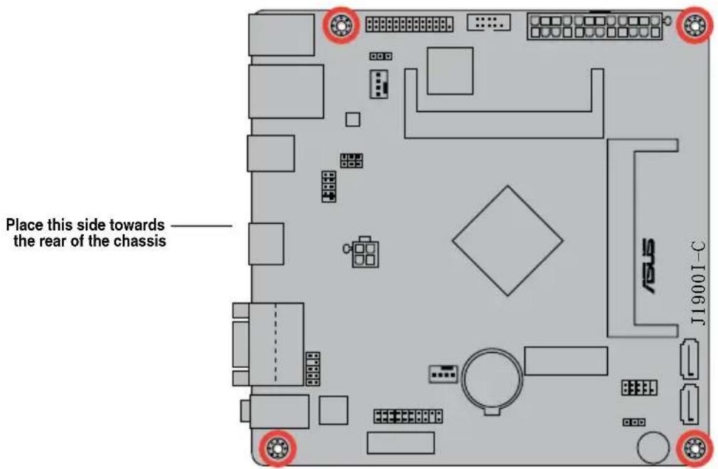
When installing the motherboard, ensure that you place it into the chassis in the correct orientation. The edge with external ports goes to the rear part of the chassis as indicated in the image below.
1.2.2 Screw holes
Place four screws into the holes indicated by circles to secure the motherboard to the chassis.

Do not overtighten the screws! Doing so can damage the motherboard.
text_image
Place this side towards the rear of the chassis J19001-C1.2.3 Motherboard layout
text_image
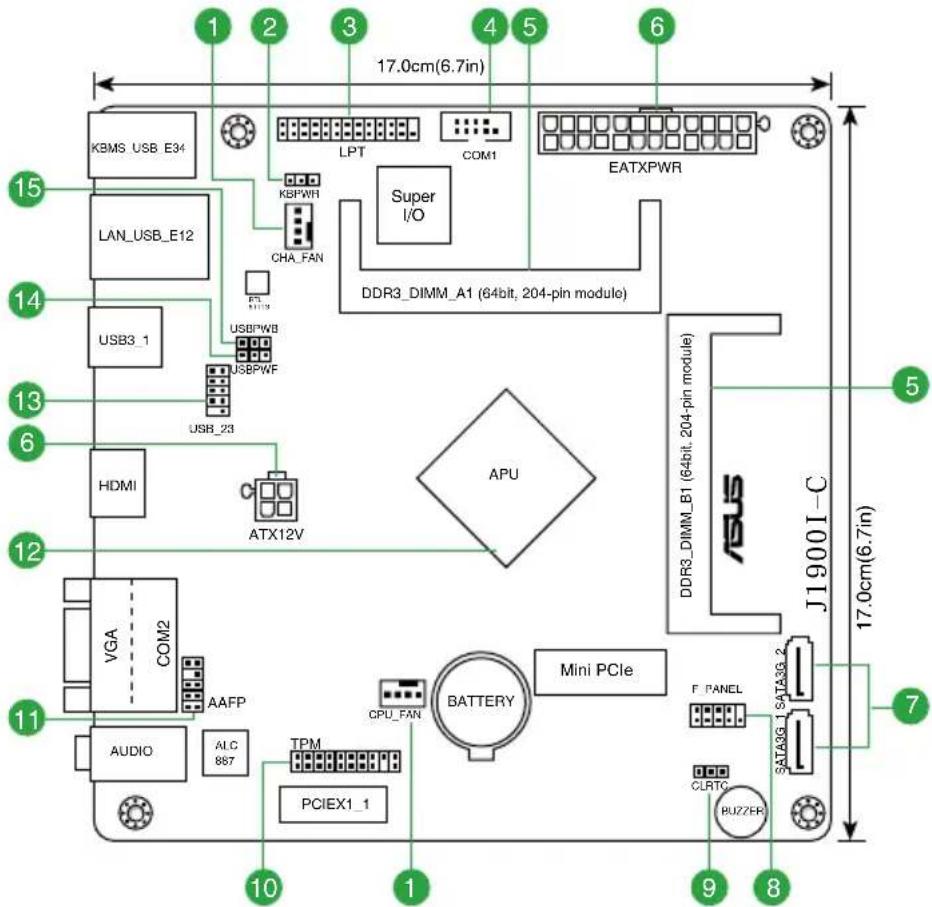
1 2 3 4 5 6 17.0cm(6.7in) KBMS USB E34 LAN_USB_E12 USB3_1 USB3_23 HDMI VGA COM2 AAFP AUDIO ALC 887 TPM PCIEX1_1 ATX12V LPT KBPWR CHA_FAN USBPWB USBPWF Super I/O DDR3_DIMM_A1 (64bit, 204-pin module) EATXPWR APU BATTERY Mini PCIe CPU_FAN F PANEL SATA3G_2 CLRTG BUZZER J19001-C 5 17.0cm(6.7in) 71.2.4 Layout contents
| Connectors/Jumpers/Slots/LED Page | |
| 1. CPU and chassis fan connectors (4-pin CPU_FAN, 4-pin CHA_FAN) 1-13 | |
| 2. Keyboard power (3-pin KBWR) 1-8 | |
| 3. LPT connector (26-1 pin LPT) 1-12 | |
| 4. COM port connector (10-1 pin COM1) 1-11 | |
| 5. DDR3 SO-DIMM sockets 1-4 | |
| 6. ATX power connectors (24-pin EATXPWR, 4-pin ATX12V) 1-12 | |
| 7. Serial ATA 3.0Gb/s connectors (7-pin SATA3G1~2) 1-14 | |
| 8. System panel connector (10-1 pin F_PANEL) | 1-15 |
| 9. Clear RTC RAM (3-pin CLRTC) | 1-7 |
| 10. TPM connector (20-1 pin TPM) 1-14 | |
| 11. Front panel audio connector (10-1 pin AAFP) | 1-11 |
| 12. Intel® Celeron Dual-core Processor J1900 | 1-4 |
| 13. USB 2.0 connector (10-1 pin USB_23) | 1-13 |
| 14. USB device wake-up (3-pin USBPWF) | 1-8 |
| 15. USB device wake-up (3-pin USBPWB) | 1-8 |
1.3 Central Processing Unit (CPU)
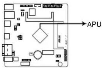
The motherboard comes with an onboard Intel® Celeron™ Dual-core Processor J1900 and a specially designed CPU heatsink.
text_image
APUJ1900I-C APU
1.4 System memory
1.4.1 Overview
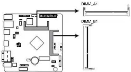
This motherboard comes with two Double Data Rate 3 (DDR3) Small Outline Dual Inline Memory Modules (SO-DIMM) sockets. The figure illustrates the location of the DDR3 DIMM sockets:
text_image
DIMM_A1 DIMM_B1J1900I-C 204-pin DDR3 SO-DIMM sockets
Channel Sockets
Channel A DIMM_A1
Channel B DIMM_B1

- Using both memory channels is supported on this motherboard. When installing 2 SO-DIMMs, use the same size and type of memory. The DIMM_A1 slot should be filled in order for the motherboard to work properly.
- This model supports a maximum total memory of 8GB DDR3 1333 only. Memory modules with a voltage higher than 1.35V will run at 1.35V. DDR3 1066Mhz memory modules are not supported.
1.4.2 Memory configurations
You may install 1GB, 2GB, 4GB and 8GB unbuffered non-ECC DDR3 SO-DIMMs into the DIMM sockets.

- Always install DIMMs with the same CAS latency. For optimum compatibility, it is recommended that you obtain memory modules from the same vendor.
- This motherboard does not support DIMMs made up of 256 megabits (Mb) chips or less.
J1900I-C Series Motherboard Qualified Vendors Lists (QVL)
DDR3-1333 MHz capability
| Vendors Part No. Size SS/DS Chip Brand Chip NO. Timing Voltage | DIMM socket support (Optional)1 DIMM 2 DIMMs | |||||||
| CRUCIAL | CT102464BF1339.C16FER | 8GB | DS | CRUCIAL | CT512X8-1339 | -1.35V | ||
| G.SKILL | F3-1333C9D-8GSL | 4GB | DS | - | K4B2G0846C | 9-9-9-24 | 1.35V | • |
| GEIL | GGS38GB1333C9DC | 4GB | DS | HYNIX | H5TQ2G83CFR | 9-9-9-24 | 1.3V | • |
DDR3-1600 MHz capability
| Vendors | Part No. | Size | SS/DS | Chip Brand | Chip NO. | Timing | Voltage | DIMM socket support (Optional)1 DIMM 2 DIMMs |
| KINGSTON | KVR16LS11/4 | 4GB | DS | NANYA | NT5CC512M8CN-DI | - | 1.35V | • |
| SAMSUNG | M473B5773DHO-YKO 1251 | 2GB | DS | - | GEHXB8A3C | - | 1.35V | • |
| SAMSUNG | M471B5273EBO-CKO 1231 | 4GB | DS | - | SEC231BCKDK4B2GO846E | - | 1.35V | • |
| TRANSCEND | TS512MSK64W6H | 4GB | DS | - | K4B4G0846B | - | 1.35V | • |
| TRANSCEND | TS1GSK64W6H | 8GB | DS | - | K4B4G0846B | - | 1.35V | |
| ADATA | ADDS1600W4G11-B | 4GB | DS | ADATA | QWND-1211AEL1329V | - | 1.35V | • |
| ADATA | ADDS1600W8G11-B | 8GB | DS | ADATA | QWND-1211AEL1329V | - | 1.35V | |
| PQI | MFCDR521UA0101 | 4GB | DS | PQI | PQD312O8D12R | - | 1.35V | • |
| PQI | MFCDR621UA0103 | 8GB | DS | PQI | PQD312O8D12R | - | 1.35V |

SS: Single-sided / DS: Double-sided
DIMM support:
• A*: Supports one module inserted into either slot.
- B*: Supports one pair of modules inserted into both the slots.

- Using both memory channels is supported on this motherboard. When installing 2 SO-DIMMs, use the same size and type of memory. The DIMM_A1 slot should be filled in order for the motherboard to work properly.
• Memory modules with a voltage higher than 1.35V will run at 1.35V. - When installing memory with frequency higher than 1333Mhz, the motherboard will automatically run the memory at 1333Mhz. DDR3 1066Mhz memory modules are not supported.

Visit the ASUS website at www.asus.com for the latest QVL.
1.5 Expansion slots
In the future, you may need to install expansion cards. The following sub-sections describe the slots and the expansion cards that they support.

Unplug the power cord before adding or removing expansion cards. Failure to do so may cause you physical injury and damage motherboard components.
1.5.1 Installing an expansion card
To install an expansion card:
- Before installing the expansion card, read the documentation that came with it and make the necessary hardware settings for the card.
- Remove the system unit cover (if your motherboard is already installed in a chassis).
- Remove the bracket opposite the slot that you intend to use. Keep the screw for later use.
- Align the card connector with the slot and press firmly until the card is completely seated on the slot.
- Secure the card to the chassis with the screw you removed earlier.
- Replace the system cover.
1.5.2 Configuring an expansion card
After installing the expansion card, configure it by adjusting the software settings.
- Turn on the system and change the necessary BIOS settings, if any. See Chapter 2 for information on BIOS setup.
- Assign an IRQ to the card.
- Install the software drivers for the expansion card.
1.5.3 PCI Express 2.0 x1 slot
This motherboard supports PCI Express 2.0 x1 network cards, SCSI cards, and other cards that comply with the PCI Express specifications.
IRQ assignments for this motherboard
| Component A B C D E F G H | |
| SATA Controller --- shared ---- | |
| HD Audio ---- shared - | |
| USB 3.0 | ---- shared ---- |
| USB 2.0 | ---- shared |
| LAN | - shared ---- |
| PCIE x1_1 | -- shared ---- |
| WLAN | --- shared ---- |
1.6 Jumpers
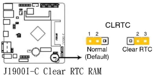
1. Clear RTC RAM (3-pin CLRTC)
This jumper allows you to clear the Real Time Clock (RTC) RAM in CMOS. You can clear the CMOS memory of date, time, and system setup parameters by erasing the CMOS RTC RAM data. The onboard button cell battery powers the RAM data in CMOS, which include system setup information such as system passwords.
text_image
J1900I-C Clear RTC RAM CLRTC 1 2 Normal (Default) 2 3 Clear RTCTo erase the RTC RAM:
- Turn OFF the computer and unplug the power cord.
- Move the jumper cap from pins 1-2 (default) to pins 2-3. Keep the cap on pins 2-3 for about 5-10 seconds, then move the cap back to pins 1-2.
- Plug the power cord and turn ON the computer.
- Hold down the
key during the boot process and enter BIOS setup to re-enter data.

Except when clearing the RTC RAM, never remove the cap on CLRTC jumper default position. Removing the cap will cause system boot failure!

- If the steps above do not help, remove the onboard battery and move the jumper again to clear the CMOS RTC RAM data. After clearing the CMOS, reinstall the battery.
- You do not need to clear the RTC when the system hangs due to overclocking. For system failure due to overclocking, use the CPU Parameter Recall (C.P.R.) feature. Shut down and reboot the system, then the BIOS automatically resets parameter settings to default values.
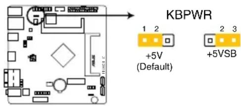
2. Keyboard power (3-pin KBPWR)
This jumper allows you to enable or disable the keyboard wake-up feature. When you set this jumper to pins 2–3 (+5VSB), you can wake up the computer by pressing a key on the keyboard. This feature requires an ATX power supply that can supply at least 1A on the +5VSB lead, and a corresponding setting in the BIOS.
text_image
KBPWR 1 2 +5V (Default) 2 3 +5VSBJ1900I-C Keyboard power setting
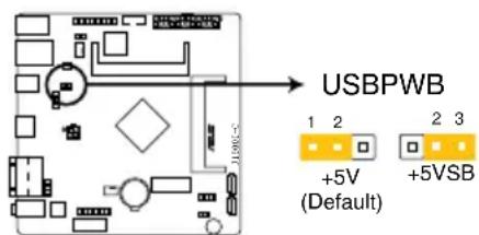
3. USB device wake-up (3-pin USBPWB)
Set this jumper to +5V to wake up the computer from S1 sleep mode (CPU stopped, DRAM refreshed, system running in low power mode) using the connected USB devices. Set to +5VSB to wake up from S3 and S4 sleep modes (no power to CPU, DRAM in slow refresh, power supply in reduced power mode).
text_image
USBPWB 1 2 +5V (Default) 2 3 +5VSBJ1900I-C USB device wake up
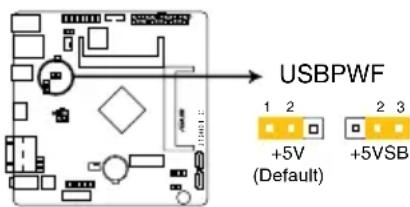
4. USB device wake-up (3-pin USBPWF)
Set this jumper to +5V to wake up the computer from S1 sleep mode (CPU stopped, DRAM refreshed, system running in low power mode) using the connected USB devices. Set to +5VSB to wake up from S3 and S4 sleep modes (no power to CPU, DRAM in slow refresh, power supply in reduced power mode).
text_image
USBPWF 1 2 3 +5V (Default) +5VSBJ1900I-C USB device wake up
1.7 Connectors
1.7.1 Rear panel connectors
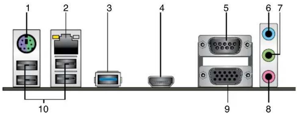
text_image
1 2 3 4 5 6 7 8 9 10- PS/2 Keyboard / Mouse Combo port. This port is for a PS/2 keyboard or mouse.
- LAN (RJ-45) port. This port allows Gigabit connection to a Local Area Network (LAN) through a network hub. Refer to the table below for the LAN port LED indications.
LAN port LED indications
| Activity/Link LED | Speed LED | ||
| Status Description Status Description | |||
| OFF No link | OFF 10Mbps connection | ||
| ORANGE Linked ORANGE | 100Mbps connection | ||
| BLINKING Data activity GREEN | 1Gbps connection | ||
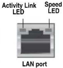
text_image
Activity Link LED Speed LED LAN port- USB 3.0 port. This 9-pin Universal Serial Bus (USB) ports is available for connecting USB 3.0 devices.

- DO NOT connect a keyboard / mouse to any USB 3.0 port when installing a Windows operating system.
- Due to USB 3.0 controller limitations, USB 3.0 devices can only be used under a Windows® OS environment after installing the USB 3.0 driver.
- USB 3.0 devices can be used for data storage only.
-
We strongly recommend that you connect USB 3.0 devices to USB 3.0 ports for a faster and better performance from your USB 3.0 devices.
-
HDMI port. This port is for a High-Definition Multimedia Interface (HDMI) connector, and is HDCP compliant allowing playback of HD DVD, Blu-Ray, and other protected content.
-
Serial port (COM2). This port connects a modem, or other devices that conform with serial specification.
- Line In port (light blue). This port connects to a tape, CD, DVD player, or other audio source.
- Line Out port (lime). This port connects to a headphone or a speaker. In the 4.1, 5.1, and 7.1-channel configurations, the function of this port becomes Front Speaker Out.
- Microphone port (pink). This port connects to a microphone.

Refer to the audio configuration table for the function of the audio ports in a 2.1, 4.1, 5.1 or 7.1-channel configuration.
Audio 2.1, 4.1, 5.1 or 7.1-channel configuration
| Port | Headset2.1-channel | 4.1-channel 5.1-channel 7.1-channel | |
| Light Blue(Rear panel) | Line In Rear Speaker Out Rear Speaker Out Rear Speaker Out | ||
| Lime (Rear panel) | Line Out Front Speaker Out Front Speaker Out Front Speaker Out | ||
| Pink (Rear panel) | Mic In Mic In Bass/Center Bass/Center | ||
| Lime (Front panel) | — — | — Side Speaker Out | |

To configure an 8-channel audio output:
Use a chassis with HD audio module in the front panel to support an 8-channel audio output.
- Video Graphics Adapter (VGA) port. This 15-pin port is for a VGA monitor or other VGA-compatible devices
- USB 2.0 ports 1\~4. These four 4-pin Universal Serial Bus (USB) ports are for USB 2.0/1.1 devices.
1.7.2 Internal connectors
1. Front panel audio connector (10-1 pin AAFP)
This connector is for a chassis-mounted front panel audio I/O module that supports either HD Audio or legacy AC'97 audio standard. Connect one end of the front panel audio I/O module cable to this connector.
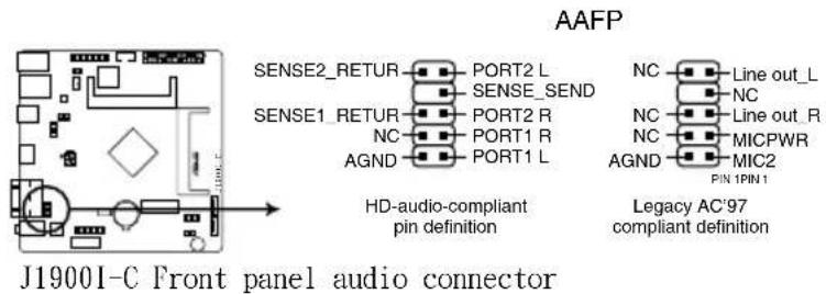
text_image
AAFP SENSE2_RETUR PORT2 L SENSE1_RETUR SENSE_SEND NC PORT2 R AGND PORT1 R PORT1 L HD-audio-compliant pin definition NC Line out_L NC Line out_R NC MICPWR AGND MIC2 PIN 1PIN 1 Legacy AC'97 compliant definition J1900I-C Front panel audio connector
- We recommend that you connect a high-definition front panel audio module to this connector to avail of the motherboard's high-definition audio capability.
- If you want to connect a high-definition front panel audio module to this connector, set the Front Panel Type item in the BIOS setup to [HD]. If you want to connect an AC'97 front panel audio module to this connector, set the item to [AC97]. By default, this connector is set to [HD]. See section 2.5.6 Onboard Devices Configuration for details.
2. Serial port connector (10-1 pin COM1)
This connector is for a serial (COM) port. Connect the serial port module cable to this connector, then install the module to a slot opening at the back of the system chassis.
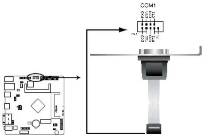
text_image
COM1 RXO DTR DSR CTS PIN1 DCO TXO CNO RTS RIJ1900I-C Serial port connectors
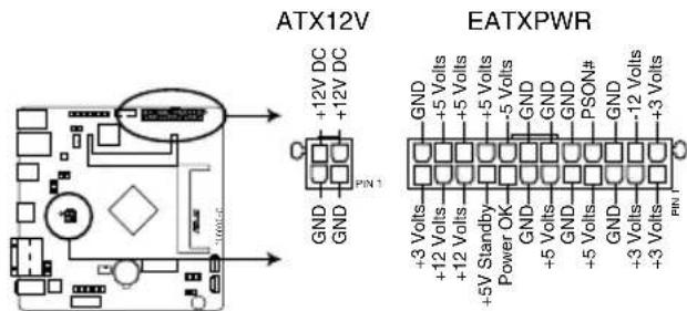
3. ATX power connectors (24-pin EATXPWR, 4-pin ATX12V)
These connectors are for ATX power supply plugs. The power supply plugs are designed to fit these connectors in only one orientation. Find the proper orientation and push down firmly until the connectors completely fit.
text_image
ATX12V +12V DC +12V DC GND GND PN 1 EATXPWR GND +5 Volts +5 Volts +5 Volts GND GND GND PSON# GND +3 Volts +12 Volts +12 Volts +5V Standby Power OK GND GND GND +5 Volts +5 Volts GND GND +3 Volts +3 Volts PN 1J1900I-C ATX power connectors

- For a fully configured system, we recommend that you use a power supply unit (PSU) that complies with ATX 12 V Specification 2.0 (or later version) and provides a minimum power of 350 W.
- DO NOT forget to connect the 4-pin ATX +12V power plug. Otherwise, the system will not boot up.
- We recommend that you use a PSU with higher power output when configuring a system with more power-consuming devices. The system may become unstable or may not boot up if the power is inadequate.
- If you are uncertain about the minimum power supply requirement for your system, refer to the Recommended Power Supply Wattage Calculator at http://support.asus.com/PowerSupplyCalculator/PSCalculator.aspx?SLanguage=en-us for details.
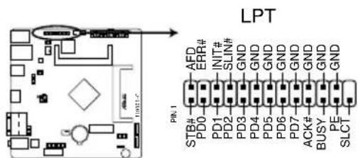
4. LPT connector (26-1 pin LPT)
The LPT (Line Printing Terminal) connector supports devices such as a printer. LPT is standardized as IEEE 1284, which is the parallel port interface on IBM PC-compatible computers.
text_image
LPT PIN 1 AFD ERR# INT# SLIN# GND GND GND GND GND GND GND GND GND GND GND GND GND GND GND GND GND GND GND GND GND GND GND GND GND GND GND GND GND GND GND GND GND GND SLCJ1900I-C Parallel port connector
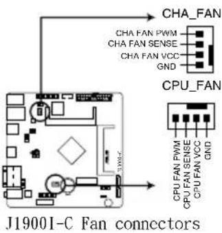
5. CPU and chassis fan connectors (4-pin CPU\_FAN, 4-pin CHA\_FAN)
Connect the fan cables to the fan connectors on the motherboard, ensuring that the black wire of each cable matches the ground pin of the connector.
text_image
CHA_FAN CHA FAN PWM CHA FAN SENSE CHA FAN VCC GND CPU_FAN J19001-C Fan connectors CPU FAN PWM CPU FAN SENSE CPU FAN VCC GND
Do not forget to connect the fan cables to the fan connectors. Insufficient air flow inside the system may damage the motherboard components. These are not jumpers! Do not place jumper caps on the fan connectors!
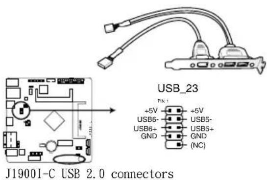
6. USB 2.0 connector (10-1 pin USB\_23)
This connector is for USB 2.0 ports. Connect the USB module cable to this connector, then install the module to a slot opening at the back of the system chassis. This USB connector complies with USB 2.0 specification that supports up to 480 Mbps connection speed.
text_image
USB_23 PIN-1 +5V USB6- USB6+ GND +5V USB5- USB5+ GND (NC) J19001-C USB 2.0 connectors
Never connect a 1394 cable to the USB connector. Doing so will damage the motherboard!

The USB module cable is purchased separately.
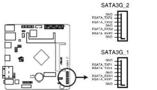
7. Serial ATA 3.0Gb/s connectors (7-pin SATA3G\_1/2)
These connectors connect to Serial ATA 3.0 Gb/s hard disk drive or optical drive via Serial ATA 3.0 Gb/s signal cables.
text_image
SATA3G_2 GND RSATA_TXP2 RSATA_TXN2 GND RSATA_RXN2 RSATA_RXP2 GND SATA3G_1 GND RSATA_TXP1 RSATA_TXN1 GND RSATA_RXN1 RSATA_RXP1 GNDJ1900I-C SATA 3.0Gb/s connectors

- To configure the default SATA type in BIOS, click Advanced Mode > Advanced tab > SATA Configuration > SATA Mode.
- When using hot-plug and NCQ, set the SATA Mode item in the BIOS to [AHCI Mode]. See section 2.5.3 SATA Configuration for details.
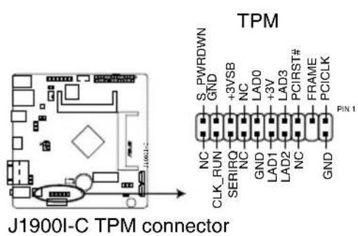
8. TPM connector (20-1 pin TPM)
This connector supports a Trusted Platform Module (TPM) system, which can securely store keys, digital certificates, passwords and data. A TPM system also helps enhance network security, protects digital identities, and ensures platform integrity.
text_image
TPM S_PWRDWN GND +3VSB NC LAD0 +3V LAD3# PCIRST# FRAME PCCLK PIN 1 NC CLK_RUN SERIRQ NC GND LAD1 LAD2 NC GND J1900I-C TPM connector9. System panel connector (10-1 pin F\_PANEL)
This connector supports several chassis-mounted functions.

text_image
F_PANEL +PWR LED PWR BTN PWR_LED+ PWR_LED- GND PIN 1 HDD_LED+ HDD_LED- Ground HWRST# (NC) +HDD_LED RESETJ1900I-C System panel connector
• System power LED (2-pin PWRLED)
This 2-pin connector is for the system power LED. Connect the chassis power LED cable to this connector. The system power LED lights up when you turn on the system power, and blinks when the system is in sleep mode.
• Hard disk drive activity LED (2-pin +HDLED)
This 2-pin connector is for the HDD Activity LED. Connect the HDD Activity LED cable to this connector. The HD LED lights up or flashes when data is read from or written to the HDD.
• ATX power button/soft-off button (2-pin PWRBTN)
This connector is for the system power button.
- Reset button (2-pin RESET)
This 2-pin connector is for the chassis-mounted reset button for system reboot without turning off the system power.
1.8 Software support
1.8.1 Installing an operating system
This motherboard supports Windows ^® 8 64-bit and Windows ^® 8.1 64-bit only. Always install the latest OS version and corresponding updates to maximize the features of your hardware.

Motherboard settings and hardware options vary. Refer to your OS documentation for detailed information.
1.8.2 Support DVD information
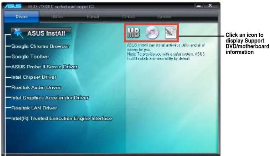
The Support DVD that comes with the motherboard package contains the drivers, software applications, and utilities that you can install to avail all motherboard features.

The contents of the Support DVD are subject to change at any time without notice. Visit the ASUS website at www.asus.com for updates.
To run the Support DVD
Place the Support DVD into the optical drive. If Autorun is enabled in your computer, the DVD automatically displays the Specials screen which contains the unique features of ASUS motherboard. Click Drivers, Utilities, Manual, and Contact tabs to display their respective menus.

The following screen is for reference only.
text_image
ASUS J1900 C motherboard support CD Drivers Utility Manual Contact Specials ASUS InstAll Google Chrome Browser Google Toolbar ASUS Probe II Sense Driver Intel Chipset Driver Realtek Audio Driver Intel Graphics Accelerator Driver Realtek LAN Driver Intel(R) Trusted Execution Engine Interface MB ASUS InstAll can install anti-virus utility and all of drivers for you. Notes: To provide you with a safer system, ASUS InstAll installs anti-virus utility by default. Click an icon to display Support DVD/motherboard informationClick an item to install

If Autorun is NOT enabled in your computer, browse the contents of the Support DVD to locate the file ASSETUP.EXE from the BIN folder. Double-click the ASSETUP.EXE to run the DVD.
BIOS information
2.1 Managing and updating your BIOS

Save a copy of the original motherboard BIOS file to a USB flash disk in case you need to restore the BIOS in the future. Copy the original motherboard BIOS using the ASUS Update utility.
2.1.1 EZ Update
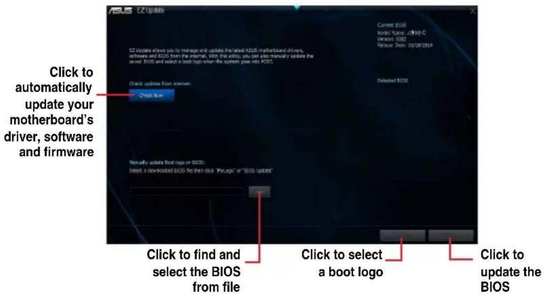
EZ Update is a utility that allows you to automatically update your motherboard's softwares, drivers and the BIOS version easily. With this utility, you can also manually update the saved BIOS and select a boot logo when the system goes into POST.
To launch EZ Update, click EZ Update on the AI Suite 3 main menu bar.
text_image
EZ Update EZ Update allows you to manage and update the latest BIOS motherboard driver, software and BIOS from the internet. With this info, you can also manually update the latest BIOS and select a boot logo when the system goes into BIOS. Current BIOS Model Name: J1800-C Version: 0302 Release Date: 02/26/2014 Check up from internet: Selected BIOS Click to find and select the BIOS from file Click to select a boot logo Click to update the BIOS
EZ Update requires an Internet connection either through a network or an ISP (Internet Service Provider).
2.1.2 ASUS EZ Flash 2
The ASUS EZ Flash 2 feature allows you to update the BIOS without using an OS-based utility.

Before you start using this utility, download the latest BIOS file from the ASUS website at www.asus.com.
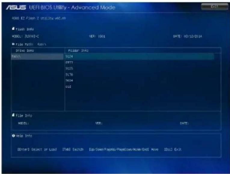
To update the BIOS using EZ Flash 2:
- Insert the USB flash disk that contains the latest BIOS file to the USB port.
- Enter the Advanced Mode of the BIOS setup program. Go to the Tool menu to select ASUS EZ Flash 2 Utility and press
to enable it. - Press
to switch to the Drive field. - Press the Up/Down arrow keys to find the USB flash disk that contains the latest BIOS, and then press
. - Press
to switch to the Folder Info field. - Press the Up/Down arrow keys to find the BIOS file, and then press
to perform the BIOS update process. Reboot the system when the update process is done.

- This function supports USB flash disks formatted using FAT32/16 on a single partition only.
- Ensure to load the BIOS default settings to ensure system compatibility and stability. Select the Load Optimized Defaults item under the Exit menu.
- DO NOT shut down or reset the system while updating the BIOS to prevent system boot failure!
text_image
ASUS UEFI BIOS Utility - Advanced Mode RDS E2 Flash 2 utility wEC.00 Flash Info MODEL: J19401-C VER: 1001 DATE: 03/12/2014 File Path: 450% Drive Info F0104: INFO Model: 9124 0077 9125 9176 9014 010 File Info Model: VER: DATE: Help Info [Enter] Select or Load [TnA] Switch [Up/Down/Page/Down/Page/Down/Home/End] Move [Dsi] Exit
Reboot the system after updating the BIOS using EZ Flash 2 to ensure that the USB 3.0 ports work properly.
2.1.3 ASUS CrashFree BIOS 3 utility
The ASUS CrashFree BIOS 3 is an auto recovery tool that allows you to restore the BIOS file when it fails or gets corrupted during the updating process. You can restore a corrupted BIOS file using the motherboard support DVD or a USB flash drive that contains the updated BIOS file.

- Before using this utility, rename the BIOS file in the removable device into J1900IC.CAP.
- The BIOS file in the support DVD may not be the latest version. Download the latest BIOS file from the ASUS website at www.asus.com.
Recovering the BIOS
To recover the BIOS:
- Turn on the system.
- Insert the support DVD to the optical drive or the USB flash drive that contains the BIOS file to the USB port.
- The utility automatically checks the devices for the BIOS file. When found, the utility reads the BIOS file and enters ASUS EZ Flash 2 utility automatically.
- The system requires you to enter BIOS Setup to recover BIOS settings. To ensure system compatibility and stability, we recommend that you press
to load default BIOS values.

DO NOT shut down or reset the system while updating the BIOS! Doing so can cause system boot failure!
2.1.4 ASUS BIOS Updater
The ASUS BIOS Updater allows you to update BIOS in a DOS environment. This utility also allows you to copy the current BIOS file that you can use as a backup when the BIOS fails or gets corrupted during the updating process.

The succeeding utility screens are for reference only. The actual utility screen displays may not be same as shown.
Before updating BIOS
- Prepare the motherboard support DVD and a USB flash drive formatted using FAT32/16 on a single partition.
- Download the latest BIOS file and BIOS Updater from the ASUS website at http://support.asus.com and save them on the USB flash drive.

NTFS is not supported under DOS environment. Do not save the BIOS file and BIOS Updater to a hard disk drive or USB flash drive in NTFS format.
- Turn off the computer and disconnect all SATA hard disk drives (optional).
Booting the system to a DOS environment
- Insert the DOS-bootable USB flash drive with the latest BIOS file and BIOS Updater to your computer's USB port.
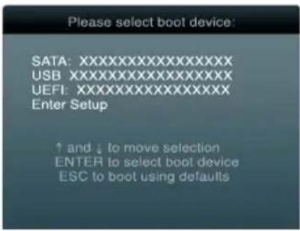
- Boot your computer. When the ASUS Logo appears, press
to show the BIOS Boot Device Select Menu.
text_image
Please select boot device: SATA:XXXXXXXXXXXXXX USB:XXXXXXXXXXXXXX UEFI:XXXXXXXXXXXXXX Enter Setup ↑ and ↓ to move selection ENTER to select boot device ESC to boot using defaults- Select the USB flash drive as the boot device. The DOS screen appears.
Welcome to FreeDOS (http://www.freedos.org)!
C:\>d:
D:\>
Updating the BIOS file
To update the BIOS file using BIOS Updater:
- At the FreeDOS prompt, type bupdater /pc /g and press
.
D:\>bupdater /pc /g
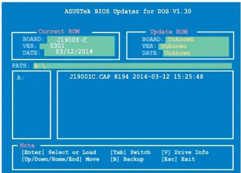
- The BIOS Updater screen appears as below.
text_image
ASUSTek BIOS Updater for DOS V1.30 Current ROM BOARD: J1900I-C VER: 0301 DATE: 03/12/2014 Update ROM BOARD: Unknown VER: Unknown DATE: Unknown PATH: A: A: J1900IC.CAP 8194 2014-03-12 15:25:48 Note [Enter] Select or Load [Tab] Switch [V] Drive Info [Up/Down/Home/End] Move [B] Backup [Esc] Exit- Press
to switch between screen fields and use the keys to select the BIOS file and press . BIOS Updater checks the selected BIOS file and prompts you to confirm BIOS update.

text_image
Are you sure to update BIOS? Yes No- Select Yes and press
. When BIOS update is done, press to exit BIOS Updater. Restart your computer.

DO NOT shut down or reset the system while updating the BIOS to prevent system boot failure!

- For BIOS Updater version 1.30 or later, the utility automatically exits to the DOS prompt after updating BIOS.
- Ensure to load the BIOS default settings to ensure system compatibility and stability. Select the Load Optimized Defaults item under the Exit menu. Refer to section 2.10 Exit menu for details.
- Ensure to connect all SATA hard disk drives after updating the BIOS file if you have disconnected them.
2.2 BIOS setup program
Use the BIOS Setup program to update the BIOS or configure its parameters. The BIOS screens include navigation keys and brief online help to guide you in using the BIOS Setup program.
Entering BIOS Setup at startup
To enter BIOS Setup at startup:
- Press
Entering BIOS Setup after POST
To enter BIOS Setup after POST:
- Press
+ + simultaneously. - Press the reset button on the system chassis.
- Press the power button to turn the system off then back on. Do this option only if you failed to enter BIOS Setup using the first two options.

Using the power button, reset button, or the keys to force reset from a running operating system can cause damage to your data or system. We recommend to always shut down the system properly from the operating system.

- The BIOS setup screens shown in this section are for reference purposes only, and may not exactly match what you see on your screen.
- Ensure that a USB mouse is connected to your motherboard if you want to use the mouse to control the BIOS setup program.
- The default BIOS settings for this motherboard apply for most conditions to ensure optimum performance. If the system becomes unstable after changing any BIOS settings, load the default settings to ensure system compatibility and stability. Select the Load Optimized Defaults item under the Exit Menu. See section 2.10 Exit Menu.
- If the system fails to boot after changing any BIOS setting, try to clear the CMOS and reset the motherboard to the default value. Refer to section 1.6 Jumpers on how to erase the RTC RAM.
- The BIOS setup program does not support the bluetooth devices.
BIOS menu screen
The BIOS setup program can be used under two modes: EZ Mode and Advanced Mode. You can change modes from the Exit menu or from the Exit/Advanced Mode button in the EZ Mode/Advanced Mode screen.
EZ Mode
By default, the EZ Mode screen appears when you enter the BIOS setup program. The EZ Mode provides you an overview of the basic system information, and allows you to select the display language, system performance mode and boot device priority. To access the Advanced Mode, click Exit/Advanced Mode, then select Advanced Mode or press F7 for the advanced BIOS settings.
Selects the display language of the BIOS setup program

text_image
Displays the CPU temperature, CPU voltage output, DRAM information, and CPU/chassis fan speed Exits the BIOS setup program without saving the changes, saves the changes and resets the system, or enters the Advanced Mode ASUS UEFI BIOS Utility - EZ Mode 10:44:32 J19001-C BIOS Version: 0301 CPU Type: Intel(R) Celern(R) CPU J1900 Q 1.59GHz Speed: 1999MHz Total Memory: 2048 MB (DDR3 1333MHz) CPU Information DRAM Information Fan Temp. +104.0°F/+40.0°C DIMM_A1:Nynix 2048MB 1333MHz CPU_FAN N/A Voltage 0.898V DIMM_B1:N/A CHA_FAN N/A Q-Fan Control Silent Standard Turbo Boot Priority Use the mouse to drag or keyboard to navigate to decide the boot priority. UEFI Shortcut(F8) Advanced Mode(F7) SATA Information Boot Menu(F6) Default(F5) Selects the boot device priority Displays the Advanced mode functions Selects the Advanced mode functions Silent mode Displays SATA details Selects the boot device priority Loads optimized default Turbo mode
Advanced Mode
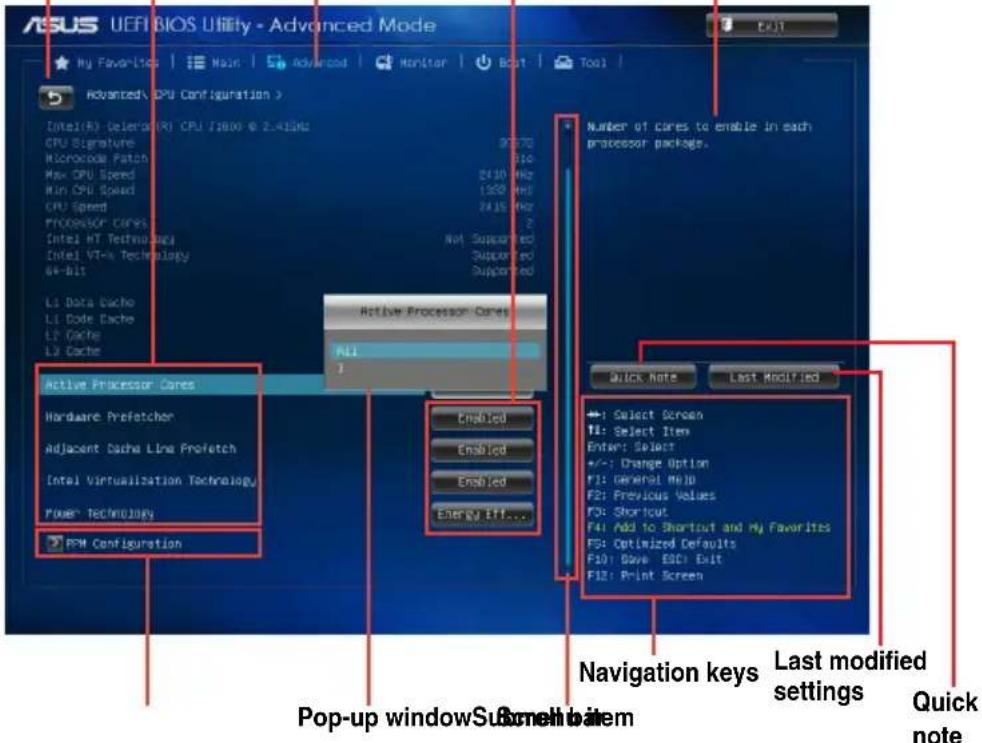
The Advanced Mode provides advanced options for experienced end-users to configure the BIOS settings. The figure below shows an example of the Advanced Mode. Refer to the following sections for the detailed configurations.

To access the EZ Mode, click Exit, then select ASUS EZ Mode.
General helpMenu bar Configuration fieldsMenu it
text_image
ASUS UEFI BIOS Utility - Advanced Mode My Favorites | Main | Advanced | Monitor | Boot | Tool | Advanced/ CPU Configuration > Intel(R)Select(A)(R)CPU 71800 @ 2.41GHz CPU Signature Microcode Patch Max CPU Speed Run CPU Speed CPU Speed Processor cores Intel HT Technol.pdc Intel VT-x Technology Alt-bit Li Data Cache Li Data Cache Li Cache Li Cache Active Processor Cores Hardware Prefetcher Adjacent Dacha Line Prefetch Intel Virtualization Technology Power Technology PPM Configuration Number of cores to enable in each processor package. Active Processor Cores ALL 1 Enabled Enabled Enabled Energy Eff... Quick Note Last Modified ←: Select Screen TI: Select Item Enter: Select +/-: Change Option F1: General Help F2: Previous Values F3: Shortcut F4: Add to Shortcut and My Favorites F5: Optimized Defaults F6: Optimized Defaults F7: Save ESCI Exit F8: Print Screen Navigation keys Last modified settings Quick note Pop-up window Sudan screen to itemMenu bar
The menu bar on top of the screen has the following main items:
| My Favorites For saving the frequently-used system settings and configuration |
| Main For changing the basic system configuration |
| Advanced For changing the advanced system settings |
| Monitor For displaying the system temperature, power status, and changing the fan settings |
| Boot For changing the system boot configuration |
| Tool For configuring options for special functions |
| Exit For selecting the exit options and loading default settings |
Menu items
The highlighted item on the menu bar displays the specific items for that menu. For example, selecting Main shows the Main menu items.
The other items (Ai Tweaker, Advanced, Monitor, Boot, Tool, and Exit) on the menu bar have their respective menu items.
Back button
This button appears when entering a submenu. Press
Submenu items
A greater than sign (>) before each item on any menu screen means that the item has a submenu. To display the submenu, select the item and press
Pop-up window
Select a menu item and press
Scroll bar
A scroll bar appears on the right side of a menu screen when there are items that do not fit on the screen. Press the Up/Down arrow keys or
Navigation keys
At the bottom right corner of the menu screen are the navigation keys for the BIOS setup program. Use the navigation keys to select items in the menu and change the settings.
General help
At the top right corner of the menu screen is a brief description of the selected item.
Configuration fields
These fields show the values for the menu items. If an item is user-configurable, you can change the value of the field opposite the item. You cannot select an item that is not user-configurable.
A configurable field is highlighted when selected. To change the value of a field, select it and press
Quick Note button
This button allows you to enter notes of the activities that you have done in BIOS.
Last Modified button
This button shows the items that you last modified and saved in BIOS Setup.
2.3 My Favorites
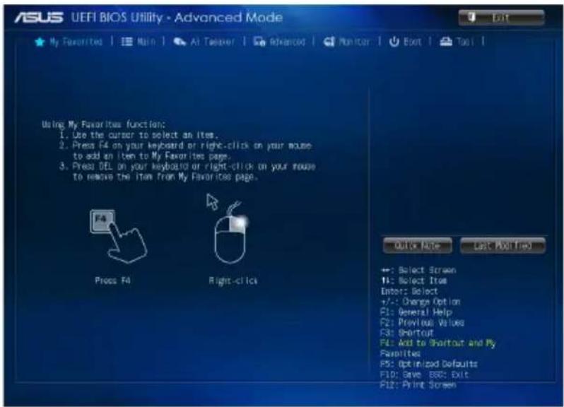
MyFavorites is your personal space where you can easily save and access your favorite BIOS items.
text_image
ASUS UEFI BIOS UTILITY - Advanced Mode + My Favorites | Main | At Tæveer | Advanced | Monitor | Exit | Tap | Using My Favorites function: 1. Use the cursor to select an item. 2. Press F4 on your keyboard or right-click on your mouse to add an item to My Favorites page. 3. Press DEL on your keyboard or right-click on your mouse to remove the item from My Favorites page. Press F4 Right-click Quick Note Last Modified +: Select Screen 14: Select Item Enter: Select +/-: Change Option F1: General Help F2: Previous Values F3: Shortcut F4: Add to Shortcut and My Preferences F5: Optimized Defaults F10: Save ESC: Exit F12: Print ScreenAdding items to My Favorites
To add frequently-used BIOS items to My Favorites:
- Use the arrow keys to select an item that you want to add. When using a mouse, hover the pointer to the item.
- Press
on your keyboard or right-click on your mouse to add the item to My Favorites page.

You cannot add the following items to My Favorites:
- Items with submenu options
- User-configurable items such as language and boot device order
- Configuration items such as Memory SPD Information, system time and date
2.4 Main menu
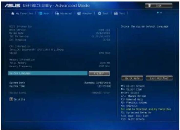
The Main menu screen appears when you enter the Advanced Mode of the BIOS Setup program. The Main menu provides you an overview of the basic system information, and allows you to set the system date, time, language, and security settings.
text_image
ASUS UEFI BIOS UNIFY - Advanced Mode Hi Favorites | Main | Advanced | Monitor | Start | Tool BIID Information BIOS Version Build Data Test Fx Version Set Operating CPU Information Details: Deformation(M) CPU /JF500 8.2.700Gb Speed Memory Information Total Memory Memory Frequency System Loadset English System Data System Time Release Time Security Thursday 02/10/2014 [05-95:18] new/distribution Choose the custom default language Quick Note Last Modified +/- Select Screen MI: Select Item Enter Select +/- Change Option F10 General Help F20 Previous Values F30 Shortcut F40 And to Shortcut and My Favorites F50 Updated Defaults F60 Save ESC: Exit F10 Print Screen2.4.1 System Language [English]
Allows you to choose the BIOS language version from the options. Configuration options:
[English] [F[Españo)] [Peydskh] [简体中文] [繁體中文] [日本語] 한국어]
2.4.2 System Date [Day xx/xx/xxxx]
Allows you to set the system date.
2.4.3 System Time [xx:xx:xx]
Allows you to set the system time.
2.4.4 Security
The Security menu items allow you to change the system security settings.
- If you have forgotten your BIOS password, erase the CMOS Real Time Clock (RTC) RAM to clear the BIOS password. See section 1.6 Jumpers for information on how to erase the RTC RAM.
- The Administrator or User Password items on top of the screen show the default Not Installed. After you set a password, these items show Installed.
Administrator Password
If you have set an administrator password, we recommend that you enter the administrator password for accessing the system. Otherwise, you might be able to see or change only selected fields in the BIOS setup program.
To set an administrator password:
- Select the Administrator Password item and press
. - From the Create New Password box, key in a password, then press
. - Confirm the password when prompted.
To change an administrator password:
- Select the Administrator Password item and press
. - From the Enter Current Password box, key in the current password, then press
. - From the Create New Password box, key in a new password, then press
. - Confirm the password when prompted.
To clear the administrator password, follow the same steps as in changing an administrator password, but press
User Password
If you have set a user password, you must enter the user password for accessing the system. The User Password item on top of the screen shows the default Not Installed. After you set a password, this item shows Installed.
To set a user password:
- Select the User Password item and press
. - From the Create New Password box, key in a password, then press
. - Confirm the password when prompted.
To change a user password:
- Select the User Password item and press
. - From the Enter Current Password box, key in the current password, then press
. - From the Create New Password box, key in a new password, then press
. - Confirm the password when prompted.
To clear the user password, follow the same steps as in changing a user password, but press
2.5 Advanced menu
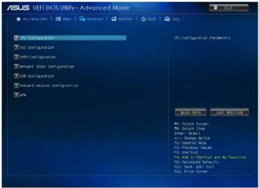
The Advanced menu items allow you to change the settings for the CPU and other system devices.

Be cautious when changing the settings of the Advanced menu items. Incorrect field values can cause the system to malfunction.
text_image
ASUS UEFI BIOS Utility - Advanced Mode My Favorites | Main | Advanced | Monitor | Boot | Tool | CPU Configuration SOC Configuration DATA Configuration Network Stock Configuration USB Configuration board devices configuration ARM CPU Configuration Parameters Quick Note Last MERIDLED +: Select Screen M: Select Item Enter: Select +/-: Change Option F1: General Help F2: Previous Values F3: Shortcut F4: Add to Shortcut and My Favorites FSF: Optimized Defaults F50: Save ESCF ENST F62: Print Screen2.5.1 CPU Configuration
The items in this menu show CPU-related information.
Active Processor Cores [All]
Allows you to choose the number of CPU cores to activate in each processor package.
Configuration options: [All] [1] [2] [3]
Hardware Prefetcher [Enabled]
[Disabled] Disables this function.
[Enabled] Allows you to turn on /off the Mid Level Cache (L2) streamer prefetcher.
Adjacent Cache Line Prefetch [Enabled]
[Disabled] Disables this function.
[Enabled] Allows a hardware platform to perform adjacent cache line prefetching.
Intel Virtualization Technology [Enabled]
[Enabled] Allows a hardware platform to run multiple operating systems separately and simultaneously, enabling one system to virtually function as several systems.
[Disabled] Disables this function.
PPM Configuration Parameters
EIST [Enabled]
Allows you to enable or disable Enhanced Intel® SpeedStep Technology (EIST).
[Disabled] The CPU runs at its default speed.
[Enabled] The operating system controls the CPU speed.
Turbo Mode [Enabled]
Allows you to enable or disable Turbo Mode.
[Disabled] Turbo Mode disabled.
[Enabled] Turbo Mode enabled.
CPU C State Report [Enabled]
Allows you to disable or enable CPU C state report to OS.
[Disabled] Disables this function.
[Enabled] Enables C state report.
Enhanced C state [Enabled]
Allows you to disable or enable Enhanced CPU C state.
[Disabled] Disables Enhanced C state.
[Enabled] Enables Enhanced C state.
Max CPU C-state [C7]
Configuration options: [C7] [C6] [C1]
2.5.2 SoC Configuration
Intel IGD Configuration
IGD Turbo Enable [Enabled]
Allows you to enable/disable IGD Turbo. Configuration options: [Enabled] [Disabled]
Primary Display [IGD]
Selects the primary display device. Configuration options: [Auto] [IGD] [PCIE]
iGPU Memory [Auto]
Allows you to select the amount of system memory allocated to DVMT 5.0 used by the
iGPU. Configuration options: [Auto] [64M] [96M] [128M] \~ [480M] [512M]
Memory Configuration
Memory Scrambler [Disabled]
Allows you to enable/disable Memory Scrambler support. Configuration options:
[Enabled] [Disabled]
Intel(R) Smart Connect Technology
ISCT Configuration [Disabled]
Allows you to enable or disable the ISCT configuration. Configuration options: [Enabled] [Disabled]
High Precision Timer [Enabled]
Allows you to enable or disable the High Precision Event Timer.
Configuration options: [Enabled] [Disabled]
2.5.3 SATA Configuration
While entering Setup, the BIOS automatically detects the presence of SATA devices. The SATA Port items show Empty if no SATA device is installed to the corresponding SATA port.
SATA Mode [AHCI Mode]
Allows you to set the SATA configuration.
[Disabled] Disables the SATA function.
[IDE Mode] Set to [IDE Mode] when you want to use the Serial ATA hard disk drives as Parallel ATA physical storage devices.
[AHCI Mode] Set to [AHCI Mode] when you want the SATA hard disk drives to use the AHCI (Advanced Host Controller Interface). The AHCI allows the onboard storage driver to enable advanced Serial ATA features that increases storage performance on random workloads by allowing the drive to internally optimize the order of commands.
S.M.A.R.T. Status Check [Enabled]
S.M.A.R.T. (Self-Monitoring, Analysis and Reporting Technology) is a monitor system. When read/write of your hard disk errors occur, this feature allows the hard disk to report warning messages during the POST. Configuration options: [Enabled] [Disabled]
Hot Plug [Disabled]
This item only appears when you set the SATA Mode Selection item to [AHCI] and allows you to enable or disable the hot-plug support for each SATA port. Configuration options: [Enabled] [Disabled]
2.5.4 Network Stack Configuration
Network Stack [Disabled]
This item allows user to disable or enable the UEFI network stack. Configuration options: [Disabled] [Enabled]
![ASUS J1900I-C - Network Stack [Disabled] - 1](/content/2026/05/815089/images/7ba69bc8c20c43d16ddcc705bc35793e47fb4f9e8afff785193ddff9df853139.jpg)
The following two items appear only when you set the previous item to [Enabled].
Ipv4 PXE Support [Enabled]
This item allows user to disable or enable the lpv4 PXE Boot support. Configuration options: [Disabled] [Enabled]
Ipv6 PXE Support [Enabled]
This item allows user to disable or enable the lpv6 PXE Boot support. Configuration options:
[Disabled] [Enabled]
2.5.5 USB Configuration
The items in this menu allow you to change USB-related features.

The USB Devices item shows the auto-detected values. If no USB device is detected, the item shows None.
XHCI Mode [Enabled]
Allows you to enable or disable the XHCI Mode. Configuration options: [Enabled] [Disabled] [Auto] [Smart Auto]
![ASUS J1900I-C - XHCI Mode [Enabled] - 1](/content/2026/05/815089/images/798d5870d2d67e18b808199b4e97d3d0a74a8052c9fb39ede1d4f78412de0827.jpg)
The following item appears only when you set the XHCI Mode item to [Disabled].
EHCI Hand-off [Disabled]
[Enabled] Enables the support for operating systems without an EHCI hand-off feature.
[Disabled] Disables the function.
USB Per Port Control
USB3_1 / USB2 / USB3 / USB_E1234 [Enabled]
Configuration options: [Enabled] [Disabled]
2.5.6 Onboard Devices Configuration
HD Audio Controller [Enabled]
[Enabled] Enables the High Definition Audio Controller.
[Disabled] Disables the controller.
![ASUS J1900I-C - HD Audio Controller [Enabled] - 1](/content/2026/05/815089/images/4e0119601f701190f40fef99c4e68b4ea49a055463730d201103ec9e4ffae39a.jpg)
The following item appears only when you set the HD Audio Controller item to [Enabled].
Front Panel Type [HD]
Allows you to set the front panel audio connector (AAFP) mode to legacy AC'97 or high-definition audio depending on the audio standard that the front panel audio module supports.
[HD] Sets the front panel audio connector (AAFP) mode to high definition audio.
[AC97] Sets the front panel audio connector (AAFP) mode to legacy AC'97
Realtek LAN Controller [Enabled]
[Enabled] Enables the Realtek LAN controller.
[Disabled] Disables the controller.
Realtek PXE OPROM [Disabled]
This item appears only when you set the Realtek LAN Controller item to [Enabled] and allows you to enable or disable the Rom of the Realtek LAN controller. Configuration options: [Enabled] [Disabled]
Serial Port 1/2 Configuration
The sub-items in this menu allow you to set the serial port configuration.
Serial Port [Enabled]
Allows you to enable or disable the serial port (COM) 1/2. Configuration options: [Enabled] [Disabled]
Change Settings [IO=3F8h; IRQ=4]
This item appears only when you set the Serial Port to [Enabled] and allows you to select the Serial Port base address. Configuration options: [IO=3F8h; IRQ=4] [IO=2F8h; IRQ=3] [IO=3E8h; IRQ=4] [IO=2E8h; IRQ=3]
Parallel Port Configuration
The sub-items in this menu allow you to set the parallel port configuration.
Parallel Port [Enabled]
Allows you to enable or disable the parallel port (LPT/LPTE). Configuration options: [Enabled] [Disabled]
![ASUS J1900I-C - Parallel Port [Enabled] - 1](/content/2026/05/815089/images/e0c41df9bca3c360e47142a33b6d08e394c642d984080b6933130df92066a3c8.jpg)
The following items appear only when you set the Parallel Port Configuration item to [Enabled].
Change Settings [Auto]
Allows you to select an optimal setting for Super I/O devices. Configuration options: [Auto] [IO=378h; IRQ=5;] [IO=378h; IRQ=5,6,7,9,10,11,12;] [IO=278h; IRQ=5,6,7,9,10,11,12;] [IO=3BCh; IRQ=5,6,7,9,10,11,12;]
Device Mode [STD Printer Mode]
Allows you to select the Printer Port mode. Configuration options: [STD Printer Mode] [SPP Mode] [EPP-1.9 and SPP Mode] [EPP-1.7 and SPP Mode] [ECP Mode] [ECP and EPP 1.9 Mode] [ECP and EPP 1.7 Mode]
2.5.7 APM
Deep S4 [Disabled]
When enabled, the system in S4 state will further reduce power usage and will power off the USB, PS/2 and LAN devices. The system in deep S4 state can only be woken up via the power button. Configuration options: [Disabled] [Enabled]
Restore AC Power Loss [Power Off]
[Power On] The system goes into on state after an AC power loss.
[Power Off] The system goes into off state after an AC power loss.
[Last State] The system goes into either off or on state, whatever the system state was before the AC power loss.
Power On By PS/2 Keyboard [Disabled]
[Disabled] Disables the Power On by a PS/2 keyboard.
[Space Bar] Sets the Space Bar on the PS/2 keyboard to turn on the system.
[Ctrl-Esc] Sets the Ctrl+Esc key on the PS/2 keyboard to turn on the system.
[Power Key] Sets Power key on the PS/2 keyboard to turn on the system. This feature requires an ATX power supply that provides at least 1A on the +5VSB lead.
Power On By PS/2 Mouse [Disabled]
[Disabled] Disables the Power On by a PS/2 mouse.
[Enabled] Enables the Power On by a PS/2 mouse. This feature requires an ATX power supply that provides at least 1A on the +5VSB lead.
Power On By PCI-E/PCI [Disabled]
[Disabled] Disables the PCI-E/PCI devices to generate a wake event.
[Enabled] Enables the PCI-E/PCI devices to generate a wake event.
Power On By Ring [Disabled]
[Disabled] Disables Ring to generate a wake event.
[Enabled] Enables Ring to generate a wake event.
Power On By RTC [Disabled]
[Disabled] Disables RTC to generate a wake event.
[Enabled] When set to [Enabled], the items RTC Alarm Date (Days) and Hour/Minute/Second will become user-configurable with set values.
RTC Alarm Date (Days)
This item appears only when you set the previous item to [Enabled] and allows you to select RTC alarm time (days). When you set the time to zero, the RTC alarms everyday. Use <+> and <-> keys to adjust the time.
- Hour / - Minute / - Second
Allows you to set the RTC alarm time. Use <+> and <-> keys to adjust the time.
Power On By WOL [Disabled]
[Disabled] Disables power on by WOL.
[Enabled] Enables power on by WOL.
2.6 Monitor menu
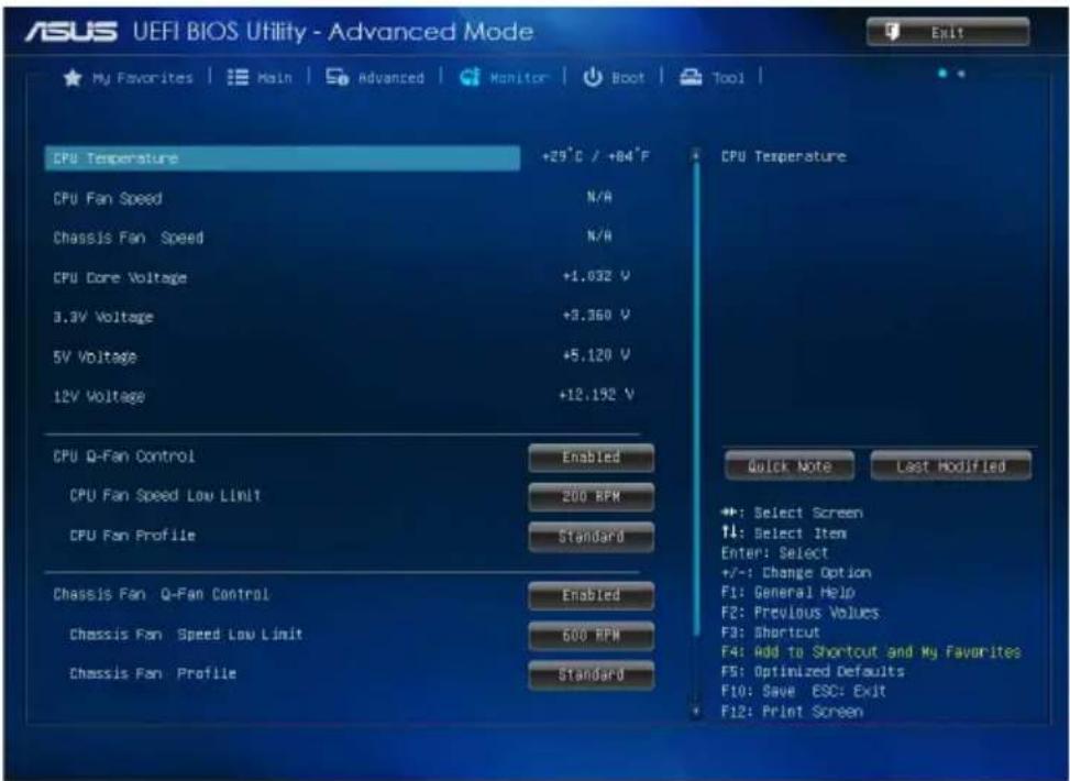
The Monitor menu displays the system temperature/power status, and allows you to change the fan settings.
text_image
ASUS UEFI BIOS Utility - Advanced Mode Exit ★ My Favorites | Main | Advanced | Monitor | Boot | Tool | CPU Temperature +29°C / +84°F CPU Fan Speed N/A Chassis Fan Speed N/A CPU Cone Voltage +1.032 V 3.3V Voltage +3.360 V 5V Voltage +5.120 V 12V Voltage +12.192 V CPU Q-Fan Control Enabled CPU Fan Speed Low Limit 200 RPM CPU Fan Profile Standard Chassis Fan Q-Fan Control Enabled Chassis Fan Speed Low Limit 600 RPM Chassis Fan Profile Standard CPU Temperature Quick Note Last Modified ◆: Select Screen ↑: Select Item Enter: Select +/-: Change Option F1: General Help F2: Previous Values F3: Shortcut F4: Add to Shortcut and My Favorites F5: Optimized Defaults F10: Save ESC: Exit F12: Print Screen2.6.1 CPU Temperature [xxx□C/xxx□F]
The onboard hardware monitor automatically detects and displays the CPU temperature.
2.6.2 CPU / Chassis Fan Speed [xxxx RPM]
The onboard hardware monitor automatically detects and displays the CPU and chassis fan speeds in rotations per minute (RPM). If the fan is not connected to the motherboard, the field shows N/A.
2.6.3 CPU Core Voltage, 3.3V Voltage, 5V Voltage, 12V Voltage
The onboard hardware monitor automatically detects the voltage output through the onboard voltage regulators.
2.6.4 CPU Q-Fan Control [Enabled]
[Disabled] Disables the CPU Q-Fan control feature.
[Enabled] Enables the CPU Q-Fan control feature.
CPU Fan Speed Low Limit [200 RPM]
This item appears only when you enable the CPU Q-Fan Control feature and allows you to disable or set the CPU fan warning speed. Configuration options: [Ignore] [100 RPM] [200 RPM] [300 RPM] [400 RPM] [500 RPM]
CPU Fan Profile [Standard]
This item appears only when you enable the CPU Q-Fan Control feature and allows you to set the appropriate performance level of the CPU fan.
[Standard] Sets to [Standard] to make the CPU fan automatically adjust depending on the CPU temperature.
[Silent] Sets to [Silent] to minimize the fan speed for quiet CPU fan operation.
[Turbo] Sets to [Turbo] to achieve maximum CPU fan speed.
[Manual] Sets to [Manual] to assign detailed fan speed control parameters.
![ASUS J1900I-C - CPU Fan Profile [Standard] - 1](/content/2026/05/815089/images/b30e929805bf79a9e9ded607aab70cced65d602285c949b6fc97350151048709.jpg)
The following four items appear only when you set CPU Fan Profile to [Manual].
CPU Upper Temperature [70]
Use the <+> and <-> keys to adjust the upper limit of the CPU temperature. The values range from 20^ C to 75^ C.
CPU Fan Max. Duty Cycle(%) [100]
Use the <+> and <-> keys to adjust the maximum CPU fan duty cycle. The values range from 20% to 100%. When the CPU temperature reaches the upper limit, the CPU fan will operate at the maximum duty cycle.
CPU Lower Temperature [20]
Use the <+> and <-> keys to adjust the lower limit of the CPU temperature. The values range from 20^ C to 75^ C.
CPU Fan Min. Duty Cycle(%) [20]
Use the <+> and <-> keys to adjust the minimum CPU fan duty cycle. The values range from 20% to 100%. When the CPU temperature is under the lower limit, the CPU fan will operate at the minimum duty cycle.
2.6.5 Chassis Fan Q-Fan Control [Enabled]
[Disabled] Disables the Chassis Q-Fan control feature.
[Enabled] Enables the Chassis Q-Fan control feature.
Chassis Fan Speed Low Limit [600 RPM]
This item appears only when you enable the Chassis Q-Fan Control feature and allows you to disable or set the Chassis fan warning speed. Configuration options: [Ignore] [200 RPM] [300 RPM] [400 RPM] [500 RPM] [600 RPM]
Chassis Fan Profile [Standard]
This item appears only when you enable the Chassis Q-Fan Control feature and allows you to set the appropriate performance level of the Chassis fan.
[Standard] Sets to [Standard] to make the Chassis fan automatically adjust depending on the Chassis temperature.
[Silent] Sets to [Silent] to minimize the fan speed for quiet Chassis fan operation.
[Turbo] Sets to [Turbo] to achieve maximum Chassis fan speed.
[Manual] Sets to [Manual] to assign detailed fan speed control parameters.
![ASUS J1900I-C - Chassis Fan Profile [Standard] - 1](/content/2026/05/815089/images/4fa00e7576c0bdac6263c17ecc2d1898f600bf37b38be99d5b388c9ffc4cdc0d.jpg)
The following four items appear only when you set Chassis Fan Profile to [Manual].
Chassis Fan Upper Temperature [70]
Use the <+> and <-> keys to adjust the upper limit of the Chassis temperature. The values range from 20^ C to 75^ C.
Chassis Fan Max. Duty Cycle(%) [100]
Use the <+> and <-> keys to adjust the maximum Chassis fan duty cycle. The values range from 20% to 100%. When the Chassis temperature reaches the upper limit, the Chassis fan will operate at the maximum duty cycle.
Chassis Fan Lower Temperature [20]
Displays the lower limit of the Chassis temperature.
Chassis Fan Min. Duty Cycle(%) [20]
Use the <+> and <-> keys to adjust the minimum Chassis fan duty cycle. The values range from 20% to 100%. When the Chassis temperature is under 40°C, the Chassis fan will operate at the minimum duty cycle.
Anti Surge Support [Disabled]
This item allows you to enable or disable the Anti Surge function. Configuration options: [Disabled] [Enabled]
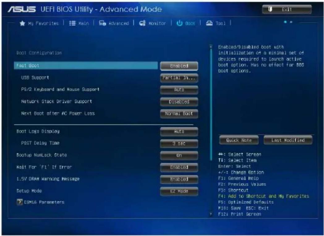
2.7 Boot menu
The Boot menu items allow you to change the system boot options.
Scroll down to display other BIOS items.
text_image
ASUS UEFI BIOS Utility - Advanced Mode My Favorites | Main | Advanced | Monitor | Boot | Tool | Boot Configuration Fast Boot Enabled USB Support Partial In... PS/2 Keyboard and Mouse Support Auto Network Stack Driver Support Disabled Next Boot after AC Power Loss Normal Boot Boot Logo Display Auto POST Delay Time 3 sec Bootup NumLock State On Wait For 'F1' If Error Enabled 1.5V DRAM Warning Message Enabled Setup Mode EZ Mode CSML6 Parameters Enabled/Disabled boot with Initialization of a minimal set of devices required to launch active boot option. Has no effect for BBS boot options. Quick Note Last Modified +: Select Screen F1: Select Item Enter: Select +/-: Change Option F1: General Help F2: Previous Values F3: Shortcut F4: Add to Shortcut and My Favorites F5: Optimized Defaults F10: Save ESC: Exit F12: Print Screen2.7.1 Fast Boot [Enabled]
[Enabled] Select to accelerate the boot speed.
[Disabled] Select to go back to normal boot.
![ASUS J1900I-C - Fast Boot [Enabled] - 1](/content/2026/05/815089/images/dc96b6c78eb62180f73ca7489ee62a2040b30e59e12410c7c7059df7aa3df481.jpg)
The following four items appear when you set Fast Boot to [Enabled].
USB Support [Partial Initialization]
[Disabled] All USB devices will not be available until OS boot up for a fastest POST time.
[Full Initialization] All USB devices will be available during POST. This process will extend the POST time.
[Partial Initialization] For a faster POST time, only the USB ports with keyboard and mouse connections will be detected.
PS/2 Keyboard and Mouse Support [Auto]
Select any of these settings when PS/2 keyboard and mouse are installed. These settings only apply when Fast Boot is enabled.
[Auto] For a faster POST time, PS/2 devices will only be available when the system boots up or rebooted when the PS/2 devices have not been reconnected or changed. If you disconnect or change PS/2 devices before restarting the system, PS/2 devices will not be available and BIOS setup program will not be accessible via PS/2 devices.
[Full Initialization] For full system control, PS/2 devices will be available during POST at any circumstances. This process will extend POST time.
[Disabled] For the fastest POST time, all PS/2 devices will not be available until your computer enters the operating system.
Network Stack Driver Support [Disabled]
[Disabled] Select to skip the network stack driver from loading during POST.
[Enabled] Select to load the network stack driver during POST.
Next Boot after AC Power Loss [Normal Boot]
[Normal Boot] Returns to normal boot on the next boot after AC power loss.
[Fast Boot] Accelerates the boot speed on the next boot after AC power loss.
2.7.2 Boot Logo Display [Enabled]
Boot Logo Display [Auto]
[Auto] Adjust automatically for Windows ^® requirement.
[Full Screen] Maximize the boot logo size.
[Disabled] Hide the logo during POST.
POST Delay Time [3 sec]
This item appears only when you set Boot Logo Display to [Enabled]. This item allows you to select the desired additional POST waiting time to easily enter the BIOS setup. You can only execute the POST delay time during Normal Boot. The values range from 0 to 10 seconds.
![ASUS J1900I-C - POST Delay Time [3 sec] - 1](/content/2026/05/815089/images/00f9879427facba894e65fc9b271dac737b290fd9af002c4c4e8b9e9fa54d0a6.jpg)
This feature will only work under normal boot.
Post Report [5 sec]
This item appears only when you set Boot Logo Display to [Disabled]. This item allows you to select a desired post report waiting time. The values range from 1 to 10 seconds.
2.7.3 Bootup NumLock State [On]
[On] Sets the power-on state of the NumLock to [On].
[Off] Sets the power-on state of the NumLock to [Off].
2.7.4 Wait for 'F1' If Error [Enabled]
When this item is set to [Enabled], the system waits for the F1 key to be pressed when error occurs. Configuration options: [Disabled] [Enabled]
2.7.5 1.5V DRAM Warning Message [Enabled]
[Enabled] Displays a warning message during the system startup when an 1.5V DRAM is installed.
[Disabled] Do not show this message.
2.7.6 Setup Mode [EZ Mode]
[Advanced Mode] Sets Advanced Mode as the default screen for entering the BIOS setup program.
[EZ Mode] Sets EZ Mode as the default screen for entering the BIOS setup program.
2.7.7 CSM16 Parameters
Allows you to configure the CSM (Compatibility Support Module) items to fully support the various VGA, bootable devices and add-on devices for better compatibility.
OS Selection [Windows 8.X]
Configuration options: [Windows 8.X] [Windows 7]
CSM Support [Disabled]
Configuration options: [Disabled] [Enabled]
![ASUS J1900I-C - CSM Support [Disabled] - 1](/content/2026/05/815089/images/6b7d2eddb984174592ed46f86a8f1ebe74926b0a6ae92fe4f309d40cc42d1b48.jpg)
The following items appear when CSM Support is set to [Enabled].
GateA20 Active [Upon Request]
[Upon Request] GA20 can be disabled using BIOS services.
[Always] Do not allow disabling GA20. This option is useful when any RT code is executed above 1MB.
Option ROM Messages [Force BIOS]
[Force BIOS] The third-party ROM messages will be forced to display during the boot sequence.
[Keep Current] The third-party ROM messages will be displayed only if the third-party manufacturer had set the add-on device to do so.
Interrupt 19 Capture [Enabled]
Set to [Enabled] to allow the option ROMs to trap Interrupt 19. Configuration options: [Disabled] [Enabled]
Boot Device Control [UEFI and Legacy OpROM]
Allows you to select the type of devices that you want to boot up. Configuration options: [UEFI and Legacy OpROM] [Legacy OpROM only] [UEFI only]
Option ROM execution order
Boot from Network Devices [Both, Legacy OPROM first]
Allows you to select the type of network devices that you want to launch. Configuration options: [Ignore] [UEFI only] [Legacy only] [Both, Legacy OPROM first] [Both, UEFI first]
Boot from Storage Devices [Both, Legacy OPROM first]
Allows you to select the type of storage devices that you want to launch. Configuration options: [Ignore] [UEFI only] [Legacy only] [Both, Legacy OPROM first] [Both, UEFI first]]
Launch Video OPROM policy [Both, Legacy OPROM first]
Configures the execution of UEFI and Legacy Video OPROM. Configuration options: [Ignore] [UEFI only] [Legacy only] [Both, Legacy OPROM first] [Both, UEFI first]]
Boot from PCI-E/PCI Expansion Devices [Both, UEFI first]
Allows you to select the type of PCIe/PCI expansion devices that you want to launch. Configuration options: [Legacy only] [Both, UEFI first]
2.7.7 Secure Boot menu
Allows you to configure the Windows® Secure Boot settings and manage its keys to protect the system from unauthorized access and malwares during POST.
OS Type [Windows UEFI mode]
Allows you to select your installed operating system.
[Windows UEFI mode] Executes the Microsoft
® Secure Boot check. Only
select this option when booting on Windows ^® UEFI mode or other Microsoft ^® Secure Boot compliant OS.
[Other OS] Get the optimized function when booting on
Windows® non-UEFI mode, Windows® Vista/XP, or other Microsoft® Secure Boot non-compliant OS. Only on Windows® UEFI mode that Microsoft® Secure Boot can function properly.
![ASUS J1900I-C - OS Type [Windows UEFI mode] - 1](/content/2026/05/815089/images/269b2ad2b3d8919f7e3b521e574e3e61a38e3cdfaccf3861d0b551a79382e833.jpg)
The following item appears when OS Type is set to [Windows UEFI mode].
Key Management
This item allows you to manage the Secure Boot keys.
Install default Secure Boot keys
This item allows you to install all default Secure Boot keys.
Clear Secure Boot keys
This item appears only when you load the default Secure Boot keys. This item allows you to clear all default Secure Boot keys.
Save Secure Boot keys
This item appears only when you load the default Secure Boot keys. This item allows you to save all default Secure Boot keys.
PK Management
The Platform Key (PK) locks and secures the firmware from any non-permissible changes. The system verifies the PK before your system enters the OS.
Delete PK
Allows you to delete the PK from your system. Once the PK is deleted, all the system's Secure Boot keys will not be active. Configuration options: [Yes] [No]
Load PK from File
Allows you to load the downloaded PK from a USB storage device.

The PK file must be formatted as a UEFI variable structure with time-based authenticated variable.
KEK Management
The KEK (Key-exchange Key or Key Enrollment Key) manages the Signature database (db) and Revoked Signature database (dbx).

Key-exchange Key (KEK) refers to Microsoft® Secure Boot Key-Enrollment Key (KEK).
Delete the KEK
Allows you to delete the KEK from your system. Configuration options: [Yes] [No]
Load KEK from File
Allows you to load the downloaded KEK from a USB storage device.
Append KEK from file
Allows you to load the additional KEK from a storage device for an additional db and dbx loaded management.

The KEK file must be formatted as a UEFI variable structure with time-based authenticated variable.
DB Management
The db (Authorized Signature database) lists the signers or images of UEFI applications, operating system loaders, and UEFI drivers that you can load on the single computer.
Delete the db
Allows you to delete the db file from your system. Configuration options: [Yes] [No]
Load db from File
Allows you to load the downloaded db from a USB storage device.
Append db from file
Allows you to load the additional db from a storage device so that more images can be loaded securely.

The DB file must be formatted as a UEFI variable structure with time-based authenticated variable.
DBX Management
The dbx (Revoked Signature database) lists the forbidden images of db items that are no longer trusted and cannot be loaded.
Delete the DBX
Allows you to delete the DBX file from your system. Configuration options: [Yes] [No]
Load DBX from File
Allows you to load the downloaded DBX from a USB storage device.
Append DBX from file
Allows you to load the additional DBX from a storage device so that more db's images cannot be loaded.

The DBX file must be formatted as a UEFI variable structure with time-based authenticated variable.
2.7.8 Boot Option Priorities
These items specify the boot device priority sequence from the available devices. The number of device items that appears on the screen depends on the number of devices installed in the system.

- To select the boot device during system startup, press
when ASUS Logo appears. - To access Windows OS in Safe Mode, press
after POST.
2.7.9 Boot Override
These items displays the available devices. The number of device items that appears on the screen depends on the number of devices installed in the system. Click an item to start booting from the selected device.
2.8 Tools menu
The Tools menu items allow you to configure options for special functions. Select an item then press
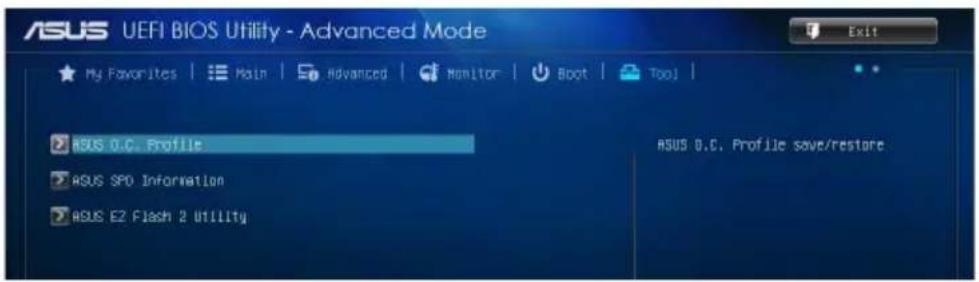
text_image
ASUS UEFI BIOS Utility - Advanced Mode My Favorites | Main | Advanced | Monitor | Boot | Tool | ASUS O.C. Profile ASUS SPD Information ASUS E2 Flash 2 Utility ASUS O.C. Profile save/restore2.8.1 ASUS O.C. Profile
This item allows you to store or load multiple BIOS settings.

The Setup Profile Status items show Not Installed if no profile is created.
Label
Allows you to input the label of the setup profile.
Save to Profile
Allows you to save the current BIOS settings to the BIOS Flash, and create a profile. Key in a profile number from one to eight, press
Load from Profile
Allows you to load the previous BIOS settings saved in the BIOS Flash. Key in the profile number that saved your CMOS settings, press

- DO NOT shut down or reset the system while updating the BIOS to prevent the system boot failure!
- We recommend that you update the BIOS file only coming from the same memory/CPU configuration and BIOS version.
Load/Save Profile from/to USB Drive
Allows you to load/save a profile from/to a USB drive. Press
2.8.2 ASUS SPD Information
DIMM Slot # [DIMM\_A1]
Displays the Serial Presence Detect (SPD) information of the DIMM module installed on the selected slot. Configuration options: [DIMM_A1] [DIMM_B1]
2.8.3 ASUS EZ Flash 2 Utility
Allows you to run ASUS EZ Flash 2. Press [Enter] to launch the ASUS EZ Flash 2 screen.

For more details, see section 2.1.2 ASUS EZ Flash 2.
2.9 Exit menu
The Exit menu items allow you to load the optimal default values for the BIOS items, and save or discard your changes to the BIOS items. You can access the EZ Mode from the Exit menu.
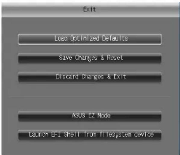
text_image
Exit Load Optimized Defaults Save Changes & Reset Discard Changes & Exit ASUS EZ Mode Launch E-F1 Shell from f/i-esystem deviceLoad Optimized Defaults
This option allows you to load the default values for each of the parameters on the Setup menus. When you select this option or if you press
Save Changes & Reset
Once you are finished making your selections, choose this option from the Exit menu to ensure the values you selected are saved. When you select this option or if you press
Discard Changes & Exit
This option allows you to exit the Setup program without saving your changes. When you select this option or if you press
ASUS EZ Mode
This option allows you to enter the EZ Mode screen.
Launch EFI Shell from filesystem device
This option allows you to attempt to launch the UEFI Shell application (shellx64.efi) from one of the available devices that have a filesystem.
Appendices
Notices
Federal Communications Commission Statement
This device complies with Part 15 of the FCC Rules. Operation is subject to the following two conditions:
• This device may not cause harmful interference.
- This device must accept any interference received including interference that may cause undesired operation.
This equipment has been tested and found to comply with the limits for a Class B digital device, pursuant to Part 15 of the FCC Rules. These limits are designed to provide reasonable protection against harmful interference in a residential installation. This equipment generates, uses and can radiate radio frequency energy and, if not installed and used in accordance with manufacturer's instructions, may cause harmful interference to radio communications. However, there is no guarantee that interference will not occur in a particular installation. If this equipment does cause harmful interference to radio or television reception, which can be determined by turning the equipment off and on, the user is encouraged to try to correct the interference by one or more of the following measures:
- Reorient or relocate the receiving antenna.
- Increase the separation between the equipment and receiver.
- Connect the equipment to an outlet on a circuit different from that to which the receiver is connected.
- Consult the dealer or an experienced radio/TV technician for help.

The use of shielded cables for connection of the monitor to the graphics card is required to assure compliance with FCC regulations. Changes or modifications to this unit not expressly approved by the party responsible for compliance could void the user's authority to operate this equipment.
IC: Canadian Compliance Statement
Complies with the Canadian ICES-003 Class B specifications. This device complies with RSS 210 of Industry Canada. This Class B device meets all the requirements of the Canadian interference-causing equipment regulations.
This device complies with Industry Canada license exempt RSS standard(s). Operation is subject to the following two conditions: (1) this device may not cause interference, and (2) this device must accept any interference, including interference that may cause undesired operation of the device.
Canadian Department of Communications Statement
This digital apparatus does not exceed the Class B limits for radio noise emissions from digital apparatus set out in the Radio Interference Regulations of the Canadian Department of Communications.
This class B digital apparatus complies with Canadian ICES-003.
VCCI: Japan Compliance Statement
VCCI Class B Statement
情報処理装置等電波障害自主規制について
KC: Korea Warning Statement
B급 기기 (가정용 방송통신기자재)
Complying with the REACH (Registration, Evaluation, Authorisation, and Restriction of Chemicals) regulatory framework, we published the chemical substances in our products at ASUS REACH website at http://csr.asus.com/english/REACH.htm.

DO NOT throw the motherboard in municipal waste. This product has been designed to enable proper reuse of parts and recycling. This symbol of the crossed out wheeled bin indicates that the product (electrical and electronic equipment) should not be placed in municipal waste. Check local regulations for disposal of electronic products.

DO NOT throw the mercury-containing button cell battery in municipal waste. This symbol of the crossed out wheeled bin indicates that the battery should not be placed in municipal waste.
ASUS Recycling/Takeback Services
ASUS recycling and takeback programs come from our commitment to the highest standards for protecting our environment. We believe in providing solutions for you to be able to responsibly recycle our products, batteries, other components as well as the packaging materials. Please go to http://csr.asus.com/english/Takeback.htm for detailed recycling information in different regions.
ASUS contact information
ASUSTeK COMPUTER INC.
Address 15 Li-Te Road, Peitou, Taipei, Taiwan 11259
Telephone +886-2-2894-3447
Fax +886-2-2890-7798
E-mail ____info@asus.com.tw
Web site http://www.asus.com
Technical Support
Telephone +86-21-3842-9911
Fax +86-21-5866-8722 ext. 9101#
Online support http://support.asus.com/techserv/techserv.aspx
ASUS COMPUTER INTERNATIONAL (America)
Address 800 Corporate Way, Fremont, CA 94539, USA
Telephone +1-510-739-3777
Fax +1-510-608-4555
Web site http://www.asus.com/us/
Technical Support
Support fax +1-812-284-0883
General support +1-812-282-2787
Online support http://www.service.asus.com/
ASUS COMPUTER GmbH (Germany and Austria)
Address Harkort Str. 21-23, D-40880 Ratingen, Germany
Fax +49-2102-959931
Web site http://www.asus.com/de
Online contact http://eu-rma.asus.com/sales
Technical Support
Telephone +49-2102-5789555
Support Fax +49-2102-959911
Online support http://www.asus.com/de/support/

EC Declaration of Conformity
| Manufacturer: | ASUSTeK COMPUTER INC. |
| Address, City: | 4F, No. 150, LI-TE Rd., PEITOU, TAIPEI 112, TAIWAN |
| Country: | TAIWAN |
| Authorized representative in Europe: | ASUS COMPUTER GmbH |
| Address, City: | HARKORT STR. 21-23, 40880 RATINGEN |
| Country: | GERMANY |
| declare the following apparatus: | |
| Product name : Motherboard | |
| Model name : J1900I-C | |
| conform with the essential requirements of the following directives: | |
| 2004/108/EC-EMC Directive | |
| EN 55022:2010-AC:2011EN 61000-3-2:2006+A2:2009EN 55013:2001-A1:2003-A2:2006 | EN 55024:2010EN 61000-3-3:2008EN 55020:2007+A11:2011 |
| 1999/5/EC-R &TTE Directive | |
| EN 300 328 V1.7.1(2006-10)EN 300 440-1 V1.6.1(2010-08)EN 300 440-2 V1.4.1(2010-08)EN 301 511 V9.0.2(2003-03)EN 301 908-1 V5.2.1(2011-05)EN 301 908-2 V5.2.1(2011-07)EN 301 893 V1.6.1(2011-11)EN 302 544-2 V1.1.1(2009-01)EN 302 623 V1.1.1(2009-01)EN 50360:2001EN 62479:2010EN 50385:2002EN 62311:2008 | EN 301 489-1 V1.9.2(2011-09)EN 301 489-3 V1.4.1(2002-08)EN 301 489-4 V1.4.1(2009-05)EN 301 489-7 V1.3.1(2005-11)EN 301 489-9 V1.4.1(2007-11)EN 301 489-17 V2.2.1(2012-09)EN 301 489-24 V1.5.1(2010-09)EN 302 326-2 V1.2.2(2007-06)EN 302 326-3 V1.3.1(2007-09)EN 301 357-2 V1.4.1(2008-11)EN 302 291-1 V1.1.1(2005-07)EN 302 291-2 V1.1.1(2005-07) |
| 2006/95/EC-LVD Directive | |
| EN 60950-1 /A12:2011 | EN 60065:2002 / A12:2011 |
| 2009/125/EC-ErP Directive | |
| Regulation (EC) No. 1275/2008Regulation (EC) No. 642/2009 | Regulation (EC) No. 278/2009Regulation (EC) No. 617/2013 |
| 2011/65/EU-RoHS Directive | |
| CE marking | |
DECLARATION OF CONFORMITY
Per FCC Part 2 Section 2. 1077(a)

Responsible Party Name: Asus Computer International
Address: 800 Corporate Way, Fremont, CA 94539.
Phone/Fax No: (510)739-3777/(510)608-4555
hereby declares that the product
Product Name : Motherboard
Model Number : J1900I-C
Conforms to the following specifications:
☒ FCC Part 15, Subpart B, Unintentional Radiators
Supplementary Information:
This device complies with part 15 of the FCC Rules. Operation is subject to the following two conditions: (1) This device may not cause harmful interference, and (2) this device must accept any interference received, including interference that may cause undesired operation.
Steve Chang / President

Signature :
Date : Mar. 31, 2014
Ver. 120601