
NV200 Compact Cargo (2020) - Automobile NISSAN - Free user manual and instructions
Find the device manual for free NV200 Compact Cargo (2020) NISSAN in PDF.


| Product Type | Automobile |
| Brand | Nissan |
| Model | NV200 Compact Cargo (2020) |
| Engine | 2.0L 4-cylinder MR20DE |
| Fuel Type | Unleaded regular gasoline (87 AKI minimum) |
| Transmission | Continuously Variable Transmission (CVT) |
| Seating Capacity | 2 (driver and front passenger) |
| Dimensions (L x W x H) | Approx. 186.9 x 68.1 x 74.0 in |
| Curb Weight | Approx. 3,500 lbs |
| Fuel Tank Capacity | Approx. 18.5 gallons |
| Safety Features | Advanced Air Bag System (front, side, curtain), seat belt pretensioners, ABS, VDC, TPMS, Rear Sonar System (optional) |
| Convenience Features | Power windows, remote keyless entry, cruise control (optional), rearview camera |
| Engine Oil | SAE 5W-30 (API SN or higher) |
| Coolant | Nissan Genuine Long Life Antifreeze/Coolant or equivalent |
| Brake Fluid | DOT 3 or DOT 4 |
| Maintenance Schedule | Refer to Owner's Manual for detailed schedule (approx. every 5,000 miles or 6 months) |
| Warranty | See separate Warranty Information Booklet |
| Owner's Manual Pages | 300 |
| Available Languages | Multiple (translation service available) |
Frequently Asked Questions - NV200 Compact Cargo (2020) NISSAN
User questions about NV200 Compact Cargo (2020) NISSAN
0 question about this device. Answer the ones you know or ask your own.
Ask a new question about this device
Download the instructions for your Automobile in PDF format for free! Find your manual NV200 Compact Cargo (2020) - NISSAN and take your electronic device back in hand. On this page are published all the documents necessary for the use of your device. NV200 Compact Cargo (2020) by NISSAN.
USER MANUAL NV200 Compact Cargo (2020) NISSAN
2020 NV200 COMPACT CARGO
OWNER'S MANUAL
and MAINTENANCE INFORMATION
For your safety, read carefully and keep in this vehicle.
CALIFORNIA PROPOSITION 65 WARNING
WARNING
Operating,servicingandmaintainingapassenger vehicleoroff-highwaymotorvehiclecanexposeyouto chemicalsincludingengineexhaust,carbonmonoxide, phthalates,andlead,whichareknowntotheStateof Californiatocausecancerandbirthdefectsorother reproductiveharm.Tominimizeexposure,avoid breathingexhaust,donotidletheengineexceptas necessary,serviceyourvehicleinawell-ventilatedarea andwearglovesorwashyourhandsfrequentlywhen servicing your vehicle. For more information go to www.P65Warnings.ca.gov/passenger-vehicle.
FOREWORD
READ FIRST—THEN DRIVE SAFELY
This manual was prepared to help you understand the operation and maintenance of your vehicle so that you may enjoy many miles (kilometers) of driving pleasure. Please read through this manual before operating your vehicle.
familiarize yourself with all disclosures, warnings, cautions and instructions concerning proper use of such accessories prior to operating the vehicle and/or accessory. It is recommended that you visit NISSAN dealer for details concerning the particular accessories with which your vehicle is equipped.
A separate Warranty Information Book- hi let explains details about the warranties covering your vehicle. The "Maintenance and schedules" section of this manual explains details about maintaining and servicing your vehicle. Additionally, a separate Customer Care/Lemon Law Booklet (U.S. only) will explain how to resolve any concerns you may have with your vehicle, as well as clarify your rights under your state's lemon law.
A NISSAN dealership knows your vehicle best. When you require any service or have any questions, they will be glad to assist you with the extensive resources available to them.
In addition to factory-installed options, your vehicle may also be equipped with additional accessories installed prior to delivery. It is recommended that you visit a NISSAN dealer for details concerning the particular accessories with which your vehicle is equipped. It is important that you
Before driving your vehicle, please read this Owner's Manual carefully. This will ensure familiarity with controls and maintenance requirements, assisting you in the safe operation of your vehicle.
WARNING
IMPORTANT SAFETY INFORMATION REMINDERS!
Follow these important driving rules to help ensure a safe and comfortable trip for you and your passengers!
- NEVER drive under the influence of alcohol or drugs.
- ALWAYS observe posted speed limits and never drive too fast for conditions.
- ALWAYS give your full attention to driving and avoid using vehicle features or taking other actions that could distract you.
- ALWAYS use your seat belts and appropriate child restraint systems.
- ALWAYS provide information about the proper use of vehicle safety features to all occupants of the vehicle.
- ALWAYS review this Owner's Manual for important safety information.
DRIVING
This vehicle will handle and maneuver differently from an ordinary passenger vehicle because it has a higher center of gravity. As with other vehicles with features of this type, failure to operate this vehicle correctly may result in loss of control or an accident. Be sure to read "Precautions when starting and driving" and "Avoiding collision and rollover" in the "Starting and driving" section of this manual.
MODIFICATION OF YOUR VEHICLE
WARNING
Any modifications or alterations of this vehicle that do not comply with the NISSAN NV200 Compact Cargo Body Builder's Guide may affect the safety of the vehicle which may result in a collision, serious personal injury or death. An electronic copy of the NISSAN NV200 Compact Cargo Body Builder's Guide is available at www.nissancommercialvehicles.com.
Modifications made to this vehicle by conversion companies or dealers may affect the final certification of the engine, vehicle or equipment. The conversion company or dealer has the responsibility to certify that the altered vehicle and equipment complies or continues to comply with all applicable motor vehicle safety standards and emissions regulations. The conversion company or dealer is responsible for making sure the modifications or installed equipment does not affect the safety of the vehicle.
NISSAN does not assume the responsibility as the final stage manufacturer for modified or altered vehicles. NISSAN is not responsible for the final certification, product liability claims, or warranty claims, resulting from any component, assembly, or system being altered. NISSAN is not responsible for modifications which cause the vehicle to become non-compliant with any of the motor vehicle safety standards, emissions regulations, or modifications that cause the vehicle to be or become defective or unsafe.
Your vehicle's warranty may not cover damage resulting from alterations, modifications, installation of non-approved accessories, or improper installation of accessories. Refer to your 2018 NV200 Compact Cargo Warranty Information Booklet for complete details.
WHEN READING THE MANUAL
WARNING
Installing an aftermarket On-Board Diagnostic (OBD) plug-in device that uses the port during normal driving, for example remote insurance company monitoring, remote vehicle diagnostics, telematics or engine reprogramming, may cause interference or damage to vehicle systems. We do not recommend or endorse the use of any aftermarket OBD plug-in devices, unless specifically approved by NISSAN. The vehicle warranty may not cover damage caused by any aftermarket plug-in device.
This manual includes information for all features and equipment available on this model. Features and equipment in your vehicle may vary depending on model, trim level, options selected, order, date of production, region or availability. Therefore, you may find information about features of equipment that are not included or installed on your vehicle.
At All information, specifications and illustrations in this manual are those in effect at the time of printing. NISSAN reserves the byright to change specifications, performance, design or component suppliers without notice and without obligation. From time to time, NISSAN may update or revise this manual to provide Owners with the most accurate information currently available. Please carefully read and retain with this manual all revision updates sent to you by NISSAN to ensure you have access to accurate and up-to-date information regarding your vehicle. Current versions of vehicle Owner's Manuals and any updates can also be found in the Owner section of the NISSAN website at https://owners.nissanusa.com/owners/navigation/manualsGuide. If you have questions concerning any information in your Owner's Manual, contact NISSAN
Consumer Affairs. For contact information, refer to the NISSAN CUSTOMER CARE PROGRAM page in this Owner's Manual.
IMPORTANT INFORMATION ABOUT THIS MANUAL
Of You will see various symbols in this manual. They are used in the following ways:
WARNING
This is used to indicate the presence of a hazard that could cause death or serious personal injury. To avoid or reduce the risk, the procedures must be followed precisely.
CAUTION
This is used to indicate the presence of a hazard that could cause minor or moderate personal injury or damage to your vehicle. To avoid or reduce the risk, the procedures must be followed carefully.
natural_image
Simple geometric X shape with diagonal lines, no text or symbols present
Arrows in an illustration that are similar to these call attention to an item in the illustration.
CALIFORNIA PERCHLORATE ADVISORY
Some vehicle parts, such as lithium batteries, may contain perchlorate material. The following advisory is provided: "Perchlorate Material - special handling may apply. For additional information, refer to www.dtsc.ca.gov/hazardouswaste/
If you see this symbol, it means "Do not do perchlorate/". this" or "Do not let this happen."

If you see a symbol similar to these in an illustration, it means the arrow points to the front of the vehicle.

Arrows in an illustration that are similar to these indicate movement or action.

BLUETOOTH® is a trademark owned by Bluetooth SIG, Inc. and licensed to Visteon and Bosch.
SiriusXM® services require a subscription after trial period and are sold separately or as a package. The satellite service is available only in the 48 contiguous USA and DC. SiriusXM® satellite service is also available in Canada; see www.siriusxm.ca.
© Nissan Mexicana, S. A. de C. V.
All rights reserved. No part of this Owner's Manual may be reproduced or stored in a retrieval system, or transmitted in any form, or by any means, electronic, mechanical, photocopying, recording or otherwise, without the prior written permission of Nissan Mexicana, S. A. de C. V.
NISSAN CUSTOMER CARE PROGRAM
NISSAN CARES...
Both NISSAN and your NISSAN dealer are dedicated to serving all your automotive needs. Your satisfaction with your vehicle and your NISSAN dealer are our primary concerns. Your NISSAN dealer is always available to assist you with all your automobile sales and service needs.
However, if there is something that your NISSAN dealer cannot assist you with or you would like to provide NISSAN directly with comments or questions, please contact the NISSAN Consumer Affairs Department using our toll-free number:
For U.S. customers
877-NIS-NCV1
(877-647-6281)
For Canadian customers
1-800-387-0122
The Consumer Affairs Department will ask You can write to NISSAN with the information for the following information: tion at:
- Your name, address, and telephone number
- Vehicle identification number (attached to the top of the instrument panel on driver's side)
- Date of purchase
- Current odometer reading
- Your NISSAN dealer's name
- Your comments or questions
OR
For U.S. customers
Nissan North America, Inc.
Consumer Affairs Department
P.O. Box 685003
Franklin, TN 37068-5003
or via e-mail at:
nnaconsumeraffairs@nissan-usa.com
For Canadian customers
Nissan Canada Inc.
5290 Orbitor Drive
Mississauga, Ontario L4W 4Z5
or via e-mail at:
information.centre@nissancanada.com
If you prefer, visit us at:
www.nissanusa.com (for U.S. customers) or
www.nissan.ca (for Canadian customers)
We appreciate your interest in NISSAN and thank you for buying a quality NISSAN vehicle.
Table of Contents
| Illustrated table of contents | 0 |
| Safety—Seats, seat belts and supplemental restraint system | 1 |
| Instruments and controls | 2 |
| Pre-driving checks and adjustments | 3 |
| Monitor, climate, audio, phone and voice recognition systems | 4 |
| Starting and driving | 5 |
| In case of emergency | 6 |
| Appearance and care | 7 |
| Do-it-yourself | 8 |
| Maintenance and schedules | 9 |
| Technical and consumer information | 10 |
| Index | 11 |
0 Illustrated table of contents
Air bags, seat belts and child restraints 0-2 Instrument panel 0-6
Exterior front 0-3 Engine compartment check locations 0-8
Exterior rear 0-4 Warning and indicator lights 0-9
Passenger compartment....0 - 5
AIR BAGS, SEAT BELTS AND CHILD RESTRAINTS

0-2 Illustrated table of contents
- Head restraints/headrests (P. 1-7)
- Front seat belt with preten- sioner(s) and shoulder height adjuster (driver's side only) (P. 1-11, 1-32)
- Roof-mounted curtain side-impact and rollover supplemental air bag (P. 1-32)
- Supplemental air bags (P. 1-32)
- Seats (P. 1-2)
- Occupant classification sensor (weight sensor) (P. 1-32)
- Front seat top tether strap anchor (located on bottom of seatback) (P. 1-21)
- Front seat-mounted side-impact supplemental air bag (P. 1-32)
Refer to the page number indicated in parentheses for operating details.
EXTERIOR FRONT
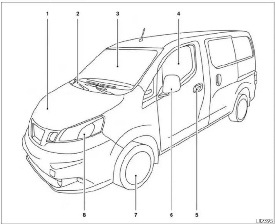
- Engine hood (P. 3-13)
- Wiper and washer switch (P. 2-21)
- Windshield (P. 8-16)
- Power windows (P. 2-31)
- Door locks (P. 3-3)
Keys (P. 3-2)
Key fob (if so equipped) (P. 3-10) - Mirrors (P. 3-18)
- Tire pressure (P. 8-31)
Flat tire (P. 6-2)
Tire chains (P. 8-31)
8 Replacing bulbs (P. 8-23)
Headlight and turn signal switch (P. 2-23)
Daytime Running Lights (DRL)
(P. 2-23)
Refer to the page number indicated in parentheses for operating details.
EXTERIOR REAR

0-4 Illustrated table of contents
- Back doors (P. 3-3) Vehicle loading (P. 10-13)
- Rearview camera (P. 4-3)
3 Replacing bulbs (P. 8-23)
Refer to the page number indicated in parentheses for operating details.
PASSENGER COMPARTMENT

- Map lights (P. 2-33)
- Sun visors (P. 3-17)
- Rearview mirror (if so equipped) (P. 3-18)
- Glove box (P. 2-28)
- Storage trays (P. 2-28)
- Fuel-filler cap (P. 3-14) Fuel recommendation (P. 10-2) Fuel-filler door (P. 3-14)
Refer to the page number indicated in parentheses for operating details.
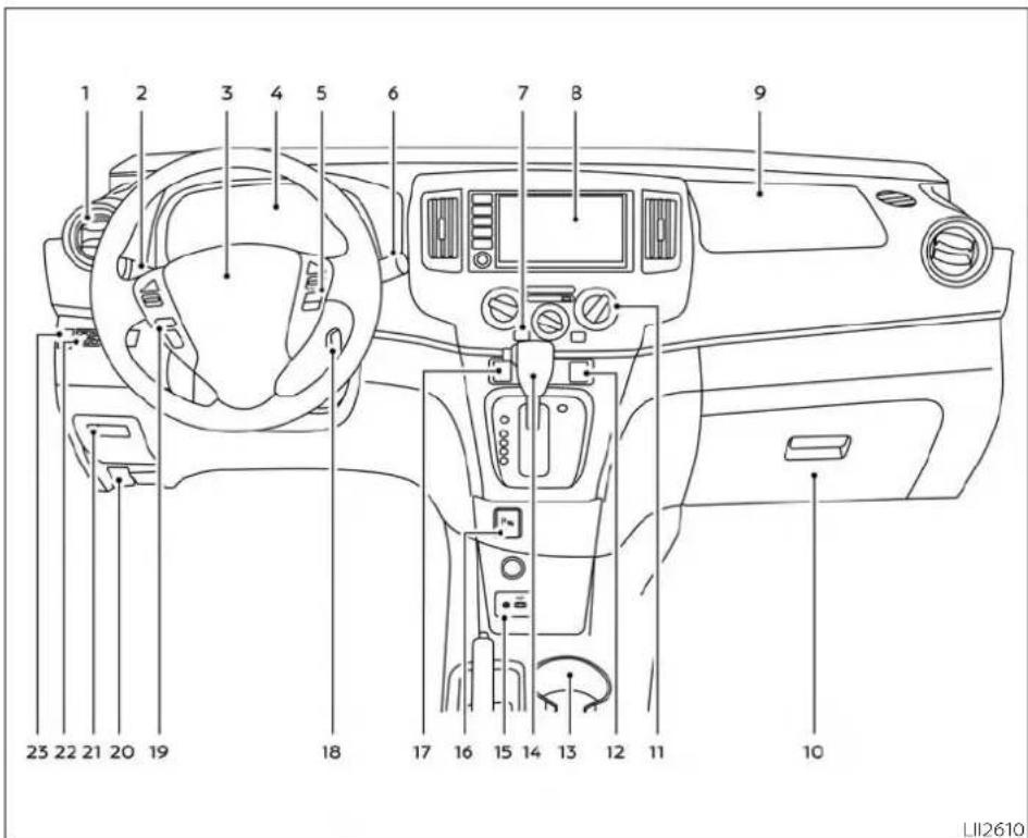
INSTRUMENT PANEL
0-6 Illustrated table of contents
- Vents (P. 4-11)
- Headlight/turn signal switch (P. 2-23)
- Driver's supplemental air bag (P. 1-32) Horn (P. 2-25)
- Meters and gauges (P. 2-3) Warning and indicator lights (P. 2-9)
- Cruise control switches (if so equipped) (P. 5-18)
- Wiper and washer switch (P. 2-21)
- Rear window and/or outside mirror defroster switch (if so equipped) (P. 2-22)
- Audio system*
- Passenger's supplemental air bag (P. 1-32)
- Glove box (P. 2-28)
- Climate controls (P. 4-11)
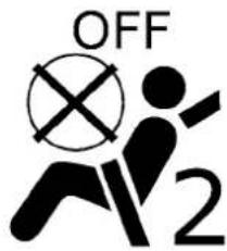
- Front passenger air bag status light (P. 2-15)
- Cup holders (P. 2-28)
- Shift lever (P. 5-14)
- AUX input/USB port*
- Rear Sonar System (RSS) OFF switch (if so equipped) (P. 5-29)
- Hazard warning flasher switch (P. 6-2)
-
Ignition switch (P. 5-8)
-
Audio control switches* Bluetooth® Hands-Free Phone System*
- Fuel-filler door release lever (P. 3-14) Hood release lever (P. 3-13)
- Fuse box (P. 8-18)
- Electronic outside rearview mirror control switch (if so equipped) (P. 3-19)
- Vehicle Dynamic Control (VDC) OFF switch (P. 2-26)
*Refer to the separate NissanConnect® Owner's Manual
Refer to the page number indicated in parentheses for operating details.
ENGINE COMPARTMENT CHECK
LOCATIONS

0-8 Illustrated table of contents
MR20DE engine
- Engine coolant reservoir (P. 8-5)
- Engine oil filler cap (P. 8-7)
- Brake fluid reservoir (P. 8-10)
- Air cleaner (P. 8-15)
- Fuse box (P. 8-18)
- Battery (P. 8-12)
- Radiator cap (P. 8-5)
- Engine oil dipstick (P. 8-7)
- Drive belt location (P. 8-14)
- Windshield-washer fluid reservoir (P. 8-11)
WARNING AND INDICATOR LIGHTS
| Warning light | Name Page | |
 or or | Anti-lock Braking System (ABS) warning light | 2-10 |
 or or | Brake warning light | 2-10 |
 | Charge warning light | 2-11 |
 | Door open warning light | 2-11 |
 | Engine oil pressure warning light | 2-11 |
 | High temperature warning light (red) | 2-11 |
| Warning light | Name Page | |
 | Low fuel warning light | 2-12 |
 | Low tire pressure warning light | 2-12 |
 | Low windshield-washer fluid warning light (if so equipped) | 2-14 |
 | Power steering warning light | 2-14 |
 | Seat belt warning light and chime | 2-14 |
 | Supplemental air bag warning light | 2-14 |
| Indicator light | Name Page | |
 | Continuously Variable Transmission (CVT) position indicator light | 2-15 |
 | ||
| KKDY] | CRUISE indicator light (if so equipped) | 2-15 |
 | Front passenger air bag status light | 2-15 |
 | High beam indicator light (blue) | 2-15 |
 | Malfunction Indicator Light (MIL) | 2-15 |
 | Overdrive OFF indicator light | 2-16 |
 | Security indicator light | 2-17 |
 | Slip indicator light | 2-17 |
 | Turn signal/hazard indicator lights | 2-17 |
 | Vehicle Dynamic Control (VDC) OFF indicator light | 2-17 |
0-10 Illustrated table of contents
1 Safety—Seats, seat belts and supplemental restraint system
Seats 1-2
Front manual seat adjustment 1 - 3
Armrest (if so equipped for driver's side
only) 1-4
Flexible seating 1 - 5
Head restraints/headrests 1 - 7
Adjustable head restraint/headrest
components 1 - 8
Non-adjustable head restraint/
headrest components....1 - 8
Remove 1-9
Install.... 1 - 9
Adjust 1-10
Seatbelts....1-11
Precautions on seat belt usage 1-11
Seat belt warning light....1-14
Pregnant women....1-14
Injured persons....1-14
Three-point type seat belt with
retractor 1-14
Seat belt extenders....1-18
Seat belt maintenance 1-18
Child safety....1-19
Infants 1-19
Small children 1-20
Larger children 1-20
Child restraints 1-21
Precautions on child restraints 1-22
Top tether anchor 1-23
Rear-facing child restraint installation
using the seat belts 1-24
Forward-facing child restraint
installation using the seat belts....1-24
Booster seats 1-28
Supplemental Restraint System (SRS)....1-32
Precautions on SRS....1-32
Supplemental air bag warning labels ..... 1-49
Supplemental air bag warning light. 1-50
SEATS


natural_image
Diagram showing car seatbelt and cross-section of a vehicle (no text or symbols)WARNING
- Do not ride in a moving vehicle when the seatback is reclined. This can be dangerous. The shoulder belt will not be against your body. In an accident, you could be thrown into it and receive neck or other serious injuries. You could also slide under the lap belt and receive serious internal injuries.
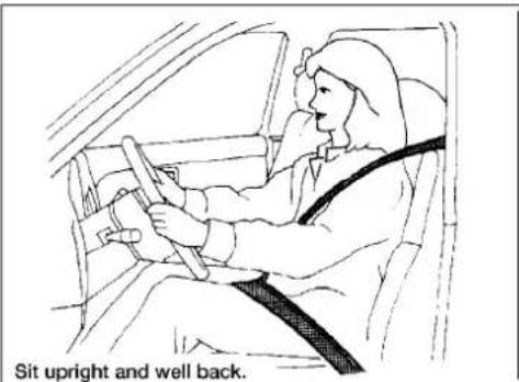
- For the most effective protection when the vehicle is in motion, the seat should be upright. Always sit well back and upright in the seat with both feet on the floor and adjust the seat properly. For additional information, refer to "Precautions on seat belt usage" in this section.
-
After adjustment, gently rock in the seat to make sure it is securely locked.
-
Do not leave children unattended inside the vehicle. They could unknowingly activate switches or controls or make the vehicle move. Unattended children could become involved in serious accidents.
- To help avoid risk of injury or death through unintended operation of the vehicle and/or its systems, do not leave children, people who require the assistance of others or pets unattended in your vehicle. Additionally, the temperature inside a closed vehicle on a warm day can quickly become high enough to cause a significant risk of injury or death to people and pets.
Do not adjust the driver's seat while driving so full attention may be given to vehicle operation. The seat may move suddenly and could cause loss of control of the vehicle. - The seatback should not be reclined any more than needed for comfort.
- Seat belts are most effective when the passenger sits well back and straight up in the seat. If the seatback is reclined, the risk of sliding under the lap belt and being injured is increased.
1-2 Safety—Seats, seat belts and supplemental restraint system
CAUTION
When adjusting the seat positions, be sure not to contact any moving parts to avoid possible injuries and/or damage.
FRONT MANUAL SEAT ADJUSTMENT
Your vehicle seats can be adjusted manually. For additional information about adjusting the seats, refer to the steps outlined in this section.

natural_image
Line drawing of a car seat with directional arrows indicating movement (no text or symbols)Forward and backward
Pull the center of the bar up and hold it while you slide the seat forward or backward to the desired position. Release the bar to lock the seat in position.

natural_image
Line drawing of a car seat with directional arrows indicating movement or force (no text or symbols)Reclining
To recline the seatback, pull the lever up and lean back. To bring the seatback forward, pull the lever up and lean your body forward. Release the lever to lock the seatback in position.
The reclining feature allows adjustment of the seatback for occupants of different sizes for added comfort and to help obtain proper seat belt fit. For additional information, refer to "Precautions on seat belt usage" in this section. Also, the seatback can be reclined to allow occupants to rest when the vehicle is stopped and the shift lever is in the P (Park) position.
Safety—Seats, seat belts and supplemental restraint system

natural_image
Line drawing of a car seat with a double-headed arrow indicating left side (no text or symbols)LRS2221 LRS2921 LRS2339

natural_image
Line drawing of a car seatbelt with directional arrows indicating movement (no text or symbols)Seat lifter (driver's seat)
Lumbar support (if so equipped for driver's seat)
Pull up or push down the adjusting lever to adjust the seat height until the desired position is achieved.
The lumbar support feature provides adjustable lower back support to the driver. Move the lever forward or backward to ad just the seat lumbar area.

ARMREST (if so equipped for driver's side only)
To use the armrest, pull it down to the resting position.
Ⓐ Stowed position
⑧ Resting position
1-4 Safety—Seats, seat belts and supplemental restraint system
FLEXIBLE SEATING
WARNING
- Do not allow people to ride in any area of your vehicle that is not equipped with seats and seat belts. Be sure everyone in your vehicle is in a seat and using a seat belt properly.
- Never allow anyone to ride in the cargo area or on the seats when they are in the fold-down position. In a collision, people riding in these areas without proper restraints are more likely to be seriously injured or killed.
- Head restraints/headrests should be adjusted properly as they may provide significant protection against injury in an accident. Always replace and adjust them properly if they have been removed for any reason.
- If the head restraints/headrests are removed for any reason, they should be securely stored to prevent them from causing injury to passengers or damage to the vehicle in case of sudden braking or an accident.
- When returning the seatbacks to the upright position, be certain they are completely secured in the latched position. If they are not completely secured, passengers may be injured in an accident or sudden stop.
Properly secure all cargo to help prevent it from sliding or shifting. Do not place cargo higher than the seat-backs. In a sudden stop or collision, unsecured cargo could cause personal injury.

LRS2719
Folding the front passenger's seatback
To fold the front passenger's seatback flat for extra storage:
- Slide the seat to the rearmost position. Lift up on the recline lever, located on the outside edge of the seat, and fold the seatback forward as far as it will go. Then lift up on the lato, located on the inside of the seatback to release the back of the seat.
- Once the seatback is released, it will enable you to fold the front passenger seatback ⓒ flat over the seat cushion.

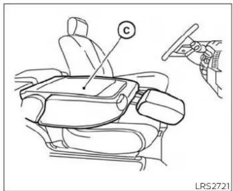
- To return the front passenger's seat to a seating position, lift up on the seat-back and push it up to an upright position. Then pull up on the recline lever and lean the seatback to a proper seating position. Release the lever to lock the seatback in position.
WARNING
- If you fold the front passenger's seat-back flat forward to carry longer objects, be sure this cargo is properly secured and not near an air bag. In a crash, an inflating air bag might force that object toward a person. This could cause severe injury or even death. Secure objects away from the area in which an air bag would inflate. For additional information, refer to "Precautions on SRS" in this section.
- Never allow anyone to ride in the cargo area or on the front passenger's seat when it is in the fold-down position. Use of these areas by passengers could result in serious injury or death in an accident or sudden stop.
Properly secure all cargo to help prevent it from sliding and shifting. In a sudden stop or collision, unsecured cargo could cause personal injury (even if the vehicle has equipped a partition accessory to divide the front seats from the cargo area).
1-6 Safety—Seats, seat belts and supplemental restraint system
HEAD RESTRAINTS/HEADRESTS
CAUTION
Do not apply a load to the back of the table if it is not fully horizontal. Doing may cause deformation/malfunction.
NOTE:
The belt buckle must be in the forward most position for the seat to be folded avoid premature aging.
WARNING
Head restraints/headrests supplement the other vehicle safety systems. They may provide additional protection against injury in certain rear end collisions. Adjustable head restraints/headrests must be adjusted properly, as specified in this section. Check the adjustment after someone else uses the seat. Do not attach anything to the head restraint/headrest stalks or remove the head restraint/headrest. Do not use the seat if the head restraint/headrest has been removed. If the head restraint/headrest was removed, reinstall and properly adjust the head restraint/headrest before an occupant uses the seating position. Failure to follow these instructions can reduce the effectiveness of the head restraints/headrests. This may increase the risk of serious injury or death in a collision.
natural_image
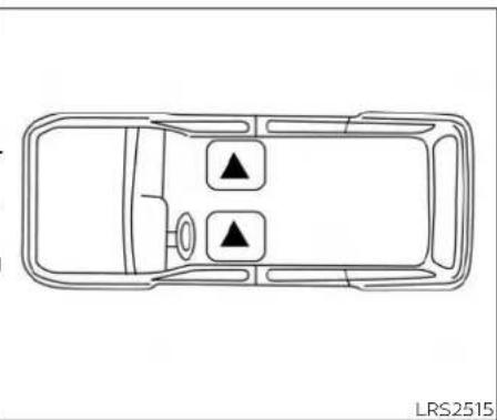
Top-down line drawing of a car interior layout with two directional indicators (no text or symbols)The illustration shows the seating positions equipped with head restraints/headrests.
▲ Indicates the seating position is equipped with a head restraint.
■Indicates the seating position is equipped with a headrest.
+ Indicates the seating position is not equipped with a head restraint or headrest (if applicable).
- Your vehicle is equipped with a head restraint/headrest that may be integrated, adjustable or non-adjustable.
- Adjustable head restraints/headrests have multiple notches along the stalk(s) to lock them in a desired adjustment position.
- The non-adjustable head restraints/headrests have a single locking notch to secure them to the seat frame.
• Proper Adjustment:
- For the adjustable type, align the head restraint/headrest so the center of your ear is approximately level with the center of the head restraint/headrest.
- If your ear position is still higher than the recommended alignment, place the head restraint/headrest at the highest position.
- If the head restraint/headrest has been removed, ensure that it is reinstalled and locked in place before riding in that designated seating position.
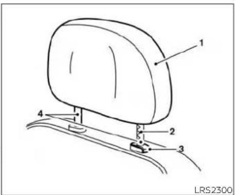
ADJUSTABLE HEAD RESTRAINT/ HEADREST COMPONENTS
- Removable head restraint/headrest
- Multiple notches
- Lock knob
- Stalks
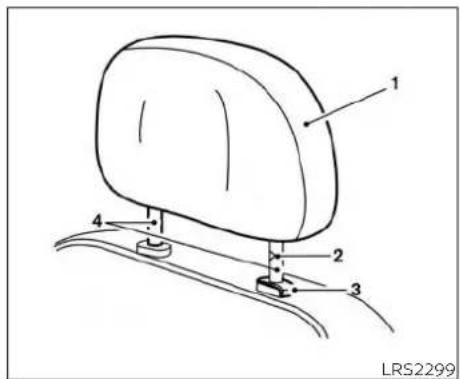
NON-ADJUSTABLE HEAD RESTRAINT/HEADREST COMPONENTS
- Removable head restraint/headrest
- Single notch
- Lock knob
- Stalks
1-8 Safety—Seats, seat belts and supplemental restraint system

natural_image
Diagram of a car seatbelt with directional arrows indicating movement (no text or symbols)- Reinstall and properly adjust the head restraint/headrest before an occupant uses the seating position.

REMOVE
Use the following procedure to remove the head restraint/headrest:
- Pull the head restraint/headrest up to the highest position.
- Push and hold the lock knob.
- Remove the head restraint/headrest from the seat.
- Store the head restraint/headrest properly in a secure place so it is not loose in the vehicle.
INSTALL
- Align the head restraint/headrest stalks with the holes in the seat. Make sure that the head restraint/headrest is facing the correct direction. The stalk with the notch (notches) ① must be installed in the hole with the lock knob ②.
- Push and hold the lock knob and push the head restraint/headrest down.
- Properly adjust the head restraint/headrest before an occupant uses the seating position.

natural_image
Side profile sketch of a person seated in a car seat, viewed from the side (no text or symbols)WRS0134 LRS2351 LRS2305

natural_image
Simple line drawing of a vehicle with a diagonal cross mark and an upward arrow, no text or symbols present.For non-adjustable head restraint/headrest
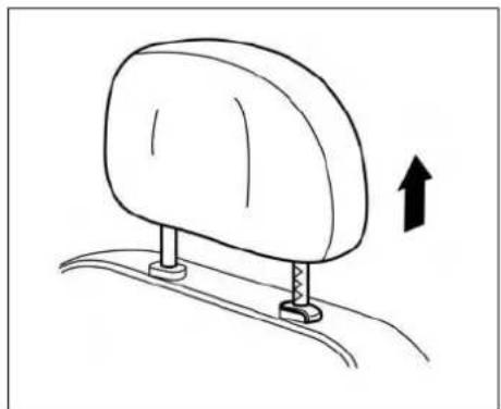
natural_image
Simple line drawing of a car seat with an upward arrow indicating motion (no text or symbols)Raise
ADJUST
For adjustable head restraint/headrest
Adjust the head restraint/headrest so the center is level with the center of your ear your ear position is still higher than the recommended alignment, place the head restraint/headrest at the highest position.
Make sure the head restraint/headrest is positioned so the lock knob is engaged in the notch before riding in that designated seating position.
To raise the head restraint/headrest, pull it up.
Make sure the head restraint/headrest is positioned so the lock knob is engaged in the notch before riding in that designated seating position.
SEAT BELTS

natural_image
Line drawing of a car seatbelt with directional arrows indicating movement (no text or symbols)Lower

PRECAUTIONS ON SEAT BELT USAGE

natural_image
Line drawing of a person seated in a car with a cross-shaped object on the steering wheel (no text or symbols)Most U.S. states and Canadian provinces or territories specify that seat belts be worn at all times when a vehicle is being driven.
To lower, push and hold the lock knob and push the head restraint/headrest down.
Make sure the head restraint/headrest is positioned so the lock knob is engaged in the notch before riding in that designated seating position.
If you are wearing your seat belt properly adjusted and you are sitting upright and well back in your seat with both feet on the floor, your chances of being injured or killed in a collision and/or the severity of injury may be greatly reduced. NISSAN strongly encourages you and all of your passengers to buckle up every time you drive, even if your seating position includes a supplemental air bag.

natural_image
Line drawing of a person sitting in a car seat, showing hands on the seat and dashboard (no text or symbols)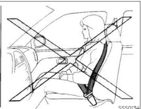
natural_image
Line drawing of a person seated in a car with a cross-shaped seatbelt (no text or symbols)
natural_image
Diagram of car seatbelt and passenger seatbelt crossed in a cross-section (no text or symbols)WARNING
- Every person who drives or rides in this vehicle should use a seat belt at all times.
WARNING
- The seat belt should be properly adjusted to a snug fit. Failure to do so may reduce the effectiveness of the entire restraint system and increase the chance or severity of injury in an accident. Serious injury or death can occur if the seat belt is not worn properly.
1-12 Safety—Seats, seat belts and supplemental restraint system

natural_image
Diagram of a person seated in a car with cross-shaped safety stripes (no text or symbols)WARNING
- Always route the shoulder belt over your shoulder and across your chest. Never put the belt behind your back, under your arm or across your neck. The belt should be away from your face and neck, but not falling off your shoulder.
-
Position the lap belt as low and snug as possible AROUND THE HIPS, NOT THE WAIST. A lap belt worn too high could increase the risk of internal injuries in an accident.
-
Be sure the seat belt tongue is securely fastened to the proper buckle.
- Do not wear the seat belt inside out twisted. Doing so may reduce its effectiveness.
- Do not allow more than one person to use the same seat belt.
- Never carry more people in the vehicle than there are seat belts.
- If the seat belt warning light glows continuously while the ignition is turned ON with all doors closed and all seat belts fastened, it may indicate a malfunction in the system. Have the system checked. It is recommended that you visit a NISSAN dealer for this service.
-
No changes should be made to the seat belt system. For example, do not modify the seat belt, add material, or install devices that may change the seat belt routing or tension. Doing so may affect the operation of the seat belt system. Modifying or tampering with the seat belt system may result in serious personal injury.
-
Once seat belt pretensioner(s) have activated, they cannot be reused and must be replaced together with the retractor. It is recommended that you visit a NISSAN dealer for this service.
All seat belt assemblies, including retractors and attaching hardware, should be inspected after any collision. It is recommended that you visit a NISSAN dealer for this service. NISSAN recommends that all seat belt assemblies in use during a collision be replaced unless the collision was minor and the belts show no damage and continue to operate properly. Seat belt assemblies not in use during a collision should also be inspected and replaced if either damage or improper operation is noted. - All child restraints and attaching hardware should be inspected after any collision. Always follow the restraint manufacturer's inspection instructions and replacement recommendations. The child restraints should be replaced if they are damaged.

natural_image
Silhouette of a person sitting cross-legged with a diagonal band crossing the seat (no text or symbols)LRS0786
SEAT BELT WARNING LIGHT
Both the driver's and passenger's front seats are equipped with a seat belt warning light. The warning light, located on the instrument panel, will show the status of the driver and passenger seat belt.
For additional information, refer to "Warning lights, indicator lights and audible reminders" In the "Instruments and controls" section of this manual.
PREGNANT WOMEN
NISSAN recommends that pregnant women use seat belts. The seat belt should be worn snug and always position the lap belt as low as possible around the hips, not the waist. Place the shoulder belt over your shoulder and across your chest. Never run the lap/shoulder belt over your abdominal area. Contact your doctor for specific recommendations.
INJURED PERSONS
NISSAN recommends that injured persons use seat belts. Check with your doctor for specific recommendations.
THREE-POINT TYPE SEAT BELT WITH RETRACTOR
A WARNING
- Every person who drives or rides in this vehicle should use a seat belt at all times.
Do not ride in a moving vehicle when the seatback is reclined. This can be dangerous. The shoulder belt will not be against your body. In an accident, you could be thrown into it and receive neck or other serious injuries. You could also slide under the lap belt and receive serious internal injuries.
- For the most effective protection when the vehicle is in motion, the seat should be upright. Always sit well back and upright in the seat with both feet on the floor and adjust the seat belt properly.
NOTE:
The front passenger seat belt warning light will not light up if the seat is not occupied.
- Do not allow children to play with the seat belts. Most seating positions are equipped with Automatic Locking Retractor (ALR) mode seat belts. If the seat belt becomes wrapped around a child's neck with the ALR mode activated, the child can be seriously injured or killed if the seat belt retracts and becomes tight. This can occur even if the vehicle is parked. Unbuckle the seat belt to release the child. If the seat belt cannot be unbuckled or is already unbuckled, release the child by cutting the seat belt with a suitable tool (such as a knife or scissors) to release the seat belt.

natural_image
Line drawing of a car seat with directional arrows indicating motion (no text or symbols)Fastening the seat belts
- Adjust the seat. For additional information, refer to "Seats" in this section.

natural_image
Line drawing of a person sitting in a car seatbelt, holding a belt and adjusting the seatbelt (no text or symbols present)-
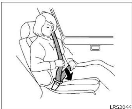
Slowly pull the seat belt out of the retractor and insert the tongue into the buckle until you hear and feel the latch engage.
-
The retractor is designed to lock during a sudden stop or on impact. A slow pulling motion permits the seat belt to move, and allows you some freedom of movement in the seat.
- If the seat belt cannot be pulled from its fully retracted position, firmly pull the belt and release it. Then smoothly pull the belt out of the retractor.
Safety—Seats, seat belts and supplemental restraint system
natural_image
Line drawing of a person sitting in a car seatbelt, showing seatbelt being lifted (no text or symbols)- Position the lap belt portion low and snug on the hips as shown.
- Pull the shoulder belt portion toward the retractor to take up extra slack. But sure the shoulder belt is routed over your shoulder and across your chest.
The front passenger seat three-point seat belt has two modes of operation:
• Emergency Locking Retractor (ELR)
• Automatic Locking Retractor (ALR)
The ELR mode allows the seat belt to extend and retract to allow the driver and passengers some freedom of movement in the seat. The ELR locks the seat belt when the vehicle slows down rapidly or during certain impacts.
The ALR mode (child restraint mode) locks the seat belt for child restraint installation.
When the ALR mode is activated, the seat belt cannot be extended again until the seat belt tongue is detached from the buckle and fully retracted. The seat belt returns to the ELR mode after the seat belt fully retracts. For additional information, refer to "Child restraints" in this section.
The ALR mode should be used only for child restraint installation. During normal seat belt use by a passenger, the ALR mode should not be activated. If it is activated it may cause uncomfortable seat belt tension. It can also change the operation of the front passenger air bag. For additional information, refer to "Front passenger air bag and status light" in this section.
WARNING
When fastening the seat belts, be certain that the seatbacks are completely secured in the latched position. If they are not completely secured, passengers may be injured in an accident or sudden stop.

Unfastening the seat belts
To unfasten the seat belt, press the button on the buckle①. The seat belt automatically retracts.
Checking seat belt operation
Seat belt retractors are designed to lock seat belt movement by two separate methods:
- When the seat belt is pulled quickly from the retractor
- When the vehicle slows down rapidly
To increase your confidence in the seat belts, check the operation as follows:
- Grasp the shoulder belt and pull forward quickly. The retractor should lock and restrict further belt movement.
If the retractor does not lock during this check, get the system checked. It is recommended that you visit a NISSAN dealer for this service, or to learn more about seat belt operation.
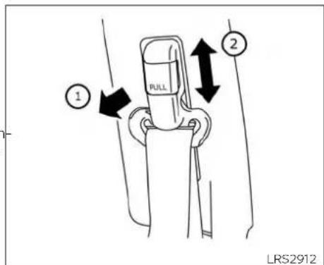
Driver's side
Shoulder belt height adjustment (driver's side)
The shoulder belt anchor height should be adjusted to the position best for you. For additional information, refer to "Precautions on seat belt usage" in this section. To adjust, pull out ① the adjustment button and move the shoulder belt anchor ② to the desired position, so the belt passes over the center of the shoulder. The belt should be away from your face and neck, but not falling off your shoulder. Release the adjustment button to lock the shoulder belt anchor into position.
WARNING
- After adjustment, release the adjustment button and try to move the shoulder belt anchor up and down to make sure it is securely fixed in position.
- The shoulder belt anchor height should be adjusted to the position best for you. Failure to do so may reduce the effectiveness of the entire restraint system and increase the chance or severity of injury in an accident.
SEAT BELT EXTENDERS
If, because of body size or driving position, it is not possible to properly fit the lap/shoulder belt and fasten it, an extender that is compatible with the installed seat belts is available for purchase. The extender adds approximately 8 in (200 mm) of length and may be used for either the driver or front passenger seating position. It is recommended that you visit a NISSAN dealer for assistance with purchasing an extender if an extender is required.
WARNING
- Only NISSAN seat belt extenders, made by the same company which made the original equipment seat belts, should be used with NISSAN seat belts.
- Adults and children who can use the standard seat belt should not use an extender. Such unnecessary use could result in serious personal injury in the event of an accident.
- Never use seat belt extenders to install child restraints. If the child restraint is not secured properly, the child could be seriously injured or killed in a collision or a sudden stop.
SEAT BELT MAINTENANCE
- To clean the seat belt webbing, apply a mild soap solution or any solution recommended for cleaning upholstery or carpet. Then wipe with a cloth and allow the seat belts to dry in the shade. Do not allow the seat belts to retract until they are completely dry.
- If dirt builds up in the shoulder belt guide of the seat belt anchors, the seat belts may retract slowly. Wipe the shoulder belt guide with a clean, dry cloth.
- Periodically check to see that the seat belt and the metal components, such as buckles, tongues, retractors, flexible wires and anchors, work properly. If loose parts, deterioration, cuts or other damage on the webbing is found, the entire seat belt assembly should be replaced.
CHILD SAFETY
WARNING
Do not allow children to play with the seat belts. Most seating positions are equipped with Automatic Locking Retractor (ALR) mode seat belts. If the seat belt becomes wrapped around a child's neck with the ALR mode activated, the child can be seriously injured or killed if the seat belt retracts and becomes tight. This can occur even if the vehicle is parked. Unbuckle the seat belt to release the child. If the seat belt cannot be unbuckled or is already unbuckled, release the child by cutting the seat belt with a suitable tool (such as a knife or scissors) to release the seat belt.
Children need adults to help protect them. They need to be properly restrained.
In addition to the general information in this manual, child safety information is available from many other sources, including doctors, teachers, government traffic safety offices, and community organizations. Every child is different, so be sure to learn the best way to transport your child. There are three basic types of child restraint systems:
- Rear-facing child restraint
Forward-facing child restraint - Booster seat
WARNING
- Never put a rear-facing child seat in the front seat.
be Never let an infant who requires the use of a rear-facing child restraint ri in this vehicle. Do not attempt to ho a child in your lap or arms.
- Infants and children need special protection. The vehicle's seat belts may not fit them properly. The shoulder belt may come too close to the face neck. The lap belt may not fit over their small hip bones. In an accident, an improperly fitting seat belt could cause serious or fatal injury. Always use appropriate child restraints.
- Never let a child stand or kneel on any seat and do not allow a child in the cargo area. The child could be seriously injured or killed in a sudden stop or collision.
The passenger seat is not suitable for use with a rear-facing child restraint needed for infants. Therefore, infants should not be transported in this vehicle.
All U.S. states and Canadian provinces or territories require the use of approved child restraints for infants and small children. For additional information, refer to "Child restraints" in this section.
A child restraint may be secured in the vehicle by using the vehicle seat belt. For additional information, refer to "Child restraints" in this section.
This is especially important because your vehicle has a supplemental restraint system (air bag system) for the front passenger. For additional information, refer to "Supplemental Restraint System (SRS)" in this section.
INFANTS
Infants up to at least 1 year old should be placed in a rear-facing child restraint. Because a rear-facing child restraint is not suitable for use in this vehicle, infants should not be transported in it.
SMALL CHILDREN
Children that are over 1 year old and weigh at least 20 lbs. (9 kg) should remain in a rear-facing child restraint as long as possible up to the height or weight limit of the child restraint. Children who outgrow the height or weight limit of the rear-facing child restraint and are at least 1 year old should be secured in a forward-facing child restraint with a harness. Refer to the manufacturer's instructions for minimum and maximum weight and height recommendations. NISSAN recommends that small children be placed in child restraints that comply with Federal Motor Vehicle Safety Standards or Canadian Motor Vehicle Safety Standards. You should choose a child restraint that fits your vehicle and always follow the manufacturer's instructions for installation and use.
LARGER CHILDREN
Children should remain in a forward-facing child restraint with a harness until they reach the maximum height or weight limit allowed by the child restraint manufacturer.
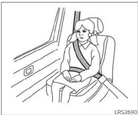
Once a child outgrows the height or weight limit of the harness-equipped forward-facing child restraint, NISSAN recommends that the child be placed in a commercially available booster seat to obtain proper seat belt fit. For a seat belt to fit properly, the booster seat should raise the child so that the shoulder belt is properly positioned across the chest and the top, middle portion of the shoulder. The shoulder belt should not cross the neck or face and should not fall off the shoulder. The lap belt should lie snugly across the lower hips or upper thighs, not the abdomen. A booster seat can only be used in seating positions that have a three-point type seat belt. The booster seat should fit the vehicle seat and have a label certifying that it complies with Federal Motor Vehicle Safety Standards or Canadian Motor Vehicle Safety Standards.
A booster seat should be used until the child can pass the seat belt fit test below:
- Are the child's back and hips against the vehicle seatback?
- Is the child able to sit without slouching?
Do the child's knees bend easily over the front edge of the seat with feet flat on the floor?
- Can the child safely wear the seat belt (lap belt low and snug across the hips and shoulder belt across mid-chest and shoulder)?
- Is the child able to use the properly adjusted head restraint/headrest?
- Will the child be able to stay in position for the entire ride?
CHILD RESTRAINTS
natural_image
Line drawing of a person sitting in a car seat, wearing a seatbelt and headband (no text or symbols)NOTE:
Laws in some communities may follow different guidelines. Check local and state regulations to confirm your child is using the correct restraint system before traveling.
WARNING
Never let a child stand or kneel on any seat and do not allow a child in the cargo area. The child could be seriously injured or killed in a sudden stop or collision.

natural_image
Line drawing of a person seated in a car with two crossed safety stripes (no text or symbols)If you answered no to any of these questions, the child should remain in a booster seat using a three-point type seat belt.

natural_image
Diagram of a car showing a person seated inside the seat with a cross symbol indicating no change or restriction (no text or labels present)PRECAUTIONS ON CHILD RESTRAINTS
WARNING
- Failure to follow the warnings and instructions for proper use and installation of child restraints could result in serious injury or death of a child or other passengers in a sudden stop or collision:
- The child restraint must be used and installed properly. Always follow all of the child restraint manufacturer's instructions for installation and use.
- Infants and children should never be held on anyone's lap. Even the strongest adult cannot resist the forces of a collision.
- Do not put a seat belt around both a child and another passenger.
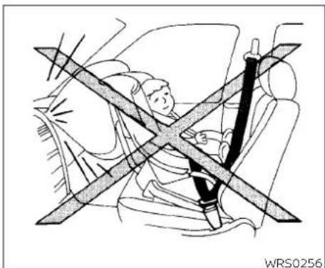
- Even with the NISSAN Advanced Air Bag System, never install a rear-facing child restraint in the front seat. An inflating supplemental air bag could seriously injure or kill your child.
- Never let an infant who requires the use of a rear-facing child restraint ride in this vehicle.
- Be sure to purchase a child restraint that will fit the child and vehicle. Some child restraints may not fit properly in your vehicle.
- Keep seatbacks as upright as possible after fitting the child restraint.
- Infants and children should always be placed in an appropriate child restraint while in the vehicle.
- When the child restraint is not in use, keep it secured with a seat belt. In a sudden stop or collision, loose objects can injure occupants or damage the vehicle.
CAUTION
A child restraint in a closed vehicle can become very hot. Check the seating surface and buckles before placing a child in the child restraint.
Several manufacturers offer child re- straints for infants and children of various sizes. When selecting any child restraint, keep the following points in mind:
- Choose only a restraint with a label certifying that it complies with Federal Motor Vehicle Safety Standard 213 or Canadian Motor Vehicle Safety Standard 213.
- Check the child restraint in your vehicle to be sure it is compatible with the vehicle's seat and seat belt system.
1-22 Safety—Seats, seat belts and supplemental restraint system
- If the child restraint is compatible with your vehicle, place your child in the child restraint and check the various adjustments to be sure the child restraint is compatible with your child. Choose a child restraint that is designed for your child's height and weight. Always follow all recommended procedures.
- Be sure to follow the child restraint manufacturer's instructions for installation.
All U.S. states and Canadian provinces or territories require that infants and small children be restrained in an approved child restraint at all times while the vehicle is being operated. Canadian law requires the top tether strap on forward-facing child restraints be secured to the designated anchor point on the vehicle.
TOP TETHER ANCHOR
WARNING
- Do not allow cargo to contact the top tether strap when it is attached to the top tether anchor. Properly secure the cargo so it does not contact the top tether strap. Cargo that is not properly secured or cargo that contacts the top tether strap may damage it during a collision. A child could be seriously injured or killed in a collision if the top tether strap is damaged.
- Child restraint anchorages are designed to withstand only those loads imposed by correctly fitted child restraints. Under no circumstances are they to be used to attach adult seat belts, or other items or equipment to the vehicle. Doing so could damage the child restraint anchorages. The child restraint will not be properly installed using the damaged anchorages, and a child could be seriously injured or killed in a collision.

- Top tether strap
- Anchor point
Top tether anchor point location
The anchor point is located on the front passenger seatback as shown.
natural_image
Diagram of a car showing a person seated inside a vehicle with a cross-shaped barrier (no text or symbols present)REAR-FACING CHILD RESTRAINT INSTALLATION USING THE SEAT BELTS
WARNING
- Never install a rear-facing child restraint in the front seat. An inflating supplemental air bag could seriously injure or kill your child.
- Never let an infant who requires the use of a rear-facing child restraint ride in this vehicle.
FORWARD-FACING CHILD RESTRAINT INSTALLATION USING THE SEAT BELTS
WARNING
The three-point seat belt with Automatic Locking Retractor (ALR) must be used when installing a child restraint. Failure to use the ALR mode will result the child restraint not being properly secured. The restraint could tip over or be loose and cause injury to a child in sudden stop or collision. Also, it can change the operation of the front passenger air bag. For additional information, refer to "Front passenger air bag and status light" in this section.

natural_image
Line drawing of a car interior showing seat, dashboard, and seatbelt (no text or symbols)Forward-facing (front passenger seat) - step 1
For additional information, refer to all warnings and Cautions in the "Child safety" and "Child restraints" sections of this manual before installing a child restraint.
Follow these steps to install a forward-facing child restraint using the vehicle seat belt in the front passenger seat:
- If you must install a child restraint in the front seat, it should be placed in a forward-facing direction only. Move the seat to the rearmost position. Child restraints for infants must be used in the rear-facing direction and,
1-24 Safety—Seats, seat belts and supplemental restraint system
therefore, must not be used in the front seat.
- Position the child restraint on the seat. Always follow the child restraint manufacturer's instructions.
The back of the child restraint should be secured against the vehicle seat-back.
If necessary, adjust or remove the head restraint/headrest to obtain the correct child restraint fit. If the head restraint/headrest is removed, store it in a secure place. Be sure to reinstall
the head restraint/headrest when the child restraint is removed. For additional information, refer to "Head restraints/headrests" in this section.

natural_image
Car seatbelt buckle diagram showing a black bandage inserted into the seat (no text or symbols)Do not install child restraints that require the use of a top tether strap in seating positions that do not have a top tether anchor.
Forward-facing - step 3
- Route the seat belt tongue through the child restraint and insert it into the buckle until you hear and feel the latch engage. Be sure to follow the child restraint manufacturer's instructions for belt routing.
If the child restraint is equipped with a top tether strap, route the top tether strap and secure the tether strap to the tether anchor point. For additional information, refer to "Installing top tether strap" in this section.
natural_image
Line drawing of a car seatbelt buckle with a belt buckle and hand adjusting the seat (no text or symbols)Forward-facing - step 4
natural_image
Line drawing of a car seatbelt with arrows indicating movement or force (no text or symbols)Forward-facing - step 5
natural_image
Line drawing of a car seatbelt with two black arrows indicating clockwise motion (no text or symbols)Forward-facing - step 6
-
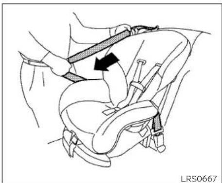
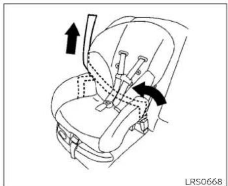
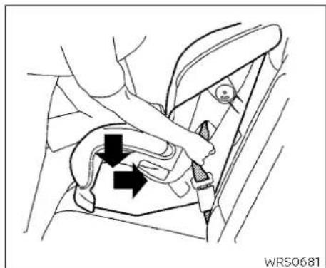
Pull the shoulder belt until the belt is fully extended. At this time, the seat belt retractor is in the ALR mode (child restraint mode). It reverts to ELR mode when the seat belt is fully retracted.
-
Allow the seat belt to retract. Pull up of the shoulder belt to remove any slack in the belt.
-
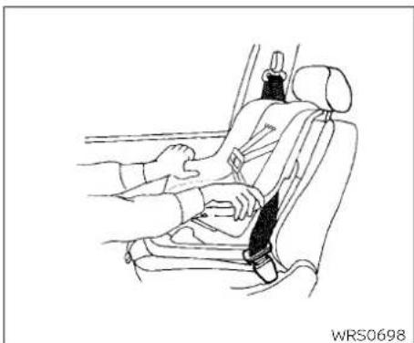
Remove any additional slack from the seat belt; press downward and rearward firmly in the center of the child restraint with your knee to compress the vehicle seat cushion and seatback while pulling up on the seat belt.
-
Tighten the tether strap according to the manufacturer's instructions to remove any slack.
1-26 Safety—Seats, seat belts and supplemental restraint system
natural_image
Line drawing of a car seatbelt with hands adjusting the seat (no text or symbols)Forward-facing - step 8
-
After attaching the child restraint, test it before you place the child in it. Push it from side to side while holding the child restraint near the seat belt path. The child restraint should not move more than 1 inch (25 mm), from side to side. Try to tug it forward and check to see if the belt holds the restraint in place. If the restraint is not secure, tighten the seat belt as necessary, or put the restraint in another seat and test it again. You may need to try a different child restraint. Not all child restraints fit in all types of vehicles.
-
Check to make sure the child restraint is properly secured prior to each use. If the seat belt is not locked, repeat steps 4 through 8.
WRS0475
Forward-facing - step 10
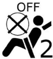
- If the child restraint is installed in the front passenger seat, place the ignition switch in the ON position. The front passenger air bag status light should illuminate. If this light is not illuminated refer to "Front passenger air bag and status light" in this section. Have the system checked. It is recommended that you visit a NISSAN dealer for this service.
After the child restraint is removed and the seat belt is fully retracted, the ALR mode (child restraint mode) is canceled.

Front passenger seat
Ⓐ Top tether strap
⑧ Anchor point
Installing top tether strap (front passenger seat)
The child restraint top tether strap must be used when installing the child restraint with the seat belts.
First, secure the child restraint with the seat belt.
WARNING
Child restraint anchorages are designed to withstand only those loads imposed by correctly fitted child restraints. Under no circumstances are they to be used to attach adult seat belts, or other items or equipment to the vehicle. Doing so could damage the child restraint anchorages. The child restraint will not be properly installed using the damaged anchorage, and a child could be seriously injured or killed in a collision.
- If necessary, raise or remove the head restraint/headrest to position the top tether strap® over the top of the seat back. If the head restraint/headrest is removed, store it in a secure place. Be sure to reinstall the head restraint/headrest when the child restraint is removed. For additional information, refer to "Head restraints/headrests" in this section.
-
Route the top tether stra(A) between the head restraint/headrest and the top of the seatback.
-
Secure the tether strap to the tether anchor point(B) as shown.
- Refer to the appropriate child restraint installation procedure steps in this section before tightening the tether strap.
If you have any questions when installing a top tether strap, it is recommended that you visit a NISSAN dealer for this service.
BOOSTER SEATS
For additional information on installing a booster seat in your vehicle, follow the instructions outlined in this section.
Precautions on booster seats
WARNING
If a booster seat and seat belt are not used properly, the risk of a child being injured or killed in a sudden stop or collision greatly increases:
- Make sure the shoulder portion of the belt is away from the child's face and neck and the lap portion of the belt does not cross the stomach.
1-28 Safety—Seats, seat belts and supplemental restraint system
- Make sure the shoulder belt is not behind the child or under the child's arm.
- A booster seat must only be installed in a seating position that has a lap/shoulder belt.

natural_image
Line drawing of two car seat compartments labeled A and B, showing different seat designs (no text or symbols beyond labels)A. Low back booster seat
B. High back booster seat
Booster seats of various sizes are offered by several manufacturers. When selecting any booster seat, keep the following points in mind:
- Choose only a booster seat with a label certifying that it complies with Federal Motor Vehicle Safety Standard 213 or Canadian Motor Vehicle Safety Standard 213.
- Check the booster seat in your vehicle to be sure it is compatible with the vehicle's seat and seat belt system.

natural_image
Line drawing of a person seated in a car seat, wearing a seatbelt and holding a belt (no text or symbols)LRS0454
- Make sure the child's head will be properly supported by the booster seat or vehicle seat. The seatback must be at or above the center of the child's ears. For example, if a low back booster seat is chosen, the vehicle seatback must be at or above the center of the child's ear. If the seatback is lower than the center of the child's ears, a high back booster seat should be used.
- If the booster seat is compatible with your vehicle, place the child in the booster seat and check the various adjustments to be sure the booster seat is compatible with the child. Always follow all recommended procedures.
All U.S. states and Canadian provinces of territories require that infants and small children be restrained in an approved child restraint at all times while the vehicle is being operated.
The instructions in this section apply to booster seat installation in the front passenger seat.
Booster seat installation
WARNING
To avoid injury to child, do not use the lap/shoulder belt in the Automatic Locking Retractor (ALR) mode when using a booster seat with the seat belts.
For additional information, refer to all Warnings and Cautions in the "Child safety", "Child restraints" and "Booster seats" sections of this manual before installing a child restraint.
Follow these steps to install a booster seat in the front passenger seat:

natural_image
Line drawing of a car interior showing seat, seatbelt, and passenger seat with directional arrow (no text or symbols)-
If you must install a booster seat in the front seat, move the seat to the rearmost position.
-
Position the booster seat on the seat. Only place it in a front-facing direction. Always follow the booster seat manufacturer's instructions.

natural_image
Line drawing of a person seated in a car seat using a seatbelt device (no text or symbols)LRS0454
Front passenger position
- The booster seat should be positioned on the vehicle seat so that it is stable.
If necessary, adjust or remove the head restraint/headrest to obtain the correct booster seat fit. If the head restraint/headrest is removed, store it in a secure place. Be sure to reinstall the head restraint/headrest when the booster seat is removed. For additional information, refer to "Head restraints/headrests" In this section.
If the seating position does not have an adjustable head restraint/headrest and it is interfering with the proper
booster seat fit, try another seating position or a different booster seat.
- Position the lap portion of the seat belt low and snug on the child's hips. Be sure to follow the booster seat manufacturer's instructions for adjusting the seat belt routing.
- Pull the shoulder belt portion of the seat belt toward the retractor to take up extra slack. Be sure the shoulder belt is positioned across the top, middle portion of the child's shoulder. Be sure to follow the booster seat manufacturer's instructions for adjusting the seat belt routing.
- Follow the warnings, cautions and instructions for properly fastening a seat belt shown in "Three-point type seat belt with retractor" in this section.
WRS0475
- If the booster seat is installed in the front passenger seat, place the ignition switch in the ON position. The front passenger air bag status light may or may not illuminate, depending on the size of the child and the type of booster seat being used. For additional information, refer to "Front passenger air bag and status light" in this section.
SUPPLEMENTAL RESTRAINT SYSTEM (SRS)
PRECAUTIONS ON SRS
This SRS section contains important information concerning the following systems:
- Driver and front passenger supplemental front-impact air bag (NISSAN Advanced Air Bag System)
- Front seat-mounted side-impact supplemental air bag
- Roof-mounted curtain side-impact and rollover supplemental air bag
- Seat belt with pretensioner(s) (front seats)
Supplemental front-impact air bag system
The NISSAN Advanced Air Bag System can help cushion the impact force to the head and chest of the driver and front passenger in certain frontal collisions.
Front seat-mounted side-impact supplemental air bag system
This system can help cushion the impact force to the chest area of the driver and front passenger in certain side-impact collisions. The side air bags are designed to inflate on the side where the vehicle is impacted.
Roof-mounted curtain side-impact and rollover supplemental air bag system
This system can help cushion the impact force to the head of occupants in front seating positions in certain side-impact collisions. The curtain air bags are designed to inflate on the side where the vehicle is impacted. In a rollover, the curtain air bags are designed to inflate and remain inflated for a short time.
The SRS is designed to supplement the crash protection provided by the driver and front passenger seat belts and is not a substitute for them. Seat belts should always be correctly worn and the occupant seated a suitable distance away from the steering wheel, instrument panel and door finishers. For additional information, refer to "Seat belts" in this section.
The supplemental air bags operate only when the ignition switch is placed in the ON position.
After placing the ignition switch in the ON position, the supplemental air bag warning light illuminates. The supplemental air bag warning light will turn off after about 7 seconds if the system is operational.
1-32 Safety—Seats, seat belts and supplemental restraint system

natural_image
Illustration of a person seated in a car with a belt bearing a diagonal band (no text or symbols)WARNING
- The front air bags ordinarily will not inflate in the event of a side impact, rear impact, rollover, or lower severity frontal collision. Always wear your seat belts to help reduce the risk or severity of injury in various kinds of accidents.
- The front passenger air bag will not inflate if the passenger air bag status light is lit. For additional information, refer to "Front passenger air bag and status light" in this section.
- The seat belts and the front air bags are most effective when you are sitting well back and upright in the seat. The front air bags inflate with great force. Even with the NISSAN Advanced Air Bag System, if you are unrestrained, leaning forward, sitting sideways or out of position in any way, you are at greater risk of injury or death in a crash. You may also receive serious or fatal injuries from the front air bag if you are up against it when it inflates. Always sit back against the seatback
and as far away as practical from the steering wheel or instrument panel. Always properly use the seat belts.
- The driver and front passenger seat belt buckles are equipped with sensors that detect if the seat belts are fastened. The NISSAN Advanced Air Bag System monitors the severity of a collision and seat belt usage, then inflates the air bags as needed. Failure to properly wear seat belts can increase the risk or severity of injury in an accident.
- The front passenger seat is equipped with an occupant classification sensor (weight sensor) that turns the front passenger air bag OFF under some conditions. This sensor is only used in this seat. Failure to be properly seated and wearing the seat belt can increase the risk or severity of injury in an accident. For additional information, refer to "Front passenger air bag and status light" in this section.
Keep hands on the outside of the steering wheel. Placing them inside the steering wheel rim could increase the risk that they are injured when the front air bag inflates.


natural_image
Diagram of a car seatbelt with diagonal crossed lines indicating safety (no text or symbols)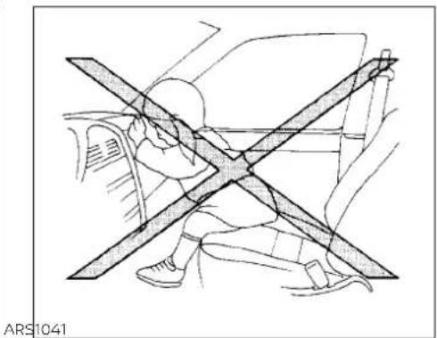
natural_image
Diagram showing a person sitting in a car with a diagonal line crossing through the window (no text or symbols)ARS1133 | ARS1041
WARNING
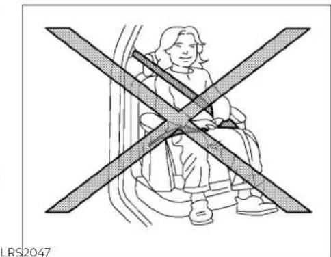
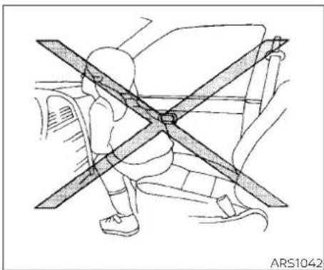
- Never let children ride unrestrained or extend their hands or face out of the window. Do not attempt to hold them in your lap or arms. Some examples of dangerous riding positions are shown in the illustrations.
1-34 Safety—Seats, seat belts and supplemental restraint system
natural_image
Line drawing of a person sitting on a car with two crossed arms, no text or symbols presentARS1042 ARS1043 ARS1044

natural_image
Diagram of a car interior showing steering wheel and dashboard (no text or symbols)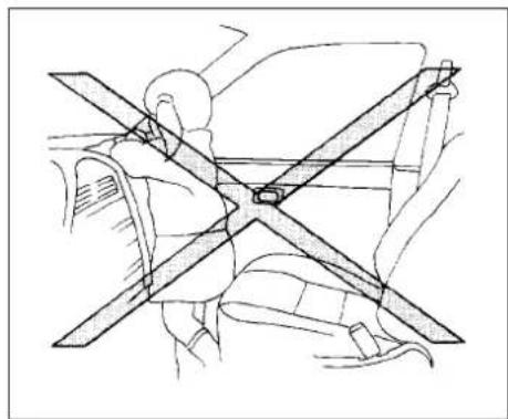
natural_image
Technical line drawing of a car seatbelt assembly (no text or symbols)WARNING
- Children may be severely injured or killed when the front air bags, side air bags or curtain air bags inflate if they are not properly restrained.

natural_image
Illustration of a person wearing a car seatbelt inside a vehicle, with no visible text or symbols.ARS1045 | ARS1046

natural_image
Line drawing of a person seated in a car seatbelt with visible straps and seatbelt (no text or symbols)WRS0431
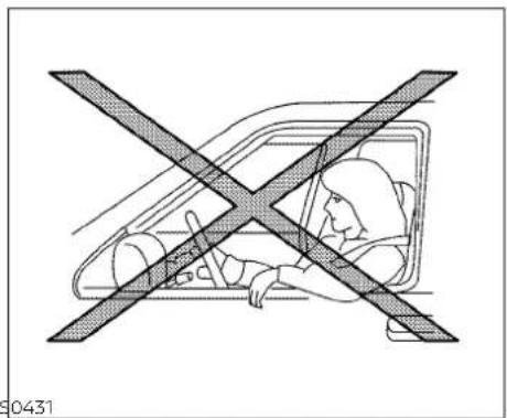
WARNING
- Even with the NISSAN Advanced Air Bag System, never install a rear-facing child restraint in the front seat. An inflating front air bag could seriously injure or kill your child. For additional information, refer to "Child restraints" in this section.
WARNING
Front seat-mounted side-impact supplemental air bags and roof-mounted curtain side-impact and roll-over supplemental air bags:
- The side air bags and curtain air bags ordinarily will not inflate in the event of a frontal impact, rear impact, or lower severity side collision. Always wear your seat belts to help reduce the risk or severity of injury in various kinds of accidents.
WARNING
- The seat belts, the side air bags and curtain air bags are most effective when you are sitting well back and upright in the seat with both feet on the floor. The side air bag and curtain air bag inflate with great force. Do not allow anyone to place their hand, leg or face near the side air bag on the side of the seatback of the front seat or near the side roof rails. Do not allow anyone sitting in the front seats to extend their hand out of the window or lean against the door. Some examples of dangerous riding positions are shown in the previous illustrations.
- Do not use seat covers on the front seatbacks. They may interfere with side air bag inflation.

SSS0162 SSS0159

natural_image
Diagram showing a person seated in a car with a cross-shaped barrier between them (no text or symbols present)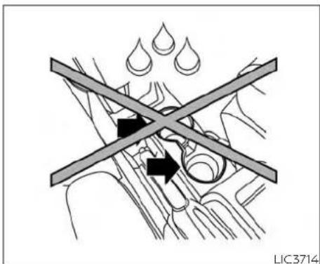
CAUTION
- Due to potential electrical component damage be careful to avoid spills near the center console, and immediately wipe any spilled liquids.
- DO NOT place uncovered or uncapped liquids, such as drinks, in the cup holders.
1-38 Safety—Seats, seat belts and supplemental restraint system
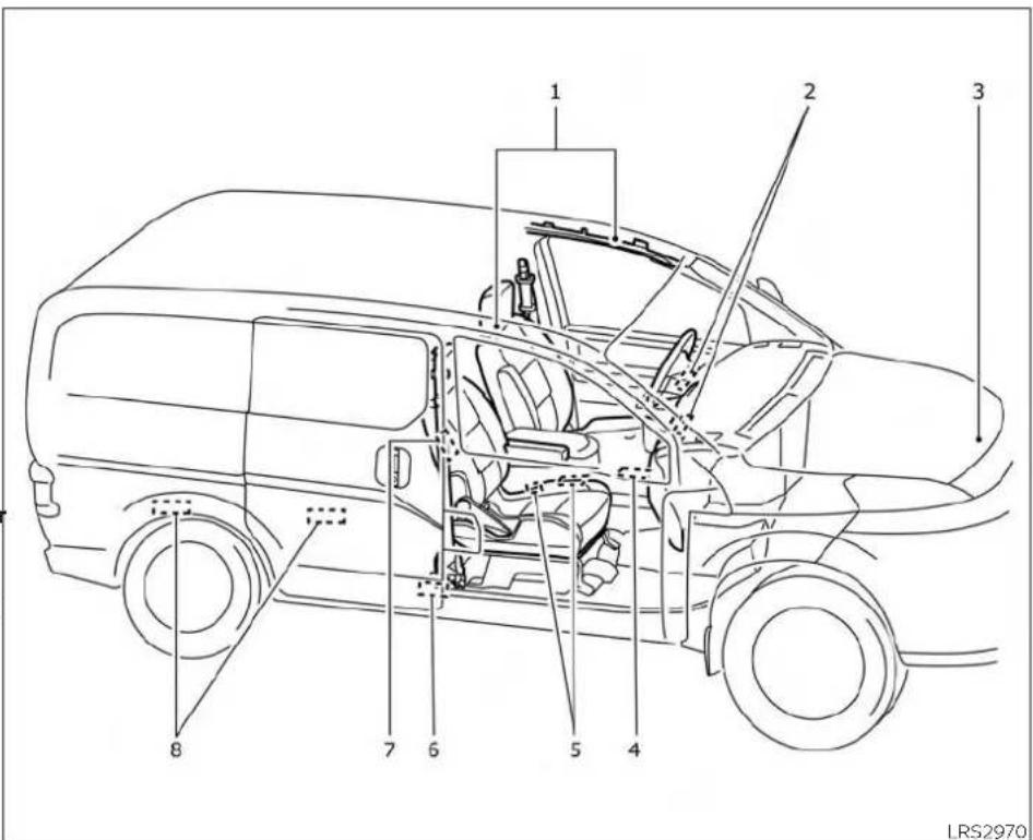
NISSAN Advanced Air Bag System (front seats)
- Roof-mounted curtain side-impact and rollover supplemental air bags
- Supplemental front-impact air bag modules
- Crash zone sensor
- Air bag Control Unit (ACU)
- Occupant classification sensor (weight sensor)
- Satellite sensors (passenger's side shown; driver's side similar)
- Front seat-mounted side-impact supplemental air bag modules (passenger's side shown; driver's side similar)
- Satellite sensors (passenger's side shown; driver's side similar)
WARNING
To ensure proper operation of the passenger's NISSAN Advanced Air Bag System, please observe the following items.
- Do not place heavy loads heavier than 9.1 lbs. (4 kg) on the seatback, head restraint/headrest or in the seatback pocket.
- Make sure that there is nothing pressing against the rear of the seatback, such as an object stored on the floor.
- Make sure that there is no object placed under the front passenger seat.
- Make sure that there is no object placed between the seat cushion and center console or between the seat cushion and the door.
-
If a forward-facing child restraint is installed in the front passenger seat, do not position the front passenger seat so the child restraint contacts the instrument panel. If the child restraint does contact the instrument panel, the system may determine the seat occupied and the passenger air bag may deploy in a collision. Also the front passenger air bag status light may not illuminate. For additional information, refer to "Child restraints" this section.
-
Confirm the operating condition with the front passenger air bag status light.
- If you notice that the front passenger air bag status light is not operating as described in this section, get the occupant classification system checked. It is recommended that you visit a NISSAN dealer for this service.
- Until you have confirmed with a dealer that your passenger seat occupant classification system is working properly, do not position the occupants in this seating position.
This vehicle is equipped with the NISSAN Advanced Air Bag System for the driver and front passenger seats. This system is designed to meet certification requirements
under U.S.regulations. It is also permitted in Canada. However, all of the information, is cautions and warnings in this manual still apply and must be followed.
The driver supplemental front-Impact air bag is located in the center of the steering wheel. The front passenger supplemental infront-Impact air bag is mounted in the dashboard above the glove box. The front air bags are designed to inflate in higher severity frontal collisions, although they
may inflate if the forces in another type of collision are similar to those of a higher severity frontal impact. They may not inflate in certain frontal collisions. Vehicle damage (or lack of it) is not always an indication of proper front air bag system operation.
The NISSAN Advanced Air Bag System monitors information from the crash zone sensor, the Air bag Control Unit (ACU), seat belt buckle sensors and occupation classification sensor (weight sensor). Inflator operation is based on the severity of a collision and seat belt usage for the driver. For the front passenger, the occupant classification sensor is also monitored. Based on information from the sensor, only one front air bag may inflate in a crash, depending on the crash severity and whether the front occupants are belted or unbelted. Additionally, the front passenger air bag may be automatically turned off under some conditions, depending on the weight detected on the front passenger seat and how the seat belt is used. If the front passenger air bag is OFF, the front passenger air bag status light will be illuminated. For additional information, refer to "Front passenger air bag and status light" in this section. One front air bag inflating does not indicate improper performance of the system.
If you have any questions about your air bag system, it is recommended that you visit a NISSAN dealer to obtain information about the system. If you are considering modification of your vehicle due to a disability, you may also contact NISSAN. Contact information is contained in the front of this Owner's Manual.
When a front air bag inflates, a fairly loud noise may be heard, followed by the release of smoke. This smoke is not harmful and does not indicate a fire. Care should be taken to not inhale it, as it may cause irritation and choking. Those with a history of a breathing condition should get fresh air promptly.
Front air bags, along with the use of seat belts, help to cushion the impact force on the face and chest of the front occupants. They can help save lives and reduce serious injuries. However, an inflating front air bag may cause facial abrasions or other injuries. Front air bags do not provide restraint to the lower body.
Even with NISSAN Advanced Air Bags, seat belts should be correctly worn and the driver and front passenger seated upright as far as practical away from the steering wheel or instrument panel. The front air
bags inflate quickly in order to help protect the front occupants. Because of this, the force of the front air bag inflating can increase the risk of injury if the occupant is too close to, or is against, the front air bag module during inflation.
The front air bags deflate quickly after a collision.
The front air bags operate only when the ignition switch is in the ON position.
After placing the ignition switch in the ON position, the supplemental air bag warning light illuminates. The supplemental air bag warning light will turn off after about 7 seconds if the system is operational.

WRS0475
Front passenger air bag and status lightStatus light
WARNING
The front passenger air bag is designed to automatically turn OFF under some conditions. Read this section carefully to learn how it operates. Proper use the seat, seat belt and child restraint necessary for most effective protection. Failure to follow all instructions this manual concerning the use of seats, seat belts and child restraints increase the risk or severity of injury an accident.
The front passenger seat is equipped with an occupant classification sensor (weight sensor) that turns the front passenger air bag on or off depending on the weight applied to the front passenger seat. The status of the front passenger air bag (ON or isFF) is indicated by the front passenger air bag status light which is located on the instrument panel.
After the ignition switch is placed in the can"ON" position, the front passenger air bag status light on the instrument panel illuminates for about 7 seconds and then turns off or remains illuminated depending on the front passenger seat occupied status. The light operates as follows:
| CONDITION DESCRIPTION | PASSENGER AIR BAG STATUS LIGHT (R) | FRONT PASSENGER AIR BAG STATUS | |
| Empty | Empty front passenger seat | ON (illuminated) | INHIBITED |
| Nobody/Somebody | Bag or Child or Child Restraint or Small Adult in front passenger seat | ON (illuminated) | INHIBITED |
| Adult | Adult in the front passenger seat | OFF (dark) | ACTIVATED |
In addition to the above, certain objects placed on the front passenger seat may also cause the light to operate as described above depending on their weight.
For additional information, refer to "Normal operation" and "Troubleshooting" in this section.
Front passenger air bag
The front passenger air bag is designed to automatically turn OFF when the vehicle is operated under some conditions as described below in accordance with U.S. regulations. If the front passenger air bag is Off, it will not inflate in a crash. The driver air bags and other air bags in your vehicle are not part of this system.
The purpose of the regulation is to help reduce the risk of injury or death from an inflating air bag to certain front passenger seat occupants, such as children, by requiring the air bag to be automatically turned OFF. Certain sensors are used to meet the requirements.
The occupant classification sensor in this vehicle is a weight sensor. It is designed to detect an occupant and objects on the seat by weight. For example, if a child is the front passenger seat, the NISSAN Advanced Air Bag System is designed to turn the front passenger air bag OFF in accordance with the regulations. Also, if a child restraint of the type specified in the regulations is on the seat, its weight and the child's weight can be detected and cause the air bag to turn OFF.
Front passenger seat adult occupants who placed on the seat could result in air bag are properly seated and using the seat belinflation, because of the object's weight de-as outlined in this manual should not be tested by the occupant classification sen-cause the front passenger air bag to be sor. Other conditions could also result in air automatically turned OFF. For small adults bag inflation, such as if a child is standing it may be turned OFF, however if the occu-on the seat, or if two children are on the pant takes his/her weight off the seat seat, contrary to the instructions in this bag cushion (for example, by not sitting uprightmanual. Always be sure that you and all by sitting on an edge of the seat, or by vehicle occupants are seated and re-otherwise being out of position), this could strained properly.
cause the sensor to turn the air bag OFF. Always be sure to be seated and wearing the seat belt properly for the most effective protection by the seat belt and supplemental air bag.
The occupant classification sensor is designed to operate as described above to turn the front passenger air bag OFF for specified child restraints as required by the regulations. Failing to properly secure child restraints and to use the ALR mode may allow the restraint to tip or move in a collision or sudden stop. This can also result the passenger air bag inflating in a crash instead of being OFF. For additional information, refer to "Child restraints" in this se Using the front passenger air bag status light, you can monitor when the front passenger air bag is automatically turned OFF.
If an adult occupant is in the seat but the front passenger air bag status light is illuminated (indicating that the air bag is OFF), it could be that the person is a small adult, nor is not sitting on the seat properly or not using the seat belt properly.
If a child restraint must be used in the front seat, the front passenger air bag status light may or may not be illuminated, depending on the size of the child and the type of child restraint being used. If the air bag status light is not illuminated (indicating that the air bag might inflate in a crash),
If the front passenger seat is not occupied, it could be that the child restraint or seat the front passenger air bag is designed nobelt is not being used properly. Make sure to inflate in a crash. However, heavy objects that the child restraint is installed properly,
1-42 Safety—Seats, seat belts and supplemental restraint system
the seat belt is used properly and the occ pant is positioned properly. If the air bag status light is still not illuminated, do not position an occupant or child restraint in this seating position.
If the front passenger air bag status light will not illuminate even though you believe that the child restraint, the seat belts and the occupant are properly positioned, it is recommended that you take your vehicle to a NISSAN dealer. A NISSAN dealer can check system status by using a special tool. However, until you have confirmed with a dealer that your air bag is working properly, do not position an occupant or child restraint in this seating position.
The NISSAN Advanced Air Bag System and front passenger air bag status light will take a few seconds to register a change in the front passenger seat status. This is normal system operation and does not indicate a malfunction.
If a malfunction occurs in the front passer ger air bag system, the supplemental air bag warning light ⚪, located in the meter and gauges area of the instrument panel, will be illuminated (blinking or steadily lit). Have the system checked. It is Recommended that you visit a NISSAN dealer for this service.
Normal operation
In order for the occupant classification sensor system to classify the front passenger based on weight, please follow the precautions and steps outlined below:
Precautions
- Make sure that there are no objects weighing over 9.1 lbs. (4 kg) hanging on the seat or placed in the seatback pocket.
- Make sure that an object is not pressing against the rear of the seatback.
- Make sure that the front passenger seat or seatback is not forced back against an object on the seat or floor behind it.
- Make sure that there is no object placed under the front passenger seat.
Steps
-
Adjust the seat as outlined in the "Seats" section of this manual. Sit upright, leaning against the seatback, and centered on the seat cushion with your feet comfortably extended to the floor.
-
Make sure there are no objects on your lap.
- Fasten the seat belt as outlined in the "Seat belts" section of this manual. Front passenger seat belt buckle status is monitored by the occupant classification system, and is used as an input to determine occupancy status. So, it is highly recommended that the front passenger fasten their seat belt.
- Remain in this position for 30 seconds allowing the system to classify the front passenger before the vehicle is put into motion.
- Ensure proper classification by checking the front passenger air bag status light.
NOTE:
This vehicle's occupant classification sensor system generally keeps the classification locked during driving, so it is important that you confirm that the front passenger is properly classified prior to driving. However, the occupant classification sensor may recalculate the weight of the occupant under some conditions (both while driving and when stopped), so front passenger seat occupants should continue to remain seated as outlined above.
Troubleshooting
If you think the front passenger air bag status light is incorrect:
- If the light is ON with an adult occupying the front passenger seat:
- Occupant is a small adult — the air bag light is functioning as intended. The front passenger air bag is suppressed.
However, if the occupant is not a small adult, then this may be due to the following conditions that may be interfering with the weight sensors:
- Occupant is not sitting upright, leaning against the seatback, and centered on the seat cushion with his/her feet comfortably extended to the floor.
- An object pressing against the rear of the seatback.
- Forcing the front seat or seatback against an object on the seat or floor - behind it.
- An object placed under the front passenger seat.
- An object placed between the seat cushion and center console or between the seat cushion and the door.
If the vehicle is moving, please come to a stop when it is safe to do so. Check and correct any of the above conditions. Restart the vehicle and wait 1 minute.
NOTE: A system check will be performed during which the front passenger air bag status light will remain lit for about 7 seconds initially.
If the light is still ON after this, the person should be advised not to ride in the front "passenger seat and the vehicle should be checked as soon as possible. It is recommended that you visit a NISSAN dealer for this service.
- If the light is OFF with a small adult, child or child restraint occupying the front passenger seat.
This may be due to the following conditions that may be interfering with the weight sensors:
- Small adult or child is not sitting upright, leaning against the seatback, and centered on the seat cushion with his/her feet comfortably extended to the floor.
- The child restraint is not properly installed, as outlined in the "Child restraints" section of this manual.
• An object weighing over 9.1 lbs. (4 kg) hanging on the seat or placed in the seatback pocket.
- An object pressing against the rear of the seatback.
- Forcing the front seat or seatback against an object on the seat or floor behind it.
1-44 Safety—Seats, seat belts and supplemental restraint system
- An object placed under the front passenger seat.
- An object placed between the seat cushion and center console.
If the vehicle is moving, please come to a stop when it is safe to do so. Check and correct any of the above conditions. Restart the vehicle and wait 1 minute.
NOTE:
A system check will be performed during which the front passenger air bag status-light will remain lit for about 7 seconds initially.
If the light is still OFF after this, the person should be repositioned and the vehicle should be checked as soon as possible. It recommended that you visit a NISSAN dealer for this service.
- If the light is OFF with no front passenger and no objects on the front passenger seat, the vehicle should be checked. It is recommended that you visit a NISSAN dealer as soon as possible.
Other supplemental front-impact air bag precautions
WARNING
- Do not place any objects on the steering wheel pad or on the instrument panel. Also, do not place any objects between any occupant and the steering wheel or instrument panel. Such objects may become dangerous projectiles and cause injury if the front air bags inflate.
- Immediately after inflation, several front air bag system components will be hot. Do not touch them; you may severely burn yourself.
- No unauthorized changes should be made to any components or wiring of the supplemental air bag system. This is to prevent accidental inflation of the supplemental air bag or damage to the supplemental air bag system.
-
Do not make unauthorized changes to your vehicle's electrical system, suspension system or front end structure. This could affect proper operation of the front air bag system.
-
Tampering with the front air bag system may result in serious personal injury. Tampering includes changes to the steering wheel and the instrument panel assembly by placing material over the steering wheel pad and above the instrument panel or by installing additional trim material around the air bag system.
- Removing or modifying the front passenger seat may affect the function of the air bag system and result in serious personal injury.
-
Modifying or tampering with the front passenger seat may result in serious personal injury. For example, do not change the front seats by placing material on the seat cushion or by installing additional trim material, such as seat covers, on the seat that are not specifically designed to assure proper air bag operation. Additionally, do not stow any objects under the front passenger seat or the seat cushion and seatback. Such objects may interfere with the proper operation of the occupant classification sensor (weight sensor).
-
No unauthorized changes should be made to any components or wiring of the seat belt system. This may affect the front air bag system. Tampering with the seat belt system may result in serious personal injury.
- It is recommended that you visit a NISSAN dealer for work on and around the front air bag. It is also recommended that you visit a NISSAN dealer for installation of electrical equipment. The Supplemental Restraint System (SRS) wiring harnesses* should not be modified or disconnected. Unauthorized electrical test equipment and probing devices should not be used on the air bag system.
- A cracked windshield should be replaced immediately by a qualified repair facility. A cracked windshield could affect the function of the supplemental air bag system.
*The SRS wiring harness connectors are yellow and orange for easy identification.
When selling your vehicle, we request that you inform the buyer about the front air bag system and guide the buyer to the appropriate sections in this Owner's Manual.
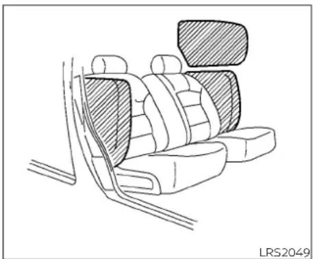
natural_image
Line drawing of a car backseat with seat covers and seatbelt, no text or symbols presentFront seat-mounted side-impact supplemental air bag and roof-mounted curtain side-impact and rollover supplemental air bag systems
The side air bags are located in the outside of the seatback of the front seats. The curtain air bags are located in the side roof rails. All of the information, cautions and warnings in this manual must be followed. The side air bags and curtain air bags are designed to inflate in higher severity side collisions, although they may inflate if the forces in another type of collision
are similar to those of a higher severity impact. They are designed to inflate on the side where the vehicle is impacted. They may not inflate in certain side collisions.
Vehicle damage (or lack of it) is not always an indication of proper side air bag and curtain air bag operation.
When the side air bags and curtain air bag inflate, a fairly loud noise may be heard, followed by release of smoke. This smoke is not harmful and does not indicate a fire. Care should be taken not to inhale it, as it may cause irritation and choking. Those with a history of a breathing condition should get fresh air promptly.
Side air bags, along with the use of seat belts, help to cushion the impact force on the chest and pelvic area of the front occupants. Curtain air bags help to cushion the impact force to the head of occupants in the front seating positions. They can help save lives and reduce serious injuries. However, an inflating side air bag and curtain a bag may cause abrasions or other injuries. Side air bags and curtain air bags do not provide restraint to the lower body.
The seat belts should be correctly worn and the driver and passenger seated up-right as far as practical away from the side-air bag. The side air bags and curtain air bags inflate quickly in order to help protect the occupants. Because of this, the force of the side air bag and curtain air bag inflating can increase the risk of injury if the occupant is too close to, or is against, these air bag modules during inflation. The side air bag will deflate quickly after the collision is over.
The curtain air bag will remain inflated for a short time.
The side air bags and curtain air bags operate only when the ignition switch is placed in the ON position.
After placing the ignition switch in the ON position, the supplemental air bag warning light illuminates. The supplemental air bag warning light will turn off after about 7 seconds if the system is operational.
WARNING
Do not place any objects near the seatback of the front seats. Also, do not place any objects (an umbrella, bag, etc.) between the front door finisher and the front seat. Such objects may become dangerous projectiles and cause injury if a side air bag inflates.
- Right after inflation, several side air bag and curtain air bag system components will be hot. Do not touch them; you may severely burn yourself.
- No unauthorized changes should be made to any components or wiring of the side air bag and curtain air bag systems. This is to prevent damage to or accidental inflation of the side air bag and curtain air bag or damage to the side air bag and curtain air bag systems.
-
Do not make unauthorized changes to your vehicle's electrical system, suspension system or side panel. This could affect proper operation of the side air bag and curtain air bag systems.
-
Tampering with the side air bag system may result in serious personal injury. For example, do not change the front seats by placing material near the seatbacks or by installing additional trim material, such as seat covers, around the side air bag.
- It is recommended that you visit a NISSAN dealer for work on and around the side air bag and curtain air bag. It is also recommended that you visit a NISSAN dealer for installation of electrical equipment. The SRS wiring harnesses* should not be modified or disconnected. Unauthorized electrical test equipment and probing devices should not be used on the side air bag or curtain air bag system.
\*The SRS wiring harness connectors are yellow and orange for easy identification.
When selling your vehicle, we request that you inform the buyer about the side air bag and curtain air bag systems and guide the buyer to the appropriate sections in this Owner's Manual.
Seat belt with pretensioner(s) - (front seats)
WARNING
- The pretensioner(s) cannot be reused after activation. They must be replaced together with the retractor and buckle as a unit.
If the vehicle becomes involved in a collision but pretensioner(s) are not activated, be sure to have the pretensioner system checked and, if necessary, replaced. It is recommended that you visit a NISSAN dealer for this service.
No unauthorized changes should be made to any components or wiring the pretensioner system. This is to prevent damage to or accidental activation of the pretensioner(s). Tampering with the pretensioner system may result in serious personal injury.
- It is recommended that you visit a NISSAN dealer for work on and around the pretensioner system. It is also recommended that you visit a NISSAN dealer for installation of electrical equipment. Unauthorized electrical test equipment and probing devices should not be used on the pretensioner system.
- If you need to dispose of the pretensioner(s) or scrap the vehicle, it is recommended that you visit a NISSAN dealer for this service. Incorrect disposal procedures could cause personal injury.
The pretensioner system may activate with the supplemental air bag system in certain types of collisions. Working with the seat belt retractor, the pretensioner(s) help tighten the seat belt when the vehicle becomes involved in certain types of collisions, helping to restrain front seat occupants.
The pretensioner(s) are encased within the seat belt retractor and to the seat belt anchor affixed to the floor of the vehicle. These seat belts are used the same way as conventional seat belts.
When pretensioner(s) activate, smoke is released and a loud noise may be heard. This smoke is not harmful and does not indicate a fire. Care should be taken not to inhale it, as it may cause irritation and choking. Those with a history of a breathing condition should get fresh air promptly. After the pretensioner(s') activation, load limiters allow the seat belt to release webbing (if necessary) to reduce forces against the chest.
The supplemental air bag warning light 🎨 Is used to indicate malfunctions in the pretensioner system. For additional information, refer to "Supplemental air bag warning light" in this section. If the operation of the supplemental air bag warning light indicates there is a malfunction, have the system checked. It is recommended that you visit a NISSAN dealer for this service.
When selling your vehicle, we request that you inform the buyer about the pretensioner system and guide the buyer to the appropriate sections in this Owner's Manual.
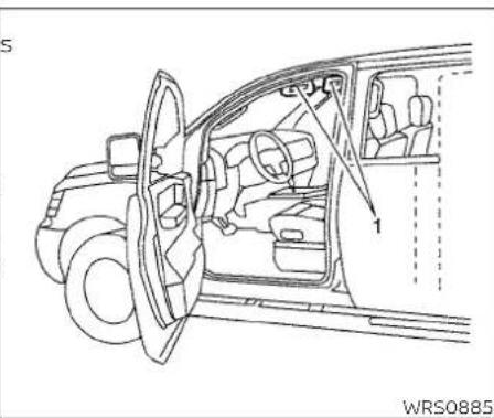
natural_image
Line drawing of a car interior showing steering wheel, dashboard, and steering wheel (no text or symbols)- SRS Air bag warning labels
The warning labels are located on the surface of the sun visor.
SUPPLEMENTAL AIR BAG WARNING LABELS
Warning labels about the supplemental front-impact air bag system are placed in the vehicle as shown in the illustration.
WARNING
Do not use a rear-facing child restraint on a seat protected by an air bag in front of it. If the air bag deploys, it may cause serious injury or death.

natural_image
Abstract black-and-white icon of two stylized human figures in motion (no text or symbols)LRS0100
SUPPLEMENTAL AIR BAG WARNING LIGHT
The supplemental air bag warning light, displaying ⚙ in the instrument panel, monitors the circuits for the air bag systems, pretensioner(s) and all related wiring. When the ignition switch is placed in the C position, the supplemental air bag warning light illuminates for about 7 seconds and then turns off. This means the system is operational.
If any of the following conditions occur, the front air bag, side air bag, curtain air bag and pretensioner systems need servicing:
- The supplemental air bag warning light remains on after approximately 7 seconds.
- The supplemental air bag warning light flashes intermittently.
- The supplemental air bag warning light does not come on at all.
Under these conditions, the front air bag, side air bag, curtain air bag or pretensione systems may not operate properly. They must be checked and repaired. It is recommended that you visit a NISSAN dealer for this service.
A WARNING
If the supplemental air bag warning light is on, it could mean that the front air bag, side air bag, curtain air bag and/or pretensioner systems will not operate in an accident. To help avoid injury to yourself or others, have your vehicle checked as soon as possible. It is recommended that you visit a NISSAN dealer for this service.
Repair and replacement procedure
The front air bags, side air bags, curtain air bags and pretensioner(s) are designed to inflate on a one-time-only basis. As a reminder, unless it is damaged, the supplemental air bag warning light remains illuminated after inflation has occurred. These systems should be repaired and/or replaced as soon as possible. It is recommended that you visit a NISSAN dealer for this service.
When maintenance work is required on the vehicle, the front air bags, side air bags, curtain air bags, pretensioner(s) and related parts should be pointed out to the person performing the maintenance. The ignition switch should always be placed in the LOCK position when working under the hood or inside the vehicle.
WARNING
- Once a front air bag, side air bag, or curtain air bag has inflated, the air bag module will not function again and must be replaced. Additionally, the activated pretensioner(s) must also be replaced. The air bag module and pretensioner(s) should be replaced. It is recommended that you visit a NISSAN dealer for this service. However, the air bag module and pretensioner(s) cannot be repaired.
- The front air bag, side air bag, curtain air bag systems and the pretensioner system should be inspected if there is any damage to the front end or side portion of the vehicle. It is recommended that you visit a NISSAN dealer for this service.
- If you need to dispose of the supplemental air bag or pretensioner systems or scrap the vehicle, it is recommended that you visit a NISSAN dealer. Incorrect disposal procedures could cause personal injury.
- If there is an impact to your vehicle from any direction, your Occupant Classification Sensor (OCS) should be checked to verify it is still functioning correctly. It is recommended that you visit a NISSAN dealer for this service. The OCS should be checked even if no air bags deploy as a result of the impact. Failure to verify proper OCS function may result in an improper air bag deployment resulting in injury or death.
MEMO
1-52 Safety—Seats, seat belts and supplemental restraint system
2 Instruments and controls
Instrument panel 2 - 2
Meters and gauges....2-3
Speedometer and odometer 2-4
Tachometer 2-6
Fuel gauge 2-6
Trip computer 2-7
Outside temperature display (if so equipped) 2 - 8
Warning lights, indicator lights and audible
reminders 2 - 9
Checking lights 2-10
Warning lights 2-10
Indicator lights 2-15
Audible reminders 2-17
Security systems 2-18
Vehicle security system (if so equipped) ..... 2-18
NISSAN Vehicle Immobilizer System 2-19
Wiper and washer switch 2-21
Switch operation 2-21
Rear window and/or outside mirror defroster
switch (if so equipped)....2-22
Headlight and turn signal switch 2-23
Headlight control switch....2-23
Daytime Running Lights (DRL) system ..... 2-24
Instrument brightness control....2-24
Turn signal switch 2-25
Horn 2-25
Vehicle Dynamic Control (VDC) OFF switch.....2-26
Rear Sonar System (RSS) OFF switch (if so equipped) 2-26
Power outlet(s) 2-27
Storage 2-28
Front-door pockets....2-28
Under-seat storage bin....2-28
Storagetrays....2-29
Glove box....2-29
Cup holders 2-30
D-Rings (if so equipped) 2-30
Windows 2-31
Power windows 2-31
Interior lights 2-33
Map lights 2-34
Cargo light 2-35
INSTRUMENT PANEL

2-2 Instruments and controls
- Vents (P. 4-11)
- Headlight/turn signal switch (P. 2-23)
- Driver's supplemental air bag (P. 1-32) Horn (P. 2-25)
- Meters and gauges (P. 2-3) Warning and indicator lights (P. 2-9)
- Cruise control switches (if so equipped) (P. 5-18)
- Wiper and washer switch (P. 2-21)
- Rear window and/or outside mirror defroster switch (if so equipped) (P. 2-22)
- Audio system*
- Passenger's supplemental air bag (P. 1-32)
- Glove box (P. 2-28)
- Climate controls (P. 4-11)
- Front passenger air bag status light (P. 2-15)
- Cup holders (P. 2-28)
- Shift lever (P. 5-14)
- AUX input/USB port*
- Rear Sonar System (RSS) OFF switch (if so equipped) (P. 5-29)
- Hazard warning flasher switch (P. 6-2)
- Ignition switch (P. 5-8)
METERS AND GAUGES
- Audio control switches* Bluetooth® Hands-Free Phone System*
- Fuel-filler door release lever (P. 3-14) Hood release lever (P. 3-13)
- Fuse box (P. 8-18)
- Electronic outside rearview mirror control switch (if so equipped) (P. 3-19)
- Vehicle Dynamic Control (VDC) OFF switch (P. 2-26)
*Refer to the separate NissanConnect® Owner's Manual
Refer to the page number indicated in parentheses for operating details.
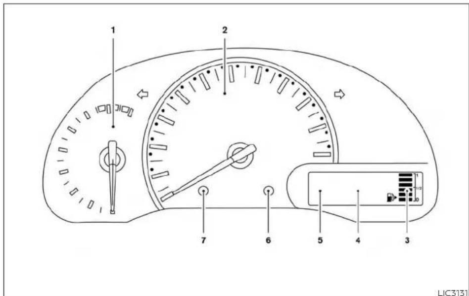
- Tachometer
- Speedometer
- Fuel gauge
-
Odometer Twin trip odometer Trip computer
-
Continuously Variable Transmission (CVT) position indicator
- Instrument brightness control knob
- Change/reset button
SPEEDOMETER AND ODOMETER
This vehicle is equipped with a speedometer and odometer. The speedometer is located in the center of the meter cluster. The odometer is located within the trip computer.

natural_image
Line drawing of a speedometer gauge with needle and scale (no text or symbols)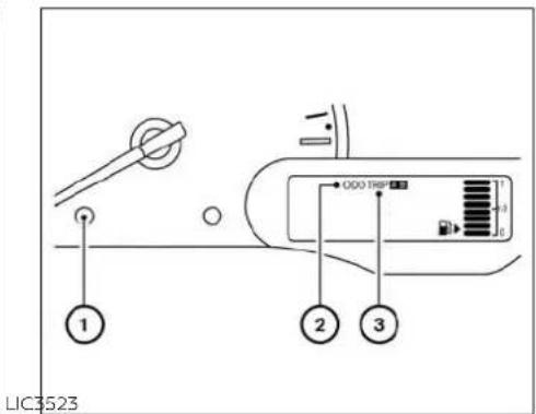
Speedometer
The speedometer indicates vehicle speed.
Odometer/Twin trip odometer
The odometer/twin trip odometer is displayed when the ignition switch is placed in the ON position.
The odometer ② records the total distance the vehicle has been driven.
The twin trip odomete ③ records the distance of individual trips.
2-4 Instruments and controls
Changing the display
Press the change/reset button ① to change the display as follows:
Odometer (ODO) → Trip A → Trip B →Instant fuel consumption → Average fuel consumption → DTE (cruising range) → Outside air temperature (if so equipped) → Odometer (ODO)
Resetting the trip odometer
Press the change/reset button for more than 1 second to reset the currently displayed trip odometer to zero.

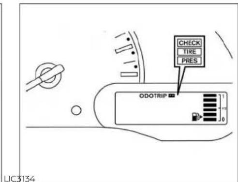
Loose fuel cap warning message
Press the change/reset button for more than 1 second to reset the LOOSE FUEL C warning message after the fuel cap has been tightened. For additional information, refer to "Fuel-filler cap" in the "Pre-driving checks and adjustments" section of this manual.
Check tire pressure warning message
The CHECK TIRE PRES (pressure) warning message is displayed when the low tire pressure warning light is illuminated and low tire pressure is detected. Check and adjust the tire pressure to the recommended COLD tire pressure shown on the Tire and Loading Information label. The CHECK TIRE PRES (pressure) warning message turns off when the low tire pressure warning light turns off.
The low tire pressure warning light remains illuminated until the tires are inflated to the recommended COLD tire pressure. The CHECK TIRE PRES (pressure) warning message is displayed each time the ignition switch is placed in the ON position as long as the low tire pressure warning light remains illuminated.
For additional information, refer to "Low tire pressure warning light" in this section, "Tire Pressure Monitoring System (TPMS)" In the "Starting and driving" section, and "Wheels and tires" in the "Do-it-yourself" section of this manual.

LIC2107 LIC\$135

FUEL GAUGE
TACHOMETER
The tachometer indicates engine speed in revolutions per minute (rpm). Do not rev the engine into the red zone.
CAUTION
When engine speed approaches the red zone, reduce engine speed. Operating the engine in the red zone may cause serious engine damage.
The gauge indicatesⒶ the approximate fuel level in the tank when the ignition switch is placed in the ON position.
The gauge may move slightly during braking, turning, acceleration, or going up or down hills.
The low fuel warning light will turn on when the amount of fuel in the tank is getting low,
2-6 Instruments and controls
Refill the fuel tank before the gauge registers E (Empty).
The ▶ indicates that the fuel-filler door is located on the passenger's side of the vehicle.
CAUTION
- If the vehicle runs out of fuel, the check engine light may come on. Refuel as soon as possible. After a few driving trips, the light should turn off. If the light remains on after few driving trips, have the system checked. It is recommended that you visit a NISSAN dealer for this service.
- For additional information, refer to "Malfunction Indicator Light (MIL)" in this section.
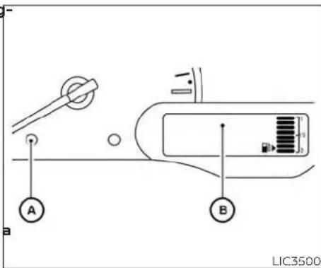
TRIP COMPUTER
When the ignition switch is placed in the position, modes of the trip computer can be selected by pressing the change/reset button Ⓐ on the instrument panel located near the speedometer. The following modes can be selected in the display:
- Trip A
- Trip B
- Instant fuel economy
• Average fuel consumption
• Distance to empty
Trip A
Measures the distance of one specific trip.
Trip B
Measures the distance of a second specific trip.
Instant fuel consumption
The instant fuel consumption mode shows the instant fuel economy. The display updates instantly when driving.
Average fuel consumption
The average fuel consumption mode shows the average fuel consumption since the last reset. Resetting is done by pressing the change/reset button® for more than approximately 1 second.
Distance to empty
The distance to empty mode provides you with an estimation of the distance that can be driven before refueling. The range is constantly being calculated, based on the amount of fuel in the fuel tank and the actual fuel consumption.
The distance to empty includes a low range warning feature: when the fuel level is low, the distance to empty is automatically selected and the digits blink in order to draw the driver's attention. Press the trip computer change/reset button Ⓐ if you wish to return to the mode that was selected before the warning occurred.
When the fuel level drops even lower, the distance to empty will display (----).
Trip computer reset
Pressing the change/reset button for more than 3 seconds will reset all modes except Trip A and distance to empty.
OUTSIDE TEMPERATURE DISPLAY (if so equipped)
The outside temperature function provides a display of the outside temperature when the ignition switch is placed in the ON position.
The display of positive temperatures is unsigned (blank); negative temperatures are prefixed with a minus sign.
2-8 Instruments and controls
WARNING LIGHTS, INDICATOR LIGHTS AND AUDIBLE REMINDERS

CHECKING LIGHTS
With all doors closed, apply the parking brake, fasten the seat belts and place the ignition switch in the ON position without starting the engine. The following lights (if so equipped) will come on:
BRAKE or ⏻, 📄, 📋, PS The following lights (if so equipped) come on briefly and then go off:
ABS or (Aided) (!) O/D OFF
If any light fails to come on or operate in way other than described, it may indicate burned-out bulb and/or a system malfunction. Have the system checked. It is recommended that you visit a NISSAN dealer for this service.
WARNING LIGHTS
This vehicle has various warning lights that may illuminate to indicate a potential problem. For additional information, refer to the specific light in this section.
ABS or (ABS) Anti-lock Braking System (ABS) warning light
When the ignition switch is placed in the position, the ABS warning light illuminates and then turns off. This indicates the ABS operational.
If the ABS warning light illuminates while the engine is running or while driving, it may indicate the ABS is not functioning properly. Have the system checked. It is recommended that you visit a NISSAN dealer for this service.
af an ABS malfunction occurs, the anti-lock function is turned off. The brake system then operates normally but without anti-lock assistance. For additional information, refer to "Brake system" in the "Starting and driving" section of this manual.
BRAKE or (!) Brake warning light
This light functions for both the parking brake and the foot brake systems.
Parking brake indicator
When the ignition switch is placed in the ON position, the light comes on when the parking brake is applied.
Low brake fluid warning light
When the ignition switch is placed in the ON position, the light warns of a low brake fluid level. If the light comes on while the engine is running with the parking brake not applied, stop the vehicle and perform the following:
-
Check the brake fluid level. Add brake fluid as necessary. For additional information, refer to "Brake fluid" in the "Do-it-yourself" section of this manual.
-
If the brake fluid level is correct, have the warning system checked. It is recommended that you visit a NISSAN dealer for this service.
WARNING
- Your brake system may not be working properly if the warning light is on. Driving could be dangerous. If you judge it to be safe, drive carefully to the nearest service station for repairs. Otherwise, have your vehicle towed because driving it could be dangerous.
- Pressing the brake pedal with the engine stopped and/or a low brake fluid level may increase your stopping distance and braking will require greater pedal effort as well as pedal travel.
- If the brake fluid level is below the MINIMUM or MIN mark on the brake fluid reservoir, do not drive until the brake system has been checked. It is recommended that you visit a NISSAN dealer for this service.

Charge warning light
If this light comes on while the engine is running, it may indicate the charging system is not functioning properly. Turn the engine off and check the generator belt. If the belt is loose, broken, or missing, or if the light remains on, have the system checked
It is recommended that you visit a NISSAN dealer for this service.
CAUTION
- Do not ground electrical accessories directly to the battery terminal. Doing so will bypass the variable voltage control system and the vehicle battery may not charge completely. For additional information, refer to "Variable voltage control system" in the "Do-it-yourself" section of this manual.
- Do not continue driving if the generator belt is loose, broken or missing.

Door open warning light
This light comes on when any of the doc are not closed securely while the ignition switch is placed in the ON position.

Engine oil pressure warning light
This light warns of low engine oil pressure. If the light flickers or comes on during normal driving, pull off the road in a safe area, stop the engine immediately and call a NEISSAN dealer or other authorized repair shop.
The engine oil pressure warning light is not designed to indicate a low oil level. Use the dipstick to check the oil level. For additional information, refer to "Engine oil" in the "Do-it-yourself" section of this manual.
CAUTION
Running the engine with the engine oil pressure warning light on could cause serious damage to the engine almost immediately. Such damage is not covered by the NISSAN New Vehicle Limited Warranty. Turn off the engine as soon as it is safe to do so.

High temperature warning light (red)
When the ignition switch is placed in the ON position, the high temperature warning light illuminates and then turns off. This indicates that the high temperature sensor in the engine coolant system is operational.
CAUTION
If the high temperature warning light illuminates while the engine is running, it may indicate the engine temperature is extremely high. Stop the vehicle safely as soon as possible. If the vehicle is overheated, continuing vehicle operation may seriously damage the engine. For additional information, refer to "If your vehicle overheats" in the "In case of emergency" section of this manual.

Low fuel warning light
This light comes on when the fuel level in the fuel tank is getting low. Refuel as soon as it is convenient, preferably before the fuel gauge reaches 0 (Empty). There will be a small reserve of fuel in the tank when the fuel gauge reaches 0 (Empty).

Low tire pressure warning light
Your vehicle is equipped with a Tire Pressure Monitoring System (TPMS) that monitors the tire pressure of all tires except the spare.
The low tire pressure warning light warns of low tire pressure or indicates that the TPMS is not functioning properly.
After the ignition switch is placed in the C position, this light illuminates for about 1 second and turns off.
Low tire pressure warning
If the vehicle is being driven with low pressure, the warning light will illuminate.
A CHECK TIRE PRES (pressure) warning message is also displayed in the odometer.
The low tire pressure warning light remains illuminated until the tires are inflated to the recommended COLD tire pressure. The CHECK TIRE PRES warning message is displayed each time the ignition switch is placed in the ON position as long as the low tire pressure warning light remains illuminated.
For additional information, refer to "Check tire pressure warning message" in this section and "Tire Pressure Monitoring System (TPMS)" in the "Starting and driving" section and in the "In case of emergency" section of this manual.
TPMS malfunction
When the low tire pressure warning light illuminates, you should stop and adjust the tire pressure of all four tires to the recommended COLD tire pressure shown on the Tire and Loading Information label located in the driver's door opening. The low tire pressure warning light does not automatically turn off when the tire pressure is adjusted. After the tire is inflated to the recommended pressure, the vehicle must be driven at speeds
above 16 mph (25 km/h) to activate the TPMS and turn off the low tire pressure warning light. Use a tire pressure gauge to check the tire pressure.
If the TPMS is not functioning properly, the low tire pressure warning light will flash for approximately 1 minute when the ignition switch is placed in the ON position. The light will remain on after 1 minute. Have the system checked. It is recommended that you visit a NISSAN dealer for this service. The "CHECK TIRE PRES" warning does not appear if the low tire pressure warning light illuminates to indicate a TPMS malfunction.
For additional information, refer to "Tire Pressure Monitoring System (TPMS)" in the "Starting and driving" section and "Tire pressure" in the "Do-it-yourself" section of this manual.
WARNING
- Radio waves could adversely affect electric medical equipment. Those who use a pacemaker should contact the electric medical equipment manufacturer for the possible influences before use.
- If the light does not illuminate with the ignition switch placed in the ON position, have the vehicle checked as soon as possible. It is recommended that you visit a NISSAN dealer for this service.
- If the light illuminates while driving, avoid sudden steering maneuvers or abrupt braking, reduce vehicle speed, pull off the road to a safe location and stop the vehicle as soon as possible. Driving with under-inflated tires may permanently damage the tires and increase the likelihood of tire failure. Serious vehicle damage could occur and may lead to an accident and could result in serious personal injury or death. Check the tire pressure for all four tires. Adjust the tire pressure to the recommended COLD tire pressure show on the Tire and Loading Information label located in the driver's door opening to turn the low tire pressure warning light off. If the light still illuminates while driving after adjusting the tire pressure, a tire may be flat or the TPMS may be malfunctioning. If you have a flat tire, replace it with a spare tire as soon as possible. If no tire is flat and all tires are properly inflated, have the vehicle checked. It is recommended that you visit a NISSAN dealer for this service.
- When replacing a wheel without the TPMS such as the spare tire, the TPMS will not function and the low tire pressure warning light will flash for approximately 1 minute. The light will remain on after 1 minute. Have your tires replaced and/or TPMS system reset as soon as possible. It is recommended that you visit a NISSAN dealer for these services.
- Replacing tires with those not originally specified by NISSAN could affect the proper operation of the TPMS.
CAUTION
- The TPMS is not a substitute for the regular tire pressure check. Be sure to check the tire pressure regularly.
- If the vehicle is being driven at speeds of less than 16 mph (25 km/h), the TPMS may not operate correctly.
- Be sure to install the specified size of tires to the four wheels correctly.

Low windshield-washer fluid warning light (if so equipped)
This light comes on when the windshield-washer fluid is at a low level. Add windshield-washer fluid as necessary. For additional information, refer to "Windshield-washer fluid" in the "Do-it-yourself" section of this manual.

Power steering warning light
WARNING
- If the engine is not running or is turned off while driving, the power sist for the steering will not work. Steering will be harder to operate.
- When the power steering warning light illuminates with the engine running, there will be no power assist for the steering. You will still have control of the vehicle, but the steering will be harder to operate. Have the power steering system checked. It is recommended that you visit a NISSAN dealer for this service.
When the ignition switch is placed in the C position, the power steering warning light illuminates. After starting the engine, the power steering warning light turns off. This indicates the power steering is operational. If the power steering warning light illuminates while the engine is running, it may indicate the power steering is not functioning properly and may need servicing. Have the power steering checked. It is recommended that you visit a NISSAN dealer for this servic
When the power steering warning light illuminates with the engine running, there will be no power assist for the steering, but you will still have control of the vehicle. At this time, greater steering effort is required to operate the steering wheel, especially in sharp turns and at low speeds.
For additional information, refer to "Power steering" in the "Starting and driving" section of this manual.

Seat belt warning light and chime
The light and chime remind you to fasten your seat belts. The light illuminates whenever the ignition switch is placed in the O
or START position and remains illuminated until the driver's seat belt is fastened. At the
Name time, the chime sounds for about 6 seconds unless the driver's seat belt is securely fastened.
The seat belt warning light may also illuminate if the front passenger's seat belt is not fastened when the front passenger's seat is occupied. For 7 seconds after the ignition switch is placed in the ON position, the system does not activate the warning light for the front passenger.
For additional information, refer to "Seat belts" in the "Safety—Seats, seat belts and supplemental restraint system" section of this manual.

Supplemental air bag warning light
When the ignition switch is placed in the ON or START position, the supplemental air bag warning light illuminates for about 7 seconds and then turns off. This means the system is operational.
If any of the following conditions occur, the front air bag, side air bag, curtain air bag, and pretensioner seat belt systems need servicing:
- The supplemental air bag warning light rene mains on after approximately 7 seconds.
- The supplemental air bag warning light flashes intermittently.
- The supplemental air bag warning light does not come on at all.
It is recommended that you visit a NISSAN dealer for these services.
Unless checked and repaired, the supplemental restraint system (air bag system) and/or the pretensioner(s) may not function properly. For additional information, refer to "Supplemental Restraint System (SRS)" in the "Safety—Seats, seat belts and supplemental restraint system" section of this manual.
WARNING
If the supplemental air bag warning light is on, it could mean that the front air bag, side air bag, curtain air bag and/or pretensioner systems will not operate in an accident. To help avoid injury to yourself or others, have your vehicle checked as soon as possible. It recommended that you visit a NISSAN dealer for this service.
INDICATOR LIGHTS
This vehicle has various indicator lights that may illuminate to indicate a system status. For additional information, refer to the specific light in this section.

Continuously Variable Transmission (CVT) position indicator light
When the ignition key is turned to the ON position, this indicator light shows the shift lever position. For additional information, refer to "Driving the vehicle" in the "Starting and driving" section of this manual.
CRUISE CRUISE indicator light (if so equipped)
The light comes on when the cruise contr ON/OFF switch is pushed. The light goes out when the ON/OFF switch is pushed again. When the CRUISE indicator light comes on, the cruise control system is operational. For additional information, refer to "Cruise control" in the "Starting and driving" section of this manual.

Front passenger air bag status light
The front passenger air bag status light will be lit and the passenger front air bag will be off depending on how the front passenger seat is being used.
For front passenger air bag status light operation, refer to "Front passenger air bag and status light" in the "Safety — Seats, seat belts and supplemental restraint system" section of this manual.

High beam indicator light (blue)
This blue light comes on when the head-light high beams are on and goes out when the low beams are selected.

Malfunction Indicator Light (MIL)
If this indicator light comes on steady or blinks while the engine is running, it may indicate a potential emission control malfunction.
The may also come on steady if the fuel-filler cap is loose or missing or if the vehicle runs out of fuel. Check to make sure the fuel-filler cap is installed and closed tightly and that the vehicle has at least 3 ga (11.4 L) of fuel in the fuel tank.
After a few driving trips, the light should turn off if no other potential emission control system malfunction exists. If this indicator light comes on steady for 20 seconds and then blinks for 10 seconds when the engine is not running, it indicates that the vehicle is not ready for an emission control system inspection/maintenance test. For additional information, refer to "Readiness for Inspection/Maintenance (I/M) test" in the "Technical and consumer information" section of this manual.
Operation
The MIL will come on in one of two ways:
- MIL on steady — An emission control gal system malfunction has been detected. Check the fuel-filler cap. If the LOOSE FUEL CAP warning message is displayed in the odometer, and the fuel filler cap is loose or missing, tighten or install the cap and continue to drive th
vehicle. The light should turn off after a few driving trips. If the light does not turn off after a few driving trips, have the vehicle inspected. It is recommended that you visit a NISSAN dealer for this service. You do not need to have your vehicle towed to the dealer.
- MIL blinking — An engine misfire has been detected which may damage the emission control system. To reduce or avoid emission control system damage:
- do not drive at speeds above 45 mph (72 km/h);
-
avoid hard acceleration or deceleration;
-
avoid steep uphill grades;
- if possible, reduce the amount of cargo being hauled.
The MIL may stop blinking and come on steady. Have the vehicle inspected. It is recommended that you visit a NISSAN dealer for this service. You do not need to have your vehicle towed to the dealer.
CAUTION
Continued vehicle operation without having the emission control system checked and repaired as necessary could lead to poor driveability, reduced fuel economy, and possible damage to the emission control system.
O/D OFF Overdrive OFF indicator light
The overdrive OFF indicator light illuminates when the overdrive OFF mode is selected.
For additional information, refer to "Continuously Variable Transmission (CVT)" in the "Starting and driving" section of this manual.

Security indicator light
This light blinks when the ignition switch placed in the OFF, LOCK or ACC position.
The blinking security indicator light indicates that the security systems equipped on the vehicle are operational.
For additional information, refer to "Security systems" in this section.

Slip indicator light
This indicator light will blink when the VDC system is operating, thus alerting the drive to the fact that the road surface is slipper and the vehicle is nearing its traction limits.
You may feel or hear the system working; this is normal.
The light will blink for a few seconds after the VDC system stops limiting wheel spin.
The indicator light also comes on when you place the ignition switch in the ON position. The light will turn off after approximately 2 seconds if the system is operational. If the light does not come on have the system checked, it is recommended that you visit a NISSAN dealer for this service.

Turn signal/hazard indicator lights
3 The appropriate light flashes when the turn signal switch is activated.
Both lights flash when the hazard switch is turned on.

Vehicle Dynamic Control (VDC) OFF indicator light
This indicator light comes on when the VDC OFF switch is pushed to off. This indi-
cates the VDC system has been turned off push the VDC OFF switch again or restart the engine and the system will operate normally. For additional information, refer
to "Vehicle Dynamic Control (VDC) system" in the "Starting and driving" section of this manual.
The VDC OFF indicator light also comes on when you place the ignition switch in the ON position. The light will turn off after about 2 seconds if the system is operational. If the light stays on or comes on along with the 🎨 Indicator light while you are driving, have the VDC system checked. It is recommended that you visit NISSAN dealer for this service.
While the VDC system is operating, you might feel a slight vibration or hear the system working when starting the vehicle or accelerating, but this is normal.
AUDIBLE REMINDERS
Brake pad wear warning
The disc brake pads have audible wear warnings. When a disc brake pad requires replacement, it makes a high pitched scraping sound when the vehicle is in motion, whether or not the brake pedal is defpressed. Have the brakes checked as soon as possible if the warning sound is heard.
Key reminder chime
A chime sounds if the driver's door is opened while the key is left in the ignition switch. Remove the key and take it with you when leaving the vehicle.
Light reminder chime
With the ignition switch placed in the OFF position, a chime sounds when the driver's door is opened if the headlights or parking lights are on.
Turn the headlight control switch off before leaving the vehicle.
SECURITY SYSTEMS
Parking brake reminder chime
A chime sounds if the parking brake is set and the vehicle is driven. The chime will stop if the parking brake is released or the vehicle speed returns to zero.

natural_image
Line drawing of a car with concentric circular patterns and a person climbing it, no text or symbols presentYour vehicle may have one of the following security systems:
- Vehicle security system
• NISSAN Vehicle Immobilizer System
VEHICLE SECURITY SYSTEM (if so equipped)
The vehicle security system provides visual and audible alarm signals if someone opens the doors when the system is armed. It is not, however, a motion detection type system that activates when a vehicle is moved or when a vibration occurs. The system helps deter vehicle theft but cannot prevent it, nor can it prevent the theft of interior or exterior vehicle components in all situations. Always secure your vehicle even if parking for a brief period. Never leave your keys in the ignition, and always lock the vehicle when unattended. Be aware of your surroundings, and park in secure, well-lit areas whenever possible.
Many devices offering additional protection, such as component locks, identification markers, and tracking systems, are available at auto supply stores and specialty shops. A NISSAN dealer may also offer such equipment. Check with your insurance company to see if you may be eligible for discounts for various theft protection features.
How to arm the vehicle security system
- Close all windows. (The system can be armed even if the windows are open.)
- Remove the key from the ignition switch.
- Close all doors. Lock all doors. The doors can be locked with the key, power door lock switch or with the key fob.
Key fob operation:
- Press the 🔒 button on the key fob. All doors lock. The hazard lights flash twice and the horn beeps once to indicate all doors are locked.
- When the 🔒 button is pressed with all doors locked, the hazard lights flash twice and the horn beeps once as a reminder that the doors are already locked.
The horn may or may not beep. For additional information, refer to "Silencing the horn beep feature" in the "Pre-driving checks and adjustments" section of this manual.
-
Confirm that the indicator light comes on. The light stays on for about 30 seconds. The vehicle security system is now pre-armed. After about 30 seconds the vehicle security system automatically shifts into the armed phase. The light begins to flash once every 3 seconds. If, during the 30-second pre-arm time period, the door is unlocked by the key or door lock switch or the key fob, or any door is open, or the ignition key is turned to ACC or ON, the system will not arm.
-
If the key is turned slowly when lock-The alarm is activated by:
ing the door, the system may not arm. Furthermore, if the key is turned beyond the vertical position toward the unlock position to remove the key, the system may be disarmed when the key is removed. If the indicator light fails to glow for a period of time, unlock the door once and lock it again. - Even when the driver and/or passengers are in the vehicle, the system will arm with all doors closed and locked
NISSAN VEHICLE IMMOBILIZER SYSTEM
Opening a door without using the key or key fob (even if the door is unlocked by using the inside lock knob or the power door lock switch).
How to stop an activated alarm The alarm stops only by unlocking the driver's door with the key or pressing the button on the key fob.
NISSAN VEHICLE IMMOBILIZER SYSTEM
with the ignition key in the OFF position.
Vehicle security system activation
The vehicle security system will give the following alarm:
• The headlights blink and the horn sounds intermittently.
- The alarm automatically turns off after a period of time. However, the alarm reactivates if the vehicle is tampered with again. The alarm can be shut off by2. unlocking the driver's door with the key or by pressing the button on the key fob.
The NISSAN Vehicle Immobilizer System will not allow the engine to start without the use of a registered key.
If the engine fails to start using a registered key (for example, when interference is caused by another registered key, an automated toll road device or automatic payment device on the key ring), restart the engine using the following procedures:
- Leave the ignition switch in the ON position for approximately 5 seconds.
1/2 . Place the ignition switch in the OFF or LOCK position and wait approximately 10 seconds.
- Repeat steps 1 and 2.
- Restart the engine while holding the device (which may have caused the interference) separate from the registered key.
If the no start condition reoccurs, NISSAN recommends placing the registered key or a separate key ring to avoid interference from other devices.
For Canada:
This device complies with Industry Canada licence-exempt RSS standard(s). Operation is subject to the following two conditions: (1) this device may not cause interference, and (2) this device must accept any interference received, including interference that may cause undesired operation of the device.
Never leave these keys in the vehicle.
FCC Notice:
For USA:
This device complies with Part 15 of the FCC Rules. Operation is subject to the following two conditions: (1) This device may not cause harmful interference, and (2) this device must accept any interference received, including interference that may cause undesired operation.
NOTE:
Changes or modifications not expressly approved by the party responsible for compliance could void the user's authority to operate the equipment.

natural_image
Simple line drawing of a car silhouette with a key on the roof (no text or symbols)Security indicator light
This light blinks whenever the ignition switch is placed in the LOCK, OFF or ACC position.
This function indicates the NISSAN Vehicle Immobilizer System is operational.
If the NISSAN Vehicle Immobilizer System is malfunctioning, the light will remain on while the ignition switch is placed in the ON position.
2-20 Instruments and controls
WIPER AND WASHER SWITCH
If the light still remains on and/or the engine will not start, seek service for the NISSAN Vehicle Immobilizer System as soon as possible. Please bring all registered keys that you have. It is recommended that you visit a NISSAN dealer for this service.
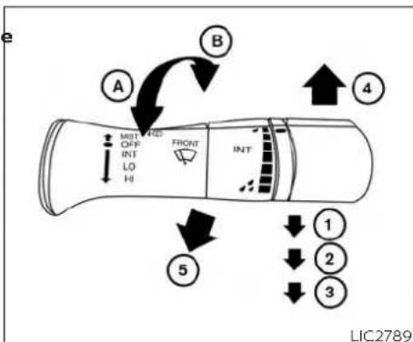
SWITCH OPERATION
WARNING
In freezing temperatures the washer solution may freeze on the windshield and obscure your vision which may lead to an accident. Warm the windshield with the defroster before you wash the windshield.
CAUTION
- Do not operate the washer continuously for more than 30 seconds.
- Do not operate the washer if the windshield-washer fluid reservoir is empty.
- Do not fill the windshield-washer fluid reservoir with windshield-washer fluid concentrates at full strength. Some methyl alcohol based windshield-washer fluid concentrates may permanently stain the grille if spilled while filling the windshield-washer fluid reservoir.
- Pre-mix windshield-washer fluid concentrates with water to the manufacturer's recommended levels before pouring the fluid into the windshield-washer fluid reservoir. Do not use the windshield-washer fluid reservoir to mix the windshield-washer fluid concentrate and water.
REAR WINDOW AND/OR OUTSIDE MIRROR DEFROSTER SWITCH (if so equipped)
NOTE:
If the windshield wiper operation is interrupted by snow or ice, the wiper may stop moving to protect its motor. If this occurs, turn the wiper switch to the OFF position and remove the snow or ice that is on and around the wiper arms. In approximately 1 minute, turn the switch on again to operate the wiper.
The windshield wiper and washer operates when the ignition switch is in the ON position.
Push the lever down to operate the wiper at the following speed:
① Intermittent (INT) — intermittent operation can be adjusted by turning the knob toward Ⓐ (Slower) or Ⓑ (Faster).
② Low (LO) — continuous low speed operation
③ High (HI) — continuous high speed operation
Push the lever up④ to have one sweep operation (MIST) of the wiper.
Pull the lever toward you⑤ to operate the washer. The wiper will also operate several times.
LIC0388
Type A (if so equipped)
To defrost the rear window and/or outside mirrors:
Start the engine and push the rear window defroster switch. The rear window defroster indicator light on the switch comes on. Push the switch again to turn the defroster off.
The rear window defroster automatically turns off after approximately 15 minutes.

LIC4253
Type B (if so equipped)
2-22 Instruments and controls
HEADLIGHT AND TURN SIGNAL SWITCH
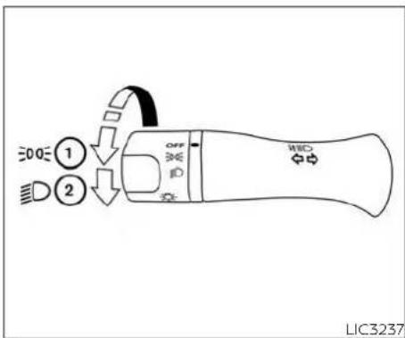

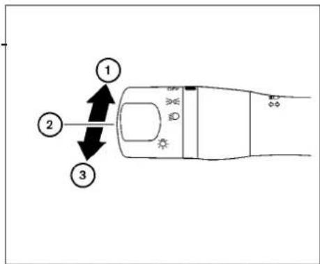
HEADLIGHT CONTROL SWITCH
Lighting
① Rotate the switch to the position, and the front parking, tail, license plate, and instrument panel lights will come on.
② Rotate the switch to the position, and the headlights will come on and all the other lights remain on.
Headlight beam select
① To select the high beam function, push the lever forward. The high beam lights come on and the ☐ light illuminates.
② Pull the lever back to select the low beam.
③ Pulling and releasing the lever flashes the headlight high beams on and off.
Battery saver system
If the ignition switch is placed in the OFF position while the headlight switch is in the ED or position, the headlights will turn off after a period of time.
CAUTION
Even though the battery saver feature automatically turns off the headlights after a period of time, you should turn the headlight switch to the OFF position when the engine is not running to avoid discharging the vehicle battery.
DAYTIME RUNNING LIGHTS (DRL) SYSTEM
The headlights automatically illuminate at a reduced intensity when the engine is started with the parking brake released. The Daytime Running Lights (DRL) operate with the headlight switch in the OFF position. Turn the headlight switch to the
or position for full illumination when driving at night.
If the parking brake is applied before the engine is started, the DRL do not illuminate. The DRL illuminate when the parking brake is released. The DRL will remain on until the ignition switch is placed in the OFF position.
2-24 Instruments and controls
WARNING
When the DRL system is active, tail lights on your vehicle are not on. It is necessary at dusk to turn on your head lights. Failure to do so could cause an accident injuring yourself and others.
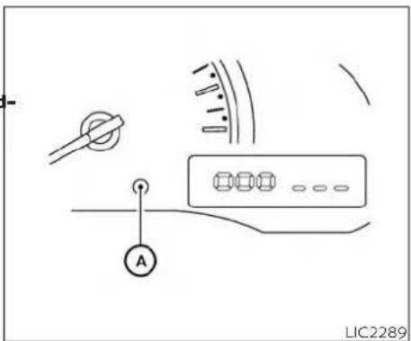
INSTRUMENT BRIGHTNESS CONTROL
The instrument brightness control operates when the headlight control switch is in the DDA or position.
Push the control Ⓐ to adjust the brightness of the instrument panel lights.
HORN

Lane change signal
Move the lever up or down until the turn signal begins to flash, but the lever does not latch, to signal a lane change. Hold the lever until the lane change is completed. Move the lever up or down until the turn signal begins to flash, but the lever does not latch, and release the lever. The turn signal will automatically flash three times (if so equipped).
Choose the appropriate method to signal a lane change based on road and traffic conditions.
LIC2419

natural_image
Diagram of a car steering wheel with directional arrows indicating clockwise motion (no text or symbols)TURN SIGNAL SWITCH
Turn signal
Move the lever up or down to signal the turning direction. When the turn is completed, the turn signals cancel automatically.
To sound the horn, push near the horn icon on the steering wheel.
WARNING
Do not disassemble the horn. Doing so could affect proper operation of the supplemental front air bag system. Tampering with the supplemental front air bag system may result in serious personal injury.
VEHICLE DYNAMIC CONTROL (VDC) OFF SWITCH
REAR SONAR SYSTEM (RSS) OFF SWITCH (if so equipped)
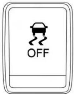
LIC3344 LIC2881
Push the VDC OFF switch again or restart the engine to turn on the system. For additional Information, refer to "Vehicle Dynamic Control (VDC) system" in the "Starting and driving" section of this manual.

The vehicle should be driven with the VDC system on for most driving conditions.
If the vehicle is stuck in mud or snow, the VDC system reduces the engine output to reduce wheel spin. The engine speed will be reduced even if the accelerator is depressed to the floor. If maximum engine power is needed to free a stuck vehicle, turn the VDC system off.
To turn off the VDC system, push the VDC OFF switch. The 📄 indicator will come on.
WARNING
The RSS is a convenience but it is not a substitute for proper backing. Always turn and check that it is safe to do so before backing up. Always back up slowly.
The RSS is active when the ignition switch is placed in the ON position and the shift selector is in R (Reverse).
When sensors detect obstacles within 5.9 ft (1.8 m) of the rear bumper, a beeping tone is emitted.
2-26 Instruments and controls
POWER OUTLET(s)
The RSS can be disabled by pushing the OFF switch. When the system is disabled, the indicator light on the switch will illuminate.
The system will automatically reset the next time the ignition switch is placed in the ON position.
For additional information, refer to "Rear Sonar System (RSS)" in the "Starting and driving" section of this manual.
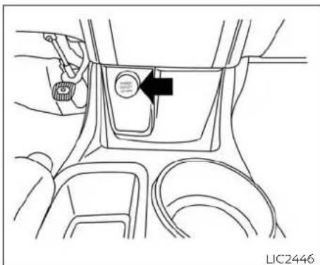
natural_image
Line drawing of a car interior showing dashboard and seatbelt (no text or symbols)Front Console
The power outlets are for powering electrical accessories such as cellular telephones. The outlet is rated at 12 volt, 120 V (10A) maximum.

natural_image
Line drawing of a car interior showing dashboard and seat components with a black arrow indicating a directional component (no text or symbols)Rear Console - (if so equipped)
CAUTION
√ The outlet and plug may be hot during or immediately after use.
- Only certain power outlets are designed for use with a cigarette lighter unit. Do not use any other power outlet for an accessory lighter. It is recommended that you visit a NISSAN dealer for additional information.
- Do not use with accessories that exceed a 12 volt, 120 W (10A) power draw
STORAGE
- Do not use double adapters or more than one electrical accessory.
- Use power outlets with the engine running to avoid discharging the vehicle battery.
- Avoid using power outlets when the air conditioner, headlights or rear window defroster (if so equipped) is on.
- Before inserting or disconnecting a plug, be sure the electrical accessory being used is turned off.
- Push the plug in as far as it will go. good contact is not made, the plug may overheat or the internal temperature fuse may open.
- When not in use, be sure to close the cap. Do not allow water or any other liquid to contact the outlet.

natural_image
Line drawing of a car interior showing the dashboard and side door with a black arrow pointing to the left side (no text or symbols present)
natural_image
Line drawing of a car seatbelt mechanism with an arrow indicating the component (no text or symbols present)FRONT-DOOR POCKETS UNDER-SEAT STORAGE BIN
To open the drawer, lift up slightly and pull to open. To remove the drawer, pull to the point of resistance and lift up and pull.
CAUTION
To avoid damaging the tray under the seat, cargo in the trays should not exceed 4 lbs. (1.8 kg).
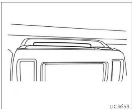
natural_image
Line drawing of a car front view with lane lines (no text or symbols)Instrument panel
STORAGE TRAYS

natural_image
Diagram of car interior showing dashboard and seat components with directional arrows indicating movement (no text or symbols)LIC2451 LIC2160

natural_image
Diagram of a mechanical component with arrows indicating motion or force direction (no text or symbols)GLOVE BOX
Open the glove box by pulling the handle.
WARNING
Do not place sharp objects in the trays to help prevent injury in an accident or sudden stop.
WARNING
Keep glove box lid closed while driving to help prevent injury in an accident or a sudden stop.
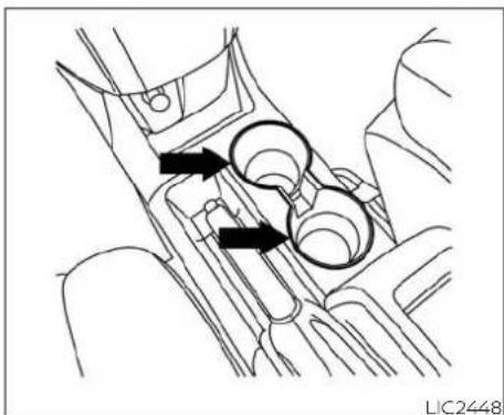
natural_image
Technical line drawing of a mechanical component with two black arrows indicating directional movement (no text or symbols)LIC2448 LIC4254
CUP HOLDERS
CAUTION
- Use only soft cups in the cup holder. Hard objects can injure you in an accident.
- Due to potential electrical component damage be careful to avoid spills near the center console, and immediately wipe any spilled liquids.
- DO NOT place uncovered or uncapped liquids, such as drinks, in the cup holders.

D-RINGS (if so equipped)
There are 12 D-Rings (if so equipped) located in the cargo area as shown and can be used to secure cargo with ropes or other types of straps.
Do not apply a total load of more than 200 lbs. (890 N) to a single D-Ring when securing cargo.
WARNING
Avoid abrupt starting and braking when the cup holder is being used to prevent spilling the drink. If the liquid is hot, it can scald you or your passenger.
WINDOWS
WARNING
- Properly secure all cargo with ropes or straps to help prevent it from sliding or shifting. Do not place cargo higher than the seatbacks. In a sudden stop or collision, unsecured cargo could cause personal injury.
- Use suitable ropes or straps to secure cargo.
- Never allow anyone to ride in the cargo area. It is extremely dangerous to ride in the a cargo area of a vehicle. In a collision, people riding in these areas are more likely to be seriously injured or killed.
- Do not allow people to ride in any area of your vehicle that is not equipped with seats and seat belts.
- Be sure everyone in your vehicle is in seat and using a seat belt properly.
For additional information, refer to "Securing the load" in the "Technical and consumer information" section of this manual.
POWER WINDOWS
WARNING
- Make sure that all passengers have their hands, etc., inside the vehicle while it is in motion and before closing the windows. Use the window lock switch to prevent unexpected use of the power windows.
- To help avoid risk of injury or death through unintended operation of the vehicle and/or its systems, including entrapment in windows or inadvertent door lock activation, do not leave children, people who require the assistance of others or pets unattended in your vehicle. Additionally, the temperature inside a closed vehicle on a warm day can quickly become high enough to cause a significant risk of injury or death to people and pets.
The power windows operate when the ignition switch is placed in the ON position for a period of time after the ignition switch is placed in the OFF position. If the driver's or passenger's door is opened during this period of time, the power to the windows canceled.

- Window lock button
- Power door lock switch (if so equipped)
- Passenger side automatic switch
- Driver side automatic switch
Driver's side power window switch
The driver's side control panel is equipped with switches to open or close all of the windows.
To open a window, push the switch to the first detent and continue to hold down until the desired window position is reached. To close a window, pull the switch to the first detent and continue to hold up until the desired window position is reached.
Instruments and controls

Locking passengers' windows
When the window lock switch is depressed only the driver's side window can be opened or closed. Push it again to cancel the window lock function.

natural_image
Simple line drawing of a device with two arrows pointing downward and an arrow upward, no text or symbols present.Front passenger's power window switch
The passenger's window switch operates only the corresponding passenger's window. To open the window, push the switch to the first detent and continue to hold it down until the desired window position is reached ①. To close the window, pull the switch to the first detent and continue to hold it up until the desired window position is reached ②.
Automatic operation
To fully open a window equipped with automatic operation, push the window switch down to the second detent and release it; it need not be held. The window automatically opens all the way. To stop the window, lift the switch up while the window is opening.
Auto-reverse function
The auto-reverse function can be activated when a window is closed by automatic operation.
2-32 Instruments and controls
INTERIOR LIGHTS
Depending on the environment or driving conditions, the auto-reverse function may be activated if an impact or load similar to something being caught in the window occurs.
WARNING
There are some small distances immediately before the closed position which cannot be detected. Make sure that all passengers have their hands, etc., inside the vehicle before closing the window.
If the vehicle's battery is disconnected, replaced, or jump started, the power window auto-reverse function may not operate properly. If this occurs, have the power window auto-reverse system re-initialized. It is recommended that you visit a NISSAN dealer for this service.
If the control unit detects something caught in a window equipped with automatic operation as it is closing, the window will be immediately lowered. When power window switch does not operate
If the power window automatic function (closing only) does not operate properly, perform the following procedure to initialize the power window system:
- Place the ignition switch in the ON position
- Open the window more than halfway by operating the power window switch.
-
Pull the power window switch and hold it to close the window, and then hold the switch more than 3 seconds after the window is closed.
-
Release the power window switch. Operate the window by the automatic function to confirm the initialization is complete. The power window automatically opens or closes depending on if the automatic down or up function is selected.
Perform steps 2 through 4 above for other windows.

The interior light has a three-position switch and operates regardless of ignition switch position.
When the switch is in the ON position ③ , the light illuminates, regardless of door position. The light will go off after a period of time unless the ignition switch is placed in the ACC or ON position.
If the power window function does not operate properly after performing the above procedure have the system checked and repaired. It is recommended that you visit a NISSAN dealer for this service.
When the switch is in the DOOR position, the light will stay on for a period of time when:
- The doors are unlocked by the key or the power door lock switch while all doors are closed and the ignition switch is placed in the OFF position.
- The driver's door is opened and then closed while the key is removed from the ignition switch.
- The key is removed from the ignition switch while all doors are closed.
The light will turn off while the timer is activated when:
- The driver's door is locked by the key, or the power door lock switch.
- The ignition switch is placed in the ON position.
When the switch is in the OFF position, the light does not illuminate, regardless of door position.
The light will turn off automatically after a period of time while doors are open to prevent the battery from becoming discharged.
2-34 Instruments and controls
CAUTION
Do not use for extended periods of time with the engine stopped. This could result in a discharged battery.
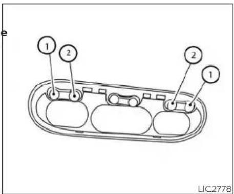
MAP LIGHTS
To turn the map lights on, push the switch to the ① position. To turn them off, push the switch to the ② position.
CAUTION
Do not use for extended periods of time with the engine stopped. This could result in a discharged battery.

natural_image
Simple line drawing of a rectangular object with a small protrusion on top, no text or symbols present.CAUTION
Do not use for extended periods of time with the engine stopped. This could result in a discharged battery.
CARGO LIGHT
The cargo light has a two-position switch and operates regardless of ignition switch position.
When the switch is in the ON position, the cargo light illuminates, regardless of door position. The light will go off after a period of time unless the ignition switch is placed in the ACC or ON position.
When the switch is in the OFF position, the cargo light will not illuminate, regardless of door position.
MEMO
2-36 Instruments and controls
3 Pre-driving checks and adjustments
Keys 3-2
NISSAN Vehicle Immobilizer System keys 3-2
Doors 3 - 3
Locking with key....3-4
Locking with inside lock knob....3-5
Locking with power door lock switch ..... 3 - 6
Operating the sliding doors....3-7
Back doors 3-8
Automatic door locks....3-10
Remote keyless entry system (if so equipped) .. 3-10
How to use remote keyless entry system 3-11
Hood 3-13
Opener operation 3-14
Fuel-filler cap 3-14
Sun visors 3-17
Card holder 3-17
Mirrors 3-18
Manual anti-glare rearview mirror (if so equipped) 3-18
Outside mirrors 3-18
KEYS
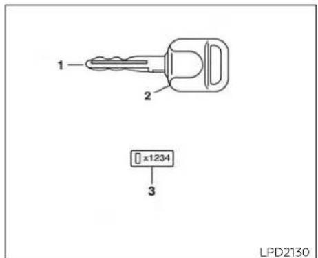
Type A (if so equipped)
- Master key
- Transponder chip
- Key number plate
A key number plate is supplied with your keys. Record the key number and keep it in a safe place (such as your wallet), not in the vehicle. If you lose your keys, it is recommended that you visit a NISSAN dealer for duplicates by using the key number. NISSAN does not record key numbers so it is very important to keep track of your key number plate.
A key number is only necessary when you have lost all your keys. If you still have a key, it can be duplicated without knowing the key number.

Type B (if so equipped)
- Integrated key fob
- Key number plate
CAUTION
Do not leave the ignition key inside the vehicle when you leave the vehicle.
NISSAN VEHICLE IMMOBILIZER SYSTEM KEYS
You can only drive your vehicle using the keys which are registered to the NISSAN Vehicle Immobilizer System components in your vehicle.
3-2 Pre-driving checks and adjustments
DOORS
The mechanical key can be used for all the locks.
Never leave these keys in the vehicle.
Additional or replacement keys:
If you still have a key, the key number is not necessary when you need extra NISSAN Vehicle Immobilizer System keys. Your existing key can be duplicated without knowing the key number. As many as four NISSAN Vehicle Immobilizer System keys can be used with one vehicle. You should bring all NISSAN Vehicle Immobilizer System keys that you have to your NISSAN dealer for registration. This is because the registration process will erase the memory of all key codes previously registered into the NISSAN Vehicle Immobilizer System. After the registration process, these components will only recognize keys coded into the NISSAN Vehicle Immobilizer System during registration. Any key that is not given to your dealer at the time of registration will no longer be able to start your vehicle.
CAUTION
Do not allow the immobilizer system key, which contains an electrical transponder, to come into contact with water or salt water. This could affect system function.
When the doors are locked using one of the following methods, the doors cannot be opened using the inside or outside door handles. The doors must be unlocked to open the doors.
WARNING
- Always have the doors locked while driving. Along with the use of seat belts, this provides greater safety in the event of an accident by helping to prevent persons from being thrown from the vehicle. This also helps keep children and others from unintentionally opening the doors, and will help keep out intruders.
- Before opening any door, always look for and avoid oncoming traffic.
- To help avoid risk of injury or death through unintended operation of the vehicle and/or its systems, including entrapment in windows or inadvertent door lock activation, do not leave children, people who require the assistance of others or pets unattended in your vehicle. Additionally, the temperature inside a closed vehicle on a warm day can quickly become high enough to cause a significant risk of injury or death to people and pets.

Driver's side
LOCKING WITH KEY

Sliding doors
To lock a sliding door, turn the key toward the front of the vehicle ① . To unlock, turn the key toward the rea ② .
To lock or unlock the vehicle, turn the key shown.
Manual (if so equipped)
To lock a front door, turn the key toward the front of the vehicle①. To unlock, turn the key toward the rea②.
3-4 Pre-driving checks and adjustments

Back door
To lock the rear door, turn the key toward the right ① of the vehicle. To unlock, turn the key toward the le② of the vehicle.

Driver's side and passenger side (if so equipped)
Power (if so equipped)
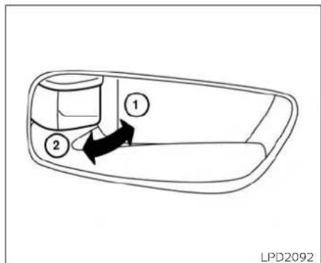
Inside lock - front driver and passenger LOCKING WITH INSIDE LOCK KNOB
The power door lock system allows you to inside lock knob to the lock position ①, lock or unlock all doors at the same time, then close the door.
Turning the key toward the from⑪ of the vehicle locks all the doors.
To unlock the door without the key, move the inside lock knob to the unlock position ②.
Turning the key one time toward the rear
② of the vehicle unlocks that door. From that position, returning the key to neutral
③(where the key can only be removed and inserted) and turning it toward the rear again within five seconds unlocks all doors
④

Inside lock - sliding doors
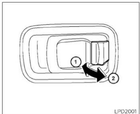
Inside lock - back door

LOCKING WITH POWER DOOR ©LOCK SWITCH
To lock the door without the key, move the ② to lock the door without the key, move the inside lock knob to the lock position ①, then close the door.
To unlock the door without the key, move To unlock the door without the key, move the inside lock knob to the unlock position the inside lock knob to the unlock position ①. ②.
To open the door from the inside, pull the Inside door handle toward you.
To lock all the doors without a key, push the door lock switch (driver's or front passenger's side) to the lock position ①. When locking the door this way, be certain not to leave the key inside the vehicle.
To unlock all the doors without a key, push the door lock switch (driver's or front passenger's side) to the unlock position.
3-6 Pre-driving checks and adjustments
Lockout protection
When the power door lock switch (driver's or front passenger's side) is moved to the lock position with the key in the ignition switch while any door is open, all doors will lock and then unlock automatically. This helps to prevent the keys from being accidentally locked inside the vehicle.

natural_image
Diagram of a car seatbelt mechanism with a black arrow indicating direction (no text or symbols)The sliding door can be opened from the inside or the outside.
To open the sliding door from the inside, pull the handle ① toward the rear of the vehicle and slide the door until the door clicks into the detent.
To close the sliding door from the inside pull the handle ① toward the front of the vehicle. The door will release from the open position and slide closed.
WARNING
- Always use the door handle to open or close the sliding door. Do not attempt to open or close the door by merely placing your hand on the door edge or door slide roller as this may cause injury.
- When opening the door on a slope, ensure that it is fully open and can be held in place by the detent. Failing to ensure the door remains open could result in serious injury.

natural_image
Diagram of a mechanical component with directional arrows indicating movement, no text or symbols present
natural_image
Technical line drawing of a vehicle door frame with internal structural components (no text or symbols)
To open a sliding door from the outside, pNOTE:
the outside handle and slide the door to- ward the rear of the vehicle until the door clicks into the detent.
To close the sliding door from the outside, pull the outside handle again. The door will release from the open position and slide closed.
The sliding door wire mesh (if so equipped) is designed for ejection mitigation purposes only, do not consider it an anti-theft feature. In case the sliding door wire mesh is removed, it is recommended that you visit a NISSAN dealer for proper installation. Any damage or failure caused by misuse is not covered under the NISSAN New Vehicle Limited Warranty.
BACK DOORS
CAUTION
- Do not operate the 180° release lever until the door has been fully opened. Doing so can result in damage to the vehicle and/or malfunction of the mechanism.
- Always look before fully opening the back door(s), to avoid an accident with oncoming traffic or pedestrians.
3-8 Pre-driving checks and adjustments
- When closing the back doors, be sure to close the left-side door before closing the right-side door.
Open the back doors by performing the following:
- From the outside of the vehicle, pull the door handle ① on the right side door and open door until it stops.

- Pull the lever②, located on the side of the left back door, toward the rear of the vehicle and pull the door to open until the door stops.

The back doors open approximately 180° to allow access to the rear of the vehicle.
- To open either door to the wide open position ③ pull the release latch Ⓐ, located on the inside of each back door, toward the front of the vehicle to release the check link arm.
- Open the door slowly until the door stops. The back doors are not designed to be latched in their fully open positions.
Park the vehicle in a safe and level place. Make sure that the area is clear of obstacles and there is enough clearance around the back doors.
Pre-driving checks and adjustments

natural_image
Technical line drawing of a car window with airflow lines and structural components (no text or symbols)NOTE:
The back door wire mesh (if so equipped) is not designed as either an ejection mitigation feature or an anti-theft feature. Do not hang items on the back door wire mesh. Any damage or failure caused by misuse is not covered under the NISSAN New Vehicle Limited Warranty.
REMOTE KEYLESS ENTRY SYSTEM (if so equipped)
AUTOMATIC DOOR LOCKS
- All doors lock automatically when the vehicle speed reaches 15 mph (24 km/h).
- All doors unlock automatically when the transmission is placed in the P (Park) position, when the ignition is turned to the OFF position, or when the key is removed from the ignition.
WARNING
- Radio waves could adversely affect electric medical equipment. Those who use a pacemaker should contact the electric medical equipment manufacturer for the possible influences before use.
The remote keyless entry key fob transmits radio waves when the buttons are pressed. The FAA advises radio waves may affect aircraft navigation and communication systems. Do not operate the remote keyless entry key fob while on an airplane. Make sure the buttons are not operated unintentionally when the unit is stored for a flight.
It is possible to lock/unlock all doors, turn the interior lights on, and activate the panic alarm by using the key fob from outside the vehicle.
Be sure to remove the key from the vehicle before locking the doors.
The key fob can operate at a distance of approximately 33 ft (10 m) from the vehicle. The effective distance depends on the conditions around the vehicle.
As many as four key fobs can be used with one vehicle. For information concerning the purchase and use of additional key fobs, it is recommended that you visit a NISSAN dealer.
The key fob will not function when:
• The battery is discharged.
- The distance between the vehicle and the key fob is over 33 ft (10 m).
The panic alarm will not activate when the key is in the ignition switch.
CAUTION
Listed below are conditions or occurrences which will damage the key fob:
- Do not allow the key fob, which contains electrical components, to come into contact with water or salt water. This could affect the system function.
- Do not drop the key fob.
- Do not strike the key fob sharply against another object.
- Do not change or modify the key fob.
- Wetting may damage the key fob. If the key fob gets wet, immediately wipe until it is completely dry.
Do not place the key fob for an extended period in an area where temperatures exceed 140°F (60°C).
- Do not attach the key fob with a key holder that contains a magnet.
- Do not place the key fob near equipment that produces a magnetic field, such as a TV, audio equipment and personal computers.
If a key fob is lost or stolen, NISSAN ommends erasing the ID code of that key fob. This will prevent the key fob from unauthorized use to unlock the vehicle. For information regarding the erasing procedure, it is recommended that you visit a NISSAN dealer.
rec-

LPD3500
HOW TO USE REMOTE KEYLESS ENTRY SYSTEM
- (lock) button
- (panic) button
- 🔒 (unlock) button
Locking doors
- Close all windows.
- Remove the key from the ignition switch.
-
Close all doors.
-
Press the button on the key fob. All the doors lock. The hazard warning lights flash twice and the horn beeps once to indicate all doors are locked.
-
When the 🔒 button is pressed with all doors locked, the hazard warning lights flash twice and the horn beeps once as a reminder that the doors are already locked.
- If a door is open and you press the 🔒 button, the doors will lock but the horn will not beep and the hazard lights will not flash.
The horn may or may not beep. For additional information, refer to "Silencing the horn beep feature" in this section.
Unlocking doors
Press the button on the key fob once.
- Only the driver's door unlocks.
- The hazard warning lights flash once if all doors are completely closed with the ignition switch in any position except the ON position.
- The interior light turns on and the light timer activates for 30 seconds when the interior light switch is in the DOOR position with the ignition switch in any position except the ON position.
Press the 🔒 button on the key fob again within five seconds.
- All doors unlock.
- The hazard warning lights flash once if all doors are completely closed.
The interior lights can be turned off without waiting a period of time by inserting the key into the ignition switch and placing the ignition switch in the ON or START position, locking the doors with the key fob, power door lock switch or pushing the interior light switch to the off position.
Auto relock
When the 🔒 button on the key fob is pressed, all doors will lock automatically within one minute unless one of the following operations is performed:
- Any door is opened.
- A key is inserted into the ignition switch and the switch is cycled from OFF to C
- Press key fob 🔒 button.
Using the panic alarm
If you are near your vehicle and feel threatened, you may activate the panic alarm to call attention by pressing and holding the 📋 button on the key fob for longer than 0.5 seconds.
The panic alarm and headlights will stay on for a period of time.
The panic alarm stops when:
It has run for a period of time.
ey Any button is pressed on the key fob.
Using the interior light
Press the 🔒 button on the key fob once to turn on the interior lights. For additional information, refer to "Interior lights" in the "Instruments and controls" section of this manual.
Silencing the horn beep feature
If desired, the horn beep feature can be deactivated using the key fob.
To deactivate: Press and hold the 🔒 and 🔒 buttons for at least 2 seconds.
The hazard warning lights will flash three times to confirm that the horn beep feature has been deactivated.
3-12 Pre-driving checks and adjustments
HOOD
To activate: Press and hold the and buttons for at least 2 seconds once more.
The hazard warning lights will flash once and the horn will sound once to confirm that the horn beep feature has been reactivated.
Deactivating the horn beep feature does not silence the horn if the alarm is triggered.
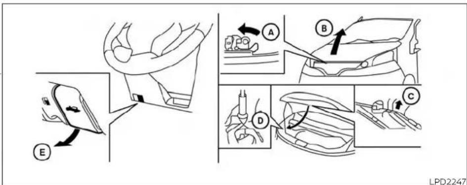
-
Pull the hood lock release handle ⑧ located below the instrument panel until the hood springs up slightly.
-
Locate the lever Ⓐ In between the hood and grille and push the lever side ways with your fingertips.
-
Raise the hood Ⓑ.
-
Remove the support rod and insert it into the slot .
Hold the coated parts of the support rod when removing or resetting the support rod. Avoid direct contact with the metal parts, as they may be hot immediately after the engine has been stopped.
When closing the hood, return the support rod to its original position, lower the hood to approximately 12 in (30 cm) above the latch and release it. This allows proper engagement of the hood latch.
FUEL-FILLER DOOR
WARNING
- Make sure the hood is completely closed and latched before driving. Failure to do so could cause the hood to fly open and result in an accident.
- If you see steam or smoke coming from the engine compartment, to avoid injury do not open the hood.
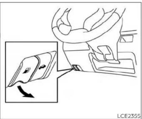
natural_image
Line drawing of a car interior showing a seatbelt switch and a hand valve mechanism (no text or symbols)OPENER OPERATION
The fuel-filler door release is located below the instrument panel. To open the fuel-filler door, pull the release. To lock, close the fuel filler door securely.
FUEL-FILLER CAP
A WARNING
- Gasoline is extremely flammable and highly explosive under certain conditions. You could be burned or seriously injured if it is misused or mishandled. Always stop the engine and do not smoke or allow open flames or sparks near the vehicle when refueling.
- Do not attempt to top off the fuel tank after the fuel pump nozzle shuts off automatically. Continued refueling may cause fuel overflow, resulting in fuel spray and possibly a fire.
- Use only an original equipment type fuel-filler cap as a replacement. It has a built-in safety valve needed for proper operation of the fuel system and emission control system. An incorrect cap can result in a serious malfunction and possible injury. It could also cause the Malfunction Indicator Light (MIL) to come on.
- Never pour fuel into the throttle body to attempt to start your vehicle.
- Do not fill a portable fuel container in the vehicle or trailer. Static electricity can cause an explosion of flammable liquid, vapor or gas in any vehicle or trailer. To reduce the risk of serious injury or death when filling portable fuel containers:
- Always place the container on the ground when filling.
- Do not use electronic devices when filling.
- Keep the pump nozzle in contact with the container while you are filling it.
- Use only approved portable fuel containers for flammable liquid.
CAUTION
- Do not use a fuel containing more than 15% ethanol in your vehicle. For additional information, refer to "Fuel Recommendation" in the "Technical and consumer information" section of this manual.
-
Failure to tighten the fuel-filler cap properly may cause the Mal-function Indicator Light (MIL) to illuminate. If the light illuminates because the fuel-filler cap is loose or missing, tighten or install the cap and continue to drive the vehicle. The light should turn off after a few driving trips. If the light does not turn off after a few driving trips, have the vehicle inspected. It is recommended that you visit a NISSAN dealer for this service.
-
The LOOSE FUEL CAP warning message will be displayed if the fuel-filler cap is not properly tightened. It may take a few driving trips for the message to be displayed. Failure to tighten the fuel-filler cap properly after the LOOSE FUEL CAP warning message is displayed may cause the Malfunction Indicator Light (MIL) to illuminate.
- For additional information, refer to the "Malfunction Indicator Light (MIL)" in the "Instruments and Controls" section of this manual.
- If fuel is spilled on the vehicle body, flush it away with water to avoid paint damage.


To remove the fuel-filler cap:
- Turn the fuel-filler cap counterclockwise ① to remove.
- Loop the tether strap around the hook Ⓐ while refueling.
To install the fuel-filler cap:
- Insert the fuel-filler cap straight into the fuel-filler tube.
- Turn the fuel-filler cap clockwise until a single click is heard.
LOOSE FUEL CAP warning message
The LOOSE FUEL CAP warning message displays in the odometer when the fuel-filler cap is not tightened correctly after the vehicle has been refueled. It may take a few driving trips for the message to be displayed. To turn off the warning message, do the following:
-
Remove and install the fuel-filler cap as previously described as soon as possible.
-
Tighten the fuel-filler cap until a single click is heard.
- Press the loose fuel cap warning reset button Ⓐ in the meter for about 1 second to turn off the LOOSE FUEL CAP warning message after tightening the fuel-filler cap.
SUN VISORS
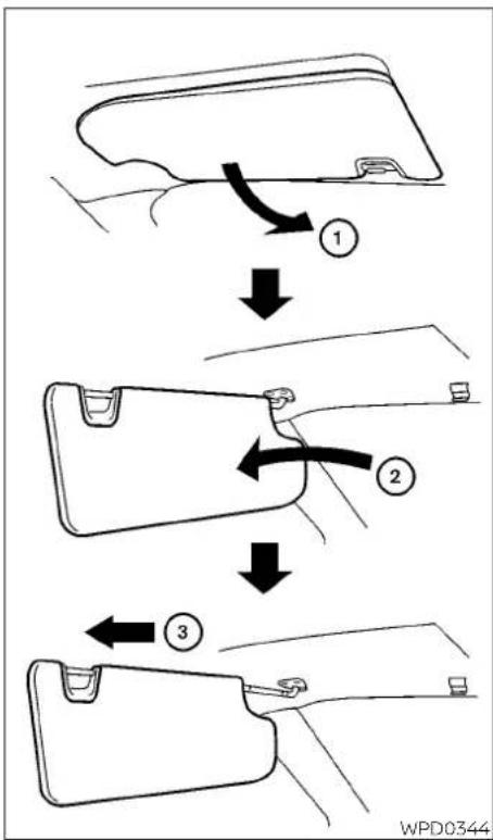
flowchart
graph TD
    A["Step 1: Rear wing"] --> B["Step 2: Rear handle"]
    B --> C["Step 3: Rear handle"]
- To block glare from the front, swing down the main sun viso 1 .
- To block glare from the side, remove the main sun visor from the center mount and swing the visor② to the side.
- To extend the sun visor③, slide in or out as needed.
CAUTION
- Do not store the sun visor before returning the extension to its original position.
- Do not pull the extension sun visor forcedly downward.

natural_image
Line drawing of a car interior with labeled point A and base plate (no text or symbols beyond label)CARD HOLDER
To use the card holder, slide card in the car holder Ⓐ. Do not view information while operating the vehicle.
MIRRORS

OUTSIDE MIRRORS
A WARNING
- Objects viewed in the outside mirror on the passenger side are closer than they appear. Be careful when moving to the right. Using only this mirror could cause an accident. Use the inside mirror or glance over your shoulder to properly judge distances to other objects.
- Do not adjust the mirrors while driving. You could lose control of your vehicle and cause an accident.
MANUAL ANTI-GLARE REARVIEW MIRROR (if so equipped)
Use the night position① to reduce glare from the headlights of vehicles behind you at night.
Use the day position ② when driving in daylight hours.
WARNING
Use the night position only when necessary, because it reduces rear view clarity.
Manual control type (if so equipped)
The outside mirrors can be moved in any direction for a better rear view.
3-18 Pre-driving checks and adjustments
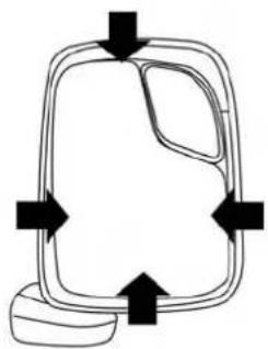
natural_image
Simple line drawing of a container with arrows indicating flow or movement (no text or symbols)
flowchart
graph TD
    A["Central Box"] --> B["Arrow 1"]
    A --> C["Arrow 2"]
    D["Arrow 1"] --> E["Arrow 2"]
    F["Arrow 2"] --> G["Arrow 1"]
    H["Arrow 2"] --> I["Arrow 1"]
    J["Arrow 2"] --> K["Arrow 1"]
    L["Arrow 2"] --> M["Arrow 1"]
    N["Arrow 2"] --> O["Arrow 1"]
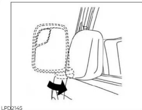
natural_image
Diagram of a car interior showing a seatbelt and dashboard, with no visible text or symbolsElectric control type (if so equipped)
The outside mirror remote control will operate only when the ignition switch is placed in the ACC or ON position.
Move the small switch① to select the right or left mirror. Move the large switch② to adjust each mirror to the desired position. Move the small switch ① to the center (neutral) position to prevent accidentally moving the mirror.
Foldable outside mirrors
Pull the outside mirror toward the door to fold it.
Heated mirrors (if so equipped)
Some outside mirrors can be heated to defrost, defog, or de-ice for improved visibility. For additional information, refer to "Rear window and/or outside mirror defroster switch" in the "Instruments and controls" section of this manual.
MEMO
3-20 Pre-driving checks and adjustments
4 Monitor, climate, audio, phone and voice recognition systems
NissanConnect® Owner's Manual 4-2
RearView Monitor 4 - 3
RearView Monitor system operation .....4 - 4
How to read the displayed lines. 4 - 4
Difference between predicted and actual distances....4-5
How to park with predicted course lines 4-7
Adjusting the screen 4 - 8
How to turn on and off predicted course lines (if so equipped) 4-9
RearView Monitor system limitations ..... 4 - 9
System maintenance....4-10
Vents....4-11
Heater and air conditioner (manual) 4-11
Controls 4-12
Heater operation 4-13
Air conditioner operation 4-14
Air flow charts 4-16
Servicing air conditioner....4-19
Antenna....4-19
Car phone or CB radio....4-19
iPod®/iPhone® 4-20
NISSANCONNECT® OWNER'S MANUAL
Refer to the NissanConnect® Owner's Manual that includes the following information.
- Audio system
- Apple CarPlay®
- Android Auto TM
- Bluetooth® Hands-Free Phone system
- Viewing information
- Other settings
- Voice Recognition
- General system information
4-2 Monitor, climate, audio, phone and voice recognition systems
REARVIEW MONITOR
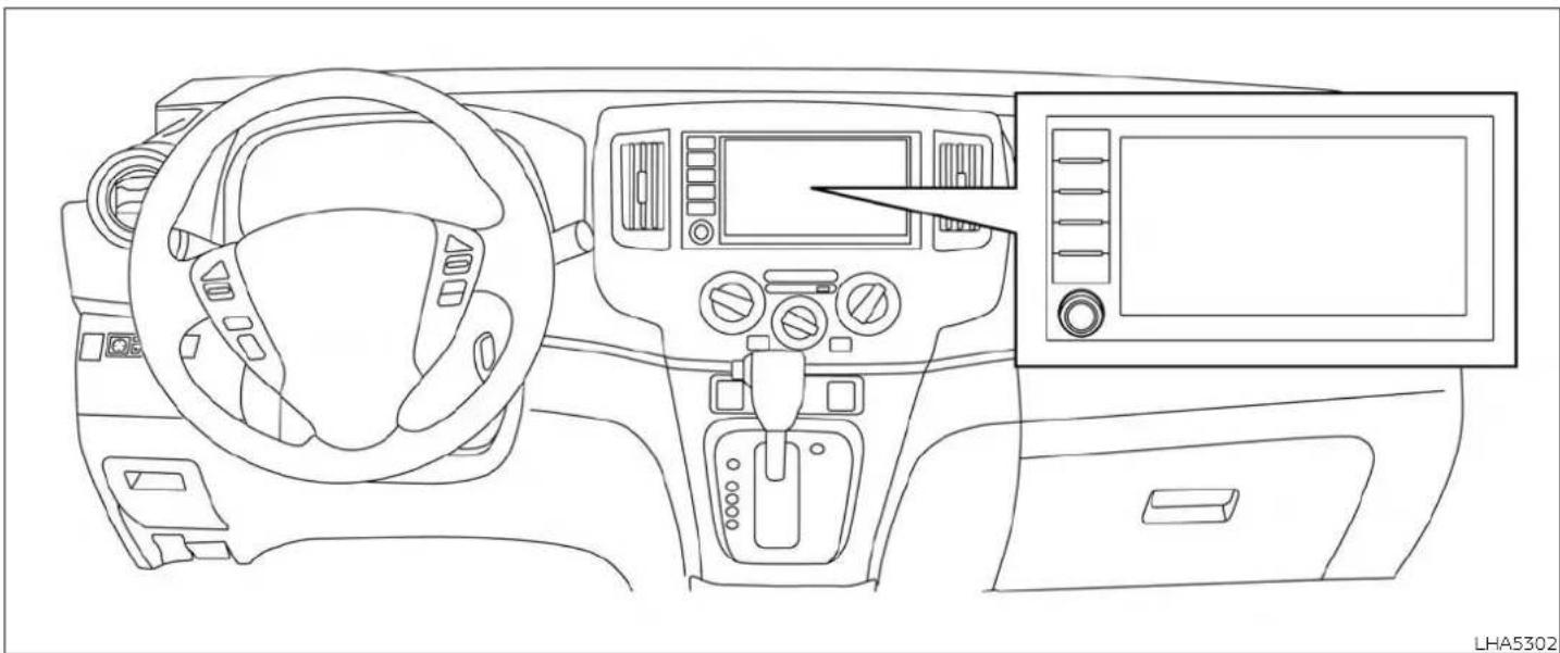
natural_image
Line drawing of a car dashboard and steering wheel (no text or symbols)WARNING
- Failure to follow the warnings and instructions for proper use of the RearView Monitor system could result in serious injury or death.
Monitor, climate, audio, phone and voice recognition systems
- RearView Monitor is a convenience feature and is not a substitute for proper backing. Always turn and look out the windows and check mirrors to be sure that it is safe to move before operating the vehicle. Always back up slowly.
- The system is designed as an aid to the driver in showing large stationary objects directly behind the vehicle, to help avoid damaging the vehicle.
- The distance guide line and the vehicle width line should be used as a reference only when the vehicle is on level paved surface. The distance viewed on the monitor is for reference only and may be different than the actual distance between the vehicle and displayed objects.
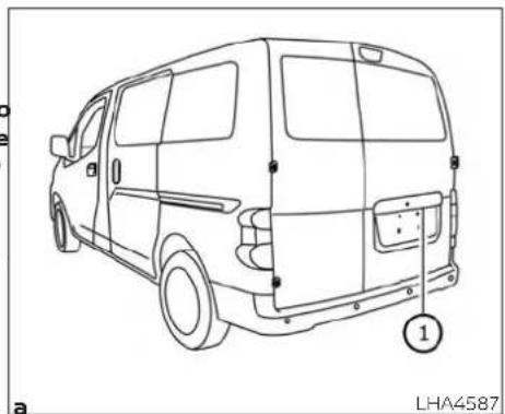
natural_image
Line drawing of a van rear view with labeled components, no text or symbols present
CAUTION Do not scratch the camera lens when cleaning dirt or snow from the front of the camera.
The RearView Monitor system automatically shows a rear view of the vehicle when the shift lever is shifted into the R (Reverse) position. The radio can still be heard while the RearView Monitor is active.
To display the rear view, the RearView MonHOW TO READ THE DISPLAYED for system uses a camera located next to the rear door handle.
With the ignition switch in the ON position, played on the monitor.
move the shift lever to the R (Reverse) po-Distance guide lines
Guiding lines which indicate the vehicle width and distances to objects with reference to the vehicle body line A are dis-
Distance guide lines
Indicate distances from the vehicle body.
- Red line ①: approx. 1.5 ft (0.5 m)
- Yellow line ② approx. 3 ft (1 m)
- Green line ③: approx. 7 ft (2 m)
4-4 Monitor, climate, audio, phone and voice recognition systems
Vehicle width guide lines
Indicate the vehicle width when backing up.
Predicted course lines 5
Indicate the predicted course when backing up. The predicted course lines will be displayed on the monitor when the shift lever is in the R (Reverse) position and the steering wheel is turned. The predicted course lines will move depending on how much the steering wheel is turned and will not be displayed while the steering wheel is in the straight-ahead position.
The vehicle width guide lines and the width of the predicted course lines are wider than the actual width and course.
DIFFERENCE BETWEEN PREDICTED AND ACTUAL DISTANCES
The distance guide line and the vehicle width guide line should be used as a reference only when the vehicle is on a level, paved surface. The distance viewed on the monitor is for reference only and may be different than the actual distance between the vehicle and displayed objects.
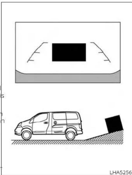
natural_image
Diagram showing a car on a slope next to an open rear ramp and a parking block, with no text or symbols present.hill is further than it appears on the monitor.
eBacking up on a steep uphill When backing up the vehicle up a hill, the distance guide lines and the vehicle width guide lines are shown closer than the actual distance. Note that any object on the

natural_image
Diagram showing a car on a slope with a block being tracked, and an inset image of a vehicle on the ground (no text or symbols)on the hill is closer than it appears on the monitor.
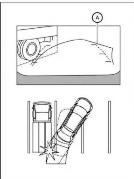
Backing up on a steep downhill
When backing up the vehicle down a hill, the distance guide lines and the vehicle width guide lines are shown farther than the actual distance. Note that any object
Backing up near a projecting object
The predicted course line ⑧ do not touch the object in the display. However, the vehicle may hit the object if it projects over the actual backing up course.
4-6 Monitor, climate, audio, phone and voice recognition systems

Backing up behind a projecting object
The position Ⓐ is shown farther than the position Ⓑ in the display. However, the position Ⓒ is actually at the same distance as the position Ⓓ. The vehicle may hit the
object when backing up to the position A if the object projects over the actual back- ing up course.
HOW TO PARK WITH PREDICTED COURSE LINES
WARNING
- If the tires are replaced with different sized tires, the predicted course lines may be displayed incorrectly.
- On a snow-covered or slippery road, there may be a difference between the predicted course line and the actual course line.
- If the battery is disconnected or becomes discharged, the predicted course lines may be displayed incorrectly. If this occurs, please perform the following procedures:
- Turn the steering wheel from lock to lock while the engine is running.
- Drive the vehicle on a straight road for more than 5 minutes.
- When the steering wheel is turned with the ignition switch in the ACC position, the predicted course lines may be displayed incorrectly.

natural_image
Top-down diagram of a car parking area with an attached circular sensor and a car, no text or symbols present.- Visually check that the parking space is safe before parking your vehicle.
- The rear view of the vehicle is displayed on the screen when the shift lever is moved to the R (Reverse) position.

-
Slowly back up the vehicle adjusting the steering wheel so that the predicted course lines® enter the parking space©.
-
Maneuver the steering wheel to make the vehicle width guide line parallel to the parking space while referring to the predicted course lines.
- When the vehicle is parked in the space completely, move the shift lever to the P (Park) position and apply the parking brake.

The procedure for adjusting the display settings of the screen differs depending on the type of screen present on the vehicle.
- While on the main menu screen, touch the "Settings" key.
- Touch the "Camera" key.
- Touch the "Brightness", "Contrast", "Tint" "Color", or "Black Level" key.
- Adjust the item by touching the "+" or "-" key on the touch-screen display.
4-8 Monitor, climate, audio, phone and voice recognition systems
NOTE:
Do not adjust any of the display settings of the RearView Monitor while the vehicle is moving. Make sure the parking brake is firmly applied.
HOW TO TURN ON AND OFF PREDICTED COURSE LINES (if so equipped)
To toggle ON and OFF the predicted course lines while in the P (Park) position:
- Touch the "Settings" key.
- Touch the "Camera" key.
- Touch the "Predicted Course Lines" key to turn the feature ON or OFF.
REARVIEW MONITOR SYSTEM LIMITATIONS
WARNING
Listed below are the system limitations for RearView Monitor. Failure to operate the vehicle in accordance with these system limitations could result in serious injury or death.
- The system cannot completely eliminate blind spots and may not show every object.
- Underneath the bumper and the corner areas of the bumper cannot be viewed on the RearView Monitor because of its monitoring range limitation. The system will not show small objects below the bumper, and may not show objects close to the bumper or on the ground.
- Objects viewed in the RearView Monitor differ from actual distance because a wide-angle lens is used.
- Objects in the RearView Monitor will appear visually opposite compared to when viewed in the rearview and outside mirrors.
- Use the displayed lines as a reference. The lines are highly affected by the number of occupants, fuel level, vehicle position, road conditions and road grade.
-
Make sure that the rear doors are securely closed when backing up.
-
Do not put anything on the rearview camera. The rearview camera is installed above the license plate.
- When washing the vehicle with high pressure water, be sure not to spray it around the camera. Otherwise, water may enter the camera unit causing water condensation on the lens, a malfunction, fire or an electric shock.
- Do not strike the camera. It is a precision instrument. Otherwise, it may malfunction or cause damage resulting in a fire or an electric shock.
The following are operating limitations and do not represent a system malfunction:
- When the temperature is extremely high or low, the screen may not clearly display objects.
- When strong light directly shines on the camera, objects may not be displayed clearly.
- Vertical lines may be seen in objects on the screen. This is due to strong reflected light from the bumper.
-
The screen may flicker under fluorescent light.
-
The colors of objects on the RearView Monitor may differ somewhat from the actual color of objects.
- Objects on the monitor may not be clear in a dark environment.
- There may be a delay when switching between views.
- If dirt, rain or snow accumulate on the camera, the RearView Monitor may not display objects clearly. Clean the camera.
- Do not use wax on the camera lens. Wipe off any wax with a clean cloth dampened with a diluted mild cleaning agent, then wipe with a dry cloth.

natural_image
Line drawing of a van rear view with labeled components, no text or symbols presentSYSTEM MAINTENANCE
If dirt, rain or snow accumulates on the camera ①, the RearView Monitor may not display objects clearly. Clean the camera by wiping it with a cloth dampened with a diluted mild cleaning agent and then wiping it with a dry cloth.
CAUTION
- Do not use alcohol, benzine or thinner to clean the camera. This will cause discoloration.
- Do not damage the camera as the monitor screen may be adversely affected.
4-10 Monitor, climate, audio, phone and voice recognition systems
VENTS HEATER AND AIR CONDITIONER
(manual)

Side vents


natural_image
Diagram of a car interior with a grid-patterned panel and a numbered label (1) pointing to the side panel.Center
Adjust the air flow direction of the vents by Adjust the air flow direction of the vents by opening, closing or rotating. moving the slide①.
WARNING
- The air conditioner cooling function operates only when the engine is running.
- Do not leave children or adults who would normally require the assistance of others alone in your vehicle. Pets should also not be left alone. They could accidentally injure themselves or others through inadvertent operation of the vehicle. Also, on hot, sunny days, temperatures in a closed vehicle could quickly become high enough to cause severe or possibly fatal injuries to people or animals.
- Do not use the recirculation mode for long periods as it may cause the interior air to become stale and the windows to fog up.
NOTE:
- Odors from inside and outside the vehicle can build up in the air conditioner unit. Odor can enter the passenger compartment through the vents.
- When parking, set the heater and air conditioner controls to turn off air recirculation to allow fresh air into the passenger compartment. This should help reduce odors inside the vehicle

LHA4462
CONTROLS
- Air flow control dial
- Air intake lever (Fresh air/Air recirculation)
- Temperature control dial
- A/C (air conditioner) button
- ✿ Fan speed control dial
- Rear window and/or outside mirror (if so equipped) defroster switch
Fan speed control dial
The fan speed control dial turns the fan on and off, and controls fan speed.
Air flow control dial
The air flow control dial allows you to select the air flow outlets.
- Air flows from center and side vents.
— Air flows from center and side vents and foot outlets. - Air flows mainly from foot outlets.
4-12 Monitor, climate, audio, phone and voice recognition systems

— Air flows from defroster outlets and foot outlets.

— Air flows mainly from defroster outlets.
Temperature control dial
The temperature control dial allows you to adjust the temperature of the outlet air. To lower the temperature, turn the dial to the left. To increase the temperature, turn the dial to the right.
Fresh air
Move the air intake lever to the position. The air flow is drawn from outside vehicle.
Air recirculation
Move the air intake lever to the position to recirculate air inside the vehicle. Use the 2 selection:
- when driving on a dusty road
• to prevent traffic fumes from entering passenger compartment - for maximum cooling when using the air conditioner
A/C (air conditioner) button
Start the engine, turn the fan speed control dial to the desired position and press the A/C button to turn on the air conditioner. To turn off the air conditioner,
press the A/C button again.
a The air conditioner cooling function operates only when the engine is running.
Rear window and/or outside mirror defroster switch (if so equipped)
For additional information, refer to "Rear window and/or outside mirror defroster switch (if so equipped)" in the "Instruments and controls" section of this manual.
HEATER OPERATION
Heating
This mode is used to direct heated air to the foot outlets. Some air also flows from the defrost outlets.
- Move the air intake lever to the position for normal heating.
-
Turn the air flow control dial to the heckmark position.
-
Turn the ✿ fan speed control dial to the desired position.
- Turn the temperature control dial to the desired position between the middle and the hot position.
Ventilation
This mode directs outside air to the side and center vents.
- Move the air intake lever to the position.
- Turn the air flow control dial to the position.
- Turn the ✿ fan speed control dial to the desired position.
- Turn the temperature control dial to the desired position.

Defrosting or defogging
This mode directs the air to the defrost outlets to defrost/defog the windows.
- Move the air intake lever to the position.
- Turn the air flow control dial to the 🎨 position.

-
Turn the π n speed control dial to the desired position.
-
Turn the temperature control dial to the desired position between the middle and the hot position.
• To quickly remove ice or fog from the windows, turn the ✝ fan speed control dial to the maximum position and the temperature control dial to the full hot position.
When the 🎨 or position is selected, the air conditioner automatically turns on (however, the indicator light will not illuminate). In this position, the air conditioner cannot be turned off. When the air flow control is turned to any position other than 🎨 or (the air conditioner will continue operating), and can be turned off using the air conditioner button. This dehumidifies the air, which helps defog the windshield.
Bi-level heating
This mode directs cooler air from the side and center vents and warmer air from the when the or position is se-floor outlets. When the temperature con-lected, the air conditioner automatically trol dial is moved to the full hot or full co-turns on (however, the indicator light will position, the air between the vents and then illuminate). In this position, the air con-floor outlets is the same temperature. ditioner cannot be turned off. When the air
-
Move the air intake lever to the position.
-
Turn the air flow control dial to the 🔍 position.
-
Turn the ✿ fan speed control dial to the desired position.
-
Turn the temperature control dial to the desired position.
Heating and defogging
This mode heats the interior and defogs the windshield.
- Move the air intake lever to the position.
- Turn the air flow control dial to the position.
- Turn the ✿ fan speed control dial to the desired position.
- Turn the temperature control dial to the desired position between the middle and the hot position.
When the 🎨 or position is selected, the air conditioner automatically turns on (however, the indicator light will not illuminate). In this position, the air conditioner cannot be turned off. When the air
flow control is turned to any position other than 🎨 or (the air conditioner will continue operating) and can be turned off using the air conditioner button. This dehumidifies the air, which helps defog the windshield.
Operating tips
Clear snow andice from the wiper blades and air inlet in front of the windshield. This improves heater operation.
AIR CONDITIONER OPERATION
Start the engine, turn the ✿ fan speed control dial to the desired position, and press the A/C button to activate the air conditioner. When the air conditioner is on, cooling and dehumidifying functions are added to the heater operation.
The air conditioner cooling function operates only when the engine is running.
Cooling
This mode is used to cool and dehumidify the air.
- Move the air intake lever to the position.
- Turn the air flow control dial to the ↗ position.
4-14 Monitor, climate, audio, phone and voice recognition systems
- Turn the π on speed control dial to the desired position.
- Press the A/C button. The indicator light comes on.
- Turn the temperature control dial to the desired position.
- For quick cooling when the outside temperature is high, move the air intake lever to the position. Be sure to return to the position for normal cooling.
Dehumidified heating
This mode is used to heat and dehumidify the air.
- Move the air intake lever to the position.
- Turn the air flow control dial to the position.
- Turn the ✿ fan speed control dial to the desired position.
- Press the A/C button. The indicator light comes on.
- Turn the temperature control dial to the desired position.
Dehumidified defogging
This mode is used to defog the windows and dehumidify the air.
- Move the air intake lever to the position.
- Turn the air flow control dial to the 🎨 position.
Turn the ✅ fan speed control dial to the desired position. When the 🎨 or 🔍 position is selected, the air conditioner automatically turns on (however, the indicator light will not illuminate). In this position, the air conditioner cannot be turned off. When the air flow control is turned to any position other than 🎨 or 🎨 the air conditioner will continue operating), and can be turned off using the air conditioner button. This dehumidifies the air, which helps defog the windshield.
- Turn the temperature control dial to the desired position.
Operating tips
- Keep the windows closed while the air conditioner is in operation.
• After parking in the sun, drive for 2 or 3 minutes with the windows open to vent hot air from the passenger compartment before closing the windows. This allows the air conditioner to cool the interior more quickly. - The air conditioning system should be operated for approximately 10 minutes at least once a month. This helps prevent damage to the system due to lack of lubrication.
- A visible mist may be seen coming from the ventilators in hot, humid conditions as the air is cooled rapidly. This does not indicate a malfunction.
- If the high temperature warning light illuminates in red indicating engine coolant temperature is over the normal range, turn the air conditioner off. For additional information, refer to "If your vehicle overheats" in the "In case of emergency" section of this manual.
AIR FLOW CHARTS
The following charts show the button and dial positions for MAXIMUM AND QUICK heating, cooling or defrosting. The air intake lever should always be in the position for heating and defrosting.

4-16 Monitor, climate, audio, phone and voice recognition systems


| Fan speed control | Air recirculation control | A/C button | Temp. control | Air flow control |
| 4 | AUTO ON | HOT (RIGHT) |

| Fan speed control | Air recirculation control | A/C button | Temp. control | Air flow control |
| 4 | ON | COLD (LEFT) |
LHA5254 LHA5255
4-18 Monitor, climate, audio, phone and voice recognition systems
SERVICING AIR CONDITIONER
ANTENNA
CAR PHONE OR CB RADIO
The air conditioner system in your NISSAN vehicle is charged with a refrigerant designed with the environment in mind.
This refrigerant does not harm the earth's ozone layer.
Special charging equipment and lubricant is required when servicing your NISSAN air conditioner. Using improper refrigerants or lubricants will cause severe damage to your air conditioner system. For additional information, refer to "Air conditioner system refrigerant and oil recommendations" in the "Technical and consumer information" section of this manual.
It is recommended that you visit a NISSAN dealer to service your "environmentally friendly" air conditioner system.
WARNING
The air conditioner system contains refrigerant under high pressure. To avoid personal injury, any air conditioner service should be done only by an experienced technician with proper equipment.
The antenna cannot be shortened, but can be removed. When you need to remove the antenna, turn the antenna rod counterclockwise.
To install the antenna rod, turn the antenna rod clockwise and hand tighten.
When installing a CB, ham radio or car phone in your vehicle, be sure to observe the following precautions; otherwise, the new equipment may adversely affect the engine control system and other electronic parts.
CAUTION
- Always properly tighten the antenna rod during installation or the antenna rod may break during vehicle operation.
- Be sure that the antenna is removed before the vehicle enters an automatic car wash.
WARNING
- A cellular phone should not be used for any purpose while driving so full attention may be given to vehicle operation. Some jurisdictions prohibit the use of cellular phones while driving.
- If you must make a call while your vehicle is in motion, the hands free cellular phone operational mode (if so equipped) is highly recommended. Exercise extreme caution at all times so full attention may be given to vehicle operation.
- If you are unable to devote full attention to vehicle operation while talking on the phone, pull off the road to a safe location and stop your vehicle.
iPod®/iPhone®
CAUTION
- Keep the antenna as far away as possible from the electronic control modules.
- Keep the antenna wire more than 8 i (20 cm) away from the electronic control system harnesses. Do not route the antenna wire next to any harness
- Adjust the antenna standing-wave ratio as recommended by the manufacturer.
- Connect the ground wire from the CB radio chassis to the body.
- For additional information, it is recommended that you visit a NISSAN dealer for this service.
"Made for iPod", "Made for iPhone" and "Made for iPad" mean that an electronic accessory has been designed to connect specifically to iPod, iPhone or iPad, respectively, and has been certified by the developer to meet Apple performance standards. Apple is not responsible for the operation of this device or its compliance with safety and regulatory standards. Please note that the use of this accessory with iPod, iPhone or iPad may affect wireless performance.
iPad, iPhone, iPod classic, iPod Nano, iPod shuffle and iPod touch are trademarks of Apple Inc., registered in the U.S. and other countries. Lightning is a trademark of Apple Inc.
MEMO
Monitor, climate, audio, phone and voice recognition systems 4-21
5 Starting and driving
Precautions when starting and driving ..... 5 - 2
Exhaust gas (carbon monoxide) 5 - 2
Three-way catalyst 5 - 2
Tire Pressure Monitoring System (TPMS) 5-3
Avoiding collision and rollover 5 - 6
Off-road recovery ...... Rapid air pressure loss .... 5 - 7
Drinking alcohol/drugs and driving 5-8
Ignition switch....5 - 8
Continuously Variable Transmission ..... 5 - 8
Ignition switch positions....5 - 9
NISSAN Vehicle Immobilizer System 5-9
Before starting the engine....5-10
Starting the engine 5-10
Driving the vehicle 5-1
Engine protection mode....5-11
Continuously Variable Transmission (CVT) 5-12
Parking brake 5-17
Cruise control (if so equipped) 5-18
Precautions on cruise control. 5-18
Cruise control operations....5-18
Break-in schedule 5-19
Fuel efficient driving tips....5-20
Increasing fuel economy 5-21
Parking/parking on hills 5-22
Power steering 5-23
Brake system....5-24 Brake precautions....5-24
5 - 6 Anti-lock Braking System (ABS) 5-24
Brake Assist 5-25
Vehicle Dynamic Control (VDC) system .....5-26
Rise-up and build-up 5-28
Brake force distribution....5-28
Hill start assist system....5-29
Rear Sonar System (RSS) (if so equipped) .....5-29
RSS system operation....5-30
How to enable/disable the RSS....5-31
RSS limitations 5-32
System temporarily unavailable .....5-32
System maintenance....5-33
Cold weather driving 5-33
Freeing a frozen door lock 5-33
Antifreeze 5-33
Battery....5-33
Draining of coolant water....5-34
Tire equipment 5-34
Special winter equipment 5-34
Driving on snow or ice 5-34
Engine block heater (if so equipped) 5-35
PRECAUTIONS WHEN STARTING AND DRIVING
WARNING
- Do not leave children or adults who would normally require the assistance of others alone in your vehicle. Pets should also not be left alone. They could accidentally injure themselves or others through inadvertent operation of the vehicle. Also, on hot, sunny days, temperatures in a closed vehicle could quickly become high enough to cause severe or possibly fatal injuries to people or animals.
- Properly secure all cargo to help prevent it from sliding or shifting. Do not place cargo higher than the seat-backs. In a sudden stop or collision, unsecured cargo could cause personal injury.
EXHAUST GAS (carbon monoxide)
WARNING
- Do not breathe exhaust gases; they contain colorless and odorless carbon monoxide. Carbon monoxide is dangerous. It can cause unconsciousness or death.
- If you suspect that exhaust fumes are entering the vehicle, drive with all windows fully open, and have the vehicle inspected immediately. - Do not run the engine in closed space such as a garage. - Do not park the vehicle with the engine running for any extended length of time. - Keep the rear vent windows, doors and trunk lids (if so equipped) closed while driving, otherwise exhaust gases could be drawn into the passenger compartment. If you must drive with one of these open, follow these precautions:
- Open all the windows.
- Turn the air recirculation mode off and set the fan speed control to the highest level to circulate the air.
- The exhaust system and body should be inspected by a qualified mechanic whenever:
a. The vehicle is raised for service.
b. You suspect that exhaust fumes are entering into the passenger compartment.
c. You notice a change in the sound of the exhaust system.
d. You have had an accident involving damage to the exhaust system, underbody, or rear of the vehicle.
THREE-WAY CATALYST
The three-way catalyst is an emission control device installed in the exhaust system. Exhaust gases in the three-way catalyst are burned at high temperatures to help reduce pollutants.
WARNING
- The exhaust gas and the exhaust system are very hot. Keep people, animals or flammable materials away from the exhaust system components.
- Do not stop or park the vehicle over flammable materials such as dry grass, waste paper or rags. They may ignite and cause a fire.
5-2 Starting and driving
CAUTION
- Do not use leaded gasoline. Deposits from leaded gasoline will seriously reduce the three-way catalyst's ability to help reduce exhaust pollutants.
- Keep your engine tuned up. Malfunctions in the ignition, fuel injection, or electrical systems can cause over rich fuel flow into the three-way catalyst, causing it to overheat. Do not keep driving if the engine misfires, or if noticeable loss of performance or other unusual operating conditions are detected. Have the vehicle inspected promptly. It is recommended that you visit a NISSAN dealer for this service.
- Avoid driving with an extremely low fuel level. Running out of fuel could cause the engine to misfire, damaging the three-way catalyst.
- Do not race the engine while warming it up.
- Do not push or tow your vehicle to start the engine.
TIRE PRESSURE MONITORING SYSTEM (TPMS)
• Each tire, including the spare (if provided), should be checked monthly when cold and inflated to the inflation pressure recommended by the vehicle manufacturer on the vehicle placard or tire inflation pressure label.
(If your vehicle has tires of a different size than the size indicated on the vehicle placard or tire inflation pressure label, you should determine the proper tire inflation pressure for those tires.)
As an added safety feature, your vehicle has been equipped with a Tire Pressure Monitoring System (TPMS) that illuminates a low tire pressure telltale when one or more of your tires is significantly underinflated. Accordingly, when the low tire pressure telltale illuminates, you should stop and check your tires as soon as possible, and inflate them to the proper pressure. Driving on a significantly underinflated tire causes the tire to overheat and can lead to tire failure. Under-inflation also reduces fuel efficiency and tire tread life, and may affect the vehicle's handling and stopping ability.
Please note that the TPMS is not a substitute for proper tire maintenance, and it is the driver's responsibility to maintain correct tire pressure, even if under-inflation has not reached the level to trigger illumination of the TPMS low tire pressure telltale.
Your vehicle has also been equipped with a TPMS malfunction indicator to indicate when the system is not operating properly. The TPMS malfunction indicator is combined with the low tire pressure telltale.
When the system detects a malfunction, the telltale will flash for approximately one minute and then remain continuously illuminated. This sequence will continue upon subsequent vehicle start-ups as long as the malfunction exists. When the malfunction indicator is illuminated, the system may not be able to detect or signal low tire pressure as intended. TPMS malfunctions may occur for a variety of reasons, including the installation of replacement or alternate tires or wheels on the vehicle that prevent the TPMS from functioning properly. Always check the TPMS malfunction telltale after replacing one or more tires or wheels on your vehicle to ensure that the replacement or alternate tires and wheels allow the TPMS to continue to function properly.
Additional information:
- When replacing a wheel without the TPMS such as the spare tire, the TPMS does not monitor the tire pressure of the spare tire.
- The TPMS will activate only when the vehicle is driven at speeds above 16 mph (25 km/h). Also, this system may not detect a sudden drop in tire pressure (for example, a flat tire while driving).
- The low tire pressure warning light does not automatically turn off when the tire pressure is adjusted for all four tires. After all your tires are inflated to the recommended pressure, the vehicle must be driven at speeds above 16 mph (25 km/h) to activate the TPMS and turn off the low tire pressure warning light. Use a tire pressure gauge to check the tire pressure.
-
The CHECK TIRE PRES (pressure) warning message is displayed in the odometer when the low tire pressure warning light is illuminated and low tire pressure is detected. The CHECK TIRE PRES warning message turns off when the low tire pressure warning light turns off.
-
The low tire pressure warning light remains illuminated until the tires are inflated to the recommended COLD tire. For additional information, refer to "Low tire pressure warning light" in the "Instruments and controls" section and "Tire Pressure pressure. The CHECK TIRE PRES warning Monitoring System (TPMS)" in the "In case of message is displayed each time the ig-emergency" section of this manual.
nition switch is placed in the ON position as long as the low tire pressure warning light remains illuminated. - The CHECK TIRE PRES warning message is not displayed if the low tire pressure warning light illuminates to indicate a TPMS malfunction.
- Tire pressure rises and falls depending on the heat caused by the vehicle's operation and the outside temperature. Do not reduce the tire pressure after driving because the tire pressure rises after driving. Low outside temperature can lower the temperature of the air inside the tire which can cause a lower tire inflation pressure. This may cause the low tire pressure warning light to illuminate. If the warning light illuminates, check the tire pressure for all four tires.
• The Tire and Loading Information label is located in the driver's door opening.
For additional information, refer to "Low tire pressure warning light" in the "Instruments and controls" section and "Tire Pressure Monitoring System (TPMS)" in the "In case of emergency" section of this manual. - Radio waves could adversely affect electric medical equipment. Those who use a pacemaker should contact the electric medical equipment manufacturer for the possible influences before use.
WARNING
5-4 Starting and driving
- If the low tire pressure warning light illuminates while driving, avoid sudden steering maneuvers or abrupt braking, reduce vehicle speed, pull off the road to a safe location and stop the vehicle as soon as possible. Driving with under-inflated tires may permanently damage the tires and increase the likelihood of tire failure. Serious vehicle damage could occur and may lead to an accident and could result in serious personal injury. Check the tire pressure for all four tires. Adjust the tire pressure to the recommended COLD tire pressure shown on the Tire and Loading Information label to turn the low tire pressure warning light off. If you have a flat tire, replace it with a spare tire as soon as possible. For additional information, refer to "Flat tire" in the "In case emergency" section of this manual.
- When replacing a wheel without the TPMS such as the spare tire, when a spare tire is mounted or a wheel is replaced, tire pressure will not be indicated, the TPMS will not function and the low tire pressure warning light will flash for approximately 1 minute. The light will remain on after 1 minute. Have your tires replaced and/or TPMS system reset as soon as possible. It is recommended that you visit a NISSAN dealer for this service.
- Replacing tires with those not originally specified by NISSAN could affect the proper operation of the TPMS.
- Do not inject any tire liquid or aerosol atire sealant into the tires, as this may oncause a malfunction of the tire pressure sensors.
of
CAUTION
Do not place metalized film or any metal parts (antenna, etc.) on the windows. This may cause poor reception of the signals from the tire pressure sensors, and the TPMS will not function properly.
Some devices and transmitters may temporarily interfere with the operation of the TPMS and cause the low tire pressure warning light to illuminate.
Some examples are:
• Facilities or electric devices using similar radio frequencies are near the vehicle.
5. If a transmitter set to similar frequencies is being used in or near the vehicle.
- If a computer (or similar equipment) or a DC/AC converter is being used in or near the vehicle.
The low tire pressure warning light may illuminate in the following cases:
- If the vehicle is equipped with a wheel and tire without TPMS.
- If the TPMS has been replaced and the ID has not been registered.
- If the wheel is not originally specified by NISSAN.
FCC Notice
For USA
This device complies with Part 15 of the FCC Rules. Operation is subject to the following two conditions: (1) This device may not cause harmful interference, and (2) this device must accept any inter ence received, including interference that may cause undesired operation.
NOTE:
Changes or modifications not expressly approved by the party responsible for compliance could void the user's authority to operate the equipment.
For Canada
This device complies with Industry Canada licence-exempt RSS standard(s). Operation is subject to the following two conditions: (1) this device may not cause interference, and (2) this device must accept any interference, including interference that may cause undesired operation of the device.
WARNING
Failure to operate this vehicle in a safe and prudent manner may result in loss of control or an accident.
Be alert and drive defensively at all times. Obey all traffic regulations. Avoid excessive speed, high speed cornering, or sudden steering maneuvers, because these driving practices could cause you to lose control your vehicle.
As with any vehicle, loss of control could result in a collision with other vehicles of objects or cause the vehicle to roll over, particularly if the loss of control causes the vehicle to slide sideways.
Be attentive at all times, and avoid driving when tired. Never drive when under the influence of alcohol or drugs (including prescription or over-the-counter drugs which may cause drowsiness). Always wear your seat belt as outlined in the "Safety - Seats, seat belts and supplemental restraint system" section of this manual, and also instruct your passengers to do so.
Seat belts help reduce the risk of injury in collisions and rollovers. In a rollover crash, an unbelted or improperly belted person is significantly more likely to be injured or killed than a person properly wearing a seat belt.
OFF-ROAD RECOVERY
While driving, the right side or left side wheels may unintentionally leave the road surface. If this occurs, maintain control of the vehicle by following the procedure below. Please note that this procedure is only of a general guide. The vehicle must be driven as appropriate based on the conditions of the vehicle, road and traffic.
- Remain calm and do not overreact.
- Do not apply the brakes.
- Maintain a firm grip on the steering wheel with both hands and try to hold a straight course.
-
When appropriate, slowly release the accelerator pedal to gradually slow the vehicle.
-
If there is nothing in the way, steer the vehicle to follow the road while vehicle speed is reduced. Do not attempt to drive the vehicle back onto the road surface until vehicle speed is reduced.
-
When it is safe to do so, gradually turn the steering wheel until both tires return to the road surface. When all tires are on the road surface, steer the vehicle to stay in the appropriate driving lane.
- If you decide that it is not safe to return the vehicle to the road surface based on vehicle, road or traffic conditions, gradually slow the vehicle to stop in a safe place off the road.
RAPID AIR PRESSURE LOSS
Rapid air pressure loss or a "blow-out" can occur if the tire is punctured or is damage due to hitting a curb or pothole. Rapid air pressure loss can also be caused by driving on under-inflated tires.
Rapid air pressure loss can affect the handling and stability of the vehicle, especially at highway speeds.
Help prevent rapid air pressure loss by maintaining the correct air pressure and visually inspecting the tires for wear and damage. For additional information, refer to "wheels and tires" in the "Do-it-yourself" section of this manual. If a tire rapidly loses air pressure or "blows-out" while driving, maintain control of the vehicle by following the procedure below. Please note that this procedure is only a general guide. The vehicle must be driven as appropriate based on the conditions of the vehicle, road and traffic.
WARNING
The following actions can increase the chance of losing control of the vehicle if there is a sudden loss of tire air pressure. Losing control of the vehicle may cause a collision and result in personal injury.
The vehicle generally moves or pulls in the direction of the flat tire.
- Do not rapidly apply the brakes.
- Do not rapidly release the accelerator pedal.
-
Do not rapidly turn the steering wheel.
-
Remain calm and do not overreact.
- Maintain a firm grip on the steering wheel with both hands and try to hold a straight course.
- When appropriate, slowly release the accelerator pedal to gradually slow the vehicle.
- Gradually steer the vehicle to a safe location off the road and away from traffic if possible.
- Lightly apply the brake pedal to gradually stop the vehicle.
- Turn on the hazard warning flashers and contact a roadside emergency service to change the tire. For additional information, refer to "Changing a flat tire" in the "In case of emergency" section of this manual.
IGNITION SWITCH
DRINKING ALCOHOL/DRUGS AND DRIVING
WARNING
Never drive under the influence of alcohol or drugs. Alcohol in the bloodstream reduces coordination, delays reaction time and impairs judgement. Driving after drinking alcohol increases the likelihood of being involved in an accident injuring yourself and others. Additionally, if you are injured in an accident alcohol can increase the severity of the injury.
NISSAN is committed to safe driving. However, you must choose not to drive under the influence of alcohol. Every year thousands of people are injured or killed in alcohol-related collisions. Although the local laws vary on what is considered to be legally intoxicated, the fact is that alcohol affects all people differently and most people underestimate the effects of alcohol.
Remember, drinking and driving don't mix! That is true for drugs (over-the-counter, prescription) and illegal drugs, too. Don't drive if your ability to operate your vehicle is impaired by alcohol, drugs, or some other physical condition.
5-8 Starting and driving
WARNING
- Never remove the ignition key or place the ignition switch in the LOCK position while driving. The steering wheel will lock (for models with a steering lock mechanism). This may cause the driver to lose control of the vehicle and could result in serious vehicle damage or personal injury.
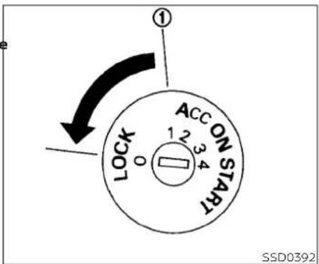
CONTINUOUSLY VARIABLE TRANSMISSION
The ignition lock is designed so that the ignition switch cannot be turned to the LOCK position until the shift lever is moved to the P (Park) position.
- When placing the ignition switch in the LOCK position, make sure that the shift lever is in the P (Park) position
- When removing the key from the ignition switch (if it is inserted), make sure that the shift lever is in the P (Park) position.
When the ignition switch cannot be placed ACC: (Accessories) (2)
in the LOCK position:
- Move the shift lever to the P (Park) position.
- Move the ignition switch slightly in the ON direction.
- Turn the ignition switch to the LOCK position.
- Remove the key if it is inserted in the ignition switch.
If the ignition switch is placed in the LOCK position, the shift lever cannot be moved from the P (Park) position.
This position activates electrical accessories such as the radio when the engine is not running.
ON: Normal operating position (3)
This position turns on the ignition system and the electrical accessories.
START: (4)
This position starts the engine. As soon as the engine has started, release the key. It automatically returns to the ON position.
NISSAN VEHICLE IMMOBILIZER
- Place the ignition switch in the OFF or LOCK position, and wait approximately 10 seconds.
- Repeat steps 1 and 2.
- Restart the engine while holding the device (which may have caused the interference) separate from the registered key.
If the no start condition re-occurs, NISSAN recommends placing the registered key on a separate key ring to avoid interference from other devices.
The shift lever can be moved if the igni SYSTEM
tion switch is in the ON position and the foot brake pedal is depressed.
There is an OFF position ① between the LOCK and ACC positions. The OFF position is indicated by a "1" on the key cylinder.
IGNITION SWITCH POSITIONS
LOCK: Normal parking position (0)
OFF: (1)
The engine can be turned off without locking the steering wheel.
The NISSAN Vehicle Immobilizer System will not allow the engine to start without the use of the registered key.
If the engine falls to start using a registered key (for example, when interference is caused by another registered key, an automated toll road device or automatic payment device on the key ring), restart the engine using the following procedure:
- Leave the ignition switch in the ON position for approximately 5 seconds.
BEFORE STARTING THE ENGINE
STARTING THE ENGINE
- Make sure the area around the vehicle is 1. Apply the parking brake. clear.
- Make the shift lever to
- Check fluid levels such as engine oil, coolant, brake fluid, and windshield-washer fluid as frequently as possible, or at least whenever you refuel.
- Check that all windows and lights are clean.
- Visually inspect tires for their appearance and condition. Also check tires for proper inflation.
- Check that all doors are closed.
- Position seat and adjust head restraints/headrests.
- Adjust inside and outside mirrors.
- Fasten seat belts and ask all passengers to do likewise.
- Check the operation of warning lights when the ignition switch is placed in the ON position. For additional information, refer to "Warning lights, indicator lights and audible reminders" in the "Instruments and controls" section of this manual.
-
Apply the parking brake.
-
Move the shift lever to P (Park) or N (Neutral). P (Park) is recommended.
The shift lever cannot be moved out of P (Park) and into any of the other gear positions if the ignition switch is turned to the OFF position or if the key is removed from the ignition switch.
The starter is designed not to operate if the shift lever is in any of the driving positions.
-
Crank the engine with your foot off the accelerator pedal by placing the ignition switch in the START position. Release the key when the engine starts. If the engine starts, but fails to run, repeat the above procedure.
-
If the engine is very hard to start in extremely cold weather or when re-starting, depress the accelerator pedal a little (approximately 1/3 to the floor) and hold it and then crank the engine. Release the key and the accelerator pedal when the engine starts.
- If the engine is very hard to start because it is flooded, depress the accel-
erator pedal all the way to the floor and hold it. Crank the engine for 5-6 seconds. After cranking the engine, release the accelerator pedal. Crank the engine with your foot off the accelerator pedal by turning the ignition key to the START position. Release the key when the engine starts. If the engine starts, but fails to run, repeat the above procedure.
CAUTION
Do not operate the starter for more than 15 seconds at a time. If the engine does not start, turn the key to the OFF position and wait 10 seconds before cranking again, otherwise the starter could be damaged.
- Allow the engine to idle for at least 30 seconds after starting. Do not race the engine while warming it up. Drive at a moderate speed for a short distance first, especially in cold weather.
In cold weather, keep the engine running for a minimum of 2-3 minutes before shutting it off. Starting and stopping the engine over a short period of time may make the vehicle more difficult to start.
DRIVING THE VEHICLE
NOTE:
ENGINE PROTECTION MODE
erator pedal, and air conditioning cooling function will automatically be turned back
Care should be taken to avoid situations that can lead to potential battery discharge and potential no-start conditions such as:
5 The engine has an engine protection mod
to reduce the chance of damage if the coolant temperature becomes too high (for example, when climbing steep grades in high temperature with heavy loads, suc
Move the vehicle off the road in a safe area and allow the engine to cool if the following
- Installation or extended use of electronic accessories that consume battery power when the engine is not running (phone chargers, GPS, DVD players, etc.).
as when towing a trailer). When the engine temperature reaches a certain level:
- The vehicle is not driven regularly and/or only driven short distances.
• The high temperature warning light will turn on.
- Engine power may be reduced.
-
The engine coolant temperature is not reduced.
-
The air conditioning cooling function does not turn back on.
-
The engine oil pressure low and high temperature warning light illuminates. This may indicate a malfunction.
In these cases, the battery may need to be charged to maintain battery health.
- The air conditioning cooling function may be automatically turned off for a short time (the blower will continue to operate).
Engine power and, under some conditions, vehicle speed will decrease. Vehicle speed can be controlled with the accelerator pedal, but the vehicle may not accelerate the desired speed. The transmission will downshift or upshift as it reaches prescribed shift points. You can also shift manually.
As driving conditions change and engine coolant temperature is reduced, vehicle speed can be increased using the accel-
If after checking the oil and coolant, the ⏻ remains on, do not continue to drive. It is recommended that you visit a NISSAN dealer for servicing.
The Malfunction Indicator Light (MIL) may also come ON. If only it remains on, you do not need to have your vehicle towed, but have it inspected soon. It is recommended that you visit a NISSAN dealer for this service. For additional information, refer to "Malfunction Indicator Light (MIL)" In the "Instruments and controls" section of this manual.
WARNING
Overheating can result in reduced engine power and vehicle speed. The reduced speed may be lower than other traffic, which could increase the chance of a collision. Be especially careful when driving. If the vehicle cannot maintain a safe driving speed, pull to the side of the road in a safe area. Allow the engine to cool and return to normal operation. For additional information, refer to "If your vehicle overheats" in the "In case of emergency" section of this manual.
CAUTION
Running the engine with the engine oil pressure warning light on could cause serious damage to the engine almost immediately. Such damage is not covered by warranty. Turn off the engine a soon as it is safe to do so.
CONTINUOUSLY VARIABLE TRANSMISSION (CVT)
WARNING
- Do not depress the accelerator pedal while shifting from P (Park) or N (Neutral) to R (Reverse), D (Drive) or L (Low). The Always depress the brake pedal until T0 shifting is completed. Failure to do so hard could cause you to lose control and have an accident.
- Cold engine idle speed is high, so use caution when shifting into a forward or reverse gear before the engine has warmed up.
- Do not downshift abruptly on slippery roads. This may cause a loss of control.
as Never shift to either the P (Park) or R (Reverse) position while the vehicle is moving forward and P (Park) or D (Drive) position while the vehicle is reversing. This could cause an accident or damage the transmission.
- Except in an emergency, do not shift to the N (Neutral) position while driving. Coasting with the transmission in the N (Neutral) position may cause serious damage to the transmission.
CAUTION
To avoid possible damage to your vehicle, when stopping the vehicle on an uphill grade, do not hold the vehicle by depressing the accelerator pedal. The foot brake should be used for this purpose.
The CVT in your vehicle is electronically controlled to produce maximum power and smooth operation.
The recommended operating procedures for this transmission are shown on the following pages. Follow these procedures for maximum vehicle performance and driving enjoyment.
NOTE:
Engine power may be automatically reduced to protect the CVT if the engine speed increases quickly when driving on slippery roads or while being tested on some dynamometers.
Starting the vehicle
WARNING
- Do not depress the accelerator pedal while shifting from P (Park) or N (Neutral) to R (Reverse), D (Drive) or L (Low). Always depress the brake pedal until shifting is completed. Failure to do so could cause you to lose control and have an accident.
- Cold engine idle speed is high, so use caution when shifting into a forward or reverse gear before the engine has warmed up.
- Do not downshift abruptly on slippery roads. This may cause a loss of control.
- Never shift to either the P (Park) or R (Reverse) position while the vehicle is moving forward and P (Park) or D (Drive) position while the vehicle is reversing. This could cause an accident or damage the transmission.
- Except in an emergency, do not shift to the N (Neutral) position while driving. Coasting with the transmission in the N (Neutral) position may cause serious damage to the transmission.
CAUTION
To avoid possible damage to your vehicle, when stopping the vehicle on an uphill grade, do not hold the vehicle by depressing the accelerator pedal. The foot brake should be used for this purpose.
The shift lever cannot be moved out of P (Park) and into any of the other gear positions if the ignition switch is placed in the LOCK, OFF or ACC position or if the key is removed.
- After starting the engine, fully depress the foot brake pedal before moving the shift lever out of the P (Park) position.
- Keep the foot brake pedal depressed and move the shift lever into a driving gear.
- Release the foot brake, then gradually start the vehicle in motion.
- Stop the vehicle completely before moving the shift lever into the P (Park) position.
The Continuously Variable Transmission is designed so the foot brake pedal MUST be depressed before shifting from P (Park) to any drive position while the ignition switch is in the ON position.

natural_image
Line drawing of a car interior showing the intake manifold and control panel (no text or symbols)Shifting
After starting the engine, fully depress the brake pedal and move the shift lever from (Park) to any of the desired shift positions.
WARNING
Apply the parking brake if the shift level is in any position while the engine is running. Failure to do so could cause the vehicle to move unexpectedly or roll away and result in serious personal injury or property damage.
If the ignition switch is placed in the OFF drill, apply the parking brake first, then place ACC position for any reason while the ve- the shift lever into the P (Park) position.
hicle is in N (Neutral), or any drive position the key cannot be turned to the LOCK position and cannot be removed from the ignition switch. If this occurs, perform the following steps:
- Apply the parking brake when the vehicle is stopped.
- Move the shift lever to P (Park) to park the vehicle and place the ignition switch in the LOCK position to remove the key.
P (Park)
CAUTION
To prevent transmission damage, use the P (Park) position only when the vehicle is completely stopped.
Use the P (Park) shift lever position when the vehicle is parked or when starting the engine. Make sure the vehicle is completed
Iptopped. The brake pedal must be depressed and the shift lever button pressed in to move the shift lever from N (Neutral) or any drive position to P (Park).
Apply the parking brake. When parking on a
R (Reverse)
A CAUTION
To prevent transmission damage, use the R (Reverse) position only when the vehicle is completely stopped.
Use the R (Reverse) position to back up. Make sure the vehicle is completely stopped before selecting the R (Reverse) position. R (Reverse) speed is limited to 30 mph (48 km/h). Do not exceed 30 mph (48 km/h) in the R (Reverse) position. The brake pedal must be depressed and the shift lever button pressed in to move the shift lever from P (Park), N (Neutral) or any drive position to R (Reverse).
N (Neutral)
Neither forward nor reverse gear is engaged. The engine can be started in this position. You may shift to N (Neutral) and restart a stalled engine while the vehicle is moving.
D (Drive)
Use this position for all normal forward driving.
L( Low )
Use this position for engine braking on steep downhill gradients/climbing steep slopes and whenever approaching sharp bends. Do not use the L (Low) position in any other circumstances.

natural_image
Diagram of a car gear shift system showing intake, mode, and control panel (no text labels)Shift lock release
If the battery is discharged, the shift lever may not be moved from the P (Park) position even with the foot brake pedal depressed.
To move the shift lever, perform the following procedure:
- Place the ignition switch in the LOCK position and remove the key.
- Apply the parking brake.
-
Remove the shift lock release cover using a suitable tool.
-
Push down the shift lock release using a suitable tool.
- Press the shift lever button and move the shift lever to the N (Neutral) position while holding down the shift lock release.
Place the ignition switch in the ON position to unlock the steering wheel. The vehicle may be moved to the desired location.
Replace the removed shift lock release cover after the operation.
If the shift lever cannot be moved out of the P (Park) position, have the Continuously Variable Transmission system checked as soon as possible. It is recommended that you visit a NISSAN dealer for this service.
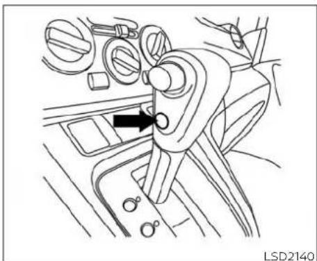
natural_image
Line drawing of a car interior showing steering wheel, dashboard, and gear shift (no text or symbols)Overdrive (O/D) OFF switch
When the O/D OFF switch is pushed with the shift lever in the D (Drive) position, the indicator light in the instrument panel illuminates. For additional information, refer to "Overdrive OFF indicator light" in the "Instruments and controls" section of this manual.
Use the overdrive OFF mode when you need improved engine braking.
To turn off the overdrive OFF mode, push the O/D OFF switch again. The O/D OFF indicator light will turn off.
Each time the engine is started, or when the shift lever is moved to any position other than D (Drive), the overdrive OFF mode will be automatically turned off.
Accelerator downshift - in D (Drive) position -
For passing or hill climbing, depress the accelerator pedal to the floor. This shifts the transmission down into a lower gear, depending on the vehicle speed.
High fluid temperature protection mode
This transmission has a high fluid temperature protection mode. If the fluid temperature becomes too high (for example, when climbing steep grades in high temperatures with heavy loads, such as when towing a trailer), engine power and, under some conditions, vehicle speed will be decreased automatically to reduce the chance of transmission damage. Vehicle speed can be controlled with the accelerator pedal, but the engine and vehicle speed may be limited.
Fail-safe
When the fail-safe operation occurs, the Continuously Variable Transmission will not be shifted into the selected driving position.
If the vehicle is driven under extreme conditions, such as excessive wheel spinning and subsequent hard braking, the fail-safe system may be activated. The Malfunction Indicator Light (MIL) may come on to indicate the fail-safe mode is activated. For additional information, refer to "Malfunction Indicator Light (MIL)" in the "Instruments and controls" section of this manual. This will occur even if all electrical circuits are functioning properly. In this case, place the ignition switch in the OFF position and wait for 10 seconds. Then place the ignition switch back in the ON position. The vehicle should return to its normal operating condition. If it does not return to its normal operating condition, have the transmission checked and repaired, if necessary. It is recommended that you visit a NISSAN dealer for this service.
PARKING BRAKE
WARNING
When the high fluid temperature protection mode or fail-safe operation occurs, vehicle speed may be gradually reduced. The reduced speed may be lower than other traffic, which could increase the chance of a collision. Be especially careful when driving. If necessary, pull to the side of the road at a safe place and allow the transmission to return to normal operation, or have it repaired if necessary.
WARNING
- Be sure the parking brake is fully released before driving. Failure to do so can cause brake failure and lead to an accident.
- Do not release the parking brake from outside the vehicle.
- Do not use the shift lever in place of the parking brake. When parking, be sure the parking brake is fully engaged.
- To help avoid risk of injury or death through unintended operation of the vehicle and/or its systems, do not leave children, people who require the assistance of others or pets unattended in your vehicle. Additionally, the temperature inside a closed vehicle on a warm day can quickly become high enough to cause a significant risk of injury or death to people and pets.

natural_image
Line drawing of a car interior showing a directional arrow pointing to a keyway (no text or symbols present)To engage: Pull the lever up.
To release:
- Firmly apply the parking brake.
- Move the shift lever to the P (Park) position.
- While pulling up on the parking brake lever slightly, press the button and lower completely.
- Before driving, be sure the brake warning light goes out.
CRUISE CONTROL (if so equipped)
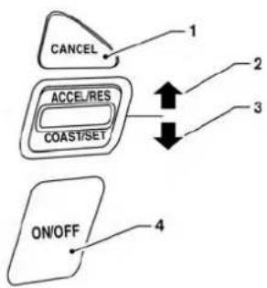
flowchart
graph TD
    A["CANCEL"] --> B["ACCEL/RES"]
    B --> C["COAST/SET"]
    C --> D["ON/OFF"]
    D --> E["4"]
    style A fill:#f9f,stroke:#333
    style B fill:#ccf,stroke:#333
    style C fill:#cfc,stroke:#333
    style D fill:#fcc,stroke:#333
    style E fill:#ffc,stroke:#333
LSD2430
PRECAUTIONS ON CRUISE CONTROL
- CANCEL switch
- ACCEL/RES switch
- COAST/SET switch
- ON/OFF switch
- If the cruise control system malfunctions, it cancels automatically.
• To properly set the cruise control system, use the following procedures.
WARNING
Do not use the cruise control when driving under the following conditions:
- When it is not possible to keep the vehicle at a set speed.
- In heavy traffic or in traffic that varies in speed.
- On winding or hilly roads.
- On slippery roads (rain, snow, ice, etc.).
- In very windy areas.
Doing so could cause a loss of vehicle control and result in an accident.
The cruise control allows driving at a speed the cruise control is automatically can-between 30 - 89 mph (48 - 144 km/h) with celed if:
out keeping your foot on the accelerator pedal.
To turn on the cruise control, push the ON/OFF switch. The CRUISE indicator light in the instrument panel comes on.
To set cruising speed, accelerate the vehicle to the desired speed, push the COAST/SET switch and release it. Take your foot off the accelerator pedal. Your vehicle maintains the set speed.
- To pass another vehicle, depress the accelerator pedal. When you release the pedal, the vehicle returns to the previously set speed.
- The vehicle may not maintain the set speed when going up or down steep hills. If this happens, drive without the cruise control.
To cancel the preset speed, use one of the following three methods:
- Push the CANCEL switch.
- Tap the brake pedal.
-
Push the ON/OFF switch. The CRUISE indicator light in the instrument panel will go out.
-
You depress the brake pedal while pushing the ACCEL/RES or COAST/SET switch. The preset speed is deleted from memory.
• The vehicle slows down more than 8 mph (13 km/h) below the set speed. - You move the shift lever to N (Neutral).
BREAK-IN SCHEDULE
To reset at a faster cruising speed, use one of the following three methods:
- Depress the accelerator pedal. When the vehicle attains the desired speed, push and release the COAST/SET switch.
- Push and hold the ACCEL/RES switch. When the vehicle attains the speed you desire, release the switch.
- Push and release the ACCEL/RES switch. Each time you do this, the set speed increases by about 1 mph (1.6 km/h).
To reset at a slower cruising speed, use one of the following three methods:
- Lightly tap the brake pedal. When the vehicle attains the desired speed, push the COAST/SET switch and release it.
- Push and hold the COAST/SET switch. Release the switch when the vehicle slows to the desired speed.
- Push and release the COAST/SET switch. Each time you do this, the set speed decreases by about 1 mph (1.6 km/h).
To resume the preset speed, push and release the ACCEL/RES switch. The vehicle returns to the last set cruising speed when the vehicle speed is over 30 mph (48 km/h)
CAUTION
During the first 1,200 miles (2,000 km), follow these recommendations to obtain maximum engine performance and ensure the future reliability and economy of your new vehicle. Failure to follow these recommendations may result in shortened engine life and reduced engine performance.
- Avoid driving for long periods at constant speed, either fast or slow, and do not run the engine over 4,000 rpm.
- Do not accelerate at full throttle in any gear.
- Avoid quick starts.
- Avoid hard braking as much as possible.
FUEL EFFICIENT DRIVING TIPS
Follow these easy-to-use Fuel Efficient Driving Tips to help you achieve the most fuel economy from your vehicle.
1. Use Smooth Accelerator and Brake Pedal Application
- Avoid rapid starts and stops.
- Use smooth, gentle accelerator and brake application whenever possible.
- Maintain constant speed while commuting and coast whenever possible.
2. Maintain Constant Speed
- Look ahead to try and anticipate and minimize stops.
- Synchronizing your speed with traffic lights allows you to reduce your number of stops.
- Maintaining a steady speed can minimize red light stops and improve fuel efficiency.
3. Use Air Conditioning (A/C) at Higher Vehicle Speeds
- Below 40 mph (64 km/h), it is more efficient to open windows to cool the vehicle due to reduced engine load.
- Above 40 mph (64 km/h), it is more efficient to use A/C to cool the vehicle due to increased aerodynamic drag.
- Recirculating the cool air in the cabin when the A/C is on reduces cooling load.
4. Drive at Economical Speeds and Distances
- Observing the speed limit and not exceeding 60 mph (97 km/h) (where legally allowed) can improve fuel efficiency due to reduced aerodynamic drag.
- Maintaining a safe following distance behind other vehicles reduces unnecessary braking.
- Safely monitoring traffic to anticipate changes in speed permits reduced braking and smooth acceleration changes.
- Select a gear range suitable to road conditions.
5. Use Cruise Control
- Using cruise control during highway driving helps maintain a steady speed.
- Cruise control is particularly effective in providing fuel savings when driving on flat terrains.
6. Plan for the Shortest Route
- Utilize a map or navigation system to determine the best route to save time.
7. Avoid Idling
- Shutting off your engine when safe for stops exceeding 30–60 seconds saves fuel and reduces emissions.
8. Buy an Automated Pass for Toll Roads
- Automated passes permit drivers to use special lanes to maintain cruising speed through the toll and avoid stopping and starting.
5-20 Starting and driving
INCREASING FUEL ECONOMY
9. Winter Warm Up
- Limit idling time to minimize impact to fuel economy.
• Vehicles typically need no more than 30 seconds of idling at start-up to effectively circulate the engine oil before driving. - Your vehicle will reach its ideal operating temperature more quickly while driving versus idling.
10. Keeping your Vehicle Cool
- Park your vehicle in a covered parking area or in the shade whenever possible.
-
When entering a hot vehicle, opening the windows will help to reduce the inside temperature faster, resulting in reduced demand on your A/C system.
-
Keep your engine tuned up.
- Follow the recommended scheduled maintenance.
- Keep the tires inflated to the correct pressure. Low tire pressure increases tire wear and lowers fuel economy.
- Keep the wheels in correct alignment. Improper alignment increases tire wear and lowers fuel economy.
- Use the recommended viscosity engine oil. For additional information, refer to "Engine oil and oil filter recommendations" in the "Technical and consumer information" section of this manual.
PARKING/PARKING ON HILLS

WARNING
- Do not stop or park the vehicle over flammable materials such as dry grass, waste paper or rags. They may ignite and cause a fire.
- Safe parking procedures require that both the parking brake be set and the transmission placed into P (Park). Failure to do so could cause the vehicle to move unexpectedly or roll away and result in an accident. Make sure the shift lever has been pushed as far forward as it can go and cannot be moved without depressing the foot brake pedal.
-
Never leave the engine running while the vehicle is unattended.
-
Do not leave children unattended inside the vehicle. They could unknowingly activate switches or controls or make the vehicle move. Unattended children could become involved in serious accidents.
- To help avoid risk of injury or death through unintended operation of the vehicle and/or its systems, do not leave children, people who require the assistance of others or pets unattended in your vehicle. Additionally, the temperature inside a closed vehicle on a warm day can quickly become high enough to cause a significant risk of injury or death to people and pets.
Firmly apply the parking brake.
- Move the shift lever to the P (Park) position.
- To help prevent the vehicle from rolling into traffic when parked on an incline, it is a good practice to turn the wheels as illustrated.
5-22 Starting and driving
POWER STEERING
- HEADED DOWNHILL WITH CUREA:
Turn the wheels into the curb and move the vehicle forward until the curb side wheel gently touches the curb.
• HEADED UPHILL WITH CURBB:
Turn the wheels away from the curb and move the vehicle back until the curb side wheel gently touches the curb.
- HEADED UPHILL OR DOWNHILL, NO CURB ©:
Turn the wheels toward the side of the road so the vehicle will move away from the center of the road if it moves
- Place the ignition switch in the LOCK position.
WARNING
- If the engine is not running or is turned off while driving, the power sist for the steering will not work. Steering will be harder to operate.
- When the power steering warning light illuminates with the engine running, there will be no power assist for the steering. You will still have control of the vehicle, but the steering will be harder to operate. Have the power steering system checked. It is recommended that you visit a NISSAN dealer for this service.
erations that could cause the power steering system to overheat.
as- You may hear a sound when the steering wheel is operated quickly. However, this is not a malfunction.
If the power steering warning light illuminates while the engine is running, it may indicate the power steering system is not functioning properly and may need servicing. Have the power steering system checked. It is recommended that you visit a NISSAN dealer for this service.
5 The power steering system is designed to provide power assist while driving to operate the steering wheel with light force.
When the steering wheel is operated repeatedly or continuously while parking or driving at a very low speed, the power assist for the steering wheel will be reduced. This is to prevent overheating of the power steering system and protect it from getting damaged. While the power assist is reduced, steering wheel operation will become heavy. When the temperature of the power steering system goes down, the power assist level will return to normal. Avoid repeating such steering wheel op-
When the power steering warning light illuminates with the engine running, there will be no power assist for the steering, but you will still have control of the vehicle. At this time, greater steering effort is required to operate the steering wheel, especially in sharp turns and at low speeds.
For additional information, refer to "Power steering warning light" in the "Instruments and controls" section of this manual.
BRAKE SYSTEM
The brake system has two separate hydraulic circuits. If one circuit malfunctions, you will still have braking at two wheels.
BRAKE PRECAUTIONS
Vacuum assisted brakes
The brake booster aids braking by using engine vacuum. If the engine stops, you can stop the vehicle by depressing the brake pedal. However, greater foot pressure on the brake pedal will be required to stop the vehicle and stopping distance will be longer.
Using the brakes
Avoid resting your foot on the brake pedal while driving. This will overheat the brakes, wear out the brake pads faster, and reduce gas mileage.
To help reduce brake wear and to prevent the brakes from overheating, reduce speed and downshift to a lower gear before going down a slope or long grade. Overheated brakes may reduce braking performance and could result in loss of vehicle control.
WARNING
- While driving on a slippery surface, be careful when braking, accelerating or downshifting. Abrupt braking or accelerating could cause the wheels to skid and result in an accident.
- If the engine is not running or is turned off while driving, the power assist for the brakes will not work. Braking will be harder.
Wet brakes
When the vehicle is washed or driven through water, the brakes may get wet. As a result, your braking distance will be longer and the vehicle may pull to one side during braking.
To dry the brakes, drive the vehicle at a safe speed while lightly pressing the brake
pedal to heat up the brakes. Do this until the brakes return to normal. Avoid driving the vehicle at high speeds until the brakes function correctly.
Parking brake break-in
Break in the parking brake shoes whenever the stopping effect of the parking brake is weakened or whenever the brake shoes
and/or drums/rotors are replaced, in order to assure the best brake performance.
This procedure is described in the vehicle service manual. It is recommended that you visit a NISSAN dealer for this service.
ANTI-LOCK BRAKING SYSTEM (ABS)
WARNING
- The ABS is a sophisticated device, but it cannot prevent accidents resulting from careless or dangerous driving techniques. It can help maintain vehicle control during braking on slippery surfaces. Remember that stopping distances on slippery surfaces will be longer than on normal surfaces even with ABS. Stopping distances may also be longer on rough, gravel or snow covered roads, or if you are using tire chains. Always maintain a safe distance from the vehicle in front of you. Ultimately, the driver is responsible for safety.
- Tire type and condition may also affect braking effectiveness.
- When replacing tires, install the specified size of tires on all four wheels.
5-24 Starting and driving
- When installing a spare tire, make sure that it is the proper size and type as specified on the Tire and Loading Information label. For additional information, refer to "Tire and Loading Information label" in the "Technical and consumer information" section of this manual.
- For additional information, refer to "Wheels and tires" in the "Do-it-yourself" section of this manual.
WARNING
Do not pump the brake pedal. Doing may result in increased stopping distances.
Self-test feature
The Anti-lock Braking System (ABS) includes electronic sensors, electric pumps, hydraulic solenoids and a computer. The computer has a built-in diagnostic feature that tests the system each time you start the engine and move the vehicle at a low speed in forward or reverse. When the self test occurs, you may hear a "clunk" noise and/or feel a pulsation in the brake pedal. This is normal and does not indicate a m-function. If the computer senses a malfunction, it switches the ABS off and illuminates the ABS warning light on the instrument panel. The brake system then operates normally but without anti-lock assistance.
If the ABS warning light illuminates during the self-test or while driving, have the vehicle checked. It is recommended that you visit a NISSAN dealer for this service.
Normal operation
soThe Anti-lock Braking System (ABS) operates at speeds above 3 - 6 m p h (5 - 10 km/h). The speed varies according to road conditions.
When the ABS senses that one or more wheels are close to locking up, the actuator rapidly applies and releases hydraulic pressure. This action is similar to pumping the brakes very quickly. You may feel a pulsation in the brake pedal and hear a noise from under the hood or feel a vibration from the actuator when it is operating. This is normal and indicates that the ABS is operating properly. However, the pulsation may indicate that road conditions are hazardous and extra care is required while driving.
BRAKE ASSIST
When the force applied to the brake pedal exceeds a certain level, the Brake Assist is activated generating greater braking force than a conventional brake booster even with light pedal force.
The ABS controls the brakes so the wheel do not lock during hard braking or when braking on slippery surfaces. The system detects the rotation speed at each wheel and varies the brake fluid pressure to prevent each wheel from locking and sliding. By preventing each wheel from locking, the system helps the driver maintain steering control and helps to minimize swerving and spinning on slippery surfaces.
Using the system
Depress the brake pedal and hold it down. Depress the brake pedal with firm steady pressure, but do not pump the brakes. The Anti-lock Braking System will operate to prevent the wheels from locking up. Steer the vehicle to avoid obstacles.
VEHICLE DYNAMIC CONTROL (VDC) SYSTEM
WARNING
The Brake Assist is only an aid to assist braking operation and is not a collision warning or avoidance device. It is the driver's responsibility to stay alert, drive safely and be in control of the vehicle at all times.
The VDC system uses various sensors to monitor driver inputs and vehicle motion. Under certain driving conditions, the VDC system helps to perform the following functions:
Controls brake pressure to reduce wheel slip on one slipping drive wheel so power is transferred to a non-slipping drive wheel on the same axle.
- Controls brake pressure and engine output to reduce drive wheel slip based on vehicle speed (traction control function).
-
Controls brake pressure at individual wheels and engine output to help the driver maintain control of the vehicle in the following conditions:
-
Understeer (vehicle tends to not follow the steered path despite increased steering input)
- Oversteer (vehicle tends to spin due to certain road or driving conditions)
The VDC system can help the driver to maintain control of the vehicle, but it cannot prevent loss of vehicle control in all driving situations.
When the VDC system operates, the indicator light in the instrument panel flashes to note the following:
- The road may be slippery or the system may determine some action is required to help keep the vehicle on the steered path.
- You may feel a pulsation in the brake pedal and hear a noise or vibration from under the hood. This is normal and indicates that the VDC system is working properly.
- Adjust your speed and driving to the road conditions.
For additional information, refer to "Slip indicator light" and "Vehicle Dynamic Control (VDC) OFF Indicator light" in the "Instruments and controls" section of this manual.
If a malfunction occurs in the system, the indicator light comes on in the instrument panel. The VDC system automatically turns off when the indicator light is on.
The VDC OFF switch is used to turn off the VDC system. The indicator light illuminates to indicate the VDC system is off. When the VDC OFF switch is used to turn off the system, the VDC system still operates
to prevent one drive wheel from slipping by transferring power to a non-slipping drive wheel. The indicator light flashes if this occurs. All other VDC functions are off and the indicator light will not flash. The VDC system is automatically reset to ON when the ignition switch is placed in the OFF position then back to the ON position.
The computer has a built-in diagnostic feature that tests the system each time you start the engine and move the vehicle forward or in reverse at a slow speed. When the self-test occurs, you may hear a clunk noise and/or feel a pulsation in the brake pedal. This is normal and is not an indication of a malfunction.
WARNING
- The VDC system is designed to help the driver maintain stability but does not prevent accidents due to abrupt steering operation at high speeds or by careless or dangerous driving techniques. Reduce vehicle speed and be especially careful when driving and cornering on slippery surfaces and always drive carefully.
Do not modify the vehicle's suspension. If suspension parts such as shock absorbers, struts, springs, stabilizer bars, bushings and wheels are not NISSAN recommended for your vehicle or are extremely deteriorated, the VDC system may not operate properly. This could adversely affect vehicle handling performance, and the indicator light may flash or the indicator light may illuminate.
- If brake related parts such as brake pads, rotors and calipers are not NISSAN recommended or are extremely deteriorated, the VDC system may not operate properly and both the 🎨 and 🌘 indicator lights may illuminate.
- If engine control related parts are not NISSAN recommended or are extremely deteriorated, both the and the indicator lights may illuminate.
- When driving on extremely inclined surfaces such as higher banked corners, the VDC system may not operate properly and the indicator light may flash or the indicator light may illuminate. Do not drive on these types of roads.
- When driving on an unstable surface such as a turntable, ferry, elevator or ramp, the indicator light may flash or the indicator light may illuminate. This is not a malfunction. Restart the engine after driving onto a stable surface.
- If wheels or tires other than the NISSAN recommended ones are used, the VDC system may not operate properly and the indicator light may flash or the indicator light may illuminate.
- The VDC system is not a substitute for winter tires or tire chains on a snow covered road.
RISE-UP AND BUILD-UP
The system gradually adjusts braking power during normal braking to help provide an enhanced brake feel.
BRAKE FORCE DISTRIBUTION
During braking while driving through turns, the system optimizes the distribution of force to each of the four wheels depending on the radius of the turn.
WARNING
- The VDC system is designed to help the driver maintain stability but does not prevent accidents due to abrupt steering operation at high speeds or by careless or dangerous driving techniques. Reduce vehicle speed and be especially careful when driving and cornering on slippery surfaces and always drive carefully.
- Do not modify the vehicle's suspension. If suspension parts such as shock absorbers, struts, springs, stabilizer bars, bushings and wheels are not NISSAN recommended for your vehicle or are extremely deteriorated, the VDC system may not operate properly. This could adversely affect vehicle handling performance, and the indicator light may flash or the indicator light may illuminate.
- If brake related parts such as brake pads, rotors and calipers are not NISSAN recommended or are extremely deteriorated, the VDC system may not operate properly and both the 🎨 and 🌘 indicator lights may illuminate.
-
If engine control related parts are not NISSAN recommended or are extremely deteriorated, both the 🎨 and the 🎩 indicator lights may illuminate.
-
When driving on extremely inclined surfaces such as higher banked corners, the VDC system may not operate properly and the indicator light may flash or the indicator light may illuminate. Do not drive on these types of roads.
- When driving on an unstable surface such as a turntable, ferry, elevator or ramp, the indicator light may flash or the indicator light may illuminate. This is not a malfunction. Restart the engine after driving onto a stable surface.
- If wheels or tires other than the NISSAN recommended ones are used, the VDC system may not operate properly and the indicator light may flash or the indicator light may illuminate.
- The VDC system is not a substitute for winter tires or tire chains on a snow covered road.
WARNING
- Never rely solely on the hill start ass system to prevent the vehicle from moving backward on a hill. Always drive carefully and attentively. Depress the brake pedal when the vehicle is stopped on a steep hill. Be especially careful when stopped on a frozen or muddy roads. Failure to prevent the vehicle from rolling backwards may result in a loss of control the vehicle and possible serious injury or death.
- The hill start assist system is not designed to hold the vehicle at a standstill on a hill. Depress the brake pedal when the vehicle is stopped on a steep hill. Failure to do so may cause the vehicle to roll backwards and may result in a collision or serious personal injury.
- The hill start assist system may not prevent the vehicle from rolling backwards on a hill under all load or road conditions. Always be prepared to depress the brake pedal to prevent the vehicle from rolling backwards. Failure to do so may result in a collision or serious personal injury.
When the vehicle is stopped on a hill, the hill start assist system automatically keeps
the brakes applied to help prevent the vehicle from rolling backward in the time it takes the driver to release the brake pedal and apply the accelerator.
The hill start assist system will operate automatically under the following conditions:
- The transmission is shifted to a forward or reverse gear.
The vehicle is stopped completely on a hill by applying the brake. The maximum holding time is 2 seconds. After 2 seconds the vehicle will begin to roll back and the hill start assist system will stop operating completely.
The hill start assist system will not operate when the shift lever is placed in the N (Neutral) or P (Park) position or on a flat and level road.
! or
WARNING
Failure to follow the warnings and instructions for proper use of the RSS could result in serious injury or death.
- The RSS is not a replacement for proper driving procedures and is not designed to prevent contact with vehicles or objects.
- Always turn and look before backing up.
- Read and understand the limitations of the RSS as contained in this section. Inclement weather may affect the function of the RSS; this may include reduced performance or a false activation.
This system is not designed to prevent contact with small or moving objects. - The system is designed as an aid to the driver in detecting large stationary objects to help avoid damaging the vehicle. The system will not detect small objects below the bumper, and may not detect objects close to the bumper or on the ground.
- If your vehicle sustains damage to the rear bumper fascia, leaving it mis-aligned or bent, the sensing zone may be altered causing inaccurate measurement of obstacles or false alarms.
The RSS sounds a tone to warn the driver obstacles near the rear bumper when the ignition is in the ON position and the shift lever is in the R (Reverse) position.
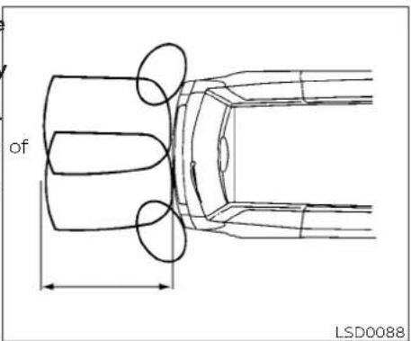
tone will sound for only 3 seconds. Once the system detects an object approaching, the tone will sound again.
The RSS is automatically activated when the ignition is in the ON position and the shift lever is in the R (Reverse) position. The system detects obstacles up to 5.9 feet (1.8 meters) from the rear bumper with decreased coverage area at the outer corners of the bumper (refer to the illustration for coverage area). As you move closer to obstacles the rate of the warning tone will increase. When the obstacle is less than 10 in. (25 cm.) away, the tone will sound continuously. If the RSS detects a stationary or receding object further than 10 in. (25 cm.) from the side of the vehicle the
5-30 Starting and driving
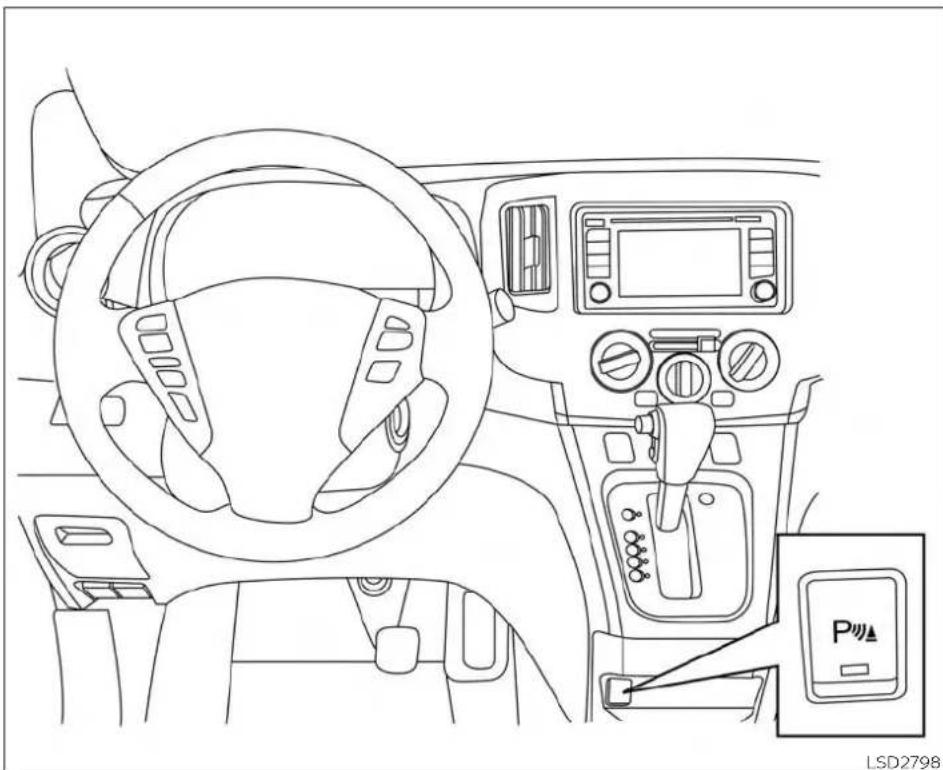
natural_image
Line drawing of a car interior showing steering wheel, dashboard, and control panel (no text or symbols)HOW TO ENABLE/DISABLE THE RSS
The RSS is automatically activated when the ignition is in the ON position and the shift lever is in the R (Reverse) position.
Perform the following steps to enable or disable the RSS:
- Push the Rear Sonar System (RSS) OFF switch (the orange light will illuminate) to turn the system off.
- To turn the system back on, push the Rear Sonar System (RSS) OFF switch (the orange light will go out) and the RSS will be enabled.
NOTE:
The RSS will automatically be turned on when the engine is restarted.
RSS LIMITATIONS
WARNING
Listed below are the system limitations for the RSS. Failure to operate the vehicle in accordance with these system limitations could result in serious injury or death.
- The driver is always responsible for safety during parking and other maneuvers. Always turn and look back before backing up. The RSS is not a substitute for proper procedures.
- Read and understand the limitations of the RSS as contained in this section. Inclement weather may affect the function of the RSS; this may include reduced performance or a false activation.
-
This system is not designed to prevent contact with small or moving objects.
-
The system is designed as an aid to the driver in detecting large stationary objects to help avoid damaging the vehicle. The system will not detect small objects below the bumper, and may not detect objects close to the bumper or on the ground.
- The system is deactivated at speeds above 6 mph (10 km/h). It is reactivated at lower speeds.
- Inclement weather or ultrasonic sources such as an automatic car wash, a truck's compressed-air brakes or a pneumatic drill may affect the function of the system; this may include reduced performance or a false activation.
- The system is not designed to prevent contact with small or moving objects. Always move slowly. The system will not detect small objects below the bumper or on the ground.
-
The system may not detect the following objects: fluffy objects such as snow, cloth, cotton, glass-wool, etc., and thin objects such as rope, wire and chain, etc., or wedge-shaped objects.
-
The system may not detect objects at speeds above 3 mph (5 km/h) and may not detect certain angular or moving objects.
- The system is deactivated at speeds above 6 mph (10 km/h) and is reactivated at lower speeds.
SYSTEM TEMPORARILY UNAVAILABLE
When sonar blockage is detected, the system will be deactivated automatically.
The system is not available until the conditions no longer exist.
The sonar sensors may be blocked by temporary ambient conditions such as splashing water, mist or fog. The blocked condition may also be caused by objects such as ice, frost or dirt obstructing the sonar sensors.
Action to take:
When the above conditions no longer exist, the system will resume automatically.
5-32 Starting and driving
COLD WEATHER DRIVING

natural_image
Line drawing of a van rear view with labeled components and a numbered marker (1), no text or symbols present.SYSTEM MAINTENANCE
The sonar sensors ① are located on the rear bumper. Always keep the area near the sonar sensors clean.
The sonar sensors may be blocked by temporary ambient conditions such as splashing water, mist or fog.
The blocked condition may also be caused by objects such as ice, frost or dirt obstructing the sonar sensors.
Check for and remove objects obstructing the area around the sonar sensors.
Do not attach stickers (including transparent material), install accessories or apply additional paint near the sonar sensors.
Do not strike or damage the area around the sonar sensors. It is recommended that you visit a NISSAN dealer if the area around the sonar sensors is damaged due to a collision.
FREEING A FROZEN DOOR LOCK
To prevent a door lock from freezing, apply de-icer through the key hole. If the lock becomes frozen, heat the key before inserting it into the key hole or use the remote keyless entry key fob.
ANTIFREEZE
In the winter when it is anticipated that the temperature will drop below 32irc F ( 0irc C), check the antifreeze to assure proper winter protection. For additional information, refer to "Engine cooling system" in the "Do-it-yourself" section of this manual.
BATTERY
If the battery is not fully charged during extremely cold weather conditions, the battery fluid may freeze and damage the battery. To maintain maximum efficiency, the battery should be checked regularly. For additional information, refer to "Battery" in the "Do-it-yourself" section of this manual.
DRAINING OF COOLANT WATER
If the vehicle is to be left outside without antifreeze, drain the cooling system, including the engine block. Refill before operating the vehicle. For additional information, refer to "Changing engine coolant" in the "Do-it-yourself" section of this manual.
TIRE EQUIPMENT
- SUMMER tires have a tread designed to provide superior performance on dry pavement. However, the performance of these tires will be substantially reduced in snowy and icy conditions. If you operate your vehicle on snowy or icy roads, NISSAN recommends the use of MUD & SNOW or ALL SEASON TIRES on all four wheels. It is recommended that you visit a NISSAN dealer for the tire type, size, speed rating and availability information.
- For additional traction on icy roads, studded tires may be used. However, some U.S. states and Canadian provinces prohibit their use. Check local, state and provincial laws before installing studded tires.
Skid and traction capabilities of studded DRIVING ON SNOW OR ICE snow tires on wet or dry surfaces may be
poorer than that of non-studded snow tires.
- Tire chains may be used. For additional information, refer to "Tire chains" in the "Do-it-yourself" section of this manual.
SPECIAL WINTER EQUIPMENT
It is recommended that the following items be carried in the vehicle during winter:
- A scraper and stiff-bristled brush to remove ice and snow from the windows and wiper blades.
- A sturdy, flat board to be placed under the jack to give it firm support.
- A shovel to dig the vehicle out of snow-drifts.
- Extra washer fluid to refill the windshield-washer fluid reservoir.
A WARNING
- Wet ice (32°F, 0°C and freezing rain), very cold snow or ice can be slick and very hard to drive on. The vehicle will have much less traction or "grip" under these conditions. Try to avoid driving on wet ice until the road is salted or sanded.
- Whatever the condition, drive with caution. Accelerate and slow down with care. If accelerating or down-shifting too fast, the drive wheels will lose even more traction.
- Allow more stopping distance under these conditions. Braking should be started sooner than on dry pavement.
- Allow greater following distances on slippery roads.
- Watch for slippery spots (glare ice). These may appear on an otherwise clear road in shaded areas. If a patch of ice is seen ahead, brake before reaching it. Try not to brake while on the ice, and avoid any sudden steering maneuvers.
5-34 Starting and driving
- Do not use the cruise control (if so equipped) on slippery roads.
- Snow can trap dangerous exhaust gases under your vehicle. Keep snow clear of the exhaust pipe and from around your vehicle.
ENGINE BLOCK HEATER (if so equipped)
Engine block heaters are used to assist with cold temperature starting.
The engine block heater should be used when the outside temperature is 20irc F ( -7irc C) or lower.
WARNING
- Do not use your engine block heater with an ungrounded electrical system or a 2-pronged adapter. You can be seriously injured by an electrical shock if you use an ungrounded connection.
-
Disconnect and properly store the engine block heater cord before starting the engine. Damage to the cord could result in an electrical shock and can cause serious injury.
-
Use a heavy-duty 3-wire, 3-pronged extension cord rated for at least 10 A. Plug the extension cord into a Ground Fault Interrupt (GFI) protected, grounded 110-VAC outlet. Failure to use the proper extension cord or a grounded outlet can result in a fire or electrical shock and cause serious personal injury.
To use the engine block heater:
- Turn the engine off.
- Open the hood and unwrap the engine block heater cord.
- Plug the engine block heater cord into a grounded 3-wire, 3-pronged extension cord.
-
Plug the extension cord into a Ground Fault Interrupt (GFI) protected, grounded 110-volt AC (VAC) outlet.
-
The engine block heater must be plugged in for at least 2 - 4 hours, depending on outside temperatures, to properly warm the engine coolant. Use an appropriate timertoturn the engine block heater on.
-
Before starting the engine, unplug and properly store the cord to keep it away from moving parts.
MEMO
5-36 Starting and driving
6 In case of emergency
Hazard warning flasher switch 6 - 2
Flat tire 6-2
Tire Pressure Monitoring System (T P M S) 6 - 2
Changing a flat tire 6 - 3
Jump starting 6-10
Push starting 6-12
If your vehicle overheats 6-12
Towing your vehicle 6-13 Towing recommended by NISSAN 6-13
Vehicle recovery (freeing a stuck vehicle)....6-15
HAZARD WARNING FLASHER SWITCH
FLAT TIRE

natural_image
Simple geometric diagram showing a large triangle with an arrow pointing downward (no text or symbols)LIC0394
Push the switch on to warn other drivers when you must stop or park under emergency conditions. All turn signal lights flash.
WARNING
- If stopping for an emergency, be sure to move the vehicle well off the road.
- Do not use the hazard warning flashers while moving on the highway unless unusual circumstances force you to drive so slowly that your vehicle might become a hazard to other traffic.
- Turn signals do not work when the hazard warning flasher lights are on.
The flashers will operate with the ignition switch placed in any position.
Some jurisdictions may prohibit the use of the hazard warning flasher switch while driving.
TIRE PRESSURE MONITORING SYSTEM (TPMS)
This vehicle is equipped with the Tire Pressure Monitoring System (TPMS). It monitors tire pressure of all tires except the spare. When the low tire pressure warning light is lit, and the CHECK TIRE PRES (pressure) warning message is displayed in the trip computer, one or more of your tires is significantly under-inflated. If the vehicle is being driven with low tire pressure, the TPMS will activate and warn you of it by the low tire pressure warning light. This system will activate only when the vehicle is driven at speeds above 16 mph (25 km/h). For additional information, refer to "Warning lights, indicator lights and audible reminders" in the "Instruments and controls" section, and "Tire Pressure Monitoring System (TPMS)" in the "Starting and driving" section of this manual.
WARNING
- Radio waves could adversely affect electric medical equipment. Those who use a pacemaker should contact the electric medical equipment manufacturer for the possible influences before use.
6-2 In case of emergency
- If the low tire pressure warning light illuminates while driving, avoid sudden steering maneuvers or abrupt braking, reduce vehicle speed, pull off the road to a safe location and stop the vehicle as soon as possible. Driving with under-inflated tires may permanently damage the tires and increase the likelihood of tire failure. Serious vehicle damage could occur and may lead to an accident and could result in serious personal injury. Check the tire pressure for all four tires. Adjust the tire pressure to the recommended COLD tire pressure shown on the Tire and Loading Information label to turn the low tire pressure warning light OFF. If the light still illuminates while driving after adjusting the tire pressure, a tire may be flat or the TPMS may be malfunctioning. If you have a flat tire, replace it with a spare tire as soon as possible. If no tire is flat and all tires are properly inflated, have the vehicle checked. It is recommended that you visit a NISSAN dealer for this service.
- When replacing a wheel without the TPMS such as the spare tire, the TPMS will not function and the low tire pressure warning light will flash for approximately 1 minute. The light will remain on after 1 minute. Have your tires replaced and/or TPMS system reset as soon as possible. It is recommended that you visit a NISSAN dealer for these services.
Do not inject any tire liquid or aerosol tire sealant into the tires, as this may cause a malfunction of the tire pressure sensors.
- Replacing tires with those not originally specified by NISSAN could affect the proper operation of the TPMS.
CHANGING A FLAT TIRE
if you have a flat tire, follow the instructions below:
Stopping the vehicle
-
Safely move the vehicle off the road and away from traffic.
-
Turn on the hazard warning flashers.
-
Park on a level surface and apply the parking brake. Move the shift lever to P (Park).
- Turn off the engine.
- Raise the hood to warn other traffic and to signal professional road assistance personnel that you need assistance.
- Have all passengers get out of the vehicle and stand in a safe place, away from traffic and clear of the vehicle.
WARNING
- Make sure the parking brake is securely applied and the Continuously Variable Transmission (CVT) is shifted into P (Park).
- Never change tires when the vehicle is on a slope, ice or slippery areas. This is hazardous.
- Never change tires if oncoming traffic is close to your vehicle. Wait for professional road assistance.

natural_image
Technical illustration of mechanical components labeled A and B, showing threaded parts with no text or symbols beyond labelsA. Blocks
B. Flat tire
Blocking wheels
Place suitable blocks at both the front and back of the wheel diagonally opposite the flat tire to prevent the vehicle from moving when it is jacked up.

Getting the spare tire and tools
Remove the jack and necessary tools from under the passenger seat by performing the following steps:

natural_image
Line drawing of a car interior showing seat, dashboard, and seatbelt (no text or symbols)- Adjust the passenger seat rearward.
WARNING
Be sure to block the wheel as the vehicle may move and result in personal injury.
6-4 In case of emergency

natural_image
Diagram of a car gear shift lever with an arrow indicating direction (no text or symbols present)- Remove the tray from under the passenger seat.

-
Loosen the jack screw counterclockwise. ③
-
Lift jack up.④
-
Pull jack forward⑤
-
Release the belt strap to remove the tool bag containing the wheel nut wrench and jacking rod.
Reverse steps 1-6 to install and secure the jack and tool bag.

- Open the back door.
- Loosen the bolt ① counterclockwise approximately 40 turns to lower the spare. Be careful not to excessively loosen the bolt because the basket may fall abruptly.
6-6 In case of emergency
- Stop turning the bolt when the spare is lowered to the point where the tire basket ② can be removed from the hook ③.
- Remove the wheel basket by pushing the basket upward.
- Lower the tire basket to the ground and take out the spare.
- Reverse steps 8-11 to return the basket to its position under the vehicle.
Spare wheel basket bolt tightening torque:
20 ft-lb (27 N-m)

Removing wheel cover (if so equipped)
CAUTION
Do not use your hands to pry off wheel caps or wheel covers. Doing so could result in personal injury.
To remove the wheel cover, use the jacking rod ①.
Apply cloth ② between the wheel and jacking rod to prevent damaging the wheel and wheel cover.
Use caution not to scratch the wheel cover or wheel surface.
Jacking up vehicle and removing the damaged tire
WARNING
- Never get under the vehicle while it is supported only by the jack. If it is necessary to work under the vehicle, support it with safety stands.
- Use only the jack provided with your 9 vehicle to lift the vehicle. Do not use the jack provided with your vehicle on other vehicles. The jack is designed for lifting only your vehicle during a tire change.
- Use the correct jack-up points. Never use any other part of the vehicle for jack support.
- Never jack up the vehicle more than necessary.
- Never use blocks on or under the jack.
-
Do not start or run the engine while the vehicle is on the jack. It may cause the vehicle to move.
-
Do not allow passengers to stay in the vehicle while it is on the jack.
- Never run the engine with a wheel(s) off the ground. It may cause the vehicle to move.
Always refer to the illustration for the correct placement and jack-up points for your specific vehicle model and jack type.
"Carefully read the caution label attached to the jack body and the following instructions.
- Loosen each wheel nut 1 or 2 turns by turning counterclockwise with the wheel nut wrench. Do not remove the wheel nuts until the tire is off the ground.
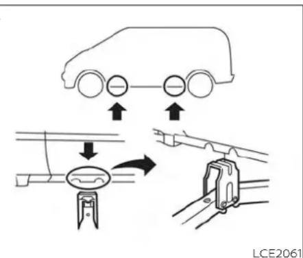
- Place the jack directly under the jack-up point so the top of the jack contacts the vehicle at the jack-up point. The jack-up points are indicated by stamped arrows on the side of the frame.
The jack should be used on firm and level ground.
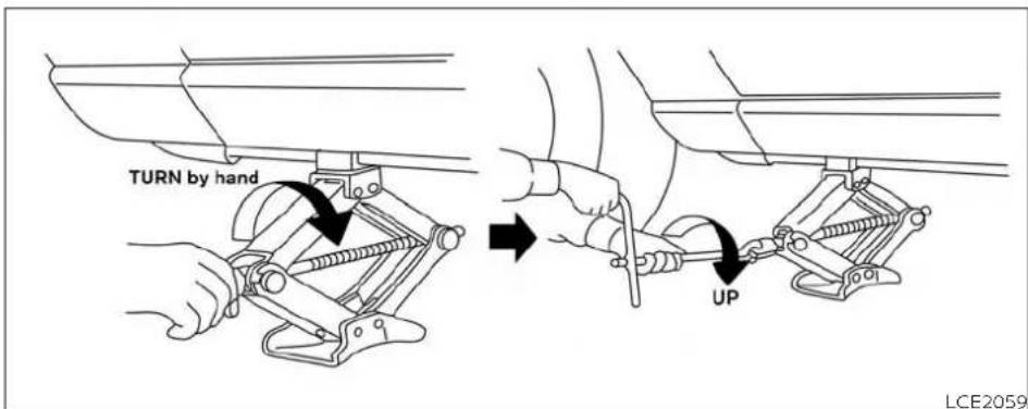

- Install the assembled jacking rod into the jack.
- To lift the vehicle, securely hold the jacking lever and rod. Carefully raise the vehicle until the tire clears the ground.
- Remove the wheel nuts and then remove the tire.
Installing the spare tire
The spare tire is designed for emergency use. For additional information, refer to "Wheels and tires" in the "Do-it-yourself" section of this manual.
- Clean any mud or dirt from the surface between the wheel and hub.
- Carefully put the spare tire on and tighten the wheel nuts finger tight.
- With the wheel nut wrench, tighten wheel nuts alternately and evenly in the sequence illustrated Ⓐ, Ⓑ, Ⓒ, Ⓓ, ⓕ) until they are tight.
6-8 In case of emergency
- Lower the vehicle slowly until the tire touches the ground. Then, with the wheel nut wrench, tighten the wheel nuts securely in the sequence illustrated (A, B, C, D, E). Lower the vehicle completely.
WARNING
- Incorrect wheel nuts or improperly tightened wheel nuts can cause the wheel to become loose or come off. This could cause an accident.
- Do not use oil or grease on the wh studs or nuts. This could cause the nuts to become loose.
- Retighten the wheel nuts when the vehicle has been driven for 600 miles (1,000 km) (also in cases of a flat tire, etc.).
As soon as possible, tighten the wheel nuts to the specified torque with a torque wrench.
Wheel nut tightening torque:
83 ft-lb (113 N·m)
The wheel nuts must be kept tightened to specification at all times. It is recommended that wheel nuts be tightened to specifications at each lubrication interval.
Adjust tire pressure to the COLD pressure.
COLD pressure: After vehicle has been parked for 3 hours or more or driven than 1 mile (1.6 km).
COLD tire pressures are shown on the tire and Loading Information label affixed to the driver side center pillar.
After adjusting tire pressure to the COLD tire pressure, the display (if so equipped) of the tire pressure information may show higher pressure than the COLD tire pressure after the vehicle has been driven more than 1 mile (1.6 km). This is because the tire pressure increases as the tire temperature rises. This does not indicate a system malfunction.
- Securely store the flat tire and jacking equipment in the vehicle.
WARNING
Always make sure that the spare tire and jacking equipment are properly secured after use. Such items can become dangerous projectiles in an accident or sudden stop.
The spare tire is designed for emergency use. For additional information, refer to specific instructions under the heading "Wheels and tires" in the "Do-it-yourself" section of this manual.
JUMP STARTING
To start your engine with a booster battery, the instructions and precautions below must be followed.
WARNING
- If done incorrectly, jump starting can lead to a battery explosion, resulting in severe injury or death. It could also damage your vehicle.
- Explosive hydrogen gas is always present in the vicinity of the battery. Keep all sparks and flames away from the battery.
- Do not allow battery fluid to come into contact with eyes, skin, clothing or painted surfaces. Battery fluid is a corrosive sulfuric acid solution which can cause severe burns. If the fluid should come into contact with anything, immediately flush the contacted area with water.
- Keep battery out of the reach of children.
- The booster battery must be rated at 12 volts. Use of an improperly rated battery can damage your vehicle.
Whenever working on or near a battery, always wear suitable eye protectors (for example, goggles or industrial safety spectacles) and remove rings, metal bands, or any other jewelry. Do not lean over the battery when jump starting.
Do not attempt to jump start a frozen battery. It could explode and cause serious injury.

WARNING
Always follow the instructions below. Failure to do so could result in damage to the charging system and cause personal injury.
- If the booster battery is in another vehicle, position the two vehicles to bring their batteries near each other.
Do not allow the two vehicles to touch.
- Apply the parking brake. Move the shift lever to P (Park). Switch off all unnecessary electrical systems (lights, heater, air conditioner, etc.).
- Connect the jumper cables in the sequence illustrated Ⓐ, Ⓑ, Ⓒ, Ⓓ).
CAUTION
- Always connect positive (+) to positive (+) and negative (−) to body ground (for example, strut mounting bolt, engine lift bracket, etc.) — not to the battery.
-
Make sure the jumper cables do not touch moving parts in the engine compartment and that the cable clamps do not contact any other metal.
-
Start the engine of the booster vehicle and let it run for a few minutes.
- Keep the engine speed of the booster vehicle at about 2,000 rpm and start the engine of the vehicle being jump started.
CAUTION
Do not keep the starter motor engaged for more than 10 seconds. If the engine does not start right away, place the ignition switch in the OFF position and wait 3 to 4 seconds before trying again.
- After starting the engine, carefully disconnect the negative cable and then the positive cable.
PUSH STARTING
IF YOUR VEHICLE OVERHEATS
CAUTION
- Do not push start this vehicle. The three-way catalyst may be damaged.
- Continuously Variable Transmission (CVT) models cannot be push-started or tow-started. Attempting to do so may cause transmission damage.
WARNING
- Do not continue to drive if your vehicle overheats. Doing so could cause engine damage or a vehicle fire.
- To avoid the danger of being scalded, never remove the radiator or coolant reservoir cap while the engine is still hot. When the radiator or coolant reservoir cap is removed, pressurized hot water will spurt out, possibly causing serious injury.
- Do not open the hood if steam is coming out.
- Overheating can result in reduced engine power and vehicle speed. The reduced speed may be lower than other traffic, which could increase the chance of a collision. Be especially careful when driving. If the vehicle cannot maintain a safe driving speed, pull to the side of the road in a safe area. Allow the engine to cool and return to normal operation.
If your vehicle is overheating (indicated by a red high temperature warning light), or if you feel a lack of engine power, detect abnormal noise, etc., take the following steps.
- Move the vehicle safely off the road, apply the parking brake and move the shift lever to P (Park).
Do not stop the engine.
-
Turn off the air conditioner. Open all the windows, move the heater or air conditioner temperature control to maximum hot and fan control to high speed.
-
Get out of the vehicle. Look and listen for steam or coolant escaping from the radiator before opening the hood. If steam or coolant is escaping, turn off the engine. Do not open the hood further until no steam or coolant can be seen.
-
Open the engine hood.
WARNING
If steam or water is coming from the engine, stand clear to prevent getting burned.
TOWING YOUR VEHICLE
- Visually check drive belts for damage or looseness. Also check if the cooling fan is running. The radiator hoses and radiator should not leak water. If coolant is leaking, the water pump belt is missing or loose, or the cooling fan does not run, stop the engine.
WARNING
Be careful not to allow your hands, hair, jewelry or clothing to come into contact with, or get caught in, engine belts or the engine cooling fan. The engine cooling fan can start at any time.
- After the engine cools down, check the coolant level in the engine coolant reservoir tank with the engine running. Add coolant to the engine coolant reservoir tank if necessary. It is recommended that you visit a NISSAN dealer for this service.
When towing your vehicle, all jurisdictional and local regulations for towing must be followed. Incorrect towing equipment could damage your vehicle. Towing instructions are available from a NISSAN dealer. Local service operators are generally familiar with the applicable laws and procedures for towing. To assure proper towing and to prevent accidental damage to your vehicle, NISSAN recommends having a service operator tow your vehicle. It advisable to have the service operator carefully read the following precautions:
WARNING
- Never ride in a vehicle that is being towed.
- Never get under your vehicle after it has been lifted by a tow truck.
CAUTION
- When towing, make sure that the transmission, axles, steering system and powertrain are in working condition. If any of these conditions apply, dollies or a flatbed tow truck must be used.
- Always attach safety chains before towing.
For additional information, refer to "Flat towing" in the "Technical and consumer information" section of this manual.
TOWING RECOMMENDED BY NISSAN
NISSAN recommends towing your vehicle based upon the type of drivetrain. For additional information, refer to the diagrams in this section to ensure that your vehicle is properly towed.
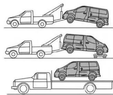
natural_image
Line drawings of three different types of utility vehicles: a tow truck, a van, and a flatbed truck (no text or symbols present)
LCE2286
Two-Wheel Drive models with Continuously Variable Transmission (CVT)
NISSAN recommends that your vehicle be towed with the driving (front) wheels off the ground or place the vehicle on a flatbed truck as illustrated.
CAUTION
- Never tow CVT models with the front wheels on the ground or four wheels on the ground (forward or backward), as this may cause serious and expensive damage to the transmission. If it is necessary to tow the vehicle with the rear wheels raised always use towing dollies under the front wheels.
- When towing CVT models with the rear wheels on the ground or on towing dollies:
- Place the ignition switch in the OFF position, and secure the steering wheel in a straight-ahead position with a rope or similar device. Never secure the steering wheel by placing the ignition switch in the LOCK position. This may damage the steering lock mechanism (for models with a steering lock mechanism).
6-14 In case of emergency
VEHICLE RECOVERY (freeing a stuck vehicle)
WARNING
To avoid vehicle damage, serious personal injury or death when recovering stuck vehicle:
- Contact a professional towing service to recover the vehicle if you have any questions regarding the recovery procedure.
- Tow chains or cables must be attached only to main structural members of the vehicle.
- Do not use the vehicle tie-downs to tow or free a stuck vehicle.
- Only use devices specifically designed for vehicle recovery and follow the manufacturer's instructions.
- Always pull the recovery device straight out from the front of the vehicle. Never pull at an angle.
- Route recovery devices so they do not touch any part of the vehicle except the attachment point.
If your vehicle is stuck in sand, snow, mud, etc., use a tow strap or other device designed specifically for vehicle recovery. Always follow the manufacturer's instructions for the recovery device.
Rocking a stuck vehicle
WARNING
- Stand clear of a stuck vehicle.
- Do not spin your tires at high speed. This could cause them to explode and result in serious injury. Parts of your vehicle could also overheat and be damaged.
If your vehicle is stuck in sand, snow, mud, etc., use the following procedure:
- Turn off the Vehicle Dynamic Control (VDC) system.
- Make sure the area in front and behind the vehicle is clear of obstructions.
- Turn the steering wheel right and left to clear an area around the front tires.
- Slowly rock the vehicle forward and backward.
- Shift back and forth between R (Reverse) and D (Drive).
- Apply the accelerator as little as possible to maintain the rocking motion.
- Release the accelerator pedal before shifting between R (Reverse) and D (Drive).
-
Do not spin the tires above 34 mph (55 km/h).
-
If the vehicle cannot be freed after a few tries, contact a professional towing service to remove the vehicle.
MEMO
6-16 In case of emergency
7 Appearance and care
Cleaning exterior 7 - 2
Washing....7-2
Waxing 7-3
Removing spots 7 - 3
Underbody 7-3
Glass 7-3
Chromeparts 7-3
Tire dressings 7-3
Cleaning interior....7-4
Air fresheners 7-4
Floor mats (if so equipped) 7 - 5
Seatbelts....7-6
Corrosion protection 7 - 6
Most common factors contributing to
vehicle corrosion 7-6
Environmental factors influence the
rate of corrosion....7-6
Protect your vehicle from corrosion 7-7
CLEANING EXTERIOR
In order to maintain the appearance of your vehicle, it is important to take proper care of it.
To protect the paint surfaces, wash your vehicle as soon as you can:
• After a rainfall to prevent possible damage from acid rain.
• After driving on coastal roads.
- When contaminants such as soot, bird droppings, tree sap, metal particles or bugs get on the paint surface.
- When dust or mud builds up on the surface.
Whenever possible, store or park your vehicle inside a garage or in a covered area.
When it is necessary to park outside, park a shady area or protect the vehicle with a body cover.
Be careful not to scratch the paint surface when putting on or removing the body cover.
WASHING
Wash dirt off with a wet sponge and plenty of water. Clean the vehicle thoroughly using a mild soap, a special vehicle soap or general purpose dishwashing liquid mixed with clean, lukewarm (never hot) water.
CAUTION
- Do not concentrate water spray directly on the sonar sensors (if so equipped) on the bumper as this will result in damage to the sensors. Do not use pressure washers capable of spraying water over 1,200 psi (8,274 kPa) to wash your vehicle. Use of high-pressure washers over 1,200 psi (8,274 kPa) can result in damage to or removal of paint or graphics. Avoid using a high-pressure washer closer than 12 inches (30 cm) to the vehicle. Always use a wide-angle nozzle only, keep the nozzle moving and do not concentrate the water spray on any one area.
- Do not use car washes that use acid in the detergent. Some car washes, especially brushless ones, use some acid for cleaning. The acid may react with some plastic vehicle components, causing them to crack. This could affect their appearance, and also could cause them not to function properly. Always check with your car wash to confirm that acid is not used.
- Do not wash the vehicle with strong household soap, strong chemical detergents, gasoline or solvents.
- Do not wash the vehicle in direct sunlight or while the vehicle body is hot, as the surface may become water-spotted.
Avoid using tight-napped or rough cloths, such as washing mitts. Care must be taken when removing caked-on dirt or other foreign substances so the paint surface is not scratched or damaged.
Rinse the vehicle thoroughly with plenty of clean water.
7-2 Appearance and care
Inside edges, seams and folds on the doors, hatches and hood are particularly vulnerable to the effects of road salt. Therefore, these areas must be cleaned regular. Take care that the drain holes in the low edge of the door are open. Spray water under the body and in the wheel wells to loosen the dirt and wash away road salt.
A damp chamois can be used to dry the vehicle to avoid water spots.
WAXING
Regular waxing protects the paint surface and helps retain new vehicle appearance. Polishing is recommended to remove built-up wax residue and to avoid a weathered appearance before re-applying wax.
A NISSAN dealer can assist you in choosing the proper product.
- Wax your vehicle only after a thorough washing. Follow the instructions supplied with the wax.
- Do not use a wax containing any abrasives, cutting compounds or cleaners that may damage the vehicle finish.
Machine compounding or aggressive polishing on a base coat/clear coat paint finish may dull the finish or leave swirl marks.
REMOVING SPOTS
Remove tar and oil spots, industrial dust, insects, and tree sap as quickly as possible from the surface of the paint to avoid lasting damage or staining. Special cleaning products are available at a NISSAN dealer or any automotive accessory store. It is recommended that you visit a NISSAN dealer for these products.
UNDERBODY
In areas where road salt is used in winter, is necessary to clean the underbody regularly in order to prevent dirt and salt from building up and causing the acceleration of
corrosion on the underbody and suspension. Before the winter period and again in the spring, the underseal must be checked and, if necessary, re-treated.
GLASS
Use glass cleaner to remove smoke and dust film from the glass surfaces. It is normal for glass to become coated with a film after the vehicle is parked in the hot sun. Glass cleaner and a soft cloth will easily remove this film.
CAUTION
When cleaning the inside of the windows, do not use sharp-edged tools, abrasive cleaners or chlorine-based disinfectant cleaners. They could damage the electrical conductors, radio antenna elements or rear window defroster elements.
CHROME PARTS
Clean all chrome parts regularly with a mon-abrasive chrome polish to maintain the finish.
TIRE DRESSINGS
NISSAN does not recommend the use of tire dressings. Tire manufacturers apply a coating to the tires to help reduce discoloration of the rubber. If a tire dressing is applied to the tires, it may react with the coating and form a compound. This compound may come off the tire while driving and stain the vehicle paint.
If you choose to use a tire dressing, take the following precautions:
- Use a water-based tire dressing. The coating on the tire dissolves more easily than with an oil-based tire dressing.
Appearance and care
CLEANING INTERIOR
- Apply a light coat of tire dressing to he prevent it from entering the tire tread/grooves (where it would be difficult to remove).
- Wipe off excess tire dressing using a dr towel. Make sure the tire dressing is completely removed from the tire tread/grooves.
- Allow the tire dressing to dry as recommended by the tire dressing manufacturer.
Occasionally remove loose dust from the interior trim, plastic parts and seats using a vacuum cleaner or soft bristled brush. Wipe the vinyl surfaces with a clean, soft cloth dampened in mild soap solution, then wipe clean with a dry, soft cloth. Gently dab or tap soiled cloth areas with a moist, soft cloth. Before using any fabric protector, read the manufacturer's recommendations. Some fabric protectors contain chemicals that may stain or bleach the seat material.
Immediately clean spills on water repellent surfaces by wiping with soft, dry cloth. Use a cloth dampened only with water to clean the meter and gauge lens.
WARNING
Do not use water or acidic cleaners (hot steam cleaners) on the seat. This can damage the seat or occupant classification sensor. This can also affect the operation of the air bag system and result in serious personal injury.
CAUTION
Never use benzine, thinner or any similar material.
Never use fabric protectors unless recommended by the manufacturer.
- Do not use glass or plastic cleaner on meter or gauge lens covers. It may damage the lens cover.
AIR FRESHENERS
Most air fresheners use a solvent that could affect the vehicle interior. If you use an air freshener, take the following precautions:
- Hanging-type air fresheners can cause permanent discoloration when they contact vehicle interior surfaces. Place the air freshener in a location that allows it to hang free and not contact an interior surface.
- Liquid-type air fresheners typically clip on the vents. These products can cause immediate damage and discoloration when spilled on interior surfaces.
Carefully read and follow the manufacturer's instructions before using the air fresheners.
7-4 Appearance and care

natural_image
Line drawing of a car seat assembly with an inset showing a hand holding a seat (no text or symbols)FLOOR MATS (if so equipped)
WARNING
To avoid potential pedal interference that may result in a collision, injury or death:
- NEVER place a floor mat on top of an other floor mat in the driver front position or install them upside down or backwards.
- Use only Genuine NISSAN floor mats or equivalent floor mats, that are specifically designed for use in your vehicle model and model year.
- Properly position the mats in the floorwell using the floor mat positioning hook. For additional information, refer to "Floor mat installation" in this section.
- Make sure the floor mat does not interfere with pedal operation.
- Periodically check the floor mats to make sure they are properly installed.
- After cleaning the vehicle interior, check the floor mats to make sure they are properly installed.
The use of Genuine NISSAN floor mats can extend the life of your vehicle carpet and make it easier to clean the interior. Mats should be maintained with regular cleaning and replaced if they become excessively worn.
Floor mat installation
the floor mat positioning hooks for each seating position varies depending on the vehicle.
When installing Genuine NISSAN floor mats, follow the installation instructions provided with the mat and the following:
- With the ignition in the OFF position, the shift lever in P (Park) position and with the parking brake fully applied, position the floor mat in the floorwell so that the floor mat grommet holes are aligned with the hook(s).
- Secure the grommet holes into the hook(s) and ensure that the floor mat is properly positioned.
- Make sure the floor mat does not interfere with pedal operation. With the ignition still in the OFF position, the shift lever in the P (Park) position and with the parking brake applied, fully apply and release all pedals. The floor mat must not interfere with pedal operation or prevent the pedal from returning to its normal position.
It is recommended that you visit a NISSAN
Your vehicle is equipped with floor mat po-dealer for details about installing the floor sitioning hook(s). The number and shape of mats in your vehicle.
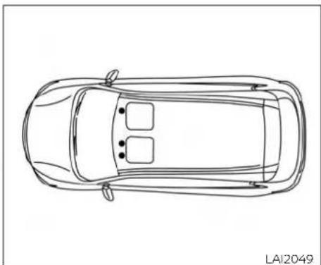
natural_image
Top-down line drawing of a car with no text or symbolsPositioning hooks
The illustration shows the location of the floor mat positioning hooks.
SEAT BELTS
The seat belts can be cleaned by wiping them with a sponge dampened in a mild soap solution. Allow the belts to dry completely in the shade before using them. For additional information, refer to "Seat belt maintenance" in the "Safety—Seats, seat belts and supplemental restraint system" section of this manual.
CORROSION PROTECTION
WARNING
Do not allow wet seat belts to roll up the retractor. NEVER use bleach, dye of chemical solvents to clean the seat belts, since these materials may severely weaken the seat belt webbing.
MOST COMMON FACTORS CONTRIBUTING TO VEHICLE CORROSION
Most vehicle corrosion is caused by:
• The accumulation of moisture-retaining dirt and debris in body panel sections, cavities, and other areas.
- Damage to paint and other protective coatings caused by gravel and stone chips or minor traffic collisions.
ENVIRONMENTAL FACTORS INFLUENCE THE RATE OF CORROSION
Moisture
Accumulation of sand, dirt and water on the vehicle body underside can accelerate corrosion. Wet floor coverings will not dry completely inside the vehicle and should be removed for drying to avoid floor panel corrosion.
Relative humidity
Corrosion will be accelerated in areas of high relative humidity, especially those areas where the temperatures stay above freezing and where atmospheric pollution exists and road salt is used.
Temperature
High temperatures accelerate the rate of corrosion to those parts which are not well ventilated.
Air pollution
Industrial pollution, the presence of salt in the air in coastal areas, or heavy road salt use accelerates the corrosion process. Road salt also accelerates the disintegration of paint surfaces.
PROTECT YOUR VEHICLE FROM CORROSION
- Wash and wax your vehicle often to keep the vehicle clean.
• Always check for minor damage to the paint and repair it as soon as possible. - Keep drain holes at the bottom of the doors open to avoid water accumulation.
- Check the underbody for accumulation of sand, dirt or salt. If present, wash with water as soon as possible.
CAUTION
- NEVER remove dirt, sand or other debris from the passenger compartment by washing it out with a hose. Remove dirt with a vacuum cleaner or broom.
- Never allow water or other liquids to come in contact with electronic components inside the vehicle as this may damage them.
Chemicals used for road surface de-icing are extremely corrosive. They accelerate corrosion and deterioration of underbody components such as the exhaust system, fuel and brake lines, brake cables, floor pan and fenders.
In winter, the underbody must be cleaned periodically.
For additional protection against rust and corrosion, which may be required in some areas, it is recommended that you visit a NISSAN dealer.
MEMO
7-8 Appearance and care
8 Do-it-yourself
Maintenance precautions 8 - 2
Engine compartment check locations 8-4
Engine cooling system 8-5
Checking engine coolant level 8-6
Changing engine coolant....8-6
Engine oil....8-7
Checking engine oil level 8 - 7
Changing engine oil and oil filter 8-7
Continuously Variable Transmission (CVT)
fluid 8-10
Brake fluid 8-10
Windshield-washer fluid 8-11
Windshield-washer fluid reservoir....8-11
Battery 8-12
Jump starting 8-13
Variable voltage control system 8-13
Drive belt 8-14
Spark plugs 8-15
Replacing spark plugs 8-15
Air cleaner....8-15
Windshield wiper blades 8-16
Cleaning 8-16
Replacing 8-16
Brakes 8-17
Fuses....8-18
Engine compartment 8-18
Passenger compartment 8-20
Battery replacement 8-21
Key fob (if so equipped) 8-22
Lights 8-23
Headlights....8-23
Front park/turn signal light 8-27
Exterior and interior lights 8-28
Wheels and tires....8-31
Tire pressure 8-31
Tire labeling 8-34
Types of tires 8-37
Tire chains 8-38
Changing wheels and tires 8-38
MAINTENANCE PRECAUTIONS
When performing any inspection or maintenance work on your vehicle, always take care to prevent serious accidental injury to yourself or damage to the vehicle. The following are general precautions which should be closely observed.
A WARNING
- Park the vehicle on a level surface, apply the parking brake securely and block the wheels to prevent the vehicle from moving. Move the shift lever to P (Park).
- Be sure the ignition key is in the OFF LOCK position when performing any parts replacement or repairs.
- If you must work with the engine running, keep your hands, clothing, hair and tools away from moving fans, belts and any other moving parts.
- It is advisable to secure or remove any loose clothing and remove any jewelry, such as rings, watches, etc. before working on your vehicle.
-
Always wear eye protection whenever you work on your vehicle.
-
Your vehicle is equipped with an automatic engine cooling fan. It may come on at any time without warning, even if the ignition key is in the OFF position and the engine is not running. To avoid injury, always disconnect the negative battery cable before working near the fan.
- If you must run the engine in an enclosed space such as a garage, be sure there is proper ventilation for exhaust gases to escape.
- Never get under the vehicle while it is supported only by a jack. If it is necessary to work under the vehicle, support it with safety stands.
- Keep smoking materials, flame and sparks away from the fuel tank and battery.
- On gasoline engine models, the fuel / filter or fuel lines should be serviced. It is recommended that you visit a NISSAN dealer for this service because the fuel lines are under high pressure even when the engine is off.
CAUTION
Do not work under the hood while the engine is hot. Turn the engine off and wait until it cools down.
- Avoid contact with used engine oil and coolant. Improperly disposed engine oil, engine coolant and/or other vehicle fluids can damage the environment. Always conform to local regulations for disposal of vehicle fluid.
- Never leave the engine or the Continuously Variable Transmission (CVT) related component harness connector disconnected while the ignition switch is in the ON position.
- Never connect or disconnect the battery or any transistorized component while the ignition switch is in the ON position.
- DO NOT power wash any interior portion of this vehicle to help minimize liquid intrusion and potential electronic component damage.
This "Do-it-yourself" section gives instructions regarding only those items which are relatively easy for an owner to perform.
8-2 Do-it-yourself
A Genuine NISSAN service manual is also available. For additional information, refer to "Owner's Manual/Service Manual order information" in the "Technical and consumer information" section of this manual.
You should be aware that incomplete or improper servicing may result in operating difficulties or excessive emissions, and could affect warranty coverage. If in doubt about any servicing, it is recommended that you visit a NISSAN dealer.
ENGINE COMPARTMENT CHECK
LOCATIONS

8-4 Do-it-yourself
MR20DE engine
- Engine coolant reservoir
- Engine oil filler cap
- Brake fluid reservoir
- Air cleaner
- Fuse box
- Battery
- Radiator cap
- Engine oil dipstick
- Drive belt location
- Windshield-washer fluid reservoir
ENGINE COOLING SYSTEM
The engine cooling system is filled at the factory with a pre-diluted mixture of 50% Genuine NISSAN Long Life Antifreeze/Coolant (blue) and 50% water to provide year-round antifreeze and coolant protection. The anti-freeze solution contains rust and corrosion inhibitors. Additional engine cooling system additives are not necessary.
WARNING
- Never remove the radiator or coolant reservoir cap when the engine is hot. Wait until the engine and radiator cool down. Serious burns could be caused by high pressure fluid escaping from the radiator. For additional information, refer to precautions in "If your vehicle overheats" found in the "In case of emergency" section of this manual.
- The radiator is equipped with a pressure type radiator cap. To prevent engine damage, use only a Genuine NISSAN radiator cap.
CAUTION
- Never use any cooling system additives such as radiator sealer. Additives may clog the cooling system and cause damage to the engine, transmission and/or cooling system.
- When adding or replacing coolant, be sure to use only Genuine NISSAN Long Life Antifreeze/Coolant (blue) or equivalent. Genuine NISSAN Long Life Antifreeze/Coolant (blue) is pre-diluted to provide antifreeze protection to -34ircF (-37°C). If additional freeze protection is needed due to weather where you operate your vehicle, add Genuine NISSAN Long Life Antifreeze/Coolant (blue) concentrate following the directions on the container. If an equivalent coolant other than Genuine NISSAN Long Life Antifreeze/Coolant (blue) is used, follow the coolant manufacturer's instructions to maintain minimum antifreeze protection to -34ircF (-37°C). The use of other types of coolant solutions other than Genuine NISSAN Long Life Antifreeze/Coolant (blue) or equivalent may damage the engine cooling system.
- The life expectancy of the factory-fill coolant is 105,000 miles (168,000 km) or 7 years. Mixing any other type of coolant other than Genuine NISSAN Long Life Antifreeze/Coolant (blue)(or equivalent coolant), including Genuine NISSAN Long Life Antifreeze/Coolant (green), or the use of non-distilled water may reduce the life expectancy of the factory-fill coolant. For additional information, refer to the "Maintenance and schedules" section of this manual.
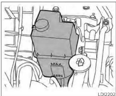
natural_image
Technical line drawing of a mechanical component with labeled parts (MAX, MIN) and no readable text or symbols beyond labelsCHECKING ENGINE COOLANT LEVEL
Check the coolant level in the reservoir when the engine is cold. If the coolant level is below the MIN level, add coolant to the MAX level. If the reservoir is empty, check the coolant level in the radiator when the engine is cold. If there is insuff cient coolant in the radiator, fill the radiato with coolant up to the filler opening and also add it to the reservoir up to the MAX level.
This vehicle contains Genuine NISSAN Long Life Antifreeze/Coolant (blue). The life expectancy of the factory-fill coolant is 105,000 miles (168,000 km) or 7 years. Mixing any other type of coolant or the use of non-distilled water will reduce the life expectancy of the factory-fill coolant. For additional information, refer to the 'Maintenance and schedules' section of this manual.
The engine coolant reservoir is a pressurized tank. When installing the cap, tighten.
If the cooling system frequently requires coolant, have it checked. It is recommended that you visit a NISSAN dealer for this service.
CHANGING ENGINE COOLANT
A NISSAN dealer can change the engine coolant. The service procedure can be found in the NISSAN Service Manual.
Improper servicing can result in reduced heater performance and engine overheating.
WARNING
- To avoid the danger of being scalded, never change the coolant when the engine is hot.
- Never remove the radiator or engine coolant reservoir cap when the engine is hot. Serious burns could be caused by high pressure fluid escaping from the radiator.
- Avoid direct skin contact with used coolant. If skin contact is made, wash thoroughly with soap or hand cleaner as soon as possible.
- Keep coolant out of the reach of children and pets.
Engine coolant must be disposed of properly. Check your local regulations.
ENGINE OIL

natural_image
Technical line drawing of an engine cylinder with a black arrow indicating a specific component (no text or symbols present)CHECKING ENGINE OIL LEVEL
- Park the vehicle on a level surface and apply the parking brake.
- Start the engine and let it idle until it reaches operating temperature.
- Turn off the engine. Wait more than 10 minutes for the oil to drain back into the oil pan.
- Remove the dipstick and wipe it clean. Reinsert it all the way.

- Remove the dipstick again and check the oil level. It should be between the (High) and L (Low) mark®. This is the normal operating oil level range. If the oil level is below the L (Low) mark®, remove the oil filler cap and pour recommended oil through the opening. Do not overfill©.
- Recheck oil level with the dipstick.
It is normal to add some oil between oil maintenance intervals or during the break-in period, depending on the severity of operating conditions.
CAUTION
Oil level should be checked regularly. Operating the engine with an insufficient amount of oil can damage the engine, and such damage is not covered by warranty.
Make sure to follow the engine oil changing intervals in the "Maintenance and schedules" section of this manual. Operating under the following conditions may require more frequent oil change:
• Repeated short distance driving
- Driving in dusty conditions
H· Stop and go commuting
CHANGING ENGINE OIL AND OIL FILTER
For additional information on engine oil and oil filter change, refer to the instructions outlined in this section.
Vehicle set-up
- Park the vehicle on a level surface and apply the parking brake.
-
Run the engine until it reaches operating temperature.
-
Turn the engine off and wait for 15 minutes.
- Raise and support the vehicle using a suitable floor jack and safety jack stands.
- Place the safety jack stands under the vehicle jack-up points.
- A suitable adapter should be attached to the jack stand saddle.
CAUTION
Make sure the correct lifting and support points are used to avoid vehicle damage.

① oil filler cap

② oil drain plug
8-8 Do-it-yourself

③ Oil filter
Engine oil and filter
- Place a large drain pan under the drain plug and oil filter.
- Remove the oil filler cap.
- Remove the drain plug with a wrench by turning it counterclockwise and completely drain the oil.
CAUTION
Be careful not to burn yourself, as the engine oil is hot.
WARNING
- Prolonged and repeated contact with used engine oil may cause skin cancer.
- Try to avoid direct skin contact with used oil. If skin contact is made, wash thoroughly with soap or hand cleaner as soon as possible.
-
Keep used engine oil out of reach of children.
-
Loosen the oil filter with an oil filter wrench by turning it counterclockwise. Remove the oil filter by turning it by hand.
-
Wipe the engine oil filter mounting surface with a clean rag.
CAUTION
Be sure to remove any old gasket material remaining on the sealing surface of the engine. Failure to do so could lead an oil leak and engine damage.
- The dipstick must be inserted in place to prevent oil spillage from the dipstick hole when filling the engine with oil.
- Coat the gasket on the new filter with clean engine oil.
- Screw in the oil filter clockwise until a slight resistance is felt, then tighten additionally more than 2/3 turn.
- Clean and re-install the drain plug with a new washer. Securely tighten the drain plug with a wrench. Do not use excessive force.
Oil filter tightening torque: 11 to 15 ft-lb (14.7 to 20.6 N·m)
Drain plug tightening torque: 22 to 29 ft-lb (29.4 to 39.2 N·m)
- Refill the engine with the recommended oil through the oil filler opening, and install the oil filler cap securely.
For additional information about drain and refill capacity, refer to "Recommended fluids/lubricants and capacities" in the "Technical and consumer information" section of this manual. The drain and refill capacity depends on the oil temperature and drain time. Use these specifications for reference only. Always use the dipstick to determine the proper amount of oil in the engine.
CONTINUOUSLY VARIABLE TRANSMISSION (CVT) FLUID
BRAKE FLUID
- Start the engine and check for leakage around the drain plug and the oil filter. Correct as required. Turn the engine off and wait more than 15 minutes. Check the oil level with the dipstick. Add engine oil if necessary.
After the operation
- Lower the vehicle carefully to the ground.
- Dispose of waste oil and filter properly.
- Check your local regulations.
CAUTION
- NISSAN recommends using Genuine NISSAN CVT Fluid NS-3 (or equivalent) ONLY in NISSAN CVTs. Do not mix with other fluids.
- Do not use Automatic Transmission Fluid (ATF) or manual transmission fluid in a NISSAN CVT, as it may damage the CVT. Damage caused by the use of fluids other than as recommended is not covered under NISSAN's New Vehicle Limited Warranty.
- Using fluids that are not equivalent to Genuine NISSAN CVT Fluid NS-3 may also damage the CVT. Damage caused by the use of fluids other than as recommended is not covered under NISSAN's New Vehicle Limited Warranty.
When checking or replacement of CVT fluid is required, it is recommended that you visit a NISSAN dealer for servicing.
WARNING
- Use only new fluid from a sealed container. Old, inferior or contaminated fluid may damage the brake system. The use of improper fluids can damage the brake system and affect the vehicle's stopping ability.
- Clean the filler cap before removing.
- Brake fluid is poisonous and should be stored carefully in marked containers out of reach of children.
CAUTION
Do not spill the fluid on any painted surfaces. This will damage the paint. If fluid is spilled, immediately wash the surface with water.
WINDSHIELD-WASHER FLUID

Check the fluid level in the reservoir. If the brake fluid is below the MIN line Ⓑ, the brake warning light will illuminate. Add brake fluid up to the MAX linA. For additional information on recommended brake fluid type, refer to "Recommended fluids/lubricants and capacities" in the "Technical and consumer information" section of this manual.
If the brake fluid must be added frequently windshield-washer fluid into the reservoir the brake system should be thoroughly opening. checked. It is recommended that you visit a NISSAN dealer for this service.
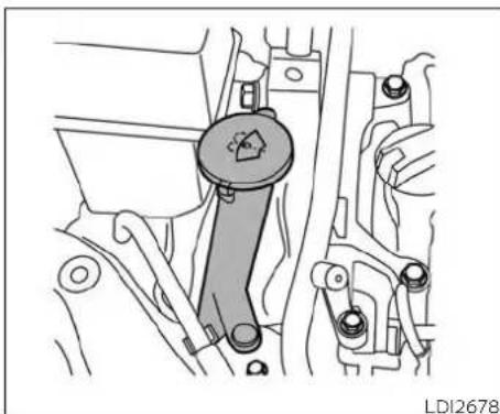
natural_image
Mechanical assembly diagram showing a lever mechanism with no visible text or symbolsWINDSHIELD-WASHER FLUID RESERVOIR
Fill the windshield-washer fluid reservoir periodically. Add windshield-washer fluid when the low windshield-washer fluid warning light (if so equipped) comes on.
To fill the windshield-washer fluid reservoir, lift the cap off the reservoir and pour the
Add a washer solvent to the washer for better cleaning. In the winter season, add a windshield-washer antifreeze. Follow the manufacturer's instructions for the mixture ratio.
Refill the reservoir more frequently when driving conditions require an increased amount of windshield-washer fluid.
Recommended fluid is Genuine NISSAN Windshield Washer Concentrate Cleaner & Antifreeze or equivalent.
CAUTION
- Do not substitute engine antifreeze coolant for windshield-washer fluid. This may result in damage to the paint.
- Do not fill the windshield-washer fluid reservoir with washer fluid concentrates at full strength. Some methyl alcohol based washer fluid concentrates may permanently stain the grille if spilled while filling the windshield-washer fluid reservoir.
BATTERY
- Pre-mix washer fluid concentrates with water to the manufacturer's recommended levels before pouring the fluid into the windshield-washer fluid reservoir. Do not use the windshield-washer fluid reservoir to mix the washer fluid concentrate and water.
- Keep the battery surface clean and dry. Clean the battery with a solution of baking soda and water.
- Make certain the terminal connections are clean and securely tightened.
- If the vehicle is not to be used for 30 days or longer, disconnect the negative (-) battery terminal cable to prevent discharge.
NOTE:
Care should be taken to avoid situations that can lead to potential battery discharge and potential no-start conditions such as:
- Installation or extended use of electronic accessories that consume battery power when the engine is not running (Phone chargers, GPS, DVD players, etc.).
- Vehicle is not driven regularly and/or only driven short distances.
In these cases, the battery may need to be charged to maintain battery health.
WARNING
- Do not expose the battery to flames, an electrical spark or a cigarette. Hydrogen gas generated by the battery is explosive. Explosive gases can cause blindness or injury. Do not allow battery fluid to contact your skin, eyes, fabrics or painted surfaces. Sulfuric acid can cause blindness or injury. After touching a battery or battery cap, do not touch or rub your eyes. Thoroughly wash your hands. If the acid contacts your eyes, skin or clothing, immediately flush with water for at least 15 minutes and seek medical attention.
- Do not operate the vehicle if the fluid in the battery is low. Low battery fluid can cause a higher load on the battery which can generate heat, reduce battery life, and in some cases lead to an explosion.
- When working on or near a battery, always wear suitable eye protection and remove all jewelry.
VARIABLE VOLTAGE CONTROL SYSTEM
- Battery posts, terminals and related accessories contain lead and lead compounds. Wash hands after handling.
- Keep battery out of the reach of children.
- Do not tip the battery. Keep the vent caps tight and the battery level.
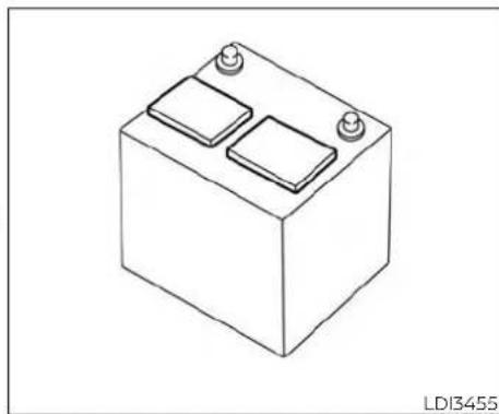
natural_image
Isometric line drawing of a battery with two side compartments and three top terminals (no text or symbols)NOTE:
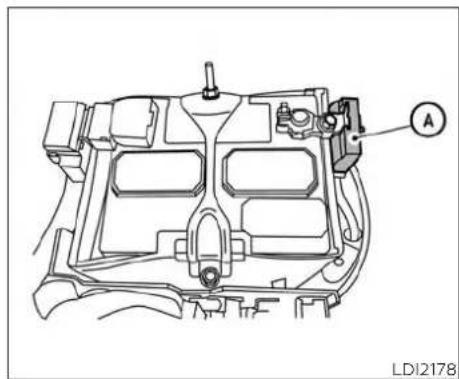
natural_image
Technical line drawing of an automotive engine compartment with labeled component A (no text or symbols beyond label)CAUTION
Do not try to open the top of this battery
This battery is not equipped with removable vent caps.
JUMP STARTING
If jump starting is necessary, refer to "Jump starting" in the "In case of emergency" section of this manual. If the engine does not start by jump starting, the battery may have to be replaced. It is recommended that you visit a NISSAN dealer for this service.
Do not ground accessories directly to the battery terminal. Doing so will bypass the variable voltage control system and the vehicle battery may not charge completely.
Use electrical accessories with the engine running to avoid discharging the vehicle battery.
Your vehicle is equipped with a variable voltage control system. This system measures the amount of electrical discharge from the battery and controls voltage generated by the generator.
DRIVE BELT
The current sensor ① is located near the battery along the negative battery cable. If you add electrical accessories to your vehicle, be sure to ground them to a suitable body ground such as the frame or engine block area.
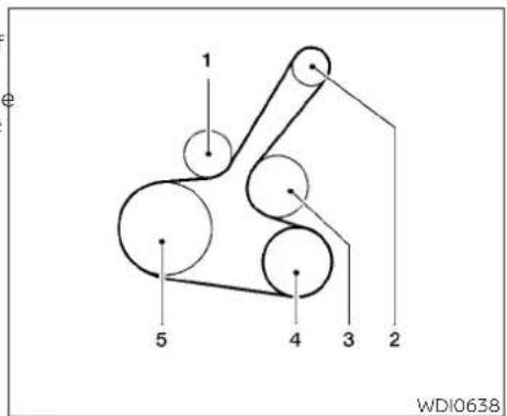
- Automatic tensioner pulley
- Generator pulley
- Water pump pulley
- Air conditioner compressor pulley
- Crankshaft pulley
WARNING
Be sure the ignition switch is in the OFF or LOCK position before servicing drive belt. The engine could rotate unexpectedly.
- Visually inspect the belt for signs of unusual wear, cuts, or fraying. If the belt is in poor condition, have it replaced or adjusted. It is recommended that you visit a NISSAN dealer for this service.
- Have the belt checked regularly for condition.
SPARK PLUGS
AIR CLEANER

REPLACING SPARK PLUGS
Iridium-tipped spark plugs
It is not necessary to replace iridium-tipped A spark plugs as frequently as conventional type spark plugs because they last much longer. Follow the maintenance log shown in the "Maintenance and schedules" section of this manual. Do not service iridium-tipped spark plugs by cleaning or regapping.
· Always replace spark plugs with recommended or equivalent ones.
WARNING
Be sure the engine and ignition switch are off and that the parking brake is engaged securely.
CAUTION
Be sure to use the correct socket to remove the spark plugs. An incorrect socket can damage the spark plugs.
If replacement is required, it is recommended that you visit a NISSAN dealer for this service.

natural_image
Technical diagram of an automotive engine compartment with hoses and a highlighted component (no text or symbols)The air cleaner filter should not be cleaned and reused. Replace it according to the maintenance log shown in the "Maintenance and schedules" section of this manual.
To remove the air cleaner filter:
- Push in the tabs① and move the air cleaner cover upward.
- Remove the air cleaner filter.
- Wipe the inside of the air cleaner filter housing and the cover with a damp cloth.
WINDSHIELD WIPER BLADES
NOTE:
CLEANING
After installing a new air cleaner, make sure the air cleaner cover is seated in housing and latch the clips.
WARNING
- Operating the engine with the air cleaner removed can cause you or others to be burned. The air cleaner not only cleans the air, it stops the flame if the engine backfires. If it isn't there, and the engine backfires, you could be burned. Do not drive with the air cleaner removed, and be careful when working on the engine with the air cleaner removed.
- Never pour fuel into the throttle body or attempt to start the engine with the air cleaner removed. Doing so could result in serious injury.
If your windshield is not clear after using the windshield-washer or if a wiper blade chatters when running, wax or other material may be on the blade or windshield.
Clean the outside of the windshield with a washer solution or a mild detergent. Your windshield is clean if beads do not form when rinsing with clear water.
Clean each blade by wiping it with a cloth soaked in a washer solution or a mild detergent. Then rinse the blades with clear water. If your windshield is still not clear after cleaning the blades and using the wiper, replace the blades.
CAUTION
Worn windshield wiper blades can damage the windshield and impair driver vision.

REPLACING
Replace the wiper blades if they are worn.
- Lift the wiper arm away from the wind-shield.
② Push the release tab, then move the wiper blade down the wiper arm to remove.
③ Remove the wiper blade. - Insert the new wiper blade onto the wiper arm until it clicks into place.
- Rotate wiper blade so the dimple is in the groove.
BRAKES
- Return the wiper to its original position and release it until it has made contact with the windshield.
CAUTION
- After wiper blade replacement, return the wiper arm to its original position; otherwise it may be damaged when the hood is opened.
- Make sure the wiper blades contact the glass; otherwise the arms may be damaged from wind pressure.
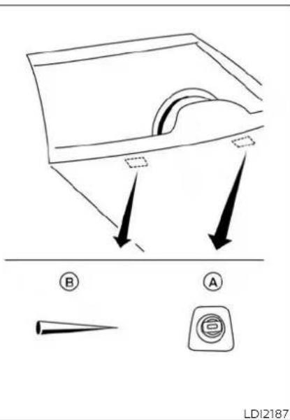
If the brakes do not operate properly, have the brakes checked. It is recommended that you visit a NISSAN dealer for this service.
Self-adjusting brakes
Your vehicle is equipped with self-adjusting brakes.
The front disc-type brakes self-adjust every time the brake pedal is applied. The rear drum-type brakes self-adjust every time the parking brake is applied.
WARNING
Have your brake system checked if the brakes pedal height does not return to normal. It is recommended that you visit a NISSAN dealer for this service.
Brake pad wear indicators
The disc brake pads on your vehicle have audible wear indicators. When a brake pad requires replacement, a high pitched scraping or screeching sound will be heard when the vehicle is in motion. The noise will be heard whether or not the brake pedal is depressed. Have the brakes checked as soon as possible if the wear indicator sound is heard.
Be careful not to let anything get into the washer nozzle(A). This may cause clogging or improper windshield washer operation. If something gets into the nozzle, remove with a needle or small p(B).
FUSES
Under some driving or climate conditions, occasional brake squeak, squeal or other noise may be heard. Occasional brake noise during light to moderate stops is normal and does not affect the function or performance of the brake system.
Proper brake inspection intervals should be followed. For additional information regarding brake inspections, refer to the appropriate maintenance schedule information in the "Maintenance and schedules" section of this manual.
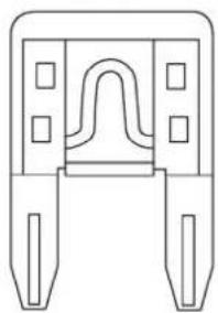
natural_image
Pure technical line drawing of a mechanical component with no text or symbolsLDI2384 LDI3456

natural_image
Technical line drawing of an internal combustion engine component (no text or labels)ENGINE COMPARTMENT
WARNING
Never use a fuse of a higher or lower amperage rating than that specified on the fuse box cover. This could damage the electrical system or electronic control units or cause a fire
If any electrical equipment does not operate, check for an open fuse.
Fuses are used in the passenger and engine compartment. Spare fuses are provided and can be found in the passenger compartment fuse box.
When installing a fuse make sure the fuse installed in the fuse box securely.
NOTE:
Your vehicle may not be equipped with all fuses listed on the fuse label.
If any electrical equipment does not come on, check for an open fuse.
-
Be sure the ignition switch and the headlight switch are in the OFF position.
-
Open the engine hood.
- Remove the fuse box cover by pushing the tab and lifting the cover up.
- Remove the fuse with the fuse puller. The fuse puller is located in the center of the fuse block in the passenger compartment.
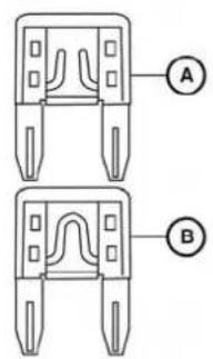
LDI2826 | LDI2718

natural_image
Technical line drawing of an engine compartment with no visible text or symbols- If the fuse is open(A), replace it with a new fuse(B).
- If a new fuse also opens, have the electrical system checked and repaired. It recommended that you visit a NISSAN dealer for this service.
Fusible links
If the electrical equipment does not operate and fuses are in good condition, check the fusible links. If any of these fusible links are melted, replace with only Genuine NISSAN parts.
For checking and replacing the fusible links, it is recommended that you visit a NISSAN dealer for this service.

LDI2828 | LDI2826
If any electrical equipment does not operate, check for an open fuse.
- Be sure the ignition switch and the headlight switch are OFF.
- Pull the fuse box cover to remove.
- Remove the fuse with the fuse puller.
PASSENGER COMPARTMENT
WARNING
Never use a fuse of a higher or lower amperage rating than that specified on the fuse box cover. This could damage the electrical system or electronic control units or cause a fire

- If the fuse is open, replace it with an equivalent good fuse.
- Push the fuse box cover to install.
- If a new fuse also opens, have the electrical system checked and repaired. It is recommended that you visit a NISSAN dealer for this service.
BATTERY REPLACEMENT

Extended storage switch
If any electrical equipment does not operate, remove the extended storage switch and check for an open fuse.
NOTE:
The extended storage switch is used for long term vehicle storage. Even if the extended storage switch is broken it is not necessary to replace it. Replace only the open fuse in the switch with a new fuse.
How to replace the extended storage switch:
- To remove the extended storage switch, be sure the ignition switch is in the OFF or LOCK position.
- Be sure the headlight switch is in the OFF position.
- Remove the fuse box cover.
- Pinch the locking tab① and ② found on each side of the storage switch.
- Pull the storage switch straight out from the fuse box③.
CAUTION
Be careful not to allow children to swallow the battery or removed parts.

KEY FOB (if so equipped)
Replace the battery in the key fob as follows:
-
Remove the screw(A).
-
Insert a small screwdriver into the slit of the corner Ⓑ and twist it to separate the upper part from the lower part. Use a cloth to protect the casing.
-
Replace the battery with a new one.
-
Do not touch the internal circuit and electric terminals as doing so could cause a malfunction.
- Make sure that the + side faces the bottom of the case©.
Recommended battery: CR1620 or equivalent.
- Close the lid and install the screw securely.
- Operate the buttons to check its operation.
It is recommended that you visit a NISSAN dealer if you need assistance for replacement.
If the battery is removed for any reason other than replacement, perform step 5
- An improperly disposed battery can hurt the environment. Always confirm local regulations for battery disposal.
The key fob is water-resistant; however, if it does get wet, immediately wipe completely dry.
- The operational range of the key fob extends to approximately 33 ft (10 m) from the vehicle. This range may vary with conditions.
Operation is subject to the following two conditions: (1) This device may not cause harmful interference, and (2) this device must accept any interference received, including interference that may cause undesired operation of the device.
FCC Notice:
For USA:
This device complies with Part 15 of the FCC Rules. Operation is subject to the following two conditions: (1) This device may not cause harmful interference, and (2) this device must accept any interference received, including interference
that may cause undesired operation. Note:
Changes or modifications not expressly approved by the party responsible for compliance could void the user's authority to operate the equipment.
8-22 Do-it-yourself
LIGHTS
For Canada:
HEADLIGHTS
This device complies with Industry
Canada licence-exempt RSS standard(s). For additional information on headlight
Operation is subject to the following two bulb replacement, refer to the instructions
conditions: (1) this device may not cause outlined in this section.
interference, and (2) this device must ac-
cept any interference, including interfer-
ence that may cause undesired opera-
tion of the device.
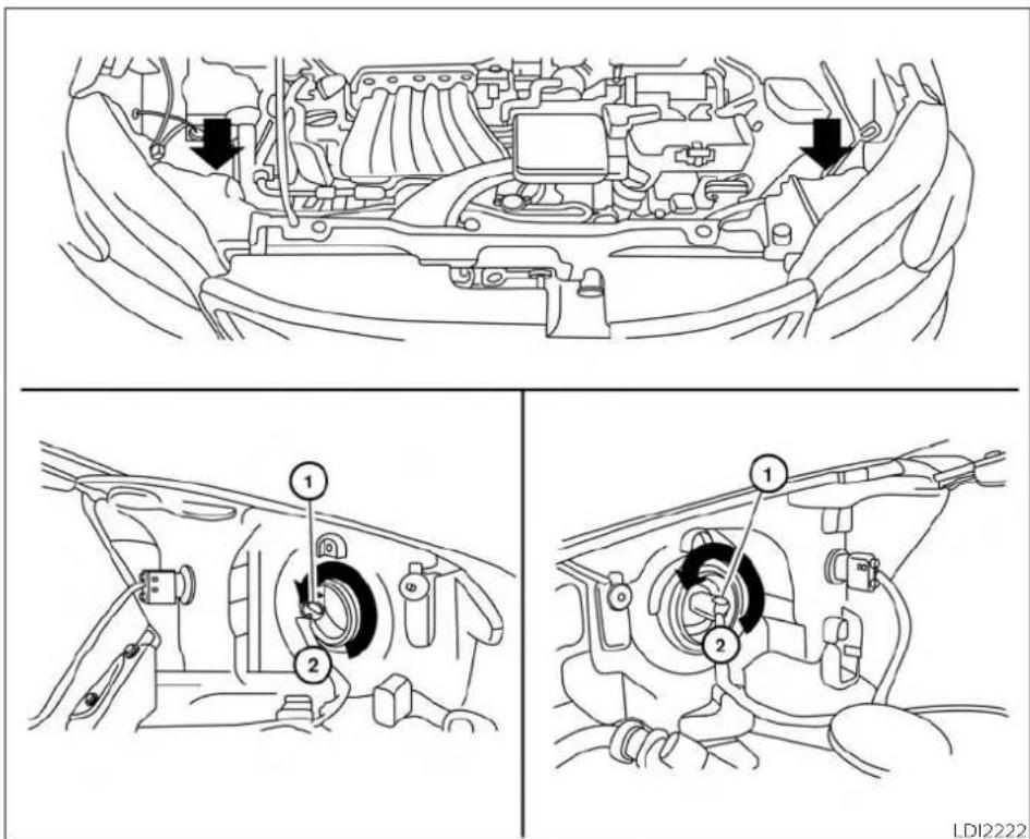
Replacing the halogen headlight bulb
Disconnect the negative battery cable before replacement and installation of the headlight bulb.
① Release the clip on the connector.
② Rotate the bulb counterclockwise and pull out to remove. Replace as necessary.
CAUTION
- Aiming is not necessary after replacing the bulb. When aiming adjustment is necessary, it is recommended that you visit a NISSAN dealer for this service.
-
Do not leave the headlight assembly open without a bulb installed for a long period of time. Dust, moisture, smoke, etc. entering the headlight body may affect bulb performance. Remove the bulb from the headlight assembly just before a replacement bulb is installed.
-
Only touch the base when handling the bulb. Never touch the glass envelope. Touching the glass could significantly affect bulb life and/or head-light performance.
- High pressure halogen gas is sealed inside the halogen bulb. The bulb m break if the glass envelope is scratched or the bulb is dropped.
- Use the same number and wattage as shown in the chart.
Fog may temporarily form inside the lens of the exterior lights in the rain or in a car wash. A temperature difference between the inside and the outside of the lens causes the fog. This is not a malfunction. If large drops of water collect Inside the lens, it is recommended that you visit a NISSAN dealer for this service.
Aiming the headlights
The headlights on your vehicle are properly aimed at the assembly plant. If your vehicle has been in a collision, the alignment of your headlights should be checked. It is recommended that you visit a NISSAN dealer for this service.
Vertical aim adjustment
NOTE:
Due to a maximum load condition of the vehicle, headlight aiming adjustment may be necessary. Please perform the following procedure:
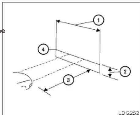
flowchart
graph TD
    1 --> 2
    2 --> 3
    3 --> 4
    4 --> 1
    style 1 fill:#f9f,stroke:#333
    style 2 fill:#f9f,stroke:#333
    style 3 fill:#f9f,stroke:#333
    style 4 fill:#f9f,stroke:#333
- Park the vehicle directly in front of a wall or screen on a level surface, approximately 25 feet (7.6 meters) away.
• ① 8 feet (2.4 meters)
• ② Center height of headlight to ground
• ③ 25 feet (7.6 meters)
• ④ Horizontal reference line
2. Measure the height from the center of the headlight to the ground and mark an 8 foot (2.4 meter) horizontal reference line on the vertical wall or screen at this height (a piece of masking tape works well).
Do-it-yourself
- Turn on the low beam headlights to illuminate the wall or screen and open the hood.
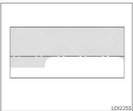
natural_image
Simple diagram with a rectangle and a dashed line, no text or symbols present
natural_image
Technical line drawing of a mechanical assembly with no visible text or symbols-
On the wall or screen you will observe an area of high intensity light. The top of the high intensity area should touch the horizontal reference line. If not, the beam will need to be adjusted.
-
Locate the vertical adjuster on each headlight, then use a suitable tool to adjust the headlight up or down.
-
Close the hood and turn off the headlights.
NOTE:
Horizontal aim is not required for this vehicle and is not adjustable.
8-26 Do-it-yourself
For additional information on front park/turn signal bulb replacement, refer to the instructions outlined in this section.
Replacing the park/turn signal bulb

Disconnect the negative battery cable before replacement and installation of the headlight bulb.
① Rotate the bulb counterclockwise and pull out to remove. Replace as necessary.
EXTERIOR AND INTERIOR LIGHTS
| Item Wattage (W) Bulb No. | ||
| Headlight assembly/daytime running lightsHigh/ Low 60/55 H13Park/Turn 28/8 3457NAKMap light 5 W5WCargo lightHigh-mounted stop lightRear combination lightStop/TailBackup (reversing)TurnLicense plate light | 5 W5W1621/716275 W5W | W16W3047KW16W3157AK |
* It is recommended that you visit a NISSAN dealer for replacement.
Always check with the Parts Department at a NISSAN dealer for the latest parts information.

- Map light
- Headlight assembly/daytime running lights
- High-mounted stop light
- Cargo light
- Rear combination light
- License plate light
WD10263

Replacement procedures
All other lights are either type A, B, C or D. When replacing a bulb, first remove the lens, lamp and/or cover using a cloth and suitable tool.

Indicates bulb removal Indicates bulb installation

Map light Use a cloth to protect the housing.
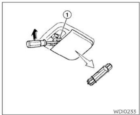
Cargo light Use a cloth to protect the housing.
8-30 Do-it-yourself
WHEELS AND TIRES
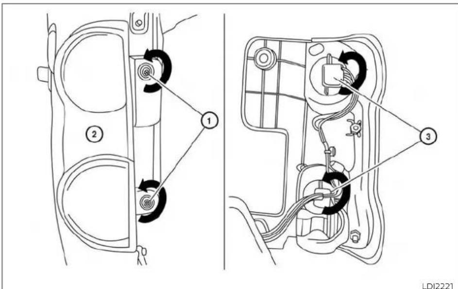
Rear combination light
① Remove the fasteners.
② Remove the rear combination light assembly.
③ Remove the bulb(s) and replace as necessary.
If you have a flat tire, refer to "Flat tire" the "In case of emergency" section of this manual.
TIRE PRESSURE
Tire Pressure Monitoring System (TPMS)
WARNING
Radio waves could adversely affect electric medical equipment. Those who use a pacemaker should contact the electric medical equipment manufacturer for the possible influences before use.
This vehicle is equipped with TPMS. It monitors tire pressure of all four tires except the spare. When the low tire pressure warning light is lit and the CHECK TIRE PRES (pressure) warning message is displayed in the odometer, one or more of your tires is significantly under-inflated.
The TPMS will activate only when the tire pressures should be checked vehicle is driven at speeds above regularly because:
16 mph (25 km/h). Also, this system may not detect a sudden drop in tire pressure (for example a flat tire while driving).
For additional information, refer to "Warning lights, indicator lights and audible reminders" in the "Instruments and controls" section, "Tire Pressure Monitoring System (TPMS)" in the "Starting and driving" section, and "Flat tire" in the "In case of emergency" section of this manual.
Tire inflation pressure
Check the tire pressures (including the spare) often and always prior to long distance trips. The recommended tire pressure specifications are shown on the F.M.V.S.S./C.M.V.S.S. certification label or the Tire and Loading Information label under the "Cold Tire Pressure" heading. The Tire and Loading Information label is affixed to the driver side center pillar.
Most tires naturally lose air over time.
- Tires can lose air suddenly when driven over potholes or other objects or if the vehicle strikes a curb while parking.
The tire pressures should be checked when the tires are cold. The tires are considered COLD after the vehicle has been parked for 3 or more hours, or driven less than 1 mile (1.6 km) at moderate speeds.
Incorrect tire pressure, including under inflation, may adversely affect tire life and vehicle handling.
WARNING
- Improperly inflated tires can fail suddenly and cause an accident.
- The Gross Vehicle Weight Rating (GVWR) is located on the F.M.V.S.S./C.M.V.S.S. certification label. The vehicle weight capacity is indicated on the Tire and Loading Information label. Do not load your vehicle beyond this capacity. Overloading your vehicle may result in reduced tire life, unsafe operating conditions due to premature tire failure, or unfavorable handling characteristics and could also lead to a serious accident. Loading beyond the specified capacity may also result in failure of other vehicle components.
- Before taking a long trip, or whenever you heavily load your vehicle, use a tire pressure gauge to ensure that the tire pressures are at the specified level.
- For additional information regarding tires, refer to "Important Tire Safety Information" (US) or "Tire Safety Information" (Canada) in the Warranty Information Booklet.
8-32 Do-it-yourself
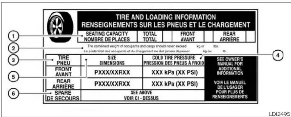
Tire and Loading Information label
① Seating capacity: The maximum number of occupants that can be seated in the vehicle.
② Vehicle load limit: For additional information, refer to "Vehicle loading information" in the "Technical and consumer information" section of this manual.
③ Original tire size: The size of the tires originally installed on the vehicle at the factory.
④ Cold tire pressure: Inflate the tires to this pressure when the tires are cold. Tires are considered COLD after the vehicle has been parked for 3 or more hours, or driven less than 1 mile (1.6 kn at moderate speeds. The recommended cold tire inflation is set by the manufacturer to provide the best balance of tire
wear, vehicle handling, driveability, tire noise, etc., up to the vehicle's GVWR.
⑤ Tire size - For additional information, refer to "Tire labeling" in this section.
⑥ Spare tire size.
Payload and replacement tire
Your vehicle is equipped with special high load index 94 tires to carry a payload of up to 1,480 lbs (671 kg) as indicated on your Tire and Loading Information label. Some after-market replacement tires may have lower load index ratings. While NISSAN does not encourage you to do so, please note that if you choose to purchase a tire with a lower load index rating, the max payload capacity of your vehicle will be reduced.
Please refer to replacement tire manufacturer usage recommendations and tire pressures.

natural_image
Technical line drawing of a mechanical assembly with concentric rings and a central component (no text or symbols)Checking tire pressure
- Remove the valve stem cap from the tire.
-
Press the pressure gauge squarely onto the valve stem. Do not press too hard or force the valve stem sideways, or air will escape. If the hissing sound of a escaping from the tire is heard while checking the pressure, re-position the gauge to eliminate this leakage.
-
Remove the gauge.
- Read the tire pressure on the gauge stem and compare to the specification shown on the Tire and Loading Information label.
- Add air to the tire as needed. If too much air is added, press the core of the valve stem briefly with the tip of the gauge stem to release pressure. Recheck the pressure and add or release air as needed.
- Install the valve stem cap.
- Check the pressure of all other tires, including the spare.
| Size Cold Tire | Inflation Pressure |
| Front Original Tire: r185/60R15C 94/92T | 44 psi, 300 kPa |
| Rear Original Tire: 185/60R15C 94/92T | 48 psi, 325 kPa |
| Spare Tire: | Full size |
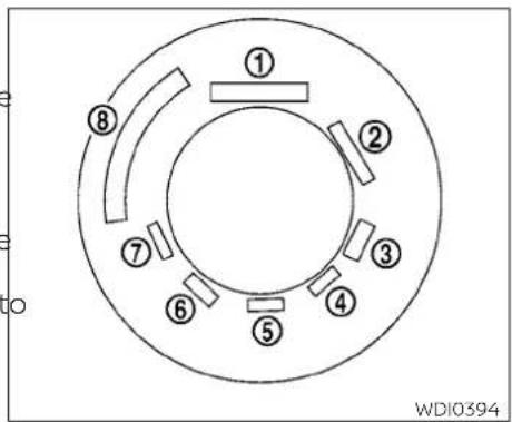
Example
TIRE LABELING
Federal law requires tire manufacturers to place standardized information on the sidewall of all tires. This information identifies and describes the fundamental characteristics of the tire and also provides the Tire Identification Number (TIN) for safety standard certification. The TIN can be used to identify the tire in case of a recall.
8-34 Do-it-yourself
P215/65R15 95H

WD10395
-
Two- or three-digit number (95): This number is the tire's load index. It is a measurement of how much weight each tire can support. You may not find this information on all tires because it is not required by law.
-
H: Tire speed rating. You should not drive the vehicle faster than the tire speed rating.
Example
① Tire size (example: P215/65R15 95H)
-
P: The "P" indicates the tire is designed for passenger vehicles (not all tires have this information).
-
Three-digit number (215): This number gives the width in millimeters of the tire from sidewall edge to sidewall edge.
-
Two-digit number (65): This number, known as the aspect ratio, gives the tire's ratio of height to width.
-
R: The "R" stands for radial.
-
Two-digit number (15): This number is the wheel or rim diameter in inches.

LDI2786
Example
② TIN (Tire Identification Number) for a new tire (example: DOT XX XX XXX XXXX)
- DOT: Abbreviation for the "Department Of Transportation". The symbol can be placed above, below or to the left or right of the Tire Identification Number.
-
Two-digit code: Manufacturer's identification mark.
-
Two-digit code: Tire size.
- Three-digit code: Tire type code (Optional).
- Four numbers represent the week and year the tire was built. For example, the numbers 3103 means the 31st week of 2003. If these numbers are missing then look on the other sidewall of the tire.
③ Tire ply composition and material
The number of layers or plies of rubber-coated fabric in the tire. Tire manufacturers also must indicate the materials in the tire, which include steel, nylon, polyester and others.
④ Maximum permissible inflation pressure
This number is the greatest amount of air pressure that should be put in the tire. Do not exceed the maximum permissible inflation pressure.
⑤ Maximum load rating
This number indicates the maximum load in kilograms and pounds that can be carried by the tire. When replacing the tires on the vehicle, always use a tire that has the same load rating as the factory installed tire.
⑥ Term of "tubeless" or "tube type"
Indicates whether the tire requires
an inner tube ("tube type") or not
("tubeless").
8-36 Do-it-yourself
⑦ The word "radial"
The word "radial" is shown if the tire has radial structure.
⑧ Manufacturer or brand name
Manufacturer or brand name is shown.
Other Tire-related Terminology
In addition to the many terms that are defined throughout this section, Intended Outboard Sidewall is (1) the sidewall that contains a whitewall, bears white lettering or bears manufacturer, brand, and/or model name molding that is higher or deeper than the same molding on the other sidewall of the tire, or (2) the outward facing sidewall of an asymmetrical tire that has a particular side that must always face outward when mounted on a vehicle.
TYPES OF TIRES
WARNING
- When changing or replacing tires, be sure all four tires are of the same type (i.e., Summer, All Season or Snow) and construction. A NISSAN dealer may be able to help you with information about tire type, size, speed rating and availability.
- Replacement tires may have a lower speed rating than the factory equipped tires, and may not match the potential maximum vehicle speed. Never exceed the maximum speed rating of the tire.
- Replacing tires with those not originally specified by NISSAN could affect the proper operation of the low tire pressure warning system.
- For additional information regarding tires, refer to "Important Tire Safety Information" (US) or "Tire Safety Information" (Canada) in the Warranty Information Booklet.
All season tires
NISSAN specifies All Season tires on some models to provide good performance all year, including snowy and icy road conditions. All Season tires are identified by ALL SEASON and/or M&S on the tire sidewall. Snow tires have better snow traction than All Season tires and may be more appropriate in some areas.
Summer tires
NISSAN specifies summer tires on some models to provide superior performance on dry roads. Summer tire performance is substantially reduced in snow and ice. Summer tires do not have the tire traction rating "M&S" on the tire sidewall.
If you plan to operate your vehicle in snowy or icy conditions, NISSAN recommends the use of SNOW tires or ALL SEASON tires on all four wheels.
-Snow tires
If snow tires are needed, it is necessary to select tires equivalent in size and load rating to the original equipment tires. If you do not, it can adversely affect the safety and handling of your vehicle.
Generally, snow tires have lower speed ratings than factory equipped tires and may not match the potential maximum vehicle speed. Never exceed the maximum speed rating of the tire.
If you install snow tires, they must be the same size, brand, construction and tread pattern on all four wheels.
For additional traction on icy roads, studded tires may be used. However, some U.S. states and Canadian provinces prohibit their use. Check local, state and provincial laws before installing studded tires. Skid and traction capabilities of studded snow tires on wet or dry surfaces may be poored than that of non-studded snow tires. - hicle suspension or body component required to accommodate the use of a winter traction device (tire chains or cables). The minimum clearances are determined using the factory equipped tire size. Other types may damage your vehicle. Use chain tensioners when recommended by the tire chain manufacturer to ensure a tight fit. Loose end links of the tire chain must be secured or removed to prevent the possibility of whipping action damage to the fenders or underbody. If possible, avoid fully loading your vehicle when using tire chains. In addition, drive at a reduced speed. Otherwise, your vehicle may be damaged and/or vehicle handling and performance may be adversely affected.
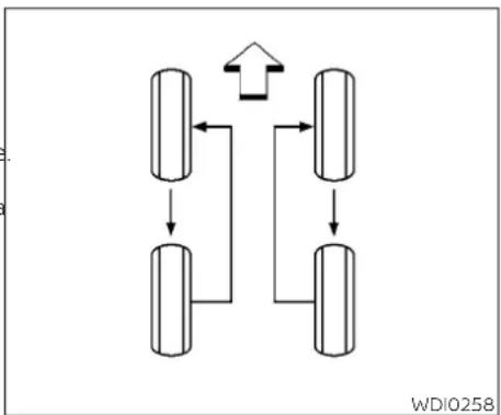
flowchart
graph TD
    A["Component 1"] --> B["Component 2"]
    B --> C["Component 3"]
    C --> D["Component 4"]
    D --> A
    style A fill:#f9f,stroke:#333
    style B fill:#ccf,stroke:#333
    style C fill:#cfc,stroke:#333
    style D fill:#fcc,stroke:#333
    note right of A: ↑
    note right of D: WDIO258
CHANGING WHEELS AND TIRES
TIRE CHAINS
Use of tire chains may be prohibited according to location. Check the local laws before installing tire chains. When installing tire chains, make sure they are the proper size for the tires on your vehicle and are installed according to the chain manufacturer's suggestions. Use only SAE class "S" chains. Class "S" chains are used on vehicles with restricted tire to vehicle clearance. Vehicles that can use Class "S" chains are designed to meet the minimum clearances between the tire and the closest ve-
Tire chains must be installed only on the front wheels and not on the rear wheels.
Do not use tire chains on dry roads. Driving tires every 7,500 miles (12,000 km). with chains in such conditions can cause damage to the various mechanisms of the For additional information on tire re-vehicle due to some overstress. replacement procedures, refer to "Flat
ires every 7,500 miles (12,000 km).
For additional information on tire replacement procedures, refer to "Flat tire" in the "In case of emergency" section of this manual.
As soon as possible, tighten the wheel nuts to the specified torque with a torque wrench.
8-38 Do-it-yourself
Wheel nut tightening torque:
83 ft-lb (113 N·m)
The wheel nuts must be kept tightened to specifications at all times. It is recommended that wheel nuts be tightened to specification at each tire rotation interval.
After rotating the tires, adjust the tire pressure to the cold tire pressure specification shown on the Tire and Loading Information label. For additional information, refer to "Checking tire pressure" in this section and "Tire and Loading Information label" in the "Technical and consumer information" section of this manual.
WARNING
- After rotating the tires, check t- and adjust the tire pressure.
- Retighten the wheel nuts when the vehicle has been driven for 600 miles (1,000 km) (also in cases of a flat tire, etc.).
Do not include the spare tire in the tire rotation.
- For additional information regarding tires, refer to "Important Tire Safety Information" (US) or "Tire Safety Information" (Canada) in the Warranty Information Booklet.

WDI0259
Tire wear and damage
- Wear indicator
- Location mark
A WARNING
- Tires should be periodically inspected for wear, cracking, bulging or objects caught in the tread. If excessive wear, cracks, bulging or deep cuts are found, the tire(s) should be replaced.
- The original tires have built-in tread wear indicators. When the wear indicators are visible, the tire(s) should be replaced.
- Tires degrade with age and use. Have tires, including the spare, over 6 years old checked by a qualified technician because some tire damage may not be obvious. Replace the tires as necessary to prevent tire failure and possible personal injury.
- Improper service of the spare tire may result in serious personal injury. If it is necessary to repair the spare tire, it is recommended that you visit a NISSAN dealer for this service.
- For additional information regarding tires, refer to "Important Tire Safety Information" (US) or "Tire Safety Information" (Canada) in the Warranty Information Booklet.
Replacing wheels and tires
When replacing a tire, use the same size, tread design, speed rating and load carrying capacity as originally equipped. For additional information, refer to "Wheels and tires" in the "Technical and consumer information" section of this manual.
WARNING
- The use of tires other than those recommended or the mixed use of tires of different brands, construction (bias, bias-belted or radial), or tread patterns can adversely affect the ride, braking, handling, VDC system, ground clearance, body-to-tire clearance, tire chain clearance, speedometer calibration, headlight aim and bumper height. Some of these effects may lead to accidents and could result in serious personal injury.
- If your vehicle was originally equipped with four tires that were the same size and you are only replacing two of the four tires, install the new tires on the rear axle. Placing new tires on the front axle may cause loss of vehicle control in some driving conditions and cause an accident and personal injury.
-
If the wheels are changed for any reason, always replace with wheels which have the same off-set dimension. Wheels of a different off-set could cause premature tire wear, degrade vehicle handling characteristics, affect the VDC system and/or interference with the brake discs. Such interference can lead to decreased braking efficiency and/or early brake pad wear. For additional information, refer to "Wheels and tires" in the "Technical and consumer information" section of this manual for wheel off-set dimensions.
-
When replacing a wheel without the TPMS, such as the spare tire, the TPMS will not function and the low tire pressure warning light will flash for approximately 1 minute. The light will remain on after 1 minute. Have your tires replaced and/or TPMS system reset as soon as possible. It is recommended that you visit a NISSAN dealer for this service.
- The TPMS sensor may be damaged if it is not handled correctly. Be careful when handling the TPMS sensor.
- When replacing the TPMS sensor, the ID registration may be required. It is recommended that you visit a NISSAN dealer for ID registration.
- Do not use a valve stem cap that is specified by NISSAN. The valve stem cap may become stuck.
- Be sure that the valve stem caps are correctly fitted. Otherwise the valve may be clogged up with dirt and cause a malfunction or loss of pressure.
-
Replacing tires with those not originally specified by NISSAN could affect the proper operation of the TPMS.
-
Do not install a damaged or deformed S wheel or tire even if it has been repaired. Such wheels or tires could have structural damage and could fail without warning.
- The use of retread tires is not recommended.
- For additional information regarding tires, refer to "Important Tire Safety Information" (US) or "Tire Safety Information" (Canada) in the Warranty Information Booklet.
Wheel balance
Unbalanced wheels may affect vehicle handling and tire life. Even with regular use, wheels can get out of balance. Therefore, they should be balanced as required.
Wheel balance service should be performed with the wheels off the vehicle. Spin balancing the wheels on the vehicle could lead to mechanical damage.
- For additional information regarding tires, refer to "Important Tire Safety Information" (US) or "Tire Safety Information" (Canada) in the Warranty Information Booklet.
Care of wheels
- Wash the wheels when washing the vehicle to maintain their appearance.
- Clean the inner side of the wheels when the wheel is changed or the underside of the vehicle is washed.
- Do not use abrasive cleaners when washing the wheels.
- Inspect wheel rims regularly for dents or corrosion. Such damage may cause loss of pressure or poor seal at the tire bead.
- NISSAN recommends waxing the road wheels to protect against road salt in areas where it is used during winter.
MEMO
8-42 Do-it-yourself
9 Maintenance and schedules
Maintenance requirements....9 - 2
General maintenance 9 - 2
Scheduled maintenance 9 - 2
Where to go for service 9 - 2
General maintenance 9 - 2
Explanation of general maintenance items....9-2
Explanation of scheduled maintenance items . . . 9-5
Emission control system maintenance:....9-5
Chassis and body maintenance: 9 - 6
Maintenance schedules 9 - 7
Additional Maintenance Items for severe operating conditions 9 - 7
Standard maintenance....9-7
Standard maintenance....9-8
Maintenance under severe operating
conditions....9-10
Severe driving conditions 9-10
Maintenance log 9-11
MAINTENANCE REQUIREMENTS
GENERAL MAINTENANCE
Some day-to-day and regular maintenance is essential to maintain your vehicle good mechanical condition, as well as its emissions and engine performance.
It is the owner's responsibility to make sur that the scheduled maintenance, as well a general maintenance, is performed.
As the vehicle owner, you are the only one who can ensure that your vehicle receives proper maintenance. You are a vital link in the maintenance chain.
GENERAL MAINTENANCE
General maintenance includes those items which should be checked during normal day-to-day operation. They are essential for proper vehicle operation. It is your responsibility to perform these procedures regularly as prescribed.
Performing general maintenance checks requires minimal mechanical skill and only a few general automotive tools.
These checks or inspections can be done by yourself, a qualified technician or, if you prefer, a NISSAN dealer.
SCHEDULED MAINTENANCE
The maintenance items listed in this section are required to be serviced at regular intervals. However under severe driving conditions, additional or more frequent maintenance will be required.
WHERE TO GO FOR SERVICE
If maintenance service is required or your vehicle appears to malfunction, have the systems checked and serviced. It is recommended that you visit a NISSAN dealer for this service.
NISSAN technicians are well-trained specialists and are kept up-to-date with the latest service information through technical bulletins, service tips and training programs. They are fully qualified to work on NISSAN vehicles before work begins.
If your vehicle is involved in a collision, it is recommended that you ask your NISSAN dealer where the nearest NISSAN Certified Collision Center is located, or go to http://collision.nissanusa.com.
You can be confident that a NISSAN dealer's service department can perform the service needed to meet the maintenance requirements on your vehicle.
During the normal day-to-day operation of the vehicle, general maintenance should be performed regularly as prescribed in this section. If you detect any unusual sounds, vibrations or smells, be sure to check for the cause or have it checked promptly. In addition, it is recommended that you visit a NISSAN dealer if you think that repairs are required.
When performing any checks or maintenance work, closely observe the "Maintenance precautions" in the "Do-it-yourself" section of this manual.
EXPLANATION OF GENERAL MAINTENANCE ITEMS
Additional information on the following items with " * " is found in the "Do-it-yourself" section of this manual.
5 Outside the vehicle
The maintenance items listed here should be performed from time to time, unless otherwise specified.
Doors and engine hood: Check that the doors and engine hood operate properly. Also ensure that all latches lock securely. Lubricate hinges, latches, latch pins, rollers and links if necessary. Make sure that the
9-2 Maintenance and schedules
secondary latch keeps the hood from opening when the primary latch is released.
When driving in areas using road salt or other corrosive materials, check lubrication frequently.
Lights*: Clean the headlights on a regular basis. Make sure that the headlights, stop lights, tail lights, turn signal lights, and oth lights are all operating properly and installed securely. Also check headlight aim.
Road wheel nuts (lug nuts)*: When checking the tires, make sure no wheel nuts are missing, and check for any loose wheel nuts. Tighten if necessary.
Tire rotation*: Tires should be rotated every 7,500 miles (12,000 km).
Tires*: Check the pressure with a gauge often and always prior to long distance trips. If necessary, adjust the pressure in all tires, including the spare, to the pressure specified. Check carefully for damage, cuts or excessive wear.
Tire Pressure Monitoring System (TPMS)
transmitter components: Replace the TPMS transmitter grommet seal, valve cor and cap when the tires are replaced due wear or age.
Wheel alignment and balance: the vehicle should pull to either side while driving on a straight and level road, or if you detect un even or abnormal tire wear, there may be need for wheel alignment. If the steering wheel or seat vibrates at normal highway speeds, wheel balancing may be needed.
For additional information regarding tires, refer to "Important Tire Safety Information" (US) or "Tire Safety Information" (Canada) in the Warranty Information Booklet.
Windshield: Clean the windshield on a regular basis. Check the windshield at least every six months for cracks or other damage. Have a damaged windshield repaired by a qualified repair facility. It is recommended that you have a damaged windshield repaired by a NISSAN dealer, or a NISSAN Certified Collision Center. To locate a collision center in your area, refer to http://collision.nissanusa.com.
Windshield wiper blades*: Check for cracks or wear if they do not wipe proper Inside the vehicle
The maintenance items listed here should be checked on a regular basis, such as when performing scheduled maintenance, cleaning the vehicle, etc.
Accelerator pedal: Check the pedal for smooth operation and make sure the pedal does not catch or require uneven effort. Keep the floor mat away from the pedal.
Brake pedal: Check the pedal for smooth operation. If the brake pedal suddenly goes down further than normal, the pedal feels spongy or the vehicle seems to take longer to stop, have your vehicle checked immediately. It is recommended that you visit a NISSAN dealer for this service. Keep the floor mat away from the pedal.
- Brakes: Check that the brakes do not pull the vehicle to one side when applied.
Continuously Variable Transmission (CVT) P (Park) position mechanism: On a fairly steep hill check that the vehicle is held securely with the shift lever in the P (Park) position without applying any brakes.
Parking brake: Check the parking brake operation regularly. The vehicle should be securely held on a fairly steep hill with only the parking brake applied. If the parking brake needs adjustment, it is recommended that you visit a NISSAN dealer for this service.
Seats: Check seat position controls such as seat adjusters, seatback recliner, etc., to ensure they operate smoothly and all latches lock securely in every position. Check that the head restraints/headrests move up and down smoothly and the lock (if so equipped) hold securely in all latched positions.
Seat belts: Check that all parts of the sea belt system (for example, buckles, anchors, adjusters and retractors) operate properly and smoothly, and are installed securely. Check the belt webbing for cuts, fraying, wear or damage.
Steering wheel: Check for changes in the steering system, such as excessive free play, hard steering or strange noises.
Warning lights and chimes: Make sure all warning lights and chimes are operating properly.
Windshield defroster: Check that the air comes out of the defroster outlets properly and in sufficient quantity when operating the heater or air conditioner.
Windshield wiper and washer*: Check that the wipers and washer operate properly and that the wipers do not streak.
Under the hood and vehicle
The maintenance items listed here should be checked periodically (for example, each time you check the engine oil or refuel).
(Battery* (for maintenance free batteries): This vehicle is fitted with a sealed maintenance free battery. It is recommended that you visit a NISSAN dealer for service.
NOTE:
Care should be taken to avoid situations that can lead to potential battery discharge and potential no-start conditions such as:
-
Installation or extended use of electronic accessories that consume battery power when the engine is not running (Phone chargers, GPS, DVD players, etc.).
-
Vehicle is not driven regularly and/or only driven short distances.
In these cases, the battery may need to be charged to maintain battery health.
Brake fluid level*: Make sure that the brake fluid level is between the MAX and MIN lines on the reservoir.
Engine coolant level*: Check the coolant level when the engine is cold.
Engine drive belts*: Make sure the drive belts are not frayed, worn, cracked or oily.
Engine oil level*: Check the level after parking the vehicle on a level spot and turning off the engine. Wait more than 15 minutes for the oil to drain back into the oil pan.
Exhaust system: Make sure there are no loose supports, cracks or holes. If the sound of the exhaust seems unusual or there is a smell of exhaust fumes, immediately have the exhaust system inspected. It is recommended that you visit a NISSAN dealer for this service. For additional information, refer to "Exhaust gas (carbon monoxide)" in the "Starting and driving" section of this manual.
Fluid leaks: Check under the vehicle for fuel, oil, water or other fluid leaks after the vehicle has been parked for a while. Water dripping from the air conditioner after use is normal. If you should notice any leaks or if fuel fumes are evident, check for the cause and have it corrected immediately.
9-4 Maintenance and schedules
EXPLANATION OF SCHEDULED MAINTENANCE ITEMS
Radiator and hoses: Check the front of the radiator and clean off any dirt, insects, leaves, etc., that may have accumulated. Make sure the hoses have no cracks, deformation, rot or loose connections.
Underbody: The underbody is frequently exposed to corrosive substances such as those used on icy roads or to control dust is very important to remove these substances, otherwise rust may form on the floor pan, frame, fuel lines and around the exhaust system. At the end of winter, the underbody should be thoroughly flushed with plain water, being careful to clean those areas where mud and dirt may accumulate. For additional information, refer to the "Appearance and care" section of this manual.
Windshield-washer fluid*: Check that there is adequate fluid in the reservoir. The following descriptions are provided to give you a better understanding of the scheduled maintenance items that should be regularly checked or replaced. The maintenance schedule indicates at which mileage/time intervals each item requires service.
t In addition to scheduled maintenance, your vehicle requires that some items be checked during normal day-to-day operation. For additional information, refer to "General maintenance" in this section.
Items marked with "" are recommended by NISSAN for reliable vehicle operation. You are not required to perform maintenance on these items in order to maintain the warranties which come with your NISSAN. Other maintenance items and intervals are required.
When applicable, additional information can be found in the "Do-it-yourself" section of this manual.
NOTE:
NISSAN does not advocate the use of non-OEM approved aftermarket flushing systems and strongly advises against performing these services on a NISSAN product. Many of the aftermarket flushing systems use non-OEM approved chemicals or solvents, the use of which has not been validated by NISSAN.
For recommended fuel, lubricants, fluids, grease, and refrigerant, refer to "Recommended fluids/lubricants and capacities" in the "Technical and consumer information" section of this manual.
Drive belts*: Check engine drive belts for wear, fraying or cracking and for proper tension. Replace any damaged drive belts.
Engine air filter: Replace at specified intervals. When driving for prolonged periods in dusty conditions, check/replace the filter more frequently.
Engine coolant*: Replace coolant at the specified interval. When adding or replacing coolant, be sure to use only Genuine NISSAN Long Life Antifreeze/Coolant (blue) or equivalent with the proper mixture. (For additional information on the proper mixture for your area, refer to "Engine cooling system" in the "Do-it-yourself" section of this manual.)
NOTE: Mixing any other type of coolant or the use of non-distilled water may reduce the recommended service interval of the coolant.
Engine oil and oil filter: Replace engine oil and oil filter at the specified intervals. For recommended oil grade and viscosity refer to "Recommended fluids/lubricants and capacities" in the "Technical and consumer information" section of this manual.
Engine valve clearance*: Inspect only if valve noise increase. Adjust valve clearance if necessary.
Evaporative emissions control vapor lines*: Check vapor lines for leaks or looseness. Tighten connections or replace parts as necessary.
Fuel lines*: Check the fuel hoses, piping and connections for leaks, looseness, or deterioration. Tighten connections or replace parts as necessary.
Spark plugs: Replace at specified intervals. Install new plugs of the same type as originally equipped.
CHASSIS AND BODY MAINTENANCE:
Brake lines and cables: Visually inspect f proper installation. Check for chafing, cracks, deterioration, and signs of leaking. Replace any deteriorated or damaged parts immediately.
Brake pads, rotors, drums and linings: Check for wear, deterioration and fluid leaks. Replace any deteriorated or damaged parts immediately.
Exhaust system: Visually inspect the ex-haust pipes, muffler and hangers for leaks, cracks, deterioration, and damage. Tighten connections or replace parts as necessary.
Steering gear and linkage, axle and suspension parts, drive shaft boots: Check for damage, looseness, and leakage of oil or grease. Under severe driving conditions, inspect more frequently.
Tire rotation: Tires should be rotated every 7,500 miles (12,000 km) according to the instructions under "Explanation of general maintenance items" in this section. When rotating tires, check for damage and uneven wear. Replace if necessary.
Transmission fluid/oil: Visually inspect for signs of leakage at specified intervals.
If using a car-top carrier, or driving on rough or muddy roads, replace the CVT fluid every 60,000 miles (96,000 km) or request the dealer to inspect the fluid deterioration data using a CONSULT. If the deterioration data is more than 210,000, replace the CVT fluid.
MAINTENANCE SCHEDULES
STANDARD MAINTENANCE
To help ensure smooth, safe and economical driving, NISSAN provides two maintenance schedules that may be used, depending upon the conditions in which you usually drive. These schedules contain both distance and time intervals, up to 120,000 miles (192,000 km)/96 months. For most people, the odometer reading will indicate when service is needed. However, if you drive very little, your vehicle should be serviced at the regular time intervals shown in the schedule.
After 120,000 miles (192,000 km)/96 months, continue maintenance at the same mileage/time intervals.
ADDITIONAL MAINTENANCE ITEMS FOR SEVERE OPERATING CONDITIONS
Additional maintenance items for severe operating conditions should be performed on vehicles that are driven under especially demanding conditions. Additional maintenance items should be performed if you primarily operate your vehicle under the following conditions:
The following tables show the standard maintenance schedule. Depending upon weather and atmospheric conditions, varying road surfaces, individual driving habits and vehicle usage, additional or more frequent maintenance may be required. After 120,000 miles (192,000 km)/96 months, continue maintenance at the same mileage/time interval.
- Repeated short trips of less than 5 miles (8 km).
- Repeated short trips of less than 10 miles (16 km) with outside temperatures remaining below freezing.
- Operating in hot weather in stop-and-go "rush hour" traffic.
- Extensive idling and/or low speed driving for long distances, such as police, taxi or door-to-door delivery use.
- Driving in dusty conditions.
- Driving on rough, muddy or salt spread roads.
• Using a car-top carrier.
STANDARD MAINTENANCE
Abbreviations: I = Inspect and correct or replace as necessary, R = Replace
| MAINTENANCE OPERATIONPerform at number of miles, kilometers or months, whichever comes first. | Miles x 1,000(km x 1,000)Months | MAINTENANCE INTERVAL | |||||||||||||||
| 75(12)6 | 15(24)12 | 22.5(36)18 | 30(48)24 | 375(60)30 | 45(72)36 | 52.5(84)42 | 60(96)48 | 675(108)54 | 75(120)60 | 82.5(132)66 | 90(144)72 | 97.5(156)78 | 105(168)84 | 112.5(180)90 | 120(192)96 | ||
| Air cleaner filter NOTE (1) R R R R | |||||||||||||||||
| Brake fluid★R R | R | R | |||||||||||||||
| B r a k | e | h | e | s | a | n | c | ||||||||||
| Brake pads, rotors, drums & linings★ | I | I | I | I | I | I | I | I | |||||||||
| C V T f | I u | d | N | O | |||||||||||||
| Drive belts | NOTE (3) | I* | I* | I* | I* | I* | |||||||||||
| Engine coolant* | NOTE (4)(5) | ||||||||||||||||
| Engine oil and oil filter★ | R | R | R | R | R | R | R | R | R | R | R | R | R | R | R | R | |
| EVAP vapor lines and fuel lines | I* | I* I* | I | ||||||||||||||
| Exhaust system★ | I | I | I | ||||||||||||||
| Front drive shaft boots★ | I | I | I | I | I | I | I | I | |||||||||
| Fuel filter | NOTE (6) | ||||||||||||||||
| Intake & exhaust valve clearance* | NOTE (7) | ||||||||||||||||
| Spark plugs (Iridium/Platinum - tipped type) | NOTE (8) | Replace every 105,000 miles (168,000 km) | |||||||||||||||
| Steering gear and linkage, axle & suspension parts★ | I | I | I | ||||||||||||||
| Tire rotation | NOTE (9) | ||||||||||||||||
NOTE:
Maintenance items with “★” should be performed more frequently according to the “Maintenance under severe driving conditions”.
(1) If operating mainly in dusty conditions, more frequent maintenance may be required.
(2) If using a car-top carrier or driving on rough or muddy roads, inspect CVT fluid deterioration every 60,000 miles (96,000 km) then change CVT fluid if necessary. And if the inspection is not performed, change (not just inspect) CVT fluid every 60,000 miles (96,000 km).
(3) After 60,000 miles (96,000 km) or 48 months, inspect every 15,000 miles (24,000 km) or 12 months. Replace the drive belts if found damaged.
(4) First replacement interval is 105,000 miles (168,000 km) or 84 months. After first replacement, replace every 75,000 miles (120,000 km) or 60 months.
(5) Use only Genuine NISSAN Long Life Antifreeze/Coolant (blue) or equivalent with proper mixture ratio of 50% antifreeze and 50% demineralized or distilled water. Mixing any other type of coolant or the use of non-distilled water may reduce the life expectancy of the factory fill coolant.
(6) Periodic maintenance is not required.
(7) Periodic maintenance is not required. However, if valve noise increased, inspect valve clearance.
(8) Replace spark plug when the plug gap exceeds 0.055 in (1.4 mm) even if within specified replacement mileage.
(9) For additional information on tire rotation, refer to "General maintenance" in the section.
* Maintenance items and intervals with "*" are recommended by NISSAN for reliable vehicle operation. The owner need not perform such maintenance in order to maintain the emission warranty or manufacturer recall liability. Other maintenance items and intervals are required.
MAINTENANCE UNDER SEVERE OPERATING CONDITIONS
The maintenance intervals shown on the preceding pages are for normal operating conditions. If the vehicle is mainly operated under severe driving conditions as shown below, more frequent maintenance must be performed on the following items as shown in the table.
SEVERE DRIVING CONDITIONS
- Repeated short trips of less than 5 miles (8 km).
- Repeated short trips of less than 10 miles (16 km) with outside temperatures remaining below freezing.
- Operating in hot weather in stop-and-go "rush hour" traffic.
- Extensive idling and/or low speed driving for long distance, such as police, taxi or door-to-door delivery use.
- Driving in dusty conditions.
- Driving on rough, muddy or salt spread roads.
• Using a car-top carrier.
Maintenance operation: Inspect = Inspect and correct or replace as necessary.
| Maintenance item Maintenance operation Maintenance interval | ||
| Brake fluid Replace Every 10,000 miles (16,000 km) or 12 months | ||
| Brake pads, rotors, drums & linings | Inspect | Every 5,000 miles (8,000 km) or 6 months |
| Engine oil & oil filter | Replace | Every 5,000 miles (8,000 km) or 6 months |
| Exhaust system | Inspect | Every 5,000 miles (8,000 km) or 6 months |
| Front drive shaft boots | Inspect | Every 5,000 miles (8,000 km) or 6 months |
| Steering gear & linkage, axle & suspension parts | Inspect | Every 5,000 miles (8,000 km) or 6 months |
MAINTENANCE LOG
| 7,500 Miles (12,000 km) or 6 MonthsDealer Name:Date:Mileage:DealerStamp: | 15,000 Miles (24,000 km) or 12 MonthsDealer Name:Date:Mileage:DealerStamp: | 22,500 Miles (36,000 km) or 18 MonthsDealer Name:Date:Mileage:DealerStamp: |
| 30,000 Miles (48,000 km) or 24 MonthsDealer Name:Date:Mileage:DealerStamp: | 37,500 Miles (60,000 km) or 30 MonthsDealer Name:Date:Mileage:DealerStamp: | 45,000 Miles (72,000 km) or 36 MonthsDealer Name:Date:Mileage:DealerStamp: |
| 52,500 Miles (84,000 km) or 42 MonthsDealer Name:Date:Mileage:DealerStamp: | 60,000 Miles (96,000 km) or 48 MonthsDealer Name:Date:Mileage:DealerStamp: | 67,500 Miles (108,000 km) or 54 MonthsDealer Name:Date:Mileage:DealerStamp: |
| 75,000 Miles (120,000 km) or 60 MonthsDealer Name:Date:Mileage:DealerStamp: | 82,500 Miles (132,000 km) or 66 MonthsDealer Name:Date:Mileage:DealerStamp: | 90,000 Miles (144,000 km) or 72 MonthsDealer Name:Date:Mileage:DealerStamp: |
| 97,500 Miles (156,000 km) or 78 MonthsDealer Name:Date:Mileage:DealerStamp: | 105,000 Miles (168,000 km) or 84MonthsDealer Name:Date:Mileage:DealerStamp: | 4112,500 Miles (180,000 km) or 90 MonthsDealer Name:Date:Mileage:DealerStamp: |
| 120,000 Miles (192,000 km) or 96 MonthsDealer Name:Date:Mileage:DealerStamp: | ____Miles (km) or ____MonthsDealer Name:Date:Mileage:DealerStamp: | ____Miles (km) or ____MonthsDealer Name:Date:Mileage:DealerStamp: |
| ____Miles (km) or ____MonthsDealer Name:Date:Mileage:DealerStamp: | ____Miles (km) or ____MonthsDealer Name:Date:Mileage:DealerStamp: | ____Miles (km) or ____MonthsDealer Name:Date:Mileage:DealerStamp: |
| ____Miles (km) or ____MonthsDealer Name:Date:Mileage:DealerStamp: | ____Miles (km) or ____MonthsDealer Name:Date:Mileage:DealerStamp: | ____Miles (km) or ____MonthsDealer Name:Date:Mileage:DealerStamp: |
| ____Miles (km) or ____MonthsDealer Name:Date:Mileage:DealerStamp: | ____Miles (km) or ____MonthsDealer Name: Date:Mileage:DealerStamp: | ____Miles (km) or ____MonthsDealer Name:Date:Mileage:DealerStamp: |
10 Technical and consumer information
Recommended fluids/lubricants and
capacities 10-2
Fuel recommendation....10-3
Engine oil and oil filter recommendations 10-6
Air conditioner system refrigerant and oil recommendations 10-7
Specifications 10-8
Engine 10-8
Wheels and tires....10-9
Dimensions and weights 10-9
When traveling or registering in another
country....10-10
Vehicle identification 10-10
Vehicle Identification Number (VIN) plate 10-10
Engine serial number....10-10
F.M.V.S.S./C.M.V.S.S. certification label ..... 10-11
Emission control information label ..... 10-11
Tire and Loading Information label .....10-11
Tire warning label 10-12
Air conditioner specification label....10-12
Installing front license plate....10-12
Vehicle loading information 10-13
Terms 10-13
Vehicle load capacity 10-14
Securing the load....10-16
Loading tips 10-17
Measurement of weights.... 10-17
Towing a trailer.... 10-17
Flat towing 10-17
Uniform tire quality grading....10-18
Emission control system warranty....10-19
Reporting safety defects 10-20
Readiness for Inspection/Maintenance (I/M) test....10-21
Event Data Recorders (EDR).... 10-21
Owner's Manual/Service Manual order information 10-22
RECOMMENDED FLUIDS/ LUBRICANTS AND CAPACITIES
The following are approximate capacities. The actual refill capacities may be slightly different. When refilling, follow the procedure described in the "Do-it-yourself" section to determine the proper refill capacity.
| Fluid type | Capacity (approximate) | Recommended Fluids/Lubricants | |||
| Metric Measure | US Measure | Imperial Measure | |||
| Fuel 55 L 14-1/2 gal 12-1/8 gal · For additional information, refer to 'Engine oil' in the 'Do-it-yourself' section of this manual. | With oil filter change | 4.6 L 4-7/8 qt 4 qt | · Genuine 'NISSAN Motor Oil 5W-30 SN' (or equivalent) is recommended· if the above motor oil (or engine oil) is not available, a synthetic SAE 5W-30 GF-5 SN motor oil (or engine oil) may be used. Damage caused the use of motor oil (or engine oil) other than as recommended is noted under NISSAN's New Vehicle Limited Warranty. For additional Information, refer to 'Engine oil and oil filter recommendations' in this section. | ||
| Without oil filter change | 4.3 L 4-1/2 qt 3-3/4 qt | ||||
| Engine coolant with reservoir | 7.6 L 2 gal 1-5/8 gal | · Pre-diluted Genuine NISSAN Long Life Antifreeze/Coolant (blue) or equivalent | |||
| Continuously Variable Transmission (CVT) fluid | Refill to the proper level according to the instructions in the 'Do-it-yourself' section of this manual. | · Genuine NISSAN CVT fluid NS-3· NISSAN recommends using Genuine NISSAN CVT Fluid NS-3 (or equivalent) ONLY in NISSAN CVTs. Do not mix with other fluids. Using fluids that are not equivalent to Genuine NISSAN CVT Fluid NS-3 may damage the CVT. Damage caused by the use of fluids other than as recommended not covered under NISSAN's New Vehicle Limited Warranty. | |||
| Brake fluid | Refill to the proper level according to the instructions in the 'Do-it-yourself' section of this manual. | · Genuine NISSAN Super Heavy Duty Brake Fluid or equivalent DOT 3· Available in mainland USA through a NISSAN dealer. | |||
| Multi-purpose grease | — | — | — | · NLGI No. 2 (Lithium Soap base) | |
| Air conditioning system refrigerant | — | — | — | · HFC-134a (R-134a)· For additional information, refer to 'Air conditioner specification label' this section. | |
| Air conditioning system oil | — | — | — | · Genuine NISSAN A/C System Oil Type S (KLHOO-PAGSO) or equivalent· For additional information, refer to 'Air conditioner specification label' this section. | |
| Windshield-washer fluid | 4.5 L | 1-1/4 gal | 1 gal | · Genuine NISSAN Windshield Washer Concentrate Cleaner & Antifreeze equivalent | |
10-2 Technical and consumer information
FUEL RECOMMENDATION
Use unleaded regular gasoline with an octane rating of at least 87 AKI (Anti-Knock Index) number (Research octane number 91).
CAUTION
- Only vehicles with the E-85 filler door label can operate on E-85.Fuel system or other damage can occur if E-85 is used in vehicles that are not designed to run on E-85.
- Using a fuel other than that specified could adversely affect the emission control system, and may also affect the warranty coverage.
-
Under no circumstances should a leaded gasoline be used, because this will damage the three-way catalyst.
-
Do not use a fuel containing more than 15% ethanol in your vehicle. Your vehicle is not designed to run on a fuel containing more than 15% ethanol. Using a fuel containing more than 15% ethanol in a vehicle not specifically designed for a fuel containing more than 15% ethanol can adversely affect the emission control devices and systems of the vehicle. Damage caused by such fuel is not covered by the NISSAN New Vehicle Limited Warranty.
- Do not use fuel that contains the octane booster methylcyclopentadienyl manganese tricarbonyl (MMT). Using fuel containing MMT may adversely affect vehicle performance and vehicle emissions. Not all fuel dispensers are labeled to indicate MMT content, so you may have to consult your gasoline retailer for more details. Note that Federal and California laws prohibit the use of MMT in reformulated gasoline.
- U.S. government regulations require ethanol dispensing pumps to be identified by a small, square, orange and black label with the common abbreviation or the appropriate percentage for that region.
Gasoline specifications
NISSAN recommends using gasoline that meets the World-Wide Fuel Charter (WWFC) specifications where it is available. Many of the automobile manufacturers developed this specification to improve emission control system and vehicle performance. Ask your service station manager if the gasoline meets the WWFC specifications.
Reformulated gasoline
Some fuel suppliers are now producing re-formulated gasolines. These gasolines are specially designed to reduce vehicle emissions. NISSAN supports efforts towards cleaner air and suggests that you use reformulated gasoline when available.
Gasoline containing oxygenates
Some fuel suppliers sell gasoline containing oxygenates such as ethanol, Methyl Tert-butyl Ether (MTBE) and methanol with or without advertising their presence.
Technical and consumer information
NISSAN does not recommend the use of fuels of which the oxygenate content and the fuel compatibility for your NISSAN cannot be readily determined. If in doubt, ask your service station manager.
If you use oxygenate-blend gasoline, please take the following precautions as the usage of such fuels may cause vehicle performance problems and/or fuel system damage.
- The fuel should be unleaded and have an octane rating no lower than that recommended for unleaded gasoline.
- If an oxygenate-blend other than methanol blend is used, it should contain no more than 15% oxygenate.
- If a methanol blend is used, it should orange and black label with the common contain no more than 5% methanol (methyl alcohol, wood alcohol). It abbreviation or the appropriate percentage for that region.
E-85 fuel
should also contain a suitable amount of appropriate cosolvents and corrosion inhibitors. If not properly formulated with appropriate cosolvents and corrosion inhibitors, such methanol blends may cause the system damage and/or vehicle performance problems. At this time, sufficient data is not available to ensure that all methanol blends are suitable for use in NISSAN vehicles.
E-85 fuel is a mixture of approximately 85% fuel ethanol and 15% unleaded gasoline. E-85 can only be used in a Flexible Fuel Vehicle (FFV). Do not use E-85 in your vehicle. U.S. government regulations require fuel ethanol dispensing pumps to be identified by a small, square, orange and black label with the common abbreviation or the appropriate percentage for that region.
If any driveability problems such as engine stalling and difficult hot-starting are experienced after using oxygenate-blend fuels, immediately change to a non-oxygenate fuel or a fuel with a low blend of MTBE.
Take care not to spill gasoline during fueling. Gasoline containing oxygenates can cause paint damage.
E-15 fuel
Fuel containing MMT
MMT, or methylcyclopentadienyl manganese tricarbonyl, is an octane boosting additive. NISSAN does not recommend the use of fuel containing MMT. Such fuel may adversely affect vehicle performance, including the emissions control system. Note that while some fuel pumps label MMT content, not all do, so you may have to consult your gasoline retailer for more de-
E-15 fuel is a mixture of approximately 15% tails.
fuel ethanol and 85% unleaded gasoline.
E-15 can only be used in vehicles designed to run on E-15 fuel. U.S. government regulations require fuel ethanol dispensing pumps to be identified with small, square,
Aftermarket fuel additives
NISSAN does not recommend the use of any aftermarket fuel additives (for example, fuel injector cleaner, octane booster, intake valve deposit removers, etc.) which are sold commercially. Many of these additives intended for gum, varnish or deposit removal may contain active sovents or similar ingredients that can be harmful to the fuel system and engine.
Octane rating tips
Incorrect ignition timing may result in spark knock, after-run and/or overheating, which may cause excessive fuel consumption or engine damage. If any of the above symptoms are encountered, have your vehicle checked. It is recommended that you visit a NISSAN dealer for servicing.
However, now and then you may notice light spark knock for a short time while accelerating or driving up hills. This is not a cause for concern, because you get the greatest fuel benefit when there is light spark knock for a short time underheavy engine load.
Using unleaded gasoline with an octane spark knock rating lower than recommended can cause persistent, heavy "spark knock." ("Spark knock" is a metallic rapping noise.) If severe, this can lead to engine damage. If you detect a persistent heavy spark knock even when using gasoline of the stated octane rating, or if you hear steady spark knock while holding a steady speed on level roads, it is recommended that you have a NISSAN dealer correct the condition. Failure to correct the condition is misuse of the vehicle, for which NISSAN is not responsible.
API certification mark

API service symbol

LTI2061
ENGINE OIL AND OIL FILTER RECOMMENDATIONS
Selecting the correct oil
It is essential to choose the correct grade, quality and viscosity engine oil to ensure satisfactory engine life and performance. For additional information, refer to "Recommended fluids/lubricants and capacities" in this section. NISSAN recommends the use of an energy conserving oil in order to improve fuel economy.
Select only engine oils that meet the American Petroleum Institute (API) certification or International Lubricant Standardization and Approval Committee (ILSAC) certification and SAE viscosity standard. These oils have the API certification mark on the front of the container. Oils which do not have the specified quality label should not be used as they could cause engine damage.
Oil additives
NISSAN does not recommend the use of oil additives. The use of an oil additive is not necessary when the proper oil type is used and maintenance intervals are followed. Oil which may contain foreign matter or has been previously used should not be used.
Oil viscosity
The engine oil viscosity or thickness changes with temperature. Because of this, it is important to select the engine oil viscosity based on the temperatures at which the vehicle will be operated before the next oil change. Choosing an oil viscosity other than that recommended could cause serious engine damage.
Selecting the correct oil filter
Your new NISSAN vehicle is equipped with a high-quality Genuine NISSAN oil filter. When replacing, use a Genuine NISSAN oil filter or its equivalent for the reason described in "Change intervals."
Change intervals
The oil and oil filter change intervals for your engine are based on the use of the specified quality oils and filters. Using en-
geline oil and filters that are not of the speci
ified quality, or exceeding recommended oil
and filter change intervals could reduce
engine life. Damage to the engine caused by improper maintenance or use of incor-
10-6 Technical and consumer information
rect oil and filter quality and/or viscosity not covered by the NISSAN New Vehicle Limited Warranty.
Your engine was filled with a high-quality engine oil when it was built. You do not to change the oil before the first recommended change interval. Oil and filter change intervals depend upon how you use your vehicle.
Operation under the following conditions may require more frequent oil and filter changes:
• repeated short distance driving at cold outside temperatures
- driving in dusty conditions
- extensive idling
- stop and go commuting
For additional information, refer to the "Maintenance and schedules" section of this manual.
AIR CONDITIONER SYSTEM REFRIGERANT AND OIL RECOMMENDATIONS
The air conditioner system in your NISSAN vehicle must be charged with the refrigerant HFC-134a (R-134a) and NISSAN A/C system oil Type S (KLH00-PAGSO) or the exact equivalents.
It is recommended that you visit a NISSAN dealer when servicing your air conditioner system.
CAUTION
The use of any other refrigerant or oil will cause severe damage to the air conditioning system and will require the replacement of all air conditioner system components.
The refrigerant HFC-134a (R-134a) in your NISSAN vehicle does not harm the earth's ozone layer. Although this refrigerant does not affect the earth's atmosphere, certain government regulations require the recovery and recycling of any refrigerant during automotive air conditioner system service. A NISSAN dealer has the trained technicians and equipment needed to recover and recycle your air conditioner system refrigerant.
SPECIFICATIONS
ENGINE
| Model MR20DE | |
| Type Gasoline, 4-cycle, DOHCCylinder arrangement 4-cylinder, inlineBore x Stroke in (mm) 3.307 x 3.547 (84 x 90.1)Displacement cu in (cmFiring order 1-3-4-2 | 5 121.86 (1,997) |
| Idle speedCVT (in "N" position)Ignition timing (degree B.T.D.C. at idle speed)CO % at Idle | No adjustment is necessary. |
| Spark plug FXE20HR-11Spark plug gap (Nominal) in (mm) 0.043 (1.1) | |
| Camshaft operation Timing chain | |
This spark ignition system complies with the Canadian standard ICES-002.
WHEELS AND TIRES
Wheel Type Offset in (mm) Size
Steel 1.77 (45) 15 x 5.5 JJ
Tires size 185/60R15C 94/92T
Spare tire Full size
DIMENSIONS AND WEIGHTS
| Overall length in (mm) 186.3 (4,732.5) | ||
| Overall width in (mm) 68.1 (1,729.5) | ||
| Overall height in (mm) | 73.5 (1,866.7) | |
| Front Track | in (mm) | 60 (1,525) |
| Rear Track | in (mm) | 59.8 (1,520) |
| Wheelbase | in (mm) | 115.2 (2,925) |
| Gross vehicle weight rating | Ibs. (kg) | See the “F.M.V.S.S./C.M.V.S.S. certification label” on the center pillar between the driver's side front and rear doors. |
| Gross axle weight rating | ||
| Front | Ibs. (kg) | |
| Rear Ibs. (kg) | ||
WHEN TRAVELING OR REGISTERING VEHICLE IDENTIFICATION IN ANOTHER COUNTRY
When planning to drive your NISSAN vehicle in another country, you should first find out if the fuel available is suitable for your vehicle's engine.
Using fuel with an octane rating that is too low may cause engine damage. All gasoline vehicles must be operated with unleaded gasoline. Therefore, avoid taking your vehicle to areas where appropriate fuel is not available.
When transferring the registration of your vehicle to another country, state, province or district, it may be necessary to modify the vehicle to meet local laws and regulations.
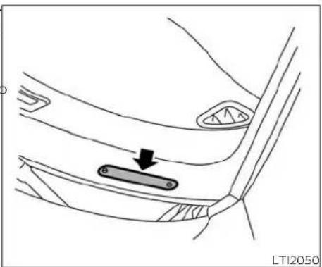
natural_image
Diagram of a car interior showing a vehicle's seatbelt with an arrow pointing to the seat area (no text or symbols present)VEHICLE IDENTIFICATION NUMBER
The laws and regulations for motor vehicle(VIN) PLATE
vary according to the country, state, province or district; therefore, vehicle specifications may differ. The VIN plate is attached as shown. This number is the identification for your vehicle and is used in the vehicle registration.
When any vehicle is to be taken into another country, state, province or district and registered, its modifications, transportation and registration are the responsibility of the user. NISSAN is not responsible for any inconvenience that may result.

natural_image
Technical line drawing of a mechanical component with no visible text or symbolsENGINE SERIAL NUMBER
The number is stamped on the engine as shown.

natural_image
Diagram of a medical or anatomical structure with a black arrow pointing to a highlighted rectangular region, no text or symbols present.F.M.V.S.S./C.M.V.S.S. CERTIFICATION LABEL

natural_image
Simple line drawing of a curved surface with a black upward arrow and a white square inside (no text or symbols)EMISSION CONTROL INFORMATION LABEL

natural_image
Line drawing of a car seatbelt mechanism with a black arrow indicating the grip point (no text or symbols present)TIRE AND LOADING INFORMATION LABEL
The Federal/Canadian Motor Vehicle Safety Standard (F.M.V.S.S./C.M.V.S.S.) certification label is affixed as shown. This label contains valuable vehicle information, such as: (GVWR), (GAWR), month and year of manufacture, (VIN), etc. Review it carefully.
The emission control information label is attached to the underside of the hood as shown.
The cold tire pressure is shown on the Tire and Loading Information label. The label is located as shown.
INSTALLING FRONT LICENSE PLATE

natural_image
Line drawing of a car seatbelt with a black arrow pointing to the seat (no text or symbols)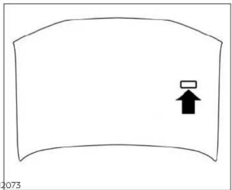
natural_image
Simple line drawing of a curved surface with an upward arrow icon (no text or symbols)TIRE WARNING LABEL AIR CONDITIONER SPECIFICATION LABEL
The air conditioner specification label is affixed to the underside of the hood as shown.

10-12 Technical and consumer information
VEHICLE LOADING INFORMATION
Use the following steps to mount the front license plate:
Before mounting the license plate, confirm that the following parts are enclosed in the plastic bag:
- License plate bracket
- License plate screws x 2
-
Screw grommets x 2
-
Hold the license plate bracket① and make a shallow hole in the bumper fascia using a drill. To avoid damaging the area behind the fascia, apply only light pressure to the drill.
- Insert the grommets ② into the holes in the bumper fascia.
- Mount the license plate bracket using the two screws③.
- Mount the front license plate.
WARNING
- It is extremely dangerous to ride in a cargo area inside a vehicle. In a collision, people riding in these areas are more likely to be seriously injured or killed.
- Do not allow people to ride in any area of your vehicle that is not equipped with seats and seat belts.
Be sure everyone in your vehicle is in a seat and using a seat belt properly.
TERMS
It is important to familiarize yourself with the following terms before loading your vehicle:
- Curb Weight (actual weight of your vehicle) - vehicle weight including: standard and optional equipment, fluids, emergency tools, and spare tire assembly. This weight does not include passengers and cargo.
- GVW (Gross Vehicle Weight) - curb weight plus the combined weight of passengers and cargo.
GVWR (Gross Vehicle Weight Rating) - maximum total combined weight of the unloaded vehicle, passengers, luggage, hitch, trailer tongue load and any other optional equipment. This information is located on the F.M.V.S.S./C.M.V.S.S. certification label. - GAWR (Gross Axle Weight Rating) - maximum weight (load) limit specified for the front or rear axle. This information is located on the F.M.V.S.S./C.M.V.S.S. certification label.
-
GCWR (Gross Combined Weight rating) - The maximum total weight rating of the vehicle, passengers, cargo, and trailer.
-
Vehicle Capacity Weight, Load limit, Total load capacity - maximum total weight limit specified of the load (passengers and cargo) for the vehicle. This is the maximum combined weight of occupants and cargo that can be loaded into the vehicle. If the vehicle is used to tow a trailer, the trailer tongue weight must be included as part of the cargo load. This information is located on the Tire and Loading Information label.
- Cargo capacity - permissible weight of cargo, the subtracted weight of occupants from the load limit.
VEHICLE LOAD CAPACITY
Before driving a loaded vehicle, confirm that you do not exceed the Gross Vehicle Weight Rating (GVWR) or the Gross Axle Weight Rating (GAWR) for your vehicle. Both the GVWR and GAWR are located on the F.M.V.S.S./C.M.V.S.S. certification label. For additional information, refer to "Measurement of weights" in this section.
Do not exceed the load limit of your vehicle shown as "The combined weight of occupants and cargo" on the Tire and Loading Information label. Do not exceed the number of occupants shown as "Seating Capacity" on the Tire and Loading Information label.
To get "the combined weight of occupants and cargo", add the weight of all occupants, then add the total luggage weight. Examples are shown in the following illustration.

Example
Steps for determining correct load limit
- Locate the statement "The combined weight of occupants and cargo should never exceed XXX lbs. or XXX kg" on your vehicle's Tire and Loading Information label.
- Determine the combined weight of the driver and passengers that will be riding in your vehicle.
- Subtract the combined weight of the driver and passengers from XXX lbs. or XXX kg.
- The resulting figure equals the available amount of cargo and luggage load capacity. For example, if the XXX amount equals 1,400 lbs. and there will be five 150 lbs. passengers in your vehicle, the amount of available cargo and luggage load capacity is 650 lbs. (1,400-750 (5 X 150) = 650 lbs.) or (640-340 (5 X 70) = 300 kg.)
Technical and consumer information 10-15
- Determine the combined weight of luggage and cargo being loaded on the vehicle. That weight may not safely exceed the available cargo and luggage load capacity calculated in step 4.
Before driving a loaded vehicle, confirm that you do not exceed the Gross Vehicle Weight Rating (GVWR) or the Gross Axle Weight Rating (GAWR) for your vehicle. For additional information, refer to "Measurement of weights" in this section.
Also check tires for proper inflation pressures. For additional information, refer to "Tire and Loading Information label" in this section.
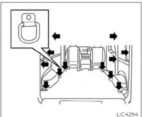
Cargo area D-Ring (if so equipped) SECURING THE LOAD
There are 12 D-rings (If so equipped) located in the cargo area as shown and can be used to secure cargo with ropes or other types of straps.
Do not apply a total load of more than 200 lbs. (890 N) to a single D-ring when securing cargo.
WARNING
- Properly secure all cargo with ropes or straps to help prevent it from sliding or shifting. Do not place cargo higher than the seatbacks. In a sudden stop or collision, unsecured cargo could cause personal injury.
- The child restraint top tether strap may be damaged by contact with items in the cargo area. Secure any items in the cargo area. Your child could be seriously injured or killed in a collision if the top tether strap is damaged.
- Do not load your vehicle any heavier than the GVWR or the maximum front and rear GAWRs. If you do, parts of your vehicle can break, tire damage could occur, or it can change the way your vehicle handles. This could result in loss of control and cause personal injury.
TOWING A TRAILER
LOADING TIPS
- The GVW must not exceed GVWR or GAWR as specified on the F.M.V.S.S./C.M.V.S.S. certification label.
- Do not load the front and rear axle to the GAWR. Doing so will exceed the GVWR.
WARNING
- Properly secure all cargo with ropes or straps to help prevent it from sliding or shifting. Do not place cargo higher than the seatbacks. In a sudden stop or collision, unsecured cargo could cause personal injury.
- Do not load your vehicle any heavier than the GVWR or the maximum front and rear GAWRs. If you do, parts of your vehicle can break, tire damage could occur, or it can change the way your vehicle handles. This could result in loss of control and cause personal injury.
- Overloading and improper loading not only can shorten the life of your vehicle and the tire, but can also cause unsafe vehicle handling and longer braking distances. This may cause a premature tire failure which could result in a serious accident and personal injury. Failures caused by overloading are not covered by the vehicle's warranty.
MEASUREMENT OF WEIGHTS
Secure loose items to prevent weight shifts that could affect the balance of your vehicle. When the vehicle is loaded, drive to a scale and weigh the front and the rear wheels separately to determine axle loads. Individual axle loads should not exceed either of the GAWR. The total of the axle loads should not exceed the GVWR. These ratings are given on the vehicle certification label. If weight ratings are exceeded, move or remove items to bring all weights below the ratings.
Do not tow a trailer with your vehicle.
FLAT TOWING
Towing your vehicle with all four wheels on the ground is sometimes called flat towing. This method is sometimes used when towing a vehicle behind a recreational vehicle, such as a motor home.
CAUTION
- Failure to follow these guidelines can result in severe transmission damage.
- Whenever flat towing your vehicle, always tow forward, never backward.
- DO NOT tow any continuously variable transmission vehicle with all four wheels on the ground (flat towing). Doing so WILL DAMAGE internal transmission parts due to lack of transmission lubrication.
- For emergency towing procedures refer to "Towing recommended by NISSAN" in the "In case of emergency" section of this manual.
UNIFORM TIRE QUALITY GRADING
Continuously Variable Transmission (CVT)
To tow a vehicle equipped with a CVT, an appropriate vehicle dolly MUST be placed under the towed vehicle's drive wheels. Always follow the dolly manufacturer's recommendations when using their product.
DOT (Department of Transportation) Quality Grades: All passenger car tires must conform to federal safety requirements in addition to these grades.
Quality grades can be found where applicable on the tire sidewall between tread shoulder and maximum section width. For example:
Treadwear 200 Traction AA Temperature A
Treadwear
ment as measured under controlled conditions on specified government test surfaces of asphalt and concrete. A tire marked C may have poor traction performance.
WARNING
The traction grade assigned to this tire is based on straight-ahead braking traction tests, and does not include acceleration, cornering, hydroplaning, or peak traction characteristics.
The treadwear grade is a comparative rat-ting based on the wear rate of the tire when tested under controlled conditions on a specified government test course. For example, a tire graded 150 would wear one and one-half (1 1/2) times as well on the government course as a tire graded 100. The relative performance of tires depends upon the actual conditions of their use, however, and may depart significantly from the norm due to variations in driving habits, service practices and differences in road characteristics and climate.
Traction AA, A, B and C
The traction grades, from highest to lowest, are AA, A, B, and C. Those grades represent the tire's ability to stop on wet pavement.
The temperature grades are A (the highest), B, and C, representing the tire's resistance to the generation of heat, and its ability to dissipate heat when tested under controlled conditions on a specified indoor laboratory test wheel. Sustained high temperature can cause the material of the tire to degenerate and reduce tire life, and excessive temperature can lead to sudden tire failure. The grade C corresponds to a level of performance which all passenger car tires must meet under the Federal Motor Vehicle Safety Standard No. 109. Grades B and A represent higher levels of performance on the laboratory test wheel than the minimum required by law.
EMISSION CONTROL SYSTEM WARRANTY
WARNING
The temperature grade for this tire is established for a tire that is properly flated and not overloaded. Excessive speed, under-inflation, or excessive loading, either separately or in combination, can cause heat build-up and possible tire failure.
Your NISSAN vehicle is covered by the following emission warranties: For Canada
inFor USA
- Emission Defects Warranty
- Emissions Performance Warranty
Details of this warranty may be found with other vehicle warranties in your Warranty Information Booklet which comes with your NISSAN vehicle. If you did not receive Warranty Information Booklet, or it is lost, you may obtain a replacement by writing to:
Emission Control System Warranty
Details of this warranty may be found with other vehicle warranties in your Warranty Information Booklet which comes with your NISSAN vehicle. If you did not receive a Warranty Information Booklet, or it is lost, you may obtain a replacement by writing to:
a. Nissan Canada Inc. 5290 Orbitor Drive Mississauga, Ontario, L4W 4Z5
• Nissan North America, Inc. Consumer Affairs Department P.O. Box 685003 Franklin, TN 37068-5003
REPORTING SAFETY DEFECTS
For USA
If you believe that your vehicle has a defect which could cause a collision or could cause injury or death, you should immediately inform the National Highway Traffic Safety Administration (NHTSA) in addition to notifying NISSAN.
If NHTSA receives similar complaints, it may open an investigation, and if finds that a safety defect exists in a group of vehicles, it may order a recall and remedy campaign. However, NHTSA cannot become involved in individual problems between you, your dealer, or NISSAN.
To contact NHTSA, you may call the Vehicle Safety Hotline toll-free at 1-888-327-4236 (TTY: 1-800-424-9153); go to http://www.safercar.gov; or write to: Administrator, NHTSA, 400 Seventh Street, SW., Washington, D.C. 20590. You can also obtain other information about motor vehicle safety from http://www.safercar.gov.
10-20
Technical and consumer information
You may notify NISSAN by contacting our Consumer Affairs Department, toll-free, at 1-800-NISSAN-1.
For Canada
If you believe that your vehicle has defect which could cause a collision or could cause injury or death, you should immediately inform Transport Canada in addition to notifying NISSAN.
If Transport Canada receives com- plaints, it may open an investigation and if it finds that a safety defect exists in a group of vehicles, it may request that NISSAN conduct a reca campaign. However, Transport Canada cannot become involved in individual problems between you, your dealer, or NISSAN.
You may contact Transport Canada's Defect Investigations and Recalls Division toll free at 1-800-333-0510. You may also report safety defects online at: https://wwwapps.tc.gc.ca/ Saf-Sec-Sur/7/PCDB-BDPP/fc-cp.aspx?lang=eng (English speakers) or https://wwwapps.tc.gc.ca/Saf-Sec-Sur/7/PCDB-BDPP/fc-cp.aspx?lang=fra (French speakers)
Additional information concerning motor vehicle safety may be obtained from Transport Canada's Road Safety Information Centre at 1-800-333-0371 or online at www.tc.gc.ca/roadsafety (English speakers) or www.tc.gc.ca/securiteroutiere (French speakers).
To notify NISSAN of any safety concerns please contact our Consumer Information Centre toll-free at 1-800-387-0122.
READINESS FOR INSPECTION/MAINTENANCE (I/M) TEST
Due to legal requirements in some states and Canadian Provinces, your vehicle may required to be in what is called the "ready condition" for an Inspection/Maintenance (I/M) test of the emission control system.
The vehicle is set to the "ready condition" when it is driven through certain driving patterns. Usually, the ready condition can be obtained by ordinary usage of the vehicle.
If a powertrain system component is repaired or the battery is disconnected, the vehicle may be reset to a "not ready" condition. Before taking the I/M test, check the vehicle's inspection/maintenance test readiness condition. Place the ignition switch in the ON position without starting the engine. If the Malfunction Indicator Light (MIL) comes on steady for 20 seconds and then blinks for 10 seconds, the I/M test condition is "not ready". If the MIL does not blink after 20 seconds, the I/M test condition is "ready". It is recommended that you visit a NISSAN dealer to set the "ready condition" or to prepare the vehicle for testing.
This vehicle is equipped with an EDR. The bemain purpose of an EDR is to record, in certain collision or near collision-like situations, such as an air bag deployment or hitting a road obstacle, data that will assist in understanding how a vehicle's systems performed. The EDR is designed to record data related to vehicle dynamics and safety systems for a short period of time, typically 30 seconds or less. The EDR in the vehicle is designed to record such data as
• How various systems in your vehicle were operating;
- Whether or not the driver and passenger safety belts were buckled/fastened;
- How far (if at all) the driver was depressing the accelerator and/or brake pedal, and,
st How fast the vehicle was traveling.
- Sounds are not recorded.
These data can help provide a better understanding of the circumstances in which collisions and injuries occur. NOTE: EDR data are recorded by your vehicle only if a nontrivial collision situation occurs; no data are recorded by the EDR under normal driving conditions and no personal data (e.g. name, gender, age and collision location) are recorded. However, other parties, such as law enforcement, could combine the EDR data with the type of personally identifying data routinely acquired during a collision investigation.
To read data recorded by an EDR, special equipment is required and access to the vehicle or the EDR is needed. In addition to the vehicle manufacturer and NISSAN dealer, other parties, such as law enforcement, that have the special equipment, can read the information if they have access to the vehicle or the EDR. EDR data will only be accessed with the consent of the vehicle owner or lessee or as otherwise required or permitted by law.
OWNER'S MANUAL/SERVICE MANUAL ORDER INFORMATION
Genuine NISSAN Service Manuals for this model year and prior can be purchased. A Genuine NISSAN Service Manual is the best source of service and repair information for your vehicle. This manual is the same one used by the factory-trained technicians working at NISSAN dealerships. Genuine NISSAN Owner's Manuals can also be purchased.
For USA
For current pricing and availability of Genuine NISSAN Service Manuals, contact:
www.nissan-techinfo.com
For current pricing and availability of Genuine NISSAN Owner's Manuals, contact:
1-800-247-5321
For Canada
To purchase a copy of a Genuine NISSAN Service Manual or Owner's Manual, for this model year and prior, please contact your nearest NISSAN dealer. For the phone number and location of a NISSAN dealer in your area, call the NISSAN Information Center at 1-800-387-0122 and a bilingual NISSAN representative will assist you.
10-22 Technical and consumer information
11 Index
| A | B | C |
| Air bag (See supplemental restraint system) .1-32 | Back door. 3 - 8B at tery .5 - 3 3 b r i c a n ts | Capacities and recommended fuel/ |
| Air bag system | Charge warning light .2 - Cargo (See vehicle loading | |
| Front (See supplemental front impact air bag s y s t e m ) . | Battery replacement. 8 - 2 1n for m at i on ) | |
| Air bag warning labels .1-49 | K e y of o b .8 - 2 1 car phone or CB radio. .4 - 1 9 | |
| Air bag w arning light . | Before starting the engine .5 - 10 Child re str aints .1-19, | |
| Air bag warning light, supplemental .1-50, 2-14 | Belt (Se e d rive belt). .1-50, 7-14 Booster seats .1-28 | Precautions on child re str aints .1-22, 1-24, |
| Air cleaner housing filter .8 - 1 5 | Brake Anti-lock Braking System (ABS) .5 - 2 4 Br ake fluid . | Top tether strap anchor point loca tions .1-2 |
| Air conditioner | B r a k e l i g h t (Se e s to p l i g .8 - 2 8 | Child restraint with top tether strap .1-23 |
| Air conditioner operation .4 - 1 4 | B r a k e s y s t e m . | Chimes, audible reminders .2 - 1 7 |
| Air conditioner specification label .10-12 | B r a k e w arning light . | C l e a n i n g ext erior and inter |
| Air conditioner system refrigerant and oil recommendations .10 - 7 | Brake wear indicators .2-17,8-17 | CM.V.S.S. certification label .10 - 1 1 |
| Air conditioner system refrigerant recommendations .10 - 7 | Self - a d j u s t i n g br a k e s .5 - 2 5 Brake Assist . | Continuously Variable Transmission (CVT) .10 .5 - 8 , 5 - 1 2 |
| Heater and air conditioner controls .4-11 | B r a k e f l u i d . | Continuously Variable Transmission (CVT) fluid .8 - 1 0 |
| Servicing air conditioner .4 - 1 | B r a k e s y s t e m . | Driving with Continuously Variable Transmission (CVT) .5-8, 5-12 |
| Air flow charts .4 - 1 | Break-in schedule .5 - 1 9 Brightness control | Controls |
| Anchor point locations .1-23 | Instrument panel .2 - 2 4 Bulb check/instrument panel .2 - 1 0 Bulb replacement .8 - 2 | Heater and air conditioner controls .4-11 Coolant |
| Antenna .4 - 1 9 | ||
| Antifreeze .5 - 3 | ||
| Anti-lock brake warning light .2 - 1 0 | Capacities and recommended fuel /lubricants . | |
| Anti-lock Braking System (ABS) .5 - 2 4 | Changing engine coolant .8 | |
| Audible reminders .2 - 1 7 | Checking engine coolant level .8-6 | |
| Automatic | Cor ro s i o n p rotection . | |
| Automatic power window switch .2-32 | Cruise con trol . | |
| Automatic door locks .3 - 1 0 | ||
| C up h old e rs | Changing engine oil filter | 8 - 7 Engine oil | 8 - 7 |
| Checking engine coolant level | 8 - 6 Windshield-washer fluid | 8 - 1 1 | |
| Checking engine oil level | 8 - F.M.V.S.S. certification label. | 1 0 - 1 1 | |
| Engine compartment check | Front air bag system | ||
| D | locations | (See Supplemental restraint system) | 1-39 |
| Daytime light system. | 2 - 2 4 Engine cooling system | 8 - 5 front-door pocket | 2-28 |
| Defroster switch | Engine oil | 8 - Front seats | |
| Rear window and outside mirror | Engine oil and oil filter | Fuel | |
| defrosterswitch | recommendation | 1 0 - 6 Capacities and recommended | |
| Dimensions and weights. | 1 0 - 9 Engine oil pressure warning light | 2 - 1 fuel / lubricants | |
| Dimmer switch for instrument panel | 2-24 Engine oil viscosity. | 1 0 - 6 Fuel economy | 5 - 2 1 |
| Door locks | 3 - 4 Engine serial number | 1 0 - 1 0 Fuel-filler door and cap | 3 - 1 4 |
| Door open warning light | 2 - 1 1 Engine specifications | 1 0 - 8 Fuel-filler door lock opener lever | 3-14 |
| Doors | 3 - 3 Starting the engine | 5 - 1 0 Fuel gauge | 2-6 |
| D-ring. | 2 - 3 0 , 1 Engine Block Heater | 5 - 3 5 Fuel octanerating | |
| Drive belt | Eve n1t4 data recorders | Fuel recommendation | 1 0 - 3 |
| Driving | Exhaust gas (Carbon monoxide). | 5 - 2 Loose fuel cap warning | |
| Cold weather driving | Explanation of maintenance items | 9 - Fuel efficient driving tips | 5 - 2 0 |
| Driving with Continuously Variable | Explanation of scheduled maintenance | Fuel-filler door | 3-14 |
| Transmission (CVT). | 5 - 8 , 5 i-t1e2m s | 9 Fuel gauge | 2 - 6 |
| Precautions when starting and driving | Extended storage switch. | 8 - 2Fuses | 8 - 1 8 |
| Driving the vehicle. | 5 - 2 | Fusible links | |
E
| Economy - fuel | 5 |
| Emission control information label | 10-11 |
| Emission control system warranty | 10-19 |
| Engine | |
| Before starting the engine | 5 |
| Capacities and recommended fuel / lubricants | |
| Changing engine coolant | 8 |
| Changing engine oil | 8 |
F
| Flashers(See hazard warning flasher switch)....6 - Q as cap....3 - Fill attire....6 Ga 2ge6 - 3 | |
| Flo or mat positioning aid..Fuel gauge....7 - 5....2-6 | |
| Fluid | Odometer....2 - 4 |
| Brake fluid....Speedometer....2-4 | |
| 10Capacities and recommended fuel / lubricants....Tachometer....2-6 | |
| Trip. computer....2-7 | |
| Continuously Variable Transmission (CVT) | Trip odometer....2 - 4 |
| 6 fluid....8 General maintenance....9 - 2 | |
| Engine coolant....8 - 5G love box....2 | |
| H | K | Headlight and turn signal switch...2-23Headlight control switch |
| Hazard warning flasher switch. . . . . . . . . . . . . . . . . . . . . . . . . . . . . . . . . . . . . . . . . . . . . . . . . . . . . . . . . . . . . . . . . . . . . . . . . . . . . . . . . . . . . . . . . . . . . . . . . . . . . | 6 - Key . . . . . . . . . . . . . . . . . . . . . . . . . . . . . . . . . . . . . . . . . . . . . . . . . . . . . . . . . . . . . . . . . . . . . . . . . . . . . . . . . . . . . . . . . . . . . . . . . . . | |
| Headlight and turn signal switch. . . . . . . . . . . . . . . . . . . . . . . . . . . . . . . . . . . . . . . . . . . . . . . . . . . . . . . . . . . . . . . . . . . . . . . . . . . . . . . . . . . . . . . . . . . . . . . . . . | 2 - Key fob battery replacement . . . . . . . . . . . . . . . . . . . . . . . . . . . . . . . . . . . . . . . . . . . . . . . . . . . . . . . . . . . . . . . . . . . . . . . . . . . . . . . . . . . . . . . . . . . . . . . . . . . | |
| Head light controls switch Keyless entry . 2 - 2 3 | Without Intelligent Key system | Interior light |
| Head lights. . . . . . . . . . . . . . . . . . . . . . . . . . . . . . . . . . . . . . . . . . . . . . . . . . . . . . . . . . . . . . . . . . . . . . . . . . . . . . . . . . . . . . . . . . . . . . . . . . . | (See remote keyless entry system). 3 - 1 0 , 3 - | Light bulbs |
| Heater and air conditioner controls . 4-11 Keys | 3 - 1 0 , 3 - | Low tire pressure warning |
| Heater operation. . . . . . . . . . . . . . . . . . . . . . . . . . . . . . . . . . . . . . . . . . . . . . . . . . . . . . . . . . . . . . . . . . . . . . . . . . . . . . | NISSAN Vehicle Immobilizer System | Low windshield-washer fluid warning |
| Hill start assist system. . . . . . . . . . . . . . . . . . . . . . . . . . . . . . . . . . . . . . . . . . . . . . . . . . . | 5 - 2 9 keys | Light h t. 2 - |
| Hood. . . . . . . . . . . . . . . . . . . . . . . . . . . . . . . . . . . . . . . . . . Horn. 2 - 2 5 | 3 - | Passenger air bag and status light..1-41 |
| L | Lights | Security indicator light 2 - 1 7 |
| I | Label | Warning/indicator lights and audible reminders 2 - 9 , 2-15 |
| Ignition switch. . . . . . . . . . . . . . . . . . . . . . . . . . . Immobilizer system 2 - 1 9 , 3 - 2 Air5 conditioner specification label 10-12 | Tire warning | Map lights. 2 |
| Important vehicle information label. 10-11 | C.M.V.S.S. certification label 10 - | Lock |
| Increasing fuel economy 5 - 2 1 Emission control information label 10-11 | Engine serial number 10 - | Door locks 3 - 4 |
| Indicator lights and audible reminders (See warning/indicator lights and audible reminders) 2 - 9 , 2 - 1T5e and Loading Information label 10-11 | F.M.V.S.S. certification label 10 - | Fuel-filler door lock opener lever 3 - 1 |
| Instrument brightness control 2 - 2 4 Vehicle identification number (VIN) 10-10 | Engine serial number 10 - | Power door locks 3-6 |
| Instrument panel 0 - 6 , 2 - Vehicle identification number (VIN) | Engine serial number 10 - | Loose fuel cap warning 2 - 5 |
| Instrument panel dimmer switch 2 - 2 4 plate. 10 - 10 | Engine serial number 10 - | Low tire pressure warning light. 2-12 |
| Interior light 2 Warning Labels for SRS) 1-49 | F.M.V.S.S. certification label 10 - | Low windshield-washer fluid warning |
| License plate | 10 - | Luggage |
| J | Installing the license plate 10 - Maintenance | |
| Jump starting | Light General maintenance 9 - 2 | |
| Air bag warning light I.m1-50,2-84 the vehicle | ||
| B10,8e-11ght (Seestop ligh Maintenance Pecations. 8 - 2 | ||
| Bulb check/instrument panel 2 - 100utsid the vehicle | ||
| Bulb replacement 8 - 2 8 Seat belt maintenance 1-18 | ||
| Charge warning light 2 - 1 1 Under the hood and vehicle 9 - 4 | ||
| Maintenance log | 9 - 11 Engine oil viscosity. | 10 - 6 | R |
| Maintenance requirements. | 9 - 20 Utsidemirrors | 3 - 18 | |
| Maintenance schedules | 9 - Overheat | ||
| Maintenance under severe operation conditions | If your vehicle overheats Owner's manual order form | 10 - 27 | Radio Car phone or CB radio Readiness for inspection maintenance (I/M) test Rear sonar system OFF switch Rear Sonar System (RSS). 5-29 |
| Malfunction indicator | Owner's manual/service manual order information | ||
| Manual front seat adjustment | 1-3 | ||
| Maplights | 2 - 34 | ||
| Meters and gauges | 2 - 3 | P | Rear view mirror Rear view Monitor |
| Instrument brightness control | 2 - 24 | ||
| Mirror | Parking | Rear window and outside mirror defroster switch 5 - 23 | |
| Outsidemirrors | Parking / parking on hills | ||
| Rearview | Parking brake | Recommended Fluids 10 - 2 | |
| Mirrors | Power | Recorders | |
| N | Power door locks | 3 - 6 | Event Data 1 |
| Power outlet | Refrigerant recommendation 10 - 7 | ||
| Power steering system | Registering a vehicle in another country 10 - 10 | ||
| Power windows | |||
| Power outlet | Remote keyless entry system 3 - 10, 3- | ||
| NissanConnect® Owner's Manual | 4 - 3 | Reporting safety defects (US only) 10-20 | |
| NISSAN Vehicle Immobilizer System | 2 - 19 | Precautions | |
| O | Maintenance precautions | 8 - 2 | S |
| Precautions on booster seats | 1-22, 1-24, 1-28 | ||
| Octane rating (See fuel octane rating). 10-5 | Precautions on child restraints | 1-22, 1-24, 1-28 | Safety Child seat belts 1-22, |
| Odometer | 2 - 4 | Precautions on seat belt usage | Reporting safety defects (US only) 10-20 |
| Oil | Precautions on supplemental restraint system | Seat adjustment | |
| Capacities and recommended fuel / lubricants | 10 - 2 | Precautions when starting and driving | Front manual seat adjustment 1-3 |
| Changing engine oil | 8 - 7 | Seat belt | |
| Changing engine oil filter | 8 - 7 | Bush starting | Infants and small children 1-19 |
| Checking engine oil level | 8 - 7 | Injured Person | |
| Engine oil | 8 - 7 | Larger children | |
| Engine oil and oil filter recommendation | 10 - 6 | Precautions on seat belt | |
| Pregnant women 1-14 | |||
| Seat belt extenders | 1-18 | Starting | Rear window and outside mirror |
| Seat belt maintenance | 1-18 | Before starting the engine | 5 - 10d ef rosters w itch |
| Seat belts | 1-11, 7-6 m p s t a r t i n g | 6 Turn0 signal switch | 2 - 2 |
| Shoulder belt height adjustment | 1-17 | Precautions when starting and | |
| Three-point typewithre to paicvtiong. | 1-14 | 5 - 2 | |
| Seat belt extenders | 1-18 | Push starting | 6 - 12T |
| Seat belt warning light | Starting4the engine | 5 - 10 | |
| Seats | Starting the engine | 5 - 17 | Teachometer 2 - 6 |
| Adjustment | 1-2 Steering | 5 - 23 | Theft (NISSAN Vehicle Immobilizer System),engine start 2 - 19,5 |
| Front seats | Power steering system | 5 - 28 | Th re e - way catalyst |
| Manual front seat adjustment | 1-3 Stop light | 2 - 8 | |
| Seats / floor mats | St o.r a7g-e5 | 2 - 8 | |
| Security indicator light | 2 - 17 D-ring | 2 - 30 | Flattire 6 - |
| Security system (NISSAN Vehicle Immobilizer System), engine start | 2 - 19,Supvisors | 2 - 28,2 - 29 | Spare tire 6 - 4 |
| Security systems | Supplemental air bag warning labels | 1-49 | Tire and Loading Information label .10-11 |
| Vehicle security system | 2 - 1 Supplemental air bag warning | 1-50, 2-14 | Tire chains 8 - 38 |
| Self-adjusting brakes | Light | 1-39 | Tire pressure 8 |
| Service manual order form | 10 - Supplemental front impact air bag | 1-49 | Tir erotation |
| Servicing air conditioner | 4 - 1system | 1-39 | Typesoftires 10 - 1 |
| Shifting | Supplemental restraint system | 1-49 | Wheels and tires 8 - 31,1 |
| Continuously Variable Transmission(CVT) | 5 - 14 Information and warning labels | 1-32 | Wheel/tire size 10 - 9 |
| Shoulder belt height adjustment | 1-17 System | 1-32 | Tire pressure |
| Sliding door | Supplemental restraint system | 1-32 | Lowtirepressurew arnin |
| Manual sliding door | 3 - (Supplemental air bag system) | 1-32 | Tire Pressure Monitoring System (TPMS).5-3 |
| Sonar | Switch | 1-32 | Tire warning label 10 - 1 |
| Rear system | 5 - 29 Automatic power window switch | 2-32 | Toptetherstrapchildrestr |
| Spark plug replacement | 8 - 15 Hazard warning flasher switch | 6 - 2 | Towing |
| Spark plugs | 8 - 15 Headlight and turn signal switch | 2 - 23 | 4-wheel drive models 6 - 14 |
| Specifications | 10 - 8 Headlight control switch | 1-32 | Flattowing |
| Speedometer | 2 - 4 Ignition switch | 5 - 8 | Towtrucktowing |
| SRS warning label | 1-49 Instrument brightness control | 2 - 24 | Trailertowing |
| Stability control | 5 - 26 Power door lock switch | 3 - 6 | To wingatraler |
| Standard maintenance | 9 - 7,9 - 8 Rear sonar system OFF switch | 2 - 26 | Transmission |
(CVT) fluid 8 - 10
| Driving with Continuously VariableTransmission (CVT)....5 - 8 , 5 - 1 2 | W | Warning lights, indicator lights and audible reminders....2 - 9 | |
| Travel (See registering a vehicle in another country)....1 0 - 1 0 | Warning | Weights (See dimensions and weights) .10-9 | |
| Trip computer....2 - 7 | Air bag warning light....1-50, 2-14 | Wheels and tires....8 - 3 1 , 1 0 | |
| Trip odometer....2 - 4 | Anti-lock brake warning light....2 - 1 0 | Wheel/tire size....1 0 - 9 | |
| Turn signal switch....2 - 2 5 | Battery charge warning light....2 - | when traveling or registering in another country....1 0 - 1 0 | |
| Brake warning light....2-10 | W i n d o w s....2 - | ||
| Door open warning light....2 - 1 1 | Locking passengers' windows....2-32 | ||
| U | Engine oil pressure warning light....2 - 1 1 | Power windows.... | |
| Hazard warning flasher switch....6 - 2 | Windshield-washer fluid....8 - 1 1 | ||
| Uniform tire quality grading....1 0 - 1 8 | Loose fuel cap warning....2 - 5 | Windshield wiper blades....8 - 1 6 | |
| Low fuel warning light....2-12 | Wiper | ||
| Low tire pressure warning light....2 - 1 2 | Wiper blades....8 - 1 6 | ||
| Low windshield-washer fluid warning light....2 - 1 4 | Wiper and washer switch....2 - 2 1 | ||
| V | |||
| Variable voltage control system....8 - 1 3 | Passenger air bag and status light...1-41 | ||
| Vehicle dimensions and weights....1 0 - 9 | Seat belt warning light....1-14, 2-14 | ||
| Vehicle Dynamic Control (VDC) | Supplemental air bag warning light....1-50, 2-14 | ||
| OFF switch....2 1 1 | |||
| Vehicle Dynamic Control (VDC) system....5-26 | Vehicle security system....2 - 1 8 | ||
| Vehicle identification....1 0 - 1 0 | Warning/indicator lights and audible reminders....2 - 9, 2 - 1 5 | ||
| Vehicle identification number (VIN)....10-10 | Warning labels (for SRS)....1-49 | ||
| Vehicle identification number (VIN) | |||
| plate....1 | Warning/indicator lights and audible reminders....2 - 9, 2 - 1 5 | ||
| Vehicle immobilizer system....2 - 1 9, 3 - 2 1 | |||
| Vehicle loading information....1 0 - 1 3 | Audible reminders....2-9, 2-15 | ||
| Vehicle recovery....Indication lights....2-9, 2-15 | |||
| Vehicle security system....2 - 1 8 | Warning lights....2-9, 2-15 | ||
| Vehicle security system (NISSAN Vehicle Immobilizer System), engine start..2-19, 5-9 | Warning lights....2-9, 2-15 | ||
| Ventilators....4 - 1 1 | |||
| Visors....3 - 1 7 | |||
MEMO
MEMO
GAS STATION INFORMATION
FUEL RECOMMENDATION:
Use unleaded regular gasoline with an octane rating of at least 87 AKI (Anti-Knock Index) number (Research octane number 91).
CAUTION
- Only vehicles with the E-85 filler door label can operate on E-85.Fuel system or other damage can occur if E-85 is used in vehicles that are not designed to run on E-85.
- Using a fuel other than that specified could adversely affect the emission control system, and may also affect the warranty coverage.
-
Under no circumstances should a leaded gasoline be used, because this will damage the three-way catalyst.
-
Do not use a fuel containing more than 15% ethanol in your vehicle. Your vehicle is not designed to run on a fuel containing more than 15% ethanol. Using a fuel containing more than 15% ethanol in a vehicle not specifically designed for a fuel containing more than 15% ethanol can adversely affect the emission control devices and systems of the vehicle. Damage caused by such fuel is not covered by the NISSAN New Vehicle Limited Warranty.
- Do not use fuel that contains the octane booster methylcyclopentadienyl manganese tricarbonyl (MMT). Using fuel containing MMT may adversely affect vehicle performance and vehicle emissions. Not all fuel dispensers are labeled to indicate MMT content, so you may have to consult you gasoline retailer for more details. Note that Federal and California laws prohibit the use of MMT in reformulated gasoline.
- U.S. government regulations require ethanol dispensing pumps to be identified by a small, square, orange and black label with the common abbreviation or the appropriate percentage for that region.
For additional information, refer to "Recommended fluids/lubricants and capacities" in the "Technical and consumer information" section of this manual.
ENGINE OIL RECOMMENDATION:
Refer to "Recommended fluids/lubricants and capacities" in the "Technical and consumer information" section of this manual.
COLD TIRE PRESSURE:
Refer to the Tire and Loading Information label.
The label is typically located on the driver side center pillar or on the driver's door. For additional information, refer to "Wheels and tires" in the "Do-it-yourself" section of this manual.
RECOMMENDED NEW VEHICLE BREAK-IN PROCEDURE:
During the first 1,200 miles (2,000 km) of vehicle use, follow the break-in procedure recommendations for the future reliability and economy of your new vehicle. For additional information, refer to "Break-in schedule" in the "Starting and driving" section of this manual. Failure to follow these recommendations may result in vehicle damage or shortened engine life.

Printing : October 2019
Publication No.: OM20EM 0M20U1
Printed in the U.S.A.
'20 M20-D

- NV200 COMPACT CARGO
- CALIFORNIA PROPOSITION 65 WARNING
- WARNING
- FOREWORD
- READ FIRST—THEN DRIVE SAFELY
- IMPORTANT SAFETY INFORMATION REMINDERS!
- DRIVING
- WHEN READING THE MANUAL
- CAUTION
- NISSAN CUSTOMER CARE PROGRAM
- NISSAN CARES...
- For U.S. customers
- For Canadian customers
- Illustrated table of contents
- AIR BAGS, SEAT BELTS AND CHILD RESTRAINTS
- EXTERIOR FRONT
- EXTERIOR REAR
- PASSENGER COMPARTMENT
- INSTRUMENT PANEL
- MR20DE engine
- WARNING AND INDICATOR LIGHTS
- Safety—Seats, seat belts and supplemental restraint system
- SEATS
- 1-2 Safety—Seats, seat belts and supplemental restraint system
- FLEXIBLE SEATING
- HEAD RESTRAINTS/HEADRESTS
- NOTE:
- ADJUSTABLE HEAD RESTRAINT/ HEADREST COMPONENTS
- NON-ADJUSTABLE HEAD RESTRAINT/HEADREST COMPONENTS
- 1-8 Safety—Seats, seat belts and supplemental restraint system
- REMOVE
- INSTALL
- ADJUST
- SEAT BELTS
- SEAT BELT WARNING LIGHT
- PREGNANT WOMEN
- INJURED PERSONS
- A WARNING
- Unfastening the seat belts
- Checking seat belt operation
- SEAT BELT EXTENDERS
- SEAT BELT MAINTENANCE
- CHILD SAFETY
- INFANTS
- SMALL CHILDREN
- LARGER CHILDREN
- CHILD RESTRAINTS
- TOP TETHER ANCHOR
- therefore, must not be used in the front seat.
- Forward-facing - step 3
- BOOSTER SEATS
- Front passenger position
- SUPPLEMENTAL RESTRAINT SYSTEM (SRS)
- PRECAUTIONS ON SRS
- Supplemental front-impact air bag system
- Front seat-mounted side-impact supplemental air bag system
- Roof-mounted curtain side-impact and rollover supplemental air bag system
- 1-32 Safety—Seats, seat belts and supplemental restraint system
- NISSAN Advanced Air Bag System (front seats)
- Front passenger air bag and status lightStatus light
- Front passenger air bag
- Normal operation
- Precautions
- Steps
- Troubleshooting
- A system check will be performed during which the front passenger air bag status-light will remain lit for about 7 seconds initially.
- Other supplemental front-impact air bag precautions
- \*The SRS wiring harness connectors are yellow and orange for easy identification.
- SUPPLEMENTAL AIR BAG WARNING LABELS
- SUPPLEMENTAL AIR BAG WARNING LIGHT
- Repair and replacement procedure
- Instruments and controls
- METERS AND GAUGES
- SPEEDOMETER AND ODOMETER
- Changing the display
- Resetting the trip odometer
- TACHOMETER
- Trip computer reset
- OUTSIDE TEMPERATURE DISPLAY (if so equipped)
- 2-8 Instruments and controls
- WARNING LIGHTS, INDICATOR LIGHTS AND AUDIBLE REMINDERS
- CHECKING LIGHTS
- WARNING LIGHTS
- Parking brake indicator
- Low brake fluid warning light
- Charge warning light
- Door open warning light
- Engine oil pressure warning light
- High temperature warning light (red)
- Low tire pressure warning
- TPMS malfunction
- INDICATOR LIGHTS
- Operation
- Security indicator light
- Slip indicator light
- Turn signal/hazard indicator lights
- Vehicle Dynamic Control (VDC) OFF indicator light
- AUDIBLE REMINDERS
- Brake pad wear warning
- Key reminder chime
- Light reminder chime
- SECURITY SYSTEMS
- Parking brake reminder chime
- VEHICLE SECURITY SYSTEM (if so equipped)
- How to arm the vehicle security system
- For Canada:
- WIPER AND WASHER SWITCH
- REAR WINDOW AND/OR OUTSIDE MIRROR DEFROSTER SWITCH (if so equipped)
- Type A (if so equipped)
- 2-22 Instruments and controls
- HEADLIGHT AND TURN SIGNAL SWITCH
- HEADLIGHT CONTROL SWITCH
- Battery saver system
- DAYTIME RUNNING LIGHTS (DRL) SYSTEM
- 2-24 Instruments and controls
- INSTRUMENT BRIGHTNESS CONTROL
- HORN
- Lane change signal
- TURN SIGNAL SWITCH
- Turn signal
- VEHICLE DYNAMIC CONTROL (VDC) OFF SWITCH
- REAR SONAR SYSTEM (RSS) OFF SWITCH (if so equipped)
- 2-26 Instruments and controls
- POWER OUTLET(s)
- STORAGE
- WINDOWS
- POWER WINDOWS
- Locking passengers' windows
- Front passenger's power window switch
- Automatic operation
- Auto-reverse function
- 2-32 Instruments and controls
- INTERIOR LIGHTS
- 2-34 Instruments and controls
- CARGO LIGHT
- Pre-driving checks and adjustments
- KEYS
- 3-2 Pre-driving checks and adjustments
- DOORS
- Never leave these keys in the vehicle.
- 3-4 Pre-driving checks and adjustments
- 3-6 Pre-driving checks and adjustments
- Lockout protection
- 3-8 Pre-driving checks and adjustments
- REMOTE KEYLESS ENTRY SYSTEM (if so equipped)
- AUTOMATIC DOOR LOCKS
- Be sure to remove the key from the vehicle before locking the doors.
- Unlocking doors
- Auto relock
- Using the interior light
- 3-12 Pre-driving checks and adjustments
- HOOD
- FUEL-FILLER DOOR
- OPENER OPERATION
- FUEL-FILLER CAP
- LOOSE FUEL CAP warning message
- SUN VISORS
- MIRRORS
- OUTSIDE MIRRORS
- Monitor, climate, audio, phone and voice recognition systems
- NISSANCONNECT® OWNER'S MANUAL
- REARVIEW MONITOR
- CAUTION Do not scratch the camera lens when cleaning dirt or snow from the front of the camera.
- Distance guide lines
- 4-4 Monitor, climate, audio, phone and voice recognition systems
- Vehicle width guide lines
- Predicted course lines 5
- DIFFERENCE BETWEEN PREDICTED AND ACTUAL DISTANCES
- VENTS HEATER AND AIR CONDITIONER
- CONTROLS
- Fan speed control dial
- Air flow control dial
- Temperature control dial
- Fresh air
- Air recirculation
- A/C (air conditioner) button
- HEATER OPERATION
- Heating
- Ventilation
- Defrosting or defogging
- Bi-level heating
- Heating and defogging
- Operating tips
- AIR CONDITIONER OPERATION
- Cooling
- Dehumidified heating
- Dehumidified defogging
- AIR FLOW CHARTS
- SERVICING AIR CONDITIONER
- ANTENNA
- CAR PHONE OR CB RADIO
- This refrigerant does not harm the earth's ozone layer.
- iPod®/iPhone®
- Starting and driving
- PRECAUTIONS WHEN STARTING AND DRIVING
- THREE-WAY CATALYST
- 5-2 Starting and driving
- TIRE PRESSURE MONITORING SYSTEM (TPMS)
- Additional information:
- 5-4 Starting and driving
- FCC Notice
- OFF-ROAD RECOVERY
- RAPID AIR PRESSURE LOSS
- IGNITION SWITCH
- CONTINUOUSLY VARIABLE TRANSMISSION
- BEFORE STARTING THE ENGINE
- STARTING THE ENGINE
- DRIVING THE VEHICLE
- ENGINE PROTECTION MODE
- CONTINUOUSLY VARIABLE TRANSMISSION (CVT)
- Starting the vehicle
- P (Park)
- R (Reverse)
- A CAUTION
- N (Neutral)
- D (Drive)
- L( Low )
- Accelerator downshift - in D (Drive) position -
- High fluid temperature protection mode
- Fail-safe
- PARKING BRAKE
- To release:
- CRUISE CONTROL (if so equipped)
- PRECAUTIONS ON CRUISE CONTROL
- BREAK-IN SCHEDULE
- FUEL EFFICIENT DRIVING TIPS
- Use Smooth Accelerator and Brake Pedal Application
- Maintain Constant Speed
- Use Air Conditioning (A/C) at Higher Vehicle Speeds
- Drive at Economical Speeds and Distances
- Use Cruise Control
- Plan for the Shortest Route
- Avoid Idling
- Buy an Automated Pass for Toll Roads
- 5-20 Starting and driving
- INCREASING FUEL ECONOMY
- Winter Warm Up
- Keeping your Vehicle Cool
- PARKING/PARKING ON HILLS
- 5-22 Starting and driving
- POWER STEERING
- BRAKE SYSTEM
- BRAKE PRECAUTIONS
- Vacuum assisted brakes
- Using the brakes
- Wet brakes
- Parking brake break-in
- 5-24 Starting and driving
- BRAKE ASSIST
- Using the system
- VEHICLE DYNAMIC CONTROL (VDC) SYSTEM
- RISE-UP AND BUILD-UP
- BRAKE FORCE DISTRIBUTION
- HOW TO ENABLE/DISABLE THE RSS
- RSS LIMITATIONS
- SYSTEM TEMPORARILY UNAVAILABLE
- Action to take:
- 5-32 Starting and driving
- COLD WEATHER DRIVING
- SYSTEM MAINTENANCE
- FREEING A FROZEN DOOR LOCK
- ANTIFREEZE
- BATTERY
- DRAINING OF COOLANT WATER
- TIRE EQUIPMENT
- Skid and traction capabilities of studded DRIVING ON SNOW OR ICE snow tires on wet or dry surfaces may be
- SPECIAL WINTER EQUIPMENT
- 5-34 Starting and driving
- In case of emergency
- HAZARD WARNING FLASHER SWITCH
- FLAT TIRE
- 6-2 In case of emergency
- CHANGING A FLAT TIRE
- Stopping the vehicle
- JUMP STARTING
- PUSH STARTING
- IF YOUR VEHICLE OVERHEATS
- Do not stop the engine.
- TOWING YOUR VEHICLE
- TOWING RECOMMENDED BY NISSAN
- Appearance and care
- CLEANING EXTERIOR
- WASHING
- 7-2 Appearance and care
- WAXING
- REMOVING SPOTS
- UNDERBODY
- GLASS
- CHROME PARTS
- TIRE DRESSINGS
- CLEANING INTERIOR
- AIR FRESHENERS
- 7-4 Appearance and care
- CORROSION PROTECTION
- MOST COMMON FACTORS CONTRIBUTING TO VEHICLE CORROSION
- ENVIRONMENTAL FACTORS INFLUENCE THE RATE OF CORROSION
- Moisture
- Relative humidity
- Temperature
- Air pollution
- PROTECT YOUR VEHICLE FROM CORROSION
- In winter, the underbody must be cleaned periodically.
- Do-it-yourself
- MAINTENANCE PRECAUTIONS
- 8-2 Do-it-yourself
- ENGINE COOLING SYSTEM
- CHANGING ENGINE COOLANT
- ENGINE OIL
- CHECKING ENGINE OIL LEVEL
- 8-8 Do-it-yourself
- Engine oil and filter
- Oil filter tightening torque: 11 to 15 ft-lb (14.7 to 20.6 N·m)
- Drain plug tightening torque: 22 to 29 ft-lb (29.4 to 39.2 N·m)
- CONTINUOUSLY VARIABLE TRANSMISSION (CVT) FLUID
- BRAKE FLUID
- After the operation
- WINDSHIELD-WASHER FLUID
- WINDSHIELD-WASHER FLUID RESERVOIR
- VARIABLE VOLTAGE CONTROL SYSTEM
- Do not try to open the top of this battery
- DRIVE BELT
- SPARK PLUGS
- AIR CLEANER
- REPLACING SPARK PLUGS
- WINDSHIELD WIPER BLADES
- CLEANING
- REPLACING
- BRAKES
- Self-adjusting brakes
- Brake pad wear indicators
- FUSES
- ENGINE COMPARTMENT
- BATTERY REPLACEMENT
- FCC Notice:
- For USA:
- 8-22 Do-it-yourself
- LIGHTS
- Aiming the headlights
- Replacement procedures
- WHEELS AND TIRES
- TIRE LABELING
- 8-34 Do-it-yourself
- Example
- 8-36 Do-it-yourself
- Other Tire-related Terminology
- TYPES OF TIRES
- All season tires
- Summer tires
- TIRE CHAINS
- ires every 7,500 miles (12,000 km).
- Wheel nut tightening torque:
- ft-lb (113 N·m)
- Replacing wheels and tires
- Care of wheels
- Maintenance and schedules
- MAINTENANCE REQUIREMENTS
- GENERAL MAINTENANCE
- SCHEDULED MAINTENANCE
- WHERE TO GO FOR SERVICE
- EXPLANATION OF GENERAL MAINTENANCE ITEMS
- Outside the vehicle
- 9-2 Maintenance and schedules
- 9-4 Maintenance and schedules
- EXPLANATION OF SCHEDULED MAINTENANCE ITEMS
- NOTE: Mixing any other type of coolant or the use of non-distilled water may reduce the recommended service interval of the coolant.
- CHASSIS AND BODY MAINTENANCE:
- MAINTENANCE SCHEDULES
- STANDARD MAINTENANCE
- MAINTENANCE UNDER SEVERE OPERATING CONDITIONS
- SEVERE DRIVING CONDITIONS
- Technical and consumer information
- RECOMMENDED FLUIDS/ LUBRICANTS AND CAPACITIES
- FUEL RECOMMENDATION
- Gasoline specifications
- Reformulated gasoline
- Gasoline containing oxygenates
- Aftermarket fuel additives
- Octane rating tips
- ENGINE OIL AND OIL FILTER RECOMMENDATIONS
- Oil viscosity
- Selecting the correct oil filter
- Change intervals
- SPECIFICATIONS
- ENGINE
- DIMENSIONS AND WEIGHTS
- WHEN TRAVELING OR REGISTERING VEHICLE IDENTIFICATION IN ANOTHER COUNTRY
- INSTALLING FRONT LICENSE PLATE
- VEHICLE LOADING INFORMATION
- TERMS
- VEHICLE LOAD CAPACITY
- TOWING A TRAILER
- LOADING TIPS
- MEASUREMENT OF WEIGHTS
- Do not tow a trailer with your vehicle.
- FLAT TOWING
- UNIFORM TIRE QUALITY GRADING
- Treadwear 200 Traction AA Temperature A
- EMISSION CONTROL SYSTEM WARRANTY
- inFor USA
- REPORTING SAFETY DEFECTS
- For USA
- For Canada
- READINESS FOR INSPECTION/MAINTENANCE (I/M) TEST
- OWNER'S MANUAL/SERVICE MANUAL ORDER INFORMATION
- Index
- E
- F
- GAS STATION INFORMATION
- FUEL RECOMMENDATION:
- ENGINE OIL RECOMMENDATION:
- COLD TIRE PRESSURE:
- RECOMMENDED NEW VEHICLE BREAK-IN PROCEDURE:
Brand : NISSAN
Model : NV200 Compact Cargo (2020)
Category : Automobile