WPN3107SW - Cooker FiveStar - Free user manual and instructions
Find the device manual for free WPN3107SW FiveStar in PDF.


User questions about WPN3107SW FiveStar
0 question about this device. Answer the ones you know or ask your own.
Ask a new question about this device
Download the instructions for your Cooker in PDF format for free! Find your manual WPN3107SW - FiveStar and take your electronic device back in hand. On this page are published all the documents necessary for the use of your device. WPN3107SW by FiveStar.
USER MANUAL WPN3107SW FiveStar
Professional Cooking Equipment
INSTALLATION INSTRUCTIONS
PROFESSIONAL RANGE MODELS
36" ALL GAS RANGE WITH OPEN BURNERS**
natural_image
Exterior view of a stainless steel double boiler with four stoves and a front opening (no visible text or symbols)IF YOU HAVE QUESTIONS, CALL 800-251-7224, 8 AM TO 5 PM EASTERN TIME, OR VISIT OUR WEBSITE, WWW.FIVESTARRANGE.COM.
Installation Instructions

BEFORE YOU BEGIN CAUTION:
Read these instructions completely and carefully.
- IMPORTANT - Save these instructions for local inspector's use.
- IMPORTANT - Observe all governing codes and ordinances.
- Note to Installer - Be sure to leave these instructions with the Consumer.
- Note to Consumer - Keep these instructions for future reference.
- FiveStar recommends this product be installed by a licensed professional.
- Product failure due to improper installation is not covered under the Warranty.

WARNING:
This appliance must be properly grounded.
In the Commonwealth of Massachusetts:
- This product must be installed by a licensed plumber or gas fitter.
- When using ball type gas shut-off valves, they shall be T handle type.
- A flexible gas connector, when used, must not exceed 3 feet.

THESE RANGES SHOULD BE INSTALLED IN CONJUNCTION WITH A SUITABLE OVERHEAD
VENT HOOD. Due to the high heat capacity of this unit, particular attention should be paid to the hood and duct work installation to assure it meets local building codes.
Standard countertop installations:
A 1200 CFM hood is recommended for 48" & 60" ranges. A 600 CFM hood is recommended for 30" & 36" ranges.
Hoods should be 24" min. deep and at least the same width as the cooktop.
Check local building codes for the proper method of gas range installation. Local codes vary. Installation, electrical connections and grounding must comply with applicable codes. In the absence of local codes, the gas range should be installed in accordance with the National Fuel Gas Code ANSI 223.1, latest edition and National Electrical Code ANSI/NFPA 70, latest edition

CAUTION:
These ranges weigh up to 510 pounds. Some disassembly will reduce the weight considerably. Due to the weight and size of the range and to reduce the risk of personal injury or damage to the product and/or damage to the floor, TWO PEOPLE ARE REQUIRED FOR PROPER INSTALLATION.
FIVESTAR®
Professional Cooking Equipment
INSTALLATION INSTRUCTIONS
Please read these instructions before attempting to install this range
Inspection & Unpacking Check the range carton for visible damage. If there is damage or even creases in the carton, contact the carrier, request an inspection and file the appropriate freight claim. Do not refuse shipment. Responsibility for shipping damage is with the carrier or end user. Cut the shipping straps, then carefully lift the carton up from the range. This will help eliminate possible damage to the backguard that is packed in the top of the range carton.
Remove, unwrap and temporarily lay aside any parts that are not attached to the range. Make sure no parts are left in the carton for accidental disposal. Carefully inspect the range for damage.
STEP 1
REMOVE PACKAGING
Before moving the range indoors:
- Remove outer carton and packing material from the shipping base. The range is now ready for removal from the wooden base.
STEP 2
Due to the weight of these ranges, use a dolly with soft wheels to move this range.
- Lift the range onto the dolly and move indoors.
- The range should be placed onto sliders to prevent damage to the floor.
STEP 3
To simplify handling and to reduce the weight of the range:
- Remove the grates and the burner pans.
■ Remove griddle/grill and housing.
■ Remove the broiler pan, racks and literature package from inside oven.
STEP 4
LIFT OFF DOOR
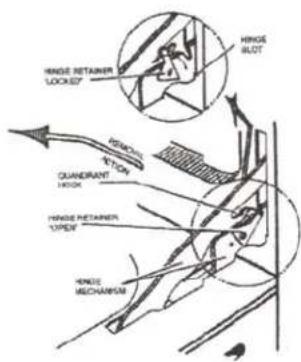
To remove oven door(s):
- Open door fully.
- Rotate the "hinge retainers" into the locked position, as shown over the hook located on the bottom side of each hinge quadrant.
- Lift the door slightly, to clear "hinge slots", and pull straight out to clear hinge mechanism from main front opening.
Lift-Off Oven Door
text_image
HINGE RETAINER LOCKED" HINGE SLOT REMOUL TICKY GUARDRANT HINDA RETAINER OPEN" HINDA MECHANISMSTEP 5
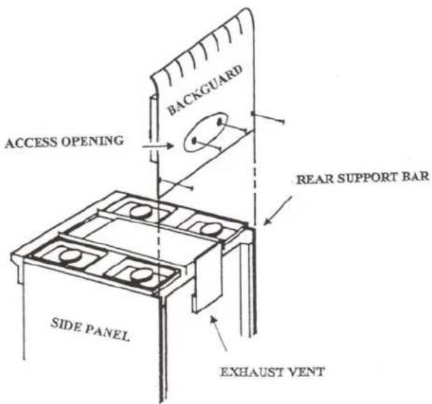
INSTALLING THE BACKGUARD - OPEN BURNER MODELS
NOTE: PLEASE READ ALL INSTRUCTIONS BEFORE STARTING INSTALLATION.
5-1
Remove the burner grates, griddle/grill and housing.
5-2
From the rear of the range, remove two screws from the rear of the side panels, the upper most screw on each side. You will need a ^5/16 " nut-driver or ^5/16 " socket to remove these screws. (Tools with a magnetized tip will be helpful in replacing the backguard screws.)
5-3
From the rear of the range, locate the upper wire cover with tab slots. Remove two ^5/_16 mounting screws. This cover will be reinstalled once the backguard is installed.
5-4
Screws are installed in the backguard, at the Factory for assembly to the backguard support. It is important that you locate and remove these four screws from the backguard before you attempt to install the backguard to the range backguard support.
5-5
Remove the vinyl protective covering from the front of the backguard.
5-6
The front of the backguard should fit in front of the rear support. Slide the backguard over the exhaust vent(s). Align the slots in the front of the backguard with the rear support bar locator studs.
5-7
With the backguard in position, secure the backguard to the rear backguard support using the four ^5/_16 screws removed in step 5-3, re-install the screws in the edge of the side panels.
5-8
Reinstall the upper wire cover that was removed in Step 5-3. Place the cover into position with the lower backguard panel fitting into the tab slots. Reinstall the two ^5/_16 " mounting cover screws.
5-9
Re-install griddle/grill housing and grates.
text_image
ACCESS OPENING BACKGUARD REAR SUPPORT BAR SIDE PANEL EXHAUST VENTBACKGUARD INSTALLATION
STEP 6 (still need pictures)
ELECTRIC CONNECTION
This range must be supplied with 120 volt, 60 Hz. and connected to an individual, properly grounded branch circuit protected by a 10 amp circuit breaker or time delay fuse.
The power cord of this appliance is equipped with a three-prong (grounding) plug which mates with a standard three-prong grounding wall receptacle to minimize the possibility of shock hazard from this appliance.
If the electrical service provided does not meet the above specifications, it is recommended that a licensed electrician install an approved outlet.
DO NOT, UNDER ANY CIRCUMSTANCES, CUT OR REMOVE THE THIRD (GROUND) PRONG FROM THE POWER CORD.
DO NOT USE AN EXTENSION CORD WITH THIS APPLIANCE.
- Locate the electric supply within the area shown or within reach of the cooktop's six foot power cord.
- To avoid tangling cord with items stored in the cabinet, locate the receptacle or rear wall, inside the cabinet.
STEP 7 (still need picture)
CONNECTING THE RANGE TO GAS
Because hard piping restricts When using test pressures greater movement of the range, the use of an than 12 psig to pressure test the gas A.G.A. certified flexible metal appliance connector is recommended disconnect the range and individual unless local codes require a hard-piped connection.
supply system of the
f piping. When using 12 p s
Never use an old connector when installing a new range. If the hard piping method is used, you must carefully align the pipe; the range cannot be moved after the connection is made.
supply system, simply isolate the range from the gas supply system by closing the individual shut-off valve.
To prevent gas leaks, put pipe joint compound on, or wrap pipe thread with Teflon* tape all around male (external) pipe threads.
*Teflon: Registered trademark of Dupont.
7-1. Remove the left most burner pan.
Locate the pressure regulator
Left of the rear burner.
7-2. Install a manual gas shut-off valve in the gas line in an easily accessed location outside the range. Make sure everyone operating the range knows where and how to shut off the gas supply to the range.
7-3. Install male 12 " flare union adapter to the 12 " NPT internal thread at inlet of the regulator. Use a backup wrench on the regulator fitting to avoid damage.
7-4. Install male 12 " or 34 " flare union adapter to the NPT internal thread of the manual shut-off valve, taking care to back-up the shut-off valve to keep it from turning.
7-5. Connect flexible metal appliance connector to the adapter on the range. Position range to permit connection at the shut-off valve or vise versa.
7-6. When all connections have been made, make sure all range controls are in the off position and turn on the main gas supply valve. Use a liquid leak detector at all joints and connections to check for leaks in the system.
STEP 8
LEVEL THE RANGE
- Remove shipping tape from the leveling legs.
- Carefully slide the range into position. Be careful not to damage the floor or entangle power cord and gas flexible tubing.
- To adjust leveling legs, turn counterclockwise to raise the range; clockwise to lower. "Channel-lock" type pliers are recommended. Avoid using a pipe wrench which can scar the legs.
IMPORTANT: The range should always be installed at countertop height or higher. DO NOT INSTALL THE RANGE LOWER THAN ADJACENT COUNTERTOP HEIGHT, DUE TO RISK OF A FIRE HAZARD
STEP 9
REPLACE THE OVEN DOORS
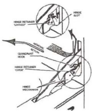
To replace the oven door(s);
- Insert hinges into front frame opening locating "hinge slots" on front frame as shown.
- Rotate "hinge retainers" back into the "open" position.
- Rotate door to make sure it functions properly.
CAUTION:
Take care when replacing the oven doors. If the hinge latch is not securely locked, the hinge may snap back and separate. If the hinge separates, you must apply pressure (possibly with your foot) to press it back together and then engage the hinge tech.
text_image
HINGE RETAINER "LOCKED" HINGE SLOT HINDA ROTION QUANDRANT HOOK HINGE RETAINER "OPEN" HINGE MECHANISMSTEP 10
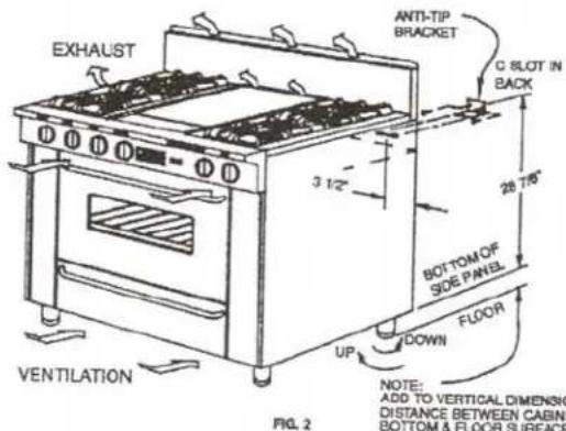
INSTALLATION OF ANTI-TIP BRACKET ON 24", 30" AND 36" MODELS
- Re-check to make sure tape has been removed from leveling legs.
- Place range in proper location with back of range against rear wall.
- Adjust leg levelers to match counter height.
- Remove range and install anti-tip bracket to wall. (See Note: Fig. 2)
- Re-install range. Anti-tip bracket flange must enter slot in back to prevent tipping.
text_image
EXHAUST ANTI-TIP BRACKET C SLOT IN BACK 3 1/2" 28 7/8" BOTTOM OF SIDE PANEL FLOOR UP DOWN VENTILATION NOTE: ADD TO VERTICAL DIMENSION DISTANCE BETWEEN CABINET BOTTOM & FLOOR SURFACE FIG. 2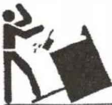
natural_image
Silhouette of a person holding a large object, possibly a lamp or sign (no text or symbols visible)
WARNING: To reduce the risk of tipping the appliance by abnormal usage or improper door loading, the appliance must be secured by properly installing the anti-tip device packed with the appliance. To check the installation remove the right top burner grates and pan and verify that the anti-tip device is engaged in the backguard slot.
STEP 11
ASSEMBLE SURFACE BURNER COMPONENTS
- Remove shipping screw from each surface burner.
- Remove each surface burner.
- Place drip pan in position under each burner. Locate "dimples".
• Re-install surface burners.
• Install burner pans.
• Install burner grates.
STEP 12 (still need picture)
- Check for proper ignition:
- Push in one control knob and turn 180^ counter clockwise to LITE position.
- The igniter will spark and the burner will light; the igniter will continue sparking until the knob is turned from the light position.
- First test may require some time, while air is flushed out of the gas line.
- Turn knob to OFF.
- Repeat the procedure for each burner.
- Burner flames should be blue and stable with no yellow or yellow tips, excessive noise or lifting of the flame from the burner. If any of these conditions exist, check that the burner ports are not blocked, and check the air mixture. If one of these conditions continues, call for service.
STEP 13
OVEN OPERATION
GAS OVEN
- Turn oven thermostat knob counter clockwise to 350^ .
- The oven burner should light within 60 seconds.
GRIDDLE OPERATION
- Turn griddle thermostat knob counter clockwise to 350^ .
- The griddle burner should light within 60 seconds.
STEP 14
- Turn gas supply "on".
- Turn electric supply "on".
STEP 15
CHECKLIST FOR OPEN BURNER INSTALLATION
□ MAKE SURE ALL CONTROLS ARE IN THE "OFF" POSITION.
□ Gas supply is “on”
□ Electric power is “on”
☐ Burner drip pans in position under burners
□ Surface burners in position
□ Burner pans in positions
□ Burner grates in position
☐ Oven and broiler racks installed
□ Surface burner ignition test
□ Griddle/Grill burner ignition test
□ Griddle/Grill assembly in position
□ Gas oven ignition test
MAKE SURE ALL CONTROLS ARE LEFT IN THE "OFF" POSITION
Date Installed & Inspected ____
Authorized Installer's Signature ____
Please Print Name ____
NOTE: Please leave this checklist, Use & Care manual and product registration card with the Homeowner.