
LMT - Remote control toy Losi - Free user manual and instructions
Find the device manual for free LMT Losi in PDF.


User questions about LMT Losi
0 question about this device. Answer the ones you know or ask your own.
Ask a new question about this device
Download the instructions for your Remote control toy in PDF format for free! Find your manual LMT - Losi and take your electronic device back in hand. On this page are published all the documents necessary for the use of your device. LMT by Losi.
USER MANUAL LMT Losi
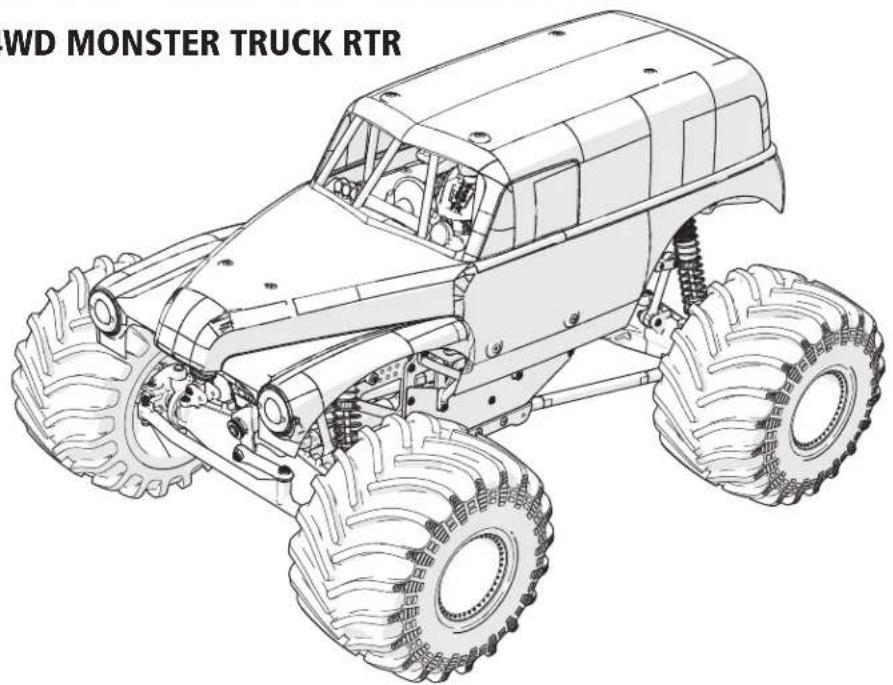
LMT SOLID AXLE 4WD MONSTER TRUCK RTR
GRAVE DIGGER
LOS04021T1
text_image
WD MONSTER TRUCK RTRSON UVA DIGGER
LOS04021T2
natural_image
Line drawing of a two-wheeled toy car with visible tires and suspension components (no text or symbols)HORIZON®
H O B B Y
INSTRUCTION MANUAL
BEDIENUNGSANLEITUNG
MANUEL D'UTILISATION
Before operating this vehicle, please read all printed materials thoroughly.
Horizon Hobby is not responsible for inadvertent errors in this manual.
NOTICE
All instructions, warranties and other collateral documents are subject to change at the sole discretion of Horizon Hobby, LLC. For up-to-date product literature, visit www.horizonhobby.com or www.towerhobbies.com and click on the support or resources tab for this product.
MEANING OF SPECIAL LANGUAGE
The following terms are used throughout the product literature to indicate various levels of potential harm when operating this product:
WARNING: Procedures, which if not properly followed, create the probability of property damage, collateral damage, and serious injury OR create a high probability of superficial injury.
CAUTION: Procedures, which if not properly followed, create the probability of physical property damage AND a possibility of serious injury.
NOTICE: Procedures, which if not properly followed, create a possibility of physical property damage AND a little or no possibility of injury.

WARNING: Read the ENTIRE instruction manual to become familiar with the features of the product before operating. Failure to operate the product correctly can result in damage to the product, personal property and cause serious injury.
This is a sophisticated hobby product. It must be operated with caution and common sense and requires some basic mechanical ability. Failure to operate this Product in a safe and responsible manner could result in injury or damage to the product or other property. This product is not intended for use by children without direct adult supervision. Do not use with incompatible components or alter this product in any way outside of the instructions provided by Horizon Hobby, LLC. This manual contains instructions for safety, operation and maintenance. It is essential to read and follow all the instructions and warnings in the manual, prior to assembly, setup or use, in order to operate correctly and avoid damage or serious injury.

WARNING AGAINST COUNTERFEIT PRODUCTS Always purchase from a Horizon Hobby, LLC authorized dealer to ensure authentic high-quality Spektrum product.
Horizon Hobby, LLC disclaims all support and warranty with regards, but not limited to, compatibility and performance of counterfeit products or products claiming compatibility with
DSM or Spektrum technology.
Age Recommendation: Not for children under 14 years. This is not a toy.
SAFETY PRECAUTIONS AND WARNINGS
As the user of this product, you are solely responsible for operating in a manner that does not endanger yourself and others or result in damage to the product or property of others.
This model is controlled by a radio signal subject to interference from many sources outside your control. This interference can cause momentary loss of control, so it is advisable to always keep a safe distance in all directions around your model as this margin will help avoid collisions or injury.
- Never operate your model with low transmitter batteries.
• Always operate your model in open spaces away from full-size vehicles, traffic and people. - Never operate the model in the street or in populated areas for any reason.
- Carefully follow the directions and warnings for this and any optional support equipment (chargers, rechargeable battery packs, etc.) you use.
-
Keep all chemicals, small parts and anything electrical out of the reach of children.
-
Never lick or place any portion of the model in your mouth as it could cause serious injury or even death.
• Exercise caution when using tools and sharp instruments.
• Take care during maintenance as some parts may have sharp edges. - Immediately after using your model, do NOT touch equipment such as the motor, electronic speed control and battery, because they generate high temperatures. You may burn yourself seriously touching them.
- Do not put fingers or any objects inside rotating and moving parts, as this may cause damage or serious injury.
- Always turn on your transmitter before you turn on the receiver in the car. Always turn off the receiver before turning your transmitter off.
- Keep the wheels of the model off the ground when checking the operation of the radio equipment.
TABLE OF CONTENTS
BOX CONTENTS....3
INCLUDED COMPONENTS....3
REQUIRED, NOT INCLUDED ....3
RECOMMENDED SKU....3
SPEKTRUM SMART TECHNOLOGY....3
WATER-RESISTANT VEHICLE WITH WATERPROOF ELECTRONICS .... 3
GENERAL PRECAUTIONS....3
WET CONDITIONS MAINTENANCE....3
QUICK START....3
ChARGING THE BATTERY....3
INSTALLING THE BATTERY ....4
TRANSMITTER FUNCTIONS ....4
TRANSMITTER BATTERY INSTALLATION ....5
SR315 RECEIVER....5
RECEIVER ANTENNA 5
POWERING ON THE VEHICLE....5
BINDING THE RECEIVER....5
DRIVING PRECAUTIONS ....5
BEFORE RUNNING YOUR VEHICLE....5
CONTROL DIRECTION TEST 6
STEERING 6
ADJUSTING STEERING AND THROTTLE TRIMS....6
STEERING TRIM 6
SPEKTRUM™ FIRMA™ SMART 130A BRUSHLESS ESC (SPMXSE1130)......6
SPECIFICATIONS....6
ESC LED STATUS....6
AUDIBLE WARNING TONES 6
ESC CALIBRATION PROCEDURE 6
THE MOTOR WILL OPERATE NORMALLY AFTER CALIBRATION IS COMPLETED. .....6
THROTTLE 6
THROTTLE TRIM 6
FULL THROTTLE 6
ESC FUNCTIONS AND MODES....7
PROGRAMMING TABLE 7
ESC PROGRAMMING PROCEDURE....7
DESCRIPTIONS 7
SPEKTRUM™ FIRMA™ 3150KV BRUSHLESS MOTOR ....8
PRECAUTIONS 8
GEARING 8
TELEMETRY SETTINGS....8
LIST OF FLUIDS 8
REQUIRED TOOLS 8
RUN TIME....8
TO IMPROVE RUN TIMES....8
VEHICLE MAINTENANCE....9
SHOCK DISASSEMBLY/CLEANING 9
REFILLING/BLEEDING SHOCKS....9
DIFFERENTIALS 10
FRONT DIFFERENTIAL 10
REAR DIFFERENTIAL ....11
CHASSIS 12
CENTER DIFFERENTIAL....13
REPLACEMENT PARTS 14
RECOMMENDED PARTS....15
OPTIONAL PARTS 16
TROUBLESHOOTING GUIDE....17
LIMITED WARRANTY 17
WARRANTY AND SERVICE CONTACT INFORMATION....18
FCC INFORMATION .... 18
IC INFORMATION ....18
COMPLIANCE INFORMATION FOR THE EUROPEAN UNION....18
BOX CONTENTS INCLUDED COMPONENTS REQUIRED, NOT INCLUDED RECOMMENDED SKU
| Losi® LMT Solid Axle Monster Truck RTR (LOS04021T1 LOS04021T2) | SpektrumTM DX3TM SMART Transmitter (SPMR2340) | 50C or Higher 2S – 3S Hardcase LiPo with IC5 | 2S – 3S Smart Hardcase LiPo with IC5 SPMX50002S50H5 – SPMX50003S50H5 |
| Spektrum SR315 3 Channel Telemetry Surface Receiver (SPMSR315) | |||
| Spektrum S614S Waterproof Servo (SPMS614S) | |||
| Spektrum FirmaTM SMART 130A Brushless ESC (SPMXSE1130) | 2S – 3S LiPo Charger | Spektrum S2100 Dual Port Smart Charger and IC5 adaptor SPMXC1010 and SPMXCA508 | |
| Spektrum Firma 3150 Kv Brushless Motor (SPMXSM1000) | |||
| 4 AA batteries (for transmitter) | |||
| Gravedigger Body (included with LOS04021T1) Son Uva Digger Body (included with LOS04021T2) |
SPEKTRUM SMART TECHNOLOGY
The LMT Solid Axle Monster Truck includes Spektrum Smart Technology in the ESC and receiver, which can provide you with telemetry information like battery voltage from your vehicle. The included DX3 Smart transmitter features an LED display to show the battery level of your vehicle during operation.
For additional Smart functionality, consider upgrading to a more advanced Smart Technology compatible Spektrum transmitter like the DX5C (SPMR5100- transmitter only), or DX5 Pro (SPMR5010- transmitter only). Use Spektrum Smart batteries to power your LMT Solid Axle Monster Truck to take full advantage of Smart Technology, which can communicate detailed battery data through the system as well.
Visit www.SpektrumRC.com for more information.
WATER-RESISTANT VEHICLE WITH WATERPROOF ELECTRONICS
Your new Horizon Hobby vehicle has been designed and built with a combination of waterproof and water-resistant components to allow you to operate the product in many "wet conditions," including puddles, creeks, wet grass, snow and even rain.
While the entire vehicle is highly water-resistant, it is not completely waterproof and your vehicle should NOT be treated like a submarine. The various electronic components used in the vehicle, such as the Electronic Speed Control (ESC), servo(s) and receiver are waterproof, however, most of the mechanical components are water-resistant and should not be submerged.
Metal parts, including the bearings, hinge pins, screws and nuts, as well as the contacts in the electrical cables, will be susceptible to corrosion if additional maintenance is not performed after running in wet conditions. To maximize the long-term performance of your vehicle and to keep the warranty intact, the procedures described in the "Wet Conditions Maintenance" section below must be performed regularly if you choose to run in wet conditions. If you are not willing to perform the additional care and maintenance required, then you should not operate the vehicle in those conditions.

CAUTION: Failure to exercise caution while using this product and complying with the following precautions could result in product malfunction and/or void the warranty.
GENERAL PRECAUTIONS
- Read through the wet conditions maintenance procedures and make sure that you have all the tools you will need to properly maintain your vehicle.
- Not all batteries can be used in wet conditions. Consult the battery manufacturer before use. Caution should be taken when using Li-Po batteries in wet conditions.
- Most transmitters are not water-resistant. Consult your transmitter's manual or the manufacturer before operation.
- Never operate your transmitter or vehicle where lightning may be present.
- Do not operate your vehicle where it could come in contact with salt water (ocean water or water on salt-covered roads), contaminated or polluted water. Salt water is very conductive and highly corrosive, so use caution.
- Even minimal water contact can reduce the life of your motor if it has not been certified as water-resistant or waterproof. If the motor becomes excessively wet, apply very light throttle until the water is mostly removed from the motor. Running a wet motor at high speeds may rapidly damage the motor.
- Driving in wet conditions can reduce the life of the motor. The additional resistance of operating in water causes excess strain. Alter the gear ratio by using a smaller pinion or larger spur gear. This will increase torque (and motor life) when running in mud, deeper puddles, or any wet conditions that will increase the load on the motor for an extended period of time.
WET CONDITIONS MAINTENANCE
- Drain any water that has collected in the tires by spinning them at high speed. With the body removed, place the vehicle upside down and pull full throttle for a few short bursts until the water has been removed.

CAUTION: Always keep hands, fingers, tools and any loose or hanging objects away from rotating parts when performing the above drying technique.
- Remove the battery pack(s) and dry the contacts. If you have an air compressor or a can of compressed air, blow out any water that may be inside the recessed connector housing.
- Remove the tires/wheels from the vehicle and gently rinse the mud and dirt off with a garden hose. Avoid rinsing the bearings and transmission.
NOTICE: Never use a pressure washer to clean your vehicle.
- Use an air compressor or a can of compressed air to dry the vehicle and help remove any water that may have gotten into small crevices or corners.
- Spray the bearings, drive train, fasteners and other metal parts with a water-displacing light oil. Do not spray the motor.
- Let the vehicle air dry before you store it. Water (and oil) may continue to drip for a few hours.
- Increase the frequency of disassembly, inspection and lubrication of the following: - Front and rear axle hub assembly bearings.
- All transmission cases, gears and differentials.
- Motor—clean with an aerosol motor cleaner and re-oil the bushings with lightweight motor oil.
QUICK START
Please read the entire manual to gain a full understanding of the LMT Solid Axle Monster Truck RTR vehicle, fine-tuning the setup and performing maintenance.
- Read the safety precautions found in this manual.
- Charge a battery for the vehicle. Refer to the included charging warnings and instructions for battery charging information.
- Install the AA batteries in the transmitter. Only use alkaline or rechargeable batteries.
-
Install the fully charged battery in the vehicle.
-
Power ON the transmitter and then the vehicle. Wait 5 seconds for the ESC to initialize. Always power the transmitter ON before the vehicle and power it OFF after the vehicle has been powered OFF.
- Check the steering and throttle control directions. Verify that the servos are moving in the correct direction.
- Drive your vehicle.
- Perform any necessary maintenance.
CHARGING THE BATTERY
The LMT Solid Axle Monster Truck requires a requires a 2S or 3S hardcase LiPo Battery with IC5 plug (not included). The included Spektrum™ Firma™ SMART 130A Brushless ESC (SPMXSE1130) has an IC5™ battery connector. We recommend a Spektrum 5000mAh 2S 7.4V 50C SMART LiPo Battery (SPMX50002S50H5), or a Spektrum 5000mAh 3S 11.1V 50C SMART LiPo Battery (SPMX50003S50H5).
We recommend charging Spektrum SMART Batteries paired with Spektrum Smart Chargers because Smart chargers will automatically configure the charge settings for Smart batteries. We We recommend the Spektrum S1100 SMART AC Charger, 1x100w (SPMXC1080) with IC3 to IC5 charge adapter (SPMXCA507).
Refer to your battery and charger manuals for usage, safety, and charging information.
INSTALLING THE BATTERY
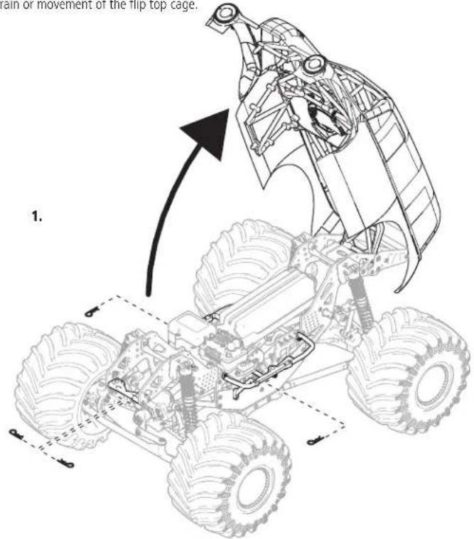
- There are four body clips securing the body, hidden under the roll cage. Remove the two body clips from the front and the body clip from each side of the vehicle as shown.
- Lift the body to access the chassis.
- Install the fully charged batteries in the vehicle.
- Secure the battery with the rubber elastomer strap.
- Connect the battery to the ESC.
IMPORTANT: Secure the battery, motor and ESC wires so they do not interfere with the drivetrain or movement of the flip top cage.
text_image
rain or movement of the flip top cage. 1.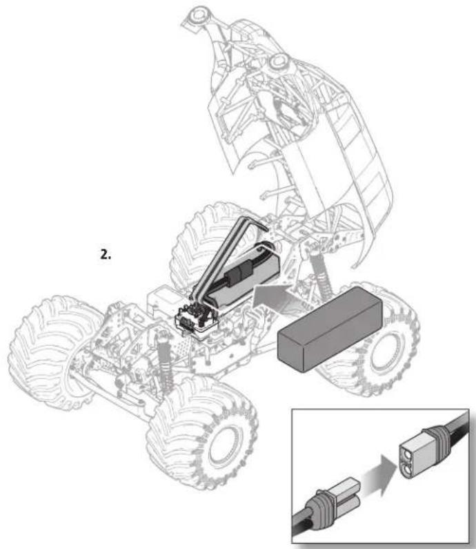
natural_image
Technical illustration of a vehicle chassis with an attached battery and connector, showing assembly details (no text or symbols)TRANSMITTER FUNCTIONS
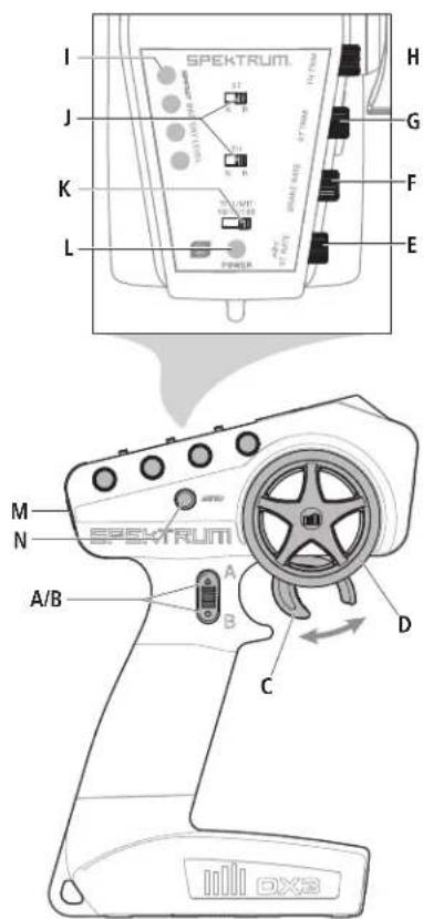
A/B. Channel 3 Button
C. Throttle/Brake
D. Steering Wheel
E. Steering Rate
Adjusts the end point of the steering
F. Brake Rate
Adjusts the braking end point.
G. Steering Trim
Adjusts the steering center point. Normally, the steering trim is adjusted until the vehicle tracks straight.
H. Throttle Trim
Adjusts the throttle neutral point
I. SMART Battery Level Indicator
J. Servo Reversing
To reverse the Throttle (TH) or Steering (ST) channel, switch the position of the correlating switch—“N” is for normal, “R” is for reverse.
K. Throttle Limit
Limits throttle output to 50/75/100%
Select 50% or 75% for less experienced drivers or when you are driving the vehicle in a small area.
L. Power LED
• Solid red lights: Indicates radio connectivity and adequate battery power
- Flashing red lights: Indicates the battery voltage is critically low. Replace batteries
M. Power Button
N. Bind Button
text_image
SPEKTRUM I J K L H G F E M N A/B A B C D SPEKTRUMTRANSMITTER BATTERY INSTALLATION
This transmitter requires 4 AA batteries
- Remove the battery cover from the transmitter.
- Install the batteries as shown.
- Install the battery cover.
CAUTION: Never remove the transmitter batteries while the model is powered ON. Loss of model control, damage, or injury may occur.
CAUTION: If using rechargeable batteries, charge only rechargeable batteries. Charging non-rechargeable batteries may cause the batteries to burst, resulting in injury to persons and/or damage to property.
CAUTION: Risk of explosion if battery is replaced by an incorrect type. Dispose of used batteries according to national regulations.
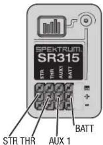
SR315 RECEIVER BINDING THE RECEIVER
Specifications
Type: Dual Protocol 3 Ch Receiver (SLT/DSMR)
Dimensions (LxWxH): 32.5 x 21.5 x 12.4mm
Antenna Length: 90mm
Channels: 3
Weight:6g
Band: 2.4GHz
Voltage Range: 3.5–9.6V
Bind Type: Bind Button
Failsafe: Hold the steering wheel and throttle trigger in the desired failsafe positions during binding
RECEIVER ANTENNA
The SR315 receivers feature a coaxial antenna design for easy installation in almost any model. Think of the last 1 inch (32mm) on the tip of the antenna as the active portion of the antenna, the coaxial portion leading up to it is just an extension. Install the antenna so the active portion is positioned as high as possible in the vehicle, and not "in the shadow" of any carbon fiber or metal. The case of the receiver can accept an antenna tube directly, making optimal antenna placement easy (antenna tube not included).
WARNING: Do not kink, cut or damage the antenna wire. The antenna is made of a coaxial wire; if the outer sheath becomes damaged, the receiver will not work properly. If the antenna is damaged in any way, replace the antenna before attempting to use the receiver.
text_image
SPEKTRUITI SR315 STR THR AUX BATT STR THR AUX 1 BATTPOWERING ON THE VEHICLE
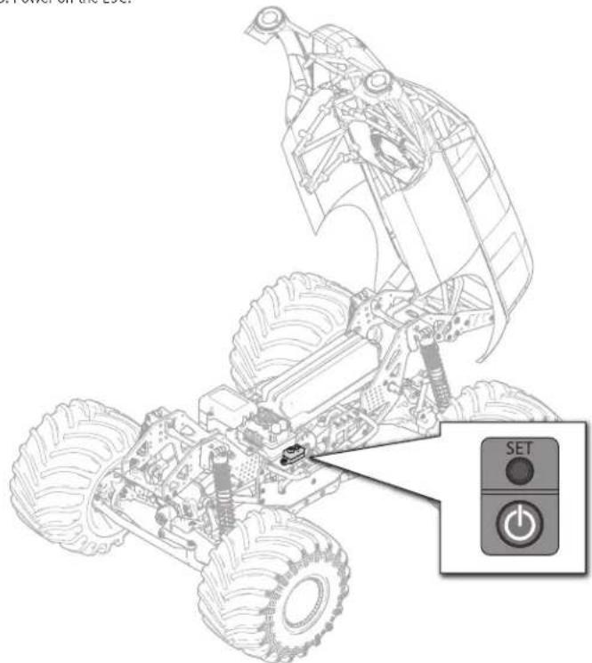
- Center the ST TRIM and TH TRIM dials on the transmitter and turn it on.
- Install a fully charged battery pack per the Installing the Battery section.
- Power on the ESC.
natural_image
Line drawing of a toy vehicle chassis with a SET button and power button, no text or symbols present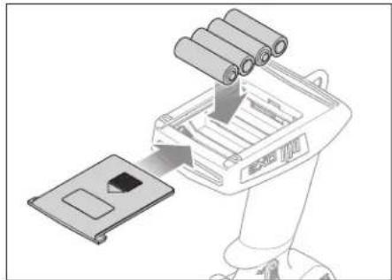
natural_image
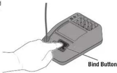
Illustration of a robotic device with a tray and battery stack being inserted (no text or symbols)Binding is the process of programming the receiver to recognize the GUID (Globally Unique Identifier) code of a single specific transmitter. In the event of a loss of signal the receiver will default the servo outputs to the failsafe position. The failsafe positions are set during binding; Leave the throttle and steering at the neutral positions during binding.
- Press and hold the bind button, and Power ON the receiver; the orange LED will begin to flash.
- Set the trims and control positions at the desired failsafe settings, press and hold the bind button, and power ON the DX3 Smart transmitter.
- When the orange LED on the DX3 Smart transmitter remains lit, it is connected to SR315 receiver.
text_image
Bind ButtonYou must rebind when:
- Different failsafe positions are desired e.g., when throttle or steering reversing has been changed.
- Binding the receiver to a different transmitter.
DRIVING PRECAUTIONS
- Maintain sight of the vehicle at all times.
- Routinely inspect the vehicle for loose wheel hardware.
- Routinely inspect the steering assembly for any loose hardware. Driving the vehicle off-road can cause fasteners to loosen over time.
- Do not drive the vehicle in tall grass. Doing so can damage the vehicle or electronics.
CAUTION: Do not discharge a Li-Po battery below 3V per cell. Batteries discharged to a voltage lower than the lowest approved voltage may become damaged, resulting in loss of performance and potential fire when batteries are charged.
- Do not apply forward or reverse throttle if the vehicle is stuck.
Applying throttle in this instance can damage the motor or ESC.
• After driving the vehicle, allow the electronics to cool before driving the vehicle again.
IMPORTANT: Keep wires away from all moving parts.
BEFORE RUNNING YOUR VEHICLE
- Check for free suspension movement. All suspension arms and steering components should move freely. Any binds will cause the vehicle to handle poorly.
TIP: To increase the ride height and ground clearance of your vehicle, screw down the shock collars to compress the springs. - Charge a battery pack. Always charge the battery pack as per the battery and/or charger manufacturers' instructions.
- Set the transmitter steering trim. Follow the instructions to set the steering trim/subtrim so that the vehicle drives straight with no input to the steering.
- Perform a Control Direction Test.
CONTROL DIRECTION TEST

natural_image
Top-down schematic of a vehicle's rear suspension system showing airflow patterns (no text or labels)STEERING
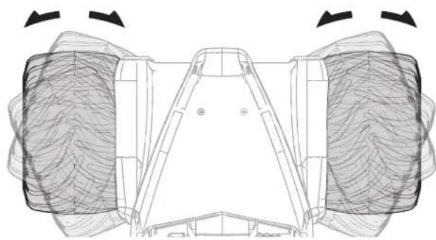
- Move the steering wheel Left and Right and observe the direction the front wheels move.
- If the wheels move the opposite direction, reverse the STR channel.
Place the vehicle on a stand supporting the chassis so the wheels are off the ground during the steering and throttle tests. Verify all the controls work correctly before turning it on with the wheels on the ground.

text_image
SPEKTRUM A B THROTTLE 1. Pull the Throttle trigger to move the vehicle forward. 2. If the vehicle moves backward, reverse the THR channel.ADJUSTING STEERING AND THROTTLE TRIMS
natural_image
Top-down technical diagram of a vehicle chassis with visible structural elements and airflow patterns (no text or labels)STEERING TRIM
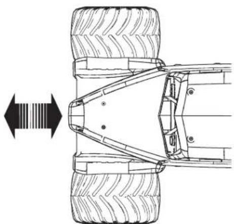
The vehicle should maintain a straight line without any steering wheel input. If not, adjust the STR Trim knob so the wheels maintain a straight line without having to turn the steering wheel.
natural_image
Technical line drawing of a vehicle chassis with tire tracks and structural components (no text or symbols)THROTTLE TRIM
Trim the vehicle with the wheels off the ground. If the wheels rotate after the vehicle is powered ON, adjust the TH Trim knob until they stop.
SPEKTRUM™ FIRMA™ SMART 130A BRUSHLESS ESC (SPMXSE1130)
SPECIFICATIONS
| Type Sensorless, SMART | Throttle Compatible |
| Output 130A/760A | |
| Function Forward/Brake | Forward/Brake Reverse |
| Input Voltage 7.4V–14.8V | |
| BEC Output 6V/4A | |
| Dimensions (LxWxH) | 57.5mm x 46mm x 38mm |
| Weight 154 g |
ESC LED STATUS
- No ESC LEDs will glow when there is no throttle input from the transmitter.
- The red ESC LED glows when there is any throttle input from the transmitter.
AUDIBLE WARNING TONES
- Input Voltage: The ESC checks the input voltage when it is powered ON. If a voltage problem is detected, the ESC continuously sounds 2 beeps with a 1 second pause (xx-xx-xx). Power OFF the ESC and ensure the connections are secure and that the battery power is not too low for safe operation.
- Radio Connection: The ESC checks radio signal input when it is powered ON. If a problem is detected, the ESC continuously sounds 1 beep with a 2 second pause (x--x--x). Power OFF the ESC and ensure the radio system is operating correctly.
NOTICE: Always disconnect the battery from the ESC after operating your vehicle. The ESC's switch only controls power to the receiver and servos. The ESC will continue to draw current when connected to the battery, resulting in possible damage to the battery through over discharge.
ESC CALIBRATION PROCEDURE
Complete the transmitter/receiver binding procedure prior to calibrating the ESC.
- Set the transmitter throttle channel to 100% travel and center the throttle trim.
- Connect a battery to the ESC battery lead.
- Power on the transmitter.
- Press and hold the SET button while turning on the ESC. Release the SET button when the red LED begins to flash, indicating the ESC is in calibration mode. The ESC will enter programming mode if the button is held for more than three seconds.
TIP: The red LED should be flashing when the ESC enters calibration mode. If the green LED is flashing the ESC has entered programming mode. Power off the ESC and repeat step 4, releasing the SET button when the red LED begins to flash.
- With the transmitter throttle trigger at the neutral position, press and release the ESC SET button. The red LED will stop flashing, the green LED will flash one time and the motor will make a tone to indicate the neutral position has been accepted.
- While holding the throttle trigger at the full throttle position, press and release the ESC SET button. The green LED will flash twice and the motor will make two tones to indicate the full throttle position has been accepted.
- While holding the throttle trigger at the full brake position, press and release the SET button. The green LED will flash three times and the motor will make three tones to indicate the full brake position has been accepted.
The motor will operate normally after calibration is completed.
ESC FUNCTIONS AND MODES
The ESC includes programming options so you can adjust the way your vehicle performs. Refer to the included programming table to adjust the ESC for your driving conditions.
PROGRAMMING TABLE
Default Settings
| PROGRAMMING ITEMS 1 2 3 4 5 | PROGRAMMING VALUE | ||||||||
| 6 7 8 9 | |||||||||
| 1. Running Mode | Forward w/ brake | Forward/Reverse w/ brake | Forward/Reverse | ||||||
| 2. Drag Brake Force | 0% | 5% | 10% | 20% | 40% | 60% | 80% | 100% | |
| 3. Low Voltage Cutoff | non-protection | 2.6V/Cell | 2.8V/Cell | 3.0V/Cell | 3.2V/Cell | 3.4V/Cell | |||
| 4. Start Mode | Level 1 | Level 2 | Level 3 | Level 4 | Level 5 | Level 6 | Level 7 | Level 8 | Level 9 |
| 5. Max Brake Force | 25% | 50% | 75% | 100% | disable | ||||
| 6. Max Reverse Force | 25% | 50% | 75% | 100% | |||||
| 7. Initial Brake Force | = Drag Brake | 0% | 20% | 40% | |||||
| 8. Neutral Range | 6% (Narrow) | 9% (Normal) | 12% (Wide) | ||||||
| 9. Timing | 0.00^ | 3.75^ | 7.50^ | 11.25^ | 15.00^ | 18.75^ | 22.50^ | 26.25^ | |
| 10. Motor Rotation | Counterclockwise | Clockwise | |||||||
| 11. Li-Po Cells | Auto Calculate | 2 Cells | 3 Cells | 4 Cells | 5 Cells | 6 Cells | |||
ESC PROGRAMMING PROCEDURE
Programming is accomplished using the SET button on the ON/OFF switch*.
- Connect a fully charged battery to the ESC.
- Power on the transmitter.
- Power on the ESC.
- Hold the SET button until the green LED flashes. Release the set button to enter programming mode.
TIP: To reset all programming items to the default values, press and hold the set button for five seconds
- Press and release the set button as needed to cycle through the programming items. The number of times the green LED flashes equals the programming item number given in the programming table.
- When at the desired programming item, press and hold the set button until the red LED flashes to select the item.
- Press and release the SET button to cycle through the values available for the programming item based on the number of times the LED flashes. Refer to the programming table.
- Save the setting by pressing and holding the SET button for 3 seconds.
- Power off the ESC to exit programming mode or to change other programming items.
* Other programming options include the Spektrum SMART Firma ESC Programming Box (SPMXCA200) and the SmartLink USB updating and programmer application. See SpektrumRC.com for more details about Spektrum SMART Firma ESCs.
DESCRIPTIONS
1. Running Mode
- Forward Only with Brake Intended for competition use, this mode allows only forward and brake controls.
- Forward/Reverse with Brake
This mode is the basic all-around mode, allowing forward, reverse and brake controls.
To engage reverse while moving forward, apply the brake until the vehicle has come to a complete stop, release brake, then apply the brake again. While braking or in reverse, engaging the throttle will result in the vehicle immediately accelerating forward.
2. Drag Brake Force
Adjusts the amount of brake automatically applied when the throttle is returned to the neutral position. This simulates the engine braking effect of a full-scale vehicle, allowing improved turn-in and your vehicle's general response to controls.
3. Low Voltage Cutoff
This function helps to prevent battery over-discharge. The ESC continuously monitors the battery's voltage. If the voltage falls below the voltage threshold for 2 seconds, the output power shuts off and the red LED flashes twice repeatedly.
The cutoff threshold calculation is based on individual Li-Po cell voltage. For Ni-MH batteries, if the voltage battery pack is higher than 9.0V, it will be treated as a 3-cell Li-Po battery pack; if it is lower than 9.0V, it will be treated as a 2-cell Li-Po battery pack. Example: for a 8.0V Ni-MH battery pack used with a 2.6V/cell threshold, it will be treated as a 2-cell Li-Po battery pack and the low-voltage cut-off threshold will be 5.2V (2.6x2=5.2).
4. Start Mode (Punch)
Sets the initial throttle punch when the car accelerates. Level 1 gives a very soft initial acceleration and level 4 gives a stronger initial acceleration.
5. Max Brake Force
Adjusts the maximum braking force. A higher value provides stronger braking, but can also cause the wheels to lock, resulting in loss of control of the car.
6. Max Reverse Force
This parameter adjusts the maximum power when travelling in reverse.
7. Initial Brake Force (minimum brake)
Adjusts the minimum amount of braking power when the brakes engage. The default value is equal to the drag brake value. A high value can lock the wheels when the brake is used.
8. Neutral Range
Adjusts the throttle sensitivity around the neutral point. A higher value results in the throttle having to be moved more for the vehicle to move forward, backward or brake.
9. Timing
Adjusts the motor drive current timing. More timing gives more performance, but can lower efficiency and cause damage to the motor and/or ESC by overload or overheating.
NOTICE: Always ensure the motor timing is set correctly. Failure to set the motor timing correctly can result in damage to the motor and ESC. Refer to the manufacturer instructions for recommended timing settings.
10. Motor Rotation
Allows you to make this change in the ESC so no wires need to be changed between the ESC and the motor.
11. Li-Po Cells
Allows the ESC to automatically detect or manually set the number of cells in your Li-Po battery back.
SPEKTRUM™ FIRMA™ 3150KV BRUSHLESS MOTOR
PRECAUTIONS
- Never touch moving parts.
- Never disassemble while the batteries are installed.
• Always let parts cool before touching. - Rated for up to 3S batteries, not suitable for 4S batteries.
GEARING
Installing a pinion gear with fewer teeth will provide greater torque but will reduce top speed. Likewise, a pinion gear with more teeth will reduce torque and increase top speed. Care should be taken when installing larger pinion gears as this can "overgear" the vehicle, resulting in overheating of the motor and ESC. When testing different gearing options, pay close attention to the temperature of the motor and speed control to ensure you are operating within the temperature range of the components. The motor or ESC should never be so hot that it cannot be touched. If temperatures are too hot, a different gearing combination with a lower pinion gear and/or higher spur gear is suggested.
- Remove the screw holding the gear cover in place.
- From the slot in the top of the gear box cover, loosen the pinion gear set screw and remove the pinion gear.
- Remove the motor mounting screws to remove the motor, or adjust the motor to the location for the corresponding pinion gear.
- Install the new pinion gear on your motor. Place the pinion gear on the end of the motor shaft so that it lines up flush with the spur gear and the set screw is located over the flat on the shaft.
- Tighten the pinion gear on the motor shaft and reinstall the upper gear cover.
RUN TIME
The largest factor in run time is the capacity of the battery pack. A larger mAh rating increases the amount of run time experienced.
The condition of a battery pack is also an important factor in both run time and speed. The battery connectors may become hot during driving. Batteries will lose performance and capacity over time.
Driving the vehicle from a stop to full speed repeatedly will damage the batteries and electronics over time. Sudden acceleration will also lead to shorter run times.
TO IMPROVE RUN TIMES
- Keep your vehicle clean and well maintained.
- Allow more airflow to the ESC and motor.
- Change the gearing to a lower ratio. A lower ratio decreases the operating temperature of the electronics. Use a smaller pinion gear or larger spur gear to lower the gear ratio.
- Use a battery pack with a higher mAh rating.
- Use the optimum charger to charge battery packs (Visit your local hobby dealer for more information).
| LIST OF FLUIDS | |
| Diff Fluids | |
| Front and Rear 100k | |
| Center 500k | |
| Shock Oil | |
| Front and Rear 25wt | |
| REQUIRED TOOLS |
| 1.5mm Hex Driver |
| 2.0mm Hex Driver |
| 2.5mm Hex Driver |
| 5.5mm Nut Driver |
| 8.0mm Nut Driver |
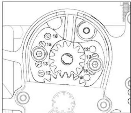
NOTICE: It is important you select the correct motor mounting holes for your pinion gear selection. The gear mesh is pre-set with each pair of motor mounting holes corresponding to the pinion gear. Selecting the wrong mounting holes is likely to cause damage to the spur gear on your LMT when you attempt to apply power.
The following drawing shows the correct motor mounting holes to use for the included 14 tooth pinion gear.
text_image
Technical diagram of a mechanical gear assembly with numbered componentsTELEMETRY SETTINGS
If using the Spektrum Dashboard app or the optional speedometer module on your transmitter, set the motor pole count to 4 and the rollout distance to 1.10" (27.9mm).
| STOCK PINION |
| 14T MOD1, 5mm shaft |
The following items require semi-frequent maintenance. Always clean screw threads and apply removable thread locking compound when threading machine screws into metal parts.
SHOCK DISASSEMBLY/CLEANING
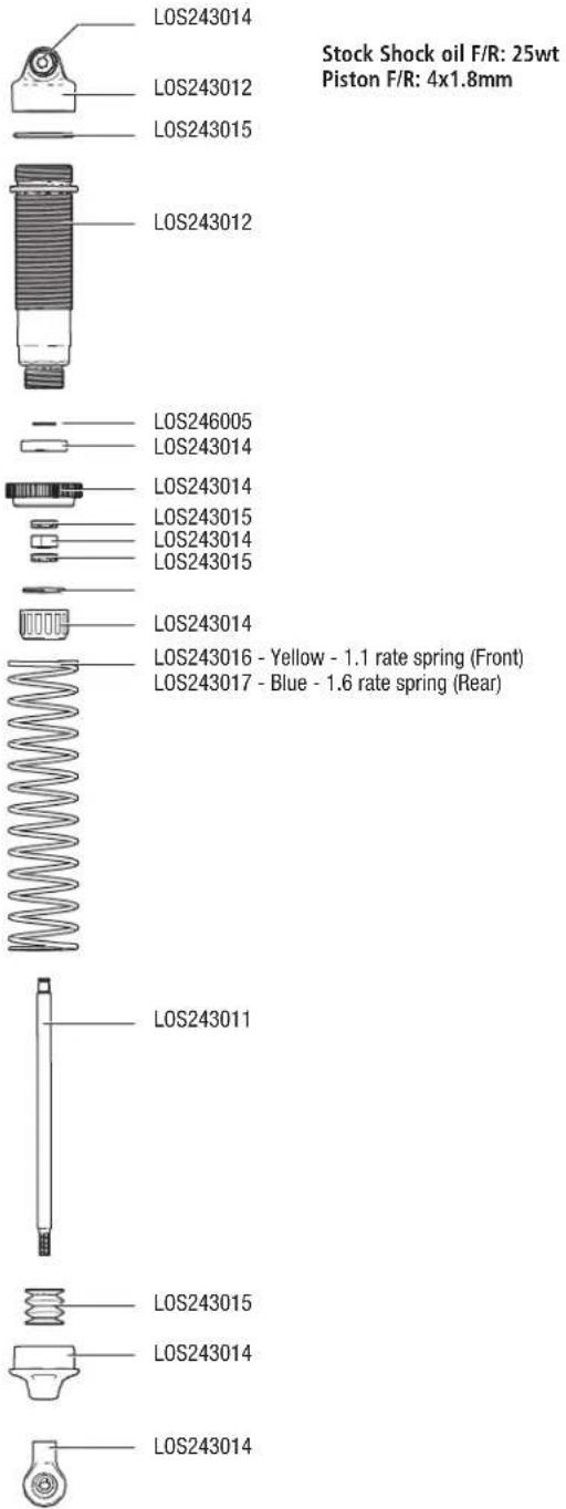
Remove the shocks and service as needed. Replace worn parts.
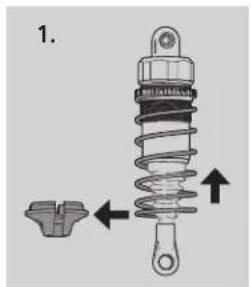
- Pull the spring up and away from the lower cup. Slide the lower spring cup up and off of the shaft. Clean with a soft brush. Remove the shock boot.
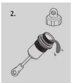
- Use the wheel wrench to hold the shock body and remove the top cap. Empty the fluid from out of the shock.
- Hold the shaft with a multi-wrench and remove the shock end. Push the shaft into the shock body and remove through the top. Remove the lower shock cap, dust cover, O-rings and spacer. Clean the shock body. Install new O-rings, re-install the spacer, replace the O-ring and install the lower shock cap. DO NOT TIGHTEN. Install the shock shaft through the shock bottom and tighten the bottom cap. Re-install the boot and shock end on the shaft.
text_image
1.
natural_image
Illustration of a mechanical component with a handle and a separate close-up view (no text or symbols)REFILLING/BLEEDING SHOCKS
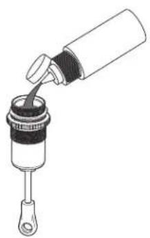
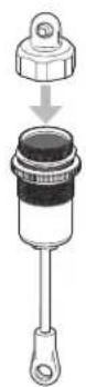
- Fill the shock body 5mm (0.2 in) from the top with 25wt silicone shock oil (TLR74004 2oz, TLR74022 4oz).
- Slowly move the piston up and down 5 times, allowing air to rise to the top. Let the shock sit for 5 minutes.
- With the piston all the way down, fill the shock body 1 mm (0.04 in) from the top. Replace the shock cap, spring and spring cup.
natural_image
Line drawing of a mechanical component with a lever and handle, no text or symbols present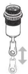
text_image
LOS243014 LOS243012 LOS243015 LOS243012 LOS246005 LOS243014 LOS243014 LOS243015 LOS243014 LOS243015 LOS243014 LOS243016 - Yellow - 1.1 rate spring (Front) LOS243017 - Blue - 1.6 rate spring (Rear) LOS243011 LOS243015 LOS243014 LOS243014 Stock Shock oil F/R: 25wt Piston F/R: 4x1.8mmDifferential Light Weight Oil Heavier Weight Oil
| Front | Increases off-power steering. Oil that is too thin will make diff action inconsistent | Increases off-power stability and on-power steering |
| Center | Has less forward drive and can unload the drivetrain easier under acceleration, which can be good on rough and slick tracks | Has more acceleration and increases on-power steering, but decreases off-power steering. Thicker center diff oil is better on high traction/smooth tracks |
| Rear Has more side traction and increased steering in the middle of a turn | Has less steering in the middle of the turn but more forward traction | |
FRONT DIFFERENTIAL
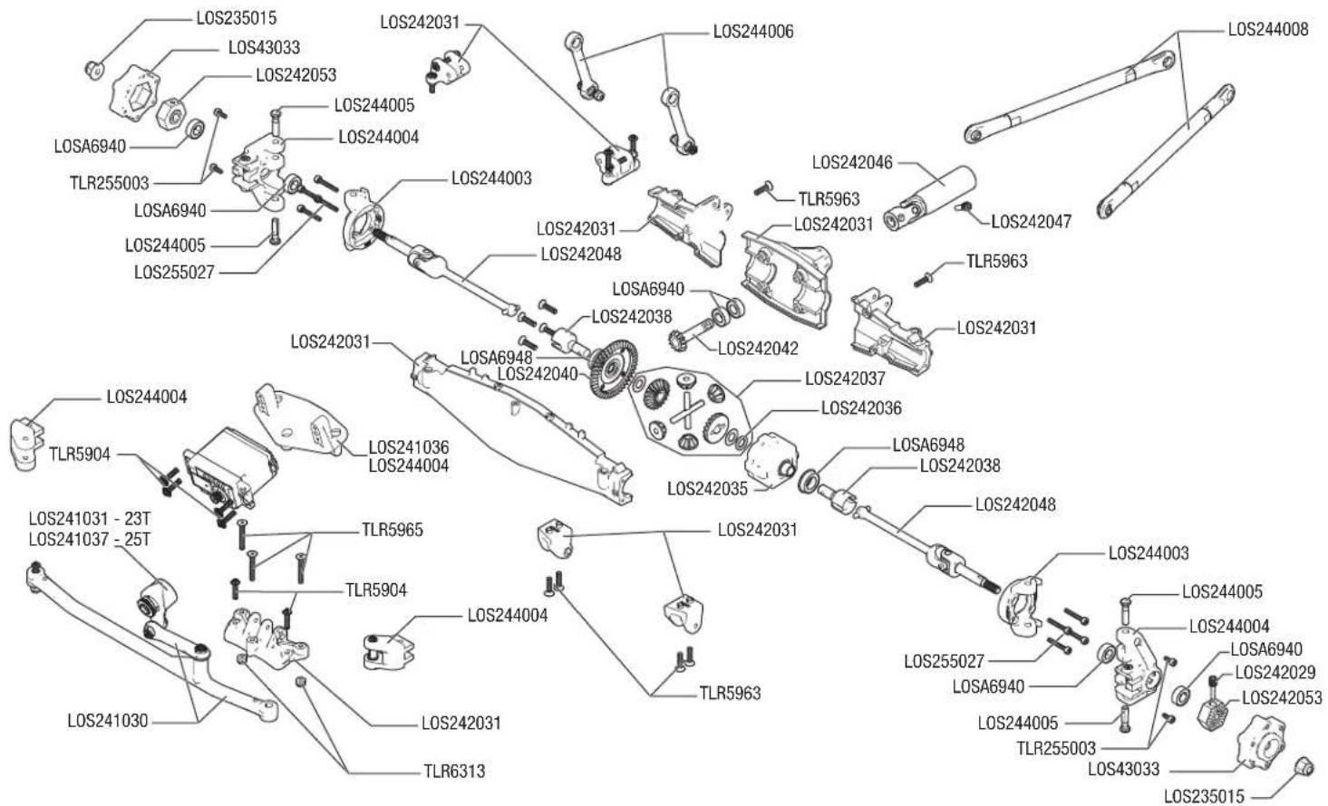
- To Remove the front differential from the axial housing, start by removing the steering servo and servo mount from the axle.
- Remove the screw holding the upper 4-link bars to the mount
- Remove the Sway bar links, shocks and lower 4-link bars from the axle housing.
- With the axle free from the chassis, remove the third member and pinion gear.
- Remove the steering spindle and spindle carrier from one side of the axle with the front universal. This will provide enough clearance to remove the differential from the axle housing.
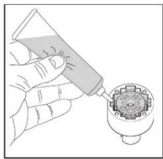
- Check the ring and pinion as well as the bevel gears in the differential. Replace as needed. If fluid is leaking, replace the outdrive o-rings and ring gear gasket. Be sure to grease the outdrives prior to sliding them through the o-rings. Apply more grease to the ring and pinion (LOSA99209).
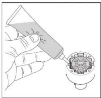
- Check the differential fluid and refill or replace as needed with TLR75004 (100k) fluid. The fluid level should be about 0.12 in (3.0mm) from the top surface of the case. Do not overfill or the differential unit might leak.
natural_image
Illustration of a hand using a tool to apply liquid into a connector pin (no text or symbols visible)Front Differential Fluid : 100,000
text_image
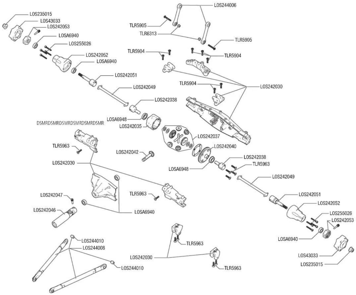
LOS235015 LOS43033 LOS242053 LOS244005 LOS244004 LOS244003 LOS242031 LOS244006 LOS244008 TLR255003 LOS6940 TLR5963 LOS242047 TLR5963 LOS242031 LOS242031 LOS242038 LOS242038 LOS242037 LOS242036 LOS242035 LOS242031 LOS241036 LOS244004 LOS241031 - 23T LOS241037 - 25T TLR5965 TLR5904 TLR5963 LOS244004 LOS244005 TLR255003 LOS242053 LOS241030 LOS242031 TLR6313 LOS244006 LOS242031 LOS242031 LOS242031 LOS242031 LOS242031 LOS242031 LOS242031 LOS242031 LOS242031 LOS242031 LOS242031 LOS242031 LOS242031 LOS255027 LOS6940 TLR255003 LOS43033 LOS235015- To remove the rear differential, start by removing the upper 4-link mount bolt.
- Remove the Sway Bar Links and Shocks from the Axle.
- Remove the lower 4-link bars from the axle housing.
- The axle housing is now free. Remove the third member and pinion gear from the axle mount.
- Remove one side of the axle housing with the axle and dogbone. This will provide enough clearance to remove the rear differential.
- Check the ring and pinion as well as the bevel gears in the differential. Replace as needed. If fluid is leaking, replace the outdrive o-rings and ring gear gasket. Be sure to grease the outdrives prior to sliding them through the o-rings. Apply more grease to the ring and pinion (LOSA99209).
- Check the differential fluid and refill or replace as needed with TLR75004 (100k) fluid. The fluid level should be about 0.12 in (3.0mm) from the top surface of the case. Do not overfill or the differential unit might leak.
natural_image
Illustration of a hand using a tool to apply liquid into a connector pin (no text or symbols visible)Rear Differential Fluid : 100,000
text_image
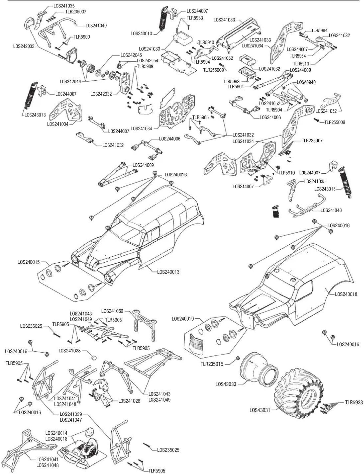
LOS235015 LOS43033 LOS242053 LOSA6940 LOS255026 LOS242052 LOSA6940 LOS242051 LOS242049 LOS242038 TLR5905 TLR6313 TLR5904 TLR5904 LOS242030 DSMRDSMRDSMRDSMRDSMR TLR5963 LOS242030 LOS242042 TLR5963 LOS242037 LOS242040 TLR5963 LOS242038 TLR5963 LOS242049 LOS242051 LOS242052 LOS255026 LOS242053 LOS6940 LOS242047 LOS242046 LOS2420410 LOS244008 LOS244010 TLR5963 LOS242030 TLR5963 LOS235015CHASSIS
text_image
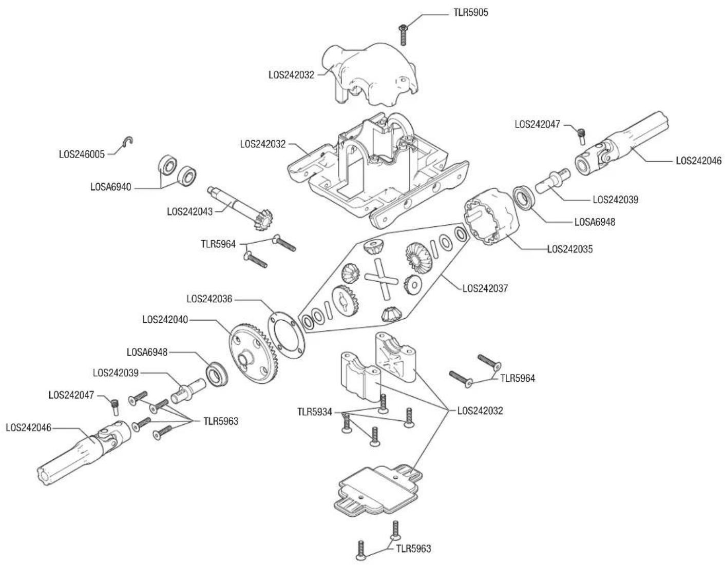
Exploded view diagram of a car's internal components with labeled parts such as LOS, TLR, and SLR identifiersCENTER DIFFERENTIAL
- To remove the center differential from the vehicle, remove the two screws in the center cover to expose the center differential.
- Remove the four screws holding the diff support blocks, and remove the diff support blocks.
- Remove the two screwpins holding the front and rear drivelines, and remove the center halves of the driveline. This will provide enough clearance to remove the differential out of the bottom of the vehicle.
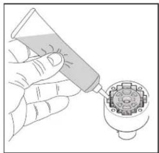
- Check the ring and pinion as well as the bevel gears in the differential. Replace as needed. If fluid is leaking, replace the outdrive o-rings and ring gear gasket. Be sure to grease the outdrives prior to sliding them through the o-rings.. Apply more grease to the ring and pinion (LOSA99209).
- Check the differential fluid and refill or replace as needed with TLR75009 (500k) fluid. The fluid level should be about 0.12 in (3.0mm) from the top surface of the case. Do not overfill or the differential unit might leak.
natural_image
Illustration of a hand using a tool to apply liquid into a circular component (no text or symbols visible)Center Differential Fluid : 500,000
text_image
TLR5905 LOS242032 LOS242032 LOS242047 LOS242046 LOS246005 LOSA6940 LOS242043 TLR5964 LOS242039 LOSA6948 LOS242035 LOS242037 LOS242036 LOS242040 LOSA6948 LOS242039 LOS242047 TLR5963 TLR5964 TLR5934 LOS242032 TLR5963REPLACEMENT PARTS
| SKU English | |
| LOS235002 Cap Head Screws M2.5x10mm(10) | |
| LOS235012 Set Screws M4mm Cup Point(10) | |
| LOS235015 Locknut Flanged M5 Serrated (10) | |
| LOS235024 Button Head Screws M3x25mm (10) | |
| LOS235025 Button Head Screws M3x30mm (10) | |
| LOS236001 3.2mm x 7mm .5mm Washer(10) | |
| LOS240013 Body Set, Painted, Grave Digger: LMT | |
| LOS240015 | Fr Headlight Set, GraveDigger:LMT |
| LOS240017 | BodySet,Painted,SonUvaDigger:LMT |
| LOS240019 | LEDLights&Grill,SonUvaDigger:LMT |
| LOS240016 Body Buttons,Top&Bottom(10)LMT | |
| LOS241027 Cage Set, Complete, Green: LMT | |
| LOS241028 Safety Seat Set: LMT | |
| LOS241029 Wheeile Bar Set, Green: LMT | |
| LOS241030 Steering Linkage Set: LMT | |
| LOS241031 ServoSaverSet,Complete:23T:LMT | |
| LOS241032 Cross Brace Set Chassis: LMT | |
| LOS241033 Battery & Radio Tray Set: LMT | |
| LOS241034 Chassis Side Plate Set: LMT | |
| LOS241035 4n1 Collective Headers,Silver:LMT | |
| LOS241036 Steering Servo Mount Plate: LMT | |
| LOS241039 Side Cage and Lower Bar, Green: LMT | |
| LOS241041 Top and Upper Cage Bars, Green: LMT | |
| LOS241043 Rear Cage and Hoop Bars, Green: LMT | |
| LOS241045 Rear Body Support and Body Posts, Green: LMT | |
| LOS241046 Cage Set Complete, Blue: LMT | |
| LOS241047 Side Cage and Lower Bar, Blue: LMT | |
| LOS241048 Top and Upper Cage Bars, Blue: LMT | |
| LOS241049 Rear Cage and Hoop Bars, Blue: LMT | |
| LOS241051 Rear Body Support and Body posts, Blue: LMT | |
| LOS241053 Wheelie Bar Set Blue: LMT | |
| LOS242029 Wheel Hex Screw Pin (10): LMT | |
| LOS242030 AxleHousingSet Complete,Rear: LMT | |
| LOS242031 AxleHousingSet Complete,Front:LMT | |
| LOS242032 Gearbox Housing Set w/covers:LMT | |
| LOS242033 Complete Diff Front or Rear: LMT | |
| LOS242034 Complete Diff Center: LMT | |
| LOS242035 Diff Housing Set (1): LMT | |
| LOS242036 Diff O-rings & Gaskets (3): LMT | |
| LOS242037 Internal Diff Rebuild Kit(1):LMT | |
| LOS242038 F/R Diff Outdrive Set (2): LMT | |
| LOS242039 Center Diff Output Shafts(2):LMT | |
| LOS242040 F/R Diff Ring Gear: LMT | |
| LOS242041 Diff Spool: LMT | |
| LOS242042 Diff Pinion, 13T (1): LMT | |
| LOS242043 13T Cntr Trans Pinion Gear: LMT | |
| LOS242044 Idle & Cush Drive Gear Set: LMT | |
| LOS242045 CushDriveRubberDamper,Med(2):LMT | |
| LOS242046 Cntr Slider Driveshaft (1): LMT | |
| LOS242047 Cntr Driveshaft Screwpin(10):LMT | |
| LOS242048 Fr Universal Driveshaft (2): LMT | |
| LOS242049 Dogbones, Rear (2): LMT | |
| LOS242051 Stub Axle, Rear (2): LMT | |
| LOS242052 Rr Axle Mount set, 0 & 3 Deg:LMT | |
| LOS242053 17mm Hex Adapter w/pin (4): LMT | |
| LOS242054 Pinlon Gear,14, 1.0M. 5mm shaft | |
| LOS243011 Shock Shaft, F/R (2): LMT | |
| LOS243012 Shock Body and Cap, Al (2): LMT | |
| LOS243013 Shock Set Complete (2): LMT | |
| LOS243014 Shock Plastics & Balls (4): LMT | |
| LOS243015 Shock RebuildHardwareSet(4):LMT | |
| LOS243016 Spring,Soft,Yel, 1.1rate(4):LMT | |
| LOS243017 Spring,Soft,Blue 1.6rate(4):LMT | |
| LOS243018 Spring,Soft,Red 2.2rate(4):LMT | |
| LOS244003 Spindle Carrier Set (L/R): LMT | |
| LOS244004 Spindle Set Front (L/R): LMT | |
| LOS244005 Kingpin, Front (I): LMT | |
| LOS244006 Sway Bar Set (F/R): LMT | |
REPLACEMENT PARTS
| SKU English | |
| LOS244007 Upper Shock Mount Set (4): LMT | |
| LOS244008 Lower 4-link Ba | Set (4): LMT |
| LOS244009 Upper 4-link bar set (4): LMT | |
| LOS244010 7mm DoubleBossPivotBalls(10):LMT | |
| LOS244011 RodEnds, Sway & DragLinks: LMT | |
| LOS246003 Body Clips, Black, Small(10):LMT | |
| LOS246004 Diff Shim, M8x13x0.4mm (10): LMT | |
| LOS246005 E-Clip & C-Clip Hardware(20):LMT | |
| LOS257007 4 x 8 x 3mm Ball Bearing (4) | |
| LOS43031 Monster Truck Tire, L/R: LMT | |
| LOS43032 Foam Tire Insert, MT (2): LMT | |
| LOS43033 MT Wheel, Silver (2): LMT | |
| LOS43034 MountedMonste TruckTires,L/R:LMT | |
| LOSA6940 6x12x4mm Sealed Ball Bearing (4) | |
| LOSA6948 8x14x4 Flanged Rubber Seal BB (4) | |
| LOSA6955 5x13x4mm HD Cltch Bearings(2):8B/8T | |
| TLR235005 Flat Head Screws, M3 x 18mm (10) | |
| TLR235007 Flat Head Screw, M2.5 x 10mm (10) | |
| TLR235015 Button Head Screws M3 x 4mm (10) | |
| TLR245012 Button Head Screws, M2.5x4mm(10) | |
| TLR255002 ButtonHead Screws,M2.5x10mm (10) | |
| TLR255003 Cap Head Screws, M2.5x6mm (10) | |
| TLR255015 Setscrew, Cup Point, M4x5mm (10) | |
| TLR5902 Button Hd Screws, M3 x 8mm (10) | |
| TLR5903 Button Hd Screws, M3 x 10mm (10) | |
| TLR5904 Button Hd Screws, M3 x 12mm (10) | |
| TLR5905 Button Hd Screws, M3 x 18mm (10) | |
| TLR5906 Button Hd Screws, M3 x 35mm (10) | |
| TLR5909 Button Head Screws, M3x16mm(10) | |
| TLR5910 Button Head Screws M3 x 14mm(10) | |
| TLR5911 Button Head Screws,M3 x 20mm(10) | |
| TLR5930 Cap Head Screws, M3 x 8mm (10) | |
| TLR5932 Cap Head Screws, M3 x 10mm (10) | |
| TLR5934 Cap Head Screws, M3 x 16mm (10) | |
| TLR5963 Flathead Screw, M3 x 12mm (10) | |
| TLR5963 Flathead Screw, M3 x 12mm (10) | |
| TLR5964 Flathead Screw, M3 x 16mm (10) | |
| TLR5965 Flathead Screw, M3 x 20mm (10) | |
| TLR6313 Locknut, M3 x .5 x 5.5mm (10) | |
| SPMR2340 DX3 3-ch | DSMR SMART Transmitter |
| SPMSR315 SR315 Surface Receiver | |
| SPMS614S S614S Waterproof Servo | |
| SPMXSE1130 Firma SMART | 130A Brushless ESC |
| SPMXSM1000 Firma 3150 Kv Brushless Motor | |
RECOMMENDED PARTS
| Part # English | |
| DYNT2010 | Machined Nut Driver Set (4) Metric |
| DYNT2030 | Machined Hex Driver Set (4) Met |
| SPM5010 | DX5 Pro DSMR Tx w/SR2100 |
| SPM5115 | DX5C DSMR 5ch TX only |
| LOS240014 | Body Set, Grave Digger Clear LMT |
| LOS240018 | BodySet,Clear,SonUvaDigger:LMT |
| SPMXC1010 | Spektrum S2100 SMART Charger* |
| SPMXC1070 | Smart S150 AC/DC Charger, 1x50W* |
| SPMX50003S50H5 | 5000mAh 3S 11.1V50CSmartLiPo IC5 |
| SPMX50002S50H5 | 5000mAh 2S 7.4V 50CSmartLiPo IC5 |
| SPMX50003S100H5 | 5000mAh 3S 11.1V100CSmartLiPo IC5 |
| SPMX50002S100H5 | 5000mAh 2S 7.4V100CSmartLiPo IC5 |
| SPMXCA507 | IC3 Batt to IC5 Device 4" |
* SPMXCA507 required to charge batteries with IC5 connectors on the \2100 and \150 Chargers
OPTIONAL PARTS
| Part # English | |
| LOS241038 Cage Set, Complete, Black: LMT | |
| LOS241037 Servo Saver Set, 25T, Complete: LMT | |
| LOS241040 Side Cage & Lower Bar, Black:LMT | |
| LOS241042 Top & Upper Cage Bars, Black:LMT | |
| LOS241044 Rear Cage & Hoop Bars, Black:LMT | |
| LOS241050 RrBodySupport&BodyPost,Black:LMT | |
| LOS241052 Wheelie Bar Set, Black: LMT | |
| LOS343200 12mm Machined Wheel Hex (4): LMT | |
| LOS343201 12mm Wheel Hex Screw Pin (10): LMT | |
| TLR5285 Silicone Diff Fluid, 30,000CS | |
| TLR5286 Silicone Diff Fluid, 50,000CS | |
| TLR5288 Silicone Diff Fluid, 125,000CS | |
| TLR74000 SIL SHOCK OIL,15WT,104CST,20Z | |
| TLR74001 SIL SHOCK OIL,175WT,150CST,20Z | |
| TLR74002 SIL SHOCK OIL,20WT,195CST,20Z | |
| TLR74003 SIL SHOCK OIL,225WT,223CST,20Z | |
| TLR74004 SIL SHOCK OIL,25WT,250CST,20Z | |
| TLR74005 SIL SHOCK OIL,275WT,294CST,20Z | |
| TLR74006 SIL SHOCK OIL,30WT,338CST,20Z | |
| TLR74007 SIL SHOCK OIL,325WT,379CST,20Z | |
| TLR74008 SIL SHOCK OIL,35WT,420CST,20Z | |
| TLR74009 SIL SHOCK OIL,375WT,468CST,20Z | |
| TLR74010 SIL SHOCK OIL,40WT,516CST,20Z | |
| TLR74011 SIL SHOCK OIL,425WT,563CST,20Z | |
| TLR74012 SIL SHOCK OIL,45WT,610CST,20Z | |
| TLR74013 SIL SHOCK OIL,50WT,710CST,20Z | |
| TLR74014 SIL SHOCK OIL,60WT,810CST,20Z | |
| TLR74015 SIL SHOCK OIL,70WT,910CST,20Z | |
| TLR74016 SIL SHOCK OIL,80WT,1014CST,20Z | |
| TLR74017 SIL SHOCK OIL,90WT,1130CST,20Z | |
| TLR74018 SIL SHOCK OIL,100WT,1325CST,20Z | |
| TLR75001 Silicone Diff Fluid, 40,000CS | |
| TLR75002 Silicone Diff Fluid, 60,000CS | |
| TLR75003 Silicone Diff Fluid, 80,000CS | |
| TLR75004 Silicone Diff Fluid, 100,000CS | |
| TLR75008 Silicon Diff Fluid, 200,000 | |
| TLR75009 Silicon Diff Fluid, 500,000 | |
TROUBLESHOOTING GUIDE
PROBLEM POSSIBLE CAUSE SOLUTION
| Vehicle does not operate | Battery not charged or plugged in Charge battery/plug in ESC switch not "On" Turn on ESC switch Transmitter not "On" or low battery Turn on/replace batteries | |
| Motor runs but wheels do not rotate | Pinion not meshing with spur gear Adjust pinion/spur mesh Pinion spinning on motor shaft Tighten pinion gear setscrew on motor shaft flat spot Transmission gears stripped Replace transmission gears Drive pin broken Check and replace drive pin | |
| Steering does not work | Servo plug not in receiver properly Make sure the steering servo plug is connected to the receiver steering channel, noting proper polarity Servo gears or motor damaged Replace or repair servo | |
| Will not turn one direction Servo gears damaged Replace or repair servo | ||
| Motor does not run | Motor wire solder joint is damaged Resolder the motor wire with the proper equipment Motor wire broken Repair or replace as needed ESC damaged Contact Horizon Hobby Product Support | |
| ESC gets hot | Motor over-geared Use smaller pinion or larger spur gear | |
| Driveline bound up | Check wheels and transmission for binding | |
| Poor run time and/or sluggish acceleration | Battery pack not fully charged | Recharge battery |
| Charger not allowing full charge | Try another charger | |
| Driveline bound up | Check wheels, transmission for binding | |
| Poor range and/or glitching | Transmitter batteries low | Check and replace |
| Vehicle battery low | Recharge battery | |
| Loose plugs or wires | Check all wire connections and plugs | |
LIMITED WARRANTY
What this Warranty Covers
Horizon Hobby, LLC, (Horizon) warrants to the original purchaser that the product purchased (the "Product") will be free from defects in materials and workmanship for a period of 2 years from the date of purchase.
What is Not Covered
This warranty is not transferable and does not cover (i) cosmetic damage, (ii) damage due to acts of God, accident, misuse, abuse, negligence, commercial use, or due to improper use, installation, operation or maintenance, (iii) modification of or to any part of the Product, (iv) attempted service by anyone other than a Horizon Hobby authorized service center, (v) Product not purchased from an authorized Horizon dealer, or (vi) Product not compliant with applicable technical regulations or (vii) use that violates any applicable laws, rules, or regulations. OTHER THAN THE EXPRESS WARRANTY ABOVE, HORIZON MAKES NO OTHER WARRANTY OR REPRESENTATION, AND HEREBY DISCLAIMS ANY AND ALL IMPLIED WARRANTIES, INCLUDING, WITHOUT LIMITATION, THE IMPLIED WARRANTIES OF NON-INFRINGEMENT, MERCHANTABILITY AND FITNESS FOR A PARTICULAR PURPOSE. THE PURCHASER ACKNOWLEDGES THAT THEY ALONE HAVE DETERMINED THAT THE PRODUCT WILL SUITABLY MEET THE REQUIREMENTS OF THE PURCHASER'S INTENDED USE.
Purchaser's Remedy
Horizon's sole obligation and purchaser's sole and exclusive remedy shall be that Horizon will, at its option, either (i) service, or (ii) replace, any Product determined by Horizon to be defective. Horizon reserves the right to inspect any and all Product(s) involved in a warranty claim. Service or replacement decisions are at the sole discretion of Horizon. Proof of purchase is required for all warranty claims. SERVICE OR REPLACEMENT AS PROVIDED UNDER THIS WARRANTY IS THE PURCHASER'S SOLE AND EXCLUSIVE REMEDY.
Limitation of Liability
HORIZON SHALL NOT BE LIABLE FOR SPECIAL, INDIRECT, INCIDENTAL OR CONSEQUENTIAL DAMAGES, LOSS OF PROFITS OR PRODUCTION OR COMMERCIAL LOSS IN ANY WAY, REGARDLESS OF WHETHER SUCH CLAIM IS BASED IN CONTRACT, WARRANTY, TORT, NEGLIGENCE, STRICT LIABILITY OR ANY OTHER THEORY OF LIABILITY, EVEN IF HORIZON HAS BEEN ADVISED OF THE POSSIBILITY OF SUCH DAMAGES. Further, in no event shall the liability of Horizon exceed the individual price of the Product on which liability is asserted. As Horizon has no control over use, setup, final assembly, modification or misuse, no liability shall be assumed nor accepted for any resulting damage or injury. By the act of use, setup or assembly, the user accepts all resulting liability. If you as the purchaser or user are not prepared to accept the liability associated with the use of the Product, purchaser is advised to return the Product immediately in new and unused condition to the place of purchase.
Law
These terms are governed by Illinois law (without regard to conflict of law principals). This warranty gives you specific legal rights, and you may also have other rights which vary from state to state. Horizon reserves the right to change or modify this warranty at any time without notice.
WARRANTY SERVICES
Questions, Assistance, and Services
Your local hobby store and/or place of purchase cannot provide warranty support or service. Once assembly, setup or use of the Product has been started, you must contact your local distributor or Horizon directly. This will enable Horizon to better answer your questions and service you in the event that you may need any assistance. For questions or assistance, please visit our website at www.horizonhobby.com, submit a Product Support Inquiry, or call the toll free telephone number referenced in the Warranty and Service Contact Information section to speak with a Product Support representative.
Inspection or Services
If this Product needs to be inspected or serviced and is compliant in the country you live and use the Product in, please use the Horizon Online Service Request submission process found on our website or call Horizon to obtain a Return Merchandise Authorization (RMA) number. Pack the Product securely using a shipping carton. Please note that original boxes may be included, but are not designed to withstand the rigors of shipping without additional protection. Ship via a carrier that provides tracking and insurance for lost or damaged parcels, as Horizon is not responsible for merchandise until it arrives and is accepted at our facility. An Online Service Request is available at http://www.horizonhobby.com/content/service-center_render-service-center. If you do not have internet access, please contact Horizon Product Support to obtain a RMA number along with instructions for submitting your product for service. When calling Horizon, you will be asked to provide your complete name, street address, email address and phone number where you can be reached during business hours. When sending product into Horizon, please include your RMA number, a list of the included items, and a brief summary of the problem. A copy of your original sales receipt must be included for warranty consideration. Be sure your name, address, and RMA number are clearly written on the outside of the shipping carton.
NOTICE: Do not ship Li-Po batteries to Horizon. If you have any issue with a Li-Po battery, please contact the appropriate Horizon Product Support office.
Warranty Requirements
For Warranty consideration, you must include your original sales receipt verifying the proof-of-purchase date. Provided warranty conditions have been met, your Product will be serviced or replaced free of charge. Service or replacement decisions are at the sole discretion of Horizon.
Non-Warranty Service
Should your service not be covered by warranty, service will be completed and payment will be required without notification or estimate of the expense unless the expense exceeds 50% of the retail purchase cost. By submitting the item for service you are agreeing to payment of the service without notification. Service estimates are available upon request. You must include this request with your item submitted for service. Non-warranty service estimates will be billed a minimum of 12 hour of labor. In addition you will be billed for return freight. Horizon accepts money orders and cashier's checks, as well as Visa, MasterCard, American Express, and Discover cards. By submitting any item to Horizon for service, you are agreeing to Horizon's Terms and Conditions found on our website http://www.horizonhobby.com/content/service-center_render-service-center.
ATTENTION: Horizon service is limited to Product compliant in the country of use and ownership. If received, a non-compliant Product will not be serviced. Further, the sender will be responsible for arranging return shipment of the unserviced Product, through a carrier of the sender's choice and at the sender's expense. Horizon will hold non-compliant Product for a period of 60 days from notification, after which it will be discarded.
10/15
WARRANTY AND SERVICE CONTACT INFORMATION
| Country of Purchase Horizon Hobby Contact Information Address | |||
| United States of America | Horizon Service Center (Repairs and Repair Requests) servicecenter.horizonhobby.com/RequestForm/ | 2904 Research Rd.Champaign, Illinois, 61822 USA | |
| Horizon Product Support (Product Technical Assistance) | productsupport@horizonhobby.com877-504-0233 | ||
| Sales | websales@horizonhobby.com800-338-4639 | ||
| European Union | Horizon Technischer Service | service@horizonhobby.eu+49 (0) 4121 2655 100 | Hanskampring 9D 22885 Barsbüttel, Germany |
| Sales: Horizon Hobby GmbH | |||
FCC INFORMATION
Contains FCC ID: BRWKATY1T
FCC ID: BRWSRIRVINGV1
Supplier's Declaration of Conformity
LOSI LMT Solid Axle Monster Truck, RTR (LOS04021)

This device complies with part 15 of the FCC Rules. Operation is subject to the following two conditions: (1) This device may not cause harmful interference, and (2) this device must accept any interference received, ing interference that may cause undesired operation.

CAUTION: Changes or modifications not expressly approved by the party responsible for compliance could void the user's authority to operate the equipment.
NOTE: This equipment has been tested and found to comply with the limits for a Class B digital device, pursuant to part 15 of the FCC Rules. These limits are designed to provide reasonable protection against harmful interference in a residential installation. This equipment generates, uses and can radiate radio frequency energy and, if not installed and used in accordance with the instructions, may cause harmful interference to radio communications. However, there is no guarantee that interference will not occur in a particular installation. If this
IC INFORMATION
CAN ICES-3 (B)/NMB-3(B)
Contains IC: 6157A-KATY1T
IC: 6157A-SRIRVINGV1
This device contains license-exempt transmitter(s)/receivers(s) that comply with Innovation, Science, and Economic Development Canada's license-exempt RSS(s). Operation is subject to the following 2 conditions:
- This device may not cause interference.
- This device must accept any interference, including interference that may cause undesired operation of the device.
equipment does cause harmful interference to radio or television reception, which can be determined by turning the equipment off and on, the user is encouraged to try to correct the interference by one or more of the following measures:
- Reorient or relocate the receiving antenna.
- Increase the separation between the equipment and receiver.
- Connect the equipment into an outlet on a circuit different from that to which the receiver is connected.
- Consult the dealer or an experienced radio/TV technician for help.
Horizon Hobby, LLC
2904 Research Rd.,
Champaign, IL 61822
Email: compliance@horizonhobby.com
Web: HorizonHobby.com
COMPLIANCE INFORMATION FOR THE EUROPEAN UNION

EU Compliance Statement:
EU Compliance Statement: Horizon Hobby, LLC hereby declares that this product is in compliance with the essential requirements and other relevant provisions of the RED Directive.
The full text of the EU declaration of conformity is available at the following internet address: https://www.horizonhobby.com/content/support-render-compliance.
Wireless Frequency Range and Wireless Output Power:
2404 - 2476 MHz
3dBm

E328
EU Manufacturer of Record:
Horizon Hobby, LLC
2904 Research Road
Champaign, IL 61822 USA
EU Importer of Record::
Horizon Hobby, GmbH
Hanskampring 9
22885 Barsbüttel Germany
WEEE NOTICE:

This appliance is labeled in accordance with European Directive 2012/19/EU concerning waste of electrical and electronic equipment (WEEE). This label indicates that this product should not be disposed of with household waste. It should be deposited at an appropriate facility to enable recovery and recycling.

text_image
LSI®WWW.LOSI.COM