PixelPro ZN-B2MTP - Security Camera Ganz - Free user manual and instructions
Find the device manual for free PixelPro ZN-B2MTP Ganz in PDF.


| Product Type | H.264 / MJPEG Network Camera, Dual Stream, ONVIF Compliant |
| Image Sensor | 1/2.8" Sony IMX-122 CMOS Sensor |
| Max Resolution | 1920 x 1080 (Full HD) |
| Lens | Motorized Zoom and Focus, f=3~9mm, F1.2~2.1 |
| Day & Night | Removable IR Cut Filter, True Day & Night |
| IR Illumination | 42 IR LEDs, Range 30m |
| Dimensions (W x H x D) | Φ150 x 350 mm |
| Weight | 1.9 kg |
| Power Supply | 24VAC (2A) or PoE (IEEE 802.3af/at) |
| Power Consumption | Max 16.7W (AC24V) / 9.6W (PoE) with IR and heater |
| Video Compression | H.264 (High Profile) and MJPEG |
| Audio | Line in, Line out; G.711 codec; external amplifier required for speaker |
| Network | 10BASE-T/100BASE-TX, RJ-45; IPv4, HTTP, SMTP, UPnP, DNS, RTP, TCP, UDP, DHCP, ARP, IGMP, ICMP, NTP |
| Alarm Input/Output | 1 x Alarm In (dry contact), 1 x Alarm Out (relay 0.5A 125VAC / 1A 30VDC) |
| Storage | Micro SD/SDHC card slot (supports up to 16GB and higher) |
| Analog Output | BNC composite output (NTSC/PAL selectable) for service monitor only |
| Heater & Fan | Built-in heater and fan for extreme temperatures; ambient -40°C~50°C with heater |
| Motion Detection | 4 user-defined regions, 10-step sensitivity |
| Event Actions | Email notification (snapshot), FTP upload (snapshot), SD card recording, alarm out |
| Web Browser Access | Internet Explorer 7.0+, Firefox, Chrome; PDA/Smartphone |
| Security | Password protection, HTTPS, IEEE 802.1X port-based network control |
| Mounting | Ceiling or wall mount with supplied screws; bracket optional |
| Environmental | Ambient temperature: -10°C~50°C (without heater); less than 90% humidity non-condensing |
| Materials | Aluminum diecasting |
| Compliance | ONVIF, RoHS (implied), CE (implied) |
Frequently Asked Questions - PixelPro ZN-B2MTP Ganz
User questions about PixelPro ZN-B2MTP Ganz
0 question about this device. Answer the ones you know or ask your own.
Ask a new question about this device
Download the instructions for your Security Camera in PDF format for free! Find your manual PixelPro ZN-B2MTP - Ganz and take your electronic device back in hand. On this page are published all the documents necessary for the use of your device. PixelPro ZN-B2MTP by Ganz.
USER MANUAL PixelPro ZN-B2MTP Ganz
Before connecting, operating or adjusting this product, read this instruction booklet carefully and completely
SAFETY INSTRUCTIONS
1) Read these instructions.
2) Keep these instructions.
3) Heed all warnings.
4) Follow all instructions.
5) Do not use this apparatus near water.
6) Clean only with a dry cloth.
7) Do not block any of the ventilation openings. Install in accordance with the manufacturer's instructions.
8) Do not install near any heat sources such as radiators, heat registers, stoves, or other apparatus that produce heat.
9) Only use the attachments/accessories specified by the manufacturer.
10) Use only with a cart, stand, tripod or bracket specified by the manufacturer, or sold with the apparatus. When a cart is used, use caution when moving the cart/apparatus combination to avoid injury from tip-over.

natural_image
Silhouette of a person climbing a ladder inside a circular frame (no text or symbols)12) Unplug this apparatus during lightning storms or when unused for long periods of time.
13) Refer all servicing to qualified service personnel. Servicing is required when the apparatus has been damaged in any way, such as power supply cord or plug is damaged, liquid has been spilled or objects have fallen into the apparatus, the apparatus has been exposed to rain or moisture, does not operate normally, or has been dropped.
CALIFORNIA USA ONLY
This Perchlorate warning applies only to primary CR (Manganese Dioxide) Lithium coin cells in the product sold or distributed ONLY in California USA. "Perchlorate Material - special handling may apply. See www.dtsc.ca.gov/hazardouswaste/perchlorate."
Caution
Danger of explosion if battery is incorrectly replaced.
Replace only with the same or equivalent type.
These servicing instructions are for use by qualified service personnel only. To reduce the risk of electric shock does not perform any servicing other than that contained in the operating instructions unless you are qualified to do so.
In USA and Canada, Use Class 2 Power Supply Only
Contents
1. PRODUCT FEATURES ....4
2. ACCESSING THE CAMERA....8
2.1 ACCESS FROM A BROWSER 8
2.2 ACCESSING THE CAMERA FROM THE INTERNET....9
2.3 ADJUSTING THE IMAGE AND FOCUS 9
2.4 THE LIVE VIEW PAGE....9
2.5VIDEOSTREAMTYPES 10
2.6 HOW TO STREAM H.264 10
3. THE SETUP .... 11
4. ANALOG OUTPUT ....12
4.1 ANALOG OUTPUT SETUP....12
5. VIDEO 12
5.1 CODEC 12
5.2 CAMERA 15
5.2.1 Exposure Control 15
5.2.2 Day & Night Control 16
5.2.3 White Balance Control 16
5.2.4 Image Property Control....16
5.2.5 Lens Adjustment 16
6. AUDIO....17
7. LIVE 18
8. SD CARD 19
9. FTP 22
9.1 FTP > CONFIG....22
9.2 FTP > EVENT 22
9.3 FTP > PERIODICAL 23
10. EVENT 24
10.1 EVENT > ALARM PORT 24
10.2 EVENT > MOTION 25
10.3 EVENT > MAPPING 26
11. NETWORK....27
11.1 NETWORK > IP SETUP 27
11.2 NETWORK > SERVICE PORT 29
11.3 NETWORK > RTP 29
11.4 NETWORK > E-MAIL 30
11.5 NETWORK > DDNS 30
11.5 NETWORK > UPNP 31
12. SYSTEM 32
12.1 SYSTEM > USER 32
12.2 SYSTEM > DATE & TIME 33
12.3 SYSTEM > MAINTENANCE 34
12.4 SYSTEM > INFORMATION....36
13.DIMENSION (MM) 37
14. SPECIFICATION....38
1. Product Features
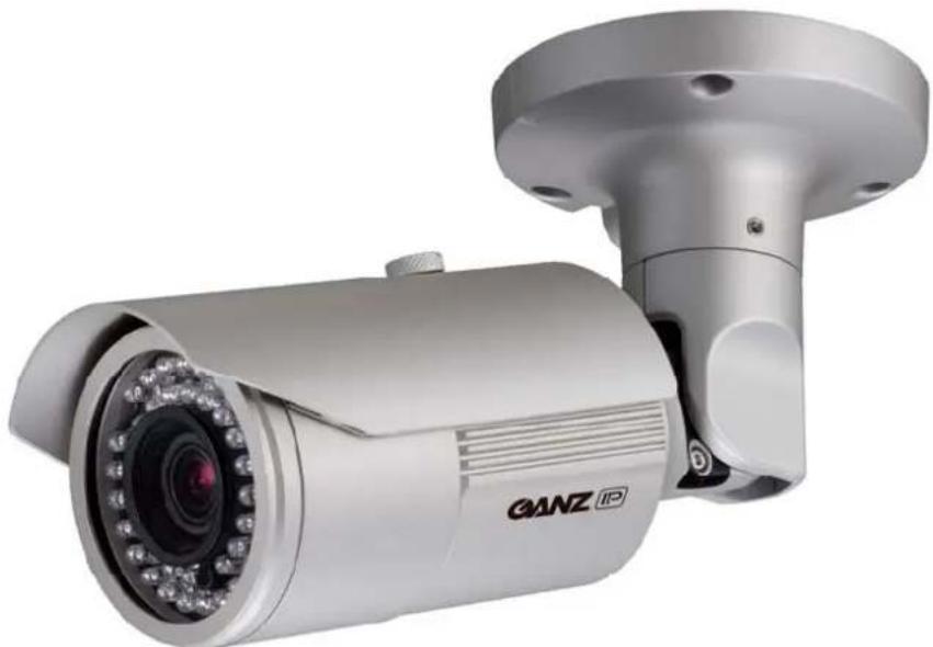
The GANZ PixelPro is a high performance H.264 network camera, designed for demanding security installations. It delivers crisp, clear images, disclosing every detail, thanks to its top quality Megapixel progressive CMOS sensor and advanced image processing.
Supported by the industry's largest base of video management software, the GANZ PixelPro provides the perfect solution for securing bank offices, airports and other facilities, and for traffic surveillance, over IP based networks.
The optimal Power over Ethernet (IEEE 802.3af) support power to the camera to be delivered via the network, eliminating the need for a power outlet and reducing installation costs. Steady power could be guaranteed with a central Uninterruptible Power Supply (UPS).
natural_image
Exterior view of a GANZ IP security camera (no text or symbols on body)The GANZ PixelPro offers a comprehensive set of network security and management features.
This includes support for port based network control (IEEE802.1X), which allows the camera to be connected to a network secured with this control, and HTTPS encryption, which provides a secure channel between camera and application. It also enables authentication of the video source. Video products are efficiently managed with the powerful GANZ PixelPro Camera Management tool, which is provided on the Installation CD which comes with each GANZ PixelPro camera.
text_image
Technical diagram of a mechanical assembly with numbered components for identification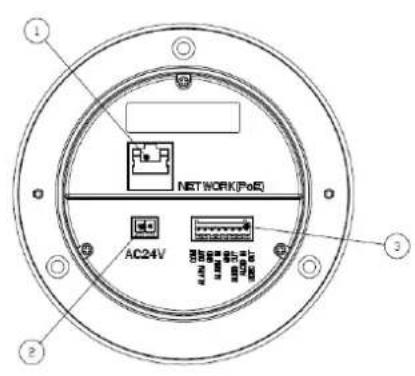
text_image
NETWORK(FeQ) AC24V 1 2 3(REAR)
1. Network connector
The GANZ PixelPro connects to the network via a standard network cable, and automatically detects the speed of the local network segment (10BaseT/100BaseTX Ethernet). This socket could also be used to power the GANZ PixelPro via Power over Ethernet (PoE). The camera auto-senses the correct power level when using a PoE (Class 2) switch, router or injector.
2. Power Connector
24VAC power connector
3. I/O connector
Audio in
Audio in (line level), for line-in mono signal (only left channel is used from a stereo signal)
Audio out
The Audio output (line level), which could be connected to a line output of a microphone system or an active speaker with a built-in amplifier.
Alarm in
One analog (dry contact) alarm input
Alarm out
One relay output (0.5A 125VAC / 1A 30VDC)
Pin Assignment
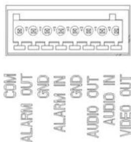
text_image
COM ALARM OUT GND ALARM IN GND AUDIO OUT AUDIO IN VIDEO OUT4. Micro SD card
Save snapshot images and video onto a Micro SD card.
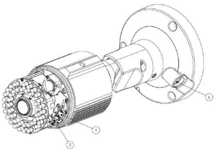
5. Control Button
Press this button to reset or restore the camera configuration to its factory default settings.
Reset : keep pushing the button about 6 seconds.
Factory Default : keep pushing the button about 12 seconds.
6. Status LED
| LED Color Indication System Status | |||
| Network | Green On Connection to 10/100Mbps Network / LAN. | ||
| Amber Flash Indication of network activity. | |||
| Unlit - No network connection established. | |||
| Status | Green | On Network connection is established. | |
| Flash Camera is booting up. | |||
| Red Flash Firmware | Upload in progress. | ||
7. Video Output for Service monitor
This analog video output is available. Use accessory cable to video output.
Adjustment
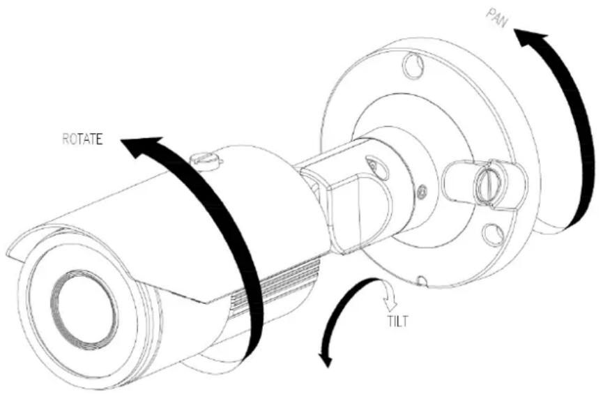
text_image
ROTATE PAN TILTMounting to a ceiling / wall
Secure the camera to ceiling or wall with three supplied tapping screws like below.
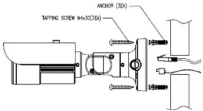
text_image
TAPPING SCREW M4x30(3EA) ANCHOR (3EA)IN CEILING MOUNT(WITHOUT BRACKET)
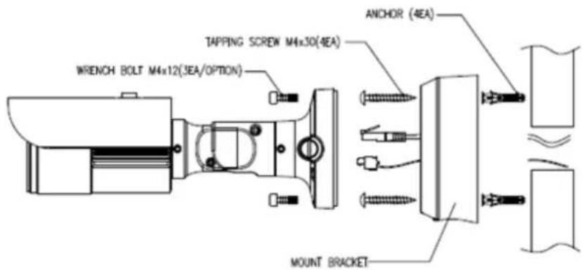
text_image
WRENCH BOLT M4x12(3EA/OPTION) TAPPING SCREW M4x30(4EA) ANCHOR (4EA) MOUNT BRACKETIN CEILING MOUNT(WITH BRACKET)
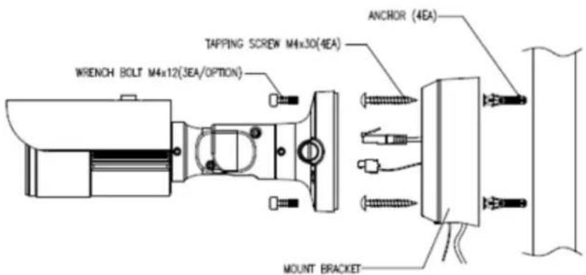
text_image
WRENCH BOLT M4x12(3EA/OPTION) TAPPING SCREW M4x30(4EA) ANCHOR (4EA) MOUNT BRACKETSURFACE MOUNT(WITH BRACKET)
2. Accessing the Camera
Follow the instructions in the GANZ PixelPro Installation Guide to install the camera.
The GANZ PixelPro could be accessed with most standard operating systems and browsers. The recommended browser is Internet Explorer for Windows with other operating systems.
2.1 Access from a browser
- Start a browser (Internet Explorer)
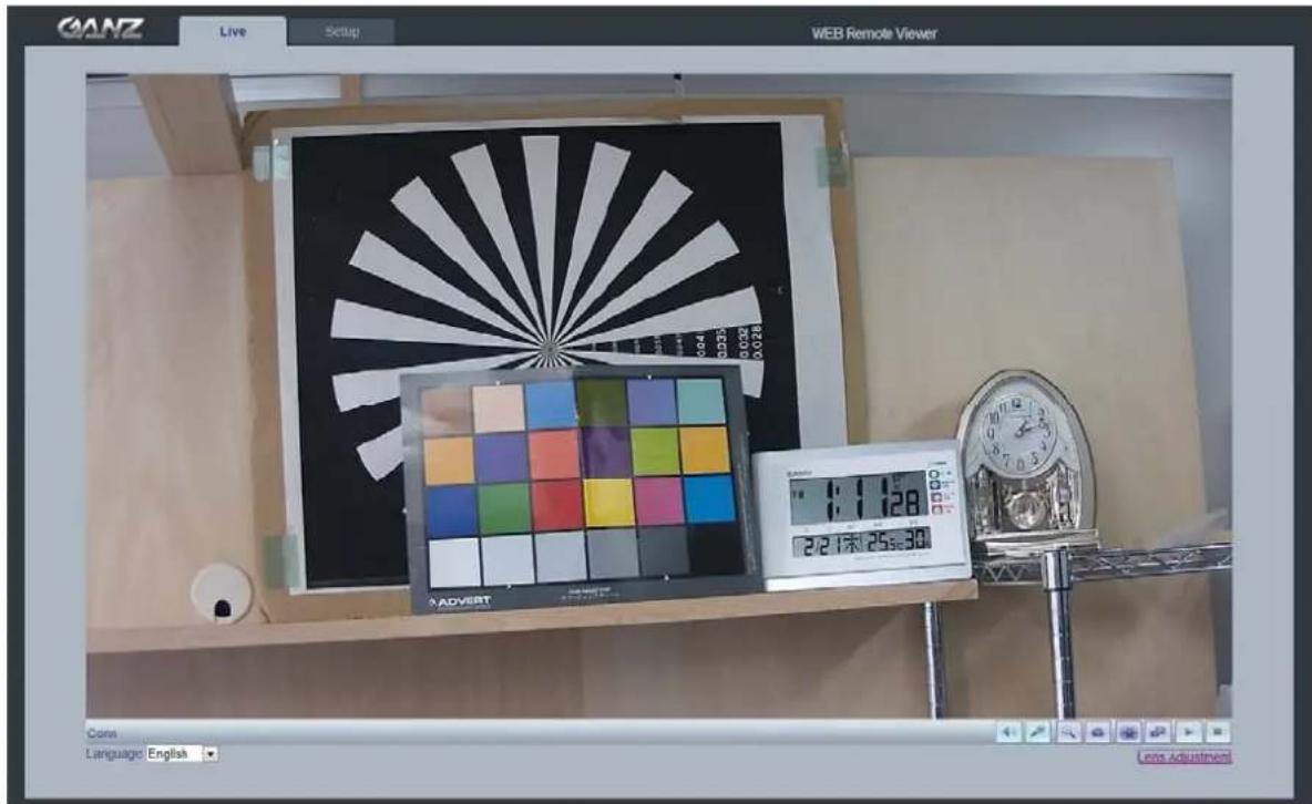
- Enter the IP address or host name of the camera in the Location/Address field of your browser. Press Enter.
text_image
GANZ Live Setup WEB Remote Viewer 3:128 2/21:00 25:30 ADVERT Cons Language: English Lens Adjustment- Login dialog will appear when the camera is accessed for the first time.
- The default user name is ADMIN, and password is 1234.
- The camera's Live View page is now displayed in your browser.
Note: The layout of the live view page in the camera may have been customized to meet specific requirements. Consequently, some of the examples and functions featured here may differ from those displayed on your own Live View page.
2.2 Accessing the camera from the Internet
Once installed, the camera is accessible on the local network (LAN). Configure the router/firewall to allow incoming data traffic to access the camera from the Internet. For security reasons this is usually done on a specific port. Please refer to the documentation for router/firewall for further instructions.
2.3 Adjusting the Image and Focus
To adjust the position of the lens:
- Open the Live View page in your web browser.
- Select the Setup tab, and open the Installation page.
- Select the 'Video Format'.
- Connect analog monitor to the VIDEO OUT (BNC) on the cable.
- Control the FOCUS with monitor's image.
- Check the image from the Live View page on your web browser.
- Set 'Installation Mode' to 'OFF' to resume normal camera operation.
2.4 The Live View page

Enable/Disable PC Speaker output

Enable/Disable PC Microphone input

Digital Zoom

Snap Shot

Full Screen

Video Stream change: First stream Second stream

Play: Click this button by manually to start the stream

Stop: Click this button by manually to stop streaming
NOTE: It is possible that not all the buttons described below will be visible unless the Live View page has been customized to display them.
2.5 Video stream types
H.264 protocols and communication methods
- RTP (Real-time Transport Protocol) is a protocol that allows programs to manage the real-time transmission of multimedia data, via unicast or multicast.
- RTSP (Real Time Streaming Protocol) serves as a control protocol, to negotiate the type of transport protocol to use for the stream. RTSP is used by a viewing client to start a unicast session.
- UDP (User Datagram Protocol) is a communications protocol that offers limited service for exchanging data in a network which uses the Internet Protocol (IP). UDP is an alternative to the Transmission Control Protocol (TCP). The advantage of UDP is that, it is not required to deliver all data and may drop network packets when there is network congestion. This is suitable for live video, as there is no point in retransmitting old information that will not be displayed anyway.
- Unicasting is communication between a single sender and a single receiver over a network. This means that the video stream goes independently to each user, and each user gets own stream. A benefit of unicasting is, in case one stream fails, it only affects one user.
- Multicasting(Will be supported)is bandwidth-conserving technology that reduces bandwidth usage by simultaneously delivering a single stream of information to multiple network recipients. This technology is used primarily on delimited networks (intranets), as each user needs an uninterrupted data flow and should not rely on network routers.
2.6 How to stream H.264
Deciding on the combination of protocols and methods to use depends on your viewing requirements, and on the properties of your network. Setting the preferred method(s) is done in webpage.
RTP+RTSP
This method (actually RTP over UDP and RTSP over TCP) should be your first consideration for live video, especially when it is important to always have an up-to-date video stream, even if some images are lost due to network problems. This could be configured as multicast or unicast.
RTP/RTSP/Multicasting (Will be supported) provides the most efficient usage of bandwidth, especially when there are large numbers of clients viewing simultaneously. Note however, that a multicast broadcast could not pass a network router unless the router is configured to allow this. For example, It is impossible to multicast over the Internet.
RTP/RTSP/Unicasting should be used for video-on-demand broadcasting, so that there is no video traffic on the network until a client connects and requests the stream. However, as more and more unicast clients get connected, the traffic on the network will increase and may cause congestion. Although there is a maximum of 10 unicast viewers, note that all multicast users combined count as 1 unicast viewer.
RTP/RTSP
This unicast method is RTP tunneled over RTSP. This could be used to exploit the fact that it is relatively simple to configure firewalls to allow RTSP traffic.
3. The Setup
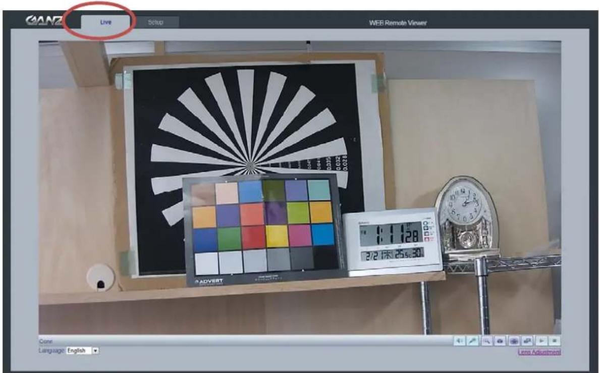
The GANZ PixelPro is configured from the Setup link, which is available on the top left hand side in the web interface. This configuration could be done by:
- Administrators, who have unrestricted access to all settings under the Setup tab.
Accessing the Setup link from a browser
-
Start your web browser and enter the IP address or host name of the camera into the address bar.
-
The Live View page is now displayed. Click on the Setup tap.
text_image
GANZ Live Setup WEB Remote Viewer 2/2 1末 25s:30 Clont Language: English Lens Adjustment4. Analog output

text_image
GANZ Live Setup WEB Remote Viewer Analog Output Setup Analog Video Format NTSC SAVE RESET Go to Setup Video Codec4.1 Analog Output Setup
Analog output allows selection of output format of the analog BNC output from the camera. NTSC, PAL: Analog Output is selectable.
5. Video
The following descriptions show examples of some of the features available in the GANZ PixelPro.
5.1 Codec
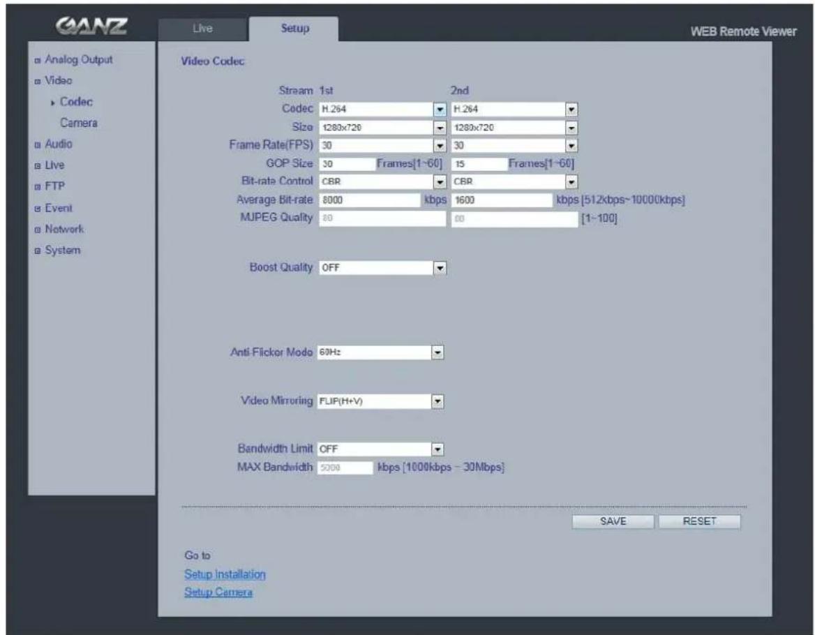
These are the tools for adjusting the H.264 settings and controlling the video bit rate.
text_image
GANZ Live Setup WEB Remote Viewer Video Codec Stream 1st 2nd Codec H.264 H.264 Size 1280x720 1280x720 Frame Rate(FPS) 30 30 GOP Size 30 Frames[1~60] 15 Frames[1~60] Bit-rate Control CBR CBR Average Bit-rate 8000kbps 1600kbps [512kbps~10000kbps] MUPEG Quality 80 60 [1~100] Boost Quality OFF Anti-Flicker Modo 60Hz Video Mirroring FLIP(H+V) Bandwidth Limit OFF MAX Bandwidth 5200kbps [1000kbps - 30Mbps] Go to Setup Installation Setup Camera SAVE RESETH.264
This is a video compression standard that makes good use of bandwidth and which could provide high-quality video streams at less than 1 Mbit/s.
The H.264 standard provides scope for a large range of different coding tools for use by various applications in different situations, and the GANZ PixelPro provides certain subsets of these tools.
Using H.264, it is also possible to control the bit rate, which in turn allows the amount of bandwidth usage to be controlled. CBR (Constant Bit Rate) is used to achieve a specific bit rate by varying the quality of the H.264 stream. While using VBR (Variable Bit Rate), the quality of the video stream is kept as constant as possible, at the cost of a varying bit rate.
Motion JPEG
This format uses standard JPEG still images in the video stream. These images then are displayed and updated at a rate sufficient to create a stream that shows constantly updated motion.
The Motion JPEG stream uses considerable amounts of bandwidth, but also provides excellent image quality and access to every individual image contained in the stream.
Multiple clients accessing Motion JPEG streams could use different image settings.
Codec
H.264 / MJPEG
Size
Video output resolution. See the next page for the output resolution table.
Frame rate
1\~30fps in normal mode (1\~15fps for slow shutter mode)
Note: If the slow shutter mode is turned on and the low light condition is met, the frame rate is automatically goes down. In this case, the frame is half of the normal mode.
GOP Size
1 \~ 60 frames
Bit-rate control (CBR or VBR)
When using H.264 compression, if there is only limited bandwidth available, a constant bit rate(CBR) is recommended, although this may compromise image quality. Use a variable bit rate(VBR) for the best possibly image quality.
Average Bit-rate (512Kbps \~ 10Mbps)
Recommended bit rate for D1: 800Kbps \~ 1Mbps
Recommended bit rate for 1.3M(720p): 3Mbps \~ 4Mbps
Recommended bit rate for 2.0M(1080p): 6Mbps \~ 8Mbps
Anti-Flicker mode (Flicker less mode)
60Hz:NTSC
50Hz:PAL or flicker-free mode(to use the camera in locations lit by fluorescent lighting).
Video Mirroring
Select Video Mirroring mode NONE/ HORIZONTAL / VERTICAL / FLIP(H+V)
Bandwidth Limit
Limit the bandwidth that the GANZ PixelPro can use during a network connection.
Max Bandwidth
Specify the maximum bandwidth that the GANZ PixelPro can use during a network connection.
< Output resolution table for PixelPro>
| First Stream | Second Stream | ||||||||
| 1920x1080 | 704x480 | 640 | x480 | 640x360 | 640x352 | 352x288 | 352 | x240 | 320x240 - |
| 1280x1024 | 704x480 | 640 | x480 | 640x360 | 352x288 | 352x240 | 320 | x240 - - | |
| 1024x768 | 704x480 | 640 | x480 | 640x360 | 352x288 | 352x240 | 320 | x240 - - | |
| 1280x720 | 1280x720 | 704 | x576 | 704x480 | 640x480 | 640x360 | 352 | x288 | 352x240 |
| 704x576 | 704x576 | 640x480 | 640x360 | 352x288 - | - | - | - | ||
| 704x480 | 704x480 | 640x480 | 640x360 | 352x240 - | - | - | - | ||
| 640x480 | 640x480 | 320x240 | - | - | - | - | - | - | - |
| 640x360 | 640x360 | 320x240 | - | - | - | - | - | - | - |
| 352x288 | 352x288 | - | - | - | - | - | - | - | - |
| 352x240 | 352x240 | - | - | - | - | - | - | - | - |
| 320x240 | 320x240 | - | - | - | - | - | - | - | - |
5.2 Camera
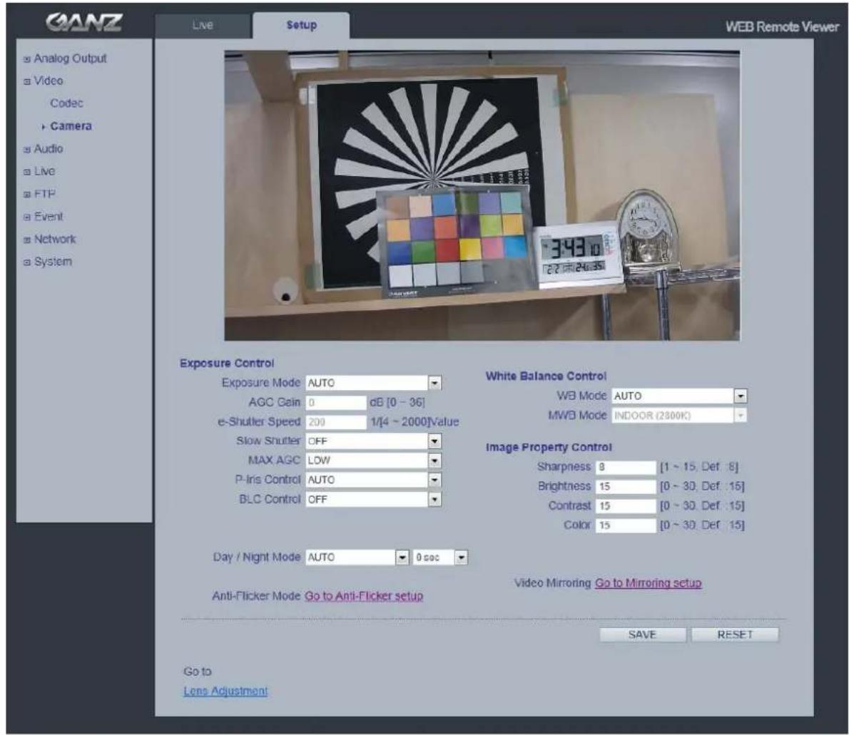
This section allows you to adjust various camera settings.
text_image
GANZ Live Setup WEB Remote Viewer Analog Output Video Codec Camera Audio Live FTP Event Network System Exposure Control Exposure Mode AUTO AGC Gain 0 dB [0 - 36] e-Shutter Speed 200 1/4 ~ 2000Value Slow Shutter OFF MAX AGC LOW P-Iris Control AUTO BLC Control OFF Day / Night Mode AUTO 0 sec Anti-Flicker Mode Go to Anti-Flicker setup White Balance Control WB Mode AUTO MWD Mode INDOOR (2300K) Image Property Control Sharpness 8 [1 ~ 15, Def .8] Brightness 15 [0 ~ 30, Def .16] Contrast 15 [0 ~ 30, Def .15] Color 15 [0 ~ 30, Def .15] Video Mirroring Go to Mirroring setup SAVE RESET Go to Lens Adjustment5.2.1 Exposure Control
Enable AE (Auto Exposure)
ON: Use this setting for automatic exposure control.
OFF: Use these settings to control camera exposure manually.
To compensate for poor lighting conditions, you can adjust the Color level, Brightness, Sharpness, Contrast and Exposure control.
NOTE: When AE is enabled, some of the submenus (AGC Gain, e-Shutter Speed) will be disabled.
Slow shutter mode
For low light conditions, turn on slow shutter mode.
Max AGC Gain
For low light conditions, adjust to a higher value, such as 30dB.
BLC Control (Back Light Compensation)
The BLC adjusts the exposure of scenes with strong backlight in the center-bottom of the image. When the image background is too bright, or the subject too dark, backlight compensation makes the subject appear clearer. The settings for low light behavior determine how the camera behaves sat low light levels. These settings affect video image quality and how much noise is in the images.
5.2.2 Day & Night Control
Day & Night Mode
Auto/Day/Night- If set to Auto, the camera will automatically switch according to the current lighting conditions.
5.2.3 White Balance Control
WB Mode
ON:ATW (Automatic White balance)
OFF: MWB (Manual White balance)
The White balance adjustment setting is used to make the colors in the image appear consistent, compensating for the different colors present in different light sources.
The GANZ PixelPro camera can be set to automatically identify the light source and compensate for its color temperature. If necessary, the type of light source could be set manually..
5.2.4 Image Property Control
Modify the video signal parameters, such as: Brightness, Sharpness, Contrast, and Color.
Sharpness (Default: 8, Range: 1\~15)
Brightness (Default: 15, Range: 0\~30)
Contrast (Default: 15, Range: 0\~30)
Color (Default: 15, Range: 0\~30)
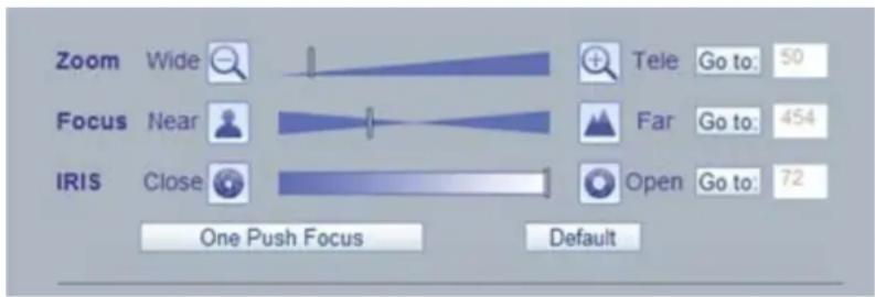
5.2.5 Lens Adjustment
Adjust the lens (Zoom, Focus & Iris) from this window.
One Push Focus : Camera will automatically adjust the focus.
Default : Back to original factory default position.
text_image
Zoom Wide Focus Near IRIS Close One Push Focus Tele Go to: 50 Far Go to: 454 Open Go to: 72 Default6. Audio
text_image
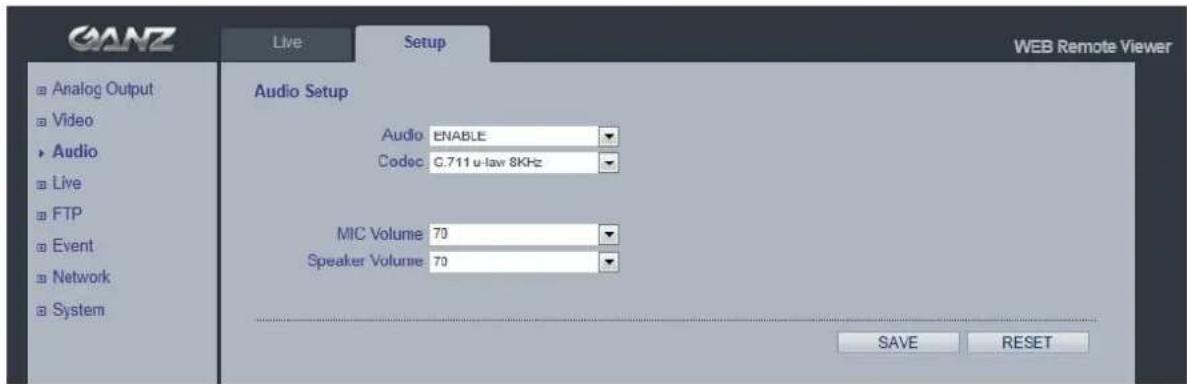
GANZ Live Setup WEB Remote Viewer Audio Setup Audio ENABLE Codec 0.711 u-law 8KHz MIC Volume 70 Speaker Volume 70 SAVE RESETThe GANZ PixelPro camera could transmit audio to other clients, using a connected external microphone and could play audio received from other clients via connected speakers. This section describes how to configure the basic audio settings for the GANZ PixelPro camera, such as setting the communication mode, adjusting the sound levels in the microphone and speakers connected to the camera.
Note: The speakers connected to the audio output must have a built-in amplifier, such as PC speakers.
Audio
ON/OFF : Check this to enable audio in the GANZ PixelPro camera.
Codec
G.711 u-law
MIC Volume
Speaker Volume
Adjust the MIC and Speaker Volume .
Audio Input
Audio from a connected line source could be connected to the Audio in connector of the GANZ PixelPro camera. If there are problems with the sound input being too low or high, adjust the input gain for the microphone connected to the GANZ PixelPro camera.
7. Live
text_image
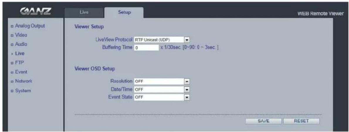
GANZ Live Setup WEB Remote Viewer Analog Output Video Audio Live FTP Event Network System Viewer Setup LiveView Protocol RTP Unicast (UDP) Buffering Time 0 x 1/30sec. [0~90: 0 ~ 3sec. ] Viewer OSD Setup Resolution OFF Date/Time OFF Event State OFF SAVE RESETThe GANZ PixelPro could support 10 simultaneous users. In case of multicast, the GANZ PixelPro could support unlimited number of users. If supported on the network, consider using multicasting, as the bandwidth consumption will be much lower.
Viewer Setup
LiveView Protocol
RTP Unicast (UDP) / RTP Multicast (UDP) / RTP over RTSP (TCP)
Buffering Time (frame based)
Determines (0 \~ 90) x 1/30 sec (0 \~ 3sec)
Viewer OSD Setup
Date : Determines whether the date is displayed.
Resolution : Determines whether the camera title is displayed.
Event State : Determines whether the event state is shown on display window.
8. SD Card
text_image
GANZ Live Setup WEB Remote Viewer Install Video Audio Live SD Card ► Config Event Periodical FTP Event Network System SD Card Configuration Overwriting Enable SD Status CHECK SD Safety Remove MOUNT UNMOUNT Erase Image Files ERASE Go to: Setup Video Codec SAVE RESET8.1 Configuration
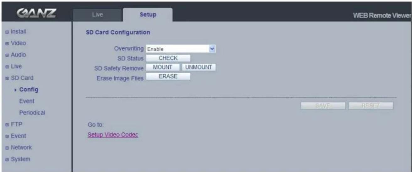
SD Card Configuration
This configuration page allows you to save still images to the Micro SD (SDHC) card.
Overwriting
The system will overwrite the oldest data on the SD card to continually record the newest data.
SD Status
Shows present SD card status. It also shows whether the SD card is present and the capacity left on it in kilobytes (KB).
Mount / Unmount The Mount button notifies the system after the SD card is inserted. The Unmount button is to notify the system before the SD card is removed. This is a similar function to the 'remove the hardware safely before taking out the USB' in the Windows OS.
NOTE: The user can download the images from the SD card using the FTP function. Turn FTP server on and connect to the camera. See Chapter 9.1 for details.
8.2 Event
text_image
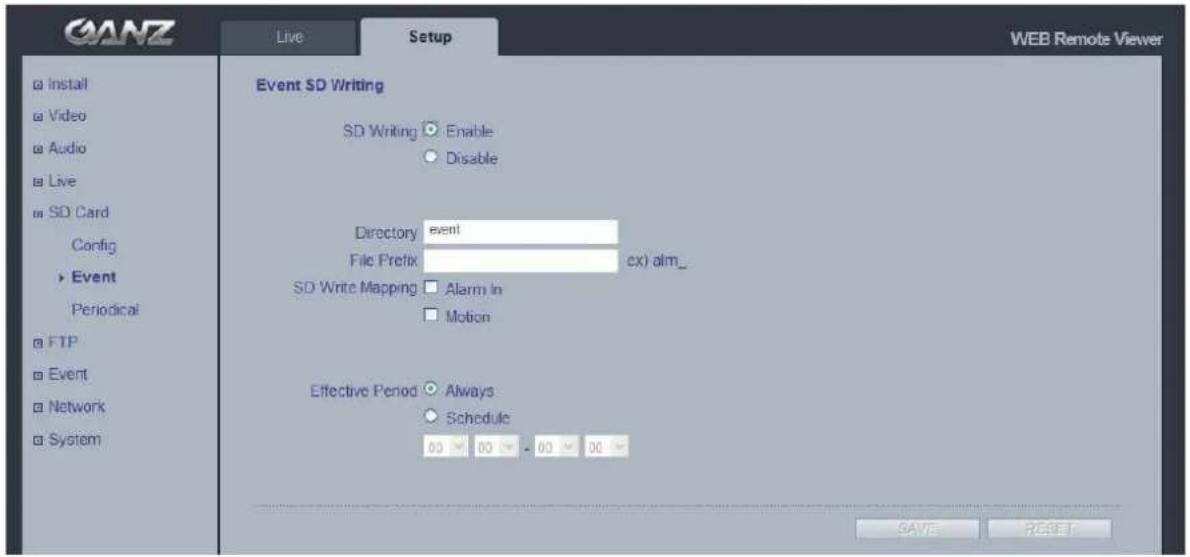
QANZ Live Setup WEB Remote Viewer Event SD Writing SD Writing ○ Enable ○ Disable Directory event File Prefix cx) alm_ SD Write Mapping □ Alarm In □ Motion Effective Period ○ Always ○ Schedule 00 00 00 00 SAVE RESETEvent SD Writing
You can configure the camera to store still images based on events such as Alarm In and Motion detection.
SD Writing
SD Writing will Enable / Disable event recording to the SD card.
When Disabled, all remaining menus will be deactivated.
Directory
The name of the sub-directory where the still images will be stored when an Event occurs.
File Prefix
You may add a file name prefix to the stored image file name.
Example: If the file prefix is 'alm', the still image would be saved as alm_date_time.jpg.
SD Write Mapping
Choose which types of events will be recorded to the SD card by checking the desired event.
Effective Period lets you decide whether to save all the events that are happening at all hours of the day, or only the events that occur within during specific times of the day. The Schedule method is used to save events on the SD card during a specific time range. The start time and the end time can be set using the dropdown list.
8.3 Periodical
text_image
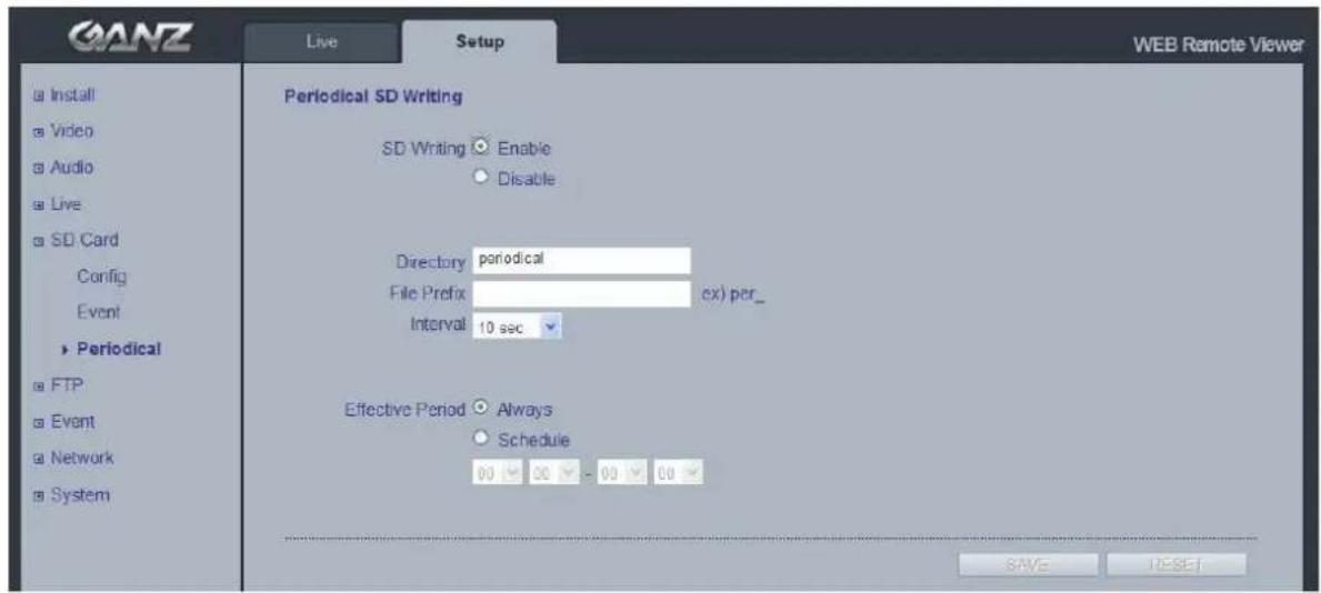
GANZ Live Setup WEB Remote Viewer Periodical SD Writing SD Writing Enable Disable Directory periodical File Prefix ex) per_ Interval 10 sec Effective Period Always Schedule 00 00 - 00 00 SAVE RESETPeriodical SD Writing
It is setting page to save the still images in the Micro SD card periodically.
The Directory and File Prefix fields are same as on the SD Card > Event page.
Interval allows for saving still images based on frequency (1 image every 10 sec, for example).
Use the drop-down control to set from 10 seconds to 1 hour.
Effective Period is also configured the same as on the SD card > Event page. Periodically, it saves the still image during a specific time range only.
9. FTP
9.1 FTP > Config
text_image
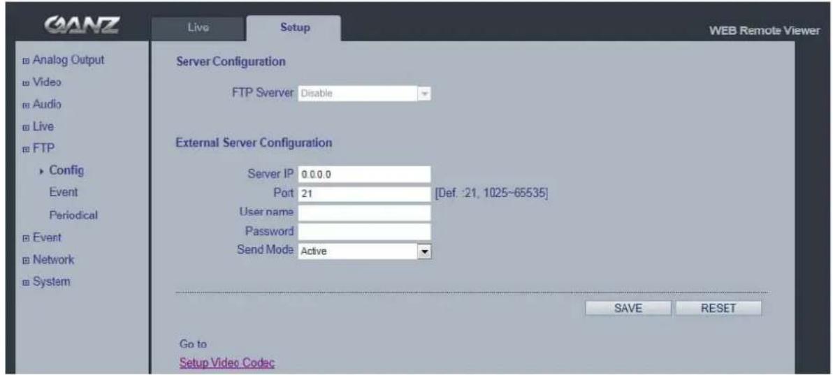
GANZ Live Setup WEB Remote Viewer Server Configuration FTP Server Disable External Server Configuration Server IP 0.0.0.0 Port 21 [Def: 21, 1025~65535] User name Password Send Mode Active GO to Setup Video Codec SAVE RESETServer Configuration (This function is N/A on this model)
External Server Configuration
It is setting page to transmit the still shot to remote sites, using the FTP server. Specify the external FTP server information such as IP address, port number, Username and password.
Note :
When the first stream is set to 1920x1080, please set the 2nd stream to MJPEG or H.264 with resolution less than 352x288. If 2nd stream is set to H.264 greater than 640x352, 30fps streaming is not guaranteed due to performance limitation.
9.2 FTP > Event
text_image
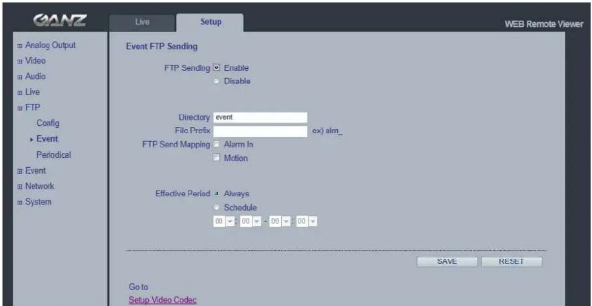
GANZ Live Setup WEB Remote Viewer Analog Output Video Audio Live FTP Config Event Periodical Event Network System Event FTP Sending FTP Sending Enable Disable Directory event File Prefix ex) alm_ FTP Send Mapping Alarm In Motion Effective Period Always Schedule 00 00 - 00 00 SAVE RESET Go to Setup Video CodecEvent FTP Sending
It enables FTP transmission triggered by event.
Directory : This folder will be created into external FTP server automatically.
File Prefix : The file name will start from this prefix.
Mapping : You can specify event mapping for Event FTP.
Effective Period : You can specify "Always" or "Schedule"
9.3 FTP > Periodical
text_image
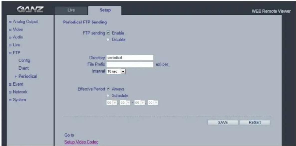
GANZ Live Setup WEB Remote Viewer Analog Output Video Audio Live FTP Config Event Periodical Event Network System Periodical FTP Sending FTP sending Enable Disable Directory periodical File Prefix ex) per_ interval 10 sec Effective Period Always Schedule 00 00 00 00 00 SAVE RESET Go to Setup Video CodecPeriodical FTP Sending
It enables FTP transmission periodically.
Directory : This folder will be created into external FTP server automatically.
File Prefix : The file name will start from this prefix.
Interval : You can specify interval time for uploading to FTP.
Effective Period : You can specify "Always" or "Schedule"
10. Event
10.1 Event > Alarm Port
text_image
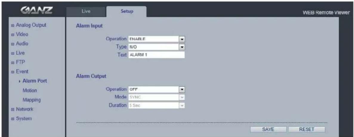
GANZ Live Setup WEB Remote Viewer Analog Output Video Audio Live FTP Event ► Alarm Port Motion Mapping ► Network ► System Alarm Input Operation ENABLE Type N/O Text ALARM 1 Alarm Output Operation OFF Mode SYNC Duration 5 Sec SAVE RESETAlarm Input - Used for connecting external alarm devices and triggering images for specific alarm-based events. The input is typically connected to a motion detector or any other external security device, and images could be uploaded whenever the detector is activated. Maximum 5VDC is allowed on the input.
Output - This could drive a maximum load of 0.5A 125VAC / 1A 30VDC directly or heavier loads by connecting additional relay circuitry. If the output is used with an external relay, a diode must be connected in parallel with the load for protection against any voltage transients.
Duration - This parameter sets the minimum tampering period, that is, an alarm will not be triggered until this period has lapsed, even if the tampering conditions are otherwise met. This could help to prevent false alarms for known conditions that affect the image.
Caution! Connecting AC to the inputs/outputs will damage the unit.
10.2 Event > Motion
text_image
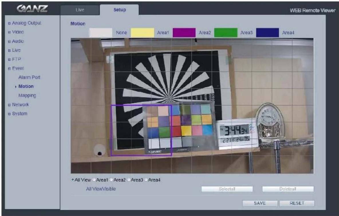
GANZ Live Setup WEB Remote Viewer Motion None Area1 Area2 Area3 Area4 All View Area1 Area2 Area3 Area4 All ViewVisible Select All Delete all SAVE RESETMotion Detection
Motion detection is used to generate an alarm whenever movement either occurs or stops in the video image. A total of 10 windows could be configured.
Configuring Motion Detection
- Click Motion Detection in the Event Config menu.
- Click Add Window, and select if you want to add an Include or an Exclude window by checking the relevant box.
- Enter a descriptive name for the window.
- Adjust the size (drag the bottom right-hand corner) and position (click on the text at the top and drag to the desired position).
- Adjust the Object size, History and Sensitivity profile sliders (see table below for details). Any detected motion within an active window is then indicated by red peaks in the Activity window (the active window has a red frame).
- Click Save.
Note: Using the motion detection feature may decrease the camera's overall performance.
10.3 Event > Mapping
text_image
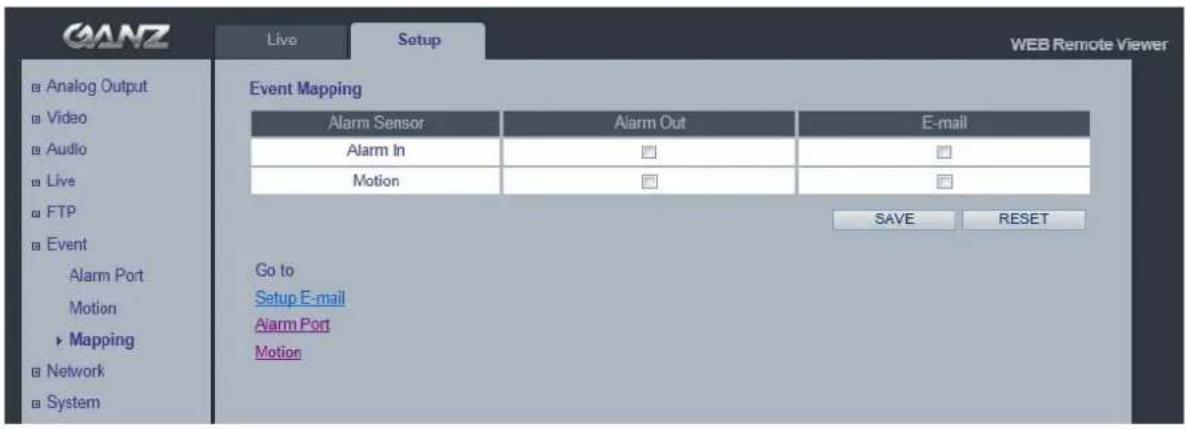
GANZ Live Setup WEB Remote Viewer Analog Output Video Audio Live FTP Event Alarm Port Motion Mapping Network System Event Mapping Alarm Sensor Alarm Out E-mail Alarm In Motion SAVE RESET Go to Setup E-mail Alarm Port MotionIt is possible to define conditions that would cause the camera to respond with certain actions. A triggered event happens as a result of a trigger, which could be motion detection or an external alarm input.
For example,
Alarm out events could be triggered by video motion detection or alarm in. E-mail could be sent by video motion detection or alarm in.
11. Network
11.1 Network > IP Setup
text_image
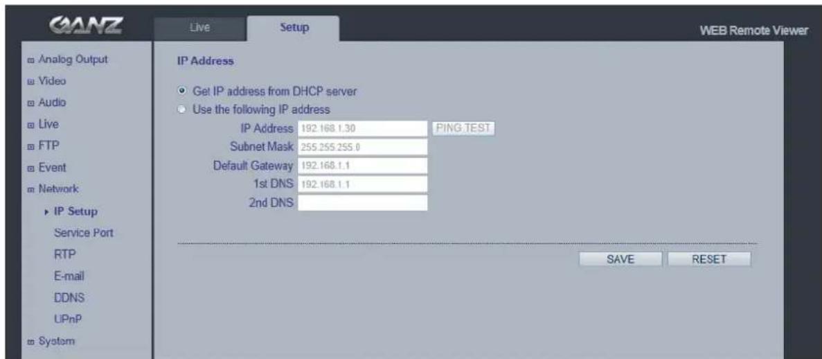
GANZ Live Setup WEB Remote Viewer Analog Output Video Audio Live FTP Event Network IP Setup Service Port RTP E-mail DDNS UPnP System IP Address Get IP address from DHCP server Use the following IP address IP Address 192.168.1.30 PING TEST Subnet Mask 255.255.255.0 Default Gateway 192.168.1.1 1st DNS 192.168.1.1 2nd DNS SAVE RESETNetwork Settings
Click the Setup > Network > IP Setup to see the current network settings.
IP Address Configuration -
The GANZ PixelPro supports both IP version 4 and IP version 6 (IPv6 will be supported in V3.00). Both versions may be enabled simultaneously, and at least one version should be always enabled.
When using IPv4, the IP address could be set automatically via DHCP, or a static IP address could be set manually. If IPv6 is enabled, your camera receives an IP address according to the configuration in the network router.
There are also options for setting up notification of changes in the IP address, and for using the Internet Dynamic DNS Service.
Notes: • To receive notification whenever the camera's IP address changes (via e.g. DHCP), configure the options for notification of IP address change. See Services below. • If your DHCP server could update a DNS server, you could access the GANZ PixelPro by a host name which is always the same, regardless of the IP address.
DNS Configuration
DNS (Domain Name Service) provides the translation of host names to IP addresses on your network.
- 1st DNS server
Enter the IP address of the primary DNS server for your network.
•2nd DNS server
Enter the IP of the Secondary DNS, which is used if the Primary DNS server is unavailable.
How to assign IP address
Default setting is set to "DHCP" and "UPnP" function is set to ON. If your network has DHCP server and UPnP function is enabled on your PC, you can find the network camera in "My network".
If DHCP server is not available in your network, please assign IP address as following process.

text_image
MULTI Upgrade Tool Y4.00 STEP NAC Address Type IP Address HTTP Port Model SW Ver. Status READY 00:1C:B8:30:0A:25 DHCP 192.168.1.25 80 ZN-DT2MA ZN2C0.2.1985.32 0-connected READY 00:1C:B8:30:2D:44 STATIC 192.168.1.115 80 ZN-DT2MAP ZN2C0.2.1985.32 0-connected READY 00:1C:B8:30:2E:A8 DHCP 192.168.1.7 80 ZN-B2MAP ZN2C0.2.2023.32 0-connected READY 00:1C:B8:30:00:55 STATIC 192.168.1.113 80 ZN-C2M ZN2C0.2.1985.32 0-connected READY 00:1C:B8:30:45:6E STATIC 192.168.1.173 80 ZN-D1A ZN2C0.2.2023.32 0-connected READY 00:1C:B8:30:37:65 STATIC 192.168.1.13 80 ZN-B2MAP ZN2C0.2.1985.32 0-connected READY 00:11:SF:0B:51:25 DHCP 192.168.1.8 80 ZN-D2MTP-R ZN2C0.2.1149.32 0-connected NIC Select : Any IPv41) Execute "MultiUpgradeTool.exe", it will search the camera on the network.
2) After the camera is listed in camera list, select the camera.
3) Type in the all network information.
4) Click "Change IP address" button to set network settings to the camera.
When you double-click the camera within the list, the default web browser (Internet Explorer or compatible equivalent) will open and automatically connect to the camera.
11.2 Network > Service Port
text_image
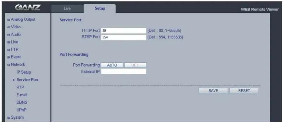
GANZ Live Setup WEB Remote Viewer Service Port HTTP Port 80 [Def: 80, 1~65535] RTSP Port 554 [Def: 554, 1~55535] Port Forwarding Port Forwarding AUTO DEL External IP SAVE RESET Analog Output Video Audio Live FTP Event Network IP Setup Service Port RTP E-mail DDNS UPnP SystemService Port
HTTP port- The default HTTP port number (80) could be changed to any port within the range 1-65535. This is useful for simple port mapping.
RTSP port- The RTSP protocol allows a connecting client to start an H.264 stream. Enter the RTSP port number to use. The default setting is 554.
NOTE: After changing the default port numbers, the user can use the "MultiUpgradeTool.exe" to search and connect automatically.
11.3 Network > RTP
text_image
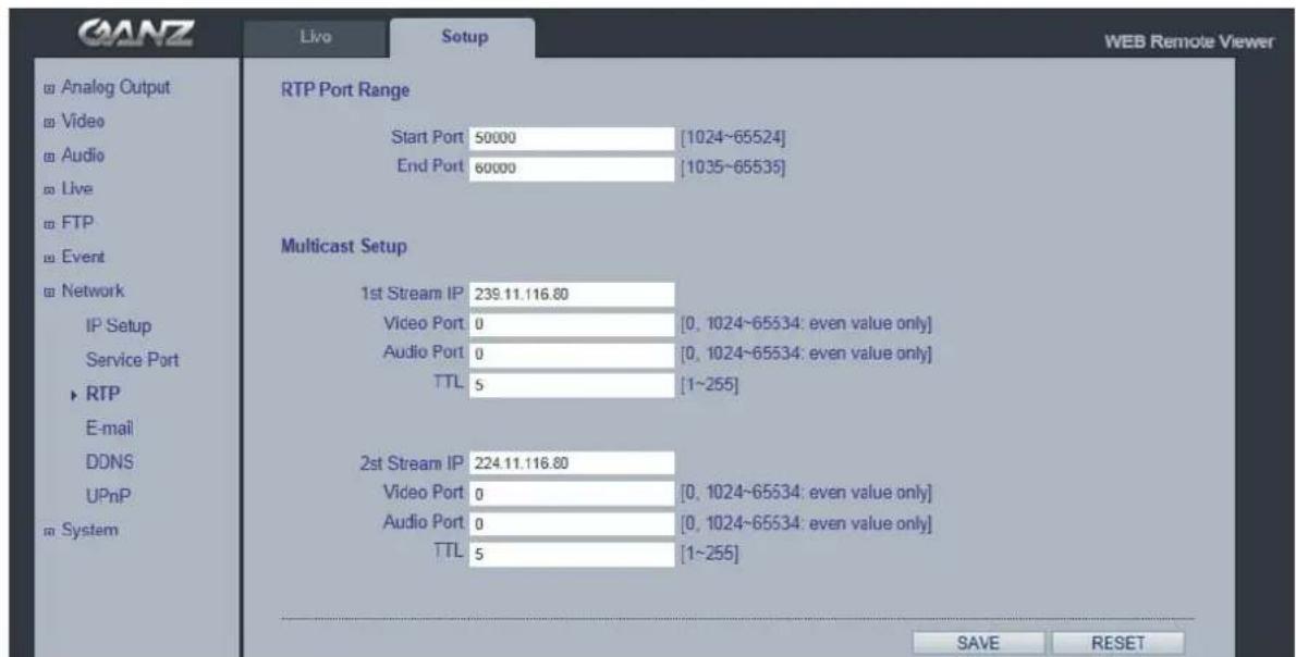
GANZ Live Setup WEB Remote Viewer Analog Output Video Audio Live FTP Event Network IP Setup Service Port ► RTP E-mail DDNS UPnP ■ System RTP Port Range Start Port 50000 [1024~65524] End Port 60000 [1035~65535] Multicast Setup 1st Stream IP 239.11.116.80 Video Port 0 [0, 1024~65534: even value only] Audio Port 0 [0, 1024~65534: even value only] TTL 5 [1~255] 2nd Stream IP 224.11.116.80 Video Port 0 [0, 1024~65534: even value only] Audio Port 0 [0, 1024~65534: even value only] TTL 5 [1~255] SAVE RESETRTP port range, Multicast Setup
These settings are the IP address, port number, and Time-To-Live value to use for the video stream(s) in multicast H.264 format.
Only certain IP addresses and port numbers should be used for multicast streams.
11.4 Network > E-mail
text_image
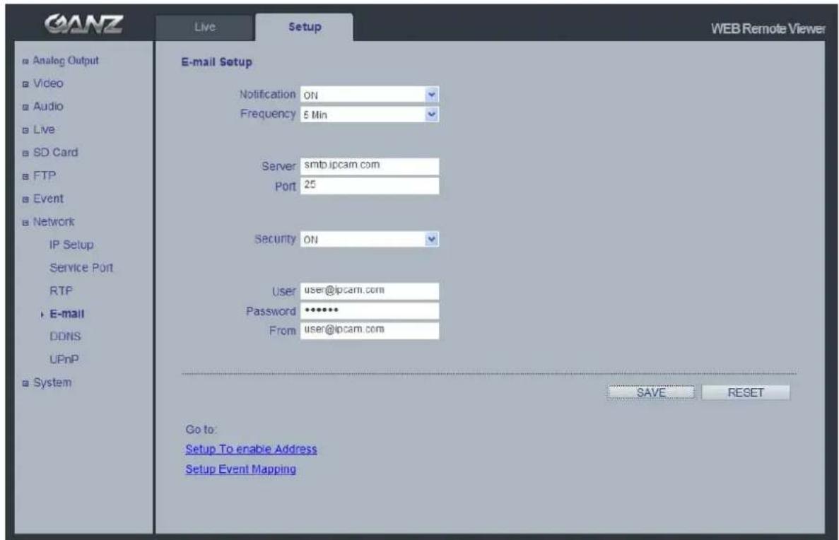
GANZ Live Setup WEB Remote Viewer Analog Output Video Audio Live SD Card FTP Event Network IP Setup Service Port RTP E-mail DDNS UPnP System E-mail Setup Notification ON Frequency 5 Min Server smtb.ipcam.com Port 25 Security ON User user@ipcam.com Password ***** From user@ipcam.com SAVE RESET Go to: Setup To enable Address Setup Event MappingYou must turn Notification to 'On' and then enter the host names or addresses for your mail servers in the fields provided, to enable the sending of event and error email messages from the camera to predefined addresses via SMTP.
Note1)
Frequency : Mail server may register the sender to SPAM list when frequency is set to "1 Min". It may be better to set "5 Min" for safe side.
Note2)
From : Specify the name who sent e-mail notification. It may be better to use e-mail format like as aaa@bbbb.com. Some e-mail server will refuses it.
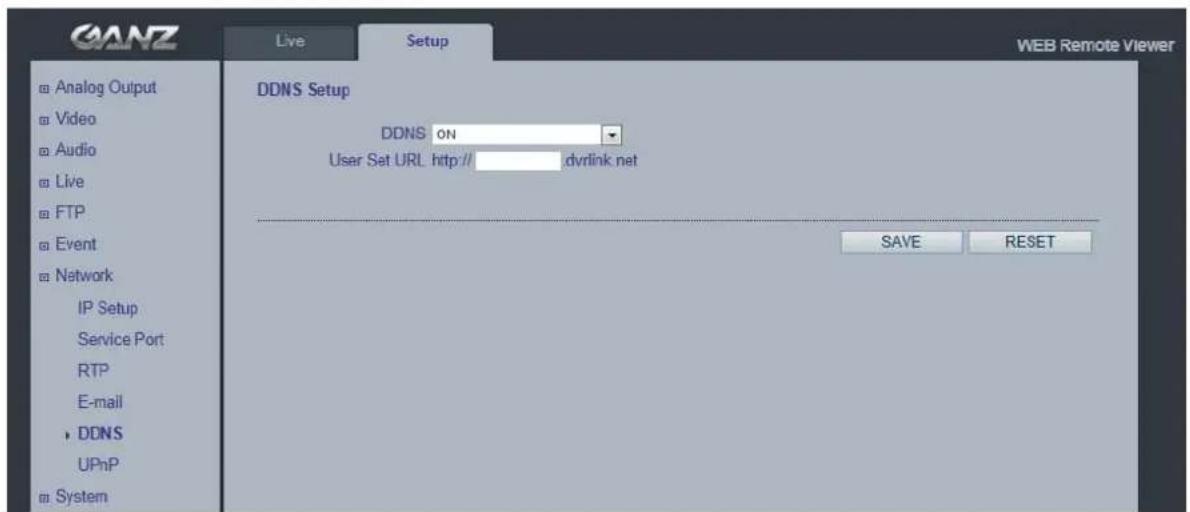
11.5 Network > DDNS
text_image
GANZ Live Setup WEB Remote Viewer Analog Output Video Audio Live FTP Event Network IP Setup Service Port RTP E-mail DDNS UPnP System DDNS Setup DDNS ON User Set URL http://dvrlink.net SAVE RESETHow to setup the DDNS:
1) DDNS set to ON.
"mac address.dvrlink.net" is registered to the DDNS server.
User can connect to the camera with: "http://mac address.dvrlink.net".
2) DDNS set to ON and user inputs "user-defined name".
"mac address.dvrlink.net" and "user-defined name.dvrlink.net" are both registered together.
User can connect to the camera using either:
"http://mac address.dvrlink.net" or "http://user-defined name.dvrlink.net".
If "user-defined name" is already registered, an error message is shown, try a different name.
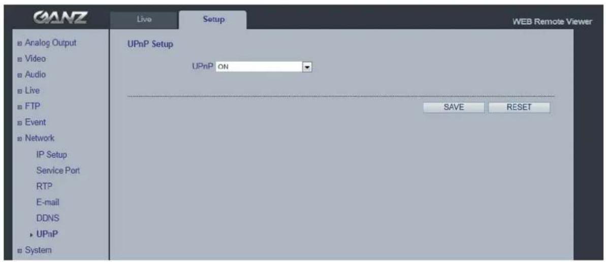
11.5 Network > UPnP
text_image
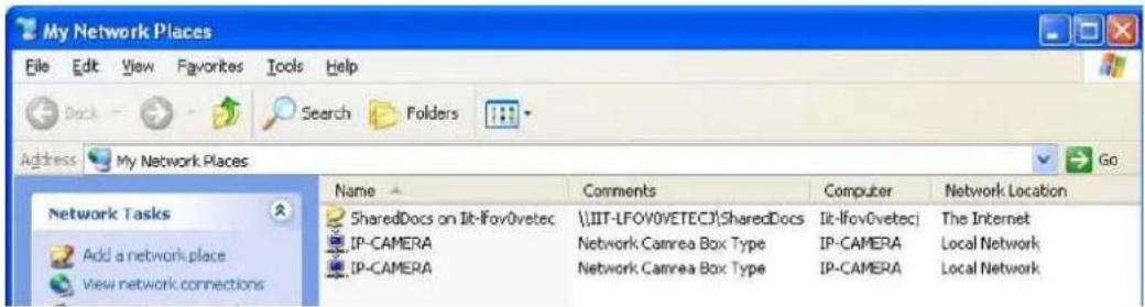
GANZ Live Setup WEB Remote Viewer ■ Analog Output ■ Video ■ Audio ■ Live ■ FTP ■ Event ■ Network IP Setup Service Port RTP E-mail DDNS ► UPnP ■ System UPnP Setup UPnP ON SAVE RESETUniversal Plug & Play (UPnP) allows you to find the IP camera automatically on your network.
text_image
My Network Places File Edit View Favorites Tools Help Back Search Folders Address My Network Places Go Network Tasks Add a network place View network connections Name Comments Computer Network Location SharedDocs on It-Ifov0vetec \\IIT-LFOV0VETECJ\SharedDocs It-Ifov0vetecj The Internet IP-CAMERA Network Camrea Box Type IP-CAMERA Local Network IP-CAMERA Network Camrea Box Type IP-CAMERA Local NetworkIn order to be able to detect the camera automatically, you must enable the UPnP function on both the camera and on your PC.
Camera : Set UPnP to "ON"
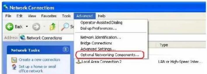
PC : Open "Control Panel" >"Network Connection"
Select "Advanced" >"Optional Networking Components..."
text_image
Network Connections File Edit View Favorites Tools Back Address Network Connections Network Tasks Create a new connection Set up a home or small office network Advanced Help Operator-Assisted Dialing Dial-up Preferences... Network Identification... Bridge Connections Advanced Settings... Optional Networking Components... Local Area Connection 2 Type LAN or High-Spec Inter...Select "Network Services" and click "Details". Then select "UPnP user Interface"
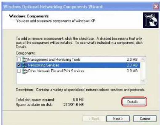
text_image
Windows Optional Networking Components Wizard Windows Components You can add or remove components of Windows XP. To add or remove a component, click the checkbox. A shaded box means that only part of the component will be installed. To see what's included in a component, click Details. Components: □ Management and Monitoring Tools 2.0 MB ☑ Networking Services 0.3 MB □ Other Network File and Print Services 0.0 MB Description: Contains a variety of specialized, network-related services and protocols. Total disk space required: 0.0 MB Space available on disk: 225781.6 MB Details... < Back Next > Cancel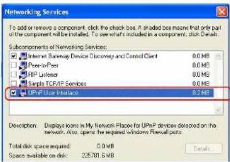
text_image
Networking Services To add or remove a component, click the check box. A shaded box means that only part of the component will be installed. To see what's included in a component, click Details. Subcomponents of Networking Services: Internet Gateway Devices Discovery and Control Client 0.0 MB Peer-to-Peer 0.0 MB RIP Listener 0.0 MB Simple TCP/IP Services 0.0 MB UPnP User Interface 0.2 MB Description: Displays icons in My Network Places for UPnP devices detected on the network. Also, opens the required Windows Firewall ports. Total disk space required: 0.0 MB Space available on disk: 225781.6 MB12. System
12.1 System > User
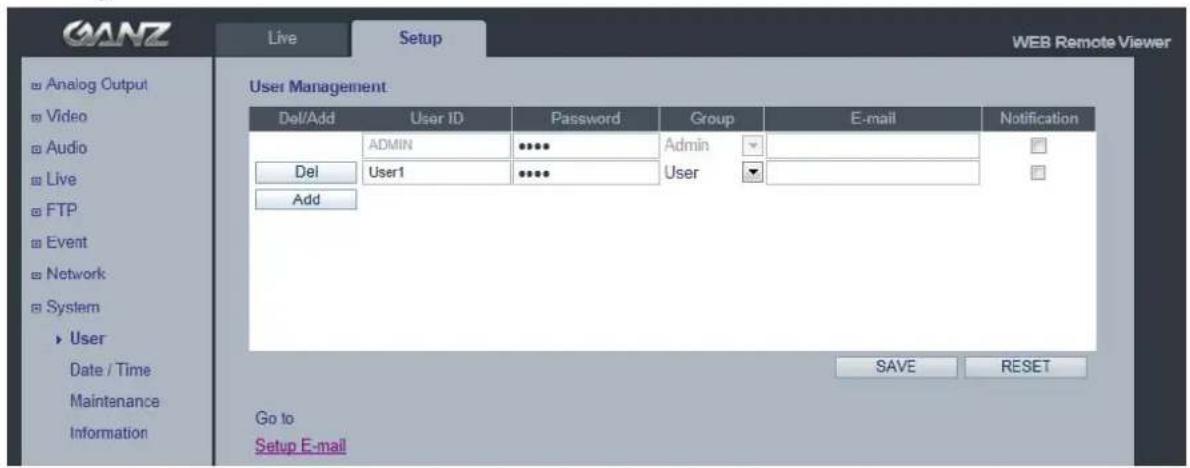
text_image
ANZ Live Setup WEB Remote Viewer User Management Del/Add User ID Password Group E-mail Notification ADMIN **** Admin Del User1 **** User Add GO to Setup E-mail SAVE RESETAccess the camera and the Configure Root Password dialog appears.
Enter the User name: ADMIN and password is 1234.
To changed password or add a user click SETUP > SYSTEM > USER. Fill the User ID,
Password and E-mail server. Select Group. Then press ADD button and click SAVE.
Note: The default administrator user name ADMIN is permanent and could not be deleted or altered.
12.2 System > Date & Time
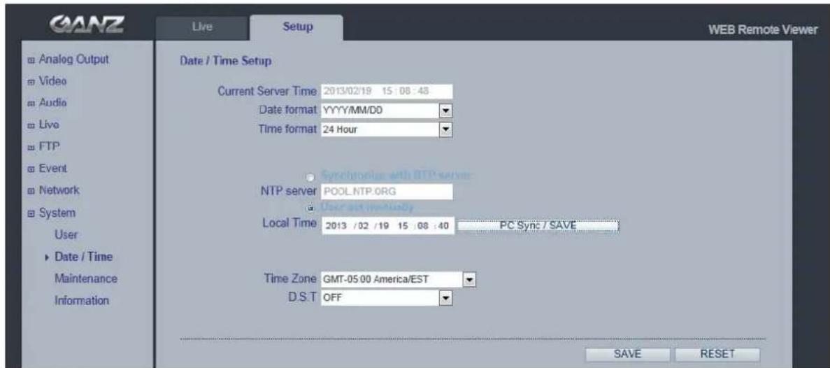
text_image
GANZ Live Setup WEB Remote Viewer Date / Time Setup Current Server Time 2013/02/19 15:08:48 Date format YYYY/MM/DD Time format 24 Hour NTP server POOL NTP.ORG Local Time 2013 /02 /19 15:08:40 PC Sync / SAVE Time Zone GMT-05:00 America/EST D.S.T OFF Date / Time Maintenance Information Analog Output Video Audio Live FTP Event Network System User ► Date / Time Maintenance Information SAVE RESETDate & Time Format - specify the formats for the date and time (12h or 24h) displayed in the Live View video streams. Use the predefined formats or use your own custom date and time formats.
Network Time Server - the camera will obtain the time from an NTP server every 60 minutes. Specify the NTP server's IP address or host name.
Time zone setup – Select your time zone from the drop-down list.
D.S.T (Daylight Saving Time) - ON/OFF
12.3 System > Maintenance
text_image
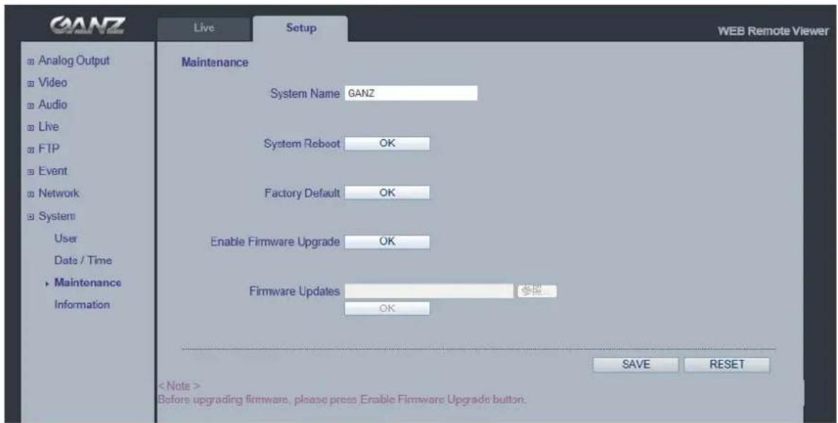
GANZ Live Setup WEB Remote Viewer Maintenance System Name GANZ System Reboot OK Factory Default OK Enable Firmware Upgrade OK Firmware Updates OK SAVE RESET < Note > Before upgrading firmware, please press Enable Firmware Upgrade button.System Name
Choose a system name to identify the camera when using e-mail notifications.
System Reboot
Reboot the camera.
Factory Default
To reset the camera back to the original factory default settings.
Enable Firmware Upgrade / Firmware Updates
To upgrade Firmware of the camera, follow the instruction below.
NOTE: Preconfigured and customized settings should be saved before the firmware is upgraded.
1) Enable Firmware Upgrade mode with clicking "OK" of Enable Firmware Upgrade menu.
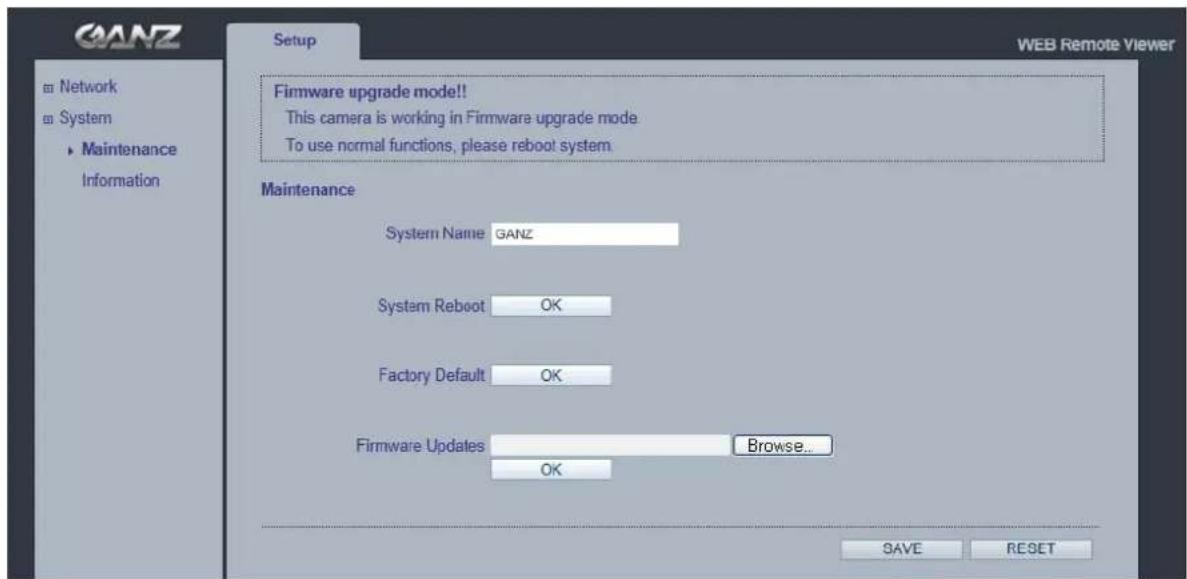
2) The camera automatically switch to Firmware Upgrade mode.
Changing to Firmware Update Mode...

3) When Firmware upgrade menu is displayed, browse to the desired firmware file on your computer. Click OK.
text_image
GANZ Network System Maintenance Information Setup WEB Remote Viewer Firmware upgrade mode!! This camera is working in Firmware upgrade mode To use normal functions, please reboot system. Maintenance System Name GANZ System Reboot OK Factory Default OK Firmware Updates Browse... OK SAVE RESETNOTE: Do not disconnect power to the unit during the upgrade. The unit will restart automatically after the upgrade has completed. (1\~5 minutes)
System Reset (Factory Default Reset)
There are two ways to reset the camera back to factory default. holding down about 10-20 sec the reset button on the Network cable
Using the web browser:
- Go to SETUP > System > Maintenance.
- Click Factory Default Button and wait 1 minute for camera to reboot.
Using the Reset Button:
- Holding down 10-20 sec the reset button on the Network cable.
- Release your finger on the reset button, waiting about 1 minute for camera reboot
NOTE: The unit will now have the default IP address from a DHCP server. Use the "MultiUpgradeTool.exe" to discover and connect to the camera.
12.4 System > Information
text_image
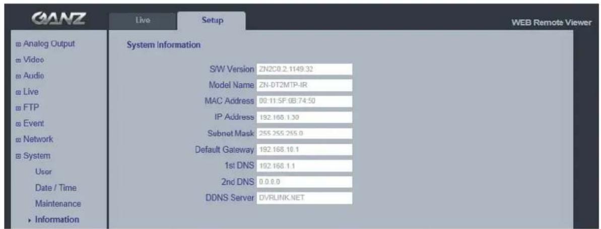
GANZ Live Setup WEB Remote Viewer Analog Output Video Audio Live FTP Event Network System User Date / Time Maintenance Information System Information S/W Version ZN2C0.2.1149.32 Model Name ZN-DT2MTP-IR MAC Address 00:11.5F.0B.74:50 IP Address 192.168.1.30 Subnet Mask 255.255.255.0 Default Gateway 192.168.10.1 1st DNS 192.168.1.1 2nd DNS 0.0.0.0 DDNS Server DVRLINK.NETSystem Information
You can confirm the system information if the camera here.
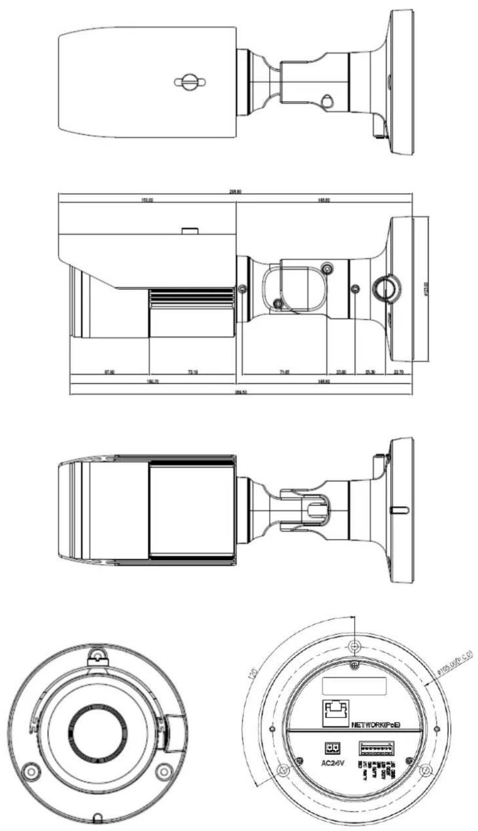
13.DIMENSION (mm)
- Specification
| Product Features | H.264 / MJPEG Network Camera | |
| Dual Stream | ||
| Motion Triggered Alarm/ External Alarm In | ||
| Multi Language GUI support | ||
| ONVIF Compliant | ||
| Dual Power: 24VAC, PoE(802.3af) | ||
| SONY CMOS Sensor IMX-122 | ||
| On The Fly supported @ GOP/Bitrate/FPS stetting | ||
| 2D DNR. (Depends on CODEC configuration)- 3D TBD | ||
| DPC(Defective Pixel Correction) on the fly | ||
| IR LED 42ea | ||
| Motorized Zoom, Focus and P-iris | ||
| True Day & Night | ||
| Analog Hybrid Output(Installation Only) | ||
| SDHC card slot | ||
| Heater | ||
| Fan | ||
| CAMERA | Image Sensor | 1/2.8" Sony IMX-122 CMOS Sensor |
| Max. Resolution | 1920 x 1080 | |
| Effective Pixels | 1984(H) x 1225(V) | |
| Effective Image Size | 5.56mm(H) x 3.43mm(V), 6.53mm(Diagonal) | |
| White Balance | ATW / MANUAL(PRESET) | |
| Electronic Zoom | 2 ~ 10x(Client Software) | |
| AGC | Yes | |
| BLC | Yes | |
| Iris | Motorized Iris / MANUAL / AES | |
| Shutter Speed | 1/4, 1/10, 1/12.5, 1/15, 1/20, 1/25, 1/30, 1/50, 1/60, 1/100, 1/120, 1/240, 1/480, 1/960, 1/1024, 1/2000s | |
| Slow Shutter | 2x | |
| Lens | Motorized Zoom and Focus lens f=3~9mm, F1.2~2.1 | |
| Day & Night | Removable IR Cut Filter | |
| S/N ratio | 48.8 dB or more | |
| Min. illumination | 0.16 lux(F1.2, 50IRE) with IR LED OFF0 lux with IR LED ON | |
| 50IRE 0.16(without IR) | ||
| ANALOG (Installation Only) | Video Signal | NTSC/PAL selectable |
| Monitor Output | Composite Output(BNC), 75 ohm 1Vpp | |
| Scanning Frequency | NTSC: (H) 15.734 kHz, (V) 59.94 Hz | |
| PAL: (H) 15.625 kHz, (V) 50 Hz | ||
| AUDIO | In/Out | Line in, Line out |
| External Amplifier is needed | ||
| CODEC | G.711 / 8K sampling | |
| NETWORK | Network | 10BASE-T, 100BASE-TX, RJ45 |
| Image Compression | H.264 : High Profile | |
| MJPEG : Image quality: 100 Steps(Q value) | ||
| Resolution | 1920 x 1080(Full HD), 1280 x 1024(SXGA), | |
| 1024x768(XGA), 1280 x 720(720p) | ||
| 640 x 480(VGA), 320 x 240(QVGA) | ||
| 704x480/576(4CIF), 352x240/288(CIF) | ||
| Protocol | IPv4, HTTP, SMTP, UPnP, DNS, | |
| RTP, TCP, UDP, RTCP, DHCP, ARP, IGMP, | ||
| IGMP, ICMP, NTP / IPv6(TBD) | ||
| Frame Rate | 1 fps ~ 25 fps / 1 fps ~ 30 fps | |
| Web Browser | Internet Explorer 7.0 or above | |
| Firefox | ||
| Chrome | ||
| PDA/Smart phone | ||
| Security | Password Protection | |
| SDK(API) | HTTP based API ONVIF | |
| VMD | User set 4 ROI(Region Of Interest) | |
| 10 Step Sensitivity | ||
| Alarm Trigger | VMD, External Alarm Input | |
| Alarm Event | E-mail notification(Snapshot), FTP transfer(Snapshot), SD Card(Snapshot), Video streaming with alarm status | |
| POWER Power Source | 24VAC(50Hz/60Hz) 2A | |
| PoE(IEEE 802.3af/at compliant) | ||
| Power Consumption | 400mA @ AC24V, 4.8 W1.48A @ AC24V, Max 16.7W(IR / p-iris / FAN ON)110mA @ DC48V(PoE), Max 5W200mA @ DC48V(PoE), Max 9.6W(IR / p-iris / FAN ON) | |
| Heater | 5W | |
| OTHER SPECIFICATIONS | Micro SD Card | SDHC card compatibleSanDisk,Transcend,Kingstone,Toshiba:2G, 4G, 8G, 16G or more |
| External I/O Terminals | Alarm In x1: NO/NC Dry contactAlarm Out x1: Relay output | |
| Audio In x1, Audio Out x1 | ||
| IR Number / Distance | 42EA / 30M | |
| FAN Number | 1EA | |
| Ambient Temperature | -10°C ~ 50°C(14°F~122°F) | |
| With Heater -40°C ~ 50°C(-40°F~122°F) | ||
| Ambient Humidity | less than 90%, Non-condensing | |
| Materials | Aluminum Diecasting | |
| Weight | 1.9kg | |
| Dimensions(W x H x D) | Φ150X350(H) mm | |

natural_image
Symbol of a trash bin crossed with no text or numbers, representing waste sorting or disposal (no text present)
English
Disposal of your old appliance
- When this crossed-out wheeled bin symbol is attached to a product it means the product is covered by the European Directive 2002/96/EC.
- All electrical and electronic products should be disposed of separately from the municipal waste stream via designated collection facilities appointed by the government or the local authorities.
- The correct disposal of your old appliance will help prevent potential negative consequences for the environment and human health.
- For more detailed information about disposal of your old appliance, please contact your city office, waste disposal service or the shop where you purchased the product.
Français/French
CBC (POLAND) Sp.zo.o
Warszawa
http://www.cbcpoland.pl
CBC Co., Ltd. MOSCOW REP OFFICE
Moscow
http://www.cbc.ru
CHINA
CBC(Beijing) Trading CO.,LTD.
Beijing
http://www.cbc-china.cn/10/
CBC (SHANGHAI) TRADING CO., LTD.
Shanghai
http://www.cbc-china.cn/10/
CBC SHANGHAI CO., LTD. GUANGZHOU OFFICE
Guangzhou
http://www.abc-china.cn/10/
CBC (H.K.) CO., LTD.
Hong Kong
http://www.abc-china.cn/10/
ASIA
CBC. S PTE LTD.
Singapore
CBC(THAILAND) CO., LTD.
Bangkok
CBC CO., LTD. MUMBAI REP OFFICE
Mumbai