
TriCaster 460 - Régler NEWTEK - Free user manual and instructions
Find the device manual for free TriCaster 460 NEWTEK in PDF.


User questions about TriCaster 460 NEWTEK
0 question about this device. Answer the ones you know or ask your own.
Ask a new question about this device
Download the instructions for your Régler in PDF format for free! Find your manual TriCaster 460 - NEWTEK and take your electronic device back in hand. On this page are published all the documents necessary for the use of your device. TriCaster 460 by NEWTEK.
USER MANUAL TriCaster 460 NEWTEK
Trademarks: NewTek, TriCaster, TriCaster XD, TriCaster 8000, TriCaster TCXD8000, TCXD8000, TriCaster 860, TriCaster TCXD860, TCXD860, TriCaster 460, TriCaster TCXD460, TCXD460, TriCaster 410, TriCaster TCXD410, TCXD410, TriCaster 40, TriCaster TCXD40, TCXD40, TriCaster 855, TriCaster TCXD855, TCXD855, TriCaster 455, TriCaster TCXD455, TCXD455, TriCaster EXTREME, TriCaster 850 EXTREME, TriCaster TCXD850 EXTREME, TCXD850 EXTREME, TriCaster 450 EXTREME, TriCaster TCXD450 EXTREME, TCXD450 EXTREME, TriCaster 850, TriCaster TCXD850, TCXD850, TriCaster 450, TriCaster TCXD450, TCXD450, TriCaster 300, TriCaster TCXD300, TCXD300, TriCaster PRO, TriCaster STUDIO, TriCaster BROADCAST, TriCaster DUO, 3PLAY, 3Play, 3Play 4800, 3PXD4800, 3Play 820, 3PXD820, 3Play 425, 3PXD425 3Play 330, 3PXD330, ProTek, ProTek Care, ProTek Elite, iVGA, SpeedEDIT, IsoCorder, LiveText, DataLink, LiveSet, TriCaster Virtual Set Editor, TriCaster VSE, LiveMae, TimeWarp, VT, VT[3], VT[4], V[T5], Video Toaster, Toaster, Inspire 3D, 3D Arsenal, Aura, LightWave, LightWave 3D and LightWave CORE are trademarks, service marks, and registered trademarks of NewTek. All other brand names, product names, or trademarks belong to their respective holders.
CHAPTER 1 ABOUT THIS MANUAL ....3
CHAPTER 2 INTRODUCTION ....5
SECTION 2.1 MEET THE FAMILY ....5
SECTION 2.2 OVERVIEW....5
SECTION 2.3 STARTUP SCREEN ....6
SECTION 2.4 LIVE DESKTOP....7
SECTION 2.5 FEATURES....8
2.5.1 Physical....8
2.5.2 Mul-Tier Failsafe 8
2.5.3 A/V Input and Output 9
2.5.4 Alpha Channel I/O 10
2.5.5 Timecode 10
2.5.6 Monitoring 11
2.5.7 Video Processing 11
2.5.8 The Switcher 12
2.5.9 M/Es....14
2.5.10 Virtual Sets 15
2.5.11 Record and Stream.... 15
2.5.12 Media Publishing....16
2.5.13 Macros 16
2.5.14 Hotspots, Triggers and Trackers....16
2.5.15 Import and Export 17
2.5.16 Audio Mixer....17
2.5.17 Audio Remote Control....18
2.5.18 Integrated Media Players....18
2.5.19 Buers 19
2.5.20 Titles and Graphics 20
2.5.21 Edit 20
2.5.22 Oponal Control Surfaces 20
CHAPTER 3 SETTING UP ......23
SECTION 3.1 COMMAND AND CONTROL....23
SECTION 3.2 ACTIVATING & AUTHORIZING WINDOWS ^® 24
SECTION 3.3 LICENSE AND REGISTRATION ....25
3.3.1 Online Registraon....26
3.3.2 Registering by Telephone 26
SECTION 3.4 RACK MOUNTING TRICASTER ....27
SECTION 3.5 INPUT CONNECTIONS....28
3.5.1 Connect A/V Sources 28
3.5.2 Connecting a Video Router 30
SECTION 3.6 GENLOCK CONNECTION .... 32
SECTION 3.7 TIMECODE CONNECTION....32
SECTION 3.8 OUTPUT CONNECTIONS....33
3.8.1 A/V Output 33
3.8.2 HD and SD 33
3.8.3 Supplemental Video Outputs....35
SECTION 3.9 TALLY LIGHTS....36
3.9.1 Connecon Details 36
SECTION 3.10 STARTING A SESSION....37
SECTION 3.11 CONFIGURE VIDEO OUTPUT ....40
3.11.1 Channel Opons 42
SECTION 3.12 CONFIGURE VIDEO INPUTS....43
3.12.1 Configure a Video Router Input 45
SECTION 3.13 CONFIGURE AUDIO....45
SECTION 3.14 CONFIGURE GENLOCK ....48
SECTION 3.15 CONFIGURE TIMECODE....49
SECTION 3.16 NETWORKING....50
CHAPTER 4 LIVE PRODUCTION WALKTHROUGH ....51
SECTION 4.1 CREATING A SESSION....51
SECTION 4.2 IMPORTING CONTENT ....52
SECTION 4.3 CONFIGURING SHARE ACCOUNTS ....53
SECTION 4.4 MONITORING....55
4.4.1 Program and Preview....55
4.4.2 WorkspaceS....56
4.4.3 Scopes 59
SECTION 4.5 AUDIO MIXER....60
4.5.1 Mute, Mono and Balance....60
4.5.2 Pan 61
4.5.3 Talk....63
4.5.4 Follow 63
SECTION 4.6 NETWORK SOURCES....65
4.6.1 iVGA Clients 65
4.6.2 Apple AirPlay ^® 67
4.6.3 LiveText™ 67
SECTION 4.7 LIVE SWITCHING....67
4.7.1 Switcher Rows 67
4.7.2 Transions....71
SECTION 4.8 RECORD AND GRAB ....78
4.8.1 Record 78
4.8.2 Grab....79
SECTION 4.9 MEDIA PLAYERS....81
4.9.1 The DDRs 81
4.9.2 Graphics Players 86
SECTION 4.10 LIVEMATTE & M/ES....90
SECTION 4.11 MORE ABOUT M/ES 94
4.11.1 Composing M/E Layers....94
4.11.2 Adding an Upstream Overlay 96
4.11.3 LiveSet™ 98
SECTION 4.12 BUFFERS....100
SECTION 4.13 STREAMING....102
4.13.1 Streaming Conguraon....102
4.13.2 Simple Pull Streaming 103
4.13.3 Push and RTMP Streaming 105
4.13.4 Capturing the Stream....105
CHAPTER 5 THE STARTUP SCREEN ....109
SECTION 5.1 INTRODUCTION TO SESSIONS .... 110
SECTION 5.2 THE HOME PAGE....112
5.2.1 New (Session) 112
5.2.2 Open (Session)....114
5.2.3 Shutdown 116
5.2.4 Help 121
5.2.5 Add-Ons....121
SECTION 5.3 THE SESSION PAGE....122
5.3.1 Live 122
5.3.2 Graphics 122
5.3.3 Manage 124
CHAPTER 6 LIVE DESKTOP: OVERVIEW....131
SECTION 6.1 DISPLAY REQUIREMENTS....131
SECTION 6.2 OVERVIEW....132
SECTION 6.3 STANDARD CONTROLS....133
SECTION 6.4 CUSTOMIZING THE LIVE DESKTOP ....134
6.4.1 Rename Input....134
6.4.2 Workspaces and Min/Maximize....134
CHAPTER 7 THE DASHBOARD....137
SECTION 7.1 FILE MENU ....138
SECTION 7.2 OPTIONS MENU....138
SECTION 7.3 HELP....140
SECTION 7.4 INFORMATION PANEL....140
CHAPTER 8 I/O CONFIGURATION....143
SECTION 8.1 OUTPUT CONFIGURATION....143
8.1.1 Output Tab 144
8.1.2 Stream and Network 149
8.1.3 Genlock & Failsafe 150
8.1.4 Center Frequency 153
8.1.5 Failsafe 153
SECTION 8.2 INPUT CONFIGURATION ....154
8.2.1 Connecon Type 154
8.2.2 Act as Alpha 158
8.2.3 Frame Sync 158
8.2.4 Proc Amp....159
8.2.5 Edges 161
8.2.6 LiveMae 162
8.2.7 HotSpots....163
8.2.8 Tracker 163
8.2.9 PTZ....166
SECTION 8.3 NETWORK INPUTS ....167
SECTION 8.4 TIMECODE CONFIGURATION....168
8.4.1 Subtract 12 Hours....168
8.4.2 Event Time....169
8.4.3 LTC Timecode 169
CHAPTER 9 SWITCHER, TRANSITIONS AND OVERLAY....171
SECTION 9.1 SWITCHER ROWS 171
9.1.1 Program and Preview....172
SECTION 9.2 VIDEO LAYERS....172
9.2.1 Selectng Sources....173
9.2.2 Linking Switcher Rows....174
SECTION 9.3 TRANSITIONS....174
9.3.1 DSK Controls 175
9.3.2 Main Controls....180
SECTION 9.4 SWITCHER MEM SLOTS....184
CHAPTER 10 MONITORING YOUR VIDEO .... 185
SECTION 10.1 INTERFACE AND MULTIVIEW....185
10.1.1 TriCaster 8000 Workspace Presets....186
10.1.2 Viewport Tools 188
SECTION 10.2 PROGRAM MONITOR....189
SECTION 10.3 LOOK AHEAD PREVIEW....190
SECTION 10.4 SCOPES .... 192
10.4.1 Clocks 193
10.4.2 Custom Image 193
CHAPTER 11 MEDIA PLAYERS & BUFFERS .... 195
SECTION 11.1 SPECIALIZED MEDIA PLAYERS....195
SECTION 11.2 SHARED FEATURES....196
11.2.3 Player Controls....202
11.2.4 MEM Slots 204
11.2.5 Network Sharing 206
SECTION 11.3 EDITING TITLE PAGES....207
SECTION 11.4 BUFFERS....209
11.4.1 Buer Types 210
11.4.2 Selecng Content 212
11.4.3 Buers Menu....213
11.4.4 Animaon Features....213
11.4.5 Sharing Buers....214
11.4.6 Watch Folders 215
11.4.7 Using Buers 215
11.4.8 Keying, Proc Amps and More 216
11.4.9 Eding tles 217
CHAPTER 12 PTZ CONTROL .... 219
SECTION 12.1 THE PTZ TAB 219
12.1.1 The Camera Bin 220
12.1.2 PTZ Presets 220
12.1.3 Conguring Presets 221
12.1.4 PTZ and the Control Surface 222
CHAPTER 13 LIVEMATTE ......223
SECTION 13.1 CHROMAKEYING....224
SECTION 13.2 MATTE....224
13.2.1 Color 225
13.2.2 Tolerance....225
13.2.3 Smoothness....226
13.2.4 Luma Limit....226
SECTION 13.3 SPILL SUPPRESSION....227
SECTION 13.4 COMPOSITING ....227
SECTION 13.5 FINE TUNING....227
SECTION 13.6 PRACTICAL STAGING FOR LIVEMATTE....228
13.6.1 Lighng 228
13.6.2 Connecon Consideraons....229
CHAPTER 14 MIX/EFFECT (M/E) TOOLS....231
SECTION 14.1 OVERVIEW....231
SECTION 14.2 M/E MODES....232
14.2.1 Mix Mode 233
14.2.2 Eect Mode 233
14.2.3 input Posion Controls 234
14.2.4 Default Eects....234
14.2.5 Virtual Sets 241
14.2.6 Holographic LiveSets 245
SECTION 14.3 KEY CHANNELS ......247
CHAPTER 15 AUDIO ...... 249
15.1.1 Audio Specicaons 250
SECTION 15.2 HEADPHONES....250
SECTION 15.3 VU METER CALIBRATION....250
SECTION 15.4 EXTERNAL SOURCES....251
15.4.1 Connecon Type 251
SECTION 15.5 COMMON CONTROLS....253
15.5.1 Mute 253
15.5.2 Lock 253
15.5.3 Talk (Talk Over) 254
15.5.4 Solo....254
SECTION 15.6 INTERNAL SOURCES ...... 255
15.6.1 Net 1 and Net 2 255
15.6.2 Media Players....255
15.6.3 Eects (Transions)....256
SECTION 15.7 ADVANCED CONFIGURATION ...... 256
15.7.1 Audio Delay 256
15.7.2 Follow 257
15.7.3 Pan 257
15.7.4 Roung 258
15.7.5 Processing 262
SECTION 15.8 OUTPUT AND PRIMARY BUS CONTROLS....265
15.8.1 Headroom Notes 266
15.8.2 Record 267
15.8.3 Stream....267
SECTION 15.9 MEM SLOT BINS ....267
CHAPTER 16 NETWORK INPUTS ...... 269
SECTION 16.1 IVGA....270
16.1.1 iVGA for OS X....270
16.1.2 iVGA PRO (Windows)....272
16.1.3 Taskbar Icon Menu 277
16.1.4 Hotkeys....278
SECTION 16.2 AIRPLAY....278
SECTION 16.3 LIVETEXT ....279
SECTION 16.4 3PLAY™ 280
SECTION 16.5 NETWORK VIDEO 280
CHAPTER 17 MACROS, AUTOMATION AND REMOTE CONTROL....283
SECTION 17.1 SYSTEM MACROS....284
SECTION 17.2 RECORDING MACROS....285
SECTION 17.3 MANAGING MACROS....286
17.3.1 Assigning Shortcuts 286
17.3.2 The Context Menu 287
SECTION 17.4 MACROS AND HOTSPOTS ...... 288
SECTION 17.5 EDIT A MACRO ...... 289
SECTION 17.6 REMOTE CONTROL ....290
17.6.1 'Twinning' TriCasters....290
CHAPTER 18 STREAMING....293
SECTION 18.1 OVERVIEW....294
18.1.1 Compact View 295
SECTION 18.2 WEB BROWSER....295
SECTION 18.3 CONNECTION OPTIONS....295
18.3.1 RTMP 296
18.3.2 Windows Media Pull....298
18.3.3 Windows Media Push....299
18.3.4 Browser Based 300
SECTION 18.4 AUDIO LEVEL....301
SECTION 18.5 CAPTURING THE STREAM ....301
SECTION 18.6 STREAMING STRATEGIES ....301
18.6.1 On Demand or Live Streaming? 302
18.6.2 Streaming Protocols 304
18.6.3 Streaming Media Providers....307
18.6.4 Other Resources 307
SECTION 18.7 PRODUCTION AND CAPTURE CONSIDERATIONS....308
SECTION 18.8 DIAGNOSTICS AND TROUBLESHOOTING....309
18.8.1 Tesng your stream 309
18.8.2 Is it Really a TriCaster Issue? 317
CHAPTER 19 PUBLISH....319
SECTION 19.1 OVERVIEW....319
SECTION 19.2 ACCOUNT CONFIGURATION....319
19.2.1 Social Media Sites....320
19.2.2 File Copy and FTP 320
19.2.3 Compression....321
19.2.4 Watermarking 321
SECTION 19.3 THE PUBLISH QUEUE....321
19.3.1 Managing the Queue 324
19.3.2 Choosing Desnaons....324
19.3.3 More 'Add to Queue' Methods....325
CHAPTER 20 RECORD AND GRAB....327
SECTION 20.1 RECORD....327
SECTION 20.2 ISOCORDER™ 327
20.2.1 Record Conguraon 328
SECTION 20.3 GRAB....334
CHAPTER 21 LIVETEXT™ AND SPEEDEDIT™ 337
SECTION 21.1 LIVETEXT ....337
21.1.1 Sessions, Projects and Display 337
21.1.2 Files/Filebin 338
21.1.3 Naming Stand-in Images....339
SECTION 21.2 SPEEDEDIT....339
21.2.1 Sessions, Projects and Display 340
21.2.2 IEEE1394 I/O Output 340
21.2.3 SpeedEDIT Desktop 340
CHAPTER 22 CONTROL SURFACES....345
SECTION 22.1 SOMETHING FOR EVERYONE ....345
22.1.1 Primary Control 345
22.1.2 Instant Replay 346
22.1.3 More Opons ....346
SECTION 22.2 CONNECTIONS & POWER....347
22.2.1 Power Consideraons....347
SECTION 22.3 TRICASTER™ 8000 CS....348
22.3.1 Overview 348
22.3.2 Delegates and Synchronizaon 349
22.3.3 MAIN TRANSITION Group....350
22.3.4 M/E Controls 353
22.3.5 POSITIONER Group 356
22.3.6 MEDIA PLAYERS Group....359
22.3.7 Record Group 361
22.3.8 Special Buttons....361
22.3.9 MACRO 362
22.3.10 T-Bar Illuminaon....362
22.3.11 M/E TRANSITION – Lighng 362
22.3.12 MAIN TRANSITION 363
22.3.13 PTZ Control 363
SECTION 22.4 TRICASTER™ 460 CS & 860 CS 364
22.4.1 Overview 365
22.4.2 Special Buons....366
22.4.3 Delegates and Synchronizaon 366
22.4.4 Switcher Controls 367
22.4.5 Transion Group 369
22.4.6 M/E Group 372
22.4.7 Posioner Group 375
22.4.8 Media Player Group 379
22.4.9 Record Group 380
22.4.10 PTZ Control 380
SECTION 22.5 TIMEWARP™ 381
22.5.1 Overview 382
22.5.2 DDR Delegate 384
22.5.3 Edit group 385
22.5.4 Play Speed 385
22.5.5 Marking Group 386
22.5.6 ALT and Qualiers 388
22.5.7 Record toggle 389
22.5.8 DDR opons....389
22.5.9 Preset (DDR Playlist)....390
22.5.10 Transport (Clip controls)....390
22.5.11 Tips and Tricks....391
SECTION 22.6 AVID® ARTIST MIX....392
22.6.1 Installing AVID® Artist Mix Soware 393
22.6.2 Connecng Arst Mix....393
22.6.3 Geng started.... 394
22.6.4 Panel Layout 395
22.6.5 NUDGE 396
22.6.6 BANK 396
22.6.7 Level Control....397
22.6.8 Knob Set Selectors 397
22.6.9 Pan Control....398
22.6.10 Talk....399
22.6.11 Solo & Mute 399
22.6.12 Follow 399
22.6.13 EQ Control 400
22.6.14 Compressor/Limiter....401
22.6.15 CHAN Mode....401
22.6.16 FLIP Mode....402
22.6.17 INSERT 403
22.6.18 Locking Channels....403
22.6.19 Audio Presets....404
SECTION 22.7 MIDI CONTROL....405
SECTION 22.8 TRICASTER™ 40 CS....407
22.8.1 Delegates and Synchronizaon 407
22.8.2 Switcher Delegates....407
22.8.3 SHIFT & ALT 409
22.8.4 Transions....410
SECTION 22.9 TRICASTER™ LC-11 412
A HOW DO I ... (?) 415
A.1 CONNECTIONS 418
A.1.1 Connect cameras? 418
A.1.2 Connect II + alpha sources?......418
A.1.3 Congure alpha mae output?......419
A.1.4 Color correct mismatched cameras?......419
A.1.5 Connect monitors? 420
A.1.6 Connect a supported external control surface? 422
A.1.7 Mirror control operaons to another TriCaster? 422
A.1.8 Insert/Remove a Drive From TriCaster's Removable Drive Bay 423
A.1.9 Connect An External Hard Drive? 424
A.1.10 Eject A Hard Drive? 424
A.1.11 Connect tally lights? 425
A.1.12 Connect to a network? 425
A.1.13 Locate a speci TriCaster on my network? 425
A.1.14 Resolve iVGA PRO Quirks 425
ADDITIONAL NOTES 425
A.1.15 Connect to an AirPlay® Source? 426
A.1.16 Enable Terminaon for video inputs? 429
A.1.17 Congure Wirecast® to receive TriCaster's Network output? 429
A.2 SESSIONS....430
A.2.1 Start an SD Session? 431
A.2.2 Start an HD Session? 431
A.2.3 Work on a Stored Session? 432
A.2.4 Backup a Session? 432
A.2.5 Restore a Session? 432
A.2.6 Delete a Session (and its Content)?......433
A.2.7 Manage Selected Content inside a Session? 433
A.2.8 Rename a Session?......433
A.2.9 Duplicate a session? 433
A.3 LIVE PRODUCTION....434
A.3.1 Make Custom Transions and LiveSets? 434
A.3.2 Restore the Default LiveSet? 434
A.3.3 Set up the 'Nightly Show A' LiveSet? 434
A.3.4 Set up the 'Night Beat 3D' LiveSet?......436
A.3.1 Set up the 'Metropolis A' LiveSet? 437
A.3.2 Initiate Streaming? 439
A.3.3 Find my Captured Stream le? 439
A.3.4 Record my Program? 440
A.3.5 Find my Recorded Program File?......440
A.3.6 Change Playback Speed for Clips in the DDR (Media Player)? 440
A.3.7 Deal With DDR (Media Player) Clips That Seem Blurry? 441
A.3.8 Get Stubborn Clips to Play in the DDR? 441
A.3.9 Change Colors for an Enre Title Playlist at Once? 443
A.3.10 Get Live Title Pages (.cgxml) to Respect All LiveText Font Aributes? ......444
A.3.11 Prepare a Matched Group of M/Es? 444
A.3.12 Improve the Quality of Mulview Output? 445
A.4 FILES....445
A.4.1 Manage Files? 445
A.4.2 Import Media Files? 445
A.4.3 Share Files On YouTube 446
A.4.4 Prepare Clips with Embedded Alpha Channel? 446
A.4.5 Add an External File Locaon to the File Browser? 447
A.4.6 Remove a Locaon From the File Browser? 447
A.4.7 Export les to an External Drive? 447
A.4.8 Import/Export Files Larger Than 4 Gigabytes? 447
A.4.9 Repair damaged recordings? 448
A.4.10 Avoid the Error “...copy this le without its properes?” 448
A.4.11 Free up Space by Deleng the Demo Clips? 448
A.5 SOFTWARE, MAINTENANCE AND UPDATES....449
A.5.1 Improve Performance?......449
A.5.2 Resolve Serious Instability or Dropped frames? 449
A.5.3 Update TriCaster? 449
A.5.4 Update the Flash ^® and/or Windows Media Encoder ^® ? 450
A.5.5 Install Virus Protecon? 450
A.5.6 Install My Favorite Soware (or Codec)?......451
A.5.7 Create a 'User Backup' Drive....451
A.5.8 Restore TriCaster Soware 452
A.6 REGISTRATION AND TECH SUPPORT 454
A.6.1 Register TriCaster? 454
A.6.2 Contact Customer Support? 455
A.6.3 Find TriCaster's Hardware/Firmware Revision Numbers? 455
A.7 MISCELLANEOUS 455
A.7.1 Access System Administraon Features? 455
A.7.2 Return to TriCaster from Administrator Mode 455
A.7.3 Add A Custom Streaming Prole to the Congure Stream Connecon Panel?......455
A.7.4 Use My iPad ^® As A MIDI Controller?......459
A.8 MORE QUESTIONS AND ANSWERS....465
A.8.1 Can I do anything to improve latency/audio sync? 465
A.8.2 Why is my power supply beeping? 465
A.8.3 Why Do Some Thumbnail Icons Look Wrong? 466
B PERFORMANCE CONSIDERATIONS 467
B.1 TESTING, ONE TWO ....467
B.2 IVGA™ AND PERFORMANCE 467
B.3 IMAG AND LATENCY 468
B.3.1 Relavity and the Speed of Light 468
B.3.2 Latency and Your Audience 469
B.3.3 Latency and Your TriCaster 469
B.3.4 Other Sources of Latency 470
C.2.1 Seng Black and White....474
C.2.2 Adjustng Color....476
C.2.3 Color Metrics 477
C.3 CALIBRATING YOUR MONITORS 479
C.3.1 Computer Monitor 480
C.3.2 Program Output Monitor....480
C.3.3 Color Adjustments....481
C.4 FURTHER READING 482
D KEYSTROKE SHORTCUTS....483
D.1 SWITCHER....483
D.2 T-BAR 484
D.3 RECORD, GRAB, AND STREAM 484
D.4 TABS....484
D.5 WORKSPACE 484
D.5.1 TriCaster 8000....484
D.5.2 TriCaster 410, 460 and 860 485
D.6 DDR 1....485
D.7 DDR 2....485
D.8 GRAPHICS 1....486
D.9 GRAPHICS 2 486
D.10 SOUND....486
D.11 GENERAL 487
D.11.1 Edit Title Pane 487
D.11.2 Selecon and Navigaon....487
D.11.3 Misc. 487
E DIMENSIONS AND MOUNTING....489
SECTION 22.10 TRICASTER 460 AND 410....489
SECTION 22.11 TRICASTER 8000 AND 860....490
SECTION 22.12 TRICASTER 8000 CS....491
SECTION 22.13 TRICASTER 860 CS....492
SECTION 22.14 TRICASTER 460 CS....493
F RELIABILITY TESTING 495
INDEX 497
CREDITS 503
PART I (GETTING STARTED)
Introducing TriCaster – connections and registration, a top-level overview of primary features, and a hands-on tour to get you started.

text_image
TCThis manual tells you everything you need to know to use your TriCaster™, and occasionally, even more. It attempts to convey essential information in a friendly, concise way, while also providing a deeper reference section you can turn to when you really need all of the relevant details.
Even if you are the hands-on, never-ask-directions type, please peruse this page. If any questions about your TriCaster arise later, you may ind the information here allows you to jump directly to the details you need with a minimum of reading.
PART I - GETTING STARTED
Introduction to TriCaster™: connecting devices (cameras, monitors, etc.) and registration, ending with the Live Production Walkthrough – a brisk jog through fundamentals, a bit less than 60 pages.
PART II - REFERENCE
This section covers every arcane detail related to using TriCaster (for those who need it, and those who just like to know everything).
PART III - APPENDICES
Leads off with a handy section titled "How do I ...?", a helpful question and answer section with its own brief index. When you have a specific need, you may well ind a quick answer here, along with cross references to more detailed information when appropriate.
Appendix D lists all shortcut keys. You will also ind a comprehensive keyword index in Part III.
Note: Consistency of layout, controls and features is a noteworthy attribute of the professional TriCaster family. This makes it easy for you to move between TriCaster models without either a significant learning curve or errors, and also lets us reveal them in a single manual. Model differences are noted in this Guide where necessary by remarks such as “TriCaster 8000 only”, “8-input models only”, etc..

text_image
TCThank you for purchasing this NewTek TriCaster™ system. NewTek is extremely proud of its record of innovation and commitments to excellence in design, manufacture, and superb product support. This chapter provides a quick tour of the major components of your new live production system.
SECTION 2.1 MEET THE FAMILY
All professional model TriCasters bear a strong family resemblance. The user interfaces of TriCaster 410, 460 and 860 have a great deal in common with the tagship system, TriCaster 8000. The latter, of course, has a number of unique attributes and features, but in large measure, many aspects of the worklow and user software are (intentionally) very similar. Among other benefits, this makes it easy for TriCaster users working with multiple machines to feel right at home and avoid errors.
SECTION 2.2 OVERVIEW
Not so long ago, live high deinition television production demanded very expensive equipment, daunting technical skills, and a large crew. TriCaster™ changed all that. In one compact system, it provides a complete set of tools you can use to create, broadcast, web stream and project your production. TriCaster even includes NewTek's latest edition of the famous LiveSet™ virtual set system to provide you with network quality 'bigger than life' production capabilities.
TriCaster continues to set new benchmarks for live production systems. Simply put it represents the most complete, reliable and efficient integrated system available for live production and web streaming. Its capabilities are equally well suited to broadcast center installations and remote production, and it can be operated, if desired, by just one person.
No matter what your live broadcast ambitions are, Newtek and TriCaster stand ready to help you fulfill them.
With TriCaster you can produce and distribute live video programs from diverse sources and digital media in both standard and high deinition. Use multiple cameras, network video sources, recorded digital video, multimedia presentations from networked laptops, live web pages, digital photos and graphics, control robotic cameras, and much more.
TriCaster also supports the Apple AirPlay® protocol, allowing off-the-shelf mobile video devices (such as iPhone® and iPad®) to stream content wirelessly to TriCaster. Your presentations can simultaneously be displayed by video projectors, television monitors, broadcast by traditional means, and streamed in high quality on the Internet.
SECTION 2.3 STARTUP SCREEN
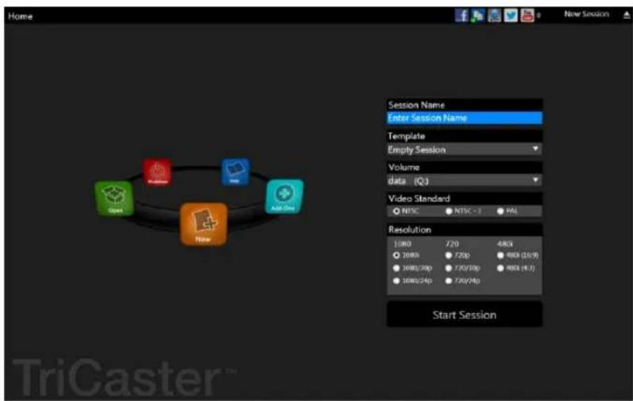
When you power up TriCaster the Startup Screen appears. This is your command center for initiating most other operations.
text_image
Home New Session Session Name Enter Session Name Template Empty Session Volume data (Q) Video Standard NTSC NTSC - 1 PSL Resolution 1000 720 4800 1000/30p 720/p 8800 (15:9) 1000/24p 720/30p 8800 (-1:1) Start Session TriGasterFIGURE 1
The Home page of the Startup Screen allows you to define and open sessions, essentially custom presets for individual productions or other purposes. Later, when you re-open a session, all of its assets and settings are remembered.
After creating a session (or opening an existing one), you are taken to the Session Page. Here you can launch the Live Desktop (for live production), or perhaps choose to prepare Graphics (title pages), Manage content (including importing and exporting media), or even create custom transitions.
SECTION 2.4 LIVE DESKTOP
TriCaster's live production features are all available from its unique Live Desktop, which in many ways mimics familiar production equipment. However, the Live Desktop provides far more functionality than similar single-purpose devices, all in one integrated environment.
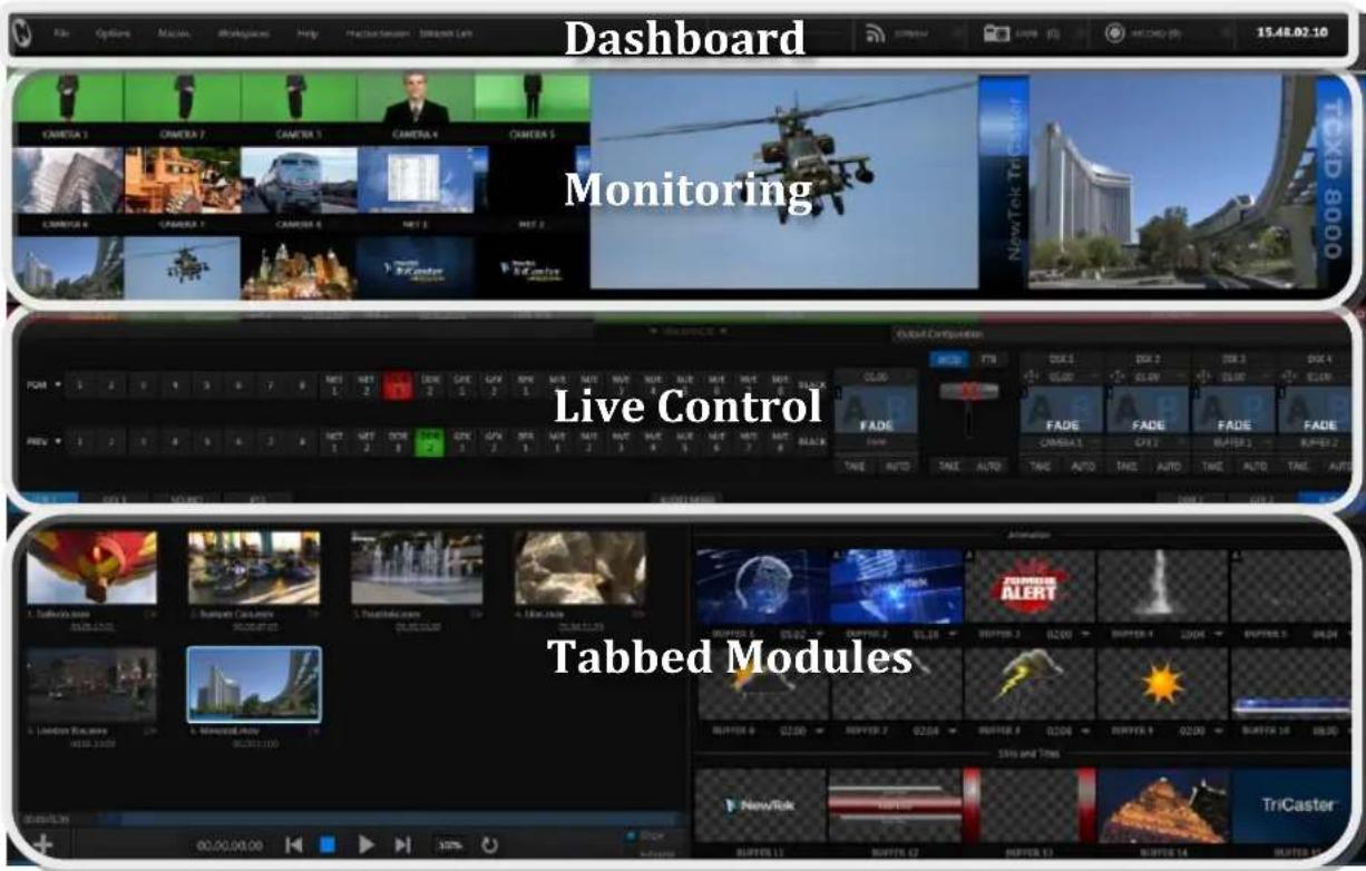
The various features, controls and modules comprising TriCaster's Live Desktop are arranged in horizontal bands, as seen in Figure 2.
text_image
Dashboard Monitoring Live Control Tabbed ModulesFIGURE 2
- The top-most band contains TriCaster's convenient and powerful Dashboard.
- The area just below the Dashboard is *normally devoted to a multi-pane monitoring display, providing source and output views.
* This area can be re-sized, and even completely hidden when outboard monitoring is in use; or the display can be customized to complement the external Multiview or for numerous other purposes. - The central Live Control section is home to the Switcher, Transition, DSKs (overlay channels) and M/E controls (M/E panels can be minimized, and are hidden from view in Figure 2).
- The bottom third of the Live Desktop holds tabbed control modules, including Media Players (DDRs and Graphics players. plus a Sound player) and Buffers, PTZ camera controls and the Audio Mixer.
SECTION 2.5 FEATURES
Here's a brief overview of just some of TriCaster's key features:
2.5.1 PHYSICAL
• Rugged rack-mount case
- Redundant power supplies (TriCaster 8000 and 860 only) ensure robust, reliable and quiet performance in fixed or mobile installations.
• Massive storage capacity.
- All audio and video, monitoring and network connectors are easily accessible from the rear for convenient installation in industry standard 19" rack-mount configurations.
- Audio and video connectors are industry standard (XLR, 14 " audio jack or BNC as appropriate), ensuring broad compatibility and secure, locked connections. Headphone output uses a standard 1/4" stereo jack.
2.5.2 MULTI-TIER FAILSAFE
TriCaster's ‘Always on Air’ features provide multi-tiered redundant failsafe mechanisms in both hardware and software.
To name just a few:
- Multiple software failsafe systems continually monitor and safeguard the live performance. Any recoverable software error conditions are quickly and unobtrusively dealt with.
- Video pass-through (see Section 8.1.5) ensures that as long there is AC power, audio and video from Input 8 (on 8-input models) or Input 4 (4-input models) are routed to Output 1 in a case of catastrophic software condition.
- If at all possible, streaming output and recording also continue even if all else fails.
- TriCaster also has a comprehensive integrated system restore feature. Operators can quickly and easily restore to factory defaults, or create a custom restore image on another drive and either restore from that drive or use the backup drive to boot from if a complete hard drive failure ever occurs.
- Should a 'less than ideal' control surface USB connection fail, TriCaster will automatically restart it without user intervention.
2.5.3 A/V INPUT AND OUTPUT
- Live switch up to eight live video sources (8-input models), including SDI, *analog, or a mixture of both types, plus internal and local or remote network video sources. (*TriCaster 410 does not have analog video inputs.)
- TriCaster 8000 only: connect popular video routers to greatly multiply input options.
- Professional BNC video connectors provide increased durability and reliability for camera connections.
• Control supported robotic (PTZ) cameras via network or serial connection. - Freely mix 16:9 or 4:3 SD formats with HD sources live.
- Output HD sessions as HD and SD (4:3 or 16:9) simultaneously from HD sessions.
- Multiple Media Player modules allow you to insert pre-recorded video, music, sounds and imagery into your live presentations.
-
Select Microsoft Windows® or Apple Macintosh® computers on the same network as Switcher inputs for your live productions using NewTek's iVGA™ clients.
-
Assign one or both Network inputs on the Switcher to receive AirPlay® streams and switch live or recorded content directly from your compatible Apple® mobile device or computer.
- Update still Buffers in ‘watch folders’ from networked graphic workstations, even when these are displayed live.
- Transmit output to another TriCaster across the local network.
- Create complex M/E effects and compositions using multiple sources and versatile virtual sets with live (virtual) camera moves.
- TriCaster 8000 (only) M/Es are reentrant, allowing you to cascade unbelievable effects in endless creative ways
- Use switcher row grouping to automatically harmonize video sources for multiple M/E s, etc.
- Mix and route internal and external audio sources, including analog or SDI Embedded audio.
- Either two or *three primary video outputs (*8-input models) TriCasters only) plus HDMI, streaming and Network output can all supply independent feeds; designate between two fully configurable output mixes or individual sources at various resolutions up to 1920x1080 for output.
• (TriCaster 8000 only) two additional Display ports. - Send either the main or a custom audio mixes independently to any of the primary audio outputs, HDMI and the Internet stream.
2.5.4 ALPHA CHANNEL I/O
- Alternate video inputs can be configured as key channels for Fill + Alpha sources.
- Network input sources, including third-party CG applications (etc.) support embedded alpha channel (freeing up two video inputs).
• Alpha channel (matte) output.
2.5.5 TIMECODE
- Supports industry standard (LTC) external timecode (not a TriCaster 410 feature).
- Default Quicktime® recording format includes full 'per frame' time-code.
- IsoCorder™ recorded clips from multiple sources are easily aligned for synchronized post show editing using embedded timecode (IsoCorder is not a TriCaster 410 feature).
2.5.6 MONITORING
text_image
CAMERA 1 CAMERA 2 CAMERA 3 CAMERA 4 CAMERA 5 CAMERA 6 CAMERA 7 CAMERA 8 MET 1 MET 2 New York Tru Center TCKD 8000 COM 2 MET 2.12.00 GEX 1 (MAY 21.02) GFX 2 (MAY 21.02) FEB APC FUNCTIONS PROGRAMFIGURE 3
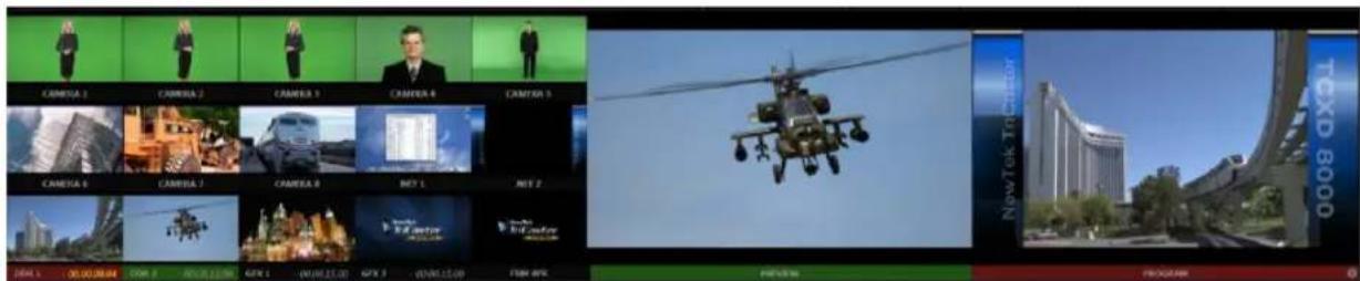
- TriCaster's Live Desktop includes a large monitoring pane with numerous multiple easily customized Workspaces. By default, this area includes Program output and Look Ahead Preview monitors with associated controls, along with all inputs.
- Configurable desktop monitor array allows you to keep an eye on all live and internal video sources, including Media Players and Network sources.
- Waveform and Vectorscope monitors help you calibrate your signal to ensure your output meets broadcast standards and looks great.
- External Multiview Workspaces offer many alternatives, including numerous multi-bridge layouts, overlays and Event Clocks.
- (TriCaster 8000 only) Monitor sources on both Live Desktop and Multiview are entirely user-conigurable, and include Media Player clip timecode counters, and custom logo display.
2.5.7 VIDEO PROCESSING
• Full 4:4:4:4 32-bit loating point internal processing of all video sources.
- Proc Amps and White Balance controls for every source preserve pristine image and color idelity.
2.5.8 THE SWITCHER
TriCaster's powerful 24-channel (8-input models)) or 15-channel switcher with native support for popular professional video routers puts countless video sources at your ingertips.

text_image
PGM 1 2 3 4 5 6 7 8 NET 1 NET 2 DDR 1 DDR 2 GFX 1 GFX 2 BFR 1 M/E 1 M/E 2 M/E 3 M/E 4 M/E 5 M/E 6 M/E 7 PREV 1 2 3 4 5 6 7 8 NET 1 NET 2 DDR 1 DDR 2 GFX 1 GFX 2 BFR 1 M/E 1 M/E 2 M/E 3 M/E 4 M/E 5 M/E 6 M/E 7FIGURE 4
VIDEO LAYERS AND TRANSITIONS
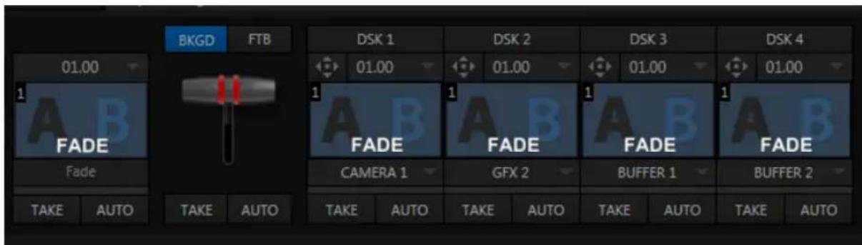
The Transition section of TriCaster's Live Desktop provides powerful tools for arranging and displaying the numerous video and graphic layers contributing to TriCaster's ultimate program output.
text_image
BKGD FTB 01.00 FADE FADE TAKE AUTO TAKE AUTO DSK 1 01.00 FADE CAMERA 1 DAK 2 GFX 2 DAK 2 DAK 3 01.00 FADE BAK 2 DAK 3 BAK 4 DAK 3 BAK 4 DAK 3 BAK 4 DAK 3 BAK 4 DAK 3 BAK 4 DAK 3 BAK 4 DAK 3 BAK 4 DAK 3 BAK 4 DAK 3 BAK 4 DAK 3 BAK 4 DAK 3 BAK 5 TAKE AUTO TAKE AUTO TAKE AUTO TAKE AUTO TAKE AUTOFIGURE 5
- Freely hot-punch or transition between external sources (Cameras or Network 1 or 2), internal sources (Media Players) and M/E effects.
- Latch selected Switcher and M/E source rows together in color groups to synchronize switching operations in multiple M/Es.
-
TriCaster 8000 provides 4 DSK (Downstream Key) channels for the Switcher and four independent Key channels for each M/E provide scores of creative possibilities. (Other models have two DSK and one M/E Key channel).
-
Use any of the hundreds of transitions supplied to reveal either Background or DSK/Key channels with animated wipes, trajectories and dissolves, or select colorful and dynamic Animation Store transitions with overlays, sound and TransWarp™ effects.
- Create an unlimited number of custom transition effects with embedded sounds, dynamic cloth effects, and full color overlays using the integrated Animation Store Creator application.
- Create eye-popping animated graphics using your favorite software (such as Adobe After Effects®), and convert them to colorful *animated Buffer effects that you can display on demand – without tying up a Media Player. (*Not a TriCaster 410 feature).
- Reveal combinations of video layers with a single operation of the T-bar or single-click Take and Auto buttons.
- Local Transition controls for BKGD (Background) and DSK layers provide flexible, independent layout and display of all layers and their transitions.
- Select individual transition effects for every layer; adjust Transition Speed, Reverse and Ping Pong options.
DSK CHANNELS
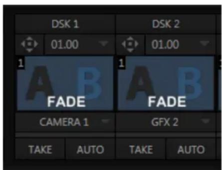
text_image
DSK 1 01.00 FADE CAMERA 1 DSK 2 01.00 FADE GFX 2 TAKE AUTO TAKE AUTOFIGURE 6
TriCaster's DSK layers support downstream overlays (not to mention M/E Key channels, which can serve as upstream overlays – that is ahead of the main Switcher). Some TriCaster models offer two DSKs, while TriCaster 8000 has four.
- Display DSK channels independently, and swap them during a switch with custom transitions for each.
- Use TriCaster's numerous Media Players to overlay title pages, including scrolls, crawls and lower-thirds, or assign a Camera feed or Network source to an overlay channel.
- Alternatively, use the Buffer channels to assign a specific title, still image or animation effect to any overlay channel.
- Independent Crop, Position, 3D Rotation, and Scale controls for each DSK channel permit you (for example) to configure multiple sources as 'Picture in Picture' elements, revealing them with individual custom effects).
2.5.9 M/ES
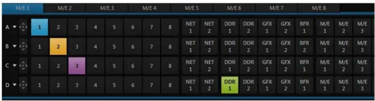
other
| | M/E 1 | M/E 2 | M/E 3 | M/E 4 | M/E 5 | M/E 6 | M/E 7 | M/E 8 | |---|---|---|---|---|---|---|---|---| | A ▼ | [icon] | 1 | 2 | 3 | 4 | 5 | 6 | 7 | | B ▼ | [icon] | 1 | 2 | 3 | 4 | 5 | 6 | 7 | | C ▼ | [icon] | 1 | 2 | 3 | 4 | 5 | 6 | 7 | | D ▼ | [icon] | 1 | 2 | 3 | 4 | 5 | 6 | 7 | NET 1 NET 2 DDR 1 DDR 2 GFX 1 GFX 2 BFR 1 M/E 1 M/E 2 M/E 3 NET 1 NET 2 DDR 1 DDR 2 GFX 1 GFX 2 BFR 2 M/E 1 M/E 2 M/E 3 NET 1 NET 2 DDR 1 DDR 2 GFX 1 GFX 2 BFR 1 M/E 1 M/E 2 M/E 3 NET 1 NET 2 DDR 1 DDR 2 GFX 1 GFX 2 BFR 1 M/E 1 M/E 2 M/E 3FIGURE 7 (TRICASTER 8000 SHOWN)
TriCaster's color-coded M/E (Mix/Effect) banks provide stunning effects.
These include secondary video mixing capabilities, switching (with traditional wipes or Animation Store transitions with TransWarp capabilities), full alpha channel support and
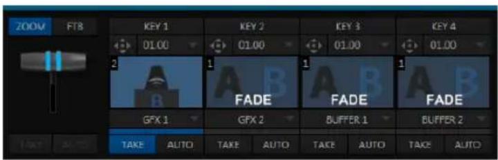
text_image
ZOOM FT8 KEY 1 01.00 KEY 2 01.00 KEY 3 01.00 KEY 4 01.00 2 1 A B FADE 1 A B FADE 1 A B GFX 1 GFX 2 BUFFER 1 BUFFER 2 TAKE AUTO TAKE AUTO TAKE AUTO TAKE AUTO TAKE AUTOFIGURE 8 (TRICASTER 8000)
LiveMatte™ realtime keying technology for green/blue screen effects, and jaw-dropping dynamic virtual sets, and much more.
Each M/E bank composition supports:
-
Multiple video sources (four for TriCaster 8000 only, or two).
• Additional Key (overlay) channels, with individual transition capabilities. -
Mix mode provides sub-mix functionality, with individual transitions for A/B Background layers and Key channel(s).
• Full keyers and discreet transition effects for every M/E channel.
• Individual Scale, Position, Crop and Rotation controls for all channels - Animated and still Buffer support in every channel.
• TriCaster 8000 provides powerful realtime motion Tracker support as well. - Convenient MEM slots allow instant access to pre-configured M / E setups.
2.5.10 VIRTUAL SETS
- Achieve the look of a large and sophisticated studio sets in a very small space with NewTek's astonishing LiveSet™ virtual set technology.
- Virtual sets support up to *4 keyable video sources (*requires TriCaster 8000).
- Zoom and pan the virtual ‘camera’ during live production (without touching the physical camera).
- Or use a Holographic LiveSet effect that lets you freely rotate and zoom the camera view.
- Set up custom virtual set animation targets even while live.
2.5.11 RECORD AND STREAM
- Record your live-switched production at full resolution to multi-platform, application friendly QuickTime® formats, and more.
- Quicktime® clips optionally include embedded timecode.
- IsoCorder™ technology lets you record up to eight a/v sources (8-input models) at once, including all camera inputs and both main outputs (not a TriCaster 410 feature).
- Grab still images from Output 1 or all inputs plus both main outputs (TriCaster 410 supports grabs from Program output only).
- Optional capture formats include MPEG-2, AVI, and H.264 (m4v).
- Quicktime and MPEG-2 iles include embedded timecode (TriCaster 410 does not support external timecode).
- Simultaneous output for broadcast, projector and live web stream to in-house and remote audiences.
-
Stream using Windows Media® or RTMP, and archive your stream locally.
-
Connect to content delivery networks easily using the powerful Conigure Stream Connection panel or dedicated third-party TriCaster plugins.
- Use NewTek's TimeWarp™ instant replay control surface to mark and replay highlights even while recording uninterrupted Program (or 'clean') output.
2.5.12 MEDIA PUBLISHING
Publish support makes it easy to distribute content to multiple targets in one pass. TriCaster stores credentials for social media and upload sites, and provides a queue for uploading and ile conversion.
text_image
Screenshot of a social media app interface showing five platforms: Facebook, WeChat, TikTok, YouTube, and Twitter with checkmarks indicating approval.FIGURE 9
Clips and stills from live sessions can easily be added to the queue without interrupting production, and then be distributed to multiple hosting and social media sites (including Twitter®, Facebook®, YouTube®, and more) all with a single click – even when live production recording is still underway.
This is great for concerts, galas, sport events, game shows and more. The Publish feature directly addresses FTP sites and network locations too; transfer media to multiple locations at the same time to meet post-production needs or other collaborative and archival requirements.
2.5.13 MACROS
Record and play back macros, whether a simple operation or more involved series of events at the touch of a button. Assign shortcut keys to macros, and assign macros to be triggered by onscreen events using Hotspots.
2.5.14 HOTSPOTS, TRIGGERS AND TRACKERS
Deine multiple onscreen Hotspots for different (chromakeyed) sources, and trigger macros whenever something enters the hotspot. This live interactivity opens up countless creative applications.

text_image
Medieval illustration of the human with surrounding colored squares labeled with symbols, likely illustrating a scientific or historical context.Trackers provide motion data from deined color regions as they move about in the frame in realtime. Lock other video sources to Tracker output using Position tools in M/Es banks and DSKs and they will follow obediently.
2.5.15 IMPORT AND EXPORT
IMPORT MEDIA
The integrated Import Media module provides a convenient one-stop approach to gathering productions assets.
- Batch import media files for use in TriCaster's Media Players.
- Imported iles are automatically categorized and sent to the correct locations, making them easy to ind and use during live productions.
- Optionally transcode selected iles to formats ensuring smooth playback.
EXPORTING CONTENT
TriCaster's default Quicktime® video capture format makes cross-platform worklows simple, and alternate recoding formats are available too. Sometimes, though, you may still a different output format. TriCaster's dedicated Export Media function allows you to create a batch list of iles for export, and additional ile format options for the exported media.
2.5.16 AUDIO MIXER
TriCaster provides extensive multi-channel audio control and management.
- Adjust individual audio sources (internal and external) and introduce them into your program manually or automatically.
- Control output levels for program, headphones, auxiliary outputs, recording, and stream separately.
- Convenient mixer MEM slots allow single-click access to prepared setups.
- Powerful and lexible audio follow video options.
- Exclusive or latched Solo controls, including the ability to monitor audio captured by the IsoCorder™ module.
- Independent 7-band EQ and compressor/limiter for each source and output.
- Multi-bus routing options.
- Configurable VU meter calibration: Show VU meter calibration using digital (dBFS) or analog (dBVU or dBu) scales (digital sources, SDI and AES/EBU, Streaming output and Record controls default to dBFS).
2.5.17 AUDIO REMOTE CONTROL
TriCaster 8000's Audio Mixer can be controlled by a companion Apple iPad® application that controls Volume, Pan, Mic Gain for every input and output. Alternatively, an Avid® Artist Mix control surface connected to TriCaster offers professional level tactile control over the Audio Mixer.
2.5.18 INTEGRATED MEDIA PLAYERS
TriCaster's numerous Media Players and title system serve up graphics, titles, video clips and audio iles quickly and easily during your live productions.
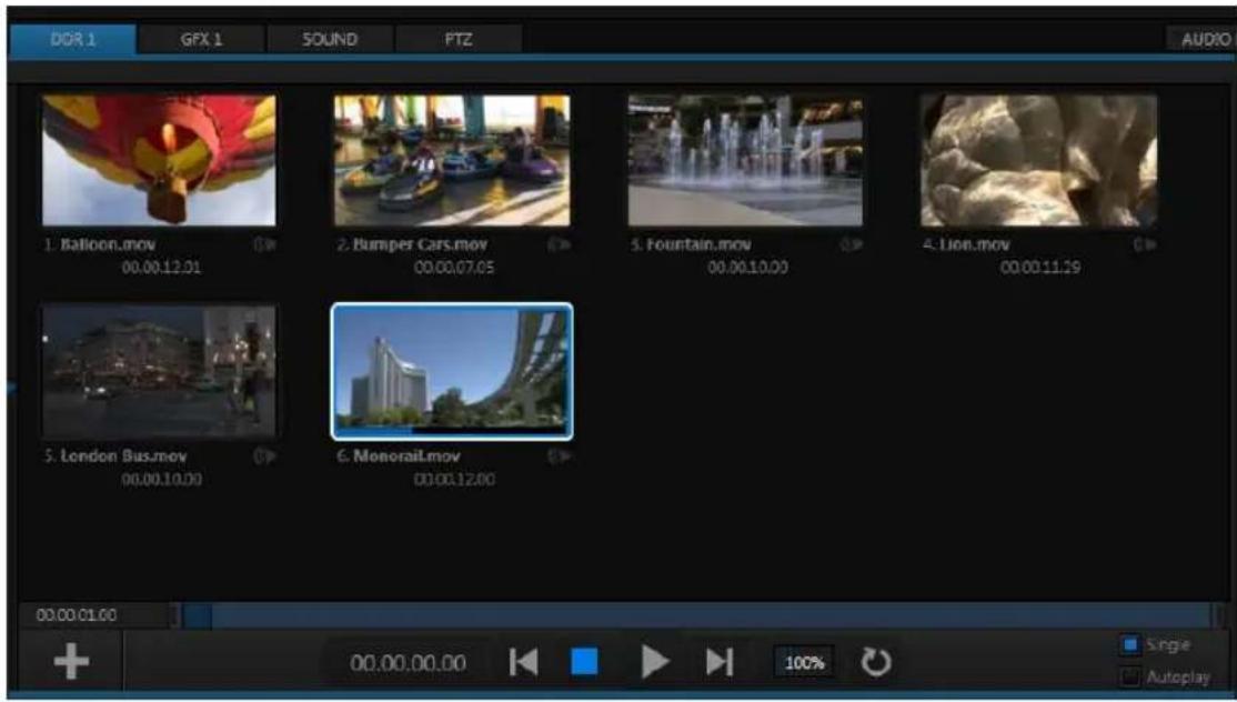
text_image
DOR 1 GPX 1 SOUND PTZ AUDIO 1. Balloon.mov 00.00.12.01 2. Bumper Cars.mov 00.00.07.05 3. Fountain.mov 00.00.10.00 4. Lion.mov 00.00.11.19 5. London Bus.mov 00.00.10.00 6. Monorail.mov 00.00.12.00 00:00:01:00 Single AutoplayFIGURE 10
- Add a/v clips, sound iles or still image iles to Media Player playlists.
-
Trim and re-order playlist entries.
• Store playlists MEM slots for easy recall. -
Flexible playback controls include variable Speed and Loop options.
- Each Media Player has corresponding volume and other advanced audio controls in the Audio Mixer.
- Convenient 'per clip' level control is provided right in the playlist.
- Autoplay feature starts and stops playback automatically based on Switcher activity.
• Control Media Players with macros triggered by other events. - Assign titles, graphics, clips or buffers to multiple DSK or M/E Key channels.
- Edit titles live, even while 'on air'.
2.5.19 BUFFERS
The Buffers module provides quick review and management of TriCaster's internal media buffer system, and is in reality a combined multiview, player and asset management tool fully supported by TriCaster's Macro system.
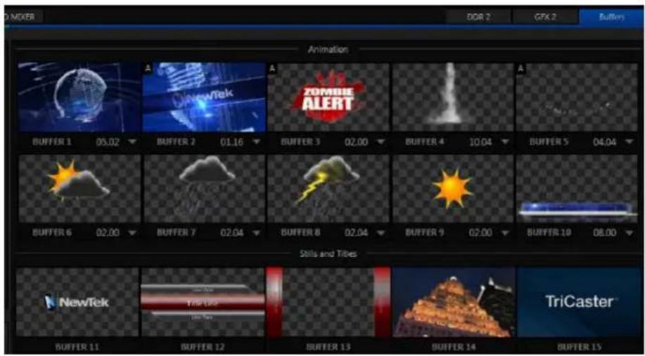
text_image
DOR 2 GFX 2 Buffers Animation A NewTek ZOMBLE ALERT A BUFFER 1 05.02 BUFFER 2 01.16 BUFFER 3 02.00 BUFFER 4 10.04 BUFFER 5 04.04 BUFFER 6 02.00 BUFFER 7 02.04 BUFFER 8 02.04 BUFFER 9 02.00 BUFFER 10 08.00 Skills and Tibles NewTek TriCaster BUFFER 11 BUFFER 12 BUFFER 13 BUFFER 14 BUFFER 15FIGURE 11 (TRICASTER 8000 SHOWN)
Buffers can be applied in any video channel, including all main Switcher and M/E rows, or as overlays in the numerous DSK and Key channels. Buffer 'slots' can contain *animated effects (compiled from your own clips using the supplied Animation Store Creator application), still graphics or title pages, all with full alpha channel support (the number of buffer slots supporting animation varies by model).
Animated buffers come in *two types, and either loop endlessly (perfect for bugs, station IDs, etc.) or 'auto-run' once when displayed. These effects are resident in reserved Switcher Memory, making it possible to use them all at once without tying up Media Players. Thus Buffers can effectively take the place of many additional DDRs. In addition, each Buffer slot has its own set of convenient presets.
* TriCaster 410 does not support animated Buffer effects.
2.5.20 TITLES AND GRAPHICS
TriCaster includes an extensive set of live-editable title pages in various theme packs, all ready for immediate use in your productions. Also part of TriCaster's integrated software suite is LiveText™, NewTek's professional titling and graphics application. LiveText allows you to create your own great looking custom title pages and motion graphics, including scrolls and crawls.
2.5.21 EDIT
The full version of NewTek's popular and versatile non-linear video editing program SpeedEDIT™ is available as a downloadable Add-On at no extra cost for TriCaster 410, 460, 860 and 8000. SpeedEDIT provides powerful, professional tools to let you prepare movies for insertion into your live productions, or perform broadcast quality post production work on recorded programs.
- Edit, import and export in full HD resolution.
• Realtime external hardware project preview in HD or SD. - Import and export ile format support includes MPEG2 and QuickTime® for versatility in program delivery.
2.5.22 OPTIONAL CONTROL SURFACES
Most TriCaster bundles include a control surface designed as the perfect complement to your switcher, making your live production operations even more convenient. Once you get your hands on one you'll never want to let go. Beyond this primary control surface, NewTek offers an optional instant replay control surface called TimeWarp. Talk to your local reseller for a demonstration of this powerful add-on for your TriCaster.
In summary, TriCaster gives you the combined power of both a network control room and a complete post-production facility in one simple to use broadcast appliance. Let's jump in now. First, we'll get you connected; following that, we'll explore TriCaster's most important features.

text_image
TCThis chapter explains how to connect power, monitors and audio visual sources, and external control devices to your NewTek TriCaster™ system.
It also reviews the registration process. After completing this short section, you'll be all set to continue into the Live Production Walkthrough chapter that follows it.
To begin, let's review 'what came in the box':
- NewTek TriCaster™ & control surface
- TriCaster 8000 only – package of three (3) 2TB hard drives
- Keys to front panel of case
- Four attachable rubber feet (for desktop use)
- A/C power cable(s)
- BNC removal tool (to assist with cable connection and removal)
- DVI to VGA adapter
- NewTek mouse and keyboard
- Quick Start Guide
- NewTek 3PLAY™ brochure
- NewTek TriCaster registration reminder card
- New product letter
SECTION 3.1 COMMAND AND CONTROL
- Connect an external computer monitor to the DVI port labeled Interface on the backplate of 8-input models. For 4-input models, use the DVI connector nearest to the Video In group for the interface monitor connection. (DVI connectors located at left near the network port are normally capped and should not be used.)
Hint: TriCaster's interface requires a resolution of at least 1600x1050.
-
Connect the mouse and keyboard to USB ports on TriCaster.
-
Connect the A/C power cord (or cords, for 8-input models) from the three-prong connection(s) on TriCaster's backplate to an external power receptacle (see Hint below).
- Turn on the computer monitor.
- Press the Power switch on TriCaster's faceplate (located behind the door).
At this point, the blue Power LED will illuminate, and the adjacent hard drive activity light should licker as the device boots up. (If this does not happen, check your connections and retry).
Though not a requirement, we do strongly recommend that you connect TriCaster using an uninterruptable power supply (UPS), as for any ‘mission critical’ system. Likewise, consider A/C “power conditioning”, especially in situations where local power is unreliable or ‘noisy’.
Surge protection is especially important in some locales. Power conditioners can reduce wear on TriCaster's power supplies and other electronics, and provide a further measure of protection from surges, spikes, lightning and high voltage.
A word about UPS devices:
'Modied sine wave' UPS devices are popular due to low manufacturing costs. However, such units should generally be viewed as being of low quality and possibly inadequate to fully protect the system from abnormal power events..
For a modest added cost, consider a "pure sine wave" UPS. These units can be relied on to supply very clean power, eliminating potential problems, and are recommended for applications demanding high reliability.
SECTION 3.2 ACTIVATING & AUTHORIZING WINDOWS®
(Your reseller may have performed this operation for you as part of his pre-delivery service.) When you see the Welcome to Windows screen:
- Click Next at lower right.
- Choose your time zone.
-
Accept the license agreement.
-
Enter your 25-digit key (generally, the sticker is a fixed inside the front door of the case).
- Decline automatic updates (by clicking "not right now").
- Give TriCaster a distinct computer name for networking.
You can authorize your Windows® installation by network or by telephone. Assuming you have an Internet connection available, and have connected TriCaster to it with an Ethernet cable, the Internet is the fastest method of activation. (See Section 3.15 and Chapter 16 Network for more detail.)
- Click 'Obtain IP and DNS automatically'.
- Agree to activate Windows®. This activation is permanent, and you won't see these screens again. (Registration with Microsoft is optional).
- Assign a name to the administrator account. You may type your name, company, or perhaps simply "TriCaster".
- Click Finish, and TriCaster will re-start.
After restarting and accepting NewTek's User Agreement, the interface will load automatically.
SECTION 3.3 LICENSE AND REGISTRATION
On launch, TriCaster presents an End User License Agreement dialog. After you accept this, the Registration dialog shown in Figure 12 is presented. If necessary, enter the unique TriCaster Serial Number and Product ID for your system.
Important note: TriCaster's video output displays a watermark until the system is registered and unlocked.
Hint: If the Serial number doesn't appear automatically, and you can't find it on your unit, you can obtain it from the registration webpage mentioned in the next section, or by calling Customer Support Desk (open seven days a week).
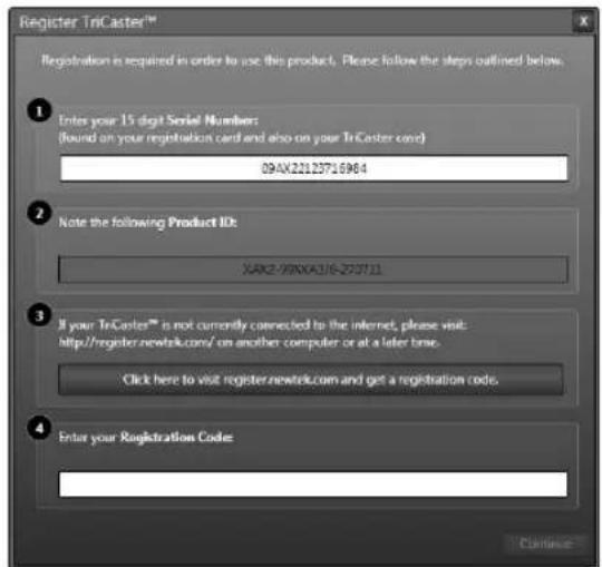
text_image
Register TriCaster™ Registration is required in order to use this product. Please follow the steps outlined below. ① Enter your 15 digit Serial Number: (bound on your registration card and also on your TriCaster code) 09-AX22123716984 ② Note the following Product ID: XARZ-99XNA116-ZS7111 ③ If your TriCaster™ is not currently connected to the internet, please visit: http://register.newtek.com/ on another computer or at a later time. Click here to visit register.newtek.com and get a registration code. ④ Enter your Registration Code: ContinueFIGURE 12
You can register and obtain your registration code either by telephone, or online (directly from TriCaster or from another system connected to the Internet) as described next.
Hint: For later convenience, record the registration code for your TriCaster on the sticker provided for the purpose inside the front access panel of the system.
3.3.1 ONLINE REGISTRATION
If you have connected your TriCaster to the Internet, simply click the button under Step 2 in the registration dialog. This will take you to the Registration page (http://register.newtek.com) on NewTek's website, where you will ind further directions.
Hint: More information on connecting TriCaster to a network can be found in Section 3.16 and Chapter 16, Network Inputs.
Otherwise, you can visit the registration webpage from another system with Internet access. In either case, after registering on the website, enter the resulting registration code into the ield provided in the Registration dialog.
3.3.2 REGISTERING BY TELEPHONE
NewTek's Customer Support center can also handle registration requests by telephone, if that is more convenient (when opportunity permits, you should still visit the website as discussed above to gain access to software updates).
Please have your Product ID (from the Registration dialog mentioned earlier) handy when you call. The phone numbers for Customer Support follow:
Telephone:
• (US) 1-800-862-7837
• (Outside US) +1-210-370-8452
• (Europe) +33 (0) 557-262-262
Hint: It's a very good idea to record the login name and password you choose when creating your website profile and keep them in a safe place. Jot down registration code too; it could come in very handy if you ever need to restore the TriCaster software to its as-shipped state when you don't have access to the Internet.
UPDATES
It's a great idea to check for recent free software updates for your system at this time, too – see the heading System Utilities in Section 5.2.3 for more on this.
ENHANCED SUPPORT (PROTEK)
NewTek's optional ProTek ^SM service programs offer renewable (and transferable) coverage and enhanced support service features extending well beyond the standard warranty period. Please see http://www.newtek.com/protek.html or your local authorized NewTek reseller for more details regarding ProTek plan options.
SECTION 3.4 RACK MOUNTING TRICASTER
Your TriCaster is designed for convenient mounting in standard 19" racks (mounting rails designed for different TriCaster models are available separately from NewTek Sales).
Please keep in mind that adequate cooling is a very important requirement for virtually all electronic and digital equipment, and this is true of TriCaster as well. We recommend allowing 1.5 to 2 inches of space on all sides for cool (i.e., comfortable 'room temperature') air to circulate around the chassis.
Good ventilation at the front and rear panel is important, and 4-input TriCasters in particular require ventilated space above the unit (1RU minimum is recommended).
Hint: When operating TriCaster in a ‘road case’ for mobile production, it’s best to do so with both the front and back covers (of the road case) removed.
When designing enclosures or mounting the unit, supplying good free air movement around the chassis as discussed above should be viewed as a critical design consideration. This is especially true in fixed installations where TriCaster will be installed inside furniture-style enclosures.
3.5.1 CONNECT A/V SOURCES
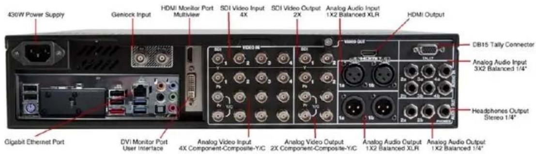
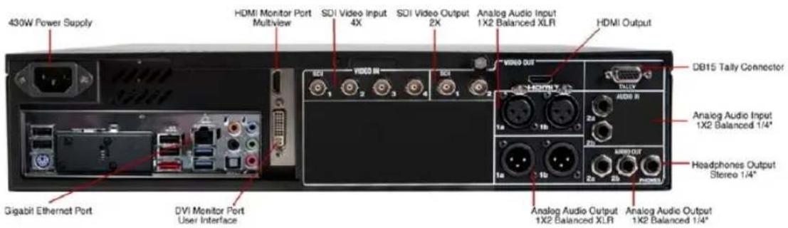
External audio and video sources are connected to the appropriate inputs on TriCaster's backplate.
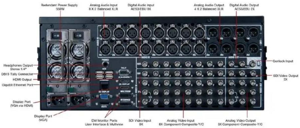
text_image
Redundant Power Supply 550W Analog Audio Input 8 X 2 Balanced XLR Digital Audio Input AES3/EBU 8X Analog Audio Output 4 X 2 Balanced XLR Digital Audio Output AES3/EBU 2X Headphones Output Stereo 1/4* DB15 Tally Connector HDMI Output Gigabit Ethernet Port Display Port (VGA via HDMI) Display Port (VGA) DVI Monitor Ports User Interface & Multiview SDI Video Input 8X Analog Video Input 8X Component-Composite-Y/C Analog Video Output 3X Component-Composite-Y/C Genleck Input SDI Video Output 3XFIGURE 13 - TRICASTER 8000
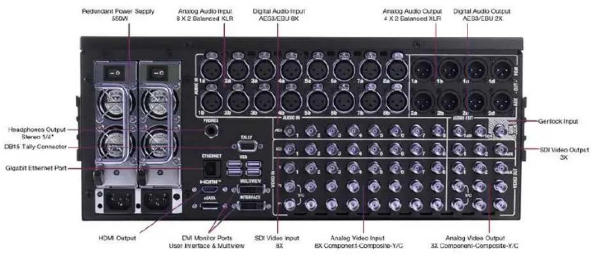
text_image
Pedundant Power Supply 550W Analog Audio Input 8 X 2 Balanced XLR Digital Audio Input AES3/EDU BX Analog Audio Output 4 X 2 Balanced XLR Digital Audio Output AES3/EBU 2X Headphones Output Stereo 1/4* DB15 Tally Connector Gigabit Ethernet Port HDMI Output DVI Monitor Ports User Interface & Multiview SDI Video Input 8X Analog Video Input 8X Component-Composite-Y/C Analog Video Output 3X Component-Composite-Y/CFIGURE 14 - TRICASTER 860
text_image
430W Power Supply Genlock Input HDMI Monitor Port Multiview SDI Video Input 4X SDI Video Output 2X Analog Audio Input 1X2 Balanced XLR HDMI Output DB15 Tally Connector Analog Audio Input 3X2 Balanced 1/4" Headphones Output Stereo 1/4" Gigabit Ethernet Port DVI Monitor Port User Interface Analog Video Input 4X Component-Composite-Y/C Analog Video Output 2X Component-Composite-Y/C Analog Audio Output 1X2 Balanced XLR Analog Audio Output 1X2 Balanced 1/4"FIGURE 15 – TRICASTER 460
text_image
430W Power Supply HDMI Monitor Port Multiview SDI Video Input 4X SDI Video Output 2X Analog Audio Input 1X2 Balanced XLR HDMI Output DB15 Tally Connector Analog Audio Input 1X2 Balanced 1/4" Headphones Output Stereo 1/4" Gigabit Ethernet Port DVI Monitor Port User Interface Analog Audio Output 1X2 Balanced XLR Analog Audio Output 1X2 Balanced 1/4"FIGURE 16 - TRICASTER 410
Note: Hardware details as depicted are subject to change without prior notice.
If your equipment supports SDI, this is the best quality option.
- Connect sources to suitable connectors in the VIDEO IN section: SDI, Component, Y/C (S-Video) or Composite (may require RCA> BNC adapter).
a. SDI - Attach your SDI source connectors to one of the upper row of BNC connectors in the Video In group (marked SDI).
SDI Recommendations:
It's worth mentioning here that SDI, while ideal for many purposes, does nevertheless have some limitations.
We do not recommend cable runs exceeding 100 meters (for HD; or double that for SD). Transmission over greater distances may result in signal losses, and call for measures to boost levels, which may in turn introduce added latency into the signal path before TriCaster.
Note: that the analog video input connection options listed next are not provided by TriCaster 410.
b. Component - Attach the appropriate BNC connectors from your sources to all three analog BNC connectors (labeled Y , Pb and Pr ) in a column of the Video In group.
c. Y/C - If your S-Video equipment and cabling has the usual 4-pin mini-DIN connectors, you will need an S-Video to dual BNC adapter.
To connect Y/C sources, attach the Y (luma) connector of your source to the second analog BNC connector (labeled Pb). Attach the source's C (chroma) connector to the bottom connector (labeled Pr).
d. Composite - Attach the composite source's connector (may require use of an RCA to BNC adapter) to the connector in the input row labeled Y).
Note: The broadcast video standard (such as NTSC, NTSC-J or PAL) of a video sources connected for a given session must match.
- To input analog audio along with the video, connect the desired audio sources to the XLR or 14 ” connectors in the Audio In group box.
Two connectors, labeled "a" and "b", are provided for each input group. We'll discuss audio Connection Type options a bit later, in Section 3.13.
Note: SDI video sources with embedded audio do not need a separate analog audio connection.
3.5.2 CONNECTING A VIDEO ROUTER
(TriCaster 8000 only) With the appropriate software installed, TriCaster 8000 systems can control and access output from brands supporting the popular Grass
Valley® Native Protocol are supported, as well as Black Magic Design® Video Hub routers.
The implementation offers a number of configuration options; a basic setup would be as follows:
- Connect the router to TriCaster by Ethernet cable, and then connect one (or more) of the router's video outputs to TriCaster inputs with matching numbers, using suitable video cables.
(For example, by default router output number 3 would be connected to TriCaster's Input 3 for control communication between the devices to be properly linked.) - Click the Shutdown icon on TriCaster's Home page (Startup), and click the Administrator Mode at right.
• In the Administrator Mode panel, click Exit to Windows. - Navigate to the C:\TriCaster\Configuration folder, and open the ile named router_setup.xml by double-clicking it (it will launch in Notepad).
This ile is where you add the routers you wish TriCaster to recognize. Each router is identified by an entry you insert between the starting and closing “config” tags, as explained in the ile comments.
A typical entry might be as follows:
$$ < \text { grassvalley ip } = " 1 0. 2 8. 1. 1 2 8" \text { port } = " 1 2 3 4 5" \text { name } = " A J A K U M O" / > $$
- Save the ile after editing, and re-launch TriCaster.
Note: TriCaster communicates with each using individual IP address and port numbers, allowing multiple routers to be connected simultaneously. Several TriCasters can even control either the same router(s) – especially useful when TriCaster control is mirrored.
File comments explain how you can bypass the default 1:1 mapping of router outputs to TriCaster inputs when required, or prevent accidental changes to inputs that are displayed on Program output, along with other extended configuration options.
For backwards compatibility reasons, these routers are auto-detected by default. (Black Magic® routers may use a USB control connection, rather than a network connection. The router's firmware should be up to date. If detection fails, please contact BMD support for assistance.)
You can, if you wish, disable auto detection by editing the XML configuration ile discussed above. (You might do this to avail yourself of the extended configuration options that are provided by doing so.) To do this, simply add the line below to the
<blackmagic_conig discovery="false"/>
SECTION 3.6 GENLOCK CONNECTION
(Not a TriCaster 410 feature.) The Genlock input on TriCaster's backplate is for connection of a 'house sync' or reference signal (often a 'black burst' signal intended specifically for this purpose).
Many studios use this method to synchronize equipment in the video chain. Genlocking is commonplace in higher-end production environments, and genlock connections are typically provided on professional gear.
If your equipment allows you to do so, you should genlock all cameras supplying TriCaster, and TriCaster itself. To connect the genlock source TriCaster, supply the reference signal from the 'house sync generator' to TriCaster's Genlock In connector. (See Section 3.14 regarding genlock configuration.)
SECTION 3.7 TIMECODE CONNECTION
(Not a TriCaster 410 feature.) TriCaster supports external linear timecode (LTC) input. Connect the cable from your timecode generator to one of the connectors in audio Input 7 (8-input models) or Input 3 (4-input models). External timecode is enabled and configured in the Live Desktop (see Sections Section 3.15 and 8.2.8).
Next we'll discuss the audio and video output connectors along with relevant settings. We'll start with video output – not only so you can view your results, but because certain items are best considered before beginning a TriCaster session.
3.8.1 A/V OUTPUT
TriCaster provides multiple video and audio output connector groups, and very flexible options for display of your live and recorded video streams. Here are some of the possibilities:
- Simultaneously send output to standard and/or high deinition devices from HD sessions.
- Simultaneously send output to both analog and digital devices (except TriCaster 410, which provides digital output connections only).
- Send program output, a secondary mix, or custom 'monitor bridge' layouts to a supplemental monitor or projector using Multiview.
- (TriCaster 8000 only) Supply independent video outputs to the two Display ports for supplemental monitoring or projection.
- Stream program output to the Internet via a suitable network connection.
3.8.2 HD AND SD
As mentioned earlier, for HD sessions TriCaster supports simultaneous output of both SD (Standard Deinition) and HD (High Deinition) video. Except for TriCaster 410, the Video Output connector groups on TriCaster's backplate are arranged in vertical columns of four BNC connectors, offering the following connection possibilities for live production:
- Output 1 video output format is determined by the session (see Section 5.1).
When the session is SD 4:3 or 16:9, output is likewise SD 4:3 or 16:9. When the session is HD, output is HD. - Output 2 is user-configurable, and can be set up in the Live Desktop (Output Configuration panel).
- (8-input models only) Output 3 can be used to mirror either of the two primary outputs, or transmit a completely different source in its original format.
- Connect downstream video devices to the appropriate output connectors in the VIDEO OUT section, whether SDI, Component, Y/C (BNC) or Composite (TriCaster 410 supports SDI output only). Please note that the latter two analog formats may require RCA (cinch plug) or S-video (4 pin mini-DIN) to BNC adapters, and also that both of these connection options support output at SD resolution only.
a. SDI – Attach SDI connectors to BNC connectors in the VIDEO OUT group labeled 1-(2 or 3).
Hint: If your equipment supports SDI, this is the best alternative. Note that the following analog output options are not supported by TriCaster 410.
b. Component - Attach your device to the second, third and fourth BNC connectors (Y, Pb and Pr).
c. Y/C – If your S-Video equipment and cabling has the usual 4-pin mini-DIN connectors, you will need an 'S-Video to dual BNC' adapter.
i. Attach the Y (luma) connector of your device to the second analog BNC connector row (labeled Pb at far left in the VIDEO IN group).
ii. Attach the C (chroma) connector to the third analog connector (labeled Pr).
d. Composite - Attach the device's connector to the irst (top) analog connector (just above the pair labeled Y/C).
- Connect TriCaster's audio outputs:
a. Analog audio - Connect external audio devices to the connectors in the AUDIO OUT section.
8-input TriCasters offer two pairs of four audio output connectors:
i. Connectors 1a-(1b or 1d) provide sound from the mix assigned to Output 1 (defaults to Master in Output Configuration)
ii. Connectors 2a-(2b or 2d) provide sound from the mix assigned to Output 2 (defaults to Aux in Output Configuration)
Note: These two output groups are actually treated by TriCaster as four independent stereo outputs, each configured and controlled separately; see Chapter 15, Audio.
b. Digital audio - A separate digital audio connection is not necessary for SDI output with embedded audio. AES/EBU connectors are provided for Output 1(channels a-d) on 8-input models.
Hint: TriCaster's SDI and analog output sections can be used simultaneously. For example, you could use the Composite output to view your program on a local composite monitor at the same time as you use the SDI connection to supply broadcast equipment.
3.8.3 SUPPLEMENTAL VIDEO OUTPUTS
Additional dedicated video outputs make it possible to connect monitors or projection devices to TriCaster for a variety of purposes including program output for IMAG (Image Magnification) installations or flexible monitoring for the convenience of the operator.
- TriCaster's external Multiview output is supplied by a connector located above the main Interface monitor connector (8-input models) or a neighboring HDMI port (4-input models). Again, connect a suitable monitor or display device. The new device should be recognized and enabled by the system automatically.
The Multiview output offers a variety of optional monitoring layouts that can be selected at any time in TriCaster's Live Desktop.
-
TriCaster also provides an additional, assignable video output on a labeled HDMI connector. Simply connect a suitable external monitor or device to the connector on the backplane.
-
Stream and Network both require only a network connection.
-
(TriCaster 8000 only) Two special outputs are labeled Display and numbered (5) and (6) on TriCaster's backplate. These ports can serve projectors or similar large display systems, though of course they can be used for other purposes too.
With the exception of Output 3 (8-input models only), most Outputs are similar as respects the optional video sources they can be configured to supply. Output 3 supports cloning either Output 1 or 2, or any single Switcher source (including Buffers).
Note: A mismatch of output format and connection type is possible at times. For example, a Graphics player might display imagery that does not correspond to the current output resolution or is not supported by the selected connection type. TriCaster will attempt to display the output despite mismatches, but may not always succeed.
SECTION 3.9 TALLY LIGHTS
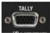
FIGURE 17
TriCaster's Tally Light support allows you to connect external tally lights and similar devices. These typically provide a red LED for the video input that is currently selected on the Switcher's Program row.
3.9.1 CONNECTION DETAILS
Here is a pin-out listing for TriCaster's DB15 Tally connector:
- Pin1 - LED1
- Pin2 - LED2
- Pin3 - LED3
-
Pin4 - LED4
• Pin5 – LED5 (8-input only)
• Pin6 - LED6 (8-input only)
• Pin7 - LED7 (8-input only)
• Pin8 - LED8 (8-input only) -
Pin9 - GND
- Pin10 - GND
- Pin11 - GPI1
- Pin12 - GPI2
- Pin13 - NC
- Pin14 - 3.3V (with 20 Ohms current limit)
-
Pin15 - NC
-
Pins 1-(4 or 8) are 'hot' when the LED should be illuminated.
■ Each LED pin 1 (4 or 8) has a 200 ohm current limiting resistor inside TriCaster. - With no load (open circuit) the LED pins can reach 5V. With a typical LED load, they can be expected to reach about 3V.
- GPI stands for General Purpose Interface. Pins 11 and 12 are assigned for possible future use as GPI1 and GPI2 connections, but support for GPI triggers has not been implemented in TriCaster at this time.)
- To prevent damage to TriCaster's components when making external connections to the tally light jacks, care should be taken that connection to Pins designated GND (Ground) are always at ground potential.
SECTION 3.10 STARTING A SESSION
If TriCaster is not already running, power it up now to reveal the Startup Screen. (If TriCaster is already running, and is in the Live Desktop or another area of the interface, you may need to click the small [x] button at upper-right to exit, or click the Back arrow at upper-left in the Session Page to return to the Home Page.)
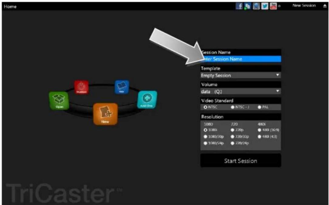
The Startup Screen consists of two similar pages – Home and Session. Among other things, the Home Page is where you choose basic TriCaster session settings (see Section 5.1 for a discussion of sessions).
THE HOME PAGE
When no previously created sessions exist, the icon ring dominating the Home Page defaults to New, inviting you to create a new session.
text_image
Home New Session Session Name Enter Session Name Template Empty Session Volume data (Q:) Video Standard NTSC NTSC - J PAL Resolution 1080 720 480i 1080/720p 480i [16-9] 1080/30p 720/30p 480i [42] 1080/24p 720/24p Start Session Open New Active One TriCaster ™FIGURE 18 (MULTI-STANDARD TRICASTER SHOWN)
A link initially containing the text "Enter Session Name" is shown at the top of the right-hand pane when the New icon is selected on the ring. Click in this area to modify the name using the keyboard if you like. (The default name is the current date.)
Note: TriCaster supports a variety of optional session configurations for live production. You can choose either HD (High Definition) or SD (Standard Definition) operating modes.
SD options include both 4:3 and 16:9 (widescreen) image aspects. TriCaster Multi-standard models permit you to select from different video standards according to your locale, choosing between NSTC, NTSC-J (Japan) or PAL.
Continue with session creation by designating the Video Standard used in your locale (Multi-standard models only). For the moment, let's choose 1080i for Resolution (even if the cameras you plan to connect are SD 4:3), then click the Start Session link below.
By default, new sessions are created on TriCaster's D: (Media) drive (see Section 5.2.1 for a discussion of session Volume options).
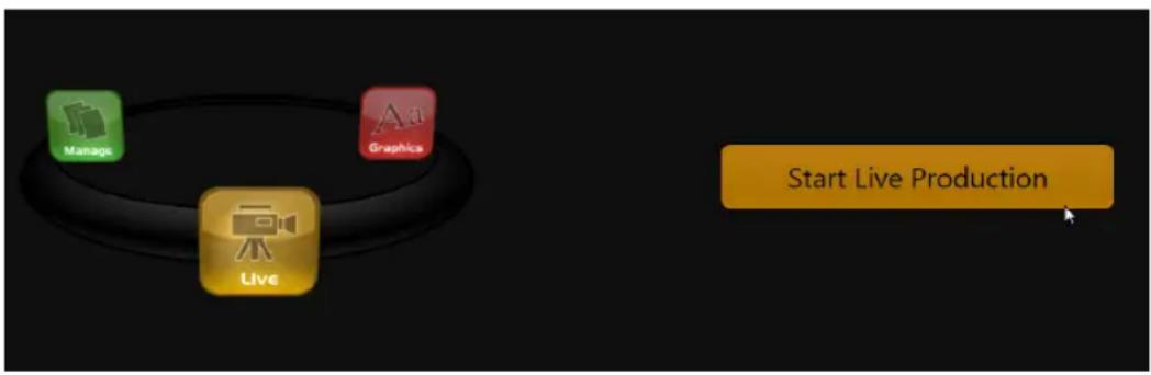
Clicking Start Session will take you to the Session Page. As our intention is to configure our connections (done in TriCaster's Live Desktop), click the Live button on the icon ring.
flowchart
graph TD
    A["Manage"] --> B["Graphics"]
    C["Live"] --> D["Start Live Production"]
FIGURE 19
Simply click the link labeled Start Live Production to launch the Live Desktop, which is likely where you will spend most of your time working with TriCaster.
THE LIVE DESKTOP
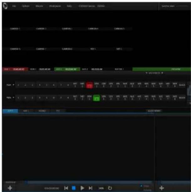
Initially, as you have yet to configure input devices or add content, the Live Desktop will look a bit barren (Figure 20). Take a quick look around, but then let's continue to configure your devices.
(We had a brief glimpse at the Live Desktop back in Section 2.4, but we'll examine it more closely in Chapter 4, Live Production Walkthrough – coming up soon.)
text_image
Screenshot of a video editing software interface showing track controls and playback settings with Chinese labelsFIGURE 20 (TriCaster 8000 shown)
SECTION 3.11 CONFIGURE VIDEO OUTPUT
TriCaster provides complete video input monitoring right on the Live Desktop.
This allows you to operate it without even connecting downstream video monitors or devices. (You might do just that in the case of productions intended primarily for live streaming.)
Often, though, you will want to connect external monitors or other downstream devices to the VIDEO OUT connectors on TriCaster's backplate (see Section 3.7).
High deinition video monitors should be connected to either SDI or Component connections.
Let's consider an example:
An HD 1080i session offers the largest list of optional output formats. The controls allow you to select any of a number of HD or SD formats. Selecting an HD format sends the source to TriCaster's SDI and Component output connectors simultaneously.
Selecting an SD format adds a "Composite + Y/C" option to the menu. Choosing this option sends composite video output to the second BNC connector in a given connector row (Y), and Y/C to the third and fourth BNC connectors (labeled Pb and Pr).
As well, 16:9 or 4:3 screen aspect alternatives are provided for SD output selections.
For standard deinition monitoring, several different connection types continue in service. These include Composite, Y/C (also known as 'S-Video') and - at the upper end of the analog quality range - Component. (SDI provides a digital output option, and is the only alternative offered by TriCaster 410.)
text_image
Output Configuration Output Genlock & Failable Connections Video Audio Resolution Analog Out 1. Program Master 1, 2 2. M/E 2 Aux 1, 2 720p 3. Follow 1 SDF Follow 1 Component 4. HDMI Follow 1 Master 1, 2 STREAM Follow 1 Master 1, 2 NETWORK Follow 1 Master 1, 2 URL: http://MyTriCaster-49840/ DISPLAY Follow 1 1920x1080, 1669 DISPLAY Follow 2 1920x1080, 1669 CloseFIGURE 21 (TriCaster 8000 shown)
To connect an analog standard deinition monitor (not supported by
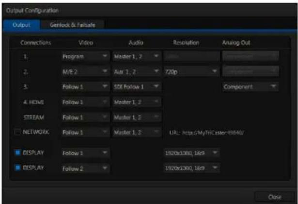
TriCaster 410), you must specify its connection type in the Output Configuration panel.
Note that analog connections for LiveText™ output (as well as the SpeedEDIT™ Add-On, when installed) are pre-deined (see Chapter 21 for details). Let's take a closer look at configuration options.
natural_image
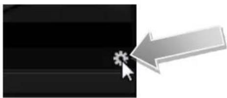
Pure graphical icon showing a cursor clicking a button on a black background with a gray arrow pointing right (no text or symbols)FIGURE 22
-
Move your mouse pointer over the large Program Output monitor on the Live Desktop.
-
Click the Configure button (gear) that appears at right below the monitor pane (Figure 22) to open the Output Configuration panel.
This panel provides two tabbed panes, the irst of which is labeled Output. This is where the video signals present on each of TriCaster's video outputs, as well as the HDMI, Network and Stream outputs and Display ports (TriCaster 8000 only) are configured. There are various decisions to make for each output:
• What video source do you want to assign to that output?
- What audio source will accompany it on connection types that carry both signals?
- Which video format will be sent to the connectors?
- For video outputs, which connection type will be used to carry the signal – SDI, Component, Y/C or Composite?
And so on ...
3.11.1 CHANNEL OPTIONS
Let's review Video source selection irst. A drop-down menu by that name permits you to select sources for TriCaster's two principal video output streams, referred to as Output 1 and 2. TriCaster can send other streams to its outputs as well, as discussed shortly – but the primary out streams are unique in certain respects.
Hint: Either (or both) of the a/v streams assigned to Outputs 1 and 2 are available for assignment to TriCaster's other outputs as well, by means of the Follow 1 and Follow 2 items in the respective source menus.
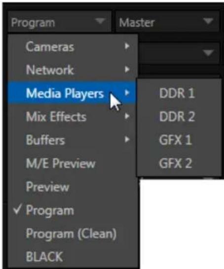
text_image
Program Cameras Network Media Players Mix Effects Buffers M/E Preview Preview ✓ Program Program (Clean) BLACK Master DDR 1 DDR 2 GFX 1 GFX 2FIGURE 23 (8-INPUT VERSION SHOWN)
Optional Source selections for these two primary output channels include any of the following:
- Program output
• A clean Program feed
• The 'look ahead' Preview
• The direct output of any M/E - Selected Buffer content
• Media Player output
• Either network input source
• The feed from any camera input
Audio menu options include the Master and Aux mixes, any audio group (by color code), or the sound from any one of TriCaster's audio inputs.
The video format (Resolution) for Output 1 always matches the current TriCaster session format, so its menu is locked. For Output 2, though, the Resolution menu allows you to independently configure the format.

text_image
480i ComponentFIGURE 24
Hint: Multiview, a versatile external display intended primarily for control room monitoring, is configured in TriCaster's Dashboard (click the Workspace menu).
It's worth mentioning that, for TriCasters with analog outputs, SD formats offer different Analog Out options than HD. HD is always presented on SDI and Component connectors, but in addition to these, Composite and Y/C connections are still in common use for SD.
Composite and Y/C can even be used simultaneously, allowing three different devices to be connected to outputs in one row for SD output formats – one digital (SDI) connection along with two analog connections (see the example at right).
SECTION 3.12 CONFIGURE VIDEO INPUTS
Control over settings for video sources is provided in TriCaster's monitoring section. The individual monitor viewports on the Live Desktop can be lexibly assigned to show different video sources. Complete monitor layouts can be prepared, stored and recalled using tools located in the Workspace menu in the Dashboard.
We'll look into that in depth in the Reference Section of this manual, but for now let's conigure the video sources you connected earlier (Section 3.5.1).
- Click Workspace in the Dashboard (at the top of TriCaster's Live Desktop).
- TriCaster 8000 presents four monitoring layout presets are listed at the top of the menu as Interface A through D. Select Interface A, if it isn't already check-marked.
-
Otherwise (all other models), select All in this menu.
-
The monitoring pane will no show individual monitors for each camera, with Camera 1 at upper left.
- To continue, you could select Conigure from the monitor's context menu,
but let's take a different approach.
- Move your mouse back and forth over the Camera 1 monitor and notice that a Configure button (gear icon) appears beneath it at right.
- Click this Configuration button to open a tabbed settings panel for Camera 1 (Figure 25).
- Click the Connection Type button to reveal a drop-down menu listing a variety of connection types. Select the correct format, such as 720p (Component) or 1080i (SDI), for the video source you connected to Video Input 1 on TriCaster's backplate (menu alternatives vary by TriCaster model; for TriCaster 410, all conn
- Close the Configuration panel for now (note that you can click the Close button or simply 'click outside' the panel to close it).
- Continue to configure all connected external video sources in the same manner.
We'll look at the other options and settings in the Configuration panel later (see Section 8.2), but at this point you should be able to view the video inputs you have configured on their respective monitors.
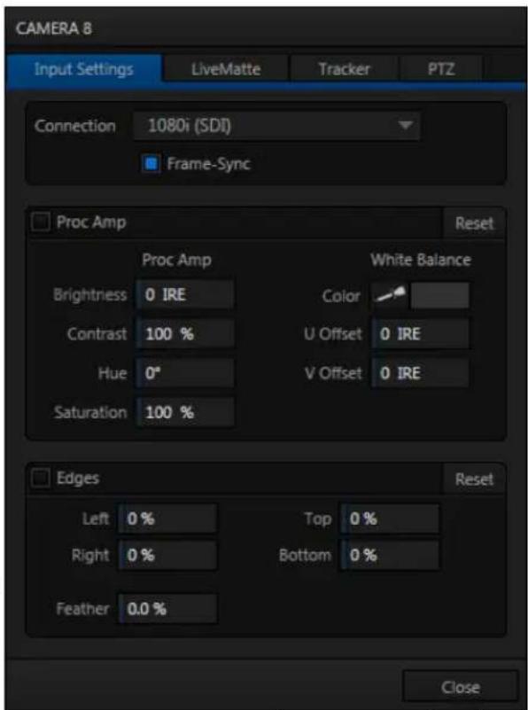
text_image
CAMERA 8 Input Settings LiveMatte Tracker PTZ Connection 1080i (SDI) Frame-Sync Proc Amp Reset Proc Amp White Balance Brightness 0 IRE Color Contrast 100 % U Offset 0 IRE Hue 0° V Offset 0 IRE Saturation 100 % Edges Reset Left 0 % Top 0 % Right 0 % Bottom 0 % Feather 0.0 % CloseFIGURE 25 (TriCaster 8000 shown)
3.12.1 CONFIGURE A VIDEO ROUTER INPUT
(TriCaster 8000 only) Conigure the input Connection to SDI, choosing the correct resolution for the device output as discussed above, and then right-click on the Switcher row button for the TriCaster input where the router is connected (see Section 3.5.2) to select which router input will be transmitted to TriCaster.
SECTION 3.13 CONFIGURE AUDIO
Click the Audio Mixer tab (centered in the lower third of the Live Desktop) to reveal audio features, including configuration controls for all internal and external audio sources, IsoCorder™ recording levels, and outputs - including streaming.
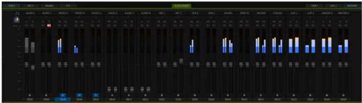
bar
RADIO/RADIO | Channel | Blue Segment | White Segment | | :--- | :--- | :--- | | 1 | 0.5 | 0.2 | | 2 | 0.8 | 0.3 | | 3 | 1.2 | 0.4 | | 4 | 1.5 | 0.5 | | 5 | 1.8 | 0.6 | | 6 | 2.1 | 0.7 | | 7 | 2.4 | 0.8 | | 8 | 2.7 | 0.9 | | 9 | 3.0 | 1.0 | | 10 | 3.3 | 1.1 | | 11 | 3.6 | 1.2 | | 12 | 3.9 | 1.3 | | 13 | 4.2 | 1.4 | | 14 | 4.5 | 1.5 | | 15 | 4.8 | 1.6 | | 16 | 5.1 | 1.7 | | 17 | 5.4 | 1.8 | | 18 | 5.7 | 1.9 | | 19 | 6.0 | 2.0 | | 20 | 6.3 | 2.1 | | 21 | 6.6 | 2.2 | | 22 | 6.9 | 2.3 | | 23 | 7.2 | 2.4 | | 24 | 7.5 | 2.5 | | 25 | 7.8 | 2.6 | | 26 | 8.1 | 2.7 | | 27 | 8.4 | 2.8 | | 28 | 8.7 | 2.9 | | 29 | 9.0 | 3.0 | | 30 | 9.3 | 3.1 | | 31 | 9.6 | 3.2 | | 32 | 9.9 | 3.3 | | 33 | 10.2 | 3.4 | | 34 | 10.5 | 3.5 | | 35 | 10.8 | 3.6 | | 36 | 11.1 | 3.7 | | 37 | 11.4 | 3.8 | | 38 | 11.7 | 3.9 | | 39 | 12.0 | 4.0 | | 40 | 12.3 | 4.1 | | 41 | 12.6 | 4.2 | | 42 | 12.9 | 4.3 | | 43 | 13.2 | 4.4 | | 44 | 13.5 | 4.5 | | 45 | 13.8 | 4.6 | | 46 | 14.1 | 4.7 | | 47 | 14.4 | 4.8 | | 48 | 14.7 | 4.9 | | 49 | 15.0 | 5.0 | | 50 | 15.3 | 5.1 | | ... (repeated) for the remaining bars are not explicitly labeled in the image.FIGURE 26 (8-INPUT VERSION SHOWN)
Each input has its own small control panel, with Volume slider(s), VU meter(s), and other important features conveniently located. At the top of each of these control panels is a label.
Roll the mouse pointer over the label to reveal a gear button at right which, when clicked, opens the Configuration panel (Figure 27) for the input. This panel holds advanced audio features as well as basic setup controls.
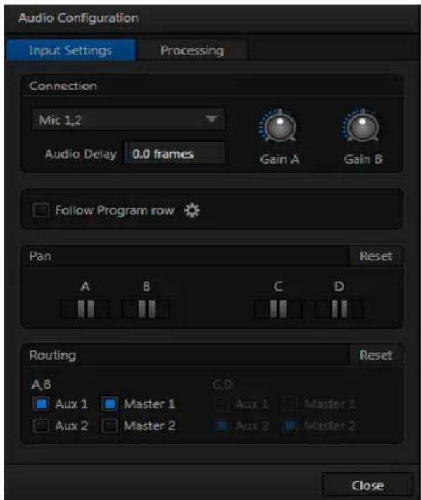
text_image
Audio Configuration Input Settings Processing Connection Mic 1,2 Audio Delay 0.0 frames Gain A Gain B Follow Program row Pan Reset A B C D Routing Reset A,B C,D Aux 1 Master 1 Aux 1 Master 1 Aux 2 Master 2 Aux 2 Master 2 CloseFIGURE 27
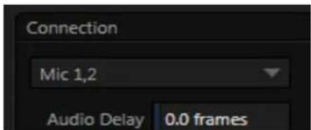
text_image
Connection Mic 1,2 Audio Delay 0.0 framesFIGURE 28
A source Type selector drop-down at the top of the Configuration panel (Figure 28) lists the Connection Type options available for the corresponding input.
For most TriCasters, options include Mic 1, 2 (with and without phantom power), Line, AES/EBU, and SDI Embedded.
After connecting audio sources to the input connectors (see also Section 3.5.1), the first thing to do is set the correct Connection Type using the drop-down menu:
- Select Mic 1, 2 for professional grade microphones or similar sources. Use the Phantom option for condenser type microphones requiring supplementary power.
- Choose Line for most other device connections (including consumer devices such as a CD player, computer audio output or VCR).
- For 8-input models only, select AES/EBU for digital audio from an AES/EBU (AES3) output.
• SDI Embedded provides digital audio from an SDI video source.
Note: Analog audio levels conform to SMPTE RP-155. The maximum input/output level is +24 dBu, nominal Mic input level +4 dBu (-20dBFS), and the sample rate is 96 kHz.
The Volume sliders (next to the VU meters) default to their lowest settings on irst launch. After adding audio sources, slowly bring these sliders up to pass their signals through the system.
Hint: Most numeric controls in TriCaster can be reset to their defaults using Shift + double-click on the control knob. The default value for Gain sliders is 0dBVU.
text_image
Gain A Gain BFIGURE 29
Some variation exists as respects signal levels from individual sources, even within the same type. For Mic (and
Mic + Phantom) connections, Gain (a.k.a., Trim) controls are provided to allow ine tuning of the input level.
To access these controls, open the Advanced Audio Configuration panel, by clicking the Configuration button (gear) in the titlebar for an input control group.
Use the Gain knobs (Figure 29) to bring the levels for microphones and similar sources into a useful range on the VU meter.
AUDIO HEADROOM
In digital audio systems, signal levels exceeding allowable values are ‘clipped’ (uniformly assigned the maximum level value). This inevitably results in audible issues that cannot be corrected later.
For this reason, it's customary to configure normal operating level (also referred to as the 'alignment level', and sometimes, 'nominal level') well below the clipping limit – sufficiently so that occasional excessively loud sounds (say, loud laughter or applause) can be accommodated without risk. This range above between nominal level and the highest possible level is commonly referred to as 'audio headroom'.
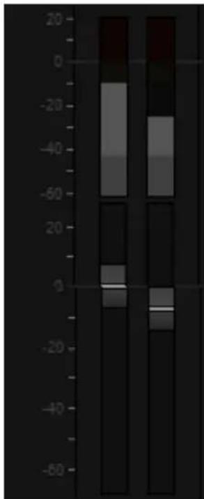
bar_stacked
| Category | Segment 1 | Segment 2 | Segment 3 | |---|---|---|---| | Top Left | -10 | -5 | 10 | | Top Right | -10 | -5 | 10 | | Bottom Left | -10 | -5 | 10 | | Bottom Right | -10 | -5 | 10 |FIGURE 30
What is considered a suitable headroom allowance can vary from one locale to another, in different industry applications, and even in individual studios.
TriCaster's audio controls follow well-established conventions, providing 20dB of headroom above nominal level (+4dBu at 0dB on the VU scale).
Hint: Confusion can sometimes arise because different calibration scales are common in various audio realms, and even for different device types and software. For example, analog mixers commonly show levels on VU scales indexed as just described. In contrast, digital devices and editing software usually display levels in dBFS (Decibels Full Scale), with 0dBFS – the absolute maximum allowable signal that can be recorded – at the top of the scale.
TriCaster's VU meters have selectable indexing, allowing you to view a traditional dB VU scale or dBFS as you please (see Section 15.8.1).
Whatever scale you choose, use Volume controls (and, for Mic connections, the Gain controls in the Configuration panel) to avoid over-modulation. TriCaster's Compressor/Limiter feature (also located in the Advanced Audio Configuration pane) is another powerful tool to help you prevent clipping – see Section 15.7.
SECTION 3.14 CONFIGURE GENLOCK
Genlocking is supported on all professional TriCaster models except TriCaster 410.
- If the Live Desktop isn't already open, launch a TriCaster session from Startup.
- Access the Output Configuration panel by double-clicking the main Program Output monitor on the Live Desktop.
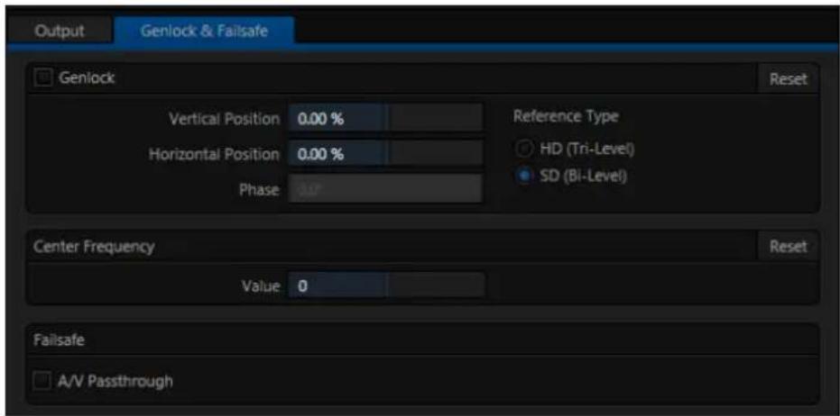
text_image
Output Genlock & Failsafe Genlock Reset Vertical Position 0.00 % Horizontal Position 0.00 % Phase 3.0° Reference Type HD (Tri-Level) SD (Bi-Level) Center Frequency Value 0 Reset Failsafe A/V PassthroughFIGURE 31
- Click the Genlock & Failsafe tab (Figure 31).
- The default Reference Type in the Genlock settings group is SD (Bi-level), as this is currently the most common reference signal type. However, if you supply an HD reference signal to the Genlock input, you may want to change the setting to HD (Tri-level).
- With the aid of downstream Waveform and Vector Scopes, adjust TriCaster's Horizontal and Vertical Position and Phase settings in the Genlock section of the I/O Configuration panel.
Ideally both the cameras and TriCaster should be genlocked. If they are not genlocked to the same reference signal as the TriCaster output, a TBC (Time Base Correction) operation is automatically applied. Time base correction may drop or insert frames as necessary to maintain sync, hence is a less desirable approach.
Note: For a deeper discussion of genlocking, please see Section 8.1.3.
SECTION 3.15 CONFIGURE TIMECODE
TriCaster can use the system clock to generate 'local timecode' shown in the Live Desktop titlebar, and also embedded in recorded Quicktime (or MPEG2) clips.
To configure timecode, click the configure button (gear) located beside the timecode display at right in the Dashboard. Please see Section 8.4.3 for more detail.
If you have an external linear timecode (LTC) source, you'll probably want to use that timecode reference rather than the local (system) time. A switch is provided in the Timecode Configuration panel to enable this support.
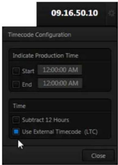
text_image
09.16.50.10 Timecode Configuration Indicate Production Time Start 12:00:00 AM End 12:00:00 AM Time Subtract 12 Hours Use External Timecode (LTC) CloseFIGURE 32
TriCaster is capable of displaying screens from networked computers running NewTek's iVGA™ client software, output from other supported applications (such as NewTek's own LiveText™, or the growing number of third-party programs), video streamed from additional TriCaster or 3Play™ systems on the network, or from Apple AirPlay®.
Generally, simply connecting a suitable cable from the Ethernet port on TriCaster's backplate to your external network is all that is required to add TriCaster to a local area network (LAN). In some settings, additional steps (beyond those mentioned when we discussed Microsoft Windows® activation in Section 3.2) may be required.
You can access the system Network and Sharing control panel to accomplish more extensive configuration tasks – see Settings: Configure Network under the heading Administrator Mode in Section 5.2.3. If further help connecting is required, please consult your system administrator.
The next section (Chapter 4 Live Production Walkthrough) will guide you through your irst experience using TriCaster.

text_image
TCThis chapter provides a quick hands-on tour of the major components and functions of your NewTek TriCaster™. In a very short time, these basics will be second nature to you.
More detailed reference material on all aspects of TriCaster follows in Part II (Reference).
Having made the essential external connections in the previous section, let's start your irst TriCaster™ session, and skim through some important fundamentals:
- Startup and Import
• Monitoring and related features.
• Audio mixing (and the Follow feature).
• Network sources. - Switching between video sources, and using transitions.
- Program output and recording.
- Playing stored clips using the DDR ('Digital Disk Recorder').
- Adding (and editing) title pages and graphics.
- Using an M/E to create a simple chromakey effect.
- Configuring a LiveSet (virtual set) shot.
- Using Buffers
- Streaming to the Internet.
SECTION 4.1 CREATING A SESSION
We ran through the basics of starting new sessions and configuring input and output devices in sections Section 3.10 through Section 3.14. If you need to review this information, go ahead and do so now. (We'll look at them individually again later in Part II (Reference), too.)
-
In the initial Startup Screen, create a new 1080i session - name it "Practice Session".
-
The Session Page will appear when you click Start Session.
- Click Manage on the icon ring (Figure 33).
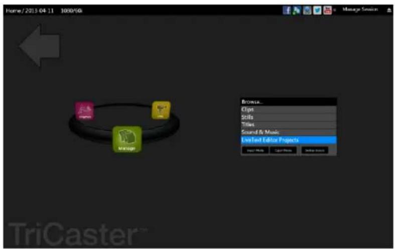
text_image
Home/2013-04-11 1080/60 Manage Session Browse... Clips Stifts Titles Sound & Music LiveText Editor Projects Image Tools Edit Tools Help Tools TriCaster™FIGURE 33
SECTION 4.2 IMPORTING CONTENT
Let's import a few files that we'll use later in our walkthrough:
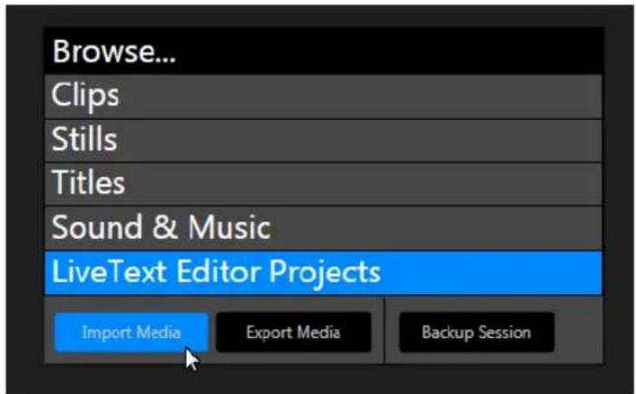
text_image
Browse... Clips Stills Titles Sound & Music LiveText Editor Projects Import Media Export Media Backup SessionFIGURE 34
- Click the Import Media button at lower-right.

text_image
Import Media Add Remove Name Transcode Status BTOne_Quad.WAV Waiting Breaking News.cgi texas_weathermep.png Waiting Waiting__________________FIGURE 35
- Click Add in Import Media (Figure 35) to open a system File Explorer.
- Navigate to C:\TriCaster\Documentation\Walkthrough Content.
- Press Ctrl + a (to multi-select everything in the folder shown in the File Explorer) – then click Open, adding these items to the file pane of the Import Media panel.
- Click Import - different media types are automatically sorted into the correct destination folders as they are imported. We'll use these files later (see also Section 5.3.3).
Hint: Although you might well never even notice, a two minute initialization period begins after you start (or re-start) TriCaster.
This ‘warm-up’ period allows the system to stabilize, ensuring consistent performance of various components (for example, video clips playing in the DDR before the end of initialization could skip some frames).
We are ready now to commence our tour of the Live Desktop, beginning with further consideration of monitoring features and options.
SECTION 4.3 CONFIGURING SHARE ACCOUNTS
TriCaster's Share Media features allow you to publish clips and stills from events to social media sites or storage locations even while the live action and capture continue.
This is a unique ability that adds value to TriCaster productions that the ‘other guys’ don’t offer. Taking full advantage of it requires a little configuration beforehand.
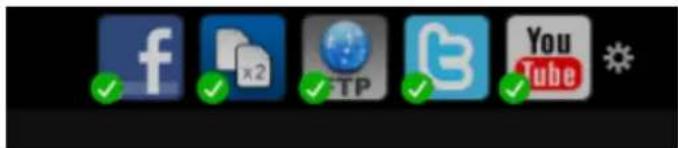
text_image
Screenshot of a social media app interface showing icons for Facebook, X2, Twitter, TikTok, YouTube, and Twitch with checkmarks indicating approval.FIGURE 36
At the top of both Home and Session pages in Startup, you'll see a row of icons (Figure 36) representing Accounts you can optionally publish your media to. These include popular social media sites like Facebook® and YouTube®, along with more prosaic but still very useful storage option.
Hint: Successfully configured accounts show a green checkmark icon.
Let's use a simple example to show how it works – one that doesn't require you to have an existing account with any social media provider.
- Click the second icon from the left (this is the File Copy icon), to open the Account Configuration panel (Figure 37).
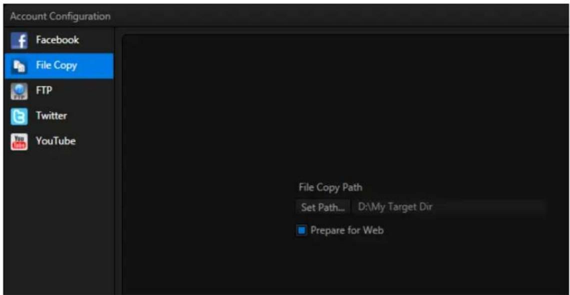
text_image
Account Configuration Facebook File Copy FTP Twitter YouTube File Copy Path Set Path... D:\My Target Dir Prepare for WebFIGURE 37
-
Click Set Path, and choose (or create) a destination folder for output.
-
If you like, enable the Prepare for Web switch.
Hint: Normally, for File Copy, and perhaps FTP destinations, you might well skip this last step. It causes shared files to be transcoded to a compact H.264 format suitable for uploading to social media sites when processed.
That's all you need to do. (Of course, if you have social media site accounts, you can configure them here too.) We'll use this a bit later in our walkthrough to demonstrate how to share media from the Live Desktop.
SECTION 4.4 MONITORING
4.4.1 PROGRAM AND PREVIEW
Inevitably, you'll be paying a lot of attention to the main Program and Preview monitors (Figure 38), occupying the right half of the Live Desktop's monitoring section by default.
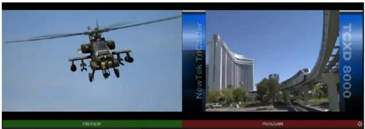
text_image
NewTek TriCaster TCXD 8000 PREVIEW PROGRAMFIGURE 38
TriCaster's 'Look Ahead' Preview monitor relects the outcome of the upcoming switching operation.
The Program monitor displays what you are sending to downstream devices and your audience.
Situated just above the monitoring display is the Dashboard, offering controls for Stream, Grab, Record, a timecode display, and more.
Let's briefly turn out attention to the Workspace menu in the Dashboard.
4.4.2 WORKSPACES
text_image
Workspaces He FIGURE 39The options provided in the Workspace menu include different Desktop and Multiview monitoring layouts.
The features available in this area vary by model.
TriCaster 8000 has the most features, and the next section illustrates some of these.
Other models provide various preconfigured monitor layouts along with Multiview monitor resolution options in the Workspace menu.
TRICASTER 8000
Click the Workspace menu to view a drop down pane allowing you to select and configure Workspace presets.
At the top of this pane are four Interface presets, labeled A-D, with accompanying graphics that depict the current layout assigned to each preset.
-
Notice that, by default, the Interface A preset displays all camera inputs along network inputs and a number of other internal sources.
-
One by one, select successive presets in the Interface group, and note the effect on the Live Desktop monitors.
-
Select Interface D, making it the active preset.
-
Click Workspace again, re-opening the preset
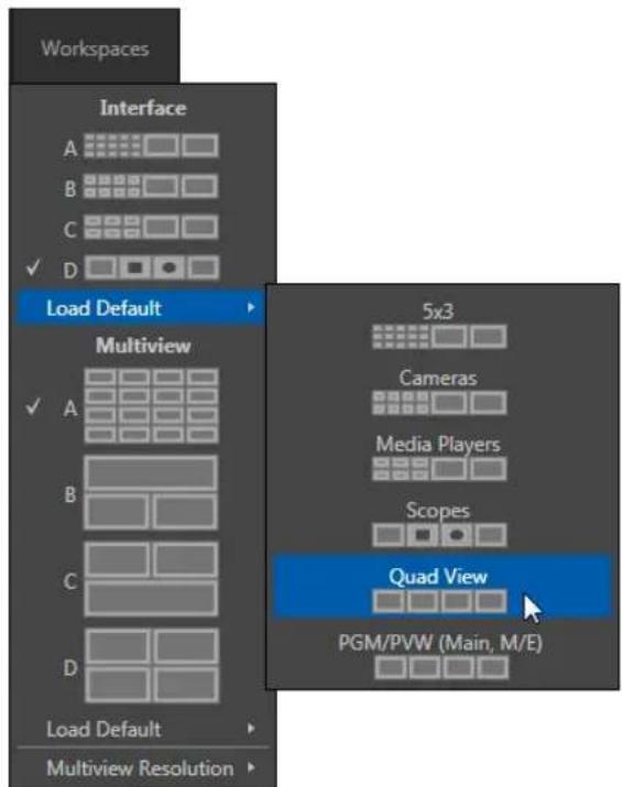
text_image
Workspaces Interface A B C ✓ D Load Default Multiview ✓ A B C D Load Default Multiview Resolution 5x3 Cameras Media Players Scopes Quad View PGM/PVW (Main, M/E)FIGURE 40 (TriCaster 8000)
controls. Slide the mouse down to the Load Default entry, revealing a sub-menu showing different monitor layouts. Select Quad View.
- Glance at the monitor display, and you'll notice that it has updated. Switch to the Interface A preset, then back to D.
Presets recall their last setting, so D continues to show the 'quadview' layout.
For TriCaster 8000, Workspaces can be modified beyond simply changing their
monitor layout, too.
-
With the Interface D preset active, reselect the Load Default menu,
-
This time, choose the Cameras preset, populating the Live Desktop monitors with 8 camera input monitors (plus Preview and Program monitors).
-
Move the mouse pointer over the monitor for Camera 1 and right-click to open the Monitor Setup menu (Figure 42).
-
Slide down to the Mix Effects entry, and select M/E 1 from the sub-menu.
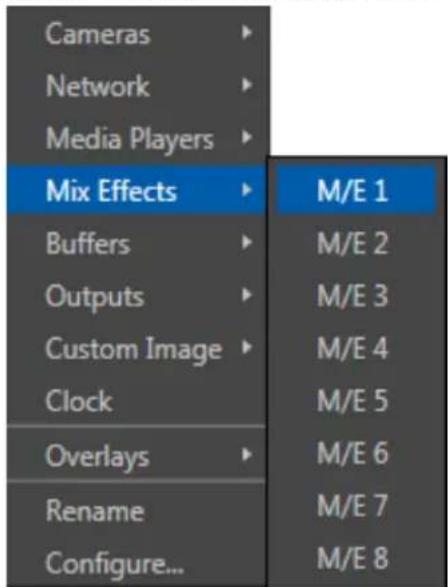
text_image
Cameras Network Media Players Mix Effects Buffers Outputs Custom Image Clock Overlays Rename Configure... M/E 1 M/E 2 M/E 3 M/E 4 M/E 5 M/E 6 M/E 7 M/E 8FIGURE 42
- Repeat this operation for the remaining seven camera monitors, selecting a different M/E as the source for each monitor in turn.
The Interface D preset now displays individual monitors showing the output of all M/Es after the associated effects are applied (including virtual sets, overlays, etc.)
All TriCaster 8000 video monitors, including those in the Interface as well as Live Desktop monitors, can be customized in similar fashion.
Hint :To restore default monitor layouts, simply activate the preset you want to modify, click Workspace and select your preferred Default Layout,
Let's look at a few more details of TriCaster's monitors before moving on:
- The Monitor Setup context menu (Figure 42) provides many options in addition to simple source assignment, including a Checkerboard background option for sources with transparency (Figure 44), VU meters, and more.
NOTE: Although only TriCaster 8000 supports independent monitor source selections as shown above, all models discussed in this Guide offer monitor overlays (such as Safe Area) in this context menu.
text_image
NewTek TriCaster 8K Practice 1080/60i 16:9 M/E 1 M/E 2FIGURE 43
- The monitor labels for sources currently visible on Program output are highlighted in red (Figure 43). Labels for sources shown on Preview have a green tint.
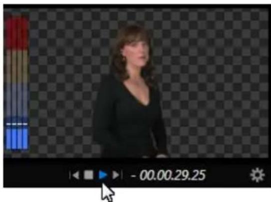
text_image
- 00.00.29.25FIGURE 44
- Monitors provide other controls and displays on rollover as appropriate, including things like Play or Stop and current position (timecode) in a clip for Media Players, and Network source selection (Figure 44).
4.4.3 SCOPES
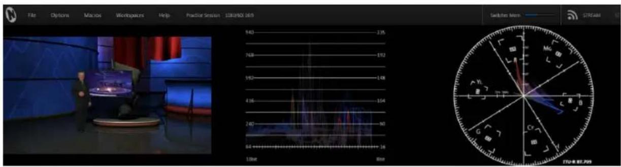
text_image
File Options Macros Workspaces Help Practice Session 120/900 169 Switches Mem STREAM 940 2.35 768 192 362 -1.08 416 -1.04 240 90 84 +16 1.0bit 8bit Mg G B C D E F G H I J K L M N O P Q R S T U A B C D E F G H I J K L M N O P Q R S T U A B C D E F G H I J K L M N O P Q R S T U A B C D E F G H J K L M N O P Q R S T U A B C D E F G H I J KFIGURE 45
- Display the Scopes again (if you've forgotten how, see the previous section).
The monitoring area displays Waveform and Vectorscope displays (along with a full color Preview source video pane), invaluable for calibrating your video sources.
- Move the mouse pointer over the horizontal divider separating the monitoring section from the Switcher area below. The pointer becomes a double-headed arrow.
- Drag downward at this location until the scopes are a comfortable size for your viewing (Figure 45).
- Move the mouse onto the video monitor at left, and right click the display to show a menu panel that lets you assign a video source.
- Double-click the video preview monitor at left to open the Input Configuration controls for the source.
-
Explore the Proc Amp and other controls in this panel, for future use.
-
When you're finished, move the mouse over the Desktop divider you previously dragged to re-size the monitors, and double-click it to restore its default location.
SECTION 4.5 AUDIO MIXER
Having previously connected and configured your audio inputs, let's explore a few of the standard features in TriCaster's Audio Mixer.
Hint: You will need to have speakers connected to (at least) the first two connectors (channel 1 and 2) in the Output 1 (upper) row of TriCaster's Audio Out section (even better, if you have them handy, connect a pair of stereo headphones and put them on).
4.5.1 MUTE, MONO AND BALANCE
- Click the DDR 1 tab below the Switcher area of the Live Desktop.
- Click the + (Add Media) button at lower left in the DDR pane.
- Click the Practice Session entry under the heading Audio in the Location list at left (this Location entry was created automatically when we imported iles back in Section 4.2, Importing Content).
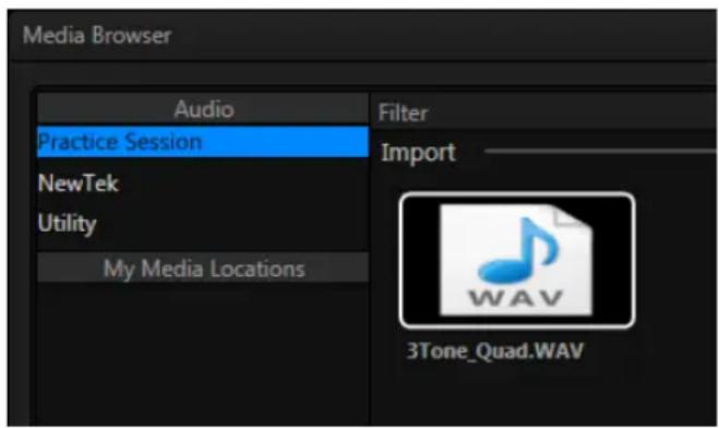
text_image
Media Browser Audio Practice Session NewTek Utility My Media Locations Filter Import 3Tone_Quad.WAVFIGURE 46
- Find the icon named "3tone_quad.WAV" in the file pane. This is a four channel audio ile, with a mid-range tone on channel 1, a higher tone on channel 2, while both channels 3 and 4 both carry a lower tone.
- Select the icon for this ile, and click OK to add this audio ile to the playlist.
- Turn on the Single and Loop switches below the DDR 1 playlist.
FIGURE 47
- To avoid any confusion in our little experiment, let's eliminate all other sounds for now. Click the Audio Mixer tab, and Mute any inputs that show live audio on their respective VU meters by clicking the speaker icons in the titlebar of each control group so they show red background (Figure 47).
- Make sure audio for DDD 1 player is not muted.
- Set DDR 1's Volume sliders to 0dB VU (you can do this quickly by holding down the keyboard Shift key while double-clicking the Volume knobs).
- Click the DDR 1 tab again, and click the Play button in the DDR 1 pane.
If you have stereo speakers or headphones connected, you should now hear two distinct tones – a mid-range tone from the left, and a higher pitched tone from the right.
- The VU meter for DDR 1 in the Audio Mixer tab will show matching sound on all four channels.
4.5.2 PAN
The Audio Mixer's Pan control is provided in the advanced Audio Configuration pane.
- To open this panel, click the Configure button (gear) below the DDR 1 label in the Audio Mixer.
text_image
Pan A BFIGURE 48
A Pan slider is provided for each channel of all audio sources. Sliding a Pan knob left or right actually moves (or 'pans') the audio from its original channel onto its neighbor (in the same stereo pair).
- Mute channels B, C and D for DDR 1.
If the DDR controls are at their default, you will now hear sound only on the left channel.
- Re-open the Audio Configuration panel.
- Move the Pan knob for channel A to the extreme right.
Notice that all of the sound previously heard from the left (channel A) is now coming from the right (channel B).
- Move the slider to the left; as you do, you will hear an increasing amount of sound moving back onto channel A.
Hint: Pan does not have any impact on the levels shown on source VU meters. However you will see its effect on the VU meters for any output mixes the sources are assigned to (in the Routing section of Audio Configuration).
- At the mid-point (i.e., when the Pan knob for channel A is centered), the audio from the irst channel of the ile playing in the DDR is divided evenly between channels A and B.
Note: In the center position, Pan controls produce a Mono effect. It's worth noting that Mic source types (only) are automatically configured with Pan A and B centered, equivalent to a 'mono' setting.
- Move the slider back to the extreme left position. The sound is now entirely sent to channel A, where it was in the first place.
Pan thus provides precise control over where the audio from any channel input is heard – whether exclusively on output channel A, B, or in differing amounts on both channels.
4.5.3 TALK
Talk is an abbreviation of "Talk Over". The Talk feature is only shown for inputs when they are set to Mic.
- Reset Pan and Mute controls to their defaults, and start DDR 1 playing the audio tone ile again.
- Set Input 1 to Mic (using the Connection menu in the Audio Configuration panel for input 1).
- Click the Talk button at the bottom of the Input 1 control group, watching DDR 1's VU meter as you do so.
Enabling Talk causes the level for all other audio sources to drop off by 20dB, allowing Input 1 to dominate. This is very useful for public address announcements, which is its principal purpose.
4.5.4 FOLLOW
- Connect (audibly different) audio sources to the input connectors for rows 1 and 2 in the Audio In group on TriCaster's rear.
- Open the advanced Audio Configuration panel for Input 1.
- In the Input Settings tab, enable the Follow Program video switch.
- Enable Follow Program video for audio Input 2, as well.
-
Select the button for Camera 1 on the Switcher's Program row.
-
Select the button for Camera 2 on the Switcher's Preview row.
At this point, you should be hearing audio only from input 1.
Hint: By default, each audio input is configured to follow the video source having the same Switcher row slot, though the Follow switch is disabled. However, it's valuable to know that these default source relationships can be modified, as we shall see shortly.
- Click the Switcher's Take button – keep an eye on the VU meters for Inputs 1 and 2 as you do so.
Notice that when the video source assigned to Camera 1 is selected on the Program (PGM) row, you hear its associated audio input. When you perform a Take the audio source connected to Input 2 in the Audio In section is heard.
When Follow is enabled for an audio source, its sound is automatically sent to output whenever video sources it is assigned to follow are displayed on output. In this case, the levels shown in the VU meter for that audio source are drawn in color.
When you switch away from the video source, the VU meter still shows its audio level, but the graph is drawn in grayscale (providing confirmation that audio is present, but indicating that it is not going live to Program out).
Hint: Follow even works when the associated video sources are displayed on output via an M/E or DSK channel.
FOLLOW VIDEO OPTIONS
The Follow Program video control group for has a drop-down menu that lets you determine exactly which video source, or sources, will be ‘followed’ by the audio source.
Let's test this:
-
Continue to supply sound to audio Inputs 1 and 2.
-
Use the Follow source menu in the respective Audio Configuration panels to set Input 1 to follow both Cameras 1 and 2, and enable the Follow switch.
-
Conigure audio Input 2 identically.
- Select Camera 1 on the Switcher's Program row. The audio from both input 1 and 2 should be audible.
- Switch to Camera 3. The audio from Inputs 1 and 2 is muted on output (and their VU meters will turn gray). If audio Input 3 has sound, you will hear it instead.
- Switch to Camera 2 and you will hear sound from both Input 1 and Input 2 again.
SECTION 4.6 NETWORK SOURCES
Perhaps you'd like to be able to add Microsoft PowerPoint® output, web pages, Skype™ video calls, application displays, titles and graphics from NewTek's LiveText or other exotic content to your productions. TriCaster supports all such displays from computers on the same network as Network (1 and 2) sources on the Switcher, via the supplied iVGA client application (not required for LiveText).
4.6.1 IVGA CLIENTS
- For a Microsoft Windows® client, copy the iVGA PRO program from the Extras\iVGA\Microsoft Windows folder (inside C:\TriCaster) to the sending computer.
For OS X® client systems, copy the correct iVGA.dmg.zip ile appropriate for your system type from the similar folder named for Apple OS X® to your Mac.
Unzip it by double-clicking it; mount the disk image (.dmg ile) in the same manner, then drag the iVGA program icon into Applications. (See Chapter 16, Network for more detail).
- Connect TriCaster to the client computer via the local network.
- Double-click the iVGA icon on the second computer.
After agreeing to the NewTek license (and a moment or two for the network connection to be established) the name of the remote computer is added (along with "Black" and any other networked systems with iVGA running on them) to TriCaster's network source list.
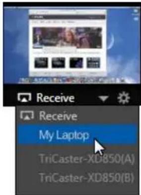
text_image
Receive Receive My Laptop TriCaster-XD850(A) TriCaster-XD850(B)FIGURE 49
Note: Gigabit networking is highly recommended, and should be considered mandatory for HD sessions in particular.
When TriCaster recognizes qualified network sources, it adds them to a drop-down menu for quick selection (Figure 49).
- Move your mouse pointer over a Network monitor in the All Monitors tabbed view.
- Click the triangular menu button below the monitor to select a networked source (or change the current selection) from the menu that appears. (For iVGA PRO, you'll need to accept the connection at least once on the client machine).
Hint: iVGA displays a status icon on the client system. For a Windows® based system, the icon is in the task tray; on Macintosh® systems, it is shown in the dock. This indicates this computer's display is ready to send to TriCaster. The icon's appearance changes to indicate when the client is actually sending output to TriCaster.
See Chapter 16 for much more detail on the use of iVGA.
4.6.2 APPLE AIRPLAY®
See Section 16.2 for details on using devices and applications supporting Apple AirPlay as network sources for TriCaster.
4.6.3 LIVETEXT™
NewTek's (optional) standalone LiveText application offers features that are very similar to TriCaster's integrated LiveText (see Chapter 21 LiveText™ and SpeedEDIT™), but installs separately on a compatible Windows® computer.
A (networked) LiveText workstation effectively constitutes a dedicated CG and title solution for TriCaster presentations. (This is a wonderful addition for those times when you could really use another pair of hands.)
When running on the network connected computer, LiveText is listed in the Network selection drop-down menus (just as an iVGA source would be).
Select LiveText (and clicking the Live button in LiveText) provides the current title page in LiveText to the Network buttons on TriCaster's Switcher, M/Es or DSK channels.
SECTION 4.7 LIVE SWITCHING
Back in Chapter 3 (Setting Up), you connected cameras to inputs on TriCaster's backplate and configured them. If you haven't already done so, let's explore basic Switcher operations.
4.7.1 SWITCHER ROWS
text_image
PGM ▼ 1 2 3 PREV ▼ 1 2 3FIGURE 50
The main Switcher features 2 rows of buttons labeled Program and Preview. Each button on a Switcher row represents one of the many and varied video sources available.
The irst button group at left on any row represents Cameras, while others represent various other sources (discussed soon).

text_image
PGM 1 2 3 4 5 6 7 8 NET 1 NET 2 DOR 1 DOR 2 GFX 1 GFX 2 BFR 1 M/E 1 M/E 2 M/E 3 M/E 4 M/E 5 M/E 6 M/E 7 M/E 8 BLACK PREV 1 2 3 4 5 6 7 8 NET 1 NET 2 DOR 1 DOR 2 GFX 1 GFX 2 BFR 1 M/E 1 M/E 2 M/E 3 M/E 4 M/E 5 M/E 6 M/E 7 M/E 8 BLACK FADE Take AUTO TAKE AUTOFIGURE 51 (8-INPUT VERSION SHOWN)
Clicking a button in any row selects the active source for that row. Program and Preview row selections determine the content of the BKGD (Background) video layer, before the application of any overlays (DSKs).
VIDEO LAYERS
TriCaster video output often consists of multiple sources of imagery, added together layer on layer to form a composite. The Switcher and Transition controls allow you to manage these video layers to show the viewer just what you want him to see.
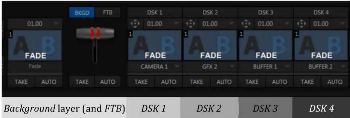
text_image
01.00 FADE Fade TAKE AUTO TAKE AUTO BKG D FTB DSK 1 01.00 FADE CAMERA 1 DAK D S K 2 01.00 FADE GFX 2 DAK D S K 3 01.00 FADE BUFFER 1 TAKE AUTO TAKE AUTO TAKE AUTO TAKE AUTO DAK D S K 4 01.00 FADE CAMERA 1 DAK D S K 2 01.00 FADE GFX 2 DAK D S K 3 01.00 FADE BUFFER 1 TAKE AUTO TAKE AUTO TAKE AUTO DAK D S K 4 01.00 FADE CAMERA 1 DAK D S K 2 01.00 FADE GFX 2 DAK D S K 3 01.00 FADE BUFFER 1 TAKE AUTO TAKE AUTO TAKE AUTOThe BKGD (Background) video layer constitutes the base of the video composition ultimately sent to Program Output.
Based on your selections, as many as ive more primary video layers may be superimposed above the BKGD layer on output:
- DSK video layers are most commonly used to apply graphics or titles to the BKGD layer (DSK stands for 'Down Stream Keyer'). The number of DSK layers varies by model.
- FTB (Fade to Black) constitutes a final video layer prior to output – one that can obscure all others when called upon to do so.
Again, the Program and Preview row selections determine the content of the BKGD (Background) video layer. The Preview row selection is normally cued up for the next Take (cut) or Transition operation. Either operation, once completed, results in the original Program and Preview row selections exchanging places. Of course during a transition, portions of both the Program and Preview row selections can be seen in varying amounts.
The BKGD layer composition can include other content as well, as we'll see later in Section 4.10 (LiveMatte) and Section 4.11 (More About M/Es).
Hint: It can be useful to have the tab for a Media Player you select on the Preview row shown automatically. To employ this behavior, enable either of the “Tabs follow Preview ...” items listed in the Options menu of TriCaster's Live Desktop (at left in the Dashboard).
CONFIGURING CAMERAS
Let's try out some of these concepts, shall we? (If you previously configured some cameras, feel free to skip ahead to the next sub-heading).
- First, conirm that the Connection Type selected for your video sources is correct.
a. Double-click an Input monitor to open the Configuration panel for that input.
b. Choose a Connection setting appropriate for your camera, and close the Configuration panel.
-
Repeat the steps above for all connected cameras.
-
Use the Workspace menu to show "All" primary Switcher sources.
-
Click the Switcher button labeled '1' on the Program row to send Camera 1 to TriCaster's BKGD layer (the PGM row button turns red).
(For experimental purposes, feel free to use internal sources such as Media Players rather than live cameras if you like.)
-
Click to select Camera 2 on the Preview row (the button will light up in green).
-
Note that the monitor labels for the corresponding sources are now also tinted red and green, respectively.
DSK SOURCES
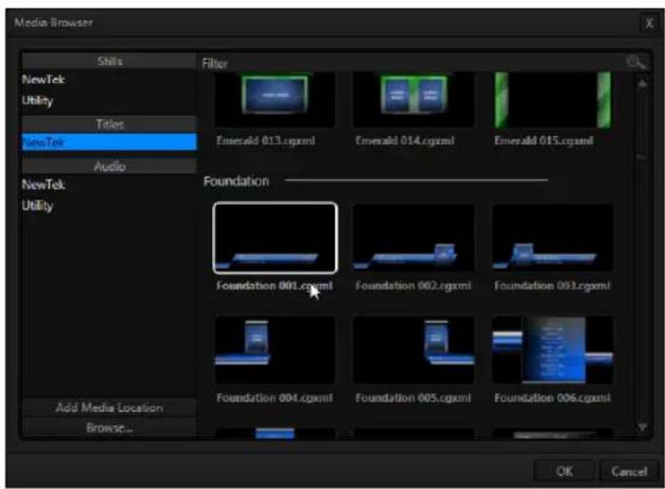
text_image
Media Browser Skills Filter NewTek Utility Titles NewTek Audio NewTek Utility Add Media Location Browse... Emerald 013.cgxml Emerald 014.cgxml Emerald 015.cgxml Foundation Foundation 001.cgxml Foundation 002.cgxml Foundation 003.cgxml Foundation 004.cgxml Foundation 005.cgxml Foundation 006.cgxml OK CancelFIGURE 52
Let's assign sources to a couple of the DSKs (Downstream Keyers) now (we'll be using these shortly):
- Add a title to the GFX 1 (or simply GFX, for TriCasters with just one Graphics player) playlist as follows:
a. Click the Graphics tab, then click the large + (Add Media) button at left in the footer of the GFX 1 player to open a custom Media Browser (Figure 52).
b. Click the NewTek location at left (under the Titles heading) in the Media Browser.
c. In the ile pane at right, scroll down to locate a title that does not cover the entire screen (such as the one shown in Figure 52).
-
In the same manner, add a different second title to the playlist.
-
Right-click the playlist icon for this second title, and select Send to Buffer 1 from the icon menu.
Hint: This introduces the TriCaster's Buffers, discussed more fully later. For now, think of them as it will suffice to think of buffers as dedicated 'instant-recall' memory slots allocated to hold media for instant display.
We're ready to configure the DSKs we want to use now.
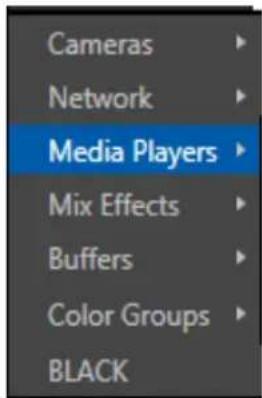
text_image
Cameras Network Media Players Mix Effects Buffers Color Groups BLACKThe DSK controls are located to the right of the Transition control group (T-bar) in the central (Switcher) area of the Live Desktop.
The name tag for the source currently assigned to each DSK channel is displayed below the DSK's own label.
FIGURE 53
- Click the source labels for DSK 1 and 2, and assign GFX 1 (or simply GFX, if applicable) and Buffer 1 as their respective sources.
4.7.2 TRANSITIONS
Now we're ready now to try out the features in the Transition section, just left of the DSK section in the onscreen Switcher. Let's begin our exploration of switching with the BKGD (Background) layer.
-
Select Camera 1 on the Switcher's Program row.
-
Select Camera 2 on the Preview row.
- Notice that the red and green highlighted monitor labels conform to the selections you just made.
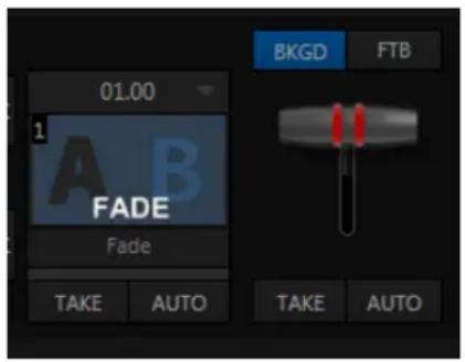
text_image
01.00 1 A B FADE Fade TAKE AUTO BKGD FTB TAKE AUTOFIGURE 54
- Click the BKGD button above the T-bar in the Transition group – Figure 54 (this dedicates the T-bar to control the BKGD video layer exclusively).
- Click the Take button below the T-bar.
a. Camera 1 is instantly removed from Program Out.
b. Camera 2 (previously the Preview row selection) moves to Program output.
c. The Camera 2 button is now lit up on the Program row.
d. The Camera 1 button is lit up on the Preview row.
e. The red and green monitor label highlights have been swapped.
- Now click the local Auto button. The Program and Preview row selections swap again, but this time, rather than a simple (and instant) Cut, the change employs the currently selected transition – by default, a Fade.
Hint: By default, the keystroke shortcuts Enter and spacebar perform the (main Switcher) Take and Auto operations, respectively.
- To replace the current transition with a different one, follow these steps:
a. Click the large Fade thumbnail icon to open the Transition Bin.
b. Slide the mouse pointer down and click a different transition effect. Test it, by clicking Auto.
The Transition Bin provides quick access to a number of transitions, but TriCaster includes many others.
To replace an entry in the Transition Bin with a completely new effect, proceed as follows:
-
Open the Transition Bin again, and hover the mouse pointer over any thumbnail icon.
-
Click the Browser button (+ sign) that appears above the icon to open the custom Media Browser.
NOTE: Four input TriCaster models, having a little more space on the Desktop, provide a second, larger, selector type for primary video effects in both the main Switcher and M/E controls. For all intents and purposes, though, effect selection in either selector type is essentially the same.
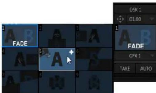
text_image
1 FADE 2 3 FADE 5 + 6 FADE GFX 1 TAKE AUTOFIGURE 55
-
The Media Browser is context sensitive. It will show transition headings in the Location list at left. Choose a new transition to replace the current entry.
-
The current transition duration is shown beneath the thumbnail icon (shown as seconds: frames).
Click the digits to edit them directly, or click the triangle button and select an entry from the menu (Figure 56).
Hint: notice that the BKGD effect menu also offers Reverse and Ping Pong options, which control transition direction.
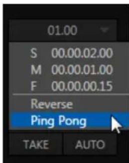
text_image
01.00 S 00.00.02.00 M 00.00.01.00 F 00.00.00.15 Reverse Ping Pong TAKE AUTOFIGURE 56
Having mastered the basic Background transition, let's take another look at the DSKs. Notice that each DSK channel has its own control group located to the right of the main T-bar (Figure 57).
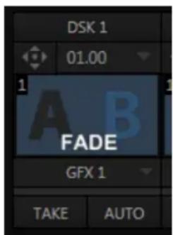
text_image
DSK 1 01.00 1 A B FADE GFX 1 TAKE AUTOFIGURE 57
Hint: DSK 2 appears 'in front of' DSK 1 (from the viewer's perspective).
DSKs can each have their own transitions, and these can be set to different durations as well if you like.
-
Click the local Auto button for DSK 1. Since GFX 1 is assigned to DSK 1, the currently selected item in that Media Player transitions in to appear above the BKGD layer.
-
Click Auto for DSK 2. DSK channel content can be individually displayed or removed from view in this manner.
Hint: DSK (and M/E Key channel) transitions are always in Ping Pong mode. If you fly a DSK on with one operation, the next transition will always fly it back off again.
That's all useful, as far as it goes, but what if you want to remove one graphic and display another simultaneously?
- Click Take for DSK 2 to remove that video layer from view (DSK 1 should still be on screen).
- In the main Transition control group (Figure 57), click the label of the DSK 1 control. It will turn blue. The main transition controls, including the T-bar, will now affect the DSK 1 video layer only.
- Try it out by pressing the main Auto button; then press it again to re-display DSK 1.
Hint: Note that the progress gauge beneath DSK 1's Take button shows that DSK 1 is fully displayed.
- With the DSK 1 delegate button lit up, press Ctrl on your keyboard, and keep it pressed while you click the button for DSK 2 – then release it.
Two Transition delegate buttons are now 'lit' - DSK 1 and DSK 2.
- Click the main Auto button again.
DSK 1 (which was displayed above the BKGD layer) is removed from view, and DSK 2 is displayed using its own transition.
Let's up the ante just slightly.
- Press Ctrl on your keyboard while you click the BKGD delegate button.
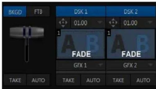
text_image
BKG D FTB DSK 1 01.00 1 FADE GFX 1 TAKE AUTO DSK 2 01.00 1 FADE GFX 2 TAKE AUTO TAKE AUTOFIGURE 58
Your Transition Delegate buttons should now resemble Error! Reference source not found., showing that three delegates are currently active.
- Press the main Auto button again.
Let's analyze what happened using the images below, which show the before and after displays on the Preview and Program monitors (from left to right).
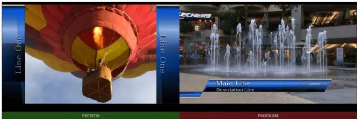
text_image
Line One Line One PREVIEW MAINE LINE DESCRIPTION LINE PROGRAMFIGURE 59 (BEFORE)
In Figure 59, the Program monitor shows the composite result of DSK 1 over the BKGD layer, the current Program row selection.
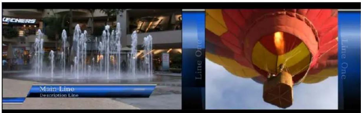
text_image
CECHERS Main Line Description Line Line One Line OneFIGURE 60 (AFTER)
In obedience to the current Transition delegate multi-selection, one click of the main Auto button resulted in all of the following operations:
- A BKGD layer transition occurred, swapping the Program and Preview row selections.
- DSK 1, which had been displayed on output, transitioned out of view.
- DSK 2, which was previously unseen before the auto, was transitioned in above the BKGD layer on Program output.
Let's pause here to consider TriCaster's Look Ahead Preview monitor. Cast your eyes over the Preview monitor, and consider how it relates to the state of the Transition Delegate controls.
In Figure 60, the Preview monitor shows DSK 2 (assigned to Buffer 1) overlaid on the current Preview row selection. The Look Ahead Preview monitor (or simply, Preview) always shows us the composition that would result if a Take or Transition operation was performed respecting the current transition delegate(s) -a look into the future, if you will.
- Hold down Ctrl on the keyboard again, and click the BKGD Delegate button (de-selecting it).
Note that, after de-selecting the BKGD delegate button, the Preview monitor no longer shows the Switcher's Preview row selection. Instead, it shows DSK 1 over the current Program row selection.
Why is that?
Since only the DSK 1 and DSK 2 delegate buttons are active, only those two video layers will be affected by a main Take or Auto operation. In this state, the result of an Auto operation will be as follows:
- DSK 2, currently seen on Program out, will be removed from view
- DSK 1 will be overlaid above Program instead.
- The BKGD layer – not being delegated – will not change in this case. Hence Preview correctly depicts the outcome of a Take or Auto, just as we've mentioned.
The Look Ahead Preview allows you to switch with real conidence; the Transition delegate features provide lexible and convenient video layer management, and thus enhanced control over your ultimate Program output composition.

text_image
RAB (0) RECORD (0) 15.48.02.10FIGURE 61
Record and Grab controls are prominently positioned immediately above the Program monitor (in its default position at upper right on the Live Desktop).
Note: The tools located above the monitoring section of the Live Desktop comprise TriCaster's Dashboard. In addition to Record and Grab, the Dashboard holds numerous other important features discussed a bit further on in this guide.
4.8.1 RECORD
text_image
RECORD (0)FIGURE 63
- Roll the mouse pointer over the Record control in the Dashboard and click the Configuration button (gear) that appears to open the Record Configuration panel (Figure 62).
- Click in the Base Name ield, and enter a unique name for the captured ile(s).
Hint: TriCaster stores recordings at (drive):\Media\Clips\sessionname\Capture (where "drive" and "sessionname" are appropriate for your system and session).
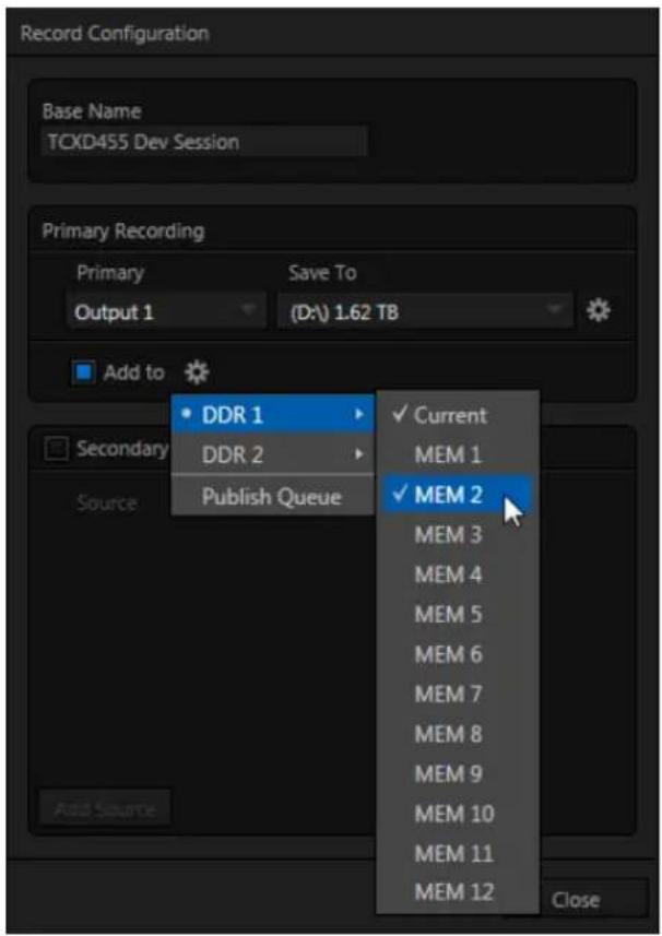
text_image
Record Configuration Base Name TCXD455 Dev Session Primary Recording Primary Save To Output 1 (D:\) 1.62 TB Add to • DDR 1 DDR 2 Publish Queue ✓ Current MEM 1 ✓ MEM 2 MEM 3 MEM 4 MEM 5 MEM 6 MEM 7 MEM 8 MEM 9 MEM 10 MEM 11 MEM 12 CloseFIGURE 62
TriCaster's IsoCorder™ technology can capture multiple a/v sources simultaneously. The irst of these sources is referred to as the Primary source. Additional sources in many combinations can be added in a Secondary recording group shown below.
(Recording options are discussed in more depth in Chapter 20, Record and Grab.)
The default capture options will work just ine for our purposes, so let's continue:
- By default, Output 1 (the primary Program output) is the selected Source in the Primary Recording area of the Record Configuration panel.
Hint: You could optionally select DDR 1 or DDR 2 in the nearby Add to Playlist menu, automatically adding newly recorded clips to a playlist – but let's not do that yet.
- Click Close.
- Make sure you have an active source playing on Program output.
- Press the Record button. It will illuminate, and the neighboring timecode ield will begin keeping track of the duration of your recording.
- After a little while, press Record again to stop recording.
This configuration will record everything that is displayed on Output 1, letting you capture your entire live production for posterity if you like. It also provides a way for you to capture clips for playback (from TriCaster's DDRs) during your live events.
4.8.2 GRAB
FIGURE 64
The Grab feature is similar to Record, just described - except of course that it grabs fresh still images from each time you click the Grab button.
Hint: Notice that the nearby counter increments with each Grab performed.

text_image
Base name TCXD8000 Session Grab all inputs De-interlace Add PGM grab to DDR 1 DDR 2 GFX 1 GFX 2 Buffers Publish QueueFIGURE 65 (TRICASTER 8000)
- As before, click the Configure button (gear) to open a setting panel for the Grab feature.
The De-interlace option smooths the results for ielded format session, and is enabled by default.
-
Enter "test" (without quotes) in the Base Name ield.
-
Enable Capture stills from all inputs (not available on TriCaster 410).
-
Enable the Add PGM grab to switch, and click the nearby gear button to select some destinations (be sure to include DDR 1).
-
Close the Configuration panel, and click the DDR 1 tab (so you can see what occurs next).
-
Click the Grab button.
Let's consider the results of this single click:
- For a given Base name, the number in the Grab button's counter display rises by 1 each time you click Grab.
- The image(s) grabbed from output is stored at in a folder on the session drive at (drive letter):\Media\Stills session name \Capture.
- As well, a new thumbnail icon (named "test 1.jpg", etc.) appears in the DDR 1 playlist; you'll see at a glance that it represents a still image from Output 1.
- Notice too that the newly grabbed frame is added to any other destinations (including the Publish Queue) you check-marked.
Note that only one thumbnail is added to the GFX 1 playlist, even though you enabled Capture stills from all inputs. The option did not fail, though. The same folder mentioned just above also contains sub-folders for each Grab you performed. You'll find the additional still image files inside these folders.
SECTION 4.9 MEDIA PLAYERS
4.9.1 THE DDRS
TriCaster's two DDRs are powerful Media Players, and can greatly enhance your live productions. (DDRs have siblings that we'll discuss a bit later – the Graphics and the Sound players.)
- Show DDR 1 by clicking its tab beneath the Switcher.
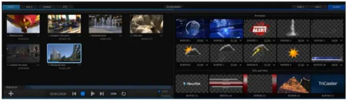
text_image
AVOC 1 SAY 5 USSO 9 FZ ALOG MARK RBN 2 SALT 2 LUXY 1. Redwood Movie 00:00:00 2. Magicbird Cattle 00:00:00 3. Ammanji Movie 00:00:00 4. Ugo Movie 00:00:00 Animation BUTTER 1 01:02 BUTTER 2 01:16 BUTTER 3 01:20 BUTTER 4 01:24 BUTTER 5 04:04 BUTTER 6 01:05 BUTTER 7 02:04 BUTTER 8 01:04 BUTTER 9 01:20 BUTTER 10 05:00 Din and Tines NewRisk BUTTER 11 BUTTER 12 BUTTER 13 BUTTER 14 BUTTER 15 TriCasterFIGURE 66
The tabbed pane shows two players side by side - Figure 66 (the arrangement of players varies slightly by model).
Hint: DDR stands for Digital Disk Recorder – a bit of a misnomer since TriCaster's DDR's don't record; Still the term continues in popular use to distinguish Media Players that can play 'clips' from those reserved for still image or audio-only tasks.
ADDING FILES
Let's add some clips to the playlist.
text_image
00.00.01.00 +FIGURE 67
-
Click the + (Add Media) button in the DDR 1 pane (Figure 67) to open a Media Browser.
-
Click the heading named for your current TriCaster session (Practice Session, if you've been following along) beneath the Clips header in the Locations column at left in the Media Browser.
Hint: Double-click an empty spot in the playlist instead of clicking the + button. When using either method, hold down the Shift key to view a standard system file window instead of the custom Media Browser.
-
The ile pane at right displays icons for recordings made in the session. It should list the ile you recorded earlier (in Section 4.8.1) under a group header labeled Capture – click the icon to select it, and then click OK.
-
You may wish to add several more iles to experiment with - sample iles are provided. DDR 1 and 2 also support most popular audio ile formats.
TRANSPORT CONTROLS

text_image
00.00.00.00 100%FIGURE 68
- Select DDR 1 on the Switcher's Program row.
- Click the newly added icon in the playlist, and press the Play button in the player's footer (to the right of Stop in Figure 68). The video clip you recorded should play on the Program monitor.
- Click the Stop button.
Notice that if you move the mouse pointer over the Speed slider (shown as a numeric percentage) it changes to a double-headed arrow, indicating you can drag the slider to a new value if you wish.
- Instead, try this: simply click inside the Speed slider (engaging direct edit mode), type "50" and press Enter to change playback Speed to 50%.
- Click Play again, and observe that playback is now in smooth slow motion.
- Adjust Speed again - notice that you can even modify Speed during playback.
- Click Stop.
- Hold down shift, and double-click the Speed value to reset it to its default.
TRIMMING AND SCRUBBING
Let's spend a moment learning how to trim a clip in the DDR. To do this you will use tools in the Scrub Bar immediately beneath the playlist pane (Figure 69).
Drag the Scrub Bar's (square) knob left or right to change the current play position.
Trimming is accomplished by dragging the start and end points for the clip using the blue ] and [ bracket controls at either end. (The mouse pointer changes to a double-headed arrow when you move it over a trim control.)
- Click the irst (top-left) clip in the playlist, highlighting it.
- Drag the trim controls to shorten the clip's runtime to 10 seconds (watching the Duration display to the right of the Scrub Bar helps when trimming).
-
Record a few more clips, if you haven't already done so, and add several to the playlist (either automatically or by using the + (Add Media) button).
-
Click the Single switch (Figure 70).
text_image
Single AutoplayFIGURE 70
-
Double-click the irst clip in DDR 1's playlist to play it (double-clicking is another way to engage Play). With Single mode engaged, playback automatically stops at the end of the current clip.
-
Select Camera 1 on the Switcher's Preview row (DDR 1 is already selected on the Program row).
-
Enable the Autoplay switch for DDR 1.
-
Play the irst clip in the playlist again. This time, just as the clip approaches its end, the Switcher automatically performs a transition (the sources on Program and Preview are automatically swapped), leaving Camera 1 on Program output.
-
After a few moments, click either Take or Transition in the Switcher's Transition section.
Notice that a transition is performed (returning DDR 1 from Preview to Program) and, more importantly, the next item in the playlist begins to roll automatically. When it ends, another automatic transition occurs, restoring Camera 1 to Program output.
Let's try Autoplay without Single mode:
-
Click Stop (if necessary).
-
Uncheck Single, leaving Autoplay engaged.
-
With DDR 1 on Program, and Camera 1 on Preview, highlight a fairly long clip (say, a minute or more).
- Click Play.
- After a few seconds, perform a Take and watch what happens:
a. Naturally, DDR 1 and Camera 1 are swapped on the Switcher.
b. DDR playback is stopped at the current frame of the current clip.
- Perform another Take.
a. As expected, DDR 1 is restored to Program output.
b. Playback re-commences at the next frame of the current clip; DDR 1 did not automatically jump ahead to the next clip this time.
You may ind Single mode your favorite way to use Media Players, but it can be useful to turn it off (as just described) at other times. Perhaps a live speaker is presenting a long clip, but wants to be free to interrupt it with live commentary at any time. Turning Single off (with Autoplay on) works perfectly in this scenario. The TriCaster operator can click Take or Auto freely, conident DDR playback will resume at precisely the right frame.
MEM SLOTS
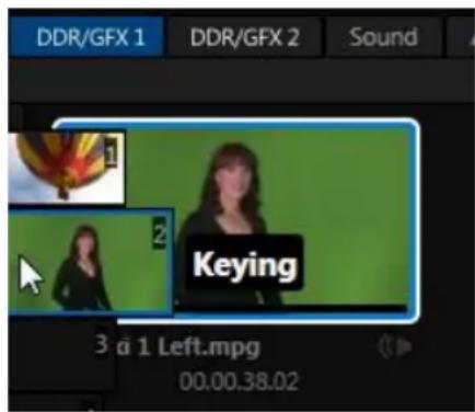
text_image
DDR/GFX 1 DDR/GFX 2 Sound 1 Keying 3 a 1 Left.mpg 00.00.38.02FIGURE 71
Let's consider one more powerful feature common to TriCaster's Media Players – the MEM slot bin.
MEM slot bins run vertically down the outer edges of the various Media Player and Audio modules, providing instant access to custom playlists and configurations.
Normally hidden, the bins ly out when you move the mouse pointer to the edge of the screen.
MEM slots store other information about the current state of the module, too, including playback position, selection status, and so on. In many ways, MEM slots act like additional Media Players.
- Move the mouse to the extreme left of the screen to open the MEM slot bin for DDR 1.
- Click an empty MEM slot, and use the + (Add Media) button to populate its playlist.
- Switch back and forth between presets, noting as you do how various attributes are retained.
Hint: Right-click a MEM slot to open a context menu offering a number of useful features, including Rename.
- Try copying and pasting playlist icons between two MEM slot (right-click to access the context menu containing Cut, Copy and Paste).
Note: Selecting a new MEM slot does not interrupt playback when it is underway. You can preview and modify a different playlist while the active one plays. See Section 11.2.4 for details.
4.9.2 GRAPHICS PLAYERS
TriCaster provide dedicated graphics players (labeled GFX) for displaying still images and titles, including TriCaster's native (live-editable) title pages. Different TriCaster models provide either one or two such dedicated players.
Graphics players are quite similar to the DDRs, just discussed, but do not provide full motion clip playback. Otherwise, the type of media iles they support remains largely the same.
All of these Media Players, regardless of title, can display TriCaster title pages and most if not all popular still image ile formats.
Hint: The DDRs can play all of the above media types as well as video clips and sound files.
The controls of the graphics players are identical to those of the DDR apart from the omission of a playback Speed control (which would be superluous and possibly confusing). Rather than cover these again, let's have a little fun:
- Select an icon in the GFX 1 playlist (or simply GFX for some models), and press CTRL + a on the keyboard to select all playlist entries.
- Press Delete on your keyboard, clearing out the all playlist entries (this is a non-destructive deletion, never fear).
- Repeat the two steps above for GFX 2 (if your unit provides two; otherwise, us a DDR as substitute).
- Add some image iles (a dozen or more) to GFX 1 (you can use some of the images from the NewTek group under the Still location heading for this example).
- Click on one the icons about halfway through the playlist, highlighting it.
- Hold down the Shift key, and click the last icon in the playlist. This will multi-select all of the iles from the irst one you clicked to the last one (the icons are given a lighter outline to show their selection status).
- Right-click anywhere in the playlist, and select Cut from the context menu.
-
Right-click in the playlist area of the GFX 2 (or DDR), and select Paste.
-
Hint: Instead of using Cut and Paste, we could simply have dragged the selected icons from one playlist to the other.
Let's pause to review. To this point, we've prepared two Media Players with similar playlists consisting of a series of still images.
Hint: Still image files default to a fifteen second duration when added to a playlist.
Fine, but ‘what about the aforementioned fun’, you ask? Indeed, let us press on:
-
Turn Single and Autoplay on in both players, and make sure Loop is off for both Media Players.
-
Select GFX 1 on the Switcher's Program row.
-
Select GFX 2 (or DDR, if you used that player above) on the Switcher's Preview row.
-
Click the irst entry in both playlists (to set the current position).
-
Press GFX 1's Play button, and watch the 'hands-free' slideshow.
Let's consider what is happening:
- When playback of the irst GFX 1 playlist entry reaches its end:
- The Autoplay setting invokes an automatic transition to Still, and stops GFX 1 playback.
- Then, unseen on Program output, GFX 1 cues up its next playlist item.
- Simultaneously, the GFX 2 player's Autoplay setting initiates playback of its first playlist entry.
- When playback of that item is reached:
- GFX 2's own Autoplay function performs another transition, returning GFX 1 to the Program row
○ And stops GFX 2 playback
- Then, unseen on Program output, the GFX 2 player cues up its next playlist entry.
- Next, GFX 1's Autoplay setting automatically starts playing its next playlist item. The cycle repeats until all items play through or is interrupted by user actions.
TITLE
TriCaster title pages can actually be added to any of the Media Players (apart from the Sound player). Media Players can also display bitmap iles exported from third-party graphics applications (or overlay them in DSK channels, especially valuable when the iles are either keyed or have an embedded alpha channel).
TriCaster's native title pages have some distinct advantages over a common still image, however. Let's try them out:
-
Click Add, and use the Media Browser to select a few of the prepared title pages from the NewTek location listed under Titles in the Location List at left.
-
Click an icon to highlight it in the Media Player playlist.
-
Display the title page on Program Output by selecting the correct Media Player on the Switcher's Program row.
-
Move the mouse over a different title page icon, and click the Configure button (gear) that appears in its lower-right corner.
-
The Title Page Editor shown in Figure 72 will appear.
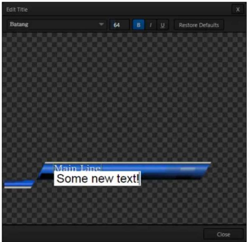
text_image
Edit Title Batang 64 B I U Restore Defaults Main Line Some new text! CloseFIGURE 72
- Move the mouse over the default text shown in the Title Page Editor's preview pane, and notice that a white bounding-box appears as you locate editable items.
- Double-click inside the bounding-box for a line of text to open a text entry yield; type something different, then press Enter on the keyboard to accept the changes.
- Notice that you were able to edit a page without disturbing the title already displayed on Program Output - Click the Close button.
- Repeat your text edit operation but this time editing the title displayed on Program Output.
Notice that, this time, the display updates immediately.

text_image
Edit Title Batang 64 B / U Restore DefaultsFIGURE 73
- Try changing the Font, Size and other attributes for a line of text, using the tools in the Title Page Editor's titlebar (Figure 73).
- Click the Close button.
SECTION 4.10 LIVEMATTE & M/ES
Let's try something different now - using LiveMatte to create a typical 'weather report' shot.
(We'll use a pre-recorded sample clip for this task, but of course if you happen to have a greenscreen studio ready to use, just skip the irst three steps below, and select the appropriate Input button on the Switcher's Program row - instead of a DDR).
- Change the Switcher's Program row selection to M/E 1, and enable the BKGD delegate button in the Transition section of the Switcher.
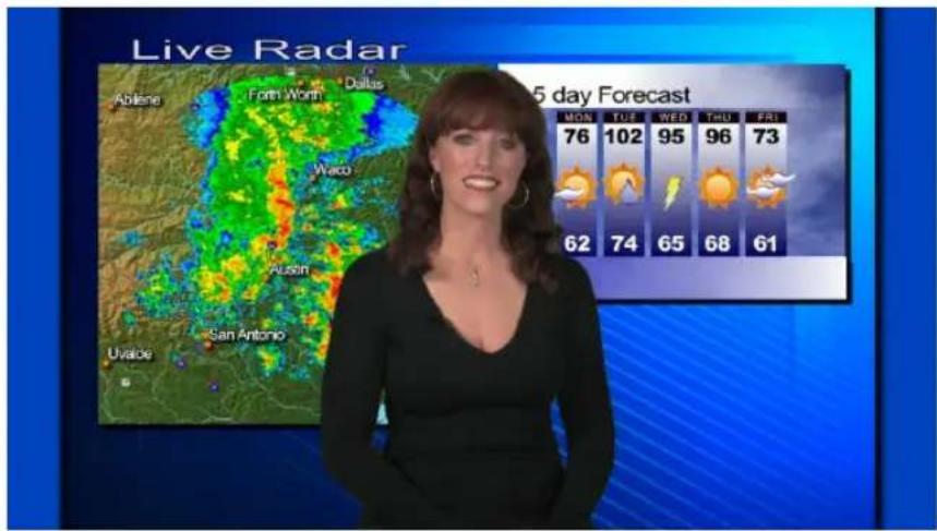
text_image
Live Radar Abilene Farm Worn Dallas Waco Austin San Antonio Uvalde 5 day Forecast MON TUE WED THU FRI 76 102 95 96 73 62 74 65 68 61FIGURE 74
- Remove any extraneous DSKs left from earlier operations from view using the local Take buttons in the Switcher's individual DSK control groups.
text_image
MIX EFFECTS M/E M/E M/E M/M/E M 3 4 5 6FIGURE 75
- If necessary, click the Mix Effects label between the Monitor and Switcher sections (or press 'm' on the keyboard) to expand the M/E pane.

text_image
MIX EFFECTS M/E 4 M/E 5 M/E 6 M/E 7 M/E 8 BLACK EFFECT 00.10.00 1 2 Default 2 LayerFIGURE 76
- Click the tab for M/E 1 to reveal the controls for the irst M/E channel.
- Click the Effect button in the M/E Effect control group (Figure 76). The default effect is named "Default (2 Layer)"; you should see the icon for this effect below the Effect button.
[Otherwise, click the + (Add Media) button that pops up when you move the mouse over the effect name (or, for 4-input TriCasters, to the right of the effect name), and use the Media Browser to select "Default (2 Layer)" from the Default group in the ile pane.]
- Notice that the left half portion of the M/E panel contains two source (input) rows labeled A and B.
a. Select DDR 1 in the button row labeled A.
b. Select DDR 2 in the B row.
- Click the DDR 1 tab, and Add the video clip named Kiki 1 Center.mov from the Green Screen group inside the Clips>NewTek location.
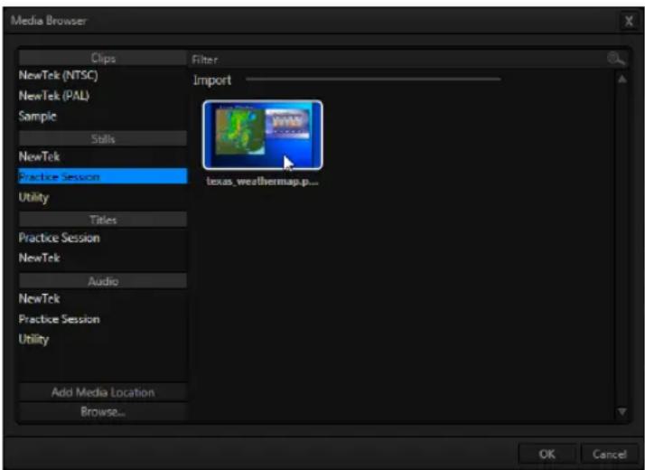
text_image
Media Browser Clips Filter NewTek (NTSC) Import NewTek (PAL) Sample Skills NewTek Practice Session Utility Titles Practice Session NewTek Audio NewTek Practice Session Utility Add Media Location Browse... OK Cancel texas_weathermap.p...FIGURE 77
- Click the DDR 2 tab, and add the image named texas_weathermap.png (from Practice Session, under Stills in the Location list at left).
- Move your mouse pointer over the desktop monitor for DDR 1, and click the Configure button (gear) that pops up at right in the label beneath the monitor.
- Click the LiveMatte tab in the Configuration panel that opens.
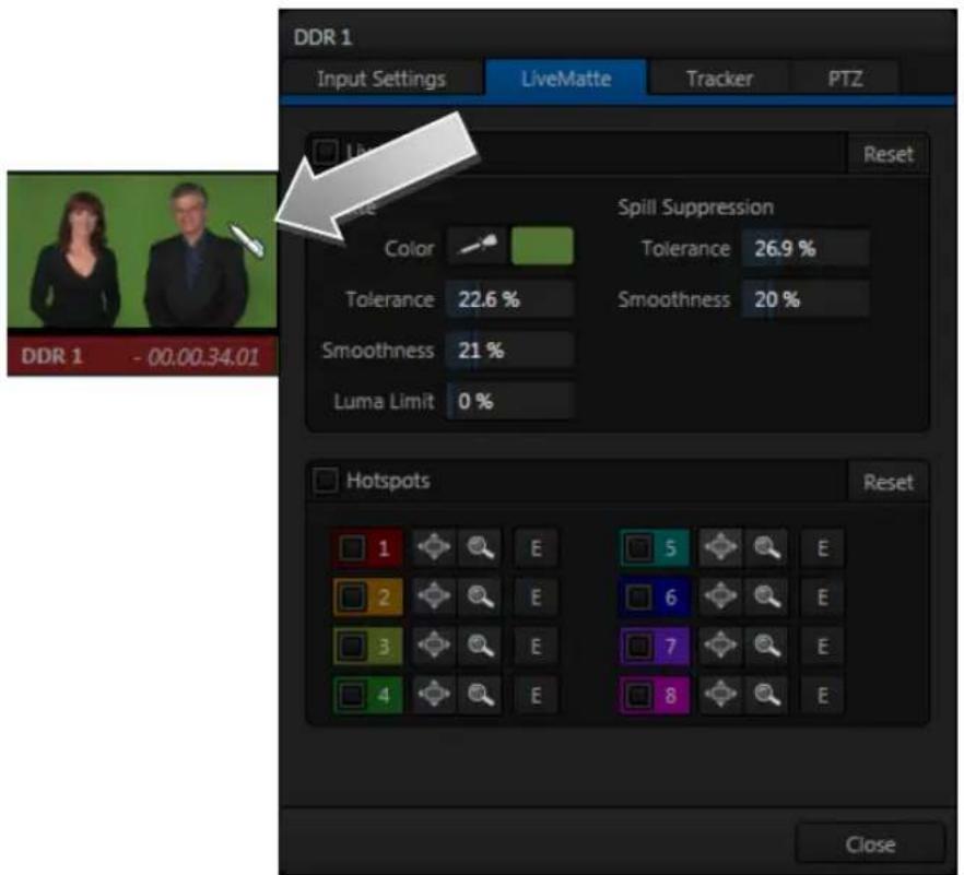
text_image
DDR 1 Input Settings LiveMatte Tracker PTZ Reset Spill Suppression Color Tolerance 26.9 % Tolerance 22.6 % Smoothness 20 % Smoothness 21 % Luma Limit 0 % Hotspots Reset CloseFIGURE 78
- Click on the Color button in the Matte section of the panel, and keep the mouse button depressed.
-
Drag the eye-dropper pointer over the green background in the monitor, and then release it (Figure 78). This sets the primary 'key color' (LiveMatte is automatically enabled when you select a color).
-
The default LiveMatte settings (Tolerance and Smoothness) are close enough for this little demonstration, so you can close the Configuration panel now.
We'll look at the details of LiveMatte in more depth in Part II (the Reference section), but already your result (as viewed on Program output) should look very similar to Figure 74. TriCaster doesn't stop here, though. Let's look a little more closely at TriCaster's powerful M/Es.
SECTION 4.11 MORE ABOUT M/ES
Depending on your model, four or eight M/E (Mix/Effect) buttons sit innocuously on TriCaster's Switcher rows. They may seem like other video inputs, but in reality they possess very powerful features. An M/E permits a composition to be prepared from multiple sources as just seen, using keying and other effects. They can be used in many other ways too – perhaps as an additional 'switcher' to provide a supplemental video mix, or for more elaborate applications (including virtual sets).
NOTE: In addition to the two sources just considered (Inputs A and B), TriCaster 8000's M/E's (only) also provide two more primary inputs – C and D – and four integrated Key (or Overlay) channels, compared to one M/E Key channel on the other models.
4.11.1 COMPOSING M/E LAYERS
When we ended the previous section, the simple ‘weather map’ setup (Figure 74) we created was on Program Out. (Remember that LiveMatte is already enabled for the greenscreen shot from our previous exercise.)
We can use a few of the unique features of M/Es to dress up our production. For example, we might want to transpose the greenscreen talent shot to one side, placing it off center in the result.
- Click the Position button just to the right of the A row label to open the Position panel for that input.
There are three sets of numeric sliders in the Position group in this panel: one with a four-pointed arrow button, a Rotation group, and Scale controls identified by a magnifying glass button.
Experiment with these controls a bit to see how they work.
Hint: Shift + double-click a control to reset it to defaults.
You can drag the mouse over the buttons in each group to freely adjust Position, Rotation or Scale on multiple axes at once, or use the numeric mini-sliders to adjust just one property at a time.
As currently configured, Program output displays the result of changes you make. Off course, during a live production you'd likely use Preview to make these sort of modifications, instead.
- Click Reset Positioning to restore default Position, Rotation and Size.
- Drag the horizontal (upper) Position mini-slider to the right, locating the foreground (talent) shot as seen in Figure 80.
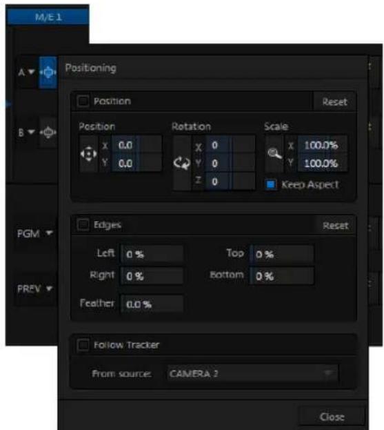
text_image
M/E 1 Positioning Position Reset Position X 0.0 Y 0.0 Rotation X 0 Y 0 Z 0 Scale X 100.0% Y 100.0% Keep Aspect Edges Reset Left 0 % Top 0 % Right 0 % Bottom 0 % Feather 0.0 % Follow Tracker From source: CAMERA 2 CloseFIGURE 79 (TRICASTER 8000 SHOWN)
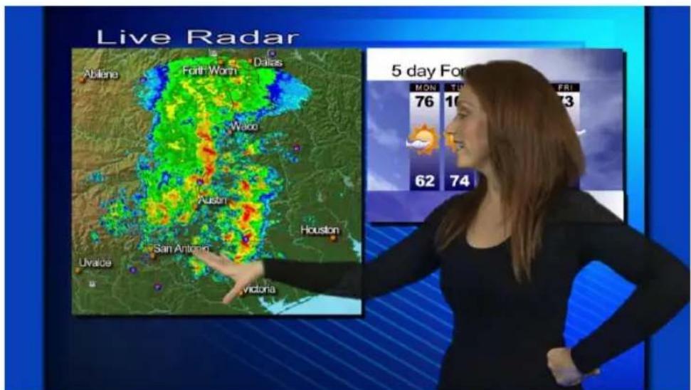
text_image
Live Radar Abilene Fort Worth Dallas Wako Auszoni Houston Uvalda San Antogan Victoria 5 day For MON 76 TUR 10 FRI 73 62 74FIGURE 80
Without having moved the physical camera, we have changed the apparent position of our talent relative to the virtual backdrop.
Hint: When the Keep Aspect switch for the Scale controls is lit, vertical and horizontal adjustments are locked together – adjusting one affects both. Otherwise, the vertical and horizontal scaling factors are independent.
Drag vertically over the ‘magnifying glass’ button to modify vertical scale, or drag laterally to adjust the horizontal scale. Another way to constrain the action to one axis is to hold down the Ctrl key before dragging.
4.11.2 ADDING AN UPSTREAM OVERLAY
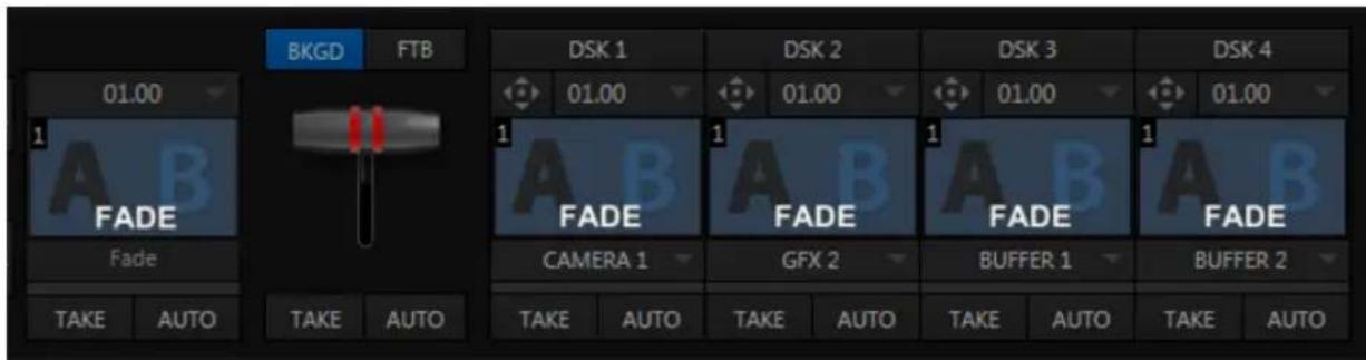
text_image
01.00 FADE Fade TAKE AUTO TAKE AUTO BKG D FTB DSK 1 01.00 FADE CAMERA 1 DAK 2 GFX 2 DAK 3 01.00 FADE 01.00 DAK 3 01.00 FADE 01.00 DAK 3 01.00 FADE 01.00 DAK 3 01.00 FADE 01.00 DAK 3 01.00 FADE 01.00 DAK 3 01.00 FADE 01.0O DAK 3 01.00 FADE 01.00 DAK 3 01.00 FADE 01.00 DAK 3 01.00 FADE 01.00 DAK 3 01.00 FADE 01.00 DAK 3 01.00 FADE 01.0U DAK 3 01.00 FADE 01.0U DAK 3 01.00 FADE 01.0U DAK 3 01.00 FADE 01.0U DAK 3 01.00 FADE 01.0U DAK 3 01.00 FADE 01.0V DAK 3 01.00 FADE 01.0U DAK 3 01.00 FADE 01.0U DAK 3 01.00 FADE 01.0U DAK 3 01.00 FADE 01.0U DAK 3 01.00 FADE 01.0W DAK 3 01.00 FADE 01.0U DAK 3 01.00 FADE 01.0U DAK 3 01.00 FADE 01.0U DAK 3 01.00FIGURE 81 (TRICASTER 8000 SHOWN)
To the right of the M/E input rows, you'll see a T-bar along with, depending on the TriCaster model, up to four control groups labeled Key with drop-down source menu and other controls.
The Key feature in M/Es work very much like the DSK video layers we used back in Sections 4.7.1 and 4.7.2. The difference is that these overlays are embedded in the output of the M/E, and thus are upstream of the main Switcher. (In other words, content in these overlay channels appears beneath anything you choose to display in the main DSK channels on Program output.)
-
Click the GFX 1 tab in the lower section of the desktop.
-
Add the "Breaking News.CGXML" icon (imported back in Section 4.2) from the Practice Sessions folder to the GFX 1 playlist
-
Edit the top line in the title to say "5 Day Forecast", as shown in Figure 82 (see the sub-heading Title in Section 4.9.2 if you've forgotten how to do this)...
-
Select GFX 1 as the source for Key 1 in the M/E tab, and display the corresponding overlay channel by clicking the Auto button below).
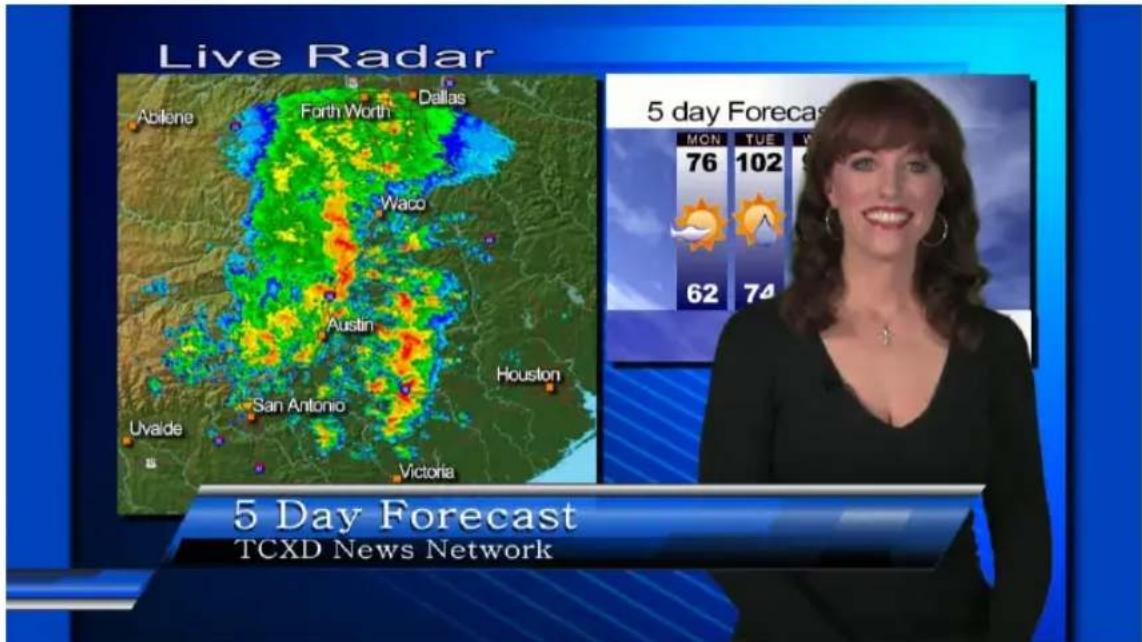
text_image
Live Radar Abilene Forth Worth Dallas Waco Austin Houston San Antonio Uvalde Victoria 5 Day Forecast TCXD News Network 5 day Forecast MON TUE W 76 102 62 74FIGURE 82
As you can see, we have replicated on our earlier composition, but with additional benefits:
- Using an M/E allowed us to offset (and even scale) the primary video source (and of course this works every bit as well with live camera streams).
- We've added a title page that can be displayed automatically or independently.
- We've got three more unused Keyer layers that can be used for other graphics relevant to this composition.
• The primary DSK video layers are left free for still other applications.
Most important of all – since the entire composition is now represented by a single button on the main Switcher (i.e., the M/E 1 button), it is very easy to Take or Transition directly to it with a single click – and just as easy to transition from one M/E to another.
Of course, this is just one way to use the basic M/E features. The creative possibilities are endless.
4.11.3 LIVESET™
text_image
00.10.00 1 2 Default 2 LayerFIGURE 83
We've saved the best for last in connection with M / E 's, however. This is also where we gain access to TriCaster's virtual set technology called LiveSet.
Note that 'LiveSets' need not necessarily be 'virtual sets'. They include other effects too. If you've been following along, you have already used a LiveSet – a simple one, named Default (2 Layer). This effect produces a composite of the video source you select as input A displayed over input B.
Hint: In cases where LiveMatte is active for input A, or perhaps is a 32bit image file (with an embedded alpha channel), or for that matter if input A is scaled or repositioned, input B will automatically show through any transparent areas above it in the composition.
Let's try something more sophisticated now:
- Click Take in the Transitions section of the Switcher, to show M/E 1 on the Preview monitor.
- Add the ile TriCaster Spin Logo.mov from the NewTek > Logos group to the playlist for DDR 2. Enable the Single and Autoplay switches for both DDR 1 and DDR 2.
- Click the current LiveSet name (above the effect icon) in the M/E 1 tab to display a Media Browser.
-
Select NewTek in the left-hand column under the heading LiveSets.
-
In the ile pane at right, click the thumbnail icon named Center.Liveset in the World Update group, and then click OK at the bottom of the Media Browser.
-
Select DDR 2 as the source for Input B.
The icon in the M/E tab and the label will update, showing that the current LiveSet is now World Update, Center.
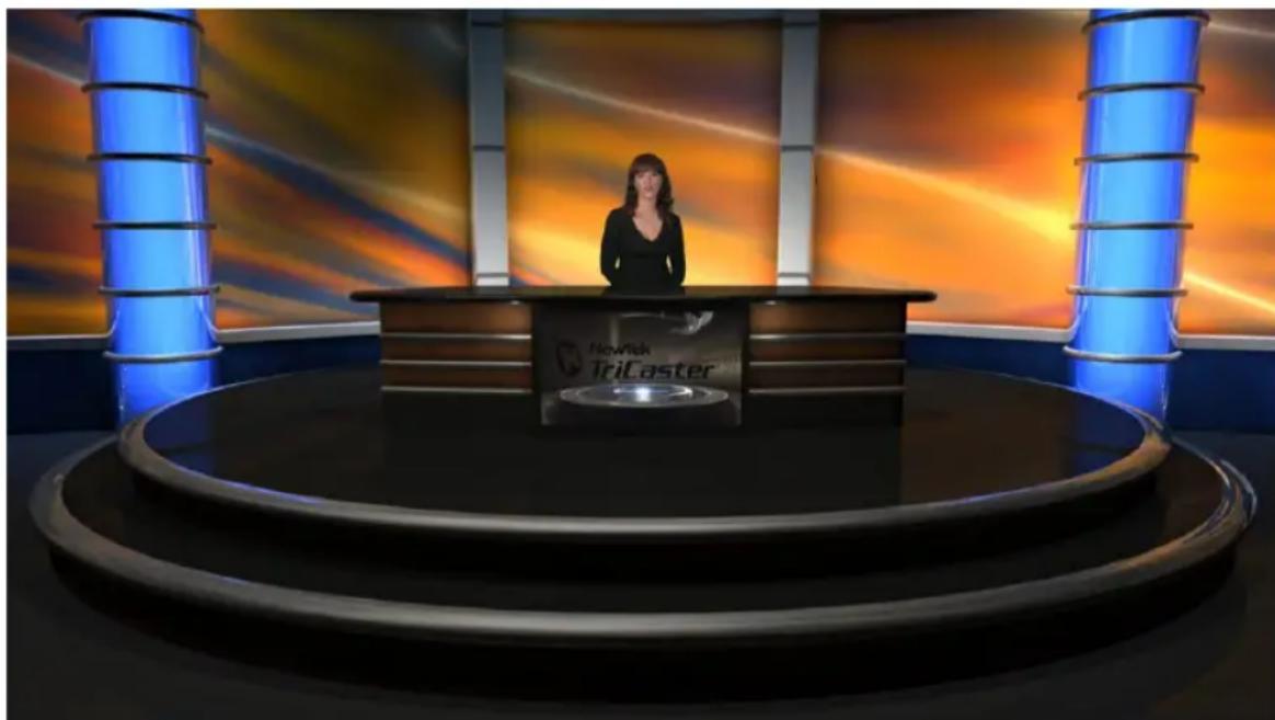
natural_image
Studio setup with a female host at a circular desk under blue and orange lighting (no visible text or symbols)FIGURE 84
Assuming that you still have LiveMatte enabled for the DDR, M/E 1's input A selector set to DDR 1 and input B set to DDR 2, a little adjustment in the Positioner for input A is all that it should take to produce a result similar to Figure 84 on Preview.
Input A is the primary input for the LiveSet, while input B serves as a secondary source – in this case assigned to the virtual desk-front monitor.
- Enable the BKGD delegate (if necessary) in the Switcher's Transition control group, and click the Auto button beneath the T-bar.
Both DDRs will begin running their currently selected clips simultaneously thanks to Autoplay (of course normally your foreground shot would be supplied by a camera).
- Now, click the effect thumbnail icon in the M/E panel, to display the popup LiveSet Shot bin.
- With one eye on the Program monitor, click the third preset (#3) in the Shot bin.

natural_image
Woman standing at a television studio desk with a large screen displaying the TriCaster logo (no visible text on person or desk)FIGURE 85
Observe that the view on the Program monitor now gradually pans/zooms to the degree represented by the zoom preset icon you clicked. The animated zoom eases out nicely as the animated effect ends at its destination.
The animation duration is controlled by the menu beneath the LiveSet icon.
- Click the duration, and select a different time for the animated zoom.
- Click the thumbnail icon to open the Shot bin, and click a different preset icon to test the new setting.
Using virtual set effects along with convenient zoom/pan presets, you can easily mimic a very large studio complex from a much smaller location.
SECTION 4.12 BUFFERS
To this point, we have used photos, graphics and titles from TriCaster's Media Players as sources for several different exercises. Of course, for DSK and M/E Key purposes, this approach requires you to carefully ensure that the current playlist entry in the respective Media Player is the right one for the moment.
TriCaster's Buffers provide an alternative worklow that not only prevents selection ‘accidents’, but also offers other benefits.
- Add the image ile TriCaster Logo w. Bkgnd.png from Still > NewTek > Logos to the playlist of a Media Player.
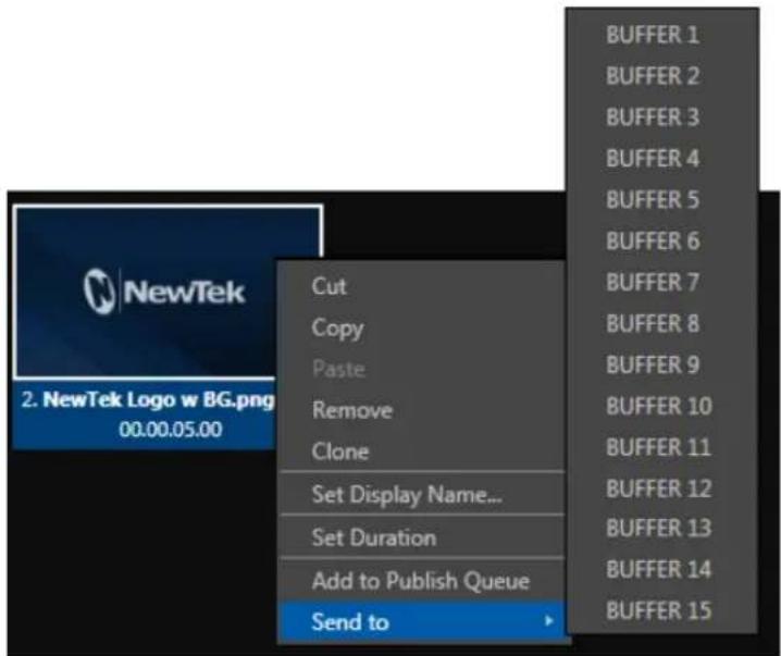
text_image
NewTek 2. NewTek Logo w BG.png 00.00.05.00 Cut Copy Paste Remove Clone Set Display Name... Set Duration Add to Publish Queue Send to BUFFER 1 BUFFER 2 BUFFER 3 BUFFER 4 BUFFER 5 BUFFER 6 BUFFER 7 BUFFER 8 BUFFER 9 BUFFER 10 BUFFER 11 BUFFER 12 BUFFER 13 BUFFER 14 BUFFER 15FIGURE 86
- Right-click on the new icon in the playlist, and slide the mouse pointer down to the item Send to Buffer. Select BFR 1 from the sub-menu that appears.
- Select the button labeled BFR as the input B source in the M/E tab. The image you sent to Buffer 1 now appears on the virtual monitor in the LiveSet.
text_image
NewTek TriCasterFIGURE 87
Hint: Right-click a Buffer button in an M/E or Switcher row to set which particular Buffer (1-15) the button refers to.
- To inish up, right-click the original TriCaster Logo w. Bkgnd.png icon in the Media Player, and select Remove. Observe that the correct image continues to appear when the LiveSet is displayed, even though the original image ile no longer exists in the playlist.
Actually, the Send to Buffer function copied the source ile and placed it in a special folder (C:\TriCaster\Effects\Frame Buffer\session_name). It remains available there, even when the original ile is not only unavailable from the playlist, but has actually been deleted from the hard drive.
Hint: There are several other important Buffer media types, including titles and powerful animated buffer effects (selected models). See Section 11.4 for complete details.
TriCaster provides ifteen separate Buffers. These can be assigned to primary M/E or Switcher inputs, or be used as sources for any DSK or Key overlay.
Note: Still image Buffers can be updated across a network using any suitable application (including Adobe Photoshop™) when Share Media Folders and Buffers is enabled in the TriCaster File menu. See Section 11.4 for more information on Buffers.
SECTION 4.13 STREAMING
Sending your output to the world (or the office) can be nearly as easy as connecting TriCaster to the Internet (or intranet), and pressing the Stream button (located right below the Program output monitor).
Note: A few frames may be dropped on video output the first time you enable streaming for a session as the encoder launches. (If you test your stream first, you'll avoid this.)
4.13.1 STREAMING CONFIGURATION
Click the Configure button (gear) situated next to the Stream (on/off) button to open the Configure Stream Connection panel, which lets you view and modify settings related to streaming your production across a network connection (Figure 88).
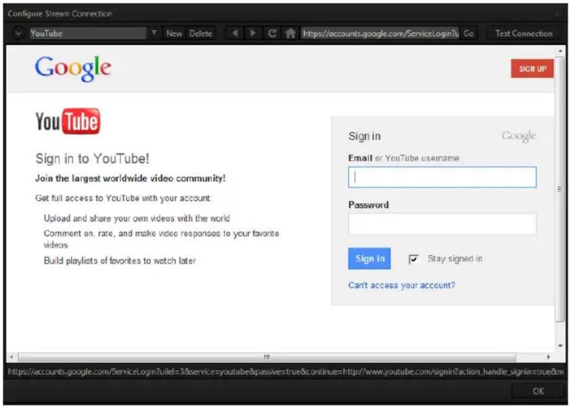
text_image
Configure Stream Connection YouTube New Delete https://accounts.google.com/ServiceLogin?&Co Test Connection Google SIGN UP You Tube Sign in to YouTube! Join the largest worldwide video community! Get full access to YouTube with your account: Upload and share your own videos with the world Comment on, rate, and make video responses to your favorite videos Build playlists of favorites to watch later Sign in Google Email or YouTube username | Password Sign In ✓ Stay signed in Can't access your account? https://accounts.google.com/ServiceLogin?uilel=3&service=youtube&passive=true&continue=http://www.youtube.com/signin?action_handle_signin=true& OKFIGURE 88
4.13.2 SIMPLE PULL STREAMING
text_image
Configure Stream Connection YouTubeFIGURE 89
"Pull" streaming, though limited, is arguably the simplest way to get your production online:
- Select “Create Connection from current URL” from the drop-down Connection menu at upper left (for Pull connections, the ‘current URL’ is actually irrelevant, so we didn’t need to navigate to a specific place on the web irst).
The Choose Connection Type dialog switches allow you to select between Browser Based, RTMP, Windows Media Pull and Windows Media Push streaming protocols.
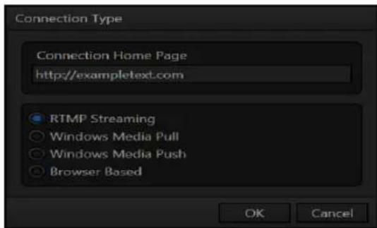
text_image
Connection Type Connection Home Page http://exampletext.com RTMP Streaming Windows Media Pull Windows Media Push Browser Based OK CancelFIGURE 90
- Select Windows Media Pull, click OK, and then supply a name for this Connection preset.
- The next thing to do is to choose a streaming proile that provides a suitable resolution and bitrate from the Resolution menu (Figure 91).
- Click the Test button.
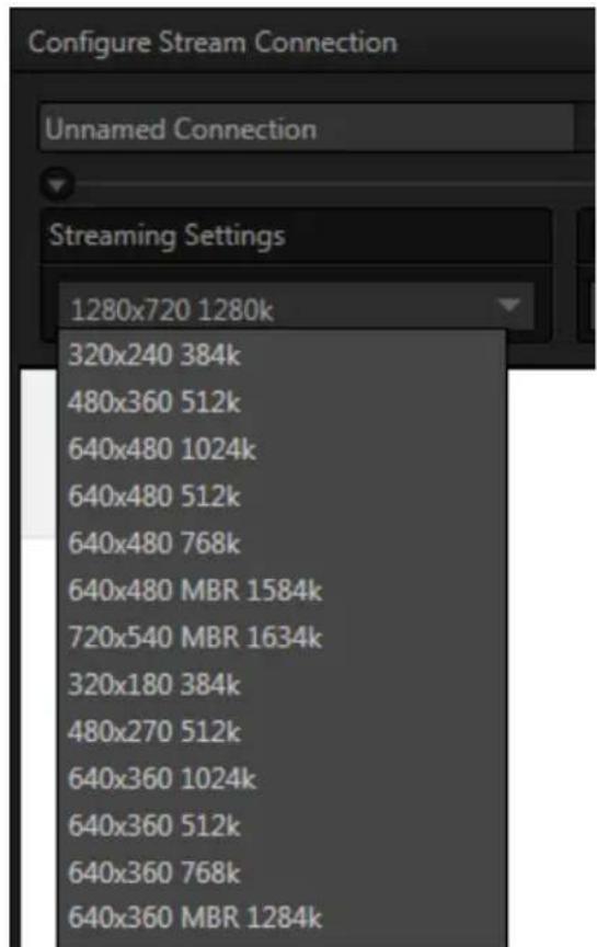
text_image
Configure Stream Connection Unnamed Connection Streaming Settings 1280x720 1280k 320x240 384k 480x360 512k 640x480 1024k 640x480 512k 640x480 768k 640x480 MBR 1584k 720x540 MBR 1634k 320x180 384k 480x270 512k 640x360 1024k 640x360 512k 640x360 768k 640x360 MBR 1284kFIGURE 91
In a few moments, TriCaster displays the IP (Internet Protocol) address of your computer as viewed from the network. This information is provided as a 'punctuated' numeric value in the Location display ield.
Hint: If your TriCaster is connected to the network by a router or is behind a firewall, it may be necessary to take further steps to provide external access. See Chapter 18, Streaming for a more elaborate explanation.
- Close the Configure Stream Connection panel now, and click the Stream button.
You're streaming! You can provide clients (or streaming providers supporting Pull streaming) the Location address. Entering this into the File menu of Windows Media
Player® (using the Open URL window) will direct WMP to show the stream from your system on client computer system(s) connected to the Internet (or intranet).
4.13.3 PUSH AND RTMP STREAMING
Browser Based, Windows Media Push and RTMP streaming are slightly more complex, largely because they depend on external resources to distribute your stream to a wider viewing audience. These may be provided in house by your organization, or you may take advantage of a commercial (or advertising sponsored) Content Delivery Network (CDN).
Arrangements and requirements of various external streaming hosts are diverse, but TriCaster's Streaming Configuration panel adapts to provide the necessary input and information ields for the various types. More detail on these matters, including connecting to a network and numerous useful tips on streaming strategies is found in Chapter 18, Streaming.
4.13.4 CAPTURING THE STREAM
Whenever you are streaming your output, TriCaster archives the live stream as a ile. Files are saved to D:\Media\Clips\sessionname\SavedStreams.This is a very useful feature. Among other things, it allows you to post the captured ile to a website immediately after an event for 'video on demand' streaming purposes – for late arrivals or others who want to review the live event.
Note: Remember to turn off the Stream when your production concludes, or TriCaster will continue writing the stream capture file.
PART II (REFERENCE)
A thorough examination of the various aspects of TriCaster: every button, menu item, feature and control is considered in this section, so you can take full advantage of your system.

text_image
TCThe TriCaster™ Startup Screen is the gateway to a suite of applications as well as maintenance and management features for both sessions and the system.
We'll discuss each of these in the pages that follow, beginning with a review of the concept of sessions.
The Startup Screen's Home Page appears whenever you launch TriCaster™.
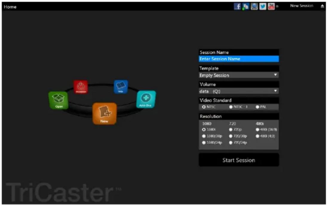
text_image
Home Session Name Enter Session Name Template Empty Session Volume data (Q:) Video Standard NTSC NTSC 1 PAL Resolution 1080 720 480i 1080i 720p 480i (16-9) 1080/30p 720/30p 480i (4:3) 1080/24p 720/24p Start Session Open New New TriCaster TMFIGURE 92(MULTI-STANDARD MODEL SHOWN)
From here, you create and launch sessions, then choose what sort of operations you wish to pursue within the current session by making a selection from an icon ring on the Session Page. Your intention may be to begin a new live production, or to produce another episode of a live series. Perhaps you wish to do prepare some title pages for an upcoming event, or perform system maintenance.
We'll look into each of these in turn, but first let's consider that fundamental TriCaster concept, the session. What is a session, and why are sessions both important and valuable to you?
Hint: Social Media accounts and other details related to TriCaster's Share Media features are configured using controls in the Startup screen's titlebar. These matters are considered in Chapter 19, Publish.
SECTION 5.1 INTRODUCTION TO SESSIONS
Whenever you work with TriCaster, you provide certain information about the production environment:
- What broadcast standard is used in your locale? Is it PAL, common in Europe among other places, or perhaps NTSC, standard throughout North American regions?
- If your task includes cameras or other live sources, are they HD, SD or a mixture of both?
- How are cameras connected (are you using component or SDI connections, something else, or a mixture of several connection types)?
As you continue, you may make other adjustments relevant to your current production requirements:
- You might calibrate your cameras individually using the Proc Amp settings in the Input Configuration panels.
- If your production plans include the use of greenscreen staging, you will probably adjust the LiveMatte settings for one or more cameras to provide optimal keying.
- Perhaps you will use the output Proc Amps to adjust the display sent to a projection system.
-
What are your output device connection preferences?
-
For example, will you send video to a local reference monitor using an S-Video or composite cable?
- Do you intend to configure a connection for a projection system? What external audio connections and adjustments are required?
- You might create a playlist of custom title pages in a Media Player, along with additional playlists for the DDRs.
During the course of the actual live production you may perform further ine-tuning, and also add to the media content used in the presentation:
- You could grab a series of still images from Program Output.
- Grab some clips from the production for replay later.
• And capture the network Stream output as a file.
The list of adjustments, activities and assets involved in a specific production goes on, but the main point to grasp here is that the session is comprised of all of the above collectively. If you do not deliberately delete the session, all of your session media and all of your session settings are ready for immediate recall and re-use.
When you re-open an existing session, it's just as if you were continuing an earlier event. Thus, if you return to the same venue another day under similar conditions, simply re-open your prior session and you are virtually ready to go. (Of course, it's the professional course of wisdom to test everything before beginning any event.)
Naturally, you can store multiple sessions and re-open them freely. This greatly simplifies business models that involve regular trips to specific remote sites or a number of unique episodic programs, and easily accommodates different users with their own individual requirements and preferences.
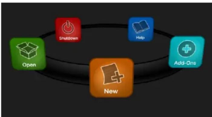
flowchart
graph TD
    A["Open"] --> B["New"]
    B --> C["Add-Ons"]
    C --> D["Help"]
    D --> E["Shutdown"]
FIGURE 93)
Having discussed sessions, let's go on to consider how sessions are created, and how you choose which one to work on. These items, along with a few other top level functions, are found in the TriCaster's Home Page.
This primary screen is the irst thing you encounter on launching TriCaster. It is dominated by the icon ring shown in Figure 93. When you click an icon on the ring (such as New or Open), that item advances to the front-most position.
Hint: Alternatively, you can use the keyboard's left and right arrow keys to cycle through the icons on the ring.
Choosing an icon from the ring also updates the right-hand pane of the Home Page to provide options and controls related to your choice.
For example, the irst thing you will likely do on launching a new TriCaster is create a session. In anticipation of that, the New icon is automatically pre-selected whenever no sessions already exist on TriCaster. This results in the relevant session options being displayed at right, as shown in Figure 94 (Multi-standard TriCaster options shown).
5.2.1 NEW (SESSION)
As just mentioned, clicking New on the icon ring populates the pane at right with related options.
Principally, for each session you must designate (by selecting switches) your local video standard (Multi-standard model only – select NTSC, PAL or NTSC-J) and session format -1080i, 1080/24p, 1080/30p, 720p, 720/30p, 720/24p, 480/30i (16:9) or 480/30i (4:3). Multi-standard models offer PAL format equivalents.
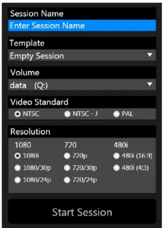
text_image
Session Name Enter Session Name Template Empty Session Volume data (Q:) Video Standard NTSC NTSC - J PAL Resolution 1080 720 480i 1080i 720p 480i (16:9) 1080/30p 720/30p 480i (4:3) 1080/24p 720/24p Start SessionFIGURE 94 (Mul-standard opons shown)
You will see a name ield for your session listed above the options pane at right (Figure 95). You can click in this ield to modify the default name (the current date) using the keyboard.
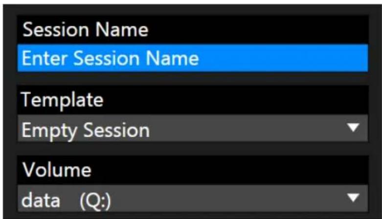
text_image
Session Name Enter Session Name Template Empty Session Volume data (Q:)FIGURE 95
TEMPLATE
The Template drop-down menu (Figure 95) lists all sessions currently available on the system. If you select an entry, the session you create subsequently retains all settings of the source session, but without content from its Media Player playlists.
VOLUME
A control labeled Volume appears just beneath the Session name. This assigns the hard drive the session (and its associated content) will be created and stored on.
Note: When using TriCaster's IsoCorder™ feature to record multiple sources, you will likely assign more than one hard drive to capture duties. Session keep track of their recorded clips too, providing easy access to them for live use.
Suitable hard drives inserted in TriCaster's removable drive bays are listed in a drop-down menu when you click on the Volume control. You can select any drive shown as the session drive.
Note: External drives are not recommended for active use as session drives. See Section A.1.8 for hard drive recommendations for use in TriCaster's removable drive bays.
Remember that for live production, TriCaster can simultaneously supply both SD and HD output for either SD or HD sessions. During an HD session, for example, you can output either (or both) HD or SD video, and SD video output can be either in a 16:9 widescreen format or cropped for display on a 4:3 television (see Section 8.1).
The session setting has some other significant ramifications, too. For example, if your session format is SD 4:3, this is the ile format captured by the Record function when capturing Program output ... even when the video cameras supplying your inputs are HD; the opposite is also true.
Note: See Section 8.1 for more information on Video Output configurations.
Having made your selections, you would normally click the Start Session button at lower right to launch TriCaster's Live Desktop – but first, let's explore a few other features of the Home Page.
EJECT
Open Session

FIGURE 96
An Eject button at the top right corner of the page allows you to safely disconnect external drives. (Drives can also be ejected from the Live Desktop.)
Note: Media configured as Read Only is not shown for the New or Open (session) features, since they cannot be used for sessions. However, Read Only media can be used for import purposes.
5.2.2 OPEN (SESSION)
If there are existing sessions on TriCaster, the icon ring on the Home Page will default to Open (Figure 97). Clicking Open causes the Sessions List to appear at right. This pane lists all sessions stored on qualified media currently mounted on TriCaster.
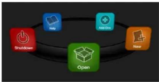
flowchart
graph TD
    A["Help"] --> B["Add One"]
    B --> C["New"]
    C --> D["Open"]
    D --> E["Shutdown"]
FIGURE 97
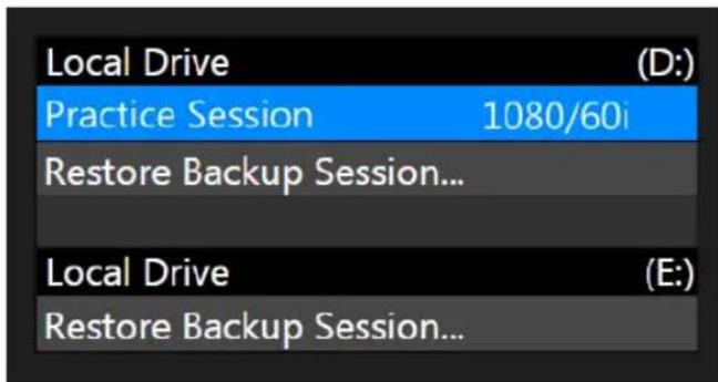
text_image
Local Drive Practice Session 1080/60i Restore Backup Session... Local Drive Restore Backup Session...FIGURE 98
Available sessions are grouped under the names of the storage volume they are located on (Figure 98). The listing shows the Session Name and Format for each session. Let's look at the Sessions List briefly before we open a session.
CONTEXT MENU
Right-click a session name to open a context menu with two items listed in it: Rename and Delete. Be aware that the Delete function should be used thoughtfully, as it cannot be undone.
All content stored in the named session's folders will be deleted, including clips, images and titles, and even LiveText title project iles created within the session (unless you have deliberately saved the projects and related iles to locations outside the session folders).
Note: Content that is not local to the session but which was used in it is not deleted. For example, you may have added still images to your playlist directly from a USB thumb-drive, doing so without actually importing the files into the session. Those external files will not be deleted.
RESTORE SESSION BACKUP
In another section of the Startup Screen (Session Page>Manage) there is a feature that allows you to back up the current session to another storage volume.
The Restore Session Backup link at the bottom of the Session List (for each drive) is provided to compliment this feature. To restore a session you have previously
archived, click Restore Session Backup (Figure 99), and use the ile explorer provided to select a .SessionBackup ile.
Media 2 (E:)
Click Open, and a progress gauge will track the restoration process. In due course, the newly restored session will be added to the Session List for the specified drive.
Hint: Restoring a session that has a lot of content can take considerable time. Be judicious, then, if considering a restoration shortly before a scheduled live production.
OPENING A SESSION
Just as you were able to select an icon on the ring using the left and right arrow keys, you can highlight a name in the Session List using the Up and Down arrow keys; then press the Enter key to open it (or simply click the name of a session to open it immediately).
Selecting a session takes you away from the Home Page to the Sessions Screen.
5.2.3 SHUTDOWN
This selection provides Restart TriCaster, Shutdown TriCaster, and Administrator Mode links. The irst two options are presumably self-explanatory, but the latter deserves a bit more discussion.
ADMINISTRATOR MODE
Selecting Administrator Mode from the Shutdown menu on the Home Page icon ring exits TriCaster's live production environment, and takes you to a new screen (Figure 100) that offers various functions and settings having to do with TriCaster system maintenance and management.
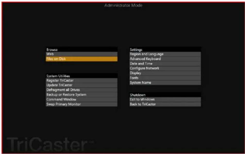
text_image
Administrator Mode Browse Web Files on Disk Settings Region and Language Advanced Keyboard Date and Time Configure Network Display Fonts System Name System Utilities Register TriCaster Update TriCaster Defragment all Drives Backup or Restore System Command Window Swap Primary Monitor Shutdown Exit to Windows Back to TriCasterFIGURE 100
Administrator Mode options are grouped under several headings, as discussed next.
BROWSE
- Web – Opens the default system Internet browser.
- Files on Disk – Opens a system ile window.
SYSTEM UTILITIES
- Register TriCaster - TriCaster shows a watermark on output before registration, so we encourage you to register early.
Among other reasons, doing so will serve to identify the unit to NewTek as yours in case of theft, and will also allow you to check for software updates that may have been recently released. (The steps in the registration process were outlined back in Section 3.3, so we won't repeat them here.)
- Update TriCaster – NewTek may periodically provide software updates for your TriCaster. Updates can enhance performance, security or even add useful new features.
If TriCaster is connected to the Internet, clicking Update TriCaster will automatically check for a more recent software version and offer to install it. This way you can be sure the very latest *release version of the software for your TriCaster is installed.
Alternatively, you can go to the NewTek web site, click My Account, and use the login details you provided when registering your TriCaster to access your personal product page. Click the “my downloads” link at the top of the page, and check the list shown.
If you ind an update, you can install it manually as follows:
- Locate a suitable update in "downloads" and click on it.
- At the dialog popup, choose Run.
- Comply with any onscreen prompts that follow.
* Advance software releases are also sometime posted on the 'downloads' page for manual download and installation. These versions, listed as "Latest" on the web page, will be newer than those provided by automatic update and (although not yet approved for inal release) might be well worth trying if you encounter an issue.
Hint: If you wish, you can instead access the same webpage from a second computer connected to the Internet, then transfer update files to TriCaster using a network connection or perhaps a USB thumb-drive.
- Defragment all Drives
Over the course of lengthy use, data on hard drives devoted to audio and video storage tends to become fragmented, which degrades playback performance. Defragmenting will correct this condition.
You could think of your hard drive as being like a shelf in your library. As time goes along, the shelf ills with books. Some are quite large, others smaller – just as TriCaster media iles may be larger smaller.
As time goes along, you decide to remove books you have inished using from the shelf, in order to make room for new additions. You remove a book here, another there, opening up gaps between the remaining books.
This makes some shelf space available by creating gaps between the remaining books. Sadly, another large new book may be too big to it in any one of the gaps.

natural_image
Stacked books arranged in two rows, showing various spines and covers (no visible text or symbols)FIGURE 101
A foolish librarian might tear the new book into smaller sections, just big enough to it into the open spaces on the shelf. This would obviously be unwise. When you wish to refer to the book later, you will waste a lot of time locating and assembling its sections before you can access it.
How much better it would be to slide the remaining books closer together, combining all the free space first. Unfortunately, computers are ‘foolish librarians’. They tend to want to fill in all the gaps in their storage areas, even if this requires literally shredding your ‘book’ (in reality large video iles from your TriCaster sessions) into tiny fragments.
Defragmenting the storage volume has the same effect as sliding the books together, resulting in one or more larger gaps. The end result is that TriCaster doesn't have to frantically search in many different places to assemble the video streams from your recorded session.
Hint: Defragmentation can sometimes take considerable time, so it's not something you want to begin just before an important event.
- Backup or Restore System – A complete set of Backup and Restore features are available to help in the event of an unforeseen problem.
We strongly encourage you to protect against any unforeseen occurrence by using the Backup feature soon after registering TriCaster. Please refer to Section A.5.7 in Appendix Chapter 22 for details.
- Command Window – Open a system command line window, allowing you (among other things) to use advanced commands to manage your system and network settings.
- Swap Primary Monitor – reverse the monitor assignments currently in use for TriCaster's interface and Multiview displays.
SETTINGS
- Regions and Language – Open the system language control panel.
- Advanced Keyboard – Open the system keyboard controls panel.
- Date and time – Open the system keyboard controls panel.
- Conigure Network – Open the system network controls panel.
- Display – Open the system display controls panel (useful for configuring multiple monitors, among other things).
- Fonts – Open the system font management console, allowing you to add that new font your client wants you to use for their title pages.
- System Name – It can be very useful to modify the default name your TriCaster is identified on the network. This is especially true when more than one TriCaster might be on the same network. The System Name feature opens the System Properties console's Computer Name tab. Click the Change button to modify the current name.
SHUTDOWN
- Exit to Windows – Leave the Administration Mode screen and display the standard system desktop.
- Back to TriCaster – Exit Administration Mode, and return to TriCaster's Startup screen and the production environment.
5.2.4 HELP
Select the Help icon to reveal links to open TriCaster manuals and other information.
The primary User Guide and Control Surface manuals are found here, as well as documentation for other TriCaster features, such as the LiveText™ manual.
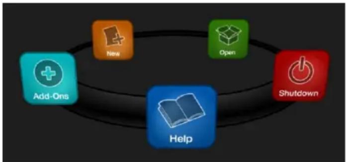
flowchart
graph TD
    A["Add-Ons"] --> B["New"]
    B --> C["Open"]
    C --> D["Shutdown"]
    D --> E["Help"]
FIGURE 102
Click the License Agreement link to review the TriCaster license requirements, or the About TriCaster link to list software version information, credits and acknowledgments.
5.2.5 ADD-ONS
NewTek offers additional software tools to expand the power of your TriCaster.
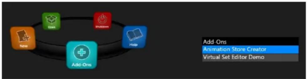
flowchart
graph TD
    A["New"] --> B["Add-Ons"]
    C["Down"] --> B
    D["Shutdown"] --> B
    E["Help"] --> B
    B --> F["Add-Ons\nAnimation Store Creator\nVirtual Set Editor Demo"]
FIGURE 103
The icon labeled Add-Ons on the Home Page provides access to some of these tools. When you select it, links are displayed for installed software applications, allowing you to launch them. (For example, Figure 103 shows links to the included Animation Store Creator utility as well as a demo version of the optional Virtual Set Editor™ program.)
Opening a session from the Home Page (whether using Open or New) takes you to the Session Page, providing a new set of selections on the icon ring.
| Home / Practice Session | 1080/60i |
FIGURE 104
The name of the current session is shown in the top-left corner of the screen. The current session is displayed in the form “Home/session name”.
If you wish to leave the current session and return to the Home Page, you can click the large Back Arrow displayed beneath the session name, or the word “Home” in the session name label.
Initially, the icon ring in the Session Page offers three selections. These are discussed next.
5.3.1 LIVE
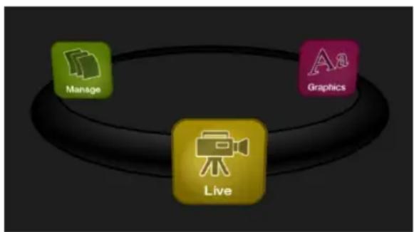
flowchart
graph TD
    A["Manage"] --> B["Live"]
    C["Graphics"] --> B["Live"]
FIGURE 105
The icon labeled Live represents the Live Desktop, TriCaster's live production center. Selecting it (by clicking the icon or using the left/right arrow keys to bring it to the front), presents a Start Live Production link in the Session Page's right-hand pane; click this link to launch the Live Desktop.
5.3.2 GRAPHICS
TriCaster includes an integrated version of LiveText, NewTek's standalone titling and CG application.
flowchart
graph TD
    A["Live"] --> B["Manage"]
    B --> C["Graphics"]
    C --> A
FIGURE 106
Selecting the Graphics icon displays a number of related items on the right-hand side of the Session Page.
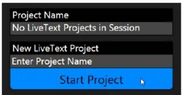
text_image
Project Name No LiveText Projects in Session New LiveText Project Enter Project Name Start ProjectFIGURE 107
When you irst enter a new session, no LiveText projects are listed in the area under Project Name. After you create one or more projects, the name(s) will appear here and, as you would expect, you can re-open the project by clicking its name.
Note: TriCaster stores new LiveText projects inside a folder named for the current session, as follows (for example):
D:\LIVETEXT PROJECTS\sessionname\projectname.cg.
LiveText's internal File menu and Save As functions default to the same location. However, it is possible to use File>Save As to store a project in another location outside the session structure.
Be aware that projects stored outside the session structure are not shown in the project list on the Sessions Page. To re-open them, you'll need to navigate to the project ile using File>Open in LiveText.
Note: Similarly, external projects will not be backed up by the Backup Session function (or be deleted by the Delete Session function)
To create a new LiveText project, click in the default project name ield (just above the Start New Project link) and modify it, then click Start New Project.
When you inish working in LiveText, click the [x] button in its upper-right corner (or select Exit in the File menu) to return to the Session Page.
5.3.3 MANAGE
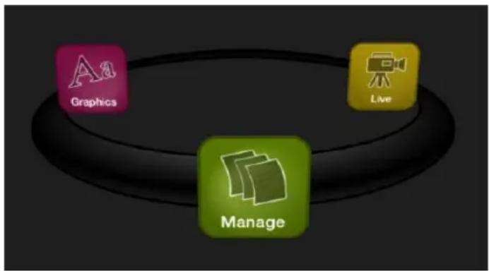
flowchart
graph TD
    A["Graphics"] --> B["Manage"]
    C["Live"] --> B["Manage"]
FIGURE 108
Various TriCaster components provide ilebins to permit you to manually administer iles related to their projects, playlists, and so on. The Manage icon in the Session Page provides an alternative approach to ile management.
At times you may ind it useful to be able to quickly access the various iles associated with specific sessions. Selecting Manage refreshes the options pane on the right-hand side of the Session Page with a number of convenient items.
BROWSE
Under the label Browse, you will see direct links to the Clips, Still, and other content associated with the current session. Clicking one of these links (or selecting it with the up/down arrow keys and pressing Enter) opens a system ile explorer.
You can use the familiar features and shortcut keystrokes in these windows (Cut, Copy, Paste, Rename, Delete and so-on) to manage the session content.
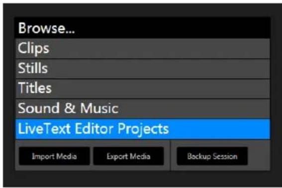
text_image
Browse... Clips Stills Titles Sound & Music LiveText Editor Projects Import Media Export Media Backup SessionFIGURE 109
Hint: Of course, you can open several of these folders simultaneously, and navigate these file windows to other locations as well.
For example, you might copy the title page (.cgxml) files from the Titles folder of one session into the Titles folder of a different one before deleting the first session.
Several other important features are contained in the Manage group, including Import Media, Export Media and Backup Session.
IMPORT MEDIA
We discussed importing media for using in TriCaster productions back in Section 4.2, so we'll just review briefly here. Import Media's quick processing makes this the fastest and most convenient way to pre-load a session with production assets.
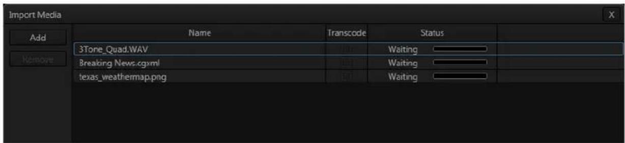
text_image
Import Media Add Remove Name Transcode Status 3Tore_Quad.WAV Waiting Breaking News.cgxml Waiting texas_weathermap.png WaitingFIGURE 110
Clicking the Import Media link opens a custom import panel, offering batch import of files for use in TriCaster's Media Players. It even allows you to transcode iles to high quality TriCaster-friendly ile formats at the same time if you wish.
Click Add to open a standard system ile window, and select (or multi-select) items to build a list in the Import Media ile pane. Some highly compressed video iles may not be well suited to live playback. Enable switches in the Transcode column for iles you wish to convert to a friendlier format on import. Files can be re-ordered by dragging their entries up or down with the mouse, or removed from the list by highlighting them and clicking Remove.
Once the batch import list is prepared, click Import to complete the operation. Files are processed quickly, and are automatically added to their proper locations (according to type) for easy access during live production.
Hint: Sections Section 4.2, 11.2.2, and A.4.2 discuss other aspects of media imports.
EXPORT MEDIA
The Export Media function allows you to create a list of video iles for export, select a new ile format for these exports to be converted to (on a per ile basis), and designate where to send them. Clicking the Export Media button opens a new pane. Click the Add button at upper left to open a custom Media Browser (see Section 11.2.2 for browser details). Use this pane to locate and select (or multi-select) video clips for export.
Hint: The Export Media panel can be resized by dragging its edges or corners with the mouse.
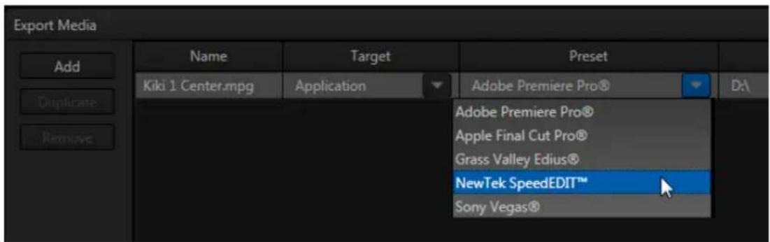
text_image
Export Media Add Duplicate Remove Name Kiki 1 Center.mpg Target Application Preset Adobe Premiere Pro® Adobe Premiere Pro® Apple Final Cut Pro® Grass Valley Edius® NewTek SpeedEDIT™ Sony Vegas®FIGURE 111
The ile pane is much like a spreadsheet table, listing all iles in the current export batch in its irst column, then the current settings for each ile in other columns. A Status column shows the current export status or progress for each ile in the list.
TOOLS
The Duplicate feature is very useful for cases when you wish to export content to multiple target ile formats or locations, for different purposes or specific software applications.
Note that Export Media's ile list pane supports multi-selection. When a ile (or group of iles) is selected, you may use the Duplicate and Remove buttons to clone or delete iles from the list.
text_image
Export Media Add Duplicate RemoveFIGURE 112
Hint: To multi-select files, you can use the familiar Shift-click or Ctrl-click techniques.
TARGET, PRESET & DESTINATION
Having prepared the ile list, click the triangle button in the Target ield to open a drop-down menu listing categories of device or application targets to choose from. Then select a specific encoding Preset in the next column.
Export presets vary according to what is appropriate for the session and ile format.
Note: When presets that do not natively support HD are selected during an HD session, output is automatically scaled as required to fit the selected file format. This is a convenience, but be sure to select a Preset suitable for your ultimate needs.
A similar Destination button opens a system ile browser to let you designate (or create) a location for ile output. Each ile to be exported can have its own Target, Preset and Destination settings.
Hint: It is possible to selected mapped network locations with a 'Drive letter' assignment as the Destination, saving time later.
Export ile format options are updated from time to time to include popular new formats. Here are some examples, as they appear for an HD session (the list is not all-inclusive, as modifications and additions are made from time to time).
Target categories are in bold text, while Presets are italicized:
• Application (formats suitable for use with various popular NLE software)
- Apple Final Cut Pro® (.mov) – very high quality M-JPEG encoding, full raster, 4:2:2 sub-sampling, high compatibility.
- AVI
- DV/ DVCPro (.avi) - moderate quality, SD only (NTSC 720x480, PAL 720x576), 25Mbit/s, 4:1:1 (NTSC) or 4:1:0 (PAL) sub-sampling, very broad compatibility.
- MJPEG (.avi) – moderate quality, SD or HD capable, 4:2:0 sub-sampling, broad compatibility.
• DVD
○ (x) (*.mpg) - SD-only MPEG 2, quality presets up to 9MB/sec bitrate (≈60 minutes) with 4:2:2 sub-sampling.
- Flash/Flash 9
○ A diverse collection of presets suitable for playback in newer or legacy Flash® players.
- Mobile Devices
o Presets suitable for use with iPad®, iPhone® or iPod Touch®.
- Quicktime
○ Renderless Conversion – high quality ‘wrapped’ Quicktime® ile.
- DV/DVCPro (.mov) – moderate quality, SD only (NTSC 720x480, PAL 720x576), 25Mbit/s, 4:1:1 (NTSC) or 4:1:0 (PAL) sub-sampling, very broad compatibility.
○ h.264 Highest Quality (.mov)
○ h.264 Very Good (.mov)
○ MJPEG (.mov)
- Same as Source – ile copy (no re-rendering)
- Video Server
○ Leightronix NEXUS\Ultra NEXUS – SD (NTSC 720x480, PAL 720x576), high quality, MPEG2 Program Stream, 9Mb/s variable bitrate, 4:2:2.
- TelVUE Princeton - SD (NTSC 720x480, PAL 720x576), high quality MPEG2 Program Stream, 9Mb/s variable bitrate, 4:2:2, NTSC 720x480 (PAL 720x576).
Next, use the Destination ield drop-down to designate a target folder for exported iles to be sent. A progress gauge is shown during ile processing. Click the Export button at the bottom of the dialogue to begin batch export processing.
Hint: The time an export takes is affected by numerous factors – the number, duration and resolution of the selected files, the speed of the device selected as target for the files, the designated format, and so on.
It is generally unwise to commence a file export shortly before a live event, since you cannot launch TriCaster's Live Desktop during export. If necessary, you can cancel the current export operation.
BACKUP SESSION
Clicking the Backup Session button opens a system ile explorer that you can use to assign a storage location for the backup iles. Backup operations can take some time, depending on the amount of content in the session.
For obvious reasons, then, it would be wise not to begin a major backup operation shortly before a scheduled live production. A progress gauge is displayed during processing, and if necessary you may Cancel the operation. Of course, the session to be backed up is the current session (to back up a different session, return to the Home Page and Open a different session.
The backup operation feature will determine whether all media used in the session is local (i.e., located in folders named for that session), or whether some content is external – stored in other places on your system, and included in the session using Add Media Location, or from folders belonging to other sessions. If all session media is local the backup proceeds without further interruption.
When external media is used in the session, a dialog is presented stating "The following iles are external to the session. Would you like to import these iles?" The optional actions in the dialog are:
- Backup without importing
- Import and Backup
- Cancel Backup

text_image
TCThe TriCaster™ Live Desktop is the control center for all your live production work. It provides control over switching, transitions and overlays, titles and graphics, audio mixing, playback of digitized content, and much more.
In addition, streaming and recording features are located here, along with keying and virtual set tools.
The TriCaster™ Live Desktop is launched by creating (or opening) a session in the Startup Screen's Home Page, then selecting the LIVE icon and clicking Start Live Production.
SECTION 6.1 DISPLAY REQUIREMENTS
The Live Desktop requires a minimum screen resolution of 1600x1050.
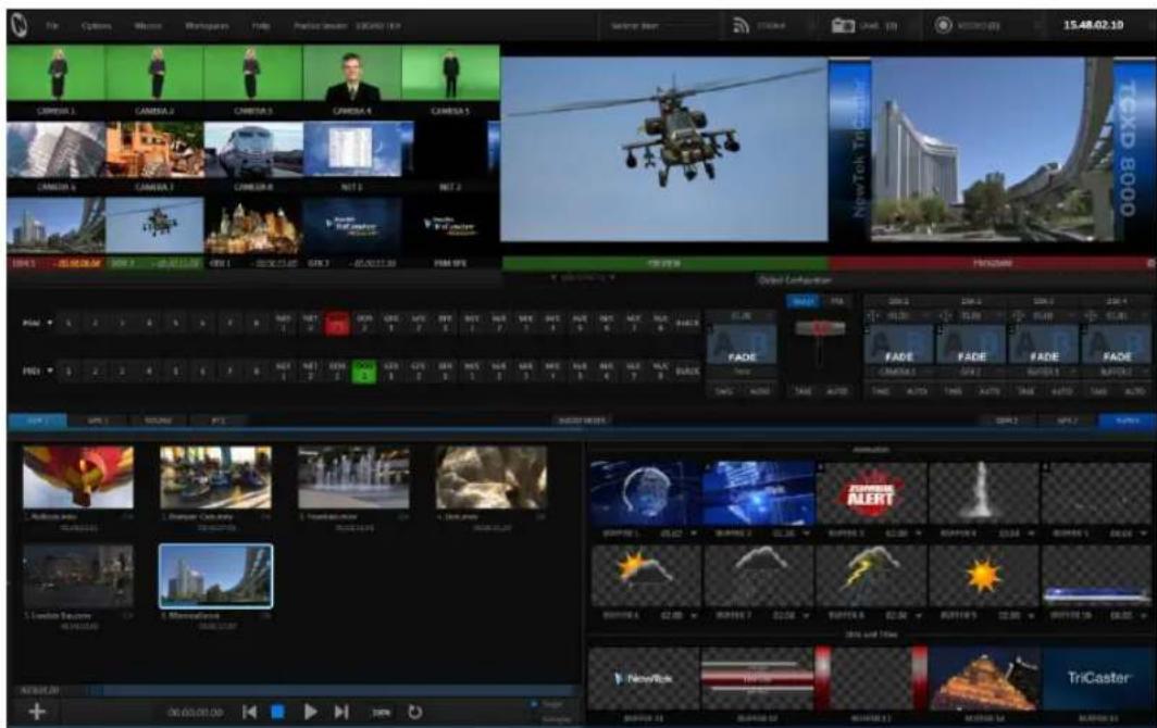
TriCaster's Live Desktop provides visual feedback for operations, including monitoring, live switching, and so on. It is divided into ive horizontal bands. From top to bottom, these are:
1 - Dashboard
- Quick access to interface opons and important tools, including Publish and Macros along with Record, Stream, Workspace and Timecode opons.
2 - Monitors
- User congorable layouts – monitor live inputs along with internal sources (such as DDRs, M/Es, and Buers) plus Look Ahead Preview and Program output
- Waveform and Vectorscope monitors
3 - M/Es
- Eect mode – control up to four primary video layers plus 4 overlay channels
- Mix mode – secondary switcher controls plus 4 overlay channels
• Each M/E includes dedicated an extensive complement of Keyers, transion generators, scaler/posioners, and more
4 - Switching
- Switcher rows – Program and Preview rows
- Transition controls – T-bar and Delegate buons
- DSK video layer conguraon and controls
5 - Tabbed Control Modules
• Internal Media Players and Buers)
•PTZ (roboc) camera controls
- Audio (mixer) – input conguraon, level control, EQ and Compressor/Limiters
You will ind various control types used repeatedly in TriCaster's Live Desktop. Some examples are shown in the table below.
| Control Type | Type | Examples | Usage |
 | Numeric Slider | Gain, Balance | Drag in line with the control's orientation to raise or lower the current value. |
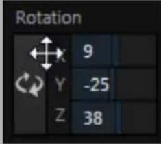 | Rotary slider | Position, Size, Rotate | Drag up-down to adjust one value, left-right to adjust the other value, diagonally to adjust two different values simultaneously.Hold down Alt while dragging vertically to modify the third value (Z) when provided. |
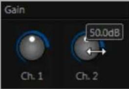 | Rotary Knob (single-value) | Audio Gain | Drag left-right to adjust the current value. |
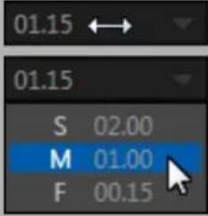 | Combo-Slider | Transition, Zoom Duration | Drag left/right to raise or lower the current valueClick the digits to type in a new valueOr click the triangle to open a drop-down menu |
To make very ine adjustments to slider values, hold down the Ctrl key while dragging the mouse (this increases accuracy by 10x). Hold down the Shift key and double-click most controls to reset them to their default values.
TriCaster's Live Desktop layout can be adapted to many different scenarios, and provides a number of customization options that can be of benefit in your worklow. In this section, we'll touch on several of these.
6.4.1 RENAME INPUT
As charming as descriptive names like Camera 1, DDR 2 and M/E 5 are, you may wish to change these labels to something more appropriate for your local needs.
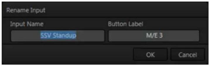
text_image
Rename Input Input Name SSV Standup Button Label M/E 3 OK CancelFIGURE 114
To do so, simply right-click on one of the following items to open the Rename Input dialog (Figure 114):
• Any monitor in the Live Desktop or external Multiview
• Any Switcher source button
The Rename Input dialog has either two or three editable text ields, including Video (the label shown under monitors), a shorter Switcher Button label and, sometimes, Audio – the name shown for the audio input with the same number..
6.4.2 WORKSPACES AND MIN/MAXIMIZE
We explored the use of monitoring Workspace presets back in Section 4.4.2 of the Live Production Walkthrough, and will review it in depth in Chapter 10. At this point, though, we want to mention a couple of related items.
You'll have noticed that various layout and custom monitoring options for the Live Desktop are provided in the Workspace menu; and that another additional options are provided for TriCaster's native Multiview display.
When a Multiview monitor is in use the two Workspace preset options can be combined with great lexibility, letting you see what you want to see where you want to see it. It's easy to set up complementary displays in the two monitor areas.
For example, you might show main Program and Preview monitors along with all 8 M/Es on the Live Desktop. Meanwhile, the Multiview monitor could display up to eight live Camera feeds plus Media Players, as well as the (program) output and B row selections for a specified M/E set to Mix mode.
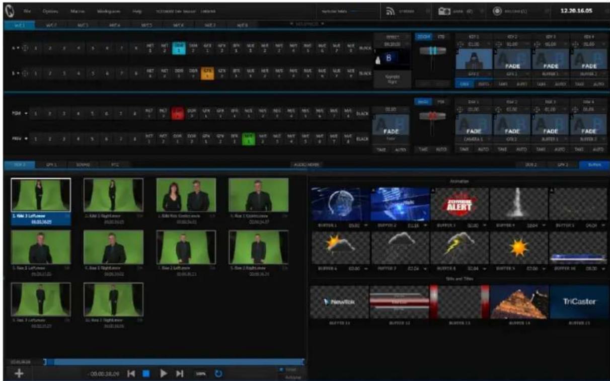
text_image
File Edit Options Master Window Help TICKERS (New Session) / Infine http://www.mate.com 12.20.16.05 文件(F) WNT 1 NET 2 NET 3 NET 4 NET 5 NET 6 NET 7 NET 8 NET 9 A • B • C D E F G H I J K L M N O P Q R S T U V W X Y Z Z Z Z Z Z Z Z Z Z Z Z Z Z Z Z Z Z Z Z Z Z Z Z Z Z Z Z Z Z Z Z Z Z Z Z Z Z Z Z Z Z Z Z Z Z Z Z Z Z Z Z Z Z Z Z Z Z Z Z Z Z Z Z Z Z Z Z Z B • C D E F F G H I J K L M N O P Q R S T U V W X Y Z Z Z Z Z Z Z Z Z Z Z Z Z Z Z Z Z Z Z Z Z Z Z Z Z Z Z Z Z Z Z Z Z FND • G H I J K L M N O P Q R S T U V W X Y Z Z Z Z Z Z Z Z Z Z Z Z Z Z Z Z Z FND • G H I J K L M N O P Q R S T U V W X Y Z Z Z Z Z Z Z Z Z Z Z Z FADE FADE FADE FADE FADE FADE FADE FADE FADE FADE FADE FADE FADE FADE FADE FADE FADE FADE FADE FADE FADE FADE FADE FADE FADE FADE FADE FADE FADE FADE FADE FADE FADE FADEFIGURE 115
Notice too that you can also drag the horizontal divider between the Live Desktop monitor pane and the Switcher to adjust it. You can even move it all the way to the bottom of the Dashboard, thus hiding the Desktop monitor pane entirely (Figure 115), providing much more room for other modules in the process.
Hint: Reset the Live Desktop divider to its default location by double-clicking it.
We mentioned previously, as well, that clicking the Mix Effects label (Figure 116) between the Monitor and Switcher sections toggles display of the M/E pane.
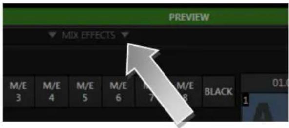
text_image
PREVIEW MIX EFFECTS M/E M/E M/E M/E M/E BLACK 3 4 5 6 7 8 1FIGURE 116
Hint: The keyboard shortcut to show/hide the M/E tab is "m".
A number of further worklow and interface options that can be very valuable are found in the TriCaster Options menu, discussed shortly (Section 7.1).

text_image
TCTriCaster's Dashboard groups important production features and system display controls in one convenient place for quick access and review.
As well, the Dashboard serves to provide information on the current session, status updates and storage usage, along with timecode and the TriCaster Options menu.

text_image
File Options Macros Workspaces Help Practice Session 1000/60x 16.9 Switcher Mem STREAM GRAB (0) RECORD (0) 15.48.02.10FIGURE 117
TriCaster's Dashboard is home to a number of important displays, tools and controls. Prominently located at the very top of the Live Desktop, the Dashboard occupies the full width of the screen. The various elements comprising the Dashboard are listed below (starting from the left):
- File menu
- Options menu
- Macros (see Chapter 17)
- Workspaces (see Chapter 10)
- Help menu
- Information (display)
- STREAM (see Chapter 18)
- GRAB (see Chapter 20)
- RECORD(see Chapter 20)
- Timecode display (see 8.2.8)
Of these items, some are so important that they rate their own chapters. Others are detailed in various sections of this guide (cross references to the relevant sections of the manual are provided above). In this chapter, we'll focus on those Dashboard features which are not discussed in depth elsewhere.
SECTION 7.1 FILE MENU
This menu drops down to reveal the following items:
• Publish Queue ... (see Section 19.3)
• Publish Destinations (see 19.3.2)
- Eject – opens a sub-menu that lets you safely disconnect selected storage volumes
• Share Media Folders and Buffers (see Section 11.4)
- Exit – close your live production session, and return to the Session page of your TriCaster's Startup screen (all session settings are stored on exiting)
SECTION 7.2 OPTIONS MENU
A number of very useful interface and worklow options are presented in the TriCaster Options menu.
- Enable Follow Preview Row for All Inputs to display the tabbed pane for a Preview row source automatically on selection changes (for M/E selections, the M/E pane must be maximized in order to see the M/E tab update).
- When Tabs Follow Preview for M/Es is checked, only the M/E pane updates (when you select an M/E as source on Preview).
Hint: Control surface delegate operations can sometimes result in a tabbed module that you want to view being obscured when certain options are enabled. When this happens, press the corresponding control surface Delegate button again to re-display the tabbed pane you are interest in.
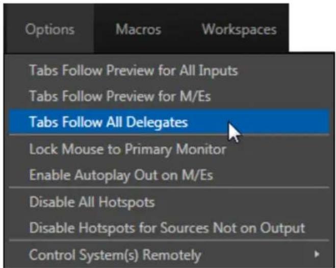
text_image
Options Macros Workspaces Tabs Follow Preview for All Inputs Tabs Follow Preview for M/Es Tabs Follow All Delegates Lock Mouse to Primary Monitor Enable Autoplay Out on M/Es Disable All Hotspots Disable Hotspots for Sources Not on Output Control System(s) RemotelyFIGURE 118 (TRICASTER 8000 SHOWN)
- Enabling Lock Mouse to Primary Monitor prevents the mouse from traveling into the external Multiview display.
- Enable Autoplay Out on M/Es – You may ind it useful to enable Autoplay's 'transition-out when nearing the end of play' feature for M/E's (Mix mode). By default, this option is off.
- The Disable All Hotspots option prevents macros from being triggered by any Hotspot activity.
- The similar Disable Hotspots for Sources Not on Output option avoids inadvertent triggering of events by unexpected off-screen activity.
- (TriCaster 8000 only) Control System(s) Remotely – select one (or more) TriCaster 8000's detected on your local network, and all control operations you perform using the user interface, the control surface, or keyboard will be echoed to the controlled system – see Section 17.6.
Select this option to display QR (Quick Response) codes you can scan with your mobile device (such as an iPad® or Android® tablet) to view TriCaster documentation. This provides an easy to use mechanism that lets you look up information about TriCaster without interfering with your live production.
SECTION 7.4 INFORMATION PANEL
An information display in the Live Desktop titlebar provides a number of useful items. Displayed information includes:
- (Session Name)
- (Session format)
- Status message display

FIGURE 119
The Status message area sits next to the session information display, but is hidden when no message is shown. When TriCaster needs to inform you regarding system events or conditions, text messages replace the normal information display. Status messages may pertain to operations or system conditions; they may be benign, as in *Figure 119, or cautionary.
* A brief initialization is required following system startup for DDR video playback to stabilize. During this brief ‘warm-up’ period, an initialization countdown appears in the Status message display...
The display automatically clears itself a few moments later so as not to pose an unnecessary distraction.
text_image
Switcher MemFIGURE 120
The Switcher Memory ‘gauge’ tracks how much system memory is consumed by currently selected virtual sets, transitions and the like. (If you do inadvertently overtax the effects system by pre-selecting many, many large custom effects – an unlikely scenario – you might just reach the limit, which could in turn result in dropped frames.)
Hint: Another useful bit of system information concerns available drive capacity. The remaining space on each individual storage volume mounted is shown in the Save To menu in the Record Configuration panel.
text_image
TCTriCaster™ provides extensive control over your video sources, along with related creative features. Each video source (internal and external) has its own Proc Amp, keyer (LiveMatte™) and Crop ('garbage matte') features.
Input Configuration panels are also home to TriCaster's powerful realtime Hotspot and Tracker features. In addition, the number and flexibility of TriCaster's outputs is astonishing, and we'll discuss these fully in this chapter.
In a break with orthodoxy, let's begin our discussion at the end – that is, with a consideration of TriCaster's plentiful Output Configuration features.
SECTION 8.1 OUTPUT CONFIGURATION
natural_image
Close-up of a black keyboard mouse cursor hovering over a button (no text or symbols visible)FIGURE 121
Roll the mouse pointer over the Program monitor to reveal a Configure button (Figure 121) at right in the titlebar below the display. Click it to open the Output Configuration panel. The features offered in this panel vary buy model.
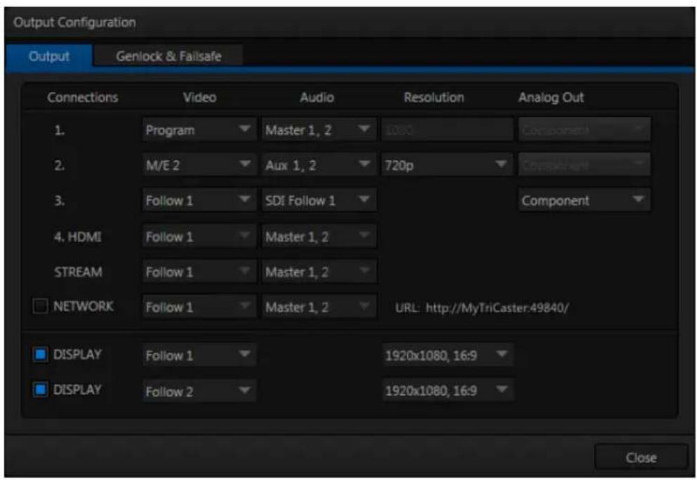
text_image
Output Configuration Output Genlock & Failsafe Connections Video Audio Resolution Analog Out 1. Program Master 1, 2 1080 Component 2. M/E 2 Aux 1, 2 720p Component 3. Follow 1 SDi Follow 1 Component 4. HDMI Follow 1 Master 1, 2 STREAM Follow 1 Master 1, 2 NETWORK Follow 1 Master 1, 2 URL: http://MyTriCaster.49840/ DISPLAY Follow 1 1920x1080, 16:9 DISPLAY Follow 2 1920x1080, 16:9 CloseFIGURE 122 (TRICASTER 8000 SHOWN)
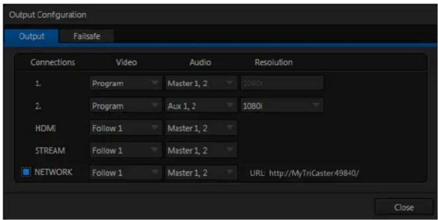
text_image
Output Configuration Output Failsafe Connections Video Audio Resolution 1. Program Master 1, 2 20801 2. Program Aux 1, 2 10801 HDMI Follow 1 Master 1, 2 STREAM Follow 1 Master 1, 2 NETWORK Follow 1 Master 1, 2 URL: http://MyTriCaster49840/ CloseFIGURE 123 (TRICASTER 410 SHOWN)
8.1.1 OUTPUT TAB
The Output Configuration panel contains two tabbed panes governing TriCaster's outputs as well as Genlock & Failsafe options (Failsafe only for TriCaster 410) and settings.
The irst tab, labeled Output, provides control over all of TriCaster's Output channels. Each of these is in some ways unique. Outputs 1 and 2 are of particular interest, for several reasons:
- Of all of TriCaster's outputs, Outputs 1 and 2 support the most diverse range of optional video sources.
- The other outputs can be assigned to 'follow' the audio and video source selections of either Output 1 or Output 2, or show certain other sources.
- Uniquely, Output 2 can be tasked with sending an alpha channel matte to downstream systems.
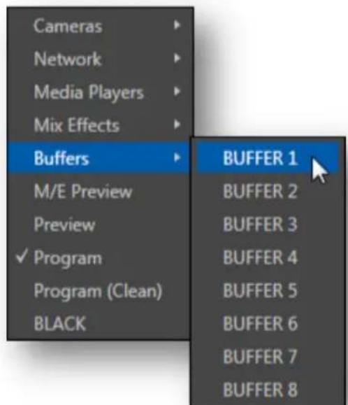
text_image
Cameras Network Media Players Mix Effects Buffers M/E Preview Preview ✓ Program Program (Clean) BLACK BUFFER 1 BUFFER 2 BUFFER 3 BUFFER 4 BUFFER 5 BUFFER 6 BUFFER 7 BUFFER 8FIGURE 124
Let's consider the optional settings provided by these two important outputs:
- Video menu (Figure 124) – assign any source from the following list to either Output 1 or Output 2:
○ Cameras 1-(4 or 8)
○ Network 1 or 2
○ Media Players
- DDR 1
DDR 2
■ GFX 1 (or simply GFX for TriCaster 455 and 410)
■ GFX 2 (not a feature of TriCaster 455 or 410)
○ Any single Buffer
○ Output from M/E 1- (4 or 8)
○ M/E Preview
○ Preview (look ahead)
○ Program
○ Program (Clean)
○ Black
○ Alpha Matte - Output 2 only
- Audio menu (Figure 125) - choose which audio is presented on the corresponding Audio Out connector groups on TriCaster's rear from the following list:
- Outputs
■ Master 1, 2 (sound from the Master 1 and 2 busses)
■ Aux (sound from the Aux 1 and 2 busses)
(See Section 15.7.2 for discussion of TriCaster's internal audio busses).
- Inputs 1-(4 or 8) – sound from any single audio input
- Resolution menu – select the video format for downstream devices you intend to connect to the corresponding output:
○ 1080p
○ 1080i
○ 720p
○ 480i (4:3)
○ 480i (16:9)
○ 576i (4:3) - Multi-format TriCasters only
○ 576i (16:9) - Multi-format TriCasters only

text_image
1080i 1080p ✓ 1080i 720p 480i (4:3) 480i (16:9) Master 1, 2 Outputs Inputs SDI Follow 1FIGURE 125
Note: Options shown in this menu vary by session format. Also, since Output 1 always transmits video in 'session format', an information display is shown rather than a Resolution menu for this output.
- Analog Out menu (not supported by TriCaster 410) – select the video connection type for downstream devices you intend to connect to the corresponding output:
- Component
○ Composite + Y/C
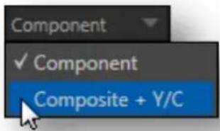
text_image
Component ✓ Component Composite + Y/CFIGURE 126
Note: The only analog connection type suitable for HD video is Component. The Analog Out menu for Outputs 1 and 2 are automatically set to Component and locked when the current Resolution selection for the row is HD.
Choosing Component or Composite + Y/C results in the output connectors in the corresponding row being configured as shown in the following table:
| Connection Type | BNC 1 (SDI) | BNC 2 (Y) | BNC 3 (Pb) | BNC 4 (Pr) |
| Component | SDI | Y | Pb | Pr |
| Composite + Y/C | SDI | Composite | Y | C |
Note: TriCaster's digital (SDI) video outputs are always active, even when the analog outputs in the same group are in use.
ALPHA MATTE
The Video source menu options for Output 2 include a switch labeled Alpha Matte. This feature can be used independently, or supplement the Act as Alpha option (discussed in Section 8.2.2).
An alpha matte can be automatically derived from suitable sources. It might be the matte from a LiveMatte keyer effect, allowing Output 2 to support downstream compositing of the full color source. Or, it could be drawn directly from an image or Title Page in a Media Player. It could just pass-through the matter from an upstream alpha channel source. Simply enable the switch in the Output Configuration panel, and select a suitable source using the same menu.
Note: Generally, the source's Resolution should match session format when supplying an Alpha Matte signal to downstream devices.
Here are some other noteworthy facts related to output:
☐ For SD session formats, session aspect (4:3 or 16:9) is respected on output (e.g., when the session is SD 16:9, video output is also 16:9).
☐ For HD sessions (which are always 16:9), SD video from Output 2 (and any output set to Follow 2) can use either a 16:9 image aspect or as (sidecropped) 4:3 video, as noted earlier when discussing the Resolution menu.
Hint: TriCaster's Record feature can capture video from Output 2, as well as Output 1 (and individual cameras). Output 2 is a particularly flexible choice for capture purposes, providing many useful alternatives – see Chapter 20, Record and Grab.
OUTPUT 3 (TRICASTER 8000 AND 860 ONLY)
Output 3 offers a subset of the options available for Outputs 1 and 2. Video menu options include:
- Cameras 1-(4 or 8)
- Follow 1 or Follow 2
Choosing either Follow 1 or Follow 2 causes Output 3 to carry the same video source, at the same resolution, as the 'followed' output. For SDI output only, audio from output 3 can follow Output 1 or Output 2.
Note: The Analog Output menu for Output 3 always shows both Component and Composite + Y/C options. (As you would expect, the latter options do not support HD sources, and will fail if selected in that case.)
OUTPUT 4 HDMI

text_image
4 HDMI Follow 1 MasterFIGURE 127
For 8-input TriCasters, Output 4 is labeled HDMI in the Output Configuration panel as well as on TriCaster's rear connection panel. Otherwise it is simply labeled HDMI. HDMI Video and Audio menu options are similar to those listed for Output 3 above,
with the addition of individual source options. Naturally, analog connection options are not required.
Note: HDMI display devices will typically show black when if they do not support video displays of the format (resolution, etc.) selected as source in Output 4's Video menu.
8.1.2 STREAM AND NETWORK
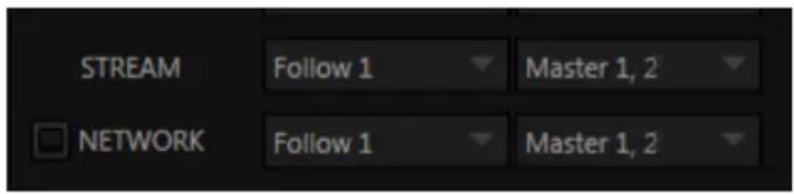
text_image
STREAM Follow 1 Master 1, 2 NETWORK Follow 1 Master 1, 2FIGURE 128
Like other output options, TriCaster's Network and Stream outputs can be independently configured to use different Video and Audio sources. The selections are the same as are offered for Output 4 above.
Network Output sends audio and video across a LAN (Local Area Network) to the Net inputs of another TriCaster, and is enabled or disabled using the switch at left.
Hint: Take special note that the Source drop-down menu for Network provides a De-Interlace item, for output targets where that would be a valuable option).
Streaming Output is more complex, since there are so many different ways to stream. In this panel, you can configure the audio and video sources sent to output. All other options and settings relevant to streaming are located in the Streaming Configuration panel – see Chapter 18 for a full discussion of this important topic.
TRICASTER 8000 DISPLAY OUTPUTS

text_image
DISPLAY Follow 1 1920x1080, 16:9 DISPLAY Follow 2 1920x1080, 16:9FIGURE 129
Two rows at the bottom of the configuration panel are labeled Display. The corresponding output ports are intended to supply video to projection systems or other display devices. These outputs are presented physically on TriCaster's rear connection panels as HDMI and VGA ports, respectively (Output 5 is DVI-D internally). No audio is supplied to these connectors.
The Video source menu for both outputs provides the same options as Output 3. When a downstream monitor is detected on either port, the corresponding Resolution menu permits selection of a suitable resolution (typically, an incorrect selection here will result in an 'out of range' error message being displayed on the downstream device).
Switches provided at left in each row permit the Display ports to be selectively disabled when they are not in use.
8.1.3 GENLOCK & FAILSAFE
TriCaster's Genlock feature allows it to 'lock' its video output to a reference video signal supplied to its Genlock input connector. (Note that TriCaster 410 does not include Genlock.)
This synchronizes TriCaster output to other external equipment locked to the same reference. Genlocking is not a requirement, but it is very beneficial, and you should definitely use it if you have the capability.
TriCaster mixes and switches output from up to eight camera sources (8-input models). Miniscule local timing differences between these may force tiny delays during switching operations, which can also contribute to throughput latency. Thus, serving i) TriCaster's Genlock input and ii) other video devices in the chain with a single reference is the best approach.
Hint: The term "genlock" refers to "generator locking".
Professional video devices often provide a “genlock input”, which allows an external reference signal (often referred to as ‘house sync’) to control its video timing.
The output of video devices connected in this manner is synchronized to the reference signal, and they are referred to as 'genlocked'.
You could think of it this way:
Genlocking your cameras has the effect of locking their output together, ensuring optimal synchronization for live switching. This may result in throughput latency benefits.
Supplying the same sync source to TriCaster's Genlock input ensures a match between TriCaster output and any downstream video devices required to handle both it and other (genlocked) sources.
Note: Digital audio is less tolerant in certain respects than analog. Some devices require SDI sources to be genlocked when mixing digital audio (whether for recording or live production).
TriCaster, however, includes dynamic audio re-sampling for each input. Genlocking of SDI audio/video sources is not a requirement. Still, genlocking sources and TriCaster to a house reference signal, or genlocking the cameras directly to the TriCaster output is encouraged (to genlock cameras, see your camera manual).
VERTICAL POSITION, HORIZONTAL POSITION AND PHASE
Locking all devices to house sync is important, but this alone does not actually ensure a perfect downstream match. Consider an army marching along: each step the soldiers take occurs at precisely the same moment, so we could say their timing is synchronized. Even so – problems result if one soldier leads with the left foot while everyone else is on the right. Or perhaps everyone is evenly spaced and perfectly aligned but for one misfit who ‘tailgates’ the soldier ahead of him and keeps stepping on his heels.
This is essentially why TriCaster provides several adjustments in its Genlock section. The Horizontal and Vertical Position settings pin the image in the proper space in the frame, and in doing so could be likened to making sure each marching soldier is in position relative to his fellows (as viewed from above).
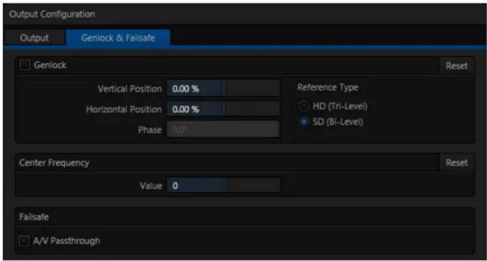
text_image
Output Configuration Output Genlock & Failsafe Genlock Reset Vertical Position 0.00 % Reference Type Horizontal Position 0.00 % HD (Tri-Level) Phase 0.07 SD (Bi-Level) Center Frequency Reset Value 0 Failsafe A/V PassthroughFIGURE 130
The Phase setting ensures proper color alignment, corresponding to making sure everyone is on the left or right foot at the same time.
Thus, the Vert Position, Horiz Position and Phase settings allow you to tweak synchronization to arrive at an optimum match between devices. Typically, these settings are ine-tuned with the aid of a downstream Vectorscope and Waveform Monitor. (A discussion of these adjustments goes beyond the scope of this manual, but a quick online search for the keywords “genlock” and “adjust” turns up a number of excellent references).
REFERENCE TYPE
The ‘bi-level’ reference signal long used for standard deinition television is often used for genlocking both SD and HD installations.
text_image
Reference TypeFIGURE 131
However, if you are supplying an HD reference signal to TriCaster's Genlock Input (and your other equipment),
select the HD (Tri-level) switch in the Reference Type area of TriCaster's Genlock settings.
Note: Reference Type options do not appear for SD sessions.
8.1.4 CENTER FREQUENCY
text_image
Failsafe A/V PassthroughFIGURE 132

text_image
Horizontal Position: 600-10 Phase 0.5°FIGURE 133
This setting is applied when a genlock reference signal is not in use. To adjust the setting, supply color bars to an input and pass TriCaster's video output to a downstream vectorscope. The vectorscope display is completely stable when Center Frequency is properly adjusted.
Note: See also Section 8.2.3, Frame Sync .
8.1.5 FAILSAFE
TriCaster's multi-tiered 'Always on Air' hardware and software failsafe systems (see Section 2.5.2) provide conidence that short of a complete power failure the show will go on.
In some studio settings, however, more elaborate hardware failsafe systems may be in use. Typically, such systems take over broadcast duties whenever the output signal fails. In such cases, TriCaster's failsafe video passthrough mechanism (which ensures that video output continues even in catastrophic circumstances) can actually prevent the external system from engaging.
For this reason, a Failsafe section has been added to Output Configuration. Its sole raison d'être is to provide a switch allowing you to disable the A/V passthrough when necessary. By default, A/V passthrough is off.
Hint: Only use fail-safe when a stable video source is connected to video Input 8.
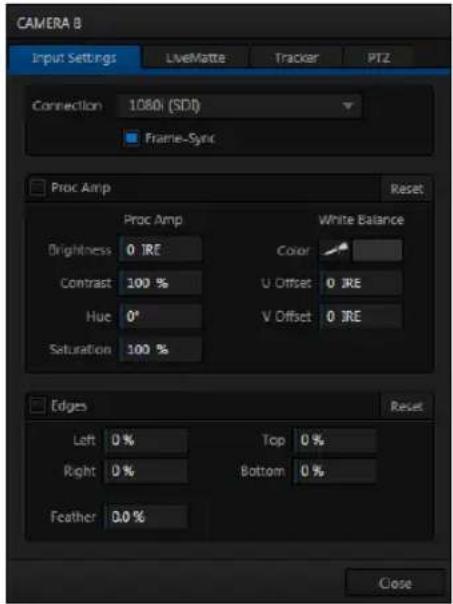
text_image
CAMERA B Input Settings LiveMatte Tracker PTZ Connection 1080i (SDI) Frame-Sync Proc Amp Reset Proc Amp White Balance Brightness 0 IRE Color Contrast 100 % U Offset 0 IRE Hue 0° V Offset 0 IRE Saturation 100 % Edges Reset Left 0 % Top 0 % Right 0 % Bottom 0 % Feather 0.0 % CloseFIGURE 134 (TRICASTER 8000 SHOWN)
TriCaster's input monitors have contextual tools that appear when you roll the mouse pointer over in the footer (that is, the titlebar below each monitor). In every case, the right-most button is a Configure button (gear). Clicking it opens the Configuration panel for a specific source (Figure 134).
8.2.1 CONNECTION TYPE
The Configuration panel for the Camera inputs features a Connection type menu at the top of its Input Settings tab. Connection menu options vary depending on the Video Standard for the session. TriCaster Multi-standard provides PAL and NTSC-J session options, in addition to NTSC.
The Connection Type menu options for a PAL session list PAL HD and SD format options. Choosing NTSC as the session Video Standard results in a Connection Type list with appropriate formats, and it is similar for NTSC-J. Changing from one Video Standard to another requires opening a new session.
Hint: All connected cameras must conform to the current Video Standard for the session.
The standard options are (note that TriCaster 410 does not support analog video input options):
1080i (Component), 1080/30PsF (Component), 1080/24p telecine (Component)
- Analog source, high denion, interlaced or PsF (Progressive Segmented Frame)
- 1080/60i, ^2 1080/50i, or 1080/24p
• 1920x1080 pixels, 16:9 picture aspect - Connected to TriCaster by Y, Pr and Pb input connectors
1080i (SDI)
• Digital source, high denion, interlaced
- 1080/60i or ^2 1080/50i
• 1920x1080 pixels, 16:9 picture aspect
- Connected to TriCaster by SDI input connectors
- Oponally carries embedded audio
1080/30p (SDI), 1080/30PsF (SDI), 1080/24p (SDI), ^1 1080/24p telecine (SDI), ^2 1080/25p (SDI), ^2 1080/25PsF (SDI)
- Digital source, high denion, progressive scan, or PsF (a hybrid)
• 1920x1080 pixels, 16:9 picture aspect - Connected to TriCaster by SDI input connectors
- Oponally carries embedded audio
720/60p (Component), ^2 720/50p (Component)
- Analog source, high denion, progressive scan
- 1280x720 pixels, 16:9 picture aspect
- Connected to TriCaster by Y, Pr and Pb input connectors
720/60p (SDI), 720/30p (SDI), 720/24p (SDI), ^2 720/50p (SDI), ^2 720/25p (SDI)
• Digital source, high denion, progressive scan
- 1280x720 pixels, 16:9 picture aspect
- Connected to TriCaster by SDI input connectors
- Oponally carries embedded audio
The standard deinition options listed below are provided in both 4:3 and 16:9 versions:
480/30i (Component)
• NTSC analog format, standard denion, interlaced
- 720x480 pixels, 4:3 picture aspect or anamorphic 16:9 picture aspect
- Connected to TriCaster by Y, Pr and Pb input connectors
480/30i (SDI)
- NTSC digital format, standard denion, interlaced
- 720x480 pixels, 4:3 picture aspect or anamorphic 16:9 picture aspect
- Connected to TriCaster by SDI input connectors
- Oponally carries embedded audio
480/30i (Y/C)
• NTSC (S-Video) analog format, standard denion, interlaced
- 720x480 pixels, 4:3 picture aspect or anamorphic 16:9 picture aspect
- Connected to TriCaster by Y and Pb input connectors
480/30i (Composite)
• NTSC analog format, standard denion, interlaced
- 720x480 pixels, 4:3 picture aspect or anamorphic 16:9 picture aspect
- Connected to TriCaster by Y input connector
^2 576/25i (Component)
• PAL analog format, Standard denion, interlaced
- 720x576 pixels, 4:3 picture aspect or anamorphic 16:9 picture aspect
- Connected to TriCaster by Y, Pr and Pb input connectors
^2 576/25i (SDI)
• PAL digital format, standard denion, interlaced
- 720x576 pixels, 4:3 picture aspect or anamorphic 16:9 picture aspect
- Connected to TriCaster by SDI input connectors
- Oponally carries embedded audio
^2 576/25i (Y/C)
• PAL (S-Video) analog format, standard denion, interlaced
- 720x576 pixels, 4:3 picture aspect or anamorphic 16:9 picture aspect
- Connected to TriCaster by Y and Pb input connectors
^2 576/25i (Composite)
• PAL analog format, standard denion, interlaced
- 720x576 pixels, 4:3 picture aspect or anamorphic 16:9 picture aspect
- Connected to TriCaster by Y input connector
^1 The ‘telecine’ option removes ‘2:3 pull-up’ in output from cameras claiming 24PsF but actually supplying video at 30 fps (to make it suitable for 24P use sessions).
^2 Multi-standard TriCaster PAL connection type
8.2.2 ACT AS ALPHA
TriCaster optionally allows one or more neighboring pairs of video inputs to be combined as a single 'video + alpha' channel (sometimes also referred to as "fill and matte").
The ability to configure one input as the alpha channel source for another is absolutely invaluable for installations employing video feeds from high end external CG and chromakeying systems (such as Chyron® and Ultimatte®).
To use this feature, select Act as Alpha Channel for Input (#) as the Connection Type in the Input Configuration panel for an even-numbered input.
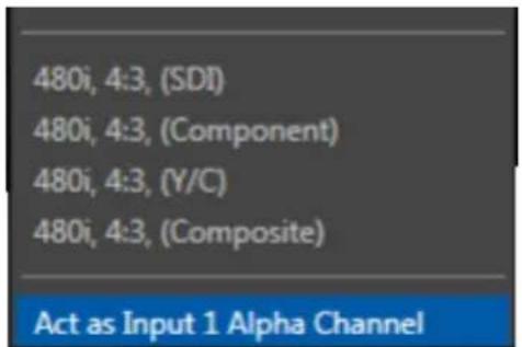
text_image
480i, 4:3, (SDI) 480i, 4:3, (Component) 480i, 4:3, (Y/C) 480i, 4:3, (Composite) Act as Input 1 Alpha ChannelFIGURE 135
Note: The input configuration (video format and connection type) for the alpha input is automatically configured to match the fill source it is paired with.
8.2.3 FRAME SYNC
FIGURE 136 (TRICASTER 8000)
TriCaster internal Frame Sync is enabled for all sources by default, allowing you to work with a wide array of potential video sources without concerns about video timing. For TriCaster 8000 (only), it is possible to ensure the very lowest possible throughput latency for genlocked sources by disabling Frame Sync.
Sources with Frame Sync disabled must be genlocked, and further, must be 'in phase' (within 180^ of the current switcher output); otherwise, video from the source will simply not be visible.
In practice, then, disable Frame Sync for your genlocked sources, adjust the Phase setting (see Section 8.1.3) until video is displayed and you should be all set.
Note: If Frame Sync is enabled or disabled for one source in a 'Fill + Alpha' input pair, the Frame Sync setting for the corresponding input channel is automatically updated to match.
8.2.4 PROC AMP
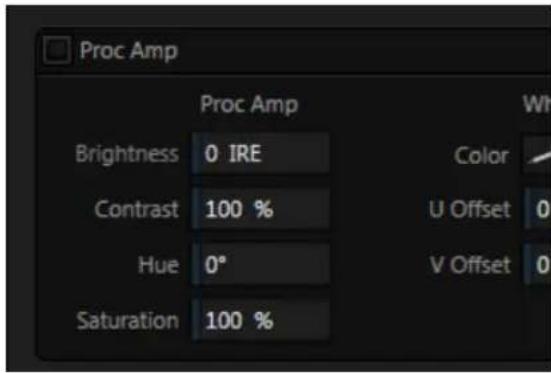
text_image
Proc Amp Proc Amp Brightness 0 IRE Contrast 100 % Hue 0° Saturation 100 %FIGURE 137
The Input Settings tab also contains Proc Amp (processing amplifier) settings. Input Proc Amp adjustments are applied after LiveMatte is processed, which can help when composing greenscreen shots to match a background or LiveSet.
You may also notice that changes to Proc Amp settings affect stopped (or frozen) sources, including live camera feeds.
A switch at the top of the Proc Amp control group toggles the feature on/off. Other controls operate as follows:
Proc Amp practices:
Whenever possible, it is best to perform color adjustments at the source or target device. For example, it is preferable to calibrate a camera's colors at the camera, before sending the signal to TriCaster. Doing so will yield higher color precision.
TriCaster's Proc amps are available for occasions when no upstream color correction is available.
- Brightness: Adjustment range from -50 to +50 IRE (the default being 0). As reference, the full luminance range of the visible portion of a video signal can be thought of as '100 IRE units' (named for the Institute of Radio Engineers) – ignoring minor regional variations.
- Contrast – Adjustment range from 25 - 400% (default 100%).
- Hue - Adjustment range between -180^ and +180^ . Adjusts the master color of the video signal from the attached source, swinging the entire image through the color wheel's spectrum.
- Saturation – Adjustment range from 0-500%. Zero saturation results in a 'black and white' picture; increased saturation results in richer colors. High saturation values can exaggerate the color portion of the signal.
(Note that over-saturated colors are considered illegal for broadcast transmission, and may result in display problems on some devices.)
Hint: your TriCaster system provides Waveform/Vectorscope monitors, an invaluable aid to calibrating your video sources.
White Balance - this secondary control group adds U Offset and V Offset controls to the Proc Amp.
text_image
White Balance Color U Offset 0 IRE V Offset 0 IREFIGURE 138
- The U portion of the video signal carries blue and yellow color information. Rotating the U Offset knob clockwise shifts the signal toward blue, while a counter-clockwise twist shifts the signal toward yellow.
- The V portion of the video signal carries red and green color information. Rotate V Offset clockwise to shift the signal toward red and counter-clockwise to shift the signal toward green.
To automatically white balance - click and hold the mouse button over the Color (eyedropper) button, and then slide the pointer onto the monitor for the
corresponding source. Release the mouse button over a part of the image that should appear as white after processing.
8.2.5 EDGES
It is very common for a source to be supplied with unintentional inclusions; these are often items that remain after chromakeying is applied, but which need to be removed along with the background. (Common examples include microphones or lighting fixtures dangling from above, or perhaps a harsh crease, blemish or tear in the background screen.) Or, as is frequently the case, the source video itself may have a few pixels of black or video ‘noise’ along one or more of its edges.
Cropping settings in the Edges control group can be used to remove such unwanted ‘garbage’ from the scene, or used independently for other purposes – such as to isolate some portion of the screen for use as a ‘Picture in Picture’ overlay source.
text_image
Edges Left 0 % Top 0 % Right 0 % Bottom 0 % Feather 0.0 %FIGURE 139
Essentially, the numeric controls in this group allow you to deine independent margins for the frame. Drag left or right on the number ields to adjust the values interactively, or double-click a ield to type a value using the keyboard. The region deined by these controls will be completely cropped. Use the Feather setting (TriCaster 8000 only) to soften the edges.
Hint: For added convenience, similar cropping tools are available separately in the Position panels of DSK channels and M/Es.
8.2.6 LIVEMATTE
The second tab in the Input Configuration panels is where TriCaster's powerful realtime keying system for live production, LiveMatte, is configured. Keying is a popular and powerful method of compositing multiple images, whether photos, video clips or live camera streams.
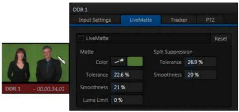
text_image
DDR 1 Input Settings LiveMatte Tracker PTZ LiveMatte Reset Matte Spill Suppression Color Tolerance 26.9 % Tolerance 22.6 % Smoothness 20 % Smoothness 21 % Luma Limit 0 %FIGURE 140 (TRICASTER 8000 SHOWN)
The process involves eliminating a portion of the image (effectively cutting a digital 'keyhole' in it) to reveal a user-deined background scene. It also plays an important role in the worklow of LiveSet, TriCaster's powerful virtual set technology.
LiveMatte's controls are deceptively simple, making a great deal of complex digital manipulations easy to use. Even so, much can be said about getting the best results. For that reason we've devoted a whole chapter in this manual to discussing it - please see Chapter 13, LiveMatte.
Hint: When LiveMatte, Proc Amp, or Crop settings are active for a source, bright green, blue and yellow indicators are lit under its monitor.
8.2.7 HOTSPOTS
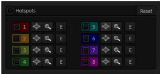
text_image
Hotspots Reset 1 2 3 4 E E E E E E 5 6 7 8FIGURE 141
The lower portion of the LiveMatte tab in the Input Configuration panel is devoted to Hotspots – TriCaster's powerful interactive automation feature.
A Hotspot is a square, user-deined region of the screen that (when active) detects opacity changes inside its boundaries. This is why the feature is paired with LiveMatte in the TriCaster interface (Hotspots do not work without LiveMatte being enabled).
With LiveMatte properly configured, the Hotspot feature can trigger a macro when opaque pixels are newly detected in an active Hotspot (as, for example, when talent in a greenscreen set walks into that location in the frame), and a second macro when all opaque pixels move out of the region.
All manner of creative implementations are possible. Hotspot setup, options and use is discussed in depth in Chapter 17, Macros, Automation and Remote Control.
8.2.8 TRACKER
(TriCaster 8000 only) The Tracker tab provides control over TriCaster's realtime motion tracking features.
This feature allows you to choose a colored region of the video frame using tools similar to those found in the LiveMatte tab (Section 8.2.6).
The tracked region is deined by choosing a primary Color using the color picker tool. The Tracker follows this region as it moves and shifts within the frame over time, and outputs the motion data to TriCaster.
In turn, Tracker output from one source can be used to control the placement of other video sources configured to do so in their individual Position panels (supplied wherever appropriate in DSK controls and M/E panes).

natural_image
Woman holding a solid orange rectangular sign against a green background (no text or symbols visible)FIGURE 142
ADJUSTING TOLERANCE
Click the eyedropper, keep the mouse button depressed, and drag the pointer over
top of the monitor showing the source you want to track (Figure 143).
The color swatch updates constantly as you drag, until you release the button to make a selection.

TriCaster makes it easy for you to adjust the Tracker settings by making it possible to see the result of your attempts in its monitors. Right-click on a monitor and select Tracking Markers from the Overlays options group in the menu. A yellow-shaded rectangle is overlaid on the video using the current settings. Watch how this overlay is affected by adjustments you make to the Tolerance value for the Tracker. Raise or lower the Tolerance value until the result is steady, not jittering or jumping about.
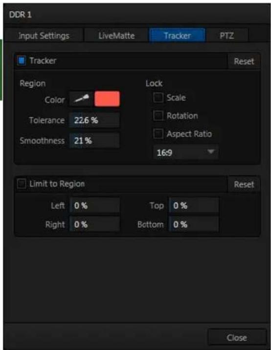
text_image
DDR 1 Input Settings LiveMatte Tracker PTZ Tracker Reset Region Color Tolerance 22.6 % Smoothness 21 % Lock Scale Rotation Aspect Ratio 16:9 Limit to Region Reset Left 0 % Top 0 % Right 0 % Bottom 0 % CloseFIGURE 143 (TriCaster 8000 Shown)
The Smoothness setting works just like the LiveMatte feature with the same name. Its impact on tracking data output is minimal, but it is often important when used with the Advanced Tracking effect in M/E panels (see Section 14.2.2).
Lock
At right are controls that permit you to Lock certain Tracker attributes (Figure 144):
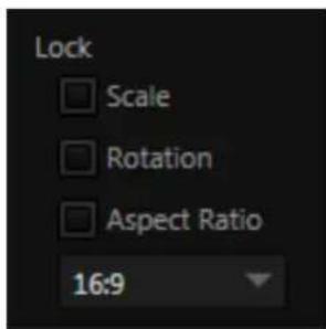
text_image
Lock Scale Rotation Aspect Ratio 16:9FIGURE 144
- Lock Scale to prevent the Tracker from automatically compensating when the scale of the tracked region grows or shrinks during motion.
- Likewise, when Rotation is locked, the orientation of Tracker output is constrained.
- The Aspect Ratio lock forces the Tracker to conform to a square (1:1), or rectangular (4:3 or 16:9) shape.
Hint: Generally, locking channels in this manner make it easier to obtain a very steady motion track; but just as often, your choices will be dictated by creative requirements.
LIMIT TO REGION
The Tracker is designed to follow the largest shape in a frame that meets the deined color criteria.
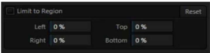
text_image
Limit to Region Left 0 % Top 0 % Right 0 % Bottom 0 %FIGURE 145
At times, similar colored articles or inclusions in the frame can interfere
with Tracker output. The settings in this group allow you to limit the area of the frame the Tracker monitors, which can help you sidestep this issue.
We'll discuss the application of the Tracker's data stream when discussing the Positioner tools.
8.2.9 PTZ
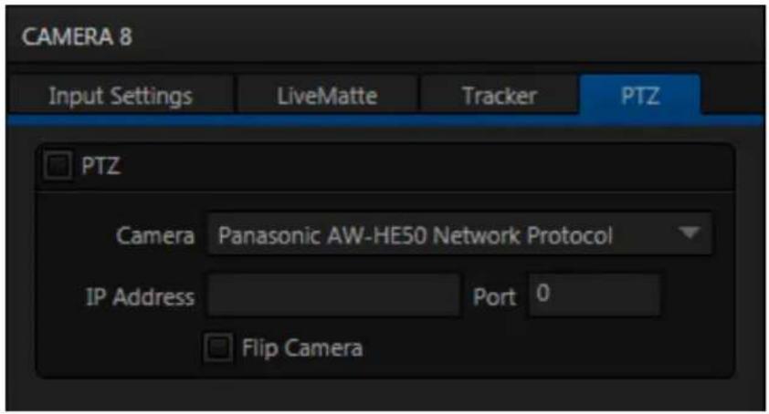
text_image
CAMERA 8 Input Settings LiveMatte Tracker PTZ PTZ Camera Panasonic AW-HE50 Network Protocol IP Address Port 0 Flip CameraFIGURE 146
PTZ (pan-tilt-zoom), or ‘robotic’ cameras can play important roles in certain types of productions. These systems range widely in price, from a few hundred dollars to those the ‘six figure’ range, with an equally diverse range of quality and features.
Generally, remote control of PTZ cameras involves sending instructions to the camera either across serial (RS232 or RS422) or network connections. TriCaster 460, 860 and 8000 provide support for both types. Connection settings shown in the PTZ tab (Input Configuration pane) update depending on which Camera type you select.
Choose your camera model (or one similar to it) using the drop-down menu, and then enter (or select) appropriate settings for the unit.
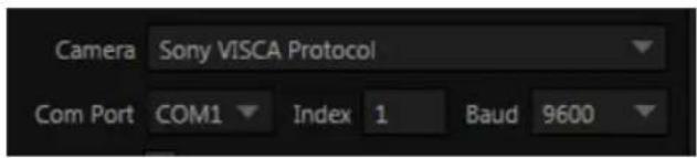
text_image
Camera Sony VISCA Protocol Com Port COM1 Index 1 Baud 9600FIGURE 147
Note: TriCaster does not have an external serial port. For PTZ cameras requiring a serial connection, you will need to use a third party USB-to-Serial Port adapter.
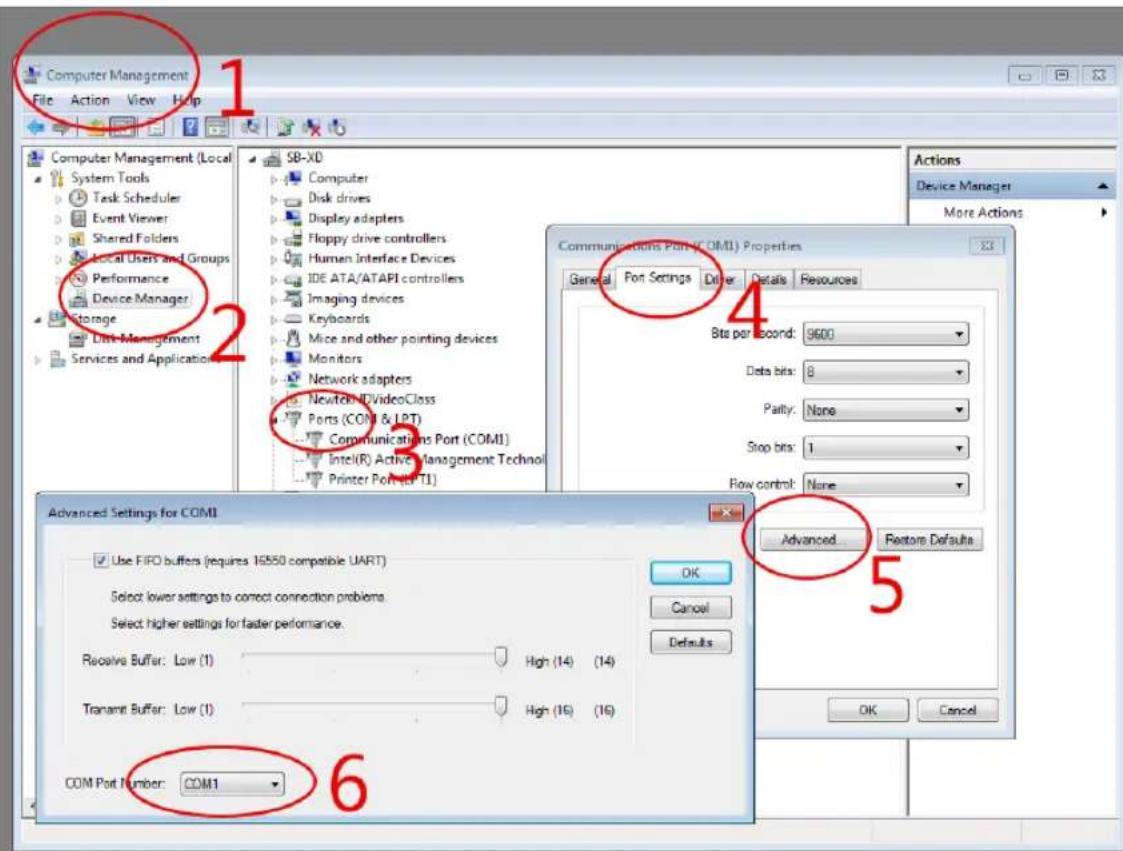
text_image
Computer Management File Action View Help 1 Computer Management (Local System Tools Task Scheduler Event Viewer Shared Folders Local Users and Groups Performance Device Manager Storage List Management Services and Applications 2 SB-XD Computer Disk drives Display adapters Floppy drive controllers Human Interface Devices IDE ATA/ATAPI controllers Imaging devices Keyboards Mice and other pointing devices Monitors Network adapters Newtek IDVideoClass Ports (COM) & LPT) Communications Port (COM1) Intel(R) Active Management Technol Printer Port (LPT1) 4 Communications Port (COM1) Properties General Port Settings Other Details Resources Bits per second: 9600 Data bits: 8 Parity: None Stop bits: 1 Row control: None Advanced Restore Defaults 5 Advanced Restore Defaults Advanced Restore Defaults COM Port Number: COM1 6FIGURE 148
Windows will automatically assign a COM port number to the adapter, usually COM 1. In some cases, you may wish to manually assign it to a specific port. Exit to Windows from TriCaster's Administration Mode screen (Section 5.2.3) to access the controls shown in Figure 148. Refer to the documentation provided with your adapter for further directions.
The Flip Camera switch inverts the image, helpful when the camera is mounted in an upside-down orientation. It also affects the pan and tilt controls, when possible (this support varies by camera).
SECTION 8.3 NETWORK INPUTS
TriCaster features two dedicated network video inputs, designated Net 1 and Net 2 in the interface and on the control surface.
Hint: Like other sources, Net 1 and 2 can be renamed.
A wide variety of sources can be supplied to Net 1 and 2, making these two inputs exceptionally versatile and powerful.
To cover these capabilities fully, we've dedicated all of Chapter 16 (Network Inputs) to the topic. We'll just mention here that both of these inputs provide TriCaster's full gamut of creative controls, including Proc Amps, LiveMatte, Edge control, Tracking, Hotspots, and so-on (see Section 8.2). Some sources even support embedded audio across the network, which is why you will ind Net 1 and 2 represented in the Audio Mixer, too (Section 15.6.1).
SECTION 8.4 TIMECODE CONFIGURATION
text_image
09.15.23.11FIGURE 149
TriCaster can supply event time values based on the system clock, when necessary. To access timecode options, click the small gear icon next to the timecode display at right in Live Desktop's Dashboard.
Hint: You can set TriCaster's system clock as for any computer by exiting to the Windows® Desktop.
Most TriCasters can optionally use an external linear timecode (LTC) reference to drive its clocks, and timecode for capture (TriCaster 410 does not support external timecode).
We'll discuss the shared timecode features first, and then focus on the unique aspects of the LTC timecode support (Section 8.4.3).
8.4.1 SUBTRACT 12 HOURS
The current time value is embedded in the frames of Quicktime video iles captured during the session using TriCaster's Record function. For this reason, a switch labeled Subtract 12 Hours is provided.
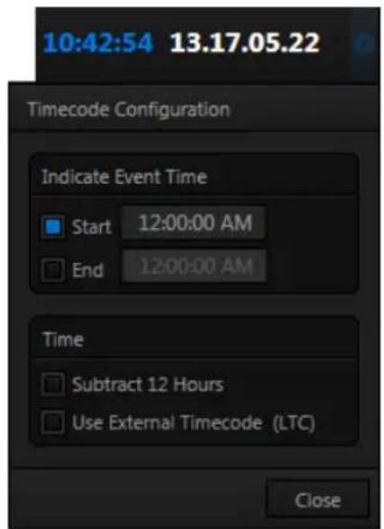
text_image
10:42:54 13.17.05.22 Timecode Configuration Indicate Event Time Start 12:00:00 AM End 12:00:00 AM Time Subtract 12 Hours Use External Timecode (LTC) CloseFIGURE 150
This option permits you to avoid confusion that might arise when sequencing files based on timecode that 'wraps around' past
midnight. (Otherwise, for example, a video frame recorded one minute before midnight would be assigned the timecode 23:59:59.00, while frames recorded one minute or more later would have timecode ≥ 01:00:00.00 – seemingly a lower (i.e., ordinarily earlier) timecode value.)
8.4.2 EVENT TIME
Two more switches, under the label Indicate Event Time, allow you to configure Start and End times for your upcoming show. Beside each of these is an editable time ield. Enable the Start/End switches, and click inside the ield to modify the time value by direct entry, or drag left right to raise or lower the current value.
During live production, the Dashboard and as well as TriCaster's monitor panes and default Multiview layouts (Figure 152) offer Broadcast Clock displays based on the current timecode. Secondary clock displays show a useful countdown to the (production) Start and End times when the corresponding switches are enabled in the Timecode Configuration panel.
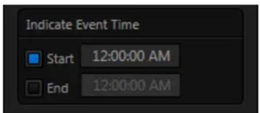
text_image
Indicate Event Time Start 12:00:00 AM End 12:00:00 AMFIGURE 151
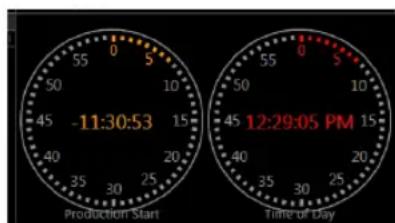
text_image
55 0 5 50 10 45 -11:30:53 15 40 20 35 30 25 Production Start Time of Day 12:29:05 PMFIGURE 152
8.4.3 LTC TIMECODE
Linear timecode is by far the most common method of sharing an external timecode reference in video production.
Output from an external timecode generator is supplied to devices in the video pipeline using a standard audio connection. TriCaster uses either Audio Input 7 or 3 for this purpose (see Section
3.7), depending on the model (as mentioned previously, TriCaster 410 does not support this feature).
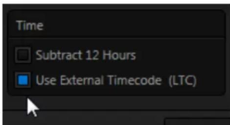
text_image
Time Subtract 12 Hours Use External Timecode (LTC)FIGURE 153
TriCaster decodes time stamps from the audible signal, and uses the values for clock displays and embedded timecode when recording video. This is a great asset for post-production purposes. Enable linear timecode using the switch labeled Use External timecode (LTC) in Timecode Configuration.
Sound from the audio input tasked with supplying timecode is automatically muted for recording and output purposes when LTC timecode is enabled, but you can un-mute it briefly in the Audio Mixer to let you adjust input levels.
Hint: The timecode display in the Live Desktop titlebar is tinted blue when external timecode is in use. If the external connection is lost for any reason, the display changes to white. TriCaster will attempt to maintain continuous timecode from the interruption on, until a valid signal is restored (in which case the display turns blue once more).

text_image
TCTriCaster's Live Desktop replicates traditional video switcher controls in easy to comprehend and use fashion. It provides numerous transitions that you can use to add interest when changing scenes, four independent downstream overlay channels, and some very useful automation.
When the M/E pane is minimized, the central band of the TriCaster™ Live Desktop (between the upper monitoring section and the tabbed modules below) is taken up by the Switcher and related controls and features, including the Layer Controls, which include main and DSK channel Transition controls and configuration features (Figure 154).

text_image
Switcher Layer Controls PUM 1 2 3 4 5 6 7 8 NET NET DOB F GND F GND GND GND GND GND GND GND GND GND GND GND GND GND GND GND GND GND GND GND GND GND GND GND GND GND GND GND GND GND GND GND GND GND GND GND GND GND GND GND GND GND GND GND GND GND GND GND GND GND GND GUND PUM 1 2 3 4 5 6 7 8 NET NET DOB F GND F GND F GND F GND F GND F GND F GND F GND F GND F GND F GND F GND F GND F GND F GND F GND F GND F GND F GND F GND F GND F GND F GND F GND F GND F GND F GND F GND F GND F GND F GND F GND F GND F GND FADE FADE FADE FADE FADE FADE FADE FADE FADE FADE FADE FADE FADE FADE FADE FADE FADE FADE FADE FADE FADE FADE FADE FADE FADE FADE FADE FADE FADE FADE FADE FADE FADE FADEFrom top to bottom, the two Switcher rows are labeled Program and Preview. Clicking a button in the Program or Preview row selects the active video source for that row (audio sources may or may not be affected by Switcher activity – see Chapter 15 Audio).
The PGM (Program) row selection determines the dominant video stream of the Background (BKGD) video layer – the bottom-most layer of the composition sent to the Program output.
Other sources may be mixed into the Background layer at times, as you apply LiveMatte, or see portions of an incoming Preview row video source during a transition.
Normally, the Preview row selection determines which source is queued up for display in the Background layer by the next (BKGD) Take or Transition operation.
Optional video source selections for the Program and Preview rows include all external (Camera and Network) inputs, including video router sources (TriCaster 8000 only); internal sources (Media Players and Buffers); and also the output from all of TriCaster's M/Es, represented on the Switcher rows by buttons labeled M/E 1-(4 or 8, by model) – see Chapter 14, Mix/Effect (M/E) Tools).
SECTION 9.2 VIDEO LAYERS
The concept of video layers is central to understanding how TriCaster's Switcher, M/E's and Transition controls relate to one another, and how they combine to form the video seen on Program Out. TriCaster's Background layer (often shortened to simply 'BKGD') is always the base for the video composition displayed on Program out. DSK (DownStream Keyer, or 'overlay') layers may or may not appear above (or, if you like, in front of) the Background. DSK layers are typically used for overlaying graphics, titles, etc., though they may serve other purposes as well.
In addition to BKGD, up to ive additional ‘primary layers’ can contribute to TriCaster’s inal Program output at any given moment:
- Either two or four (TriCaster 8000) overlay layers (DSKs are composed above the BKGD layer on output. (DSK 2 appears 'in front of' DSK 1 on Program Output – that is, closest to the viewer – and so on in order).
- FTB (Fade to Black) constitutes a inal overlay layer – one that obscures all other layers when applied.

flowchart
graph LR
    A["BKGD"] --> B["Program Preview"]
    B --> C["DSK 1"]
    C --> D["DSK 2"]
    D --> E["DSK 3"]
    E --> F["TriCaster 8000 only"]
    F --> G["DSK 4"]
    G --> H["FTB"]
    H --> I["Program Out"]
Recall, too, that the BKGD layer itself is often a composite of sub-layers:
It may include mixed video from both the Program or Preview rows.
- Selecting an M / E as source on Program or Preview can bring many more sub-layers into the BKGD composite, including the M/E's primary Inputs and the dedicated M/E Key layers, which are similar to DSK layers.
Note: Since M/Es are reentrant, the BKGD layer alone can at times reach astronomical numbers of sub-layers in its composition!
9.2.1 SELECTING SOURCES
Video sources for PGM (Program) and PVW (Preview) rows, of course, are selected by pressing buttons on those rows.
For DSK video layers, source selection is made using a drop-down menu above the four individual DSK layer controls, located at right in the Layer Control section of the Switcher section.
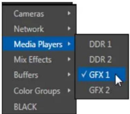
text_image
Cameras Network Media Players Mix Effects Buffers Color Groups BLACK DDR 1 DDR 2 ✓ GFX 1 GFX 2FIGURE 156 (8-input model shown)
Hint: Right-click camera input or Buffer buttons to select special sources from video routers or Buffers – see Section 3.12.1 (Configuring Routers) and Section 11.4 (Buffers).
9.2.2 LINKING SWITCHER ROWS
It can be very useful to link two (or more) Switcher or M/E source rows together, causing them to operate synchronously.
The Program and Preview rows, and the source rows in any M/E operating in Mix mode, show a downward pointing triangle to the right of the row label (Figure 157). Click it to open a menu that lets you create these linkages.
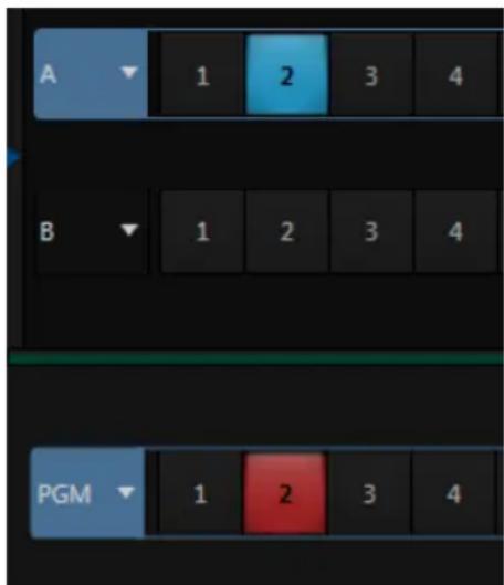
text_image
A 1 2 3 4 B 1 2 3 4 PGM 1 2 3 4FIGURE 158
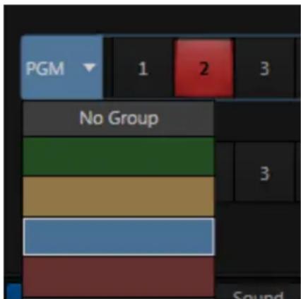
text_image
PGM 1 2 3 No Group 3 SoundFIGURE 157
Rows assigned to any single color group are linked. Making a selection in any linked row updates the selection of all other rows in the group to match. Thus Figure 158 shows the Input A row for an M/E linked to the PGM row of the main Switcher.
The inal menu item removes the links for all rows assigned to the current group.
SECTION 9.3 TRANSITIONS
We discussed video layers in Section 9.2. With this in mind, it's easy to comprehend the layout and use of TriCaster's Transition controls.
At left in this group are the main Transition controls, including the T-bar. The larger portion at right provides solo control and configuration options individually for the four primary DSK layers.
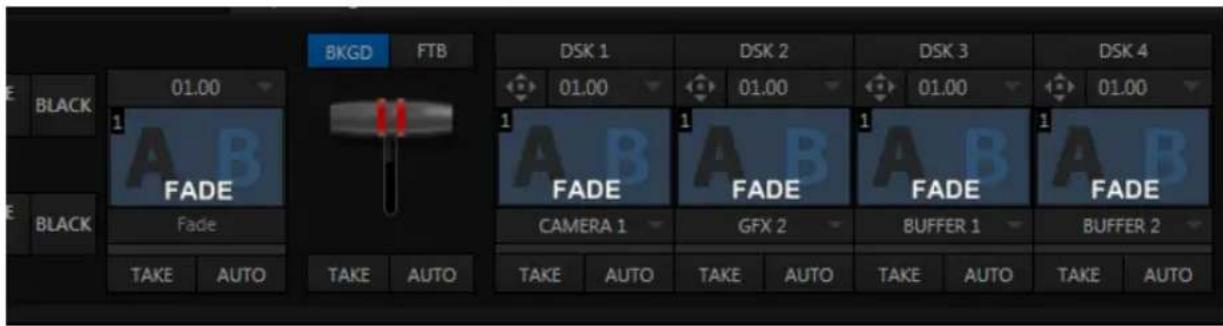
text_image
BKGD FTB DSK 1 DSK 2 DSK 3 DSK 4 01.00 01.00 01.00 01.00 01.00 01.00 FADE FADE FADE FADE FADE CAMERA 1 GFX 2 BUFFER 1 BUFFER 2 TAKE AUTO TAKE AUTO TAKE AUTO TAKE AUTO TAKE AUTO TAKE AUTO TAKE AUTO TAKE AUTO TAKE AUTO TAKE AUTOFIGURE 159 (TRICASTER 8000 SHOWN)
Let's consider the individual DSK Layer Controls irst, before proceeding to the slightly more complex main controls.
9.3.1 DSK CONTROLS
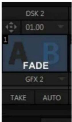
text_image
DSK 2 01.00 1 A B FADE GFX 2 TAKE AUTOFIGURE 160
Pressing the local Take button for any DSK displays or hides the corresponding video layer (shown on top of the BKGD layer).
The local Auto buttons perform similarly, but apply the currently selected transition - that is, the effect represented by the thumbnail icon shown.
Hint: You can halt an Auto operation partway by clicking the button again during the transition. For DSK (and M/E KEY layer) transitions, if the effect has progressed more than halfway when halted, clicking Auto again will complete it. Otherwise it is reversed, returning the layer to its prior display state.
CONFIGURING TRANSITIONS
Each DSK has its own transition effect, applied when you click Auto. Click the transition icon for any DSK control area to reveal a palette of different transitions provided for quick selection, shown in Figure 161 (4-input models do not require this control).
To replace an entry in the palette, click its label, or move the mouse pointer over an icon and click the "+" sign that pops up - see Figure 161.
This opens the Custom Media Browser to let you choose from the hundreds of transition effects included with TriCaster, or even custom Animation Store effects that you prepare using the included Animation Store Creator application.
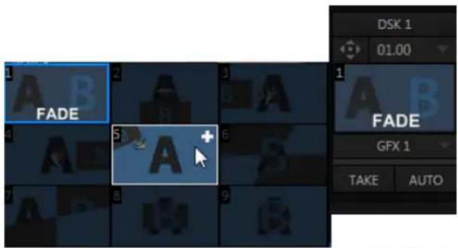
text_image
FADE FADE GFX 1 TAKE AUTO DSK 1 01.00FIGURE 161
The selected effect will replace the current one in the palette.
Hint: The frequently-used Fade transition is always available in transition palette. As it cannot be replaced, no Configure button appears for its icon.
Transition durations are controlled independently on a 'per slot' basis, using a numeric setting above the effect icon. You can drag the mouse pointer left or right over the numeric display to set a custom time, or alternatively, click the numeric yield directly to enable keyboard entry.
Another approach to setting duration allows you to quickly select a duration setting from the drop-down menu provided. The menu provides convenient two, one and 12 second presets.
FIGURE 162
Hint: The direction of Transitions applied as DSK (and M/E Key) effects automatically alternates. If the first click displays the layer using an effect, the next click removes it using the reverse effect. This 'Ping Pong' behavior is optional for BKGD (Background) layer transitions.
ANIMATION STORE TRANSITIONS
TriCaster can also employ special transition effects called Animation Stores. These powerful effects normally include an embedded full color animated overlay, along with individual sounds for transitioning in and out (transition sounds are optional; also note that audio level control for Effects is provided in the Audio (mixer) tab).
These special Animation Store transitions are loaded into the Transition Palette in the same way as their less colorful cousins, using the Browse feature.
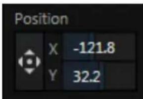
text_image
Position X -121.8 Y 32.2FIGURE 165
A number of Animation Store transitions are supplied, but you can generate your own using the supplied Animation Store Creator application and custom animation content you have access to or create using art software.
Note: The Animation Store Creator application is covered in its own manual, which can be opened from the Help menu in TriCaster Startup.
DSK POSITIONING
FIGURE 163
Each DSK layer has its own Position button and settings.
Click the 'diamond-arrow' button arrow to open the Position panel.
This button is a toggle switch, and is lit when Position settings are active for the associated DSK.
Position panel settings are organized into three groups from top to bottom:
- Position
- Crop Edges
- Follow Tracker
The current settings for each group can be toggled as well, using the switch provided.
The upper-most section of the panel is devoted to Position settings. Across the top you will see three labels: Position, Rotation, and Scale (viewed from left to right).
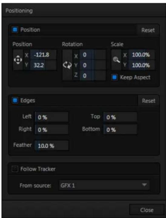
text_image
Positioning Position Reset Position Rotation Scale X -121.8 Y 32.2 X 0 Y 0 Z 0 X 100.0% Y 100.0% Keep Aspect Edges Reset Left 0 % Top 0 % Right 0 % Bottom 0 % Feather 10.0 % Follow Tracker From source: GFX 1 CloseFIGURE 164 (TriCaster 8000 shown)
Click and drag on the Position button to relocate the associated DSK layer vertically or horizontally within the frame. Dragging left or right directly on either of the two nearby numeric controls adjusts the position on a single axis only.
Hint: You can also constrain mouse actions to one axis by holding down the Ctrl key before dragging.
In similar fashion, drag the pointer over the Rotation button with the left mouse button depressed to turn the overlay source on three axes as follows:
- Drag left/right to rotate the source about the Y (vertical) axis.
- Drag up/down to rotate the source about the X (horizontal) axis.
- Drag while holding Alt down to rotate about the Z axis.
- Drag on a single numeric slider below, or hold down Ctrl while dragging to constrain rotation to one axis.
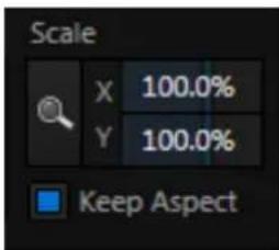
text_image
Scale X 100.0% Y 100.0% Keep AspectFIGURE 167
Dragging the cursor on the Scale button (magnifying glass) affects the size of the overlay.
When Keep Aspect is enabled, dragging in any direction affects scale equally on both axes.
Otherwise, dragging vertically on Scale changes the height, while dragging horizontally affects width.
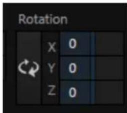
text_image
Rotation X 0 Y 0 Z 0FIGURE 166
DSK layers automatically appear temporarily on the Preview and (M/E Preview) monitors when the Position panel is open (regardless layer display options).
This frees you to tinker with positioning without the result appearing on output prematurely.
Hint: If you click a numeric field (or right-click it), you can type a value into the gadget using the keyboard – press Enter to complete the editing action, or Esc to cancel it).
Again, if you drag just one of the numeric gadgets below the Scale button (with the lock disabled) or hold down Ctrl while doing so, you can adjust just one dimension of the corresponding DSK layer – width or height.
EDGES
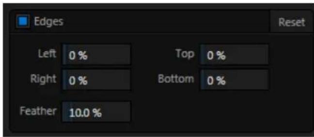
text_image
Edges Left 0 % Right 0 % Feather 10.0 % Top 0 % Bottom 0 %FIGURE 168
Edge controls for DSK layers are similar to those found in TriCaster's Input Configuration panel. However these settings are independent, applying even when the similar option in Input Configuration is not active. Individual settings can be reset by double-clicking with the shift key held down. Restore default settings to all parameters of the Position or Crop control groups by clicking Reset.
FOLLOW TRACKER
Assign the motion data output from the Tracker for any video source to the current DSK layer by selecting it in this menu.
text_image
Follow Tracker From source: CAMERA 2FIGURE 169
Positioner settings enabled above continue in force, but will be applied relative to Tracker output. For example, X and Y Position settings entered in the upper part of the panel result in an offset from the co-ordinates supplied by the Tracker.
DSK TRANSPARENCY
Sources assigned to DSKs are often partially transparent. This might be because they are drawn from a Media Player (DDR or Graphics) ile that includes an embedded alpha channel, because LiveMatte or Crop options are enabled for the
source, because a Network source includes an alpha channel, or all of these factors operating together.
In all of these cases, DSK layers automatically respect transparency when supplied by the source. The BKGD layer and all visible content in lower-numbered DSKs will appear through or around sources with transparency as appropriate.
Important Note: It's best to use files with straight (a.k.a. "non-premultiplied") alpha channels in TriCaster's Media Players. Premultiplied files will generally not yield correct results when overlaid on other imagery.

text_image
TextFIGURE 170
TriCaster's DSK layers offer a lot of creative possibilities. You might use DSK channels to display a permanent station ID 'bug', superimpose a company logo onto a title page, perhaps to add a 'spinning globe' animation playing in the DDR to a lower-third, 'frame' a keyed source composed over a title (Figure 170), or set up many other elaborate effects in this manner.
9.3.2 MAIN CONTROLS
In large measure, TriCaster's main Transition controls behave similarly to their local sidekicks. What makes them especially powerful is the T-bar and Transition Delegate button group located just above.
Transition control settings in this section apply to the Background video layer only. In most respects, these tools are identical to the DSK transition controls discussed earlier (Section 9.3.1), but there is one difference worth mentioning.
The Duration menu for the Background transition offers two additional items compared to the similar menu in the DSK control groups:
- Reverse – configures the current transition to run in reverse direction the next time it is applied.
- Ping Pong – when enabled, this option causes the direction of the transition to be automatically swapped after each time it is applied.
TRANSITION DELEGATES
An executive maxim suggests “Don’t do anything yourself when you can delegate it”. The familiar main T-bar, Auto and Take controls occupying the left half of TriCaster’s Transition control group are surmounted by a set of Transition Delegate buttons.
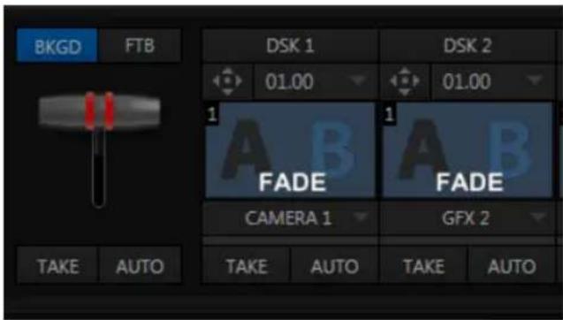
text_image
BKG D FTB DSK 1 01.00 DSK 2 01.00 1 A B FADE 1 A B FADE CAMERA 1 GFX 2 TAKE AUTO TAKE AUTO TAKE AUTOFIGURE 171
Let's see how applying the concept of delegating controls affects their use:
- Assign something suitable to the DSK 1 and DSK 2 layers.
- Click the solo Take buttons in the DSK control groups to hide these DSK layers, if they are visible on output.
- Click the BKGD button in the Transition Delegate group.
- Click the main Auto button (below the T-bar).
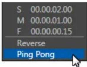
- Now, hold down the Ctrl key and click the delegate button for DSK 1. Or, press both the BKGD and DSK 1 buttons in the TriCaster CS (control surface) Transition Delegate group at the same time instead.
You have just delegated the controls below to two video layers. You can likely guess what comes next.
- Press Auto or Take, and observe the result.
- Now add DSK2 to the delegate selection, and switch again.
The BKGD layer is updated, DSK 1 is removed, and DSK 2 is displayed.
Hint: The Look Ahead Preview monitor respects your Transition Delegate selections, allowing you to configure layers for upcoming switcher operations with great confidence.
A progress bar beneath the each of the DSK control groups tracks transition progress (progress bars remain fully 'on' when a layer is 100% displayed).
FTB
Let's discuss the final button in the Transition Delegate group - FTB.
The acronym (i) stands for Fade to Black. The result of selecting the FTB delegate and displaying the video layer it controls will not likely surprise you very much. FTB offers a convenient method of doing precisely what its name implies, simply fading Program Output out completely (to black).
It might help to think of FTB as 'DSK 5', since it represents a inal video layer added above all others before ultimate Program output. FTB has several unique characteristics, however. For one thing, DSKs can display colorful video sources (with or without transparency); the FTB video layer is always 100% opaque black, and completely obscures everything below it.
Note: Like the DSK layers, hiding or displaying FTB triggers both Autoplay and Audio Follow Video when these settings are active for Media Players. FTB also fades Master Audio to mute when displayed, and back up again when hidden.
Also unlike other video layers, FTB does not support custom transitions (pressing Auto simply fades it on or off) or timing; FTB 's fade duration is drawn from the BKGD layer setting.
Hint: Hold down Shift while pressing the (CS or onscreen) FTB button to directly initiate an FTB operation, rather than merely delegating the T-bar to it. As a memory aid, the FTB button pulses during operation.
TAKE AND AUTO
As we have seen, clicking the main Take button (keyboard shortcut Enter) performs
a straight cut for all video layers that are currently selected in the Transition Delegate group.
Likewise, if you press Auto (or the keyboard Spacebar), the transitions assigned to all delegated video layers are performed.
You can halt an Auto operation partway by clicking the button a second time during the transition. The operation will be
completed the next time you click the button.
text_image
BKGD FTB TAKE AUTOFIGURE 173
Note that there are local (BKGD layer-only) Take and Auto buttons beneath the Background Transition icon.
T-BAR
The T-bar mimics the similar control on a traditional video switcher, and allows you to manually perform a transition between delegated video layers (see the subheading Transition Delegates above).
To use the T-bar, pull it downward by dragging it with the mouse pointer. Drag it all the way to the bottom and release to complete a transition; the T-bar then pops back to the top.
Hint: Naturally, when the T-bar is dragged part way, a partial transition occurs. With certain transitions this can be useful for split screen effects.
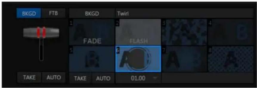
text_image
BkgD FTB BkgD Twirl 1 2 3 A B FADE FLASH 5 6 7 A B TAKE AUTO Take AUTO 01.00FIGURE 174
Since a little more free space is available on the Live Desktop of 4-input TriCaster models, an expanded version of the effect control is provided for the most important transition selection (Background).
This Background Transition bin shows eight different icons for immediate selection. The all-important Fade is permanently afixed to the irst slot in the bin, but the others can be replaced easily: simply move the mouse pointer over an icon, and click the small + button that appears (in its upper right corner) to open TriCaster's Media Browser.
SECTION 9.4 SWITCHER MEM SLOTS
Note that bumping the cursor at the left edge of the screen reveals a fully functional MEM slot bin with features that are just like those provided for M/E banks, Media Players, and Audio Mixer (Section 11.2.4 provides full details).

text_image
TCThe word “monitor” comes from the Latin “monēre” – meaning ‘to warn’. The word has taken on additional meaning since Roman times. As a verb, these include such connotations as ‘keeping an eye’ on something, and ‘checking continually’. As a noun, we understand it to mean devices that permit one to do just that.
As you would expect, TriCaster™ provides extensive and versatile monitoring – just what is needed to control your live productions. Monitoring features can also warn you of conditions that might affect output quality, as well as providing access to adjustments providing quality control and creative alternatives.
Among others you will ind Proc Amp, LiveMatte, Hotspot, Tracking (TriCaster 8000 only) and Crop controls. (To give some of these features the attention due, they are treated individually in Chapter 8, I/O Configuration, and elsewhere. Likewise, network inputs are discussed in Chapter 16, Network Inputs.)
SECTION 10.1 INTERFACE AND MULTIVIEW
Really, TriCaster provides two multiview monitor displays – one right on the Live Desktop (a.k.a., the "Interface"), normally comprising its upper third, and the other a fully independent display presented on a secondary monitor output labeled Multiview on TriCaster's rear connector panel.
text_image
Screenshot of a video editing interface with multiple video thumbnails and a helicopter display showing the same scene.FIGURE 175
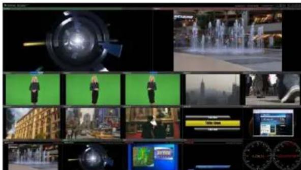
text_image
Screenshot of a video editing interface with multiple video thumbnails and UI elements, showing urban scenes and user interfaces.FIGURE 176
As we saw way back in Section 4.4.2, the overall layout of each of these multiview monitoring areas is governed by two Workspace presets.
10.1.1 TRICASTER 8000 WORKSPACE PRESETS
TriCaster 8000 provides expanded Workspace options. Freely switch from preset A to B to C to D for either Interface or Multiview, customize the display shown, recall it at a moment's notice, or reset it to a default layout using Load Default.
Each viewport in any layout offers diverse input or output source options, and can be further modified to produce just what you need.
As you'd also expect, the settings you select for individual monitors are retained in the current Workspace preset.
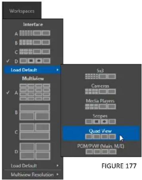
text_image
Workspaces Interface A B C ✓ D Load Default Multiview ✓ A B C D Load Default Multiview Resolution 5x3 Cameras Media Players Scopes Quad View PGM/PVW (Main, M/E) FIGURE 177Note: The external Multiview has an menu that lets you choose a Resolution supported by the display device you connect. Select the native resolution of the external display device for best results. Changing Multiview output options can cause frames to be dropped, so modifications during live production are discouraged.
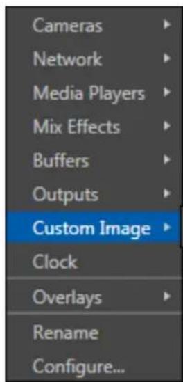
text_image
Cameras Network Media Players Mix Effects Buffers Outputs Custom Image Clock Overlays Rename Configure...FIGURE 178
Let's consider the optional settings at your ingertips for individual monitor ports.
VIEWPORT OPTIONS
Right-clicking a monitor viewport opens a context menu. The irst option group governs the monitor's source. In addition to the external video inputs (including Network sources), you can assign the output of Media Players; M/Es; main Program output
(including DSK channels and effects); Program (Clean) without; the main Switcher's look ahead Preview; another Preview showing M/E source B output (Mix mode only); or Output 1 or 2.
Several special displays are also available.
Selecting Clock selection supplants the video display with Event Clocks showing current time or LTC timecode along with countdown style Start and End clocks (see Section 8.4.3). The Custom Image feature lets you display a network logo.
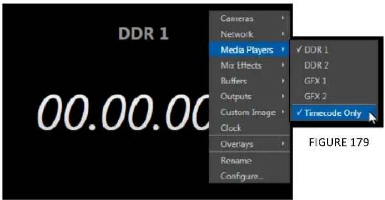
text_image
DDR 1 00.00.00 Cameras Network Media Players Mix Effects Buffers Outputs Custom Image Clock Overlays Rename Configure... ✓ DDR 1 DDR 2 GFX 1 GFX 2 ✓ Timecode Only FIGURE 179A further display you may ind useful is the Timecode Only option that appears at the bottom of the Media Players sub-menu.
text_image
Cameras Network Media Players Mix Effects Buffers Outputs Custom Image Clock Overlays Rename Configure...This alternative displays a counter showing the current position of the playhead in the Media Player. The display respects Reverse Direction and Warning Colors options, too.
Below the basic source selection options in the menu, you'll find another group that provides access to optional Overlays for the monitor port.
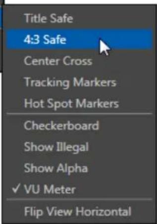
text_image
Title Safe 4:3 Safe Center Cross Tracking Markers Hot Spot Markers Checkerboard Show Illegal Show Alpha ✓ VU Meter Flip View HorizontalFIGURE 180
Available overlay displays include Checkerboard (shows a checkerboard pattern wherever transparency exists in the source); Title Safe (note this is a 4:3 format safe margin); 4:3 Safe (a true 4:3 frame edge boundary), Center Cross to help with alignment, and Show Illegal and Show Alpha.
In addition, you may choose to display VU Meters with the source, Tracking Markers (see 8.2.8) and Hot Spot Markers (see Section 8.2.7).
The inal Overlay option lips the images horizontally, useful for a variety of studio requirements such as talent orientation in greenscreen applications (including Hotspot operations).
Note: Certain Overlay menu options are not suitable for all monitor sources, hence are not listed when innappropriate.
Two inal items complete the monitor viewport options:
- Rename – allows you to supply a custom name to be shown for the monitor viewport (as well as the associated Switcher row button) for sources.
- Configure -opens the Input Configuration panel for the corresponding source.
Hint: Double-click a monitor to open the same Input Configuration panel, without having to hunt for the gear or open the menu.
10.1.2 VIEWPORT TOOLS
Media Player and Network viewports provide additional features when you move your mouse pointer over them.
natural_image
Group of colorful inflatable boats on a reflective surface, no visible text or symbolsFIGURE 181

Media Player monitors (Figure 181) display handy transport controls - Previous, Play, Stop, and Next As well, a timecode ield is shown.
Right-click the time ield to open a menu allowing you to Reverse Direction, toggle Warning Colors, or use Playlist Duration.
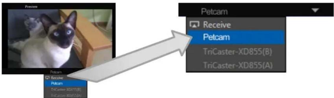
text_image
Preview Petcam Receive Petcam TriCaster-XD855(B) TriCaster-XD855(A)FIGURE 182
Click the triangle button that appears in the titlebar for Network input monitors (Figure 182) to select the active source from a drop-down menu listing all those currently detected.
Just as for other sources, a Conigure (gear) button is shown on rolling over these monitor types; clicking it opens the Configuration panel for the related source (see Chapter 8 I/O Configuration, Section 8.2).
Hint: When LiveMatte, Proc Amp, or Crop settings are active for a source, bright green, blue and yellow indicators are lit under its monitor.
SECTION 10.2 PROGRAM MONITOR
The Program Output monitor could hardly be more important, hence it's prominent default location at upper-right on the Live Desktop.
text_image
NewTek TriCaster TCXD 8000 PROGRAMFIGURE 183
Normally, the Program monitor shows what TriCaster is displaying to your principal viewing audience at any moment. The display includes the BKGD video layer as well as any other video layers (such as one or more a DSKs, or FTB) displayed above it.
Note: By default, Program output is sent to TriCaster's outputs, but this is subject to assignments made in Output Configuration. When you move your mouse pointer over a Program monitor, a Configure button (gear) appears at right in its titlebar. Clicking this button opens the tabbed Output Configuration panel (see Section 8.1).

text_image
NewTek Family Fun Annual Bumper DerbyFIGURE 184
Again, by default, the Live Desktop also prominently displays the Look Ahead Preview monitor (labeled simply Preview).
The Look Ahead Preview is versatile and powerful. Instead of showing just one video source (the Preview row selection), it displays the composite result of a Take operation applied to all currently delegated video layers (see the sub-heading Transition Delegates in Section 9.3.2).
- Selecting the BKGD delegate tells TriCaster you intend the next transition to swap the Program and Preview layers. The Preview monitor will show the Preview row selection as its background.
- When the BKGD delegate is not active, the BKGD layer will not change during a transition. Consequently, in this case the Preview and Program monitors share identical backgrounds.
- Delegated DSK layers are shown above the background on Preview according to their current state. That is, if a delegated DSK layer is currently displayed on Program output it does not appear on Preview – since the next transition would remove it.
In other words, 'what you see is what you will get' – after performing the next Take or Auto operation as currently configured. This lets you set up the next shot, check
its composition (including titles and overlay positioning), and switch to it with sublime conidence.
M/E MONITORS AND PREVIEW
As mentioned earlier, TriCaster 8000's monitor viewports can also be assigned to display the output of TriCaster's M/Es.
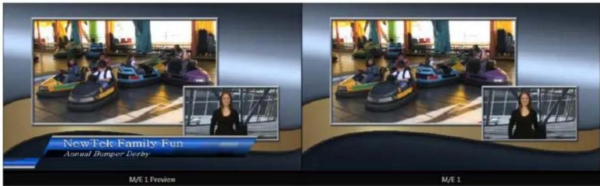
text_image
NewTek Family Fun Annual Bumper Derby M/E 1 Preview M/E 1FIGURE 185
Among other things, this means you can freely assign a monitor as a secondary 'program output monitor' in cases where you are using an M/E in Mix mode to supply an auxiliary program mix for independent display.
Complementing this feature, TriCaster provides Look Ahead Preview monitoring capability for M/Es as well (Figure 185). The TriCaster 8000 Viewport Options menu group Outputs lists a special M/E Preview option for this purpose.
Hint: All viewports assigned as M/E Previews show output from the same M/E. Making a tab selection in the pane M/E updates all M/E viewports when Tabs Follow all Delegates is enabled.
Just like the main Look Ahead Preview, the M/E Preview respects Delegate selections made in the Transition section of the assigned M/E, showing you the display that will result from the currently configured (M/E) Take/Auto operation.
Hint: Two special M/E viewports in Workspace options named "Program/Preview (Main, M/E)" track your M/E delegate selection, for convenient monitoring when using an M/E to produce a secondary switched program. Likewise, two special viewport source options (M/E Preview, and M/E Follow) are provided for your use when customizing TriCaster 8000 monitor layouts.
SECTION 10.4 SCOPES
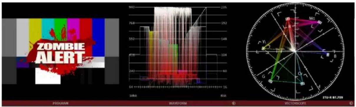
text_image
ZOMBIE ALERT PROGRAM WAVEFORM VECTORSCOPE 940 125 768 192 592 148 418 104 240 60 64 16 80bit ITU-X 61.709FIGURE 186
A further and very useful monitoring option is Scopes, providing Waveform and Vectorscope displays.
Among other things, these help you to judge Proc Amp and LiveMatte settings (see Appendix C, Video Calibration). (To display the Scopes view, select that entry from the Load Default options.)

text_image
Load Default Multiview ✓ A B 5x3 Cameras Media Players ScopesFIGURE 187
By default, the scopes and associated monitor refer to the Look Ahead Preview composition (including any delegated DSK channels, or FTB), shown at left for reference. Right-click either scope display to change the monitored source to the source you wish to view. Adjust the Brightness controls in the scope footers (Shift + double-click the control to restore defaults), and the trace overlay in full or solid colors using the context menu.
Hint: To use Scopes to calibrate a DSK source independently, first select it as the Preview row source.
Double-click the video monitor in this Workspace to access Proc Amp and LiveMatte ^™ controls for the current source (or the Output Configuration panel for Program and Preview selections).
10.4.1 CLOCKS
As discussed back in Section 8.4.2, TriCaster provides handy Event Time clocks. One of these time displays is shown at upper right in the Dashboard.
It's possible to show clocks in any monitor pane, as well – whether in the Interface or Multiview displays. As for any other display, simply choose the Clock option in the Viewport Options menu.
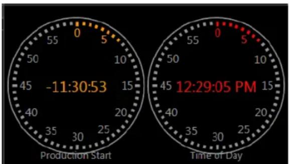
gauge
| Time | Value | |------|-------| | Production Start | 0 | | Production Start | 5 | | Production Start | 10 | | Production Start | 15 | | Production Start | 20 | | Production Start | 25 | | Production Start | 30 | | Production Start | 35 | | Production Start | 40 | | Production Start | 45 | | Production Start | -11:30:53 | | Time of Day | 0 | | Time of Day | 5 | | Time of Day | 10 | | Time of Day | 15 | | Time of Day | 20 | | Time of Day | 25 | | Time of Day | 30 | | Time of Day | 35 | | Time of Day | 40 | | Time of Day | 45 | | Time of Day | 50 | | Time of Day | 55 | | Time of Day | 60 | | Time of Day | 65 | | Time of Day | 70 | | Time of Day | 75 | | Time of Day | 80 | | Time of Day | 85 | | Time of Day | 90 | | Time of Day | 95 | | Time of Day | 100 |FIGURE 188
Hint: The Timecode Configuration panel in the Dashboard allows you to enter time values employed by Event Clocks.
10.4.2 CUSTOM IMAGE
It is often useful to include a network or corporate logo in the Multiview layout. The Custom Image item in the Viewport Options menu supports this requirement.
The Browse item in the menu opens a Media Browser, allowing you to select a suitable image for display. You can supply an image for this purpose in almost any common bitmap ile format.

text_image
TCTriCaster's Media Players permit you to integrate video, stills and title pages into your live presentation with simplicity and style. Preload content and display it sequentially as a playlist, or call up individual items on demand. Media Players can even play, stop and advance automatically in response to your Switcher operations.
On models that support animated buffer effects, buffers can provide similar capability, but are resident in memory, and thus best suited to short duration or looping effects. Conveniently, this makes them perfect for many purposes, freeing up the Media Players for long form or more elaborate requirements. Still image and title buffers (all models) provide similar advantages.
SECTION 11.1 SPECIALIZED MEDIA PLAYERS
TriCaster™ sports multiple Media Players, located in tabbed panes found in the bottom third of the Live Desktop. Here you will ind individual DDR 1, DDR 2, GFX (Graphics) and Sounds modules. (This is also where the powerful Buffers feature is located.)
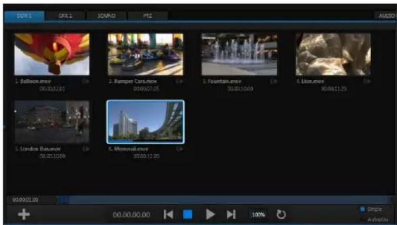
text_image
DOW 1 GFX 1 SOUND PTI AUDIO 1. Balloon.mov 06:00:12:05 2. Bumper Cars.mov 09:00:07:05 3. Fountain.mov 06:00:10:09 4. Lion.mov 06:00:11:29 5. London Busanov 06:00:10:00 6. Memorial.mov 09:00:12:00 90:00:01:00 00:00:00:00 Single AudioFIGURE 189
TriCaster's different Media Players are essentially specialized variants of a single module, modified to suit specific and complementary purposes. The foremost difference between players is in the ile formats each supports (and even that distinction is not rigidly adhered to, as we will see).
- Graphics (GFX) players are principally intended for display and management of title pages (whether those based on TriCaster's integrated titling system, or titles prepared as image iles in third party applications) or other still imagery – photos, graphics, and the like.
- The purpose of the Sound player is self-explanatory, and perhaps it is equally obvious why (alone among Media Players) it is not represented by a Switcher row button. Sound plays back standard .wav or .mp3 format audio iles, but does not support graphics of any sort. Controls are similar to other Media Players, except that neither Autoplay nor Speed controls are provided.
Only the two DDRs have the capability to play video clips (including motion titles such as scrolls). DDRs can also host images, title pages, or even audio iles.
SECTION 11.2 SHARED FEATURES
Media Players of different types are accessed using tabs in the lower section of TriCaster's Live Desktop. (With the exception of Sound, pairs of Media Players of the same type are presented side by side.)
11.2.1 PLAYLISTS
The dominant feature of all of TriCaster's Media Players is a storyboard-style playlist, used to organize content for use during live productions.
text_image
1. Balloon.mov 00.00.12.01 2. Bumper Cars.mov 00.00.07.05 3. Fountain.mov 00.00.10.00FIGURE 190
This arrangement offers easily visible thumbnail icons for each entry. A scrollbar at right accommodates long playlists when necessary.
natural_image
Close-up of a hot air balloon in mid-air against a blue sky (no text or symbols visible)FIGURE 191
Icons in the playlist can quickly and easily be reordered using the familiar drag and drop worklow. The playlist can even be altered during playback (of course, if the currently playing item is removed, playback stops immediately).
The ilename (with extension) of each item in the current playlist is displayed above the thumbnails, and its duration is shown below.
Hint: The duration is the play time after trimming, and thus may be less than the file length on disk. In such cases, the In and Out markers on the Scrub Bar (spanning the width of the playlist immediately below it) show the effect of trimming operations, while the full width of the Scrub Bar depicts the total length of the file on disk.
Clicking an item selects it. The play position is automatically set to the In Point on selection. Standard Shift + click and Ctrl + click multi-selection operations are supported, and all selected items are denoted by a white border around their icon.
When a Media Player is stopped, its output to video monitors tracks selection and trimming operations. The current item is the Media Player's output, and in consequence appears on monitors dedicated to the player, if any.
Of course, only one item can be displayed on output at a time; the frame surrounding the thumbnail icon for the currently displayed item is illuminated. Double-clicking a thumbnail (or clicking the Play button) begins playback from the In Point of the current ile.
Hint: Double-clicking elsewhere in the playlist pane opens the Media Browser (hold down shift when clicking to open a system file explorer instead of the custom Media Browser).
Note that even still images and static title pages added to the playlist are given a play duration. The default duration for these items is fifteen seconds. This duration can be adjusted on an item by item basis (or as noted earlier, en masse for multi-selected stills or title pages).
During playback, the border around successive playlist items illuminates as each is played in turn. When necessary, the playlist pane scrolls to display the icon for the currently playing item. A progress bar is displayed beneath the currently playing thumbnail, and the Scrub-Bar knob also tracks playback progress.
Hint: Selection status is independent of which clip is playing. Selected items have a white border in the Playlist pane.
FILE OPERATIONS
- Click the large + (Add Media) button beneath the playlist pane to open a custom Media Browser (see Section 11.2.2). Alternatively, double-click in an empty part of the Playlist pane.
Note: Add Media also supports compatible third-party asset management systems. Hold down the keyboard Ctrl key when clicking the + sign to access these tools.
- Newly-added iles become selected items in the Playlist pane.
- Drag (appropriate type) file(s) from one module's playlist to another module.
- Right-click in the playlist pane to show a menu with context relevant items from the following list (operations affect selected playlist items):
○ Cut
○ Copy
○ Paste
○ Remove
○ Set Display Name
○ Clone
- Set Duration (Still image and title icons)
○ Edit Title
○ Send to > Buffer n (Still image and title icons – see Section 11.4)
○ Set Audio Level (clips with sound and audio icons)
○ Add to Publish Queue – see Section 19.3.
- Standard Cut, Copy, Paste and Delete keystrokes are supported for playlist entries.
- Un-playable (missing, corrupt, or unsupported) ile icons are dimmed.
Hint: Multi-selection is supported for most operations, including Set Duration (applies to Still and Title only).
Interestingly, the playlist Set Display Name feature edits a local alias, or 'playlist nickname'. It does not actually change the name of the ile on your hard drive. Roll the mouse over the icon display name to see the true ilename.
ICON AUDIO SLIDER
The playlist of the two DDRs and Sounds offer an additional audio feature:
text_image
2. Kiki 3 Righ.mov 00.00.36.11FIGURE 192
The icons of audio iles (or clips with embedded audio) will display a small configure (gear) icon at lower right. Click this icon to pop up a small level slider (Figure 192).
SCRUB BAR
Just beneath the playlist pane is a full-width Scrub-Bar (Figure 193). The width of the scrub-bar represents the full run time of the current clip or other media ile. Drag the knob left or right to change time position in the current playlist item.

text_image
00.00.01.00 00.00.00.00 100% Single AutoplayFIGURE 193
Initially, In and Out Point handles at either end of the Scrub-Bar are at their extreme positions, marking the actual limits of the ile on disk. Dragging the handles adjusts timing for the selected item (multi-selections are ignored for trimming).
text_image
00.00.00.00FIGURE 194
During playback, the Scrub-Bar knob traverses the span between the In and Out Points. The duration (taking into account trimming operations) is displayed in a timecode ield just to the left.
Hint: For longer durations, holding SHIFT while dragging scrub bar handles or the knob increases precision.
ALPHA CHANNEL SUPPORT
For iles with transparency such as 32bit image iles, use non-premultiplied (or 'straight') alpha channels in TriCaster's Media Players. Premultiplied iles will not give the correct results when overlaid on other imagery.
Hint: Monitors can optionally show a checkerboard pattern behind transparent content.
11.2.2 MEDIA BROWSER
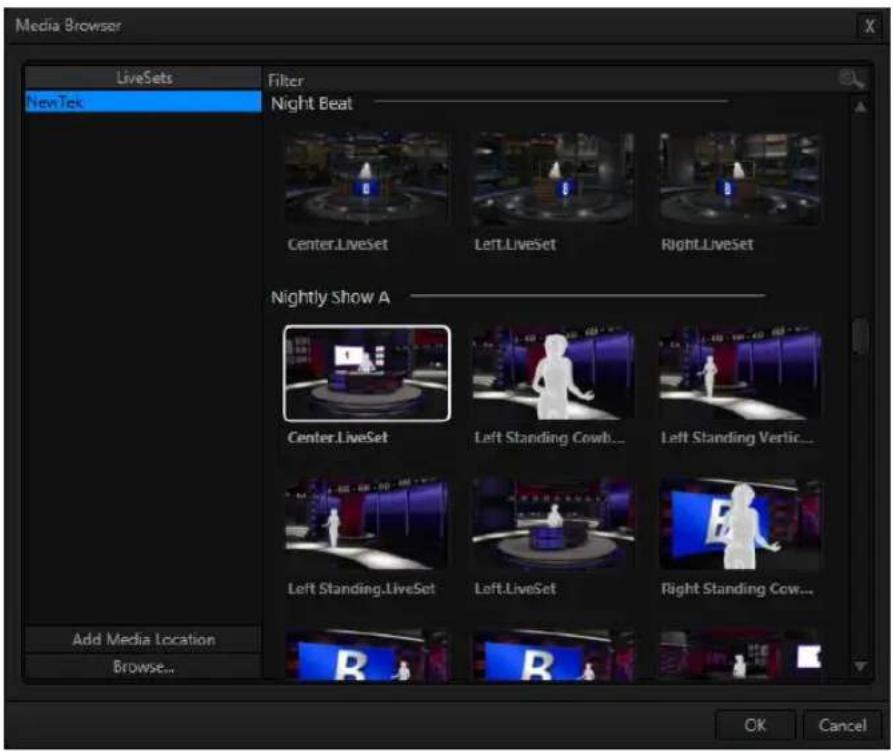
text_image
Media Browser LiveSets Filter NewTek Night Beat Center.LiveSet Left.LiveSet Right.LiveSet Nightly Show A Center.LiveSet Left Standing Cowb... Left Standing Vertic... Left Standing.LiveSet Left.LiveSet Right Standing Cow... Add Media Location Browse... OK CancelFIGURE 195
The custom Media Browser provides easy navigation to and selection of suitable content on your TriCaster or other NewTek live production system on the local network.
The Media Browser appears anywhere in the Live Desktop that you might wish to select content, transitions or effects for use in your project (such as the Media Players, LiveSet and Transitions sections). Its layout is principally comprised of two panes at left and right that we'll refer to as the Location List and File Pane.
LOCATION LIST
The Location List is a column of favorite “locations”, grouped under headings such as LiveSets, Clips, Titles, Stills, and so on. The Media Browser is context sensitive, so the headings shown are generally appropriate for the purpose for which they were opened.
A list of sub-headings will appear under each main heading in the Location List. These may correspond to named sessions, or groups of content. When you select a sub-heading, the right hand pane – the File Pane – is populated.
ADD MEDIA LOCATION & BROWSE
Clicking Browse opens a standard system ile explorer, rather than the custom Media Browser.
Hint: To jump to the standard system file explorer (rather than the custom Media Browser) from a Media Player, hold keyboard Shift while clicking the Add button.
FILE PANE
Icons appearing in the File Pane represent content located inside the sub-heading selected at left in the Locations List. These are grouped under horizontal dividers named for sub-folders, which allows related content to be organized conveniently.
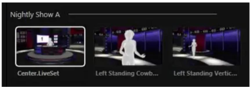
text_image
Nightly Show A Center.LiveSet Left Standing Cowb... Left Standing Vertic...FIGURE 196
FILE FILTERS
The File Pane view is iltered to show only relevant content. For example, when selecting LiveSets, the browser only shows LiveSet iles (.vsfx).

text_image
FilterFIGURE 197
An additional ilter appears above the File Pane. This ilter quickly locates iles matching criteria you enter, doing so even as you type. For example, if you enter "wav" into the ilter ield, the File Pane displays all content at the current location with that string as part of its ilename. This would include any ile with the extension ".wav" (WAVE audio file format), but also "wavingman.jpg" or "lightwave_render.avi".
FILE CONTEXT MENU
Right-click on a ile icon in the right-hand pane to show a menu providing Rename and Delete options. Be aware that Delete really does remove content from your hard drive. This menu is not shown if the item clicked is write-protected.
11.2.3 PLAYER CONTROLS
Transport controls and playback settings are located directly below the Playlist and Scrub-Bar.

text_image
00.00.00.00 100% Single AutoplayFIGURE 198
TIME DISPLAY
During playback, a timecode ield beside the transport controls displays the Current Time for the player. This may be the current time position in the active playlist item (when Single mode is enabled), or relate to the duration of the entire playlist.
FIGURE 199
Left-click the ield to type in a timecode, then press Enter to jump to that point in the ile (or playlist).
If you right-click the timecode ield instead, a menu allows you to choose to between showing current time and remaining time (Reverse Direction), enabling or disabling Warning Colors, or toggling Playlist Duration on and off (versus single playlist item duration).
Hint: With Warning Colors enabled, the time display provides visual indication that the playback is nearing its end. Ten seconds before the end of play for the current item, the digits in the time display turn amber. With only five seconds left, numbers are red.
SINGLE
Media Player playback normally conforms to typical playlist practice – each item in the playlist playing back in orderly succession.
FIGURE 200
When Single mode is enabled, playback stops when the Out Point of the current playlist item is reached (unless Loop is also enabled, in which case playback of the current item repeats until manually interrupted).
TRANSPORT CONTROLS
A simple set of controls beneath the playlist pane provides all playback-related functions:
- Previous button – go to previous playlist entry
- Stop (clicking Stop when already stopped goes to the irst frame)
- Play
- Next button – go to next playlist entry
FIGURE 201
- (Not shown) – Double-click an entry in the playlist pane to begin playback at the start of that playlist entry
SPEED
The Speed control is only found in the DDR. The DDR supports variable speed playback between 25% and 400% of the normal rate (100%). Speed can even be adjusted during playback.
Note: Certain highly compressed video file formats cannot successfully be played back at rates beyond 200%, even though Speed value is set to a higher value.
As is common for numeric input controls in TriCaster, drag left or right to adjust the Speed value, or click the slider to access a direct entry ield allowing you to type a value using the keyboard.
Hint: Press Shift while double-clicking Speed to quickly reset to the 100% default.
Loop
Enabling Loop repeats playback continuously (respecting the Single switch state).
AUTOPLAY
When enabled, the Autoplay switch has several important effects. First, it initiates playback automatically when the associated Media Player is placed on Program Out by a (Switcher) Take or Transition operation either directly (as a Switcher row selection) or indirectly – such as by being displayed via an M/E channel or DSK operation.
Second, if player output is displayed on Program the reverse Switcher transition occurs automatically as the end of play approaches, whether the Out Point of the current item for Single play or the end of the playlist. (This behavior is optional for M/Es – see Options in Section 14.2 and Section 7.1.)
Note: Unlike Switcher transitions, the DSK 'out' effect does not occur automatically as the end of play approaches.
In either case, when the Media Player is in Single mode, the current play position advances to the next item after playback is automatically stopped.
11.2.4 MEM SLOTS
Another very useful feature of all TriCaster Media Players is the MEM Slot Bin, which provides quick and convenient access to stored playlists. As mentioned back in Section 4.9.1, MEM slots also store the state of various Media Player controls.
To display the bin, roll the mouse pointer to the (nearest) side of the screen in a tabbed Media Player or the Audio tab (for Sound and Audio, MEM slots are presented on the left only).
When you change playlists by selecting another MEM slot, it's almost as though you are accessing another Media Player. Use MEM slots for quick access to different categories of content for use during a live presentation, playlists prepared for different clients, or for completely different programs you produce.
MEM slots can be named, and also display a small representative image (taken from the irst entry in the playlist). As you move the mouse over a MEM slot icon it expands, providing an enlarged view of that playlist item's irst frame. To populate a new MEM slot, simply click a blank icon.

text_image
Keying 3 d 1 Left.mpg 00.00.38.02FIGURE 202
To name a MEM slot, right-click it to open a context menu, and select Rename. Other menu options include Delete, Export and Import (the file will be saved with the extension '.pst').
PREVIEWING MEM SLOTS
At times you may wish to preview the contents of a different Media Player MEM slot without disrupting playback of the current playlist.
When a clip is playing, a small white 'play indicator' is shown over the icon for the currently selected entry in the lyout MEM slot bin. If you select a different MEM slot while the current clip continues to play, the playlist bin view updates, but the original item continues to play. The transport controls (Play, Stop, etc.) at the bottom of the tab remain *dedicated to the active playlist – that is, the one actually playing, rather than the one currently being previewed in the tab.
To change to the previewed MEM slot immediately – ending playback and display of the current item – you can do so by any of the following means:
- Double-click an icon in the previewed playlist.
- Or press *Stop twice, and then Play (playback of the active item ends with the irst Stop command; the second sets the playhead to the start of the current item in the new playlist).
* Normally, pressing Stop a second time when a clip is playing resets the playhead to the start frame in the same clip. The exception above occurs only when you are previewing the content of a different MEM slot during playback.
11.2.5 NETWORK SHARING
Default media ile folders (Clips, Stills, etc.) are maintained for each session. This approach makes it easy to locate items using the Custom File Browser, and is also convenient for backup and other ile management purposes.
The default media locations for the active session can be made accessible across your local network. Share Media Folders and Buffers in the File menu is on by default, and allows network clients to update media in the active session, even while live. The following session media locations are dynamically shared:
- Audio
- Clips
- Stills
- Titles
- Buffers
Transferring very large iles across a network can time consuming, and impacts both disk access and network resources.
When these resources are already heavily taxed, dropped frames on streaming or video outputs, or sluggish response to controls may result.
We strongly urge you to gather media assets before starting your live productions whenever possible.
Note: Several ‘non-session dependent’ locations in the main TriCaster application folder are also shared. This allows applications such as NewTek’s Virtual Set Editor, etc., running on external systems to export directly to TriCaster. These network shares are unaffected by the Share Media Folders and Buffers setting.
When suitable content is added to these shared folders, TriCaster's Media Browser provides immediate access to it. Simply select the session name (under Clips, Stills, etc.) in the Location List at left to reveal the updated iles in the File Pane at right.
This is wonderfully convenient, but should be approached with a measure of common sense. Network bandwidth has fixed limits. Be judicious when transferring files while 'live'. TriCaster may be using the network for many purposes – including streaming, or video feeds from a 3Play ^™ , iVGA ^™ , LiveText ^™ or third party software, as well as any unrelated traffic on the network.
SECTION 11.3 EDITING TITLE PAGES
On mouse-over, title page icons display a configuration (gear) icon in their lower right corner. Clicking this button (or selecting Edit Title in the icon context menu) opens the pop-up Title Page Editor.
Opening the pop-up Title Page Editor during playback is permitted, meaning Title Page content can be edited during both play and display (changes are detected and shown immediately).
Hint: The panel can be re-sized by dragging its lower-right corner, and re-positioned by dragging its titlebar.
When you move the mouse over text in the Title Page Editor's preview pane, a white bounding-box appears (Figure 203). If you click once inside the box it turns yellow, indicating the text object is selected, and a text edit ield opens.
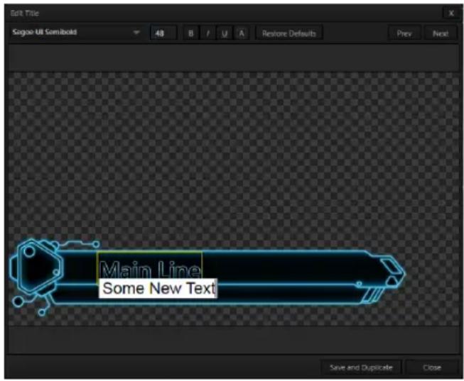
text_image
Edit Title Sagoo UB Semibuild 48 B / U A Restore Defaults Prev Next Main Line Some New Text Save and Duplicate CloseFIGURE 203
Press Enter or click outside the box to complete editing operations, or press Tab to advance to next entry ield (press Shift + Tab instead to jump to the prior text ield).
Note that the cursor keys – that is, the left/right and up/down arrows – allow you to navigate between text ields on the current title page. (If the text edit box is open, left/right arrows change the edit point as usual, but up/down closes the edit box, and subsequent cursor key actions move to the next object.)
Hint: A red line under a character or word (Figure 203) indicates the spell-checker questioning its spelling. Right-click the word to open a menu suggesting alternatives. Click one of the entries shown if you wish to update the original.

text_image
Edit Title Segoe UI Semibold 48 B / U A Restore Defaults Prev NextFIGURE 204
The header of the Title Page Editor holds an assortment of text attribute controls. These include a Font selector drop-down menu, numeric Size control, and Bold, Italic, Underline and 'ALLCAPS' switches.
The Prev and Next buttons let you store your changes and move to another title page in the playlist without the tedium of closing the Title Edit pane.
SAVE AND DUPLICATE
You can click Close when inished with the current edit, but often you'll find the Save and Duplicate feature handy. Click
FIGURE 205
it to store your edits to the current title page, create a clone of item in the playlist, and load the new page for editing.
This is a great way to quickly produce a number of matching pages.
Hint: Press Ctrl + s on the keyboard to perform this ‘save and duplicate’ operation without using the mouse. Similarly, PageUp and PageDown keys perform Previous and Next operations.
Images embedded in Title Pages may be locked, or they may be editable stand-ins. When you roll the mouse over an embedded image and a yellow border is displayed around the image, the image is a stand-in. Click a stand-in to open the File Browser, and select a replacement image ile.
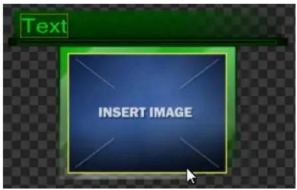
text_image
Text INSERT IMAGEFIGURE 206
You can check whether images are locked or unlocked (stand-ins), and toggle the lock status. Hold down the Shift key while rolling around inside the Title Page.
With Shift depressed, a red border appears around any locked image under the cursor. Stand-in (unlocked) images show a green border. To toggle the status for an image, left-click it with Shift depressed.
If you right-click a stand-in image, a menu is presented that provides several optional methods of itting the source image to its frame. Choosing Stretch causes the image to completely ill the frame. Fill Area retains the interested image's original aspect, cropping if necessary to it inside the frame. Show All Image also retains the original image aspect, but its the entire source image inside the frame (which may result in 'pillar-boxing' or 'letter-boxing').
SECTION 11.4 BUFFERS
TriCaster's powerful Buffer system provides convenient alternative graphics and animation sources for M / Es (including their associated Key channels), the Switcher's
primary Program and Preview rows, and its four DSK channels. The tabbed Buffers module (Figure 207) shows icons and controls for ifteen Buffers.
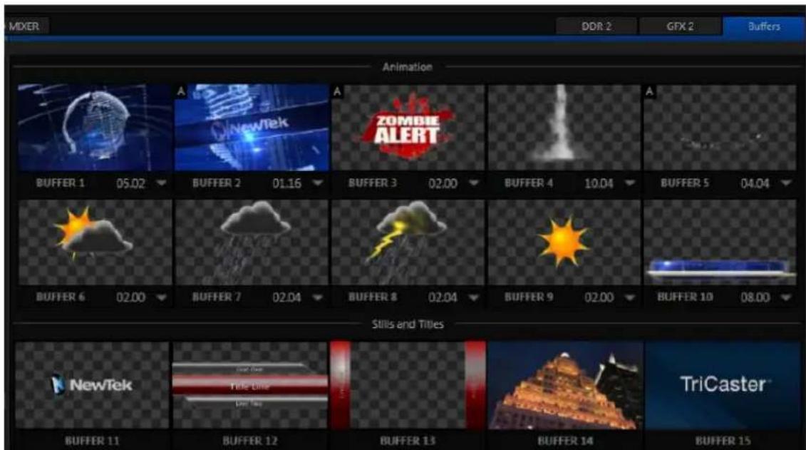
text_image
MIXER DDR 2 GTX 2 Buffers Animation A NewTek A ZOMBIE ALERT A BUFFER 1 05.02 BUFFER 2 01.16 BUFFER 3 02.00 BUFFER 4 10.04 BUFFER 5 04.04 BUFFER 6 02.00 BUFFER 7 02.04 BUFFER 8 02.04 BUFFER 9 02.00 BUFFER 10 08.00 Stills and Titles NewTek New Tek Title Time Title Time TriCaster™ BUFFER 11 BUFFER 12 BUFFER 13 BUFFER 14 BUFFER 15FIGURE 207
Buffers are sometimes even more useful than similar imagery supplied from Media Players. Buffers are retained in Switcher Memory for immediate recall and display. Using a buffer for a specific DSK or M/E channel (rather than a Media Player) eliminates the risk of accidentally displaying the wrong graphic, as might otherwise happen if the current Media Player item selection was not the one intended.
11.4.1 BUFFER TYPES
Buffers support the following media types:
• Animation effects (TriCaster 460, 860 and 8000 only)
These are short duration full-motion video effects created in your favorite graphics or video applications and compiled using the add-on Animation Store Creator application.
○ Looping effects – These animations play repeating endlessly, making them ideal for station ID 'bugs' and the like.
○ Auto-run effects – These effects auto-run on display following a Take or Auto. Playback runs once and then holds the last frame.
• Graphics (all TriCaster models)
○ Images - 24 bit or 32 bit (with embedded alpha channel) images.
Title pages – editable TriCaster title pages, identical to those served up by the various Media Players.
Buffers tab item selection and display is controlled by a Buffer (BFR) button on main Switcher source rows, M/E rows, and options in DSK and M/E Key source menus.
Hint: We considered a Buffer example back in Section 4.12.
For TriCaster 8000, the top ten buffer slots (or the top ive, for TriCaster 460 and 860) support both compiled animation effects and graphics - still image iles or TriCaster title pages. (Again, TriCaster 410 does not support animated buffers.)
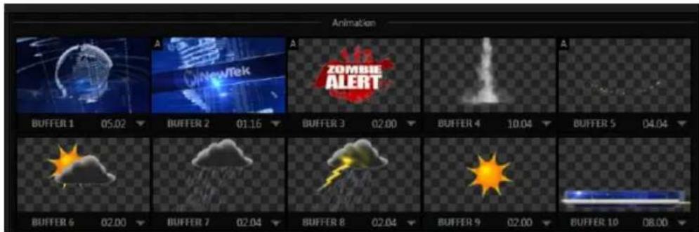
text_image
Animation BUFFER 1 05.02 BUFFER 2 01.16 BUFFER 3 02.00 BUFFER 4 10.04 BUFFER 5 04.04 BUFFER 6 02.00 BUFFER 7 02.04 BUFFER 8 02.04 BUFFER 9 02.00 BUFFER 10 08.00FIGURE 208
The remaining buffer slots are restricted to graphics content, including popular image formats along with TriCaster title pages (i.e., .cgxml iles).

text_image
Skills and Titles NewTek Title One New Tek Buffer 11 Buffer 12 Buffer 13 Buffer 14 TriCaster™ Buffer 15FIGURE 209
11.4.2 SELECTING CONTENT
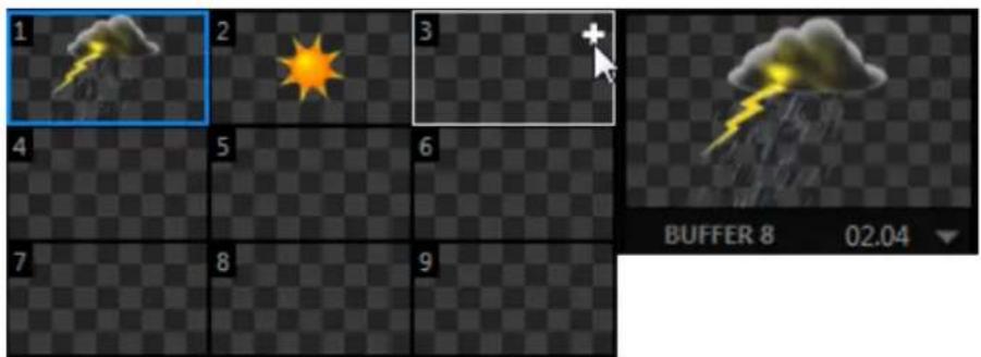
text_image
1 2 3 4 5 6 7 8 9 BUFFER 8 02.04FIGURE 211
Clicking an icon reveals a palette of nine buffer presets (Figure 211). When you move the mouse over one of these icons a [+]
(Add Media) button appears. Click this + sign to display the Media Browser, and then pick a suitable ile to populate that buffer preset.
Alternatively, assign content to a buffer slot by following the steps below:
- Right-click a still image or title page icon in a Media Player, and choose Send to from the playlist context menu.
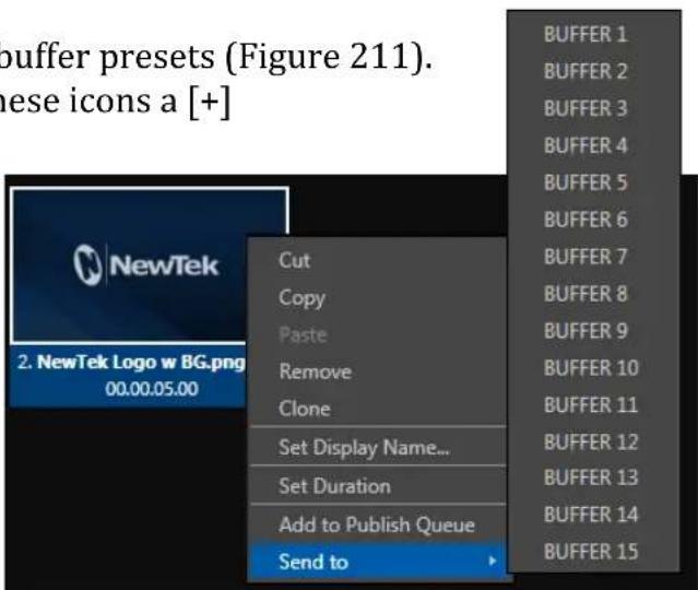
text_image
buffer presets (Figure 211). these icons a [+] 2. NewTek Logo w BG.png 00.00.05.00 Cut Copy Paste Remove Clone Set Display Name... Set Duration Add to Publish Queue Send to BUFFER 1 BUFFER 2 BUFFER 3 BUFFER 4 BUFFER 5 BUFFER 6 BUFFER 7 BUFFER 8 BUFFER 9 BUFFER 10 BUFFER 11 BUFFER 12 BUFFER 13 BUFFER 14 BUFFER 15FIGURE 210
- Select a specific buffer you wish to assign the ile to using the hierarchical menu.
Note that, in DDRs, this menu item only appears for still image formats and TriCaster title pages. Animation effects must be complied using the Animation Store Creator ^™ add-on application before they can be loaded into buffers.
(Naturally, if an image or title has previously been previously assigned to the active preset for the designated buffer, the new ile will replace the current one.)
Note: Generally, Buffers are linked to the original source file on disk. Having added a file to a buffer using the "Send to (Buffer x)" menu, it no longer matters whether the item continues to be available in a Media Player playlist. The buffer link will only fail if the original file is moved, or deleted from the hard drive - with one exception: editable title page buffers are fully independent of their original source files.
11.4.3 BUFFERS MENU
Right-click a thumbnail icon in the Buffers pane to open a menu offering two items:
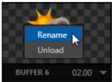
text_image
Rename Unload BUFFER 6 02.00FIGURE 212
- Rename allows you to assign a custom name to the buffer. The name will also be visible in menus (such as DSK source menus).
- The Unload option clears the effect, freeing Switcher Memory reserved for effects.
Hint: A small [x] button appears over the upper-right corner on rolling the cursor into a Buffers tab icon. This button simply provides another convenient method of unloading an effect from Switcher Memory.
11.4.4 ANIMATION FEATURES
The thumbnail icon for a buffer with an animation effect assigned to it provides several additional features.
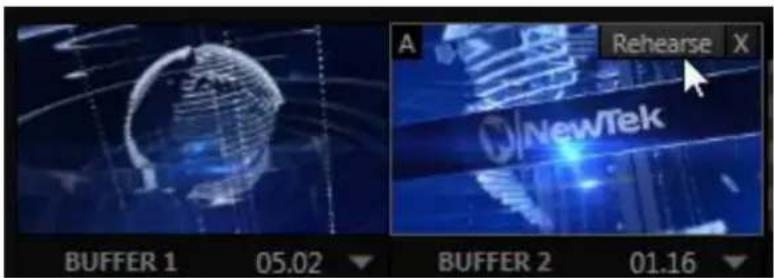
text_image
A Rehearse X NewTek BUFFER 1 05.02 BUFFER 2 01.16FIGURE 213
As mentioned earlier, animation effects can be of either looping or auto-run type (the type determination is made in the Animation Store Creator utility when the effect is generated).
Loading either class of animation effect into a buffer results in a time control being displayed at right in the buffer label below the icon (Figure 213).
Hint: Select a Slow, Medium or Fast preset value from the drop-down menu, drag the mouse left or right over the time to change the current value, or click to enter a number directly using the keyboard.
For auto-run animation effects, a further control is added to the thumbnail icon when you move the cursor over it. The Rehearse button appears just next to the [x] at upper-right (Figure 213). Clicking it plays the animation from its irst frame through to the last, and holds that image.
Hint: In addition to providing a way to preview the effect (by displaying it on the Preview monitor, for example), Rehearse offers a handy way to re-run animated alerts and similar overlays at will. Remember, too, that the Macros feature provides a great deal of useful functionality in connection with Buffers and their display.
Still image Buffers have another very valuable ability, discussed next.
11.4.5 SHARING BUFFERS
If you wish, you can share the Frame Buffer folder, which contains any still images used in Buffers, across a network. Share Media Folders and Buffers is easily enabled or disabled even during a live production using the File menu at the left-hand end of the Dashboard.
The iles which serve individual still image buffers are located in clearly named sub-folders of the Frame Buffer folder for each session. These folders are arranged as follows:
Sessiondrive:\Sessions\sessionname\Frame Buffer\Buffer (#)
e.g., D:\Sessions\MySession\Frame Buffer\Buffer 3
The top level Frame Buffer folder for the current session is accessible on the network when sharing is enabled. This allows still image buffers to be updated across a network using suitable graphics application (such as Photoshop®).
Note: This special share name assignment is dynamic. Network sharing is activated and the current Buffer path is automatically updated whenever you enter a session with the option enabled. This ensures that applications on networked systems can remotely access and update buffer graphics for the current TriCaster session.
11.4.6 WATCH FOLDERS
The Frame Buffer folder is a “watch folder”. When you save an image into the correct location for a given buffer, the corresponding buffer immediately updates, even if it is currently displayed. This lets you refresh overlays virtually instantly from any computer on the same network.
- Still image Buffers are normally stored using the popular 32 bit PNG (Portable Network Graphics) format, but other formats are also supported.
- Specific ilenames are not important in the buffer workflow. Actually, multiple media iles with different names can reside in buffer folders. TriCaster always shows the 'newest' file – that is, the one with the most recent modification date.
11.4.7 USING BUFFERS
Creative uses for buffers abound. You'll notice that the sample media content supplied with your TriCaster includes a number of different styles of animated buffers – some full screen, suitable for looping backgrounds or similar applications; others that are suited to overlay, bug, or alert tasks.
Buffers of all sorts can be displayed in the following locations:
- Main Switcher
Program/Preview) rows - right-click the BFR button to select which buffer to assign to that button.
- DSK channels – choose a specific buffer using the DSK's drop-down source menu.
• M/E banks
- Mix mode – select a buffer for the A/B row BFR button just as you would for the main Switcher.
- Effect Mode – for multi-layer effects, the BFR button in each row can be assigned independently.
- Key channels – choose a buffer for any Key channel using its dropdown source menu.
Buffers allow abundant use of animation throughout your productions – as virtual set elements, layered graphics overlays, etc., all without tying up precious Media Players.
(Consider that, for TriCaster 8000, in addition to the buffer cross-points in the main Switcher, each M/E supports up to eight animated buffers. Since all of TriCaster 8000's M/Es are re-entrant, layering possibilities are nearly endless.)
11.4.8 KEYING, PROC AMPS AND MORE
It's worth noting that you can apply LiveMatte, Proc Amp and Edge (cropping and feathering) settings to individual buffers by assigning a desktop or Multiview monitor to the Buffer (or choosing a Workspace option that includes Buffers) and opening its Input Configuration panel. Of course you can also apply Position settings, including Rotation and Scale, in DSK, M/E and Key channels.
11.4.9 EDITING TITLES
When a title page (.cgxml ile) is loaded into a buffer, TriCaster's live Edit Title panel (see Section 11.3) can be opened by clicking the gear icon that appears at lower-right when you move the mouse over the icon (Figure 214).
Changes made in this panel take effect immediately. If the buffer is displayed, the new title will appear as soon as your modifications are complete.
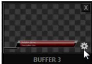
text_image
Multi Line Multi Line BUFFER 3FIGURE 214

text_image
TCOnce primarily used in security applications, robotic or 'PTZ' (pan, tilt, zoom) cameras are appearing on the production scene in ever increasing numbers. Not only do they offer dramatic potential savings, robotic camera installations also offer both creative possibilities and, in certain environments, safety benefits.
TriCaster's PTZ implementation makes it easy to operate supported PTZ cameras from the Live Desktop or control surface.
For all TriCaster professional models, the Input Configuration panels for cameras 1-8 allows any or all of these cameras to be configured as a PTZ cam, controlled directly from TriCaster (see Section 8.2.9).
In addition to pan, tilt and zoom control, TriCaster can also govern White Balance settings, Focus, Iris (or 'brightness'), and Animation Speed ('travel speed') settings for supported cameras. TriCaster also provides a convenient and very visual PTZ preset system allowing you to 'lock in' your shots and access them quickly.
SECTION 12.1 THE PTZ TAB
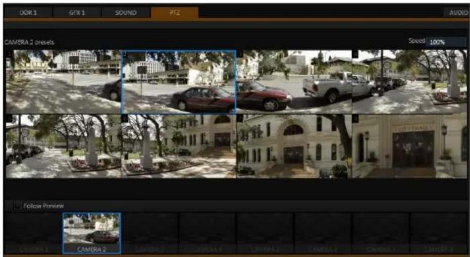
text_image
DOR 1 GPX 1 SOUND PTZ AUDIO CAMERA 2 presets Speed 100% Follow Preview CAMERA 1 CAMERA 2 CAMERA 3 CAMERA 4 LAMP 5 CAMERA 6 CAMERA 7 CAMERA 8FIGURE 215
All of the controls and features just mentioned are located in the PTZ tab, located at left in the lower third of the Live Desktop (Figure 215).
12.1.1 THE CAMERA BIN

The Camera Bin (Figure 216), located across the bottom of the PTZ tab contains icons for each camera. A camera currently being controlled is denoted by a blue outline. The icons update to show the thumbnail for the preset icon selected above.
Hint: Cameras whose PTZ switches are disabled in their respective Input Configuration panels (Section 8.2.9) show dimmed icons in the Camera Bin, but may still be selected.
Enabling the Follow Preview switch at left in the Camera Bin header will automatically select camera icons for you as these are chosen on the main Switcher's Preview row.
12.1.2 PTZ PRESETS
The large Preset Bin (above the Camera Bin) shows eight thumbnail icons for the currently selected PTZ camera. Click a preset to select it, and the camera automatically begins moving to the new position.
Hint: The number of the current Preset icon is shown in an overlay at upper left. When the actual camera position at the moment does not correspond to a preset, an "M" is shown over the most recent selection, rather than a number.
SPEED
text_image
Speed 100%FIGURE 217
The Speed control in the PTZ tab titlebar governs the rate of change when a new preset is selected.
Camera travel speed capabilities vary widely, so think of this setting as a percentage of the maximum speed your unit can manage.
12.1.3 CONFIGURING PRESETS
When you roll the mouse over a preset, a configuration overlay ('gear') appears in its upper right corner. Click this to display the PTZ Preset Editor (Figure 218).
Initially, preset icons display the default PTZ Canvas representation. When a live source is connected (and enabled in the PTZ tab of Input Configuration), making adjustments causes an image to be grabbed from the live video input. (Click the Update Snapshot button to update without closing the Preset Editor).
NAVIGATING IN THE PRESET EDITOR
While you will likely use the control surface joystick for most purposes during production (see Section 12.1.4, the canvas in the PTZ Preset Editor panel also provides ‘trackball-like’ control over pan and tilt for connected cameras using the mouse.
Simply drag horizontally or vertically on the canvas to pan or tilt. The mouse-wheel provides zoom control.
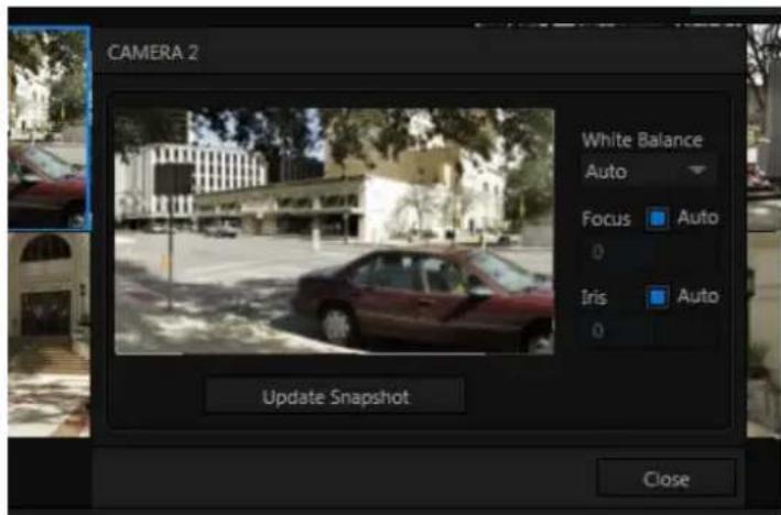
text_image
CAMERA 2 White Balance Auto Focus Auto 0 Iris Auto 0 Update Snapshot CloseFIGURE 218
Hint: If no camera is connected, a virtual display updates to simulate rotation and zoom as you navigate, but you may well prefer to connect a camera and assign it to Preview, checking the output the camera on a larger monitor while making adjustments.
CAMERA SETTINGS
Some further camera settings are grouped together just to the right of the Preset Editor's Canvas. The White Balance menu offers three options – Auto, Indoor and Outdoor. (This is a global setting, and affects all presets for the selected camera.)
By contrast, the Focus setting, and the state of its Auto switch are stored individually in each preset. This is also true for the Iris setting, and its Auto switch.
12.1.4 PTZ AND THE CONTROL SURFACE
Pan, tilt, zoom control, and several settings for connected robotic cameras are also directly supported on several NewTek control surfaces. See Chapter 22, Control Surfaces for details.

text_image
TCAlthough its controls are deceptively simple, TriCaster's LiveMatte™ employs powerful chromakeying technology capable of extremely high quality results. Used alone or in conjunction with TriCaster's DSKs, M/E Overlays and LiveSet features, you will ind LiveMatte can play a 'key' role in your live productions.
As we mentioned earlier, chromakeying – or simply “keying” – is used to combine images by eliminating a portion of a foreground image (effectively cutting a digital ‘keyhole’ in it) to reveal another background. TriCaster™ also relies on this method to insert talent seamlessly into virtual sets via LiveSet™.
LiveMatte™ controls are located in the Input Configuration panels for every S witcher source. To access them, click the Conigure button (gear) that appears above an onscreen monitor in the All Monitors tab. The second tab in the (source) Configuration panel is labeled LiveM atte.
The method by which part of the image is deined as transparent is generically referred to as chromakeying, for its dependence on the color values (chrominance) of the video stream.
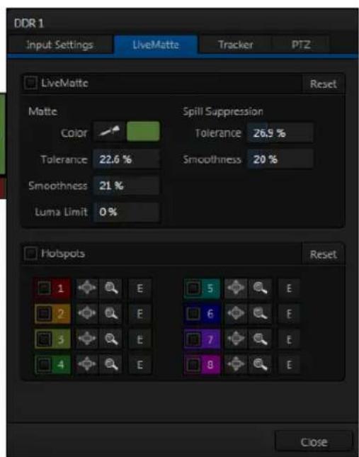
text_image
DDR 1 Input Settings LiveMatte Tracker PTZ LiveMatte Reset Matte Color Spill Suppression Tolerance 26.9 % Tolerance 22.6 % Smoothness 20 % Smoothness 21 % Luma Limit 0 % Hotspots Reset 1 E 2 E 3 E 4 E 5 E 6 E 7 E 8 E CloseFIGURE 219
(LiveMatte algorithms actually go well beyond simple chromakeying techniques to provide support realtime results, but for our discussion it's not necessary to get into all of the details; sufice to say it works very well, and is easy to conigure.)
Hint: Crop controls in the Input Settings tab can serve as a 'garbage matte' tool for chromakey sources.
Chromakeying has become an essential tool in video and ilm production. Typically, foreground footage is shot in front of a blue or green screen, and then that background color – the key color – is treated as transparent, allowing another image to be inserted.
For example, when you see a television meteorologist in front of a weather map, that person is almost certainly posed in front of a green screen. The background is 'keyed out' and replaced by computer generated imagery.
Of course, if you choose poor settings, foreground areas may inadvertently be cut away as well. Good keying often requires judicious balance between ‘too much’ and ‘too little’. Let’s consider the tools TriCaster provides to help you achieve a great result.
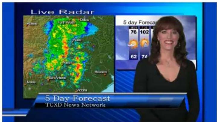
text_image
Live Radar Atkinsi Fort Worth Dallas Waco Kash San Antonio Houston Ukraine Vicina 5 day Forecast TCXD News Network 76 102 62 74FIGURE 220
SECTION 13.2 MATTE
The term Matte refers to a black and white representation deining the transparent (background) and opaque (foreground) parts of an image during compositing.
Portions of the matte that are grey are treated as semi-transparent, which is very useful in progressively smoothing edges between foreground source material and inserted background imagery.
natural_image
Portrait of a smiling woman with shoulder-length hair wearing a black top, against a dark background (no text or symbols visible)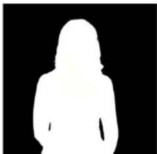
natural_image
Silhouette of a person against a black background (no text or symbols)FIGURE 221
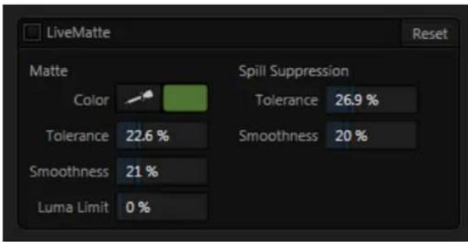
text_image
LiveMatte Reset Matte Color Spill Suppression Tolerance 26.9 % Tolerance 22.6 % Smoothness 20 % Smoothness 21 % Luma Limit 0 %FIGURE 222
TriCaster's supplies a digital version of this traditional tool. The controls under the Matte label, as you would expect, allow you to deine and adjust the matte for the corresponding video input.
13.2.1 COLOR
Initially, LiveMatte removes a specific color from the foreground image. This color is chosen using the Color button.
To choose this key color, click on the Color button (Figure 222) and keep the mouse button depressed. Drag the eyedropper tool over one of the video monitors to choose the color you wish to remove and then release it. The neighboring 'color well' is updated to show the color selected.
13.2.2 TOLERANCE
No physical greenscreen is perfectly comprised of one color. Wrinkles, folds and shadows along with the seemingly inevitable uneven lighting result in difference. For this reason, TriCaster provides a numeric slider labeled Tolerance just beneath the Color picker.
The Tolerance setting allows you to broaden the range considered as the key color, including more ‘near-neighbor’ colors to be included in the matte. A low tolerance removes only color values close to the primary or key color. As you raise the tolerance, you extend the range of values on either side of the primary color that will be treated as transparent. This allows you to deal with those imperfections we mentioned.
On the other hand, it may be that there is (usually unplanned for) detail in the foreground that is somewhat similar to the key color. Reducing Tolerance may allow you to prevent unwanted holes appearing when the subject opts to wear his St. Patrick's Day tie.
13.2.3 SMOOTHNESS
Smoothness deines a further tolerance factor, and a very useful one. We want our keyed foreground to blend smoothly into the background – rather than to stand out in hard relief like a postage stamp or decal. Smoothness serves this purpose. Don't overdo it though, as aggressive settings can cause the foreground to become unnecessarily ‘muddy’.
13.2.4 LUMA LIMIT
When working with poorly-lit backgrounds (or poor quality footage), the color Tolerance range separating the foreground (talent) from the background can be extremely narrow.
This problem can be aggravated by the subject's choice of clothing, or when there are harsh shadows. There is often a strong chroma component (and associated chroma noise) in dark foreground areas. The ‘noise’ may be partially or completely transparent when tolerances are critical. Because the noise varies over time, ‘holes’ in the foreground can result, and even worse these may licker on and off from one frame to another.
LiveMatte's Luma Limit control makes it possible to overcome this issue. In essence, it restricts the chromakey operation based on luminance (brightness) values. Dark foreground areas which typically cause the problems just described normally have quite different luminance values from the background color. In simplest terms, problem areas of this type can be decisively ‘pulled’ back into the foreground by pre-iltering the chromakey effect around a luminance threshold.
Generally, try to set up the best key you can before raising the Luma Limit from its default value of zero (no effect). Then gradually raise the limit until you are pleased with the result.
The term Spill refers to key color unintentionally reflected or ‘spilled’ onto the foreground subject. For example, a little green spill often appears on the shoulders of someone in a greenscreen shot.
The Spill controls let you remove key color spill in your scene by reducing the amount of that color in the
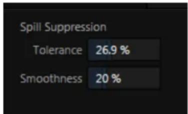
bar
| Metric | Value | | -------------- | ------- | | Tolerance | 26.9 % | | Smoothness | 20 % |FIGURE 223
foreground, where it doesn't belong. The net result is that the impression of spill color is eliminated, or at least reduced to the point where it is not objectionable.
Use the Tolerance and Smoothness controls under Spill Suppression in similar fashion to the controls by the same name discussed earlier. Endeavor to subdue spill without overdoing it, which could result in an unsightly gray fringe around offending edges of your foreground.
SECTION 13.4 COMPOSITING
When you enable (and conigure) LiveMatte for an input, the onscreen monitor for that input shows the source keyed over a checkerboard pattern.
If you select the (LiveMatte-enabled) input as Input A in an M/E tab in LiveMatte mode, the keyed source is overlaid on sources in lower input rows. You will see the composite result when the output is assigned to either the PGM or Preview row.
SECTION 13.5 FINE TUNING
You'll find LiveMatte easy to configure with a little experimentation – but a few handy worklow tips follow below.
You may ind it useful initially to turn Smoothness off or nearly so. Likewise begin with a low value for Tolerance – perhaps just 5-10, or so. Put the video source on Preview or Program Output before you do so, to provide a larger view to help you assess your settings.
Hint: The best method for optimizing the key is to begin with the best incoming source possible; if your cameras have both composite and S-video outputs, check to see which one gives you the best picture quality.
Pick your primary Color, but – before releasing the mouse button – slide the eyedropper around to different parts the background. Watch the monitor as you do so to see how the area of transparency is affected by different Color choices. Release the mouse when you find the color that produces maximum results. It's often preferable to pick an 'average' color from a location fairly close to the boundary between the background and foreground regions.
Now you can start to ramp up Tolerance. Bring it up slowly until most of the background color has been eliminated, cutting away most of the background to within a few pixels of the foreground/background boundary. Now raise Smoothness to fine tune that edge region, and you're nearly done.
Before considering your settings inal, make sure to test the result using a moving source. This will sometimes reveal that overly aggressive settings cause small 'blocks' of pixels in the edge region to appear to snap on and off during motion - as they either qualify or disqualify for inclusion in the resulting matte. (A little reduction in Tolerance and increase in Smoothness will usually resolve this problem.)
Hint: it can be useful to zoom in using Position controls when fine tuning LiveMatte.
SECTION 13.6 PRACTICAL STAGING FOR LIVEMATTE
We'd like to offer a few suggestions here to guide you in preparing your set.
13.6.1 LIGHTING
The single most important aspect of ‘pulling a clean key’ is lighting. The lighting should be even and diffuse. Bright ‘hotspots’ and shadows create different shades on the wall, and overexposed areas lack sufficient color for clean keying. (It is not how much light you have on the key wall, but how evenly lit that wall is.) Naturally, you want to keep your green (or blue) screen clean and free of wrinkles, ripples, folds, tears, or other blemishes, as well.
Second, the distance from your talent to the screen behind can make a profound difference in key quality. When the subject stands too close to the key colored background, the key color relects back onto the subject, creating a green or blue fringe that is difficult to remove. If you have available space, move your subject farther away from the wall.
When good distance is out of the question, you can improve things somewhat by placing lights above and behind the talent, lighting them from behind with a complimentary color filter over the light to 'cancel out' unwanted reflection (for green use a magenta ilter; for blue, orange or amber.
Don't overdo back (or top) lighting, however. The limited dynamic range of the camera means there will be little useful color data in badly over-exposed highlights. This can make it next to impossible to separate fringe zones (such as hair detail) from the background (especially when this is also overexposed).
13.6.2 CONNECTION CONSIDERATIONS
As mentioned above, washed-out areas in the video signal lack sufficient color information to provide good separation. For similar reasons, it's worth considering the color characteristics different types of video signals.
- SDI connections are ideal, if you can use them. Otherwise, in the analog video realm you will encounter three main types of camera connections. We present them here in ascending order according to the quality of video signal they provide (and as things go, in the reverse order of their cost, and the likelihood that you will have access to them):
- Composite – a two conductor design using the classic RCA connector (also referred to as a phono connector or CINCH/AV connector)
- Y/C - typically using a round, 4-pin mini-DIN connector or two BNC connectors, Y/C keeps Y (luminance) and C (chrominance) signals separate.
Hint: Y/C is occasionally called “component” (which while technically correct, can be a bit confusing given the name of the next class), S-Video (legitimate) or “S-VHS” (completely incorrect, though a common error.)
- Component (a.k.a. 'YUV' or 'Y, Pb, Pr') – a three wire system typically using BNC (push & twist-on) connectors.
For analog connections, either of the last two methods is to be preferred – but it is entirely possible to succeed with only a composite signal. When you have something better available, however, you should naturally use it. (Try to avoid downgrading the pre-LiveMatte signal from a Y/C camera, for example, by connecting it to your TriCaster using composite cabling.)
Hint: cameras using IEEE 1394 connection (such as mini-DV or HDV format) are no supported as live switching sources, for several reasons. However they may often be connected by Y/C cable (SD cameras only) or Component cabling. This configuration may actually provide a better color rendition for keying purpose than if it were possible to connect them by IEEE1394 cable.

text_image
TCM/E banks provide truly awesome production power and convenience. Pre-conigure multi-layered compositions and switch them as easily as you would to any single input, or use an M/E to control a special purpose sub-mix. This is also where TriCaster's potent realtime virtual set technology, called LiveSet ^™ , is applied.
We introduced TriCaster's M / Es back in Section 4.10 and Section 4.11 of the Live Production Walkthrough chapter. Now we'll look into these extremely powerful tools in greater depth.
SECTION 14.1 OVERVIEW
text_image
MIX EFFECTSFIGURE 224
The Mix Effects label (Figure 224) beneath the monitoring pane on the Live Desktop is a toggle button you can click to expand or collapse the M/E interface (Figure 224).

When expanded, the M/E pane spans the upper-central part of the Live Desktop. M/E's are presented individually in tabbed panes, each corresponding to a button in the main Switcher. The number of M/Es available varies by model, up to eight.
As you would expect, selecting an M/E button on the (main Switcher) Program row displays the output from the corresponding M/E on Program Output. Likewise, punching an M/E button on the Preview row cues up that M/E bank's output for an upcoming Take or Auto operation. This makes it easy to Take or Auto directly to, from, or even between M/Es with a single click.
For TriCaster 8000, M/E buttons also appear on source selection rows and Key channel source menus inside the M/E panels. This type of M/E, referred to as "reentrant", is an exceptionally powerful feature, and one offering endless creative possibilities.
Note: Self-referential reentrancy (i.e., re-assigning a given M/E as one of its own sources) is not supported. TriCaster will simply show black in such cases. However you can often mimic effects of this sort by using multiple channels in another M/E.
SECTION 14.2 M/E MODES
At irst glance, an M/E panel in its default operating mode (Mix) is scarcely distinguishable from the main Switcher. However, each of TriCaster's M/Es actually offers two different operating modes:
- Mix (the default mode): A secondary switcher layout, with controls and options that are very similar to the main Switcher.
- Effect mode: The M/E is configured for effects, including virtual set operations.
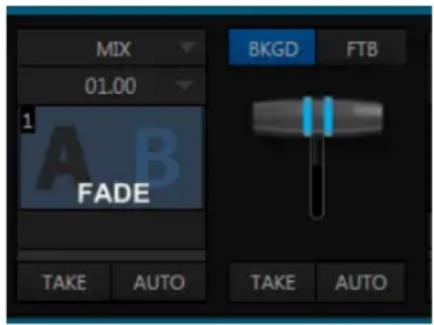
text_image
MIX 01.00 1 A B FADE BkgD FTB TAKE AUTO TAKE AUTOFIGURE 226
Autoplay and the M/E:
One notable point regarding an M/E in Mix mode and the main Switcher involves the Autoplay feature (see Section 11.2.3).
To avoid undesirable consequences for Media Player content aired on the all-important main Program output, M/E's in Mix mode trigger Autoplay operations within the same M/E only.
As well, a switch in the TriCaster options menu toggles AutoPlay's triggering of 'Auto out' transitions.
The M/E's mode is set using a menu above the effect icon in the central control group (Figure 226) of the panel. For the most part, you will initially see very little difference in the M/E panel when you change modes.
- In either Mix or Effect mode you will observe two source button rows at left labeled input A and B (Figure 227) by default.
- At right are up to four Key control groups, depending on which TriCaster model you are using. In most respects these are identical in appearance and practice to the DSK controls located in the main Switcher (see Section 9.3.1).
- Even the central control group mimics the main Switcher, with its Transition controls and options, T-bar and delegate buttons and so on.
text_image
A 1 B 1 2FIGURE 227
14.2.1 MIX MODE
Really, an M/E in Mix mode is a switcher:
- Input rows labeled A and B behave just like the main Switcher's Program and Preview rows
• Transition controls work in the same manner
• One or more Key channels stand-in for DSKs - M/E output can even be routed directly to one of TriCaster's two main outputs (as well as the IsoCorder section).
14.2.2 EFFECT MODE
Careful scrutiny reveals some (outwardly) subtle differences in the controls when you change to Effect mode (Figure 228):
- The Take and Auto buttons normally located beneath the T-bar and Transition icon are hidden.
- A Zoom control button replaces the BKGD delegate.
- The current Transition icon is replaced by the default Effect icon.
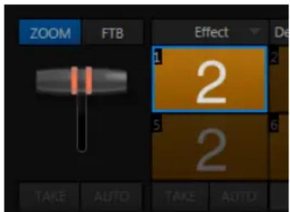
text_image
ZOOM FTB Effect 1 2 2 5 6 TAKE AUTO TAKE AUTOFIGURE 228 (4-INPUT VERSION)
- As required, as many as 4 input rows may be shown in Effect mode.
- Position controls appear for up to four input layers (A, B, C, and D) as supported by the effect, and depending on which TriCaster model is in use).
Let's consider these reasons behind for these changes in the interface. An M/E in Effect mode allows preparation of a composite of two or more video sources, whether for direct output, or as a source for the main Switcher, or as an input for other downstream channels (for TriCaster 8000, also including other M/Es).
Even in Mix mode, an M/E provides access to effects – including Position and transition effects (including Animation Stores). In Effect mode, however, an M/E asserts its realtime compositing and effects prowess more aggressively.
14.2.3 INPUT POSITION CONTROLS
FIGURE 229
Position controls for all appear to the left of all input rows. Click this button to open the input's Position panel. These controls replicate those discussed previously, under the subheading DSK Positioning in Section 9.3.1.
14.2.4 DEFAULT EFFECTS
To begin with, Effect mode supports up to four primary input layers (TriCaster 8000). The M/E doesn't transition between A and B, or C and D, though, in Effect mode. Instead, effects of various types are applied to the selected video inputs. Let's consider the effects in the Default group as examples:
Click the Effect button (if you haven't already), and then click the label above the thumbnail icon to open the Media Browser.
Select the LiveSet location at left, and use the scrollbar in the File Pane at right to locate the effect group labeled Default. With one
exception (Advanced Tracking: TriCaster 8000 only), these effects are straightforward compositing effects involving multiple video layers. Effect output (i.e., the background prior to Key overlays) is simply the sum of all input layers.
text_image
00.10.00 1 2 Default (2 Layer)FIGURE 230
If the source assigned to input A is fully opaque, any content in the layers below is hidden. Or if input A is at least partially transparent, the source assigned to input B is blended into the M/E background layer, and so on.
Hint: Don't overlook the fact that the input Position controls allow you to create more elaborate compositions even with these simple compositing effects.
The output of any active Key layers is then added to the effect output before passing the combined result onward to the inal M/E output.
As we mentioned, effects can be ‘simple’ compositing effects, like most of the Default group, or more advanced. Before considering TriCaster’s virtual set system (a.k.a, LiveSet™), let’s talk about some of the other effect types.
Effects can vary widely in their types, from relatively simple utilities effects to image processing or advanced compositing effects.

text_image
00.10.00 Default Advanced TrackingFIGURE 231
For example, we mentioned that one member of the Default group is unique.
The Advanced Tracking effect takes three video sources as input to produce a result that would otherwise require the use of an additional M/E.
Set up this effect as follows:
- Click the label above the Effect icon, and use the Media Browser to select the Advanced Tracking effect from the Default group.
-
Add the clip named Kiki Track Rectangle.mov (NewTek location, Green Screen group) to the playlist for DDR 1.
-
Enable Single and Loop modes for DDR 1.
-
Add the clip named "Bumper Cars.mov" (Samples group) to DDR 2, set it to Single and Loop as well.
-
Add an attractive full frame graphic to the Graphics 1 player.
-
Select M/E 1 on the main Switcher's Program row, to make it easy to view the result of the following steps.
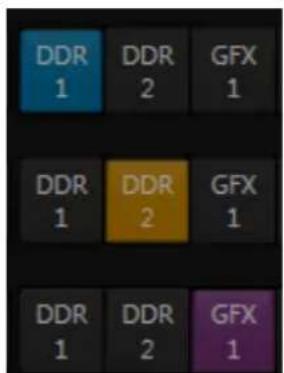
text_image
DDR 1 DDR 2 GFX DDR 1 DDR 2 GFX DDR 1 DDR 2 GFX GFX 1FIGURE 232
-
In the M/E 1 tab, select DDR 1 on the input A row.
-
Select DDR 2 as input B.
-
Select GFX 1 as input C.
-
Double-click the monitor for DDR 1 to open its Input Configuration panel.
Continue to configure both LiveMatte and the Tracker for the video clip in DDR 1:
-
In the LiveMatte tab, click Reset to update the keyer settings to their defaults, and enable the LiveMatte switch at upper-left.
-
Use the Scrub bar under the playlist in DDR 1 to advance through the clip until the orange card is visible in the frame.
-
Switch to the Tracker tab, click the Color picker (eyedropper) and keep the mouse button held down to assign the card's orange color to the Tracker for DDR 1.
-
Boost the Tolerance setting to 34%.
-
Press Play for both DDRs.
Let's take a moment to review our progress, before completing setup steps:
On the Program monitor, you should see the talent clip overlaid on the image from GFX 1 (LiveMatte is turning the green pixels in the DDR 1 clip transparent). You'll also see imagery from DDR 2 displayed wherever the (originally) orange card appears in the frame.
What's happening is that the Advanced Tracking effect is applying the values from the (DDR 1) Tracker for a secondary iteration of LiveMatte. Our LiveMatte settings cut away the green, revealing the C layer behind. Afterward, the orange color range is also keyed out, revealing the B source through the transparent region.
Up to this point, the effect takes advantage of the Tracker color values, applying them as a secondary keyer – but we haven't yet done anything with the actual motion data the Tracker is supplying to TriCaster. Let's do so now.
- Click the Position button for input B to open the Position Panel for that layer.
- Select DDR 1 in the From source menu.
text_image
Follow Tracker From source: DDR 1FIGURE 233
- Enable Follow Tracker (Figure 233).
The result on your Program monitor should look much like Figure 234; full motion video appears wherever the orange card appears in the foreground clip. This is the standard setup for the Advanced Tracking effect, though it's possible to use it in different ways too.
Further Notes: Advanced Tracker 2 provides much improved compositing. (The original effect is provided for legacy purposes, but might also produce a better result in rare cases where a source has embedded transparency). Among other benefits, the newer effect performs spill suppression at the edges of the tracked region. Using the size (etc.) parameters of the tracker, the area being tracked can be mdae slightly larger to taste, to moderate this effect.
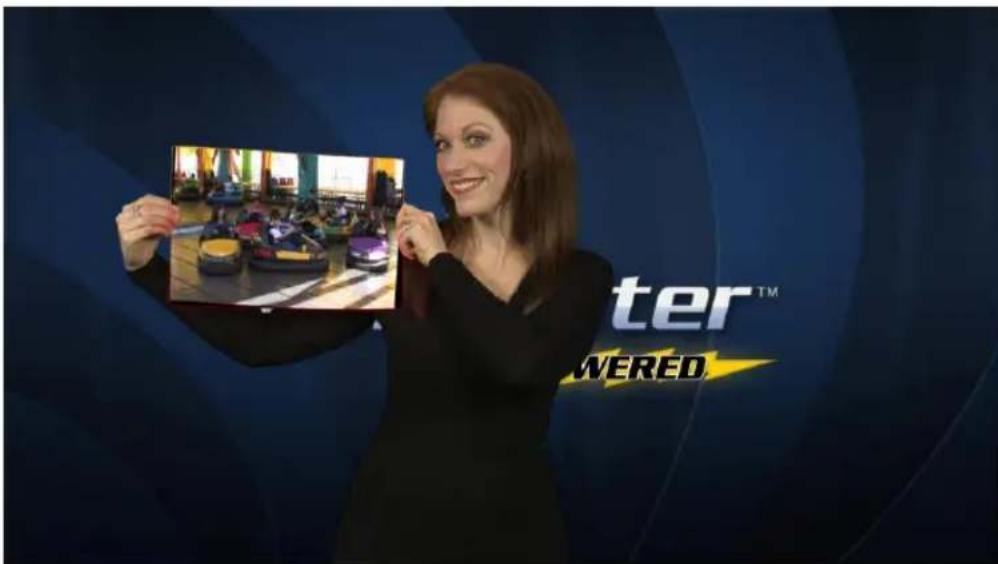
text_image
ter™ WEREDFIGURE 234
Now would be a good time to test the effect of the Scale, Rotation, and Aspect controls in the Tracker tab for DDR 1 (remember you can double-click the DDR 1 monitor to open this panel).
UTILITIES
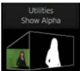
text_image
Utilities Show AlphaFIGURE 235
Effects can take other forms as well. We've looked into the Default effects group; now let's consider Utility effects.
If you were following along in the previous section, replace the current effect in M/E 1 with the Show Alpha effect from the Utilities group.
Applying this effect immediately causes the display on the Program monitor update, showing the content of the alpha channel for input A (Input B is ignored).
The current input A source is keyed, so the effect displays black on Program out reveals wherever transparency exists in the foreground, white for full opacity, and shades of gray for in-between blends.

natural_image
Silhouette of a person holding a rectangular object against a black background (no text or symbols)FIGURE 236
With this in mind, it won't be hard to guess what Show Inverse Alpha does. In contrast, the Show Color effect in this group passes the full color output of LiveMatte prior to being multiplied by the alpha channel.
(It might seem as though this would be identical to the original source, but you may notice subtle differences. This is because of the Spill Suppression processing.)
Let's look at another of the effects in the Utilities group, Color Correction. Replace the current effect with the Color Correction effect (again, click the Effect label above the icon to open the Media Browser).
You'll notice that M/E 1's output on the Program monitor is now rendered in monochromatic grayscale. Move the mouse pointer over the effect's icon, and click the gear button that pops up.
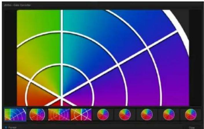
natural_image
Color palette design with gradient color blocks and a white selection grid at the bottom (no text or symbols)FIGURE 237
This opens the effect's Shot Editor.

natural_image
Row of eight circular color swatches with gradient and grid patterns, no text or symbols presentFIGURE 238
Across the bottom of this panel, you'll see a bind containing 9 thumbnail icons representing the different shots (position/zoom presets) currently configured for
the effect. The current shot is bordered in blue. Clicking a shot selects it for editing. Click the Preview switch at lower left to view the effect of adjustments you make on the Program monitor.
The large Effect Preset Editor canvas is interactive. Zoom in the shot you chose, using either the nearby T-bar in the M/E panel, or the mouse-wheel.
As you do so, observe that color is progressively added to the video scene (note that it's not necessary to open the Editor to zoom in this manner).
After zooming in, drag the mouse diagonally from upper-right to lower-left in the canvas to re-center the colored display (Figure 237). You'll see that the M/E output is tinted as you do so.
Close the Editor pane. The effect represented by the current shot icon is active. Click the icon itself this time, rather than its ‘configure gear’. This opens the Shot Palette, which is much like the Transition Palette discussed earlier.
Click to select a different shot for this effect; you'll see the M/E output change over time as the effect transitions from the settings represented by the original shot to those of the new one. Finally, the Make Legal effect ensures the output of an M/E is within broadcast signal tolerances.
3D
The Anaglyph (Red, Cyan) effect found in the 3D category is a special purpose tool.
The anaglyph method of displaying 3D imagery depends on stereo video inputs that are iltered and composited into a single output stream.
In turn, this combined stream resolves into 3D when viewed through special glasses with red and cyan (blue-green) ilters for left and right eyes respectively.
natural_image
3D rendering of a white-framed 3D glasses with blue and red color bars (no text or symbols)FIGURE 239
TriCaster provide easy access to anaglyphic technology by means of the Anaglyph effect. The effect combines 2 video inputs selected in an M/E. 3D output can then be switched easily like any other source. No complex configuration steps or tricky control surface operations are required.
14.2.5 VIRTUAL SETS
We've considered TriCaster's Default and Utility effects. Let's move on to a more glamorous species, the virtual set, presented in TriCaster as LiveSet™ effects.
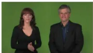
natural_image
Two individuals standing side by side against a solid green background (no text or symbols visible)FIGURE 240

text_image
NewTek TriCast ITER - HIGH DEFINITION - PORT A NewTek www.newtek.comFIGURE 241
LiveSet is one of TriCaster's most powerful tools, and can dramatically enhance a production. With it you can achieve the look of a large, sophisticated studio setting (Figure 241) within a very small studio space (Figure 240), all without the need for external equipment.
Broadly speaking, setup of a LiveSet effect is much like the Default effects previously considered (see Default Effects, Section 14.2.2).
A typical LiveSet consists of a greenscreen shot (usually input A) with LiveMatte applied composited into a virtual set. LiveSet adds the foreground and background for the scene, and additional video inputs may add to the effect in various ways.
Hint: Most virtual sets require LiveMatte settings to be applied to Input A. Other inputs may also require keying, depending on the design of the virtual set.
To select a LiveSet, click the label above the effect icon in the M/E to open the Media Browser (Section 11.2.2).
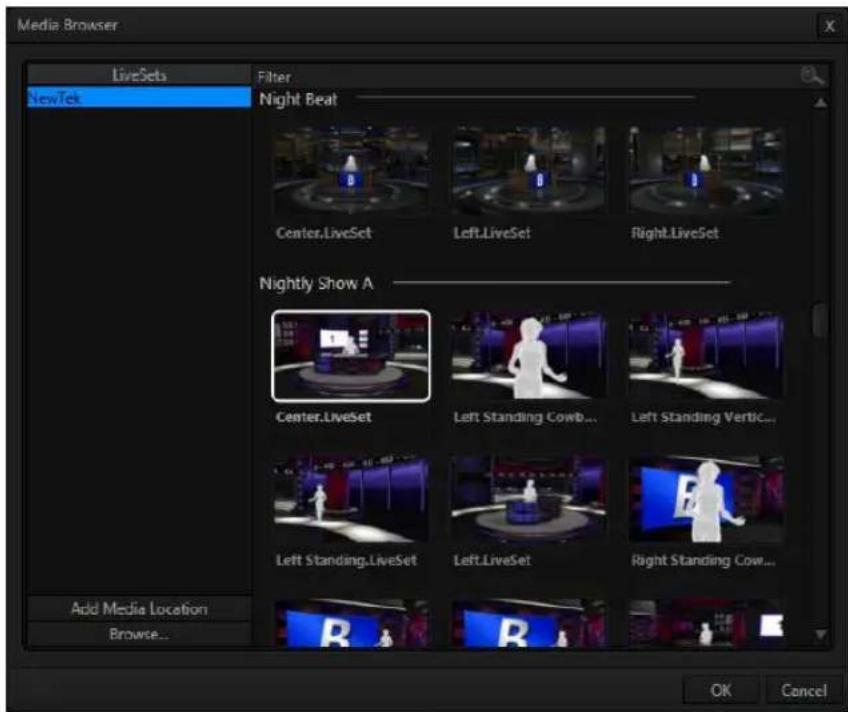
text_image
Media Browser LiveSets Filter NewTek Night Beat Center.LiveSet Left.LiveSet Right.LiveSet Nightly Show A Center.LiveSet Left Standing Cowb... Left Standing Vertic... Left Standing.LiveSet Left.LiveSet Right Standing Cow... Acid Media Location Browse... OK CancelFIGURE 242
The Location List of the Media Browser lists any installed LiveSet groups under the heading “LiveSets”. Select an entry beneath to show thumbnail icons in the Browser’s File Pane (Figure 242 shows the content of the NewTek location under the LiveSets heading).
INPUT POSITION
We discussed Position controls for M/E video inputs previously (Section 14.2.3). It's worth adding here that Position options do affect the scale, rotation and position for LiveSet video inputs.
FIGURE 243
You can often use Position controls to achieve a 'good fit' and natural appearance of talent or another source appearing in your virtual sets (greatly reducing the need to fuss with physical camera positions).

text_image
CENTERHint: The Align group of LiveSet effects is provided especially to make it easier for you to adjust cameras and position talent on your physical set to suit the design of typical virtual sets supplied with TriCaster.
SHOTS AND ANIMATION
In LiveSet terminology, shots are different ‘virtual camera’ position presets, represented by the eight icons in the Shot Palette. Click the effect icon to show this.
Making a selection in the palette begins the animated change from the current shot to the new one, over the duration set in the numeric control below the effect icon.
Note: Some LiveSets (e.g., double-box sets) do not support zooming and panning. In such cases, Shot selection and T-bar actions may be inoperative.
The Duration control works like similar numeric ields in TriCaster's Live Desktop: drag to adjust the value, click to type directly into the ield using the keyboard, or press (keyboard) Shift and double-click to restore the default value. The drop-down Duration menu offers several convenient presets as well as a Cut option.
Hint: The maximum duration for an animated zoom is 2 minutes.
EFFECT PRESET EDITOR
©When the mouse pointer moves over a shot icon (whether in the Shot Palette or the icon for the current effect), a gear button is shown (Figure 244). As we observed when discussing more mundane effects, you can click this gear to open the Effect Preset Editor (a.k.a., the 'Shot Editor').
FIGURE 244
While this tool provides control for some other effects too, its principle purpose is to allow you to create custom shots for virtual sets. In turn, this permits you to perform great looking animated camera moves that center on various points of interest in the frame.
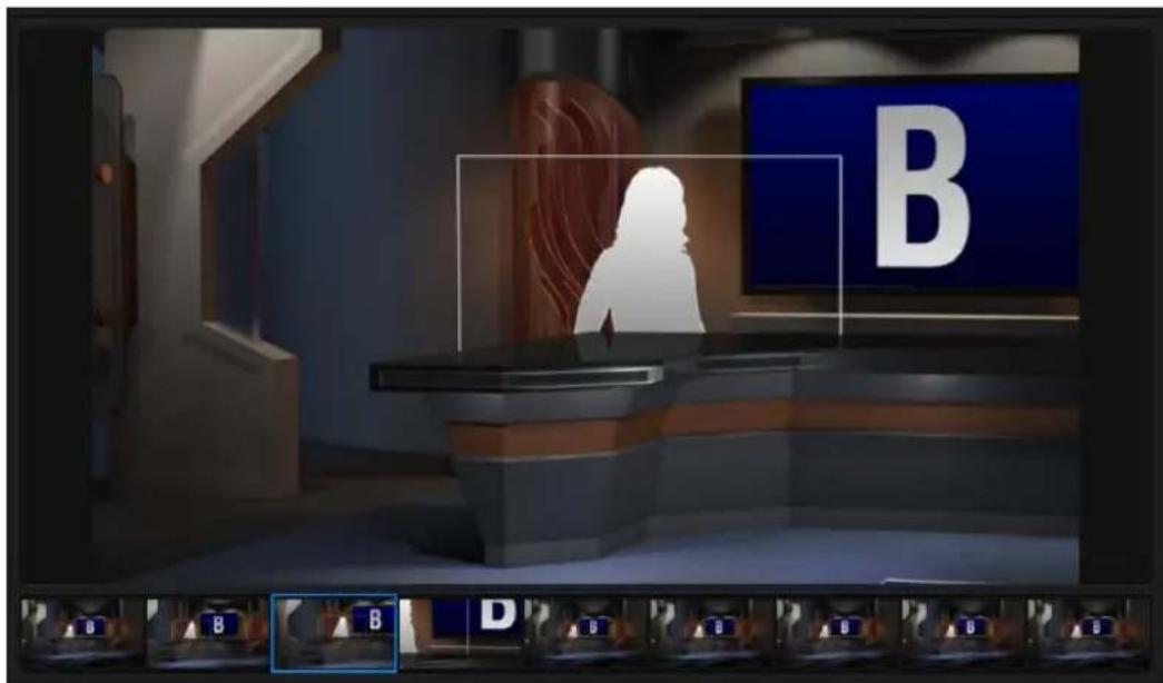
text_image
B B B DFIGURE 245
Operations in Effect Preset Editor are very easy to perform. The current shot is bordered in blue in the selector across the bottom of the pane. Simply click to choose another shot to modify.
To change the zoom level of the LiveSet shown on the large canvas, roll your mouse wheel; or drag the M/E's T-bar; or hold down the right mouse button while dragging vertically. To pan the preview on the canvas, left-click, hold and drag.
THE T-BAR
text_image
ZOOM FTB TAKE AUTOFIGURE 246
The Zoom T-bar is located beside the Effect icon. Dragging it vertically adjusts the virtual 'camera distance' for the active LiveSet, between 0-100%.
When you click a Zoom Preset, the T-bar updates to the zoom level of the new shot. Conversely though, adjusting the T-bar does not update the current value for a Preset. (When the current T-bar position corresponds to the zoom value in the shot, its icon shows a blue border.)
It's important to realize that the Key (and FTB) Delegate buttons continue to serve their normal purpose in Effect mode. That is, they enable you to perform an Auto affecting the associated channel(s); they do not perform a zoom on these layers. Only the Background layer (which includes the virtual set) zooms during an Auto operation.
14.2.6 HOLOGRAPHIC LIVESETS
A special variant of TriCaster's LiveSets are referred to as 'holographic'. These effects can be amazingly lifelike and convincing, and are relatively easy to create.

text_image
CITY HALLFIGURE 247
Holographic LiveSet effects are loaded into an M/E in the same manner as any other effect.
Simply move the cursor over the effect name (below the thumbnail icon for the current effect), and click the + sign (Add Media button) that appears to open TriCaster's Media Browser, and choose the effect you wish to load (several examples are included with your system).
Adjust the current view for holographic LiveSets in similar fashion to standard effects – that is, using the Effect Preset Editor (Figure 249) discussed in Section 14.2.5.
text_image
EFFECT 00.10.00 2 City HallFIGURE 248
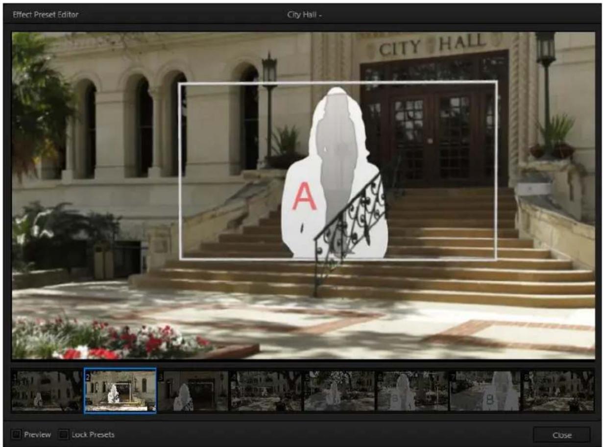
text_image
Effect Preset Editor City Hall - CITY HALL A Preview Lock Presets CloseFIGURE 249
Preset adjustments made using the mouse and canvas vary slightly, however, for holographic effects.
For a standard LiveSet effect, dragging the mouse left, right, up or down changes the camera position in the frame; the mouse-wheel zooms in or out. In a holographic LiveSet, mouse-wheel operations are the same, zooming in or out. However dragging the mouse laterally or vertically on the canvas modifies camera rotation, rather than position.
Hint: Holographic effects, like standard LiveSets, are compiled using the optional Virtual Set Editor application. A demo version of this utility is installed on your TríCaster, and its instruction manual can be located in Startup>Help.
text_image
KEY 1 01.00 1 A B FADE GFX 1 TAKE AUTOFIGURE 250
The Key channels in M/E panes match the DSK channels found in the Switcher's main Transition section in almost all respects.
Unlike the DSKs, though, they constitute a 'pre-Switcher' sub-layer. This means that Key channels are applied before the composition is sent to the Switcher (or another M/E). Content in a Key channel appears beneath anything displayed via the (Switcher) DSK channels.
Key channel selection and Position controls work just like their DSK cousins, discussed earlier (see 9.3.1), the sole distinction being that their behavior in connection with Autoplay mimics other M/E sources.

text_image
TCLess than 100 years ago, movies were silent. We've come a very long way since "The Jazz Singer" (1927, Warner Bros.), and great audio now plays a huge role in video production. TriCaster™ provides an extensive set of professional quality audio tools, which we'll explore in this chapter.
External audio connections and basic configuration were touched on back in Sections 3.5.1 and 3.8.1. TriCaster presents more precise control over individual audio sources and outputs in a tabbed pane labeled Audio Mixer, found just below the main Switcher.
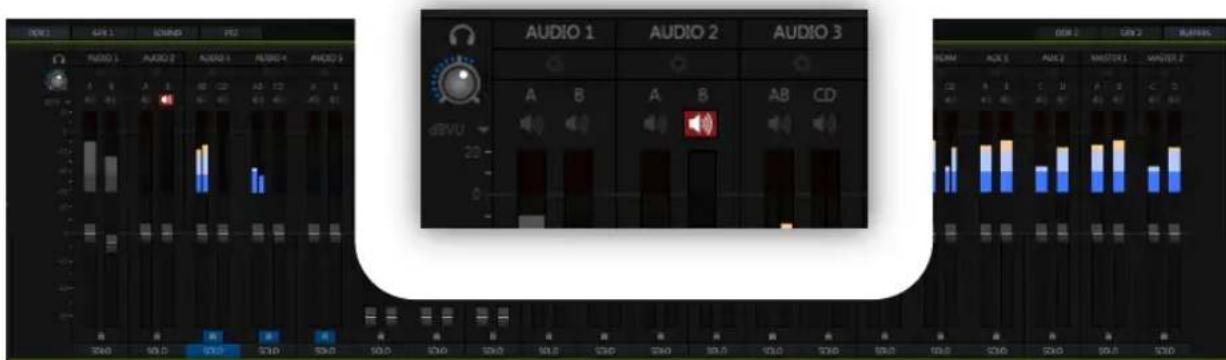
text_image
DIDI GND 1 GND 2 FET AUDIO 1 AUDIO 2 AUDIO 3 AUDIO 1 AUDIO 2 AUDIO 3 A B A B AB CD JBLVU S400 95.0 CD/D 940 59.0 S50 930 S60 91.0 S70 S80 92.0 S90 93.0 S100 93.0 S10.0 S11.0 S12.0 S13.0 S14.0 S15.0 S16.0 S17.0 S18.0 S19.0 S20.0 S21.0 S22.0 S23.0 S24.0 S25.0 S26.0 S27.0 S28.0 S29.0 S30.0 S31.0 S32.0 S33.0 S34.0 S35.0 S36.0 S37.0 S38.0 S39.0 S40.0 S41.0 S42.0 S43.0 S44.0 S45.0 S46.0 S47.0 S48.0 S49.0 S50.0 S51.0 S52.0 S53.0 S54.0 S55.0 S56.0 S57.0 S58.0 S59.0 S60.0 S61.0 S62.0 S63.0 S64.0 S65.0 S66.0 S67.0 S68.0 S69.0 S70.0 S71.0 S72.0 S73.0 S74.0 S75.0 S76.0 S77.0 S78.0 S79.0 S80.0FIGURE 251 (TRICASTER 8000 SHOWN)
Compact sub-panels in this pane provide configuration and control for individual audio sources and also audio outputs as follows, from left to right:
- External audio sources – controls for Inputs 1-(4 or 8, depending on the TriCaster model), along with Network audio sources.
- Internal sources – Media Players, and Effects (sound embedded in Animation Store transitions)
- Record – controls levels for capturing Output 1 and Output 2 as a/v files
- Stream – controls TriCaster's web stream output
- Aux 1 & 2-controls for TriCaster's two stereo Aux audio busses
• Master 1 & 2 – controls TriCaster's primary stereo audio busses
NOTE: 4-input TriCaster systems do not provide analog output connections for channel C and D. However the extra channels can be recorded, streamed, or output via SDI-embedded connections.
15.1.1 AUDIO SPECIFICATIONS
TriCaster's analog audio conforms to SMPTE RP-155. The maximum input/output level is +24 dBu. Nominal input level is +4 dBu (-20dBFS), and the sample rate is 96 kHz. Levels above 0dBVU are shown in red in the VU meters, to caution you that overly high levels can result in clipping in recordings.
Hint: An error message appears in the Status Bar above the main Program output monitor to warn you if clipping occurs – see Section 7.4; see also Section 15.7 (Advanced Configuration) and Section 15.8.1 (Headroom Notes).
SECTION 15.2 HEADPHONES
text_image
dBVU 20 0FIGURE 252
At the extreme left side of the Audio Mixer you will observe a simple volume control for the Headphones output.
By default, headphones connected to this stereo output jack will carry the audio signal from the output designated Master 1 – that is, the same audio carried by outputs marked 1a and 1b in the Audio Out group on TriCaster's backplane.
Remember that this output is also affected source Solo switches. When Solo is enabled for one or more sources – or outputs – only the soloed sources are sent to the connector. (See Solo in Section 15.5.4 for more information on this feature.)
SECTION 15.3 VU METER CALIBRATION
VU (Volume Unit) meters are located right above the Volume control sliders throughout the Mixer. The calibration of the VU meters can be changed to suit your preference.
Click the label below the Mute button in the Headphone control at
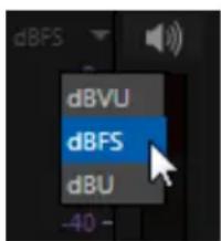
text_image
dBFS dBVU dBFS dBU -40 -FIGURE 253
left to open a small menu offering three options as follows:
- dBVU – most familiar to users of typical analog audio mixers
- dBFS – dB 'Full Scale' – the digital standard; see notes under the heading Audio Headroom in Section 3.13
- dBu – based on a voltage of 0.775 VRMS (a shy scale rarely seen in public, supplied for completeness, comparison, and the amusement of audiophiles)
SECTION 15.4 EXTERNAL SOURCES
Columns in the irst set of control groups are labeled for correspondingly numbered Input rows on TriCaster's rear connector panel (right-click to Rename audio inputs).

text_image
AUDIO 1 AUDIO 2 AUDIO 3 AUDIO 4 A B A B AB CD AB CDFIGURE 254
You may choose to think of these audio sources as being associated with the same-numbered video inputs in the nearby rows on the rear connector panel.
This linkage is not strictly enforced, however. At times you may well prefer to treat various audio sources as independent of the nominally associated video input. The Follow (audio follows video) feature plays an important role in this context – see Section 15.7.2.
15.4.1 CONNECTION TYPE
FIGURE 255
Individual sub-panel panels for external sources govern a group of audio connections including variously (depending on TriCaster model) of two XLR inputs, an AES/EBU (AES3) BNC connector, and an SDI Embedded digital audio source.
Naturally, only one connection type can be active for a given audio input group at any moment. To access the Connection menu, move the cursor into the box just below the label for an input, and click the Conigure (gear) button (Figure 255).
The advanced Audio Configuration panel (Figure 256) will be shown.
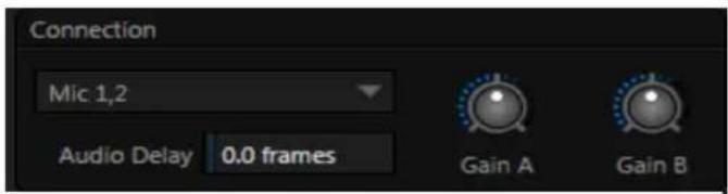
text_image
Connection Mic 1,2 Audio Delay 0.0 frames Gain A Gain BFIGURE 256
The drop-down Connection menu at the top of this pane allows selection of one of the following options:
- Mic 1, 2 – low impedance microphones and other common professional audio sources
- Mic 1, 2 + Phantom (power) - microphones (typically condenser mics) requiring supplementary DC power
- Line – generally consumer audio sources such as CD players, VCRs, etc.
Note: For TriCaster 410, the first two input pairs support Line level analog audio source options.
• AES/EBU - digital audio (8-input models only)
- SDI Embedded – digital audio embedded with digital video transmitted via a Serial Digital Interface (SDI) connection
GAIN A/B
For Mic selections only, a Gain knob is sown at right for each input channel. This provides additional trim for Mic type inputs, allowing you to bring input levels into a suitable operating range.
Many important features and optional settings are common to most source types, and some even appear for outputs. Let's review these before continuing.
15.5.1 MUTE
Mute switches for audio sources are located (Figure 257) just above the in the main Mixer panel. A single button may control one or two channels, as appropriate for that source.
FIGURE 257
Enabling Mute removes the sound from that source from all downstream audio mixes and outputs.
Hint: Muted sources still show signal activity on the VU meters, but levels are drawn in gray rather than full color. This is also true for sources with Follow set that are not currently audible on output.
One important exception to Mute operation involves recording:
TriCaster's IsoCorder™ feature lets you capture audio from the mixer, or directly from 'same number' inputs. That is, the audio recorded with the video is taken from the matching number audio input, and routed directly to the recording module prior to most adjustments in the Audio Mixer – including Mute.
Note: Either Audio 7 or 3, depending on model, is automatically muted when Use Linear timecode (LTC) is enabled in Timecode Configuration (Section 8.4). You can un-mute it briefly to adjust signal levels, but of course you don't want this to be audible during a live production – Solo might be useful in such cases.
15.5.2 LOCK
Clicking the Lock button (padlock icon) at the bottom of an input group links the two Volume sliders above to each other, enabling you to adjust them in unison.
15.5.3 TALK (TALK OVER)
It is often useful to reduce all other audio source levels so that an important announcement can be clearly understood by the audience.
The Talk button (also known as “Talk Over”) is only shown at the bottom of input groups when the Connection Type for is set to one of the Mic options. Enabling Talk for a source (typically a microphone) reduces the output level of all other audio sources by 20dB.
15.5.4 SOLO
Solo implementations and options vary widely in the audio industry, but broadly speaking, they provide several very useful functions. TriCaster's Solo feature (Figure 258) offers remarkable lexibility without overly confusing complexity.
Consider a few basic design concepts:
The Solo switch state has no impact on the audio mix(es) sent to other outputs.

text_image
SOLO FIGURE 258✿ Enabling Solo for a source sends its (after-fader) sound to the Headphones output, and removes all other sources from that output.
- TriCaster's Solo feature is normally what it called ‘exclusive Solo’ (or ‘X-Or’ type). This means that enabling Solo for a given source disables all other Solo buttons.
It is possible to use what is called 'Solo latch', ganging multiple sources for Solo output. Hold down the Ctrl key and click additional Solo buttons to add or remove their respective audio contributions from the latched Solo group.
AUDITIONING AN AUDIO SOURCE
It can be very useful to be able to preview one or more audio sources, doing so without allowing the test sound to be audible on Program output. Typically, this need arises in connection with testing microphones or other audio sources that will be used in the production.
To audition an audio source in this manner:
- First Mute the source, removing it from primary outputs.
- Then enable Solo to hear it on the Headphones output.
SECTION 15.6 INTERNAL SOURCES
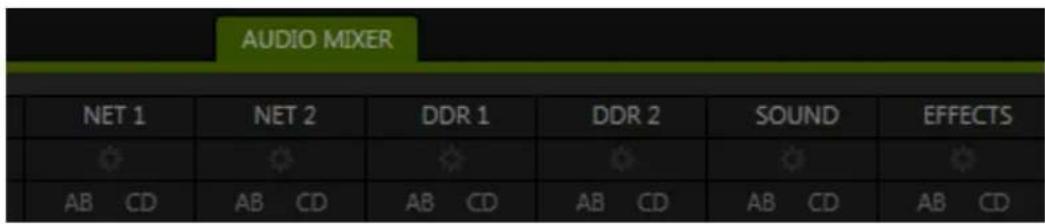
text_image
AUDIO MIXER NET 1 NET 2 DDR 1 DDR 2 SOUND EFFECTS AB CD AB CD AB CD AB CD AB CDFIGURE 259
Besides external audio sources, sounds played from TriCaster's internal storage volumes (including removable media such as external hard drives or 'thumb' drives) via the Media Players (DDRs, etc.) can be added to the output mix.
15.6.1 NET 1 AND NET 2
The Net 1 and Net 2 audio control groups affect sound associated with the Switcher sources by the same name. Numerous network input sources, including iVGA PRO™, AirPlay®, 3Play™, network feeds from another TriCaster, and more may support embedded audio (see Chapter 16, Network Inputs).
15.6.2 MEDIA PLAYERS
Video and audio-only iles in DDR 1 and 2 playlists along with audio iles in the Sounds player may contain one or more audio channels. At most, Media Players output the irst four audio channels of multiple channels – additional embedded channels are ignored. Other options and controls in these sub-panels are similar to those provided for external audio sources.
15.6.3 EFFECTS (TRANSITIONS)
This control group governs the sound embedded in Animation Store Transitions.
The remaining control groups in the Audio Mixer are dedicated to TriCaster's various audio outputs. We'll come back to them in Section 15.8, but before we do so, let's drill further down into more advanced audio options and tools.
SECTION 15.7 ADVANCED CONFIGURATION
The controls for all inputs (including internal audio sources) as well as the Effects, Stream, Aux 1, 2 and Master 1, 2 output groups include a configuration button located just below the source or output label.
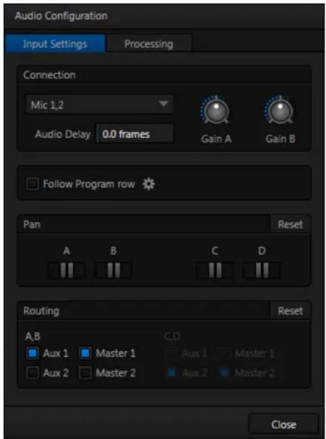
text_image
Audio Configuration Input Settings Processing Connection Mic 1,2 Audio Delay 0.0 frames Gain A Gain B Follow Program row Pan Reset A B C D Routing Reset A,B C,D Aux 1 Master 1 Aux 1 Master 1 Aux 2 Master 2 Aux 2 Master 2 CloseFIGURE 260
The familiar 'gear' icon opens an advanced Audio Configuration panel.
We touched on this panel briefly when we discussed selecting a Connection type for external audio inputs, and (mic) Gain. The Audio Configuration panel offers many more important features and controls, however. Let's explore these now.
15.7.1 AUDIO DELAY
Audio and video arriving at TriCaster inputs will maintain sync throughout the system to output or recording. However upstream issues can occasionally cause video to arrive at TriCaster's inputs later than the corresponding sound.
To mitigate this sort of external problem, TriCaster provides an adjustable Audio Delay setting.
E.g., many cameras support simultaneous digital and analog audio output. In-camera processing can delay digital a/v output, resulting in analog audio output actually leading the digital output by a meaningful measure.
15.7.2 FOLLOW
Enabling Follow Video options for an audio source directs TriCaster to track switcher operations affecting the related video source.
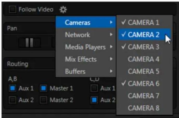
text_image
Follow Video Pan Routing A,B Aux 1 Master 1 Aux 2 Master 2 Cameras Network Media Players Mix Effects Buffers C,D ✓ CAMERA 1 ✓ CAMERA 2 ✓ CAMERA 3 CAMERA 4 CAMERA 5 ✓ CAMERA 6 CAMERA 7 CAMERA 8FIGURE 261
Audio for sources with Follow Program video enabled in the Audio Configuration panel is automatically removed from mixed outputs until one or more specified video sources are actually displayed on Program Output.
Hint: When the corresponding video source is not displayed on output, the audio source's VU meter level is displayed as a grayscale.
15.7.3 PAN
The Audio Configuration panel also provides complete Pan control.
Pan is a very useful feature. It adjusts placement of sound from source audio channels on the stereo channels comprising the audio mix(es).
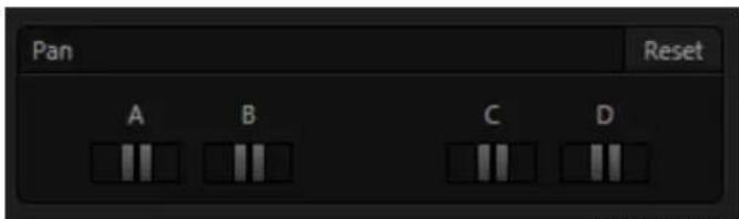
text_image
Pan Reset A B C DFIGURE 262
Using Pan, you can place all or part of channel A onto channel B, and vice versa.
- When Pan is set to the extreme left position for Input 1a, its audio is sent exclusively to the irst channel for the Input 1 group.
- Centering the Pan knob labeled A splits the sound received by Input 1a equally onto channels A and B.
- Sliding Pan for Input 1a all the way to the right results in that source only being audible on channel B, removing it completely from its original channel.
Pan also modulates the sound levels on the left and right channels so that the overall volume neither rises nor drops as a result of adjustments.
Hint: "Pan" is not the same as "Balance". The balance control in a stereo system varies the relative level of the left and right channels, but sound from the left channel will never come out of the right speaker, or vice versa (whereas Pan does permit this to occur).
15.7.4 ROUTING
A control group labeled Routing appears below the Pan group in the irst tabbed pane (Input Settings) of the Audio Configuration panel for all sources.
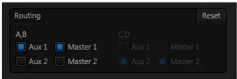
text_image
Routing Reset A,B Aux 1 Master 1 Aux 2 Master 2 C,D Aux 1 Master 1 Aux 2 Master 2FIGURE 263
The controls in this group determine output routing of the stereo pair(s) comprising the input group. Switches let you send channels A and B to different internal audio buses maintained by TriCaster.
When present, channels C and D can be separately routed. Let's talk about what an audio bus is and how it is useful before proceeding.
Busses and Outputs
Consider a very basic audio mixer. Its main audio signal path, from input to output, is properly called the ‘master bus.’ Sound supplied to one or more inputs is placed on this master bus (in the jargon of audio processing, this is called a ‘send’), which ultimately lows to output connectors.
Secondary audio busses:
Actually, beyond the primary busses mentioned here, TriCaster maintains a large number of secondary internal busses.
For example, the Solo switch for each input (and output) is actually a 'send' that adds sound to a 'Solo bus'.
Likewise, the IsoCorder™ module (on supporting models) permits discrete recording directly from the unmodified audio input associated with any single video source; really, this constitutes another up to eight additional audio busses.
Slightly more advanced mixers often provide more than one 'send' for individual inputs. For example, the sound from all inputs may be sent to the master bus, comprising the 'master mix'. A different mix, sometimes called a 'sub-mix', might also be created by sending certain signals to a secondary ('auxiliary', or 'Aux') bus.
Hint: A secondary mix, prepared on an Aux bus, can serve many purposes. For example, you might wish to record a mix with all sound from talent microphones but that excludes any sound effects or music.
Let's summarize what we have learned so far: A ‘send’ pipes audio signals from an input to a discrete pathway called a ‘bus’. Multiple sends can be used to place sound from a given source onto one or more internal busses. OK, what else should we know?
Each audio bus is discrete. Each can be directed along different output paths. And even when the blend of signals it carries is otherwise identical to another bus, it can be processed separately; its level, equalization, and compressor/limiter settings can be unique.
TriCaster provides four primary audio busses. These are identified in the Audio Mixer as:
- Master 1
- Master 2
- AUX 1
- AUX 2
The Audio Mixer provides control groups for each of these busses (Figure 264), allowing you to set their levels and signal processing.
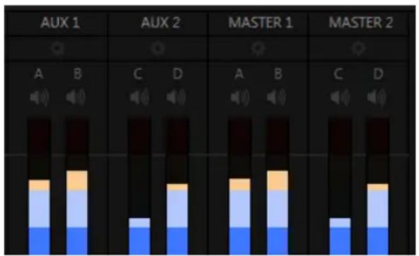
bar_stacked
| Category | Condition | Blue Segment | Orange Segment | Light Blue Segment | Yellow Segment | | :--- | :--- | :--- | :--- | :--- | :--- | | AUX 1 | A | 0 | 0 | 0 | 0 | | AUX 1 | B | 0 | 0 | 0 | 0 | | AUX 1 | C | 0 | 0 | 0 | 0 | | AUX 1 | D | 0 | 0 | 0 | 0 | | AUX 2 | A | 0 | 0 | 0 | 0 | | AUX 2 | B | 0 | 0 | 0 | 0 | | AUX 2 | C | 0 | 0 | 0 | 0 | | AUX 2 | D | 0 | 0 | 0 | 0 | | MASTER 1 | A | 0 | 0 | 0 | 0 | | MASTER 1 | B | 0 | 0 | 0 | 0 | | MASTER 1 | C | 0 | 0 | 0 | 0 | | MASTER 1 | D | 0 | 0 | 0 | 0 | | MASTER 2 | A | 0 | 0 | 0 | 0 | | MASTER 2 | B | 0 | 0 | 0 | 0 | | MASTER 2 | C | 0 | 0 | 0 | 0 | | MASTER 2 | D | 0 | 0 | 0 | 0 |FIGURE 264
It is important to understand the distinction between busses and outputs. Now that we understand the former, let's consider the latter. For TriCaster purposes, an output may be physical, or virtual – i.e., it may involve a connector on the rear panel, or not. For example, the audio recorded by TriCaster does not necessarily require an output connector.
The important thing to realize is that the audio content of any bus may be directed to one or more outputs or, in some cases, to none at all, and – that this is all up to you. By default, the sound from the primary busses is routed to physical outputs as shown in the following table.
| Bus | Output Connectors | ||
| Analog Outputs | SDI Outputs | AES Outputs | |
| Master 1 | 1a, 1b | 1 (channels 1 & 2)3 (channels 1 & 2) | 1a,b(8-input models) |
| Master 2 | 1c, 1d(8-input models) | 1 (channels 3 & 4)3 (channels 3 & 4) | 1c,d(8-input models) |
| Aux 1 | 2a, 2b | 2 (channels 1 & 2) | |
| Aux 2 | 2c, 2d(8-input models) | 2 (channels 3 & 4) | |
However, the standard mapping of busses to outputs can also be modified to suit your specific needs - See Section 8.1, Output Configuration (Figure 265).
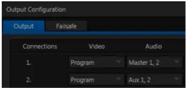
text_image
Output Configuration Output Failsafe Connections Video Audio 1. Program Master 1, 2 2. Program Aux 1, 2FIGURE 265
SUB-MIXES AND 'MIX MINUS'
At times you may require specially configured audio mixes, typically using one of TriCaster's two stereo Aux audio outputs.
For instance – some installations call for sending audio from one or more internal sources (such as a DDR or the Sounds player) to a secondary distribution system. Alternatively, you may want a ‘clean’ output from one or more sources for use apart from the main primary output mix.
Specialized sub-mixes are often referred to as ‘mix-minus,’ since one or more sources are deliberately subtracted from the main program. Mix-minus capabilities can be invaluable for productions like ‘phone-in’ shows. The remote caller needs to be able to hear the interviewer; but if you simply send the primary mix back to him, he is forced to endure a late-arriving echo of his own voice. Needless to say, this would be confusing and undesirable.
Suppose your interviewer is speaking into a microphone connected to Input 1. The audio from your interviewee is routed into Input 2.
- For Input 1, enable both the Master 1 and Master 2 switches under Routing in the Audio Configuration panel.
- For Input 2, enable only Master 1.
This setup gives you a clean output consisting of just the interviewer's voice on the Master 1 bus. You can then proceed as follows:
- Assign Master to Output 1 in Output Configuration (Figure 265).
- The Master 1 output connectors (1a and 1b) supply your primary audio program output for distribution.
- Connect TriCaster's connectors Master 2 connectors (1c and 1d) to your remote call hookup's local audio input to send the clean 'mix minus' back to your interviewee.
This approach eliminates annoying echoing, feedback and the like. Meanwhile, both participants can be heard on the main Program output. Also important, independent control and signal processing is provided for each part of the pipeline.
15.7.5 PROCESSING
The second tab in Audio Configuration is named Processing, and likewise holds very valuable features.
EQUALIZER
The seven-band equalizer allows you to 'shape' sound to taste, accommodate sources with different acoustic characteristics (say, mismatched mics), minimize feedback or roll off unwanted parts of the audio spectrum.
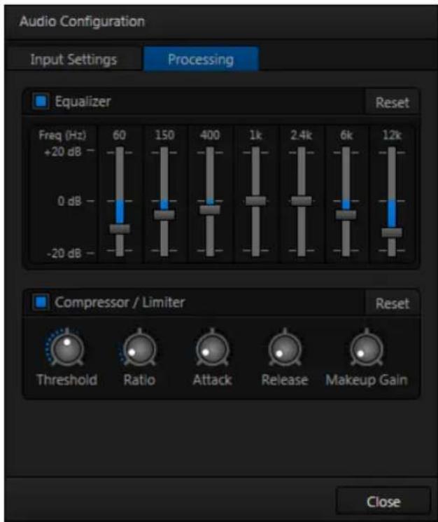
text_image
Audio Configuration Input Settings Processing Equalizer Reset Freq (Hz) 60 150 400 1k 2.4k 6k 12k +20 dB 0 dB -20 dB Compressor / Limiter Reset Threshold Ratio Attack Release Makeup Gain CloseFIGURE 266
Enable or disable the Equalizer using the switch beside the label above its control group.
The sliders attenuate or boost the tonal range centered on the frequency shown at the top. The effect applied falls off gradually as sound draws closer to neighboring frequencies on either side. Click Reset to return all sliders to 0dB.
Hint: Naturally, reducing or increasing the level of one or more tonal bands affects the overall output level as well. This may call for you to trim the main level setting for the affected input or output.
COMPRESSOR LIMITER
The Compressor/Limiter is capable of preventing clipping (see Section 15.8.1) from unexpected peaks or transients, and making talent sound better than they do in real life, bringing voices, music and other audio sources into an optimal dynamic range.
Being able to do this independently for each output too is icing on the cake, especially for Internet streaming, as it ensures correct levels at any time.
THRESHOLD
Sound above the set Threshold level will be compressed; the amount of compression and the manner in which it is applied are both dictated by the other settings.
RATIO
A Ratio of 4:1 means that if input level is 4 dB over the threshold, the output signal level after compression will be just 1 dB over the threshold. The gain (level) is reduced by 3dB.
Very high ratio settings are the reason for the word “limiter” is part of the title for this feature. The highest ratio setting will effectively reduce any signal that would rise above the threshold all the way down to the threshold level (with the exception of a brief period during a sudden increase in source loudness, as dictated by the Attack setting).
Compressor ... Limiter - what's the difference, anyway?
Compression and limiting are not really different processes, but rather a matter of degree and perceived effect.
Compression, ideally, takes the form of a subtle, almost imperceptible modulation of the sound level to bring it into a more pleasing and convenient range. A limiter is applied more for the purpose of managing, even ‘crushing’, unwanted spikes and transients.
That distinction aside, a limiter is essentially just a compressor set to a high ratio and, generally, a fast attack time. Audio engineers typically consider 'compression' with a ratio of 10:1 or more as 'limiting'.
ATTACK
Attack (like Release) is labeled in milliseconds. The setting represents the amount of time it takes for the gain to change by a specified amount.
It would not be grossly incorrect to think of this setting as changing the slope of a graph depicting how aggressively the compressor pursues the target value (deined by applying the Ratio setting to the amount the signal surpasses the Threshold).
Shorter values are more aggressive, while longer values are more subtle (and tend to be less noticeable to the audience).
RELEASE
Release is similar to Attack in many ways, but refers instead to the speed with which the compression effect is removed as a source signal falls back on its own so that it no longer exceeds the Threshold.
GAIN
Naturally, compression impacts the overall output level of the source or output. The Gain control allows you to compensate, bringing the post-compressor/limiter signal back to a comfortable nominal range.
Hint: Different circumstances call for different Attack and Release strategies. For example, much less aggressive settings could work nicely for vocals, but fail badly when applied to a snare drum. Many websites provide suggestions on establishing the best compressor/limiter settings for different environments.
SECTION 15.8 OUTPUT AND PRIMARY BUS CONTROLS
As has been discussed (Section 15.7.2), TriCaster provides four primary audio busses – Master 1 and 2, and Aux 1 and 2. Each of these is represented by its own control group Audio Mixer's output section, and regulates sound sent to physical connectors or to 'logical outputs'.
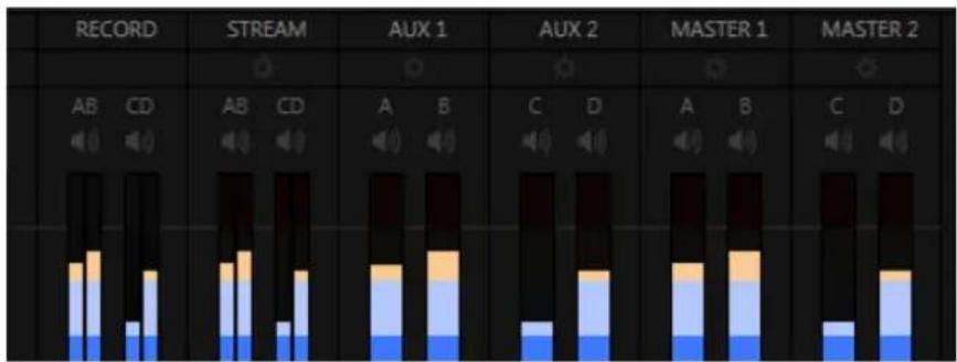
bar_stacked
| Category | Segment 1 | Segment 2 | Segment 3 | |---|---|---|---| | RECORD | 0 | 0 | 0 | | STREAM | 0 | 0 | 0 | | AUX 1 | 0 | 0 | 0 | | AUX 2 | 0 | 0 | 0 | | MASTER 1 | 0 | 0 | 0 | | MASTER 2 | 0 | 0 | 0 |FIGURE 267
Hint: Shift + double click Volume knobs to restore their default values (0dB).
Settings in all of the control groups in this section (Figure 267) take effect downstream from all audio sources, further modulating and processing audio sent to outputs as the Aux and Master mixes, for recording, and for Internet streaming.
Note: Record and Stream are logical outputs with their own control groups in the Audio Mixer's output section. This allows them to be governed independently of other outputs that the same mixes may have been assigned to.
15.8.1 HEADROOM NOTES
In digital audio systems, signal levels that exceed maximum values are uniformly assigned the maximum value, a condition known as “clipping”.
Clipping inevitably results in annoying audible issues. Worse, over-modulation that may not be apparent while listening during live production may nonetheless appear in recorded iles. This is often true even when levels appear to be below the ceiling level (0dBFS, the maximum allowable digital level).
For this reason, digital audio system designs customarily allow substantial 'headroom' above the benchmark 'alignment level', making over-modulation much less likely. Often this allowance seems high to those familiar with analog audio systems; headroom levels between 18 and 24dB are not uncommon in professional digital audio realms.
TriCaster allows for any preference in this regard, by its provision of separate Record (and Stream) level controls discussed shortly. For example, dropping the Record slider to -20dBFS (our base recommendation, by the way) approximates typical professional practice. This has no impact on levels at TriCaster's audio outputs, but all but ensures clipping in recorded iles will be avoided.
Advanced users can thus record iles conforming to regional standards or personal preference, substantially reduce the possibility of audio clipping in recorded iles, and even adjust the level on the ly if necessary.
The main point to remember from all of this is that for digital audio recording “less is often more”. When it comes to levels, by all means go as high as necessary – but it’s equally practical to go no higher than necessary.
Hint: The Audio Mixer also provides Compressor/Limiters for each input and output. These can also be invaluable in defeating clipping due to over-modulation.
15.8.2 RECORD
The Record control group provides dedicated level modulation over the audio recording chain applying to *most sources assigned to Output 1 and Output 2 in the Output Configuration panel.
Again, this control group has no effect whatsoever on audio sent to output connectors. Similarly, it does not impact audio levels in iles which are configured (in Record Configuration) to capture anything other than Output 1 and 2.
* When Output 1 and 2 are assigned (in Output Configuration) to use audio directly from a designated TriCaster audio input (Input 1-8), the audio signal recorded is 'pre-mixer'.
15.8.3 STREAM
The Stream controls provide a method of independently adjusting levels and processing for (stereo) audio sent to the encoder when streaming is enabled.
SECTION 15.9 MEM SLOT BINS
Roll the mouse to the left edge of the screen in the Audio Mixer to show its MEM slot bin. Audio MEM slots work just like their counterparts in the Media Players (see Section 11.2.4). MEM slots are a convenient way to quickly store and recall audio steps and settings for different venues, productions, and users.
text_image
TCTriCaster™ supports two simultaneous network sources, letting you switch displays from networked computers or other network video sources – including streaming video – as part of your production.
Also, when connected to a networked workstation or laptop computer running LiveText™, NewTek's powerful realtime titling software, you can assign your CG duties to a second operator, freeing you to focus on live switching.
Video served across a network can be selected as Switcher and overlay sources in the TriCaster™ live production environment (see also Section 8.3).
Potential network sources include:
- Displays from (Windows® or OS X® based) computer systems (via iVGA™)
- Text and graphics overlays from NewTek's LiveText™ application
- NewTek 3Play™, TriCaster, or Apple Airplay® network outputs
• Video and CG output from numerous third party applications
• Streaming Internet (and intranet) video sources - Webcams and IP cameras
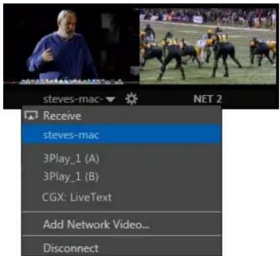
text_image
steves-mac Receive steves-mac 3Play_1 (A) 3Play_1 (B) CGX: LiveText Add Network Video... DisconnectFIGURE 268
Qualified network sources (including webcams directly connected to TriCaster) are listed in Net 1 and 2 drop-down menus, available for immediate use in your presentation, and can of course be captured or streamed as well.
Note: Gigabit networking is highly recommended, and should be considered mandatory for HD sessions in particular. This can also be important for third-party network sources.
Let's consider some of the available network source types.
SECTION 16.1 IVGA
iVGA is the proprietary NewTek utility supplied to let you use data directly from the interface of a networked computer. It has a tiny footprint, and can even be run from a USB thumb drive, without no need to install it directly on the hard drive of the remote client system.
iVGA client programs are supplied for both Microsoft Windows® and Apple OS X®. You will ind iVGA installation iles inside the C:\TriCaster\Extras\iVGA folder on your TriCaster system drive. There are several versions of iVGA, and you should select the one best suited to your host system. (Readme iles found in the same location will help you determine which one is appropriate.)
16.1.1 IVGA FOR OS X
The iVGA installation for OS X is supplied as a zipped disk image (.dmg) ile. To install it, irst copy this ile to your Macintosh® Desktop (either using a network connection between your Macintosh® and TriCaster systems, or perhaps by using a USB thumb drive).
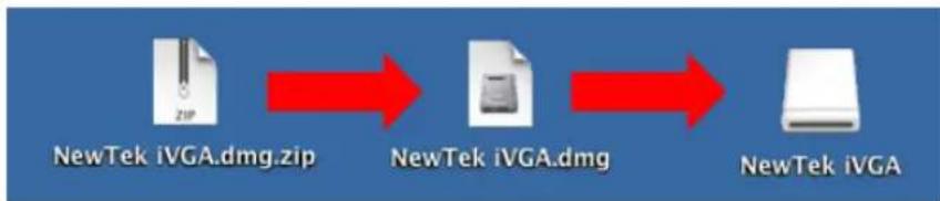
flowchart
graph LR
    A["NewTek iVGA.dmg.zip"] --> B["NewTek iVGA.dmg"]
    B --> C["NewTek iVGA"]
FIGURE 269
- Double-click the Zip ile to decompress it, and then double-click the .dmg ile to mount it.
- The NewTek iVGA icon shown above will be placed on your Desktop. Open it (by double-clicking, and you will see two iles in a Finder window – the readme ile, and the iVGA client program.
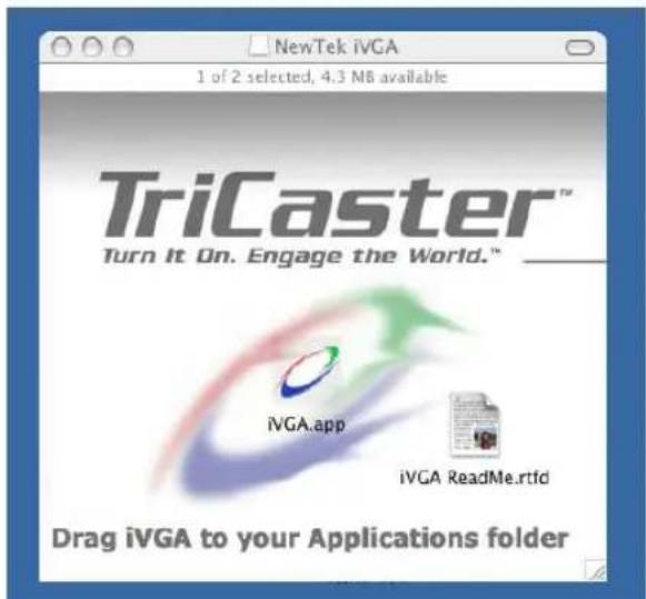
text_image
NewTek iVGA 1 of 2 selected, 4.3 MB available TriCaster™ Turn It On. Engage the World.™ iVGA.app iVGA ReadMe.rtfd Drag iVGA to your Applications folderFIGURE 270
- Drag the iVGA icon from the inder to your Applications folder.
- Run it by double-clicking the icon, and in a moment or two the iVGA swirl will be placed in your Dock, and an onscreen dialog reporting 'iVGA Ready and listening!'
When you roll your mouse over the Net 1 or Net 2 monitors in TriCaster's All Monitors tab, a triangular button appears next to the Configure button (gear). The new source (your 'Mac' desktop) will be listed in the drop-down selection menu that opens when you click the triangle.
When iVGA is running, the icon in the (OS X) Dock has a menu you can access by right-clicking it:
- Engaging Privacy Mode prevents the client display from appearing accidentally on the TriCaster display when you don't want it to.
- Keynote Mode allows the iVGA client to update the screen even if Keynote® is running. (This also can be used with some games, though the framerate will likely be only one frame per second.)
- Hide the mouse cursor in output with the Hide Mouse option.
- Show either desktop monitor when you have more than one attached using the Monitor 1 or Monitor 2 options in the menu.
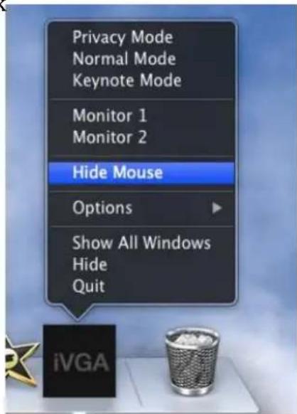
text_image
Privacy Mode Normal Mode Keynote Mode Monitor 1 Monitor 2 Hide Mouse Options Show All Windows Hide Quit iVGAFIGURE 271
- The Options list contains settings for Open at Login, Remove from Dock, and Show in Finder.
16.1.2 IVGA PRO (WINDOWS)
The iVGA PRO™ installation for Microsoft Windows® systems is supplied as an executable (program) ile. To use it, copy this ile to the client system from its location in the iVGA folder (found inside on C:\TriCaster\Extras).
Run iVGA on the client computer by double-clicking its icon (iVGA PRO will run from anywhere you put it on the client system – even a thumb drive).
Note: iVGA PRO is for use with XD series TriCasters. Those with SD-only model TriCasters (or 32bit iVGA client computers) should use the earlier 'iVGA' application.
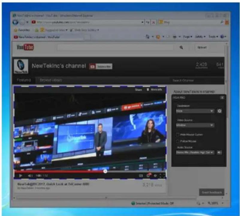
text_image
NewTekInc's channel - YouTube - Windows Disney Express http://www.yukuba.com/sv2003/ Favorites Supported Web Web Buy Button NewTekInc channel - YouTube You Tube NewTek NewTek Inc's channel Search View info Share View info About newtek access channels FPGA PRO Description Name Video Source Window Photo Mouse Curner Follow Mouse Audio Source Video Mix creation, high: 5x 5x NewTek@8C2012 Quick Look at TrICaster 2000 by NewTek Inc. (Copyright only) 3,218 views Get instructions Internet | Protected Mode Of 4,100%FIGURE 272
The first time you launch iVGA PRO you'll be asked to accept an End User License Agreement.
Afterward, several things will occur:
- A small icon is added to the Windows® task bar notification area.
- The iVGA PRO control panel opens on your computer desktop.
The control panel, Taskbar iVGA PRO icon (and its context menu) along with a marquee discussed momentarily provide all the settings and controls you need to configure and manage the application and its output.
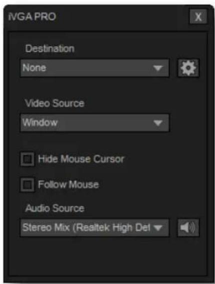
text_image
IVGA PRO Destination None Video Source Window Hide Mouse Cursor Follow Mouse Audio Source Stereo Mix (Realtek High DelFIGURE 273
THE CONTROL PANEL
Let's begin our review of the tools provided by looking more closely at the iVGA PRO control panel.
DESTINATION
The default Destination setting is None, indicating that iVGA PRO's audio and video output is not connected to a TriCaster on your local network.
When one or more TriCaster systems are detected, the drop-down menu will display their machine names (Figure 274). A given TriCaster may display more than one possible entry in the list depending on how many are currently free for iVGA selection.
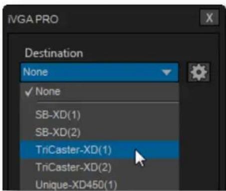
text_image
IVGA PRO Destination None ✓ None SB-XD(1) SB-XD(2) TriCaster-XD(1) TriCaster-XD(2) Unique-XD450(1)FIGURE 274
Alternatively, TriCaster operators on the same network can directly select your iVGA client as a network source for their Net 1 or Net 2 inputs (see Section 10.1.2).
When a TriCaster you have not previously connected to selects your iVGA output, iVGA pops up a 'connection request' dialog. You can then authorize or decline the connection request (click the gear icon next to Destination and checkmark Accept All Connections in the menu if you prefer that this dialog not be shown).
Note: If you decline a connection request from a TriCaster with "Always do this" enabled in the dialog, future requests from that unit will simply be ignored. Turn on "Accept All Connections" if you later wish to view all incoming connection requests; alternatively, connecting to a given unit from iVGA to re-enable the dialog for that system alone.
RECORDING
The last entry in the Destination menu is always Record. Selecting Record redirects iVGA PRO output into a movie ile instead of transmitting it across the network.
When you select Record a ile window opens to let you set the path and ile name for
the clip that will be captured.
Note: You can choose between alternate ile formats for recording by modifying the 'Save as type' setting (in the ile path dialog).
Also, the Send button at the bottom of the control panel is re-labeled Record. As you would expect, clicking the button initiates recording of the current iVGA source. Press it again to end capture.
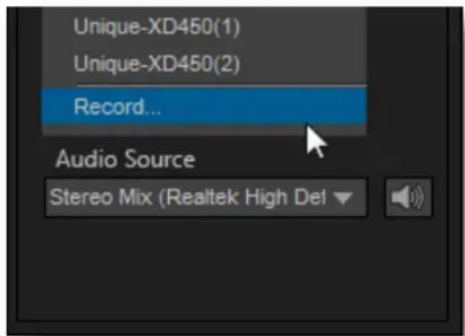
text_image
Unique-XD450(1) Unique-XD450(2) Record... Audio Source Stereo Mix (Realtek High Del)FIGURE 275
Hint: Changing the Video Source while recording will automatically stop and restart recording. The current file name is numerically incremented as required.
QUALITY (CONFIGURE)
Click the Configure (gear) button beside Destination to reveal a menu providing quality options. The setting here affects iVGA's video compression parameters. You can use these options to improve performance when your local network connection lacks the bandwidth required to deliver the highest quality iVGA output to TriCaster.
Note: Gigabit network connection provides the best transfer rates and the best quality video output. Slower connections may cause dropped frames, and should be considered unsuitable, especially for HD sessions. In extreme cases, where network capability is low or unreliable because of other traffic, iVGA may still be useful for static displays.
VIDEO SOURCE
The video source menu governs the imagery iVGA transmits or captures. The menu lists a number of important options (Figure 276).
- At the top, you will see all monitors connected to the system iVGA PRO is running on named. Selecting a monitor by name assigns its entire display as the current iVGA source.
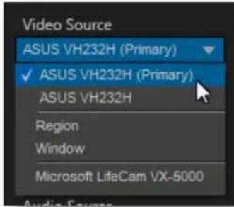
text_image
Video Source ASUS VH232H (Primary) ✓ ASUS VH232H (Primary) ASUS VH232H Region Window Microsoft LifeCam VX-6000FIGURE 276
- Just beneath the list of monitors is the Region option. This refers to the portion of the screen that is inside a rectangular marquee that is shown when Region source mode is newly selected.
- Drag the cross-hair icon in the center of the marquee to relocate it on the screen or to a different monitor.
- Drag the mouse on any border of the marquee to scale it up or down. By default, scaling is constrained to retain a 16:9 marquee aspect. Hold down Ctrl
when dragging to release the aspect lock. To restore the marquee's standard widescreen aspect, simply drag the border again without the Ctrl key depressed.
text_image
Pricetudio Browse video DingleriskFIGURE 278
The next Video Source option shown in the menu is Window. This is a particularly useful option, as it allows you to 'snap' iVGA to a specific application window (or child
text_image
Video Source WindowFIGURE 277
For example, you might designate just the video player pane on a browser page as the source; or perhaps you might want to snap to the video display pane in an application such as Skype™.
When you select the Window option in the Video Source menu, a new icon is shown at right (Figure 277). Click the mouse on this icon, and then drag it to the application window you want to assign as the source.
(The marquee updates as you drag the mouse around the screen from one application window to another. Note that it automatically disappears from view when the control panel is closed.)
Hint: Many application windows actually comprise a number of child windows grouped together. When you drag the marquee around in Window mode its borders snap to the current child window, showing what is currently selected.
- Finally, if you have any webcams or similar video input devices connected to the system, you'll see these listed below the Window option in the Video Source menu.
AUDIO SOURCE
This menu allows you to directly select sound from available audio inputs and system audio devices (the latter may provide useful level and mixing options).
iVGA PRO transmits the selected sound to the Network inputs of TriCaster's that support this feature. A nearby mute icon allows you to toggle sound output on/off.
Hint: Select None to mute audio output. (Privacy mode also temporarily engages Mute.)
OPTIONS
- Hide Mouse Cursor – the mouse pointer will not appear on iVGA's video output when this option is enabled.
- Follow Mouse – the marquee tracks mouse movement when this option is enabled.
SEND/RECORD/STOP
A multi-function button at the bottom of the iVGA PRO control panel toggles output (or recording) on and off. The button label updates to display the action that will occur if you click it according to the current operation and state of the application. It may variously show Send, Record or Stop, as appropriate.
16.1.3 TASKBAR ICON MENU

text_image
10:40 AM 11/29/2012FIGURE 279
A ‘radio beacon’ icon (shown at left in Figure 279) is shown in the system taskbar when iVGA PRO is running. The icon shows a ‘radiating’ animation when connected to a TriCaster.
Click the icon to show the iVGA PRO Control Panel (and marquee, when enabled).
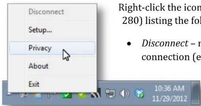
text_image
Disconnect Setup... Privacy About Exit Right-click the icon (280) listing the fol • Disconnect - r connection (e 10:36 AM 11/29/2012FIGURE 280
Right-click the icon to display its context menu (Figure 280) listing the following items:
- Disconnect – releases the currently selected connection (equivalent to selecting None in the control panel Destination menu).
- Setup – shows the iVGA PRO control panel.
- Privacy – while engaged, iVGA PRO's video output is replaced by a static privacy image (see hint below) and audio output is muted.
Privacy mode allows the user to check e-mail, or perhaps view or arrange something, without risk of the audience observing. The taskbar icon shows a red indicator when Privacy mode is engaged.
Hint: If an image named “privacy.bmp (or privacy.jpg) exists in the folder that iVGA is launched from, it will be sent. Otherwise the default privacy screen is used.
- About – displays information about the application.
- Exit (exits the iVGA application)
16.1.4 HOTKEYS
In Region mode, it's possible to zoom the marquee to several preset sizes (150%, 200%, 400%) using the hotkeys Right Ctrl + number pad 1, 2 or 3 (these hotkeys enable Region mode).
Right Ctrl + (number pad) 0 selects the full screen for output. Pressing Right Ctrl + (number pad) 5 toggles the Marquee display on/off (even if the control panel is closed), while Right Ctrl + (number pad) 9 enables or disables the Follow Mouse option.
Tip: See Section A.1.14 for information on troubleshooting iVGA issues.
SECTION 16.2 AIRPLAY
AirPlay® is Apple's protocol for getting audio and video from 'here' to 'there' - specifically, from an AirPlay source (which may be an Apple® computer, or a mobile device such as iPad®, iPod®, or iPhone®) to a second device.
The local network is the means of transmission between units, and a wireless connection from the player to the network is perfectly acceptable. Typically, the target device for AirPlay might be a television display or set of speakers, but in this case, your TriCaster is the beneficiary. It basically works as follows:
- You select the AirPlay entry in the Source menu for Net 1 or Net 2, just as you would select an iVGA or LiveText source. (Unlike iVGA, embedded audio, with level control, is supported.)
• TriCaster identifies itself as a network client for AirPlay apps/applications. - You can then designate TriCaster as the output device for content played on the device.
- AirPlay streams audio, video, or both from the device to the local network, and on to TriCaster.
• The AirPlay output is available just like any other TriCaster Switcher source.
Consider just a few of the countless possibilities: Use your iPad® as a touch-driven external (wireless) DDR, or capture video or snapshots on your iPhone®, and instantly stream this content to the TriCaster.
Note: Please see Appendix A, Section A.1.14 for more on Airplay connections.
SECTION 16.3 LIVETEXT
As we noted in the Walkthrough chapter (Section 4.6.2) a companion workstation on your TriCaster network with LiveText standalone installed serves as a dedicated CG and title solution for your live presentations.
When running and connected, LiveText will be listed in TriCaster's Net 1 and Net 2 drop-down menus, similar to an iVGA source. For more information on installing and using LiveText, please refer to its manual.
text_image
LIVE OUTPUT JOHN J.J. JAMES Camera TYRONE WELLS Editor MARCHALL EVANS Graphics JAMES STEWART Technical Director TRISTA VALDEZ Creative Services JOHN GREEN No animals were burnedFIGURE 281
3Play's Output A and Output B are available as Switcher sources to TriCaster. They appear in the source selector menu for TriCaster's network inputs as "3Play(A)" and "3Play(B)," where "3Play" is the name for the system.
Conveniently, 3Play's network output also includes embedded audio, freeing up multiple TriCaster a/v inputs for other purposes.

text_image
3Play1(A) 3Play1(A) 3Play1(B) LiveText CG: MyLaptopFIGURE 282
SECTION 16.5 NETWORK VIDEO
The Net 1 and 2 inputs also support a number of different streaming network video source types and protocols, such as RTSP and RTMP, so-called 'IP cameras', and more.
The various source types discussed earlier in this chapter, having been designed for the purpose, advertise their availability over the network to TriCaster; this, in turn, allows TriCaster to list them in its source drop-down menus automatically on detection.
This is not the case with video sources of the types listed in the previous paragraph, but with basic address information you can add them to the source menu listing. The Source selection menu for both Net inputs shows the item Add Network Video (Figure 283).
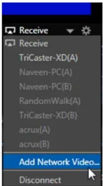
text_image
Receive Receive TriCaster-XD(A) Naveen-PC(A) Naveen-PC(B) RandomWalk(A) TriCaster-XD(B) acrux(A) acrux(B) Add Network Video... DisconnectFIGURE 283
Select this entry to pen the Network Video Configuration panel (Figure 284). Enter a name for the camera (to help you identify it in the dropdown Source menu later, complete the address ield (expand the Examples just below the Address input ield for help on syntax), and click Done.
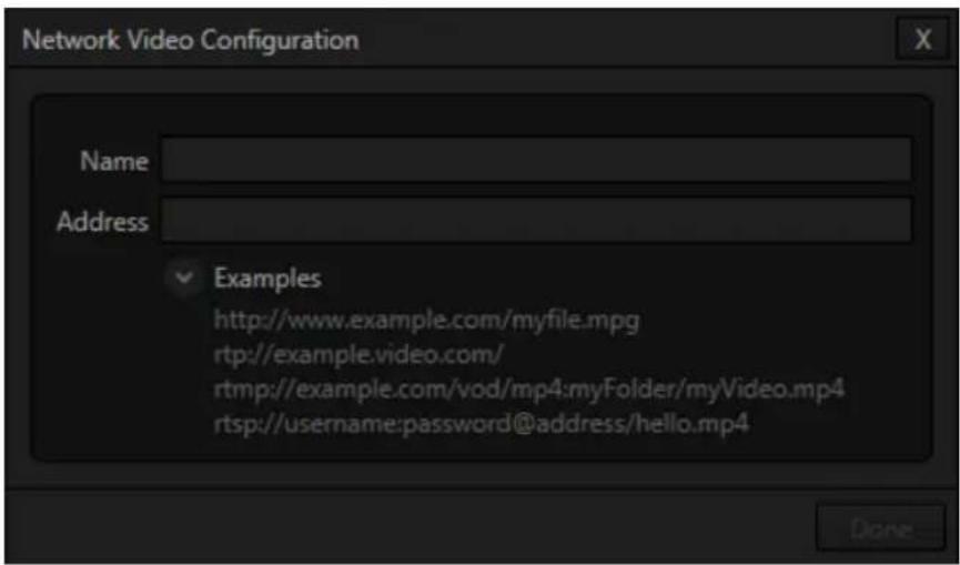
text_image
Network Video Configuration Name Address Examples http://www.example.com/myfile.mpg rtp://example.video.com/ rtmp://example.com/vod/mp4:myFolder/myVideo.mp4 rtsp://username:password@address/hello.mp4FIGURE 284
Afterward, the new entry appears in the Source menu (Figure 285) along with any other network sources that have been detected or added manually.
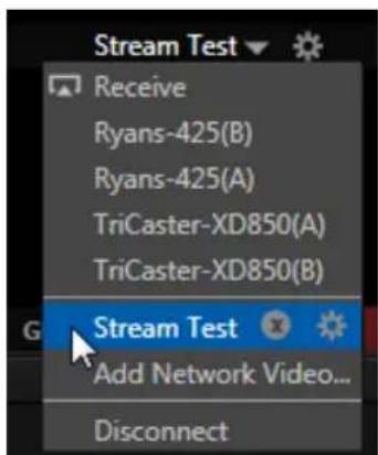
text_image
Stream Test Receive Ryans-425(B) Ryans-425(A) TriCaster-XD850(A) TriCaster-XD850(B) Stream Test Add Network Video... DisconnectFIGURE 285
natural_image
Illustration of a kangaroo standing on a beach with a 'Stream Test' button (no text or symbols on the image itself)FIGURE 286
Notice that moving the mouse over the new entry in the menu adds two control gadgets. The familiar gear icon reopens the Configuration panel, to allow you to edit the details. The small x button removes the entry from the menu.
MACROS, AUTOMATION AND REMOTE Chapter 17 CONTROL

text_image
TCMacro capabilities smooth out your workflow, reducing complex operations to a single button press, and make it easy to produce sophisticated programs. Combined with TriCaster's Hotspot automation, macros provide many opportunities for both workflow streamlining and creative applications. (As well, macros can reduce or eliminate embarrassing operator errors.)
This Chapter also covers Remote Control, which allows TriCaster operations to be synchronized for various purposes.
One of the hardest things about live switching is keeping up with the action. We're only human, limited as to how fast our ingers can move, recall and perform important sequential steps, and so on.
TriCaster's macros are the answer to that dilemma. Record any sequence of events as a macro and play it back with one click. Alternatively, trigger it with a keystroke, control surface operation, or HotSpot.

text_image
File Options Macros Workspaces Help Practice SessionFIGURE 287
Macros can do almost anything; Preload and play content, modify audio settings, automate complex switcher sequences or perform synchronous operations.
The compelling usefulness of macros justifies the prominent Macros menu placement in TriCaster's Dashboard.
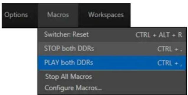
text_image
Options Macros Workspaces Switcher: Reset CTRL + ALT + R STOP both DDRs CTRL + . PLAY both DDRs CTRL + . Stop All Macros Configure Macros...FIGURE 288
Click Macros to show a menu (Figure 288) containing a Configure Macros item. This opens the Macro Configuration Editor, which is where you can create and manage macros.
Hint: The Switcher: Reset entry is permanently included in the Favorites menu. This macro sets all effects (including DSK and Key transitions) to the default Fade, and assigns M/Es to Mix mode. It does not alter active source selections.
SECTION 17.1 SYSTEM MACROS
The largest part of the (resizable) Macro Configuration Editor consists of the Macro List. By default it will initially display a single line entry labeled System Commands.
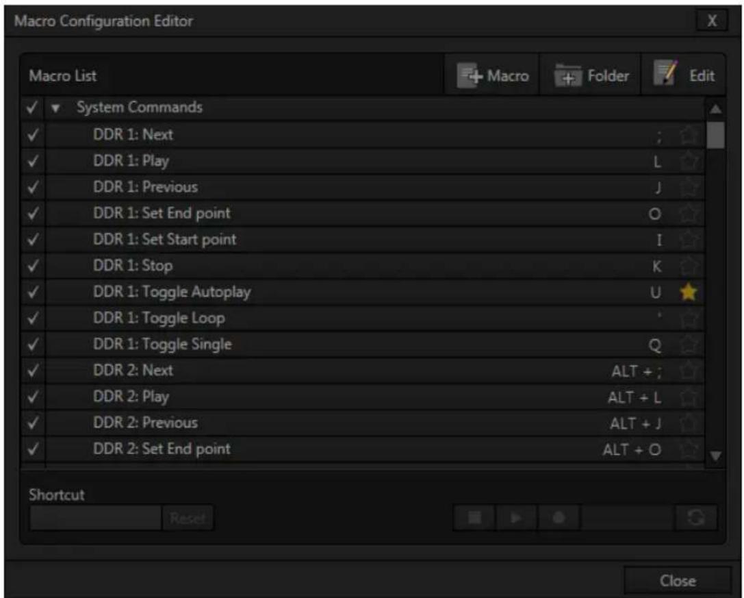
text_image
Macro Configuration Editor Macro List + Macro + Folder Edit ✓ System Commands ✓ DDR 1: Next ✓ DDR 1: Play ✓ DDR 1: Previous ✓ DDR 1: Set End point ✓ DDR 1: Set Start point ✓ DDR 1: Stop ✓ DDR 1: Toggle Autoplay ✓ DDR 1: Toggle Loop ✓ DDR 1: Toggle Single ✓ DDR 2: Next ✓ DDR 2: Play ✓ DDR 2: Previous ✓ DDR 2: Set End point ALT + J ALT + O Shortcut Reset CloseFIGURE 289
System Commands are actually the very same shortcuts called by the user interface and Control Surface to operate your TriCaster. Expand this entry by clicking the triangle at left to see a long list of these important macros.
Hint: Notice that keystroke shortcuts for macro entries are shown at right, which is convenient reference if nothing else.
It's worth noting a few unique aspects of System Macros. First, System Macros are specially safeguarded within the system. Rename, Delete, Clone and Paste features are disabled, nor can you alter the order of entries in the list.
Also, be aware that un-checking the enable switch at left for the entire System Macros folder (or individual entries within it) will naturally result in the failure of all related keystroke shortcuts. By design, this does not affect Control Surface operations, however.
Hint: If keyboard shortcuts are unresponsive even though System Macros are enabled, check the state of the similar Enable Keystroke Shortcuts setting in the TriCaster Options menu (see Section 7.1).
SECTION 17.2 RECORDING MACROS
text_image
Macro FolderFIGURE 290
Creating a new macro is simple. Buttons at upper right let you add folders and macros. Click the irst to add a folder and name it. Selecting a folder in the list (other than the System Macros folder) enables the Add Macro button (Figure 290). Click this button to add a new macro entry.
Continue to deine the macro by clicking the Record button at the bottom of the panel, and then just go ahead and perform the sequence of operations you wish to include in the macro. You can use mouse, keyboard, and Control Surface operations when doing so.
text_image
100%FIGURE 291
When inished, click the Stop button to complete recording. Test the new macro by clicking the Play button. You'll notice that an animated bar in the background of the macro's entry in the list tracks playback progress.
Of course, you can modify the playback rate using the menu next to the Record button. You can even set macros to loop using the button at extreme right.
SNAPSHOT MODE
One option in this menu bears explanation – Snapshot is rather special. When you choose Snapshot as the macro's 'speed', you essentially force it jump to its end result. Any operation that is ultimately irrelevant in achieving that end result is simply omitted. Snapshot mode is very useful for macros that configure TriCaster to a particular state.
One example would be when you want to instantly reconfigure M/Es with different virtual sets for a scene change; or perhaps you want to quickly disable LiveMatte for all Media Players at once. The possibilities are endless.
Hint: You can record a macro that includes other macros. Depending on your order of operations, you may need to re-highlight the newly recorded macro in the list to show its Stop control (to end macro recording).
SECTION 17.3 MANAGING MACROS
The Macro Configuration panel has management features such as folders, rename, clone, and hotkey assignment, as well as Import and Export (share macros with other TriCaster users).
17.3.1 ASSIGNING SHORTCUTS
Macros may be triggered by keystroke shortcuts, or control surface button presses – including MIDI (see Chapter 22, Control Surfaces for more information on supported hardware alternatives.)
text_image
Shortcut ResetFIGURE 292
You can readily see the shortcut assigned to a macro at right in its entry in the lister. You'll also see a 'star' gadget at right (Figure 293). Click this to add (or remove) the macro to the Favorites
FIGURE 293
menu (Figure 288), shown when you click directly on the Macro control in the Dashboard.
To set a new shortcut or modify an existing one, click in the Shortcut ield at lower left in the Macro Configuration Editor panel (it will display a "Listening ..." tag). Then press the desired keystroke.
Hint: For clarity, lower-case characters are shown as capitals. True upper-case letters are displayed in the form [Shift + (character)].
Shortcuts are ‘per user’, allowing you to employ your personal favorites without conflicting with the shortcut preferences of other users. Speaking of conflicts, note that assigning a single shortcut combination to multiple macros is supported.
Conlicted keystrokes are shown in red. You can resolve conflicts in several ways. Of course you can assign a different keystroke to conflicted macros. Or you can disable them if you like, using the checkmark switch at left for the entries involved.
Hint: Folder level enable/disable switches offer an alternative method for managing program-specific shortcuts. The keystroke assignments for entire folders full of macros designed for various programs or purposes may conflict with shortcuts in another folder., but keystrokes for any inactive folders are ignored.
Otherwise, pressing the conflicted shortcut key will perform all macros sharing that keystroke assignment – which may be just what you had in mind.
17.3.2 THE CONTEXT MENU
Entries in the lister have a context menu, shown when you right-click an item (Figure 294).
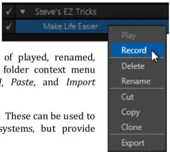
text_image
Steve's EZ Tricks Make Life Easier Record Delete Rename Cut Copy Clone ExportFIGURE 294
Macros can be recorded, as we've seen, of played, renamed, deleted, copied, cloned, or exported. The folder context menu supports, in addition, Play All, Stop All, Paste, and Import operations.
Import and Export are noteworthy features. These can be used to share macros with multiple users and systems, but provide another important opportunity.
A good deal of time can be spent preparing complex macros designed to support your production. It would be a shame for these to be lost unintentionally through some mishap, as by some tidy soul deleting a folder on your day off (or perhaps by performing a System Restore). For this reason, we encourage you to use the Export feature to prepare a backup archive of your painstakingly designed macros. (This is quite easy to do, since Export of entire folders is supported, as is multi-selection.)
SECTION 17.4 MACROS AND HOTSPOTS
On-screen HotSpots (see Section 8.2.7) are another way to activate TriCaster's powerful macros. Live action on-stage can trigger multiple macros based on HotSpots activity detected.
This is very powerful technology – the practical (and whimsical) applications are limited only by your imagination.
natural_image
Woman in black dress holding a red card against a dark background (no text or symbols visible)FIGURE 295
This feature makes TriCaster's virtual set system especially powerful. Talent can trigger one macro by moving their hand (for example) into a Hotspot, another by moving it out; and each source supports 8 hotspots.
- Use live action to make Overlays and DSKs appear auto-magically, or switch the video in a virtual monitor by tapping it with a ingertip.
natural_image
Woman presenting a laptop in a modern studio setting with abstract lighting (no visible text or symbols)FIGURE 296
- Switch from a seated desk shot to a standup virtual set simply set by walking into it; then auto-switch to the next shot when you walk back out of the frame.
- Load up new DDR MEM slot, audio configuration and camera assignments when talent moves from the desk shot to standup in a virtual set.
- Reveal an over-the-shoulder Skype® shot and configure audio for a remote interview, then close it and restore the 'local' sound setup with a wave of the hand; or trigger a sound – a drum roll, gong, or the entire Muppets® anthology.
Hint: Use the Overlay option Flip View Horizontal to let talent see for exactly where their marks are on the screen – See 0.
SECTION 17.5 EDIT A MACRO
text_image
Folder EditFIGURE 297
Often you will wish to modify values assigned to the various steps in an existing macro, rather than re-recording it; or perhaps you want to experiment with other possibilities. Click the Edit button (Figure 297) to open the Macro Editor for the currently selected macro.
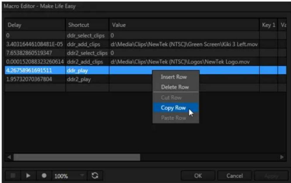
text_image
Macro Editor - Make Life Easy Delay Shortcut Value Key 1 Va 0 ddr_select_clips 0 3.40316446108481E-05 ddr_add_clips d:\Media\Clips\NewTek (NTSC)\Green Screen\Kiki 3 Left.mov 7.65382860519347 ddr2_select_clips 0 0.000152088323260614 ddr2_add_clips d:\Media\Clips\NewTek (NTSC)\Logos\NewTek Logo.mov 4.26758961691511 ddr_play 1.95732070367804 ddr2_play Insert Row Delete Row Cut Row Copy Row Paste Row OK Cancel ApplyFIGURE 298
This deceptively simple editor presents the shortcut sequence your macro contains, along with all of its values in a simple to comprehend 'spreadsheet-style' interface. Simply click a cell to edit the current entry.
Right-clicking opens the shortcut row menu. When done, click the Apply button (or Cancel to close the editor without saving your changes).
Hint: Use the Record button in the foote rof the Editor to insert newly recorded entries into the current at the selected line.
SECTION 17.6 REMOTE CONTROL
(TriCaster 8000 only) In high-end broadcast applications and multimedia production environments, it can sometimes be quite important for redundant TriCaster systems to be operating synchronously.
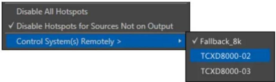
text_image
Disable All Hotspots ✓ Disable Hotspots for Sources Not on Output Control System(s) Remotely > ✓ Fallback_8k TCXD8000-02 TCXD8000-03FIGURE 299
The Options menu (Live Desktop Dashboard) contains the item Control System(s) Remotely. Selecting a suitable TriCaster 8000 unit in this menu checkmarks it; subsequently, the all command operations given to the local unit are echoed to the controlled TriCaster, which will follow along submissively.
Tip: Mirrored systems should be running identical software versions, specifically Rev.1c or better.
17.6.1 'TWINNING' TRICASTERS
For most purposes, media content and all initial control states of both local and controlled systems must be absolutely identical in order for remote control (a.k.a., 'mirroring') to work as expected. Thankfully, achieving this 'twinned' state is not that difficult.
- Conigure the irst TriCaster:
○ Create a new session in the desired format.
- Go on to configure cameras, Proc Amps, media content, Audio Inputs and Mixer settings, M/E configurations, etc., just the way you want for your production.
- Exit the session, and use TriCaster's Backup Session feature (see 5.3.3) to back it up, gathering all media assets in the process.
- Click the Shutdown icon on the Home Page, and select Administration Mode.
- From the Administration Mode screen, Exit to Windows, and locate the session backup ile you created.
- Transfer the session backup across the network to the remote system.
- Use the Restore Session Backup feature (see Section 5.2.2) on the Home page of the remote system to open the backup session ile, and launch the session.
- Re-launch the original session on the controlling system, and enable remote control over the second system using the Options menu item as described earlier.
That does it as far as configuring TriCaster goes. Obviously too, though, mirroring normally calls for upstream distribution amps to multiply camera feeds, attention to matching up audio routing, and so on. Likewise, in most cases, attention must be given to output routing (and sometimes, 'failover' device planning and connection).
In yet another approach to all of this, you might consider using an outboard network drive as the Session Volume for both systems.
Note: Normally, TriCasters operating under remote control retain autonomous local control response. You can actually enable bi-directional remote control by configuring two systems to control each other. This can be very desirable, such in cases where different operators are responsible for certain aspects of the production process.

text_image
TCLive webcasting has dramatically altered the broadcast landscape. Information can now be shared among audiences around the world with very small transmission costs. The live streaming market provides many creative and proitable opportunities. When it comes to taking advantage of this new medium, TriCaster™ places you in the forefront of all the excitement.
Internet streaming for different purposes involves a wide variety of attributes; at times, too, account login details are required for your streaming service or CDN (content delivery network). You may well maintain multiple accounts for different purposes, as well.
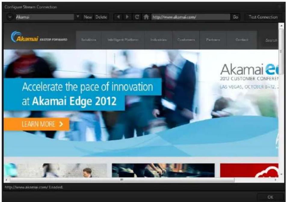
text_image
Configure Stream Connection Akamai New Delete http://www.akamai.com/ Go Test Connection Akamai FASTER FORWARD Solutions IndePtegriki PteEliaros Industria Customers Partners Contact Search Accelerate the pace of innovation at Akamai Edge 2012 LEARN MORE > Akamai e 2012 CUSTOMER CONFERENCE LAS VEGAS, OCTOBER 8-12, http://www.akamai.com/Loaded. OKFIGURE 300
TriCaster's Streaming Configuration panel supports the creation and configuration of all of the information and settings you are likely to need in this context.
The information you enter for a given Connection is retained in a preset that is easily accessed afterward from a convenient drop-down me.
In addition, this panel has built-in web browser capabilities, permitting you to both view your stream from the remote site (just as your audience will see it) and access webpage based controls as required.
SECTION 18.1 OVERVIEW
To open the Configure Stream Connection panel, click the Configure button (gear) at right in the Dashboard's large Stream button.
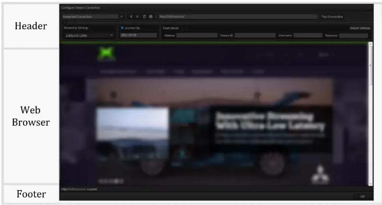
text_image
Header Configur Stream Connection Streamed Connection http://www.com/ Test Connection Streaming Settings Archive File Flash Server Import Settings 1280x720 1280x 2013-05-06 Address Stream ID Username Password Web Browser Footer http://www.com/ Loaded OKThe panel is comprised of three bands:
- The uppermost band contains controls for creating and managing Connection proiles, along with familiar web browser navigation tools.
- The larger area beneath this displays the current webpage, if any.
- At the bottom of the panel is the footer, containing a status line and OK.
18.1.1 COMPACT VIEW
text_image
Unnamed ConnectionFIGURE 301
Just to mention it in passing, after configuring one or more Connections, you can collapse the header to a compact view using the up/down control just below the connection name ield (Figure 301).
SECTION 18.2 WEB BROWSER
A simple set of navigation controls (Figure 302) is provided above the Web Browser viewport.
text_image
http://FIGURE 302
Easily recognizable Backward, Forward and Refresh buttons operate just like those on a typical web browser. The URL ield allows you to type in a webpage address, and access it using the Go button at right.
SECTION 18.3 CONNECTION OPTIONS
The process of configuring a Connection (preset) begins with selecting the item "Create Connection from current URL ..." from the Connection menu at left. This action will immediately open a dialog entitled Choose Configuration Type. The options available are as shown in Figure 303.
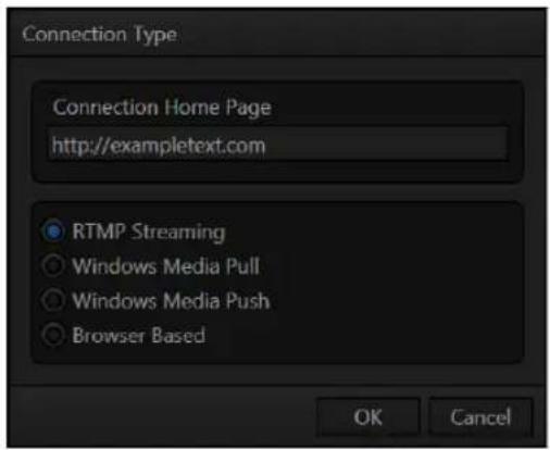
text_image
Connection Type Connection Home Page http://exampletext.com RTMP Streaming Windows Media Pull Windows Media Push Browser Based OK CancelFIGURE 303
Hint: The Connection Type options may seem unfamiliar if you are new to streaming. You may find it helpful to read over Section 18.6, entitled Streaming Strategies.
After selecting a Connection Type and clicking OK, the Name ield in the main Conigure Stream Connection panel is highlighted, to encourage you to supply a descriptive name for the preset.
18.3.1 RTMP
TriCaster's first encoding and streaming alternative is the RTMP protocol, popularized by Adobe Flash®. In determining whether you should choose RTMP or another encoding method for your own purposes, you might ind it helpful to review the section titled Live Streaming in Section 18.6.1.
When you select RTMP as the Connection Type, the controls presented in the header of the Configure Stream Connection panel update accordingly.
text_image
Streaming Settings 1280x720 1280kFIGURE 304
The irst thing you might notice is the Streaming Settings menu at left (Figure 304). This drop-down selector lets you choose from a prepared list of streaming proiles, labeled to show their respective resolution and bandwidth settings.

text_image
Flash Server Address Stream ID Username Password Import SettingsFIGURE 305
At right, you will see the Server control group (Figure 305), where you will enter the specific parameters required by your streaming service (or CDN – Content Delivery Network). Let's consider the information you need to complete this successfully.
The Username and Password are supplied to you by the streaming service, and are specific to your account. Location (also referred to as the Server Address) is the address TriCaster will send the stream to (this is supplied to you by the service provider).
The Stream ID may or may not be provided, depending on the service provider; in some cases you can simply enter a custom ID number.
Many service providers will supply you with a streaming proile in the form of an XML ile. If this is the case, you can click the button labeled Import Settings From File, navigate to and select the XML ile, and TriCaster will automatically import the Location and Stream ID values for the Connection.
Note: By design, the Import feature does not automatically change the Resolution profile you have selected at left. You should ensure that this setting is compatible with your service.
BROWSE (IMPORT A CUSTOM PROFILE)
A related function involves the ability to directly import a custom Resolution proile. You might create such a proile for a specific purpose (using either the Flash Media Live Encoder® or Windows Media Encoder® application installed on your TriCaster), or download it from a streaming service.
The Browse item at the bottom of the Streaming Settings menu allows you to select an appropriate ile in a system ile explorer, which is then copied to the correct location for it to be listed in the menu for your use in future.
Note: the nearby Delete button allows you to dispose of unused imports of this type. The default Resolution profiles cannot be deleted, however.
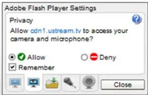
text_image
Adobe Flash Player Settings Privacy Allow cdn1.ustream.tv to access your camera and microphone? Allow Deny Remember CloseOne other Flash-related detail deserves mention. The irst time you configure a RTMP stream, a webpage applet may pop-up up a configuration dialog asking you to permit Adobe Flash Player to access your TriCaster audio and video devices.
Click Allow, and checkmark Remember, too. Then, in turn, click the 'microphone' button and 'webcam' button, selecting TriCaster's audio and video devices from the drop down menus provided.
(If you ever need to open this panel again, you can get to the settings by right-clicking on a lash applet in the browser, and select Settings.)
18.3.2 WINDOWS MEDIA PULL
If you are streaming internally (to people in your building or inside your own corporate irewall), Pull streaming may well provide the easiest approach.
That said, Pull is not a universal solution. Since your stream may be constrained by lower bandwidth than a commercial streaming service typically offers, Pull streaming may falter when more than a few users are viewing the stream.
For a Pull Connection Type, the Location ield attempts to automatically display the Internet address you would provide viewers, or in some cases, your streaming service provider. This the IP (Internet Protocol) address of your computer on the network. This information will be provided as 'punctuated' numeric value.
IMPORTANT Note: routers provide a measure of network security by masking the details of systems connected to them, thus preventing direct external access.
If TriCaster is connected to the network by a router, the IP number shown in the location field is only valid for viewers connected on the same side of the router as your TriCaster (as they might be in a local intranet configuration.)
The Location provided in this case is merely a local number assigned by the router, and is not accessible to the world at large. To find out how to provide external access to your stream in this configuration, please see Section 18.8, Diagnostics and Troubleshooting, for information on routers and “port forwarding”.
You can provide any clients or streaming providers this address. Entering this address into the File menu of Windows Media Player® (using copy, and pasting it into the Open URL window) will direct the player to show the stream from your system on client computer system(s) connected to the Internet.
Hint: Most web browsers can be also configured to invoke a compatible player when required, as well, but using WMP directly in this fashion may save some steps.
Beyond this, simply select a suitable proile from the Resolution menu for your need. Once you are done setting up the connection, click OK to close the panel. Your live program stream will be sent continuously to the network while the Stream button is enabled.
18.3.3 WINDOWS MEDIA PUSH
A Push Connection Type is often the most convenient method, especially in cases where TriCaster is connected behind a irewall. Push streaming is also usually simpler when you need to stream from major venues (such as hotels or convention centers). The program stream passes quietly out through any irewalls or routers between the facility and your streaming server.
Also, once your streaming provider has provided you the connection specifics, you can resume the stream at any time without intervention from the server. When a Push proile is chosen, the Server control group updates to allow entry of the (prearranged) host web address (Location), Username and Password.
Note: The publishing point is placed at the end of the URL, following a forward slash (i.e., http://225.21.1.4:8080/NewTek).
Enabling the Stream button then “pushes” the stream from your location, logging into the pre-arranged web address using the username and password you provided. The streaming service then re-transmits your stream for all to see.
Note: You will find information on the use of custom streaming profiles including MBR (multi-bitrate) options at Section A.7.3 in Appendix A.
18.3.4 BROWSER BASED
The basic Browser Based connection option can arguably be thought of as the lowest common denominator, and also the least demanding approach in terms of learning curve for you, the operator. No local settings are required for this connection type (beyond the URL) of the streaming site you intend to use.
Many of the organizations providing streaming services offer free accounts with limited capabilities and options (often ad-sponsored). These arrangements can be just what you need to get started experimenting with live streaming, or may even satisfy all of your needs in this regard. Generally, the companies involved also offer paid-for accounts as upgrades. The benefits may include such things as removing ads, more streaming options (such as higher bitrate and resolutions or multi-bitrate streaming), two-way live chat, and so-on.
Note: The steps involved in creating an account with a streaming service provider and configuring the stream vary widely, and unfortunately cannot really be dealt with in depth here. Generally, though, they are pretty simple, and providers offer step by step information and support through their sites. And, of course, NewTek's own TriCaster forum membership can often offer helpful hands-on experience and advice.
Once configured on the remote site, you can audition your streaming broadcast using the Stream button in the Dashboard at the top of the Live Desktop panel. If you do not wish to archive your stream, disable the Archive File switch beforehand.
Hint: Some services may show you what they are receiving from TriCaster when you press Test or Stream, but do not actually broadcast that stream until you indicate that you are ready to go ‘on air’, using controls on the website.
For Browser Based streaming, the encoding of your program into a stream for transmission to the service provider (and ultimately beyond, to your Internet audience) is performed by an applet running on the website.
As mentioned before, however, this arrangement often doesn't give you as much control or as many options as you might want. Other Connection Type options are more hands-on in this respect, but require you to manually select related settings, as discussed next for each type.
Hint: Password-protected streams are an option with certain CDN accounts. In some cases (where Flash is used to provide the client side password support), using this option will mean that iOS devices cannot view the stream. This is not a TriCaster issue, per se, but something you can discuss with your streaming service if it arises.
SECTION 18.4 AUDIO LEVEL
Recall that the Stream control group in the Audio tab provides level control, equalization and Compressor/Limiter tools that can help you deliver the best possible sound to your listeners.
SECTION 18.5 CAPTURING THE STREAM
TriCaster can archive your live stream ile as it is created. Enable the Archive File switch in the Server control group, and supply a ile name in the adjoining ield. A folder is automatically created (at D:\Media\Clips\sessionname\SavedStreams) to receive the captured stream ile.
Note: this option is not shown for Browser-based connections since archival services are commonly offered by the CDN in that case.)
SECTION 18.6 STREAMING STRATEGIES
One of the best approaches when beginning (to stream your productions) is to establish a relationship with a commercial streaming media provider. A good provider can guide you past irewalls, provide public addresses for everyone to view your stream, and provide no end of valuable guidance.
And it may not be as expensive as you think (costs vary based on considerations such as how many viewers you expect, how much web bandwidth you use each month, and so-on). Some services based on an advertising model will even host your stream free.
18.6.1 ON DEMAND OR LIVE STREAMING?
Not all ‘streaming’ is ‘live streaming.’ The difference is similar to i) watching a television program you previously recorded at a time convenient for you, or ii) watching a live event.
On demand streams are stored on a server (often supplied by an external service provider), ready to be transmitted whenever a viewer wishes. Live streams are available at the time they are broadcast, such as during a live concert or event.
ON DEMAND HOSTING
TriCaster permits you to record live productions to a local hard drive. The resulting iles can be hosted on a network later, so viewers can connect whenever they like. If you have the resources available, you can host the video yourself – but if many people will likely want to view your production, you will likely avail yourself of a service to stream it on your behalf.
Ideally, ‘on demand’ streaming video begins to play on request after a few moments. (Letting the stream get a bit ahead of the client playback device is called ‘buffering’, and helps ensure smooth playback). This stands in contrast to other types of online video distribution which requires the viewer to completely download the video ile before he can begin play. Given a sufficiently high speed connection between host and viewer, they may well be able to enjoy a seamless viewing experience without stuttering or other issues.
LIVE STREAMING
Live streaming is a growing international market, and one you may well wish to serve. This form of streaming is a somewhat more demanding implementation. Rather than record a ile and deal with it later, live video is transmitted over the network (effectively in realtime, give or take a little ‘time in the pipe’ as it were.)
Delivering a good quality stream requires that you consider both your network connection capabilities and that of your viewers. As well, to ensure reliable delivery, you will ideally have some idea of the size of your audience. Nevertheless, for all cases, TriCaster gives you the tools to do the job.
Naturally, streaming video is highly compressed to reduce bandwidth demands and make it available to a wider group. TriCaster supports two popular and prolific encoding systems, Microsoft's Windows Media® and RTMP (Adobe Flash®).
The decision as to which encoding format to use for your live stream is up to you or – in some cases – your client. Here are some things to consider:
Some corporate and institutional network administrators opt to support one or another format exclusively. (Check with your IT department to ind out if this affects your decision).
- RTMP has a very wide installed user base, and seems poised to increase in proliferation in the foreseeable future.
- RTMP works well across multiple platforms (PCs, Macs, Linux, etc.). Windows Media® is well represented, but perhaps not to the same degree.
- Some sources report that the RTMP movies will have a larger ile size and use greater bandwidth than Windows Media for a given stream quality. (This is hard to assess, and changes constantly as developers update their products).
- Encoding applications for both types are updated with fair regularity, and when you choose the 'latest, greatest' encoding, your viewers may not all have the current player, requiring them to update.
BANDWIDTH CONSIDERATIONS
You'll often hear the term 'bitrate' in connection with streaming video. This expression refers to data throughput per second (generally measured in Kilobits per second, or Kbps.)
You could think of this as being like water lowing through a hose. You control the 'faucet', because you get to choose the Stream Proile in TriCaster's Stream Configuration panel. However, you don't own the 'hose' – or at least, not the entire hose.
Once the stream leaves your immediate environment, even if you can supply good throughput locally, bandwidth may be constricted elsewhere along the transmission path. The level of Internet traffic can impose limits, but another major factor is the sort of connection your viewing audience may have.
Consider an example scenario:
Even though you know that most of your audience is going to connect to your program using (relatively slow) wireless devices, you use a very high outgoing bitrate – thinking that this will surely be enough to fill the need. The fact is, though, a high bitrate actually ensures their experience will be poor!
The client player tries to play the stream at the bitrate you specified, but (in this example) the wireless bottleneck impedes flow. It is as if you connected a fire hose on your end, giving them a suitable high capacity nozzle for their end – but in the last stage of flow, the stream must pass through a small garden hose. Sadly, the stream will be quite insufficient, and output from the 'nozzle' (the client player) will falter badly.
For reliable performance, try to ensure the potential upload bandwidth from your system to the net is around twice the bitrate you choose. You can broadcast at a rate closer to your actual ceiling, but reliable performance cherishes headroom.
Also consider the expected download abilities of your viewers. Ideally, a safety margin 1.5 times the stream's bitrate is desirable. This may mean you need to consider using a lower resolution, or lower framerate for your stream – but doing so when required will generally deliver a smooth result, and is the wise course. (Nothing inclines viewers to turn away quicker than a stuttering, start and stop stream. See “Speed Tests” in Section 18.8.1 for some useful resources.)
18.6.2 STREAMING PROTOCOLS
Additionally, there are two primary streaming methods, known as Pull and Push. Choosing the best method for your needs is important. Let's review each, and consider what is best for your needs.
Simply put, the Windows Media Encoder® in TriCaster allows your (networked) audience to connect directly to it, and it distributes the stream to them.
Connecting in this manner requires you to have a connection with sufficient bandwidth to deliver a stream to each individual user. For this reason, the simple Pull streaming method rarely works well for more than 1 or 2 viewers.
Advantages:
- When TriCaster is not behind a irewall or does not have a public IP address, this is a very simple way to let a few viewers watch your program stream.
Disadvantages:
- Requires either a public IP address or requires users to be on the same network. Facilities such as hotels or convention centers will usually not provide a public IP address. Even if they do, getting them to open holes in their irewall is next to impossible.
- If TriCaster is behind a router, your router must be configured to 'port forward'.
- Requires significant bandwidth -- for example, with TriCaster connected to the Internet by a DSL or Cable Modem line, upload bandwidth is often less than 400kbits/second. Allowing for network overhead, at best a 320kbit steam can be accommodated. This bandwidth would be fully consumed by two viewers watching 160kbit streams, or a single viewer pulling a 170-320kbit stream. (Even a T1 digital line can only handle four simultaneous 300kbit streams).
A variation on the Pull method involves using an external streaming provider. At one time the only method for streaming using such a provider was to have the server 'pull' it from the encoder. Under this system the server did not receive the stream until the irst user requested it. Then the server would connect to the
encoder, pull the stream to it, and inally begin re-distributing it to everyone requesting it. This method worked passably until irewalls became more common.
Advantages:
- Pull doesn't waste bandwidth; no signal is being sent out to the server unless somebody wants to view it.
- If you lose your connection to the (provider side) server, the server will re-connect to your encoder automatically when Internet connection resumes.
- Providers typically have significant bandwidth, and are able to meet necessary requirements to deliver stutter-free, high quality streams to large numbers of viewers.
Disadvantages:
- Like the “Pull by End Users” method above, this requires a public IP address, preferably a “static IP address” (which does not change dynamically if you need to reconnect) as well as open ports for the connection to be established. These requirements are becoming increasingly difficult to meet (given common security measures).
PUSH TO PROVIDER
Windows Server2003® introduced “Push” technology. With this method, the encoder sends the stream to downstream servers. This allows the encoder to establish a connection to the server on a specified port. Once this connection is established, additional network ports may be opened as required (since the Encoder established the connection, not the server.)
Advantages:
- Easy to connect to the provider. There are no requirements for open ports on your local system, or public IP's. In addition, firewalls do not get in the way.
Disadvantages:
○ Live streams that have no viewers are still consuming bandwidth. From a provider point of view, it is possible that all of our bandwidth could be utilized with no viewers. However, that is more theoretical than practical.
- Some external streaming providers prefer to Pull streams, as reconnection can performed from their end automatically if necessary. But in many venues system administrators are very reluctant to configure their system with an open port to have your stream Pulled from.
18.6.3 STREAMING MEDIA PROVIDERS
Using a commercial streaming media provider (sometimes referred to as a Content Delivery Network, or simply 'CDN') bypasses otherwise high-bandwidth requirements for the encoding computer. When you have made arrangements for a streaming media provider to distribute your stream, the encoder only needs enough bandwidth to get a single a/v stream to the provider. All end users connect to the provider to view the stream.
Most streaming providers have access to massive bandwidth (and often, with very little notice, they can scale up your allotment to meet a temporary need.) Since your local bandwidth is really only used for uploading a single stream, you can send a high quality stream, secure in the knowledge that it will not degrade as soon as a second viewer attempts to see it.
Hint: A helpful way to find a good streaming service provider is to ask other TriCaster users for recommendations in NewTek's online discussion forums.
18.6.4 OTHER RESOURCES
If you're still struggling with the differences between Push and Pull streaming methods, you can ind lots of online resources (in addition to excellent information available in NewTek's user forums!)
The popular web resource Wikipedia® hosts many articles on the subject, notably these two:
http://en.wikipedia.org/wiki/Push_technology
http://en.wikipedia.org/wiki/Pull_technology
Microsoft even hosts an animation on the subject at:
www.microsoft.com/windows/windowsmedia/knowledgecenter/wminaction/streaming_pushpull.aspx
(Ignore the detailed discussion of configuring the encoder, and just enjoy the pretty pictures – your TriCaster makes that part easy for you!)
SECTION 18.7 PRODUCTION AND CAPTURE CONSIDERATIONS
If you're not intent on live streaming, but wish to capture a live switching session, you would likely record at full resolution using the Record button (rather than Stream). The high quality captured files can then be used later in TriCaster's DDR, edited in SpeedEDIT™, or even be transferred to another computer (even on a different platform) for external processing or editing.
Hint: use an external hard drive to transfer the files between systems, or simply transfer them across a local network.
You can always convert these files to a streaming file format if you later decide you'd like to supply them for 'on demand' Internet viewing. This lets you retain best quality right through to inal output. When you eventually encode for streaming, you can choose settings that best suit the intended audience and streaming environment.
At the very least, if (perhaps to save conversion time) you capture video for web distribution, it's best to capture it at least at the size that you intend for inal output. This helps ensure satisfactory video quality for your viewers. When video is compressed (as it invariably is for web viewing) you can lose important detail; compressing a full-screen video down to a quarter or a sixteenth of its size is a lesson in humility!
Other variables to keep in mind when you're creating video for the web are contrast and motion. During video encoding for web distribution, a fair amount of video information and detail can be lost. For this reason, good lighting of your source video is essential.
Also, web streaming doesn't handle detail, transitions and motion all that well -- so your best shots should be close up, and without a lot of movement. Too, audio from cameras and camcorders is rarely as good as that from external microphones. You should at least use a clip-on lavaliere microphone, if not a directional or shotgun microphone to be sure you record only the audio you really want. Finally, for high quality streaming, consider using a 720p session, even when your cameras may be SD and interlaced (there is no particular benefit to working in SD when your goal is a smaller streaming output.
SECTION 18.8 DIAGNOSTICS AND TROUBLESHOOTING
As technologies go, video streaming is still in its adolescent phase, at best. There are a lot of different standards and diverse environments to consider. TriCaster gives you the necessary tools, but there are still some teething problems you may encounter. This section will point you in the right direction to overcome them.
When it comes to using your TriCaster in a professional live production environment (i.e., your bread and butter depends on getting it right, and now - not tomorrow), failure to test beforehand is not merely unwise - it can be professional suicide.
You should already be aware of the need for redundancy in a professional environment (you didn't bring just one camera, did you?) As reliable as any device may be, Murphy's Law has not been repealed ... so you plan for this, bringing the appropriate equipment, such as uninterruptable power supplies, backup recording devices (there's no shame in having a VCR backing up your digital record – 'low tech' still has a place in the grand scheme.)
But you also need to perform onsite testing, to ensure your live stream is working well before ‘zero hour.’ No-one will thank you for excuses, no matter how brilliantly they point the inger at forces beyond your control.
- Set up and enable a test program stream from your TriCaster.
- You can use the tools and integrated web browser in the Streaming Configuration panel, but you may want to conirm using an external system, too.
- Open Windows Media Player®, and select File> Open URL from its ile menu (in some versions, you need to right-click WMP's title bar to present the menu).
- Enter the IP address and port number for your stream here.
- You should be able to connect and view your program stream.
Success at this point does not necessarily mean you're done. You may be able to see the stream locally, but can someone outside the local environment connect to it over the Internet? The best way to ind out is to have someone at a remote location verify that your stream is streaming properly. If it is, great! Otherwise, keep reading...
FLASH MEDIA LIVE ENCODER NOTES
Unfortunately, there are cases in which Flash Media Live Encoder® fails to report significant error conditions. For example, no error message is displayed if the network cable is disconnected while streaming, or if the connection to the remote server is lost.
Note: If the connection to a server is lost after initial success, the encoder attempts to resume streaming automatically if the connection becomes available again during the session.
Before your stream can be seen - whether on a local intranet or the Internet - client computers (or your service provider) need to be able to establish a network connection with your TriCaster.
Ping is a humble but effective tool to ensure the basic connection exists, thus it can help you with streaming, iVGA ^TM and LiveText ^TM connection issues, too (and it works just ine in a multi-platform environment!)
Ping sends a small set of data packets to the target host (IP number), then 'listens' for an echo response in return. Ping estimates the round-trip time in milliseconds, records any data losses, and displays a summary when inished.
Bottom line, if you can't ‘ping’ your target, your connection has problems (the problem might be as simple as a bad cable connection). To issue a ping, you need know the IP number of the target computer.
Finding the target IP number
For Windows XP®
- Select Run from the Windows® Start Menu (look in the Settings sub-menu if it is not listed at the top level).
- Type "cmd" (without the quotation marks) into the dialog, and press Enter on the keyboard.
- In the command shell that opens, type "ipconfig" (without the quotation marks) and press Enter again.
- The IP Address for the system will be reported in the window, along with other data.
For Windows Vista® (or later)
-
Type "run" (without the quotation marks) into the Search ield, then press Enter on the keyboard.
-
Type "cmd" (without the quotation marks) into the dialog, and press Enter on the keyboard.
- In the command shell that opens, type "ipconfig" (without the quotation marks) and press Enter again.
- The IP Address for the system will be reported in the window (listed next to "IPv4 Address"), along with other data.
To ind the IP Address for a system running OS X®
- Click the Apple icon at upper left on the Desktop, and select About This Mac.
- Click More info ... in the panel which opens.
- Click Network in the Contents column at left.
- The IP number for the system will be listed in the right hand pane.
Issuing a Ping
Ping is a command line program, and must be run from a command shell on the issuing computer. To open a command shell and send a ping, follow the procedure below that applies.
Windows®
- Repeat the steps you performed above to re-open a command shell.
- Type "ping" (without quotes) followed by a space and the target IP number, as in the image below – then press Enter.
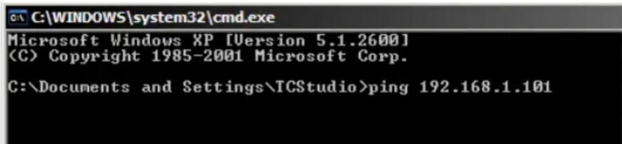
text_image
C:\WINDOWS\system32\cmd.exe Microsoft Windows XP [Version 5.1.2600] (C) Copyright 1985-2001 Microsoft Corp. C:\Documents and Settings\TCStudio>ping 192.168.1.101FIGURE 306
- Ping will go to work, and in a moment or two begin reporting results. A ping failure (indicating a network problem) will look like Figure 307. A success ping will display a report like Figure 308.
C:\WINDOWS\system32\cmd.exe
Microsoft Windows XP [Version 5.1.2600]
(C) Copyright 1985-2001 Microsoft Corp.
C:\Documents and Settings\TCStudio>ping 192.168.1.101
Pinging 192.168.1.101 with 32 bytes of data:
Request timed out.
Request timed out.
Request timed out.
Request timed out.
Ping statistics for 192.168.1.101:
    Packets: Sent = 4, Received = 0, Lost = 4 (100% loss),
C:\Documents and Settings\TCStudio>
FIGURE 307
C:\WINDOWS\system32\cmd.exe
Microsoft Windows XP [Version 5.1.2600]
(C) Copyright 1985-2001 Microsoft Corp.
C:\Documents and Settings\TCStudio>ping 192.168.1.101
Pinging 192.168.1.201 with 32 bytes of data:
Reply from 192.168.1.201: bytes=32 time<1ms TTL=128
Reply from 192.168.1.201: bytes=32 time<1ms TTL=128
Reply from 192.168.1.201: bytes=32 time<1ms TTL=128
Reply from 192.168.1.201: bytes=32 time<1ms TTL=128
Ping statistics for 192.168.1.101:
    Packets: Sent = 4, Received = 4, Lost = 0 (0% loss),
Approximate round trip times in milli-seconds:
    Minimum = 0ms, Maximum = 0ms, Average = 0ms
C:\Documents and Settings\TCStudio>
FIGURE 308
Apple OS X
For a system running Apple's OS X® :
-
Double-click Terminal in the Applications\Utilities folder.
-
Type the following command into the Terminal (without quotations) and then add the IP number, and press Enter:
"ping -c 4 ipnumber."
(So, for example, you might type: ping -c 4 192.168.1.101)
The response will be similar to the Windows® example described above. Again, a ping failure indicates a problem with the network connection.
PULL CONNECTION ISSUES
Note that - if you are Pull streaming from 'behind' a router – the IP number shown in the TriCaster's Location ield will only be valid for other systems behind the router. You will need to derive the true external IP address to pass to your viewers (or service provider.)
Again, in this environment you may wish to consider Push streaming with the aid of a Content Delivery Network (a commercial service), as this is generally free of firewall and router woes that often require a friendly system administrator to resolve otherwise.
You will also need to enable "port forwarding" on the router, as discussed next.
Port Forwarding
If you are streaming from behind a router, to preserve a reasonable level of security while allowing outside computers to connect to your system you will need to 'port forward' your router.
Port forwarding permits a sort of 'blind hand-off' between external clients (your viewers) and a local transaction port which you manually specify. (The router will pass requests to view the stream through to the TriCaster, without exposing the internal IP routing.)
To enable port forwarding, you need three pieces of information:
- The login information for the router. Your router's manual will have this information, which typically involves entering a specific IP number into your
web browsers URL ield, and perhaps also a password you have set previously.
- The specific IP local number that the router has assigned to your TriCaster. You can read this right from TriCaster's Location display. It will comprise the entire string of punctuated numbers before the colon (the colon separates the port number you chose for your stream).
• The port number just mentioned (the part after the colon).
Although the steps vary a bit by brand and model, generally you would proceed as follows:
-
Log into the router, so it shows its control panel in your web browser.
-
Select the port forwarding page of the router controls. These options may be found in an obscure place, such as the router's "Applications and Gaming" page (since online gaming often requires port forwarding).
| Setup | Wireless | Security | Access Restrictions | Applications & Gaming |
| Port Range Forward | 1 | Port Triggering | DMZ | QoS |
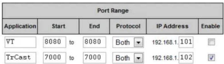
text_image
Port Range Application Start End Protocol IP Address Enable VT 8080 to 8080 Both ▼ 192.168.1.101 TrCast 7000 to 7000 Both ▼ 192.168.1.102FIGURE 309
-
Enter an Application name, if required (this is for your own recognition purposes, so use anything you like).
-
Enter the Start and End port values – you can use the same port number in both fields, but of course it must be the one you set in TriCaster's Port ield.
- IF possible, select Both for Protocol (or select UDP).
- Enter the full (punctuated numeric) local IP address shown in the Location yield of your TriCaster after you enable the stream.
- Checkmark Enable.
Some routers may have other security settings that need to be modified for your Pull stream to be visible from the outside. For example, the Linksys® router shown above has a setting in the Security page named Block Anonymous Internet Requests. While this may be a great idea normally, it's not going to help much when outside computers request that your system permit them to Pull the video stream, is it?
There are countless makes and models of routers – for information on various models, and a great deal of help on port forwarding generally, we can recommend the following site:
http://www.portforward.com/english/routers/port_forwarding/routerindex.htm
Firewalls:
You may also run into software irewalls. Generally, these can be configured in similar to permit exceptions to the irewall policy, permitting specific ports or applications to be opened to the world. Information on exceptions in the Windows® Firewall can be found in its Help system.
FINDING YOUR EXTERNAL IP NUMBER
Again, the numbers assigned behind your router only work locally. In a Pull scenario, you need to supply the true external IP number (and port) for your TriCaster to viewers outside the LAN (Local Area Network.)
You can ind this number in several ways. For example, your router will display it as its "IP Address" in its Status page. Or, you may want to use one of several handy websites that will quickly supply your current IP number (one such is http://www.whatismyip.com). Simply go to the website in your browser and read
the IP number from the screen. Append a colon and the port number you are using to this number and you've got everything you need for your viewers to connect.
SPEED TESTS
Are you sure your upload bandwidth is adequate to the bitrate you've set for your stream? Why not test and make sure. Again, a number of websites provide free speed testing. These will give you a basic idea of what your local bandwidth really is. One site which provides a list of online speed test resources is: http://www.dslreports.com/speedtest?more=1
18.8.2 IS IT REALLY A TRICASTER ISSUE?
With regard to streaming issues, don't overlook the fact that TriCaster is just one of the pieces of the puzzle. There are many others that are just as important.
Here are some useful things to try:
- Check the ile:
Archive the streaming output ile locally, and then examine it to see if it has any problems. This ile corresponds exactly to what TriCaster is sending the downstream server. In cases of sync problems, low frame-rate problems, audio popping problems, etc., if it's a TriCaster issue, the problem will be seen in this ile. On the other hand (if the ile looks good), then the issue has to be up-stream of the TriCaster.
- Dropped Frames
To really confirm that TriCaster is outputting the frame-rate you chose (i.e., not dropping frames) you can edit a proile inside Flash® to cause FMLE to write out frame-rate stats. These settings apply when using the TriCaster, which lets you verify that it is uploading the stream at the rate designated. (In FMLE, select the Encoding tab, and check mark "Log To File").

text_image
TCTriCaster's Publish features allow broadcasters to publish clips and stills from events like syndicated sports, entertainment or news programming to social media sites even while the live action and capture continue. Networks, corporate users and others with sophisticated website and distribution needs can deliver content moments after events occur for all manner of timely applications.
SECTION 19.1 OVERVIEW
In today's broadcasting world, a single program feed is often inadequate, inappropriate, or both. More and more viewers ingest media from multiple sources, even simultaneously. A live (and lively) online presence is critical for many productions with little or no traditional broadcast following.
Publishing supplemental content such as backstage feeds, locker room interviews, pre and post-game chatter, etc.), via such popular Internet sites as Facebook®, YouTube®, or Twitter® provides opportunities for brand extension and monetization. In addition, TriCaster's Publish feature supports distribution to corporate web sites, intranets and the like.
Briely, you pre-enter credentials for your social media accounts and other publishing targets before production. Publish tools in the Live Desktop make it quick and easy to distribute selected content to multiple sites even while production and recording is still underway – just perfect for concerts, galas and sport events.
SECTION 19.2 ACCOUNT CONFIGURATION
text_image
Screenshot of a social media app icons with checkmarks and logos, including Facebook, X2, Twitter, and YouTube.FIGURE 310
You will see Publish Account icons in the titlebar of both the Home and Session pages of TriCaster's Startup screen (Figure 310).
Click a specific icon or the neighboring configure button (gear) to open the Account Configuration panel (Figure 311). This is where you enter your credentials and details for social media sites or storage targets (local volumes or ftp sites).
Hint: A green checkmark overlay on the Account icon indicates it has been successfully configured for sharing.
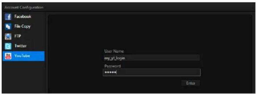
text_image
Account Configuration Facebook File Copy FTP Twitter YouTube User Name my_yt_login Password ****** EnterFIGURE 311
Click an entry in the Account List at left to display corresponding entry ields for your credentials in the pane at right. Typically you will need a user name and password for your social media accounts, as well as FTP servers (connections are tested when you press Enter, and will report an error if a problem exists).
19.2.1 SOCIAL MEDIA SITES
At the time of writing, TriCaster's Publish feature can publish media to Facebook®, Twitter® and YouTube®. Other connections may be supported as it becomes possible to do so.
Note: See also Section A.4.3, How Do I Share Files On YouTube®?
19.2.2 FILE COPY AND FTP
The File Copy and FTP options are very useful output alternatives, effectively providing a live export method that does not force you to wait until production ends to use them. These features can be invaluable for collaboration, whether local or remote.
19.2.3 COMPRESSION
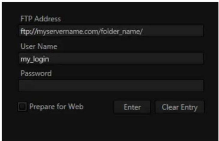
text_image
FTP Address ftp://myservername.com/folder_name/ User Name my_login Password Prepare for Web Enter Clear EntryFIGURE 312
A feature common to both File Copy and FTP publishing is the option to compress video before sharing.
Enabling the Prepare for Web option encodes iles to a compact progressive scan H.264 (MP4) format suitable for the Internet. (Disable this option when you wish to use the iles for post-production.)
19.2.4 WATERMARKING
To avoid unauthorized of use private or copyrighted media, you may want to add a watermark before publishing it to public sites. The Watermark feature allows you to select a suitable overlay image.
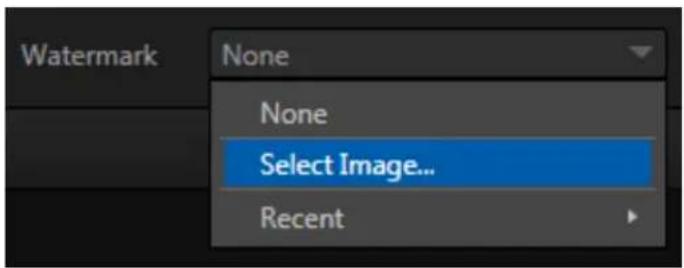
text_image
Watermark None None Select Image... RecentFIGURE 313
The image you select will be composited onto published video or still image iles. It should normally be a 32bit still image ile (supported formats include popular formats such as PNG and Targa) that positions the watermark correctly in the frame taking into account the resolution and aspect of exported iles.
SECTION 19.3 THE PUBLISH QUEUE
Having discussed configuration of publishing accounts, let's move on to look at live operations.
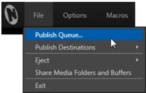
text_image
File Options Macros Publish Queue... Publish Destinations Eject Share Media Folders and Buffers ExitFIGURE 314
In the Dashboard's File menu, select the Publish Queue ... (Figure 314) to open the Publish Queue panel (Figure 315).
This is where you will create and manage the Publish Queue – that is, the list of clips and still images you wish to publish. The features of the Publish Queue are easy to comprehend.
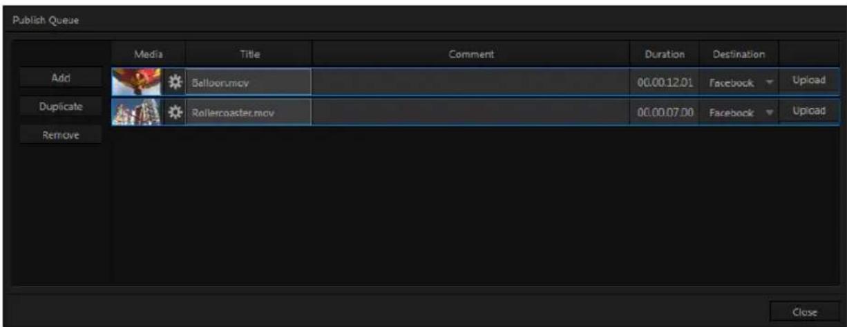
text_image
Publish Queue Media Title Comment Duration Destination Add Belloorumov 00.00.12.01 Facebook Upload Duplicate Rollercoaster.mov 00.00.07.00 Facebook Upload Remove CloseFIGURE 315
Click the Add button in the tool panel at left in this pane to open a Media Browser which you can use to select (and multi-select) content you wish to publish. You can choose items from your current session or another location.
Hint: You can Add and even Upload files that you are currently recording, even before pressing Stop. These files will be found in Clips/Capture folder for the current session.
The selected entries are subsequently listed in the queue pane at right. Related information is displayed, including the ile name (or 'alias', in the case of iles added from a Media Player playlist), Duration, and Destination (depending on settings, multiple entries pointed at different destinations may be added in one operation).
The Comment column allows you to add remarks that will be sent along with the upload to sites that support this. Click in this column to enable keyboard entry, or navigate to it and simply start typing. Press Enter or click elsewhere to end editing.
Editing the Title column entry in similar fashion affects uploads to social media accounts, but not FTP or File Copy operations. The Destination column provides a menu that allows you to choose between different publishing targets for the ile.
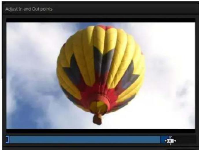
natural_image
Yellow and red hot air balloon floating against a cloudy sky (no text or symbols visible)FIGURE 316
Click the gear icon at left in any row to open a trimmer (Figure 316) that allows you to adjust the in and out points for clips you plan to share (not that some ile formats may not support trimming).
Hint: Select the Still Frame switch in the trimmer to select a frame and convert it to a JPEG image file on upload.
Note that you can even select destinations that have not yet been configured (Section 19.2), which allows you to queue up content, then later exit the Live Desktop, configure the credentials for the accounts (see Section 19.2) and – only then – upload the content.
Click in the Upload column to actually publish the ile (note that multi-selection is supported; all selected iles are uploaded in this case). The neighboring Status column tracks upload progress.
19.3.1 MANAGING THE QUEUE
text_image
Publish Queue Add Duplicate RemoveFIGURE 317
We touched on the Add button in the previous section. Two other nearby features help you manage your queue entries:
Duplicate clones selected entries, allowing you to quickly and easily create versions of the entries that can then be assigned to different social media accounts or target locations. Remove, as you'd expect, deletes entries from the queue, doing so without any effect on the source iles.
19.3.2 CHOOSING DESTINATIONS
While we considered the matter of setting up ‘accounts’ for publishing purposes back in Section 19.2, it remains for us to determine what media types we want to send to which various (including FTP, File Copy, and social media sites).
For example, it might be useful to send video clips to YouTube®, or to an FTP server, but still images to Twitter(R), or Facebook ®. The Publish Destinations item in TriCaster's File menu (Figure 318) is where you configure these optional output targets.
Selecting this option opens a sub-menu showing two lists. The irst is titled For Video; while the second is labeled For Stills. Adding a checkmark beside an account name in the Video list tells TriCaster that when you add a clip to the Publish Queue, it should create a queue entry with the corresponding destination.
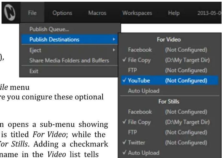
text_image
File Options Macros Workspaces Help 2013-05-0 Publish Queue... Publish Destinations Eject Share Media Folders and Buffers Exit For Video Facebook (Not Configured) ✓ File Copy (D:\My Target Dir) FTP (Not Configured) ✓ YouTube (Not Configured) Auto Upload For Stills Facebook (Not Configured) ✓ File Copy (D:\My Target Dir) FTP (Not Configured) ✓ Twitter (Not Configured) ✓ Auto UploadFIGURE 318
Similarly, check-marking File Copy in the For Stills group will cause a matching entry to be added whenever a still image is sent to the queue.
Note: You aren't forced to configure accounts beforehand. You can add media to the queue for un-configured destinations, and then supply the necessary account settings at a later time.
AUTO UPLOAD
Each group in this sub-menu – Video and Stills – has an additional checkmark-able option – Auto Upload. This allows you to determine when uploads to your configured accounts occur.
When Auto Upload is enabled, processing begins immediately after you add an item. Otherwise (left un-checked), you can perform uploads manually at a time of your choosing.
Hint: While it's possible to process video uploads even as recording is underway, if there's a lot going in your production you may find it preferable to upload stills on the fly and handle larger uploads afterward.
19.3.3 MORE 'ADD TO QUEUE' METHODS
Live production can demand your full attention. Spending time using Add in the Publish Queue panel could be a challenge. For this reason, TriCaster provides several quick and convenient sharing alternatives.
PUBLISHING ISO CORDER™ CLIPS
In the Record Configuration panel, the same menu Add to (Media Player) to menu used to send newly captured iles to a Media Player playlist also offers an easy to use Publish Queue feature. Simply checkmark this item to update the Publish queue each time you press Stop while capturing video.
Hint: A TriCaster™ TimeWarp control surface makes a perfect addition to the system for sharing purposes. With Add to Publish Queue configured and Auto Upload enabled, a TimeWarp operator can easily mark and upload clips to social media sites on the fly, all without bothering the TriCaster operator.
The Grab feature has a similar Add to menu, complete with Publish Queue feature, but naturally this operates on still images rather than clips.
You can use this to upload the image from Program output to multiple social media sites with a single push of the Grab button.
Hint: To add other angles from the same Grad, use the Add button in the Publish Queue; or add them directly from a Media Player they reside in, as discussed next.
SHARING MEDIA PLAYER CONTENT
Media Players also have a context menu item labeled Add to Publish Queue.
This sends selected items to the Queue, respecting the established (File menu) Publish Destination targets and Auto Upload settings.
(Just to mention it again, note that it is possible to select currently un-configured Destinations. This lets you add entries to the queue, entering credentials for social
media Accounts at a later time before uploading.)
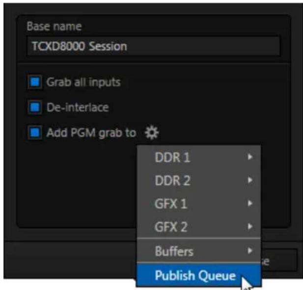
text_image
Base name TCXD8000 Session Grab all inputs De-interlace Add PGM grab to DDR 1 DDR 2 GFX 1 GFX 2 Buffers Publish QueueFIGURE 319

text_image
TCYou will often want to capture video clips from external sources, as well as to record your own live TriCaster™ productions.
Similarly, it can be quite useful to be able to grab stills from Program output for use in the current production. This chapter will provide everything you need to know about this topic.
SECTION 20.1 RECORD
TriCaster ^™ provides a great deal of flexibility when it comes to capturing your production, selected elements of it, and a wide array of internal and external sources (with embedded timecode). This is all very helpful for post-production purposes or even for immediate playback from a DDR during your production.
text_image
RECORD (0)
text_image
(1) 00.00.26.05FIGURE 320
SECTION 20.2 ISOCORDER™
TriCaster's unique IsoCorder™ technology (not a feature of TriCaster 410) brings even more powerful capability to TriCaster's Record feature. With IsoCorder, it's possible to record all primary video sources simultaneously, or a perhaps mix of sources and output channels, including Outputs 1 and 2. Since the latter outputs are configurable, you can also capture Program, Program (Clean), individual Switcher sources, or even an Alpha Matte.
Recording is easily enabled by clicking the large Record button in the Dashboard (Figure 320). The nearby counter tracks the number of clips recorded with the current base ilename, and shows the duration of the current recording.
Of course, before you begin recording, you'll want to determine what to record, where to record it to, and so on. Settings and controls for recording are grouped in the Record Configuration panel. Click the popup Configure button (gear) in the Record control to open the Record Configuration panel.
text_image
Record Configuration Base Name TCXD455 Dev Session Primary Recording Primary Save To Output 1 (D:\) 1.62 TB Add to • DDR 1 ✓ Current DDR 2 ✓ MEM 1 Publish Queue ✓ MEM 2 Source MEM 3 MEM 4 MEM 5 MEM 6 MEM 7 MEM 8 MEM 9 MEM 10 MEM 11 MEM 12 CloseFIGURE 321
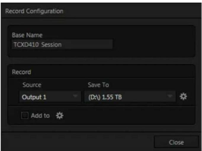
text_image
Record Configuration Base Name TCXD410 Session Record Source Save To Output 1 (D:\) 1.55 TB Add to CloseFIGURE 322 (TRICASTER 410 VERSION)
First off, the Record Configuration panel allows you to configure a Primary recording source; TriCaster models featuring IsoCorder ^™ also allow as many as seven additional (Secondary) sources to be captured at the same time.
Let's review the features and settings found in the Record Configuration panel, starting from the top.
BASENAME
text_image
Base Name TCXD8000 SessionFIGURE 323
The irst thing you may want to do is replace the default Base Name for captured iles with a custom ile name. TriCaster uses the base name and other information (such as the source) to apply a unique name to each captured ile (the names are numerically incremented automatically as well).
PRIMARY RECORDING
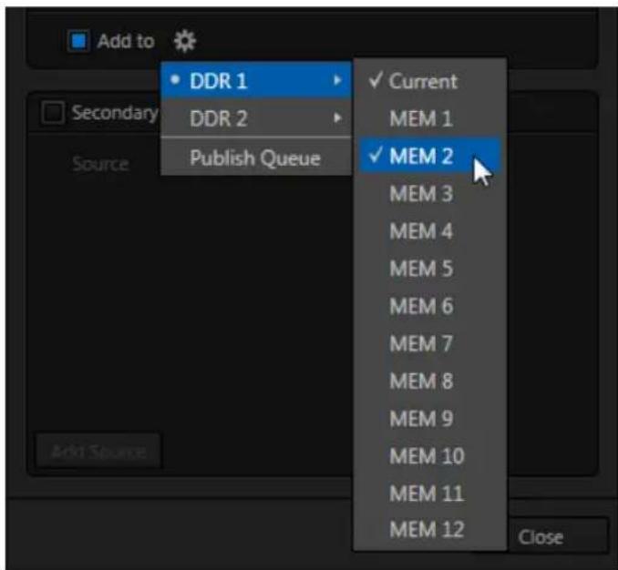
text_image
Add to DDR 1 Current Secondary DDR 2 MEM 1 Publish Queue MEM 2 MEM 3 MEM 4 MEM 5 MEM 6 MEM 7 MEM 8 MEM 9 MEM 10 MEM 11 MEM 12 CloseFIGURE 324
The main features of the Primary and Secondary Recording control groups, when present (IsoCorder models), are identical – but they are grouped separately to highlight two unique aspects of the Primary Recording, those being the Add to Playlist and Add to Share Queue controls.
ADD TO
Select one or more DDR MEM slots using the menu that opens when you click the nearby gear to automatically append newly completed Primary clips to designated playlist(s) of the corresponding Media Player(s).
Hint: You'll generally this feature enabled and set to "Current" for one of the DDRs when using the optional NewTek TimeWarp™ control surface with your TriCaster for 'insta replay' purposes.
PUBLISH QUEUE
Check-marking Publish Queue in the Send to menu causes the primary recording to be added to TriCaster's Publish Queue, with destinations as configured in the Publish Destinations menu (see Section 19.3.2).
Hint: Enabling Publish Queue does not automatically initiate file upload when recording is stopped, except when Auto Upload is also enabled – see Auto Upload in Section 19.3.2.
SHARED OPTIONS

text_image
Source Output 1 Save to Jans Drive (D:) 785GBFIGURE 325
Apart from the Add to (playlist) feature, Primary and Secondary (IsoCorder models) recording controls are similar.
SOURCE
A drop-down menu labeled Source lets you choose which video channel (along with the audio assigned to it) will be captured.
TriCaster provides numerous source options. Selecting Output 1 or 2 gives you access to a variety of useful video and audio source combinations and formats in Output Configuration. In addition, any single camera input can be designated as a source in Record Configuration.
Note that Output 1 and 2 can likewise be configured to use any single camera as source. However – when you opt to record an Output (1 or 2) using the Source selection menu, it may well result in a very different recording than if you directly select the same input as Source in the Record Configuration panel.
Consider an example:
• Perhaps Cam 1 is a 16:9 SD source
- Cam 2 is a 720p camera
- Cam 3 is 1080i
With Output 2 set (in Output Configuration) to display Cam 1, Cam2 or Cam 3 as 1080i, selecting Output 2 as Source for recording in Record Configuration will always result in a 1080i format ile.
By contrast, directly selecting a Camera directly in Record Configuration captures iles in the actual source format of that input (in our example, this would be SD 16:9, 720p, and 1080i respectively), accompanied by the original sound from matching ('same number') audio inputs.
Hint: This means you can record a given source more than once in Record Configuration, capturing it in multiple resolutions and formats simultaneously.
SAVE TO
The Save To drop-down menu allows you to select from available storage volumes as targets for the recording.
DEFAULT ENCODING
Notice that there is a Configure button (gear) at the right-hand end of the row for each recording. Clicking it reveals a menu listing optional encoding formats. The default ile format for capture is Quicktime®, a popular and widely supported ile format. For this and other reasons, we strongly encourage that you use this default encoding option.
Hint: Download free NewTek codec packs for Windows® and Apple® MacIntosh computer platforms from your personal ‘downloads’ page in the “Registration” area of NewTek’s website.
ALTERNATE FORMATS
For certain purposes, you may prefer to capture one or more iles in alternative formats.
Note: Some TriCaster features do not provide full functionality for some of the alternate formats. For example, certain of the formats do not support embedded timecode.
Let's consider TriCaster's two MPEG-2 formats irst.
MPEG-2
TriCaster's 'double-rate' MPEG-2 format for capture is comprised entirely of 'I-frames', resulting in excellent image quality. Two variants are provided; the choice principally affects color sampling applied to captured clips.
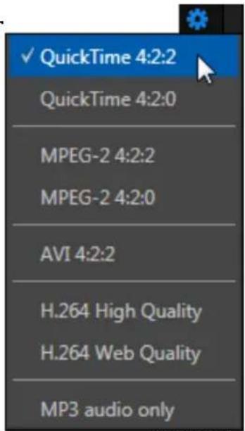
text_image
✓ QuickTime 4:2:2 QuickTime 4:2:0 MPEG-2 4:2:2 MPEG-2 4:2:0 AVI 4:2:2 H.264 High Quality H.264 Web Quality MP3 audio onlyFIGURE 326
- MPEG-2 Compatibility encoding invokes 4:2:0 color sampling (similar to that of the popular 'DV' and 'HDV' formats).
- MPEG-2 High Proile encoding raises color sampling to 4:2:2. These iles retain more color information than standard DV/HDV iles as well as many other ile formats. The increased color idelity is especially valuable for chromakeying purposes. (Please see the notes which follow regarding ile compatibility.)
The 4:2:2 sampling and high idelity of the MPEG-2 High Proile format make it especially suitable for chromakeying applications.
Support for High Proile MPEG-2 iles by various applications is not universal, however. It would be prudent to test ile compatibility with your favorite third-party programs before making extensive use of this option.
Note: TriCaster's High Profile MPEG-2 files meet the "High Profile" MPEG-2 definition established by the Moving Pictures Expert Group (MPEG). Please see http://en.wikipedia.org/wiki/Mpeg2 for more detailed information on High Profile MPEG-2 encoding.
SPEEDHQ AVI
Selecting AVI (.avi) encoding tells TriCaster to capture the designated source using NewTek's native AVI format, called SpeedHQ. This is a high quality, 4:2:2 ile format suitable for both SD and HD applications. (See the hint under Encoding above regarding NewTek codec packs to use this option with your favorite applications.)
H.264
Another important encoding type is H.264. TriCaster supports two different bitrates, designated High Quality and Web Quality. The former uses 8 Mbit/sec CBR encoding and session format, while the latter option uses a *2 Mbit/sec bitrate.
* Note that, to maintain good image quality at low bitrates suitable for online use, Web Quality recording is always standard deinition format.
Note: H.264 encoding is processor intensive. To avoid dropped frames, this format should only be used to encode one video stream at any time. Also, be aware that if an unexpected condition (such as a power outage) should interrupt recording, incomplete H.264 files cannot be repaired. For this reason, we recommend Quicktime or MPEG2 formats for critical mission capture, with H.264 used only for redundant recordings.
SECONDARY RECORDINGS
NewTek's IsoCorder™ technology provides additional capture capabilities to all models other than TriCaster 410. Additional sources for capture can be individually added in the Secondary Sources pane of the Record Configuration panel. A Switch next to the Secondary Sources label toggles the operational state of all recordings configured below.
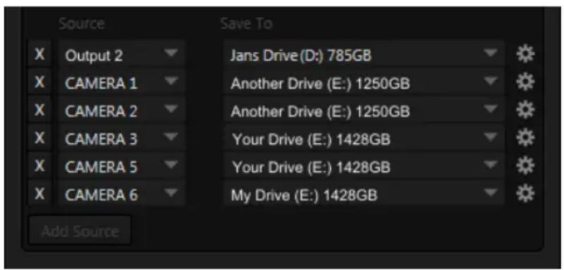
text_image
Source X Output 2 X CAMERA 1 X CAMERA 2 X CAMERA 3 X CAMERA 5 X CAMERA 6 Add Source Save To Jans Drive (D:) 785GB Another Drive (E:) 1250GB Another Drive (E:) 1250GB Your Drive (E:) 1428GB Your Drive (E:) 1428GB My Drive (E:) 1428GBFIGURE 327
Click the Add Source button to place an additional entry into the list (up to eight sources in total for 8-input TriCaster models, counting the Primary). To remove an entry, click the corresponding [X] button at left. Secondary recordings are configured in exactly the same manner as the Primary source discussed previously.
Caution: It is recommended that any single drive be tasked to capture one or two video sources at most. A warning message is displayed if you exceed this number when assigning Destination settings. TriCaster does not prevent you from exceeding this limit, however, when you are confident that very fast volumes are capable of handling the load.
SECTION 20.3 GRAB
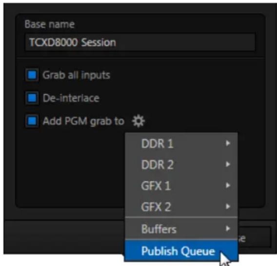
text_image
Base name TCXD8000 Session ■ Grab all inputs ■ De-interlace ■ Add PGM grab to DDR 1 DDR 2 GFX 1 GFX 2 Buffers Publish QueueFIGURE 328
At times, all you really want to capture is a still image from the current Program Output video stream (or perhaps, all inputs). This is the purpose of TriCaster's Grab function.
Click the Configure button (gear) next to Grab in the Dashboard at the top of the Live Desktop to open the Grab Still Configuration panel. The options presented are mostly similar to those of Record Configuration, though a bit simpler.
Again, enter a Base Name. The name you supply which will be numerically
incremented as required. Enable De-Interlace if you wish to avoid a 'comb' effect caused by inter-frame motion in ielded sessions.
The option Capture all inputs is especially powerful. It can store an image from every camera, plus those sources configured as Outputs 1 and 2.
Enable the Add PGM grab to switch to automatically include newly captured images at the end of selected playlists, or to send them to a specific Buffer, ready for immediate playback during the live production. Likewise, enable Publish Queue in this menu to immediately append the grabbed image to the Queue.
Close the Grab Still Configuration panel by clicking Close, or clicking outside the panel. Then click the Dashboard Grab button to capture the selected a/v source(s) to your hard drive. Image iles are stored in a folder named for the session inside the main Still folder for the current session (sub-folders are created for the supplementary iles captured when Grab all inputs is in use).
Hint: During a session, the 'grab counter' situated beside the button keeps track of the number of images stored for the current base name entry.

text_image
TCLiveText™ is a powerful title and CG application, allowing you to create title pages for use in the Media Players of your TriCaster™. SpeedEDIT™ provides a great editing tool for pre and post production purposes. It is innovative and powerful, ready to handle numerous editing and also ile conversion chores.
LiveText and SpeedEDIT are both full-blown, powerful, professional programs also available as a standalone applications. Each of these programs has its own complete manual, which can be accessed from the Help icon in the TriCaster™ Startup Screen (the source .pdf iles are located in the C:\TriCaster\Documentation folder, in case you wish to print them out). In this section, then, we will review matters specific to the different applications when running in as an integrated part of the TriCaster environment.
SECTION 21.1 LIVETEXT
LiveText projects are launched from the Session Page in TriCaster's Startup Screen. After creating a new session or opening an existing one, click Graphics on the icon ring (see Section 5.3). This reveals options and links at right, discussed previously in the Startup Screen chapter just mentioned.
21.1.1 SESSIONS, PROJECTS AND DISPLAY
LiveText uses the current session settings for output to TriCaster's video outputs, new projects (created within the LiveText File menu or from the Session Page) and bitmap ile exports. If you use the File menu to Open a project whose settings do not correspond to the current session settings, TriCaster will attempt to display it on its hardware video outputs, if possible.
LiveText sends output from the canvas to TriCaster's outputs continuously while running. For this reason, the Live Display pane and associated tools that appear at upper-right (above the Pages Panel) in LiveText standalone do not appear in TriCaster's LiveText interface.
When LiveText is running, TriCaster's video outputs (rows 1-3) will all conform to the session format. That is, if the project is HD, the SDI outputs will all be HD, and the analog outputs will be Component HD.
Likewise when the project is SD, the SDI outputs will all be SD. As there are multiple connection options for analog SD video, please refer to the following table in this case:
| Row Number | SDI | Analog BNC 1 | Analog BNC 2 | Analog BNC 3 |
| 1 | SD | Y | Pb | Pr |
| 2 | SD | Composite | Y | C |
Note: It is possible to use LiveText's File menu to open a project that does not correspond to the current session settings. TriCaster will attempt to provide video output, but it's possible that a given monitor may not display it correctly.
21.1.2 FILES/FILEBIN
LiveText's ile dialogs (for File>Open, File>Add, File>Save and Save As) have pre- configured QuickTabs pointing to the following default paths for the current session.
Note: the_Quicktab links_refer to 'session-dependent' paths, thus are not permanent. That is, for a given session, the path the Quicktab refers to is established at launch time. For this reason, the TriCaster version of LiveText does not support user-added Quicktabs.
LiveText's File menu has two special items – Send Current Page to Live, and Send All Pages to Live. (These take the place of other export options appearing in the standalone version of LiveText.) As you would expect, these functions creates iles for use in the Live Desktop, automatically storing them in the correct place(s) for easy access.
Titles prepared in LiveText can be either still or motion pages. When you send a still page to Live, it becomes a Title Page ile, with the characteristic ilename extension ".cgxml". Title Page files can be edited in the Live Desktop's Media Players. Send Current Page to Live will automatically store exported title page iles in the D:Media\Titles\sessionname\projectname folder.
Motion pages (scrolls and crawls) that you send to Live are stored as bitmap animation files (with an .avi file extension), suitable for playback in Live Desktop's DDR. These are sent to the session folder inside TriCaster's main Clips folders. The content of motion pages cannot be edited in the Live Desktop.
When you select Send All Pages to Live, each page in the project is exported in turn to the appropriate format and location. This means they are readily accessible in the Live Desktop's Media Browser afterward, for easy addition to a Media Player playlist. Title Page icons will appear grouped under their project names in the Media Browser's File Pane when you select the session name in the Location List at left.
21.1.3 NAMING STAND-IN IMAGES
Among other things, the Title Editor in TriCaster's Media Players (DDR, Still and Titles) allows you to substitute a different image for stand-in (or "placeholder") images in Title Pages (.cgxml) exported from LiveText (working with stand-in images is discussed in Section 11.4).
When creating title pages for this purpose in LiveText, you may ind it saves you time to add the string “_placeholder” somewhere in the filename of images you prepare for this purpose. For example, you might name an image "headshot_placeholder.png", or "_PLACEHOLDER_crest.jpg".
Images named in this manner will automatically appear as stand-in images (unlocked) in the Title Pages you export to TriCaster using the Send to Live options in LiveText's File menu.
SECTION 21.2 SPEEDEDIT
SpeedEDIT is an optional application, and can be found in the downloads section of NewTek's website.
SpeedEDIT is launched from the Home Page in TriCaster's Startup Screen. After creating a new session or opening an existing one, click Add-Ons on the icon ring (see Section 0). This reveals options and links at right, including SpeedEDIT after it has been installed.
Normally, TriCaster uses its current session settings for video output. New SpeedEDIT projects (created using SpeedEDIT's File menu (New), for example) may be a various resolutions, however. SpeedEDIT sends output to TriCaster's audio and video outputs continuously, without selecting any menu setting.
Unlike the arrangement for Live Desktop output, for SpeedEDIT purposes TriCaster's video outputs (rows 1-3) attempt to conform to the SpeedEDIT project format. So if the project is HD, TriCaster's SDI outputs will all send HD-SDI, and the analog outputs will all be Component HD.
Likewise when the project is SD, the SDI outputs will all be SD. As there are multiple connection options for analog SD video, please refer to the following table in this case:
| Row Number | SDI | Analog BNC 1 | Analog BNC 2 | Analog BNC 3 |
| 1 | SD | Y | Pb | Pr |
| 2 | SD | Composite | Y | C |
Note: When opening projects, TriCaster will attempt to provide hardware video output for SpeedEDIT, which may require it to reset the display hardware from HD to SD (or vice versa). It's possible that this could result in a monitor, its connection type, or both being inappropriate for TriCaster's output mode.
21.2.2 IEEE1394 I/O OUTPUT
The realtime IEE1394 (DV/HDV) preview found in SpeedEDIT standalone is not supported for TriCaster, which has other (superior) video display options.
21.2.3 SPEEDEDIT DESKTOP
TriCaster launches SpeedEDIT on a desktop of its own, spanning all connected monitors. You can exit SpeedEDIT by clicking the [x] button in the upper-right corner of the desktop, or by using the File men item Close.
If you have a secondary monitor connected to TriCaster, you can drag SpeedEDIT's Video Output window (opened from the Window menu) onto that screen.
Maximize it by double-clicking inside the preview area (double-clicking a second time restores the standard 'loating' window).
Similarly, you might ind it convenient to maximize the SpeedEDIT window to ill the primary monitor display. To do this, double-click the window border. In this configuration, the Desktop exit button is not available, but you can exit the application using the File menu's Close item.
PART III (APPENDICES)
A time-saving question and answer section, followed by an extensive listing of Shortcut Keys, schematic diagram and keyword index ...

text_image
TCThis chapter introduces the different control surfaces offered by NewTek®, helping you to see how they complement your TriCaster™ and bring added ability to your production setup.
The section also includes brief notes on connecting TriCaster ^™ control surfaces for use with your live production system.
NewTek TriCaster ^™ systems provide unrivalled live production power. With a TriCaster ^™ control surface in front of you, all of that power is right at your ingertips.
These sleek yet rugged control surfaces deliver precise control over the video layers constituting your program. Quickly and conidently perform your switching operations, and extend your capabilities in a wide variety of ways.
This Chapter discusses multiple TriCaster ^™ control surfaces, including TriCaster ^™ 8000 CS, 460 CS, 860 CS, and others. Of these, two (TriCaster ^™ 460 CS and 860 CS) are virtually identical as respects operations and control layouts, so we will consider them together. Others sections cover specific control surfaces in turn.
We're very confident you'll find one or more of these devices to be excellent for your live production needs.
SECTION 22.1 SOMETHING FOR EVERYONE
TriCaster control surfaces can be grouped into two main categories, offering either primary switcher control or instant replay functionality.
22.1.1 PRIMARY CONTROL
Primary control surfaces manage transitions on a per layer basis, govern the background composition, overlay and overlay transitions, multi-layer M/E configuration and zoom, control multiple Media Players, record, stream and grab
features, and even more. At the time of writing, three devices fall into this category, as follows:
TriCaster 8000 CS: A full-function control surface matched to the TriCaster 8000 live production system.
➢ TriCaster 860 CS: A full-function control surface designed to complement TriCaster 860.
TriCaster 460 CS: Similar to the above but, slightly more compact, being designed for use with 4-input TriCasters.
(Two further devices, TriCaster 40 CS and LC-11, may provide some lesser capabilities for certain models, as discussed in Section 22.8 and Section 22.9.)
22.1.2 INSTANT REPLAY
NewTek provides potent instant replay solutions in the form of its dedicated 3Play™ systems, but for less demanding installations many have found their TriCaster-based TimeWarp™ control surfaces (which take advantage of TriCaster's integrated recording and playback capabilities) quite valuable.
TriCaster 850 TW: The perfect complement to either TriCaster 855 CS or TriCaster 455 CS, this instant replay controller is equally capable of performing as a solo act alongside any high deinition TriCaster live production system.
TriCaster™ TW-42: This is NewTek's original TimeWarp™ device. While originally supplied for use with the standard deinition TriCaster lineup, it also provides workmanlike instant replay functionality with high deinition TriCaster models.
22.1.3 MORE OPTIONS
Although the control surfaces just mentioned are particularly applicable, some may also wish to take advantage of other alternatives, including NewTek's own more
compact TriCaster 40CS (or the older LC-11) and also third-party MIDI devices. These options will also be reviewed in this Chapter.
SECTION 22.2 CONNECTIONS & POWER
Simply connect the TriCaster control surface unit to your NewTek TriCaster using the USB cable supplied. There is no need to install drivers, or configure the software. Recognition of the control surface is automatic.
22.2.1 POWER CONSIDERATIONS
The power requirements of TriCaster control surfaces vary, but generally speaking are not inconsequential.
- TriCaster 8000CS requires a standard AC power connection, in addition to its USB control connection.
- All other control surfaces are powered by their USB cable. In the latter case, connecting the unit using a USB cable longer than the one originally supplied can diminish available power to the point where problems could ensue, including connection recognition failure or operational problems.
Except for TriCaster 8000 CS then, we strongly recommend that if you must operate the control surface at greater distances from the TriCaster than recommended above, you first connect it to a powered USB hub by a short USB cable, in turn connecting the USB hub to one of TriCaster's USB ports.
Important Note: So-called USB extenders are not recommended, having proven less reliable than long USB cables (with powered hub, as discussed above). This is because each added connector in the circuit introduces 'reflections' that can degrade the signal. In this configuration, the control surface may seem reliable for some time, but then fail unexpectedly. (If this should happen, disconnecting and reconnecting the control surface may temporarily restore functionality).
This spectacular and innovative control surface is the perfect complement to TriCaster 8000.
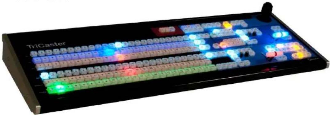
natural_image
Black triCaster audio workstation with illuminated grid and control buttons (no readable text or symbols)FIGURE 329
TriCaster 8000's unparalleled integration of advanced live production technologies offers many exciting new creative possibilities. Fittingly, an incredibly powerful and innovative control surface is included with the system.
TriCaster™ 8000 CS provides more than just control; it goes well beyond the norm in providing useful feedback. You'll quickly find yourself at home with its features and functions.
22.3.1 OVERVIEW
The TriCaster 8000 CS control layout closely conforms to the user interface, the principle exception being that singular M/E and Position control groups governed by delegate buttons serve the purpose of multiple controls in the UI.
Controls are comprised of grouped sets including the following hardware types:
- Backlit push buttons
- Twist knobs
- T-bars
- 3-axis joystick
22.3.2 DELEGATES AND SYNCHRONIZATION
Both TriCaster's Live Desktop and the control surface supply delegate button groups to govern other controls. This is extends the capability of controls and also supports multi-selections, thus permitting simultaneous operations.
When initially selecting multiple delegates, the settings and states of the individual members selected will often vary. For example – when you delegate several M/Es at once, the transition Rate for various channels in the multi-selection could very well be different. Generally, wherever it makes sense to do so, settings for multi-delegated groups the settings are progressively synchronized as you make adjustments.
SWITCHER CONTROLS
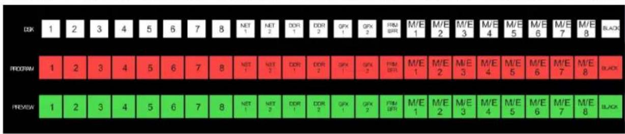
other
| Category | DSK | PROGRAM | PREVIEW | |---|---|---|---| | DSK | 1 | 1 | 1 | | DSK | 2 | 2 | 2 | | DSK | 3 | 3 | 3 | | DSK | 4 | 4 | 4 | | DSK | 5 | 5 | 5 | | DSK | 6 | 6 | 6 | | DSK | 7 | 7 | 7 | | DSK | 8 | 8 | 8 | | NET | 1 | NET | NET | | NET | 2 | NET | NET | | DOR | 1 | DOR | DOR | | DOR | 2 | DOR | DOR | | GPX | 1 | GPX | GPX | | GPX | 2 | GPX | GPX | | PRIM BFR | 1 | PRIM BFR | PRIM BFR | | M/E | 1 | M/E | M/E | | M/E | 2 | M/E | M/E | | M/E | 3 | M/E | M/E | | M/E | 4 | M/E | M/E | | M/E | 5 | M/E | M/E | | M/E | 6 | M/E | M/E | | M/E | 7 | M/E | M/E | | M/E | 8 | M/E | M/E | | BLACK | Black | BLACK | BLACKFIGURE 330
DSK, PROGRAM AND PREVIEW
The DSK, PROGRAM and PREVIEW rows each present the following source selection buttons:
- 1 - 8, Camera inputs
- NET 1 and NET 2
- Media Players:
a. DDR 1 and DDR 2
b. GFX 1 and GFX 2
c. BFR (Buffer)
d. M/E 1 - 8
e. BLACK
Switcher row buttons are mutually exclusive, and the active selection button remains lit. (The subordinate role of the DSK row is subtly reinforced by the use of slightly smaller buttons.)
Hint: Hold down CTRL when clicking a button on the PREVIEW row to toggle LiveMatte on/off for that source. Likewise, hold SHIFT while pushing a PREVIEW row button to toggle its Proc Amp. Note that the source need not be actually selected on the PREVIEW row to do this, and multi-selections are supported.
MAIN DSK DELEGATE
text_image
MAIN DSK DELEGATE DSK 1 DSK 2 DSK 3 DSK 4FIGURE 331
MAIN DSK DELEGATE button selections govern which DSK layer(s) the row is currently controlling; or - from another perspective - which video layers the selected source is assigned to.
Note: When possible, all related button selections (and illumination state) are updated to show their current states when new delegate selections are first made. This is true for all delegate groups.
(An exception is made when newly selecting multiple delegates with control settings that do not initially match. For example, if DSK1 and DSK 2 have different sources assigned and are newly multi-selected in the delegate group, no buttons on the DSK row are lit.)
22.3.3 MAIN TRANSITION GROUP
The controls in this group are analogous to those in the corresponding area on the Live Desktop, performing the same functions in much the same manner.
(In one deviation, switcher layer positioning is provided by a single, shared set of Positioner tools, discussed later.)
As on the Live Desktop, active delegate buttons remain lit. Multiple selections can be performed by pressing one or more buttons at the same time.
DELEGATE buttons determine what video layers the main Take, Auto, and T-Bar affect, and the scope of the Select and Rate knobs.
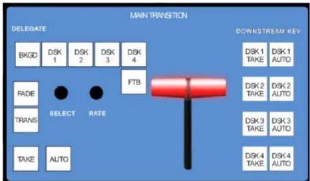
text_image
MAIN TRANSITION DELEGATE BKG D SK 1 D SK 2 D SK 3 D SK 4 FADE TRANS TAKE AUTO SELECT RATE FTB DOWNSTREAM KEY DSK 1 D SK 1 TAKE AUTO DSK 2 D SK 2 TAKE AUTO DSK 3 D SK 3 TAKE AUTO DSK 4 D SK 4 TAKE AUTOFIGURE 332
FTB
Note that FTB (Fade to Black), although not located beside the other delegates as it is in the user interface, is a delegate button - not an action button - and works exactly the same manner as its Live Desktop twin.
Note that FTB has no dedicated transition controls; its fade in/out duration is derived from the BKGD transition setting.
Hint: When FTB is displayed on Program Out, it obscures all other Switcher activity. To alert you to this important fact, the FTB button flashes for several seconds if you should make a new TRANSITION DELEGATE selection that does not include FTB.
TRANSITION BIN CONTROL
The control surface does not have Transition Bins for the different video layers as such, but can nevertheless control the transitions (and their attributes) for delegated video layers.
SELECT
When a single layer, such as BKGD, is selected in the MAIN TRANSITION > DELEGATE group on the control surface, rotating the SELECT knob cycles the current transitions in the Transition Bin for that layer.
When multiple video layers have been delegated, turning SELECT affects the transitions for all layers as follows:
- When all delegated layers are currently on the same transition bin 'slot', the selection in the corresponding transition bins simply cycles left or right synchronously.
- Otherwise (when the Transition Bin slots for multi-delegated layers are not harmonized), rotating the knob moves the selection layer by layer as the knob turns until the selected slots are aligned. From that point, continuing to twist SELECT moves the transition selection in lock step.
The SELECT knob also acts as a push button:
- Push SELECT to toggle the Reverse setting for the BKGD transition.
- Push SHIFT + SELECT to toggle the Ping Pong switch for the BKGD transition.
RATE
The RATE knob operates in similar fashion to SELECT. Rotate the knob to modify the transition Rate for delegated layers. Or press the knob to cycle through the standard Slow, Medium and Fast presets.
Hint: Multi-delegate selections are handled as for Select (for twist and push operations alike).
FADE & TRANS
These two buttons provide a quick way to control the Transition Bin selection for the delegated switcher layer(s). The FADE and TRANS (Transition) buttons are mutually exclusive; selecting either one cancels the other, and only the currently active button remains lit.
Pushing FADE offers a quick and convenient way to select the Crossfade transition. Push the TRANS button to activate the last-used transition icons for a video layer (or layers. For new sessions, TRANS jumps to the irst transition in the bin.
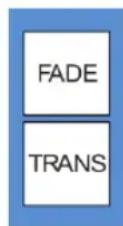
FIGURE 333
Just as in the user interface, the TriCaster control surface provides both local and main transition controls.
MAIN T-BAR, TAKE AND AUTO
These controls correspond exactly to their Live Desktop counterparts, and affect all currently delegated video layers (BKGD, DSK 1-4, or FTB) at the same time.
LOCAL TAKE & AUTO
Local Take and Auto buttons are provided for DSK 1 - DSK 4 (but not FTB). These perform a cut or transition respectively, affecting only the corresponding switcher layer.
Hint: When a DSK layer is fully displayed on Program out, its local Take button (on the Live Desktop as well as the control surface) remains lit.
22.3.4 M/E CONTROLS

text_image
1 2 3 4 5 6 7 8 9 10 11 12 13 14 15 16 17 18 19 20 21 22 23 24 25 26 27 28 29 30 31 32 33 34 35 36 37 38 39 40 41 42 43 44 45 46 47 48 49 50 51 52 53 54 55 56 57 58 59 60 61 62 63 64 65 66 67 68 69 70 71 72 73 74 75 76 77 78 79 80 81 82 83 84 85 86 87 88 89 90 91 92 93 94 95 96 97 98 99 100FIGURE 334
This section of the control surface corresponds to the tabbed M/E pane on the Live Desktop. The M/E DELEGATE button group determines which M/E (from the eight available) is being controlled.
M/E DELEGATE
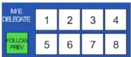
text_image
M/E DELEGATE 1 2 3 4 FOLLOW PREV 5 6 7 8FIGURE 335
As you'd expect, the eight buttons in the M/E DELEGATE group (Figure 335) let you select (or multi-select) which M/E(s) are being controlled.
FOLLOW PVW
Enabling the FOLLOW PREV button forces the DELEGATE selection to track the Switcher's PVW row selection. This can be very valuable, as it automatically ensures that adjustments you make to settings will affect the M/E that you plan to display next.
The M/E control section actually employs three additional sets of delegate controls to provide full control over all aspects of your M/E composition. The first two of these are discussed next (M/E TRANSITION DELEGATES are in M/E TRANSITION group discussed a bit layer).
M/E LAYER AND KEY DELEGATE
These two delegate button groups control the functionality of the source selection rows at left, allowing you to specify sources for any or all of the video layers of all currently delegated M/E(s). Naturally, the M/E KEY DELEGATE selection(s) govern the KEY row buttons at left
Just beneath the KEY row you will notice two identical rows labeled A/C and B/D. The result of selections in the A/C source row is controlled by the M/E LAYER DELEGATE buttons labeled A and C. Likewise, B and D buttons in the M/E LAYER DELEGATE group govern the B/D row.
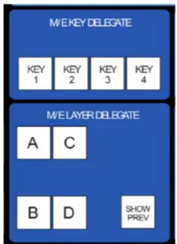
text_image
M/E KEY DELEGATE KEY 1 KEY 2 KEY 3 KEY 4 M/E LAYER DELEGATE A C B D SHOW PREVFIGURE 336
SHOW PREV
This buttons toggles the Tabs Follow All Delegates option in TriCaster, which in turn causes M/E Preview monitor panes to update when a new M/E Delegate selection is made.
INPUT ROWS
All three input, or 'source selector' row rows provide buttons for all camera inputs, Net 1, Net 2, Frame Buffer, Media Players (excluding Sound), and Black.
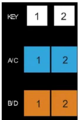
heatmap
| KEY | 1 | 2 | |---|---|---| | A/C | 1 | 2 | | B/D | 1 | 2 |FIGURE 337
Hint: Each M/E has its own dedicated Frame Buffer. As you'd expect, selecting this button invokes the appropriate Frame Buffer for each delegated M/E, even for multi-delegate selections. If you wish to specify a different Frame Buffer instead of the default one for a given M/E, you can do so using the menus in the user interface.
M/E TRANSITION CONTROLS
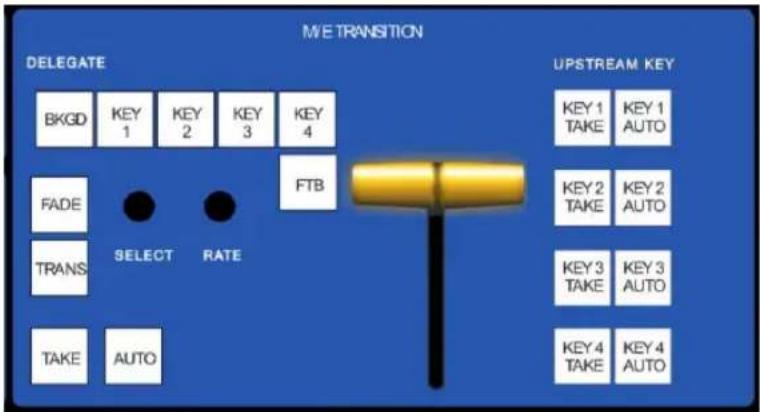
text_image
M/E TRANSITION DELEGATE UPSTREAM KEY BkgD KEY 1 KEY 2 KEY 3 KEY 4 FADE TRANS SELECT RATE FTB KEY 1 TAKE KEY 1 AUTO KEY 2 TAKE KEY 2 AUTO KEY 3 TAKE KEY 3 AUTO KEY 4 TAKE KEY 4 AUTOFIGURE 338
The inal set of M/E delegates referred to earlier is located in the M/E TRANSITION control group.
A cursory glance at this control group reveals that is for all intents a twin of the MAIN TRANSITION group, discussed back in Section 22.3.3. Using these controls, you can manage all layers of a composite effect, or even produce a complete secondary switch for output.
LIVESET SHOT
The LIVESET SHOT group buttons labeled 1-8 select the active Zoom Preset for the delegated M/Es.
The ANIM ZOOM button toggles the CUT (Duration) option for delegated M/Es. When ANIM ZOOM is enabled, pressing an unselected zoom preset button initiates a smooth zoom from the current level to the new level.
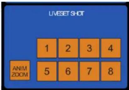
text_image
LIVESET SHOT 1 2 3 4 ANIM ZOOM 5 6 7 8FIGURE 339
Otherwise, preset selections apply directly to all delegated M/Es. If you push a zoom preset button a second time at any point, the animated zoom will ease-out and stop. Press it again to re-commence the zoom and complete it.
M/E PRESET
Four of the buttons in the LIVESET SHOT groups have secondary functions.
22.3.5 POSITIONER GROUP

text_image
POSITIONER A B C D DSK 1 DSK 2 DSK 3 DSK 4 UVESET ZOOM POS/ SCALE ROT CROP KEY 1 KEY 2 KEY 3 KEY 4 SHTL RESETFIGURE 340
DELEGATES
The Positioner section allows you to adjust position attributes for any video layer in the Switcher or any M/E effect using the Joystick. Positioner delegates are in two groups at left.
The first Positioner delegate group consists of eight buttons, one for each of the primary M/E input layers (A-D) and KEY layers. These delegate Joystick operations to the corresponding layers in the M/Es currently selected M/Es in the M/E DELEGATE group. The second Positioner delegate group relates to the four DSK layers of the main Switcher.
Hint: See Section 22.3.13 for information on controlling PTZ cameras with the joystick.
JOYSTICK DELEGATES
The type of operation applied to delegated video layers is further modified by button selections in other sections of the control surface.
text_image
LIVESET ZOOM SHTL POS/ SCALE ROT CROP RESETFIGURE 341
Hint: For finer control, hold down CTRL when operating the joystick. This will increase its sensitivity by a factor of 10.
Two joystick mode buttons are placed separately at left. LiveSet Zoom and SHTL (Shuttle) modes are special in that they dedicate the joystick to operations that are not strictly speaking 'position-related'.
Hint: The buttons in the other joystick mode group (such as POS/SCALE, discussed shortly) cannot be multi-selected with either LIVESET ZOOM or SHTL.
LIVESET ZOOM
Selecting LIVESET ZOOM assigns the joystick to control the zoom level and pan position of the currently delegated M/E(s) .
Use the joystick to control zoom and pan as follows:
- To zoom in/out :
- Rotate the joystick clockwise/counter-clockwise (as viewed from above)
- To pan:
○ Title the joystick backward, forward, left or right.
SHTL (SHUTTLE)
Push SHTL (Shuttle) to delegate the joystick to shuttle the Media Player(s) currently selected in the MEDIA PLAYERS > DELEGATE group. (Again, the other joystick mode buttons cannot be multi-selected with SHTL.)
- To shuttle delegated Media Players, move the joystick horizontally (as viewed from above).
Note: You can zoom multiple LiveSets simultaneously when these are delegated together, just as you can also shuttle several delegated Media Players.
Let's turn now to the members of the second joystick mode delegate group.
POS/SCALE
- Move the joystick horizontally, vertically or diagonally (as viewed from above) to move delegated video source(s) on its X and Y axes.
- Twist the joystick clockwise to scale delegated source(s) up, or counterclockwise to scale down.
Hint: When multi-delegate selections are active for the Positioner, adjustments are generally relative to the current state for individual delegates, as opposed to absolute.
ROT (ROTATE)
- Move the joystick horizontally (as viewed from above) to rotate delegated sources on the Y axis.
- Move the joystick vertically to rotate delegated sources on the X axis.
- Twist the joystick clockwise/counter-clockwise to rotate delegated sources on the Z axis.
CROP
- Twist the joystick clockwise (as viewed from above) to crop delegated sources inward on all four edges, maintaining the original aspect ratio.
- Twist the joystick counter-clockwise to reduce cropping of delegated sources on all 4 edges.
- Move the joystick horizontally to crop only the left edge of delegated sources.
- Move the joystick horizontally with the joystick button pressed to crop only the right edge of delegated sources.
- Move the joystick vertically to crop only the top edge of delegated sources.
- Move the joystick vertically with the joystick button pressed to crop only the bottom edge of delegated sources.
RESET
Despite its location, RESET is really an action button (not a Joystick mode). Press it to restore all position settings for currently delegated source(s) to their defaults. (This is also why RESET does not stay selected when pressed, nor does it change the current Joystick mode. The two special delegate selections also work differently with RESET:
- When VIRTUAL ZOOM is delegated, the LiveSet preset for delegated M/Es) is reset to the #1 preset.
- When SHUTTLE is delegated, selected Media Players are reset to the starting point of the current item (or playlist).
MONITORING
While using the joystick in most POSITIONER DELEGATE modes, many adjustments are temporarily shown on the Live Desktop's Preview monitor. The Preview monitor reverts to its default display a few moments after releasing the joystick to its at-rest position, just as occurs when using Positioner tools on the Live Desktop.
22.3.6 MEDIA PLAYERS GROUP
MEDIA PLAYER > DELEGATE
text_image
MEDIA PLAYERS DELEGATE DDR 1 DDR 2 GFX 1 GFX 2 SNDFIGURE 342
The MEDIA PLAYERS > DELEGATE group contains buttons for TriCaster's DDR1, DDR2, GFX1, GFX2, and SND (Sound) modules.
This selection determines which Media Player is being controlled at the moment. (Support for multi-selection allows you to do things like start and stop both DDRs at the identical moment.)
PREV/NEXT PRESET
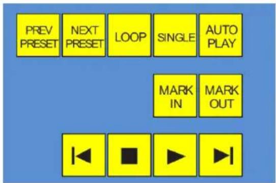
text_image
PREV PRESET NEXT PRESET LOOP SINGLE AUTO PLAY MARK IN MARK OUTFIGURE 343
These two buttons let you to cycle backwards or forwards respectively through existing presets for the delegated Media Player.
MARK IN/OUT
Click these buttons to set the in point or out point for the current playlist item in delegated players to the current frame. Press SHIFT with the button to reset the end point to its full limit.
TRANSPORT CONTROL
- |◀ (Previous Item) – Press this button to go to the previous playlist entry in delegated Media Players. (The selection cycles to the last playlist entry when necessary.)
- (Stop) - Push once to end playback for delegated Media Players; push a second time to return to the start position (this operation respects the Single setting for individual Media Players
- (Play) – Push to initiate playback for delegated Media Players.
- ▶| (Next Item) – Push this button to go to the next playlist entry in delegated Media Players. (The selection cycles to the 1rst playlist entry when necessary.)
LOOP, SINGLE, and AUTOPLAY are mode buttons, and toggle the respective settings for all delegated Media Players as appropriate (for example, the Sound player has no Autoplay feature, so logically AUTOPLAY does not affect it).
22.3.7 RECORD GROUP
Three buttons labeled REC, STRM, and GRAB are located in the RECORD group.
- REC - Pressing this button enables TriCaster's Record feature. As a safety measure, pressing the REC button when recording is underway does not stop recording.
text_image
RECORD REC STRM GRABFIGURE 344
Instead, the CTRL button lashes to reminds you that you must hold the CTRL button down while pushing REC to end recording.
- STREAM – Push to enable or disable TriCaster's live streaming feature.
- GRAB – Push to store a snapshot of Program output using TriCaster's Grab feature.
22.3.8 SPECIAL BUTTONS
The SHIFT, CTRL and ALT buttons provided on the control surface support extended features and future expansion. To the extent that these buttons are currently assigned to any feature, they have been described in context earlier.
text_image
MACRO SHIFT CTRL ALTFIGURE 345
22.3.9 MACRO
The last button we will discuss offers spectacular convenience. TriCaster's powerful macro system is fully addressable from 8000CS. A macro can be assigned to any button on the control surface in much the same manner as it can be assigned to a keyboard button. The steps are as follows:
- On TriCaster's Live Desktop, open the Macro Configuration Editor.
- Select the macro you wish to assign in the onscreen lister.
- Click the mouse in the Listen ield at bottom left.
- Hold down the MACRO button and press a suitable button on the control surface.
That's it – you can close the Macro configuration Panel and test the result. To play back the macro at any time, press the MACRO button along with the assigned key.
22.3.10 T-BAR ILLUMINATION
TriCaster 8000CS uses colorful illumination to provide feedback and status updates your control surface selections and operations. The lighting schemes for both the M/E and MAIN TRANSITION T-Bars reinforce the traditional button illumination in a way that soon becomes instinctive and which provides unparalleled conidence in use.
The following tables provide a color code for your convenience.
22.3.11 M/E TRANSITION - LIGHTING
Control surface T-Bar illumination largely conforms to M/E tab color on the Live Desktop.
| M/E 1 | M/E 2 | M/E 3 | M/E 4 | M/E 5 | M/E 6 | M/E 7 | M/E 8 |
| Blue | Aqua | Soft Pink | Cinnabar | Dark Blue | BrightPink | Chartreuse | Magenta |
- If BKGD is delegated alone, the T-Bar color is as shown in the table above, identifying which M/E is delegated in the M/E DELEGATE group. (When multiple M/Es are delegated, the irst selected delegate determines the color.)
- This color is at its brightest when the A source (effectively the Program row for a Mix effect) is fully displayed. As the T-Bar is moved (or AUTO is pressed) to begin a transition, the color gradually dims until the effect is complete. At that point, it pops back to full brightness, just as the onscreen T-Bar returns to the top of its stroke.
- In a mixed delegate situation (BKGD along with one or more KEY layers) the T-Bar is lit it medium blue, and conforms to the BKGD behavior described above.
- If one or more KEY layers are delegated without BKGD, the T-Bar color is purple. When the KEY layer (or, for multi-KEY selections, the irst KEY layer) is fully displayed, T-Bar lighting is at its brightest. Removing the layer dims the illumination.
22.3.12 MAIN TRANSITION
- Just as you would expect, the illumination of this T-Bar uses red-green coloration, standard color coding for Program and Preview rows.
- As for M/Es, described earlier, DSK-only delegate operations result in the T-Bar being lit in purple.
- Mixed mode (BKGD plus DSK delegates) likewise result in blue illumination, just like the M/E T-Bar behavior previously described.
22.3.13 PTZ CONTROL
Pan, tilt, zoom control over connected robotic cameras is also provided using the joystick.
Note: Joystick operations do not affect stored PTZ preset values.
To delegate the joystick to control a PTZ camera assigned to a specific TriCaster input, hold down SHIFT button on the control surface and press a button (1-8) in the M/E Delegate group. (Afterward, the button corresponding to the current PTZ camera selection will light whenever SHIFT is pressed.)
- Pan: With SHIFT depressed, tilt the joystick left-right.
- Tilt: With SHIFT depressed, tilt the joystick backward-forward.
- Zoom: With SHIFT depressed, twist the joystick clockwise or counterclockwise.
- Focus: When Auto is off, and with SHIFT + CTRL both pressed, twist the joystick clockwise or counter-clockwise.
○ Auto Focus toggle: With SHIFT + CTRL held down, press the joystick button.
- Preset selection: Press CTRL + LIVESET SHOT (1-8) to choose a preset for the selected camera.
- Press CTRL + RATE (M/E Transition group) to adjust the camera's Animation Speed.
Hold down CTRL and press the top joystick button to update the current PTZ preset (position, zoom and thumbnail icon).
SECTION 22.4 TRICASTER™ 460 CS & 860 CS
The principle difference between these two members of the TriCaster family of control surfaces is the number of channels supported by their namesake TriCaster live production system.
TriCaster 860 CS is a bit wider than the 460 CS, as necessary to support the additional channels offered by the larger TriCaster. As well, a few control groups are in slightly different locations on the two control surfaces.
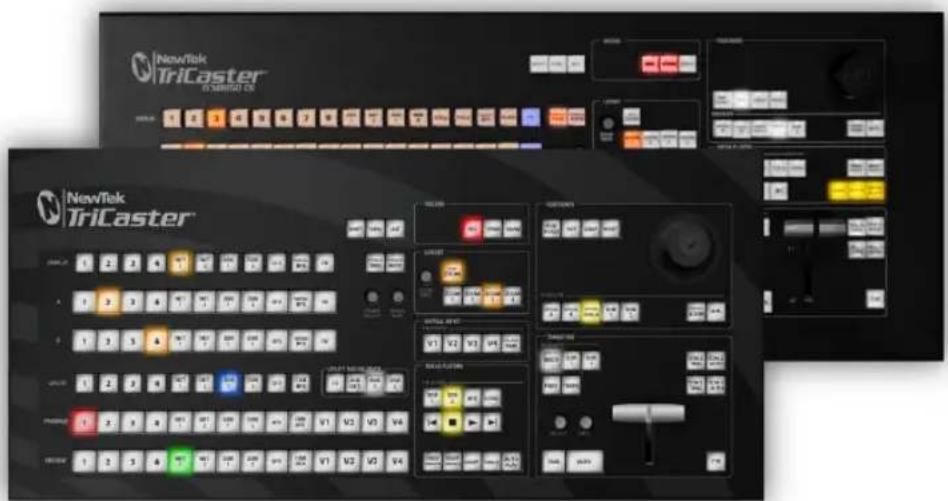
text_image
NewTek TriCaster TRICASTER CN NewTek TriCaster 1 2 3 4 5 6 7 8 9 10 11 12 13 14 15 16 17 18 19 20 21 22 23 24 25 26 27 28 29 30 31 32 33 34 35 36 37 38 39 40 41 42 43 44 45 46 47 48 49 50 51 52 53 54 55 56 57 58 59 60 61 62 63 64 65 66 67 68 69 70 1 V1 V2 V3 V4 V5 V6 V7 V8 V9 V10 V11 V12 V13 V14 V15 V16 V17 V18 V19 V20 V21 V22 V23 V24 V25 V26 V27 V28 V29 V30 V31 V32 V33 V34 V35 V36 V37 V38 V39 V40 V41 V42 V43 V44 V45 V46 V47 V48 V49 V50 V51 V52 V53 V54 V55 V56 V57 V58 V59 V60 V61 V62 V63 V64 V65 V66 V67 V68 V69 V70 V71 V72 V73 V74 V75 V76 V77 V78 V79 V80 V81 V82 V83 V84 V85 V86 V87 V88 V89 V90 V91 V92 V93 V94 V95 V96 V97 V98 V99 OUTPUT NAME: TRICASTER OUTPUT SIZE: [ ]FIGURE 346
Apart from these distinctions, the features of both of these control surfaces correspond very closely, allowing us to treat them simultaneously in the following discussion.
22.4.1 OVERVIEW
The CS control layout closely follows that of the TriCaster user interface, the principle exceptions being that:
- The M/E control group on the control surface is located above the main Switcher rows (for comfort).
- A single Position control group governed by delegate buttons takes the place of multiple controls in the UI.
The controls are comprised of grouped sets including the following hardware types:
- Backlit push buttons
- Twist knobs
-
T-bar
-
3-axis joystick
- LED indicators
22.4.2 SPECIAL BUTTONS
text_image
SHIFT CTRL MACROFIGURE 347
The SHIFT and CTRL buttons provided on the control surface support extended features and future expansion. To the extent that these buttons are currently assigned to any feature, they have been described in context.
MACRO
The last button in this group offers spectacular convenience. A TriCaster macro can be assigned to any button on the control surface in much the same manner as it can be assigned to a keyboard button. The steps are as follows:
- On TriCaster's Live Desktop, open the Macro Configuration Editor.
- Select the macro you wish to assign in the onscreen lister.
- Click the mouse in the Listen ield at bottom left.
- Hold down the MACRO button and press a suitable button on the control surface.
That's it – you can close the desktop Macro configuration panel and test the result. To play back the macro at any time, press the MACRO button along with the assigned key.
22.4.3 DELEGATES AND SYNCHRONIZATION
Both TriCaster's Live Desktop and the control surface supply delegate button groups to govern other controls. This is done both to extend the capability of other controls, and to support multi-selections – resulting in simultaneous operations.
When initially selecting multiple delegates, as often as not the settings and states of the individual members selected will vary. For example, when you delegate several M/Es at once, the Overlay Transition Rate of each member of the multi-selection could be different. Generally, wherever it makes sense to do so, when you make adjustments to settings for multi-delegated groups, the settings will be progressively synchronized. For example:
- The Zoom Rate for V1 is set to "S"; V2 is set to "M"; V3's Zoom Rate is "F".
• You multi-delegate these three M/Es. - You push the Zoom Rate button once. The rate for V1 increments to "M". (V2 and V3 are not affected.)
- You push the Zoom Rate button again. The rate for both V1 and V2 are incremented to "F"; the Zoom Rate for all three delegated M/Es is now synchronized.
You will see this synchronization method applied to the following controls:
• Media Players > Loop, Autoplay and Single
- Transition>Rate
- Transition>Select
• M/E > (Overlay) Trans Rate
• M/E > (Overlay) Trans Select
- M/E > Zoom Rate
• M/E > Overlay display state
22.4.4 SWITCHER CONTROLS
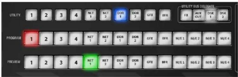
text_image
UTILITY BUS DELETE FX AUX DSK DSK 1 2 3 4 NET 1 NET 2 DDR 1 DDR 2 GFX BFR UTILITY PROGRAM 1 2 3 4 NET 1 NET 2 DDR 1 DDR 2 GFX BFR M/E 1 M/E 2 M/E 3 M/E 4 PREVIEW 1 2 3 4 NET 1 NET 2 DDR 1 DDR 2 GFX BFR M/E 1 M/E 2 M/E 3 M/E 4FIGURE 348
The Program and Preview rows each hold selection buttons as follows:
- 1 - (4 or 8); Camera inputs
- NET 1 and NET 2
- Media Players:
a. DDR 1 and DDR 2
b. STILL or Graphics
c. TITLE (TriCaster 855 CS only)
d. FRAME BUFFER
e. BLACK (TriCaster 855 CS only)
f. M/E 1 - M/E 4 (or M/E 8)
Switcher row buttons are mutually exclusive, and the active selection button remains lit.
Hint: Hold down CTRL when clicking a button on the Preview row to toggle LiveMatte on/off for that source. Likewise, hold SHIFT while pushing a Preview row button to toggle its Proc Amp. Note that the source need not be actually selected on the PREVIEW row to do this, and multi-selections are supported.
UTIL (UTILITY) Row
UTIL row buttons are also mutually exclusive. The subordinate role of the UTIL Row is subtly reinforced by the use of slightly smaller buttons. Source options include:
- 1 - (4 or 8); Camera inputs
- NET 1 and NET 2
- Media Players:
a. DDR 1 and DDR 2
b. STILL or Graphics
c. TITLE (TriCaster 855 CS only)
d. FRAME BUFFER
e. BLACK (TriCaster 855 CS only)
Press SHIFT + (UTIL row button) to access extended source options for the AUX Out delegate only:
f. [SHIFT + 1] - [SHIFT + (4 or 8)] select VI BFR 1- (4 or 8)
g. [SHIFT + NET 1] select Preview
h. [SHIFT + NET 2] → select Program
i. [SHIFT + DDR 1] → select Program (Clean)
UTIL BUS DELEGATE
text_image
UTILITY BUS DELEGATE FX AUX OUT DSK 1 DSK 2FIGURE 349
UTIL BUS DELEGATE (Figure 349) button selections govern which switcher layers the UTIL row is currently controlling; or – from another perspective – which video layers the selected source is assigned to.
Note: When possible, all related button selections (and illumination state) are updated to show their current state when new delegate selections are first made. This is true for all delegate groups.
(An exception is made when newly selecting multiple delegates with control settings that do not initially match. For example, if DSK1 and DSK 2 have different sources assigned and are newly multi-selected in the delegate group, no buttons on the UTIL row will light.)
22.4.5 TRANSITION GROUP
The controls in this group (Figure 350) are analogous to those in the eponymous group in user interface, performing the same functions in much the same manner.
(In one deviation from the Live Desktop, switcher layer positioning is provided by a single, shared set of Positioner tools, discussed later.)
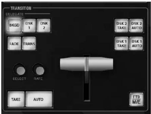
text_image
TRANSITION DELEGATE BKG0 DSK 1 DSK 2 FADE TRANS SELECT RATE TAKE AUTO DSK 2 TAKE DSK 2 AUTO DSK 1 TAKE DSK 1 AUTO FTB M/EFIGURE 350
As on the Live Desktop, active delegate buttons remain lit. Multiple selections can be performed by pressing one or more buttons at the same time. DELEGATE buttons determine what video layers the main Take, Auto, and T-Bar affect, and the scope of the Select and Rate knobs.
M/E | FTB
As a convenience, it is possible to re-purpose the entire TRANSITION control group to control M/Es rather than main Switcher controls.
To do this, press the M/E button at bottom right in this section. While this button is lit, the BKGD and DSK1 delegate buttons, along with other controls in the TRANSITION group that correspond to existing M/E and M/E KEY layers and effects are diverted to the currently delegated M/Es/
Note that when you hold down SHIFT while pressing this button, an FTB (Fade to Black) operation is performed instead. ( FTB has no dedicated transition controls; its fade in/out duration is derived from the BKGD transition setting.)
Hint: When FTB is displayed on Program Out, it obscures all other Switcher activity.
TRANSITION BIN CONTROL
The control surface does not have Transition Bins for the different video layers as such, but can nevertheless control the transition selection and attributes for delegated video layers.
SELECT
When a single layer, such as BKGD, is selected in the TRANSITION DELEGATE group on the control surface, rotating the SELECT knob cycles the current transitions in the Transition Bin for that layer.
When multiple video layers have been delegated, turning SELECT affects the transitions for all layers as follows:
- When all delegated layers are currently on the same transition bin 'slot', the selection in the corresponding transition bins simply cycles left or right synchronously.
- Otherwise (when the Transition Bin slots for multi-delegated layers are not aligned vertically), rotating the knob moves the selection layer by layer as the knob turns until the selected slots are aligned. From that point, continuing to twist SELECT moves the transition selection in lock step.
The SELECT knob also acts as a push button:
- Push SELECT to toggle the Reverse setting for the BKGD transition.
- Push ALT + SELECT to toggle the Ping Pong switch for the BKGD transition.
RATE
The RATE knob operates in similar fashion to SELECT. Rotate the knob to modify the transition Rate for delegated layers. Or press the knob to cycle through the standard Slow, Medium and Fast presets. Multi-delegate selections are handled the same as for Select (for both twist and push operations).
FADE & TRANS
FIGURE 351
These two buttons provide a quick way to control the Transition Bin selection for the delegated switcher layer(s). The FADE and TRANS (Transition) buttons are mutually exclusive; selecting either one cancels the other, and only the currently active button remains lit.
Pushing FADE offers a quick and convenient way to select the Crossfade transition. Push the TRANS button to activate the last-used transition icons for a video layer (or layers. For new sessions, TRANS jumps to the irst transition in the bin.
Just as in the user interface, the TriCaster control surface provides both local and main transition controls.
MAIN T-BAR, TAKE AND AUTO
These controls correspond exactly to their Live Desktop counterparts, and affect all currently delegated video layers (BKGD, DSK 1, DSK 2, or FTB) at the same time.
Note that two small LEDs are situated near the left side of the T-Bar – one at each extreme of its stroke. When a transition is in progress (or is halted partway), one LED is illuminated. This LED marks which direction to push the T- to complete the current transition.
LOCAL TAKE/AUTO
Local Take and Auto buttons are provided for DSK 1 and DSK 2, but not FTB. These perform a cut or transition respectively, affecting only the corresponding switcher layer.
Hint: When a DSK layer is fully displayed on Program out, its local Take button (on the Live Desktop as well as the control surface) remains lit.
22.4.6 M/E GROUP
This section of the control surface corresponds to the tabbed M/E panes on the Live Desktop. The M/E DELEGATE button group determines which M/E (from the four or eight available) is being controlled.
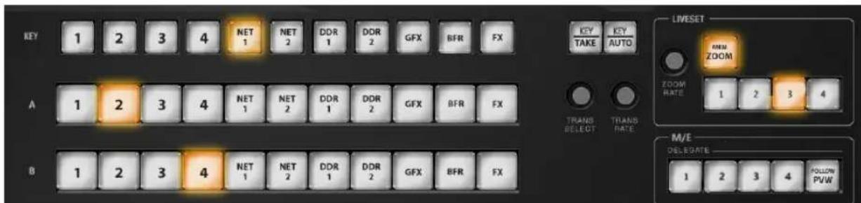
text_image
KEY 1 2 3 4 NET 1 NET 2 DDR 1 DDR 2 GFX BFR FX A 1 2 3 4 NET 1 NET 2 DDR 1 DDR 2 GFX BFR FX B 1 2 3 4 NET 1 NET 2 DDR 1 DDR 2 GFX BFR FX LIVESET MEN ZOOM ZOOM RATE 1 2 3 4 TRANS SELECT TRANS RATE M/E DELEGRATE 1 2 3 4 FOLLOW PVWFIGURE 352
In contrast with the Live Desktop, your TriCaster CS adjusts position attributes M/E video layers using a single set of Positioner tools governed by Delegate controls (see Section 22.4.7).
M/E DELEGATE
Your TriCaster CS provides an M/E DELEGATE button group to govern which M/E(s) are affected by operations. Selected DELEGATE buttons are illuminated and, conveniently, multiple selections are supported.
FOLLOW PVW
Enabling the FOLLOW PVW button (M/E DELEGATE group) forces the DELEGATE selection to track the Switcher's PVW row selection. This can be very valuable, as it automatically ensures that adjustments you make to settings will affect the M/E that you plan to display next.
INPUT ROWS
Just as in the Live Desktop, the Overlay row selection determines the source for the Overlay layer of an M/E. However, since the control surface supports selection of multiple M/Es simultaneously, operations can affect more than one M/E at a time.
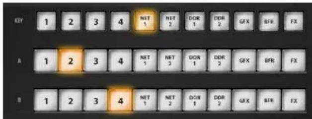
text_image
KEY 1 2 3 4 NET 1 NET 2 DDR 1 DDR 2 GFX BFR FX A 1 2 3 4 NET 1 NET 2 DDR 1 DDR 2 GFX BFR FX B 1 2 3 4 NET 1 NET 2 DDR 1 DDR 2 GFX BFR FXFIGURE 353
Likewise, the A (Input A) and B (Input B) row selections determine the sources for those layers for delegated M/Es. All three rows provide buttons for all camera inputs, Net 1, Net 2, all Media Players (excluding Sound), Virtual Buffer, Black (TriCaster 860 CS only) and FX.
Hint: Punching FX is a quick way to assign the row to the Green (FX) switcher row group.
KEY TRANSITION SETTINGS
Rotate the TRANS SELECT knob to cycle the transition bin selection through transitions currently available in the (KEY) Transition Bin in the user interface. Rotate the TRANS RATE knob to modify the transition duration. Press the knob to cycle through the standard Slow, Medium and Fast presets.
TAKE, AUTO AND KEY
For an M/E In Mix mode, the TAKE and AUTO perform the named operation between A and B input layers, treating the former as “program” and the latter as “preview” sources.
Press SHIFT + TAKE to show or hide the KEY layer(s) for currently delegated M/Es. Similarly, SHIFT + AUTO will transition the selected KEY(s) using the individual effects selected for delegated M/Es.
Hint: See also the sub-heading "M/E | FTB" in Section 22.4.5 for information on using main Switcher controls to govern M/Es.
LIVESET ZOOM
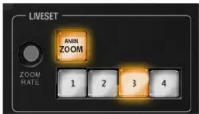
text_image
LIVESET ANIN ZOOM ZOOM RATE 1 2 3 4FIGURE 354
The buttons labeled ZOOM 1-4 select one of the first four Zoom Presets for the currently delegated M/Es. Add the SHIFT button to access presets 5-8. The ANIM ZOOM button toggles the CUT (Duration) option for delegated M/Es. When ANIM ZOOM is enabled, pressing an unselected zoom preset button initiates a smooth zoom from the current level to the new level. Preset selection applies directly to all delegated M/Es.
If you push a zoom preset button a second time at any point, the animated zoom will ease-out and stop. Press it again to re-commence the zoom and complete it.
The duration of animated zooms is determined by the ZOOM RATE setting. Rotate the knob to modify the duration of the effect, or push it to jump to a preset duration (Slow, Medium or Fast).
22.4.7 POSITIONER GROUP
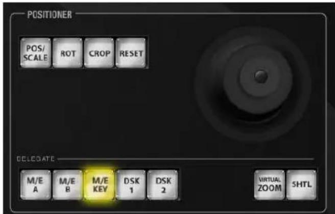
text_image
POSITIONER POS/ SCALE ROT CROP RESET DELEGATE M/E A M/E B M/E KEY DSK 1 DSK 2 VIRTUAL ZOOM SHTLFIGURE 355
POSITIONER DELEGATE
The Positioner section allows you to adjust position attributes for different overlays and video layers using the Joystick. The DELEGATE group includes seven buttons. In some cases, the scope of application for a DELEGATE selection is further modified by button selections in other sections of the control surface.
For example:
- The M/E A and B buttons delegate Joystick operations to Input A and Input B of the M/Es currently selected in the M/E DELEGATE group.
- Similarly, the M/E KEY button assigns the Joystick to control position attributes for the KEY layer of currently delegated M/Es.
- Again, selecting VIRTUAL ZOOM tells the Joystick to control the zoom level of the currently delegated M/Es. The joystick mode buttons (such as POS/SCALE, discussed shortly) are not lit when the POSITIONER DELEGATE selection is VIRTUAL ZOOM.
Use the joystick to control Virtual Zoom as follows:
- To zoom in:
- Push the joystick forward (as viewed from above), or twist the joystick clockwise.
- To zoom out:
- Pull the joystick back (as viewed from above, or twist the joystick counter-clockwise.
- Push SHUTTLE to delegate the joystick to shuttle the Media Player(s) currently selected in the MEDIA PLAYERS DELEGATE group. Use CTRL with the joystick for slower and more accurate shuttle speed. Joystick mode buttons are not lit when SHUTTLE is delegated.
Use the joystick to control Virtual Zoom as follows:
To shuttle delegated Media Players, move the joystick horizontally (as viewed from above).
The DSK 1 and DSK 2 delegate buttons provide direct selection for these video layers, and are not modified by selections elsewhere.
Note: Two of the delegates (VIRTUAL ZOOM and SHUTTLE) are set apart from their siblings. This is because neither of these options supports multi-selection (with other Positioner delegates) like the rest. (Nevertheless, you can zoom multiple M/Es simultaneously when these are selected in the M/E DELEGATE group, or shuttle several delegated Media Players.)
Generally, changes resulting from joystick operations are governed by the current Joystick Mode. Mode selections are mutually exclusive (only one buttons is illuminated at a time).
Also note that when the active Positioner DELEGATE is either Virtual Zoom or Shuttle, the Joystick Mode is irrelevant, and is ignored.
POS/SCALE
- Move the joystick horizontally, vertically or diagonally (as viewed from above) to move delegated video source(s) on its X and Y axes.
- Twist the joystick clockwise to scale delegated source(s) up, or counterclockwise to scale down.
Hint: When multi-delegate selections are active for the Positioner, adjustments are generally relative to the current state for individual delegates, as opposed to absolute.
ROT (ROTATE)
When the POSITIONER DELEGATE selection is anything other than VIRTUAL ZOOM or SHUTTLE:
- Move the joystick horizontally (as viewed from above) to rotate delegated sources on the Y axis.
- Move the joystick vertically to rotate delegated sources on the X axis.
- Twist the joystick clockwise/counter-clockwise to rotate delegated sources on the Z axis.
CROP
Except when the POSITIONER DELEGATE selection is VIRTUAL ZOOM or SHUTTLE:
- Twist the joystick clockwise (as viewed from above) to crop delegated sources inward on all 4 edges, maintaining the original aspect ratio.
- Twist the joystick counter-clockwise to reduce cropping of delegated sources on all 4 edges.
- Move the joystick horizontally to crop only the left edge of delegated sources.
- Move the joystick horizontally with the joystick button pressed to crop only the right edge of delegated sources.
- Move the joystick vertically to crop only the top edge of delegated sources.
- Move the joystick vertically with the joystick button pressed to crop only the bottom edge of delegated sources.
Hint: For finer control, hold down CTRL when operating the joystick. This will increase its sensitivity by a factor of 10.
RESET
Despite its location, RESET is really an action button (not a Joystick mode). Press it to restore all position settings for currently delegated source(s) to their defaults. (This is also why RESET does not stay selected when pressed, nor does it change the current Joystick mode.
The two special delegate selections also work differently with RESET:
- When VIRTUAL ZOOM is delegated, the Zoom preset for delegated M/Es) is reset to the #1 preset.
- When SHUTTLE is delegated, selected Media Players are reset to the starting point of the current item (or playlist).
MONITORING
While using the joystick in most POSITIONER DELEGATE modes, many adjustments are temporarily shown on the Live Desktop's Preview monitor.
The Preview monitor reverts to its default display a few moments after releasing the joystick to its at-rest position.
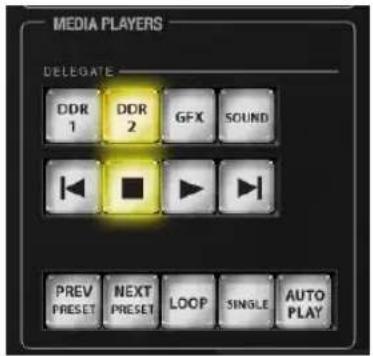
text_image
MEDIA PLAYERS DELEGATE DDR 1 DDR 2 GFX SOUND PREV PRESET NEXT PRESET LOOP SINGLE AUTO PLAYFIGURE 356
MEDIA PLAYER DELEGATE
The MEDIA PLAYER DELEGATE group contains buttons for TriCaster's DDR 1, DDR 2, Graphics (455 CS), STILL and TITLE (855 CS), and SOUND modules. This selection determines which Media Player is being controlled at the moment. (Support for multi-selection allows you to do things like start and stop both DDRs at the identical moment.)
PREV/NEXT PRESET
These two buttons let you to cycle backwards or forwards respectively through existing presets for the delegated Media Player.
TRANSPORT CONTROL
- |◀ (Previous Item) – Press this button to go to the previous playlist entry in delegated Media Players. (The selection cycles to the last playlist entry when necessary.)
- (Stop) – Push once to end playback for delegated Media Players; push a second time to return to the start position (this operation respects the Single setting for individual Media Players
- (Play) – Push to initiate playback for delegated Media Players.
- ▶| (Next Item) - Push this button to go to the next playlist entry in delegated Media Players. (The selection cycles to the irst playlist entry when necessary.)
LOOP, SINGLE, and AUTOPLAY are mode buttons, and toggle the respective settings for all delegated Media Players as appropriate (for example, Sounds has no Autoplay feature, so logically AUTOPLAY does not affect it).
22.4.9 RECORD GROUP
text_image
RECORD REC STRM GRABFIGURE 357
Three buttons labeled REC, STRM, and GRAB are located in the RECORD group.
- REC – Pressing this button enables TriCaster's Record feature. As a safety measure, pressing the REC button when recording is underway does not stop recording. Instead, the CTRL button lashes to reminds you that you must hold the CTRL button down while pushing REC to end recording.
- STREAM – Push to enable or disable TriCaster's live streaming feature.
- GRAB – Push to store a still imaged grabbed from Program output using TriCaster's Grab feature.
22.4.10 PTZ CONTROL
In Version 2, joystick control over pan, tilt, and zoom for connected robotic cameras is also provided.
Note: Joystick operations do not affect stored PTZ preset values.
To delegate the joystick to control a PTZ camera assigned to a specific TriCaster input, hold down SHIFT button on the control surface and press a button (1-8) in the M/E Delegate group. (Afterward, the button corresponding to the current PTZ camera selection will light whenever SHIFT is pressed.)
- Pan: With SHIFT depressed, tilt the joystick left-right.
- Tilt: With SHIFT depressed, tilt the joystick backward-forward.
- Zoom: With SHIFT depressed, twist the joystick clockwise or counterclockwise.
- Focus: When Auto is off, and with SHIFT + CTRL both pressed, twist the joystick clockwise or counter-clockwise.
○ Auto Focus toggle: With SHIFT + CTRL held down, press the joystick button.
- Preset selection:
○ Use CTRL + Zoom preset (1-4); add SHIFT to the above combination for presets (5-8).
- Press CTRL + ZOOM RATE to adjust the camera's Animation Speed.
- Hold down CTRL and press the top joystick button to update the current PTZ preset (position, zoom and thumbnail icon).
SECTION 22.5 TIMEWARP™
This chapter discusses the use of two NewTek TimeWarp ^™ control surfaces in two variants. Both models (TriCaster ^™ 850TW and its predecessor, TW-42) add convenient slow motion instant replay to the already potent capability of your TriCaster system.
TriCaster 850TW has the same sleek proile as TriCaster 460 CS and TriCaster 860 CS. Of course it delivers the same precise control over TriCaster's instant replay recording and live playback when used alone. The TW-42 model, though designed for use with earlier TriCasters, continues to provide great functionality.
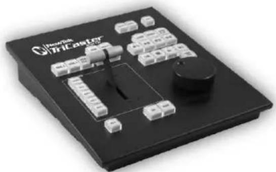
natural_image
Black industrial control panel with labeled components and a central knob (no readable text or symbols)For the most part, both TimeWarp™
models have similar controls, with similar labels, and perform in much the same manner. For that reason, in the discussion which follows we will focus on the newer TriCaster 850TW, simply giving you a friendly heads-up whenever we discuss an item where TW-42 varies from its newer sibling.
TW-42 NOTES Wherever items of special interest to TW-42 users appear in this chapter, they will be agged in the same manner as this paragraph.
22.5.1 CONFIGURING TRICASTER
- Connect a suitable video source to a camera input on your TriCaster live production system.
- Select that source on the Switcher's Program row.
- Open TriCaster's Record Configuration panel and set the Primary Source (typically to the Program option).
- Select a suitable Encoding format and Destination for the captured files.
- Use the Add to menu in the Primary Recording controls to assign the recorded clips to either DDR 1 or 2.
22.5.1 OVERVIEW
TriCaster 850 TW is quite straightforward to use, especially true if you are already familiar with common TriCaster controls and features. In this section, we'll discuss each part of the control surface, explaining how the various controls operate and what effect they have, revealing a few little tricks that you may ind helpful along the way.
TriCaster 850 TW provides convenient control over TriCaster's two DDRs as well as the recording of the Primary source configured for capture (Secondary recording on is unaffected by clip marking operations).
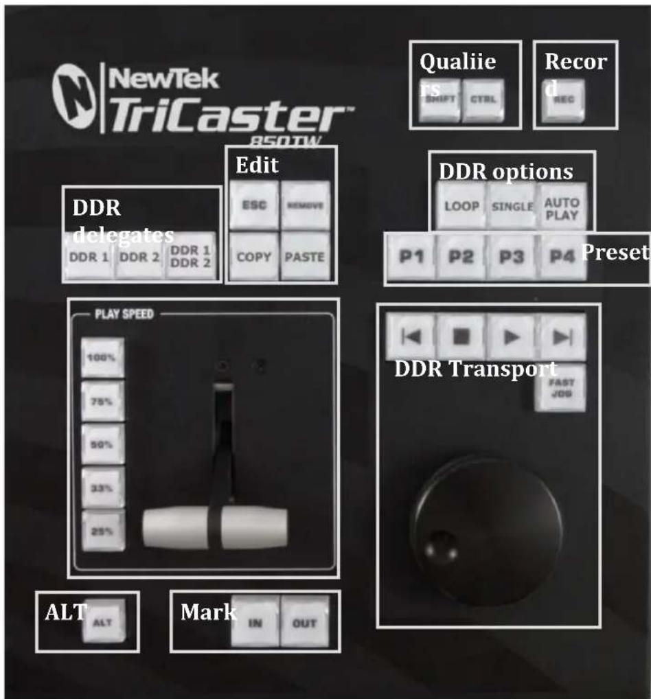
text_image
NewTek TriCaster™ 850TW Qualie s SHIFT CTRL Record REC Edit EDR delegates DDR 1 DDR 2 DDR 1 DDR 2 ESC REMOVE COPY PASTE DDR options LOOP SINGLE AUTO PLAY P1 P2 P3 P4 Preset PLAY SPEED 100% 75% 50% 33% 25% DDR Transport FAST JOG ALT Mark IN OUTFIGURE 358
For convenience, related controls and buttons are grouped together on the control surface. We will discuss the features and operations supported by each group in the pages that follow. The layout includes the control groups listed below (as shown in Figure 358):
-
DDR Delegates
• Edit group (modify playlist content) -
Play Speed (T-bar and presets)
• Mark (replay clip creation buttons) - ALT and Qualifiers (which modify the operation of other controls)
- Record toggle
- DDR options
- Preset (DDR Playlist)
• DDR Transport (clip playback and position controls)
Let's take a closer look at the members of each control group and their purpose.
22.5.2 DDR DELEGATE
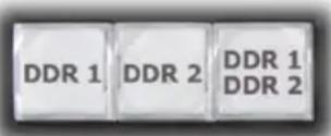
FIGURE 359
Much of the functionality of your TriCaster 850 TW relates to clip playback, navigation, and the like. These are essentially Media Player functions, controlling one or another of TriCaster's DDRs.
The irst two buttons in this group (DDR 1 and DDR 2) basically delegate the other controls to the service of the DDR named (TriCaster 300 is, of course unique in having just one DDR).
The DDR 1 and DDR 2 buttons are 'radio button' controls. This means that they operate just like the 'Favorite' buttons provided on a car radio to let you jump to a preset station.
Pressing a button produces an immediate change of state, and your selections are mutually exclusive.
Note: These buttons only relate to TriCaster 850 TW operations, and do not interact with the Switcher (or TriCaster 855 CS) delegate buttons.
The third button in this group button is not a delegate button (nor is it a radio button). The DDR 1/DDR 2 button is a toggle switch. When enabled, it tells the control surface to apply DDR Transport control group operations to both DDRs (see Section 22.5.10).
TW-42 NOTES There is no corresponding DDR 1/DDR 2 buon on TW-42. Muldelegang DDRs is not supported with this control surface.
22.5.3 EDIT GROUP
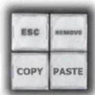
FIGURE 360
In general, these buttons operate on selected playlist content in the currently delegated DDR (see Section 22.5.2).
- Remove – Push to remove currently selected entries from the delegated DDR's playlist (selected items are not deleted from the hard drive, however).
TW-42 NOTES The Remove buon is labeled RMV on TW-42.
- Copy – Push to copy currently selected playlist items into the Paste buffer.
- Paste – Push to insert Paste buffer content into the playlist of the delegated DDR
- Esc – close any popup dialog or text entry item.
Hint: These four buttons are also 'action buttons' – that is, pushing one of them has an immediate effect (but unlike a radio button, the operation is complete on release, and does not remain in force).
TW-42 NOTES There are no Copy, Paste or Esc buons on TW-42.
22.5.4 PLAY SPEED
As you would expect, the speed preset buttons in this group (marked 25%, 33%, 50%, 75% and 100%) govern the playback rate of the active DDR.
Speed preset buttons are mutually exclusive, and establish a playback mode. They do not initiate playback; rather, the playback speed you choose is applied when subsequently press Play.
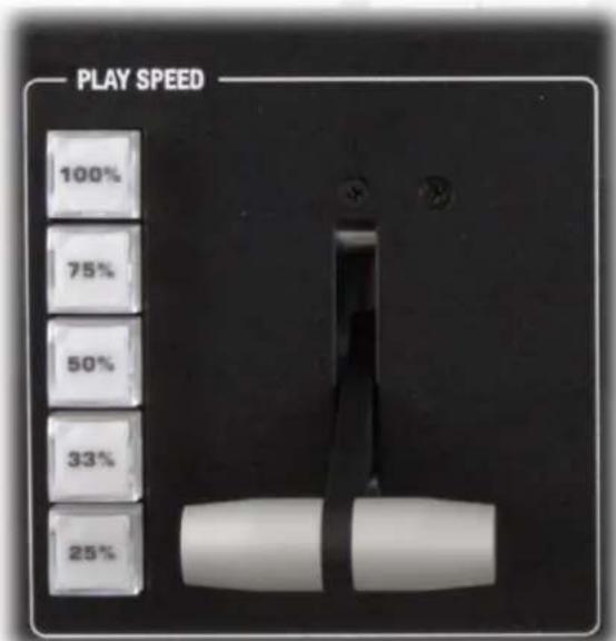
text_image
PLAY SPEED 100% 75% 50% 33% 25%FIGURE 361
(If a DDR is already playing, pushing a speed preset button alters the current playback speed immediately.)
Hint: If you use an onscreen speed control to change to a new playback speed, the control surface button selection state follows when possible (in cases where no button corresponds exactly to the newly established speed, no preset button will be illuminated).
The speed T-Bar works in similar fashion to the preset buttons, but provides a smoothly variable approach to setting playback speed.
TW-42 NOTES There is no Speed T-bar on TW-42.
22.5.5 MARKING GROUP
FIGURE 362
The IN and OUT buttons in this group allow you to indicate the In points and Out points for events you wish to record for later replay.
(MARK) IN
Pressing IN actually performs several related functions. First, remember that TriCaster must be in Record mode for any instant replay marking purpose. For this reason, if you should happen to push the IN button before enabling recording, it is
enabled automatically (illuminating the interface Record button just as if you had pressed it on the screen).
With Record active, an In Point is set for the current clip that will eventually be stored (when you press OUT) in the currently delegated DDR (see Section 22.5.2).
Hint: Actually, the IN button can also be thought of as a 'reset In Point' function. Pressing it updates the In Point, discarding any incomplete clip (i.e., one for which an Out Point had not been set. The partially recorded data up to that time is simply dropped (and is not added to the DDR playlist).
ALT + IN
FIGURE 363
A different operation results when you hold down ALT (see Section 22.5.6) at the same time as you push IN. This operation updates the In Point of the active clip in the currently delegated DDR to the frame currently displayed.
TW-42 NOTES This feature is supported on TW-42 as well.
Hint: This represents a non-destructive edit of the playlist clip, equivalent to dragging the trim handle at the left-hand end of the DDR scrub bar.
(MARK) OUT
Pushing the OUT button likewise performs a short series of several actions:
- The clip currently being recorded (if any) is ended.
- In this case, and if the Add Source to DDR Playlist is enabled in the Record Configuration panel, the new clip is added to the end of the playlist (of the active DDR.
- Recording recommences using the current time as the In Point.
Hint: The OUT button might also be thought of as a ‘chop’ feature. If you wish, you can simply keep pressing it at any time, without ever touching IN. This effectively sub-divides your entire program into consecutive clips (a frame or two may be lost between neighboring clip, however).
ALT + OUT
A different operation results when you hold down ALT (see Section 22.5.6) at the same time as you push OUT. This operation updates the Out Point of the active clip in the currently delegated DDR to the frame currently displayed.
SHIFT + OUT
Hold down SHIFT at the same time as you push OUT to automatically trim the play start setting of the newly added clip to a frame ive seconds prior to the Out Point (this is a non-destructive trimming operation. The duration of the ile on disk is not modiied.)
This feature is supported on TW-42 as well.
Hint: This is a non-destructive edit of the playlist clip, equivalent to dragging the trim handle at right-hand end of the DDR scrub bar.
ONE BUTTON MARKING
Another handy method of creating clips for instant replay is referred to as 'one button marking'. With Record enabled, watch for notable events, and simply press OUT whenever one occurs (no need to press IN beforehand in this case). This creates a new clip with an Out Point at the current frame, automatically setting the In Point to the irst frame of the current clip (i.e., the last time you pressed OUT).
22.5.6 ALT AND QUALIFIERS
text_image
SHIFT CTRLFIGURE 364
For ergonomic reasons, ALT is in a special location by itself just below the Play Speed control group. It, along with SHIFT and CTRL (Control) are what are termed 'qualifiers buttons', in that (like their keyboard equivalents) they qualify, or modify the outcome of operating some other control.
We've discussed one use of ALT in Section 22.5.5; see also Section 22.5.7. At the time of writing SHIFT and CTRL are reserved for as yet unspecified future purposes.
22.5.7 RECORD TOGGLE
FIGURE 365
It's probably no surprise at all that pressing the REC (Record) button enables TriCaster's own Record feature. It's worth mentioning though, that REC is not a simple toggle button (as it is on the user interface). Simply pressing REC again does not turn Record off.
Recording is such an important function, we are sure you agree you don't want anyone to be able to accidentally disable it.
For this reason, you must use ALT + REC (hold down ALT while pushing REC ) to turn recording off. This makes disabling recording a very deliberate operation, and not one that is at all likely to have been unintentional (as perhaps by some hapless passerby coming in contact with the control surface while looking over your shoulder).
TW-42 NOTES There is no REC buon on TW-42. Even so, pushing the Replay In buon will automacally enable Record.
Also, for use with the Publish/Share features of models with social media support, you can perform a Grab operation by pressing SHIFT + REC.
22.5.8 DDR OPTIONS
text_image
LOOP SINGLE AUTO PLAYFIGURE 366
The LOOP, SINGLE and AUTOPLAY buttons toggle their namesake features for the currently delegated DDR.
TW-42 NOTES There is no Loop or Autoplay buon on TW-42. While there is no Single buon either, TW-42's Sel (Select) and List buons turn Single mode on and o for the current DDR.
22.5.9 PRESET (DDR PLAYLIST)
"P" is for "preset" ... or "playlist", if you prefer. However you choose to view it, the buttons labeled P1 - P4 allow you to quickly access any of the irst four playlist presets for the currently selected DDR.
text_image
P1 P2 P3 P4FIGURE 367
TW-42 NOTES Preset selecon is not supported by TW-42.
22.5.10 TRANSPORT (CLIP CONTROLS)
text_image
FAST JOGFIGURE 368
This group of controls provides a variety of convenient clip transport and navigation tools. The dominant feature is a large, smoothly operating Jog Wheel.
This oversize knob permits you to traverse the current clip in the delegated DDR in frame-accurate increments.
The Jog Wheel can be a real boon when coupled with the ALT + IN/OUT method of trimming already captured clips (Section 22.5.5), or can allow you to review an event by scrubbing through it manually even while it is displayed live.
The Jog Wheel is supplemented by the nearby Fast Jog button. Press this control to toggle a high-speed jog mode, which skims through the clip at eight times the normal rate.
TW-42 NOTES The Jog wheel on TW-42 works similarly, but is augmented by an outer Shule ring that can be used to move quickly through a clip or playlist.
The other buttons in this control group are labeled with familiar VCR-style icons, and work as follows:
- Previous (Clip) - Push to highlight the prior clip in the playlist of the delegated DDR.
-
Stop
-
Push to end playback at the current frame.
- When already stopped, push again to go to the irst frame of the current clip (or playlist, when Single mode is off for the DDR).
-
Push Alt + Stop during playback to jump to the end of the current clip.
-
Play – Push to play the current clip in delegated DDR, beginning at the current frame.
- Next (Clip) – highlights the next clip in the playlist of the delegated DDR.
TW-42 NOTES
- Press ALT + Next to jump the play head 1 sec. forward from its current position in the clip.
- Press Alt + Prev to jump the play head 1 sec. back from its current position in the clip.
22.5.11 TIPS AND TRICKS
- Primary and Secondary – TriCaster's IsoCorder™ technology supports multi-source capture. TriCaster 850 TW depends on the Primary recording function, but you can continue to use the Secondary capture features for all manner of other purpose, without interruption by your instant replay operations.
- Audio Control – Remember that you can reduce (or Mute) the audio for replays individually using the local playlist pane audio controls in a DDR, or with the DDR level controls provided in TriCaster's Audio tab(s).
- DSKs and LiveSet - TriCaster provides a great deal of creative versatility in connection with instant replays. For example, a DDR with replay clips that is assigned to the Overlay channel of an M/E can be quickly displayed or hidden
(with its own transition effect). And, of course, something similar can be achieved with either of the primary DSK layers.
- Zoom, Crop (etc.) – Use the Position tools for Overlay and DSK layers to zoom in on the action in a replay.
- Clip Organization – It can be helpful, at times, to use the MEM slot options in the DDR to collate clips for different purposes.
SECTION 22.6 AVID® ARTIST MIX
TriCaster's support for the AVID® Artist Mix hardware surface brings a highly desirable level of convenience and creative control to a critical aspect of almost every video production – audio. This section explains how to connect and use this powerful third party device.
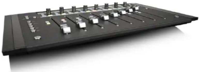
natural_image
Black industrial audio workstation with multiple sliders and control knobs (no visible text or labels)The AVID(R) Artist Mix hardware surface provides great convenience, delivering hands-on external audio control to TriCaster operators. Adjust audio levels, channel panning, equalization, select mixer presets, and more.
The compact Artist Mix console provides excellent visual feedback, and delivers control beyond what can possibly be provided with the mouse and keyboard alone. Almost all adjustments are bi-directional – adjusting the control surface updates the user interface controls, and vice versa. Artist Mix communicates with TriCaster using a popular open control communication protocol named EUCON™ (Extended User Control); the control surface acts and feels like a physical extension of your software. Let's begin by discussing installation and setup.
AVID(R) provides a utility called EuControl for use with the Artist Mix control surface. This software runs in the background, and is required for TriCaster to recognize and respond to the control surface.
- From the TriCaster Startup screen, click the Shutdown icon, and choose Administrator Mode.
- Select Exit to Windows to leave the TriCaster environment.
- Obtain the EuControl installer by using one of the following two methods:
a. With TriCaster connected to the Internet, download the most recent installer for the Windows(R) 64bit operating system from the webpage below: www.avid.com/artistsupport (Requires Avid website account.)
b. Otherwise, download the installer as above to a different computer, and transfer it to TriCaster's hard drive across a network or by USB lash drive (etc.)
-
Double-click the icon for the installer application (Install_EuControl.exe).
-
Follow the instructions displayed to complete the installation.
22.6.2 CONNECTING ARTIST MIX
After the software installation is complete, shut down TriCaster, and connect the AVID(R) Artist Mix panel to TriCaster as follows:
-
Plug one end of the AC power cord into the power adapter and the other into an electrical outlet (push the AC power connector firmly into the adapter).
-
Connect the DC output cable from the power adapter to the DC input on the left rear side of the control surface.
-
Connect the control surface to TriCaster using the crossover cable supplied with the Artist Mix, or – as will often be true, in cases where TriCaster network connectivity is a requirement – to the same network subnet your TriCaster is connected to using a suitable Ethernet cable. In most cases you
will wish to use a switch or router rather than a direct connection between the two devices, so TriCaster can also connect to the Internet, etc.
- Power up TriCaster, and wait for the Start screen to appear; then press the POWER button on the control surface.
AVID symbols briefly appear on the OLED display above each fader at this point. When EuControl recognizes the control surface, the display shows rectangles in place of the logo icons to tell you the control surface is in a 'ready' state.
Connectivity Notes: If the control surface OLED display continues to show the AVID symbols, it has not been detected by EuControl. Try cycling the Artist Control power off and then on again. If this does not help, power Artist Mix off, restart TriCaster, and turn the surface on again. If Artist Mix is still not recognized, double-check your connections. If more than one TriCaster is connected to the network, give each unit a unique system name. If this fails (or when multiple TriCasters or Artist Mix devices are on the same network) you may need to Exit to Windows, right-click the EuControl icon (E) shown in the Notification Area of the Windows taskbar, select EuControl Settings and and use the configuration tools provided therein. Refer to the AVID® documentation for further details.
- Launch a TriCaster session. The OLED rectangle icons are replaced by custom TriCaster audio control labels and displays.
22.6.3 GETTING STARTED

text_image
Audio 1A Pan Audio 1B Pan Audio 2A Pan Audio 2B Pan Audio 3A Pan Audio 3B Pan Audio 4A Pan Audio 4BFIGURE 369
When you irst connect it to your TriCaster and open a TriCaster session, Artist Mix is automatically configured to TriCaster's default Audio Mixer setup. The OLED information display will look like Figure 369. Let's note in passing that this initial layout may or may not match the Audio Mixer setup in your current TriCaster session. We'll discuss how to customize this default configuration a bit later, but for now let's consider basic navigation.
Figure 370 illustrates the control surface layout.
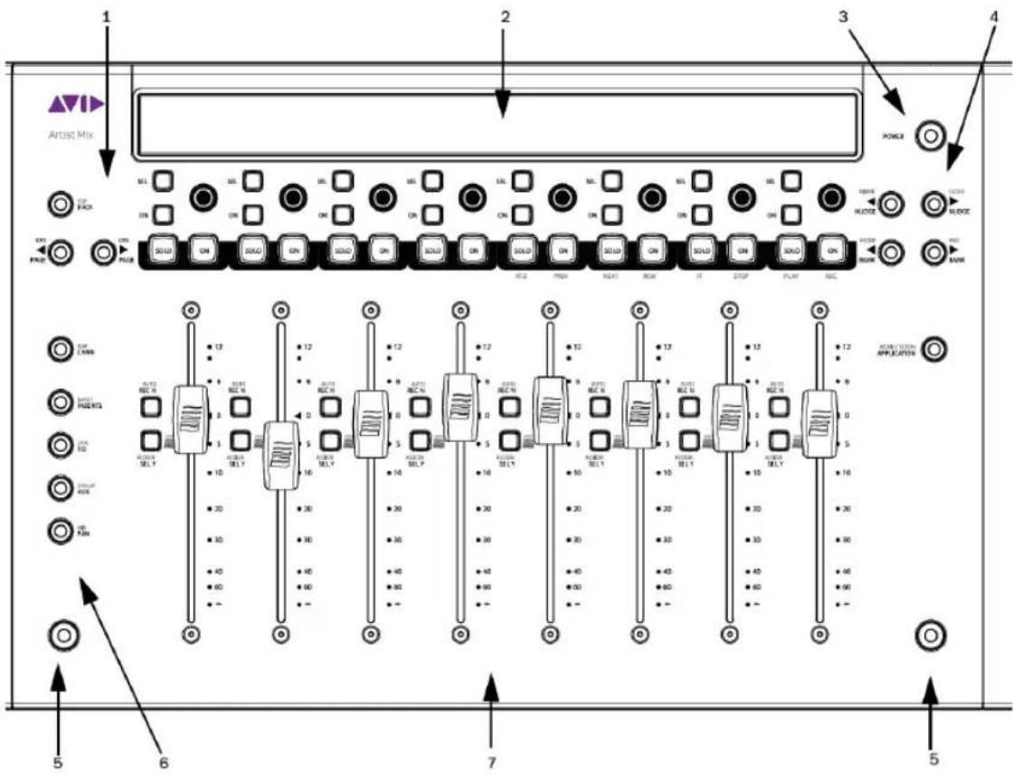
text_image
1 2 3 4 Artist Mix SILL SILL SILL SILL SILL SILL SILL SILL SILL SILL SILL SILL SILL SILL SILL SILL SILL SILL SILL SILL SILL SILL SILL SILL SILL SILL SILL SILL SILL SILL SILL SILL SILL SILL 12 SILL 12 SILL 12 SILL 12 SILL 12 SILL 12 SILL 12 SILL 12 SILL 12 SILL 12 SILL 12 SILL 12 SILL 12 SILL 12 SILL 12 SILL 12 SILL 12 SILL 50000000000000000000000000000000000000000000000000000000000000000000000000000000000000000000000000000 512 512 512 512 512 512 512 512 512 512 512 512 512 512 512 512 512 512 512 512 512 512 512 512 512 511988888888888888888888888888888888888888888888888888888888888888888888888888888888888888888888888888886666666666666666666666666666666666666666666666666666666666666666666666666666666666666666666666666666 55555555555555555555555555555555555555555555555555555555555555555555555555555 777777777777777777777777777777777777777777777777777777777777777777777777777777777777777777777 444444444444444444444444444444444444444444444444444444444444444444444444444444444444444 3333333333333333333333333333333333333333333333333333333333333333333333333333333333333333333333333333FIGURE 370
-
Soft Key navigation buttons
-
SHIFT keys
-
OLED Display
-
Knob Set selectors
-
Power button
-
Fader strips
-
Fader Navigation buttons
Of course, Artist Mix can be used with a variety of systems and software applications apart from TriCaster. You may already be familiar with its use for certain other purposes. The Artist Mix User Guide provides details regarding each control. In this manual, we'll focus on the controls as they apply to TriCaster only.
22.6.5 NUDGE
At any one time, Artist Mix can display controls for as many as eight of TriCaster's audio inputs, internal sources, and outputs. To access the other audio controls, use the navigation buttons located at right on the control surface, just beneath the POWER button (Figure 371).
Two NUDGE buttons in this group move the entire control group currently displayed one slot left or right from the current position.
Thus, from the default Input 1-8 view, pressing ▶ NUDGE updates the controls and display to govern TriCaster's Audio Inputs 2-7 along with Net 1. (Push ◀ NUDGE to restore Input 1 to the left-most slot.)
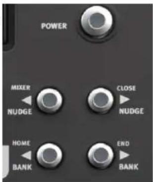
text_image
POWER MIXER CLOSE NUDGE NUDGE HOME END BANK BANKFIGURE 371
22.6.6 BANK
Below the two NUDGE buttons are two similar buttons labeled BANK. Pushing either of these buttons normally replaces the entire set of controls with their eight nearest neighbors. So, for example, if you are currently viewing/controlling Inputs 1-8, pushing the ▶ BANK button swaps out those controls and replaces them with the next set of eight sources to the right, starting with NET 1 at left and continuing to AUX in the eighth slot.
A number of buttons on the Artist Mix control surface have two labels. For example, the ▶ BANK button (Figure 372) has a secondary END label above.
The upper label denotes alternative functions for the button that are invoked when you hold down one of the two Shift buttons on the surface at the same time.
FIGURE 372
Note that the ▶ BANK buttons each have alternate functions when pressed with Shift, specifically HOME and END. These combinations jump past all other configured control groups to display the irst and last entries respectively.
22.6.7 LEVEL CONTROL
FIGURE 373
As you would expect, adjusting the position of a given fader modifies the volume level of the corresponding control in TriCaster's Audio Mixer.
For example, pushing the control surface fader labeled Audio1 A raises the volume for the source labeled Audio 1 A in TriCaster's Audio Mixer.
22.6.8 KNOB SET SELECTORS
A set of Knob Set selectors (Figure 374) runs vertically down the left side of Artist mix (left of the irst fader). Essentially, these are mode buttons that select which audio attributes are governed by the eight 'knob sets' – that being one OLED display group and the knob immediately beneath it, along with the two buttons to the left of the knob (SEL and ON) in that set (see Figure 375).
Note: The FLIP/CHAN button in this group is a special case, and can be selected even when another mode is active. Generally speaking, you will very likely find it best to leave this button off except for certain operations – notably for EQ and Mic Trim adjustments. We'll discuss these exceptions in context as we go along.
The default Knob Set mode is PAN. For the most common production operations, this is the mode you will choose. In fact, at the simples level, once you have configured the Artist Mix channels to take any SDI sources into account, you could likely be forgiven for never using another Knob Set mode.
text_image
FLIP CHAN INPUT INSERTS DYN EQ GROUP AUX MIX PANFIGURE 374
Generally speaking, the alternative Knob Set modes provide access to deeper audio configuration options and settings. We'll provide the details of their use in context as we go along.
Several controls are nested above each fader, along with the matching OLED display group for that audio input or source. Looking at Figure 375 you'll notice that in the default operating mode (PAN; See the previous section) the Audio 1A track's display shows a VU meter at left, and a PAN graph below the input label. Rotate the knob
below the PAN graph display to adjust PAN for the channel this source is on.
MULTI-CHANNEL PAN CONTROL
For a four channel source, such as an input set to SDI Embedded, TriCaster's level knobs each control two channels. An Artist Mix knob set can likewise be configured to control "Audio1 AB" and "Audio 1 CD" (for example) to control the two channel pairs for a single SDI source (see Section 22.6.17 for details).
text_image
Audio 1A Pan SEL ONFIGURE 375
In such cases, the PAN control knob adjusts the irst channel by default (A, in this example) for the assigned pair.
To adjust PAN settings for the other channel in the same pair, press the SEL button (just below the OLED in the same Knob Set group). This lights the button, and re-assigns the PAN control on the surface to the associated channel. Press the SEL button again to restore control over the irst channel (the SEL button light will go out.
text_image
AUTO REC N ASSIGN SEL YFIGURE 376
GAIN A AND B (MIC TRIM)
To adjust MIC GAIN for a channel, press the CHAN button. Then push the button labeled SEL located to the left of the fader for the channel you want to control. The highlight behind the source label in the OLED display updates to show the newly selected source. In CHAN mode, an additional control (labeled GAIN A or B) appears at right of the channel's PAN control on the surface.
These GAIN controls correspond to mic trim controls found in TriCaster's input Audio Configuration panels (Audio Mixer tab). Press CHAN again to restore normal, single channel control, when done making adjustments.
Hint: Although the GAIN control is shown for other source types, it really only has any effect on inputs configured as Mic types in TriCaster's audio input source selector.
22.6.10 TALK
Push the small ON button to the left of the knob to toggle the Talk (Talk Over) feature for Mic sources.
22.6.11 SOLO & MUTE
Two larger buttons labeled SOLO and ON (Mute) are positioned below the knob; that is, above each of the eight faders (Figure 377). These two buttons are outside the Knob Set group, and thus independent of the mode established by the of Knob Set selectors.
text_image
SOLO ONFIGURE 377
That's just a wordy way of explaining how it is that a SOLO button always toggles the Solo feature for its respective source; and likewise the ON (Mute) buttons always mute or un-mute them – even when you might be in a different mode.
Hint: As with most convenient rules, there is one exception to the above. If the SOLO and ON buttons are unresponsive, check to see if the SHIFT LOCK button (i.e., the left SHIFT button on the control surface) is lit; if it is, turn it off.
At the time of writing, multi-selection of Solo is not supported on the Artist Mix surface (though it can be performed in the TriCaster user interface).
22.6.12 FOLLOW
Two other small buttons sit just to the left of each fader strip. These are labeled AUTO/REC N and ASSIGN/SEL Y. The latter is not normally relevant in (the default) PAN mode, but we are interested in the irst - AUTO/REC N. This button (with the earlier caveat about SHIFT LOCK in mind) toggles the Follow feature on and off for the designated TriCaster audio source.
text_image
AUTO REC N 6 0 5 10 ASSIGN SEL YFIGURE 378
Having covered the basic control functions and settings, let's advance
to consider the tools available in different Knob Set modes.
22.6.13 EQ CONTROL
FIGURE 379
TriCaster provides independent 7-band equalization along with Compressor/Limiter features for each source. And Artist Mix lets you access the controls without ever touching the TriCaster user interface.
To display EQ controls, it will probably come as no surprise by this point that you need to push the EQ button in the Knob Set control group.

text_image
Line 1 60 Line 2 150 Line 3 400 Line 4 1k Line 5 2.4k Line 6 6k Line 7 12k Line 8FIGURE 380
The OLED display will now appear as seen in Figure 380. Normally, all 7 bands for a single input are shown in this manner. In this mode, the knobs below the graph in each group control the setting for a single EQ band, shown above.
Note that the label for one input is highlighted in the OLED display. (For example, Figure 381 shows a highlight behind the Line 1 label; Line 2 is not highlighted.)
text_image
Line 1 60 Line 2 150FIGURE 381
This highlight identifies the currently selected source. Any adjustments made in this state affect the EQ settings for the selected source only. In this fashion, you can easily adjust all settings for one source. To select a particular source (such as Input 1 or 2) for adjustment, press the button labeled SEL to the left of the fader in the control surface slot with the corresponding label above.
The highlight in the OLED display updates to show the newly selected source.
To enable, disable or reset the EQ, press the EQ (Knob Set) button to enter EQ control mode, and press CHAN, to turn Channel mode off; the display should show the 60Hz level. Select an input (press the SEL Y button beside a fader), and press the SEL button just below the OLED to enable/disable EQ for this input; or press ON (just beneath) to reset the EQ for this input.
text_image
AUTO REC N ASSIGN SEL YFIGURE 382
22.6.14 COMPRESSOR/LIMITER
To access TriCaster's Compressor/Limiter controls for the currently selected source, simply hold down a Shift key on the control surface and press the EQ button again (the label for the 'shifted' state of this button is DYN).
Again, the labels above the little graphs in each control surface slot update to show Compressor/Limiter settings – Threshold, Ratio, Attack, Release, and also Mic Gain. And naturally, the knobs beneath are delegated to control the corresponding attribute for the currently selected source.
Hint: Mic Trim (not the same thing as Mic Gain) is only shown for sources set to a Mic mode.
22.6.15 CHAN MODE
CHAN is short for "Channel". By default, this button is unlit, and Artist Mix operates
in 'standard' mode. Standard mode (CHAN off) is the default operating mode for the PAN Knob Set mode that you will use for most 'non-configuration' Audio Mixer activity. It imposes one-to-one relationship between control groups and individual audio sources – each group governs one source exclusively.
FIGURE 383
Pushing the CHAN button changes this relationship. In channel mode, all knobs and faders are assigned to a single TriCaster audio source (or 'channel', from the Artist Mix viewpoint). The SEL switch, introduced in 22.6.13, determines which source has 'focus', and the various adjustable settings for that source are expanded across the entire control surface, with one Artist Mix 'slot' assigned to each.
We've seen how this works in EQ mode, where it expands the different equalizer bands for a single (selected) audio source across multiple knobs. In fact CHAN mode is so appropriate in this case that it is automatically activated whenever you press the EQ Knob Set selector. (In CHAN mode, a 'grid' background is displayed in the OLED - see Figure 384. And as we saw before, the label for the selected source is highlighted in the same manner).
Hint: It is possible to switch to standard operating mode manually using Artist Mix t control EQ settings. Just press the CHAN button to toggle that mode off. In this state, the knobs in all eight control groups are assigned to a single parameter – so, for example, you could view (and adjust) the 60Hz EQ setting for all sources in the current Artist Mix bank at once if you need to quickly damp that low rumble your microphones are picking up when the air conditioning kicks in.
You will probably find that standard mode works best for most operations apart from EQ, however.
To enable/disable or reset the Comp/Limiter, hold SHIFT and press the EQ (Knob Set) button, then press CHAN, to turn Channel mode off; the display should show the Threshold level). Press the SEL Y button beside a fader to select an input, and press SEL button below the OLED to toggle EQ for this input; or press ON (just beneath) to reset the Compressor/Limiter.
text_image
Line 1 60FIGURE 384
22.6.16 FLIP MODE
The shifted state of the CHAN button is labeled FLIP. Like the former, FLIP also affects the mapping of the Artist Mix controls. In this case, the roles of the fader and the rotary knob are swapped. For example – in the default PAN Knob Set mode, the faders normally controls source levels, while the rotary knob adjusts Balance or Pan. When FLIP is active, it's the other way around.
While not particularly useful for most operations, FLIP comes into its own in EQ mode, allowing you to use the much larger faders to provide convenient control over the rather similar sliders in TriCaster's equalizer (don't forget to turn flip off when you switch back to normal PAN mode, though).
The INPUT/INSERTS button serves several important purposes. It can be used to reassign the label for a slider input to a different TriCaster audio control by name, or to insert (or remove) a new (initially unassigned) control column on the surface.
Controls for unused inputs or outputs can be removed from the surface, or if you wish, you can re-order controls using the Remove and Insert features. To insert a
new control strip on the surface, proceed as follows
text_image
SEL ONFIGURE 386
- Make sure FLIP and CHAN are both turned off, and then press the INSERTS button in the Knob Set group.
- Rotate the knob for Input one clockwise, cycling through optional settings until the label above the knob says Insert.
At this point, the small SEL button just left of the rotary knob begins to lash, to indicate that if you wish to conirm your selection you must press it (otherwise,
press MIX/PAN to cancel the operation and revert to the original selection).
FIGURE 385
- Press the SEL button to execute the insertion.
This action inserts a new, unassigned control, pushing the original Artist Mix control group to the right to make room for the addition.
- Slowly rotate the same knob again – this time, you could choose an option (such as Master 1 option), and then press SEL once more to lock the input to TriCaster's Input 1a (left) input channel. Instead, just select Remove this time and press SEL to conirm.
Hint: Normally, if you insert a source that already appears elsewhere in the layout, the inserted control group is kept and the original is removed.
22.6.18 LOCKING CHANNELS
By default, Artist Mix presents control groups for each TriCaster audio source in their natural order from left to right. It can be very desirable however, to lock one
or more sources in a fixed position, thus keeping it in view on the control surface at all times despite any use of the navigation buttons.
For example, you may well wish to consider locking the Master audio controls to the seventh and eighth slots, so that these important faders will always be available. To do so, follow these steps:
- Navigate (using NUDGE or BANK buttons if necessary) to position Master in the furthest right control slot on Artist Mix.
- (With FLIP and CHAN both off), press the INSERTS Knob Set button.
- Press the small ON button located to the left of the Master 1 knob (Figure 386).
- Press the PAN button in the Knob Set selector group (to exit INSERT mode).
A small padlock icon appears in the OLED, indicating that Master is now locked in its current place on the control surface. If you use the navigation buttons to move left or right, Master stays right where you want it.
Hint: When locking multiple channels on the AVID Artist Mix, always lock the rightmost of the channels to be locked first.
Unlocking a previously locked source restores it to its normal position.
Note: Locking sources has one slightly annoying side effect. You will see a clone of locked sources elsewhere in the Artist Mix layout. This does not pose a real issue, since the duplicate is fully synced with the locked one, and will operate as expected if you do use it.
22.6.19 AUDIO PRESETS
Artist Mix implementation provides full access to TriCaster's Audio Mixer preset system. Keep in mind that these can be a very convenient way to store and recall different source layouts for Artist Mix, too. You can choose a preset or create a new one using either the user interface or Artist mix. To select a preset, proceed as follows:
- Press Shift + INSERTS (INPUT) to display the list of existing mixer presets left to right across the slots in the OLED display.
- Press the SEL button below the PLED label of the reset you want to select.
Hint: Rotate the knob below a preset on the OLED display to access copy and paste (preset) functions.
SECTION 22.7 MIDI CONTROL
Another very useful (and often very affordable) control option available to TriCaster users is MIDI.
Literally thousands of devices of this sort are available. (Typically, MIDI devices are used in the audio industry in particular, but often they are used for other applications as well).
TriCaster's Macro system can 'listen' for button presses from most MIDI devices (just as it it recognizes input from other control surfaces or the keyboard) and uses this facility to trigger macros. For TriCaster purposes, many MIDI devices will provide 'plug-and-play' convenience.
Some (including the example mentioned in the box at right above) do require the installation of third party device drivers.
Generally, adding device drivers to TriCaster is discouraged, since these may not have been prepared with the rigorous demands of live production in mind. As we cannot guarantee suitability of third-party MIDI drivers for TriCaster use, it's good to know that a TriCaster Restore operation will restore normal operation if a driver you install has unintended consequences.
MIDI Configuration Add-On:
The Add-On group in TriCaster's Session page (Startup) includes a link named Ableton Novation Launchpad. This link opens a simple configuration application that allows you to alter the colors used to illuminate buttons on this popular MIDI device.
Simply choose a specific device from the menu at upper left, choose a Fill Color, and click a button on the screen with the ill bucket mouse pointer. (Alternatively, each button has a right-click menu you can use to select the color for that button.)
MIDI can be useful in many, many ways Too, a wide variety of MIDI software and extensions are available for other devices. These can be used to create unique custom TriCaster control alternatives. For example, the mockups below depict custom iPad® interfaces (created using third-party iOS® apps) providing wireless control over TriCaster's Publish features (Figure 387) and DDRs (Figure 388).
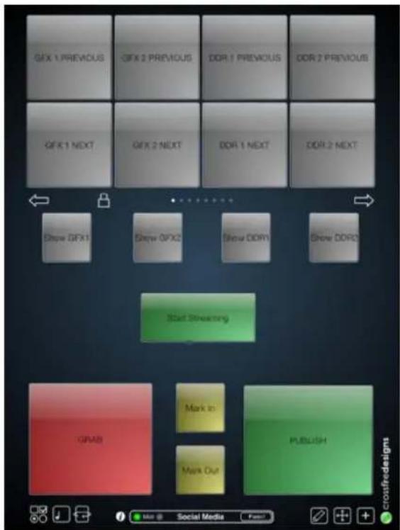
text_image
GFX 1 PREVIOUS GFX 2 PREVIOUS DDR 1 PREVIOUS DDR 2 PREVIOUS GFX 1 NEXT GFX 2 NEXT DDR 1 NEXT DDR 2 NEXT Show GFX1 Show GFX2 Show DDR1 Show DDR2 Start Streaming GRAB Mark In Mark Out PUBLISH cronfredesignsFIGURE 387
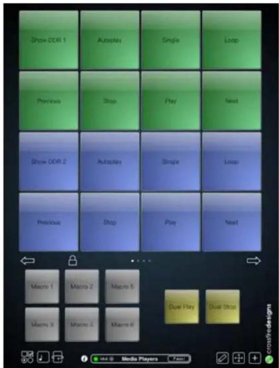
text_image
Show DDR 1 Autoplay Single Loop Previous Stop Play Next Show DDR 2 Autoplay Single Loop Previous Stop Play Next Macro 1 Macro 2 Macro 5 Macro 3 Macro 4 Macro 6 Dual Play Dual Stop User Media Players castredesignsFIGURE 388
Countless other possibilities exist, too, of course – see Section A.7.4 (How do I) Use My iPad® As A MIDI Controller? for some additional suggestions.
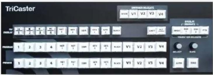
text_image
TriCaster SHIFTER DELGATE MAIN V1 V2 V3 V4 F/U ORDER 1 2 3 4 NET 1 NET 2 SET 3 GEX 4 GFX 5 BLACK SHIFT RESET PROVAS 1 2 3 4 NET 1 NET 2 SET 3 GEX 4 GEX 5 BLACK V1 V2 V3 V4 PROM 1 2 3 4 NET 1 NET 2 SET 3 GEX 4 GEX 5 BLACK V1 V2 V3 V4 DISPLAY RESET RATE AUTO MAKEFIGURE 389
TriCaster 40 CS ^™ , though designed for TriCaster 40 (not covered in this Guide), may be preferred by some users at times. For this reason, it has been supported for all 4-input models (only).
22.8.1 DELEGATES AND SYNCHRONIZATION
As discussed, delegate button groups govern other controls on the control surface. Some delegate groups support multi-selection, and allow simultaneous operations to be performed. When initially selecting multiple delegates, as often as not the settings and states of the individual members selected will vary. For example, when you delegate both DSK's at once in the TRANSITION DELEGATE group, the RATE for current transitions for the two DSKs could well be different.
Generally, wherever it makes sense to do so, when you make adjustments to settings for multi-delegate features, the settings will be progressively synchronized, then advance in lock step.
22.8.2 SWITCHER DELEGATES
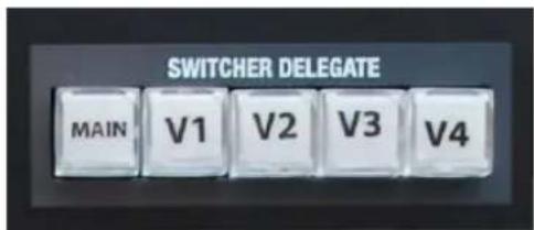
text_image
SWITCHER DELEGATE MAIN V1 V2 V3 V4FIGURE 390
This delegate group dictates what the FX/OVERLAY, PROGRAM and PREVIEW rows will control. The options are mutually exclusive – that is, multiple selections are not supported. Choose one of:
- MAIN
- VI - M / E1
- V2 - M/E 2
- V3 - M/E 3
- V4 - M/E 4
MAIN
FX/OVERLAY ROW
When MAIN is selected in the SWITCHER DELEGATE group, operations in this row are further modified by the OVERLAY DELEGATE selection in the Transition (T-Bar) group.
- When MAIN is selected in the SWITCHER DELEGATE group, if either DSK1, DSK2 or both are lit, making a selection on the FX/OVERLAY row sets the source for the related channel(s).
- If BKGD alone is lit (or, for that matter FTB only), a button selection in the FX/OVERLAY row assigns the 'FX' source. For professional model TriCasters, this is the same as setting the source assigned to the Green (FX) switcher row group.
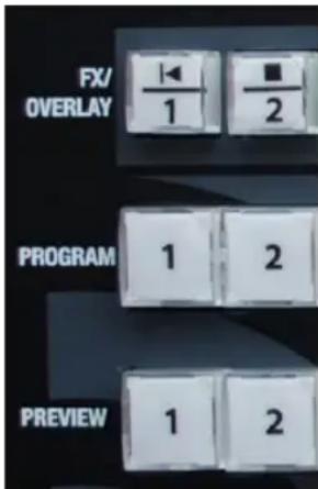
text_image
FX/ OVERLAY 1 2 PROGRAM 1 2 PREVIEW 1 2FIGURE 391
PROGRAM AND PREVIEW
As you would expect, when MAIN is selected in the SWITCHER DELEGATE group, PROGRAM and PREVIEW row operations perform just like their onscreen counterparts.
On the other hand, when one of the Virtual Input delegates (V1-V4) is selected in the SWITCHER DELEGATE group, the three rows beneath are repurposed to correspond to the OVERLAY, INPUT A and INPUT B rows of the delegated M/E(s).
22.8.3 SHIFT & ALT
SHIFT
SHIFT is a ‘qualifier button’ (like ALT), providing access to secondary functions for certain buttons. (For example, SHIFT + (Preview row selection) toggles the LiveMatte feature for the designated video source.)
FIGURE 392
ALT
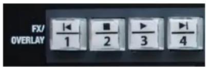
text_image
FX/ OVERLAY 1 2 3 4FIGURE 393
Holding ALT provides access to secondary functions for certain buttons. You'll note on inspection that the irst four buttons in the FX/OVERLAY row have icons on their upper half representing transport and navigation features associated with TriCaster's Media Players.
Specially, the supported control operations are:
- |◀ (Previous Item) – Press this button to go to the previous playlist entry in delegated Media Players. (The selection cycles to the last playlist entry when necessary.)
- (Stop) – Push once to end playback for delegated Media Players; push a second time to return to the start position (this operation respects the Single setting for individual Media Players.
- (Play) – Push to initiate playback for delegated Media Players.
- ▶| (Next Item) – Push this button to go to the next playlist entry in delegated Media Players. (The selection cycles to the irst playlist entry when necessary.)
You determine which Media Player to control by pressing ALT. Doing so lights one of the Media Player selection buttons in the FX/OVERLAY row – whether the DDR, GFX 1, or GFX 2. To change the active player, make a different Media Player selection while ALT is pressed. Without releasing ALT, press one of the first four buttons in the row to perform the transport/navigation operation assigned to it as listed above.
ALT AND SHIFT FUNCTIONS
Press ALT along with a button on the PREVIEW row to toggle the Proc Amp for the corresponding video source. Replace the ALT button combination with SHIFT to toggle the source's LiveMatte feature instead. ALT also provides access to transition controls for Virtual Input Overlay layers, as discussed in the next section.
22.8.4 TRANSITIONS
The transition area on TriCaster 40 CS offers familiar controls, including a T-Bar, transition selector and timing knobs, along with AUTO and TAKE buttons. These are all governed by delegates, as discussed earlier.
The TRANSITION DELEGATE buttons include BKGD, DSK 1, DSK 2, and FTB (Fade to Black) buttons. These can be multi-selected, and govern which video layers are affected by operations performed with the SELECT and RATE knobs, AUTO and TAKE buttons, and the T-Bar.
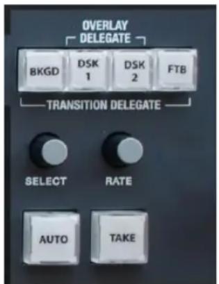
text_image
OVERLAY DELEGATE BKG D SK 1 D SK 2 FTB TRANSITION DELEGATE SELECT RATE AUTO TAKEFIGURE 394
TriCaster's Background layer effectively comprises the program output before any DSKs or FTB are considered. When the BKGD delegate button is selected alone, a TAKE swaps the source selected on the PREVIEW row for the one shown on the PROGRAM row.
If one or more DSKs is selected along with the BKGD delegate button, the display state for the delegated DSK(s) will be affected as well. Depending on their current status, this may bring them into view, or remove them from program output. This allows you to simultaneously hide one DSK (such as a title page) while revealing another, even as you bring in a new BKGD source. Or you can display and hide both DSK channels in tandem.
SHIFT FUNCTIONS
The SHIFT key provides access to certain special features in connection with transitions as follows:
- SHIFT + AUTO: Reverse direction to fully remove or display delegated video sources left partially displayed by an incomplete prior transition.
- SHIFT + BKGD (TRANSITION DELEGATE): Perform an immediate BKGD TAKE.
- SHIFT + DSK 1 (TRANSITION DELEGATE): Perform an immediate DSK 1 TAKE.
- SHIFT + DSK 2 (TRANSITION DELEGATE): Perform an immediate DSK 2 TAKE.
- SHIFT + FTB (TRANSITION DELEGATE): Perform an immediate FTB TAKE.
ALT FUNCTIONS
When pressed with either TAKE or AUTO buttons, display of the currently delegated Virtual Input's Overlay will be transitioned on or off. (If a Virtual Input is not selected in the Switcher Delegate button group, ALT is ignored).
SELECT AND RATE
These two buttons are also governed by the delegate buttons above. Select BKGD and twist the appropriate knob to select a different BKGD transition from the onscreen bin, or to change its rate.
These knobs also act like pushbuttons. Push down and release SELECT to toggle the Reverse switch for the current BKGD transition.
Hint: Background transitions are the only type to offer a reverse option; DSK transitions automatically toggle their direction.
Or - push the RATE knob repeatedly to cycle through the default S (Slow), M (Medium) and F(Fast) transition speeds. Recall that multi-selection is supported, as well.
T-BAR INDICATORS
TriCaster's onscreen T-Bar always snaps back to the top at the end of a transition. This is not true, of course, for the T-Bar on the control surface. To help you know what will result from moving the physical T-Bar, observe that there are green LEDs located near either end of its stroke. Normally, one of these is lit to indicate the direction the T-Bar should be moved to complete the last operation or perform a new one.
In some cases, transition operations can result in the onscreen T-Bar and its control surface counterpart being out of synch with one another. In such cases one of the LEDs begins to lash, and the T-Bar is deactivated. It will remain in this state until it is moved fully to one end of its stroke, re-synchronizing it with the user interface. Afterward, the T-Bar resumes control over the delegated sources.
SECTION 22.9 TRICASTER™ LC-11
Some TriCaster owners still own and (for reasons of their own) occasionally wish to use the older TriCaster LC-11 ^™ control surface. This device was originally designed for use with earlier, standard deinition TriCasters. However, it was later adapted to provide limited support for the eight-input TriCaster 850.
With these users in mind, at the time of writing, ‘unofficial’ support for LC-11 has been extended to TriCaster 410, 460 and 860. Generally, LC-11 operations on these newer platforms are similar to those provided with TriCaster 850, as depicted in Figure 395.
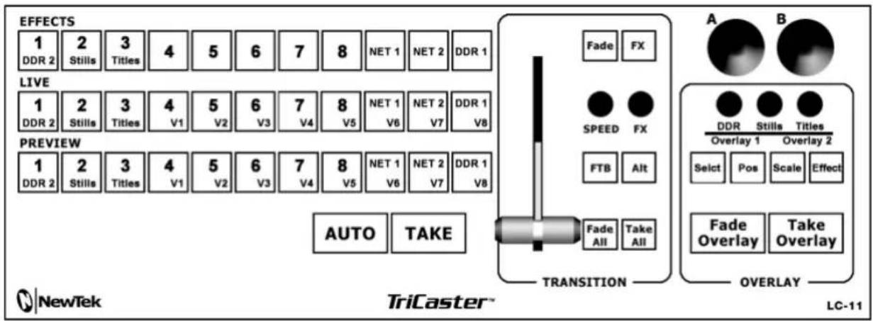
text_image
EFFECTS 1 DDR 2 Stills Titles 4 5 6 7 8 NET 1 NET 2 DDR 1 LIVE 1 DDR 2 Stills Titles V1 V2 V3 V4 V5 NET 1 V6 NET 2 V7 DDR 1 V8 PREVIEW 1 DDR 2 Stills Titles V1 V2 V3 V4 V5 NET 1 V6 NET 2 V7 DDR 1 V8 AUTO TAKE A Fade FX SPEED FX FTB Alt TRANSITION A B DDR Stills Titles Overlay 1 Overlay 2 Select Pos Scale Effect Fade Overlay Take Overlay OVERLAY NewTek TriCaster™ LC-11FIGURE 395
Hint: With the newer software, LC-11's EFFECTS works similarly to the UTIL row on the 460 and 860 CS models (documented elsewhere in this Guide).

text_image
TCIn this section, we'll consider the most common questions TriCaster™ operators may have (and of course we'll provide the answer, too). Answers are intentionally brief – perhaps just a reminder of one or two steps required to perform some operation. For this reason, we'll also point you to explanatory information elsewhere in this manual whenever that would be useful.
If you've largely mastered your TriCaster™ but have a specific question, this may be the best place to look irst. The headings that follow list related questions and answers together, along with cross-references and other helpful remarks.
Hint: The NewTek website includes a comprehensive FAQ database containing a wealth of useful information on all of its products – please see http://www.newtek.com/faq/
How do I ... (?)
CONNECTIONS 418
Connect cameras? 418
Connect II + alpha sources....418
Color correct mismatched cameras? 419
Connect monitors? 420
Supplement: Why don't I see the Mulview monitor resoluon I want listed in the Mulview Resoluon menu?
Supplement: Aer reconnectng monitors, my Mulview and Interface monitor conguraon is messed up. What can I do?
Connect a supported external control surface 422
Supplement: TriCaster The control surface has suddenly stopped working. What can I do?
Mirror control operaons to another TriCaster? 422
Insert/Remove a Drive From TriCaster's Removable Drive Bay....423
Supplement: What hard drives are recommended for TriCaster?
Connect an external hard drive? 424
Eject a hard drive?......424
Connect tally lights? 425
Connect to a network/the Internet? 425
Locate a speciC TriCaster on my network? 425
Resolve iVGA PRO Quirks? 425
Connect to an AirPlay ^® source?......426
Supplement: Why doesn't my AirPlay® device list TriCaster as a target?
Supplement: Why do some clips not play properly across an AirPlay conncon?
Enable terminaon for video inputs? 429
Congure Wirecast ^® to receive TriCaster's Network output?......429
SESSIONS 430
Supplement: What is a 'session?...... 430
Start an SD session? 431
Start an HD session? 431
Supplement: What is the best session format for streaming? 431
Work on a stored session? 432
Backup a session? 432
Restore a session? 432
Delete a session (and its content)? 433
Manage selected content inside a session? 433
Rename a session? 433
Duplicate a session? 433
LIVE PRODUCTION 434
Make custom transions and LiveSets? 434
Restore the default LiveSet?......434
Set up the 'Nightly Show A' LiveSet? 434
Set up the 'Night Beat 3D' LiveSet?......436
Set up the 'Metropolis A' LiveSet?......437
Iniate streaming? 439
Find my captured stream le?......439
Record my program? 440
Find my recorded program le? 440
Change playback speed for clips in the DDR (Media Player)? 440
Deal with clips that seem blurry when examined in the DDR (Media Player)? ......441
Get stubborn clips to play in the DDR?......441
Quickme®
AVI
Flash ^® (F4V)
Change the colors for an enre tle playlist at once?......443
Get live tle pages (.cgxml) to respect all LiveTEXT font aributes? 444
Prepare a matched group of M/Es? 444
Improve the quality of Mulview output? 445
FILES......445
Manage les? 445
Import media les? 445
Share Files On YouTube ^® ? 446
Prepare Clips with Embedded Alpha Channel? 446
Add an external File Locaon to the File Browser? 447
Remove a Locaon From the File Browser? 447
Export Files to an external drive? 447
Import/Export les larger than 4 Gigabytes?......447
Free up space by deleng the demo clips? 448
SOFTWARE, MAINTENANCE AND UPDATES....449
Resolve serious instability or dropped frames? 449
Update my TriCaster? 449
Update the Flash ^® and/or Windows Media Encoder? 450
Install virus protecon? 450
Install my favorite soware (or codec)? 451
Supplement: Can I install the MainConcept AAC Encoder for Flash®?
Create a 'User Backup' drive? 451
Restore TriCaster soware?......452
REGISTRATION AND TECH SUPPORT 454
Register TriCaster? 454
Access Technical Support? 455
Find TriCaster's hardware/rmware revision numbers?......455
MISCELLANEOUS 455
Access System Administraon Features....455
Return to TriCaster from Administrator Mode 455
Add A Custom Streaming Prole to the Congure Stream Connecon Panel....455
Supplement: Does TriCaster support mul-bitrate streaming proles
Supplement: Is it beer to use a Baseline or Main prole for H.264 encoding?
MORE QUESTIONS AND ANSWERS....465
Can I do anything to improve latency/audio sync? 465
Supplement: Why does latency seem higher for certain video formats (i.e. 24p)?
Why is my power supply beeping? 465
Supplement: Where can I obtain replacement or spare Power Supply modules?
Why do some thumbnail icons look wrong? 466
A.1.1 CONNECT CAMERAS?
- Connect video sources to the appropriately labeled BNC input connectors on TriCaster's backplate according to your camera's video output connection type (see Section 3.5).
(Because of the ‘busy’ nature of the backplate, you may find the BNC removal tool provided with TriCaster helpful for this purpose). - Open a TriCaster session (or create a new one) from the Home Page of the Startup Screen.
- Click the Live icon on the Session Page of the Startup Screen, and press Enter (or click the Start Live Production link).
- Roll the mouse pointer over the monitor for the camera you want to set up, and click the Conigure (gear) button that appears in its titlebar.
- Choose an appropriate Connection Type for your camera in the Input Settings tab (see Section 8.2.1).
A.1.2 CONNECT FILL + ALPHA SOURCES?
- Connect the Fill (color) source to an odd-numbered video input.
- Connect the Alpha channel source to the adjacent (higher) even-numbered video input.
- Open a TriCaster session (or create a new one) from the Home Page of the Startup Screen.
-
Click the Live icon on the Session Page of the Startup Screen, and press Enter (or click the Start Live Production link).
-
Roll the mouse pointer over the monitor for the camera you want to set up, and click the Conigure (gear) button that appears in its titlebar.
- Choose the appropriate Connection Type for the source attached to the odd-numbered input in the Input Settings tab (see Section 8.2.1).
- Choose Act as Alpha Channel for Input (#) as the Connection Type for the even-numbered source in the Input Settings tab. (See Section 8.2.2).
A.1.3 CONFIGURE ALPHA MATTE OUTPUT?
- Open the Output Configuration panel, by double-clicking the main Program monitor.
- Click the Output tab in the Output Configuration panel which opens
- Checkmark the Alpha Matte switch at the bottom of the Video source menu for Output 2.
- Select a suitable source, again using the Source menu.
A.1.4 COLOR CORRECT MISMATCHED CAMERAS?
TriCaster permits the use of sources that do not match the current session format. You might connect an SD camera during an HD session, for example. The official broadcast standard for SD video is Rec. 601, but HD video conforms to Rec. 709. TriCaster's output color space is governed by the session format.
When the natural color space for a connected source does not match TriCaster's current output specification (in this example, Rec. 709), TriCaster automatically attempts to compensate – but as always, it's good to refer to the scopes for critical accuracy.
As required, TriCaster's Waveform and Vectorscope displays can be used to monitor corrections made using the Proc Amp tools. (Scope calibration automatically conforms to the broadcast color specification for the current session – HD or SD, and is appropriately labeled as a convenient reminder.)
A.1.5 CONNECT MONITORS?
COMPUTER MONITOR
With the power off, connect an external computer monitor to the Interface port on TriCaster's backplate, using an adapter if necessary.
MULTIVIEW MONITOR (OR PROJECTOR)
TriCaster supports a Multiview output feature by means of the output connector labeled Multiview.
- Connect the external device to the Multiview output on TriCaster's backplate using an appropriate cable (and/or adapter, if required).
- Open a TriCaster session (or create a new one) from the Home Page of the Startup Screen, click the Live icon on the Session Page of the Startup Screen, and press Enter (or click the Start Live Production link).
- Click Workspace in the Dashboard at the top of the Live Desktop, and click the Configure (gear) button that appears above it.
- Select a suitable Multiview Resolution from the bottom of the menu shown to match the native resolution of the external monitor you wish to use.
SUPPLEMENTARY QUESTIONS:
Q1: Why don't I see the Multiview monitor resolution I want listed in the Multiview Resolution menu?
A: Normally the Multiview Resolution menu list is updated using DDC (Display Data Channel) information the monitor itself provides. In some cases this information may not be not available (e.g., a monitor switch or adapter might prevent the available display mode information from being supplied to the operating system).
If you are sure your monitor supports an unlisted mode, you can attempt to add it to the menu manually by editing an (XML format) configuration ile supplied for this purpose. The ile is named multiview_resolutions.xml, and is located in the folder at C:\TriCaster\Configuration. Comments in the ile provide details of its use.
(Note that if your display hardware declines to work with additions you make to the menu, the Live Desktop status message display may show an ‘unsupported display mode’ warning, and the monitor may either revert to the previous mode or simply not show anything at all.)
NOTE: Changing Output Resolution can cause frames to be dropped briefly. We do not recommend changing this setting during live production.
Q2: After reconnecting monitors, my Multiview and Interface monitor configuration is messed up. What can I do?
A: If you disconnect (or power down) and reconnect monitors while on TriCaster's Live Desktop, the operating system can have difficulty with monitor recognition and configuration. To avoid problems, naturally it's best to leave display devices alone while live.
In the case of an accidental disconnection, avoid reconnecting both monitors at the same time. Rather, allow the display on the irst monitor connected to stabilize before connecting the second.
VIDEO MONITORS/DEVICES
Downstream video monitoring devices must be compatible with the video broadcast standard (such as NTSC or PAL) you intend to use in the TriCaster session.
- Connect cables between downstream devices (whether monitors or other devices) and appropriately labeled connectors on TriCaster's backplate (see Section 3.8.1).
- Open a TriCaster session (or create a new one) from the Home Page of the Startup Screen.
- Click the Live icon on the Session Page of the Startup Screen, and press Enter (or click the Start Live Production link).
- For SD display devices, you may need to adjust the connection options found in Output Configuration:
a. Move the mouse over the Program monitor, and double-click to open Output Configuration.
b. Click the Output tab, and select one of either Composite + Y/C or Component for Inputs 1-3 according to the connection type used by devices connected to each output. (Please see 0 for more information.)
A.1.6 CONNECT A SUPPORTED EXTERNAL CONTROL SURFACE?
Connect the USB cable from the Control Surface to one of TriCaster's USB ports.
SUPPLEMENTARY QUESTION:
Q: The control surface has suddenly stopped working. What can I do?
A: The foremost reason this might happen is if the cable (or extender cable) you are using between the control surface and the TriCaster failed to deliver sufficient current consistently. In the short term (if you are in the middle of a show), you can generally resolve this issue by simply unplugging and re-plugging the control surface.
However, please note that the use of so-called "USB extenders" is not recommended. Whenever possible, use a single USB cable of the correct length. Each added connector on the signal path is a potential connection problem, and also causes signal 'reflections'. Such an arrangement may seem to work for a while, then fail unpredictably.
If you are using a very long USB cable (or a poor quality cable), you should supply a powered hub at the end of the cable nearest the control surface, then complete the connection with a short USB cable from the hub to the control surface. (An unpowered hub will be of no help.)
A.1.7 MIRROR CONTROL OPERATIONS TO ANOTHER TRICASTER?
-
Connect the second TriCaster to the same network.
-
Refer to Section 17.6.1 for details of preparing the two TriCasters and enabling Remote Control.
A.1.8 INSERT/REMOVE A DRIVE FROM TRICASTER'S REMOVABLE DRIVE BAY
- If TriCaster is running, and if applicable (not a TriCaster 410 feature) – Eject the hard drive you wish to remove (see Section A.1.10).
- Open TriCaster's front panel.
- Open the removable drive bay door.
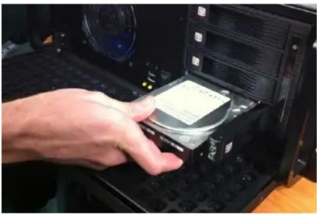
natural_image
Hand inserting a CD into a computer motherboard (no visible text or symbols)FIGURE 396
- Pull the hard drive currently in the drive bay (if applicable) to remove it.
- Insert the new hard drive ('connector end' first)
- Close the drive bay door.
- Close TriCaster's front panel.
SUPPLEMENTARY QUESTION:
Q: What hard drives are recommended for TriCaster's removable drive bay(s)?
A NewTek supplied storage media has been carefully tested to meet exacting specifications, and can be expected to provide optimal performance and reliability.
Of course, you are free to purchase storage media from other sources.
Keep in mind that manufacturer specifications and reviews may highlight favorable statistics, focusing on results from ‘typical’ (i.e., less demanding) operating environments. (Naturally, NewTek cannot guarantee that hard drives obtained from such sources will provide performance adequate to TriCaster’s requirements.)
Here are some guidelines to keep in mind when obtaining hard drives from other sources:
- All else being equal, larger drives are normally faster – try to use 1TB drives or above.
• Use SATA 3.0GB/s drives with rotational speed of 7200 R.P.M. (or better). - Drives should have a larger onboard cache (32Mb or better is recommended).
A.1.9 CONNECT AN EXTERNAL HARD DRIVE?
Connect a suitable USB cable from the external hard drive to one of TriCaster's USB ports. Note that the hard drive should probably be formatted using the NTSF ile system (the FAT ile system chokes on exported iles exceeding 4 Gigabytes, as will often be the case).
A.1.10 EJECT A HARD DRIVE?
- Launch TriCaster, and click the Open icon on the Home Page of the Startup Screen.
- Click the Eject gadget at upper right on the screen, and select the hard drive you wish to safely disconnect, or...
- Open the Live Desktop's TriCaster Options menu by clicking the label NewTek TriCaster at left in the Dashboard, select Eject and select the desired drive (see Section 7.1).
A.1.11 CONNECT TALLY LIGHTS?
External tally light devices and their connections vary widely. Please refer to Section 3.9 for details on TriCaster's tally light jack implementation.
A.1.12 CONNECT TO A NETWORK?
Please refer to Section 3.16 and Chapter 16 Network.
A.1.13 LOCATE A SPECIFIC TRICASTER ON MY NETWORK?
Please refer to Section 3.2 for details on giving your TriCasters unique network names.
A.1.14 RESOLVE IVGA PRO QUIRKS
ADDITIONAL NOTES
- Some antivirus software can interfere with certain iVGA PRO features. In such cases, try disabling your protection briefly. If the problem goes away, consider using a different anti-malware product.
- If iVGA PRO's connection to TriCaster seems intermittent, make sure only one network path exists between the two systems, to prevent the PC from switching back and forth between connections.
- In some cases, the use of headphones or other audio hardware may disable or hijack standard system audio output. You can sometimes resolve this issue by simply unplugging the headphones. In other cases, third party audio drivers that have been installed do not support
-
Some systems and third-party audio device drivers deliberately restrict access to system sound (for DRM reasons), preventing their output from appearing as an audio source option for iVGA PRO. Several workarounds exist.
-
You could simply loop an audio cable from the system's output back to an input, and select that input as the audio source for iVGA PRO.
- Often you may be able to select a different audio device (such as “Stereo Mix” or “SoundMAX”) as the system default. Right-click the ‘speaker’ icon at right in your Windows® Desktop taskbar, and select “Recording Devices”. This opens the audio device control applet, allowing you to choose among those available. (It is sometimes useful to right-click in this pane and enable “Show Disabled Devices”, as well.)
- Other third-party software solutions exist as well. An Internet search for terms like “audio loopback software” or “virtual audio cable” will turn up relevant links.
A.1.15 CONNECT TO AN AIRPLAY® SOURCE?
The local network (the same network you connect TriCaster to) is the means of transmission for AirPlay®, and a wireless connection from the player to the network is perfectly acceptable.
- Select the AirPlay® entry in the Source menu for Net 1 or Net 2 (just as you would select an iVGA™ or LiveText™ source).
- TriCaster identifies itself as a potential client device to the AirPlay® source.
- One or more TriCaster devices will be listed as potential output devices for the AirPlay® device. Select one and you are done.
Note: A limitation of the current iTunes release prevents it from properly addressing the second AirPlay® connection it detects. Instead, it attempts to use the first connection. If the first connection is already committed to another source, this attempt will fail.
SUPPLEMENTARY QUESTIONS:
Q: Why doesn't my AirPlay® device list TriCaster as a target?
A1: The irst time you connect to a network with the TriCaster, a network 'location' is selected. This is a standard Windows® process that automatically conigures appropriate irewall and security settings for the type of network that you connect to.
There are three location options: Home, Work, and Public. If TriCaster's active network has inadvertently been set to 'Public', AirPlay® will not connect. Be sure this is set to either Home or Work.
A2: By default, the Windows® irewall is disabled on TriCaster. If your AirPlay device does not recognize TriCaster after enabling AirPlay® for Net 1 or Net 2, it may be that someone has enabled it, and it is preventing connection. You can either disable it, or (if you really must have it) adjust its settings as follows:
- Click Configure Network in the Administration Mode screen.
- Open the Windows® Firewall interface using the link shown at lower-left in the Network and Sharing control panel.
- In the left pane, click Advanced Settings. (If prompted for an administrator password or confirmation, type the password or provide confirmation).
- In the Windows Firewall with Advanced Security dialog box, click Inbound Rules in the left pane, and then click New Rule in the right pane.
- Follow the instructions in the New Inbound Rule wizard.
- Ensure that the following ports are open:
| Port | Protocol | Name |
| 80 | TCP | HTTP |
| 443 | TCP | HTTPS |
| 554 | TCP/UDP | RTSP |
| 3689 | TCP | DAAP |
| 5353 | UDP | mDNS (Bonjour) |
A3: Make sure you are connected to the correct network, especially for Wi-Fi. iOS® connects to known networks by default. If multiple Wi-Fi connections are available, it may connect automatically to a previously known network. For a wireless AirPlay® source such as iPad®, follow these steps:
- Tap Settings > Wi-Fi. If Wi-Fi is off, turn it on by tapping the on/off icon.
- Available Wi-Fi networks appear under Choose a Network...
- Locate and tap the Wi-Fi network that TriCaster is connected to.
A4: Wi-Fi uses radio frequency technology to connect hardware and software applications so that they can communicate. However, RF interference can be a major problem, especially in an environment such as a trade-show or conference that might entail numerous competing signals.
Other devices contributing to RF clutter include microwave ovens, cordless phones, Bluetooth devices, wireless video cameras, outdoor microwave links, wireless game controllers, fluorescent lights, and so on. These sources can cause significant interference and signal degradation. Where possible, try to eliminate or minimize the potential interference in your installation design.
A5: Consider the following suggestions when many conflicting wireless sources are in the immediate area:
- Set the wireless network SSID to any unique name. Choose a name that is unique to your network and is not shared by other nearby networks or other networks you are likely to encounter to avoid connection failures, or unintentionally connecting to other networks sharing the same SSID.
- Make sure that the network is not set to 'hidden.' iOS® devices may interpret this as a closed network and fail to connect.
- If using security, make sure that it is set to WPA2 Personal (AES). Use of WEP is not recommended for compatibility, reliability, performance, and security reasons.
- If possible, configure 2.4 GHz Radio mode to 802.11b/g/n.
-
If the router supports 5 GHz Radio mode, set it to 802.11a/n.
-
Channel Settings should be set to 1, 6 or 11 (11 is the most common choice, since it is the starting channel, making 1 or 6 a good choice).
- Channel width should be set to 20 MHz or "Narrow Band" in 2.4 GHz mode.
• Channel width should be set to both 20 MHz and 40 MHz in 5 GHz mode. - Ensure that only one DHCP server is active on the network.
Q: Why do some clips not play properly across an AirPlay® connection?
A: There are several possibilities: First, TriCaster cannot play media governed under Digital Rights Management (DRM) schemes. This is a common limitation of commercial content.
Otherwise, if an iOS® device loses its connection with the network for any reason it does not refresh the AirPlay® destination list for about one hour. It may seem as though the TriCaster is detected even though the connection has been lost.
One way to flush the AirPlay list is to enable and disable ‘Airplane mode’ in the device settings. Finally, make sure you are connected to the correct Wii network (etc.)
A.1.16 ENABLE TERMINATION FOR VIDEO INPUTS?
TriCaster has full-time video termination. If you need to loop through (or t-off from) other video devices (such as an external monitor) prior to TriCaster in your video pipeline, you should ensure termination is OFF for earlier devices.
A.1.17 CONFIGURE WIRECAST® TO RECEIVE TRICASTER'S NETWORK OUTPUT?
To set up Telestream's Wirecast ^® software to recognize TriCaster's Network output as a source, follow these steps:
- Double-click the main Program monitor to open TriCaster's Output Configuration panel.
-
Select the desired audio and video sources for Network output, and enable it.
-
At the time of writing, Wirecast ^® does not fully support interlaced video, so you must also checkmark De-Interlace at the bottom of the Network video source menu.
- Next, open the Sources menu in the Wirecast® interface (Figure 397), and select the "New Web Stream" option.
The Source Settings dialog will open.
- Set Protocol to "HTTP".
- Type the Network URL displayed in TriCaster's Output Configuration pane into the Wirecast® URL ield.
TriCaster's Network video output should now appear in Wirecast ^® , ready to be added to a shot like any other valid source.
A.2 SESSIONS
SUPPLEMENTARY QUESTION:
Q: What is a session?
A: Sessions can be thought of as 'top-level presets'. They store all of the settings, playlists, device configurations, and so on for a given live production. See Section 5.1.
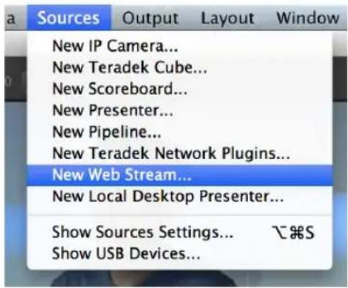
text_image
Sources Output Layout Window New IP Camera... New Teradek Cube... New Scoreboard... New Presenter... New Pipeline... New Teradek Network Plugins... New Web Stream... New Local Desktop Presenter... Show Sources Settings... &S Show USB Devices...FIGURE 397
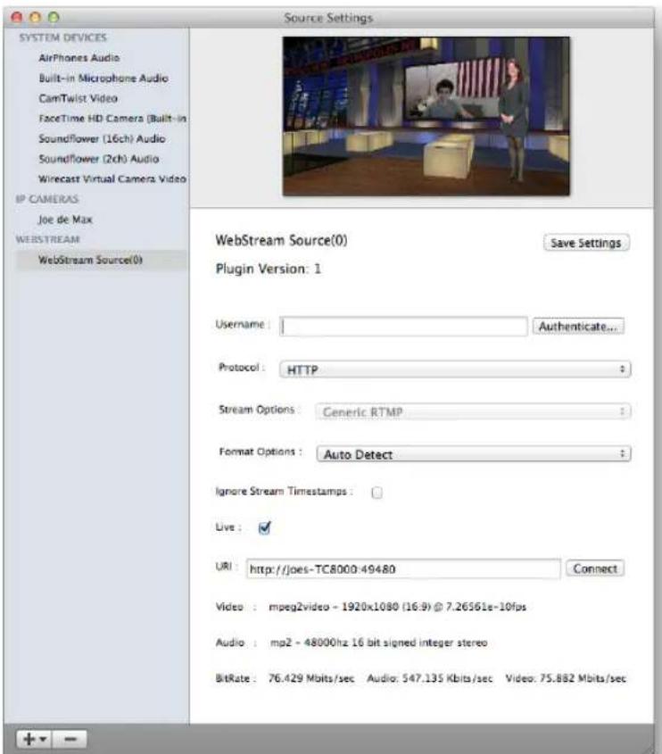
text_image
SYSTEM DEVICES AirPhones Audio Built-in Microphone Audio CamTwist Video FaceTime HD Camera (Built-in Soundflower (16ch) Audio Soundflower (2ch) Audio Wirecast Virtual Camera Video IP CAMERAS Joe de Max WEBSTREAM WebStream Source(0) Source Settings WebStream Source(0) Save Settings Plugin Version: 1 Username : Authentication... Protocol : HTTP : Stream Options : Generic RTMP : Format Options : Auto Detect : Ignore Stream Timestamps : Live : URL : http://joes-TC8000:49480 Connect Video : mpeg2video - 1920x1080 (16.9) @ 7.26561e-10fps Audio : mp2 - 48000hz 16 bit signed integer stereo BitRate : 76.429 Mbits/sec Audio: 547.135 Kbits/sec Video: 75.882 Mbits/secFIGURE 398
A.2.1 START AN SD SESSION?
- Connect your SD sources to TriCaster's input connectors (see Section 3.5).
- Connect your SD monitors to TriCaster's output connectors (see Section 3.8.1)
- Select the New icon in the Home Page of the Startup Screen.
- Click the Enter Session Name link (under Session Name at right) and supply a name for the new session.
- Select a Volume (hard drive) for the new session.
- TriCaster Multi-standard only: choose your local Video Standard (NTSC, NTSC-J or PAL)
- Choose either SD 4:3 or SD 16:9 (widescreen) for Resolution, and click the Start Session link (lower-right).
(See also Sections Section 3.10 and Section 5.1.)
A.2.2 START AN HD SESSION?
- Follow steps 1-6 in the preceding section.
- Select either 720p or 1080i for Resolution.
- Click the Start Session link (lower-right).
SUPPLEMENTARY QUESTION:
Q: What is the best session format for streaming?
A: We strongly recommend that you use a progressive video format for sessions you intend primarily for streaming.
Doing so eliminates ielding artifacts that might otherwise occur due to converting ielded video to progressive video for streaming. This will generally result in noticeably better quality.
A.2.3 WORK ON A STORED SESSION?
- Click the Open icon in the Home Page of the Startup Screen.
- Click the name of the session you want to re-open.
A.2.4 BACKUP A SESSION?
- Open the TriCaster session you wish to backup, then click the Manage icon in the Startup Screen's Session Page.
- Click the Backup Session button (below the Browse list). If the session has external iles in its playlists, choose one of the options from the dialog that opens next.
- Use the system ile explorer that opens next to select the location for the backup ile, and click OK. This process can take considerable time if the session has a lot of content; in such cases, it's best not to commence unless time (before a production) permits. (See Backup Session under Section 5.3 for more detail.)
A.2.5 RESTORE A SESSION?
- Click the Open icon the Home Page of the Startup Screen
- Click the Restore Session Backup link at the bottom of the Sessions list as right.
- Navigate to and select the previously stored session backup ile, and click Open.
A.2.6 DELETE A SESSION (AND ITS CONTENT)?
- Right-click the name of the session in Home Page of the Startup Screen.
- Select Delete from the menu.
This will delete the session, and any content that is local to the session, including associated LiveText projects (external data that has not been imported will not be deleted).
A.2.7 MANAGE SELECTED CONTENT INSIDE A SESSION?
- Click the name of the session containing the content you wish to delete in the Home Page of the Startup Screen.
- Click the Manage icon on the Session Page.
- Under Browse at right, click the link for the type of content you wish to manage (see the sub-heading Manage in Section 5.3).
A.2.8 RENAME A SESSION?
- Make sure all drives that have session data on them (such as captured clips) are inserted.
- Right-click the name of the session you want to rename in the Home Page of the Startup Screen.
- Choose Rename from the menu that appears.
A.2.9 DUPLICATE A SESSION?
It can be very useful to make a copy of a session. For example, it might often take less time to modify a copy of an existing session than to configure an entirely new one.
-
Backup a session – see Section A.2.4.
-
Rename the current session – see Section A.2.8.
- Restore the backed up session – see Section A.2.5.
A.3 LIVE PRODUCTION
A.3.1 MAKE CUSTOM TRANSITIONS AND LIVESETS?
The Animation Store Creator application is included with your TriCaster. Its documentation can be accessed from the Help menu on the Home Page in Startup.
As well, an optional, user-friendly, tool called TriCaster Virtual Set Editor ^™ is available. This tool makes it easy to modify LiveSets to suit your specific needs.
A.3.2 RESTORE THE DEFAULT LIVESET?
- Click the label button [...] above the current LiveSet name to open the Media Browser.
- Click the NewTek heading beneath the LiveSets heading in the locations list at left.
- Select Default (2 Layer) in the Default group in the ile pane at right.
A.3.3 SET UP THE 'NIGHTLY SHOW A' LIVESET?
As you may know, TriCaster 8000's LiveSets support four primary video inputs, along with sources dedicated to Key channels. Other models provide less video inputs for effects. The 'Nightly Show A' LiveSet is special in that it appears to show many different video sources simultaneously (see Figure 399), even including a moving 'news ticker'.
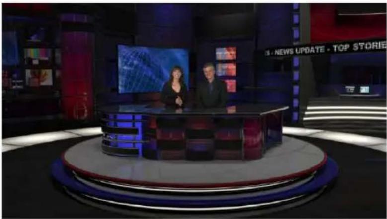
natural_image
Studio scene with two hosts at a desk in front of a large screen, no visible text or symbols on the main subjects.FIGURE 399
This virtual multi-monitor effect depends on a single clip (played from a DDR) which is itself a montage composed of a number of different looping video clips composited into a single frame (e.g., Figure 400).
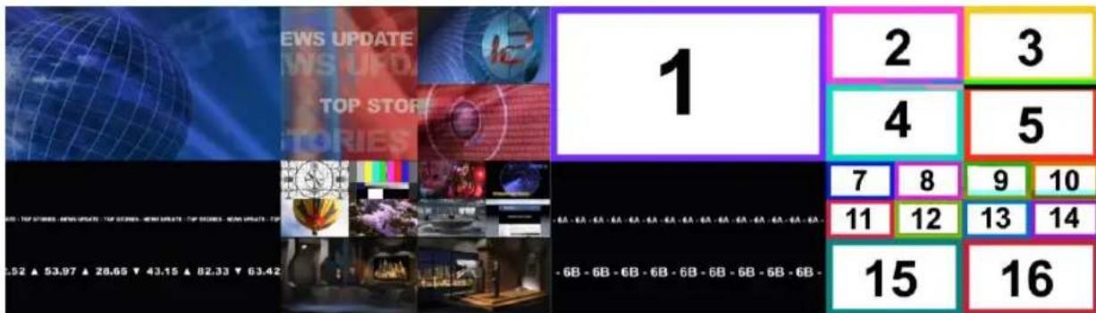
text_image
1 2 3 4 5 7 8 9 10 11 12 13 14 15 16FIGURE 400
FIGURE 401
Hint: A template clip (Figure 401) is supplied in the Clips>NewTek folder (as are several looping sample clips). You can use the template as a guide to prepare similar clips with content positioned correctly for use with the Nightly Show set, using in the software of your choice.
To configure the effect:
- Assign your talent shot to Input A in the M/E tab
- Put the looping montage clip you prepared in a DDR, and select that DDR as Input B.
This particular set was designed to work with all TCXD model TriCasters, including those supporting just two primary sources. For TriCaster 8000 (only), which adds C and D inputs in M/E panels, the set has been updated as follows to provide more ability:
- Input C targets the 'virtual ticker'. Knowing this, you might for example use Input C's positioner to compose a LiveText feed (from a Network input) to correspond to the lower right quadrant of the template clip (as seen in Figure 401 above). This would then be mapped to the ticker, allowing you to update the virtual ticker remotely.
- Input D is mapped to the virtual ‘control room monitor displays’. Position another source to conform to any of the numbered input areas of the template clip to replace the corresponding ‘screen ‘in the virtual control room. This allows you, for example, to send live video switched in another M/E to one of these monitors.
Hint: To use the set as originally designed, simply assign one looping 'montage clip' (like the provided samples) to all of inputs B, C and D.
Note: This effect requires TriCaster 8000, because it alone provides reentrant M/Es.
One of the sample LiveSets provided with TriCaster provides camera angles intended for use with the 3D Anaglyph effect. Here's how to set up the Night Beat 3D LiveSet for this purpose:
- Select an unused M/E, and assign a keyed talent shot to Input A.
- Assign another source, perhaps a full frame graphic, to Input B.
- Click the button labeled Effect above the central Effect thumbnail.
-
Click the + sign that appears when you move the mouse over the label below the effect thumbnail to open a Media Browser.
-
Click the NewTek label under the LiveSet heading in the Media Browser, and choose "3D Center L.LiveSet" from the "Night Beat" folder in the file pane at right.
This M/E provides the left angle for the center desk shot of the ultimate 3D result.
- Choose another free M/E, and set it up exactly as described above – but this time choose "3D Center R.LiveSet" from the "Night Beat" folder.
This second M/E provides the right angle for the 3D effect.
- Set a third M/E pane to Effect mode, and assign "3D Anaglyph (Red, Cyan).LiveSet" from the "3D" folder to it.
- In this third M/E pane, assign the left angle M/E prepared earlier to Input A, and the M/E you configured as the right angle to Input B.
- Select this third M/E on the main Switcher's Program row, and view the result through red/cyan 3D glasses. (Note that the anaglyph effect is maintained even through a LiveSet zoom.)
Hint: If you assign suitable left and right images to the Input B rows of the respective left and right M/Es, the desk front monitor imagery will also be shown in 3D.
A.3.1 SET UP THE 'METROPOLIS A' LIVESET?
Note: This number of sources required for this effect limits its use to TriCaster 8000.
Metropolis is a ‘million dollar set’, and provides endless opportunities for creative use. There are actually two versions of this set, labeled A and B, with multiple shots in each group. The second of these groups ('B') employs tighter camera shots with less video sources visible at one time, and requires no special care to configure.
Metropolis A, however, is a complex set, with three different primary talent positions as well as numerous secondary displays. When viewed in its widest zoom angle, it can require as many as 8 different sources to supply all of these – not counting the Key (overlay) layers.
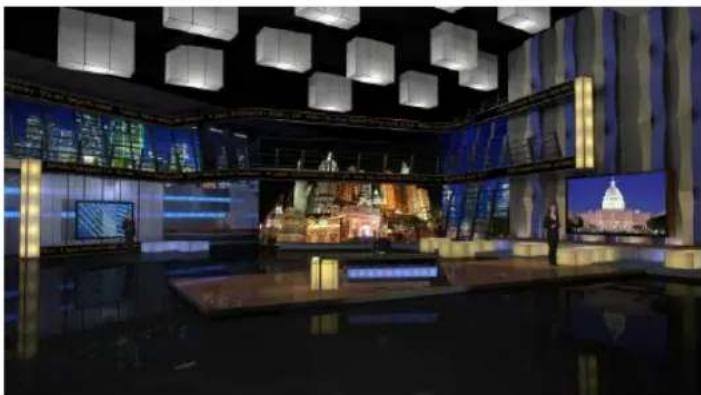
natural_image
Interior of a modern digital art studio with large screens displaying cityscape and text, no visible signage or text.FIGURE 402
Since a single M/E accommodates four independent sources (Inputs A-D) at most, it requires two M/Es to take full advantage of Metropolis A. Here's how to set up the most complex shot in this network-class virtual set group:
-
Select an unused M/E - let's use M/E 1 for our example.
-
Click the button labeled Effect above the Effect thumbnail in the M/E pane.
-
Click the + sign that appears when you move the mouse over the label below the thumbnail to open a Media Browser.
-
Click the NewTek label under the LiveSet heading in the Media Browser, and choose "Metropolis A Wide" from the "Metropolis A" folder in the file pane at right.
-
Assign keyed talent sources to Inputs A, B and C.
-
Assign another M/E (we'll use M/E 2) to Input D.
This last source – Input D – will provides the imagery for the live ‘news tickers’ in the scene, as well as the three large monitors behind the keyed talent sources.
-
Select the tab for the second M / E - M / E2 in our example, and set it to effect mode as well.
-
Click the + sign that appears when you move the mouse over the label below the effect thumbnail to open a Media Browser.
-
Click the NewTek label under the LiveSet heading in the Media Browser, and choose "Metropolis A Quad Split" from the "Metropolis A" folder in the ile pane at right.
- Assign video or graphics sources to Inputs A-C. These inputs supply the three monitors behind your talent shots.
- Input D is meant to feed animated text (whether from a DDR, or perhaps a Network Input source such as LiveText) to the various news tickers in the scene.
Your animated text should be centered vertically in the frame, and presented over either a transparent or black background. The font size need not be overly large, but you can use the Position tools for the Input D layer to scale and reposition it as necessary.
Hint: If you temporarily select M/E 2 on Program output, you'll see how this quad source is arranged (prior to being fed to Input D of M/E 1).
A.3.2 INITIATE STREAMING?
- Connect TriCaster to the Internet (see Section 3.16).
- Open (or create) a TriCaster session (see Section 3.10).
- Click the Configure (gear) button in the Dashboard's Stream control area.
- Supply Connection parameters in this panel as required (passwords, username, etc. (See Section 18.3)
- Close the panel, and – when ready – click the Stream button. (See Section 4.13 and Chapter 17 Network for full details.)
A.3.3 FIND MY CAPTURED STREAM FILE?
- Got to Locate the Home Page of the Startup Screen and click Open.
-
Click the name of the session you streamed at right.
-
Click the Manage icon on the Session Page.
- Under Browse at right, click the Clips link. A system ile explorer will open.
- Open the Saved Streams folder in the ile explorer.
A.3.4 RECORD MY PROGRAM?
- Open (or create) a TriCaster session (see Section 3.10).
- Click the Configure (gear) button in the Dashboard's Record control.
- Choose your recording options (see Section 4.8.1 and Chapter 20, Record and Grab) and enter a Base Name for the ile(s).
- Close the panel, and - when ready - click the Record button.
A.3.5 FIND MY RECORDED PROGRAM FILE?
- Got to Locate the Home Page of the Startup Screen and click Open.
- Click the name of the session you streamed at right.
- Click the Manage icon on the Session Page.
- Under Browse at right, click the Clips link. A system ile explorer will open.
- Open the Capture folder in the ile explorer.
A.3.6 CHANGE PLAYBACK SPEED FOR CLIPS IN THE DDR (MEDIA PLAYER)?
The DDR's Speed control adjusts playback speed between 25-400%. Simply adjust the slider knob to suit the need.
(Note that certain highly compressed video ile formats cannot successfully be played back at rates beyond 200%, even though Speed value is set to a higher value.) See Section 11.2.3 for more.
A.3.7 DEAL WITH DDR (MEDIA PLAYER) CLIPS THAT SEEM BLURRY?
When paused or stopped, TriCasters DDRs perform motion removal (to avoid unwanted licker). This can make the image seem slightly blurred when paused, but it should look perfect during playback. (Recorded static title pages look their best when captured using the Grab function with De-Interlace turned off.)
A.3.8 GET STUBBORN CLIPS TO PLAY IN THE DDR?
First, note that TriCaster has a two minute warm-up period during which system software initializes. During this period, frames may be dropped during playback.
QUICKTIME®
At the time of writing, a 64bit version of Quicktime for Microsoft Windows® is not available. TriCaster provides internal support for many QuickTime ile formats, but not all of them. If a QuickTime ile fails to play smoothly (or at all) in the DDR, converting it to a friendlier format can help.
We recommend downloading and installing the NewTek TriCaster Codec Pack (Mac) from the downloads page of your personal registration area on the NewTek website (http://reg.newtek.com/Default.aspx). This will permit you to select from several NewTek SpeedHQ codecs (including 32bit formats with embedded alpha channel) from applications that render to Quicktime® formats.
Alternatively, Final Cut® users might consider M-JPEG, MPEG2, DVCPRO HD, or the DV Quicktime codec (for SD clips only, of course) as intermediate formats.
AVI
AVI codecs are plentiful. Most are suitable for DDR playback, but a few are not. For a given clip to play in the DDR, a corresponding 64bit codec needs to be available. However, we strongly discourage installing 'foreign' codecs, codec packs and the like downloaded from Internet sites, etc. For the sake of stability, if an AVI clip does not
play well in the DDR, please consider converting it to a 'friendlier' format. We can recommend NewTek's own SpeedHQ, or perhaps DV (for Standard Deinition clips), M2T or MPG – please continue reading for more information on ile conversion.
REMUXING CLIPS
Even when a specific AVI exists and can generally be considered ‘friendly’, the manner in which audio and video data is multiplexed (or ‘muxed’, in the jargon) by some few applications can cause playback issues that are only evident under stress. That is, a clip that plays back adequately in a typical player or NLE application may not do as well when played in a DDR at times when many other concurrent operations are occurring simultaneously.
In general, remuxing such iles is all that is needed to obtain good performance. One approach is to use any of a number of freely obtainable remuxing utilities. A quick Internet search for “remux avi” turns up several applications you could use, some free. Installed on an external system, these will remux AVI iles losslessly, resolving the issue.
You may prefer one of several simpler approaches that can be performed right on your TriCaster. For example, if the clip will play properly in a DDR when the system is not heavily loaded with other tasks, you could simply put the DDR on Program output, click Record, play the clip, and stop recording. With a little trimming of the recorded clip you'll have a very usable file.
Or, you can use SpeedEDIT - its Convert to SpeedHQ feature (found in the Filebin's context menu) can easily convert a number of clips in a single operation.
FLASH (F4V)
F4V format iles written by Adobe® Flash Media Encoder are incompatible with most video playback applications (even those from Adobe). The developer has explained the situation as follows:
"Adobe Flash Media Server version 3.5 and later and Adobe Flash Media Live Encoder 3 can record content in MPEG-4 (F4V) format using an industry-standard recording technology known as "fragments" or "moof atoms." Some MPEG-4 compatible tools and players do not support moof atoms, and therefore cannot recognize iles recorded by Flash Media Server. The F4V Post Processor
tool aggregates the information from all the moof atoms into a single moov atom and outputs a new file"
Unconverted F4V iles imported will not play in TriCaster's DDR either. Conveniently, TriCaster can automate the conversion for you to a degree. If you locate the folder named Media\Clips\sessionname\SavedStreams on your primary session drive, you will see the "raw" (unprocessed) streaming file(s) and a batch file (.bat) that can be used to convert all iles in that folder.
Simply double-click the .bat ile to initiate processing. (Note that processing can take some time, so don't do this just before a production.) Output iles will be placed in the same folder after conversion.
Hint: The .bat file supports several additional features if employed with command line switches. A readme file located in the same folder provides details of these alternatives.
If you prefer to perform this post-processing on another computer, you can transfer the raw iles to it and use the Adobe F4V Post Processor tool, available from the URL below (requires an account to login):
https://www.adobe.com/cfusion/entitlement/index.cfm?event=custom&sku=FS0000522&e=fms35
A.3.9 CHANGE COLORS FOR AN ENTIRE TITLE PLAYLIST AT ONCE?
You can quickly alter the default colors for a complete playlist of Title Pages in a Media Player (such as Titles).
- Select the button for the player containing the titles on the Preview row of the Switcher.
- Click the Configuration (gear) button for the player's onscreen monitor to access the Proc Amp.
- Click and drag the Hue slider left or right, swinging colors through the spectrum.
Observe that black and white graphics and titles are unaffected by the hue shift. In many cases, this allows you to modify background imagery without any effect on text objects (which are often white).
A.3.10 GET LIVE TITLE PAGES (.CGXML) TO RESPECT ALL LIVETEXT FONT ATTRIBUTES?
TriCaster's Title Page ile format (.cgxml) presently supports almost every attribute that LiveText offers – but there are a few exceptions.
For example, multiple font styles on one text line are not supported, which means that different words on a single line cannot be different colors, or use different typefaces. (Of course you can achieve the same effect by using additional text objects as necessary.)
For similar reasons, text entered as paragraphs is automatically split into multiple lines in .cgxml Title Page iles.
A.3.11 PREPARE A MATCHED GROUP OF M/ES?
Suppose you want to assign matching shots from one theme group of LiveSets to different M/Es (or MEM slot).
- Prepare the first M/E - click its tab, use the controls to select a LiveSet, assign and position a Key source, and select a shot (position/zoom preset).
- Move the mouse pointer to the extreme left of the screen, right-click on the Preset icon in the lyout preset bin, and select Export.
- Supply a ilename for the Preset.
- Click the second M/E tab.
- Right-click on a blank Preset, and select Import from the menu.
- Select the ile you exported above, and click Open.
The second M/E will adopt the exact same settings as the irst. Now all you need to do is replace the currently assigned LiveSet with a matching one by clicking Add at upper-right in the tab, choosing the LiveSet you want, and clicking OK.
A.3.12 IMPROVE THE QUALITY OF MULTIVIEW OUTPUT?
For best visual quality, be sure that the Multiview Resolution you choose in the Dashboard's Workspace menu corresponds to the optimum display size for the monitor connected (see Section 10.1).
NOTE: Changing Output Resolution can cause frames to be dropped briefly. Thus we do not recommend changing this setting during live production.
A.4 FILES
A.4.1 MANAGE FILES?
Please refer to the item (How do I) Manage Selected Content inside a Session? (Section A.2.7).
A.4.2 IMPORT MEDIA FILES?
Importing iles implies copying them into the TriCaster session folders, making them local (rather than external). To import media iles:
- Open (or create) a TriCaster session.
- Click the Manage icon in the Startup Screen's Session Page.
- Click the Import Media button (below the Browse list).
- Use the Import Media module that opens to create a list of iles you wish to import into the current session, and click the Import button.
Hint: You may know that external files can be used in a session without being imported, by adding them to Media Player playlists using the “Add Media Location” feature. However, such external files used in a session will not be included in session backups (unless they are deliberately imported during the backup process), nor are they deleted when sessions are deleted.
Also, the transfer speed of many external devices is too slow for reliable playback of large clips, making it wise to use Import instead whenever possible.
Although you have opened an account with YouTube® and correctly configured the account (see Section 19.2) for TriCaster sharing, uploading may fail because you have not yet created a YouTube® "channel".
The basic YouTube® account lets you log in to watch existing content and make playlists. To create a channel, follow these additional steps:
-
Browse to YouTube®, login and click Upload at the top of the home page.
-
Follow instructions to add a channel to your account.
Afterward, TriCaster will be able to upload directly to your channel by means of its Share Media feature.
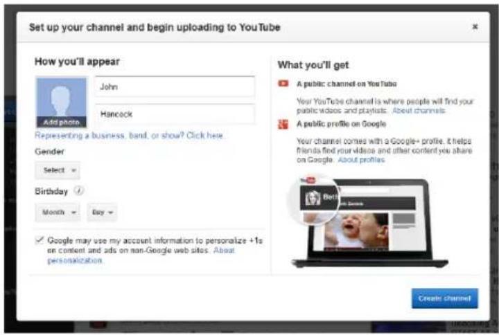
text_image
Set up your channel and begin uploading to YouTube How you'll appear John Hancock Representing a business, band, or show? Click here. Gender Select Birthday Month Buy Google may use my account information to personalize +1s on content and ads on non-Google web sites. About personalization. What you'll get A public channel on YouTube Your YouTube channel is where people will find your public videos and playlists. About channels. A public profile on Google Your channel comes with a Google+ profile. It helps friends find your video and other content you share on Google. About profiles. Create channelFIGURE 403
A.4.4 PREPARE CLIPS WITH EMBEDDED ALPHA CHANNEL?
Probably the best format to use for iles with embedded alpha channel for use in TriCaster are those encoded using NewTek's own SpeedHQ 4:2:2:4 codec. This format can serve for either SD or HD clips, and represents a high quality, moderately compressed alternative. (As a registered NewTek customer, you can download the NewTek TriCaster Codec Pack for either Windows® or Mac® platforms from your personal Downloads page on the NewTek website.)
Apple® computer users have several other options available which support an alpha channel, including the Animation and PNG Quicktime® movie codecs (select "Millions of Colors +" in the codec settings to include alpha in the file).
A.4.5 ADD AN EXTERNAL FILE LOCATION TO THE FILE BROWSER?
- Open (or create) a TriCaster session.
- Click the Add button for a Media Player (DDR, Still or Title).
- Click the Add Media Location button at bottom left in the File Browser.
- Select the folder you wish to list as a location in TriCaster's File Browser, and click OK.
(See Add Media Location in Section 11.2.2)
A.4.6 REMOVE A LOCATION FROM THE FILE BROWSER?
- Click the Add button for a Media Player (DDR, Still or Title)
- Right-click the name of the location you wish to remove from the list, and select Remove in the menu that opens.
(See the sub-heading File Context Menu in Section 11.2.2)
A.4.7 EXPORT FILES TO AN EXTERNAL DRIVE?
There are several approaches to exporting media iles from within TriCaster sessions. By far the simplest is to use the Export Media feature – see the subheading by that title in Section 5.3.3.
A.4.8 IMPORT/EXPORT FILES LARGER THAN 4 GIGABYTES?
This question may arise if you are using external media, perhaps portable hard drives or USB 'thumb' drives. These are commonly prepared using the FAT32 file system, which does not support iles larger than 4GB.
As video iles will often exceed this size, FAT32 is not very suitable for use in that context. You should reformat these drives using the NTFS system to eliminate this
limitation (or you might consider transferring larger iles to TriCaster over a network connection).
A.4.9 REPAIR DAMAGED RECORDINGS?
At times, a catastrophic event (such as a power outage) that interrupts recording will result in a damaged Quicktime® clip. Generally, such a clip can be repaired by simply adding it to a DDR playlist. (Note that this process depends on the clip being stored as-is within the NTFS ile system at all times before repair. Operations like zipping the ile, transferring it to a FAT32 drive and then back, etc., will make recovery impossible).
A.4.10 AVOID THE ERROR “...COPY THIS FILE WITHOUT ITS PROPERTIES?”
Windows® shows this error message when you export a media ile from TriCaster to an external volume that does not use the NTFS ile system. The warning is not really a concern (although we highly recommend using NTFS formatted storage, as noted in Section A.4.8). The iles will copy just ine regardless.
TriCaster generates metadata attributes for media iles for internal use. This metadata is only retained when you export to storage formatted as NTFS. That being said, the metadata is automatically regenerated if you use the iles with TriCaster again later, so its loss poses no issue.
A.4.11 FREE UP SPACE BY DELETING THE DEMO CLIPS?
- Go to TriCaster's Startup Screen.
- Open a session (it doesn't matter which one).
- Click Manage on the icon ring, and click the Clips link at right.
- Use the system File Explorer that opens to navigate up one level in the folder hierarchy, to D:\Media\Clips.
- Selectively delete content from the sub-folders you find in this location.
A.5.1 IMPROVE PERFORMANCE?
- Click the Shut Down icon on the Home Page of the Startup Screen, and click the Administrator Mode link at right to exit the TriCaster environment.
- In the Administrator Mode screen, click the Defragment Hard Drive link (under the System Utilities heading) and follow directions provided (see the heading System Utilities in Section 5.2.3).
This process can take considerable time, so it's best not to commence unless time (before a production) permits.
A.5.2 RESOLVE SERIOUS INSTABILITY OR DROPPED FRAMES?
If the system becomes seriously unstable or is dropping frames with ‘known compatible’ video files (after the warm-up period), consider a full System Restore (see item A.5.7).
A.5.3 UPDATE TRICASTER?
- Connect TriCaster to a valid Internet connection
- Click the Shut Down icon on the Home Page of the Startup Screen.
- Click the Administrator Mode link at right to exit the TriCaster environment.
- In the Administrator Mode screen, click Update TriCaster under the System Utilities heading, and follow directions provided (see the heading System Utilities in Section 5.2.3).
Note: Updates sometimes require changes to TriCaster configuration files. In such cases, the original (pre-update) files are automatically stored in a directory named "Configuration (Backup)" I cated at C:\TriCaster\Configuration, to avoid unintended loss of custom settings. At times you might decide to restore one of these in place of the newer configuration file, to retain use of certain settings (or perhaps, macros). An advanced
user might opt to cut and paste relevant lines from the older file into the new one (we suggesting backing up the newer file in this case, too, out of an abundance of caution).
A.5.4 UPDATE THE FLASH® AND/OR WINDOWS MEDIA ENCODER®?
TriCaster is not designed to be user-upgradable. For certain features to work correctly, specific versions of third-party utilities must be present. These applications are upgraded in timely fashion in official TriCaster updates.
It is quite likely that any attempt to update these manually will have unintended results, and you are strongly cautioned against doing so (unless otherwise direct by Customer Support).
A.5.5 INSTALL VIRUS PROTECTION?
Virus and malware protection applications can dramatically impact system performance. In general, once additional software or services are enabled on TriCaster, real-time performance cannot be guaranteed.
In a perfect world, we'd love to recommend that you do not install virus and/or malware protection software on TriCaster. Certainly you should always take sensible precautions to avoid introducing infected iles into TriCaster by rigorously virus-checking media you plan to connect or import beforehand – ideally, do so on a laptop or other system before connecting to TriCaster.
Realistically though, in some settings you may feel the need for protection outweighs the risk. If you really feel you must install virus protection, switch all of its ‘active scanning’ operations off so that nothing can occur in the background while TriCaster’s Live Desktop is running.
Anything that provides full-time protection will dramatically reduce memory and disk speed on your system, so you should disable those features. Then, only when you need to do so (perhaps on a daily or weekly schedule), perform a manual scan. Never let scanning continue into a live switching event, and do not assume that you can now omit pre-checking iles and external media for nasty surprises.
Hint: In the unfortunate event that malware ever does evade your defensive measures, you can always use TriCaster's Restore TriCaster function to completely rehabilitate your system.)
A.5.6 INSTALL MY FAVORITE SOFTWARE (OR CODEC)?
TriCaster is not a ‘general purpose’ computer. The installed software suite is finely tuned to provide reliable performance and amazing features. Anything you install apart from oficial TriCaster updates places these important goals at risk. Doing so is strongly discouraged.
Regarding codecs, TriCaster supports the vast majority of popular image, audio and video formats. That said, hardly a day passes without another new one appearing on the scene. If a ile you would like to use does not play back well (or at all), consider converting it to a friendlier format.
If you feel the format is so popular that TriCaster should support it, please submit the details as a feature request. (Please also see Section A.3.8 above.)
SUPPLEMENTARY QUESTION:
Q: Can I install the MainConcept AAC Encoder - Plug-In for Adobe® Flash® Media Live Encoder?
A: This is not required.
A.5.7 CREATE A 'USER BACKUP' DRIVE
The Backup and Restore system permits you to create a bootable clone of TriCaster's system drive on another (same size) hard drive inserted into one of the removable drive bays or connected externally for this purpose.
The clone operation includes:
• The hidden, factory-prepared Restore partition
- The complete C partition (uncompressed)
Afterward, the backup drive can be removed and stored, to be used later if necessary to i) restore the internal drive should, or ii) in the case of a catastrophic drive failure, to be connected internally to completely replace the original drive.
Note: Since opening TriCaster's case is a breach of warranty, please call Custome Service to obtain direction before proceeding with an internal drive replacement.
The actual creation process for the backup is discussed in the next section.
A.5.8 RESTORE TRICASTER SOFTWARE
We irmly expect you will never need it, but isn't it good to know that comprehensive TriCaster Restore features are available in the event of an unforeseen problem? You can use one of two methods to access TriCaster's Restore features, depending on your situation.
To restore your TriCaster system software after the system launches normally:
- Click the Shut Down icon on the Home Page of the Startup Screen.
- Click the Administrator Mode link at right to exit the TriCaster environment.
- In the Administrator Mode screen, select the link labeled Backup or Restore System.
- Select the Restore Factory Defaults bootup option.
If TriCaster should ever fail to boot up properly, you may need to try a different approach to restore your TriCaster system software, as follows:
- Select the menu item labeled Restore Factory Defaults from the black boot screen that appears shortly after powering TriCaster up. (If this screen does not automatically appear, reboot and press F8 a few times in quick succession, say once per second, immediately after powering up.)
Either method described above will ultimately present you with powerful system backup and restore tools. The management screen initially presents you with 3 options as follows:
- Restore System Partition to Factory Defaults: overwrites the C partition (only) on the existing system drive from the disk image in its local Restore partition.
Note: Following a Reset to Factory Defaults operation, the Windows® system software must be re-activated. To do this, you will need the operating system serial number, which you will find on a sticker affixed to the exterior of your TriCaster.
This procedure restores your system drive ("C:") to its 'as-shipped' state. The "D:" drive, which holds content and sessions won't be modified. However any TriCaster software updates (possibly including optional TriCaster expansion packs) will be overwritten – so use this function only when necessary. When you do restore, remember to update the TriCaster software afterward.
- Create User Backup Drive: create a bootable clone of the entire system drive (as it exists at the time) on either an external HDD or a drive mounted in a removable hard drive bay.
The clone operation includes:
○ The existing (factory-prepared) Restore partition
○ The complete C partition
In cases of catastrophic drive failure requiring drive replacement, a service technician can simply connect the User Backup ‘clone’ drive in place of the original internal system drive and you’ll be back in production (prudence would call for creating a new User Backup drive as the irst order of business.
- Restore System Partition from User Backup Drive: overwrites the C partition (only) on the existing system drive with the C partition on the external user backup drive. This allows you to insert a User Backup drive into a removable drive bay (or otherwise connect it), and regain a functional system partition as stored on the clone drive.
Note: This feature it is intended to allow a restore operation of the system drive that the clone was prepared on. It is not intended to allow restoration from a 'foreign' TriCaster. Using the 'Restore System Partition from User Backup Drive' in the latter manner will almost certainly cause multiple problems.
In a dire emergency, however (such as if a system drive fails when no Use Backup from the same unit has been prepared) a User Backup created on similar model TriCaster can be helpful, as follows:
- Install the 'foreign' User Backup drive to replace the defunct system drive.
- Power up, and – at the boot selection screen – select 'Manage TriCaster'.
- Choose 'Restore System Partition to Factory Defaults', and follow prompts.
It will be necessary to re-activate Windows, re-enter the registration unlock code, and possibly update the TriCaster software after the restoration process in this case. Be aware that the approach above is not encouraged, since minor hardware differences between the two TriCasters involved may well result in issues in the resulting Windows installation. As well, the new system drive will no longer have a factory restore partition. Still, it might be better than nothing in a crisis.
A.6 REGISTRATION AND TECH SUPPORT
A.6.1 REGISTER TRICASTER?
- Read and accept the License Agreement shown when TriCaster launches.
- Select and copy (Ctrl + c) the characters in the Product ID ield in Step 1 of the registration dialog that appears next.
- If you have connected TriCaster to the Internet, click the button in Step 2 of the registration dialog.
- Follow the directions on the Registration webpage (in the Customer Care section of the NewTek website) to obtain your registration code
- If TriCaster does not have Internet access, call (or email) Customer Support with the Product ID:
(US) 1-800-862-7837 (Outside US) +1-210-370-8452
- http://www.newtek.com/faq/index.php?contact=service
- Enter the Registration Code provided into the Registration dialog at Step 3 (Please see Section 3.3 for more detail. Also, note that it's always good to check for updates after registration.)
A.6.2 CONTACT CUSTOMER SUPPORT?
Visit the NewTek Website, at www.newtek.com and select Support from the main Customer Care menu at the top of the page. This link leads to the latest support information for your NewTek products, including FAQs and documentation. It also lists the Customer Support Department's hours of operation and contact details.
A.6.3 FIND TRICASTER'S HARDWARE/FIRMWARE REVISION NUMBERS?
Click the Help icon in the Startup Screen's Home Page, and select About TriCaster. This opens an information panel listing version numbers (at the bottom).
A.7 MISCELLANEOUS
A.7.1 ACCESS SYSTEM ADMINISTRATION FEATURES?
- Exit the Live Desktop, and navigate to the Home page in Startup.
- Click the Shutdown icon, and then click the Administrator Mode link.
A.7.2 RETURN TO TRICASTER FROM ADMINISTRATOR MODE
Click the Return to TriCaster link in the Administrator Mode screen to return to the TriCaster Startup Screen.
A.7.3 ADD A CUSTOM STREAMING PROFILE TO THE CONFIGURE STREAM CONNECTION PANEL?
The streaming proiles shown in the drop-down Resolution menu in the Configure Stream Connection panel are drawn from the folder C:\TriCaster\Streaming Proiles.
These iles are organized according to whether they are WMV or RTMP proiles, again into NTSC or PAL versions (Multi-standard models only), and then inally subdivided into folders labeled 4x3, 16x9 (the latter two being Standard Deinition proiles), and HD.
(Note that proiles in the various sub-folders only appear in the Stream Type List for the corresponding session type.)
The easiest method of creating a custom proile is to modify an existing proile and then store it using a new name. The procedure differs depending on whether you are working with a RTMP or Windows Media® proile.
Note: It is possible to create streaming profiles that place very high demands on system resources, or are impractical for streaming over most networks.
The default profiles are suitable for most purposes, and should not interfere with other operations. Attention to these considerations when creating custom profiles is vital to ensure reliable performance, and we encourage you to perform real world testing beforehand.
IMPORTING A CUSTOM PROFILE USING 'BROWSE'
Flash Media Encoder proiles are XML iles, while Windows Media Encoder® uses a .prx ile extension for its proiles. If you already have a prepared custom proile and wish to import it, follow these steps:
- Open the Conigure Stream Connection panel, by clicking the Conigure button (gear) next to the Stream button on the Live Desktop.
- Click New (Connection)
- Select the option appropriate to the proile you wish to import in the popup Choose Connection Type panel.
- Click the Resolution drop down menu, and slide the pointer all the way down to the bottom to select Browse.
-
Navigate to the custom proile, select it and click Open.
-
From TriCaster's Startup Screen, click the Shutdown icon, and select Exit to Windows.
- Click the Exit to Windows button in the confirmation dialog that pops up.
- Double-click the My Computer icon, and navigate to C:\TriCaster\StreamingProiles\WMVPRoiles.
- Identify a proile (.prx ile) similar to the one you wish to create inside the appropriate sub-folder at that location.
- Copy the ile, and paste the copy in at the same location.
- Double-click the new proile to open it in the Windows Media Proile Editor.
- Make such changes to the settings as you see it, then click the Save and Close button.
- Rename the modified proile to differentiate it from the others in the same folder.
- Close the folder, and re-launch TriCaster.
CREATING A CUSTOM RTMP STREAMING PROFILE
- From TriCaster's Startup Screen, click the Shutdown icon, and select Administration Mode.
- Press the Windows® key on your keyboard, and launch Adobe Flash Media Live Encoder® from the Windows® Start Menu.
- Select Open Proile from the File menu in the encoder application.
-
Navigate to C:\TriCaster\Configuration\Streaming Proiles\FlashProfiles.
-
Continue to identify a proile (.xml ile) similar to the one you wish to create inside the appropriate sub-folder at that location, and click the Open button in the ile explorer.
-
In Adobe Flash Media Live Encoder®, modify the settings for the proile to suit your need.
-
Select Save Proile from the File menu.
-
Navigate (again) to the appropriate sub-folder inside the main C:\TriCaster\Configuration\Streaming Proiles\FlashProile directory, supply a suitable name for the new proile, and click the Save button.
-
Exit Adobe Flash Media Live Encoder, and re-launch TriCaster.
SUPPLEMENTARY QUESTION:
Q: Does TriCaster support multi-bitrate streaming proiles?
A: Yes it does, but there are a few things you should consider. Multi-bitrate encoding places higher demands on system resources than usual. It is entirely possible to create a custom multi-bitrate proile that is impractical, either because its bandwidth expectations are unrealistic, or because the encoding requires so many cpu cycles that it can intrude into other important live functionality.
For this reason, we encourage you to use the proiles supplied with your system whenever possible, and if you do opt to use a custom proile – especially a multi-bitrate one – do perform meaningful testing in advance, to ensure everything goes as planned.
Note: The Stream ID (text string) for multi-bitrate profiles must contain the character combination "%i", without the quotation marks. (The exact position of the character combination does not matter, and spaces are permitted – though the latter may pose issues for some CDNs.)
A multi-bitrate profile without “%i” in the Stream ID will produce a Flash Media Encoder® error on attempting to stream. Also, the filename for multi-bitrate streaming recordings TriCaster saves will automatically include the requisite “%i” (because the originating stream ID contains it).
SUPPLEMENTARY QUESTION:
Q: Is it better to use a Baseline or Main proile for H.264 encoding?
A: Flash Media Live Encoder lets you choose either Baseline or Main type proiles in the Advanced Encoder Settings that opens when you click the Configure (wrench) button beside the Format menu (in the Video section of FMLE's Encoding Options tab).
At the time of writing, all NewTek H.264 proiles use the Baseline option as it seems to be the best supported by various online services, and produces excellent results.
A.7.4 USE MY IPAD® AS A MIDI CONTROLLER?
Custom control of TriCaster functions can be provided using an iPad with suitable MIDI software installed. What follows is a typical approach, using the iPad® example (similar methods can be found for numerous other applications and devices, too).
For this example, you will require the following:
- An iPad ^ running iOS ^ 4.3 or later.
- The MidiPads™ Lite or MidiPads™ app installed on the iPad; you can find this in the App Store on your device. (MidiPads Lite is free, hence attractive for initial experiments. The full version of the app allows for interface customization.)
- rtpMIDI: download this utility to a USB stick from the link below.
http://www.tobias-erichsen.de/software/rtpmidi.html
- Apple ^ Bonjour™ PS for Windows®: download this utility to a USB stick from the link below.
http://support.apple.com/kb/DL999
- A wireless router to connect TriCaster and the iPad ^ to. (If TriCaster can see AirPlay ^ or can be controlled by the NewTek iPad Audio Mixer app, your networking configuration is correctly set up.)
- Once you have the rtpMIDI and Bonjour applications downloaded on the memory stick, plug it into a USB port on TriCaster. In the TriCaster interface, go into the Administration panel from the Shutdown icon and Exit to Windows.
- From a ile window, unzip the rtpMIDI software, and double click the rtpMIDI installer icon.
- If rtpMIDI says that Apple Bonjour isn't found, exit the installer and run the Apple Bonjour® installer. Install rtpMIDI after that has completed. (Use the default installation settings for both.)
- After rtpMIDI has installed, you will ind the rtpMIDI icon on the desktop. Double click on this icon to configure rtpMIDI.
The rtpMIDI interface is used to configure TriCaster and the remote devices it will communicate with.
- Click the '+' button below the panel called 'My Sessions'.
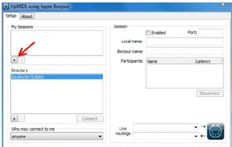
text_image
rtpMIDI: using Apple Bonjour Setup About My Sessions + - Directory KeyAccts-TC8000 + - Connect Who may connect to me Anyone Session Enabled Port: Local name: Bonjour name: Participants: Name Latency Disconnect Live routings → ←FIGURE 404
At this point, your computer name will appear in the list (Figure 404).
- Next to the computer name is a checkbox - check-mark this box. This should make the 'Enabled' checkbox turn on (if it doesn't, check-mark it as well).
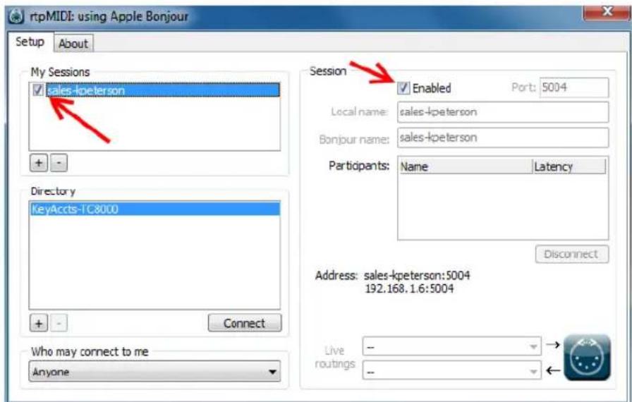
text_image
rtpMIDI: using Apple Bonjour Setup About My Sessions sales-kpeterson Session Enabled Port: 5004 Local name: sales-kpeterson Bonjour name: sales-kpeterson Participants: Name Latency Directory KeyAccts-1C8000 Connect Address: sales-kpeterson:5004 192.168.1.6:5004 Who may connect to me Anyone Live routings -- →FIGURE 405
Now we need to configure the iPad.
Hint: You might see your iPad listed in the directory panel automatically. It is best to add your iPad to rtpMIDI, manually, however. MIDI communication only occurs when the iPad app is open. Adding the iPad manually will succeed even when the app isn't running.
It is recommended that your iPad be configured with a static IP address. You can do this either by i) setting up a static IP in the iPad's network settings or ii) configuring the router to reserve an IP address for the device in the DHCP settings. Making these changes is not in the scope of this document, check your networking gear to see which option can work for you.
For now, let just setup the system using the current IP of your iPad. (You can use it this way, but you will need to go through these steps each time your power up your equipment since a new IP address may be assigned to the iPad on startup. Manually configuring for a static IP will avoid having to do this.)
- To find the iPad's IP address, open the Settings application (Figure 406).
- On the left side of the settings panel you will see Wi-Fi settings – tap here to select it.
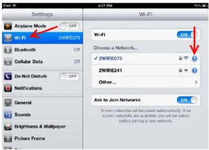
text_image
Settings Airplane Mode OFF Wi-Fi 2WIRE075 Bluetooth Off Cellular Data Off Do Not Disturb OFF Notifications General Sounds Brightness & Wallpaper Picture Frame Wi-Fi Choose a Network... ✓ 2WIRE075 2WIRE241 Other... Ask to Join Networks ON Known networks will be joined automatically. If no known networks are available, you will be asked before joining a new network.FIGURE 406
- The right side panel lists Wi-Fi access points. The one that is check-marked is the one you have connected to. Press the blue arrow to get details on the connection. Your IP address is shown at the top of the details page.
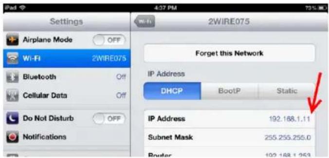
text_image
Settings Airplane Mode OFF Wi-Fi 2WIRE075 Bluetooth Off Cellular Data Off Do Not Disturb OFF Notifications 4:37 PM 2WIRE075 Forget this Network IP Address DHCP BootP Static IP Address 192.168.1.11 Subnet Mask 255.255.255.0 Router 192.168.1.253FIGURE 407
- Click on the + button below the directory listing in rtpMIDI. A window will ask for a name and host/port information.
The name can be anything you like. Enter the IP number displayed on the iPad® followed by a colon and the number '5004' into the host/port ield (e.g., for an iPad® IP address is 192.168.1.11, you would enter 192.168.1.11:5004).
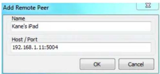
text_image
Add Remote Peer Name Kane's iPad Host / Port 192.168.1.11:5004 OK CancelFIGURE 408
- Press OK and you will see the new directory member listed. Select it, press the Connect button, and it will appear in the Participants list.
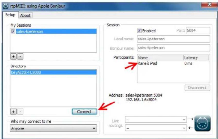
text_image
rtpMIDI: using Apple Bonjour Setup About My Sessions sales-kpeterson + - Directory KeyAccts-TC8000 + - Connect Who may connect to me Anyone Session Enabled Port: 5004 Local name: sales-kpeterson Bonjour name: sales-kpeterson Participants: Name Latency Kane's iPad 0 ms Disconnect Address: sales-kpeterson:5004 192.168.1.6:5004 Live routings -- ->FIGURE 409
You have now successfully configured rtpMIDI for use with your iPad ^®
-
Start TriCaster and launch a session.
-
Start the MidiPads™ application on the iPad®.
-
Open TriCaster's Macro panel, select a macro entry, and click in the Shortcut field to 'listen' for input.
-
Press the button you want to assign the macro to in the MidiPads™ app and it will be assigned. Afterward, pressing this button in MidiPads™ will run the assigned macro.
Hint: You can also copy and paste commands from the 'System Commands' folder TriCaster's Macro panel to your own folder, then assign a new shortcut to the copy. This way you still have the original keyboard shortcut available along with the new MIDI shortcut.
With the full version of the MidiPads app you can design multiple custom interfaces with button labels and colors to make a control surface that works the way you would like. Just make sure that you assign each button to a unique musical key so the TriCaster will know which button is being pressed.
A.8.1 CAN I DO ANYTHING TO IMPROVE LATENCY/AUDIO SYNC?
Latency might be defined as the ‘transit time’ for the a/v stream. Each device in the video chain introduces some limited (transmission) delay.
TriCaster's latency is very minimal (as little as 1 frame), but you can take measures to keep it to a minimum – irst and foremost, by genlocking your video devices – see Section 8.1.3. For genlocked sources, consider disabling TriCaster's Frame Sync – see Section 8.2.3.
In a seemingly related matter, note that audio and video passing through TriCaster are always synchronized. However, aspects of the physical design for IMAG (video projection) installations can make mimic a sync issue for viewers at some locations in the auditorium. These issues are discussed in detail in Section B.3, IMAG and Latency.
SUPPLEMENTARY QUESTION:
Q: Why does latency seem higher for certain video formats (i.e. 24p, 25p, or 30p)?
A: TriCaster passes frames through the switcher at the appropriate frame rate. When the session format calls for frames at 60Hz, displayed frames are refreshed much more often than (for example) a 24p format. Consequently, apparent latency will also be less than half what it would be at 24Hz.
In general, the lower the frame-rate of the session video format, the higher latency will seem to be.
A.8.2 WHY IS MY POWER SUPPLY BEEPING?
TriCaster 8-input systems provide redundant, replaceable power supply units. When you i) disconnect or ii) power down just one of the modules, or iii), if a PSU should fail, a beep is sounded to alert you. If you wish, you can mute the alert by pressing the green button on the back of the unit.
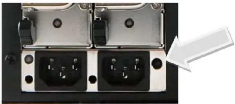
natural_image
Close-up of two black electrical connectors with pins, one highlighted by a white arrow (no text or symbols visible)FIGURE 410 (8-INPUT TRICASTER SHOWN)
SUPPLEMENTARY QUESTION:
Q: Where can I obtain replacement or spare Power Supply modules?
A: Contact NewTek Sales for purchase information for spare TriCaster components.
A.8.3 WHY DO SOME THUMBNAIL ICONS LOOK WRONG?
Some ile formats (notably AVI) do not provide embedded aspect ratio information. As a result, their thumbnail image in Media Player icons for may not be properly proportioned. Generally the problem does not extend to playback (the DDR will 'guess' the aspect ratio correctly).

text_image
TCYour TriCaster™ has been carefully designed to faithfully execute its duties under any reasonable circumstances. Still, your production environment – especially in remote locations – may impose limitations that you are wise to consider. This chapter discusses a few matters that may help you get optimal performance in less than ideal settings.
B.1 TESTING, ONE TWO ...
Professionals simply do not leap into new environments blindly. They prepare, plan, plan some more, and then – most importantly – they test. This allows them to tackle the really tough jobs with conidence.
B.2 IVGA™ AND PERFORMANCE
Although iVGA ^™ is highly efficient, it does require significant system resources, especially when a large portion of the display is refreshed. This is not normally problematic as – for iVGA purposes – the client system is not required to perform other concurrent tasks. Its entire duties involve providing a video source for the (downstream) TriCaster via the iVGA client software. However, it is very unwise to install and run the iVGA client software directly on a TriCaster itself.
TriCaster's live video processing requires unhindered CPU and GPU access. Adding the resource demands of the iVGA client to TriCaster would almost certainly cause frames to be dropped on output, and should simply never be done. The same warning applies to other ‘screen-sharing’ or ‘remote desktop’ applications, which would actually be as bad or worse.
Of course iVGA benefits from the fastest possible network connections between remote clients and TriCaster even when “used as directed”. This is especially true if you intend to stream high resolution motion graphics to TriCaster using iVGA.
What's IMAG? It's a compression of the expression "Image MAGnification." Typically in modern IMAG applications, video cameras supply live imagery to projection systems, magnifying speakers and performers so that audience members further back in large venues can still see what's going on.
IMAG is a very tricky task at the best of times, one that calls for excellent planning, and where possible, testing. Those designing an IMAG installation have, not just one, but two inter-related broadcasts to consider – in the form of the audio and video streams.
B.3.1 RELATIVITY AND THE SPEED OF LIGHT
Wouldn't it be nice if audio and video travelled from their respective broadcast devices at the same speed? Then, wherever you were seated in the audience, the sound from hypothetically perfect speakers and the video image from huge video displays co-located at the front of the auditorium would reach your ears and your retinas at precisely the same moment!
This is not the case, however. Sound travels quite slowly – so slow, in fact, that even in relatively small venues it reaches those in the rear of the audience noticeably later than those in the front.
In loose terms, for a mid-size auditorium 600 feet long, it takes around a half-second for the audio to reach those in the back.
For this reason, audio engineers often position speakers throughout the 'house', then introduce carefully considered delays by electronic means - to ensure 'late sound' from front speakers does not arrive after sound from the nearest speaker to those further back.
Light, on the other hand, travels so much faster that for all intents transmission can be considered instantaneous in the same setting. So a person in the rear will see the image on a screen at the front long before sound from a co-located speaker arrives.
If transmission of the video signal from the camera lens right through to the projection screen were instantaneous (it's not, mind you), we'd likely need to ind a way to delay it. Viewed in this light, a certain amount of latency is actually “A Good Thing!”
B.3.2 LATENCY AND YOUR AUDIENCE
"Latency" - what's that you ask? In this context, latency refers to the time it takes for the video signal to transit one part of the IMAG path, from camera lens to inal display. Latency is usually expressed either in milliseconds or in video "frames" (typically either 25 or 29.97 to the second.)
As we said above, really a little video latency is not a bad thing as viewed from a surprisingly short distance back into the audience. This is just as well, since for all practical purposes a little latency is also unavoidable.
Even so, as long as audio and video are in sync at your seat, only a rather 'significant' degree of latency will be objectionable - unless you happen to be very near the stage. For those in the front rows, a few extra frames of latency may be rather disconcerting. (It's true that IMAG was conceived primarily for the benefit of those further back, but if the latency is too obvious for those nearest the front it can be disconcerting distraction.)
For this reason, it's desirable to keep video latency to an agreeable minimum – but put away any notion of ‘zero latency.’ Not only would this require bending the laws of physics, it would be a bad idea.
Even before considering minimizing latency in the device chain, acknowledging that there is always going to be some latency calls for some creative thinking with regard to practical staging. For example, if you design your IMAG layout in such a fashion that those in the front row are unlikely to be able to see the screen(s) without lifting their eyes from the onstage talent, they are extremely unlikely to notice a small amount of latency.
B.3.3 LATENCY AND YOUR TRICASTER
TriCaster is a wonderful tool in the IMAG arsenal, but inevitably it is only one (albeit critical) link in a chain of devices. It is common for each device to contribute a little to the combined total latency for the system.
TriCaster's portion of the total latency sum is well within acceptable standards for devices of this sort – roughly between 1.5 and 2.5 frames (the actual amount can vary slightly within this range, depending on several factors).
For example, suppose a ‘video frame’ supplied by a camera arrives at TriCaster’s inputs one millisecond after a different frame has been sent to the output. Obviously the new arrival must wait its turn; it can’t be transmitted until the correct duration for its predecessor has elapsed. Thus the newly arrived frame must ‘wait’ almost one entire frame, until its turn comes.
How can you achieve the lowest possible latency for the TriCaster section of the IMAG chain? One trick is to 'Genlock' your cameras to the TriCaster output (see Sections Section 3.6, Section 3.14 and 8.1.3). This allows TriCaster to bypass its input time-base correctors, ensuring latency is consistent during switching operations. For genlocked sources, consider disabling TriCaster's Frame Sync – see Section 8.2.3.
Hint: you can actually assess the latency of your TriCaster installation fairly easily. Run timecode directly to 1) a monitor and at the same time 2) through the TriCaster to second (identical) monitor. Take a photograph that encompasses both monitors, and compare the timecode shown!
B.3.4 OTHER SOURCES OF LATENCY
More often than not, significant latency is added by other devices in the IMAG chain that come after the TriCaster. Projectors are a common contributor, but at times the cameras themselves are a factor.
Here are some helpful points to consider when designing and connecting your system:
- If you use Multiview output from the TriCaster to the projector -- if at all possible, match the resolution sent from the TriCaster to the native resolution of the projector. (On some projectors this allows the unit to avoid using its own internal scaling, which is often a significant factor in unwanted latency.)
- When possible, try supplying the projector with analog video. This can eliminate a lot of the complexity from the process (of course, this is not always possible.)
- Certain projectors provide a 'low latency mode' to disable features of the unit that carry a heavy toll in latency. Enabling this mode can make positioning the projector slightly more challenging (as you may sacrifice some ability to position and scale the image using projector menu functions) -- but the latency reduction can be very worthwhile.
- Some cameras include features that add more latency than you would expect. For instance, image stabilization (by deinition) adds one ield of latency and sometimes more. Disable anything of that sort that you can.
- Latency may be slightly lower for progressive sessions, so for lowest latency, (genlocked) 720p cameras and session are theoretically ideal (again, for genlocked sources, consider disabling TriCaster's Frame Sync – see Section 8.2.3).

text_image
TCAn oft-heard expression is “Don’t worry – we’ll fix it in post”. Post-production techniques are invaluable, but they do not invalidate another often repeated axiom – “Garbage in, garbage out.” And, in the case of live production, the results are immediately obvious to your audience ... for good or for bad.
For these reasons and many more, it's important to control the visual quality of your work all the way through the production pipeline. Adequate lighting, good cameras, and high quality connections are critical, but there are other things to consider.
Human vision is remarkably adaptable. In one study, participants equipped with inverting lenses initially saw everything upside-down. After a few days, people reported that things appeared right-side-up again.
text_image
y adaptable. In one study, verting lenses initially n. After aEven when things are dramatically wrong our brains compensate to a remarkable degree. Have you ever looked at a television in a store without noticing anything untoward, and then realized that the colors on another unit nearby looked much better?
This built-in tolerance makes it difficult for us to judge whether the blacks in our video productions are really black -or just dark gray; whether reds are purple or tinged with a slight greenish caste, and so on. What we really need is a reference for comparison – just as we ind it easier to pick the best-looking display from a row of television sets on a store shelf.
C.1 WHAT (AND WHERE) TO CALIBRATE?
Tip one – forget ‘point and shoot’. Lighting, set design, and countless other factors have an impact on the video attributes our cameras ‘see’.
As a irst step, cameras need to be properly calibrated. Ideally, this is done right at the camera. Corrective measures taken downstream never fully compensate for problems at the irst link in the chain. Most cameras, even inexpensive consumer models, provide adequate controls for this purpose. Some other video sources do not offer much if anything in the way of adjustment, however. You may need to adjust the TriCaster Proc Amp settings to improve previously recorded video played from a DVD player, or a networked ‘video chat’ system.
In both cases above, the Waveform and Vectorscope monitors in TriCaster's Preview Scopes tab will help. We also need to give consideration to downstream devices, though.
Computer displays are inherently different than television sets. Thus the video you see on your computer interface can vary quite a bit from what your viewers see on their televisions. Too, you will want to be able to correctly judge colors when preparing titles and graphics. It will help you a great deal if your downstream (from TriCaster) video monitors are properly set up to allow you to make these judgments.
C.2 CALIBRATING VIDEO SOURCES
The obvious disparity between neighboring televisions on display in a store amply demonstrates that even identical (and brand-new) video devices can differ dramatically. When mixing multiple cameras we need to ensure that their output matches. Switching to a camera with obviously different color characteristics will be seen as a glaring error by your viewers.
Even when we restrict matters to a single unit, color characteristics can change as the system warms up, and as it ages. For this reason, it's important to allow a device to warm up before attempting to calibrate it.
C.2.1 SETTING BLACK AND WHITE
Naturally, the color range available for transmission and recording is bounded at the upper level by white and at the lower level by black. Anything else falls somewhere in-between.
Consider what happens if you gradually raise the brightness control on your television. Beyond a certain point (and unlike claims made for laundry detergent) your whites do not become whiter. They can't – the upper limit (white) is firmly fixed. Instead, parts of the image that are nearly white are boosted, eventually also becoming white. Meanwhile, black portions of the picture are tending towards gray. Since white cannot become whiter, and black has become gray, we could say that the dynamic range of the image has been narrowed. The net result is a less vibrant image.
The same thing is true for video from your cameras. If the black and white levels from the camera are incorrect, you are effectively losing either shadow or highlight detail. For this reason, the irst thing many do is calibrate their camera for correct levels.
WAVEFORM MONITOR
From days of old, for video engineering purposes the scale between black and white was defined in IRE units (IRE being an acronym for “Institute of Radio Engineers”). White was pegged at 100 IRE. For PAL (and NTSC-J) countries, black was deined as 0 IRE. For NTSC lands, black properly sat at 7.5 IRE.
Thankfully, the day of strict adherence to these analog video concepts has virtually disappeared. Today, confirming that the black and white levels your camera is sending TriCaster are correct is as simple as sending irst black, and then white (or the brightest past of your scene, and reading values from the scale alongside TriCaster's Waveform scope.
Hint: TriCaster automatically compensates for the traditional 7.5 IRE black (also known as “setup” and “pedestal”) in SD format NTSC sessions.
Connect your camera to the correct TriCaster input, block the lens so it receives no illumination, and check the level shown in the Waveform monitor. Generally, it should be 16 on the 8bit scale.
To check white, use either the brightest part of your scene or a white card, ensuring that it is evenly illuminated with the same lighting your main subject will receive. Move in or zoom to ill the viewinder with this, and confirm that the Waveform monitor is showing 235 on the same scale. Otherwise, you might try using your
camera's Auto White Balance feature with the white card – your camera manual will provide instructions. Afterwards, check the black level again.
Some more professional cameras offer full manual controls for white balance and/or black level. Use these as instructed to ensure your camera is providing the correct white and black levels.
If you cannot make source adjustments, or can't get it quite right by these means alone, you can use the Brightness and Contrast controls in the Proc Amp TriCaster provides for that input to tweak black and white levels. (Of course it is always best to perform adjustments at the source if possible.)
C.2.2 ADJUSTING COLOR
We're going to move into color calibration next, but first we can actually use our black and white signals for some further tests.
VECTORSCOPE
While we're still working with black and white levels, we can introduce TriCaster's Vectorscope, and perform an initial test of the camera's color balance.
A vectorscope (Figure 411) can be likened to the familiar ‘color wheel’ (Figure 412) which sweeps radially through the colors of the spectrum – yellow, red, magenta, and so-on, around the arc of a circle. Colors are more progressively intense (saturated) towards the outside of the circle, while color saturation is zero at its center.
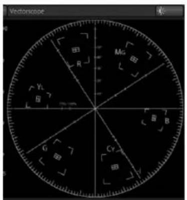
text_image
Vectorkobe R Mg B YL G Cy BFIGURE 411
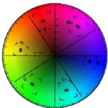
pie
| Category | Value | |---|---| | Mg | 75 | | R | 60 | | H | 45 | | Y1 | 30 | | G | 25 | | C1 | 20 | | Y | 15 |FIGURE 412
As it happens, from the vectorscope point of view, neither black nor white properly have any color saturation. Thus with the lens cap on (or with a white card illing the viewinder), the vectorscope should show only a small fuzzy trace at its center. If the fuzzy dot is off-center horizontally or vertically, this would indicate that the camera is incorrectly calibrated, actually tinting gray areas.
When the trace is off center, the direction and distance of the offset tells us what sort of tint (and how much) is represented by the deviation. You may be able to use the color controls at your camera to correct for this offset, or you can use the U Offset and V Offset controls in TriCaster's Proc Amp to do so (as always, source controls are best). Adjustments to U Offset move the trace left or right, while V Offset changes adjust its vertical position.
Let's move on to a slightly more rigorous testing.
C.2.3 COLOR METRICS
At this point, we've assured ourselves that the signal from the camera is neither too bright nor too dark, that its output falls within broadcast legal luminance limits, and that the black & white part of the signal does not have an unwanted color cast.
We haven't done anything yet, though, to assure our reds are red, not slightly brown, or that our blues are not slightly green or magenta, etc. The Vectorscope can provide much more specific information about your cameras color signal. Let's see how it can assist you to ensure your colors are accurate.
USING COLOR BARS
You'll no doubt have seen the familiar color bars used as a standard reference for video signal calibration. Two examples are shown here. Figure 413 is an example of the color bars used in NTSC countries, while Figure 414 is a PAL example, common throughout European nations.

natural_image
Color test pattern with vertical bars in gray, cyan, yellow, green, magenta, red, blue, black, and white (no text or symbols)FIGURE 413 (NTSC)
natural_image
Color block composition with vertical bars in yellow, cyan, green, magenta, red, blue, and black (no text or symbols)FIGURE 414 (PAL)
You can use color bars in conjunction with TriCaster's Waveform and Vectorscope to make sure the video supplied to the Switcher is consistent, accurate and broadcast legal.
Most video cameras are capable of displaying color bars - check your camera manual to see how to display these (given a choice, use 75% bars). Then look at the Vectorscope to see how it traces the individual colors comprising the image.
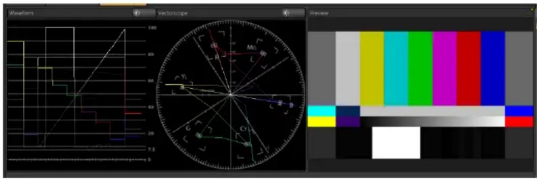
text_image
Waveform Vectroscope Preview M0 G Y B C G Y B CY 7.5FIGURE 415
The Vectorscope graticule has six distinct rectangular targets, one each for Yellow, Red, Magenta, Cyan, Blue, and Green. The targets are small rectangles with a cross-hair superimposed on them.
When a source is properly calibrated, the trace from the different colored segments of the color bars displayed will fall right inside their individual targets (see Figure 416).
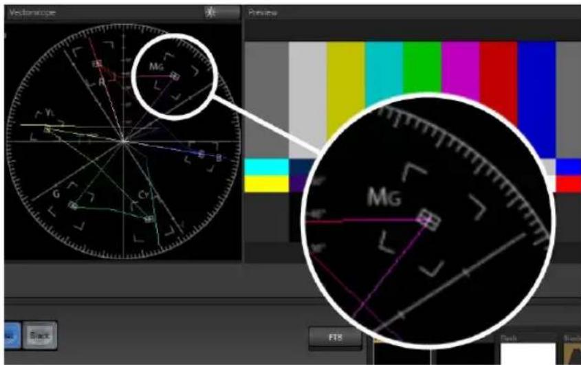
text_image
Mg Mg F18 Black Flash BlackFIGURE 416
If the trace vectors do not line up as they should even after performing a white balance at the camera, you can use TriCaster's Proc Amp controls to tweak the signal.
Adjust the Hue control to rotate the vectors around the center point to line them up correctly on their respective targets. Increasing Saturation will move the trace further out towards the edge of the scope. Decreasing Saturation lowers color intensity, bringing the trace back closer to the center.
Hint: Naturally, you should repeat the steps above for each connected source, to ensure a perfect match when switching from camera to camera during your live productions.
At this point, your video signal should be reasonably accurate, and broadcast legal. Naturally, there are other devices between that signal, you, and your viewers. Let's discuss ways to calibrate downstream video monitors to ensure that you see your video at its best.
C.3 CALIBRATING YOUR MONITORS
In most cases, you will use a computer monitor of one type or another to display TriCaster's controls – the so-called user interface. Even though the television monitors you likely use for inal program output may look somewhat similar to your
computer monitor, they do differ in a number of important respects. For this reason, we will approach their calibration separately.
C.3.1 COMPUTER MONITOR
This is a subject that could (and does) easily ill multiple volumes, but which we will sadly give short shrift. It may not be quite as important to achieve 'spot-on' color calibration for the monitor used for the user interface. Not surprisingly, video output color is best judged on larger downstream video monitors.
Nevertheless, you may ind a trip to one of any number of websites providing test imagery and calibration hints useful. A search for “computer monitor calibration” will yield an endless list, along with some commercial utilities for those who feel the need. Here are links to several such sites:
http://epaperpress.com/monitorcal/
http://www.lagom.nl/lcd-test/
http://www.jasc.com/support/kb/articles/monitor.asp
http://www.photofriday.com/calibrate.php
http://www.onecomputerguy.com/windows7/windows7_calibrate_color.htm
C.3.2 PROGRAM OUTPUT MONITOR
Again, a search of the Internet for “video monitor calibration” will yield a large number of resources, both free and commercial. If you have television monitors connected to TriCaster’s outputs, though, you can make further use of the color bars. The approach is somewhat similar to what we did for our video sources, in that the irst adjustments are to ensure that black and white levels are correct. Color calibration is performed afterward.
First, warm up your monitor for at least 10 minutes (some sources recommend a half-hour), to stabilize its output. Dim room lights and window light, to eliminate light sources that might skew your color perception. Pass the color bars from your camera through to program output (or use a color bars image in one of TriCaster's Media Players for this purpose.
C.3.3 COLOR ADJUSTMENTS
Having set the black and white levels earlier, let's continue...
NTSC
- If your monitor has a "Blue-gun only" setting, enable it. Depending on the brand of your monitor, the alternating bars will appear either as light gray and black, or blue and black (Figure 417).
natural_image
Abstract geometric pattern with blue and black vertical bars (no text or symbols)FIGURE 417
- If the monitor lacks a "Blue-gun only" feature, you can obtain a colored filter such as a Kodak Wratten #47B gel, and hold that between your eyes and the monitor for a similar result.
- Tweak the Color (or Saturation) knob until the small rectangular patches at very bottom of the tall upper bars on the extreme right and left of your screen merge with the tall bars above.
- Tweak the monitor's Hue control until the small rectangles beneath the third andifth tall upper bars likewise blend into bar above.
-
You may need to redo the last two steps several times, balancing the adjustments of these two controls until all four of the lighter bars evenly match the smaller rectangles just beneath them. (Note that a perfect match simply may not be possible on some monitors.)
-
Check your results with some familiar imagery, and make any further tweaks you feel are required.
PAL
- If your monitor has a "Blue-gun only" setting, enable it. Raise the Color or Saturation setting until the three right hand bars all appear to be the same shade.
- If the monitor lacks a "Blue-gun only" feature, you can obtain a colored filter such as a Kodak Wratten #47B gel, and hold that between your eyes and the monitor for a similar result.
- Turn off the "Blue-gun only" feature (or dispense with the ilter if you used one), and examine the red bar. It should appear not be so vivid that it bleeds onto the nearby bars.
- Check your results with some known familiar imagery, and make any further tweaks you feel are required.
C.4 FURTHER READING
You may find it helpful to review the white paper, available from NewTek's website, entitled “NewTek TriCaster Scopes – How and Why”, by Allan Tépper. This document provides many helpful insights into waveform and vectorscope use, as well as the development and application of video standards.
D.1 SWITCHER...
| Program Row, Inputs 1 to 24 (by model) | F1 - F12 plus [Shift + F1-12] |
| Preview Row, Inputs 1 to 24 (by model) | 1 - 0, -, =, and [Shift + 1-0, -, =,] |
| Transition Delegate - select BKGD | [ key (left square bracket) |
| Transition Delegate - multi-select BKGD | Shift + [ |
| Transition Delegate - select DSK 1 | ] key (right square bracket) |
| Transition Delegate - multi-select DSK 1 | Shift + ] |
| Transition Delegate - select DSK 2 | \ key (backslash) |
| Transition Delegate - multi-select DSK 2 | Shift + \ |
| Transition Delegate - select DSK 3 | Backspace |
| Transition Delegate - multi-select DSK 3 | Shift + Backspace |
| Transition Delegate - select DSK 4 | Insert |
| Transition Delegate - multi-select DSK 4 | Shift + Insert |
| Transition Delegate - select FTB | b |
| Transition Delegate - multi-select FTB | Shift + b |
| Select FTB Delegate and perform Fade | Ctrl + b |
| Auto DSK 1 On/Off | a |
| Auto DSK 2 On/Off | s |
| Auto DSK 3 On/Off | d |
| Auto DSK 4 On/Off | f |
| Take DSK 1 On/Off | Shift + a |
| Take DSK 2 On/Off | Shift + s |
| Take DSK 3 On/Off | Shift + d |
| Take DSK 4 On/Off | Shift + f |
| Select Transition (prev/next) | , and . (comma and period) |
| Select Fade Transition | Ctrl + f |
| Restore Last Transition | Shift + Ctrl + f |
| Transition - Slow ... Medium ... Fast | z...x... c |
| Transition - Increase Speed | Shift + c |
| Transition - Decrease Speed | Shift + z |
| Toggle Reverse Transition On/Off | e |
| Ping Pong Transition (off/on) | Alt + e |
D.2 T-BAR
| Take | Return Key |
| Take T-bar Back to Top | Shift + Return |
| Transition ... Go/Pause | Spacebar |
| Auto Reverse | Shift + Spacebar |
| Adjust T-bar... Down/Up | t / Shift + t (faster add Ctrl) |
| Halfway T-bar... Take | h |
D.3 RECORD, GRAB, AND STREAM
| Record on/off | r/ Shift + r |
| Grab (still image) | p |
| Stream Start | Ctrl + / |
| Stream Stop | Ctrl + Alt + / |
D.4 TABS
| Show (DDR, PTZ, Mixer, etc.; varies by model) tab | Ctrl + (F1 to Fn) |
| Select M/E 1-8 | Ctrl + Shift + F1-F8 |
| Show M/E pane | Ctrl + m |
| Hide M/E pane | Alt + m |
| Toggle M/E pane | m |
D.5 WORKSPACE
| D.5.1 TRICASTER 8000 | |
| Show Interface A | Alt + Numpad 0 |
| Show Interface B | Alt + Numpad 1 |
| Show Interface C | Alt + Numpad 2 |
| Show Interface D | Alt + Numpad 3 |
| Show Multiview A | Ctrl + Numpad 0 |
| Show Multiview B | Ctrl + Numpad 1 |
| Show Multiview C | Ctrl + Numpad 2 |
| Show Multiview D | Ctrl + Numpad 3 |
D.5.2 TRICASTER 410, 460 AND 860
| Show Interface > optional layouts, sequentially | Alt + Numpad 0-4 |
| Show Multiview > optional layouts, sequentially | Ctrl + Numpad 0-7 |
D.6 DDR 1
| Stop | k |
| Play | l (lower case L) |
| Go to previous playlist item | j |
| Go to next playlist item | ; (semi colon) |
| Autoplay On/Off | u |
| Loop On/Off | ‘ (apostrophe) |
| Single On/Off | q |
| Navigate through Playlist items | Up/Down/Left/Right Arrows |
| Set In Point for current Playlist Item (Clip or Audio ile) | i |
| Set Out Point for current Playlist Item (Clip or Audio ile) | o |
D.7 DDR 2
| Stop | Alt + k |
| Play | Alt + l (lower case L) |
| Go to previous playlist item | Alt + j |
| Go to next playlist item | Alt +; (semi colon) |
| Autoplay On/Off | Alt + u |
| Loop On/Off | Alt + ‘ (apostrophe) |
| Single On/Off | Alt + q |
| Navigate through Playlist items | Up/Down/Left/Right Arrows |
| Set In Point for current Playlist Item (Clip or Audio ile) | Alt + i |
| Set Out Point for current Playlist Item | Alt + o |
D.8 GRAPHICS 1
| Stop | Shift + k |
| Play | Shift + l (L) |
| Go to previous playlist item | Shift + j (J) |
| Go to next playlist item | Shift + ; (:, colon) |
| Autoplay On/Off | Shift + u (U) |
| Loop On/Off | Shift + ' (“, quotation) |
| Single On/Off | Shift + 1 (Q) |
D.9 GRAPHICS 2
| Stop | Ctrl + k |
| Play | Ctrl + l (lower case L) |
| Go to previous playlist item | Ctrl + j |
| Go to next playlist item | Ctrl +; (semi colon) |
| Autoplay On/Off | Ctrl + u |
| Loop On/Off | Ctrl + ‘ (apostrophe) |
| Single On/Off | Ctrl + q |
D.10 SOUND
| Stop | Ctrl + Shift + k |
| Play | Ctrl + Shift + l (lower case L) |
| Go to previous playlist item | Ctrl + Shift + j |
| Go to next playlist item | Ctrl + Shift + ; (semi colon) |
| Loop On/Off | Ctrl + Shift + ‘ (apostrophe) |
| Single On/Off | Ctrl + Shift + q |
| Set In Point for current Playlist Item | Ctrl + Shift + i |
| Set Out Point for current Playlist Item | Ctrl + Shift + o |
D.11 GENERAL
D.11.1 EDIT TITLE PANE
| Save the current title page | Ctrl + Shift+ s |
| Save the current title page, and duplicate it in the playlist | Ctrl + Shift+ s |
| Save the page and move to the previous playlist item | Page Up |
| Save the page and move to the next playlist item | Page Down |
D.11.2 SELECTION AND NAVIGATION
| Select All | Ctrl + a |
| First/Last Item | Home/End |
| Navigate through Playlist items | Up/Down/Left/Right Arrows |
| Select All Previous/Following Items | Shift + Home/End |
| Playlist - select to Top/Bottom | Shift + Home/End |
| Playlist – add to selection (Up/Down) | Shift + Up/Down arrow |
D.11.3 MISC.
| Cut | Ctrl + x |
| Copy | Ctrl + c |
| Paste | Ctrl + v |
| Delete | Delete Key |
| Show TriCaster version | Alt + b |

text_image
TCIt's important when planning your installation to provide adequate support for the unit's weight, with particular attention to providing room for both cable access and adequate ventilation. This section provides physical dimensions and recommendations intended to inform and guide you when mounting TriCaster systems and related control surfaces.
SECTION 22.10 TRICASTER 460 AND 410
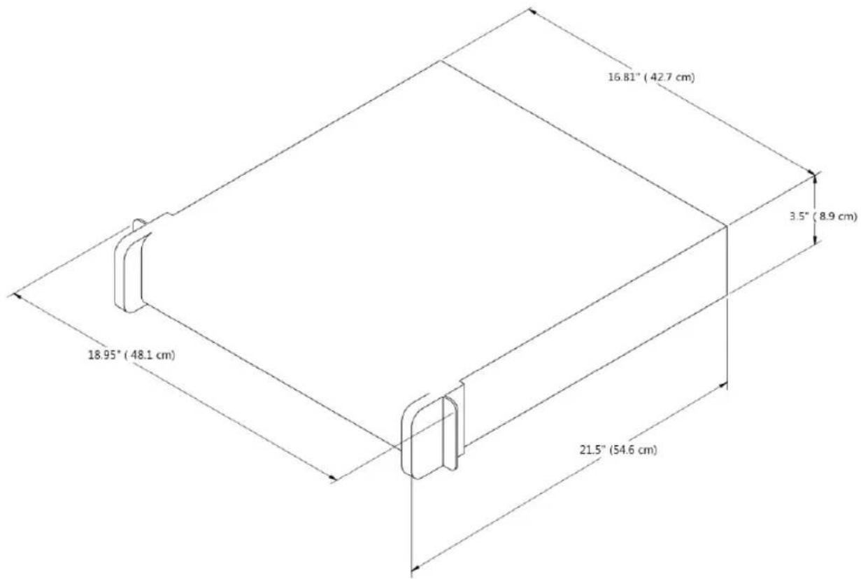
text_image
16.81" (42.7 cm) 3.5" (8.9 cm) 18.95" (48.1 cm) 21.5" (54.6 cm)FIGURE 418
TriCaster 460 and 410 both ship in 2 Rack Unit (RU) enclosures supplied with 'ears' designed to permit mounting in standard 19" rack architecture.
The units weigh nearly 25 pounds (>11 KG). A shelf or rear support will distribute the load more evenly if rack-mounted. Good front and rear access is important for convenience in cabling, access to removable drive bays (TriCaster 460). In view of the top panel vents on 2RU models, at least one RU should be allowed above these systems for ventilation and cooling.
SECTION 22.11 TRICASTER 8000 AND 860
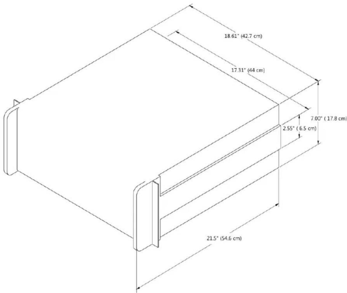
text_image
18.61" (42.7 cm) 17.31" (44 cm) 7.00" (17.8 cm) 2.55" (6.5 cm) 21.5" (54.6 cm)FIGURE 419
TriCaster 8000 and TriCaster 860 are encased in similar 4 Rack Unit (RU) chassis supplied with 'ears' designed to permit mounting in standard 19" rack architecture.
As these units weigh in at about 40 pounds (>18 KG), we strongly encourage you to provide a shelf or rear support to distribute the load more evenly if rack-mounting is planned.
Good front and rear access is important for convenience in cabling, access to removable drive bays, and should be considered mandatory for ventilation and cooling.
SECTION 22.12 TRICASTER 8000 CS
Normally, the 8000 CS is used in a table-top configuration. Otherwise, the 12 " (1.2 cm) rabbit provided at the front and back of the panel (only) permits you to embed the base in a cutout prepared for the purpose.
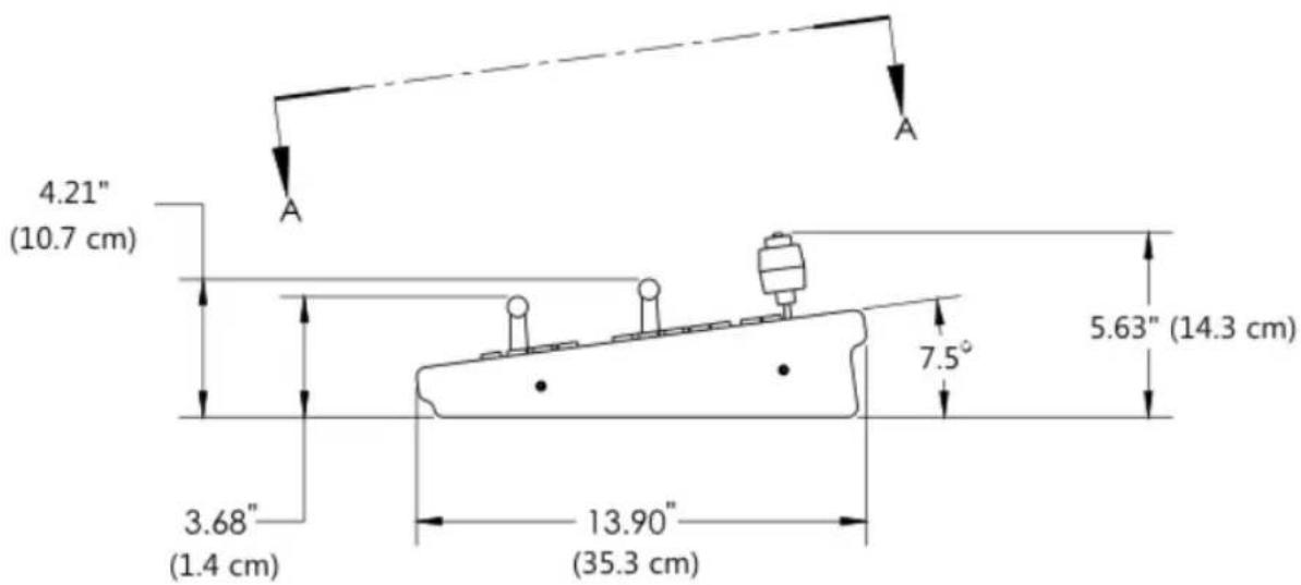
text_image
4.21" (10.7 cm) 3.68" (1.4 cm) 13.90" (35.3 cm) 7.5° 5.63" (14.3 cm)FIGURE 420
If you plan to mount the surface in the latter manner, take care that the thickness of the supporting material does not block access to the AC power connection and USB port at rear left on the control surface body.
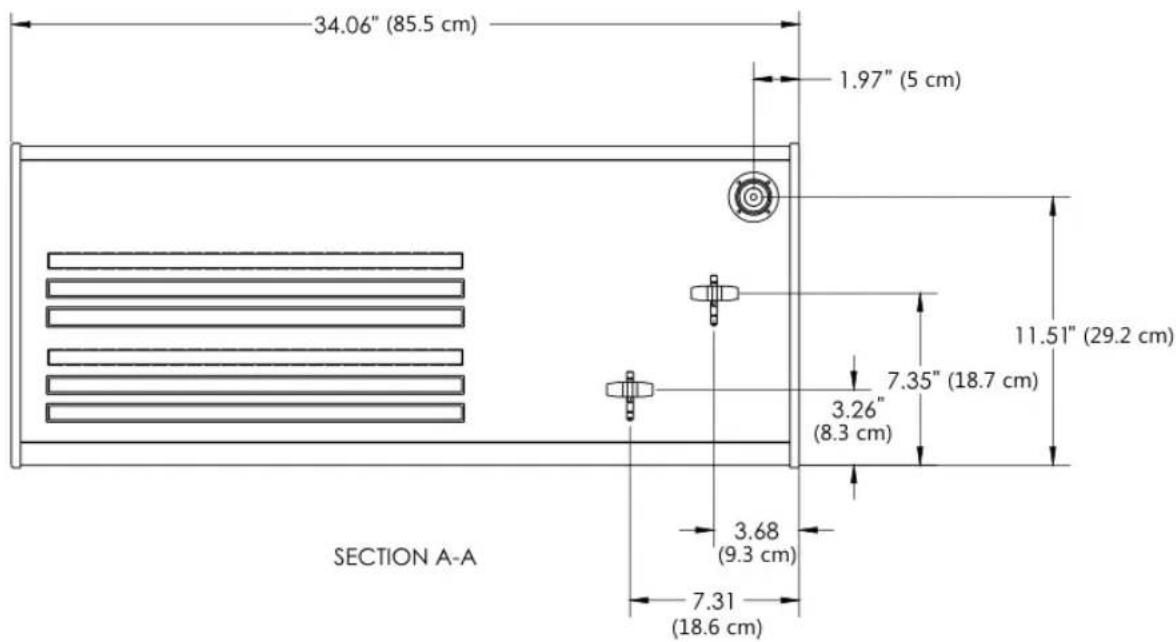
text_image
34.06" (85.5 cm) 1.97" (5 cm) 11.51" (29.2 cm) 7.35" (18.7 cm) 3.26" (8.3 cm) 3.68 (9.3 cm) 7.31 (18.6 cm) SECTION A-AFIGURE 421
SECTION 22.13 TRICASTER 860 CS
Normally, the 860 CS is used in a table-top configuration. Otherwise, a rabbit on all four sides permits you to embed the base in a cutout prepared for the purpose.
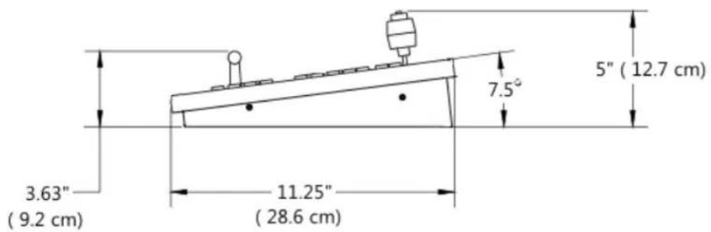
text_image
3.63" (9.2 cm) 11.25" (28.6 cm) 7.5° 5" (12.7 cm)FIGURE 422
At the sides, a 12 " (1.2 cm) ledge is formed for this purpose. The overlap provided front and back is narrower, about 5/16" (.31 cm).
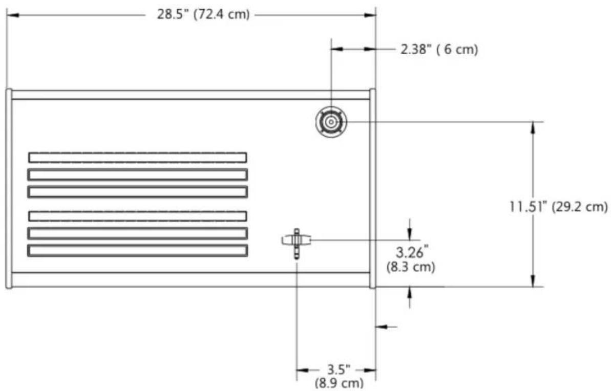
text_image
28.5" (72.4 cm) 2.38" (6 cm) 11.51" (29.2 cm) 3.26" (8.3 cm) 3.5" (8.9 cm)FIGURE 423
SECTION 22.14 TRICASTER 460 CS
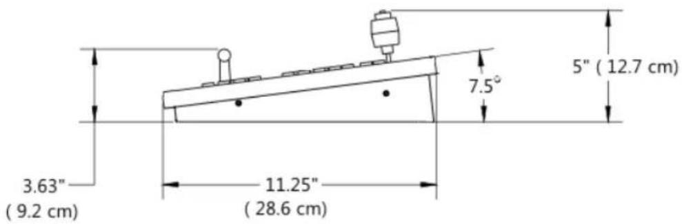
text_image
3.63" (9.2 cm) 11.25" (28.6 cm) 7.5° 5" (12.7 cm)FIGURE 424
Normally, the 460 CS is used in a table-top configuration. Otherwise, a rabbit on all four sides permits you to embed the base in a cutout prepared for the purpose.
At the sides, a 12 " (1.2 cm) ledge is formed for this purpose. The overlap provided front and back is narrower, about 5/16" (.31 cm).
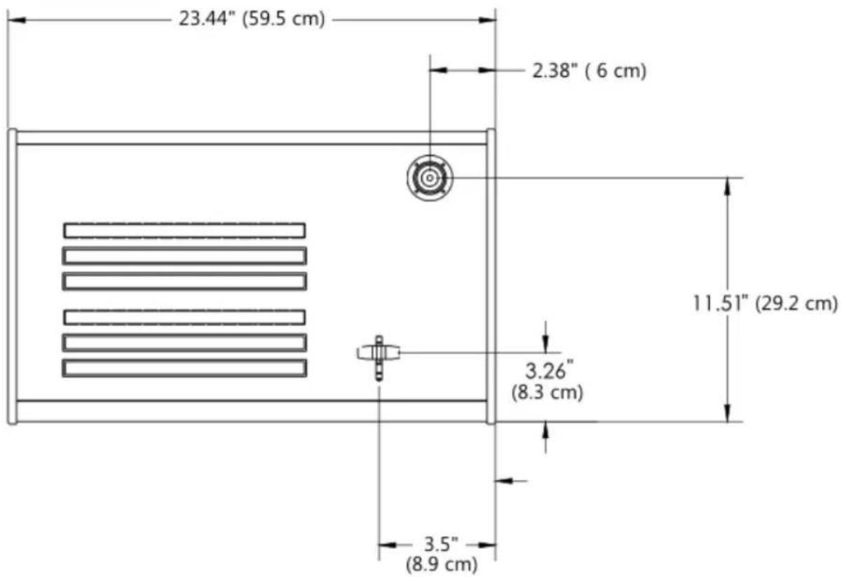
text_image
23.44" (59.5 cm) 2.38" (6 cm) 11.51" (29.2 cm) 3.26" (8.3 cm) 3.5" (8.9 cm)FIGURE 425
We know our products play vital roles in the productions of our customers. Durability and consistent, robust performance are much more than just adjectives for your business and ours.
For this reason, all NewTek products undergo rigorous reliability testing to ensure they meet our exacting test standards. For TriCaster 8000, 860 and 460, the following standards are applicable:
| Test Parameter | Evaluaon Standard |
| Temperature | Mil-Std-810F Part 2, Secons 501 & 502 |
| Ambient Operang | 0°C and +40°C |
| Ambient Non-Operang | -10°C and +55°C |
| Humidity | Mil-STD 810, IEC 60068-2-38 |
| Ambient Operang | 20% to 90% |
| Ambient Non-Operang | 20% to 95% |
| Vibraon | ASTM D3580-95; Mil-STD 810 |
| Sinusoidal | Exceeds ASTM D3580-95 Paragraph 10.4: 3 Hz to 500 Hz |
| Random | Mil-Std 810F Part 2.2.2, 60 minutes each axis,Secon 514.5 C-VII |
| Electrostac Discharge | IEC 61000-4-2 |
| Air Discharge | 8K Volts |
| Contact | 4K Volts |
3
3D, 242
8
850 TW
Layout, 385
A
AAC Encoding, 453
Act as Alpha. See I/O Configuration: Video Input
Activate Windows. See Windows
Add-Ons, 121
Administrator Mode, 50, 116, 451, 454, 457
Advanced Tracking, 237
AirPlay®, 257, 428
Alpha Channel, 179
Alpha Input. See I/O Configuration: Video Input
ALT, 363, 389, 390
ALT + IN, 389, 392
ALT + OUT, 390, 392
ALT + REC, 391
Anaglyph, 242
Animation Store. See Live Desktop: Transitions: Animation Store
Apple AirPlay®, 280, 428
Asset Management, 198
Audio, 394
Mix Minus, 263
Audio Mixer. See Live Desktop:Audio Mixer, See Live Desktop:Audio Mixer, See Live Desktop:Audio Mixer
Audio Sync, 467
AUTOPLAY, 391
AUX Out, 370
Aux Output (Audio), 263, 264
AVI Codecs, 443
B
Beep, 467
Buffers, 100, 101, 209, 210, 214
Network Sharing, 214
C
Cable, 349
Calibration, 475
Chroma Keying. See LiveMatte
Clip Transport, 392
Clocks. See Multiview Output and Sessions
Codecs, 443, 453
Color Correction, 241
Connection, 349
Connections
Cameras, 28, 154, 420, 421
External Drive, 426
Genlock, 32
LC-11, 424
Output, 33, 422, 423
Tally Lights, 36, 427
Copy, 387
Crop, 394
CTRL, 363
CTRL, 390
D
DDR. See Live Desktop: Media Player
DDR Delegate, 386
DDR options, 391
DDR Transport, 392
Default Effects, 236, 243
De-Interlace, 149
E
Edit. See SpeedEDIT
Eject, 114, 426
Esc, 387
EULA. See TriCaster: Register
Export Media. See Startup Screen, See Startup Screen
External Audio. See Live Desktop:Audio Mixer
F
F4V, 444
Facebook®. See Share Media
Fade to Black, 353, 372
Fast Jog, 392
File Copy. See Share Media
Files
Export, 205, 340, 446, 449
Import, 205, 447
Flash. See Streaming
Flash F4V, 444
FTB, 353, 372
FTP. See Share Media
G
Genlock. See Connections: Genlock
Conigure. See I/O Configuration
Grab, 363, 382, See Live Desktop:Grab
Graphics. See LiveText
H
Hard Drive
Eject, 114, 426
Hard drive (external), 426
Home Page. See Startup Screen
Home Page, 37
Hotspots, 16, 139, 163, 187, 285, 290
I
I/O Configuration
Audio, 45
Genlock, 48, 150, 151
Proc Amp, 11, 110, 159, 192
Video Input, 43, 154
Act as Alpha, 158, 420
Connection Type, 154, 158
Video Output, 40, 143, 144
Alpha Matte, 147, 421
IMAG, 35, 467, 470, 471, 472
Images, Stand-in. See Live Desktop: Media Player: Title Pages
IN, 388
Input Connectors, 28
Installing Third-Party Software, 453
Internal Audio. See Live Desktop:Audio Mixer
iVGA. See Network
J
Jog Wheel, 392
Fast Jog, 392
K
Keyboard, 24
Keying. See LiveMatte
L
Latency, 470, 471, 472
LC-11 Control Surface, 424
Live Desktop, 7, 39, 131, 132
Audio Mixer, 17, 56, 60, 251
Balance, 60
Connection Type, 256
External Audio tab, 253
Follow, 63
Internal Audio tab, 257
Lock, 255
Mono, 60
Mute, 60, 255
Pan, 61
Phones Output, 252
Presets, 269
Solo, 256
Stream Output, 269
Talk, 256
VU Meters, 252
Grab, 79, 336
Media Browser, 82, 200
Add Media Location, 449
Filter, 202
Media Player, 18, 81, 257
Asset Management, 198
Autoplay, 84, 204
Presets, 85, 204
Scrub, 83
Single, 84, 203
Speed, 83, 203, 442
Title Pages, 207
Editing, 207, 208
Stand-In Images, 209, 341
Trimming, 83
Options Menu, 138
Remote Control, 292, 424
Tabs Follow Preview Row, 138
Tabs Follow Preview Row for M/E, 138
Overlay
Position, 177
Record, 78, 79, 148, 310, 329, 442
Quality Setting, 334
Switcher, 67, 171, 172
Take, 69, 84, 183
T-Bar, 183
Transitions, 8, 12, 68, 69, 71, 139, 171, 174
Animation Store, 13, 121, 176, 236, 251, 258, 436
Waveform/Vectorscope, 49, 152, 160, 476, 477, 478, 480
Workspace Presets, 11, 43, 56, 134, 185
LiveMatte, 14, 90, 225, 226, 227, 232, 352, 370
Luma Limit, 228
Spill Suppression, 229
LiveSet, 15, 98, 394
Default, 98, 436
Metropolis A, 439
Night Beat, 438
Nightly Show, 436
Tools, 436
Zoom T-Bar, 246
LiveText, 20, 339, 340, 341
Standalone, 67, 271, 281
LOOP, 391
Luma Keying. See LiveMatte
M
M/E, 69, 94, 446
LiveSet. See LiveSet
Overlay, 96
Position, 236
Macros, 16, 163, 285
Mark IN, 388
Mark OUT, 389
Marking Group, 388
Marking, One Button, 390
Media Player. See Live Desktop: Media Player
Media Players
Autoplay, 363, 382
Delegate, 381
Loop, 363, 382
Options, 363, 382
Preset, 381
Single, 363, 382
Transport Controls, 362, 381
MIDI, 288
Mix Minus, 263
Monitoring, 361, 380
Monitors
Computer, 23, 422
Output (external), 423
Switcher Monitors Tab, 59
Multi-bitrate Streaming, 460
Multiview, 185
Multiview Output
Broadcast Clocks, 169
N
Network
3Play™, 282
AirPlay®, 257, 428
Connecting, 65, 301, 311
iVGA, 50, 65, 271, 469
Ping, 313
Port Forwarding, 316
Sharing Buffers, 206
Sharing Media Folders, 206
Testing, 311
Network Sharing, 206
Network Sharing, 214
Next, 393
NTSC. See Video Standard
0
One Button Marking, 390
Open/Manage Session. See Startup Screen
OUT, 389
Overlay
M/E. See M/E: Key
P
PAL. See Video Standard
Paste, 387
Pause, 486
Ping, 313
Play, 387, 393
Play Speed, 387
Play, Pause, & Stop, 486
Position, 394
Positioner
Delegate, 358, 377
Joystick Modes, 379
Power Supply, 467
Preview Row, 351, 370
Previous, 393
Proc Amp, 352, 370
Proile, H.264
Baseline, 461
Proile, Streaming, 453
multi-bitrate, 460
Program Output Monitor, 55
Program Row, 351, 370
Publish. See Share Media
Pull. See Streaming: Pull
Push. See Streaming:Push
Q
Qualifier Buttons, 363, 368
Quicktime, 443
R
Record, 363, 382, 391, See Live Desktop
Register. See TriCaster: Register
Remote Control. See Live Desktop: Options
Remove, 387
Rename Input, 134
Restart. See Startup Screen: Shutdown System
Restore TriCaster, 119, 454
S
Session
Volume (Storage), 115
Session Page, 39
Sessions, 37, 110, 432
Backup/Restore, 115, 124, 129, 434
Share Media, 53, 321, 331, 332, 448
SHIFT, 390
SHIFT, 363
SHIFT + OUT, 390
Show Alpha, 240
Show Inverse Alpha, 241
Shutdown. See Startup Screen: Shutdown
SINGLE, 391
Social Media. See Share Media
Software
Installing Third-Party, 453
Speed. See Live Desktop: Meida Player
Speed Presets, 387
Speed T-Bar, 388
SpeedEDIT, 20, 341, 342
Spell Check, 208
Spill Suppresion. See LiveMatte
Startup Screen, 6, 37, 109
Export Media, 17, 126
Home Page, 6
New Session, 433
Open/Manage Session, 114, 435, 441
Shutdown, 116
Exit to Windows, 116
System Utilities
Defragment, 451
Update TriCaster, 451, 452
Stills. See Live Desktop: Media Player
Stop, 393, 486
Storage (external), 426
Stream, 363, 382
Streaming, 298, 303, 304, 306
AAC, 453
Bitrate, 305
Capture, 303, 442
Port Forwarding, 316
RTMP, 305, 312, 319, 444, 452, 453
Session Format, 433
WME, 305, 452
Support, 457
Switcher. See Live Desktop
T
Tally Lights. See Connections: Tally Lights
T-Bar, 388
Technical Support, 457
Tips, 393
Titlebar, 140
Titles. See Live Desktop: Media Player
Titling. See LiveText
Trackers, Tracking, 17, 163, 177, 179, 238
Transition
Auto, 355, 374
Delegates, 353, 372
Fade, 354, 373
Local Controls, 355, 374
Main Controls, 355, 374
Rate, 354, 373
Select, 353, 372
Take, 355, 374
T-Bar, 355, 374
T-Bar LEDs, 374
Trans, 354, 373
Transport, Clip controls, 392
TriCaster
Register, 25, 456
Triggers, 16, 139, 163, 290
Twitter®. See Share Media
U
USB hubs, 349
Utility Row, 370
Delegates, 352, 371
V
Vectorscope. See Live Desktop
Video
Calibration. See Calibration
Streaming. See Streaming
Video Standard, 30
Virtual Input, 394
Virtual Input,. See M/E, See M/E
Virtual Inputs
Follow PVW, 356, 375
Input Rows, 375
Overlay Auto, 376
Overlay Take, 376
Overlay Transition, 376
Virtual Set. See LiveSet
Virus Checker, 452
W
Waveform Monitor. See Live Desktop
Windows ^TM
Activate, 24
Exit to. See Startup Screen: Shutdown
Wirecast®, 431
Workspace Presets. See Live
Desktop:Workspace Presets
Y
YouTube®. See Share Media
Z
Zoom, 394
Acknowledgments: Tim Jenison, Jim Plant
Engineering: Andrew Cross, Alvaro Suarez, Bennie Pierce, Bob Peene, Brian Brice, Cary Tetrick, Charles Steinkuehler, Dan Fletcher, Greg Heine, James Killian, Jan Uribe, Jarrod Davis, Jeremy Brosius, Jeremy Wiseman, John Perkins, Karen Zipper, Kevin Rouviere, Kirk Morger, Kristen Perez, Mahdi Mohajer, Masaaki Konno, Menghua Wang, Michael Joiner, Michael Watkins, Mike Murphy, Nathan Kovner, Naveen Jayakumar, Robert Sion, Ryan Hansberger, Shawn Wisniewski, Steve Bowie, Todd Bryant, Troy Stevenson
Design Consultants: Kris Gurrad, Joe de Max, John Powell
Additional thanks to: NewTek Markeng, Sales, Business Development, Customer Support, Training and Development, and Operaons
This product uses the following libraries, licensed under the LGPL license (see link below). For the source, and the ability to change and recompile these components, please visit the links provided:
– Freelmage library hp://freeimage.sourceforge.net/
– LAME library hp://lame.sourceforge.net/
- FFMPEG library hp://mpeg.org/
For a copy of the LGPL licence, please look in the folder c:\TriCaster\LGPL\
Porons use Microso Windows Media Technologies. Copyright (c)1999-2008 Microso Corporaon. All Rights reserved. VST PlugIn Spec. by Steinberg Media Technologies GmbH.
This product uses Inno Setup. Copyright (C) 1997-2010 Jordan Russell. All rights reserved.
Porons Copyright (C) 2000-2010 Marjn Laan. All rights reserved. Inno Setup is provided subject to its license, which can be found at:
hp://www.jrsoware.org/les/is/license.txt. Inno Setup is distributed WITHOUT ANY WARRANTY; without even the implied warranty of MERCHANTABILITY of FITNESS FOR A PARTICULAR PURPOSE.
Trademarks: NewTek, TriCaster, TriCaster XD, TriCaster 8000, TriCaster TCXD8000, TCXD8000, TriCaster 860, TriCaster TCXD860, TCXD860, TriCaster 460, TriCaster TCXD460, TCXD460, TriCaster 410, TriCaster TCXD410, TCXD410, TriCaster 40, TriCaster TCXD40, TCXD40, TriCaster 855, TriCaster TCXD855, TCXD855, TriCaster 455, TriCaster TCXD455, TCXD455, TriCaster EXTREME, TriCaster 850 EXTREME, TriCaster TCXD850 EXTREME, TCXD850 EXTREME, TriCaster 450 EXTREME, TriCaster TCXD450 EXTREME, TCXD450 EXTREME, TriCaster 850, TriCaster TCXD850, TCXD850, TriCaster 450, TriCaster TCXD450, TCXD450, TriCaster 300, TriCaster TCXD300, TCXD300, TriCaster PRO, TriCaster STUDIO, TriCaster BROADCAST, TriCaster DUO, 3PLAY, 3Play, 3Play 4800, 3PXD4800, 3Play 820, 3PXD820, 3Play 425, 3PXD425 3Play 330, 3PXD330, ProTek, ProTek Care, ProTek Elite, iVGA, SpeedEDIT, IsoCorder, LiveText, DataLink, LiveSet, TriCaster Virtual Set Editor, TriCaster VSE, LiveMae, TimeWarp, VT, VT[3], VT[4], V[T5], Video Toaster, Toaster, Inspire 3D, 3D Arsenal, Aura, LightWave, LightWave 3D and LightWave CORE are trademarks, service marks, and registered trademarks of NewTek. All other brand names, product names, or trademarks belong to their respective holders.