
DP1000II - Lighting GODOX - Free user manual and instructions
Find the device manual for free DP1000II GODOX in PDF.


User questions about DP1000II GODOX
0 question about this device. Answer the ones you know or ask your own.
Ask a new question about this device
Download the instructions for your Lighting in PDF format for free! Find your manual DP1000II - GODOX and take your electronic device back in hand. On this page are published all the documents necessary for the use of your device. DP1000II by GODOX.
USER MANUAL DP1000II GODOX
natural_image
Black Godox DP600 II studio lighting equipment with digital display and control buttons (no visible text or symbols on device body)深圳市神牛摄影器材有限公司
Building A4, Xinhe Huafa Industrial Zone, Fuzhou RD West, Fuyong
Town, Baoan District, Shenzhen 518103, China
电话/Tel: +86-755-29609320(8062) 传真/Fax: +86-755-25723423
邮箱/E-mail: godox@godox.com
http://www.godox.com
705-DP2000-00 Made In China
CE RoHS
Instruction Manual
说明手册
Chinese English Bilingual | 中英文双语
FOREWORD
Thanks for choosing DPII series studio flash.
DPII series studio flash provides a functional and durable lighting solution for studio and workshop shooting. It is equipped with a wireless control port so that an optional remote power control and flash triggering system is available. With a solid build, it adopts Bowens-style mount to add various studio light shaping accessories. The flash performs excellently in portrait and product shooting, wedding photography, advertising and fashion commercial photography. The DPII flash offers:
• Built-in Godox 2.4G wireless X system
• 1/2000 to 1/800 second short flash duration and fast recycling with 150W modeling lamp
- Wireless control of the flash power ratio, modeling lamp and buzzer, as well as flash triggering
- Anti-preflash function, enabling synchronization with cameras having a one-preflash firing system
- Precise output control, 40 steps from 1/16-1/1
• Stable color temperature ranging within 5600±200K
- Compatible Bowens mount adds various accessories to give multiple lighting effects
* Adjusted settings are remembered after 3 seconds and recovered after a restart
CONTENTS
0 Foreword9
10 Warning
10 Caution
Names of Parts11
11 • Body
12 • LCD Panel
12 • Accessories
12 • Separately Sold Accessories
13 Operations
13 • Flash Preparation
13 · Power Connection
13 • Modeling Lamp
14 · Power Output Control
14 • Test Button
14 · Sync Triggering
14 • GR/CH Button
15 • Slave Trigger Model
15 • Buzz Function
15 • Key Combination
15 • Alarm Display
15 • Memory Function
16 • Wireless Control Function
17 • Tube Replacement
18 Technical Data
18 Maintenance
Warning
To prevent damage to the product or injury to you or to others, read the following warnings in their entirety before using this product. Keep these Warning where users can read them for ready reference.
Do not disassemble or modify. Should the product break down, send the defective back to the authorized service center for inspection and maintenance.
▲ Keep dry. Do not handle with wet hands, immerse in water, or expose to rain.
▲ Keep out of reach of children.
▲ Please put the device in a ventilation environment and keep the parts of lighting and heat dissipation holes are unobstructed. Do not use in flammable environment.
As this product adopts make and break device, please keep it easy to be used.
▲ No touching the heating parts of this product.
▲ Please turn off the power and wear insulated gloves before installing and connecting accessories. When replacing the tube or modeling lamp, please make sure that the tube is cool and wear insulated gloves to prevent burns.
Do not flash directly towards naked eyes (especially those of babies), otherwise it may lead to visual impairment.
▲ Disconnect from the power supply when it will not be used for an extended period.
CAUTION
After 30 continuous flashes at full power, the flash should be cooled down for about 3 minutes. Overheating will occur if it is used continuously without cooling down.
Do not keep using the modeling lamp for a long time; otherwise flammable accessories attaching to flash head, e.g. softbox will get burnt. A 10-minute time is recommended in this case. After 10 minutes, cool it down for 1 minute.
When using a snoot, do not keep the modeling lamp on for a long time or fire too frequently (not over six times for one minute). Overheating will result in damages for strobe housing and/or studio light.
Avoid sudden impacts as this can damage the flash tube and/or modeling lamp.
NAMES OF PARTS
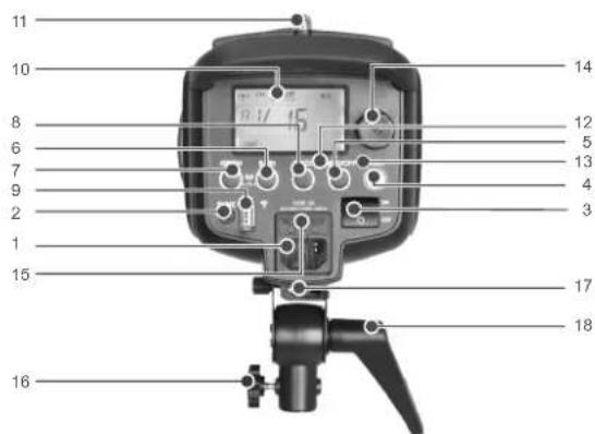
- Body
text_image
Labeled diagram of a digital camera with numbered parts for identification- AC Power Socket
- Sync Cord Jack
- Power Switch
- Test Button
- MOD/OFF Modeling Lamp Button
- S1/S2 Slave Model Button
- Group/Channel Button
- BUZZ Button
-
Wireless Control Port
-
LCD Display
- Light Sensor
- Modeling Lamp Indicator
- Test Indicator
- Select Dial + SET Button
- Fuse
- Mounting Bracket
- Umbrella Input
- Direction Adjusting Handle
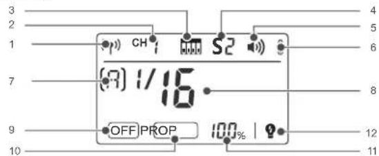
- LCD Panel
text_image
(7) 1/16 OFF PROP 100% | 12 11 12 8 6 5 4 3 2 1 10- Built-in 2.4G Wireless
Transmission - Built-in Wireless Channel
- Built-in Wireless Channel Dial
- Slave Model Indicator
- Beep
- Temperature Alarm Display
-
Built-in Wireless Group
-
Flash Output
- Modeling Lamp is off
- Modeling Lamp is in the PROP mode
- Modeling Lamp shows the power in percentage
- Modeling Lamp is off when triggering the flash
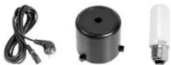
- Accessories
- Power Cord
- Lamp Cover
- Modeling Lamp
- Instruction Manual
natural_image
Three electronic components: a cordless cable, a black cylindrical device with a plug, and a light bulb (no text or symbols visible)• Separately sold accessories
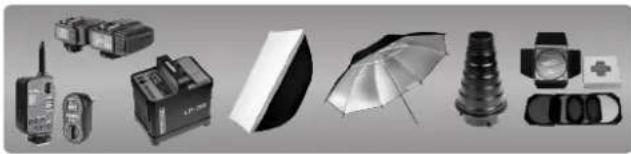
The product can be used in combination with the following accessories sold separately, so as to achieve best photography effects: X1, XT16 or FT-16 remote control, Power Inverter, Softbox, Photographic Umbrella, Light Stand, Barndoor, Snoot, etc.
natural_image
Collection of various photography equipment including a radio, lamp, umbrella, and camera (no visible text or labels)-12--11-
OPERATIONS
- Flash Preparation
- Take down the lamp cover. Install the modeling lamp and put on the glass protection cover and the standard reflector.
(To uninstall the standard reflector, press the release button on the flash head and turn the standard reflector counter-clockwise to take it out, as illustrated in the picture.)
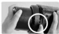
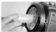
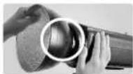
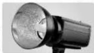
- Attach the flash unit onto an appropriate light stand. Adjust the mounting bracket (16) for a good angle and make sure it is tightened and fixed. Use the direction adjusting handle (18) to adjust the flash to a desired direction. Umbrella input (17) is for different photo umbrellas to put in.
• Power Connection
Use the power cord to connect the flash to an AC power source and turn on the power switch (3).
- Modeling Lamp
Short press the Modeling Lamp Button (5) to choose the modeling lamp's mode (OFF, PROP and percentage); and long press the Modeling Lamp Button (5) to switch on or off the function that the modeling is off when triggering the flash. Modeling lamp will be off automatically after lighting for 4 hours, avoiding overheat due to long-time lighting when the user is not nearby.
OFF: Modeling lamp is off.
PROP: The modeling lamp's power changes with the flash's power. The bigger power the flash has, the brighter the modeling lamp is.
Percentage: Adjust the modeling lamp's light brightness manually from 5% to 100%.
Setting:
-
When OFF is displayed, short press the
Button to enter PROP mode. Now the LCD panel shows PROP. -
When PROP is displayed, short press the
Button to enter Percentage mode. Short press the SET Button and the percentage value is blinking. Turn the Select Dial to choose the light brightness from 5% to 100%. Short press the SET Button to exit. -
When PROP is displayed, short press the
Button can back to mode. - When in NON OFF mode, long press the
Button for 2 seconds to switch on the function that the modeling is off when triggering the flash. Now the LCD panel shows (☐). Long press the Button again to exit this mode.

When there is flammable accessory on the flash unit, do not keep the modeling lamp on for a long time. It is recommended to cool it down for one minute after 10 minutes' working.
• Power Output Control
Select dial (14) decides different power output, satisfying light requirements in different environment. The power is adjustable freely from 1/32 to 1/1 which will be accordingly shown on the LCD display (10). "--" on the display indicates that the flash triggering function is turned off. Press the test button to discharge power when the flash output is adjusted from high to low.
- Test Button
To fire the flash without taking a picture, press the test button (4). It can also help adjust the flash brightness when combined with the select dial (14). Press the SET button and turn on the flash to view its version.
- Sync Triggering
The sync cord jack (2) is a 3.5mm plug. Insert a trigger plug here and the flash will be fired synchronously with the camera shutter. Synchronously press the S1/S2 button and BUZZ button to recover factory settings.
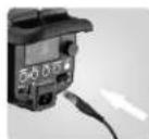
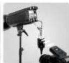
- GR/CH Button
Short press the GR/CH button can adjust the built-in wireless group. When the group indicator on the LCD panel is blinking, turn the select dial to change. And long press the GR/CH button can adjust the built-in wireless channel. When the channel indicator on the LCD panel is blinking, turn the select dial to change.
- Slave Trigger Model
Three slave triggering models are available and can be set by pressing slave model button (6).
◆No optical control: S1 or S2 is not displayed on the LCD panel, indicating the slave triggering function is shut down.
◆Optic S1 Secondary Unit Setting: In M manual flash mode, press
◆Optic S2 Secondary Unit Setting: Press
- Buzz Function
The BUZZ button (8) is used for deciding whether there is sound reminder for ready flash after recharging. When the buzz indicator is on the LCD panel, the buzz function is working; when it is disappear, the buzz function is not working. A "BI" sound will be heard when it's fully charged.
• Key Combination
Synchronously press the
- Alarm Display
E0 The temperature sensor is not connected.
E1 When charging, the capacitance and voltage are not rising within 1 second.
E2 The fastest heating-up component is over the extra temperature.
E3 Discharged capacitance and voltage > rating +10%
Alarm sounds, BIBI, ringing per 0.5 second. Press SET button to stop alarming.
- Memory Function
The device is equipped with memory function for the panel setting. It will help remember the panel setting 3 seconds after you set it. When starting up the flash next time, the panel setting will be the same as that before powering it off.
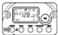
• Wireless Control Function
The flash unit has built-in 2.4G wireless transmission, which can be used together with X1 and XT16 flash trigger.
Synchronously press the
Setting the Communication Channel
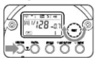
1
Long press the
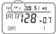
2
Turn the Select Dial to choose the channel from 1 to 32.

3
Press the
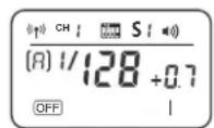
Setting the Communication Group
1
Short press the
2
Turn the Select Dial to choose the group from 0 to F.
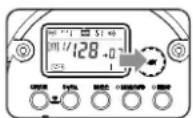
3
Press the
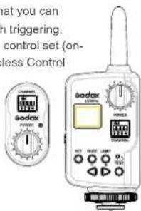
The flash unit is built in with a Wireless Control Port so that you can wirelessly adjust the power level of the flash and the flash triggering. To control the flash wirelessly, you need a FT-16 remote control set (on-camera and on-flash). Insert its receive end into the Wireless Control
Port on the flash and insert the transmit end into the camera hot shoe. Settings made on the hotshoe-mounted transmit and receive ends will be wirelessly communicated to the flash. Then you can press the camera shutter release button to trigger the flash. You can also hold the transmit end at hand to control your off-camera flash.
text_image
what you can h triggering. control set (on- less Control
For full instructions on the use of FT series remote control, see its user manual.
- Tube Replacement
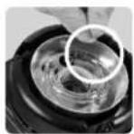
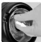
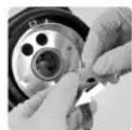
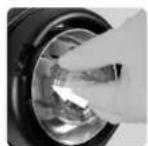
Shut down the power and remove the power cord before replacing the flash tube and wear insulated gloves. Then, loosen the iron wire on the tube, keep a balanced hold on the two feet of the flash tube and pull out the old tube gently. Take down the feet casing from the old tube and put it on the new one. Hold two feet of the new tube, and target directly towards the two copper outlets, then push them slightly in. Twine the iron wire on the stainless steel sheet to fix the flash tube.
TECHNICAL DATA
| Model | DP300 II | DP400 II | DP600 II | DP800 II | DP1000 II |
| Max Power (WS) | 300Ws | 400Ws | 600Ws | 800Ws | 1000Ws |
| Guide Number(m ISO 100) | 58 | 65 | 80 | 88 | 92 |
| Color Temperature | 5600±200K | ||||
| Operating Voltage | AC110V-120V~60Hz or AC220V-240V~50Hz | ||||
| Power Output Control | OFF, 6.0~10.0(1/16~1/1) | ||||
| Modeling Lamp (W) | 150W | ||||
| Triggering Method | Sync cord, Test button, Slave triggering, Wireless control port | ||||
| Flash Duration | 1/2000~1/800s | ||||
| Parameters Output from the Sync Cord Jack | 5V | ||||
| Parameters Output from the USB Port | 5V/200mA (only for Godox receiver) | ||||
| Fuse | 5A | 8A | |||
| Recycle Time | 0.3-1.2s | 0.3-1.5s | 0.4-2s | ||
| Dimension | Flash diameter12.5CM, height of flash with handle 21.5CM, length of flash with lamp cover 42CM | ||||
| Net Weight | Approx. 2.5kg 2.59kg 3.02kg 3.2kg 3.3kg | ||||
MAINTENANCE
- Shut down the device immediately when it works abnormally and find out the reason.
- Avoid sudden impacts and the lamp should be dedusted regularly.
- It is normal for the lamp to be warm when in use. Avoid continuous flashes if unnecessary.
- Maintenance of the flash must be performed by our authorized maintenance department which can provide original accessories. The flash-tube and the modeling lamp are user-replaceable. Replacement tubes and lamps can be obtained from the manufacturer.
- This product, except consumables e.g. flash tube and modeling lamp, is supported with a one-year warranty.
• Unauthorized service will void the warranty.
• If the product had failures or was wetted, do not use it until it is repaired by professionals. - Disconnect the power when cleaning the flash or when changing the flashtube / modeling lamp.
• Changes made to the specifications or designs may not be reflected in this manual.