
Air Remote TTL-N - Remote trigger PROFOTO - Free user manual and instructions
Find the device manual for free Air Remote TTL-N PROFOTO in PDF.


User questions about Air Remote TTL-N PROFOTO
0 question about this device. Answer the ones you know or ask your own.
Ask a new question about this device
Download the instructions for your Remote trigger in PDF format for free! Find your manual Air Remote TTL-N - PROFOTO and take your electronic device back in hand. On this page are published all the documents necessary for the use of your device. Air Remote TTL-N by PROFOTO.
USER MANUAL Air Remote TTL-N PROFOTO
This user guide is available in other languages at profoto.com/support
Congratulations on your new Profoto product!
Regardless if you chose a new flash or a new light-shaping tool, know that almost half a century's worth of experience was put into its making.
If the years have taught us one thing, it is to never neglect a single detail. We only put our name on a product in which we have the fullest confidence. Before shipping, every one of our products pass an extensive and strict testing program. Unless it complies with the specified performance, quality and safety, it is a no-go.
As a result, we are confident that your new Profoto product will stay with you for years and help you grow as a photographer.
But getting the product is only the beginning of that journey. Using it for light shaping is the real adventure. That is why we take pride in providing you with such a wide assortment of light-shaping tools, allowing you to shape the light in any way you can imagine.
The almost infinite possibilities might seem bewildering at first, but we're certain you will soon get the hang of it.
Still, I encourage you to sign up for our newsletter at www.profoto.com/newsletter or visit our blog at www.profoto.com/blog so that we can share our experience from almost 50 years of light shaping and hopefully inspire you to grow even further.
Enjoy your Profoto product!
Conny Dufgran, founder
General safety instructions

SAFETY PRECAUTIONS!
Do not operate the equipment before studying the instruction manual and the accompanying safety information. Make sure that Profoto Safety Instructions always accompany the equipment! Profoto products are intended for professional use! Generators, lamp heads and accessories are intended for indoor photographic use only. Do not place or use the equipment where it can be exposed to moisture, extreme electromagnetic fields, or in areas with flammable gases or dust! Do not expose the equipment to dripping or splashing. Do not place any objects filled with liquids, such as vases, on or near the equipment. Do not expose the equipment to rapid temperature changes in humid conditions as this could lead to condensation water in the unit. Do not connect this equipment to flash equipment from other brands. Do not use flash heads without supplied protective glass covers or protective grids. Glass covers must be changed if they have become visibly damaged to such an extent that their effectiveness is impaired, for example by cracks or deep scratches. Lamps must be changed if they are damaged or thermally deformed. When placing a lamp into the holder ensure not to touch the bulb with bare hands. Equipment must only be serviced, modified or repaired by authorized and competent service personnel! Warning - The terminals marked with the flash symbol are hazardous when live.

WARNING – Electrical Shock – High Voltage!
Mains powered generators shall always be connected to a mains socket outlet with a protective earthing connection! Only use Profoto extension cables! Do not open or disassemble generators or lamp heads! Equipment operates with high voltage. Generator capacitors are electrically charged for a considerable length of time after being turned off. Do not touch modeling lamps or flash tubes when mounting an umbrella metal shaft in its reflector hole. Disconnect the lamp head cable between the generator and lamp head when changing the modeling lamp or flash tube! The mains plug or appliance coupler is used as disconnect device. The disconnect device shall remain readily operable. Batteries (battery pack or batteries installed) shall not be exposed to excessive heat such as direct sunlight, fire, or the like.

Caution – Burn Hazard – Hot Parts!
Do not touch hot parts with bare fingers! Modeling lamps, flash tubes and certain metal parts emit strong heat when used! Do not point modeling lamps or flash tubes too close to people. All lamps may on rare occasions explode and throw out hot particles! Make sure that the rated voltage for the modeling lamp corresponds with the technical data in the user guide regarding the power supply!
NOTICE
NOTICE – Equipment Overheating Risk
Remove transport cap from lamp head before use! Do not obstruct ventilation by placing filters, diffusing materials, etc. over inlets and outlets of the equipment ventilation or directly over glass covers, modeling lamps or flash tubes!
Note about RF!
This equipment makes use of the radio spectrum and emits radio frequency energy. Proper care should be taken when the device is integrated in systems. Make sure that all specifications within this document are followed, especially those concerning operating temperature and supply voltage range. Make sure the device is operated according to local regulations. The frequency spectrum this device is using is shared with other users. Interference cannot be ruled out.

Final Disposal
Equipment contains electrical and electronic components that could be harmful to the environment. Equipment may be returned to Profoto distributors free of charge for recycling according to WEEE. Follow local legal requirements for separate disposal of waste, for instance WEEE directive for electrical and electronic equipment on the European market, when product life has ended!
Table of Contents
General safety instructions....4
System description & compatible products ....7
General notes on wireless operation with Profoto Air....8
Nomenclature 9
Operating instructions....10
Quick guide....10
Power on/off....10
Channel selection....10
Sync selection....11
Mode selection (TTL or Manual)....11
Operation in TTL mode (Automatic mode) 11
Operation in MAN mode....13
Test sync....14
Other 14
Technical data 15
Regulatory information 16
World-wide Usage of Radio Spectrum....16
Unites States and Canada....16
Japan....17
System description & compatible products
The small, lightweight Air Remote TTL-N is designed to make off-camera flash easy. Mounted on the camera hot shoe, it acts as a wireless extension of your camera to your Profoto flashes, combining TTL (Through-The-Lens) exposure control with the option to manually adjust and sync your Profoto lights.
- The Air Remote TTL-N is specifically designed for Nikon cameras that use Nikon's i-TTL metering system.
- Some camera models may not be supported or have limited functionality. Create a free user account on profoto.com/myprofoto to check and install latest firmware version or download release note with updated listing of supported cameras.
- The Air Remote TTL-N operates with Profoto flash units and generators, with built-in Profoto Air functionality according to the table below.
- The Air Remote TTL-N can also be used to trigger the Air Remote and Air Sync Profoto Air transceivers.
- The Air Remote TTL-N is not compatible with Nikon Speedlights or other non-Profoto flashes.
- The Air Remote TTL-N is not compatible with any 3rd party radio triggering systems.
| Air labeling on Profoto flash | Enabled features on Air Remote TTL-N | ||
| Manual sync Remote | control TTL | ||
| Air TTLXXX | |||
| Air XX | |||
| AirS X | |||
General notes on wireless operation with Profoto Air
The Profoto Air channels [1-8] use eight specific frequencies in the 2.4 GHz band and have an operating range of up to 300 meters (1000ft). The frequencies are evenly distributed over the entire frequency band. Since each channel uses a different radio frequency, it possible to select a channel without interference from other photographers using Profoto Air, WLAN/Bluetooth devices or other radio equipment operating on the 2.4 GHz frequency band.
- Keep cables and cords away from antennas.
- Maintain line of sight between the Air Remote TTL-N and the flash unit whenever possible
- When hiding the flash from view, try to not hide it behind or against metal or water-filled objects as this will affect the radio range.
Nomenclature
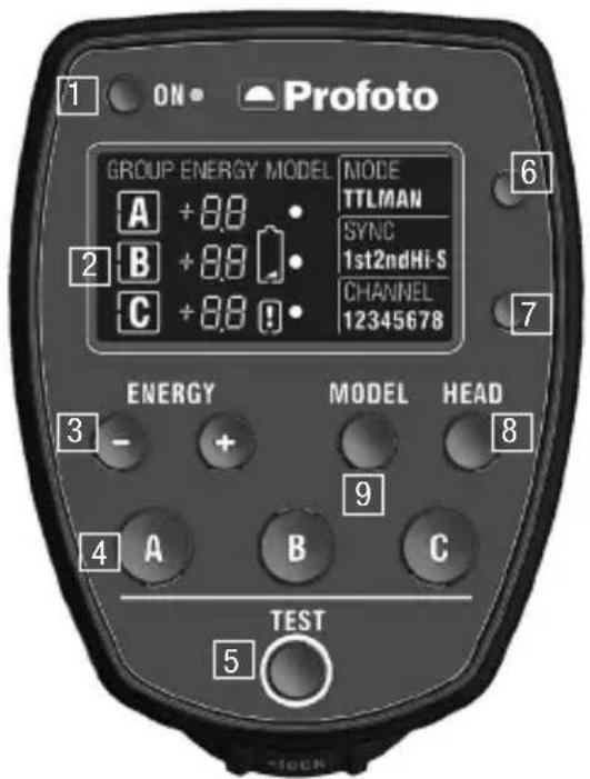
text_image
1 ON • Profoto GROUP ENERGY MODEL MODE A +8.0 • TTLMAN SYNC 1st2ndHi-S CHANNEL 12345678 2 B +8.0 C +8.0 ! 3 - + 4 A B C TEST 5- ON button
- Display
- Energy buttons
- Group buttons (A, B, C)
-
Test button
-
Mode button
- Channel button
- Head button
- Model button
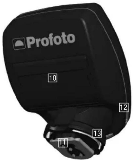
text_image
Profoto 10 12 13 11- Battery compartment
-
Hot shoe connector
-
USB port (for service only)
- Locking mechanism
Operating instructions
Quick guide
For detailed instructions, refer to the subsequent sections.
Profoto Flash setups
- Set the flash to synchronization via Radio/Air (may differ by generator).
- Select the same radio channel on all flashes.
- Select the same group (A, B or C) for all lamp heads to be controlled simultaneously.
- Slide the hot shoe connector on the Air Remote TTL-N into the hot shoe of the camera. Turn the Locking mechanism [13] to secure the device.
- Switch on the device.
- Select the same radio channel as on the generators.
- Press the Mode button [6] to toggle between TTL (Automatic) and MAN (Manual) mode.
- Press the A, B or C button to select the corresponding group.
- When a group is selected:
a) Press the HEAD button [8] to turn on/off the lamp heads.
b) Press the MODEL [9] button to turn on/off the modeling light.
c) Press the ENERGY buttons [3] to adjust the energy level for the group in relation to the other groups (TTL mode) or the energy level for the group (MAN mode). - Press the TEST button [5] to manually transmit a sync signal, in order to test the settings.
Air remote TTL-N
Power on/off
- Press and hold down the ON button [1] to switch on/off the remote.
Channel selection
The currently selected channel is shown in the CHANNEL section on the Display [2].
- Press the Channel button [7] repeatedly until the desired channel is displayed.
Sync selection
The selected sync setting (cameras sync setting) is shown in the SYNC section on the Display [2].
- 1st: The flashes fire when the first shutter curtain is fully open.
- 2nd: The flashes fire just before the second curtain starts traveling.
NOTE:
The sync setting is selected in the camera menu. Refer to the camera's user guide.
Mode selection (TTL or Manual)
The currently selected mode is shown in the MODE section on the Display [2].
-
Press the Mode button [6] to toggle between TTL and MAN mode.
-
TTL mode: The camera dictates the light output of the flashes. The relationship between the energy levels for group A, B and C can be adjusted.
• MAN mode: The light output for group A, B and C can be controlled manually.
Operation in TTL mode (Automatic mode)
In TTL mode the camera dictates the light output of the flashes. If more than one light is used the relationship between the energy levels for group A, B and C can be adjusted. This can, for example, be used to achieve more light on one side of the object.
- Press the A, B or C Group button [4] to select the group you want to adjust.
- Use the ENERGY buttons [3] to set the relative light output for the selected group, in relation to the other groups. The relations can be set ±2.0 f-stop for each group A, B or C.
- To change the total flash exposure, use the flash exposure compensation function in the camera. Refer to the camera manual for details.
- Press the Model button [9] to turn on/off the modeling light in the selected group.
- Press the Head button [8] to turn on/off the lamp heads in the selected group (if the heads in a group are turned off, the relation value for that group will display ‘--’)
- When changing from MAN mode to TTL mode, the previous TTL relation value is displayed.
text_image
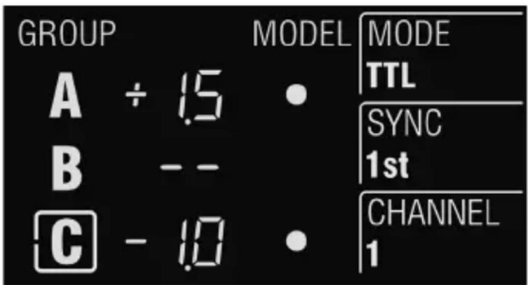
GROUP A ÷ 1.5 B -- C - 1.0 MODEL • MODE TTL SYNC 1st CHANNEL 1Example of remote Display[2] settings in TTL mode operation
The figure shows the Display [2] when:
- TTL mode, 1st-curtain sync and channel 1 are selected.
- Group C is selected to be adjusted.
- The relative light output from lights in group A is set to 2.5 f-stops more than lights in group C. (A to +1.5 f-stops and C to -1.0 f-stops).
- Lights/Heads in Group B are turned off.
- The modeling light is turned on in both group A and C.
NoTe:
- If only one flash group is used in TTL mode, the relation value will not have any effect on the total flash exposure as the flash exposure is automatically set by the camera.
- If flashes without Profoto AirTTL support are used in combination with Profoto AirTTL flashes in TTL mode, the flash outputs of the non-TTL flashes are added to the total flash exposure. Such flashes can for instance be used to manually set the exposure on the background.
- If a Profoto AirTTL compatible flash is set to group D, E or F, it will be synchronized but not be part of the TTL calculation. The flash outputs of these flashes are added to the total flash exposure and can for instance be used to manually set the exposure on the background.
Operation in MAN mode
With the Air Remote TTL-N set to MAN mode, the light output for groups A,B and C can be adjusted manually. By alternating between TTL and MAN mode, you can test your way to the perfect light.
- Press the A, B or C Group button [4] to select the corresponding group.
- To select all groups, press one of the Group button [4] two times.
- Use the ENERGY buttons [3] to adjust the light output for the group. The adjustment (increase/decrease) always starts from the current light output setting and the adjustment value is momentarily shown in the ENERGY section on the Display [2].
- Press the Model button [9] to turn on/off the modeling light in the selected group.
- Press the Head button [8] to turn on/off the lamp heads in the selected group (if the heads in a group are turned off, the relation value for that group will display ‘--’)
text_image
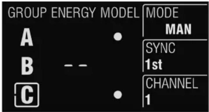
GROUP ENERGY MODEL MODE MAN SYNC 1st CHANNEL 1Example of remote Display[2] settings in MANmode operation
The figure shows the Display [2] when:
• MAN mode, 1st-curtain sync, and channel 1 are selected.
- Group C is selected to be adjusted.
- Lights/Heads in Group B are turned off.
- The modeling light is turned on in both group A and C. If the light output for group A or C is adjusted, the energy change will be shown momentarily.
NOTE:
- Press the ENERGY button to increase/decrease in 1/10 f-stop increments.
- Press and hold down the ENERGY button to increase/decrease in 1 f-stop increments.
- If a light output cannot be set by the generator because a lamp head is in minimum or maximum position, the Air Remote TTL-N beeps to signal that the command was not executed. The light output of all lamp heads in the group then remains unchanged.
- In MAN mode, the Air Remote TTL-N can also be used as to remote control Profoto flashes that support Air but not AirTTL (further info on compatible products are found in section System Description and Compatible Products)
- When all groups are selected the remote will also control lights in group D, E or F (selected on flash).
Test sync
- Press the Test button [6] to manually transmit a sync signal.
Other
Factory reset
Reset the Air Remote TTL-N to factory settings:
- Switch off the Air Remote TTL-N.
- Press and hold down the TEST button [5] and the ON button [1] simultaneously.
Battery check & built-in power saving
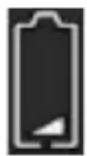
The low battery symbol is displayed when the battery voltage reaches a critical level.
To save battery, the display automatically switches off after 30 seconds of inactivity. Press the ON button [1] to switch on the display. The display also switches on when any of the function buttons are used.
Check Firmware version
Press and hold the MODE button [6] for 10 seconds when turning the remote on.
Change Firmware version
Create a free user account at profoto.com/myprofoto to register your product and download the latest upgrades.
Technical data
| Specifications | |
| Frequency band 2.4 GHz | |
| No of frequency channels 8 (1-8) | |
| No of groups per channel 3 (A-C) | |
| Operation modes TTL & Manual | |
| Camera TTL compatibility Nikon | i-TTL |
| Camera mount/Connectors Hot | shoe mount for Nikon.USB mini connector for firmware upgrades. |
| Range Up to 300 m (1000ft) for | normal triggering |
| Up to 100 m (330ft) for remote control and TTL | |
| Battery type 2xAAA | |
| Typical battery lifetime 30 hours | |
| Antenna type Integrated | |
| LCD display Yes | |
| Auto power off Remote: after 30 | min of inactivityDisplay: after 30 sec of inactivity |
| Supported Profoto Air functionality | |
| Flash Sync/Trigger | Yes, Air Remote TTL-N triggers Air Remote & Air Sync transceivers plus all Profoto flashes labeled AirTTL, Air and AirS. |
| Remote control | Yes, Air Remote TTL-N works as a manual remote control for all Profoto flashes labeled AirTTL & Air. |
| TTL control | TTL with group control for all Profoto flashes labelled AirTTL. |
| Measurements | |
| Dimensions | 75x60x35 mm / 2.9x2.3x1.4 in |
| Weight | 75 g / 2.6 oz including batteries |
All figures are to be considered as nominal and Profoto reserves the right make changes without further notice.
Regulatory information
World-wide Usage of Radio Spectrum
The Profoto Air Sync and Profoto Air Remote operates on the license-free 2.4GHz ISM band for SRD (Short Range Devices). This band may be used in most parts of the world. Regional restrictions may apply.
Note:
Refer to national regulations for the region where the Air Remote TTL-N shall be operated and make sure that they are followed.
Unites States and Canada
F.C.C. and Industry Canada
Compliance Statement (Part 15.19) This device complies with Part 15 of FCC rules and RSS-210 of Industry Canada. Operation is subject to the following two conditions:
1) this device may not cause harmful interference and,
2) this device must accept any interference received, including interference that may cause undesired operation.
Warning (Part 15.21)
Changes or modifications not expressly approved by the party responsible for compliance could void the user's authority to operate the equipment.
The term ‘IC’ before the certification/registration number only signifies that the Industry Canada technical specifications were met.
Transmitter / Receiver
MODEL: Profoto Air Remote TTL-N
PRODUCT NO: PCA5337-0000
FCC ID: W4G-RMI
IC: 8167A-RMI
Made in Sweden
Japan
The module has been granted modular approval for sale and operation in Japan.
特定無線設備の種類
Classification of specified radio equipment:
Article 2, Clause 1, Item 19
2.4 GHz Wide Band Low Power Data Communication
This is to certify that the above-mentioned certification by type has been granted in accordance with the provisions of Article 38-24, Paragraph 1 of the Radio Law.
R202WW08109202

R 202WW08109203
R202WW08109204
Profoto AB
P.O. Box 1264
SE-172 65 Sundbyberg, SWEDEN
Visiting address: