HD-5000 - Tripod Flycam - Free user manual and instructions
Find the device manual for free HD-5000 Flycam in PDF.


User questions about HD-5000 Flycam
0 question about this device. Answer the ones you know or ask your own.
Ask a new question about this device
Download the instructions for your Tripod in PDF format for free! Find your manual HD-5000 - Flycam and take your electronic device back in hand. On this page are published all the documents necessary for the use of your device. HD-5000 by Flycam.
USER MANUAL HD-5000 Flycam
natural_image
Black FlyGA 5000 hover device with two spools and a handle (no visible text or symbols on the device body)5000 Handheld Video Stabilizer (FLCM-5000-Q)
Instruction Manual
FLYCAM
At Flycam, our goal is to ensure 100% Customer Satisfaction in all that we do.
We back our sales with a 1 year warranty from the date of purchase and work hard to resolve any problems in the unlikely event one should arise.
With our commitment to continuous improvement and your Feedback, building on our reputation of providing affordable, quality products is
PRIORITY #1.
Table of Contents
Subject Page
Foreword 3
Introduction 4
Safety Hints 5-6
Assembling 6-11
Balancing 11-15
Warranty 16
■ Welcome To Flycam!
Dear Client,
On behalf of all the people that work so hard to provide you with the most up-to-date, flexible and cost-efficient production gear, we would like to welcome you into the Flycam family.
By purchasing your 5000 Handheld Video Stabilizer, you have just joined a host of designers, engineers, machinists, assembly, customer service and office staff that take great pride in all that they do. Our mantra of continuous improvement has been the guiding principle of how we conduct our business since day one.
Once you have the opportunity to experience your new 5000 Handheld Video Stabilizer, we hope you will agree that we craft quality products at a competitive price. Products designed to meet and exceed the standards of today's real production world.
Standards set by our valued clients and standards we strive to maintain.
With Best Wishes,
Flycam Team
Introduction
Flycam 5000 is a precise camera stabilizer which helps you in getting the stable and smooth gliding movements with absolutely zero shakes. It allows you to make fast moves while following quick actions. Thus it is easy to operate and best for travel shooting, events, and video productions.
What's In The Box
Please inspect the contents of your shipped package to ensure you have received everything that is listed below.
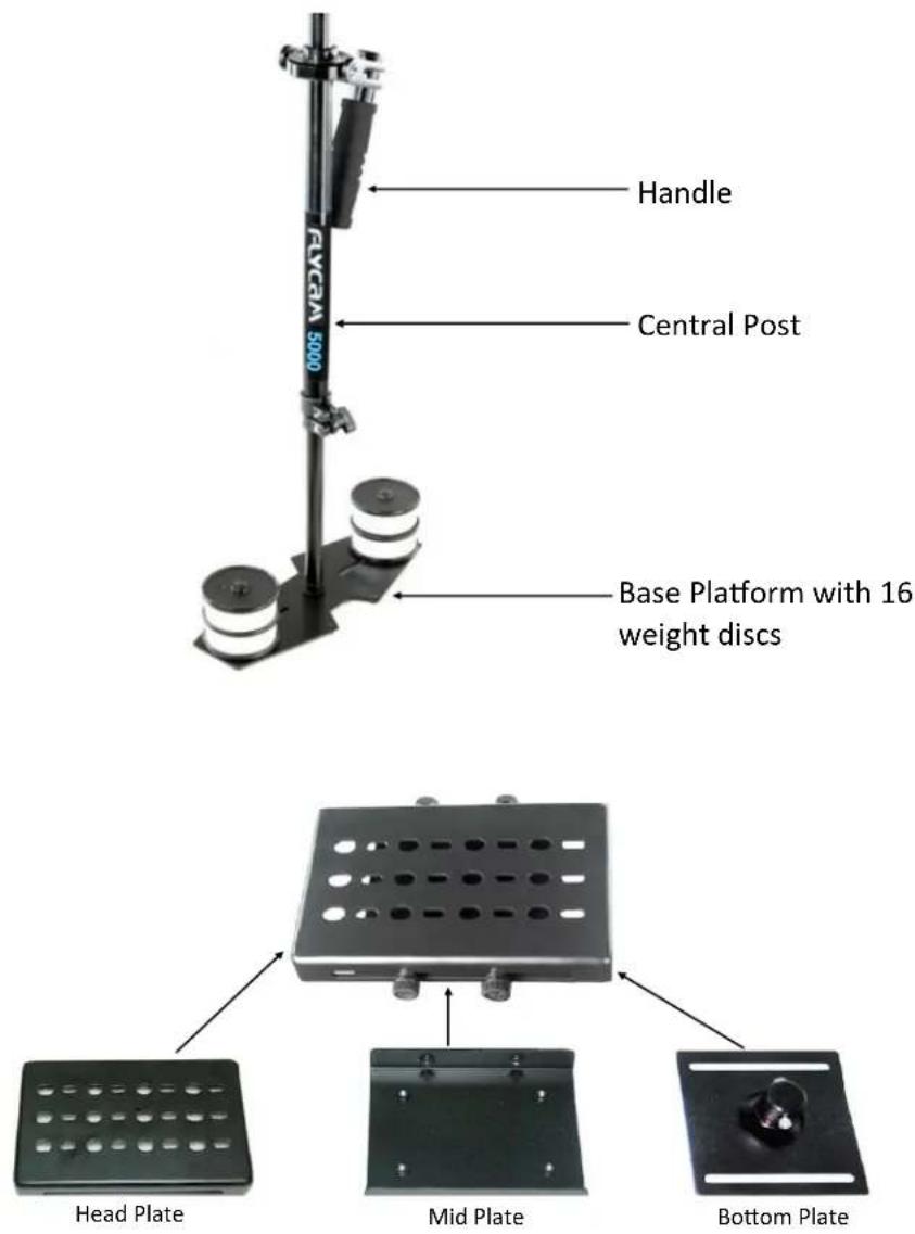
text_image
RVCA 5000 Handle Central Post Base Platform with 16 weight discs Head Plate Mid Plate Bottom PlateHead Assembly (These three individual pieces are shipped as one assembled unit)
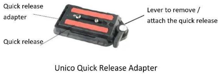
text_image
Quick release adapter Quick release Lever to remove / attach the quick release Unico Quick Release Adapter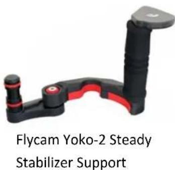
text_image
Flycam Yoko-2 Steady Stabilizer SupportNote: A locking pin located at the front prevents camera rotation.
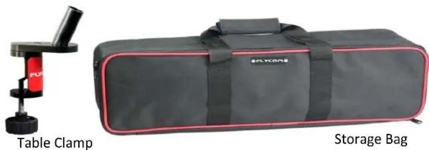
natural_image
Two items: a Table Clamp device and a Storage Bag with black casing (no text or symbols on the devices themselves)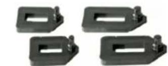
natural_image
Four black plastic mechanical components with mounting holes and threaded fasteners (no text or symbols visible)V-shape Adapter (to attach Camera to Head Plate)

Safety Hints
ATTENTION: PLEASE READ THIS BEFORE USING TO PREVENT SERIOUS DAMAGE TO THE GEAR!
BE HIGHLY VIGILANT OF SURROUNDINGS
Check the area you will be shooting in, before shooting. Make sure your path is clear. Look for obstacles and note anything you might run into or trip over. Extra care is also necessary when tackling stairs and other kinds of uneven ground.
ALWAYS WEAR PROTECTIVE GEAR
If you intend to shoot while moving fast or while traversing uneven terrain, do not hesitate to wear protective gear as knee or elbow pads, or a helmet.
DO NOT SHOOT IN UNSAFE CONDITIONS
Avoid situations where one commonly falls like skis, skates or running in muddy fields.
ADULT SUPERVISION IS RECOMMENDED
Minors using this product should have adult supervision.
FOLLOWING THESE GUIDELINES WILL PROVIDE BETTER SHOTS AND TROUBLE-FREE OPERATION.
SHOULD YOU NEED ADDITIONAL INFORMATION, TECHNICAL ASSISTANCE IS AVAILABLE 'ONLINE' BY CONTACTING YOUR SALES REPRESENTATIVE

Assembling
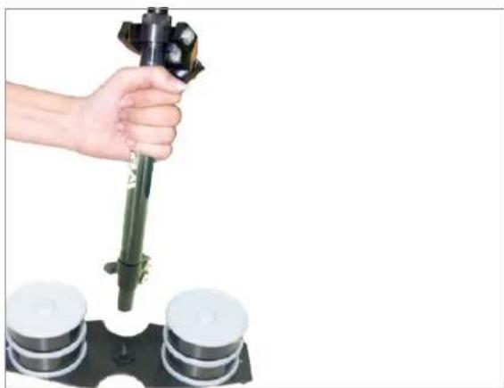
- A threaded stud is located in the center of Base Platform for attaching Central Post. Securely tighten the adjustment knob on telescoping clamp by rotating it clockwise.
NOTE: The adjustment knob should only be tightened by hand. Do not over-tighten it as it could cause thread stripping.
natural_image
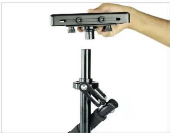
Hand holding a black cylindrical device with three white circular components on a black base (no text or symbols visible)- Loosen allen bolts at the bottom of Camera Plate, align its holes with the top of Central Post & re-tighten them securing the plate to post.
natural_image
Hand holding a black electronic device mounted on a stand, with no visible text or symbols.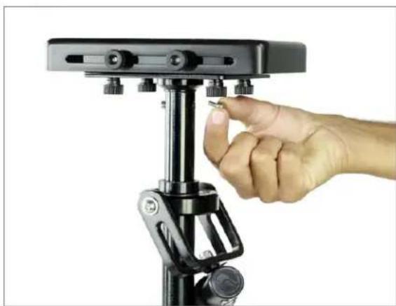
natural_image
Hand adjusting a black mechanical device with adjustment knobs (no text or symbols visible)- Remove Head Plate by unscrewing the four side knobs to mount Quick Release Adapter.
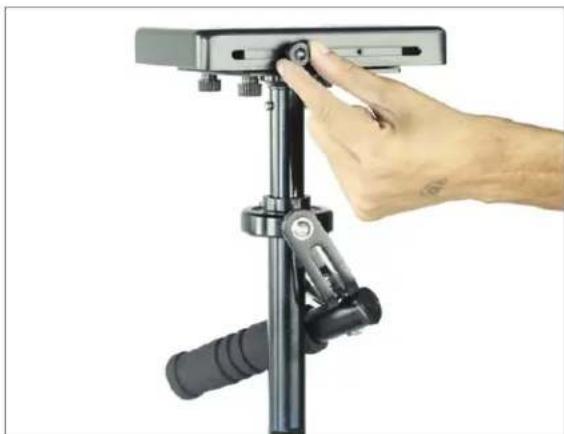
natural_image
Hand adjusting a mechanical lever device with a black handle and metal frame (no text or symbols visible)- Loosen allen bolt at the bottom of Quick Release Adapter and attach it to Head Plate.
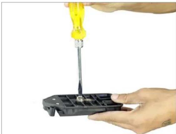
natural_image
Close-up of hands using a yellow screwdriver to adjust or install a black plastic component (no text or symbols visible)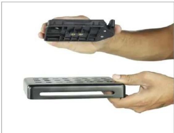
natural_image
Two hands holding a black electronic device with ports and a perforated base (no visible text or symbols)- Then attach Head Plate to stabilizer with appropriate fore & aft positioning and tighten all four side knobs, as shown. Further fine tuning will probably be required.
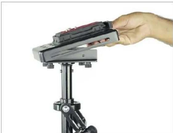
natural_image
Hand inserting a battery into a tripod-mounted device (no text or symbols visible)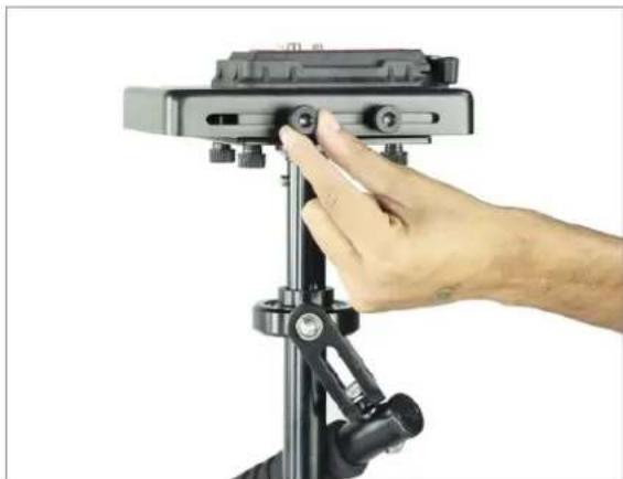
natural_image
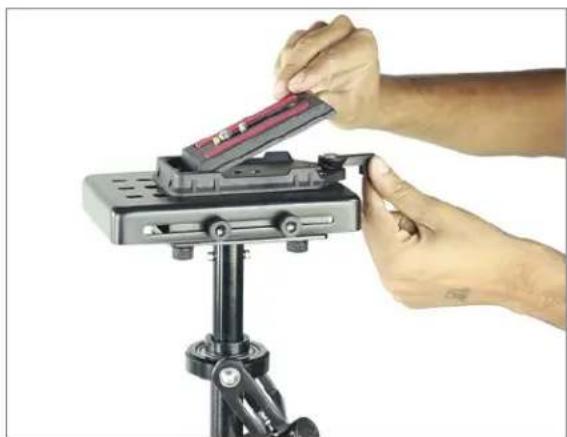
Hand adjusting a camera frame mounted on a tripod stand (no text or symbols visible)- Open the lever and remove Quick Release Plate from Adapter. Then attach it with your camera with the help of screw driver.
natural_image
Close-up of hands installing a red component onto a black tripod-mounted device (no text or symbols visible)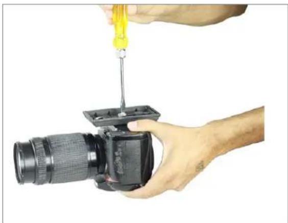
natural_image
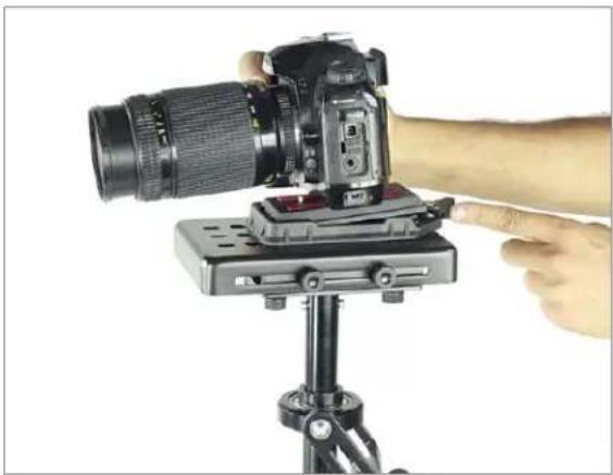
Person using a screwdriver to adjust or install a DSLR camera lens (no text or symbols visible)- Insert your camera setup with Quick Release Plate into the Adapter and tighten the lever back.
natural_image
Hand operating a DSLR camera on a tripod, with no visible text or symbolsNOTE: If you wish to bypass Quick Release Plate, the camera can be directly attached to Head Plate by following this assembly sequence:
- Remove Head plate from 3-piece Head Assembly in order to attach it to your camera. You will note a number of mounting holes that can be used to adapt various cameras.
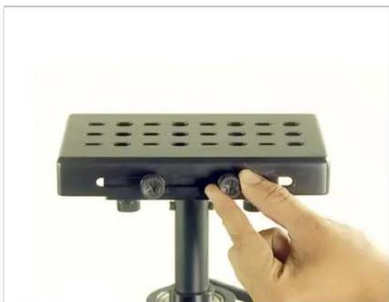
natural_image
Hand adjusting a black plastic stand with circular buttons (no text or symbols visible)- Keep the camera in center of Head Plate and secure it properly. Do not over tighten this adjustment as it can break the threaded insert.
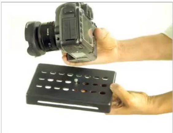
natural_image
Hand holding a digital camera and a black plastic tray (no text or symbols visible)- The many slots located on Head Plate and Bottom Plate allows you to easily adjust X & Y Axis for perfect balance. Place the assembly in line with the center of stabilizer post and tighten the side adjusters, as shown. Further fine tuning will probably be required.
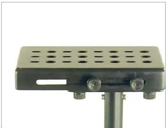
natural_image
Close-up of a black rectangular electronic device with two metallic adjustment knobs and perforated top panel (no text or symbols visible)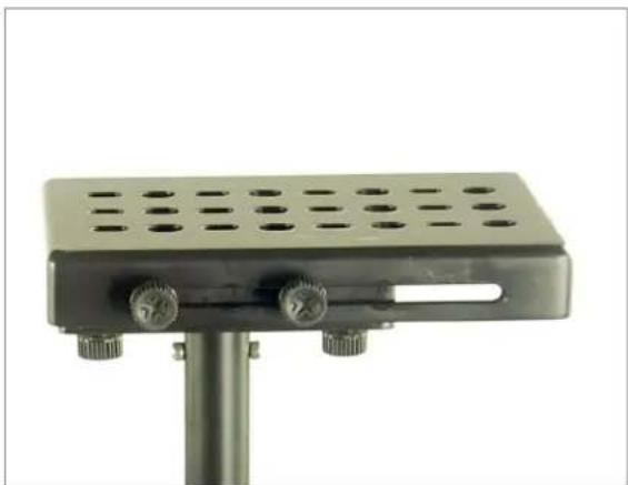
natural_image
Close-up of a black metal stand with perforated top and two side knobs (no text or symbols visible)Head Plat e X adjustment
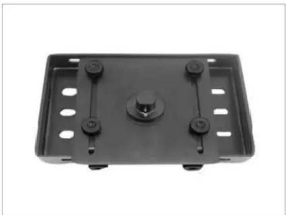
natural_image
Top-down view of a black plastic enclosure with four mounting holes and a central cylindrical component (no text or symbols visible)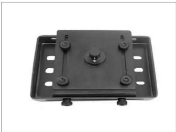
natural_image
Black plastic electrical connector with mounting holes and a central knob (no text or symbols visible)Head Plat e Y adjus tm ent
Adding Weights & Positioning for Proper Balance
Continuing the assembly and balance requirements to make your Flycam Handheld Video Stabilizer fully functional you will note that the base platform has a provision to mount the balance weights in their cups via a slot found on both sides of the post.
The purpose of the counter weight system is to match the low end of the stabilizer to the weight of the camera and accessories at the high/top end with the gimbaled handle as the pivot point in between.
The heavier the camera and accessories, the more weights are required to achieve proper balance. Generally as you add weight to one side of the central post, an equal amount has to be added to the other side to maintain horizontal balance.
However if you are using an offset configuration such as a flip out viewfinder or off center accessories, extra weights might be needed on the opposite side of the post to counter act and maintain proper balance.
Total weight fixed to the base platform should be equal to the weight of your camera plus the head and any accessories.
Horizontal adjustment on base platform is made by loosening the retaining screws and moving counterweight plates closer to or farther away from post and then re-tightening. You will probably need to adjust and re-adjust the horizontal position to achieve optimum performance.
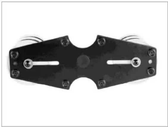
natural_image
Black mechanical component with multiple holes and a central slot, shown against a white background (no text or symbols)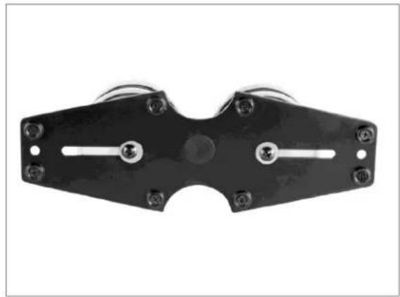
natural_image
Black metal mechanical component with two mounting holes and a central circular feature (no text or symbols visible)NOTE: When adding weight in cups, use the supplied foam spacers as silencers to prevent metal to metal washer noise.
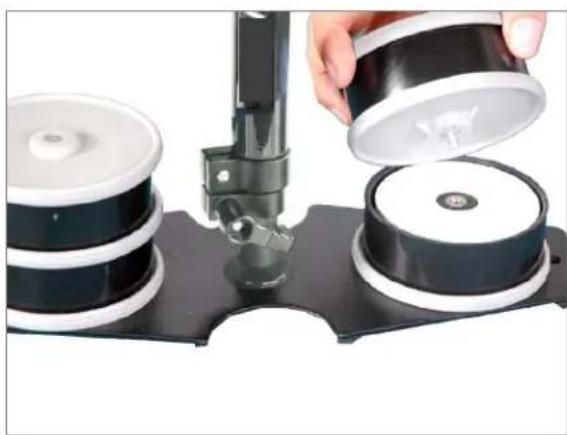
natural_image
Close-up of a hand pouring liquid into a black cylindrical device on a black base (no text or symbols visible)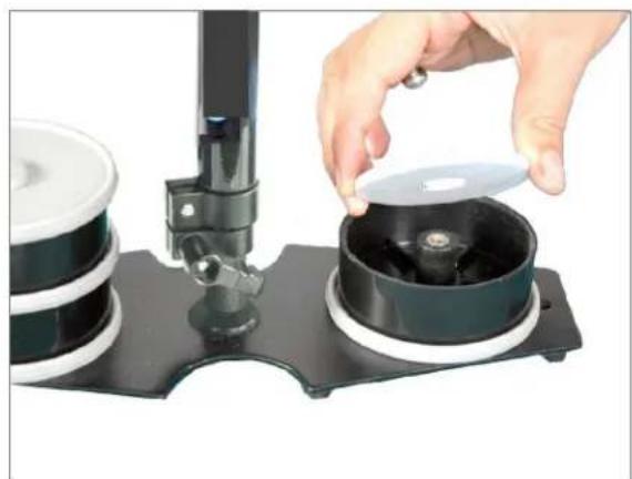
natural_image
Close-up of a hand pouring liquid into a black cylindrical container on a black base (no text or symbols visible)Vertical Adjustment of telescopic central post is made by loosening the control located at the base, raising or lowering the post to desired location and then retightening the vertical control. Do not over-tighten this control.
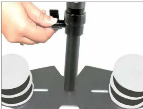
natural_image
Hand adjusting a black cylindrical component on a road marked with white and black stripes (no text or symbols visible)Balancing your Flycam Stabilizer
Before beginning the balancing process check the following:
• Camera is securely attached to Head Plate
- Lens cap is removed and secured
• Telescoping Clamp is tightened
• Weight discs are added successfully
• All screws are tightened securely
- Battery, all accessories and cables are secured
Balancing the Horizontal Axis
When your Flycam Stabilizer is properly assembled, you can start the test and setup of horizontal balance. Horizontal Balance allows the camera to remain level, during operation, with the Central Post in a vertical position unless off-axis framing is desired.
When testing for horizontal balance start from a flat and level surface like table. This will allow the stabilizer to hang freely as you hold it. If your stabilizer is correctly balanced on its horizontal axis, then it will be both leveled & upright, with Central Post in a perfect vertical position.
NOTE: If you do not have enough weight on Base Platform the entire Flycam could flip upside down. If this movement starts to happen, be ready to catch the sled before a complete 180^ occurs. This type of unwanted movement requires more weight to be added to the base with additional weight discs.
Another way to accomplish Horizontal Balance is to move the center of gravity of camera by re-mounting the camera to a different area of the Head and Mid Plate, either front-to-back or side-to-side.
If the stabilizer be front heavy, loosen the screws on the sides of Head Plate and gently slide Head Plate back until optimum balance is achieved. Tilting to the back means the load is tail heavy requiring the plate to be adjusted forward on the head.
If the stabilizer leans towards right, then loosen the screws on the bottom of Bottom Plate and gently slide the Mid Plate towards left. If it leans to left, then adjust the Mid Plate towards right. A bit at a time until balance is achieved.
NOTE: Always secure the screws and all parts after any adjustments are made.
Balancing the Vertical Axis
The sled should be tied up to the docking adapter of your stand or similar, so that you can start the fore & aft balancing adjustments by centering the camcorder over Central Post. To do this-
- Loosen the side screws of Head Plate and the bottom screws of Bottom Plate. Look at the stabilizer from side. If the camcorder lens is tipped up or down, move the camcorder forward or backward until the center of balance is situated over Central Post.
- Then, look at the stabilizer from front. If the post is not vertical, adjust the bottom plate until Central Post is vertical.
- You can also adjust the weight cups closer to & farther away from the sled as per requirement, till the post is straight up and down.
NOTE: The stability of Flycam Stabilizer depends on it being slightly bottom heavy. If it is top heavy, it will tilt more. If it is too bottom heavy, it will be sluggish and hard to aim.
Slightly Bottom Heavy, it will be both Stable and Easier to Control. Check the Vertical Balance by using this Drop Time Test.
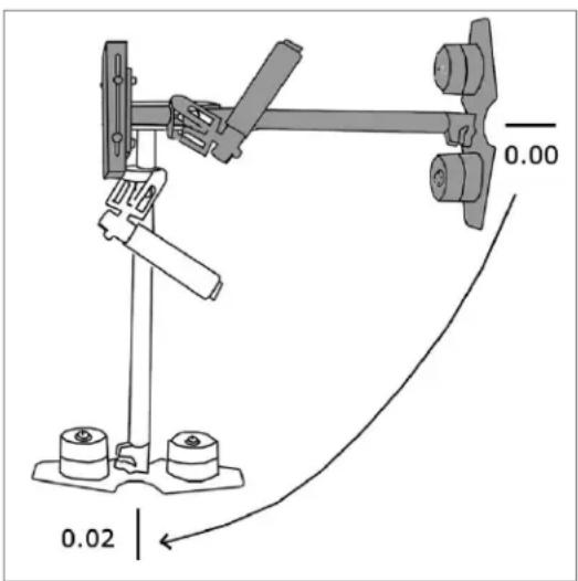
text_image
0.00 0.02• Make sure that everything is tight.
- Grasp Central Post near the base and move it from vertical to horizontal.
- Hold it there. Be sure that it will not hit the stand when you drop it. Keep your free hand to catch the central post when it drops.
• Count how many seconds it takes to fall to vertical. Try using a stopwatch.
- If the drop time is less than 2 seconds, it is too bottom heavy. You need to move the bottom mass closer to post.
- If the drop time is more than 2 seconds, it is top heavy.
A Drop Time of 2-2.5 seconds is preferred.
NOTE: Recheck the balance by looking at sled. If necessary, use side screws and bottom plate screws to make required adjustments.
Balancing Review
Proper system balance can only be achieved once your camera is set up with appropriate accessories ready for shooting. This means batteries, lenses, media cards, LCD viewfinder/ monitor, quick release plate, on-cam lights, and all the gear you will use for your recording session.
- Remove top plate of stabilizer and line-up your camera so that its center of gravity is as close to the center of plate as possible (basically hold the camera in your hand until it feels balanced both left and right as well as forward and backward).
- Find hole in the plate that is as close to threaded tripod mount on your camera as possible (while you are still holding your camera's center of gravity to the center of plate). Attach your camera (or quick release, if you have one). Tighten it down so it won't accidentally rotate.
- Re-attach top plate to the stabilizer. Center it, but don't worry about getting it absolutely perfect.
- Remove most of the weights from Base Platform, but leave one on each side.
- Insert the central post as far as it can go and tighten so it won't slide out.
- Hold the handle normally and turn stabilizer so that it is horizontal to the ground. Let go of the stalk while keeping a firm grip on handle and count how long it takes to return to vertical again. You should be able to count a good, 'One-one thousand, two-one thousand', before it rights itself. With only two little weights it might take considerably longer.
-
Add one pair of weights at a time and repeat 'horizontal to vertical' test, until it falls at the correct rate. It will probably not be perfect.
-
You'll get one movement that's too slow and then you'll add a pair and it will fall too fast. When that happens, take off the last pair of weights that you added.
- Tighten down the weights so they don't slide around.
- To get the perfect count, slightly lower Central Post that attaches the Base Platform with the weights, until you get the 'one-one thousand, two one thousand' count to vertical position.
- Fine-tune the left-right, forward-backward balance. You will have to go back and forth between the two directions to get the balance just right. Loosen the screw sets that allow the sled to move left and right. Adjust the top plate so that it is centered and tighten down the screws.
- Repeat for forward-backward balancing.
- Check to see if your camera is sitting level. If not, repeat the necessary steps until it does.
- Practice walking movements ensuring your body motion is not transmitted to your hands and then to stabilizer and camera.
Holding your Flycam Stabilizer
When handling your Flycam 5000 Stabilizer, one hand holds onto the handle while other is used to gently guide the camera in direction you wish to shoot and frame shot. For normal shooting, hold the handle in middle.
For normal shooting, hold the handle in middle.
For shots that require framing the camera up, down or sideways, hold the handle firmly at bottom.
This will allow the yoke part of gimbal to rotate without hitting your hand or knuckles.
Maintenance
Bearing Maintenance: The main bearing on stabilizer is attached to Central Post about two inches from top. It is of metal construction and partially enclosed by bearing assembly. If after a period of time your bearings don't turn smoothly, lubricate with a minimum quantity of light lubricating oil. It can also be used on the Yoke and Handle Bearings. Be sure to keep oil away from your camera, & clean up any over spill.
Cleaning: Do not use solvents or harsh cleaners of any kind on your stabilizer. If the unit becomes dirty, use a damp soft cloth or sponge with mild detergent to gently clean external parts.
Storage: Should you need to store your Flycam 5000 stabilizer for a long period of time, then place the unit upright in a dry or low-to-normal humidity area whenever possible. If you are unable to find this kind of environment then we suggest you store the unit in an airtight plastic bag. Standing the unit upright is preferred as it alleviates stress on the system.
NOTE: Flycam 5000 Stabilizer doesn't work under water, nor is it waterproof. Avoid direct exposure to rain, water spray or any harsh environment. The bearings are not sand proof. Avoid getting dirt or sand in them.
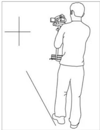
Practice Makes You Perfect - Walking the Line
Practice this simple exercise to master your Flycam Handheld stabilizer with professional results.
- Using masking or gaffers tape, create a cross mark on a flat and even wall. The mark becomes your framing center. On the floor leading up to the cross mark, lay a straight tape line of about 20 feet. Practice walking the line, while keeping the cross mark center framed and in-focus. With a bit of effort, dramatic fluid like movements will become your second nature and provide production value to all your setups.
natural_image
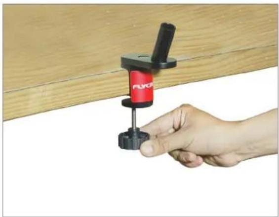
Line drawing of a person using a camera to observe a wall-mounted object (no text or symbols)NOTE: If you wish to use Table Clamp, then follow this:
- Attach Clamp onto the table, tighten provided knob to secure, then attach handle onto the Clamp. It helps achieving balance in just seconds and saves your professional time.
natural_image
Hand holding a red and black FLYO tool against a wooden wall (no text or symbols visible)
natural_image
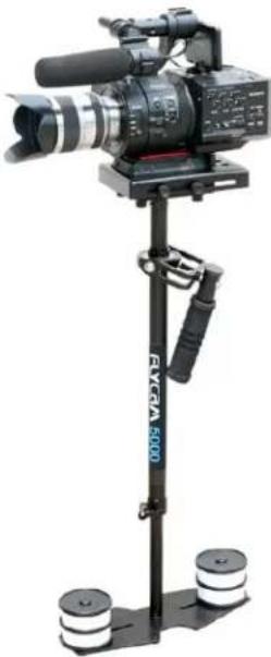
Close-up of hands using a black clamp to lift a red object, no visible text or symbolsYOUR FLYCAM 5000 HANDHELD VIDEO STABILIZER ALL DRESSED UP AND READY TO GO!
natural_image
Professional video camera setup with tripod stand and two spools (no visible text or symbols)(SHOWN WITH OPTIONAL ACCESSORIES)
WARRANTY
We offer a one year warranty for our products from the date of purchase.
We will repair or replace your product, free of charge, in the event of a defect in materials or craftsmanship obtained during normal use or handling based on the user manual. Please note that we will not cover any shipping costs for returning the product to us. If any VAT or import duties are applied to the return, we will also charge these costs to the customer.
The warranty does not include, by the way of example, damage caused by products that we do not supply or from mishandling in transit, accident, misuse, neglect, lack of care of the product, or service by anyone other than our company.
We are not liable for incidental or consequential damages resulting from the use of the unit or occurring due to any breach of this warranty.
Replacement parts of the product will be provided at nominal cost (covering the cost price of the replacement parts only) to the customers after the Warranty Period has expired. We will cover
the complete cost of sending replacement parts within the warranty period. After that, Nominal cost of the product & Actual shipping cost will be charged.
Do not send the unit to us without first getting a response and getting the approval to send back the item.
In case of any kind of dissatisfaction, we urge you to Contact us immediately and we shall do our Best to help you out. For any other assistance you can reach us via email.
For any other assistance you can reach us via email.