
SD5A445XA-HNR - Security Camera Dahua Technology - Free user manual and instructions
Find the device manual for free SD5A445XA-HNR Dahua Technology in PDF.


User questions about SD5A445XA-HNR Dahua Technology
0 question about this device. Answer the ones you know or ask your own.
Ask a new question about this device
Download the instructions for your Security Camera in PDF format for free! Find your manual SD5A445XA-HNR - Dahua Technology and take your electronic device back in hand. On this page are published all the documents necessary for the use of your device. SD5A445XA-HNR by Dahua Technology.
USER MANUAL SD5A445XA-HNR Dahua Technology
IR Intelligent Speed Dome
Installation Manual
General
This Installation Manual (hereinafter referred to as "Manual") introduces the appearance, preparation before installation, and installation of the Network PTZ Camera (hereinafter referred to as "camera").
Safety Instructions
The following categorized signal words with defined meaning might appear in the Manual.
| Signal Words | Meaning |
 NOTE NOTE | Provides additional information as the emphasis and supplement to the text. |
 CAUTION CAUTION | Indicates a potential risk which, if not avoided, could result in property damage, data loss, lower performance, or unpredictable result. |
Revision History
| Version | Revision Content | Release Time |
| V1.0.0 | First Release. | April, 2019 |
Privacy Protection Notice
As the device user or data controller, you might collect personal data of other such as face, fingerprints, car plate number, Email address, phone number, GPS and so on. You need to be in compliance with the local privacy protection laws and regulations to protect the legitimate rights and interests of other people by implementing measures include but not limited to: providing clear and visible identification to inform data subject the existence of surveillance area and providing related contact.
About the Manual
- The Manual is for reference only. If there is inconsistency between the Manual and the actual product, the actual product shall prevail.
• We are not liable for any loss caused by the operations that do not comply with the Manual. -
The Manual would be updated according to the latest laws and regulations of related regions. For detailed information, see the paper manual, CD-ROM, QR code or our official website. If there is inconsistency between paper manual and the electronic version, the electronic version shall prevail.
-
All the designs and software are subject to change without prior written notice. The product updates might cause some differences between the actual product and the Manual. Please contact the customer service for the latest program and supplementary documentation.
- There still might be deviation in technical data, functions and operations description, or errors in print. If there is any doubt or dispute, please refer to our final explanation.
- Upgrade the reader software or try other mainstream reader software if the Manual (in PDF format) cannot be opened.
- All trademarks, registered trademarks and the company names in the Manual are the properties of their respective owners.
- Please visit our website, contact the supplier or customer service if there is any problem occurred when using the device.
- If there is any uncertainty or controversy, please refer to our final explanation.
Read the Manual carefully before using the camera, comply with them when using, and keep it well for future reference.
Requirements
- Requirements for installation personnel:
◇ Have certificates related to installation and maintenance of the closed-circuit television (CCTV).
Have certificates related to working at height. ◇
◇ Have basic knowledge and operation technique for low-voltage wiring and low-voltage electronic circuit connection.
Read the Manual carefully and comprehend all the content. ◇
- Requirements for lifting appliance
Select appropriate lifting appliances. ◇
The lifting appliances can reach the installation height. ◇
The lifting appliances shall have high safety performance. ◇
- Requirements for installation
◇ All installation and operation here should conform to your local electrical safety regulations, fire protection regulations, and relevant regulations.
◇ Make sure the application scenarios of the camera conforms to the installation requirements. Contact your local retailer or customer service center if there is any problem.
- Keep the original packing material well, you may need it to pack the camera and send it back for repair.
Warning
- Do not press hard, violently vibrate, and soak the radar when transporting, storing, and installing it.
- If smoke and abnormal odor occur, you should power off the camera, and then contact us. Do not look directly at the laser light. ◇
◇ Do not disassemble or refit the camera.
- Do not put metal objects or flammable materials into the camera; otherwise fire, short-circuit, or other damage will occur.
- Power off the camera and disconnect the power supply immediately if water or liquid flows into the camera, and then contact the customer service center. Avoid the sea water or rain eroding the camera.
- Keep the camera away from devices that generate electromagnetic field like televisions, radio transmitters, electromagnetic devices, electric machine, transformers, and speakers; otherwise image quality will be influenced.
- Keep the camera away from smoke, vapor, heat, and dust.
• Install the camera at places with good condition of ventilation and cooling.
- Do not aim the lens directly at intense light like the sun, illuminators; otherwise the lens will be damaged.
Cleanning
- Use soft cloth that moistened with cleaning solution to clean the camera, and then dry the camera. Do not use gasoline, paint diluent, or other chemicals to clean the camera; otherwise deformation and paint peeling might occur.
- Read all the manuals included before you use chemical cloth. Do not let the housing of the camera be in contact with plastic or rubber materials for too long; otherwise damage to the housing or peeling paint will occur.
Table of Contents
Foreword ...... I
Important Safeguards and Warnings .... III
1 Overview.... 1
1.1 Appearance....1
1.2 Reset Button and SD Card .... 1
1.3 Cables 3
1.3.1 Cable Preparation.... 3
1.3.2 Cable Requirement.... 3
1.3.3 Cable Description .... 3
2 Installing the Speed Dome 6
2.1 Check Notes....6
2.2 Installation Modes 6
2.2.1 Installing on the Wall....6
2.2.2 Hanging from the Ceiling 8
Appendix 1 Thunder-Proof and Surge Protection....12
Appendix 2 RS-485 Cable....15
Appendix 2.1 General 15
Appendix 2.2 RS-485 Transmission Distance 15
Appendix 2.3 Frequently Occurred Problems....15
Appendix 2.4 FAQ....16
Appendix 3 Relationship between Cable Diameter (24V AC) and Transmission Distance...... 18
Appendix 4 Relationship between Cable Diameter (12V DC) and Transmission Distance...... 19
Appendix 5 Wire Gauge Reference Sheet 20
Appendix 6 Cybersecurity Recommendations....21
After unpacking the box, check if there is obvious damage to the appearance of the camera, and make sure the components are complete against the packing list.
Appearance 1.1
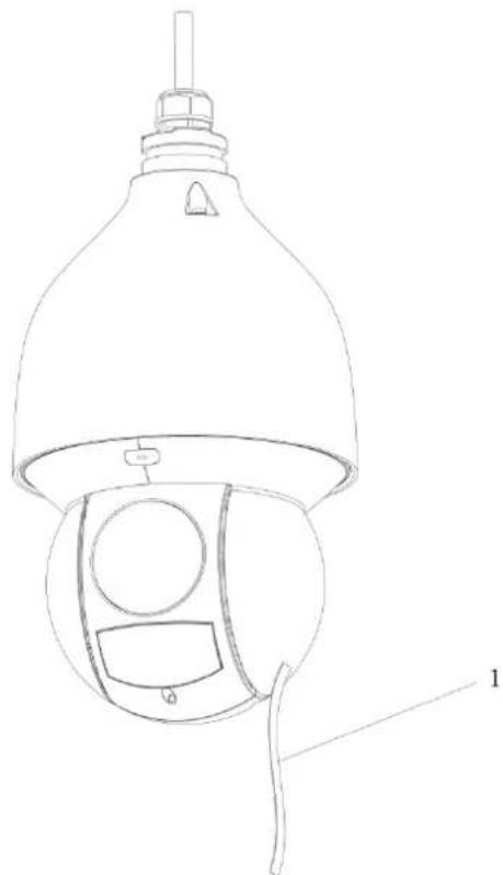
For appearance of the speed dome, see Figure 1-1.
Appearance Figure 1-1
natural_image
Technical line drawing of a security camera with labeled component (no text or symbols)Table 1-1
| Number | Name |
| 1 | Protective tape/film |
Reset Button and SD Card 1.2
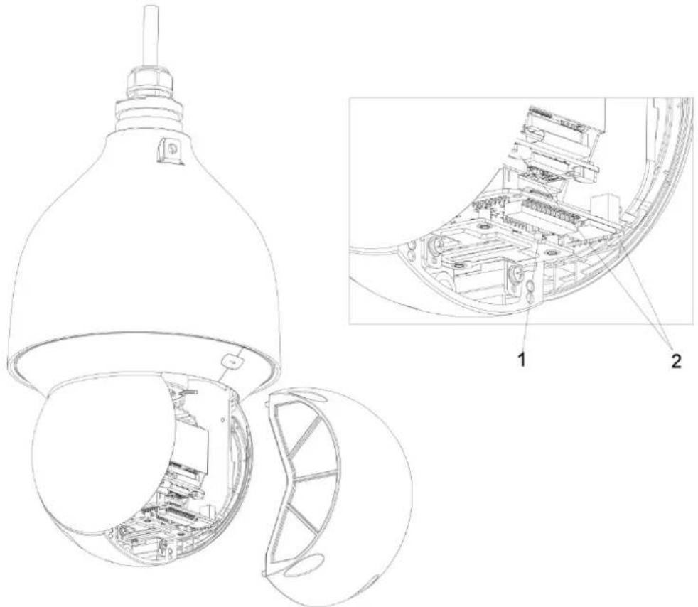
Unscrew screws at the bottom, remove the bottom cover, and then you can see the reset button and SD card. See Figure 1-2.
Reset button and SD card Figure 1-2
natural_image
Technical line drawing of a device interior with exploded and assembled views (no text or symbols)Table 1-2 Reset button and SD card
| Number | Name |
| 1 | Reset button |
| 2 | SD card (on the speed dome module or on the circuit board, the real product shall prevail) |
Reset Button
After you have opened the camera rear cover, press and hold the reset button for over 10 seconds, and the camera will be restored to the factory default settings.
SD Card
The SD card is for data storage.
Make the side with metal dots face downwards, and insert the card into the card slot.

- When removing the SD card, if you push the card inside a little, and the card will be ejected automatically.
- Make sure that the SD card is removed when the camera is not communicating or transferring information; otherwise files will be corrupted and the SD card will be damaged.
Cables 1.3
1.3.1 Cable Preparation
Select video cables depending on the transmission distance.
1.3.2 Cable Requirement
- 75 ohm.
- Pure copper cored cables.
- 95% braided copper shielding.
- For RS-485 communication cable, see "Appendix 2 RS-485 Cable".
Table 1-3 Cable model
| China Model | International Model | Maximum Transmission Distance |
| RG59/U | RG59/U | 750ft/229m |
| 5C-2V | RG6/U | 1,000ft/305m |
| 7C-2V | RG11/U | 1,500ft/457m |

Cable specifications above are only applicable to network cameras.
1.3.3 Cable Description
For 24V AC power supply devices, see “Appendix 3 Relationship between Cable Diameter (24V AC) and Transmission Distance”.
For12V DC power supply, see "Appendix 4 Relationship between Cable Diameter (12V DC) and Transmission Distance".
Cable Description
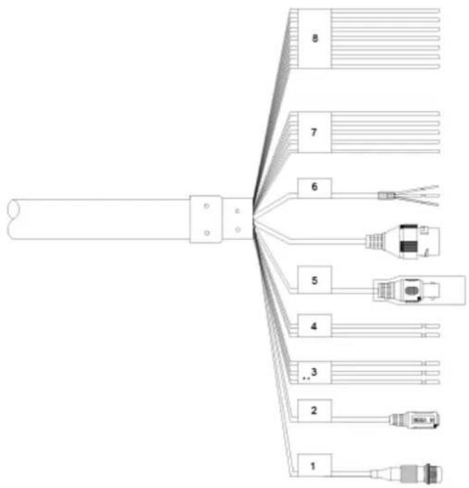
The camera is equipped with a multi-functional cable including power cord, video cable, audio cable, RS-485 control cable, alarm cable, network cable, audio cable, and optical fiber cable. For picture of the multi-functional cable, see Figure 1-3.

Camera cables can be different depending on different models, and the actual cables shall prevail.
text_image
8 7 6 5 4 3 2 1Table 1-4 Cable descriptions
| No. | Description |
| 1 | FC connector. |
| 2 | DC power input port. |
| 3 | 24V AC power input.Red: V+;Black: V-;Yellow-green: ground cable. |
| 4 | RS-485: Yellow: A+, Orange: B-. |
| 5 | Video output port. |
| 6 | Ethernet port:White: audio input;Red: audio output;Black: audio ground cable. |
| 7 | Blue: alarm output 1;Black: alarm output 2;Green: contact switch 1;Pink: contact switch 2;Yellow-green: ground cable. |
| 8 | Red: alarm input 1;Brown: alarm input 2;Grey: alarm input 3;Light green: alarm input 4;Purple: alarm input 5;White: alarm input 6;● Yellow-black: alarm input 7. |
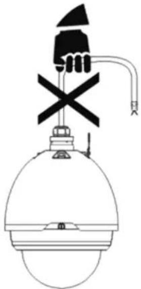
Do not carry the camera as displayed in Figure 1-4.
Wrong way of carrying the camera Figure 1-4
natural_image
Simple line drawing of a device with a handle, cross symbol, and pipe (no text or labels)Cable Connection
Connect the multi-functional cable of the bracket to the multi-functional cable (including power cord, video cable, audio cable, RS-485 control cable, alarm cable, network cable, high-frequency signal cable, and optical fiber cable) of the camera. Wrap the cable joints around with insulated rubber tape and do waterproof operations.

There are thermal contraction tube around the video output port. After the connection is finished, heat the two ends of the tube to make the video output port moistureproof and waterproof.
Alarm Cable Connection
____ Connect alarm input device to the ALARM_IN and ALARM_GND of user cable. Step 1
Connect alarm output device to the ALARM_OUT and ALARM_COM of user cable. Step 2
The alarm output is relay output.
Go to Web page of the speed dome, and then do configuration for alarm input device Step 3 and alarm output device.
Select normally on mode or normally off mode depending on alarm device signal Step 4 strength and electrical level when alarms are triggered.

Ground Cable Connection
Connect the yellow-green power cord of the multi-functional cable to the lightning protection device, and make sure the lightning protection device is connected to the ground cable.
2 Installing the Speed Dome
Check Notes 2.1
- Make sure that the place where the speed dome is installed has enough space to hold the speed dome and its mounting accessories.
- Make sure that the bracket, pole, and wall where the speed dome is installed have the capacity to bear eight times the weight of the speed and its accessories.
- Make sure the wall is thick enough to allow bolts to be installed.
- If the speed dome is laser speed dome, the installation height should be above 6 meters.
Installation Modes 2.2
Depending on the installation base, the camera can be installed in two manners: installing on the wall and hanging from the ceiling.
2.2.1 Installing on the Wall
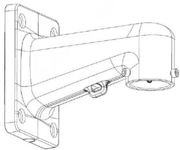
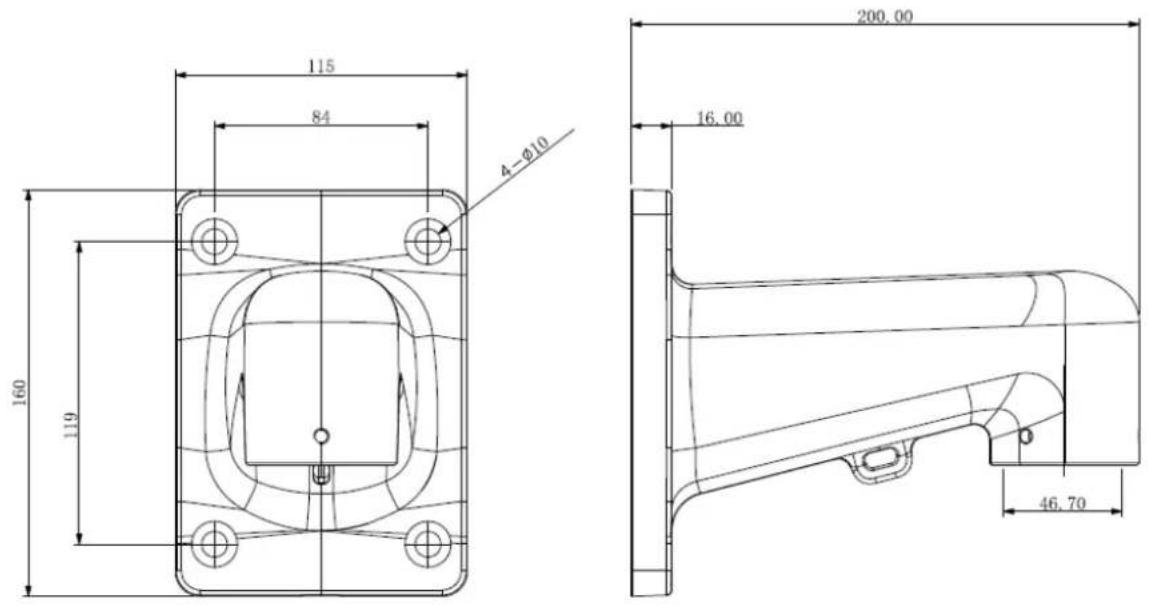
You need a bracket to install the speed dome on the wall.
Bracket appearance Figure 2-1
natural_image
Technical line drawing of a mechanical assembly with mounting flanges and a cylindrical component (no text or symbols)Bracket dimension (mm) Figure 2-2
text_image
115 84 4-Ø10 200.00 16.00 160 119 46.70____ Drill holes in the wall according to holes on the bracket base. Step 1
Hammer expansion screws into the holes you drilled. Step 2
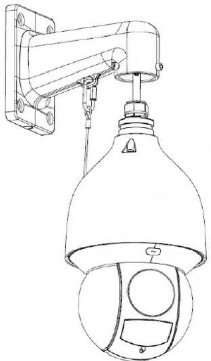
Step 3 Fix the bracket on the wall (thread multi-functional cable through the hole). See Figure 2-3.
Thread multi-functional cable through the bracket hole Figure 2-3
natural_image
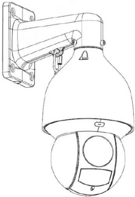
Line drawing of a security camera with mounted sensor and bell jar (no text or symbols)____ Push the speed dome upwards and tighten screws on the bracket. See Figure 2-4. Step 4
Tighten screws on the bracket Figure 2-4
natural_image
Line drawing of a security camera with mounted sensor array (no text or symbols)2.2.2 Hanging from the Ceiling
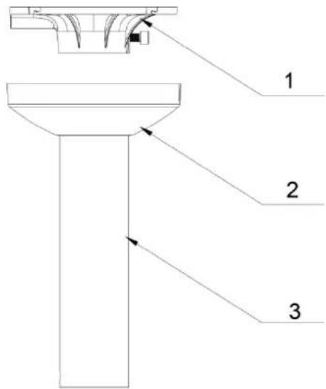
Bracket appearance Figure 2-5
text_image
1 2 3Table 2-1 Bracket description
| Number | Name |
| 1 | Plate |
| 2 | Ornamental cover |
| 3 | Pole |
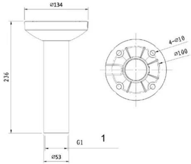
Bracket dimension (mm) Figure 2-6
text_image
Ø134 236 G1 Ø53 1 4-Ø10 Ø100Table 2-2 Bracket dimension description
| Number | Name |
| 1 | 1/2 Pipe thread |

The bracket length can be 200mm or 400mm, select bracket according to your needs.
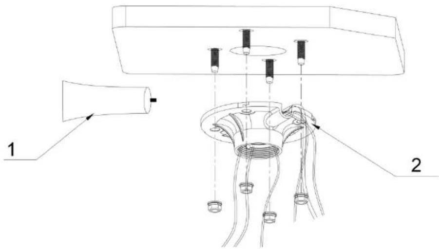
____ Detach the plate from the bracket by unscrew the four M4 screws. Step 1
____ Thread cables through the plate. See Figure 2-7. Step 2
Fix the speed dome on the bracket Figure 2-7
text_image
1 2Table 2-3 Bracket dimension description
| Number | Name |
| 1 | Silica gel |
| 2 | Plate |
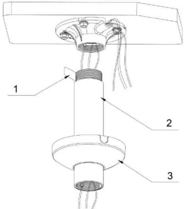
Fix the plate on the ceiling. See Figure 2-8. Step 3
Fix the plate on the ceiling Figure 2-8
text_image
1 2 3Table 2-4 Description of fixing the plate on the ceiling
| Number | Name |
| 1 | Teflon tape |
| 2 | Pole |
| 3 | Ornamental cover |

If the speed dome is installed outdoors, twine teflon tape around the upper part of the pole and then screw the pole in the plate.
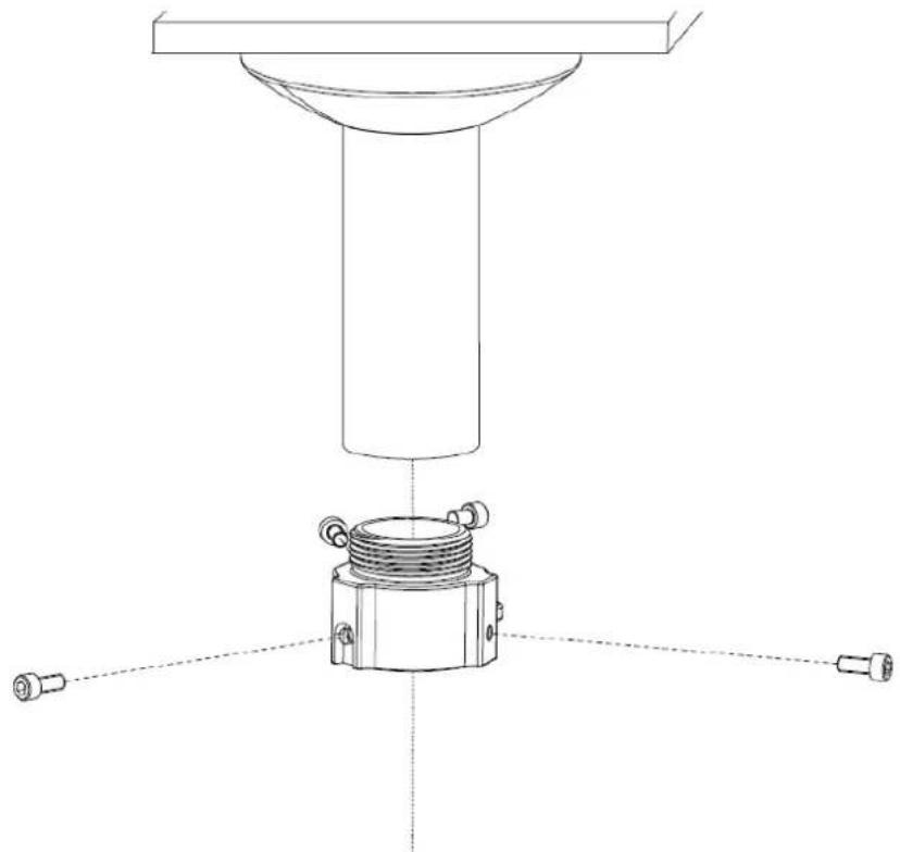
____ Push the ornamental cover upwards and fasten it on the plate by buckles on the plate. Step 4 ____ Fix the installation joint on the pole by screws. See Figure 2-9. Step 5
Fix the installation jont on the pole Figure 2-9
natural_image
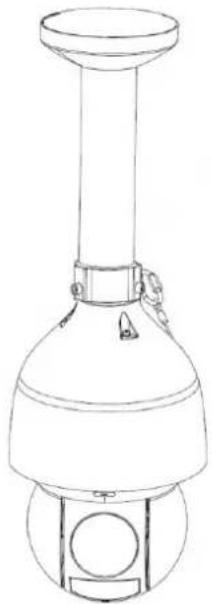
Technical line drawing of a mechanical assembly with a cylindrical component and three mounting holes (no text or symbols)____ Connect cables that come out of the pole to speed dome cables and then fix the speed Step 6 dome on the installation joint. See Figure 2-10.
Fix the speed dome on the installation joint Figure 2-10
natural_image
Line drawing of a cylindrical mechanical device with a flanged top and base, no text or symbols presentInstall Lightning Protection Devices Outdoors
Transient voltage suppressor (TVS) is applied to protect devices against voltage spikes and overvoltage below 6000V. However, it is still necessary to take safeguard measures when installing the camera outdoors according to your local electrical safety regulations.
- The distance between the signal transmission cable and high-voltage device (or high-voltage cable) shall be at least 50 meters.
- When laying cables outdoors, try to lay them under the eaves.
- At open places, lay cables underground by hermetic steel tube, and then do equipotential grounding to both ends of steel tubes. Laying overhead power cables is prohibited.
- At places with severe thunderstorms and induced voltage (like substation), high-powered lightning protection devices and lightning conductors are required.
- When laying cables and connecting lightning protection devices, you must comply with regional laws and regulations.
- The grounding devices must have strong anti-interference ability and must comply with electrical safety standards. Make sure that cable connections are correct; otherwise short circuit and accidents may occur. When the electrical system is connected to the ground cable, the impedance shall not exceed 4 , and the cross-sectional area of the ground cable shall not exceed 25mm^2 .
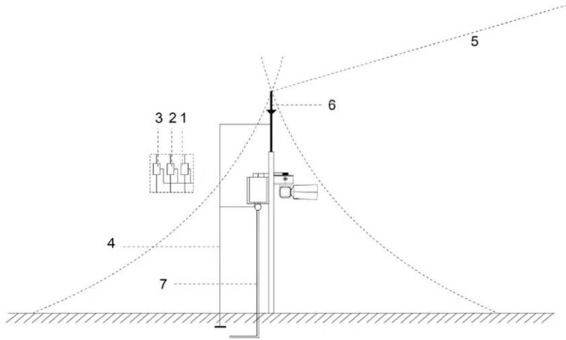
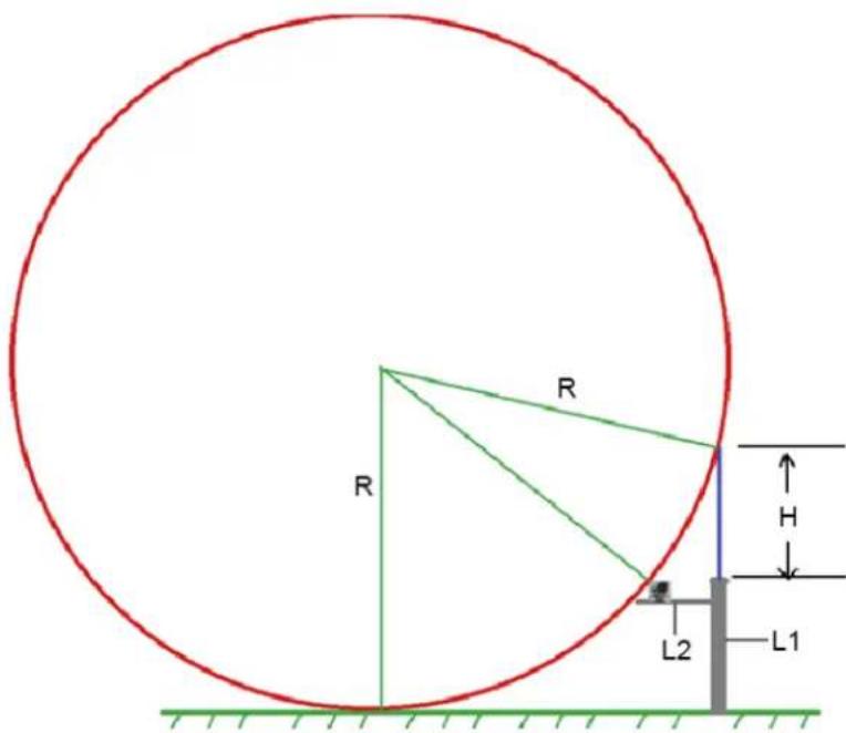
For the installation of camera lightning protection devices outdoors, see Appendix figure 1-1 and Appendix figure 1-1.
Appendix figure 1-1 Install camera lightning protection devices outdoors(1)
text_image
3 2 1 4 7 6 5Appendix table 1-1 Install PTZ lightning protection devices
| No. | Description |
| 1 | Video lightning conductor. |
| 2 | Communication lightning conductor. |
| 3 | Power supply lighting conductor. |
| 4 | Impedance of the cable connected to the ground wire should be less than 4Ω. |
| 5 | The radius is 60 m. |
| 6 | Lightning conductor. |
| 7 | Steel tube. |
Appendix figure 1-2 Install PTZ lightning protection devices (2)
text_image
R R R H L2 L1
• R: The radius of the circle, and R=60 m;
• L1: The length of the pole that holds the lightning conductor;
• L2: The length of the rail that holds the camera;
• H: The length of the lightning conductor.
To get the value of L1, you need to use the formula:
$$ \left(\sqrt {R ^ {2} - \left[ R - (L 1 + H) \right] ^ {2}} - L 2\right) ^ {2} + (R - L 1) ^ {2} = R ^ {2} $$
Install Lightning Protection Devices Indoors
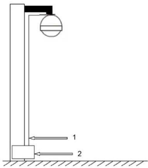
You shall use multiple copper cables whose cross-sectional area are not less than 25mm^2 to connect the yellow-green ground cable/ground screws to the indoor equipotential earthing terminals. See Appendix figure 1-3.
Appendix figure 1-3 Lightning devices indoors
text_image
Technical diagram showing a vertical structure with two labeled components and directional arrows indicating movement or force.Table 2-5
| No. | Name |
| 1 | Yellow-green ground cable |
| 2 | Indoor equipotential earthing terminal |
Appendix 2.1 General
RS-485 industrial buses are half-duplex communication buses whose characteristic impedance is 120 . Its maximum load is 32 payloads (including drivers and receivers).
Appendix 2.2 RS-485 Transmission Distance
When using 0.56 mm (24AWG) twisted pair, different baud rates correspond to different maximum theoretical transmission distances. See Appendix table 2-1.
Appendix table 2-1 Theoretical maximum transmission distance
| Baud rate | Maximum transmission distance |
| 2400 bps | 1800 m |
| 4800 bps | 1200 m |
| 9600 bps | 800 m |
The maximum transmission distance might be reduced in the following conditions; otherwise, maximum transmission distance will be increased.
- When thinner communication cables are used;
- The Camera is used in places with intense electromagnetic interference;
- Too many devices are connected to the RS-485 cable.
Appendix 2.3 Frequently Occurred Problems
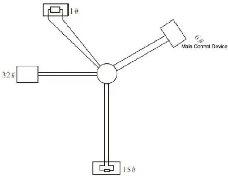
Customers tend to connect devices as the way displayed in Appendix figure 2-1. In this condition, the terminal resistance must be connected to the two devices whose cable length is the largest among all the devices (in Appendix figure 2-1, cable length between 1# and 15# is the largest). However, this connection manner dose not comply with the RS-485 industrial bus standard. As a result, problems like signal reflection and anti-interference capability reduction might occur. Due to the above mentioned problems, the Camera can be out of control.
Appendix figure 2-1 The common manner of connecting devices
flowchart
graph TD
    A["Main Control Device"] --> B["1#"]
    A --> C["32#"]
    A --> D["6#"]
    A --> E["15#"]
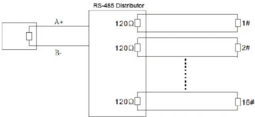
To solve the problems, we recommend that you use RS-485 distributors. The RS-485 distributor can avoid the common manner of connection so as to improve transmission quality. See Appendix figure 2-2.
Appendix figure 2-2 RS-485 distributor applied
text_image
RS-485 Distributor A+ 120Ω 1# B- 120Ω 2# 120Ω 16#Appendix 2.4 FAQ
| Problem | Possible reason | Solution |
| The camera can do self-check but can not be controlled. | Baud rate and IP address of the host and camera are not properly configured. | Modify the baud rate and IP address of the host or camera to make them are properly configured. |
| Positive electrode and negative electrode of RS-485 cable are misconnected. | Connect cables to the positive electrode and negative electrode correctly. | |
| Loose connection | Connect the cables firmly. | |
| RS-485 cable is broken. | Replace the broken RS-485 cable with a new one. | |
| You can control the | RS-485 cable is in poor contact. | Connect the RS-485 cable firmly. |
| camera but it is not smooth. | One of the RS-485 cables is broken. | Replace the broken RS-485 cable with a new one. |
| The distance between the host and camera is too long. | Install terminal resistance. | |
| Too many cameras are connected in parallel. | Install RS-485 distributors. |
The recommended transmission distances are for reference only, and the actual conditions shall prevail.
For cameras powered by alternating current, the maximum voltage lose rate allowed is 10%. For example, when a device of 20 W rated power is installed 141 inches (42m) away from the transformer, the minimum diameter needed is 0.8000 mm.
| Transmission power (W) | Diameter (mm) | |||
| 0.8000 | 1.000 | 1.250 | 2.000 | |
| Transmission distance Feet (m) | ||||
| 5 | 488.52 (148.90) | 763.31 (232.66) | 1192.67 (363.53) | 3053.25 (930.63) |
| 10 | 244.26 (74.45) | 381.66 (116.33) | 596.34 (181.76) | 1526.62 (465.31) |
| 15 | 162.84 (49.63) | 254.44 (77.55) | 397.56 (121.18) | 1017.75 (310.21) |
| 20 | 122.13 (37.23) | 190.83 (58.16) | 298.17 (90.88) | 763.31 (232.66) |
| 25 | 97.70 (29.78) | 152.66 (46.53) | 238.53 (72.71) | 610.65 (186.13) |
| 30 | 81.42 (24.82) | 127.22 (38.78) | 198.78 (60.59) | 508.87 (155.10) |
| 35 | 69.79 (21.27) | 109.04 (33.24) | 170.38 (51.93) | 436.18 (132.95) |
| 40 | 61.06 (18.61) | 95.41 (29.08) | 149.08 (45.44) | 381.66 (116.33) |
| 45 | 54.28 (16.54) | 84.81 (25.85) | 132.52 (40.39) | 339.25 (103.40) |
| 50 | 48.85 (14.89) | 76.33 (23.27) | 119.27 (36.35) | 305.32 (93.06) |
| 55 | 44.41 (13.54) | 69.39 (21.15) | 108.42 (33.05) | 277.57 (84.60) |
| 60 | 40.71 (12.41) | 63.61 (19.39) | 99.39 (30.29) | 254.44 (77.55) |
| 65 | 37.58 (11.45) | 58.72 (17.90) | 91.74 (27.96) | 234.87 (71.59) |
| 70 | 34.89 (10.64) | 54.52 (16.62) | 85.19 (25.97) | 218.09 (66.47) |
| 75 | 32.57 (9.93) | 50.89 (15.51) | 79.51 (24.24) | 203.55 (62.04) |
| 80 | 30.53 (9.31) | 47.71 (14.54) | 74.54 (22.72) | 190.83 (58.16) |
| 85 | 28.74 (8.76) | 44.90 (13.69) | 70.16 (21.38) | 179.60 (54.74) |
| 90 | 27.14 (8.27) | 42.41 (12.93) | 66.26 (20.20) | 169.62 (51.70) |
| 95 | 25.71 (7.84) | 40.17 (12.25) | 62.77 (19.13) | 160.70 (48.98) |
| 100 | 24.43 (7.45) | 38.17 (11.63) | 59.63 (18.18) | 152.66 (46.53) |
- The recommended transmission distances are for reference only, and the actual conditions shall prevail.
- The chart below gives the maximum transmission distance of cables with certain diameters when the 12V DC power source voltage lose rate is bellow 10%.
- For cameras powered by direct current, the maximum voltage loss rate allowed is 10%.
- Cables mentioned in the table below are copper cables (the resistivity of copper = 0.0175 * mm^2/m )
| Transmission power (W) | Cable diameter (mm) | |||
| 0.8000 | 1.000 | 1.250 | 2.000 | |
| Transmission distance Feet (m) | ||||
| 5 | 122.13 (37.23) | 190.83 (58.16) | 298.17 (90.88) | 763.31 (232.66) |
| 10 | 61.06 (18.61) | 95.41 (29.08) | 149.08 (45.44) | 381.66 (116.33) |
| 15 | 40.71 (12.41) | 63.61 (19.39) | 99.39 (30.29) | 254.44 (77.55) |
| 20 | 30.53 (9.31) | 47.71 (14.54) | 74.54 (22.72) | 190.83 (58.16) |
| 25 | 24.43 (7.45) | 38.17 (11.63) | 59.63 (18.18) | 152.66 (46.53) |
| 30 | 20.35 (6.20) | 31.80 (9.69) | 49.69 (15.15) | 127.22 (38.78) |
| 35 | 17.45 (5.32) | 27.26 (8.31) | 42.60 (12.98) | 109.04 (33.24) |
| 40 | 15.27 (4.65) | 23.85 (7.27) | 37.27 (11.36) | 95.41 (29.08) |
| 45 | 13.57 (4.14) | 21.20 (6.46) | 33.13 (10.10) | 84.81 (28.85) |
| 50 | 12.21 (3.72) | 19.08 (5.82) | 29.82 (9.09) | 76.33 (23.27) |
| 55 | 11.10 (3.38) | 17.35 (5.29) | 27.11 (8.26) | 69.39 (21.15) |
| 60 | 10.18 (3.10) | 15.90 (4.85) | 24.85 (7.57) | 63.61 (19.39) |
| 65 | 9.39 (2.86) | 14.68 (4.47) | 22.94 (6.99) | 58.72 (17.90) |
| 70 | 8.72 (2.66) | 13.63 (4.15) | 21.30 (6.49) | 54.52 (16.62) |
| 75 | 8.14 (2.48) | 12.72 (3.88) | 19.88 (6.06) | 50.89 (15.51) |
| 80 | 7.63 (2.33) | 11.93 (3.64) | 18.64 (5.68) | 47.71 (14.54) |
| 85 | 7.18 (2.19) | 11.23 (3.42) | 17.54 (5.35) | 44.90 (13.69) |
| 90 | 6.78 (2.07) | 10.60 (3.23) | 16.56 (5.05) | 42.41 (12.93) |
| 95 | 6.43 (1.96) | 10.04 (3.06) | 15.69 (4.78) | 40.17 (12.25) |
| 100 | 6.11 (1.86) | 9.54 (2.91) | 14.91 (4.54) | 38.17 (11.63) |
| Metric bare wire diameter (mm) | AWG | SWG | Bare wire cross section area (mm2) |
| 0.050 | 43 | 47 | 0.00196 |
| 0.060 | 42 | 46 | 0.00283 |
| 0.070 | 41 | 45 | 0.00385 |
| 0.080 | 40 | 44 | 0.00503 |
| 0.090 | 39 | 43 | 0.00636 |
| 0.100 | 38 | 42 | 0.00785 |
| 0.110 | 37 | 41 | 0.00950 |
| 0.130 | 36 | 39 | 0.01327 |
| 0.140 | 35 | / | 0.01539 |
| 0.160 | 34 | 37 | 0.02011 |
| 0.180 | 33 | / | 0.02545 |
| 0.200 | 32 | 35 | 0.03142 |
| 0.230 | 31 | / | 0.04115 |
| 0.250 | 30 | 33 | 0.04909 |
| 0.290 | 29 | 31 | 0.06605 |
| 0.330 | 28 | 30 | 0.08553 |
| 0.350 | 27 | 29 | 0.09621 |
| 0.400 | 26 | 28 | 0.1257 |
| 0.450 | 25 | / | 0.1602 |
| 0.560 | 24 | 24 | 0.2463 |
| 0.600 | 23 | 23 | 0.2827 |
| 0.710 | 22 | 22 | 0.3958 |
| 0.750 | 21 | / | 0.4417 |
| 0.800 | 20 | 21 | 0.5027 |
| 0.900 | 19 | 20 | 0.6362 |
| 1.000 | 18 | 19 | 0.7854 |
| 1.250 | 16 | 18 | 1.2266 |
| 1.500 | 15 | / | 1.7663 |
| 2.000 | 12 | 14 | 3.1420 |
| 2.500 | / | / | 4.9080 |
| 3.000 | / | / | 7.0683 |
Mandatory actions to be taken towards cybersecurity
1. Change Passwords and Use Strong Passwords:
The number one reason systems get “hacked” is due to having weak or default passwords. It is recommended to change default passwords immediately and choose a strong password whenever possible. A strong password should be made up of at least 8 characters and a combination of special characters, numbers, and upper and lower case letters.
2. Update Firmware
As is standard procedure in the tech-industry, we recommend keeping NVR, DVR, and IP camera firmware up-to-date to ensure the system is current with the latest security patches and fixes.
"Nice to have" recommendations to improve your network security
1. Change Passwords Regularly
Regularly change the credentials to your devices to help ensure that only authorized users are able to access the system.
2. Change Default HTTP and TCP Ports:
- Change default HTTP and TCP ports for systems. These are the two ports used to communicate and to view video feeds remotely.
- These ports can be changed to any set of numbers between 1025-65535. Avoiding the default ports reduces the risk of outsiders being able to guess which ports you are using.
3. Enable HTTPS/SSL:
Set up an SSL Certificate to enable HTTPS. This will encrypt all communication between your devices and recorder.
4. Enable IP Filter:
Enabling your IP filter will prevent everyone, except those with specified IP addresses, from accessing the system.
5. Change ONVIF Password:
On older IP Camera firmware, the ONVIF password does not change when you change the system's credentials. You will need to either update the camera's firmware to the latest revision or manually change the ONVIF password.
6. Forward Only Ports You Need:
- Only forward the HTTP and TCP ports that you need to use. Do not forward a huge range of numbers to the device. Do not DMZ the device's IP address.
- You do not need to forward any ports for individual cameras if they are all connected to a recorder on site; just the NVR is needed.
7. Disable Auto-Login on SmartPSS:
Those using SmartPSS to view their system and on a computer that is used by multiple people should disable auto-login. This adds a layer of security to prevent users without the appropriate credentials from accessing the system.
8. Use a Different Username and Password for SmartPSS:
In the event that your social media, bank, email, etc. account is compromised, you would not want someone collecting those passwords and trying them out on your video surveillance system. Using a different username and password for your security system will make it more difficult for someone to guess their way into your system.
9. Limit Features of Guest Accounts:
If your system is set up for multiple users, ensure that each user only has rights to features and functions they need to use to perform their job.
10. UPnP:
- UPnP will automatically try to forward ports in your router or modem. Normally this would be a good thing. However, if your system automatically forwards the ports and you leave the credentials defaulted, you may end up with unwanted visitors.
- If you manually forwarded the HTTP and TCP ports in your router/modem, this feature should be turned off regardless. Disabling UPnP is recommended when the function is not used in real applications.
11. SNMP:
Disable SNMP if you are not using it. If you are using SNMP, you should do so only temporarily, for tracing and testing purposes only.
12. Multicast:
Multicast is used to share video streams between two recorders. Currently there are no known issues involving Multicast, but if you are not using this feature, deactivation can enhance your network security.
13. Check the Log:
If you suspect that someone has gained unauthorized access to your system, you can check the system log. The system log will show you which IP addresses were used to login to your system and what was accessed.
14. Physically Lock Down the Device:
Ideally, you want to prevent any unauthorized physical access to your system. The best way to achieve this is to install the recorder in a lockbox, locking server rack, or in a room that is behind a lock and key.
15. Connect IP Cameras to the PoE Ports on the Back of an NVR:
Cameras connected to the PoE ports on the back of an NVR are isolated from the outside world and cannot be accessed directly.
16. Isolate NVR and IP Camera Network
The network your NVR and IP camera resides on should not be the same network as your public computer network. This will prevent any visitors or unwanted guests from getting access to the same network the security system needs in order to function properly.