
IPC-HDW3541T-ZAS - Security Camera Dahua Technology - Free user manual and instructions
Find the device manual for free IPC-HDW3541T-ZAS Dahua Technology in PDF.


| Product Type | Security Camera (Dome) |
| Brand | Dahua Technology |
| Model | IPC-HDW3541T-ZAS |
| Resolution | 5 Megapixels (2592 x 1944) |
| Lens | Motorized varifocal, 2.7mm~13.5mm |
| Day/Night | ICR, True Day/Night |
| Minimum Illumination | 0.005 Lux (Color), 0 Lux (IR) |
| IR Range | Up to 40m (Smart IR) |
| Video Compression | H.265+/H.265/H.264+/H.264 |
| Max Frame Rate | 25fps@5MP (PAL), 30fps@5MP (NTSC) |
| Power Supply | 12V DC / PoE (802.3af) |
| Power Consumption | < 12W |
| Dimensions | φ122mm × 105mm |
| Weight | Approx. 0.5 kg |
| Operating Temperature | -30°C to +60°C |
| Ingress Protection | IP67 |
| Storage | Micro SD slot (max 256GB) |
| Intelligent Features | Motion detection, IVS (tripwire, intrusion), face detection, people counting, ANPR |
| Audio | Built-in microphone; 1 input, 1 output |
| Alarm | 1 input, 1 output |
| Network Protocols | TCP/IP, HTTP, DHCP, DNS, DDNS, SMTP, etc. |
| Maintenance | Regular cleaning with soft cloth; avoid solvents; upgrade firmware via web interface |
| Safety | Strong password recommended; enable HTTPS; disable unnecessary services |
| Spare Parts / Repairability | Contact authorized service; power adapter, lens, IR board available |
Frequently Asked Questions - IPC-HDW3541T-ZAS Dahua Technology
User questions about IPC-HDW3541T-ZAS Dahua Technology
0 question about this device. Answer the ones you know or ask your own.
Ask a new question about this device
Download the instructions for your Security Camera in PDF format for free! Find your manual IPC-HDW3541T-ZAS - Dahua Technology and take your electronic device back in hand. On this page are published all the documents necessary for the use of your device. IPC-HDW3541T-ZAS by Dahua Technology.
USER MANUAL IPC-HDW3541T-ZAS Dahua Technology
Network Camera Web 3.0
Operation Manual

natural_image
Abstract geometric composition with gray and red color blocks (no text or symbols)Foreword
General
This manual introduces the functions, configuration, general operation, and system maintenance of network camera.
Safety Instructions
The following categorized signal words with defined meaning might appear in the manual.
| Signal Words | Meaning |
 WARNING WARNING | Indicates a medium or low potential hazard which, if not avoided, could result in slight or moderate injury. |
 CAUTION CAUTION | Indicates a potential risk which, if not avoided, may result in property damage, data loss, lower performance, or unpredictable result. |
 TIPS TIPS | Provides methods to help you solve a problem or save you time. |
 NOTE NOTE | Provides additional information as the emphasis and supplement to the text. |
Revision History
| Version | Revision Content | Release Date |
| V2.0.2 | 1. Modified the contents of "5.15 Setting ANPR."2. Added modeling in "5.11 Face Detection." | December 2019 |
| V2.0.1 | Added "5.5 Setting Smart Motion Detection." | August 2019 |
| V2.0.0 | 1. Consolidated the outline, and added baseline and safety contents, and some intelligent functions such as face recognition and ANPR.2. Deleted some old function such as stereo vision. | July 2019 |
| V1.0.4 | 1. Updated the chapters of "People Counting" and "Heat Map" function.2. Add VR mode of Fisheye device.3. Add video structuralization function. | March 2019 |
| V1.0.3 | Added Stereo Analysis function. | November 2018 |
| V1.0.2 | 1. Added chapters of "Initialization" and "Stereo vision."2. Updated the chapters of "Account", "Profile Management" and "SNMP." | October 2017 |
| V1.0.1 | First release. | September 2016 |
About the Manual
- The manual is for reference only. If there is inconsistency between the manual and the actual product, the actual product shall prevail.
• We are not liable for any loss caused by the operations that do not comply with the manual.
- The manual would be updated according to the latest laws and regulations of related regions. For detailed information, see the paper manual, CD-ROM, QR code or our official website. If there is inconsistency between paper manual and the electronic version, the electronic version shall prevail.
- All the designs and software are subject to change without prior written notice. The product updates might cause some differences between the actual product and the manual. Please contact the customer service for the latest program and supplementary documentation.
- There still might be deviation in technical data, functions and operations description, or errors in print. If there is any doubt or dispute, please refer to our final explanation.
- Upgrade the reader software or try other mainstream reader software if the manual (in PDF format) cannot be opened.
- All trademarks, registered trademarks and the company names in the manual are the properties of their respective owners.
- Please visit our website, contact the supplier or customer service if there is any problem occurred when using the device.
- If there is any uncertainty or controversy, please refer to our final explanation.
Important Safeguards and Warnings
Electrical Safety
All installation and operation shall conform to your local electrical safety codes.
The power source shall conform to the Safety Extra Low Voltage (SELV) standard, and supply power with rated voltage which conforms to Limited power Source requirement according to IEC60950-1. Note that the power supply requirement is subject to the device label.
Make sure that the power supply is correct before operating the device.
A readily accessible disconnecting device shall be incorporated in the building installation wiring.
Prevent the power cable from being trampled or pressed, especially the plug, power socket and the junction extruded from the device.
Environment
Do not aim the device at strong light to focus, such as lamp light and sun light; otherwise it might cause over brightness or light marks, which are not the device malfunction, and affect the longevity of Complementary Metal-Oxide Semiconductor (CMOS).
Do not place the device in a damp, dusty extremely hot or cold environment, or the locations with strong electromagnetic radiation or unstable lighting.
Keep the device away from any liquid to avoid damage to the internal components.
Keep the indoor device away from rain or damp to avoid fire or lightning.
Keep sound ventilation to avoid heat accumulation.
Transport, use and store the device within the range of allowed humidity and temperature.
Heavy stress, violent vibration or water splash are not allowed during transportation, storage and installation.
Pack the device with standard factory packaging or the equivalent material when transporting the device.
Install the device in the location where only the professional staff with relevant knowledge of safety guards and warnings can access. The accidental injury might happen to the non-professionals who enter the installation area when the device is operating normally.
Operation and Daily Maintenance
Do not touch the heat dissipation component of the device to avoid scald.
Carefully follow the instructions in the manual when performing any disassembly operation about the device; otherwise, it might cause water leakage or poor image quality due to unprofessional disassembly. Please contact after-sale service for desiccant replacement if there is condensed fog on the lens after unpacking or when the desiccant turns green. (Not all models are included with the desiccant).
It is recommended to use the device together with lightning arrester to improve lightning protection effect.
- It is recommended to ground the device to enhance reliability.
- Do not touch the image sensor (CMOS) directly. Dust and dirt could be removed with air blower, or you can wipe the lens gently with soft cloth that is moistened with alcohol.
- You can clean the device body with soft dry cloth, and for stubborn stains, use the cloth with mild detergent. To avoid possible damage on device body coating which could cause performance decrease, do not use volatile solvent such as alcohol, benzene, diluent and so on to clean the device body, nor can strong, abrasive detergent be used.
- Dome cover is an optical component. Do not touch or wipe the cover with your hands directly during installation or operation. For removing dust, grease or fingerprints, wipe gently with moistened oil-free cotton with diethyl or moisten soft cloth. You can also remove dust with an air blower.

WARNING
- Strengthen the protection of network, device data and personal information by adopting measures which include but not limited to using strong password, modifying password regularly, upgrading firmware to the latest version, and isolating computer network. For some device with old firmware versions, the ONVIF password will not be modified automatically along with the modification of the system password, and you need to upgrade the firmware or manually update the ONVIF password.
- Use standard components or accessories provided by manufacturer and make sure that the device is installed and maintained by professional engineers.
- The surface of the image sensor should not be exposed to laser beam radiation in an environment where a laser beam device is used.
- Do not provide two or more power supply sources for the device unless otherwise specified. A failure to follow this instruction might cause damage to the device.
Table of Contents
Foreword .... I
Important Safeguards and Warnings .... III
1 Overview....1
1.1 Introduction ...... 1
1.2 Network Connection....1
1.3 Function .... 1
1.3.1 Basic Function .... 1
1.3.2 Intelligent Function....2
2 Configuration Flow....5
3 Device Initialization....6
4 Basic Configuration 9
4.1 Login....9
4.2 Live....10
4.2.1 Live Interface 10
4.2.2 Encode bar 11
4.2.3 Live View Function Bar....11
4.2.4 Window Adjustment Bar 13
4.3 PTZ Operation....20
4.3.1 Configuring External PTZ Protocol....20
4.3.2 Configuring PTZ Function.... 21
4.3.3 Calling PTZ 32
4.4 Playback....35
4.4.1 Playback Interface 35
4.4.2 Playing back Video or Picture....38
4.4.3 Clipping Video 40
4.4.4 Downloading Video or Picture 41
4.5 Camera....42
4.5.1 Conditions 42
4.5.2 Setting Video Parameters.... 55
4.5.3 Audio 70
4.6 Network 72
4.6.1 TCP/IP 73
4.6.2 Port 75
4.6.3 PPPoE 76
4.6.4 DDNS....77
4.6.5 SMTP (Email)....78
4.6.6 UPnP 80
4.6.7 SNMP 81
4.6.8 Bonjour....83
4.6.9 Multicast....84
4.6.10 802.1x 85
4.6.11 QoS 85
4.6.12 Access Platform 86
4.7 Storage....88
4.7.1 Setting Storage Plan....88
4.7.2 Setting Schedule....89
4.7.3 Setting Destination....90
4.8 System 93
4.8.1 General 93
4.8.2 Date & Time 94
4.8.3 Splicing 95
4.8.4 Account 96
4.8.5 Safety....102
4.8.6 Peripheral....109
5 Event.... 113
5.1 Setting Alarm Linkage....113
5.1.1 Alarm Linkage....113
5.1.2 Subscribing Alarm.... 120
5.2 Setting Smart Track 122
5.2.1 Setting Calibration Parameters for Smart Track.... 122
5.2.2 Enabling Alarm Track....123
5.3 Setting Panoramic Calibration 124
5.4 Setting Video Detection 126
5.4.1 Setting Motion Detection 126
5.4.2 Setting Video Tamper 128
5.4.3 Setting Scene Changing....129
5.5 Setting Smart Motion Detection 129
5.6 Setting Audio Detection.... 130
5.7 Setting Smart Plan....132
5.8 Setting IVS 132
5.8.1 Global Configuration.... 133
5.8.2 Rule Configuration 135
5.9 Setting Crowd Map 139
5.9.1 Global Configuration.... 139
5.9.2 Rule Configuration 140
5.10 Setting Face Recognition.... 143
5.10.1 Setting Face Detection 143
5.10.2 Setting Face Database 145
5.10.3 Setting Face Recognition Alarm Linkage 155
5.10.4 Viewing Face Recognition Result.... 155
5.11 Setting Face Detection.... 158
5.12 Setting People Counting 160
5.12.1 People Counting 160
5.12.2 Queuing 164
5.12.3 Viewing People Counting Diagram.... 166
5.12.4 Viewing People Counting Report....168
5.13 Setting Heat Map 169
5.13.1 Heat Map 169
5.13.2 Viewing Heat Map Report.... 170
5.14 Setting Stereo Analysis.... 171
5.14.1 Setting Rules for Stereo Analysis.... 171
5.14.2 Calibration Configuration.... 174
5.15 Setting ANPR 175
5.15.1 Scene Configuration 175
5.15.2 Setting Picture Overlay 176
5.15.3 Viewing ANPR Report.... 177
5.16 Setting Video Structuralization.... 178
5.16.1 Scene Configuration 178
5.16.2 Setting Picture Information 181
5.16.3 Viewing Video Structuralization Report 182
5.17 Setting Relay-in.... 182
5.18 Setting Abnormality 183
5.18.1 Setting SD Card....183
5.18.2 Setting Network 184
5.18.3 Setting Illegal Access.... 185
5.18.4 Setting Voltage Detection 185
5.18.5 Setting Security Exception.... 186
6 Maintenance....187
6.1 Requirements.... 187
6.2 Auto Maintain 187
6.3 Resetting Password....188
6.4 Backup and Default....190
6.4.1 Import/Export 190
6.4.2 Default....191
6.5 Upgrade 191
6.6 Information 192
6.6.1 Version....192
6.6.2 Log....192
6.6.3 Remote Log 194
6.6.4 Online User 194
Appendix 1 Cybersecurity Recommendations .... 196
1 Overview
Introduction 1.1
IP camera (Internet Protocol camera), is a type of digital video camera that receives control data and sends image data through internet. They are commonly used for surveillance, requiring no local recording device, but only a local area network.
IP camera is divided into single-channel camera and multi-channel camera according to the channel quantity. For multi-channel camera, you can set the parameters for each channel.
Network Connection 1.2
In the general IPC network topology, IPC is connected to PC through network switch or router. See Figure 1-1.
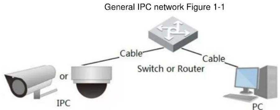
flowchart
graph TD
    A["Security Camera"] -->|or| B["Switch or Router"]
    B -->|Cable| C["Switch or Router"]
    B -->|Cable| D["PC"]
Get IP address by searching on ConfigTool, and then you can start accessing IPC through network.
Function 1.3
Functions might vary with different devices, and the actual product shall prevail.
1.3.1 Basic Function
Real-time Monitoring
- Live view.
- When live viewing the image, you can enable audio, voice talk and connect monitoring center for quick processing on the abnormality.
- Adjust the image to the proper position by PTZ.
- Snapshot and triple snapshot abnormality of the monitoring image for subsequent view and processing.
- Record abnormality of monitoring image for subsequent view and processing.
- Configure coding parameters, and adjust live view image.
Record
• Auto record as schedule.
- Play back recorded video and picture as needed..
- Download recorded video and picture.
- Alarm linked recording.
Account
- Add, modify and delete user group, and manage user authorities according to user group.
- Add, modify and delete user, and configure user authorities.
- Modify user password.
1.3.2 Intelligent Function
Alarm
- Set alarm prompt mode and tone according to alarm type.
• View alarm prompt message.
Smart Track
- Set calibration and parameters for smart track and enable alarm track.
- Switch between smart track and speed dome auto track.
Video Detection
• Motion detection, video tampering detection and scene changing detection.
- When an alarm is triggered, the system performs linkages such as recording, alarm output, sending email, PTZ operation, and snapshot.
Smart Motion Detection
- Avoid the alarms triggered by the environment changes.
- When an alarm is triggered, the system performs linkages such as recording, alarm output, sending email, PTZ operation, and snapshot.
Audio Detection
- Audio input abnormal detection and intensity change detection.
- When an alarm is triggered, the system performs linkages such as recording, alarm output, sending email, PTZ operation, and snapshot.
IVS
- Tripwire, intrusion, abandoned object, moving object, fast moving, parking detection, people gathering, and loitering detection.
- When an alarm is triggered, the system performs linkages such as recording, alarm output, sending email, PTZ operation, and snapshot.
Crowd Map
• View crowd distribution in real time for the timely arm to avoid accidents like stampede.
- When an alarm is triggered, the system performs linkages such as recording, alarm output, sending email, PTZ operation, and snapshot.
Face Detection
- Detect face and display the related attributes on the live interface.
- When an alarm is triggered, the system performs linkages such as recording, alarm output, sending email, PTZ operation, and snapshot.
Face Recognition
- After detecting face, make comparison between the detected face with the face in face database, and activates alarm output.
- Query the recognition result.
People Counting
• Count the people flow in/out the detection area, and generate report.
- When an alarm is triggered, the system performs linkages such as recording, alarm output, sending email, PTZ operation, and snapshot.
Heat Map
• Count cumulative density of moving objects.
• View report of heat map.
Stereo Analysis
- Include fall detection, violence detection, people No. error, people approaching detection, and stay detection.
- When an alarm is triggered, the system performs linkages such as recording, alarm output, sending email, PTZ operation, and snapshot.
ANPR
- Recognize plate number in detection area, and display the related information on live interface.
- When an alarm is triggered, the system links alarm output and snapshot.
Video Structuralization
- Snap people, non-motor vehicle and vehicle, and display the related information on the live interface.
- When an alarm is triggered, the system links alarm output.
Alarm Setting
- The alarm is triggered when an external alarm input device inputs alarm.
- When an alarm is triggered, the system performs linkages such as recording, alarm output, sending email, PTZ operation, and snapshot.
Abnormality
- SD card error, network disconnection, illegal access, voltage detection and security exception.
- When SD card error or illegal access is triggered, the system links alarm output and sending email.
- When network disconnection alarm is triggered, the system links recording and alarm output.
- When the input voltage is more or less than the rated voltage, the alarm is triggered and the system links sending email.
2 Configuration Flow
For the device configuration flow, see Figure 2-1. For details, see Table 2-1. Configure the device according to the actual situation.
Configuration flow Figure 2-1
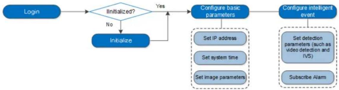
flowchart
graph TD
    A["Login"] --> B{Initialized?}
    B -->|No| C["Initialize"]
    B -->|Yes| D["Configure basic parameters"]
    D --> E["Set IP address"]
    D --> F["Set system time"]
    D --> G["Set image parameters"]
    E --> H["Set detection parameters (such as video detection and IVS)"]
    F --> H
    G --> I["Subscribe Alarm"]
    D --> J["Configure intelligent event"]

Main task

Sub Task

Judging Task
Table 2-1 Description of flow
| Configuration | Description | Reference | |
| Login | Open IE browser and enter IP address to log in to the web interface, The camera IP address is 192.168.1.108 by default. | 4.1 Login | |
| Initialization | Initialize the camera when you use it for the first time. | 3 Device Initialization | |
| Basic parameters | IP address | Modify IP address according to network planning for the first use or during network adjustment. | 4.6.1 TCP/IP |
| Date & time | Set date and time to ensure the recording time is correct. | 4.8.2 Date & Time | |
| Image parameters | Adjust image parameters according to the actual situation to ensure the image quality. | 4.5.1 Conditions | |
| Intelligent Event | Detection rules | Configure the necessary detection rules, such as video detection and IVS. | 5 Event |
| Subscribe alarm | Subscribe alarm event. When the subscribed alarm is triggered, the system will record the alarm on the alarm tab. | 5.1.2 Subscribing Alarm | |
3 Device Initialization
Device initialization is required for the first use. This manual is based on the operation on the web interface. You can also initialize device through ConfigTool, NVR, or platform devices.

- To ensure the device safety, keep the password properly after initialization and change the password regularly.
- When initializing device, keep the PC IP and device IP in the same network.
____ Open IE browser, enter the IP address of the device in the address bar, and then press Step 1 Enter.
The Device Initialization interface is displayed. See Figure 3-1.

The IP is 192.168.1.108 by default.
Device initialization Figure 3-1
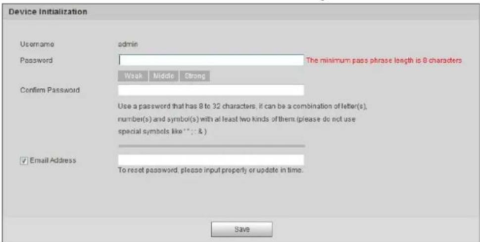
text_image
Device Initialization Username admin Password The minimum pass phrase length is 8 characters Weak Middle Strong Confirm Password Use a password that has 8 to 32 characters, if can be a combination of letter(s), number(s) and symbol(s) with at least two kinds of them (please do not use special symbols like **: & ) ✓ Email Address To reset password, please input properly or update in time. SaveSet the password for admin account. For details, see Table 3-1. Step 2
Table 3-1 Description of password configuration
| Parameter | Description |
| User name | The default user name is admin. |
| Password | The password must consist of 8 to 32 non-blank characters and contain at least two types of characters among upper case, lower case, number, and special character (excluding ' " ; : &). Set a high security level password according to the password security notice. |
| Confirm password | |
| Enter an email address for password reset, and it is selected by default.When you need to reset the password of the admin account, a security code for password resetting will be sent to the reserved email address. |
Click Save. Step 3
The End-User License Agreement interface is displayed. See Figure 3-2.
End-user license agreement Figure 3-2
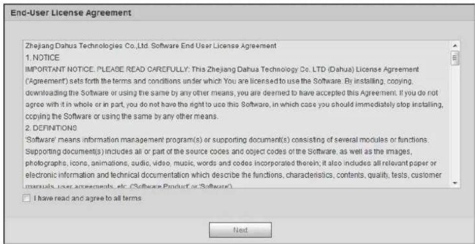
text_image
End-User License Agreement Zhejiang Dahua Technologies Co.,Ltd. Software End User License Agreement 1. NOTICE IMPORTANT NOTICE. PLEASE READ CAREFULLY: This Zhejiang Dahua Technology Co. LTD (Dahua) License Agreement ('Agreement') sets forth the terms and conditions under which You are licensed to use the Software. By installing, copying, downloading the Software or using the same by any other means, you are deemed to have accepted this Agreement. If you do not agree with it in whole or in part, you do not have the right to use this Software, in which case you should immediately stop installing, copying the Software or using the same by any other means. 2. DEFINITIONS 'Software' means information management program(s) or supporting document(s) consisting of several modules or functions. Supporting document(s) includes all or part of the source codes and object codes of the Software, as well as the images, photographs, icons, animations, audio, video, music, words and codes incorporated therein; it also includes all relevant paper or electronic information and technical documentation which describe the functions, characteristics, contents, quality, tests, customer manuals, user agreements, etc. ('Software Product' or 'Software') I have read and agree to all terms NextStep 4 Select the I have read and agree to all terms check box, and then click Next. The Easy4ip interface is displayed. See Figure 3-3.
Easy4ip Figure 3-3

text_image
Easy4ip ✓ Easy4ip Register device to EASY4IP and then suitable for user to apply for cloud account. It can realize cloud service such as remote surveillance, device record, alarm, cloud storage, using device to manage cloud. Please scan the QR code on the actual interface. Scan and Download EASY4IP APP NextStep 5 You can register the camera to Easy4ip, select the check box as needed, and then click Next.
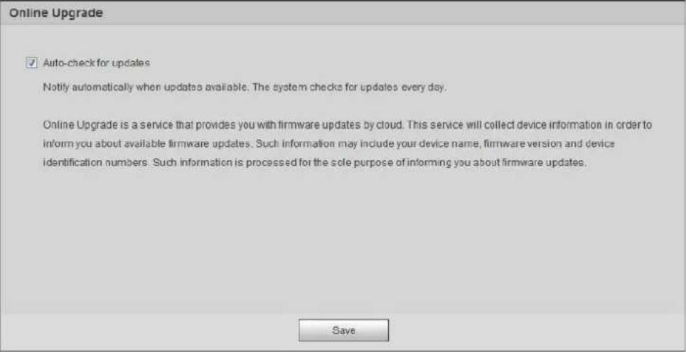
The Online Upgrade interface is displayed. See Figure 3-4.
Online upgrade Figure 3-4
text_image
Online Upgrade ✓ Auto-check for updates Notify automatically when updates available. The system checks for updates every day. Online Upgrade is a service that provides you with firmware updates by cloud. This service will collect device information in order to inform you about available firmware updates. Such information may include your device name, firmware version and device identification numbers. Such information is processed for the sole purpose of informing you about firmware updates. SaveSelect the upgrading method as needed. Step 6 If you select Auto-check for updates, the system checks new version once a day automatically. There will be system notice on Upgrade interface and Version interface if any new version is available. Select Setting > System > Upgrade > Online Upgrade, and you can enable the auto-check function. Click Save. Step 7 Device initialization is completed.
4 Basic Configuration
The chapter introduces the basic configuration, including login, live view, PTZ operation, playback operation, camera configuration, network configuration, storage configuration and system configuration.
Login 4.1
This section introduces how to log in to and log out of the web interface. This section takes IE Explorer 9 as an example.

- You need to initialize the camera before logging in to the web interface. For details, see "3 Device Initialization."
- When initializing the camera, keep the PC IP and device IP in the same network.
- Follow the instruction to download and install the plug-in for the first login.
____ Open IE browser, enter the IP address of the camera (192.168.1.108 by default) in the Step 1 address bar and press Enter.
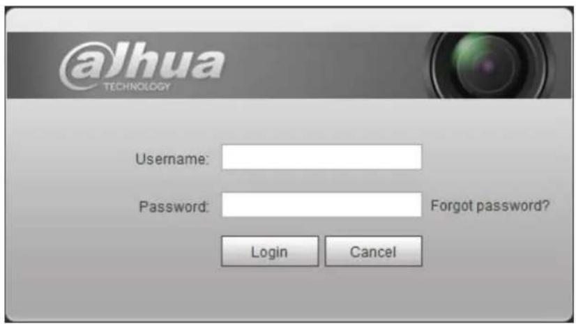
The login interface is displayed. See Figure 4-1.
Login Figure 4-1
text_image
@Jhua TECHNOLOGY Username: Password: Forgot password? Login CancelEnter the username and password. Step 2
The username is admin by default.

Click Forget password?, and you can reset the password through the email address that is set during the initialization. For details, see "6.3 Resetting Password."
Click Login. Step 3
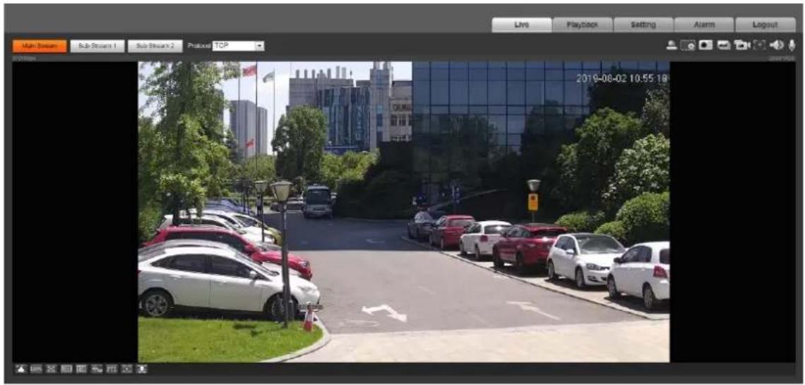
The Live interface is displayed, see Figure 4-2.
• Live: Click Live, and you can view the real-time monitoring image.
- Playback: Click Playback, and you can play back or download recorded video or image files.
- Setting: Click Setting, and you can configure the basic and intelligent functions of the camera.
For the camera with multiple channels, through selecting channel numbers, you can set the parameters of the channels.
• Alarm: Click Alarm, and you can subscribe and view alarm information.
- Logout: Click Logout to go to login interface.
The system will sleep automatically after idling for a period of time.
Live Figure 4-2
text_image
Multi-Stream Sub-Stream 1 Sub-Stream 2 Protocol TCP Live Playback Setting Alarm Logout 2019-08-02 10:55 18Live 4.2
This section introduces the layout of the interface and function configuration.
4.2.1 Live Interface
This section introduces system menu, encode bar, live view function bar, and window adjustment bar.
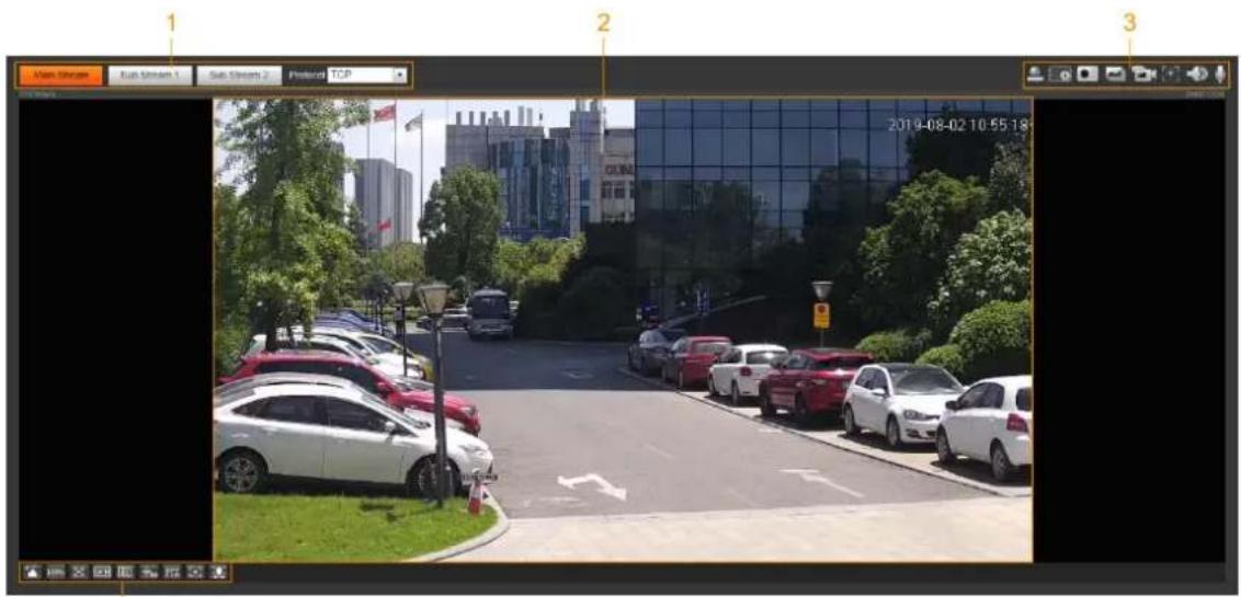
Log in and click the Live tab, and the Live interface is displayed. See Figure 4-3. For the layout details, see Table 4-1.

The functions and interfaces of different models might vary, and the actual product shall prevail.
Live Figure 4-3
text_image
Main Street Rush Stream 1 Sub Stream 2 Federal TCP 2019-08-02 10:55:18Table 4-1 Description of function bar
| No. | Function | Description |
| 1 | Encode bar | Sets stream type and protocol. |
| 2 | Live view | Displays the real-time monitoring image. |
| 3 | Live view function bar | Functions and operations in live viewing. |
| 4 | Window adjustment bar | Adjustment operations in live viewing. |
4.2.2 Encode bar
For encode bar, see Figure 4-4.
Encode bar Figure 4-4

text_image
Main Stream Sub Stream 1 Sub Stream 2 Protocol TCP- Main Stream: It has large bit stream value and image with high resolution, but also requires large bandwidth. This option can be used for storage and monitoring. For details, see "4.5.2.1 Video."
- Sub Stream: It has small bit stream value and smooth image, and requires less bandwidth. This option is normally used to replace main stream when bandwidth is not enough. For details, see "4.5.2.1 Video."
- Protocol: You can select the network transmission protocol as needed, and the options are TCP, UDP and Multicast.

Before selecting Multicast, make sure that you have set the Multicast parameters.
4.2.3 Live View Function Bar
For the live view function bar, see Table 4-2.
Table 4-2 Description of live view function bar
| Icon | Function | Description |
 | Manual Position | Manually position the tracking speed dome to the selected location of corresponding panoramic camera.Click the icon and click or select randomly on the image of panoramic camera channel, the tracking speed dome will automatically position the selected location. For multi-sensor panoramic network camera + PTZ camera, before enabling manual position, make sure that you have enabled alarm track and smart track calibration. For details, see "5.2 Setting Smart Track."For panoramic network camera, before enabling manual position, make sure that you have enabled panoramic linkage. For details, see "5.3 Setting Panoramic Calibration." For multi-sensor panoramic network camera + PTZ camera, before enabling manual position, make sure that you have enabled alarm track and smart track calibration. For details, see "5.2 Setting Smart Track."For panoramic network camera, before enabling manual position, make sure that you have enabled panoramic linkage. For details, see "5.3 Setting Panoramic Calibration." |
 | Regional Focus | Select channel image of the tracking speed dome, click the icon and click or select randomly on the channel image of the tracking speed dome, and then the speed dome can realize auto focus upon the selected region. |
 | Wiper | Controls the wiper of the camera.Click the icon to enable or disable wiper function. |
 | Ranging | Click the icon, select a point on the ground, and the distance between the camera and the selected point will be displayed. Before using this function, you need to set the installation of device first. For details, see "4.5.2.3.11Configuring Ranging." Before using this function, you need to set the installation of device first. For details, see "4.5.2.3.11Configuring Ranging." |
 | Gesture | Controls PTZ by operating the mouse on the live view of tracking speed dome.Select the live view of tracking speed dome, click the icon, press left-button and drag image to control PTZ. And you can zoom the image through rolling mouse wheel. |
 | Manual Track | Click the icon, and select tracking target on the live view of tracking speed dome, the camera tracks the selected target automatically. |
 | Relay-out | Displays alarm output state. Click the icon to force to enable or disable alarm output.Alarm output state description:Red: Alarm output enabled.Grey: Alarm output disabled. |
 | Digital Zoom | You can zoom video image through two operations.Click the icon, and then select an area in the videoimage to zoom in; right-click on the image to resume the original size. In zoom in state, drag the image to check other area.Click the icon, and then scroll the mouse wheel in the video image to zoom in or out. |
 | Snapshot | Click the icon to capture one picture of the current image, and it will be saved to the configured storage path. About viewing or configuring storage path, see "4.5.2.5 Path." About viewing or configuring storage path, see "4.5.2.5 Path." |
 | Triple Snapshot | Click the icon to capture three pictures of the current image, and they will be saved to the configured storage path. About viewing or configuring storage path, see "4.5.2.5 Path." About viewing or configuring storage path, see "4.5.2.5 Path." |
 | Record | Click the icon to record video, and it will be saved to the configured storage path. About viewing or configuring storage path, see "4.5.2.5 Path." About viewing or configuring storage path, see "4.5.2.5 Path." |
 | Easy Focus | Click the icon, the AF Peak (focus eigenvalue) and AF Max (max focus eigenvalue) are displayed on the video image.AF Peak: The eigenvalue of image definition, it displays during focus.AF Max: The best eigenvalue of image definition.The smaller the difference between AF peak value and the AF max value, the better the focus is. Easy focus closes automatically after five minutes. Easy focus closes automatically after five minutes. |
 | Audio | Click the icon to enable or disable audio output. |
 | Talk | Click the icon to enable or disable the audio take. |
4.2.4 Window Adjustment Bar
4.2.4.1 Adjustment
This section introduces the adjustment of image. For details, see Table 4-3.
Table 4-3 Description of adjustment bar
| Icon | Function | Description |
 | Image Adjustment | Click the icon, and then the Image Adjustment interface is displayed at the right side of the Live interface. You can adjust brightness, contrast, hue, and saturation.The adjustment is only available on the web interface, and it does not adjust the camera parameters.(KTTY)htness adjustment): Adjusts the overall image brightness, and changes the value when the image is too bright or too dark. The bright and dark areas will have equal changes.[DSHW](Contrast adjustment): Changes the value when the image brightness is proper but contrast is not enough. adjustment): Makes the color deeper or lighter. The default value is made by the light sensor, and it is recommended. adjustment): Makes the color deeper or lighter. The default value is made by the light sensor, and it is recommended. (Iration adjustment): Adjusts the image saturation, this value does not change image brightness. (Iration adjustment): Adjusts the image saturation, this value does not change image brightness. |
| 100% | Original Size | Click the icon, and then the video displays with original size. |
| Full Screen | Click the icon to enter full screen mode; double-click or press Esc to exit. | |
| W:H | Click the icon to resume original ratio or change ratio. | |
| Fluency | Click the icon to select the fluency from Realtime, Fluency and Normal.Realtime:Guarantees the real time of the image. When the bandwidth is not enough, the image might not be smooth.Fluency:Guarantees the fluency of the image. There might be delay between live view image and real-time image.Normal:It is between Realtime and Fluency. | |
 | Rule InfoPTZ | Click the icon, and then select Enable to display smart rules and detection box; select Disable to stop the display. It is enabled by default.Click the icon, and the PTZ control panel is displayed at the right side of the Live interface. You can control and call PTZ function. For details, see "4.3.3 Calling PTZ." |
 | Zoom and Focus | Adjust focal length to zoom in and out video image.Click the icon, and the Zoom and Focus configuration interface is displayed at the right side of the Live interface. You can control and call PTZ function. For details, see "4.2.4.2 Zoom and Focus." |
 | Fisheye | Click the icon, and then the fisheye configuration interface is displayed at the right side of the Live interface. For details, see "4.2.4.3 Fisheye." |
 | Face | Click the icon, and the face detection or face recognition results are displayed on the Live interface.For face recognition, see "5.10 Setting Face Recognition."For face detection: see "5.11 Setting Face Detection." |
 | ANPR | Click the icon, and the ANPR results are displayed on the Live interface. For details, see "5.15 Setting ANPR." |
 | Video Structuralization | Click the icon, the video structuralization results are displayed on the Live interface. For details, see "5.16 Setting Video Structuralization." |
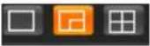 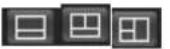 | Window Layout | When view multi-channel image, you can select display layout. |
 | Crowd Map | Click the icon and select the Enable check box. The Crowd Map interface is dispalyed. For details, see "5.9 Setting Crowd Map." |
4.2.4.2 Zoom and Focus
You can adjust focal length to zoom in or out video image; by adjusting focus manually, automatically or within a certain area, you can change image clarity or correct adjusting errors.

The focus would adjust automatically after zooming in or out.
Zoom and focus Figure 4-5

text_image
Zoom and Focus Zoom Speed 20 - Zoom out Zoom in Focus Speed 20 - Near Far Auto Focus Restore All Refresh Regional FocusTable 4-4 Description of zoom and focus
| Parameter | Description |
| Zoom | Changes the focal length of the camera to zoom in or out the image.1. Set theSpeedvalue. TheSpeedis the adjustment range in one click.The larger the value is, the more the image would zoom in or out in one click.2. Click or hold +/– button, or drag the slider to adjust zoom. |
| Focus | Adjusts the optical back focal length to make the image clearer.1. Set theSpeedvalue. TheSpeedis the adjustment range in one click.The larger the value is, the more the image would zoom in or out in one click.2. Click or hold+/– button, or drag the slider to adjust zoom. |
| Auto Focus | Adjusts image clarity automatically. Do not make any other operation during auto focus process. Do not make any other operation during auto focus process. |
| Restore All | Restores focus to default value and corrects errors. You can restore the focus if the image has poor clarity or has been zoomed too frequently. You can restore the focus if the image has poor clarity or has been zoomed too frequently. |
| Regional Focus | Focus on the subject of a selected area.ClickRegional Focus, and then select an area in the image, the camera performs auto focus in that area. |
| Refresh | Get the latest zoom setting of the device. |
4.2.4.3 Fisheye
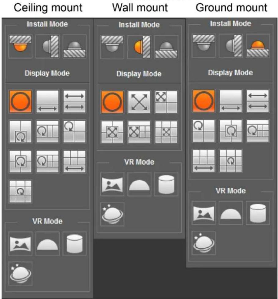
You can select the installation mode, display mode and VR mode of fisheye devices as needed. For details, see Table 4-5.
• Install Mode: Select the installation mode according to the actual situation.
• Display Mode: Select the display mode of live view.
• VR Mode: Select VR mode to display images in stereo mode.
Fisheye Figure 4-6
text_image
Ceiling mount Wall mount Ground mount Install Mode Install Mode Install Mode Display Mode Display Mode Display Mode VR Mode VR ModeTable 4-5 Description of fisheye configuration
| Parameter | Description |
| Installation mode | Includes ceiling mount, wall mount, and ground mount. |
| Display mode | The display model of the current image. There are different display modes for each installation mode.Ceiling: 1P+1, 2P, 1+2, 1+3, 1+4, 1P+6, 1+8.Wall: 1P, 1P+3, 1P+4, 1P+8.Ground: 1P+1, 2P, 1+3, 1+4, 1P+6, 1+8.The image will be on original size by default when switching installation mode. |
| Parameter | Description | |
| Ceiling/Wall/Ground mount |  Original image Original image | The original image before correction. |
| Ceiling/Ground mount | [BT55]1P+1 | 360° rectangular panoramic image screen + independent sub-screens.You can zoom or drag the image in all the screens.You can move the start point (left and right) on rectangular panoramic image screen. |
 2P 2P | Two associated 180° rectangular image screens, and at any time, the two screens form a 360° panoramic image. It is also called dual-panoramic image.You can move the start point (left and right) on the two rectangular panoramic image screens, and the two screens link each other. | |
 1+2 1+2 | Original image screen + two independent sub-screens. Ground Mount does not support this display mode.You can zoom or drag the image in all the screens.You can rotate the image on the original image screen to change the start point. | |
 1+3 1+3 | Original image screen + three independent sub-screens.You can zoom or drag the image in all the screens.You can rotate the image on the original image screen to change the start point. | |
 1+4 1+4 | Original image screen + four independent sub-screens.You can zoom or drag the image in all the screens.You can rotate the image on the original image screen to change the start point. | |
 1P+6 1P+6 | 360° rectangular panoramic screen + six independent sub-screens.You can zoom or drag the image in all the screens.You can move the start point (left and right) on rectangular panoramic image screen. | |
 1P+8 1P+8 | Original image screen + eight independent sub-screens.You can zoom or drag the image in all the screens.You can rotate the image on the original image screen to change the start point. | |
| Wall mount |  1P 1P | 180° rectangular panoramic image screen (from left to right).You can drag the image in all the screens (up and down) to adjust the vertical view. |
 1P+3 1P+3 | 180° rectangular panoramic image screen + three independent sub-screens.You can zoom or drag the image in all the screens.You can drag the image in all the screens (upper and lower) to adjust the vertical view. | |
 1P+4 1P+4 | 180° rectangular panoramic image screen + four independent sub-screens.You can zoom or drag the image in all the screens.You can drag the image in all the screens (upper and lower) to adjust the vertical view. | |
 1P+8 1P+8 | 180° rectangular panoramic image screen + eight independent sub-screens.You can zoom or drag the image in all the screens.You can drag the image in all the screens (upper and lower) to adjust the vertical view. | |
| VR mode |  Panorama Panorama | Drag or cross the screen 360° to unfold the distortion panorama, and you can drag the image in left/right direction. |
 Semi-circle Semi-circle | You can drag the image in upper/lower/left/right direction. Press I to display the panorama, and press O to resume the original size.Press S to rotate the image in anticlockwise direction, and press E to stop the rotation.Scroll the mouse wheel to zoom the image. | |
| [ywgx] Cylinder | Display the distortion panorama in 360° circularity.You can drag the image in upper/lower/left/right direction. Press I to display the panorama, and press O to return to the original size.Press S to rotate the image in anticlockwise direction, and press E to stop the rotation.Scroll the mouse wheel to zoom the image. | |
| [x256] Asteroid | You can drag the image in upper/lower/left/right direction. Press I to display the panorama, and press O to return to the original size.Press the left mouse-button to slide down to display the image on the plane surface.Scroll the mouse wheel to zoom the image. | |
PTZ Operation 4.3
This section introduces PTZ parameter configuration, PTZ control and PTZ function configuration.
4.3.1 Configuring External PTZ Protocol
You need to configure PTZ protocol when accessing external PTZ; otherwise the camera cannot control external PTZ.
Preparation
- Access external PTZ through RS-485.
- You have configured the parameters of serial port. For details, see "4.8.6.1 Serial Port Settings."
Procedure
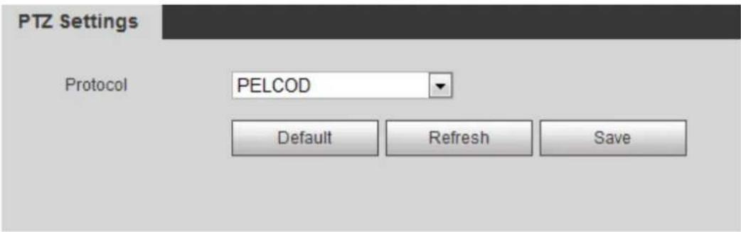
Select Setting > PTZ Setting > Protocol. Step 1
The PTZ Setting interface is displayed. See Figure 4-7.
PTZ setting Figure 4-7
text_image
PTZ Settings Protocol PELCOD Default Refresh SaveSelect the PTZ protocol. Step 2
Click OK. Step 3
4.3.2 Configuring PTZ Function
4.3.2.1 Preset
Preset means a certain position that the camera can make quick orientation to. It includes PTZ pan and tilt angles, camera focus, and location.
Select Setting > PTZ settings > Function > Preset. Step 1
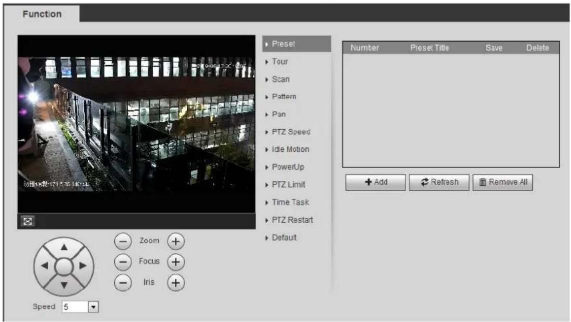
The Preset interface is displayed. See Figure 4-8.
Preset Figure 4-8
text_image
Function Presel Tour Scan Pattern Pan PTZ Speed Idle Motion PowerUp PTZ Limit Time Task PTZ Restart Default Number Preset Title Save Delete + Add Refresh Remove All Zoom + Focus + Iris + Speed 5Step 2 Set the speed, and click , - and + to adjust the parameters of direction, zoom, focus and iris, to move the camera to the position you need.
Step 3 Click Add to add the current position to be a preset, and the preset is displayed in preset list.
Double-click the preset title to edit it. Step 4
Step 5 Click to save the preset.
Other Operations
- Click - to delete the preset.
- Click Remove All to remove all presets.
4.3.2.2 Tour
Tour means a series of movements that the camera makes along several presets.
Preparation
You have set several presets.
Procedure
Select Setting > PTZ settings > Function > Tour. Step 1
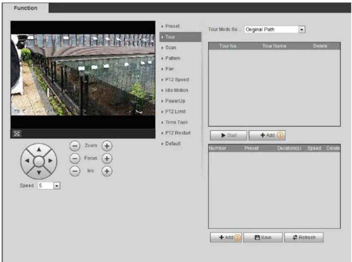
The Tour interface is displayed. See Figure 4-9.
Tour Figure 4-9
text_image
Function ▶ Preset ▶ Tour ▶ Scan ▶ Pattern ▶ Pan ▶ PTZ Speed ▶ Idle Motion ▶ PowerUp ▶ PTZ Limit ▶ Time Task ▶ PTZ Restart ▶ Default Tour Mode Se... Original Path Tour No. Tour Name Delete ▶ Start + Add ? Number Preset Duration(s) Speed Delete + Add Save Refresh Zoom + Focus + Iris + Speed 5Click Add ① to add tour. Step 2
Double-click the tour name to edit the name.
Click Add ② to add preset. Step 3
Double-click the duration to set the duration.
Select the tour mode. Step 4
- Original path: The PTZ camera moves in the order of the selected presets.
- Shortest path: The PTZ camera ranks presets by distance, and moves in the optimal path.
Click Save. Step 5
Click Start to start touring. Step 6

- If you operate PTZ during tour, the camera will stop tour.
- Click Stop to stop touring.
4.3.2.3 Scan
Scan means the camera moves horizontally at a certain speed between the configured left and right limits.
Select Setting > PTZ settings > Function > Scan. Step 1
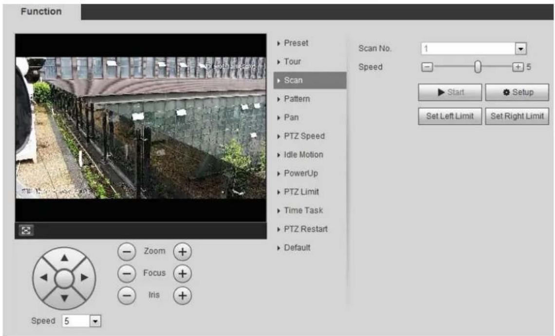
The Scan interface is displayed. See Figure 4-10.
Scan Figure 4-10
text_image
Function ▶ Preset ▶ Tour ▶ Scan ▶ Pattern ▶ Pan ▶ PTZ Speed ▶ Idle Motion ▶ PowerUp ▶ PTZ Limit ▶ Time Task ▶ PTZ Restart ▶ Default Scan No. 1 Speed 5 ▶ Start ▼ Setup Set Left Limit Set Right Limit Zoom + Focus + Iris + Speed 5Select the scan number, and set the speed. Step 2
Click Setup to set left limit and right limit. Step 3
1) Click Set Left Limit to set the current position to be the left limit.
2) Click Set Right Limit to set the current position to be the right limit.
Click Start to start scanning. Step 4
Click Stop to stop scanning.
4.3.2.4 Pattern
Pattern means a recording of a series of operations that you make to the camera, and when pattern starts, the camera performs the operations repeatedly. The operations include horizontal and vertical movements, zoom and preset calling. Record and save the operations, and then you can call the pattern path directly.
Select Setting > PTZ settings > Function > Pattern. Step 1
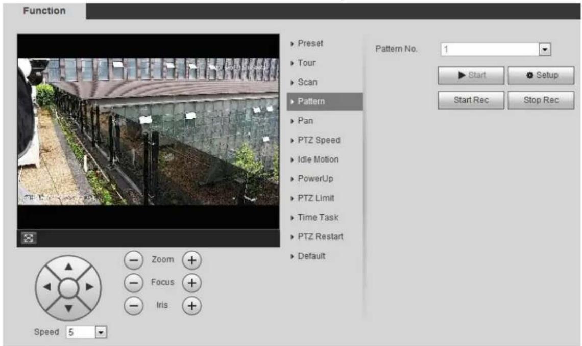
The Pattern interface is displayed. See Figure 4-11.
Pattern Figure 4-11
text_image
Function ▶ Preset ▶ Tour ▶ Scan ▶ Pattern ▶ Pan ▶ PTZ Speed ▶ Idle Motion ▶ PowerUp ▶ PTZ Limit ▶ Time Task ▶ PTZ Restart ▶ Default Pattern No. 1 ▶ Start Setup Start Rec Stop Rec Zoom + Focus + Iris + Speed 5Select the pattern number. Step 2
Step 3 Click Setup, and then click Start Rec. Adjust the parameters of direction, zoom, focus and iris according to the actual situation.
Step 4 Click Stop Rec to stop recording.
Click Start to start patterning. Step 5
Click Stop to start patterning.
4.3.2.5 Pan
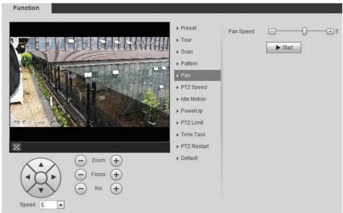
Enable Pan, the camera can realize continuous 360^ horizontal rotation at a certain speed.
Step 1 Select Setting > PTZ settings > Function > Pan.
The Pan interface is displayed. See Figure 4-12.
Pan Figure 4-12
text_image
Function ► Preset ► Tour ► Scan ► Pattern ► Pan ► PTZ Speed ► Idle Motion ► PowerUp ► PTZ Limit ► Time Task ► PTZ Restart ► Default Pan Speed - 0 + 5 ► Start Zoom + Focus + Iris + Speed 5Step 2 Set the pan speed and click Start, and the camera starts horizontal rotation. Click Stop to stop rotation.
4.3.2.6 PTZ Speed
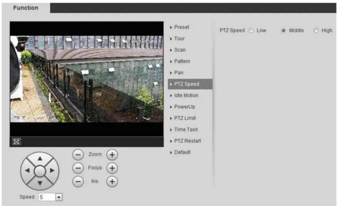
PTZ speed means the rotation speed of the PTZ camera during touring, pattern, or auto tracking.
Step 1 Select Setting > PTZ settings > Function > PTZ Speed. The PTZ Speed interface is displayed. See Figure 4-13.
PTZ speed Figure 4-13
text_image
Function ► Preset ► Tour ► Scan ► Pattern ► Pan ► PTZ Speed ► Idle Motion ► PowerUp ► PTZ Limit ► Time Task ► PTZ Restart ► Default PTZ Speed ○ Low ● Middle ○ High Zoom + Focus + Iris + Speed 5Step 2 Select the PTZ speed: Low, Middle, and High.

Speed under the direction buttons refers to the rotation angle of the PTZ camera for each press of the direction button.
4.3.2.7 Idle Motion
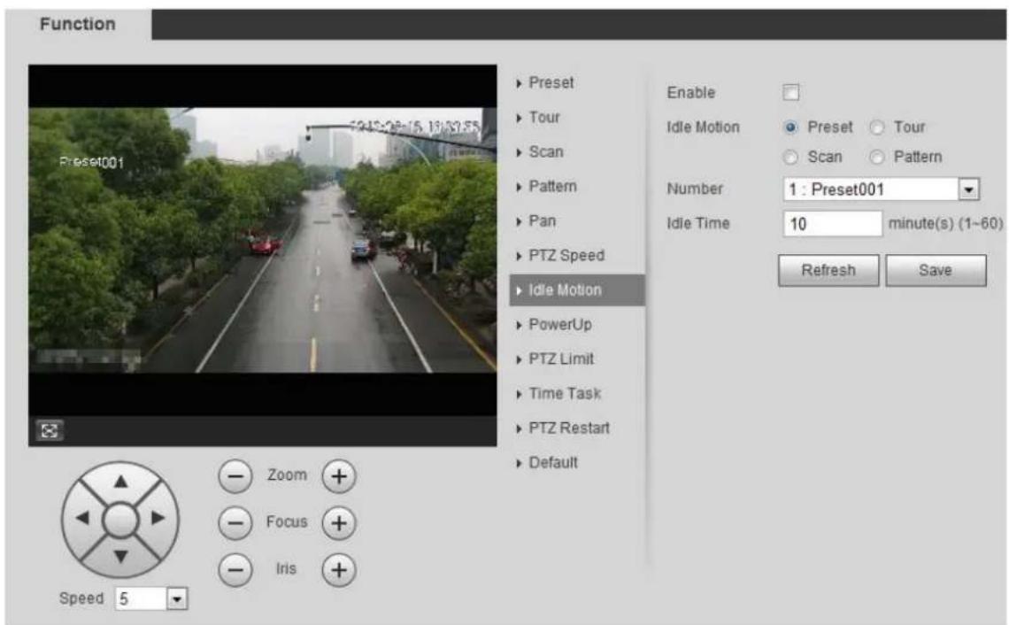
Idle motion means that the PTZ camera implements the operation which is configured in advance when it does not receive any valid command within the set time
Preparation
You have configured the PTZ motions, including preset, scan, tour, or pattern.
Procedure
Step 1 Select Setting > PTZ settings > Function > Idle Motion.
The Idle Motion interface is displayed. See Figure 4-14.
Idle motion Figure 4-14
text_image
Function Preset001 5:12:08:15 18:32:55 ► Preset ► Tour ► Scan ► Pattern ► Pan ► PTZ Speed ► Idle Motion ► PowerUp ► PTZ Limit ► Time Task ► PTZ Restart ► Default Enable Idle Motion ● Preset ○ Tour ○ Scan ○ Pattern Number 1 : Preset001 Idle Time 10 minute(s) (1~60) Refresh Save Speed 5 Zoom + Focus + Iris +Step 2 Select the Enable check box to enable the idle motion function.
Select the idle motion and set the idle time. Step 3
You need to select the corresponding number for some selected idle motions, such as Preset001.
Click Save Step 4
4.3.2.8 PowerUp
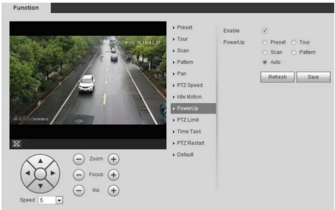
After setting Powerup motion, the camera will perform the configured motion after it is power on.
Preparation
You have configured the PTZ motions, including preset, scan, tour, or pattern.
Procedure
Select Setting > PTZ settings > Function > PowerUp. Step 1 The PowerUp interface is displayed. See Figure 4-15.
PowerUp Figure 4-15
text_image
Function Preset Tour Scan Pattern Pan PTZ Speed Idle Motion PowerUp PTZ Limit Time Task PTZ Restart Default Enable PowerUp Preset Tour Scan Pattern Auto Refresh Save Zoom + Focus + Iris + Speed 5Step 2 Select the Enable check box to enable the power up function.
Select the power up motion. Step 3

When you select Auto, the system will perform the last motion that is executed for more than 20 s before power-off.
Click OK. Step 4
4.3.2.9 PTZ Limit
After setting PTZ limit, the camera can only rotate within the configured area.
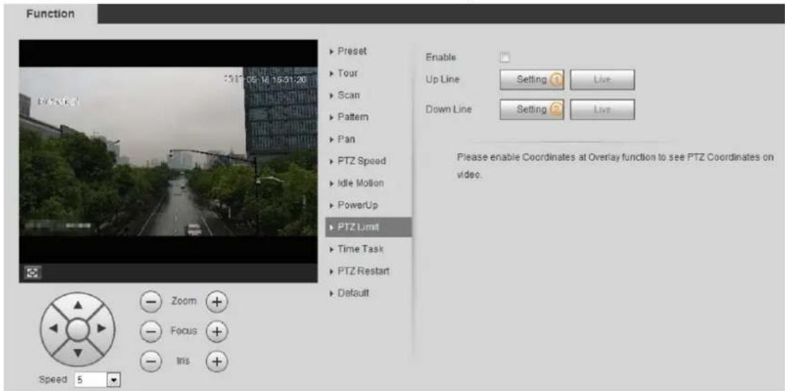
Step 1 Select Setting > PTZ settings > Function > PTZ Limit.
The PTZ Limit interface is displayed. See Figure 4-16.
PTZ limit Figure 4-16
text_image
Function 3317.05.16 19:31:20 ► Preset ► Tour ► Scan ► Pattern ► Pan ► PTZ Speed ► Idle Motion ► PowerUp ► PTZ Limit ► Time Task ► PTZ Restart ► Default Enable: Up Line Setting Live Down Line Setting Live Please enable Coordinates at Overlay function to see PTZ Coordinates on video. Zoom Focus Iris Speed 5Step 2 Adjust the direction buttons, and then click Setting ① to set the up line; click Setting ② to set the down line.
Click Live to view the configured up line and down line.
Select the Enable check box to enable the PTZ limit function. Step 3
4.3.2.10 Time Task
After setting time task, the camera performs the motions during the configured period.
Preparation
You have configured the PTZ motions, including preset, scan, tour, and pattern.
Procedure
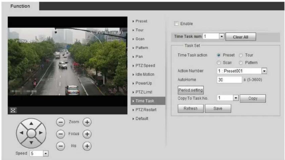
Step 1 Select Setting > PTZ settings > Function > Time Task.
The Time Task interface is displayed. See Figure 4-17.
Time task Figure 4-17
text_image
Function Preset Tour Scan Pattern Pan PTZ Speed Idle Motion PowerUp PTZ Limit Time Task PTZ Restart Default Zoom Focus Iris Speed 5 Enable Time Task num 1 Clear All Task Set Time Task action Preset Tour Scan Pattern Action Number 1: Preset001 AutoHome 30 s (5-3600) Period setting Copy To Task No. 1 Copy Refresh SaveSelect the Enable check box to enable time task function. Step 2
Select the time task number. Step 3
Step 4 Select the time task action.
You need to select the corresponding action number for some selected time task actions.
Set the auto home time in AutoHome. Step 5
AutoHome: When you call PTZ, the time task will be interrupted. After setting AutoHome time, the camera will resume the time task automatically.
Step 6 Click Period setting to set the time of the task, and then click Save.
For setting arm time, see "5.1.1.1 Setting Period."
Click Save. Step 7
Other Operations
You can copy the configurations of existing task number to other task number.
Step 1 Select the existing task number in Time Task num.
Select the task number to be configured in Copy To Task No. Step 2
Click Copy. Step 3
Step 4 Click Save.
4.3.2.11 PTZ Restart
This function can restart the PTZ camera.
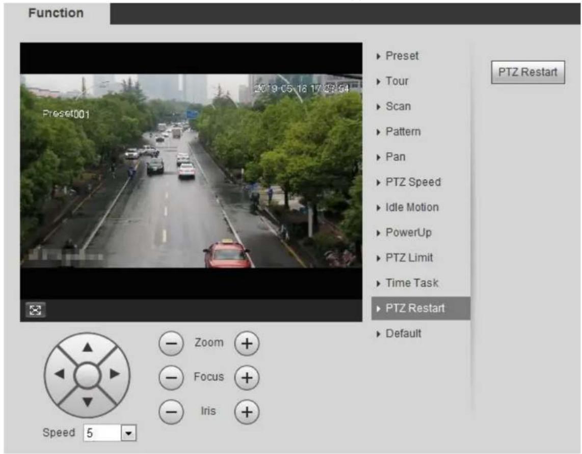
Step 1 Select Setting > PTZ settings > Function > PTZ Restart.
The PTZ Restart interface is displayed. See Figure 4-18.
PTZ restart Figure 4-18
text_image
Function Preset001 2019-05-18 17:28:54 PTZ Restart Zoom Focus Iris Speed 5____ Click PTZ Restart to restart PTZ. Step 2
4.3.2.12 Default

Be careful when doing this operation. It will restore the camera to default configuration, and result in data loss.
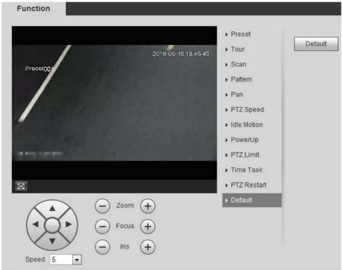
Select Setting > PTZ settings > Function > Default. Step 1
The Default interface is displayed. See Figure 4-19.
Default Figure 4-19
text_image
Function Preset001 2019-05-18 18:45:45 Default Zoom Focus Iris Speed 5Step 2 Click Default and the PTZ function is restored to default.
4.3.3 Calling PTZ
Click PTZ on Live interface, and the PTZ configuration panel is displayed. You can control PTZ and call PTZ function.
4.3.3.1 PTZ Control
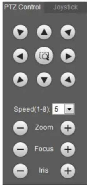
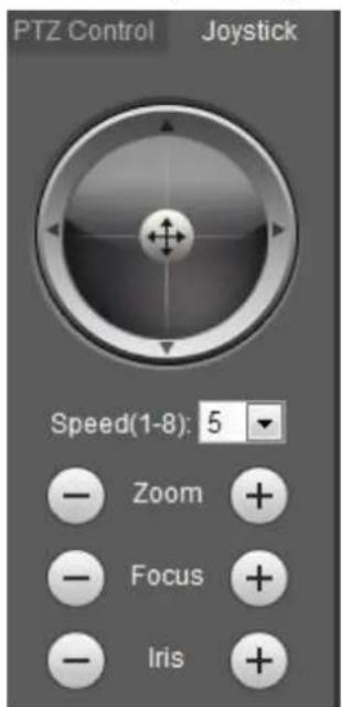
You can rotate device, zoom image, and adjust iris through PTZ control or virtual joystick. See Figure 4-20 and Figure 4-21.
PTZ control Figure 4-20
text_image
PTZ Control Joystick Speed(1-8): 5 Zoom + Focus + Iris +Joystick Figure 4-21
text_image
PTZ Control Joystick Speed(1-8): 5 Zoom + Focus + Iris +
- : Rotate PTZ direction through direction button. PTZ supports eight directions: left/right/up/down/upper left/upper right/bottom left/bottom right. Click , and draw a box in the image, PTZ will rotate, focus and quickly position the defined scene.
- : Rotate PTZ direction through joystick. Select and hold ⚠️, and drag it to the direction that you need, then PTZ will move to the defined direction.
- Speed: Measure the rotation speed. The higher the speed value is, the faster the speed becomes.
- Zoom, focus and iris: Click - or + to adjust zoom, focus and iris.
4.3.3.2 PTZ Function
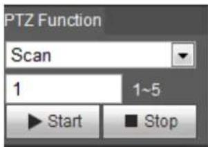
Select the PTZ function from the drop-down list to call the corresponding functions, including Scan, Preset, Tour, Pattern, Pan, Go to, Assistant and Light Wiper. See Figure 4-22. For details, see Table 4-6. Before calling PTZ function, see "4.3.2 Configuring PTZ Function" to configure PZT function.

- If an external PTZ is connected to the camera, the configurations are valid only when the corresponding functions are available on the external PTZ.
• The range of PTZ function (such as preset and tour) depends on the PTZ protocol.
PTZ function Figure 4-22
text_image
PTZ Function Scan 1 1~5 Start StopTable 4-6 Description of PTZ function
| Parameter | Description |
| Scan | Set the scan number and click Start, the camera moves horizontally at a certain speed between the set left and right limit. Click Stop to stop scanning. |
| Preset | Set the preset number and click Go to, the camera quickly positions the corresponding preset. |
| Tour | Set the tour number and click Start, the camera moves in the order of the selected presets. Click Stop to stop touring. |
| Pattern | Set the pattern number and click Start, the camera moves continuously according to the operation recording. Click Stop to stop patterning.Operation recording includes the information of manual operation, focus and zoom. |
| Pan | Click Start, and the camera rotates 360° at a certain speed in horizontal direction. |
| Go to | Set the horizontal angle, vertical angle, and zoom. Click Go to to position a certain point accurately. |
| Assistant | Set the assistant number and click Aux On to enable the corresponding assistant function, and then you can adjust the camera. Click Aux On to disable the corresponding assistant function. |
| Light/Wiper | Set the light or wiper of the camera.Click Enable to enable light/wiper function.Click Disable to disable light/wiper function. |
Playback 4.4
This section introduces playback related functions and operations, including video playback and picture playback.

- Before playing back video, configure record time range, record storage method, record schedule and record control. For details, see "5.1.1.2.1 Setting Record Plan."
- Before playing back picture, configure snapshot time range, snapshot storage method, snapshot plan. For details, see "5.1.1.3.1 Setting Snapshot Plan."
- When using Dahua smart card, make sure that the card has been authenticated before using.
4.4.1 Playback Interface
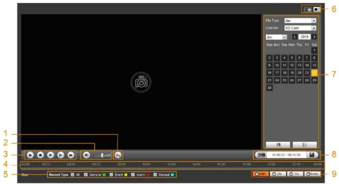
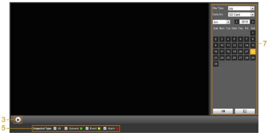
Click the Playback tab, and the Playback interface is displayed. See Figure 4-23 and Figure 4-24. For details, see Table 4-7.
Video playback Figure 4-23
text_image
File Type: day Data Src: SD Card Jun 2019 Sun Mon Tue Wed Thu Fri Sat 1 2 3 4 5 6 7 8 9 10 11 12 13 14 15 16 17 18 19 20 21 23 24 25 26 27 28 29 30 90.00.00 - 00.00.00 Record Type All General Event Alarm Manual Stop Stop Record Type All General Event Alarm Manual 24hr 2hr 1hr 0minPicture playback Figure 4-24
text_image
File Type.jpg Data Src:SD Card Jun < 2019 > Sun Mon Tue Wan Thu Fri Sat 1 2 3 4 5 6 7 8 9 10 11 12 13 14 15 16 17 18 19 20 21 23 24 25 26 27 28 29 30 Snapshot Type All General Event AlarmTable 4-7 Playback interface description
| No | Function | Description |
| 1 | Fisheye | Click , you can select display mode according to the installation mode during playback. —This function is only available on fisheye cameras. —This function is only available on fisheye cameras. |
| Rules Info |  Intelligent rules and object detection box are displayed. It is enabled by default. Intelligent rules and object detection box are displayed. It is enabled by default. —Rules Info is valid only when you enabled the rule during recording. —Rules Info is valid only when you enabled the rule during recording. | |
| 2 | Sound | Controls the sound during playback. ute mode. ute mode. pcal state. You can adjust the sound. pcal state. You can adjust the sound. |
| 3 | Play control bar | Controls playback.● :  the icon to play back recorded videos.● : ( the icon to play back recorded videos.● : (  the icon to stop playing back recorded videos.● : ( the icon to stop playing back recorded videos.● : (  the icon to play the next frame. the icon to play the next frame. When you enable the function of playing video by frame, you need to stop playback.● : ( When you enable the function of playing video by frame, you need to stop playback.● : (  the icon to slow down the playback.● : ( the icon to slow down the playback.● : (  the icon to speed up the playback. the icon to speed up the playback. |
| 4 | Progress bar | Displays the record type and the corresponding period.● Click any point in the colored area, and the system will play back the recorded video from the selected moment.● Each record type has its own color, and you can see their relations in Record Type bar. |
| 5 | Record/Snapshot Type | Select the record type or snapshot type:● Record type includes General, Event, Alarm, Manual● Snapshot type includes General, Event, Alarm |
| 6 | Assistant | ● :  an zoom video image of the selected area through two operations.◇ Click the icon, and then select an area in the video image to zoom in; right-click on the image to resume the original size. In zoom in state, drag the image to check other area.◇ Click the icon, and then scroll the mouse wheel in the video image to zoom in or out.● : ( an zoom video image of the selected area through two operations.◇ Click the icon, and then select an area in the video image to zoom in; right-click on the image to resume the original size. In zoom in state, drag the image to check other area.◇ Click the icon, and then scroll the mouse wheel in the video image to zoom in or out.● : (  the icon to capture one picture of the current video, and it will be saved to the configured storage path. the icon to capture one picture of the current video, and it will be saved to the configured storage path. About viewing or configuring storage path, see "4.5.2.5 Path." About viewing or configuring storage path, see "4.5.2.5 Path." |
| 7 | Playback video | You can select the file type, data source, and record date. |
| 8 | Video clip | Clip a certain recorded video and save it. For details, see "4.4.3 Clipping Video." |
| 9 | Time format of progress bar | Includes 4 time formats:  , ,  , ,  ,30min. Take as an example, the whole progress stands for 24 hours. ,30min. Take as an example, the whole progress stands for 24 hours. |
4.4.2 Playing back Video or Picture
This section introduces the operation of video playback and picture playback. This section takes video playback as an example.
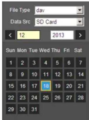
Step 1 Select dav from the Record Type drop-down list and SD card from the Data Src drop-down list. See Figure 4-25.
Select jpg from Record Type drop-down list when playing back pictures, and you do not need to select data source.
File type selection Figure 4-25
text_image
File Type dav Data Src SD Card < 12 2013 > Sun Mon Tue Wed Thu Fri Sat 1 2 3 4 5 6 7 8 9 10 11 12 13 14 15 16 17 18 19 20 21 22 23 24 25 26 27 28 29 30 31Step 2 Select the record type in Record Type. See Figure 4-26.
Figure 4-26 Record type selection

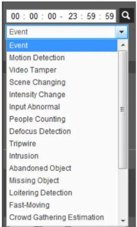
When selecting Event as the record type, you can select the specific event types from the playback file list, such as Motion Detection, Video Tamper and Scene Changing. See Figure 4-27.
Specific event types Figure 4-27
text_image
00 : 00 : 00 - 23 : 59 : 59 Event Event Motion Detection Video Tamper Scene Changing Intensity Change Input Abnormal People Counting Defocus Detection Tripwire Intrusion Abandoned Object Missing Object Loitering Detection Fast-Moving Crowd Gathering EstimationSelect the month and year of the video that you want to play. Step 3

Those dates with blue color indicate there were videos recorded in those days.
Play video. Step 4
- Click in the control bar.
The system plays the recorded video of the selected date (in the order of time). - Click any point in the colored area on the progress bar. See Figure 4-28. The playback starts from that moment.
Progress bar Figure 4-28

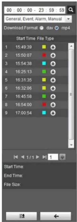
- Click , the video files of the selected date would be listed. See Figure 4-29.
Enter the start time and end time, and then click to search all files between the start time and end time. Double-click the file in the list, and the system plays the video and displays file size, starting time, and ending time.
Playback file list (1) Figure 4-29
text_image
00 : 00 : 00 - 23 : 59 : 59 General, Event, Alarm, Manual Download Format dav mp4 Start Time File Type 1 15:49:39 2 15:50:07 3 15:54:38 4 16:25:13 5 16:31:35 6 16:32:06 7 16:45:58 8 16:54:00 9 17:00:54 Start Time: End Time: File Size:4.4.3 Clipping Video
Click , the video files of the selected date are listed. Step 1
Step 2 Select dav or mp4 in Download Format.
Step 3 Click on the progress bar to select the start time of the target video, and then click

See Figure 4-30.
Clipping video Figure 4-30

text_image
80.06:09 - 08:01:00____ Click again on the progress bar to select the end time of the target video, and then clickStep 4

Step 5 Click to download the video.
The system will prompt that it cannot play back and download at the same time.
Click OK. Step 6
The playback stops and the clipped file is saved in the configured storage path. For the configuration of storage path, see "4.5.2.5 Path."
4.4.4 Downloading Video or Picture
Download video or picture to a defined path. You can download single video or picture file, or download them in batches. This section takes downloading video as an example.

- Playback and downloading at the same time is not supported.
• Operations might vary with different browsers, and the actual product shall prevail. - For details of viewing or setting storage path, see "4.5.2.5 Path."
4.4.4.1 Downloading Single File
Step 1 Select dav from Record Type drop-down list and SD card from the Data Src drop-down list.
Select jpg from Record Type drop-down list when playing back pictures, and you do not need to select data source.
Click, the video files of the selected date are listed. See Figure 4-29. Step 2
Step 3 Select dav or mp4 in Download Format. Click ↓ next to the file to de download.
The system starts to download the file to the configured path. When downloading pictures, you do not need to select the download format.
4.4.4.2 Downloading Files in Batches
Step 1 ____ Click on the playback interface.
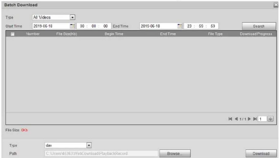
The Batch Download interface is displayed. See Figure 4-31.
Batch download Figure 4-31
text_image
Batch Download Type All Videos Start Time 2019-06-18 00 : 00 : 00 End Time 2019-06-18 23 : 59 : 59 Search Number File Size(Kb) Begin Time End Time File Type Download Progress File Size: 0Kb Type dav Path C:\Users\45363\WebDownload\PlaybackRecord Browse... DownloadStep 2 Select the record type, set the start time and end time, and then click Search. The searched files are listed.
Step 3 Select the files to be downloaded, select dav or mp4 from Format drop-down list, and then set the storage path. Click Download.
The system starts to download the file to the configured path. When downloading picture, you do not need to select the download format.
Camera 4.5
This section introduces the camera setting, including conditions, video and audio.

Camera parameters of different devices might vary, and the actual product shall prevail.
4.5.1 Conditions
Configure camera parameters of the camera to ensure surveillance goes properly.
4.5.1.1 Conditions
Configure camera parameters according to the actual situation, including picture, exposure, backlight and white balance.
4.5.1.1.1 Interface Layout
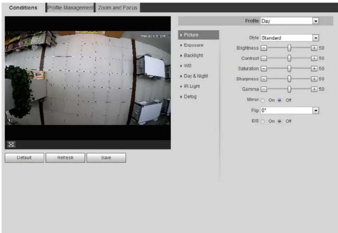
Configure camera parameters to improve the scene clarity, and ensure that surveillance goes properly. See Figure 4-32.
- You can select from normal, day and night mode to view the configuration and the effect of the selected mode, such as picture, exposure, and backlight.
- Camera with PZT function supports zoom, focus and iris operations. See Figure 4-33.
Configure speed, click direction button, and to adjust the direction, zoom, focus and iris and so on, to adjust the camera to the proper position.
Camera conditions Figure 4-32
text_image
Conditions Profile Management Zoom and Focus Profile Day ▶ Picture ▶ Exposure ▶ Backlight ▶ WB ▶ Day & Night ▶ IR Light ▶ Defog Default Refresh Save Style Standard Brightness +50 Contrast +50 Saturation +50 Sharpness +50 Gamma +50 Mirror On Off Flip 0° EIS On OffCamera conditions (PTZ camera) Figure 4-33
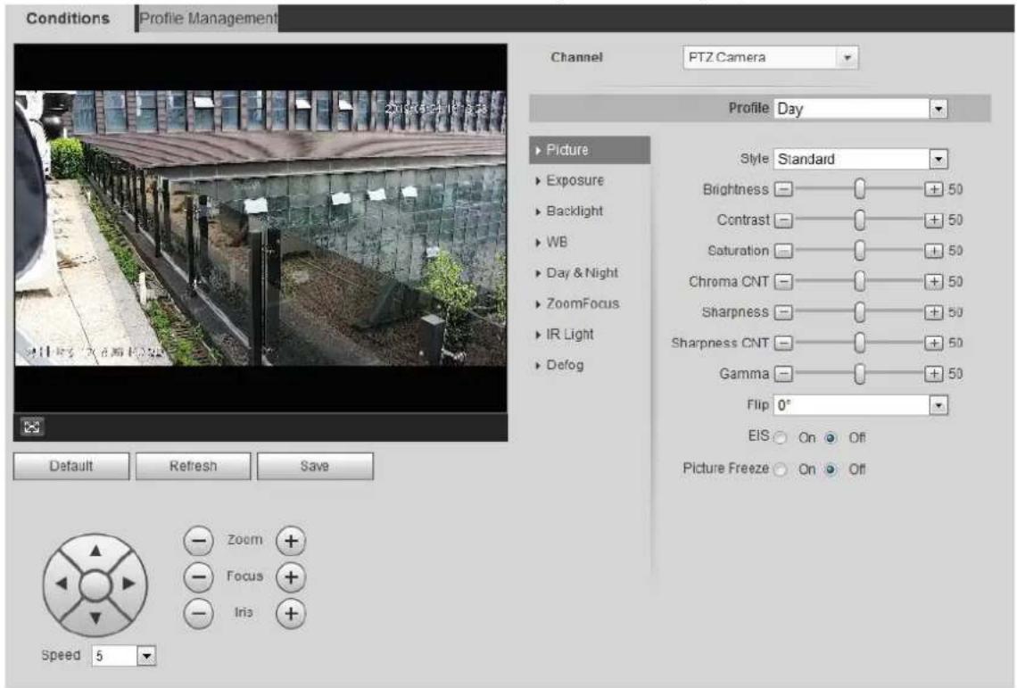
text_image
Conditions Profile Management Channel PTZ Camera Profile Day ▶ Picture ▶ Exposure ▶ Backlight ▶ WB ▶ Day & Night ▶ ZoomFocus ▶ IR Light ▶ Defog Style Standard Brightness —— 50 Contrast —— 50 Saturation —— 50 Chroma CNT —— 50 Sharpness —— 50 Sharpness CNT —— 50 Gamma —— 50 Flip 0° EIS ○ On ○ Off Picture Freeze ○ On ○ Off Zoom + Focus + Iris + Speed 54.5.1.1.2 Picture
You can configure picture parameters as needed.
Step 1 Select Setting > Camera > Conditions > Conditions > Picture.
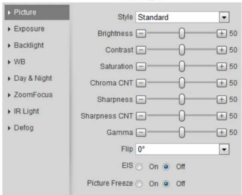
The Picture interface is displayed. See Figure 4-34.
Picture Figure 4-34
text_image
Picture Exposure Backlight WB Day & Night ZoomFocus IR Light Defog Style Standard Brightness ——○—+ 50 Contrast ——○—+ 50 Saturation ——○—+ 50 Chroma CNT ——○—+ 50 Sharpness ——○—+ 50 Sharpness CNT ——○—+ 50 Gamma ——○—+ 50 Flip 0° EIS ○ On ● Off Picture Freeze ○ On ● OffConfigure picture parameters. For details, see Table 4-8. Step 2
Table 4-8 Description of picture parameters
| Parameter | Description |
| Style | Select the picture style from soft, standard and vivid.● Soft: Default image style, displays the actual color of the image.● Standard: The hue of the image is weaker than the actual one, and contrast is smaller.● Vivid: The image is more vivid than the actual one. |
| Brightness | Changes the value to adjust the picture brightness. The higher the value is, the brighter the picture will be, and the smaller the darker. The picture might be hazy if the value is configured too big. |
| Contrast | Changes the contrast of the picture. The higher the value is, the more the contrast will be between bright and dark areas, and the smaller the less. If the value is set too big, the dark area would be too dark and bright area easier to get overexposed. The picture might be hazy if the value is set too small. |
| Saturation | Makes the color deeper or lighter. The higher the value is, the deeper the color will be, and the lower the lighter. Saturation value does not change imag brightness. |
| Sharpness | Changes the sharpness of picture edges. The higher the value is, the clearer the picture edges will be, and if the value is set too big, picture noises are more likely to appear. |
| Gamma | Changes the picture brightness and improves the picture dynamic range in a non-linear way. The higher the value is, the brighter the picture will be, and the smaller the darker. |
| Mirror | Select On, and the picture would display with left and right side reversed. |
| Flip | Changes the display direction of the picture, see the options below.● 0° : Normal display.● 90° : The picture rotates 90° clockwise.● 180° : The picture rotates 90° counterclockwise.● 270° : The picture flips upside down. For some models, please set the resolution to be 1080p or lower when using 90° and 180° . For details, see "4.5.2.1 Video." For some models, please set the resolution to be 1080p or lower when using 90° and 180° . For details, see "4.5.2.1 Video." |
| EIS | Corrects the device shaking with difference comparison algorithm and improves the image clarity, effectively solves the picture shaking problem. |
| Picture Freeze | When you call a preset, the image displays the preset location, not the rotation image. |
Click Save. Step 3
4.5.1.1.3 Exposure
Configure iris and shutter to improve image clarity.

Cameras with true WDR do not support long exposure when WDR is enabled in Backlight.
Step 1 Select Setting > Camera > Conditions > Conditions > Exposure.
The Exposure interface is displayed. See Figure 4-35.
Exposure Figure 4-35
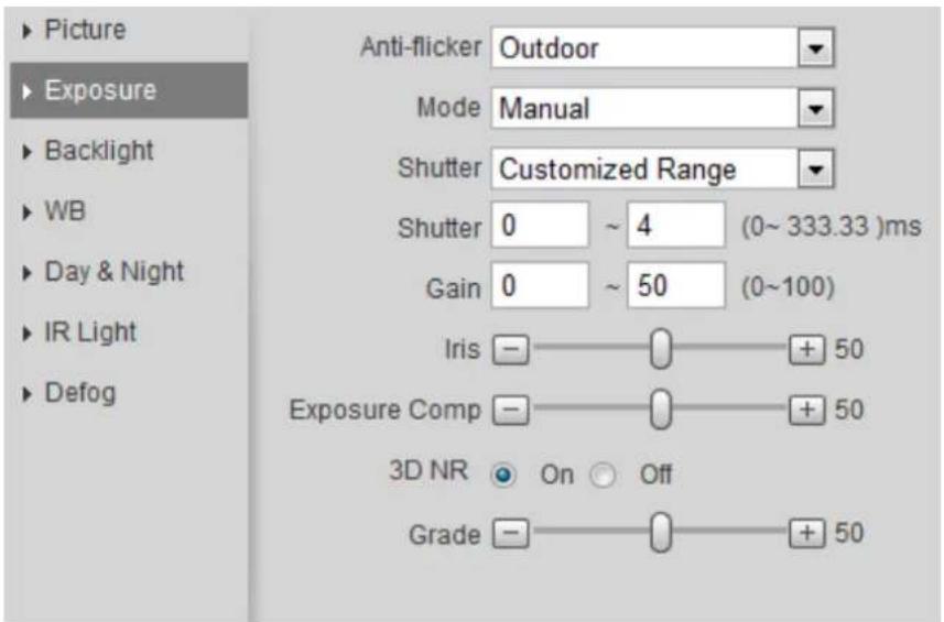
text_image
Picture Exposure Backlight WB Day & Night IR Light Defog Anti-flicker Outdoor Mode Manual Shutter Customized Range Shutter 0 ~ 4 (0~333.33)ms Gain 0 ~ 50 (0~100) Iris — — + 50 Exposure Comp — — + 50 3D NR On Off Grade — — + 50Configure exposure parameters. For details, see Table 4-9. Step 2
Table 4-9 Description of exposure parameters
| Parameter | Description |
| Anti-flicker | You can select from 50 Hz, 60 Hz and Outdoor.50 Hz: When the electric supply is 50 Hz, the system adjusts the exposure according to ambient light automatically to ensure that there is no stripe appears.60 Hz: When the electric supply is 60 Hz, the system adjusts the exposure according to ambient light automatically to ensure that there is no stripe appears.Outdoor: You can select any exposure mode as needed. |
| Mode | Device exposure modes.Auto: Adjusts the image brightness according to the actual condition automatically.Gain Priority: When the exposure range is normal, the system prefers the configured gain range when auto adjusting according to the ambient lighting condition. If the image brightness is not enough and the gain has reached upper or lower limit, the system adjusts shutter value automatically to ensure the image at ideal brightness. You can configure gain range to adjust gain level when using gain priority mode.Shutter priority: When the exposure range is normal, the system prefers the configured shutter range when auto adjusting according to the ambient lighting condition. If the image brightness is not enough and the shutter value has reached upper or lower limit, the system adjusts gain value automatically to ensure the image at ideal brightness.Iris priority: The iris value is set to a fixed value, and the device adjusts shutter value then. If the image brightness is not enough and the shutter value has reached upper or lower limit, the system adjusts gain value automatically to ensure the image at ideal brightness.Manual: Configure gain and shutter value manually to adjust image brightness.When the Anti-flicker is set to Outdoor, you can select Gain priority or Shutter priority in the Mode list. |
| Exposure Comp | Sets the value, and it ranges from 0 to 50. The higher the value is, the brighter the image will be. |
| Shutter | Set the effective exposure time. The smaller the value, the shorter the exposure time will be. |
| Shutter range | When selecting Shutter Priority or Manual in Mode, and setting Customized Range in Shutter, you can set shutter range, and the unit is ms. |
| Gain | When selecting Gain Priority or Manual in Mode, you can set shutter range. With minimum illumination, the camera increases Gain automatically to get clearer images. |
| Iris | When selecting Aperture Priority in Mode, you can set iris range. |
| Auto Iris | This configuration is available only when the camera is equipped with auto-iris lens.When auto iris is enabled, the iris size changes automatically according to the ambient lighting condition, and the image brightness changes accordingly.When auto iris is disabled, the iris stays at full size and does not change no matter how ambient lighting condition changes. |
| 2D NR | Average single-frame dots and other dots around to reduce noise. |
| 3D NR | Works with multi-frame (no less than 2 frames) images and reduce noise by using the frame information between previous and latter frames. |
| Grade | This configuration is available only when the 3D DNR is enabled.The higher the DNR level is, the better the result will be. |
Click Save. Step 3
4.5.1.1.4 Backlight
You can select backlight mode from Auto, BLC, WDR, and HLS.
Step 1 Select Setting > Camera > Conditions > Conditions > Backlight.
The Backlight interface is displayed. See Figure 4-36.
Backlight Figure 4-36
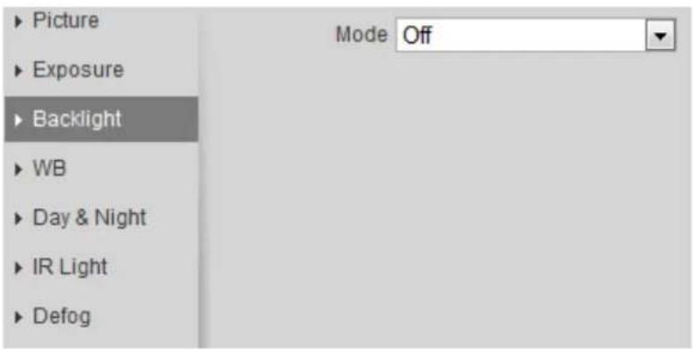
text_image
Picture Exposure Backlight WB Day & Night IR Light Defog Mode OffStep 2 Configure backlight parameters. For details, see Table 4-10.
Table 4-10 Description of backlight parameters
| Backlight mode | Description |
| Auto | The system adjusts image brightness according to ambient lighting condition automatically to ensure image clarity. |
| BLC | Enable BLC, the camera can get clearer image of the dark areas on the target when shooting against light. You can selectDefaultmode orCustomizedmode.When inDefaultmode, the system adjusts exposure according to ambient lighting condition automatically to ensure the clarity of the darkest area.When inCustomizedmode, the system auto adjusts exposure only to the set area according to ambient lighting condition to ensure the image of the set area at ideal brightness. |
| WDR | The system dims bright areas and compensates dark areas to ensure the clarity of all the area. The higher the value is, the brighter the dark will be, but the more the noise will be. There might be a few seconds of video loss when the device is switching to WDR mode from other mode. There might be a few seconds of video loss when the device is switching to WDR mode from other mode. |
| HLS | Enable HLS when extreme strong light is in the environment (such as toll station or parking lot), the camera will dim strong light, and reduce the size of Halo zone to lower the brightness of the whole image, so that the camera can capture human face or car plate detail clearly. The higher the value is, the more obvious the HLS effect will be. |
Click Save. Step 3
4.5.1.1.5 WB
WB function makes the image color display precisely as it is. When in WB mode, white objects would always display white color in different environments.
Step 1 Select Setting > Camera > Conditions > Conditions > WB.
The WB interface is displayed. See Figure 4-37.
WB Figure 4-37
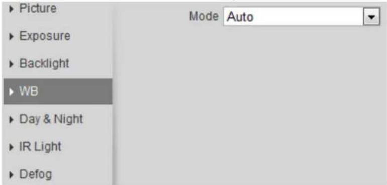
text_image
Picture Exposure Backlight WB Day & Night IR Light Defog Mode AutoConfigure WB parameters. For details, see Table 4-11. Step 2
Table 4-11 Description of WB parameters
| WB mode | Description |
| Auto | The system compensates WB according to color temperature to ensure color precision. |
| Natural | The system auto compensates WB to environments without artificial light to ensure color precision. |
| Street Lamp | The system compensates WB to outdoor night scene to ensure color precision. |
| Outdoor | The system auto compensates WB to most outdoor environments with natural or artificial light to ensure color precision. |
| Manual | Configure red and blue gain manually; the system auto compensates WB according to color temperature. |
| Regional Custom | The system compensates WB only to the set area according to color temperature to ensure color precision. |
Click Save. Step 3
Configure the display mode of the image. The system switches between color and black-and-white mode according to the actual condition.
Step 1 Select Setting > Camera > Conditions > Conditions > Day & Night.
The Day & Night interface is displayed. See Figure 4-38.
Day and night Figure 4-38
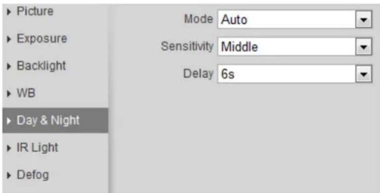
text_image
Picture Exposure Backlight WB Day & Night IR Light Defog Mode Auto Sensitivity Middle Delay 6sConfigure day and night parameters. For details, see Table 4-12. Step 2
Table 4-12 Description of day and night parameters
| Parameter | Description |
| Mode | You can select device display mode from Color, Auto, and B/W. Day & Night configuration is independent from profile management configuration.Color: The system displays color image.Auto: The system switches between color and black-and-white display according to the actual condition.B/W: The system displays black-and-white image. Day & Night configuration is independent from profile management configuration.Color: The system displays color image.Auto: The system switches between color and black-and-white display according to the actual condition.B/W: The system displays black-and-white image. |
| Sensitivity | This configuration is available only when you set Auto in Mode.You can configure camera sensitivity when switching between color and black-and-white mode. |
| Delay | This configuration is available only when you set Auto in Mode.You can configure the delay when camera switching between color and black-and-white mode. The lower the value is, the faster the camera switches between color and black-and-white mode. |
Click Save. Step 3
4.5.1.1.7 Zoom and Focus
Initialize lens to adjust zoom and focus. Only PTZ camera supports lens initialization.
Step 1 Select Setting > Camera > Conditions > Conditions > ZoomFocus.
The ZoomFocus interface is displayed. See Figure 4-39.
Zoom and focus Figure 4-39
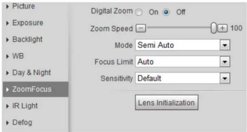
text_image
Picture Exposure Backlight WB Day & Night ZoomFocus IR Light Defog Digital Zoom On Off Zoom Speed 100 Mode Semi Auto Focus Limit Auto Sensitivity Default Lens InitializationConfigure zoom and focus parameters. For details, see Figure 4-13. Step 2
Table 4-13 Description of zoom and focus parameters
| Parameter | Description |
| Digital Zoom | Select On to enable digital zoom function.After the optical zoom reached the upper limit, enable digital zoom function, you still can do digital zoom operation. |
| Zoom Speed | Adjusts zoom speed. The higher the value is, the higher the speed will be. |
| Mode | Sets focus mode.Auto: When image moves or object changes in the scene, the camera will focus automatically.Semi Auto: Click ☑ or + corresponding to Focus or Zoom, the camera will focus. Calling preset, positioning accurately or rotating PTZ also will trigger focus.Manual: Click ☑ or + corresponding to Focus to adjust the focus. |
| Focus Limit | When the focus length is too short, the camera will focus on the dome cover. Sets the shortest focus distance to avoid focusing on the dome cover. You can also change the focus speed by changing focus length. |
| Sensitivity | The sensitivity of triggering focus. The higher the value is, the easier the focus will be triggered. |
Step 3 Click Save.

Click Lens Initialization, the lens will adjust the zoom and focus parameters.
4.5.1.1.8 IR Light
This configuration is available only when the device is equipped with IR light.
Step 1 Select Setting > Camera > Conditions > Conditions > IR Light.
The IR Light interface is displayed. See Figure 4-40.
IR light Figure 4-40
text_image
Picture Exposure Backlight WB Day & Night IR Light Defog Mode AutoConfigure IR light parameters. For details, see Table 4-14. Step 2
Table 4-14 Description of IR light parameters
| IR light mode | Description |
| Manual | Adjust the brightness of IR light manually, and then the system will supply IR light to the image accordingly. |
| Auto | The system adjusts the IR light intensity according to the ambient lighting condition. |
| Smart IR | |
| ZoomPrio | The system adjusts the IR light intensity automatically according to the change of the ambient light.When the ambient light turns darker, the system turns on the low beam lights first, if the brightness is still not enough, it turns on the high beam lights then.When the ambient light turns brighter, the system dims high beam lights until they are off, and then the low beam lights.When the focus reaches certain wide angle, the system will not turn on high beam light in order to avoid over-exposure in short distance. In the meantime, you can configure light compensation manually to fine-tune IR light intensity. |
| Off | IR light is off. |
Click Save. Step 3
4.5.1.1.9 Defog
The image quality is compromised in foggy or hazy environment, and defog can be used then to improve image clarity.
Step 1 Select Setting > Camera > Conditions > Conditions > Defog.
The Defog interface is displayed. See Figure 4-41.
Defog Figure 4-41
text_image
Picture Exposure Backlight WB Day & Night IR Light Defog Mode OffConfigure defog parameters. For details, see Table 4-15. Step 2
Table 4-15 Description of defog parameters
| Defog | Description |
| Manual | Configure function intensity and atmospheric light mode manually, and then the system adjusts image clarity accordingly. Atmospheric light mode can be adjusted automatically or manually. |
| Auto | The system adjusts image clarity according to the actual condition. |
| Off | Defog function is disabled. |
Click Save. Step 3
4.5.1.1.10 Fisheye
Select install mode and record mode according to the actual installation scene. When the camera accesses to the platform with corrective stream, the platform displays the corrective image.

This function is only available on fisheye device.
Step 1 Select Setting > Camera > Conditions > Conditions > Fisheye.
The Fisheye interface is displayed. See Figure 4-42.
Fisheye Figure 4-42
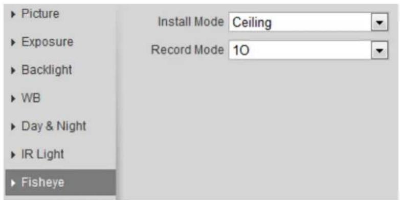
text_image
Picture Exposure Backlight WB Day & Night IR Light Fisheye Install Mode Ceiling Record Mode 10Step 2 Set install mode and record mode. For details, see Table 4-16.
Table 4-16 Description of fisheye parameters
| Parameter | Description |
| Install Mode | You can selectCeiling, Wall, or Ground. |
| Record Mode | 1O: The original image before correction.1P: 360° rectangular panoramic image.2P: When the install mode isCeilingor Ground, you can set this mode. Two associated 180° rectangular image screens, and at any time, the two screens form a 360° panoramic image.1R: Original image screen + independent sub-screen. You can zoom or drag the image in all the screens.2R: Original image screen + two independent sub-screens. You can zoom or drag the image in all the screens.4R: Original image screen + four independent sub-screens. You can zoom or drag the image in all the screens.1O + 3R: Original image screen + three independent sub-screens. You can zoom or drag the image in original image screen, and move the image (upper and lower) in sub-screens to adjust the vertical view. |
Click Save. Step 3
4.5.1.2 Profile Management
The surveillance system works in different ways as profile configured in different time.
Step 1 Select Setting > Camera > Conditions > Profile Management.
The Profile Management interface is displayed.
Manage profile. Step 2
- When Profile Management is set as General, the surveillance system works under General configuration.
Figure 4-43 General
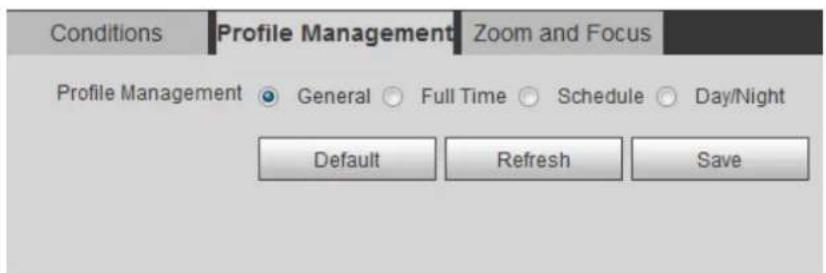
text_image
Conditions Profile Management Zoom and Focus Profile Management ● General ○ Full Time ○ Schedule ○ Day/Night Default Refresh Save- When Profile Management is set as Full Time, you can select Day or Night in the Always Enable list, the surveillance system works under Always Enable configuration.
Full time Figure 4-44
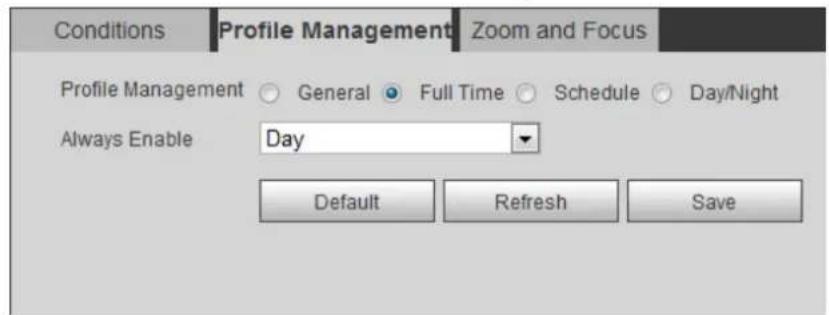
text_image
Conditions Profile Management Zoom and Focus Profile Management General Full Time Schedule Day/Night Always Enable Day Default Refresh Save- When Profile Management is set as Schedule, you can drag the slide block to set certain time as Day or Night. For example, set 8:00–18:00 as day, and 0:00–8:00 and 18:00–24:00 as night.
Schedule Figure 4-45
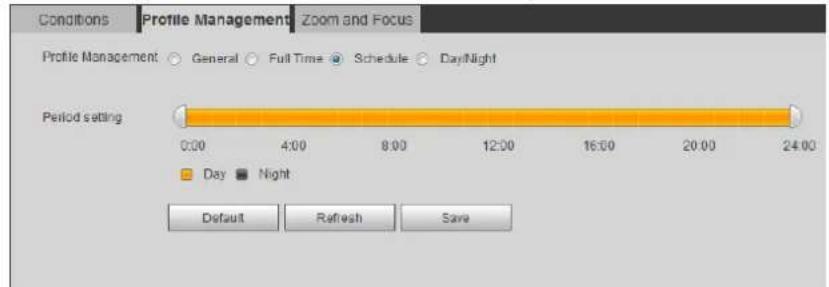
text_image
Conditions Profile Management Zoom and Focus Profile Management General Full Time Schedule Day/Night Period setting 0:00 4:00 8:00 12:00 16:00 20:00 24:00 Day Night Default Refresh Save- When Profile Management is set as Day & Night, the surveillance system works under Day & Night configuration.
Day/Night Figure 4-46
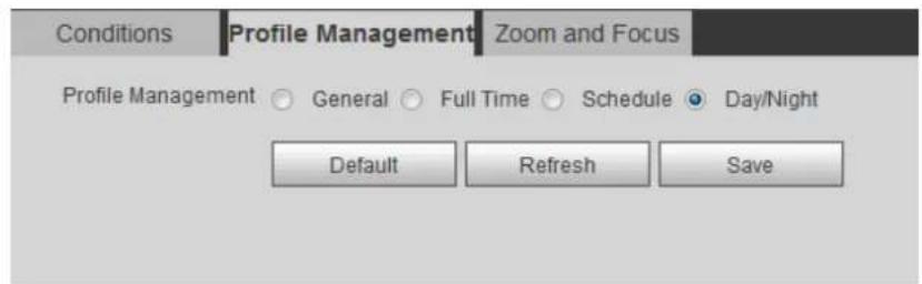
text_image
Conditions Profile Management Zoom and Focus Profile Management ○ General ○ Full Time ○ Schedule ● Day/Night Default Refresh SaveClick Save. Step 3
4.5.1.3 Zoom and Focus
You can adjust image clarity through auto or manual focus; and adjust the image size through zoom. For details, see 4.2.4.2 Zoom and Focus."
4.5.2 Setting Video Parameters
This section introduces video parameters, such as video, snapshot, overlay, ROI (region of interest), and path.

Click Default, and the device is restored to default configuration. Click Refresh to view the latest configuration.
4.5.2.1 Video
Configure video stream parameters, such as stream type, encode mode, resolution, frame rate, bit rate type, bit rate, I frame interval, SVC, and watermark.
Select Setting > Camera > Video > Video. Step 1
The Video interface is displayed. See Figure 4-47.
Video Figure 4-47
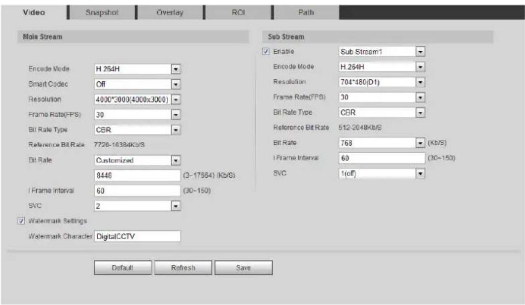
text_image
Video Snapshot Overlay ROI Path Main Stream Encode Mode H 264H Smart Codec Off Resolution 4000*3000(4000x3000) Frame Rate(FPS) 30 Bit Rate Type CBR Reference Bit Rate 7726-16384Kb/S Bit Rate Customized 8448 (3-17664) (Kb/S) Frame interval 60 (30-150) SVC 2 Watermark Settings Watermark Character DigitalCCTV Sub Stream Enable Sub Stream1 Encode Mode H.264H Resolution 704*480(D1) Frame Rate(FPS) 30 Bit Rate Type CBR Reference Bit Rate 512-2048Kb/S Bit Rate 768 (Kb/S) Frame Interval 60 (30-150) SVC 1(off) Default Refresh SaveConfigure video parameters. For details, see Table 4-17. Step 2
Table 4-17 Description of video parameters
| Parameter | Description |
| Enable | Select the Enable check box to enable sub stream, it is enabled by default. You can enable multiple sub streams simultaneously. You can enable multiple sub streams simultaneously. |
| Encode Mode | Select encode mode.H.264: Main profile encode mode. Compared with H.264B, it requires smaller bandwidth.H.264H: High profile encode mode. Compared with H.264, it requires smaller bandwidth.H.264B: Baseline profile encode mode. It requires smaller bandwidth.H.265: Main profile encode mode. Compared with H.264, it requires smaller bandwidth.MJPEG: When under this mode, the image requires high bit rate value to ensure clarity, you are recommended to set the Bit Rate value to the biggest value in the Reference Bit Rate. |
| Smart Codec | Enable smart codec to improve video compressibility and save storage space. After smart codec is enabled, the device would stop supporting the third bit stream, ROI, and smart event detection, and the actual interface shall prevail. After smart codec is enabled, the device would stop supporting the third bit stream, ROI, and smart event detection, and the actual interface shall prevail. |
| Resolution | The resolution of the video. The higher the value is, the clearer the image will be, but the bigger the bandwidth will be required. |
| Video Clip | This function is available only for sub stream 2 of some select models. TheAreainterfaceis displayed.2. Select resolution as needed and clip image on the interface.3. View the clipped video onLiveinterface (the live interface of sub stream 2 only displays the clipped area). TheAreainterfaceis displayed.2. Select resolution as needed and clip image on the interface.3. View the clipped video onLiveinterface (the live interface of sub stream 2 only displays the clipped area). |
| Frame Rate (FPS) | The number of frame in one second of video. The higher the value is, the clearer and smoother the video will be. |
| Bit Rate Type | The bit rate control type during video data transmission. You can select bit rate type from:CBR (Constant Bit Rate): The bit rate changes a little and keeps close to the defined bit rate value.VBR (Variable Bit Rate): The bit rate changes as monitoring scene changes.[ASYD]TheBit Rate Typecan be only be set as CBR when Encode Modeis set as MJPEG. |
| Quality | This parameter can be configured only when theBit Rate Typeis set as VBR.The better the quality is, the larger the bandwidth will be requested. |
| Reference Bit Rate | The most suitable bit rate value range recommended to user according to the defined resolution and frame rate. |
| Max Bit Rate | This parameter can be configured only when theBit Rate Typeis set as VBR.You can select the value of theMax Bit Rateaccording to theReference Bit Ratevalue.The bit rate then changes as monitoring scene changes, but the max bit rate keeps close to the defined value. |
| Bit Rate | This parameter can be configured only when theBit Rate Typeis set as CBR.Select bit rate value in the list according to actual condition. |
| I Frame Interval | The number of P frames between two I frames, and theIFrame Intervalrange changes asFPSchanges.It is recommended to setIFrame Intervaltwice as big asFPS. |
| SVC | Scaled video coding, able to encode a high quality video bit stream that contains one or more subset bit streams. When sending stream, to improve inflency, the system will quit some data of related lays according to the network staus.1: The default value, which means that there is no layered coding.2, 3 and 4: The lay number that the video stream is packed. |
| Watermark Settings | You can verify the watermark to check if the video has been tampered.1. Select the check box to enable watermark function.2. The default character is DigitalCCTV. |
| Watermark Character |
Click Save. Step 3
4.5.2.2 Snapshot
You can configure snapshot parameters, including snapshot type, image size, quality and interval.
Select Setting > Camera > Video > Snapshot. Step 1
The Snapshot interface is displayed, see Figure 4-48.
Snapshot Figure 4-48
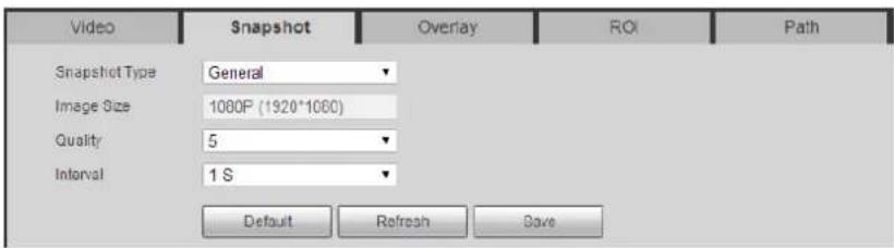
text_image
Video Snapshot Overlay ROI Path Snapshot Type General Image Size 1080P (1920*1060) Quality 5 Interval 1 S Default Refresh SaveConfigure snapshot parameters. For details, see Table 4-18. Step 2
Table 4-18 Description of snapshot parameter
| Parameter | Description |
| Snapshot Type | You can select General and Event.General: The system takes snapshot as scheduled. For details, see "4.7.2 Setting Schedule.""Event: The system takes snapshot when the video detection, audio detection, event, or alarm is triggered. This function requires the corresponding snapshot being enabled. |
| Image Size | The same resolution with main stream. |
| Quality | Configures the snapshot quality. There are six levels of Image quality, and the sixth is the best. |
| Interval | Configures the snapshot frequency.Select Customized, and then you can configure snapshot frequency manually. |
Click Save. Step 3
4.5.2.3 Overlay
Configure overlay information, and it will be displayed on the Live interface.
4.5.2.3.1 Configuring Privacy Masking
You can enable this function when you need to protect privacy of some area on the video image.
Step 1 Select Setting > Camera > Video > Overlay > Privacy Masking.
The Privacy Masking interface is displayed. See Figure 4-49 and Figure 4-50.
Privacy masking Figure 4-49
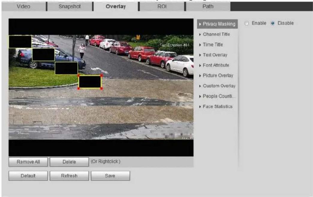
text_image
Video Snapshot Overlay ROI Path Privacy Masking Enable Disable Channel Title Time Title Text Overlay Font Attribute Picture Overlay Custom Overlay People Counti... Face Statistics Remove All Delete (Or Rightclick) Default Refresh SavePrivacy masking (speed dome) Figure 4-50
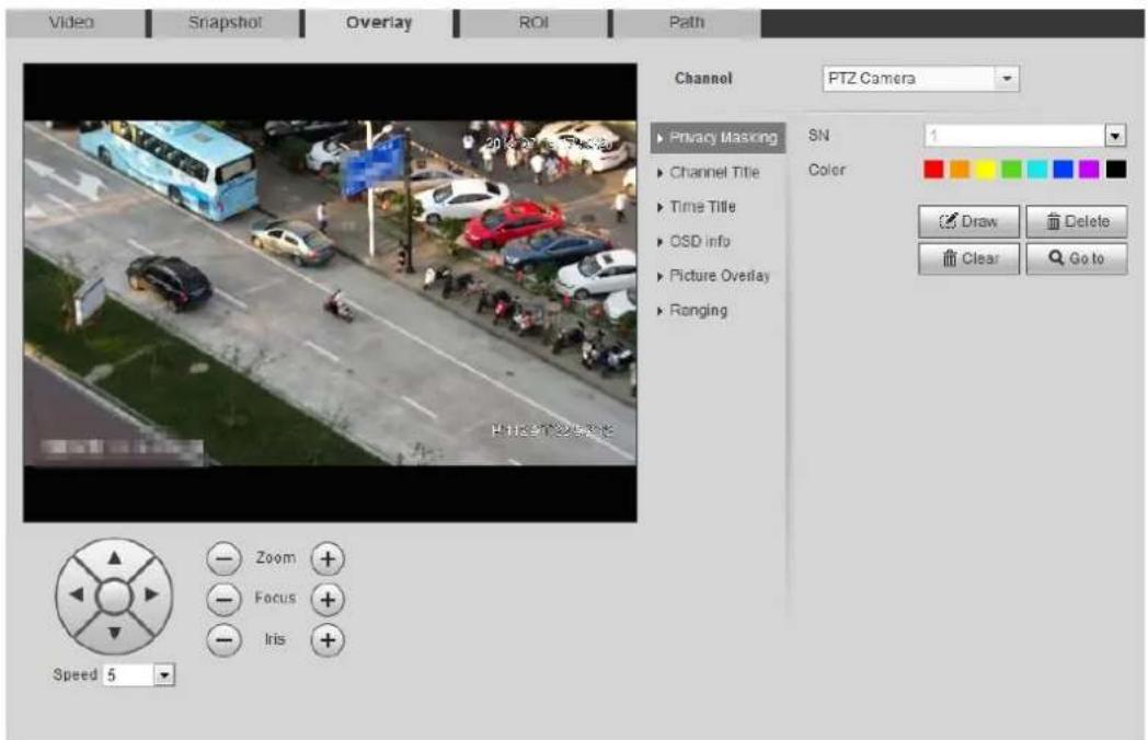
text_image
Video Snapshot Overlay ROI Path Channel PTZ Camera Privacy Masking SN 1 Color Draw Delete Clear Go to Zoom Focus Iris Speed 5Configure privacy masking. Step 2
- Speed Dome
1) Select the SN.
2) Adjust the live image to the proper location through PTZ, select the color, and then click Draw. Press the mouse button to draw rectangles. The configuration takes effect immediately.
Other operations:
◇ Select the SN, and click Go to, the speed dome rotates to the masked area.
◇ Select the SN, and click Delete to delete the masking rectangles.
◇ Click Clear, and the click OK to clear all masking rectangles.
- Other cameras
1) Select the Enable check box, and then drag the block to the area that you need to cover.

- You can drag four rectangles at most.
- Click Remove All to delete all the area boxes; select one box, and then click Delete or right-click to delete it.
2) Adjust the size of the rectangle to protect the privacy.
3) Click Save.
4.5.2.3.2 Configuring Channel Title
You can enable this function when you need to display channel title in the video image.
Step 1 Select Setting > Camera > Video > Overlay > Channel Title.
The Channel Title interface is displayed. See Figure 4-51.
Channel title Figure 4-51
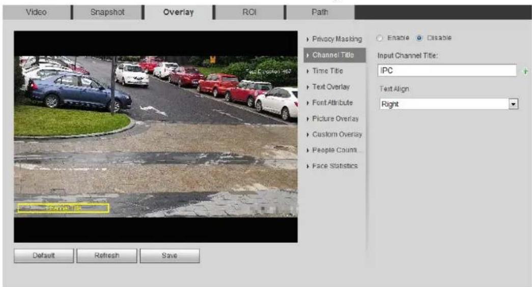
text_image
Video Snapshot Overlay ROI Path Privacy Masking Channel Title Time Title Text Overlay Font Attribute Picture Overlay Custom Overlay People Count Face Statistics Enable Disable Input Channel Title: IPC Text Align Right Default Refresh SaveStep 2 Select the Enable check box, enter the channel title, and select the text align.

Click +to expand the channel title, and you can expand 1 line at most.
Step 3 Move the title box to the position that you want in the image.
Click Save. Step 4
4.5.2.3.3 Configuring Time Title
You can enable this function when you need to display time in the video image.
Step 1 Select Setting > Camera > Video > Overlay > Time Title.
The Time Title interface is displayed. See Figure 4-52.
Time title Figure 4-52
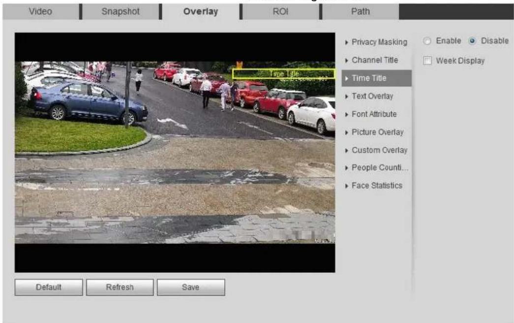
text_image
Video Snapshot Overlay ROI Path ▶ Privacy Masking ▶ Channel Title ▶ Time Title ▶ Text Overlay ▶ Font Attribute ▶ Picture Overlay ▶ Custom Overlay ▶ People Count... ▶ Face Statistics Default Refresh Save Enable Disable Week DisplaySelect the Enable check box. Step 2
Select the Week Display check box. Step 3
Move the time box to the position you want in the image. Step 4
Click Save. Step 5
4.5.2.3.4 Configure Text Overlay
You can enable this function if you need to display text in the video image.

Text overlay and picture overlay cannot work at the same time, and the IPC that connects to mobile NVR with private protocol would display GPS information as priority.
Step 1 Select Setting > Camera > Video > Overlay > Text Overlay.
The Text Overlay interface is displayed. See Figure 4-53.
Text overlay Figure 4-53
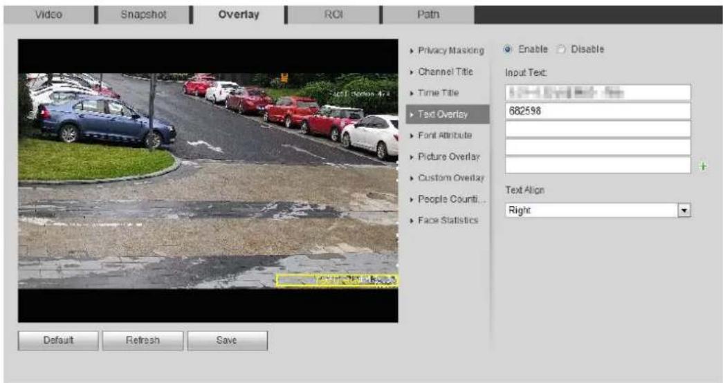
text_image
Video Snapshot Overlay ROI Path Enable Disable Input Text: 682598 Text Align Right Default Refresh SaveSelect the Enable check box, enter the text you need, and then select alignment. The Step 2 text is displayed in the video image.

Click + to expand the text overlay, and you can expand 9 lines at most.
Move the text box to the position you want in the image. Step 3
Click Save. Step 4
4.5.2.3.5 Configure Font Attribute
You can enable this function if you need to adjust the font size in the video image.
Step 1 Select Setting > Camera > Video > Overlay > Font Attribute.
The Font Attribute interface is displayed. See Figure 4-54.
Font attribute Figure 4-54

text_image
Video Snapshot Overlay ROI Path ▶ Privacy Masking ▶ Channel Title ▶ Time Title ▶ Text Overlay ▶ Font Attribute ▶ Picture Overlay ▶ Custom Overlay ▶ People Count ▶ Face Statistics Color Font Size 48*48 Default Refresh SaveSelect the font color and size. Step 2
Click More Color to customize the font color.
Click Save. Step 3
4.5.2.3.6 Configure Picture Overlay
You can enable this function if you need to display picture information on the video image.

Text overlay and picture overlay cannot work at the same time.
Step 1 Select Setting > Camera > Video > Overlay > Picture Overlay.
The Picture Overlay interface is displayed. See Figure 4-55.
Picture overlay Figure 4-55
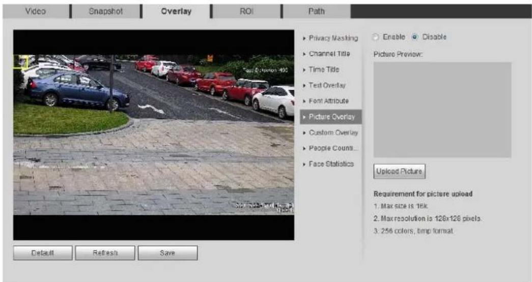
text_image
Video Snapshot Overlay ROI Path Privacy Masking Channel Title Time Title Test Overlay Font Attribute Picture Overlay Custom Overlay People Count... Face Statistics Enable Disable Picture Preview: Upload Picture Requirement for picture upload 1. Max size is 16k 2. Max resolution is 128x126 pixels. 3. 256 colors, tmp format Default Refresh SaveStep 2 Select the Enable check box, click Upload Picture, and then select the picture to be overlaid.
The picture is displayed on the video image.
Move the overlaid picture to the position you want in the image. Step 3
Click Save. Step 4
4.5.2.3.7 Configure Custom Overlay
You can enable this function if you need to display custom information on the video image.
Step 1 Select Setting > Camera > Video > Overlay > Custom Overlay.
The Custom Overlay interface is displayed. See Figure 4-56.
Custom overlay Figure 4-56
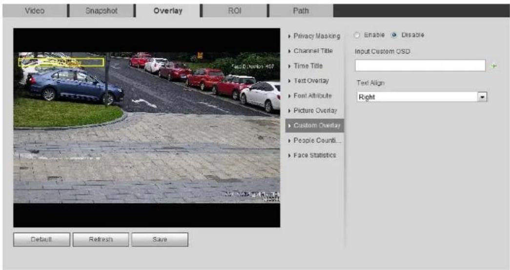
text_image
Video Snapshot Overlay ROI Path Privacy Masking Channel Title Time Title Text Overlay Font Attribute Picture Overlay Custom Overlay People Count... Face Statistics Enable Disable Input Custom OSD Text Align Right Default Refresh SaveSelect the Enable check box, and then select the text align. Step 2

Click + to expand the custom overlay, and you can expand 1 line at most.
Step 3 Move the custom box to the position you want in the image.
Click Save. Step 4
4.5.2.3.8 Configuring OSD Info
You can enable this function if you want to display the information of preset, PTZ coordinates, zoom, tour and location on the video image.

Only tracking speed dome supports OSD info function.
Step 1 Select Setting > Camera > Video > OSD Info.
The OSD Info interface is displayed. See Figure 4-57.
OSD info Figure 4-57
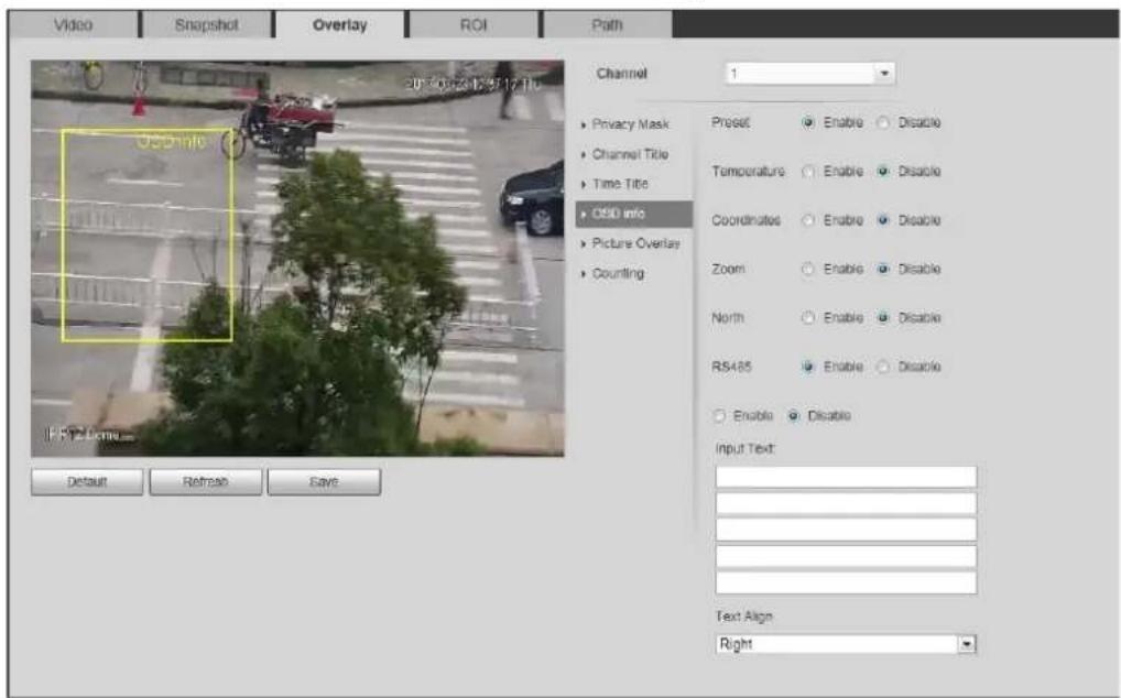
text_image
Video Snapshot Overlay ROI Path Channel 1 Privacy Mask Channel Title Time Title OSD info Picture Overlay Counting Preset Enable Disable Temperature Enable Disable Coordinates Enable Disable Zoom Enable Disable North Enable Disable RS485 Enable Disable Enable Disable Input Text: Text Align Right Default Refresh SaveStep 2 Configure OSD information. See Table 4-19.
Table 4-19 Description of OSD information
| Parameter | Description |
| Preset | Select Enable, and the preset name is displayed in the image when the camera turns to the preset, and it will disappear 3 s later. |
| Temperature | Select Enable and the internal temperature of the current device is displayed. |
| Coordinates | Select Enable and the PTZ coordinates info is displayed in the image. |
| Zoom | Select Enable and the zoom info is displayed in the image. such as  , which means 12x zoom rate. , which means 12x zoom rate. |
| North | Select Enable and the north direction is displayed in the image. |
| RS485 | Select Enable and it will enable RS-485 communication function. |
| Text | Select Enable and set text, and the text is displayed in the image. |
| Input Text | |
| Text Align | Alignment mode of the displayed information in the image. |
Step 3 Move the OSD box to the position you want in the image.
Step 4 Click Save.
4.5.2.3.9 Configuring Counting
The image displays statistics of the enter number and leave number. When the overlay function is enabled during intelligent rules configuration, this function is enabled simultaneously.
Step 1 Select Setting > Camera > Video > Overlay > Counting.
The Counting interface is displayed. See Figure 4-58.
Counting Figure 4-58
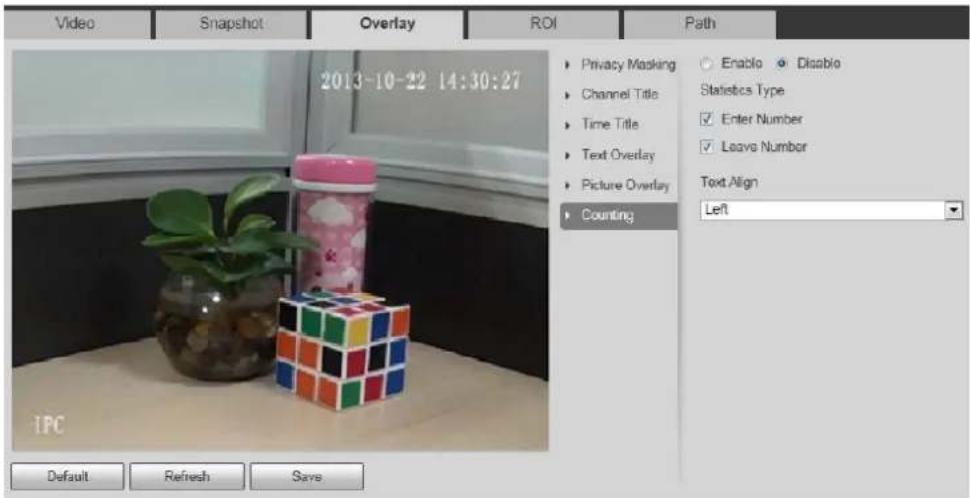
text_image
Video Snapshot Overlay ROI Path 2013-10-22 14:30:27 Privacy Masking Enable Disable Channel Title Statistics Type Time Title Enter Number Text Overlay Leave Number Picture Overlay Text Align Counting Left Default Refresh SaveStep 2 Select the Enable check box, and then configure counting method and alignment.
Move the counting box to the position you want in the image. Step 3
Click Save. Step 4
4.5.2.3.10 Configuring Structured Statistics
The image displays structured statistics. When the overlay function enabled during intelligent rules configuration, this function is enabled simultaneously.
Step 1 Select Setting > Camera > Video > Overlay > Structured Statistics.
The Structured Statistics interface is displayed. See Figure 4-59.
Structured statistics Figure 4-59
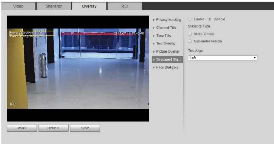
text_image
Video Snapshot Overlay ROI Face Detection (FX) Face Recognition (FX) IFC Privacy Masking Channel Title Time Title Text Overlay Picture Overlay Structured Sta... Face Statistics Enable Disable Statistics Type Motor Vehicle Non-motor Vehicle Text Align Left Default Refresh SaveStep 2 Select the Enable check box, select the statistics type, and then select text align.
Step 3 Move the structured statistics box to the position you want in the image.
Step 4 Click Save.
4.5.2.3.11 Configuring Ranging
Configure camera height and the display time of overlay information. Click any point on the ground that the pole is installed on the image, and the overlay information between camera and the selected point is displayed.
Step 1 Select Setting > Camera > Video > Overlay > Ranging.
The Ranging interface is displayed. See Figure 4-60.
Ranging Figure 4-60
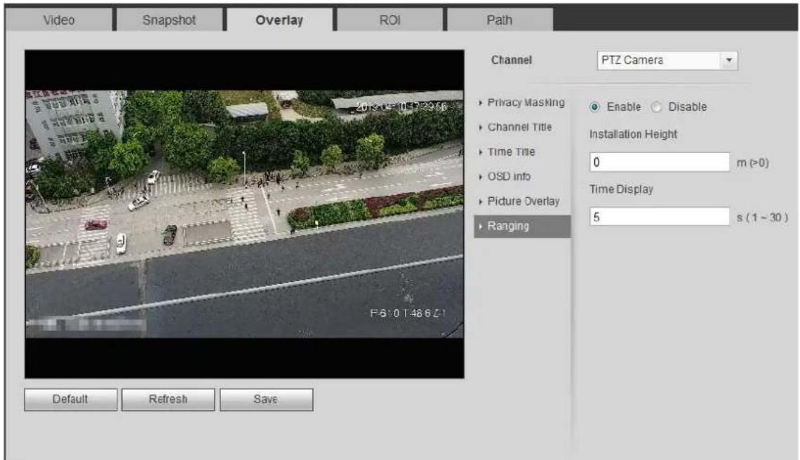
text_image
Video Snapshot Overlay ROI Path Channel PTZ Camera Privacy Masking Channel Title Time Title OSD info Picture Overlay Ranging Enable Disable Installation Height 0 m (>0) Time Display 5 s (1 ~ 30) Default Refresh SaveStep 2 Select the Enable check box, and then set the installation height and time display. Time display: The display time of the ranging information on live image.
Step 3 Click Save.
4.5.2.3.12 Configuring ANPR
The image displays ANPR statistics information. When the overlay function enabled during intelligent rules configuration, this function is enabled simultaneously.
Step 1 Select Setting > Camera > Video > Overlay > ANPR.
The ANPR interface is displayed. See Figure 4-61.
ANPR Figure 4-61
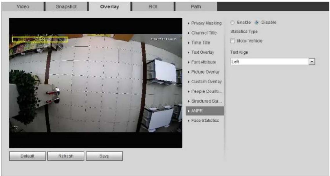
text_image
Video Snapshot Overlay ROI Path Privacy Masking Channel Title Time Title Text Overlay Font Attribute Picture Overlay Custom Overlay People Counti... Structured Sta... ANPR Face Statistics Enable Disable Statistics Type Motor Vehicle Text Align Left Default Refresh SaveStep 2 Select the Enable check box, select the statistics type, and then select text align.
Step 3 Move the ANPR box to the position you want in the image.
Step 4 Click Save.
4.5.2.3.13 Configuring Face Statistics
The image displays face statistics information. When the overlay function enabled during intelligent rules configuration, this function is enabled simultaneously.
Step 1 Select Setting > Camera > Video > Overlay > Face Statistics.
The Face Statistics interface is displayed. See Figure 4-62.
Face statistics Figure 4-62

text_image
Video Snapshot Overlay ROI Path ▶ Privacy Masking ▶ Channel Title ▶ Time Title ▶ Text Overlay ▶ Font Attribute ▶ Picture Overlay ▶ Custom Overlay ▶ People Counti... ▶ Face Statistics Enable Disable Text Align Left Default Refresh SaveStep 2 Select the Enable check box, and select the text align.
Step 3 Move the structured statistics box to the position you want in the image.
Step 4 Click Save.
4.5.2.4 ROI
Select ROI (region of interest) on the image and configure the image quality of ROI, and then the selected image is displayed at defined quality.
Step 1 Select Setting > Camera > Video > ROI.
The ROI interface is displayed. See Figure 4-63.
ROI Figure 4-63
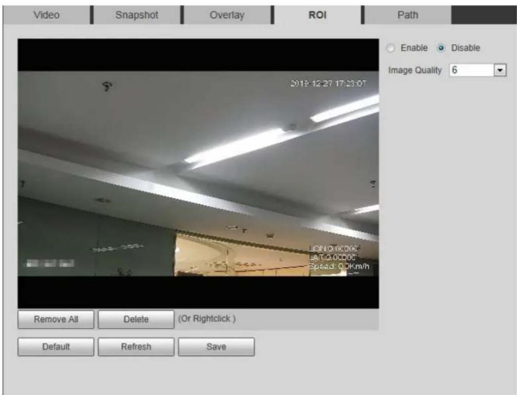
text_image
Video Snapshot Overlay ROI Path Enable Disable Image Quality 6 2018-12-27 17:33:07 LON 0.0000 LSTO 0.0000 Speed 0.0Km/h Remove All Delete (Or Rightclick ) Default Refresh SaveSelect the Enable check box, draw the area on the image, and then configure the Step 2 image quality of ROI.

- You can draw four area boxes at most.
- The higher the image quality value is, the better the quality will be.
- Click Remove All to delete all the area boxes; select one box, and then click Delete or right-click to delete it.
Click Save. Step 3
4.5.2.5 Path
You can configure the storage path for live snapshot, live record, playback snapshot, playback download, and video clips.
Step 1 Select Setting > Camera > Video > Path.
The Path interface is displayed. See Figure 4-64.
Path Figure 4-64
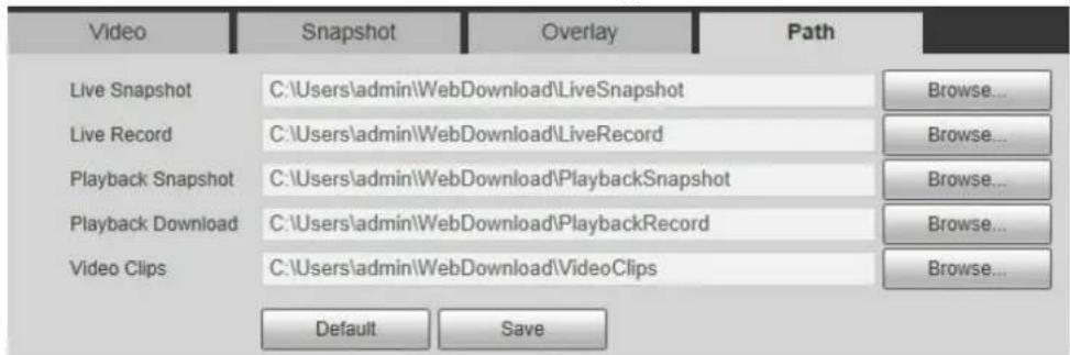
text_image
Video Snapshot Overlay Path Live Snapshot C:\Users\admin\WebDownload\LiveSnapshot Browse... Live Record C:\Users\admin%\WebDownload\LiveRecord Browse... Playback Snapshot C:\Users\admin%\WebDownload\PlaybackSnapshot Browse... Playback Download C:\Users\admin%\WebDownload\PlaybackRecord Browse... Video Clips C:\Users\admin%\WebDownload\VideoClips Browse... Default SaveStep 2 Click Browse to select the storage path for live snapshot, live record, playback snapshot, playback download, and video clips. For details, see Table 4-20.
Table 4-20 Description of path
| Parameter | Description | |
| Live Snapshot | The snapshot of live interface.The default path isC:\Users\admin\WebDownload\LiveSnapshot. | Admin in the path refers to the account being used. |
| Live Record | The recorded video of live interface.The default path isC:\Users\admin\WebDownload\LiveRecord. | |
| PlaybackSnapshot | The snapshot of playback interface.The default path isC:\Users\admin\WebDownload\PlaybackSnapshot. | |
| PlaybackDownload | The downloaded video of playback interface.The default path isC:\Users\admin\WebDownload\PlaybackRecord. | |
| Video Clips | The clipped video of playback interface.The default path isC:\Users\admin\WebDownload\VideoClips. | |
Click Save. Step 3
4.5.3 Audio
You can configure audio parameters and alarm audio.
4.5.3.1 Configuring Audio Parameter
This section introduces audio parameters, including encode mode, sampling frequency, audio in type, and noise filter.
Step 1 Select Setting > Camera > Audio > Audio.
The Audio interface is displayed. See Figure 4-65.
Audio Figure 4-65
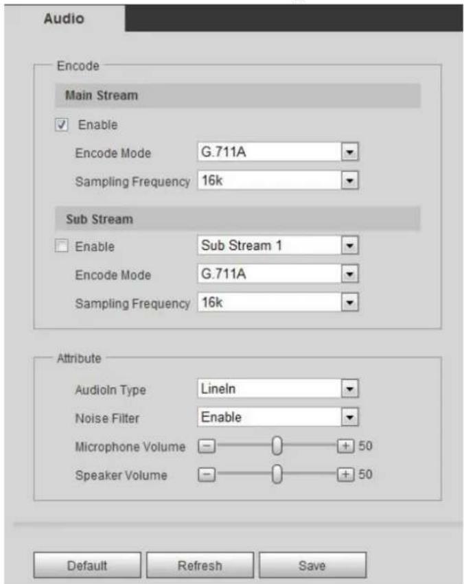
text_image
Audio Encode Main Stream Enable Encode Mode G.711A Sampling Frequency 16k Sub Stream Enable Sub Stream 1 Encode Mode G.711A Sampling Frequency 16k Attribute AudioIn Type Lineln Noise Filter Enable Microphone Volume - + 50 Speaker Volume - + 50 Default Refresh SaveStep 2 Select the Enable check box in Main Stream or Sub Stream.
For the camera with multiple channels, select the channel number.
Configure audio parameters. For details, see Table 4-21. Step 3
Table 4-21 Description of audio parameters
| Parameter | Description |
| Encode Mode | You can select audio Encode Mode from G.711A, G.711Mu, AAC, G.726.The configured audio encode mode applies to both audio and intercom. The default value is recommended. |
| Sampling Frequency | Sampling number per second. The higher the sampling frequency is, the more the sample in a second will be, and the more accuracy the restored signal will be. You can select audio Sampling Frequency from 8K, 16K, 32K, 48K, 64K. |
| Audioin Type | You can select audioin type from:Linein: Requires external audio device.Mic: Not require external audio device. |
| Noise Filter | Enable this function, and the system auto filters ambient noise. |
| Microphone Volume | Adjusts microphone volume. |
| Speaker Volume | Adjusts speaker volume. |
Click Save. Step 4
4.5.3.2 Configuring Alarm Audio
You can record or upload alarm audio file. The audio file will be played when the alarm is triggered.
- Click to play the selected audio.
- Click to download the audio to local storage.
Step 1 Select Setting > Camera > Audio > Alarm Audio.
The Alarm Audio interface is displayed. See Figure 4-66.
Alarm audio Figure 4-66
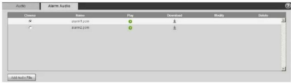
text_image
Audio Alarm Audio Choose Name Play Download Modify Delete alarm1.com 0 1 alarm2.com 0 1 Add Audio File____ Click Add Audio File. Step 2
The Add Audio File dialog box is displayed. See Figure 4-67.
Add audio file Figure 4-67
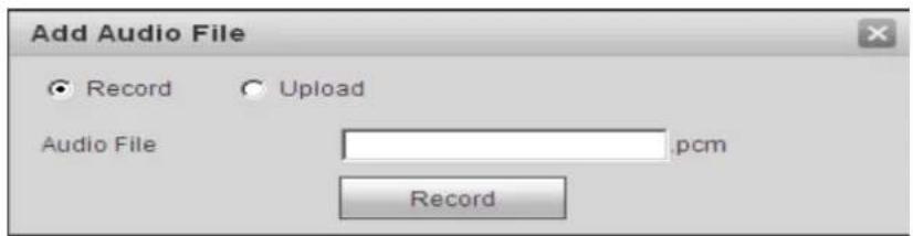
text_image
Add Audio File Record Upload Audio File pcm RecordConfigure the audio file. Step 3
- Select Record, enter the audio name in the input box, and then click Record.
- Select Upload, click to select the audio file to be uploaded, and then click Upload.

The camera supports audio file with .pcm format only, and you can upload audio files with .pcm or .wav2 formats.
Select the file you need. Step 4
4.6 Network
This section introduces network configuration.
4.6.1 TCP/IP
You can configure IP address and DNS (Domain Name System) server and so on according to network planning.
Preparation
The camera has connected to the network.
Procedure
Step 1 Select Setting > Network > TCP/IP.
The TCP/IP interface is displayed. See Figure 4-68.
TCP/IP Figure 4-68
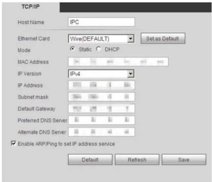
text_image
TCP/IP Host Name IPC Ethernet Card Wire(DEFAULT) Set as Default Mode Static DHCP MAC Address IP Version IPv4 IP Address Subnet mask Default Gateway Preferred DNS Server Alternate DNS Server Enable ARP/Ping to set IP address service Default Refresh SaveConfigure TCP/IP parameters. For details, see Table 4-22. Step 2
Table 4-22 Description of TCP/IP parameters
| Parameter | Description |
| Host Name | Enter the host name, and the maximum length is 15 characters. |
| Ethernet Card | Select the Ethernet card that need to be configured, and the default one is Wire. |
| Mode | The mode that the camera gets IP:StaticConfigure IP Address, Subnet Mask, and Default Gateway manually, and then click Save, the login interface with the configured IP address is displayed.DHCPWhen there is DHCP server in the network, select DHCP, and the camera acquires IP address automatically. |
| MAC Address | Displays host MAC address. |
| IP Version | Select IPv4 or IPv6. |
| IP Address | When you selectStaticin Mode, enter the IP address and subnet mask that you need. ---IPv6 does not have subnet mask.The default gateway must be in the same network segment with the IP address. ---IPv6 does not have subnet mask.The default gateway must be in the same network segment with the IP address. |
| Subnet Mask | |
| Default Gateway | |
| Preferred DNS | IP address of the preferred DNS |
| Alternate DNS | IP address of the alternate DNS |
| Enable ARP/Ping to set IP address service | Select the check box, get the camera MAC address, and then you can modify and configure the device IP address with ARP/ping command.This is enabled by default. During reboot, you will have no more than 2 minutes to configure the device IP address by a ping packet with certain length, the server will be turned off in 2 minutes, or it will be turned off immediately after the IP address is successfully configured. If this is not enabled, the IP address cannot be configured with ping packet.A demonstration of configuring IP address with ARP/Ping.1. Keep the camera that needs to be configured and the PC within the same local network, and then get a usable IP address.2. Get the MAC address of the camera from device label.3. Open command editor on the PC and enter the following command.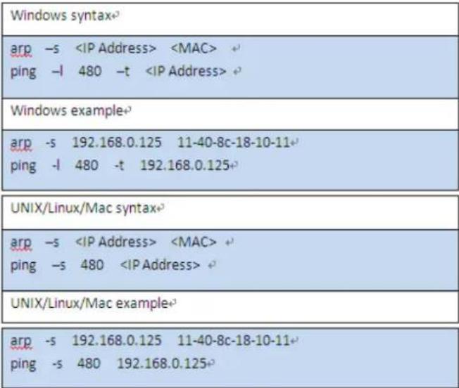 4. Reboot camera.5. Check the PC command line, if information such asReply from 192.168.0.125... is displayed, the configuration succeeds, and you can turn it off then.6. Enter http://(IP address) in the browser address bar to log in. 4. Reboot camera.5. Check the PC command line, if information such asReply from 192.168.0.125... is displayed, the configuration succeeds, and you can turn it off then.6. Enter http://(IP address) in the browser address bar to log in. |
Click Save. Step 3
4.6.2 Port
Configure the port numbers and the maximum number of users (includes web, platform client, and mobile phone client) that can connect to the device simultaneously.
Step 1 Select Setting > Network > Port.
The Port interface is displayed. See Figure 4-69.
Port Figure 4-69

text_image
Port Max Connection 10 (1~20) TCP Port 37777 (1025~65534) UDP Port 37778 (1025~65534) HTTP Port 80 RTSP Port 554 RTMP Port 1935 (1025~65534) HTTPS Port 443 Default Refresh SaveConfigure port parameters. For details, see Table 4-23. Step 2

- 0–1024, 1900, 3800, 5000, 5050, 9999, 37776, 37780–37880, 39999, 42323 are occupied for specific uses.
- Do not use the same value of any other port during port configuration.
Table 4-23 Description of port parameters
| Parameter | Description |
| Max Connection | The max number of users (web client, platform client or mobile phone client) that can connect to the device simultaneously. The value is 10 by default. |
| TCP Port | Transmission control protocol port. The value is 37777 by default. |
| UDP Port | User datagram protocol port. The value is 37778 by default. |
| HTTP Port | Hyper text transfer protocol port. The value is 80 by default. |
| RTSP Port | Real time streaming protocol port, and the value is 554 by default. If you play live view with QuickTime, VLC or Blackberry smart phone, the following URL format is available.When the URL format requiring RTSP, you need to specify channel number and bit stream type in the URL, and also user name and password if needed.When playing live view with Blackberry smart phone, you need to turn off the audio, and then set the codec mode to H.264B and resolution to CIF.URL format example:rtsp://username:password@ip:port/cam/realmonitor?channel=1&subtype=0Among that:Username: The user name, such as admin.Password: The password, such as admin.IP: The device IP, such as 192.168.1.112.Port: Leave it if the value is 554 by default.Channel: The channel number, which starts from 1. For example, if you are using channel 2, then the channel=2.Subtype: The bit stream type; 0 means main stream (Subtype=0) and 1 means sub stream (Subtype=1).Example: If you require the sub stream of channel 2 from a certain device, then the URL should be:rtsp://admin:admin@10.12.4.84:554/cam/realmonitor?channel=2&subtype=1If user name and password are not needed, then the URL can be:rtsp://ip:port/cam/realmonitor?channel=1&subtype=0 |
| RTMP Port | Real Time Messaging Protocol. The port that RTMP provides service. It is 1935 by default. |
| HTTPS Port | HTTPS communication port. It is 443 by default. |
Click Save. Step 3

The configuration of Max Connection takes effect immediately, and others will take effect after reboot.
4.6.3 PPPoE
Point-to-Point Protocol over Ethernet, it is one of the protocols that device uses to connect to the internet. Get the PPPoE user name and password from the internet service provider, and then set up network connection through PPPoE, the camera will acquire a WAN dynamic IP address.

- Disable UPnP while using PPPoE to avoid possible influence.
- After making PPPoE connection, the device IP address cannot be modified through web interface.
Preparation
• The camera has connected to the network.
• You have gotten the account and password from Internet Service Provider.
Procedure
Step 1 Select Setting > Network > PPPoE.
The PPPoE interface is displayed. See Figure 4-70.
PPPoE Figure 4-70
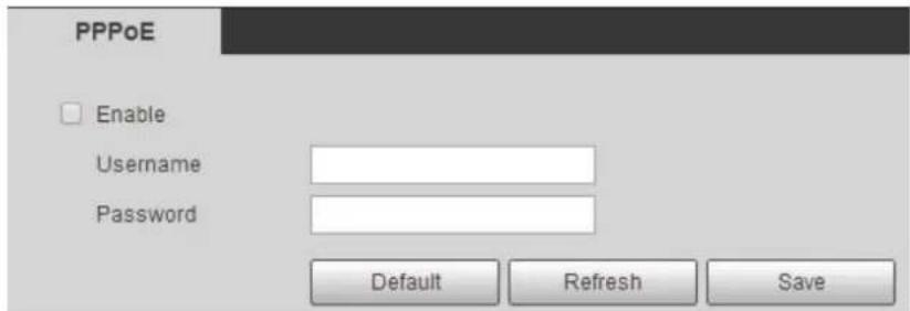
text_image
PPPoE Enable Username Password Default Refresh SaveSelect the Enable check box, and then enter user name and password. Step 2
Click Save. Step 3
The success prompt box is displayed, and then the real-time WAN IP address is displayed. You can visit camera through the IP address.
4.6.4 DDNS
Properly configure DDNS, and then the domain name on the DNS server matches your IP address and the matching relation refreshes in real time. You can always visit the camera with the same domain name no matter how the IP address changes.

• Third party server might collect your device information after DDNS is enabled.
- Register and log in to the DDNS website, and then you can view the information of all the connected devices in your account.
Preparation
Check the type of DNS server supported by the camera.
Procedure
Step 1 Select Setting > Network > DDNS.
The DDNS interface is displayed. See Figure 4-71.
DDNS (1) Figure 4-71
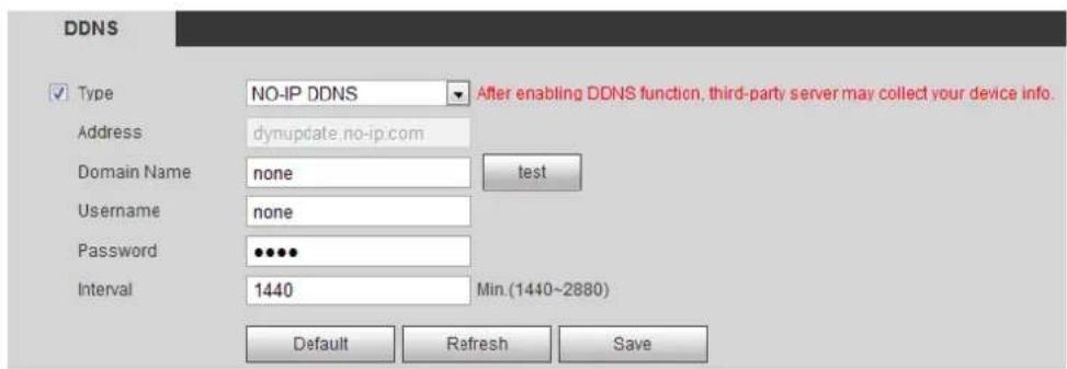
text_image
DDNS ✓ Type NO-IP DDNS After enabling DDNS function, third-party server may collect your device info. Address dynupdate.no-ip.com Domain Name None funds Username:none Password ●●●● Interval 1440 Min.(1440~2880) Default Refresh SaveStep 2 Select Type, and configure the parameters as needed. For details, see Table 4-24.
Table 4-24 Description of DDNS parameters
| Parameter | Description |
| Type | The name and web address of the DDNS service provider, see the matching relationship below:• CN99 DDNS web address: www.3322.org• NO-IP DDNS web address: dynupdate.no-ip.com• Dyndns DDNS web address: members.dyndns.org |
| Web Address | |
| Domain Name | The domain name you registered on the DDNS website. |
| Test | Only when selecting NO-IP DDNS type, you can click test to check whether the domain name registration is successful. |
| Username | Enter the user name and password that you got from the DDNS server provider. You need to register an account (includes user name and password) on the DDNS server provider's website. |
| Password | |
| Interval | The update cycle of the connection between the device and the server, and the time is 10 minutes by default. |
Click Save. Step 3
Verification
Open the browser on PC, enter the domain name at the address bar, and then press Enter, the login interface is displayed.
4.6.5 SMTP (Email)
Configure email parameter and enable email linkage. The system sends email to the defined address when the corresponding alarm is triggered.
Step 1 Select Setting > Network > SMTP (Email).
The SMTP (Email) interface is displayed. See Figure 4-72.
SMTP (Email) Figure 4-72
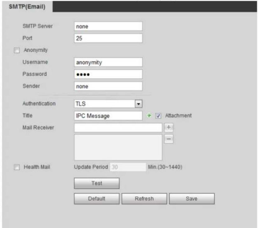
text_image
SMTP(Email) SMTP Server none Port 25 Anonymity Username anonymity Password ••••• Sender none Authentication TLS Title IPC Message + Attachment Mail Receiver + Health Mail Update Period 30 Min.(30~1440) Test Default Refresh SaveConfigure SMTP (Email) parameters. For details, see Table 4-25. Step 2
Table 4-25 Description of SMTP (Email) parameters
| Parameter | Description | |
| SMTP Server | SMTP server address |  For details, see "Table 4-26." For details, see "Table 4-26." |
| Port | The port number of the SMTP server. | |
| Username | The account of SMTP server. | |
| Password | The password of SMTP server. | |
| Anonymity | Select the check box, and the sender's information is not displayed in the email. | |
| Sender | Sender's email address. | |
| Authentication | Select Authentication from None, SSL and TLS.[BTZT]For details, see "Table 4-26." | |
| Title | Enter maximum 63 characters in Chinese, English, and Arabic numerals.Click + to select title type, including Name, Device ID, and Event Type, and you can set maximum 2 titles. | |
| Attachment | Select the check box to support attachment in the email. | |
| Mail Receiver | Receiver's email address. Supports 3 addresses at most. | |
| Health Mail | The system sends test mail to check if the connection is successfully configured. Select Health Mail and configure the Update Period, and then the system sends test mail as the set interval. | |
For the configuration of major mailboxes, see Table 4-26.
Table 4-26 Description of major mailbox configuration
| Mailbox | SMTP server | Authentication | Port | Description |
| smtp.qq.com | SSL | 465 | The authentication type cannot be None.You need to enable SMTP service in your mailbox.The authentication code is required, the QQ password or email password is not applicable. Authentication code: The code you receive when enabling SMTP service. Authentication code: The code you receive when enabling SMTP service. | |
| TLS | 587 | |||
| 163 | smtp.163.com | SSL | 465/994 | You need to enable SMTP service in your mailbox.The authentication code is required; the email password is not applicable. Authentication code: the code you receive when enabling SMTP service. Authentication code: the code you receive when enabling SMTP service. |
| TLS | 25 | |||
| none | 25 | |||
| Sina | smtp.sina.com | SSL | 465 | Enable SMTP service in your mailbox. |
| none | 25 | |||
| 126 | smtp.126.com | none | 25 | Enable SMTP service in your mailbox. |
Click Save. Step 3
Step 4 Click Test to test whether the emails can be sent and received successfully.
4.6.6 UPnP
UPnP (Universal Plug and Play), a protocol that establishes mapping relation between local area and wide area networks. This function enables you to visit local area device through wide area IP address.
Preparation
- Make sure the UPnP service is installed in the system.
- Log in the router, and configure WAN IP address to set up internet connection.
- Enable UPnP in the router.
- Connect your device to the LAN port of the router.
- Select Setting > Network > TCP/IP, in IP Address, enter the local area IP address of the router or select DHCP and acquires IP address automatically.
Procedure
Step 1 Select Setting > Network > UPnP.
The UPnP interface is displayed. See Figure 4-73.
UPnP Figure 4-73
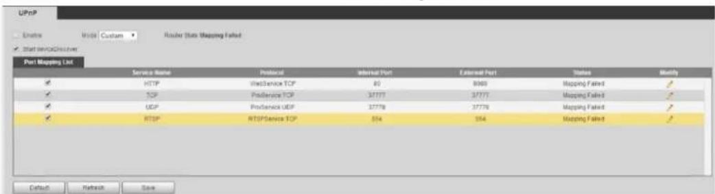
text_image
UPnP Enable User Custom Router State Mapping Failed Start serviceDiscover Port Mapping List Service Name Protocol Internal Port External Port Status Modify HTTP fixedService TCP 80 8000 Mapping Failed ✓ TCP Provider TCP 37777 37777 Mapping Failed ✓ UDP Provider UDP 37778 37778 Mapping Failed ✓ RTSP Provider TCP 354 354 Mapping Failed ✓ Default Network SaveStep 2 Select the Enable check box, and there are two mapping modes: Custom and Default.
- Select Custom, click and then you can modify external port as needed.
- Select Default, and then the system finishes mapping with unoccupied port automatically, and you cannot modify mapping relation.
Click Save. Step 3
Open web browser on PC, enter http:// wide area IP address: external port number, and then you can visit the local area device with corresponding port.
4.6.7 SNMP
SNMP (Simple Network Management Protocol), which can be used to enable software such as MIB Builder and MG-SOFT MIB Browser to connect to the camera and manage and monitor the camera.
Preparation
- Install SNMP monitoring and managing tools such as MIB Builder and MG-SOFT MIB Browser.
- Get the MIB file of the matched version from technical support.
Procedure
Step 1 Select Setting > Network > SNMP.
The SNMP interface is displayed. See Figure 4-74 and Figure 4-75.
SNMP (1) Figure 4-74
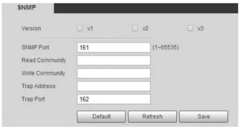
text_image
SNMP Version v1 v2 v3 SNMP Port 161 (1~65535) Read Community Write Community Trap Address Trap Port 162 Default Refresh SaveSNMP (2) Figure 4-75
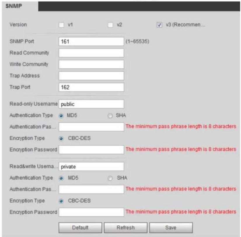
text_image
SNMP Version v1 v2 v3 (Recommend... SNMP Port 161 (1~65535) Read Community Write Community Trap Address Trap Port 162 Read-only Username public Authentication Type MD5 SHA Authentication Pas... The minimum pass phrase length is 8 characters Encryption Type CBC-DES Encryption Password The minimum pass phrase length is 8 characters Read&write Userna... private Authentication Type MD5 SHA Authentication Pas... The minimum pass phrase length is 8 characters Encryption Type CBC-DES Encryption Password The minimum pass phrase length is 8 characters Default Refresh SaveSelect SNMP version to enable SNMP. Step 2
- Select V1, and the system can only process information of V1 version.
- Select V2, and the system can only process information of V2 version.
- Select V3, and then V1 and V2 become unavailable. You can configure user name, password and authentication type. It requires corresponding user name, password and authentication type to visit your device from the server.

Using V1 and V2 might cause data leakage, and V3 is recommended.
In Trap Address, enter the IP address of the PC that has MIB Builder and MG-SOFT MIB Browser installed, and leave other parameters to the default.
Table 4-27 Description of SNMP parameters
| Parameter | Description |
| SNMP Port | The listening port of the software agent in the device. |
| Read Community, Write Community | The read and write community string that the software agent supports. You can enter number, letter, underline and dash to form the name. You can enter number, letter, underline and dash to form the name. |
| Trap Address | The target address of the Trap information sent by the software agent in the device. |
| Trap Port | The target port of the Trap information sent by the software agent in the device. |
| Read-onlyUsername | Set the read-only username accessing device, and it is public by default. You can enter number, letter, and underline to form the name. You can enter number, letter, and underline to form the name. |
| Read/WriteUsername | Set the read/write username access device, and it is public by default. You can enter number, letter, and underline to form the name. You can enter number, letter, and underline to form the name. |
| Authentication Type | You can select from MD5 and SHA. The default type is MD5. |
| AuthenticationPassword | It should be no less than 8 digits. |
| Encryption Type | The default is CBC-DES. |
| EncryptionPassword | It should be no less than 8 digits. |
Click Save. Step 3
Verification
View device configuration through MIB Builder or MG-SOFT MIB Browser.
Step 1 Run MIB Builder and MG-SOFT MIB Browser.
____ Compile the two MIB files with MIB Builder. Step 2
Load the generated modules with MG-SOFT MIB Browser. Step 3
____ Enter the IP address of the device you need to manage in the MG-SOFT MIB Browser, Step 4 and then select version to search.
____ Unfold all the tree lists displayed in the MG-SOFT MIB Browser, and then you can view Step 5 the configuration information, video channel amount, audio channel amount, and software version.

Use PC with Windows OS and disable SNMP Trap service. The MG-SOFT MIB Browser will display prompt when alarm is triggered.
4.6.8 Bonjour
Enable this function, and the OS and clients that support Bonjour would find the camera automatically. You can have quick visit to the camera with Safari browser.

Bonjour is enabled by default.
Procedure
Step 1 Select Setting > Network > Bonjour.
The Bonjour interface is displayed. See Figure 4-76.
Bonjour Figure 4-76
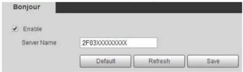
text_image
Bonjour Enable Server Name 2F03XXXXXXXXX Default Refresh SaveSelect the Enable check box, and then configure server name. Step 2
Click Save. Step 3
Verification
In the OS and clients that support Bonjour, follow the steps blow to visit the network camera with Safari browser.
Step 1 Click Show All Bookmarks in Safari.
Step 2 Enable Bonjour. The OS or client automatically detects the network cameras with Bonjour enabled in the LAN.
Click the camera to visit the corresponding web interface. Step 3
4.6.9 Multicast
When multiple users are previewing the device video image simultaneously through network, it might fail due to limited bandwidth. You can solve this problem by setting up a multicast IP (224.0.1.0–238.255.255.255) for the camera and adopt the multicast protocol.
Procedure
Step 1 Select Setting > Network > Multicast.
The Multicast interface is displayed. See Figure 4-77.
Multicast Figure 4-77
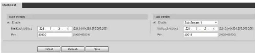
text_image
Multicast Main Stream Enable Multicast Address 224 1 2 4 (224.0.0-239.255.255.255) Port 40000 (1025-65500) Sub Stream Enable Sub Stream 1 Multicast Address 224 1 2 4 (224.0.0-239.255.255.255) Port 40016 (1025-65500) Default Refresh SaveSelect the Enable check box, and enter IP address and port number. For details, see Step 2 Table 4-28.
Table 4-28 Description of multicast parameters
| Parameter | Description |
| Multicast Address | The multicast IP address ofMain Stream/Sub Streamis 224.1.2.4 by default, and the range is 224.0.0.0–239.255.255.255. |
| Port | The multicast port of corresponding stream:Main Stream:40000;Sub Stream1:40016;Sub Stream2:40032, and all the range is 1025–65500. |
Click Save. Step 3
Verification
In the Live interface, select RTSP in Multicast, and then you can view the video image with multicast protocol.
4.6.10 802.1x
Cameras can connect to LAN after passing 802.1x authentication.
Step 1 Select Setting > Network > 802.1x.
The 802.1x interface is displayed. See Figure 4-78.
Figure 4-78 802.1x

text_image
802.1x Enable Authentication PEAP Username none Password ...... Default Refresh SaveStep 2 Select the Enable check box, and then configure parameters. For details, see Table 4-29.
Table 4-29 Description of 802.1x parameters
| Parameter | Description |
| Authentication | PEAP (protected EAP protocol). |
| Username | The user name that was authenticated on the server. |
| Password | Corresponding password. |
Click Save. Step 3
4.6.11 QoS
You can solve problems such as network delay and congestion with this function. It helps to assure bandwidth, reduce transmission delay, packet loss rate, and delay jitter to improve experience.
0–63 means 64 degrees of priority; 0 for the lowest and 63 the highest.
Step 1 Select Setting > Network > QoS.
The QoS interface is displayed. See Figure 4-79.
QoS Figure 4-79
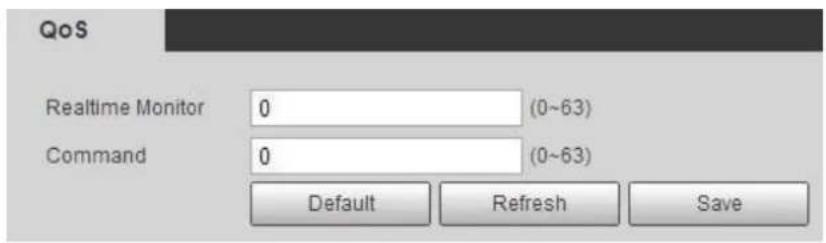
text_image
QoS Realtime Monitor 0 (0~63) Command 0 (0~63) Default Refresh SaveConfigure QoS parameters. For details, see Table 4-30. Step 2
Table 4-30 Description of QoS parameters
| Parameter | Description |
| Realtime Monitor | Configure the priority of the data packets that used for network surveillance. 0 for the lowest and 63 the highest. |
| Command | Configure the priority of the data packets that used for configure or checking. |
Click Save. Step 3
4.6.12 Access Platform
4.6.12.1 P2P
P2P is a private network traversal technology which enables user to manage devices easily without requiring DDNS, port mapping or transit server.
Scan the QR code with your smart phone, and then you can add and manage more devices on the mobile phone client.
Step 1 Select Setting > Network >Access Platform > P2P.
The P2P interface is displayed. See Figure 4-80.
P2P Figure 4-80
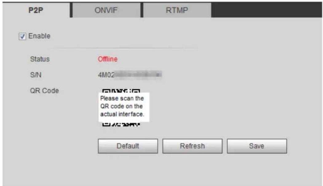
text_image
P2P ONVIF RTMP ✓ Enable Status Offline S/N 4M02 QR Code Please scan the QR code on the actual interface. OK/Cancel Default Refresh Save- When P2P is enabled, remote management on device is supported.
- When P2P is enabled and the device accesses to the network, the status shows online. The information of the IP address, MAC address, device name, and device SN will be collected. The collected information is for remote access only. You can cancel Enable selection to reject the collection.
Log in to mobile phone client and tap Device management. Step 2
Tap the + at the upper right corner. Step 3
Scan the QR code on the P2P interface. Step 4
____ Follow the instructions to finish the settings. Step 5
4.6.12.2 ONVIF
The ONVIF authentication is On by default, which allows the network video products (including video recording device and other recording devices) from other manufacturers to connect to your device.

ONVIF is enabled by default.
Step 1 Select Setting > Network > Port > ONVIF.
The ONVIF interface is displayed. See Figure 4-81.
ONVIF Figure 4-81
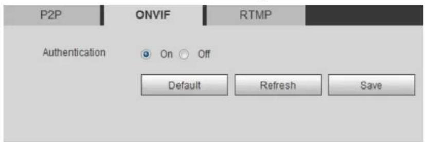
text_image
P2P ONVIF RTMP Authentication On Off Default Refresh SaveStep 2 Select On in Authentication.
Click Save. Step 3
4.6.12.3 RTMP
Through RTMP, you can access the third-party platform (such as Ali and YouTube) to realize video live view.

- RTMP can be configured by admin only.
- RTMP supports the H.264, H.264 B and H.264H video formats, and the AAC audio format only.
Step 1 Select Setting > Network > Port > RTMP.
The RTMP interface is displayed. See Figure 4-82.
ONVIF Figure 4-82
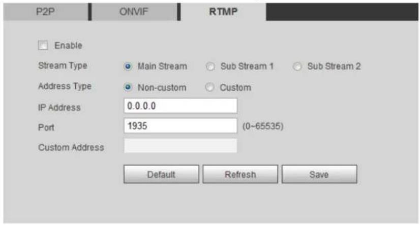
text_image
P2P ONVIF RTMP Enable Stream Type Main Stream Sub Stream 1 Sub Stream 2 Address Type Non-custom Custom IP Address 0.0.0.0 Port 1935 (0~65535) Custom Address Default Refresh SaveSelect the Enable check box. Step 2

Make sure that the IP address is trustable when enabling RTMP.
Configure RTMP parameters. For details, see Table 4-31. Step 3
Table 4-31 Description of RTMP parameters
| Parameter | Description |
| Stream Type | The stream for live view. Make sure that the video format is the H.264, H.264 B and H.264H, and the audio format is AAC. |
| Address Type | Includes Non-custom and Custom.Non-custom: Enter the server IP and domain name.Custom: Enter the path allocated by the server. |
| IP Addreaa | When selecting Non-custom, you need to enter server IP address and port.IP address: Support IPv4 or domain name.Port: We recommend that you use the default one. |
| Port | |
| Custom Address | When selecting Custom, you need to enter the path allocated by the server. |
Click Save. Step 4
Storage 4.7
This section introduces how to manage saved resources (such as recorded video) and storage space. The storage management helps to make best use of storage space.
4.7.1 Setting Storage Plan
- Setting record plan and record control to achieve all-time recording, recording in specific period or alarm linked recording. For details, see "5.1.1.2.1 Setting Record Plan" and "5.1.1.2.2 Setting Record Control."
- Set the snapshot schedule as needed. "5.1.1.3.1 Setting Snapshot Plan."
4.7.2 Setting Schedule
You can configure record schedule, snapshot schedule and holiday schedule.

When holiday schedule setting is not the same as the general setting, holiday schedule setting is prior to the general setting. For example, with Holiday Schedule enabled, if the day is holiday, the system snapshots or records as holiday schedule setting; otherwise, the system snapshots or records as general setting
Set certain days as holiday, and when the Record or Snapshot is selected in the holiday schedule, the system takes snapshot or records video as holiday schedule defined.
Preparation
- Set the record mode to be Auto in Record Control. For details, see "5.1.1.2.1 Setting Record Plan."
- Configure holiday record and snapshot schedule. For details, see "5.1.1.2.1 Setting Record Plan" and "5.1.1.3.1 Setting Snapshot Plan."
Procedure
Step 1 Select Setting > Storage > Schedule > Holiday Schedule.
The Holiday Schedule interface is displayed. See Figure 4-83.
Holiday schedule Figure 4-83

text_image
Record Snapshot Holiday Schedule Record Snapshot Calendar Jul Sun Mon Tue Wen Thu Fri Sat 1 2 3 4 5 6 7 8 9 10 11 12 13 14 15 16 17 18 19 20 21 22 23 24 25 26 27 28 29 30 31 Refresh SaveSelect Record or Snapshot. Step 2
Select the days you need to set as holiday. Step 3
Those days with yellow color indicates that they were set as holidays.
Click Save. Step 4
4.7.3 Setting Destination
This section introduces the configuration of the storage method for the recorded videos and snapshots.
4.7.3.1 Path
You can select different storage paths for the recorded videos and snapshots according to event type. You can select from SD card, FTP and NAS.

Local is displayed only on models that support SD card.
Select Setting > Storage > Destination > Path. Step 1
The Path interface is displayed. See Figure 4-84.
Path Figure 4-84
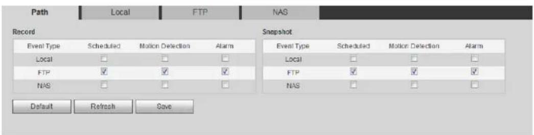
text_image
Path Local FTP NAS Record Snapshot Event Type Scheduled Motion Detection Alarm Local □ □ □ FTP ✓ ✓ ✓ NAS □ □ □ Event Type Scheduled Motion Detection Alarm Local □ □ □ FTP ✓ ✓ ✓ NAS □ □ □ Default Refresh Save____ Select the storage method that you need for the recorded videos and snapshots of Step 2 different types.
Table 4-32 Description of path parameters
| Parameter | Description |
| Event Type | Select fromScheduled, Motion Detection and Alarm. |
| Local | Save in the internal SD card. |
| FTP | Save in the FTP server. |
| NAS | Save in the NAS (network attached storage). |
Click Save. Step 3
Step 4 Configure other path parameters on Destination, FTP or NAS interface. For details, see "4.7.3 Setting Destination", "4.7.3.3 FTP" or "4.7.3.4 NAS."
4.7.3.2 Local
Display the information of the local SD card. You can set it as read only or read & write; you can also hot swap and format SD card, and reset password for it. When inserting Dahua smart card onto a device available for it, there are 3 modes according to the SD card status:
- Normal mode: The new SD cards and the cards whose password are cleared successfully show normal mode. The SD cards of this status do not support authorization operation.
- Unauthorized mode: The SD card authorized by other devices shows unauthorized mode. The SD cards of this status do not support operations of setting read only, read & write, formatting and encryption.
- Encrypted mode: The SD cards encrypted and authorized on this camera show encrypted mode. The camera can record max. 10 pieces of encrypted SD information. When the recorded videos exceed 10 pieces, the earliest ones will be overwritten.

• Functions might vary with different models, and the actual product shall prevail.
- If you enter the wrong password for five times when authorizing, modifying, and clearing password, the camera will be locked for five minutes.
• Make sure that the SD card has been authorized before recording and playback.
• The health status of SD card:
◇ Green: The health status is excellent.
◇ Blue: The health status is good.
◇ Orange: The health status is moderate.
◇ Red: The health status is poor, and you need to replace the SD card.
Select Setting > Storage > Destination > Local, and then the Local interface is displayed. See Figure 4-85.
- Click Read Only, and then the SD card is set to read only.
- Click Read & Write, and then the SD card is set to read & write.
- Click Hot Swap, and then you can pull out the SD card.
- Click Refresh, and then you can format the SD card.
Local Figure 4-85
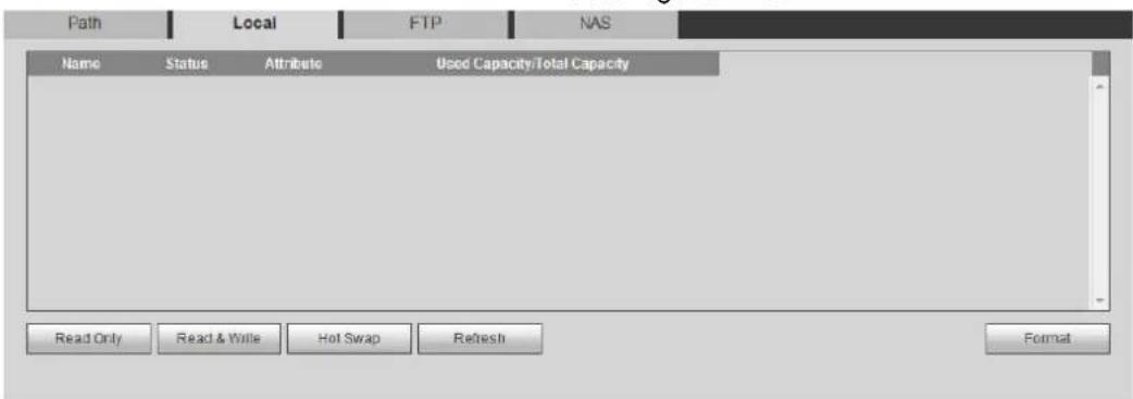
text_image
Path Local FTP NAS Name Status Attribute Used Capacity/Total Capacity Read Only Read & Write Hot Swap Refresh Format4.7.3.3 FTP
FTP function can be enabled only when it was selected as a destination path. When the network does not work, you can save all the files to the internal SD card for emergency.
Step 1 Select Setting > Storage > Destination > FTP. The FTP interface is displayed. See Figure 4-86.
FTP Figure 4-86
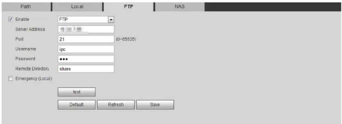
text_image
Path Local FTP NAS Enable FTP Server Address Port 21 (0-65535) Username ipc Password *** Remote Directory share Emergency (Local) test Default Refresh SaveStep 2 Select the Enable check box to enable FTP function, and select the FTP type.

You select FTP or SFPT from the drop-down list. SFTP is recommended to enhance network security.
Configure FTP parameters. For details, see Table 4-33. Step 3
Table 4-33 Description of FTP parameters
| Parameter | Description |
| Server Address | The IP address of the FTP server. |
| Port | The port number of the FTP server. |
| Username | The user name to log in to the FTP server. |
| Password | The password to log in to the FTP server. |
| Remote Directory | The destination path in the FTP server. |
| Emergency (Local) | Select Emergency (Local), and when the FTP server does not work, all the files are saved to the internal SD card. |
Click Save. Step 4
Step 5 Click test to test whether FTP function works normally.
4.7.3.4 NAS
This function can be enabled only when NAS was selected as a destination path. Enable this function, and you can save all the files in the NAS.
Select Setting > Storage > Destination > NAS. Step 1
The NAS interface is displayed. See Figure 4-87.
NAS Figure 4-87
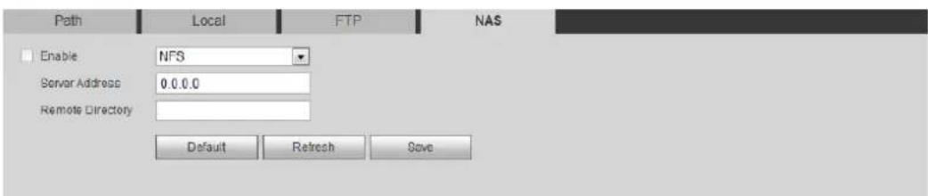
text_image
Path Local FTP NAS Enable NFS Server Address 0.0.0.0 Remote Directory Default Refresh SaveStep 2 Select the Enable check box to enable NAS function, and select NAS protocol type.
- NFS (Network File System): A file system which enables computers in the same network share files through TCP/IP.
- SMB (Server Message Block): Provides shared access for clients and the server.
Configure NAS parameters. For details, see Table 4-34. Step 3
Table 4-34 Description of NAS parameters
| Parameter | Description |
| Server Address | The IP address of the NAS server. |
| Username | When selecting SMB protocol, you are required to enter user name and password. Enter them as needed. |
| Password | |
| Remote Directory | The destination path in the NAS server. |
Click Save. Step 4
System 4.8
This section introduces system configurations, including general, date & time, account, safety, PTZ settings, default, import/export, remote, auto maintain and upgrade.
4.8.1 General
You can configure device name, language and video standard.
Select Setting > System > General > General. Step 1
The General interface is displayed. See Figure 4-88.
General Figure 4-88
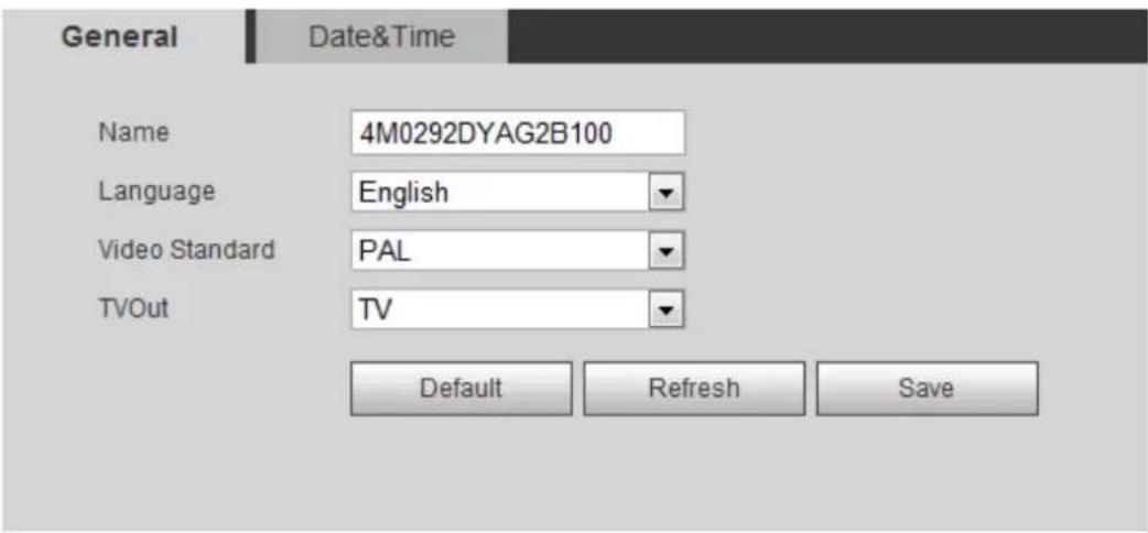
text_image
General Date&Time Name 4M0292DYAG2B100 Language English Video Standard PAL TVOut TV Default Refresh SaveConfigure general parameters. For details, see Table 4-35. Step 2
Table 4-35 Description of general parameters
| Parameter | Description |
| Name | The name of the device.Each device has its own name. |
| Language | Select system language. |
| Video Standard | Select video standard fromPALandNTSC. |
| TVOut | SelectOnorOff.This function is available on models with analog output. If the TV out isOn, smart plans will be disabled; if the smart plans are enabled, the TV out will be set asOff.SDI and HDCVI are available on select models. If the TV out isOn, smart plans will be disabled; if the smart plans are enabled, the TV out will be set asOff.SDI and HDCVI are available on select models. |
Click Save. Step 3
4.8.2 Date & Time
You can configure date and time format, time zone, current time, DST (Daylight Saving Time) or NTP server.
Select Setting > System > General > Date & Time. Step 1
The Date & Time interface is displayed. See Figure 4-89.
Date and time Figure 4-89
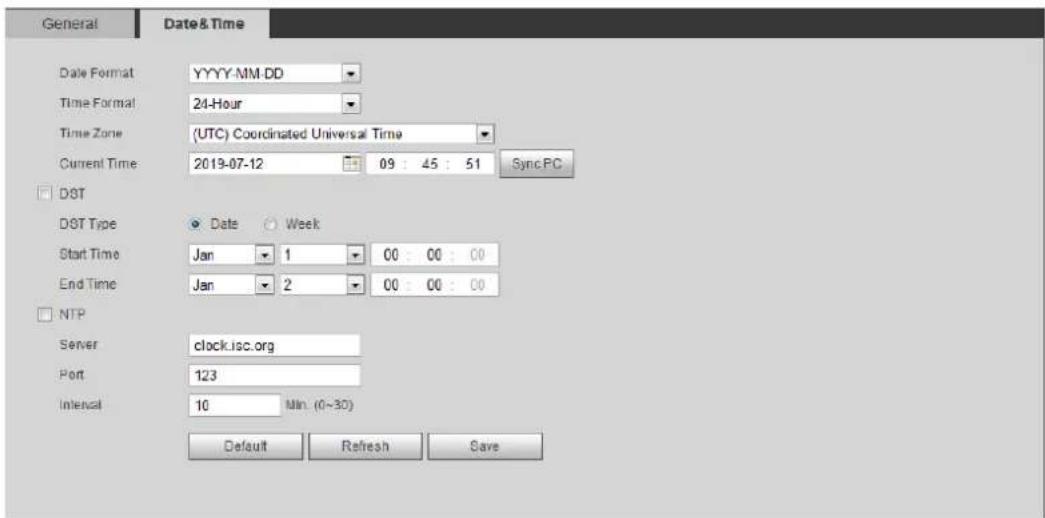
text_image
General Date&Time Date Format YYYY-MM-DD Time Format 24-Hour Time Zone (UTC) Coordinated Universal Time Current Time 2019-07-12 09 : 45 : 51 Sync.PC DST DST Type Date Week Start Time Jan 1 00 : 00 : 00 End Time Jan 2 00 : 00 : 00 NTP Server clock.isc.org Port 123 Interval 10 Min: (0~30) Default Refresh SaveStep 2 Configure date and time parameters. For details, see Table 4-36.
Table 4-36 Description of date and time parameters
| Parameter | Description |
| Date Format | Configure the date format. |
| Time Format | Configure the time format. You can select from 12-Hour or 24-Hour. |
| Time Zone | Configure the time zone that the camera is at. |
| Current Time | Configure system time.Click Sync PC, and the system time changes to the PC time. |
| DST | Enable DST as needed.Select the check box, and configure start time and end time of DST with Date or Week. |
| NTP | Select the check box, and then NTP (network time protocol) is enabled, |
| NTP Server. | the system then syncs time with the internet server in real time.You can also enter the IP address, time zone, port, and interval of a PC which installed NTP server to use NTP. |
| Time Zone | |
| Port | |
| Interval |
Click Save. Step 3
4.8.3 Splicing
When the panorama contains multiple images of various lens, enable this function. Before splicing, make sure that the surveillance scene is large and there is no shield on the image, and do not move the camera; otherwise, the splicing might fail.
Select Setting > System > General > Splicing Step 1
The Splicing interface is dispalyed. See Figure 4-90 and Figure 4-91.
Splicing (1) Figure 4-90
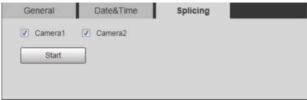
text_image
General Date&Time Splicing ✓ Camera1 ✓ Camera2 StartSplicing (2) Figure 4-91
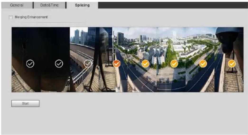
text_image
General Date&Time Splicing Merging Enhancement StartSelect the camera which needs to be spliced. Step 2 When splicing the image through selecting lenses, you need to select the continuous splicing screens. The screen with the icon (deeper color) means the first screen of the splicing. You can select any screen as the first one, and select the following screens continuously. The system supports the splicing of 4, 5, 6, 7 and 8 sensors.

This function is available on some select models. And it is all sensors splicing by default.
Click Start. Step 3
The system begins to splice image.
- Some camera restarts automatically after splicing is completed, and you can view the splicing effect on the Live interface.
- Some camera displays splicing live view interface after splicing is completed. Click OK, and then the system prompts default box. And then click OK. The splicing takes effect.
4.8.4 Account
Manage all the users. You can add, delete, or modify users. Users include admin, added users and ONVIF users.
Managing users and groups are only available for administrator users.
- The max length of the user or group name is 31 characters which consisted of number, letters, underline, dash, dot and @.
- The password must consist of 8 to 32 non-blank characters and contain at least two types of characters among upper case, lower case, number, and special character (excluding '";: &).
- You can have 18 users and 8 groups at most.
- You can manage users through single user or group, and duplicate user names or group names are not allowed. A user can be in only one group at a time, and the group users can own authorities within group authority range.
• Online users cannot modify their own authority. - There is one admin by default which has highest authority.
- Select Anonymous Login, and then log in with only IP address instead of user name and password. Anonymous users only have preview authorities. During anonymous login, click Logout, and then you can log in with other username.
4.8.4.1 Adding a User
You are admin user by default. You can add users, and configure different authorities.
Step 1 Select Setting > System > Account > Account > Username.
The Username interface is displayed. See Figure 4-92.
Username Figure 4-92
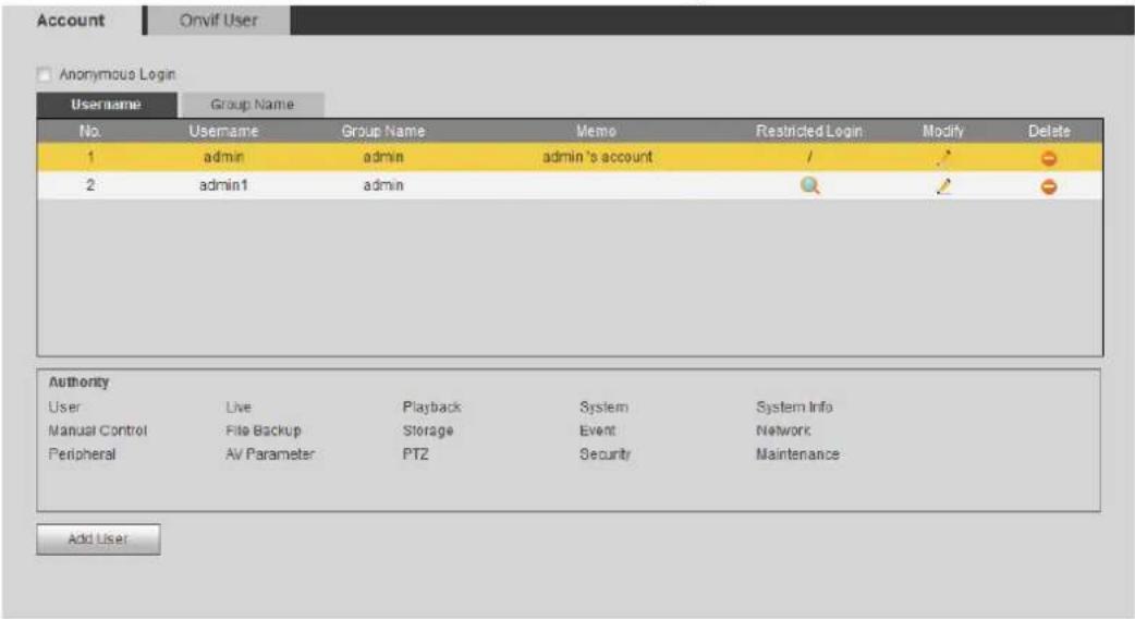
text_image
Account Onvif User Anonymous Login Username Group Name No. Username Group Name Memo Restricted Login Modify Delete 1 admin admin admin's account / 2 admin1 admin Authority User Live Playback System System Info Manual Control File Backup Storage Event Network Peripheral AV Parameter PTZ Security Maintenance Add UserClick Add User. Step 2
The Add User interface is displayed. See Figure 4-93 and Figure 4-94.
Add user (operation permission) Figure 4-93
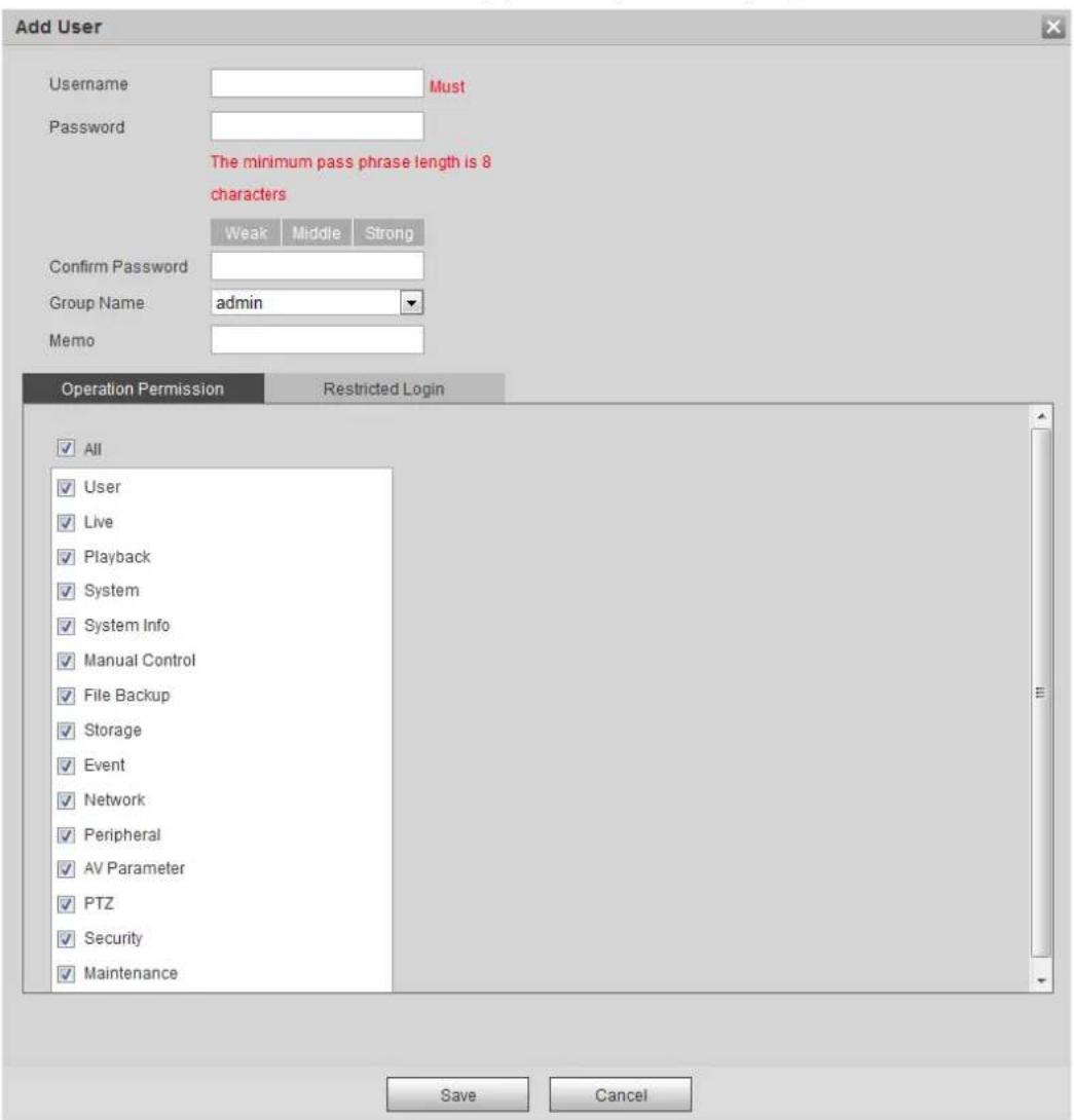
text_image
Add User Username Must Password The minimum pass phrase length is 8 characters Weak Middle Strong Confirm Password Group Name admin Memo Operation Permission Restricted Login All User Live Playback System System Info Manual Control File Backup Storage Event Network Peripheral AV Parameter PTZ Security Maintenance Save CancelAdd user (restricted login) Figure 4-94
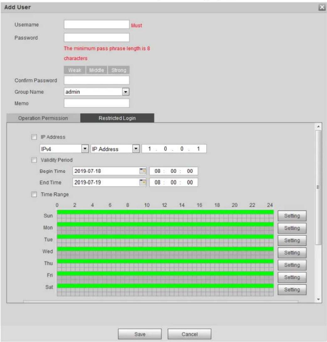
text_image
Add User Username Must Password The minimum pass phrase length is 8 characters Weak Middle Strong Confirm Password Group Name admin Memo Operation Permission Restricted Login IP Address IPv4 IP Address 1.0.0.1 Validity Period Begin Time 2019-07-18 08:00:00 End Time 2019-07-19 08:00:00 Time Range Sun Setting Mon Setting Tue Setting Wed Setting Thu Setting Fri Setting Sat Setting Save CancelConfigure user parameters. For details, see Table 4-37. Step 3
Table 4-37 Description of user parameters (1)
| Parameter | Description |
| Username | User's unique identification. You cannot use existed user name. |
| Password | Enter password and confirm it again.The password must consist of 8 to 32 non-blank characters and contain at least two types of characters among upper case, lower case, number, and special character (excluding '";: &). |
| Confirm Password | |
| Group Name | The group that users belong to. Each group has different authorities. |
| Memo | Describe the user. |
| Operation Permission | Select authorities as needed. It is recommended to give fewer authorities to normal users than premium users. It is recommended to give fewer authorities to normal users than premium users. |
| Restricted Login | Set the PC address that allows the defined user to log in to the camera and the validity period and time range. You can log in to web with the defined IP in the defined time range of validity period.IP address: You can log in to web through the PC with the set IP. Validity period: You can log in to web in the set validity period.Time Range: You can log in to web in the set time range.Set as following:1. Select IP Address: Select IP type and set IP address.◇ IP Address: Enter the IP address of the host to be added.◇ IP segment: Enter the start address and end address of the host to be added.2. Select Validity Period: Set the begin time and end time.3. Select Time Range: Set the time range that allow user to log in. For details, see "5.1.1.1 Setting Period." |
Click Save. Step 4
The newly added user is displayed in the user name list.

- After adding user, click 🔍 to modify password, group, memo or authorities;
click to delete the added users. Admin user cannot be deleted. - Click in the admin row to modify its username and email address.
4.8.4.2 Adding User Group
You have two groups named admin and user by default, and you can add new group, delete added group or modify group authority and memo.
Step 1 Select Setting > System > Account > Account > Group Name.
The Group Name interface is displayed. See Figure 4-95.
Group name Figure 4-95
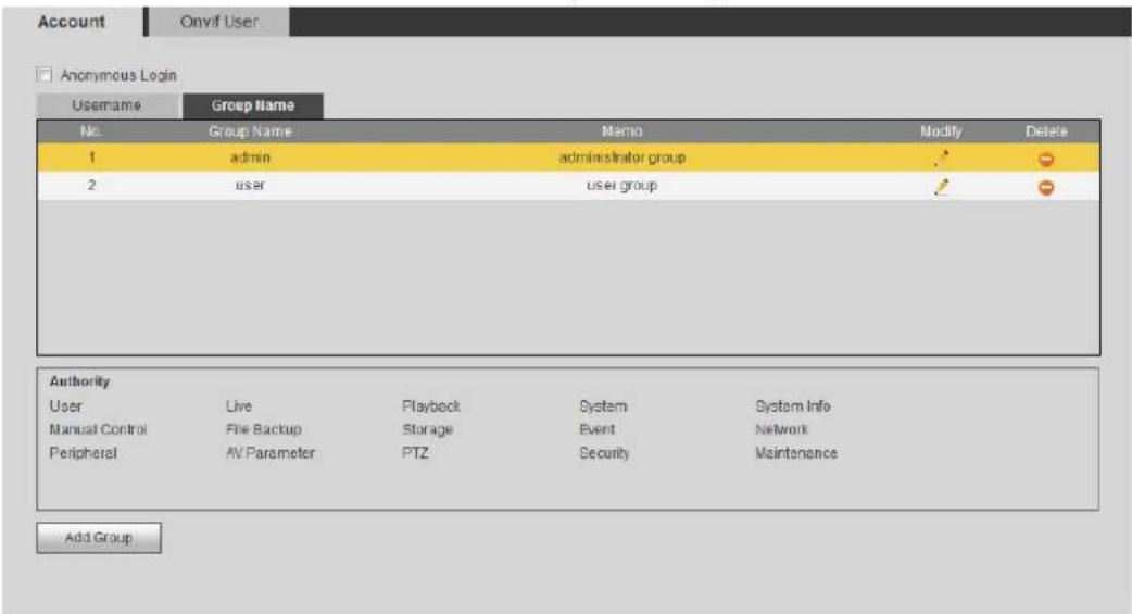
text_image
Account Onyif User Anonymous Login Username Group Name No. Group Name Memo Modify Delete 1 admin administrator group 2 user user group Authority User Live Playback System System Info Manual Control File Backup Storage Event Network Peripheral AV Parameter PTZ Security Maintenance Add GroupClick Add Group. Step 2
The Add Group interface is displayed. See Figure 4-96.
Add group Figure 4-96
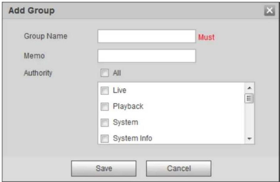
text_image
Add Group Group Name Must Memo Authority All Live Playback System System Info Save CancelEnter the group name and memo, and then select group authorities. Step 3
Click Save to finish configuration. Step 4
The newly added group displays in the group name list.

- After adding group, click 🔍 to modify group memo or authorities; click 🔍 to delete the added group, admin group and user group cannot be deleted.
- Click in the row of admin group or user group to modify group memo.
4.8.4.3 ONVIF User
You can add, delete ONVIF user, and modify their passwords.
Select Setting > System > Account > ONVIF User. Step 1
The ONVIF User interface is displayed. See Figure 4-97.
ONVIF user Figure 4-97
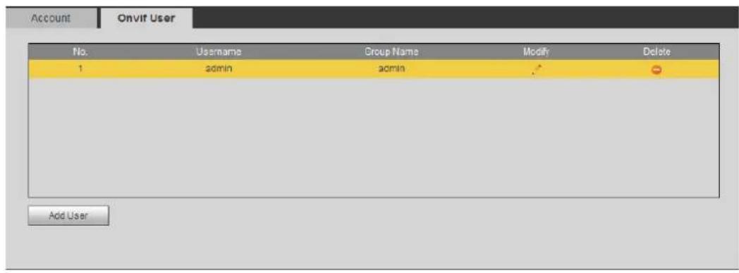
text_image
Account Onvif User No. Username Group Name Modify Delete 1 admin admin Add UserClick Add User. Step 2
The Add User interface is displayed. See Figure 4-98.
Add user Figure 4-98
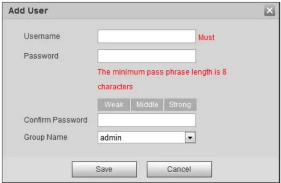
text_image
Add User Username Must Password The minimum pass phrase length is 8 characters Weak Middle Strong Confirm Password Group Name admin Save CancelConfigure user parameters. For details, see Table 4-38. Step 3
Table 4-38 Description of user parameters (2)
| Parameter | Description |
| Username | User's unique identification. You cannot use existed user name. |
| Password | Enter password and confirm it again.The password must consist of 8 to 32 non-blank characters and contain at least two types of characters among upper case, lower case, number, and special character (excluding '' ; : &). |
| Confirm Password | |
| Group Name | The group that users belong to. Each group has different authorities. |
Click Save. Step 4
The newly added user displays in the user name list.

- After adding user, click 🔍 to modify password, group, memo or authorities;
click to delete the added user. Admin user cannot be deleted. - Click in the admin row to modify its username and email address.
4.8.5 Safety
You can configure system service, HTTPS, and Firewall.
4.8.5.1 System Service
Configure the IP hosts (devices with IP address) that are allowed to visit the device. Only the hosts in the trusted sites list can log in to the web interface. This is to enhance network and data security.
Select Setting > System > Safety > System Service. Step 1
The System Service interface is displayed. See Figure 4-99.
System service Figure 4-99
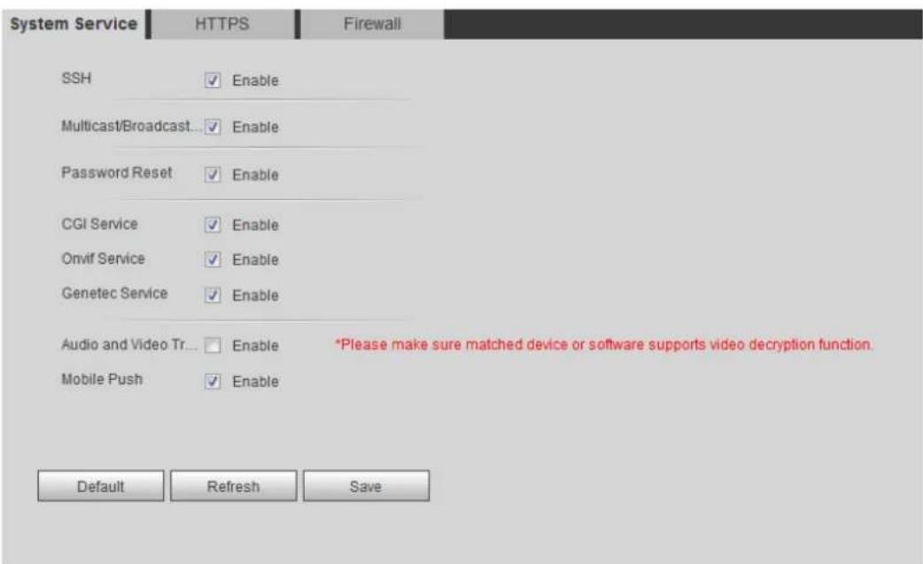
text_image
System Service HTTPS Firewall SSH ✓ Enable Multicast/Broadcast... ✓ Enable Password Reset ✓ Enable CGI Service ✓ Enable Onvif Service ✓ Enable Genetec Service ✓ Enable Audio and Video Tr... ✓ Enable *Please make sure matched device or software supports video decryption function. Mobile Push ✓ Enable Default Refresh SaveEnable the system service according to the actual needs. For details, see Table 4-39. Step 2
Table 4-39 Description of system service parameters
| Function | Description |
| SSH | You can enable SSH authentication to perform safety management. |
| Multicast/Broadcast Search | Enable this function, and then when multiple users are previewing the device video image simultaneously through network, they can findyour device with multicast/broadcast protocol. |
| Password Reset | Manage system security with this function. |
| CGI Service | Enable this function, and then other devices can access through this service. |
| Onvif Service | Enable this function, and then other devices can access through this service. |
| Genetec Service | Enable this function, and then other devices can access through this service. |
| Audio and Video TransmissionEncryption | Enable to encrypt audio/video transmission. Make sure that the other devices and software that working together with the camera support video decryption. Make sure that the other devices and software that working together with the camera support video decryption. |
| Mobile Push | Enable this function, and then the system would send the snapshot that was taken when alarm is triggered to your phone, this is enabled by default. |
Click Save. Step 3
4.8.5.2 HTTPS
Create certificate or upload the authenticated certificate, and then you can log in through HTTPS with your PC. The HTTPS can protect page authenticity on all types of websites, secure accounts, and keep user communications, identity, and web browsing private.
____ Create certificate or upload the authenticated certificate. Step 1
- If you select Create Certificate, follow the steps below.
1) Select Setting > Network > HTTPS.
The HTTPS interface is displayed. See Figure 4-100.
Figure 4-100 HTTPS (1)
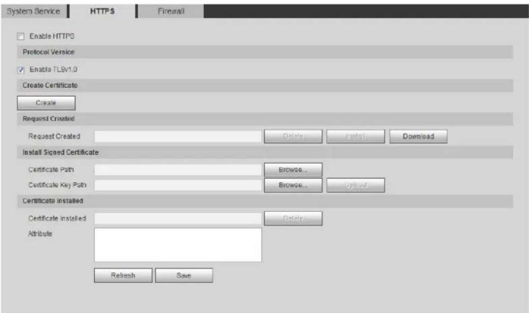
text_image
System Service HTTPS Firewall Enable HTTPS Protocol Version Enable TLSv1.0 Create Certificate Create Request Created Request Created Delete Install Download Install Signed Certificate Certificate Path Browse... Certificate Key Path Browse... Upload Certificate installed Certificate installed Delete Attribute Refresh Save2) Click Create.
The HTTPS dialog box is displayed. See Figure 4-101.
HTTPS dialog box Figure 4-101
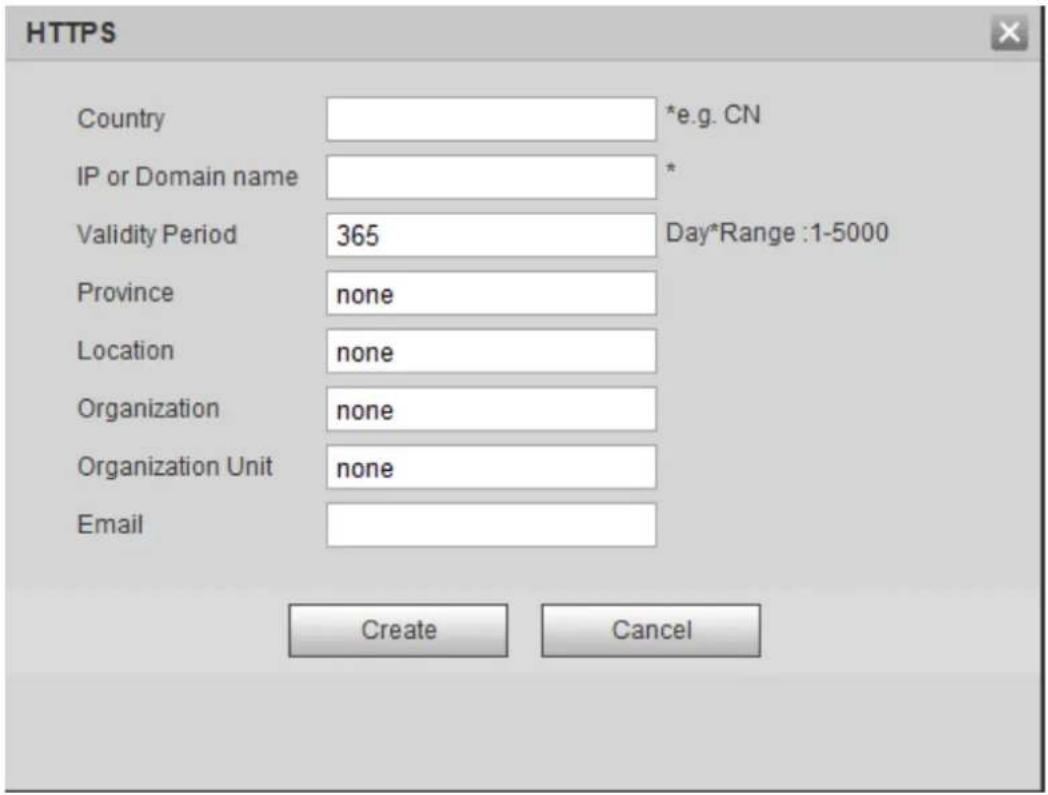
text_image
HTTPS Country *e.g. CN IP or Domain name * Validity Period 365 Day*Range :1-5000 Province None Location None Organization None Organization Unit None Email Create Cancel3) Enter the required information and then click Create.

The entered IP or Domain name must be the same as the IP or domain name of the device.
4) Click Install. See Figure 4-102.
Figure 4-102 Certificate installation
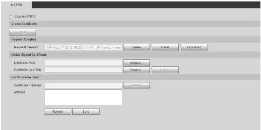
text_image
HTTPS Enable HTTPS Create Certificate Create Request Created Request Created: HYP=http://172.12.80.250/C-CN.ST=one,L=one Delete Install Download Install Signed Certificate Certificate Path Browse... Certificate Key Path Browse... Upload Certificate Installed Certificate Installed Delete Attribute Refresh Save5) Click Download to download root certificate.
6) Click Download Root Certificate.
The File Download-Security Warning dialogue box is displayed. See Figure 4-103.
File download Figure 4-103
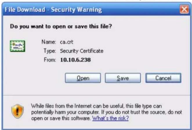
text_image
File Download - Security Warning Do you want to open or save this file? Name: ca.crt Type: Security Certificate From: 10.10.6.238 Open Save Cancel While files from the Internet can be useful, this file type can potentially harm your computer. If you do not trust the source, do not open or save this software. What's the risk?7) Click Open. The Certificate Information interface is displayed. See Figure 4-104. Certificate information Figure 4-104
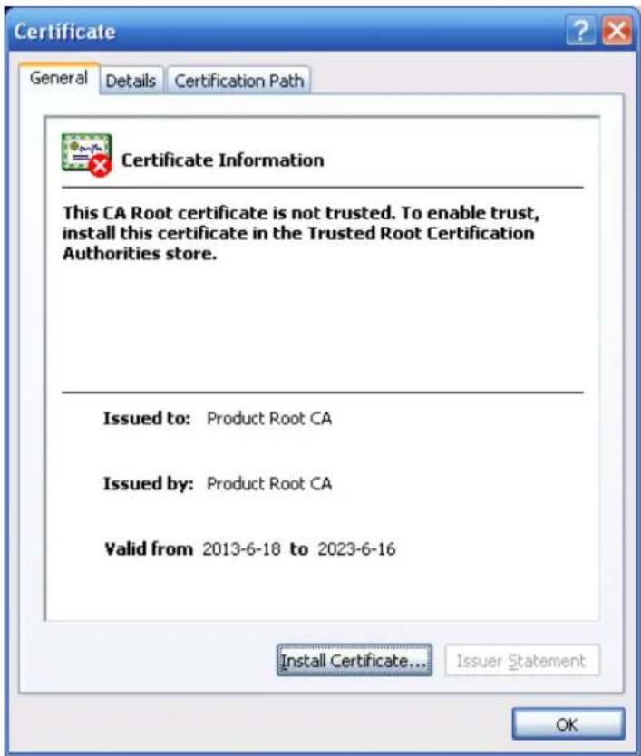
text_image
Certificate General Details Certification Path Certificate Information This CA Root certificate is not trusted. To enable trust, install this certificate in the Trusted Root Certification Authorities store. Issued to: Product Root CA Issued by: Product Root CA Valid from 2013-6-18 to 2023-6-16 Install Certificate... Issuer Statement OK8) Click Install Certificate.
9) The Certificate Import Wizard interface is displayed. See Figure 4-105.
Certificate import wizard Figure 4-105
text_image
Certificate Import Wizard Welcome to the Certificate Import Wizard This wizard helps you copy certificates, certificate trust lists, and certificate revocation lists from your disk to a certificate store. A certificate, which is issued by a certification authority, is a confirmation of your identity and contains information used to protect data or to establish secure network connections. A certificate store is the system area where certificates are kept. To continue, click Next.10) Click Next.
The Certificate Store interface is displayed. See Figure 4-106.
Certificate import wizard Figure 4-106
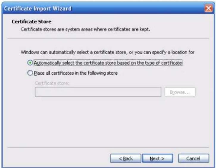
text_image
Certificate Import Wizard Certificate Store Certificate stores are system areas where certificates are kept. Windows can automatically select a certificate store, or you can specify a location for Automatically select the certificate store based on the type of certificate Place all certificates in the following store Certificate store: Browse... < Back Next > Cancel11) Select the storage location and click Next.
The Certificate Import Wizard interface is displayed. See Figure 4-107.
Certificate import wizard Figure 4-107
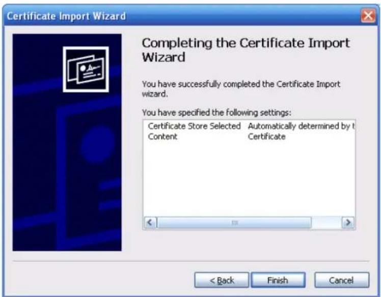
text_image
Certificate Import Wizard Completing the Certificate Import Wizard You have successfully completed the Certificate Import wizard. You have specified the following settings: Certificate Store Selected Automatically determined by t Content Certificate < Back Finish Cancel12) Click Finish and a dialog box showing The import was successful pops up. See Figure 4-108.
Import succeeds Figure 4-108
text_image
Certificate Import Wizard The import was successful. OK4.8.5.3 Firewall
Configure Network Access, PING prohibited and Prevent Semijoin to enhance network and data security.
• Network Access: Set trusted list and restricted list to limit access.
Trust list: Only when the IP/MAC of your PC in the trusted list, can you access the camera. Ports are the same.
Banned list: When the IP/MAC of your PC is in the banned list, you cannot access the camera. Ports are the same.
- PING prohibited: Enable PING prohibited function, and the camera will not respond to the ping request.
- Prevent Semijoin: Enable Prevent Semijoin function, and the camera can provide service normally under Semijoin attack.

- You cannot set trust or banned list for camera IP or MAC addresses.
-
You cannot set trust or banned list for port MAC addresses.
-
When the IP addresses of the camera and your PC are in the same LAN, MAC verification takes effect.
- When you access the camera through internet, the camera verifies the MAC address according to the router MAC.
This section takes Network Access as an example.
Step 1 Select Setting > System > Safety > Firewall.
The Firewall interface is displayed. See Figure 4-109.
Firewall Figure 4-109

text_image
System Service HTTPS Firewall Rule Type Network Access Enable ✓ Mode TrustList ○ BannedList Only the listed IP addresses/MAC are allowed to visit corresponding ports of the device. ✓ IP address MAC address Port Modify Delete ✓ Device All Ports ✓ - ✓ Device All Ports ✓ - ✓ Device All Ports ✓ - ✓ Device All Ports ✓ - Add IP/MAC Default Refresh SaveStep 2 Select Network Access from Rule Type list, and then select the Enable check box.
- Enable PING prohibited and Prevent Semijoin, and click Save. You do not need to configure parameters.
- Enable Network Access, and configure trust list and banned list.
1) Select the mode: TrustList and BannedList.
2) Click Add IP/MAC.
The Add IP/MAC interface is displayed. See Figure 4-110.
Figure 4-110 Add IP/MAC
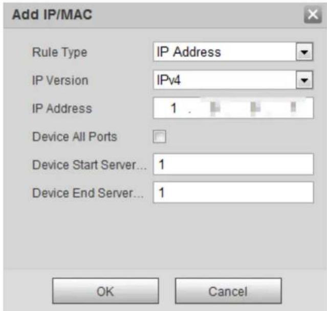
text_image
Add IP/MAC Rule Type IP Address IP Version IPv4 IP Address 1 Device All Ports Device Start Server... 1 Device End Server... 1 OK CancelConfigure parameters. For details, see Table 4-40. Step 3
Table 4-40 Description of adding IP/MAC parameters
| Parameter | Description |
| Rule Type | Select IP address, IP segment, MAC address or all IP addresses.IP address: Select IP version and enter the IP address of the host to be added.IP segment: Select IP version and enter the start address and end address of the segment to be added.MAC address: Enter MAC address of the host to be added.All IP addresses: Set all IP addresses in trusted list or restricted list. |
| Device All Ports | Set access ports. You can select all ports or the ports in defined areas.Device all ports: Set all IP port in trust list or Banned list.When selectingBannedListinMode, andAll IP AddressinRule Type, you cannot select theDevice All Portscheck box.Device start server port and Device end server port: Set Device start server port and device end server port, and the range is 1–65535. |
| Device Start Server Port | |
| Device End Server Port |
Step 4 Click OK, and the Firewall interface is displayed.
Step 5 Click Save.
4.8.6 Peripheral
4.8.6.1 Serial Port Settings
Set the serial port of the external device.
Step 1 Select Setting > System > Peripheral > Serial Port Settings.
The Serial Port Settings interface is displayed. See Figure 4-111.
Serial port settings Figure 4-111
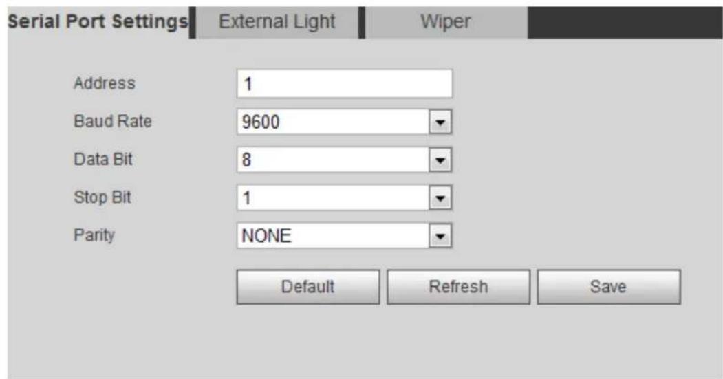
text_image
Serial Port Settings External Light Wiper Address 1 Baud Rate 9600 Data Bit 8 Stop Bit 1 Parity NONE Default Refresh SaveConfigure serial port settings parameters. For details, see Table 4-41. Step 2
Table 4-41 Description of serial port settings parameters
| Parameter | Description |
| Address | The corresponding device address. It is 1 by default. Make sure that the address is the device address; otherwise you cannot control the device. Make sure that the address is the device address; otherwise you cannot control the device. |
| Baud Rate | Select the boud rate for the camera. It is 9600 by default. |
| Date Bit | It is 8 by default. |
| Stop Blt | It is 1 by default. |
| Parity | It is None by default. |
Click Save. Step 3
4.8.6.2 External Light
You need to configure external light mode when the external light is used.
Preparation
- Connect external light with RS-485 port.
- You have configured serial port parameters. For details, see "4.8.6.1 Serial Port Settings."
Procedure
Step 1 Select Setting > System > Peripheral > External Light.
The External Light interface is displayed. See Figure 4-112.
External light Figure 4-112
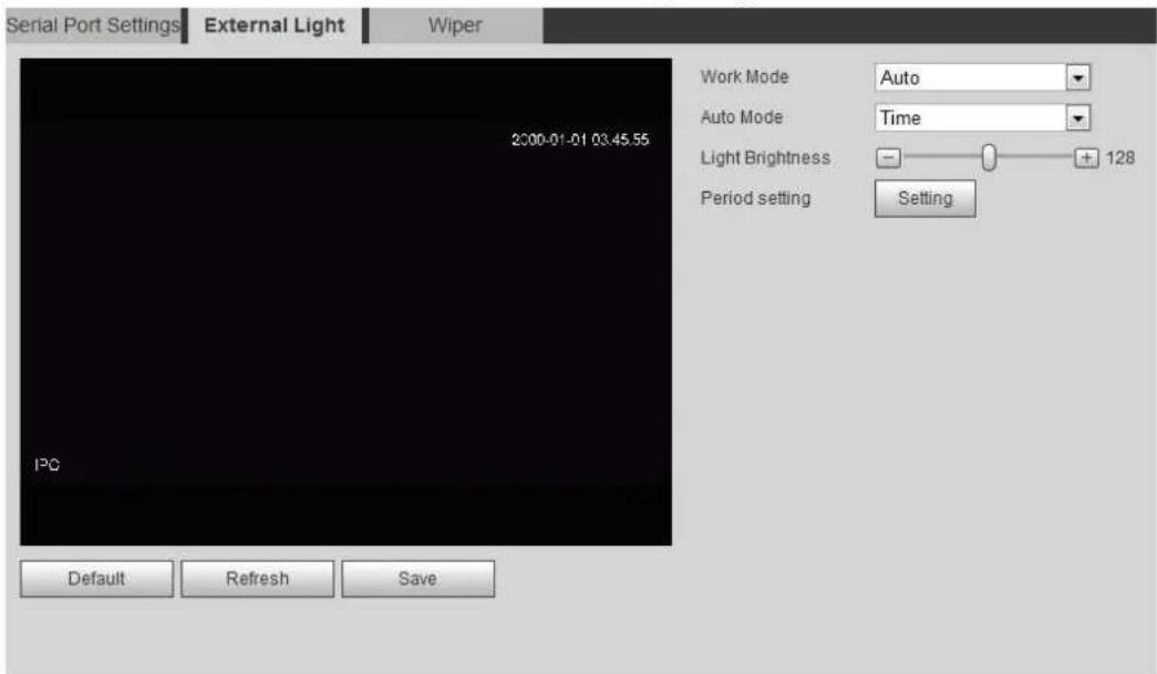
text_image
Serial Port Settings External Light Wiper 2000-01-01 03.45.55 Work Mode Auto Auto Mode Time Light Brightness - + 128 Period setting Setting Default Refresh SaveConfigure external light work mode. For details, see Table 4-42. Step 2
Table 4-42 Description of external light parameters
| Parameter | Description |
| Work Mode | Off: Turn off the external light.Manual: Set the light brightness manually.Auto: The camera turns on or turns off the light according to the light time and photoresister automatically. |
| Auto Mode | Time: When selecting Time in Auto Mode, click Setting to set the arming period. During the arming period, the external light is on. For details of arming period setting, see "5.1.1.1 Setting Period."Photoresister: When you select Photoresister in Auto Mode, the system turns on the external light according to the brightness automatically. |
| Light Brightness | Set the brightness of the external light. |
Click Save. Step 3
4.8.6.3 Wiper
Step 1 Select Setting > System > Peripheral > Wiper. The Wiper interface is displayed. See Figure 4-113.
Wiper Figure 4-113
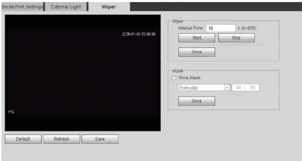
text_image
Serial Port Settings External Light Wiper 2000-01-01 03.59.58 Wiper Interval Time 10 s (0~255) Start Stop Once Wash Time Wash Everyday 04 : 00 Once Default Refresh SaveConfigure wiper work mode. For details, see Table 4-43. Step 2
Table 4-43 Description of wiper parameters
| Parameter | Description |
| Interval Time | The interval time between stop mode and start mode. For example, set the time to 10 s, and the wiper will work every 10 s. |
| Sart | Set the work status of the wiper.Start: Click Start, and the wiper works as the set interval time.Stop: Click Stop, and the wiper stops working.Once: Click Once, and the wiper works once. |
| Stop | |
| Once | |
| Time Wash | Select the Time Wash check box and set the time, and then the wiper will work as the set time. Click Once, and the wiper works once. It can be used to check whether the wiper can work normally. |
Click Save. Step 3
5 Event
This chapter introduces intelligent event settings, including smart track, panoramic calibration, video detection, audio detection, smart plan, IVS, face detection, face recognition, people counting, heat map, video structuralization, alarm, and abnormality.
Setting Alarm Linkage 5.1
5.1.1 Alarm Linkage
When configuring alarm events, select alarm linkages (such as record, snapshot). See Figure 5-1. When the corresponding alarm is triggered in the configured arming period, the system will alarm.
Alarm linkage Figure 5-1
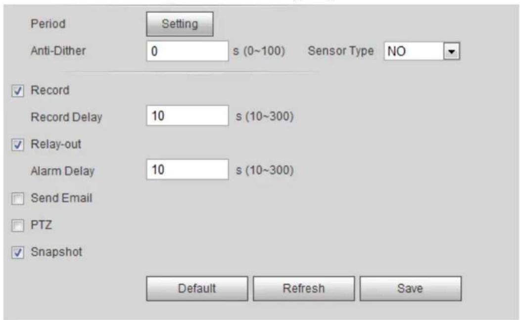
text_image
Period Setting Anti-Dither 0 s (0~100) Sensor Type NO ✓ Record Record Delay 10 s (10~300) ✓ Relay-out Alarm Delay 10 s (10~300) □ Send Email □ PTZ ✓ Snapshot Default Refresh Save5.1.1.1 Setting Period
Set arming periods. The system only performs corresponding linkage action in the configured period.
Step 1 Click Setting next to Period.
The Period interface is displayed. See Figure 5-2.
Period Figure 5-2
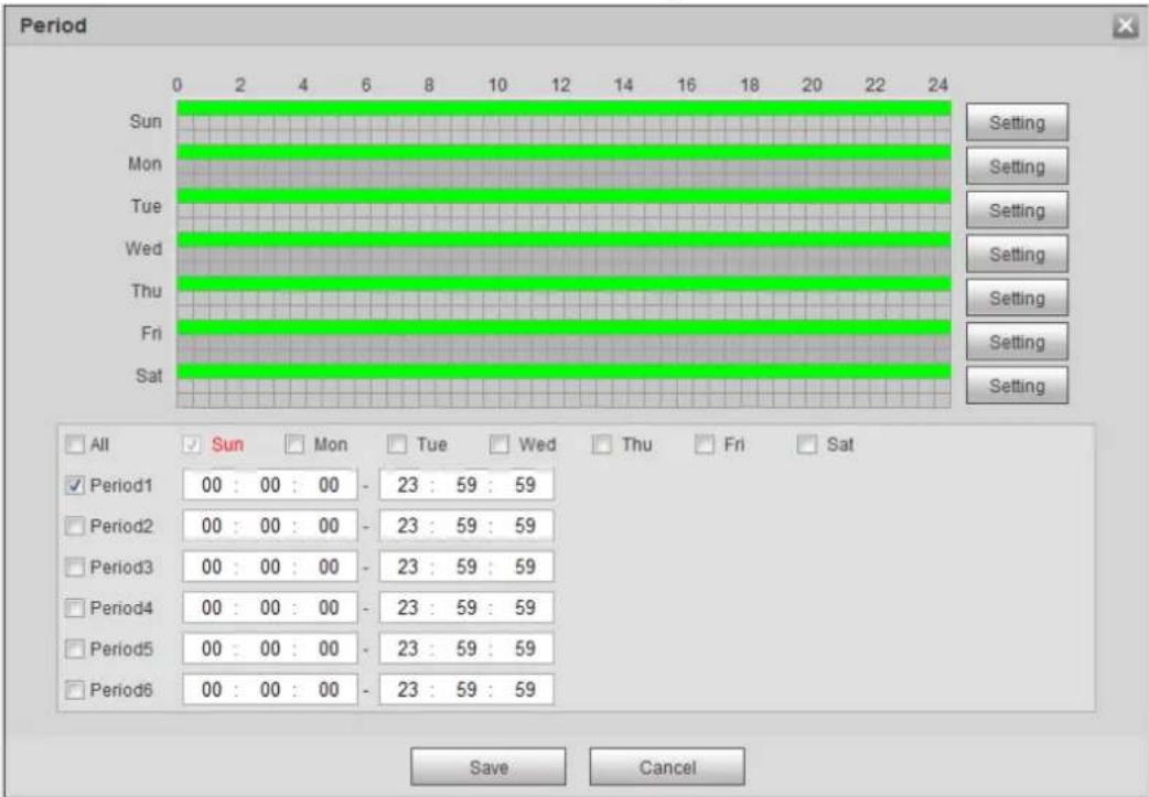
text_image
Period Sun Mon Tue Wed Thu Fri Sat Setting Setting Setting Setting Setting Setting Setting Setting All Sun Mon Tue Wed Thu Fri Sat Period1 00 : 00 : 00 - 23 : 59 : 59 Period2 00 : 00 : 00 - 23 : 59 : 59 Period3 00 : 00 : 00 - 23 : 59 : 59 Period4 00 : 00 : 00 - 23 : 59 : 59 Period5 00 : 00 : 00 - 23 : 59 : 59 Period6 00 : 00 : 00 - 23 : 59 : 59 Save CancelStep 2 Set arming periods. Alarms will be triggered in the time period in green on the timeline.
- Method one: Directly press and drag the left mouse button on the timeline.
• Method two: Enter an actual time period.
1) Click Setting next to a day.
2) Select a time period to be enabled.
3) Enter start time and end time of a time period.

Select All or check boxes of some days to set the time period of multiple days at one time.
◇ You can set 6 time periods per day.
Step 3 Click Save.
5.1.1.2 Record Linkage
The system can link record channel when an alarm event occurs. After alarm, the system stops recording after an extended time period according to the Record Delay setting.
To use the record linkage function, set record plan for motion detection alarm and enable auto recording in record control.
5.1.1.2.1 Setting Record Plan
After the corresponding alarm type (Normal, Motion, Alarm) is enabled, the record channel links recording.
Step 1 Select Setting > Storage > Schedule > Record.
The Record interface is displayed. See Figure 5-3.
Record Figure 5-3
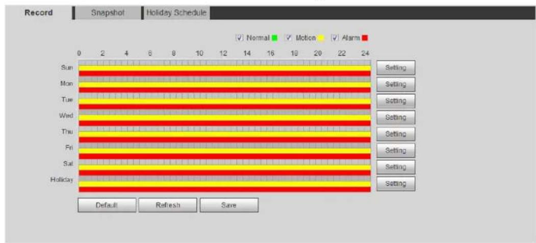
text_image
Record Snapshot Holiday Schedule Normal Motion Alarm Sun Mon Tue Wed Thu Fri Sat Holiday Setting Setting Setting Setting Setting Setting Setting Default Refresh SaveSet record plan. Step 2
Green represents normal record plan (such as timing recording); yellow represents motion record plan (such as recording triggered by intelligent events); red represents alarm record plan (such as recording triggered by alarm-in).
- Method one: Select a record type, such as Normal, and directly press and drag the left mouse button to set the time period for normal record on the timeline.
- Method two: Enter an actual time period.
1) Click Setting next to a day.
The Setting interface is displayed. See Figure 5-4.
Setting (record time period) Figure 5-4
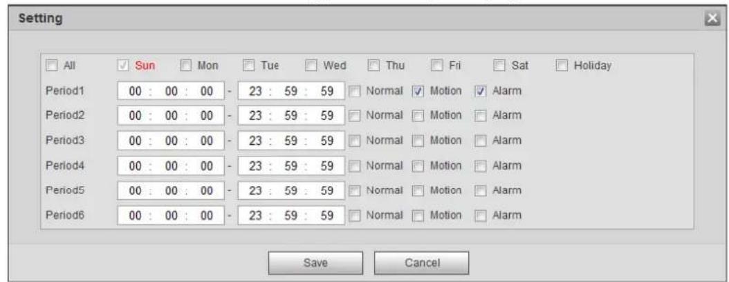
text_image
Setting All Sun Mon Tue Wed Thu Fri Sat Holiday Period1 00 : 00 : 00 - 23 : 59 : 59 Normal Motion Alarm Period2 00 : 00 : 00 - 23 : 59 : 59 Normal Motion Alarm Period3 00 : 00 : 00 - 23 : 59 : 59 Normal Motion Alarm Period4 00 : 00 : 00 - 23 : 59 : 59 Normal Motion Alarm Period5 00 : 00 : 00 - 23 : 59 : 59 Normal Motion Alarm Period6 00 : 00 : 00 - 23 : 59 : 59 Normal Motion Alarm Save Cancel2) Select a day, and the alarm type next to a period, and then set the period.

Select All or check boxes of some days to set the time period of multiple days at one time.
◇ You can set 6 time periods per day.
3) Click Save.
The Record interface is displayed.
Click Save. Step 3
5.1.1.2.2 Setting Record Control
Set parameters such as pack duration, pre-event record, disk full, record mode, and record stream.

Make sure that the SD card is authenticated before recording if you use Dahua smart card. For details, see "4.5.2.5 Path."
Select Setting > Storage > Record Control. Step 1
The Record Control interface is displayed. See Figure 5-5.
Record control Figure 5-5
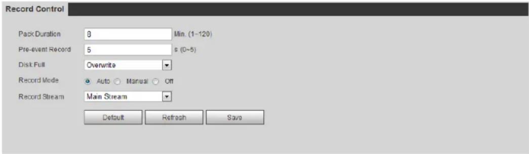
text_image
Record Control Pack Duration 8 Min. (1-120) Pre-event Record 5 s (0-5) Disk Full Overwrite Record Mode Auto Manual Off Record Stream Main Stream Default Refresh SaveSet parameters. See Table 5-1. Step 2
Table 5-1 Description of record control parameters
| Parameter | Description |
| Pack Duration | The time for packing each video file. |
| Pre-event Record | The time to record the video in advance of a triggered alarm event. For example, if the pre-event record is set to be 5 s, the system saves the recorded video of 5 s before the alarm is triggered. When an alarm or motion detection links recording, and the recording is not enabled, the system saves the video data within the pre-event record time to the video file. When an alarm or motion detection links recording, and the recording is not enabled, the system saves the video data within the pre-event record time to the video file. |
| Disk Full | Recording strategy when the disk is full.Stop: Stop recording when the disk is full.Overwrite: Cyclically overwrite the earliest video when the disk is full. |
| Record Mode | When you selectManual, the system starts recording; when you selectAuto, the system starts recording in the configured time period of record plan. |
| Record Stream | Select record stream, includingMain StreamandSub Stream. |
Click Save. Step 3
5.1.1.2.3 Setting Record Linkage
On the alarm event setting interface (such as the motion detection interface), select Record and set Record Delay to set alarm linkage and record delay.
After Record Delay is configured, alarm recording continues for an extended period after the alarm ends.
Record linkage Figure 5-6

text_image
✓ Record Record Delay 10 s (10~300)5.1.1.3 Snapshot Linkage
After snapshot linkage is configured, the system can automatically alarm and take snapshots when an alarm is triggered.
After Motion is enabled in Snapshot, the system takes snapshots when an alarm is triggered. For querying and setting snapshot storage location, see "4.5.2.5 Path."
5.1.1.3.1 Setting Snapshot Plan
According to the configured snapshot plan, the system enables or disables snapshot at corresponding time.
Step 1 Select Setting > Storage > Schedule > Snapshot.
The Snapshot interface is displayed. See Figure 5-1.
Snapshot Figure 5-1
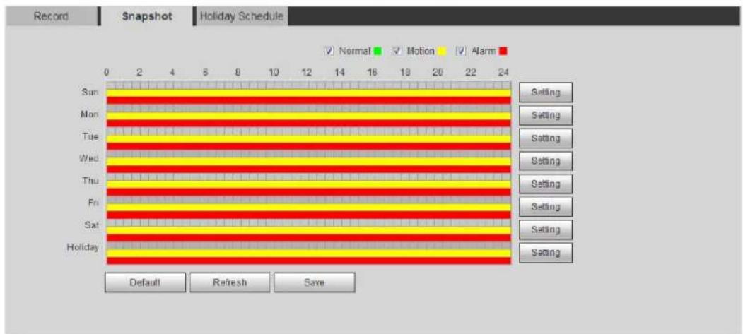
text_image
Record Snapshot Holiday Schedule ✓ Normal ✓ Motion ✓ Alarm Sun Mon Tue Wed Thu Fri Sat Holiday 0 2 4 5 8 10 12 14 16 18 20 22 24 Setting Setting Setting Setting Setting Setting Setting Setting Setting Default Refresh SaveSelect snapshot type and set time period. Step 2
Green represents normal snapshot plan (such as timing snapshot); yellow represents motion snapshot plan (such as snapshot triggered by intelligent events); red represents alarm snapshot plan (such as snapshot triggered by alarm-in).
- Method one: Select snapshot type, such as Normal, and directly press and drag the left mouse button to set time period for normal snapshot on the timeline.
- Method two: Enter an actual time period.
1) Click Setting next to a day.
The Setting interface is displayed. See Figure 5-2.
Setting (snapshot time period) Figure 5-2
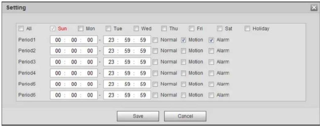
text_image
Setting All Sun Mon Tue Wed Thu Fri Sat Holiday Period1 00 : 00 : 00 - 23 : 59 : 59 Normal Motion Alarm Period2 00 : 00 : 00 - 23 : 59 : 59 Normal Motion Alarm Period3 00 : 00 : 00 - 23 : 59 : 59 Normal Motion Alarm Period4 00 : 00 : 00 - 23 : 59 : 59 Normal Motion Alarm Period5 00 : 00 : 00 - 23 : 59 : 59 Normal Motion Alarm Period6 00 : 00 : 00 - 23 : 59 : 59 Normal Motion Alarm Save Cancel2) Select a day, and the alarm type next to a period. Then set the period.

Select All or check boxes of some days to set the time period of multiple days at one time.
◇ You can set 6 time periods per day.
3) Click Save.
The Snapshot interface is displayed.
Click Save. Step 3
5.1.1.3.2 Setting Snapshot Linkage
On the alarm event setting interface (such as the motion detection interface), select Snapshot and set alarm linkage snapshot.
Snapshot linkage Figure 5-3
5.1.1.4 Relay-out Linkage
When an alarm is triggered, the system can automatically link with relay-out device.
On the alarm event setting interface (such as the motion detection interface), select Alarm and set Alarm Delay.
When alarm delay is configured, alarm continues for an extended period after the alarm ends.
Relay-out linkage Figure 5-4

text_image
✓ Relay-out Alarm Delay 10 s (10~300)5.1.1.5 Email Linkage
When an alarm is triggered, the system will automatically send an email to users.
Email linkage takes effect only when SMTP is configured. For details, see "4.6.5 SMTP (Email)."
Email linkage Figure 5-5

text_image
Send Email5.1.1.6 PTZ Linkage
When an alarm is triggered, the system links PTZ to do some operations. For example, the system links PTZ to rotate to the preset X.
PTZ linkage Figure 5-6

text_image
PTZ Activation Preset No. 1 (1~255)5.1.1.7 White Light Linkage
When an alarm is triggered, the system can automatically enable the white light.
Set Mode, Duration, Flicker Frequency, Duration, and Period.
- Mode: The display mode of the white light when an alarm is triggered. It includes Normally on and Flicker. When set flicker as the mode, you need to set the flicker frequency.
- Duration: After setting white light duration, the white light is turned off after an extended time of period after an alarm. It is 5 seconds–30 seconds.
- Period: The period for using white light. When an alarm triggered during the configured period, the system links white light. For the configuration, see "5.1.1.1 Setting Period."
White light linkage Figure 5-7
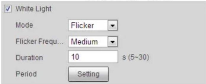
text_image
White Light Mode Flicker Flicker Frequ... Medium Duration 10 s (5~30) Period Setting5.1.1.8 Audio Linkage
The system broadcasts alarm audio file when an alarm event occurs. Select Setting > Camera > Audio > Alarm Audio to set alarm audio file.
Audio linkage Figure 5-8

text_image
Audio Linkage Play Duration 10 s5.1.2 Subscribing Alarm
5.1.2.1 About Alarm Types
For alarm types and preparations of alarm events, see Table 5-2.
Table 5-2 Description of alarm types
| Alarm Type | Description | Preparation |
| Motion Detection | The alarm is triggered when moving object is detected. | Motion detection is enabled. For details, see "5.4.1 Setting Motion Detection." |
| Disk Full | The alarm is triggered when the free space of SD card is less than the set value. | The SD card no space function is enabled. For details, see "5.18.1 Setting SD Card." |
| Disk Error | The alarm is triggered when there is failure or malfunction in the SD card. | SD card failure detection is enabled. For details, see "5.18.1 Setting SD Card." |
| Video Tampering | The alarm is triggered when the camera lens is covered or there is defocus in video images. | Video tampering is enabled. For details, see "5.4.2 Setting Video Tamper." |
| External Alarm | The alarm is triggered when there is external alarm input. | The device has alarm input port and external alarm function is enabled. For details, see "5.17 Setting Relay-in." |
| Illegal Access | The alarm is triggered when the number of consecutive login password error is up to the allowable number. | Illegal access detection is enabled. For details, see "5.18.3 Setting Illegal ." |
| Audio Detection | The alarm is triggered when there is audio connection problem. | Abnormal audio detection is enabled. For details, see "5.5 Setting Smart Motion Detection." |
| IVS | The alarm is triggered when intelligent rule is triggered. | Enable IVS, crowd map, face detection or people counting, and other intelligent functions. |
| SceneChanging | The alarm is triggered when the device monitoring scene changes. | Scene changing detection is enabled. For details, see "5.4.3 Setting Scene Changing." |
| Voltage Detection | The alarm is triggered when the device detects abnormal voltage input. | Voltage detection is enabled. For details, see "5.18.4 Setting Voltage Detection." |
| Security Exception | The alarm is triggered when the device detects malicious attack. | Voltage detection is enabled. For details, see "5.18.5 Setting Security Exception." |
5.1.2.2 Subscribing Alarm Information
You can subscribe alarm event. When a subscribed alarm event is triggered, the system records detailed alarm information at the right side of the interface.

Functions of different devices might vary, and the actual product shall prevail.
Click the Alarm tab. Step 1
The Alarm interface is displayed. See Figure 5-9.
Step 2 Select Alarm Type according to the actual need. For details, see Table 5-2.
- Select Prompt. The system prompts and records alarm information according to actual conditions.
When the subscribed alarm event is triggered and the Alarm interface is not
displayed, the 📄 is displayed on the Alarm tab and the alarm information is recorded automatically. Click the Alarm tab, and this icon disappears.
When the subscribed alarm event is triggered and the Alarm interface is displayed, the corresponding alarm information is displayed in the alarm list at the right side of the Alarm interface.
- Select Play Alarm Tone, and select the tone path.
The system would play the selected audio file when the selected alarm is triggered.
Setting Smart Track 5.2
After setting calibration and parameters for smart track, the tracking speed dome can automatically link to a corresponding position and tracks an object till it is out of the object is beyond the monitoring range or the set tracking time is reached when the intelligent rules for panoramic camera triggers an alarm.
5.2.1 Setting Calibration Parameters for Smart Track
The camera has calibration parameters by default, and you can modify the parameters manually when the effect is not good with default setting.
Select Setting > Event > Smart Track > Smart Track. Step 1
The Smart Track interface is displayed. See Figure 5-10.
Smart track Figure 5-10
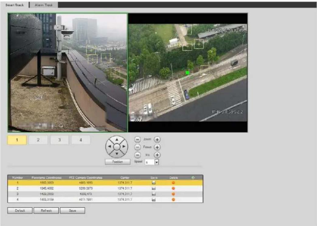
text_image
Smart Track Alarm Track 2019/07-15 14:43 P.463T-39 S Z 2 1 2 3 4 Position Speed Zoom Focus Mix Number Pacarmpa Coordinatus PTZ Camera Coordinatus Center Save Delete 1 1800,3000 4600,1000 1374,311.7 # 2 1345,4000 5299,3879 1374,311.7 # 3 1420,2500 4300,470 1374,311.7 # 4 1453,3159 4071,1861 1374,311.7 # Default Refresh SaveStep 2 Select scene number under the video images in turns (See Figure 5-11) to add calibration points on the video images of the corresponding scene. Scene numbers 1 to 4 are four splitting scenes of spliced image, and at least add four calibration points on each scene.
Selecting scene number Figure 5-11

text_image
1 2 3 4Add calibration points according to the following procedure.
1) Adjust the video image of the speed dome to a position aligned with the panoramic
image, and then click

Calibration box is displayed in the images of speed dome and panoramic camera.
2) Drag the calibration box to a proper position, and click to save one pair of calibration boxes.
After the calibration record is saved, the calibration box is displayed in yellow.
Click Save. Step 3
5.2.2 Enabling Alarm Track
Alarm Track is disabled by default. Smart Track is enabled only after Alarm Track is enabled and intelligent rules of the panoramic camera. Smart Track is supported only when rules of crowd map, intrusion and tripwire are triggered. See "5.8 Setting IVS" and "5.9 Setting Crowd Map."
Select Setting > Event > Smart Track > Alarm Track. Step 1
The Alarm Track interface is displayed. See Figure 5-12.
Alarm track Figure 5-12
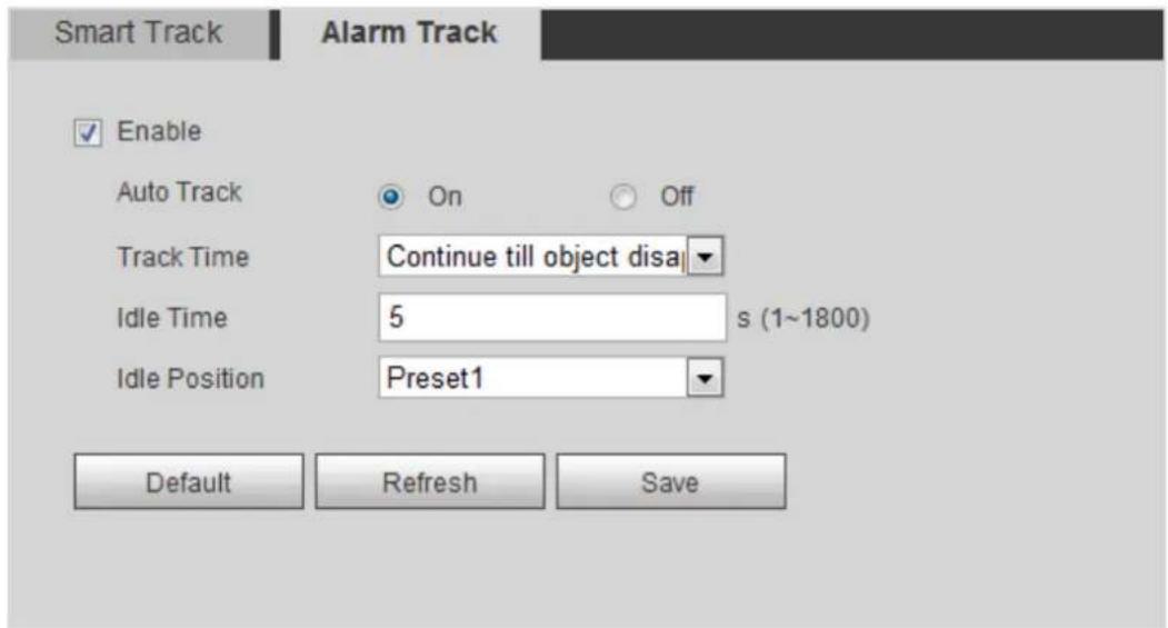
text_image
Smart Track Alarm Track Enable Auto Track On Off Track Time Continue till object disa Idle Time 5 s (1~1800) Idle Position Preset1 Default Refresh SaveTo enable track linkage, select the Enable check box. Step 2
- Manual positioning and manual track are enabled after Alarm Track is enabled.
• Auto Track is enabled after Alarm Track and Auto Track are enabled.
Step 3 Set parameters. See Table 5-3.
Table 5-3 Description of alarm track parameters
| Parameter | Description |
| Auto Track | Select On, the speed dome would automatically links to a corresponding position and tracks an object when the intelligent rules of the panoramic camera trigger alarms. |
| Track Time | Set the alarm track time.Before an object disappears: The speed dome would automatically links to a corresponding position and tracks an object until the object moves out of the monitoring range when the intelligent rules of the panoramic camera trigger alarms.Custom: Set the auto alarm track time of the speed dome. |
| Idle Time | It is an interval from the end of alarm track of the speed dome to the start of idle mode.Set Idle Time and Idle Position. If no event needs to be tracked after the configured idle time, the device automatically rotates to the set idle position. For example, the Idle Time is set to be five seconds and the Idle Position is set to be preset point 1. When the speed dome does not start tracking after five seconds, it automatically rotates to preset point 1.To set Idle Position, first set a preset point. For preset point, see "4.3.2.1 Preset." |
| Idle Position |
Step 4 Click Save.
Setting Panoramic Calibration 5.3
The device has calibration parameters by default, and you can modify the parameters manually when the effect is not good with default setting. Before manually calibrating a channel, clear all default calibration parameters.
Channel 1 is PTZ camera. You should calibrate the scene coordinates of Channel 1 and other channels. Take Channel 2 as an example.
Select Setting > Event > Panoramic Calibration. Step 1
The Panoramic Calibration interface is displayed. See Figure 5-13.
Panoramic calibration Figure 5-13
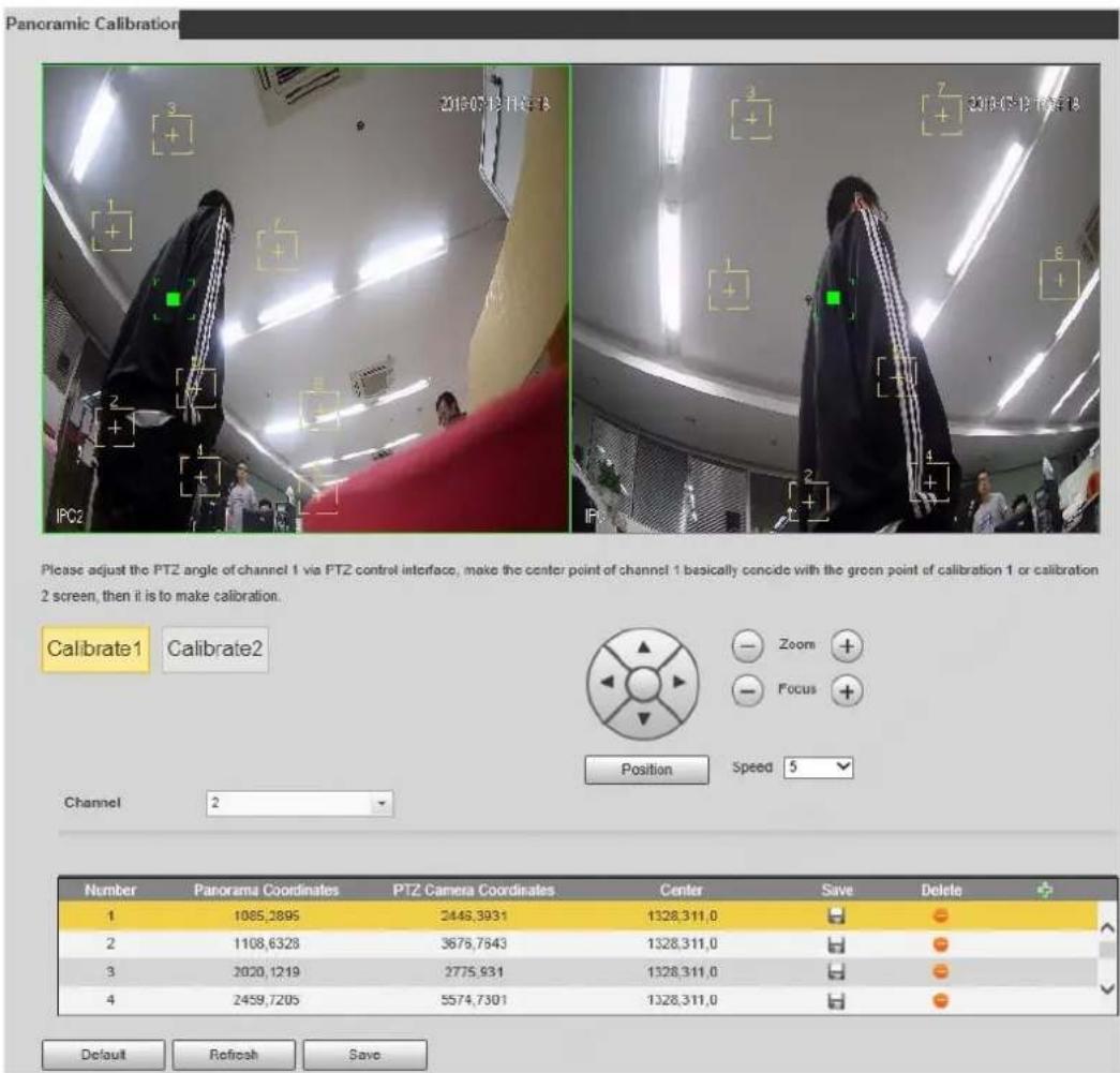
text_image
Panoramic Calibration 2013-07-13 PM: 18 IPC2 2 3 4 5 6 7 8 9 10 11 12 13 14 15 16 17 18 Please adjust the PTZ angle of channel 1 via PTZ control interface, make the center point of channel 1 basically concide with the green point of calibration 1 or calibration 2 screen, then it is to make calibration. Calibrate1 Calibrate2 Position Speed 5 Channel 2 Number Panorama Coordinates PTZ Camera Coordinates Center Save Delete 1 1085,2895 2448,3931 1328,311,0 2 1108,6328 3678,7843 1328,311,0 3 2020,1219 2775,931 1328,311,0 4 2459,7205 5574,7301 1328,311,0 Default Refresh SaveSelect channel 2, and then select a calibration number under the video images in turns Step 2 (See Figure 5-14) to add calibration points to the corresponding video images. Take Calibrate1 as an example.
Figure 5-14 Selecting a calibration number
1) Adjust the PTZ angle of channel 1 through the PTZ control interface to rotate the center of channel 1 to a position aligned with the green point in Calibrate1 image,
and then click

Calibration box is displayed in images of Channel 1 and Calibrate1.
2) Respectively drag calibration boxes on images of Channel 1 and Calibrate1 to the corresponding positions. Click to save this pair of calibration boxes.
You are recommended to drag calibration box to a static position with clear edges in the image. This can ensure the edges can be accurately distinguished by the camera. After the calibration record is saved, the calibration box is displayed in yellow.
Repeat steps 1)-2) to add at least 4 pairs of calibration points to each calibration picture.
Click Save. Step 3
Setting Video Detection 5.4
Check whether there are considerable changes on the video by analyzing video images. In case of any considerable change on the video (such as moving object, fuzzy image), the system performs an alarm linkage.
5.4.1 Setting Motion Detection
The system performs an alarm linkage when the moving object appears on the image and its moving speed reaches the preset sensitivity.

- If you enable motion detection and smart motion detection simultaneously, and configure the linked activities, the linked activities take effect as following:
When Motion Detection is triggered, the camera will record and take snapshots, but other configured linkages such as sending emails, PTZ operation will not take effect.
When Smart Motion Detection is triggered, all the configured linkages take effect. - If you only enable motion detection, all the configured linkages take effect when motion detection is triggered.
Step 1 Select Setting > Event > Video Detection > Motion Detection.
The Motion Detection interface is displayed. See Figure 5-15.
Motion detection Figure 5-15
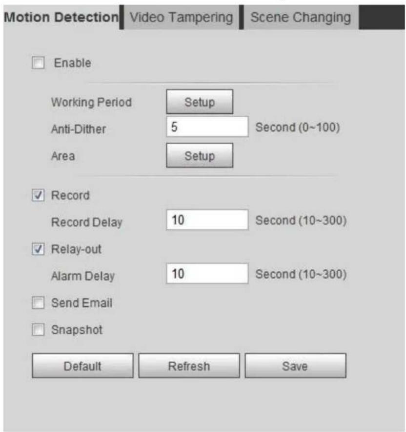
text_image
Motion Detection Video Tampering Scene Changing Enable Working Period Setup Anti-Dither 5 Second (0~100) Area Setup ✓ Record Record Delay 10 Second (10~300) ✓ Relay-out Alarm Delay 10 Second (10~300) Send Email Snapshot Default Refresh SaveSelect the Enable check box to enable Motion Detection. Step 2 Set the area for motion detection. Step 3
1) Click Setup next to Area. The Area interface is displayed. See Figure 5-16.
Area Figure 5-16
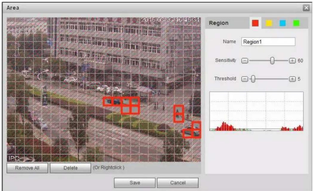
text_image
Area Region Name Region1 Sensitivity 60 Threshold 5 IPC Remove All Delete (Or Rightclick ) Save Cancel2) Select a color and set the region name. Select an effective area for Motion Detection in the image and set Sensitivity and Threshold.

- Select a color on to set different detection parameters for each region.
- Sensitivity: Sensitive degree of outside changes. It is easier to trigger the alarm with higher sensitivity.
◇ Threshold: Effective area threshold for Motion Detection. The smaller the threshold is, the easier the alarm is triggered.
◇ The whole video image is the effective area for Motion Detection by default.
The red line in the waveform indicates that the Motion Detection is triggered, and the green one indicates that there is no motion detection. Adjust sensitivity and threshold according to the waveform.
3) Click Save.
Step 4 Set arming periods and alarm linkage action. For details, see "5.1.1 Alarm Linkage." Anti-dither: After the Anti-dither time is set, the system only records one motion detection event in the period.
Click Save. Step 5
5.4.2 Setting Video Tamper
The system performs alarm linkage when the lens is covered or video output is mono-color screen caused by light and other reasons.
Step 1 Select Setting > Event > Video Detection > Video Tamper.
The Video Tamper interface is displayed. See Figure 5-17.
Video tampering Figure 5-17

text_image
Motion Detection Video Tampering Scene Changing Enable Video Tampering Enable Defocus Detection Working Period Setup Record Record Delay 10 Second (10~300) Relay-out Alarm Delay 10 Second (10~300) Send Email Snapshot Default Refresh SaveStep 2 Select the Enable Video Tampering check box, and set arming periods and alarm linkage action. For details, see "5.1.1 Alarm Linkage."
Select the Enable Defocus Detection check box: The alarm is triggered when the image is fuzzy. This function is available on some select models.
Click Save. Step 3
5.4.3 Setting Scene Changing
The system performs alarm linkage when the image switches from the current scene to another one.
Step 1 Select Setting > Event > Video Detection > Scene Changing.
The Scene Changing interface is displayed. See Figure 5-18.
Scene changing Figure 5-18
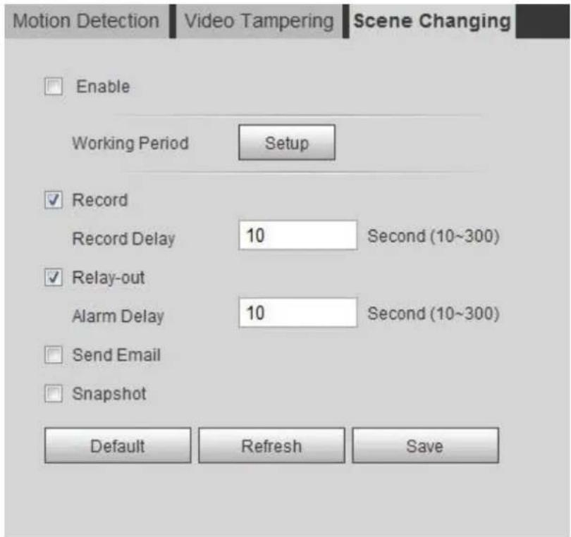
text_image
Motion Detection Video Tampering Scene Changing Enable Working Period Setup ✓ Record Record Delay 10 Second (10~300) ✓ Relay-out Alarm Delay 10 Second (10~300) ✓ Send Email Snapshot Default Refresh SaveStep 2 Set arming periods and alarm linkage action. For details, see "5.1.1 Alarm Linkage."
Click Save. Step 3
Setting Smart Motion Detection 5.5
The system performs alarm linkage when human, non-motorized vehicle, or motor vehicle appear on the image and its moving speed reaches the preset sensitivity. Enabling smart motion detection can avoid the alarms triggered by the environment changes, and the function is enabled by default.
Preparation
- Select Setting > Event > Video Detection > Motion Detection to enable Motion Detection.
- You have set Period and Area in Motion Detection, and make sure that the sensitivity value is larger than 0, and the threshold value is smaller than 100.
Procedure
Select Setting > Event > Smart Motion Detection. Step 1 The Smart Motion Detection interface is displayed. See Figure 5-19. Smart motion detection Figure 5-19
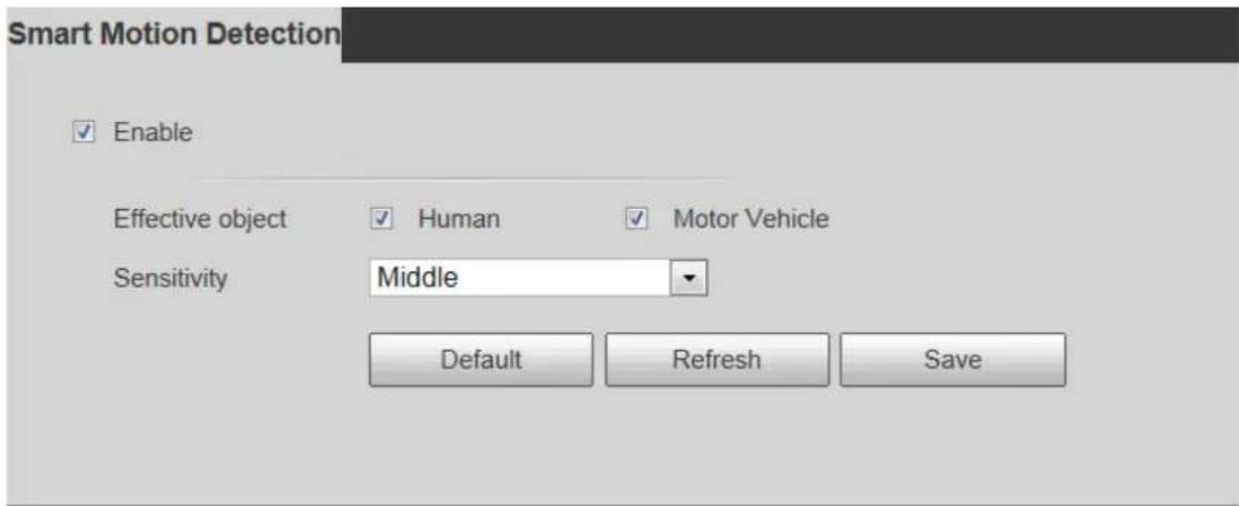
text_image
Smart Motion Detection Enable Effective object Sensitivity Human Motor Vehicle Middle Default Refresh SaveStep 2 Select the Enable check box to enable smart motion detection function.
Set effective object and sensitivity. Step 3
- Effective object: Includes Human and Motor vehicle. When you select Human, the camera will detect human and non-motorized vehicle.
- Sensitivity: Includes Low, Middle, and High. The higher the sensitivity is, the easier the alarm will be triggered.
Click OK. Step 4
Setting Audio Detection 5.6
The system performs alarm linkage when vague voice, tone change, or sound intensity rapid change is detected.
Step 1 Select Setting > Event > Audio Detection.
The Audio Detection interface is displayed. See Figure 5-20.
Audio detection Figure 5-20
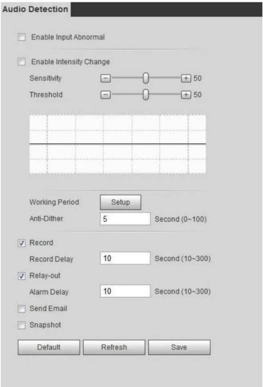
text_image
Audio Detection Enable Input Abnormal Enable Intensity Change Sensitivity - + 50 Threshold - + 50 Working Period Setup Anti-Dither 5 Second (0~100) ✓ Record Record Delay 10 Second (10~300) ✓ Relay-out Alarm Delay 10 Second (10~300) ✓ Send Email ✓ Snapshot Default Refresh SaveSet parameters. Step 2
- Input abnormal: Select the Enable Input Abnormal check box, and the alarm is triggered when the system detects abnormal sound input.
- Intensity change: Select the Enable Intensity Change check box and then set Sensitivity and Threshold. The alarm is triggered when the system detects that the sound intensity exceeds the set threshold.
It is easier to trigger the alarm with higher sensitivity or smaller threshold. Set a high threshold for noisy environment.
The red line in the waveform indicates audio detection is triggered, and the green one indicates no audio detection. Adjust sensitivity and threshold according to the waveform.
Step 3 Set arming periods and alarm linkage action. For details, see "5.1.1 Alarm Linkage."
Click Save. Step 4
Setting Smart Plan 5.7
Smart plan includes face detection, heat map, IVS, people counting, face detection, video structuralization, and stereo analysis. The intelligent function can be enabled only after the corresponding smart plan is enabled.
Select Setting > Event > Smart Plan. Step 1
The Smart Plan interface is displayed. For smart plan icon, see Table 5-4.
Table 5-4 Description of smart plan icon
| Icon | Description | Icon | Description | Icon | Description |
 | Face detection |  | Stereo vision |  | Heat map |
 | Stereo analysis |  | IVS |  | Face recognition |
 | People counting |  | Video Structuralization |  | Crowd map |
 | ANPR | - | - |
Enable smart functions as need. Step 2
Different cameras support different ways to enable smart functions. Select corresponding ways to enable these functions according to the actual interface.
- Select an icon to enable the corresponding smart plan.
Click an icon to enable it, and the selected smart function is highlighted. Click it again to cancel the selection.
If there is icon on the interface, click it to enable the smart function switch.
- Enable smart plan through Add Plan.
1) Select a preset point from the Add Plan the interface.
The smart plan for the point is displayed.
2) To enable a smart function, click the corresponding icon.
The selected smart function is highlighted. Click it again to cancel the selection.
Step 3 Click Save.
5.8 Setting IVS
This section introduces scene selection requirements, rule configuration, and global configuration for IVS (intelligent video surveillance).
Basic requirements on scene selection are as follows.
- The target should occupy no more than 10% of the whole image.
- The target size in the image should be no more than 10×10 pixels. The size of abandoned object in the image should be no less than 15×15 pixels (CIF image). The target height and width should no more less than a third of the image height and width. The recommended target height is 10% of the image height.
- The brightness difference of the target and the background should be no less than 10 gray levels.
- The target should be continuously present in the image for no less than two seconds, and the moving distance of the target should be larger than its width and no less than 15 pixels (CIF image) at the same time.
- Reduce the complexity of surveillance scene as much as you can. Intelligent analysis functions are not recommended to be used in scene with dense targets and frequent illumination change.
- Avoid areas such as glass, reflective ground, water surface, and areas interfered by branch, shadow and mosquito. Avoid backlight scene and direct light.
5.8.1 Global Configuration
Set global rules for IVS, including anti-disturb, depth of field calibration, and valid motion parameter for targets.
Calibration Purpose
Determine corresponding relationship between 2D image captured by the camera and 3D actual object according to one horizontal ruler and three vertical rulers calibrated by the user and the corresponding actual distance.
Applicable Scene
- Medium or distant view with installation height of more than three meters. Scenes with parallel view or ceiling-mounted are not supported.
• Calibrate horizontal plane, not vertical walls or sloping surfaces.
- This function is not applicable to scenes with distorted view, such as the distorted views captured by super wide-angle or fisheye camera.
Notes
- Calibration Drawing
◇ Calibration area: The calibration area drawn should be on one horizontal plane.
- Vertical ruler: The bottom of three vertical rulers should be on the same horizontal plane. Select three reference objects with fixed height in triangular distribution as vertical rulers, such as vehicle parked at roadside or road lamp poles. Arrange three persons to draw at each of the three positions in the monitoring scene.
◇ Horizontal ruler: Select reference object with known length on the ground, such as sign on the road, or use a tape to measure the actual length.
• Calibration Verification
After setting the ruler, draw a straight line on the image, check the estimated value of the straight line, and then compare this value with the value measured in the actual scene to verify calibration accuracy. In case of major difference between the estimated value and the actual one, fine-tune or reset parameters until the error requirement is met.
Procedure
Select Setting > Event > IVS > Global Setup. Step 1
The Global Setup interface is displayed. See Figure 5-21.
Global setup of IVS Figure 5-21
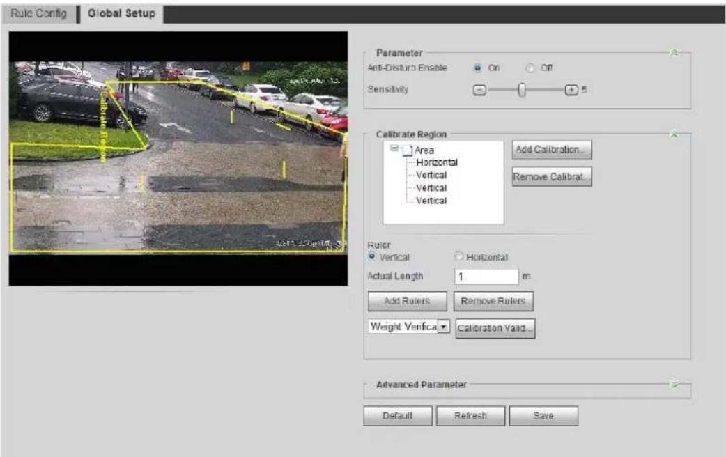
text_image
Rule Config Global Setup Parameter Anti-Disturb Enable On Off Sensitivity 5 Calibrate Region Area Horizontal Vertical Vertical Vertical Add Calibration... Remove Calibrat... Ruler Vertical Horizontal Actual Length 1 m Add Rulers Remove Rulers Weight Verifica Calibration Valid... Advanced Parameter Default Refresh SaveSet parameters. See Table 5-5. Step 2
Table 5-5 Description of global setup (IVS) parameters
| Parameter | Description |
| Anti-Disturb Enable | A reserved function. |
| Sensitivity | Adjust the filter sensitivity. With higher value, it is easier to trigger an alarm when low-contrast object and small object are captured, and the false detection rate is higher. |
| Tracking Overlap Rate | A reserved function. |
| Valid Tracking Distance | A reserved function. |
| Valid Tracking Time | A reserved function. |
Set calibration area and ruler. Step 3
1) Click Add Calibration Area and draw a calibration area in the image.
2) Select a calibration type and enter the actual length, and then click Add Rulers.
3) Draw one horizontal ruler and three vertical rulers in the calibration area.
Click Save. Step 4
Verification
Step 1 Select the verification type, and then click Calibration Valid.
To verify vertical ruler and horizontal ruler, respectively select Height Verification and Width Verification.
Draw a straight line in the image to verify whether the rulers are correctly set. Step 2 In case of big difference between the estimated value and the actual one, fine-tune or reset parameters until the error requirement is met.
5.8.2 Rule Configuration
Set rules for IVS, including cross fence detection, tripwire, intrusion, abandoned object, moving object, fast moving, parking detection, crowd gathering, and loitering detection.
For the functions and applications of the rules, see Table 5-6.
Table 5-6 Description of IVS functions
| Rule | Description | Applicable Scene |
| Tripwire | When the target crosses tripwire from the defined motion direction, the system performs alarm linkages. | Scenes with sparse targets and no occlusion among targets, such as the perimeter protection of unattended area. |
| Intrusion | When the target enters, leaves, or appears in the detection area, the system performs alarm linkages. | |
| Abandoned object | When an object is abandoned in the detection area over the set time, the system performs alarm linkages. | Scenes with sparse targets and without obvious and frequent light change.Simple scene in the detection area is recommended.Missed alarm might increase in the scenes with dense targets, frequent occlusion, and people staying.In scenes with complex foreground and background, false alarm might be triggered for abandoned or missing object. |
| Missing object | When an object is taken out of the detection area over the defined time, the system performs alarm linkages. | |
| Fast moving | When the motion speed is higher than the configured speed, the system performs alarm linkages. | Scene with sparse targets and less occlusion. The camera should be installed right above the monitoring area. The light direction should be vertical to the motion direction. |
| Parking detection | When the target stays over the configured time, the system performs alarm linkages. | Road monitoring and traffic management. |
| Crowd gathering | When the crowd gathers or the crowd density is large, the system performs alarm linkages. | Scenes with medium or long distance, such as outdoor plaza, government entrance, station entrance and exit. It is not suitable for short-distance view analysis. |
| Loitering detection | When the target loiters over the shortest alarm time, the system performs alarm linkages. After alarm is triggered, if the target stay in the area within the time interval of alarm, then alarm will be triggered again. | Scenes such as park and hall. |
Preparation
- Select Setting > Event > Smart Plan, and enable IVS.
- Select Setting > Event > IVS > Global Setup to finish global configuration, and then configure Fast Moving rule.
Procedure
Configure IVS rules. This section takes tripwire as an example.

Go to the Rule Config interface of the speed dome, and the PTZ lock function is automatically enabled. The locking time is 180 seconds. You can only manually control the PTZ during the locking time. Click Unlock at lower left corner of the Rule Config interface to manually unlock the PTZ, and click Lock again to relock the PTZ.
Step 1 Select Setting > Event > IVS > Rule Config.
The Rule Config interface is displayed.
Step 2 Click +, double-click the name to modify the rule name, and select Tripwire from the Rule Type drop-down list. See Figure 5-22.
Tripwire Figure 5-22
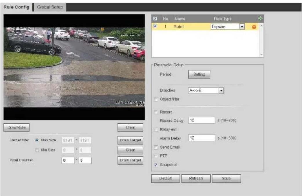
text_image
Rule Config Global Setup No. Name Rule Type 1 Rule 1 Tripwire Parameter Setup Period Setting Direction A<->B Object filter Record Record Delay 10 s (10~300) Relay-out Alarm Delay 10 s (10~300) Send Email PT2 Snapshot Draw Rule Clear Target filter Max Size 8191 * 8191 Min Size 0 * 0 Pixel Counter 0 * 0 Draw Target Clear Draw Target Default Refresh SaveStep 3 Click Draw Rule to draw rule line in the image. Right-click to finish drawing. For requirements of drawing rules, see Table 5-7. After drawing rules, drag corners of the detection area to adjust the area range.
Table 5-7 Description of IVS analysis
| Rule | Description |
| Tripwire | Draw a detection line. |
| Intrusion | Draw a detection area.During the detection of abandoned object, the alarm is also triggered if pedestrian or vehicle stays for a long time. If the abandoned object is smaller than pedestrian and vehicle, set the target size to filte pedestrian and vehicle or properly extend the duration to avoid false alarm triggered by transient staying of pedestrian.During the detection of crowd gathering, false alarm might be triggered by low installation height, large percentage of single person in an image or obvious target occlusion, continuous shaking of the camera, shaking of leaves and tree shade, frequent opening or closing of retractable door, or dense traffic or people flow. |
| Abandoned object | |
| Missing object | |
| Fast moving | |
| Parking detection | |
| Crowd gathering | |
| Loitering detection |
Step 4 (Optional) Click Draw Target at the right side of Target Filter, and then draw the target in the image.
- When the rule of crowd gathering is configured, you do not need to set target filter, but draw the minimum gathering area. Click Draw Target to draw the minimum gathering area in the scene. The alarm is triggered when the number of people in the detection area exceeds the minimum area and the duration.
- Click Clear to delete all drawn detection lines.
- Click Draw Target at the right side of Pixel Counter, and then press and hold the left mouse button to draw a rectangle, the Pixel Counter then displays its pixel.
Step 5 Set rule parameters for IVS. For details, see Table 5-8.
Table 5-8 Description of IVS parameters
| Parameter | Description |
| Direction | Set the direction of rule detection.When setting cross fence detection and tripwire, select A->B, B->A or A<->BWhen setting intrusion, select Enters, Exits, or Enter&Exit. |
| Action | When setting intrusion action, select Appears or Cross. |
| Object tracking | Select Object Tracking to enable this function. When alarm is triggered by a moving object, select 1P+3 or 1P+5 as the object tracking display mode in the Live interface. Then the tracking scene follows the moving object until the object is out of the camera range. For details, see "4.2.4 Window Adjustment Bar."This function is available on some select models. |
| Track linkage | Select Alarm Track and set the tracking time. When alarm is triggered, the camera automatically tracks the person or object that triggers the alarm. Tracking time is the duration that the camera automatically tracks the object.Before enabling this function, you need to enable or disable the Alarr Track function under Smart Track as needed.When the Channel is set as 1, disable Alarm Track under Smart Track.When the Channel is set as 2 or 3, enable Alarm Track under Smart Track. |
| Track Time | |
| AI Recognition | Select AI Recognition to enable this function.When you select Person as the alarm target, an alarm will be triggered when the system detects that persons trigger the rule.When you select Vehicle as the alarm target, alarm will be triggered when the system detects that vehicle trigger the rule. |
| Duration | For abandoned object, the duration is the shortest time for triggering an alarm after an object is abandoned.For missing object, the duration is the shortest time for triggering an alarm after an object is missing.For parking detection, crowd gathering, or loitering detection, the duration is the shortest time for triggering an alarm after an objec appears in the area. |
| Sensitivity | For fast moving, sensitivity is related to the triggering speed. Lower sensitivity requires faster moving speed to trigger the alarm.For crowd gathering, sensitivity is related to the alarm triggering time. It is easier to trigger the alarm with higher sensitivity. |
Step 6 Set arming periods and alarm linkage action. For details, see "5.1.1 Alarm Linkage." Click Save. Step 7
To view alarm information on the Alarm tab, you need to subscribe relevant alarm event. For details, see "5.1.2 Subscribing Alarm."
Setting Crowd Map 5.9
You can view crowd distribution on the map in real time for timely arming, to prevent stampede and other accidents.
5.9.1 Global Configuration
Set calibration parameters of panoramic camera.
Calibration Purpose
Determine corresponding relationship between 2D image captured by the camera and 3D actual object according to the rulers calibrated by the user and its corresponding actual distance.
Notes
Draw two rulers at a position close to and a position far away from the center area in the image to ensure small difference between actual vertical distance and the calibrated one of each point in the image after calibration. It is recommended to arrange two persons to draw at each of the two positions in the monitoring scene.
Procedure
Select Setting > Event > Crowd Map > Global Setup. Step 1 The Global Setup interface is displayed. See Figure 5-23.
Global setup (crowd map) Figure 5-23
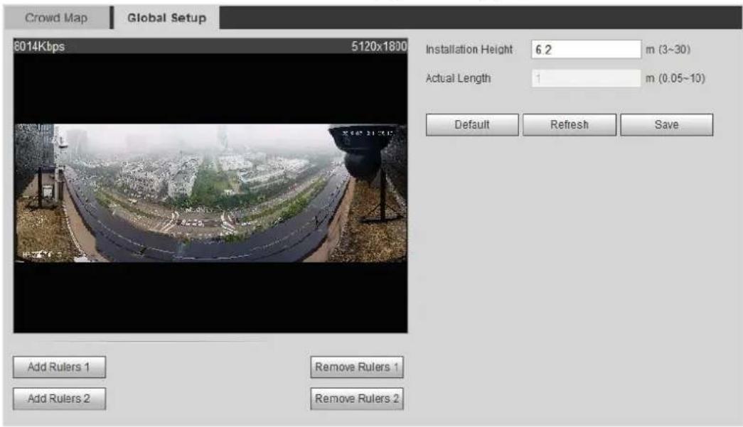
text_image
Crowd Map Global Setup 8014Kbps 5120x1800 Installation Height 6.2 m (3~30) Actual Length 1 m (0.05~10) Default Refresh Save Add Rulers 1 Remove Rulers 1 Add Rulers 2 Remove Rulers 2Step 2 Click Add Rulers 1 and Add Rulers 2 to respectively draw a ruler in the area.
____ Enter the installation height and the actual length according to the actual situation. Step 3
Click Save. Step 4
5.9.2 Rule Configuration
When the number of people or the crowd density in the detection area exceeds the configured threshold, the system performs alarm linkages.
Preparation
- Select Setting > Event > Smart Plan, and enable Crowd Map.
- Select Setting > Event > Crowd Map > Global Setup to configure the crowd map.
Procedure
Select Setting > Event > Crowd Map > Crowd Map. Step 1
The Crowd Map interface is displayed. See Figure 5-24.
Crowd map Figure 5-24
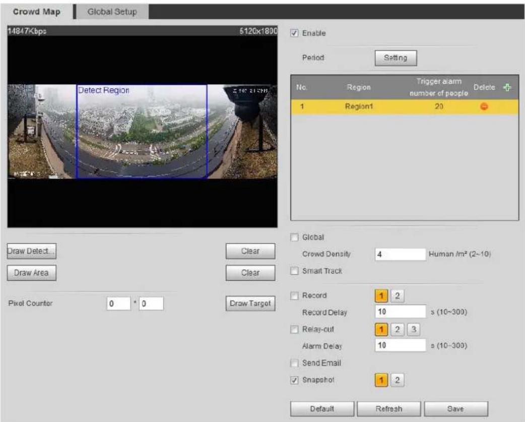
text_image
Crowd Map Global Setup 14847Kbps 5120x1800 Enable Period Setting No. Region Trigger alarm number of people Delete + 1 Region1 20 - Draw Detect... Clear Draw Area Clear Pixel Counter 0 * 0 Draw Target Global Crowd Density 4 Human /m² (2~10) Smart Track Record 1 2 Record Delay 10 s (10~300) Relay-out 1 2 3 Alarm Delay 10 s (10~300) Send Email Snapshot 1 2 Default Refresh SaveStep 2 Select the Enable check box, and then the crowd map function is enabled.
Step 3 Click Draw Detection Area to draw global area for detecting crowd distribution in the image.
After drawing a global area, you can draw multiple local statistical areas in the global area as needed.
1) Click +, and then click Draw Area to draw local statistical area in global detection area.
You can draw up to eight local statistical areas.
2) Double-click the area name and the alarm people amount to set the area name of local statistical area and the threshold of the alarm people amount.
When the number of people in the statistical area exceeds the alarm people amount, the system performs alarm linkages. The default alarm people amount is 20.
Set parameters. See Table 5-9. Step 4
Table 5-9 Description of crowd map parameters
| Parameter | Description |
| Global | Select the Global check box and set the crowd density threshold. The system detects crowd distribution in the global area. When the crowd density exceeds the configured threshold, the system performs alarm linkages. |
| Crowd Density | |
| Smart track | Select theSmart Trackcheck box, and when alarm is triggered by the panoramic camera, the speed dome automatically turns to the position where alarm is triggered. The tracking time is "idle time + five seconds." For the details of idle time configuration, see "5.2.2 Enabling Alarm Track."Linkage rules:Detect global alarm only: Turns to crowd with highest density.Detect local alarm only: Turns to local area that triggers alarm first.Detect global alarm + one local alarm: First turns to local area, and then the crowd with highest density when there is no alarm in local area.Detect global alarm + multiple local alarms: First turns to local area that triggers alarm first, and then the crowd with highest density when there is no alarm in local area. Before enabling this function, you need to configure Smart Track. For details, see "5.2 Setting Smart Track." Before enabling this function, you need to configure Smart Track. For details, see "5.2 Setting Smart Track." |
| Pixel Counter | ClickDraw Targetnext toPixel Counter, and then press and hold the left mouse button to draw a rectangle, thePixel Counterthen displays its pixel. |
Step 5 Set arming periods and alarm linkage actions. For details, see "5.1.1 Alarm Linkage."
Click Save. Step 6
Verification
Click on the Live interface to view the crowd map. See Figure 5-25.
Crowd map (1) Figure 5-25
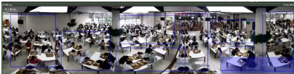
text_image
Panoramic photo of a large-scale food processing or processing facility with multiple workstations, tables, and workers, each framed by blue bounding boxes highlighting specific locations.Double-click the rendering area at the lower-right corner in the image to view crowd distribution in the area. See Figure 5-26.
Crowd map (2) Figure 5-26
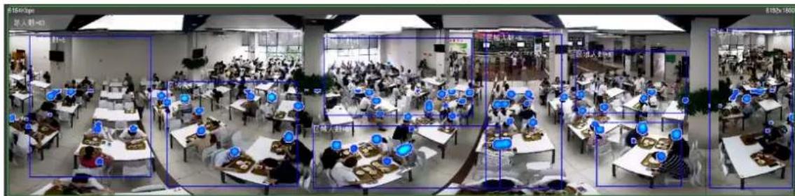
text_image
Street photo with visible store signboards and blue bounding boxes highlighting locations in a large restaurant hallSetting Face Recognition 5.10
When a face is detected or recognized in the detection area, the system performs alarm linkage and supports searching face detection and recognition results.
- Face Detection: When a face is detected in the area, the system performs alarm linkage, such as recording and sending emails.
- Face Recognition: When a face is detected in the area, the system compares the captured face image with the information in the face database, and links alarm according to the comparison result.
For the process of setting face recognition, see Figure 5-27.
Face recognition flowchart Figure 5-27
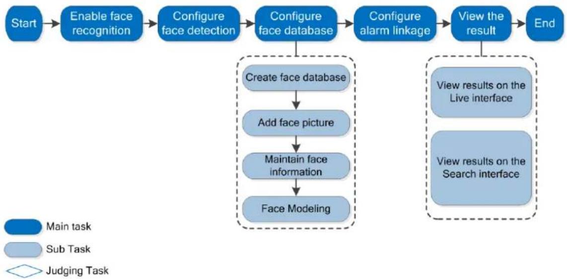
flowchart
graph TD
    A["Start"] --> B["Enable face recognition"]
    B --> C["Configure face detection"]
    C --> D["Configure face database"]
    D --> E["Create face database"]
    E --> F["Add face picture"]
    F --> G["Maintain face information"]
    G --> H["Face Modeling"]
    D --> I["Configure alarm linkage"]
    I --> J["View the result"]
    J --> K["End"]
    L["Main task"] --> B
    M["Sub Task"] --> C
    N["Judging Task"] --> D
    O["View results on the Live interface"] --> J
    P["View results on the Search interface"] --> J
5.10.1 Setting Face Detection
When a face is recognized in the detection area, the system performs alarm linkage.
Preparation
Enable Face Recognition from Setting > Event > Smart Plan.
Procedure
Step 1 Select Setting > Event > Face Recognition > Face Detection.
The Face Detection interface is displayed. See Figure 5-28.
Face detection Figure 5-28
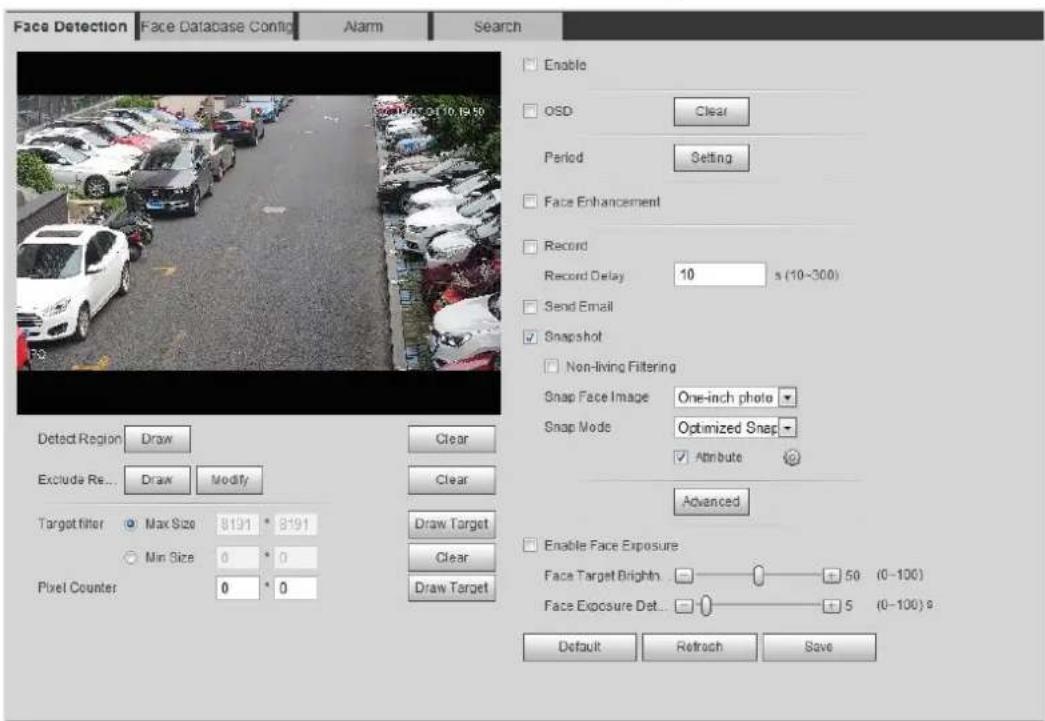
text_image
Face Detection Face Database Config Alarm Search Enable OSD Clear Period Setting Face Enhancement Record Record Delay 10 s (10-300) Send Email Snapshot Non-living Filtering Snap Face Image One-inch photo Snap Mode Optimized Snap ✓ Attribute Advanced Enable Face Exposure Face Target Brights 50 (0-100) Face Exposure Det 5 (0-100) s Default Retrench Save Detect Region Draw Clear Exclude Re... Draw Modify Clear Target filter Max Size 8191 * 8191 Min Size 0 * 0 Pixel Counter 0 * 0 Draw Target Clear Draw Target Clear Draw TargetStep 2 Select the Enable check box to enable the face detection function.
Step 3 (Optional) Click Draw next to Detect Region to draw a face detection area in the image.
Step 4 (Optional) Click Draw next to Exclude Region to draw a non-face detection area in the Detect Region.
Step 5 (Optional) Select Max Size or Min Size, click Draw Target at the right side of Target filter, and then draw the target in the image.
Set parameters. See Table 5-10. Step 6
Table 5-10 Description of face detection parameters
| Parameter | Description |
| OSD | Select the OSD check box, and the number of people with face detected and recognized is displayed on the Live interface.Click Reset to recount. |
| Face Enhancement | Select the Face Enhancement check box to preferably guarantee clear face with low stream. |
| Non-living Filtering | Filter non-living faces in the image, such as a face picture. |
| Snap Face Image | Set a range for snapping face image, including face picture and one-inch picture. |
| Snap Mode | Optimized Snapshot: Capture the clearest picture within the configured time after the camera detects face.Recognition Priority: Repeatedly compare the captured face to the faces in the armed face database, and capture the most similar face image and send the alarm. It is recommended to use this mode in access control scene.Click Advanced to set the optimized time. |
| Attribute | Select the Attribute check box, and click to set the display of face attribute during the face detection. |
| Advanced | Snapshot Angle Filter: Set snapshot angle to be filtered during the face detection.Snapshot Sensitivity: Set snapshot sensitivity during the face detection. It is easier to detect face with higher sensitivity.Optimized Time: Set a time period to capture the clearest picture after the camera detects face. |
| Enable Face Exposure | Select the Enable Face Exposure check box. When a face is detected, the camera can enhance brightness of the face to make the face image clear. |
| Face Target Brightness | Set the face target brightness. It is 50 by default. |
| Face Exposure Detection Interval | Set the face exposure detection interval to prevent image flickering caused by constant adjustment of face exposure. It is five seconds by default. |
| Pixel Counter | Click Draw Target next to Pixel Counter, and then press and hold the left mouse button to draw a rectangle, the Pixel Counter then displays its pixel. |
Step 7 Set arming periods and alarm linkage actions. For details, see "5.1.1 Alarm Linkage."
Step 8 Click Save.
5.10.2 Setting Face Database
By setting face database, the face database information can be used to compare with the face detected.
Face database configuration includes creating face database, adding face picture, and face modeling.
5.10.2.1 Creating Face Database
Face database includes face picture, face data and other information. It also provides comparison data for the captured face pictures.
Step 1 Select Setting > Event > Face Recognition > Face Database Config.
The Face Database Config interface is displayed. See Figure 5-29.
Capacity Limit: Shows the usage of the memory.
Face database configuration Figure 5-29
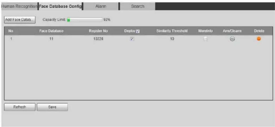
text_image
Human Recognition Face Database Config Alarm Search Add Face Data... Capacity Limit: 92% No. Face Database Register No Deploy Similarity Threshold MoreInfo Arm/Disarm Delete 1 11 10228 10 Refresh SaveClick Add Face Database. Step 2
The Add Face Database interface is displayed. See Figure 5-30.
Add face database Figure 5-30
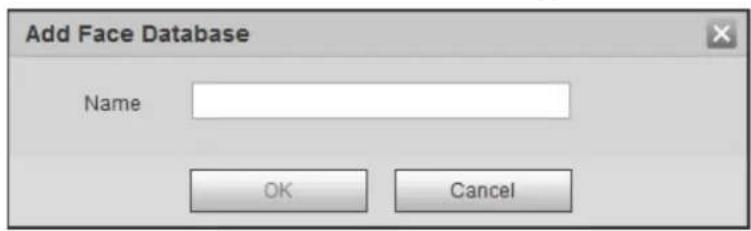
text_image
Add Face Database Name OK CancelSet the name of the face database. Step 3
Click OK. See Figure 5-31. Step 4
Face database successfully added Figure 5-31
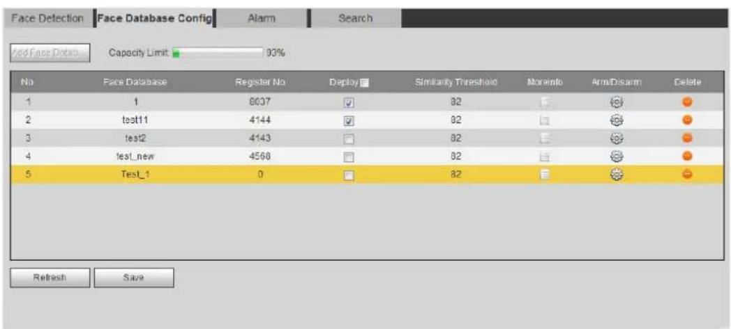
text_image
Face Detection Face Database Config Alarm Search Add Face Data Capacity Limit: 93% No Face Database Register No Deploy Similarity Threshold Moreinfo Arm/Disarm Delete 1 1 8037 ✓ 82 E © ● 2 test11 4144 ✓ 82 □ © ● 3 test2 4143 □ 82 E © ● 4 test_new 4568 □ 82 □ © ● 5 Test_1 0 □ 82 E © ● Refresh SaveStep 5 Set parameters. See Table 5-11.
Table 5-11 Description of face database parameters
| Parameter | Description |
| Deploy | Select the Deploy check box, and the face database deployment is enabled. The captured face picture is compared to the armed face database. |
| Similarity Threshold | The detected face matches the face database only when the similarity between the detected face and the face feature in face database reaches the configured similarity threshold. After successful match, the comparison result is displayed on theLiveinterface. |
| MoreInfo | Click MoreInfo to manage face database. You can search face images by setting search conditions, register personnel, and modify personnel information. |
| Arm/Disarm | Set the alarm time period. Alarm event will be triggered only within the defined time. See "5.1.1.1 Setting Period." |
| Delete | Delete the selected face database. |
5.10.2.2 Adding Face Picture
Add face picture to the created face database. Single adding and batch importing are supported.
Requirements on face pictures.
- A single face picture size is 50K–150K in JPEG format. The resolution is less than 1080p.
- Face size is 30%–60% of the whole picture. Pixel should be no less than 100 pixels between the ears.
- Taken in full-face view directly facing the camera without makeup, beautification, glasses, and fringe. Eyebrow, mouth and other face features must be visible.
5.10.2.2.1 Single Adding
Add face pictures one by one. Select this way when you need to add a small number of face pictures.
Step 1 Select Setting > Event > Face Recognition > Face Database Config.
The Face Database Config interface is displayed.
Click next to the face database to be set. Step 2
The Face Database Config interface is displayed. See Figure 5-32.
Figure 5-32 Face database configuration
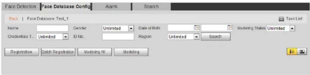
text_image
Face Detection Face Database Config Alarm Search Back | Face Database: Test1 Task List Name Gender Unlimited Date of Birth Modeling Status Unlimited Credentials T... Unlimited ID No. Region Unlimited Search Registration Catch Registration Modeling All ModelingStep 3 Click Registration.
The Registration interface is displayed. See Figure 5-33.
Registration (1) Figure 5-33
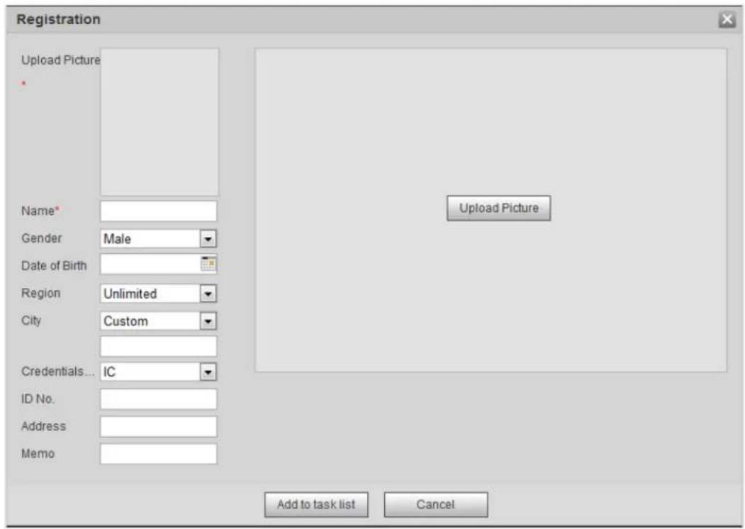
text_image
Registration Upload Picture Name* Gender Male Date of Birth Region Unlimited City Custom Credentials... IC ID No. Address Memo Upload Picture Add to task list CancelStep 4 Click Upload Picture, select a face picture to be uploaded, and click Open. The interface shown as Figure 5-34 is displayed.

You can manually select the area for a face. After uploading picture, box select a face and click OK. When there are multiple faces in a photo, select the target face and click OK to save face picture.
Registration (2) Figure 5-34
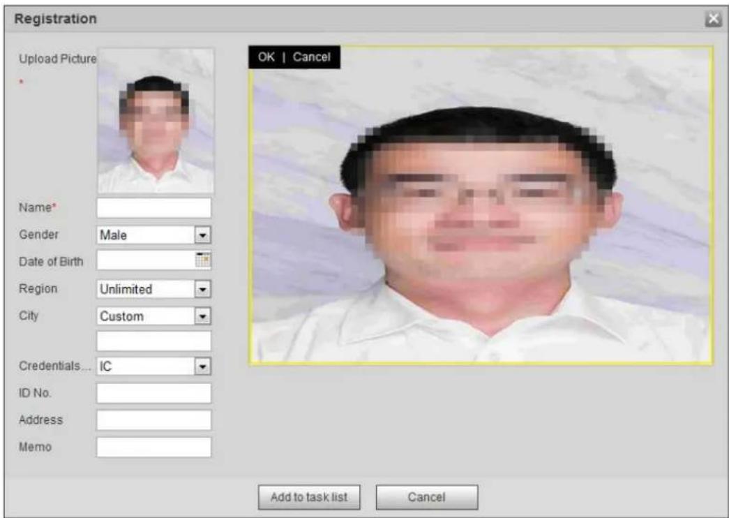
text_image
Registration Upload Picture Name* Gender Male Date of Birth Region Unlimited City Custom Credentials... IC ID No. Address Memo OK | Cancel Add to task list CancelEnter the information about face picture according to the actual situation. Step 5 Click Add to task list. Step 6
____ Click , and then click OK. Step 7
The Task List interface is displayed. See Figure 5-35. Click Remove All to remove all tasks by one click.
Task list (manually add) Figure 5-35
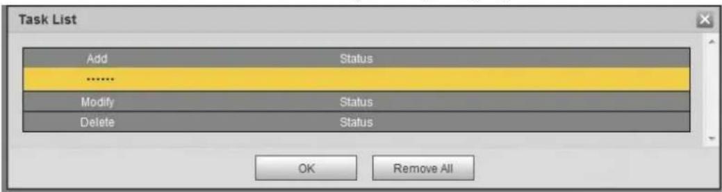
text_image
Task List Add Status ...... Modify Status Delete Status OK Remove AllIf adding user fails, the error code is displayed on the interface. For details, see Table 5-12. For face modeling operation, see "5.10.2.4 Face Modeling."
Table 5-12 Description of error code
| Parameter | Error | Description |
| 0x1134000C | Picture importing error | The picture is too large, and the upper limit is 150K. |
| 0x1134000E | The quality of the added pictures is to the upper limit. | |
| 0x11340019 | The space of the face database exceeds the upper limit. | |
| 1 | Picture modeling error | The picture format is not correct. Import the picture in JPG format. |
| 2 | No face in the picture or the face is not clear. Change the picture. | |
| 3 | Mutiple faces in the picture. Change the picture | |
| 4 | Fails to decode the picture. Change the picture. | |
| 5 | The picture is not suitable to be imported to the face database. Change the picture. | |
| 6 | The database error. Restart the camera and model faces again. | |
| 7 | Fails to get the picture. Import the picture again. | |
| 8 | System error. Restart the camera and model faces again. |
5.10.2.2.2 Batch Importing
Import face pictures in batches. Select this way when you need to add a large number of face pictures.
Preparation
Before importing pictures in batches, name face pictures in a format of "Name#SGender#BDate of Birth#NRegion#TCredentials Type#MID No.jpg" (for example, "John#S1#B1990-01-01#T1#M0000). For naming rules, see Table 5-13.

- The max. size of a single face picture is 150K, and the resolution is less than 1080p.
- When naming pictures, Name is required, and others are optional.
Table 5-13 Description of naming rules for batch import parameters
| Parameter | Description |
| Name | Enter a name. |
| Gender | Enter a figure. "1" is male and "2" female. |
| Date of Birth | Enter a figure. Format: yyyy-mm-dd, such as 2017-11-23. |
| Credentials Type | Enter a figure. "1" is ID card and "2" passport. |
| ID number | Enter ID No.. |
Procedure
Step 1 Select Setting > Event > Face Recognition > Face Database Config. The Face Database Config interface is displayed.
____ Click next to the face database that you want to set. Step 2
The Face Database interface is displayed.
Click Batch Registration. Step 3 The Task List interface is displayed. See Figure 5-36.
Batch add Figure 5-36
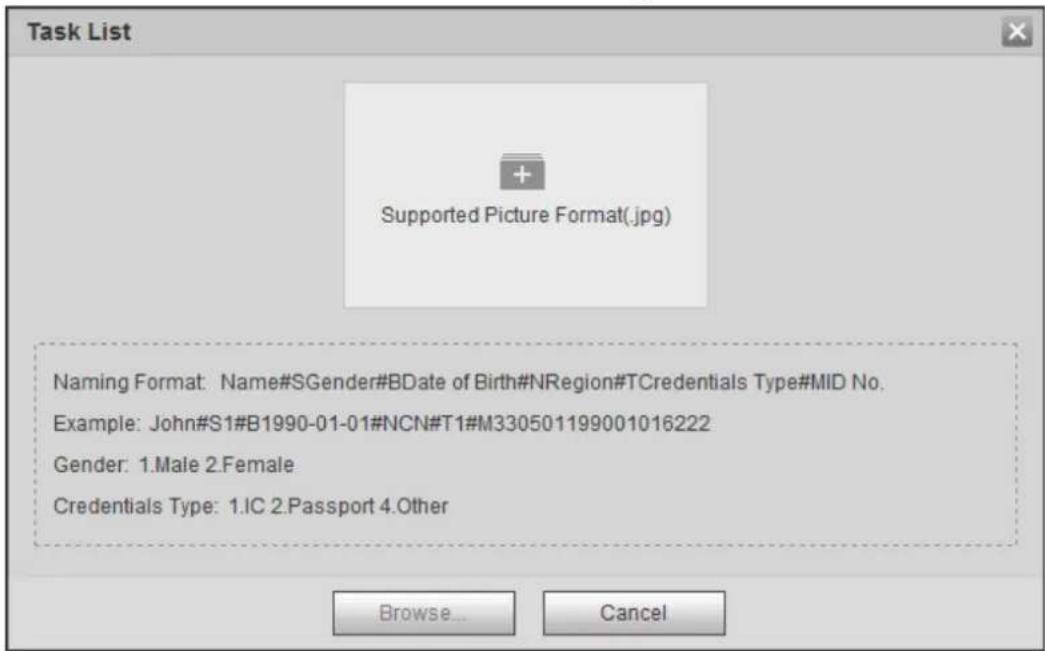
text_image
Task List Supported Picture Format(.jpg) Naming Format: Name#SGender#BDate of Birth#NRegion#TCredentials Type#MID No. Example: John#S1#B1990-01-01#NCN#T1#M330501199001016222 Gender: 1.Male 2.Female Credentials Type: 1.IC 2.Passport 4.Other Browse... Cancel____ Click to select file path. Step 4
Batch import Figure 5-37
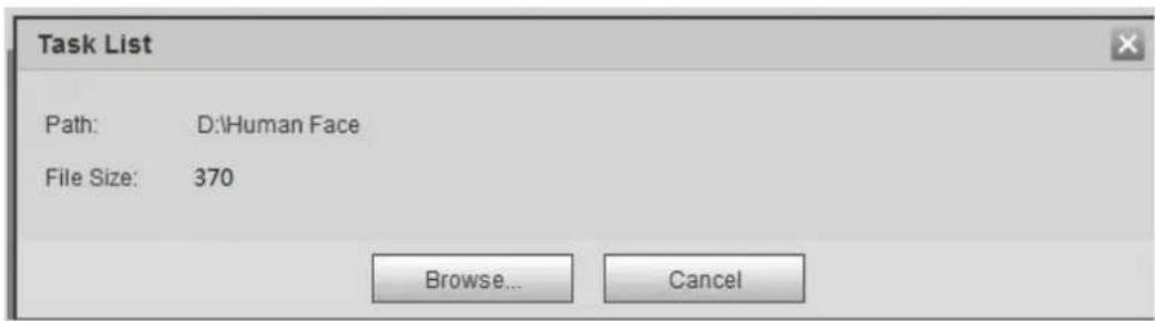
text_image
Task List Path: D:\Human Face File Size: 370 Browse... CancelClick Browse. Step 5 The interface shows import process. After finishing the import, the interface shown as Figure 5-38 is displayed.
Importing successfully Figure 5-38
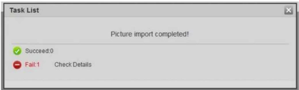
text_image
Task List Picture import completed! ✓ Succeed:0 - Fail:1 Check Details5.10.2.3 Managing Face Picture
Add face pictures to face database, and then manage and maintain face pictures to ensure correct information.
5.10.2.3.1 Modifying Face Information
Step 1 Go to the Face Database Config interface, set filtering condition as needed, and click Search.
The search result is displayed.
Select the row where the face picture or the personnel information is located, and then Step 2

The Registration interface is displayed. See Figure 5-39.
Face information modification Figure 5-39
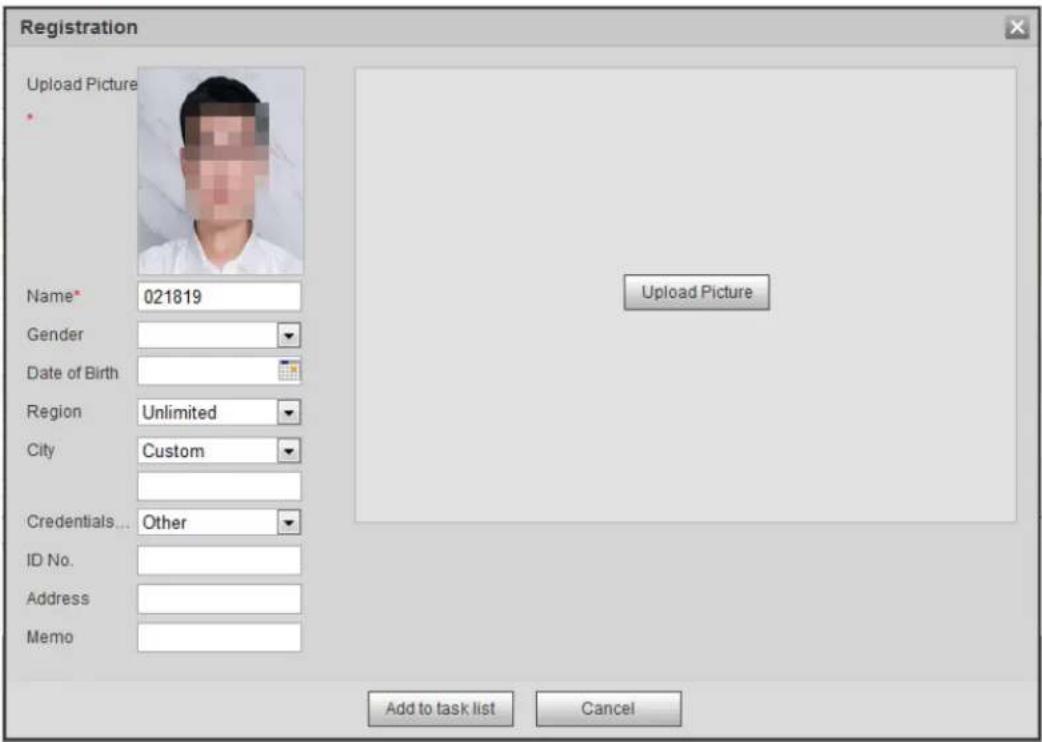
text_image
Registration Upload Picture Name* 021819 Gender Date of Birth Region Unlimited City Custom Credentials... Other ID No. Address Memo Upload Picture Add to task list CancelStep 3 Modify face information according to the actual need. Click Add to task list.
____ Click , and then click OK. Step 4
5.10.2.3.2 Deleting Face Picture
Go to the Face Database Config Interface, and delete the created face picture.
- Single delete: Select the row where the face picture or the personnel information is located, and click 📄 or to delete the face picture.
- Batch delete: Select □ at the upper right corner of the face picture or □ of the row
where the personnel information is located. Select the information, click Add to Deletion List, , and then click OK to delete the selected face picture.
- Delete all: When viewing face pictures in a list, click ☐ of the row where the serial number is located; when viewing by thumbnail, select All to select all face pictures. Click Add to Deletion List, Task List1, and then click OK to delete all face pictures.
5.10.2.4 Face Modeling
Face modeling extracts face picture information and imports the information to a database to establish relevant face feature models. Through this function, the face recognition and other intelligent detections can be realized.

- The more the selected face pictures are, the longer time the face modeling takes. Please wait patiently.
- During modeling, some intelligent detection functions (such as face recognition) are not available temporarily, and will be available after modeling.
Step 1 Select Setting > Event > Face Recognition > Face Database Config.
The Face Database Config interface is displayed.
____ Click next to the face database to be set. Step 2
The Face Database Config interface is displayed. See Figure 5-40.
Face database configuration Figure 5-40
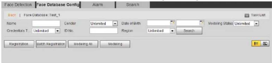
text_image
Face Detection Face Database Config Alarm Search Back | Face Database: Test_1 Task List Name Gender Unlimited Date of Birth Modeling Status Unlimited Credential's T. Unlimited ID No. Region Unlimited Search Registration Batch Registration Modeling All ModelingStep 3 Start modeling.
- Selective modeling.
If there are many face pictures in the face database, you can set search criteria to select the pictures that need to be modeled.
1) Set the search criteria, and click Search.
2) Select the face pictures to be modeled.
3) Click Modeling.
- All modeling,
Click Modeling All to complete modeling of all face pictures in the face database.
Step 4 View the modeling result.
- For successful modeling, see Figure 5-41.
Successful modeling Figure 5-41
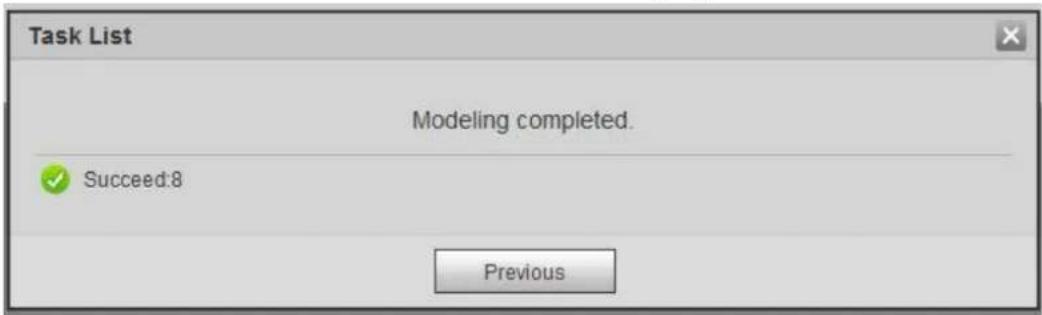
text_image
Task List Modeling completed. Succeed:8 Previous• For failed modeling, see Figure 5-42.
Failed modeling Figure 5-42

text_image
Task List Modeling completed. ✓ Succeed:0 ● Fail:1 Search PreviousClick Search, and the face details are displayed. Click to view the face picture in list format. See Figure 5-43. Click to view the face picture in thumbnail format. See Figure 5-44.
When the modeling status is Valid in the list or is displayed on the left corner of the thumbnail, it means the modeling succeeded.
When the modeling status is Invalid in the list or is not displayed on the left corner of the thumbnail, it means the modeling failed. Point to the modeling status in the list or the pictures without to view the details of the failure. Change the pictures according to the details.
Modeling status (list) Figure 5-43
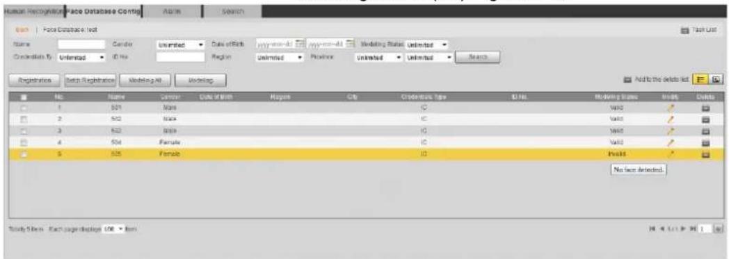
text_image
Human Recognition Place Database Contig Search Search File Database Test Name Center Unlimited Case of Birth My-learn-and My-learn-and Medding Status Unlimited Conducts By Unlimited ID No Region Unlimited Positive Unlimited Unlimited Search Registration Datch Registration Modeling All Ordering Add by the delete list No. Name Senter CASA OF WITH Rates City Codderface type ID No. 1 501 Mate C Valid ✓ 2 502 State C Valid ✓ 3 503 State C Valid ✓ 4 504 Female C Valid ✓ 5 505 Female C Invalid ✓ No less detected. Study Items: Each large display: 106 - ItemModeling status (thumbnail) Figure 5-44
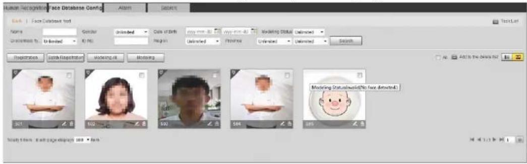
text_image
Face Database Config Atom Actions Back | Face Database Text Name Gender Unlimited Calls of Birth www.mim.ab www.mim.ab Modeling Status Unlimited Unlimited Unlimited Unlimited Search Registration Match Registration Modeling it Modeling All: Add to the Deals list 301 无首 502 无首 502 无首 504 无首 505 无首 Modeling Statuswasid(No free detected) Study file: each page displays 100 -Form5.10.3 Setting Face Recognition Alarm Linkage
When face recognition succeeded or failed, the device links alarm out.
Select Setting > Event > Face Recognition > Alarm. Step 1 The Alarm interface is displayed. See Figure 5-45.
Alarm (face recognition) Figure 5-45
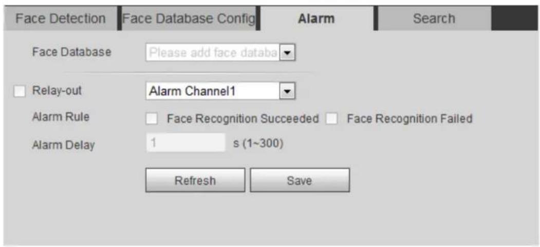
text_image
Face Detection Face Database Config Alarm Search Face Database Please add face databa Relay-out Alarm Channel1 Alarm Rule Face Recognition Succeeded Face Recognition Failed Alarm Delay 1 s (1~300) Refresh SaveSelect a face database and an alarm rule. Step 2
- Face recognition succeeded: When the detected face matches that in the face database, the device links alarm out.
- Face recognition failed: When the detected face fails to match that in the face database, the device links alarm out.
Set alarm linkage actions. For details, see "5.1.1 Alarm Linkage." Step 3
Click Save. Step 4
5.10.4 Viewing Face Recognition Result
View face recognition result on the Live interface or by the search function.
5.10.4.1 Viewing Result in the Live Interface
View face recognition result on the Live interface. See Figure 5-46.
- Face recognition result is displayed at the left side and the captured face pictures and attribute information at the right side.
- Click a face picture in the display area, and the information is displayed.
Face recognition result Figure 5-46
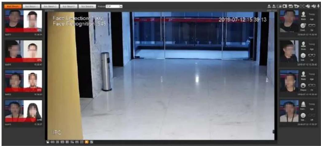
text_image
Face Detection 1992 Face Recognition 543 2019-07-12-15:39:13 IRG5.10.4.2 Viewing Result by Search Function
View face recognition or face snapshot result. Take face recognition search as an example.
Preparation
You have installed a SD card in the camera.
Procedure
Select Setting > Event > Face Recognition > Search. Step 1
The Search interface is displayed. See Figure 5-47.
Face recognition search Figure 5-47

text_image
Face Detection Face Database Config Alarm Search Type Face Snapsh Start Time 2019-07-03 14 : 20 : 55 End Time 2019-07-04 14 : 20 : 55 Advanced Par... Search Age Unlimited Gender Unlimited Expression Unlimited Glasses Unlimited Mouth Mask Unlimited Beard UnlimitedStep 2 Select Face Recognition for Type, enter the start time and the end time, and then click Search.
The result is displayed. See Figure 5-48.
- Click Advanced Parameters to set more search conditions.
- Click the search result to view details. See Figure 5-49.
Search result (face recognition) Figure 5-48
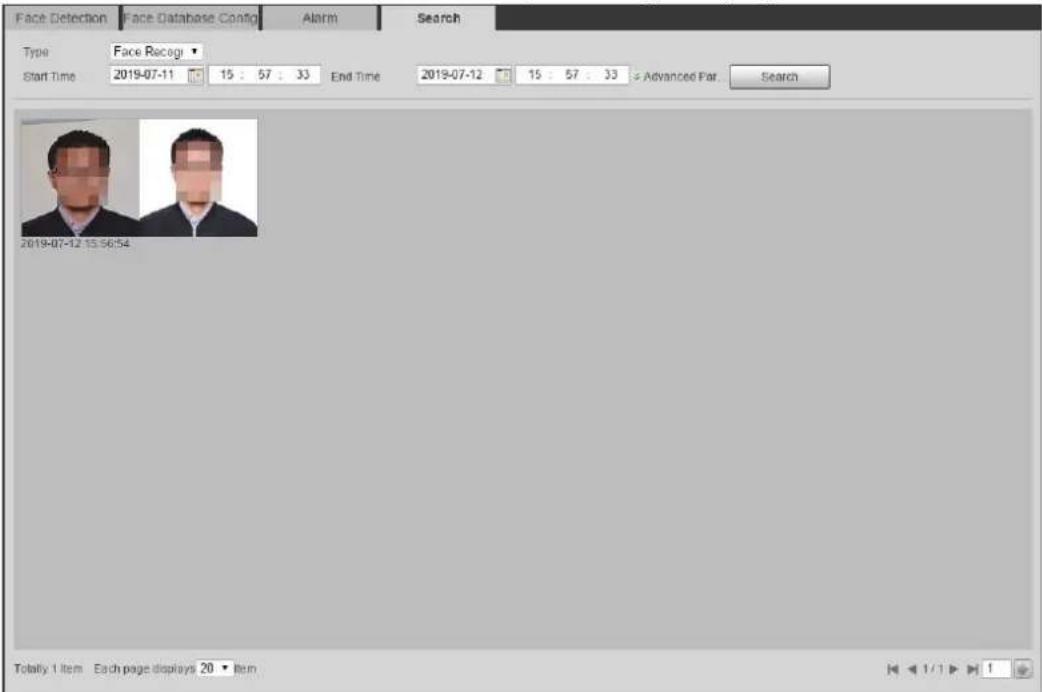
text_image
Face Detection Face Database Config Alarm Search Type Face Recogr Start Time 2019-07-11 15 : 57 : 33 End Time 2019-07-12 15 : 57 : 33 Advanced Par Search 2019-07-12 15:56:54 Totally 1 item Each page displays 20 ItemMoreInfo (face recognition) Figure 5-49
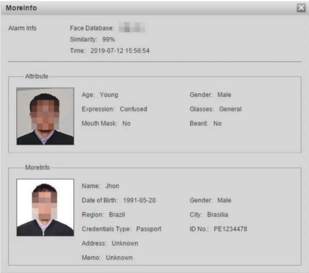
text_image
MoreInfo Alarm Info Face Database: Similarity: 99% Time: 2019-07-12 15:56:54 Attribute Age: Young Gender: Male Expression: Confused Glasses: General Mouth Mask: No Beard: No MoreInfo Name: Jhon Date of Birth: 1991-05-20 Gender: Male Region: Brazil City: Brasilia Credentials Type: Passport ID No.: PE1234478 Address: Unknown Memo: UnknownSetting Face Detection 5.11
When a face is detected in the detection area, the system performs an alarm linkage.
Preparation
Select Setting > Event > Smart Plan, and then enable Face Detection.
Procedure
Select Setting > Event > Face Detection. Step 1
The Face Detection interface is displayed. See Figure 5-50.
Face detection Figure 5-50

text_image
Face Detection Enable OSD Clear Period Setting Face Enhancement Record Record Delay 10 s (10~300) Relay-out 1 2 Alarm Delay 10 s (10~300) Send Email Snapshot Non-living Filtering Snap Face Image One-inch photo Snap Mode Optimized Snap Attribute Advanced Enable Face Exposure Face Target Brightn... 50 (0~100) Face Exposure Det... 5 (0~100) s Default Refresh Save Deted Region Draw Clear Exclude Re... Draw Modify Clear Target filter Max Size 8191 * 8191 Min Size 0 * 0 Pixel Counter 0 * 0 Clear Draw Target Clear Draw Target Clear Draw Target Excl. (Excl.)Select the Enable check box to enable the face detection. Step 2
Step 3 (Optional) Click Draw next to Detect Region to draw a face detection area in the image.
Step 4 (Optional) Click Draw next to Exclude Region, and then draw an area excluding face detection in the image.
Step 5 (Optional) Select Max Size or Min Size, click Draw Target at the right side of Target filter, and then draw the target in the image.
Set parameters. See Table 5-14. Step 6
Table 5-14 Description of face detection parameters
| Parameter | Description |
| OSD | Select the OSD check box, and the number people with face detected and recognized is displayed on the Live interface.Click Reset to recount. |
| Face Enhancement | Select the Face Enhancement check box to preferably guarantee clear face with low stream. |
| Target Box Overlay | Select the Non-living Filtering check box to add a target box to the face in the captured picture to highlight the face.The captured face picture is saved in SD card. Click the Snap Face Image tab to view the captured picture. |
| Non-living Filtering | Filter non-living faces in the image, such as a face picture. |
| Snap Face Image | Set a range for snapping face image, including face picture and one-inch picture. |
| Snap Mode | Optimized Snapshot: Capture the clearest picture within the configured time after the camera detects face.Recognition Priority: Repeatedly compare the captured face to the faces in the armed face database, and capture the most similar face image and send the event. It is recommended to use this mode in access control scene.Click Advanced to set the optimized time. |
| Attribute | Select the Attribute check box, and click to set the display of face attribute during the face detection. |
| Advanced | Snapshot Angle Filter: Set snapshot angle to be filtered during the face detection.Snapshot Sensitivity: Set snapshot sensitivity during the face detection. It is easier to detect face with higher sensitivity.Optimized Time: Set a time period to capture the clearest picture after the camera detects face. |
| Enable Face Exposure | Select the Enable Face Exposure check box. When a face is detected, the camera can enhance brightness of the face to make the face image clear. |
| Face Target Brightness | Set the face target brightness. It is 50 by default. |
| Face Exposure Detection Interval | Set the face exposure detection interval to prevent image flickering caused by constant adjustment of face exposure. It is five seconds by default. |
| Pixel Counter | Click Draw Target next to Pixel Counter, and then press and hold the left mouse button to draw a rectangle, the Pixel Counter then displays its pixel. |
Step 7 Set arming periods and alarm linkage actions. For details, see "5.1.1 Alarm Linkage." Step 8 Click Save.
To view alarm information on the Alarm tab, subscribe relevant alarm event. For details, see "5.1.2 Subscribing Alarm."
Verification
The face detection result is displayed on the live interface. See Figure 5-51.
- The face pictures snapped in real time and their attribute information is displayed.
- Click a face picture in the display area, and the details are displayed.
Face detection result Figure 5-51
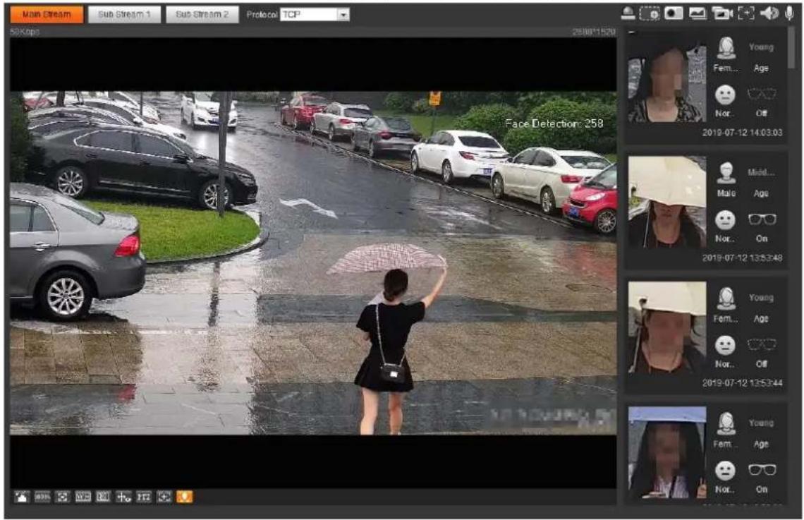
text_image
Main Stream Sub Stream 1 Sub Stream 2 Proteco TCP 50Kbps 268811520 Face Detection: 258 Young Fem... Age Nor... Off 2019-07-12 14:03:03 Mold... Male Age Nor... On 2019-07-12 13:53:48 Young Fem... Age Nor... Off 2019-07-12 13:53:44 Young Fem... Age Nor... On5.12 Setting People Counting
Make statistics on people flow (including enter number, leave number and people number in area), and view the people counting data in report form.
5.12.1 People Counting
The system counts the people flow entering and leaving the detection area. When the counted people flow exceeds the configured value, the system performs an alarm linkage.
Preparation
Select Setting > Event > Smart Plan, and then enable People Counting.
Procedure
Select Setting > Event > People Counting. Step 1
The People Counting interface is displayed. See Figure 5-52 and Figure 5-53.
People counting Figure 5-52
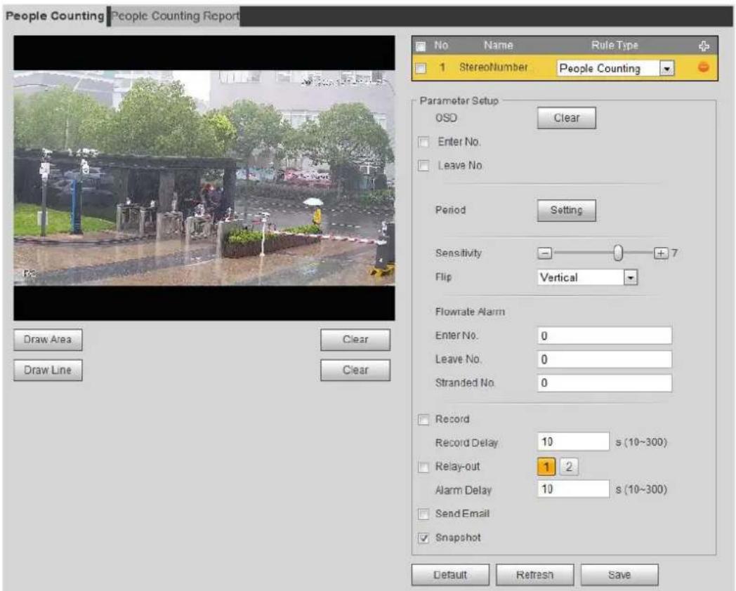
text_image
People Counting | People Counting Report No Name Rule Type + 1 StereoNumber People Counting Parameter Setup OSD Clear Enter No. Leave No. Period Setting Sensitivity 7 Flip Vertical Flowrate Alarm Enter No. 0 Leave No. 0 Stranded No. 0 Record Record Delay 10 s (10~300) Relay-out 1 2 Alarm Delay 10 s (10~300) Send Email Snapshot Draw Area Clear Draw Line Clear Default Refresh SaveIn area No. Figure 5-53
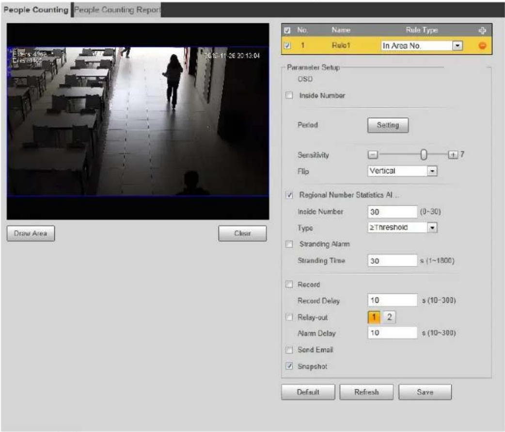
text_image
People Counting People Counting Report No. Name Rule Type 1 Rule1 In Area No. Parameter Setup OSD Inside Number Period Setting Sensitivity 7 Flip Vertical Regional Number Statistics AI ... Inside Number 30 (0~30) Type ≥Threshold Stranding Alarm Stranding Time 30 s (1~1800) Record Record Delay 10 s (10~300) Relay-out 1 2 Alarm Delay 10 s (10~300) Sond Email Snapshot Draw Area Clear Default Refresh SaveClick to add the people counting function. Step 2
Step 3 Double-click the name to modify the rule name. Select People Counting or In Area No.
- People Counting: The system counts the people flow entering and leaving the detection area. When the counted number of people who enter, leave, or stay in the area exceeds the configured value, the system performs an alarm linkage.
- In Area No.: The system counts the people flow in the detection area and the duration that people stay in the area. When the counted number of people in the detection area or the stay duration exceeds the configured value, the system performs an alarm linkage. This function is available on some select models.
Click Draw Area to draw a detection area in the image. Step 4
- When setting People Counting, you need to draw direction lines. When targets enter or leave along the direction line, they will be counted.
- For the models that support multiple counting rules, different detection areas can be overlapped.
Set parameters. See Table 5-15. Step 5
Table 5-15 Description of people counting parameters
| Parameter | Description |
| OSD | Select the OSD check box or select the Enter No. or Leave No. check box under OSD to display the people counting data in the image.Click Clear to clear the count. |
| Flip | Set the viewing angle of the image as Inclined or Vertical. |
| Flowrate Alarm | Set Enter No., Leave No., and Stranded No. The alarm is triggered when the configured value is reached. |
| Regional People Number Statistics Alarm | Set the number of people in the people counting region. When the people count reaches the threshold or the stay duration exceeds the configured value, the alarm is triggered.When you set inside number to be 0, and select the type to be ≥slant Threshold, the system will not perform the alarm linkage. |
| Inside Number | |
| Type | |
| Stranding Alarm | Select the Stranding Alarm check box, and then set the stranding time, when the stay duration exceeds the configured value, the alarm will be triggered. |
| Stranding Time | |
| Sensitivity | Set the alarm-triggered sensitivity. The higher the sensitivity is, the easier the alarm will be triggered. |
Step 6 Set arming periods and alarm linkage actions. For details, see "5.1.1 Alarm Linkage."
Click Save. Step 7
To view alarm information on the Alarm tab, subscribe relevant alarm event. For details, see "5.1.2 Subscribing Alarm."
Verification
You can view the counting result on the Live interface. See Figure 5-54.
- For People Counting rule, the entry and exit numbers are displayed.
- For In Area No. rule, the inside number is displayed.
Counting result Figure 5-54
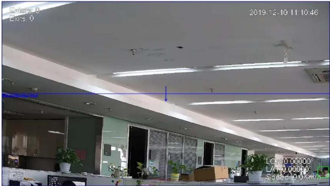
text_image
Evers: 0 Exits: 0 2019-12-10 11:10:46 LON:0.00000 LAT:0.00000 Speed: 0.0km/h5.12.2 Queuing
The system counts the queue people in the detection area. When the queue people number exceeds the configured number or the queue time exceeds the configured time, the alarm is triggered, and the system performs an alarm linkage.
Preparation
Select Setting > Event > Smart Plan, and then enable People Counting.
Procedure
Select Setting > Event > Queuing. Step 1
The Queuing interface is displayed. See Figure 5-55.
Queuing Figure 5-55
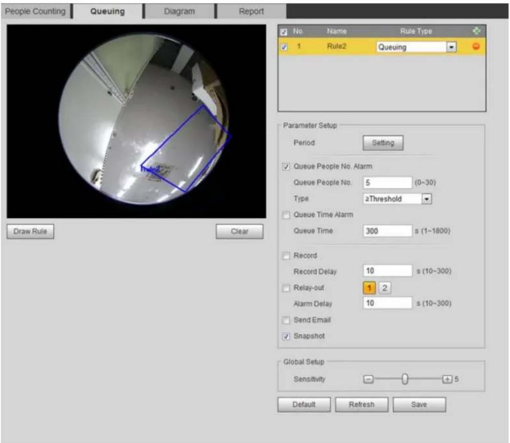
text_image
People Counting Queuing Diagram Report No Name Rule Type 1 Rule2 Queuing Parameter Setup Period Setting Queue People No. Alarm Queue People No: 5 (0~30) Type ≥Threshold Queue Time Alarm Queue Time 300 s (1~1800) Record Record Delay 10 s (10~300) Relay-out 1 2 Alarm Delay 10 s (10~300) Send Email Snapshot Global Setup Sensitivity + 5 Default Refresh Save____ Click to add the queuing function. Step 2

You can add 4 rules at most.
Double-click the name to modify the rule name. Click Draw Rule to draw a detection Step 3 area in the image, and right-click to complete the drawing.
Set parameters. See Table 5-16. Step 4
Table 5-16 Description of people queuing
| Parameter | Description |
| Queue People No. Alarm | Set the queue people number for triggering the alarm and counting type. When the queue people number reaches the configured value, the alarm is triggered. |
| Queue People No. | |
| Type | |
| Queue Time Alarm | Set the queue time. When the queue time reaches the configured value, the alarm is triggered. |
| Queue Time | |
| Sensitivity | Set the alarm-triggered sensitivity. The higher the sensitivity is, the easier the alarm will be triggered. |
Step 5 Set arming periods and alarm linkage actions. For details, see "5.1.1 Alarm Linkage." Click Save. Step 6 To view alarm information on the Alarm tab, subscribe relevant alarm event. For details, see "5.1.2 Subscribing Alarm."
Verification
You can view the queuing result on the Live interface. See Figure 5-56.
The queuing number and the stranding time of each target are displayed on the interface.
Queuing result Figure 5-56
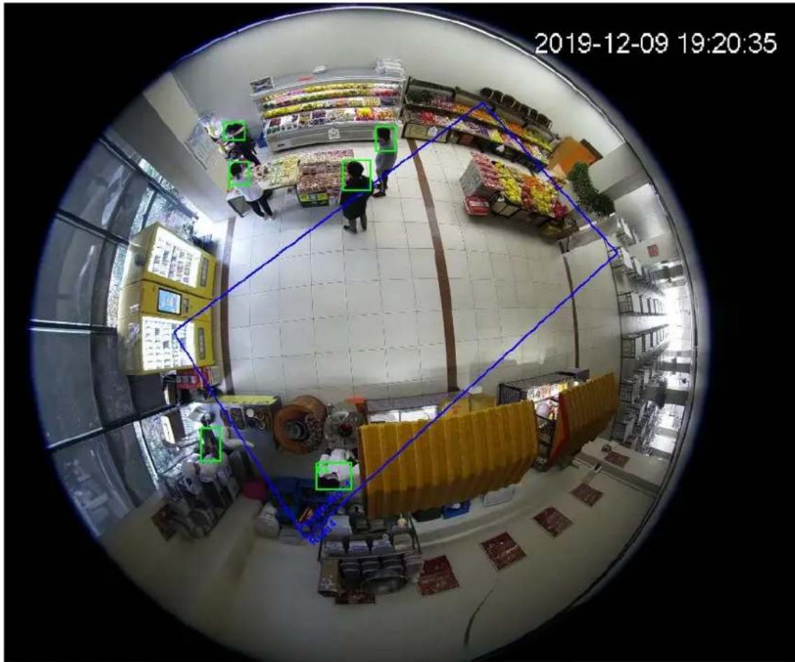
text_image
2019-12-09 19:20:355.12.3 Viewing People Counting Diagram
You can search and export the heat map and tracking map according to the set searching criteria. This function is available on some Fisheye camera.
Select Setting > Event > People Counting > Diagram. Step 1 The Diagram interface is displayed. See Figure 5-57.
Diagram Figure 5-57
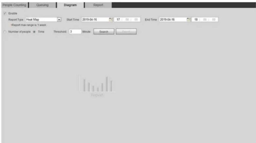
text_image
People Counting Queuing Diagram Report Enable Report Type Heat Map Start Time 2019-04-16 17:00:00 End Time 2019-04-16 18:00:00 Report max range is 1 week: Number of people Time Threshold 3 Minutes Search Export Repeat!Select the Enable check box to enable diagram function. And then you can search the Step 2 diagram during the set period. Set the searching criteria. See Table 5-17. Step 3
Table 5-17 Description of searching criteria
| Parameter | Description |
| Report Type | Select the report type from the following two types:● Heat Map: Density statistics of moving object, the color range is from blue to red, blue means the minimum heat value and red means the maximum heat value.● Track Map: Tendency statistics of moving object. |
| Start Time | The start time of the report. |
| End Time | The end time of the report. |
| Number of People | When selecting heat map as the report type, you can select Number of People, and set the threshold. The system searches the diagram according to the number of people in the area, and shows the heat map. |
| Threshold | |
| Time | When selecting heat map as the report type, you can select Time, and set the threshold. The system searches the diagram according to the queuing time in the area and shows the heat map.. |
| Threshold |
Click Search to complete the diagram. See Figure 5-58. Step 4 Click Export to export the report.
Diagram Figure 5-58
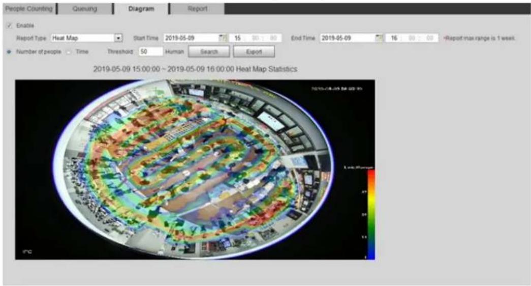
text_image
People Counting Quenuing Diagram Report Enable Report Type Heat Map Start Time 2019-05-09 15 80 80 End Time 2019-05-09 16 80 80 - Report max range is 1 week. Number of people Time Threshold 50 Human Search Export 2019-05-09 15:00:00 ~ 2019-05-09 16:00:00 Heat Map Statistics 7/15/04/2019 54:00:35 Lisk: 25 person
With the ruler on the right, you can read the diagram clearly.
5.12.4 Viewing People Counting Report
Generate people counting data in report form.
Step 1 Select Setting > Event > People Counting > People Counting Report.
The People Counting Report interface is displayed. See Figure 5-59.
People counting report Figure 5-59
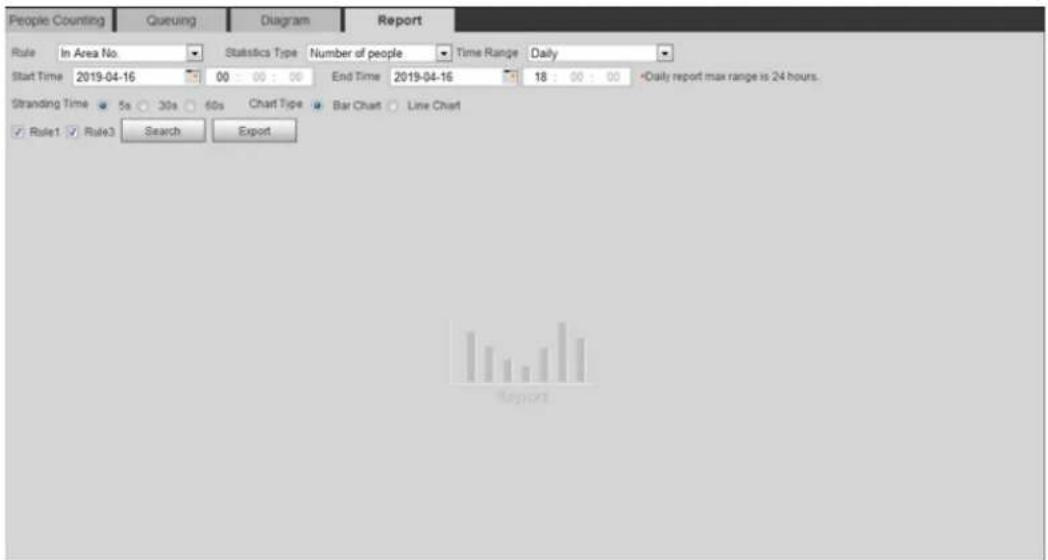
text_image
People Counting Queuing Diagram Report Rule In Area No. Statistics Type Number of people Time Range Daily Start Time 2019-04-16 00 : 00 : 00 End Time 2019-04-16 18 : 00 : 00 *Daily report max range is 24 hours. Stranding Time 5s 30s 60s Chart Type Bar Chart Line Chart Rule1 Rule3 Search ExportSet search conditions. For details, see Table 5-18. Step 2
Table 5-18 Description of people counting report parameters
| Parameter | Description |
| Rule | Select the rule of the report from In Area No and Queuing. |
| Statistics Type | The statistical type of people counting report.When you selectNumber of people, the system generates the report of the number of people that exceeds the configured number of people.When you selectAverage stranding time, the system generates the report of the average stranding time that exceeds the average stranding time. |
| Time Range | Select the period for the report.When selectingPeople Counting, you can view daily report, monthly report and annual report.When selectingIn Area No., you can view daily report and monthly report. |
| Begin Time | The begin time and the end time of people counting. |
| End Time | |
| People Counting Direction | In and out directions of people counting report. You can selectEntrance orLeave. SelectDisplay Data, and the statistical quantity is displayed on the report. |
| Stranding Time | Count the stay time, select 5 s, 30 s, or 60 s. |
| Queue Time | Count the queuing tine, select 1 minute, 5 minutes, or 10 minutes. |
| Report Type (Bar Chart/Line Chart) | Includes bar chart and line chart. |
| Rule 1, Rule 2... | Select the check box to search the report of the corresponding rule. |
Click Search to complete the report. Step 3
Click Export to export the report in .bmp or .csv format.
Setting Heat Map 5.13
Make statistics on the cumulative density of object movement and view heat map in report.
5.13.1 Heat Map
Detect the distribution of dynamically moving objects in the target area within a certain period and displays the distribution on a heat map. Color varies from blue to red. The lowest heating value is in blue, and the highest heating value is in red.
When mirroring occurs on the camera or the viewing angle changes, original data on the heat map will be cleared.
Preparation
Select Setting > Event > Smart Plan, and then enable Heat Map.
Procedure
Select Setting > Event > Heat Map > Heat Map. Step 1 The Heat Map interface is displayed. See Figure 5-60.
Heat map Figure 5-60
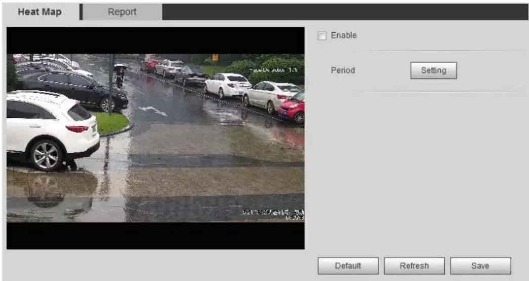
text_image
Heat Map Report Enable Period Setting Default Refresh SaveStep 2 Select the' Enable check box to enable the heat map function.
Set the arming period. For details, see "5.1.1.1 Setting Period." Step 3
Click Save. Step 4
5.13.2 Viewing Heat Map Report
The system can export heat map data as a report.
Select Setting > Event > Heat Map > Report. Step 1
The Report interface is displayed. See Figure 5-61.
Heat map report Figure 5-61
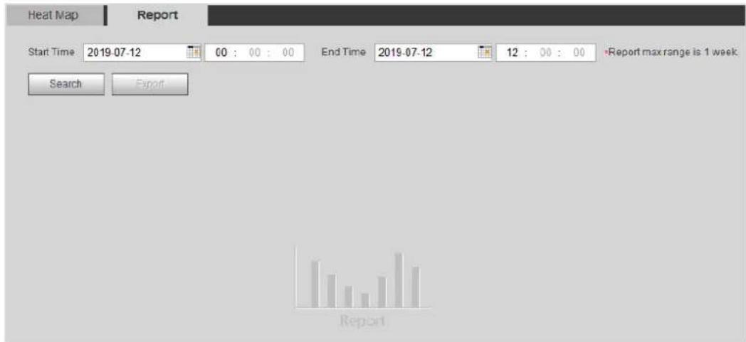
text_image
Heat Map Report Start Time 2019-07-12 00 : 00 : 00 End Time 2019-07-12 12 : 00 : 00 Report max range is 1 week Search Export ReportSet the start time and end time. Step 2
Only some devices support heat map sequence numbers.
Click Search to complete the report. Step 3
Click Export to export the statistical report.
Setting Stereo Analysis 5.14
Stereo analysis includes rule configuration and calibration configuration.
5.14.1 Setting Rules for Stereo Analysis
The rules for stereo analysis include Fall Detection, Violence Detection, People No. Error, People Approaching Detection, and Strand Detection.
For the functions and applications of the rules, see Table 5-19.
Table 5-19 Description of stereo analysis function
| Rule | Function | Applicable Scene |
| Fall Detection | When walking or standing people in the detection area suddenly fall down on the ground, the alarm is triggered. | Park and hall |
| Violence Detection | When people walking or standing inside or outside the self-service hall or ATM protection cabin have violent movement (such as smashing ATM machine) or fighting, the alarm is triggered. | Bank halls and ATM protection cabins |
| People No. Error (Functions of People No. Error vary from devices.) | The camera can recognize the real-time number of people in the monitoring area. When the number of people exceeds the configured value, the alarm is triggered. | Scenic spots and banks |
| When a recording device is used, the device that monitors the front of a classroom needs to be configured with this function. With this function, the teacher's actions can be traced and enlarged. When the number of people in the image is not 1, the whole image is displayed. | Classrooms | |
| People Approaching Detection | When the distance between walking or standing people reaches the configured value, the alarm is triggered. | Banks and educational institutions |
| Strand Detection | When people in the monitoring area stay longer than the configured stranding time, the alarm is triggered. | Banks and parks |
Preparation
Select Setting > Event > Smart Plan, and then enable Stereo Analysis.
Procedure
This section takes Fall Detection as an example to introduce the configuration of stereo analysis rule.
Step 1 Select Setting > Event > Stereo Analysis > Stereo Analysis.
The Stereo Analysis interface is displayed.
Step 2 Click +, double-click the name to modify the rule name, and then select People
Approaching Detection as Rule Typ. See Figure 5-62.
Figure 5-62 People approaching detection
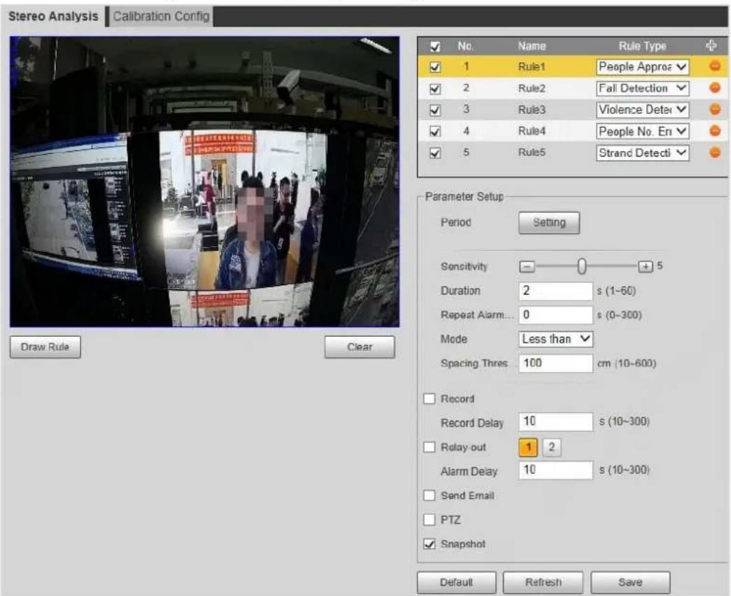
text_image
Stereo Analysis Calibration Config No. Name Rule Type + ✓ 1 Rule1 People Approz ✓ 2 Rule2 Fall Detection ✓ 3 Rule3 Violence Deter ✓ 4 Rule4 People No. En ✓ 5 Rule5 Strand Detecti Parameter Setup Period Setting Sensitivity 0 + 5 Duration 2 s (1~60) Repeat Alarm... 0 s (0~300) Mode Less than Spacing Thres: 100 cm (10~600) Record Record Delay 10 s (10~300) Relay-out 1 2 Alarm Delay 10 s (10~300) Send Email PTZ Snapshot Draw Rule Clear Default Refresh SaveStep 3 (Optional) Click Clear to delete the default rule box, and then click Draw Rule to draw a detection area in the image.
- When selecting People No. Error for a recording device, draw the front of a classroom as the detection area.
- When selecting Stand Detection for a recording device, draw the area where the students stay as the detection area.
- For other devices without special requirements, use the default box of the system (draw the full screen as the detection area).
Set parameters. See Table 5-20. Step 4
Parameters for recording device and common device are different. The actual interface shall prevail.
Table 5-20 Description of stereo analysis parameters
| Parameter | Description |
| Sensitivity | Set the alarm-triggered sensitivity. The higher the sensitivity is, the easier the alarm will be triggered. |
| Alarm People Amount | When configuringPeople No. Error, set the alarm people amount and alarm type. Alarm type includesGreater than, Equal to, Less than, andUnequal to.When the real-time number of people in the detection area is greater than, equal to, less than, or unequal toAlarm People Amount, the alarm is triggered. |
| Alarm Type | |
| Duration | For People Approaching Detection, when the time for people approaching reaches the configured value, the alarm is triggered.For Fall Detection, when the time of people falling down on the ground reaches the configured value, the alarm is triggered.For People No. Error, when the number of people in the area reaches the configured value of alarm people amount and alarm type, and the time reaches the configured value, the alarm is triggered. |
| Close-up Mode | For people No. error function for a recording device, selectTracking Mode as Close-up Mode. Then the camera traces the teacher's walking trajectory. You can view the tracking effect through sub stream 1 of the live interface. When the number of people on the image is not 1, the full screen is displayed.When setting the stand detection function for a recording device, selectFixed Mode as Close-up Mode. Then sub stream 1 enlarges and displays the image of standing people. When the number of standing people is not 1, the full screen is displayed. Before viewing the tracking or enlargement effect through sub stream 1, ensure that sub stream 1 is enabled and the resolution of the main stream and sub stream is 1080p. For configuration details of the main and sub streams, see "4.5.2.1 Video." Before viewing the tracking or enlargement effect through sub stream 1, ensure that sub stream 1 is enabled and the resolution of the main stream and sub stream is 1080p. For configuration details of the main and sub streams, see "4.5.2.1 Video." |
| Repeat Alarm Time | After the alarm is triggered, if the status lasts for the configured timeRepeat Alarm Time, the alarm will be triggered again. 0 indicates that the function is disabled. 0 indicates that the function is disabled. |
| Strand Time Threshold | When configuring Strand Detection, you need to set the strand time threshold. When people in the area stay longer than the configured strand time threshold, the alarm is triggered. |
Step 5 Set arming periods and alarm linkage actions. For details, see "5.1.1 Alarm Linkage." Step 6 Click Save.
- Select Setting > Event > Stereo Analysis > Calibration Config to finish calibration configuration for other devices, and then the detection rule becomes valid. For details, see "5.14.2 Calibration Configuration."
• To view alarm information on the Alarm tab, you should subscribe relevant alarm
event. For details, see "5.1.2 Subscribing Alarm."
5.14.2 Calibration Configuration
After configuring the rule configuration for stereo analysis, set the installation height and angle of the camera through calibration configuration.
- Calibration mode 1: Directly enter the installation height and angle according to the actual conditions.
- Calibration mode 2: Draw an area in the image to automatically calculate the installation height and the angle.
Preparation
You have set at least one rule under Setting > Event > Stereo Analysis > Stereo Analysis.
Procedure
Take the calibration mode 2 as an example.
Step 1 Select Setting > Event > Stereo Analysis > Calibration Config.
The Calibration Config interface is displayed. See Figure 5-63.
Calibration configuration (stereo analysis) Figure 5-63
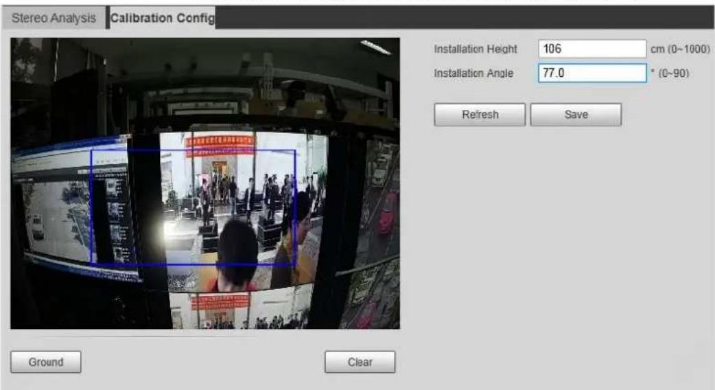
text_image
Stereo Analysis Calibration Config Installation Height 106 cm (0~1000) Installation Angle 77.0 ° (0~90) Refresh Save Ground ClearClick Clear to clear the default calibration box. Step 2
Click Ground to draw a rectangular box in the image. Step 3
Ground should be on the same plane and as big as possible for calibration.
Step 4 Click Save, and then the camera calculates its height above the ground and the angle it forms with the ground.
If the height and angle are quite different from the actual situation, repeat Step 2–Step 4.
Setting ANPR 5.15
Extract information of motor vehicles and display related attributes on the live interface.
5.15.1 Scene Configuration
Configure non-motor vehicle detection.
Preparation
Select Setting > Event > Smart Plan, and then enable ANPR.
Procedure
Select Setting > Event > ANPR > Scene Set. Step 1
The Scene Set interface is displayed. See Figure 5-64.
Scene set (ANPR) Figure 5-64
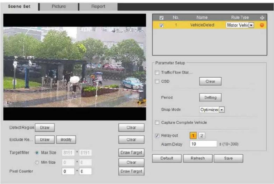
text_image
Scene Set Picture Report No. Name Rule Type 1 VehicleDetect Motor Vehic Parameter Setup Traffic Flow Stat... CSD Clear Period Setting Snap Mode Optimized Capture Complete Vehicle Retay-out 1 2 Alarm Delay 10 s (10~300) Default Refresh Save Detect Region Draw Clear Exclude Re... Draw Modify Clear Targetfiller Max Size 8191 * 8191 Min Size 0 * 0 Pixel Counter 0 * 0 Draw Target Clear Draw TargetClick Draw to draw a detect region and an exclude region in the image. Step 2
- Detect region: The region that needs to be detected.
- Exclude region: The region that does not need to be detected. Click Modify to modify the drawn region.
Click Clear at the right side to draw the detection area again.
Step 3 Click Draw Target next to Target Filter to draw the maximum size and minimum size for the detection target in the image.
Configure parameters. See Table 5-21. Step 4
Table 5-21 Description of scene set parameters (ANPR)
| Parameter | Description |
| Traffic Flow Statistics | Select Traffic Flow Stat, and the device detects the number of motor vehicles and non-motor vehicles in the detection area and generates the statistical report. If Traffic Flow Stat is disabled, the report has no statistical data.Select OSD to display the statistical result on the preview interface. To clear the statistical result, click Clear. |
| OSD | |
| Snap Mode | Select the snap mode: Optimized Snap and Tripwire. |
| Relay-out | Select the Relay-out check box, and when alarm is triggered, the system interacts with the linked alarm devices. |
| Alarm Delay | The Alarm linkage keeps running for the configured time after alarm is ended. |
Step 5 Set arming periods and alarm linkage action. For details, see "5.1.1 Alarm Linkage."
Click Save. Step 6
Verification
The ANPR result is displayed on the live interface. See Figure 5-65.
- The plate no. and attribute information of vehicle are displayed at the right side.
- Click the picture in the display area, and the detailed information is displayed.
ANPR result Figure 5-65
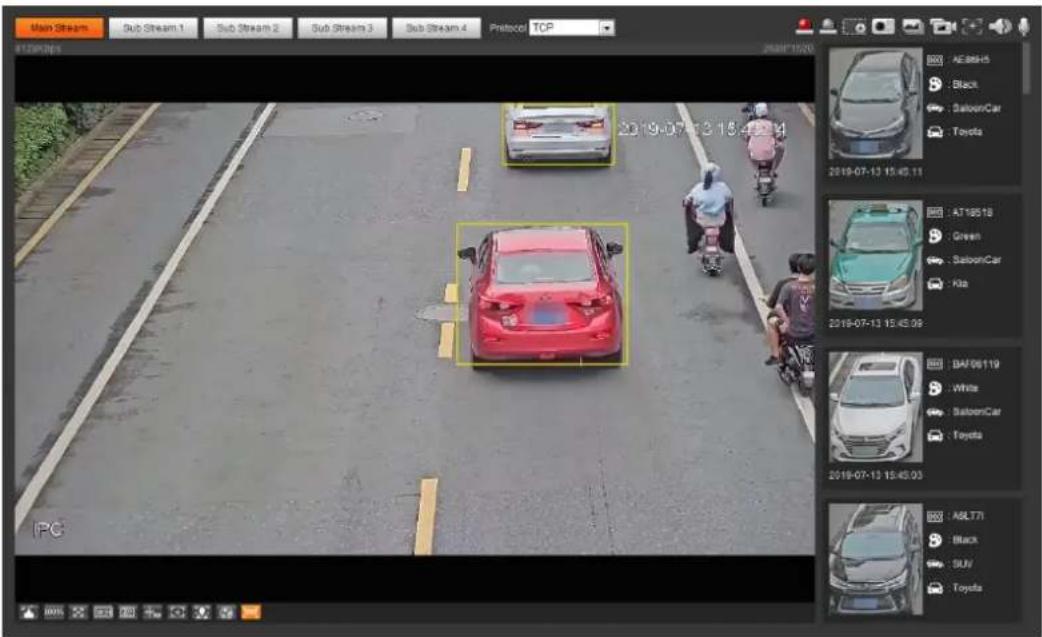
text_image
Main Stream Sub Stream 1 Sub Stream 2 Sub Stream 3 Sub Stream 4 Protocol TCP 2019-07-13 15:45:41 PC AE88H5 Black SaloonCar Toyota 2019-07-13 15:45:11 AT18518 Green SaloonCar Kia 2019-07-13 15:45:09 DAF06119 White SaloonCar Toyota 2019-07-13 15:45:03 ABL71 Black SUV Toyota5.15.2 Setting Picture Overlay
Set overlay of motor vehicle.
Select Setting > Event > ANPR > Picture. Step 1 The Picture interface is displayed. See Figure 5-66.
Picture (plate no. recognition) Figure 5-66

text_image
Scene Set Picture Report Car Type Car Color Plate No. Car Logo Picture Overlay Type Motor Vehicle ✓ Plate No. ✓ Car Color ✓ Car Type ✓ Car Logo □ Sunshield □ Seatbelt □ Smoking Status □ Calling Status □ Ornament □ Inspection Sticker □ Time □ Location Upload Picture ✓ Vehicle Body Pic... Default Refresh SaveStep 2 Select Motor Vehicle from the Type drop-down list.
Set overlay information and box position, such as plate no., time, car color, car type, Step 3 and car logo.
Click Save. Step 4
5.15.3 Viewing ANPR Report
Generate data of ANPR in report form.
Select Setting > Event > ANPR > Report. Step 1
The Report interface is displayed. See Figure 5-67.
Report Figure 5-67
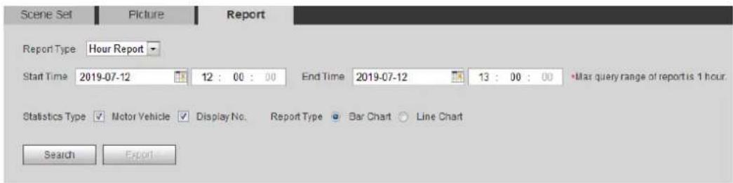
text_image
Scene Set Picture Report Report Type Hour Report Start Time 2019-07-12 12 : 00 : 00 End Time 2019-07-12 13 : 00 : 00 •Mar query range of report is 1 hour. Statistics Type Motor Vehicle Display No. Report Type Bar Chart Line Chart Search ExportStep 2 Select the report type, start time, end time, and other parameters.
Click Search. Step 3
The statistical results are displayed. See Figure 5-68. Click Export to export the statistical report.
Statistical results Figure 5-68
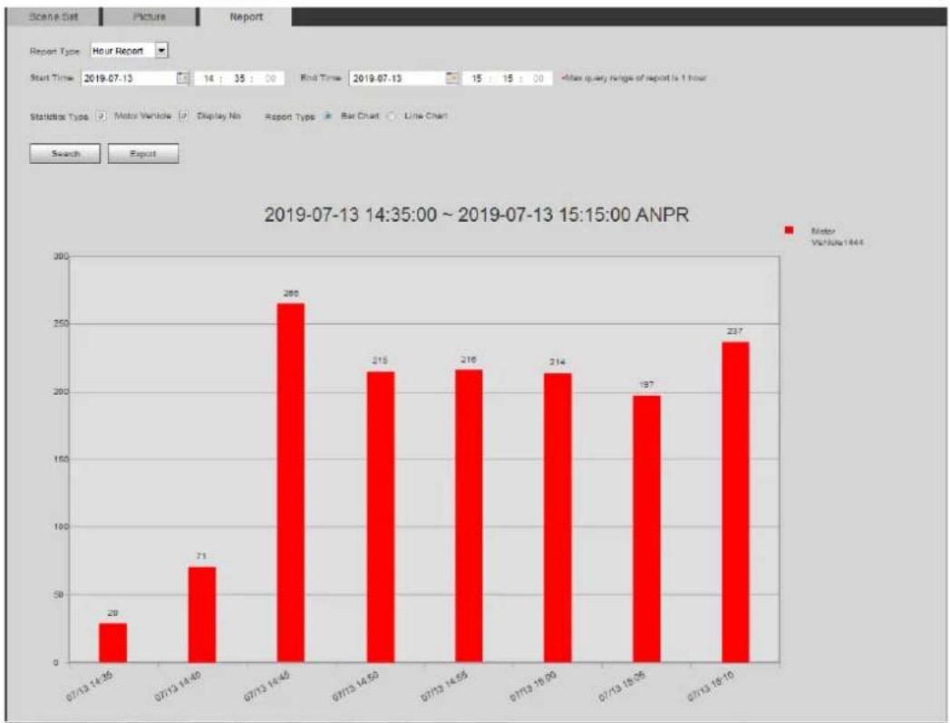
bar
2019-07-13 14:35:00 ~ 2019-07-13 15:15:00 ANPR | Time | Motor Variable 1844 | | :--- | :--- | | 07/13 14:35 | 29 | | 07/13 14:40 | 71 | | 07/13 14:45 | 269 | | 07/13 14:50 | 215 | | 07/13 14:55 | 216 | | 07/13 15:00 | 214 | | 07/13 15:05 | 197 | | 07/13 16:10 | 237 | Search Export Start Time: 2019-07-13 14:35:00 - 2019-07-13 15:15:00 ANPRSetting Video Structuralization 5.16
Classify people, non-motor vehicles and motor vehicles in the captured video, and display the relevant attributes on the live interface.
5.16.1 Scene Configuration
Set the detection scenes and rules, including rules for people, non-motor vehicles and motor vehicles.
Preparation
Select Setting > Event > Smart Plan, and then enable Video Structuralization.
Procedure
Take setting of the People Detection rules as an example.
Step 1 Select Setting > Event > Video Structuralization > Scene Set.
The Scene Set interface is displayed. See Figure 5-69.
Scene set (video structuralization) Figure 5-69
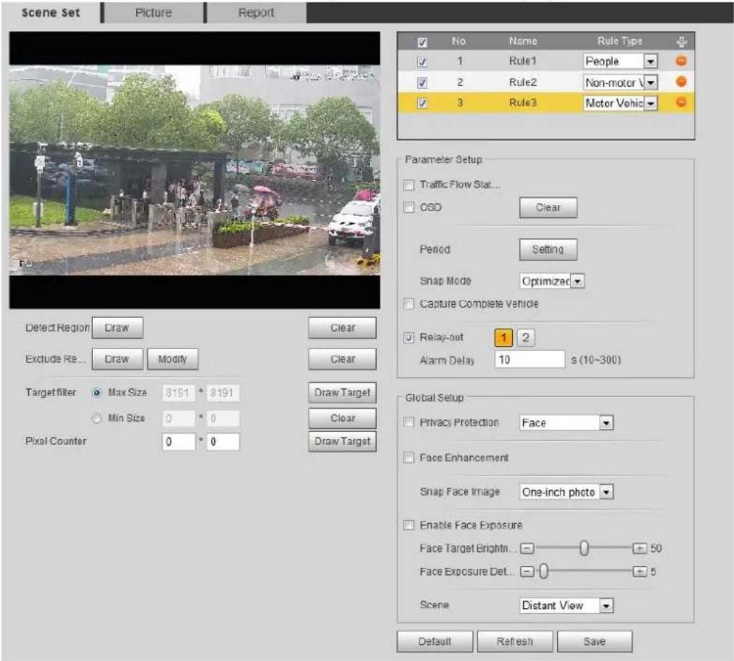
text_image
Scene Set Picture Report No Name Rule Type 1 Rule1 People 2 Rule2 Non-motor 3 Rule3 Motor Vehic Parameter Setup Traffic Flow Slot... OSD Clear Period Setting Snap Mode Optimized Capture Complete Vehicle Relay-out 1 2 Alarm Delay 10 s (10~300) Global Setup Privacy Protection Face Face Enhancement Snap Face Image One-inch photo Enable Face Exposure Face Target Brightn... 50 Face Exposure Det... 5 Scene Distant View Default Refresh SaveClick , and double-click the name to modify the rule name, and select People in Step 2
Rule Type list.
Click Draw to draw a detect region and an exclude region in the image. Step 3
- Detect Region: The region that needs to be detected.
- Exclude Region: The region that does not need to be detected. Click Modify to modify the drawn region.
Step 4 Click Draw Target next to Target Filter to draw the maximum size and minimum size for the detection target in the image.
Set parameters. For details, see Table 5-22. Step 5
Table 5-22 Description of scene set parameters (video structuralization)
| Parameter | Description |
| People Flow Statistics | Select the People Flow Statistics check box to count the number of people in the detection area. |
| Traffic Flow Stat | Select the Traffic Flow Statistics check box to count the number of motor vehicles in the detection area. |
| Capture whole vehicle | Select the Capture Whole Vehicle check box to capture whole vehicle. The snapshot is saved in the preset path for monitoring snapshots. For details, see "4.5.2.5 Path." |
| Non-motor Vehicle Flow Statistics | Select the Non-motor Vehicle Flow Statistics check box to count the number of non-motor vehicles in the detection area. |
| OSD | Select the OSD check box, and the numbers of motor vehicles, non-motor vehicles and people in the detection area are displayed.Click Reset to recount. |
| Pixel Counter | Click Draw Target next to Pixel Counter, and then press and hold the left mouse button to draw a rectangle, the Pixel Counter then displays its pixel. |
| Face Enhancement | Select the Face Enhancement check box to preferably guarantee clear face with low stream. |
| Snap Face Image | Set a range for snapping face image, including face picture and one-inch picture. |
| Enable Face Exposure | Select the Enable Face Exposure check box to make face clearer by adjusting lens aperture and shutter. |
| Face Target Brightness | Set the face target brightness, and it is 50 by default. |
| Face Exposure Detection Interval | Set the face exposure detection interval to prevent image flickering caused by constant adjustment of face exposure. It s 5 seconds by default. |
| Scene | Set scene as Distant View or Close View. |
Step 6 Set arming periods and alarm linkage actions. For details, see "5.1.1 Alarm Linkage." Click Save. Step 7
Verification
Click on the live interface to view the detection results of video structuralization. See
Figure 5-70.
- The plate no. and attributes of motor vehicle are displayed at the right side, and pictures of people and non-motor vehicles and their attributes at the bottom.
- Click the picture in the display area, and the detailed information is displayed.
Video structuralization result Figure 5-70
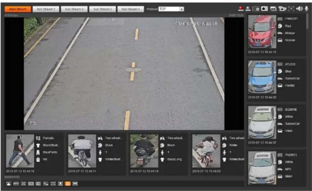
text_image
Main Stream Sub Stream 1 Sub Stream 2 Sub Stream 3 Sub Stream 4 Protocol TCP 2019-07-13 15:44:08 FAN8317 Red Mincar Nissan 2019-07-13 15:44:16 ATJ333 Blue SavonCar Hawlar B320WE White SavonCar Volvo 2019-07-13 15:44:07 TA2967J White MPV BMW5.16.2 Setting Picture Information
Set overlay of motor vehicle, non-motor vehicle and people and the box position.
This section takes the configuration of motor vehicle overlay as an example.
Step 1 Select Setting > Event > Video Structuralization > Picture.
The Picture interface is displayed. See Figure 5-71.
Picture (video structuralization) Figure 5-71
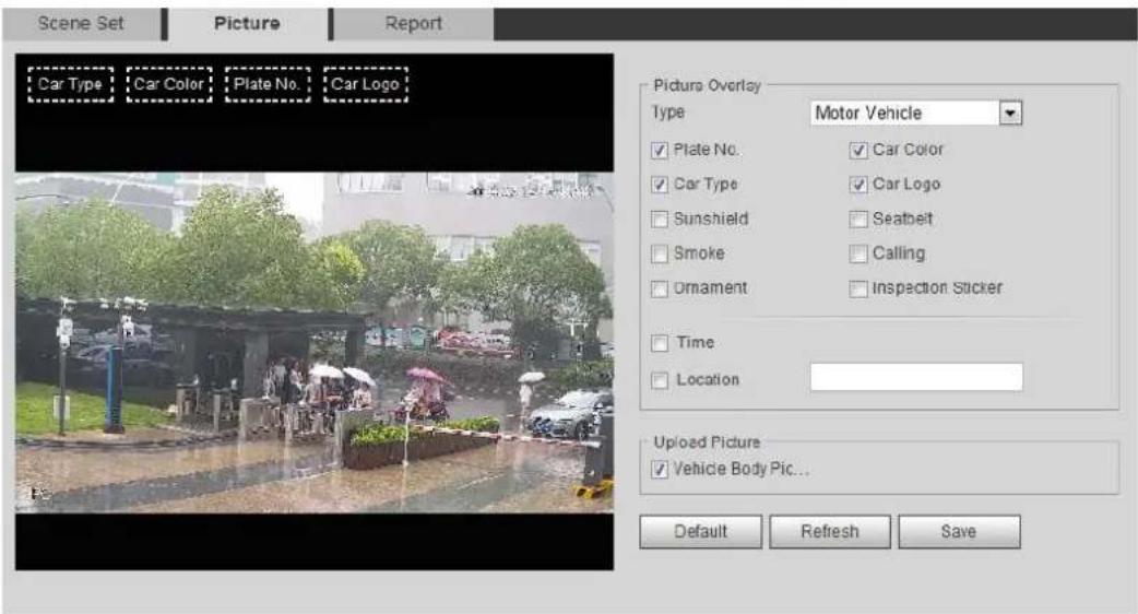
text_image
Scene Set Picture Report Car Type Car Color Plate No. Car Logo Picture Overlay Type Motor Vehicle ✓ Plate No. ✓ Car Color ✓ Car Type ✓ Car Logo □ Sunshield □ Seatbeit □ Smoke □ Calling □ Ornament □ Inspection Sticker □ Time □ Location Upload Picture ✓ Vehicle Body Pic... Default Refresh SaveStep 2 Select Motor Vehicle from the Type drop-down list.
Select Non-motor Vehicle or People, and set non-motor vehicle and people overlay.
Set overlay information and box position, such as plate no., time, car color, car type, Step 3 and car logo.
Click Save. Step 4
5.16.3 Viewing Video Structuralization Report
Generate data of video structuralization recognition in report form.
Step 1 Select Setting > Event > Video Structuralization > Report.
The Report interface is displayed.
Step 2 Select the report type, start time, end time, and other parameters.
Click Search to complete the report. Step 3
The statistical results are displayed. See Figure 5-72. Click Export to export the statistical report.
Figure 5-72 Video structuralization report
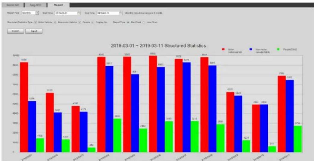
bar
2019-03-01 ~ 2019-03-11 Structured Statistics | Date | Motor (mm) | Motor-Engine (mm) | Passenger (mm) | |---|---|---|---| | 2019-03-01 | 8566 | 534 | 1436 | | 2019-03-02 | 6126 | 4267 | 1315 | | 2019-03-03 | 4787 | 4174 | 474 | | 2019-03-04 | 8545 | 8341 | 3482 | | 2019-03-05 | 8566 | 8081 | 2464 | | 2019-03-06 | 8570 | 7882 | 3195 | | 2019-03-07 | 8578 | 8278 | 3213 | | 2019-03-08 | 8564 | 8285 | 2956 | | 2019-03-09 | 6329 | 5649 | 1224 | | 2019-03-10 | 4823 | 4832 | 511 | | 2019-03-11 | 7595 | 7473 | 2754 |Setting Relay-in 5.17
When an alarm is triggered at the alarm-in port, the system performs alarm linkage.
Select Setting > Event > Alarm Settings > Alarm. Step 1
The Alarm interface is displayed. See Figure 5-73.
Alarm linkage Figure 5-73
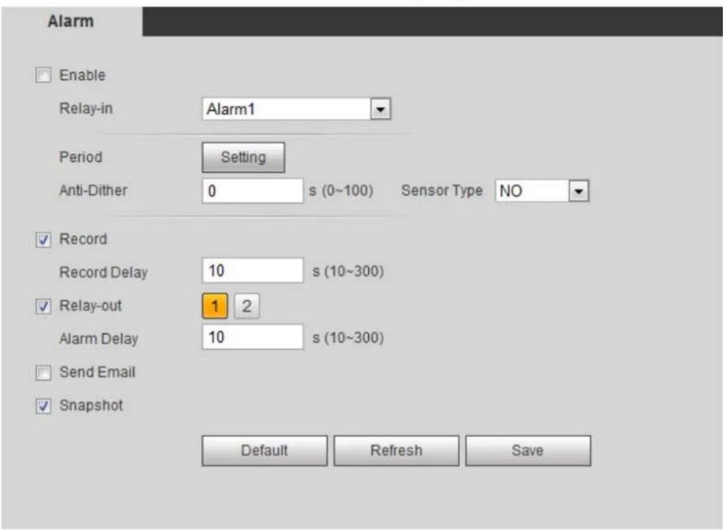
text_image
Alarm Enable Relay-in Alarm1 Period Setting Anti-Dither 0 s (0~100) Sensor Type NO Record Record Delay 10 s (10~300) Relay-out 1 2 Alarm Delay 10 s (10~300) Send Email Snapshot Default Refresh SaveSelect the Enable check box to enable the alarm linkage. Step 2
Select a relay-in port and a sensor type. Step 3
- Sensor Type: NO or NC
- Anti-Dither: Only record one alarm event during the anti-dither period.
Step 4 Set arming periods and alarm linkage action. For details, see "5.1.1 Alarm Linkage."
Click Save. Step 5
Setting Abnormality 5.18
Abnormality includes SD card, network, illegal access, voltage detection, and security exception.

Only the device with SD card has the abnormality functions, inducing No SD Card, SD Card Error, and Capacity Warning.
5.18.1 Setting SD Card
In case of SD card abnormality, the system performs alarm linkage. The event types include No SD Card, Capacity Warning, and SD Card Error. Functions might vary with different models, and the actual interface shall prevail.
Step 1 Select Setting > Event > Exception Handling > SD Card.
The SD Card interface is displayed. See Figure 5-74.
SD card Figure 5-74
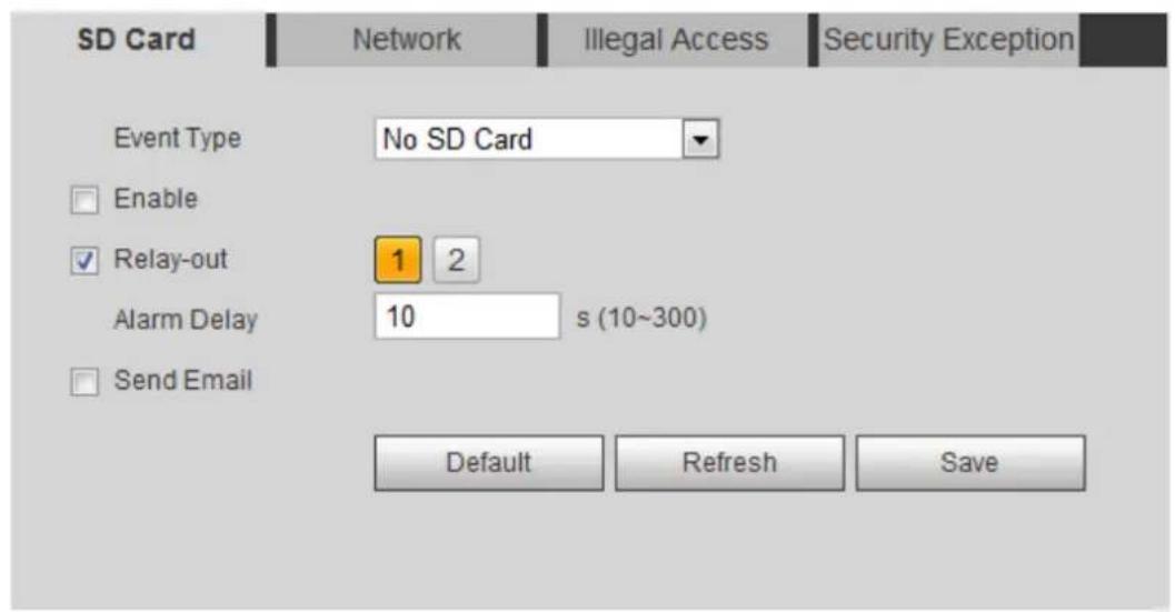
text_image
SD Card Network Illegal Access Security Exception Event Type No SD Card Enable Relay-out 1 2 Alarm Delay 10 s (10~300) Send Email Default Refresh SaveStep 2 Select the event type from the Event Type drop-down list, and then select the Enable check box to enable the SD card detection function.
When setting Capacity Warning as Event Type, set Capacity Limit. When the remaining space of SD card is less than this value, the alarm is triggered.
Step 3 Set alarm linkage actions. For details, see "5.1.1 Alarm Linkage."
Click Save. Step 4
5.18.2 Setting Network
In case of network abnormality, the system performs alarm linkage. The event types include Disconnection and IP Conflict.
Select Setting > Event > Abnormality > Network. Step 1
The Network interface is displayed. See Figure 5-75.
Network Figure 5-75
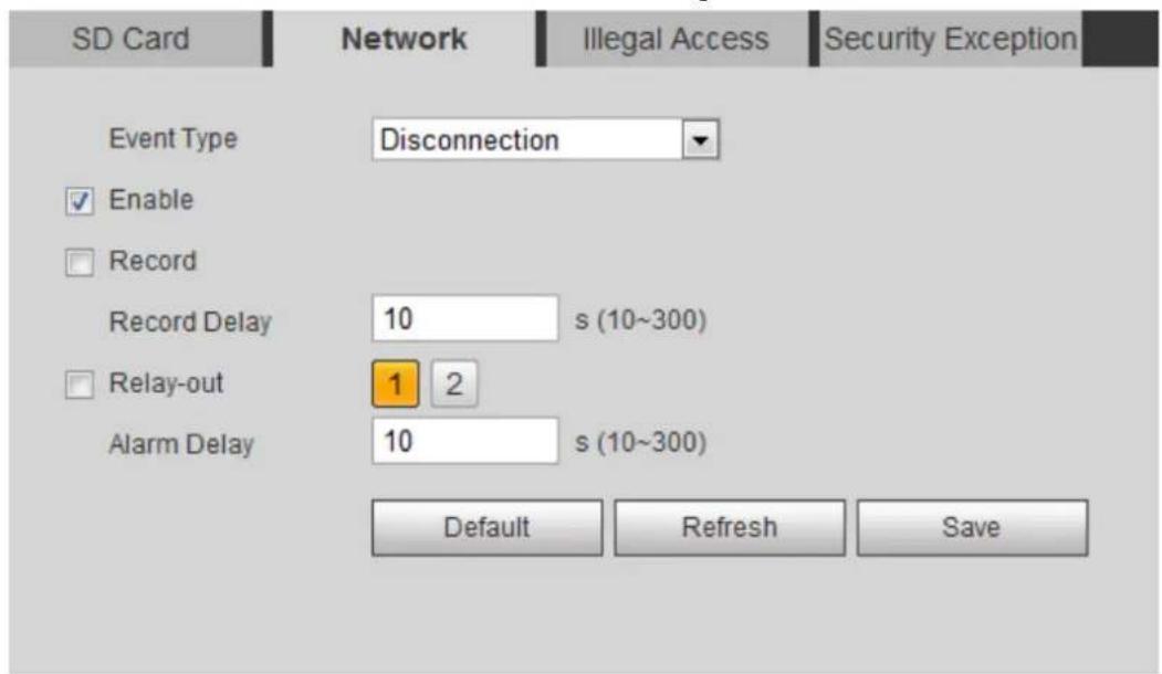
text_image
SD Card Network Illegal Access Security Exception Event Type Disconnection Enable Record Record Delay 10 s (10~300) Relay-out 1 2 Alarm Delay 10 s (10~300) Default Refresh SaveStep 2 Select the event type from the Event Type drop-down list, and then select the Enable check box to enable the network detection function.
Set alarm linkage actions. For details, see "5.1.1 Alarm Linkage." Step 3
Click Save. Step 4
5.18.3 Setting Illegal Access
When you enter a wrong login password more than the set times, the system performs alarm linkage.
Step 1 Select Setting > Event > Abnormality > Illegal Access.
The Illegal Access interface is displayed. See Figure 5-76.
Illegal access Figure 5-76
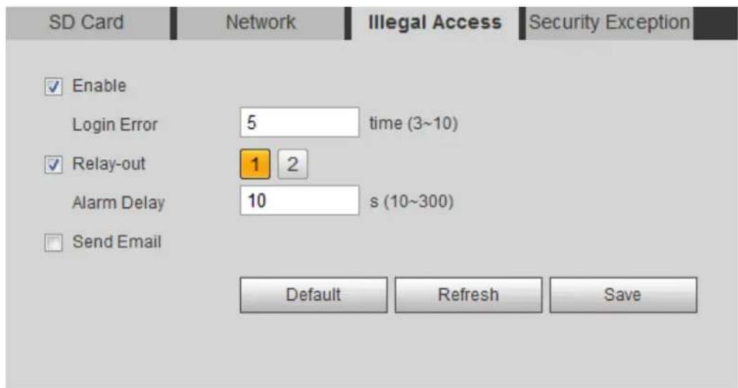
text_image
SD Card Network Illegal Access Security Exception Enable Login Error 5 time (3~10) Relay-out 1 2 Alarm Delay 10 s (10~300) Send Email Default Refresh SaveStep 2 Select the Enable check box to enable the illegal access detection function.
Set Login Error. Step 3
If you consecutively enter a wrong password more than the set value, the account will be locked.
Set alarm linkage actions. For details, see "5.1.1 Alarm Linkage." Step 4
Step 5 Click Save.
5.18.4 Setting Voltage Detection
When the input voltage is higher than or lower than the rated value of the device, the system performs alarm linkage.
Step 1 Select Setting > Event > Abnormality > Voltage Detection.
The Voltage Detection interface is displayed. See Figure 5-77.
Voltage detection Figure 5-77
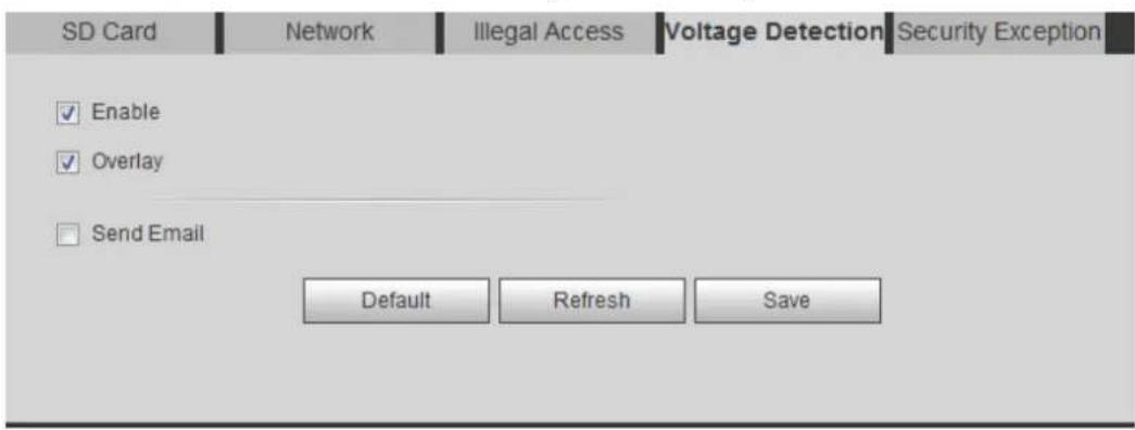
text_image
SD Card Network Illegal Access Voltage Detection Security Exception ✓ Enable ✓ Overlay Send Email Default Refresh SaveStep 2 Select the Enable check box to enable the voltage detection function.
Select Overlay, and the alarm icon is displayed by overlapping when the alarm is
triggered. indicates undervoltage and indicates overvoltage.
Set alarm linkage actions. For details, see "5.1.1 Alarm Linkage." Step 3
Click Save. Step 4
5.18.5 Setting Security Exception
When a hostile attack is detected, the system performs alarm linkage.
Step 1 Select Setting > Event > Abnormality > Security Exception.
The Security Exception interface is displayed. See Figure 5-78.
Security exception Figure 5-78
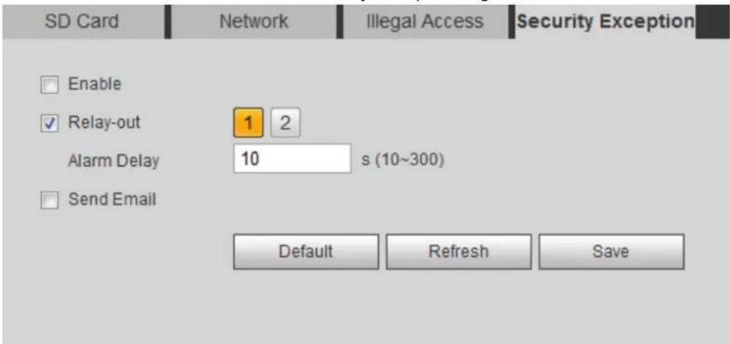
text_image
SD Card Enable Relay-out Alarm Delay 10 s (10~300) Send Email Default Refresh SaveStep 2 Select the Enable check box to enable the security exception detection function.
Set alarm linkage actions. For details, see "5.1.1 Alarm Linkage." Step 3
Click Save. Step 4
6 Maintenance
Requirements 6.1
To make sure the system runs normally, maintain it as the following requirements:
- Check surveillance images regularly.
- Clear regularly user and user group information that are not frequently used.
- Modify the password every three months. For details, see "4.8.4 Account."
• View system logs and analyze them, and process the abnormality in time. - Back up the system configuration regularly.
- Restart the device and delete the old files regularly.
- Upgrade firmware in time.
Auto Maintain 6.2
You can restart the system manually, and set the time of auto reboot and auto deleting old files. This function is disabled by default.
Select Setting > System > Auto Maintain. Step 1
The Auto Maintain interface is displayed. See Figure 6-1.
Auto maintain Figure 6-1
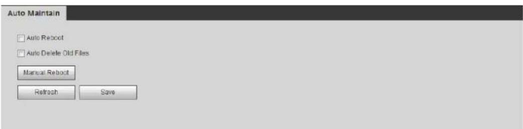
text_image
Auto Maintain □ Auto Reboot □ Auto Delete Old Files Manual Reboot Refresh SaveConfigure auto maintain parameters. For details, see Figure 6-2. Step 2
- Select the Auto Reboot check box, and set the reboot time, the system automatically restarts as the set time every week.
- Select the Auto Delete Old Files check box, and set the time, the system automatically deletes old files as the set time. The time range is 1 to 31 days.
- Click Manual Reboot, and then click OK on the displayed interface, the camera will restart.

When you enable and confirm the Auto Delete Old Files function, The The deleted files cannot be restored, are you sure? notice is displayed. Operate it carefully.
Description of auto maintain parameters Figure 6-2
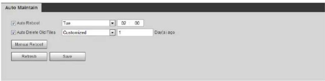
text_image
Auto Maintain ✓ Auto Reboot Tue 02:00 ✓ Auto Delete Old Files Customized 1 Day(s) ago Manual Reboot Refresh SaveClick OK. Step 3
Resetting Password 6.3
When you need to reset the password for the admin account, there will be a security code sent to the entered email address which can be used to reset the password.
Preparation
You have enabled password reset service. For details, see "4.8.5.1 System Service."
Procedure
____ Open IE browser, enter the IP address of the device in the address bar and press Step 1 Enter.
The login interface is displayed, see Figure 6-3.
Login Figure 6-3
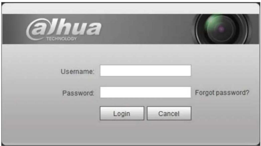
text_image
@Jhua TECHNOLOGY Username: Password: Forgot password? Login CancelClick Forgot password? Step 2 The Prompt dialog box is displayed. See Figure 6-4.
Prompt Figure 6-4

text_image
Prompt In order to provide a secure password and reset environment, we need to collect your email address, device MAC address, device SN, etc. At collected site is used only for the purposes of verifying device validity and sending a security code to you. Do you agree and want to continue the operation? OK CancelClick OK. Step 3
The Reset the password (1/2) interface is displayed, see Figure 6-5.

Clicking OK means that you are informed that some of your personal data might be collected to help reset the password, such as phone number, MAC address, and device serial number. Read the prompt carefully to decide whether to authorize the collection activity.
Reset the password (1) Figure 6-5
Reset the password(1/2)
SN: 2C04AB9YAZD0019
QR code:
text_image
Please scan the QR code on the actual interfaceNote(For admin only):
Option 1. Please download Easy4ip and then from Me-Settings-Reset device password, scan the left QR code.
Option 2. Please use an APP to scan the left QR code to get special strings. And then send the strings to support_rpwd@global.dahuatech.com.
The security code will be delivered to 1***@qq.com
Security code:
Cancel
Next
Step 4 Reset the password.
____ Scan the QR code, and there will be a security code sent to the email address you Step 5 entered. Enter the security code as instructed.

- Please use the security code within 24 hours after you receive it. Otherwise, it will become invalid.
- If you fail to use the security code for two times continuously, there will be fail notice when you try to get a security code for the third time. You have to reset the device to get a security code or wait 24 hours to get it again.
Click Next. Step 6
The Reset the password (2/2) interface is displayed, see Figure 6-6.
Reset the password (2) Figure 6-6
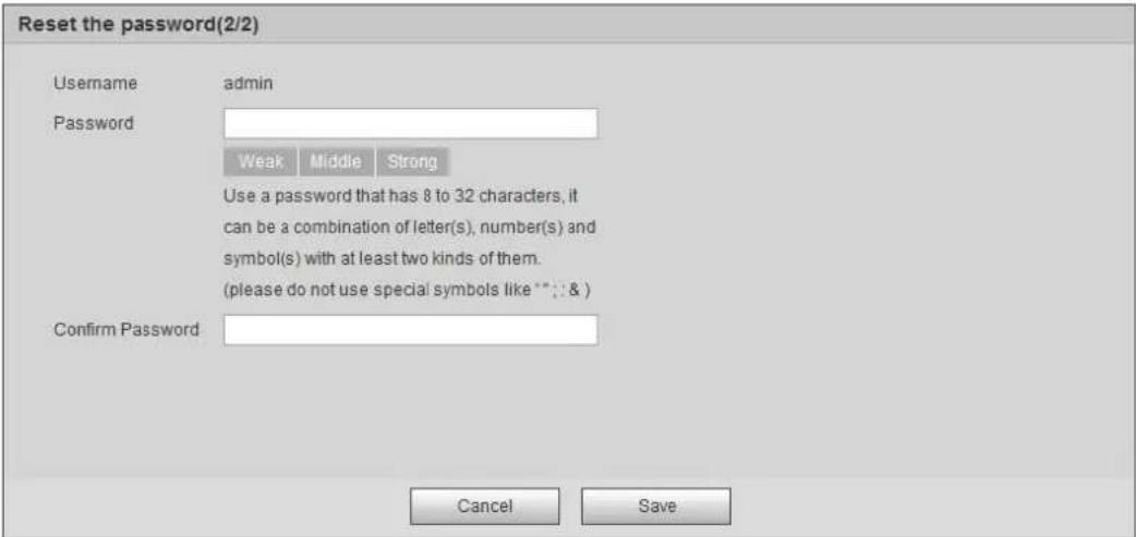
text_image
Reset the password(2/2) Username admin Password Weak Middle Strong Use a password that has 8 to 32 characters, it can be a combination of letter(s), number(s) and symbol(s) with at least two kinds of them. (please do not use special symbols like **: & ) Confirm Password Cancel SaveReset and confirm the password. Step 7 The password must consist of 8 to 32 non-blank characters and contain at least two types of characters among upper case, lower case, number, and special character (excluding '";: &). Click Save. Step 8 The login interface is displayed.
Backup and Default 6.4
6.4.1 Import/Export
- Export the system configuration file to back up the system configuration.
- Import system configuration file to make quick configuration or recover system configuration.
Select Setting > System > Import/Export. Step 1 The Import/Export interface is displayed. See Figure 6-7.
Import/Export Figure 6-7
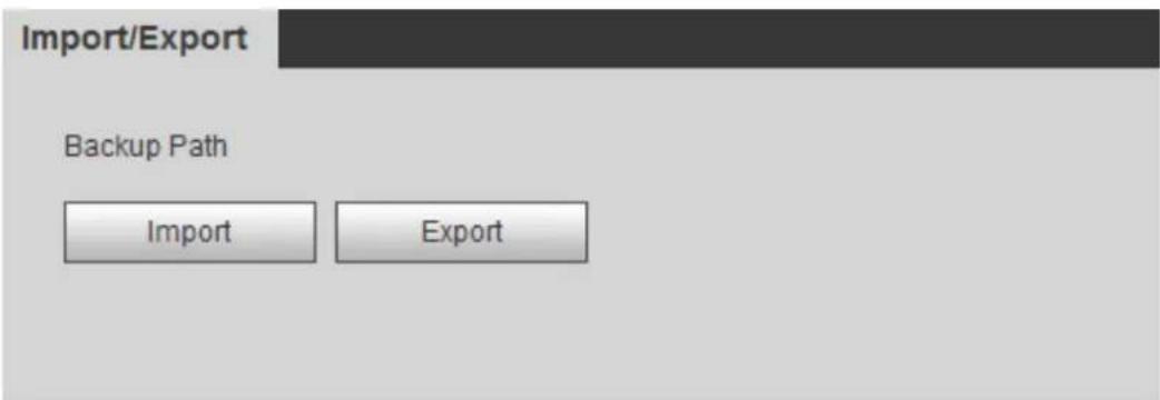
text_image
Import/Export Backup Path Import ExportStep 2 Click Import or Export.
- Import: Select local configuration file, and click Open to import the local system configuration file to the system.
- Export: Select the storage path, and click Save to export the system configuration file to local storage.
Click Save to finish configuration. Step 3
6.4.2 Default
Restore the device to default configuration or factory settings.

This function will restore the device to default configuration or factory setting.
Select Setting > System > Default. The Default interface is displayed. See Figure 6-8.
- Click Default, and then all the configurations except IP address and account are reset to default.
- Click Factory Default, and all the configurations are reset to factory settings.
Default Figure 6-8
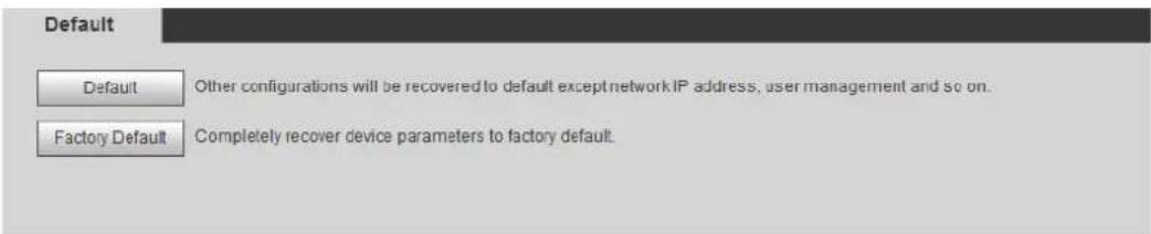
text_image
Default Default Other configurations will be recovered to default except network IP address, user management and so on. Factory Default Completely recover device parameters to factory default.Upgrade 6.5
Upgrading to the latest system can perfect camera functions and improve stability.

If wrong upgrade file has been used, restart the device; otherwise some functions might not work properly.
Select Setting > System > Upgrade. Step 1 The Upgrade interface is displayed. See Figure 6-9.
Upgrade Figure 6-9
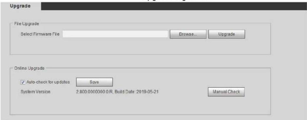
text_image
Upgrade File Upgrade Select Firmware File Browse... Upgrade Online Upgrade ✓ Auto-check for updates Save System Version 2.800.000000.0 R, Build Date: 2019-05-21 Manual CheckSelect upgrading method according to the actual needs. Step 2
- File Upgrade
1) Click Browse, and then upload upgrade file.
The upgrade file should be a .bin file.
2) Click Upgrade.
The upgrade starts.
- Online Upgrade
1) Select the Auto-check for updates check box.
The system checks for upgrade once a day automatically, and there will be system notice if any upgrade is available.

We need to collect the data such as device name, firmware version, and device serial number to proceed auto-check. The collected information is only used for verifying the legality of cameras and upgrade notice.
2) If there is any upgrade available, click Upgrade, and then the system starts upgrading.

Click Manual Check to check for upgrade manually.
Information 6.6
You can view the information, including version, log and online user, and back up or clear log.
6.6.1 Version
You can view device information such as hardware, system version, and web version.
Select Setting > Information > Version to view the version information.
6.6.2 Log
You can view and back up logs.
Select Setting > Information > Log. Step 1 The Log interface is displayed. See Figure 6-10.
Log Figure 6-10
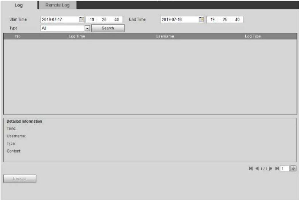
text_image
Log Remote Log Start Time 2019-07-17 19 25 40 End Time 2019-07-16 19 25 40 Type All Search No Log Time Username Log Type Detailed Information Time: Username: Type: Content BackupStep 2 Configure Start Time and End Time, and then select the log type.
The start time should be later than January 1st, 2000, and the end time should be earlier than December 31, 2037.
The log type includes All, System, Setting, Data, Event, Record, Account, and Safety.
- System: Includes program start, abnormal close, close, program reboot, device closedown, device reboot, system reboot, and system upgrade.
- Setting: Includes saving configuration and deleting configuration file.
- Data: Includes configuring disk type, clearing data, hot swap, FTP state, and record mode.
- Event (records events such as video detection, smart plan, alarm and abnormality): includes event start and event end.
- Record: Includes file access, file access error, and file search.
- Account: Includes login, logout, adding user, deleting user, modifying user, adding group, deleting group, and modifying group.
• Safety: Includes password resetting and IP filter.
Click Search. Step 3
The searched results are displayed. See Figure 6-11.
- Click a certain log, and then you can view the detailed information in Detailed Information area.
- Click Backup, and then you can back up all found logs to local PC.
Log Figure 6-11
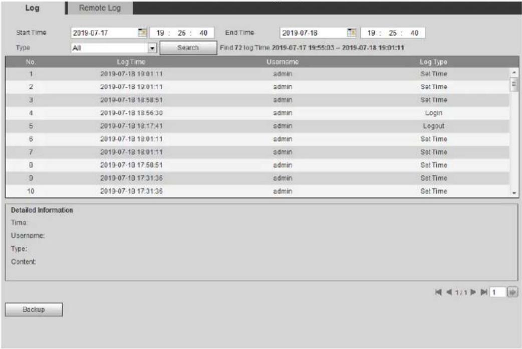
text_image
Log Remote Log Start Time 2019-07-17 19 : 25 : 40 End Time 2019-07-18 19 : 25 : 40 Type All Search Find 72 log Time 2019-07-17 19:55:03 - 2019-07-18 19:01:11 No. Log Time Username Log Type 1 2019-07-18 19:01:11 admin Set Time 2 2019-07-18 19:01:11 admin Set Time 3 2019-07-18 18:58:51 admin Set Time 4 2019-07-18 18:56:30 admin Login 5 2019-07-18 18:17:41 admin Logout 6 2019-07-18 18:01:11 admin Set Time 7 2019-07-18 18:01:11 admin Set Time 8 2019-07-18 17:58:51 admin Set Time 9 2019-07-18 17:31:36 admin Set Time 10 2019-07-18 17:31:36 admin Set Time Detailed Information Time: Username: Type: Content:6.6.3 Remote Log
Configure remote log, and you can get the related log by accessing the set address.
Select Setting > Information > Remote Log. Step 1
The Remote Log interface is displayed. See Figure 6-12.
Log Figure 6-12
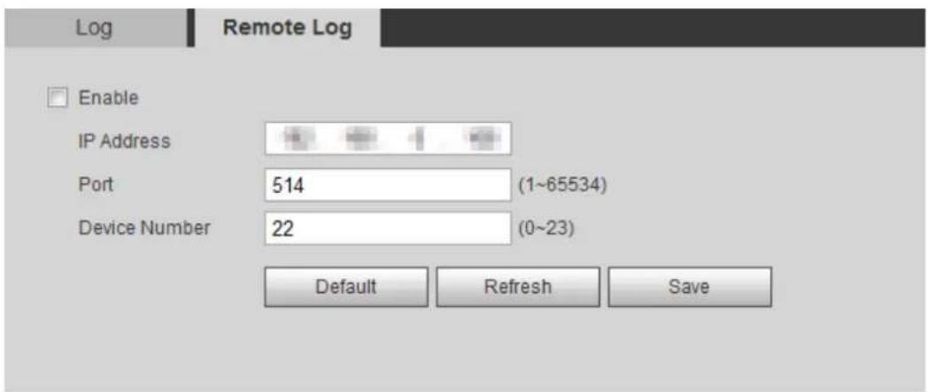
text_image
Log Remote Log Enable IP Address Port 514 (1~65534) Device Number 22 (0~23) Default Refresh SaveSelect the Enable check box to enable remote log function. Step 2
Set address, port and device number. Step 3
Click Save. Step 4
6.6.4 Online User
View all the current users logging in to web.
Select Setting > Information > Online User. The Online User interface is displayed. See Figure 6-13.
Online user Figure 6-13
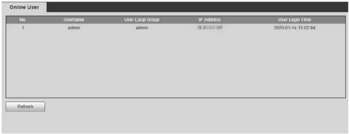
text_image
Online User No. Username User Local Group IP Address User Login Time 1 admin admin 2020-01-14 15:02:04 RefreshCybersecurity Recommendations Apper
Cybersecurity is more than just a buzzword: it's something that pertains to every device that is connected to the internet. IP video surveillance is not immune to cyber risks, but taking basic steps toward protecting and strengthening networks and networked appliances will make them less susceptible to attacks. Below are some tips and recommendations on how to create a more secured security system.
Mandatory actions to be taken for basic equipment network security:
1. Use Strong Passwords
Please refer to the following suggestions to set passwords:
- The length should not be less than 8 characters;
- Include at least two types of characters; character types include upper and lower case letters, numbers and symbols;
- Do not contain the account name or the account name in reverse order;
- Do not use continuous characters, such as 123, abc, etc.;
- Do not use overlapped characters, such as 111, aaa, etc.;
2. Update Firmware and Client Software in Time
- According to the standard procedure in Tech-industry, we recommend to keep your equipment (such as NVR, DVR, IP camera, etc.) firmware up-to-date to ensure the system is equipped with the latest security patches and fixes. When the equipment is connected to the public network, it is recommended to enable the “auto-check for updates” function to obtain timely information of firmware updates released by the manufacturer.
• We suggest that you download and use the latest version of client software.
"Nice to have" recommendations to improve your equipment network security:
1. Physical Protection
We suggest that you perform physical protection to equipment, especially storage devices. For example, place the equipment in a special computer room and cabinet, and implement well-done access control permission and key management to prevent unauthorized personnel from carrying out physical contacts such as damaging hardware, unauthorized connection of removable equipment (such as USB flash disk, serial port), etc.
2. Change Passwords Regularly
We suggest that you change passwords regularly to reduce the risk of being guessed or cracked.
3. Set and Update Passwords Reset Information Timely
The equipment supports password reset function. Please set up related information for password reset in time, including the end user's mailbox and password protection questions. If the information changes, please modify it in time. When setting password protection questions, it is suggested not to use those that can be easily guessed.
4. Enable Account Lock
The account lock feature is enabled by default, and we recommend you to keep it on to guarantee the account security. If an attacker attempts to log in with the wrong password several times, the corresponding account and the source IP address will be locked.
5. Change Default HTTP and Other Service Ports
We suggest you to change default HTTP and other service ports into any set of numbers between 1024\~65535, reducing the risk of outsiders being able to guess which ports you are using.
6. Enable HTTPS
We suggest you to enable HTTPS, so that you visit Web service through a secure communication channel.
7. Enable Whitelist
We suggest you to enable whitelist function to prevent everyone, except those with specified IP addresses, from accessing the system. Therefore, please be sure to add your computer's IP address and the accompanying equipment's IP address to the whitelist.
8. MAC Address Binding
We recommend you to bind the IP and MAC address of the gateway to the equipment, thus reducing the risk of ARP spoofing.
9. Assign Accounts and Privileges Reasonably
According to business and management requirements, reasonably add users and assign a minimum set of permissions to them.
10. Disable Unnecessary Services and Choose Secure Modes
If not needed, it is recommended to turn off some services such as SNMP, SMTP, UPnP, etc., to reduce risks.
If necessary, it is highly recommended that you use safe modes, including but not limited to the following services:
- SNMP: Choose SNMP v3, and set up strong encryption passwords and authentication passwords.
- SMTP: Choose TLS to access mailbox server.
- FTP: Choose SFTP, and set up strong passwords.
- AP hotspot: Choose WPA2-PSK encryption mode, and set up strong passwords.
11. Audio and Video Encrypted Transmission
If your audio and video data contents are very important or sensitive, we recommend that you use encrypted transmission function, to reduce the risk of audio and video data being stolen during transmission.
Reminder: encrypted transmission will cause some loss in transmission efficiency.
12. Secure Auditing
- Check online users: we suggest that you check online users regularly to see if the device is logged in without authorization.
- Check equipment log: By viewing the logs, you can know the IP addresses that were used to log in to your devices and their key operations.
13. Network Log
Due to the limited storage capacity of the equipment, the stored log is limited. If you need to save the log for a long time, it is recommended that you enable the network log function to ensure that the critical logs are synchronized to the network log server for tracing.
14. Construct a Safe Network Environment
In order to better ensure the safety of equipment and reduce potential cyber risks, we recommend:
- Disable the port mapping function of the router to avoid direct access to the intranet devices from external network.
- The network should be partitioned and isolated according to the actual network needs. If there are no communication requirements between two sub networks, it is suggested to use VLAN, network GAP and other technologies to partition the network, so as to achieve the network isolation effect.
- Establish the 802.1x access authentication system to reduce the risk of unauthorized access to private networks.