button to switch the Select line to either luminance, red, green, or blue.
- Line selection items switch each time the is pressed only when the waveform monitor is displayed.
| “Select line (luminance)” Displayed in white waveform. |
| “Select line (red)” Displayed in red waveform. |
| “Select line (green)” Displayed in green waveform. |
"Select line (blue)" Displayed in blue waveform.
Note
- Setting is also available from [FUNCTION BUTTON] (→ page 121).
- Waveform monitor cannot be displayed in [P IN P].
- The waveform monitor turns off when [P IN P] is executed during waveform monitoring.
- The waveform monitor is not displayed when on-screen display is hidden (off).
Project the luminance adjustment signal of a commercial test disk (0 % (0 IRE or 7.5 IRE) - 100 % (100 IRE)) and adjust.
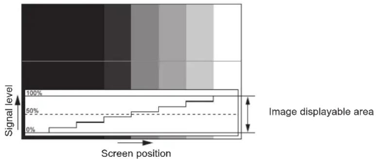
bar
| Screen position | Signal level |
| --------------- | ------------ |
| 0% | 0% |
| 50% | 50% |
| 100% | 100% |
1) Select "Select line (luminance)" on the waveform monitor.
2) Adjust black level.
- Use [BRIGHTNESS] in the on-screen menu [PICTURE] to adjust the black level 0 % of the video signal to the 0 % position of the waveform monitor.
3) Adjust white level.
- Use [CONTRAST] in the on-screen menu [PICTURE] to adjust the white level 100 % of the video signal to the 100 % position of the waveform monitor.
Adjusting red, green, and blue
1) Set [COLOR TEMPERATURE] to [USER1] or [USER2] ( page 72).
2) Select "Select line (red)" on the waveform monitor.
3) Adjust dark red areas.
- Use [RED] in [WHITE BALANCE LOW] to adjust the black level 0% of the video signal to the 0% position of the waveform monitor.
4) Adjust bright red areas.
- Use [RED] in [WHITE BALANCE HIGH] to adjust the white level 100 % of the video signal to the 100 % position of the waveform monitor.
5) Use the procedure for [RED] to adjust [GREEN] and [BLUE].
Note
- For DVI-D signal, HDMI signal, SDI signal, and DIGITAL LINK signal, confirm that the [SIGNAL LEVEL] setting is correct before starting adjusting the black level.
[CUT OFF]
Each red, green, and blue color component can be removed.
1) Press ▲▼ to select [CUT OFF].
2) Press the button.
• The [CUT OFF] screen is displayed.
3) Press ▲▼ to select [RED], [GREEN], or [BLUE].
4) Press ◀▶ to switch the item.
[OFF] Disables cutoff.
[ON] Enables cutoff.
Note
- When input is switched or a signal is switched, the cutoff setting returns to its original setting (off).
On the menu screen, select [PROJECTOR SETUP] from the main menu, and select an item from the sub-menu.
Refer to "Navigating through the menu" ( page 65) for the operation of the menu screen.
• After selecting the item, press ▲▼◀▶ to set.
![PANASONIC PT-DZ870U - [PROJECTOR SETUP] menu - 1](/content/2026/05/813109/images/05c64bf2e61b0fb05618dd54d9f04e7ed3b55b0fe03a33c55ea46e3e6d49a18d.jpg)
![PANASONIC PT-DZ870U - [PROJECTOR SETUP] menu - 2](/content/2026/05/813109/images/a47f727e5ae8a1716126d38220546093b70679871cdec82ecab3b32a151c63ee.jpg)
text_image
FUNCTION STATUS DEFAULT
1 2 3
4 5 6
7 8 9
AUTO SETUP 0 ID SET
Panasonic
PROJECTOR
[PROJECTOR ID]
The projector has an ID number setting function that can be used when multiple projectors are used side by side to enable simultaneous control or individual control via a single remote control.
1) Press ▲▼ to select [PROJECTOR ID].
2) Press ◀▶ to switch the item.
- The items will switch each time you press the button.
[ALL] Select when controlling projectors without specifying an ID number.
[1] - [64] Select when specifying an ID number to control individual projector.
Note
- To specify an ID number for individual control, the ID number of a remote control must match the ID number of the projector.
- When the ID number is set to [ALL], the projector will operate regardless of the ID number specified during remote control or computer control.
If multiple projectors are set up side by side with IDs set to [ALL], they cannot be controlled separately from the projectors with other ID numbers.
- Refer to "Setting the remote control ID numbers" (→ page 29) for how to set the ID number on the remote control.
[PROJECTION METHOD]
Set the projection method in accordance with the installation status of the projector.
Change the projection method if the screen display is upside down or inverted.
1) Press ▲▼ to select [PROJECTION METHOD].
2) Press the button.
- The [PROJECTION METHOD] screen is displayed.
3) Press ▲▼ to select the projection method.
| [FRONT/FLOOR] When installing the projector on the desk, etc., in front of the screen |
| [FRONT/CEILING] | When installing the projector in front of the screen using the Ceiling Mount Bracket (optional) |
| [REAR/FLOOR] | When installing the projector on the desk, etc., behind the screen (with a translucent screen) |
| [REAR/CEILING] | When installing the projector behind the screen (with a translucent screen) using the Ceiling Mount Bracket (optional) |
4) Press the button.
5) When the confirmation screen is displayed, press ◀▶ to select [OK], and press the button.
Attention
- When the [PROJECTION METHOD] setting is changed, confirm that [COOLING CONDITION] (→ page 109) is set correctly.
[COOLING CONDITION]
Change the fan control depending on the direction of projection.
Set [COOLING CONDITION] according to the projection direction, but set it to [AUTO] normally. Using the projector with [COOLING CONDITION] set incorrectly may shorten the life of the lamp.
![PANASONIC PT-DZ870U - [COOLING CONDITION] - 1](/content/2026/05/813109/images/e8f59c34330678adc4ce6b7d77b840ce0d412314356b95394240528d21d0379f.jpg)
text_image
[VERTICAL UP SETTING]
[FLOOR SETTING] 30° 30° 30°
[CEILING SETTING]
[VERTICAL DOWN SETTING]
: Projection direction
1) Press ▲▼ to select [COOLING CONDITION].
2) Press the button.
• The [COOLING CONDITION] screen is displayed.
3) Press ▲▼ to select a cooling condition.
- When [AUTO] is selected, the cooling conditions of [FLOOR SETTING], [CEILING SETTING], [VERTICAL UP SETTING], and [VERTICAL DOWN SETTING] are set automatically.
You can check the setting from [COOLING CONDITION] on the [STATUS] screen.
4) Press the button.
5) When the confirmation screen is displayed, press ◀▶ to select [OK], and press the button.
Note
- This item cannot be set when using the optional Replacement lamp unit (for portrait mode) (Model No.: ET-LAD120P (1 pc), ET-LAD120PW (2 pcs)). (Setting is fixed to [PORTRAIT SETTING].)
[HIGH ALTITUDE MODE]
Set to [ON] when using the projector at high altitudes between 1 400 m (4 593') and 2 700 m (8 858') above sea level.
1) Press ▲▼ to select [HIGH ALTITUDE MODE].
2) Press ◀▶ to switch the item.
| [OFF] When using at a location lower than 1 400 m (4 593') above sea level |
| [ON] | When using at high altitudes (between 1 400 m (4 593') and 2 700 m (8 858') above sea level) |
3) When the confirmation screen is displayed, press ◀▶ to select [OK], and press the button.
Note
- The speed of the fan increases and the operation sound becomes louder when set to [ON].
[LAMP SELECT]
Select the lamp to be turned on from the two built-in luminous lamps according to the use conditions or purposes.
1) Press ▲▼ to select [LAMP SELECT].
2) Press ◀▶ to switch the item.
| [DUAL] Two lamps will light. |
| [SINGLE] One lamp will light. (The lamp with shorter runtime will automatically light.) |
| [LAMP1] Lamp 1 will light. |
| [LAMP2] Lamp 2 will light. |
3) Press the button.
Note
- When [SINGLE], [LAMP1], or [LAMP2] is selected, if the lamp turns off or if the runtime exceeds 3 000 hours ^1 (when [LAMP POWER] is set to [NORMAL]), the other lamp turns on. When [DUAL] is selected, if either lamp turns off or if the runtime exceeds 3 000 hours ^1 (when [LAMP POWER] is set to [NORMAL]), only the other lamp remains on. However, if both lamps turn off or when operation times of both lamps exceed 3 000 hours ^1 (when [LAMP POWER] is set to [NORMAL]), the projector turns into standby.
*1 1 000 hours when using the optional Replacement lamp unit (for portrait mode) (Model No.: ET-LAD120P (1 pc), ET-LAD120PW (2 pcs)).
•The colors of the items indicate the status.
| Green Current setting |
| Yellow Current setting (when there is a lamp that cannot turn on or failed to turn on) |
| Red Lamp that has failed to turn on |
| White Any other status |
- When the lamp is repeatedly used in a short-time cycle, the life of the lamp shortens.
[LAMP RELAY]
Switch the lamp to be turned on automatically by specifying the day of the week and time.
The degradation of the lamp due to continuous usage can be reduced by automatically switching the lamp to be turned on when using the projector continuously for a week or more.
1) Press ▲▼ to select [LAMP RELAY].
2) Press ◀▶ to switch the item.
| [OFF] Disables lamp relay. |
| [24H] Switches the lamp daily. |
| [1WEEK] Switches the lamp weekly. |
- When [24H] or [1WEEK] is selected, proceed to Step 3).
3) Press ▲▼ to select [TIME].
4) Press the button.
- Enters adjustment mode (the display is blinking).
5) Press ◀▶ to select "hour" or "minute", and press ▲▼ or the number (<0> - <9>) buttons to set a time.
- Selecting "hour" allows setting of only the hour in increments of one hour, and selecting "minute" allows setting of only the minute in increments of one minute between 00 and 59.
6) Press the button.
•The adjusted time is established.
- When [1WEEK] is selected in Step 2), proceed to Step 7).
7) Press ▲▼ to select [DAY OF THE WEEK].
8) Press ◀▶ to switch the item.
| [SUNDAY] | Switches the lamp automatically on the set day of the week. |
| [MONDAY] |
| [TUESDAY] |
| [WEDNESDAY] |
| [THURSDAY] |
| [FRIDAY] |
| [SATURDAY] |
Note
- The [LAMP RELAY] function is enabled when [DUAL] or [SINGLE] is selected in [LAMP SELECT].
- When [DUAL] is selected in [LAMP SELECT], only one lights for four hours from the specified time.
- The operating time will be the local time. (→ page 121)
[LAMP POWER]
Switch the brightness of the lamp according to the operating environment of the projector or the purpose.
1) Press ▲▼ to select [LAMP POWER].
2) Press ◀▶ to switch the item.
[NORMAL] Select when high luminance is required.
[ECO] Select when high luminance is not required.
Note
- When [ECO] is set, you can reduce power consumption and operation noise, and extend the life of the lamp.
[BRIGHTNESS CONTROL]
The projector is equipped with a luminance sensor to measure brightness and functions to correct screen brightness resulting from changes in lamp brightness.
Use the projector when using multiple projectors to display on multiple screens to reduce changes in overall brightness of the multiple screens due to lamp degradation and suppress variation in brightness to preserve uniformity.
Setting [BRIGHTNESS CONTROL GAIN]
Adjust the brightness when displaying multiple screens using multiple projectors.
1) Press ▲▼ to select [BRIGHTNESS CONTROL].
2) Press the button.
• The [BRIGHTNESS CONTROL] screen is displayed.
3) Press ▲▼ to select [BRIGHTNESS CONTROL GAIN].
4) Press ◀▶ to adjust.
| Operation | Adjustment | Range of adjustment |
| Brightness | Maximum amount of brightness correction |
| Press the ▶ button. | The screen becomes brighter. | The maximum amount of correction is reduced. | 20% - 100% |
| Press the ◀ button. | The screen becomes darker. | The maximum amount of correction is increased. |
Note
- When using only one projector, the value obtained by subtracting the value of the [BRIGHTNESS CONTROL GAIN] from 100 % is the maximum amount of brightness correction. Brightness cannot be corrected through brightness control since the maximum amount of correction becomes 0 % when [BRIGHTNESS CONTROL GAIN] is at 100 %.
- Luminance will be unsteady for eight minutes after a lamp is turned on. Make adjustments at least 8 minutes after starting projection.
- The result of [BRIGHTNESS CONTROL GAIN] adjustments is reflected on all image signals, internal test patterns, and on-screen menus.
- The [BRIGHTNESS CONTROL GAIN] setting is enabled even if [BRIGHTNESS CONTROL SETUP] is [OFF].
Setting [BRIGHTNESS CONTROL SETUP]
Set brightness control operation.
1) Press ▲▼ to select [BRIGHTNESS CONTROL].
2) Press the button.
- The [BRIGHTNESS CONTROL] screen is displayed.
3) Press ▲▼ to select [BRIGHTNESS CONTROL SETUP].
4) Press the button.
- The [BRIGHTNESS CONTROL SETUP] screen is displayed.
5) Press ▲▼ to select [MODE].
6) Press ◀▶ to switch the item.
- The items will switch each time you press the button.
| [OFF] Does not correct the brightness of the screen by the brightness sensor. |
| [AUTO] | Corrects the brightness of the screen by the brightness sensor.Automatically corrects screen brightness when lamp brightness changes. |
| [PC] | Synchronizes nine or more projectors through a computer using the dedicated software “Multi Projector Monitoring & Control SoftwareTM1. |
*1 "Multi Projector Monitoring & Control Software" is included in the supplied CD-ROM.
- When [AUTO] is selected, proceed to Step 7).
7) Press ▲▼ to select [LINK].
8) Press ◀▶ to switch the item.
- The items will switch each time you press the button.
| [OFF] | Performs corrections by the brightness sensor in one projector without synchronizing with the other projectors.The period, in which the constant brightness kept by the small value of [BRIGHTNESS CONTROL GAIN], is prolonged. |
| [GROUP A][GROUP B][GROUP C][GROUP D] | Synchronizes corrections in multiple projectors by the brightness sensor.You can set up to four groups (A to D) within the same subnet by using the network function.You can also register and synchronize up to eight projectors in one group. |
9) Press ▲▼ to select [CALIBRATION TIME].
10) Press the button.
- Enters adjustment mode (the display is blinking).
11) Press ◀▶ to select "hour" or "minute", and press ▲▼ or the number (<0> - <9>) buttons to set a time.
- Selecting "hour" allows setting of only the hour in increments of one hour, and selecting "minute" allows setting of only the minute in increments of one minute between 00 and 59.
- If you do not specify the time, select [OFF] between 23 and 00 o'clock or between 59 and 00 minutes.
12) Press the button.
•[CALIBRATION TIME] is set.
- Measures the brightness at the specified time. Iris is fixed to open during measurement.
13) Press ▲▼ to select [CALIBRATION MESSAGE].
14) Press ◀▶ to switch the item.
- The items will switch each time you press the button.
| [ON] Messages are displayed during calibration. |
| [OFF] Messages are not displayed during calibration. |
15) Press ▲▼ to select [APPLY].
- The set [MODE] and [LINK] are enabled, and LAMP RELAY screen alert is displayed when the [LAMP RELAY] setting is [OFF]. When [CALIBRATION MESSAGE] is set to [ON], a calibration running message is displayed which will automatically disappear 30 seconds after calibration completes.
- If the button is pressed with [MODE] in [BRIGHTNESS CONTROL SETUP] set to other than [OFF], the brightness of the lamp at the time the button was pressed is recorded as the standard brightness.
- If the button is pressed when [LINK] is set from [GROUP A] to [GROUP D], the group name is displayed on the screens of projectors that have been set in the same group.

Note
- When [MODE] in [BRIGHTNESS CONTROL SETUP] is set to [AUTO] or [PC], keep the shutter open for at least two minutes to perform the brightness sensor calibration after completed the [BRIGHTNESS CONTROL SETUP] setting.
- If the shutter is closed within approx. 10 minutes after the lamp has turned on while [MODE] in [BRIGHTNESS CONTROL SETUP] is set to [AUTO] or [PC], brightness cannot be measured. Therefore, brightness may be corrected approx. two minutes after the shutter opens.
- When [MODE] in [BRIGHTNESS CONTROL SETUP] is set to [AUTO] or [PC], the lamp brightness is automatically measured eight minutes after the lamp is turned on, and correction is performed so that the screen brightness will be the same as the standard brightness when the brightness control is adjusted. Lamp brightness cannot be measured during the eight minutes after it is turned on because it is not steady.
- If a lamp turns off or lamp relay is performed while [MODE] in [BRIGHTNESS CONTROL SETUP] is set to [AUTO] and when [DUAL] is set in the [PROJECTOR SETUP] menu → [LAMP SELECT], brightness is corrected to the possible extent one minute later.
- When [MODE] in [BRIGHTNESS CONTROL SETUP] is set to [AUTO] and [LINK] is set to [OFF], brightness will be corrected until it reaches the maximum amount of correction.
- The variation in brightness may increase due to dust accumulating on the lens, screen, or inside the projector, depending on the installation environment of the projector.
- Adjust brightness control again when lamp degradation causes increased variation in brightness or a lamp is replaced.
- For continued use longer than 24 hours, set the [BRIGHTNESS CONTROL SETUP] to [CALIBRATION TIME], or set [LAMP RELAY] (→ page 110). If it is not set, correction will not be performed automatically.
- Brightness control and dynamic iris operate simultaneously, but the iris is fully open and does not operate while a brightness measurement is performed.
- The [CALIBRATION TIME] setting will be reflected at the time when you enter the time.
- The [CALIBRATION MESSAGE] setting will be reflected at the time when items are switched using ◀.
Displaying [BRIGHTNESS CONTROL STATUS]
Display the brightness control status.
1) Press ▲▼ to select [BRIGHTNESS CONTROL].
2) Press the button.
- The [BRIGHTNESS CONTROL] screen is displayed.
3) Press ▲▼ to select [BRIGHTNESS CONTROL STATUS].
4) Press the button.
- The [BRIGHTNESS CONTROL STATUS] screen is displayed.
[BRIGHTNESS CONTROL STATUS] screen display example
When [MODE] of [BRIGHTNESS CONTROL SETUP] is set to [OFF]
The screen shows the status that the brightness control is disabled.
![PANASONIC PT-DZ870U - [BRIGHTNESS CONTROL STATUS] screen display example - 1](/content/2026/05/813109/images/67fc1debac29c63feb1f5c598a4f35f5a19ea77a47226923822fa062798703d7.jpg)
text_image
BRIGHTNESS CONTROL STATUS
MODE OFF
PROJECTOR
1
RETURN
When [MODE] of [BRIGHTNESS CONTROL SETUP] is set to [AUTO] and [LINK] is set to [OFF]
The screen shows the status of the brightness control in one projector.
![PANASONIC PT-DZ870U - [BRIGHTNESS CONTROL STATUS] screen display example - 2](/content/2026/05/813109/images/cb7255d44a94b92af1b1ed409ed590c55756ece5fedc60ed0c3e0bfeab9762a0.jpg)
text_image
BRIGHTNESS CONTROL STATUS
LINK OFF 5
PROJECTOR
6
RETURN
When [MODE] of [BRIGHTNESS CONTROL SETUP] is set to [AUTO] and [LINK] is set from [GROUP A] to [GROUP D]
The screen shows the status of the brightness control of synchronized projectors (up to eight units), including the projector being controlled through the on-screen menu.
![PANASONIC PT-DZ870U - When [MODE] of [BRIGHTNESS CONTROL SETUP] is set to [AUTO] and [LINK] is set from [GROUP A] to [GROUP D] - 1](/content/2026/05/813109/images/a889616657c557c50b6e02ed36123ff64c0df22a0c2c8d0ee38b9e321162f40f.jpg)
text_image
BRIGHTNESS CONTROL STATUS
LINK GROUP A
1
2
3
PROJECTOR 192. 168. 30. 2
1: PROJECTOR2 192. 168. 30. 3
2: PROJECTOR3 192. 168. 30. 4
3:
4:
5:
6:
7:
UPDATE
MENU SELECT
5
7
8
When [MODE] of [BRIGHTNESS CONTROL SETUP] is set to [PC]
![PANASONIC PT-DZ870U - When [MODE] of [BRIGHTNESS CONTROL SETUP] is set to [PC] - 1](/content/2026/05/813109/images/402f36fab55ac3a87817bbda80aabb0559b627157082513a2bebca67ed64df46.jpg)
text_image
BRIGHTNESS CONTROL STATUS
MODE PC
PROJECTOR
5
1
6
RETURN
1 Display the name of the projector.
2 Display the synchronized group.
3 Display the IP address of the projector.
4 Display the names and IP addresses of projectors in same group detected over the network.
5 Display the status by color.
Green: There is an allowance for brightness correction.
Yellow: There is little allowance for brightness correction.
Red: There is a brightness control error.
6 Display error detailed messages.
7 Display error messages.
When the message [Failed to apply BRIGHTNESS CONTROL to some projectors.] appears, it means that synchronization with the projector displayed in red has failed.
Press ▲▼ to select the projector displayed in red, and press the button to display the error details.
8 Update to the latest status information.
■Error details
| Error message Measures to take |
| [Exceed maximum number of projectors.] | Limit the number of projectors in one group to eight.When synchronizing nine or more projectors, use the dedicated software "Multi Projector Monitoring & Control Software" ^1 through a computer. |
| [Please check the COMMAND CONTROL setting.] | Set [NETWORK CONTROL] → [COMMAND CONTROL] to [ON] for the projector in error.Set [NETWORK CONTROL] → [COMMAND PORT] of all projectors to be linked to the same value. |
| [Please check the USER NAME and PASSWORD in the COMMAND CONTROL setting.] | Assign the same [User name] and [Password] strings that have web control administrator rights to all projectors to be linked. |
| [Cannot apply BRIGHTNESS CONTROL. Please check projector status.] | The projector is in standby. Switch on the power. |
| [Brightness Sensor Error] | There is a problem with the brightness sensor. If problems persist even after switching on the power, consult your dealer. |
*1 "Multi Projector Monitoring & Control Software" is included in the supplied CD-ROM.
Note
- If the synchronized projectors are not displayed in the list, check the following: -Are there devices with the same IP address on the network?
- Are the LAN cables connected correctly? (→ page 137)
- Are the subnets of the projectors the same?
- Are the same [LINK] settings applied to a group?
- Refer to [NETWORK SETUP] (→ page 135) or “[Network config] page” (→ page 145) on how to change the projector name.
Brightness control adjustment procedure example
The steps exemplify an adjustment to link the brightness of eight projectors connected in a network.
1) Connect all projectors to the hub using LAN cables. (→ page 137)
2) Switch on all projectors and start projection.
3) Set [LAMP SELECT] to either [DUAL] or [SINGLE] for all projectors.
4) Set [MODE] of [BRIGHTNESS CONTROL SETUP] to [OFF], and select [APPLY], and then press the button.
5) Set [SUBNET MASK] and [IP ADDRESS] in each projector.
- To be able to communicate over the network, set the same value in [SUBNET MASK] for all projectors and set a different value in [IP ADDRESS] for each projector.
6) Wait for at least eight minutes after starting projection until the lamp brightness becomes steady.
7) Set all items in the [PICTURE] menu of all projectors to the same values.
8) Adjust [COLOR MATCHING] to match colors.
9) Display the internal test pattern "All white" in all projectors.
10) Set [BRIGHTNESS CONTROL GAIN] to 100 % in all projectors.
11) Set [BRIGHTNESS CONTROL GAIN] to 90 % in the projector with the least brightness.
12) Adjust [BRIGHTNESS CONTROL GAIN] in each projector.
- Adjust [BRIGHTNESS CONTROL GAIN] of all the other projectors so that the brightness is matched to the projector of which [BRIGHTNESS CONTROL GAIN] is set to 90 %.
13) Set [MODE] of [BRIGHTNESS CONTROL SETUP] to [AUTO], and [LINK] to [GROUP A] in all projectors.
14) Select [APPLY] of [BRIGHTNESS CONTROL SETUP] and press the button in all projectors.
- Brightness control starts.
Note
- Brightness is automatically corrected each time the lamp blinks when the power is switched on or off.
- Adjust brightness control again when lamp degradation causes increased variation in brightness or a lamp is replaced.
[STANDBY MODE]
Set the power consumption during the standby.
1) Press ▲▼ to select [STANDBY MODE].
2) Press ◀▶ to switch the item.
- The items will switch each time you press the button.
[NORMAL] Use this setting to use the network function during standby.
[ECO] Use this setting to reduce power consumption during standby.
Note
- In the [ECO] setting, the network function, the terminal, and some RS-232C commands become inoperable during standby. In the [NORMAL] setting, the network function and the terminal become operable during standby.
- When set to [ECO], it may take approx. 10 seconds longer before the projector starts projecting after the power is turned on, compared with when [NORMAL] is set.
- The [STANDBY MODE] setting is not reset to the factory default even when [ALL USER DATA] is executed from the [PROJECTOR SETUP] menu → [INITIALIZE] (→ page 123).
[SCHEDULE]
Set the command execution schedule for each day of the week.
Enabling/disabling the schedule function
1) Press ▲▼ to select [SCHEDULE].
2) Press ◀▶ to switch the item.
•The items will switch each time you press the button.
| [OFF] Disables the schedule function. |
| [ON] | Enables the schedule function. Refer to “How to assign a program” (⇨ page 116) or “How to set a program” (⇨ page 116) for how to set the schedule. |
Note
- When [SCHEDULE] is set to [ON], the [STANDBY MODE] setting is forcibly switched to [NORMAL], and the setting cannot be changed. Even if [SCHEDULE] is then set to [OFF] when in this state, the setting of [STANDBY MODE] remains at [NORMAL].
How to assign a program
1) Press ▲▼ to select [SCHEDULE].
2) Press ◀▶ to select [ON], and press the button.
• The [SCHEDULE] screen is displayed.
3) Select and assign program to each day of week.
- Press ▲▼ to select the day of week, and press ◀▶ to select a program number.
- You can set the program from No.1 to No.7. “--” indicates that the program number has not been set.
How to set a program
Set up to 16 commands to each program.
1) Press ▲▼ to select [SCHEDULE].
2) Press ◀▶ to select [ON], and press the button.
• The [SCHEDULE] screen is displayed.
3) Press ▲▼ to select [PROGRAM EDIT].
4) Press ◀▶ to select a program number, and press the button.
5) Press ▲▼ to select a command number, and press the button.
•You can change the page using ◀▶.
6) Press ▲▼◀▶ to select [TIME], and press the button.
7) Press ◀▶ to select "hour" or "minute", and press ▲▼ or the number (<0> - <9>) buttons to set a time, and then press the button.
8) Press ▲▼◀▶ to select [COMMAND].
9) Press the button.
- The [COMMAND] detailed screen is displayed.
10) Press ▲▼ to select a [COMMAND].
- For [COMMAND] which requires detailed settings, the items of the detailed settings will switch each time you press ◀.
- When [INPUT] is selected, press the button, and then press ▲▼◀▶ to select the input to set.
| [COMMAND] | Detailed settings of [COMMAND] | Description |
| [POWER ON] — Switches on the projector. | |
| [STANDBY] — Enters standby. | |
| [SHUTTER] | [OPEN] Opens the shutter. |
| [CLOSE] Closes the shutter. |
| [INPUT] | [VIDEO] Switches the input to VIDEO. |
| [RGB1] Switches the input to RGB1. |
| [RGB2] Switches the input to RGB2. |
| [DVI-D] Switches the input to DVI-D. |
| [HDMI] Switches the input to HDMI. |
| [DIGITAL LINK] Switches the input to DIGITAL LINK. |
| [SDI]*1 | Switches the input to SDI. |
| [INPUT1] - [INPUT10]*2 | Switches the input to DIGITAL LINK, and switch the input of the Panasonic twisted-pair-cable transmitter to the specified input. |
| [LAMP SELECT] | [DUAL] Turns on two lamps. |
| [SINGLE] | Turns on one lamp. (The lamp with shorter runtime will automatically light.) |
| [LAMP POWER] | [NORMAL] Sets the lamp brightness to high luminance. |
| [ECO] Sets the lamp brightness to low luminance. |
| [P IN P] | [OFF] | P IN P function is not used. |
| [USER1] | Lays out the sub-screen with the settings of [USER1]. |
| [USER2] | Lays out the sub-screen with the settings of [USER2]. |
| [USER3] | Lays out the sub-screen with the settings of [USER3]. |
*1 Only for PT-DZ870U
*2 When the Panasonic twisted-pair-cable transmitter (such as the optional Digital Interface Box (Model No.: ET-YFB100G)) is connected to the projector, its input name is reflected from [INPUT1] to [INPUT10] automatically. If an item where the input name is not reflected is selected, it is disabled.
11) Press the button.
- The command is fixed and is displayed at the left of the selected command.
- After the command is fixed, press the
12) Press ▲▼◀▶ to select [STORE], and press the button.
Note
- If you attempt to register the setting that would make the lamp turn on for a short time, an error message will be displayed on the screen. Set the time and command again.
- To delete a command already set, press the button on the remote control at the screen in Step 5), or select [DELETE] at the screen in Step 6) and press the button.
- If multiple commands have been set for the same time, they are executed in chronological order starting from the smallest command number.
- The operating time will be the local time. (→ page 121)
- If an operation is executed with the remote control or control panel of the projector or with a control command before the command set in [SCHEDULE] is executed, the command set with this function may not be executed.
Set the input when the projector is switched on to start projection.
1) Press ▲▼ to select [STARTUP INPUT SELECT].
2) Press the button.
- The [STARTUP INPUT SELECT] screen is displayed.
- The items will switch each time you press the button.
| [LAST USED] Keeps the input selected last. |
| [VIDEO] Sets the input to VIDEO. |
| [RGB1] Sets the input to RGB1. |
| [RGB2] Sets the input to RGB2. |
| [DVI-D] Sets the input to DVI-D. |
| [HDMI] Sets the input to HDMI. |
| [DIGITAL LINK] Sets the input to DIGITAL LINK. |
| [SDI] ^1 | Sets the input to SDI. |
| [INPUT1] - [INPUT10] ^2 | Sets the input to DIGITAL LINK, and switch the input of Panasonic twisted-pair-cable transmitter to the specified input. |
*1 Only for PT-DZ870U
*2 When the Panasonic twisted-pair-cable transmitter (such as the optional Digital Interface Box (Model No.: ET-YFB100G)) is connected to the projector, its input name is reflected from [INPUT1] to [INPUT10] automatically. If an item where the input name is not reflected is selected, it is disabled.
[RS-232C]
Set the communication conditions of the / terminal.
Setting the communication condition of the terminal
1) Press ▲▼ to select [RS-232C].
2) Press the button.
• The [RS-232C] screen is displayed.
3) Press ▲▼ to select [INPUT SELECT].
4) Press ◀▶ to switch the item.
| [PROJECTOR] | Use theterminal of the projector to execute RS-232C communication. |
| [DIGITAL INTERFACE BOX] | Executes RS-232C communication via the optional Digital Interface Box (Model No.: ET-YFB100G) and theterminal. |
5) Press ▲▼ to select [(IN) BAUDRATE].
6) Press ◀▶ to switch the item.
- The items will switch each time you press the button.
| [9600] | Select the proper speed.[19200] |
|
| [38400] |
7) Press ▲▼ to select [(IN) PARITY].
8) Press ◀▶ to switch the item.
- The items will switch each time you press the button.
| [NONE] | Select the parity condition.[EVEN] |
|
| [ODD] |
Setting the communication condition of the terminal
1) Press ▲▼ to select [RS-232C].
2) Press the button.
• The [RS-232C] screen is displayed.
3) Press ▲▼ to select [(OUT) BAUDRATE].
118 - ENGLISH
4) Press ◀▶ to switch the item.
| [9600] | Select the proper speed.[19200] |
|
| [38400] |
5) Press ▲▼ to select [(OUT) PARITY].
6) Press ◀▶ to switch the item.
- The items will switch each time you press the button.
| [NONE] | Select the parity condition.[EVEN] |
|
| [ODD] |
Setting the response
1) Press ▲▼ to select [RS-232C].
2) Press the button.
• The [RS-232C] screen is displayed.
3) Press ▲▼ to select [RESPONSE(ID ALL)].
4) Press ◀▶ to switch the item.
| [ON] Returns the response when the ID setting is ALL. |
| [OFF] Does not return the response when the ID setting is ALL. |
5) Press ▲▼ to select [GROUP].
6) Press ◀▶ to switch the item.
| [A] - [Z] | Controls multiple projectors simultaneously by sending the ID of RS-232C. You can set groups from [A] to [Z]. The projector responds when the ID of RS-232C matches the setting. |
7) Press ▲▼ to select [RESPONSE(ID GROUP)].
8) Press ◀▶ to switch the item.
| [ON] Returns the response when the ID setting is GROUP. |
| [OFF] Does not return the response when the ID setting is GROUP. |
Note
- When [INPUT SELECT] is set to [DIGITAL INTERFACE BOX], communication using that serial terminal is available only when the corresponding device (such as the optional Digital Interface Box (Model No.: ET-YFB100G)) is connected to the terminal.
- When transferring logos via the optional Digital Interface Box (Model No.: ET-YFB100G), "NO SIGNAL SLEEP" of ET-YFB100G must be set to "OFF" to avoid cutting off communication.
- When [INPUT SELECT] is set to [DIGITAL INTERFACE BOX], communication speed is fixed to 9 600 bps.
[STATUS]
Display the status of the projector.
1) Press ▲▼ to select [STATUS].
2) Press the button.
• The [STATUS] screen is displayed.
3) Press ◀▶ to switch the pages.
- The page will change each time you press the button.
| [INPUT] Displays the input terminal currently selected. |
| [SIGNAL NAME] Displays the input signal name. |
| [SIGNAL FREQUENCY] Displays the frequency of the input signal. |
| [PROJECTOR RUNTIME] Displays the operation times of the projector. |
| [LAMP1] ^3 | Displays the runtime and status of Lamp 1. |
| [LAMP2] ^3 | Displays the runtime and status of Lamp 2. |
| [INTAKE AIR TEMP. ^2 | Displays the status of the air intake temperature of the projector. |
| [OPTICS MODULE TEMP. ^2 | Displays the status of the internal temperature of the projector. |
| [AROUND LAMP TEMP. ^2 | Displays the status of the temperature around the lamps of the projector. |
| [PROJECTOR TYPE] Displays the type of the projector. |
| [SERIAL NUMBER] Displays the serial number of the projector. |
| [LAMP UNIT MODEL NO.] Displays the model no. of the lamp unit. |
| [LAMP1 SERIAL NUMBER] Displays the serial number of the lamp 1. |
| [LAMP2 SERIAL NUMBER] Displays the serial number of the lamp 2. |
| [MAIN VERSION] Displays the main version of the firmware of the projector. |
| [SUB VERSION] Displays the sub version of the firmware of the projector. |
| [UPGRADE(ET-UK20)] ^1 | Displays the activation status based on the Upgrade Kit. |
| [ON COUNT] | [POWER ON TIMES] Displays the number of times the power is turned on. |
| [LAMP1 ON] | Displays the number of times the lamp is turned on. |
| [LAMP2 ON] |
| [SHUTTER] Displays the number of times the shutter is closed. |
| [LAMP1] Displays runtime in detail. |
| [LAMP2] Displays runtime in detail. |
| [NUMBER OF REGISTERED SIGNAL] | Displays the number of registered signals. |
| [REMOTE2 STATUS] Displays the control status of the REMOTE2. |
| [AC VOLTAGE] Displays the status of the AC voltage. |
| [COOLING CONDITION] | Displays the set cooling conditions. When [AUTO] is set, automatically recognized result is displayed. |
| [SIGNAL INFORMATION] | [MEMORY NO.] | Displays the memory number of the input signal. |
| [INPUT] | Displays the input terminal currently selected. |
| [SIGNAL NAME] | Displays the input signal name. |
| [SIGNAL FREQUENCY] Displays the frequency of the input signal. |
| [SYNC.STATE] | Displays the synch polarity of the input signal. |
| [V.SYNC WIDTH] | Displays the vertical sync signal pulse width of the input signal. |
| [SCAN TYPE] | Displays the scan type of the input signal. |
| [TOTAL DOTS] | Displays the total dot count of the input signal. |
| [DISPLAY DOTS] Displays the number of input signal display dots. |
| [TOTAL LINES] | Displays the total line count of the input signal. |
| [DISPLAY LINES] | Displays the number of input signal display lines. |
| [SAMPLING] | Displays the sampling information of the input signal. |
| [SIGNAL LEVEL] Displays the signal level of the input signal. |
| [BIT DEPTH] ^1 | Displays the gradation of the input signal. |
*1 Only for PT-DZ870U
*2 The temperature status is displayed with text color (green/yellow/red) and bar scale. Use the projector within the indication in green.
*3 The lamp runtime to be displayed is real time. The following conversion is required to calculate the rough estimate for lamp replacement.
| Formula for lamp replacement time (rough estimate) |
| (A × 4 + B × 3) ÷ 4 A : Runtime when [LAMP POWER] is set to [NORMAL] B : Runtime when [LAMP POWER] is set to [ECO]The formula when the optional Replacement lamp unit (for portrait mode) is used is: (A × 13 + B × 10) ÷ 13 |
Note
- The content of status can be sent via E-mail by pressing the button while displaying the [STATUS] screen.
- Some items in [SIGNAL INFORMATION] may be displayed and others not displayed, depending on the signal being input.
[NO SIGNAL SHUT-OFF]
A function that automatically switches the power source of the projector to standby if there is no input signal for a certain period of time. The time before switching to standby can be set.
1) Press ▲▼ to select [NO SIGNAL SHUT-OFF].
2) Press ◀▶ to switch the item.
- The items will switch each time you press the button.
[DISABLE] Disables the No signal shut-off function.
[10MIN.] - [90MIN.] Allows you to set in ten minutes intervals.
[REMOTE2 MODE]
You can set the terminal.
1) Press ▲▼ to select [REMOTE2 MODE].
2) Press ◀▶ to switch the item.
- The items will switch each time you press the button.
| [DEFAULT] | The pin assignment of theterminal is used by the factory default setting of the projector. |
| [USER] Used to change the setting of theterminal. |
| [L6500 SERIES] | The setting ofterminal is used for the L6500 series compatibility. |
- When [USER] is selected, proceed to Step 3).
4) Press ▲▼ to select one from [PIN2] to [PIN8], and press ◀▶ to switch the setting.
Set the functions of the button on the remote control.
- The [FUNCTION BUTTON] screen is displayed.
3) Press ▲▼ to select a function.
| [DISABLE] Disables thebutton. |
| [P IN P] | Switches the [P IN P] setting to [OFF], [USER1], [USER2], or [USER3]. (→ page 124) |
| [SUB MEMORY] | Displays the sub memory list. (→ page 129) |
| [SYSTEM SELECTOR] | Switches the [SYSTEM SELECTOR] setting. (→ page 76) |
| [SYSTEM DAYLIGHT VIEW] | Switches the [SYSTEM DAYLIGHT VIEW] setting. (→ page 74) |
| [FREEZE] | Temporarily pauses the image. (→ page 105) |
| [WAVEFORM MONITOR] | Displays the waveform of the input signal. (→ page 105) |
| [LEFT/RIGHT SWAP] | Switches the flip horizontal settings. (→ page 92) |
| [ASPECT] | Switches the aspect setting. (→ page 78) |
[DATE AND TIME]
Set the time zone, date, and time of the built-in clock of the projector.
Setting the time zone
1) Press ▲▼ to select [DATE AND TIME].
- The [DATE AND TIME] screen is displayed.
3) Press ▲▼ to select [TIME ZONE].
4) Press ◀▶ to switch [TIME ZONE].
Setting the date and time manually
1) Press ▲▼ to select [DATE AND TIME].
2) Press the button.
- The [DATE AND TIME] screen is displayed.
3) Press ▲▼ to select [ADJUST CLOCK].
4) Press the button.
• The [ADJUST CLOCK] screen is displayed.
5) Press ▲▼ to select an item, and press ◀▶ to set the local date and time.
6) Press ▲▼ to select [APPLY], and press the button.
•The setting of the date and time will be completed
Setting the date and time automatically
1) Press ▲▼ to select [DATE AND TIME].
2) Press the button.
• The [DATE AND TIME] screen is displayed.
3) Press ▲▼ to select [ADJUST CLOCK].
4) Press the button.
• The [ADJUST CLOCK] screen is displayed.
5) Press ▲▼ to select [NTP SYNCHRONIZATION], and press ◀▶ to change the setting to [ON].
6) Press ▲▼ to select [APPLY], and press the button.
- The setting of the date and time will be completed
Note
- To set the date and time automatically, the projector must be connected to the network.
- If synchronization with the NTP server fails just after [NTP SYNCHRONIZATION] is turned [ON], or if [NTP SYNCHRONIZATION] is turned [ON] while the NTP server is not set, [NTP SYNCHRONIZATION] will return to [OFF].
- Access the projector via a web browser to set the NTP server. Refer to “[Adjust clock] page” (→ page 146) for details.
[LENS CALIBRATION]
Automatically set the lens shift limit values and home position for the projector.
1) Press ▲▼ to select [LENS CALIBRATION].
2) Press the button.
•The confirmation screen is displayed.
3) Press ◀▶ to select [OK], and press the button.
• To cancel, select [CANCEL].
- The lens moves up, down, left, and right to automatically set the lens shift limit values and home position.
•The lens stops to complete the calibration.
Note
- [PROGRESS] is displayed on the menu during lens calibration. Cannot cancel mid-operation.
- When lens calibration executes correctly, [COMPLETE] is displayed and [INCOMPLETE] is displayed when it does not execute correctly.
[SAVE ALL USER DATA]
Save the various setting values as a backup in the built-in memory of the projector.
1) Press ▲▼ to select [SAVE ALL USER DATA].
2) Press the button.
- The [SECURITY PASSWORD] screen is displayed.
3) Enter a security password and press the button.
4) When the confirmation screen is displayed, press ◀▶ to select [OK], and press the button.
•[PROGRESS] is displayed while saving data.
Note
- Data set from the computer application is not included in [ALL USER DATA].
[LOAD ALL USER DATA]
Load the various setting values saved as a backup in the built-in memory of the projector.
1) Press ▲▼ to select [LOAD ALL USER DATA].
2) Press the button.
- The [SECURITY PASSWORD] screen is displayed.
3) Enter a security password and press the button.
4) When the confirmation screen is displayed, press ◀▶ to select [OK], and press the button.
Note
- The projector will go into the standby status to reflect the setting values when [LOAD ALL USER DATA] is executed.
- Data registered from a computer is not included in [ALL USER DATA].
[INITIALIZE]
Return various setting values to their factory default settings.
1) Press ▲▼ to select [INITIALIZE].
2) Press the button.
- The [SECURITY PASSWORD] screen is displayed.
3) Enter a security password and press the button.
- The [INITIALIZE] screen is displayed.
4) Press ▲▼ to select an item to initialize.
| [ALL USER DATA] | Returns all setting items including [REGISTERED SIGNAL], [NETWORK SETUP], [E-mail set up], and [USER LOGO] to the factory default settings.The projector will go into the standby status to reflect the setting values. |
| [REGISTERED SIGNAL] | Deletes all the setting values saved for each input signal.To delete only a part of a registered signal, perform the procedure described in “Deleting the registered signal” (→ page 127). |
| [NETWORK/E-MAIL] Returns [NETWORK SETUP] and [E-mail set up] to factory default settings. |
| [LOGO IMAGE] Deletes | the image registered in [USER LOGO]. |
5) Press the button.
6) When the confirmation screen is displayed, press ◀▶ to select [OK], and press the button.
[SERVICE PASSWORD]
This function is used by a service person.
On the menu screen, select [P IN P] from the main menu, and select an item from the submenu.
Refer to "Navigating through the menu" (→ page 65) for the operation of the menu screen.
• After selecting the item, press ▲▼◀▶ to set.
![PANASONIC PT-DZ870U - [P IN P] menu - 1](/content/2026/05/813109/images/f419d69267df0d0d2ec37eb131b0635f301054e99390ea444e0b9ff45958dcd3.jpg)
Using P IN P function
Locate a separate, small sub screen in the main screen to project two images simultaneously.
1) Press ▲▼ to select [P IN P MODE].
2) Press the button.
- The [P IN P MODE] screen is displayed.
3) Press ▲▼ to select a function.
| [OFF] P IN P function is not used. |
| [USER1] | The items set in “Setting P IN P function” (→ page 124) are used in P IN P function. |
| [USER2] |
| [USER3] |
4) Press the button.
Setting P IN P function
P IN P function settings can be saved to [USER1], [USER2], and [USER3].
1) Press ▲▼ to select [P IN P MODE].
2) Press the button.
- The [P IN P MODE] screen is displayed.
3) Press ▲▼ to select the desired mode from [USER1], [USER2], and [USER3], and press the button.
4) Press ▲▼ to select [MAIN WINDOW] or [SUB WINDOW], and press the button.
5) Press ▲▼ to select the input terminal to be displayed in the window, and press the button.
6) Press ▲▼ to select an item.
| [SIZE] Set the window display size between 10 % and 100 %. |
| [POSITION] Set the display position of the window within the screen. |
| [CLOCK PHASE] | When the sub window is input from theterminal or theterminal and a flickering image or smeared outline appears, set between 0 and +31. |
7) If [SIZE] is selected in Step 6), press the button.
•The sub-menu is displayed.
8) Press ▲▼ to select an item.
9) Press ◀▶ to make adjustment, and press the
124 - ENGLISH
14) Press ◀▶ to switch the item.
[MAIN WINDOW] Set frame lock to the input signal set in the main window.
[SUB WINDOW] Set frame lock to the input signal set in the sub window.
15) Press ▲▼ to select [TYPE].
16) Press ◀▶ to switch the item.
[MAIN WINDOW] The main window has display priority.
[SUB WINDOW] The sub window has display priority.
Note
- The P IN P function may not be available for some signals being input or terminals being selected. Refer to “Two-window display combination list” ( page 177) for details.
- The main window setting values are applied to image adjustment values such as [PICTURE MODE], [GAMMA], and [COLOR TEMPERATURE].
- On the main screen (when no menu is displayed), press ◀▶ to switch the sizes and positions of the main window and sub window while P IN P is operating.
- When [FRAME RESPONSE] is set to other than [NORMAL], [P IN P] cannot be set.
•3D images cannot be displayed in P IN P.
- The P IN P state continues while the P IN P function is used, even if 3D images of the simultaneous system are displayed.
- The combination of DIGITAL LINK and other input cannot be displayed in P IN P.
On the menu screen, select [TEST PATTERN] from the main menu.
Refer to "Navigating through the menu" (→ page 65) for the operation of the menu screen.
- Press ◀▶ to switch.
![PANASONIC PT-DZ870U - [TEST PATTERN] menu - 1](/content/2026/05/813109/images/d4ffd1d00fdda5fe9a3502820c1ef780afbdc695b4205ba4957e17197336b89a.jpg)
[TEST PATTERN]
Display the test pattern built-in to the projector.
Settings of position, size, and other factors will not be reflected in test patterns. Make sure to display the input signal before performing various adjustments.
1) Press ◀▶ to switch the [TEST PATTERN] item.
- The items will switch each time you press the button.
| Menu screen + All white | Displays test patterns with the menu screen. Select a test pattern so that it is easy to make various adjustments. |
| Menu screen + All black |
| Menu screen + Window |
| Menu screen + Window (inversion) |
| Menu screen + Color bar (vertical) |
| Menu screen + Color bar (horizontal) |
| Menu screen + 16:9/4:3 aspect frame |
| Menu screen + Focus |
| Menu screen + Entry screen | Displays the menu screen and input signal.Built-in test patterns are not displayed. |
Note
- Press the button on the remote control while the test pattern is displayed to hide the menu screen.
Changing color or a focus test pattern
When the "Menu Screen + Focus" test pattern is displayed, the color can be changed.
1) Press ◀▶ to select the "Menu Screen + Focus" test pattern.
2) Press the button.
- The [TEST PATTERN COLOR] screen is displayed.
3) Press ▲▼ to select a color, and press the button.
•The test pattern color changed to the color selected.
Note
- The test pattern color settings return to [WHITE] when the projector is switched off.
- Colors of the test patterns other than focus test patterns cannot be changed.
On the menu screen, select [SIGNAL LIST] from the main menu.
Refer to "Navigating through the menu" ( page 65) for the operation of the menu screen.
![PANASONIC PT-DZ870U - [SIGNAL LIST] menu - 1](/content/2026/05/813109/images/fb5a0b93a1e62f92c5d86e4359cd284722a520feddce4726ddb13a7fbdca4136.jpg)
text_image
MENU
LENS
SHUTRI
ENTER
ON SCREEN
INPUT/RESET
TEST METER
RIDE 1/2
PROMATE
DVD-D
VIDEO
SDI
HDMI
FUNCTION
STATUS
DEFAULT
■Registered signal details
text_image
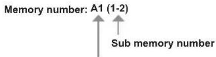
Memory number: A1 (1-2)
↑
Sub memory number
When the address number (A1, A2, ... L7, L8) signal is registered
- A name can be set for each sub memory (→ page 129).
Registering new signals
After a new signal is input and the
- Up to 96 signals, including sub memories, can be registered to the projector.
- There are 12 pages (eight memories of A through L, with eight memories possible on each page) for memory numbers, and the signal is registered to the lowest number that is available. If there is no available memory number it will be overwritten from the oldest signal.
- The names to be registered are automatically determined by the input signals and memory numbers.
- If a menu is being displayed, the new signals will be registered at the instant they are input.
Renaming the registered signal
Registered signals can be renamed.
1) Press ▲▼◀▶ to select the signal of which name is to be changed.
2) Press the button.
• The [REGISTERED SIGNAL STATUS] screen is displayed.
- The memory number, input terminal, input signal name, frequency, synch polarity, etc., are displayed.
- Press the
- The [REGISTERED SIGNAL DELETE] screen is displayed.
- To cancel the deletion, press the
•The selected signal will be deleted.
Note
- A registered signal can also be deleted from [REGISTERED SIGNAL DELETE] on the [REGISTERED SIGNAL SETUP] screen.
Protecting the registered signal
1) Press ▲▼◀▶ to select the signal to protect.
2) Press the button.
- The [REGISTERED SIGNAL STATUS] screen is displayed.
3) Press the button.
- The [REGISTERED SIGNAL SETUP] screen is displayed.
4) Press ▲▼ to select [LOCK].
5) Press ◀▶ to switch the item.
- The items will switch each time you press the button.
[OFF] The signal is not protected.
[ON] The signal is protected.
Note
- When [LOCK] is set to [ON], signal deletion, image adjustment, and automatic setup are not available. To perform these operations, set [LOCK] to [OFF].
- A signal can be registered to the sub memory even if it is protected.
- Even a protected signal will be deleted if [INITIALIZE] is executed.
Expanding signal lock-in range
1) Press ▲▼◀▶ to select the signal to set.
2) Press the button.
- The [REGISTERED SIGNAL STATUS] screen is displayed.
3) Press the button.
- The [REGISTERED SIGNAL SETUP] screen is displayed.
4) Press ▲▼ to select [LOCK-IN RANGE].
5) Press ◀▶ to switch the item.
- The items will switch each time you press the button.
[NARROW] Select in most cases.
[WIDE] Widens the lock-in range.
Note
- Switch the range that determines that a signal to be input is the same signal that is already registered.
- To prioritize the determination that it is the same signal that is already registered, set to the [WIDE] setting.
- Use in cases such as when the synchronizing frequency of a signal to be input has changed slightly, or multiple signal lists are registered.
- Can only be used when a signal is input from the terminal, terminal, terminal, terminal, or terminal.
- When [WIDE] is set, the image may appear distorted because a signal is determined to be the same signal even if a synchronizing frequency changes slightly.
- When a signal to be input corresponds to multiple signals set in [WIDE], a registered signal with a high memory number receives priority. Example: a signal to be input that corresponds to memory numbers A2, A4, and B1 will be determined to be B1.
- When a registration signal is deleted, the settings are also deleted.
- In an environment where multiple types of signals are input to the same terminal, signals are sometimes not determined correctly when the setting is set to [WIDE].
Sub memory
The projector has a sub memory function that can register the multiple image adjustment data, even if it is recognized as the same signal by the frequency or format of the synchronization signal source.
Use this function when you need to adjust the picture quality such as switching of the aspect ratio or white balance by the same synchronization signal source. The sub memory includes all the data that can be adjusted for each signal, such as the screen aspect ratio and data adjusted in the [PICTURE] item ([CONTRAST], [BRIGHTNESS], etc.).
Registering to the sub memory
1) Press ◀▶ on the normal screen (when the menu is not displayed).
- The sub memory registration screen is displayed if the sub memory is not registered. Proceed to Step 3).
- A list of sub memories registered to the signal currently input is displayed.
- By selecting [SUB MEMORY] in the [PROJECTOR SETUP] menu → [FUNCTION BUTTON], the button on the remote control can be used instead of ◀.
2) Press ▲▼◀▶ to select the sub memory number to register in [SUB MEMORY LIST].
3) Press the button.
- The [SIGNAL NAME CHANGE] screen is displayed.
4) Press ▲▼◀▶ to select [OK], and press the button.
- To rename the registered signal, follow the procedure in Steps 6) and 7) in "Renaming the registered signal" (→ page 127).
Switching to the sub memory
1) Press ◀▶ on the normal screen (when the menu is not displayed).
- A list of sub memories registered to the signal currently input is displayed.
2) Press ▲▼◀▶ to select the signal to switch in [SUB MEMORY LIST].
3) Press the button.
• This switches to the signal selected in Step 2).
Deleting the sub memory
1) Press ◀▶ on the normal screen (when the menu is not displayed).
- The [SUB MEMORY LIST] screen is displayed.
2) Press ▲▼◀▶ to select the sub memory to delete, and press the button on the remote control.
- The [REGISTERED SIGNAL DELETE] screen is displayed.
- To cancel the deletion, press the
3) Press the button.
•The selected sub memory will be deleted.
On the menu screen, select [SECURITY] from the main menu, and select an item from the submenu.
Refer to "Navigating through the menu" (→ page 65) for the operation of the menu screen.
- When the projector is used for the first time
Initial password: Press ▲▶▼◀▲▶▼◀ in order, and press the button.
• After selecting the item, press ▲▼◀▶ to set.
![PANASONIC PT-DZ870U - [SECURITY] menu - 1](/content/2026/05/813109/images/4f263d53e134a8ff7081505966f9d85026aa4edae4f361385d1cebec93ef2c86.jpg)
text_image
MENU
LENS
SHUTTER
ENTER
ON
SCREEN
INPUT SELECT
TEST
PATTERN
RGB 1/2
Differential
LINK
DVD
VIDEO
SDI
HDMI
FUNCTION
STATUS
DEFAULT
Attention
- When you select the [SECURITY] menu and press the button, entering a password is required. Enter the preset password and then continue operations of the [SECURITY] menu.
- When the password has been changed previously, enter the changed password, and press the button.
Note
- The entered password is displayed with*marks on the screen.
- An error message is displayed on the screen when the entered password is incorrect. Re-enter the correct password.
[SECURITY PASSWORD]
The [SECURITY PASSWORD] screen is displayed when the power is turned on. When the entered password is incorrect, the operation will be restricted to the power standby <↓> button, the button, and the (, , and ) buttons.
1) Press ▲▼ to select [SECURITY PASSWORD].
2) Press ◀▶ to switch the item.
•The items will switch each time you press the button.
[OFF] Disables the security password entry.
[ON] Enables the security password entry.
Note
- In the factory default setting of after [ALL USER DATA] in [INITIALIZE] (→ page 123) is executed, the [SECURITY PASSWORD] setting is set to [OFF].
- Change the password periodically that is hard to guess.
- The security password is enabled after setting [SECURITY PASSWORD] to [ON] and turning the switch to .
[SECURITY PASSWORD CHANGE]
Change the security password.
1) Press ▲▼ to select [SECURITY PASSWORD CHANGE].
2) Press the button.
- The [SECURITY PASSWORD CHANGE] screen is displayed.
3) Press ▲▼◀▶ and the number (<0> - <9>) buttons to set the password.
- Up to eight button operations can be set.
4) Press the button.
5) Re-enter the password for the confirmation.
6) Press the button.
Note
- The entered password is displayed with*marks on the screen.
[DISPLAY SETTING]
Overlap the security message (text or image) over the projecting image.
1) Press ▲▼ to select [DISPLAY SETTING].
2) Press ◀▶ to switch the item.
- The items will switch each time you press the button.
| [OFF] The text display is disabled. |
| [TEXT] The text display is enabled. |
| [USER LOGO] Displays the image registered by the user. |
Note
- To create/register the [USER LOGO] image, use "Logo Transfer Software" included in the supplied CD-ROM.
[TEXT CHANGE]
Change the text displayed when the text display is enabled by selecting [TEXT] in [DISPLAY SETTING].
1) Press ▲▼ to select [TEXT CHANGE].
2) Press the button.
- The [TEXT CHANGE] screen is displayed.
3) Press ▲▼◀▶ to select the text, and press the button to enter the text.
4) Press ▲▼◀▶ to select [OK], and press the button.
•The text is changed.
[CONTROL DEVICE SETUP]
Enable/disable the button operations on the control panel and the remote control.
1) Press ▲▼ to select [CONTROL DEVICE SETUP].
2) Press the button.
- The [CONTROL DEVICE SETUP] screen is displayed.
3) Press ▲▼ to select [CONTROL PANEL] or [REMOTE CONTROL].
| [CONTROL PANEL] You can set the limitation on the control from the control panel. |
| [REMOTE CONTROL] You can set the limitation on the control from the remote control. |
4) Press the button.
- The [CONTROL PANEL] screen or the [REMOTE CONTROL] screen is displayed.
5) Press ▲▼ to select [CONTROL PANEL] or [REMOTE CONTROL].
6) Press ◀▶ to switch the item.
- You can set the operation restriction from the control panel or the remote control.
| [ENABLE] Enables all | button operations. |
| [DISABLE] Disables all | button operations. |
| [USER] | Operation of all buttons can be enabled/disabled separately.Refer to “Enabling/disabling any button” (⇨ page 131) for details. |
7) Press ▲▼ to select [APPLY], and press the button.
•The confirmation screen is displayed.
8) Press ◀▶ to select [OK], and press the button.
1) Press ▲▼ to select [CONTROL DEVICE SETUP].
- The [CONTROL DEVICE SETUP] screen is displayed.
3) Press ▲▼ to select [CONTROL PANEL] or [REMOTE CONTROL].
5) Press ▲▼ to select [CONTROL PANEL] or [REMOTE CONTROL].
6) Press ◀▶ to switch [USER].
- When [INPUT SELECT BUTTON] is selected, press the button, and then press ▲▼ to select the button to set.
| Buttons that can be set |
| [CONTROL PANEL] [REMOTE CONTROL] |
| [POWER BUTTON] | Power standby <∅> button, power on <|> button |
| [INPUT SELECT BUTTON] | button, , button, , button, , button, , button, , button, , button, , button, , button, , button, , button, , button, , button, , button, , button, , button, , button, , button, , button, , button, , button, , button, , button, , button, , button, , button, , button, , button, , button, , button, , button, , button, , button, , button, , button | button, or button, , button, , button, , button, , button, , button, , button, , button, , button, , button, , button, , button, , button, , button, , button, , button, , button, , button, , button, , button, , button, , button, , button, , button, , button, , button, , button, , button, , button, , button, , button, , button, , button, , buttons, , buttons, , buttons, , buttons, , buttons, , buttons, , buttons, , buttons, , buttons, , buttons, , buttons, , buttons, , buttons, , buttons, , buttons, , buttons, , buttons, , buttons, , buttons, , buttons, , buttons, , buttons, , buttons, , buttons, , buttons, , buttons, , buttons, , buttons, , buttons, , buttons, , buttons, , buttons, , buttons, , buttons |
| [MENU BUTTON]button |
| [LENS BUTTON]button Lens (,, ) button |
| [AUTO SETUP BUTTON]button |
| [SHUTTER BUTTON]button |
| [ON SCREEN BUTTON] —button | |
| [OTHER BUTTON]▲▼▶,buttonButtons not listed above | button |
*1 Only for PT-DZ870U
8) Press ◀▶ to switch the item.
| [ENABLE] Enables button operations. |
| [DISABLE] | Disables button operations. |
- The following items are available only when [RGB1/2 BUTTON] of [INPUT SELECT BUTTON] is selected.
| [TOGGLE] | Switches between RGB1 and RGB2 when the button is operated. |
| [RGB1] | Fixes to RGB1. |
| [RGB2] | Fixes to RGB2. |
| [DISABLE] | Disables button operations. |
- When [INPUT SELECT BUTTON] is selected in Step 7), and after the item is switched, press the
- When a button operation is performed on the device set to [DISABLE], the [CONTROL DEVICE PASSWORD] screen is displayed. Enter the control device password.
- The [CONTROL DEVICE PASSWORD] screen will disappear when there is no operation for approx. 10 seconds.
- If the operations of both [CONTROL PANEL] and [REMOTE CONTROL] are set to [DISABLE], the projector cannot be turned off (cannot enter standby).
- When the setting has completed, the menu screen will disappear. To operate continuously, press the
- Even when button operation on the remote control is disabled, operation of the button on the remote control is enabled.
[CONTROL DEVICE PASSWORD CHANGE]
The control device password can be changed.
1) Press ▲▼ to select [CONTROL DEVICE PASSWORD CHANGE].
2) Press the button.
- The [CONTROL DEVICE PASSWORD CHANGE] screen is displayed.
3) Press ▲▼◀▶ to select the text, and press the button to enter the text.
4) Press ▲▼◀▶ to select [OK], and press the button.
• To cancel, select [CANCEL].
Attention
- The initial password is "AAAA" by the factory default or when [ALL USER DATA] in [INITIALIZE] (→ page 123) is executed.
- Change the password periodically that is hard to guess.
On the menu screen, select [NETWORK] from the main menu, and select an item from the submenu.
Refer to "Navigating through the menu" (→ page 65) for the operation of the menu screen.
• After selecting the item, press ▲▼◀▶ to set.
![PANASONIC PT-DZ870U - [NETWORK] menu - 1](/content/2026/05/813109/images/7235662ad75141aa94c7cb5d079128a9ac27a1dd32a818dd52344999640f7552.jpg)
text_image
MENU
LENS
SHUTTER
ENTER
ON SCREEN
DATA INPUT/RESET
DATA OUTPUT
RGB 1/2
DIGITAL LINK
DVD
VIDEO
SDI
HDMI
FUNCTION
STATUS
DEFAULT
[DIGITAL LINK MODE]
Switch the communication method of the terminal of the projector.
1) Press ▲▼ to select [DIGITAL LINK MODE].
2) Press ◀▶ to switch the item.
•The items will switch each time you press the button.
| [AUTO] Switches the communication method automatically to DIGITAL LINK or Ethernet. |
| [DIGITAL LINK] Fixes the communication method to DIGITAL LINK. |
| [ETHERNET] Fixes the communication method to Ethernet. |
Possible communication modes
| Setting | Communication possible |
| Image transmission Ethernet RS-232C | |
| [AUTO] | For DIGITAL LINK | √√√ | | |
| For Ethernet — | | √ | — |
| [DIGITAL LINK] | √√√ | | |
| [ETHERNET] — | | √ | — |
√: Communication possible
—: Communication not possible
[DIGITAL LINK SETUP]
Set the communication method of DIGITAL LINK.
When the projector is connected directly via Ethernet
1) Press ▲▼ to select [DIGITAL LINK SETUP].
2) Press the button.
• The [DIGITAL LINK SETUP] screen is displayed.
3) Press ▲▼ to select [DUPLEX(ETHERNET)].
4) Press ◀▶ to switch the communication method.
•The items will switch each time you press the button.
| [AUTONEGOTIATION] The | communication method is set automatically. |
| [100BaseTX-Full] Full duplex communication method is set. |
| [100BaseTX-Half] | Half-duplex communication method is set. |
5) Press ▲▼ to select [STORE].
6) Press the button.
134 - ENGLISH
7) When the confirmation screen is displayed, press ◀▶ to select [OK], and press the button.
Note
- The projector does not support 10BaseT Full/Half.
When the projector is connected to a twisted-pair-cable transmitter
1) Press ▲▼ to select [DIGITAL LINK SETUP].
2) Press the button.
- The [DIGITAL LINK SETUP] screen is displayed.
3) Press ▲▼ to select [DUPLEX(DIGITAL LINK)].
4) Press ◀▶ to switch the communication method.
- The items will switch each time you press the button.
| [100BaseTX-Full] Full duplex communication method is set. |
| [100BaseTX-Half] Half-duplex communication method is set. |
| [AUTONEGOTIATION] The communication method is set automatically. |
5) Press ▲▼ to select [STORE].
6) Press the button.
7) When the confirmation screen is displayed, press ◀▶ to select [OK], and press the button.
[DIGITAL LINK STATUS]
Display DIGITAL LINK connection environment.
1) Press ▲▼ to select [DIGITAL LINK STATUS].
2) Press the button.
- The [DIGITAL LINK STATUS] screen is displayed.
| [LINK STATUS] Either [NO LINK], [DIGITAL LINK], or [ETHERNET] is displayed. |
| [HDCP STATUS] Either [NO SIGNAL], [OFF], or [ON] is displayed. |
| [SIGNAL QUALITY] | [SIGNAL QUALITY] is a numerical value of the amount of error, and the display color changes to green, yellow, or red depending on that value.Check the signal quality level while receiving a signal from the twisted-pair-cable transmitter.MAX/MIN: Maximum/minimum value of the amount of error.Green (-12 dB or lower) → Normal signal quality level.Yellow (-11 to -8 dB) → Warning level where there is the possibility of noise introduced on the screen.Red (-7 dB or higher) → Abnormal level where synchronization may be interrupted, or a signal may not be received. |
[NETWORK SETUP]
Perform the initial setting of the network before using the network function.
1) Press ▲▼ to select [NETWORK SETUP].
2) Press the button.
- The [NETWORK SETUP] screen is displayed.
3) Press ▲▼ to select an item, and change the settings according to the operation instructions of the menu.
| [PROJECTOR NAME] Change the setting when using a DHCP server. |
| [DHCP] | Set to [ON] when obtaining an IP address automatically using a DHCP server. Set to [OFF] when not using a DHCP server. |
| [IP ADDRESS] Enter the IP address when not using a DHCP server. |
| [SUBNET MASK] Enter the subnet mask when not using a DHCP server. |
| [DEFAULT GATEWAY] Enter the default gateway address when not using a DHCP server. |
| [STORE] Save the current network settings. |
4) Press ▲▼ to select [STORE], and press the button.
5) When the confirmation screen is displayed, press ◀▶ to select [OK], and press the button.
Note
- When using a DHCP server, confirm that the DHCP server is running.
- Consult your network administrator regarding the IP address, subnet mask, and default gateway.
[NETWORK CONTROL]
Set up the control method of the network.
1) Press ▲▼ to select [NETWORK CONTROL].
2) Press the button.
- The [NETWORK CONTROL] screen is displayed.
3) Press ▲▼ to select an item, and press ◀▶ to change the setting.
| [WEB CONTROL] Set to | [ON] to control with the web browser. |
| [PJLink CONTROL] Set to | [ON] to control with the PJLink protocol. |
| [COMMAND CONTROL] | Set to [ON] to control with the/terminal control command format (⇨ page 175). Refer to “Control commands via LAN” (⇨ page 170). |
| [COMMAND PORT] Set the | port number used for command control. |
| [CRESTRON RoomView] Set | to [ON] to control with RoomView of Crestron Electronics, Inc. |
| [AMX D.D.] | Set to [ON] to control with the controller of AMX Corporation.Setting this function to [ON] enables detection through “AMX Device Discovery”. For details, refer to the website of AMX Corporation.URL http://www.amx.com/ |
| [EXTRON XTP] | Set to [ON] when connecting the “XTP transmitter” of Extron Electronics to theterminal.The [EXTRON XTP] setting must be set to [OFF] when connecting the optional Digital Interface Box (Model No.: ET-YFB100G).For details of the “XTP transmitter”, refer to the website of Extron Electronics.URL http://www.extron.com/ |
| [STORE] Save the current network control settings. |
4) Press ▲▼ to select [STORE], and press the button.
5) When the confirmation screen is displayed, press ◀▶ to select [OK], and press the button.
[NETWORK STATUS]
Display the status of the projector network.
1) Press ▲▼ to select [NETWORK STATUS].
2) Press the button.
- The [NETWORK STATUS] screen is displayed.
[DIGITAL INTERFACE BOX]
When the optional Digital Interface Box (Model No.: ET-YFB100G) is connected to the terminal, the main menu of ET-YFB100G is displayed. Refer to the Operating Instructions of ET-YFB100G for details.
Note
- When [EXTRON XTP] is set to [ON], [DIGITAL INTERFACE BOX] cannot be selected.
- The operation guidance for the "RETURN" button is displayed on the menu screen of the Digital Interface Box. The projector does not have the "RETURN" button, but same operation is available with the
[Art-Net SETUP]
Settings to use the Art-Net function is executed.
1) Press ▲▼ to select [Art-Net SETUP].
2) Press the button.
- The [Art-Net SETUP] screen is displayed.
3) Press ▲▼ to select an item.
| [Art-Net] | Sets to [ON] when the Art-Net function is used. Sets to [OFF] when the Art-Net function is not used. |
| [PORT ADDRESS] Inputs | a port address that the projector processes Art-Net. |
| [START ADDRESS] Inputs | a start address that the projector processes Art-Net. |
4) Press ◀▶ to switch the setting.
5) Press ▲▼ to select [STORE], and press the button.
6) When the confirmation screen is displayed, press ◀▶ to select [OK], and press the button.
Network connections
The projector has a network function, and the following operations are available from the computer using the web control.
- Setting and adjustment of the projector
•Display of the projector status
- Sending of E-mail messages when there is a problem with the projector
The projector supports "Crestron RoomView", and the following application software of Crestron Electronics, Inc. can be used.
•RoomView Express
•Fusion RV
•RoomView Server Edition
Attention
- When a LAN cable is directly connected to the projector, the network connection must be made indoors.
Note
- "Crestron RoomView" is a system of Crestron Electronics, Inc. that collectively manages and controls devices on multiple systems connected to a network using a computer.
- For details of "Crestron RoomView", refer to the website of Crestron Electronics, Inc. (English only)
URL http://www.crestron.com
To download "RoomView Express", go to the following website of Crestron Electronics, Inc. (English only)
URL http://www.crestron.com/getroomview
- A LAN cable is required to use the network function.
■Example of a normal network connection
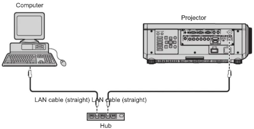
flowchart
graph TD
    A["Computer"] -->|LAN cable (straight)| B["Hub"]
    C["Projector"] -->|LAN cable (straight)| B["Hub"]
- A web browser is required to use this function. Confirm that the web browser can be used beforehand.
Compatible OS: Windows XP/Windows Vista/Windows 7/Windows 8, Mac OS X v10.4/v10.5/v10.6/v10.7/v10.8
Compatible browser: Internet Explorer 7.0/8.0/9.0/10.0, Safari 4.0/5.0/6.0 (Mac OS)
- Communication with an E-mail server is required to use the E-mail function. Confirm that the E-mail can be used beforehand.
- Use a LAN cable that is compatible with category 5 or higher.
- Use a LAN cable of 100 m (328'1") or shorter.
Connecting to a twisted-pair-cable transmitter
The projector has a function that can receive Ethernet signals from a twisted-pair-cable transmitter together with video and audio signals via a LAN cable. Connect a LAN cable to the terminal of the projector. (▶ pages 18, 28)
■Example of network connections via a twisted-pair-cable transmitter
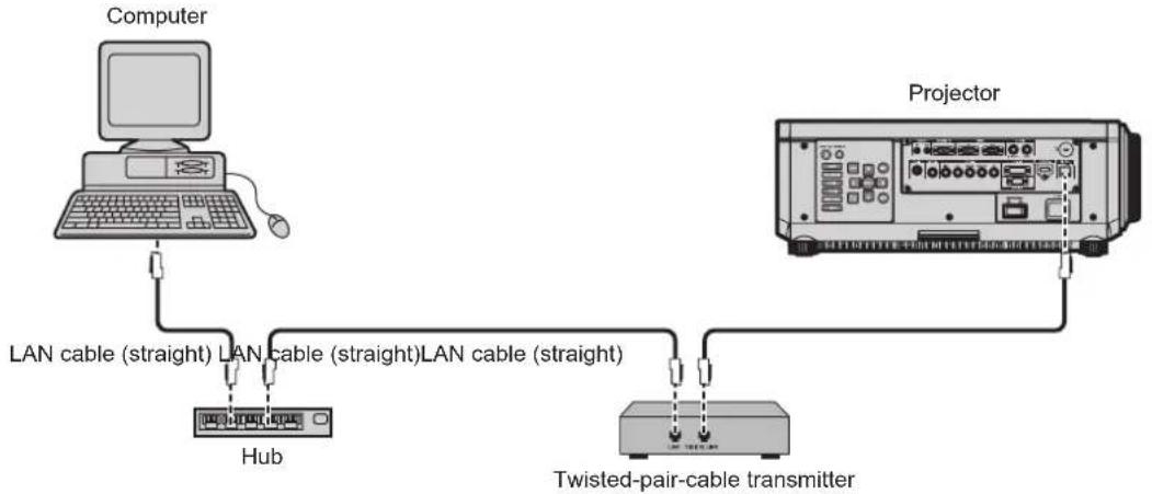
flowchart
graph TD
    A["Computer"] -->|LAN cable (straight)| B["Hub"]
    B -->|LAN cable (straight) | C["Projector"]
    C -->|LAN cable (straight) | D["Twisted-pair-cable transmitter"]
- For the LAN cable between a twisted-pair-cable transmitter and the projector, use a cable that meets the following criteria:
-Compatible with CAT5e or higher
-Shielded type (including connectors)
-Straight-through
-Single wire
- The maximum transmission distance between the twisted-pair-cable transmitter and the projector is 100 m (328'1"). If this distance is exceeded, image may be disrupted and may cause a malfunction in LAN communication.
- When laying cables between a twisted-pair-cable transmitter and the projector, check that cable characteristics are compatible with CAT5e or higher using tools such as a cable tester or cable analyzer.
When using a relay connector midway, include it in the measurement.
- Do not use a hub between a twisted-pair-cable transmitter and the projector.
- Do not pull cables forcefully. Also, do not bend or fold cables unnecessarily.
- To reduce the effects of noise as much as possible, stretch out the cables between the twisted-pair-cable transmitter and the projector without any loops.
- Lay the cables between a twisted-pair-cable transmitter and the projector away from other cables, particularly power cables.
- When installing multiple cables, run them side by side along the shortest distance possible without bundling them together.
- After laying the cables, confirm that the value of [SIGNAL QUALITY] in the [NETWORK] menu → [DIGITAL LINK STATUS] is displayed in green (indicates normal quality). (→ page 135)
- For twisted-pair-cable transmitter of other manufacturers of which the operation has been verified with the DIGITAL LINK compatible projector, refer to Panasonic website (http://panasonic.net/avc/projector/). Note that the verification for devices of other manufacturers has been made for the items set by Panasonic Corporation, and not all the operations have been verified. For operation or performance problems caused by the devices of other manufacturers, contact the respective manufacturers.
Accessing from the web browser
1) Start up the web browser on the computer.
2) Enter the IP address set on the projector into the URL entry field of the web browser.
3) Enter the user name and the password.
- The factory default setting of the user name is user1 (user rights)/admin1 (administrator rights) and the password is panasonic (lower case).
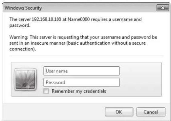
text_image
Windows Security
The server 192.168.10.100 at Name0000 requires a username and password.
Warning: This server is requesting that your username and password be sent in an insecure manner (basic authentication without a secure connection).
User name
Password
Remember my credentials
OK Cancel
4) Click OK.
•The [Projector status] page is displayed.
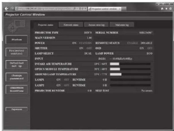
text_image
Projector Control Window
Projector status Network status Access error log Mail error log
PROJECTOR TYPE D/F/B SERIAL NUMBER SHL134567
MAIN VERSION 1.00
POWER ON STANDY REMOTED STATUS ENABLE DISABLE
SHUTTER ON OFF ON ON OFF
LAMP SELECT DUAL LAMP POWER ECO
INPUT RGB1 - (40MHz/80MHz)
INTAKE AIR TEMPERATURE 1PC / 64T
OPTICS MODULE TEMPERATURE 2PC / 68T
AROUND LAMP TEMPERATURE 2PC / 77T
LAMP1 ON OUT RUNTIME 0 H
LAMP2 ON OUT RUNTIME 0 H
PROJECTOR RUNTIME 0 H SELF TEST No errors
Status
Projector control
Detailed net up
Change password
CRESSION RUNTIME
Sequence
Note
- If you use a web browser to control the projector, set [WEB CONTROL] to [ON] in [NETWORK CONTROL] (→ page 136).
- Do not perform setting or control simultaneously by starting up multiple web browsers. Do not set or control the projector from multiple computers.
- Change the password first. (→ page 152)
- The administrator rights allow use of all functions. The user rights allow use of [Projector status] (→ page 140), confirmation of the error information page (→ page 141), [Network status] (→ page 142), [Basic control] (→ page 143), and [Change password] (→ page 152) only.
- Access will be locked for few minutes when an incorrect password is entered three times consecutively.
- Some items on the projector setting page use the Javascript function of the web browser. The projector may not be able to be controlled properly if it is set with a browser that does not have this function enabled.
- If the screen for the web control is not displayed, consult your network administrator.
- While updating the screen for the web control, the screen may become white for a moment, but it is not a malfunction.
Descriptions of items

text_image
Projector Control Window
Projector name Network status Active error log Mail error log
PROJECTOR TYPE D278 SERIAL NUMBER SH115456?
MAIN VERSION 1.00
POWER ON SLANDS REMOTE2 STATUS ENABLE DISABLE
MUTTER ON OFF QSD ON OFF
LAMP SELECT DUAL LAMP POWER ICO
INPUT RGB1 - (0.00Hz/0.00Hz)
EQUITY METER TEMPERATURE 25°C / OFF
OPTICS MODULE TEMPERATURE 20°C / OFF
AROUND LAMP TEMPERATURE 15% / OFF
LAMP1 ON OFF RUNTIME 0 H
LAMP2 ON OFF RUNTIME 0 H
CREATION
RunTime PROJECTION RUNTIME 9.0 SELF END No errors
Parameters
1 Page tab
Switches pages by clicking this item.
2 [Status]
The status of the projector is displayed by clicking this item.
3 [Projector control]
The [Projector control] page is displayed by clicking this item.
4 [Detailed set up]
The [Detailed set up] page is displayed by clicking this item.
5 [Change password]
The [Change password] page is displayed by clicking this item.
6 [CRESTRON RoomView]
The control page of RoomView is displayed by clicking this item.
[Projector status] page
Click [Status] → [Projector status].
Display the status of the projector for the following items.
![PANASONIC PT-DZ870U - [Projector status] page - 1](/content/2026/05/813109/images/9c568de5443cc8be014f71394f3530a57af73cb0265f3e83b1af8df92ff28ecd.jpg)
text_image
Projector Control Window
Projector control window
Projector control window
Projector control window
Projector control window
Projector control window
Projector control window
Projector control window
Projector control window
Projector control window
Projector control window
Projector control window
Projector control window
Projector control window
Projector control window
Projector control window
Projector control window
Projector control window
Projector control window
Projector control window
Projector control window
Projector control room
Projector control room
Projector control room
Projector control room
Projector control room
Projector control room
Projector control room
Projector control room
Projector control room
Projector control room
Projector control room
Projector control room
Projector control room
Projector control room
Projector control room
Projector control room
Projector control room
Projector control room
Projector control room
Projector control room
Projector control rooms
Projector control rooms
Projector control rooms
Projector control rooms
Projector control rooms
Projector control rooms
Projector control rooms
Projector control rooms
Projector control rooms
Projector control rooms
Projector control rooms
Projector control rooms
Projector control rooms
Projector control rooms
Projector control rooms
Projector control rooms
Projector control rooms
Projector control rooms
Projector control rooms
Projector control rooms
Projector control room
Projector control room
Projector control room
Projector control room
Projector control room
Projector control room
Projector control room
Projector control room
Projector control room
Projector control room
Projector control room
Projector control room
Projector control room
Projector control room
Projector control room
Projector control room
Projector control room
Projector control room
Projector control room
Projector controlRoom
Projector controlRoom
Projector controlRoom
Projector controlRoom
Projector controlRoom
Projector controlRoom
Projector controlRoom
Projector controlRoom
Projector controlRoom
Projector controlRoom
Projector controlRoom
Projector controlRoom
Projector controlRoom
Projector controlRoom
Projector controlRoom
Projector controlRoom
Projector controlRoom
Projector controlRoom
Projector controlRoom
Projector controlRoom
Projector controlRumTime
1 [PROJECTOR TYPE]
Displays the type of the projector.
2 [MAIN VERSION]
Displays the firmware version of the projector.
3 [POWER]
Displays the status of the power.
4 [SHUTTER]
Displays the status of the shutter (ON: closed, OFF: open).
5 [LAMP SELECT]
Displays the setting status of [LAMP SELECT] (→ page 109).
6 [SERIAL NUMBER]
Displays the serial number of the projector.
7 [REMOTE2 STATUS]
Displays the control status of the terminal.
8 [OSD]
Displays the status of the on-screen display.
9 [LAMP POWER]
Displays the setting status of [LAMP POWER] (→ page 111).
10 [INPUT]
Displays the status of the selected input.
11 [INTAKE AIR TEMPERATURE]
Displays the status of the air intake temperature of the projector.
12 [OPTICS MODULE TEMPERATURE]
Displays the status of the internal temperature of the projector.
13 [AROUND LAMP TEMPERATURE]
Displays the status of the temperature around the lamp of the projector.
14 [LAMP1], [LAMP2], [RUNTIME]
Displays the status and the runtime (converted value) of the lamp.
15 [SELF TEST]
Displays the self-diagnosis information.
16 [PROJECTOR RUNTIME]
Displays the runtime of the projector.
Error information page
When [Error (Detail)] or [Warning (Detail)] is displayed in the self-diagnosis display of the [Projector status] screen, click it to display the error/warning details.
- The projector may go into the standby status to protect the projector depending on the contents of the error.
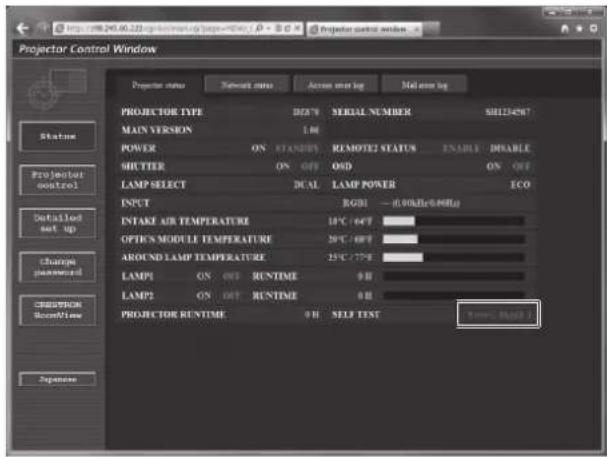
text_image
Projector Control Window
Projector status
Network status
Across over log
Mid over log
PROJECTOR TYPE
DIGN
SERIAL NUMBER
SH124967
MAIN VERSION
1.00
POWER ON STANDERS REMOTE2 STATUS ENABLE DISABLE
SHUTTER ON OFF OSD ON OFF
LAMP SELECT DUAL LAMP POWER ECO
INPUT RGB1 - 0.00Hz/0.0MHz
INTAKE AIR TEMPERATURE 18°C /60°F
OPTICS MODULE TEMPERATURE 20°C /60°F
AROUND LAMP TEMPERATURE 25°C /72°F
LAMP1 ON OUT RUNTIME 0 H
LAMP2 ON OUT RUNTIME 0 H
PROJECTOR RUNTIME 0 H SELF TEXT
Save BackUp
Projection
Status
Projected control
Detailed set up
Change password
STRUCTION
RunTime
Sequence
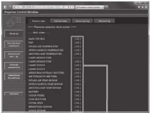
text_image
Projector Control Window
Projector status
Current status
Access viewing
Back view log
Panasonic projector check system
check system
MAIN CPU BCS
FAN
INTAKE AIR TEMPERATURES
OPTICS MODULE TEMPERATURES
AROUND LAMP TEMPERATURES
LAMP1 ESMAIN TIME
LAMP2 REMAIN TIME
LAMP3 STATUS
LAMP4 STATUS
APERTURE(CONTRAST SHUTTER)
SHUTTER(NUTY-SHUTTER)
INTAKE AIR TEMP SENSOR
OPTICS MODULE TEMP SENSOR
AROUND LAMP TEMP SENSOR
BATTERY
COLOR WHEEL
LENS MOUNTER
COPPER OPEN
DRIGHTNESS SENSOR
ANGLE SENSOR
[OK]
[OK]
[OK]
[OK]
[OK]
[OK]
[OK]
[OK]
1
1 Self-diagnosis result display
Displays the item check results.
[OK]:
Indicates that operation is normal.
[FAILED]:
Indicates that there is a problem.
[WARNING]:
Indicates that there is a warning.
■[FAILED] items
| Parameter Description | |
| [MAIN CPU BUS] There is a problem with the microcomputer circuitry. Consult your dealer. |
| [FAN] There is a problem with the fan or the fan drive circuit. Consult your dealer. |
| [INTAKE AIR TEMPERATURE] | The air intake temperature is too high. The projector may be used in an environment where the temperature is high, such as near a heating appliance. |
| [OPTICS MODULE TEMPERATURE] | The temperature around the optics module inside the projector is high. The projector may be used in an environment where the temperature is high, such as near a heating appliance. |
| [AROUND LAMP TEMPERATURE] The temperature around the lamp is high. The air exhaust port may be blocked. |
| [LAMP1 REMAIN TIME] The runtime of the lamp has exceeded the specified time, and it is time to replace the lamp. |
| [LAMP2 REMAIN TIME] | |
| [LAMP1 STATUS] The lamp has failed to turn on. Wait a while until the luminous lamp cools off, and then turn on the power. |
| [LAMP2 STATUS] | |
| [APERTURE(CONTRAST-SHUTTER)] There is a problem in the contrast shutter circuit for dynamic iris. Consult your dealer. |
| [SHUTTER(MUTE-SHUTTER)] There is a problem with the shutter circuitry. Consult your dealer. |
| [INTAKE AIR TEMP.SENSOR] | There is a problem with the sensor used to detect intake temperature. Consult your dealer. |
| [OPTICS MODULE TEMP.SENSOR] | There is a problem with the sensor used to detect temperature inside the projector. Consult your dealer. |
| [AROUND LAMP TEMP.SENSOR] | There is a problem with the sensor used to detect exhaust air temperature. Consult your dealer. |
| [BATTERY] | Battery replacement is required. Consult your dealer. |
| [COLOR WHEEL] | There is a problem with the color wheel or the color wheel drive circuit. Consult your dealer. |
| [LENS MOUNTER] | There is a problem in the lens mounter. Consult your dealer. |
| [COVER OPEN] | Installation of the lamp unit cover is incomplete. Check the installation of the lamp unit cover. ( page 162) |
| [BRIGHTNESS SENSOR] | There is a problem with the luminance sensor. If problems persist even after switching on the power, consult your dealer. |
| [ANGLE SENSOR] | There is a problem with the sensor that detects angle. Consult your dealer. |
| [AIR FILTER CASE] | The air filter case is not attached. Check the attachment of the air filter unit. ( page 160) |
Chapter 4 Settings — [NETWORK] menu
| Parameter Description | |
| [AIR FILTER] | There is too much dust accumulated in the air filter. Turn theswitch(⇨ page 57), and clean the air filter. (⇨ page 160) |
■[WARNING] items
| Parameter Description | |
| [AC POWER] | AC input voltage is weak. Use electric wiring that can sufficiently withstand the power consumption of the projector. |
| [LOW-TEMPERATURE] | The temperature around the optics module inside the projector is low. Projection cannot be started until the optics module becomes warm. |
| [HORIZONTAL TILT] | The projector is used tilting at an angle that exceeds 15° from the horizontal plane.When using the Replacement lamp unit (for portrait mode), install the projector with the terminals surface facing down. |
| [LIGHT OUTPUT LIMIT] | The projector may be used in an environment where the temperature is high. The light output is reduced by approx. 20 % to protect the projector. |
| [LAMP MIX] The Replacement lamp unit (for portrait mode) and normal lamp unit are mixed. |
[Network status] page
Click [Status] → [Network status].
The current network setting status is displayed.
![PANASONIC PT-DZ870U - [Network status] page - 1](/content/2026/05/813109/images/f950099da9081ad8e246cf1580f2082ee813b91dc7040cbfc429c3bd3a58661a.jpg)
text_image
Projector Control Window
Projector status Network status Access error log Mail error log
Status
Projector control
Detailed net up
Change password
CHINAION
Rackflow
Sequence
DBCP OFF IP ADDRESS 192.168.03.109
SUBNET MASK 255.255.255.0 DEFAULT GATEWAY 192.168.10.1
MAC ADDRESS 78.58-12-00-00:00
[Access error log] page
Click [Status] → [Access error log].
The error log on the web server is displayed such as access to the pages that do not exist or access with unauthorized user names or passwords.
![PANASONIC PT-DZ870U - [Access error log] page - 1](/content/2026/05/813109/images/c0e489dd3cced24d2bb9a5d1054e9fdf51861065db00b1361e53c280896b9f7a.jpg)
text_image
http://164.245.80.223log.html/164.245.80.224
Projector partial server log
Property status
Server status
Access error log
Main error log
Web server error log
[Sun Wed 06 04:18:09 2014] [user][Tclamers 100-245-24.224] [FormA00001 *]
[Mail error log] page
Click [Status] → [Mail error log].
Display E-mail error information if failed to send periodic E-mails.
![PANASONIC PT-DZ870U - [Mail error log] page - 1](/content/2026/05/813109/images/a4338cc6fc88c2b5c602949704f2685a094bfc5fddec9aaa20bb9c79e6fb02f7.jpg)
text_image
Projector Control Window
Projector status
Network status
Active error log
Mail error log
Status
Projector control
Detailed set-up
Change password
CREPROM BoomFlow
Zagosome
[Use Dev 10.051813 2012][Mail delivery;EATRS CONNECTION: EBITR SEAVES : Paramount projector report]
Note
- [Access error log] and [Mail error log] display the recent few thousand accesses/requests. All information may not be displayed when many accesses/requests are made at one time.
- When [Access error log] and [Mail error log] exceeds a certain amount, older information is erased.
- Check [Access error log] and [Mail error log] periodically.
[Basic control] page
Click [Projector control] → [Basic control].
![PANASONIC PT-DZ870U - [Basic control] page - 1](/content/2026/05/813109/images/3444360d47efa6b5b5a00abcb10d8b1d02367810debebee0a12031e32bd670cb.jpg)
text_image
Projector Control Window
Projector control window
Projector Control Window
Projector Control Window
Projector Control Window
Projector Control Window
Projector Control Window
Projector Control Window
Projector Control Window
Projector Control Window
Projector Control Window
Projector Control Window
Projector Control Window
Projector Control Window
Projector Control Window
Projector Control Window
Projector Control Window
Projector Control Window
Projector Control Window
Projector Control Window
Projector Control Window
Projector Control Window
Projector Control Panel
Projector Control Panel
Projector Control Panel
Projector Control Panel
Projector Control Panel
Projector Control Panel
Projector Control Panel
Projector Control Panel
Projector Control Panel
Projector Control Panel
Projector Control Panel
Projector Control Panel
Projector Control Panel
Projector Control Panel
Projector Control Panel
Projector Control Panel
Projector Control Panel
Projector Control Panel
Projector Control Panel
Projector Control Panel
Projector Control Table1
Projector Control Table2
Projector Control Table3
Projector Control Table4
Projector Control Table5
Projector Control Table6
Projector Control Table7
Projector Control Table8
Projector Control Table9
Projector Control Table10
Projector Control Table11
Projector Control Table12
Projector Control Table13
Projector Control Table14
Projector Control Table15
Projector Control Table16
Projector Control Table17
Projector Control Table18
Projector Control Table19
Projector Control Table20
Projector Control Table21
Projector Control Table22
Projector Control Table23
Projector Control Table24
Projector Control Table25
Projector Control Table26
Projector Control Table27
Projector Control Table28
Projector Control Table29
Projector Control Table30
Projector Control Table31
Projector Control Table32
Projector Control Table33
Projector Control Table34
Projector Control Table35
Projector Control Table36
Projector Control Table37
Projector Control Table38
Projector Control Table39
Projector Control Table40
Projector Control Table41
Projector Control Table42
Projector Control Table43
Projector Control Table44
Projector Control Table45
Projector Control Table46
Projector Control Table47
Projector Control Table48
Projector Control Table49
Projector Control Table50
Projector Control Table51
Projector Control Table52
Projector Control Table53
Projector Control Table54
Projector Control Table55
Projector Control Table56
Projector Control Table57
Projector Control Table58
Projector Control Table59
Projector Control Table60
Projector Control Table61
Projector Control Table62
Projector Control Table63
Projector Control Table64
Projector Control Table65
Projector Control Table66
Projector Control Table67
Projector Control Table68
Projector Control Table69
Projector Control Table70
Projector Control Table71
Projector Control Table72
Projector Control Table73
Projector Control Table74
Projector Control Table75
Projector Control Table76
Projector Control Table77
Projector Control Table78
Projector Control Table79
Projector Control Table80
1 [POWER]
Turns on/off the power.
2 [SHUTTER]
Switches the setting whether to use the shutter function (closing/opening of the shutter).
3 [OSD]
Switches on (display)/off (hide) the on-screen display function.
4 [SYSTEM]
Switches the system method.
5 On-screen display of the projector
Displays the same items as shown on the on-screen display of the projector. You can check or change the settings of the menus. It is displayed even if the on-screen display function is set to off (hide).
6 [INPUT SELECT]
Switches the input signal.
[Detail control] page
Click [Projector control] → [Detail control].
![PANASONIC PT-DZ870U - [Detail control] page - 1](/content/2026/05/813109/images/22fe7984b8048f0ca76c76728296e3a65258ff9ebace7069f99a5b67649d2de9.jpg)
text_image
Projector Control Window
Power
SETTER
GSD
SYSTEM
INPUT AUDI
BIO SIGNAL
PROFESSION
ADVERTED MENU
DISPLAY LANGUAGE
TO RESPOND
DISPLAY WINDOW
PROFESSION REDUCE
TIP P
TEXT PATTERN
RICAL LIGHT
REQUENCY
A NEW SELECT
NEW MENU
SUB MEMORY
SELECT SWITCH
PRESS SWITCH RUN
LEFT
P B P
LEFT RIGHT SWAP
LEFT FLOWER
P B P
GET OSG
Status
Projection control
Defaulted set up
Change
Imped by
1 2 3 4 5 6 7 8 9 10
1 Control of the projector
The projector is controlled by clicking the buttons in the same way as the buttons on the remote control. After control, the on-screen display of the projector at the right of the control page is updated.
2 [SUB MEMORY]
Switches the sub memory.
3 [SYSTEM DAYLIGHT VIEW]
Switches to system daylight view settings.
4 [FREEZE]
Temporarily pauses the image.
5 [P IN P]
Switches the P IN P setting.
6 [LEFT/RIGHT SWAP]
Switches the flip horizontal settings.
7 [WAVEFORM MONITOR]
Displays the waveform of the input signal.
8 [LENS]
Adjusts the projection lens.
9 [TEST PATTERN]
Displays the test pattern.
10 [GET OSD]
Updates the on-screen display of the projector at the right of the control page.
[Network config] page
Click [Detailed set up] → [Network config].
- Click [Network config] to display the [CAUTION!] screen.
- The current settings are displayed by pressing the [Next] button.
- Click [Change] to display the setting change screen.
![PANASONIC PT-DZ870U - [Network config] page - 1](/content/2026/05/813109/images/0a61766449c270ebb3b5374eb17bb47b3827bf07002464d3c7e30ffcefded8dd.jpg)
text_image
Projector Control Window
E-mail up
Authentication set up
Network config
About config
Flag set
Projector NAME
NAME:4787
IP
● DHCP ON
○ DHCP OUT
IP ADDRESS 192.168.0.0 [Example: 192.168.0.100]
SUBNEXT MASK 296.299.259.0 [Example: 296.299.259.0]
DEFAULT 192.168.0.0 [Example: 192.168.0.254]
DATA
DNS1: [Example: 192.168.0.100]
DNS2: [Example: 192.168.0.100]
Back Next
Projector control
Detailed web-up
Change password
CREPROM NetworkView
Expansion
1
2
3
4
5
6
7
8
1 [PROJECTOR NAME]
Enter the name of the projector. Enter the host name if it is required when using a DHCP server etc.
2 [DHCP ON], [DHCP OFF]
To enable the DHCP client function, set to [DHCP ON].
3 [IP ADDRESS]
Enter the IP address when not using a DHCP server.
4 [SUBNET MASK]
Enter the subnet mask when not using a DHCP server.
5 [DEFAULT GATEWAY]
Enter the default gateway address when not using a DHCP server.
6 [DNS1]
Enter the DNS1 server address.
Permissible characters for the entry of DNS1 server address (primary):
Numbers (0 - 9), period (.)
(Example: 192.168.0.253)
7 [DNS2]
Enter the DNS2 server address.
Available characters for the entry of DNS2 server address (secondary):
Numbers (0 - 9), period (.)
(Example: 192.168.0.254)
8 [Back], [Next]
Click the [Back] button to return to the original screen. The current settings are displayed by pressing the [Next] button. Click the [Submit] button to update the settings.
Note
- When you use the "Forward" and "Back" functions of your browser, a warning message "Page has Expired" may appear. In that case, click [Network config] again since the following operation will not be guaranteed.
- Changing LAN settings while connected to the LAN may cause the connection to cut out.
[Adjust clock] page
Click [Detailed set up] → [Adjust clock].
![PANASONIC PT-DZ870U - [Adjust clock] page - 1](/content/2026/05/813109/images/15d786a7c0e3068aebb392925c93fb47b0631bef462818391c9d7299251180c5.jpg)
text_image
Projector Control Window
File set up
Authentication set up
Network config
Adjust clock
Flag bus
Start user
Projector control
Details Sold
set up
Change password
CREAMON
Balance Line
Expansion
Time Zone: 0.00*+0.00
Select Local Time zone
Current zone is GMT+09:00
Set time zone
Current time is set to 2012/01/08 07:53:44
NTP SYNCHRONIZATION ON OFF
NTP SERVER NAME Up to CI character
Date 2012/1/08 Date type is YYYY/MM/DD
Time 07:53:41 Time type is None on
Subset
1 [Time Zone]
Select the time zone.
2 [Set time zone]
Updates the time zone setting.
3 [NTP SYNCHRONIZATION]
Set to [ON] to adjust the date and time automatically.
4 [NTP SERVER NAME]
Enter the IP address or server name of the NTP server when you set to adjust the date and time manually.
(To enter the server name, the DNS server needs to be set up.)
5 [Date]
Enter the date to be changed.
6 [Time]
Enter the time to be changed.
7 [Submit]
Updates the date and time settings.
Note
- The replacement of the battery inside the projector is required when the time goes out of alignment right after correcting the time. Consult your dealer.
[Ping test] page
Check whether the network is connected to the E-mail server, POP server, DNS server, etc. Click [Detailed set up] → [Ping test].
![PANASONIC PT-DZ870U - [Ping test] page - 1](/content/2026/05/813109/images/ea627d070b72ff5266c10d252c751e0d2999c0784d22435f0e101084833f04e4.jpg)
text_image
Projector Control Window
E-mail set up
Authentication set up
Showout config
About dock
Plug net
Status
Projector control
Detailed set up
Change password
CROSPROM
Recovery
Exposure
Select CP address
Select
1
2
1 [Input IP address]
Enter the IP address of the server to be tested.
2 [Submit]
Executes the connection test.
![PANASONIC PT-DZ870U - [Ping test] page - 2](/content/2026/05/813109/images/a20170bc370ec97d633e9227c4148f291f8bdb081230e9945aacac584dda6e92.jpg)
text_image
PING 192.168.10.218 (192.168.10.218): 56 data bytes
64 bytes from 192.168.10.213: sec=0 ttl=128 time=1.228 ms
64 bytes from 192.168.10.213: sec=1 ttl=128 time=0.942 ms
64 bytes from 192.168.10.213: sec=2 ttl=128 time=0.854 ms
64 bytes from 192.168.10.213: sec=3 ttl=128 time=0.962 ms
--- 192.168.10.218 ping statistics ---
4 packets transmitted, 4 packets received, 0% packet loss
round-trip min/avg/max = 0.854/0.996/1.228 ns
PING 192.168.10.217 (192.168.10.217): 56 data bytes
--- 192.168.10.217 ping statistics ---
4 packets transmitted, 0 packets received, 100% packet loss
3 Example of display when the connection has succeeded
4 Example of display when the connection has failed
[E-mail set up] page
When there is a problem or the runtime of a lamp reaches a set value, an E-mail can be sent to preset E-mail addresses (up to two addresses).
Click [Detailed set up] → [E-mail set up].
![PANASONIC PT-DZ870U - [E-mail set up] page - 1](/content/2026/05/813109/images/5d8be17f234c89179ee1b7c7c8b37c624824824a7d7ccfe76376cf9ae3c4b035.jpg)
text_image
Projector Control Window
Network config
Adjust clock
Plug bus
E-mail at up
Authentication at up
Status
Projector
control
Default List
set-up
Change
password
DESCRIPTION
Record Time
Sequence
MAIL SERVER
ENABLE
ENABLE
SMTP SERVER NAME
Up to 67 characters
MAIL OPTION
MAIL FROM
Up to 67 characters
MEMO
Est. location, county, corporation, etc.
Up to 67 characters
TEMPERATURE WARNING SET UP
MINIMUM TIME
up 60 minutes interval
50 to 1000 minutes
INTAKE AIR TEMPERATURES
Over 40/20/98"
E-MAIL ADDRESS 1
E-MAIL ADDRESS 1
Reset to:
Up to 67 characters
MAIL CONTENTS
© NORMAL
● SIMPLE
ERROR
OFF
1 [ENABLE]
Select [ENABLE] to use the E-mail function.
2 [SMTP SERVER NAME]
Enter the IP address or the server name of the E-mail server (SMTP). To enter the server name, the DNS server needs to be set up.
3 [MAIL FROM]
Enter the E-mail address of the projector. (Up to 63 characters in single byte)
4 [MEMO]
Enter information such as the location of the projector that notifies the sender of the E-mail. (Up to 63 characters in single byte)
5 [MINIMUM TIME]
Change the minimum interval for the temperature warning E-mail. The default value is 60 minutes. In this case, another E-mail will not be sent for 60 minutes after sending the temperature warning E-mail even if it reaches the warning temperature.
6 [INTAKE AIR TEMPERATURE]
Change the temperature setting for the temperature warning mail. A temperature warning E-mail is sent when the temperature exceeds this value.
![PANASONIC PT-DZ870U - [INTAKE AIR TEMPERATURE] - 1](/content/2026/05/813109/images/10d0a856baab03bb0bae148550ed47b58ee6d46e57244aed4cac8f9741a4b2a2.jpg)
text_image
Projector Control Window
E-mail setup
Adjust clock
Pag net
E-mail up
Authentication up
E-MAIL ADDRESS 1
E-MAIL ADDRESS 1
Send to:
Up to 61 characters
MAIL CONTENTS
NORMAL
SAMPLE
ERROR
OFF -
LAMP1 RUNTIME
OFF - REMAIN: 400 H
LAMP1 RUNTIME
OFF - REMAIN: 200 H
LAMP2 RUNTIME
OFF - REMAIN: 400 H
LAMP2 RUNTIME
OFF - REMAIN: 200 H
INTAKE AIR TEMPERATURE
OFF -
PERIODIC REFLECT
Sunday
Monday
Tuesday
Wednesday
Wednesday
Wednesday
Thursday
Friday
Sunday
00:00 01:00 02:00 03:00
04:00 05:00 06:00 07:00
08:00 09:00 10:00 11:00
12:00 13:00 14:00 15:00
16:00 17:00 18:00 19:00
20:00 21:00 22:00 23:00
E-MAIL ADDRESS 2
7 [E-MAIL ADDRESS 1], [E-MAIL ADDRESS 2]
Enter the E-mail address to be sent. Leave [E-MAIL ADDRESS 2] blank when two E-mail addresses are not to be used.
![PANASONIC PT-DZ870U - [INTAKE AIR TEMPERATURE] - 2](/content/2026/05/813109/images/d94076b7e2bbde2d1acbd83f1802bc6e261e97092b4fd6160a173340cf813c8d.jpg)
text_image
Projector Control Window
Network config
Adjust clock
Plug bus
E-mail setup
Authentic input up
E-MAIL ADDRESS 2
Send to:
Up to all characters
E-MAIL CONTENTS
NORMAL
SIMPLE
ERROR
OFF
LAMP1 RUNTIME
OFF
REMAIN 400 %
LAMP1 RUNTIME
OFF
REMAIN 200 %
LAMP1 RUNTIME
OFF
REMAIN 400 %
LAMP1 RUNTIME
OFF
REMAIN 200 %
INTAKE ARE TEMPERATURE
OFF
Sunday
Monday
Tuesday
Wednesday
Thursday
Friday
Saturday
Sunday
30:00 01:00 12:00 17:00
34:00 05:00 26:00 07:00
36:00 09:00 28:00 11:00
32:00 11:00 14:00 15:00
34:00 17:00 28:00 19:00
30:00 21:00 22:00 25:00
PERIODIC REPORT
Submit
8 Settings of the conditions to send E-mail
Select the conditions to send E-mail.
Select either [NORMAL] or [SIMPLE].
Send an E-mail when an error occurred in the self-diagnosis.
An E-mail message is sent when the remaining lamp on time for the lamp 1 has reached the value set at the right field.
An E-mail message is sent when the remaining lamp on time for the lamp 2 has reached the value set at the right field.
Send an E-mail when the air intake temperature has reached the value set at the above field.
Place a check mark on this to send an E-mail periodically.
It will be sent on the days and time with the check mark.
Update the settings.
[MAIL CONTENTS]:
[ERROR]:
[LAMP1 RUNTIME]:
[LAMP2 RUNTIME]:
[INTAKE AIR TEMPERATURE]:
[PERIODIC REPORT]:
9 [Submit]
Note
- Set each item of [LAMP1 RUNTIME] and [LAMP2 RUNTIME] to 1000 hours or less when using the optional Replacement lamp unit (for portrait mode) (Model No.: ET-LAD120P (1 pc), ET-LAD120PW (2 pcs)).
[Authentication set up] page
Set the authentication items when POP authentication or SMTP authentication is necessary to send an E-mail. Click [Detailed set up] → [Authentication set up].
![PANASONIC PT-DZ870U - [Authentication set up] page - 1](/content/2026/05/813109/images/be79354102d28dcb00b60a29419f0e17b2e1b6f2fa1c3562b7062a92dfa51ad7.jpg)
text_image
Projector Control Window
Network config
Adjust clock
Play out
E-mail on up
Automatic start up
Solution
Pro:Start/Start Control
Detailed set up
Change packeted
COMPUTATION
Access Time
Access
Auth
OFF
SMTP Auth
POP before SMTP
SMTP Auth
PLAIZ
LOGDN
POP server name
Up to 63 characters
User name
Up to 63 characters
Password
Password for POP-SMTP server
SMTP server port 25
Default = 25
POP server port 110
Default = 110
Subsea
1
2
3
4
5
6
7
8
1 [Auth]
Select the authentication method specified by your Internet service provider.
2 [SMTP Auth]
Set when the SMTP authentication is selected.
3 [POP server name]
Enter the POP server name.
Allowed characters:
Alphanumerics (A - Z, a - z, 0 - 9)
Minus sign (-) and period (.)
4 [User name]
Enter the user name for the POP server or the SMTP server.
5 [Password]
Enter the password for the POP server or the SMTP server.
6 [SMTP server port]
Enter the port number of the SMTP server. (Normally 25)
7 [POP server port]
Enter the port number of the POP server.
(Normally 110)
8 [Submit]
Update the settings.
Contents of E-mail sent
Example of E-mail sent when E-mail is set
The following E-mail is sent when the E-mail settings have been established.
| === Panasonic projector report (CO NFI G URE) ===Project or Type : DZ 870Serial No : SH1234567 |
| ---- E-mail setup data ----TEMPERATURE WARNING SETUPMINIMUM TIME at [ 60] minutes intervalINT AKE AIR TEMPERATURE O ver [ 46 degC / 114 degF ] |
| ERRO R [ OFF ]LAMP1 RUNTIME [ OFF ] at REMAIN [ 400] HLAMP1 RUNTIME [ OFF ] at REMAIN [ 200] HLAMP2 RUNTIME [ OFF ] at REMAIN [ 400] HLAMP2 RUNTIME [ OFF ] at REMAIN [ 200] HINTAKE AIR TEMPERATURE [ OFF ]PERI O DIC REPO RTSunday [ OFF ] Monday [ OFF ] Tuesday [ OFF ] Wednesday [ OFF ]Thursday [ OFF ] Friday [ OFF ] Saturday [ OFF ] |
| 00:00 [ OFF ] 01:00 [ OFF ] 02:00 [ OFF ] 03:00 [ OFF ]04:00 [ OFF ] 05:00 [ OFF ] 06:00 [ OFF ] 07:00 [ OFF ]08:00 [ OFF ] 09:00 [ OFF ] 10:00 [ OFF ] 11:00 [ OFF ]12:00 [ OFF ] 13:00 [ OFF ] 14:00 [ OFF ] 15:00 [ OFF ]16:00 [ OFF ] 17:00 [ OFF ] 18:00 [ OFF ] 19:00 [ OFF ]20:00 [ OFF ] 21:00 [ OFF ] 22:00 [ OFF ] 23:00 [ OFF ] |
| ---- check system ---- |
| MAI N CPU BUS [ OK ]FAN [ OK ]INTAKE AIR TEMPERATURE [ OK ]OPTICS MODULE TEMPERATURE [ OK ]AROUND LAMP TEMPERATURE [ OK ]LAMP1 REMAIN TIME [ OK ]LAMP2 REMAIN TIME [ OK ]LAMP1 STATUS [ OK ]LAMP2 STATUS [ OK ]APERT URE(CO NT RAST -SHUTT ER) [ OK ]SHUT T ER(MUT E-SHUT T ER) [ OK ]INTAKE AIR TEMP.SENSOR [ OK ]OPTICS MODULE TEMP.SENSOR [ OK ]AROUND LAMP TEMP.SENSOR [ OK ]BATTERY [ OK ]COLO R WHEEL [ OK ]LENS MO UNTER [ OK ]COVER OPEN [ OK ]BRIGHTNESS SENSOR [ OK ]ANGLE SENSOR [ OK ]AIR FILTER CASE [ OK ]AIR FILTER [ OK ]AC POWER [ OK ](Error code 00 00 00 00 00 00 00 00 00 00 00 00 00 00) |
| Int ake air t emperat ure : 27 degC / 80 degFO pt ics module t emperat ure : 33 degC / 91 degFAround lamp t emperat ure : 30 degC / 86 degFPRO JECTO R RUNTIME 1 HPO WER O N 1 timesLAMP1 O N 0 timesLAMP1 ECO 0 HLAMP1 NO RMAL 1 HLAMP1 REMAI N 2999 HLAMP2 O N 1 timesLAMP2 ECO 0 HLAMP2 NO RMAL 1 HLAMP2 REMAI N 2999 H |
| ---- Current status ---- |
| MAIN VERSION 1.00SUB VERSION 1.00LAMP STATUS LAMP1=ON LAMP2=ONINPUT RGB1 --- |
| 0.00kHz / 0.00HzREMOTE2 STATUS DISABLE |
| ---- Wired Network configuration ---- |
| DHCP Client OF IP address 192.168.0.8MAC address 70:58:12:00:00:0Mon Dec 03 15:39:36 2012 |
| ---- Memo ---- |
Example of the E-mail sent for an error
The following E-mail is sent when an error has occurred.
=== Panasonic projector report (ERRO R) ===
Project or Type : DZ 870
Serial No : SH1234567

---- check system ----
MAI N CPU BUS [ OK ]
FAN [ OK ]
INTAKE AIR TEMPERATURE [ OK ]
OPTICS MODULE TEMPERATURE [ OK ]
AROUND LAMP TEMPERATURE [ OK ]
LAMP1 REMAIN TIME [ OK ]
LAMP2 REMAIN TIME [ OK ]
LAMP1 STATUS [ OK ]
LAMP2 STATUS [ OK ]
APERT URE(CONT RAST -SHUT TER) [ OK ]
SHUT T ER(MUT E-SHUT T ER) [ OK ]
INTAKE AIR TEMP.SENSOR [ OK ]
OPTICS MODULE TEMP.SENSOR [ OK ]
AROUND LAMP TEMP.SENSOR [ OK ]
BATTERY [ OK ]
COLO R WHEEL [ OK ]
LENS MO UNTER [ OK ]
COVER OPEN [ OK ]
BRIGHTNESS SENSOR [ OK ]
ANGLE SENSOR [ OK ]
AIR FILTER CASE [ FAILED ]
AIR FILTER [ OK ]
AC POWER [ OK ]
(Error code 00 00 00 00 00 00 00 00 00 01 00 00 00 00 00)

Int ake air t emperat ure : 27 degC / 80 degF
O pt ics module t emperat ure : 33 degC / 91 degF
Around lamp t emperat ure : 30 degC / 86 degF
PRO JECTO R RUNTIME 1 H
PO WER O N 1 times
LAMP1 O N 0 times
LAMP1 ECO 0 H
LAMP1 NO RMAL 1 H
LAMP1 REMAI N 2999 H
LAMP2 O N 1 times
LAMP2 ECO 0 H
LAMP2 NO RMAL 1 H
LAMP2 REMAI N 2999 H

---- Current status ----
MAIN VERSION 1.00
SUB VERSION 1.00
LAMP STATUS LAMP1=ON LAMP2=ON
INPUT RGB1 ---
0.00kHz / 0.00Hz

REMOTE2 STATUS DISABLE

---- Wired Network configuration ----
DHCP Client OF F
IP address 192.168.0.8
MAC address 70:58:12:00:00:0

Mon Dec 03 15:39:36 2012

---- Memo ----
[Change password] page
Click [Change password].
![PANASONIC PT-DZ870U - [Change password] page - 1](/content/2026/05/813109/images/c1d07ffab9dca76596ab42fdc9de1fda22c5c343b2570c595af326ebb416c7f6.jpg)
text_image
Projector Control Window
Projector control window
Charge password
Select Account
Account
Measure
Load
First
Status
Projector control
Details list start up
Change password
CREATION
AccessFlow
Sigma
1
2
3
1 [Administrator]
Used to change the setting of the [Administrator].
2 [User]
Used to change the setting of the [User].
3 [Next]
Used to change the setting of the password.
[Administrator] account
![PANASONIC PT-DZ870U - [Administrator] account - 1](/content/2026/05/813109/images/60cafc062112ead26cd3861bd5a2d314b9e7b05a55ba77c4da1fb4eec2ad6ceb.jpg)
text_image
Projector Control Window
Charge password
Accuer Admasure
Current
Live name
Password
New
Live name
Password
Password(Replace)
OK
1 [Account]
Displays the account to change.
2 [Current]
[User name]:
Enter the user name before the change.
[Password]:
Enter the current password.
3 [New]
[User name]:
Enter the desired new user name. (Up to 16 characters in single byte)
[Password]:
Enter the desired new password. (Up to 16 characters in single byte)
[Password(Retype)]:
Enter the desired new password again.
4 [OK]
Determines the change of password.
[User] account
![PANASONIC PT-DZ870U - [User] account - 1](/content/2026/05/813109/images/caa149a526e2071457cac944cfdb73801b6c0315506d8b483d69d84b82b201cf.jpg)
text_image
Projector Control Window
Status
Projector control
Detailed work up
Change password
CRESTION Review
Response
Close password
Access - Use
New
User name
Password
Password(Range)
OK
1
2
3
1 [Account]
Displays the account to change.
3 [OK]
Determines the change of password.
2 [New]
[User name]:
Enter the desired new user name. (Up to 16 characters in single byte)
[Password]:
Enter the desired new password. (Up to 16 characters in single byte)
[Password(Retype)]:
Enter the desired new password again.
[Change password] (For user rights)
Only the change of password is enabled under the user rights.
![PANASONIC PT-DZ870U - [Change password] (For user rights) - 1](/content/2026/05/813109/images/e747dd00544bea1788b9f880b7edbe0b0c585cf037f7ff15ab98e81181774cc6.jpg)
text_image
Projection portal window
Status
Projector
control
Change
password
Choose password
Old Password
New Password
Recipe
OK
1
2
3
4
1 [Old Password]
Enter the current password.
3 [Retype]
Enter the desired new password again.
2 [New Password]
Enter the desired new password. (Up to 16 characters in single byte)
4 [OK]
Determines the change of password.
Note
- To change the account of the administrator, you must enter the [User name] and [Password] in [Current].
[CRESTRON RoomView] page
The projector can be monitored/controlled with RoomView.
To start the RoomView control page from the web control screen, you need to access with the administrator rights. (For user rights, the [CRESTRON RoomView] button is not displayed on the web control screen.)
The control page of RoomView is displayed by clicking [CRESTRON RoomView].
It is not displayed if Adobe Flash Player is not installed on the computer used, or the browser used does not support Flash. In that case, click [Back] on the control page to go back to the previous page.
Control page
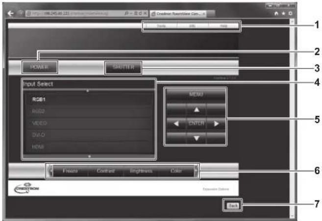
text_image
1
2
3
4
5
6
7
Input Select
RGB1
RGB2
VIDEO
DJO
HDMI
MENU
ENTER
Floats Contrast Brightness Color
C:\C#STROM Expansion Options
1 [Tools], [Info], [Help]
Tabs for selecting the setting, information, or help page of the projector.
2 [POWER]
Turns on/off the power.
3 [SHUTTER]
Switches the setting whether to use the shutter function (closing/opening of the shutter).
4 [Input Select]
Controls input selection.
Not available when the power of the projector is turned off.
5 Menu screen control buttons
Navigates the menu screen.
6 Freeze/image quality adjustment
Controls items related to freeze/image quality.
7 [Back]
Performs return to the previous page.
[Tools] page
Click [Tools] on the control page.
![PANASONIC PT-DZ870U - [Tools] page - 1](/content/2026/05/813109/images/c82854dc4bb40e3d9432417a01e2bc2b3b48cccf418fa73f0968779d5945a535.jpg)
text_image
http://ML245.00.222
Creation Room/View Con...
Control System
IP Address
IPO: 3
Port: 41794
Send
User Password
New Password:
Customs
DNSP
ISPuser
IP Address: IPO 995.6.3
Select/Block: DNSP 995.6.3
Default Gateway: IPO 995.6.3
DNS Server
Admin Password
New Password:
Customs
Send
Exit
Back
1 [Control System]
Set the information required for communicating with the controller to be connected with the projector.
2 [User Password]
Set the user rights password for the RoomView control page.
3 [Admin Password]
Set the administrator rights password for the RoomView control page.
4 Network status
Displays the settings of wired LAN.
[DHCP]
Displays the current setting.
[Ip Address]
Displays the current setting.
[Subnet Mask]
Displays the current setting.
[Default Gateway]
Displays the current setting.
[DNS Server]
Displays the current setting.
5 [Exit]
Returns to the control page.
[Info] page
Click [Info] on the control page.
![PANASONIC PT-DZ870U - [Info] page - 1](/content/2026/05/813109/images/2ff1d2abc0fcf1097b6395a3e161851cbb93da1f4bc2885bb974a28e66ebdef6.jpg)
text_image
1
2
3
4
5
6
7
8
Projector Information
Projector Name: MANC-APCP
Projector Status:
Power Status: BANCAER
Source: RZRT
Wet Address: PLEE 52.09.09.09
Layout Status: 0 %
Layout Floor: 0 %
Limit Mode: SCREEN
Inner Status: ENTERSTOCKED
Exit
Startbox System
Back
1 [Projector Name]
Displays the projector name.
2 [Mac Address]
Displays the MAC address.
3 [Lamp Hours]
Displays the runtime of the lamps (converted value).
4 [Power Status]
Displays the status of the power.
5 [Source]
Displays the selected input.
6 [Lamp Mode]
Displays the setting status of [LAMP POWER] (→ page 111).
7 [Error Status]
Displays the error status.
8 [Exit]
Returns to the control page.
[Help] page
Click [Help] on the control page.
The [Help Desk] window is displayed.
![PANASONIC PT-DZ870U - [Help] page - 1](/content/2026/05/813109/images/c31128a6f762d2759253133749b3d6d91fac0166b4b8816073c243ecb50d14c0.jpg)
text_image
http://86.245.00-222/10/19/2019/10/23
Create Tanger Filter Cons...
Help Desk
SAVE
POWER
SPUTTER
Input Select
RGB1
RGB2
VIDEO
DVD
HOLD
MENU
ENTER
Fines
Contrast
Brightness
Color
C:\Users\Tools\Back
1 [Help Desk]
Send/receive messages to/from an administrator who uses
Crestron RoomView.
Chapter 5 Maintenance
This chapter describes methods of inspection when there are problems, maintenance, and replacement of the units.
Lamp/temperature/filter indicators
When an indicator lights up
If a problem should occur inside the projector, the lamp indicators /, the temperature indicator , and the filter indicator will inform you by lighting or flashing. Check the status of the indicators and manage the indicated problems as follows.
Attention
- When switching off the projector to deal with problems, make sure to follow the procedure in "Switching off the projector" (→ page 57).
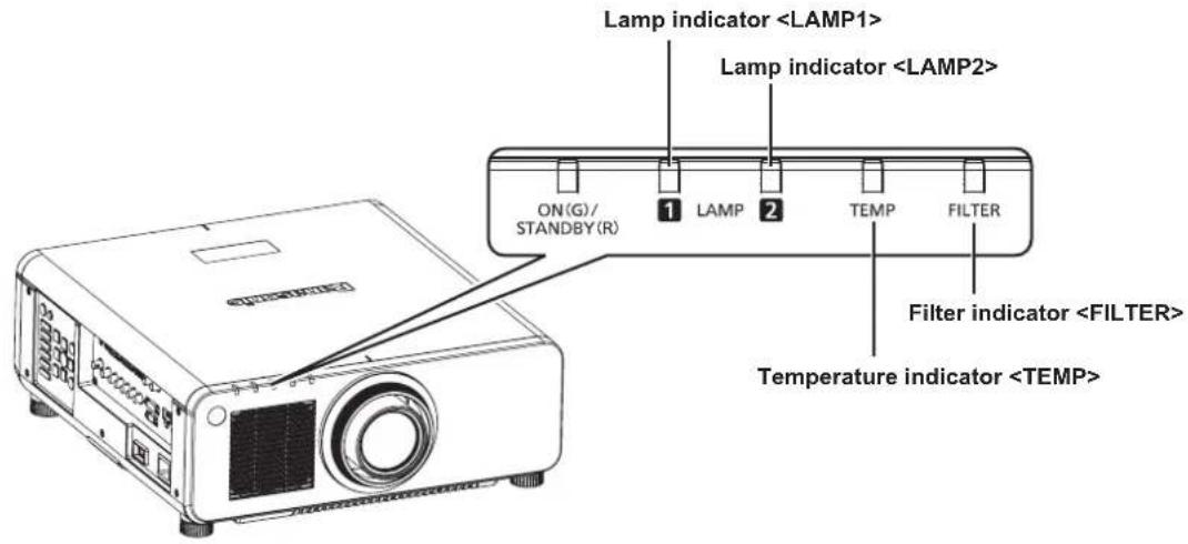
text_image
Lamp indicator
Lamp indicator
ON(G)/
STANDBY(R)
1 LAMP 2
TEMP FILTER
Filter indicator
Temperature indicator
Lamp indicators /
| Indicator status | Lighting in red/lighting in orange*1 | Flashing in red (1 time) | Flashing in red (3 times) |
| Status | Time to replace the lamp unit. (→ page 161) | The lamp unit is not installed. | A problem is detected in the lamp or the power supply for the lamp. |
| Cause | ●Was [REPLACE LAMP] displayed when you turned on the power?●The indicator lights up when the runtime of the lamp unit reaches 2 800 hours (when [LAMP POWER] is set to [NORMAL])*2. | ●Is the lamp unit attached? | ●Have you turned on the power again immediately after turning it off? | ●Some error has occurred in the lamp circuit. Check for fluctuation (or drop) in the source voltage. |
| Solution ●Replace | the lamp unit. | ●Install the lamp unit if it is not installed.●If the indicator is still flashing in red even when having installed the lamp unit, consult your dealer. | ●Wait a while until the luminous lamp cools off, and then turn on the power. | ●Turn theswitch to(→ page 57), and consult your dealer. |
*1 The indicator lights up in red while the lamp is turned off, and lights up in orange while the lamp is turned on.
*2 800 hours when using the optional Replacement lamp unit (for portrait mode) (Model No.: ET-LAD120P (1 pc), ET-LAD120PW (2 pcs)) (when [LAMP POWER] is set to [NORMAL]).
Note
- If the lamp indicators / are still lit or flashing after taking the preceding measures, ask your dealer for repair.
Temperature indicator
| Indicator status Lighting in red | Flashing in red(2 times) | Flashing in red(3 times) |
| Status Warm-up status | | Internal temperature is high (warning). | Internal temperature is high (standby status). | The cooling fan has stopped. |
| Cause | Did you turn on the power when the temperature was low (around 0 °C (32 °F))? | Is the air intake/exhaust port blocked?Is the room temperature high?Is the filter indicatorlit? | — |
| Solution | Wait at least five minutes in the current status.Install the projector in a location with the operating environment temperature between 0 °C (32 °F) and 45 °C (113 °F)*1. | Remove any objects that are blocking the air intake/ exhaust port.Install the projector in a location with the operating environment temperature between 0 °C (32 °F) and 45 °C (113 °F)*1.Do not use the projector at high altitudes of 2 700 m (8 858') or higher above sea level.Clean or replace the air filter. (→ page 159) | Turn theswitch to(→ page 57), and consult your dealer. |
*1 When using the projector at high altitudes (1 400 m (4 593') or higher – lower than 2 700 m (8 858') above sea level), the operating environment temperature should be between 0 °C (32 °F) and 40 °C (104 °F). If you use the Replacement lamp unit (for portrait mode), the operating environment temperature should be between 0 °C (32 °F) and 40 °C (104 °F) when using the projector at elevations lower than 1 400 m (4 593') above sea level, and between 0 °C (32 °F) and 35 °C (95 °F) when using the projector at high altitudes.
Note
- If the temperature indicator is still lit or flashing after taking the preceding measures, ask your dealer for repair.
- If you use the projector with the following two settings, the light output may drop by approx. 20 % to protect the projector when the operating environment temperature becomes 40 °C (104 °F) or higher (35 °C (95 °F) or higher when [HIGH ALTITUDE MODE] is set to [ON]).
-When [LAMP SELECT] is set to [DUAL] from the menu
-When [LAMP POWER] is set to [NORMAL] from the menu
Filter indicator
| Indicator status Lighting in red Flashing in red | |
| Status | The filter is clogged.The temperature inside or outside the projector is abnormally high. | The air filter case is not attached. |
| Cause •Is the air filter dirty? | •Is the air intake/exhaust port blocked? | •Is [HIGH ALTITUDE MODE] set correctly? | •Is the air filter case attached? | |
| Solution | •Clean or replace the air filter. (⇨ page 159) | •Remove any objects that are blocking the air intake/exhaust port. | •When using the projector at high altitudes between 1 400 m (4 593') and 2 700 m (8 858') above sea level, set [HIGH ALTITUDE MODE](⇨ page 109) to [ON].•Do not use the projector at high altitudes of 2 700 m (8 858') or higher above sea level. | •Attach the air filter case. |
Note
- If the filter indicator is still lit or flashing after taking the preceding measures, ask your dealer for repair.
- If the air filter case is not attached when the projector is switched on, the filter indicator flashes in red, and then the projector is switched off after ten minutes.
Maintenance/replacement
Before performing maintenance/replacement
- Make sure to turn off the power before maintaining the projector or replacing the unit. (→ pages 54, 57)
- When switching off the projector, make sure to follow the procedures in "Switching off the projector" (→ page 57).
Maintenance
Outer case
Wipe off dirt and dust with a soft, dry cloth.
- If the dirt is persistent, soak the cloth with water and wring it thoroughly before wiping. Dry off the projector with a dry cloth.
- Do not use benzene, thinner, or rubbing alcohol, other solvents, or household cleaners. Doing so may deteriorate the outer case.
- When using chemically treated dust cloths, follow the instructions written on its packaging.
Lens front surface
Wipe off dirt and dust from the front surface of the lens with a soft clean cloth.
- Do not use a cloth that is fluffy, dusty, or soaked with oil/water.
- Since the lens is fragile, do not use excessive force when wiping the lens.
Attention
- The lens is made of glass. Impacts or excessive force when wiping may scratch its surface. Handle with care.
Air Filter
Perform maintenance of the air filter in the following cases.
- The air filter is clogged with dust, causing the filter replacement message to appear on the screen and the filter indicator to light in red.
Removing the air filter
Lamp unit cover
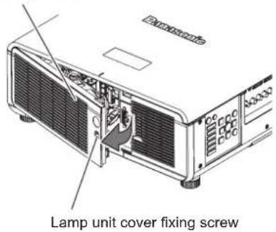
text_image
Pavantou
Lamp unit cover fixing screw
Fig. 1
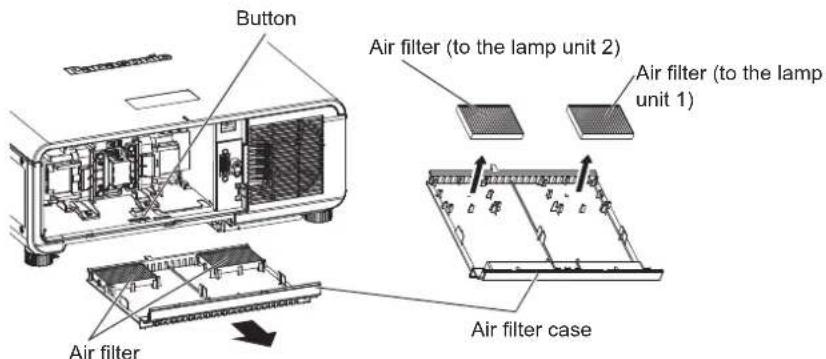
text_image
Button
Air filter (to the lamp unit 2)
Air filter (to the lamp unit 1)
Air filter
Air filter case
Fig. 2 Fig. 3
1) Remove the lamp unit cover. (Fig. 1)
- Use a Phillips screwdriver to turn the lamp unit cover fixing screw (x1) counterclockwise until it turns freely, and open the lamp unit cover slowly in the direction of the arrow.
- Opening the lamp unit cover quickly may result in damage to the cover.
- If you loosen the lamp unit cover fixing screw with the projector installed upward in the vertical direction, the lamp unit cover may open on its weight and the lamp unit may be dropped off.
2) Pull out the air filter case. (Fig. 2)
- Pull out the air filter case from the projector while pressing the button on the projector.
3) Remove the air filter from the air filter case. (Fig. 3)
Cleaning the air filter
Remove the air filter beforehand with the previously described procedure of "Removing the air filter".
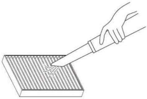
natural_image
Line drawing of a hand using a tool to clean or store contents on a striped surface (no text or symbols)
1) Clean the air filter.
•Vacuum dust from the air filter with a vacuum cleaner.
Attaching the air filter
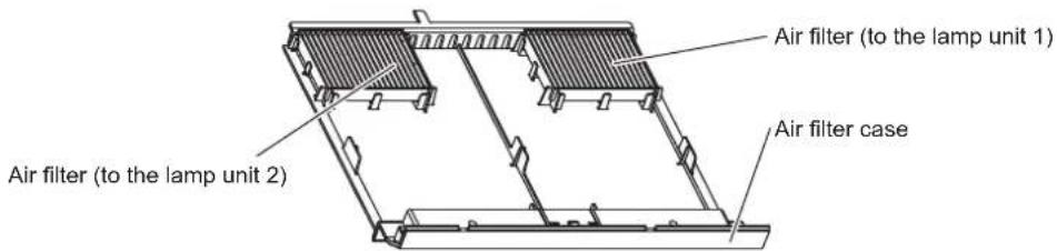
text_image
Air filter (to the lamp unit 1)
Air filter (to the lamp unit 2)
Air filter case
Fig. 1
1) Attach the air filter. (Fig. 1)
- Insert the air filter to the filter case rib securely.
2) Attach the air filter case to the projector.
- Push in the air filter case securely until the clicking sound is made.
3) Attach the lamp unit cover.
- Close the lamp unit cover in the reverse order of Step 1) of "Removing the air filter".
- Attach the lamp unit cover so that the connector of the lamp unit cover is inserted to the fan power connector securely.
- Use a Phillips screwdriver to firmly tighten the lamp unit fixing screw (x1).
- Make sure to attach the lamp unit cover securely.
Note
- Make sure that the air filter case is properly attached before using the projector. If it is not properly attached, the projector will suck in dirt and dust causing a malfunction.
- If you use the projector without attaching the air filter case, the filter indicator flashes in red and the message appears on the projection screen for approximately 30 seconds.
- Do not use water when washing the air filter. Washing with water may decrease the dust absorption capability.
- When the dust remains after cleaning, it is time to replace the air filter.
The air filter for replacement (TMZX5209) is an optional accessory (service part). To purchase the product, consult your dealer. One air filter is provided for the optional Replacement lamp unit (Model No.: ET-LAD120 (1 pc)) and the optional Replacement lamp unit (for portrait mode) (Model No.: ET-LAD120P (1 pc)), and two air filters are provided for the optional Replacement lamp unit (Model No.: ET-LAD120W (2 pcs)) and the optional Replacement lamp unit (for portrait mode) (Model No.: ET-LAD120PW (2 pcs)).
Replacing the unit
Lamp unit
The lamp unit is a consumable component. Refer to "When to replace the lamp unit" ( page 161) for details about the replacement cycle. When purchasing the optional Replacement lamp unit (Model No.: ET-LAD120 (1 pc), ET-LAD120W (2 pcs)) and the optional Replacement lamp unit (for portrait mode) (Model No.: ET-LAD120P (1 pc), ET-LAD120PW (2 pcs)), consult your dealer.
It is recommended that you request a qualified technician to replace the lamp unit. Consult your dealer.
Warning
Replace the lamp unit after the lamp has cooled (after waiting at least one hour).
The high temperature inside the cover will cause burns.
Checking the lamp unit to be replaced
1) Check the status of the lamp indicators /.
- The lamp unit corresponding to the lamp indicator that is lit in red is required to be replaced.
Notes on the replacement of the lamp unit
- A Phillips screwdriver is necessary when replacing the lamp unit.
- Since the luminous lamp is made of glass, it may burst if dropped or hit with a hard object. Handle with care.
- Do not disassemble or modify the lamp unit.
- When replacing the lamp unit, be sure to hold it by the handle because its surface is pointed and its shape is protruded.
- The lamp may rapture. Replace the lamp unit carefully so the glass fragments of the lamp do not scatter. While attaching the projector to the ceiling, do not work right under the lamp unit or do not conduct work while your face is near the lamp unit.
- The lamp contains mercury. When disposing of used lamp units, contact your local authorities or dealer for correct methods of disposal.
Attention
- Panasonic takes no responsibility for any damage or malfunction of the product resulting from use of lamp units which are not manufactured by Panasonic. Use only specified lamp units.
- For the portrait setting, be sure to use the Replacement lamp unit (for portrait mode).
- Do not use the Replacement lamp unit (for portrait mode) and normal lamp unit together.
- Use the Replacement lamp unit (for portrait mode) only when installing the projector in the portrait setting.
Note
- The model numbers of accessories and optional accessories are subject to change without prior notice.
When to replace the lamp unit
The lamp unit is a consumable component. Since its brightness gradually decreases over time, it is necessary to replace the lamp unit regularly. The estimated duration before replacement is 3 000 hours, but the lamp may go off before reaching to 3 000 hours, depending on the characteristics of the individual lamp, usage conditions, and the installation environment. It is recommended that the Replacement lamp unit be prepared earlier.
If you continue to use the lamp unit after 3 000 hours has elapsed, the lamp turns off automatically after approximately 10 minutes, as it may cause malfunction of the projector.
| On-screen displayREPLACE LAMP | Lamp indicator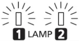 |
| Over 2 800 hours | The message is displayed for 30 seconds. Pressing any button on the control panel or remote control within 30 seconds will clear the message. | The indicator lights in red even during the standby mode. (Only the corresponding lamp lights on.) |
| Over 3 000 hours | The message remains displayed until you press any button. |
Note
- To predict when to replace the lamp, check the lamp runtime displayed on [LAMP1] and [LAMP2] in [STATUS] (→ page 119).
- 3000 hours is only the target for replacement and not the warranty time.
- The estimated duration before replacing the Replacement lamp unit (for portrait mode) is 1000 hours. The on-screen message for replacing the lamp appears after 800 hours.
How to replace the lamp unit
Attention
- When the projector is mounted on the ceiling, do not conduct work while your face is near the lamp unit.
- Use the same type of lamp unit for both lamps.
- Make sure to attach the lamp unit and the lamp unit cover securely.
- If the lamp unit is not installed properly, remove it and then push it in slowly. Pushing it in quickly or forcibly may break the connector.
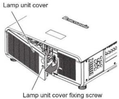
text_image
Lamp unit cover
Lamp unit cover fixing screw
Fig. 1
Lamp unit 2
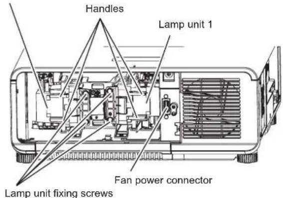
text_image
Handles
Lamp unit 1
Fan power connector
Lamp unit fixing screws
Fig. 2
1) Set the switch to and disconnect the power plug from the power outlet.
- Wait at least one hour and check if the lamp unit has cooled down.
2) Remove the lamp unit cover. (Fig. 1)
- Use a Phillips screwdriver to turn the lamp unit cover fixing screw (x1) counterclockwise until it turns freely, and open the lamp unit cover slowly in the direction of the arrow.
- Opening the lamp unit cover quickly may result in damage to the cover.
- If you loosen the lamp unit cover fixing screw with the projector installed upward in the vertical direction, the lamp unit cover may open on its weight and the lamp unit may be dropped off.
3) Remove the lamp unit. (Fig. 2)
- Use a Phillips screwdriver to turn the lamp unit fixing screws (x2) counterclockwise until they turn freely, and then remove the lamp unit.
- Hold the handles of the lamp unit and remove it straight.
4) Push in the new lamp unit while paying attention to the insertion position.
- If the lamp unit is not installed properly, remove it and then push it in slowly. Pushing it in quickly or forcibly may break the connector.
5) Use a Phillips screwdriver to firmly tighten the lamp unit fixing screws (x2 each).
- Make sure to attach the lamp unit securely.
6) Attach the lamp unit cover.
i) Close the lamp unit cover in Step 2) in the reverse order.
- Attach the lamp unit cover so that the connector of the lamp unit cover is inserted to the fan power connector securely.
ii) Use a Phillips screwdriver to firmly tighten the lamp unit fixing screw (x1).
- Make sure to attach the lamp unit cover securely.
Note
- When you replace the lamp unit with new one, the projector resets the runtime of the lamp unit automatically.
Air filter
When the dust remains after cleaning, the filter replacement timing has come.
The air filter for the replacement (TMZX5209) is the optional accessories (service part). To purchase the product, consult your dealer.
When replacing the lamp unit, replace the corresponding air filter.
One air filter is provided for the optional Replacement lamp unit (Model No.: ET-LAD120 (1 pc)) and the optional Replacement lamp unit (for portrait mode) (Model No.: ET-LAD120P (1 pc)), and two air filters are provided for the optional Replacement lamp unit (Model No.: ET-LAD120W (2 pcs)) and the optional Replacement lamp unit (for portrait mode) (Model No.: ET-LAD120PW (2 pcs)).
Replacing the air filter
Attention
- Make sure to turn off the power before replacing the air filter.
- When attaching the air filter, make sure that the projector is stable, and perform the replacement in a safe place where the unit will not be damaged even if you drop the air filter.
1) Remove the air filter.
- Refer to "Removing the air filter" (→ page 159).
2) Replace the air filter to the new one and attach the air filter case to the projector.
- Refer to "Attaching the air filter" (→ page 160).
Attention
- When switching on the projector, make sure that the air filter is attached. If it is not properly attached, the projector will suck in dirt and dust causing a malfunction.
- If you use the projector without attaching the air filter case, the filter indicator flashes in red and the message appears on the projection screen for approximately 30 seconds.
Troubleshooting
Review the following points. For details, see the corresponding pages.
| Problems Points to | be checked Page | |
| Power does not turn on. | Is the power plug firmly inserted into the outlet? —Is theswitch set to? 57Is the wall outlet supplying electricity? —Have the circuit breakers tripped? —Are the lamp indicatoror the temperature indicatorlit or flashing?Is the lamp unit cover attached? 162 | 157 |
| No image appears. | Are connections to external devices correctly performed? 49Is the input selection setting correct? 62Is the [BRIGHTNESS] adjustment setting at a minimum? 71Is the external device that is connected to the projector working properly?Is the shutter function in use? 61If the power indicatoris flashing in red, consult your dealer.Is the lens cover still attached to the lens? | — |
| Image is fuzzy. | Is the lens focus set correctly?Is the projection distance appropriate?Is the lens dirty?Is the projector installed perpendicular to the screen? | 583319— |
| Color is pale or grayish. | Is [COLOR] or [TINT] adjusted correctly?Is the external device connected to the projector adjusted correctly?Is the RGB cable damaged? | 7249— |
| Remote control does not respond. | Are the batteries depleted?Is the polarity of the batteries set correctly?Are there any obstructions between the remote control and the remote control signal receiver of the projector?Is the remote control being used beyond its effective operation range?Are other forms of light, such as fluorescent light, affecting the projection?Is the [REMOTE CONTROL] setting in [CONTROL DEVICE SETUP] set to [DISABLE]?Is theterminal used for contact control?Is the ID number setting operation correct? | —2925252513117629 |
| Menu screen does not appear. | Is the on-screen display function turned off (hidden)? | 101 |
| Buttons on the control panel do not operate. | Is the [CONTROL PANEL] setting in [CONTROL DEVICE SETUP] set to [DISABLE]?Is theterminal used for contact control? | 131176 |
| Image does not display correctly. | Is the [SYSTEM SELECTOR] selection set correctly?Is there a problem with the video tape or other image sources?Is a signal which is not compatible with the projector being input? | 76—178 |
| Image from a computer does not appear. | Is the cable too long? (Use D-Sub cables that are 10 m (32'10") or shorter.)Is the external video output on the laptop computer set correctly? (Ex.: The external output settings may be switched by pressing "Fn" + "F3" or "Fn" + "F10" simultaneously. Since the method varies depending on the computer type, refer to the user manual provided with your computer.) | — |
| Image output from DVI-D of the computer does not appear. | Is the [DVI-D IN] setting [EDID3] or [EDID2:PC]?The graphics accelerator driver of the computer may need to be updated to the latest version.The computer may need to be restarted after performing the [DVI-D IN] setting. | 98—98 |
| Video from HDMI compatible device does not appear or it appears jumbled. | Is the HDMI cable connected securely?Turn the power of the projector and the external device on and off.Is a signal which is not compatible with the projector being input? | 49—178 |
| Cannot control the projector with Art-Net. | Are the connections between the twisted-pair-cable transmitter and the projector or an external device correctly done?Is the [Art-Net] setting [ON]?Are the [PORT ADDRESS] and [START ADDRESS] settings correct? | —136136 |
Chapter 5 Maintenance — Troubleshooting
| Problems Points to | be checked Page | |
| The DIGITAL LINK input image is not displayed. | Are the connections between the twisted-pair-cable transmitter and the projector or an external device correctly done?Is [DIGITAL LINK MODE] set to [AUTO] or [DIGITAL LINK]? Is it set to [ETHERNET]?Is a signal which is not compatible with a twisted-pair-cable transmitter being input? | —134— |
| 3D function is not working. | Is the [3D INPUT FORMAT] setting of [3D SETTINGS] correct? 91Check the 3D eyewear settings. —Is a signal which is supported by the projector being input? 180 | |
| Left and right images are reversed (not showing properly). | Are the devices synchronized? Check the 3D eyewear settings. —Change the [LEFT/RIGHT SWAP] setting of [3D SETTINGS]. | 92 |
| Image in the 3D eyewear flickers. | Are you within the reception range? — | |
| 3D eyewear is not functioning. | Are batteries of the 3D eyewear drained? If you use the rechargeable 3D eyewear, charge it. If you use the battery-powered 3D eyewear, replace the battery.Is the [3D SETTINGS] setting correct? 90 | — |
Attention
- If problems persist even after checking the preceding points, consult your dealer.
Chapter 6 Appendix
This chapter describes specifications and after-sales service for the projector.
PJLink protocol
The network function of this projector supports the PJLink class 1, and the PJLink protocol can be used to perform projector setting and projector status query operations from a computer.
Control commands
The following table lists the PJLink protocol commands that can be used to control the projector.
•x characters in tables are non-specific characters.
| Command Control details Parameter | / return string Remark | |
| POWR Power supply control | 0 Standby1 Power on | |
| POWR? | Power supply status query | 0 Standby1 Power on2 Preparing for switching off the 3 Warm-up | projector |
| INPT Input selection | 11 RGB112 RGB221 VIDEO31 DVI-D32 HDMI33 DIGITAL LINK34 SDI (only for PT-DZ870U) | |
| INPT? Input selection query |
| AVMT Shutter control 30 Shutter function off (shutter open) | |
| AVMT? | Shutter status query | 31 Shutter function on (shutter closed) |
| ERST? | Error status query xxxxxx | | 1st byte | Indicates fan errors, and returns 0 - 2. | ●0 = No error is detected●1 = Warning●2 = Error |
| 2nd byte | Indicates lamp errors, and returns 0 - 2. |
| 3rd byte | Indicates temperature errors, and returns 0 - 2. |
| 4th byte | Indicates cover open errors, and returns 0 or 2. |
| 5th byte | Indicates filter errors, and returns 0 - 2. |
| 6th byte | Indicates other errors, and returns 0 - 2. |
| LAMP? Lamp status query xxxxxxxxx | 1st digits (1 - 5 digits): Lamp 1 runtime2nd digit: 0 = Lamp 1 off, 1 = Lamp 1 on3rd digits (1 - 5 digits): Lamp 2 runtime4th digit: 0 = Lamp 2 off, 1 = Lamp 2 on |
| INST? Input selection list query | 11 12 21 31 32 33 34 Only for PT-DZ870U |
| 11 12 21 31 32 33 | Only for PT-DW830U, PT-DX100U |
| NAME? | Projector name query | xxxxx | Returns the name set in [PROJECTOR NAME] of [NETWORK SETUP]. |
| INF1? | Manufacturer name query | Panasonic | Returns manufacturer name. |
| INF2? | Model name query | DZ870DW830DX100 | Returns model name. |
| INF0? | Other information queries | xxxxx | Returns information such as version number. |
| CLSS? | Class information query | 1 Returns class for PJLink. | |
PJLink security authentication
The password used for PJLink is the same as that of the password set for web control.
When using the projector without security authentication, do not set a password for web control.
- For specifications related to PJLink, refer to the website of Japan Business Machine and Information System Industries Association.
URL http://pjlink.jbmia.or.jp/english/
Using Art-Net function
The network function of the projector supports the Art-Net function, and the Art-Net protocol can operate the DMX controller setting, and the application software can control the projector setting.
CHANNEL DEFINITION
The following table lists the channel definitions used for controlling the projector with the Art-Net function.
| Channel Control details Performance Parameter Remark | | |
| 1 Shutter control | SHUTTER:OPEN 0-63 | | |
| No operation 64-191 | |
| SHUTTER:CLOSE 192-255 | |
| 2 Input selection | No operation 0-7 | | |
| RGB1 8-15 | |
| RGB2 16-23 | |
| VIDEO 24-31 | |
| DVI-D 32-39 | |
| HDMI 40-47 | |
| DIGITAL LINK | 48-55 |
| SDI (only for PT-DZ870U) | 56-63 |
| No operation 64-127 | |
| Execute P IN P, USER1 | 128-135 |
| Execute P IN P, USER2 | 136-143 |
| Execute P IN P, USER3 | 144-151 |
| No operation 152-255 | |
| 3 Lens function select | No operation 0-15 | | |
| Lens H shift | 16-31 | Operate together with “Lens adjustment” of the channel 4. |
| Lens V shift | 32-47 |
| Lens focus | 48-63 |
| Lens zoom | 64-79 |
| Move to the home position | 80-95 | Operate together with “Command performance execute” of the channel 4. |
| No operation 96-255 | | |
| 4 Lens control | Lens adjustment | (-) High speed | 0-31 | |
| (-) Low speed | 32-63 |
| (-) Fine adjustment | 64-95 |
| Adjustment stop | 96-127 |
| Lens adjustment | (+) Fine adjustment | 128-159 |
| (+) Low speed | 160-191 |
| (+) High speed | 192-223 |
| Command performance execute | 224-255 |
| 5 Power supply control | Standby | 0-63 | |
| No operation 64-191 | |
| Power on | 192-255 |
| 6 Light volume adjustment | 100 % | 0 | Can be set in 256 steps between 100 % and 0 %. |
| ... | ... |
| 0 % | 255 |
| 7 Lock | Operation not available | 0-127 | When “Operation not available” is set, operation of all channels become unacceptable. |
| Operation available | 128-255 |
Chapter 6 Appendix — Technical information
| Channel Control details Performance Parameter Remark | | |
| 8 Fade-in time setting | 0.0s 0-15 | | Operate together with channel 1. |
| 0.5s 16-31 | |
| 1.0s 32-47 | |
| 1.5s 48-63 | |
| 2.0s 64-79 | |
| 2.5s 80-95 | |
| 3.0s 96-111 | |
| 3.5s 112-127 | |
| 4.0s 128-143 | |
| 5.0s 144-159 | |
| 7.0s 160-175 | |
| 10.0s 176-191 | |
| No operation 192-255 | | |
| 9 Fade-out time setting | 0.0s 0-15 | | Operate together with channel 1. |
| 0.5s 16-31 | |
| 1.0s 32-47 | |
| 1.5s 48-63 | |
| 2.0s 64-79 | |
| 2.5S 80-95 | |
| 3.0s 96-111 | |
| 3.5s 112-127 | |
| 4.0s 128-143 | |
| 5.0s 144-159 | |
| 7.0s 160-176 | |
| 10.0s 176-191 | |
| No operation 192-255 | | |
| 10 Custom masking | OFF 0-31 | | To use this function, the optional Upgrade Kit (Model No.: ET-UK20) is required. |
| PC-1 32-63 | |
| PC-2 64-95 | |
| PC-3 96-127 | |
| No operation 128-255 | |
| 11 Geometry | OFF 0-15 | | (Only for PT-DZ870U) To use PC-1, PC-2, or PC-3, the optional Upgrade Kit (Model No.: ET-UK20) is required. |
| KEYSTONE 16-31 | |
| CURVED 32-47 | |
| PC-1 48-63 | |
| PC-2 64-79 | |
| PC-3 80-95 | |
| CORNER CORRECTION | 96-111 |
| No operation 112-255 | |
Note
- If the projector is operated with the remote control or on the control panel, or by the control command while controlling the projector by using the Art-Net function, the setting of the DMX controller and the computer application may be different from the projector status. In that case, set the "Lock" setting of the channel 7 to "Operation not available" and then reset to "Operation available". The controls of all channels become reflected to the projector.
Control commands via LAN
When web control administrator rights password is set (Protect mode)
Connecting
1) Obtain the IP address and port number (Initial set value = 1024) of the projector and request for a connection to the projector.
- You can obtain both the IP address and the port number from the menu screen of the projector.
| IP address | Obtain from the main menu → [NETWORK] → [NETWORK STATUS] |
| Port number | Obtain from the main menu → [NETWORK] → [NETWORK CONTROL] → [COMMAND PORT] |
2) Check the response from the projector.
| Data section Blank | Mode Blank | Random number section | | Termination symbol |
| Command example | “NTCONTROL” (ASCII string) | ‘’ 0x20 | ‘1’ 0x31 | ‘’ 0x20 | “zzzzzzzz” (ASCII code hex number) (CR) 0x0d |
| Data length 9 | bytes 1 byte 1 byte 1 byte | 8 bytes 1 byte | | | |
- Mode: 1 = Protect mode
3) Generate a 32-byte hash value from the following data using MD5 algorithm.
- "xxxxxx:yyyy:zzzzzzzzz"
| xxxxxx Administrator rights user name for the web control (default user name is “admin1”) |
| yyyy Password of above administrator rights user (default password is “panasonic”) |
| zzzzzzzz 8-byte random number obtained in Step 2) |
Command transmission method
Transmit using the following command formats.
■ Transmitted data
| Header | Data section | Termination symbol |
| Command example | Hash value(Refer to “Connecting” above) | ‘0’0x30 | ‘0’0x30 | Control command(ASCII string) | (CR)0x0d |
| Data length | 32 bytes | 1 byte | 1 byte | Undefined length | 1 byte |
■ Received data
| Header | Data section | Termination symbol |
| Command example | ‘0’0x30 | ‘0’0x30 | Control command(ASCII string) | (CR)0x0d |
| Data length | 1 byte | 1 byte | Undefined length | 1 byte |
■ Error response
| String | Details | Termination symbol |
| Message | “ERR1” | Undefined control command | (CR)0x0d |
| “ERR2” | Out of parameter range |
| “ERR3” | Busy state or no-acceptable period |
| “ERR4” | Timeout or no-acceptable period |
| “ERR5” | Wrong data length |
| “ERRA” | Password mismatch |
| Data length | 4 bytes | — | 1 byte |
When web control administrator rights password is not set (Non-protect mode)
Connecting
1) Obtain the IP address and port number (Initial set value = 1024) of the projector and request for a connection to the projector.
- You can obtain both the IP address and the port number from the menu screen of the projector.
| IP address | Obtain from the main menu → [NETWORK] → [NETWORK STATUS] |
| Port number | Obtain from the main menu → [NETWORK] → [NETWORK CONTROL] → [COMMAND PORT] |
2) Check the response from the projector.
| Data section Blank Mode | | Termination symbol |
| Command example | “NTCONTROL” (ASCII string) | ‘’ 0x20 | ‘0’ 0x30 | (CR) 0x0d |
| Data length 9 | bytes 1 byte 1 byte 1 byte | | | |
- Mode: 0 = Non-protect mode
Command transmission method
Transmit using the following command formats.
■Transmitted data
| Header Data section | | Termination symbol |
| Command example | ‘0’0x30 | ‘0’0x30 | Control command(ASCII string) | (CR)0x0d |
| Data length | 1 byte | 1 byte | Undefined length | 1 byte |
■Received data
| Header Data section | | Termination symbol |
| Command example | '0'0x30 | '0'0x30 | Control command(ASCII string) | (CR)0x0d |
| Data length | 1 byte | 1 byte | Undefined length | 1 byte |
■Error response
| String | Details | Termination symbol |
| Message | “ERR1” | Undefined control command | (CR)0x0d |
| “ERR2” | Out of parameter range |
| “ERR3” | Busy state or no-acceptable period |
| “ERR4” | Timeout or no-acceptable period |
| “ERR5” | Wrong data length |
| “ERRA” | Password mismatch |
| Data length | 4 bytes | — | 1 byte |
/ terminal
The / terminal of the projector conforms with RS-232C so that the projector can be connected to and controlled from a computer.
Connection
● Single projector
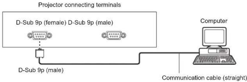
flowchart
graph TD
    A["Projector connecting terminals"] --> B["D-Sub 9p (female) D-Sub 9p (male)"]
    B --> C["D-Sub 9p (male)"]
    C --> D["Computer"]
    D --> E["Communication cable (straight)"]
● Multiple projectors
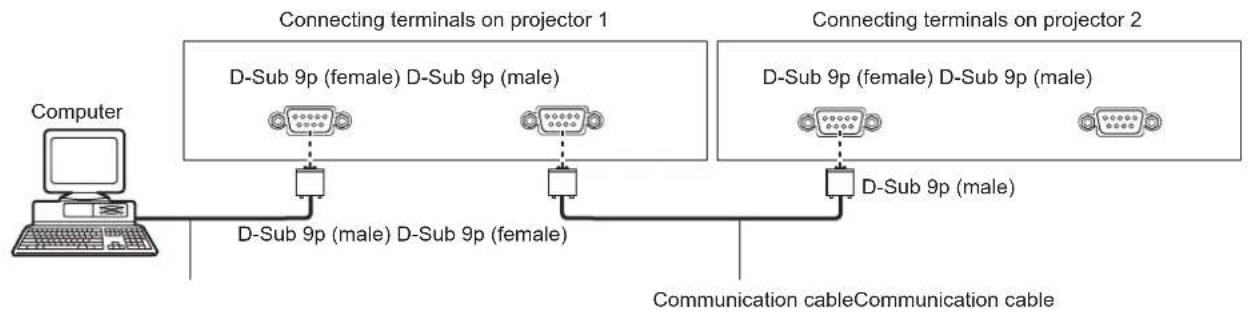
flowchart
graph LR
    A["Computer"] --> B["D-Sub 9p (male) D-Sub 9p (female)"]
    B --> C["D-Sub 9p (female) D-Sub 9p (male)"]
    C --> D["D-Sub 9p (male) D-Sub 9p (male)"]
    D --> E["Communication cable"]
    style A fill:#f9f,stroke:#333
    style B fill:#ccf,stroke:#333
    style C fill:#cfc,stroke:#333
    style D fill:#fcc,stroke:#333
    style E fill:#ffc,stroke:#333
● When connecting with the DIGITAL LINK compatible devices
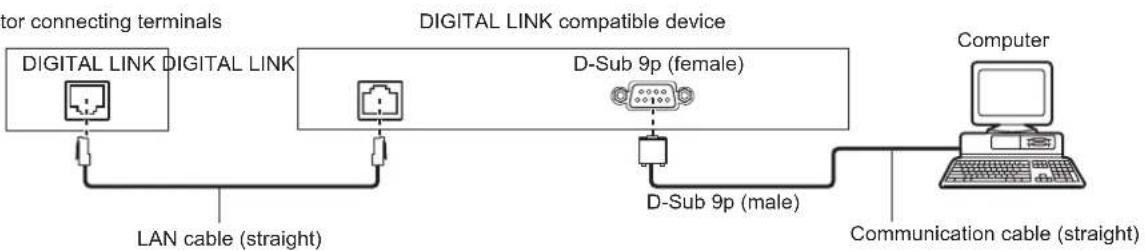
flowchart
graph LR
    A["Digital Link"] -->|LAN cable (straight)| B["Digital Link"]
    B --> C["D-Sub 9p (female)"]
    C --> D["D-Sub 9p (male)"]
    D --> E["Computer"]
    F["Communication cable (straight)"] --> E
Note
- The destination of [RS-232C] (→ page 118) must be set according to the connection method.
- When connecting by a DIGITAL LINK compatible device, set the [PROJECTOR SETUP] menu → [STANDBY MODE] (→ page 116) setting to [NORMAL] to control the projector during standby.
When [STANDBY MODE] is set to [ECO], the projector cannot be control during standby.
Pin assignments and signal names
| D-Sub 9-pin (female) Outside view | Pin No. Signal name Details | |
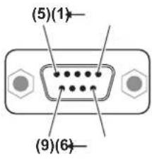 | (1) — NC | | |
| (2) TXD Transmitted data | |
| (3) | RXD | Received data |
| (4) — NC | | |
| (5) | GND | Earth |
| (6) — NC | | |
| (7) CTS | | Connected internally |
| (8) RTS | |
| (9) — NC | | |
Chapter 6 Appendix — Technical information
| D-Sub 9-pin (male) Outside view | Pin No. Signal name Details | |
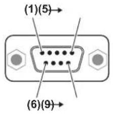 | (1) — NC | |
| (2) RXD Received data | |
| (3) TXD Transmitted data | |
| (4) — NC | |
| (5) GND Earth | |
| (6) — NC | |
| (7) RTS | |
| (8) CTS | |
| (9) — NC | |
Communication conditions (Factory default)
| Signal level RS-232C-compliant |
| Sync. method Asynchronous |
| Baud rate | 9 600 bps |
| Parity | None |
| Character length | 8 bits |
| Stop bit | 1 bit |
| X parameter | None |
| S parameter | None |
Transmission from the computer starts with STX, then the ID, command, parameter, and ETX are sent in this order. Add parameters according to the details of control.
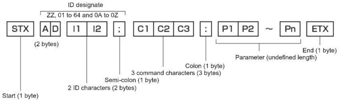
flowchart
graph TD
    A["Start (1 byte)"] --> B["STX"]
    B --> C["A D (2 bytes)"]
    B --> D["I1 I2"]
    D --> E["2 ID characters (2 bytes)"]
    D --> F["..."]
    F --> G["C1 C2 C3"]
    G --> H["Semi-colon (1 byte)"]
    G --> I["Colon (1 byte)"]
    I --> J["P1 P2 ~ Pn"]
    J --> K["End (1 byte)"]
    style A fill:#f9f,stroke:#333
    style K fill:#f9f,stroke:#333
    note right of A: ID designate
    note right of B: ZZ, 01 to 64 and 0A to 0Z
    note right of D: Semi-colon (1 byte)
    note right of G: 3 command characters (3 bytes)
Basic format (has subcommands)
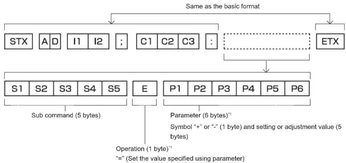
flowchart
graph TD
    A["STX"] --> B["ETX"]
    C["A D"] --> B
    D["I1 I2"] --> B
    E["C1 C2 C3"] --> B
    B --> F["S1 S2 S3 S4 S5"]
    G["E"] --> H["P1 P2 P3 P4 P5 P6"]
    I["Sub command (5 bytes)"] --> J["Operation (1 byte)'"]
    K["Parameter (6 bytes)'"] --> L["“=” (Set the value specified using parameter)"]
    M["Symbol “+” or “-” (1 byte) and setting or adjustment value (5 bytes)"] --> N["Operation (1 byte)'"]
*1 When transmitting a command which does not need a parameter, an operation (E) and parameter are not necessary.
Attention
- If a command is transmitted after the lamp starts illuminating, there may be a delay in response or the command may not be executed. Try sending or receiving any command after 60 seconds.
- When transmitting multiple commands, be sure to wait until 0.5 seconds has elapsed after receiving the response from the projector before sending the next command. When transmitting a command which does not need a parameter, a colon (:) is not necessary.
Note
- If a command cannot be executed, the "ER401" response is sent from the projector to the computer.
- If an invalid parameter is sent, the "ER402" response is sent from the projector to the computer.
- ID transmission in RS-232C supports ZZ (ALL) and 01 to 64, as well as 0A to 0Z groups.
- If a command is sent with a specified ID, a response will be sent to the computer only in the following cases.
-It matches the projector ID
-ID setting is set to ALL and [RESPONSE(ID ALL)] is [ON]
-ID setting is set to GROUP and [RESPONSE(ID GROUP)] is [ON]
- STX and ETX are character codes. STX shown in hexadecimal is 02, and ETX shown in hexadecimal is 03.
When multiple projectors are controlled
When multiple projectors are all controlled
When controlling multiple projectors together via RS-232C, perform the following settings.
1) Set a different ID for each projector.
2) Set [RESPONSE(ID ALL)] to [ON] in only one projector.
3) Set [RESPONSE(ID ALL)] to [OFF] for all other projectors set in Step 2).
When multiple projectors are all controlled by group unit
When controlling multiple projectors by group unit via RS-232C, perform the following settings.
1) Set a different ID for each projector.
2) Set [RESPONSE(ID GROUP)] to [ON] in only one projector.
3) Set [RESPONSE(ID GROUP)] to [OFF] for all other projectors set in Step 2).
Note
- There will be no response if two or more projectors have [RESPONSE(ID ALL)] set to [ON].
- There will be no response if two or more projectors of the same group have [RESPONSE(ID GROUP)] set to [ON].
- When setting multiple groups, set [RESPONSE(ID ALL)] to [ON] in only one projector in each group.
Cable specification
When connected to a computer
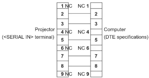
text_image
Projector
( terminal)
1 NC NC 1
2
3
4 NC NC 4
5
6 NC NC 6
7
8
9 NC NC 9
Computer
(DTE specifications)
When multiple projectors are connected
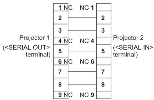
text_image
Projector 1
(
terminal)
1 NC NC 1
2
3
4 NC NC 4
5
6 NC NC 6
7
8
9 NC NC 9
Projector 2
(
terminal)
Control command
The following table lists the commands that can be used to control the projector using a computer.
■Projector control command
| Command Details | Parameter/response string | Remark (parameter) |
| PON Power on | — To check if the power is on, use the “Power query” command. |
| POF Power standby |
| QPW Power query | 000001 | STANDBYPower on |
| IIS | Switching the input signal | VID VIDEORG1 RGB1RG2 RGB2DVI DVI-DHD1 HDMIDL1 DIGITAL LINKSD1 SDI (only for PT-DZ870U) | |
| QSL Query for lamp selection | 0 DUAL1 SINGLE2 LAMP13 LAMP2 | |
| LPM Lamp selection | 0 DUAL1 SINGLE2 LAMP13 LAMP2 | *1 |
| QSL | Lamp cumulative runtime query | 1 LAMP12 LAMP2 | Response is 0000 to 4000 |
| OLP Lamp power | 0 NORMAL1 ECO | |
| OSH Shutter 0 OPEN | | |
| QSH Shutter status query 1 CL | CLOSE | |
| VSE Aspect ratio switch | 0 DEFAULT/VID AUTO1 4:32 16:95 THROUGH6 HV FIT9 H FIT10 | V FIT |
| QSE | Aspect ratio settings query |
| OPP P IN | P execute | 0 OFF1 USER12 USER23 USER3 | |
| QPP P IN | P setting query | 0 OFF1 USER12 USER23 USER3 | |
| OCS Sub | memory switch | 01 - 96 | Sub memory number |
| QSB | Sub memory status query |
*1 Use Lamp 1 or Lamp 2 whichever has a shorter runtime.
■Projector control command (with sub command)
| Command | Sub command | Details | Remark |
| VXX RYCI1 | RGB 1 input setting | +00000 = RGB/YP | _BP_R, +00001 = Y/C |
■ Lens control command
| Command Sub command Details Remark | |
| VXX LNS12 Lens H shift | | +00000 = Fine adjustment 1+, +00001 = Fine adjustment 1-, +00100 = Fine adjustment 2+, +00101 = Fine adjustment 2-, +00200 = Coarse adjustment+, +00201 = Coarse adjustment- |
| VXX LNS13 Lens V shift | |
| VXX LNS14 Lens focus | |
| VXX LNS15 Lens zoom | |
terminal
It is possible to control the projector remotely (by external contact) from a control panel located away from the projector where remote control signals cannot reach.
Use the terminal on the connecting terminals of the projector to connect to the control panel.
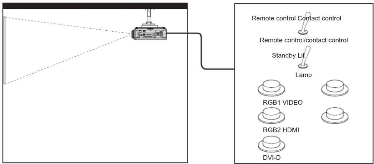
flowchart
graph TD
    A["Remote control Contact control"] --> B["Standby Lit"]
    C["Lamp"] --> B
    B --> D["RGB1 VIDEO"]
    B --> E["RGB2 HDMI"]
    B --> F["DVI-D"]
Installation locations in meeting rooms, etc.
Remote control board in another location
Pin assignments and signal names
| D-Sub 9-pinOutside view | Pin No. Signal name Open (H) Short (L) | | |
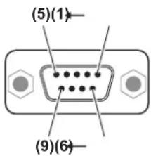 | (1) | GND | — | GND |
| (2) | POWER | OFF | ON |
| (3) | RGB1 | Other | RGB1 |
| (4) | RGB2 | Other | RGB2 |
| (5) | VIDEO | Other | VIDEO |
| (6) | HDMI | Other | HDMI |
| (7) | DVI-D | Other | DVI-D |
| (8) | SHUTTER | OFF | ON |
| (9) | RST/SET | Controlled by remote control | Controlled by external contact |
Attention
- When controlling, make sure to short-circuit pins (1) and (9).
- When pins (1) and (9) are short-circuited, the following buttons on the control panel and the remote control are disabled. Commands for RS-232C and network functions corresponding to these functions are also disabled.
- Power on <|> button, power standby <∅> button, button
- When pins (1) and (9) are short-circuited, and then any pins from (3) to (7) and the pin (1) are short-circuited, the following buttons on the control panel and the remote control are disabled. Commands for RS-232C and network functions corresponding to these functions are also disabled.
- Power on <|> button, power standby <∅> button, button, button,
Note
- For pin (2) to pin (8) settings, you can make changes if you set [REMOTE2 MODE] to [USER]. (→ page 121)
Two-window display combination list
| Sub window |
| RGB1 RGB2 | | VIDEO input |
| Main window RGB Movie | | *1 | Y/C input R | GB Movie | *1 |
| RGB1 | RGB — — — | | | | ✓✓✓ | | |
| Movie*1 | — — — | | | ✓▲▲ | | |
| Y/C input — — — | — | | | ✓ | ▲ | — |
| RGB2 | RGB | ✓✓✓ | | | — | — | ✓ |
| Movie*1 | ✓▲▲ | | | — | — | ▲ |
| VIDEO input | ✓ | ▲ | — | ✓ | ▲ | — |
| DVI-D | RGB*2 | ✓✓✓✓✓✓ | | | | | |
| Movie*3 | ✓▲▲✓▲▲ | | | | | |
| HDMI | RGB*2 | ✓✓✓✓✓✓ | | | | | |
| Movie*3 | ✓▲▲✓▲▲ | | | | | |
| SDI | ✓▲▲✓▲▲ | | | | | |
| DIGITAL LINK | RGB*2 | — — — | — — — | | | | |
| Movie*3 | — — — | — — — | | | | |
| Sub window |
| DVI-D HDMI | | SDI | DIGITAL LINK |
| Main window RGB | ^*2 | Movie ^*3 | RGB ^*2 | Movie ^*3 | RGB ^*2 | Movie ^*3 |
| RGB1 | RGB | √√√√√ | | | | | — | — |
| Movie ^*1 | √▲√▲▲ | | | | | — | — |
| Y/C input | √▲√▲▲ | | | | | — | — |
| RGB2 | RGB | √√√√√ | | | | | — | — |
| Movie ^*1 | √▲√▲▲ | | | | | — | — |
| VIDEO input | √▲√▲▲ | | | | | — | — |
| DVI-D | RGB ^*2 | — | — | √√√ | | | — | — |
| Movie ^*3 | — | — | √▲▲ | | | — | — |
| HDMI | RGB ^*2 | √ | √ | ——— | —— | | | |
| Movie ^*3 | √ | ▲ | ——— | —— | | | |
| SDI | √ | ▲ | ——— | —— | | | |
| DIGITAL LINK | RGB ^*2 | ——— | ——— | | | | | |
| Movie ^*3 | ——— | ——— | | | | | |
√: P IN P (picture in picture) combination is possible
▲: P IN P (picture in picture) combination is possible through the same frequency
—:P IN P (picture in picture) combination is not possible
*1 480i, 480p, 576i, 576p, 720/60p, 720/50p, 1080/60i, 1080/50i, 1080/24sF, 1080/24p, 1080/25p, 1080/30p, 1080/50p, 1080/60p
*2 VGA (640 x 480) - WUXGA (1 920 x 1 200)
Non-interlace signal, dot clock frequency: 25 MHz to 162 MHz (The WUXGA signal is only compatible with VESA CVT RB (Reduced Blanking) signals.)
*3 Only supports 480p, 576p, 720/60p, 720/50p, 1080/60i, 1080/50i, 1080/24sF, 1080/24p, 1080/25p, 1080/30p, 1080/50p, and 1080/60p
Control device password
To initialize your password, consult your distributor.
Upgrade Kit
(Only for PT-DZ870U)
If the optional Upgrade Kit (Model No.: ET-UK20) is applied, the following functions are extended.
| Function Standard s | status When the Upgrade Kit is applied | |
| Adjustment range of [VERTICAL KEYSTONE] | Maximum of ± 40^ 1 | Maximum of ± 45^ 1 |
| Adjustment range of [HORIZONTAL KEYSTONE] | Maximum of ± 15^ 1 | Maximum of ± 40^ 1 |
| Adjustment range of [CURVED] | Vertical arc, Maximum ± 50^ 1Horizontal arc, Maximum ± 50^ 1 | Vertical arc, Maximum ± 100^ 1Horizontal arc, Maximum ± 100^ 1 |
| [CUSTOM MASKING] Cannot be used. The image can be masked in optional form. |
| [PC CORRECTION] of [UNIFORMITY] | Cannot be used. The brightness and unevenness of color of the entire screen can be corrected. |
*1 The adjustment range of the menu. Refer to "[GEOMETRY(2D)] projection range" (→ page 34) for the possible projection range.
For details, refer to the Operating Instructions included in the CD-ROM of the optional Upgrade Kit (Model No.: ET-UK20).
List of compatible signals
The following table specifies the video signals compatible with the projector.
- Symbols that indicate formats are as follows.
-V:VIDEO,Y/C
-R: RGB
-Y: YCC R /YP B P _R
-D: DVI-D
-H: HDMI
- S: SDI (only for PT-DZ870U)
| Mode | Resolution(Dots) | Scanning freq. | Dot clockfreq.(MHz) | Format | Plug and play ^1 |
| Horizontal(kHz) | Vertical(Hz) | RGB2 | DVI-D | HDMI |
| EDID1 | EDID2 | EDID3 |
| NTSC/NTSC4.43/PAL-M/PAL60 | 720 x 480i 15.7 | 59.9 — V | — — — | — — | | | | | | |
| PAL/PAL-N/SECAM | 720 x 576i 15.6 | 50.0 — V | — — — | — — | | | | | | |
| 525i (480i) | 720 x 480i | 15.7 | 59.9 | 13.5 | R/Y/S | — | — | — | — | — |
| 625i (576i) | 720 x 576i | 15.6 | 50.0 | 13.5 | R/Y/S | — | — | — | — | — |
| 525i (480i) | 720 (1440) x 480 ^2 | 15.7 59.9 | 27.0 | D/H | — | — | — | | |
| 625i (576i) | 720 (1440) x 576 ^2 | 15.6 50.0 | 27.0 | D/H | — | — | — | | |
| 525p (480p) | 720 x 483 | 31.5 | 59.9 | 27.0 | R/Y/D/H | — | √ | — | √ | √ |
| 625p (576p) | 720 x 576 | 31.3 | 50.0 | 27.0 | R/Y/D/H | — | √ | — | √ | √ |
| 750 (720)/60p | 1 280 x 720 | 45.0 | 60.0 | 74.3 | R/Y/D/H/S | — | √ | — | √ | √ |
| 750 (720)/50p | 1 280 x 720 | 37.5 | 50.0 | 74.3 | R/Y/D/H/S | — | √ | — | √ | √ |
| 1125 (1080)/60 ^3 | 1 920 x 1 080i | 33.8 | 60.0 | 74.3 | R/Y/D/H/S | — | √ | — | √ | √ |
| 1125 (1080)/50i | 1 920 x 1 080i | 28.1 | 50.0 | 74.3 | R/Y/D/H/S | — | √ | — | √ | √ |
| 1125 (1080)/24p | 1 920 x 1 080 | 27.0 | 24.0 | 74.3 | R/Y/D/H/S | — | √ | — | √ | √ |
| 1125 (1080)/24sF | 1 920 x 1 080i | 27.0 | 48.0 | 74.3 | R/Y/D/H/S | — | — | — | — | — |
| 1125 (1080)/25p | 1 920 x 1 080 | 28.1 | 25.0 | 74.3 | R/Y/D/H/S | — | √ | — | √ | — |
| 1125 (1080)/30p | 1 920 x 1 080 | 33.8 | 30.0 | 74.3 | R/Y/D/H/S | — | — | — | — | — |
| 1125 (1080)/60p | 1 920 x 1 080 | 67.5 | 60.0 | 148.5 | R/Y/D/H/S | — | √ | — | √ | √ |
| 1125 (1080)/50p | 1 920 x 1 080 | 56.3 | 50.0 | 148.5 | R/Y/D/H/S | — | √ | — | √ | √ |
| VESA400 | 640 x 400 | 31.5 | 70.1 | 25.2 | R/D/H | — | — | — | — | — |
| 640 x 400 | 37.9 | 85.1 | 31.5 | R/D/H | — | — | — | — | — |
| VGA480 | 640 x 480 | 31.5 59.9 | 25.2 | R/D/H | √ | √ | √ | √ | √ |
| 640 x 480 | 35.0 | 66.7 | 30.2 | R/D/H | — | — | — | — | — |
| 640 x 480 | 37.9 72.8 | 31.5 | R/D/H | √ | — | √ | √ | √ |
| 640 x 480 | 37.5 75.0 | 31.5 | R/D/H | √ | — | √ | √ | √ |
| 640 x 480 | 43.3 | 85.0 | 36.0 | R/D/H | — | — | — | — | — |
Chapter 6 Appendix — Technical information
| Mode | Resolution(Dots) | Scanning freq. | Dot clockfreq.(MHz) | Format | Plug and play*1 |
| Horizontal(kHz) | Vertical(Hz) | RGB2 | DVI-D | HDMI |
| EDID1 | EDID2 | EDID3 |
| SVGA | 800 x 600 35.2 | 56.3 36.0 | R/D/H | | | √ | — | √√√ | | |
| 800 x 600 37.9 | 60.3 40.0 | R/D/H | | | √ | — | √√√ | | |
| 800 x 600 48.1 | 72.2 50.0 | R/D/H | | | √ | — | √√√ | | |
| 800 x 600 46.9 | 75.0 49.5 | R/D/H | | | √ | — | √√√ | | |
| 800 x 600 53.7 | 85.1 56.3 | R/D/H — | — — — — | | | | | | |
| MAC16 832 x 62 | 4 49.7 74.6 57.3 R/D/H | | | | | √ | — | √√√ | | |
| XGA | 1 024 x 768 39.6 | 50.0 51.9 | R/D/H — | — — — — | | | | | | |
| 1 024 x 768 48.4 | 60.0 65.0 | R/D/H | | | √ | — | √√√ | | |
| 1 024 x 768 56.5 | 70.1 75.0 | R/D/H | | | √ | — | √√√ | | |
| 1 024 x 768 60.0 | 75.0 78.8 | R/D/H | | | √ | — | √√√ | | |
| 1 024 x 768 65.5 | 81.6 86.0 | R/D/H — | — — — — | | | | | | |
| 1 024 x 768 68.7 | 85.0 94.5 | R/D/H — | — — — — | | | | | | |
| 1 024 x 768 81.4 | 100.0 11 | 3.3 R/D/H | | *4 | — — | — — — | | | |
| 1 024 x 768 98.8 | 120.0 13 | 9.1 | R/D/H | *4 | √ | — | √√√ | | |
| MXGA | 1 152 x 864 53.7 | 60.0 81.6 | R/D/H — | — — — — | | | | | | |
| 1 152 x 864 64.0 | 70.0 94.2 | R/D/H — | — — — — | | | | | | |
| 1 152 x 864 67.5 | 74.9 | 108.0 | R/D/H — — — — — | | | | | | |
| 1 152 x 864 77.1 | 85.0 | 119.7 | R/D/H — — — — — | | | | | | |
| MAC21 | 1 152 x 870 68.7 | 75.1 | 100.0 | R/D/H | | √ | — | √√√ | | |
| 1280 x 720 | 1 280 x 720 37.1 | 49.8 60.5 | R/D/H — | — — — — | | | | | | |
| 1 280 x 720 44.8 | 59.9 74.5 | R/D/H — | — — — — | | | | | | |
| 1 280 x 720 76.3 | 100.0 13 | 1.8 | R/D/H | *4 | — — | — — — | | | |
| 1 280 x 720 92.6 | 120.0 16 | 1.6 | R/D/H | *4 | — — | — — — | | | |
| 1280 x 768 | 1 280 x 768 39.6 | 49.9 65.3 | R/D/H — | — — — — | | | | | | |
| 1 280 x 768 47.8 | 59.9 79.5 | R/D/H — | — — — — | | | | | | |
| 1 280 x 768*5 | 47.4 60 | 0.68.3 R/D/H — — — — — | | | | | | | |
| 1 280 x 768 60.3 | 74.9 | 102.3 | R/D/H — — — — — | | | | | | |
| 1 280 x 768 68.6 | 84.8 | 117.5 | R/D/H — — — — — | | | | | | |
| 1280 x 800 | 1 280 x 800 41.3 | 50.0 68.0 | R/D/H — | — — — — | | | | | | |
| 1 280 x 800 49.7 | 59.8 83.5 | R/D/H | | | √*6 | — | √*6 | √*6 | √*6 |
| 1 280 x 800*5 | 49.3 59.9 | 71.0 R/D/H — — — — — | | | | | | | |
| 1 280 x 800 62.8 | 74.9 | 106.5 | R/D/H — — — — — | | | | | | |
| 1 280 x 800 71.6 | 84.9 | 122.5 | R/D/H — — — — — | | | | | | |
| MSXGA 1 280 x | 960 60.0 60.0 | 108.0 | | R/D/H — — — — — | | | | | | |
| SXGA | 1 280 x 1 024 | 52.4 50.0 | 88.0 R/D/H — — — — — | | | | | | | |
| 1 280 x 1 024 | 64.0 60.0 | | 108.0 | R/D/H | √ | — | √√√ | | |
| 1 280 x 1 024 | 72.3 | 66.3 | 125.0 | R/D/H | — | — | — | — | — |
| 1 280 x 1 024 | 78.2 | 72.0 | 135.1 | R/D/H | — | — | — | — | — |
| 1 280 x 1 024 | 80.0 75.0 | | 135.0 | R/D/H | √ | — | √√√ | | |
| 1 280 x 1 024 | 91.1 | 85.0 | 157.5 | R/D/H | — | — | — | — | — |
| 1366 x 768 | 1 366 x 768 47.7 | 59.8 85.5 | R/D/H — | — — — — | | | | | | |
| 1 366 x 768 39.6 | 49.9 69.0 | R/D/H — | — — — — | | | | | | |
| SXGA+ | 1 400 x 1 050 | 54.1 50.0 | 99.9 R/D/H — — — — — | | | | | | | |
| 1 400 x 1 050 | 64.0 | 60.0 | 108.0 | R/D/H | — | — | — | — | — |
| 1 400 x 1 050 | 65.2 60.0 | | 122.6 | R/D/H | √ | — | √√√ | | |
| 1 400 x 1 050 | 65.3 | 60.0 | 121.8 | R/D/H | — | — | — | — | — |
| 1 400 x 1 050 | 78.8 | 72.0 | 149.3 | R/D/H | — | — | — | — | — |
| 1 400 x 1 050 | 82.2 | 75.0 | 155.9 | R/D/H | — | — | — | — | — |
| WXGA+ | 1 440 x 900 55.9 | 59.9 | 106.5 | R/D/H — — — — — | | | | | | |
| 1 440 x 900 46.3 | 49.9 86.8 | R/D/H — — — — — | | | | | | | |
| UXGA60 | 1 600 x 1 200 | 75.0 | 60.0 | 162.0 | R/D/H | √ | — | √√√ | | |
| WSXGA+ | 1 680 x 1 050 | 65.3 | 60.0 | 146.3 | R/D/H | — | — | — | — | — |
| 1 680 x 1 050 | 54.1 | 50.0 | 119.5 | R/D/H | — | — | — | — | — |
Chapter 6 Appendix — Technical information
| Mode | Resolution(Dots) | Scanning freq. | Dot clockfreq.(MHz) | Format | Plug and play*1 |
| Horizontal(kHz) | Vertical(Hz) | RGB2 | DVI-D | HDMI |
| EDID1 | EDID2 | EDID3 |
| 1920 x 1080 | 1 920 x 1 080 55.6 | 49.9 14 | 1.5 R/D/H | — — — — — | | | | | | |
| 1 920 x 1 080*5 | 66.6 59 | 9.9 138.5 | R/D/H — — — — — | — | | | | | |
| 1 920 x 1 080*7 | 67.2 60 | 0.0 173.0 | R — — — — — | | | | | | |
| WUXGA | 1 920 x 1 200 61.8 | 49.9 15 | 8.3 R/D/H | — — — — — | | | | | | |
| 1 920 x 1 200*5 | 74.0 60 | 0.0 154.0 | R/D/H | | √ | — | √ | √*8 | √*8 |
| 1 920 x 1 200*7 | 74.6 59 | 9.9 193.3 | R — — — — — | | | | | | |
*1 Signals with √ in the Plug and play columns are signals described in EDID (extended display identification data) of the projector. A signal, which has no √ in the Plug and play columns but has an entry in the Format column, can be input. For signals without √ in the Plug and play columns, resolution may not be selected in the computer even though the projector supports them.
*2 Pixel-Repetition signal (dot clock frequency 27.0 MHz) only
*3 When a 1125 (1035)/60i signal was input, it is displayed as a 1125 (1080)/60i signal.
*4 When [3D INPUT FORMAT] is set to [AUTO], 3D images in frame sequential format are displayed. To display images in 2D, set [3D INPUT FORMAT] to [NATIVE].
*5 VESA CVT-RB (Reduced Blanking)-compliant
*6 Only for PT-DW830U
*7 Samples the pixels in the image processing circuit and projects the image.
*8 Only for PT-DZ870U
Note
- The display dot for PT-DZ870U is 1920 x 1200, the display dot for PT-DW830U is 1280 x 800, and the display dot for PT-DX100U is 1024 x 768. A signal with a different resolution is converted to the number of display dots.
- The "i" at the end of the resolution indicates an interlaced signal.
- When interlaced signals are connected, flickering may occur on the projected image.
- DIGITAL LINK input compatible signal is the same as HDMI input compatible signal.
List of 3D compatible signals
The following table specifies the 3D compatible video signals that the projector can project.
- Abbreviations for input formats and 3D formats in the table have the following meanings.
-FP: Frame packing system
-SBS: Side by side system
-TB: Top and bottom system
-LBL: Line by line system
-FS: Frame sequential system
-3G: 3G-SDI Level B simultaneous system
-H-D: HDMI & DVI-D Input simultaneous system
-R1-2: RGB1 & RGB2 Input simultaneous system
| 3D compatible signal | Resolution (Dots) | Scanning freq. | Dot clock freq. (MHz) | HDMI | DVI-D |
| Horizontal (kHz) | Vertical (Hz) | FP | SBS*1 | TB | FS | SBS*1 | TB | LBL | FS |
| 750 (720)/60p | 1 280 x 720 | 45.0 | 60.0 | 74.3 | ✓✓✓ | | | — | ✓✓✓ | | | — |
| 750 (720)/50p | 1 280 x 720 | 37.5 | 50.0 | 74.3 | ✓✓✓ | | | — | ✓✓✓ | | | — |
| 1080/60i | 1 920 x 1 080i | 33.8 | 60.0 | 74.3 | ✓ | ✓ | — | — | ✓ | ✓ | — | — |
| 1080/50i | 1 920 x 1 080i | 28.1 | 50.0 | 74.3 | ✓ | ✓ | — | — | ✓ | ✓ | — | — |
| 1080/24p | 1 920 x 1 080 | 27.0 | 24.0 | 74.3 | ✓✓✓ | | | — | ✓ | ✓ | — | — |
| 1080/24sF | 1 920 x 1 080i | 27.0 | 48.0 | 74.3 | — | — | — | — | ✓ | ✓ | — | — |
| 1080/25p | 1 920 x 1 080 | 28.1 | 25.0 | 74.3 | — | — | — | — | ✓ | ✓ | — | — |
| 1080/30p | 1 920 x 1 080 | 33.8 | 30.0 | 74.3 | — | — | — | — | ✓ | ✓ | — | — |
| 1080/60p | 1 920 x 1 080 | 67.5 | 60.0 | 148.5 | — | ✓ | ✓ | — | ✓ | ✓ | — | — |
| 1080/50p | 1 920 x 1 080 | 56.3 | 50.0 | 148.5 | — | ✓ | ✓ | — | ✓ | ✓ | — | — |
| VGA480 | 640 x 480 | 31.5 | 59.9 | 25.2 | — | — | — | — | ✓ | — | — | — |
| SVGA | 800 x 600 | 37.9 | 60.3 | 40.0 | — | — | — | — | ✓ | — | — | — |
| XGA | 1 024 x 768 | 39.6 | 50.0 | 51.9 | — | — | — | — | ✓ | — | — | — |
| 1 024 x 768 | 48.4 | 60.0 | 65.0 | — | — | — | — | ✓ | — | — | — |
| 1 024 x 768 | 81.4 | 100.0 | 113.3 | — | — | — | ✓ | — | — | — | ✓ |
| 1 024 x 768 | 98.8 | 120.0 | 139.1 | — | — | — | ✓ | — | — | — | ✓ |
| MXGA | 1 152 x 864 | 53.7 | 60.0 | 81.6 | — | — | — | — | ✓ | — | — | — |
Chapter 6 Appendix — Technical information
| 3D compatible signal | Resolution(Dots) | Scanning freq. | Dot clockfreq.(MHz) | HDMI DVI-D | |
| Horizontal(kHz) | Vertical(Hz) | FP | SBS*1 | TB FS | SBS*1 | TB L | BL FS | | |
| 1280 x 720 | 1 280 x 720 37.1 | 49.8 60.5 | — — — — | | | | | | √ | — — | — | |
| 1 280 x 720 44.8 | 59.9 74.5 | — — — — | | | | | | √ | — — | — | |
| 1 280 x 720 76.3 | 100.0 131 | 8 — — — | | | | | √ | — — | — | | √ |
| 1 280 x 720 92.6 | 120.0 161 | 6 — — — | | | | | √ | — — | — | | √ |
| 1280 x 768 | 1 280 x 768 39.6 | 49.9 65.3 | — — — — | | | | | | √ | — — | — | |
| 1 280 x 768 47.8 | 59.9 79.5 | — — — — | | | | | | √ | — — | — | |
| 1 280 x 768*2 | 47.4 60 | 0 68.3 — — — | | | | | | √ | — — | — | |
| 1280 x 800 | 1 280 x 800 41.3 | 50.0 68.0 | — — — — | | | | | | √ | — — | — | |
| 1 280 x 800 49.7 | 59.8 83.5 | — — — — | | | | | | √ | — — | — | |
| 1 280 x 800*2 | 49.3 59 | 9 71.0 — — — | | | | | | √ | — — | — | |
| MSXGA 1 280 x | 960 60.0 60.0 108.0 | — — — — | | | | | | | √ | — — | — | |
| SXGA | 1 280 x 1 024 52.4 | 50.0 88.0 | — — — — | | | | | | √ | — — | — | |
| 1 280 x 1 024 64.0 | 60.0 108.0 | 0 — — — — | | | | | | √ | — — | — | |
| 1366 x 768 | 1 366 x 768 47.7 | 59.8 85.5 | — — — — | | | | | | √ | — — | — | |
| 1 366 x 768 39.6 | 49.9 69.0 | — — — — | | | | | | √ | — — | — | |
| SXGA+ | 1 400 x 1 050 54.1 | 50.0 99.9 | — — — — | | | | | | √ | — — | — | |
| 1 400 x 1 050 64.0 | 60.0 108.0 | 0 — — — — | | | | | | √ | — — | — | |
| 1 400 x 1 050 65.2 | 60.0 122.6 | — — — — | | | | | | √ | — — | — | |
| 1 400 x 1 050 65.3 | 60.0 121.8 | — — — — | | | | | | √ | — — | — | |
| WXGA+ | 1 440 x 900 55.9 | 59.9 106.5 | — — — — | | | | | | √ | — — | — | |
| 1 440 x 900 46.3 | 49.9 86.8 | — — — — | | | | | | √ | — — | — | |
| UXGA60 1 600 x | 1 200 75.0 60.0 162.0 | — — — — | | | | | | | √ | — — | — | |
| WSXGA+ | 1 680 x 1 050 65.3 | 60.0 146.3 | — — — — | | | | | | √ | — — | — | |
| 1 680 x 1 050 54.1 | 50.0 | 119.5 | — — — — | | | | | √ | — — | — | |
| 1920 x 1080 | 1 920 x 1 080 55.6 | 49.9 141.5 | — — — — | | | | | | √ | — — | — | |
| 1 920 x 1 080*2 | 66.6 59 | 9 138.5 — — — | | | | | | √ | — — | — | |
| WUXGA | 1 920 x 1 200 61.8 | 49.9 158.3 | — — — — | | | | | | √ | — — | — | |
| 1 920 x 1 200*2 | 74.0 60 | 0 154.0 — — — | | | | | | √ | — | √ | — |
*1 Supports half.
*2 VESA CVT RB (Reduced Blanking)-compliant
Chapter 6 Appendix — Technical information
| 3D compatible signal | Resolution(Dots) | Scanning freq. | Dot clockfreq.(MHz) | RGB1/RGB2 SDI | *1 | H-D | R1-2 |
| Horizontal(kHz) | Vertical(Hz) | SBS*2 | TB | LBL | FS | SBS*2 | TB | LBL | 3G |
| 750 (720)/60p 1 280 x 720 45.0 60.0 74.3 | | | | ✓✓✓ | | | — | ✓✓✓ | ✓✓✓ | | | | |
| 750 (720)/50p 1 280 x 720 37.5 50.0 74.3 | | | | ✓✓✓ | | | — | ✓✓✓ | ✓✓✓ | | | | |
| 1080/60i 1 920 x 1 080i 33.8 60.0 74.3 | | | | ✓ | ✓ | — | — | ✓ | ✓ | — | ✓✓✓ | | |
| 1080/50i 1 920 x 1 080i 28.1 50.0 74.3 | | | | ✓ | ✓ | — | — | ✓ | ✓ | — | ✓✓✓ | | |
| 1080/24p 1 920 x 1 080 27.0 24.0 74.3 | | | | ✓ | ✓ | — | — | ✓ | ✓ | — | ✓✓✓ | | |
| 1080/24sF 1 920 x 1 080i 27.0 48.0 74.3 | | | | ✓ | ✓ | — | — | ✓ | ✓ | — | ✓✓✓ | | |
| 1080/25p 1 920 x 1 080 28.1 25.0 74.3 | | | | ✓ | ✓ | — | — | ✓ | ✓ | — | ✓✓✓ | | |
| 1080/30p 1 920 x 1 080 33.8 30.0 74.3 | | | | ✓ | ✓ | — | — | ✓ | ✓ | — | ✓✓✓ | | |
| 1080/60p 1 920 x 1 080 67.5 60.0 148.5 | | | | ✓ | ✓ | — | — | ✓ | ✓ | — | — | ✓ | ✓ |
| 1080/50p 1 920 x 1 080 56.3 50.0 148.5 | | | | ✓ | ✓ | — | — | ✓ | ✓ | — | — | ✓ | ✓ |
| VGA480 640 x 480 31.5 59.9 25.2 | | | | ✓ | — | — | — | — | — | — | — | | |
| SVGA | 800 x 600 | 37.9 60.3 40.0 | | | ✓ | — | — | — | — | — | — | — | | |
| XGA | 1 024 x 768 39.6 50.0 51.9 | | | | ✓ | — | — | — | — | — | | | ✓ | ✓ |
| 1 024 x 768 48.4 60.0 65.0 | | | | ✓ | — | — | — | — | — | | | ✓ | ✓ |
| 1 024 x 768 | 81.4 | 100.0 | 113.3 | — | — | — | ✓ | — | — | — | — | | |
| 1 024 x 768 | 98.8 | 120.0 | 139.1 | — | — | — | ✓ | — | — | — | — | | |
| MXGA 1 152 x 864 53.7 60.0 81.6 | | | | ✓ | — | — | — | — | — | — | — | | |
| 1280 x 720 | 1 280 x 720 37.1 49.8 60.5 | | | | ✓ | — | — | — | — | — | — | — | | |
| 1 280 x 720 44.8 59.9 74.5 | | | | ✓ | — | — | — | — | — | — | — | | |
| 1 280 x 720 | 76.3 | 100.0 | 131.8 | — | — | — | ✓ | — | — | — | — | | |
| 1 280 x 720 | 92.6 | 120.0 | 161.6 | — | — | — | ✓ | — | — | — | — | | |
| 1280 x 768 | 1 280 x 768 39.6 49.9 65.3 | | | | ✓ | — | — | — | — | — | — | — | | |
| 1 280 x 768 47.8 59.9 79.5 | | | | ✓ | — | — | — | — | — | — | — | | |
| 1 280 x 768*3 | 47.4 60.0 68.3 | | | ✓ | — | — | — | — | — | — | — | | |
| 1280 x 800 | 1 280 x 800 41.3 50.0 68.0 | | | | ✓ | — | — | — | — | — | | | ✓ | ✓ |
| 1 280 x 800 49.7 59.8 83.5 | | | | ✓ | — | — | — | — | — | | | ✓ | ✓ |
| 1 280 x 800*3 | 49.3 59.9 71.0 | | | ✓ | — | — | — | — | — | | | ✓ | ✓ |
| MSXGA | 1 280 x 960 60.0 60.0 108.0 | | | | ✓ | — | — | — | — | — | — | — | | |
| SXGA | 1 280 x 1 024 52.4 50.0 88.0 | | | | ✓ | — | — | — | — | — | — | — | | |
| 1 280 x 1 024 64.0 60.0 108.0 | | | | ✓ | — | — | — | — | — | — | — | | |
| 1366 x 768 | 1 366 x 768 47.7 59.8 85.5 | | | | ✓ | — | — | — | — | — | — | — | | |
| 1 366 x 768 39.6 49.9 69.0 | | | | ✓ | — | — | — | — | — | — | — | | |
| SXGA+ | 1 400 x 1 050 54.1 50.0 99.9 | | | | ✓ | — | — | — | — | — | — | — | | |
| 1 400 x 1 050 64.0 60.0 108.0 | | | | ✓ | — | — | — | — | — | — | — | | |
| 1 400 x 1 050 65.2 60.0 122.6 | | | | ✓ | — | — | — | — | — | — | — | | |
| 1 400 x 1 050 65.3 60.0 121.8 | | | | ✓ | — | — | — | — | — | — | — | | |
| WXGA+ | 1 440 x 900 55.9 59.9 106.5 | | | | ✓ | — | — | — | — | — | — | — | | |
| 1 440 x 900 46.3 49.9 86.8 | | | | ✓ | — | — | — | — | — | — | — | | |
| UXGA60 | 1 600 x 1 200 75.0 60.0 162.0 | | | | ✓ | — | — | — | — | — | — | — | | |
| WSXGA+ | 1 680 x 1 050 65.3 60.0 146.3 | | | | ✓ | — | — | — | — | — | — | — | | |
| 1 680 x 1 050 54.1 50.0 119.5 | | | | ✓ | — | — | — | — | — | — | — | | |
| 1920 x 1080 | 1 920 x 1 080 55.6 49.9 141.5 | | | | ✓ | — | — | — | — | — | — | — | | |
| 1 920 x 1 080*3 | 66.6 59.9 138.5 | | | ✓ | — | — | — | — | — | — | — | | |
| WUXGA | 1 920 x 1 200 61.8 49.9 158.3 | | | | ✓ | — | — | — | — | — | | | ✓ | ✓ |
| 1 920 x 1 200*3 | 74.0 60.0 154.0 | | | ✓ | — | ✓ | — | — | — | — | | ✓ | ✓ |
*1 Only for PT-DZ870U
*2 Supports half.
*3 VESA CVT RB (Reduced Blanking)-compliant
Note
- DIGITAL LINK input compatible signal is the same as HDMI input compatible signal.
Specifications
The specifications of the projector are as follows.
| Power supply AC 120 V - 240 V | 50 Hz/60 Hz |
| Power consumption | 1 030 W (10 A - 5.2 A) |
| 0.3 W when [STANDBY MODE] is set to [ECO]3 W when [STANDBY MODE] is set to [NORMAL] |
| DLP chip | Size | PT-DZ870U 17 mm (0.67") (aspect ratio 16:10) |
| PT-DW830U 16.5 mm (0.65") (aspect ratio 16:10) |
| PT-DX100U 17.8 mm (0.7") (aspect ratio 4:3) |
| Display system 1-unit DLP chip, DLP type |
| Number of pixels | PT-DZ870U 2 304 000 pixels (1 920 x 1 200 dots) |
| PT-DW830U 1 024 000 pixels (1 280 x 800 dots) |
| PT-DX100U 786 432 pixels (1 024 x 768 dots) |
| Lens*1 | Electric zoom | PT-DZ870U 1.7 - 2.4:1 | |
| PT-DW830U, PT-DX100U 1.8 - 2.5:1 |
| Electric focus | F = 1.7 - 1.9f = 25.6 mm - 35.7 mm |
| Luminous lamp 420 W UHM lamp x 2 |
| Light output*2*3 | PT-DZ870U, PT-DW830U 8 500 lm(ANSI) |
| PT-DX100U 10 000 lm(ANSI) | |
| Contrast ratio*3 | 10 000:1 (when [DYNAMIC IRIS] is set to [3]) |
| Color system 7 standards (NTSC/NTSC4.43/PAL/PAL-N/PAL-M/SECAM/PAL60) |
| Projection screen size*4 | 1.27 m (50") to 15.24 m (600") |
| Screen aspect ratio | PT-DZ870U, PT-DW830U 16:10 | |
| PT-DX100U 4:3 | |
| Projection method [FRONT/CEILING], [FRONT/FLOOR], [REAR/CEILING], [REAR/FLOOR] |
| Power cable length 3.0 m (118-1/8") |
| Outer case Molded plastic | |
| Dimensions | Width 498 mm (19-19/32") |
| Height 200 mm (7-7/8") (with legs at shortest position) |
| Depth | PT-DZ870U, PT-DW830U,PT-DX100U | 556 mm (21-7/8") (including standard zoom lens) |
| PT-DZ870UL, PT-DW830UL,PT-DX100UL | 513 mm (20-3/16") (excluding optional lens) |
| Weight | PT-DZ870U, PT-DW830U,PT-DX100U | Approx. 18.3 kg (40 lbs.)5 (including standard zoom lens) |
| PT-DZ870UL, PT-DW830UL,PT-DX100UL | Approx. 17.6 kg (38.8 lbs.)5 (excluding optional lens) |
| Noise level*3 | 40 dB |
| Operating environment temperature*6 | 0 °C (32 °F) to 45 °C (113 °F) |
|
| Remote control | Power supply | DC 3 V (AAA/R03 battery x 2) |
| Operating range | Within approx. 30 m (98'5") (when operated directly in front of signal receiver) |
| Weight | 102 g (3.6 oz.) (including batteries) |
| Dimensions | Width: 48 mm (1-7/8"), Height: 145 mm (5-23/32"), Depth: 27 mm (1-1/16") |
*1 For PT-DZ870UL, PT-DW830UL, and PT-DX100UL, lenses are optional accessories.
*2 Value is for the supplied standard zoom lens. The value varies depending on the lens.
*3 Measurement, measuring conditions and method of notation all comply with ISO21118 international standards.
*4 When the ET-DLE055 lens is used, the maximum size is 5.08 m (200").
*5 Average value. Weight varies for each product.
*6 When using the projector at high altitudes (1 400 m (4 593') or higher – lower than 2 700 m (8 858') above sea level), the operating environment temperature should be between 0 °C (32 °F) - 40 °C (104 °F).
If you use the Replacement lamp unit (for portrait mode), the operating environment temperature should be between 0 °C (32 °F) and 40 °C (104 °F) when using the projector at elevations lower than 1 400 m (4 593') above sea level, and between 0 °C (32 °F) and 35 °C (95 °F) when using the projector at high altitudes.
If the [PROJECTOR SETUP] menu → [LAMP SELECT] is set to [DUAL], and [LAMP POWER] is set to [NORMAL], and the operating environment temperature reaches 40 °C (104 °F) or higher (35 °C (95 °F) or higher when [HIGH ALTITUDE MODE] is set to [ON]), the light output may drop by approx. 20 % to protect the projector.
■Applicable scanning frequency
Refer to "List of compatible signals" ( page 178) for the types of video signals that can be used with the projector.
| For video signal(including Y/C signal) | Horizontal: 15.75 kHz/15.63 kHz, Vertical: 50 Hz/60 Hz |
| For RGB signal | Horizontal: 15 kHz to 100 kHz, Vertical: 24 Hz to 120 HzPIAS (Panasonic Intelligent Auto Scanning) system |
| Dot clock frequency: 162 MHz or less |
| For YC_BC_R/YP_BP_R signal | 525i (480i)Horizontal: 15.75 kHz, Vertical: 60 Hz525p (480p)Horizontal: 31.5 kHz, Vertical: 60 Hz750 (720)/60pHorizontal: 45 kHz, Vertical: 60 Hz1125 (1035)/60iHorizontal: 33.75 kHz, Vertical: 60 Hz1125 (1080)/50iHorizontal: 28.13 kHz, Vertical: 50 Hz1125 (1080)/24sFHorizontal: 27 kHz, Vertical: 48 Hz1125 (1080)/30pHorizontal: 33.75 kHz, Vertical: 30 Hz1125 (1080)/50pHorizontal: 56.25 kHz, Vertical: 50 HzThe SYNC/HD and VD terminals do not support 3 value SYNC. | 625i (576i)Horizontal: 15.63 kHz, Vertical: 50 Hz625p (576p)Horizontal: 31.25 kHz, Vertical: 50 Hz750 (720)/50pHorizontal: 37.5 kHz, Vertical: 50 Hz1125 (1080)/60iHorizontal: 33.75 kHz, Vertical: 60 Hz1125 (1080)/24pHorizontal: 27 kHz, Vertical: 24 Hz1125 (1080)/25pHorizontal: 28.13 kHz, Vertical: 25 Hz1125 (1080)/60pHorizontal: 67.5 kHz, Vertical: 60 Hz |
| For DVI-D signal | 525i (480i)*1, 625i (576i)*1, 525p (480p), 625p (576p), 750 (720)/60p, 750 (720)/50p, 1125 (1080)/60i, 1125 (1080)/50i, 1125 (1080)/24p, 1125 (1080)/24sF, 1125 (1080)/25p, 1125 (1080)/30p, 1125 (1080)/60p, 1125 (1080)/50p |
| Displayable resolution: VGA to WUXGA (non-interlaced)Dot clock frequency: 25 MHz to 162 MHz |
| For HDMI signal | 525i (480i)*1, 625i (576i)*1, 525p (480p), 625p (576p), 750 (720)/60p, 750 (720)/50p, 1125 (1080)/60i, 1125 (108O)/50i, 1125 (1080)/24p, 1125 (1080)/24sF, 1125 (1080)/25p, 1125 (1080)/30p, 1125 (1080)/60p, 1125 (1080)/50p |
|
| Displayable resolution: VGA to WUXGA (non-interlaced)Dot clock frequency: 25 MHz to 162 MHz |
| For SDI signal(Only for PT-DZ870U) | SD-SDI signal SMPTE ST 259 compliant YC_BC_R 4:2:2 10-bit480i, 576iSingle link HD-SDI signal SMPTE ST 292 compliant YP_BP_R 4:2:2 10-bit720/50p, 720/60p, 1035/60i, 1080/50i, 1080/60i, 1080/25p, 1080/24p, 1080/24sF, 1080/30p3G-SDI signal SMPTE ST 424 compliant YP_BP_R 4:2:2 10-bit1080/50p, 1080/60pRGB 4:4:4 12-bit/10-bit1080/50i, 1080/60i, 1080/25p, 1080/24p, 1080/24sF, 1080/30p |
*1 Pixel-Repetition signal (dot clock frequency 27.0 MHz) only
Note
- DIGITAL LINK input compatible signal is the same as HDMI input compatible signal.
Terminal
| 1 set (BNC x 5 (RGB/YP _B P _R /YC _B C _R /YC x 1))RGB signal 0.7 V [p-p] 75 Ω (SYNC ON GREEN: 1.0 V [p-p] 75 Ω)SYNC/HD TTL high impedance, automatic positive/negative polarity compatibleVD TTL high impedance, automatic positive/negative polarity compatibleYP _B P _R signal Y: 1.0 V [p-p] including synchronization signal, P _B P _R : 0.7 V [p-p] 75 ΩY/C signal Y: 1.0 V [p-p], C: 0.286 V [p-p] 75 Ω |
| 1 set, high-density D-Sub 15 p (female)RGB signal 0.7 V [p-p] 75 Ω (SYNC ON GREEN: 1.0 V [p-p] 75 Ω)SYNC/HD TTL high impedance, automatic positive/negative polarity compatibleVD TTL high impedance, automatic positive/negative polarity compatibleYP _B P _R signal Y: 1.0 V [p-p] including synchronization signal, P _B P _R : 0 .7 V [p-p] 75 Ω |
| 24 p, single link DVI 1.0 compliant, HDCP compatible |
| 19 pin, HDCP compatible, Deep Color compatible |
| 1.0 V [p-p] 75 Ω |
| 1 set (BNC)SD-SDI signal SMPTE ST 259 compliantHD-SDI signal SMPTE ST 292 compliant3G-SDI signal SMPTE ST 424 compliant |
| 1 set (BNC)During input setting TTL high impedanceDuring output setting TTL output: Maximum 10 mA |
| 1 set (BNC)TTL output: Maximum 10 mA |
| D-Sub 9 p, 1 set each, RS-232C compliant, for computer control |
| M3 stereo mini jack cable, 1 set each, for remote control (wired)/projector link control |
| D-Sub 9 p, for external control |
| 1 set, RJ-45 network, for DIGITAL LINK connection, PJLink compatible, 100Base-TX, Art-Net compatible |
Note
- The model numbers of accessories and optional components are subject to change without prior notice.
Dimensions
Unit: mm

text_image
Pensone
513 (20-3/16")
43 (1-11/16)
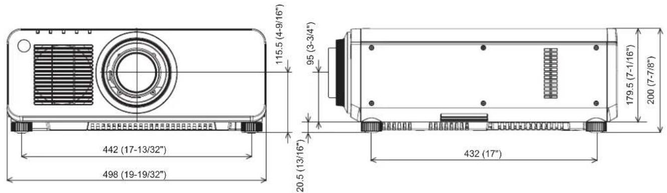
text_image
115.5 (4-9/16")
95 (3-3/4")
20.5 (13/16")
442 (17-13/32")
498 (19-19/32")
179.5 (7-1/16")
200 (7-7/8")
432 (17)
* The above dimensions are obtained when the standard zoom lens is attached.
* Actual dimensions may differ depending on the product.
Precautions for Ceiling Mount Bracket
- When installing the projector to a ceiling, be sure to use the specified optional Ceiling Mount Bracket (Model No.: ET-PKD120H (for high ceilings), ET-PKD120S (for low ceilings), ET-PKD120B (Projector Mount Bracket)). Ceiling Mount Bracket (Model No.: ET-PKD120H (for high ceilings), ET-PKD120S (for low ceilings)) is used in combination with Ceiling Mount Bracket (Model No.: ET-PKD120B (Projector Mount Bracket)).
- When installing the projector, attach the drop-prevention kit included with the Ceiling Mount Bracket.
When the drop-prevention kit (Service Model No.: TTRA0214) is necessary, consult your dealer.
- Ask a qualified technician to do the installation work such as mounting the projector on the ceiling.
- Panasonic takes no responsibility for any damage to the projector resulting from use of a ceiling mount bracket not manufactured by Panasonic or the inappropriate choice of location for installation, even if the warranty period of the projector has not expired.
- Unused products must be removed promptly by a qualified technician.
- Use a torque screwdriver or Allen torque wrench to tighten bolts to their specified tightening torques. Do not use electric screwdrivers or impact screwdrivers.
- Read the Installation Instructions for the Ceiling Mount Bracket for details.
- The model numbers of accessories and optional accessories are subject to change without prior notice.
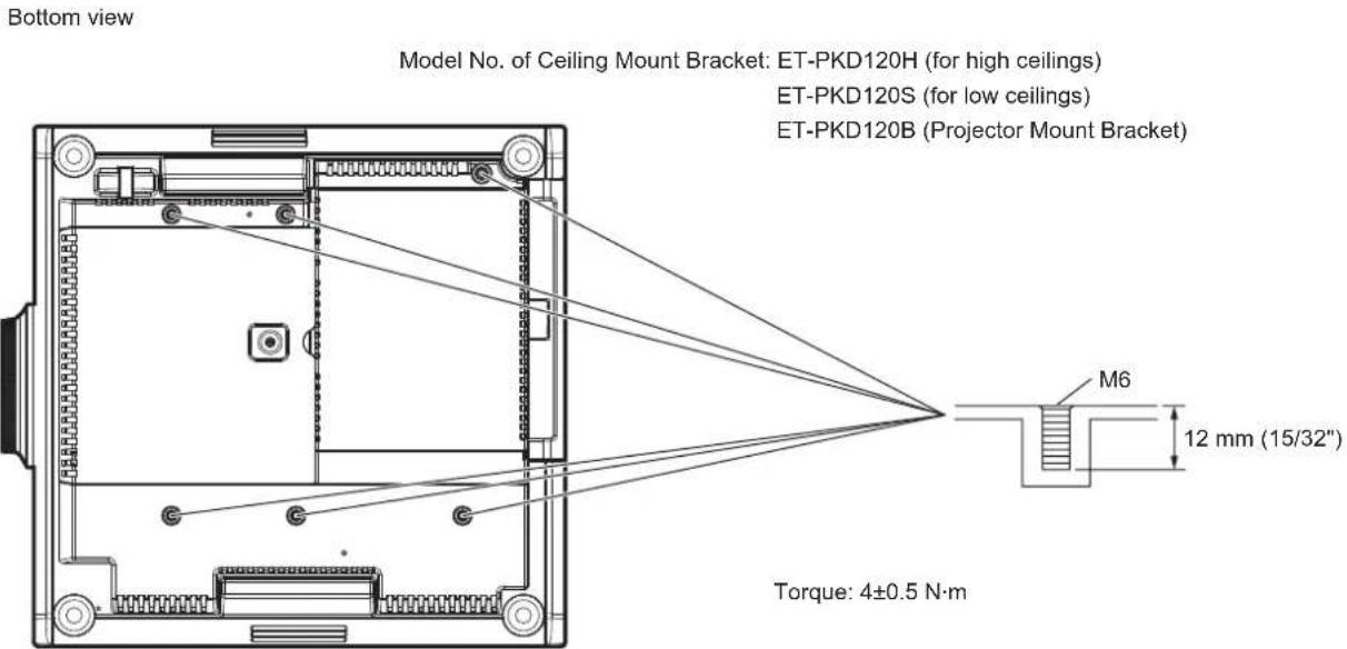
text_image
Bottom view
Model No. of Ceiling Mount Bracket: ET-PKD120H (for high ceilings)
ET-PKD120S (for low ceilings)
ET-PKD120B (Projector Mount Bracket)
Torque: 4±0.5 N·m
M6
12 mm (15/32")
Bottom view
Index
0 - 9
[3D 24Hz IMAGE POSITION] ......
[3D 24Hz IMAGE PROJECTION] ......
92
[3D FRAME DELAY] 93
[3D INPUT FORMAT] 91
[3D SAFETY PRECAUTIONS] 94
[3D SETTINGS] 68,90
[3D SIMUL INPUT SETTING] 91
[3D SYNC SETTING] 90
[3D SYSTEM SETTING] 90
[3D TEST MODE] 93
[3D TEST PATTERN]....93
A
Accessories ......
terminal 27, 54
Adjusting adjustable feet 46
[ADVANCED MENU] 67,84
Air filter 159
Art-Net 18,168
[Art-Net SETUP] 136
[ASPECT] 78
Automatic setup function 63
[AUTO SETUP] 97
button
Projector body 27,63
Remote control 25,63
[AUTO SIGNAL] 97
B
[BACK COLOR]
[BLANKING] 84
[BRIGHTNESS] 71
[BRIGHTNESS CONTROL] 111
C
Cautions on use
Cautions when installing 16
Cautions when transporting 16
Ceiling Mount Bracket 187
[CLAMP POSITION] 85
[CLOCK PHASE] 80
[CLOSED CAPTION SETTING] 102
[COLOR] 72
[COLOR CORRECTION] 96
[COLOR MATCHING] 95
[COLOR TEMPERATURE]....72
Connecting the power cord 54
Connecting to the projector with a cable 30
Connection 49
[CONTRAST]....71
[CONTROL DEVICE PASSWORD CHANGE]....133
[CONTROL DEVICE SETUP] 131
[COOLING CONDITION] 109
Crestron RoomView 137, 153
[CUT OFF] 106
D
[DATE AND TIME]
button
Remote control 25,66
Deleting the registered signal 127
[DIGITAL CINEMA REALITY]......84
[ DIGITAL INTERFACE BOX]....136
DIGITAL LINK 18
button
Projector body 27,62
Remote control 25,62
[DIGITAL LINK IN] 99
[DIGITAL LINK MODE] 134
[DIGITAL LINK SETUP] 134
[DIGITAL LINK STATUS] 135
Dimensions 186
Display language 68, 89
[DISPLAY OPTION] 68, 95
[DISPLAY SETTING] 131
Disposal 18
[DLP Link] 90
button
Projector body 27,62
Remote control 25,62
[DVI-D IN] 98
[DYNAMIC IRIS] 75
E
[EDGE BLENDING]
button
Projector body 27
Remote control 25
Expanding signal lock-in range 128
92
Filter indicator
button
Remote control 25, 58
[FRAME LOCK] 88
[FRAME RESPONSE] 87
[FREEZE] 105
Function button 63
button
Remote control 25,63
[FUNCTION BUTTON] 121
F
G
20
[GAMMA]
[GEOMETRY(2D)] 80
H
button
Projector body 27,62
Remote control 25,62
[HDMI IN] 99
[HIGH ALTITUDE MODE] 109
1
button
Remote control 25, 29
[INITIALIZE] 123
Initial setting 22
[INPUT RESOLUTION] 85
Installation mode 32
K
[KEYSTONE]
[KEYSTONE(3D)] 82
19
L
Lamp indicator
[LAMP POWER] 111
[LAMP RELAY] 110
[LAMP SELECT] 109
Lamp unit cover 26
[LEFT/RIGHT SWAP] 92
button
Projector body 27
ENS CALIBRATION] 122
List of compatible signals 178
[LOAD ALL USER DATA] 123
M
Main menu
Main power switch 27,55
Maintenance 159