
DH-HAC-HFW1200TL - Security Camera Dahua Technology - Free user manual and instructions
Find the device manual for free DH-HAC-HFW1200TL Dahua Technology in PDF.


User questions about DH-HAC-HFW1200TL Dahua Technology
0 question about this device. Answer the ones you know or ask your own.
Ask a new question about this device
Download the instructions for your Security Camera in PDF format for free! Find your manual DH-HAC-HFW1200TL - Dahua Technology and take your electronic device back in hand. On this page are published all the documents necessary for the use of your device. DH-HAC-HFW1200TL by Dahua Technology.
USER MANUAL DH-HAC-HFW1200TL Dahua Technology
natural_image
Abstract geometric composition with gray and blue color blocks (no text or symbols)Foreword
General
This manual introduces the functions and operations of the HDCVI camera (hereinafter referred to as "the device"). Read carefully before using the device, and keep the manual safe for future reference.
Safety Instructions
The following categorized signal words with defined meaning might appear in the manual.
| Signal Words Meaning | |
 DANGER DANGER | Indicates a high potential hazard which, if not avoided, will result in death or serious injury. |
 WARNING WARNING | Indicates a medium or low potential hazard which, if not avoided, could result in slight or moderate injury. |
 CAUTION CAUTION | Indicates a potential risk which, if not avoided, could result in property damage, data loss, reductions in performance, or unpredictable results. |
 TIPS TIPS | Provides methods to help you solve a problem or save time. |
 NOTE NOTE | Provides additional information as a supplement to the text. |
Revision History
| Version | Revision Content | Release Time |
| V1.0.2 | Added "5 Smart Dual Illuminators Cameras Configuration".Added "7.4 Configuring Smart Dual Illuminators Active Deterrence Camera". | August 2022 |
| V1.0.1 | Adjusted the format of tables.Added Cybersecurity Recommendations. | August 2021 |
| V1.0.0 | First release. | June 2020 |
Privacy Protection Notice
As the device user or data controller, you might collect the personal data of others such as their face, fingerprints, and license plate number. You need to be in compliance with your local privacy protection laws and regulations to protect the legitimate rights and interests of other people by implementing measures which include but are not limited: Providing clear and visible identification to inform people of the existence of the surveillance area and provide required contact information.
About the Manual
- The manual is for reference only. Slight differences might be found between the manual and the product.
- We are not liable for losses incurred due to operating the product in ways that are not in compliance with the manual.
- The manual will be updated according to the latest laws and regulations of related jurisdictions. For detailed information, see the paper user's manual, use our CD-ROM, scan the QR code or visit our official website. The manual is for reference only. Slight differences might be found between the electronic version and the paper version.
- All designs and software are subject to change without prior written notice. Product updates might result in some differences appearing between the actual product and the manual. Please contact customer service for the latest program and supplementary documentation.
- There might be errors in the print or deviations in the description of the functions, operations and technical data. If there is any doubt or dispute, we reserve the right of final explanation.
- Upgrade the reader software or try other mainstream reader software if the manual (in PDF format) cannot be opened.
- All trademarks, registered trademarks and company names in the manual are properties of their respective owners.
- Please visit our website, contact the supplier or customer service if any problems occur while using the device.
- If there is any uncertainty or controversy, we reserve the right of final explanation.
Important Safeguards and Warnings
Electrical Safety
- All installation and operation should conform to your local electrical safety codes.
- The power supply must conform to the requirements of ES1 in IEC 62368-1 standard and be no higher than PS2. Note that the power supply requirements are subject to the device label.
- A readily accessible disconnect device shall be incorporated in the building installation wiring.
- Make sure that the power adapter meets the device operating voltage requirement before powering up the device (The material and length of the power cable might influence the device voltage).
- Prevent the power cable from being trampled or pressed, especially the plug, power socket and the junction extruded from the device.
- We assume no liability or responsibility for all the fires or electrical shock caused by improper handling or installation.
Operating Requirements
- Do not aim the device at strong light to focus, such as lamp light and sun light.
● Transport, use and store the device within the range of allowed humidity and temperature. - Keep the device away from water or other liquid to avoid damages to the internal components.
- Keep sound ventilation to avoid heat accumulation.
- Heavy stress, violent vibration or water splash are not allowed during transportation, storage and installation.
- Pack the device with standard factory packaging or the equivalent material when transporting the device.
- You are recommended to use the device together with lightning arrester to improve lightning protection effect.
- You are recommended to ground the device to enhance reliability.
- You are recommended to use qualified video transmission cable to improve video quality, and use RG59 coaxial cable or higher standard.

WARNING
- Use standard components or accessories provided by the manufacturer and make sure that the device is installed and maintained by professional engineers.
- The surface of the image sensor should not be exposed to laser beam radiation in an environment where a laser beam device is used.
- Do not provide two or more power supply sources for the device; otherwise it might damage the device.
- If PoC power supply is used, do not connect any other device between the device and PoC transceiver including UTC, Balun, optical transceiver, distributor and convertor and so on; otherwise, the device might get burned.
- PoC supply voltage is up to 52V. Do not dismantle the device during normal operation; otherwise it might cause danger to both device and users due to high voltage.
Table of Contents
Foreword ....I
Important Safeguards and Warnings .... III
1 Overview....1
1.1 Introduction....1
1.2 Application.... 1
1.3 Transmission Distance....2
2 Cable Connection....3
2.1 Power Output 3
2.2 12 VDC Power Input Port 3
2.3 24 VAC Power Input Port .... 3
2.4 Video Output Port.... 4
2.5 Audio Input Port 4
2.6 Alarm Output Port 4
2.7 DIP Switch 5
2.8 HD/SD Switch Control Cable 5
2.9 HDCVI Aviation Connector 5
3 General Configuration and Operation....7
3.1 Entering XVR Main Menu....7
3.2 Setting Audio Input 7
3.3 Operating PTZ Control Panel 8
3.3.1 Operating OSD Menu 8
3.3.2 Operating Auto Focus (AF) 10
4 Full-Color Camera Configuration....11
4.1 Enabling/Disabling Smart Light.... 11
4.2 Configuring Smart Light Adjustment.... 11
5 Smart Dual Illuminators Cameras Configuration....12
6 Temperature and Humidity Camera Configuration....14
6.1 Enabling/Disabling Temperature and Humidity.... 14
6.2 Configuring Temperature Monitoring Mode 14
6.3 Adjusting Temperature and Humidity Display 14
6.4 Viewing Temperature and Humidity.... 15
7 Active Deterrence Camera Configuration ....16
7.1 Detection Range of PIR Detector 16
7.2 Configuring Trigger Mode 16
7.3 Configuring Light Warning and Audio Alarm 17
7.4 Configuring Smart Dual Illuminators Active Deterrence Camera 17
8 Gateway Camera Configuration....20
Connecting Node Devices on OSD menu 20 8.1
8.2 Connecting Node Devices on XVR.... 20
9 Box Camera Installation ....22
9.1 Lens Installation 22
9.1.1 Installing Lens Type 1 22
9.1.2 Installing Lens Type 2 23
9.2 I/O Port Installation 24
9.2.1 Connecting Cable 24
9.2.2 Removing Cable 24
9.3 Device Installation....24
10 Fisheye Camera Configuration ....26
10.1 Fisheye Dewarp on the Live Interface....26
10.2 Fisheye Dewarp During Playback.... 27
11 FAQ ....28
11.1 PoC Power Supply 28
11.2 Long Distance Power Supply 28
11.3 Centralized Power Supply 28
11.4 Connector Waterproof Protection 29
Maintenance....31
Appendix 1 Cybersecurity Recommendations....32
1 Overview
Introduction 1.1
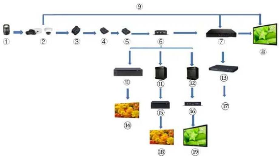
The devices comply with the HDCVI standard and support the transmission of video and control signal over coaxial cable. The devices produce video signal with megapixel resolution and require connected XVRs to achieve high-speed, long-distance, and zero-lag transmission of the signal. They are applicable to various scenes, such as roads, warehouses, underground parking lots, bars, pipelines, and gas stations.
Application 1.2
Figure 1-1 Application scenario
flowchart
graph TD
    A["①"] --> B["②"]
    B --> C["③"]
    C --> D["④"]
    D --> E["⑤"]
    E --> F["⑥"]
    F --> G["⑦"]
    G --> H["⑧"]
    F --> I["⑩"]
    F --> J["⑪"]
    F --> K["⑫"]
    F --> L["⑫"]
    F --> M["⑫"]
    F --> N["⑬"]
    F --> O["⑭"]
    I --> P["⑭"]
    J --> Q["⑮"]
    K --> R["⑯"]
    L --> S["⑰"]
    M --> T["⑱"]
    N --> U["⑲"]
    O --> V["⑳"]
Table 1-1 Description of the application
| No. | Name | No. | Name | No. | Name |
| 1 | (Optional) Lens | 8 | Display Screen | 15 | Splicer |
| 2 | HDCVI Products | 9 | Direct Connection | 16 | Convertor |
| 3 | (Optional) Surge Protection Device | 10 | Integrated Video Platform | 17 Ethernet | |
| 4 | (Optional) Optical Transceiver (Send) | 11 | Matrix | 18 | Splicing Screen |
| 5 | (Optional) Optical Transceiver (Receive) | 12 | Matrix | 19 | Display Screen |
| 6 | (Optional) Distributor | 13 | Switch | — | — |
| 7 | HCVR Products | 14 | Splicing Screen | — | — |
Transmission Distance 1.3
Table 1-2 Transmission distance
| Cable | 720P | 1080P | 4MP/4K | |
| Coaxial Cable | RG6 (75-5) | 1200 m | 800 m | 700 m |
| RG59 (75-3) | 800 m | 500 m | 500 m | |
| UTP | CAT6 | 450 m | 300 m | 300 m |
Table 1-3 Transmission distance of PoC HDCVI powered by PoC XVR
| PoC XVR Series | PoC Mode | RG59 | RG6 |
| Full series | AT | 100 m | 100 m |
| AF | 200 m | 200 m |
2 Cable Connection

Cable types might vary with different cameras, and the actual product shall prevail.
Power Output 2.1
Supplies 12 VDC power.

- Ensure that power consumption of devices connected to this port is below 2 W. - Ensure that supply frequency of devices connected to this port is higher than 1 MHz, such as sound pick-up, temperature/humidity sensor and other devices without power consumption change. It might cause image flickering if this port is connected to devices with supply frequency less than 1 MHz, such as fan, hall sensor, loudspeaker, motor and other electromechanical devices with power consumption change.
Figure 2-1 Power output

natural_image
Pure technical line drawing of a mechanical connector or plug (no text or symbols)12 VDC Power Input Port 2.2
Inputs 12 VDC power.

Device abnormality or damage could occur if power is not supplied correctly for 12 VDC power input port. Be sure to supply power as instructed in the manual.
Figure 2-2 12 VDC power input port

text_image
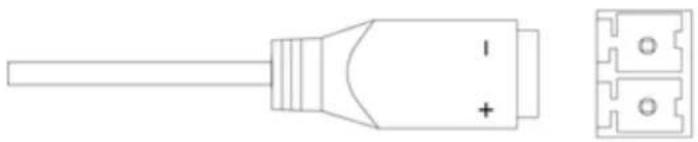
DC12V IN2.3 24 VAC Power Input Port
Inputs 24 VAC power.

Device abnormality or damage could occur if power is not supplied correctly. Please be sure to supply
power as instructed in the manual.
Figure 2-3 24 VAC power input port
natural_image
Technical line drawing of a plug with two side views showing internal components (no text or symbols)Video Output Port 2.4
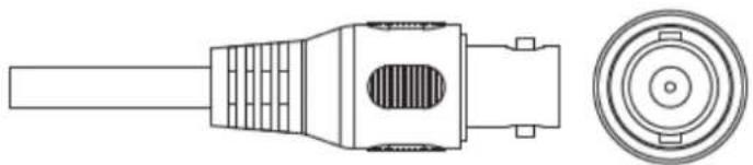
Connects to the XVR to output video signal.

WARNING
- When the device is in the condition of PoC power supply, do not connect any other device between the device and PoC XVR or PoC transceiver including UTC, Balun, optical transceiver, distributor and convertor and so on; otherwise, the device might get burned.
- PoC power supply is with high voltage. Do not dismantle the device during normal operation; otherwise it might cause danger to both device and users due to high voltage.
Figure 2-4 Video output port
natural_image
Technical line drawing of a mechanical connector with top and side views (no text or symbols)Audio Input Port 2.5
Connects to sound pickup devices to receive analog audio signal.
Figure 2-5 Audio input port

natural_image
Technical line drawing of a plug and socket (no text or symbols)Alarm Output Port 2.6
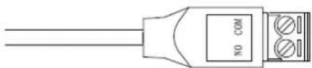
Connects to external alarm devices such as siren to trigger alarms.
Figure 2-6 Alarm output port
natural_image
Pure electrical connector diagram without any text or symbolsDIP Switch 2.7
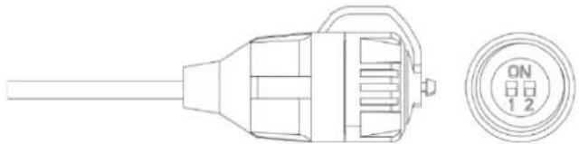
Dial switches to change output mode. Switch up indicates "ON", and switch down indicates "OFF."
Figure 2-7 DIP switch
natural_image
Technical line drawing of a connector with a pin and circular button labeled ON 1 2 (no text or symbols beyond basic labels)Table 2-1 Operations of DIP switch
| Switch1 Switch2 Output Mode | ||
| OFF OFF CVI | ||
| ON ON CVBS | ||
| ON OFF AHD | ||
| OFF ON TVI |
HD/SD Switch Control Cable 2.8
When the HD/SD switch control cable forms a short circuit, video output mode switches from HD to SD. On the contrary, it will switch back to HD video output when the cable forms an open circuit.
Figure 2-8 HD/SD switch control cable

natural_image
Pure electrical circuit lines without any symbols
The HD/SD switch control cable is available on select models.
2.9 HDCVI Aviation Connector
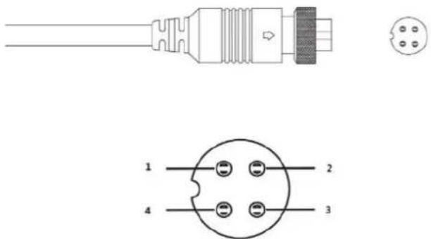
Aviation connector could strengthen the connection of mobile devices and provide four ports for your convenience.
Figure 2-9 HDCVI aviation connector
text_image
1 2 3 4Table 2-2 HDCVI aviation connector components
| No. | Name | No. | Name |
| 1 | (Yellow): Video | 3 | (White): Video Ground |
| 2 (Black): Power Ground 4 (Red): Power | |||
3 General Configuration and Operation
Power up the device and connect it to the XVR with coaxial cable, and then the live interface is displayed. Then you can start configuring HDCVI cameras on the XVR.

- The No. of the coaxial ports on XVR will display at the lower-left corner of each window to indicate the corresponding camera.
- Ports might vary depending on the XVR models, and the actual product shall prevail.
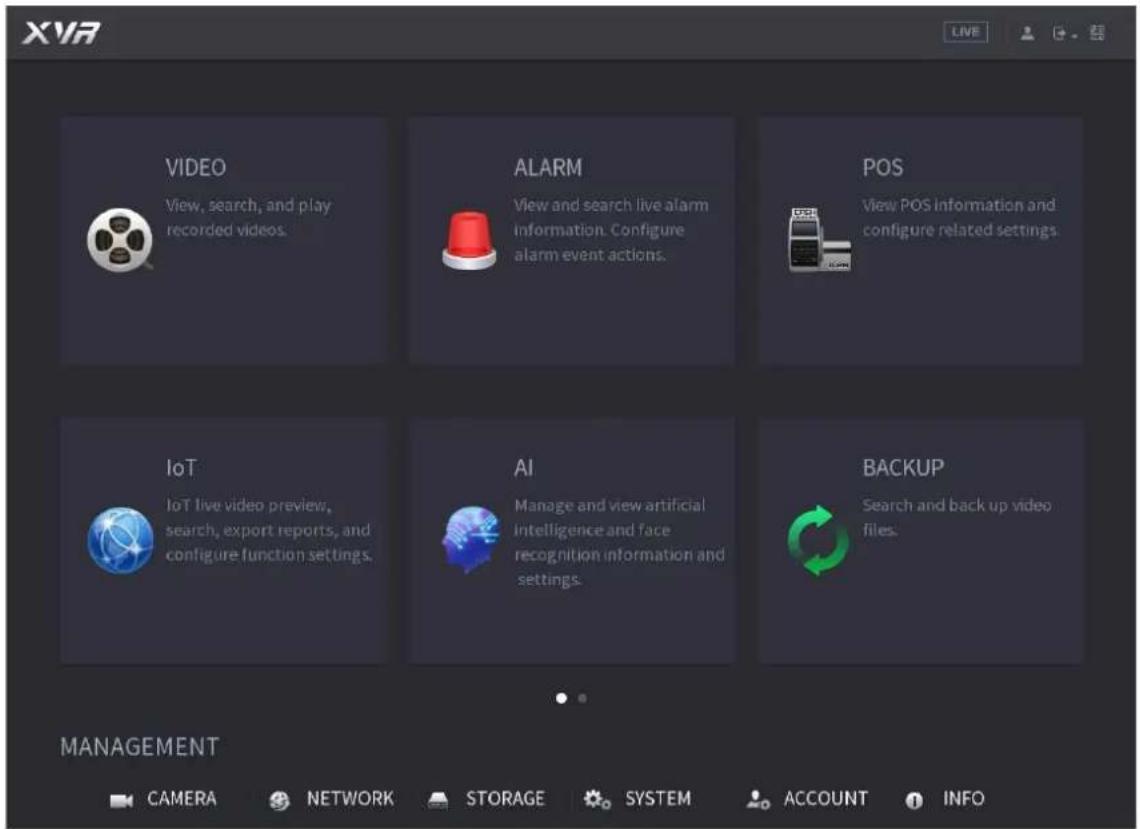
3.1 Entering XVR Main Menu
Step 1 Right-click on the live interface, and the shortcut menu is displayed.
Step 2 Click Main Menu and then log in to the system. The main menu of XVR is displayed.
Figure 3-1 XVR main menu
text_image
XVR VIDEO View, search, and play recorded videos. ALARM View and search live alarm information. Configure alarm event actions. POS View POS information and configure related settings. IoT IoT live video preview, search, export reports, and configure function settings. AI Manage and view artificial intelligence and face recognition information and settings. BACKUP Search and back up video files. MANAGEMENT CAMERA NETWORK STORAGE SYSTEM ACCOUNT INFOSetting Audio Input 3.2

Audio input is available on select models.
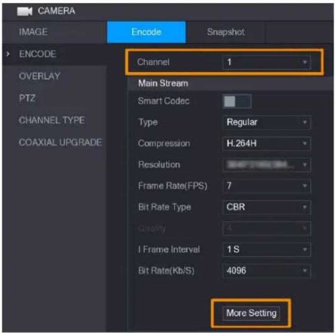
Step 1 On the Main Menu interface, select CAMERA > ENCODE > Encode.
Step 2 On the Channel I drop-down list, select the device that you want to configure according to the coaxial port No.
Step 3 Under Main Stream, click More Setting.
Figure 3-2 Encode setting
text_image
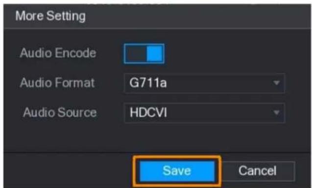
CAMERA IMAGE Encode Snapshot ENCODE CHANNEL 1 OVERLAY Main Stream Smart Codec Type Regular Compression H.264H Resolution Frame Rate(FPS) 7 Bit Rate Type CBR Quality I Frame Interval 1 S Bit Rate(Kb/S) 4096 More SettingStep 4 On the More Setting interface, enable Audio Encode function and then configure the audio settings. In the Audio Format list, leave it as default; in the Audio Source list, select HDCVI.
Step 5 Click Save.
Figure 3-3 More setting
text_image
More Setting Audio Encode Audio Format G711a Audio Source HDCVI Save CancelStep 6 On the Encode interface, click Apply.
3.3 Operating PTZ Control Panel
3.3.1 Operating OSD Menu

- The OSD menus of different cameras might vary, and the actual product shall prevail.
- When you use OSD menu to restore the device to default settings, the resolution, mode, frame rate and language of the device will not be restored.
Step 1 On the live interface, right-click the device that you want to configure. The shortcut menu is
displayed.
Figure 3-4 Shortcut menu

text_image
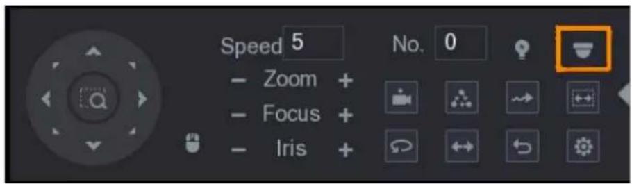
Main Menu Search PTZ View 1 View 4 View 8 View 9 View 16 Previous Screen Next Screen Manual Preview Mode Color Setting Image Sub PortStep 2 Click PTZ and click ▶ to extend the menu.
Figure 3-5 PTZ setting options
text_image
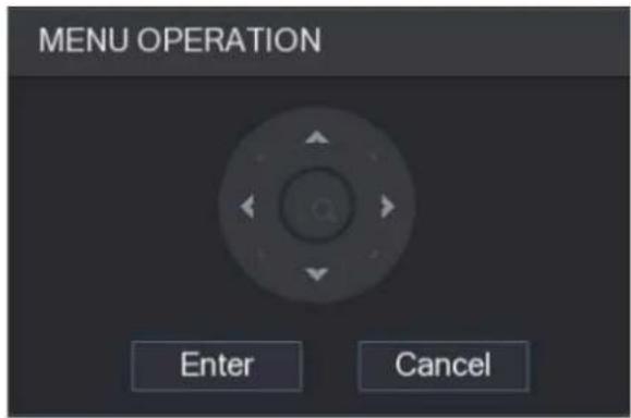
Speed 5 - Zoom + - Focus + - Iris + No. 0Step 3 Click The MENU OPERATION panel is displayed.
Figure 3-6 Menu Operation panel
text_image
MENU OPERATION Enter CancelTable 3-1 Menu operation panel function
| Button | Function | Button | Function | |
| Enter Enter or confirm an item |  |  | Select item | |
| Cancel Exit OSD menu |  |  | Change item value | |
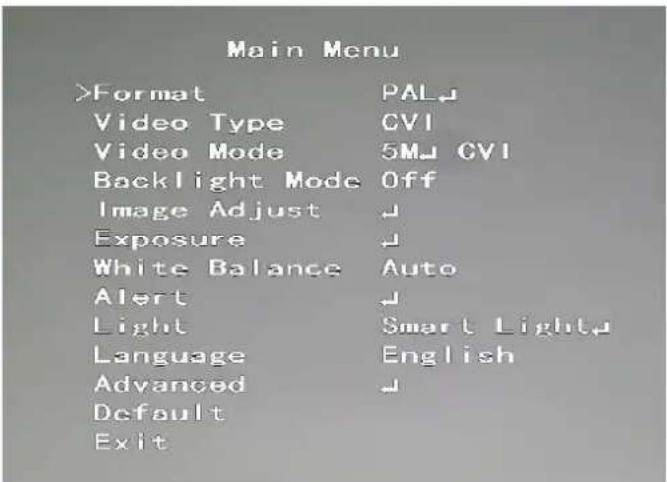
The OSD menu of the corresponding device is displayed on the live interface. If the value of OSD item is "←", click Enter to go to the next level of this item. Click Return to go back to the previous level. Click Cancel to exit OSD menu without saving the modifications.
Figure 3-7 OSD menu
text_image
Main Menu >Format PAL↓ Video Type CVI Video Mode 5M↓ CVI Backlight Mode Off Image Adjust ↓ Exposure ↓ White Balance Auto Alert ↓ Light Smart Light↓ Language English Advanced ↓ Default Exit3.3.2 Operating Auto Focus (AF)
Table 3-2 Parameter of AF
| Parameter Description | |
| Zoom |  Zoom out. Zoom out.  Zoom in. Zoom in. |
| Focus |  Focus far. Focus far.  Focus near. Focus near. |
| Iris |  Auto focus. Auto focus.  Open OSD menu. Open OSD menu. |
| PTZ movement Supports eight directions. | |
 | Click  then you can control the four directions (left, right, up, and down) of PTZ through mouse operation. then you can control the four directions (left, right, up, and down) of PTZ through mouse operation. |
 | Click  to unfold PTZ control panel. to unfold PTZ control panel. |
4 Full-Color Camera Configuration
This chapter introduces how to configure the working modes of smart light, including auto and manual. Smart light will change the brightness of white light automatically according to the ambient lighting condition to avoid over-exposure. Smart light is only available for full-color camera.
4.1 Enabling/Disabling Smart Light
Smart light is enabled by default. To switch the mode of smart light, enter OSD menu (Figure 3-7) and select Light > Smart Light.
4.2 Configuring Smart Light Adjustment
In the smart light mode, configure the maximum brightness level of the smart light, and the device will change brightness automatically according to the ambient lighting condition. You can also configure the sensitivity of the smart light.
Configuring Brightness Level
Step 1 On the OSD menu, select Light > Smart Light > Level.
Step 2 Select from 1 to 5 to configure the maximum brightness level.

The maximum brightness level is 5 by default.
Step 3 Click Return and then Exit to exit the configuration.

You can also configure the brightness level manually in Light > Manual > Level.
Configuring Sensitivity
Step 1 Select Light > Smart Light > Sensitivity.
Step 2 Select from 1 to 5 to configure the sensitivity value of the smart light.

- The higher the value is, the easier the smart light will be woken up.
● The sensitivity value is 3 by default.
Step 3 Click Return and then Exit to exit the configuration.
5 Smart Dual Illuminators Cameras Configuration
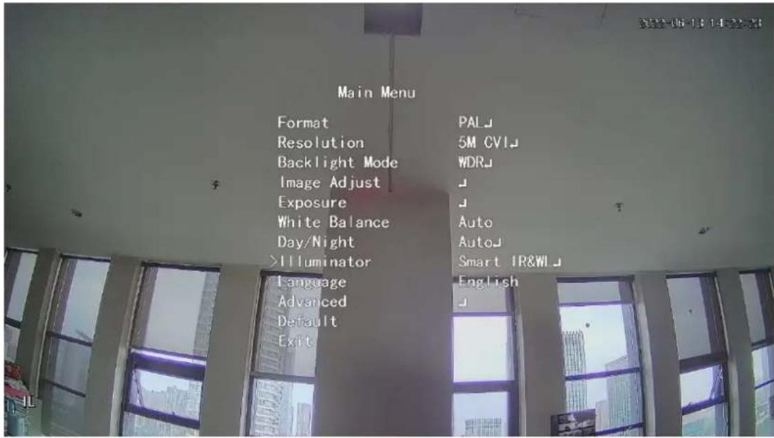
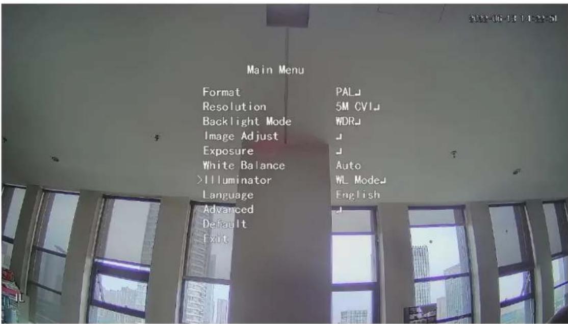
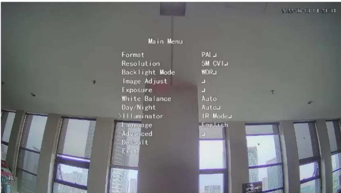
Smart dual illuminators camera supports three light modes: Smart IR&WL, WL mode, IR mode.
On the OSD menu, select Illuminator, and then view the three different modes.
- Smart IR&WL: Turn on the IR light in low ambient brightness. If SMD or IVS has been associated with smart dual illuminators cameras, and when the SMD detects people and vehicles on the screen, or perimeter rules are triggered by the IVS, then the camera will be controlled to turn on the warm light, and the screen automatically switch to the full-color. When SMD or IVS has detected that no rules are triggered by people and vehicles, the camera will turn off the warm light and turn on the IR light to switch to the black & white night vision.
- WL mode: If the screen is full-color in low ambient brightness, then the camera is a full-color camera.
- IR mode: If the screen is black & white in low ambient brightness, then the camera is an IR camera.
Figure 4-1 Smart IR&WL
text_image
Main Menu Format Resolution Backlight Mode Image Adjust Exposure White Balance Day/Night >Illuminator Language Advanced Default Exit PAL 5M CVI WDR Auto Auto Smart IR&WI EnglishFigure 4-2 WL mode
text_image
Main Menu Format Resolution Backlight Mode Image Adjust Exposure White Balance >Illuminator Language Advanced Default Exit PAL 5M CVI WDR Auto WL Mode EnglishFigure 4-3 IR mode
text_image
Main Menu Format Resolution Backlight Mode Image Adjust Exposure White Balance Day/Night >Illuminator Language Advanced Default Exit PAL 5M CVI MDR Auto Auto IR Mode English6 Temperature and Humidity Camera Configuration
Temperature and humidity camera can measure the ambient temperature and humidity and display the value on the live interface.
6.1 Enabling/Disabling Temperature and Humidity
On the OSD menu (Figure 3-7), select Advanced > Temp. & Humidity to enable and disable the function. You can view real-time temperature and humidity in the image.
6.2 Configuring Temperature Monitoring Mode
The temperature and humidity camera supports temperature correction under strong light outdoors. You can change the temperature monitoring mode.
Step 1 Enable Temp. & Humidity.
Step 2 Select Standard or Sunlight in the Measure Mode to change the temperature monitoring mode. Standard is set by default.

You are recommended to change the mode into Standard or Sunlight when the camera is used indoors or outdoors respectively.
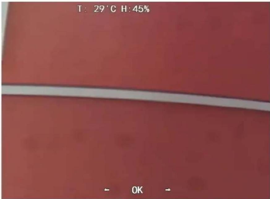
6.3 Adjusting Temperature and Humidity Display
Step 1 Select Advanced > Temperature & Humidity > Location on the OSD menu.

Make sure that the temperature and humidity function is enabled.
Step 2 Click the direction buttons on the PTZ menu to change the display location.
Step 3 Click Enter to save the configuration.
Figure 6-1 Adjust temperature and humidity display
text_image
T: 29°C H:45% ← OK →
Right-click anywhere on the monitoring image to return to the previous interface after all the settings are completed.
6.4 Viewing Temperature and Humidity
Step 1 Right-click on the live interface to enter XVR main menu (Figure 3-1).
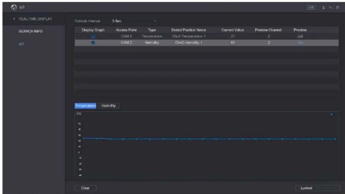
Step 2 Select IoT > REALTIME DISPLAY, and then you can view the real-time temperature and humidity.
Figure 6-2 View temperature and humidity
text_image
IoT REALTIME DISPLAY Refresh Interval 5 Sec Display Graph Access Point Type Detect Position Name Current Value Preview Channel Preview CAM 2 Temperature Chin2-Temperature-1 27 2 Low CAM 2 Humidity Chin2-Humidity-1 69 2 Low Temperature Humidity Clear Locked
For details, see XVR user's manual.
7 Active Deterrence Camera Configuration
Active deterrence camera can warn off intruders actively with LED even before users are aware of the incident. Once an intrusion is detected, the LED will be turned on to alert the intruder.
7.1 Detection Range of PIR Detector
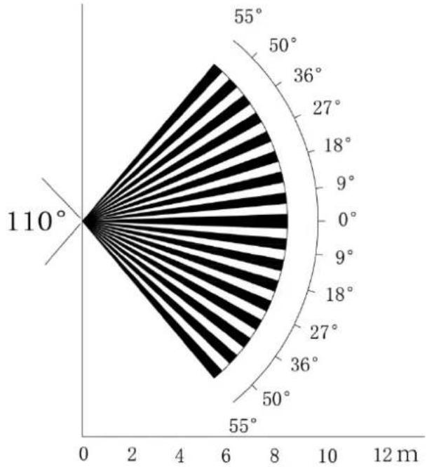
The horizontal detection range of the sensor is 100^ or 110^ .
Figure 7-1 Horizontal detection range
radar
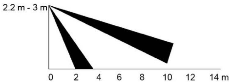
| Angle (°) | Value | | --------- | ----- | | 0 | 0 | | 36 | 55 | | 78 | 50 | | 110 | 0 |The vertical detection distance of the sensor is 2 m–10 m, 1 m–14 m or 1 m–12 m.
Figure 7-2 Vertical detection distance
area
| x | y | | ---- | ----- | | 0 | 2.2 | | 2 | 0 | | 4 | 0 | | 6 | 0 | | 8 | 0 | | 10 | 0 | | 12 | 0 | | 14 | 0 |7.2 Configuring Trigger Mode
On the OSD menu (Figure 3-7), select Alert > Trigger Mode.
If you select Camera Set, the sound and light alarm will be triggered in the device.
If you select XVR Set, the sound and light alarm will be triggered in the XVR.

For more information about XVR Set, see user's manual of XVR.
7.3 Configuring Light Warning and Audio Alarm

This function is available only when the trigger mode is set to Camera Set.
- On the OSD menu (Figure 3-7), select Alert. Set Light Warning to ON, and then enter the item.
◇ For Mode, You can select from Lighting to Flash.
◇ If you select Flash, you can set the Flash Frequency to Low, Medium or High.
◇ For Alert Duration, you can adjust from 5 seconds to 60 seconds.
- On the Audio Alert item, set it to ON, and then enter the item.
◇ In the Audio item, you can select from three audios.

You can contact after-sales support to customize alarm audios.
◇ In the Volume item, you can select from Low, Medium and High.
◇ In the Alert Duration, you can adjust from 5 seconds to 60 seconds.
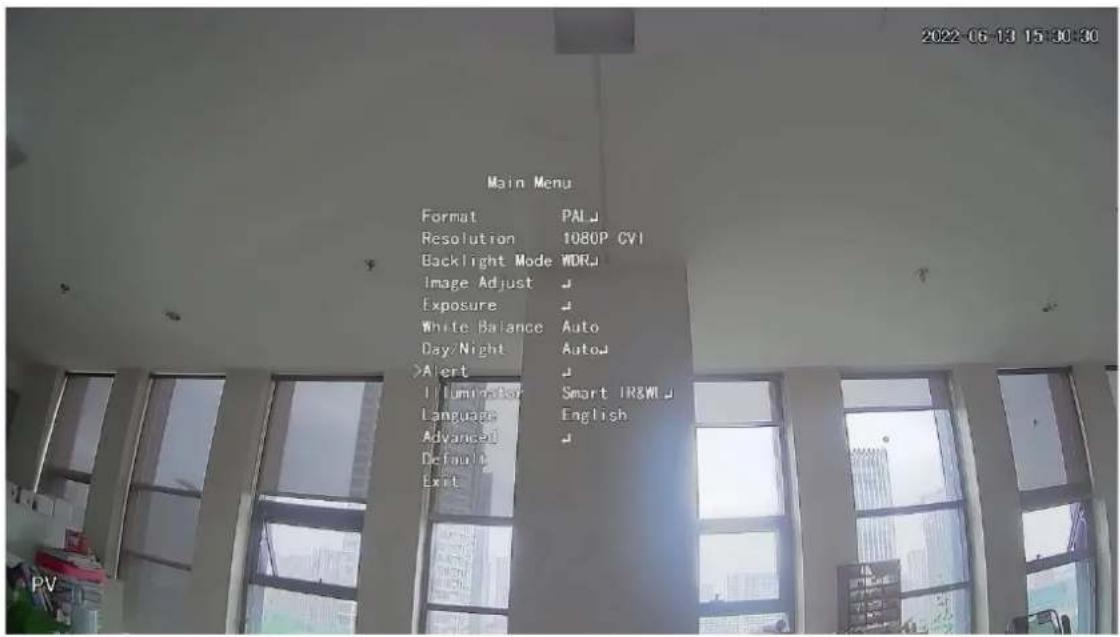
7.4 Configuring Smart Dual Illuminators Active Deterrence Camera

For details on configuring smart dual illuminators, see "5 Smart Dual Illuminators Cameras Configuration".
Step 1 Select Main Menu > Alert, and then set Audio Alert to ON.
Step 2 Set the Volume and Alert Duration.

The shortest of alert duration is 5 s, and the longest is 60 s.
Step 3 Select 5 different audio clips (including Alarm, No parking here, Private land no entry, Warning zone keep off, and Welcome).

You can also DIY the first clip to a .bin file and import to the back-end to use.
Figure 7-3 Main menu
text_image
Main Menu Format PALJ Resolution 1080P CVI Backlight Mode WDRJ Image Adjust Exposure White Balance Auto Day/Night AutoJ >Alert | Lightmeter Smart IR&MJ Language English Advanced Default ExitFigure 7-4 Alert
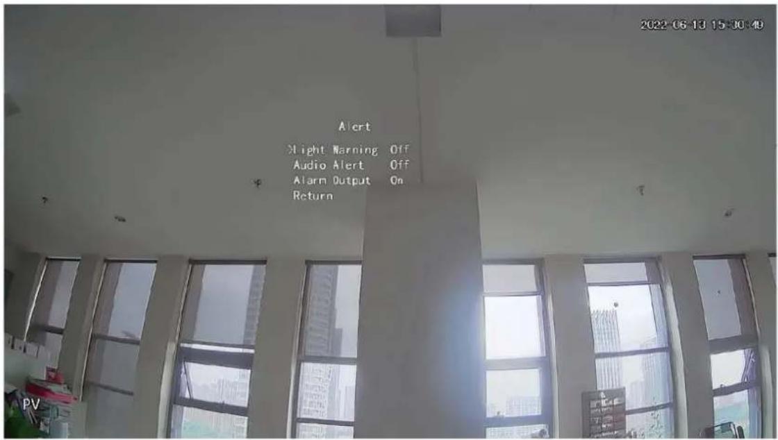
text_image
Alert Light Warning Off Audio Alert Off Alarm Output On Return 2022-06-13 15:30:49 PVFigure 7-5 Audio alert
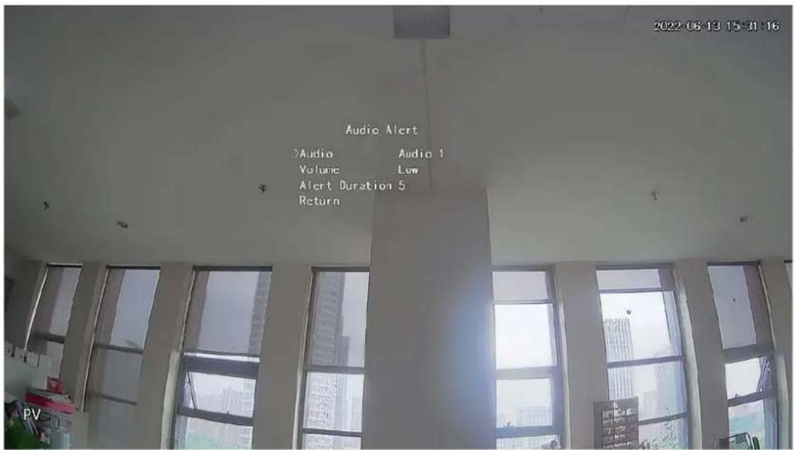
text_image
Audio Alert ?Audio Audio 1 Volume Low Alert Duration 5 ReturnStep 4 Select Main Menu > Alert, and then set Light Warning to ON.
Step 5 Set the Flash Freq and Alert Duration.

The shortest of alert duration is 5 s, and the longest is 60 s.
Figure 7-6 Light warning
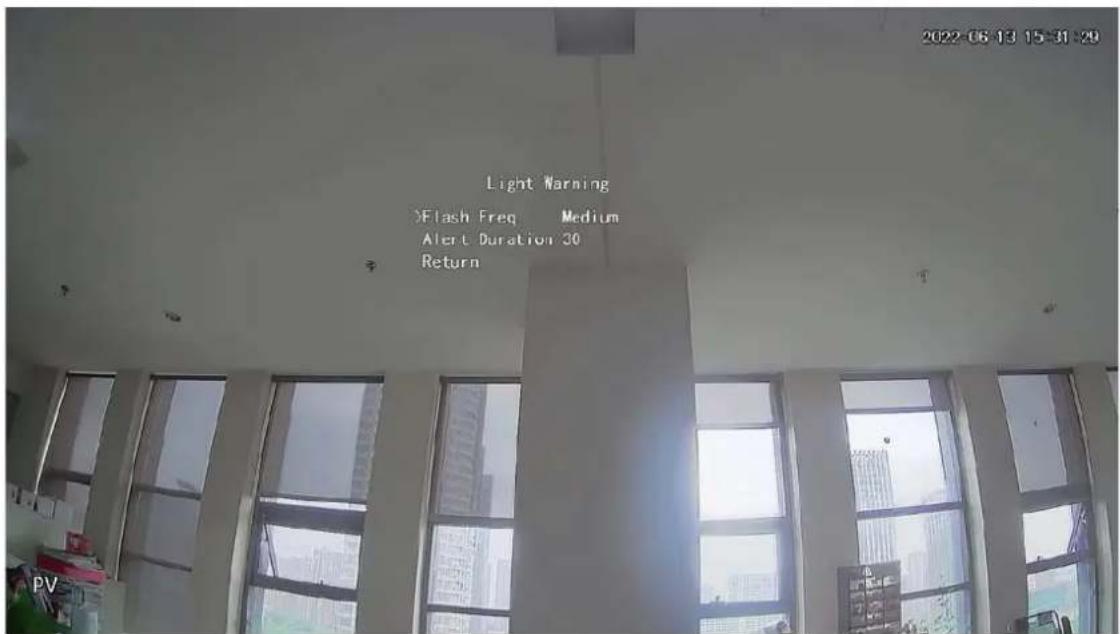
text_image
Light Warning Flash Freq Medium Alert Duration 30 Return 2022-06-13 15:31:29 PV8 Gateway Camera Configuration

This function is available on select models.
This series of devices can serve as a gateway to connect compatible wireless node devices, including door/window contact, siren, and PIR detector to XVR to form a local alarm network. Once any alarm from devices within the network is triggered, the device transmits alarm signal as configured.
Figure 7-7 Network diagram
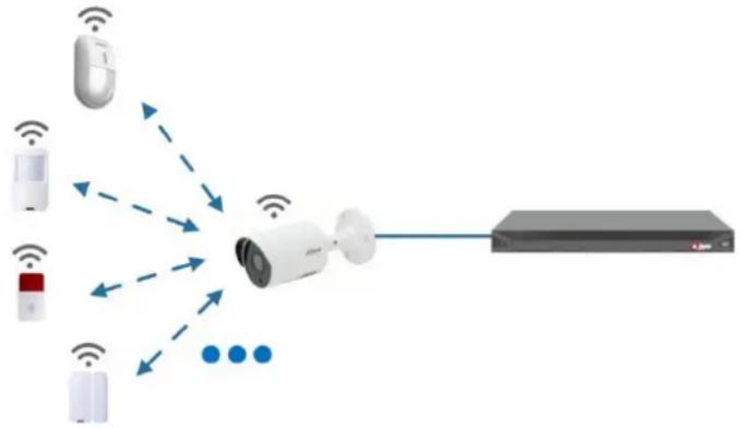
flowchart
graph TD
    A["Camera"] -->|Wireless Signal| B["Monitor"]
    C["Camera"] -->|Wireless Signal| B
    D["Camera"] -->|Wireless Signal| B
    E["Camera"] -->|Wireless Signal| B
    B --> F["Server"]
Connect the wireless node devices to XVR with gateway camera and then configure parameters.

For more detailed configuration, see user's manual of XVR or node device.
8.1 Connecting Node Devices on OSD menu
Step 1 On the OSD menu (Figure 3-7), select Advanced.
Step 1 Set Enroll to ON, and the device enters pairing mode.
Operate the node device and enter pairing mode according to corresponding manual.
Step 2 After pairing is completed, you can check the information of the connected device on the Sensor Pairing interface.
8.2 Connecting Node Devices on XVR
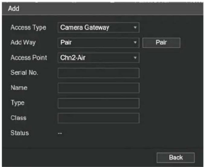
Step 1 On the XVR Main Menu (Figure 3-1), select IoT > MANAGER > Sensor Pairing.
Step 2 Click Add.
Figure 8-1 Add sensor pairing (1)
text_image
Add Access Type Camera Gateway Add Way Pair Pair Access Point Chn2-Air Serial No. Name Type Class Status -- BackStep 3 In the Access Type list, select Camera Gateway.
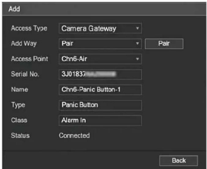
Step 4 Click Pair, and the device enters pairing mode.
Operate the node device and enter pairing mode.
Figure 8-2 Add sensor pairing (2)
text_image
Add Access Type Camera Gateway Add Way Pair Pair Access Point Chn6-Air Serial No. 3J01837 Name Chn6-Panic Button-1 Type Panic Button Class Alarm In Status Connected BackStep 5 Click Back.

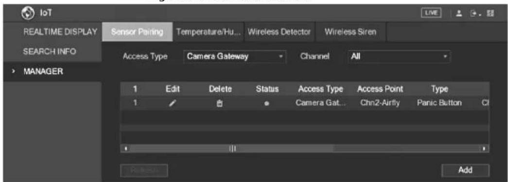
Click ↗ to modify the device name; click 🔒 to delete node device.
Figure 8-3 Connected device
text_image
IoT REALTIME DISPLAY Sensor Pairing Temperature/Hu... Wireless Detector Wireless Siren SEARCH INFO Access Type Camera Gateway Channel All MANAGER 1 Edit Delete Status Access Type Access Point Type 1 ✓ 📋 Camera Gat... Chn2-Airtfly Panic Button Cl Add9 Box Camera Installation

- The device is not equipped with lens when it is delivered out of factory and you need to install lens.
- Do not remove the electrostatic adsorption film on the surface of transparent cover before installation and debugging are completed, which is to avoid damage during installation.
- Install the lens onto the device in time after unpacking, which is to avoid the device module being exposed in humid environment for a long time.
● The mounting surface shall be thick enough to sustain at least 3 times of the device weight.
• Install the C/CS adapter ring to the camera if you are using C mount lens.
● The following installation figure is for reference only.
Lens Installation 9.1
9.1.1 Installing Lens Type 1
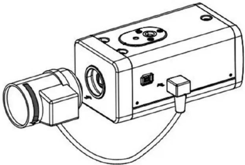
Step 1 Remove the protection cap from the device. Align the lens to the lens position of the device (Install the C/CS adapter ring to the device if you are using C mount lens). Turn clockwise to secure the lens firmly.
Step 2 Insert the socket of the lens cable into the auto iris lens connector on the side panel of the device. Skip this step if you are using auto iris lens.
Step 3 Fasten the screw near the focusing ring, and then turn anti-clockwise to move the focusing ring out to focus manually until you get clear video.
Step 4 After you completed focusing, fix the screw near the focusing ring firmly.
Step 5 Fasten the focusing ring.
Figure 9-1 Lens installation (1)
natural_image
Technical line drawing of a mechanical device with ports and wiring (no text or symbols)9.1.2 Installing Lens Type 2
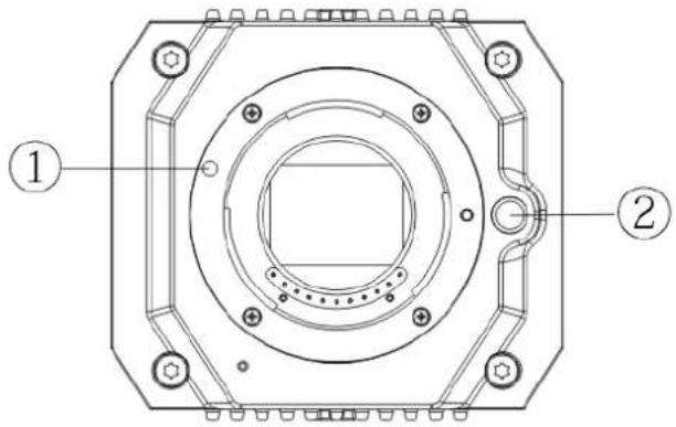
Figure 9-2 Front panel
text_image
Technical diagram of a mechanical component with labeled parts 1 and 2Table 9-1 Front panel components
| No. | Name | No. | Name |
| 1 | Red sign | 2 | Lens-dismounting button |
Step 1 Remove the protection cover on the device lens, align the red sign of the lens with the red sign ① on the device, rotate the buckle clockwise until the lens-dismounting button ② bounces upward, and then the lens is installed.
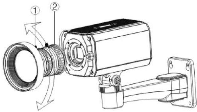
Step 2 Loosen the screw on the focusing ring, rotate the focusing ring outward to focus manually until you get clear video. Skip this step if you are using lens that supports auto focusing.
Figure 9-3 Lens installation (2)
text_image
Technical diagram of a surveillance camera with labeled components and directional arrows indicating motionTable 9-2 Lens components
| No. | Name | No. | Name |
| 1 | Screw | 2 | Focusing ring |
Step 3 After focusing, tighten the screw on the focusing ring and fix the focusing ring.

To dismount the lens, press lens-dismounting button ②, rotate the lens anticlockwise, and release the bucket.
I/O Port Installation 9.2
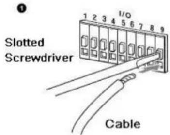
9.2.1 Connecting Cable
Step 1 Press and hold the mini screwdriver to press the button on the hole groove of the cable to be connected.
Step 2 Insert the cable into the hole groove.
Step 3 Release the screwdriver.
Figure 9-4 Install cable
text_image
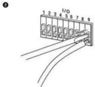
Slotted Screwdriver I/O 1 2 3 4 5 6 7 8 9 Cable9.2.2 Removing Cable
Step 1 Use the mini screwdriver to press the button on the hole groove of the cable to be connected.
Step 2 Pull out the cable from the hole groove.
Step 3 Release the screwdriver.
Figure 9-5 Remove cable
text_image
1 2 3 4 5 6 7 8 9 I/O MIL-24Device Installation 9.3

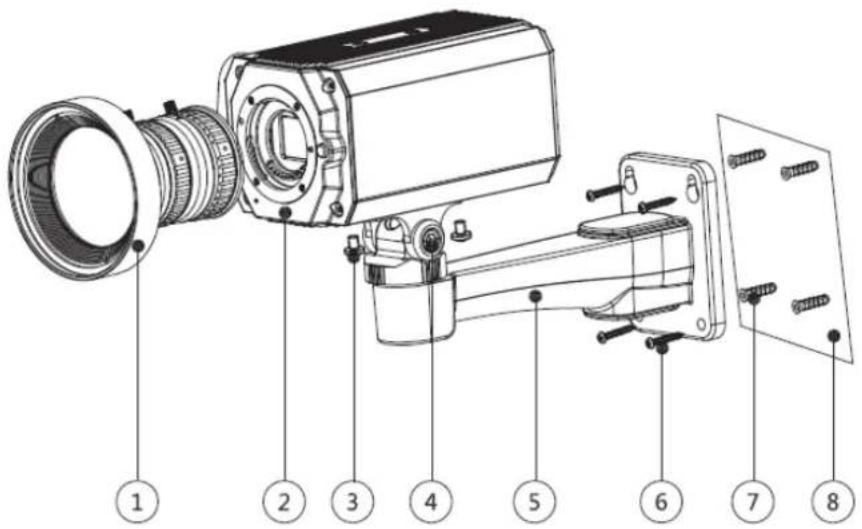
The device is delivered without mounting bracket and screw. You need to purchase them separately.
Figure 9-6 Device components
text_image
Technical diagram of a camera module with numbered parts for identificationTable 9-3 Device components
| No. | Name | No. | Name |
| 1 Lens | 5 Mounting bracket | ||
| 2 | Front panel | 6 | Self-tapping screw |
| 3 Fixing screw | 7 Expansion bolt | ||
| 4 | Bracket adjusting screw | 8 | Mounting surface |
Step 1 Fix the mounting bracket ⑤ on the mounting surface ⑧.
1) Mark the bracket mounting hole positions on the mounting surface ⑧, drill four holes on the marked positions, insert four expansion bolts ⑦ into the mounting holes and then tighten.
2) Align the four screw holes on the bottom of the mounting bracket ⑤ with the expansion bolts, insert four self-tapping screws ⑥ and then tighten.
Step 2 Fix the device on the mounting bracket ⑤.
Align the mounting hole positions on the bottom of device casing with the mounting holes positions on the mounting bracket ⑤, and then install the device on the mounting bracket with fixing screw ③.
Step 3 Adjust camera monitoring angle.
Use a wrench to loosen the adjusting screw ④, adjust camera to the location which needs to be monitored, and then use wrench to tighten bracket adjusting screw ④ to fix the device.
Step 4 Connect the cable to the back panel of the device.
After device installation and cable connection, you can view monitoring image through storage device such as XVR.
10 Fisheye Camera Configuration
The fisheye camera (panoramic camera) has wide monitoring angle but its video is distorted. The dewarp function can provide the proper and vivid video suitable for human eyes. Fisheye function should be configured at XVR.
10.1 Fisheye Dewarp on the Live Interface
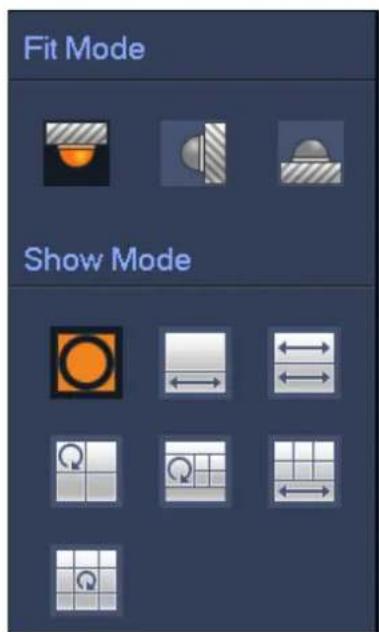
Step 1 On the XVR shortcut menu, select Fisheye.
Step 2 Set fisheye Fit Mode and Show Mode.
Figure 10-1 Fisheye menu
text_image
Fit Mode Show ModeTable 10-1 Parameters of fisheye
| Fit Mode | Icon | Description |
Ceiling mount  Ground mount Ground mount | 360° panorama original window | |
| 1 dewarp window and 1 panorama expanded window | ||
| 2 panorama expanded windows | ||
| 1 360° panorama window and 3 dewarp windows | ||
| 1 360° panorama window and 4 dewarp windows | ||
| 4 dewarp windows and 1 panorama expanded window | ||
| 1 360° panorama window and 8 dewarp windows | ||
| Wall mount (WAY) | 360° panorama original window | |
| Panorama expanded window | ||
| 1 panorama unfolding window and 3 dewarp windows | ||
| 1 panorama unfolding window and 4 dewarp windows | ||
| 1 panorama unfolding window and 8 dewarp windows |

- The dewarp modes might vary for different installation modes.
- For the non-fisheye channel, a prompt is displayed to remind you that dewarp function is not supported.
- Some series products support 180° dewarp which can only be wall mounted. The actual product shall prevail.
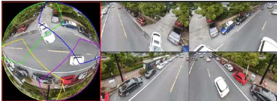
Figure 10-2 Fisheye show mode
natural_image
Four-panel fisheye view of a multi-lane urban street scene with cars and vehicles, no visible text or symbolsYou can use the mouse to drag the color areas on the left original screen or the rectangular screens on the right to change the monitoring ranges. (Not supported for wall mount.)
10.2 Fisheye Dewarp During Playback
When playing back the fisheye recorded video, you can use dewarp function to adjust video.
Step 1 On the XVR main menu, click SEARCH.
Step 2 Select 1-window playback mode and corresponding fisheye channel, and then click to play.
Step 3 Right-click to go to the dewarp playback interface.
11 FAQ
11.1 PoC Power Supply
PoC XVR supports PoC function.
PoC camera can be divided into AT camera and AF camera. Power consumption of AT camera is less than 12W, and power consumption of AF camera is less than 6W.
You need to check the maximum power of PoC before use. Assuming that the maximum power of one XVR is 48W, the XVR can connect AT cameras up to 48/12=4 and AF cameras up to 48/6=8.
When the device is in the condition of PoC power supply, do not connect any other device between the device and PoC XVR or PoC transceiver such as UTC, Balun, optical transceiver, distributor and convertor and so on; otherwise, the device might get burned.
PoC power supply is with high voltage. Do not dismantle the device during normal operation; otherwise it might cause danger to both device and users due to high voltage.
11.2 Long Distance Power Supply
In many scenarios, our clients adopt long distance power supply, transmitting 12V DC to cameras located over 100 m. Such long distance power supply might cause problems.
Q1: Recurrent restart of devices or even ICR Failure.
Possible reasons: The long power supply cable leads to a large voltage drop on the equipment power supply cable, and turning on the IR light at night leads to a further increase of the voltage drop, resulting in restart of the device. After the device is restarted, the ICR is switched to the Day mode by default. By judging the ambient light at night, the device will operate in Night mode, and then the infrared light is turned on, which causes the device to restart again because of undervoltage. Thus, ICR is switched to every 2 seconds, impacting its switching lifespan.
Q2: Unable to restart devices at night, and black screen or restart occurs when switching ICR.
Possible reasons: The long power supply cable leads to a large voltage drop on the equipment power supply cable, and turning on the IR light at night leads to a further increase of the voltage drop, resulting in restart of the device and black screen.
Solution: During construction, when the camera location is far from the power supply, you need to adopt long distance separate power supply or purchase –DP dual power supply to use 24V AC power supply.
11.3 Centralized Power Supply
The typical problem of centralized power supply is that there are obvious black stripes on the device screen, which interferes with the display.
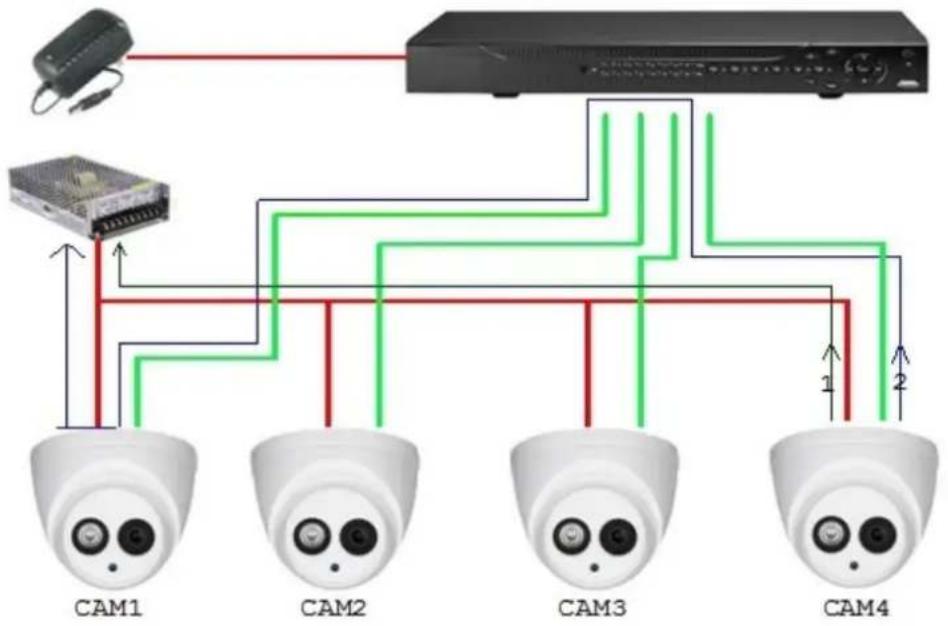
The principle of centralized power supply is as follows:
Figure 11-1 Principle of centralized power supply
flowchart
graph TD
    A["Server"] --> B["CAM1"]
    A --> C["CAM2"]
    A --> D["CAM3"]
    A --> E["CAM4"]
    B -->|Red Line| C
    C -->|Green Line| D
    D -->|Red Line| E
    B -->|Red Line| F["Monitor"]
    C -->|Red Line| G["Monitor"]
    D -->|Red Line| H["Monitor"]
    E -->|Red Line| I["Monitor"]
There are two paths for the power output of CAM4, return path 1 and return path 2. Reflow 2 first flows to CAM1, and then flows to the power supply from power supply ground of CAM1. In this way, the reflow of power supply ground CAM4 affects the video ground of CAM1, resulting in interference stripes on the screen. And CAM4 also interferes with CAM2 and CAM3.
In the same way, CAM1, CAM2 or CAM3 affects other cameras besides itself.
The main reason for the interference of centralized power supply is that the power supply ground of camera is not isolated. To solve this problem: Use dual-power devices with isolation of power supply ground; equip low-power devices with power isolators to block the return path 2 low-power devices can also use power isolators to block the return path 2; use isolated power supplies for each channel, or power the device separately, which are the two recommended methods.
11.4 Connector Waterproof Protection
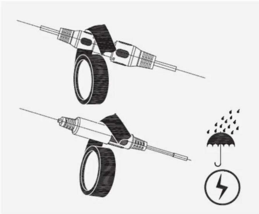
HDCVI cameras need to be well waterproofed and protected. After installation, wrap the BNC connector and power connector tightly with insulated or waterproofed tape to prevent water and external electromotive forces. When metal casing device is installed on metal surfaces such as elevators and buses, the metal casing should not be in contact with the installation surface to prevent water and external electromotive forces.
Figure 11-2 Waterproof measures
natural_image
Illustration of a tire and pen being compressed by an umbrella, with a lightning bolt symbol indicating the impact (no text or labels present)Maintenance

In order to maintain the image quality and proper functioning of the device, please read the following maintenance instructions carefully and hold rigid adherence.
Disassembly and Desiccant Replacement
- Carefully follow the instructions in the manual when performing any disassembly operation about the device; otherwise, it might cause water leakage or poor image quality due to unprofessional disassemble.
- Please contact after-sale service for desiccant replacement if there is condensed fog found on the lens after unpacking or when the desiccant turns green. (Not all models are included with the desiccant).
Maintaining Lens and Lens Protector
- The lens and lens protector are covered with antireflection coating, which could be contaminated or damaged and result in lens scratches or haze images when being touched with dust, grease, fingerprints and other similar substances.
- Do not touch the image sensor (CCD or CMOS) directly. Dust and dirt could be removed with air blower, or you can wipe the lens gently with soft cloth that moistened with alcohol.
Maintaining Device Body
- Device body can be cleaned with soft dry cloth, which can also be used to remove stubborn stains when moistened with mild detergent.
- To avoid possible damage on device body coating which could cause performance decrease, do not use volatile solvent such as alcohol, benzene, diluent and so on to clean the device body, nor can strong, abrasive detergent be used.
Appendix 1 Cybersecurity Recommendations
Mandatory actions to be taken for basic device network security:
1. Use Strong Passwords
Please refer to the following suggestions to set passwords:
- The length should not be less than 8 characters;
- Include at least two types of characters; character types include upper and lower case letters, numbers and symbols;
- Do not contain the account name or the account name in reverse order;
- Do not use continuous characters, such as 123, abc, etc.;
- Do not use overlapped characters, such as 111, aaa, etc.;
2. Update Firmware and Client Software in Time
- According to the standard procedure in Tech-industry, we recommend to keep your device (such as NVR, DVR, IP camera, etc.) firmware up-to-date to ensure the system is equipped with the latest security patches and fixes. When the device is connected to the public network, it is recommended to enable the "auto-check for updates" function to obtain timely information of firmware updates released by the manufacturer.
- We suggest that you download and use the latest version of client software.
"Nice to have" recommendations to improve your device network security:
1. Physical Protection
We suggest that you perform physical protection to device, especially storage devices. For example, place the device in a special computer room and cabinet, and implement well-done access control permission and key management to prevent unauthorized personnel from carrying out physical contacts such as damaging hardware, unauthorized connection of removable device (such as USB flash disk, serial port), etc.
2. Change Passwords Regularly
We suggest that you change passwords regularly to reduce the risk of being guessed or cracked.
3. Set and Update Passwords Reset Information Timely
The device supports password reset function. Please set up related information for password reset in time, including the end user's mailbox and password protection questions. If the information changes, please modify it in time. When setting password protection questions, it is suggested not to use those that can be easily guessed.
4. Enable Account Lock
The account lock feature is enabled by default, and we recommend you to keep it on to guarantee the account security. If an attacker attempts to log in with the wrong password several times, the corresponding account and the source IP address will be locked.
5. Change Default HTTP and Other Service Ports
We suggest you to change default HTTP and other service ports into any set of numbers between 1024\~65535, reducing the risk of outsiders being able to guess which ports you are using.
6. Enable HTTPS
We suggest you to enable HTTPS, so that you visit Web service through a secure communication channel.
7. MAC Address Binding
We recommend you to bind the IP and MAC address of the gateway to the device, thus reducing the risk of ARP spoofing.
8. Assign Accounts and Privileges Reasonably
According to business and management requirements, reasonably add users and assign a minimum set of permissions to them.
9. Disable Unnecessary Services and Choose Secure Modes
If not needed, it is recommended to turn off some services such as SNMP, SMTP, UPnP, etc., to reduce risks.
If necessary, it is highly recommended that you use safe modes, including but not limited to the following services:
- SNMP: Choose SNMP v3, and set up strong encryption passwords and authentication passwords.
- SMTP: Choose TLS to access mailbox server.
- FTP: Choose SFTP, and set up strong passwords.
- AP hotspot: Choose WPA2-PSK encryption mode, and set up strong passwords.
10. Audio and Video Encrypted Transmission
If your audio and video data contents are very important or sensitive, we recommend that you use encrypted transmission function, to reduce the risk of audio and video data being stolen during transmission.
Reminder: encrypted transmission will cause some loss in transmission efficiency.
11. Secure Auditing
- Check online users: we suggest that you check online users regularly to see if the device is logged in without authorization.
- Check device log: By viewing the logs, you can know the IP addresses that were used to log in to your devices and their key operations.
12. Network Log
Due to the limited storage capacity of the device, the stored log is limited. If you need to save the log for a long time, it is recommended that you enable the network log function to ensure that the critical logs are synchronized to the network log server for tracing.
13. Construct a Safe Network Environment
In order to better ensure the safety of device and reduce potential cyber risks, we recommend:
- Disable the port mapping function of the router to avoid direct access to the intranet devices from external network.
- The network should be partitioned and isolated according to the actual network needs. If there are no communication requirements between two sub networks, it is suggested to use VLAN, network GAP and other technologies to partition the network, so as to achieve the network isolation effect.
- Establish the 802.1x access authentication system to reduce the risk of unauthorized access to private networks.
- Enable IP/MAC address filtering function to limit the range of hosts allowed to access the device.