MPA240 - Blender Cloud - Free user manual and instructions
Find the device manual for free MPA240 Cloud in PDF.


| Product Type | Integrated Mixer Amplifier |
| Model | MPA240 |
| Brand | Cloud |
| Output Power | 240 watts RMS (1 kHz, <0.07% THD+N) |
| Dimensions (W x H x D) | 482.6 mm x 88 mm (2U) x 300 mm (plus connectors & knobs) |
| Net Weight | 21.6 kg |
| Power Supply | 230 V, 115 V, or 100 V versions available; fuse rating T4A H (230V) / T8A H (115/100V) |
| Line Inputs | 6 stereo (RCA phono), unbalanced, 47 kΩ impedance |
| Microphone Inputs | 4 balanced (3-pin screw terminal), >2 kΩ impedance, switchable phantom power (+15 V) |
| Speaker Outputs | 100 V / 70 V / 25 V line outputs (transformer isolated) and low-impedance (4 Ω minimum) |
| Frequency Response (Line) | 20 Hz – 20 kHz (+0/-1 dB low-Z, +0/-2 dB high voltage, 65 Hz filter out) |
| Distortion (Line) | <0.03% (low-Z) / <0.04% (high voltage) @ 1 kHz, 1 dB below full power |
| Music Equalization | Bass ±10 dB @ 50 Hz, Treble ±10 dB @ 10 kHz (preset on rear panel) |
| Microphone Equalization | LF ±10 dB @ 100 Hz, HF ±10 dB @ 5 kHz (preset on rear panel) |
| Priority Functions | Mic over music (VOX), Mic 1 over Mics 2-4, Line 6 music priority |
| Cooling | Forced-air, front-to-rear, thermostatically controlled fan |
| Remote Control Compatibility | RL-1 (level only) or RSL-6 (source select and level) |
| Protection | Limiter, DC protection, IV limiting, short circuit protection, switch-on delay |
| Safety | Unit must be earthed; do not expose to water or moisture; hazardous voltages present |
| Maintenance | No user-serviceable parts; refer servicing to qualified personnel |
| Accessories (Optional) | Bose® EQ modules, remote control plates RL-1/RSL-6 |
Frequently Asked Questions - MPA240 Cloud
User questions about MPA240 Cloud
0 question about this device. Answer the ones you know or ask your own.
Ask a new question about this device
Download the instructions for your Blender in PDF format for free! Find your manual MPA240 - Cloud and take your electronic device back in hand. On this page are published all the documents necessary for the use of your device. MPA240 by Cloud.
USER MANUAL MPA240 Cloud
text_image
MIC 1 ON LEVEL MIC 2 ON LEVEL MIC 3 ON LEVEL MIC 4 ON LEVELInstallation and User Guide
Contents
Safety Information 4
Safety Notes regarding Installation....4
Conformities......4
Safety Considerations and Information ....4
Caution - High Voltages 4
Caution - Mains Fuse ....4
Caution - Servicing....4
General Description......5
Schematic Diagram 5
Front Panel Description 6
Rear Panel Description......6
Music Inputs....7
Sensitivity & Gain Control....7
Music Source Select 7
Music Level Control....7
Remote Control of Music Source ....7
Select and Level....7
Music Equalisation......8
Music Priority 8
Microphone Inputs 8
Gain Control....8
Microphone Access Input....8
Front Panel Microphone Level Controls.....8
Microphone Equalisation......8
Microphone Priority....9
Microphone over music priority 9
Mic I over Mics 2-4 priority 9
Chime....9
Power Amplifier Stage and Outputs...... 9
Line Output....9
Low impedance operation....9
High pass filter....10
Music Mute(Fire Alarm Interface)......10
Bose® Equalisation Modules ...... 10
Installation Instructions....10
General Notes ...... II
Multi-zone Applications ..... 11
EMC Considerations....II
Earthing....11
Ventilation....11
Technical Specifications....12
Location of internal jumpers, etc....13
Factory Default Jumper Settings....13
Safety Information
Safety Notes regarding Installation
- Do not expose the unit to water or moisture.
- Do not expose the unit to naked flames.
- Do not block or restrict any air vent.
- Do not operate the unit in ambient temperatures above 35^ C .
- Do not touch any part or terminal carrying the hazardous live symbol (⚡) while power is supplied to the unit.
- Do not perform any internal adjustments unless you are qualified to do so and fully understand the hazards associated with mains-operated equipment.
- The unit has no user-serviceable parts. Refer servicing to qualified service personnel.
- If the moulded plug is cut off the mains lead for any reason, the discarded plug is a potential hazard and should be disposed of in a responsible manner.
For more detailed information refer to the rear of the manual. Safety Notes
Conformities
This product conforms to the following European EMC Standards:
BS EN 55103-1:1997
BS EN 55103-2:1997

This product has been tested for use in commercial and light industrial environments. If the unit is used in controlled EMC environments, the urban outdoors, heavy industrial environments or close to railways, transmitters, overhead power lines, etc., the performance of the unit may be degraded.
The product conforms to the following European electrical safety standard:
BS EN 60065:2002
The MPA Series was developed and manufactured with high quality materials and components, which can be recycled and/or reused.
The WEEE symbol indicates that electrical and electronic equipment must be disposed of separately from normal waste at the end of its operational lifetime.

Please dispose of this product by taking it to your local collection point or recycling centre.
Safety Considerations and Information
The unit must be earthed. Ensure that the mains power supply provides an effective earth connection using a three-wire termination.
When the mains switch is in the off 'O' position the live and neutral conductors of the mains transformer are disconnected.
Caution - High Voltages
Do not touch any part or terminal carrying the hazardous live symbol (4) while power is supplied to the unit.
Terminals to which the hazardous live symbol refers require installation by a qualified person.
Caution - Mains Fuse
Replace the mains fuse only with the same type and rating as marked on the rear panel.
The fuse body size is 20mm x 5mm.
Caution - Servicing
The unit contains no user serviceable parts. Refer servicing to qualified service personnel. Do not perform servicing unless you are qualified to do so.
Disconnect the power cable from the unit before removing the top panel and do not make any internal adjustments with the unit switched on.
Only reassemble the unit using bolts/screws identical to the original parts.
General Description
The Cloud MPA Series is a range of mixer-amplifiers with applications in Licensed, Retail, Leisure and similar venues.
Three models are available to suit different output power requirements (60, 120 or 240 watts); otherwise all models have identical facilities.
The mixer-amplifiers have inputs for six stereo line signals and four microphone signals. Front panel controls are provided for music source selection, music level and microphone levels. All pre-set controls are located on the rear panel with further configuration jumpers mounted on the main PCB.
A remote level control or combined level control/music source selector can be wired to the unit for installations that require remote control.
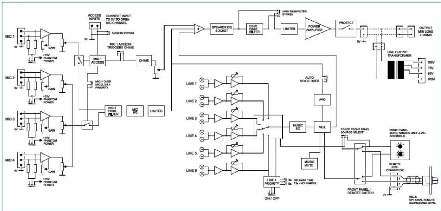
Schematic Diagram
flowchart
graph TD
    subgraph MIC_1
        A["0V"] --> B["GAIN"]
        B --> C["+15V PHANTOM POWER"]
        C --> D["MIC 1 ACCESS"]
        D --> E["CHIME"]
        E --> F["MIC 1 ACCESS TRIGGERS CHIME"]
        F --> G["High PASS FILTER"]
        G --> H["LIMITER"]
        H --> I["SPEAKER EQ SOCKET"]
        I --> J["HIGH PASS FILTER"]
        J --> K["LIMITER"]
        K --> L["POWER AMPLIFIER"]
        L --> M["PROTECT"]
        M --> N["OUTPUT MIN LOAD 4 OHMS"]
    end

    subgraph MIC_2
        O["0V"] --> P["GAIN"]
        P --> Q["+15V PHANTOM POWER"]
        Q --> R["MIC 1 OVER MIC 2,3,4 PRIORITY"]
        R --> S["High Pass Filter"]
        S --> T["LIMITER"]
        T --> U["POWER AMPLIFIER"]
        U --> V["PROTECT"]
        V --> W["OUTPUT MIN LOAD 4 OHMS"]
    end

    subgraph MIC_3
        X["0V"] --> Y["GAIN"]
        Y --> Z["+15V PHANTOM POWER"]
        Z --> AA["MIC 1 OVER MIC 2,3,4 PRIORITY"]
        AA --> AB["High Pass Filter"]
        AB --> AC["LIMITER"]
        AC --> AD["POWER AMPLIFIER"]
        AD --> AE["PROTECT"]
        AE --> AF["OUTPUT MIN LOAD 4 OHMS"]
    end

    subgraph MIC_4
        AG["0V"] --> AH["GAIN"]
        AH --> AI["+15V PHANTOM POWER"]
        AI --> AJ["MIC 1 OVER MIC 2,3,4 PRIORITY"]
        AJ --> AK["High Pass Filter"]
        AK --> AL["LIMITER"]
        AL --> AM["POWER AMPLIFIER"]
        AM --> AN["PROTECT"]
        AN --> AO["OUTPUT MIN LOAD 4 OHMS"]
    end

    subgraph LINE_1
        AP["LINE 1"] --> AQ["NOTED Triangle"]
        AR["LINE 2"] --> AS["NOTED Triangle"]
        AT["LINE 3"] --> AU["NOTED Triangle"]
        AV["LINE 4"] --> AW["NOTED Triangle"]
        AX["LINE 5"] --> AY["NOTED Triangle"]
        AZ["LINE 6"] --> BA["NOTED Triangle"]
    end

    subgraph LINE_2
        BB["LINE 2"] --> BC["NOTED Triangle"]
        BD["LINE 3"] --> BE["NOTED Triangle"]
        BF["LINE 4"] --> BG["NOTED Triangle"]
        BH["LINE 5"] --> BI["NOTED Triangle"]
        BJ["LINE 6"] --> BK["NOTED Triangle"]
    end

    subgraph LINE_3
        BL["LINE 3"] --> BM["NOTED Triangle"]
        BN["LINE 4"] --> BO["NOTED Triangle"]
        BP["LINE 5"] --> BQ["NOTED Triangle"]
        BR["LINE 6"] --> BS["NOTED Triangle"]
    end

    subgraph LINE_4
        BT["LINE 4"] --> BU["NOTED Triangle"]
        BV["LINE 5"] --> BW["NOTED Triangle"]
        BX["LINE 6"] --> BY["NOTED Triangle"]
    end

    subgraph LINE_5
        BZ["LINE 5"] --> CA["NOTED Triangle"]
        CB["LINE 6"] --> CD["NOTED Triangle"]
    end

    subgraph LINE_6
        CE["LINE 6 PRIORITY ON/OFF"] --> CF["3s RELEASE TIME 6s 12s - NO JUMPER"]
    end

    subgraph AUTO VOCING
        CG["AVO"] --> DH["VCA"]
    end

    subgraph MUSICE MUTE
        DI["MUSIC EQ"] --> DJ["VCA"]
    end

    subgraph FORCE FRONT PANEL SOURCE SELECT
        DK["MUSIC MUTE"] --> DL["VCA"]
    end

    subgraph FRONT PANEL MUSIC SOURCE AND LEVEL CONTROLS
        DM["MUSIC SOURCE SELECT"] --> DN["FORM FRONT PANEL CONNECTOR"]
        DD["MUSIC SOURCE AND LEVEL CONTROLS"] --> DP["RRemote Level Connector"]
        DP --> DR["RSL-6 OPTIONAL REMOTE SOURCE AND LEVEL"]

    subgraph FRONT PANEL MUSE SOURCE
        DS["RFL-6 OPTIONAL REMOTE SOURCE AND LEVEL"] --> DT["RSL-6 OPTIONAL REMOTE SOURCE AND LEVEL"]

    subgraph OUTPUT LINER
        DU["100V"] --> DV["LINE OUTPUT TRANSFORMER"]
        DV --> DW["70V COM"]

    style MIC_1 fill:#f9f,stroke:#333
    style MIC_2 fill:#f9f,stroke:#333
    style MIC_3 fill:#f9f,stroke:#333
    style MIC_4 fill:#f9f,stroke:#333
    style LINE_1 fill:#ccf,stroke:#333
    style LINE_2 fill:#ccf,stroke:#333
    style LINE_3 fill:#ccf,stroke:#333
    style LINE_4 fill:#ccf,stroke:#333
    style LINE_5 fill:#ccf,stroke:#333
    style LINE_6 fill:#ccf,stroke:#333
    style LINE_7 fill:#ccf,stroke:#333
    style LINE_8 fill:#ccf,stroke:#333
    style LINE_9 fill:#ccf,stroke:#333
    style LINE_10 fill:#ccf,stroke:#333
    style LINE_11 fill:#ccf,stroke:#333
    style LINE_12 fill:#ccf,stroke:#333
    style LINE_13 fill:#ccf,stroke:#333
    style LINE_14 fill:#ccf,stroke:#333
    style LINE_15 fill:#ccf,stroke:#333
    style LINE_16 fill:#ccf,stroke:#333
    style LINE_17 fill:#ccf,stroke:#333
    style LINE_18 fill:#ccf,stroke:#333
    style LINE_19 fill:#ccf,stroke:#333
    style LINE_20 fill:#ccf,stroke:#333
    style LINE_21 fill:#ccf,stroke:#333
    style LINE_22 fill:#ccf,stroke:#333
    style LINE_23 fill:#ccf,stroke:#333
    style LINE_24 fill:#ccf,stroke:#333
    style LINE_25 fill:#ccf,stroke:#333
    style LINE_26 fill:#ccf,stroke:#333
    style LINE_27 fill:#ccf,stroke:#333
    style LINE_28 fill:#ccf,stroke:#333
    style LINE_29 fill:#ccf,stroke:#333
    style LINE_30 fill:#ccf,stroke:#333
    style LINE_31 fill:#ccf,stroke:#333
    style LINE_32 fill:#ccf,stroke:#333
    style LINE_33 fill:#ccf,stroke:#333
    style LINE_34 fill:#ccf,stroke:#333
    style LINE_35 fill:#ccf,stroke:#333
    style LINE_36 fill:#ccf,stroke:#333
    style LINE_37 fill:#ccf,stroke:#333
    style LINE_38 fill:#ccf,stroke:#333
    style LINE_39 fill:#ccf,stroke:#333
    style LINE_40 fill:#ccf,stroke:#333
fig.1: MPA Series Schematic Diagram
text_image
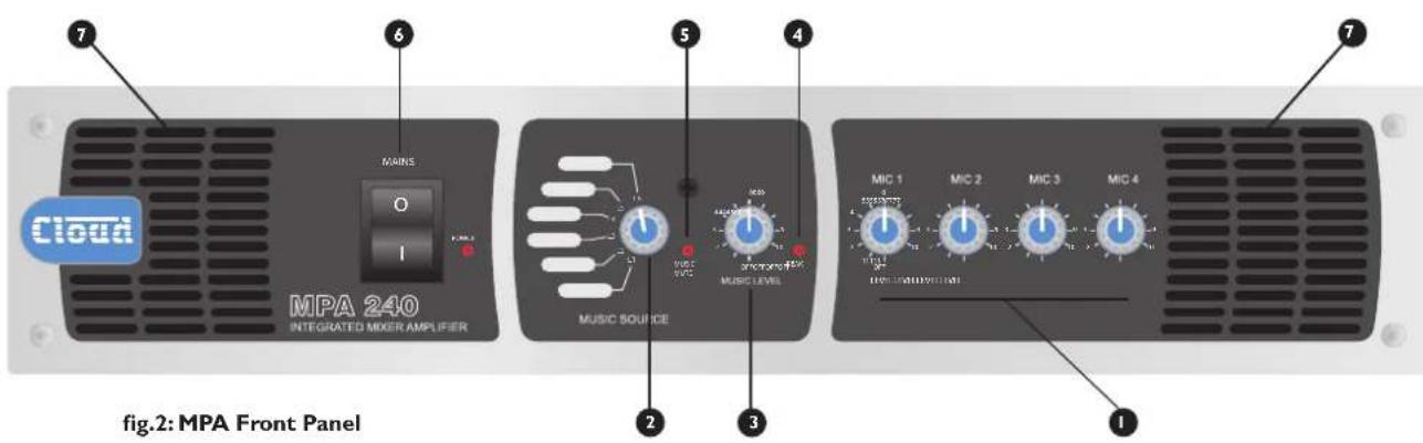
Cloud MPA 240 INTEGRATED MIXER AMPLIFIER MAIN O I MUSIC SOURCE MUSIC LEVEL MUSIC MIC 1 MIC 2 MIC 3 MIC 4 FIG.2: MPA Front Panel 1 2 3 4 5 6 7Front Panel Description
① MIC LEVEL I to 4 - level controls for Mic Inputs I to 4
2 MUSIC SOURCE – selects active Line Input (1 to 6)
3 MUSIC LEVEL – adjusts level of selected Line Input
4 PEAK – illuminates if Mic or Line signals level are too high
5 MUSIC MUTE – illuminates when external Emergency Mute is active
6 MAINS - AC power switch with LED
7 Ventilation slots – forced-air cooling air intake

text_image
LINE INPUTS LINE 1 LINE 2 GAIN GAIN GAIN GAIN GAIN GAIN LINE 3 LINE 4 Line 5 Line 6 Line 7 Line 8 Line 9 Line 10 Line 11 Line 12 Line 13 Line 14 Line 15 MIC INPUTS BALANCED MICROPHONE CONNECTIONS PIN - SUBSTORMPOUND PIN - COULY FLOWING PIN - MODE 2 FLOWING MIC 3 +100 V/100 V/100 V/100 V/100 V/100 V/100 V/100 V/100 V/100 V/100 V/100 V/100 V/100 V/100 V/100 V/100 V/100 V/100 V/100 V/100 V/ PAIN MCI MIC T GAIN 1.2.3 ACCESS GAIN 1.2.3 GAIN 1.2.3 GAIN 1.2.3 GAIN 1.2.3 MIC SG MUSIC SG LIF LIF SPEAKER OUTPUTS OUTPUT RATING, R/W LINE OUTPUT CANCE HIGH VOLTAGE CONNECT TO RISKUARY RELAY CONTACTS REMOTE MUSIC CONTROL ON REMOTE LOCAL FIRE ALARM MUSIC MUTE THE LINE MUST BE EARTHED VIA THE POWER COLD. FUSE REFERENCE Fuses WITH SAME TYPE AND RATING: OPEN TO USE THIS OUTPUT TBS 150V, LIF TSA+FIRESfig.3: MPA Rear Panel
Rear Panel Description
LINE 1 to LINE 6 – stereo line inputs for music sources
2 GAIN I to GAIN 6 – level trims for each line input
3 MUSIC EQ – LF and HF EQ adjustment for music channel
4 MIC I to MIC 4 – balanced mic inputs
5 GAIN I to GAIN 4 – level trims for each mic input
6 MIC EQ - LF and HF EQ adjustment for mic channel
7 ACCESS – external paging control input for Mic I
8 LOW IMPEDANCE OUTPUT – speaker output for low-Z connection
9 LINE OUTPUT – for connection of 100 V/70 V/25 V line distribution system
10 MUSIC MUTE – Emergency control input for muting music source
11 REMOTE MUSIC CONTROL – for connection of RL-1 or RSL-6 remote control panels
12 REMOTE/LOCAL – disables front panel controls when remote control is in use
13 IEC mains input
14 Mains fuse
15 Fan – forced-air cooling air exhaust
Music Inputs
The unit has six stereo line inputs; these inputs are suitable for most music sources such as compact disc players, tape players, satellite receivers and the like. Each stereo input is summed internally to mono.
All inputs are unbalanced and use RCA phono sockets. The input impedance is 47k ohm.
Line 6 input can be configured to have priority over any other music source, see Music Priority, page 8.
Sensitivity & Gain Control
All six stereo line inputs have a preset gain control on the rear panel adjacent to the respective input sockets. The gain control has a range of 20 dB allowing the input sensitivity to be varied from -12 dBu (200 mV) to +8 dBu (2.0 V).
The preset gain control should be adjusted so that all the input signals are operating at the same level and that the front panel level control has an optimum range of control.
Music Source Select
This front panel six position switch is used to select the desired music signal. Remote control of source selection is possible with a remote control plate (RSL-6). See fig.4.
Music Level Control
A front panel mounted music level control is provided.
Remote control of music level is possible by connecting a remote control plate (either RSL-6 or RL-1), See fig.4.
Remote Control of Music Source Select and Level
The MPA Series mixer-amplifiers are compatible with standard Cloud remote control plates Types RSL-6 (music source select and level) and RL-1 (level only).
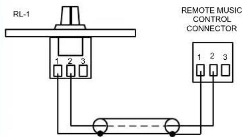
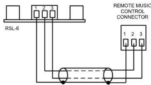
Either type of plate may be connected at the rear 3-pin 5 mm-pitch screw terminal connector (Remote Music Control), using the wiring shown in fig.4.
Use two-core (RSL-6 or RL-1) or single-core (RL-1 only) screened cable to connect the remote level plate (max length 100 metres).
Pressing the button adjacent to the rear panel connector activates the remote control plate and disables both the front panel level and source select controls. If an RL-1 is being used, the internal jumper J4 should be moved from its default 'SW' setting to 'FR', to override the disabling of the front panel source select switch. See fig.7 for location of jumpers.
REMOTE LEVEL CONTROL WIRING
text_image
RL-1 REMOTE MUSIC CONTROL CONNECTOR 1 2 3 1 2 3SINGLE-CORE SCREENED CABLE MAY BE USED
REMOTE SOURCE & LEVEL CONTROL WIRING
text_image
RSL-6 1 2 3 REMOTE MUSIC CONTROL CONNECTOR 1 2 3USE TWO-CORE SCREENED CABLE
fig.4: RL-I and RSL-6 Wiring
text_image
MIC INPUTS PIN 1: SCREEN (GROUND) PIN 2: COLD/ANTIPHASE (-) PIN 3: HOT/PHASE (+) + - SCNBALANCED CONNECTION
text_image
1 2 3 SCN +UNBALANCED CONNECTION
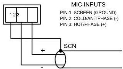
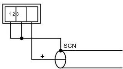
fig.5: Microphone Input Wiring
Music Equalisation
One set of independent bass and treble controls is provided for the music signals. These preset controls are located on the rear panel below the line input sockets. The treble control has a range of ±10 dB at 10 kHz and the bass control has a range of ±10 dB at 50 Hz.
Music Priority
A Juke Box, Digital Sound Store or other audio source can be given automatic priority over all other music inputs by connecting it to Line 6 input and moving internal jumpers 5A and 5B from the OFF position (factory default) to the ON. When this mode of operation is selected, the unit will operate normally until a signal is detected on Line 6, when the selected source (usually background music) is muted, allowing the source connected to Line 6 to replace it. Once the signal on line 6 stops, the selected source will smoothly restore to its former level. The time taken for the restoration is set in the factory at 3 seconds, but it may be set at 6 or 12 seconds with internal jumper J7. (3s is suitable for announcements, but the longer times may be more appropriate when a jukebox or similar is the Line 6 source.) See fig.7 for location of jumpers.
Microphone Inputs
Four microphone inputs are provided; the microphone pre-amplifiers are an electronically balanced, transformer-less design configured for optimum low noise performance. The input impedance is greater than 2 kΩ and is suitable for microphones in the 200 Ω to 600 Ω range.
Inputs are via 3-pin 3.5 mm-pitch screw terminal connectors on the rear panel.
Connect microphones as shown in fig.5. Note that if using an unbalanced microphone, pins 1 and 2 should be connected together.
Phantom power is available on any or all of the mic inputs, and is activated by setting internal jumpers J9 to J12 (for mic inputs 1 to 4 respectively) to the ON position. See fig.7 for location of jumpers.
Care should be taken to ensure that phantom power is activated only when the microphone connected to the input requires external phantom power; damage to the microphone may result otherwise.
Gain Control
A mic gain control (of the preset type) is provided adjacent to each input connector.
The gain can be adjusted from 10 dB to 50 dB. A high overload margin is maintained at all gain settings.
Microphone Access Input
Mic input I is equipped with an external access control input; this is a 2-pin 5 mm-pitch screw terminal connector adjacent to the Mic input I connector. The access input is primarily intended to provide compatibility with paging microphones and their associated switching arrangements. By default, the access function is bypassed.
To use the function, it must be enabled by moving internal jumper J13 from its default ON setting to OFF. See fig.7 for location of jumpers. Once enabled, the microphone input is muted while the pins of the access connector are open-circuit. When the pins are connected together, Mic input I becomes active for use.
The access input can also trigger the following functions:
• Mic I Priority over Mics 2-4
Activation of Mic I via the access input will give Mic I priority over Mics 2, 3 and 4 if internal jumper J8 is set to ON. See fig.7 for location of jumpers. See also Mic I over Mics 2-4 priority, page 9.
- Chime
The internal chime generator will be activated if internal jumper J1 is set to ON. See fig.7 for location of jumpers. See also Chime, page 9.
Front Panel Microphone Level Controls
A separate level control is provided for each mic input and these provide the user with a convenient means of adjusting the audio level of the microphones.
The microphone signals are routed directly to the power stage and are unaffected by the operation of the music level control.
The gain controls on the rear panel (see Gain Control) should be set at a level where microphone distortion does not occur even when the front panel level controls are fully clockwise.
Microphone Equalisation
The four microphone inputs are summed together and are routed to the power stage via a fixed high pass filter and an adjustable EQ section. The fixed filter attenuates the signal below 100 Hz, which helps to reduce the effects of microphone handling noise.
The two preset EQ controls are on the rear panel adjacent to the mic inputs; the LF and HF controls provide ± 10 dB of adjustment below 100Hz and above 5kHz respectively. After installation, some test announcements should be made,
ideally by the people who will normally make them. The Mic EQ should be adjusted if necessary to maximise voice clarity.
Microphone Priority
MPA Series mixer-amplifiers provide two separate microphone priority functions. One of these enables the microphones to have priority over music, the other allows Mic I to have priority over the other microphones.
Microphone over music priority
Fully automatic voice operated priority (VOX function) is available for the microphone signals. This function is enabled by internal jumper J6 (default setting is ON). When enabled, the music signal is automatically attenuated by 30 dB when a microphone signal is detected, allowing the message to be clearly heard. Normal music operation is restored smoothly after the announcement ends.
Note that the presence of a signal on any of the four mic inputs will operate this function.
Mic I over Mics 2-4 priority
If internal jumper J8 is set to ON (the default setting is OFF), Mic inputs 2, 3 and 4 will be muted whenever the Microphone Access Input is enabled. This ensures that Mic I will always have priority over any other microphones in use when Mic I is used for paging.
Note that if jumper J13 is left at its default setting of ON, Mics 2, 3 and 4 will be permanently disabled by this function, leaving Mic 1 as the only active microphone input.
Chime
The MPA Series amplifiers have an internal pre-announcement chime generator. The chime is triggered by the Microphone Access Input, if enabled by jumper J1 being set to ON. J1's default setting is OFF.
An internal preset rotary control is provided to adjust the chime volume; the front panel level controls have no effect on the chime level. See fig.7 for locations of internal controls.
Power Amplifier Stage and Outputs
Line Output
The MPA Series amplifier's output stage incorporates an output transformer suitable for driving 100 V, 70 V or 25 V line speaker distribution system. The secondary (output side) of the transformer is permanently wired to the line output connector (a 4-pin 5 mm-pitch screw terminal type). A safety cover is fitted over the connector, which may be removed to connect the speaker cable. Replace the cover after the connection has been made.
The transformer secondary has 3 line outputs: 100 V, 70 V and 25 V; while these have a common 0 V connection, the output is fully floating i.e., it is isolated from the rest of the amplifier. The maximum total combined load should not exceed the rated power for the amplifier model (see table below).
When driving 100/70/25 V line circuits, it is strongly recommended that the amplifier's 65 Hz high pass filter is set ON (see High pass filter - page 10).
Low impedance operation
To convert the amplifier to low impedance operation, the primary winding of the toroidal transformer nearer the rear of the unit should be unplugged from CON8 on the main pcb (a short pair of heavy red and black wires), and replaced by the spare plug connected to the rear panel low impedance output socket (same wire types). Refer to fig. 7 (page 13) for the location of this connector. Note that the 100/70/25 V line outputs will no longer be available once the transformer is unplugged even though the transformer secondary is still connected to the line output connector.
The low impedance output is available on a 2-pin 5mm -pitch screw terminal connector on the rear panel. Note that one of the output pins is connected internally to 0V .
The MPA Series amplifiers are able to deliver their rated power into a 4 ohm load, as follows:
| Model Rated Power | |
| MPA60 | 60 watts |
| MPA120 | 120 watts |
| MPA240 | 240 watts |
The maximum output power will be reduced with higher load impedances. When using multiple low-impedance loudspeakers (normally 8 ohms) with a single amplifier, series and parallel wiring should be employed to produce a total load impedance of not less than 4 ohms.
High pass filter
A high pass filter is provided to protect speakers, transformers etc. from the effects of low frequency signals. The filter is enabled by the internal jumper J2 (see fig.7). The filter reduces the output level of frequencies below 65 Hz, and ideally should be used if the line output transformer is in circuit.
Music Mute
(Fire Alarm Interface)
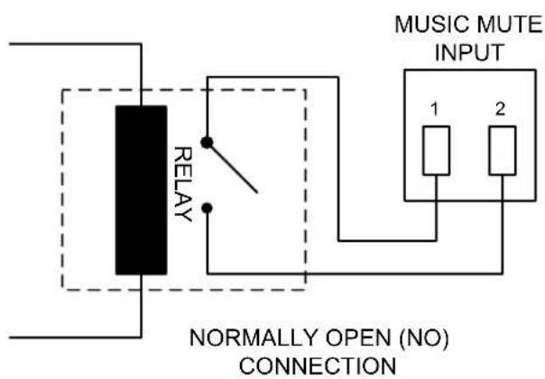
In some installations (such as licensed premises or retail outlets within a shopping mall), there may be a local authority or fire service requirement to mute the music signals from a fire alarm control panel when an alarm condition arises. The MPA Series amplifiers include a facility to mute the music signals only (i.e., mic inputs are still active), via the Music Mute input. This is a 2-pin 5 mm-pitch screw terminal connector on the rear panel, and the contacts are fully isolated.
Activation of the Music Mute is often via a relay mounted close to the MPA Series amplifier, powered by the fire alarm control panel. Other arrangements may exist depending on the design of the fire control system and the fire alarm installation company should be consulted when making the connection. The MPA Series amplifiers will mute on either a contact closure at the Music Mute input (NO) or an open-circuit (NC). Selection of NO or NC operation is made with internal jumper J14. NO is the factory default. See fig.6.
Bose® Equalisation Modules
MPA Series amplifiers are compatible with single channel Bose® Series II equalisation modules. EQ modules are available to suit the following Bose® loudspeakers:
- Panaray MA12
• Panaray 402-II, 502B and 502BEX
• Panaray LT Series: Models 3302, 4402, 9402 and 9702.
Modules to suit other models are available – please enquire.
Installation Instructions
Refer to the pcb layout diagram (see fig.7) for the location of the Bose EQ module connector and its associated bypass jumper J3.
To install an EQ module, proceed as follows:
- Switch off the power and isolate the unit from the mains.
2 Remove the top panel. - Remove jumper J3 from the main pcb.
- Plug the Bose® equalisation module onto its connector; note that the connector has two notches on one side which engage with lugs on the module's mating connector to ensure correct orientation.
- Replace the top panel.
REMOTE MUSIC MUTE TERMINATIONS
text_image
MUSIC MUTE INPUT RELAY 1 2 NORMALLY OPEN (NO) CONNECTION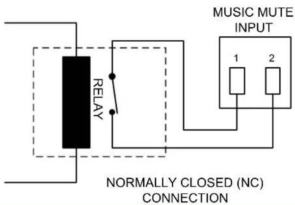
text_image
MUSIC MUTE INPUT RELAY 1 2 NORMALLY CLOSED (NC) CONNECTIONfig.6: Remote Music Mute
General Notes
Multi-zone Applications
Where the sound system specification calls for separate control in several zones, MPA Series amplifiers can be used in multiples.
Signal sources can be connected to several inputs as required, but care must be taken to ensure the output stage of the signal source is capable of driving the resulting lower input impedance.
The impedance of the line inputs (music inputs) is 47k ohms and it is reasonable to assume that most op-amp based signal sources are able to drive a 10k ohm load, allowing up to five amplifiers to be paralleled.
The input impedance of the mic inputs is 2.4k ohms, making them suitable for microphones with a nominal impedance of 600 ohms or less. A single 600 ohm microphone could therefore typically be connected to four paralleled mic inputs. If this guideline figure cannot be adhered to, the use of suitable mic or line distribution amplifiers is recommended.
To avoid any problems associated with differences in mains supply earthing, we recommend that all MPA Series amplifiers used in a multi-zone application should be co-located and connected to a common mains supply.
Note that when using multiple MPA Series amplifiers in a 19" rack, suitable ventilation arrangements must be made to ensure that lower amplifiers do not cause those above to overheat (see Ventilation for further information).
EMC Considerations
MPA Series amplifiers fully conform to the relevant electromagnetic compatibility (EMC) standards and are technically well behaved. You should experience no problems interfacing units to other items of equipment and under normal circumstances, no special precautions need to be taken.
If the unit is to be used in close proximity to potential sources of HF disturbance such as high power communication transmitters, radar stations and the like, it is suggested that input signal leads be kept as short as possible.
Always use balanced interconnections wherever possible. If the MPA Series amplifier is mounted in a 19" rack, do not locate the unit in close proximity to a powerful amplifier of any kind, which may radiate a strong magnetic field from the power transformer.
Earthing
When several mains powered units are connected together via their signal cables, there is a risk of one or more earth loops which may cause an audible hum on the system even with the gain controls set to minimum.
The 0 V rail of an MPA Series amplifier is directly coupled to the chassis ground. No interconnection problems should be encountered, but if there is any hum or other extraneous noise when source equipment is connected, the situation can generally be remedied by observing the following guidelines:
• Always connect sources using balanced connections wherever possible, with the cable screen only connected at the receiving end (amplifier input).
- Use audio isolating transformers (readily available from trade suppliers) at the inputs if necessary. These will ensure that the amplifier is electrically isolated from the source equipment.
- The signal source units should be located as close as possible to the amplifiers and the metal housing of the various units should not be electrically connected together through the equipment rack. If this is a problem, rack isolating kits are available from specialist hardware suppliers. If the problem persists, try to connect all interconnected units, including power amplifiers to a common power source to ensure a common ground is provided.
Ventilation
MPA Series amplifiers are force cooled by a thermostatically-controlled fan. The fan is operative at all times, remaining at low speed at internal temperatures below 50 °C, then increasing in speed above this temperature to a maximum speed at 70 °C.
Always allow adequate space around the amplifier(s) to allow a free flow of air through the unit(s). In 19" rack applications we recommend leaving IU of rack space above and below each unit. Plain IU blank panels, not slotted ventilation panels should be used, as the latter reduce the effect of forced-air cooling.
The direction of airflow in MPA Series amplifiers is from front-to-rear; it is recommended not to mix the amplifiers with other equipment employing forced-air cooling which acts in the opposite direction within the same rack.
In free standing applications we recommend fitting the feet supplied and placing the unit on a flat surface and leaving the ventilation slots on top of the unit free from any obstructions.
Technical Specifications
Line Inputs
| Frequency response | Low-Z output +0 dB/-1 | dB from 20 Hz – 20 kHz (65 Hz filter switched out) |
| High voltage outputs +0 | dB/-2 dB from 20 Hz – 20 kHz (65 Hz filter switched out) | |
| Distortion | Low-Z output <0.03% @ I kHz, I dB below full power (80 kHz bandwidth) | |
| High voltage outputs <0.04% @ I kHz, I dB below full power (80 kHz bandwidth) | ||
| Sensitivity | 195 mV (-12 dBu) to 2.0 V (+8 dBu) | |
| Input Gain control | 20 dB range | |
| Input impedance | 47k ohms | |
| Headroom | >20 dB | |
| Noise | -90 dB 22 Hz –22 kHz, at speaker output, relative to full power | |
| Equalisation | HF: ±10 dB/10 kHz LF: ±10 dB/50 Hz | |
Microphone Inputs
| Frequency response | Low-Z output -3 dB @ | 100 Hz (3 rd. order filter); -1 dB @20 kHz |
| High voltage output -3 dB @ 100 Hz (3 rd. order filter); -2 dB @20 kHz | ||
| Distortion <0.03% @ 1 kHz, 1 dB below full power (80 kHz bandwidth) | ||
| Gain range 40 dB range | ||
| Input Impedance >2k ohms (balanced) | ||
| Phantom Power 15 v, switchable per-input by jumpers | ||
| Headroom >20 dB | ||
| Noise -127 dB EIN 22 Hz-22 kHz (150 ohms) | ||
| Equalisation | HF: ±10 dB/5 kHz LF: ±10 dB/100 Hz | |
Outputs
| Output Power* (any output, 1kHz continuous sine wave @ <0.07% THD+N) | MPA60 60 watts | |
| MPA120 | 120 watts | |
| MPA240 | 240 watts | |
| Protection | Fixed level signal limiter max gain reduction of 20 dB, DC protection, IV limiting & short circuit protection, switch-on delay | |
| Cooling | Forced-air, front-to-rear airflow, thermostatically controlled | |
* see also Low impedance operation, page 9.
General Specifications
| Power input | 230 V, 115 V, 100 V versions available | ||
| Fuse rating | MPA60 230V | TIA H | |
| 115/100V | T2A H | ||
| MPA120 | 230V | T2A H | |
| 115/100V | T4A H | ||
| MPA240 | 230V | T4A H | |
| 115/100V | T8A H | ||
| Fuse type | All models | 20 mm x 5 mm | |
| Dimensions (mm) | 482.6 wide x 88 high (2U) x 300 deep (+ connectors & knobs) | ||
| Net weight (kg) | MPA60 | 9.0 | |
| MPA120 | 10.5 | ||
| MPA240 | 21.6 | ||
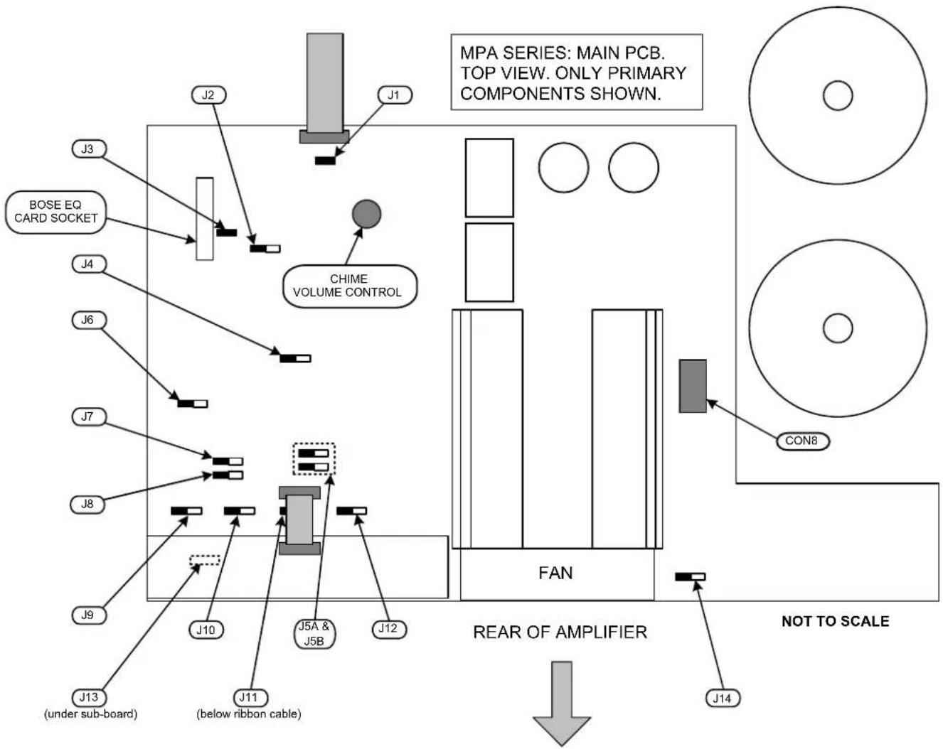
Location of internal jumpers, etc.
flowchart
graph TD
    A["MPA SERIES: MAIN PCB. TOP VIEW. ONLY PRIMARY COMPONENTS SHOWN."] --> B["J1"]
    B --> C["J2"]
    C --> D["J3"]
    D --> E["BOSE EQ CARD SOCKET"]
    E --> F["J4"]
    F --> G["J6"]
    G --> H["J7"]
    H --> I["J8"]
    I --> J["J9"]
    J --> K["J10"]
    K --> L["J11 (below ribbon cable)"]
    L --> M["J12"]
    M --> N["J13 (under sub-board)"]
    N --> O["J14"]
    O --> P["FAN"]
    P --> Q["CON8"]
    Q --> R["REAR OF AMPLIFIER"]
    R --> S["NOT TO SCALE"]
    style A fill:#f9f,stroke:#333
    style B fill:#ccf,stroke:#333
    style C fill:#cfc,stroke:#333
    style D fill:#fcc,stroke:#333
    style E fill:#ffc,stroke:#333
    style F fill:#fcc,stroke:#333
    style G fill:#fcc,stroke:#333
    style H fill:#fcc,stroke:#333
    style I fill:#fcc,stroke:#333
    style J fill:#fcc,stroke:#333
    style K fill:#fcc,stroke:#333
    style L fill:#fcc,stroke:#333
    style M fill:#fcc,stroke:#333
    style N fill:#fcc,stroke:#333
    style O fill:#fcc,stroke:#333
    style P fill:#ccf,stroke:#333
    style Q fill:#ccf,stroke:#333
    style R fill:#ccf,stroke:#333
    style S fill:#ccf,stroke:#333
fig.7: Internal jumpers
Factory Default Jumper Settings
| Jumper Function | Default Setting | |
| J1 | Mic I access triggers chime | OFF |
| J2 | 65 Hz high pass filter frequency | ON |
| J3 | EQ card socket bypass | ON |
| J4 | Front panel source select switch disable | SW |
| J5 (A & B) | Line input 6 priority | OFF |
| J6 | Mic over music priority (VOX function) | ON |
| J7 | Line 6 priority release time 3, 6 or 12 seconds | 3S |
| J8 | Mic I priority over Mics 2, 3 & 4 | OFF |
| J9 | Mic I phantom power | OFF |
| J10 | Mic 2 phantom power | OFF |
| J11 | Mic 3 phantom power | OFF |
| J12 | Mic 4 phantom power | OFF |
| J13 | Mic I Access Input bypass | ON |
| J14 Music Mute | NO or NC NO |
Bose® is a registered trademark of The Bose Corporation.
In the interest of continuing improvements Cloud Electronics Limited reserves the right to alter specifications without prior notice.
CLOUD
Cloud Electronics Limited
140 Staniforth Road
Sheffield S9 3HF
England
Tel: +44 (0)114 244 7051
Fax: +44 (0)114 242 5462
email: info@cloud.co.uk
web: www.cloud.co.uk