Rugo 2 - Signal lamp FoxFury - Free user manual and instructions
Find the device manual for free Rugo 2 FoxFury in PDF.


User questions about Rugo 2 FoxFury
0 question about this device. Answer the ones you know or ask your own.
Ask a new question about this device
Download the instructions for your Signal lamp in PDF format for free! Find your manual Rugo 2 - FoxFury and take your electronic device back in hand. On this page are published all the documents necessary for the use of your device. Rugo 2 by FoxFury.
USER MANUAL Rugo 2 FoxFury
natural_image
Technical line drawing of a mechanical housing or enclosure with internal components (no text or symbols)RUGO™ 2
700-301
TABLE OF CONTENTS
INTRODUCTION
Reference Guide 3
Overview 4
Physical Characteristics 4
POWER PACK
Charging the Power Pack 5
Reassembling the Rugo™ 2 after Charging 6
Power Pack Life 6
Operational Modes 6
TRI-LENS™
Using the Tri-Lens ^™ 7
Removing the Tri-Lens ^™ 7
REMOVING/CHANGING MOUNTS
Removing the Standard Mount 8
Removing the 14 "-20 & Cold-Shoe Mount 8
MOUNTING TO DEVICES
GoPro ^® 9
DSLR 9
Tripod/Puck Adaptor 9
MAINTENANCE
Replacing the Seal 10
Removing the Guard 10
WARNINGS/WARRANTY 4, 12-13
CARE/CLEANING 12
CONTACT FOXFURY 13
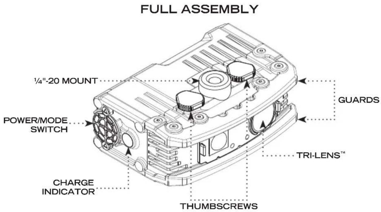
text_image
FULL ASSEMBLY 1/4"-20 MOUNT POWER/MODE SWITCH CHARGE INDICATOR THUMBSCREWS GUARDS TRI-LENS™| DISASSEMBLED LIGHT HEAD | DISASSEMBLED POWER PACK |
| LED CONTACT CAVITY (2) LED MODULE SCREW HOLE (4) “O”-RING ACCESS SCREW | LOCKING POST USB CHARGE PORT POWER CONTACTS |
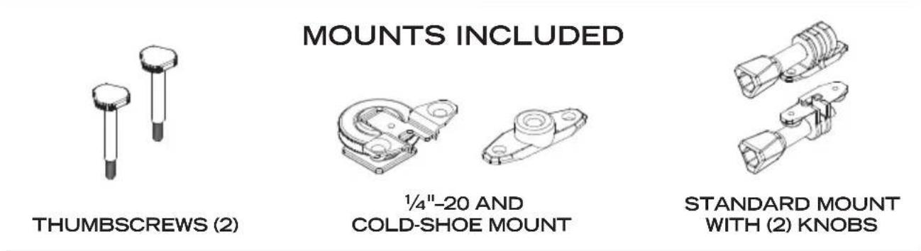
text_image
MOUNTS INCLUDED THUMBSCREWS (2) 1/4"-20 AND COLD-SHOE MOUNT STANDARD MOUNT WITH (2) KNOBSThe Rugo™ 2 is a compact and powerful LED Light which has the ability to be mounted to the GoPro®, a DSLR, a drone, a tripod and many other devices. Having four different intensities (70–620 Lumens) with three interchangeable lens settings (Tri-Lens™), makes it a powerful tool for action sports as well as photography and filming. A Charge Indicator and Quick Swap™ Power Pack makes the Rugo™ 2, patents pending, one of a kind.
IMPORTANT!
Please fully charge the Power Pack before using the Rugo™ 2 for the first time.
PHYSICAL CHARACTERISTICS
Please read below before using your Rugo™ 2 as it relays beneficial operating and safety information.
| RUGO ^TM 2 | |
| DIMENSIONS 2 | 9 x 1.0 x 2.0 in (74 x 25 x 51 mm) |
| WEIGHT | 5.6 oz (158 g) with Power Pack and Light Head2.6 oz (73 g) Power Pack |
WARNINGS

When used for extended periods of time the Rugo ^™ 2 will become HOT to the touch.

Do not stare into the LEDs for long periods of time or from a close range (less than 2 ft (0.6 m)).

This product is designed as an auxiliary lighting tool to be used with photo, video, and film.

DO NOT use the Rugo ^™ 2 as a primary light source for activities.

While using any FoxFury product, please operate at safe speeds.

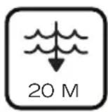
Be sure to rinse the Rugo™ 2 with fresh water immediatley after use in the ocean or a pool.

It is the responsibility of drone/UAV users to follow the FAA laws and regulations and/or the laws and regulations applicable to the flight location.
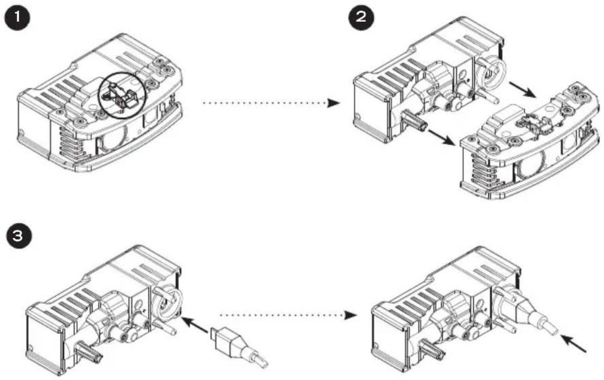
1 Press and hold the Power Pack Release Lever located on the Light Head portion of the Rugo™ 2.
2 While maintaining pressure on the Power Pack Release Lever, pull the Light Head and the Power Pack apart.
If unable to pull apart easily (due to resistance of the internal rubber gasket), try moving the Power Pack back and forth while pulling apart.
NOTE: Once apart, be sure to keep both ends dry and away from water, moisture and dust. While the Power Pack and Light Head are separated, the unit DOES NOT maintain its waterproof rating.
3 Insert the provided Micro USB Cable into the Power Pack—respect the orientation/alignment. Then, insert the opposite end, USB (Type A) into a USB compatible power source or into the included AC/DC Adaptor. (Input: 100V-240VAC 50/60 Hz, Output: 5V DC 1000mAh).
The Charge Indicator will be solid red while charging. Once fully charged, it will turn green.
Charging time will be approximately 2.5 hours.
After the Power Pack is charged, disconnect it from USB Cable.
**PLEASE NOTE: The Rugo™ 2 in steps 1–3 is shown with no mounts and is flipped to show the Power Pack Release Lever.
REASSEMBLING THE RUGO™ AFTER CHARGING
1 Install the Power Pack to the Light Head—confirm position of alignment posts to their respected cavities.
2 Push both halves together. A 'click' should be heard as they become locked together.
Test the light to make sure that the Power Pack is properly connected to the Light Head by pressing the Power/Mode Switch.
POWER PACK LIFE
| MODE DURATION | LUMENS | |
| HIGH 1 hour 620 | ||
| MEDIUM 1.5 hours | 380 | |
| LOW 6.75 hours 70 | ||
| STROBE 1.5 Hz 2.5 hours 620 |
*Power Pack life may vary according to age and ambient conditions.
OPERATIONAL MODES
ON/LOW mode: Press the Power/Mode Switch once.
MEDIUM mode: From LOW mode, press the Power/Mode Switch once.
HIGH mode: From MEDIUM mode, press and hold the Power/Mode Switch once.
STROBE 1.5 Hz mode: From HIGH mode, press and hold the Power/ Mode switch once.
OFF: From ANY mode, press and hold the Power/Mode Switch for 2 sec.
LOW POWER INDICATOR: At a low level, the Charge Indicator will flash for approximately 0.5–1.0 sec. It is suggested that you then charge or replace the Power Pack with a fully charged one. If on a higher mode and you need to continue using the light, it is suggested that you adjust the mode to a lower setting.
NOTE: The light does not retain the mode in memory. Once you turn the light ON, you will have to re-select the mode you desire.
USING THE TRI-LENS™
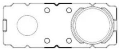
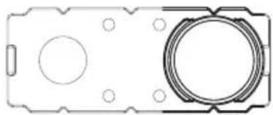
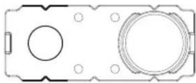
The Rugo™ 2 Tri-Lens™ has three (3) beam emission angles which can be used for many different applications by simply sliding from left to right and vise-versa.
FLOOD
natural_image
Pure technical diagram of a rectangular device with circular cutouts and mounting holes (no text or symbols)120°
BEAM DISTANCE: 10 ft (3 m)
USED FOR: Close-up
AREA
natural_image
Pure technical diagram of a mechanical component with circular features and mounting holes (no text or symbols)55°
BEAM DISTANCE: 30 ft (10 m)
USED FOR: Mid-range
SPOT
natural_image
Pure technical diagram of a mechanical component with circular features and mounting holes (no text or symbols)25°
BEAM DISTANCE: 100 ft (30 m)
USED FOR: Distance
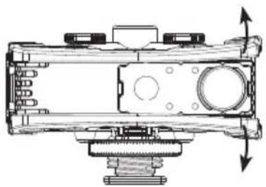
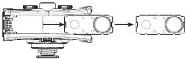
REMOVING THE TRI-LENS™
1
natural_image
Technical line drawing of a mechanical assembly with no visible text or symbols2
natural_image
Technical line drawing of a mechanical assembly with internal components and a close-up view of a flanged component (no text or symbols)1 Push the Tri-Lens ^™ to either the right or left side until it won't go any further. Use your fingers to slightly pull the Guards away from the unit, while pushing the Tri-Lens ^™ with your thumb. This will help the Tri-Lens ^™ to overcome the ridge, (located at the end of the Guard) and will allow it to be easily released.
2 Once the Tri-Lens ^TM overcomes the ridge, pull it free from the Light Head.
FOR RE-INSTALLATION: Line up the Tri-Lens ^™ with the ridge. Then push it back into position on the Light Head.
REMOVING/CHANGING MOUNTS
STANDARD MOUNT
flowchart
graph TD
    A["Engine Component"] --> B["Valve Component"]
    B --> C["Motor Assembly"]
    style A fill:#f9f,stroke:#333
    style B fill:#ccf,stroke:#333
    style C fill:#cfc,stroke:#333
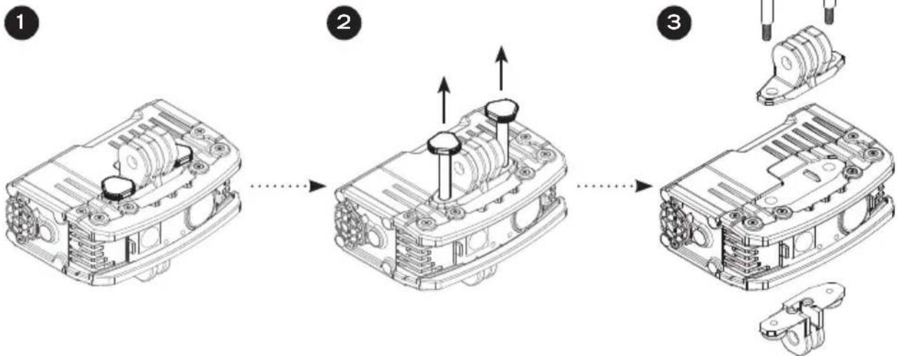
1 Start with the Rugo™ 2 positioned so that the Thumbscrews are on top.
2 Twist each Thumbscrew counter-clockwise until they become loose. They should then be ready to pull out completely.
3 Once Thumbscrews are removed, the Standard Mount can then be disengaged from the Rugo™ completely.
1/4'' -20 AND COLD-SHOE MOUNT
flowchart
graph TD
    A["Initial housing component"] --> B["Assembly steps"]
    B --> C["Reassembly of valve parts"]
    C --> D["Final assembly with valve parts"]
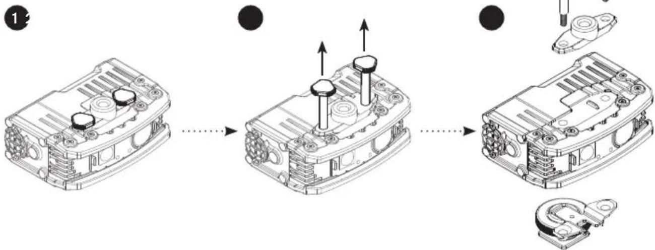
1 Start with the Rugo™ 2 positioned so that the Thumbscrews are on top.
2 Twist each Thumbscrew counter-clockwise until they become loose. They should then be ready to pull out completely.
3 Once Thumbscrews are removed, the 14 "-20 or Cold-shoe mount can then be disengaged from the Rugo™ 2 completely.
ACTION CAM
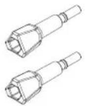
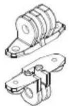
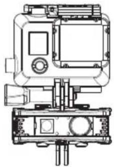
The Rugo™ 2 can be mounted to an Action Cam via the removable Standard Mount. Line up the mounts on the Rugo™ with the mounts on the Action Cam and then tighten the Mount Knobs.
NOTE: Orientation of Knobs should match as shown below.
natural_image
Technical line drawing of a mechanical device with front and side views (no text or symbols)CAMERA
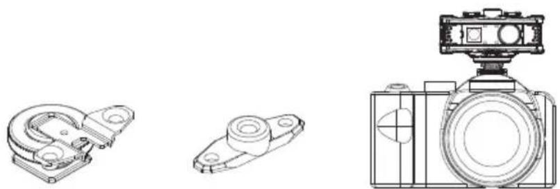
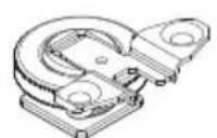
The Rugo™ 2 can be mounted to a DSLR camera via the removable Cold-shoe Mount. Simply slide the mount onto the camera flash attachment and twist the Locking Ring until securely fastened.
natural_image
Technical line drawings of three mechanical components: a clamping bracket, a mounting bracket, and a camera frame (no text or symbols present)TRIPOD OR PUCK ADAPTOR
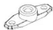
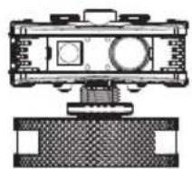
The Rugo™ 2 can be mounted to most tripods or to the Puck Adaptor (purchased separately) via the provided 14 "-20 Mount. Twist the threaded hole of the Rugo™ 2 14 "-20 Mount onto the screw of the tripod or Puck Adaptor. Then, twist the Rugo™ 2 and Puck Adaptor until it is securely fastened.
natural_image
Technical line drawing of a mechanical device with mounting base (no text or symbols)
natural_image
Line drawing of a tripod-mounted camera with adjustable legs and a top-mounted head (no text or symbols)REPLACING THE O-RING (P/N 51-112)
flowchart
graph TD
    A["1: Mounting Body"] --> B["2: Bearing Component"]
    B --> C["3: O-Ring Assembly"]
    style A fill:#f9f,stroke:#333
    style B fill:#ccf,stroke:#333
    style C fill:#cfc,stroke:#333
    note right of C: O-RING RETAINING TAB
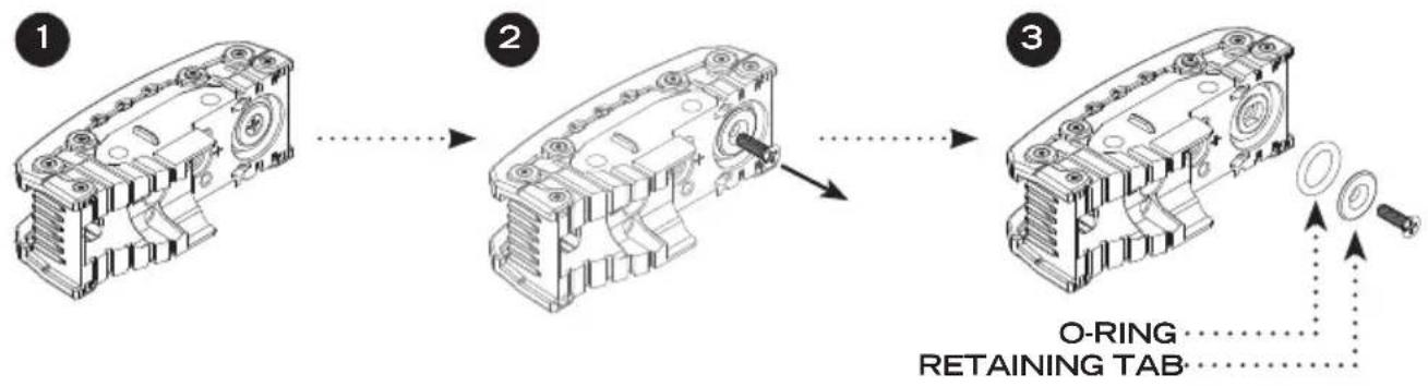
1 Separate the Power Pack from the Light Head (follow steps 1-2 in the "Charging the Power Pack" section on page 5).
2 Using a #2 Phillips head screwdriver (not included) remove the screw from the Light Head (reference "Disassembled Light Head" diagram on page 3).
3 The Retaining Tab and O-Ring can now be removed.
If the O-Ring does not fall out on its own when unscrewed, it may need to be pulled out.
Examine the O-Ring for cracks. If cracks are found, a replacement will be needed to ensure the Rugo™ 2 waterproof rating.
FOR RE-INSTALLATION, follow the above listed steps in reverse order. NOTE: The O-Ring can be lubricated with a non-silicone based grease.
text_image
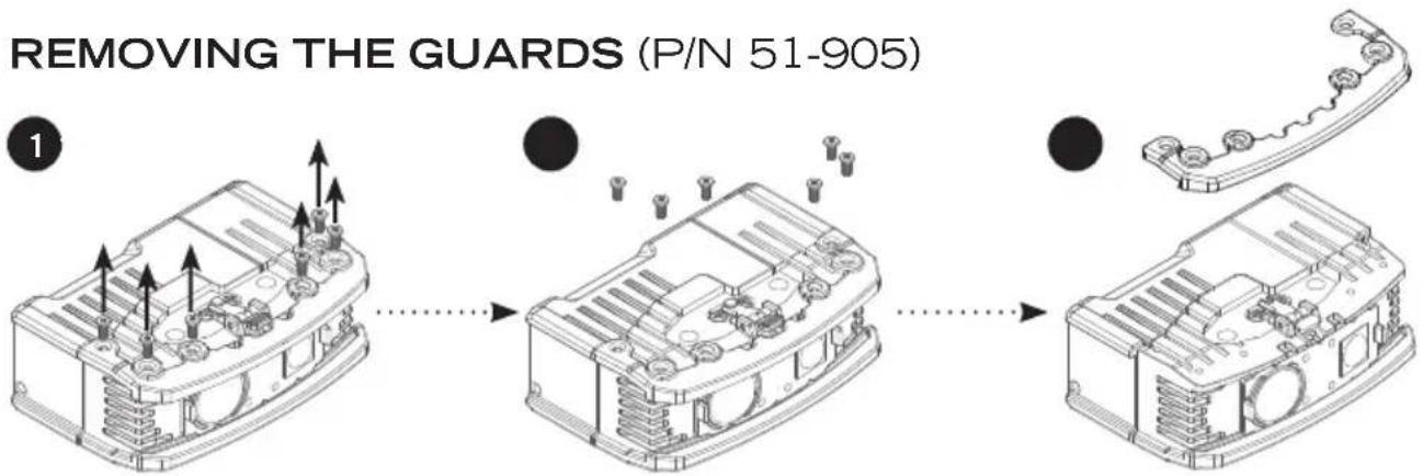
REMOVING THE GUARDS (P/N 51-905)1 Use a size T6 Star-Tip (TORX) driver or bit (not included) to take out the screws on the top and bottom of the Rugo™ 2.
2 Once screws are loose, remove them and then lift up on the Guard to remove it.
3 Repeat steps 1-2 to remove the Guard on the opposite side of the Rugo ^™ 2.
FOR RE-INSTALLATION, make sure to tighten the screws until they are snug.
NOTES
WARRANTY AND OTHER INFORMATION
PRODUCT DURABILITY

CE
PRODUCT NAME: Rugo™ 2
MODEL NUMBER: 700-301
ADAPTOR INPUT: AC 100-240V, 50/60 Hz
CARE/CLEANING
Your FoxFury product is a professional tool. Regular maintenance and care of your light will maximize performance for you. As needed, wash your FoxFury product using a soft washcloth, clean water and a mild soap. Be sure that both the Light Head and Power Pack are reassembled securely before washing. When done, pat dry with a damp cloth.
AVAILABLE ACCESSORIES
Puck Adaptor, P/N 85-045
Tripo-Scope® M1, P/N 650-100
Rugo™ Quick Swap® Power Pack with Strobe, P/N N50-220
Rugo™ Standard Mount, P/N N50-132
Rugo™ 1/4"-20 and Cold-shoe Mount, P/N N50-133
Handlebar/Drone Mount, P/N 85-026
Drone Mounts for DJI Phantom, P/N 85-027
Drone Mounts for YUNEEC H520 and Typhoon H, P/N 85-023
WARNINGS
FoxFury, LLC is not responsible for the incorrect use of any FoxFury Lighting product.
When used for extended periods of time the Rugo™ 2 will become HOT to the touch. Please use care when operating.
Lights are strong enough to cause damage to the human eye.
not stare into LEDs for long periods of time or from a close range (less than 2 ft (0.6 m)).
FoxFury, LLC is not responsible for any injury or damage caused during the use of this product.
Usage of this product must be supervised by an adult when it is being used by a minor.
Any FoxFury product should be operated at speeds safe enough to maneuver around surrounding obstacles.
Do not use under the influence of drugs or alcohol.
LIMITED LIFETIME WARRANTY
FoxFury, LLC (“FoxFury”) warrants this product to be free from defects in material for a lifetime of use except for batteries, LEDs, abuse, and normal wear. We will repair or replace this product should we determine it to be defective. This limited lifetime warranty excludes rechargeable batteries, chargers, switches, and electronics, which have a 2-year warranty with proof of purchase.
This limited lifetime warranty is given only to the original end user of the accompanying product. If you purchased a product from someone other than an authorized FoxFury reseller/distributor or if the product was used, (including but not limited to demo models, show models or refurbished product by someone other than FoxFury) prior to your purchase, you are not the Original Purchaser and the product that you purchased is not covered by this warranty. This limited warranty is VOID if this Product has been altered or modified in any way (including but not limited to attempted warranty repair without authorization from Foxfury and/or alteration/removal of the serial number). To expedite warranty concerns, we encourage the end user to register their FoxFury Product at www.foxfury.com/pages/warranty-registration.
THIS IS THE ONLY WARRANTY, EXPRESSED OR IMPLIED, INCLUDING ANY WARRANTY OF MERCHANTABILITY OR FITNESS FOR A PARTICULAR PURPOSE. INCIDENTAL, CONSEQUENTIAL OR SPECIAL DAMAGES ARE EXPRESSLY DISCLAIMED EXCEPT WHERE SUCH LIMITATION IS PROHIBITED BY LAW.
You may have other specific legal rights which vary by jurisdiction. Go to www.foxfury.com/pages/warranty for a complete copy of the warranty. Retain your receipt for proof of purchase.
CONTACT FOXFURY
FoxFury, LLC
Oceanside, CA 92056 USA
Toll-Free: 844-FOXFURY
Tel: 760.945.4231
Fax: 760.433.3650
Email: service@FoxFury.com
Web: FoxFury.com
All FoxFury products are designed in Oceanside, CA. All FoxFury products are manufactured with the highest quality USA and foreign parts. Products are assembled in either FoxFury's controlled plant in Asia or the USA, under strict quality control.