
UltraStudio 3G - Computer Blackmagic Design - Free user manual and instructions
Find the device manual for free UltraStudio 3G Blackmagic Design in PDF.


| Product Type | External video capture and playback device |
| Connectivity | Thunderbolt™ or USB 3.0 (depending on model) |
| Video Input | SDI (3G-SDI), HDMI (model dependent) |
| Video Output | SDI (3G-SDI), HDMI (model dependent) |
| Supported Video Formats | SD, HD up to 1080p60 |
| Audio Input | Embedded SDI, AES/EBU, XLR, RCA/HiFi, Microphone |
| Audio Output | Embedded SDI, AES/EBU, analog (XLR, RCA) |
| Power | External power supply (included) |
| Main Functions | Real-time capture and playback, up/down conversion, HDR support (model dependent) |
| Software | Blackmagic Desktop Video Setup, Blackmagic Media Express, plugins for Adobe, Avid, Final Cut Pro X |
| Safety | Complies with FCC Class A, ISED Canada; do not expose to dripping or splashing; adequate ventilation required |
| Maintenance | No user-serviceable parts; refer servicing to authorized Blackmagic Design service center |
| Spare Parts | Recommended SFP modules for optical connections: 3G-SDI PL-4F20-311C, 6G-SDI PL-8F10-311C, 12G-SDI PL-TG10-311C |
| Warranty | 36 months from date of purchase for UltraStudio family (excluding connectors, cables, cooling fans) |
Frequently Asked Questions - UltraStudio 3G Blackmagic Design
User questions about UltraStudio 3G Blackmagic Design
0 question about this device. Answer the ones you know or ask your own.
Ask a new question about this device
Download the instructions for your Computer in PDF format for free! Find your manual UltraStudio 3G - Blackmagic Design and take your electronic device back in hand. On this page are published all the documents necessary for the use of your device. UltraStudio 3G by Blackmagic Design.
USER MANUAL UltraStudio 3G Blackmagic Design
Installation and Operation Manual
Desktop Video
DeckLink, UltraStudio, Intensity
January 2020
English, 日本語, Français, Deutsch, Español, 中文,
한국어, Русский, Italiano, Português and Türkçe.

natural_image
Circular portrait photo of a smiling man in a dark shirt against a gray background (no text or symbols)Welcome
We hope you share our dream for the television industry to become a truly creative industry by allowing anyone to have access to the highest quality video.
Previously, high end television and post production required investment in millions of dollars of hardware, however with Blackmagic Design video hardware, even Ultra HD 60p is now easily affordable. We hope you get years of use from your new UltraStudio, DeckLink or Intensity and have fun working with some of the world's hottest television and design software!
This instruction manual should contain all the information you'll need on installing your Blackmagic Design video hardware. If you're installing a PCI Express card, it's always a good idea to ask a technical assistant for help if you have not installed hardware cards into computers before. As Blackmagic Design video hardware uses uncompressed video and the data rates are quite high, you'll need fast disk storage and a high end computer.
We think it should take you approximately 10 minutes to complete installation. Before you install Blackmagic Design video hardware, please check our website at www.blackmagicdesign.com and click the support page to download the latest updates to this manual and Desktop Video driver software. Lastly, please register your Blackmagic Design video hardware when downloading software updates. We would love to keep you updated on new software updates and new features. Perhaps you can even send us your latest show reel of work completed on your Blackmagic Design video hardware and any suggestions for improvements to the software. We are constantly working on new features and improvements, so we would love to hear from you!
Grant Petty
Grant Petty
CEO Blackmagic Design
Contents
Desktop Video
Getting Started 5
Introduction to Desktop Video 5
System Requirements 5
Connecting Power 5
Connecting Video Hardware 6
Connecting via Thunderbolt 6
Connecting via USB 3.0 7
Connecting via PCIe 7
Installing the Desktop Video Software 10
Applications, Plugins and Drivers 10
Mac OS Installation 10
Windows Installation 12
Linux Installation 12
Capturing and Playing Back Video 14
Blackmagic Desktop Video Setup 15
Introducing Blackmagic
Desktop Video Setup 15
Video Settings 17
Connector Mapping for
DeckLink Quad 2 21
Audio Settings 22
Conversions Settings 24
About 25
Using UltraStudio 4K Mini's
Front Control Panel 26
Teranex Mini Smart Panel 27
Attaching a Teranex Mini Smart Panel 27
Smart Panel Features 29
Teranex Mini Rack Shelf 29
DaVinci Resolve 30
Live Grading with DaVinci Resolve 30
Editing with DaVinci Resolve 31
Using your Favorite
3rd Party Software 32
Adobe After Effects CC 32
Adobe Photoshop CC 34
Adobe Premiere Pro CC 35
Adobe Character Animator CC 40
Final Cut Pro X 41
Avid Media Composer 44
Autodesk Smoke 51
Blackmagic Media Express 57
What is Blackmagic Media Express? 57
Capturing Video and Audio Files 57
Playing back Video and Audio Files 62
Browsing Media 64
Editing Video and Audio Files to Tape 67
Capturing H.265 Video 68
H.265 Hardware Encoder 69
Capturing H.265 Video with
UltraStudio 4K Extreme 69
Blackmagic Disk Speed Test 70
Removing the Mezzanine Card
from DeckLink 4K Extreme 12G 73
Recovering a DeckLink Card
from an Interrupted Update 74
Help 76
Developer Information 77
Regulatory Notices 78
Safety Information 79
Warranty 80
Getting Started
Introduction to Desktop Video
This manual takes you through computer system requirements and installation instructions for Blackmagic Design's Desktop Video hardware and software, and how to use them with your favorite third party software.
The software includes drivers, plugins and applications like the Blackmagic Desktop Video Setup, and Blackmagic Media Express for fast capture and playback. Blackmagic Desktop Video software works in conjunction with your UltraStudio, DeckLink, Intensity or Teranex hardware.

natural_image
Front view of a UltraStudio 4K Extreme audio workstation (no visible text or symbols on the device body)System Requirements
Your computer requires at least 4GB of RAM to efficiently process video.
Mac OS
Blackmagic Desktop Video software runs on the latest versions of Mac OS.
Windows
Desktop Video runs exclusively on 64-bit versions of Windows 7, 8 and 10 with the latest service pack installed.
Linux
Desktop Video runs on 32-bit and 64-bit x86 computers running Linux 2.6.23 or higher. Please refer to the release notes for the latest list of supported Linux distributions, package formats and software dependencies.
Connecting Power
If your Desktop Video hardware includes an external power supply, simply connect it to the unit and switch on the power.
TIP DeckLink 4K Extreme 12G can also be connected to additional power using the power adapter cable included with the card. DeckLink 4K Extreme 12G is very powerful and we are always looking for ways to provide additional features, such as mezzanine cards for expanded connectivity. For this purpose, we have included a power adapter cable so you can plug in additional power if future hardware expansion on your DeckLink card draws more power than your computer's PCIe slot can provide.

natural_image
Diagram of an electronic device showing a circuit board with connectors and connected cables (no text or symbols visible)If you need to supply external power to your DeckLink 4K Extreme 12G you can easily use the supplied power adapter cable. Simply disconnect the power from your graphics card and plug it into the adapter cable. The plug will only connect to one end so there's no way to connect it incorrectly.
Connecting Video Hardware
There are three types of connectors your Blackmagic Desktop Video hardware may use to connect to your computer depending on your model. These connection types include Thunderbolt, USB 3.0, or PCIe.
Connecting via Thunderbolt
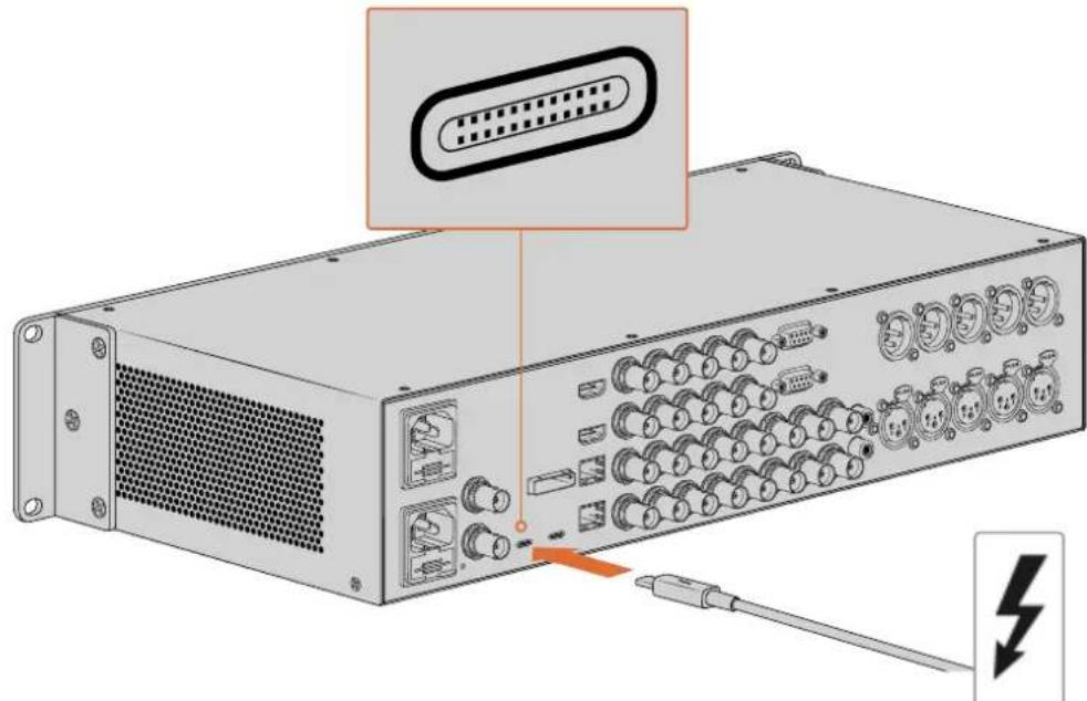
Blackmagic UltraStudio 4K and UltraStudio 4K Extreme feature two Thunderbolt™ 2 ports so if your computer only has a single Thunderbolt port, you can use the additional port to attach a RAID or other device.
Blackmagic UltraStudio 4K Extreme 3 has two Thunderbolt™ 3 ports and UltraStudio HD Mini has one Thunderbolt 3 port, for up to 40Gb/s data speeds. When connecting via Thunderbolt 3, connect your Blackmagic Desktop Video hardware directly to the Thunderbolt 3 port on your
computer using a Thunderbolt 3 cable. Connecting to a Thunderbolt 2 port on your computer via a Thunderbolt 3 to Thunderbolt 2 adapter is not supported on bus-powered products like UltraStudio HD Mini.
natural_image
Illustration of a server rack with multiple ports and connectors, showing an external connector and cable connection (no text or symbols present)Make sure your computer is Thunderbolt 3 compatible by looking for the Thunderbolt icon near its USB-C connector, as shown on the right.
Connecting via USB 3.0
Connect a SuperSpeed USB 3.0 cable into the USB 3.0 port on the unit. Plug the other end of the cable into your computer's USB 3.0 port.

Connecting a SuperSpeed USB 3.0 cable to Intensity Shuttle
Connecting via PCIe
Blackmagic Design PCIe cards plug into a PCIe slot in your computer. Check the information printed on your card's box to determine the number of PCIe lanes your card requires. For example, depending on your PCIe card, it will require a x1, x4 or x8 PCIe slot.
It's worth noting that you can insert PCIe cards into higher capacity slots than they require. For example, a x4 lane PCIe card can be inserted into a x16 lane PCIe slot, though not the other way around.
If you can't find the information you need on the box, you can find the number of lanes your card requires, plus other helpful information about your card, in the tech specs at www.blackmagicdesign.com/products.

natural_image
Diagram of a computer motherboard showing cable routing and connector components (no text or labels)Install a Blackmagic Design PCIe card in a spare PCIe slot. If your card includes an HDMI bracket, it can be installed in any spare PCIe mount and connects to the rear of the card with the supplied HDMI cables.

Please be careful when installing your DeckLink PCIe card to avoid damaging delicate components on the card.

natural_image
Illustration of a computer tower with an attached VGA cable showing port connections (no text or symbols)If your card includes a breakout cable, simply plug it into your card's breakout cable connector.
Connecting UltraStudio 4K Extreme via PCIe
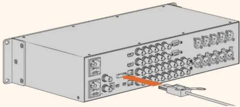
UltraStudio 4K Extreme and UltraStudio 4K Extreme 3 can also connect to your computer via PCIe using a PCIe adapter card and cable. Both UltraStudio 4K Extreme and UltraStudio 4K Extreme 3 need to be connected to a PCIe Gen 2 slot in your computer. The Blackmagic PCIe Cable Kit contains a PCIe cable and the PCIe adapter card and is available from your nearest Blackmagic Design reseller.
For the original UltraStudio 4K Extreme, you can use either the Blackmagic PCIe Cable Kit, or purchase a standard PCIe adapter card from your nearest computer store.
natural_image
Illustration of a server rack with multiple ports and connectors, no text or symbols presentUltraStudio 4K Extreme features a PCIe port for connection to an external PCIe adapter card that is installed in your computer

natural_image
Technical line drawing of a mechanical assembly with a green circuit board and cooling unit (no text or symbols)The PCIe adapter card is inserted into a PCIe Gen 2 slot inside your computer

natural_image
Back view of a server rack with ports and a cable inserted (no visible text or labels)Connect the other end of the PCIe cable to the PCIe port located at the back of your computer
Installing the Desktop Video Software
Applications, Plugins and Drivers
The Blackmagic Design Desktop Video software includes all the drivers, plugins and applications needed to use your Desktop Video hardware. Below is a list that shows all the software items that are installed on your computer.
| Mac OS Windows Linux | ||
| Blackmagic Desktop Video drivers Blackmagic Desktop Video drivers Blackmagic Desktop Video drivers | ||
| Blackmagic Desktop Video Setup Blackmagic Desktop Video Setup Blackmagic Desktop Video Setup | ||
| Blackmagic Design LiveKey Blackmagic Design LiveKey – | ||
| Blackmagic Media Express Blackmagic Media Express Blackmagic Media Express | ||
| Blackmagic QuickTime ^TM codecs | Blackmagic AVI and QuickTime ^TM codecs | – |
| Blackmagic Disk Speed Test Blackmagic Disk Speed Test – | ||
| Adobe Premiere Pro CC, After Effects CC, Photoshop CC presets and plug-ins | Adobe Premiere Pro CC, After Effects CC, Photoshop CC presets and plug-ins | – |
| Final Cut Pro X plug-ins – – | ||
| Avid Media Composer plug-in Avid Media Composer plug-in – | ||
Automatic Updates
After installing the Desktop Video software and once your computer restarts, it will check the internal software on your Desktop Video hardware. If it doesn't match the version installed on your computer, the software will prompt you to update. Click 'ok' to start the update and restart your computer to complete the process.
NOTE If your DeckLink card is not working after an interrupted update, refer to the section near the end of this manual called 'recovering a DeckLink card from an interrupted update'.
The remainder of the Getting Started section will show you the Desktop Video software installation process for Mac OS, Windows and Linux.
Mac OS Installation
Make sure you have administrator privileges before installing any software.
1 Ensure you have the very latest driver. Visit www.blackmagicdesign.com/support
2 Launch the Desktop Video Installer from the media included with your Blackmagic Design equipment, or from the file you downloaded from the Blackmagic Design support center.
3 Click the 'continue', 'agree' and 'install' buttons to install the software.
4 Restart your computer to enable the new software drivers.
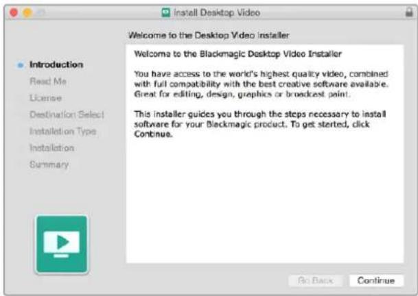
Desktop Video Installer for Mac
NOTE If you are installing Desktop Video on macOS High Sierra or later for the first time, then you will need to enable your Mac to use your Desktop Video equipment during the installation process.
To enable extensions on macOS High Sierra or later:
When instructed, click on 'open security preferences' or open 'system preferences' and click on 'security and privacy'.
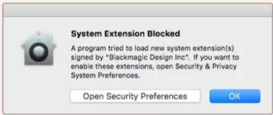
2 In the 'security and privacy' preferences, click 'allow' to enable the Desktop Video software on your computer.

Click 'allow' in the security and privacy preferences to enable the Desktop Video software on your computer
3 Back in Desktop Video Installer, complete the software installation by clicking 'restart'.
Windows Installation
1 Ensure you have the very latest driver. Visit www.blackmagicdesign.com/support
2 Open the "Desktop Video" folder and launch the "Desktop Video" installer.
3 The drivers will now be installed on your system. An alert will appear: "Do you want to allow the following program to install software on this computer?" Click 'yes' to continue.
4 You will see a dialog bubble saying "found new hardware" and the hardware wizard will appear. Select "install automatically" and the system will find the required Desktop Video drivers.
TIP If you have a DeckLink Quad 2 installed in a Windows 7 computer, Windows Update will attempt to check each driver in case a newer version is available. In this particular case it is unnecessary as all drivers in the latest Desktop Video release are the most recent. You can temporarily disable the feature by clicking on the notification and then clicking "Skip obtaining driver software from Windows Update". Confirm the action by clicking 'yes'. The installation will now be a lot faster.
5 After all drivers have been installed, a dialog bubble will appear saying "your new hardware is ready for use." Restart your computer to enable the new software drivers.

Desktop Video Installer for Windows
Linux Installation
1 Download the latest Desktop Video software for Linux from www.blackmagicdesign.com/support
2 Open the Desktop Video folder and navigate to the packages required for your distribution and architecture. Note that 'amd64' refers to Intel and AMD 64 bit processors. There are three sets of packages provided:
- The desktopvideo package provides the core drivers and API libraries.
- The desktopvideo-gui package provides the Desktop Video Setup software.
- The mediaexpress package provides a simple capture and playback utility.
3 Double click the packages you wish to install and follow the onscreen instructions. If you see any messages about missing dependencies, ensure they are installed first and then rerun the Desktop Video installer.
4 When the installer has finished it is recommended that you restart your computer to complete the installation process.
If you cannot find a native Desktop Video package for your Linux distribution, or if you prefer to install from a command line, refer to the ReadMe file for detailed installation instructions.
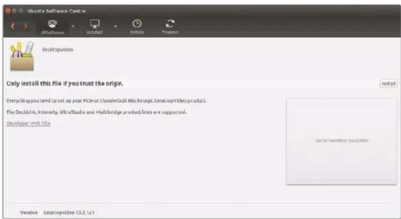
Desktop Video software ready to be installed from the Ubuntu Software Center.
Updates
If you have not installed the setup software, you can check the internal software is up to date using the BlackmagicFirmwareUpdater command line tool:
# BlackmagicFirmwareUpdater status
A message similar to the following will appear:
0: /dev/blackmagic/io0 [DeckLink SDI 4K] 0x73 OK
1: /dev/blackmagic/io1 [DeckLink 4K Extreme 12G] 0x0A PLEASE UPDATE
In this case you could update the internal software with the following command:
# BlackmagicFirmwareUpdater update 1
See the 'man' page for a more detailed description of the command's usage. e.g., for more info on the internal software updater command, type "man BlackmagicFirmwareUpdater".
That's all there is to getting started! Now that you have installed your Blackmagic Desktop Video hardware and software, you can start capturing and playing back video.
Capturing and Playing Back Video
Once the Desktop Video hardware and software is installed, you can start capturing and playing back clips straight away. First, plug your video source into the input on your Desktop Video hardware, then connect a monitor to the output.
A quick way to begin capture and playback is to record a clip in Blackmagic Media Express, which was installed on your computer when you installed the Desktop Video software.
Setting Up
1 Connect a monitor or TV to the video output of your Blackmagic Design hardware.
2 Connect a video source to the input of your Blackmagic Design hardware.
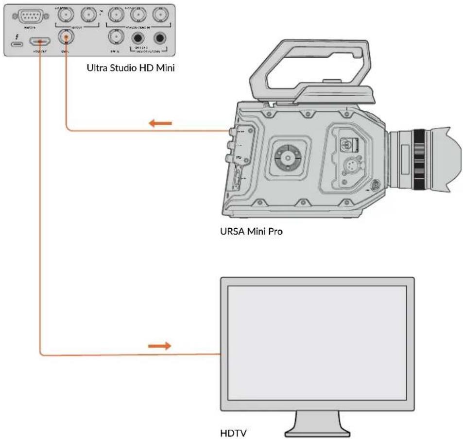
Connect a video monitor and source to your Blackmagic Design video hardware.
Testing Video Capture
1 Launch Blackmagic Media Express. Click on the 'log and capture' tab. Your input video format is automatically detected and Media Express sets the project video format to match. Your video source will appear in the Media Express preview pane.
2 Click 'capture' at the bottom of the 'log and capture' window to perform the capture test. Click 'capture' again to finish the test. The captured clip is added to the media list on the left side of Media Express.

Click the 'capture' button to commence recording.
Testing Video Playback
1 Click on the ' playback' tab.
2 Double click the test clip. The video and any present audio will be sent to the monitor connected to your hardware's output.
Blackmagic Desktop Video Setup
Introducing Blackmagic Desktop Video Setup
Blackmagic Desktop Video Setup provides a central location for configuring hardware settings, plus a real time status display showing the video connected to your hardware's inputs and outputs.
To launch Blackmagic Desktop Video Setup:
- On Mac OS, click Blackmagic Desktop Video in 'system preferences' or you can launch the utility from your 'applications' folder.
- On Windows 7, click the 'start' button>all programs>Blackmagic Design>Desktop Video and click the Desktop Video setup application. The Desktop Video Setup utility also launches from the Windows 7 'control panel'.
- On Windows 8, from the 'start' page type 'Blackmagic' and then click the Blackmagic Desktop Video Setup application. The Desktop Video Setup utility also launches from the Windows 8 'control panel'.
- On Windows 10, click the 'start' button>all programs>Blackmagic Design>Desktop Video and click the Desktop Video Setup application. The Desktop Video setup software also launches from the Windows 10 'control panel'.
- On Linux, go to 'applications' and then 'sound and video' and double click the Blackmagic Desktop Video Setup application.
When you first open Blackmagic Desktop Video Setup, the home page displays your connected hardware and provides an overview of all video activity on your hardware's input and output connections. If you are sending a video signal to your input, it will be automatically detected and the format will be displayed under the Video Input icon.
If you have multiple Blackmagic capture and playback devices connected, you can cycle through them by clicking the arrow buttons on the sides of the home page. To configure settings, simply click on the hardware image, or the settings icon located below the hardware name. The Desktop Video Setup utility only displays the settings that are relevant to your selected hardware, so you don't have to scroll through pages of menus to find the settings you want.
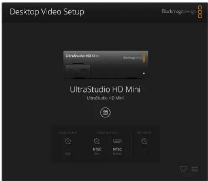
Blackmagic Desktop Video Setup home page
The following pages of this manual will show you how to adjust settings using Blackmagic Desktop Video Setup.

Blackmagic Desktop Video Setup lets you adjust video and audio input and output settings, apply up or down conversions during capture and playback, and provides information about the driver.
Video Settings
Video Input
Click on a connector icon to set the 'video input' connection for your Blackmagic Design hardware. Only the connectors that are built into your hardware will be shown. When a valid video signal is detected, the input and video format will be displayed on the Blackmagic Desktop Video Setup home page.

Click on an icon to set your video input connection.
Use XLR Timecode
Select this setting to read timecode from the XLR input instead of the SDI stream.

Use XLR Timecode Input
Enable the checkbox to capture timecode from the dedicated XLR input
Analog Video Input Levels
Drag the 'video' and 'chroma' sliders to adjust the analog video input levels for component or composite video. Dragging the video slider affects the luma gain and the chroma sliders decrease or increase the color saturation. When using component video, you can adjust the Cb and Cr values independently. Click the 'link' icon to connect them if you want to adjust them simultaneously.

Video Output
Select the video standard and adjust other settings for your video output.
General
- Default Video Standard
To use broadcast monitoring with Final Cut Pro X, set the output format to match your Final Cut Pro X project.
- When Paused
Click to select whether to display a full frame or a single field on the output when paused.
- Video Playback
Click to select whether to display a freeze frame or black output when not playing.
During Capture
Click to select whether the video output displays the playback video or input video during capture. If you select the 'video output displays playback video' option, then your selection in the 'video playback' section will dictate what is displayed on your output. If you select the 'video output displays input video' option, then the input video will be displayed on your outputs.
During Playback
Some Desktop Video products are capable of converting Rec. 601 and Rec. 709 video outputs to Rec. 2020 for TVs and video monitors that may require it. If your Desktop Video hardware supports this feature, select 'convert to Rec. 2020' in the setup utility. If your video is already using the Rec. 2020 color space, or is displaying correctly, you can leave this setting set to 'keep default color gamut'.
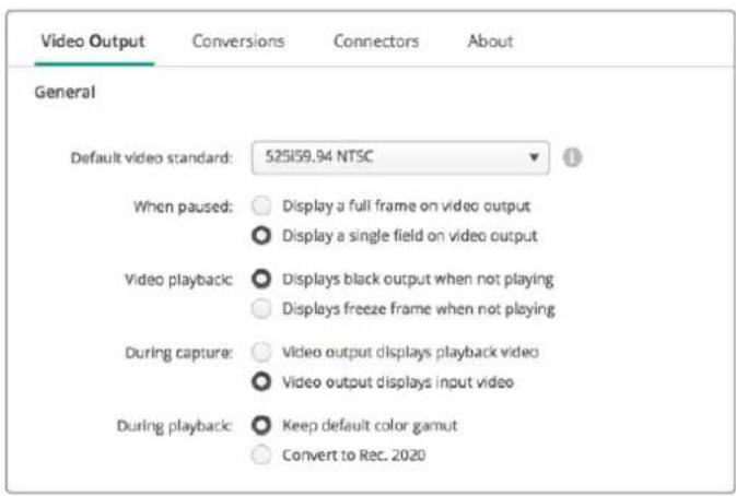
Select what to display on the output when paused, during video playback and during capture
SDI Output
Color Space
Click to select the color space to convert to. Options are 4:4:4 RGB video or Y, Cb, Cr 4:2:2.
3G-SDI Formats
Click to select whether to output 3Gb/s SDI signals as SMPTE Level A direct mapping or to have 3Gb/s signals sent with Level B mapping.
1080p HD and 2K
Click to select whether 1080p HD and 2K are output as 1080p progressive video, or as progressive segmented frame video.
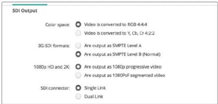
Use the SDI Settings to control the output of your SDI video.
SDI Configuration
Select between single link, dual link and quad link for 3G, 6G or 12G-SDI output. Some professional color grading monitors and projectors only accept high bandwidth signals like 2160p60 or DCI 4K 4:4:4 via quad link. UltraStudio 4K Extreme can output quad link 3G-SDI and you can also get a Quad SDI add on card for DeckLink 4K Extreme 12G.
SDI connector:

Single Link

Dual Link

Quad Link
Choose whether to output via single link, dual link or quad link for 3G, 6G and 12G-SDI video signals
8K Formats
8K video is played back via quad link SDI and you can choose your desired quad link output format.
The two options available are:
Square Division Quad Split – The 8K image is distributed as four quadrant 4K images in a 2 x 2 multi view configuration. Each 4K quadrant image is supplied via SDI using a quad link connection and reconstructed at the destination to form a complete 8K image. This is also the selection to use if you want to send each output to a separate display to create a video wall of Ultra HD monitors.
Sample interleave – Alternate pixels from a single 8K image are distributed as four separate 4K images via quad link SDI, then combined at the destination to form one complete 8K image. Therefore, an added benefit of this format is the option to use any of the four outputs as a down converted 4K image.
4K and 8K formats:

Are output as Square Division Quad Split (SQ)

Are output as Sample Interleave (SI)
When using desktop video equipment for 8K playback, set your desired quad link 8K output format
Set Analog Video Output
If your Blackmagic Design hardware has shared analog video connectors, you can choose whether to output your video via 'component', 'composite' or 's-video' by selecting between the 'analog video output' options.
HDMI 3D Output
This setting determines the 3D format for your HDMI monitoring.
- Top and Bottom
Arranges both left and right eye images vertically with 50% compression.
Frame Packing
Combines left and right eye images into a single frame without compression.
- Side by Side
Arranges both left and the right eye images horizontally with 50% compression.
- Left Eye
Only the left eye image is displayed.
Line by Line
The left and right eye images are carried on alternate video lines without compression.
Right Eye
Only the right eye image is displayed.

Set your HDMI 3D Output format.
Analog Video Output Levels
Drag the 'video' and 'chroma' sliders to adjust the analog video output levels for component or composite video. Dragging the video slider affects the luma gain and the chroma sliders decrease or increase the color saturation. When using component video, you can adjust the Cb and Cr values independently. Click the 'link' icon to connect them if you want to adjust them simultaneously.

Adjust the video slider to set composite analog video output levels, and the Cb and Cr sliders for controlling color balance when using component video.
- Use Betacam Levels
Blackmagic Design products use SMPTE component analog levels to maintain compatibility with most modern video equipment. Enable the checkbox if working with Sony Betacam SP decks.
NTSC IRE
Select the 7.5 IRE setup for the NTSC composite video used in the USA and other countries. Select the 0 IRE setup if you're working in Japan or countries that don't use the 7.5 IRE setup. PAL and high definition formats do not use this setting.
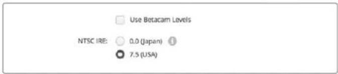
Enable the 'use Betacam levels' checkbox when working with Sony Betacam SP decks. Select the relevant NTSC IRE level when using an NTSC composite video format.
Reference Input
The reference adjustment lets you adjust the timing of the video outputs of your hardware relative to the video reference input. This is commonly used in large broadcast facilities where the video output needs to be accurately timed. The reference adjustment is in samples so you can get an extremely accurate timing adjustment down to the sample level.
A common example of how this setting would be used is where all the hardware in your facility has a stable common reference connected and then all the devices would have the timing set so the video outputs all match perfectly. This would then make it possible to switch between devices on a downstream router or production switcher and would eliminate any glitching when switching is performed.

If locking to a reference, adjust this setting to time the video output relative to the reference input.
Connector Mapping for DeckLink Quad 2
If you have a DeckLink Quad 2 installed in your computer, you can input or output SDI signals over 8 independent mini BNC connectors. This gives you the ability to capture or play back 8 separate video streams, similar to having 8 capture and playback devices in a single product. This is why your DeckLink Quad 2 appears in Desktop Video Setup as 8 individual DeckLink Quad devices which makes it easier to configure your inputs and outputs. You can even name each device so you can keep track of which DeckLink Quad device is being used for a specific video signal.
SDI connectors can be mapped to each device using the 'connector mapping' settings in the Desktop Video Setup utility, but it's important to know that specific connectors are dedicated to specific devices. For example, SDI 1 is dedicated to DeckLink Quad (1), and SDI 2 is dedicated to DeckLink Quad (1) and DeckLink Quad (5).

If you have a DeckLink Quad 2 installed, the 'connector mapping' setting lets you assign SDI connectors to each DeckLink Quad device.
You can see which SDI connectors are dedicated to each DeckLink Quad device by looking at the table below, where you can also check the mapping options for them.
Mapping Options
| DeckLink Quad Devices Dedicated SDI Connectors | |
| DeckLink Quad (1) SDI 1 and 2 or SDI 1 | |
| DeckLink Quad (2) SDI 3 and 4 or SDI 3 | |
| DeckLink Quad (3) SDI 5 and 6 or SDI 5 | |
| DeckLink Quad (4) SDI 7 and 8 or SDI 7 | |
| DeckLink Quad (5) SDI 2 or none | |
| DeckLink Quad (6) SDI 4 or none | |
| DeckLink Quad (7) SDI 6 or none | |
| DeckLink Quad (8) SDI 8 or none |
It's worth mentioning that when configuring an SDI connector for a specific device, it will also affect the device sharing that connector. For example, if DeckLink Quad (1) is set to use SDI 1 and 2, DeckLink Quad 5 will automatically be set to 'none' because its shared SDI connector is being used. Alternatively, if you select SDI 2 on DeckLink Quad (5), DeckLink Quad (1) will automatically be set to SDI 1. For this reason, it's important to note which SDI inputs or outputs are being used by each device to avoid accidentally interrupting the input or output of another device.
TIP If you have an original DeckLink Quad installed in your facility and are using a custom designed SDK application, you can be confident that installing DeckLink Quad 2 will work in your system without having to make any changes to your application. Additional mapping features in your DeckLink Quad 2 will allow you to build on your existing system to provide even more input and output configurations if you need them.
Audio Settings
Audio Input
Click on a connector icon to set your 'audio input' connection for your Blackmagic Design hardware. You can select from the following inputs:
- Embedded
Includes audio channels as part of video signals. SDI and HDMI are capable of carrying embedded audio.
- AES/EBU
Is a digital audio signal that can carry 2 audio channels over a single connector.
- XLR
Is a three pin audio connector that is predominantly used by professional analog audio equipment.
- RCA or HIFI
Is a connector used to connect unbalanced analog audio to and from consumer audio equipment, such as HiFi systems, DVD players and televisions.
- Microphone
Phantom power supplies power through microphone cables and is a convenient power source for condenser microphones.
Enable the 'use +48V phantom power' option if your microphone requires phantom power. If you're unsure whether your mic needs phantom power or not, it's best to leave this box unchecked as there is a risk of causing damage to microphones that are self powered. An LED on the front of UltraStudio 4K Extreme will illuminate when phantom power is active. Be sure to wait at least 10 seconds for phantom power to discharge after disconnecting before plugging in a self powered microphone. Older ribbon type microphones and dynamic microphones are not suitable for phantom power usage.
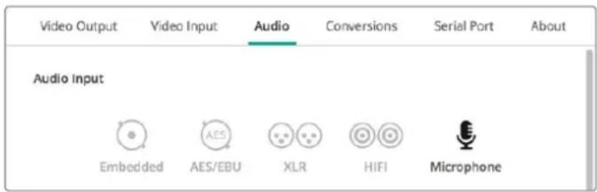
Click on a connector icon to set your 'audio input' connection.

Drag the 'input level' slider to control your microphone input level.
HDMI Audio Output
This setting lets you remap the 5.1 audio channels in your project to match the configuration used by your HDMI monitoring equipment. For example, some home theatre AV receivers require your surround sound audio to be mapped to specific channels. If you are working on a project that uses a different surround sound channel ordering, such as SMPTE ordering, you can enable the 'Use 5.1 surround channel ordering' checkbox to ensure compatibility with your HDMI AV receiver.

Enable 'use 5.1 surround channel ordering' to ensure compatibility with other HDMI monitoring equipment
AES/EBU
Drag the sliders to adjust the 'ref' level, or gain, for the AES/EBU audio inputs and outputs. Press the reset icon to reset the gain to 0 dB.

Drag the 'output level' slider to control your AES/EBU digital output level.
Analog Audio Input Levels
Channel 1/Channel 2
These settings adjust the gain for the analog audio inputs when capturing. Click the 'link' icon to adjust them simultaneously.
Use HiFi Audio Levels
Professional XLR connectors are standard on UltraStudio and DeckLink models. If you want to connect consumer audio equipment to the XLR connectors, make sure you enable the 'use HiFi audio levels' checkbox as the audio levels between professional and consumer equipment differ. You'll also need to use an RCA to XLR adapter.

Adjust the input channel sliders to control your analog audio input levels. Enable the 'use HiFi audio levels' checkbox if connecting consumer audio equipment.
Analog Audio Output Levels
Channel 1/Channel 2
These settings adjust the strength of the audio signal, or gain, for the analog audio outputs while playing back video. Click the 'link' icon to adjust them simultaneously.
Reset Icon
When adjusting sliders, you may want to cancel your change. The reset icon is the circular arrow located at the right of each settings' title bar. Press the reset icon in each setting to restore the gain sliders to 0 dB.
Conversions Settings
Input Conversion
This setting enables real time up and down conversion during capture. Select your desired conversion from the 'input conversion' dropdown menu.
Input conversion results in up to a 2 frame delay, so you'll need to adjust your editing software's timecode offset to ensure frame accuracy.
Display As
Select how you would like your converted video presented. Depending on your input video's original aspect ratio, options may include letterbox, anamorphic, center cut, pillarbox, 16:9 zoom or 14:9 zoom.
Output Conversion
This setting enables real time up and down conversion during playback. Select your desired conversion from the dropdown menu.
Output conversion results in up to a 2 frame delay, so you'll need to adjust your editing software's timecode offset to ensure frame accuracy.
Convert Analog Outputs
Enable this checkbox to also perform your conversion on the analog video outputs.
Display As
Select how you'd like your converted video presented. Depending on your video's original aspect ratio, options may include letterbox, anamorphic, center cut, pillarbox, 16:9 zoom or 14:9 zoom.

To set your up or down conversion settings, select your input or output conversion from the respective dropdown menu, and click on the desired aspect ratio selection. Remember to click 'save' to apply your settings.
The following table outlines the different aspect ratio selections available during conversions.
| Down Conversion | Source Image | Converted Image | |
| Letterbox |  | 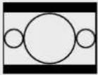 | Scales the entire 16:9 HD image into a 4:3 SD frame leaving black bars on the top and bottom. |
| Anamorphic |  |  | Horizontally squeezes the 16:9 HD image into a 4:3 SD frame. |
| Center Cut |  |  | This setting cuts a 4:3 SD frame from the 16:9 HD image. This aspect ratio setting discards a portion from each side of the 16:9 image. |
| Pillarbox |  |  | Displays a 4:3 SD image inside an 16:9 HD frame. Black bars feature on the sides. |
| 16:9 Zoom |  |  | Scales the 4:3 SD image to fill the 16:9 HD frame. |
| 14:9 Zoom |  |  | A compromise between Pillarbox and 16:9 Zoom. Minimal black bars with slight crop top and bottom. |
About
Driver
The ‘about’ page in Blackmagic Desktop Video Setup provides information about your hardware’s current driver and the last time your hardware was updated.
TIP You can generate a status report by clicking on the status report 'create' button, which lets you save a file containing technical information such as the video format detected on your input and output reference, color space, color sampling and bit depth, driver information, operating system and machine information. This report can be useful if you ever need to contact our technical support team. The file is also very small so can be easily emailed.
Product Notes
Changing the name of your Blackmagic Design equipment lets you identify each unit in the Desktop Video Setup software and keep track of where and how it's being used. This is useful if you have the same hardware in various locations on a network, plus it can be handy to name the different units for their purposes, e.g., Edit Suite 2, Color Suite 1, etc.
When you enter a name for your hardware in the label field, it is saved to the Blackmagic Desktop Video Setup home page and displayed beneath the hardware image.
You can also enter important information that you may want to refer to later, such as the hardware serial number, where and when your hardware was purchased, as well as the seller's contact details.
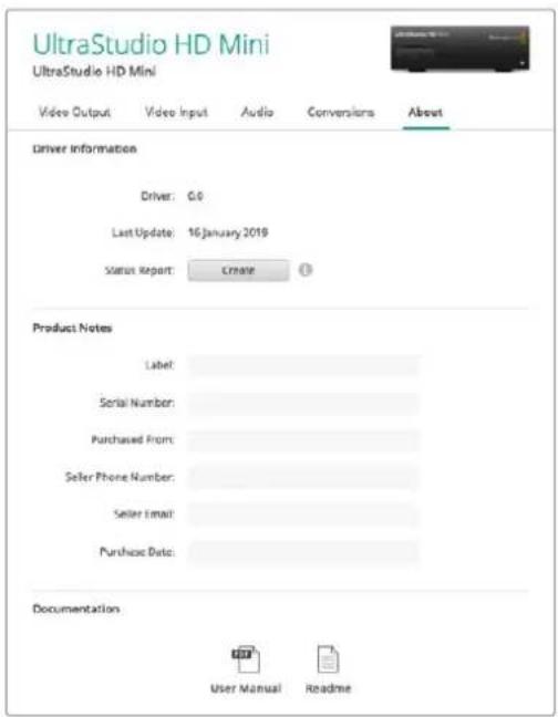
The 'about' section provides valuable information such as the driver version, user manual and release notes. You can also generate a status report and enter product notes specific to your hardware.
Using UltraStudio 4K Mini's Front Control Panel
On UltraStudio 4K Mini, most of the settings that can be changed in the Desktop Video Setup utility are also available via the LCD menu on the front panel. To navigate through the settings, press the 'menu' button to open the menu, then scroll through the options using the settings knob. To enter submenus and confirm a setting, press the 'set' button.
To exit the menu, keep pressing the 'menu' button to step back through the menus and return to the home screen.
TIP You can also navigate directly to the video or audio settings by pressing the 'video' or 'audio' buttons. This lets you go directly to the relevant settings without scrolling through the settings list, which can save time.

Use the LCD menu on UltraStudio 4K Mini's front panel to change settings
Audio Settings
UltraStudio 4K Mini also has additional audio settings in the LCD menu. These settings let you change the type of audio meters displayed on the LCD during capture and playback. The two audio meter types are VU and PPM.
VU
The VU meter, or 'volume units' meter, averages out short peaks and troughs in your audio signal. If you are using VU metering, adjust the output levels of your source so that the meter peaks at the 0db indicator on the audio meter. This maximizes the signal to noise ratio and ensures your audio is at the highest quality. If your audio peaks beyond the 0dB indicator there is a high risk of sound distortion. If you are using the analog audio inputs of the UltraStudio 4K Mini, the input levels can be adjusted in the LCD menu or setup utility.
PPM
PPM meters, or 'peak programme meters', display a 'peak hold' feature that momentarily holds the signal peaks with a slow fall back so you can easily see the audio level at which your audio is peaking.
Both VU and PPM meters can be set to use reference levels of -18dB or -20dB so you can monitor your audio to suit different international broadcasting standards.
SD Card Slot
UltraStudio 4K Mini's front panel also features an SD card slot that reads and writes files when the unit is connected to a Mac or Windows computer. This slot can be used just like a typical SD card reader or writer and is detected by your computer as another drive. This means you can quickly import clips from your camera's SD card or set Media Express to capture a clip to portable media.
Teranex Mini Smart Panel
Attaching a Teranex Mini Smart Panel
Blackmagic UltraStudio HD Mini is a small capture and playback solution that shares a similar form factor to other Blackmagic equipment like Teranex Mini converters and recording decks such as HyperDeck Studio Mini. These products are designed to be portable and modular so you can take them with you on location, mount them on your desk, or attach them to a Teranex Mini Rack Shelf. The rack shelf lets you mount the equipment in a rack.
Attaching an optional Teranex Mini Smart Panel to your UltraStudio HD Mini allows you to preview video and audio directly from the front of the unit during playback and capture.
The built in LCD on the Teranex Mini Smart Panel displays the input image as well as audio meters, which allow you to preview your audio levels.
The Panels are hot swappable so you don't even need to turn off your Blackmagic UltraStudio HD Mini when installing it.
1 Remove the two M3 screws on each side of your Blackmagic UltraStudio HD Mini's basic front panel using a Pozidriv 2 screwdriver and gently pull the panel away from the front of your the unit.
2 On the inside of the basic panel, you'll notice a small clear plastic tube attached to the bottom corner. This tube directs light from the LED inside the unit to illuminate the status indicator on the basic panel. This tube should stay attached to the basic front panel.
TIP If reattaching the basic front panel, make sure the light tube is aligned with the slot in the front of the unit.
3 Align the connector on the rear of the Teranex Mini Smart Panel with the corresponding connector on the face of your UltraStudio HD Mini and gently push the Smart Panel towards the unit until the connectors are firmly seated. The Teranex Mini Smart Panel should make a firm connection and fit neatly inside the face of your UltraStudio HD Mini.
4 Re-insert the M3 screws from the original panel.

natural_image
Illustration of a hand inserting a remote control into a computer drive (no text or symbols visible)When installing the Teranex Mini Smart Panel to your Blackmagic UltraStudio HD Mini, holding the panel with your fingers and thumb aligned with the panel's rear connector will help guide it into place
If your UltraStudio HD Mini is installed in a Teranex Mini Rack Shelf, you will need to remove the unit from the rack shelf to access the front panel screws.
See the 'Teranex Mini Rack Shelf' section for more information.
The original basic panel is very strong, so if you need to mount your Blackmagic UltraStudio HD Mini in the back of a rack system or in areas where there are lots of cables or activity, you can always reinstall the original basic panel.
Smart Panel Features
LCD Display
The home screen is the first feature you'll see on your Teranex Mini Smart Panel's LCD display. The home screen shows you important information, including:

Video monitor – Displays the Input video source that is connected to UltraStudio HD Mini.
Teranex Mini Rack Shelf
When using Blackmagic UltraStudio HD Mini with other equipment like Blackmagic ATEM Television Studio HD or Blackmagic Teranex Mini converters, you can use Teranex Mini Rack Shelf to install your units into a broadcast rack or road case. Up to three Teranex Mini sized units can fit neatly onto each 1RU Teranex Mini Rack Shelf.
UltraStudio HD Mini is installed into the rack shelf by removing the unit's rubber feet, if attached, and screwing the unit into the base of the shelf using the mounting holes on the underside.

natural_image
Front view of a Teranex Mini UltraStudio HD Mini device with visible ports and connectors (no text or symbols on the device body)The Teranex Mini Rack Shelf ships with two original blank panels which you can use to cover gaps if you don't need to install additional units.
For more information, check the Blackmagic Design website at www.blackmagicdesign.com
DaVinci Resolve
Live Grading with DaVinci Resolve
Desktop Video 10 allows simultaneous capture and playback on Blackmagic Design 4K and 8K hardware. This is great for users who want to use the live grading feature within DaVinci Resolve, as it means you don't require two separate devices for input and output.

When using live grading on set, simply connect the output of the camera to the input of your Blackmagic Design hardware. Then connect the hardware's output to an on set monitor for grading evaluation and viewing.
Setting Up
1 Launch DaVinci Resolve. From the preferences menu, select the 'video and audio I/O' tab and select your hardware from the 'for Resolve Live use' option. Save your preferences and restart DaVinci Resolve to apply your changes.
2 Start a project and open the 'project settings' window. From the 'master settings' tab set the timeline resolution and frame rate to match your camera.
3 Go to the 'capture and playback' tab and select your desired format from the 'video capture and playback' menu.

Select your format from the 'video capture and playback' menu.
4 Go to the 'edit' page and select file>new timeline.
5 From the 'color' page, click on the 'color' menu and select Resolve live > on. You should now see live video within the viewer and a bright red 'Resolve Live' button will appear above the video.
Using Resolve Live
1 In Resolve Live mode, the 'freeze' button (snowflake icon) freezes the current incoming video frame, so you can grade it without being distracted by motion occurring during the shoot.
2 Once you're happy with a grade, clicking the 'snapshot' button (camera icon) saves a snapshot of the current still in the viewer, the incoming timecode value, and your grade into the timeline. Snapshots are simply one frame clips. Once you've taken your snapshot, press the snowflake icon again to resume playing until you find the next shot you want to grade.
TIP Please refer to the DaVinci Resolve manual for more information on Resolve Live.
Editing with DaVinci Resolve
Blackmagic DaVinci Resolve features an editor friendly interface with all the tools to edit and finish projects. Whether you use the mouse to drag and drop clips, or your keyboard for precision editing, DaVinci Resolve features all of the functionality professional editors require.
Setting Up
1 Launch DaVinci Resolve. From the 'preferences' menu, select the 'video and audio I/O' tab and select your Blackmagic Design hardware from the 'for capture and playback use' option. Save your preferences and restart DaVinci Resolve to apply your changes.
2 Load a project, open 'project settings' from the file menu and under 'master settings', set your 'timeline resolution', 'timeline frame rate' and 'playback frame rate'.
3 Under the 'video monitoring' section, set your 'video format'. Blackmagic Desktop Video Setup will automatically change to the video format you choose for output to your Blackmagic Design video hardware.
4 Click the 'save' button to save the changes and close the project settings window.
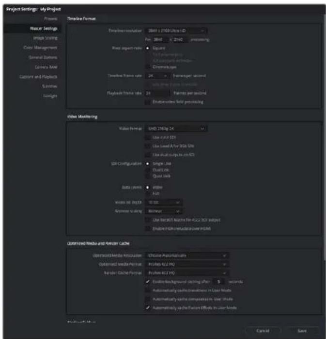
Use the 'project settings' window to set your timeline format and video monitoring options.
Editing
1 Use the media storage browser on the 'media' page to load your clips into the media pool.
2 On the 'edit' page, select file>new timeline, name your timeline and click the 'create' button.
3 Now you can drag a clip from the media pool to the source viewer on the left hand side.
4 You can set the in and out points in source clips by using the I and O keys and dragging the playhead in the bar below the viewer window.
5 To edit the clip into the timeline, simply drag and drop the clip from the source viewer into the timeline.
TIP Refer to the Blackmagic DaVinci Resolve manual for more detailed information on how to edit with DaVinci Resolve.
Using your Favorite 3rd Party Software
Adobe After Effects CC

After Effects CC
How to Preview Video
To display your composition in real time through your Blackmagic Design hardware, go to preferences > video preview. 'Enable Mercury Transmit' must be ticked in order to use your Blackmagic Design hardware with After Effects CC. Under 'video device', select Blackmagic Playback. You can now use a broadcast monitor to view your After Effects compositions in the correct video colorspace.

'Video Preview' preferences
If you work with unsupported or non standard frame sizes, these can also be correctly outputted by your Blackmagic Design hardware. Go to preferences > video preview and click the 'setup' button next to 'Blackmagic playback'. The 'Blackmagic device selection' window will appear. You can scale your image up or down to the next closest video standard supported by your hardware. For example, if you are using UltraStudio 4K and your After Effects composition is set to a resolution of 2048 x 1152, scaling down will output DCI 2K, scaling up will output Ultra HD.
Rendering
When you have completed your composition, you can render a DPX image sequence or any of the following codecs:
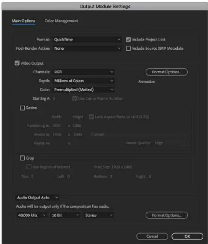
'Output Module Settings' rendering options
QuickTime codecs on Mac OS
- Blackmagic RGB 10 bit (uncompressed)
- Apple Uncompressed YUV 10 bit 4:2:2
- Apple Uncompressed YUV 8 bit 4:2:2
• Apple Photo - JPEG (compressed)
• Apple DV - NTSC (compressed)
• Apple DV - PAL (compressed)
Other codecs including ProRes and DVCPRO HD will be available if you have Final Cut Pro installed.
AVI codecs on Windows
- Blackmagic 10 bit 4:4:4 (uncompressed)
- Blackmagic 10 bit 4:2:2 (uncompressed)
- Blackmagic HD 8 bit 4:2:2 (uncompressed)
- Blackmagic SD 8 bit 4:2:2 (uncompressed)
- Blackmagic 8 bit MJPEG (compressed)
Other codecs including DVCPRO HD and DVCPRO50 will be available if you have Premiere Pro CC installed.
QuickTime codecs on Windows
- Blackmagic RGB 10 bit (uncompressed)
- Blackmagic 10 bit (uncompressed)
- Blackmagic 8 bit (uncompressed)
- Apple Photo-JPEG (compressed)
• Apple DV - NTSC (compressed) - Apple DV - PAL (compressed)
Adobe Photoshop CC

Photoshop CC
How to Import and Export Video Frames
Import an image into Photoshop CC
1 Select file > import > Blackmagic image import.
2 Select the 'video input format' and the 'image bit depth' and then click 'import image'.
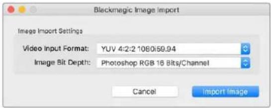
Image Capture
Export an image from Photoshop CC
1 Select file > export > Blackmagic image export.
2 Select 'video output format' and then click 'export image'.
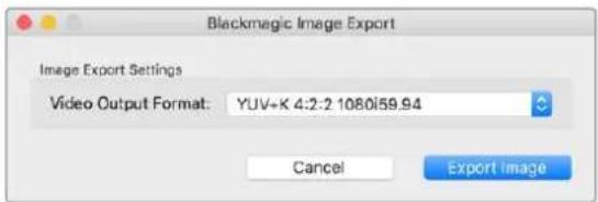
Image Export
Once you have set the 'import' or 'export' options, subsequent imports and exports will not display the settings window. However, you can still change your settings, by holding the Option [Mac] or Ctrl [Win] key, when selecting import or export.
Adobe Premiere Pro CC

Premiere Pro CC
Setting Up a Blackmagic Design Project
1 Open Premiere Pro and click on 'new project'. Type in a name for the project and select a storage location for it.
2 If your graphics card is supported by Premiere Pro CC's Mercury Playback Engine, the renderer option will be available and you should switch it to Mercury Playback Engine GPU acceleration.
3 In the 'capture format' drop down menu, select 'Blackmagic capture'. Click the 'settings' [mac] or 'properties' [windows] button to set the video and audio capture settings. Select the video standard and video format. Click 'ok' to return to the 'new project' window.
4 Click on the 'scratch disks' tab to set the locations for your captured video, captured audio, video and audio previews. Click 'ok' and your new project will open.
5 Now check your default system audio is not set to Blackmagic Desktop Video.
On Mac OS, open 'system preferences', click on the 'sound' option and in the output tab, make sure your Blackmagic device is not selected. In the input tab, select your microphone input, making sure your Blackmagic product is not selected.
On Windows, go to the task bar and right click on the audio 'speaker' icon to open the sound settings. Click on the ' playback' tab and set your PC to use the on board sound hardware or a sound output device other than your Blackmagic Design hardware. Click on the 'recording' tab and set the computer to use a recording device other than your Blackmagic Design hardware.
6 Back in Adobe Premiere Pro, click on the 'preferences' menu and select 'audio hardware'. Set your 'default output' to 'built-in output' using the dropdown menu. Under 'output mapping', map output for 'Adobe desktop audio'.

When setting up Adobe Premiere Pro's audio hardware preferences, make sure the default audio output and output mapping settings are set to 'built-in output'.
7 In the ' playback' menu under preferences, select 'Blackmagic playback' from the 'audio device' dropdown menu and check the 'Blackmagic playback' box under 'video device'. Press 'ok'.
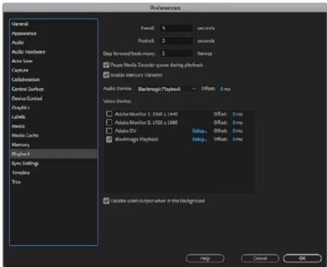
Set Adobe Premiere Pro's ' playback' audio device to ' Blackmagic Playback' and be sure to check the ' Blackmagic Playback' checkbox in the ' video device' settings.
8 To create a new sequence, click file > new > sequence. Select the desired preset, give the sequence a name and then click 'ok'.
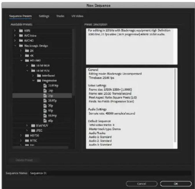
Create a new sequence from the Blackmagic Design presets
Device Control
Many Blackmagic Design capture and playback models feature RS-422 device control for controlling decks. Click preferences > device control, and check that Blackmagic device control has been selected from the 'devices' menu. Click 'ok'.

Playback
If you work with unsupported or non-standard frame sizes, these can also be correctly outputted from your Blackmagic Design hardware. Go to preferences > playback, and click the 'setup' button next to 'Blackmagic playback'. The 'Blackmagic device selection' window will appear. You can scale your image up or down to the next closest video standard supported by your hardware. For example, if you are using UltraStudio 4K and your Premiere sequence is set to a resolution of 3996 x 2160, scaling down will output Ultra HD, scaling up will output DCI 4K.

Select an option to output unsupported frame sizes.
If your Desktop Video device supports HDR, you can also set the color gamut and transfer function for HDR projects. These include HLG and PQ for Rec 2020. The HDR mastering display setting should be set to the maximum nits your monitor or television is capable of displaying.
Capture
To capture choose:
File > capture [F5]
Enter your desired tape and clip name.

Set your capture and device control settings in the capture window
To immediately capture, or to capture from a non-controllable device, click the red record button [G].
If you wish to log the clip using RS-422 deck control, enter the desired in and out points using the 'set in' and 'set out' buttons, or by manually typing the timecode and clicking 'log clip'. Enter a clip name and press 'ok'. The empty clip will now appear in the 'project' window. Repeat this until you have logged all of the clips you wish to batch capture.
Then choose: File > batch capture [F6]. To set handles on the clips, enable the option to capture with handles and type the number of additional frames you require at the start and end of each clip and click 'ok'. You will now be prompted to enter your tape. Click 'ok' and your clips will now be captured.
Export to Tape
If you want to edit your timeline to an external deck, you can do so using Premiere Pro's 'edit to tape' feature. Choose between two export types: insert and assemble. Insert editing requires unbroken timecode for the duration of the project which is to be laid to tape, and is also a great solution when you want to replace a shot on an existing tape. In assemble mode, the tape needs only to be "blacked" until a point just beyond the starting timecode of the sequence. As assemble editing erases the tape ahead of the record heads, it should not be used where other projects already exist on the tape after the out point of your edit.

Use the 'edit to tape' feature to export your edit to an external deck.
TIP When exporting to tape using the assemble mode, it's always good to add at least 30 seconds of black to the end of your sequence. This assists with tape post roll functions and prevents unwanted media appearing directly after your footage.
To export to tape via RS-422 deck control:
1 Make sure the Adobe Premiere Pro preferences are configured correctly as described in 'setting up a Blackmagic Design project' earlier in this section.
2 Open Premiere Pro's 'edit to tape' window by clicking File > export > tape (serial device). Click on 'recorder settings', select Blackmagic capture from the dropdown menu and click 'settings'. Choose your video standard and format along with audio settings. Click 'ok'. If the capture format does not match the output format, it can cause confusion for the deck during preroll and audio might not be exported.
3 Now choose your 'export type' by selecting 'assemble' or 'insert' from the dropdown menu, enter the desired in point timecode and click 'record'.
When editing to tape, the software waits at the first frame of your project for the deck to drop into record at the predetermined timecode. Should you find that either the first frame of your program is repeated or lost during the edit to tape procedure, you will need to adjust the 'playback > video device > offset' setting to bring the deck and computer in sync. You should only need to do this once with any combination of deck and computer and the correct setting will be retained.
Adobe Character Animator CC
Some Desktop Video capture and playback devices let you connect graphics generated by Adobe Character Animator CC to other video equipment such as a confidence monitor. For example, you may want to use the performance of a virtual character in a video edit and monitor the performance in realtime.
This section shows you how to set the output options in Adobe Character Animator CC.

1 In Adobe Character Animator, select Character > Preferences > Live Output.
2 Ensure 'enable Mercury transmit and syphon' is checked.
3 Ensure 'Blackmagic playback' is checked.
4 Select 'setup' next to 'Blackmagic playback'.
5 In the 'output mode' drop down menu, choose a mode from the following options.
Playback
Outputs a signal directly from Adobe Character Animator CC without any keying.
Internal Keying
This option allows you to superimpose your animated character over another video source using your Desktop Video device's internal keyer. For example, the background could be a video of a location relevant to a news story and the character could be superimposed over the top providing a live interview. Another option would be to have the character superimposed over the broadcast feed and sit in the bottom corner like a logo or watermark, providing reactions to the content that is being broadcast.
Fill/Key
If you want to perform the keying using an external switcher, for example an ATEM switcher, you can set the output mode to fill/key. The fill signal is the animated character and the key signal is the grayscale mask that tells a keyer to make the space around the character transparent. This allows the keyer to superimpose the character over a background.
Final Cut Pro X
You can use the A/V output option in Final Cut Pro X to output your video through Blackmagic Design video hardware. If you are using a Desktop Video device that supports HDR, you can also view and edit HDR video with a wide color gamut on a compatible television or monitor.
Final Cut Pro X
Setting Up Final Cut Pro X
1 Ensure you are running Final Cut Pro X 10.0.4 or later with the latest version of Mac OS.
2 Open Blackmagic Desktop Video Setup. Click on the 'video standard' drop down menu and then set the same format that you will use in your Final Cut Pro X project. For example, 2160p29.97. The format should be the same as the video format of your clips. The video standard setting also determines the monitoring video output mode.
Final Cut Pro X
Video standard:
2160p29.97

Pixel format:
10-bit YUV 4:2:2

Color gamut:
Rec. 2020 PQ

Set the 'output format' to match your Final Cut Pro X project format.
3 Click on the 'pixel format' drop down menu and set it to match a format your TV or external monitor will accept. For example, if you are working with a wide HDR color gamut, choose '10-bit YUV 4:2:2' or '10-bit RGB 4:4:4' based on your monitor's compatibility requirements.
4 Click on the 'color gamut' drop down menu and set this to match the color gamut your project is using. If you are working with a standard or high definition project with a standard dynamic range, choose 'Rec. 601/Rec. 709'. If you are using a Desktop Video device that supports HDR and you are editing a 4K or high dynamic range project, select 'Rec. 2020'. For projects that are both 4K and high dynamic range, choose either 'Rec. 2020 HLG' or 'Rec. 2020 PQ'. This should also be a format your TV or monitor is capable of displaying.
Now that you have set your output display settings using Desktop Video Setup, you can create a new project in Final Cut Pro X.
To create a new project:
1 Launch Final Cut Pro X. In the library properties, you will notice the default untitled standard project name. Click on its corresponding 'modify' icon. Create a new library by going to the file menu, then selecting new and library.
TIP If after creating a new library, the library properties on the right side of the screen are hidden, enable them by clicking the clapper board icon in the top left corner. This opens the libraries sidebar.
2 Select the new library in the libraries sidebar and click its corresponding 'modify' icon. An options window will appear asking you to set the color space for your project. Select 'standard' for an SD or HD project using a standard color gamut. If you are intending to create a wide color gamut HDR movie, select 'wide gamut HDR'.
3 Click 'change' to confirm your setting.
4 Create a new project by right clicking the library name in the libraries sidebar and selecting, 'new project'. Type a name and choose an event to place your project in. If you haven't already created one, you can choose the default event, which is named as the current date.
5 Click 'use custom settings'. Set the 'video format', 'resolution' and 'rate' to match the video standard and frame rate you set in Blackmagic Desktop Video Setup.

6 Set 'rendering' to your preferred Apple ProRes codec or 'uncompressed 10-bit 4:2:2' for an uncompressed workflow.
7 If your project is standard HD, you don't have to change the color space as Final Cut Pro selects the standard HD Rec. 709 color space for you. If you are working on an HDR project with a wide color gamut, select the color space and either PQ or HLG according to what your TV or monitor is able to display.
8 Set the audio channels to stereo, or you can choose 'surround' for 6 audio channels. Set the audio sample rate to the television rate of 48kHz.
9 Click OK to complete the creation of your new project.
If you have an external HDMI or SDI monitor connected, you will need to ensure your new project displays correctly.
To set the output display settings in Final Cut Pro X:
1 Go to the Final Cut Pro menu, choose 'preferences' and then click the 'playback' tab. Ensure the 'A/V Output' setting has 'Blackmagic' selected and the video standard matches your project. Close the preferences.
2 In the menu bar, select 'window' and click on 'A/V Output' to enable the video output via your Blackmagic Design video hardware.
To configure the audio output on Mac OS:
1 Open the Mac OS 'system preferences' and click on the 'sound' icon.
2 Click on the 'output' tab and select 'Blackmagic Audio' for the sound output.
TIP You can also monitor audio via your Desktop Video hardware.
Playback
1 Import some clips in to your new project.
2 You can now use the Final Cut Pro X timeline on your computer monitor and view the video preview on the monitor or TV connected to the output of your Blackmagic Design video hardware.
Capturing Video and Audio
You can use Blackmagic Media Express to capture video and audio with your Blackmagic Design video hardware. Once you have captured the clips, you can import them into Final Cut Pro X for editing.
When capturing clips with Media Express, make sure you choose one of the video formats that is also supported by Final Cut Pro X. For example, Apple ProRes 4444 XQ, ProRes 4444, ProRes 422 HQ, ProRes 422, ProRes 422 LT or uncompressed 10-bit 4:2:2.
Editing to Tape
Once you have completed a project in Final Cut Pro X, you can render the project to a movie file and then use Blackmagic Media Express to master the movie to tape with your Blackmagic Design video hardware.
1 Select your clips from the timeline in Final Cut Pro X.
2 Go to file>share>master file and the 'master file' window opens.
3 Click 'settings' and select your desired video codec from the dropdown menu.
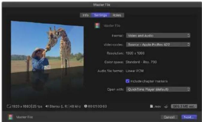
4 Click 'next...' and select a location for your movie and then click 'save'.
5 Open Media Express and import the clip that was exported from Final Cut Pro X.
6 Refer to the Blackmagic Media Express section of this manual for 'Editing video and audio files to tape'.
Avid Media Composer
Avid Media Composer captures and plays back up to 4K video and audio with Blackmagic Design video hardware and also supports RS-422 deck control. Blackmagic plug-ins for Media Composer are automatically installed if Media Composer is installed before the Desktop Video software.

Avid Media Composer
Setting Up
1 Launch Media Composer and the 'select project' dialog box will appear.
2 Choose your preferred 'user profile' if you have previously created one.
3 Select a private, shared or external project location for your project.
4 Click the 'new project' button.
5 Type a project name and set the project options including format, color space and stereoscopic. Click 'ok'. The color space and stereoscopic settings can be changed later in the 'format' tab of the project.

Type a project name and set the project options.
6 Double click the project name in the 'select project' dialog box. The Media Composer interface will appear along with the project window for your new project. You have completed setting up your project.
Playback
As a quick test to make sure everything is connected correctly, go to the 'help menu', click 'read me' and select the Media Composer Editing Guide. Follow the 'Importing Color Bars and Other Test Patterns' section. Double click the imported file to play it. You should now see the image on both your computer monitor and your Blackmagic Design hardware output.
If you can't see any video on your Blackmagic Design hardware output, check the connections again and ensure you have the correct output settings configured within Blackmagic Desktop Video Setup by choosing tools > hardware setup from within Media Composer. Make sure the hardware icon above the timeline is enabled.
NOTE If you are using an external Blackmagic video device such as Blackmagic UltraStudio 4K, make sure it is powered and connected prior to starting Media Composer.
Capture from Non-Controllable devices
Many video sources including all kinds of modern cameras and disk recorders, as well as old cameras and VHS tape players, do not have any device control.
To capture video without deck control:
1 Choose file > input > tape capture to open the 'capture tool'.
2 Click the 'toggle source' button so that the button's icon of a deck shows the satellite button, an earth icon with plus symbol. This symbol indicates that deck control has been disabled.

Set up the 'capture tool' to capture video without deck control by clicking the 'toggle source' button.
3 Select the video and audio source tracks you wish to capture. These are labeled 'V' and 'A1', 'A2', etc. Using the dropdown menus below, select Blackmagic for both video and audio.
4 Use the 'bin' menu to select a target bin from the list of open bins.
5 From the resolution menu labeled 'res', choose which codec you wish to use for your captured clips. In this example, select DNxHD175x for 10-bit HD video.
6 Select the disk storage for your captured video and audio. Use the 'single/dual drive mode' button to choose if video and audio will be stored together on a single drive or on separate drives. Select the drives for your captured media from the 'target drives' menu.
7 Click the 'tape name?' button at the bottom of the window to open the 'select tape' dialog box. Add a tape name, or select from the list if you've used the tape before.
8 Ensure your video and audio source is ready or playing and then click the 'capture' button. The capture button will flash red while recording. Click the capture button again to end the capture.
Capture from Controllable Devices with UltraStudio, DeckLink and Teranex
If you have a deck that connects via RS-422, you will need to configure the deck settings before performing a capture with deck control.
1 Connect an RS-422 serial cable from your Blackmagic Design video hardware and your deck. Set the deck to 'remote'. If you're using an external Blackmagic Video device, make sure it it connected and powered prior to starting Media Composer.
2 From your project window, click the settings tab and double click on 'deck configuration'.
3 In the 'deck configuration' dialog box, click 'add channel' and then set the channel type to 'direct' and the port to 'RS-422 deck control'. Click 'ok' and choose 'no' when asked, 'do you want to autoconfigure the channel now?'
4 Click 'add deck' and then select your brand and model of deck from the device menus and also set the desired preroll. Click 'ok' and then 'apply'.
5 Under the settings tab, double click on 'deck preferences'.
6 If you plan to make assemble edits to tape, enable the option to 'allow assemble edit and crash record for digital cut'. If this option is left unchecked, you will only be able to perform insert edits. Click 'ok'.
TIP If Media Composer fails with the error, 'failed to find coincidence point on tape', you can check the 'relax coincidence point detection' option in deck preferences to continue.
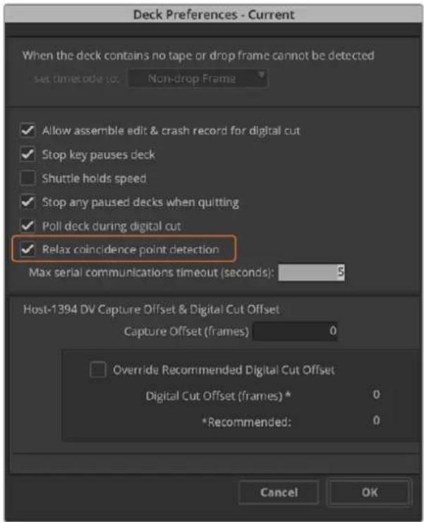
In the 'deck preferences', enable the option to 'relax coincidence point detection'.
To capture with deck control on the fly:
1 Choose file > input > tape capture to open the 'capture tool'. If a connected deck is recognized and contains a tape or disk, you will be prompted to enter a tape name, or you can choose it from the list.
2 The 'toggle source' button should show the icon of a deck. If the satellite icon is present, click the button to enable deck control and make the deck icon appear.
3 The 'capture/log mode' button should show the 'cap' icon. If this button displays a 'log' icon, click the button to switch to capture mode and the cap icon should appear.
4 If 'no deck' is displayed in the timecode window, or a deck name appears in italics underneath, click the dropdown menu and select 'check decks'. When deck control is re-established, the deck name will appear without italics. Now try the standard J, K, L shortcut keys to control the deck.
5 Select Blackmagic for the video and audio input. Select your video and audio source tracks, target bin, res, target drive and tape name the same way as in 'capture from non-controllable devices'.
6 Use the deck controller window in the 'capture tool' to cue the tape and start playing.
7 Click the 'capture' button. The capture button will flash red while recording. Click the capture button again to end the capture.

Set the 'cap' and 'toggle source' buttons to use deck control.
Use the 'deck controller window' to cue the tape and start playing.
Batch Capture with UltraStudio and DeckLink
To log clips for batch capture:
1 Choose file > input > tape capture to open the 'capture tool'.
2 If the deck is in satellite mode, click the toggle source button to change it to deck mode. Click on the 'capture/log mode' button so it displays the 'log' pencil icon.
3 Configure video and audio input, video and audio source tracks, target bin, res, target drive and tape name the same way as in 'capture from non-controllable devices'.
4 Use the 'deck controller window', or use the standard j, k, l shortcut keys, to shuttle backwards, pause and shuttle forwards on the deck and locate the video you want to capture.
5 Click the 'mark in/out' button, to the left of the log button. The icon will alternate between in and out so you only have to click the one button to mark all your in and out points and log your clip. This can be more convenient that using the separate 'mark in' and 'mark out' buttons in the deck controller window. Alternatively use the 'i' and 'o' keys on the keyboard to mark in and out points, and the keyboard shortcut 'F4' to log the clip.
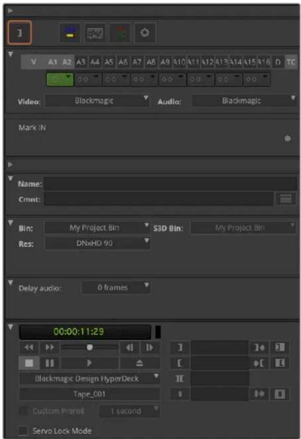
Click on the 'mark in/out' button or use the 'i' and 'o' keys on the keyboard to mark in and out points.
6 When you have finished logging your clips, close the capture tool, open the logging bin and select the clips you want to capture.
7 From the 'clip' menu, choose batch capture, select the desired options in the resulting dialog box and click 'ok'.
Recording to Tape with UltraStudio and DeckLink
Once you have captured your clips, dragged them in to the timeline, edited them and applied and rendered any effects, you will want to record the completed project to tape.
1 Double click your sequence, to open it into the timeline window.
2 Choose file > output > digital cut to open the 'digital cut tool'.
3 Set 'output mode' to real time and bit depth to 10-bit. Check 'entire sequence' to record your whole sequence, and check the 'remote' deck control option.
4 Choose 'insert edit' or 'assemble edit' for precise edits onto a timecode striped tape. Alternatively choose 'crash record' for a simple way to record. If 'insert edit' is the only option, go to the settings tab in your project, double click on 'deck preferences' and enable 'allow assemble edit & crash record for digital cut'.
5 If a deck name appears in italics or 'no deck' is displayed, click the menu and select 'check decks' until the deck is listed without italics and deck control is re-established.
6 Press the 'play digital cut' button (red triangle icon) to record your sequence to tape.
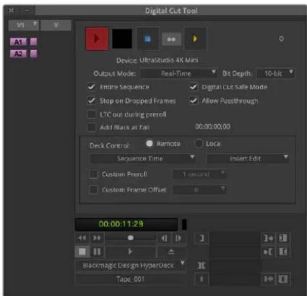
The 'digital cut tool' is used for recording to tape.
Autodesk Smoke
Autodesk Smoke brings together editing, compositing and 3D effects into a single workspace. Smoke captures and plays back standard definition and high definition video and audio with Blackmagic Design video hardware and also supports RS-422 deck control.

Autodesk Smoke
Setting Up a VTR
Before starting Autodesk Smoke, you must use a utility called Smoke setup to select the model of the VTR in your facility and its appropriate timing settings.
1 Go to Applications > Autodesk > Smoke 2018 > Utilities and open 'Smoke Setup'.
2 In the 'general' tab, make sure that 'video device' and 'audio device' are set to 'BMD'.
3 In the VTR tab, enable the VTR model and the timings you want to use with Autodesk Smoke. Enable the rows with live NTSC or live PAL to enable crash record or live output.
4 Click 'apply' and close Smoke Setup.

Ensure 'video device' and 'audio device' are set to BMD in the Smoke Setup utility.
Getting started
1 Launch Smoke and the 'project' and 'user settings' window will appear. Choose your 'project' and 'user' if you have previously created them. Otherwise, create a new project and/or user.
2 Set the project settings to match your delivery settings, i.e., 1080HD. Most of these settings can be changed later during your session.
3 Choose your intermediate format, such as 'ProRes 422 HQ' or even 'uncompressed' for your project generated media. Remember to choose a format that your storage can handle.
4 Click the 'create' button.
Setting Up Hardware
It's a good idea to follow the steps below when you are preparing for a VTR session.
1 Connect the outputs of your VTR to the inputs of your Blackmagic Design capture and playback device. Connect the outputs of your Blackmagic Design capture and playback device to the inputs of your VTR.
2 Connect an RS-422 deck control cable from the serial port on your VTR to the remote control port of your Blackmagic Design capture and playback device.
3 Set your VTR to remote.
4 Connect a sync generator to the sync input of the VTR to ensure frame-accurate capture.
If you have a separate audio device, an audio sync signal must be connected to it as well.

Type a project name and set the project options.
Capture from Controllable Devices with UltraStudio and DeckLink
Autodesk Smoke can be configured to capture from controllable VTRs with RS-422 deck control.
1 Select a folder in the media library where you want the captured clip to be created.
2 Select file>capture from VTR. The VTR capture module appears.

Ensure 'video device' and 'audio device' are set to BMD in the Smoke Setup utility.
3 Cue the tape to the start frame of the clip you want to capture.
4 Select the video and audio channels you wish to record. The buttons will turn red to let you know which tracks are enabled.
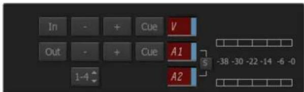
Video and audio tracks turn red when enabled for capture from your VTR.
5 Enter 'in' and 'out' points in the in and out fields.
6 Click 'capture' to start the capture. The timecode field will turn green to indicate that capture is in progress.
7 End the capture at any time by clicking anywhere over the preview window. The clip will automatically be saved to the location that you selected before entering the VTR input module.
Recording to Tape with UltraStudio and DeckLink
Load a clip into the VTR output module and set the 'in' and 'out' points for the output clip. If needed, you can also enable the options to offset the start frame for output and to apply a letterbox overlay.
1 Select file>output to VTR.
2 Choose the clip(s) to output from the media library. You can also select a folder if you wish to output its contents in one session. The VTR output module appears.

Your VTR should be selectable in the drop down list.
3 Select the VTR in the device name box. The preview window displays the video from the tape in the selected VTR.
4 Make sure that the correct video track and audio channel buttons are enabled so that the corresponding video track and audio channels are output to tape.
5 Enable or disable 'all audio' in the 'clip output' menu. When all audio is enabled, every audio channel will be converted to the format on your tape, not just the ones you enabled.
6 Click preview to watch the clip before outputting.
7 To output the selected clip starting at any frame other than the first one, enter the start timecode in the 'start offset' field.
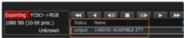
Clips you have selected to output appear in a list with their current status.
8 Set the 'in' and 'out' points for clip output.
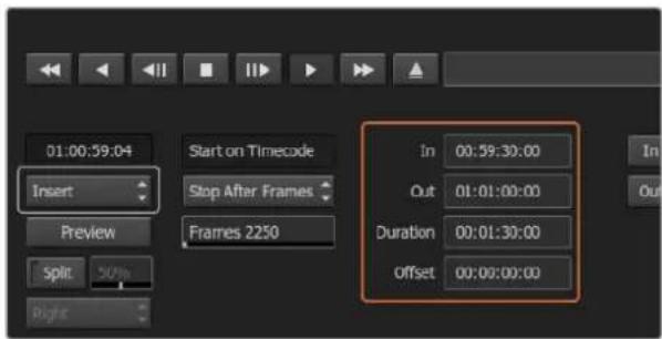
Set your 'in' and 'out' points, then select Insert from the 'output' dropdown menu.
9 To output the clip to the VTR, select 'insert'. The selected clips will be output to tape. During output, the status of each clip will be updated to 'pending', 'output', and then 'done'.
10 Cue to the In timecode and then select 'play' to check that the transfer was successful.
11 When you are finished, click 'exit output clip' to close the module.
Crash Record and Live Output
Autodesk Smoke allows you to capture a live video signal or crash record a clip by using a tablet pen or a mouse to start and stop the clip input or output process. When you choose this form of capture, Autodesk Smoke checks the available space on your Autodesk media storage device to determine the available space, which varies depending on your preferred intermediate format.
Also, if you are using a device that does not support remote control via RS-422, such as a camera, VCR, or any other device, use the Live NTSC or PAL option to capture, and the 'live video' option to output clips.

Enable the rows with live NTSC or live PAL to enable crash record or live output.
To crash record a live video signal:
1 Choose a folder from the 'media library' where you would like the captured clip to be created.
2 Select file>capture from VTR. The VTR capture module appears.
3 From the VTR device box, select 'live NTSC' or 'live PAL'. The incoming live video signal appears in the preview window.
4 Select the 'start on pen' mode. End the capture by using 'stop on pen' or 'stop on frames'. Traditionally, Autodesk Smoke was operated with a tablet and pen, hence the 'start on pen' terminology.
When 'stop on pen' is selected for capture stop mode, the out point and the duration timecode fields will be updated to show the longest possible clip that can be recorded on your Autodesk Media storage device. The capture will either end when you click anywhere on the screen or when your storage fills up.
5 Enter the clip name and enable the video tracks and audio channels that you want to capture.
6 Make sure you are receiving the live video signal.
7 Press 'play' on the video device.
8 Select 'process' to begin capturing.
9 Click anywhere on the screen to end capturing in 'stop on pen' mode.
To output a live video signal:
1 Select file>output to VTR.
2 Select the clip(s) to output from the 'media library'. You can also select a folder to output its contents. The VTR output module appears.

Select Live PAL or Live NTSC when outputting a live video signal.
3 From the VTR device box, select Live NTSC or Live PAL.
The 'start mode' box is unavailable. With 'live video' output, you must use the default start setting. You can use 'stop on pen' or 'stop on frames' to end the output.

Use the default start settings for live output.
4 Set output options. For example, enter the clip name and enable the video tracks and audio channels that you want to capture.
5 On the device receiving the signal, start the recording, or take any action required to enable the reception of the signal from Autodesk Smoke.
6 Select 'process' to begin the output on Autodesk Smoke.
7 Click anywhere on the screen to end the output in 'stop on pen' mode.
Blackmagic Media Express

natural_image
Close-up of a metallic film reel with six circular blades and a central hub (no text or symbols visible)What is Blackmagic Media Express?
Blackmagic Media Express software is included with every UltraStudio, DeckLink and Intensity as well as every ATEM Switcher, Blackmagic Camera, H.264 Pro Recorder, Teranex Processor and Universal Videohub. Media Express is a great tool when you don't need the complexity of NLE software but simply want to capture, play back and output clips to tape.
Capturing Video and Audio Files
Setting Up a Project
Media Express automatically detects your input video format and sets the 'project video format' to match. If you want to set the project video format manually:
1 Go to Media Express>preferences on Mac, or edit>preferences on Windows or Linux. Select your 'project video format' from the dropdown menu at the top of the preferences window. You can choose from a range of compressed and uncompressed capture formats, or even a DPX image sequence from the 'capture file format' drop down menu. Video will be captured in the chosen format and saved as a QuickTime movie. You can also choose to capture an RGB source using a YUV codec or vice versa.
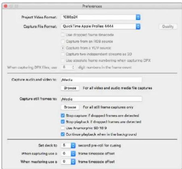
Use the preferences window to set project video format, capture file format, storage location and other settings.
2 Set the storage location for your captured video and audio. Click the 'browse' button to point the software to a folder on your computer.
3 Choose whether to stop capture or playback if dropped frames are detected.
Standard definition projects use the 4:3 aspect ratio unless you enable the 'use anamorphic SD 16:9' checkbox.
Applications will normally stop playing video if you send them to the background. Tick the checkbox 'continue playback when in the background' if you want Media Express to keep playing video even if you open another application.
The final options relate to tape decks with RS-422 deck control and include pre-roll and timecode offsets.

Capture
To capture video, all you need to do is connect a video source, wait for Blackmagic Media Express to detect your input and press the 'capture' button.
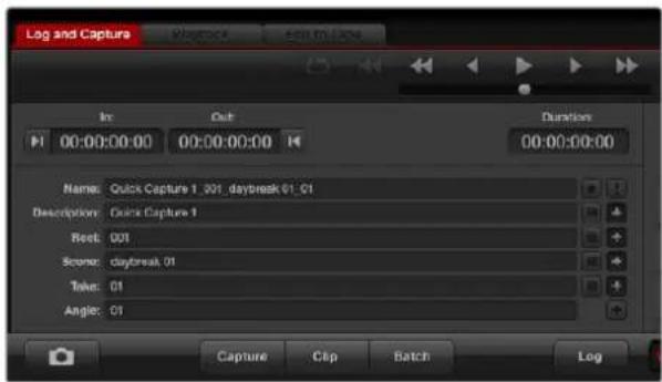
Enter a description for your video.
1 Start by connecting your video source to an input of your Blackmagic Design hardware. Launch Desktop Video Setup and check that the 'input connection' is the same as your video source, e.g., SDI, HDMI, Component, etc.
2 Open Media Express and click the red 'log and capture' tab.
3 Your source video will appear in the preview pane. Enter a description into the 'description' field.
4 Click the '+' button next to the description to add it to the automatic 'name' field. Click the '+' button next to any of the other fields that you wish to add to the name field.
- To increment the value in each of these fields, click the corresponding clapper board icon. Alternatively, type directly into any field to customize its name and number.
- The text in the automatic name field will be applied to the clip(s) about to be captured.
- To log the clip as a favorite, click the star icon next to the name field.
- For a clip name confirmation prompt to appear before every capture, click the ‘!’ icon next to the name field.
5 Set the desired number of audio channels to be captured.

Set the desired number of audio channels to be captured.
6 Click the 'capture' button to start recording. To stop the capture and keep the clip, click the 'capture' button again or press esc. The captured clips are added to the media list on the left side of Media Express.

Click the 'capture' button to begin capturing.
If the video input format changes from the project video format, Media Express will automatically detect it and will prompt you to save the current project and create a new one.

Blackmagic Media Express will automatically detect if you change your ATEM switcher's program output format and will give you the option to save and start a new project.
Logging clips
Ensure an RS-422 serial cable is connected between your Blackmagic Design video hardware and the deck.
Ensure the deck's remote/local switch is set to remote. Use the standard j, k, l shortcut keys to shuttle backwards, pause and shuttle forwards.
- Click the 'mark in' button to mark the in point, or use the shortcut key i.
- Click the 'mark out' button to mark the out point, or use the shortcut key o.
- Click the 'log clip' button to log the clip, or use the shortcut key p. The entry should now appear in the media list with a red X in its icon to indicate the media is offline.
Batch Capture
After logging a clip, you can click the 'clip' button to capture a single clip.
To capture multiple clips, continue logging the clips for batch capture.
Select the logged clips in the media list and do one of the following:
- Click the 'batch' button.
- Right click on the selection and select batch capture.
- Go to the 'file' menu and choose batch capture.
Media Express will capture the clip from the in to out timecode.
DPX Capture
If you want to capture a DPX image sequence rather than a movie file, open the Media Express preferences and set the 'capture file format' to DPX 10-Bit RGB.
- Create a DPX project by setting the capture file format to DPX.
- Capture.
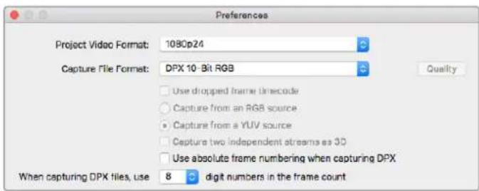
DPX capture preferences.
When the capture has been completed, a single thumbnail will appear in the media list representing the entire frame sequence. The sequence of DPX frames will be stored in its own folder in your disk storage. Audio will be stored in a .wav file in the same folder.
By default, DPX captures are assumed to be from YUV sources. If you are capturing from an RGB source, select 'capture from an RGB source'.
If you want the DPX frame numbers to be based on the timecode of the captured video, rather than just starting from zero, enable the option to 'use absolute frame numbering when capturing DPX'.
If you aren't performing long DPX captures, you may wish to reduce the number of zeroes in the frame numbers by changing the option, 'when capturing DPX files, use (2-8) digit numbers in the frame count'.
3D Capture
When Media Express is used with a Blackmagic Design video hardware model that supports dual stream 3D, you can create left and right eye 3D video clips by capturing 2 streams of HD-SDI video simultaneously.
- Create a 3D project which matches the frame rate of your dual stream 3D video source.
- If capturing from an SDI source, make sure you have 2 discrete HD-SDI video inputs to the Blackmagic video hardware.
- Capture.

Select a project video format with "3D" in its name to capture dual stream stereoscopic 3D video clips.
When capturing and logging dual stream 3D in Media Express, the clip name will be applied to the left eye video. The right eye video will be appended with '_right' text. For example, if you name the stereo clip "Clip 1", the left eye clip will be called "Clip 1.mov" and the right eye clip will be called "Clip 1_right.mov".
The Media List presents an eye catching indication that the captured clip is a 3D clip:
- In thumbnail view, the left and right eye clips are connected by a 3D indicator and presented as a single, large icon.
- In timecode list view, the left and right eye clips are listed on two lines and linked together by a 3D indicator.

In Thumbnail view, the left and right eye clips are connected by a 3D indicator and presented as a single, large icon.

Playing back Video and Audio Files
Playing back single and multiple clips
To play back a single clip, double click the clip in the media list. Alternatively, select the clip in the media list and press the space bar on your keyboard or the play button in the transport controls.

You can use the transport controls to play, stop, jump to the next or previous clip and loop playback.
To play back multiple clips, select the clips in the media list and then press the space bar on your keyboard or the play button in the transport controls.
Your video will play back in the video preview pane of Media Express and on all the video outputs of your Blackmagic Design video hardware. During playback, the audio channels being monitored can be switched on or off via the track enable/disable buttons.
Importing clips
You can play back your video and audio files after importing media into Media Express in any of the following ways:
- Double click an empty area of the media list, browse to your file's location and click 'open'.
- Right click an empty area of the media list and select 'import clip' from the contextual menu.
- Go to the 'file' menu, select 'import' and then 'media files'.
Select the video and audio clip(s) you wish to import and press 'open'. The clips will appear in the 'scratch' area of the media list. If you have created your own bins in the media list, you can drag the clips into the desired bin.
To import directly to a bin, right click within the desired bin and select 'import clip' from the contextual menu.
If the files being imported do not match the frame rate and size of existing clips in the media list, you will be prompted to create a new project and to save the current project.

If the imported clips do not match the existing clips, you will be prompted to create a new project.
TIP Media Express also supports the import of multichannel audio only files recorded at 48kHz in the uncompressed WAVE and AIFF formats.
Another way to import media is to use an XML file exported from an NLE such as Final Cut Pro 7 or Final Cut Pro X. Go to the 'file' menu, select 'import' and then either Final Cut Pro 7 XML or Final Cut Pro X XML. Open the desired XML and all the bins and media from the Final Cut Pro project will appear in the media list.
Media Express also supports the import of CMX EDL files to batch capture clips using EDL files from other video software. Go to the 'file' menu, select 'import' and then CMX EDL. Select the EDL and open it.
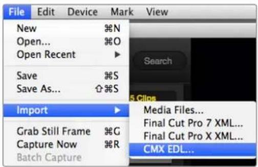
You can import media directly, or import with an XML or EDL.
The logging information will appear in the media list. Select the logged clips and perform a batch capture to import the clips from your deck.
Browsing Media
Thumbnail view
Thumbnails are the most intuitive way to display your clips. Hover your mouse over the clip's thumbnail and then click on the popup info icon at the bottom right of the thumbnail. Click the info bubble to hide it.

Click a thumbnail's popup info icon to view the info bubble.
List view
You can view your clips in 'timecode list' view by clicking on the 'timecode list' button at the top right of the media list. Use the horizontal scroll bar to view all the columns of information for your clips.

In the media list, choose to view your clips in 'timecode list' view or 'thumbnail' view. Click the 'favorites' button to show only your favorite clips. Type in the search field to find your favorite clips.
Creating and using bins
To create a bin, right click an empty spot in the media list and select 'create bin'. Name the new bin.
You can move clips around by dragging the clip icons to the desired bin. If you want a clip to appear in more than one bin, import the same clip again by right clicking on the bin and choosing 'import clip'.
By default, logged clips appear in the 'scratch'. If you want to log clips and have them appear in a new bin, right click the new bin and choose 'select as log bin'.
Creating and using favorites
In the 'log and capture' tab, click the 'star' icon next to the name field if you want to tag a clip as a favorite.
In the ' playback' tab, clicking the star icon will make the clip a favorite if it is selected in the media list. Click the star icon again to deselect it as a favorite.
Clips marked as favorites will show a yellow star in their icon in 'timecode list' view and 'thumbnail' view.
Once you have marked clips as favorites, click on the 'show only favorites' button at the top of the media list. The star icon will turn yellow. All clips will be hidden except for those marked as favorites.

In the 'log and capture' tab, click the 'star' icon next to the name field if you want to log the clip as a favorite.
Linking an audio clip to a video clip
To link an audio clip to a video clip in the media list:
- Select a video clip which contains no audio channels.
- Right click on the video clip and select 'link audio file' from the contextual menu.
- Browse to the audio file you want to link to and click 'open'. The video and audio will link in the media list view.
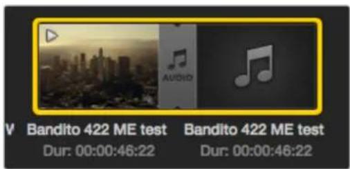
The media list presents a highly visible indication that the video and audio clips are linked.
You can now play back the combined clip or master it to tape.
Deleting clips and bins
To delete clips, select the unwanted clips and press the backspace button on your keyboard.
This will only delete the clips from the media list and they will safely remain on your disk storage.
To delete bins, right click within a bin and choose 'delete bin'. This action will delete the bin and any clips it contained. This will only delete the clips from the media list and they will safely remain on your disk storage.
Creating a 3D clip
To add a stereoscopic 3D clip to the media list:
- Select a 3D project video format that is the same frame rate as your 3D media.
- Import the 'left eye' file into the media list.
- Right click on the left eye file and select "set right eye clip" from the contextual menu. If the right eye clip was previously captured by Media Express, the right eye video will be appended with '_right' text.

Select a 3D project video format.
The media list presents a highly visible indication that the imported clip is a 3D clip. The left and right eye clips are displayed side by side in the 'video preview' window, indicating a 3D video project.
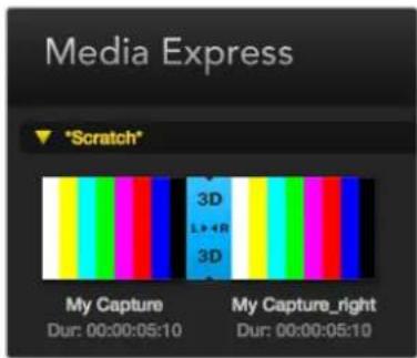
The media list presents a highly visible indication that the imported clip is a 3D clip.
If you find the left and right eyes of a 3D stereo clip have been loaded the wrong way around:
- Right click the 3D clip in the media list.
- Select 'swap eyes' from the contextual menu.
Searching the Media List
Clips can easily be found in a project by typing the name of your clips in the search field at the top of the media list. When used in conjunction with the favorites feature, the search will be confined to your favorite clips so you will see a shorter list of found clips.

Type In the search field to find clips.

Editing Video and Audio Files to Tape
While we usually talk about mastering or editing to "tape", it doesn't matter if your deck uses tapes or disks. To master your clips:
- Select the clips you want to send to tape.
- Click the blue 'edit to tape' tab.
- Set the in point and type of edit.
- Master to tape.
Selecting clips to master
From the media list, select the clips you wish to master to tape. You can even insert multichannel audio only clips to replace the master audio track on a master tape. If you only want to send your favorite clips to tape, click the favorite (star) icon at the top of the media list to show your favorites and hide all other clips. Then select the favorite clips you wish to send to tape.

Click the favorite (star) icon at the top of the media list to show only your favorites.
Insert and Assemble to tape
Click the 'edit to tape' tab. Enter the in point of the tape by entering timecode into the 'in' point field, or by cueing the tape to the desired in point via the transport control and then clicking the 'mark in' button.
If no 'out' point is entered, Media Express will set the duration of the edit to the total length of the clips in the media list. If an out point is defined, Media Express will stop recording once the 'out' point timecode is reached, even if some clips have not been output.

Two clips have been selected for output to tape.
Choose to master to tape using 'assemble' or 'insert' edit. Then press the 'master' button.
Preview mode mimics the edit process but does not record to tape. This mode lets you check the edit point. Preview edit operations should always be checked on monitors connected directly to the output of the deck. This lets you view the video already on tape in conjunction with the new video.
If 'record inhibit' is enabled either on the deck or on the tape, Media Express will report this when you click the 'master' button. Disable 'record inhibit' before trying again.
Select the video and audio channels you wish to output via the track enable/disable buttons. Deselect the video channel if you only want to output audio.

Set the desired number of audio channels to be mastered.
Click the favorite (star) icon at the top of the media list to show only your favorites.
Two clips have been selected for output to tape.
Set the desired number of audio channels to be mastered.
Capturing H.265 Video
To capture video using Blackmagic UltraStudio 4K Extreme's built in H.265 encoder:
1 Open Media Express 'preferences' and set the 'capture file format' to MP4 H.265.
2 Set the bitrate for your H.265 capture by clicking on the 'quality' button located next to the H.265 setting and dragging the 'encoding settings' slider left or right. Close the 'encoding settings' window to confirm your setting.
TIP For more information about H.265 capture and bitrate settings, refer to the next section in this manual, 'H.265 Hardware Encoder'.
H.265 Hardware Encoder
Capturing H.265 Video with UltraStudio 4K Extreme
Blackmagic UltraStudio 4K Extreme has a powerful built in H.265 hardware encoder that lets you capture the latest H.265 video in real time. This gives you the ability to capture video using encoding technology that maintains stunning video quality at the lowest possible bitrate.
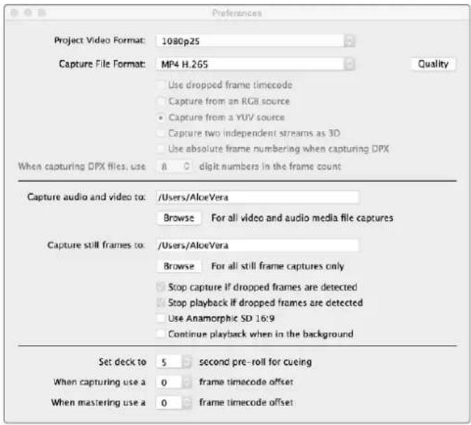
To capture H.265 video using Blackmagic UltraStudio 4K Extreme, set the capture file format in Media Express preferences to MP4 H.265.
To capture video using the built in H.265 encoder:
1 Launch the Blackmagic Media Express software. Open Media Express 'preferences' and set the 'capture file format' to MP4 H.265.
2 Set the bitrate for your H.265 capture by clicking on the 'quality' button located next to the H.265 setting and dragging the 'encoding settings' slider left or right. Close the 'encoding settings' window to confirm your setting. Your Blackmagic UltraStudio 4K Extreme is now ready to encode H.265 video using Blackmagic Media Express.
For information about how to capture and play back video using Media Express, refer to the 'Blackmagic Media Express' section of this manual.
Setting the Bitrate
The default bitrate is set to 15 Mb/s which is a good choice for high quality Ultra HD video that is streamed online, but you can set it anywhere between 3 to 50 Mb/s. For online streaming of HD video, a good choice is between 3 to 5 Mb/s.
Drag the 'encoding settings' slider to the left if you need to capture video with a smaller file size and a lower bitrate, or drag to the right if file sizes are not an issue and you want the best possible video quality. Setting the bitrate too low will result in compression artifacts in your picture, such as visible macro blocking, pixelation or banding. However, the H.265 hardware encoder is very efficient and keeps artifacts to a minimum, so you can set the bitrate lower than you normally would for H.264 video and still retain great video quality.

Set the bitrate for H.265 capture by clicking on the 'quality' button and dragging the 'encoding settings' slider left or right.
When encoding H.265 video, or any type of video encoding for online streaming, it's often helpful to consider a few things, such as the bandwidth of your intended delivery system, the amount of movement and contrast between frames in your video, and the frame rate of your video. For example, if there is a large number of people streaming your video, you may need to lower the bitrate in your encoding so audience members with slower internet connections can watch without download interruptions. Higher bitrates are better for video content with lots of contrast and movement between frames, such as bright to dark, or high energy sporting events and graphics. Video with high frame rates also require higher bitrates compared to video at lower frame rates.
Choosing a bitrate for your encoding can often be an experimental process to achieve the best video quality in the smallest file size, so it's worth testing a variety of bitrate settings for the best results.
Blackmagic Disk Speed Test
What is Blackmagic Design Disk Speed Test?
Blackmagic Disk Speed Test measures the read and write performance of storage media in video frame sizes. Disk Speed Test is included with your Desktop Video software and can be downloaded free from the App Store for macOS. Access the Disk Speed Test settings by clicking on the 'settings' gear icon, located just above the 'start' button.

gauge
| Metric | Value | |--------|-------| | Current | 432.5 | | Peak | 432.5 |Select Target Drive
Click 'select target drive' and ensure you have read and write permissions.
Save Screenshot
Click 'save screenshot' to save a screenshot of the results.
Stress
The stress level can be set between 1GB and 5GB in 1GB increments. 5GB is the default setting and will provide the most accurate results.
| Select Target Drive...Save Screenshot... #S |
| Stress |
| 1 GB |
| 2 GB |
| 3 GB |
| 4 GB |
| √ 5 GB |
| Disk Speed Test HelpAbout Disk Speed Test |
| Quit |
Open the Settings menu by clicking the gear icon.
Disk Speed Test Help
Click 'Disk Speed Test help' to launch the PDF manual for Blackmagic Disk Speed Test.
About Disk Speed Test
About Disk Speed Test displays which version of the Disk Speed Test software you are running.
Start
Click the 'start' button to commence the test. Disk Speed Test will write and then read a temporary file to the selected target drive. Disk Speed Test will continue writing and reading until you stop the test by clicking the 'start' button again.
Will it Work?
The 'will it work?' panel shows common video formats and displays a check mark or cross to indicate if disk performance is adequate. Be sure to do several test cycles to reveal any video formats for which the disk performance might be marginal. If a video format exhibits a check mark switching between a cross, it indicates that the disk storage cannot reliably support the video format.
How Fast? (FPS)
The 'how fast? (FPS)' results panel shows the frame rates your drive can achieve and should be read in conjunction with the 'will it work?' panel. If the 'will it work?' panel shows a green check mark for 2K DCI 25p in 10-bit YUV 4:2:2, but the 'how fast? (FPS)' panel shows that a maximum of 25fps will be supported, the disk storage performance is too marginal to be reliable.

Removing the Mezzanine Card from DeckLink 4K Extreme 12G
How to Remove the Mezzanine Card
If you don't have enough room on your motherboard to fit a dual slot PCIe card, you can easily remove DeckLink 4K Extreme 12G's mezzanine card.
To remove the mezzanine card:
1 Ensure that you are statically discharged. Place the DeckLink card on its side on a flat, clean surface, with the gold PCIe contacts facing up.
2 On the underside of the DeckLink card, locate the two screws for the mezzanine card's stand off supports. They are the two screws furthest away from the BNC connectors. Gently remove the screws using a Phillips head screwdriver.
3 Hold the base DeckLink card by its edges and gently lift the mezzanine card until its bridge connector is released from the slot.
4 Ensure the bridge connector is firmly seated in the mezzanine card in case you'd like to reattach it.
5 Keep the two screws fastened to their stand off supports, place the mezzanine card in an anti static bag and store in a secure place.
You can now install your DeckLink 4K Extreme 12G card into your computer using one PCIe slot.
To reattach the mezzanine card:
1 Align the two mezzanine card stand off supports with the screw holes on each side of the base DeckLink card and gently secure the mezzanine card to the bridge connector slot. Ensure the mezzanine card is properly seated in the bridge connector slot.
2 Fasten the stand off supports to the base DeckLink card by tightening their screws using a Phillips head screwdriver. Be careful not to over tighten the screws.
If you need assistance or have any questions please visit the Blackmagic Design support center at www.blackmagicdesign.com/support.

natural_image
Technical illustration of a mechanical assembly with exploded view and internal components (no text or symbols)DeckLink 4K Extreme 12G's mezzanine card can easily be removed.
Recovering a DeckLink Card from an Interrupted Update
If you are updating a DeckLink card and the update process is interrupted, for example power is accidentally disconnected from your computer, this can leave your card in a disabled state. However, many DeckLink cards have a special USB port that will let you perform an update recovery.
If your DeckLink card supports USB recovery, the mini B USB port will be located on the rear or side of the card. This USB port will let you plug into your computer and update the card directly.
To recover an interrupted update on a DeckLink card:
1 Shut down your computer and disconnect the power.
2 Gently remove your DeckLink card from your computer's PCIe slot and place it safely on a stable surface, such as a desk or workbench. We recommend placing the card on an anti-static bag and wearing an anti-static earthing wrist band to avoid the risk of damaging the card with a potential electric shock.
3 Plug a USB cable into the mini B USB port on the rear or side of your DeckLink card.

natural_image
Illustration of a computer motherboard with CPU socket and connectors, showing a hand holding a tool (no text or symbols present)Remove the DeckLink card from your computer's PCIe slot and plug it into your computer using the mini B USB port on the rear or side of the card
4 Plug the other end of the USB cable into your computer's USB port.
5 Power your computer and turn it on. After your computer's start up sequence an alert window will appear asking you to update the card.

Click 'update'.

A progress bar will indicate the update process and will let you know when the update is complete.
Once complete, disconnect the USB cable and reinstall the card into your computer's PCIe slot.
NOTE Don't forget to shut down your computer and disconnect power before accessing the PCIe slot.
With your card reinstalled you can now power your computer. The DeckLink card will be recognized by your computer and you can continue with your production.
Help
Getting Help
The quickest way to obtain help is to check the latest support material for your specific hardware at the Blackmagic Design online support pages.
Blackmagic Design Online Support Pages
The latest manual, software and support notes can be found at the Blackmagic Design support center at www.blackmagicdesign.com/support.
Contacting Blackmagic Design Support
If you can't find the help you need in our support material, please use the "send us an email" button on the support page to email a support request. Alternatively, click on the "find your local support team" button on the support page and call your nearest Blackmagic Design support office.
Checking the Version Currently Installed
To check which version of Blackmagic Desktop Video Setup software is installed on your computer, open Blackmagic Desktop Video Setup.
- On Mac OS, open 'Blackmagic Desktop Video Setup' within your 'applications' folder. The software version number appears by clicking on the 'about Blackmagic Desktop Video Setup' menu heading.
- On Windows 7, click the 'start' button>all programs>Blackmagic Design>Desktop Video and click the Blackmagic Desktop Video Setup application. The software version number appears by clicking on the 'Blackmagic Desktop Video Setup' menu heading.
- On Windows 8 and 8.1, from the 'start' page type "Blackmagic" and then click the Blackmagic Desktop Video Setup application. The software version number appears by clicking on the 'about Blackmagic Desktop Video Setup' menu heading.
- On Windows 10, click the 'start' button and type 'Blackmagic' in the search box. Click the Blackmagic Desktop Video Setup application. The software version number appears by clicking on the 'about Blackmagic Desktop Video Setup' menu heading.
- On Linux, go to 'applications' and then 'sound and video' and double click the Blackmagic Desktop Video Setup application. The software version number appears by clicking on the 'about Blackmagic Desktop Video Setup' menu heading.
How to Get the Latest Updates
After checking the version of Blackmagic Desktop Video Setup installed on your computer, please visit the Blackmagic Design support center at www.blackmagicdesign.com/support to check for the latest updates. While it is advisable to run the latest updates, you should avoid updating software when in the middle of an important project.
To see when you last updated your driver, click on the 'about' tab in the Blackmagic Desktop Video Setup utility. You can also generate a driver status report by clicking on the status report 'create' button.
Developer Information
Developing Custom Software using Blackmagic Design Hardware
The DeckLink SDK is available for developers to control Blackmagic video hardware with their own custom software. The DeckLink SDK supports the UltraStudio, DeckLink and Intensity products.

The DeckLink SDK provides both low level control of hardware and high level interfaces to allow developers to easily perform common tasks. The DeckLink SDK supports technologies including:
- DeckLink API
- Apple QuickTime
- Apple Core Media
- Microsoft DirectShow
Downloading the Free Blackmagic Design SDK
The DeckLink SDK can be downloaded at: www.blackmagicdesign.com/support
Joining the Blackmagic Design Software Developers Forum
If you're looking for answers, feedback or suggestions regarding technologies used by Blackmagic Design, such as codecs, core media, APIs, SDK and more, visit the Blackmagic Design Software Developers forum. The forum is a helpful place for you to engage with both Blackmagic Design support staff and other forum members who can answer developer specific questions and provide further information. The Software Developers forum can be found within the Blackmagic Design Forum at: forum.blackmagicdesign.com
Contacting Blackmagic Design Developer Assistance
If you wish to ask questions outside of the Blackmagic Design Software Developers forum, please contact us at: developer@blackmagicdesign.com
Regulatory Notices
Disposal of Waste of Electrical and Electronic Equipment Within the European Union.

The symbol on the product indicates that this equipment must not be disposed of with other waste materials. In order to dispose of your waste equipment, it must be handed over to a designated collection point for recycling. The separate collection and recycling of your waste equipment at the time of disposal will help conserve natural resources and ensure that it is recycled in a manner that protects human health and the environment. For more information about where you can drop off your waste equipment for recycling, please contact your local city recycling office or the dealer from whom you purchased the product.

This equipment has been tested and found to comply with the limits for a Class A digital device, pursuant to Part 15 of the FCC rules. These limits are designed to provide reasonable protection against harmful interference when the equipment is operated in a commercial environment. This equipment generates, uses, and can radiate radio frequency energy and, if not installed and used in accordance with the instructions, may cause harmful interference to radio communications. Operation of this product in a residential area is likely to cause harmful interference, in which case the user will be required to correct the interference at personal expense.
Operation is subject to the following two conditions:
1 This device may not cause harmful interference.
2 This device must accept any interference received, including interference that may cause undesired operation.
ISED Canada Statement

This device complies with Canadian standards for Class A digital apparatus.
Any modifications or use of this product outside its intended use could void compliance to these standards.
Connection to HDMI interfaces must be made with high quality shielded HDMI cables.
This equipment has been tested for compliance with the intended use in a commercial environment. If the equipment is used in a domestic environment, it may cause radio interference.
Safety Information
For protection against electric shock, the equipment must be connected to a mains socket outlet with a protective earth connection. In case of doubt contact a qualified electrician.
To reduce the risk of electric shock, do not expose this equipment to dripping or splashing.
Product is suitable for use in tropical locations with an ambient temperature of up to 40 °C.
Ensure that adequate ventilation is provided around the product and that it is not restricted.
When rack mounting, ensure that the ventilation is not restricted by adjacent equipment.
No operator serviceable parts inside product. Refer servicing to your local Blackmagic Design service center.
Some products have the facility to connect small form-factor transceiver (SFP) optical fibre modules. Only use Laser class 1 optical SFP modules.
Recommended Blackmagic Design SFP modules:
- 3G-SDI: PL-4F20-311C
- 6G-SDI: PL-8F10-311C
-12G-SDI: PL-TG10-311C

Use only at altitudes not more than 2000m above sea level.
State of California statement
This product can expose you to chemicals such as trace amounts of polybrominated biphenyls within plastic parts, which is known to the state of California to cause cancer and birth defects or other reproductive harm.
For more information go to www.P65Warnings.ca.gov.
Warning for Authorized Service Personnel


Disconnect power from both power inlets before servicing!


Caution - Double Pole/ Neutral Fusing
The power supply contained in this equipment has a fuse in both line and neutral conductors and is suitable for connection to the IT power distribution system in Norway.
Warranty
Limited Warranty
Blackmagic Design warrants that UltraStudio, DeckLink and Multibridge family products will be free from defects in materials and workmanship for a period of 36 months from the date of purchase excluding connectors, cables, cooling fans, fiber optic modules, fuses, keyboards and batteries which will be free from defects in materials and workmanship for a period of 12 months from the date of purchase. Blackmagic Design warrants that Intensity family products will be free from defects in materials and workmanship for a period of 12 months from the date of purchase. If a product proves to be defective during this warranty period, Blackmagic Design, at its option, either will repair the defective product without charge for parts and labor, or will provide a replacement in exchange for the defective product.
In order to obtain service under this warranty, you the Customer, must notify Blackmagic Design of the defect before the expiration of the warranty period and make suitable arrangements for the performance of service. The Customer shall be responsible for packaging and shipping the defective product to a designated service center nominated by Blackmagic Design, with shipping charges pre paid. Customer shall be responsible for paying all shipping charges, insurance, duties, taxes, and any other charges for products returned to us for any reason.
This warranty shall not apply to any defect, failure or damage caused by improper use or improper or inadequate maintenance and care. Blackmagic Design shall not be obligated to furnish service under this warranty: a) to repair damage resulting from attempts by personnel other than Blackmagic Design representatives to install, repair or service the product,b) to repair damage resulting from improper use or connection to incompatible equipment, c) to repair any damage or malfunction caused by the use of non Blackmagic Design parts or supplies, or d) to service a product that has been modified or integrated with other products when the effect of such a modification or integration increases the time or difficulty of servicing the product. THIS WARRANTY IS GIVEN BY BLACKMAGIC DESIGN IN LIEU OF ANY OTHER WARRANTIES, EXPRESS OR IMPLIED. BLACKMAGIC DESIGN AND ITS VENDORS DISCLAIM ANY IMPLIED WARRANTIES OF MERCHANTABILITY OR FITNESS FOR A PARTICULAR PURPOSE. BLACKMAGIC DESIGN'S RESPONSIBILITY TO REPAIR OR REPLACE DEFECTIVE PRODUCTS IS THE WHOLE AND EXCLUSIVE REMEDY PROVIDED TO THE CUSTOMER FOR ANY INDIRECT, SPECIAL, INCIDENTAL OR CONSEQUENTIAL DAMAGES IRRESPECTIVE OF WHETHER BLACKMAGIC DESIGN OR THE VENDOR HAS ADVANCE NOTICE OF THE POSSIBILITY OF SUCH DAMAGES. BLACKMAGIC DESIGN IS NOT LIABLE FOR ANY ILLEGAL USE OF EQUIPMENT BY CUSTOMER. BLACKMAGIC IS NOT LIABLE FOR ANY DAMAGES RESULTING FROM USE OF THIS PRODUCT. USER OPERATES THIS PRODUCT AT OWN RISK.
© Copyright 2019 Blackmagic Design. All rights reserved. 'Blackmagic Design', 'DeckLink', 'HDLink', 'Workgroup Videohub', 'Videohub', 'DeckLink', 'Intensity' and 'Leading the creative video revolution' are registered trademarks in the US and other countries. All other company and product names may be trade marks of their respective companies with which they are associated.
Thunderbolt and the Thunderbolt logo are trademarks of Intel Corporation in the U.S. and/or other countries.

- Installation and Operation Manual
- Desktop Video
- DeckLink, UltraStudio, Intensity
- Welcome
- Contents
- Getting Started 5
- Getting Started
- Introduction to Desktop Video
- System Requirements
- Mac OS
- Windows
- Linux
- Connecting Power
- Connecting Video Hardware
- Connecting via Thunderbolt
- Connecting via USB 3.0
- Connecting via PCIe
- Connecting UltraStudio 4K Extreme via PCIe
- Installing the Desktop Video Software
- Applications, Plugins and Drivers
- Automatic Updates
- Mac OS Installation
- To enable extensions on macOS High Sierra or later:
- Windows Installation
- Linux Installation
- Updates
- Capturing and Playing Back Video
- Setting Up
- Testing Video Capture
- Testing Video Playback
- Blackmagic Desktop Video Setup
- Introducing Blackmagic Desktop Video Setup
- To launch Blackmagic Desktop Video Setup:
- Video Settings
- Video Input
- Use XLR Timecode
- Analog Video Input Levels
- Video Output
- General
- - Default Video Standard
- - When Paused
- - Video Playback
- During Capture
- During Playback
- SDI Output
- Color Space
- 3G-SDI Formats
- 1080p HD and 2K
- SDI Configuration
- 8K Formats
- Set Analog Video Output
- HDMI 3D Output
- Right Eye
- Analog Video Output Levels
- - Use Betacam Levels
- NTSC IRE
- Reference Input
- Connector Mapping for DeckLink Quad 2
- Mapping Options
- Audio Settings
- Audio Input
- - Embedded
- - AES/EBU
- - XLR
- - RCA or HIFI
- - Microphone
- HDMI Audio Output
- AES/EBU
- Analog Audio Input Levels
- Channel 1/Channel 2
- Use HiFi Audio Levels
- Analog Audio Output Levels
- Reset Icon
- Conversions Settings
- Input Conversion
- Display As
- Output Conversion
- Convert Analog Outputs
- About
- Driver
- Product Notes
- Using UltraStudio 4K Mini's Front Control Panel
- VU
- PPM
- SD Card Slot
- Teranex Mini Smart Panel
- Attaching a Teranex Mini Smart Panel
- Smart Panel Features
- LCD Display
- Teranex Mini Rack Shelf
- DaVinci Resolve
- Live Grading with DaVinci Resolve
- Using Resolve Live
- Editing with DaVinci Resolve
- Editing
- Using your Favorite 3rd Party Software
- Adobe After Effects CC
- How to Preview Video
- Rendering
- QuickTime codecs on Mac OS
- AVI codecs on Windows
- QuickTime codecs on Windows
- Adobe Photoshop CC
- Import an image into Photoshop CC
- Export an image from Photoshop CC
- Adobe Premiere Pro CC
- Setting Up a Blackmagic Design Project
- Device Control
- Playback
- Capture
- To capture choose:
- Export to Tape
- To export to tape via RS-422 deck control:
- Adobe Character Animator CC
- Internal Keying
- Fill/Key
- Final Cut Pro X
- Setting Up Final Cut Pro X
- To create a new project:
- To set the output display settings in Final Cut Pro X:
- To configure the audio output on Mac OS:
- Capturing Video and Audio
- Editing to Tape
- Avid Media Composer
- Capture from Non-Controllable devices
- Capture from Controllable Devices with UltraStudio, DeckLink and Teranex
- To capture with deck control on the fly:
- Batch Capture with UltraStudio and DeckLink
- Recording to Tape with UltraStudio and DeckLink
- Autodesk Smoke
- Setting Up a VTR
- Setting Up Hardware
- Capture from Controllable Devices with UltraStudio and DeckLink
- Crash Record and Live Output
- To crash record a live video signal:
- To output a live video signal:
- Blackmagic Media Express
- What is Blackmagic Media Express?
- Capturing Video and Audio Files
- Setting Up a Project
- Logging clips
- Batch Capture
- DPX Capture
- 3D Capture
- Playing back Video and Audio Files
- Playing back single and multiple clips
- Importing clips
- Browsing Media
- Thumbnail view
- List view
- Creating and using bins
- Creating and using favorites
- Linking an audio clip to a video clip
- Deleting clips and bins
- Creating a 3D clip
- Searching the Media List
- Editing Video and Audio Files to Tape
- Selecting clips to master
- Insert and Assemble to tape
- Capturing H.265 Video
- H.265 Hardware Encoder
- Capturing H.265 Video with UltraStudio 4K Extreme
- To capture video using the built in H.265 encoder:
- Setting the Bitrate
- Blackmagic Disk Speed Test
- What is Blackmagic Design Disk Speed Test?
- Select Target Drive
- Save Screenshot
- Stress
- Disk Speed Test Help
- About Disk Speed Test
- Start
- Will it Work?
- How Fast? (FPS)
- Removing the Mezzanine Card from DeckLink 4K Extreme 12G
- How to Remove the Mezzanine Card
- To remove the mezzanine card:
- To reattach the mezzanine card:
- Recovering a DeckLink Card from an Interrupted Update
- To recover an interrupted update on a DeckLink card:
- Help
- Getting Help
- Blackmagic Design Online Support Pages
- Contacting Blackmagic Design Support
- Checking the Version Currently Installed
- How to Get the Latest Updates
- Developer Information
- Developing Custom Software using Blackmagic Design Hardware
- Downloading the Free Blackmagic Design SDK
- Joining the Blackmagic Design Software Developers Forum
- Contacting Blackmagic Design Developer Assistance
- Regulatory Notices
- Disposal of Waste of Electrical and Electronic Equipment Within the European Union.
- ISED Canada Statement
- Safety Information
- State of California statement
- Warning for Authorized Service Personnel
- Caution - Double Pole/ Neutral Fusing
- Warranty
- Limited Warranty
Brand : Blackmagic Design
Model : UltraStudio 3G
Category : Computer