
WS X299 SAGE - Motherboard ASUS - Free user manual and instructions
Find the device manual for free WS X299 SAGE ASUS in PDF.


User questions about WS X299 SAGE ASUS
0 question about this device. Answer the ones you know or ask your own.
Ask a new question about this device
Download the instructions for your Motherboard in PDF format for free! Find your manual WS X299 SAGE - ASUS and take your electronic device back in hand. On this page are published all the documents necessary for the use of your device. WS X299 SAGE by ASUS.
USER MANUAL WS X299 SAGE ASUS
Copyright© 2018 ASUSTeK COMPUTER INC. All Rights Reserved.
No part of this manual, including the products and software described in it, may be reproduced, transmitted, transcribed, stored in a retrieval system, or translated into any language in any form or by any means, except documentation kept by the purchaser for backup purposes, without the express written permission of ASUSTeK COMPUTER INC. ("ASUS").
Product warranty or service will not be extended if: (1) the product is repaired, modified or altered, unless such repair, modification of alteration is authorized in writing by ASUS; or (2) the serial number of the product is defaced or missing.
ASUS PROVIDES THIS MANUAL "AS IS" WITHOUT WARRANTY OF ANY KIND, EITHER EXPRESS OR IMPLIED, INCLUDING BUT NOT LIMITED TO THE IMPLIED WARRANTIES OR CONDITIONS OF MERCHANTABILITY OR FITNESS FOR A PARTICULAR PURPOSE. IN NO EVENT SHALL ASUS, ITS DIRECTORS, OFFICERS, EMPLOYEES OR AGENTS BE LIABLE FOR ANY INDIRECT, SPECIAL, INCIDENTAL, OR CONSEQUENTIAL DAMAGES (INCLUDING DAMAGES FOR LOSS OF PROFITS, LOSS OF BUSINESS, LOSS OF USE OR DATA, INTERRUPTION OF BUSINESS AND THE LIKE), EVEN IF ASUS HAS BEEN ADVISED OF THE POSSIBILITY OF SUCH DAMAGES ARISING FROM ANY DEFECT OR ERROR IN THIS MANUAL OR PRODUCT.
SPECIFICATIONS AND INFORMATION CONTAINED IN THIS MANUAL ARE FURNISHED FOR INFORMATIONAL USE ONLY, AND ARE SUBJECT TO CHANGE AT ANY TIME WITHOUT NOTICE, AND SHOULD NOT BE CONSTRUED AS A COMMITMENT BY ASUS. ASUS ASSUMES NO RESPONSIBILITY OR LIABILITY FOR ANY ERRORS OR INACCURACIES THAT MAY APPEAR IN THIS MANUAL, INCLUDING THE PRODUCTS AND SOFTWARE DESCRIBED IN IT.
Products and corporate names appearing in this manual may or may not be registered trademarks or copyrights of their respective companies, and are used only for identification or explanation and to the owners' benefit, without intent to infringe.
Offer to Provide Source Code of Certain Software
This product contains copyrighted software that is licensed under the General Public License ("GPL"), under the Lesser General Public License Version ("LGPL") and/or other Free Open Source Software Licenses. Such software in this product is distributed without any warranty to the extent permitted by the applicable law. Copies of these licenses are included in this product.
Where the applicable license entitles you to the source code of such software and/or other additional data, you may obtain it for a period of three years after our last shipment of the product, either
(1) for free by downloading it from https://www.asus.com/support/
or
(2) for the cost of reproduction and shipment, which is dependent on the preferred carrier and the location where you want to have it shipped to, by sending a request to:
ASUSTeK Computer Inc.
Legal Compliance Dept.
15 Li Te Rd.,
Beitou, Taipei 112
Taiwan
In your request please provide the name, model number and version, as stated in the About Box of the product for which you wish to obtain the corresponding source code and your contact details so that we can coordinate the terms and cost of shipment with you.
The source code will be distributed WITHOUT ANY WARRANTY and licensed under the same license as the corresponding binary/object code.
This offer is valid to anyone in receipt of this information.
ASUSTeK is eager to duly provide complete source code as required under various Free Open Source Software licenses. If however you encounter any problems in obtaining the full corresponding source code we would be much obliged if you give us a notification to the email address gpl@asus.com, stating the product and describing the problem (please DO NOT send large attachments such as source code archives, etc. to this email address).
Contents
Safety information......vi
About this guide....vii
WS X299 SAGE/10G specifications summary ix
Package contents......xiii
Installation tools and components....xiv
Chapter 1: Product Introduction
1.1 Motherboard overview....1-1
1.1.1 Before you proceed....1-1
1.1.2 Motherboard layout....1-2
1.1.3 Central Processing Unit (CPU) 1-4
1.1.4 System memory 1-5
1.1.5 Expansion slots....1-7
1.1.6 Onboard buttons and switches.... 1-9
1.1.7 Jumpers 1-12
1.1.8 Onboard LEDs 1-13
1.1.9 Internal connectors....1-15
Chapter 2: Basic Installation
2.1 Building your PC system....2-1
2.1.1 Motherboard installation....2-1
2.1.2 CPU installation....2-3
2.1.3 CPU heatsink and fan assembly installation....2-5
2.1.4 DIMM installation.... 2-6
2.1.5 ATX power connection....2-7
2.1.6 SATA device connection....2-8
2.1.7 Front I/O connector 2-9
2.1.8 Expansion card installation 2-10
2.1.9 M.2 installation 2-11
2.1.10 ASUS fan holder installation 2-12
2.2 BIOS update utility....2-13
2.3 Motherboard rear and audio connections....2-15
2.3.1 Rear I/O connection 2-15
2.3.2 Audio I/O connections....2-17
2.4 Starting up for the first time....2-19
2.5 Turning off the computer 2-19
Chapter 3: BIOS Setup
3.1 Knowing BIOS 3-1
3.2 BIOS setup program 3-2
3.2.1 EZ Mode....3-3
3.2.2 Advanced Mode 3-4
3.2.3 QFan Control....3-7
3.2.4 EZ Tuning Wizard 3-9
3.3 My Favorites 3-12
3.4 Main menu 3-14
3.5 Ai Tweaker menu....3-14
3.6 Advanced menu 3-16
3.6.1 CPU Configuration 3-16
3.6.2 Platform Misc Configuration....3-16
3.6.3 System Agent (SA) Configuration 3-16
3.6.4 PCH Configuration....3-17
3.6.5 PCH Storage Configuration.... 3-17
3.6.6 CPU Storage Configuration.... 3-18
3.6.7 Onboard Devices Configuration....3-18
3.6.8 APM Configuration....3-19
3.6.9 Network Stack Configuration.... 3-19
3.6.10 HDD/SSD SMART Information 3-19
3.6.11 USB Configuration 3-19
3.6.12 Thunderbolt(TM) Configuration....3-20
3.6.13 PCH-FW Configuration 3-20
3.7 Monitor menu 3-20
3.8 Boot menu 3-20
3.9 Tool menu....3-22
3.9.1 ASUS EZ Flash 3 Utility 3-22
3.9.2 Secure Erase 3-23
3.9.3 ASUS Overclocking Profile 3-24
3.9.4 ASUS SPD Information....3-24
3.9.5 Graphics Card Information....3-24
3.10 Exit menu....3-25
3.11 Updating BIOS....3-26
3.11.1 EZ Update....3-26
3.11.2 ASUS EZ Flash 3....3-27
3.11.3 ASUS CrashFree BIOS 3....3-29
Chapter 4: RAID Support
4.1 RAID configurations 4-1
4.1.1 RAID definitions 4-1
4.1.2 Installing storage devices....4-2
4.1.3 Intel® Rapid Storage Technology in UEFI BIOS....4-2
4.1.4 Intel® Virtual Raid on CPU in UEFI BIOS....4-6
4.1.5 Intel® Rapid Storage Technology Option ROM utility 4-13
4.2 Creating a RAID driver disk 4-17
4.2.1 Creating a RAID driver disk in Windows ^® .....4-17
Chapter 5: Multi GPU Support
5.1 AMD® CrossFireX™ technology 5-1
5.1.1 Requirements....5-1
5.1.2 Before you begin....5-1
5.1.3 Installing two CrossFireX™ graphics cards 5-2
5.1.4 Installing three CrossFireX™ graphics cards....5-3
5.1.5 Installing four CrossFireX™ graphics cards....5-4
5.1.6 Installing the device drivers....5-5
5.1.7 Enabling the AMD ^ CrossFireX ^TM technology....5-5
5.2 NVIDIA ^® SLI ^TM technology....5-7
5.2.1 Requirements....5-7
5.2.2 Installing two SLI-ready graphics cards 5-7
5.2.3 Installing three SLI-ready graphics cards....5-8
5.2.4 Installing four SLI-ready graphics cards....5-9
5.2.5 Installing the device drivers....5-10
5.2.6 Enabling the NVIDIA ^ SLI ^TM technology 5-10
Appendix
WS X299 SAGE/10G block diagram (44-Lane)..... A-1
WS X299 SAGE/10G block diagram (28-Lane).... A-2
WS X299 SAGE/10G block diagram (16-Lane)...... A-2
Q-Code table....A-3
Notices ...... A-6
ASUS contact information.... A-10
Safety information
Electrical safety
- To prevent electrical shock hazard, disconnect the power cable from the electrical outlet before relocating the system.
- When adding or removing devices to or from the system, ensure that the power cables for the devices are unplugged before the signal cables are connected. If possible, disconnect all power cables from the existing system before you add a device.
- Before connecting or removing signal cables from the motherboard, ensure that all power cables are unplugged.
- Seek professional assistance before using an adapter or extension cord. These devices could interrupt the grounding circuit.
- Ensure that your power supply is set to the correct voltage in your area. If you are not sure about the voltage of the electrical outlet you are using, contact your local power company.
- If the power supply is broken, do not try to fix it by yourself. Contact a qualified service technician or your retailer.
Operation safety
- Before installing the motherboard and adding devices on it, carefully read all the manuals that came with the package.
- Before using the product, ensure all cables are correctly connected and the power cables are not damaged. If you detect any damage, contact your dealer immediately.
- To avoid short circuits, keep paper clips, screws, and staples away from connectors, slots, sockets and circuitry.
- Avoid dust, humidity, and temperature extremes. Do not place the product in any area where it may become wet.
- Place the product on a stable surface.
- If you encounter technical problems with the product, contact a qualified service technician or your retailer.
About this guide
This user guide contains the information you need when installing and configuring the motherboard.
How this guide is organized
This guide contains the following parts:
1. Chapter 1: Product Introduction
This chapter describes the features of the motherboard and the new technology it supports. It includes description of the switches, jumpers, and connectors on the motherboard.
2. Chapter 2: Basic Installation
This chapter lists the hardware setup procedures that you have to perform when installing system components.
3. Chapter 3: BIOS Setup
This chapter tells how to change system settings through the BIOS Setup menus. Detailed descriptions of the BIOS parameters are also provided.
4. Chapter 4: RAID Support
This chapter describes the RAID configurations.
5. Chapter 5: Multi GPU support
This chapter describes how to install and configure multiple AMD ^® CrossFire ^™ and NVIDIA ^® SLI ^™ graphics cards.
Where to find more information
Refer to the following sources for additional information and for product and software updates.
1. ASUS website
The ASUS website (www.asus.com) provides updated information on ASUS hardware and software products.
2. Optional documentation
Your product package may include optional documentation, such as warranty flyers, that may have been added by your dealer. These documents are not part of the standard package.
Conventions used in this guide
To ensure that you perform certain tasks properly, take note of the following symbols used throughout this manual.

DANGER/WARNING: Information to prevent injury to yourself when trying to complete a task.

CAUTION: Information to prevent damage to the components when trying to complete a task.

IMPORTANT: Instructions that you MUST follow to complete a task.

NOTE: Tips and additional information to help you complete a task.
Typography
Bold text
Indicates a menu or an item to select.
Italics
Used to emphasize a word or a phrase.
means that you must press the enclosed key.
Example:
WS X299 SAGE/10G specifications summary
| CPU | LGA2066 Socket for Intel® CoreTM X-Series ProcessorsSupports 14nm CPUSupports Intel® Turbo Boost Max Technology 3.0*** Refer to www.asus.com for Intel® CPU support list.** Support of these features depends on the CPU types. |
| Chipset | Intel® X299 Chipset |
| Memory | Intel® Socket 2066 CoreTM X-series Processors (6-core or above)- 8 x DIMM, Max. 128GB, DDR4 4200(O.C.)* / 4133(O.C.)* / 4000(O.C.)* / 3600(O.C.)* / 2666 / 2400 / 2133 MHz, non-ECC, unbuffered memoryIntel® CoreTM X-Series Processors (4-core)- 4 x DIMM, Max. 64GB, DDR4 4200(O.C.)* / 4133(O.C.)* / 4000(O.C.)* / 3600(O.C.)* / 2666 / 2400 / 2133 MHz, non-ECC, unbuffered memorySupports Intel® Extreme Memory Profile (XMP)* Hyper DIMM support is subject to the physical characteristics of individual CPUs.Please refer to Memory QVL (Qualified Vendors List) for details.** Supported memory capacity depends on both CPU installed and memory installed. |
| Expansion slots | 7 x PCI Express 3.0/2.0 x16 Slots (Single at x16, Dual at x16/x16, Quad at x16/x16/x16/x16, Seven at x16/x8/x8/x8/x8/x8/x8)** Please refer to the block diagrams in the Appendix for more details. |
| Multi-GPU support | Supports AMD® 4-Way CrossFireXTM TechnologySupports NVIDIA® 4-Way SLITM Technology** Actual number of multi-graphic support differs per vendors' graphic cards.Please check with Vendor beforehand. |
| Storage | Intel® X299 Chipset with RAID 0, 1, 5, 10 and Intel Rapid Storage Technology 15 support- 1 x M.2_1 (Gen 3 x4) socket3, type 2242/2260/2280/22110 storage devices support (PCIe mode)*- 1 x M.2_2 (Gen 3 x4) socket3, type 2242/2260/2280 storage devices support (PCIe mode)*- 8 x SATA 6.0 Gb/s Ports- 1 x U.2 connector (supports U.2 NVMe device)**- Intel® OptaneTM Memory Ready- Intel® Virtual RAID (VROC) support for CPU RAID**** Due to hardware design, RAID Volume between M.2_1 and M.2_2 is not supported.** The M.2_1 and U.2 connectors are only supported on 44-Lane CPUs.***Intel® VROC is supported via RSTe, and Intel® VROC_HW_key. VROC_HW_Key is purchased separately. NVMe RAID type and function will depend on the Intel® VROC_HW_key installed. |
| LAN | Intel® X550-AT2 , 2 x 10 Gigabit LAN ports |
(continued on the next page)
WS X299 SAGE/10G specifications summary
| Audio | Realtek® ALC S1220A 8-Channel High Definition Audio CODEC featuring Crystal sound 3- Power pre-regulator reduces power input noise to ensure consistent performance.- Separate layer for left and right track, ensuring both sound deliver equal quality-Impedance sense for front and rear headphone outputs-Audio Shielding: Ensures precision analog/digital separation and greatly reduced multi-lateral interference- Internal audio Amplifier to enhance the highest quality sound for headphone and speakers- Unique de-pop circuit: Reduces start-up popping noise to audio outputs-Premium Japanese-made audio capacitors provides warm, natural and immersive sound with exceptional clarity and fidelity-High quality 120dB SNR stereo playback output (Line-out@back) & 113dB SNR input (Line-in) support-Supports up to 32-Bit/192kHz playback*- DTS Connect-DTS Headphone:X-Supports: Jack-detection, Multi-streaming, Front Panel Jack-retasking(MIC)- Optical S/PDIF out port(s) at back panel* Due to limitations in HDA bandwidth, 32-Bit/192kHz is not supported for 8-channel audio. 32-Bit/192kHz is only available under Windows® 10. |
| Back Panel I/O Ports | 1 x Optical S/PDIF Out Port2 x USB 3.1 Gen 2 ports (Type C & Type A)4 x USB 3.1 Gen 1 ports (Blue)2 x Intel LAN (RJ45) Ports8-channel Audio I/O Ports |
| Features | Supporting ASUS Control Center (ACC) Management IT software OC Design - ASUS PRO Clock Technology-Full BCLK range for extreme overclocking performance.5-Way Optimization- Whole system optimization with a single click! Perfectly consolidates better CPU performance, power saving, digital power control, system cooling and app usages.DIGI+ Power Control-CPU Power: Digital 8-phase power design- DRAM Power: Digital 2-phase power designTPU-Auto Tuning, TPUEPUFan Xpert 4 with FAN Extension Card supportTurbo Core App |
(continued on the next page)
WS X299 SAGE/10G specifications summary
| Features | Intel Virtual RAID on CPU (VROC) readyASMedia USB 3.1 Gen 2 Controller supports Multiple-Ins function Thunderbolt 3 support- Blistering-fast 40 Gb/s data transfers upgrades with ThunderboltEX 3 cardsM.2 and U.2 Onboard (The Latest Transfer Technology with up to 32Gb/s Data-transfer Speeds for M.2 and U.2)Vertical M.2 design with bracket set, up to 22110ASUS SafeSlot and SafeSlot Core:Fortified PCIe Slot preventing damagesASUS Overvoltage Protection:World-class circuit-protecting power designASUS Enhanced DRAM Overcurrent Protection- Short circuit damage preventionASUS Stainless-Steel Back I/O:3X corrosion-resistance for greater durability!ASUS ESD Guards - Enhanced ESD protectionAURA Sync- Aura RGB Strip Headers- Aura Addressable Strip HeaderAi Charger +File TransferASUS Q-Design:- ASUS Q-Shield- ASUS Q-Code- ASUS Q-LED (CPU, DRAM, VGA, Boot Device LED)- ASUS Q-Slot- ASUS Q-DIMM- ASUS Q-ConnectorASUS USB BIOS FlashbackOnboard Button: Power/ResetUEFI BIOS- CrashFree BIOS 3- EZ Flash3- EZ Tuning Wizard- ASUS UEFI BIOS EZ Mode- Multi-language BIOSMemOK!AI Suite 3 |
(continued on the next page)
WS X299 SAGE/10G specifications summary
| USB | Intel® X299 Chipset- 6 x USB 3.1 Gen 1 ports (4 ports @ rear, 2 ports @ front)ASMedia® USB3.1 Gen 2 Controller- 2 x USB 3.1 Gen 2 ports @ rear (1 x Type A; 1 x Type C)- 1 x USB 3.1 Gen 2 port @ front (optional Type C) |
| Internal I/O connectors | 1 x Aura Addressable Strip Header1 x AAFP connector1 x Aura RGB Strip Header1 x TPM Header1 x USB 3.1 Gen 1 connector(s) support(s) additional 2 USB 3.1 Gen 1 ports1 x USB 3.1 Gen 2 front panel connector1 x M.2 Socket 3 with M key, type 2242/2260/2280 storage devices support (PCIE 3.0 x 4 mode)1 x M.2 Socket 3 with M key, type 2242/2260/2280/22110 storage devices support (PCIE 3.0 x 4 mode)8 x SATA 6Gb/s connectors1 x VROC_HW_Key2 x CPU Fan connectors2 x Channel Fan connectors1 x PUMP Fan connector1 x AIO_PUMP connector1 x Thunderbolt header1 x 24-pin EATX Power connector2 x 8-pin ATX 12V Power connectors1 x 6-pin ATX 12V Power connector1 x EZ XMP switch1 x M.2 Fan connector1 x System panel1 x 5-pin EXT_FAN(Extension Fan) connector1 x MemOK! button1 x Thermal sensor connector1 x Power-on button1 x Reset button1 x Clear CMOS button1 x U.2 connector1 x CPU_OV jumper1 x COM port header1 x BIOS Flashback Button |
| Operating system support | Windows® 10 64-bit |
| Form factor | CEB Form Factor, 12" x 10.5" (30.5cm x 26.7cm) |

- Specifications are subject to change without notice.
- Visit the ASUS website for the software manual.
Package contents
Check your motherboard package for the following items.
| Motherboard 1 x WS X299 SAGE/10G motherboard | |
| Cables | 8 x Serial ATA 6Gb/s cables |
| 1 x Extension cable for Addressable LED | |
| Accessories | 1 x M.2 screws kit |
| 1 x Vertical M.2 bracket set | |
| 1 x ASUS 3-Way SLITM bridge | |
| 1 x ASUS 4-Way SLITM bridge | |
| 1 x ASUS HB SLITM bridge | |
| 1 x COM port bracket | |
| 1 x I/O shield | |
| 1 x ASUS fan holder | |
| 2 x Fan screws | |
| 1 x Fan kit | |
| 1 x Q-Connector | |
| Application DVD 1 x Motherboard support DVD | |
| Documentation | 1 x User guide |
| 1 x ASUS CONTROL CENTER QSG | |

If any of the above items is damaged or missing, contact your retailer.
Installation tools and components
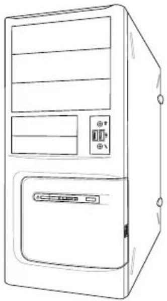
natural_image
Line drawing of a desktop computer tower case with ventilation slots and drive buttons (no text or symbols)PC chassis
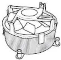
natural_image
Technical line drawing of a mechanical component with no visible text or symbolsIntel ^® LGA 2066 compatible CPU Fan
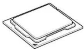
natural_image
Simple line drawing of a layered electronic component or chip (no text or symbols)Intel® LGA 2066 CPU
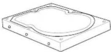
natural_image
Isometric line drawing of a rectangular electronic device with a circular cutout on top (no text or symbols)SATA hard disk drive
natural_image
Line drawing of a screwdriver with a flat blade and handle (no text or symbols)Phillips (cross) screwdriver
natural_image
Simple line drawing of a box with two outlets (no text or symbols)Power supply unit
1 bag of screws
natural_image
Diagram of a 12-pin RAM module with no text or symbols on its body, labeled 'DIMM' below (no other text or symbols)DIMM
natural_image
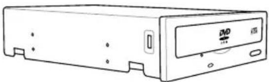
Line drawing of a CD-ROM drive (no text or symbols visible)SATA optical disc drive (optional)
natural_image
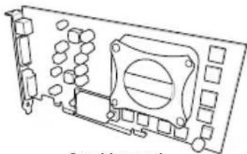
Technical line drawing of a mechanical component with no visible text or symbolsGraphics card

M.2 SSD module (optional)

The tools and components in the table above are not included in the motherboard package.
Product Introduction
1.1 Motherboard overview
1.1.1 Before you proceed
Take note of the following precautions before you install motherboard components or change any motherboard settings.

- Unplug the power cord from the wall socket before touching any component.
- Before handling components, use a grounded wrist strap or touch a safely grounded object or a metal object, such as the power supply case, to avoid damaging them due to static electricity.
- Hold components by the edges to avoid touching the ICs on them.
- Whenever you uninstall any component, place it on a grounded antistatic pad or in the bag that came with the component.
- Before you install or remove any component, ensure that the ATX power supply is switched off or the power cord is detached from the power supply. Failure to do so may cause severe damage to the motherboard, peripherals, or components.
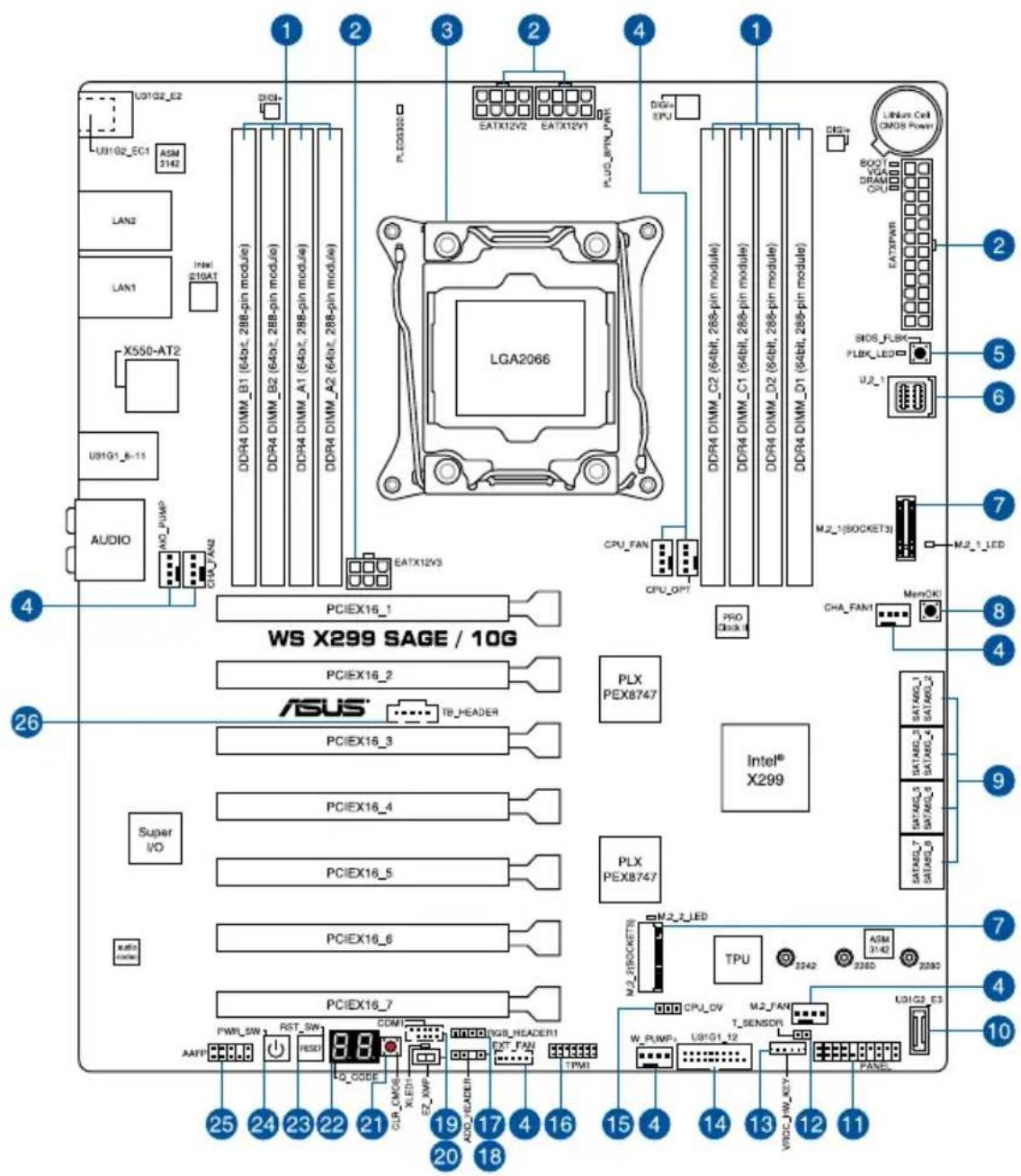
1.1.2 Motherboard layout
text_image
U8102_E2 U8102_EC1 ASM LAN2 LAN1 Intel E10AT X550-AT2 U81G1_B-11 AUDIO AND_PUMP CHU_TAN2 PCIEX16_1 WS X299 SAGE / 10G PCIEX16_2 ASUS® TB_HEADER PCIEX16_3 Super I/O PCIEX16_4 PCIEX16_5 PCIEX16_6 PCIEX16_7 AATT 25 24 23 22 21 20 18 COM1 Q_CODE CJB CMOS XLED1 Z2_NWP ADD_HEADER EST_FAN TPM1 PLDX300 EATX12V2 EATX12V1 PUD_BPM_PWR LGA2066 CPU_FAN CPU_OPT PRO Block CPU_OPT DDR4 DIMM_C2 (64bit, 288-pin module) DDR4 DIMM_C1 (64bit, 288-pin module) DDR4 DIMM_D2 (64bit, 288-pin module) DDR4 DIMM_D1 (64bit, 288-pin module) DDR4 DIMM_C3 (64bit, 288-pin module) DDR4 DIMM_C2 (64bit, 288-pin module) DDR4 DIMM_C1 (64bit, 288-pin module) DDR4 DIMM_C2 (64bit, 288-pin module) DDR4 DIMM_C3 (64bit, 288-pin module) DDR4 DIMM_C2 (64bit, 288-pin module) DDR4 DIMM_C3 (64bit, 288-pin module) DDR4 DIMM_C3 (64bit, 288-pin module) DDR4 DIMM_C3 (64bit, 288-pin module) DDR4 DIMM_C3 (64bit, 288-pin module) DDR4 DIMM_C3 (64bit, 288-pin module) DDR4 DIMM_C3 (64bit, 288 pin module) DDR4 DIMM_C3 (64bit, 288 pin module) DDR4 DIMM_C3 (64bit, 288 pin module) DDR4 DIMM_C3 (64bit, 288 pin module) DDR4 DIMM_C3 (64bit, 288 pin module) DDR4 DIMM_C3 (64bit, 288 pin module) DDR4 DIMM_C3 (SATEX00000000000000000000000000000000000000000000000000000000000000000000000000000000000000 LEDbus Cell (OMOS Power) BOOT VGG DRAM CPU EATX/PWR BODO SIDS_FLBK FLBK_LED U2_1 M.2_1(SOCKET3) M.2_1_LED CHA_FAN1 MemOKI Intel® X299 TPU CPU_OV W_PUMP: U31G1_12 M.2_FAN T_SENSDIN VDDC_HW_KEY FANGC
Refer to 1.1.9 Internal connectors and 2.3.1 Rear I/O connection for more information about rear panel connectors and internal connectors.
Layout contents
| Connectors/Jumpers/Buttons and switches/Slots Page | |
| 1. DDR4 DIMM slots 1-5 | |
| 2. ATX power connectors (24-pin EATXPWR; 8-pin EATX12V1-2; 6-pin EATX12V3) | 1-19 |
| 3. LGA2066 CPU socket 1-4 | |
| 4. Fan and pump connectors (4-pin CPU_FAN; 4-pin CPU_OPT; 4-pin AIO_PUMP; 4-pin W_PUMP+; 4-pin M.2_FAN; 5-pin EXT_FAN; 4-pin CHA_FAN1-2) | 1-18 |
| 5. BIOS Flashback button 2-13 | |
| 6. U.2 connector (U.2_1) 1-21 | |
| 7. M.2 sockets (M.2_1(Socket 3); M.2_2(Socket 3)) 1-22 | |
| 8. MemOK! button 1-10 | |
| 9. Intel ^ Serial ATA 6 Gb/s connectors (7-pin SATA6G_12; SATA 6G_34; SATA 6G_56; SATA 6G_78) | 1-15 |
| 10. USB 3.1 Gen 2 front panel connector (U31G2_E3) 1-16 | |
| 11. System panel connector (20-3 pin PANEL) 1-20 | |
| 12. Thermal sensor connector (2-pin T_SENSOR) 1-23 | |
| 13. VROC_HW_KEY connector (4-pin VROC_HW_KEY) 1-26 | |
| 14. USB 3.1 Gen 1 connectors (20-1 pin U31G1_12) 1-17 | |
| 15. CPU Over Voltage jumper (3-pin CPU_OV) 1-12 | |
| 16. TPM connector (14-1 pin TPM1) 1-26 | |
| 17. RGB header (4-pin RGB_HEADER1) 1-24 | |
| 18. Addressable RGB header (4-pin ADD_HEADER) | 1-25 |
| 19. Serial port connector (10-1 pin COM1) | 1-23 |
| 20. EZ XMP switch | 1-11 |
| 21. Clear CMOS button (CLR_CMOS) | 1-11 |
| 22. Q-Code LEDs | 1-14 |
| 23. Reset button | 1-9 |
| 24. Power-on button | 1-9 |
| 25. Front panel audio connector (10-1 pin AAFP) | 1-16 |
| 26. Thunderbolt header (5-pin TB_HEADER) | 1-21 |
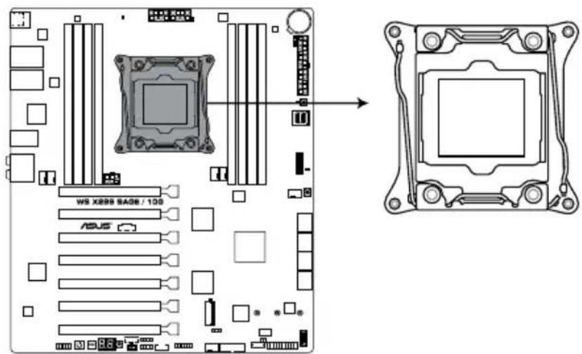
1.1.3 Central Processing Unit (CPU)
The motherboard comes with a surface mount LGA2066 socket designed for the Intel® Core™ X-series Processors.
text_image
WS X888 SAGE / 100 ASUSWS X299 SAGE/10G LGA2066 Socket

- Ensure that you install the correct CPU designed for LGA2066 socket only. DO NOT install a CPU designed for other sockets on the LGA2066 socket.
- Ensure that all power cables are unplugged before installing the CPU.
- Upon purchase of the motherboard, ensure that the PnP cap is on the socket and the socket contacts are not bent. Contact your retailer immediately if the PnP cap is missing, or if you see any damage to the PnP cap/socket contacts/motherboard components. ASUS will shoulder the cost of repair only if the damage is shipment/transit-related.
- Keep the cap after installing the motherboard. ASUS will process Return Merchandise Authorization (RMA) requests only if the motherboard comes with the cap on the LGA2066 socket.
- The product warranty does not cover damage to the socket contacts resulting from incorrect CPU installation/removal, or misplacement/loss/incorrect removal of the PnP cap.
1.1.4 System memory
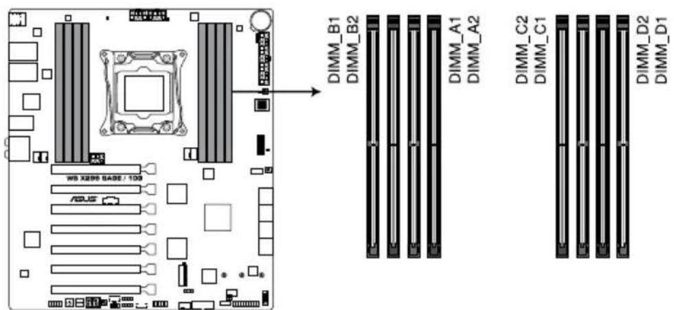
The motherboard comes with eight DDR4 (Double Data Rate 4) Dual Inline Memory Modules (DIMM) slots.

A DDR4 module is notched differently from a DDR, DDR2, or DDR3 module. DO NOT install a DDR, DDR2, or DDR3 memory module to the DDR4 slot.
text_image
DIMM_B1 DIMM_B2 DIMM_A1 DIMM_A2 DIMM_C2 DIMM_C1 DIMM_D2 DIMM_D1 WB XB98 BASE / 100 ADJ5WS X299 SAGE/10G 288-pin DDR4 DIMM socket
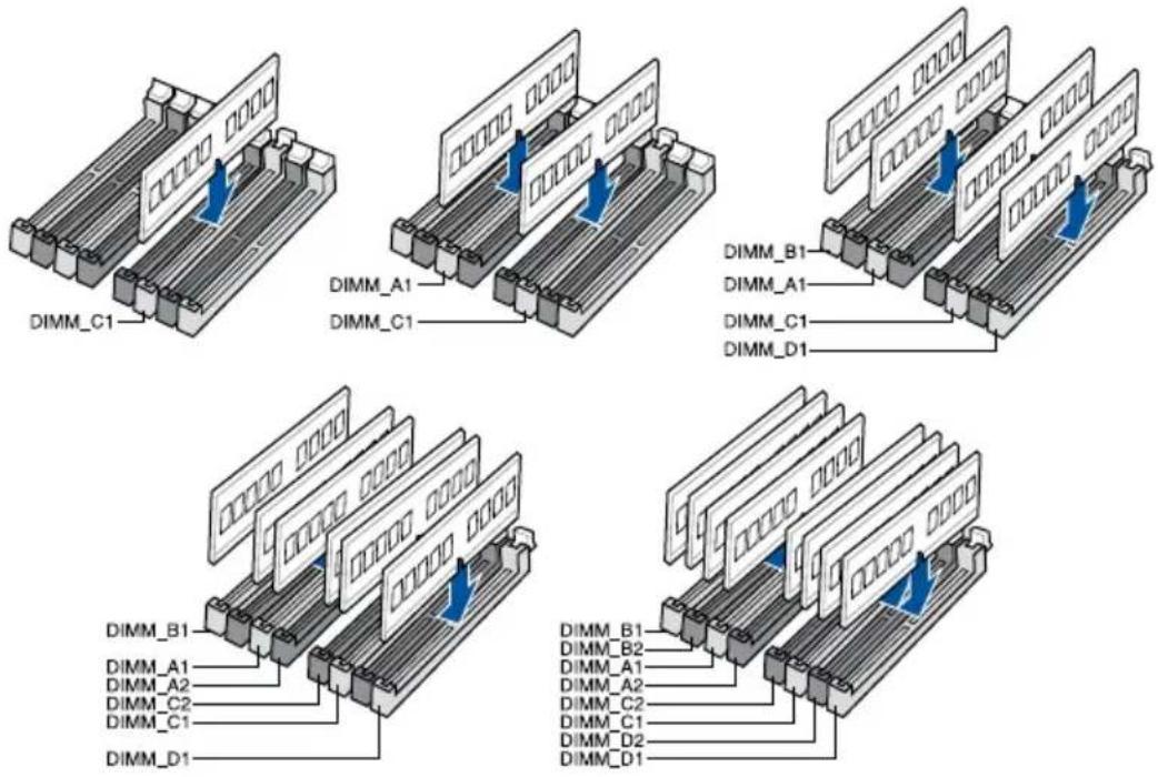
Recommended memory configurations
Intel ^® Core ^TM X-series Processors (6-core or above)
text_image
DIMM_C1 DIMM_A1 DIMM_C1 DIMM_B1 DIMM_A1 DIMM_C1 DIMM_D1 DIMM_B1 DIMM_A1 DIMM_C2 DIMM_C1 DIMM_D1 DIMM_B2 DIMM_A1 DIMM_C2 DIMM_C1 DIMM_D2 DIMM_D1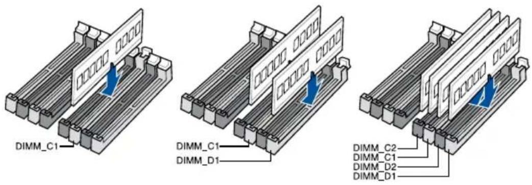
text_image
DIMM_C1 DIMM_C1 DIMM_D1 DIMM_C2 DIMM_C1 DIMM_D2 DIMM_D1Memory configurations
You may install 2 GB, 4 GB, 8 GB and 16 GB unbuffered and non-ECC DDR4 DIMMs into the DIMM sockets.

- For Inte ^ Core ^TM X-Series Processors (4-core), you may install varying memory sizes in Channel C and Channel D. The system maps the total size of the lower-sized channel for the dual-channel configuration. Any excess memory from the higher-sized channel is then mapped for single-channel operation.
- For Intel ^ Core ^TM X-Series Processors (6-core or above), you may install varying memory sizes in Channel A, Channel B, Channel C, and Channel D. The system maps the total size of the lower-sized channel for the quad-channel configuration. Any excess memory from the higher-sized channel is then mapped for single-channel operation.

- The default memory operation frequency is dependent on its Serial Presence Detect (SPD), which is the standard way of accessing information from a memory module. Under the default state, some memory modules for overclocking may operate at a lower frequency than the vendor-marked value.
- For system stability, use a more efficient memory cooling system to support a full memory load (8 DIMMs) or overclocking condition.
- Always install the DIMMS with the same CAS Latency. For an optimum compatibility, we recommend that you install memory modules of the same version or data code (D/C) from the same vendor. Check with the vendor to get the correct memory modules.
- Visit the ASUS website for the latest QVL.
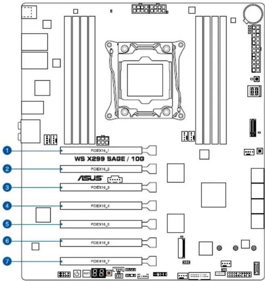
1.1.5 Expansion slots

Unplug the power cord before adding or removing expansion cards. Failure to do so may cause you physical injury and damage motherboard components.
text_image
1 PCIEX16_1 WS X299 SAGE / 10G 2 PCIEX16_2 ASUS 3 PCIEX16_3 4 PCIEX16_4 5 PCIEX16_5 6 PCIEX16_6 7 PCIEX16_7| Slot No. Slot Description |
| 1PCIE 3.0/2.0 x16_1 slot |
| 2PCIE 3.0/2.0 x16_2 slot (x0/x8 mode) |
| 3PCIE 3.0/2.0 x16_3 slot (x16/x8 mode) |
| 4PCIE 3.0/2.0 x16_4 slot (x0/x8 mode) |
| 5PCIE 3.0/2.0 x16_5 slot (x16/x8 mode) |
| 6 PCIE 3.0/2.0 x16_6 slot (x0/x8 mode) |
| 7PCIE 3.0/2.0 x16_7 slot (x16/x8 mode) |
| PCI Express 3.0 operating mode | |||||||
| VGA configuration | PCIe 3.0/2.0 x16_1 | PCIe 3.0/2.0 x16_2 | PCIe 3.0/2.0 x16_3 | PCIe 3.0/2.0 x16_4 | PCIe 3.0/2.0 x16_5 | PCIe 3.0/2.0 x16_6 | PCIe 3.0/2.0 x16_7 |
| Single VGA/ PCIe card | x16 (single VGA recommended) | N/A N/A N/A N/A N/A N/A | |||||
| Dual VGA/PCIe cards | x16 N/A x16 N/A N/A N/A N/A | ||||||
| x16 N/A N/A N/A x16 N/A N/A | |||||||
| Triple VGA/ PCIe cards | x16 N/A x16 N/A x16 N/A N/A | ||||||
| Quad VGA/ PCIe cards | x16 N/A x16 N/A x16 N/A x16 | ||||||
| Septuple VGA/ PCIe cards | x16 x8 x8 x8 x8 x8 | ||||||

- We recommend that you provide sufficient power when running CrossFireX™ or SLI® mode.
- Connect a chassis fan to the motherboard connector labeled CHA_FAN1-2 when using multiple graphics cards for better thermal environment.
- We recommend that install the graphics cards into the PCIe 3.0/2.0 x16_1 and PCIe 3.0/2.0 x16_3 slots when running 2-Way SLITM bridge.
1.1.6 Onboard buttons and switches
Onboard buttons and switches allow you to fine-tune performance when working on a bare or open-case system. This is ideal for overclockers and gamers who continually change settings to enhance system performance.
1. Power-on button
The motherboard comes with a power-on button that allows you to power up or wake up the system. The button also lights up when the system is plugged to a power source indicating that you should shut down the system and unplug the power cable before removing or installing any motherboard component.
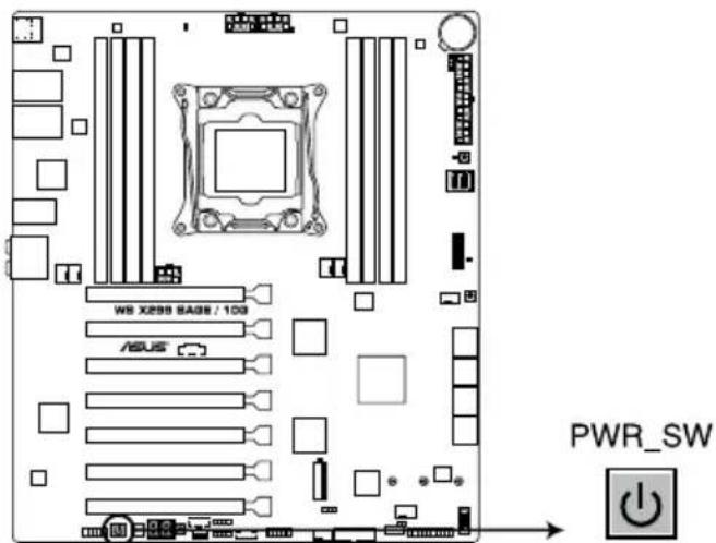
text_image
WS X298 SAG8 / 10G ASUS PWR_SWWS X299 SAGE/10G Power on button
2. Reset button
Press the reset button to reboot the system.
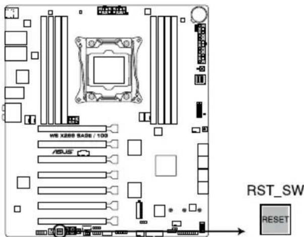
text_image
WBS X288 BASE / 100 ASUS RST_SW RESETWS X299 SAGE/10G Reset button
3. MemOK! button
Installing DIMMs that are not compatible with the motherboard may cause system boot failure. If the system fails to boot during POST stage and the DRAM_LED near the MemOK! button lights continuously, press the MemOK! button until the DRAM_LED starts blinking. System will begin automatic memory compatibility tuning and reboot for successful boot.
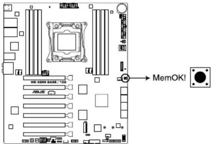
text_image
W8 X888 SAGE / 108 ASUS MemOK!WS X299 SAGE/10G MemOK! button

• Refer to section 1.1.8 Onboard LEDs for the exact location of the DRAM_LED.
- The DRAM_LED also lights up when the DIMM is not properly installed. Turn off the system and reinstall the DIMM before using the MemOK! function.
- The MemOK! button does not function under Windows ® OS environment.
- During the tuning process, the system loads and tests failsafe memory settings. It takes about 30 seconds for the system to test one set of failsafe settings. If the test fails, the system reboots and tests the next set of failsafe settings. The blinking speed of the DRAM_LED increases, indicating different test processes.
- Due to memory tuning requirement, the system automatically reboots when each timing set is tested. If the installed DIMMs still fail to boot after the whole tuning process, the DRAM_LED lights continuously. Replace the DIMMs with ones recommended in the Memory QVL (Qualified Vendors Lists) at www.asus.com.
- If you turn off the computer and replace DIMMs during the tuning process, the system continues memory tuning after turning on the computer. To stop memory tuning, turn off the computer and unplug the power cord for about 5–10 seconds.
- If your system fails to boot up due to BIOS overclocking, press the MemOK! button to boot and load the BIOS default settings. A message will appear during POST reminding you that the BIOS has been restored to its default settings.
• We recommend that you download and update to the latest BIOS version from www.asus.com after using the MemOK! function.
4. Clear CMOS button (CLR\_CMOS)
Press this button to clear the BIOS setup information only when the systems hangs due to overclocking.
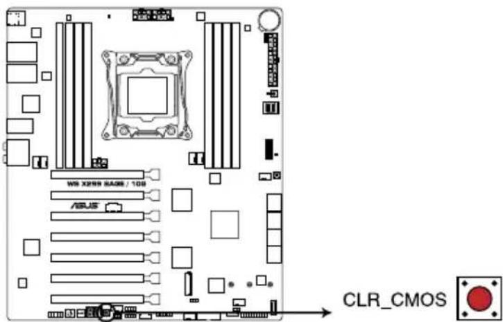
text_image
W8 X2594 RAGS / 108 ASUS CLR CMOSWS X299 SAGE/10G Clear CMOS button
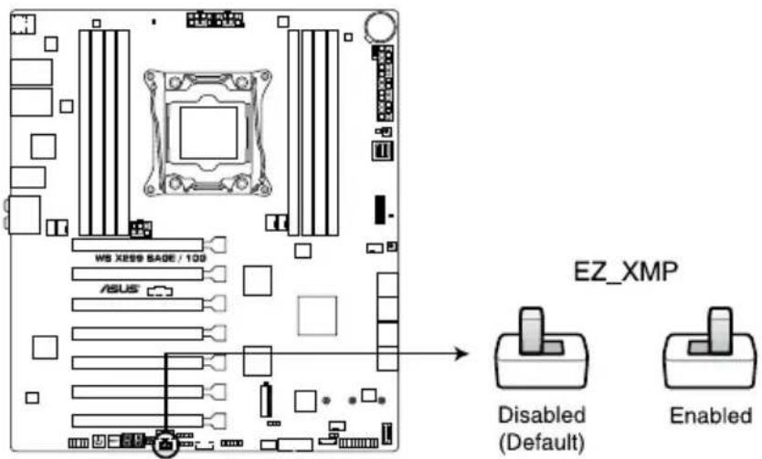
5. EZ XMP switch
Enable this switch to overclock the installed DIMMs, allowing you to enhance the DIMM's speed and performance.
text_image
WS X899 BAGE / 100 ASUS EZ_XMP Disabled (Default) EnabledWS X299 SAGE/10G EZ_XMP switch
1.1.7 Jumpers
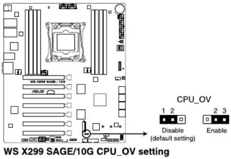
1. CPU Over Voltage jumper (3-pin CPU\_OV)
The CPU Over Voltage jumper allows you to set a higher CPU voltage for a flexible overclocking system, depending on the type of the installed CPU. To gain more CPU voltage setting, insert the jumper to pins 2-3. To go back to its default CPU voltage setting, insert the jumper to pins 1-2.
text_image
WS X299 SAGE / 10G ASUS CPU_OV 1 2 Disable (default setting) 2 3 Enable WS X299 SAGE / 10G CPU_OV setting1.1.8 Onboard LEDs
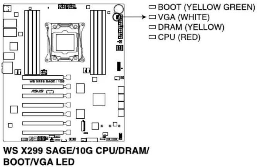
1. POST State LEDs
The POST State LEDs provide the status of these key components during POST (Power-On Self-Test): CPU, memory modules, VGA card, and hard disk drives. If an error is found, the critical component's LED stays lit up until the problem is solved.
text_image
BOOT (YELLOW GREEN) VGA (WHITE) DRAM (YELLOW) CPU (RED) WS X888 SAGE / 10G ASUS WS X299 SAGE/10G CPU/DRAM/ BOOT/VGA LED
The POST State LEDs provide the most probable cause of an error code as a starting point for troubleshooting. The actual cause may vary from case to case.
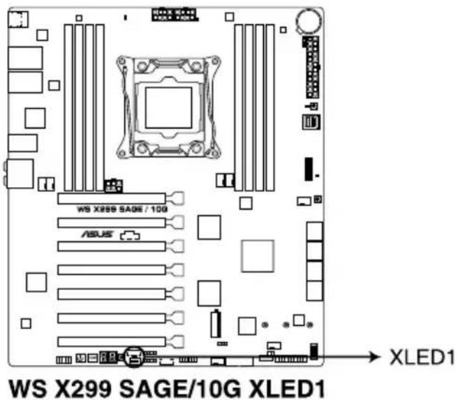
2. EZ XMP LED (XLED1)
This LED lights up when you enable the EZ XMP switch.
text_image
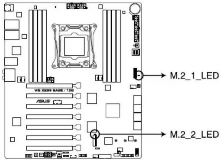
WS X299 SAGE/10G XLED1 XLED13. M.2 LEDs (M.2\_1\_LED; M.2\_2\_LED)
The M.2 LED near the M.2 socket will light up when an SATA SSD device is detected.
text_image
M.2_1_LED WS XE99 BASE / 100 ASUS M.2_2_LEDWS X299 SAGE/10G M.2 LEDs

This motherboard supports PCIE SSD devices only.
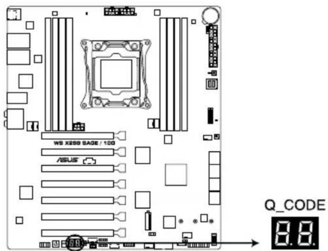
4. Q-Code LEDs
The Q-Code LED design provides you with a 2-digit error code that displays the system status. Refer to the Q-Code table on the next page for details.
text_image
WS X899 SAGE / 100 ASUS Q_CODE 8.8.WS X299 SAGE/10G Q-Code LED

- The Q-Code LEDs provide the most probable cause of an error code as a starting point for troubleshooting. The actual cause may vary from case to case.
- Please refer to the Q-Code table in the Appendix section for more details.
1.1.9 Internal connectors
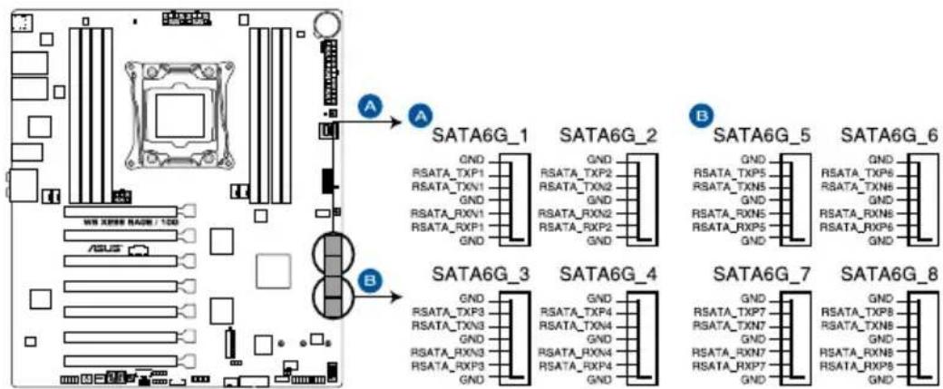
- Intel ^ Serial ATA 6 Gb/s connectors (7-pin SATA6G_12; SATA 6G_34; SATA 6G_56; SATA 6G_78)
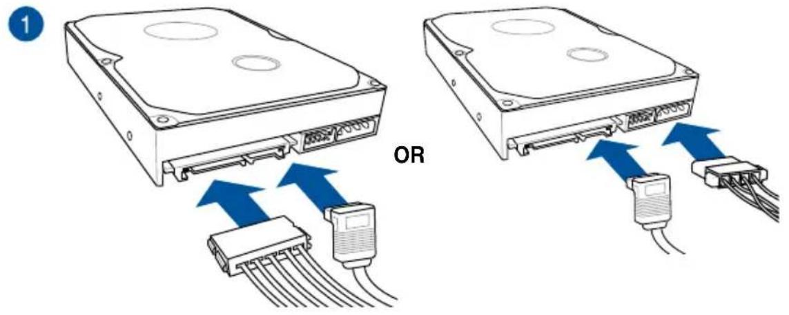
These connectors connect to Serial ATA 6 Gb/s hard disk drives via Serial ATA 6 Gb/s signal cables.
If you installed Serial ATA hard disk drives, you can create a RAID 0, 1, 5, and 10 configuration with the Intel® Rapid Storage Technology through the onboard Intel® X299 chipset.
flowchart
graph TD
    A["CPU"] --> B["MC"]
    B --> C["SATA6G_1"]
    B --> D["SATA6G_2"]
    B --> E["SATA6G_3"]
    B --> F["SATA6G_4"]
    B --> G["SATA6G_5"]
    B --> H["SATA6G_6"]
    B --> I["SATA6G_7"]
    B --> J["SATA6G_8"]

    subgraph SATA6G_1
        K["CS102020000000000000000000000000000000000000000000000000000000000000000000000000000000000000000000000000000"]
    end

    subgraph SATA6G_2
        L["CS1021222222222222222222222222222222222222222222222222222222222222222222222222222222222222222222222222<br>    "]
    end

    subgraph SATA6G_3
        M["CS111111111111111111111111111111111111111111111111111111111111111111111111111111111111111<br>    "]
    end

    subgraph SATA6G_4
        N["CS13333333333333333333333333333333333333333333333333333333333333333333333333333333333333333333333333333<br>    "]
    end

    subgraph SATA6G_5
        O["CS15555555555555555555555555555555555555555555555555555555555555555555555555555555"]
        P["CS177777777777777777777777777777777777777777777777777777777777777777777777"]
    end

    subgraph SATA6G_6
        Q["CS19999999999999999999999999999999999999999999999999999999999999999999999999999999999999999999999999999<br>    "]
    end

    subgraph SATA6G_7
        R["CS2444444444444444444444444444444444444444444444444444444444444444444444<br>    "]
    end

    subgraph SATA6G_8
        S["CS288888888888888888888888888888888888888888888888888888888888888888888888888888888888<br>    "]
    end
WS X299 SAGE/10G Intel® Serial ATA 6 Gb/s connectors
text_image
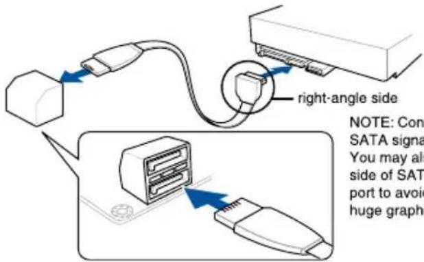
right-angle side NOTE: Con SATA signa You may als side of SAT port to avoid huge graphNOTE: Connect the right-angle side of SATA signal cable to SATA device. You may also connect the right-angle side of SATA cable to the onboard SATA port to avoid mechanical conflict with huge graphics cards.

These connectors are set to [AHCI Mode] by default. If you intend to create a Serial ATA RAID set using these connectors, set the SATA Mode item in the BIOS to [Intel RST Premium (RAID)].
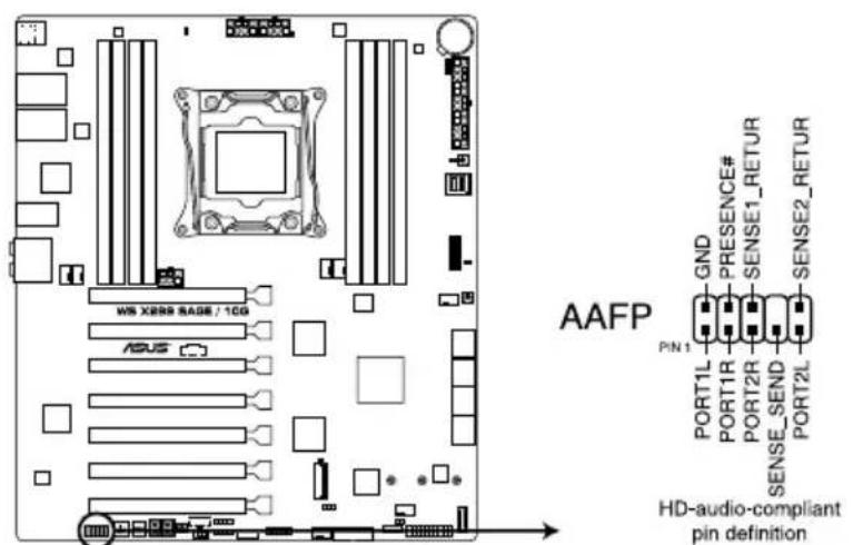
2. Front panel audio connector (10-1 pin AAFP)
This connector is for a chassis-mounted front panel audio I/O module that supports HD Audio. Connect one end of the front panel audio I/O module cable to this connector.
text_image
MS X888 RAGE / 1CG ASUS AAFP GND PRESENCE# SENSE1_RETUR P/N 1L PORT1R PORT2R SENSE_SEND PORT2L HD-audio-compliant pin definitionWS X299 SAGE/10G Front panel audio connector

We recommend that you connect a high-definition front panel audio module to this connector to avail of the motherboard's high-definition audio capability.
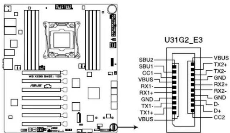
3. USB 3.1 Gen 2 front panel connector (U31G2\_E3)
This connector allows you to connect a USB 3.1 Gen 2 module for additional USB 3.1 Gen 2 ports. The latest USB 3.1 Gen 2 connectivity provides data transfer speeds of up to 10 Gbps.
text_image
U31G2_E3 SBU2 SBU1 CC1 VBUS RX1- RX1+ GND TX1- TX1+ VBUS VBUS TX2+ TX2- GND RX2+ RX2- GND D- D+ CC2WS X299 SAGE/10G USB 3.1 Gen 2 front panel connector
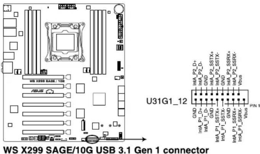
4. USB 3.1 Gen 1 connectors (20-1 pin U31G1\_12)
This connector allows you to connect a USB 3.1 Gen 1 module for additional USB 3.1 Gen 1 front or rear panel ports. With an installed USB 3.1 Gen 1 module, you can enjoy all the benefits of USB 3.1 Gen 1 including faster data transfer speeds of up to 5 Gb/s, faster charging time for USB-chargeable devices, optimized power efficiency, and backward compatibility with USB 2.0.
text_image
WS X299 SAGE/10G USB 3.1 Gen 1 connector U31G1_12 Pin 1 IntA_P2_D+ IntA_P2_D- GND IntA_P2_SSTX+ GND IntA_P2_SSTX- GND IntA_P2_SSRX+ Vbus GND IntA_P1_SSTX+ GND IntA_P1_SSTX- GND IntA_P1_SSRX+ Vbus P1N 1
The USB 3.1 Gen 1 module is purchased separately.

The plugged USB 3.1 Gen 1 device may run on xHCI or EHCI mode depending on the operating system's setting.
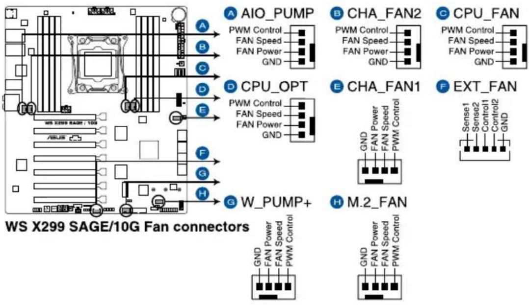
5. Fan and pump connectors (4-pin CPU\_FAN; 4-pin CPU\_OPT; 4-pin AIO\_PUMP; 4-pin W\_PUMP+; 4-pin M.2\_FAN; 5-pin EXT\_FAN; 4-pin CHA\_FAN1-2)
Connect the fan cables to the fan connectors on the motherboard, ensuring that the black wire of each cable matches the ground pin of the connector.
text_image
A AIO_PUMP PWM Control FAN Speed FAN Power GND B CHA_FAN2 PWM Control FAN Speed FAN Power GND C CPU_FAN PWM Control FAN Speed FAN Power GND D CPU_OPT PWM Control FAN Speed FAN Power GND E CHA_FAN1 GND FAN Power FAN Speed PWM Control F EXT_FAN Sense1 Sense2 Control12 GND F W_PUMP+ GND FAN Power FAN Speed PWM Control H M.2_FAN GND FAN Power FAN Speed PWM Control
- DO NOT forget to connect the fan cables to the fan connectors. Insufficient air flow inside the system may damage the motherboard components. These are not jumpers! Do not place jumper caps on the fan connectors!
- Ensure that the CPU fan cable is securely installed to the CPU fan connector.

- The CPU_FAN connector supports the CPU fan of maximum 1A (12 W) fan power.
- W_PUMP+ function support depends on water cooling device.
- Connect the fan of your water cooling kit to the AIO_PUMP connector.
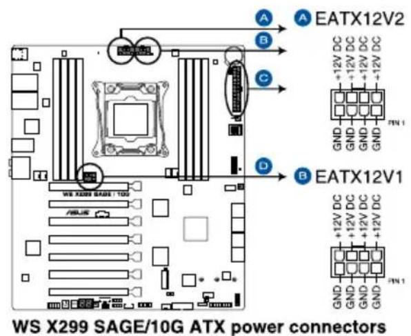
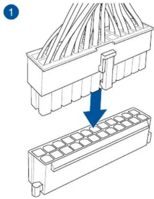
6. ATX power connectors (24-pin EATXPWR; 8-pin EATX12V1-2; 6-pin EATX12V3)
These connectors are for ATX power supply plugs. The power supply plugs are designed to fit these connectors in only one orientation. Find the proper orientation and push down firmly until the connectors completely fit.
text_image
A EATX12V2 B C D EATX12V1 WS X299 SAGE/10G ATX power connectors +12V DC +12V DC +12V DC +12V DC +12V DC +12V DC +12V DC +12V DC +12V DC +12V DC +12V DC +12V DC +12V DC +12V DC +12V DC +12V DC +12V DC +11V DC +11V DC +11V DC +11V DC +11V DC +11V DC +11V DC +11V DC +11V DC +11V DC +11V DC +11V DC +11V DC +11V DC +11V DC +11V DC +11V DC + - - - - - - - - - - - - - - - - - - - - - - - - - - - - - - - - - - - - - - - - - - - - - - - - - - - - - - - - - - - - - - - - - - - - - - - - - - - - - - - - -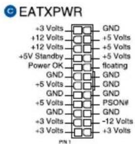
text_image
EATXPWR +3 Volts GND +12 Volts +5 Volts +12 Volts +5 Volts +5V Standby +5 Volts Power OK floating GND GND +5 Volts GND GND GND +5 Volts GND GND GND +3 Volts -12 Volts +3 Volts +3 Volts PN1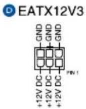

- DO NOT connect the 6-pin power plug only, the motherboard may overheat under heavy usage.
- Ensure to connect the 8-pin power plug, or connect both the 8-pin and 6-pin power plugs.

- For a fully configured system, we recommend that you use a power supply unit (PSU) that complies with ATX 12V Specification 2.0 (or later version) and provides a minimum power of 350 W.
- We recommend that you use a PSU with a higher power output when configuring a system with more power-consuming devices. The system may become unstable or may not boot up if the power is inadequate.
- If you want to use two or more high-end PCI Express x16 cards, use a PSU with 1000W power or above to ensure the system stability.
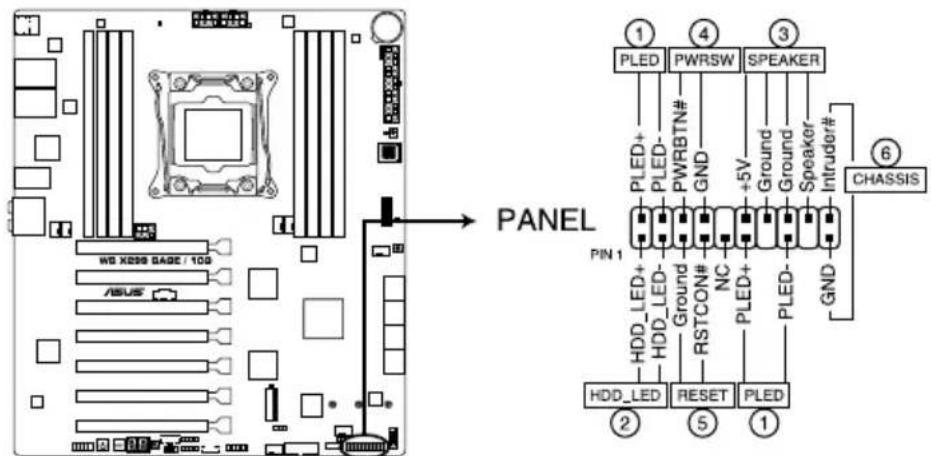
7. System panel connector (20-3 pin PANEL)
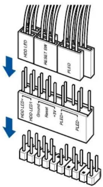
This connector supports several chassis-mounted functions.
text_image
WD X298 GASE / 10G ASUS PANEL ① PLED ④ PWRSW ③ SPEAKER PLED+ PLED- PWRBTN# GND +5V Ground Speaker Intruder# ⑥ CHASSIS PIN 1 HDD_LED+ HDD_LED- Ground RSTCON# NC PLED+ PLED- GND ② HDD_LED RESET PLED ⑤ ①WS X299 SAGE/10G System panel connector
• System power LED (2-pin or 3-1 pin PLED)
The 2-pin or 3-1 pin connector is for the system power LED. Connect the chassis power LED cable to this connector. The system power LED lights up when you turn on the system power, and blinks when the system is in sleep mode.
• Hard disk drive activity LED (2-pin HDD_LED)
This 2-pin connector is for the HDD Activity LED. Connect the HDD Activity LED cable to this connector. The HDD LED lights up or flashes when data is read from or written to the HDD.
• System warning speaker (4-pin SPEAKER)
This 4-pin connector is for the chassis-mounted system warning speaker. The speaker allows you to hear system beeps and warnings.
• ATX power button/soft-off button (2-pin PWRSW)
This connector is for the system power button. Pressing the power button turns the system on or puts the system in sleep or soft-off mode depending on the operating system settings. Pressing the power switch for more than four seconds while the system is ON turns the system OFF.
- Reset button (2-pin RESET)
This 2-pin connector is for the chassis-mounted reset button for system reboot without turning off the system power.
• Chassis intrusion connector (2-pin CHASSIS)
This connector is for a chassis-mounted intrusion detection sensor or switch. Connect one end of the chassis intrusion sensor or switch cable to this connector. The chassis intrusion sensor or switch sends a high-level signal to this connector when a chassis component is removed or replaced. The signal is then generated as a chassis intrusion event.
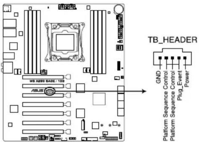
8. Thunderbolt header (5-pin TB\_HEADER)
This connector is for the add-on Thunderbolt I/O card that supports Intel's Thunderbolt Technology, allowing you to connect up to six Thunderbolt-enabled devices and a DisplayPort-enabled display in a daisy-chain configuration.
text_image
TB_HEADER GND Platform Sequence Control Platform Sequence Control Plug_Event PowerWS X299 SAGE/10G TB_HEADER connector
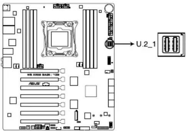
9. U.2 connector (U.2\_1)
This motherboard comes with an U.2 connector which supports PCIe 3.0 x4 NVM Express storage.
text_image
U.2_1 W8 X888 RAM / 10Ω ASUSWS X299 SAGE/10G U.2 connector

U.2 connector is only supported on 44-Lane CPUs.
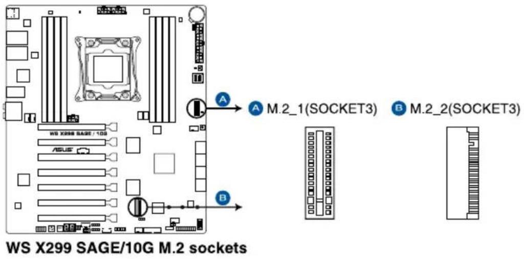
10. M.2 sockets (M.2\_1(Socket 3); M.2\_2(Socket 3))
These sockets allow you to install M.2 SSD modules.
text_image
WS X299 SAGE/10G M.2 sockets A M.2_1(SOCKET3) B M.2_2(SOCKET3) B
- M.2_1 socket supports PCIe 3.0 x4 mode M Key design and type 2242 / 2260/ 2280 / 22110 PCIe storage devices.
- M.2_2 socket supports PCIe 3.0 x4 mode M Key design and type 2242 / 2260 / 2280 PCIe storage devices.
- M.2_1 socket supports RSTe (Intel ® Rapid Storage Technology enterprise).
- M.2_2 socket supports IRST (Intel ® Rapid Storage Technology).
• M.2_1 socket is only supported on 44-Lane CPUs. - Due to hardware design, RAID Volume between M.2_1 and M.2_2 is not supported.

• The M.2 SSD module is purchased separately.
• This motherboard supports PCIE SSD devices only.
- The M.2 LED near the M.2 socket will light up when an SATA SSD device is detected. Refer to section 1.1.8 Onboard LEDs for the exact location of the M.2 LED.
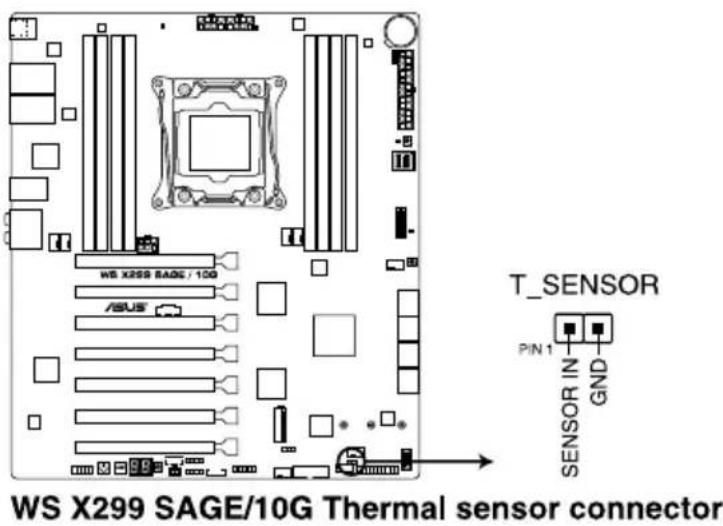
11. Thermal sensor connector (2-pin T\_SENSOR)
This connector is for the thermistor cable that monitors the temperature of the devices and the critical components inside the motherboard. Connect the thermistor cable and place the sensor on the device or the motherboard's component to detect its temperature.
text_image
WS X299 SAGE/10G Thermal sensor connector T_SENSOR PIN 1 SENSOR IN GND
The thermal sensor is purchased separately.
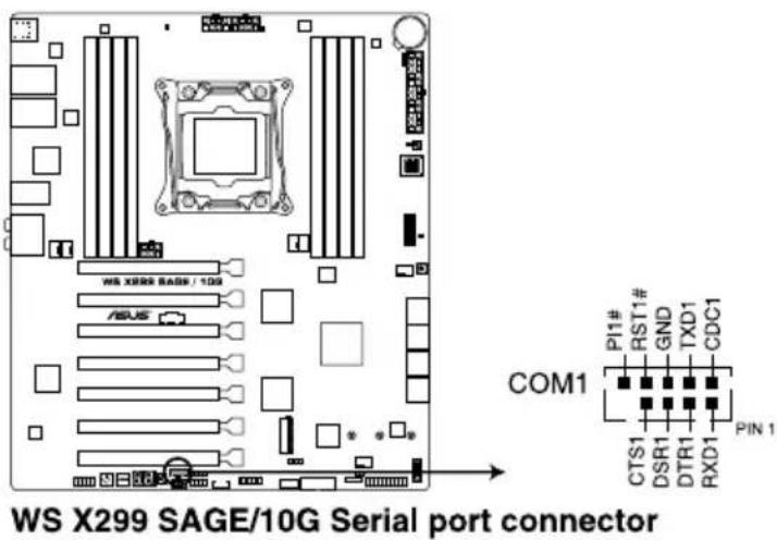
12. Serial port connector (10-1 pin COM1)
This connector is for a serial (COM) port. Connect the serial port module cable to this connector, then install the module to a slot opening at the back of the system chassis.
text_image
WS X299 SAGE/10G Serial port connector COM1 PI1# RST1# GND TXD1 CDC1 PTIN 1 CTS1 DSR1 DTR1 RXD113. RGB header (4-pin RGB\_HEADER1)
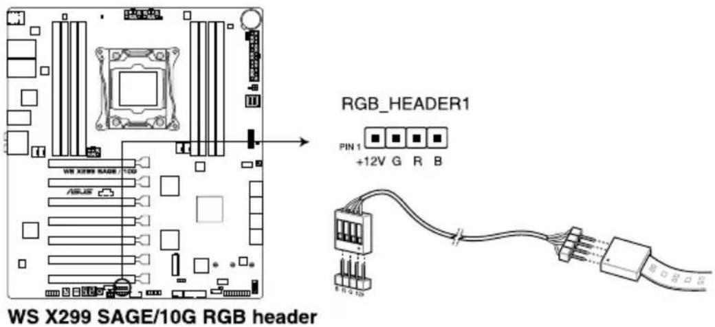
This connector is for RGB LED strips.
text_image
WS X299 SAGE/10G RGB header RGB_HEADER1 PIN 1 +12V G R B E N G 12G
The RGB header supports 5050 RGB multi-color LED strips (12V/G/R/B), with a maximum power rating of 2A (12V), and no longer than 2 m.

Before you install or remove any component, ensure that the ATX power supply is switched off or the power cord is detached from the power supply. Failure to do so may cause severe damage to the motherboard, peripherals, or components.

• Actual lighting and color will vary with LED strip.
- If your LED strip does not light up, check if the RGB LED extension cable and the RGB LED strip is connected in the correct orientation, and the 12V connector is aligned with the 12V header on the motherboard.
- The LED strip will only light up under the operating system.
• The LED strip is purchased separately.
14. Addressable RGB header (4-pin ADD\_HEADER)
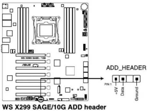
This connector is for individually addressable RGB WS2812B LED strips or WS2812B based LED strips.
text_image
WS X299 SAGE/10G ADD header ADD_HEADER PIN 1 +5V Data Ground
The addressable RGB header supports WS2812B addressable RGB LED strips (5V/Data/Ground), with a maximum power rating of 3A (5V) and a maximum of 60 LEDs.

Before you install or remove any component, ensure that the ATX power supply is switched off or the power cord is detached from the power supply. Failure to do so may cause severe damage to the motherboard, peripherals, or components.

• Actual lighting and color will vary with LED strip.
- If your LED strip does not light up, check if the addressable RGB LED strip is connected in the correct orientation, and the 5V connector is aligned with the 5V header on the motherboard.
- The addressable RGB LED strip will only light up under the operating system.
- The addressable RGB LED strip is purchased separately.
15. VROC\_HW\_KEY connector (4-pin VROC\_HW\_KEY)
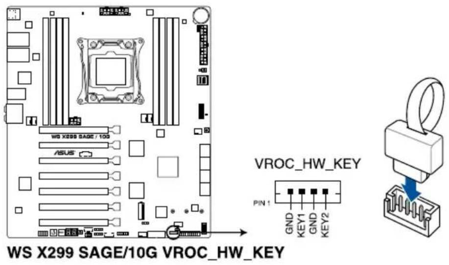
This connector allows you to connect a KEY module to enable additional CPU RAID functions with Intel® CPU RSTe.
text_image
WS X299 SAGE/10G VROC_HW_KEY VROC_HW_KEY PIN 1 GND KEY1 GND KEY2 WS X299 SAGE / 10G ASUS
• The KEY module is purchased separately.
- Due to CPU behavior, CPU RAID functions with Intel ^ CPU RSTe only supports Intel ^ Core ^TM X-series Processors (6-core or above) and Intel ^ SSD modules.
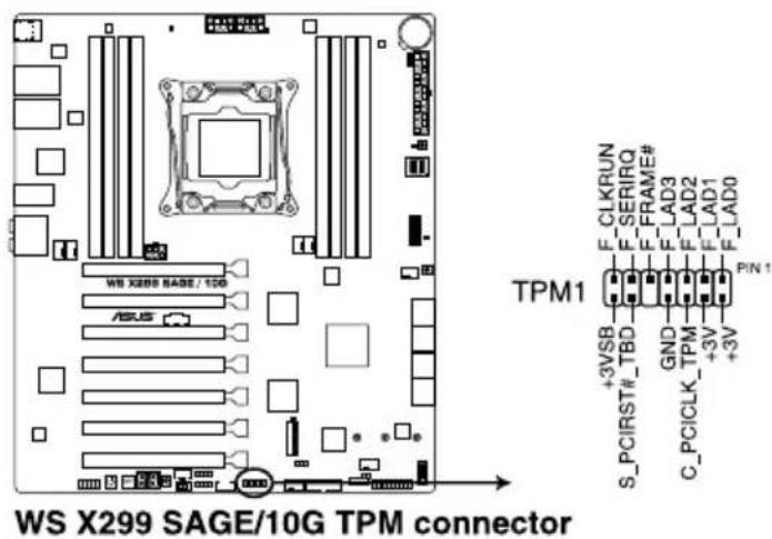
16. TPM connector (14-1 pin TPM1)
This connector supports a Trusted Platform Module (TPM) system, which securely store keys, digital certificates, passwords and data. A TPM system also helps enhance network security, protect digital identities, and ensures platform integrity.
text_image
WS X299 SAGE/10G TPM connector TPM1 F_CLKRUN F_SERIRQ F_FRAME# F_LAD3 F_LAD2 F_LAD1 F_LAD0 +3VSB S_PCIRST#_TBD GND C_PCICLK_TPM +3V +3V PIN 1
The TPM module is purchased separately.
Basic Installation
2.1 Building your PC system

The diagrams in this section are for reference only. The motherboard layout may vary with models, but the installation steps are the same for all models.
2.1.1 Motherboard installation
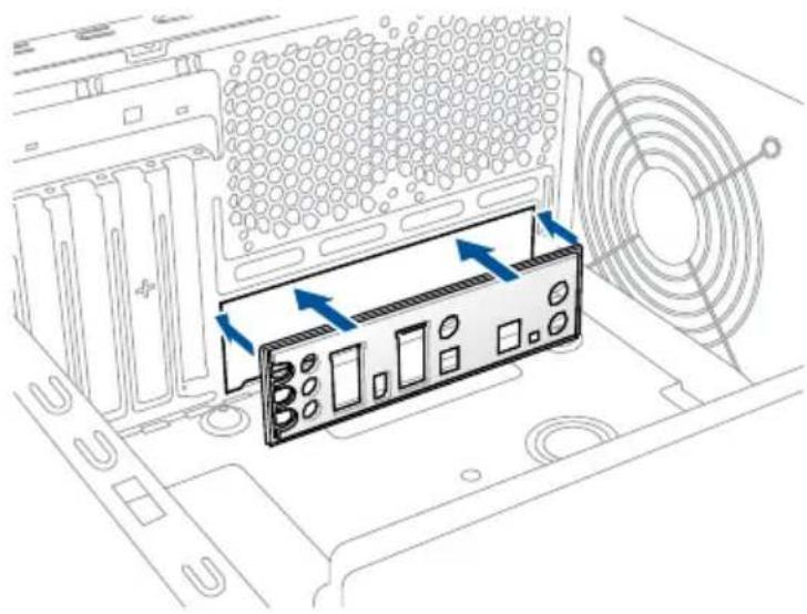
- Install the ASUS Q-Shield to the chassis rear I/O panel.
natural_image
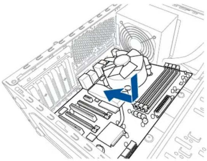
Diagram of a computer tower with an internal RAM module and fan array (no text or symbols)- Place the motherboard into the chassis, ensuring that its rear I/O ports are aligned to the chassis' rear I/O panel.
natural_image
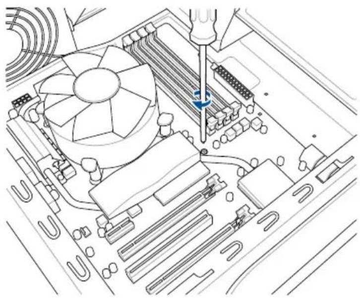
Diagram of a computer motherboard showing CPU socket, fan, and drive slots (no text or labels)- Place nine screws into the holes indicated by circles to secure the motherboard to the chassis.
natural_image
Technical line drawing of a computer motherboard with CPU socket and screwdriver (no text or symbols)
text_image
WS X299 SAGE / 100 ASUS
DO NOT overtighten the screws! Doing so can damage the motherboard.
2.1.2 CPU installation

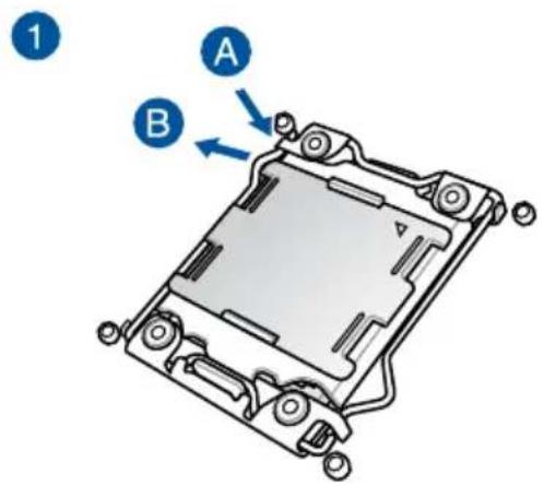
Please note the order in opening/closing the double latch. Follow the instructions printed on the metal sealing hatch or the illustrations shown below in this manual. The plastic cap will pop up automatically once the CPU is in place and the hatch properly sealed down.
text_image
1 A B
natural_image
Technical line drawing of a mechanical component with no visible text or symbols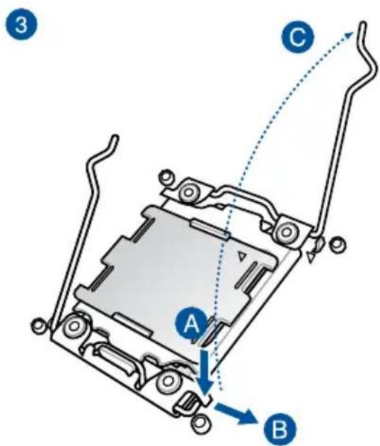
text_image
3 A B C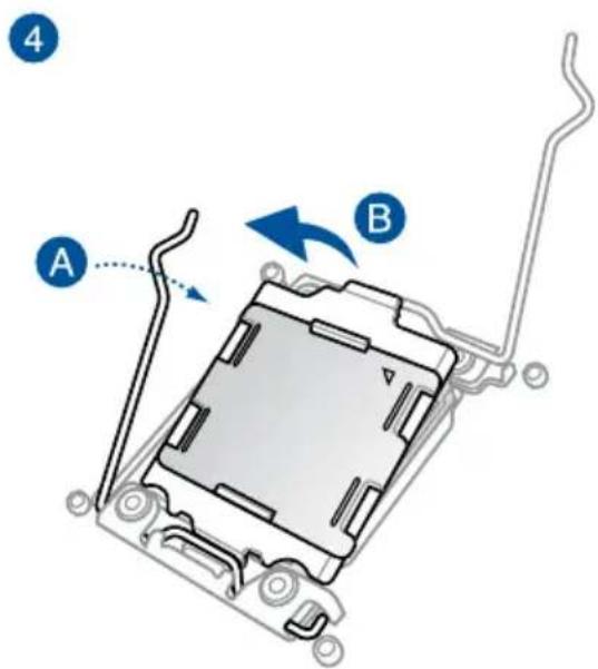
text_image
A B 4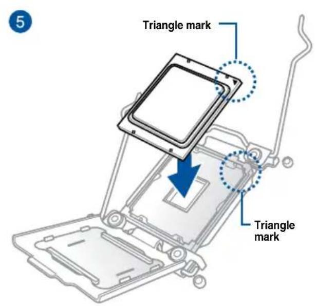
text_image
5 Triangle mark Triangle mark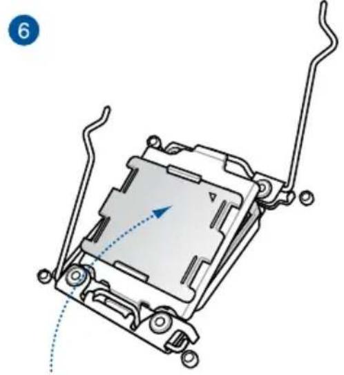
natural_image
Mechanical component diagram showing a housing with attached parts and a blue arrow indicating direction (no text or symbols)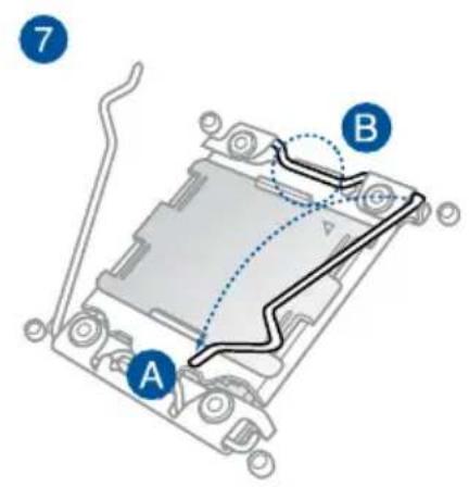
text_image
7 A B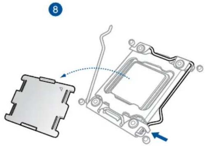
text_image
8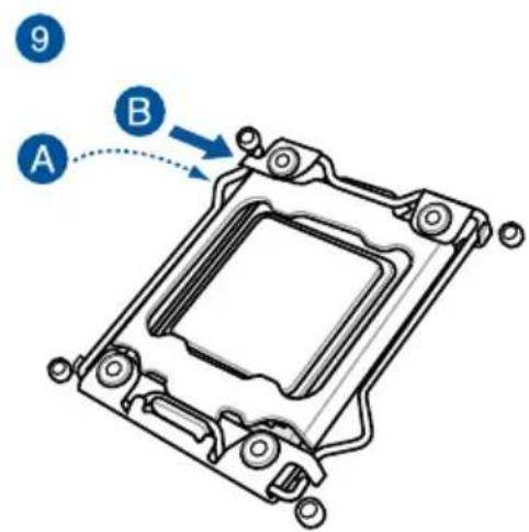
text_image
9 A B2.1.3 CPU heatsink and fan assembly installation
natural_image
Technical line drawing of a mechanical component with a spring and screw base (no text or symbols)
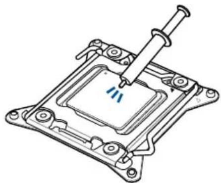
Apply the Thermal Interface Material to the CPU heatsink and CPU before you install the heatsink and fan, if necessary.
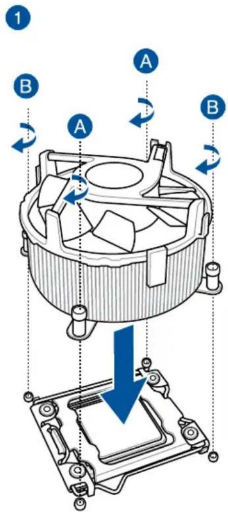
To install the CPU heatsink and fan assembly
text_image
1 B A A B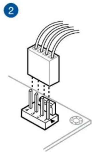
natural_image
Isometric diagram of a mechanical component with multiple wires and pins, mounted on a base plate (no text or symbols)2.1.4 DIMM installation
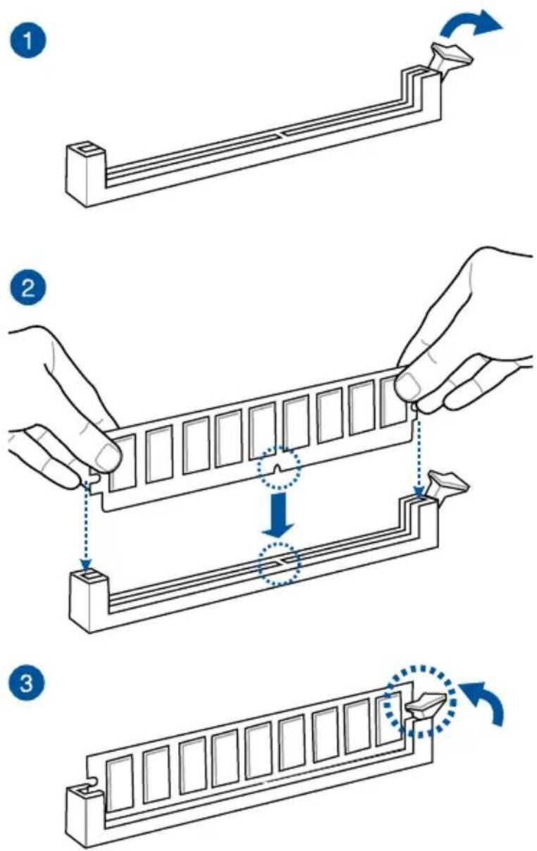
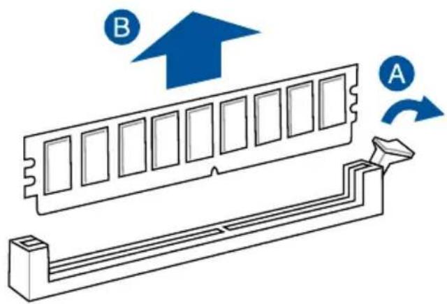
To remove a DIMM
natural_image
Diagram of a computer RAM module with labeled components A and B, showing internal structure and directional arrows (no text or symbols beyond labels)2.1.5 ATX power connection
natural_image
Diagram showing a mechanical assembly with two views of a connector, one being inserted into a grid and the other remaining in a housing (no text or symbols present)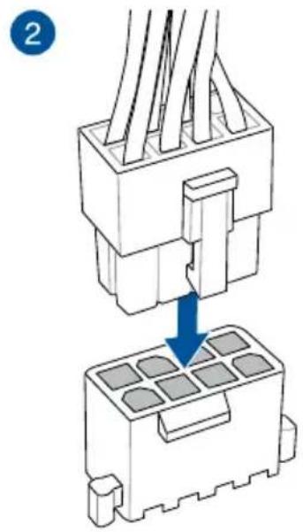
text_image
2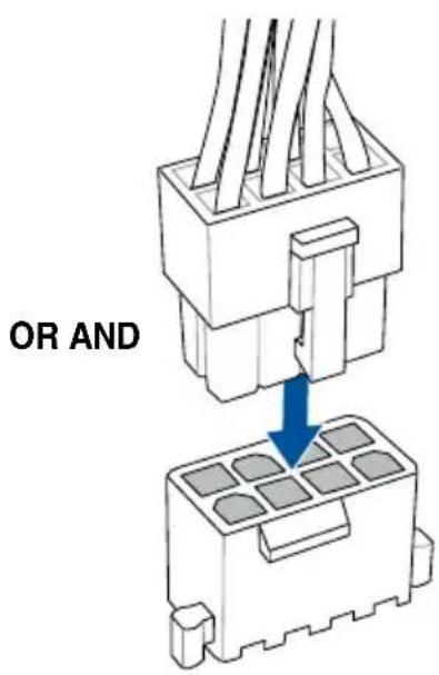
text_image
OR AND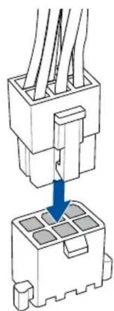
natural_image
Diagram of a connector assembly showing pin arrangement and a blue arrow indicating direction (no text or symbols)
- DO NOT connect the 6-pin power plug only, the motherboard may overheat under heavy usage.
- Ensure to connect the 8-pin power plug, or connect both the 8-pin and 6-pin power plugs.
2.1.6 SATA device connection
text_image
OR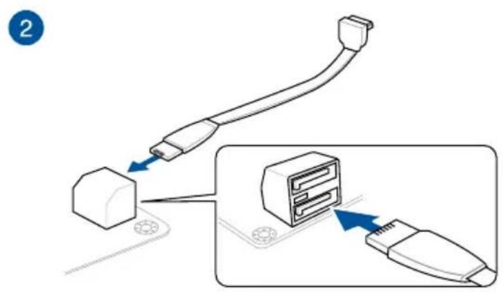
text_image
Diagram showing cable connection to a device with labeled components and directional arrows2.1.7 Front I/O connector
To install USB 3.1 Gen 2 connectorTo install ASU
text_image
HDD LED RESET SW PLED HDD LED+ HDD LED1 Ground Reset +3V PLED+ PLED-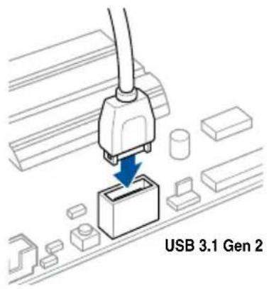
text_image
USB 3.1 Gen 2
This connector will only fit in one orientation. Push the connector until it clicks into place.
To install USB 3.1 Gen 1 connector
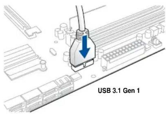
text_image
USB 3.1 Gen 1To install front panel audio connector
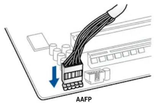
text_image
AAFP2.1.8 Expansion card installation
To install PCIe x16 cards
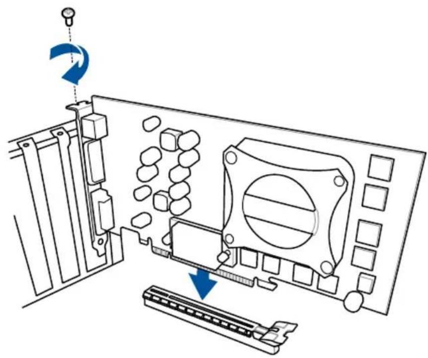
natural_image
Diagram of a computer monitor internal structure showing ports, panels, and a scroll (no text or labels)2.1.9 M.2 installation
1
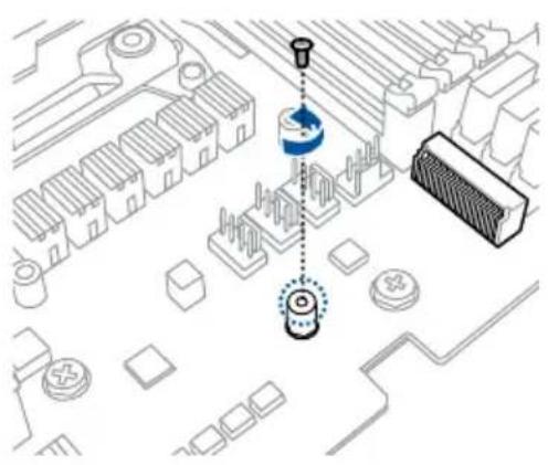
natural_image
Isometric diagram of a circuit board layout with components and a central sensor or sensor (no text or symbols)OR
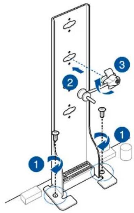
text_image
Diagram illustrating a mechanical assembly with numbered components and directional arrows indicating motion or movement.2
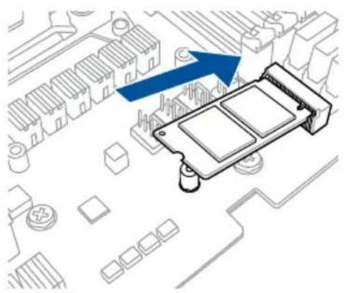
natural_image
Isometric view of a computer motherboard with an electronic component and a blue arrow indicating direction (no text or symbols)3
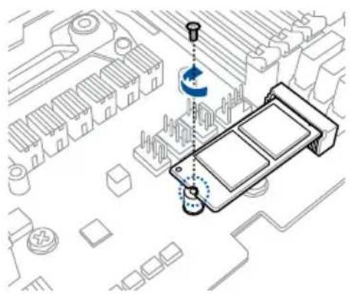
natural_image
Isometric diagram of a car interior with circuit board and mechanical components, no text or symbols present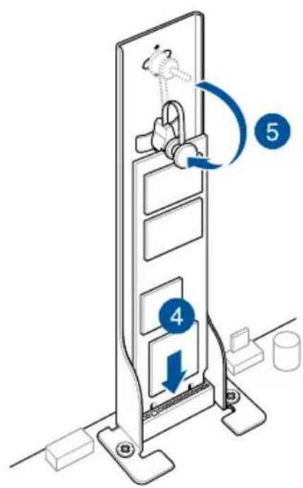
text_image
Diagram of a mechanical device with labeled parts and directional arrows indicating motion or movement
Supported M.2 type varies per motherboard.
2.1.10 ASUS fan holder installation
When using high performance settings whilst overclocking, ensure to install the fan holder for additional fan(s).

- You may install 12V (1A, 12W), 40mm x 40mm fans or 50mm x 50mm fans.
- Ensure to the use the bundled screws that came with your fans.
2.2 BIOS update utility
USB BIOS Flashback
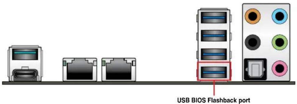
USB BIOS Flashback allows you to easily update the BIOS without entering the existing BIOS or operating system. Simply insert a USB storage device to the USB port (the USB port hole marked in green on the I/O shield) then press the USB BIOS Flashback button for three seconds to automatically update the BIOS.
To use USB BIOS Flashback:
- Insert a USB storage device to the USB Flashback port.

We recommend you to use a USB 2.0 storage device to save the latest BIOS version for better compatibility and stability.
text_image
USB BIOS Flashback port- Visit https://www.asus.com/support/ and download the latest BIOS version for this motherboard.
- Rename the file as WSXTG.CAP, then copy it to your USB storage device.
-
Shut down your computer.
-
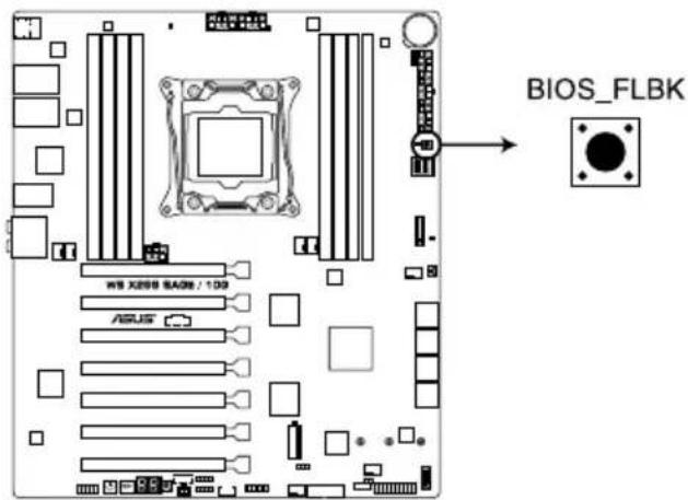
On your motherboard, press the BIOS Flashback button for three seconds until the Flashback LED blinks three times, indicating that the BIOS Flashback function is enabled.
text_image
BIOS_FLBK WIS X888 SAGR / 109 ASUSWS X299 SAGE/10G BIOS_FLBK button

Refer to section 1.1.8 Onboard LEDs for more information of the Flashback LED.

If the system fails to boot after flashing the BIOS, unplug the power core and restart the system.
- Wait until the light goes out, indicating that the BIOS updating process is completed.

For more BIOS update utilities in BIOS setup, refer to the section 3.11 Updating BIOS in Chapter 3.

- Do not unplug portable disk, power system, or press the CLR_CMOS button while BIOS update is ongoing, otherwise update will be interrupted. In case of interruption, please follow the steps again.
- If the light flashes for five seconds and turns into a solid light, this means that the BIOS Flashback is not operating properly. This may be caused by improper installation of the USB storage device and filename/file format error. If this scenario happens, please restart the system to turn off the light.
- Updating BIOS may have risks. If the BIOS program is damaged during the process and results to the system's failure to boot up, please contact your local ASUS Service Center.
2.3 Motherboard rear and audio connections
2.3.1 Rear I/O connection
text_image
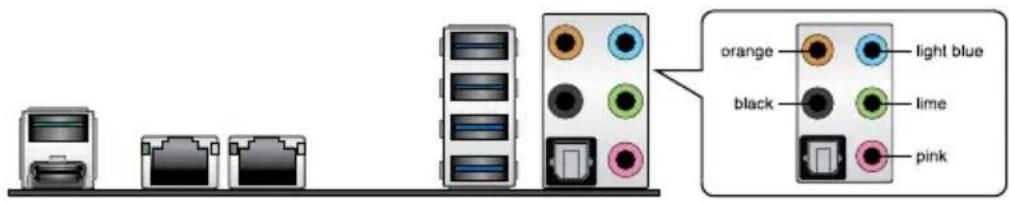
1 2 3 4 5 USB BIOS Flashback port 6 7Rear panel connectors
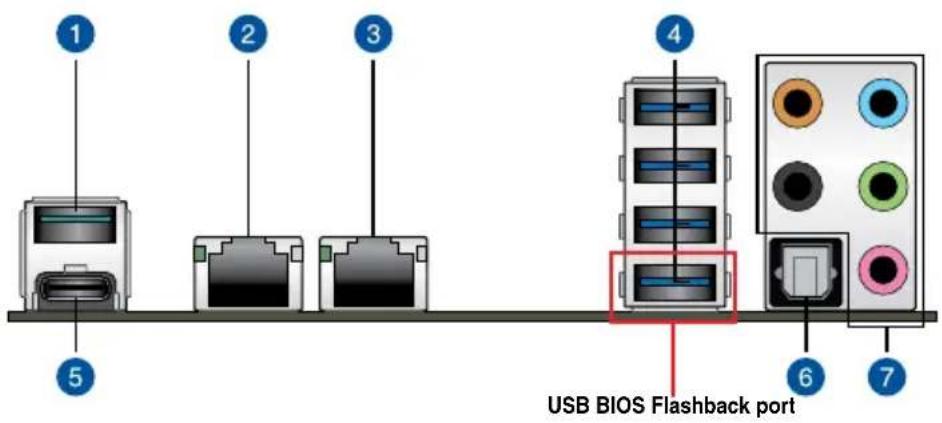
| 1. USB 3.1 Gen 2 Type-A port E2 5. USB 3.1 Gen 2 Type-CTM port EC1 | |
| 2. Intel ® 10G LAN port (LAN2)* 6. Optical S/PDIF Out port | |
| 3. Intel ® 10G LAN port (LAN1)* 7. Audio I/O ports** | |
| 4. USB 3.1 Gen 1 ports 8, 9, 10 and 11 (bottom port supports USB BIOS Flashback | |
* and **: Refer to the tables on the next page for the LAN port LEDs and audio port definitions.

- USB 3.1 Gen 1/Gen 2 devices can only be used as data storage only.
- We strongly recommend that you connect your devices to ports with matching data transfer rate. Please connect your USB 3.1 Gen 1 devices to USB 3.1 Gen 1 ports and your USB 3.1 Gen 2 devices to USB 3.1 Gen 2 ports for faster and better performance for your devices.
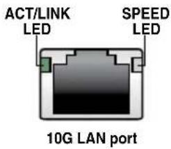
* 10G LAN ports LED indications
| Activity Link LED | Speed LED | ||
| Status | Description | Status | Description |
| Off | No link | Off | 100 Mbps connection |
| Green | Linked | Orange | 1 Gbps connection |
| Green (Blinking) | Data activity | Green | 10 Gbps connection |
text_image
ACT/LINK LED SPEED LED 10G LAN port
You can disable the LAN controllers in BIOS. Due to hardware design, the LAN1 port's LEDs may continue to blink even when disabled.
Audio 2, 4, 5.1, or 7.1-channel configuration
| Port | Headset2-channel | 4-channel 5.1-channel 7.1-channel | |
| Light Blue Line In Line In Line In Side Speaker Out | |||
| Lime Line Out Front Speaker Out Front Speaker Out Front Speaker Out | |||
| Pink Mic In Mic In Mic In | |||
| Orange -- Center/Subwoofer Center/Subwoofer | |||
| Black | - | Rear Speaker Out | Rear Speaker Out |
2.3.2 Audio I/O connections
Audio I/O ports
text_image
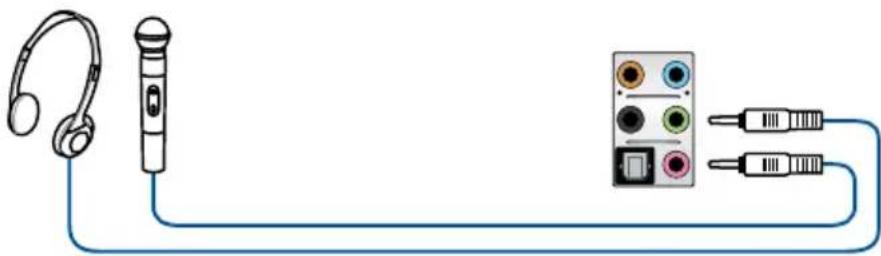
orange light blue black lime pinkConnect to Headphone and Mic
natural_image
Diagram showing a microphone connected to an audio recording device via cable (no text or symbols present)Connect to Stereo Speakers
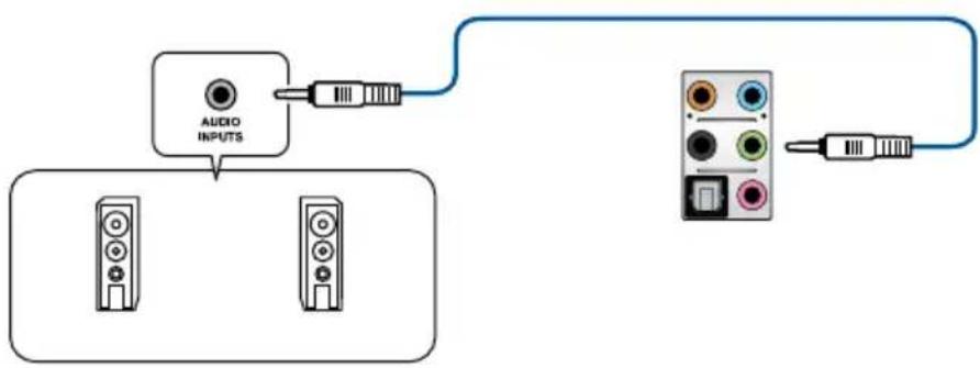
flowchart
graph TD
    A["Audio INPUTS"] --> B["USB Cable"]
    C["Video Units"] --> D["USB Cable"]
    E["Output"] --> F["USB Cable"]
Connect to 2-channel Speakers
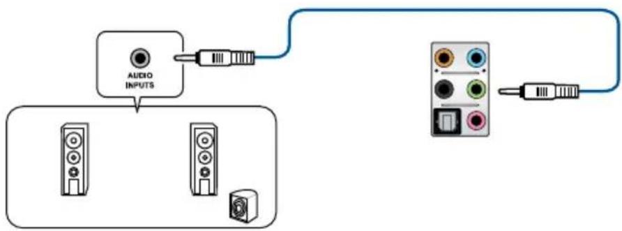
flowchart
graph TD
    A["Audio INPUTS"] --> B["Device 1"]
    A --> C["Device 2"]
    A --> D["Device 3"]
    A --> E["Device 4"]
Connect to 4-channel Speakers
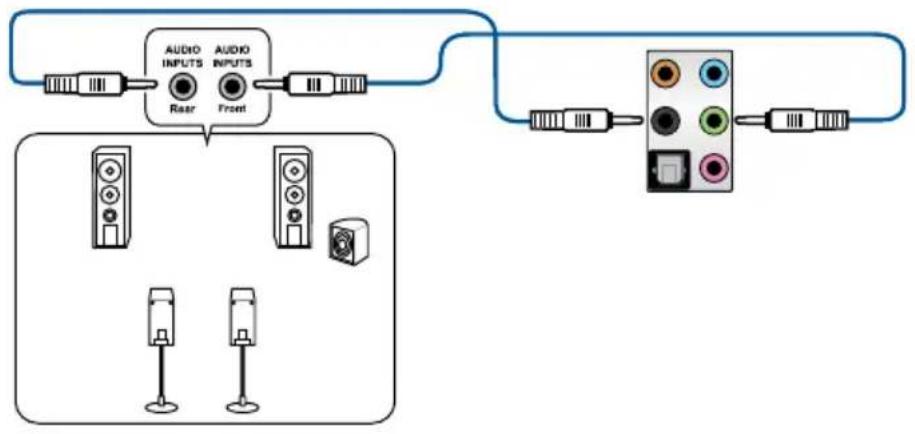
flowchart
graph TD
    A["Audio Inputs"] --> B["Rear"]
    C["Audio Inputs"] --> D["Front"]
    B --> E["Output Port"]
    D --> E
    F["Speaker 1"] --> G["Speaker 2"]
    H["Speaker 3"] --> I["Speaker 4"]
Connect to 5.1-channel Speakers
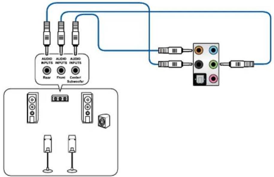
flowchart
graph TD
    A["Audio Inputs"] --> B["Rear"]
    A --> C["Front"]
    A --> D["Center Subwoofer"]
    E["Audio Inputs"] --> F["Back"]
    G["Subwoofer"] --> H["Central"]
    I["Radio Station"] --> J["Three Speakers"]
    K["Radio Station"] --> L["Three Speakers"]
Connect to 7.1-channel Speakers
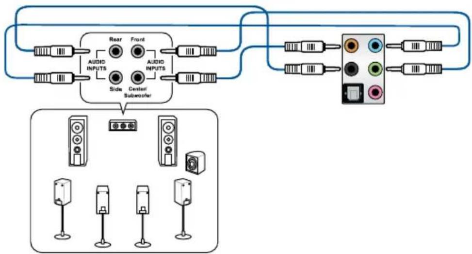
flowchart
graph TD
    A["Speaker 1"] --> B["AUDIO INPUTS"]
    C["Speaker 2"] --> D["AUDIO INPUTS"]
    E["Speaker 3"] --> F["AUDIO INPUTS"]
    G["Speaker 4"] --> H["AUDIO INPUTS"]
    I["Speaker 5"] --> J["AUDIO INPUTS"]
    K["Speaker 6"] --> L["AUDIO INPUTS"]
    M["Speaker 7"] --> N["AUDIO INPUTS"]
    O["Speaker 8"] --> P["AUDIO INPUTS"]
    Q["Speaker 9"] --> R["AUDIO INPUTS"]
    S["Speaker 10"] --> T["AUDIO INPUTS"]
    U["Speaker 11"] --> V["AUDIO INPUTS"]
    W["Speaker 12"] --> X["AUDIO INPUTS"]
    Y["Speaker 13"] --> Z["AUDIO INPUTS"]
    AA["Speaker 14"] --> AB["AUDIO INPUTS"]
    AC["Speaker 15"] --> AD["AUDIO INPUTS"]
    AE["Speaker 16"] --> AF["AUDIO INPUTS"]
    AG["Speaker 17"] --> AH["AUDIO INPUTS"]
    AI["Speaker 18"] --> AJ["AUDIO INPUTS"]
    AK["Speaker 19"] --> AL["AUDIO INPUTS"]
    AM["Speaker 20"] --> AN["AUDIO INPUTS"]
    AO["Speaker 21"] --> AP["AUDIO INPUTS"]
    AQ["Speaker 22"] --> AR["AUDIO INPUTS"]
    AS["Speaker 23"] --> AT["AUDIO INPUTS"]
    AU["Speaker 24"] --> AV["AUDIO INPUTS"]
    AW["Speaker 25"] --> AX["AUDIO INPUTS"]
    AY["Speaker 26"] --> AZ["AUDIO INPUTS"]
    BA["Speaker 27"] --> BB["AUDIO INPUTS"]
    BC["Speaker 28"] --> BD["AUDIO INPUTS"]
    BE["Speaker 29"] --> BF["AUDIO INPUTS"]
    BG["Speaker 30"] --> BH["AUDIO INPUTS"]
    BI["Speaker 31"] --> BJ["AUDIO INPUTS"]
    BK["Speaker 32"] --> BL["AUDIO INPUTS"]
    BM["Speaker 33"] --> BN["AUDIO INPUTS"]
    BO["Speaker 34"] --> BP["AUDIO INPUTS"]
    BQ["Speaker 35"] --> BR["AUDIO INPUTS"]
    BS["Speaker 36"] --> BT["AUDIO INPUTS"]
    BU["Speaker 37"] --> BV["AUDIO INPUTS"]
    BW["Speaker 38"] --> BX["AUDIO INPUTS"]
    BY["Speaker 39"] --> BZ["AUDIO INPUTS"]
    CA["Speaker 40"] --> CB["AUDIO INPUTS"]
    CC["Speaker 41"] --> CD["AUDIO INPUTS"]
    CE["Speaker 42"] --> CF["AUDIO INPUTS"]
    CG["Speaker 43"] --> DH["AUDIO INPUTS"]
    DI["Speaker 44"] --> DJ["AUDIO INPUTS"]
    DK["Speaker 45"] --> DL["AUDIO INPUTS"]
    DM["Speaker 46"] --> DE["AUDIO INPUTS"]
    DF["Speaker 47"] --> DG["AUDIO INPUTS"]
    DH --> DH
    DE --> DH
    DL --> DH
    DG --> DH
2.4 Starting up for the first time
- After making all the connections, replace the system case cover.
- Ensure that all switches are off.
- Connect the power cord to the power connector at the back of the system chassis.
- Connect the power cord to a power outlet that is equipped with a surge protector.
- Turn on the devices in the following order:
a. Monitor
b. External SCSI devices (starting with the last device on the chain)
c. System power
- After applying power, the system power LED on the system front panel case lights up. For systems with ATX power supplies, the system LED lights up when you press the ATX power button. If your monitor complies with the "green" standards or if it has a "power standby" feature, the monitor LED may light up or change from orange to green after the system LED turns on.
The system then runs the power-on self tests (POST). While the tests are running, the BIOS beeps (refer to the BIOS beep codes table) or additional messages appear on the screen. If you do not see anything within 30 seconds from the time you turned on the power, the system may have failed a power-on test. Check the jumper settings and connections or call your retailer for assistance.
| BIOS Beep Description | |
| One short beep VGA detected | Quick boot set to disabledNo keyboard detected |
| One continuous beep followed by two short beeps then a pause (repeated) | No memory detected |
| One continuous beep followed by three short beeps | No VGA detected |
| One continuous beep followed by four short beeps | Hardware component failure |
- At power on, hold down the
key to enter the BIOS Setup. Follow the instructions in Chapter 3.
2.5 Turning off the computer
While the system is ON, press the power button for less than four seconds to put the system on sleep mode or soft-off mode, depending on the BIOS setting. Press the power switch for more than four seconds to let the system enter the soft-off mode regardless of the BIOS setting.
BIOS Setup
3.1 Knowing BIOS

The new ASUS UEFI BIOS is a Unified Extensible Interface that complies with UEFI architecture, offering a user-friendly interface that goes beyond the traditional keyboard-only BIOS controls to enable a more flexible and convenient mouse input. You can easily navigate the new UEFI BIOS with the same smoothness as your operating system. The term “BIOS” in this user manual refers to “UEFI BIOS” unless otherwise specified.
BIOS (Basic Input and Output System) stores system hardware settings such as storage device configuration, overclocking settings, advanced power management, and boot device configuration that are needed for system startup in the motherboard CMOS. In normal circumstances, the default BIOS settings apply to most conditions to ensure optimal performance. DO NOT change the default BIOS settings except in the following circumstances:
- An error message appears on the screen during the system bootup and requests you to run the BIOS Setup.
- You have installed a new system component that requires further BIOS settings or update.

Inappropriate BIOS settings may result to instability or boot failure. We strongly recommend that you change the BIOS settings only with the help of a trained service personnel.

- When downloading or updating the BIOS file, rename it as WSXTG.CAP for this motherboard.
- BIOS settings and options may vary due to different BIOS release versions. Please refer to the latest BIOS version for settings and options.
3.2 BIOS setup program
Use the BIOS Setup to update the BIOS or configure its parameters. The BIOS screen include navigation keys and brief onscreen help to guide you in using the BIOS Setup program.
Entering BIOS at startup
To enter BIOS Setup at startup, press
Entering BIOS Setup after POST
To enter BIOS Setup after POST:
- Press
+ + simultaneously. - Press the reset button on the system chassis.
- Press the power button to turn the system off then back on. Do this option only if you failed to enter BIOS Setup using the first two options.
After doing either of the three options, press

- The BIOS setup screens shown in this section are for reference purposes only, and may not exactly match what you see on your screen.
- Ensure that a USB mouse is connected to your motherboard if you want to use the mouse to control the BIOS setup program.
- If the system becomes unstable after changing any BIOS setting, load the default settings to ensure system compatibility and stability. Select the Load Optimized Defaults item under the Exit menu or press hotkey
. See section 3.10 Exit Menu for details. - If the system fails to boot after changing any BIOS setting, try to clear the CMOS and reset the motherboard to the default value. See section 1.1.6 Onboard buttons and switches for information on how to erase the RTC RAM via the Clear CMOS button.
- The BIOS setup program does not support the Bluetooth devices.

Please visit ASUS website for the detailed BIOS content manual.
BIOS menu screen
The BIOS Setup program can be used under two modes: EZ Mode and Advanced Mode. You can change modes from Setup Mode in Boot menu or by pressing the
3.2.1 EZ Mode
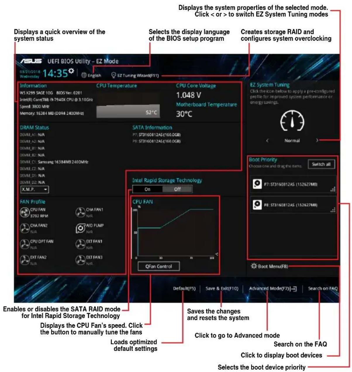
By default, the EZ Mode screen appears when you enter the BIOS setup program. The EZ Mode provides you an overview of the basic system information, and allows you to select the display language, system performance, mode and boot device priority. To access the Advanced Mode, select Advanced Mode or press the

The default screen for entering the BIOS setup program can be changed. Refer to the Setup Mode item in section Boot menu for details.
text_image
Displays a quick overview of the system status Displays the system properties of the selected mode. Click < or > to switch EZ System Tuning modes Selects the display language of the BIOS setup program Creates storage RAID and configures system overclocking ASUS UEFI BIOS Utility - EZ Mode 03/21/2018 14:35 English EZ Tuning Wizard(F11) Information CPU Temperature CPU Core Voltage WS X299 SAGE 10G BIOS Ver. 0201 1.048 V Intel(R) Core(TM) i9-7940X CPU @ 3.10GHz Motherboard Temperature Speed: 3800 MHz 30°C Memory: 16384 MB (DDR4 2400MHz) S2°C DRAM Status SATA Information DIMM_A1: N/A P7: ST3160B12AS (160.0GB) DIMM_A2: N/A P8: ST3160B12AS (160.0GB) DIMM_B1: N/A DIMM_B2: N/A DIMM_C1: Samsung 16384MB 2400MHz DIMM_C2: N/A DIMM_D1: N/A DIMM_D2: N/A X.M.P. FAN Profile CPU FAN CHA FAN1 3792 RPM N/A CHA FAN2 AID PUMP N/A N/A CPU OPT FAN EXT FAN1 N/A N/A EXT FAN2 EXT FAN3 N/A N/A Intel Rapid Storage Technology On Off CPU FAN QFan Control Boot Priority Choose one and drag the items. Switch all P7:ST3160B12AS (152627MB) P8:ST3160B12AS (152627MB) Boot Menu(F8) Default(F5) Save & Exit(F10) Advanced Mode(F7) Search on FAQ Enables or disables the SATA RAID mode for Intel Rapid Storage Technology Displays the CPU Fan's speed. Click the button to manually tune the fans Loads optimized default settings Saves the changes and resets the system Click to go to Advanced mode Search on the FAQ Click to display boot devices Selects the boot device priority
The boot device options vary depending on the devices you installed to the system.
3.2.2 Advanced Mode
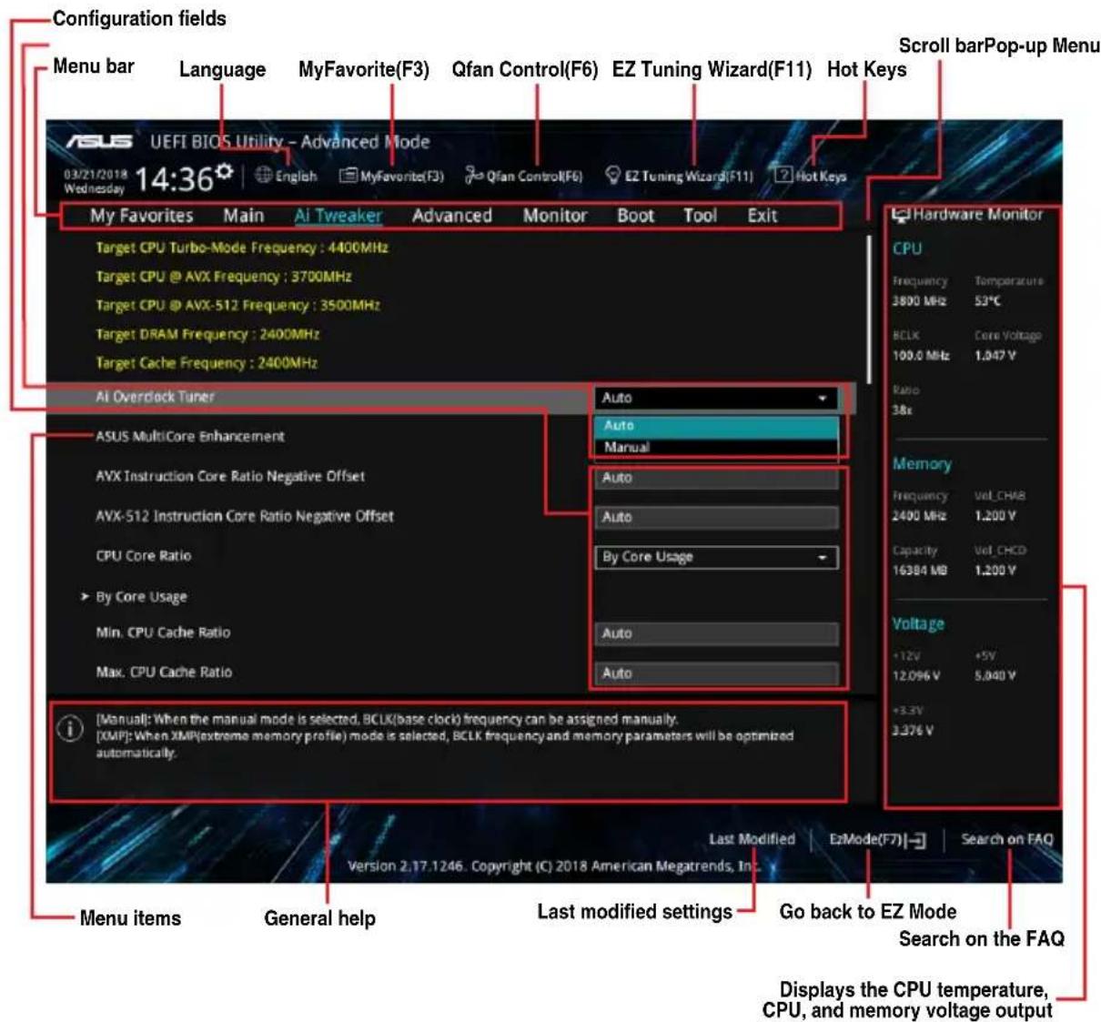
The Advanced Mode provides advanced options for experienced end-users to configure the BIOS settings. The figure below shows an example of the Advanced Mode. Refer to the following sections for the detailed configurations.

To switch from EZ Mode to Advanced Mode, click Advanced Mode(F7) or press the
text_image
Configuration fields Menu bar Language MyFavorite(F3) Qfan Control(F6) EZ Tuning Wizard(F11) Hot Keys Scroll barPop-up Menu ASUS UEFI BIOS Utility - Advanced Mode 03/21/2018 14:36 English MyFavorite(F3) Qfan Control(F6) EZ Tuning Wizard(F11) Hot Keys My Favorites Main AI Tweaker Advanced Monitor Boot Tool Exit Target CPU Turbo-Mode Frequency : 4400MHz Target CPU @ AVX Frequency : 3700MHz Target CPU @ AVX-512 Frequency : 3500MHz Target DRAM Frequency : 2400MHz Target Cache Frequency : 2400MHz AI Overclock Tuner Auto ASUS MultiCore Enhancement Auto Manual AVX Instruction Core Ratio Negative Offset Auto AVX-512 Instruction Core Ratio Negative Offset Auto CPU Core Ratio By Core Usage By Core Usage Auto Min. CPU Cache Ratio Auto Max. CPU Cache Ratio Auto [Manual]: When the manual mode is selected, BCLK(base clock) frequency can be assigned manually. [XMIP]: When XMR(extreme memory profile) mode is selected, BCLK frequency and memory parameters will be optimized automatically. Menu items General help Last modified settings Go back to EZ Mode Search on the FAQ Last Modified E2Mode(F7) Search on FAQ Version 2.17.1246. Copyright (C) 2018 American Megatrends, Inc Displays the CPU temperature, CPU, and memory voltage outputMenu bar
The menu bar on top of the screen has the following main items:
| My Favorites | For saving the frequently-used system settings and configuration. |
| Main | For changing the basic system configuration |
| Ai Tweaker | For changing the overclocking settings |
| Advanced | For changing the advanced system settings |
| Monitor | For displaying the system temperature, power status, and changing the fan settings. |
| Boot | For changing the system boot configuration |
| Tool | For configuring options for special functions |
| Exit | For selecting the exit options and loading default settings |
Menu items
The highlighted item on the menu bar displays the specific items for that menu. For example, selecting Main shows the Main menu items.
The other items (My Favorites, Ai Tweaker, Advanced, Monitor, Boot, Tool, and Exit) on the menu bar have their respective menu items.
Submenu items
A greater than sign (>) before each item on any menu screen means that the item has a submenu. To display the submenu, select the item and press
Language
This button above the menu bar contains the languages that you can select for your BIOS. Click this button to select the language that you want to display in your BIOS screen.
My Favorites (F3)
This button above the menu bar shows all BIOS items in a Tree Map setup. Select frequently-used BIOS settings and save it to MyFavorites menu.

Refer to section 3.3 My Favorites for more information.
Q-Fan Control (F6)
This button above the menu bar displays the current settings of your fans. Use this button to manually tweak the fans to your desired settings.

Refer to section 3.2.3 QFan Control for more information.
EZ Tuning Wizard (F11)
This button above the menu bar allows you to view and tweak the overclocking settings of your system. It also allows you to change the motherboard's SATA mode from AHCI to RAID mode.

Refer to section 3.2.4 EZ Tuning Wizard for more information.
Search on FAQ
Move your mouse over this button to show a QR code, scan this QR code on your mobile device to connect to the BIOS FAQ web page of the ASUS support website. You can also scan the following QR code:

text_image
QR code image containing encoded data, no visible human-readable textHot keys
This button above the menu bar contains the navigation keys for the BIOS setup program. Use the navigation keys to select items in the menu and change the settings.
Scroll bar
A scroll bar appears on the right side of a menu screen when there are items that do not fit on the screen. Press the Up/Down arrow keys or
General help
At the bottom of the menu screen is a brief description of the selected item. Use
Configuration fields
These fields show the values for the menu items. If an item is user-configurable, you can change the value of the field opposite the item. You cannot select an item that is not user-configurable.
A configurable field is highlighted when selected. To change the value of a field, select it and press
Last Modified button
This button shows the items that you last modified and saved in BIOS Setup.
3.2.3 QFan Control
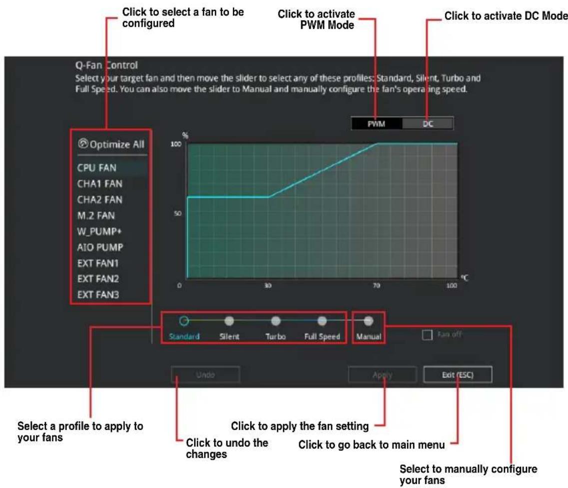
The QFan Control allows you to set a fan profile or manually configure the operating speed of your CPU and chassis fans.
text_image
Click to select a fan to be configured Click to activate PWM Mode Click to activate DC Mode Q-Fan Control Select your target fan and then move the slider to select any of these profiles: Standard, Silent, Turbo and Full Speed. You can also move the slider to Manual and manually configure the fan's operating speed. Optimize All CPU FAN CHA1 FAN CHA2 FAN M.2 FAN W_PUMP+ AIO PUMP EXT FAN1 EXT FAN2 EXT FAN3 Standard Silent Turbo Full Speed Manual Fan off Undo Apply Exit (ESC) Select a profile to apply to your fans Click to apply the fan setting Click to undo the changes Click to go back to main menu Select to manually configure your fansConfiguring fans manually
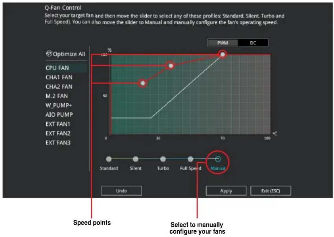
Select Manual from the list of profiles to manually configure your fans' operating speed.
line
| Fan Type | Speed (%) | | ---------- | --------- | | CHA1 FAN | 50 | | CHA2 FAN | 70 | | M.2 FAN | 70 | | W_PUMP+ | 70 | | AIO PUMP | 70 | | EXT FAN1 | 70 | | EXT FAN2 | 70 | | EXT FAN3 | 70 |To configure your fans:
- Select the fan that you want to configure and to view its current status.
- Click and drag the speed points to adjust the fans' operating speed.
- Click Apply to save the changes then click Exit (ESC).
3.2.4 EZ Tuning Wizard
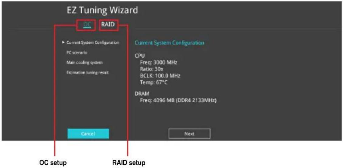
EZ Tuning Wizard allows you to easily overclock your CPU and DRAM, computer usage, and CPU fan to their best settings. You can also set RAID in your system using this feature.
text_image
EZ Tuning Wizard OC RAID ► Current System Configuration PC scenario Main cooling system Estimation tuning result Current System Configuration CPU Freq: 3000 MHz Ratio: 30x BCLK: 100.0 MHz Temp: 67°C DRAM Freq: 4096 MB (DDR4 2133MHz) Cancel Next OC setup RAID setupOC Tuning
To start OC Tuning:
- Press
on your keyboard or click EZ Tuning Wizard screen.
from the BIOS screen to open
- Click OC then click Next.
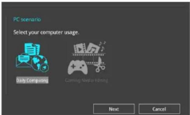
- Select a PC scenario Daily Computing or Gaming/Media Editing, then click Next.
text_image
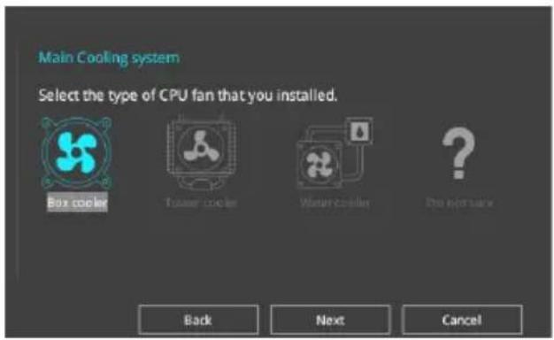
PC scenario Select your computer usage. Daily Computing Coming Media Editing Next Cancel- Select a Main Cooling System BOX cooler, Tower cooler, Water cooler, or I'm not sure, then click Next.
text_image
Main Cooling system Select the type of CPU fan that you installed. Box cooler Turbine cooler Water cooler I'm not sure Back Next Cancel- After selecting the Main Cooling System, click Next then click Yes to start the OC Tuning.
Creating RAID
To create RAID:
- Press
on your keyboard or click EZ Tuning Wizard screen.
from the BIOS screen to open
- Click Yes to enable RAID.

- Ensure that your HDDs have no existing RAID volumes.
-
Ensure to connect your HDDs to Intel ^ SATA connectors.
-
Select the port that you want to set to [RAID] mode, CPU or SATA, then click Next.
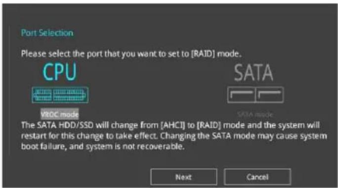
text_image
Port Selection Please select the port that you want to set to [RAID] mode. CPU MROC mode SATA SATA mode The SATA HDD/SSD will change from [AHCI] to [RAID] mode and the system will restart for this change to take effect. Changing the SATA mode may cause system boot failure, and system is not recoverable. Next Cancel
-
CPU (VROC mode): Supports Intel ^ Virtual Raid on CPU. This feature requires a KEY module (purchased separately) and Intel ^ SSD modules.
• SATA (SATA mode): Supports SATA RAID. -
Select the type of storage for your RAID, Easy Backup or Super Speed, then click Next.
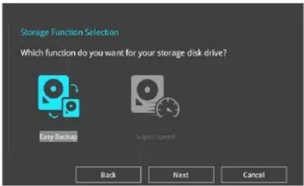
text_image
Storage Function Selection Which function do you want for your storage disk drive? Easy Backup Super Speed Back Next Cancela. For Easy Backup, click Next then select from Easy Backup (RAID 1) or Easy Backup (RAID 10).

text_image
Storage Function Selection Select the RAID type for your selected storage function Easy Backup (RAID 1) Back Next Cancel
You can only select Easy Backup (RAID 10) if you connect four (4) HDDs.
b. For Super Speed, click Next then select from Super Speed (RAID 0) or Super Speed (RAID 5).
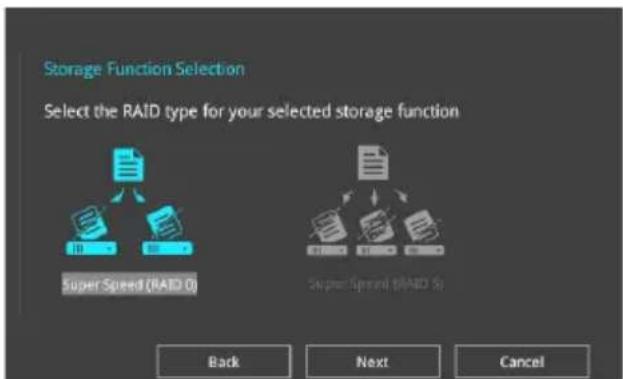
text_image
Storage Function Selection Select the RAID type for your selected storage function Super Speed (RAID 0) Super Speed (RAID 5) Back Next Cancel- After selecting the type of RAID, click Next then click Yes to continue the RAID setup.
- After the RAID setup is done, click Yes to exit the setup then click OK to reset your system.
3.3 My Favorites
My Favorites is your personal space where you can easily save and access your favorite BIOS items. My Favorites comes with several performance, power saving, and fast boot related items by default. You can personalize this screen by adding or removing items.
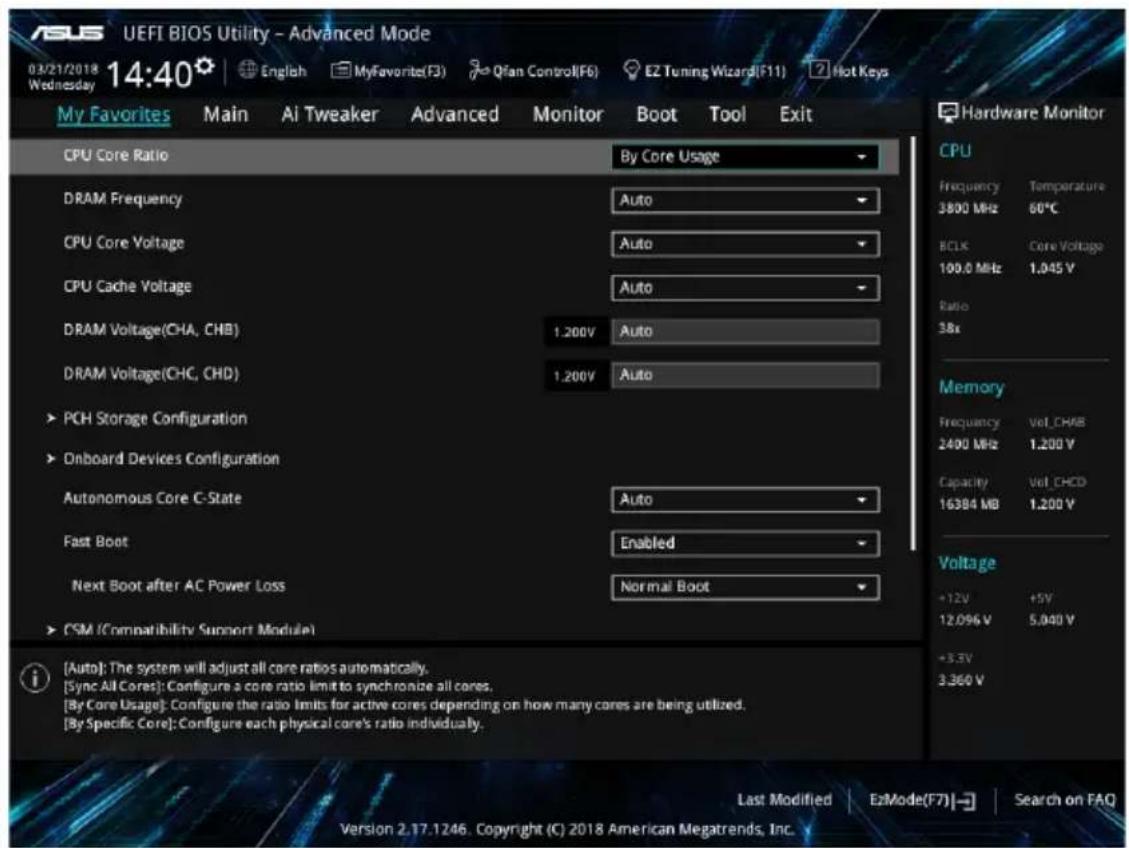
text_image
USI UEFI BIOS Utility - Advanced Mode 03/21/2018 14:40 English MyFavorite(F3) Qfan Control(F6) EZ Tuning Wizard(F11) Hot Keys My Favorites Main AI Tweaker Advanced Monitor Boot Tool Exit CPU Core Ratio By Core Usage DRAM Frequency Auto CPU Core Voltage Auto CPU Cache Voltage Auto DRAM Voltage(CHA, CHB) 1.200V Auto DRAM Voltage(CHC, CHD) 1.200V Auto > PCH Storage Configuration > Onboard Devices Configuration Autonomous Core C-State Auto Fast Boot Enabled Next Boot after AC Power Loss Normal Boot > CSM (Compatibility Support Module) (Auto): The system will adjust all core ratios automatically. [Sync All Cores]: Configure a core ratio limit to synchronize all cores. [By Core Usage]: Configure the ratio limits for active cores depending on how many cores are being utilized. [By Specific Core]: Configure each physical core's ratio individually. Last Modified EzMode(F7) Search on FAQ Hardware Monitor CPU Frequency Temperature 3800 MHz 60°C BCLK Core Voltage 100.0 MHz 1.045 V Ratio 3.8x Memory Frequency Vol_CHAB 2400 MHz 1.200 V Capacity Vol_CHCD 16384 MB 1.200 V Voltage +12V +5V 12.096 V 5.040 V +3.5V 3.360 V Version 2.17.1246. Copyright (C) 2018 American Megatrends, Inc.Adding items to My Favorites
To add BIOS items:
- Press
on your keyboard or click Setup Tree Map screen.

from the BIOS screen to open
- On the Setup Tree Map screen, select the BIOS items that you want to save in My Favorites screen.
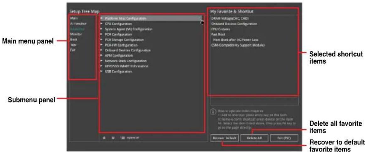
text_image
Setup Tree Map Main Air Speaker Monitor Monitor Best Tool Fast Platform Map Configuration CPU Configuration System Agent (TA) Configuration PCM Configuration PCIH Storage Configuration PCI/HW Configuration Onboard Devices Configuration APN Configuration Network Stock Configuration HDD/SSD SMART Information USB Configuration My Favorite & Shortcut DRAM Voltage(Off, Off) Onboard Devices Configuration CPU/C-States Fast Boot Next Boot after AC Power Loss CSM (Compatibility Support Module) Main menu panel Submenu panel Selected shortcut items Delete all favorite items Recover to default favorite items- Select an item from main menu panel, then click the submenu that you want to save as favorite from the submenu panel and click + or press
on your keyboard.

You cannot add the following items to My Favorite items:
- Items with submenu options
- User-managed items such as language and boot order
-
Configuration items such as Memory SPD Information, system time and date.
-
Click Exit (ESC) or press
key to close Setup Tree Map screen. - Go to My Favorites menu to view the saved BIOS items.
3.4 Main menu
The Main menu screen appears when you enter the Advanced Mode of the BIOS Setup program. The Main menu provides you an overview of the basic system information, and allows you to set the system date, time, language, and security settings.
Security
The Security menu items allow you to change the system security settings.

- If you have forgotten your BIOS password, erase the CMOS Real Time Clock (RTC) RAM to clear the BIOS password. See section 1.1.6 Onboard buttons and switches for information on how to erase the RTC RAM via the Clear CMOS button.
- The Administrator or User Password items on top of the screen show the default [Not Installed]. After you set a password, these items show [Installed].
3.5 Ai Tweaker menu
The Ai Tweaker menu items allow you to configure overclocking-related items.

Be cautious when changing the settings of the Ai Tweaker menu items. Incorrect field values can cause the system to malfunction
The configuration options for this section vary depending on the CPU and DIMM model you installed on the motherboard.
Ai Overclock Tuner
Allows you to select the CPU overclocking options to achieve the desired CPU internal frequency.
[Auto] Loads the optimal settings for the system.
[Manual] Allows you to individually set overclocking parameters.
[X.M.P.] If you install memory modules supporting the eXtreme Memory Profile (X.M.P.) Technology, choose this item to set the profiles supported by your memory modules for optimizing the system performance.
The [X.M.P.] configuration option appears only when you install memory modules supporting the eXtreme Memory Profile(X.M.P.) Technology.
The following item appears only when you set the Ai Overclocking Tuner to [Manual].
BCLK Frequency
This item allows you to set the BCLK (base clock) frequency to enhance the system performance. Use the <+> or <-> to adjust the value.

We recommend you to set the value based on the CPU specification, as high BCLK frequencies may damage the CPU permanently.
ASUS MultiCore Enhancement
[Auto] This item allows you to maximize the overclocking performance optimized by ASUS core ratio settings.
[Disabled] This item allows you to set to default core ratio settings.
CPU Core Ratio
This item allows you to set the CPU core ratios.
Configuration options: [Auto] [Sync All Cores] [By Core Usage] [By Specific Core]
BCLK Frequency : DRAM Frequency Ratio
[Auto] The BCLK frequency to DRAM frequency ratio will be set to the optimized setting.
[100:133] The BCLK frequency to DRAM frequency ratio will be set to 100:133.
[100:100] The BCLK frequency to DRAM frequency ratio will be set to 100:100.
DRAM Frequency
This item allows you to set the memory operating frequency. The configurable options vary with the BCLK (base clock) frequency setting. Select the auto mode to apply the optimized setting.
Configuration options: [Auto] [DDR4-800MHz] - [DDR4-4400MHz]
TPU
This item allows you to automatically overclock the CPU and DRAM frequencies and voltage for an enhanced system performance.
[Keep Current Settings] Keep the current settings without changing anything.
[TPU I] Applies air cooling overclocking conditions.
[TPU II] Applies water cooling overclocking conditions.

Ensure to use water cooling device before selecting [TPU II].
Internal CPU Power Management
The subitems in this menu allow you to set the CPU ratio and features.
Enhanced Intel SpeedStep Technology
Allows the operating system to dynamically adjust the processor voltage and cores frequency to decrease the average power consumption and decrease average heat production. Configuration options: [Enabled] [Disabled]
Turbo Mode
Allows you to enable your processor cores to run faster than the base operating frequency when it is below power, current and specification limit. Configuration options: [Disabled] [Enabled]
3.6 Advanced menu
The Advanced menu items allow you to change the settings for the CPU and other system devices.

Be cautious when changing the settings of the Advanced menu items. Incorrect field values can cause the system to malfunction.
3.6.1 CPU Configuration
The items in this menu show the CPU-related information that the BIOS automatically detects.

The items in this menu may vary based on the CPU installed.
Hyper-Threading [ALL]
This item allows a hyper-threading processor to appear as two logical processors, allowing the operating system to schedule two threads or processors simultaneously.
Configuration options: [Disabled] [Enabled]
CPU Power Management Configuration
This item allows you to manage and configure the CPU's power.
Enhanced Intel SpeedStep Technology
Allows the operating system to dynamically adjust the processor voltage and cores frequency to decrease the average power consumption and decrease average heat production. Configuration options: [Enabled] [Disabled]
Turbo Mode
This item allows you to automatically set the CPU cores to run faster than the base operating frequency when it is below the operating power, current and temperature specification limit.
Configuration options: [Enabled] [Disabled]
Autonomous Core C-State [Disabled]
Allows you to enable or disable Autonomous Core C-State Report.
Configuration options: [Auto] [Disabled] [Enabled]
3.6.2 Platform Misc Configuration
The items in this menu allow you to change the ASPM for PCH and SA PCI Express.
3.6.3 System Agent (SA) Configuration
The items in this menu allow you to adjust the Link Speed for PEG Port and Multi-Monitor.
3.6.4 PCH Configuration
The items in this menu allow you to adjust the PCH PCI Express speed.
PCI Express Configuration
This item allows you to configure the PCI Express slots.
PCIe Speed
This item allows your system to automatically select the PCI Express port speed.
Configuration options: [Auto] [Gen1 (2.5 GT/s)] [Gen2 (5 GT/s)] [Gen3 (8 GT/s)]
3.6.5 PCH Storage Configuration
While entering Setup, the BIOS automatically detects the presence of SATA devices. The SATA Port items show Not Present if no SATA device is installed to the corresponding SATA port.
SATA Controller(s)
This item allows you to enable or disable the SATA Device.
Configuration options: [Disabled] [Enabled]
SATA Mode Selection
This item allows you to set the SATA configuration.
[AHCI] Set to [AHCI] when you want the SATA hard disk drives
to use the AHCI (Advanced Host Controller Interface).
The AHCI allows the onboard storage driver to enable advanced Serial ATA features that increases storage performance on random workloads by allowing the drive to internally optimize the order of commands.
[Intel RST Premium (RAID)]
Set to [Intel RST Premium (RAID)] when you want to create a RAID configuration from the SATA hard disk drives.
SMART Status Check
SMART (Self-Monitoring, Analysis and Reporting Technology) is a monitoring system that shows a warning message during POST (Power-on Self Test) when an error occurs in the hard disks.
Configuration options: [On] [Off]
SATA6G\_1 - SATA6G\_8
SATA6G\_1 - SATA6G\_8
This item allows you to enable or disable the selected SATA port.
Configuration options: [Disabled] [Enabled]
Hot Plug
These items appears only when the SATA Mode Selection is set to [AHCI] and allows you to enable or disable SATA Hot Plug Support.
Configuration options: [Disabled] [Enabled]
3.6.6 CPU Storage Configuration
The items in this menu allow you to configure CPU storage configurations.

- This menu will appear only when an Intel ^ Core ^TM X-series Processors (6-core or above) is installed.
- Due to CPU behavior, CPU RAID functions with Intel ^ CPU RSTe only supports Intel ^ Core ^TM X-series Processors (6-core or above) and Intel ^ SSD modules.
3.6.7 Onboard Devices Configuration
The items in this menu allow you to switch between PCIe Lanes and configure onboard devices.
HD Audio Controller
This item allows you to use the Azalia High Definition Audio Controller
Configuration options: [Disabled] [Enabled]
USB Type C Power Switch
[Auto] The system will automatically detect your USB Type C devices and provide suitable power if needed.
[Enabled] The USB Type C port will always provide power to your devices.
RGB LED lighting
When system is in working state
This item allows you to turn the RGB LED lighting on or off when the system is in the working state.
Configuration options: [On] [Off]
When system is in sleep, hibernate or soft off states
This item allows you to turn the RGB LED lighting on or off when the system is in the sleep, hibernate or soft off states.
Configuration options: [On] [Off]
Intel LAN Controller
This item allows you to enable or disable the Intel LAN controller.
Configuration options: [Disabled] [Enabled]
3.6.8 APM Configuration
The items in this menu allow you to set system wake and sleep settings.
ErP Ready
This item allows you to switch off some power at S4+S5 or S5 to get the system ready for ErP requirement. When set to [Enabled], all other PME options are switched off.
Configuration options: [Disabled] [Enable(S4+S5)] [Enable(S5)]
3.6.9 Network Stack Configuration
The items in this menu allow you to configure lpv4 / lpv6 PXE support.
3.6.10 HDD/SSD SMART Information
This menu displays the SMART information of the connected devices.

NVM Express devices do not support SMART information.
3.6.11 USB Configuration
The items in this menu allow you to change the USB-related features.

The Mass Storage Devices item shows the auto-detected values. If no USB device is detected, the item shows None.
USB Single Port Control
This item allows you to enable or disable the individual USB ports.

Refer to section 1.1.2 Motherboard layout for the location of the USB ports.
3.6.12 Thunderbolt(TM) Configuration
The items in this menu allow you to configure Thunderbolt settings.
TBT Root port Selector
This item allows you to select the thunder root port.
Configuration options: [Thunderbolt Disabled] [PCIE16_2]
3.6.13 PCH-FW Configuration
This item allows you to configure the firmware TPM.
3.7 Monitor menu
The Monitor menu displays the system temperature/power status, and allows you to change the fan settings.
Q-Fan Configuration
Q-Fan Tuning
Click this item to automatically detect the lowest speed and configure the minimum duty cycle for each fan.
AIO PUMP/W\_PUMP+ Control
[Disabled] Disable the Water Pump control feature.
[Auto] Detects the type of water pump installed and automatically switches the control modes.
[DC mode] Enable the Water Pump control in DC mode for 3-pin chassis fan.
[PWM mode] Enable the Water Pump control in PWM mode for 4-pin chassis fan.
3.8 Boot menu
The Boot menu items allow you to change the system boot options.
Fast Boot
[Disabled] Allows your system to go back to its normal boot speed.
[Enabled] Allows your system to accelerate the boot speed.

The following items appear only when you set the Fast Boot to [Enabled].
Next Boot after AC Power Loss
[Normal Boot] Returns to normal boot on the next boot after an AC power loss.
[Fast Boot] Accelerates the boot speed on the next boot after an AC power loss.
Boot Configuration
Setup Mode
[Advanced Mode] This item allows you to go to Advanced Mode of the BIOS after POST.
[EZ Mode] This item allows you to go to EZ Mode of the BIOS after POST.
CSM (Compatibility Support Module)
This item allows you to configure the CSM (Compatibility Support Module) items to fully support the various VGA, bootable devices and add-on devices for better compatibility.
Launch CSM
[Auto] The system automatically detects the bootable devices and the add-on devices.
[Enabled] For better compatibility, enable the CSM to fully support the non-UEFI driver add-on devices or the Windows® UEFI mode.
[Disabled] Disable the CSM to fully support the non-UEFI driver add-on devices or the Windows® UEFI mode.

The following items appear only when you set the Launch CSM to [Enabled].
Boot Devices Control
This item allows you to select the type of devices that you want to boot.
Configuration options: [UEFI and Legacy OPROM] [Legacy OPROM only] [UEFI only]
Boot from Network Devices
This item allows you to select the type of network devices that you want to launch.
Configuration options: [Ignore] [Legacy only] [UEFI driver first]
Boot from Storage Devices
This item allows you to select the type of storage devices that you want to launch.
Configuration options: [Ignore] [Legacy only] [UEFI driver first]
Boot from PCI-E/PCI Expansion Devices
This item allows you to select the type of PCI-E/PCI expansion devices that you want to launch.
Configuration options: [Legacy only] [UEFI driver first]
Secure Boot
This item allows you to configure the Windows® Secure Boot settings and manage its keys to protect the system from unauthorized access and malwares during POST.
Boot Option Priorities
These items specify the boot device priority sequence from the available devices. The number of device items that appears on the screen depends on the number of devices installed in the system.

- To access Windows ^ OS in Safe Mode, press
after POST (Windows ^ 8 not supported). - To select the boot device during system startup, press
when the ASUS Logo appears.
Boot Override
These items displays the available devices. The number of device items that appears on the screen depends on the number of devices installed in the system. Click an item to start booting from the selected device.
3.9 Tool menu
The Tool menu items allow you to configure options for special functions. Select an item then press
Setup Animator
This item allows you to enable or disable the Setup animator.
Configuration options: [Disabled] [Enabled]
3.9.1 ASUS EZ Flash 3 Utility
This item allows you to run ASUS EZ Flash 3. When you press

For more details, refer to section 3.11.2 ASUS EZ Flash 3.
3.9.2 Secure Erase
SSD speeds may lower over time as with any storage medium due to data processing. Secure Erase completely and safely cleans your SSD, restoring it to factory performance levels.

Secure Erase is only available in AHCI mode. Ensure to set the SATA mode to AHCI. Click Advanced > PCH Storage Configuration > SATA Mode Selection > AHCI.
To launch Secure Erase, click Tool > Secure Erase on the Advanced mode menu.

Check the ASUS support site for a full list of SSDs tested with Secure Erase. The drive may become unstable if you run Secure Erase on an incompatible SSD.

- The time to erase the contents of your SSD may take a while depending on its size. Do not turn off the system during the process.
- Secure Erase is only supported on Intel SATA port. For more information about Intel SATA ports, refer to section 1.1.2 Motherboard layout of this manual.
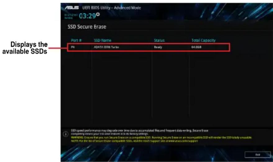
text_image
UEFI BIOS Utility - Advanced Mode 03:29° 03:29 SSD Secure Erase Port # SSD Name Status Total Capacity PA ADATA 5596 Turbo Ready 64.0GB SSD speed performance may degrade over time due to accumulated files and frequent data-mting. Secure Base complementing cleaners your SSD and remains it to its factory settings. 8AM MENU Ensure that you run Secure Erase on incompatible SSD. Running Secure Erase on an incompatible SSD will render the SSD totally unavailable. NOTE for the list of Secure Erase compatible SSDs, AND the ADATA Support Size at www.alasccveisupport Exit
Status definition:
- Frozen. The frozen state is the result of a BIOS protective measure. The BIOS guards drives that do not have password protection by freezing them prior to booting. If the drive is frozen, a power off or hard reset of your PC must be performed to proceed with the Secure Erase.
- Locked. SSDs might be locked if the Secure Erase process is either incomplete or was stopped. This may be due to a third party software that uses a different password defined by ASUS. You have to unlock the SSD in the software before proceeding with Secure Erase.
3.9.3 ASUS Overclocking Profile
This item allows you to store or load multiple BIOS settings.
Load from Profile
This item allows you to load the previous BIOS settings saved in the BIOS Flash. Key in the profile number that saved your BIOS settings, press

- DO NOT shut down or reset the system while updating the BIOS to prevent the system boot failure!
- We recommend that you update the BIOS file only coming from the same memory/CPU configuration and BIOS version.
Profile Name
This item allows you to key in a profile name.
Save to Profile
This item allows you to save the current BIOS settings to the BIOS Flash, and create a profile. Key in a profile number from one to eight, press
Load/Save Profile from/to USB Drive
This item allows you to load or save profile from your USB drive, load and save profile to your USB drive.
3.9.4 ASUS SPD Information
This item allows you to view the DRAM SPD information.
3.9.5 Graphics Card Information
This item displays the information about the graphics card installed in your system.
GPU Post
This item displays the information and recommended configuration for the PCIE slots that the graphics card is installed in your system.

This feature is only supported on selected ASUS graphics cards.
Bus Interface
This item allows you to select the bus interface.
Configuration options: [PCIEX16_1] [PCIEX16_2] [PCIEX16_3] [PCIEX16_4] [PCIEX16_5] [PCIEX16_6] [PCIEX16_7]
3.10 Exit menu
The Exit menu items allow you to load the optimal default values for the BIOS items, and save or discard your changes to the BIOS items. You can access the EZ Mode from the Exit menu.
Load Optimized Defaults
This option allows you to load the default values for each of the parameters on the Setup menus. When you select this option or if you press
Save Changes & Reset
Once you are finished making your selections, choose this option from the Exit menu to ensure the values you selected are saved. When you select this option or if you press
Discard Changes & Exit
This option allows you to exit the Setup program without saving your changes. When you select this option or if you press
Launch EFI Shell from filesystem device
This item allows you to attempt to launch the EFI Shell application (shellx64.efi) from one of the available filesystem devices.
3.11 Updating BIOS
The ASUS website publishes the latest BIOS versions to provide enhancements on system stability, compatibility, and performance. However, BIOS updating is potentially risky. If there is no problem using the current version of BIOS, DO NOT manually update the BIOS. Inappropriate BIOS updating may result in system's failure to boot. Carefully follow the instructions in this chapter to update your BIOS when necessary.

Visit http://www.asus.com to download the latest BIOS file for this motherboard.
The following utilities allow you to manage and update the motherboard BIOS setup program.
- EZ Update: Updates the BIOS in Windows ^® environment.
- ASUS EZ Flash 3: Updates the BIOS using a USB flash drive.
- ASUS CrashFree BIOS 3: Restores the BIOS using the motherboard support DVD or a USB flash drive when the BIOS file fails or gets corrupted.
3.11.1 EZ Update
The EZ Update is a utility that allows you to update the motherboard BIOS in Windows® environment.

- EZ Update requires an Internet connection either through a network or an ISP (Internet Service Provider).
- This utility is available in the support DVD that comes with the motherboard package.
3.11.2 ASUS EZ Flash 3
ASUS EZ Flash 3 allows you to download and update to the latest BIOS through the Internet without having to use a bootable floppy disk or an OS-based utility.

Updating through the Internet varies per region and Internet conditions. Check your local Internet connection before updating through the Internet.
To update the BIOS by USB:
- Enter the Advanced Mode of the BIOS setup program. Go to the Tool menu to select ASUS EZ Flash Utility and press
. - Insert the USB flash disk that contains the latest BIOS file to the USB port.
- Select via Storage Device(s).
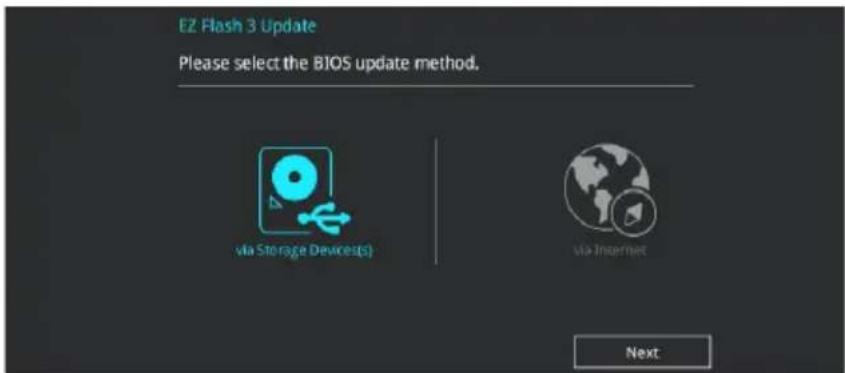
text_image
EZ Flash 3 Update Please select the BIOS update method. via Storage Devices(S) via Internet Next- Press
to switch to the Drive field. - Press the Up/Down arrow keys to find the USB flash disk that contains the latest BIOS, and then press
. - Press
to switch to the Folder Info field. - Press the Up/Down arrow keys to find the BIOS file, and then press
to perform the BIOS update process. Reboot the system when the update process is done.
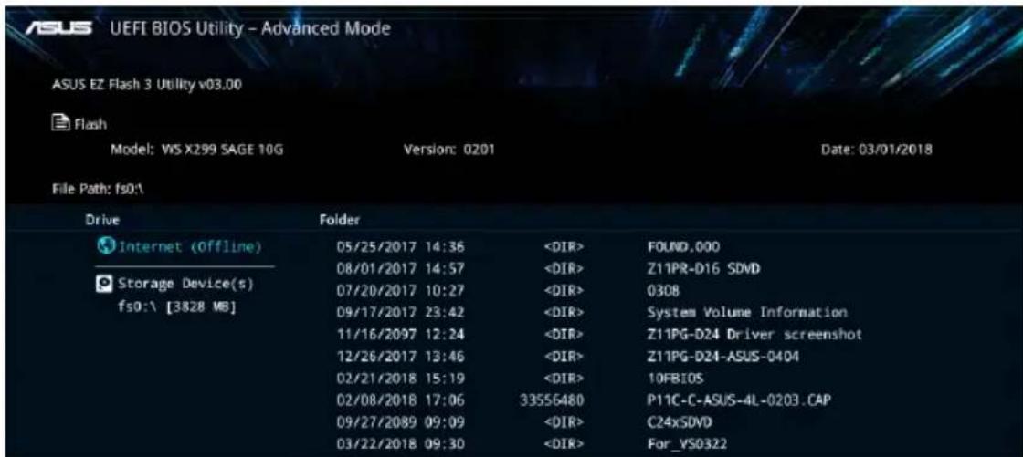
text_image
ASUS EZ Flash 3 Utility v03.00 Flash Model: WS X299 SAGE 10G Version: 0201 Date: 03/01/2018 File Path: fs0% Drive Folder Internet (Offline) 05/25/2017 14:36
- This function can support devices such as a USB flash disk with FAT 32/16 format and single partition only.
- DO NOT shut down or reset the system while updating the BIOS to prevent system boot failure!

Ensure to load the BIOS default settings to ensure system compatibility and stability. Select the Load Optimized Defaults item under the Exit menu. See section 3.10 Exit Menu for details.
To update the BIOS by Internet:
- Enter the Advanced Mode of the BIOS setup program. Go to the Tool menu to select ASUS EZ Flash Utility and press
. - Select via Internet.
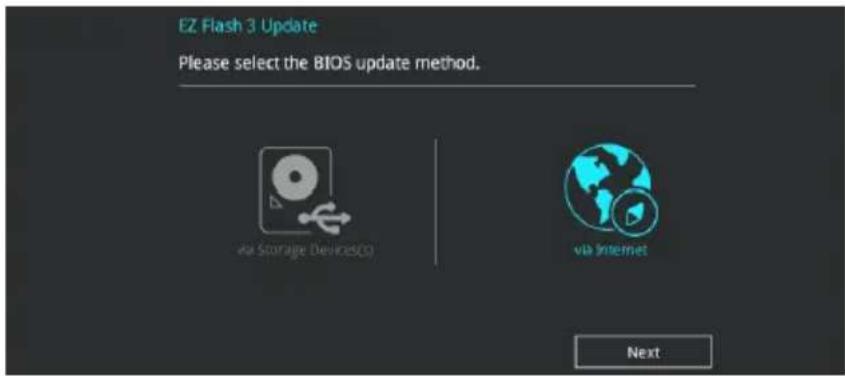
text_image
EZ Flash 3 Update Please select the BIOS update method. via Storage Devices(S) via Internet Next- Press the Left/Right arrow keys to select an Internet connection method, and then press
.
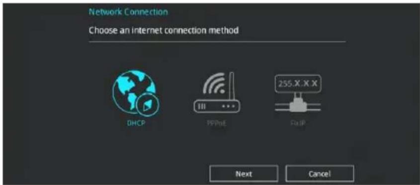
text_image
Network Connection Choose an internet connection method DHCP PPPoE 255.X.X X FastP Next Cancel- Follow the onscreen instructions to complete the update.
- Reboot the system when the update process is done.

Ensure to load the BIOS default settings to ensure system compatibility and stability. Select the Load Optimized Defaults item under the Exit menu. See section 3.10 Exit Menu for details.
3.11.3 ASUS CrashFree BIOS 3
The ASUS CrashFree BIOS 3 utility is an auto recovery tool that allows you to restore the BIOS file when it fails or gets corrupted during the updating process. You can restore a corrupted BIOS file using the motherboard support DVD or a USB flash drive that contains the BIOS file.

The BIOS file in the motherboard support DVD may be older than the BIOS file published on the ASUS official website. If you want to use the newer BIOS file, download the file at https://www.asus.com/support/ and save it to a USB flash drive.
Recovering the BIOS
To recover the BIOS:
- Turn on the system.
- Insert the motherboard support DVD to the optical drive, or the USB flash drive containing the BIOS file to the USB port.
- The utility automatically checks the devices for the BIOS file. When found, the utility reads the BIOS file and enters ASUS EZ Flash 3 automatically.
- The system requires you to enter BIOS Setup to recover the BIOS setting. To ensure system compatibility and stability, we recommend that you press
to load default BIOS values.

DO NOT shut down or reset the system while updating the BIOS! Doing so can cause system boot failure!
RAID Support
4.1 RAID configurations
The motherboard supports Intel® Rapid Storage Technology with RAID 0, RAID 1, RAID 5, and RAID 10 solution.

If you want to install a Windows® operating system to a hard disk drive included in a RAID set, you have to create a RAID driver disk and load the RAID driver during OS installation. Refer to section 4.2 Creating a RAID driver disk for details.
4.1.1 RAID definitions
RAID 0 (Data striping) optimizes two identical hard disk drives to read and write data in parallel, interleaved stacks. Two hard disks perform the same work as a single drive but at a sustained data transfer rate, double that of a single disk alone, thus improving data access and storage. Use of two new identical hard disk drives is required for this setup.
RAID 1 (Data mirroring) copies and maintains an identical image of data from one drive to a second drive. If one drive fails, the disk array management software directs all applications to the surviving drive as it contains a complete copy of the data in the other drive. This RAID configuration provides data protection and increases fault tolerance to the entire system. Use two new drives or use an existing drive and a new drive for this setup. The new drive must be of the same size or larger than the existing drive.
RAID 5 strips both data and parity information across three or more hard disk drives. Among the advantages of RAID 5 configuration include better HDD performance, fault tolerance, and higher storage capacity. The RAID 5 configuration is best suited for transaction processing, relational database applications, enterprise resource planning, and other business systems. Use a minimum of three identical hard disk drives for this setup.
RAID 10 is data striping and data mirroring combined without parity (redundancy data) having to be calculated and written. With the RAID 10 configuration you get all the benefits of both RAID 0 and RAID 1 configurations. Use four new hard disk drives or use an existing drive and three new drives for this setup.
4.1.2 Installing storage devices
The motherboard supports Serial ATA hard disk drives and PCIE SSD storage devices. For optimal performance, install identical drives of the same model and capacity when creating a disk array.

Refer to Chapter 2 for details on installing storage devices to your motherboard.
4.1.3 Intel® Rapid Storage Technology in UEFI BIOS
To enter the Intel® Rapid Storage Technology in UEFI BIOS:
- Enter the BIOS Setup during POST.
- Go to the Advanced menu > PCH Storage Configuration, then press
. - Set the SATA Mode Selection item to [Intel RST Premium (RAID)].

If you are using PCIE storage devices, ensure to enable all the PCIE Storage RAID Support items.
-
Go to the Boot menu > CSM (Compatibility Support Module) > Launch CSM, then set the item to [Disabled].
-
Save your changes and exit the BIOS Setup, then enter the BIOS Setup again.
-
Go to the Advanced menu > Intel(R) Rapid Storage Technology, then press
to display the Intel® Rapid Storage Technology menu.

Refer to Chapter 3 for details on entering and navigating through the BIOS Setup.

Due to chipset limitation, when SATA ports are set to RAID mode, all SATA ports run at RAID mode together.
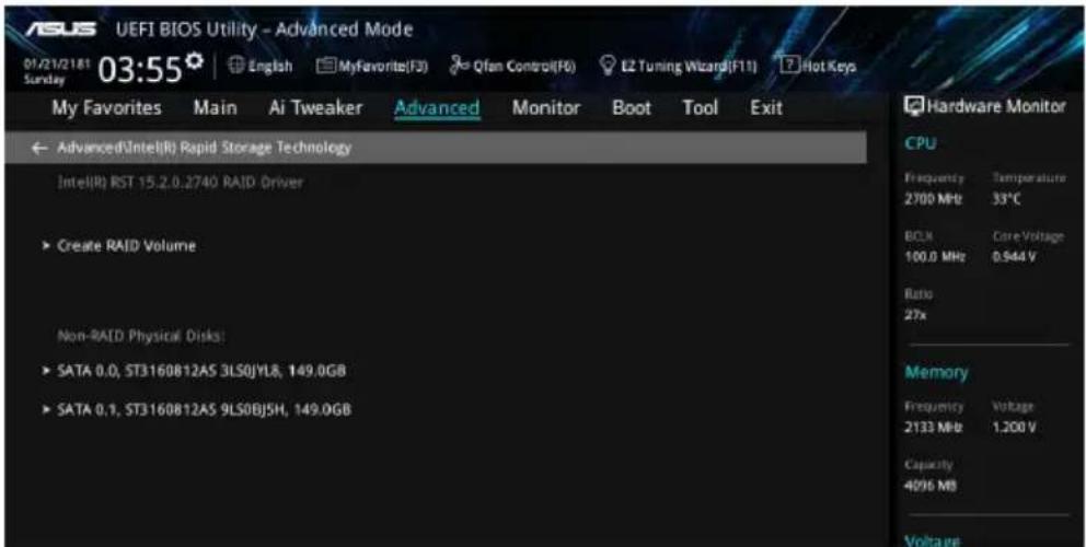
text_image
USI UEFI BIOS Utility - Advanced Mode 01/21/2181 03:55 English MyFavorite(F3) Qfan Control(F6) E2 Tuning Wizard(F11) Hot Keys My Favorites Main Ai Tweaker Advanced Monitor Boot Tool Exit Advanced(IntelR) Rapid Storage Technology Intel(R) RST 15.2.0.2740 RAID Driver ► Create RAID Volume Non-RAID Physical Disks: ► SATA 0.0, ST3160812A5 3LS0JYL8, 149.0GB ► SATA 0.1, ST3160812A5 9LS0BJ5H, 149.0GB Hardware Monitor CPU Frequency Temperature 2700 MHz 53°C BOLN Core Voltage 100.0 MHz 0.944 V Ratio 27x Memory Frequency Voltage 2133 MHz 1.200 V Capacity 4096 MB VoltageCreating a RAID set
To create a RAID set:
- From the Intel ^ Rapid Storage Technology menu, select Create RAID Volume and press
. The following screen appears:
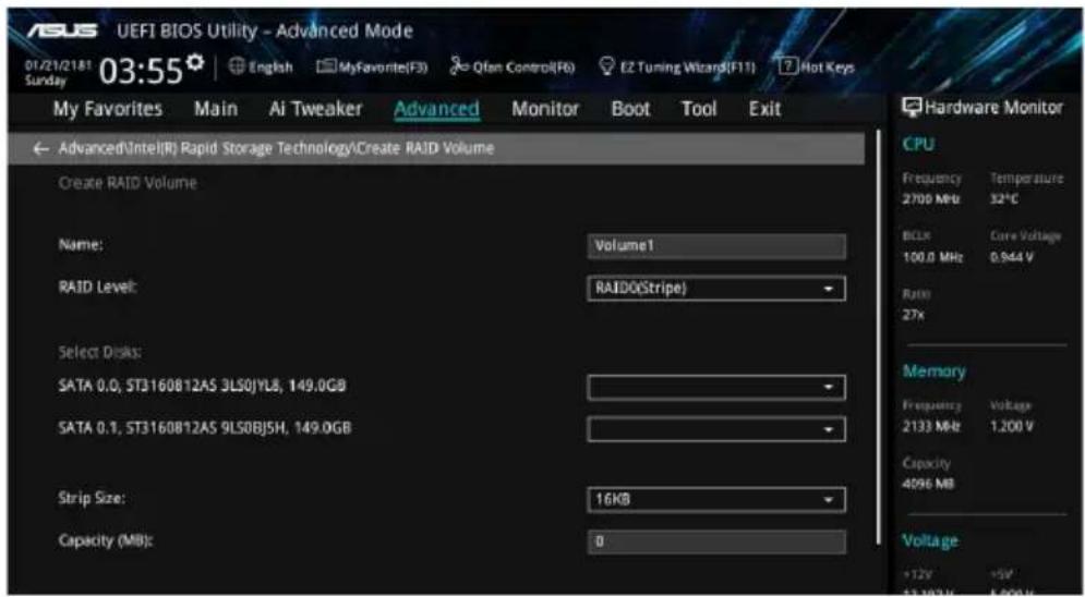
text_image
ASUS UEFI BIOS Utility - Advanced Mode 01/21/2181 03:55 Sunday My Favorites Main Ai Tweaker Advanced Monitor Boot Tool Exit Advanced\Intel(R) Rapid Storage Technology\Create RAID Volume Create RAID Volume Name: Volume1 RAID Level: RAIDO(Stripe) Select Disks: SATA 0.0, ST3160812AS 3L50JYL8, 149.0GB SATA 0.1, ST3160812AS 9L50BJ5H, 149.0GB Strip Size: 16KB Capacity (MB): 0 Hardware Monitor CPU Frequency Temperature 2700 MHz 32°C BCLX Care Voltage 100.0 MHz 0.944 V Rate 27x Memory Frequency Voltage 2133 MHz 1.200 V Capacity 4096 MB Voltage +12V +5V 12.18GHz 1.50GHz- When the Name item is selected, enter a name for the RAID set and press
. - When the RAID Level item is selected, press
to select the RAID level to create, and then press . - Under Select Disks, press
and select X for the disks you want to include in the RAID set.
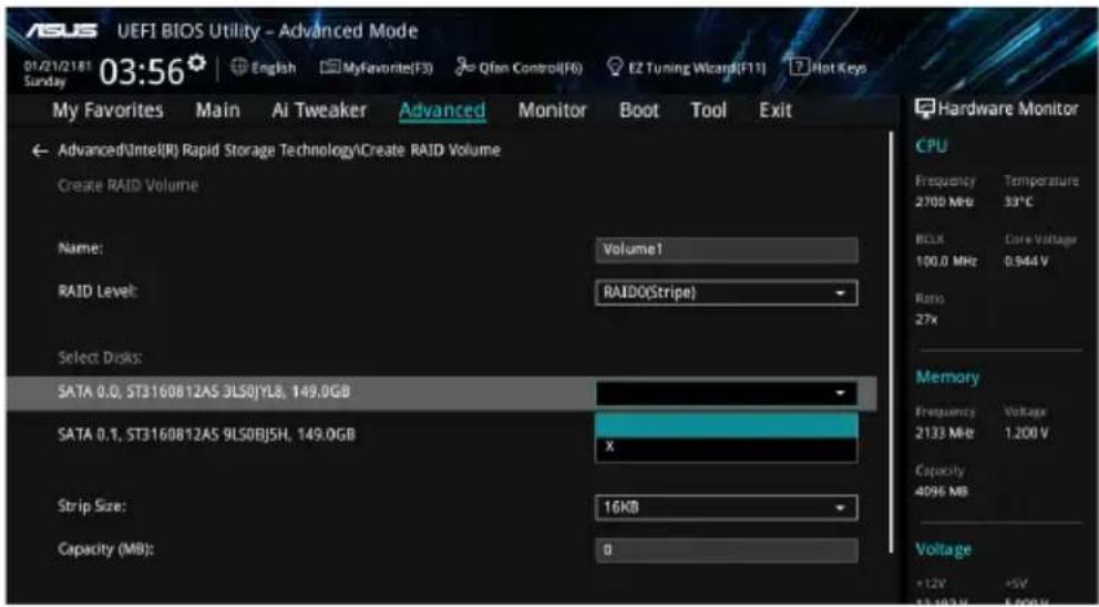
text_image
USI UEFI BIOS Utility - Advanced Mode 01/21/2181 03:56 English MyFavorite(F3) Qfan Control(F6) EZ Tuning Wizard(F11) Hot Keys My Favorites Main Ai Tweaker Advanced Monitor Boot Tool Exit Advanced(Intel(R) Rapid Storage Technology\Create RAID Volume Create RAID Volume Name: Volume1 RAID Level: RAIDO(Stripe) Select Dicks: SATA 0.0, ST3160812AS 3LSOJYL8, 149.0GB SATA 0.1, ST3160812AS 9LSOBJ5H, 149.0GB x Strip Size: 16KB Capacity (MB): 0 Hardware Monitor CPU Frequency Temperature 2700 MHz 33°C BCLK Core Voltage 100.0 MHz 0.944 V Ratio 27x Memory Frequency Voltage 2133 MHz 1.200 V Capacity 4096 MB Voltage +12V +5V 13 182Hz 5.50Hz-
When the Strip Size item is selected, press
to select strip size for the RAID array (for RAID 0, 10 and 5 only), and then press . The available strip size values range from 4 KB to 128 KB. The following are typical values: -
RAID 0: 128 KB
- RAID 10: 64 KB
- RAID 5: 64 KB

We recommend a lower strip size for server systems, and a higher strip size for multimedia computer systems used mainly for audio and video editing.
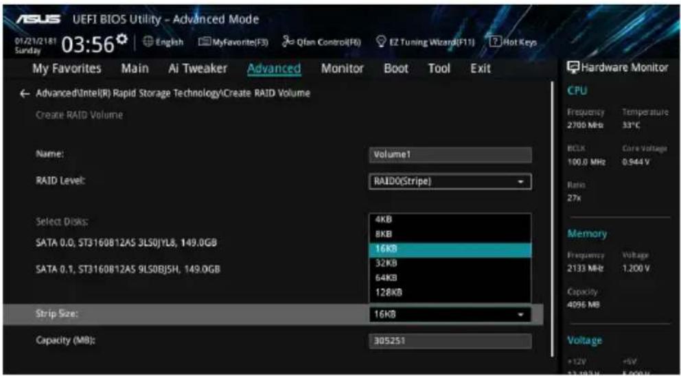
text_image
USI UEFI BIOS Utility - Advanced Mode 01/21/2181 Sunday 03:56 English MyFavorite(F3) Qfan Control(F6) EZ Tuning Wizard(F11) Hot Keys My Favorites Main Ai Tweaker Advanced Monitor Boot Tool Exit Advanced\Intel(R) Rapid Storage Technology\Create RAID Volume Create RAID Volume Name: Volume1 RAID Level: RAIDO(Stripe) Select Disks: 4KB SATA 0.0, ST3160812A5 3LS0JYL8, 149.0GB 8KB SATA 0.1, ST3160812A5 9LS0BJ5H, 149.0GB 16KB Strip Size: 16KB Capacity (MB): 305251 Hardware Monitor CPU Frequency Temperature 2700 MHz 33°C BCLK Core Voltage 100.0 MHz 0.944 V Ratio 27x Memory Frequency Voltage 2133 MHz 1.200 V Capacity 4096 MB Voltage +12V +5V 12.18GHz 5.00Hz- When the Capacity (MB) item is selected, enter the RAID volume capacity that you want and press
. The default value indicates the maximum allowed capacity. - When the Create Volume item is selected, press
to create the RAID volume and return to the Intel® Rapid Storage Technology menu.
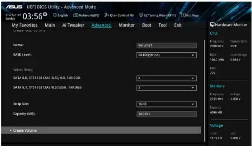
text_image
ASUS UEFI BIOS Utility - Advanced Mode 01/21/2181 03:56 English MyFavorite(F3) Qfan Control(F6) EZ Tuning Wizard(F11) Hot Keys My Favorites Main Ai Tweaker Advanced Monitor Boot Tool Exit CREATE RAID VOLUME Name: Volume1 RAID Level: RAIDO(Stripe) Select Disks: SATA 0.0, ST3160812AS 3LS0JYLB, 149.0GB X SATA 0.1, ST3160812AS 9LS0BJ5H, 149.0GB X Strip Size: 16KB Capacity (MB): 305251 Create Volume Hardware Monitor CPU Frequency Temperature 2700 MHz 33°C BCLK Core Voltage 100.0 MHz 0.944 V Ratio 27x Memory Frequency Voltage 2133 MHz 1.200 V Capacity 4096 MB Voltage +12V +5V 12.192 V 5.000 VDeleting a RAID set

Be cautious when deleting a RAID set. You will lose all data on the hard disk drives when you delete a RAID set.
To delete a RAID set:
- From the Intel ^ Rapid Storage Technology menu, select the RAID volume you want to delete and press
. The following screen appears:
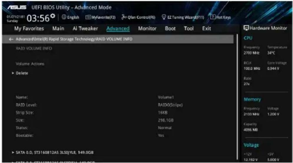
text_image
UEFI BIOS Utility - Advanced Mode 01/21/2181 03:56 English MyFavorite(F3) Qfan Control(F6) EZ Tuning Wizard(F11) Hot Keys My Favorites Main AI Tweaker Advanced Monitor Boot Tool Exit Advanced\Intel(R) Rapid Storage Technology\RAID VOLUME INFO RAID VOLUME INFO Volume Actions ► Delete Name: Volume1 RAID Level: RAID(Stripe) Strip Size: 16KB Size: 298.1GB Status: Normal Bootable: Yes ► SATA 0.D, ST3160812AS 3LSOYLS, 149.0GB Hardware Monitor CPU Frequency Temperature 2700 MHz 34°C BCLK Core Voltage 100.0 MHz 0.944 V Ratio 27x Memory Frequency Voltage 2133 MHz 1.200 V Capacity 4096 MB Voltage +12V -5V 12.192 V 5.000 V- When the Delete item is selected, press
, then select Yes to delete the RAID volume and return to the Intel® Rapid Storage Technology menu, or select No to cancel.
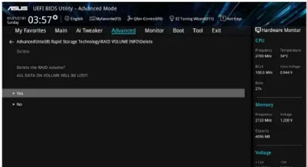
text_image
ASUS UEFI BIOS Utility - Advanced Mode 01/21/2181 03:57 English MyFavorite(F3) Qfan Control(F6) E2 Tuning Wizard(F11) Hot Keys My Favorites Main Ai Tweaker Advanced Monitor Boot Tool Exit Advanced\Intel(R) Rapid Storage Technology\RAID VOLUME INFO\Delete Delete Delete the RAID volume? ALL DATA ON VOLUME WILL BE LOST! Yes No Hardware Monitor CPU Frequency Temperature 2700 MHz 34°C BCLX Core Voltage 100.0 MHz 0.944 V Ratio 27x Memory Frequency Voltage 2133 Mb 1.200 V Capacity 4096 MB Voltage +1.2V +5V 22.102Hz 5.000 V4.1.4 Intel® Virtual Raid on CPU in UEFI BIOS
This feature requires a KEY module to enable CPU RAID functions with Intel® CPU RSTe.

• The KEY module is purchased separately.
- Due to CPU behavior, CPU RAID functions with Intel ^ CPU RSTe only supports Intel ^ Core ^TM X-series Processors (6-core or above) and Intel ^ SSD modules.
- Refer to section 1.1.9 Internal connectors for the location of the VROC_HW_KEY connector.

- Due to hardware design, CPU RAID configuration as OS drives is only supported in the following configuration sets and cannot be created across different sets:
[Set 1] M.2_1 and U.2_1.
[Set 2] PCIEX16_1 to PCIEX16_3 with Intel ^® P3500 or P3600 SSDs installed.
[Set 3] PCIEX16_4 to PCIEX16_7 with Intel ^ P3500 or P3600 SSDs installed.
- Due to hardware design, RAID Volume between M.2_1 and M.2_2 is not supported.
To enter the Intel® Virtual Raid on CPU in UEFI BIOS:
- Enter the BIOS Setup during POST.
- Go to the Boot menu > CSM (Compatibility Support Module) > Launch CSM, then set the item to [Disabled].
- Go to the Advanced menu > CPU Storage Configuration, then set the PCIE slot(s) that you have installed the storage devices to [Enabled].
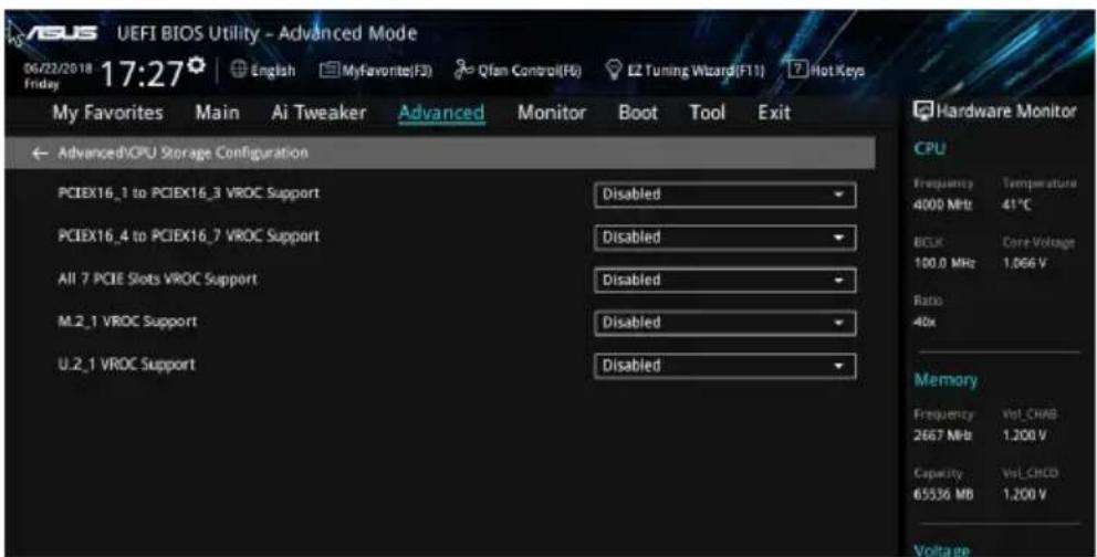
text_image
UEFI BIOS Utility - Advanced Mode 06/22/2018 17:27 English MyFavorite(F3) Qfan Control(F6) LZ Tuning Wizard(F11) Hot Keys My Favorites Main Ai Tweaker Advanced Monitor Boot Tool Exit AdvancedXPU Storage Configuration PCIEX16_1 to PCIEX16_3 VROC Support Disabled PCIEX16_4 to PCIEX16_7 VROC Support Disabled All 7 PCIe Slots VROC Support Disabled ML2_1 VROC Support Disabled U.2_1 VROC Support Disabled Hardware Monitor CPU Frequency Temperature 4000 MHz 41°C BCLK Core Voltage 100.0 MHz 1.066 V Ratio 40x Memory Frequency Vol_CHAB 2667 Mb 1.200 V Capacity Vol_CNCD 65536 MB 1.200 V Voltage- Save your changes and exit the BIOS Setup, then enter the BIOS Setup again.
- Go to the Advanced menu > Intel(R) Virtual Raid on CPU > All Intel VMD Controllers, then press
to display the Intel® Virtual Raid on CPU menu.

Refer to Chapter 3 for details on entering and navigating through the BIOS Setup.
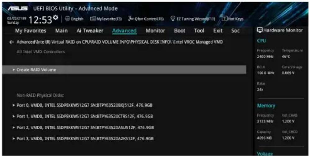
text_image
ASUS UEFI BIOS Utility - Advanced Mode 03/22/2189 12:53 Sunday My Favorites Main Ai Tweaker Advanced Monitor Boot Tool Exit Soc Advanced\Intel(R) Virtual RAID on CPU\RAID VOLUME INFO\PHYSICAL DISK INFO\Intel VROC Managed VMD All Intel VMD Controllers Create RAID Volume Non-RAID Physical Disk: ► Port 0, VMD0, INTEL SSDPEKKW512G7 SN:BTPY63520BXJ512F, 476.9GB ► Port 1, VMD0, INTEL SSDPEKKW512G7 SN:BTPY63520CTRS12F, 476.9GB ► Port 2, VMD0, INTEL SSDPEKKW512G7 SN:BTPY63520ASU512F, 476.9GB ► Port 3, VMD0, INTEL SSDPEKKW512G7 SN:BTPY63520A2KS12F, 476.9GB Hardware Monitor CPU Frequency Temperature 2400 MHz 46°C BCLR Care Voltage 100.0 MHz 0.869 V Ratio 24x Memory Frequency Vol_CHAB 2133 MHz 1.200 V Capacity Vol_CHBD 4096 MB 1.200 V VoltageCreating a RAID set
To create a RAID set:
- From the Intel ^ Virtual Raid on CPU menu, select Create RAID Volume and press
. The following screen appears:
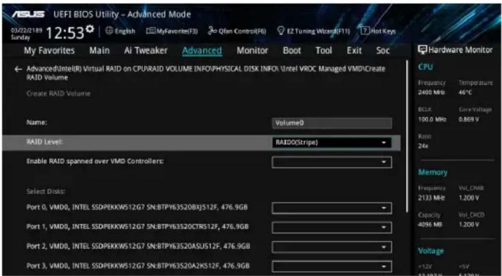
text_image
ASUS UEFI BIOS Utility - Advanced Mode 03/22/2189 12:53 English MyFavorite(F3) Qfan Control(F6) EZ Tuning Wizard(F11) Hot Keys Sunday My Favorites Main Ai Tweaker Advanced Monitor Boot Tool Exit Soc AdvancedIntel(R) Virtual RAID on CPURAID VOLUME INFO/PHYSICAL DISK INFO\Intel VROC Managed VMD\Create RAID Volume Create RAID Volume Name: Volume0 RAID Level: RAIDO(Stripe) Enable RAID spanned over VMD Controllers: Select Disks: Port 0, VMD0, INTEL SSDPEKKW512G7 SN:BTPY63520BXJ512F, 476.9GB Port 1, VMD0, INTEL SSDPEKKW512G7 SN:BTPY63520CTR512F, 476.9GB Port 2, VMD0, INTEL SSDPEKKW512G7 SN:BTPY63520ASU512F, 476.9GB Port 3, VMD0, INTEL SSDPEKKW512G7 SN:BTPY63520A2KS12F, 476.9GB Hardware Monitor CPU Frequency Temperature 2400 MB 46°C BCLK Core Voltage 100.0 MHz 0.809 V Ratio 24x Memory Frequency Vol_CNAB 2133 MB 1.200 V Capacity Vol_CNCD 4096 MB 1.200 V Voltage +12V +5V -13.10V -5.12V- When the Name item is selected, enter a name for the RAID set and press
. - When the RAID Level item is selected, press
to select the RAID level to create, and then press . - When the Enable RAID spanned over VMD Controllers item is selected, press
and select X to enable this function. - Under Select Disks, press
and select X for the disks you want to include in the RAID set.

text_image
USI UEFI BIOS Utility - Advanced Mode 03/22/2189 12:53 Sunday My Favorites Main Ai Tweaker Advanced Monitor Boot Tool Exit Soc AdvancedIntel(R) Virtual RAID on CPURAID VOLUME INFOPHYSICAL DISK INFO\Intel VROC Managed VMD\Create RAID Volume Create RAID Volume Name: Volume0 RAID Level: RAIDO(Stripe) Enable RAID spanned over VMD Controllers: X Select Disks: Port 0, VMD0, INTEL SSDPEKKW512G7 SN:BTPY63520BXJ512F, 476.9GB Port 1, VMD0, INTEL SSDPEKKW512G7 SN:BTPY63520CTR512F, 476.9GB Port 2, VMD0, INTEL SSDPEKKW512G7 SN:BTPY63520ASUS12F, 476.9GB Port 3, VMD0, INTEL SSDPEKKW512G7 SN:BTPY63520A2KS12F, 476.9GB Hardware Monitor CPU Frequency Temperature 2400 Mb 45°C BIUR Care Voltage 100.0 MHz 0.869 V Ratio 24x Memory Frequency Vol_CHAD 2133 Mb 1.200 V Capacity Vol_CHCD 4096 MB 1.200 V Voltage +12V +5V -12.70Hz -1.20V-
When the Strip Size item is selected, press
to select strip size for the RAID array (for RAID 0, 10 and 5 only), and then press . The available strip size values range from 4 KB to 128 KB. The following are typical values: -
RAID 0: 128 KB
- RAID 10: 64 KB
- RAID 5: 64 KB

We recommend a lower strip size for server systems, and a higher strip size for multimedia computer systems used mainly for audio and video editing.
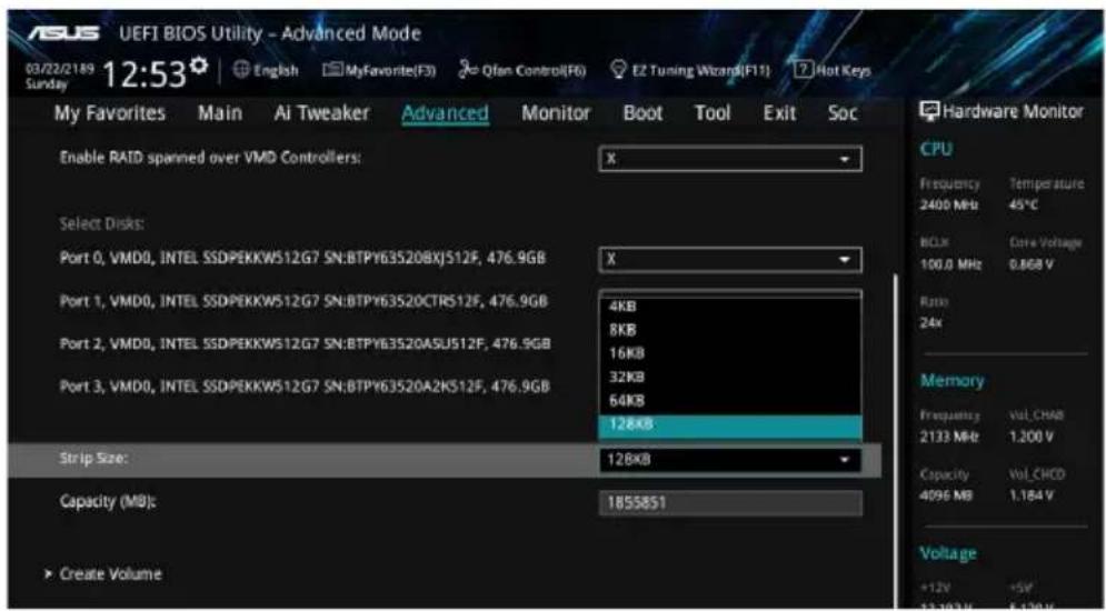
text_image
UEFI BIOS Utility - Advanced Mode 03/22/2189 12:53 English MyFavorite(F3) Qfan Control(F6) EZ Tuning Wizard(F11) Hot Keys My Favorites Main Ai Tweaker Advanced Monitor Boot Tool Exit Soc Enable RAID spanned over VMD Controllers: X Select Disks: Port 0, VMD0, INTEL SSDPEKKW512G7 SN:BTPY63520BXJ512F, 476.9GB X Port 1, VMD0, INTEL SSDPEKKW512G7 SN:BTPY63520CTR512F, 476.9GB 4KB 8KB 16KB 32KB 64KB 128KB Port 2, VMD0, INTEL SSDPEKKW512G7 SN:BTPY63520ASU512F, 476.9GB Port 3, VMD0, INTEL SSDPEKKW512G7 SN:BTPY63520A2K512F, 476.9GB Strip Size: 128KB Capacity (MB): 1855851 ▶ Create Volume Hardware Monitor CPU Frequency Temperature 2400 MHz 45°C BOX Core Voltage 100.0 MHz 0.868 V Ratio 24x Memory Frequency Vol_CHAD 2133 MHz 1.200 V Capacity Vol_CHCD 4096 MB 1.184 V Voltage +12V +5V 13.193V 5.130V- When the Capacity (MB) item is selected, enter the RAID volume capacity that you want and press
. The default value indicates the maximum allowed capacity. - When the Create Volume item is selected, press
to create the RAID volume and return to the Intel® Rapid Storage Technology menu.
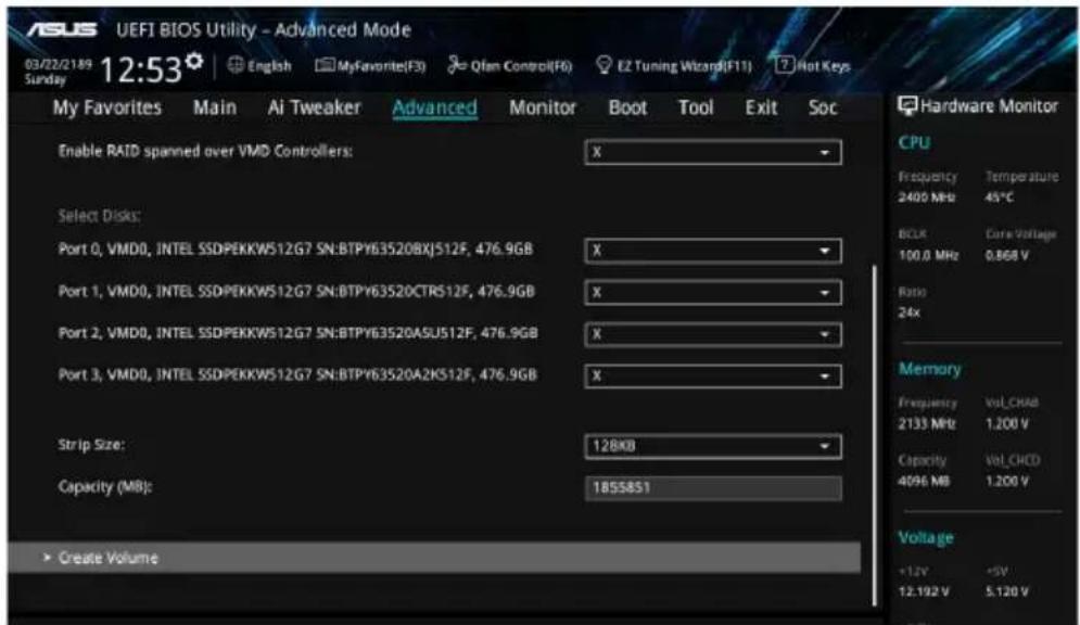
text_image
ASUS UEFI BIOS Utility - Advanced Mode 03/22/2189 Sunday 12:53 English MyFavorite(F3) Qian Control(F6) E2 Tuning Wizard(F11) Hot Keys My Favorites Main Ai Tweaker Advanced Monitor Boot Tool Exit Soc Enable RAID spanned over VMD Controllers: X Select Disks: Port 0, VMD0, INTEL SSDPEKKW512G7 SN:BTPY63520BXJ512F, 476.9GB X Port 1, VMD0, INTEL SSDPEKKW512G7 SN:BTPY63520CTR512F, 476.9GB X Port 2, VMD0, INTEL SSDPEKKW512G7 SN:BTPY63520ASU512F, 476.9GB X Port 3, VMD0, INTEL SSDPEKKW512G7 SN:BTPY63520A2K512F, 476.9GB X Strip Size: 128KB Capacity (MB): 1855851 ► Create Volume Hardware Monitor CPU Frequency Temperature 2400 MHz 45°C BCLK Care Voltage 100.0 MHz 0.868 V Ratio 24x Memory Frequency Vol_CHAD 2133 MHz 1.200 V Capacity Vol_CHCD 4096 MB 1.200 V Voltage +1.2V -5V 12.192 V 5.120 VDeleting a RAID set

Be cautious when deleting a RAID set. You will lose all data on the hard disk drives when you delete a RAID set.
To delete a RAID set:
- From the Intel ^ Virtual Raid on CPU menu, select the RAID volume you want to delete and press
. The following screen appears:
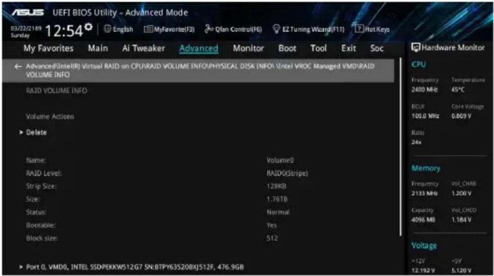
text_image
ASUS UEFI BIOS Utility - Advanced Mode 03/22/2189 12:54 English MyFavorite(F3) Qfan Control(F6) EZ Tuning Wizard(F11) Hot Keys My Favorites Main AI Tweaker Advanced Monitor Boot Tool Exit Soc Advanced(Intel(R) Virtual RAID on CPU\RAID VOLUME INFO\PHYSICAL DISK (INFO\Intel)VROC Managed VMD\RAID VOLUME INFO RAID VOLUME INFO Volume Actions ► Delete Name: Volume0 RAID Level: RAID(Stripe) Strip Size: 12KB Size: 1.76TB Status: Normal Bootable: Yes Block size: 512 ► Port 0, VMD0, INTEL SSDPEKKW512G7 SN:BTPY63520BXJ512F, 476.9GB Hardware Monitor CPU Frequency Temperature 2400 MHz 45°C BCLK Core Voltage 100.0 MHz 0.869 V Ratio 24x Memory Frequency Vol_CHAB 2133 MHz 1.200 V Capacity Vol_CHED 4096 MB 1.184 V Voltage +12V -9V 12.192 V 5.120 V- When the Delete item is selected, press
, then select Yes to delete the RAID volume and return to the Intel® Virtual Raid on CPU menu, or select No to cancel.
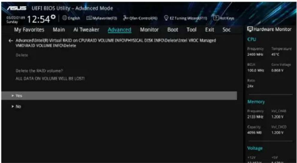
text_image
ASUS UEFI BIOS Utility - Advanced Mode 03/22/21/09 12:54 English MyFavorite(F3) Qfan Control(F6) EZ Tuning Wizard(F11) Hot Keys My Favorites Main Ai Tweaker Advanced Monitor Boot Tool Exit Soc Advanced\Intel(R) Virtual RAID on CPU\RAID VOLUME INFO\PHYSICAL DISK INFO\Delete\Intel VROC Managed VMD\RAID VOLUME INFO\Delete Delete Delete the RAID volume? ALL DATA ON VOLUME WILL BE LOST! Yes No Hardware Monitor CPU Frequency Temperature 2400 MHz 45°C BCLK Core Voltage 100.0 MHz 0.868 V Ratio 24x Memory Frequency Vol_CHAB 2133 MHz 1.200 V Capacity Vol_CHOD 4096 MB 1.200 V Voltage +12V +5V 13.162 Hz 5.130 HzInstalling the RAID controller driver during Windows® 10 OS installation
This part provides the instructions on how to install the RAID controller drivers during OS installation.
To install the RAID controller driver when installing Windows® 10 OS:
- Boot the computer using the Windows ^® 10 OS installation disc. Follow the screen instructions to start installing Windows ^® 10.
- When prompted to choose a type of installation, click Custom: Install Windows only (advanced).
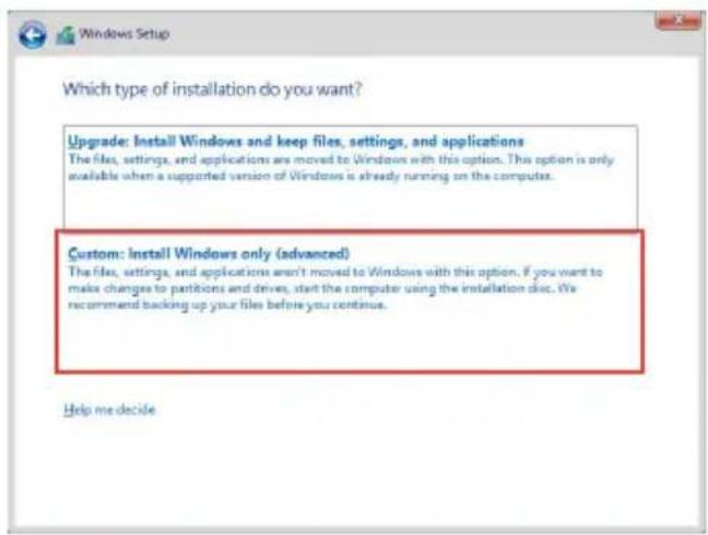
text_image
Which type of installation do you want? Upgrade: Install Windows and keep files, settings, and applications The files, settings, and applications are moved to Windows with this option. This option is only available when a supported version of Windows is already running on the computer. Custom: Install Windows only (advanced) The files, settings, and applications aren't moved to Windows with this option. If you want to make changes to partitions and drives, start the computer using the installation disc. We recommend backing up your files before you continue. Help me decide- Click Load Driver.
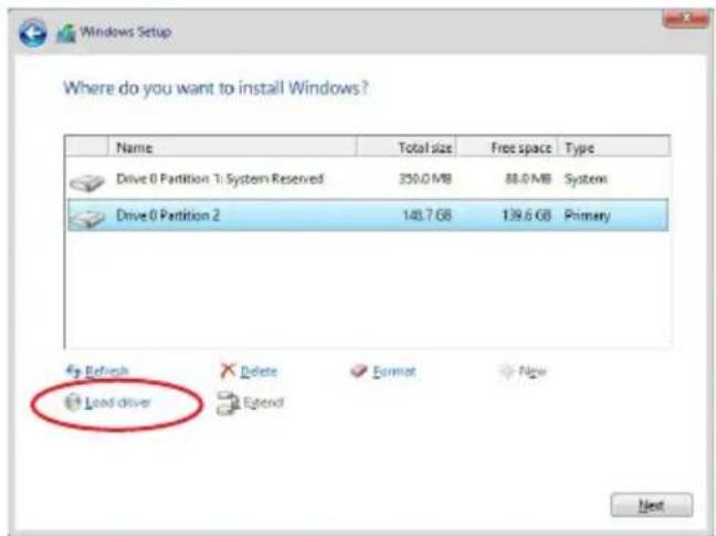
text_image
Windows Setup Where do you want to install Windows? Name Total size Free space Type Drive 0 Partition 1 System Reserved 350.0 MB 88.0 MB System Drive 0 Partition 2 140.7 GB 139.6 GB Primary Load driver Refresh Delete Format New Extend Next- A message appears, reminding you to insert the installation media containing the driver of the RAID controller driver. If you have only one optical drive installed in your system, eject the Windows OS installation disc and replace with the motherboard Support DVD into the optical drive. Click Browse to continue.
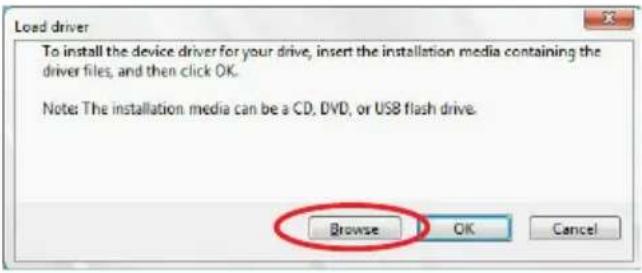
text_image
Load driver To install the device driver for your drive, insert the installation media containing the driver files, and then click OK. Note: The installation media can be a CD, DVD, or USB flash drive. Browse OK Cancel- Locate the driver in the corresponding folder of the Support DVD then click OK to continue.
- Select the RAID controller driver you need from the list and click Next.
- When the system finishes loading the RAID driver, replace the motherboard Support DVD with the Windows Server installation disc. Select the drive to install Windows and click Next.
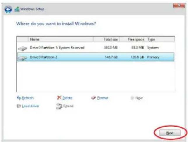
text_image
Windows Setup Where do you want to install Windows? Name Total size Free space Type Drive 0 Partition 1: System Reserved 350.0 MB 88.0 MB System Drive 0 Partition 2 148.7 GB 139.0 GB Primary Refresh Delete Format Now Load driver Egstand Next- Setup then proceeds with the OS installation. Follow screen instructions to continue.
4.1.5 Intel® Rapid Storage Technology Option ROM utility
To enter the Intel® Rapid Storage Technology Option ROM utility:
- Turn on the system.
- During POST, press
+ to display the utility main menu.
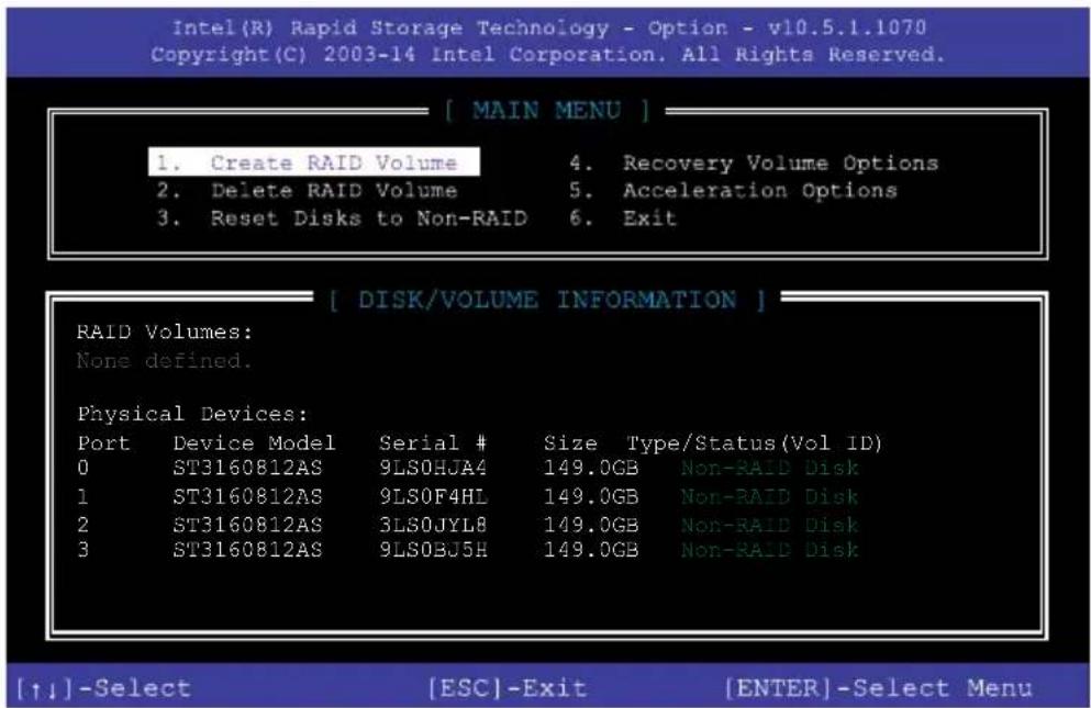
text_image
Intel(R) Rapid Storage Technology - Option - v10.5.1.1070 Copyright(C) 2003-14 Intel Corporation. All Rights Reserved. [ MAIN MENU ] 1. Create RAID Volume 4. Recovery Volume Options 2. Delete RAID Volume 5. Acceleration Options 3. Reset Disks to Non-RAID 6. Exit [ DISK/VOLUME INFORMATION ] RAID Volumes: None defined. Physical Devices: Port Device Model Serial # Size Type/Status(Vol ID) 0 ST3160812AS 9LS0HJA4 149.0GB Non-RAID Disk 1 ST3160812AS 9LS0F4HL 149.0GB Non-RAID Disk 2 ST3160812AS 3LS0JYL8 149.0GB Non-RAID Disk 3 ST3160812AS 9LS0BJ5H 149.0GB Non-RAID Disk [↑↓]-Select [ESC]-Exit [ENTER]-Select MenuThe navigation keys at the bottom of the screen allow you to move through the menus and select the menu options.

The RAID BIOS setup screens shown in this section are for reference only and may not exactly match the items on your screen.

The utility supports maximum four hard disk drives for RAID configuration.
Creating a RAID set
To create a RAID set:
- From the utility main menu, select 1. Create RAID Volume and press
. The following screen appears:
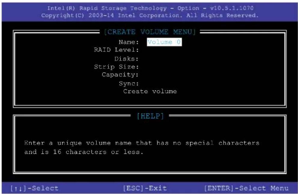
text_image
[CREATE VOLUME MENU] Name: Volume 0 RAID Level: Disks: Strip Size: Capacity: Sync: Create volume [HELP] Enter a unique volume name that has no special characters and is 16 characters or less. [↑↓]-Select [ESC]-Exit [ENTER]-Select Menu- Enter a name for the RAID set and press
. - When the RAID Level item is selected, press the up/down arrow key to select a RAID level to create, and then press
. - When the Disks item is selected, press
to select the hard disk drives you want to include in the RAID set. The SELECT DISKS screen appears:
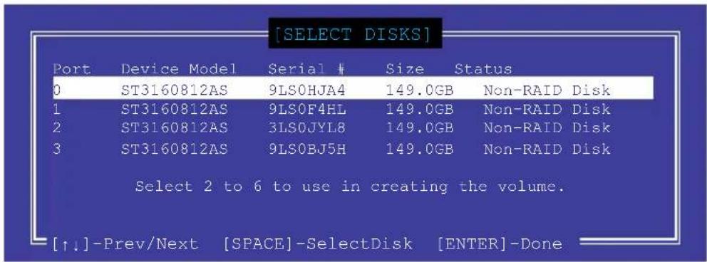
text_image
[SELECT DISKS] Port Device Model Serial # Size Status 0 ST3160812AS 9LS0HJA4 149.0GB Non-RAID Disk 1 ST3160812AS 9LS0F4HL 149.0GB Non-RAID Disk 2 ST3160812AS 3LS0JYL8 149.0GB Non-RAID Disk 3 ST3160812AS 9LS0BJ5H 149.0GB Non-RAID Disk Select 2 to 6 to use in creating the volume. [↑↓]-Prev/Next [SPACE]-SelectDisk [ENTER]-Done- Use the up/down arrow key to select a drive, and then press
to select. A small triangle marks the selected drive. Press after completing your selection. -
Use the up/down arrow key to select the strip size for the RAID array (for RAID 0, 10 and 5 only), and then press
. The available strip size values range from 4 KB to 128 KB. The following are typical values: -
RAID 0: 128 KB
- RAID 10: 64 KB
- RAID 5: 64 KB

We recommend a lower strip size for server systems, and a higher strip size for multimedia computer systems used mainly for audio and video editing.
- When the Capacity item is selected, enter the RAID volume capacity that you want and press
. The default value indicates the maximum allowed capacity. - When the Create Volume item is selected, press
. The following warning message appears:
WARNING: ALL DATA ON SELECTED DISKS WILL BE LOST.
Are you sure you want to create this volume? (Y/N)
- Press
to create the RAID volume and return to the main menu, or to go back to the CREATE VOLUME menu.
Deleting a RAID set

Be cautious when deleting a RAID set. You will lose all data on the hard disk drives when you delete a RAID set.
To delete a RAID set:
- From the utility main menu, select 2. Delete RAID Volume and press
. The following screen appears:
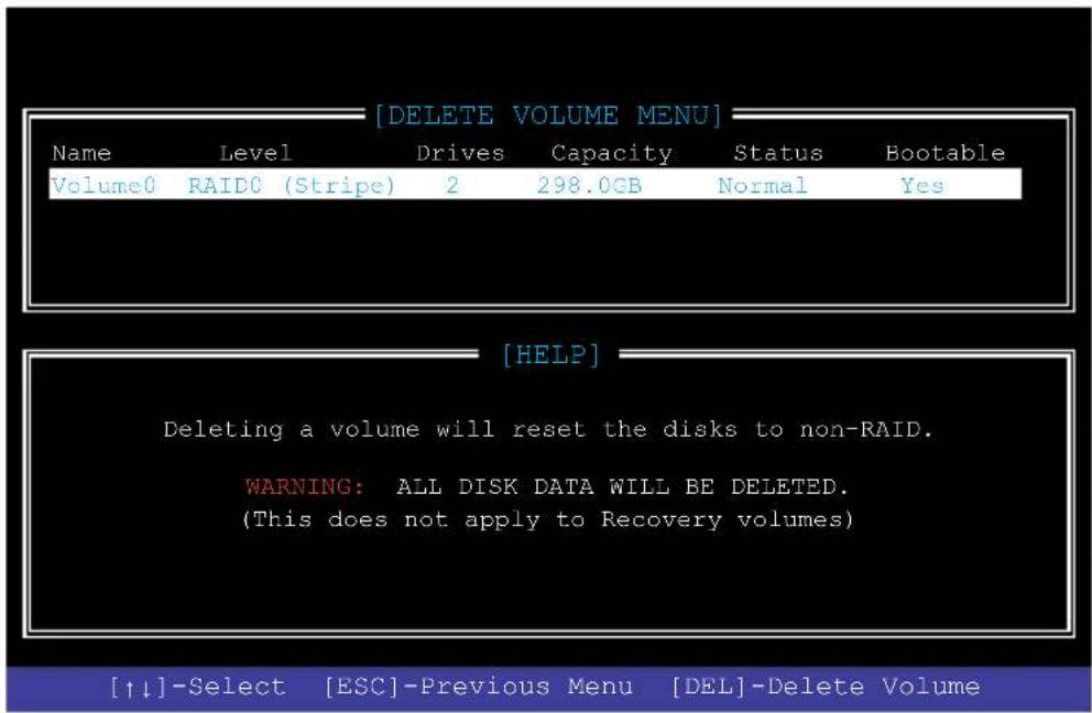
text_image
[DELETE VOLUME MENU] Name Level Drives Capacity Status Bootable Volume0 RAID0 (Stripe) 2 298.0GB Normal Yes [HELP] Deleting a volume will reset the disks to non-RAID. WARNING: ALL DISK DATA WILL BE DELETED. (This does not apply to Recovery volumes) [↑↓]-Select [ESC]-Previous Menu [DEL]-Delete Volume- Use the up/down arrow key to select the RAID set you want to delete, and then press
. The following warning message appears:
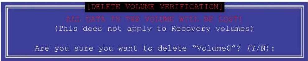
text_image
[DELETE VOLUME VERIFICATION] ALL DATA IN THE VOLUME WILL BE LOST! (This does not apply to Recovery volumes) Are you sure you want to delete "Volume0"? (Y/N):- Press
to delete the RAID set and return to the utility main menu, or press to return to the DELETE VOLUME menu.
Exiting the Intel® Rapid Storage Technology Option ROM utility
To exit the utility:
- From the utility main menu, select 6. Exit, then press
. The following warning message appears:
[CONFIRM EXIT]
Are you sure you want to exit? (Y/N):
- Press
to exit or press to return to the utility main menu.
4.2 Creating a RAID driver disk
4.2.1 Creating a RAID driver disk in Windows ®
To install the RAID driver for Windows® OS:
- During the OS installation, click Load Driver to allow you to select the installation media containing the RAID driver.
- Insert the USB flash drive with RAID driver into the USB port or the support DVD into the optical drive, and then click Browse.
-
Click the name of the device you've inserted, go to Drivers > RAID, and then select the RAID driver for the corresponding OS version. Click OK.
-
Follow the succeeding screen instructions to complete the installation.

Before loading the RAID driver from a USB flash drive, you have to use another computer to copy the RAID driver from the support DVD to the USB flash drive.

To set up a Windows® UEFI operating system under RAID mode, ensure to load the UEFI driver for your optical drive.
Multiple GPU Support
5.1 AMD® CrossFireX™ technology
The motherboard supports the AMD ^® CrossFireX ^™ technology that allows you to install multi-graphics processing units (GPU) graphics cards. Follow the installation procedures in this section.
5.1.1 Requirements
- In Dual CrossFireX™ mode, you should have two identical CrossFireX™-ready graphics cards or one CrossFireX™-ready dual-GPU graphics card that are AMD® certified.
- Ensure that your graphics card driver supports the AMD ^ CrossFireX ^TM technology. Download the latest driver from the AMD ^ website at www.AMD.com.
- Ensure that your power supply unit (PSU) can provide at least the minimum power required by your system. See Chapter 1 for details.

• We recommend that you install additional chassis fans for better thermal environment.
- Visit the AMD ^ Game website at http://game.AMD.com for the latest certified graphics card and the supported 3D application list.
5.1.2 Before you begin
For AMD ^® CrossFireX ^™ to work properly, you have to uninstall all existing graphics card drivers before installing AMD ^® CrossFireX ^™ graphics cards to your system.
To uninstall existing graphics card drivers:
- Close all current applications.
- Go to Control Panel > Programs and Features.
- Select your current graphics card driver/s.
- Select Uninstall.
- Turn off your computer.
5.1.3 Installing two CrossFireX™ graphics cards

The following pictures are for reference only. The graphics cards and the motherboard layout may vary with models, but the installation steps remain the same.
To install two CrossFireX™ graphics cards:
- Prepare two CrossFireX™-ready graphics cards.
-
Insert the two graphics card into the PCIEX16 slots. If your motherboard has more than two PCIEX16 slots, refer to Chapter 1 in this user manual for the locations of the PCIEX16 slots recommended for multi-graphics card installation.
-
Ensure that the cards are properly seated on the slots.
-
Align and firmly insert the CrossFireX™ bridge connector to the goldfingers on each graphics card. Ensure that the connector is firmly in place.
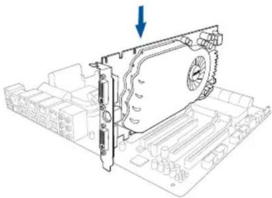
natural_image
Technical line drawing of a computer motherboard with a fan component and a blue arrow indicating direction (no text or symbols)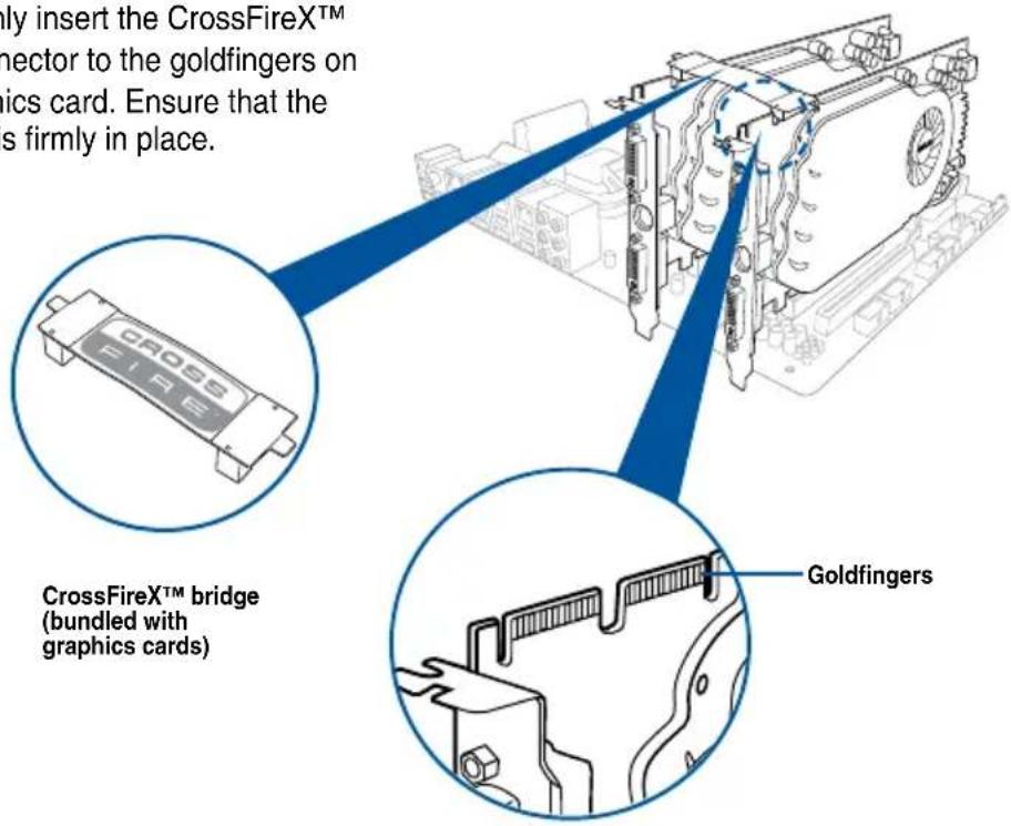
text_image
only insert the CrossFireXTM nector to the goldfingers on pics card. Ensure that the s firmly in place. CrossFireX™ bridge (bundled with graphics cards) Goldfingers
The CrossFireX™ bridge is only required for selected graphics cards.
- Connect two independent auxiliary power sources from the power supply to the two graphics cards separately.
- Connect a VGA or a DVI cable to the graphics card.
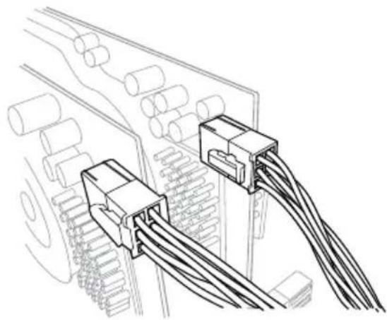
natural_image
Technical line drawing of two connected electrical connectors with coiled wires (no text or symbols)5.1.4 Installing three CrossFireX™ graphics cards
To install three CrossFireX™ graphics cards:
- Prepare three CrossFireX™-ready graphics cards.
-
Insert the three graphics card into the PCIEX16 slots. If your motherboard has more than three PCIEX16 slots, refer to Chapter 1 in this user manual for the locations of the PCIEX16 slots recommended for multi-graphics card installation.
-
Ensure that the cards are properly seated on the slots.
-
Align and firmly insert the two CrossFireX™ bridge connectors to the goldfingers on each graphics card. Ensure that the connectors are firmly in place.
-
Connect three independent auxiliary power sources from the power supply to the three graphics cards separately.
-
Connect a VGA or a DVI cable to the graphics card.
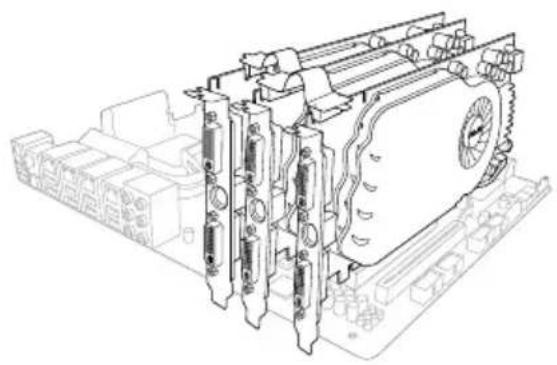
natural_image
Technical line drawing of a computer motherboard with visible slots and connectors (no text or symbols)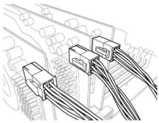
natural_image
Technical line drawing of electrical connectors and wiring (no text or symbols)5.1.5 Installing four CrossFireX™ graphics cards
To install four CrossFireX™ graphics cards:
-
Prepare four CrossFireX™-ready graphics cards.
-
Insert the four graphics cards into the PCIEX16 slots. Refer to Chapter 1 in this user manual for the locations of the PCIEX16 slots recommended for multi-graphics card installation.
-
Ensure that the cards are properly seated on the slots.
-
Align and firmly insert the three CrossFireX™ bridge connectors to the goldfingers on each graphics card. Ensure that the connectors are firmly in place.
-
Connect four independent auxiliary power sources from the power supply to the four graphics cards separately.
-
Connect a VGA or a DVI cable to the graphics card.
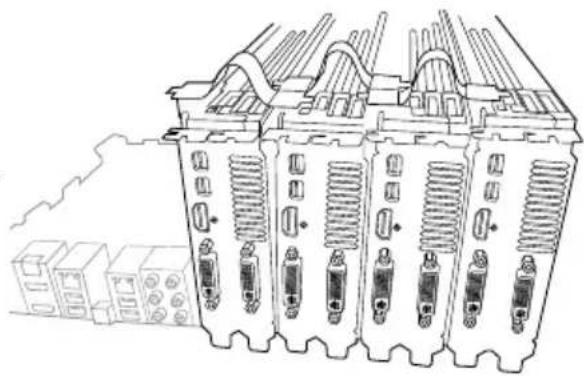
natural_image
Technical line drawing of a multi-chamber electrical enclosure with cooling fans and heat sinks (no text or symbols)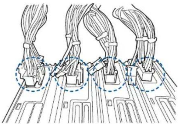
natural_image
Diagram of three cable connector assemblies on a circuit board, showing wiring connections and mounting points (no text or labels)5.1.6 Installing the device drivers
Refer to the documentation that came with your graphics card package to install the device drivers.

Ensure that your PCI Express graphics card driver supports the AMD® CrossFireX™ technology. Download the latest driver from the AMD® website at www.AMD.com.
5.1.7 Enabling the AMD ^ CrossFireX ^TM technology
After installing your graphics cards and the device drivers, enable the CrossFireX™ feature through the AMD® Vision Engine Control Center in Windows environment.
Launching the AMD® VISION Engine Control Center
To launch the AMD® VISION Engine Control Center:
- Right-click on the Windows ^ desktop and select AMD ^ VISION Engine Control Center.
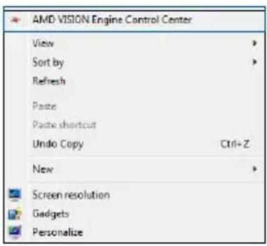
text_image
AMD VISION Engine Control Center View Sort by Refresh Paste Paste shortcut Undo Copy Ctrl+Z New Screen resolution Gadgets PersonalizeEnabling Dual CrossFireX™ technology
To enable Dual CrossFireX™ technology:
- In the AMD ^ Vision Engine Control Center window, click Performance > AMD ^ CrossFireX ^TM .
- Select Enable CrossFireX™.
- Select a GPU combination from the drop-down list.
- Click Apply to save and activate the GPU settings made.
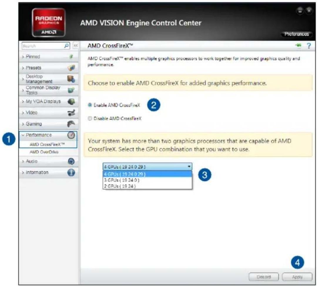
text_image
RADEON GRAPHICS AMD AMD VISION Engine Control Center Preferences Search Pinned Presets Desktop Management Common Display Tasks My VGA Displays Video Gaming Performance AMD CrossFireX™ AMD OverDrive Audio Information AMD CrossFireX™ AMD CrossFireX™ enables multiple graphics processors to work together for improved graphics quality and performance. Choose to enable AMD CrossFireX for added graphics performance. Enable AMD CrossFireX Disable AMD CrossFireX Your system has more than two graphics processors that are capable of AMD CrossFireX. Select the GPU combination that you want to use. 4 GPUs (19 24 0 29) 4 GPUs (19 24 0 29) 3 GPUs (19 24 0) 2 GPUs (19 24) 3 4 Discard Apply5.2 NVIDIA® SLI™ technology
The motherboard supports the NVIDIA® SLITM (Scalable Link Interface) technology that allows you to install multi-graphics processing units (GPU) graphics cards. Follow the installation procedures in this section.
5.2.1 Requirements
- In SLI™ mode, you should have two identical SLI-ready graphics cards that are NVIDIA® certified.
- Ensure that your graphics card driver supports the NVIDIA ^ SLI ^TM technology. Download the latest driver from the NVIDIA ^ website at www.NVIDIA.com.
- Ensure that your power supply unit (PSU) can provide at least the minimum power required by your system.

• We recommend that you install additional chassis fans for better thermal environment.
- Visit the NVIDIA ^ zone website at http://www.nzone.com for the latest certified graphics card and supported 3D application list.
5.2.2 Installing two SLI-ready graphics cards

The following pictures are for reference only. The graphics cards and the motherboard layout may vary with models, but the installation steps remain the same.
To install two SLI-ready graphics cards:
- Prepare two SLI-ready graphics cards.
- Insert the two graphics card into the PCIEX16 slots. If your motherboard has more than two PCIEX16 slots, refer to Chapter 1 in this user manual for the locations of the PCIEX16 slots recommended for multi-graphics card installation.
- Ensure that the cards are properly seated on the slots.
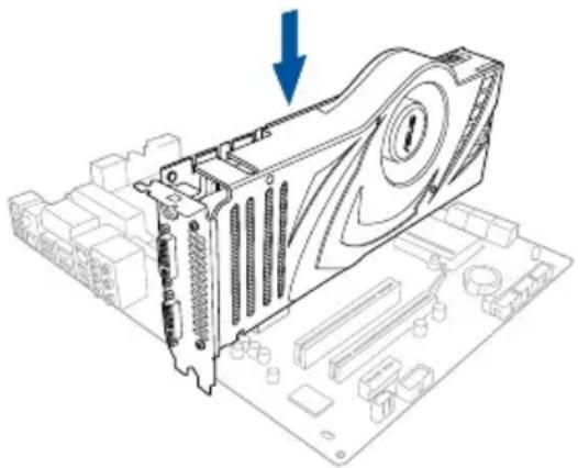
natural_image
Technical line drawing of a computer motherboard with a monitor and CPU socket (no text or symbols)- Align and firmly insert the SLI™ bridge connector to the goldfingers on each graphics card. Ensure that the connector is firmly in place.
- Connect two independent auxiliary power sources from the power supply to the two graphics cards separately.
- Connect a VGA or a DVI cable to the graphics card.
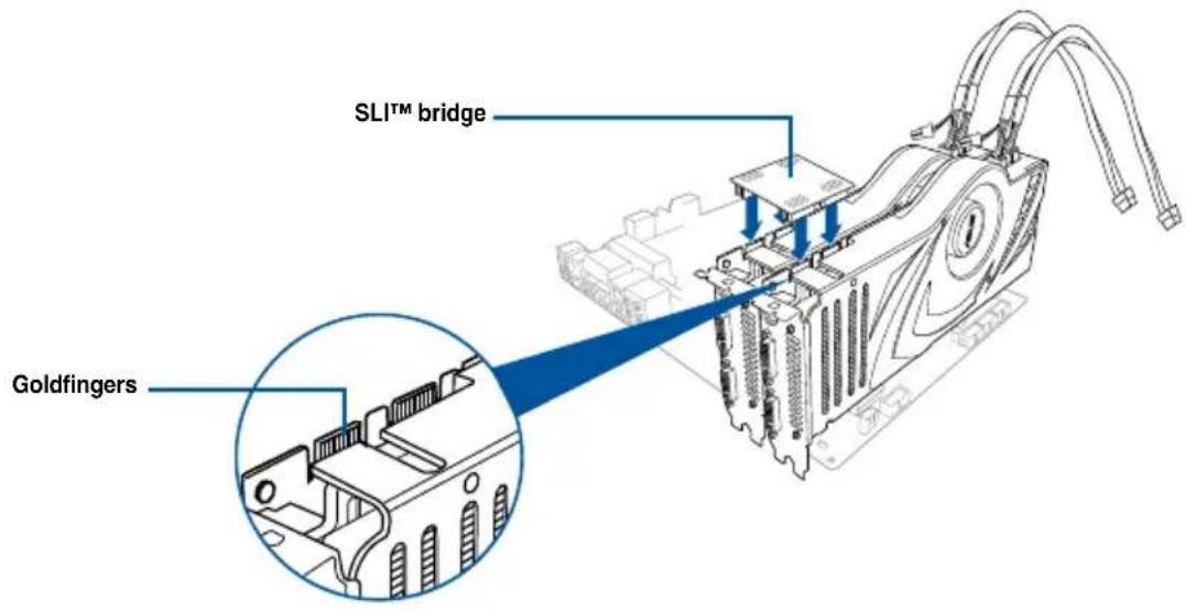
text_image
SLITM bridge Goldfingers5.2.3 Installing three SLI-ready graphics cards
Refer to the documentation that came with your graphics card package to install the device drivers.
To install three SLI-ready graphics cards:
- Prepare three SLI-ready graphics cards.
- Insert the three graphics cards into the PCIEX16 slots. If your motherboard has more than two PCIEX16 slots, refer to Chapter 1 in this user manual for locations of the PCIEX16 slots recommended for multi-graphics card installation.
- Ensure that the cards are properly seated on the slots.
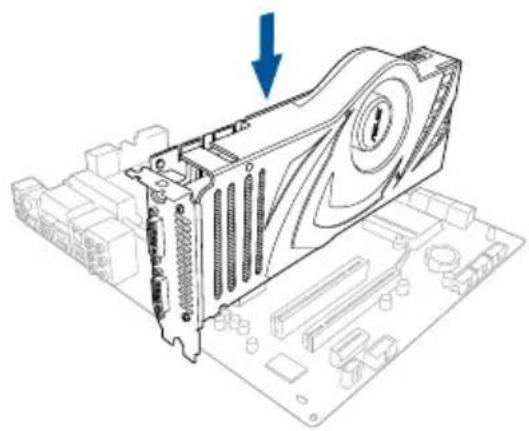
natural_image
Technical line drawing of a computer motherboard with a monitor and CPU socket (no text or symbols)-
Align and firmly insert the 3-way SLI™ bridge connector to the goldfingers on each graphics card. Ensure that the connector is firmly in place.
-
Connect three independent auxiliary power sources from the power supply to the three graphics cards separately.
-
Connect a VGA or a DVI cable to the graphics card.
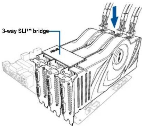
text_image
3-way SLITM bridge5.2.4 Installing four SLI-ready graphics cards
To install four SLI-ready graphics cards:
- Prepare four SLI-ready graphics cards.
- Insert the four graphics cards into the PCIEX16 slots. If your motherboard has more than two PCIEX16 slots, refer to Chapter 1 in this user manual for the locations of the PCIEX16 slots recommended for multi-graphics card installation.
- Ensure that the cards are properly seated on the slots.
- Align and firmly insert the 4-way SLITM bridge connector to the goldfingers on each graphics card. Ensure that the connector is firmly in place.
- Connect four independent auxiliary power sources from the power supply to the four graphics cards separately.
- Connect a VGA or a DVI cable to the graphics card.
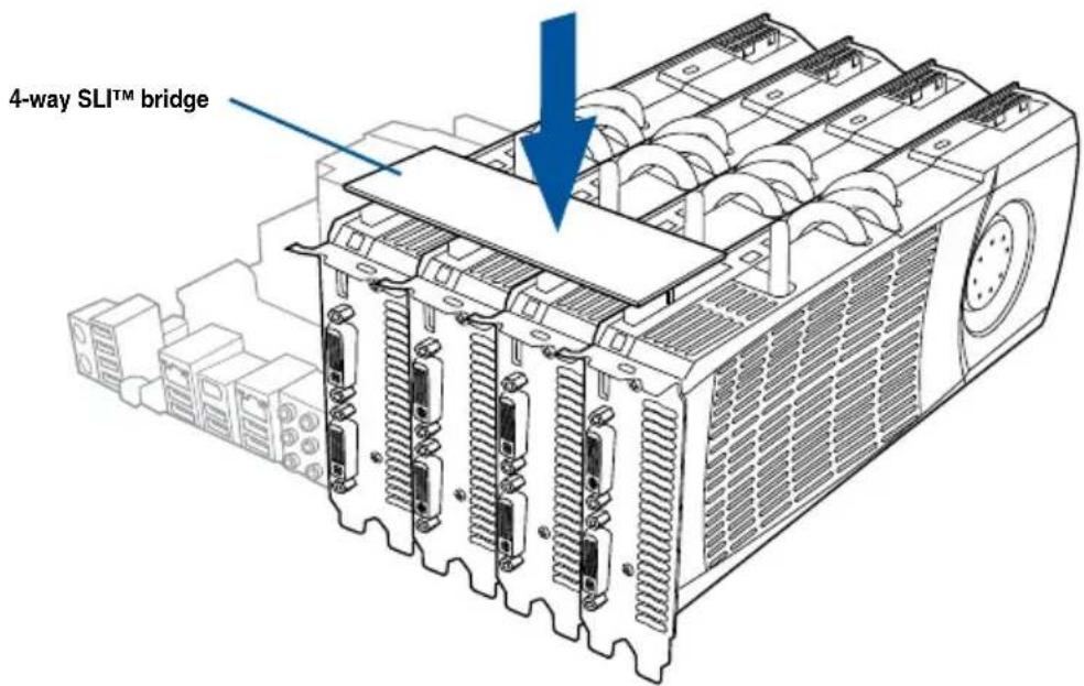
text_image
4-way SLITM bridge5.2.5 Installing the device drivers
Refer to the documentation that came with your graphics card package to install the device drivers.

Ensure that your PCI Express graphics card driver supports the NVIDIA® SLITM technology. Download the latest driver from the NVIDIA® website at www.NVIDIA.com.
5.2.6 Enabling the NVIDIA ^® SLI ^TM technology
After installing your graphics cards and the device drivers, enable the SLI™ feature in NVIDIA® Control Panel under the Windows® 7 operating system.
Launching the NVIDIA® Control Panel
You can launch the NVIDIA® Control Panel by the following two methods:
A. Right click on the empty space of the Windows ^® desktop and select NVIDIA ^® Control Panel.
The NVIDIA B3). ^® Control Panel window appears (See Step
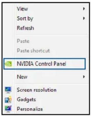
text_image
View Sort by Refresh Paste Paste shortcut NVIDIA Control Panel New Screen resolution Gadgets PersonalizeB1. If you cannot see the NVIDIA ^ Control Panel item in step (A), select Screen Resolution.
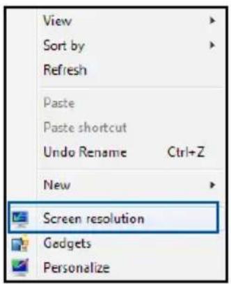
text_image
View Sort by Refresh Paste Paste shortcut Undo Rename Ctrl+Z New Screen resolution Gadgets PersonalizeB2. From the Screen Resolution window, click Advanced settings.
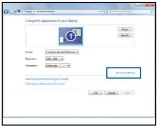
text_image
Change the appearance of your display Display: 1. Dense, Normal-All Monitors Regulations: 1200 - 900 Orientation: Landscape Advanced settings Make text and other items larger or smaller What display settings should be checked? OK Cancel ApplyB3. The NVIDIA ^® Control Panel window appears.
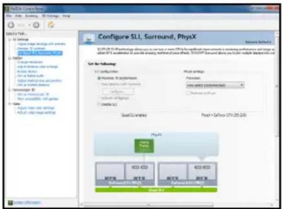
text_image
Configure SL1, Surround, PhysX Set for following: SL1 config centerIncrease in performance
Increase in performance
Increase in performance
Increase SL1
Proof C:\Build Proof X\Software (379.25-200) PhysX Proof X Proof X Proof X Proof XEnabling SLI™ settings
From the NVIDIA® Control Panel window, select Configure SLI, Surround, PhysX. In the Quad-SLI enabled, click Maximize 3D Performance SLI to set the display for viewing SLI™ rendered content. When done, click Apply.
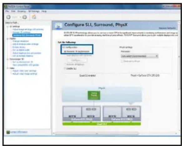
text_image
PDSX Group Name File Edit View Help Tools Help Configure SLI, Surround, PhysX Set for following: SLI Setup this or Transfer to Surround Start Settings Start Settings Process Start Settings System: SLI Start Settings PhysX + GeForce 27.25.20.0 PhysX Software 12.0000000000000000000000000000000000000000000000000000000000000000000000000000000000000000000000000 Start SLI End SLI System InformationAppendix
WS X299 SAGE/10G block diagram (44-Lane)
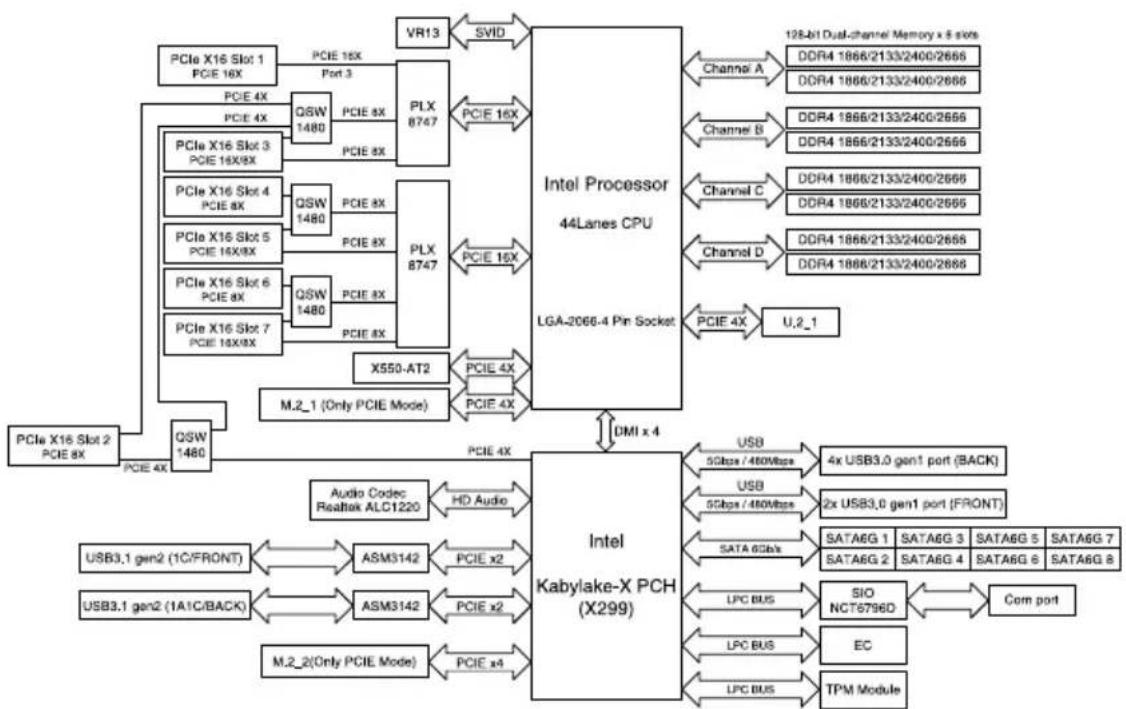
flowchart
graph TD
    A["PCIe X16 Slot 1\nPCIE 16X"] --> B["PCIE 4X"]
    B --> C["QSW 1480"]
    C --> D["PLX 8747"]
    D --> E["PCIE 16X"]
    E --> F["SVID"]
    F --> G["Intel Processor\n44Lanes CPU\nLGA-2066-4 Pin Socket"]
    G --> H["Channel A"]
    H --> I["DDR4 1866/2133/2400/2666"]
    G --> J["Channel B"]
    J --> K["DDR4 1866/2133/2400/2666"]
    G --> L["Channel C"]
    L --> M["DDR4 1866/2133/2400/2666"]
    G --> N["Channel D"]
    N --> O["DDR4 1866/2133/2400/2666"]
    G --> P["PCIE 4X"]
    P --> Q["U.2_1"]
    G --> R["PCIe X16 Slot 2\nPCIE 8X"]
    R --> S["QSW 1480"]
    S --> T["PCIe 4X"]
    T --> U["PCIE 4X"]
    U --> V["PCIe X16 Slot 5\nPCIE 16X8X"]
    U --> W["QSW 1480"]
    W --> X["PLX 8747"]
    X --> Y["PCIE 16X"]
    Y --> Z["PCIe X16 Slot 4\nPCIE 8X"]
    Y --> AA["QSW 1480"]
    AA --> AB["PLX 8747"]
    AB --> AC["X550-AT2"]
    AC --> AD["M.2_1 (Only PCIE Mode)"]
    AD --> AE["PCIe 4X"]
    AE --> AF["PCIe 4X"]
    AF --> AG["PCIe 4X"]
    AG --> AH["PCIe 4X"]
    AH --> AI["PCIe 4X"]
    AI --> AJ["PCIe 4X"]
    AJ --> AK["PCIe 4X"]
    AK --> AL["PCIe 4X"]
    AL --> AM["PCIe 4X"]
    AM --> AN["PCIe 4X"]
    AN --> AO["PCIe 4X"]
    AO --> AP["PCIe 4X"]
    AP --> AQ["PCIe 4X"]
    AQ --> AR["PCIe 4X"]
    AR --> AS["PCIe 4X"]
    AS --> AT["PCIe 4X"]
    AT --> AU["PCIe 4X"]
    AU --> AV["PCIe 4X"]
    AV --> AW["PCIe 4X"]
    AW --> AX["PCIe 4X"]
    AX --> AY["PCIe 4X"]
    AY --> AZ["PCIe 4X"]
    AZ --> BA["PCIe 4X"]
    BA --> BB["PCIe 4X"]
    BB --> BC["PCIe 4X"]
    BC --> BD["PCIe 4X"]
    BD --> BE["PCIe 4X"]
    BE --> BF["PCIe 4X"]
    BF --> BG["PCIe 4X"]
    BG --> BH["PCIe 4X"]
    BH --> BI["PCIe 4X"]
    BI --> BJ["PCIe 4X"]
    BJ --> BK["PCIe 4X"]
    BK --> BL["PCIe 4X"]
    BL --> BM["PCIe 4X"]
    BM --> BN["PCIe 4X"]
    BN --> BO["PCIe 4X"]
    BO --> BP["PCIe 4X"]
    BP --> BQ["PCIe 4X"]
    BQ --> BR["PCIe 4X"]
    BR --> BS["PCIe 4X"]
    BS --> BT["PCIe 4X"]
    BT --> BU["PCIe 4X"]
    BU --> BV["PCIe 4X"]
    BV --> BW["PCIe 4X"]
    BW --> BX["PCIe 4X"]
    BX --> BY["PCIe 4X"]
    BY --> BZ["PCIe 4X"]
    BZ --> CA["PCIe 4X"]
    CA --> CB["PCIe 4X"]
    CB --> CC["PCIe 4X"]
    CC --> CD["PCIe 4X"]
    CD --> CE["PCIe 4X"]
    CE --> CF["PCIe 4X"]
    CF --> CG["PCIe 4X"]
    CG --> CH["PCIe 4X"]
    CH --> CI["PCIe 4X"]
    CI --> CJ["PCIe 4X"]
    CJ --> CK["PCIe 4X"]
    CK --> CL["PCIe 4X"]
    CL --> CM["PCIe 4X"]
    CM --> CN["PCIe 4X"]
    CN --> CO["PCIe 4X"]
    CO --> CP["PCIe 4X"]
    CP --> CQ["PCIe 4X"]
    CQ --> CR["PCIe 4X"]
    CR --> CS["PCIe 4X"]
    CS --> CT["PCIe 4X"]
    CT --> CU["PCIe 4X"]
    CU --> CV["PCIe 4X"]
    CV --> CW["PCIe 4X"]
    CW --> CX["PCIe 4X"]
    CX --> CY["PCIe 4X"]
    CY --> CZ["PCIe 4X"]
WS X299 SAGE/10G block diagram (28-Lane)
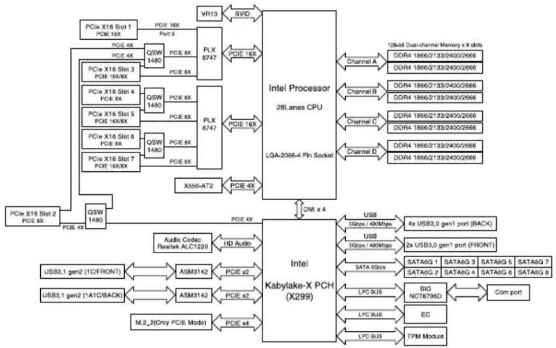
flowchart
graph TD
    A["PCie X16 Slot 1\nPCIE 16X"] --> B["QSW 1480"]
    B --> C["PLX 8747"]
    C --> D["CPU 28Lanes CPU\nLGA-2066-4 Pin Socket"]
    D --> E["Channel A"]
    D --> F["Channel B"]
    D --> G["Channel C"]
    D --> H["Channel D"]
    A --> I["QSI 1480"]
    I --> J["PLX 8747"]
    J --> K["CPU 28Lanes CPU\nLGA-2066-4 Pin Socket"]
    K --> L["Channel A"]
    K --> M["Channel B"]
    K --> N["Channel C"]
    K --> O["Channel D"]
    P["PCie X16 Slot 2\nPCIE 8X"] --> Q["QSW 1480"]
    Q --> R["X550-AT2"]
    R --> S["CPU 28Lanes CPU\nLGA-2066-4 Pin Socket"]
    S --> T["Channel A"]
    S --> U["Channel B"]
    S --> V["Channel C"]
    S --> W["Channel D"]
    X["Audio Codec\nRes/tek ALC1220"] --> Y["HD Audio"]
    Y --> Z["CPU 28Lanes CPU\nLGA-2066-4 Pin Socket"]
    Z --> AA["Channel A"]
    Z --> AB["Channel B"]
    Z --> AC["Channel C"]
    Z --> AD["Channel D"]
    AE["USB3.1 gen2 (1C/FRONT)"] --> AF["ASM3142"]
    AF --> AG["CPU x2"]
    AG --> AH["CPU 28Lanes CPU\nLGA-2066-4 Pin Socket"]
    AH --> AI["Channel A"]
    AH --> AJ["Channel B"]
    AH --> AK["Channel C"]
    AH --> AL["Channel D"]
    AM["USB3.1 gen2 (1A1C/BACK)"] --> AN["ASM3142"]
    AN --> AO["CPU x2"]
    AO --> AP["CPU 28Lanes CPU\nLGA-2066-4 Pin Socket"]
    AP --> AQ["Channel A"]
    AP --> AR["Channel B"]
    AP --> AS["Channel C"]
    AP --> AT["Channel D"]
    AU["M.2_2(Only PCIE Mode)"] --> AV["PCIe x4"]
    AV --> AW["CPU 28Lanes CPU\nLGA-2066-4 Pin Socket"]
    AW --> AX["Channel A"]
    AW --> AY["Channel B"]
    AW --> AZ["Channel C"]
    AW --> BA["Channel D"]
    BB["SATA6G1"] --> BC["SATA6G 1"]
    BB --> BD["SATA6G 2"]
    BB --> BE["SATA6G 3"]
    BB --> BF["SATA6G 4"]
    BB --> BG["SATA6G 5"]
    BB --> BH["SATA6G 6"]
    BB --> BI["SATA6G 7"]
    BB --> BJ["SATA6G 8"]
    BK["LPC BUS"] --> BL["SIO NCT6796D"]
    BL --> BM["Com port"]
        BN["LPC BUS"] --> BO["EC"]
        BN --> BP["TPM Module"]
    B <-->|PCE 4X| Q
    Q <-->|PCE 4X| R
    R <-->|PCE 4X| S
    S <-->|PCE 4X| T
WS X299 SAGE/10G block diagram (16-Lane)
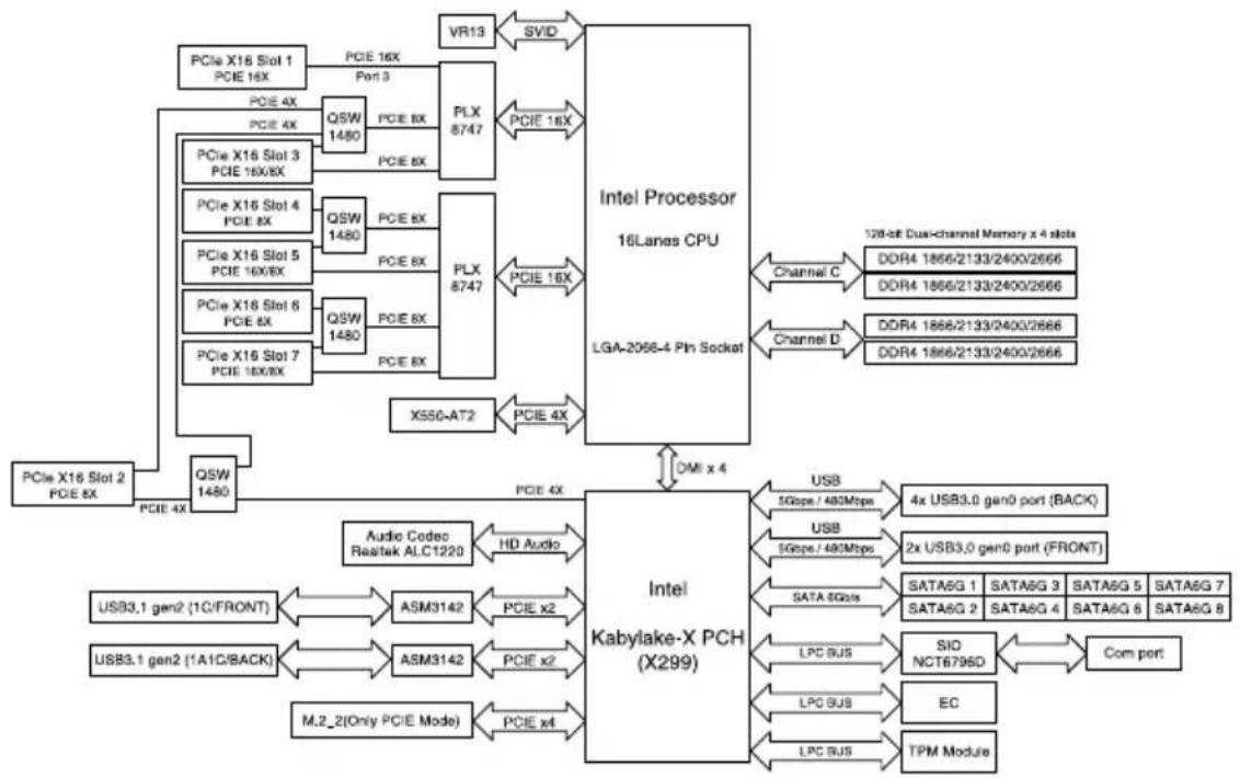
flowchart
graph TD
    A["PCle X16 Slot 1\nPCIE 16X"] -->|PCIE 4X| B["QSW 1480"]
    A -->|PCIE 4X| C["PLX 8747"]
    B -->|QSW 1480| D["PCIE 8X"]
    B -->|QSW 1480| E["PLX 8747"]
    C -->|QSW 1480| F["PCIE 8X"]
    C -->|QSW 1480| G["PLX 8747"]
    H["PCle X16 Slot 2\nPCIE 8X"] -->|PCIE 4X| I["QSW 1480"]
    I --> J["PCIE 4X"]
    K["CPU"] --> L["VR13"]
    L --> M["SVID"]
    M --> N["Intel Processor\n16Lanes CPU\nLGA-2066-4 Pin Socket"]
    N --> O["Channel C"]
    O --> P["DDR4 1866/2133/2400/2666"]
    N --> Q["DDR4 1866/2133/2400/2666"]
    N --> R["DDR4 1866/2133/2400/2666"]
    N --> S["DDR4 1866/2133/2400/2666"]
    N --> T["DDR4 1866/2133/2400/2666"]
    U["PCIe X16 Slot 3\nPCIE 16X/8X"] --> V["QSW 1480"]
    V --> W["PCIE 4X"]
    X["PCIe X16 Slot 5\nPCIE 16X/8X"] --> Y["QSW 1480"]
    Y --> Z["PCIE 8X"]
    AA["PCIe X16 Slot 6\nPCIE 8X"] --> AB["QSW 1480"]
    AB --> AC["PCIE 8X"]
    AD["PCIe X16 Slot 7\nPCIE 16X/8X"] --> AE["QSW 1480"]
    AE --> AF["PCIE 8X"]
    AG["X550-AT2"] --> AH["PCIE 4X"]
    AI["X550-AT2"] --> AJ["PCIE 4X"]
    AK["CPU"] --> AL["Audio Codec\nRestek ALC1220"]
    AL --> AM["HD Audio"]
    AM --> AN["Intel\nKabylake-X PCH\n(X299)"]
    AN --> AO["USB 5Gbps / 480Mbps"]
    AN --> AP["USB 5Gbps / 480Mbps"]
    AN --> AQ["SATA 5Gbps"]
    AQ --> AR["SATA5G 1 SATA5G 3 SATA5G 5 SATA5G 7"]
    AQ --> AS["SATA5G 2 SATA5G 4 SATA5G 6 SATA5G 8"]
    AN --> AT["LPC BUS"]
    AT --> AU["SIO NCT6795D"]
    AN --> AV["LPC BUS"]
    AN --> AW["LPC BUS"]
    AN --> AX["TPM Module"]
    AN --> AY["Com port"]
Q-Code table
| Code Description | |
| 00 | Not used |
| 02 | microcode |
| 03 | CACHE_ENABLED |
| 04 | PCH initialization |
| 06 | CPU_EARLY_INIT |
| 10 | PEI Core is started |
| 11 – 14 | Pre-memory CPU initialization is started |
| 15 – 18 | Pre-memory System Agent initialization is started |
| 19 – 1C | Pre-memory PCH initialization is started |
| 2B – 2F | Memory initialization |
| 30 | Reserved for ASL (see ASL Status Codes section below) |
| 31 | Memory Installed |
| 32 – 36 | CPU post-memory initialization |
| 37 – 3A | Post-Memory System Agent initialization is started |
| 3B – 3E | Post-Memory PCH initialization is started |
| 4F | DXE IPL is started |
| 50 – 53 | Memory initialization error. Invalid memory type or incompatible memory speed |
| 4F | DXE IPL is started |
| 54 | Unspecified memory initialization error |
| 55 | Memory not installed |
| 56 | Invalid CPU type or Speed |
| 57 | CPU mismatch |
| 58 | CPU self test failed or possible CPU cache error |
| 59 | CPU micro-code is not found or micro-code update is failed |
| 5A | Internal CPU error |
| 5B | Reset PPI is not available |
| 5C – 5F | Reserved for future AMI error codes |
| E0 | S3 Resume is stared (S3 Resume PPI is called by the DXE IPL) |
| E1 | S3 Boot Script execution |
| E2 | Video repost |
| E3 | OS S3 wake vector call |
| E4 – E7 | Reserved for future AMI progress codes |
| E8 | S3 Resume Failed |
| E9 | S3 Resume PPI not Found |
| EA | S3 Resume Boot Script Error |
| EB | S3 OS Wake Error |
| EC – EF | Reserved for future AMI error codes |
| F0 | Recovery condition triggered by firmware (Auto recovery) |
| F1 | Recovery condition triggered by user (Forced recovery) |
| F2 | Recovery process started |
| F3 | Recovery firmware image is found |
| F4 | Recovery firmware image is loaded |
| F5 – F7 | Reserved for future AMI progress codes |
| F8 | Recovery PPI is not available |
| F9 | Recovery capsule is not found |
(continued on the next page)
| Code Description | |
| FA | Invalid recovery capsule |
| FB - FF | Reserved for future AMI error codes |
| 60 | DXE Core is started |
| 61 | NVRAM initialization |
| 62 | Installation of the PCH Runtime Services |
| 63 - 67 | CPU DXE initialization is started |
| 68 | PCI host bridge initialization |
| 69 | System Agent DXE initialization is started |
| 6A | System Agent DXE SMM initialization is started |
| 6B - 6F | System Agent DXE initialization (System Agent module specific) |
| 70 | PCH DXE initialization is started |
| 71 | PCH DXE SMM initialization is started |
| 72 | PCH devices initialization |
| 73 - 77 | PCH DXE Initialization (PCH module specific) |
| 78 | ACPI module initialization |
| 79 | CSM initialization |
| 7A - 7F | Reserved for future AMI DXE codes |
| 90 | Boot Device Selection (BDS) phase is started |
| 91 | Driver connecting is started |
| 92 | PCI Bus initialization is started |
| 93 | PCI Bus Hot Plug Controller Initialization |
| 94 | PCI Bus Enumeration |
| 95 | PCI Bus Request Resources |
| 96 | PCI Bus Assign Resources |
| 97 | Console Output devices connect |
| 98 | Console input devices connect |
| 99 | Super IO Initialization |
| 9A | USB initialization is started |
| 9B | USB Reset |
| 9C | USB Detect |
| 9D | USB Enable |
| 9E - 9F | Reserved for future AMI codes |
| A0 | IDE initialization is started |
| A1 | IDE Reset |
| A2 | IDE Detect |
| A3 | IDE Enable |
| A4 | SCSI initialization is started |
| A5 | SCSI Reset |
| A6 | SCSI Detect |
| A7 | SCSI Enable |
| A8 | Setup Verifying Password |
| A9 | Start of Setup |
| AA | Reserved for ASL (see ASL Status Codes section below) |
| AB | Setup Input Wait |
(continued on the next page)
| Code Description | |
| AC | Reserved for ASL (see ASL Status Codes section below) |
| AD | Ready To Boot event |
| AE | Legacy Boot event |
| AF | Exit Boot Services event |
| B0 | Runtime Set Virtual Address MAP Begin |
| B1 | Runtime Set Virtual Address MAP End |
| B2 | Legacy Option ROM Initialization |
| B3 | System Reset |
| B4 | USB hot plug |
| B5 | PCI bus hot plug |
| B6 | Clean-up of NVRAM |
| B7 | Configuration Reset (reset of NVRAM settings) |
| B8-BF | Reserved for future AMI codes |
| D0 | CPU initialization error |
| D1 | System Agent initialization error |
| D2 | PCH initialization error |
| D3 | Some of the Architectural Protocols are not available |
| D4 | PCI resource allocation error. Out of Resources |
| D5 | No Space for Legacy Option ROM |
| D6 | No Console Output Devices are found |
| D7 | No Console Input Devices are found |
| D8 | Invalid password |
| D9 | Error loading Boot Option (LoadImage returned error) |
| DA | Boot Option is failed (StartImage returned error) |
| DB | Flash update is failed |
| DC | Reset protocol is not available |
ACPI/ASL Checkpoints (under OS)
| Code Description | |
| 03 | System is entering S3 sleep state |
| 04 | System is entering S4 sleep state |
| 05 | System is entering S5 sleep state |
| 30 | System is waking up from the S3 sleep state |
| 40 | System is waking up from the S4 sleep state |
| AC | System has transitioned into ACPI mode. Interrupt controller is in PIC mode. |
| AA | System has transitioned into ACPI mode. Interrupt controller is in APIC mode. |
Notices
Federal Communications Commission Statement
This device complies with Part 15 of the FCC Rules. Operation is subject to the following two conditions:
- This device may not cause harmful interference.
- This device must accept any interference received including interference that may cause undesired operation.
This equipment has been tested and found to comply with the limits for a Class B digital device, pursuant to Part 15 of the FCC Rules. These limits are designed to provide reasonable protection against harmful interference in a residential installation. This equipment generates, uses and can radiate radio frequency energy and, if not installed and used in accordance with manufacturer's instructions, may cause harmful interference to radio communications. However, there is no guarantee that interference will not occur in a particular installation. If this equipment does cause harmful interference to radio or television reception, which can be determined by turning the equipment off and on, the user is encouraged to try to correct the interference by one or more of the following measures:
- Reorient or relocate the receiving antenna.
- Increase the separation between the equipment and receiver.
- Connect the equipment to an outlet on a circuit different from that to which the receiver is connected.
- Consult the dealer or an experienced radio/TV technician for help.

The use of shielded cables for connection of the monitor to the graphics card is required to assure compliance with FCC regulations. Changes or modifications to this unit not expressly approved by the party responsible for compliance could void the user's authority to operate this equipment.
Compliance Statement of Innovation, Science and Economic Development Canada (ISED)
This Class B digital apparatus complies with Canadian ICES-003, RSS-210, and CAN ICES-3(B)/NMB-3(B).
This device complies with Industry Canada license exempt RSS standard(s). Operation is subject to the following two conditions: (1) this device may not cause interference, and (2) this device must accept any interference, including interference that may cause undesired operation of the device.
VCCI: Japan Compliance Statement Class B ITE
KC: Korea Warning Statement
B급 기기 (가정용 방송통신기자재)
Complying with the REACH (Registration, Evaluation, Authorisation, and Restriction of Chemicals) regulatory framework, we published the chemical substances in our products at ASUS REACH website at http://csr.asus.com/english/REACH.htm.
DO NOT throw the motherboard in municipal waste. This product has been designed to enable proper reuse of parts and recycling. This symbol of the crossed out wheeled bin indicates that the product (electrical and electronic equipment) should not be placed in municipal waste. Check local regulations for disposal of electronic products.

DO NOT throw the mercury-containing button cell battery in municipal waste. This symbol of the crossed out wheeled bin indicates that the battery should not be placed in municipal waste.
ASUS Recycling/Takeback Services
ASUS recycling and takeback programs come from our commitment to the highest standards for protecting our environment. We believe in providing solutions for you to be able to responsibly recycle our products, batteries, other components as well as the packaging materials. Please go to http://csr.asus.com/english/Takeback.htm for detailed recycling information in different regions.
Regional notice for California

WARNING
Cancer and Reproductive Harm - www.P65Warnings.ca.gov
RF exposure warning
This equipment must be installed and operated in accordance with provided instructions and the antenna(s) used for this transmitter must be installed to provide a separation distance of at least 20 cm from all persons and must not be co-located or operating in conjunction with any other antenna or transmitter. End-users and installers must be provided with antenna installation instructions and transmitter operating conditions for satisfying RF exposure compliance.
Google™ License Terms
Copyright© 2018 Google Inc. All Rights Reserved.
Licensed under the Apache License, Version 2.0 (the "License"); you may not use this file except in compliance with the License. You may obtain a copy of the License at:
http://www.apache.org/licenses/LICENSE-2.0
Unless required by applicable law or agreed to in writing, software distributed under the License is distributed on an "AS IS" BASIS, WITHOUT WARRANTIES OR CONDITIONS OF ANY KIND, either express or implied.
See the License for the specific language governing permissions and limitations under the License.
English ASUSTeK Computer Inc. hereby declares that this device is in compliance with the essential requirements and other relevant provisions of related Directives. Full text of EU declaration of conformity is available at: www.asus.com/support
Address 4F, No. 150, Li-Te Rd., Peitou, Taipei 112, Taiwan
Telephone +886-2-2894-3447
Fax +886-2-2890-7798
Web site https://www.asus.com
Technical Support
Telephone +86-21-38429911
Fax +86-21-58668722 ext: 9101
Online Support https://www.asus.com/support/Product/ContactUs/
Services/questionform/?lang=en
ASUS COMPUTER INTERNATIONAL (America)
Address 48720 Kato Rd., Fremont, CA 94538, USA
Fax +1-510-608-4555
Web site https://www.asus.com/us/
Technical Support
Support fax +1-812-284-0883
Telephone +1-812-282-2787
Online support https://www.asus.com/support/Product/ContactUs/
Services/questionform/?lang=en-us
ASUS COMPUTER GmbH (Germany and Austria)
Address Harkort Str. 21-23, 40880 Ratingen, Germany
Fax +49-2102-959931
Web site https://www.asus.com/de/
Technical Support
Telephone +49-2102-5789555
Support Fax +49-2102-959911
Online support https://www.asus.com/support/Product/ContactUs/
Services/questionform/?lang=de-de
FCC COMPLIANCE INFORMATION
Per FCC Part 2 Section 2.1077(a)

Responsible Party: Asus Computer International
Address: 800 Corporate Way, Fremont, CA 94539.
Phone/Fax No: (510)739-3777/(510)608-4555
hereby declares that the product
Product Name : Motherboard
Model Number : WS C422 SAGE/10G, WS X299 SAGE/10G
compliance statement:
This device complies with part 15 of the FCC Rules. Operation is subject to the following two conditions: (1) This device may not cause harmful interference, and (2) this device must accept any interference received, including interference that may cause undesired operation.
Ver. 180125