
Z11PA-U12 - Motherboard ASUS - Free user manual and instructions
Find the device manual for free Z11PA-U12 ASUS in PDF.


User questions about Z11PA-U12 ASUS
0 question about this device. Answer the ones you know or ask your own.
Ask a new question about this device
Download the instructions for your Motherboard in PDF format for free! Find your manual Z11PA-U12 - ASUS and take your electronic device back in hand. On this page are published all the documents necessary for the use of your device. Z11PA-U12 by ASUS.
USER MANUAL Z11PA-U12 ASUS
text_image
Digital globe with binary code overlay and binary code text on the left sideE13901
Revised Edition V2
January 2018
Copyright © 2018 ASUSTeK COMPUTER INC. All Rights Reserved.
No part of this manual, including the products and software described in it, may be reproduced, transmitted, transcribed, stored in a retrieval system, or translated into any language in any form or by any means, except documentation kept by the purchaser for backup purposes, without the express written permission of ASUSTeK COMPUTER INC. ("ASUS").
Product warranty or service will not be extended if: (1) the product is repaired, modified or altered, unless such repair, modification of alteration is authorized in writing by ASUS; or (2) the serial number of the product is defaced or missing.
ASUS PROVIDES THIS MANUAL "AS IS" WITHOUT WARRANTY OF ANY KIND, EITHER EXPRESS OR IMPLIED, INCLUDING BUT NOT LIMITED TO THE IMPLIED WARRANTIES OR CONDITIONS OF MERCHANTABILITY OR FITNESS FOR A PARTICULAR PURPOSE. IN NO EVENT SHALL ASUS, ITS DIRECTORS, OFFICERS, EMPLOYEES OR AGENTS BE LIABLE FOR ANY INDIRECT, SPECIAL, INCIDENTAL, OR CONSEQUENTIAL DAMAGES (INCLUDING DAMAGES FOR LOSS OF PROFITS, LOSS OF BUSINESS, LOSS OF USE OR DATA, INTERRUPTION OF BUSINESS AND THE LIKE), EVEN IF ASUS HAS BEEN ADVISED OF THE POSSIBILITY OF SUCH DAMAGES ARISING FROM ANY DEFECT OR ERROR IN THIS MANUAL OR PRODUCT.
SPECIFICATIONS AND INFORMATION CONTAINED IN THIS MANUAL ARE FURNISHED FOR INFORMATIONAL USE ONLY, AND ARE SUBJECT TO CHANGE AT ANY TIME WITHOUT NOTICE, AND SHOULD NOT BE CONSTRUED AS A COMMITMENT BY ASUS. ASUS ASSUMES NO RESPONSIBILITY OR LIABILITY FOR ANY ERRORS OR INACCURACIES THAT MAY APPEAR IN THIS MANUAL, INCLUDING THE PRODUCTS AND SOFTWARE DESCRIBED IN IT.
Products and corporate names appearing in this manual may or may not be registered trademarks or copyrights of their respective companies, and are used only for identification or explanation and to the owners' benefit, without intent to infringe.
Contents
Notices ...... viii
Federal Communications Commission Statement......viii
Canadian Department of Communications Statement....ix
REACH ix
Safety information....x
Electrical safety....x
Operation safety....x
Australia statement notice....xi
How this guide is organized....xii
Where to find more information....xii
Z11PA-U12 Series specifications summary.... xiv
Chapter 1: Product Introduction
1.1 Welcome! 1-2
1.2 Package contents 1-2
1.3 Serial number label....1-3
1.4 Special features....1-3
1.4.1 Product highlights....1-3
1.4.2 Innovative ASUS features....1-4
Chapter 2: Hardware Information
2.1 Before you proceed 2-2
2.2 Motherboard overview....2-3
2.2.1 Placement direction....2-3
2.2.2 Screw holes....2-3
2.2.3 Motherboard layout 2-4
2.2.4 Layout contents....2-6
2.3 Central Processing Unit (CPU) 2-8
2.3.1 Installing the CPU and heatsink....2-8
2.4 System memory 2-10
2.4.1 Overview 2-10
2.4.2 Memory Configurations....2-10
2.4.3 Installing a DIMM on a single clip DIMM socket.... 2-11
Contents
2.5 Expansion slots....2-12
2.5.1 Installing an expansion card....2-12
2.5.2 Configuring an expansion card 2-12
2.5.3 Interrupt assignments....2-13
2.5.4 PCI Express x16 slot (x16 link) 2-13
2.5.5 PCI Express x8 slot (x8 link) 2-13
2.5.6 PCI Express x8 slot (x4 link) 2-13
2.6 Onboard LEDs....2-15
2.7 Jumpers 2-19
2.8 Connectors 2-25
2.8.1 Rear panel connectors....2-25
2.8.2 Internal connectors....2-27
Chapter 3: Powering Up
3.1 Starting up for the first time....3-2
3.2 Powering off the computer....3-3
3.2.1 Using the OS shut down function....3-3
3.2.2 Using the dual function power switch....3-3
Chapter 4: BIOS Setup
4.1 Managing and updating your BIOS 4-2
4.1.1 ASUS CrashFree BIOS 3 utility.... 4-2
4.1.2 ASUS EzFlash Utility....4-3
4.1.3 BUPDATER utility 4-4
4.2 BIOS setup program 4-6
4.2.1 BIOS menu screen....4-7
4.2.2 Menu bar....4-7
4.2.3 Menu items....4-8
4.2.4 Submenu items 4-8
4.2.5 Navigation keys....4-8
4.2.6 General help....4-8
4.2.7 Configuration fields 4-8
4.2.8 Pop-up window....4-8
4.2.9 Scroll bar....4-8
4.3 Main menu 4-9
4.3.1 System Date [Day xx/xx/xxxx]....4-9
4.3.2 System Time [xx:xx:xx] 4-9
Contents
4.4 Advanced menu 4-10
4.4.1 Trusted Computing.... 4-10
4.4.2 ACPI Settings....4-11
4.4.3 Smart Settings....4-11
4.4.4 Super IO Configuration 4-12
4.4.5 Serial Port Console Redirection....4-12
4.4.6 Onboard LAN 4-15
4.4.7 APM 4-17
4.4.8 PCI Subsystem Settings 4-18
4.4.9 Network Stack Configuration.... 4-22
4.4.10 CSM Configuration....4-23
4.4.11 NVMe Configuration....4-24
4.4.12 USB Configuration 4-24
4.4.13 iSCSI Configuration 4-25
4.4.14 Intel(R) Virtual RAID on CPU 4-25
4.5 Platform Configuration menu 4-26
4.5.1 PCH Configuration 4-26
4.5.2 Miscellaneous Configuration....4-29
4.5.3 Server ME Configuration....4-29
4.5.4 Runtime Error Logging 4-30
4.6 Socket Configuration menu 4-31
4.6.1 Processor Configuration.... 4-31
4.6.2 Common RefCode Configuration....4-33
4.6.3 UPI Configuration....4-33
4.6.4 Memory Configuration....4-34
4.6.5 IIO Configuration....4-35
4.6.6 Advanced Power Management Configuration.... 4-36
4.7 Event Logs menu 4-39
4.7.1 Change Smbios Event Log Settings 4-39
4.7.2 View Smbios Event Log 4-39
4.8 Server Mgmt menu....4-40
4.8.1 System Event Log....4-40
4.8.2 BMC network configuration....4-41
4.8.3 View System Event Log 4-42
4.9 Security menu 4-43
4.10 Boot menu 4-46
4.11 Tool menu....4-47
4.12 Save & Exit menu....4-47
Contents
Chapter 5: RAID Configuration
5.1 RAID configurations 5-2
5.1.1 RAID definitions 5-2
5.1.2 Installing Serial ATA hard disks 5-3
5.1.3 Setting the RAID item in BIOS 5-3
5.1.4 RAID configuration utilities....5-3
5.2 Intel® Rapid Storage Technology enterprise SATA/SSATA Option ROM Utility 5-4
5.2.1 Creating a RAID set....5-5
5.2.2 Deleting a RAID set....5-7
5.2.3 Resetting disks to Non-RAID 5-8
5.2.4 Exiting the Intel ^® Rapid Storage Technology enterprise SATA/SSATA Option ROM utility....5-9
5.2.5 Rebuilding the RAID....5-9
5.2.6 Setting the Boot array in the BIOS Setup Utility....5-11
5.3 Intel ^® Rapid Storage Technology enterprise (Windows)....5-12
5.3.1 Creating a RAID set....5-13
5.3.2 Changing a Volume Type....5-15
5.3.3 Deleting a volume 5-16
5.3.4 Preferences....5-17
5.4 Intel® Virtual Raid on CPU in BIOS....5-18
5.4.1 Creating a RAID set....5-19
5.4.2 Deleting a RAID set....5-21
5.4.3 Installing the RAID controller driver during Windows ^® 10 OS installation....5-22
Chapter 6: Driver Installation
6.1 RAID driver installation 6-2
6.1.1 Creating a USB flash drive with RAID drive....6-2
6.1.2 Installing the RAID controller driver.... 6-2
6.2 Management applications and utilities installation....6-5
6.3 Running the Support DVD....6-5
6.4 Intel ^® chipset device software installation 6-8
6.5 Installing the Intel ^® I210 Gigabit Adapters driver....6-10
6.7Intel® Rapid Storage Technology enterprise 5.0 installation....6-13
Contents
Appendix
Z11PA-U12 Series block diagram....A-2
Z11PA-U12/10G-2S....A-2
Z11PA-U12....A-3
Q-Code table....A-4
Simplified EU Declaration of Conformity...... A-6
ASUS contact information.... A-7
Notices
Federal Communications Commission Statement
This device complies with Part 15 of the FCC Rules. Operation is subject to the following two conditions:
- This device may not cause harmful interference, and
- This device must accept any interference received including interference that may cause undesired operation.
Z11PA-U12/10G-2S
This equipment has been tested and found to comply with the limits for a Class A digital device, pursuant to part 15 of the FCC Rules. These limits are designed to provide reasonable protection against harmful interference when the equipment is operated in a commercial environment. This equipment generates, uses, and can radiate radio frequency energy and, if not installed and used in accordance with the instruction manual, may cause harmful interference to radio communications. Operation of this equipment in a residential area is likely to cause harmful interference in which case the user will be required to correct the interference at his own expense.
Z11PA-U12
This equipment has been tested and found to comply with the limits for a Class B digital device, pursuant to Part 15 of the FCC Rules. These limits are designed to provide reasonable protection against harmful interference in a residential installation. This equipment generates, uses and can radiate radio frequency energy and, if not installed and used in accordance with manufacturer's instructions, may cause harmful interference to radio communications. However, there is no guarantee that interference will not occur in a particular installation. If this equipment does cause harmful interference to radio or television reception, which can be determined by turning the equipment off and on, the user is encouraged to try to correct the interference by one or more of the following measures:
- Reorient or relocate the receiving antenna.
- Increase the separation between the equipment and receiver.
- Connect the equipment to an outlet on a circuit different from that to which the receiver is connected.
- Consult the dealer or an experienced radio/TV technician for help.

The use of shielded cables for connection of the monitor to the graphics card is required to assure compliance with FCC regulations. Changes or modifications to this unit not expressly approved by the party responsible for compliance could void the user's authority to operate this equipment.
Compliance Statement of Innovation, Science and Economic Development Canada (ISED)
This device complies with Innovation, Science and Economic Development Canada licence exempt RSS standard(s). Operation is subject to the following two conditions: (1) this device may not cause interference, and (2) this device must accept any interference, including interference that may cause undesired operation of the device.
Z11PA-U12/10G-2S: CAN ICES-3(A)/NMB-3(A)
Z11PA-U12/10G-2S: CAN ICES-3(B)/NMB-3(B)
Z11PA-U12/10G-2S: CAN ICES-3(A)/NMB-3(A)
Z11PA-U12/10G-2S: CAN ICES-3(B)/NMB-3(B)
REACH
Complying with the REACH (Registration, Evaluation, Authorization, and Restriction of Chemicals) regulatory framework, we publish the chemical substances in our products at ASUS REACH website at http://csr.asus.com/english/REACH.htm.
Safety information
Electrical safety
- To prevent electrical shock hazard, disconnect the power cable from the electrical outlet before relocating the system.
- When adding or removing devices to or from the system, ensure that the power cables for the devices are unplugged before the signal cables are connected. If possible, disconnect all power cables from the existing system before you add a device.
- Before connecting or removing signal cables from the motherboard, ensure that all power cables are unplugged.
- Seek professional assistance before using an adapter or extension cord. These devices could interrupt the grounding circuit.
- Make sure that your power supply is set to the correct voltage in your area. If you are not sure about the voltage of the electrical outlet you are using, contact your local power company.
- If the power supply is broken, do not try to fix it by yourself. Contact a qualified service technician or your retailer.
Operation safety
- Before installing the motherboard and adding devices on it, carefully read all the manuals that came with the package.
- Before using the product, make sure all cables are correctly connected and the power cables are not damaged. If you detect any damage, contact your dealer immediately.
- To avoid short circuits, keep paper clips, screws, and staples away from connectors, slots, sockets and circuitry.
- Avoid dust, humidity, and temperature extremes. Do not place the product in any area where it may become wet.
- Place the product on a stable surface.
- If you encounter technical problems with the product, contact a qualified service technician or your retailer.

DO NOT throw the motherboard in municipal waste. This product has been designed to enable proper reuse of parts and recycling. This symbol of the crossed out wheeled bin indicates that the product (electrical and electronic equipment) should not be placed in municipal waste. Check local regulations for disposal of electronic products.

DO NOT throw the mercury-containing button cell battery in municipal waste. This symbol of the crossed out wheeled bin indicates that the battery should not be placed in municipal waste.
Australia statement notice
From 1 January 2012 updated warranties apply to all ASUS products, consistent with the Australian Consumer Law. For the latest product warranty details please visit https://www.asus.com/support. Our goods come with guarantees that cannot be excluded under the Australian Consumer Law. You are entitled to a replacement or refund for a major failure and compensation for any other reasonably foreseeable loss or damage. You are also entitled to have the goods repaired or replaced if the goods fail to be of acceptable quality and the failure does not amount to a major failure.
If you require assistance please call ASUS Customer Service 1300 2787 88 or visit us at https://www.asus.com/support.
About this guide
This user guide contains the information you need when installing and configuring the motherboard.
How this guide is organized
This user guide contains the following parts:
• Chapter 1: Product Introduction
This chapter describes the features of the motherboard and the new technologies it supports.
• Chapter 2: Hardware Information
This chapter lists the hardware setup procedures that you have to perform when installing system components. It includes description of the switches, jumpers, and connectors on the motherboard.
• Chapter 3: Powering Up
This chapter describes the power up sequence and ways of shutting down the system.
• Chapter 4: BIOS Setup
This chapter tells how to change system settings through the BIOS Setup menus. Detailed descriptions of the BIOS parameters are also provided.
• Chapter 5: RAID Configuration
This chapter provides instructions for setting up, creating, and configuring RAID sets using the available utilities.
• Chapter 6: Driver Installation
This chapter provides instructions for installing the necessary drivers for different system components.
• Appendix: Reference Information
This appendix includes additional information that you may refer to when configuring the motherboard.
Where to find more information
Refer to the following sources for additional information and for product and software updates.
1. ASUS websites
The ASUS website provides updated information on ASUS hardware and software products. Refer to the ASUS contact information.
2. Optional documentation
Your product package may include optional documentation, such as warranty flyers, that may have been added by your dealer. These documents are not part of the standard package.
Conventions used in this guide
To ensure that you perform certain tasks properly, take note of the following symbols used throughout this manual.

DANGER/WARNING: Information to prevent injury to yourself when trying to complete a task.

CAUTION: Information to prevent damage to the components when trying to complete a task.

IMPORTANT: Instructions that you MUST follow to complete a task.

NOTE: Tips and additional information to help you complete a task.
Typography
Bold text
Indicates a menu or an item to select.
ItalicsUsed to emphasize a word or a phrase.
that you must press the enclosed key.
Example:
Example:
Command
Means that you must type the command exactly as shown, then supply the required item or value enclosed in brackets.
Example: At DOS prompt, type the command line:
format A:/S
Z11PA-U12 Series specifications summary
| Model Name Z11PA-U12/10G-2S Z11PA-U12 | |||
| Processor Support / System Bus | 1 x Socket P0 (LGA 3647)Intel® Xeon® processor Scalable Family - Skylake | ||
| Core Logic | Intel® C622 PCH Intel | ® C621 PCH | |
| Form Factor | ATX, 12" x 9.6" (EEB Mounting Hole Locations) | ||
| ASUS Features | Fan Speed Control | √ | |
| Rack Ready (Rack and Pedestal dual use) | √ | ||
| ASUS Control Center | √ | ||
| Memory | Total Slots | 12 (6-channel per CPU, 12 DIMM per CPU) | |
| Voltage | 1.2 V | ||
| Capacity | Maximum up to 1536GB | ||
| Memory Type | DDR4 2666 / 2400 / 2133 RDIMM / LRDIMM / 3DS DIMM* Refer to www.asus.com for the latest memory AVL update | ||
| Memory Size | 4GB, 8GB, 16GB, 32GB (RDIMM)32GB, 64GB (LRDIMM)64GB, 128GB (LRDIMM 3DS) | ||
| Expansion Slots (follow SSI Location number) | Total PCI / PCI-E Slots | 4 | |
| Slot Location 1 | 1 x PCI-E x8 (x4 Gen3 Link) | ||
| Slot Location 2 | 1 x PCI-E x16 (x16 Gen3 Link) | ||
| Slot Location 3 | 1 x PCI-E x8 (x8 Gen3 Link) | ||
| Slot Location 4 | 1 x PCI-E x16 (x16 Gen3 Link)(Auto switch to x8 Gen3 Link if slot 3 is occupied) (support riser) | ||
| Additional Slot 1 | M.2(NGFF) support (PCIe x2 Gen3 Link or SATA x1)) | ||
| Additional Slot 2 | Oculink connectors support (PCIe x4 Gen3 on each slot) | ||
| Networking | LAN | 2 x Intel I210AT2 x 10G SFP+ LAN(10G SKU only)1 x Management Port with2 x USB 2.0 ports | 2 x Intel I210AT1 x Management Port with2 x USB 2.0 ports |
| Storage | SATA Controller | Intel® C620 series13 x SATA 6Gb/s ports (3 x mini SAS HD + 1 x SATA)1 x M.2 (PCIe x2 Gen3 Link or SATA x1) connector ;NGFF Type 2280 | |
| SAS Upgrade | Optional kits:ASUS PIKE II 3008 8-port SAS 12G RAID cardASUS PIKE II 3108 8-port SAS 12G HW RAID card | ||
(continued on the next page)
Z11PA-U12 Series specifications summary
| Model Name Z11PA-U12/10G-2S | Z11PA-U12 | ||
| Graphic | VGA | Aspeed AST2500 64MB | |
| Onboard I/O Connectors | TPM Header | 1 | |
| PSU Connector | 24-pin SSI power connector + 8-pin SSI 12V | ||
| Management connector | Onboard ASMB9-iKVM | ||
| USB Connectors | 1 x USB 3.0 pin header (up to 2 devices)1 x USB 2.0 pin header (up to 2 devices) | ||
| Fan Header | 6 x 4-pin | ||
| SMBus | 1 | ||
| Chassis Intruder | 1 | ||
| Front LAN LED | 2 | ||
| Serial Port Header | 1 | ||
| M.2 Connector | 1 x NGFF Type 2242, 2260, 2280 | ||
| VROC Key Header | 1 | ||
| Rear I/O Connectors | VGA Port | 1 | |
| External USB Port | 2 x USB 3.0 ports | ||
| SFP+ | 2 x SFP+ — | ||
| RJ-45 | 2 x GbE LAN1 x Mgmt LAN | ||
| Management Solution | Software | ASUS Control Center | |
| Out of Band | |||
| Remote Management | ASMB9-iKVM for KVM-over-Internet | ||
| Monitoring | CPU Temperature | √ | |
| FAN RPM | √ | ||
| Environment | Operation temperature: 10°C ~ 35°CNon operation temperature: -40°C ~ 70°CNon operation humidity: 20% ~ 90% (Non condensing) | ||
* Specifications are subject to change without notice.
Product Introduction
This chapter describes the motherboard features and the new technologies it supports.
1
1.1 Welcome!
Congratulations and thank you for buying an ASUS® Z11PA-U12 Series motherboard!
The motherboard delivers a host of new features and latest technologies, making it another standout in the long line of ASUS quality motherboards!
Before you start installing the motherboard and hardware devices on it, check the items in your package with the list below.
1.2 Package contents
Check your motherboard package for the following items.
| Standard Gift Box Pack | Standard Bulk Pack | ||
| I/O Shield | 1 | 1 | |
| SATA 6G cable | 1 | - | |
| Application CD | Support DVD | 1 1 piece per carton | |
| Packaging Quantity | 1 piece per carton 10 pieces per carton | ||

If any of the above items is damaged or missing, contact your retailer.
| Optional items Description | |
| PIKE II 3008 LSI 8-port SAS | 12G RAID card |
| PIKE II 3108 | LSI 8-port SAS 12G HW RAID card |
| PEM-FDR | Mellanox ConnectX-3 FDR card |
| PEB-10G/57840-2S | Dual port 10G SFP+ Ethernet Adapter |
| PEB-10G/57811-1S | Single port 10G SFP+ Ethernet Adapter |
1.3 Serial number label
Before requesting support from the ASUS Technical Support team, you must take note of the motherboard's serial number containing 12 characters xxS2xxxxxxxxx shown in the figure below. With the correct serial number of the product, ASUS Technical Support team members can then offer a quicker and satisfying solution to your problems.

text_image
Z11PA-U12 Series xxS2xxxxxxxxx Made in China 合格1.4 Special features
1.4.1 Product highlights
Latest Processor Technology
The motherboard supports Intel Xeon ^® processor scalable family which provides compelling IPC increases for legacy performance improvements, floating point improvement, easier multi-core programming, and with next-generation processor power management.
Intel ^® AVX 512
Intel ^® AVX 512 extends 512-bit vector support for integer vector operations, doubles fixed point arithmetic throughput, adds support for new vector gather, permutes/blend, vector shifts resulting in fixed and floating-point algorithm improvements. Also, Intel's new microarchitecture doubles the cache bandwidth at L1/L2 to support higher FLOPS and contributes to greater performance in signal and image processing applications.
Next Generation of processor power management
Intel ^® Xeon processor scalable family enhances the processor power management with the features of Energy Efficient Turbo, Uncore Frequency Scaling, and Per-Core P-state. Also, the Integrated Voltage Regulator enables generational performance and power improvements that the standard VR solutions cannot provide.
DDR4 memory support
The motherboard supports DDR4 memory that features faster clock frequencies and higher data transfer rates of 2133 MT/s to 2666 MT/s (million transfers per second). DDR4 offers a lower voltage standard of 1.2V that reduces memory power demand and provides improved performance.
M.2 Support
This motherboard features the M.2 slot, which shares bandwidth with the SATA 6Gb/s port and is dedicated to the operating system.
PCI Express 3.0
PCI Express 3.0 (PCIe 3.0) is the PCI Express bus standard that provides an optimal graphics performance, unprecedented data speed, and seamless transition with its complete backward compatibility to PCIe 2.0 devices.
Intel ^® I210AT LAN Solution
The motherboard comes with two Gigabit LAN controllers and ports which provide a total solution for your networking needs. The onboard Intel ^® I210AT Gigabit LAN controllers use the PCI Express interface and could achieve network throughput close to Gigabit bandwidth.
Intel ^® C620 Series Chipset
The Intel ^® C620 series chipset supports with enterprise class features which is targeted for Cloud and Storage applications. It is optimized and validated to work with the latest Xeon ^® processor scalable family, compared with the last generation, it also reduces the TDP, supports USB 3.0 with up to 14 ports for SATA and SSATA thus bringing more features and benefits to the target users.
Serial ATA III technology
The motherboard supports the Serial ATA III technology through the Serial ATA interface and Intel® C621 / C622 chipset, delivering up to 6 Gb/s data transfer rates. It also provides enhanced scalability, faster data retrieval, and double the bandwidth of current bus systems.
Temperature, fan, and voltage monitoring
The CPU temperature is monitored to prevent overheating and damage. The system fan rotations per minute (RPM) is monitored for timely failure detection. The chip monitors the voltage levels to ensure a stable supply of current for critical components.
1.4.2 Innovative ASUS features
ASUS Fan Speed control technology
The ASUS Fan Speed control technology smartly adjusts the fan speeds according to the system loading to ensure a quiet, cool, and efficient operation.
Hardware Information
2
This chapter lists the hardware setup procedures that you have to perform when installing system components. It includes description of the jumpers and connectors on the motherboard.
2.1 Before you proceed
Take note of the following precautions before you install any motherboard component or change any motherboard settings.

- Unplug the power cord from the wall socket before touching any component.
- Use a grounded wrist strap or touch a safely grounded object or a metal object, such as the power supply case, before handling components to avoid damaging them due to static electricity.
- Hold components by the edges to avoid touching the ICs on them.
- Whenever you uninstall any component, place it on a grounded antistatic pad or in the bag that came with the component.
- Before you install or remove any component, ensure that the power supply is switched off or the power cord is detached from the power supply. Failure to do so may cause severe damage to the motherboard, peripherals, and/or components.
2.2 Motherboard overview
Before you install the motherboard, study the configuration of your chassis to ensure that the motherboard fits into it.
To optimize the features of your motherboard, we highly recommend that you install it in an ATX 2.2 compliant chassis.

Ensure to unplug the chassis power cord before installing or removing the motherboard. Failure to do so can cause you physical injury and damage motherboard components!
2.2.1 Placement direction
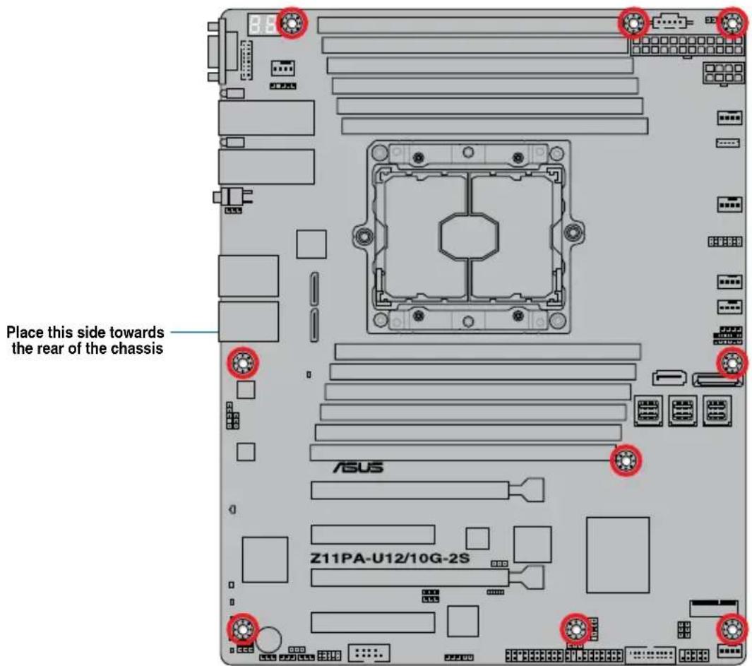
When installing the motherboard, ensure that you place it into the chassis in the correct orientation. The edge with external ports goes to the rear part of the chassis as indicated in the image below.
2.2.2 Screw holes
Place nine (9) screws into the holes indicated by circles to secure the motherboard to the chassis.

DO NOT overtighten the screws! Doing so can damage the motherboard.
text_image
Place this side towards the rear of the chassis ASUS Z11PA-U12/10G-2S2.2.3 Motherboard layout
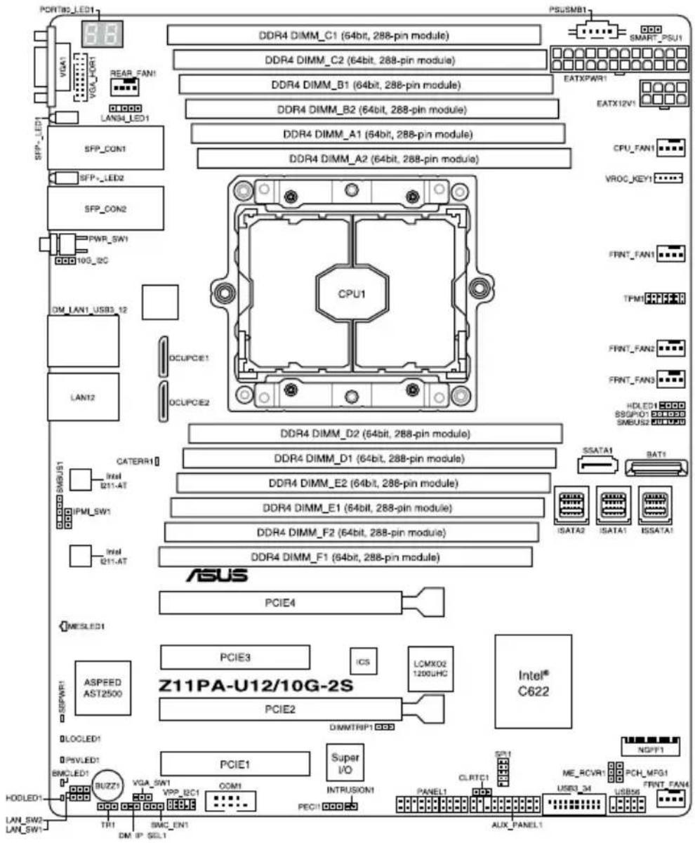
Z11PA-U12/10G-2S
text_image
PORT82_LED1 VGA1 VGA_PORT1 REAR_FAN1 LAN34_LED1 SFP_LED1 SFP_CON1 SFP_LLED2 SFP_CON2 PWR_SW1 10G_2C DM_LAN1_USB3_12 LAN12 CPU1 OCUPCE1 OCUPCE2 DDR4 DIMM_C1 (64bit, 288-pin module) DDR4 DIMM_C2 (64bit, 288-pin module) DDR4 DIMM_B1 (64bit, 288-pin module) DDR4 DIMM_B2 (64bit, 288-pin module) DDR4 DIMM_A1 (64bit, 288-pin module) DDR4 DIMM_A2 (64bit, 288-pin module) PSUSMB1 SMART_PSU1 EATXPWR1 EATX12V1 CPU_FAN1 VROC_KEY1 FRNT_FAN1 TFMI FRNT_FAN2 FRNT_FAN3 HDLED1 89GP01 SNBUS2 CATERR1 Intel B211-AT IPMI_SW1 Intel B211-AT DDR4 DIMM_D2 (64bit, 288-pin module) DDR4 DIMM_D1 (64bit, 288-pin module) DDR4 DIMM_E2 (64bit, 288-pin module) DDR4 DIMM_E1 (64bit, 288-pin module) DDR4 DIMM_F2 (64bit, 288-pin module) DDR4 DIMM_F1 (64bit, 288-pin module) SSATA1 BAT1 ISATA2 ISATA1 ISSATA1 ASUS PCIE4 MESLED1 ASPEED AST2500 SPWRW1 DLOCLED1 PSVLED1 BMCLED1 BUZZI VGA_SW1 VPP_BC1 COM1 PCIE3 IC5 LCMX02 1200UHC Intel® C622 DIMMTRIP1 PCIE2 Super I/O INTRUSION1 PANCII CLRTC1 ALUX PANEL1 NGPF1 ME_RCVR1 USB3_34 PCH_MFG1 USB56 FRNT_FAN4Z11PA-U12
text_image
PORTBLED1 VGA1 VGA_HORT REAR_FAN1 LAN3A_LED1 PWR_SW1 DM_LAN1_USB3_12 LAN12 CPU1 DCUPCIE1 DCUPCIE2 DDR4 DIMM_C1 (64bit, 288-pin module) DDR4 DIMM_C2 (64bit, 288-pin module) DDR4 DIMM_B1 (64bit, 288-pin module) DDR4 DIMM_B2 (64bit, 288-pin module) DDR4 DIMM_A1 (64bit, 288-pin module) DDR4 DIMM_A2 (64bit, 288-pin module) SSATA1 BAT1 ISATA2 ISATA1 ISSATA1 CATERR1 Intel 211-AT IPMI_SW1 Intel 211-AT DDR4 DIMM_D2 (64bit, 288-pin module) DDR4 DIMM_D1 (64bit, 288-pin module) DDR4 DIMM_E2 (64bit, 288-pin module) DDR4 DIMM_E1 (64bit, 288-pin module) DDR4 DIMM_F2 (64bit, 288-pin module) DDR4 DIMM_F1 (64bit, 288-pin module) ASUS PCIE4 MESLED1 ASPEED AST2500 Z11PA-U12 PCIE3 ICS LCMXO2 1200UHC PCIE2 DIMMTRIP1 Intel® C621 DLOCLED1 DPSVLED1 BMCLLED1 GUZZI VGA_SW1 VPP_SC1 COM1 PCIE1 Super I/O INTRUSION1 PENL1 CLRTC1 SPR1 ME_RCVR1 USB3_34 PCH_MFG1 USB56 FRNT_FAN4 NDFF1 LAN_SW2 LAN_SW1 TR1 BMC_EN1 DM_IP_SEL1 Aux_PANEL12.2.4 Layout contents
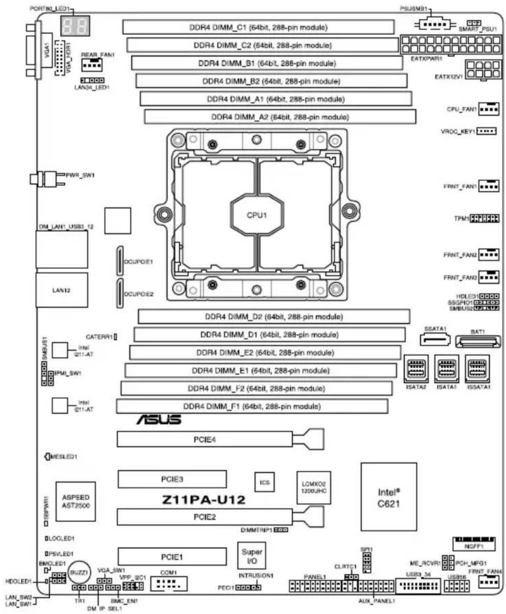
| Slots/Sockets | Page |
| 1. CPU socket 2-8 | |
| 2. DDR4 sockets 2-10 | |
| 3. PCI Express x16 / PCI Express x8 2-12 |
| Onboard LEDs | Page |
| 1. Standby Power LED (SBPWR1) 2-16 | |
| 2. Baseboard Management Controller LED (BMCLED1) 2-16 | |
| 3. CATT LED (CATERR1) | 2-17 |
| 4. Hard disk activity LED (HDDLED1) | 2-17 |
| 5. Message LED (MESLED1) | 2-18 |
| 6. Location LED (LOCLED1) 2-18 | |
| 7. Q-Code LEDs (PORT80_LED1) 2-19 |
| Jumpers | Page |
| 1. Clear RTC RAM (CLRTC1) 2-19 | |
| 2. VGA controller setting (3-pin VGA_SW1) 2-20 | |
| 3. LAN controller setting (3-pin LAN_SW1, LAN_SW2) | 2-20 |
| 4. ME firmware force recovery setting (3-pin ME_RCVR1) 2-21 | |
| 5. DDR4 thermal event setting (3-pin DIMMTRIP1) 2-21 | |
| 6. PCH_MFG1 setting (3-pin PCH_MFG1) 2-22 | |
| 7. Smart Ride Through (SmaRT) setting (3-pin SMART_PSU1) 2-22 | |
| 8. DMLAN setting (3-pin DM_IP_SEL1) 2-23 | |
| 9. IPMI SW setting (3-pin IPMI_SW1) | 2-23 |
| 10. Baseboard Management Controller setting (3-pin BMC_EN1) | 2-24 |
| Internal connectors | Page |
| 1. Serial ATA 6.0/3.0 Gb/s connector (7-pin SSATA1) 2-27 | |
| 2. Mini-SAS HD connector (ISATA1-2; ISSATA1) 2-27 | |
| 3. M.2 (NGFF) connector (NGFF1) | 2-28 |
| 4. Trusted Platform Module connector (14-1 pin TPM1) 2-28 | |
| 5. USB 2.0 connector (10-1 pin USB56) 2-29 | |
| 6. USB 3.0 connector (20-1 pin USB3_34) 2-29 | |
| 7. Power Supply SMBus connector (5-pin PSUSMB1) 2-30 | |
| 8. Serial port connector (10-1 pin COM1) 2-30 | |
| 9. CPU, front, and rear fan connectors (4-pin CPU_FAN1, FRNT_FAN1-4, REAR_FAN1) | 2-31 |
| 10. Hard disk activity LED connector (4-pin HDLED1) 2-31 | |
| 11. EATX power connectors (24-pin EATXPWR, 8-pin EATX12V1) 2-32 | |
| 12. LAN34_LED connector (5-1 pin LAN34_LED1) 2-32 | |
| 13. System panel connector (20-1 pin PANEL1) 2-33 | |
| 14. Auxiliary panel connector (20-2 pin AUX_PANEL1) 2-34 | |
| 15. VPP_I2C1 connector (10-1 pin VPP_I2C1) 2-35 | |
| 16. Chassis Intrusion (2-pin INTRUSION) 2-35 | |
| 17. OCUPCIE connectors (OCUPCIE1-2) 2-36 | |
| 18. System Management Bus (SMBUS) connectors (5-1 pin SMBUS1; 6-1 pin SMBUS2) | 2-36 |
| 19. Serial General Purpose Input/Output connector (6-1 pin SSGPIO1) | 2-37 |
| 20. VGA connector (16-pin VGA_HDR1) | 2-37 |
| 21. VROC_KEY connector (4-pin VROC_KEY1) | 2-38 |
| 22. Thermal sensor cable connector (3-pin TR1) | 2-38 |
2.3 Central Processing Unit (CPU)
The motherboard comes with a surface mount Socket P0 (LGA 3647) designed for the Intel® Xeon® processor Skylake-SP product family.

- Upon purchase of the motherboard, ensure that the PnP cap is on the socket and the socket contacts are not bent. Contact your retailer immediately if the PnP cap is missing, or if you see any damage to the PnP cap/socket contacts/motherboard components. ASUS will shoulder the cost of repair only if the damage is shipment/transit-related.
- Keep the cap after installing the motherboard. ASUS will process Return Merchandise Authorization (RMA) requests only if the motherboard comes with the cap on the Socket P0 (LGA 3647).
- The product warranty does not cover damage to the socket contacts resulting from incorrect CPU installation/removal, or misplacement/loss/incorrect removal of the PnP cap.
2.3.1 Installing the CPU and heatsink
To install a CPU:
- Locate the CPU socket on the motherboard.
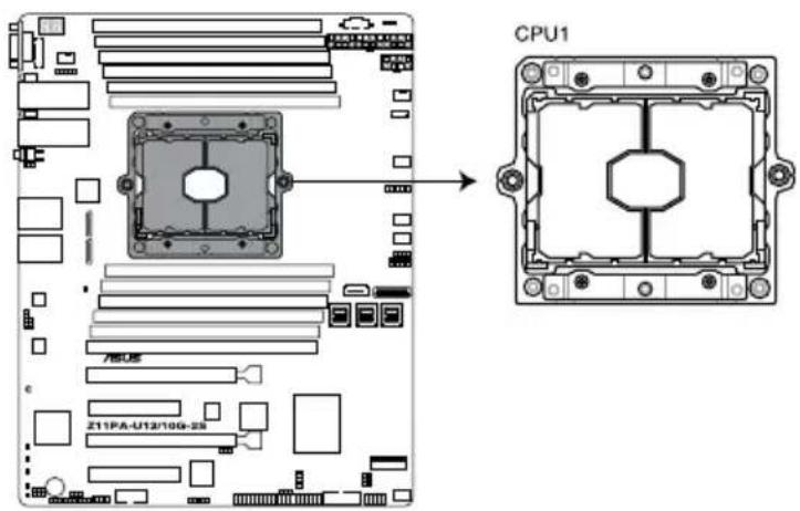
text_image
CPU1 Z11PA-U12/10G-28Z11PA-U12/10G-2S CPU LGA3647 Socket

Before installing the CPU, ensure that the socket box is facing toward you and the triangle mark is on the top-right position.
- Remove the PNP cap from the CPU socket.
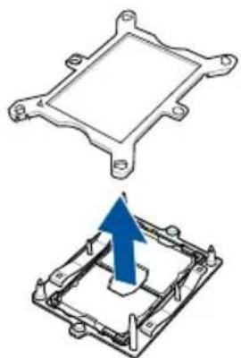
natural_image
Technical illustration of a mechanical component with a blue upward arrow indicating a change or assembly (no text or symbols present)- Align the triangle mark on the CPU with the triangle mark on the CPU Carrier (A), then install the CPU into the CPU Carrier until it clicks firmly into place (B), and then install the CPU Carrier into the heatsink until it clicks firmly in place (C).

Ensure that the triangle mark on the CPU matches the triangle mark on the CPU Carrier.

Apply the Thermal Interface Material to the CPU heatsink and CPU before you install the heatsink and fan, if necessary.
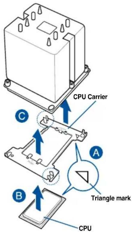
text_image
CPU Carrier C A Triangle mark B CPU- Twist each of the four screws with a screwdriver just enough to attach the heatsink to the motherboard. When the four screws are attached, tighten them one by one in a diagonal sequence to completely secure the heatsink.

The CPU and heatsink assembly fits in only one correct orientation. DO NOT force the CPU and heatsink assembly into the socket to prevent damaging the CPU pins on the socket.

The heatsink screws are T30 models. A torque value of 12 inch-lbf is recommended.
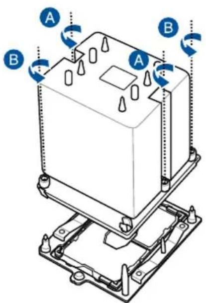
text_image
Technical diagram of an electronic component with labeled parts A and B, showing internal structure and rotation indicators.2.4 System memory
2.4.1 Overview
The motherboard comes with twelve (12) Double Data Rate 4 (DDR4) Dual Inline Memory Modules (DIMM) sockets.
The figure illustrates the location of the DDR4 DIMM sockets:
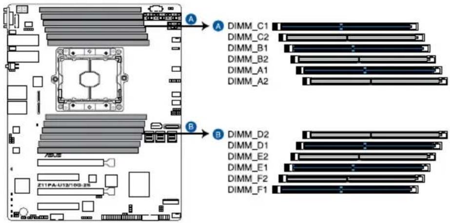
text_image
DIMM_C1 DIMM_C2 DIMM_B1 DIMM_B2 DIMM_A1 DIMM_A2 DIMM_D2 DIMM_D1 DIMM_E2 DIMM_E1 DIMM_F2 DIMM_F1 Z11PA-U12/10G-35Z11PA-U12/10G-2S 288-pin DDR4 DIMM sockets
2.4.2 Memory Configurations
You may install 4 GB, 8 GB, 16 GB, and 32 GB RDIMMs or 32 GB and 64 GB LR-DIMMs into the DIMM sockets using the memory configurations in this section.

• Refer to ASUS Server AVL for the updated list of compatible DIMMs.
- When installing DIMMs, always start from slot A1.
- Always install DIMMs with the same CAS latency. For optimum compatibility, it is recommended that you obtain memory modules from the same vendor.
You can refer to the following recommended memory population:
| Recommended Memory configuration | |||||||||||||||
| DIMM | |||||||||||||||
| A2 | A1 | B2 | B1 | C2 | C1 | D2 | D1 | E2 | E1 | F2 | F1 | ||||
| 1 DIMM | - | √ | - - - | - - - | - - | ||||||||||
| 2 DIMMs | - | √ | - - - | - | √ | - - - | |||||||||
| 4 DIMMs | - | √ | - | √ | √ | - | √ | ||||||||
| 6 DIMMs | - | √ | - | √ | √ | - | √ | ||||||||
| 8 DIMMs | √ | √ | - | √ | √ | √ | - | √ | |||||||
| 12 DIMMs | √ | √ | √ | √ | √ | √ | √ | √ | √ | √ | |||||
2.4.3 Installing a DIMM on a single clip DIMM socket
-
Press the retaining clip outward to unlock the DIMM socket.
-
Align a DIMM on the socket such that the notch on the DIMM matches the DIMM slot key on the socket.
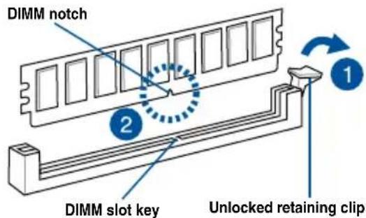
text_image
DIMM notch 2 1 DIMM slot key Unlocked retaining clip
A DIMM is keyed with a notch so that it fits in only one direction. DO NOT force a DIMM into a socket in the wrong direction to avoid damaging the DIMM.
- Hold the DIMM at both ends then insert the DIMM into the socket. Apply force to both ends of the DIMM simultaneously until the retaining clip clicks into place and the DIMM is seated securely in place.
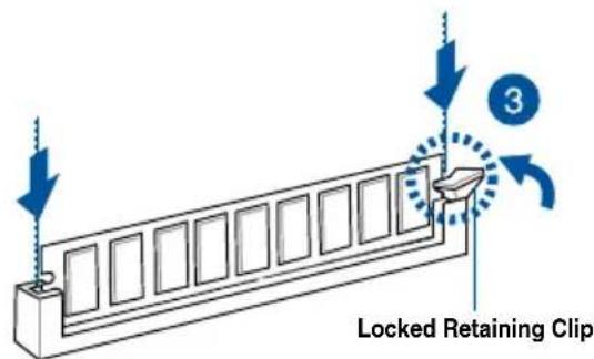
text_image
Locked Retaining Clip 3
Always insert the DIMM into the socket VERTICALLY to prevent DIMM notch damage.

- To install two or more DIMMs, refer to the user guide bundled with the motherboard package.
• Refer to the user guide for qualified vendor lists of the memory modules.
Removing a DIMM from a single clip DIMM socket
-
Press the retaining clip outward to unlock the DIMM.
-
Remove the DIMM from the socket.
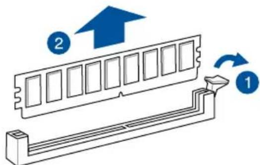
text_image
Diagram showing a RAM module with two directional arrows labeled 1 and 2, indicating movement or flow.
Support the DIMM lightly with your fingers when pressing the retaining clips. The DIMM might get damaged when it flips out with extra force.
2.5 Expansion slots
In the future, you may need to install expansion cards. The following subsections describe the slots and the expansion cards that they support.

Ensure to unplug the power cord before adding or removing expansion cards. Failure to do so may cause you physical injury and damage motherboard components.
2.5.1 Installing an expansion card
To install an expansion card:
- Before installing the expansion card, read the documentation that came with it and make the necessary hardware settings for the card.
- Remove the system unit cover (if your motherboard is already installed in a chassis).
- Remove the bracket opposite the slot that you intend to use. Keep the screw for later use.
- Align the card connector with the slot and press firmly until the card is completely seated on the slot.
- Secure the card to the chassis with the screw you removed earlier.
- Replace the system cover.
2.5.2 Configuring an expansion card
After installing the expansion card, configure it by adjusting the software settings.
-
Turn on the system and change the necessary BIOS settings, if any. See Chapter 4 for information on BIOS setup.
-
Assign an IRQ to the card.

Refer to the table Standard Interrupt assignments in section Interrupt assignments for more information.
- Install the software drivers for the expansion card.

When using PCIe cards on shared slots, ensure that the drivers support "Share IRQ" or that the cards do not need IRQ assignments. Otherwise, conflicts may arise between the two PCIe groups, making the system unstable and the card inoperable.
2.5.3 Interrupt assignments
Standard Interrupt assignments
| IRQ Priority Standard function | |
| 0 1 System Timer | |
| 1 2 Keyboard Controller | |
| 2 - Programmable Interrupt | |
| 3* 11 Communications Port (COM2) | |
| 4* 12 Communications Port (COM1) | |
| 5* 13 -- | |
| 6 14 Floppy Disk Controller | |
| 7* 15 -- | |
| 8 3 System CMOS/Real Time Clock | |
| 9* 4 ACPI Mode when used | |
| 10* 5 IRQ Holder for PCI Steering | |
| 11* 6 IRQ Holder for PCI Steering | |
| 12* 7 PS/2 Compatible Mouse Port | |
| 13 8 Numeric Data Processor | |
| 14* 9 Primary IDE Channel | |
| 15* 10 Secondary IDE Channel | |
* These IRQs are usually available for ISA or PCI devices.
2.5.4 PCI Express x16 slot (x16 link)
The onboard PCIE4 and PCIE2 slots provide two x16 Gen3 link to CPU1 and only PCIE4 supports auto switches to x8 link if PCIE3 is occupied. These two slots support VGA cards and various server class high performance add-on cards.
2.5.5 PCI Express x8 slot (x8 link)
The onboard PCIE3 slot provides one x8 Gen3 link to CPU1. This slot supports VGA cards and various server class high performance add-on cards.
2.5.6 PCI Express x8 slot (x4 link)
The onboard PCIE1 slot provides one x4 Gen3 link to CPU1 This slot supports various server class high performance add-on cards.
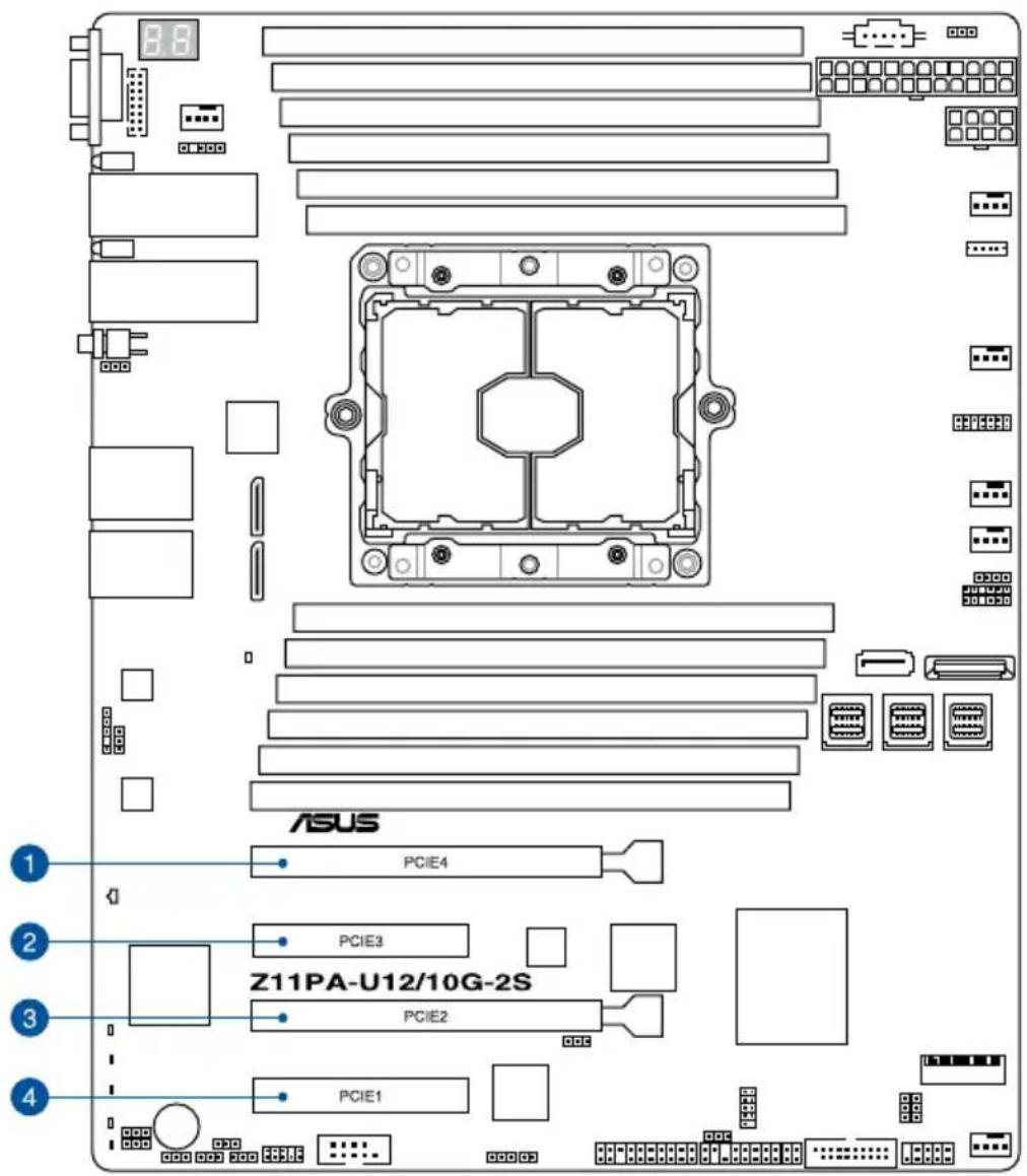
text_image
8.6 ASUS PCIE4 PCIE3 Z11PA-U12/10G-2S PCIE2 PCIE1No. (Slot location) Short description
| 1 PCIE4 | PCI-E x16 (x16 Gen3 Link)(Auto switch to x8 Gen3 Link if slot 3 is occupied)(support riser) |
| 2 PCIE3 | PCI-E x8 (x8 Gen3 Link) |
| 3 PCIE2 | PCI-E x16 (x16 Gen3 Link) |
| 4 PCIE1 | PCI-E x8 (x4 Gen3 Link) |
2.6 Onboard LEDs
1. Standby Power LED (SBPWR1)
The motherboard comes with a standby power LED. The green LED lights up to indicate that the system is ON, in sleep mode, or in soft-off mode. This is a reminder that you should shut down the system and unplug the power cable before removing or plugging in any motherboard component. The illustration below shows the location of the onboard LED.
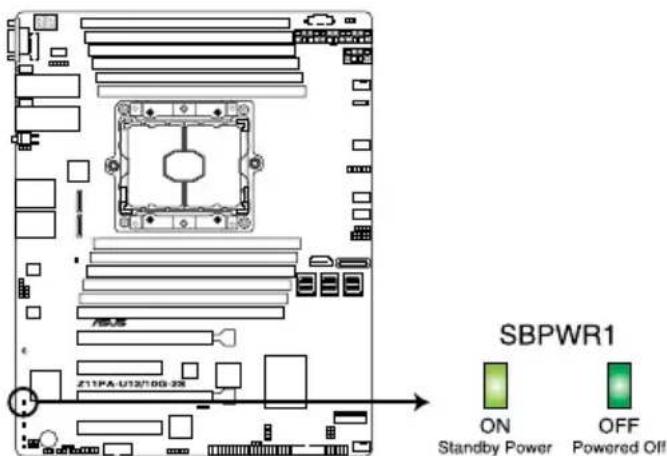
text_image
SBPWR1 ON Standby Power OFF Powered Off Z11PA-U132/0G-328Z11PA-U12/10G-2S Standby Power LED
2. Baseboard Management Controller LED (BMCLED1)
The green heartbeat LED blinks per second to indicate that the ASMB9 is working normally.
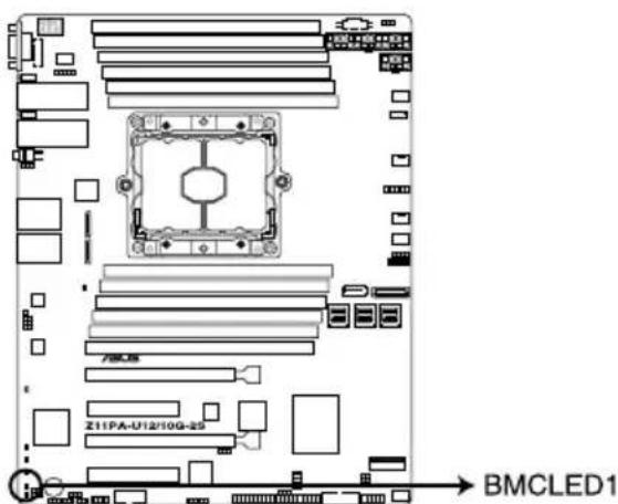
text_image
Z11PA-U12/10G-23 → BMCLED1Z11PA-U12/10G-2S BMC LED
3. CATT LED (CATERR1)
The CATT LED indicates that the system has experienced a fatal or catastrophic error and cannot continue to operate.
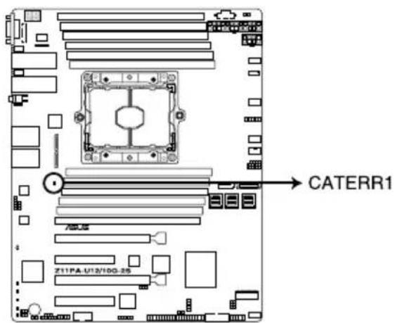
text_image
CATERR1 Z11PA-U12/10G-26Z11PA-U12/10G-2S CATERR LED
4. Hard disk activity LED (HDDLED1)
This LED is for the storage devices connected to the onboard SATA, or SATA/SAS add-on card. The read or write activities of any device connected to the onboard SATA, or SATA/SAS add-on card causes the rear panel LED to light up.
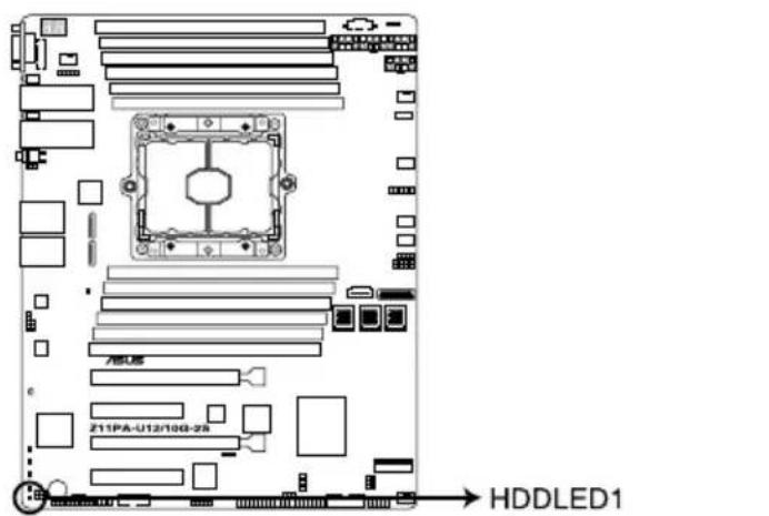
text_image
Z11PA-U12/100-25 HDDLED1Z11PA-U12/10G-2S Storage device activity LED
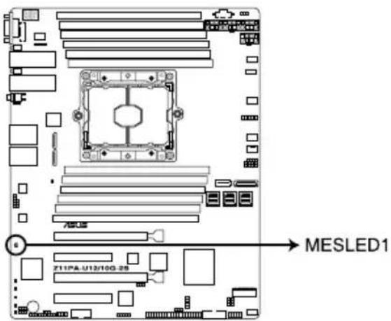
5. Message LED (MESLED1)
This onboard LED lights up to red when there is a BMC event log is generated.
text_image
MESLED1 Z11PA-U12/10G-28Z11PA-U12/10G-2S MESLED
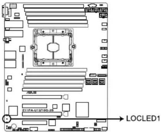
6. Location LED (LOCLED1)
This onboard LED lights up when the Location button on the server is pressed or when triggered by a system management software. The Location LED helps visually locate and quickly identify the server in error on a server rack.
text_image
LOCLED1 Z11PA-U12*10G-25Z11PA-U12/10G-2S Location LED
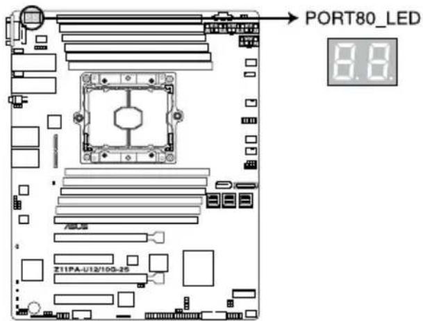
7. Q-Code LEDs (PORT80\_LED1)
The Q-Code LED provides a 2-digit display that shows the status of your system.
text_image
PORT80_LED 8.8 Z11PA-U12/10G-25Z11PA-U12/10G-2S Q-CODE LED

- The Q-Code LEDs provide the most probable cause of an error code as a starting point for troubleshooting. The actual cause may vary from case to case.
- Please refer to the Q-Code table in the Appendix section for more details.
2.7 Jumpers
1. Clear RTC RAM (3-pin CLRTC1)
This jumper allows you to clear the Real Time Clock (RTC) RAM in CMOS. You can clear the CMOS memory of date, time, and system setup parameters by erasing the CMOS RTC RAM data. The onboard button cell battery powers the RAM data in CMOS which include system setup information such as system passwords.
To erase the RTC RAM:
- Turn OFF the computer and unplug the power cord.
- Move the jumper cap from the default pins 1–2 to pins 2–3. Keep the cap on pins 2–3 for about 5 to 10 seconds, then move the cap back to pins 1–2.
- Plug the power cord and turn ON the computer.
- Hold down the
key during the boot process and enter BIOS setup to re-enter data.

DO NOT remove the cap on CLRTC1 jumper default position except when clearing the RTC RAM. Removing the cap will cause system boot failure!

If the steps above do not help, remove the onboard battery and move the jumper again to clear the CMOS RTC RAM data. After the CMOS clearance, reinstall the battery.

text_image
CLRTC1 1 2 Normal (Default) 2 3 Clear CMOSZ11PA-U12/10G-2S Clear RTC RAM
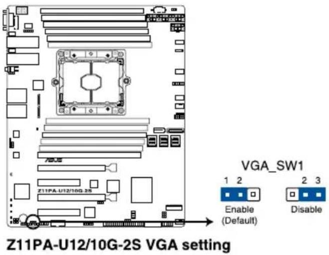
2. VGA controller setting (3-pin VGA\_SW1)
This jumper allows you to enable or disable the onboard VGA controller. Set to pins 1–2 to activate the VGA feature.
text_image
Z11PA-U12/10G-2S VGA setting VGA_SW1 1 2 Enable (Default) 2 3 Disable3. LAN controller setting (3-pin LAN\_SW1, LAN\_SW2)
These jumpers allow you to enable or disable the onboard LAN_SW1 or LAN_SW2. Set to pins 1–2 to activate the Gigabit LAN feature.
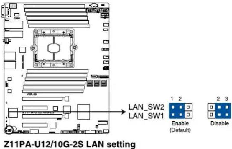
text_image
Z11PA-U12/10G-2S LAN setting LAN_SW2 LAN_SW1 1 2 Enable (Default) 2 3 Disable4. ME firmware force recovery setting (3-pin ME\_RCVR1)
This jumper allows you to force Intel® Management Engine (ME) boot from recovery mode when ME becomes corrupted.
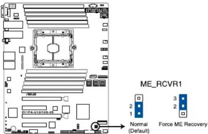
text_image
ME_RCVR1 2 3 1 Normal (Default) 2 Force ME RecoveryZ11PA-U12/10G-2S ME recovery setting
5. DDR4 thermal event setting (3-pin DIMMTRIP1)
This jumper allows you to enable or disable DDR4 DIMM thermal sensing event pin.
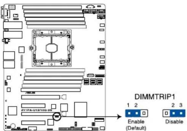
text_image
DIMMTRIP1 1 2 Enable (Default) 2 3 DisableZ11PA-U12/10G-2S Thermaltrip setting
6. PCH\_MFG1 setting (3-pin PCH\_MFG1)
This jumper allows you to update the BIOS ME block.
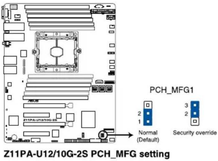
text_image
Z11PA-U12/10G-2S PCH_MFG setting PCH_MFG1 Normal (Default) Security override7. Smart Ride Through (SmaRT) setting (3-pin SMART\_PSU1)
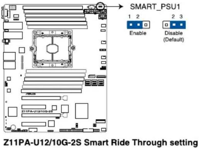
This jumper allows you to enable or disable the Smart Ride Through (SmaRT) function. This feature is disabled by default. Set to pins 1-2 to enable it. When enabled, SmaRT allows uninterrupted operation of the system during an AC loss event.
text_image
SMART_PSU1 1 2 Enable 2 3 Disable (Default) Z11PA-U12/10G-2S Smart Ride Through setting8. DMLAN setting (3-pin DM\_IP\_SEL1)
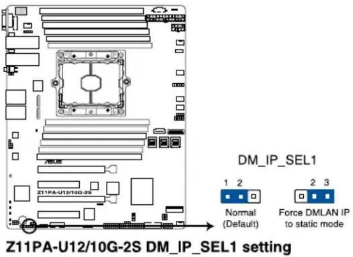
This jumper allows you to select the DMLAN setting. Set to pins 2-3 to force the DMLAN IP to static mode (IP=10.10.10.10, submask=255.255.255.0).
text_image
Z11PA-U12/10G-2S DM_IP_SEL1 setting DM_IP_SEL1 1 2 Normal (Default) 2 3 Force DMLAN IP to static mode9. IPMI SW setting (3-pin IPMI\_SW1)
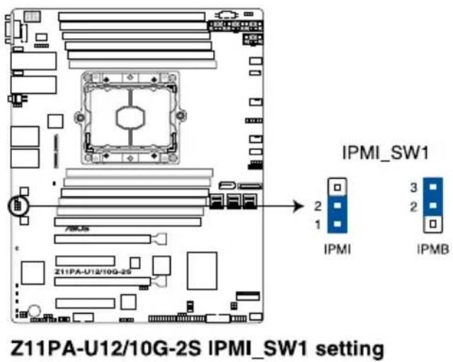
This jumper allows you to select which protocol in the GPU sensor to function.
text_image
Z11PA-U12/10G-2S IPMI_SW1 setting IPMI_SW1 2 3 2 IPMI IPMB10. Baseboard Management Controller setting (3-pin BMC\_EN1)
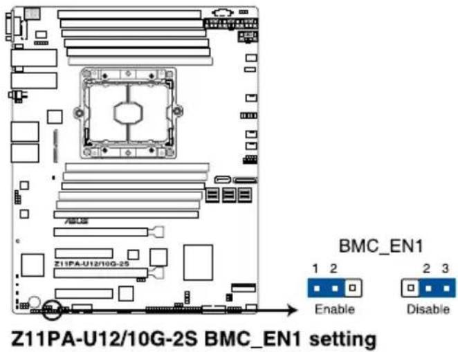
This jumper allows you to enable (default) or disable on-board BMC. Ensure to set this BMC jumper to enabled to avoid system fan control and hardware monitor error.
text_image
Z11PA-U12/10G-2S BMC_EN1 setting BMC_EN1 1 2 Enable 2 3 Disable2.8 Connectors
2.8.1 Rear panel connectors
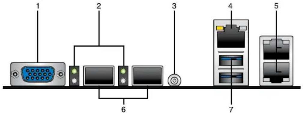
text_image
1 2 3 4 5 6 7- Video Graphics Adapter (VGA) port: This port is for a VGA monitor or other VGA-compatible devices..
- SFP+ LEDs (only available for Z11PA U12/10G-2S): These LEDs indicate the link status and the link speed of the SFP+ ports. Refer to the table below for the SFP+ LED indications.
- Power-on Button: Press this button to turn on the system.
- RJ-45 port for iKVM: This RJ-45 port functions when you enable the ASMB8 controller.
- RJ-45 ports for LAN 1 and 2: These ports allow Gigabit connection to a LAN through a network hub. Refer to the LAN port LED indications table for more information.
- SFP+ ports (only available for Z11PA U12/10G-2S): These ports are for connecting the enhanced small form-factor pluggable (SFP+) module that supports data rates up to 10 Gbps.
- USB 3.0 ports 1 and 2: These two 4-pin Universal Serial Bus (USB) ports are available for connecting USB 3.0 devices.
LAN1/LAN2 LEDs
| Activity/Link LED Speed LED | ||
| Status Description Status Description | ||
| OFF No link OFF 10 Mbps connection | ||
| GREEN Linked ORANGE 100 Mbps connection | ||
| BLINKING Data activity GREEN 1 Gbps connection | ||
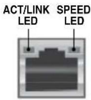
Management LAN port LED indications
| Activity/Link LED Speed LED | ||
| Status Description Status Description | ||
| OFF No link OFF 10 Mbps connection | ||
| ORANGE Linked ORANGE 100 Mbps connection | ||
| BLINKING Data activity GREEN 1 Gbps connection | ||
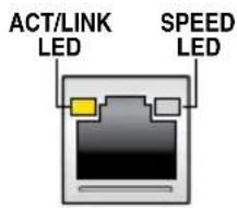
text_image
ACT/LINK LED SPEED LEDSFP+\_LED indications (only available for Z11PA U12/10G-2S)
| Activity LED Speed LED | ||
| Status Description Status Description | ||
| OFF No activity OFF - | ||
| BLINKING Data activity AMBER 1 Gbps connection | ||
| GREEN 10 Gbps connection | ||
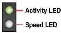
SFP+ LED
2.8.2 Internal connectors
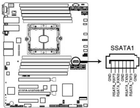
1. Serial ATA connectors (7-pin SSATA1)
This connector, controlled by Intel® C620 chipset, is for the Serial ATA signal cable for Serial ATA hard disk drives.
text_image
SSATA1 GND RSATA_RXP3 RSATA_RXN3 GND RSATA_TXN3 RSATA_TXP3 GNDZ11PA-U12/10G-2S SSATA connector
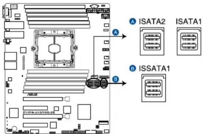
2. Mini-SAS HD connector (ISATA1-2; ISSATA1)
This motherboard comes with mini Serial Attached SCSI (SAS) HD connectors, the storage technology that supports Serial ATA. Each connector supports up to four devices.
text_image
A ISATA2 ISATA1 B ISSATA1 Z11PA-U12/10G-26Z11PA-U12/10G-2S ISATA & ISSATA connectors
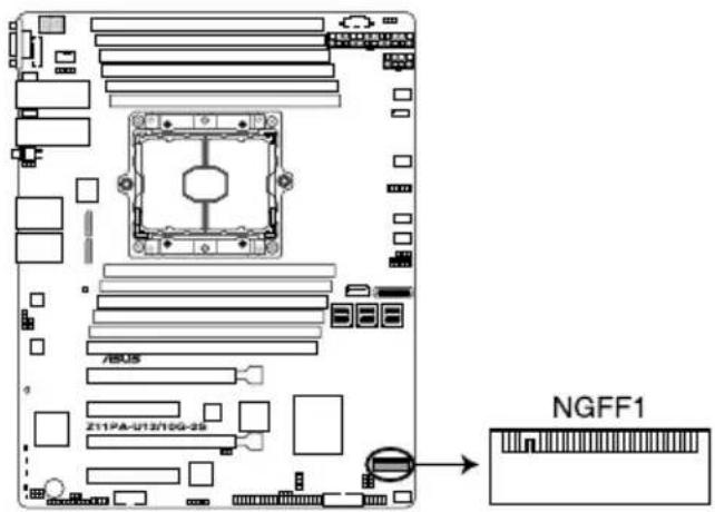
3. M.2 (NGFF) connector (NGFF1)
This connector allows you to install an M.2 device.
text_image
7605 Z11PA-U13/10G-25 NGFF1Z11PA-U12/10G-2S NGFF connector

This connector supports type 2242 / 2260 / 2280 devices on both PCI-E (2 lanes only) and SATA interface.

The M.2 (NGFF) device is purchased separately.
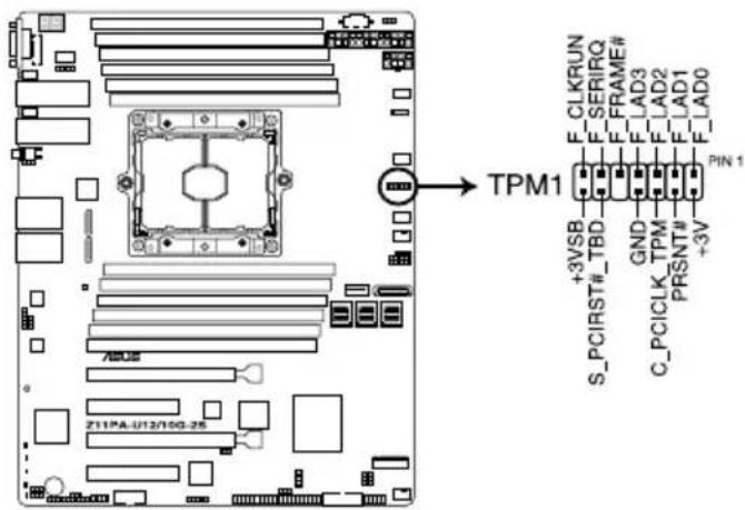
4. Trusted Platform Module connector (14-1 pin TPM1)
This connector supports a Trusted Platform Module (TPM) system, which can securely store keys, digital certificates, passwords, and data. A TPM system also helps enhance network security, protects digital identities, and ensures platform integrity.
text_image
TPM1 +3VSB S_PCIRST#_TBD GND TPM C_PCICLK# PRSNT# +3V F_LAD0 F_LAD1 F_LAD2 F_LAD3 F_FRAME# F_SERIRQ F_CLKRUNZ11PA-U12/10G-2S TPM connector
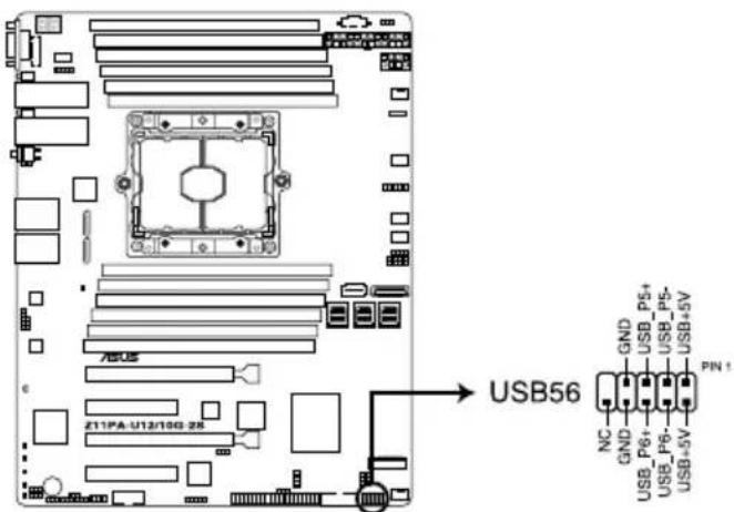
5. USB 2.0 connector (10-1 pin USB56)
This connector is for USB 2.0 ports. Connect the USB module cable to the connector, and then install the module to a slot opening at the back of the system chassis. The USB connectors comply with USB 2.0 specification that supports up to 480 Mbps connection speed.
text_image
USB56 GND USB_P5+ USB_P5- USB+5V NC GND USB_P6+ USB_P6- USB+5V PIN 1Z11PA-U12/10G-2S USB 2.0 connector

The USB port module is purchased separately.
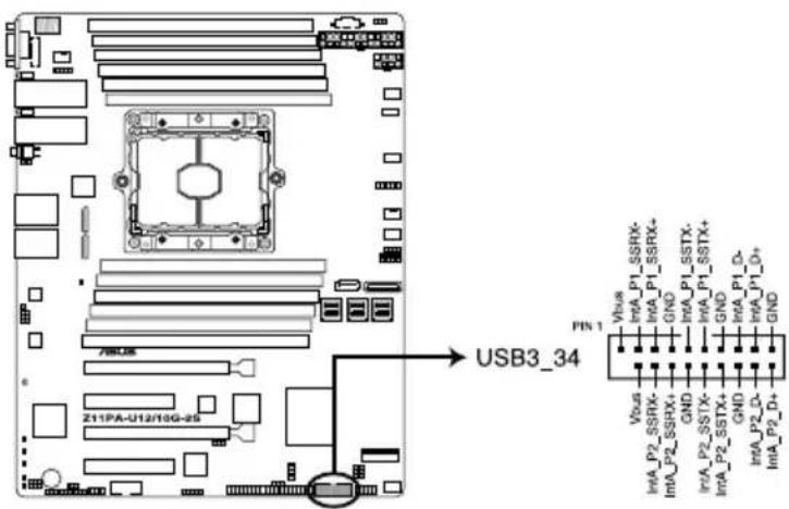
6. USB 3.0 connector (20-1 pin USB3\_34)
This connector allows you to connect a USB 3.0 module for additional USB 3.0 front or rear panel ports. With an installed USB 3.0 module, you can enjoy all the benefits of USB 3.0 including faster data transfer speeds of up to 5Gbps, faster charging time for USB-chargeable devices, optimized power efficiency, and backward compatibility with USB 2.0.
text_image
USB3_34 Pin 1 Vbus IntA_P1_SSRX- GND IntA_P1_SSTX- GND IntA_P1_D- GND IntA_P2_D- GND Vbus IntA_P2_SSTX+ GND IntA_P2_SSTX+ GND IntA_P2_D+ GND Z11PA-U12/10G-25Z11PA-U12/10G-2S USB 3.0 connector

The USB port module is purchased separately.
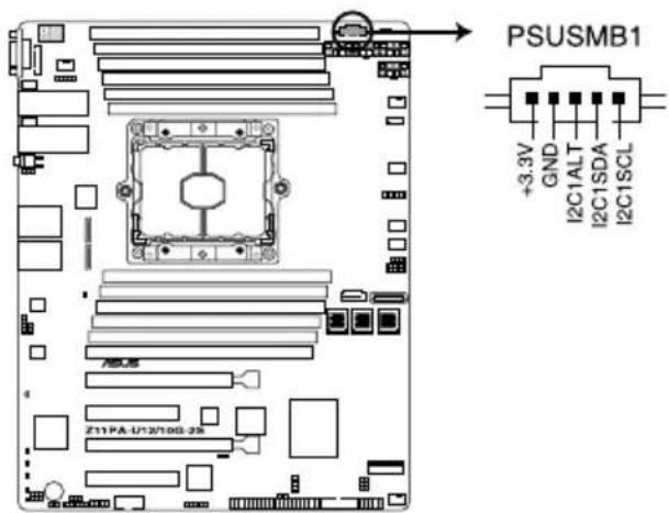
7. Power Supply SMBus connector (5-pin PSUSMB1)
This connector allows you to connect SMBus (System Management Bus) to the PSU (power supply unit) to read PSU information. Devices communicate with an SMBus host and/or other SMBus devices using the SMBus interface.
text_image
PSUSMB1 +3.3V GND I2C1ALT I2C1SDA I2C1SCL Z11PA-U12/10G-25Z11PA-U12/10G-2S Power supply SMBus connector

Power supply is required to meet PMBus specification and customized BMC FW may be needed. Please contact ASUS if your need further support.
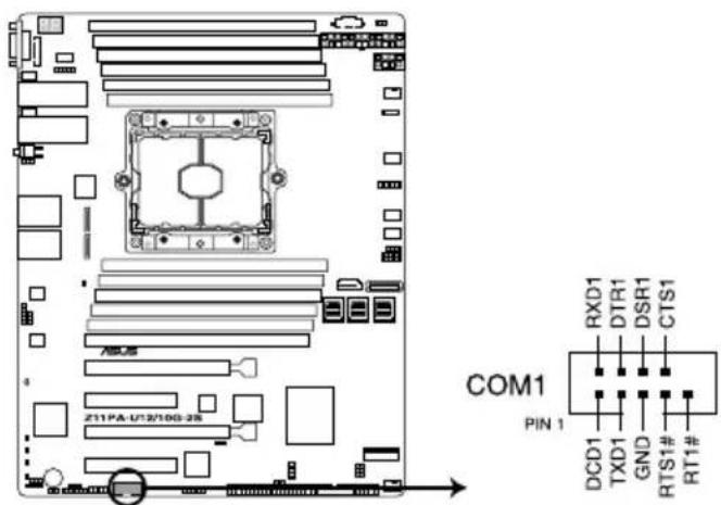
8. Serial port connector (10-1 pin COM1)
This connector is for the serial COM port. Connect the serial port module cable to one of these connectors, then install the module to a slot opening at the back of the system chassis.
text_image
COM1 PIN 1 RXD1 DTR1 DSR1 CTS1 DCD1 TXD1 GND RTS1# RT1#Z11PA-U12/10G-2S Serial port connector

The COM module is purchased separately.
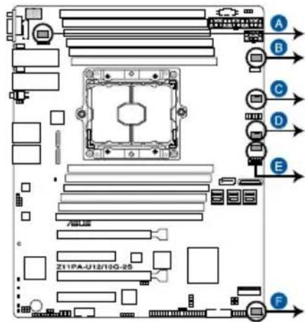
9. CPU, front, and rear fan connectors (4-pin CPU\_FAN1, FRNT\_FAN1-4, REAR\_FAN1)
The fan connectors support cooling fans. Connect the fan cables to the fan connectors on the motherboard, ensuring that the black wire of each cable matches the ground pin of the connector.

- DO NOT forget to connect the fan cables to the fan connectors. Insufficient air flow inside the system may damage the motherboard components.
• These are not jumpers! DO NOT place jumper caps on the fan connectors!
• All fans feature the ASUS Smart Fan technology.
text_image
A B C D E Z11PA-U12/10G-25 FA REAR_FAN1
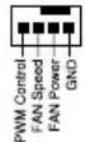
B CPU_FAN1
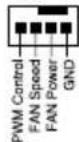
CFRNT_FAN1
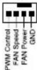
FRNT_FAN2
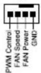
E FRNT_FAN3
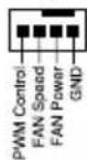
F FRNT_FAN4
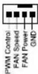
Z11PA-U12/10G-2S FAN connectors
10. Hard disk activity LED connector (4-pin HDLED1)
This LED connector is for the storage add-on card cable connected to the SATA or SAS add-on card. The read or write activities of any device connected to the SATA or SAS add-on card causes the front panel LED to light up.
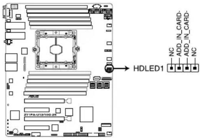
text_image
HDLED1 NC ADD_IN_CARD- ADD_IN_CARD- NC Z11PA-U12/10G-28Z11PA-U12/10G-2S Storage device activity LED connector
11. EATX power connectors (24-pin EATXPWR, 8-pin EATX12V1)
These connectors are for the SSI or ATX power supply plugs. The power supply plugs are designed to fit these connectors in only one orientation. Find the proper orientation and push down firmly until the connectors completely fit.

- DO NOT forget to connect the 24+8-pin power plugs when using 85W or below CPU; otherwise, the system will not boot up.
- Use of a PSU with a higher power output is recommended when configuring a system with more power-consuming devices. The system may become unstable or may not boot up if the power is inadequate.
- Ensure that your power supply unit (PSU) can provide at least the minimum power required by your system.
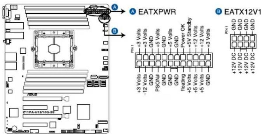
text_image
A EATXPWR B +3 Volts +3 Volts GND +5 Volts GND +5 Volts GND +5 Volts GND +5 Volts GND +5 Volts GND +5 Volts GND +5 Volts GND +5 Volts GND +5 Volts GND +5 Volts GND +5 Volts GND +5 Volts GND +5 Volts Floating +5 Volts +5 Volts +5 Volts +5 Volts +5 Volts +5 Volts +5 Volts +5 Volts +5 Volts +5 Volts +5 Volts +5 Volts +5 Volts +5 Volts +5 Volts +5 Volts +5 Volts +5 Volts +5 Volts +5 Volts +5 Volats +5 Volts +5 Volts +5 Volts +5 Volts +5 Volts +5 Volts +5 Volts +5 Volts +5 Volts +5 Volts +5 Volts +5 Volts +5 Volts +5 Volts +5 Volts +5 Volts +5 Volts +5 Volts +5 Volts +5 Volits +5 Volits +5 Volits +5 Volits +5 Volits +5 Volits +5 Volits +5 Volits +5 Volits +5 Volits +5 Volits +5 Volits +5 Volits +5 Volits +5 Volits +5 Volits +5 Volits +5 Volits +5 Volits +5 Volits +5 Voluts +5 Voluts +5 Voluts +5 Voluts +5 Voluts +5 Voluts +5 Voluts +5 Voluts +5 Voluts +5 Voluts +5 Voluts +5 Voluts +5 Voluts +5 Voluts +5 Voluts +5 Voluts +5 VolutsZ11PA-U12/10G-2S ATX power connectors
12. LAN34\_LED connector (5-1 pin LAN34\_LED1)
These LEDs are for Gigabit LAN activity LEDs on the front panel. Connect the LAN LED cable to the backplane for LAN activity indication.
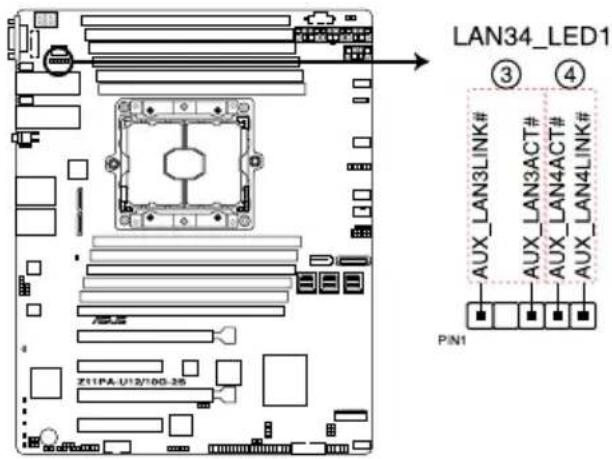
text_image
LAN34_LED1 ③ ④ AUX_LAN3LINK# AUX_LAN3ACT# AUX_LAN4ACT# AUX_LAN4LINK# PIN1 Z11PA-U12/10G-25Z11PA-U12/10G-2S LAN3 & LAN4 LED
13. System panel connector (20-1 pin PANEL1)
This connector supports several chassis-mounted functions.
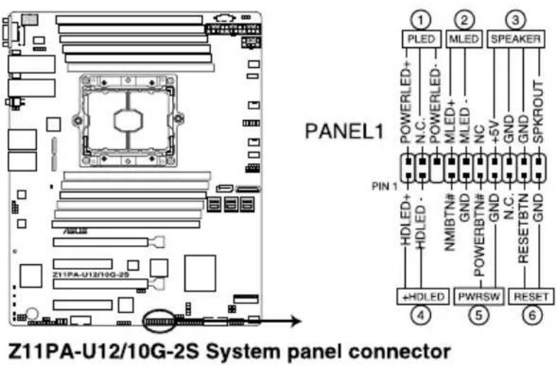
text_image
PANEL1 Z11PA-U12/10G-2S System panel connector ① PLED ② MLED ③ SPEAKER PIN 1 HDLED+ HDLED- NMBTNT# GND POWERBNT# GND N.C. +SV GND SPKROUT +HDLED PWRSW RESET ④ ⑤ ⑥1. System power LED (3-pin PLED)
This 3-pin connector is for the system power LED. Connect the chassis power LED cable to this connector. The system power LED lights up when you turn on the system power, and blinks when the system is in sleep mode.
2. Message LED (2-pin MLED)
This 2-pin connector is for the message LED cable that connects to the front message LED. The message LED is controlled by Hardware monitor to indicate an abnormal event occurrence.
3. System warning speaker (4-pin SPEAKER)
This 4-pin connector is for the chassis-mounted system warning speaker. The speaker allows you to hear system beeps and warnings.
4. Hard disk drive activity LED (2-pin HDD LED)
This 2-pin connector is for the HDD Activity LED. Connect the HDD Activity LED cable to this connector. The HD LED lights up or flashes when data is read from or written to the HDD.
5. Power button/soft-off button (2-pin PWRSW)
This connector is for the system power button. Pressing the power button turns the system on or puts the system in sleep or soft-off mode depending on the BIOS settings. Pressing the power switch for more than four seconds while the system is ON turns the system OFF.
6. Reset button (2-pin RESET)
This 2-pin connector is for the chassis-mounted reset button for system reboot without turning off the system power.
14. Auxiliary panel connector (20-2 pin AUX\_PANEL1)
This connector is for additional front panel features including front panel SMB, locator LED and switch, and LAN LEDs.
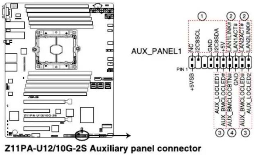
text_image
AUX_PANEL1 PIN 1 +5VSB NC I2C8SCL GND I2C8SDA +5V LAN1LINK# LAN1ACT# XN2XCT# LAN2LINK# AUX_LOCLED1 AUX_BMCLOCLED# AUX_BMCLOCBTN# GND AUX_BMCLOCLED# AUX_LOCLED2 Z11PA-U12/10G-2S Auxiliary panel connector ① ② ③ ④ ③- Front panel SMB (10-2 pin FPSMB)
These connectors are for the front panel SMBus cable.
- LAN activity LED (2-pin LAN1_LED, LAN2_LED)
These connectors are for Gigabit LAN activity LEDs on the front panel.
- Locator LED (2-pin LOCATORLED1, LOCATORLED2)
These connectors are for the locator LED1 and LED2 on the front panel. Connect the Locator LED cables to these 2-pin connector. The LEDs will light up when the Locator button is pressed.
- Locator Button/Switch (2-pin LOCATORBTN)
These connectors are for the locator button on the front panel. This button queries the state of the system locator.
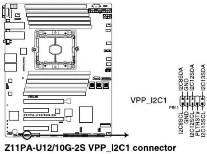
15. VPP\_I2C1 connector (10-1 pin VPP\_I2C1)
This connector is used for the Intel VMD function and sensor readings.
text_image
Z11PA-U12/10G-2S VPP_I2C1 connector VPP_I2C1 I2C8SDA GND I2C12SDA PLTRST# I2C13SDA PIN 1 I2C8SCL GND I2C12SCL PLTRST# I2C13SCL16. Chassis Intrusion (2-pin INTRUSION1)
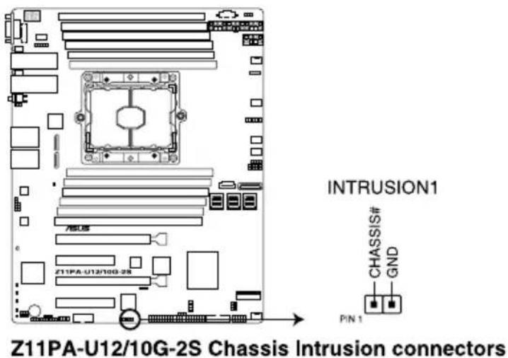
These leads are for the intrusion detection feature for chassis with intrusion sensor or microswitch. When you remove any chassis component, the sensor triggers and sends a high level signal to these leads to record a chassis intrusion event. The default setting is short CHASSIS# and GND pin by jumper cap to disable the function.
text_image
INTRUSION1 CHASSIS# GND PIN 1 Z11PA-U12/10G-2S Chassis Intrusion connectors17. OCUPCIE connectors (OCUPCIE1-2)
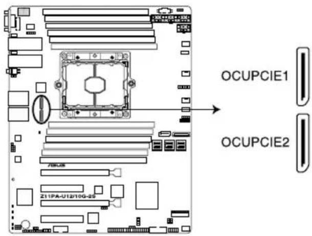
Connects the PCIE signal to the front riser card or NVME port on the backplane.
text_image
OCUPCIE1 OCUPCIE2 Z11PA-U12/10G-25Z11PA-U12/10G-2S OCUPCIE1 & OCUPCIE2
18. System Management Bus (SMBUS) connectors (5-1 pin SMBUS1; 6-1 pin SMBUS2)
These connectors control the system and power management-related tasks. These connectors process the messages to and from devices rather than tripping the individual control lines.

text_image
A SMBUS2 PIN1 B SMBUS1 SCL GND SDA CHIL_PROG PIN 1 7605 Z11PA-U13/10G-28Z11PA-U12/10G-2S SMBUS connectors
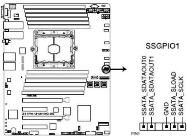
19. Serial General Purpose Input/Output connector (6-1 pin SSGPIO1)
The SSGPIO 1 connector is used for the Intel Rapid Storage Technology Enterprise SGPIO interface that controls the LED pattern generation, device information, and general purpose data.
text_image
SSGPIO1 SSATA_SDATAOUT0 SSATA_SDATAOUT1 GND SSATA_SLOAD SSATA_SCLK PIN1Z11PA-U12/10G-2S SSGPIO1 connector
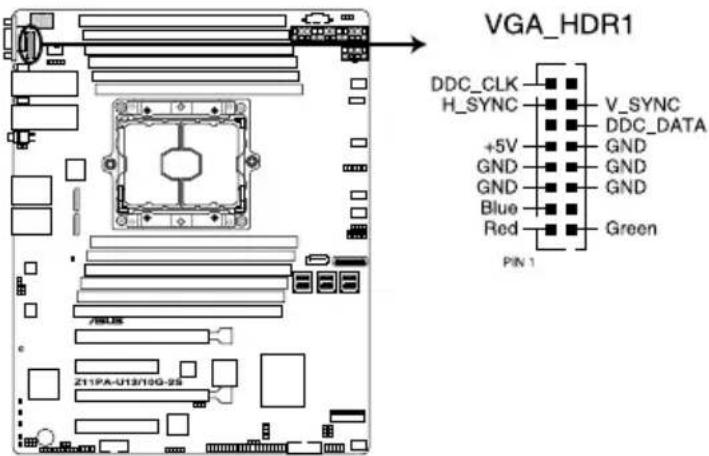
20. VGA connector (16-pin VGA\_HDR1)
This connector supports the VGA High Dynamic-Range interface.
text_image
VGA_HDR1 DDC_CLK H_SYNC +5V GND GND Blue Red V_SYNC DDC_DATA GND GND GND Green PIN 1 Z11FA-U13/10G-25Z11PA-U12/10G-2S Internal VGA connector
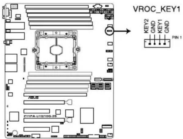
21. VROC\_KEY connector (4-pin VROC\_KEY1)
This connector allows you to connect a KEY module to support Intel VMD RAID function.
text_image
VROC_KEY1 KEY2 GND KEY1 GND PIN 1 Z11PA-U/12/10G-25Z11PA-U12/10G-2S VROC_KEY1
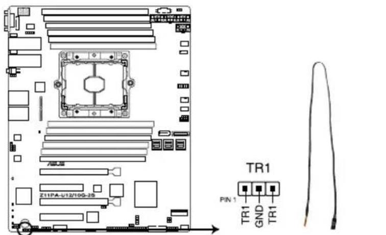
22. Thermal sensor cable connector (3-pin TR1)
This connector allows you to connect a Thermal sensor cable that is used for temperature monitoring. Connect the Thermal sensor cable to the connector and place its probe to the device that you want to check the temperature.
text_image
TR1 PIN 1 TR1 GND TR1Z11PA-U12/10G-2S Thermal sensor cable connector
Powering Up
This chapter describes the power up sequence, and ways of shutting down the system.
3
3.1 Starting up for the first time
- After making all the connections, replace the system case cover.
- Be sure that all switches are off.
- Connect the power cord to the power connector at the back of the system chassis.
-
Connect the power cord to a power outlet that is equipped with a surge protector.
-
Turn on the devices in the following order:
a. Monitor
b. External storage devices (starting with the last device on the chain)
c. System power
- After applying power, the system power LED on the system front panel case lights up. For systems with ATX power supplies, the system LED lights up when you press the ATX power button. If your monitor complies with "green" standards or if it has a "power standby" feature, the monitor LED may light up or switch between orange and green after the system LED turns on.
The system then runs the power-on self-test or POST. While the tests are running, the BIOS beeps or additional messages appear on the screen. If you do not see anything within 30 seconds from the time you turned on the power, the system may have failed a power-on test. Check the jumper settings and connections or call your retailer for assistance.
The following shows the possible beep codes and its corresponding error condition
| BIOS Beep codes | |
| Beep Error condition | |
| 1 short Power supply | surges detected during the previous power on. |
| 1 short No Keyboard | Detected. |
| 1 short, 2 short No DIMM Detected. | |
| 1 short, 8 short No VGA Detected. | |
| 2 long Chassis Intrusion. | |
| 2 long BIOS-image Crash Detected. | |
- At power on, hold down the
key to enter the BIOS Setup. Follow the instructions in Chapter 4.
3.2 Powering off the computer
3.2.1 Using the OS shut down function
Using Windows ^® Server 2012 R2:
- Press
+ + . - Click on the Power icon on the lower right side of the screen.
- Select Shut down.
- In the Shutdown Event Tracker, select the Other (Planned) option in the selection lists. Otherwise, select the option that best describes why you want to shut down the computer.
- Click Continue.
Using Windows ^® Server 2016:
- Press
+ . - In the What do you want the computer to do?, select Shut down.
- In the Shutdown Event Tracker, select the Other (Planned) option in the selection list. Otherwise, select the option that best describes why you want to shut down the computer.
- Click OK.
3.2.2 Using the dual function power switch
While the system is ON, press the power switch for less than four seconds to put the system to sleep mode or to soft-off mode, depending on the BIOS setting.

Pressing the power switch for more than four seconds lets the system enter the soft-off mode regardless of the BIOS setting.
BIOS Setup
4
This chapter tells how to change the system settings through the BIOS Setup menus. Detailed descriptions of the BIOS parameters are also provided.
4.1 Managing and updating your BIOS
The following utilities allow you to manage and update the motherboard Basic Input/Output System (BIOS) setup:
1. ASUS CrashFree BIOS 3
To recover the BIOS using a bootable USB flash disk drive when the BIOS file fails or gets corrupted.
2. ASUS EzFlash
Updates the BIOS using a USB flash disk.
3. BUPDATER
Updates the BIOS in DOS mode using a bootable USB flash disk drive.
Refer to the corresponding sections for details on these utilities.

Save a copy of the original motherboard BIOS file to a bootable USB flash disk drive in case you need to restore the BIOS in the future. Copy the original motherboard BIOS using the BUPDATER utility.
4.1.1 ASUS CrashFree BIOS 3 utility
The ASUS CrashFree BIOS 3 is an auto recovery tool that allows you to restore the BIOS file when it fails or gets corrupted during the updating process. You can update a corrupted BIOS file using a USB flash drive that contains the updated BIOS file.

Prepare a USB flash drive containing the updated motherboard BIOS before using this utility.
Recovering the BIOS from a USB flash drive
To recover the BIOS from a USB flash drive:
- Insert the USB flash drive with the original or updated BIOS file to one USB port on the system.
- The utility will automatically recover the BIOS. It resets the system when the BIOS recovery finished.

DO NOT shut down or reset the system while recovering the BIOS! Doing so would cause system boot failure!

The recovered BIOS may not be the latest BIOS version for this motherboard. Visit the ASUS website at www.asus.com to download the latest BIOS file.
4.1.2 ASUS EzFlash Utility
The ASUS EzFlash Utility feature allows you to update the BIOS using a USB flash disk without having to use a DOS-based utility.

Download the latest BIOS from the ASUS website at www.asus.com before using this utility.

The succeeding BIOS screens are for reference only. The actual BIOS screen displays may not be the same as shown.
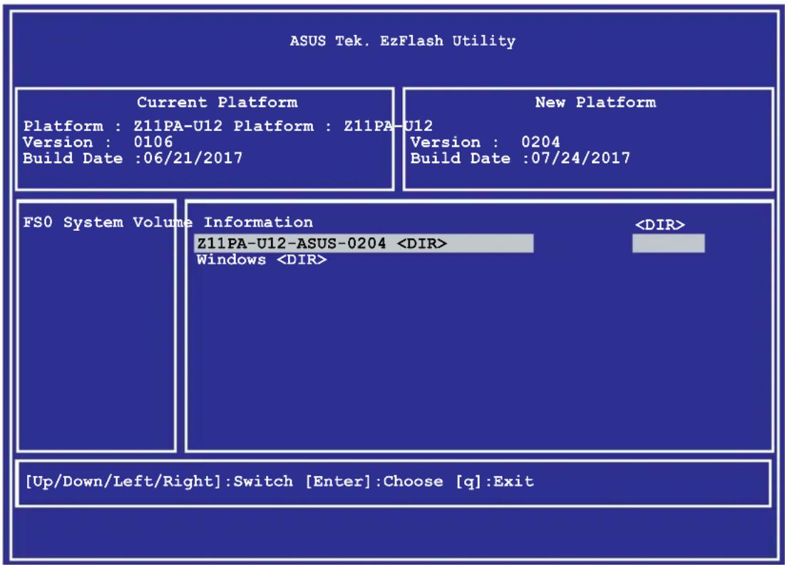
To update the BIOS using EzFlash Utility:
- Insert the USB flash disk that contains the latest BIOS file to the USB port.
- Enter the BIOS setup program. Go to the Tool menu to select Start EzFlash and press
to enable it.
text_image
ASUS Tek. EzFlash Utility Current Platform Platform : Z11PA-U12 Platform : Z11PA-U12 Version : 0106 Build Date :06/21/2017 New Platform Version : 0204 Build Date :07/24/2017 FSO System Volume Information Z11PA-U12-ASUS-0204- Press
to switch to the Drive field. - Press the Up/Down arrow keys to find the USB flash disk that contains the latest BIOS then press
. - Press
to switch to the Folder Info field. - Press the Up/Down arrow keys to find the BIOS file then press
. - Reboot the system when the update process is done.

- This function can support devices such as a USB flash disk with FAT 32/16 format and single partition only.
- DO NOT shut down or reset the system while updating the BIOS to prevent system boot failure!

Ensure to load the BIOS default settings to ensure system compatibility and stability. Press
4.1.3 BUPDATER utility

The succeeding BIOS screens are for reference only. The actual BIOS screen displays may not be the same as shown.
The BUPDATER utility allows you to update the BIOS file in DOS environment using a bootable USB flash disk drive with the updated BIOS file.
Updating the BIOS file
To update the BIOS file using the BUPDATER utility:
- Visit the ASUS website at www.asus.com and download the latest BIOS file for the motherboard. Save the BIOS file to a bootable USB flash disk drive.
- Download the BUPDATER utility (BUPDATER.exe) from the ASUS support website at support.asus.com to the bootable USB flash disk drive you created earlier.
- Boot the system in DOS mode, then at the prompt, type:
BUPDATER /i[filename].CAP
where [filename] is the latest or the original BIOS file on the bootable USB flash disk drive, then press
A:>BUPDATER /i [file name]CAP
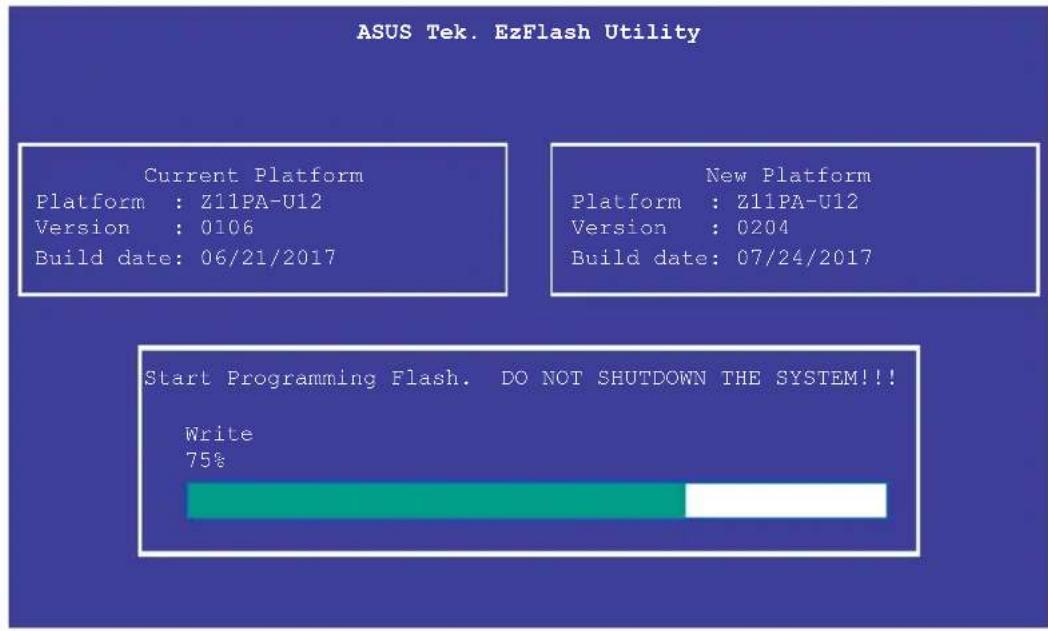
- The utility verifies the file, then starts updating the BIOS file.
text_image
ASUS Tek. EzFlash Utility Current Platform Platform : Z11PA-U12 Version : 0106 Build date: 06/21/2017 New Platform Platform : Z11PA-U12 Version : 0204 Build date: 07/24/2017 Start Programming Flash. DO NOT SHUTDOWN THE SYSTEM!!! Write 75%
DO NOT shut down or reset the system while updating the BIOS to prevent system boot failure!
- The utility returns to the DOS prompt after the BIOS update process is completed. Reboot the system from the hard disk drive.
The BIOS update is finished! Please restart your system.
C:\>
4.2 BIOS setup program
This motherboard supports a programmable firmware chip that you can update using the provided utility described in section 4.1 Managing and updating your BIOS.
Use the BIOS Setup program when you are installing a motherboard, reconfiguring your system, or prompted to "Run Setup." This section explains how to configure your system using this utility.
Even if you are not prompted to use the Setup program, you can change the configuration of your computer in the future. For example, you can enable the security password feature or change the power management settings. This requires you to reconfigure your system using the BIOS Setup program so that the computer can recognize these changes and record them in the CMOS RAM of the firmware chip.
The firmware chip on the motherboard stores the Setup utility. When you start up the computer, the system provides you with the opportunity to run this program. Press during the Power-On Self-Test (POST) to enter the Setup utility; otherwise, POST continues with its test routines.
If you wish to enter Setup after POST, restart the system by pressing
The Setup program is designed to make it as easy to use as possible. Being a menu-driven program, it lets you scroll through the various sub-menus and make your selections from the available options using the navigation keys.

- The default BIOS settings for this motherboard apply for most conditions to ensure optimum performance. If the system becomes unstable after changing any BIOS settings, load the default settings to ensure system compatibility and stability. Press
and select Yes to load the BIOS default settings. - The BIOS setup screens shown in this section are for reference purposes only, and may not exactly match what you see on your screen.
- Visit the ASUS website (www.asus.com) to download the latest BIOS file for this motherboard.
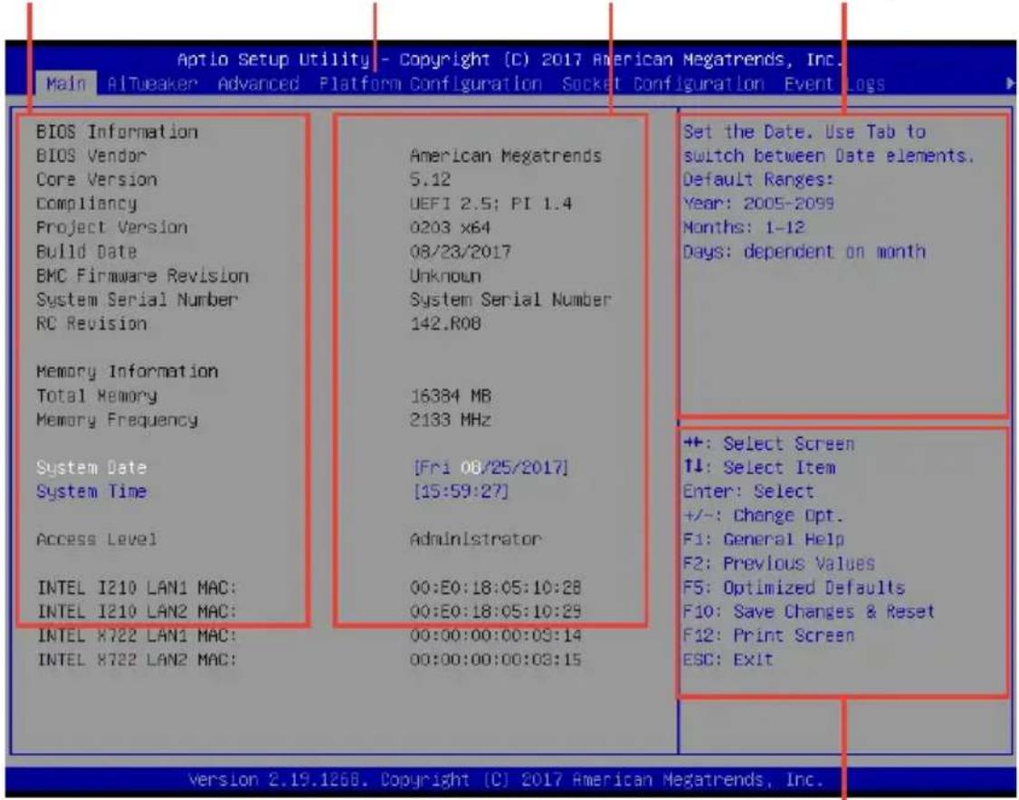
4.2.1 BIOS menu screen
General helpMenu bar Configuration fieldsM
text_image
Aptio Setup Utility - Copyright (C) 2017 American Megatrends, Inc. Main Altueaker Advanced Platform Configuration Socket Configuration Event Logs BIOS Information BIOS Vendor Core Version Compliance Project Version Build Date BMC Firmware Revision System Serial Number RC Revision Memory Information Total Memory Memory Frequency System Date System Time Access Level INTEL I210 LAN1 MAC: INTEL I210 LAN2 MAC: INTEL X722 LAN1 MAC: INTEL X722 LAN2 MAC: American Megatrends 5.12 UEF1 2.5; PI 1.4 0203 x64 08/23/2017 Unknown System Serial Number 142.R08 16384 MB 2133 MHz [Fri 08/25/2017] [15:59:27] Administrator 00:E0:18:05:10:28 00:E0:18:05:10:29 00:00:00:00:03:14 00:00:00:00:03:15 Set the Date. Use Tab to switch between Date elements. Default Ranges: Year: 2005-2099 Months: 1-12 Days: dependent on month +: Select Screen ↓: Select Item Enter: Select +/-: Change Opt. F1: General Help F2: Previous Values F5: Optimized Defaults F10: Save Changes & Reset F12: Print Screen ESC: Exit Version 2.19.1268. Copyright (C) 2017 American Megatrends, Inc.Navigation keys
4.2.2 Menu bar
The menu bar on top of the screen has the following main items:
Main For changing the basic system configuration
Ai Tweaker For changing the overclocking settings
Advanced For changing the advanced system settings
Platform Configuration For changing the platform settings
Socket Configuration For changing the socket settings
Event Logs For changing the event log settings
Server Mgmt For changing the server mgmt settings
Security For changing the security settings
Boot For changing the system boot configuration
Tool For configuring options for special functions
Save & Exit For selecting the save & exit options
To select an item on the menu bar, press the right or left arrow key on the keyboard until the desired item is highlighted.
4.2.3 Menu items
The highlighted item on the menu bar displays the specific items for that menu. For example, selecting Main shows the Main menu items.
The other items (Advanced, Platform Configuration, Socket Configuration, Event Logs, Server Mgmt, Security, Boot, Tool, and Save & Exit) on the menu bar have their respective menu items.
4.2.4 Submenu items
A solid triangle before each item on any menu screen means that the item has a submenu. To display the submenu, select the item then press
4.2.5 Navigation keys
At the bottom right corner of a menu screen are the navigation keys for the BIOS setup program. Use the navigation keys to select items in the menu and change the settings.
4.2.6 General help
At the top right corner of the menu screen is a brief description of the selected item.
4.2.7 Configuration fields
These fields show the values for the menu items. If an item is user-configurable, you can change the value of the field opposite the item. You cannot select an item that is not user-configurable.
A configurable field is enclosed in brackets, and is highlighted when selected. To change the value of a field, select it and press
4.2.8 Pop-up window
Select a menu item and press
4.2.9 Scroll bar
A scroll bar appears on the right side of a menu screen when there are items that do not fit on the screen. Press the Up/Down arrow keys or
4.3 Main menu
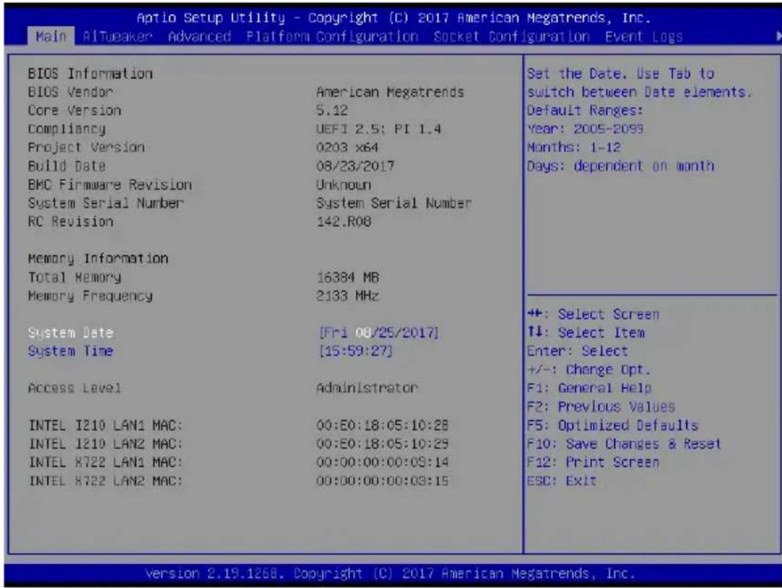
When you enter the BIOS Setup program, the Main menu screen appears. The Main menu provides you an overview of the basic system information, and allows you to set the system date, time, language, and security settings.
text_image
Aptio Setup Utility - Copyright (C) 2017 American Megatrends, Inc. Main AITueaker Advanced Platform Configuration Socket Configuration Event Logs BIOS Information BIOS Vendor American Megatrends Core Version 5.12 Compliance UEFI 2.5; PI 1.4 Project Version 0203 x64 Build Date 08/23/2017 BMC Firmware Revision Unknown System Serial Number System Serial Number RC Revision 142.R08 Memory Information Total Memory 16384 MB Memory Frequency 2133 MHz System Date [Fri 08/25/2017] System Time [15:59:27] Access Level Administrator INTEL I210 LAN1 MAC: 00:E0:18:05:10:28 INTEL I210 LAN2 MAC: 00:E0:18:05:10:29 INTEL X722 LAN1 MAC: 00:00:00:00:09:14 INTEL X722 LAN2 MAC: 00:00:00:00:09:15 Set the Date. Use Tab to switch between Date elements. Default Ranges: Year: 2005-2099 Months: 1-12 Days: dependent on month ++: Select Screen T↓: Select Item Enter: Select +/-: Change Opt. F1: General Help F2: Previous Values F5: Optimized Defaults F10: Save Changes & Reset F12: Print Screen ESC: Exit Version 2.19.1268. Copyright (C) 2017 American Megatrends, Inc.4.3.1 System Date [Day xx/xx/xxxx]
Allows you to set the system date.
4.3.2 System Time [xx:xx:xx]
Allows you to set the system time.
4.4 Advanced menu
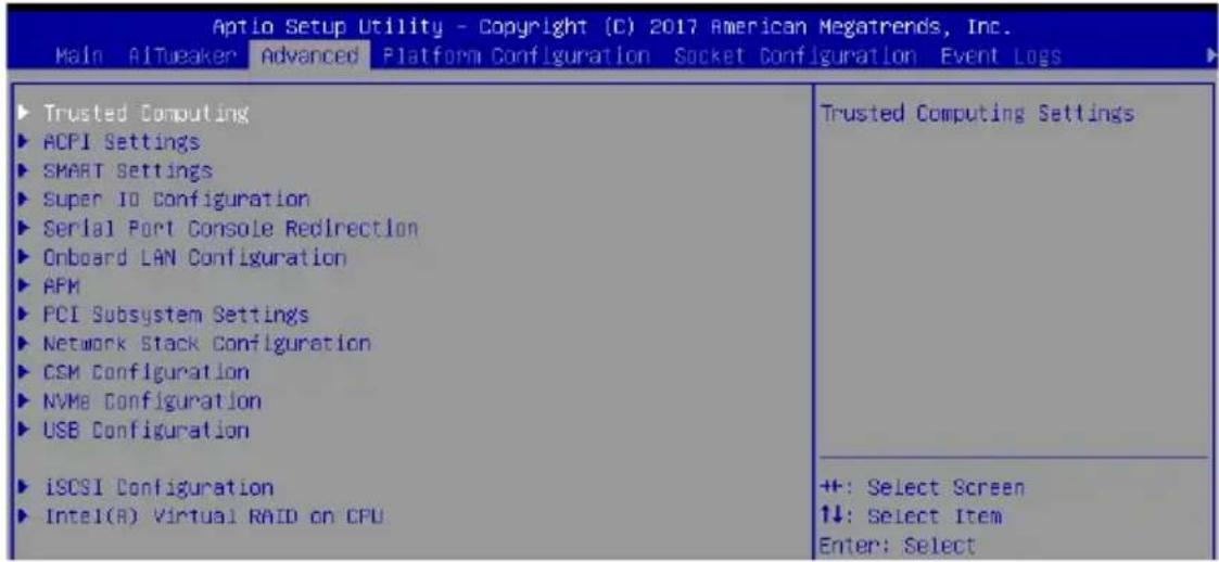
The Advanced menu items allow you to change the settings for the CPU and other system devices.

Take caution when changing the settings of the Advanced menu items. Incorrect field values can cause the system to malfunction.
text_image
Aptio Setup Utility - Copyright (C) 2017 American Megatrends, Inc. Main AI/Tweaker Advanced Platform Configuration Socket Configuration Event Logs Trusted Computing ACPI Settings SMART Settings Super IO Configuration Serial Port Console Redirection Onboard LAN Configuration APM PCI Subsystem Settings Network Stack Configuration CSM Configuration NVMe Configuration USB Configuration iSCSI Configuration Intel(R) Virtual RAID on CPU Trusted Computing Settings +: Select Screen ↑↓: Select Item Enter: Select4.4.1 Trusted Computing
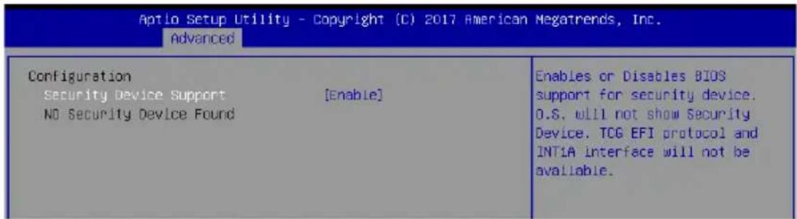
text_image
Aptio Setup Utility - Copyright (C) 2017 American Megatrends, Inc. Advanced Configuration Security Device Support [Enable] NO Security Device Found Enables or Disables BIOS support for security device. O.S. will not show Security Device. TCG EFI protocol and INT1A interface will not be available.Configuration
Security Device Support [Enabled]
Allows you to enable or disable the BIOS support for security device. Configuration options: [Disabled] [Enabled]
4.4.2 ACPI Settings
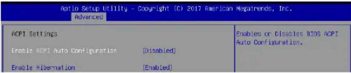
text_image
Aptlo Setup Utility - Copyright (C) 2017 American Megatrends, Inc. Advanced ACPI Settings Enable ACPI Auto Configuration [Disabled] Enable Hibernation [Enabled] Enables or Disables BIOS ACPI Auto Configuration.Enable ACPI Auto Configuration [Disabled]
Allows you to enable or disable the BIOS ACPI Auto Configuration.
Configuration options: [Disabled] [Enabled]
Enable Hibernation [Enabled]
Allows you to enable or disable the ability of the system to hibernate (OS/S4 Sleep State).
Configuration options: [Disabled] [Enabled]
![ASUS Z11PA-U12 - Enable Hibernation [Enabled] - 1](/content/2026/05/812826/images/31d4d8becdc76f6e14424389caa9f41972e670f2e9545eae53a37bae22600bb6.jpg)
This option may be not be effective with some OS.
4.4.3 Smart Settings

text_image
Aptio Setup Utility - Copyright (C) 2017 American Megatrends, Inc. Advanced SMART Settings SMART Self Test [Enabled] Run SMART Self Test on all HODs during POST.SMART Self Test [Enabled]
Allows you to run SMART Self Test on all HDDs during POST. Configuration options: [Disabled] [Enabled]
4.4.4 Super IO Configuration
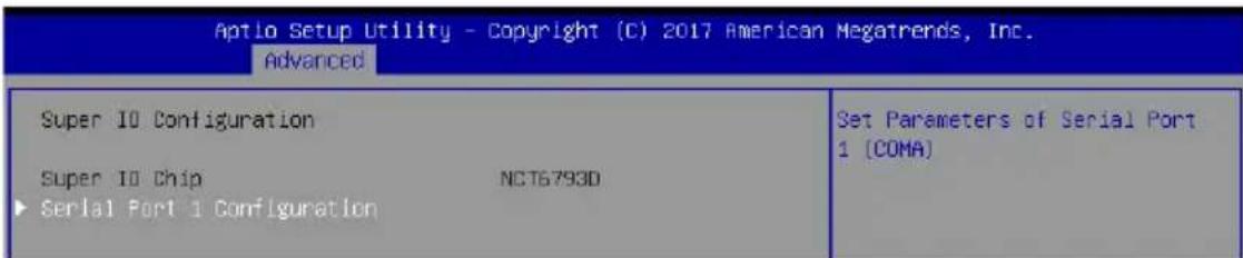
text_image
Aptio Setup Utility - Copyright (C) 2017 American Megatrends, Inc. Advanced Super IO Configuration Super IO Chip NCT6793D Serial Port 1 Configuration Set Parameters of Serial Port 1 [COMA]Serial Port 1 Configuration
Allows you to set the parameters of Serial Port 1.
Serial Port [Enabled]
Allows you to enable or disable Serial Port.
Configuration options: [Disabled] [Enabled]
![ASUS Z11PA-U12 - Serial Port [Enabled] - 1](/content/2026/05/812826/images/b3ac21be6d0201055c3ac2873f2d2b56388b02225ce999b85b469e8c1506cd00.jpg)
The following item appears only when you set Serial Port to [Enabled].
Change Settings [Auto]
Allows you to choose the setting for Super IO device.
Configuration options: [Auto] [IO=3F8h; IRQ=4;] [IO=3F8h; IRQ=3, 4, 5, 6, 7, 9, 10, 11,
12;] [IO=2F8h; IRQ=3, 4, 5, 6, 7, 9, 10, 11, 12;] [IO=3E8h; IRQ=3, 4, 5, 6, 7, 9, 10, 11,
12;] [IO=2E8h; IRQ=3, 4, 5, 6, 7, 9, 10, 11, 12;]
4.4.5 Serial Port Console Redirection
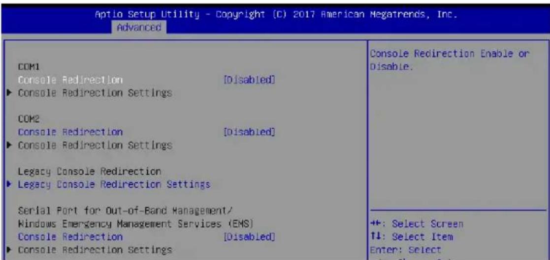
text_image
Aptio Setup Utility - Copyright (C) 2017 American Megatrends, Inc. Advanced COM1 Console Redirection [Disabled] ► Console Redirection Settings COM2 Console Redirection [Disabled] ► Console Redirection Settings Legacy Console Redirection ► Legacy Console Redirection Settings Serial Port for Out-of-Band Management/ Windows Emergency Management Services (EMS) Console Redirection [Disabled] ► Console Redirection Settings Console Redirection Enable or Disable. +#: Select Screen ↑↓: Select Item Enter: SelectCOM1 / COM2
Console Redirection [Disabled]
Allows you to enable or disable the console redirection feature.
Configuration options: [Disabled] [Enabled]
Console Redirection Settings
This item becomes configurable only when you enable the Console Redirection item. The settings specify how the host computer and the remote computer (which the user is using) will exchange data. Both computers should have the same or compatible settings.
| Aptio Setup Utility - Copyright (C) 2017 American Megatrends, Inc. Advanced | |
| COM1 Console Redirection Settings | Emulation: ANSI: Extended ASCII char set. VT100: ASCII char set. VT100+: Extends VT100 to support color, function keys, etc. VT-UTF8: Uses UTF8 encoding to map unicode chars onto 1 or more bytes. |
| Terminal Type [VT-UTF8] Bits per second [57600] Data Bits [8] Parity [None] Stop Bits [1] Flow Control [Hardware RTS/CTS] VT-UTF8 Combo Key Support [Enabled] Recorder Mode [Disabled] Legacy OS Redirection Resolution [80x24] Putty KeyPad [VT100] Redirection After BIOS POST [Always Enable] | ++: Select Screen ↑↓: Select Item |
Terminal Type [VT-UTF8]
Allows you to set the terminal type.
[VT100] ASCII char set.
[VT100+] Extends VT100 to support color, function keys, etc.
[VT-UTF8] Uses UTF8 encoding to map Unicode chars onto 1 or more bytes.
[ANSI] Extended ASCII char set.
Bits per second [57600]
Selects serial port transmission speed. The speed must be matched on the other side.
Long or noisy lines may require lower speeds.
Configuration options: [9600] [19200] [38400] [57600] [115200]
Data Bits [8]
Configuration options: [7] [8]
Parity [None]
A parity bit can be sent with the data bits to detect some transmission errors. [Mark] and [Space] parity do not allow for error detection.
[None] None.
[Even] parity bit is 0 if the num of 1's in the data bits is even.
[Odd] parity bit is 0 if num of 1's in the data bits is odd.
[Mark] parity bit is always 1.
[Space] parity bit is always 0.
Stop Bits [1]
Stop bits indicate the end of a serial data packet. (A start bit indicates the beginning.) The standard setting is 1 stop bit. Communication with slow devices may require more than 1 stop bit.
Configuration options: [1] [2]
Flow Control [Hardware RTS/CTS]
Flow control can prevent data loss from buffer overflow. When sending data, if the receiving buffers are full, a "stop" signal can be sent to stop the data flow. Once the buffers are empty, a "start" signal can be sent to re-start the flow. Hardware flow control uses two wires to send start/stop signals.
Configuration options: [None] [Hardware RTS/CTS]
VT-UTF8 Combo Key Support [Enabled]
Allows you to enable the VT-UTF8 Combo Key Support for ANSI/VT100 terminals.
Configuration options: [Disabled] [Enabled]
Recorder Mode [Disabled]
With this mode enabled only text will be sent. This is to capture Terminal data.
Configuration options: [Disabled] [Enabled]
Legacy OS Redirection Resolution [80x24]
This allows you to set the number of rows and columns supported on the Legacy OS.
Configuration options: [80x24] [80x25]
Putty Keypad [VT100]
This allows you to select the FunctionKey and Keypad on Putty.
Configuration options: [VT100] [LINUX] [XTERMR6] [SCO] [ESCN] [VT400]
Redirection After BIOS POST [Always Enable]
This setting allows you to specify if Bootloader is selected than Legacy console redirection.
Configuration options: [Always Enable] [Bootloader]
Legacy Console Redirection Settings

text_image
Aptlo Setup Utility - Copyright (C) 2017 American Megatrends, Inc. Advanced Legacy Serial Redirection Port [COM1] Select a COM port to display redirection of Legacy OS and Legacy OPROM MessagesLegacy Serial Redirection Port [COM1]
Allows you to select a COM port to display redirection of Legacy OS and Legacy OPROM Messages.
Configuration options: [COM1] [COM2]
Serial Port for Out-of-Band Management/Windows Emergency Management Services (EMS)
Console Redirection [Disabled]
Allows you to enable or disable the console redirection feature.
Configuration options: [Disabled] [Enabled]
![ASUS Z11PA-U12 - Console Redirection [Disabled] - 1](/content/2026/05/812826/images/d40fab51c7d0af0efc2b107b5365ea1205c45838799a8fb0a2c93ceaeae8a2ce.jpg)
text_image
Aptio Setup Utility - Copyright (C) 2017 American Megatrends, Inc. Advanced Out-of-Band Hgmt Port [COM1] Terminal Type [VT-UTF8] Bits per second [115200] Flow Control [None] Data Bits 8 Parity None Stop Bits 1 Microsoft Windows Emergency Management Services (EMS) allous for remote management of a Windows Server OS through a serial port.Console Redirection Settings
Out-of-Band Mgmt Port [COM1]
Microsoft Windows Emergency Management Services (EMS) allows for remote management of a Windows Server OS through a serial port.
Configuration options: [COM1] [COM2]
Terminal Type [VT-UTF8]
Allows you to set the terminal type for out-of-band management.
Configuration options: [VT100] [VT100+] [VT-UTF8] [ANSI]
Bits per second [115200]
Allows you to set the serial port transmission speed.
Configuration options: [9600] [19200] [57600] [115200]
Flow Control [None]
Allows you to set the flow control to prevent data loss from buffer overflow.
Configuration options: [None] [Hardware RTS/CTS] [Software Xon/Xoff]
4.4.6 Onboard LAN

text_image
Aptlo Setup Utility - Copyright (C) 2017 American Megatrends, Inc. Advanced ► Onboard I210 LAN Configuration ► Onboard X722 LAN Configuration Onboard I210 LAN Enable/DisableOnboard I210 LAN Configuration
| Aptio Setup Utility - Copyright (C) 2017 American Megatrends, Inc. Advanced | |
| Onboard I210 LAN Configuration | Intel LAN Enable/Disable |
| INTEL I210 LAN1 MAC: 00:E0:18:05:10:96 INTEL I210 LAN2 MAC: 00:E0:18:05:10:97 Intel LAN1 Enable [Enabled] Intel LAN1 ROM Type [PXE] Intel LAN2 Enable [Enabled] Intel LAN2 ROM Type [Disabled] | |
Intel LAN1 Enable [Enabled]
Allows you to enable or disable the Intel LAN.
Configuration options: [Disabled] [Enabled]
![ASUS Z11PA-U12 - Intel LAN1 Enable [Enabled] - 1](/content/2026/05/812826/images/b59004bb559ed143ef1ee76f4bb67123c7a01dd264da34f4e8045d53c66f94d6.jpg)
The following item appears only when you set Intel LAN1 Enable to [Enabled].
Intel LAN ROM Type [PXE]
Allows you to select the Intel LAN ROM type.
Configuration options: [Disabled] [PXE] [iSCSI]
![ASUS Z11PA-U12 - Intel LAN ROM Type [PXE] - 1](/content/2026/05/812826/images/52b2d1dc8f3a75d04430a4f1613d52f4ce6ccd79f4e15e104fcae999d46be241.jpg)
Due to Intel ^® limitations, both Intel LAN ROM Type options should be the same when [PXE] or [iSCSI] is selected.
Intel LAN2 Enable [Enabled]
Allows you to enable or disable the Intel LAN.
Configuration options: [Disabled] [Enabled]
![ASUS Z11PA-U12 - Intel LAN2 Enable [Enabled] - 1](/content/2026/05/812826/images/494c5b8cc2a6d63224d06f6d59ffd4739cce8f9a40db731fd7a09a2b799f26e8.jpg)
The following item appears only when you set Intel LAN2 Enable to [Enabled].
Intel LAN ROM Type [Disabled]
Allows you to select the Intel LAN ROM type.
Configuration options: [Disabled] [PXE] [iSCSI]
![ASUS Z11PA-U12 - Intel LAN ROM Type [Disabled] - 1](/content/2026/05/812826/images/a990e12d981486c56a9950f6d978d27424e1fdac34ba05f66ac9bb33ffb4819e.jpg)
Due to Intel ^® limitations, both Intel LAN ROM Type options should be the same when [PXE] or [iSCSI] is selected.
Onboard X722 LAN Configuration

text_image
Aptio Setup Utility - Copyright (C) 2017 American Megatrends, Inc. Advanced Onboard X722 LAN Configuration Intel X722 LAN Enable [Enabled] Intel LAN Enable/DisableIntel X722 LAN Enable [Enabled]
Allows you to enable or disable the Intel LAN.
Configuration options: [Disabled] [Enabled]
4.4.7 APM
Allows you to configure the Advance Power Management (APM) settings.
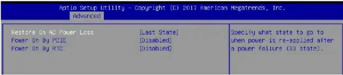
text_image
Aptio Setup Utility - Copyright (C) 2017 American Megatrends, Inc. Advanced Restore On AC Power Loss [Last State] Power On By PCIE [Disabled] Power On By RTC [Disabled] Specify what state to go to when power is re-applied after a power failure (69 state).Restore AC Power Loss [Last State]
When set to [Power Off], the system goes into off state after an AC power loss. When set to [Power On], the system will reboot after an AC power loss. When set to [Last State], the system goes into either off or on state, whatever the system state was before the AC power loss.
Configuration options: [Power Off] [Power On] [Last State]
Power On By PCIE [Disabled]
[Disabled] Disables the PCIE devices to generate a wake event.
[Enabled] Enables the PCIE devices to generate a wake event.
Power On By RTC [Disabled]
[Disabled] Disables RTC to generate a wake event.
[Enabled] When set to [Enabled], the items RTC Alarm Date (Days) and Hour/Minute/Second will become user-configurable with set values.
4.4.8 PCI Subsystem Settings
Allows you to configure PCI, PCI-X, and PCI Express Settings.
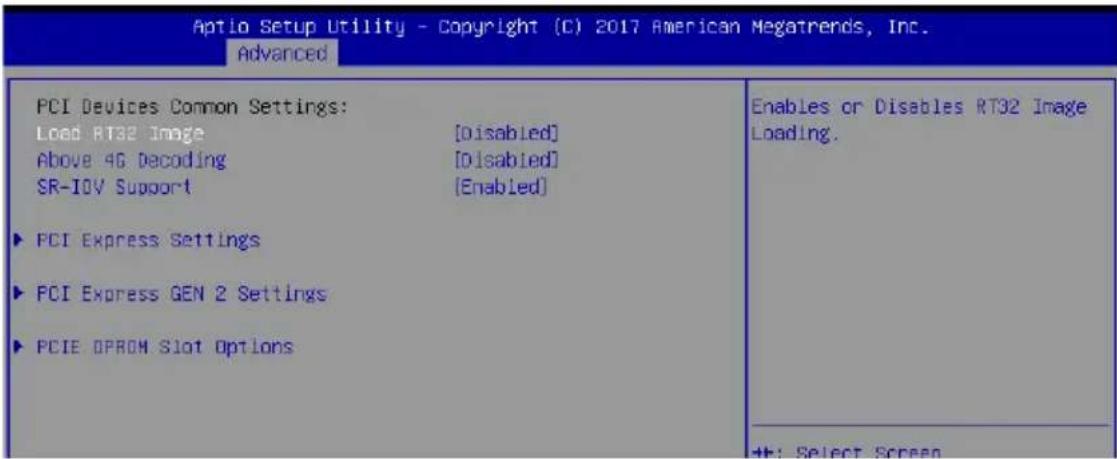
text_image
Aptio Setup Utility - Copyright (C) 2017 American Megatrends, Inc. Advanced PCI Devices Common Settings: Load RT32 Image [Disabled] Above 4G Decoding [Disabled] SR-IOV Support [Enabled] ► PCI Express Settings ► PCI Express GEN 2 Settings ► PCIE OPRDM Slot Options Enables or Disables RT32 Image Loading. ◆: Select ScreenLoad RT32 Image [Disabled]
Allows you to enable or disable RT32 Image Loading.
Configuration options: [Disabled] [Enabled]
Above 4G Decoding [Disabled]
Allows you to enable or disable 64-bit capable devices to be decoded in above 4G address space. It only works if the system supports 64-bit PCI decoding.
Configuration options: [Disabled] [Enabled]
SR-IOV Support [Enabled]
This option enables or disables Single Root IO Virtualization Support if the system has SRIOV capable PCIe devices.
Configuration options: [Disabled] [Enabled]
PCI Express Settings
PCI Express Device Register Settings
Relaxed Ordering [Enabled]
This option allows you to enable or disable PCI Express Device Relaxed Ordering.
Configuration options: [Disabled] [Enabled]
Extended Tag [Disabled]
This option allows Device to use an 8-bit Tag field as a requester when set to Enabled.
Configuration options: [Disabled] [Enabled]
No Snoop [Enabled]
This option allows you to enable or disable PCI Express Device No Snoop option.
Configuration options: [Disabled] [Enabled]
Maximum Payload [Auto]
This option allows you to set the Maximum Payload of PCI Express Device or allow System BIOS to select the value.
Configuration options: [Auto] [128 Bytes] [256 Bytes] [512 Bytes] [1024 Bytes]
Maximum Read Request [Auto]
This option allows you to set the Maximum Read Request of PCI Express Device or allow System BIOS to select the value.
Configuration options: [Auto] [128 Bytes] [256 Bytes] [512 Bytes] [1024 Bytes]
PCI Express Device Link Register Settings
ASPM Support [Disabled]
This option allows you to set the ASPM level.
[Force L0s] Force all links to L0s State.
[Auto] BIOS auto configure.
[Disabled] Disables ASPM.
![ASUS Z11PA-U12 - ASPM Support [Disabled] - 1](/content/2026/05/812826/images/a3afc11d02ba1c7f9075332660ecf2751f2096f9deca655fba1993dcef6a5115.jpg)
Enabling ASPM may cause some PCI-E devices to fail.
Extended Synch [Disabled]
This option allows the generation of Extended Synchronization patterns when set to Enabled.
Configuration options: [Disabled] [Enabled]
Link Training Retry [5]
This option allows you to set the number of Retry Attempts software will take to retrain the link if previous training attempt was unsuccessful.
Configuration options: [Disabled] [2] [3] [5]
Link Training Timeout [1000]
This option allows you to set the number of Microseconds software will wait before polling 'Link Training' but in Link Status Register. The value ranges from 10 to 10000 uS.
Unpopulated Links [Keep Link On]
This option will disable unpopulated PCI Express links to save power when set to Disabled.
Configuration options: [Disabled] [Keep Link On]
PCI Express Gen 2 Settings
PCI Express GEN2 Device Register Settings
Completion Timeout [Default]
This option allows system software to modify the Completion Timeout value for device Functions which support Completion Timeout programmability.
[Default] 50us to 50ms.
[Shorter] Shorter timeout ranges supported by hardware will be used.
[Longer] Longer timeout ranges supported by hardware will be used.
[Disabled] Disable Completion Timeout.
ARI Forwarding [Disabled]
If supported by hardware and set to Enabled, the Downstream Port disables its traditional Device Number filed being 0 enforcement when turning a Type1 Configuration Request into a Type0 Configuration Request, permitting access to Extended Functions in an ARI Device immediately below the Port.
Configuration options: [Disabled] [Enabled]
Atomic0p Request Enable [Disabled]
If supported by hardware and set to Enabled, this function initiates AtomicOp Requests only if Bus Master Enable bit is in the Command Register Set.
Configuration options: [Disabled] [Enabled]
Atomic0p Egress Blocking [Disabled]
If supported by hardware and set to Enabled, outbound AtomicOp Requests via Egress Ports will be blocked.
Configuration options: [Disabled] [Enabled]
IDO Request Enable [Disabled]
If supported by hardware and set to Enabled, this permits setting the number of ID-Based Ordering (IDO) bit (Attribute[2]) requests to be initiated.
Configuration options: [Disabled] [Enabled]
IDO Completion Enable [Disabled]
If supported by hardware and set to Enabled, this permits setting the number of ID-Based Ordering (IDO) bit (Attribute[2]) requests to be initiated.
Configuration options: [Disabled] [Enabled]
LTR Mechanism Enable [Disabled]
If supported by hardware and set to Enabled, this enables the Latency Tolerance Reporting (LTR) Mechanism.
Configuration options: [Disabled] [Enabled]
IDO Request Enable [Disabled]
If supported by hardware and set to Enabled, this permits setting the number of ID-Based Ordering (IDO) bit (Attribute[2]) requests to be initiated.
Configuration options: [Disabled] [Enabled]
End-End TLP Prefix Blocking [Disabled]
If supported by hardware and set to Enabled, this function will block forwarding of TLPs containing End-End TLP Prefixes.
Configuration options: [Disabled] [Enabled]
PCI Express GEN2 Device Register Settings
Target Link Speed [Auto]
If supported by hardware and set to Force to X.X GT/s, for Downstream Ports, this sets an upper limit on Link operational speed by restricting the values advertised by the Upstream component in its training sequences. When Auto is selected HW initialized data will be used.
Configuration options: [Auto] [Force to 2.5 GT/s] [Force to 5.0 GT/s] [Force to 8.0 GT/s]
Clock Power Management [Disabled]
If supported by hardware and set to Enabled, the device is permitted to use CLKREQ# signal for power management of Link clock in accordance to protocol defined in appropriate form factor specification.
Configuration options: [Disabled] [Enabled]
Compliance SOS [Disabled]
If supported by hardware and set to Enabled, this will force LTSSM to send SKP Ordered Sets between sequences when sending Compliance Pattern or Modified Compliance Pattern.
Configuration options: [Disabled] [Enabled]
Hardware Autonomous Width [Enabled]
If supported by hardware and set to Disabled, this will disable the hardware's ability to change link width except for width size reduction for the purpose of correcting unstable link operation.
Configuration options: [Disabled] [Enabled]
Hardware Autonomous Speed [Enabled]
If supported by hardware and set to Disabled, this will disable the hardware's ability to change link speed except for speed rate reduction for the purpose of correcting unstable link operation.
Configuration options: [Disabled] [Enabled]
PCIE OPROM Slot Options
PCIE1-6 Slot OPROM [Enabled]
This option allows you to enable or disable the OPROM of the PCIe slots.
Configuration options: [Disabled] [Enabled]
4.4.9 Network Stack Configuration
Allows you to configure the netword stack configuration.

text_image
Aptlo Setup Utility - Copyright (C) 2017 American Megatrends, Inc. Advanced Network Stack [Disabled] Enable/Disable UEFI Network StackNetwork Stack [Disabled]
Allows you to enable or disable UEFI Network Stack.
Configuration options: [Disabled] [Enabled]
![ASUS Z11PA-U12 - Network Stack [Disabled] - 1](/content/2026/05/812826/images/c93e160dc243ccf6f9a08cc9b46375557dbeb4df0d03429052cffc0e4b02f4b3.jpg)
The following items appear only when you set the Network Stack to [Enabled].
Ipv4 PXE Support [Disabled]
Enables or disables the lpv4 PXE Boot Support. If disabled, lpv4 PXE boot option will not be created.
Configuration options: [Disable] [Enable]
Ipv4 HTTP Support [Disabled]
Enables or disables the lpv4 HTTP Boot Support. If disabled, lpv4 PXE boot option will not be created.
Configuration options: [Disable] [Enable]
Ipv6 PXE Support [Disabled]
Enables or disables the lpv6 PXE Boot Support. If disabled, lpv6 PXE boot option will not be created.
Configuration options: [Disable] [Enable]
Ipv6 HTTP Support [Disabled]
Enables or disables the lpv6 HTTP Boot Support. If disabled, lpv6 PXE boot option will not be created.
Configuration options: [Disable] [Enable]
PXE boot wait time [0]
Set the wait time to press ESC key to abort the PXE boot. Use the <+> or <-> to adjust the value. The values range from 0 to 5.
Media detect count [1]
Set the number of times presence of media will be checked. Use the <+> or <-> to adjust the value. The values range from 1 to 50.
4.4.10 CSM Configuration
| Aptio Setup Utility - Copyright (C) 2017 American Megatrends, Inc. Advanced | |
| Compatibility Support Module Configuration | |
| CSM Support | [Enabled] |
| CSM16 Module Version | 07.81 |
| GateA20 Active | [Upon Request] |
| Option ROM Messages | [Force BIOS] |
| INT19 Trap Response | [Immediate] |
| Boot option filter | [Legacy only] |
| Option ROM execution | |
| Network | [Legacy] |
| Storage | [Legacy] |
| Video | [Legacy] |
| Other PCI devices | [Legacy] |
| +:-: Select Screen ↑↓: Select Item Enter: Select +/-: Change Opt. F1: General Help F2: Previous Values | |
CSM Support [Enabled]
This option allows you to enable or disable CSM Support.
Configuration options: [Disabled] [Enabled]
![ASUS Z11PA-U12 - CSM Support [Enabled] - 1](/content/2026/05/812826/images/a4fca9c7d9b8fe2206269ea4fc13481ad5632e4dc57af9ed6fe0cf9d647c8c0d.jpg)
The following items appear only when you set the CSM Support to [Enabled].
GateA20 Active [Upon Request]
This allows you to set the GA20 option.
[Upon Request] GA20 can be disabled using BIOS services.
[Always] Do not allow disabling GA20; this option is useful when any RT code is executed above 1MB.
Option ROM Messages [Force BIOS]
This allows you to set the display mode for option ROM.
Configuration options: [Force BIOS] [Keep Current]
INT19 Trap Response [Immediate]
This option allows you to control the BIOS reaction on INT19 trapping by Option ROM.
[Immediate] Execute the trap right away.
[Legacy only] Execute the trap during legacy boot.
Boot Option filter [Legacy only]
This option allows you to control the Legacy/UEFI ROMs priority.
Configuration options: [UEFI and Legacy] [Legacy only] [UEFI only]
Network / Storage / Video [Legacy]
This option allows you to control the execution of UEFI and Legacy PXE/ Storage/Video OpROM.
Configuration options: [UEFI] [Legacy]
Other PCI devices [Legacy]
This item determines the OpROM execution policy for devices other than Network, Storage, or Video.
Configuration options: [UEFI] [Legacy]
4.4.11 NVMe Configuration
You may view the NVMe controller and Drive information if an NVMe device is connected.

text_image
Aptlo Setup Utility - Copyright (C) 2017 American Megatrends, Inc. Advanced NVMe controller and Drive Information No NVME Device Found4.4.12 USB Configuration
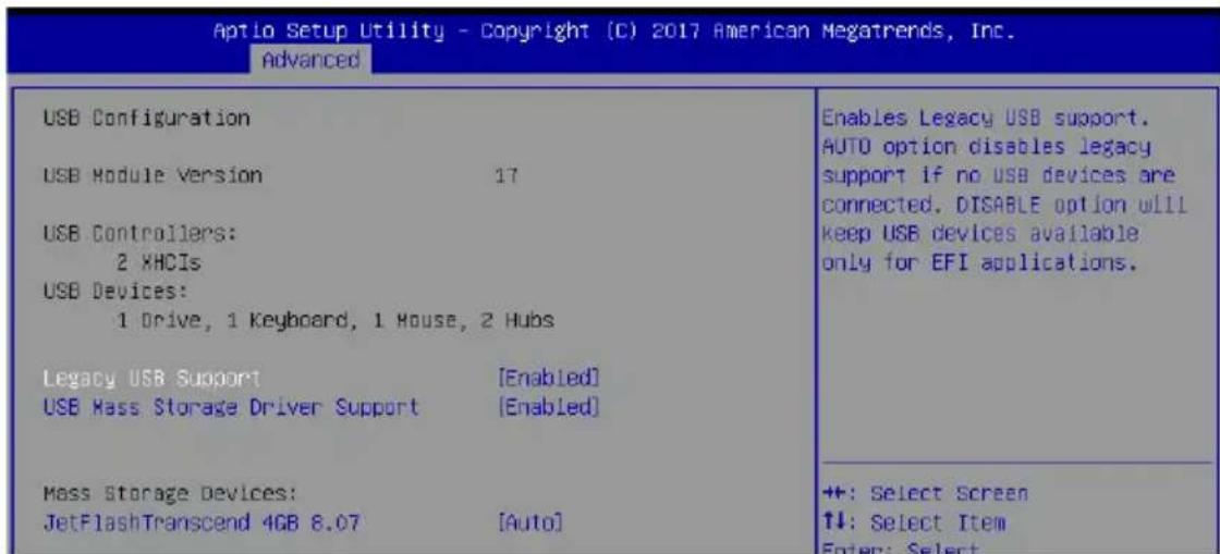
text_image
Aptio Setup Utility - Copyright (C) 2017 American Megatrends, Inc. Advanced USB Configuration USB Module Version 17 USB Controllers: 2 XHCIs USB Devices: 1 Drive, 1 Keyboard, 1 House, 2 Hubs Legacy USB Support [Enabled] USB Mass Storage Driver Support [Enabled] Mass Storage Devices: JetFlashTranscend 4GB 8.07 [Auto] Enables Legacy USB support. AUTO option disables legacy support if no USB devices are connected. DISABLE option will keep USB devices available. only for EFI applications. ++: Select Screen ↑↓: Select Item Enter: SelectLegacy USB Support [Enabled]
[Disabled] The USB devices can be used only for the BIOS setup program. It cannot be recognized in boot devices list.
[Enabled] Enables the support for USB devices on legacy operating systems (OS).
[Auto] Allows the system to detect the presence of USB devices at startup. If detected, the USB controller legacy mode is enabled. If no USB device is detected, the legacy USB support is disabled.
USB Mass Storage Driver Support [Enabled]
Allows you to enable or disable the USB Mass Storage driver support. Configuration options: [Disabled] [Enabled]
Mass Storage Devices
Allows you to select the mass storage device emulation type for devices connected. Configuration options: [Auto] [Floppy] [Forced FDD] [Hard Disk] [CD-ROM]
4.4.13 iSCSI Configuration
Allows you to configure the iSCSi parameters.
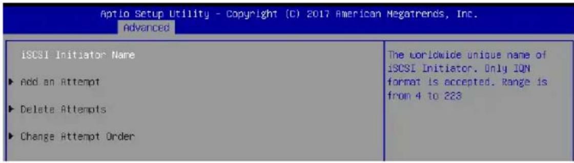
text_image
Aptio Setup Utility - Copyright (C) 2017 American Megatrends, Inc. Advanced iSCSI Initiator Name ► Add an Attempt ► Delete Attempts ► Change Attempt Order The worldwide unique name of iSCSI Initiator. Only IQN format is accepted. Range is from 4 to 2234.4.14 Intel(R) Virtual RAID on CPU
Allows you to configure the view the RAID volumes and VMD controllers on the system.
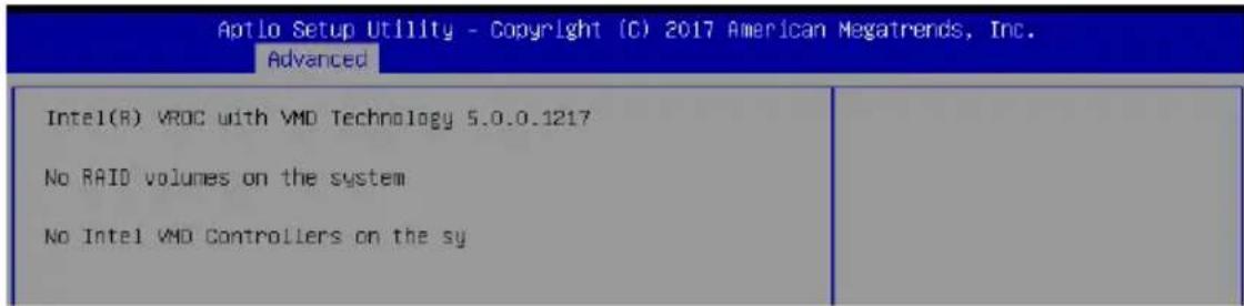
text_image
Aptlo Setup Utility - Copyright (C) 2017 American Megatrends, Inc. Advanced Intel(R) VROC with VMD Technology 5.0.0.1217 No RAID volumes on the system No Intel VMD Controllers on the sy4.5 Platform Configuration menu
The IntelRCSetup menu items allow you to change the platform settings.
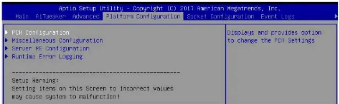
text_image
Aptio Setup Utility - Copyright (C) 2017 American Megatrends, Inc. Main AITweaker Advanced Platform Configuration Socket Configuration Event Logs ▶ PCH Configuration ▶ Miscellaneous Configuration ▶ Server HE Configuration ▶ Runtime Error Logging --------Setup Warning: Setting items on this Screen to incorrect values may cause system to malfunction! Displays and provides option to change the PCH Settings
Take caution when changing the settings of the Platform Configuration menu items. Incorrect field values can cause the system to malfunction.
4.5.1 PCH Configuration
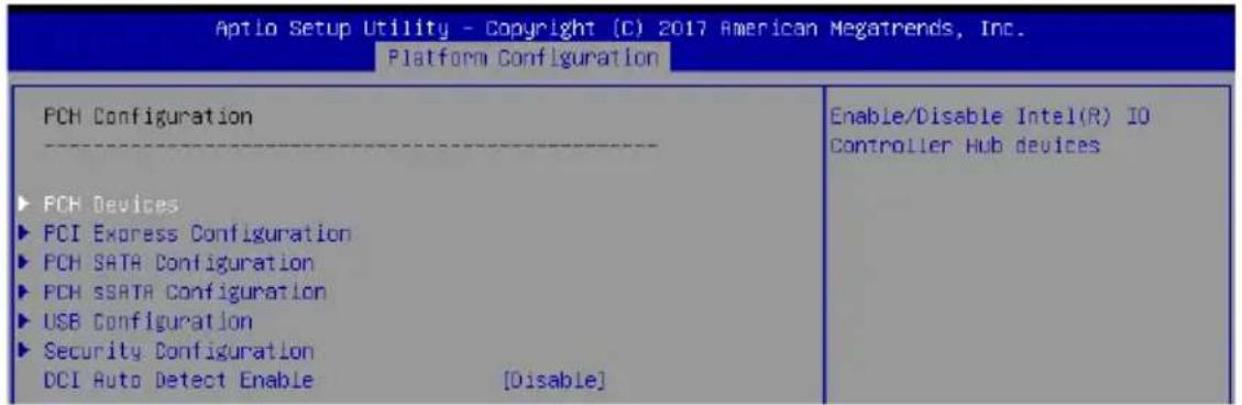
text_image
Aptio Setup Utility - Copyright (C) 2017 American Megatrends, Inc. Platform Configuration PCH Configuration ---- ► PCH Devices ► PCI Express Configuration ► PCH SATA Configuration ► PCH SSATA Configuration ► USB Configuration ► Security Configuration DCI Auto Detect Enable [Disable] Enable/Disable Intel(R) IO Controller Hub devicesPCH Devices
Board Capability [DeepSx]
[SUS_PWR_DN_ACK] Send.
[DeepSx] Show DeepSx Policies.
DeepSx Power Policies [Disabled]
Allows you to configure the DeepSx Mode configuration.
Configuration options: [Disabled] [Enabled in S5] [Enabled in S4 and S5]
GP27 Wake From DeepSx [Disabled]
Allows you to enable or disable GP27 Wake From DeepSx.
Configuration options: [Disabled] [Enabled]
PCI Express Configuration
PCI-E ASPM Support (Global) [L1 Only]
Allows you to select ASPM support for all downstream devices.
Configuration options: [Per individual port] [L1 Only]
PCH DMI ASPM [Platform-POR]
Allows you to configure the PCH DMI ASPM.
Configuration options: [Platform-POR] [ASPM L1] [Disabled]
PCH SATA Configuration
SATA Controller [Enabled]
Allows you to enable or disable the SATA Controller.
Configuration options: [Disabled] [Enabled]
![ASUS Z11PA-U12 - SATA Controller [Enabled] - 1](/content/2026/05/812826/images/c841ecf99d7b87bef785b4d138f0ad38f248149da95ff958825a47bbe1f45a8c.jpg)
The following item appears only when you set SATA Controller to [Enabled].
Configure SATA as [AHCI]
Allows you to identify the SATA port connected to Solid State Drive or Hard Disk Drive. Configuration options: [AHCI] [RAID]
Support Aggressive Link Power Management [Enabled]
Allows you to enable or disable the Support Aggressive Link Power (SALP) Management.
Configuration options: [Disabled] [Enabled]
SATA Port 0-7
Port 0-7
Allows you to enable or disable the SATA port.
Configuration options: [Disabled] [Enabled]
PCH sSATA Configuration
sSATA Controller [Enabled]
Allows you to enable or disable the sSATA Controller. Configuration options: [Disabled] [Enabled]
![ASUS Z11PA-U12 - sSATA Controller [Enabled] - 1](/content/2026/05/812826/images/0a13ea883096823dee709f13741aa9fc38f9fac9d5cdc1f60785b1b367f38135.jpg)
The following item appears only when you set sSATA Controller to [Enabled].
Configure sSATA as [AHCI]
Allows you to identify the SATA port connected to Solid State Drive or Hard Disk Drive. Configuration options: [AHCI] [RAID]
Support Aggressive Link Power Management [Enabled]
Allows you to enable or disable the Support Aggressive Link Power (SALP) Management.
Configuration options: [Disabled] [Enabled]
sSATA Port 0-5
Port 0-5
Allows you to enable or disable the SATA port.
Configuration options: [Disabled] [Enabled]
USB Configuration
USB Precondition [Disabled]
Allows you to enable or disable precondition work on USB host controller and root ports for faster enumeration.
Configuration options: [Disabled] [Enabled]
XHCI Manual Mode [Disabled]
This option is used by validation.
Configuration options: [Disabled] [Enabled]
![ASUS Z11PA-U12 - XHCI Manual Mode [Disabled] - 1](/content/2026/05/812826/images/6dfc0d1c3227b794bf4ff0cc159311b58de22e3c438463a0326675306cb63e2f.jpg)
The following items appear only when the XHCI Manual Mode is set to [Enabled].
Trunk Clock Gating (BTCG) [Enabled]
Allows you to enable or disable BTCG.
Configuration options: [Disabled] [Enabled]
Enable USB 3.0 pins [Disable all pins]
Allows you to enable or disable USB 3.0 pins or on a per pin basis.
Configuration options: [Select Per-Pin] [Disable all pins] [Enable all pins]
USB Per-Connector Disable [Disabled]
Allows you to enable or disable each of the USB physical connectors. Once a connector is disabled, any USB devices plugged into the connector will not be detected by BIOS or OS.
Configuration options: [Disabled] [Enabled]
![ASUS Z11PA-U12 - USB Per-Connector Disable [Disabled] - 1](/content/2026/05/812826/images/75e5f407321722120dccf03e831bc3f920318a108dd7f51dd073bcbab52b6155.jpg)
The following items appear only when the USB Per-Connector Disable is set to [Enabled].
USB HS Physical Connector #0-13 Disable [Enabled]
Configuration options: [Disabled] [Enabled]
USB SS Physical Connector #0-9 Disable [Enabled]
Configuration options: [Disabled] [Enabled]
Security Configuration
SMM BIOS Write Protect [Enabled]
Allows you to enable or disable SMM BIOS Write Protect.
Configuration options: [Disabled] [Enabled]
DCI Auto Detect Enable [Disabled]
When enabled, it detects DCI being connected during BIOS POST time and enables DCI. Configuration options: [Disabled] [Enabled]
4.5.2 Miscellaneous Configuration
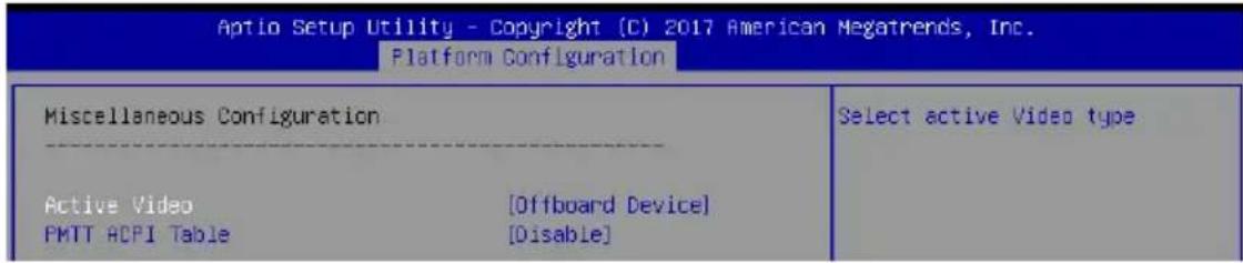
text_image
Aptio Setup Utility - Copyright (C) 2017 American Megatrends, Inc. Platform Configuration Miscellaneous Configuration Active Video [Offboard Device] PMTT ACPI Table [Disable] Select active Video typeActive Video [Offboard Device]
Allows you to select the video type.
Configuration options: [Onboard Device] [Offboard Device]
PMTT ACPI Table [Disabled]
Allows you to enable or disable PMTT ACPI Table for DDR4 only.
Configuration options: [Disabled] [Enabled]
4.5.3 Server ME Configuration
Displays the Server ME Technology parameters on your system.
| Aptio Setup Utility - Copyright (C) 2017 American Megatrends, Inc. Platform Configuration | |
| General ME Configuration | |
| Oper. Firmware version | OA:4.0.3.219 |
| Backup Firmware Version | OA:4.0.3.219 |
| Recovery Firmware Version | OA:4.0.3.219 |
| ME Firmware Status #1 | 0x000F0255 |
| ME Firmware Status #2 | 0x8811A006 |
| Current State | Operational |
| ME Firmware Features | |
| SiEn | Support |
| NM | Support |
Navigate to the second page of the screen to see the rest of items in this menu by pressing the Up or Down arrow keys.

To quickly go to the last item of the second page, press the Page Down button. Press the Page Up button to go back to the first item in the first page.
4.5.4 Runtime Error Logging
Displays the Server ME Technology parameters on your system.

text_image
Aptlo Setup Utility - Copyright (C) 2017 American Megatrends, Inc. Platform Configuration Runtime Error Logging System Errors [Enable] ▶ Whea Settings System Error Enable/Disable setup options.System Errors [Enabled]
This item allows you to enable or disable System Errors.
Configuration options: [Disabled] [Enabled]
Whea Settings
Whea Support [Enabled]
This item allows you to enable or disable the WHEA support.
Configuration options: [Disabled] [Enabled]
4.6 Socket Configuration menu
The IntelRCSetup menu items allow you to change the socket settings.
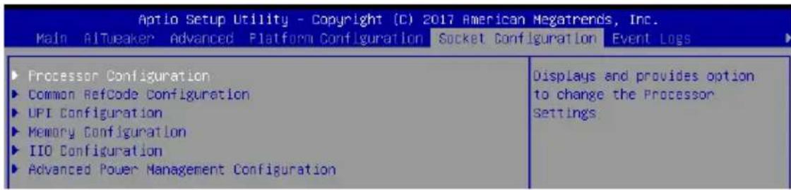
text_image
Aptio Setup Utility - Copyright (C) 2017 American Megatrends, Inc. Main Altueaker Advanced Platform Configuration Socket Configuration Event Logs ► Processor Configuration ► Common RefCode Configuration ► UPI Configuration ► Memory Configuration ► IIO Configuration ► Advanced Power Management Configuration Displays and provides option to change the Processor Settings4.6.1 Processor Configuration
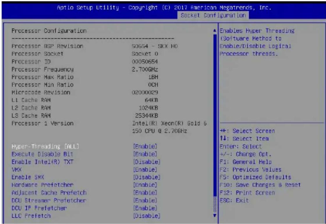
text_image
Aptio Setup Utility - Copyright (C) 2017 American Megatrends, Inc. Socket Configuration Processor Configuration Processor BSP Revision 50654 - SKX HO Processor Socket Socket 0 Processor ID 00050654 Processor Frequency 2.700GHz Processor Max Ratio 1BH Processor Min Ratio OCH Microcode Revision 02000029 L1 Cache RAM 64KB L2 Cache RAM 1024KB L3 Cache RAM 25344KB Processor 1 Version Intel(R) Xeon(R) Gold 6 150 CPU @ 2.70GHz Hyper-Threading [ALL] [Enable] Execute Disable BLT [Enable] Enable Intel(R) TXT [Disable] VMX [Enable] Enable SMX [Disable] Hardware Prefetcher [Enable] Adjacent Cache Prefetch [Enable] DCU Streamer Prefetcher [Enable] DCU IP Prefetcher [Enable] LLC Prefetch [Disable] Enables Hyper Threading (Software Method to Enable/Disable Logical Processor threads. +: Select Screen ↓: Select Item Enter: Select +/-: Change Opt. F1: General Help F2: Previous Values F5: Optimized Defaults F10: Save Changes & Reset F12: Print Screen ESC: ExitNavigate to the second page of the screen to see the rest of items in this menu by pressing the Up or Down arrow keys.

To quickly go to the last item of the second page, press the Page Down button. Press the Page Up button to go back to the first item in the first page.
Hyper-threading [ALL] [Enabled]
This item allows a hyper-threading processor to appear as two logical processors, allowing the operating system to schedule two threads or processors simultaneously.
Configuration options: [Disabled] [Enabled]
Execute Disable Bit [Enabled]
XD can prevent certain classes of malicious buffer overflow attacks when combined with a supporting OS (Windows Server 2003 SP1, Windows XP SP2, SuSE Linux 9.2, Redhat Enterprise 3 Update 3).
Configuration options: [Disabled] [Enabled]
Enable Intel(R) TXT [Disabled]
Forces the XD feature log to always return 0 when disabled.
Configuration options: [Disabled] [Enabled]
VMX [Enabled]
Enables the Vanderpool Technology. Takes effect after reboot.
Configuration options: [Disabled] [Enabled]
Enable SMX [Disabled]
Enables the Safer Mode Extensions.
Configuration options: [Disabled] [Enabled]
Hardware Prefetcher [Enabled]
This Item allows you to turn on/off the mid level cache(L2) streamer prefetcher.
Configuration options: [Disabled] [Enabled]
Adjacent Cache Prefetch [Enabled]
This Item allows you to turn on/off prefetching of adjacent cache lines.
Configuration options: [Disabled] [Enabled]
DCU Streamer Prefetcher [Enabled]
This Item allows you to enable or disable prefetcher of next L1 data line.
Configuration options: [Disabled] [Enabled]
DCU IP Prefetcher [Enabled]
This Item allows you to enable or disable prefetch of next L1 line based upon sequential load history.
Configuration options: [Disabled] [Enabled]
LLC Prefetch [Disabled]
This Item allows you to enable or disable LLC Prefetch on all threads.
Configuration options: [Disabled] [Enabled]
DCU Mode [32KB 8Way Without ECC]
Configuration options: [32KB 8Way Without ECC] [16KB 4Way With ECC]
Extended APIC [Disabled]
This Item allows you to enable or disable the extended APIC support.
Configuration options: [Disabled] [Enabled]
AES-NI [Enabled]
This Item allows you to enable or disable the AES-NI support.
Configuration options: [Disabled] [Enabled]
4.6.2 Common RefCode Configuration

text_image
Aptlo Setup Utility - Copyright (C) 2017 American Megatrends, Inc. Socket Configuration Common RefCode Configuration --------[Enable] NumaNuma [Enabled]
This item enables or disables the Non uniform Memory Access (NUMA).
Configuration options: [Disabled] [Enabled]
4.6.3 UPI Configuration
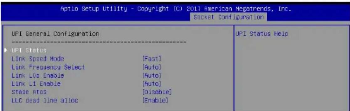
text_image
Aptio Setup Utility - Copyright (C) 2017 American Megatrends, Inc. Socket Configuration UPI General Configuration UPI Status Link Speed Mode [Fast] Link Frequency Select [Auto] Link L0p Enable [Auto] Link L1 Enable [Auto] Stale Atos [Disable] LLC dead line alloc [Enable] UPI Status HelpUPI General Configuration
UPI Status
This item displays information about the UPI status.
Link Speed Mode [Fast]
This item allows you to select the UPI link speed as either the fast mode or slow mode.
Configuration options: [Slow] [Fast]
Link Frequency Select [Auto]
This item allows for selecting the UPI link frequency.
Configuration options: [Auto] [9.6 GB/s] [10.4 GB/s] [Use Per Link Setting]
Link0p Enable [Auto]
Configuration options: [Disabled] [Enabled] [Auto]
Link1 Enable [Auto]
Configuration options: [Disabled] [Enabled] [Auto]
Stale AtoS [Disabled]
Configuration options: [Disabled] [Enabled] [Auto]
LLC dead line alloc [Enabled]
Configuration options: [Disabled] [Enabled] [Auto]
4.6.4 Memory Configuration
| Aptio Setup Utility - Copyright (C) 2017 American Megatrends, Inc. Socket Configuration | |
| Integrated Memory Controller (iHC) | |
| Enforce POR [Auto] Memory Frequency [Auto] Data Scrambling for DDR4 [Auto] ► Memory Topology ► Page Policy ► Memory Map ► Memory RAS Configuration | Enable - Enforces Plan Of Record restrictions for DDR4 frequency and voltage programming. Disable - Disables this feature. Auto - Sets it to the MRC default setting; current default is Enable. |
Enforce POR [Auto]
Allows you to enforce POR restrictions for DDR4 frequency and voltage programming. Configuration options: [Auto] [POR] [Disabled]
Memory Frequency [Auto]
Allows you to select the memory frequency setting. Configuration options: [Auto] [2133] [2400] [2666]
Data Scrambling for DDR4 [Auto]
Allows you to enable or disable data scrambling. Configuration options: [Auto] [Disabled] [Enabled]
Memory Topology
Displays memory topology with DIMM population information.
Page Policy
Allows you to configure Page Policy settings.
Page Policy [Auto]
Configuration options: [Auto] [Closed] [Adaptive]
Memory Map
IMC Interleaving [Auto]
Select different IMC interleaving setting. Configuration options: [Auto] [1-way Interleave] [2-way Interleave]
Channel Interleaving [Auto]
Select different channel interleaving setting. Configuration options: [Auto] [1-way Interleave] [2-way Interleave] [3-way Interleave]
Rank Interleaving [Auto]
Select different rank interleaving setting. Configuration options: [Auto] [1-way Interleave] [2-way Interleave] [4-way Interleave] [8-way Interleave]
Memory RAS Configuration
Mirror mode [Disabled]
Allows you to select Mirror modes. Mirror mode will set entire 1LM/2LM memory in system to be mirrored, consequently reducing the memory capacity by half. Enabling Mirror mode will disable XPT Prefetch.
Configuration options: [Disabled] [Mirror Mode 1LM] [Mirror Mode 2LM]
Mirror TAD0 [Disabled]
Allows you to enable or disable Mirror on entire memory for TAD0.
Configuration options: [Disabled] [Enabled]
Enable Partial Mirror [Disabled]
Partial mirror mode will enable the required size of memory to be mirrored. If rank sparing is enabled, partial mirroring will not take effect. Mirror Enable will disable XPT Prefetch.
Configuration options: [Disabled] [Enabled]
UEFI ARM Mirror [Disabled]
Allows you to enable or disable UEFI ARM Mirror.
Configuration options: [Disabled] [Enabled]
Memory Rank Sparing [Disabled]
Allows you to enable or disable Memory Rank Sparing
Configuration options: [Disabled] [Enabled]
Patrol Scrub [Enabled]
Allows you to enable or disable Patrol Scrub.
Configuration options: [Disabled] [Enabled]
4.6.5 IIO Configuration
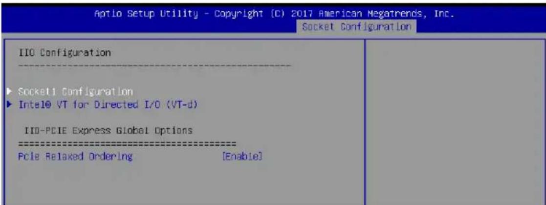
text_image
Aptio Setup Utility - Copyright (C) 2017 American Megatrends, Inc. Socket Configuration IIO Configuration Socket1 Configuration Intel0 VT for Directed I/O (VT-d) IIO-PCIE Express Global Options Pcie Relaxed Ordering [Enable]Socket1 Configuration
This option allows you to change the settings related to the PCI Express Ports.
Intel® VT for Directed I/O (VT-d)
Intel® VT for Directed I/O (VT-d) [Enabled]
Allows you to enable or disable the Intel Virtualization Technology for Directed I/O.
Configuration options: [Disabled] [Enabled]
IIO-PCIE Express Global Options
PCIE relaxed Ordering [Enabled]
Allows you to enable or disable PCIE relaxed Ordering.
Configuration options: [Disabled] [Enabled]
4.6.6 Advanced Power Management Configuration
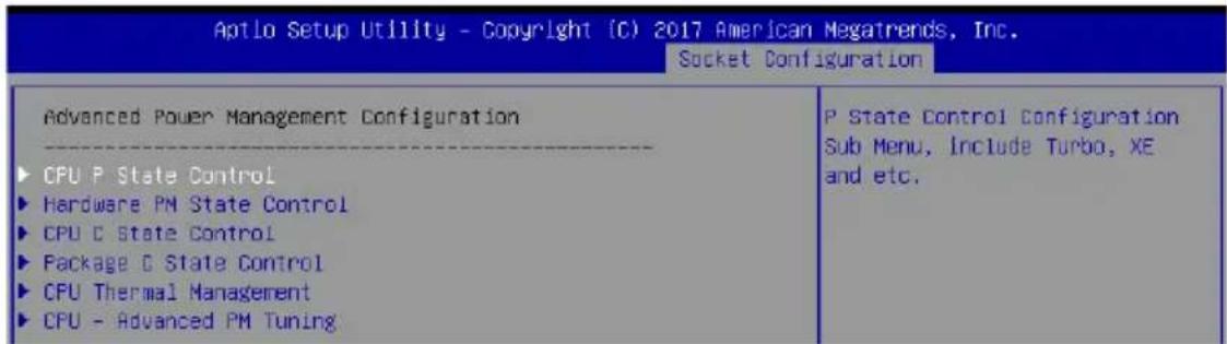
text_image
Aptlo Setup Utility - Copyright (C) 2017 American Megatrends, Inc. Socket Configuration Advanced Power Management Configuration CPU P State Control Hardware PM State Control CPU C State Control Package C State Control CPU Thermal Management CPU - Advanced PM Tuning P State Control Configuration Sub Menu, Include Turbo, XE and etc.CPU P State Control
Boot performance mode [Max Performance]
Allows you to switch between Boot performance mode.
Configuration options: [Max Performance] [Max Efficient] [Set by Intel Node Manager]
Energy Efficient Turbo [Enabled]
Allows you to enable or disable Energy Efficient Turbo.
Configuration options: [Disabled] [Enabled]
Turbo Mode [Enabled]
Allows you to enable or disable Turbo Mode.
Configuration options: [Disabled] [Enabled]
Hardware PM State Control
Hardware P-States [Native Mode]
Allows you to switch between Hardware P-States mode.
Configuration options: [Disabled] [Native Mode] [Out of Band Mode]
[Native Mode with no Legacy Support]
CPU C State Control
Autonomous Core C-State [Disabled]
Allows you to enable or disable Autonomous Core C-State Report.
Configuration options: [Disabled] [Enabled]
CPU C6 Report [Auto]
Allows you to select CPU C6 Report.
Configuration options: [Disabled] [Enabled] [Auto]
OS ACPI Cx [ACPI C2]
Allows you to select OS ACPI Cx Report.
Configuration options: [ACPI C2] [ACPI C3]
Package C State Control
Package C State [Auto]
Allows you to select Package C State.
Configuration options: [C0/C1 state] [C2 state] [C6(non Retention state)]
[C6(Retention state)] [No Limit] [Auto]
CPU Thermal Control
CPU T State Control
Software Controlled T-States [Disabled]
Allows you to enable or disable Software Controlled T-States.
Configuration options: [Disabled] [Enabled]
CPU - Advanced PM Tuning
Energy Perf BIAS
Power Performance Tuning
Configuration options: [OS Controls EPB] [BIOS Controls EPB]

The following item appears only when you set Power Performance Tuning to [OS Controls EPB].
PECI PCS EPB
This option controls whether PECI has control over EPB.
Configuration options: [OS Controls EPB] [PECI Controls EPB using PCS]

The following item appears only when you set Power Performance Tuning to [BIOS Controls EPB].
ENERGY\_PERF\_BIAS\_CFG Mode
Configuration options: [Performance] [Balanced Performance] [Balanced Power] [Power]
Dynamic Loadline Switch
Configuration options: [Disabled] [Enabled]
Workload Configuration
This option allows optimization for the workload characterization.
Configuration options: [UMA] [NUMA]
Averaging Time Window
This option is used to control the effective window of the average C0 an P0 time.
Configuration options: [0] - [99]
P0 TotalTimeThreshold Low
The HW switching mechanism DISABLES the performance setting (0) when the total P0 time is less than the threshold set.
Configuration options: [0] - [99]
P0 TotalTimeThreshold High
The HW switching mechanism Enables the performance setting (0) when the total P0 time is greater than the threshold set.
Configuration options: [0] - [99]
4.7 Event Logs menu

text_image
Aptlo Setup Utility - Copyright (C) 2017 American Megatrends, Inc. Main AiTueaker Advanced Platform Configuration Socket Configuration Event Logs Change Smbios Event Log Settings View Smbios Event Log Press (Enter) to change the Smbios Event Log configuration.4.7.1 Change Smbios Event Log Settings
Press
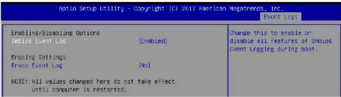
text_image
Aptio Setup Utility - Copyright (C) 2017 American Megatrends, Inc. Event Logs Enabling/Disabling Options Smbios Event Log [Enabled] Erasing Settings Erase Event Log [No] NOTE: All values changed here do not take effect until computer is restarted. Change this to enable or disable all features of Smbios Event Logging during boot.
All values changed here do not take effect until computer is restarted.
Enabling/Disabling Options
Smbios Event Log [Enabled]
Change this to enable or disable all features of Smbios Event Logging during boot.
Configuration options: [Disabled] [Enabled]
Erasing Settings
Erase Event Log [No]
Choose options for erasing Smbios Event Log. Erasing is done prior to any logging activation during reset.
Configuration options: [No] [Yes, Next reset] [Yes, Every reset]
4.7.2 View Smbios Event Log
Press
4.8 Server Mgmt menu
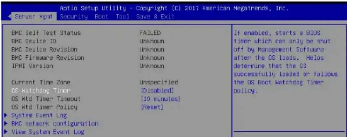
text_image
Aptio Setup Utility - Copyright (C) 2017 American Megatrends, Inc. Server Rgmt Security Boot Tool Save & Exit BMC Self Test Status FAILED BMC Device ID Unknown BMC Device Revision Unknown BMC Firmware Revision Unknown IPMI Version Unknown Current Time Zone Unspecified OS Watchdog Timer [Disabled] OS Htd Timer Timeout [10 minutes] OS Htd Timer Policy [Reset] ► System Event Log ► EMC network configuration ► View System Event Log If enabled, starts a BIOS timer which can only be shut off by Management Software after the OS loads. Helos determine that the OS successfully loaded or follows the OS Boot Watchdog Timer policy.OS Watchdog Timer [Disabled]
This item allows you to start a BIOS timer which can only be shut off by Intel Management Software after the OS loads.
Configuration options: [Disabled] [Enabled]
![ASUS Z11PA-U12 - OS Watchdog Timer [Disabled] - 1](/content/2026/05/812826/images/28dfbb7977faa39fdf86ebb478412b2320271157993af6e343830cd87d3f740e.jpg)
The following items are configurable only when the OS Watchdog Timer is set to [Enabled].
OS Wtd Timer Timeout [10 minutes]
Allows you to configure the length for the OS Boot Watchdog Timer.
Configuration options: [5 minutes] [10 minutes] [15 minutes] [20 minutes]
OS Wtd Timer Policy [Reset]
This item allows you to configure the how the system should respond if the OS Boot Watch Timer expires.
Configuration options: [Do Nothing] [Reset] [Power Down]
4.8.1 System Event Log
Allows you to change the SEL event log configuration.
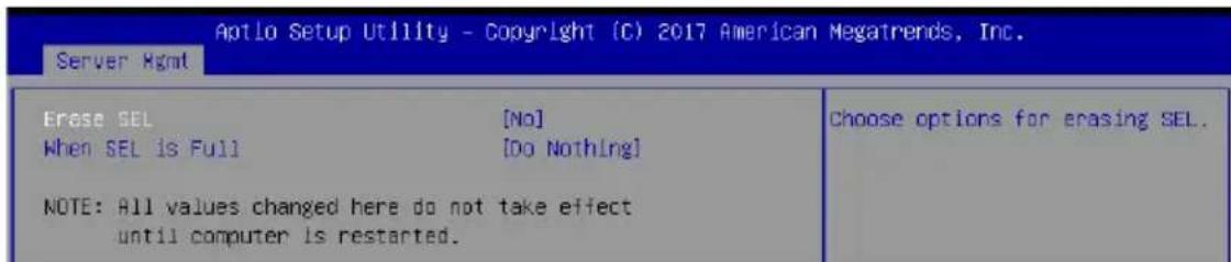
text_image
Aptlo Setup Utility - Copyright (C) 2017 American Megatrends, Inc. Server Rgmt Erase SEL [No] When SEL is Full [Do Nothing] NOTE: All values changed here do not take effect until computer is restarted. Choose options for erasing SEL.
All values changed here do not take effect until computer is restarted.
Erase SEL [No]
Allows you to choose options for erasing SEL.
Configuration options: [No] [Yes, On next reset] [Yes, On every reset]
When SEL is Full [Do Nothing]
Allows you to choose options for reactions to a full SEL.
Configuration options: [Do Nothing] [Erase Immediately]
4.8.2 BMC network configuration
The sub-items in this configuration allow you to configure the BMC network parameters.
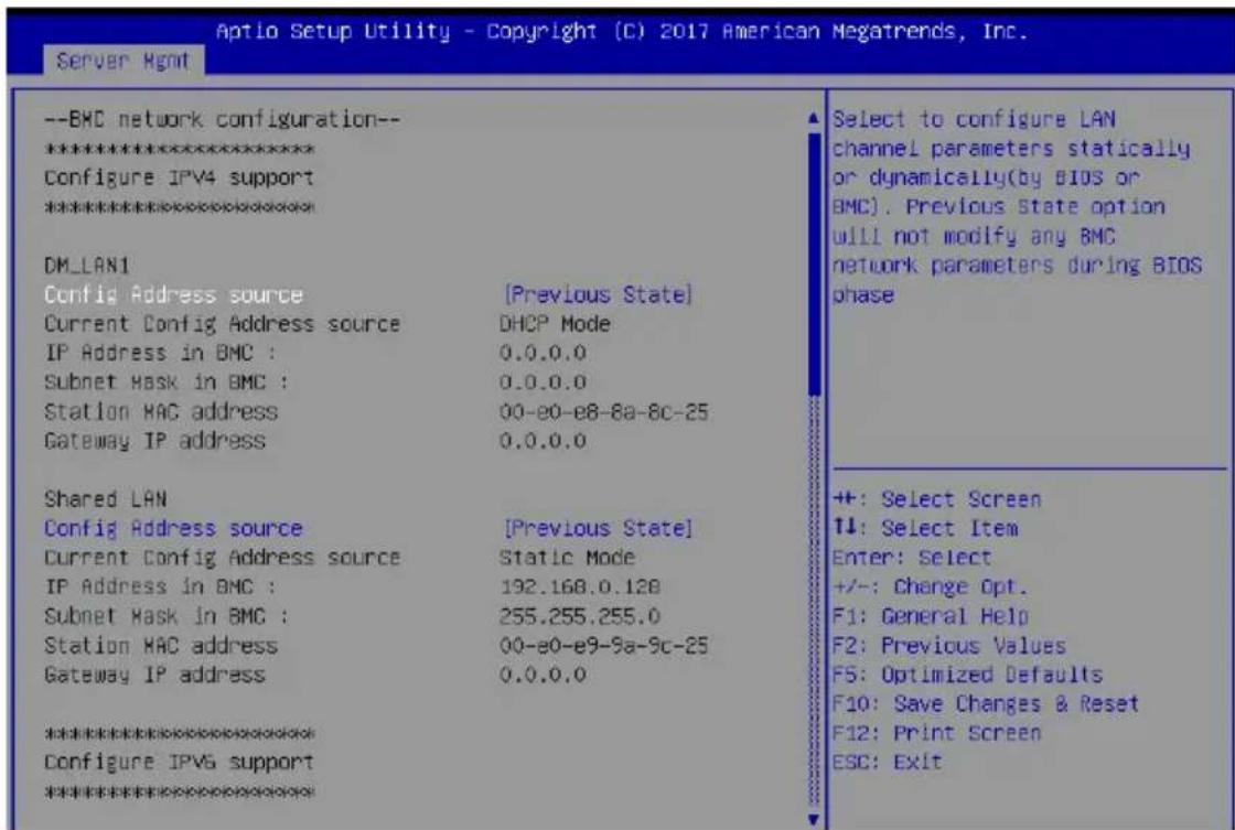
text_image
Aptio Setup Utility - Copyright (C) 2017 American Megatrends, Inc. Server Hgmt --BMC network configuration-- ***************** Configure IPV4 support ***************** DM_LAN1 Config Address source [Previous State] Current Config Address source DHCP Mode IP Address in BMC : 0.0.0.0 Subnet Mask in BMC : 0.0.0.0 Station MAC address 00-e0-e8-8a-8c-25 Gateway IP address 0.0.0.0 Shared LAN Config Address source [Previous State] Current Config Address source Static Mode IP Address in BMC : 192.168.0.128 Subnet Mask in BMC : 255.255.255.0 Station MAC address 00-e0-e9-9a-9c-25 Gateway IP address 0.0.0.0 ***************** Configure IPV6 support *****************Select to configure LAN channel parameters statically or dynamically(by BIOS or BMC). Previous State option will not modify any BMC network parameters during BIOS phase +: Select Screen ++: Select Item Enter: Select +/-: Change Opt. F1: General Help F2: Previous Values F5: Optimized Defaults F10: Save Changes & Reset F12: Print Screen ESC: ExitNavigate to the second page of the screen to see the rest of items in this menu by pressing the Up or Down arrow keys.

To quickly go to the last item of the second page, press the Page Down button. Press the Page Up button to go back to the first item in the first page.
IPV4
DM\_LAN1/ Shared LAN
Config Address source [Previous State]
This item allows you to configure LAN channel parameters statistically or dynamically (by BIOS or BMC). Unspecified option will not modify any BMC network parameters during BIOS phase.
Configuration options: [Previous State] [Static] [DynamicBmcDhcp] [DynamicBmcNonDhcp]
IPV6
DM\_LAN1/ Shared LAN
IPV6 Support [Enabled]
Allows you to enable or disable LAN1 IPV6 Support.
Configuration options: [Disabled] [Enabled]
Config Address source [Previous State]
This item allows you to configure LAN channel parameters statistically or dynamically (by BIOS or BMC). Unspecified option will not modify any BMC network parameters during BIOS phase.
Configuration options: [Previous State] [Static] [DynamicBmcDhcp] [DynamicBmcNonDhcp]
4.8.3 View System Event Log
This item allows you to view the system event log records.
4.9 Security menu
This menu allows a new password to be created or a current password to be changed. The menu also enables or disables the Secure Boot state and lets the user configure the System Mode state.
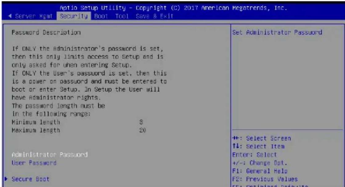
text_image
Aptio Setup Utility - Copyright (C) 2017 American Megatrends, Inc. ◀ Server Hgmt Security Boot Tool Save & Exit Password Description If ONLY the Administrator's password is set, then this only limits access to Setup and is only asked for when entering Setup. If ONLY the User's password is set, then this is a power on password and must be entered to boot or enter Setup. In Setup the User will have Administrator rights. The password length must be in the following range: Minimum length 8 Maximum length 20 Administrator Password User Password ▶ Secure Boot Set Administrator Password +: Select Screen ↑↓: Select Item Enter: Select +/-: Change Opt. F1: General Help F2: Previous Values F5: Optimized DefaultsAdministrator Password
To set an administrator password:
- Select the Administrator Password item and press
. - From the Create New Password box, key in a password, then press
. - Confirm the password when prompted.
To change an administrator password:
- Select the Administrator Password item and press
. - From the Enter Current Password box, key in the current password, then press
. - From the Create New Password box, key in a new password, then press
. - Confirm the password when prompted.

To clear the administrator password, follow the same steps as in changing an administrator password, but press
User Password
To set a user password:
- Select the User Password item and press
. - From the Create New Password box, key in a password, then press
. - Confirm the password when prompted.
To change a user password:
- Select the User Password item and press
. - From the Enter Current Password box, key in the current password, then press
. - From the Create New Password box, key in a new password, then press
. - Confirm the password when prompted.
To clear a user password:
- Select the Clear User Password item and press
. - Select Yes from the Warning message window then press
.
Secure Boot
This item allows you to customize the Secure Boot settings.
| Aptio Setup Utility - Copyright (C) 2017 American Megatrends, Inc. Security | ||
| System Mode | Setup | Secure Boot activated when Platform Key(PK) is enrolled, System mode is user/Deployed, and CSM function is disabled |
| Secure Boot | Not Active | |
| Vendor Keys | Active | |
| Attempt Secure Boot | [Disabled] | |
| Secure Boot Mode | [Custom] | |
| Key Management | ||
Attempt Secure Boot [Disabled]
Secure Boot can be enabled if the system is running in User mode with enrolled platform Key (EPK) or if the CSM function is disabled.
Configuration options: [Disabled] [Enabled]
Secure Boot Mode [Custom]
Allows you to set the Secure Boot selector.
Configuration options: [Custom] [Standard]
Key Management
This item only appears when the item Secure Boot Mode is set to [Custom]. The Key Management item allows you to modify Secure Boot variables and set Key Management page.
| Aptio Setup Utility - Copyright (C) 2017 American Megatrends, Inc. Security | ||||
| Provision Factory Defaults [Disabled] | Allow to provision factory default Secure Boot Keys when System is in Setup Mode | |||
| Install Factory Default Keys Enroll Efl Image Save all Secure Boot variables | ||||
| Secure Boot variable | Size | Keys# | Key Source | ||||
| Platform Key(PK) | 0 | 0 | No Key | |
| Key Exchange Keys | 0 | 0 | No Key | |
| Authorized Signatures | 0 | 0 | No Key | |
| Forbidden Signatures | 0 | 0 | No Key | |
| Authorized Timestamps | 0 | 0 | No Key | |
| OsRecovery Signatures | 0 | 0 | No Key | |
Provision Factory Defaults [Disabled]
Allows you to provision factory default Secure Boot keys when the system is in Setup Mode.
Configuration options: [Disabled] [Enabled]
Install Factory Default keys
This item will install all Factory Default keys.
Reset to Setup Mode
This item appears only when you load the default Secure Boot keys. This item allows you to clear all default Secure Boot keys.
Enroll Efi Image
This item will allow the image to run in Secure Boot mode.
Save All Secure Boot Variables
This item will ask you if you want to save all secure boot variables. Select Yes if you want to save all secure boot variables, otherwise select No.
Platform Key (PK)
Configuration options: [Save to File] [Set New] [Erase]
Key Exchange Keys / Authorized Signatures / Forbidden Signatures
Configuration options: [Save to File] [Set New] [Append] [Erase]
Authorized TimeStamps
Configuration options: [Set New] [Append]
OsRecovery Signatures
Configuration options: [Set New] [Append]
4.10 Boot menu
The Boot menu items allow you to change the system boot options.

text_image
Aptio Setup Utility - Copyright (C) 2017 American Megatrends, Inc. ◀ Server Hgmt Security Boot Tool Save & Exit Boot Configuration Bootup NumLock State [On] Boot Logo Display [Disabled] POST Report [5 sec] Boot Option Priorities Boot Option #1 [ASUS AI Flash-5 PMAP] Boot Option #2 [ASUS AI Flash-5 PMAP] Boot Option #3 [IBA GE Slot 0200 v1584] Network Device BBS Priorities Hard Drive BBS Priorities Floppy Drive BBS Priorities Select the keyboard NumLock state ++: Select Screen ↑↓: Select Item Enter: SelectBootup NumLock State [On]
Allows you to select the power-on state for the NumLock.
Configuration options: [Off] [On]
Boot Logo Display [Disabled]
Allows you to enable or disable the full screen logo display feature.
Configuration options: [Auto] [Full Screen] [Disabled]
![ASUS Z11PA-U12 - Boot Logo Display [Disabled] - 1](/content/2026/05/812826/images/28863bd99956804cd2ab75c3ba587ab44a96045fa8ef9f9849a2d1b94626ff26.jpg)
The following item appears only when you set the Boot Logo Display to [Disabled].
POST Report [5 sec]
Allows you to set the desired POST Report waiting time from 1 to 10 seconds.
Configuration options: [1 sec] \~ [10 sec] [Until Press ESC]
Boot Option Priorities
These items specify the boot device priority sequence from the available devices. The number of device items that appears on the screen depends on the number of devices installed in the system.

- To select the boot device during system startup, press
when ASUS Logo appears. - To access Windows OS in Safe Mode, please press
after POST.
Network Device BBS Priorities
This item allows you to set the booting from network.
Hard Drive / Floppy Drive BBS Priorities
These items appear only when you connect SATA ODD or hard drive to the SATA ports and allow you to set the booting order of the SATA devices.
4.11 Tool menu
The Tool menu items allow you to configure options for special functions. Select an item then press
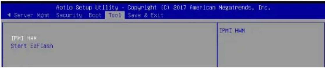
text_image
Aptlo Setup Utility - Copyright (C) 2017 American Megatrends, Inc. Server Hgmt Security Boot Tool Save & Exit IFMI HMM Start EzFlash IPMI HMMIPMI HWM
Allows you to run the IPMI hardware monitor.
Start EzFlash
Allows you to run ASUS EzFlash BIOS ROM Utility when you press
4.12 Save & Exit menu
The Exit menu items allow you to save or discard your changes to the BIOS items.
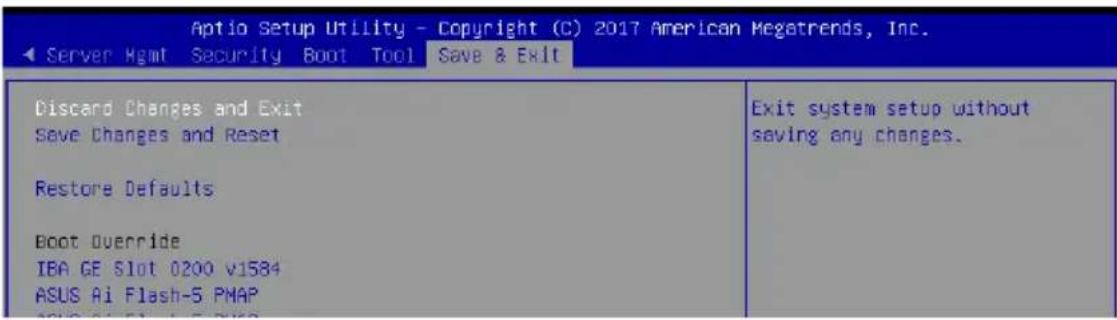
text_image
Aptio Setup Utility - Copyright (C) 2017 American Megatrends, Inc. Server Hgmt Security Boot Tool Save & Exit Discard Changes and Exit Save Changes and Reset Restore Defaults Boot Override IBA GE Slot 0200 v1584 ASUS Ai Flash-5 PMAP Exit system setup without saving any changes.
Pressing
Discard Changes and Exit
Exit System setup without saving any changes.
Save Changes and Reset
Exit System setup after saving the changes.
Restore Defaults
Restore/load default values for all the setup options.
Boot Override
These items displays the available devices. The device items that appears on the screen depends on the number of devices installed in the system. Click an item to start booting from the selected device.
Launch EFI Shell from filesystem device
This item allows you to attempt to launch the EFI Shell application (shellx64.efi) from one of the available filesystem devices.
RAID Configuration
This chapter provides instructions for setting up, creating, and configuring RAID sets using the available utilities.
5
5.1 RAID configurations
The motherboard supports Intel® Rapid Storage Technology enterprise Option ROM Utility with RAID 0, RAID 1, RAID 10, and RAID 5 support.

If you want to install a Windows® operating system to a hard disk drive included in a RAID set, you have to create a RAID driver disk and load the RAID driver during OS installation. Refer to section 6.1 RAID driver installation for details.
5.1.1 RAID definitions
RAID 0 (Data striping) optimizes two identical hard disk drives to read and write data in parallel, interleaved stacks. Two hard disks perform the same work as a single drive but at a sustained data transfer rate, double that of a single disk alone, thus improving data access and storage. Use of two new identical hard disk drives is required for this setup.
RAID 1 (Data mirroring) copies and maintains an identical image of data from one drive to a second drive. If one drive fails, the disk array management software directs all applications to the surviving drive as it contains a complete copy of the data in the other drive. This RAID configuration provides data protection and increases fault tolerance to the entire system. Use two new drives or use an existing drive and a new drive for this setup. The new drive must be of the same size or larger than the existing drive.
RAID 5 stripes both data and parity information across three or more hard disk drives. Among the advantages of RAID 5 configuration include better HDD performance, fault tolerance, and higher storage capacity. The RAID 5 configuration is best suited for transaction processing, relational database applications, enterprise resource planning, and other business systems. Use a minimum of three identical hard disk drives for this setup.
RAID 10 is data striping and data mirroring combined without parity (redundancy data) having to be calculated and written. With the RAID 10 configuration you get all the benefits of both RAID 0 and RAID 1 configurations. Use four new hard disk drives or use an existing drive and three new drives for this setup.

If you want to boot the system from a hard disk drive included in a created RAID set, copy first the RAID driver from the support DVD to a floppy disk before you install an operating system to the selected hard disk drive.
5.1.2 Installing Serial ATA hard disks
The motherboard supports Serial ATA hard disk drives. For optimal performance, install identical drives of the same model and capacity when creating a disk array.
To install the SATA hard disks for a RAID configuration:
- Install the SATA hard disks into the drive bays.
- Connect the SATA signal cables.
- Connect a SATA power cable to the power connector on each drive.
5.1.3 Setting the RAID item in BIOS
You must set the RAID item in the BIOS Setup before you can create a RAID set from SATA hard disk drives attached to the SATA connectors supported by Intel® C620 chipset.
To do this:
- Enter the BIOS Setup during POST.
- Go to the Platform Configuration menu > PCH Configuration menu > PCH SATA Configuration, then press
. - Set Configure SATA as to [RAID Mode].
- Press
to save your changes and exit the BIOS Setup.

Refer to Chapter 4 for details on entering and navigating through the BIOS Setup.
5.1.4 RAID configuration utilities
Depending on the RAID connectors that you use, you can create a RAID set using the utilities embedded in each RAID controller. For example, use the Intel® Rapid Storage Technology if you installed Serial ATA hard disk drives on the Serial ATA connectors supported by the Intel® C620 chipset.
Refer to the succeeding section for details on how to use the RAID configuration utility.
5.2 Intel® Rapid Storage Technology enterprise SATA/SSATA Option ROM Utility
The Intel® Rapid Storage Technology enterprise SATA/SSATA Option ROM utility allows you to create RAID 0, RAID 1, RAID 10 (RAID 1+0), and RAID 5 set from Serial ATA hard disk drives that are connected to the Serial ATA connectors supported by the Southbridge.

Before you proceed, ensure that you have installed the Serial ATA hard disk drives, and have set the correct SATA mode in the BIOS setup. You can refer to the Installing Serial ATA hard disks, and Setting the RAID item in BIOS sections in this manual for more information.
To launch the Intel® Rapid Storage Technology enterprise SATA/SSATA Option ROM utility:
- Turn on the system.
- During POST, press
+ to display the utility main menu.
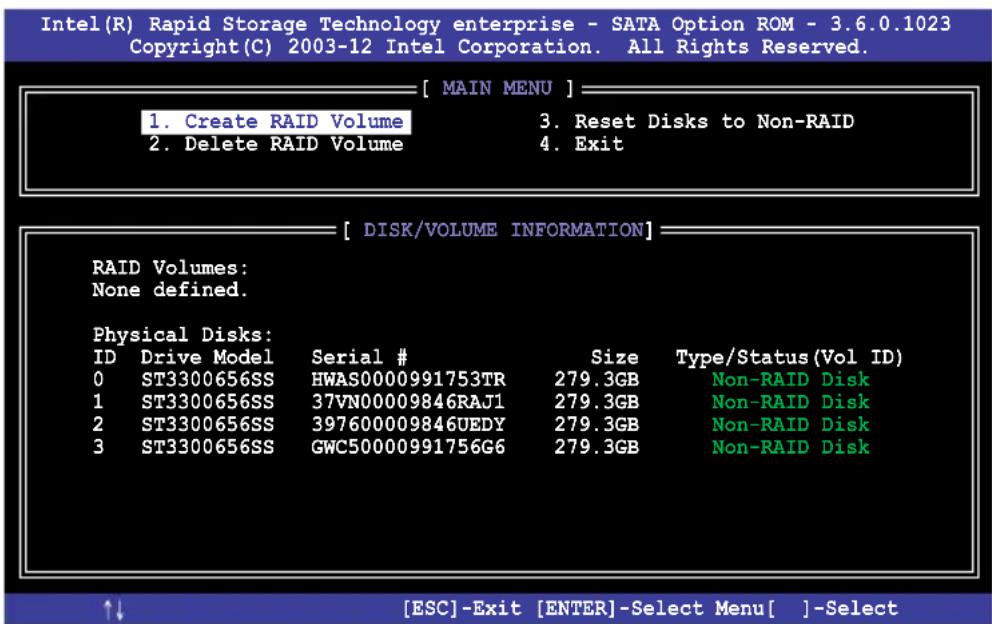
text_image
Intel(R) Rapid Storage Technology enterprise - SATA Option ROM - 3.6.0.1023 Copyright(C) 2003-12 Intel Corporation. All Rights Reserved. [ MAIN MENU ] 1. Create RAID Volume 3. Reset Disks to Non-RAID 2. Delete RAID Volume 4. Exit [ DISK/VOLUME INFORMATION ] RAID Volumes: None defined. Physical Disks: ID Drive Model Serial # 0 ST3300656SS HWAS0000991753TR 279.3GB Type/Status(Vol ID) 1 ST3300656SS 37VN00009846RAJ1 279.3GB Non-RAID Disk 2 ST3300656SS 397600009846UEDY 279.3GB Non-RAID Disk 3 ST3300656SS GWC50000991756G6 279.3GB Non-RAID Disk ↑↓ [ESC]-Exit [ENTER]-Select Menu[ ]-SelectThe navigation keys at the bottom of the screen allow you to move through the menus and select the menu options.

The RAID BIOS setup screens shown in this section are for reference only and may not exactly match the items on your screen.
5.2.1 Creating a RAID set
To create a RAID set:
- From the utility main menu, select 1. Create RAID Volume and press
. - Key in a name for the RAID set and press
.
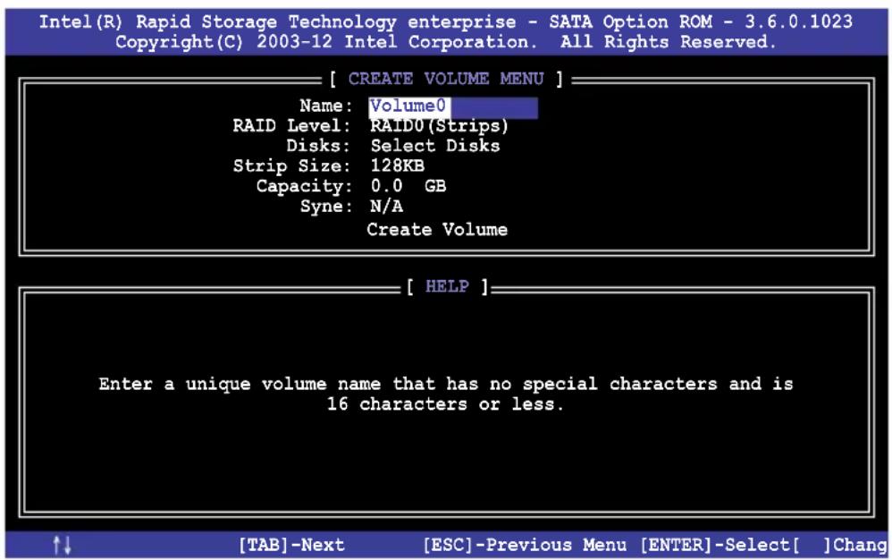
text_image
Intel(R) Rapid Storage Technology enterprise - SATA Option ROM - 3.6.0.1023 Copyright(C) 2003-12 Intel Corporation. All Rights Reserved. [ CREATE VOLUME MENU ] Name: Volume0 RAID Level: RAID0(Strips) Disks: Select Disks Strip Size: 128KB Capacity: 0.0 GB Syne: N/A Create Volume [ HELP ] Enter a unique volume name that has no special characters and is 16 characters or less.-
Press the up/down arrow keys to select a RAID Level that you wish to create then press
. -
From the Disks item field, press
to select the hard disk drives that you want to include in the RAID set.
| Port | Drive Model | Serial # | Size | Status | |
| 0 | ST3300656SS | HWAS0000991753TR | 279.3GB | Non-RAID Disk | |
| 1 | ST3300656SS | 37VN00009846RAJ1 | 279.3GB | Non-RAID Disk | |
| 2 | ST3300656SS | 397600009846UEDY | 279.3GB | Non-RAID Disk | |
| 3 | ST3300656SS | GWC50000991756G6 | 279.3GB | Non-RAID Disk | |
| Select 1 Master and 1 Recovery disk to create volume. | |||||
| [↑↓]-Prev/Next [TAB]-(M)aster [SPACE]-(R)ecovery [ENTER]-Done | |||||
-
Use the up/down arrow keys to move the selection bar then press
to select a disk. A small triangle before the Port number marks the selected drive. Press when you are done. -
Use the up/down arrow keys to select the stripe size for the RAID array (for RAID 0, 10 and 5 only) then press
. The available stripe size values range from 4 KB to 128 KB. The following are typical values:
RAID 0: 128KB
RAID 10: 64KB
RAID 5: 64KB

We recommend a lower stripe size for server systems, and a higher stripe size for multimedia computer systems used mainly for audio and video editing.
- In the Capacity field item, key in the RAID volume capacity that you want to use and press
. The default value field indicates the maximum allowed capacity. - Press
to start creating the RAID volume. - From the following warning message, press
to create the RAID volume and return to the main menu, or press to go back to the CREATE VOLUME menu.
WARNING: ALL DATA ON SELECTED DISKS WILL BE LOST.
Are you sure you want to create this volume? (Y/N):
5.2.2 Deleting a RAID set

Take caution when deleting a RAID set. You will lose all data on the hard disk drives when you delete a RAID set.
To delete a RAID set:
- From the utility main menu, select 2. Delete RAID Volume and press
. - From the Delete Volume Menu, press the up/down arrow keys to select the RAID set you want to delete then press
.
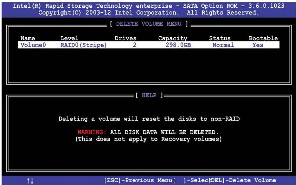
text_image
Intel(R) Rapid Storage Technology enterprise - SATA Option ROM - 3.6.0.1023 Copyright(C) 2003-12 Intel Corporation. All Rights Reserved. [ DELETE VOLUME MENU ] Name Level Drives Capacity Status Bootable Volume0 RAID0 (Stripe) 2 298.0GB Normal Yes [ HELP ] Deleting a volume will reset the disks to non-RAID WARNING: ALL DISK DATA WILL BE DELETED. (This does not apply to Recovery volumes) ↑↓ [ESC]-Previous Menu[ ]-SelectDEL]-Delete Volume- Press
to confirm deletion of the selected RAID set and return to the utility main menu, or press to return to the DELETE VOLUME menu.

text_image
[ DELETE VOLUME VERIFICATION ] ALL DATA IN THE VOLUME WILL BE LOST! (This does not apply to Recovery volumes) Are you sure you want to delete volume "Volume0"? (Y/N):5.2.3 Resetting disks to Non-RAID

Take caution before you reset a RAID volume hard disk drive to non-RAID. Resetting a RAID volume hard disk drive deletes all internal RAID structure on the drive.
To reset a RAID set:
- From the utility main menu, select 3. Reset Disks to Non-RAID and press
. - Press the up/down arrow keys to select the drive(s) or disks of the RAID set you want to reset, then press
. A small triangle before the Port number marks the selected drive. Press when you are done.
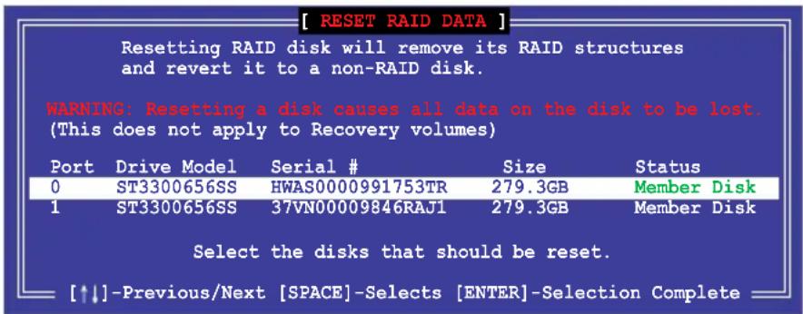
text_image
[ RESET RAID DATA ] Resetting RAID disk will remove its RAID structures and revert it to a non-RAID disk. WARNING: Resetting a disk causes all data on the disk to be lost. (This does not apply to Recovery volumes) Port Drive Model Serial # Size Status 0 ST3300656SS HWAS0000991753TR 279.3GB Member Disk 1 ST3300656SS 37VN00009846RAJ1 279.3GB Member Disk Select the disks that should be reset. [↑↓]-Previous/Next [SPACE]-Selects [ENTER]-Selection Complete- Press
in the confirmation window to reset the drive(s) or press to return to the utility main menu.
5.2.4 Exiting the Intel ^® Rapid Storage Technology enterprise SATA/SSATA Option ROM utility
To exit the utility:
- From the utility main menu, select 4. Exit then press
. - Press
to exit or press to return to the utility main menu.
[ CONFIRM EXIT ]
Are you sure you want to exit? (Y/N):
5.2.5 Rebuilding the RAID

This option is only for the RAID 1 set.
Rebuilding the RAID with other non-RAID disk
If any of the SATA hard disk drives included in the RAID 1 array failed, the system displays the status of the RAID volume as "Degraded" during POST. You can rebuild the RAID array with other installed non-RAID disks.
To rebuild the RAID with other non-RAID disk:
- During POST, press
+ at the prompt to enter the Intel Rapid Storage Technology option ROM utility. - If there is a non-RAID SATA Hard Disk available, the utility will prompt you to rebuild the RAID. Press the up/down arrow keys to select the destination disk then Press
to start the rebuilding process, or press to exit.
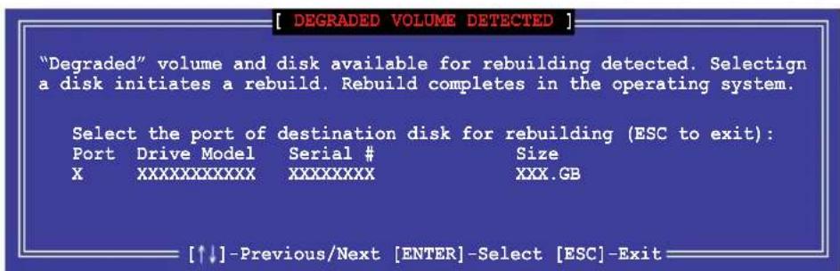
text_image
[ DEGRADED VOLUME DETECTED ] "Degraded" volume and disk available for rebuilding detected. Selectign a disk initiates a rebuild. Rebuild completes in the operating system. Select the port of destination disk for rebuilding (ESC to exit): Port Drive Model Serial # Size XXXXXXXXXXXXX XXXXXXXX XXX.GB [↑↓] -Previous/Next [ENTER]-Select [ESC]-Exit
Select a destination disk with the same size as the original hard disk.
- The utility immediately starts rebuilding after the disk is selected. When done, the status of the degraded RAID volume is changed to "Rebuild".
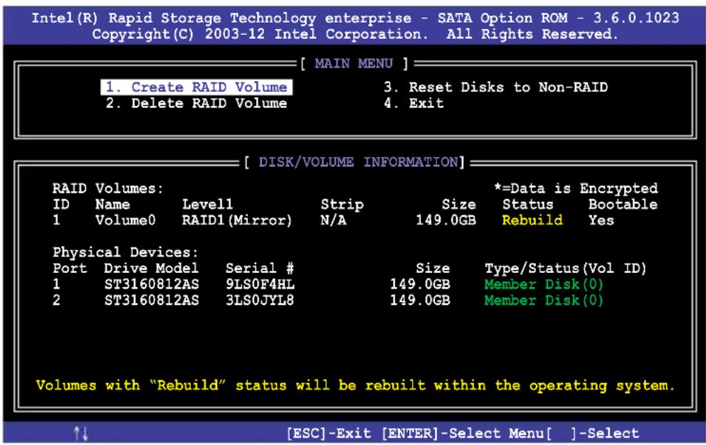
text_image
Intel(R) Rapid Storage Technology enterprise - SATA Option ROM - 3.6.0.1023 Copyright(C) 2003-12 Intel Corporation. All Rights Reserved. [ MAIN MENU ] 1. Create RAID Volume 2. Delete RAID Volume 3. Reset Disks to Non-RAID 4. Exit [ DISK/VOLUME INFORMATION ] RAID Volumes: ID Name Level1 Strip Size *=Data is Encrypted 1 Volume0 RAID1(Mirror) N/A 149.0GB Status Bootable Rebuild Yes Physical Devices: Port Drive Model Serial # 1 ST3160812AS 9LS0F4HL Size Type/Status(Vol ID) 2 ST3160812AS 3LS0JYL8 149.0GB Member Disk(0) Volumes with "Rebuild" status will be rebuilt within the operating system. ↑↓ [ESC]-Exit [ENTER]-Select Menu[ ]-Select- Press
to exit Intel Rapid Storage Technology and reboot the system. - Select Start > Programs > Intel Rapid Storage > Intel Rapid Storage Console or click the Intel Rapid Storage Technology tray icon to load the Intel Rapid Storage Manager utility.
- From the View menu, select Advanced Mode to display the details of the Intel Rapid Storage Console.
- From the Volumes view option, select RAID volume to view the rebuilding status. When finished, the status is changed to "Normal".
Rebuilding the RAID with a new hard disk
If any of the SATA hard disk drives included in the RAID array failed, the system displays the status of the RAID volume as "Degraded" during POST. You may replace the disk drive and rebuild the RAID array.
To rebuild the RAID with a new hard disk:
- Remove the failed SATA hard disk and install a new SATA hard disk of the same specification into the same SATA Port.

Select a destination disk with the same size as the original hard disk.
- Reboot the system then follow the steps in section Rebuilding the RAID with other non-RAID disk.
5.2.6 Setting the Boot array in the BIOS Setup Utility
You can set the boot priority sequence in the BIOS for your RAID arrays when creating multi-RAID using the Intel® Rapid Storage Technology enterprise SATA Option ROM utility.
To set the boot array in the BIOS:

Set at least one of the arrays bootable to boot from the hard disk.
- Reboot the system and press
to enter the BIOS setup utility during POST. - Go to the Boot menu and select the boot option priority.
- Use up/down arrow keys to select the boot priority and press
. See the Boot menu section of Chapter 4 for more details. - From the Exit menu, select Save Changes & Exit, then press
. - When the confirmation window appears, select Yes, then press
.
5.3 Intel ^® Rapid Storage Technology enterprise (Windows)
The Intel® Rapid Storage Technology enterprise allows you to create RAID 0, RAID 1, RAID 10 (RAID 1+0), and RAID 5 set(s) from Serial ATA hard disk drives that are connected to the Serial ATA connectors supported by the Southbridge.

You need to manually install the Intel® Rapid Storage Technology enterprise utility on a Windows® operating system. Please refer to the installation instructions in Chapter 6.
To enter the Intel® Rapid Storage Technology enterprise utility under Windows operating system:
-
Turn on the system and go to the windows desktop.
-
Click the Intel ^® Rapid Storage Technology enterprise icon to display the main menu.
Your storage system is configured for data protection, increased performance and optimal data storage capacity. You can create additional volumes to further optimize your storage system.
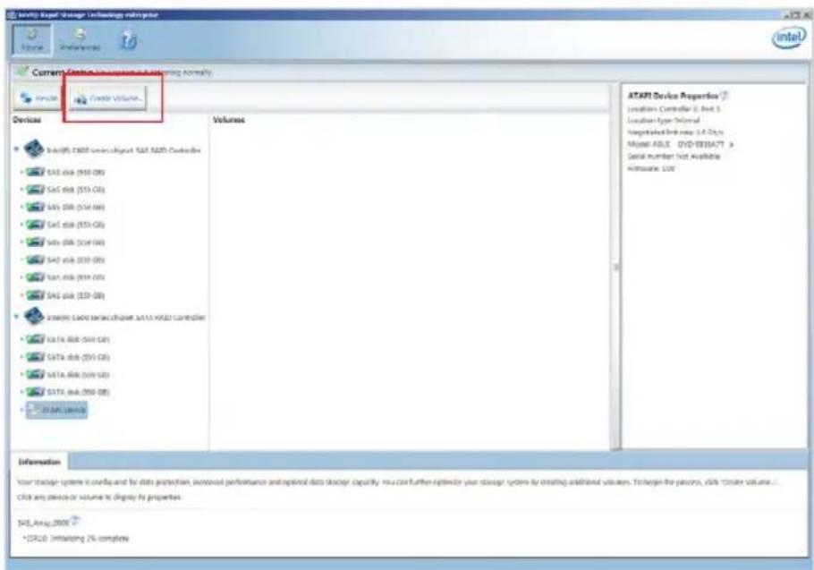
text_image
Current Device Configuration Ordering Normally Volume Device Volume Volumes ATAPI Device Properties Location Controller C Part 5 Location Type Control Negotiated Link new: L3-Dryx Myself-ASILE DVD-BYBATT # Serial number not Available Altisscale: L06 Your storage system is configured for data protection, focused performance and optional data storage capacity, you can further optimize your storage system by creating additional volumes. To begin the person, click "Store Volume... Click any options or volume to display its properties. SLS_Amy_2000 *CPU20 Initiating 7% complete
You can click Rescan to re-scan any attached hard disks.
5.3.1 Creating a RAID set
To create a RAID set:
- From the utility main menu, select Create Volume and select volume type.
- Click Next.
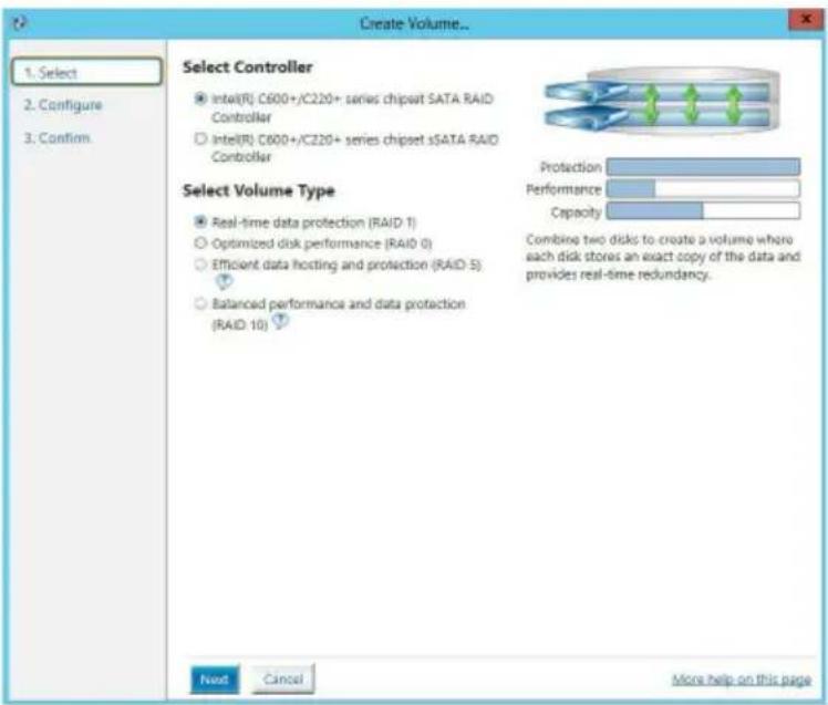
text_image
Create Volume... 1. Select 2. Configure 3. Confirm Select Controller Intel(R) C600+/C220+ series chipset SATA RAID Controller Intel(R) C600+/C220+ series chipset sSATA RAID Controller Select Volume Type Real-time data protection (RAID-1) Optimized disk performance (RAID 0) Efficient data hosting and protection (RAID-5) Balanced performance and data protection (RAID-10) Protection Performance Capacity Combine two disks to create a volume where each disk stores an exact copy of the data and provides real-time redundancy. Next Cancel More help on this page- Enter a name for the RAID set, then select the array disks.
- Select Volume Size tab, you can drag the bar to decide the volume size.
- Click Next.
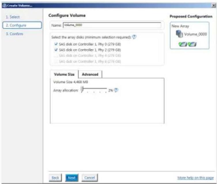
text_image
Create Volume... 1. Select 2. Configure 3. Confirm Configure Volume Name: Volume_0000 Select the array disks (minimum selection required) ✓ SAS disk on Controller 1, Phy 0 (279 GB) ✓ SAS disk on Controller 1, Phy 2 (279 GB) ... SAS disk on Controller 1, Phy 4 (279 GB) ... SAS disk on Controller 1, Phy 6 (279 GB) Volume Size Advanced Volume Size 4,468 MB Array allocation: 2% Back Next Cancel More help on this page Proposed Configuration New Array Volume_0000
- If you do not want to keep the data on one of the selected disks, select NO when prompted.
-
If you want to Enable volume write-back cache or Initialize volume, click Advanced.
-
Confirm the volume creation, than click Create Volume to continue.

This process could take a while depending on the number and size of the disks. You can continue using other applications during this time.
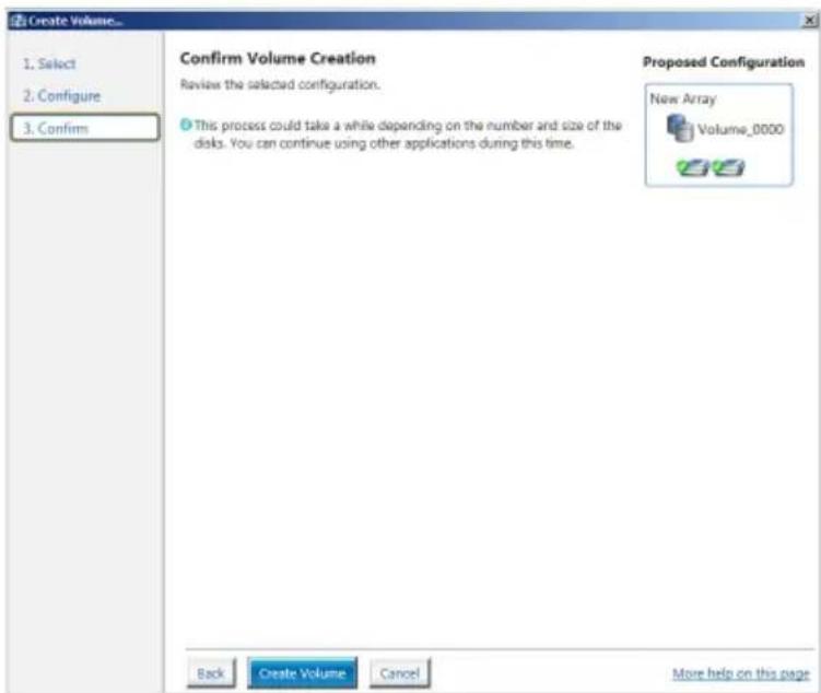
text_image
Create Volume... 1. Select 2. Configure 3. Confirm Confirm Volume Creation Review the selected configuration. This process could take a while depending on the number and size of the disks. You can continue using other applications during this time. Proposed Configuration New Array Volume_0000 Back Create Volume Cancel More help on this page- Wait until the process is completed, then click OK when prompted.
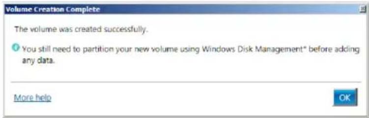
text_image
Volume Creation Complete The volume was created successfully. ● You still need to partition your new volume using Windows Disk Management* before adding any data. More help OK
You still need to partition your new volume using Windows Disk Management before adding any data.
The RAID set is displayed in the Volume Properties.
Volumes list and you can change the settings in
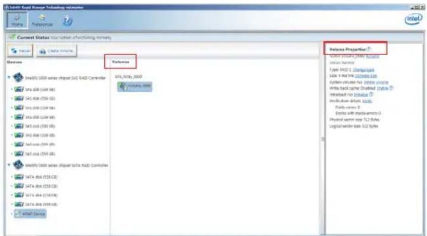
text_image
Delhi Kacid Manage Technologies Current Status: Your website functioning normally Valores Valores Properties? Open your Kacid Manager Status History Type: MDD 1. Characteristics S2K 1. Net flow: 0.0000000000000000000000000000000000000000000000000000000000000000000000000 Valves Properties? Open your Kacid Manager Status History Type: MDD 1. Characteristics S2K 1. Net flow: 0.000000000000000000000000000000000000000000000 System Volume: No, Vertical volume Write back time: Disabled, Blue Interload: No, Botanical Verification: Yes, Blue Family view: 2 Bottle with mechanical parts Physical sector size: 52.2 Bytes Logistic worker size: 52 Bytes5.3.2 Changing a Volume Type
To change the volume type in Volume Properties:
- Click the SATA array items you want to change in Volumes field.
- From the Volume Properties field, select Type:RAID 1 Change type.
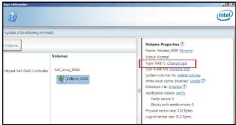
text_image
logy enterprise intel system is functioning normally. Volume... Volume Properties ? Name: Volume_0000 Rename Status: Normal Type RAID 1 Change type Size: 4,468 MB Increase size System volume: No Delete volume Write-back cache: Disabled Enable ? Initialized: No Initialize ? Verification details Verify Parity errors: 0 Blocks with media errors: 0 Physical sector size: 512 Bytes Logical sector size: 512 Bytes- You can change the Name, Select the new volume type, and Select additional disks to include in the new volume if needed.
- Select the Data stripe size for the RAID array (for RAID 0, 10 and 5 only), and click OK. The available stripe size values range from 4 KB to 128 KB. The following are typical values:
RAID 0: 128KB
RAID 10: 64KB
RAID 5: 64KB
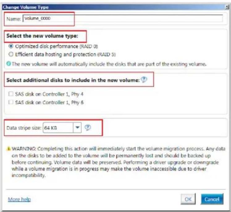
text_image
Change Volume Type Name: Volume_0000 Select the new volume type: Optimized disk performance (RAID 0) Efficient data hosting and protection (RAID 5) The new volume will automatically include the disks that are part of the existing volume. Select additional disks to include in the new volume: SAS disk on Controller 1, Phy 4 SAS disk on Controller 1, Phy 6 Data stripe size: 64 KB WARNING: Completing this action will immediately start the volume migration process. Any data on the disks to be added to the volume will be permanently lost and should be backed up before continuing. Volume data will be preserved. Performing a driver upgrade or downgrade while a volume migration is in progress may make the volume inaccessible due to driver incompatibility. More help OK Cancel
We recommend a lower stripe size for server systems, and a higher stripe size for multimedia computer systems used mainly for audio and video editing.
5.3.3 Deleting a volume

Be cautious when deleting a volume. You will lose all data on the hard disk drives. Before you proceed, ensure that you back up all your important data from your hard drives.
To delete a volume:
- From the utility main menu, select the volume (exp. Volume_0000) in Volumes field you want to delete.
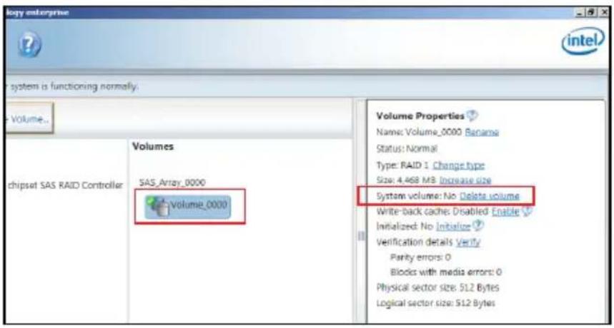
text_image
Volume enterprise intel system is functioning normally. Volume... Volumes SAS_Array_0000 Volume_0000 Chipset SAS RAID Controller Volume Properties Name: Volume_0000 Bana Status: Normal Type: RAID 1 Change type Size: 4,468 MB Increase size System volume: No Delete volume Write-back cache: Disabled Enable Initialized: No Initiate Verification details Verify Parity errors: 0 Blocks with media errors: 0 Physical sector size: 512 Bytes Logical sector size: 512 Bytes- Select Delete volume in Volume Properties field. The following screen appears.
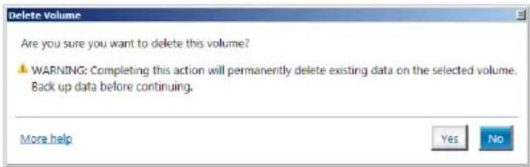
text_image
Delete Volume Are you sure you want to delete this volume? WARNING: Completing this action will permanently delete existing data on the selected volume. Back up data before continuing. More help Yes No- Click Yes to delete the volume and return to the utility main menu, or click No to return to the main menu.
5.3.4 Preferences
System Preferences
Allow you to set to show the notification area icon and show system information, warning, or errors here.
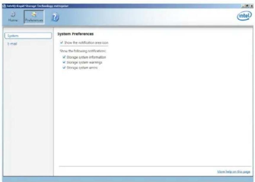
text_image
Intel® Rapid Storage Technology startup Home Preferences System t-mail System Preferences ✓ Show the notification area icon Show the following notifications: ✓ Storage system information ✓ Storage system warnings ✓ Storage system errors More help on this pageE-Mail Preferences
Allow you to set to sent e-mail of the following events:
• Storage system information
• Storage system warnings
- Storage system errors
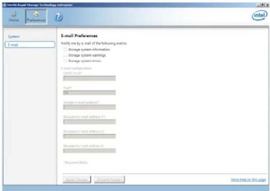
text_image
Intel® Rapid Storage Technology Enterprise Home Preferences System E-mail E-mail Preferences Notify me by e-mail of the following events: Storage system information Storage system earnings Storage system errors E-mail configuration SASOS Host* Host: 15 Sender e-mail address*: Recipient e-mail address 1* Recipient e-mail address 2 Recipient e-mail address 3. *Required fields Apply Changes Cancel Changes More help on this page5.4 Intel® Virtual Raid on CPU in BIOS
This feature requires a KEY module to enable CPU RAID functions with Intel® CPU RSTe.

• The KEY module is purchased separately.
- Refer to section 2.8.2 Internal connectors for the location of the VROC_HW_KEY connector.

Due to hardware design, your motherboard does not support CPU RAID configurations as OS drives.
To enter the Intel® Virtual Raid on CPU in BIOS:
- Enter the BIOS Setup during POST.
- Go to the Advanced menu > Intel(R) Virtual Raid on CPU > All Intel VMD Controllers then press
to display the Intel® Virtual Raid on CPU menu.

Refer to Chapter 4 for details on entering and navigating through the BIOS Setup.

Due to chipset limitation, when SATA ports are set to RAID mode, all SATA ports run at RAID mode together.
| Aptio Setup Utility - Copyright (C) 2017 American Megatrends, Inc. Advanced | |
| All Intel VMD Controllers ► Create RAID Volume Non-RAID Physical Disks; ► Port 0, VMDO, INTEL SSDPE2MX400G4 SN:CVPD6212006W400NGN,... ► Port 1, VMDO, INTEL SSDPE2MX400G4 SN:CVPD6212008H400NGN,... ► Port 2, VMDO, INTEL SSDPE2MX400G4 SN:CVPD6212004T400NGN,... ► Port 3, VMDO, INTEL SSDPE2MX400G4 SN:CVPD62120005400NGN,... | This page allows you to create a RAID volume |
| +: Select Screen ↑↓: Select Item Enter: Select +/-: Change Opt. F1: General Help F2: Previous Values F5: Optimized Defaults F10: Save Changes & Reset F12: Print Screen ESC: Exit | |
5.4.1 Creating a RAID set
To create a RAID set:
- From the Intel ^ Virtual Raid on CPU menu, select Create RAID Volume and press
. The following screen appears:
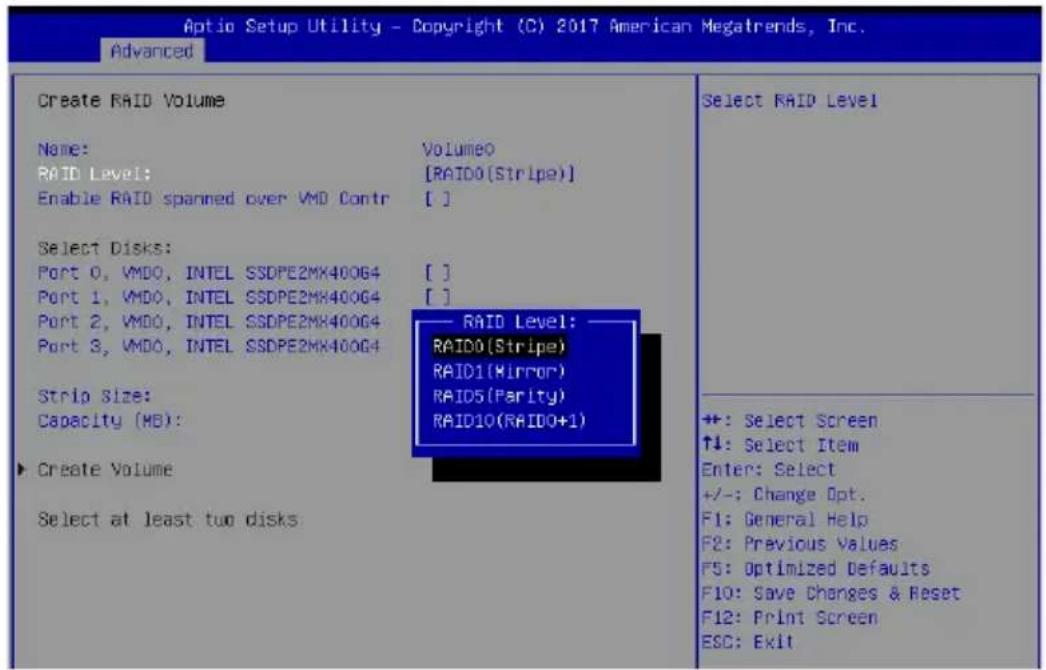
text_image
Optio Setup Utility - Copyright (C) 2017 American Megatrends, Inc. Advanced Create RAID Volume Name: RAID Level: Enable RAID spanned over VMD Contr VolumeO [RAID0(Stripe)] [ ] Select Disks: Port 0, VMDO, INTEL SSDPE2MX400G4 Port 1, VMDO, INTEL SSDPE2MX400G4 Port 2, VMDO, INTEL SSDPE2MX400G4 Port 3, VMDO, INTEL SSDPE2MX400G4 RAID Level: — RAID0(Stripe) RAID1(Mirror) RAID5(Parity) RAID10(RAIDO+1) Strip Size: Capacity (MB): Create Volume Select at least two disks Select RAID Level +: Select Screen ↑↓: Select Item Enter: Select +/-: Change Opt. F1: General Help F2: Previous Values F3: Optimized Defaults F10: Save Changes & Reset F12: Print Screen ESC: Exit- When the Name item is selected, enter a name for the RAID set and press
. - When the RAID Level item is selected, press
to select the RAID level to create, and then press . - When the Enable RAID spanned over VMD Controllers item is selected, press
and select X to enable this function. - Under Select Disks, press
and select X for the disks you want to include in the RAID set. -
When the Strip Size item is selected, press
to select strip size for the RAID array (for RAID 0, 10 and 5 only), and then press . The available strip size values range from 4 KB to 128 KB. The following are typical values: -
RAID 0: 128 KB
- RAID 10: 64 KB
- RAID 5: 64 KB

We recommend a lower strip size for server systems, and a higher strip size for multimedia computer systems used mainly for audio and video editing.
- When the Capacity (MB) item is selected, enter the RAID volume capacity that you want and press
. The default value indicates the maximum allowed capacity. - When the Create Volume item is selected, press
to create the RAID volume and return to the Intel® Rapid Storage Technology menu.
| Aptio Setup Utility - Copyright (C) 2017 American Megatrends, Inc. Advanced | |
| Create RAID Volume Name: Volume0 RAID Level: [RAIDS(Parity)] Enable RAID spanned over VMD Contr [X] | |
| Select Disks: Port 0, VMDO, INTEL SSDPE2MX400G4 [X] Port 1, VMDO, INTEL SSDPE2MX400G4 [X] Port 2, VMDO, INTEL SSDPE2HX400G4 [X] Port 3, VMDO, INTEL SSDPE2HX400G4 [X] | |
| Strip Size: [126KB] Capacity (MB): 1087416 RWH Policy [Disable] | |
| ▶ Create Volume | Create a volume with the settings specified above |
| +: Select Screen ↑↓: Select Item Enter: Select +/-: Change Opt. F1: General Help F2: Previous Values F5: Optimized Defaults F10: Save Changes & Reset F12: Print Screen ESC: Exit | |
5.4.2 Deleting a RAID set

Be cautious when deleting a RAID set. You will lose all data on the hard disk drives when you delete a RAID set.
To delete a RAID set:
- From the Intel ^ Virtual Raid on CPU menu, select the RAID volume you want to delete and press
. The following screen appears:
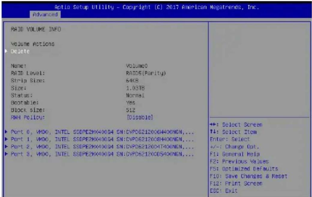
text_image
Aptlo Setup Utility - Copyright (C) 2017 American Megatrends, Inc. Advanced RAID VOLUME INFO Volume Actions Delete Name: Volume0 RAID Level: RAID5(Parity) Strip Size: 64KB Size: 1.03TB Status: Normal Bootable: Yes Block size: 512 RWH Policy: [Disable] ► Port 0, VMDO, INTEL SSDPE2HX400G4 SN:CVPD6212006W400NGN,... ► Port 1, VMDO, INTEL SSDPE2HX400G4 SN:CVPD6212008H400NGN,... ► Port 2, VMDO, INTEL SSDPE2HX400G4 SN:CVPD6212004T400NGN,... ► Port 3, VMDO, INTEL SSDPE2HX400G4 SN:CVPD6212000S400NGN,... ++: Select Screen ↑↓: Select Item Enter: Select +/-: Change Opt. F1: General Help F2: Previous Values F5: Optimized Defaults F10: Save Changes & Reset F12: Print Screen ESC: Exit- When the Delete item is selected, press
, then select Yes to delete the RAID volume and return to the Intel® Virtual Raid on CPU menu, or select No to cancel.

text_image
Aptio Setup Utility - Copyright (C) 2017 American Megatrends, Inc. Advanced Delete Delete the RAID volume? ALL DATA ON VOLUME WILL BE LOST! Yes No Deleting a volume will reset the disks to non-RAID.5.4.3 Installing the RAID controller driver during Windows 10 OS installation
®
This part provides the instructions on how to install the RAID controller drivers during OS installation.
To install the RAID controller driver when installing Windows® 10 OS:
- Boot the computer using the Windows ^ 10 OS installation disc. Follow the screen instructions to start installing Windows ^ 10.
- When prompted to choose a type of installation, click Custom: Install Windows only (advanced).
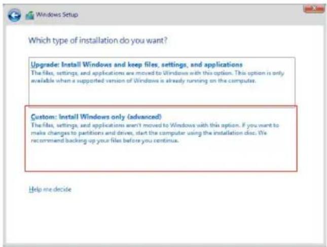
text_image
Which type of installation do you want? Upgrade: Install Windows and keep files, settings, and applications The files, settings, and applications are moved to Windows with this option. This option is only available when a supported version of Windows is already running on the computer. Custom: Install Windows only (advanced) The files, settings, and applications aren't moved to Windows with this option. If you want to make changes to partitions and drives, start the computer using the installation disc. We recommend backing up your files before you continue. Help me decide- Click Load Driver.
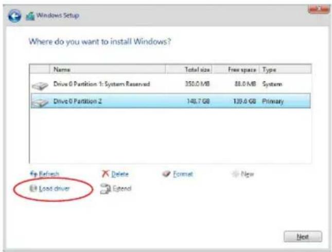
text_image
Where do you want to install Windows? Name Total size Free space Type Drive 0 Partition 1: System Reserved 350.0 MB 88.0 MB System Drive 0 Partition 2 148.7 GB 139.6 GB Primary Up Refresh Delete Format New Load driver Next- A message appears, reminding you to insert the installation media containing the driver of the RAID controller driver. If you have only one optical drive installed in your system, eject the Windows OS installation disc and replace with the motherboard Support DVD into the optical drive. Click Browse to continue.
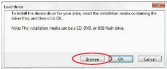
text_image
Load driver To install the device driver for your drive, insert the installation media containing the driver files, and then click OK. Note: The installation media can be a CD, DVD, or USB flash drive. Browse OK Cancel- Locate the driver in the corresponding folder of the support DVD then click OK to continue.
- Select the RAID controller driver you need from the list and click Next.
- When the system finishes loading the RAID driver, replace the motherboard Support DVD with the Windows Server installation disc. Select the drive to install Windows and click Next
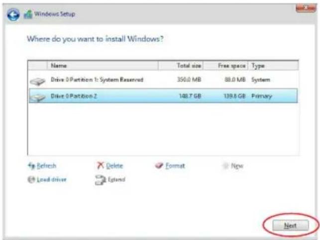
text_image
Where do you want to install Windows? Name Total size Free space Type Drive 0 Partition 1: System Reserved 350.0 MB 88.0 MB System Drive 0 Partition 2 148.7 GB 139.6 GB Primary Refresh Delete Format Now Load driver Egland Next- Setup then proceeds with the OS installation. Follow screen instructions to continue.
Driver Installation
This chapter provides the instructions for installing the necessary drivers for different system components in the Windows ^® Operating Systems.

6.1 RAID driver installation
After creating the RAID sets for your server system, you are now ready to install an operating system to the independent hard disk drive or bootable array. This part provides the instructions on how to install the RAID controller drivers during OS installation.
6.1.1 Creating a USB flash drive with RAID drive
When installing Windows ^® Server OS, you can load the RAID driver from a USB flash drive. You can create a USB flash drive with RAID driver in Windows by copying the files from the support DVD to the USB flash drive.
To copy the RAID driver to a USB flash drive in Windows environment:
- Place the motherboard support DVD in the optical drive.
- Connect a USB flash drive to your system.
-
Click on the optical drive to browse the contents of the support DVD.
-
Click Drivers > C620 INTEL RAID > Windows > Driver and then copy the RAID driver folder to the USB flash drive.
6.1.2 Installing the RAID controller driver
During Windows ^® Server 2012 R2 OS installation
To install the RAID controller driver when installing Windows® Server 2012 R2 OS:
- Boot the computer using the Windows ^ Server 2012 R2 OS installation disc. Follow the screen instructions to start installing Windows Server 2012 R2.
- When prompted to choose a type of installation, click Custom: Install Windows only (advanced).
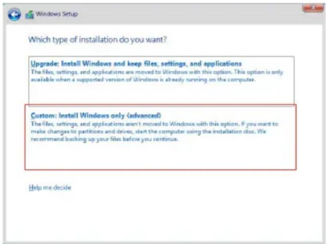
text_image
Which type of installation do you want? Upgrade: Install Windows and keep files, settings, and applications The files, settings, and applications are moved to Windows with this option. This option is only available when a supported version of Windows is already running on the computer. Custom: Install Windows only (advanced) The files, settings, and applications aren't moved to Windows with this option. If you want to make changes to partitions and drives, start the computer using the installation disc. We recommend backing up your files before you centinus. Help me decide3. Click Load Driver.
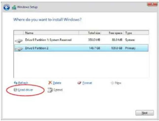
text_image
Where do you want to install Windows? Name Total size Free space Type Drive 0 Partition 1: System Reserved 350.0 MB 88.0 MB System Drive 0 Partition Z 148.7 GB 129.6 GB Primary Load driver Next-
A message appears reminding you to insert the installation media containing the driver of the RAID controller driver (the installation media can be a CD, DVD, or USB flash drive).
-
If you have only one optical drive installed in your system, eject the Windows OS installation disc and replace with the motherboard Support DVD into the optical drive.
- Or you may connect a USB flash drive containing the RAID controller driver.
Click Browse to continue.
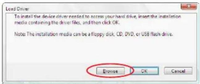
text_image
Load Driver To install the device driver needed to access your hard drive, insert the installation media containing the driver files, and then click OK. Note: The installation media can be a floppy disk, CD, DVD, or USB flash drive. Browse OK Cancel- Locate the driver in the corresponding folder of the Support DVD or USB flash drive and then click OK to continue.
-
Select the RAID controller driver you need from the list and click Next.
-
When the system finishes loading the RAID driver,
-
Replace the motherboard Support DVD with the Windows Server installation disc.
- Remove the USB flash drive.
Select the drive to install Windows and click Next.
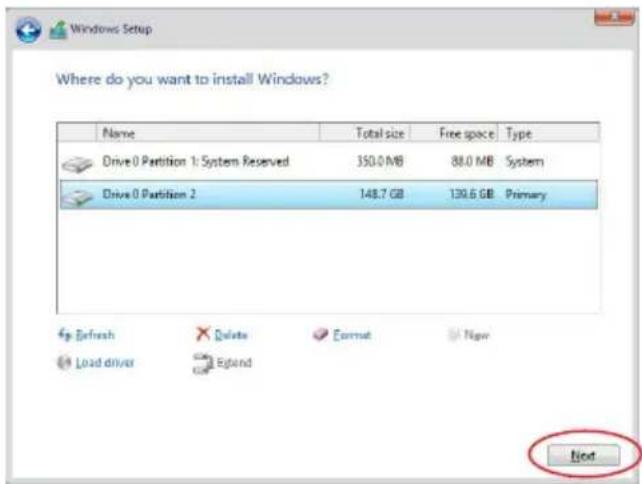
text_image
Where do you want to install Windows? Name Total size Free space Type Drive 0 Partition 1: System Reserved 350.0 MB 88.0 MB System Drive 0 Partition 2 148.7 GB 130.6 GB Primary Refresh Delete Format New Load driver Extend Next- Setup then proceeds with the OS installation. Follow screen instructions to continue.
6.2 Management applications and utilities installation
The support DVD that is bundled with your motherboard contains drivers, management applications, and utilities that you can install to maximize the features of your motherboard.

- The contents of the support DVD are subject to change at any time without notice. Visit the ASUS website (www.asus.com) for the latest updates on software and utilities.
- The support DVD is supported on Windows ^® Server 2012 R2 and Windows ^® Server 2016.
6.3 Running the Support DVD
When you place the support DVD into the optical drive, the DVD automatically displays the main screen if Autorun is enabled in your computer. By default, the Drivers tab is displayed.

If Autorun is NOT enabled in your computer, browse the contents of the support DVD to locate the file ASSETUP.EXE from the BIN folder. Double-click the ASSETUP.EXE to run the support DVD.
The main screen of the Support DVD contains the following tabs:
- Drivers
- Utilities
- Manual
- Contact

The main screen of the Support DVD looks exactly the same on the Windows® Server 2012 R2 and on the Windows® Server 2016 Operating System (OS).
6.3.1 Drivers menu tab
The Drivers Menu shows the available device drivers if the system detects installed devices. Install the necessary drivers to activate the devices.
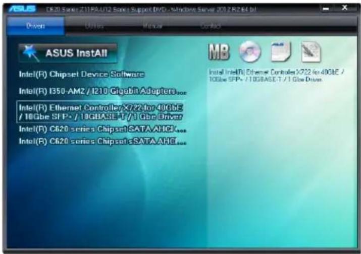
text_image
ASUS Install Intel(R) Chipset Device Software Intel(R) I350-AM2 / I210 Gigabit Adapters... Intel(R) Ethernet Controller X722 for 40GbE / 10GbE SFP+ / 10GBASE-T / 1 Gbe Driver Intel(R) C620 series Chipset SATA AHCI... Intel(R) C620 series Chipset sSATA AHCI... MB Install Intel(R) Ethernet Controller X722 for 40GbE / 10GbE SFP+ / 10GBASE-T / 1 Gbe Driver.6.3.2 Utilities menu tab
The Utilities menu displays the software applications and utilities that the motherboard supports.
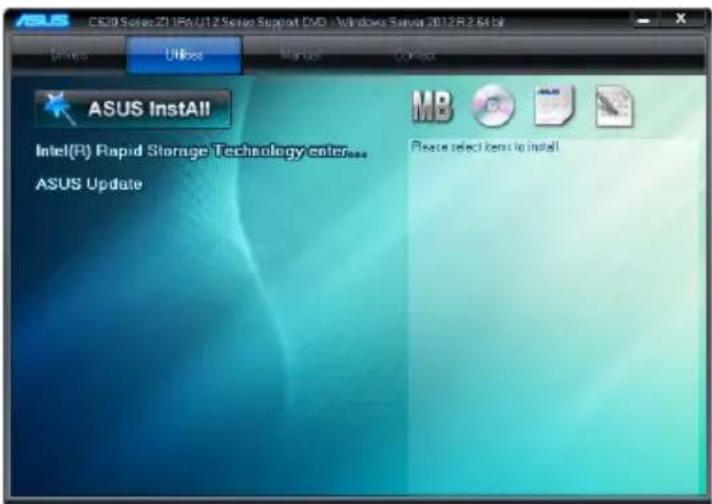
text_image
ASUS CS20 Series Z1 IPA U12 Series Support DVD - Windows Server 2012R.2.64 bit Options Unives Windows Outbox ASUS InstAll Intel(R) Rapid Storage Technology enterprise ASUS Update MB Please select items to install6.3.3 Manual menu
The Manual menu provides the link to the Broadcom NetXtreme II Network Adapter user guide.

You need an internet browser installed in your OS to view the User Guide.
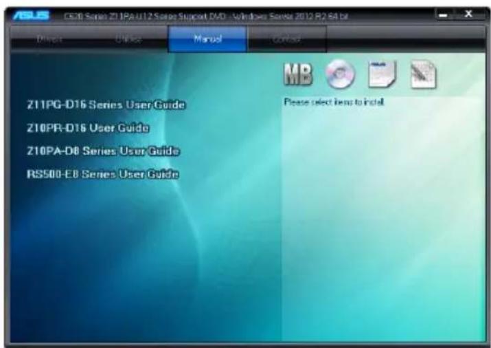
text_image
Z11PG-D16 Series User Guide Z10PR-D16 User Guide Z10PA-D8 Series User Guide RS500-E8 Series User Guide Please select items to install6.3.4 Contact information menu
The Contact menu displays the ASUS contact information, e-mail addresses, and useful links if you need more information or technical support for your motherboard.

text_image
ASUSTek COMPUTER INC Address: 151-Te Road, Petou, Taipei, Taiwan 11259 Telephone: +886-2-2894-3447 Web site: https://www.asus.com/senin.htm Technical Support: https://www.asus.com/support/ Contact us: https://www.asus.com/support/Call Us Email us: http://support.asus.com/tech/sentech/eav.aspx ASUSTek COMPUTER INC (Taiwan) ASUSTek COMPUTER INC (China) ASUS COMPUTER INTERNATIONAL (America) ASUS COMPUTER GmbH (Germany & Austria)6.4 Intel® chipset device software installation
This section provides the instructions on how to install the Intel® chipset device software on the system.
You need to manually install the Intel ^® chipset device software on a Windows operating system.
To install the Intel® chipset device software:
-
Restart the computer, and then log on with Administrator privileges.
-
Insert the motherboard/system support DVD into the optical drive. The support DVD automatically displays the Drivers menu if Autorun is enabled in your computer.

If Autorun is NOT enabled in your computer, browse the contents of the support DVD to locate the file ASSETUP.EXE from the BIN folder. Double-click the ASSETUP.EXE to run the support DVD.
- Click the item Intel ^ Chipset Device Software from the menu.
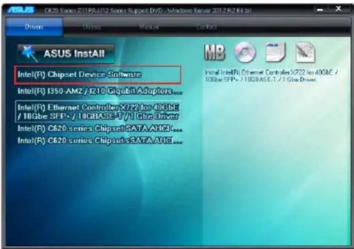
text_image
ASUS Install Intel(R) Chipset Device Software Intel(R) I350-AM2 / I210 GbGBnAdapters... Intel(R) Ethernet Controller X/22 for 40GbE / 10GbE SFP - / 10GBASE-T /1 Gbe Driver Intel(R) C620 series Chipset SATA AHCI... Intel(R) C620 series Chipset SATA AHCI... MB Install Intel(R) Ethernet Controller X722 for 40GbE / 10GbE SFP - / 10GBASE-T /1 Gbe Driver- The Intel® Chipset Device Software window appears. Click Next to start the installation.
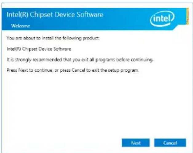
text_image
Intel(R) Chipset Device Software Welcome You are about to install the following product: Intel(R) Chipset Device Software It is strongly recommended that you exit all programs before continuing. Press Next to continue, or press Cancel to exit the setup program. Next Cancel- Read the License Agreement and click Accept to continue the process.
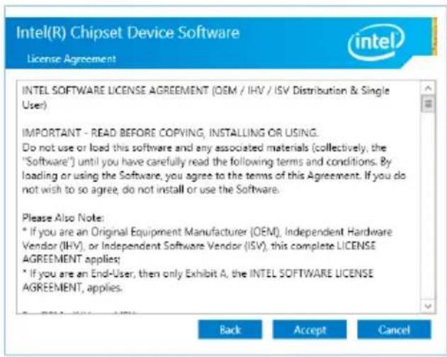
text_image
Intel(R) Chipset Device Software License Agreement intel INTEL SOFTWARE LICENSE AGREEMENT (OEM / IHV / ISV Distribution & Single User) IMPORTANT - READ BEFORE COPVING, INSTALLING OR USING. Do not use or load this software and any associated materials (collectively, the "Software") until you have carefully read the following terms and conditions. By loading or using the Software, you agree to the terms of this Agreement. If you do not wish to so agree, do not install or use the Software. Please Also Note: * If you are an Original Equipment Manufacturer (OEM), Independent Hardware Vendor (IHV), or Independent Software Vendor (ISV), this complete LICENSE AGREEMENT applies; * If you are an End-User, then only Exhibit A, the INTEL SOFTWARE LICENSE AGREEMENT, applies.- Read the Readme File Information and click Install to start the installation process.
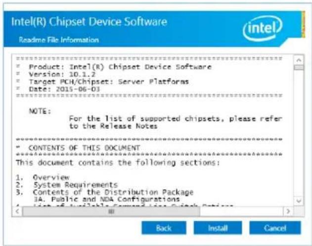
text_image
Intel(R) Chipset Device Software Readme File Information Product: Intel(R) Chipset Device Software Version: 10.1.2 Target PCH/Chipset: Server Platforms Date: 2015-06-03 NOTE: For the list of supported chipsets, please refer to the Release Notes CONTENTS OF THIS DOCUMENT This document contains the following sections: 1. Overview 2. System Requirements 3. Contents of the Distribution Package 3A. Public and NDA Configurations Back Install Cancel- Click Restart Now to complete the setup process.
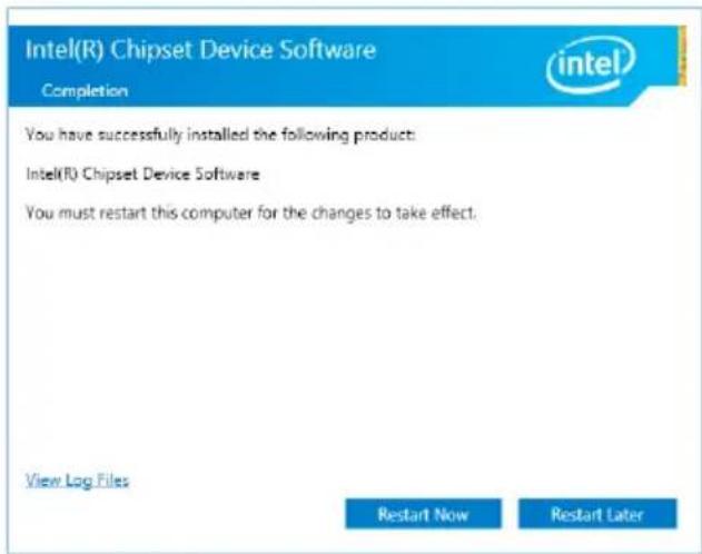
text_image
Intel(R) Chipset Device Software Completion You have successfully installed the following product: Intel(R) Chipset Device Software You must restart this computer for the changes to take effect. View Log Files Restart Now Restart Later6.5 Installing the Intel ^® I210 Gigabit Adapters driver
This section provides the instructions on how to install the Intel® I210 Gigabits Adapter Driver on the system.
To install the Intel® I210 Gigabit Adapters Driver on the Windows® operating system:
- Restart the computer.
- Log on with Administrator privileges.
- Insert the motherboard/system support DVD to the optical drive.

If Autorun is NOT enabled in your computer, browse the contents of the support DVD to locate the file ASSETUP.EXE from the BIN folder. Double-click the ASSETUP.EXE to run the support DVD.
- Click Int50-AM1/I350-AM2/I210 Gigabit Adapters Driver in the Drivers menu of the main screen to start the installation.
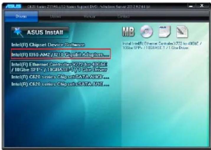
text_image
ASUS InstAll Intel(R) Chipset Device Software Intel(R) I350-AMZ / I210 Gigabit Adapters... Intel(R) Ethernet Controller X722 for 40GBE / 10Gbe SFP+ / 10GBASE-T / 1 Gbe Driver Intel(R) C620 series Chipset SATA AHCI... Intel(R) C620 series Chipset SATA AHCI... Intel Intel(R) Ethernet Controller X722 for 40GBE / 10Gbe SFP+ / 10GBASE-T / 1 Gbe Driver- Click Install Drivers and Software option to begin installation.
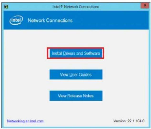
text_image
Intel® Network Connections Intel Network Connections Install Drivers and Software View User Guides View Release Notes Networking at Intel.com Version: 22.1 104.0- Click Next when the Intel(R) Network Connections Install Wizard window appears.
text_image
Intel(R) Network Connections Install Wizard Welcome to the install wizard for Intel(R) Network Connections inTEL® Installs drivers, Intel(R) Network Connections, and Advanced Networking Services. WARNING: This program is protected by copyright law and international treaties. < Back Next > Cancel- Tick I accept the terms in the license agreement and click Next to continue.
text_image
Intel(R) Network Connections Install Wizard License Agreement Please read the following license agreement carefully. INTEL SOFTWARE LICENSE AGREEMENT IMPORTANT - READ BEFORE COPYING, INSTALLING OR USING. Do not copy, install, or use this software and any associated materials (collectively, the "Software") provided under this license agreement ("Agreement") until you have carefully read the following terms and conditions. By copying, installing, or otherwise using the Software, you agree to be bound by the terms of this Agreement. If you do not agree to the terms of this Agreement, do not accept install, or use the license agreement. ● I accept the terms in the license agreement ○ I do not accept the terms in the license agreement < Back Next > Cancel- From the Setup Options window, click Next to start the installation.

By default, Intel(R) PROSet for Windows Device Manager and Windows PowerShell Module are ticked.
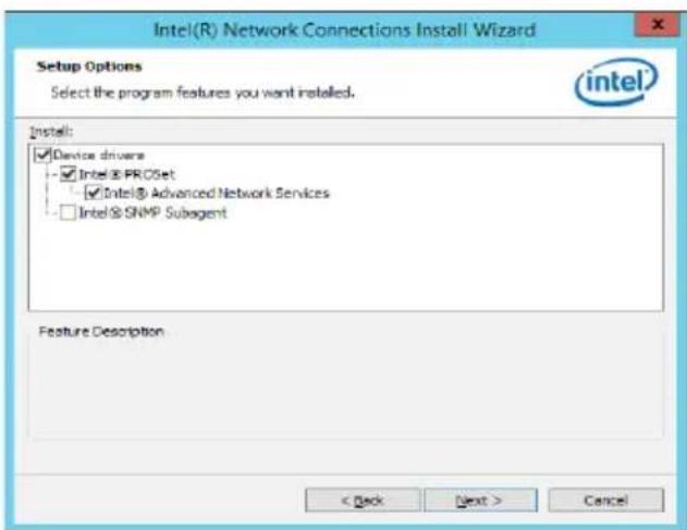
text_image
Intel(R) Network Connections Install Wizard Setup Options Select the program features you want installed. intel Install: ✓ Device drivers - ✓ Intel® PROSet - - ✓ Intel® Advanced Network Services - □ Intel® SNMP Subagent Feature Description < Back Next > Cancel- Click Install to start the installation.
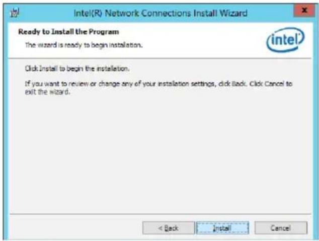
text_image
Intel(R) Network Connections Install Wizard Ready to Install the Program The wizard is ready to begin installation. intel Click Install to begin the installation. If you want to review or change any of your installation settings, click Back. Click Cancel to exit the wizard. < Back Install Cancel- When the installation is done, press Finish to complete the installation.
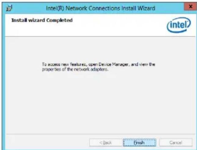
text_image
Intel(R) Network Connections Install Wizard Install wizard Completed intel To access new features, open Device Manager, and view the properties of the network adapters. < Back Finish Cancel6.7Intel® Rapid Storage Technology enterprise 5.0 installation
This section provides the instructions on how to install the Intel® Rapid Storage Technology enterprise 5.0 on the system.
You need to manually install the Intel® Rapid Storage Technology enterprise 5.0 utility on a Windows® operating system.
To install the Intel® Rapid Storage Technology enterprise 5.0 utility:
- Restart the computer, and then log on with Administrator privileges.
- Insert the motherboard/system support DVD into the optical drive, and navigate to the Utilities menu.
- Click the Intel® Rapid Storage Technology enterprise to begin installation.
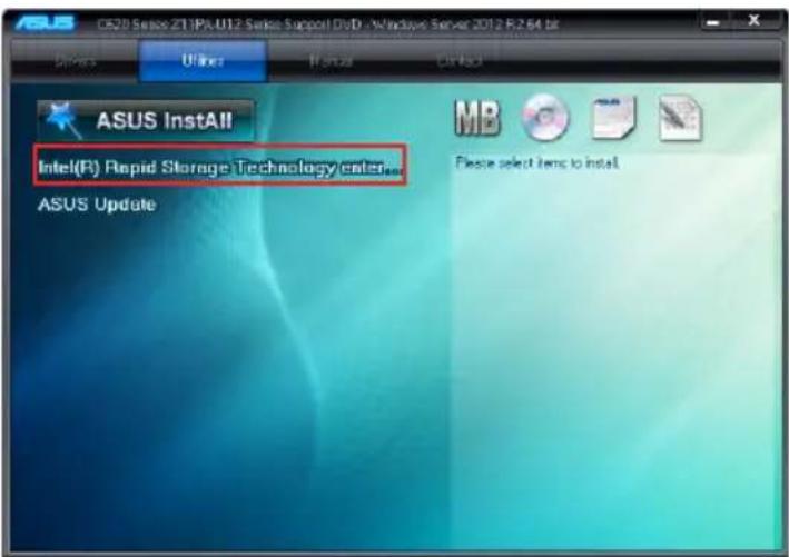
text_image
ASUS CS20 Service 21 IPC U12 Service Support DVD - Windows Server 2012 R2 64 bit Drivers Online If you CIP/3D ASUS InstAll Intel(R) Rapid Storage Technology call ASUS Update MB Please select items to install.- The Intel® Rapid Storage Technology enterprise window appears. Click Next to start the installation.
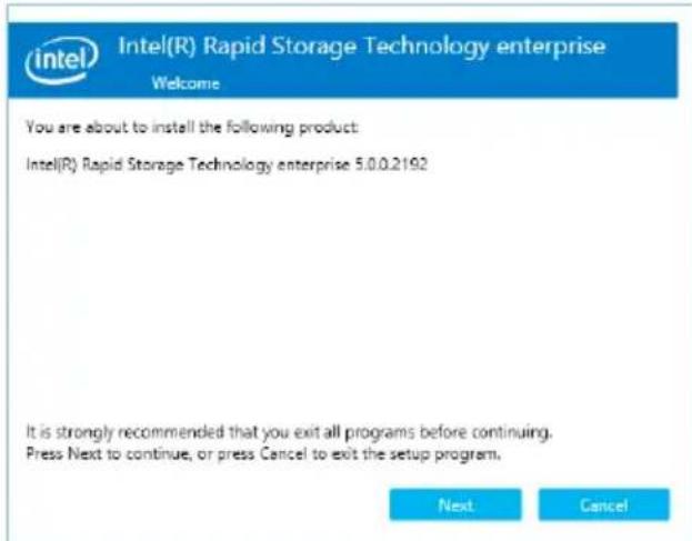
text_image
Intel(R) Rapid Storage Technology enterprise Welcome You are about to install the following product: Intel(R) Rapid Storage Technology enterprise 5.0.0.2192 It is strongly recommended that you exit all programs before continuing. Press Next to continue, or press Cancel to exit the setup program. Next Cancel- Read the Warning message and click Next to continue.
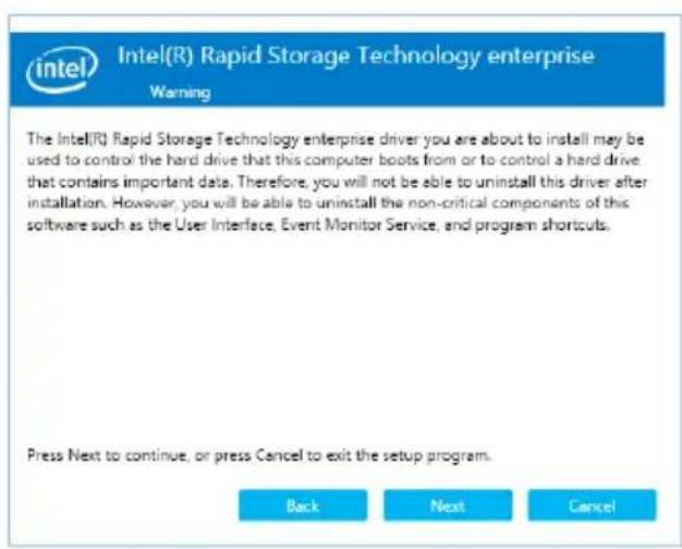
text_image
Intel(R) Rapid Storage Technology enterprise Warning The Intel(R) Rapid Storage Technology enterprise driver you are about to install may be used to control the hard drive that this computer boots from or to control a hard drive that contains important data. Therefore, you will not be able to uninstall this driver after installation. However, you will be able to uninstall the non-critical components of this software such as the User Interface, Event Monitor Service, and program shortcuts. Press Next to continue, or press Cancel to exit the setup program.- Read the License Agreement and click Accept to continue the process.
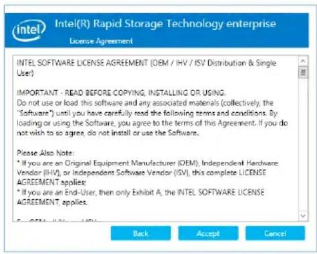
text_image
Intel(R) Rapid Storage Technology enterprise License Agreement INTEL SOFTWARE LICENSE AGREEMENT (OEM / IHV / ISV Distribution & Single User) IMPORTANT - READ BEFORE COPYING, INSTALLING OR USING. Do not use or load this software and any associated materials (collectively, the "Software") until you have carefully read the following terms and conditions. By loading or using the Software, you agree to the terms of this Agreement. If you do not wish to so agree, do not install or use the Software. Please Also Note: * If you are an Original Equipment Manufacturer (OEM), Independent Hardware Vendor (IHV), or Independent Software Vendor (ISV), this complete LICENSE AGREEMENT applies; * If you are an End-User, then only Exhibit A, the INTEL SOFTWARE LICENSE AGREEMENT, applies.- Select the destination folder and click Next to continue.
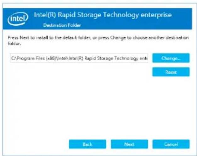
text_image
Intel(R) Rapid Storage Technology enterprise Destination Folder Press Next to install to the default folder, or press Change to choose another destination folder. C:\Program Files (x86)\Intel\Intel(R) Rapid Storage Technology ente Change... Reset Back Next Cancel- Tick the features that you would like to install and click Next to continue.
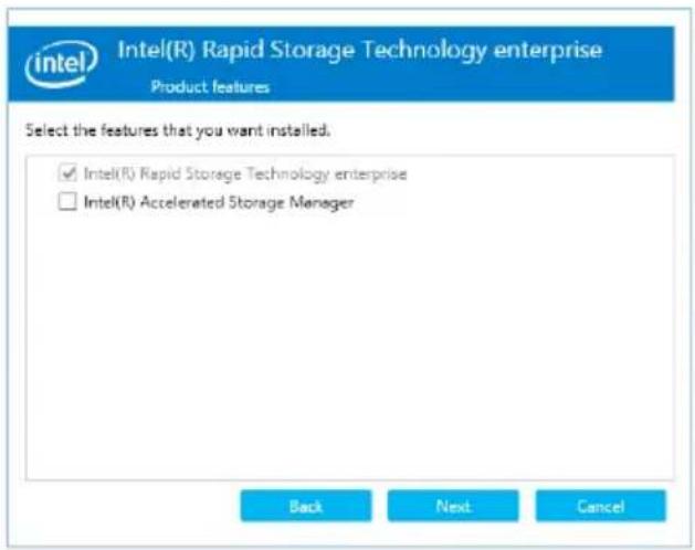
text_image
Intel(R) Rapid Storage Technology enterprise Product features Select the features that you want installed. ✓ Intel(R) Rapid Storage Technology enterprise □ Intel(R) Accelerated Storage Manager Back Next Cancel- Click Install to start the installation process.
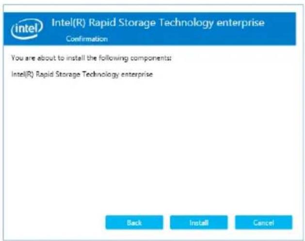
text_image
Intel(R) Rapid Storage Technology enterprise Confirmation You are about to install the following components: Intel(R) Rapid Storage Technology enterprise Back Install Cancel- Click Restart Now to complete the setup process.
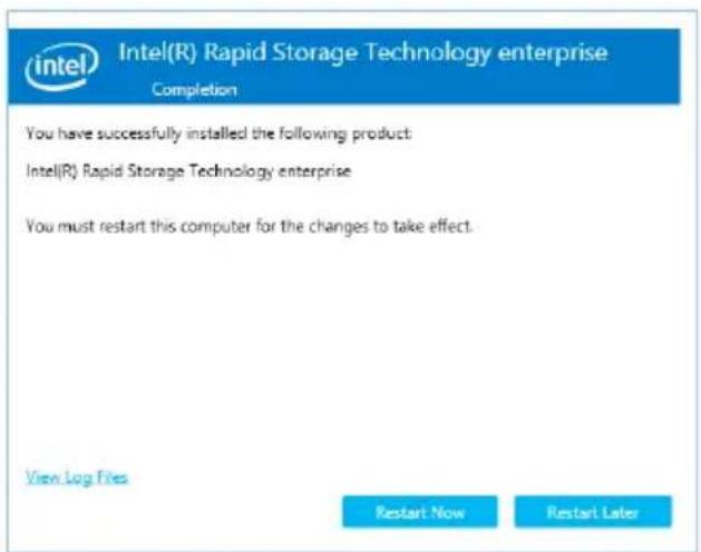
text_image
Intel(R) Rapid Storage Technology enterprise Completion You have successfully installed the following product: Intel(R) Rapid Storage Technology enterprise You must restart this computer for the changes to take effect. View Log Files Restart Now Restart LaterAppendix
This appendix includes additional information that you may refer to when configuring the motherboard.

Z11PA-U12 Series block diagram
Z11PA-U12/10G-2S
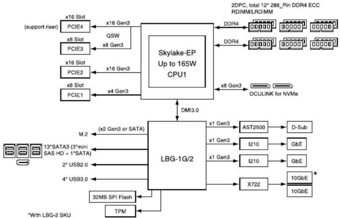
flowchart
graph TD
    A["Skylake-EP Up to 165W CPU1"] -->|x16 Gen3| B["x16 Slot PCIE4"]
    A -->|x8 Gen3| C["x8 Slot PCIE3"]
    A -->|x16 Gen3| D["x16 Slot PCIE2"]
    A -->|x4 Gen3| E["x8 Slot PCIE1"]
    A -->|DMI3.0| F["LBG-1G/2"]
    F --> G["x1 Gen3 AST2500"]
    F --> H["x1 Gen3 I210"]
    F --> I["x1 Gen3 I210"]
    F --> J["X722"]
    G --> K["D-Sub"]
    H --> L["GbE"]
    I --> M["GbE"]
    J --> N["10GbE"]
    J --> O["10GbE"]
    P["2DPC, total 12* 288_Pin DDR4 ECC RDIMM/LRDIMM"] --> Q["DDR4"]
    R["OCULINK for NVMe"] --> S["x8 Gen3"]
    T["*With LBG-2 SKU"] --> U["32MB SPI Flash"]
    T --> V["TPM"]
    W["(support riser)"] --> X["x16 Slot PCIE4"]
    X --> Y["x8 Slot PCIE3"]
    Z["13*SATA3 (3*mini SAS HD + 1*SATA)"] --> AA["x2 Gen3 or SATA"]
    AB["2* USB2.0"] --> AC["x2 Gen3 or SATA"]
    AD["4* USB3.0"] --> AE["x2 Gen3 or SATA"]
Z11PA-U12
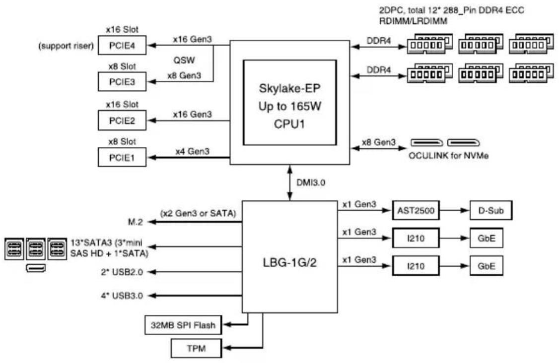
flowchart
graph TD
    A["Skylake-EP Up to 165W CPU1"] -->|x16 Gen3| B["PCIE4"]
    A -->|x8 Gen3| C["PCIE3"]
    A -->|x16 Gen3| D["PCIE2"]
    A -->|x4 Gen3| E["PCIE1"]
    B --> F["QSW"]
    C --> G["QSW"]
    D --> H["QSW"]
    E --> I["QSW"]
    J["LBG-1G/2"] --> K["x1 Gen3"]
    J --> L["x1 Gen3"]
    J --> M["x1 Gen3"]
    J --> N["AST2500"]
    J --> O["I210"]
    J --> P["I210"]
    J --> Q["D-Sub"]
    J --> R["GbE"]
    J --> S["GbE"]
    J --> T["TPM"]
    J --> U["32MB SPI Flash"]
    J --> V["13*SATA3 (3*mini SAS HD + 1*SATA)"]
    J --> W["M.2"]
    J --> X["MDI3.0"]
    J --> Y["OCULINK for NVMe"]
    Z["(support riser)"] --> AA["x16 Slot PCIE4"]
    AA --> AB["x8 Slot PCIE3"]
    AB --> AC["x16 Gen3"]
    AD["(support riser)"] --> AE["x8 Slot PCIE2"]
    AE --> AF["x8 Slot PCIE1"]
    AG["2DPC, total 12* 288_Pin DDR4 ECC RDIMM/LRDIMM"] --> AH["DDR4"]
    AH --> AI["DDR4"]
    AI --> AJ["DDR4"]
    AJ --> AK["DDR4"]
    AK --> AL["DDR4"]
    AL --> AM["DDR4"]
    AM --> AN["DDR4"]
    AN --> AO["DDR4"]
    AO --> AP["DDR4"]
    AP --> AQ["DDR4"]
    AQ --> AR["DDR4"]
    AR --> AS["DDR4"]
    AS --> AT["DDR4"]
    AT --> AU["DDR4"]
    AU --> AV["DDR4"]
    AV --> AW["DDR4"]
Q-Code table
| Action PHASE POST CODE TYPE DESCRIPTION | |||
| Normal boot | Security Phase | 01 Progress First post code(POWER_ON_POST_CODE) | |
| 02 Progress Load BSP microcode(MICROCODE_POST_CODE) | |||
| 03 Progress Set cache as ram for PEI phase(CACHE_ENABLED_POST_CODE) | |||
| 06 Progress CPU Early init.(CPU_EARLY_INIT_POST_CODE) | |||
| 04 Progress initializes South bridge for PEI preparation | |||
| PEI (Pre-EFI initialization) phase | 10 Progress PEI Core Entry | ||
| 15 Progress NB initialize before installed memory | |||
| 19 Progress SB initialize before installed memory | |||
| 78~00 Progress Wait BMC ready(duration: 120 seconds) | |||
| A1 MRC Progress QPI initialization | |||
| A3 MRC Progress QPI initialization | |||
| A7 MRC Progress QPI initialization | |||
| A8 MRC Progress QPI initialization | |||
| A9 MRC Progress QPI initialization | |||
| AA MRC Progress QPI initialization | |||
| AB MRC Progress QPI initialization | |||
| AC MRC Progress QPI initialization | |||
| AD MRC Progress QPI initialization | |||
| AE MRC Progress QPI initialization | |||
| AF MRC Progress QPI initialization Complete | |||
| 2F Progress Memory Init. | |||
| B0 MRC Progress Memory Init. | |||
| B1 MRC Progress Memory Init. | |||
| AF MRC Progress RC Reset if require | |||
| B4 MRC Progress Memory Init. | |||
| B2 MRC Progress Memory Init. | |||
| B3 MRC Progress Memory Init. | |||
| B5 MRC Progress Memory Init. | |||
| B6 MRC Progress Memory Init. | |||
| B7 MRC Progress Memory Init. | |||
| B8 MRC Progress Memory Init. | |||
| B9 MRC Progress Memory Init. | |||
| BA MRC Progress Memory Init. | |||
| BB MRC Progress Memory Init. | |||
| BC MRC Progress Memory Init. | |||
| BF MRC Progress Memory Init. Done | |||
| 5A MRC Progress Other config. After RC end | |||
| 31 Progress Memory already installed | |||
| 32 Progress CPU Init. | |||
| 34 Progress CPU Init. | |||
| 36 Progress CPU Init. | |||
| 4F Progress DXE Initial Program Load(IPL) | |||
(continued on the next page)
Q-Code table
| Action PHASE POST CODE TYPE DESCRIPTION | ||||
| Normal boot | DXE (Driver Execution Environment) phase | 60 Progress DXE Core Started | ||
| 61 Progress DXE NVRAM Init. | ||||
| 62 Progress SB run-time init. | ||||
| 63 Progress DXE CPU Init | ||||
| 68 Progress NB Init. | ||||
| 69 Progress NB Init. | ||||
| 6A Progress NB Init. | ||||
| 70 Progress SB Init. | ||||
| 71 Progress SB Init. | ||||
| 72 Progress SB Init. | ||||
| 78 Progress ACPI Init. | ||||
| 79 Progress CSM Init. | ||||
| BDS (Boot Device Selection) phase | 90 Progress BDS started | |||
| 91 Progress Connect device event | ||||
| 92 Progress PCI Bus Enumeration. | ||||
| 93 Progress PCI Bus Enumeration. | ||||
| 94 Progress PCI Bus Enumeration. | ||||
| 95 Progress PCI Bus Enumeration. | ||||
| 96 Progress PCI Bus Enumeration. | ||||
| 97 Progress Console output connect event | ||||
| 98 Progress Console input connect event | ||||
| 99 Progress AMI Super IO start | ||||
| 9A Progress AMI USB Driver Init. | ||||
| 9B Progress AMI USB Driver Init. | ||||
| 9C Progress AMI USB Driver Init. | ||||
| 9D Progress AMI USB Driver Init. | ||||
| b2 Progress Legacy Option ROM Init. | ||||
| b3 Progress Reset system | ||||
| b4 Progress USB hotplug | ||||
| b6 Progress NVRAM clean up | ||||
| b7 Progress NVRAM configuration reset | ||||
| A0 Progress IDE, AHCI Init. | ||||
| A1 Progress IDE, AHCI Init. | ||||
| A2 Progress IDE, AHCI Init. | ||||
| A3 Progress IDE, AHCI Init. | ||||
| A8 Progress BIOS Setup Utility password verify | ||||
| A9 Progress BIOS Setup Utility start | ||||
| AB Progress BIOS Setup Utility input wait | ||||
| AD Progress Ready to boot event | ||||
| AE Progress Legacy boot event | ||||
| Operating system phase | AA Progress APIC mode | |||
| AC Progress PIC mode | ||||
Simplified EU Declaration of Conformity
English ASUSTeK Computer Inc. hereby declares that this device is in compliance with the essential requirements and other relevant provisions of related Directives. Full text of EU declaration of conformity is available at: www.asus.com/support
Address 4F, No. 150, Li-Te Rd., Peitou, Taipei 112, Taiwan
Telephone +886-2-2894-3447
Fax +886-2-2890-7798
Web site https://www.asus.com
Technical Support
Telephone +86-21-38429911
Fax +86-21-58668722 ext: 9101
Online Support https://www.asus.com/support/Product/ContactUs/Services/
questionform/?lang=en
ASUSTeK COMPUTER INC. (Taiwan)
Address 4F, No. 150, Li-Te Rd., Peitou, Taipei 112, Taiwan
Telephone +886-2-2894-3447
Fax +886-2-2890-7798
Web site https://www.asus.com/tw/
Technical Support
Telephone +886-2-2894-3447 (0800-093-456)
Online Support https://www.asus.com/support/Product/ContactUs/Services/
questionform/?lang=zh-tw
ASUSTeK COMPUTER INC. (China)
Address No. 5077, Jindu Road, Minhang District, Shanghai, China
Telephone +86-21-5442-1616
Fax +86-21-5442-0099
Web site https://www.asus.com.cn
Technical Support
Telephone +86-20-2804-7506 (400-620-6655)
Online Support https://www.asus.com/support/Product/ContactUs/Services/
questionform/?lang=zh-cn
ASUS contact information
ASUS COMPUTER INTERNATIONAL (America)
Address 800 Corporate Way, Fremont, CA 94539, USA
Fax +1-510-608-4555
Web site https://www.asus.com/us/
Technical Support
Support fax +1-812-284-0883
General support +1-812-282-2787
Online support https://www.asus.com/support/Product/ContactUs/Services/
questionform/?lang=en-us
ASUS COMPUTER GmbH (Germany and Austria)
Address Harkort Str. 21-23, 40880 Ratingen, Germany
Fax +49-2102-959911
Web site https://www.asus.com/de/
Technical Support
Telephone +49-1805-010923
Support Fax +49-2102-959911
Online support https://www.asus.com/support/Product/ContactUs/Services/
questionform/?lang=de-de
ASUS Czech Service s.r.o. (Europe)
Address Na Rovince 887, 720 00 Ostrava – Hrabová,
Czech Republic
Telephone +420-596766888
Web site https://www.asus.com/cz/
Technical Support
Telephone +420-596-766-891
Fax +420-596-766-329
E-mail advance.rma.eu@asus.com
Online Support https://www.asus.com/support/Product/ContactUs/Services/
questionform/?lang=cs-cz
ASUS contact information
ASUS Holland BV (The Netherlands)
Address Marconistraat 2, 7825GD EMMEN, The Netherlands
Web site https://www.asus.com/nl/
Technical Support
Telephone +31-(0)591-5-70292
Fax +31-(0)591-666853
E-mail advance.rma.eu@asus.com
Online Support https://www.asus.com/support/Product/ContactUs/Services/
questionform/?lang=nl-nl
ASUS Polska Sp. z o.o. (Poland)
Online Support https://www.asus.com/support/Product/ContactUs/Services/
questionform/?lang=pl-pl
ASK-Service (Russia and CIS)
Online Support https://www.asus.com/support/Product/ContactUs/Services/
questionform/?lang=ru-ru
DECLARATION OF CONFORMITY
Per FCC Part 2 Section 2. 1077(a)

Responsible Party Name: Asus Computer International
Address: 800 Corporate Way, Fremont
, CA 94539.
Phone/Fax No: (510)739-3777/(510)608-4555
hereby declares that the product
Product Name : Motherboard
Model Number : Z11PA-U12/10G-2S
Conforms to the following specifications:
☒ FCC Part 15, Subpart B, Unintentional Radiators
Supplementary Information:
This device complies with part 15 of the FCC Rules. Operation is subject to the following two conditions: (1) This device may not cause harmful interference, and (2) this device must accept any interference received, including interference that may cause undesired operation.
Representative Person's Name : Steve Chang / President
Steve Chang
Signature :
DECLARATION OF CONFORMITY
Per FCC Part 2 Section 2. 1077(a)

Responsible Party Name: Asus Computer International
Address: 800 Corporate Way, Fremont
, CA 94539.
Phone/Fax No: (510)739-3777/(510)608-4555
hereby declares that the product
Product Name : Motherboard
Model Number : Z11PA-U12
Conforms to the following specifications:
☒ FCC Part 15, Subpart B, Unintentional Radiators
Supplementary Information:
This device complies with part 15 of the FCC Rules. Operation is subject to the following two conditions: (1) This device may not cause harmful interference, and (2) this device must accept any interference received, including interference that may cause undesired operation.
Representative Person's Name : Steve Chang / President
Steve Chang
Signature :