
ROG Strix B550-F WIFI - Motherboard ASUS - Free user manual and instructions
Find the device manual for free ROG Strix B550-F WIFI ASUS in PDF.


User questions about ROG Strix B550-F WIFI ASUS
0 question about this device. Answer the ones you know or ask your own.
Ask a new question about this device
Download the instructions for your Motherboard in PDF format for free! Find your manual ROG Strix B550-F WIFI - ASUS and take your electronic device back in hand. On this page are published all the documents necessary for the use of your device. ROG Strix B550-F WIFI by ASUS.
USER MANUAL ROG Strix B550-F WIFI ASUS
ROG STRIX B550-F GAMING (WI-FI)

text_image
ASUS MotherboardCopyright © 2020 ASUSTeK COMPUTER INC. All Rights Reserved.
No part of this manual, including the products and software described in it, may be reproduced, transmitted, transcribed, stored in a retrieval system, or translated into any language in any form or by any means, except documentation kept by the purchaser for backup purposes, without the express written permission of ASUSTeK COMPUTER INC. ("ASUS").
Product warranty or service will not be extended if: (1) the product is repaired, modified or altered, unless such repair, modification of alteration is authorized in writing by ASUS; or (2) the serial number of the product is defaced or missing.
ASUS PROVIDES THIS MANUAL "AS IS" WITHOUT WARRANTY OF ANY KIND, EITHER EXPRESS OR IMPLIED, INCLUDING BUT NOT LIMITED TO THE IMPLIED WARRANTIES OR CONDITIONS OF MERCHANTABILITY OR FITNESS FOR A PARTICULAR PURPOSE. IN NO EVENT SHALL ASUS, ITS DIRECTORS, OFFICERS, EMPLOYEES OR AGENTS BE LIABLE FOR ANY INDIRECT, SPECIAL, INCIDENTAL, OR CONSEQUENTIAL DAMAGES (INCLUDING DAMAGES FOR LOSS OF PROFITS, LOSS OF BUSINESS, LOSS OF USE OR DATA, INTERRUPTION OF BUSINESS AND THE LIKE), EVEN IF ASUS HAS BEEN ADVISED OF THE POSSIBILITY OF SUCH DAMAGES ARISING FROM ANY DEFECT OR ERROR IN THIS MANUAL OR PRODUCT.
SPECIFICATIONS AND INFORMATION CONTAINED IN THIS MANUAL ARE FURNISHED FOR INFORMATIONAL USE ONLY, AND ARE SUBJECT TO CHANGE AT ANY TIME WITHOUT NOTICE, AND SHOULD NOT BE CONSTRUED AS A COMMITMENT BY ASUS. ASUS ASSUMES NO RESPONSIBILITY OR LIABILITY FOR ANY ERRORS OR INACCURACIES THAT MAY APPEAR IN THIS MANUAL, INCLUDING THE PRODUCTS AND SOFTWARE DESCRIBED IN IT.
Products and corporate names appearing in this manual may or may not be registered trademarks or copyrights of their respective companies, and are used only for identification or explanation and to the owners' benefit, without intent to infringe.
Offer to Provide Source Code of Certain Software
This product contains copyrighted software that is licensed under the General Public License (“GPL”), under the Lesser General Public License Version (“LGPL”) and/or other Free Open Source Software Licenses. Such software in this product is distributed without any warranty to the extent permitted by the applicable law. Copies of these licenses are included in this product.
Where the applicable license entitles you to the source code of such software and/or other additional data, you may obtain it for a period of three years after our last shipment of the product, either
(1) for free by downloading it from https://www.asus.com/support/ or
(2) for the cost of reproduction and shipment, which is dependent on the preferred carrier and the location where you want to have it shipped to, by sending a request to:
ASUSTeK Computer Inc.
Legal Compliance Dept.
1F., No. 15, Lide Rd.,
Beitou Dist., Taipei City 112
Taiwan
In your request please provide the name, model number and version, as stated in the About Box of the product for which you wish to obtain the corresponding source code and your contact details so that we can coordinate the terms and cost of shipment with you.
The source code will be distributed WITHOUT ANY WARRANTY and licensed under the same license as the corresponding binary/object code.
This offer is valid to anyone in receipt of this information.
ASUSTeK is eager to duly provide complete source code as required under various Free Open Source Software licenses. If however you encounter any problems in obtaining the full corresponding source code we would be much obliged if you give us a notification to the email address gpl@asus.com, stating the product and describing the problem (please DO NOT send large attachments such as source code archives, etc. to this email address).
Contents
Safety information....iv
About this guide....v
ROG STRIX B550-F GAMING (WI-FI) specifications summary...... vi
Connectors with shared bandwidth ....x
Package contents....xi
Installation tools and components....xii
Chapter 1: Product Introduction
1.1 Before you proceed....1-1
1.2 Motherboard layout....1-2
Chapter 2: Basic Installation
2.1 Building your PC system....2-1
2.1.1 CPU installation....2-1
2.1.2 Cooling system installation....2-2
2.1.3 DIMM installation....2-5
2.1.4 M.2 installation 2-6
2.1.5 Motherboard installation....2-8
2.1.6 ATX power connection....2-9
2.1.7 SATA device connection....2-9
2.1.8 Front I/O connector 2-10
2.1.9 Expansion card installation 2-11
2.2 BIOS update utility 2-12
2.3 Motherboard rear and audio connections 2-13
2.3.1 Rear I/O connection 2-13
2.3.2 Audio I/O connections....2-15
2.4 Starting up for the first time....2-17
2.5 Turning off the computer 2-17
Chapter 3: BIOS and RAID Support
3.1 Knowing BIOS....3-1
3.2 BIOS setup program....3-2
3.3 EZ Update 3-2
3.4 ASUS EZ Flash 3 3-3
3.5 ASUS CrashFree BIOS 3....3-4
3.6 RAID configurations 3-5
Appendix
Notices ...... A-1
ASUS contact information...... A-8
Safety information
Electrical safety
- To prevent electrical shock hazard, disconnect the power cable from the electrical outlet before relocating the system.
- When adding or removing devices to or from the system, ensure that the power cables for the devices are unplugged before the signal cables are connected. If possible, disconnect all power cables from the existing system before you add a device.
- Before connecting or removing signal cables from the motherboard, ensure that all power cables are unplugged.
- Seek professional assistance before using an adapter or extension cord. These devices could interrupt the grounding circuit.
- Ensure that your power supply is set to the correct voltage in your area. If you are not sure about the voltage of the electrical outlet you are using, contact your local power company.
- If the power supply is broken, do not try to fix it by yourself. Contact a qualified service technician or your retailer.
Operation safety
- Before installing the motherboard and adding devices on it, carefully read all the manuals that came with the package.
- Before using the product, ensure all cables are correctly connected and the power cables are not damaged. If you detect any damage, contact your dealer immediately.
- To avoid short circuits, keep paper clips, screws, and staples away from connectors, slots, sockets and circuitry.
- Avoid dust, humidity, and temperature extremes. Do not place the product in any area where it may become wet.
- Place the product on a stable surface.
- If you encounter technical problems with the product, contact a qualified service technician or your retailer.
- Your motherboard should only be used in environments with ambient temperatures between 0°C and 40°C.
About this guide
This user guide contains the information you need when installing and configuring the motherboard.
How this guide is organized
This guide contains the following parts:
• Chapter 1: Product Introduction
This chapter describes the features of the motherboard and the new technology it supports. It includes description of the switches, jumpers, and connectors on the motherboard.
• Chapter 2: Basic Installation
This chapter lists the hardware setup procedures that you have to perform when installing system components.
• Chapter 3: BIOS and RAID Support
This chapter tells how to boot into the BIOS, upgrade BIOS using the EZ Flash Utility and support on RAID.
Where to find more information
Refer to the following sources for additional information and for product and software updates.
1. ASUS website
The ASUS website (www.asus.com) provides updated information on ASUS hardware and software products.
2. Optional documentation
Your product package may include optional documentation, such as warranty flyers, that may have been added by your dealer. These documents are not part of the standard package.
Conventions used in this guide
To ensure that you perform certain tasks properly, take note of the following symbols used throughout this manual.


CAUTION: Information to prevent damage to the components and injuries to yourself when trying to complete a task.
IMPORTANT: Instructions that you MUST follow to complete a task.
NOTE: Tips and additional information to help you complete a task.
ROG STRIX B550-F GAMING (WI-FI) specifications summary
| CPU | AMD Socket AM4 for 3^rd Gen AMD RyzenTM Processors* * Refer to www.asus.com for CPU support list. |
| Chipset | AMD 550 Chipset |
| Memory | 3^rd Gen AMD RyzenTM Processors4 x DIMM, Max. 128GB, 4400(O.C)/4266(O.C)/4133(O.C)/4000(O.C)/3866(O.C)/3600(O.C)/3466(O.C.)/3200/3000/2800/2666/2400/2133 MHz, Un-buffered Memory*Dual Channel Memory ArchitectureOptiMem II* ECC memory(ECC mode) support varies by CPU.* Refer to www.asus.com for the Memory QVL (Qualified Vendors Lists). |
| Graphics | 1 x DisplayPort 1.2*1 x HDMITM 2.1 (4K@60HZ)* Graphics specifications may vary between CPU types. |
| Expansion Slots | 3^rd Gen AMD RyzenTM Processors1 x PCIe 4.0 x16 SafeSlots (supports x16 mode)AMD B550 Chipset1 x PCIe 3.0 x16 slot (supports x4 mode)*3 x PCIe 3.0 x1 slots* Share bandwidth with PCIe3.0 x1_1, PCIe3.0 x1_2, PCIe3.0 x1_3 |
| Multi-GPU Support | Supports AMD 2-Way CrossFireXTM Technology |
| Storage | Total supports 2 x M.2 slots and 6 x SATA 6Gb/s ports 3^rd Gen AMD RyzenTM ProcessorsM.2_1 slot (Key M), type 2242/2260/2280/22110(supports PCIe 4.0 x4 & SATA modes)AMD B550 ChipsetM.2_2 slot (Key M), type 2242/2260/2280/22110(supports PCIe 3.0 x4 & SATA modes)*6 x SATA 6Gb/s portsSupports RAID 0,1,10* When the M.2_2 Socket 3 is populated , SATA6G_5/6 ports will be disabled. |
| Ethernet | 1 x Intel® I225-V 2.5Gb EthernetASUS LANGuard |
| Wireless & Bluetooth | Intel® Wi-Fi 6 AX2002x2 Wi-Fi 6 (802.11 a/b/g/n/ac/ax) support 1024QAM/OFDMA/MU-MIMOSupports up to 2.4/5GHz transfer speedSupports channel bandwidth: HT20/HT40/HT80/HT160Bluetooth v5.1*BT 5.1 function will be ready in Windows 10 build 19041 or later. |
(continued on the next page)
ROG STRIX B550-F GAMING (WI-FI) specifications summary
| USB | Rear USB (Total 8 ports)2 x USB 3.2 Gen 2 ports (1 x Type-A + 1 x Type-C®)4 x USB 3.2 Gen 1 ports (4 x Type-A)2 x USB 2.0 ports (2 x Type-A)Front USB (Total 6 ports)1 x USB 3.2 Gen 1 header supports additional 2 USB 3.2 Gen 1 ports2 x USB 2.0 headers support additional 4 USB 2.0 ports |
| Audio | ROG SupremeFX 7.1-Channel High Definition Audio CODEC S1220A- Impedance sense for front and rear headphone outputs- Jack-detection, Multi-streaming, Front Panel Jack-retasking- High quality 120 dB SNR stereo playback output and 113 dB SNR recording input- Supports up to 32-Bit/192kHz playback*Audio Features:- SupremeFX Shielding Technology- Dual OP Amplifiers- Premium Japanese audio capacitors- Audio cover* Due to limitations in HDA bandwidth, 32-Bit/192 kHz is not supported for 8-Channel audio. |
| Back Panel I/O Ports | 2 x USB 3.2 Gen 2 ports (1 x Type-A + 1 x Type-C®)4 x USB 3.2 Gen 1 ports (4 x Type-A)2 x USB 2.0 ports (2 x Type-A)1 x DisplayPort1 x HDMITM port1 x Intel® I225-V 2.5G Ethernet1 x Optical S/PDIF out1 x ASUS Wi-Fi Module5 x Audio jacks |
| Internal I/O Connectors | Fan and cooling-related1 x 4-pin CPU Fan header1 x 4-Pin CPU_OPT fan header1 x 4-pin AIO_Pump header3 x 4-pin Chassis Fan headersPower related1 x 24-pin Main Power connector1 x 8-pin +12V Power connector1 x 4-pin +12V Power connectorStorage related2 x M.2 slots (Key M)6 x SATA 6Gb/s portsUSB1 x USB 3.2 Gen 1 header supports additional 2 USB 3.2 Gen 1 ports2 x USB 2.0 headers support additional 4 USB 2.0 ports |
(continued on the next page)
ROG STRIX B550-F GAMING (WI-FI) specifications summary
| Internal I/O Connectors | Miscellaneous1 x AURA Addressable Gen 2 header2 x AURA RGB headers1 x Clear CMOS header1 x Front Panel Audio header (AAFP)1 x 20-3 pin System Panel header1 x Thermal sensor header1 x Thunderbolt header |
| Special Features | ASUS Q-Design- ASUS Q-DIMM- ASUS Q-LED (DRAM [yellow],CPU [red], VGA [white], Boot Device [yellow green)- ASUS Q-SlotASUS Thermal Solution- Aluminum M.2 heatsink designASUS EZ DIY- BIOS FlashbackTM button- BIOS FlashBackTM LED- Clear CMOS header- ProCool- Pre-mounted I/O shield- SafeSlotAURA Sync- Standard RGB headers- Addressable Gen 2 RGB header |
| Software Features | ROG Exclusive Software- RAMCache III- ROG CPU-Z- GameFirst VI- Sonic Studio III + Sonic Studio Virtual Mixer- Sonic Radar III- DTS®Sound Unbound- Overwolf- Anti-virus softwareASUS Exclusive Software FeaturesArmoury Crate- Aura Creator- Aura Sync- AI Noise Cancelling Microphone |
(continued on the next page)
ROG STRIX B550-F GAMING (WI-FI) specifications summary
| Software Features | AI Suite 3- PPSUEPU Digi+ VRM Fan Xpert 4 TurboV EVO - EZ Update WinRAR UEFI BIOS ASUS EZ DIY - ASUS CrashFree BIOS 3 - ASUS EZ Flash 3 - ASUS UEFI BIOS EZ Mode |
| BIOS | 256 Mb Flash ROM, UEFI AMI BIOS |
| Manageability | WOL by PME, PXE |
| Operating System | Windows® 10 - 64 bit |
| Form Factor | ATX Form Factor 12 inch x 9.6 inch (30.5 cm x 24.4 cm) |

Specifications are subject to change without notice. Please refer to the ASUS website for the latest specifications.
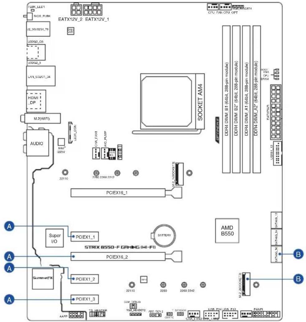
Connectors with shared bandwidth
text_image
LBR_LED1 BOS_REFK U2_3XU8251.78 U32G2_C6 U32G2_5 LAV_US2G1_34 HDMI_DP M.2(WIFI) AUDIO Intel® 222V LED_CON CHA_LVIN AIC_PLISP PCIEX16_1 22110 2280 2260 2242 M-2-1(SOCKET)# AMD B550 STRIX B550-F GRHING (HI-FI) PCIEX16_2 Super I/O PCIEX1_1 Battery PCIEX1_2 PCIEX1_3 AAFF TR_HEARER COM_DEBU8 TGE_HEADER2 ADD_GCV 2 SPECK04 CHA_FNO OPPL_EAN2 USB_ES4 USB_F12 PANFI CPU, FAN, CPU, OPT DDR4 DIMM_B1 (64bit, 288-pin module) DDR4 DIMM_B2* (64bit, 288-pin module) DDR4 DIMM_A1 (64bit, 288-pin module) DDR4 DIMM_A2* (64bit, 288-pin module) DDR4 DIMM_A3 (64bit, 288-pin module) DDR4 DIMM_A4 (64bit, 288-pin module) DDR4 DIMM_A5 (64bit, 288-pin module) DDR4 DIMM_A6 (64bit, 288-pin module) DDR4 DIMM_A7 (64bit, 288-pin module) DDR4 DIMM_A8 (64bit, 288-pin module) DDR4 DIMM_A9 (64bit, 288-pin module) DDR4 DIMM_A10 (64bit, 288-pin module) DDR4 DIMM_A11 (64bit, 288-pin module) DDR4 DIMM_A12 (64bit, 288-pin module) DDR4 DIMM_A13 (64bit, 288-pin module) DDR4 DIMM_A14 (64bit, 288-pin module) DDR4 DIMM_A15 (64bit, 288-pin module) DDR4 DIMM_A16 (64bit, 288-pin module) DDR4 DIMM_A17 (64bit, 288-pin module) DDR4 DIMM_A18 (64bit, 288-pin module) DDR4 DIMM_A19 (64bit, 288-pin module) DDR4 DIMM_A20 (64bit, 288-pin module) DDR4 DIMM_A21 (64bit, 288-pin module) DDR4 DIMM_A22 (64bit, 288-pin module) DDR4 DIMM_A23 (64bit, 288-pin module) DDR4 DIMM_A24 (64bit, 288-pin module) DDR4 DIMM_A25 (64bit, 288-pin module) DDR4 DIMM_A26 (64bit, 288-pin module) DDR4 DIMM_A27 (64bit, 288-pin module) DDR4 DIMM_A28 (64bit, 288-pin module) DDR4 DIMM_A29 (64bit, 288-pin module) DDR4 DIMM_A30 (64bit, 288-pin module) DDR4 DIMM_A31 (64bit, 288-pin module) DDR4 DIMM_A32 (64bit, 288-pin module) DDR4 DIMM_A33 (64bit, 288-pin module) DDR4 DIMM_A34 (64bit, 288-pin module) DDR4 DIMM_A35 (64bit, 288-pin module) DDR4 DIMM_A36 (64bit, 288-pin module) DDR4 DIMM_A37 (64bit, 288-pin module) DDR4 DIMM_A38 (64bit, 288-pin module) DDR4 DIMM_A39 (64bit, 288-pin module) DDR4 DIMM_A40 (64bit, 288-pin module) DDR4 DIMM_A41 (64bit, 288-pin module) DDR4 DIMM_A42 (64bit, 288-pin module) DDR4 DIMM_A43 (64bit, 288-pin module) DDR4 DIMM_A44 (64bit, 288-pin module) DDR4 DIMM_A45 (64bit, 288-pin module) DDR4 DIMM_A46 (64bit, 288-pin module) DDR4 DIMM_A47 (64bit, 288-pin module) DDR4 DIMM_A48 (64bit, 288-pin module) DDR4 DIMM_A49 (64bit, 288-pin module) DDR4 DIMM_A50 (64bit, 288-pin module) DDR4 DIMM_A51 (64bit, 288-pin module) DDR4 DIMM_A52 (64bit, 288-pin module) DDR4 DIMM_A53 (64bit, 288-pin module) DDR4 DIMM_A54 (64bit, 288-pin module) DDR4 DIMM_A55 (64bit, 288-pin module) DDR4 DIMM_A56 (64bit, 288-pin module) DDR4 DIMM_A57 (64bit, 288-pin module) DDR4 DIMM_A58 (64bit, 288-pin module) DDR4 DIMM_A59 (64bit, 288-pin module) DDR4 DIMM_A60 (64bit, 288-pin module) DDR4 DIMM_A61 (64bit, 288-pin module) DDR4 DIMM_A62 (64bit, 288-pin module) DDR4 DIMM_A63 (64bit, 288-pin module) DDR4 DIMM_A64 (64bit, 288-pin module) DDR4 DIMM_A65 (64bit, 288-pin module) DDR4 DIMM_A66 (64bit, 288-pin module) DDR4 DIMM_A67 (64bit, 288-pin module) DDR4 DIMM_A68 (64bit, 288-pin module) DDR4 DIMM_A69 (64bit, 288-pin module) DDR4 DIMM_A70 (64bit, 288-pin module) DDR4 DIMM_A71 (64bit, 288-pin module) DDR4 DIMM_A72 (64bit, 288-pin module) DDR4 DIMM_A73 (64bit, 288-pin module) DDR4 DIMM_A74 (64bit, 288-pin module) DDR4 DIMM_A75 (64bit, 288-pin module) DDR4 DIMM_A76 (64bit, 288-pin module) DDR4 DIMM_A77 (64bit, 288-pin module) DDR4 DIMM_A78 (64bit, 288-pin module) DDR4 DIMM_A79 (64bit, 288-pin module) DDR4 DIMM_A80 (64bit, 288-pin module) DDR4 DIMM_A81 (64bit, 288-pin module) DDR4 DIMM_A82 (64bit, 288-pin module) DDR4 DIMM_A83 (64bit, 288-pin module) DDR4 DIMM_A84 (64bit, 288-pin module) DDR4 DIMM_A85 (64bit, 288-pin module) DDR4 DIMM_A86 (64bit, 288-pin module) DDR4 DIMM_A87 (64bit, 288-pin module) DDR4 DIMM_A88 (64bit, 288-pin module) DDR4 DIMM_A89 (64bit, 288-pin module) DDR4 DIMM_A90 (64bit, 288-pin module) DDR4 DIMM_A91 (64bit, 288-pin module) DDR4 DIMM_A92 (64bit, 288-pin module) DDR4 DIMM_A93 (64bit, 288-pin module) DDR4 DIMM_A94 (64bit, 288-pin module) DDR4 DIMM_A95 (64bit, 288-pin module) DDR4 DIMM_A96 (64bit, 288-pin module) DDR4 DIMM_A97 (64bit, 288-pin module) DDR4 DIMM_A98 (64bit, 288-pin module) DDR4 DIMM_A99 (64bit, 288-pin module) DDR4 DIMM_A100 (65/700)# LCD_PCP_100 LCD_PCP_101 LCD_PCP_102 LCD_PCP_103 LCD_PCP_105 LCD_PCP_107 LCD_PCP_109 LCD_PCP_110 LCD_PCP_111 LCD_PCP_113 LCD_PCP_115 LCD_PCP_117 LCD_PCP_119 LCD_PCP_120 LCD_PCP_121 LCD_PCP_123 LCD_PCP_125 LCD_PCP_127 LCD_PCP_129 LCD_PCP_130 LCD_PCP_131 LCD_PCP_133 LCD_PCP_135 LCD_PCP_137 LCD_PCP_139 LCD_PCP_139 LCD_PCP_139 LCD_PCP_139 LCD_PCP_139 LCD_PCP_139 LCD_PCP_139 LCD_PCP_139 LCD_PCP_139 LCD_PCP_139 LCD_PCP_139 LCD_PCP_139 LCD_PCP_139 LCD_PCF_139 LCD_PCF_139 LCD_PCF_139 LCD_PCF_139 LCD_PCF_139 LCD_PCF_139 LCD_PCF_139 LCD_PCF_139 LCD_PCF_139 LCD_PCF_139 LCD_PCF_139 LCD_PCF_139 LCD_PCF_13| Configuration | 1 | 2 | |
| A | PCIEX16_2 x4 x1 | ||
| PCIEX1_1 - x1 | |||
| PCIEX1_2 - x1 | |||
| PCIEX1_3 - x1 | |||
| Configuration 1 2 | |||
| B | M.2_2 PCIe 3.0 x4 / SATA - | ||
| SATA6G_56 - | v | ||

- PCIEX16_2 shares bandwidth with PCIEX1_1, PCIEX1_2, and PCIEX1_3. When PCIEX16_2 runs x4 mode, PCIEX1_1, PCIEX1_2, and PCIEX1_3 will be disabled. PCIEX16_2 will run x1 mode when PCIEX1_1, PCIEX1_2, or PCIEX1_3 is occupied.
- When M.2_2 slot is populated, SATA6G_56 will be disabled.
Package contents
Check your motherboard package for the following items.
| Motherboard 1 x ROG STRIX B550-F GAMING (WI-FI) motherboard | |
| Cables | 1 x Addressable RGB extension cable4 x SATA 6Gb/s cables |
| Miscellaneous | 1 x Cable ties pack1 x M.2 Rubber Package1 x M.2 SSD screw package1 x ROG STRIX sticker1 x ROG STRIX thank you card1 x ASUS 2x2 dual band Wi-Fi moving antenna |
Installation Media 1 x Support DVD
Documentation 1 x User manual

If any of the above items is damaged or missing, contact your retailer.
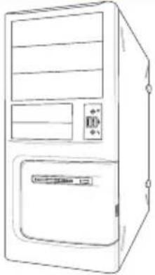
Installation tools and components
 | 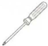 |
| Phillips (cross) screwdriver | |
 | |
| PC chassis Power supply unit | |
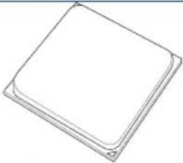 | 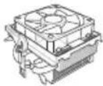 |
| AMD AM4 CPU AMD AM4/AM3 compatible CPU Fan | |
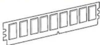 | 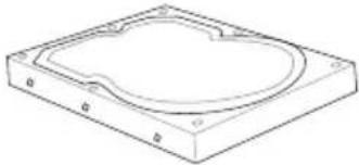 |
| DDR4 DIMM SATA hard disk drive | |
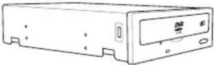 | 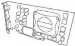 |
| SATA optical disc drive (optional) Graphics card (optional) | |
 | 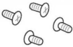 |
| M.2 SSD module (optional) 1 Bag of screws | |

The tools and components in the table above are not included in the motherboard package.
Product Introduction
1.1 Before you proceed
Take note of the following precautions before you install motherboard components or change any motherboard settings.

- Unplug the power cord from the wall socket before touching any component.
- Before handling components, use a grounded wrist strap or touch a safely grounded object or a metal object, such as the power supply case, to avoid damaging them due to static electricity.
- Hold components by the edges to avoid touching the ICs on them.
- Whenever you uninstall any component, place it on a grounded antistatic pad or in the bag that came with the component.
- Before you install or remove any component, ensure that the ATX power supply is switched off or the power cord is detached from the power supply. Failure to do so may cause severe damage to the motherboard, peripherals, or components.
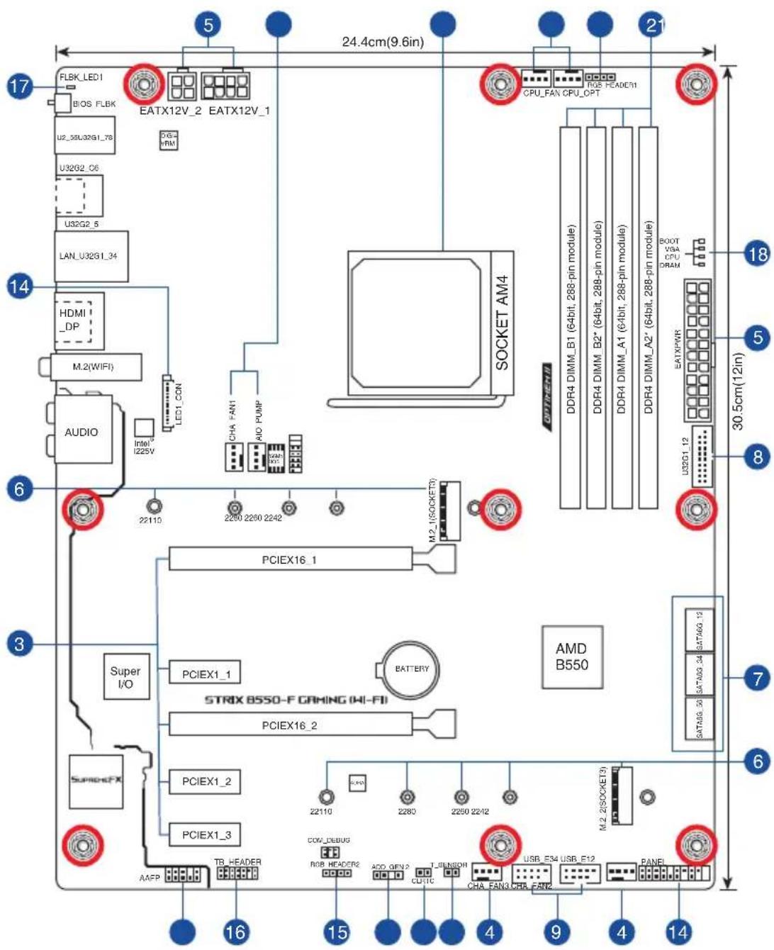
1.2 Motherboard layout
text_image
Super I/O AACP TR HEADER PCIEX1_3 PCIEX1_2 PCIEX1_1 STRIK B550-F ORING (KI-FI) PCIEX16_2 PCIEX16_1 BATTERY M2_1(SOCKET3) AUDIO M.2(WIFI) HDMI DP LAN_U32G1_24 UBX32_5 UBX32_C8 u2_24U2491_7a BIOS_FLBK LED1_CON CHA FAN1 AIO PUMP SOCKET AM4 OPTIMEN II DDR4 DIMM_B1 (64bit, 288-pin module) DDR4 DIMM_B2* (64bit, 288-pin module) DDR4 DIMM_A1 (64bit, 288-pin module) DDR4 DIMM_A2* (64bit, 288-pin module) U32G1_12 EATXPWR U32G1_36 SATA6G_34 SATA6G_12 30.5cm(12in) 3 5 17 24.4cm(9.6in) 21 6 7 8 9 10 11 12 13 14 15 16 17| Layout contents Page | |
| 1. CPU socket 1-4 | |
| 2. DIMM slots 1-5 | |
| 3. Expansion slots 1-7 | |
| 4. Fan and Pump headers 1-9 | |
| 5. Power connectors 1-10 | |
| 6. M.2 slots (SOCKET 3) 1-11 | |
| 7. SATA 6Gb/s ports 1-12 | |
| 8. USB 3.2 Gen 1 header 1-13 | |
| 9. USB 2.0 headers 1-14 | |
| 10. AURA Addressable Gen 2 header 1-15 | |
| 11. AURA RGB headers 1-16 | |
| 12. Clear CMOS header 1-17 | |
| 13. Front Panel Audio header 1-18 | |
| 14. System Panel header | 1-19 |
| 15. Thermal sensor header | 1-20 |
| 16. Thunderbolt header | 1-20 |
| 17. BIOS FlashBackTM LED | 1-21 |
| 18. Q-LED | 1-21 |
1. CPU socket
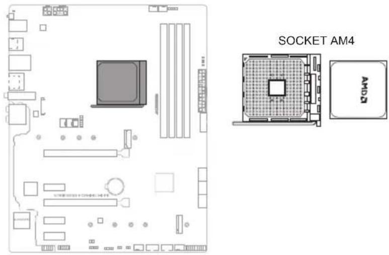
The motherboard comes with an AMD Socket AM4 designed for 3 ^rd Gen AMD Ryzen ^TM Processors.
text_image
SOCKET AM4 AM4
The AM4 socket has a different pinout design. Ensure that you use a CPU designed for the AM4 socket. The CPU fits in only one correct orientation. DO NOT force the CPU into the socket to prevent bending the connectors on the socket and damaging the CPU!

Ensure that all power cables are unplugged before installing the CPU.
2. DIMM slots
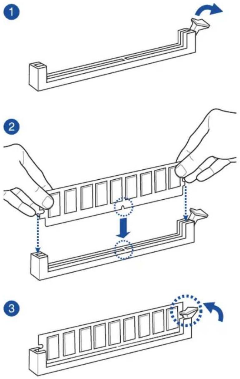
The motherboard comes with Dual Inline Memory Modules (DIMM) slots designed for DDR4 (Double Data Rate 4) memory modules.

A DDR4 memory module is notched differently from a DDR, DDR2, or DDR3 module. DO NOT install a DDR, DDR2, or DDR3 memory module to the DDR4 slot.
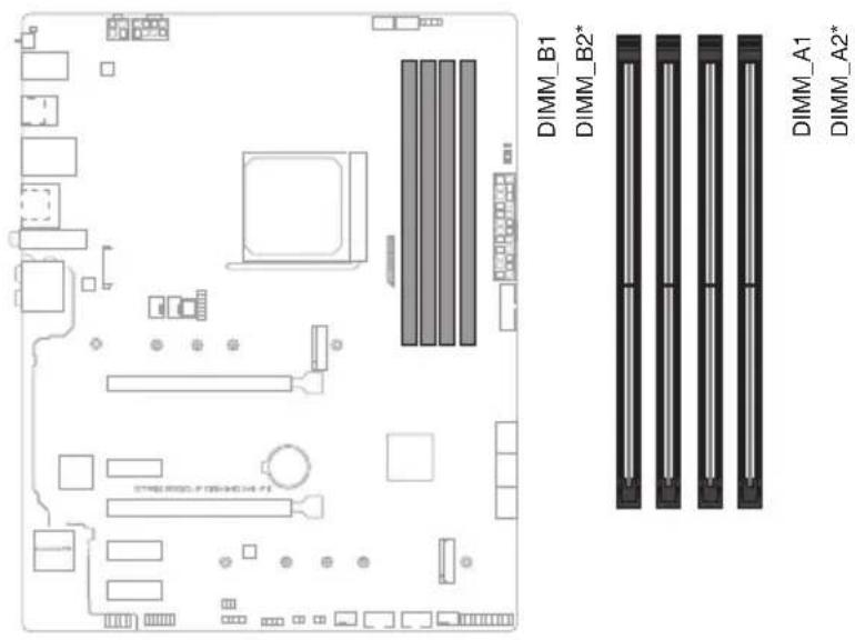
text_image
DIMM_B1 DIMM_B2* DIMM_A1 DIMM_A2*Recommended memory configurations
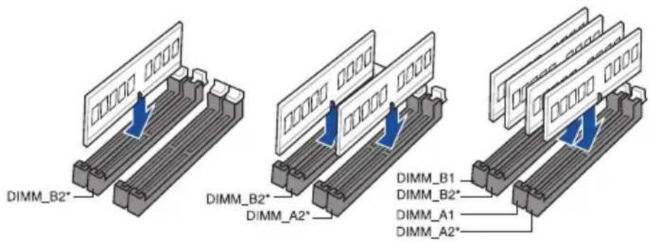
text_image
DIMM_B2* DIMM_B2* DIMM_A2* DIMM_B1 DIMM_B2* DIMM_A1 DIMM_A2*Memory configurations
You may install 4 GB, 8 GB, 16 GB, and 32 GB unbuffered ECC and non-ECC DDR4 DIMMs into the DIMM sockets.

You may install varying memory sizes in Channel A and Channel B. The system maps the total size of the lower-sized channel for the dual-channel configuration. Any excess memory from the higher-sized channel is then mapped for single-channel operation.

- The default memory operation frequency is dependent on its Serial Presence Detect (SPD), which is the standard way of accessing information from a memory module. Under the default state, some memory modules for overclocking may operate at a lower frequency than the vendor-marked value.
- For system stability, use a more efficient memory cooling system to support a full memory load or overclocking condition.
- Always install the DIMMS with the same CAS Latency. For an optimum compatibility, we recommend that you install memory modules of the same version or data code (D/C) from the same vendor. Check with the vendor to get the correct memory modules.
- Visit the ASUS website for the latest QVL.
3. Expansion slots

Unplug the power cord before adding or removing expansion cards. Failure to do so may cause you physical injury and damage motherboard components.
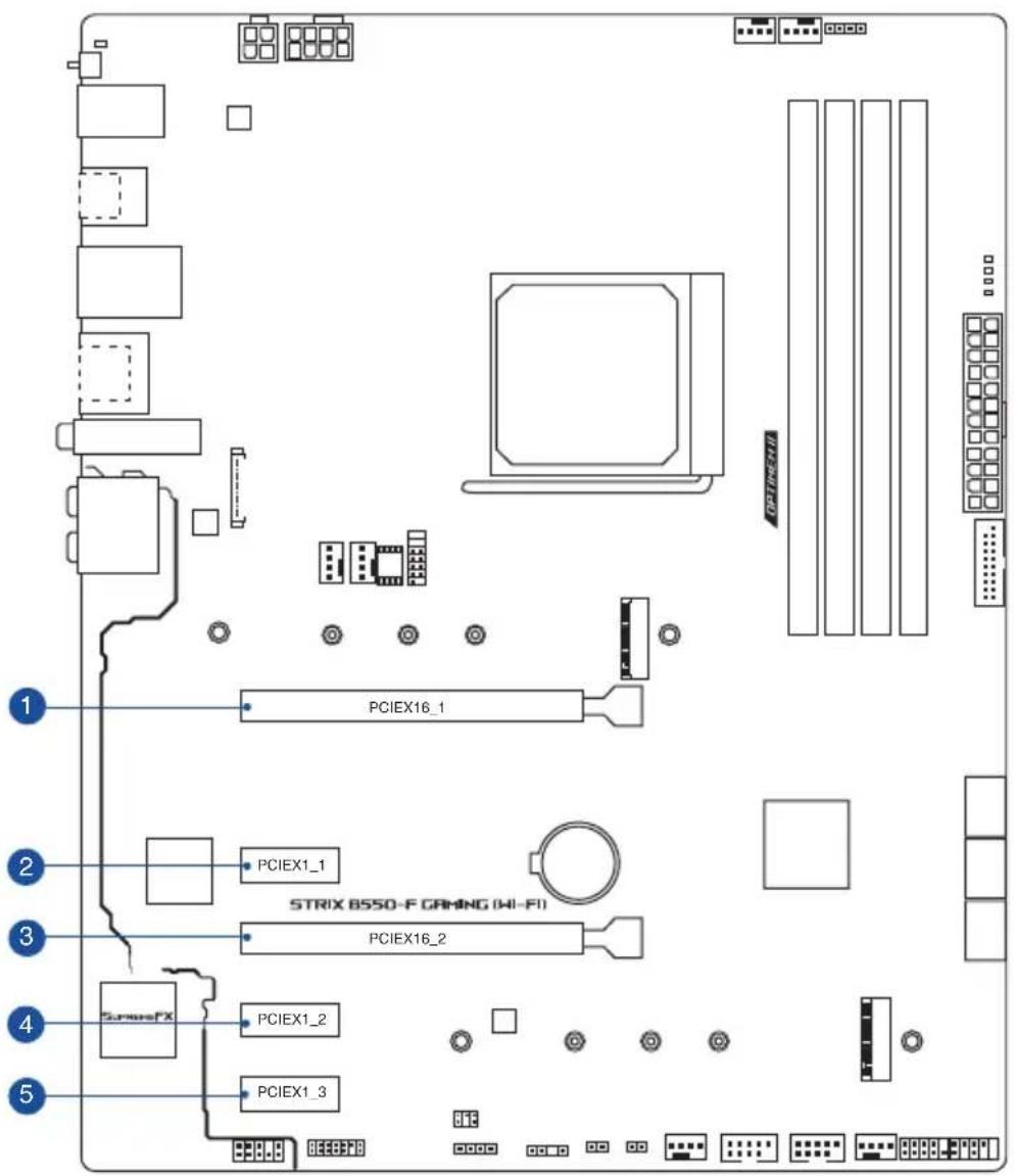
text_image
PCIEX16_1 PCIEX1_1 STRIK 8550-F GAMING (HI-FI) PCIEX16_2 PCIEX1_2 PCIEX1_3Please refer to the following table for the recommended VGA configuration.
Recommended VGA configuration
| Slot Description Single VGA Dual VGA | ||
| PCIe x16_1 x16 x16 | ||
| PCIe x16_2 | - | x4 |

- We recommend that you provide sufficient power when running CrossFireX™ mode.
- Ensure to connect the 8-pin and 4-pin power plugs when running CrossFireX™ mode.
- Connect a chassis fan to the chassis fan connectors when using multiple graphics cards for better thermal environment.
Hyper M.2 X16 series card configuration
| Slot | PCIe bifurcation settings in PCIe x16 slots with different Ryzen ^TM CPUs |
| 3 ^rd Gen AMD Ryzen ^TM Processors (Support PCIe Gen 4 SSDs) | |
| Supported SSDs | |
| PCIEX16_1 4 |

• Hyper M.2 X16 series card is purchased separately.
- When using 3 ^rd Gen AMD Ryzen ^TM Processors and a Hyper M.2 X16 series card with 4 M.2 SSDs, if you wish to connect a display, we suggest installing a VGA card to PCIe X16_2, which will run at x4.
- Set PCIEX16_1 to [PCIe RAID Mode] under BIOS settings to enable the Hyper M.2 X16 series card.
4. Fan and Pump headers
The Fan and Pump headers allow you to connect fans or pumps to cool the system.
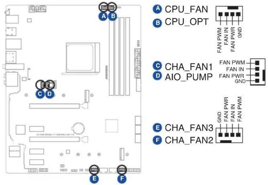
text_image
A CPU_FAN B CPU_OPT C CHA_FAN1 D AIO_PUMP E CHA_FAN3 F CHA_FAN2
- DO NOT forget to connect the fan cables to the fan headers. Insufficient air flow inside the system may damage the motherboard components. These are not jumpers! Do not place jumper caps on the fan headers!
- Ensure the cable is fully inserted into the header.

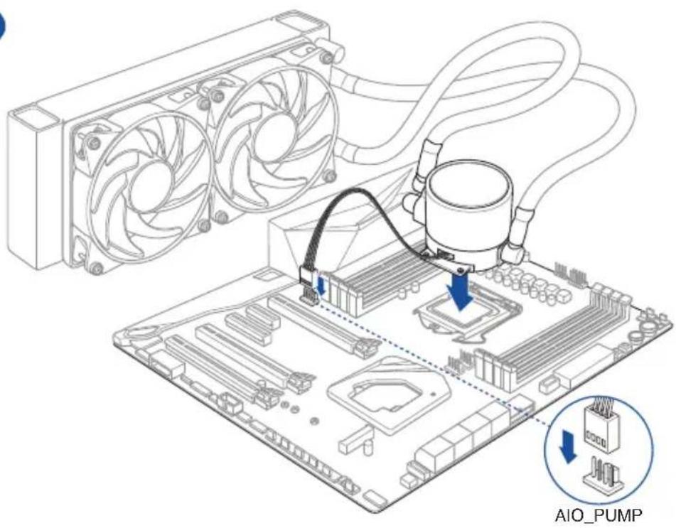
For water cooling kits, connect the pump connector to the AIO_PUMP header.
| Header Max. Current Max. Power Default Speed Shared Control | |||
| CPU_FAN 1A 12W Q-Fan Controlled A | |||
| CPU_OPT | 1A 12W Q-Fan Controlled A | ||
| CHA_FAN1 1A 12W Q-Fan Controlled - | |||
| CHA_FAN2 1A 12W Q-Fan Controlled - | |||
| CHA_FAN3 1A 12W Q-Fan Controlled - | |||
| AIO_PUMP 1A 12W Full-Speed | - | ||
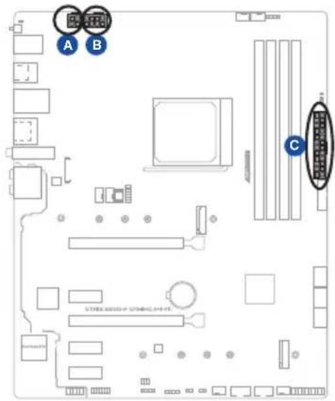
5. Power connectors
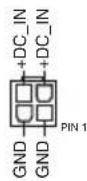
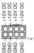
These Power connectors allow you to connect your motherboard to a power supply. The power supply plugs are designed to fit in only one orientation. Find the proper orientation and push down firmly until the power supply plugs are fully inserted.
text_image
Diagram of a computer motherboard layout with labeled components and connectorsA EATX12V_2
B EATX12V_1
C EATXPWR
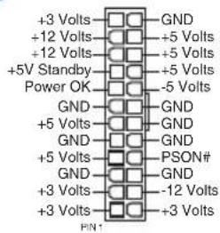
text_image
+3 Volts +12 Volts +12 Volts +5V Standby Power OK GND +5 Volts GND +5 Volts GND +3 Volts +3 Volts GND +5 Volts GND +5 Volts GND +5 Volts GND +5 Volts GND +5 Volts GND +5 Volts GND +5 Volts GND +5 Volts GND +5 Volts GND +5 Volts GND +5 Volts GND +5 Volts GND +5 Volts FEN1
- DO NOT connect the 4-pin power plug only. The motherboard may overheat under heavy usage.
- Ensure to connect the 8-pin power plug, or connect both the 8-pin and 4-pin power plugs.

- For a fully configured system, we recommend that you use a power supply unit (PSU) that complies with ATX 12V Specification 2.0 (or later version) and provides a minimum power of 350W.
- We recommend that you use a PSU with a higher power output when configuring a system with more power-consuming devices. The system may become unstable or may not boot up if the power is inadequate.
- If you want to use two or more high-end PCI Express x16 cards, use a PSU with 1000W power or above to ensure the system stability.
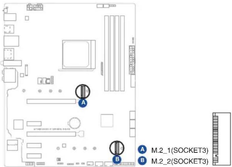
6. M.2 slots
The M.2 slots allow you to install M.2 devices such as M.2 SSD modules.
text_image
A B A M.2_1(SOCKET3) B M.2_2(SOCKET3)
- M.2_1 slot supports PCIe 4.0 x4 and SATA modes Key M design and type 2242/2260/2280/22110 storage devices.
- M.2_2 slot supports PCIe 3.0 x4 and SATA modes Key M design and type 2242/2260/2280/22110 storage devices.
- When M.2_2 slot is populated, SATA6G_5/6 will be disabled.

The M.2 SSD module is purchased separately.
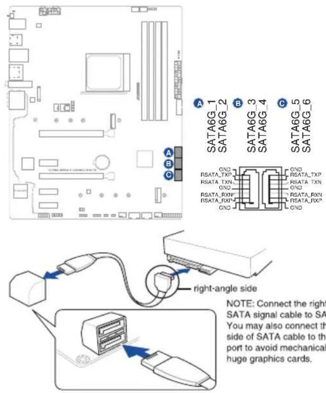
7. SATA 6Gb/s ports
The SATA 6Gb/s ports allow you to connect SATA devices such as optical disc drives and hard disk drives via a SATA cable.
text_image
A SATA6G_1 SATA6G_2 B SATA6G_3 SATA6G_4 C SATA6G_5 SATA6G_6 GND RSATA_TXP RSATA_TXN GND RSATA_RXN RSATA_RXP GND RSATA_RXN RSATA_RXP GND right-angle side NOTE: Connect the right SATA signal cable to SATA You may also connect the side of SATA cable to the port to avoid mechanical huge graphics cards.
• These connectors are set to [AHCI] by default. If you intend to create a Serial ATA RAID set using these connectors, set the SATA Mode Selection item in the BIOS to [RAID].
- Before creating a RAID set, refer to the RAID Configuration Guide. You can download the RAID Configuration Guide from the ASUS website.
- When the M.2_2 Socket 3 is populated, SATA6G_5/6 ports will be disabled.
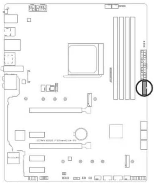
8. USB 3.2 Gen 1 header
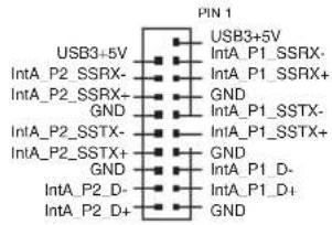
The USB 3.2 Gen 1 header allows you to connect a USB 3.2 Gen 1 module for additional USB 3.2 Gen 1 ports. The USB 3.2 Gen 1 header provides data transfer speeds of up to 5 Gb/s.
text_image
STIM 6001 P5000000 PCU32G1_12
text_image
PIN 1 USB3+5V IntA_P2_SSRX- IntA_P2_SSRX+ GND IntA_P2_SSTX- IntA_P2_SSTX+ GND IntA_P2_D- IntA_P2_D+ GND USB3+5V IntA_P1_SSRX- IntA_P1_SSRX+ GND IntA_P1_SSTX- IntA_P1_SSTX+ GND IntA_P1_D- IntA_P1_D+
The USB 3.2 Gen 1 module is purchased separately.
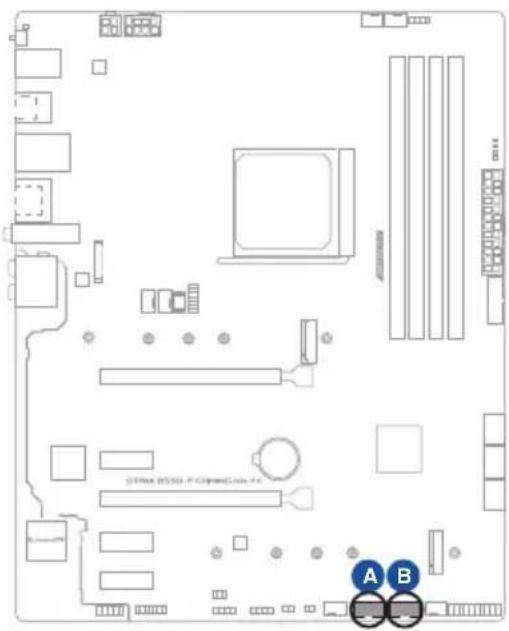
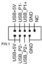
9. USB 2.0 headers
The USB 2.0 headers allow you to connect a USB module for additional USB 2.0 ports. The USB 2.0 headers provide data transfer speeds of up to 480 Mb/s.
text_image
STMicro BSSD - P C1000000000 A BA USB_E34
B USB_E12
text_image
USB+5V USB_P1- USB_P1+ GND NC PIN 1 USB+5V USB_P2- USB_P2+ GND
DO NOT connect a 1394 cable to the USB connectors. Doing so will damage the motherboard!

The USB 2.0 module is purchased separately.
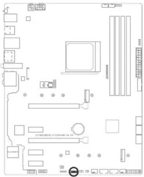
10. AURA Addressable Gen 2 header
The Addressable Gen 2 header allows you to connect individually addressable RGB WS2812B LED strips or WS2812B based LED strips.
text_image
STRAWBELL FORING 34 N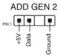

The Addressable Gen 2 header supports WS2812B addressable RGB LED strips (5V/ Data/Ground), with a maximum power rating of 3A (5V) and the addressable header on this board can handle a combined maximum of 500 LEDs.

Before you install or remove any component, ensure that the power supply is switched off or the power cord is detached from the power supply. Failure to do so may cause severe damage to the motherboard, peripherals, or components.

• Actual lighting and color will vary with LED strip.
- If your LED strip does not light up, check if the addressable RGB LED strip is connected in the correct orientation, and the 5V connector is aligned with the 5V header on the motherboard.
- The addressable RGB LED strip will only light up when the system is powered on.
- The addressable RGB LED strip is purchased separately.
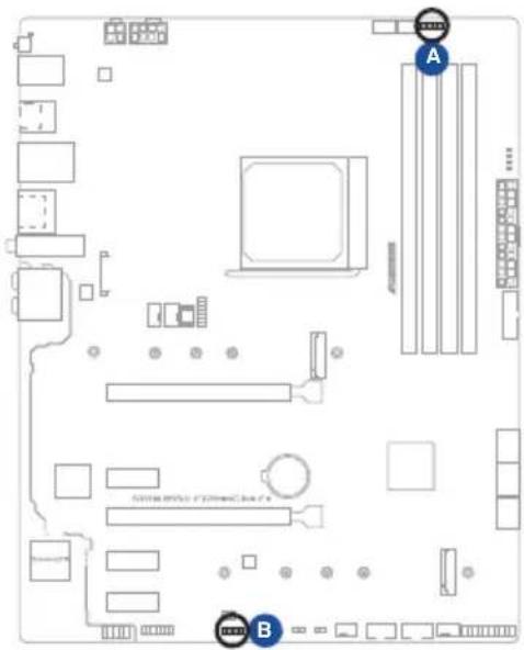
11. AURA RGB headers
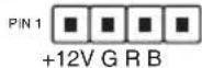
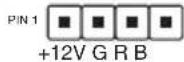
The RGB headers allow you to connect RGB LED strips.
text_image
Diagram of a computer motherboard layout with labeled components A and B, showing circuit board, RAM slots, and connectors.
RGB_HEADER1

RGB_HEADER2
natural_image
Pure electrical circuit lines without any symbols
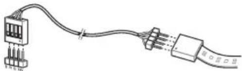
The RGB headers support 5050 RGB multi-color LED strips (12V/G/R/B), with a maximum power rating of 3A (12V).

Before you install or remove any component, ensure that the power supply is switched off or the power cord is detached from the power supply. Failure to do so may cause severe damage to the motherboard, peripherals, or components.

- Actual lighting and color will vary with LED strip.
- If your LED strip does not light up, check if the RGB LED extension cable and the RGB LED strip is connected in the correct orientation, and the 12V connector is aligned with the 12V header on the motherboard.
- The LED strip will only light up when the system is powered on.
• The LED strip is purchased separately.
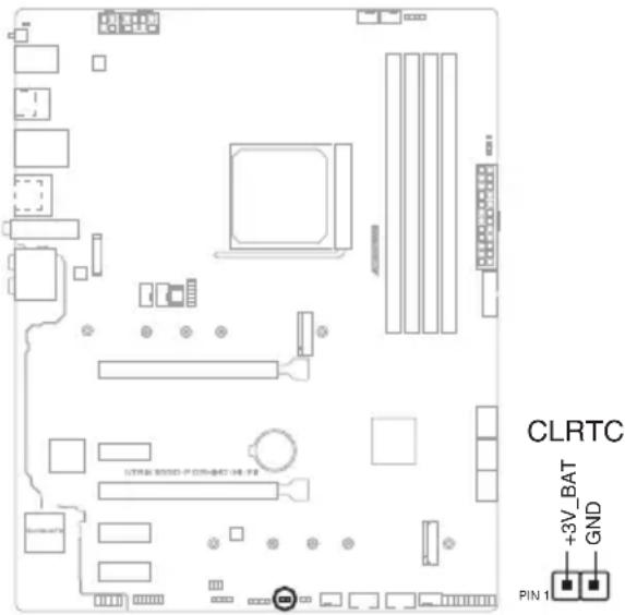
12. Clear CMOS header
This header allows you to clear the Real Time Clock (RTC) RAM in CMOS. You can clear the CMOS memory of date, time, and system setup parameters by erasing the CMOS RTC RAM data. The onboard button cell battery powers the RAM data in CMOS, which include system setup information such as system passwords.
text_image
CLRTC +3V_BAT GND PIN 1To erase the RTC RAM:
- Turn OFF the computer and unplug the power cord.
- Use a metal object such as a screwdriver to short the two pins.
- Plug the power cord and turn on the computer.
- Hold down the
key during the boot process and enter BIOS setup to re-enter data.

DO NOT short-circuit the pins except when clearing the RTC RAM. Short-circuiting or placing a jumper cap will cause system boot failure!

If the steps above do not help, remove the onboard battery and short the two pins again to clear the CMOS RTC RAM data. After clearing the CMOS, reinstall the battery.
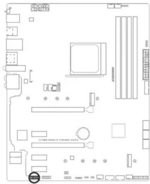
13. Front Panel Audio header
The front panel audio header is for a chassis-mounted front panel audio I/O module that supports HD Audio. Connect one end of the front panel audio I/O module cable to this header.
text_image
Diagram of a computer motherboard layout with labeled components and connectors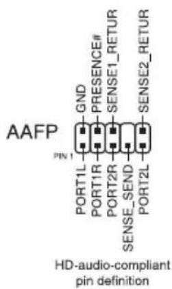
text_image
AAFP GND PRESENCE# SENSE1_RETUR PIN 1 PORT1L PORT1R PORT2R SENSE_SEND SENSE2_RETUR PORT2L HD-audio-compliant pin definition
We recommend that you connect a high-definition front panel audio module to this connector to avail of the motherboard's high-definition audio capability.
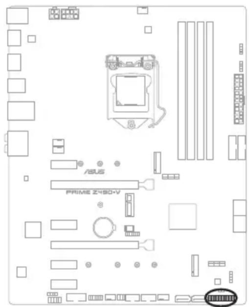
14. System Panel header
The System Panel header supports several chassis-mounted functions.
text_image
/USB PRIME 2480+V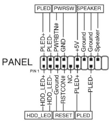
text_image
PANEL PIN 1 PLED+ PWRSW SPEAKER +5V Ground Ground Speaker HDD_LED+ Ground RSTCON# NC PLED+ HDD_LED- Ground RSTCON# NC PLED- RESET PLED• System power LED (2-pin PLED)
This 2-pin header is for the system power LED. Connect the chassis power LED cable to this header. The system power LED lights up when you turn on the system power, and blinks when the system is in sleep mode.
- Hard disk drive activity LED (2-pin HDD\_LED)
This 2-pin header is for the HDD Activity LED. Connect the HDD Activity LED cable to this header. The HDD LED lights up or flashes when data is read from or written to the HDD.
- System warning speaker (4-pin SPEAKER)
This 4-pin header is for the chassis-mounted system warning speaker. The speaker allows you to hear system beeps and warnings.
- ATX power button/soft-off button (2-pin PWRSW)
This header is for the system power button. Pressing the power button turns the system on or puts the system in sleep or soft-off mode depending on the operating system settings. Pressing the power switch for more than four seconds while the system is ON turns the system OFF.
- Reset button (2-pin RESET)
This 2-pin header is for the chassis-mounted reset button for system reboot without turning off the system power.
15. Thermal Sensor header
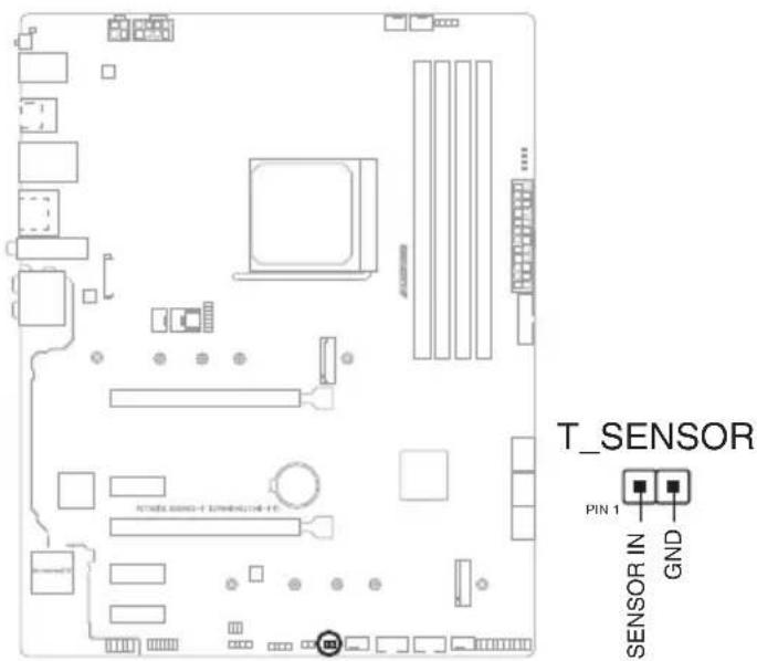
The Thermal Sensor header allows you to connect a sensor to monitor the temperature of the devices and the critical components inside the motherboard. Connect the thermal sensor and place it on the device or the motherboard's component to detect its temperature.
text_image
T_SENSOR PIN 1 SENSOR IN GND
The thermal sensor is purchased separately.
16. Thunderbolt header
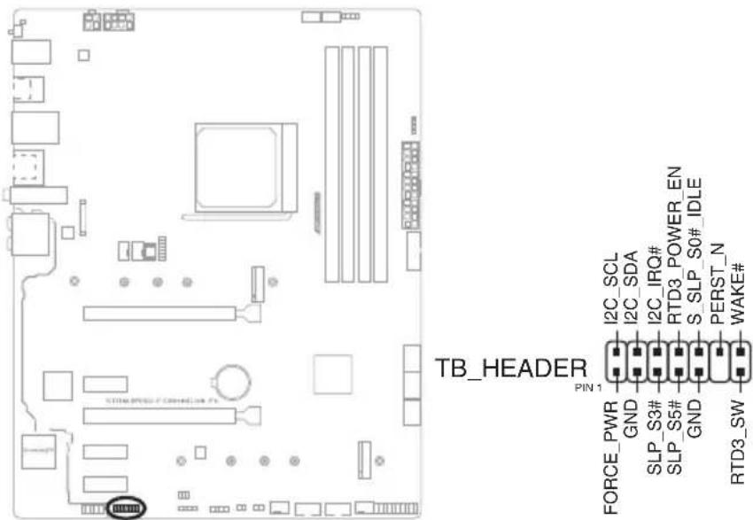
The Thunderbolt header allows you to connect an add-on Thunderbolt I/O card that supports Intel's Thunderbolt Technology, allowing you to connect up to six Thunderbolt-enabled devices and a DisplayPort-enabled display in a daisy-chain configuration.
text_image
TB_HEADER PIN 1 I2C_SCL I2C_SDA I2C_IRQ# RTD3_POWER_EN S_SLP_S0# IDLE PERST_N GND SLP_S3# SLP_S5# GND RTD3_SW WAKE#
The add-on Thunderbolt I/O card and Thunderbolt cables are purchased separately.
17. BIOS FlashBack™ LED
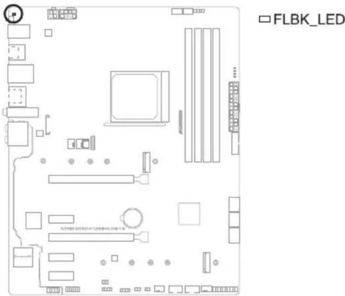
The FlashBack™ LED lights up or blinks to indicate the status of the BIOS FlashBack™.
text_image
FLBK_LED18. Q-LEDs
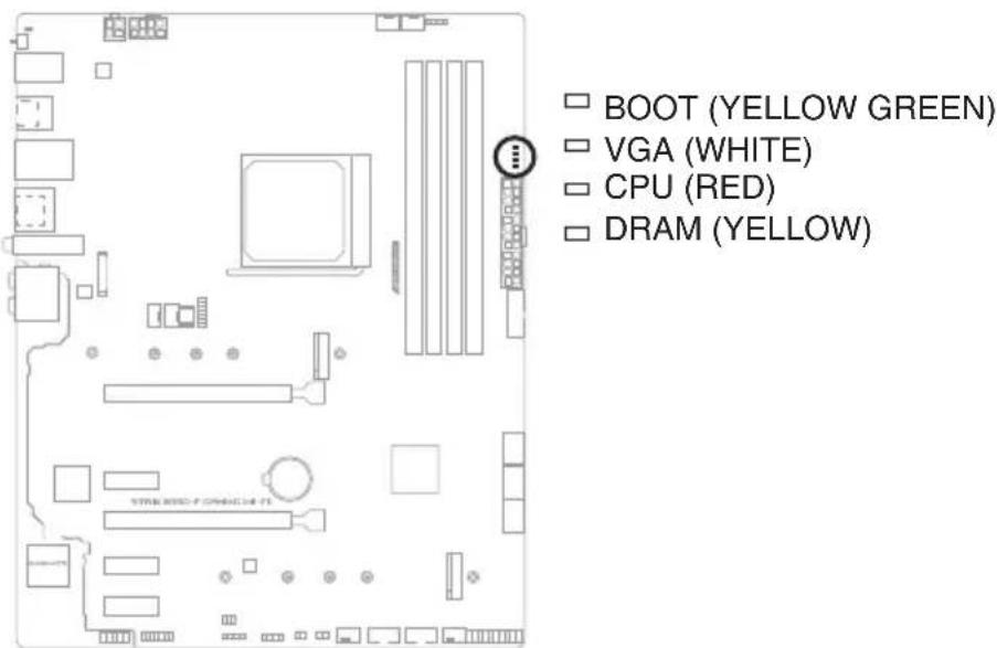
The Q-LEDs check key components (CPU, DRAM, VGA, and booting devices) during the motherboard booting process. If an error is found, the critical component's LED stays lit up until the problem is solved.
text_image
BOOT (YELLOW GREEN) VGA (WHITE) CPU (RED) DRAM (YELLOW)
The Q-LEDs provide the most probable cause of an error code as a starting point for troubleshooting. The actual cause may vary from case to case.
Basic Installation
2
2.1 Building your PC system

The diagrams in this section are for reference only. The motherboard layout may vary with models, but the installation steps are the same for all models.
2.1.1 CPU installation

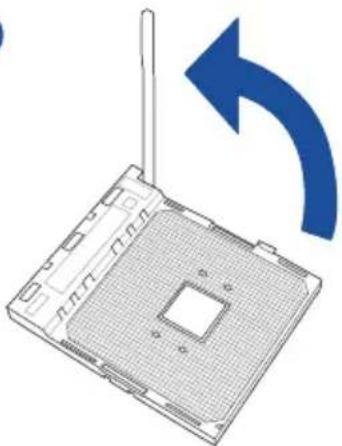
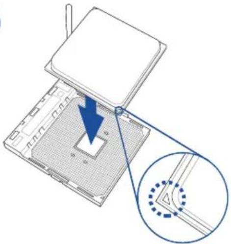
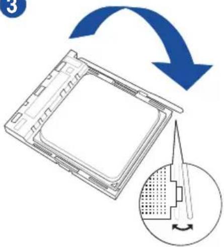
- The AMD AM4 socket is compatible with AMD AM4 processors. Ensure you use a CPU designed for the AM4 socket. The CPU fits in only one correct orientation. DO NOT force the CPU into the socket to prevent bending the connectors on the socket and damaging the CPU!
- ASUS will not cover damages resulting from incorrect CPU installation/removal, incorrect CPU orientation/placement, or other damages resulting from negligence by the user.

natural_image
3D diagram of a computer processor with a blue arrow indicating rotation (no text or symbols)
natural_image
Diagram of a device with a blue arrow pointing to a component, showing internal structure and a magnified inset (no text or symbols)
text_image
Diagram illustrating a mechanical or electronic component with an arrow indicating rotation and a magnified inset showing a tool interacting with a textured surface.2.1.2 Cooling system installation

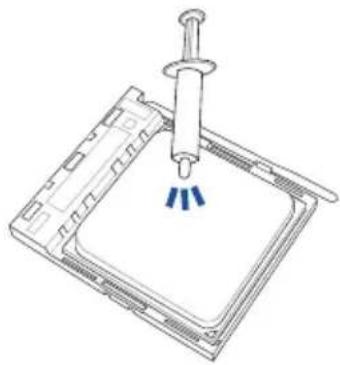
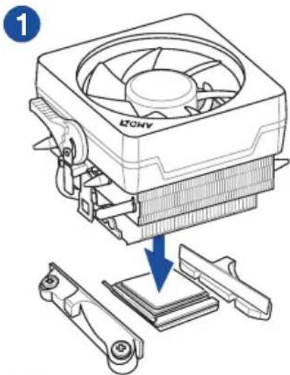
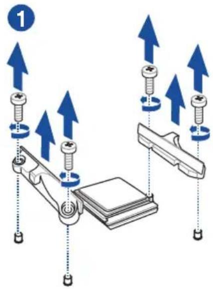
Apply the Thermal Interface Material to the CPU heatsink and CPU before you install the heatsink and fan if necessary.
natural_image
Technical line drawing of a mechanical assembly with a central component and three blue pins (no text or symbols)CPU Heatsink and fan assembly Type 1
text_image
1 ANOZ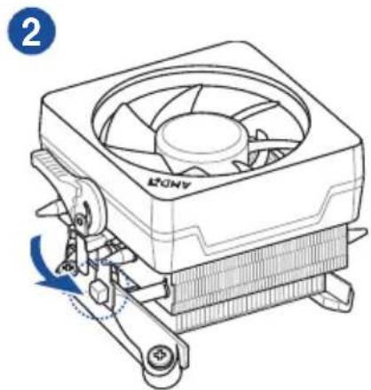
natural_image
Line drawing of a CPU cooler with cooling fan and heatsink (no text or symbols)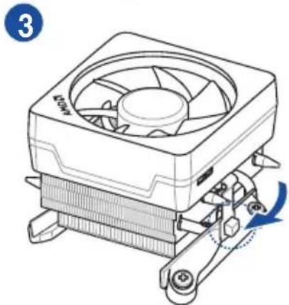
natural_image
Line drawing of a CPU cooler with fan and cooling mechanism (no text or symbols)
natural_image
Technical line drawing of a CPU fan with cooling mechanism, no text or symbols present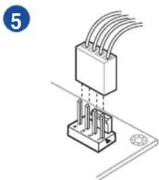
natural_image
Isometric illustration of a mechanical component with wires and pins, no text or symbols presentCPU Heatsink and fan assembly Type 2
text_image
1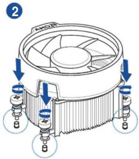
text_image
AKD8 2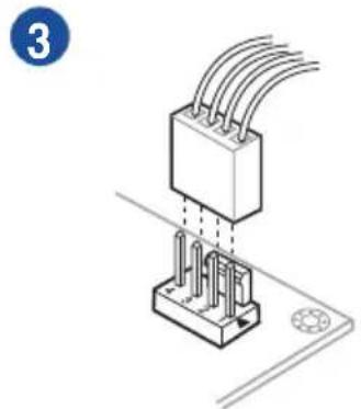
natural_image
Isometric illustration of a mechanical assembly with three parallel wires inserted into a housing (no text or symbols)
When using this type of CPU fan, remove the screws and the retention module only. Do not remove the plate on the bottom.
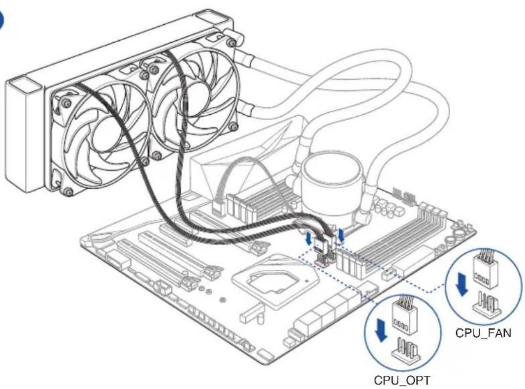
To install an AIO cooler

If you wish to install an AIO cooler, we recommend installing the AIO cooler after installing the motherboard into the chassis.
1
text_image
AIO_PUMP2
text_image
CPU_FAN CPU_OPT2.1.3 DIMM installation
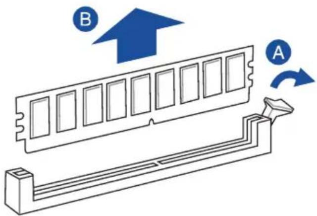
To remove a DIMM
natural_image
Technical illustration of a mechanical component with labeled parts A and B, showing internal structure and motion indicators (no text or symbols beyond labels)2.1.4 M.2 installation
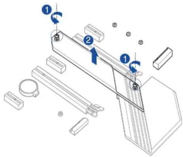
text_image
Technical diagram showing mechanical assembly with labeled components and directional arrows indicating motion or movement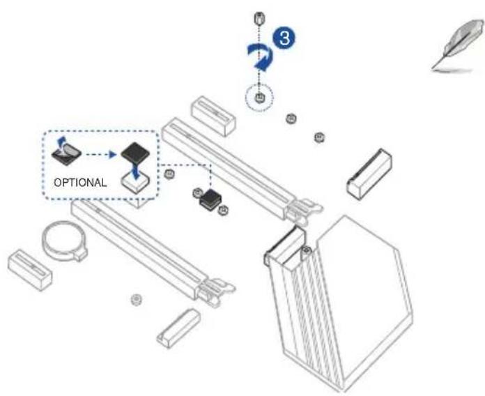
text_image
OPTIONAL 3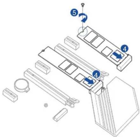
text_image
Technical diagram showing exploded view of a mechanical assembly with numbered components and directional arrows indicating motion or assembly steps.- The M.2 rubber pad is optional for when installing a single sided M.2 storage device. Ensure to install the bundled M.2 rubber pad before installing your single sided M.2 storage device.
- DO NOT install the bundled M.2 rubber pads when installing a double-sided M.2 storage device. The rubber pad installed by default is compatible with double sided M.2 storage devices.
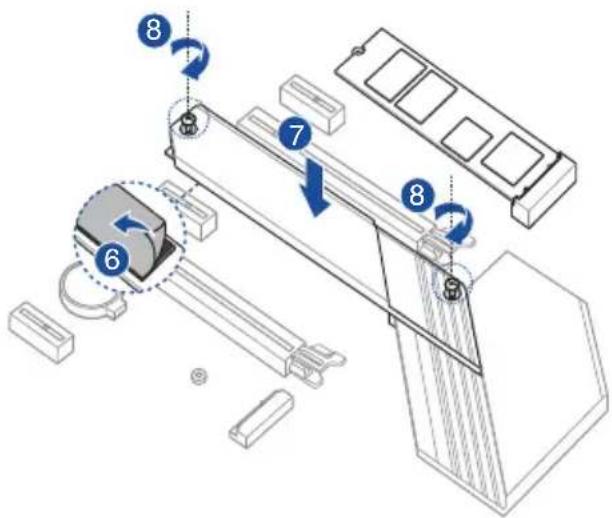
text_image
Technical diagram of a mechanical assembly with numbered components and directional arrows indicating motion or assembly steps.
The M.2 is purchased separately.
2.1.5 Motherboard installation
- Place the motherboard into the chassis, ensuring that its rear I/O ports are aligned to the chassis' rear I/O panel.

natural_image
Diagram of a computer motherboard showing CPU socket, fan, and drive mechanism (no text or labels)- Place nine (9) screws into the holes indicated by circles to secure the motherboard to the chassis.
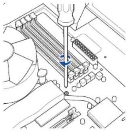
natural_image
Technical line drawing of a mechanical assembly with a screwdriver inserted, showing internal components and no visible text or symbols.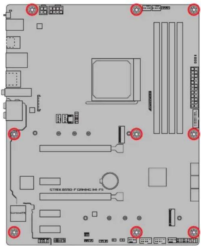
text_image
STRIX BSSO-F CABBING (M-H-F)
DO NOT over tighten the screws! Doing so can damage the motherboard.
2.1.6 ATX power connection
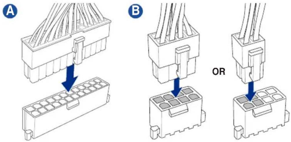

Ensure to connect the 8-pin or 4-pin power plug.
2.1.7 SATA device connection
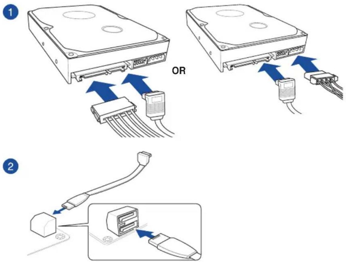
2.1.8 Front I/O connector To install front panel connector
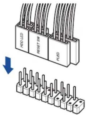
text_image
H00 LED RESET SW PLEDTo install front panel audio connector
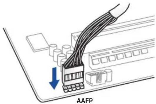
text_image
AAFPTo install USB 3.2 Gen 1 connector
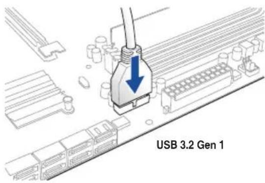
text_image
USB 3.2 Gen 1To install USB 2.0 connector
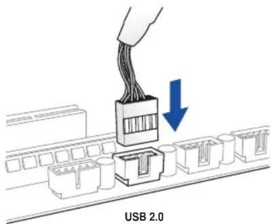
text_image
USB 2.0
This connector will only fit in one orientation. Push the connector until it clicks into place.
2.1.9 Expansion card installation To install PCIe x16 cards
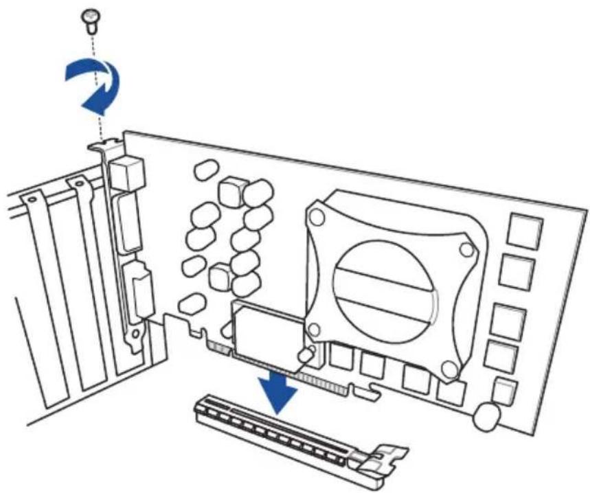
natural_image
Technical diagram of a computer monitor internal structure showing drive, scroll, and control panel (no text or labels)To install PCIe x1 cards
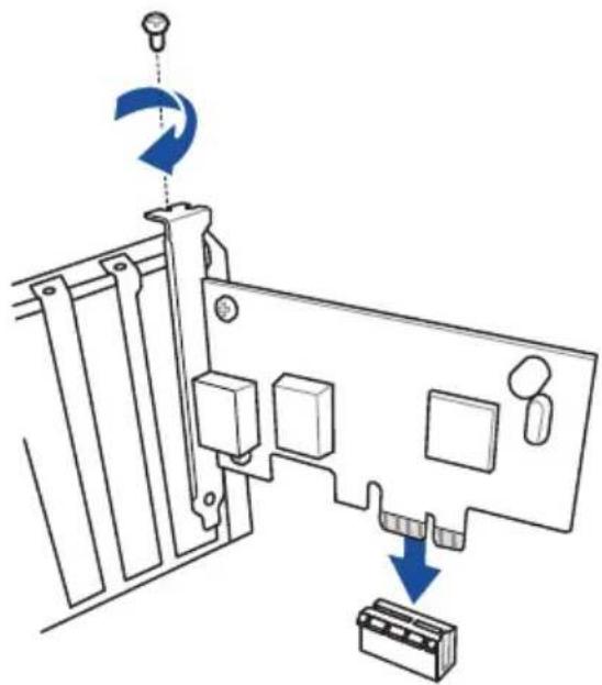
natural_image
Diagram of a computer monitor with labeled ports and directional arrows indicating rotation (no text or symbols present)2.2 BIOS update utility
BIOS FlashBack™
BIOS FlashBack™ allows you to easily update the BIOS without entering the existing BIOS or operating system. Simply insert a USB storage device to the USB port (the USB port hole is marked on the I/O shield) then press the BIOS FlashBack™ button for three seconds to automatically update the BIOS.
To use BIOS FlashBack™:
- Insert a USB storage device to the BIOS FlashBack™ port.

We recommend you to use a USB 2.0 storage device to save the latest BIOS version for better compatibility and stability.
-
Visit https://www.asus.com/support/ and download the latest BIOS version for this motherboard.
-
Manually rename the file as RB550FGW.CAP, or launch the BIOSRenamer.exe application to automatically rename the file, then copy it to your USB storage device.

The BIOSRenamer.exe application is zipped together with your BIOS file when you download a BIOS file for a BIOS FlashBack™ compatible motherboard.
- Shut down your computer.
- Press the BIOS FlashBack™ button for three seconds until the BIOS FlashBack™ LED blinks three times, indicating that the BIOS FlashBack™ function is enabled.
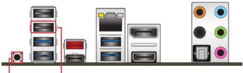
natural_image
Diagram of server rack and front panel layout with no visible text or symbolsBIOS FlashBack™ button BIOS FlashBack™ port
- Wait until the light goes out, indicating that the BIOS updating process is completed.

For more BIOS update utilities in BIOS setup, refer to the section Updating BIOS in Chapter 3.

- Do not unplug portable disk, power system, or short the CLRTC header while BIOS update is ongoing, otherwise update will be interrupted. In case of interruption, please follow the steps again.
- If the light flashes for five seconds and turns into a solid light, this means that the BIOS FlashBack™ is not operating properly. This may be caused by improper installation of the USB storage device and filename/file format error. If this scenario happens, please restart the system to turn off the light.
- Updating BIOS may have risks. If the BIOS program is damaged during the process and results to the system's failure to boot up, please contact your local ASUS Service Center.
2.3 Motherboard rear and audio connections
2.3.1 Rear I/O connection
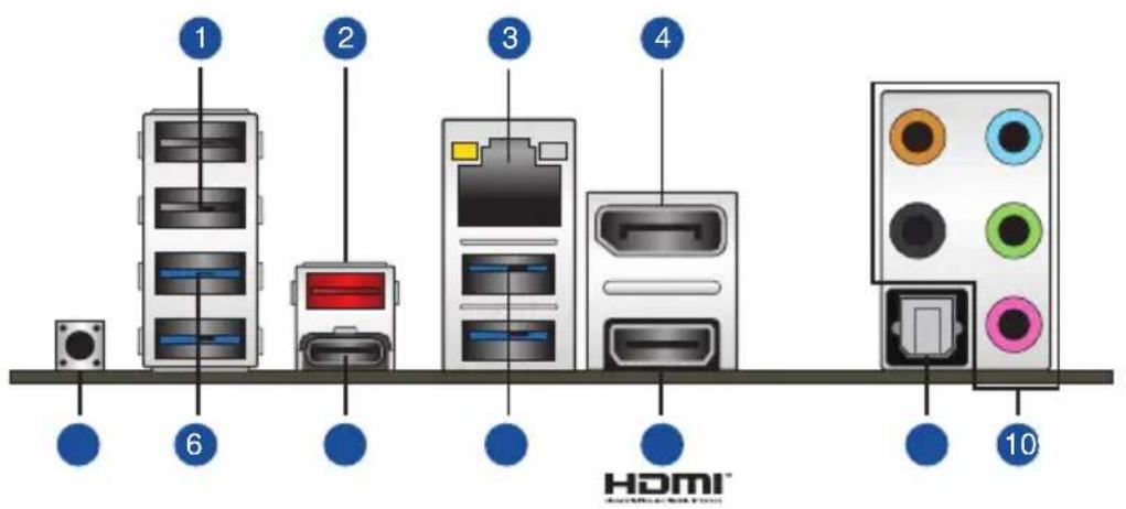
text_image
1 2 3 4 6 HDMI™ 10Rear panel connectors
| 1. USB 2.0 ports 5 and 6 |
| 2. USB 3.2 Gen 2 Type-A port 5 |
| 3. Intel ® I225-V 2.5Gb Ethernet port* |
| 4. DisplayPort |
| 5. BIOS FlashBackTM button |
| 6. USB 3.2 Gen 1 Type-A ports 3, 4, 7 and 8 |
| 7. USB 3.2 Gen 2 Type-C ® port C6 |
| 8. HDMITM port |
| 9. Optical S/PDIF Out port |
| 10. Audio jacks** |
* and ** : Refer to the tables on the next page for LAN port LEDs, and audio port definitions.

We strongly recommend that you connect your devices to ports with matching data transfer rate. Please connect your USB 3.2 Gen 1 devices to USB 3.2 Gen 1 ports and your USB 3.2 Gen 2 devices to USB 3.2 Gen 2 ports for faster and better performance for your devices.
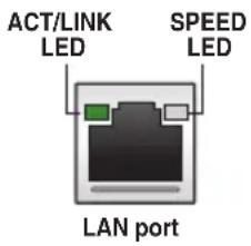
* Intel® I225-V 2.5Gb Ethernet port LED indications
| Activity Link LED Speed LED | |||
| Status | Description | Status | Description |
| OFF | No link | OFF | 100 Mbps connection |
| GREEN | Linked GREEN | 2.5 Gbps connection | |
| BLINKING | Data activity ORANGE | 1 Gbps / 100 Mbps / 10 Mbps connection | |
text_image
ACT/LINK LED SPEED LED LAN port** Audio 2, 4, 5.1 or 7.1-channel configuration
| Port | Headset 2-channel | 4-channel 5.1-channel | 7.1-channel | |
| Light Blue | Line In Line In Line | In Side Speaker Out | ||
| Lime Line | Out Front Speaker | Out Front Speaker | Out Front Speaker | Out |
| Pink Mic | In Mic In Mic In | Mic In | ||
| Orange – – | Center/Sub | woofer | Center/Sub woofer | |
| Black | – | Rear Speaker Out | Rear Speaker Out | Rear Speaker Out |
2.3.2 Audio I/O connections
Audio I/O ports

text_image
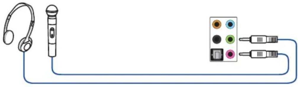
orange light blue black lime pinkConnect to Headphone and Mic
natural_image
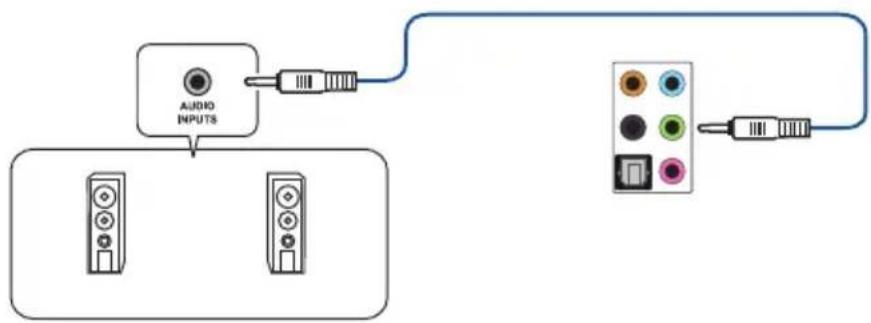
Diagram showing audio recording setup with headphones, a microphone, and a connected audio jack (no text or labels)Connect to Stereo Speakers
flowchart
graph TD
    A["Audio INPUTS"] --> B["Display Unit 1"]
    A --> C["Display Unit 2"]
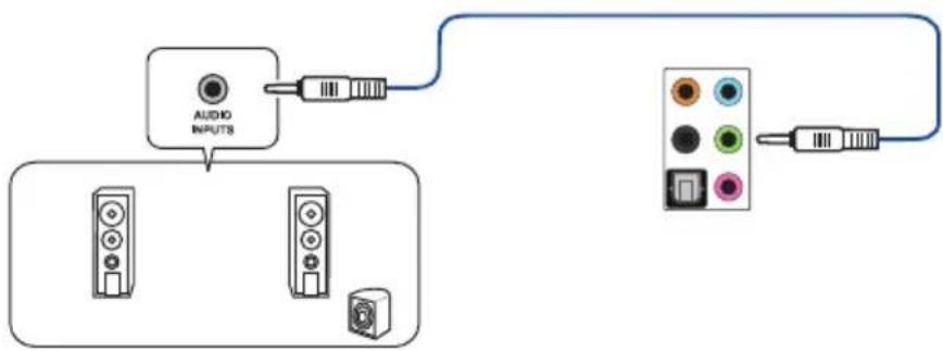
Connect to 2-channel Speakers
flowchart
graph TD
    A["Audio Inputs"] --> B["Device 1"]
    A --> C["Device 2"]
    A --> D["Device 3"]
    A --> E["Device 4"]
    B --> F["Switch"]
    C --> G["Switch"]
    D --> H["Switch"]
    E --> I["Switch"]
Connect to 4-channel Speakers
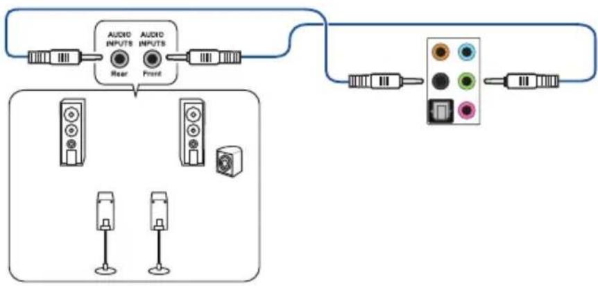
flowchart
graph TD
    A["Audio Inputs"] --> B["Rear"]
    C["Audio Inputs"] --> D["Front"]
    B --> E["Output"]
    D --> E
    F["Resistors"] --> G["Resistors"]
    H["Resistors"] --> I["Resistors"]
    J["Resistors"] --> K["Resistors"]
Connect to 5.1-channel Speakers
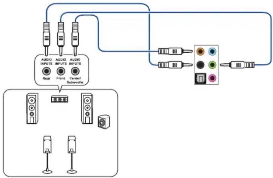
flowchart
graph TD
    A["Audio Inputs"] --> B["Rear"]
    A --> C["Front"]
    A --> D["Center Subwoofer"]
    E["Audio Inputs"] --> F["Central Subwoofer"]
    G["Display Unit"] --> H["Top 10"]
    I["Display Unit"] --> J["Bottom 10"]
Connect to 7.1-channel Speakers
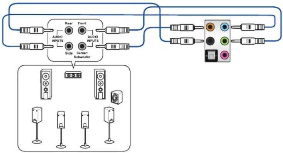
flowchart
graph TD
    A["Input"] --> B["AUDIO INPUTS"]
    B --> C["Rear"]
    B --> D["Front"]
    B --> E["Side"]
    B --> F["Center"]
    B --> G["Subwoofer"]
    H["Display Unit"] --> I["Speaker 1"]
    H --> J["Speaker 2"]
    H --> K["Speaker 3"]
    H --> L["Speaker 4"]
2.4 Starting up for the first time
- After making all the connections, replace the system case cover.
- Ensure that all switches are off.
- Connect the power cord to the power connector at the back of the system chassis.
- Connect the power cord to a power outlet that is equipped with a surge protector.
- Turn on the devices in the following order:
a. Monitor
b. External storage devices (starting with the last device on the chain)
c. System power
- After applying power, the system power LED on the system front panel case lights up. For systems with ATX power supplies, the system LED lights up when you press the ATX power button. If your monitor complies with the "green" standards or if it has a "power standby" feature, the monitor LED may light up or change from orange to green after the system LED turns on.
The system then runs the power-on self tests (POST). While the tests are running, the BIOS beeps (refer to the BIOS beep codes table) or additional messages appear on the screen. If you do not see anything within 30 seconds from the time you turned on the power, the system may have failed a power-on test. Check the jumper settings and connections or call your retailer for assistance.
| BIOS Beep Description | |
| One short beep | VGA detectedQuick boot set to disabledNo keyboard detected |
| One continuous beep followed by two short beeps then a pause (repeated) | No memory detected |
| One continuous beep followed by three short beeps | No VGA detected |
| One continuous beep followed by four short beeps | Hardware component failure |
- At power on, hold down the
key to enter the BIOS Setup. Follow the instructions in Chapter 3.
2.5 Turning off the computer
While the system is ON, press the power button for less than four seconds to put the system on sleep mode or soft-off mode, depending on the BIOS setting. Press the power button for more than four seconds to let the system enter the soft-off mode regardless of the BIOS setting.
BIOS and RAID Support

For more details on BIOS and RAID configurations, please refer to www.asus.com/support.
3.1 Knowing BIOS

The new ASUS UEFI BIOS is a Unified Extensible Interface that complies with UEFI architecture, offering a user-friendly interface that goes beyond the traditional keyboard-only BIOS controls to enable a more flexible and convenient mouse input. You can easily navigate the new UEFI BIOS with the same smoothness as your operating system. The term "BIOS" in this user manual refers to "UEFI BIOS" unless otherwise specified.
BIOS (Basic Input and Output System) stores system hardware settings such as storage device configuration, overclocking settings, advanced power management, and boot device configuration that are needed for system startup in the motherboard CMOS. In normal circumstances, the default BIOS settings apply to most conditions to ensure optimal performance. DO NOT change the default BIOS settings except in the following circumstances:
- An error message appears on the screen during the system bootup and requests you to run the BIOS Setup.
- You have installed a new system component that requires further BIOS settings or update.

Inappropriate BIOS settings may result to instability or boot failure. We strongly recommend that you change the BIOS settings only with the help of a trained service personnel.

- When downloading or updating the BIOS file, rename it as RB550FGW.CAP for this motherboard.
- BIOS settings and options may vary due to different BIOS release versions. Please refer to the latest BIOS version for settings and options.
3.2 BIOS setup program
Use the BIOS Setup to update the BIOS or configure its parameters. The BIOS screen includes navigation keys and brief onscreen help to guide you in using the BIOS Setup program.
Entering BIOS at startup
To enter BIOS Setup at startup, press
Entering BIOS Setup after POST
To enter BIOS Setup after POST:
- Press
+ + simultaneously. - Press the reset button on the system chassis.
- Press the power button to turn the system off then back on. Do this option only if you failed to enter BIOS Setup using the first two options.
After doing either of the three options, press

- Ensure that a USB mouse is connected to your motherboard if you want to use the mouse to control the BIOS setup program.
- If the system becomes unstable after changing any BIOS setting, load the default settings to ensure system compatibility and stability. Select the Load Optimized Defaults item under the Exit menu or press hotkey
. - If the system fails to boot after changing any BIOS setting, try to clear the CMOS and reset the motherboard to the default value.
- The BIOS setup program does not support Bluetooth devices.
BIOS menu screen
The BIOS Setup program can be used under two modes: EZ Mode and Advanced Mode. You can change modes from Setup Mode in Boot menu or by pressing the
3.3 EZ Update
The EZ Update is a utility that allows you to update the motherboard BIOS in Windows® environment.

- EZ Update requires an Internet connection either through a network or an ISP (Internet Service Provider).
- This utility is available in the support DVD that comes with the motherboard package.
3.4 ASUS EZ Flash 3
The ASUS EZ Flash 3 feature allows you to update the BIOS without using an OS-based utility.

Ensure to load the BIOS default settings to ensure system compatibility and stability. Select the Load Optimized Defaults item under the Exit menu or press hotkey
To update the BIOS:

- This function can support devices such as a USB flash disk with FAT 32/16 format and single partition only.
-
DO NOT shut down or reset the system while updating the BIOS to prevent system boot failure!
-
Insert the USB flash disk that contains the latest BIOS file to the USB port.
- Enter the Advanced Mode of the BIOS setup program. Go to the Tool menu to select ASUS EZ Flash 3 Utility and press
. - Press
to switch to the Drive field. - Press the Up/Down arrow keys to find the USB flash disk that contains the latest BIOS, and then press
. - Press
to switch to the Folder field. - Press the Up/Down arrow keys to find the BIOS file, and then press
to perform the BIOS update process. Reboot the system when the update process is done.
3.5 ASUS CrashFree BIOS 3
The ASUS CrashFree BIOS 3 utility is an auto recovery tool that allows you to restore the BIOS file when it fails or gets corrupted during the updating process. You can restore a corrupted BIOS file using a USB flash drive that contains the BIOS file.

If you want to use the latest BIOS file, download the file at https://www.asus.com/support, and save it to a USB flash drive.
Recovering the BIOS
To recover the BIOS:
- Turn on the system.
- Insert the USB flash drive containing the BIOS file to the USB port.
- The utility automatically checks the devices for the BIOS file. When found, the utility reads the BIOS file and enters ASUS EZ Flash 3 automatically.
- The system requires you to enter BIOS Setup to recover the BIOS setting. To ensure system compatibility and stability, we recommend that you press
to load default BIOS values.

DO NOT shut down or reset the system while updating the BIOS! Doing so can cause system boot failure!
3.6 RAID configurations
The motherboard comes with the RaidXpert2 Configuration Utility that supports Volume, RAIDABLE, RAID 0, RAID 1, and RAID 10 (depends on system licensing) configurations.

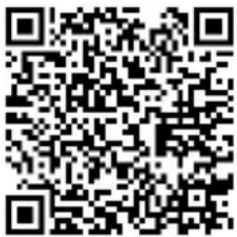
For more information on configuring your RAID sets, please refer to the RAID Configuration Guide which you can find at https://www.asus.com/support, or by scanning the QR code.
text_image
QR code image containing encoded data, no visible human-readable textRAID definitions
RAID 0 (Data striping) optimizes two identical hard disk drives to read and write data in parallel, interleaved stacks. Two hard disks perform the same work as a single drive but at a sustained data transfer rate, double that of a single disk alone, thus improving data access and storage. Use of two new identical hard disk drives is required for this setup.
RAID 1 (Data mirroring) copies and maintains an identical image of data from one drive to a second drive. If one drive fails, the disk array management software directs all applications to the surviving drive as it contains a complete copy of the data in the other drive. This RAID configuration provides data protection and increases fault tolerance to the entire system. Use two new drives or use an existing drive and a new drive for this setup. The new drive must be of the same size or larger than the existing drive.
RAID 10 is data striping and data mirroring combined without parity (redundancy data) having to be calculated and written. With the RAID 10 configuration you get all the benefits of both RAID 0 and RAID 1 configurations. Use four new hard disk drives or use an existing drive and three new drives for this setup.
Appendix
Notices
FCC Compliance Information
Responsible Party: Asus Computer International
Address: 48720 Kato Rd., Fremont, CA 94538, USA
Phone / Fax No: (510)739-3777 / (510)608-4555
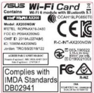
Identification of the assembled product: INTEL ^® WI-FI 6 AX200
Identification of the modular components used in the assembly:
Model Name: INTEL® WI-FI 6 AX200 FCC ID: PD9AX200NG
This device complies with part 15 of the FCC Rules. Operation is subject to the following two conditions: (1) This device may not cause harmful interference, and (2) this device must accept any interference received, including interference that may cause undesired operation.
This equipment has been tested and found to comply with the limits for a Class B digital device, pursuant to part 15 of the FCC Rules. These limits are designed to provide reasonable protection against harmful interference in a residential installation. This equipment generates, uses and can radiate radio frequency energy and, if not installed and used in accordance with the instructions, may cause harmful interference to radio communications. However, there is no guarantee that interference will not occur in a particular installation. If this equipment does cause harmful interference to radio or television reception, which can be determined by turning the equipment off and on, the user is encouraged to try to correct the interference by one or more of the following measures:
- Reorient or relocate the receiving antenna.
- Increase the separation between the equipment and receiver.
- Connect the equipment into an outlet on a circuit different from that to which the receiver is connected.
- Consult the dealer or an experienced radio/TV technician for help.
RF exposure warning
This equipment must be installed and operated in accordance with provided instructions and the antenna(s) used for this transmitter must be installed to provide a separation distance of at least 20 cm from all persons and must not be co-located or operating in conjunction with any other antenna or transmitter. End-users and installers must be provide with antenna installation instructions and transmitter operating conditions for satisfying RF exposure compliance.
Compliance Statement of Innovation, Science and Economic Development Canada (ISED)
This device complies with Innovation, Science and Economic Development Canada licence exempt RSS standard(s). Operation is subject to the following two conditions: (1) this device may not cause interference, and (2) this device must accept any interference, including interference that may cause undesired operation of the device.
Operation in the band 5150–5250 MHz is only for indoor use to reduce the potential for harmful interference to co-channel mobile satellite systems.
CAN ICES-3(B)/NMB-3(B)
KC: Korea Warning Statement
B급 기기 (가정용 방송통신기자제)
Copyright© 2020 Google Inc. All Rights Reserved.
Licensed under the Apache License, Version 2.0 (the "License"); you may not use this file except in compliance with the License. You may obtain a copy of the License at:
http://www.apache.org/licenses/LICENSE-2.0
Unless required by applicable law or agreed to in writing, software distributed under the License is distributed on an "AS IS" BASIS, WITHOUT WARRANTIES OR CONDITIONS OF ANY KIND, either express or implied.
See the License for the specific language governing permissions and limitations under the License.
NCC: Taiwan Wireless Statement
Japan RF Equipment Statement
屋外での使用について
Declaration of compliance for product environmental regulation
ASUS follows the green design concept to design and manufacture our products, and makes sure that each stage of the product life cycle of ASUS product is in line with global environmental regulations. In addition, ASUS disclose the relevant information based on regulation requirements.
Please refer to http://csr.asus.com/Compliance.htm for information disclosure based on regulation requirements ASUS is complied with:
EU REACH and Article 33
Complying with the REACH (Registration, Evaluation, Authorisation, and Restriction of Chemicals) regulatory framework, we published the chemical substances in our products at ASUS REACH website at http://csr.asus.com/english/REACH.htm.
EU RoHS
This product complies with the EU RoHS Directive. For more details, see http://csr.asus.com/english/article.aspx?id=35
India RoHS
This product complies with the “India E-Waste (Management) Rules, 2016” and prohibits use of lead, mercury, hexavalent chromium, polybrominated biphenyls (PBBs) and polybrominated diphenyl ethers (PBDEs) in concentrations exceeding 0.1% by weight in homogenous materials and 0.01% by weight in homogenous materials for cadmium, except for the exemptions listed in Schedule II of the Rule.
Vietnam RoHS
ASUS products sold in Vietnam, on or after September 23, 2011, meet the requirements of the Vietnam Circular 30/2011/TT-BCT.
ASUS recycling and takeback programs come from our commitment to the highest standards for protecting our environment. We believe in providing solutions for you to be able to responsibly recycle our products, batteries, other components as well as the packaging materials. Please go to http://csr.asus.com/english/Takeback.htm for detailed recycling information in different regions.
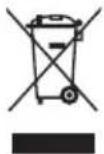
DO NOT throw the motherboard in municipal waste. This product has been designed to enable proper reuse of parts and recycling. This symbol of the crossed out wheeled bin indicates that the product (electrical and electronic equipment) should not be placed in municipal waste. Check local regulations for disposal of electronic products.
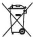
DO NOT throw the mercury-containing button cell battery in municipal waste. This symbol of the crossed out wheeled bin indicates that the battery should not be placed in municipal waste.
Regional notice for California

WARNING
Cancer and Reproductive Harm - www.P65Warnings.ca.gov
Simplified EU Declaration of Conformity
ASUSTek Computer Inc. hereby declares that this device is in compliance with the essential requirements and other relevant provisions of Directive 2014/53/EU. Full text of EU declaration of conformity is available at https://www.asus.com/support/
The WiFi operating in the band 5150-5350MHz shall be restricted to indoor use for countries listed in the table below:
ASUSTek Computer Inc.
For the standard EN 300 440, if this device operates in 5725-5875 MHz, it will be considered as a receiver category 2.
text_image
ASUS Wi-Fi Card Contains Wi-Fi 6 module with Bluetooth 5.1 Model: AX200NGW FETEL: RCPINAX19-0480 FCC ID: PDBAX200NG GMT ID: 2019AJ2274(M) IC: 1000M-AX200NG Jordan: TRCISB/2019/122 ACCRPEN LANST MAXOC Plants of the standard: M_1000_0307_DCT Type of solution: 1797031 Complies with IMDA Standards DB02941 CCAH19LP065070 R-C-INT-AX200NGW 003-190022 SLSA-35 DHC D190021003 R-NZ TRA RUMERTONI N. CHACCIONE ECALIK 2019/122ASUS contact information
ASUSTeK COMPUTER INC.
Address 1F., No. 15, Lide Rd., Beitou Dist., Taipei City 112, Taiwan
Telephone +886-2-2894-3447
Fax +886-2-2890-7798
Web site https://www.asus.com
Technical Support
Telephone +86-21-38429911
Online support https://qr.asus.com/techserv
ASUS COMPUTER INTERNATIONAL (America)
Address 48720 Kato Rd., Fremont, CA 94538, USA
Telephone +1-510-739-3777
Fax +1-510-608-4555
Web site https://www.asus.com/us/
Technical Support
Support fax +1-812-284-0883
Telephone +1-812-282-2787
Online support https://qr.asus.com/techserv
ASUS COMPUTER GmbH (Germany and Austria)
Address Harkortstrasse 21-23, 40880 Ratingen, Germany
Web site https://www.asus.com/de
Online contact https://www.asus.com/support/Product/ContactUs/
Services/questionform/?lang=de-de
Technical Support
Telephone (DE) +49-2102-5789557
Telephone (AT) +43-1360-2775461
Online support https://www.asus.com/de/support