
624 - Hi-Fi System MOTU - Free user manual and instructions
Find the device manual for free 624 MOTU in PDF.


| Product Type | 16x16 Thunderbolt/USB/AVB Audio Interface with DSP Mixer |
| Dimensions (approx.) | Half-rack width (8.5 in / 216 mm), 1U height (1.75 in / 44 mm), depth 6.5 in / 165 mm |
| Weight (approx.) | 2.5 lb (1.13 kg) |
| Power Supply | External DC adapter, 12-18V DC, 1.0A max, tip-positive |
| Analog Inputs | 4x TRS balanced line in (1/4"), 2x XLR mic in with preamp, 2x TS guitar in (1/4") |
| Analog Outputs | 6x TRS balanced line out (1/4"), 1x stereo headphone (1/4"), 1x stereo main out (1/4") |
| Digital I/O | ADAT optical in/out (8 ch at 44.1/48 kHz, 4 ch at 88.2/96 kHz), switchable to TOSLink S/PDIF |
| Computer Connectivity | Thunderbolt (USB-C), USB 3.0 (compatible with USB 2.0), AVB Ethernet (for Mac) |
| Sample Rates | 44.1, 48, 88.2, 96, 176.4, 192 kHz |
| Internal DSP Mixer | 48 channels, 12 stereo busses, 32-bit floating point effects (EQ, compressor, reverb, gate) |
| Web App Control | MOTU Pro Audio Control web app accessible via browser on any device on the same network |
| AVB Networking | IEEE 802.1 AVB/TSN Ethernet for multi-device expansion and low-latency streaming |
| Front Panel Display | Color LCD with metering for all I/O, sample rate, clock source, and menu navigation |
| Precision Digital Trim | Digitally controlled analog trims for inputs (1 dB steps) and outputs (1 dB steps) |
| Phantom Power | +48V switchable per mic input |
| Included Accessories | USB cable, DC power adapter, rack mounting kit, manual |
| Operating Temperature | 10°C to 40°C (50°F to 104°F) |
| System Requirements | Mac OS X 10.8+ or Windows 7+, 2 GB RAM, USB or Thunderbolt port; for AVB: Mac with Thunderbolt, OS X 10.11+ |
| Maintenance | Clean with dry cloth only; do not use liquid or aerosol cleaners |
| Safety | Read safety guide before installation; do not expose to rain or moisture; no user-serviceable parts |
| Spare Parts & Repairability | No user-serviceable parts; refer servicing to qualified personnel; 2-year limited warranty on hardware |
| General Information | Brand: MOTU; Model: 624; Manufactured by Mark of the Unicorn, Inc., Cambridge, MA, USA |
Frequently Asked Questions - 624 MOTU
User questions about 624 MOTU
0 question about this device. Answer the ones you know or ask your own.
Ask a new question about this device
Download the instructions for your Hi-Fi System in PDF format for free! Find your manual 624 - MOTU and take your electronic device back in hand. On this page are published all the documents necessary for the use of your device. 624 by MOTU.
USER MANUAL 624 MOTU
1280 Massachusetts Avenue
Cambridge, MA 02138
Business voice: (617) 576-2760
Business fax: (617) 576-3609
Web site: www.motu.com
Tech support: www.motu.com/support
SAFETY PRECAUTIONS AND ELECTRICAL REQUIREMENTS FOR THE 624 ("PRODUCT")

CAUTION! READ THIS SAFETY GUIDE BEFORE YOU BEGIN INSTALLATION OR OPERATION. FAILURE TO COMPLY WITH SAFETY INSTRUCTIONS COULD RESULT IN BODILY INJURY OR EQUIPMENT DAMAGE.

HAZARDOUS VOLAGES: CONTACT MAY CAUSE ELECTRIC SHOCK OR BURN. TURN OFF UNIT BEFORE SERVICING.
WARNING: TO REDUCE THE RISK OF FIRE OR ELECTRICAL SHOCK, DO NOT EXPOSE THIS APPLIANCE TO RAIN OR OTHER MOISTURE.
CAUTION: TO REDUCE THE RISK OF ELECTRICAL SHOCK, DO NOT REMOVE COVER. NO USER-SERVICEABLE PARTS INSIDE. REFER SERVICING TO QUALIFIED SERVICE PERSONNEL.
IMPORTANT SAFEGUARDS
- Read these instructions. All the safety and operating instructions should be read before operating the product.
- Keep these instructions. These safety instructions and the product owner's manual should be retained for future reference.
- Heed all warnings. All warnings on the product and in the owner's manual should be adhered to.
- Follow all Instructions. All operating and use instructions should be followed.
- Do not use the product near water.
- Cleaning - Unplug the product from the computer and clean only with a dry cloth. Do not use liquid or aerosol cleaners.
- Ventilation - Do not block any ventilation openings. Install in accordance with the manufacturer's instructions.
- Heat - Do not install the product near any heat sources such as radiators, heat registers, stoves, or another apparatus (including an amplifier) that produces heat.
- Overloading - Do not overload wall outlets and extension cords as this can result in a risk of fire or electrical shock.
- Power supply cord - Protect the product power supply cord from being walked on or pinched by items placed upon or against them.
- Power switch - Install the product so that the power switch can be accessed and operated at all times.
12.Disconnect - The main power supply plug is considered to be the disconnect device for the product and shall remain readily operable. - Accessories - Only use attachments/accessories specified by the manufacturer.
- Surge protection - Unplug the product during lightning storms or when unused for long periods of time.
- Servicing - Refer all servicing to qualified service personnel. Servicing is required when the product has been damaged in any way, such as when a power-supply cord or plug is damaged, liquid has been spilled or objects have fallen into the product, the product has been exposed to rain or moisture, does not operate normally, or has been dropped.
- Power Sources - Refer to the manufacturer's operating instructions for power requirements.
- Installation - Do not install the product in an unventilated rack, or directly above heat-producing equipment such as power amplifiers. Observe the maximum ambient operating temperature listed below.
- Power amplifiers- Never attach audio power amplifier outputs directly to any of the unit's connectors.
- Replacement Parts - When replacement parts are required, be sure the service technician has used replacement parts specified by the manufacturer or have the same characteristics as the original part. Unauthorized substitutions may result in fire, electric shock or other hazards.
- Safety Check - Upon completion of any service or repairs to this MOTU product, ask the service technician to perform safety checks to determine that the product is in safe operating conditions.
ENVIRONMENT, HEAT AND VENTILATION
Operating Temperature: 10^ C to 40^ C ( 50^ F to 104^ ). The product should be situated away from heat sources or other equipment that produces heat. When installing the product in a rack or any other location, be sure there is adequate space around the product to ensure proper ventilation. Improper ventilation will cause overheating and can damage the unit.
TO REDUCE THE RISK OF ELECTRICAL SHOCK OR FIRE
Do not handle the power supply with wet hands. Do not pull on the power supply cord when disconnecting it from an AC wall outlet. Grasp it by the plug. Do not expose this apparatus to rain or moisture. Do not place objects containing liquids on it.
DC INPUT
10 - 24V DC • 1.0A max

Contents
Part 1: Getting Started
7 Quick Start Guide
9 624 Front Panel
10 624 Rear Panel
11 MOTU Pro Audio Control Web App
23 About the 624
27 Packing List and System Requirements
29 Software Installation
33 Hardware Installation
Part 2: Using the 624
51 Presets
55 The Front Panel LCD
57 Working with Host Audio Software
65 Mixer Effects
73 MOTU Audio Tools
89 Networking
Part 3: Appendices
97 Troubleshooting
99 Audio Specifications
101 Mixer Schematics
105 Updating Firmware
107 OSC Support
109 Index
About the Mark of the Unicorn License Agreement and Limited Warranty on Software
TO PERSONS WHO PURCHASE OR USE THIS PRODUCT: carefully read all the terms and conditions of the "click-wrap" license agreement presented to you when you install the software. Using the software or this documentation indicates your acceptance of the terms and conditions of that license agreement.
Mark of the Unicorn, Inc. ("MOTU") owns both this program and its documentation. Both the program and the documentation are protected under applicable copyright, trademark, and trade-secret laws. Your right to use the program and the documentation are limited to the terms and conditions described in the license agreement.
Reminder of the terms of your license
This summary is not your license agreement, just a reminder of its terms. The actual license can be read and printed by running the installation program for the software. That license agreement is a contract, and clicking "Accept" binds you and MOTU to all its terms and conditions. In the event anything contained in this summary is incomplete or in conflict with the actual click-wrap license agreement, the terms of the click-wrap agreement prevail.
YOU MAY: (a) use the enclosed program on a single computer; (b) physically transfer the program from one computer to another provided that the program is used on only one computer at a time and that you remove any copies of the program from the computer from which the program is being transferred; (c) make copies of the program solely for backup purposes. You must reproduce and include the copyright notice on a label on any backup copy.
YOU MAY NOT: (a) distribute copies of the program or the documentation to others; (b) rent, lease or grant sublicenses or other rights to the program; (c) provide use of the program in a computer service business, network, time-sharing, multiple CPU or multiple user arrangement without the prior written consent of MOTU; (d) translate, adapt, reverse engineer, decompile, disassemble, or otherwise alter the program or related documentation without the prior written consent of MOTU.
MOTU warrants to the original licensee that the disk(s) on which the program is recorded be free from defects in materials and workmanship under normal use for a period of ninety (90) days from the date of purchase as evidenced by a copy of your receipt. If failure of the disk has resulted from accident, abuse or misapplication of the product, then MOTU shall have no responsibility to replace the disk(s) under this Limited Warranty.
THIS LIMITED WARRANTY AND RIGHT OF REPLACEMENT IS IN LIEU OF, AND YOU HEREBY WAIVE, ANY AND ALL OTHER WARRANTIES, BOTH EXPRESS AND IMPLIED, INCLUDING BUT NOT LIMITED TO WARRANTIES OF MERCHANTABILITY AND FITNESS FOR A PARTICULAR PURPOSE. THE LIABILITY OF MOTU PURSUANT TO THIS LIMITED WARRANTY SHALL BE LIMITED TO THE REPLACEMENT OF THE DEFECTIVE DISK(S), AND IN NO EVENT SHALL MOTU OR ITS SUPPLIERS, LICENSORS, OR AFFILIATES BE LIABLE FOR INCIDENTAL OR CONSEQUENTIAL DAMAGES, INCLUDING BUT NOT LIMITED TO LOSS OF USE, LOSS OF PROFITS, LOSS OF DATA OR DATA BEING RENDERED INACCURATE, OR LOSSES SUSTAINED BY THIRD PARTIES EVEN IF MOTU HAS BEEN ADVISED OF THE POSSIBILITY OF SUCH DAMAGES. THIS WARRANTY GIVES YOU SPECIFIC LEGAL RIGHTS WHICH MAY VARY FROM STATE TO STATE. SOME STATES DO NOT ALLOW THE LIMITATION OR EXCLUSION OF LIABILITY FOR CONSEQUENTIAL DAMAGES, SO THE ABOVE LIMITATION MAY NOT APPLY TO YOU.
Update Policy
In order to be eligible to obtain updates of the program, you must complete and return the attached Mark of the Unicom Purchaser Registration Card to MOTU.
Copyright Notice
Copyright © 2016 by Mark of the Unicorn, Inc. All rights reserved. No part of this publication may be reproduced, transmitted, transcribed, stored in a retrieval system, or translated into any human or computer language, in any form or by any means whatsoever, without express written permission of Mark of the Unicorn, Inc., 1280 Massachusetts Avenue, Cambridge, MA, 02138, U.S.A.
Limited Warranty on Hardware
Mark of the Unicorn, Inc. and S&S Research ("MOTU/S&S") warrant this equipment against defects in materials and workmanship for a period of TWO (2) YEARS from the date of original retail purchase. This warranty applies only to hardware products; MOTU software is licensed and warranted pursuant to separate written statements.
If you discover a defect, first write or call Mark of the Unicorn at (617) 576-2760 to obtain a Return Merchandise Authorization Number. No service will be performed on any product returned without prior authorization. MOTU will, at its option, repair or replace the product at no charge to you, provided you return it during the warranty period, with transportation charges prepaid, to Mark of the Unicorn, Inc., 1280 Massachusetts Avenue, MA 02138. You must use the product's original packing material for in shipment, and insure the shipment for the value of the product. Please include your name, address, telephone number, a description of the problem, and the original, dated bill of sale with the returned unit and print the Return Merchandise Authorization Number on the outside of the box below the shipping address.
This warranty does not apply if the equipment has been damaged by accident, abuse, misuse, or misapplication; has been modified without the written permission of MOTU, or if the product serial number has been removed or defaced.
ALL IMPLIED WARRANTIES, INCLUDING IMPLIED WARRANTIES OF MERCHANTABILITY AND FITNESS FOR A PARTICULAR PURPOSE, ARE LIMITED IN DURATION TO TWO (2) YEARS FROM THE DATE OF THE ORIGINAL RETAIL PURCHASE OF THIS PRODUCT.
THE WARRANTY AND REMEDIES SET FORTH ABOVE ARE EXCLUSIVE AND IN LIEU OF ALL OTHERS, ORAL OR WRITTEN, EXPRESS OR IMPLIED. No MOTU/S&S dealer, agent, or employee is authorized to make any modification, extension, or addition to this warranty.
MOTU/S&S ARE NOT RESPONSIBLE FOR SPECIAL, INCIDENTAL, OR CONSEQUENTIAL DAMAGES RESULTING FROM ANY BREACH OF WARRANTY, OR UNDER ANY LEGAL THEORY, INCLUDING LOST PROFITS, DOWNTIME, GOODWILL, DAMAGE OR REPLACEMENT OF EQUIPMENT AND PROPERTY AND COST OF RECOVERING REPROGRAMMING, OR REPRODUCING ANY PROGRAM OR DATA STORED IN OR USED WITH MOTU/S&S PRODUCTS.
Some states do not allow the exclusion or limitation of implied warranties or liability for incidental or consequential damages, so the above limitation or exclusion may not apply to you. This warranty gives you specific legal rights, and you may have other rights which vary from state to state.
MOTU, Digital Performer, AudioDesk, Mark of the Unicorn and the unicorn silhouette logo are trademarks of Mark of the Unicorn, Inc.
Thunderbolt and the Thunderbolt logo are trademarks of Intel Corporation in the U.S. and/or other countries.
This equipment has been type tested and found to comply with the limits for a class B digital device, pursuant to Part 15 of the FCC Rules. These limits are designed to provide reasonable protection against harmful interference in a residential installation. This equipment generates, uses, and can radiate radio frequency energy and, if not installed and used in accordance with the instruction manual, may cause harmful interference to radio communications. However, there is no guarantee that interference will not occur in a particular installation. If this equipment does cause interference to radio or television equipment reception, which can be determined by turning the equipment off and on, the user is encouraged to try to correct the interference by any combination of the following measures:
• Relocate or reorient the receiving antenna
- Increase the separation between the equipment and the receiver
• Plug the equipment into an outlet on a circuit different from that to which the receiver is connected
If necessary, you can consult a dealer or experienced radio-television technician for additional assistance.
PLEASE NOTE: only equipment certified to comply with Class B (computer input/output devices, terminals, printers, etc.) should be attached to this equipment, and it must have shielded interface cables in order to comply with the Class B FCC limits on RF emissions.
WARNING: changes or modifications to this unit not expressly approved by the party responsible for compliance could void the user's authority to operate the equipment.

Part 1
Getting Started
Quick Start Guide
Thank you for purchasing an 624! Follow these easy steps to get started quickly.
1 Download and run the MOTU Pro Audio Installer found here:
http://www.motu.com/avb
2 (Optional) For quick access to the 624 from your iPad or iPhone, download the MOTU Discovery app from the Apple App Store.
Your iPhone and iPad must be on the same Wi-Fi network as your computer.
3 Connect the interface to your computer with a USB cable (included) or Thunderbolt cable (sold separately). If you have a Thunderbolt-equipped Mac running OS X El Capitan (10.11) or later, you can alternately connect the 624 to the Mac's Ethernet port with a standard CAT-5e or CAT-6 Ethernet cable (sold separately).
4 Switch on the 624.
5 Open the MOTU Pro Audio Controlweb app by doing one of the following:
-
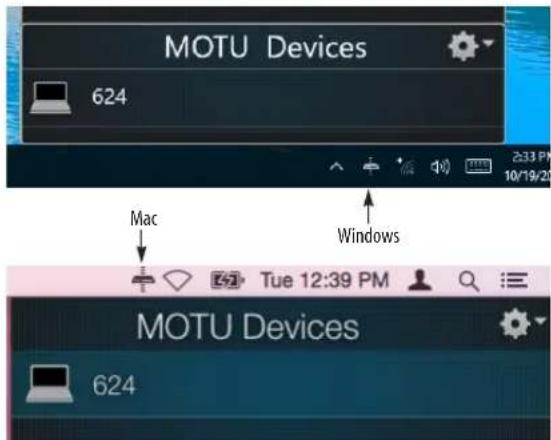
Choose the 624 from the MOTU Discovery app menu (found in the Mac menu bar or Windows taskbar).
■ Alternately, you can launch theMOTU Pro Audio WebUI Setup shortcut found on the Windows desktop or in Start menu> All Programs> MOTU
■ From your iPad or iPhone, launch the MOTU Discovery app, and tap your interface. -
You should now see theMOTU Pro Audio Control web app in your browser, as shown on page 12. If not, visit Appendix A, “Troubleshooting” (page 97).
■ For advanced network options, and device discovery from any modern browser, see chapter 10, “Networking” (page 89).
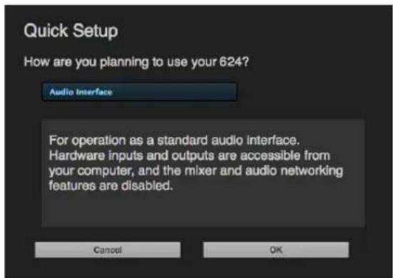
6 Choose a preset from the Quick Setup.
624 Front Panel
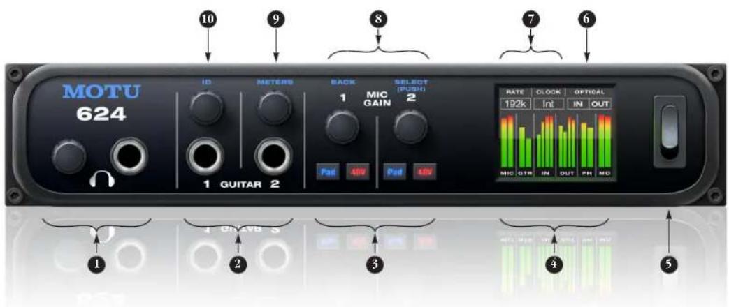
- HEADPHONE OUTPUT with volume control. Push the phone volume knob to toggle between PHONE volume control and MAIN OUT volume control. The LCD provides visual feedback with a volume meter. Double-tap the knob to mute/unmute. Hold in the knob to lock the volume meter on screen; hold it in again to unlock and dismiss.
- GUITAR INPUTS with trim control. These are high-impedance guitar inputs that provide authentic guitar amp response and feel.
-
Individual MIC INPUT preamp gain, switchable 48V phantom power, and optional \~20 dB pad switches for each mic input. The Precision Digital Trim™ knob provides 63 dB of preamp gain. Turn the knob to see the gain adjustments in the LCD. Hold in the knob to lock the gain adjustment on screen; hold it again to unlock and dismiss.
-
This portion of the LCD displays level meters for all analog inputs and outputs, including mic inputs (MIC), guitar inputs (GTR), line inputs and outputs (IN/OUT), phones (PH) and main outs (MO). It can also show device settings and network information, using the knobs to the left.
- Power switch.
- This portion of the multi-purpose color LCD shows audio activity over the 624's optical ports (in and out).
-
This portion of the LCD displays the current sample rate and clock source, such as /nt (Internal clock mode).
-
Push SELECT to enter the LCD menu. Turn SELECT to scroll through menu options. Push again to go into the submenus, if applicable. To choose the current setting, push SELECT a third time. Push BACK to return to the previous menu level, and do so repeatedly to exit the menu altogether.
- Push METERS to immediately jump to the main screen with metering.
- Push ID to display network settings for the device, including its IP address.
624 Rear Panel
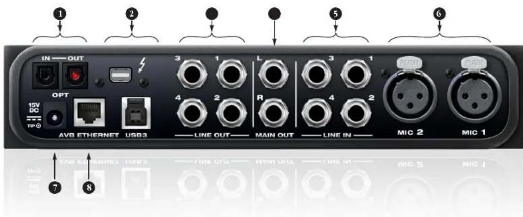
- These ADAT optical "lightpipe" jacks provide 8 channels of 24-bit ADAT optical digital I/O at 1x sample rates (44.1 or 48 kHz) and 4 channels at 2x sample rates (88.2 or 96 kHz). They are disabled at higher sample rates. Alternately, they can operate as stereo TOSLink (optical S/PDIF) connectors.
- Connect the 624 to the computer here with Thunderbolt or USB 3.0, using a standard Thunderbolt or USB cable (one or the other, but not both). For details, see chapter 4, "Hardware Installation" (page 33).
-
The analog LINE OUTS provide additional analog output for secondary studio monitors, surround monitoring, sub-mixes or any other desired destination. These connectors are balanced (tip/ring/sleeve), but they also accept an unbalanced plug. They are DC-coupled. Control volume from the MOTU Pro Audio Control web app or your host audio software.
-
The MAIN OUT pair provides stereo analog output for primary (powered) studio monitors or PA speakers, or any other desired destination. Control volume from the MOTU Pro Audio Control web app or from the front panel as follows: push the headphone volume knob to switch to main out volume control, then turn the knob. For details, see item #1 on the previous page.
To hear audio playback from your host audio software on the MAIN OUT pair, use the Audio Interface preset and then assign audio tracks (and master fader) to these main outs. You can also use the MOTU Pro Audio Control web app to route live 624 inputs (and network inputs) here as well.
- Equipped with very high quality 24-bit 192 kHz converters, these four analog inputs are balanced TRS (tip/ring/sleeve) quarter-inch connectors that can also accept an unbalanced plug (with the ring disconnected). Use them for keyboards or other line level analog sources. These inputs are equipped with the 624's Precision Digital Trim™ feature: digitally controlled analog trims that let you adjust input level in 1 dB increments from the MOTU Pro Audio Control web app.
- The MIC INPUTS accept any standard mic cable and are equipped with high-quality, transparent preamps. Controls for preamp gain, 48V phantom power and pad are on the front panel.
-
This jack accepts any standard 12-18V DC power supply (1.0A max) with tip-positive polarity.
-
This AVB/TSN Ethernet port provides industry standard IEEE 802.1 network connectivity to other network devices. Examples include:
■ Another 624 or any other MOTU AVB-equipped audio interface, such as the 1248, 8M, 16A, 24Ai, 24Ao, 112D, Monitor 8, etc.
■ A standard Ethernet hub or Wi-Fi router (for internet connection and communication with the web app software).
■ A standard AVB Ethernet switch for high-speed, low-latency, high-capacity audio connectivity to an AVB audio network.
■ A recent-generation Mac (any Mac with a Thunderbolt port) running OS X El Capitan (10.11) or later. This allows you to operate the 624 as an audio interface over Ethernet.
MOTU Pro Audio Control Web App
OVERVIEW
MOTU Pro Audio Controls a web app that gives you complete control over the 624. If you have several MOTU AVB interfaces networked together, such as the 624, 1248 and 8M, you can control them all. If you are working with a large network of many MOTU AVB interfaces, you can access any device on the network.
IT'S NOT ON YOUR HARD DRIVE
The MOTU Pro Audio Control web app is served from the 624 hardware itself, therefore it is not an application on your computer's hard drive. Instead, access it from the MOTU Discovery app (in the Mac menu bar or Windows taskbar), the MOTU Pro Audio WebUI Setupshortcut (Windows only) or through your web browser.
USE YOUR FAVORITE WEB BROWSER
The MOTU Pro Audio Control web app runs in any modern web browser on any device connected to the 624, either directly or wirelessly through a Wi-Fi network. You can use any device you wish: a desktop computer, laptop, iPad, tablet, iPhone or smart phone. If it can run a web browser, it can run the web app. You can use any browser you prefer: Chrome, Firefox, Safari, etc. The latest versions are strongly recommended.
CONTROL FROM MULTIPLE DEVICES
You can run the web app on multiple host devices simultaneously.
RUN THE INSTALLER, GET THE APP
Visit www.motu.com/avb to get the latest MOTU Pro Audio Installer and run it on your computer to install the MOTU Discovery app, MOTU Pro Audio WebUI Setupshortcut (Windows only) and other software elements. Visit the Apple App Store to install the discovery app on your iPad or iPhone.
MAKE HARDWARE AND NETWORK CONNECTIONS
Connect your 624 to your computer or laptop with a USB or Thunderbolt cable. Make sure your iPad, iPhone, tablet or smartphone is connected to the same Wi-Fi network as your computer or device. You can use any network connection explained in "Setup for web app control" on page 38.
LAUNCHING THE WEB APP
To launch the web app, do any of the following:
- Choose the 624 from the MOTU Discovery app menu (in the Mac menu bar or Windows taskbar, as shown on page 7) or launch the MOTU Pro Audio WebUI Setup shortcut (Windows only).
■ From your iPad or iPhone, launch the MOTU Discovery app.
■ In your favorite web browser, type this URL: localhost:1280. (This URL requires a Thunderbolt or USB connection to the 624.) - If the 624 Ethernet port is connected to your Ethernet or Wi-Fi network, type the unit's IP address (see below) into your browser.
You should now see the MOTU Pro Audio Control web app in your browser, as shown on page 12. If not visit Appendix A, “Troubleshooting” (page 97).
Obtaining the 624's IP address
On the front panel of the interface, push the ID knob once. The LCD now displays the unit's IP address, which should look something like this: "IP: 192.168.1.209".
DEVICE TAB
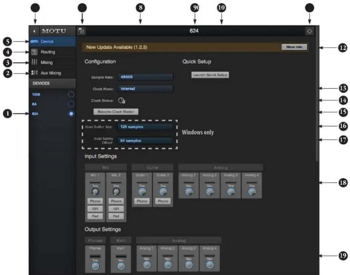
- If you have two or more MOTU AVB interfaces, the Devices list lets you choose the one you are currently controlling with the web app.
- The Aux Mixing tab lets you view each Aux bus in the mixer, one at a time.
- The Mixing tab gives you access to the mixing and DSP in the interface.
- The Routing tab displays a grid matrix, where you can make direct connections between inputs and outputs, your computer, the mixer, and network audio streams, if networked interfaces are connected.
- The Device tab has settings for the hardware itself, such as analog input and output trim.
-
Expands and collapses the sidebar.
-
Lets you create, save, recall and manage presets for the 624. These presets capture and recall the complete state of the device (all settings in all tabs).
- Choose the desired sample rate. Make sure your host audio software is set to the same rate.
- Click to rename the interface. To restore the default name, delete the current name.
- The Quick Setup button prompts factory presets used to configure your interface for a specific application. See chapter 5, "Presets" (page 51).
-
Click this device ID button to identify the unit you are currently viewing and controlling with the web app software. The front panel LCD on the hardware itself will flash the name of the device, and its name will also flash in the Device list (1).
-
If an update is available for your device, and the computer you are viewing it from is connected to the internet, you'll be notified here. Click More Info to learn what's new and start the update process. Firmware updating requires a network connection. See Appendix D, "Updating Firmware" (page 105).
- Choose the clock source from the Clock Mode menu. Your MOTU device will resolve its digital clock to this master source.
- The Clock Status icon indicates that the current device (1) is successfully resolved to its chosen Clock Mode source (13). If it cannot lock for some reason, this icon flashes red. Check your chosen clock source, cables, etc.
-
If you have multiple MOTU interfaces, one of them may serve as a master clock source for the network. Click the Become Clock Master button to choose the current interface (1) as the master clock source.
-
(Windows only) Choose the Host Buffer Size. Smaller values reduce latency but increase your computer's CPU load. See "Host Buffer Size" on page 30.
- (Windows only) Choose a Host Safety Offset to fine tune host buffer latency. See "Host Safety Offset" on page 31.
- The Input Settings section provides gain settings for inputs, plus phase invert for mic and guitar inputs, if any. You can also toggle the 48V phantom power and -20 dB pad for the mic inputs.
- The Output Settings section lets you adjust the trim for any output or output pair which supports it. Phones and Main outputs provide full volume control. Analog outputs provide calibration control (-24 to 0 dB).
DEVICE TAB (CONTINUED)
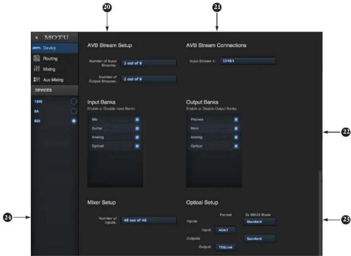
Scroll down to view these additional Device tab settings.
-
AVB is IEEE's Audio Video Bridging Ethernet standard for high-bandwidth, low-latency audio streaming over Ethernet. If your MOTU interface is connected to a 2nd MOTU interface through its network port, or to an AVB switch for access to an extended AVB network, you can stream audio channels to and from other devices on the network. AVB streams are handled in banks of eight channels, so if you enable 2 streams, that's 16 channels. See chapter 10, "Networking" (page 89).
-
If you have the AVB network input stream enabled (20), connect them to the output streams of other devices on the network here. This is how you route audio from the other devices to the 624.
-
In the Input/Output Banks sections, you can disable any banks that you are not using. Doing so hides them from the routing matrix and mixer to simplify operation. Doing so also helps conserve DSP resources.
-
Configure the optical ports for either 8-channel ADAT or stereo TOSLink. At 88.2 or 96 kHz, the ADAT setting supports 4-channel SMUX format. See "Optical I/O" on page 44.
-
The digital mixer in the 624 supports up to 48 channels at 44.1 or 48 kHz. At higher sample rates, the maximum number of supported channels is lower, due to finite DSP resources. If you don't need 48 inputs (or the maximum available), you can lower the number here to simplify mixer and routing operation and conserve DSP bandwidth for effects processing.
DEVICE TAB (CONTINUED)
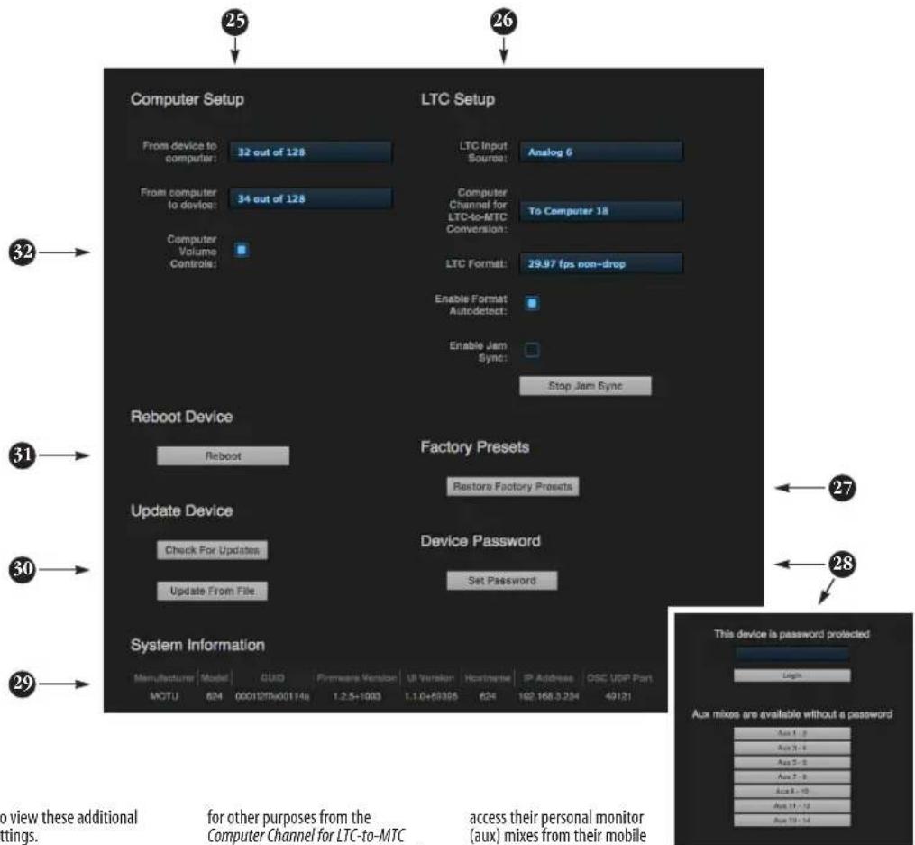
Scroll down to view these additional Device tab settings.
- In the Computer Setup section, you can specify how many audio channels you would like to be able to stream to and from your computer, up to 128 channels each way, simultaneously, over USB or Thunderbolt. Map them as desired in the Routing tab (page 15).
- Your MOTU interface can resolve to SMPTE time code, also referred to as LTC (Longitudinal Time Code), by choosing LTC from the Clock Mode menu (item 13 on page 12). From the LTC Input Source menu (26 above), choose the analog or digital input that is receiving the time code. If you would also like to send time code (LTC) to the computer, where it will be converted to MIDI Time Code (MTC) for resolving your DAW or other software to MTC via OS X Core Audio (a Mac-only feature), choose an audio channel you are not using
for other purposes from the Computer Channel for LTC-to-MTC Conversion menu; otherwise, leave it set to None. Choose the desired frame format, or use the Enable Format Autodetect to automatically detect the frame format of the incoming time code. When Enable Jam Sync is turned on, your interface will continue to operate under its own clock and continue LTC-to-MTC conversion, even after it stops receiving time code. Click Stop Jam Sync to exit this mode. For further details about time code sync, see "Syncing to SMPTE time code (LTC)" on page 45 and "LTC-to-MTC conversion" on page 63.
- Use Restore Factory Presets to restore your MOTU device's factory presets.
- Use Set Password to password-protect the interface on the network. All settings are blocked, except for aux bus mixing, as shown above (28). This allows musicians to
access their personal monitor (aux) mixes from their mobile devices, while all other device settings remain blocked. To clear the password, log in and then click Clear Password. If you forget the password, you can clear it in the Settings menu in the front panel LCD (see page 56) with either the Clear Password setting or by doing a factory reset with the Factory Default setting.
- The System Information section displays information about your MOTU device, including the firmware version and network IP address.
- Use these buttons to manually check for and install updates for your MOTU interface. For complete details, see Appendix D, "Updating Firmware" (page 105). Updating from a file can be done offline from your computer, using an update you've obtained through MOTU's
web site or tech support department. The Check For Updates button requires that the computer (or device) you are using to view your MOTU interface is connected to the internet through a local network or Wi-Fi. Updating from the internet is easy and convenient.
- Click Reboot to restart the interface.
- When the Computer Volume Controls option is enabled (a Mac only feature), the Audio MIDI Setup utility in OS X provides volume control for each output channel to your MOTU audio interface. In addition, the volume controls for your Mac (on your computer keyboard) will control the channels you've designated for computer output in Audio MIDI Setup, if any. Be careful when toggling this setting because sudden changes in your computer volume can result.
ROUTING TAB
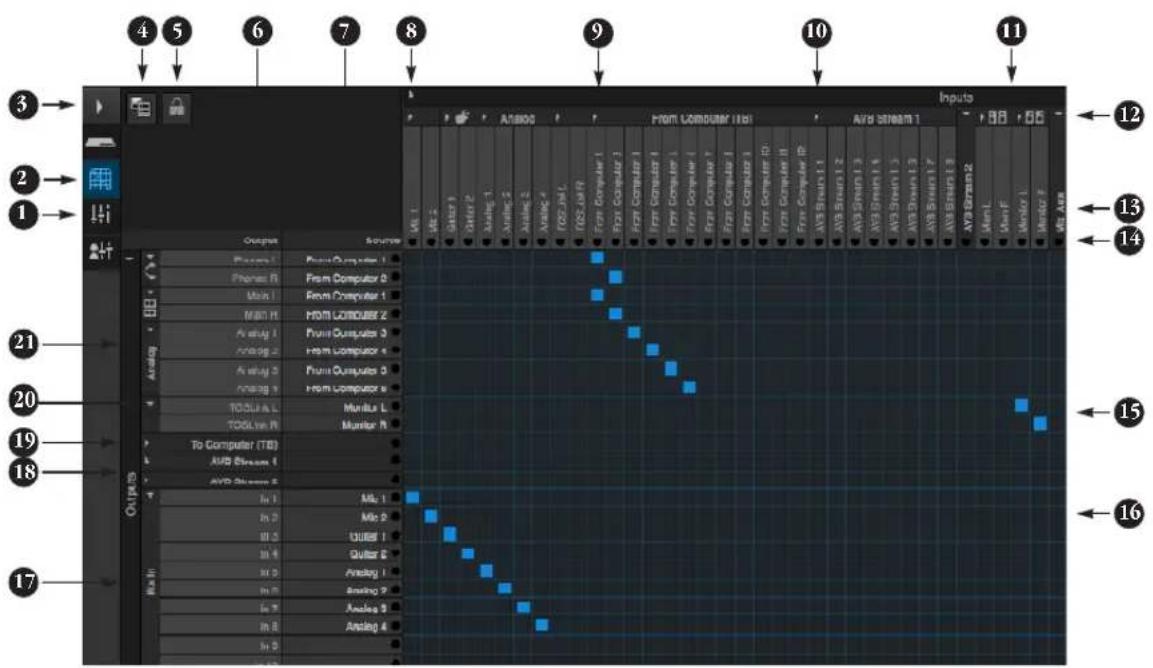
The Routing Tab lets you route inputs to outputs. Outputs are listed by row on the left; inputs are listed in columns across the top. Simply click in the grid to make a single connection. Click and drag to make multiple connections in one gesture. To route a single input to multiple outputs, make multiple connections vertically in the same column below the input. To mix multiple inputs to the same output, you'll need to use the mixer (page 16) and the Mix In bank in the routing tab (17).
- In its collapsed form, (shown here), the sidebar displays icons for each tab.
- Click this icon to view the Routing tab, shown on this page.
- Click here to show or hide the sidebar.
- Create, save, recall and manage routing presets.
-
Locks the grid to prevent accidental changes. Unlock to make changes to the grid.
-
Outputs are listed in rows on the left.
- When you make a connection, the source (input) signal is listed by name here in the Source column, just to the right of the output it is being routed to.
- Inputs are listed in columns across the top of the grid, starting with the physical inputs on the hardware itself. In this example, the two mic and guitar inputs are being routed to the 624's mixer inputs 1-4. Analog inputs 1-4 are routed to mixer inputs 5-8.
- The From Computer input bank lets you route audio channels from your host audio software to any output, including AVB network streams or the mixer, where you can mix computer audio with local inputs. Use the Device tab to choose how many computer channels are available.
- AVB streams are 8-channel banks that let you route audio to or from other devices on the AVB network (if
any are connected) to local hardware inputs and outputs. Use the Device tab (page 13) to configure how many AVB streams you wish to work with. If you aren't working with network audio, you can set the number of streams to zero.
- These input streams are busses that originate from the mixer, which supplies the main mix bus, monitor mix bus, seven stereo aux busses, three stereo group busses, a reverb return bus and postFX channel sends (for sending processed inputs to the computer or elsewhere). You can route these mixer busses to any outputs you wish (6), including physical outputs, host software on your computer, other devices on the AVB network, or even back in to the mixer (beware of feedback loops!)
- Use these triangles to expand or collapse groups of inputs. For example, it might be convenient to collapse banks that you are not using at the moment.
-
Click a channel label to rename it.
-
Audio activity indicators.
- Here, the Monitor bus from the mixer is being routed to the optical (TOSLink) output on the 624.
- Click the grid to make a connection. Click a connection to remove it. Click and drag to make or break multiple connections in one gesture.
- The Mix In group lets you route audio to the 48-channel mixer.
- These AVB output streams let you route any audio to other devices on the AVB network.
- The To Computer output bank routes any input to host audio software running on your computer. Use the Device tab to choose how many computer channels are available.
- Use these triangles to expand or collapse groups of outputs.
- These are the physical outputs on the interface itself.
MIXING TAB
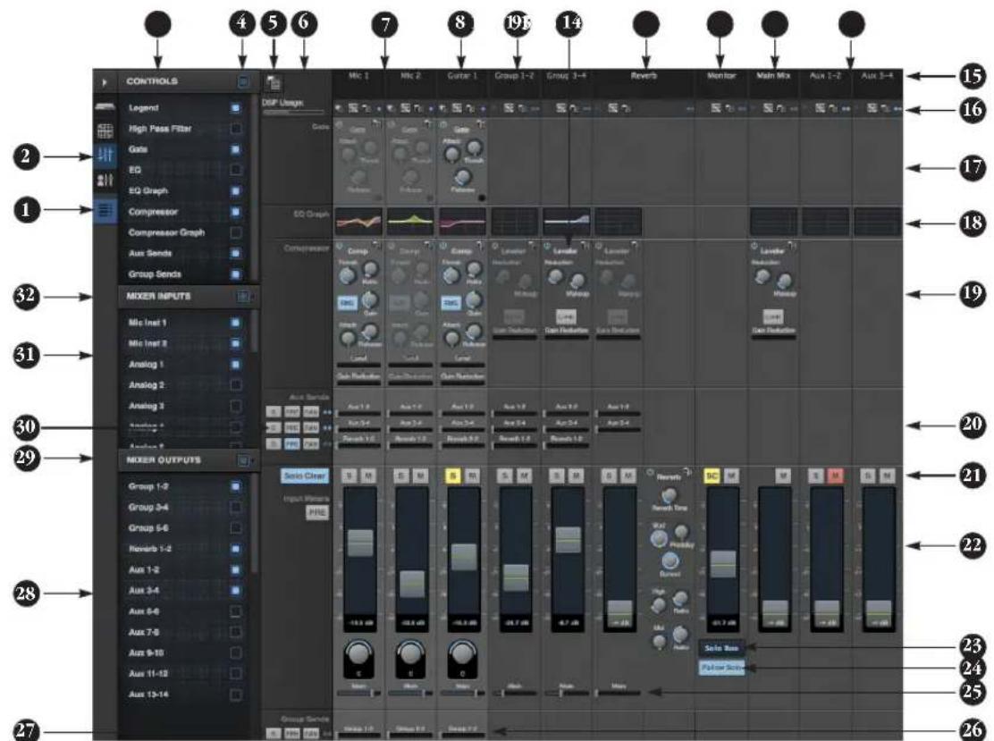
The Mixing tab gives you full access to the 48-channel mixer in the 624, which provides a main mix bus, monitor bus, three group busses, seven aux busses, and a dedicated reverb bus. Use the Device tab to configure how many inputs you wish to work with (up to 48). Use the Routing tab (page 15) to route channels to the mixer inputs. Channels can come from any source, such as the physical inputs on the interface, channels coming from the computer, or channels coming from the AVB network.
- Shows and hides the Mixer Setup sidebar (3), which lets you show and hide channels, channel strip settings, effects, and the Legend (6).
- The Mixing tab selects the mixer.
- Use the Mixer Setup sidebar to show and hide elements in the mixer.
- Shows and hides all elements in the section with one click.
- Create, save, recall and manage mixer presets.
- This column is the Legend. It provides labels and controls for
channel strip sections. The menu at the top lets you create, name, save and manage entire mixer presets.
- Mixer input channels.
- This input channel has its Gate and Compressor enabled.
- This is Group bus 1-2. You can send inputs to this group with their Group send fader (26). Groups are sent to the Main Mix with its Main send fader (25) or aux busses (20).
- Group buses, the main mix bus, and the reverb return bus are equipped with the Leveler, a vintage compressor modeled after the Teletronix LA-2A leveling amplifier.
- The reverb channel strip provides the reverb processor. Use the reverb send on inputs or groups to route them to the reverb bus, which can then be mixed in with the main mix or aux busses. Disable the reverb processor to use it as an extra group.
-
The Monitor Bus can mirror the output of any other bus, or it can act as a separate Solo bus. See page 19.
-
The Main Mix bus is the master fader for the entire mixer. You can add EQ and Leveler compression.
- You can adjust Aux bus output levels here, or in the Aux Mixing tab shown on page 17.
- Click a name to change it, except for the Main Mix, Monitor, and Reverb busses, which cannot be changed.
- Stereo toggle to switch channels pairs between mono or stereo. Use the other menus to manage channel strip presets and to choose audio sources and destinations for mixer inputs and bus outputs.
- Gate processing for inputs.
- Click the thumbnail EQ graph to open the full-size, editable EQ graph (Figure 8-4 on page 67).
- The Dynamics section provides a conventional compressor for inputs and the Leveler for output busses.
-
Reverb and aux sends.
-
Solo and mute. On the Monitor bus, the SC button clears all solos.
- Channel faders.
- Choose the source for the Monitor bus from this menu. It can mirror any output bus or the Solo Bus.
- When Follow Solo is enabled, the Monitor bus temporarily switches to the solo bus when any channel is soloed.
- Main Mix sends.
- Group sends.
- 'S' lets you solo the group. 'PRE' toggles the sends between pre- and post-fader routing, i.e. before or after the channel fader.
- Show and hide output busses here.
- Show/hide all busses with one click.
- Same as (27) above.
- Show and hide inputs here.
- Show/hide all inputs with one click.
AUX MIXING TAB
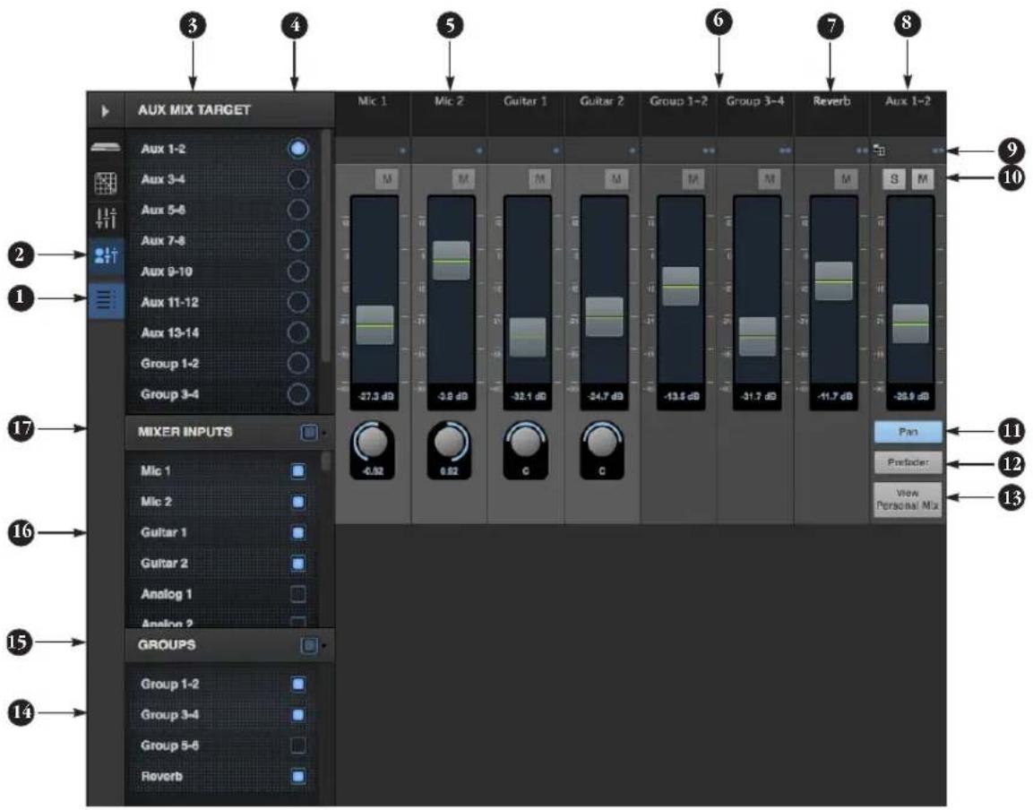
The Aux Mixing tab provides quick access to the 624's mix busses (aux busses, groups and reverb bus), viewed one at a time. Choose a bus in the Aux Mix Target section and then use the faders to directly mix the send levels from all mixer inputs, groups, and the reverb bus.
- Shows and hides the Mixer Setup sidebar (3), which lets you show and hide channels.
- The Aux Mixing tab (shown on this page) gives you access to the Aux busses and groups in the mixer.
-
Use the Aux Mix Target sidebar to control which aux bus or group you are currently viewing. You can also show/hide inputs and group sends.
-
Click the aux bus or group you wish to view in the window. In this example, Aux bus 1-2 is being displayed.
- These are mixer inputs (aux sends from each mixer channel). To include an input in the aux bus mix, simply bring up its fader.
- These are group bus faders.
- This is the mixer's reverb bus fader.
- This is the master fader for the current aux bus being viewed (4).
-
Indicates if the input or group is stereo or mono. This indicator is for display purposes only. To toggle between mono and stereo operation, use the toggle switch in the Mixing tab (item #16 on page 16).
-
Solo and mute for the aux bus master fader. The mute buttons for the input channels and other buses are for display purposes only, so that you can see if they are muted or not (in the mixer).
- Shows and hides the pan controls for aux bus inputs.
- When Prefader is enabled, all send levels to the aux bus are independent of the main fader for each channel. In other words, changing an individual channel's main fader in the Mixing tab won't affect its send level to the aux bus.
-
Click the View Personal Mix button to open a new web page that displays only that specific Aux Mix or Group.
-
Show and hide mix groups and the reverb bus here.
- Use the Groups button here to show or hide all groups with one click. Drag this section divider vertically to resize the list.
- Show and hide mixer inputs (channel sends) here.
- Show and hide all mixer inputs with one click here. Drag this section divider vertically to resize the list.
MIXER INPUT CHANNEL STRIPS
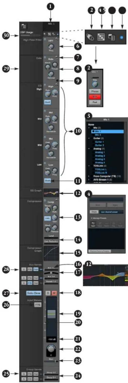
To access a mixer input channel strip, go to the Mixing tab (page 16), reveal the side bar (item #3 on page 16), and then show the input channel you want in the Mixer Inputs section (31).
To show and hide sections of the channel strip, such as EQ or the compressor, use the Controls section of the side bar (item #3 in the Mixing tab on page 16).
-
Click the input channel name to change it. Delete the current name to restore the default name.
-
Provides hardware settings for inputs, if any, such as preamp gain. If there are no hardware settings for the assigned input, this icon is grayed out. If the channel has been assigned to an input on another AVB device on the audio network, you can use these settings to control it remotely.
-
Choose the source for the input channel. You can also make this setting directly on the Routing grid (page 15).
-
Create, name, save and recall channel strip presets.
-
Toggles the input between mono and a stereo pair.
-
High Pass Filter with cutoff frequency.
-
Each effect in the channel strip (High Pass Filter, Gate, EQ, etc.) has an on/off button on the left and a preset menu on the right, for managing presets that apply only to that processing module. For example, you can create your own EQ presets for the EQ modules.
-
The Gate processor provides standard attack, threshold and release controls.
-
The Gate indicator turns red when the gate is engaged.
-
The EQ section provides four bands of parametric EQ, each with standard Gain, Frequency, and Bandwidth settings.
-
The High and Low EQ bands provide a Shelf filter button for standard high and low shelf filtering.
-
The thumbnail EQ Graph displays the currently enabled EQ filters, if any. Click it to open the full-size, editable EQ Graph (Figure 8-4 on page 67).
-
The Compressor provides standard controls for Threshold, Ratio, Attack, Release and Gain. Normally, the compressor operates in Peak mode, where signal peaks determine the input level. Engage the RMS button to uses RMS values (a computational method for determining overall loudness) to measure the input level.
-
Input level and gain reduction meters for the compressor.
-
The thumbnail Compressor Graph provides a graphic representation of the compressor, when enabled. Click it to open the full-size, editable Compressor Graph (Figure 8-6 on page 68).
-
Aux 1-2 send.
-
Pan for the Aux 1-2 send. This is enabled in the Aux mix tab (item #11 on page 17).
-
Solo/Mute. Mute affects all sends as well as the main channel. Pre-fader sends are not affected by Mute.
-
Move the fader to adjust level. Double-click to return to zero (unity gain) or -∞.
-
Click the dB scale numbers to make the fader jump exactly to that level. Click and drag horizontally to jump consecutive faders to the same level.
-
Click to type in an exact dB level.
-
Channel pan. For mono inputs, double-click to center.
-
Main Mix Slider is used to feed signal to the Main Mix. Slider is set to 0 dB by default, so all channel strips are pre-routed to the Main Mix bus. If a channel is being sent to a Group (which will eventually be fed to the Main Mix), drag the slider to -∞ so it is not sent to Main Mix directly.
-
Group sends.
-
'S' lets you solo the group. 'PRE' toggles the sends between pre- and post-fader routing, i.e. before or after the channel fader.
-
The input level meter (behind the fader handle, 19) can display either pre- or post-fader levels. Toggle here.
-
Clears all solos.
-
'S' lets you solo the Aux bus. 'PRE' toggles the sends between pre- and post-fader routing, i.e. before or after the channel fader. The dots let you toggle the Aux bus between mono and stereo.
-
This side bar, with the section labels in it, can be shown or hidden using the Legend switch in the Controls section of the side bar (item #3 in the Mixing tab on page 16).
-
Shows how much DSP power is being used by the mixer hardware. To free up DSP bandwidth, try reducing the number of mixer ins, disabling channel effects, reverb, etc. See "DSP Usage" on page 71 for more info.
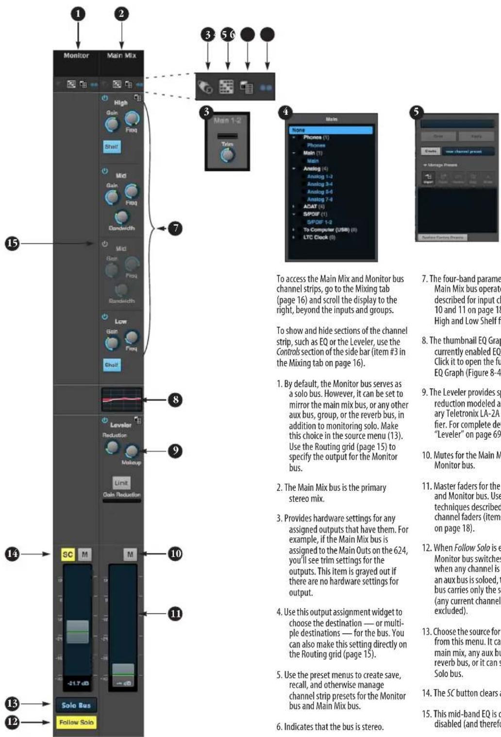
MAIN MIX AND MONITOR CHANNEL STRIPS
AUX BUS CHANNEL STRIPS
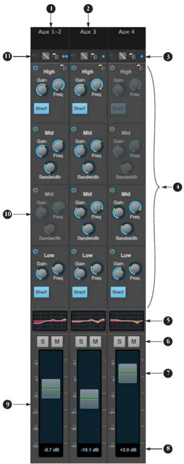
Aux busses can be used to create sub-mixes. An aux bus can be assigned to any output in the Routing grid (page 15).
To access an Aux bus channel strip, go to the Mixing tab (page 16), reveal the side bar (item #3 on page 16), and then show the aux busses you want in the Mixer Outputs section (28).
To show and hide the four-band EQ section of the channel strip, use the Controls section of the side bar (item #3 in the Mixing tab on page 16).
- A stereo aux bus.
- A mono aux bus.
- Click this dot to toggle an aux bus between mono and stereo.
- The four-band parametric EQ module for Aux busses operates the same as described for input channels (items 10 and 11 on page 18), including High and Low Shelf filter options.
- The thumbnail EQ Graph displays the currently enabled EQ filters, if any. Click it to open the full-size, editable EQ Graph (Figure 8-4 on page 67).
- Aux bus solo and mute.
- Aux bus master fader.
- Click to type specific value manually.
- Click the dB scale numbers to make the fader jump exactly to that level. Click and drag horizontally to jump consecutive faders to the same level.
- A disabled EQ band.
- Use these menus (hardware settings, output assignment, and presets) in a similar fashion as described for the Main Out bus (items 3-5 on page 19).
GROUP AND REVERB CHANNEL STRIPS
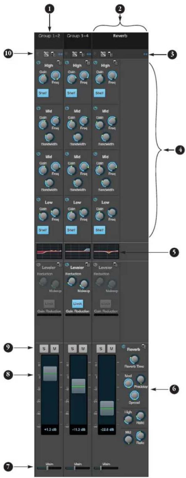
Group busses can be used to create a mix sub-group, which is a set of inputs you wish to control together as a group. Groups differ from aux busses in that they have aux sends, a reverb send, as well as a main mix send. In addition, group busses are equipped with the Leveler.
The Reverb bus is a special group bus that provides a reverb processor. If you disable the reverb, the reverb bus functions as a (fourth) regular group bus.
To access the Group and Reverb bus channel strips, go to the Mixing tab (page 16), reveal the side bar (item #3 on page 16), and then show the desired Group busses or Reverb bus in the Mixer Outputs section (28).
To show and hide the four-band EQ section of the channel strip, use the Controls section of the side bar (item #3 in the Mixing tab on page 16).
- A Group bus channel strip. Click the name to rename it. Delete the current name to return to its default.
- The Reverb bus. If you disable the Reverb processor, it can be used as a fourth Group bus. The Reverb channel strip is twice as wide as other mixer channel strips to accommodate the Reverb processor controls.
- Group busses and the Reverb bus are always stereo.
- The four-band parametric EQ module for Group busses and the Reverb bus operates the same as described for input channels (items 10 and 11 on page 18), including High and Low Shelf filter options.
- The thumbnail EQ Graph displays the currently enabled EQ filters, if any. Click it to open the full-size, editable EQ Graph (Figure 8-4 on page 67).
- The Reverb processor. For complete information, see "Reverb" on page 70.
- Main Mix sends.
- Master faders for the Group and Reverb busses.
- Mute and Solo.
- Use these menus (hardware settings, output assignment, and presets) in a similar fashion as described for the Main Out bus (items 3-5 on page 19).
CHAPTER 1 About the 624
The 624 is an 16 x 16 Thunderbolt/USB/AVB audio interface with console-style 48-channel mixing, DSP effects, wireless control, AVB audio networking and very high quality A/D/A conversion at sample rates up to 192 kHz for on-the-go mobile audio recording.
Powerful DSP delivers large console style mixing with 48 channels, 12 stereo busses, and 32-bit floating point effects processing, including modeled analog EQ, vintage compression and classic reverb. Matrix routing lets you quickly patch ins to outs, or split inputs to multiple destinations.
The 624 can operate as an audio interface for a studio workstation (DAW), as a standalone mixer, or as an auxiliary monitor mixing system in the studio or on stage. The following sections provide a brief overview of its main features and characteristics.
Comprehensive I/O
The 624 provides a variety of analog and digital interconnects, all active simultaneously, designed to provide everything you need for a well-equipped mobile recording studio.
Connection Input Output
| Quarter-inch analog on bal/unbal TRS 4 6 |
| Mic inputs with individual preamps on XLR 2 - |
| Hi-Z guitar inputs 2 - |
| Headphone output - 1 x stereo |
| ADAT optical digital (at 44.1 or 48 kHz) 8 8 |
| Total 16 16 |
Network I/O
624 is capable of handling eight 8-channel banks of network audio input and eight 8-channel banks of network output for an additional 64 channels of network I/O.
Other MOTU AVB interfaces
The 624 is part of a larger family of audio interfaces that offer complementary I/O configurations. For details, visit motu.com.
Universal connectivity
The 624 can connect to a computer with Thunderbolt or super-speed USB 3.0, which is compatible with USB 2.0. It is USB audio class-compliant, which means that it is iPad compatible (with a camera connection kit) and does not require driver installation for USB connection to a computer.
Alternately, the 624 can be connected to the Ethernet port on a recent-generation Mac (any Mac with Thunderbolt on it) running Mac OS X El Capitan (10.11) or later for audio interface operation through AVB Ethernet.
On-board DSP with mixing and effects
624 is equipped with a powerful DSP engine that drives both an extensive routing matrix and a 48-input digital mixer with 12 stereo busses and effects. The mixer offers familiar operation modeled after large format mixing consoles.
32-bit floating point processing
All of the mixing and effects processing in the DSP engine is handled with 32-bit floating point calculations, to maintain and deliver virtually unlimited headroom and the utmost in sound quality.
Modeled vintage effects processing
Effects include “classic” reverb, compression modeled after the legendary Teletronix LA-2A compressor, and 4-band EQ modeled after British analog console EQs.
AVB/TSN system expansion and audio networking
AVBstands for the IEEE 802.1 Audio Video Bridging Ethernet standard for high-bandwidth, low-latency audio streaming over Ethernet. You may also hear AVB referred to as AVBTSNor simply TSN because the IEEE is in the process of renaming the standard to Time Sensitive Networking to accommodate the expanding scope of the specification to applications beyond audio and video.
The AVB Ethernet network port on the 624 lets you add a second AVB-equipped MOTU interface using any standard CAT-5e Ethernet cable. You can network up to five MOTU interfaces together using a MOTU AVB Switch ^™ (sold separately), and then run them as a stand-alone network or as an extended bank of I/Os for your computer-based production system (or both). You can even connect multiple computers, each with full access to all devices on the network (including the other computers).
With additional standard AVB switches (from MOTU or other brands) and standard Ethernet cabling, you can build an extensive AVB audio network. The entire network operates with near-zero network latency, even over very long cable runs. MOTU's AVB implementation allows you to stream hundreds of audio channels among devices and computers on the network with guaranteed Quality of Service (QoS), prioritizing audio streams over less important traffic.
Matrix routing and multing
The 624 provides completely flexible matrix-style audio routing and multing. You can route any analog or digital input, computer channel, or network stream to any other output, computer, or network device. You can also mult any single input to unlimited multiple output destinations.
Web app control
You can control the 624's on-board DSP, mixing, device settings, clock/sync settings and network audio routing from the MOTU Pro Audio Control web app software running in your favorite browser on a laptop, tablet or smart phone. Multiple devices can be used simultaneously on a shared Wi-Fi network to access any audio interface settings. Optional password protection prevents unauthorized access from the network.
Stand-alone mixing with wireless control
If you connect the 624 to an Apple Airport or other Wi-Fi router with a standard Ethernet cable, you can control its powerful mixing and DSP effects from your smart phone or tablet, without a computer — great for live sound mixing from your iPad, tablet, or other wireless device.
ADAT digital input
The 624 provides 8-channel optical digital I/O. Connect outboard digital processors, digital mixers or other gear: 8 channels at 44.1/48 kHz or 4 channels at 88.2/96 kHz. Alternately, the optical ports can be independently configured to support stereo TOSLink (optical S/PDIF).
Comprehensive metering
The color LCD displays all signal activity at a glance with detailed metering for all I/O. You can access many hardware settings directly from the front panel.
Headphone output
The 624 front panel provides an independent headphone jack with separate volume control. You can program the phones to mirror another set of outputs or act as its own independent output.
Precision Digital Trim™
Analog inputs are equipped with digitally controlled analog trims, adjustable in 1 dB increments. Analog outputs offer 32-bit trim in the DAC, also adjustable in 1 dB increments. You can save your trim configurations as a preset for instant recall.
Rack mount or desktop operation
The 624 is housed in a sturdy, metal-alloy half-rack enclosure. Rack mounting brackets are included for mounting side by side with any other MOTU half-rack unit.
AudioDesk
AudioDesk is a full-featured audio workstation software package for Mac and Windows that is available as a free download for you as an 624 owner. Visit motu.com/avb to obtain your copy. AudioDesk provides multi-channel waveform editing, automated virtual mixing, graphic editing of ramp automation, real-time effects plug-ins with crossfades, support for many third-party audio plug-ins, sample-accurate editing and placement of audio, and more.
CHAPTER 2 Packing List and System Requirements
PACKING LIST
the 624 ships with the items listed below. If any of these items are not present in the box when you first open it, please immediately contact your dealer or MOTU.
■One audio interface
■One USB cable
■One DC power adapter
■ One rack mounting kit with brackets and screws
■One manual
■ Product registration card
SYSTEM REQUIREMENTS
■ A 1 GHz Intel-based Mac or Pentium-based PC (or compatible). Faster CPUs are recommended for best performance.
■2 GB RAM; 4 GB or more recommended.
■ OS X 10.8 or later; Windows 7 or later; for operation as an AVB Ethernet audio interface, Mac OS X 10.11 or later is required, running on a recent-generation Mac (any Mac with a Thunderbolt port on it).
■ Available super-speed USB 3.0 (or 2.0) port.
■ A large hard drive (preferably at least 500 GB).
PLEASE REGISTER TODAY!
Please register the 624 today. There are two ways to register.
■ Visit www.motu.com/register
OR
■ Fill out and mail the included product registration card
As a registered user, you will be eligible to receive technical support and announcements about product enhancements as soon as they become available. Only registered users receive these special update notices, so please register today.
Thank you for taking the time to register your new MOTU products!
CHAPTER 3 Software Installation
OVERVIEW
USB audio class-compliant operation.... 29
Software installation.... 29
Audio drivers 30
MOTU Discovery app 31
MOTU Pro Audio WebUI Setup for Windows.... 31
AudioDesk workstation software.... 31
Working with host audio software 31
USB AUDIO CLASS-COMPLIANT OPERATION
The 624 is a USB audio class-compliant device. This means that you can connect it to your Mac (running OS X 10.8 or higher) with a USB cable and use it without installing any software drivers. The computer recognizes the 624 as a USB audio device and makes its inputs and outputs available to your host audio software. Basic settings, such as the hardware's sample rate, are made in either your host software (Mac) or your system settings (Windows).
In this scenario, the 624 provides basic audio input and output, and no software driver installation is necessary.
Connection to iOS devices (iPad and iPhone)
Audio-class compliant operation allows you to connect the 624 to any iOS device with a standard camera connection kit adapter. The 624 then provides multi-channel audio I/O to your audio apps. Use your audio app to configure the number of available audio channels.
Web app control
As explained earlier in this guide, the MOTU Pro Audio Control web app provides full access to all settings in the device, including the extensive on-board routing, mixing, and effects processing features. Since the web app is served from the audio interface hardware itself, it does not require any software installation on your computer; all it requires is a network connection between your computer and the 624 with a standard Ethernet cable, Ethernet hub, or shared Wi-Fi network. For details about accessing the web app through the network port, see “MOTU Pro Audio Control Web App” on page 11.
SOFTWARE INSTALLATION
Software installation is required for any of the following scenarios:
■ You are using a PC running Windows 7 or later.
■ You will use the 624 as a Thunderbolt audio interface with your laptop or desktop computer.
■ You will use 624 as a USB audio interface, and you want to access the web app without the network port.
■ You will be using multiple MOTU interfaces.
If none of the above scenarios apply to you, then you can skip software installation if you wish, and proceed to details about accessing the web app through the network port, see “MOTU Pro Audio Control Web App” on page 11.
Download and run the MOTU Pro Audio Installer
To download the latest MOTU Pro Audio installer for Mac or Windows, visit www.motu.com/avb. Follow the directions that the installer gives you.
We recommend that you run the software installer before you connect the 624 to your computer and power it on. This ensures that all driver components are properly installed in your system.
AUDIO DRIVERS
The installer provides Thunderbolt and USB audio drivers for Mac (CoreAudio) and Windows (ASIO and Wave).
Thunderbolt support for Mac and Windows
You can connect your MOTU interface to a Thunderbolt-equipped PC and access up to 128 channels of simultaneous audio input and output using the MOTU Pro Audio ASIO driver. On OS X, the MOTU Pro Audio Core Audio driver provides similar high-bandwidth Thunderbolt I/O for Mac audio applications. On both Mac and Windows, you will enjoy access to very low buffer settings and extremely low I/O latency performance from your host audio software.
Check motu.com/support for the latest information regarding PC Thunderbolt compatibility, as some PC products are not yet qualified for use with MOTU Thunderbolt-equipped audio interfaces.
Industry-leading I/O latency performance
On OS X and Windows, the MOTU Pro Audio driver provides exceptionally low I/O latency performance for both Thunderbolt and USB operation. For example, with a 32-sample buffer size, a 624 interface operating at 96 kHz produces round trip latency (RTL) performance of 1.9 milliseconds (ms) over Thunderbolt on Windows and 1.6 ms on OS X. RTL is the measurement of the time it takes audio to pass from an analog input, through a high-performance DAW host such as Digital Performer, to an analog output.
MOTU Pro Audio ASIO Driver
On Windows, to enable the 624 in your ASIO host software, choose the MOTU Pro Audio ASIO driver.
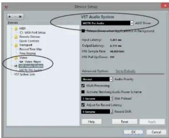
Figure 3-1: Choosing the MOTU Pro Audio ASIO driver in Cubase.
WDM / Wave driver support
On Windows, the MOTU Pro Audio driver includes stereo and multi-channel support (up to 24 channels) for WDM (Wave) compatible audio software.
Host Buffer Size
When connected to a Windows host, the Host Buffer Size menu (Figure 3-2) is available in the Device tab (page 12). This setting determines the amount of latency (delay) you may hear when live audio is patched through your Windows audio software. Smaller buffer sizes produce lower latency, with sizes of 256 samples or less producing virtually imperceptible delay. Many host applications report audio hardware I/O latency, so you can see what happens to the reported latency when making adjustments to this setting.
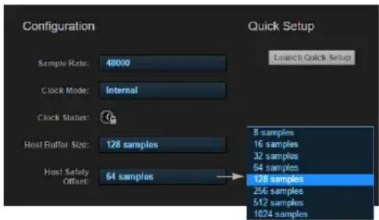
Figure 3-2: Access the 'Host Buffer Size' and 'Host Safety Offset' settings in the web app Device tab for your MOTU interface.
Be careful with very small buffer sizes, as they can cause performance issues from your host software or PC.
At sea level, audio travels approximately one foot (30 cm) per millisecond. A latency of ten milliseconds is about the same as being ten feet (three meters) from an audio source.
Host Safety Offset
When connected to a Windows host, the Host Safety Offset menu (Figure 3-2) also becomes available. This setting allows you to fine tune host latency. Larger offsets allow the driver more time to process audio as it transfers to and from the hardware. Lower settings produce lower latency, but if you go too low, your host software may experience performance issues. Generally speaking, 48 samples should serve as a good baseline setting. You can then experiment with lower settings from there. Be mindful, however, when reducing the safety offset, as this parameter can have a significant impact on your computer system's performance.
MOTU DISCOVERY APP
The MOTU Discovery app (found in the Mac menu bar or Windows taskbar) locates all MOTU AVB interfaces connected to the computer, either directly through USB or Thunderbolt or indirectly through your network, and displays them in a list. Choose an interface to access its settings through the web app (“MOTU Pro Audio Control Web App” on page 11).
MOTU PRO AUDIO WEBUI SETUP FOR WINDOWS
On Windows, the installer provides a MOTU Pro Audio WebUI Setup shortcut found on the Windows desktop or in Start menu> All Programs> MOTU. Use this shortcut to access the MOTU Pro Audio Control web app directly in your favorite web browser.
AUDIODESK WORKSTATION SOFTWARE
AudioDesk is an advanced workstation software package for Mac and Windows that lets you record, edit, mix, process, bounce and master multi-track digital audio recording projects. Advanced features include real-time effects processing, recording, and much more.
See the AudioDesk User Guide, available on your computer hard drive as a PDF document.
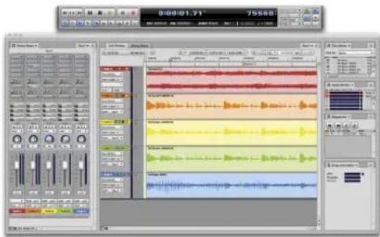
Figure 3-3: AudioDesk.
WORKING WITH HOST AUDIO SOFTWARE
For further information about using the 624 with host audio software, see "Working with Host Audio Software" on page 57.
CHAPTER 4 Hardware Installation
OVERVIEW
Thunderbolt audio interface setup 33
USB or iOS audio interface setup 33
AVB Ethernet audio interface setup.... 34
Setup for two interfaces 34
Setup for three to five interfaces.... 35
Setup for a multi-switch network.... 36
Setup for multiple interfaces.... 37
Setup for web app control 38
Setup for AVB Ethernet audio interface operation ... 40
A typical 624 setup .... 43
Audio connections.... 44
Syncing to SMPTE time code (LTC) 45
Syncing an AVB network.... 46
Syncing multiple AVB audio interfaces connected to a Mac ....47
THUNDERBOLT AUDIO INTERFACE SETUP
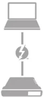
natural_image
Diagram showing a laptop connected to a network device with a lightning bolt symbol (no text or labels)Use this setup if you want to use your MOTU device as an audio interface, and your computer has Thunderbolt™.
■ Use a standard Thunderbolt cable.
■ Place it at the end of the Thunderbolt chain (up to six devices in the chain, not including the computer).
■ See chapter 3, “Software Installation” (page 29).
USB OR iOS AUDIO INTERFACE SETUP
flowchart
graph TD
    A["Computer or iOS device"] --> B["Camera connection kit (adapter) required for iOS operation"]
    B --> C["Hi-SPEED USB"]
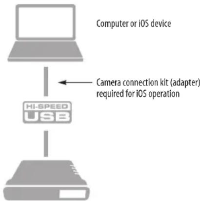
Use this setup if you want to use the 624 as a USB audio interface for a computer or iOS device.
■ Use a standard USB cable.
■ Connect to any USB port (USB2.0 or 3.0) on your computer, or use a standard camera connection kit (adapter) for your iOS device.
■ See “USB audio class-compliant operation” on page 29.
■ No driver installation is necessary.
AVB ETHERNET AUDIO INTERFACE SETUP
flowchart
graph TD
    A["Laptop"] --> B["IEEE 802.1 AVB"]
    B --> C["Server"]
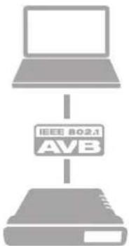
Use this setup if you want to use the 624 as an AVB Ethernet audio interface for a recent-generation Mac (i.e. any Mac with a Thunderbolt port on it). OS X El Capitan (10.11) or later is required for AVB audio I/O.
■ Use a standard CAT-5e or CAT-6 cable.
■ Connect to the computer's Ethernet port.
See "Setup for AVB Ethernet audio interface operation" on page 40.
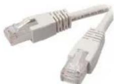
About CAT-5e cables
Use shielded CAT-5e or CAT-6 cables, which are a higher grade version of a standard Ethernet cable. They are available wherever network cables are sold.
SETUP FOR TWO INTERFACES
flowchart
graph TD
    A["Laptop"] -->|OR| B["Hi-SPEED USB"]
    B --> C["Network switch"]
    C --> D["IEEE 802.1 AVB"]
    D --> E["Computer"]
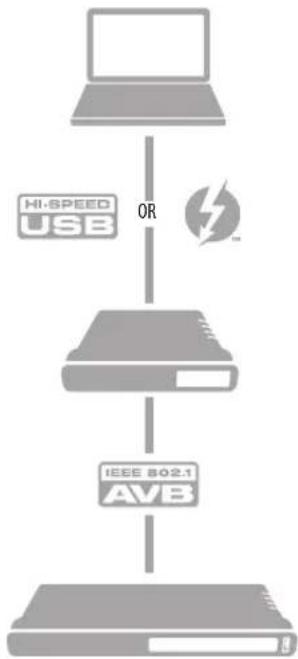
Use this setup if you want to connect two MOTU interfaces to your computer.
■ The connection to the computer can be either USB or Thunderbolt, if you have a Thunderbolt-equipped MOTU AVB interface such as the 624, 8M, 16A, 1248, 112D or 8A.
■ Use a standard Thunderbolt cable. Place it at the end of the Thunderbolt chain.
■ Use any standard CAT-5e Ethernet network cable to connect the two interfaces together using their NETWORK ports.
■ As an alternative, see "Setup for multiple interfaces" on page 37.
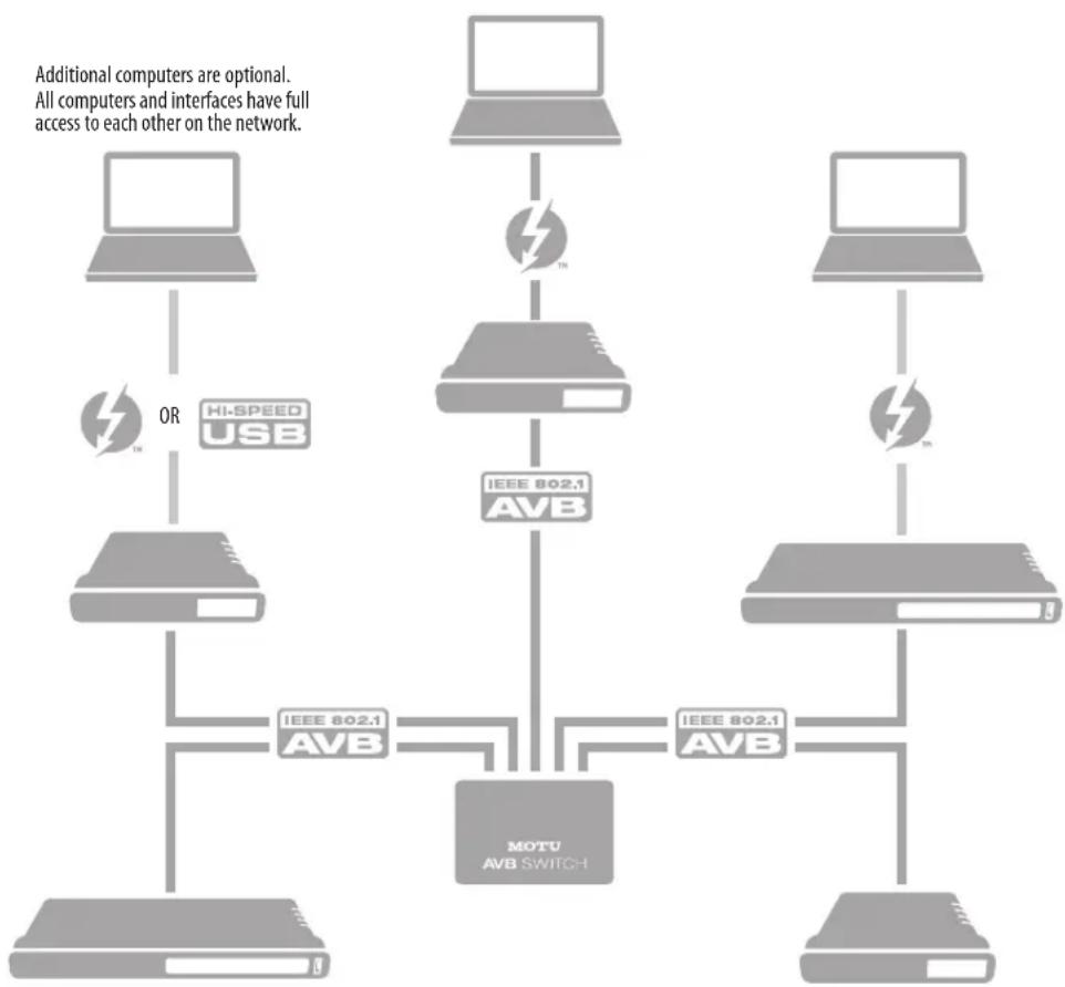
SETUP FOR THREE TO FIVE INTERFACES
Use this setup if you want to connect three to five MOTU interfaces to your computer using a MOTU AVB Switch ^™ (sold separately).
■ The connection to the computer can be USB or Thunderbolt (if you have a Thunderbolt-equipped MOTU AVB interface). Use Thunderbolt or USB 3.0, if possible, to support a large number of audio streams to and from the networked interfaces. A single Thunderbolt or USB 3.0 connection supports 128 channels in and out, simultaneously.
■ Use standard CAT-5e Ethernet network cables to connect the interfaces to the MOTU AVB Switch using their NETWORK ports.
■ Use the five AVB NETWORK ports on the switch (not the Ethernet port).
■ Network cable lengths can be long: 100 meters with standard copper wire cables; much longer with fiber-optic network cables.
■ See “About CAT-5e cables” on page 34.
■ As an alternative, see “Setup for multiple interfaces” on page 37.
■ To add more computers to the network, connect them to any interface, as shown. All computers and interfaces have full access to each other.
■ See chapter 10, “Networking” (page 89).
flowchart
graph TD
    A["Desktop"] -->|OR| B["Hi-SPEED USB"]
    B --> C["Server"]
    D["Desktop"] -->|TM| E["IEEE 802.1 AVB"]
    E --> F["MOTU AVB SWITCH"]
    F --> G["Server"]
    H["Desktop"] -->|TM| I["IEEE 802.1 AVB"]
    I --> F
    style A fill:#f9f,stroke:#333
    style D fill:#f9f,stroke:#333
    style H fill:#f9f,stroke:#333
    style B fill:#ccf,stroke:#333
    style E fill:#ccf,stroke:#333
    style F fill:#cff,stroke:#333
    style G fill:#cff,stroke:#333
    note1["Additional computers are optional. All computers and interfaces have full access to each other on the network."]
SETUP FOR A MULTI-SWITCH NETWORK
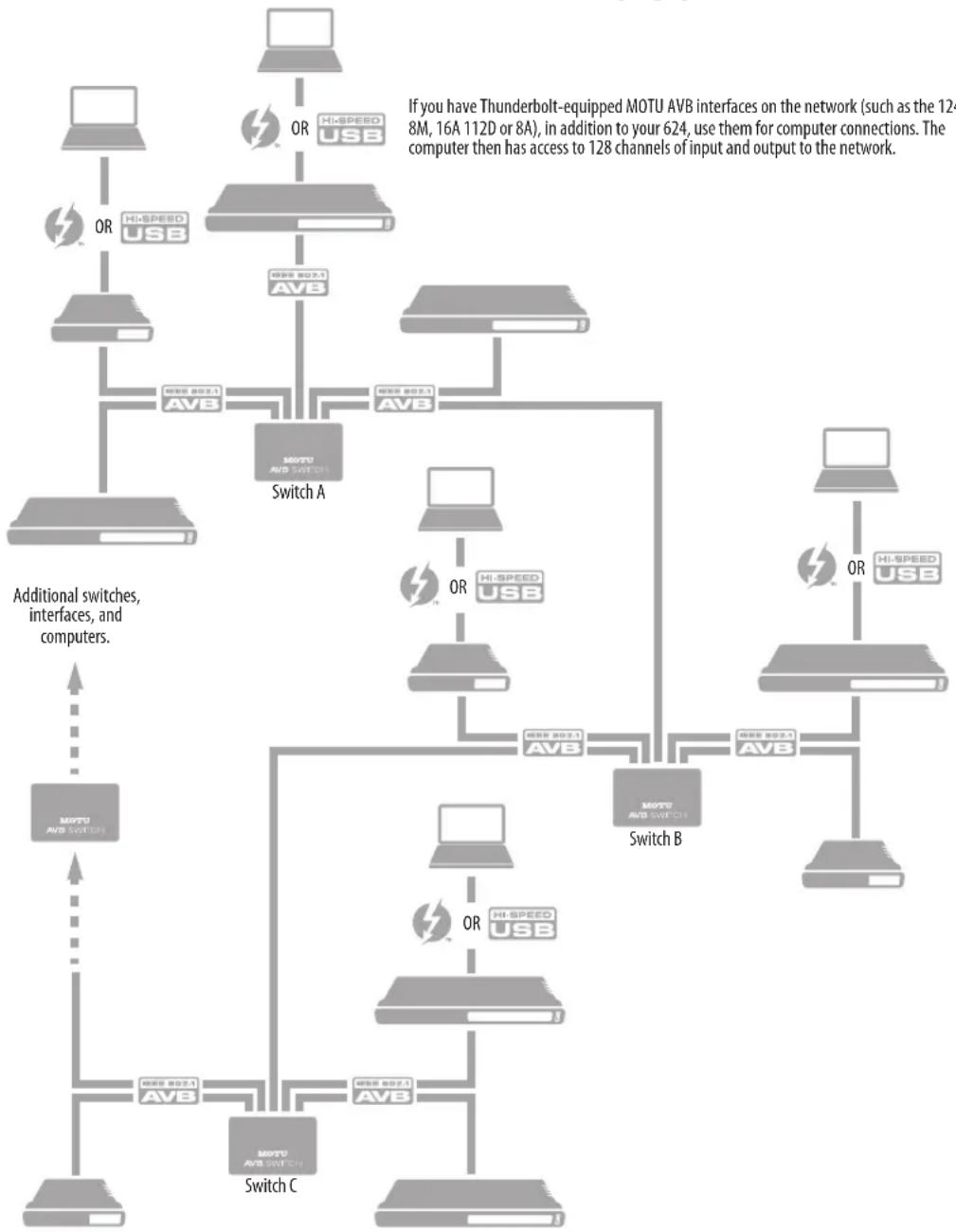
Use this setup if you want to connect more than five MOTU interfaces to an extended network that employs multiple AVB switches. AVB Ethernet is an industry standard, so you can use MOTU AVB Switches or 3rd-party AVB switches.
- You can daisy-chain switches in serial fashion, but don't create loops. For example, switches A, B, and C below are chained properly, but don't connect C back to A. Alternately, you could connect both Switches B and C to Switch A.
■ For further information, see chapter 10, "Networking" (page 89).
flowchart
graph TD
    subgraph_Switch_A["Switch A"]
        A1["Computer"] -->|OR| A2["MTU AVB"]
        A2 -->|HISPEED USB| A3["MTU AVB SWITCH"]
        A3 -->|OR| A4["MTU AVB SWITCH"]
        A4 -->|HISPEED USB| A5["MTU AVB SWITCH"]
        A5 -->|OR| A6["MTU AVB SWITCH"]
        A6 -->|HISPEED USB| A7["MTU AVB SWITCH"]
    end

    subgraph_Switch_B["Switch B"]
        B1["Computer"] -->|OR| B2["MTU AVB SWITCH"]
        B2 -->|HISPEED USB| B3["MTU AVB SWITCH"]
        B3 -->|OR| B4["MTU AVB SWITCH"]
        B4 -->|HISPEED USB| B5["MTU AVB SWITCH"]
    end

    subgraph_Switch_C["Switch C"]
        C1["Computer"] -->|OR| C2["MTU AVB SWITCH"]
        C2 -->|HISPEED USB| C3["MTU AVB SWITCH"]
        C3 -->|OR| C4["MTU AVB SWITCH"]
        C4 -->|HISPEED USB| C5["MTU AVB SWITCH"]
    end

    Note1["If you have Thunderbolt-equipped MOTU AVB interfaces on the network (such as the 124 8M, 16A 112D or 8A), in addition to your 624, use them for computer connections. The computer then has access to 128 channels of input and output to the network."] --> A2
    Note2["Additional switches, interfaces, and computers."] --> C1
SETUP FOR MULTIPLE INTERFACES
It is possible to connect multiple MOTU interfaces directly to your host computer through multiple USB (and Thunderbolt) ports. However, there are several disadvantages to using any of these direct connection schemes:
■ The audio interfaces will not be clocked to one another and may be susceptible to drift, unless you use external word clock connections (if available). You are better off using the AVB network connections shown on pages 34-36. In this setup, the interfaces are very tightly synchronized with each other (measured in pico seconds) through their network connections.
■ You will not be able to route audio directly from one audio interface to another. You are better off using the AVB network connections shown on pages 34-36, which allows you to route audio streams (hundreds at a time) directly among interfaces with near-zero latency.
Connecting multiple interfaces using Thunderbolt
If you have other MOTU AVB interfaces with Thunderbolt connectivity (1248, 8M, 16A, 112D, 624 or 8A) and your host computer has two or more Thunderbolt ports, you can connect one interface to each port, either directly or at the end of a Thunderbolt daisy chain (on either port or both ports).
Connecting multiple interfaces using Thunderbolt and USB
Another way to operate multiple interfaces on the same host computer is to connect the first interface to a Thunderbolt port and the second to a USB 3.0 (or 2.0) port.
Multiple interfaces and USB
When connected through USB, the 624 operates as a USB 3.0 device, unless it is connected to a USB 2.0 port. USB 2.0 provides enough bus speed for several USB 2.0 devices, but due to the 624's high-performance requirements for real-time operation and low latency timing, we recommend the following:
■ Try to use USB 3.0 whenever possible.
- If your computer has USB 2.0 ports, do not connect more than two units to your computer's USB 2.0 ports.
- When two units are connected with USB 2.0, don't connect other USB 2.0 or 3.0 devices, such as external hard drives.
■ For best results, establish clock synchronization with other interfaces connected to the same computer. You can use optical or AVB to achieve clock synchronization.
Multiple AVB Ethernet audio interfaces
When operating 624 as an AVB Ethernet audio interface (“AVB Ethernet audio interface setup” on page 34), multiple AVB audio interfaces can be connected using a MOTU AVB Switch (or any 3rd-party AVB switch), and the Mac can see all of them through their AVB connection. For example, you could connect an Avid S3 console to the Mac, and then connect a MOTU 624 to the S3’s extra network port (which is a built-in switch). The Mac can see both 624 and S3 for audio I/O. For best results in this scenario, be sure to use OS X 10.11 (El Capitan) or later. See “Syncing multiple AVB audio interfaces connected to a Mac” on page 47.
Mixing and matching audio interfaces
You can mix and match MOTU audio interfaces. For example, you could connect a 624 through Thunderbolt and another MOTU audio interface, such as the Stage-B16, through USB 2.0.
SETUP FOR WEB APP CONTROL
The MOTU Pro Audio Control web app gives you access to all settings, routing, mixing, and effects processing in the 624, and each interface on the AVB network, if applicable. For more info, see “MOTU Pro Audio Control Web App” on page 11.
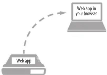
The web app is a web application served by the hardware. All you need to run it is a web browser running on a device that has a connection to your audio interface through Thunderbolt, USB or a shared network.
flowchart
graph TD
    A["Web app"] --> B["Web app in your browser"]
Figure 4-1: The web app is served from the hardware, and accessed through any web browser on any device connected to the interface.
Web app control can be set up independently of audio connections
The connections in this section, especially the network scenarios, can be set up independently of Thunderbolt, USB or AVB networking connections you make for audio routing (as shown in the setup diagrams earlier in this chapter). In addition, connections for web app control can be made over standard Ethernet and do not require AVB Ethernet connections. Think of web app control as being separate from audio. Doing so opens up a lot of possibilities for control of the 624, independent of the connections you make for audio.
Mixing and matching web app control scenarios
The web app connection scenarios shown in the following sections are not exclusive from one another. You can set up as many web app connections as you wish and control your MOTU device from many web app hosts simultaneously.
Launching the web app
Once you've made any of the connections shown in the following sections, launch the web app as explained in “Make hardware and network connections” on page 11.
Web app control over Thunderbolt or USB
If the 624 is connected through Thunderbolt or USB to a computer with internet access (as shown on page 33), you can access the web app from the computer, or any other device on the network. In this case, make sure you've run the software installer (page 29), which installs drivers that allow your computer to properly communicate with the device.
Web app control through standard Ethernet
The 624 can also be controlled by the web app running on any device that has a standard Ethernet connection to the interface, either directly with a network cable, through an Ethernet hub, or through Wi-Fi on your local network. The sections on the opposite page show you how to set up each of these connection scenarios.
Ethernet cable
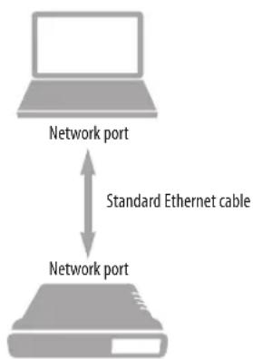
A simple Ethernet cable connection can be used for web app control, even without a USB or Thunderbolt connection to your computer. For example, if you are using your MOTU device as a mixer or audio router, you could control the on-board routing, mixing and effects from the web app through a standard Ethernet connection.
flowchart
graph TD
    A["Laptop"] -->|Standard Ethernet cable| B["Network port"]
    B -->|Internet cable to Ethernet cable| A
Figure 4-2: Web app control through a simple Ethernet cable.
Ethernet hub or network (LAN)
In this scenario, both your laptop and your MOTU device are connected to a standard Ethernet hub or home/office network (LAN). You can run the web app on multiple computers simultaneously.
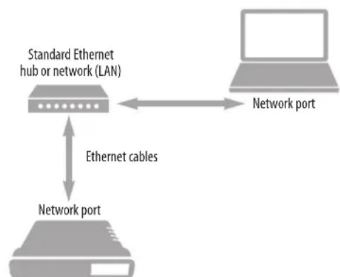
flowchart
graph TD
    A["Standard Ethernet hub or network (LAN)"] <--> B["Network port"]
    A <--> C["Network port"]
    D["Ethernet cables"] --> A
Figure 4-3: Web app control through a standard Ethernet hub or network (LAN).
Wi-Fi
When using standard Wi-Fi as shown, you can control the 624 from multiple Wi-Fi devices simultaneously.
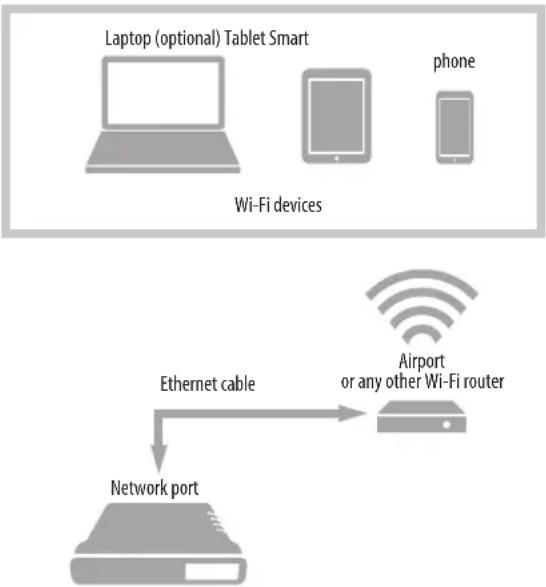
flowchart
graph TD
    A["Laptop (optional) Tablet Smart"] --> B["Wi-Fi devices"]
    C["phone"] --> D["Wi-Fi devices"]
    E["Airport or any other Wi-Fi router"] --> F["Network port"]
    G["Ethernet cable"] --> F
Figure 4-4: Web app control through Wi-Fi.
Ethernet network + Wi-Fi
You can, of course, combine the setups shown in Figure 4-3 and Figure 4-4, with Wi-Fi connected to the Ethernet hub or network.
MOTU AVB Switch
The MOTU AVB Switch provides five AVB
Ethernet ports, plus one standard Ethernet port.
Use the AVB ports for MOTU audio interfaces, and use the Ethernet port for Wi-Fi, Ethernet, etc.
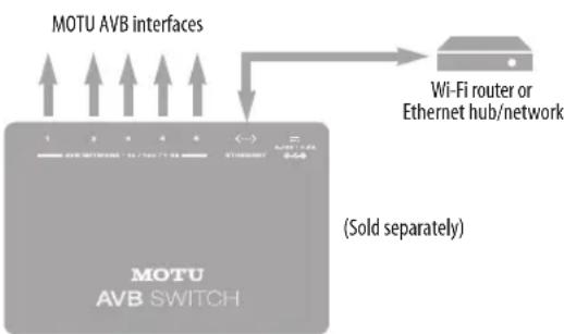
Figure 4-5: Using the Ethernet port on the MOTU AVB Switch.
SETUP FOR AVB ETHERNET AUDIO INTERFACE OPERATION
Your MOTU hardware can serve as an Ethernet audio interface when connected to a recent generation AVB-equipped Mac. You can then use your MOTU interface as a standard multi-channel audio interface with any Core Audio compatible host software running on the Mac.
For Ethernet audio interface operation, you need:
■ A recent Mac (any Mac that has a Thunderbolt port on it)
■ OS X El Capitan (10.11) or later
■ Firmware version 1.2.5 or later in your MOTU interface
Ethernet connection to the Mac
As shown on page 34, connect the network port on your MOTU interface to the Ethernet port on the Mac using a standard, high-grade (CAT-5e or CAT-6) network cable up to 100 meters in length.
If your Mac doesn't have an Ethernet port, you can connect your MOTU interface via Ethernet using a Thunderbolt-to-Ethernet adapter. Ethernet might be preferable over Thunderbolt because the Ethernet cable can be up to 100 meters long, using standard Ethernet cabling (which is very affordable).
USB-to-Ethernet adapters cannot be used because the Mac's USB chip set does not support AVB Ethernet.
Alternately, you can connect both the Mac and the interface to an AVB-compatible Ethernet switch.
Web app setup
To set up your MOTU device as an AVB Ethernet audio interface:
1 Launch the MOTU Discovery app. From the Settings menu (circled in red below), choose Launch Mac Virtual Entity, and from the sub-menu choose the Ethernet port to which your MOTU AVB interface is connected. It should now be checked.
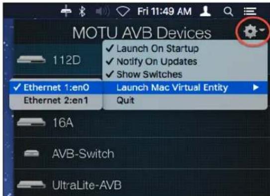
Figure 4-6: Enabling AVB connectivity to the Mac.
2 After completing step #1 above, the Mac will appear in the AVB device list in the MOTU AVB web app, as shown below. PLEASE NOTE: it may take several minutes for the Mac to appear in the list, the first time you set this up. After the first time, though, you won't experience any delays.
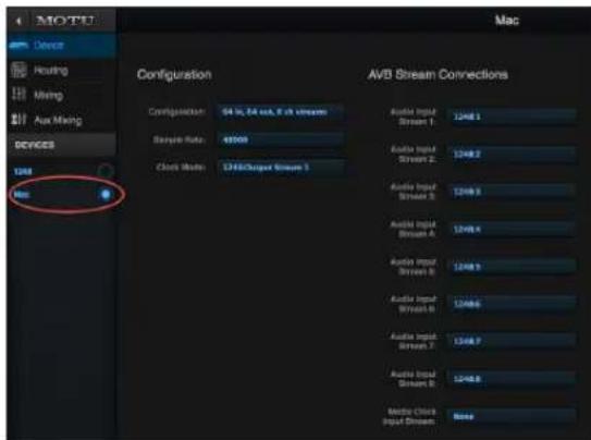
Figure 4-7: Accessing the AVB settings for the Mac in the MOTU web app.
3 From the Configuration menu (Figure 4-7), choose the channel mode for the Mac that best fits your workflow.
MOTU interfaces currently only support 8-channel streams (or less) so be sure to avoid configurations with streams that have more than eight channels.
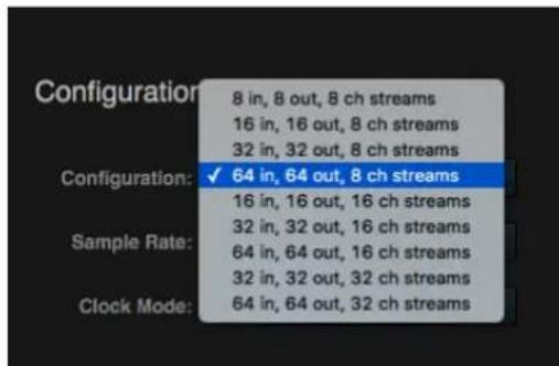
Figure 4-8: Choosing an AVB configuration for the Mac.
4 From the Sample Rate menu (Figure 4-7), choose the desired sample rate. Currently, the Mac only supports 48, 96 and 192 kHz sample rates.
5 For Playback from the Mac, go to the Device tab for your MOTU interface (the 1248 in the example below), and connect the input streams to the Mac's output streams.
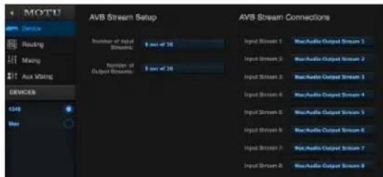
Figure 4-9: Routing computer streams to the interface for playback from the Mac.
6 In the Routing tab, route the Mac's output streams to desired physical outputs on your MOTU interface.
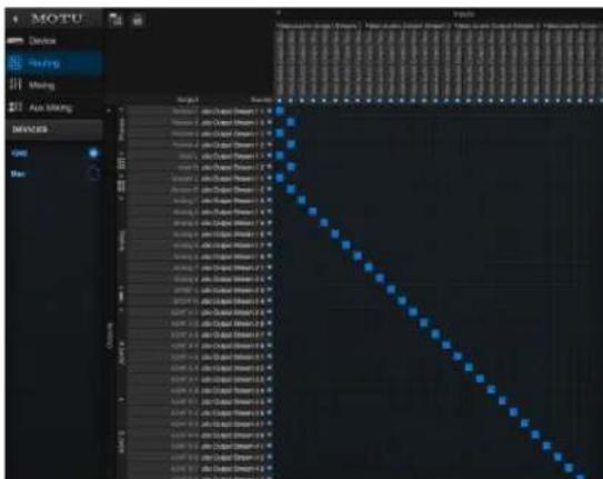
Figure 4-10: Routing Mac channels to physical outputs.
7 For Recording to the Mac, route desired physical inputs on your MOTU interface to output streams.
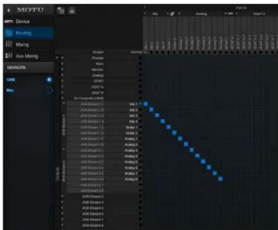
Figure 4-11: Routing physical inputs to the Mac.
8 On the Mac's Device tab, connect the Mac's input streams to the MOTU interface's output streams.
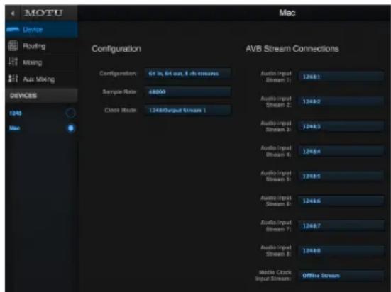
Figure 4-12: Routing streams from your MOTU interface to the Mac.
Leave Media Clock Input Stream set to None. (This setting can be used to sync the Mac to certain 3rd-party AVB devices that support Media Clock. This setting is not needed for MOTU devices.)
Clocking
In the example in Figure 4-12, the 1248 is the clock master and the Mac is clocking to the 1248's Output Stream 1. You can also reverse this scenario, where the Mac becomes the master and the 1248 clocks to Mac's Output Stream 1. The Mac does not follow the web app's Become Clock Master button, so you must set the Mac's Clock Mode manually.
AVB stream and channel counts
Each MOTU AVB stream is a group of eight audio channels. While testing is on-going, OS X AVB performance varies with different Mac models. Models such as the Mac Pro (late 2013) are able to handle eight streams (64 channels) in and out simultaneously, for MOTU interface models that support eight streams. (Check motu.com/avb for a summary of supported stream counts for each MOTU interface model.) For older Macs, we recommend one or two streams in each direction. Generally speaking, it is best to enable only as many streams as you need.
A TYPICAL 624 SETUP
Here is a typical 624 setup. This rig can be operated with or without a separate mixer. All mixing and effects processing can be done in the 624 itself,
controlled from your laptop, tablet, and smart phone — or several devices simultaneously.
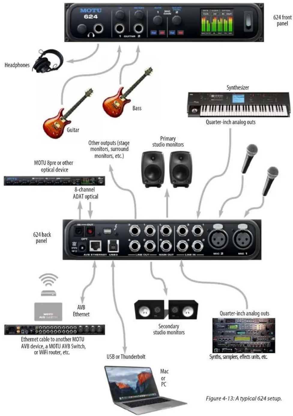
flowchart
graph TD
    A["624 front panel"] --> B["Headphones"]
    A --> C["Guitar"]
    A --> D["Bass"]
    A --> E["Synthesizer"]
    A --> F["Quarter-inch analog outs"]
    A --> G["MOTU 8pre or other optical device"]
    A --> H["8-channel ADAT optical"]
    A --> I["624 back panel"]
    I --> J["AVB Ethernet"]
    I --> K["Secondary studio monitors"]
    I --> L["Quarter-inch analog outs"]
    I --> M["USB or Thunderbolt"]
    I --> N["Mac or PC"]
    I --> O["Ethernet cable to another MOTU AVB device, a MOTU AVB Switch, or WiFi router, etc."]
AUDIO CONNECTIONS
Here are a few things to keep in mind as you are making audio connections to your 624 interface.
Mic inputs with preamps
Connect a microphone using a standard mic cable.
Do not connect a +4 dBu (line level) signal to the mic inputs without using the -20dB Pad. It is recommended you connect line level signals to the quarter-inch inputs instead.
Phantom power
If you are connecting a condenser microphone or another device that requires phantom power, engage the mic input's corresponding front-panel phantom power button.
Preamp gain
The 624's preamp provides 63 dB of gain. Use the front panel detented trim knobs to adjust gain as needed for each input. The LCD provides visual feedback as you turn the trim knob. Preamp gain is digitally controlled, so you can make fine-tuned adjustments in 1dB increments. You can also adjust preamp gain in the web app. See “Device tab” on page 12.
-20 dB pad
Each mic input (XLR jack) is equipped with a -20 dB pad switch, to accommodate input signals that could overdrive the input.
Guitar inputs
The 624 provides two dedicated guitar inputs on its front panel. These inputs are specially designed for guitar or bass instruments, with a high-impedance load of 1 megaohm. Use the knob to adjust input trim. Range is 24 dB (-12 to +12).
TRS quarter-inch analog inputs and outputs
Quarter-inch analog inputs and outputs are balanced (TRS) connectors that can also accept an unbalanced plug.
Quarter-inch analog outputs are not cross-coupled. Therefore, when connecting them to an unbalanced input, use a TRS plug with the ring disconnected. Not floating the negative terminal will short it to the sleeve ground and cause distortion.
Dedicated main outs
Like all I/O on the 624, the main outputs operate as an independent pair (they don't share signal with any other output pair). In a standard studio configuration, the main outs are intended for a pair of studio monitors, but they can also be used as regular outputs for any purpose. With adjustable converter trim, they support a wide range of industry-standard reference levels. Main out volume is controlled by the headphone volume knob on the front panel: push it repeatedly until you see Main Vol in the LCD and then turn it to adjust the master volume output.
Analog trims
All quarter-inch analog inputs and outputs can be trimmed. This allows them to support a variety of standards, including EBU-R68, SMPTE RP-155, +4dBu, -10dBV, 2vRMS, 1vRMS.
The 624's quarter-inch analog inputs are equipped with high-quality, digitally controlled analog trim that provides a range from -96 to +22 dB in 1dB steps.
Quarter-inch outputs can be trimmed in the DAC itself. Range is 24 dB. The Main Outs and Phones provide full trim range from 0 dB to - (-127).
Trim controls are most easily accessed in the web app. See “Device tab” on page 12. Trim settings can also be accessed in the LCD menu.
Optical I/O
The 624 provides ADAT optical (“lightpipe”) connectors (one input and one output). Together, they provide 8 channels of ADAT optical digital I/O
at 44.1 or 48 kHz, or 4 channels of SMUX optical at 2x sample rates (88.2 or 96 kHz). SMUX operation supports two modes (item #23 on page 13):
■ Standard — for 2x optical connection to 3rd-party SMUX-compatible hardware products.
■ Type II (Legacy) — for 2x optical connection to legacy MOTU products that are equipped with optical ports and support 2x operation.
The optical ports are disabled when the interface is operating at a 176.4 or 192 kHz.
TOSLink (optical S/PDIF)
Alternately, the optical ports can be configured for stereo TOSLink (optical S/PDIF) in the web app (item #23 on page 13). The optical IN and OUT banks can be configured independently.
Choosing a clock source for optical connections When connecting an optical device, make sure that its digital audio clock is phase-locked (in sync with) the 624. There are two ways to do this:
A. Resolve the optical device to the 624
B. Resolve the 624 to the optical device
For A, choose Internal (or anything other than Optical) as the clock source in the Device tab (item #13 on page 12). Then configure the other device to resolve to its optical input.
For B, choose Optical as the clock source (item #13 on page 12), and configure the other device to resolve to its own internal clock.
SYNCING TO SMPTE TIME CODE (LTC)
The Clock Mode menu (item #13 on page 12) provides the ability to resolve to SMPTE time code (Longitudinal Time Code, referred to as LTC) from any specified analog or digital input.
When you choose the LTC clock mode setting, the audio phase lock engine in your MOTU interface resolves to the incoming time code. (See below for how to specify the time code input.) This ensures that audio passing through the interface remains resolved to time code and won't drift over time, as long as the audio is coming from other sources that are also resolved to the same time code. This also ensures that audio recorded by DAW host software on a connected computer, or audio playing back from the DAW, will remain resolved to time code and won't drift over time, even when restarting or cueing the source time code.
Depending on the stability of the incoming time code, it may take a few seconds for your interface to lock to the time code. The more stable the incoming time code, the faster the lock-up time.
SMPTE time code (LTC) settings
There are several settings for the time code features in your MOTU interface. In the web app, go to the Device tab (page 14) and scroll to the LTC Setup section, shown below.
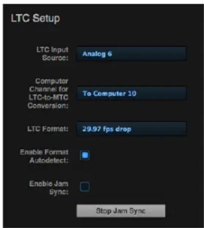
Figure 4-14: Settings for SMPTE time code sync.
LTC Input Source
Choose the input on your interface that is receiving the time code (LTC). Any input can be used, including an analog input, digital input or even an AVB network channel.
Computer Channel for LTC-to-MTC Conversion Choose a computer channel that you aren't using for anything else here. It will be used to transmit LTC from the interface to the computer. If all of your computer channels are being used, you can add extra channels using the To computer setting in the Routing tab. See “LTC-to-MTC conversion” on page 63 for further info about LTC-to-MTC conversion.
LTC Format
Choose the frame format that matches the incoming time code.
Enable Format Autodetect
If you would like your MOTU interface to automatically detect the frame format of the incoming time code, check this box.
Enable Jam Sync
When this option is checked, your MOTU interface will continue to convert LTC to MTC even after incoming time code stops being received. Once Jam Sync kicks in, it will continue generating until you click Stop Jam Sync.
SYNCING AN AVB NETWORK
The AVB protocol provides sophisticated and accurate timing, synchronization, and clocking features for AVB device networks of any size as shown on pages 35-36, including:
■ Low latency
■ Network-wide time base
■ Better-than-sample-accurate phase lock across all connected devices
■ Timing accuracy down to the nanosecond
Choosing a master clock
The web app provides an easy way to choose one device as the master clock for your whole MOTU AVB network.
1 Go to the Devices tab (page 12).
2 In the device list (item #1 on page 12), choose the MOTU interface you wish to use as the clock master.
3 Click the Become Clock Master button below the Clock Mode menu.
Now, all other MOTU AVB devices on the network are resolved to this device.
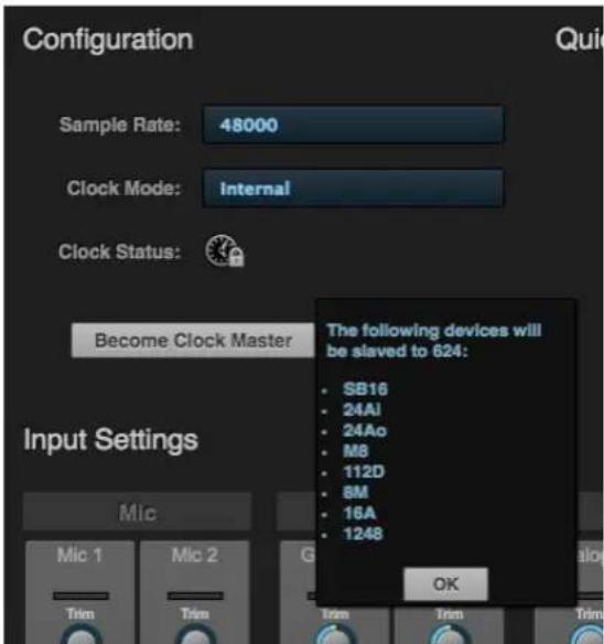
Figure 4-15: Choosing a clock master.
Alternately, you can go to the clock mode menu for each individual device separately and choose the master clock device by hand. For example, you may be in a situation where at least one MOTU device on the network must remain resolved to its own clock (or another clock source). Just know that in this case, audio cannot be streamed between MOTU AVB devices that don't share the same master clock.
Resolving the master clock device to an external clock source
The MOTU device you've specified as the AVB network clock master can itself be resolved to an external time base such as word clock (if available) or optical. Just choose the desired clock source from its Clock Mode menu (in the Device tab). Doing so effectively resolves the entire AVB network to the external clock source.
SYNCING MULTIPLE AVB AUDIO INTERFACES CONNECTED TO A MAC
There are several options for clocking multiple AVB audio devices connected to the Mac:
■ You can resolve them to an external clock source (like word clock, if available).
■ You can create an aggregate device, as usual. The aggregate device setup panel has a check box called Drift Correction, which sample-rate converts devices that are not synchronized.
Part 2
Using the
624
CHAPTER 5 Presets
OVERVIEW
Because of its advanced, extensive feature set, the 624 can be used for many different purposes. This chapter discusses common use cases and their corresponding device presets, to help you use the hardware for your needs.
Preset menu
The preset menu (item #7 on page 12) contains a number of presets specifically designed for common use cases. By loading the corresponding preset, the 624's routing tab and mixer will be reconfigured accordingly. You can visit the routing and Mixing tabs to inspect settings and adjust them as needed.
Audio interface....51
Stand-alone mixer 52
Interface + mixer.... 52
Live recording with monitor mixing 53
AVB Expansion.... 53
Optical converter 54
Create your own presets
You can create presets to suit your specific needs. The 624 is highly capable and configurable, allowing it to perform many tasks simultaneously.
Video tutorials
To view several excellent video tutorials for the presets described in this chapter, visit:
www.motu.com/avb
AUDIO INTERFACE
Choose the Audio Interface preset to use the 624 as a standard Thunderbolt, USB or iOS audio interface. Hardware inputs and outputs are accessible from your computer or iOS device. From Computer channels 1-2 are routed to the 624 Main Outs (through the on-board mixer), and From Computer channels 3-4 are routed to the on-board mixer's monitor bus, which is routed to the 624's Headphone output. The rest of the the From Computer channels are mapped consecutively to the rest of the 624's analog and digital outputs. All of the 624's physical inputs (analog, optical, etc.) are routed to both to the computer and the on-board mixer, too. If you want to monitor a live input with zero latency, simply unmute its input in the mixer and you'll hear its no-latency signal on the Main Outs (and/or Headphone Outs). Networking features are disabled.
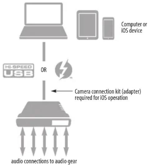
flowchart
graph TD
    A["Computer or iOS device"] -->|OR| B["Camera connection kit (adapter) required for iOS operation"]
    C["HI-SPEED USB"] -->|OR| B
    D["Audio Gear"] -->|Output| B
    E["Computer or iOS device"] -->|Output| B
Figure 5-1: Using the 624 as an audio interface.
STAND-ALONE MIXER
Choose the Stand-alone mixer preset to use 624 as a mixer. Doing so routes all physical inputs to the mixer, with the mixer's main mix bus and monitor bus going to the Main Outs and Phones, respectively.
To control the mixer (with the web app), you have several options. You can connect a computer to the 624 using Thunderbolt, USB, Ethernet, or Wi-Fi, as explained in “Setup for web app control” on page 38. Figure 5-2 below shows the Wi-Fi scenario. Note that you can control the mix from multiple Wi-Fi devices.
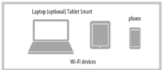
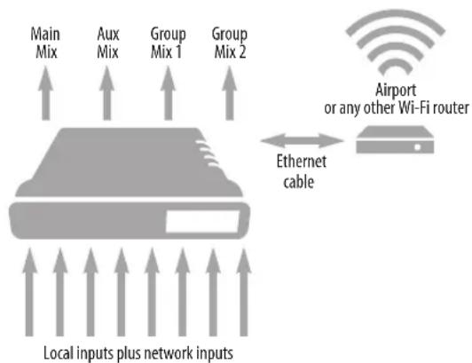
flowchart
graph TD
    A["Local inputs plus network inputs"] --> B["Main Mix"]
    A --> C["Aux Mix"]
    A --> D["Group Mix 1"]
    A --> E["Group Mix 2"]
    B --> F["Airport or any other Wi-Fi router"]
    C --> F
    D --> F
    E --> F
    F --> G["Ethernet cable"]
    G --> H["Output"]
Figure 5-2: Using the 624 as a stand-alone mixer. This example demonstrates how you can control the mixer from several Wi-Fi devices.
INTERFACE + MIXER
Choose the Interface + Mixer preset to use the 624 as both an audio interface and mixer, simultaneously. This preset is identical to the Audio Interface preset, except that all From Computer channels are also routed to the 624's on-board mixer, which mixes them to the Main Mix bus (to the Main Outs) and the Monitor bus (to the Headphone Out). The on-board mixer mixes all of the following sources:
■ The 624's analog inputs
■ The 624's optical inputs
■ All From Computer channels (Thunderbolt or USB channels from the host computer)
The Monitor bus is set up as a solo bus.
In this scenario, you can control the mixer from the MOTU Pro Audio Control web app running on the computer. You can also run the web app from wireless devices on the same Wi-Fi network as the laptop.
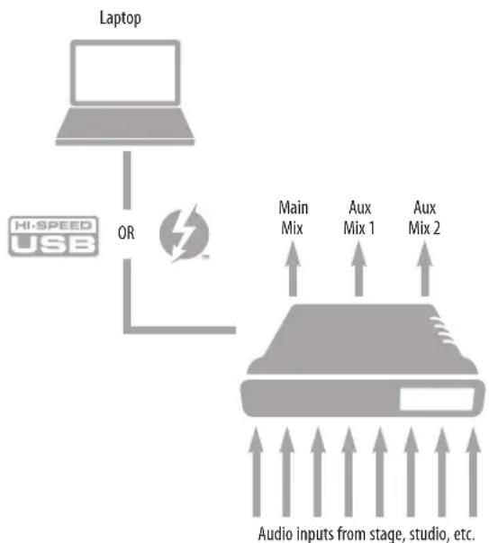
flowchart
graph TD
    A["Laptop"] -->|OR| B["Audio Inputs from stage, studio, etc."]
    B --> C["Main Mix"]
    B --> D["Aux Mix 1"]
    B --> E["Aux Mix 2"]
    F["Hi-SPEED USB"] --> A
Figure 5-3: Using the 624 as an audio interface and mixer, simultaneously.
LIVE RECORDING WITH MONITOR MIXING
Choose the Live recording with monitor mixing preset when you are tracking in the studio. The setup is pretty much the same as for the “Interface + mixer” preset shown in Figure 5-3 on page 52, except that aux busses are routed to the 624’s analog outs (in consecutive pairs) for independent monitor mixes. All physical inputs on the interface are routed to both the computer (for recording) and the Main Mix and Monitor busses in the mixer (for near-zero latency monitoring). Thunderbolt or USB channels from the computer are included in the 624’s mix.
AVB EXPANSION
Use the AVB Expansion preset when you want to connect the inputs and outputs on the 624 to other devices over Ethernet cabling. This preset routes all inputs and outputs on the 624 interface to 8-channel AVB network streams in the routing grid, which are then broadcast to any/all other devices on the same AVB Ethernet network.
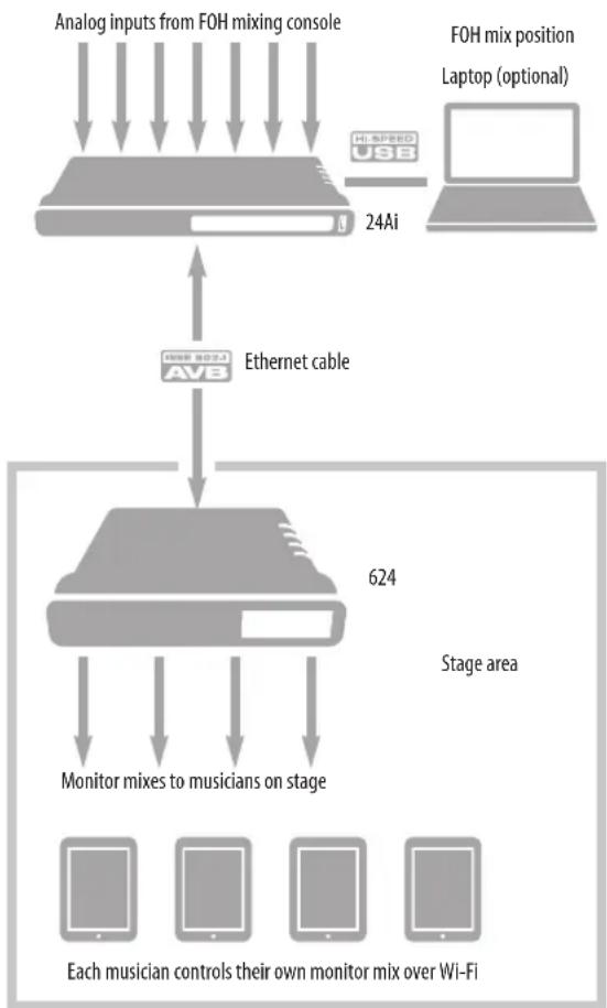
flowchart
graph TD
    A["Analog inputs from FOH mixing console"] --> B["24Ai"]
    C["FOH mix position\nLaptop (optional)"] --> D["Laptop"]
    B --> E["Ethernet cable"]
    D --> E
    E --> F["624"]
    F --> G["Monitor mixes to musicians on stage"]
    G --> H["Each musician controls their own monitor mix over Wi-Fi"]
Figure 5-4: An example of using the AVB Expansion preset: 24 channels from the FOH console are being distributed to musicians on stage as 4 separate monitor mixes.
OPTICAL CONVERTER
Choose the Optical converter preset if you would like the 624 to serve as a multi-channel digital-to-analog or analog-to-digital converter connected to another device equipped with an optical port. This preset sends optical inputs to the 624's analog outputs; conversely, analog inputs are routed to the optical outputs.
For example, if you have another MOTU interface equipped with optical, you could connect its optical output banks to the 624's optical input banks. The 624 then serves as an expander that adds the 624's analog outputs to your setup.
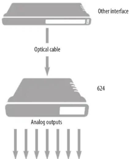
flowchart
graph TD
    A["Other interface"] --> B["Optical cable"]
    B --> C["624"]
    C --> D["Analog outputs"]
Figure 5-5: Use the Optical converter preset to use the 624 as an optical-to-analog output expander. You can also use this preset to use the 624 as an analog-to-optical input expander.
CHAPTER 6 The Front Panel LCD
OVERVIEW
The front panel LCD displays level meters for all analog inputs and outputs and activity indicators for optical I/O. The LCD also provides several menus that provide status information and basic hardware settings.
Level meters....55
Push-button Knobs 55
ID....55
Channel focus 55
Main volume....55
Meters....56
Menu Navigation 56
Device menu....56
Network menu....56
Settings menu 56
Presets menu 56
Version menu....56
Clock....56
Stand-alone operation.... 56
LEVEL METERS
In its default state when the unit is first powered on, the LCD displays level meter activity for all analog audio inputs and outputs (Figure 6-1).
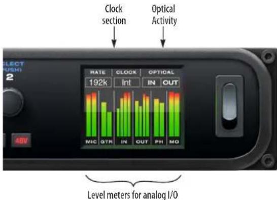
Figure 6-1: Analog metering and activity indicators for optical I/O.
PUSH-BUTTON KNOBS
The front-panel knobs (Figure 6-2) are push-button digital rotary encoders. Push the knob for the function labeled in blue.
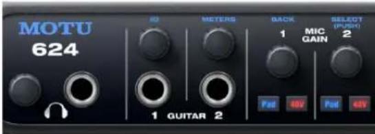
Figure 6-2: Push the knob to activate the functions labeled in blue.
ID
Push ID (Figure 6-2) to immediately view the 624's network information, including its IP Address. Push BACK to return to the meters.
CHANNEL FOCUS
When turning a knob to adjust volume or input gain, the LCD shows the level setting. A few seconds after you stop turning the knob, the LCD returns to the previous display. To temporarily suspend the focus timeout, push and hold the knob while focused. A “lock” icon appears in the LCD to indicate that the focused metering will remain on screen until you hold the knob again to dismiss it.
MAIN VOLUME
Push the headphone volume knob to toggle volume control between the phones and main outs. The LCD provides visual feedback.
MUTE
When adjusting headphone volume or main out volume, the LCD provides visual feedback of the volume setting. While the volume display is on screen, double-tap the volume knob to temporarily mute (or unmute) the headphones or main outs.
METERS
Push the METERS knob to immediately jump back to the default screen that displays level meters.
MENU NAVIGATION
Push SELECT to access the main menu, which provides settings and status information.
Main Menu
Turn the SELECT knob to scroll through the menu settings.
Push SELECT to enter the selected sub-menu or to select the currently highlighted parameter.
Push BACK to go to the parent menu.
To exit the menu entirely, push BACK repeatedly until the menu disappears from the display, or push METERS to return to the default meter screen.
Device menu
The Device menu provides information about the device, such as its name and connection mode (Thunderbolt, USB or AVB).
Network menu
The Network menu displays the following network-related information:
Setting Explanation
| Serial/UID Unique AVB network identifier and serial number that can be used for troubleshooting and registering your device at motu.com/register. |
IP address The unique network address for the unit. Type this address into your web browser to access the unit's settings in the MOTU Pro Audio Control web app.
AVB Indicates whether AVB networking is currently enabled or disabled. For example, AVB could be disabled because a non-AVB switch is being used. When AVB is disabled, audio streaming over the network is disabled.
Settings menu
The Settings menu provides access to basic hardware settings.
Setting What it does
| Clock Mode Sets the digital audio clock source for the device. |
| Sample Rate Sets the sample rate for the device. |
| Optical Specifics ADAT or TOSLink, or the SMUX format when operating at 88.2 or 96 kHz. See “Optical I/O” on page 44. |
| Configure IP Chooses between DHCP and a manually assigned IP Address. |
| Clear Password Removes password protection in the web app. |
| Factory Defaults Restores factory default settings. |
Presets menu
The Presets menu lets you recall settings that have been saved as a device preset. Use the web app to create and save presets (item #7 in the “Device tab” on page 12).
Version menu
The Version menu displays firmware version info.
CLOCK
The Clock section of the LCD (Figure 6-1 on page 55) displays the sample rate at which the unit is currently operating, and the current Clock Mode setting (item #13 in the Devices tab on page 12). The Clock Mode setting can also be found (and changed) in the Settings Menu.
All settings, including mix settings and device settings, are saved in the 624's memory. They remain in effect even when the interface is not connected to a computer. This allows you to use the 624 as a stand-alone mixer. You can make adjustments to any setting at any time from the web app running on a device that has a network connection to the 624, as explained in “Setup for web app control” on page 38.
CHAPTER 7 Working with Host Audio Software
OVERVIEW
The 624 provides multi-channel audio input and output for Core Audio compatible audio applications on the Mac and ASIO or Wave compatible applications on Windows, including MOTU's Digital Performer and AudioDesk, Apple's Logic Pro and GarageBand, and other third-party software applications such as Ableton Live, Avid Pro Tools, Cockos Reaper, Propellerhead Reason, Steinberg Cubase and Nuendo, Cakewalk SONAR, PreSonus Studio One, Bitwig, and others.
AudioDesk is available as a free download for 624 owners at motu.com/avb. For complete information about all of AudioDesk's powerful workstation features, refer to the AudioDesk User Guide.pdf found in the Help menu of the AudioDesk application.
Digital Performer, MOTU's state-of-the-art digital audio workstation software, is available separately; for details about upgrading from AudioDesk to Digital Performer, talk to your authorized MOTU dealer or visit motu.com.
Preparation 57
Run the web app.... 57
Choose the MOTU Pro Audio driver.... 58
Reducing monitoring latency.... 58
Working with the Routing grid 61
Working with on-board mixing and effects.... 63
LTC-to-MTC conversion 63
PREPARATION
Install your host audio software first if you haven't already done so, and complete these chapters before proceeding:
■ chapter 3, “Software Installation” (page 29)
■ chapter 4, “Hardware Installation” (page 33)
RUN THE WEB APP
Before you run your host audio software, launch the web app to configure your MOTU hardware.
The web app lets you configure important settings in your audio interface, enable the desired inputs and outputs, and set up audio streams to and from the computer.
Sample Rate
Choose the desired sample rate for the 624 (item #8 in the Device tab on page 12) and your host audio software. Make sure the sample rates for the hardware and software match. Newly recorded audio will have this sample rate.
Clock Mode
The Clock Mode setting (item #13 in the Device tab on page 12) is important because it determines the master digital audio clock for your system.
If you do not have any digital audio connections to your MOTU device (you are using the analog inputs and outputs only), and you will not be resolving your host software to optical or another external clock source, choose Internal.
If you have devices connected to the optical ports, see “Choosing a clock source for optical connections” on page 45.
Audio Interface preset
Click Launch Quick Setup (item #10 in the Device tab on page 12) and choose the Audio Interface preset. Your MOTU interface is now set up for operation as an audio interface with any host audio software. For details about customizing the audio routing to and from the computer, see “Working with the Routing grid” on page 61.
CHOOSE THE MOTU PRO AUDIO DRIVER
Once you've made the preparations described so far in this chapter, you're ready to run your audio software and enable the MOTU Pro Audio driver, which allows your host software to use the 624 as an audio interface.
For Mac OS X audio software
For audio software running under Mac OS X, go to the menu item or preference where you choose the audio device (Core Audio driver) you wish to use, and then select the 624 by name.
For Windows audio software
For audio software running under Windows, go to the menu item or preference where you choose the ASIO driver you wish to use, and then choose MOTU Pro Audio. If your host audio software doesn't support ASIO, choose the MOTU Pro Audio Wave driver instead.
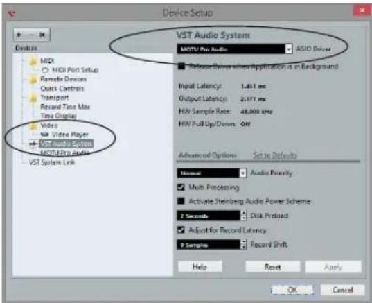
Figure 7-1: Choosing the MOTU Pro Audio ASIO driver in Cubase.
Where to go in popular audio hosts
Here is the location for this setting in various popular audio software host applications:
Host software Location for choosing the 624
| Digital Performer and AudioDesk | Setup menu > Configure Audio System > Configure Hardware Driver |
| Pro Tools 9 or later Setup menu > Playback Engine or Current Engine | |
| Logic Pro Preferences > Audio tab > Devices tab > Core Audio tab | |
| Garage Band Garage Band menu > Preferences > Audio/ MIDI > Audio Output/Input menus | |
| Cubase and Nuendo | Device Setup > Devices list > VST Audio System menu |
| Live Preferences > Audio tab | |
| Reason Preferences > Audio preferences | |
Reaper Preferences > Audio prefs > Devices
Other audio software
Consult your software's manual for further information.
REDUCING MONITORING LATENCY
Monitoring latency is a slight delay caused by running an input signal through your host audio software and back out. For example, you might hear it when you drive a live guitar input signal through an amp modeling plug-in running in your audio sequencer.
This delay is caused by the amount of time it takes for audio to make the entire round trip through your computer, from when it first enters an input on the 624, passes through the interface hardware into the computer, through your host audio software, and then back out to an output.
Monitoring through the 624
If you don't need to process a live input with plug-ins, the easiest way to avoid monitoring latency is to disable your DAW's live monitoring feature and instead use the digital mixer in the 624 to route the input directly to your outputs. For details, see “Mixing tab” on page 16. The mixer in the 624 even provides zero latency effects processing (EQ, compression and reverb), which can be applied to the signal.
Direct hardware playthrough / Direct ASIO monitoring
When managing your live monitor mix through the 624 mixer, remember to disable your DAW's live monitoring features, so that you won't hear record-enabled tracks in your DAW. Also note that the 624 does not support Direct Hardware Playthrough in Digital Performer, or the Direct ASIO Monitoring feature (or similar) offered and other DAWs, which lets you control no-latency hardware monitoring from within the host application. Instead, you can use the MOTU Pro Audio Control web app mixer ("Mixing tab" on page 16) to make these live monitoring connections manually.
If you don't require any effects processing on the input signal (no reverb or compression, for example), all this takes is one click in the routing grid to route the input being recorded to the output you are using for monitoring.
If you are recording a mono input that you'd like to monitor in stereo, or if you need to apply effects to the monitored signal, you can simply route the input to the mixer in the 624. This is done by opening the Mix In group in the Outputs column along the left side of the grid, and clicking the tile at the intersection of the input's column and the desired mixer input's row. Once routed to the mixer, use the input channel, reverb bus, and monitor bus in the mixer to apply effects as desired, and perhaps include other channels to the mix, and then assign the monitor bus output in the routing grid to the output you are using for monitoring.
In either case (routing directly in the grid or routing through the mixer), be sure to maintain the input's connection to the computer as well, so the input signal can be recorded in your host software. In other words, you'll want to make sure there are two tiles enabled in the input's column in the grid: one tile for the connection to the computer and another tile for your monitoring output (or a mixer input, if you are using the mixer to apply effects). If you need to route the input signal to other destinations, too, you can certainly do so (you can route the input to multiple destinations).
Monitoring through your host audio software
If you do need to process a live input with host software plug-ins, or if you are playing virtual instruments live through your MOTU audio hardware, you can significantly reduce latency by adjusting the audio buffer setting in your host audio software, as explained in the next section.
It is important to note that monitoring delay has no effect on the recording, or playback, of audio data from disk. The actual recording and playback is extremely precise, it is only the monitoring of your live input signal which may be delayed.
Adjusting your host software audio buffer
Buffers are small bundles of audio data. The 624 "speaks" to your computer in buffers, rather than one sample at a time. The size of these buffers determine how much delay you hear when monitoring live inputs through your audio software: larger buffers produce more delay; smaller buffers produce less.
Adjusting buffer size on Mac OS X
Under Mac OS X, audio I/O buffer size is handled by the host audio application (not by the 624's Core Audio driver). Most audio software applications provide an adjustable audio buffer setting that lets you control the amount of delay you'll hear when monitoring live inputs or processing them with software plug-ins. Here are a few examples.
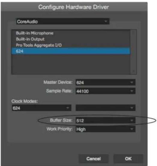
Figure 7-2: In Digital Performer and AudioDesk, choose Setup menu> Configure Audio System> Configure Hardware Driver to open the dialog shown above and access the Buffer Size setting.
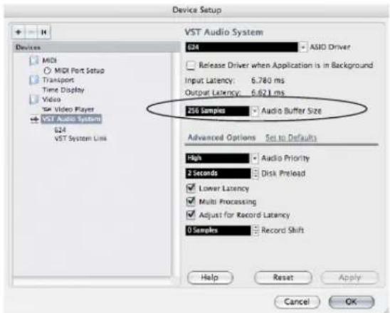
Figure 7-3: In Cubase or Nuendo, choose Devices menu > Device Setup. Select your interface (624), then click the Control Panel button to access the window above and the Buffer Size setting.
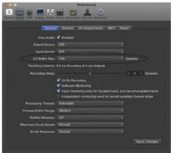
Figure 7-4: In Logic Pro, go to the Audio Driver preferences to access the Buffer Size option shown above.
Adjusting buffer size on Windows
On Windows, the buffer size is adjusted in the web app Device tab (page 12). See "Host Buffer Size" and "Host Safety Offset" on page 31.
Lower latency versus higher CPU overhead
Buffer size has a large impact on the following:
■ Monitoring latency
■ The load on your computer's CPU
■ Responsiveness of transport controls and effect knobs in AudioDesk, Digital Performer or other audio software.
■ Real-time virtual instrument latency.
The buffer setting presents you with a trade-off between the processing power of your computer and the delay of live audio as it is being patched through your software. If you reduce the size, you reduce monitoring latency, but significantly increase the overall processing load on your computer, leaving less CPU bandwidth for things like real-time effects processing. On the other hand, if you increase the buffer size, you reduce the load on your computer, freeing up bandwidth for effects, mixing and other real-time operations.
Figure 7-5: When adjusting the buffer size to reduce monitoring latency, watch the 'processor' meter in Digital Performer or AudioDesk's Performance Monitor. If you hear distortion, or if the Performance meter is peaking, try raising the buffer size.
If you are at a point in your recording project where you are not currently working with live, patched-thru material (e.g. you're not recording vocals), or if you have a way of externally processing inputs, choose a higher buffer size. Depending on your computer's CPU speed, you might find that settings in the middle work best (256 to 1024).
Transport responsiveness
Buffer size also impacts how quickly your audio software will respond when you begin playback, although not by amounts that are very noticeable. Lowering the buffer size will make your software respond faster; raising the buffer size will make it a little bit slower.
Effects processing and automated mixing
Reducing latency with the buffer size setting has another benefit: it lets you route live inputs through the real-time effects processing and mix automation of your audio software.
WORKING WITH THE ROUTING GRID
The Routing grid (Figure 7-6) gives you a lot of control over the audio routing to and from your computer, as explained in the following sections.
Enabling and disabling input/output banks
In the web app Device tab (page 13), you can enable all input and output banks on your MOTU device that you wish to make available to your host audio software. You can disable banks you are not using to simplify operation. Be sure to keep at least one input and output bank enabled, though.
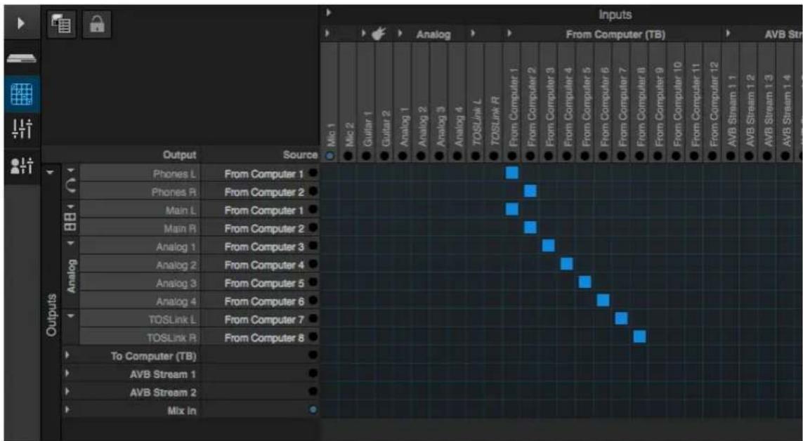
Figure 7-6: An example of routing computer channels (from host audio software) to the analog outputs on a 624. Computer channels 1-2 are being split to two pairs of outputs: Phones L-R and Main L-R.
Specifying the number of computer channels In the web app Device tab (item 25 on page 14), in the Computer Setup section, you can specify the number of computer channels for streaming audio to and from your host audio software. You might want enough channels to cover the following:
■ Physical inputs you want to record on your computer.
■ The physical outputs you want to send audio playback to.
■ Any audio streams going to and from the on-board mixer in your MOTU device.
■ Any audio streams going to and from the AVB network, if you have multiple networked MOTU AVB devices.
If you aren't sure how many channels you'll need, visit the Routing tab, as explained below.
Making inputs and outputs available to your host software
In the web app, use the Routing tab (page 15) to map inputs and outputs to computer channels, as demonstrated in Figure 7-6 and Figure 7-7.
Configuration presets
The presets menu (item #7 in the Devices tab on page 12) provides many useful presets for various host routing scenarios. These presets are a convenient shortcut for the routing grid setups discussed in the next few sections.
Naming computer input and output channels
Click on any computer input or output name in the routing grid (Figure 7-6) to change its name. These names appear in your host audio software.
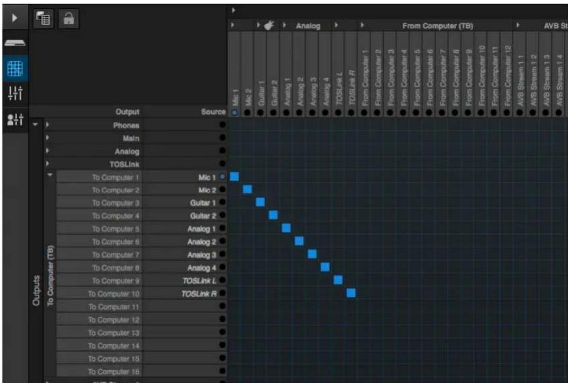
Figure 7-7: An example of routing physical inputs on the 624 to computer channels (for host audio software).
Streaming computer audio to and from the on-board mixer
In the Routing grid, you'll see mixer inputs across the top of the grid, including Main, Monitor, Aux, etc. (item 11 on page 15). These are output busses from the 624's on-board mixer. To route one of these mix busses to your host computer software, click the grid at the intersection of the mix column and desired computer channel row. Now, the mix bus output will be routed to the computer via the channel you selected.
Conversely, you can stream audio from the computer into the mixer. Channels coming from the computer are represented across the top of the routing grid as inputs. To route a computer channel to the mixer, click the grid at the intersection of the computer channel column and the desired mix input row. Now, that computer channel will be routed to the mixer input.
Working with AVB network streams
Audio channels going to networked AVB interfaces can be streamed to and from your host audio software through the 624 connected directly to the computer. For information about how to set this up, see “Mapping computer channels to network streams” on page 93.
Mirroring computer channels to multiple outputs
Figure 7-6 shows an example of mirroring one stereo audio stream from host audio software to several outputs. In the example, computer channels 1-2 are being sent to Phones L-R and Main L-R. To route a source to multiple destinations, click multiple boxes in its column, (see computer channels 1-2 in Figure 7-6).
Combining multiple sources to one output
To merge (mix) any channels in the grid (computer streams or otherwise), route them to mixer inputs and then use the on-board mixer (“Mixing tab” on page 16).
Routing grid tutorials
For further information about using the routing grid, including many useful tips and techniques, visit:
www.motu.com/techsupport/technotes/avbrouting
and
www.motu.com/avb
WORKING WITH ON-BOARD MIXING AND EFFECTS
The 624 provides powerful mixing, EQ, compression and reverb, which can operate hand-in-hand with your host's mixing environment. For example, the 624 can serve as a monitor mixer, routing channels to musicians, or it can serve as an integrated extension of your host's mixing environment. You can even save a particular mixing configuration as a preset for future recall. For details, see “Mixing tab” on page 16.
LTC-TO-MTC CONVERSION
When connected to a Mac, your MOTU interface can convert SMPTE time code (LTC) to MIDI Time Code (MTC), allowing any MTC-compatible host audio software to resolve to MTC.
LTC-to-MTC conversion can be done even when the Clock Mode setting for the MOTU interface is set to Internal (or any other setting). Note that the Clock Mode setting does NOT have to be set to LTC. In other words, the interface can convert LTC to MTC even when it is not resolving its audio engine to the incoming time code. This allows your DAW host software to resolve to time code with fast lockup response.
To set up LTC-to-MTC conversion:
1 Set the interface Clock Mode to Internal (or any other desired setting).
2 Set the other LTC settings as needed, as discussed in “Syncing to SMPTE time code (LTC)” on page 45, including the Computer Channel for LTC-to-MTC Conversion setting.
3 If you would like MIDI Time Code to continue to be generated, even after LTC stops being received, check Enable Jam Sync (Figure 4-14 on page 45). Otherwise, leave it unchecked.
4 Follow the directions for MTC (SMPTE) sync in your DAW software.
Your MOTU interface driver automatically communicates with OS X, creating a device in the computer's Audio MIDI Setup configuration that reports its time code port to any MTC-compatible host software. If your host software requires that you specify the port, you should see your MOTU interface SMPTE Sync port as an available option in the list. In Digital Performer, this is the Sync to port menu in the Receive Sync settings (Setup menu), which is set to Any by default (so it should just work). Here's a summary for a few popular DAW hosts:
Host software Sync settings
| Digital Performer and AudioDesk | Settings menu >Receive Sync >Sync to port menu |
| Pro Tools Setup > Peripherals > Synchronization | |
| Logic File > Project Settings > Synchronization > General | |
| Live Preferences > MIDI Sync | |
Cubase Transport > Project Synchronization Setup
CHAPTER 8 Mixer Effects
OVERVIEW
This chapter provides further information about the effects processors available in the DSP mixer in the 624. For basic mixer operation, see:
Mixing tab.... 16
Aux Mixing tab 17
Mixer input channel strips.... 18
Main Mix and Monitor channel strips.... 19
Aux bus channel strips.... 20
Group and Reverb channel strips.... 21
Powerful DSP-driven mixing and effects
The mixer is driven by a powerful DSP that delivers 32-bit floating point precision and plenty of processing bandwidth for no-latency effects, including parametric EQ, dynamics, and reverb. Effects can be applied when operating as an audio interface or as a stand-alone mixer without a computer. Input signals to the computer can be recorded wet and/or dry, or recorded dry while a real-time wet monitor mix is sent to musicians. Effects include:
High Pass Filter 65
A conventional high pass filter
Gate 66
A standard gate with threshold/attack/release controls
Four-band parametric EQ.... 66
Multi-band parametric EQ modeled after British analog consoles
Compressor.... 67
A standard compressor with threshold/ratio/attack/release/gain controls
Leveler 69
The Leveler™, an accurate model of the legendary LA-2A optical compressor, which provides vintage, musical automatic gain control
Reverb 70
Classic reverb with tail lengths up to 60 seconds
Advantages over host-based mixing and processing
The hardware mixer in the 624 provides several major advantages over mixing and processing in your host audio software:
- No buffer latency. The DSP-mixer provides the same near-zero latency throughput performance as a conventional digital mixer. Effects processing doesn't impact your computer's CPU.
■ DSP mixing and routing can be maintained independently of individual software applications or projects.
■ DSP-driven mixing can function without the computer, allowing the 624 to operate as a portable, stand-alone mixer with effects.
Effects are disabled when operating at 4x sample rates (176.4 or 192 kHz).
HIGH PASS FILTER
All input channel strips provide a 12 dB per octave high pass filter. High Pass filters are often used to remove unwanted mic rumble, for example.
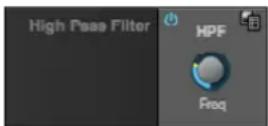
Figure 8-1: The High Pass Filter.
GATE
All input channel strips provide a Gate module.
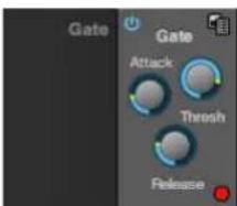
Figure 8-2: The Gate module.
The gate silences the signal when the input signal's level drops below the Threshold.
The rate at which the gate responds, (opens to let signal through) is determined by the Attack parameter. With a short Attack time, the gate will open as soon as the signal crosses the Threshold; with longer Attack times, the gate will gradually open, much like a fade-in.
When the input level falls back below the Threshold, the time it takes for the gate to close (how quickly the signal is attenuated), is determined by the Release parameter. Short Release times will close the gate quickly, abruptly attenuating your signal, versus longer release times, which will gradually attenuate your signal, like a natural fade-out.
FOUR-BAND PARAMETRIC EQ
All mixer channel strips, (except for the Monitor bus), provide modeled, four-band parametric EQ.
Vintage EQ
Inspired by legendary British large console EQs, the EQ section (Figure 8-3) models the sound of the most sought-after classic equalizers. Four bands of center frequency parametric EQ filtering are provided, each with a bandwidth control. The High and Low bands include a shelf filtering option. With 32-bit floating point precision, the vintage EQ has been carefully crafted and meticulously engineered to produce musical results in a wide variety of applications.
Enabling EQ
Each band has an enable/disable button (Figure 8-3), allowing you to enable as few or as many bands as needed for the channel strip.
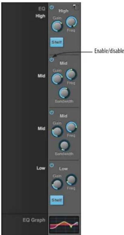
Figure 8-3: The Four-band parametric EQ module.
EQ filter controls
The EQ filters have three controls:
Control unit range
Gain dB -20.00 to +20.00
Frequency Hertz 20 to 20,000
Bandwidth Octaves 0.01 to 3.00
Double-click a knob to return to its default position.
EQ filter characteristics
EQ is one of the most widely used processing tools and can be applied to many different situations, from minor corrective tasks to creative tone
sculpting. The four-band EQ has been designed to be flexible enough to cover a broad range of applications. By adjusting Gain and Bandwidth together, you can emulate the smooth and musical character of classic analog EQ circuits, in which the Gain/Bandwidth dependency was dictated by the actual circuit design and electrical components used.
Low and high shelf filters
The Low and High bands offer a shelf option that is similar to those found in most conventional parametric EQs.
EQ graph
The EQ graph below the EQ section (Figure 8-3) provides a thumbnail visual indication of the current EQ settings for the input channel. It is for visual reference only and cannot be edited directly. However, you can click it to open the full-size EQ graph in a separate window (Figure 8-4), which is fully editable.
COMPRESSOR
All mixer input channel strips provide a compressor module.

Figure 8-5: The Compressor module.
The Compressor (Figure 8-5) lowers the level of the input when amplitude of the signal is above the Threshold. The amount of attenuation is determined by the Ratio and the input level. For example, if the input is 6 dB above the Threshold and the Ratio is 3:1, the compressor will attenuate
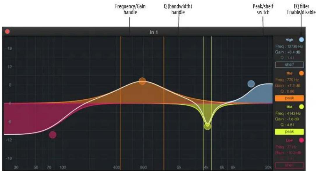
line
| Frequency Gain | Gain (dB) | | -------------- | --------- | | +7.3 | 0.86 | | -7.6 | 4.81 | | -10.3 | 1.41 |Figure 8-4: The full-size EQ graph.
the signal to 2 dB above the Threshold. When the input level goes above the threshold, the attenuation is added gradually to reduce distortion. The rate at which the attenuation is added is determined by the Attack parameter. Likewise, when the input level falls below the Threshold, the attenuation is removed gradually. The rate at which the attenuation is removed is determined by the Release parameter. Long Release times may cause the audio to drop out briefly when a soft passage follows a loud passage. Short Release times may cause the attenuation to "pump", a term used to describe the sound of the compressor when the average input level quickly fluctuates above and below the Threshold. These types of issues can be addressed by adjusting the compressor's parameters, or applying the Leveler instead. Gain adjusts the overall output level of the compressor, post processing. The Level meter (Figure 8-5) shows the level of the input signal entering the compressor. It shows either the Peak envelope or the RMS level, if enabled.
Gain reduction meter
The Gain reduction meter (Figure 8-5) displays the current amount of attenuation applied by the compressor, before the makeup gain stage.
RMS mode
By default, the compressor operates in Peak mode, which uses signal peaks to determine the input level. In RMS mode, the compressor measures the input signal's loudness, using the root-mean-square computational method. When RMS is disabled, RMS mode will let brief peaks through because the detector sidechain is only looking at the average signal level. By contrast, peak mode will catch those brief peaks. Peak mode is generally used for drums, percussion and other source material with strong transients, while RMS mode is mostly used for everything else.
The level meter shows either the peak level or the RMS level, depending on the mode.
Compressor graph
The Compressor graph below the Compressor section (Figure 8-5) provides a thumbnail visual indication of the current compressor settings for the input channel. It is for visual reference only and cannot be edited directly. However, you can click it to open the full-size Compressor graph in a separate window (Figure 8-6), which provides graphic editing of the Ratio and Threshold controls.
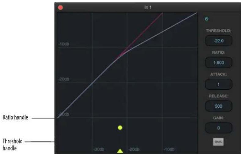
Figure 8-6: The full-size Compressor graph.
LEVELER
The Leveler ^™ (Figure 8-7) provides an accurate model of the legendary Teletronix ^™ LA-2A ^® optical compressor, known for its unique and highly sought-after Automatic Gain Control (AGC) characteristics.
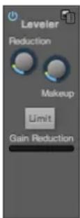
Figure 8-7: The Leveler module.
The Leveler is available on the Main Mix bus and all Group busses, including the Reverb bus.
A model of an optical compressor
An optical leveling amplifier works by shining a light on a photoresistor. The intensity of the light source is proportional to the audio signal, and the resistance of the photoresistor is in turn inversely proportional to the intensity of the light. Photoresistors respond quite quickly to increases in light intensity, yet return to their dark resistance very slowly. Thus, incorporation of the photoresistor into an attenuator followed by an amplifier which provides make-up gain produces a signal which maintains a constant overall loudness.
Automatic gain control using light
The AGC circuit of the LA-2A uses a vintage optocoupler known by its model number T4. The T4 contains an electroluminescent-panel (ELP) and photoresistor mounted so that the emission of the panel modulates the resistance. An ELP consists of a thin layer of phosphorescent material sandwiched between two insulated electrodes to form a capacitor. Making one of the electrodes transparent allows the light to escape. These devices are essentially glow-in-the-dark paint on a piece of foil covered by metalized glass or plastic, and are the same devices used in low-power night lights. Unfortunately, these devices need high voltages to operate, and are best driven by tube circuits which can supply voltage swings of several hundred volts.
Response characteristics
Once the light has faded away, the photoresistor then decays back to its dark state. The shape of the decay curve varies depending on how bright the light was, and how long the light lasted. A general rule of thumb is that the louder the program, the slower the release. Typically, the release can take up to and over one minute. One thing to keep in mind when using these types of devices is that the typical concepts of compression ratio, attack, release, and threshold do not apply. The light intensity is determined by the highly non-linear interactions of the input signal, AGC circuit, and ELP, and thus exhibit a strong program dependence that is impossible to describe without the mind-numbing mathematics of statistical mechanics. The actual results, however, can be almost mystical: even when you feed the same material (a loop perhaps) through the Leveler twice, you'll often see a new response the second time through a loop, complete with unique attack times, release times and compression ratios. Furthermore, two different input signals with the same RMS levels may be leveled in a drastically different manner.
It is precisely this self-adjusting behavior that makes optical compressors the tool of choice for smoothing out vocals, bass guitar and full-program mixes without destroying perceived dynamics.
Enabling or disabling the Leveler
The Leveler models the LA-2A so closely, it also models the time it takes for an actual LA-2A to "warm up" after it is turned on. Therefore, when you enable the Leveler, give it a moment to "settle" before you begin processing signals with it.
Gain Reduction
Gain Reduction (Figure 8-7) sets the strength of the signal sent to the AGC model.
Makeup Gain
Makeup gain (Figure 8-7) amplifies the output signal to make up for gain reduction.
Limit button
The Limit button (Figure 8-7) models the original LA-2A Limit/Compress mode switch. The effect is very subtle, with the Limit option behaving only slightly more like a limiter than a compressor. The switch increases the level of the input to the AGC model and runs the attenuator at a slightly lower level. The Leveler then responds more strongly to transients, but otherwise still behaves like a leveling amplifier.
REVERB
Use the enable/disable button (Figure 8-8) to turn the reverb processor on or off. Since reverb uses considerable DSP resources, it is best to leave it off when you are not using it.
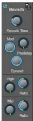
Figure 8-8: The Reverb processor.
Routing inputs and groups to the reverb processor
The reverb processor is a single, independent unit that provides stereo reverb. You can route any input channel or Group bus to the Reverb processor with the Reverb send on its channel strip. All incoming signals to the reverb processor are merged and processed together. The resulting stereo output from the reverb can then be merged into the Main Mix bus with the Main send on the Reverb channel strip (item #7 on page 21).
Reverb Time
Reverb time (Figure 8-8) determines the length of decay, or tail, of the reverb. The knob's range is from 100 milliseconds to 60 seconds.
Predelay
Predelay is the amount of time before the acoustic energy from the source returns to the listener, after reflecting off the surfaces of the listening space. The very first reflections helps you perceive information about the listening space, (size, distance, surface type, etc.). In large rooms, it takes a while (on the order of milliseconds) before the first reflections return to the listener. Predelay is useful for adding clarity, as it delays these reflections, before the onset of full reverberation. For example, with pre-delay added to vocals, the reflections won't start until after the initial sound of a word has been sung.
Spread
Spread controls stereo imaging. A position of 12 o'clock produces essentially a mono image. Turning the control all the way to the left completely swaps the stereo image.
High and Mid frequency bands
The High and Mid frequency bands let you independently control the reverb time for separate frequency bands, relative to the low frequency reverb time. The High setting represents the bottom frequency of the High band; the Mid
setting represents the bottom frequency of the Mid band. The Ratio determines the length for each band specified in a percentage of the low frequency reverb time.
DSP USAGE
The DSP Usage meter (item #30 on page 18) shows how much of the available DSP processing power is currently being used by the mixer for the mix and for effects processing. If there aren't enough DSP resources for all effects to be enabled on a channel, effects are disabled for that channel and all subsequent channels.
Unlike other effects, HPF and EQ on a stereo channel requires approximately twice the DSP resources as on a mono channel.
CHAPTER 9 MOTU Audio Tools
The MOTU Audio Tools application provides advanced audio analysis tools, which can be applied to a left channel input, right channel input, or both.
Installation....73
Device menu....73
Analysis menu 74
Left/right input 74
FFT and Spectrogram display.... 74
Oscilloscope 76
X-Y Plot....81
Phase Analysis 84
INSTALLATION
MOTU Audio Tools is a standard software application installed on your Mac or PC when you run the MOTU Pro Audio installer or setup app. It can be found in the Applications folder (Mac) or Start menu under MOTU (Windows).
DEVICE MENU
If you are working with more than one MOTU audio interface, the Device menu (Figure 9-1) displays all interfaces that are currently connected to your host computer. Choose the device you wish to work with.
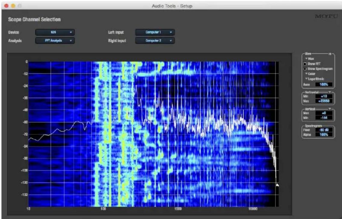
line
| X Value | Y Value | |---------|---------| | 10 | -72 | | 100 | -60 | | 1000 | -50 | | 10000 | -132 |Figure 9-1: The MOTU Audio Tools window with the FFT and Spectrogram Analysis.
ANALYSIS MENU
Choose the desired form of audio analysis from the Analysis menu (Figure 9-1). For details on each analysis pane, see the following sections of this guide.
LEFT/RIGHT INPUT
Choose the desired channel(s) you wish to scope from the Left Input and Right Input menus (Figure 9-1). These menus display the To Computer channels configured in the MOTU Pro Audio Control web app. The number of channels shown is controlled by the From device to computer setting in the Device tab. For example, if 18 channels are specified, you'll see 18 channels in the Left/Right Input menus. Use the Routing tab to map desired audio sources (listed across the top of the grid) to the To Computer audio channels, as demonstrated in Figure 7-7 on page 62.
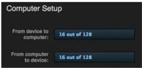
Figure 9-2: The 'From device to computer' setting determines how many channels you see in the Left Input and Right Input menus.
FFT AND SPECTROGRAM DISPLAY
The FFT analysis pane displays a real-time Fast Fourier Transform (FFT) frequency measurement and spectrogram “waterfall”, as shown in Figure 9-3.
Spectrogram
The spectrogram scrolls from top to bottom, where the top edge of the display represents what you are hearing “now”. Color represents amplitude along the left/right frequency spectrum. The amplitude color scale runs from black (silence) to red (full scale) as follows:

Figure 9-4: Spectrogram color-to-amplitude spectrum.
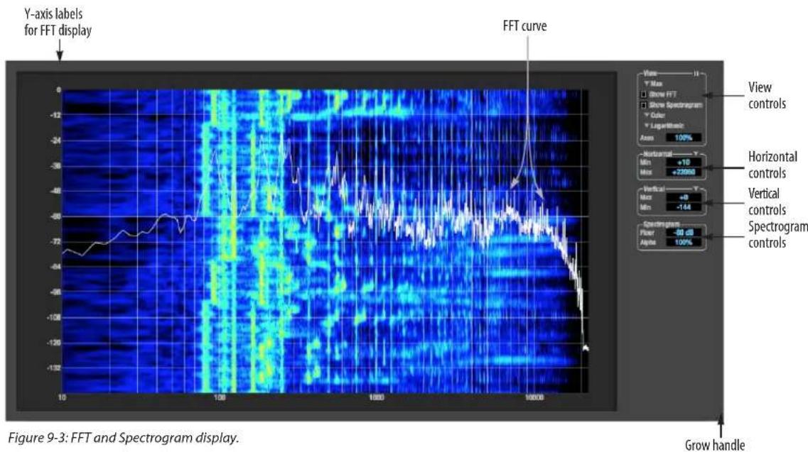
line
| X-axis Value | Y-axis Label | | ------------ | ------------ | | 10 | Y-axis label | | 100 | Y-axis label | | 1000 | Y-axis label | | 10000 | Y-axis label | | 10 | FFT curve | | 100 | FFT curve | | 1000 | FFT curve | | 10000 | FFT curve |View controls
You can show and hide the FFT display and spectrogram as desired using the View controls (Figure 9-5).
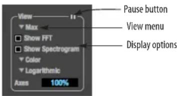
Figure 9-5: FFT view controls.
View menu
This menu provides various options for displaying the two input channels.
View menu setting What it does
| Left Displays the left channel only. |
| Right Displays the right channel only. |
| Split Screen H Shows both channels side by side, with the screen split horizontally. |
| Split Screen V Shows both channels side by side, with the screen split vertically. |
| Shared Displays both FFTs (left is green and right is red), and the spectrogram waterfall shows the maximum level of either the left or right channel (whichever is greater). |
| Max The FFT and spectrogram shows the maximum level of either the left or right channel. |
Subtract L - R Subtracts the right channel from the left channel and displays the results.
Logarithmic or Linear X-Axis Scale
The x-axis defaults to a logarithmic scale, but it can be changed to a linear scale if desired. In the View controls (Figure 9-5), click Logarithmic to access the x-axis scale options menu. With a linear scale selected, frequency is constant, but the width of each octave along the x-axis is different. With a logarithmic scale selected, octaves are displayed with a constant width, but frequency is displayed logarithmically within each octave.
Axes display
The Axes control (Figure 9-5) sets the opacity of the grid displayed in the graph, from 100% (fully visible) down to 0% (fully hidden).
Pausing the display
The Pause button in the upper right corner of the View section (Figure 9-5) allows you to freeze the display at any time. To resume, click the button again.
Horizontal controls (frequency axis)
The Horizontal controls (Figure 9-6) configure the value range of the x-axis (frequency). Click and drag the values up or down to set them, or double-click to return to the default value.
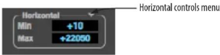
Figure 9-6: The Horizontal controls.
There are two modes for the controls: Zoom/Offset and Min/Max. To change the mode, use the Horizontal control menu (Figure 9-6).
In Zoom/Offset mode, Zoom sets the display zoom from 1x to 100x, where the number represents the zoom factor relative to the entire frequency range. For example, when the horizontal zoom value is 1x, the entire frequency range from 10 to 24000 Hertz is displayed; when the horizontal zoom value is 2x, one half of the entire frequency range is displayed. Pos determines which frequency is displayed at the center of the graph.
In Min/Max mode, Min and Max set the lowest and highest displayed frequencies (in Hertz).
Vertical controls (amplitude axis)
The Vertical controls (Figure 9-7) operate similarly to the Horizontal controls, except that they configure the y-axis (amplitude).
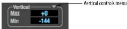
Figure 9-7: The Vertical controls.
In Zoom/Offset mode, Zoom sets the display zoom from 1x to 100x, and Pos sets the center amplitude of the graph. In Min/Max mode, Min and Max set the smallest and largest displayed amplitude.
Spectrogram controls
The Floor control (Figure 9-8) sets the amplitude threshold for the spectrogram display, from -144 dB up to 0 dB.
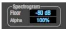
Figure 9-8: The Spectrogram controls.
The Alpha control (Figure 9-8) sets the opacity of the spectrogram information displayed in the graph, from 100% (fully visible) to 0% (hidden).
OSCILLOSCOPE
The Oscilloscope (Figure 9-9) graphs the amplitude of an audio signal over time.
Amplitude is displayed on the y-axis and time is displayed on the x-axis. A thick white vertical line marks where time equals zero; a thick white horizontal line marks where amplitude equals zero (Figure 9-9, below).
Level meters are displayed to the right of the graph. One or two meters are shown, depending on the current view mode (see “View controls”).
View controls
The View controls (Figure 9-10) provide several options for the oscilloscope display.
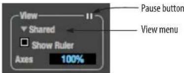
Figure 9-10: View controls.
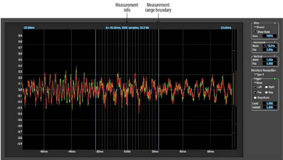
line
| Measurement Range | Value | | ----------------- | ----- | | 45.35ms | 22.68ms | | 2000 samples | 22.68ms | | Range | 100% | | Zoom | 1 / 0.84x | | Pos | 0.00s | | Vertical | 1.00s | | Zoom | 0.00s | | Pos | 0.00s | | Waveform Recognition Type II | Trigger | | Trigger | None | | Left | Right | | Pos | Ang | | Magnitude | Level | | Holdoff | 0.00s |Figure 9-9: Oscilloscope.
View menu
The View menu (Figure 9-10) lets you choose how to display the audio channel(s) being displayed.
View menu setting What it displays
| Left Left channel only |
| Right Right channel only |
| Split screen Left channel on top; right channel on the bot-tom |
| Shared Left and right on top of each other; left is green, right is red |
| Add Left and right channels' amplitudes are added together |
Subtract L-R The right channel's amplitude is subtracted from the left channel's amplitude
Display options
The Axes control (Figure 9-10) sets the opacity of the grid displayed in the graph, from 100% (fully visible) down to 0% (fully hidden). The Show Ruler option toggles the measurement items (see “Measurement information” on page 79).
Pausing the display
The Pause button in the upper right corner of the View section (Figure 9-10) allows you to freeze the display at any time. To resume, click the button again. The level meters will remain active while the display is paused.
Horizontal controls (time axis)
The Horizontal controls (Figure 9-11) configure the value range of the x-axis (time). Click and drag the values up or down to set them, or double-click to return to the default value.
There are two modes for the controls: Zoom/Offset and Min/Max. To change the mode, use the Horizontal control menu (Figure 9-11).
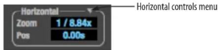
Figure 9-11: Horizontal controls.
In Zoom/Offset mode, Zoom sets the display zoom from 1/1000x to 10x, where the number represents the number of pixels per sample. For example, when the horizontal zoom value is 10x, 10 samples are displayed in 100 pixels; when the horizontal zoom value is 1/10x, 100 samples are displayed in 10 pixels. Pos moves the line marking time equals zero left or right.
In Min/Max mode, Min and Max set the earliest and most recent displayed time.
Time Units
The Time Units sub-menu (Figure 9-11) provides the option to view the X axis in Seconds or Samples.
Vertical controls (amplitude axis)
The Vertical controls (Figure 9-9) operate similarly to the Horizontal controls, except that they configure the y-axis (amplitude).
In Zoom/Offset mode, Zoom sets the display zoom from 1/2 to 100x, and Pos moves the line marking amplitude equals zero line up or down.
In Min/Max mode, Min and Max set the smallest and largest displayed amplitude.
Waveform Recognition
The Waveform Recognition option (Figure 9-9) searches through new audio data looking for a waveform which most resembles that which was previously displayed. The region where this takes place is a small window around the line marking time equals zero, denoted by the extra vertical graph lines surrounding it. There are two kinds of waveform recognition available: Type I and Type II.
Type I recognition provides the most stable display of the waveform. It is the most resistant to change. Louder transients, such as those produced by a snare drum, are not displayed inside of the waveform window. Type I is best for observing the shape of a signal produced by a synthesizer or observing the tone of a guitar through a chain of pedals.
Type II recognition is less resistant to change. It will include loud transients within the waveform recognition window. Type II is better for observing percussive music where the beat itself is to be centered within the waveform window.
Trigger
When the Trigger (Figure 9-12) is not enabled (the Trigger menu is set to None), the graph updates based on time: after every n samples of the monitored audio signal, the most recent samples are displayed. When the Trigger is enabled (set to any mode other than None), the graph updates in response to specific conditions in the signal. The Trigger section defines that criteria and how the graph will display the events that match.
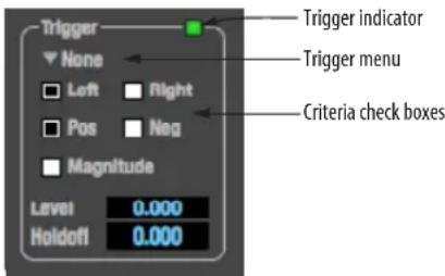
Figure 9-12: Trigger settings.
Criteria
The criteria checkboxes (Figure 9-12) determine the conditions that the trigger is looking for and where it will look for them.
The Left checkbox causes the condition to be looked for in the left channel of the signal; likewise, the Right checkbox looks for the condition in the right channel. One or both of these can be enabled simultaneously. If neither is enabled, the criteria will not be found because the trigger is not looking at any audio signal.
The Pos and Neg checkboxes determine the slope of the event. When the Pos checkbox is enabled, the trigger will look for an event where amplitude is increasing; likewise, enabling the Neg checkbox tells the trigger to look for an event where amplitude is decreasing. One or both of these can be enabled simultaneously. If neither is enabled, the criteria will not be found because the trigger is not looking for any particular kind of event.
The Level setting defines the amplitude threshold that the trigger is looking for. The Level is indicated on the graph by a blue horizontal line (or two blue horizontal lines, if Magnitude is enabled). Events which cross this threshold using the enabled slope(s) in the enabled channel(s) will activate the trigger. The response of the trigger is set by the Trigger mode (see “Trigger modes”, below).
Enabling the Magnitude checkbox tells the trigger to look for both positive and negative Level values, regardless of whether the Level value is positive or negative. For example, if Level is set to +0.500 and Magnitude is enabled, the trigger will look for both +0.500 and -0.500. You will see a second blue line appear in the display when Magnitude is enabled to denote the second value.
Holdoff
Holdoff defines a time interval during which the oscilloscope does not trigger. The most recent trace will be displayed during that period. When the period is over, the trigger is “re-armed”, i.e. it will begin looking for the criteria again.
Click and drag this value up or down to set it, or double-click to return to the default value.
Trigger modes
The Trigger menu (Figure 9-12) provides four modes:
Trigger mode What it does
| None The Trigger is not active; this is the default mode.The incoming audio signal will be displayed continuously as audio is received. | |
| Auto The display is always updating, but when the condition is met, the trigger event will be displayed centered around the line marking time equals zero. | |
| Normal The display updates only when the condition is met; the last trace will be displayed until the next matching event is found. | |
| Single Sweep | Similar to Normal mode, but the last trace will be displayed until you manually arm the trigger by clicking the Trigger indicator (Figure 9-12 on page 78) or by pressing the spacebar. |
Trigger indicator
The Trigger indicator (Figure 9-12) displays the state of the trigger, and also provides a way to manually interact with it. The Trigger indicator always displays one of three colors:
Color Status
| Green When the current Trigger criteria has been met (including when the Trigger mode is None). | |
| Yellow | When the Trigger is armed, but has not yet found an event which matches its criteria. Yellow can also indicate that the graph has been manually paused using the Pause button in the View section (see “Pausing the display” on page 77). |
Red When the Trigger is being held off, either because the Trigger mode is set to Single Sweep or the Holdoff time is not set to zero.
You can also click on the Trigger indicator to force certain actions, depending on the Trigger mode. In Auto and Normal modes, clicking on the Trigger indicator causes the display to run freely; you may click & hold to force this to occur for as long as you'd like. In Single Sweep mode, clicking on the Trigger indicator re-arms the trigger. When the Trigger mode is None, clicking on the Trigger indicator has no effect.
Measurement information
You can view detailed information about a particular time range by using the measurement bars (Figure 9-9).
To adjust the left and right edges of the measurement area, click and drag the blue bars in the graph (Figure 9-9), or click and drag the blue numbers in the upper left or right corners. To reset them to the default value, double-click the numbers.
Information about the measured area is displayed at the center of the top ruler: the duration (in seconds and samples), the approximate frequency, and the scientific note name. If the measured area is long enough, the approximate beats per minute (bpm) is displayed.
Ideas for using the Oscilloscope
The Oscilloscope can be used in many useful ways during the routine operation of your recording studio. Here are just a few examples.
Analyzing and comparing harmonic content The oscilloscope lets you “see” the nature of the harmonic profile in any audio material. You can also view two signals side by side (in stereo mode) to compare their profiles and, if necessary, make adjustments to the source of each signal and view your changes in real time.
Viewing transients such as drum hits
If you loop a snare hit or other similar transient audio clip and feed it through the oscilloscope, you can more or less “freeze” the transient waveform in the oscilloscope frame. This can be useful, for example, for viewing the results of real-time compression that you are applying with an effects plug-in. For example, when you are compressing a
snare hit, as you make adjustment the compressor, you can see the transient waveform change the next time the Oscilloscope triggers. For compression, this can be particularly useful for balancing the effect of the attack on the transient, relative to the decay portion of the waveform. Conversely, you can see the effect of the threshold setting directly on the decay portion, relative to the attack. In effect, you can see as well as hear the results of your compression adjustments.
To view a transient waveform in the Oscilloscope display, turn off Waveform Recognition and use the Normal Trigger mode. Adjust the level high enough to encompass the vertical amplitude of most of the transient. If the transient pulse sweeps across the screen, try raising the Holdoff level. Once the transient is settled in the display and fairly stable, you may need to adjust the horizontal position to center it in the display. You can also pause the display at any time and adjust the horizontal bounds to locate a transient.
Clip detection
You can use the Oscilloscope to detect clipping in a digital audio signal. To do so, enable all criteria (Figure 9-12), choose Single Sweep from the trigger menu (Figure 9-12), set the level to 0.999 and click the trigger indicator (Figure 9-12) to arm it (yellow). As soon as the signal clips, the trigger indicator will turn red, and the display will show the offending clip at the line marking time equals zero.
Viewing timing pulses
If you have two audio signals with recognizable, timed pulses in them, and you wish to compare their timing with respect to each other, you can use Split Screen or Shared view to visually compare the timing of the two signals. You can zoom in to the sample level for sample accurate viewing.
Building synthesizer patches
If you are building a synth patch on a synthesizer (or forming similar highly periodic audio material), you can run the audio signal through the Oscilloscope as you adjust its sound to check in real time for undesirable (and possibly inaudible) characteristics, which are easily seen in the Oscilloscope display. A good example is DC offset. If a signal develops DC offset, the apparent vertical center of its overall waveform will drift above or below the line marking amplitude equals zero. Try setting Waveform Recognition to Type I and setting Trigger to None.
Another example is waveform polarity. If you are combining several raw waveforms, polarity is a critical, yet not always obvious, factor in determining the resulting sound. You can use the Oscilloscope to easily view and compare polarities to see if they are inverted from one another or not. The Add and Subtract L - R View menu settings are particularly useful here.
You can also use the Oscilloscope to help you apply waveform modulation and keep it “in bounds”. For example, you could easily see if pulse width modulation is collapsing in on itself to choke the sound, an effect that is readily seen in the Oscilloscope display but not necessarily easy to determine by ear when using multiple modulation sources.
Guitarists can also visually observe the effects of their pedals and processing, while playing. With the Trigger mode set to None and Waveform Recognition set to Type I, the waveform will be tracked automatically.
When applying filters and filter resonance, the visual effect on the waveform can be invaluable in reinforcing what you are hearing as you make adjustments.
X-Y PLOT
The X-Y Plot window (Figure 9-13) graphs the amplitude of a stereo audio signal on a two-dimensional grid.
For each unit of time (i.e., each sample), the amplitude of the left channel is displayed on the x-axis and the amplitude of the right channel is displayed on the y-axis. A thick white vertical line marks where left channel amplitude equals zero; a thick white horizontal line marks where right channel amplitude equals zero (Figure 9-13). There are also thick white diagonal lines for y = x and
$$ \mathrm{y} = - \mathrm{x}. $$
Metering
Level meters are displayed above and to the right of the graph for the left (green) and right (red) channels, respectively. An additional Correlation meter (blue) is displayed on the right. This meter displays the correlation between the two channels.
The higher the meter, the higher the correlation between the two channels. Below are a few examples:
Situation Meter level X-Y Plot graph Mathematical
relationship
| Perfect correla-tion | +1 Diagonal line | y = x |
| going from lower left to upper right: | ||
| Zero correlation 0 No discern-ible pattern | None | |
| Perfectly out of phase | -1 Diagonal line | y = -x |
| going from upper left to lower right: | ||
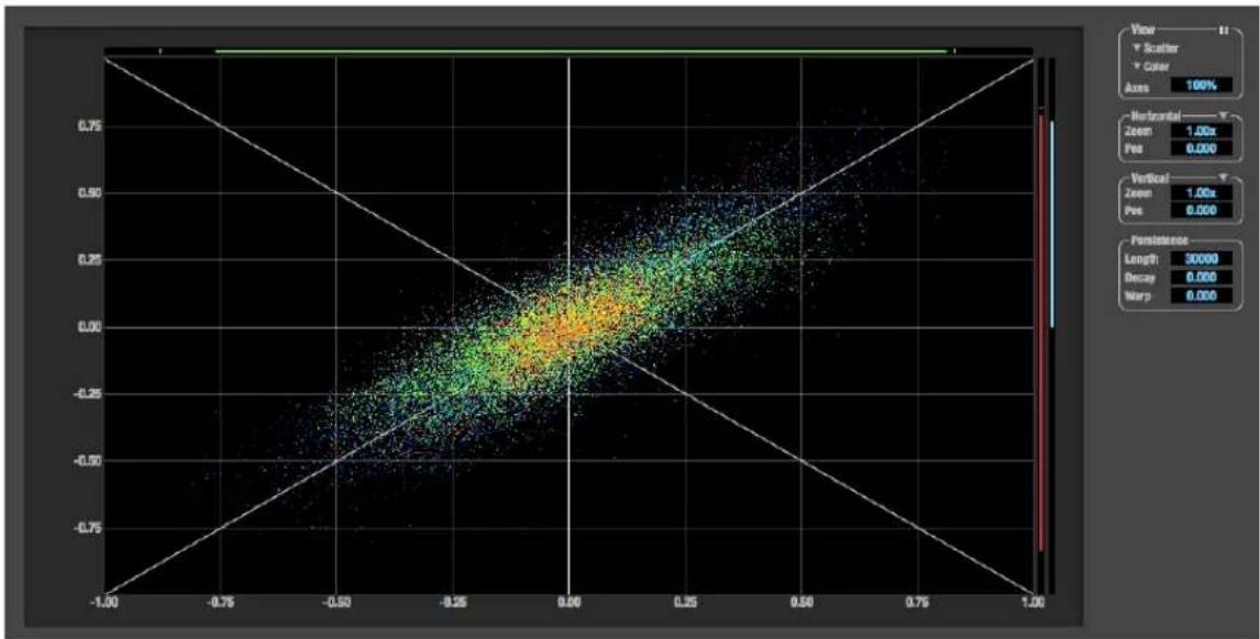
scatter
| X | Y | | ------ | ------ | | -1.00 | -1.00 | | -0.75 | -0.75 | | -0.50 | -0.50 | | -0.25 | -0.25 | | 0.00 | 0.00 | | 0.25 | 0.25 | | 0.50 | 0.50 | | 0.75 | 0.75 | | 1.00 | 1.00 |Figure 9-13: X-Y Plot.
View controls
The View controls (Figure 9-14) provide several options for the X-Y Plot display.
Figure 9-14: View controls.
Pausing the display
The Pause button in the upper right corner of the View section (Figure 9-14) allows you to freeze the display at any time. To resume, click the button again. The level meters will remain active while the display is paused.
Line/Scatter
Choose either Line or Scatter from the menu in the View section (Figure 9-14) to plot each point (sample) as either a single pixel or as a continuous line that connects each plot point to the next, as shown below in Figure 9-15.
heatmap
| X | Y | Value | |---|---|-------| | 0.0 | 0.0 | 0.0 | | 0.1 | 0.1 | 0.2 | | 0.2 | 0.2 | 0.4 | | 0.3 | 0.3 | 0.6 | | 0.4 | 0.4 | 0.8 | | 0.5 | 0.5 | 1.0 | | 0.6 | 0.6 | 1.2 | | 0.7 | 0.7 | 1.4 | | 0.8 | 0.8 | 1.6 | | 0.9 | 0.9 | 1.8 | | 1.0 | 1.0 | 2.0 |
heatmap
| X | Y | Value | |---|---|-------| | 0.0 | 0.0 | Low | | 0.5 | 0.5 | Medium-High | | 1.0 | 1.0 | High | | 1.5 | 1.5 | Medium-High | | 2.0 | 2.0 | Low | | 2.5 | 2.5 | Medium | | 3.0 | 3.0 | High | | 3.5 | 3.5 | Medium-High | | 4.0 | 4.0 | Low | | 4.5 | 4.5 | Medium | | 5.0 | 5.0 | High | | 5.5 | 5.5 | Medium-High | | 6.0 | 6.0 | Low | | 6.5 | 6.5 | Medium | | 7.0 | 7.0 | High | | 7.5 | 7.5 | Medium-High | | 8.0 | 8.0 | Low | | 8.5 | 8.5 | Medium | | 9.0 | 9.0 | High | | 9.5 | 9.5 | Medium-High | | 10.0 | 10.0 | Low | | 10.5 | 10.5 | Medium | | 11.0 | 11.0 | High | | 11.5 | 11.5 | Medium-High | | 12.0 | 12.0 | Low | | 12.5 | 12.5 | Medium | | 13.0 | 13.0 | High | | 13.5 | 13.5 | Medium-High | | 14.0 | 14.0 | Low | | 14.5 | 14.5 | Medium | | 15.0 | 15.0 | High | | 15.5 | 15.5 | Medium-High | | 16.0 | 16.0 | Low | | 16.5 | 16.5 | Medium | | 17.0 | 17.0 | High | | 17.5 | 17.5 | Medium-High | | 18.0 | 18.0 | Low | | 18.5 | 18.5 | Medium | | 19.0 | 19.0 | High | | 19.5 | 19.5 | Medium-High | | 20.0 | 20.0 | Low | | 20.5 | 20.5 | Medium | | 21.0 | 21.0 | High | | 21.5 | 21.5 | Medium-High | | 22.0 | 22.0 | Low | | 22.5 | 22.5 | Medium | | 23.0 | 23.0 | High | | 23.5 | 23.5 | Medium-High | | 24.0 | 24.0 | Low | | 24.5 | 24.5 | Medium | | 25.0 | 25.0 | High | | 25.5 | 25.5 | Medium-High | | 26.0 | 26.0 | Low | | 26.5 | 26.5 | Medium | | 27.0 | 27.0 | High | | 27.5 | 27.5 | Medium-High | | 28.0 | 28.0 | Low | | 28.5 | 28.5 | Medium | | 29.0 | 29.0 | High | | 29.5 | 29.5 | Medium-High | | 30.0 | 30.0 | Low | | 30.5 | 30.5 | Medium | | 31.0 | 31.0 | High | | 31.5 | 31.5 | Medium-High | | 32.0 | 32.0 | Low | | 32.5 | 32.5 | Medium | | 33.0 | 33.0 | High | | 33.5 | 33.5 | Medium-High | | 34.0 | 34.0 | Low | | 34.5 | 34.5 | Medium | | 35.0 | 35.0 | High | | 35.5 | 35.5 | Medium-High | | 36.0 | 36.0 | Low | | 36.5 | 36.5 | Medium | | 37.0 | 37.0 | High | | 37.5 | 37.5 | Medium-High | | 38.0 | 38.0 | Low | | 38.5 | 38.5 | Medium | | 39.0 | 39.0 | High | | 39.5 | 39.5 | Medium-High | | 40.0 | 40.0 | Low | | 40.5 | 40.5 | Medium | | 41.0 | 41.0 | High | | 41.5 | 41.5 | Medium-High | | 42.0 | 42.0 | Low | | 42.5 | 42.5 | Medium | | 43.0 | 43.0 | High | | 43.5 | 43.5 | Medium-High | | 44.0 | 44.0 | Low | | 44.5 | 44.5 | Medium | | 45.0 | 45.0 | High | | 45.5 | 45.5 | Medium-High | | 46.0 | 46.0 | Low | | 46.5 | 46.5 | Medium | | 47.0 | 47.0 | High | | 47.5 | 47.5 | Medium-High | | 48.0 | 48.0 | Low | | 48.5 | 48.5 | Medium | | 49.0 | 49.0 | High | | 49.5 | 49.5 | Medium-High | | 50.0 | 50.0 | Low | | ... (additional values) are not explicitly labeled in the image but correspond to the visual grid lines on the right side of the chart). The data is presented in a single column format with no explicit numerical values or trends visible in the table.Figure 9-15: The same X-Y Plot displayed in Line versus Scatter mode.
Line mode is significantly more CPU intensive than Scatter. You can reduce Line mode CPU overhead on the X-Y Plot by reducing the Length parameter (described below).
Color/Grayscale
In Color mode (Figure 9-14) the most recently displayed audio data is shown in red, which fades to yellow, green and then finally blue, before disappearing. In Grayscale mode, data is first shown in white and then fades to gray. To adjust the scale of this color/brightness change, see “Decay” on page 83.
Axes
The Axes control (Figure 9-14) sets the opacity of the grid displayed in the graph, from 100% (fully visible) down to 0% (fully hidden).
Horizontal and vertical controls
The Horizontal and Vertical controls (Figure 9-16) configure the value range of the x-axis (left channel amplitude), and y-axis (right channel amplitude), respectively. Click and drag the values up or down to set them, or double-click to return to the default value.
There are two modes for the controls: Zoom/Offset and Min/Max. To change the mode, use the menu shown in Figure 9-16.
Figure 9-16: Setting the Horizontal or Vertical control modes.
In Zoom/Offset mode, Zoom scales the axis. Pos moves the lines marking x = 0 left and right, or y = 0 up and down.
In Min/Max mode, Min and Max let you scale the grid by moving the -1.0 and +1.0 points along the axis. Min/Max mode lets you control the graph boundaries directly.
Persistence
The Persistence controls (Figure 9-17) affect the appearance of data from when it is first displayed until it disappears from the grid.

Figure 9-17: The Persistence controls.
Length
Length (Figure 9-17) sets the number of recent samples to show on the plot. For example, when Length is set to 10,000, the 10,000 most recent samples are shown.
Decay
The brightness (in Grayscale mode) or hue (in Color mode) of each sample on the plot is determined by a linear scale, with the most recent sample displayed at the maximum value and the oldest sample displayed at the minimum value. Decay (Figure 9-17 on page 83) determines the brightness or hue of the minimum value. When Decay is zero, the oldest sample is black. When Decay is +1.000, the oldest sample is fully opaque (in Grayscale mode) or red (in Color mode).
Warp
Warp (Figure 9-17) determines the position of data points after they are first drawn. When warp is zero, data points remain in the same position.
When warp is positive, they contract towards the origin (center of the grid). When warp is negative, they expand away from the origin. The further the warp value is from zero, the greater the effect.
Using the X-Y Plot
The X-Y Plot helps you “see” the width of the stereo field of a mix (Figure 9-18). It also helps you determine if a mix has issues with polarity, as follows:
Activity on the X-Y Plot What it indicates
| Signal activity occurs mostly along the x = y axis (lower left to upper right) and the Correlation meter reading is high | Left and right channels are predominantly in polarity (the stereo field is relatively narrow) |
| Signal activity occurs mostly along the y = -x axis (upper left to lower right) and the Correlation meter reading is low (near -1) | Left and right channels are predominantly out of polarity (not in phase) |
| Signal activity occurs in a seemingly random fashion throughout the grid | No phase relationship exists (i.e. it is probably a wide stereo field) |
If a stereo signal is out of phase, it is not mono compatible because it can cancel itself out, either partially or nearly completely, when collapsed to mono.
In polarity Out of polarity No polarity
heatmap
| X | Y | Value | |---|---|-------| | (various) | (various) | (color-coded intensity scale) |
heatmap
| X | Y | Value | |----|----|-------| | 0 | 0 | Low | | 1 | 1 | Medium| | 2 | 2 | High | | 3 | 3 | Medium| | 4 | 4 | Low | | 5 | 5 | Medium| | 6 | 6 | High | | 7 | 7 | Low | | 8 | 8 | Medium| | 9 | 9 | High | | 10 | 10 | Low | | 11 | 11 | Medium| | 12 | 12 | High | | 13 | 13 | Low | | 14 | 14 | Medium| | 15 | 15 | High | | 16 | 16 | Low | | 17 | 17 | Medium| | 18 | 18 | High | | 19 | 19 | Low | | 20 | 20 | Medium| | 21 | 21 | High | | 22 | 22 | Low | | 23 | 23 | Medium| | 24 | 24 | High | | 25 | 25 | Low | | 26 | 26 | Medium| | 27 | 27 | High | | 28 | 28 | Low | | 29 | 29 | Medium| | 30 | 30 | High | | 31 | 31 | Low | | 32 | 32 | Medium| | 33 | 33 | High | | 34 | 34 | Low | | 35 | 35 | Medium| | 36 | 36 | High | | 37 | 37 | Low | | 38 | 38 | Medium| | 39 | 39 | High | | 40 | 40 | Low | | 41 | 41 | Medium| | 42 | 42 | High | | 43 | 43 | Low | | 44 | 44 | Medium| | 45 | 45 | High | | 46 | 46 | Low | | 47 | 47 | Medium| | 48 | 48 | High | | 49 | 49 | Low | | 50 | 50 | Medium| | 51 | 51 | High | | 52 | 52 | Low | | 53 | 53 | Medium| | 54 | 54 | High | | 55 | 55 | Low | | 56 | 56 | Medium| | 57 | 57 | High | | 58 | 58 | Low | | 59 | 59 | Medium| | 60 | 60 | High | | 61 | 61 | Low | | 62 | 62 | Medium| | 63 | 63 | High | | 64 | 64 | Low | | 65 | 65 | Medium| | 66 | 66 | High | | 67 | 67 | Low | | 68 | 68 | Medium| | 69 | 69 | High | | 70 | 70 | Low | | 71 | 71 | Medium| | 72 | 72 | High | | 73 | 73 | Low | | 74 | 74 | Medium| | 75 | 75 | High | | 76 | 76 | Low | | 77 | 77 | Medium| | 78 | 78 | High | | 79 | 79 | Low | | 80 | 80 | Medium| | 81 | 81 | High | | 82 | 82 | Low | | 83 | 83 | Medium| | 84 | 84 | High | | 85 | 85 | Low | | 86 | 86 | Medium| | 87 | 87 | High | | 88 | 88 | Low | | 89 | 89 | Medium| | 90 | 90 | High | | 91 | 91 | Low | | 92 | 92 | Medium| | 93 | 93 | High | | 94 | 94 | Low | | 95 | 95 | Medium| | 96 | 96 | High | | 97 | 97 | Low | | 98 | 98 | Medium| | 99 | 99 | High | | Note: The actual values may vary due to the random nature of the data generation. The provided values are just an example. The actual values may be the result of the random number generation. The actual values may not be extracted from the code. The numbers in the CSV data are estimated based on the data generated by the code.
Figure 9-18: Checking polarity in a stereo signal with the X-Y Plot.
PHASE ANALYSIS
The Phase Analysis window (Figure 9-19) graphs frequency versus phase difference versus amplitude of a stereo signal on either rectangular or polar coordinates.
In rectangular coordinates, the vertical axis represents frequency, and the horizontal axis represents the phase of the left channel minus the phase of the right channel (measured in radians).
In polar coordinates, the radius represents frequency and the angle (theta) from the +y vertical axis represents the phase difference of left channel minus the right channel.
Correlation Meter
The blue Correlation Meter to the right of the display shows the correlation between the two channels. The higher the meter, the higher the correlation between the two channels.
View controls
The View controls (Figure 9-20) provide several options for the Phase Analysis display.
Figure 9-20: View controls.
Pausing the display
The Pause button in the upper right corner of the View section (Figure 9-20) allows you to freeze the display at any time. To resume, click the button again. The correlation meter will remain active while the display is paused.
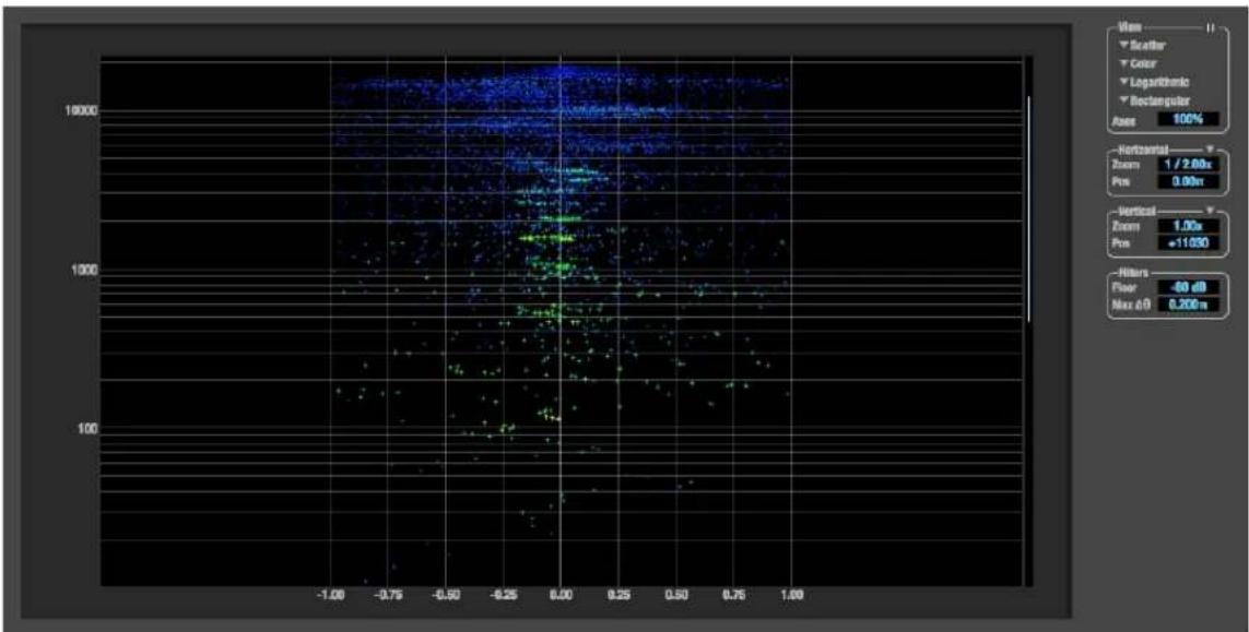
scatter
| X Value | Y Value | |---------|---------| | -1.00 | 100 | | -0.75 | 100 | | -0.50 | 100 | | -0.25 | 100 | | 0.00 | 100 | | 0.25 | 100 | | 0.50 | 100 | | 0.75 | 100 | | 1.00 | 100 |Figure 9-19: Phase Analysis.
Line/Scatter
Choose either Line or Scatter from the menu in the View section (Figure 9-20) to plot each data point as either a single pixel or as a continuous line that connects each frequency data point to the next, as shown below in Figure 9-15.
natural_image
Abstract green and blue vertical gradient pattern on black background (no text or symbols)
natural_image
Abstract green and blue vertical gradient pattern on black background (no text or symbols)Figure 9-21: The same Phase Analysis displayed in Line versus Scatter mode.
Line mode is significantly more CPU intensive than Scatter. You can reduce Line mode CPU overhead for the Phase Analysis display by increasing the Floor filter and reducing the Max Delta Theta filters (see “Filters” on page 86).
Color/Grayscale
In Color mode (Figure 9-20) signal amplitude is indicated by color as follows: red is loud and blue is soft. In grayscale mode, white is loud and gray is soft.
Linear/Logarithmic
Choose either Linear or Logarithmic from the menu in the View section (Figure 9-20) to change the scale of the frequency axis. In rectangular coordinates, the vertical axis represents frequency, and in polar coordinates, the radius from the center is frequency. With a linear scale, frequencies are spaced evenly; in a logarithmic scale, each octave is spaced evenly (frequencies are scaled logarithmically within each octave).
Linear is better for viewing high frequencies; logarithmic is better for viewing low frequencies.
Rectangular/Polar
Choose either Rectangular or Polar from the menu in the View section (Figure 9-20) to control how audio is plotted on the Phase Analysis grid. Rectangular plots the audio on an X-Y grid, with frequency along the vertical axis and phase difference on the horizontal axis. Polar plots the data on a polar grid with zero Hertz at its center. The length of the radius (distance from the center) represents frequency, and the angle (theta) measured from the +y (vertical) axis represents the phase difference in degrees.
scatter
| x | y | |---|---| | 0.0 | 0.0 | | 0.1 | 0.1 | | 0.2 | 0.2 | | 0.3 | 0.3 | | 0.4 | 0.4 | | 0.5 | 0.5 | | 0.6 | 0.6 | | 0.7 | 0.7 | | 0.8 | 0.8 | | 0.9 | 0.9 | | 1.0 | 1.0 |
heatmap
| X | Y | Value | |---|---|-------| | 0.0 | 0.0 | 0.0 | | 0.1 | 0.1 | 0.2 | | 0.2 | 0.2 | 0.4 | | 0.3 | 0.3 | 0.6 | | 0.4 | 0.4 | 0.8 | | 0.5 | 0.5 | 1.0 | | 0.6 | 0.6 | 1.2 | | 0.7 | 0.7 | 1.4 | | 0.8 | 0.8 | 1.6 | | 0.9 | 0.9 | 1.8 | | 1.0 | 1.0 | 2.0 |Figure 9-22: Rectangular versus Polar display (with a linear plot).
Above, Figure 9-22 shows Rectangular versus Polar display with a Linear plot. Below, Figure 9-23 shows the same displays (and the same data) with a Logarithmic plot:
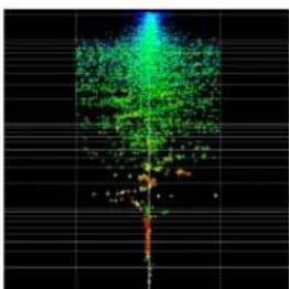
bar
| Category | Value | |---|---| | Bar 1 | 0.5 | | Bar 2 | 0.6 | | Bar 3 | 0.7 | | Bar 4 | 0.8 | | Bar 5 | 0.9 | | Bar 6 | 1.0 | | Bar 7 | 1.1 | | Bar 8 | 1.2 | | Bar 9 | 1.3 | | Bar 10 | 1.4 | | Bar 11 | 1.5 | | Bar 12 | 1.6 | | Bar 13 | 1.7 | | Bar 14 | 1.8 | | Bar 15 | 1.9 | | Bar 16 | 2.0 | | Bar 17 | 2.1 | | Bar 18 | 2.2 | | Bar 19 | 2.3 | | Bar 20 | 2.4 | | Bar 21 | 2.5 | | Bar 22 | 2.6 | | Bar 23 | 2.7 | | Bar 24 | 2.8 | | Bar 25 | 2.9 | | Bar 26 | 3.0 | | Bar 27 | 3.1 | | Bar 28 | 3.2 | | Bar 29 | 3.3 | | Bar 30 | 3.4 | | Bar 31 | 3.5 | | Bar 32 | 3.6 | | Bar 33 | 3.7 | | Bar 34 | 3.8 | | Bar 35 | 3.9 | | Bar 36 | 4.0 | | Bar 37 | 4.1 | | Bar 38 | 4.2 | | Bar 39 | 4.3 | | Bar 40 | 4.4 | | Bar 41 | 4.5 | | Bar 42 | 4.6 | | Bar 43 | 4.7 | | Bar 44 | 4.8 | | Bar 45 | 4.9 | | Bar 46 | 5.0 | | Bar 47 | 5.1 | | Bar 48 | 5.2 | | Bar 49 | 5.3 | | Bar 50 | 5.4 | | Bar 51 | 5.5 | | Bar 52 | 5.6 | | Bar 53 | 5.7 | | Bar 54 | 5.8 | | Bar 55 | 5.9 | | Bar 56 | 6.0 | | Bar 57 | 6.1 | | Bar 58 | 6.2 | | Bar 59 | 6.3 | | Bar 60 | 6.4 | | Bar 61 | 6.5 | | Bar 62 | 6.6 | | Bar 63 | 6.7 | | Bar 64 | 6.8 | | Bar 65 | 6.9 | | Bar 66 | 7.0 | | Bar 67 | 7.1 | | Bar 68 | 7.2 | | Bar 69 | 7.3 | | Bar 70 | 7.4 | | Bar 71 | 7.5 | | Bar 72 | 7.6 | | Bar 73 | 7.7 | | Bar 74 | 7.8 | | Bar 75 | 7.9 | | Bar 76 | 8.0 | | Bar 77 | 8.1 | | Bar 78 | 8.2 | | Bar 79 | 8.3 | | Bar 80 | 8.4 | | Bar 81 | 8.5 | | Bar 82 | 8.6 | | Bar 83 | 8.7 | | Bar 84 | 8.8 | | Bar 85 | 8.9 | | Bar 86 | 9.0 | | Bar 87 | 9.1 | | Bar 88 | 9.2 | | Bar 89 | 9.3 | | Bar 90 | 9.4 | | Bar 91 | 9.5 | | Bar 92 | 9.6 | | Bar 93 | 9.7 | | Bar 94 | 9.8 | | Bar 95 | 9.9 | | Bar 96 | 10.0 | | Bar 97 | -0.1 | | Bar 98 | -0.2 | | Bar 99 | -0.3 | | Bar100 | -0.4 |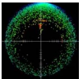
natural_image
Circular abstract pattern with green and orange dots on black background, no text or symbols visibleFigure 9-23: Rectangular versus Polar display with a logarithmic plot.
Axes
The Axes control (Figure 9-20) sets the opacity of the grid displayed in the graph, from 100% (fully visible) down to 0% (fully hidden).
Horizontal and vertical controls
The Horizontal and Vertical controls (Figure 9-24) let you scale each axis of the grid and offset its zero point. Click and drag the values up or down to set them, or double-click to return to the default value.
There are two modes for the controls: Zoom/Offset and Min/Max. To change the mode, use the menu shown in Figure 9-24.
Figure 9-24: Setting the Horizontal or Vertical control modes.
In Zoom/Offset mode, Zoom scales the axis. Pos moves the zero line.
In Min/Max mode, Min and Max let you scale the grid by moving the end points along the axis. Min/Max mode lets you set the boundaries of the graph directly.
Filters
The Filters section (Figure 9-25) lets you control the density of the Phase Analysis display.
Figure 9-25: Filters.
Floor
Floor (Figure 9-25) determines the amplitude threshold for the display. When the amplitude of both channels drops below this threshold, the signal is not shown.
Max delta theta
Max delta theta (Figure 9-25) only affects Line view (see “Line/Scatter” on page 85) and sets the maximum difference in frequency between plot points in the line plot. For two adjacent frequencies, if the distance (phase difference) between the two frequencies is greater than the Max delta theta, then the line is not drawn.
Using the Phase Analysis
In the polar display (top row of Figure 9-26 on page 87), stereo material that is predominantly phase-aligned (correlated) appears along the vertical axis, as demonstrated in the first column (Perfectly in phase) in Figure 9-26. If the vertical line tilts left or right, this indicates general differences in phase; the more the tilt (delta theta), the more the phase difference. If the vertical line points downwards in the polar display, this indicates that the stereo image is predominantly out of polarity, as demonstrated by the fourth column (Inverted) in Figure 9-26. Delays appear as spirals in the polar display.
The rectangular display (bottom row of Figure 9-26) also shows a predominantly phase-aligned stereo image along the vertical axis, and tilt (or left-right offset) from the center vertical axis represents differences in phase. If a signal is predominantly out of polarity, it appears along the theta = -1.0 or theta = +1.0 lines in the rectangular display, as demonstrated in the fourth column (Inverted) in Figure 9-26 on page 87.
Using Phase Analysis for multiple mic placement The polar display can be very useful when recording drums or another instrument with multiple microphones. The slight delays caused by the differences in distance to the source can often create a comb filtering (delay) effect between two mic signals, due to phase cancellation. These comb filter effects appear as spirals in the polar display. If you arrange the mics so that the null points (where the spiral pattern meets the negative y axis) are
outside the critical frequency range of the instrument being recorded, you can avoid phase problems among the mic signals.
Tuning PA systems
The Phase Analysis window can also be used to troubleshoot and tune PAs and sound reinforcement systems by placing microphones in strategic locations, comparing the two signals in the Phase Analysis grid and looking for phase issues at various locations.
Summing to mono
The Phase Analysis window is ideal for checking stereo audio that needs to be summed to mono. The Phase Analysis lets you see what frequencies will be canceled out when summed.
In the rectangular view, any lines in the signal that touch the +1.0 or -1.0 vertical lines in the grid will be canceled out at the frequency where they touch, when the signal is summed to mono.
In the polar view, any signal that falls on the negative y axis (below zero) will be canceled out when the signal is summed to mono.
Checking for phase issues in stereo tracks
You can use the Phase Analysis window to check the overall polarity of a stereo mix. Figure 9-27 is an example of a full stereo mix that has phase issues, as indicated by the majority of the signal's energy, which is predominantly skewed to the left side of the rectangular view (left) and spread along the -y axis in the polar view (right).
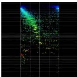
natural_image
Abstract digital artwork with glowing green and blue patterns on black grid background (no text or symbols)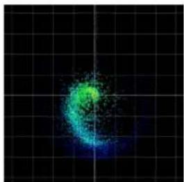
natural_image
Abstract glowing green and blue circular pattern on black grid background (no text or symbols)Figure 9-27: A stereo mix with phase issues.
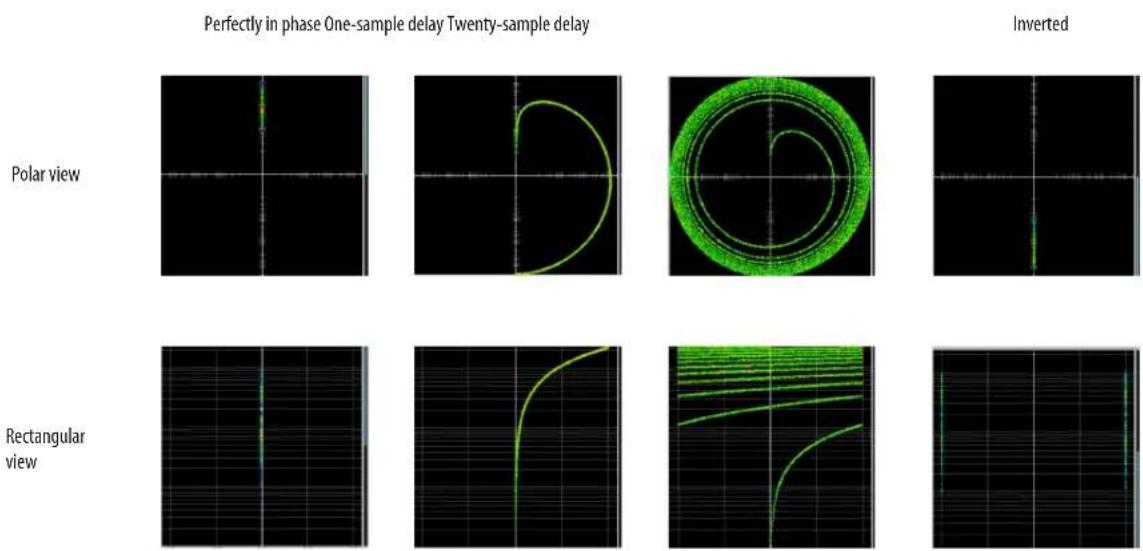
Figure 9-26: Two identical audio streams in the Phase Analysis.
CHAPTER 10 Networking
OVERVIEW
The Audio Video Bridging (AVB) network port on the 624 opens up a world of possibilities for creating expanded, customized audio network systems.
About AVB 89
MOTU's AVB implementation 90
Networking examples....90
A quick guide to networking 92
Setting up a MOTU AVB interface for networking.... 93
Mapping audio to network streams 93
Mapping computer channels to network streams ... 93
Device presets and AVB stream connections..... 94
Bridging to Ethernet 94
The MOTU AVB Switch 94
ABOUT AVB
Audio Video Bridging (AVB) is an extension of the Ethernet standard developed by the IEEE (802.1 standards committee) specifically to add high-performance audio and video networking.
You may also hear AVB referred to as AVB/TSN or simply TSN because the IEEE is in the process of renaming the standard to Time Sensitive Networking to accommodate the expanding scope of the specification to applications beyond audio and video.
AVB brings together the worlds of networking technology and high-end audio. Here is a brief summary of some of the immediate benefits of AVB for you, as a MOTU AVB interface user:
■ An open industry standard — AVB has been developed by the IEEE as an international standard specification. It is not proprietary or controlled by one company.
■ High channel counts — AVB provides hundreds of network channels.
■ Extremely low latency — AVB guarantees low-latency, real-time performance.
■Guaranteed Quality of Service (QoS) — AVB's Stream Reservation Protocol provides Guaranteed Quality of Service for each and every audio stream. If the network cannot continuously maintain every bit of every sample in the audio stream, it will not allow you to make the network connection in the first place. AVB streams are prioritized over other network traffic to ensure high performance.
■ Network-wide clocking and sync — AVB devices all clock together over your network for better-than-sample-accurate phase lock across all connected devices. Timing accuracy is down to the nanosecond.
■ True plug-and-play operation — AVB has been designed from the ground up to provide automatic device discovery, enumeration, and connection management. Just plug the 624 into a standard AVB switch and go. If you wish to make stream connections and have the ability to select media clock, you must use the web app, or some other AVB controller. You don’t need an IT professional to configure the network. AVB is a self-managing network protocol.
■ Bridging to standard Ethernet — AVB cooperates with standard Ethernet networks, for connecting traditional Ethernet devices like wireless routers, switches, or any other non-AVB-aware device.
■ Support for existing network infrastructure — Replace your existing switches with standard AVB-compatible switches, and your CAT-5e or CAT-6 wired infrastructure now supports AVB.
■ Long cable runs — a single AVB network connection can run up to 100 meters with a standard copper wire CAT-5e or CAT-6 cable. Fiber-optic cable runs can be much longer. With multiple switches, you can create a network that covers very large distances, if necessary. You can use up to seven “hops” (switch-to-switch connections).
■ AVB is already shipping on current Macs — Apple supports AVB on all current shipping Macs, and the 624 can operate as a standard AVB audio interface when connected to your Mac's AVB-equipped Ethernet port.
MOTU'S AVB IMPLEMENTATION
MOTU engineering has faithfully implemented the IEEE 802.1 AVB standard for the MOTU AVB products. This means that MOTU devices are fully interoperable with any 3rd party AVB-compatible device. In addition, MOTU has fine-tuned AVB operation among MOTU AVB devices for optimum performance, within the AVB specification. Here is a brief summary of advantages you will enjoy when using MOTU AVB devices together in a network:
■ Up to 256 channels of host I/O — MOTU AVB interfaces (depending on the model) can support up to 256 simultaneous channels of audio I/O (128 in, 128 out) to and from the entire network through Thunderbolt or USB 3.0.
■Support for multiple computer hosts — All computers and all network devices run in sync with each other, resolved to the network's master clock.
■ Gigabit Ethernet — The MOTU AVB Switch delivers 1 Gbit Ethernet performance, which provides substantially higher bandwidth than 100 Mbit Ethernet. This allows you to have many more devices on the AVB network.
- Over 500 channels of network audio — MOTU's AVB network can stream over 500 channels of audio throughout the network. Depending on the model, some MOTU AVB devices can broadcast sixteen 8-channel network streams and simultaneously listen to sixteen 8-channel network streams.
■ Exceptionally low network latency — Standard AVB network latency is 2 ms. MOTU AVB network latency is an astonishing 0.6 ms, even over seven “hops” (switches) and hundreds of meters of cable. By comparison, other commercially available, proprietary audio network protocols have variable (unpredictable) network latency in the range of 2-5 ms.
■ Star configuration — MOTU AVB supports a star network configuration, which is much more flexible than daisy-chain scenarios, which depends on all devices in the chain.
■ Web interface — MOTU AVB devices can be controlled from the MOTU Pro Audio Control web app, which runs within any web browser on any networked laptop, tablet, or smart phone. Although the web app shares the network with AVB, AVB audio streams are never compromised because AVB streams over the network traffic.
■ Bridging to standard Ethernet — the MOTU AVB Switch provides an extra standard Ethernet port for bridging to your local Ethernet network, Wi-Fi, etc. for command and control, internet access, and other standard network traffic. All ports allow connection to standard (non-AVB) network devices, however, the “Ethernet” port is suggested because it does not support AVB.
NETWORKING EXAMPLES
Networking comes into play as soon as you hook up a second MOTU interface to your first one, as explained in “Setup for two interfaces” on page 34, to add more I/O to your studio. Here are just a few examples of what is possible.
Personal studio expansion
Let's say you have a 624 next to your computer. You could add an 8M interface and position it across the room, near your drum kit, for placing up to 8 mics on the drums. All the mic cabling is kept near the drums, and you have one simple, clean network cable running back to your computer system.
Despite the distance, the two interfaces operate as a seamless system, controlled from your computer or iPad.
Studio installation
A studio installation of three to five interfaces can be handled with a single MOTU AVB Switch. See "Setup for three to five interfaces" on page 35.
Networking is ideal for studio installation because you can position interfaces at strategic locations. Running cables becomes much simpler and more cost effective. Not only does a setup like this give you access to all I/O from your computer, even multiple computers, you can also route audio from any input to any output across devices with near zero latency. You can also route audio from one computer to another with very low latency. As a simple example, you could deploy several interfaces in a studio as follows:
Interface Location Purpose
| 24Ao Control room Multi-channel output in control room for main monitors, secondary monitors, surround, etc. | |
| 1248 Iso booth Local mic and instrument I/O in the iso booth. | |
| 624 Studio room Local inputs and monitoring system for musicians. | |
| 8M Studio room More mic inputs, or additional mic inputs for drum kit | |
| 8M Studio room drum kit | 8 more mics on the drum kit |
24Ai Machine room Analog inputs for hardware synths, outboard returns, etc.
Large studio facility
In a larger studio facility, you could build audio network neighborhoods similar to the studio installation described earlier in multiple rooms, even multiple floors, with multiple computers and Wi-Fi control from anywhere in the facility. All computers and devices can see each other and you can stream audio anywhere on the network with near-zero latency, as if any two devices were connected directly to each other.
Concert systems
Concert systems must be flexible so they can adapt to each new venue while on tour. Because of its modular nature, AVB networking allows you to design systems that are scalable and easy to adapt to each venue. You can easily bring devices on and offline, rerouting audio stems as needed.
Because MOTU AVB networking employs a star configuration, instead of daisy-chaining, you can set up backup computer playback systems on a shared network. For example, in a concert setting, if one computer system goes down, the backup system can be brought on line instantly through the same network infrastructure.
Traditionally, live performance setups often have separate domains for front of house mixing, monitor mixing, computer backline, and other systems. With MOTU AVB networking, these systems can be unified on the same network, opening up many possibilities for shared resources and mixing/routing responsibilities, especially from multiple sources (laptops, iPads, tablets, etc.) MOTU AVB networking handles audio in convenient 8-channel stems, making large-scale network management more manageable. MOTU AVB's very low latency makes it particularly suitable for line arrays and sound reinforcement.
Large-scale venues
With long cable runs and industry standard networking infrastructure, MOTU AVB systems are well-suited for large-scale commercial installations such as arenas, stadiums, theme parks, clubs, casinos, houses of worship, broadcast facilities, schools, universities, and so on. Audio streams can travel long distances with sub-millisecond latency through as many as seven switches. Audio can be distributed from a centralized location to anywhere in the venue.
A QUICK GUIDE TO NETWORKING
MOTU AVB networking has been designed to be powerful, yet straightforward to set up and use. Here are a few things that are useful to know.
Networking basics
■ Before proceeding below, review the networking connection diagrams on pages 34-36.
■ To make network connections, use shielded CAT-5e or CAT-6 cables (a higher grade cable).
■ Network cable lengths can be long: 100 meters with standard copper wire cables; much longer with fiber-optic network cables.
Working with AVB switches
■ Networks of three or more interfaces require an AVB-compatible switch. You can use any standard AVB switch on the market. MOTU offers the five-port MOTU AVB Switch™ (sold separately).
A non-AVB compatible switch will not work.
■ Connect MOTU AVB interfaces to any AVB Switch using their NETWORK ports.
■ On the MOTU AVB Switch, connect MOTU interfaces to the five AVB NETWORK ports (not the Ethernet port). Connect the Ethernet port to a Wi-Fi router, your Local Area Network (LAN) or your computer (for running web app only).
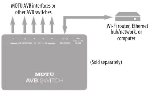
■ Expand the network by adding more switches. Make a single connection from one switch to the other. On MOTU AVB Switches, use their AVB NETWORK ports, NOT the Ethernet port.
- You can daisy-chain switches in serial fashion, but don't create loops. For example, in the network below, do not make any additional connections between any two switches.
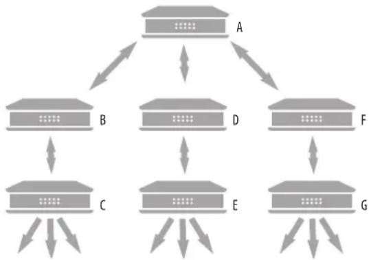
flowchart
graph TD
    A["..."] --> B["..."]
    A --> D["..."]
    A --> F["..."]
    B --> C["..."]
    C --> E["..."]
    D --> E
    F --> G["..."]
    G --> E
    style A fill:#f9f,stroke:#333
    style B fill:#ccf,stroke:#333
    style C fill:#cfc,stroke:#333
    style D fill:#fcc,stroke:#333
    style E fill:#cff,stroke:#333
    style F fill:#ffc,stroke:#333
    style G fill:#cfc,stroke:#333
■ AVB audio can't pass through more than seven switches. However, you can daisy-chain more than seven switches and route audio freely among them. You just won't be able to create point-to-point connects that span more than seven switches.
Working with computers on a network
■ Computers are not required for network operation, as you can control the network from iPads, tablets and smart phones.
■ To add computers to the network, connect them to any interface using Thunderbolt (which offers the highest possible channel counts). If Thunderbolt is not available, use USB.
- A computer can be connected to the network through its Ethernet port, but only for the purposes of running the web app on the computer for command and control over the network. (In this scenario, you won't be able to stream audio to/from the network from the computer.)
■ All computers and interfaces on the network have full access to each other.
■ MOTU employs a 1 Gbit AVB implementation in the MOTU AVB Switch. The switch allows routing of many audio channels on the network.
SETTING UP A MOTU AVB INTERFACE FOR NETWORKING
Depending on the model, MOTU AVB interfaces have the ability to broadcast up to sixteen 8-channel streams to the rest of the network. Conversely, it can “listen” to as many as sixteen 8-channel streams from anywhere else in the network. The specific number of streams supported depends on the model.
For each device on the network, set it up for network operation as follows:
1 In the MOTU Pro Audio Control web app, choose the device (item #1 on page 12).
2 Go to the Device tab (item #5 on page 12), go to the AVB Stream Setup section (item #20 on page 13), and type in the number of 8-channel input and output streams you want for that device.
3 Go to the AVB Stream Connections section (item #21 on page 13), and choose the network stream you want the device to listen to for each bank.
4 Use the Routing tab to map specific I/O channels within each MOTU AVB interface to its network input and output streams, as explained in the next section.
MAPPING AUDIO TO NETWORK STREAMS
Once you've configured a device's AVB streams, as explained above, use the Routing tab (page 15) to map audio channels to network input and output streams.
Input streams (coming from the rest of the network) are listed across the top of the routing grid. Expand the stream and click on the grid to map incoming network channels to local destinations, including physical outputs on the device, computer channels (to a connected computer), or mixer channels.
Output streams being broadcast to the rest of the network are listed in rows along the left side of the grid. Expand each stream bank and map individual network output channels to local sources, such as physical inputs on the interface, channels coming from the computer, or channels coming from the device's mixer.
MAPPING COMPUTER CHANNELS TO NETWORK STREAMS
If a host computer is connected to an interface (through USB), mapping network input and output streams is accomplished as described in the previous two sections. Simply enable AVB streams as desired, and map them to computer channels in the Routing grid.
If, while mapping, you run out of computer channels, enable more in the Computer Setup section of the Device tab (item #25 on page 14). If the computer is connected with Thunderbolt or USB 3.0 (to a MOTU interface that supports it), you can enable a maximum of 128 channels in and
out. If the computer is connected with USB 2.0, performance will vary, depending on the sample rate and other factors.
DEVICE PRESETS AND AVB STREAM CONNECTIONS
When you save a preset for a MOTU device (item 7 on page 12), any AVB stream connections that it has established with other devices on the network are now included with the saved preset. When you recall the preset, those saved stream connections are restored, as long as the other devices are still present on the network and broadcasting the same streams. If the other device is not present (or perhaps turned off), its streams will be reported as “offline”.
In general, if you have multiple devices on a network with interconnecting AVB streams, and you wish to preserve the state of the network, it is recommended that you save a device preset for each device on the network. Doing so will allow you to faithfully restore the entire network stream configuration by recalling each device's saved preset.
BRIDGING TO ETHERNET
The Ethernet port on the MOTU AVB Switch allows you to connect standard network devices, such as:
■ A Wi-Fi router
■ An Ethernet hub or switch connected to a local home, studio, or office network
■ Any other standard networking device
THE MOTU AVB SWITCH
The heart of a MOTU AVB network is the MOTU AVB Switch (sold separately). For a brief overview of the switch and its features, visit:
www.motu.com/products/avb/avb-switch.
Part 3
Appendices
APPENDIX A Troubleshooting
Some or all of my MOTU interface inputs and outputs are not available in my host audio software.
Make sure that the inputs and outputs are enabled in the Device tab (“Device tab” on page 12) and routed to and from the computer in the Routing tab (“Routing tab” on page 15). For details, see “Making inputs and outputs available to your host software” on page 62. A quick and easy way to do this is to choose the Audio Interface preset from Quick Setup (item 10 on page 12).
I have absolutely no audio input or output happening to or from my interface. Why?
Make sure that the unit has a stable sample rate (the sample rate will flash if the clock hasn't settled yet). Try setting the unit's clock source to Internal if you can't sync to any external clock sources. Check that audio is working with Internal sync, and if so, then work on establishing a stable external clock.
I can't hear computer audio output through my MOTU AVB interface.
In the Sound panel of System Preferences, the 624 should be selected as the output device. Almost all applications will use just the first two output channels, so make sure that From Computer 1 and From Computer 2 are routed to the physical outputs that you are listening to in the Routing tab (e.g. Phones 1-2 or Analog 1-2).
How do I monitor live inputs?
Please refer to the documentation for the audio application that you are using. If your application does not support input monitoring, you will need to use the mixer in the 624. Please see “Monitoring through the 624” on page 59.
How do I control monitoring latency?
See “Reducing monitoring latency” on page 58.
The Routing tab (page 15) doesn't display some of the inputs or outputs on my interface.
The Routing tab only displays input and output banks that are enabled in the Device tab (page 12), so be sure any banks you wish to work with are enabled there. However, to conserve DSP resources and help consolidate screen-space in the other tabs, it is efficient practice to disable unused input or output banks (optical banks, for example, when only working with analog banks, or all output banks when only working with Phones).
I'm getting a "Could not enable this effect because DSP is overloaded" error. What should I do?
Disable other effects or reduce the number of mixer inputs to conserve DSP resources. If there are audio input and output banks on your interface that you are not using (such as the optical banks), disable them in the Device tab (page 12).
I accidentally deleted my factory presets. How do I restore them?
In the Device tab (page 12), click the Restore Factory Presets button to restore all factory presets.
How do I factory reset my device?
Push the SELECT knob/button to enter the main menu. Navigate to Settings > Factory Default and push the SELECT knob/button twice to reset.
Clicks and pops due to hard drive problems...
If you have checked your clock settings and you are still getting clicks and pops in your audio, you may have a drive related problem. Set your Clock Source to Internal and try recording just using the analog inputs and outputs on the 624. If you encounter the same artifacts you may want try using another drive in your computer. Clicks and pops can also occur when the drive is severely fragmented or there are other drive-related issues.
Connecting or powering gear during operation... It is not recommended that you connect/ disconnect, or power on/off devices connected to the 624 while recording or playing back audio. Doing so may cause a brief glitch in the audio.
CUSTOMER SUPPORT
We are happy to provide complimentary customer support to our registered users. If you haven't already done so, please take a moment to register online at MOTU.com, or fill out and mail the included registration card. Doing so entitles you to technical support and notices about new products and software updates.
TECHNICAL SUPPORT
If you are unable, with your dealer's help, to solve problems you encounter with your MOTU device, you may contact our technical support department in one of the following ways:
■ Tech support hotline: (617) 576-3066 (Monday through Friday, 9 a.m. to 6 p.m. EST)
■ Online support: www.motu.com/support
Please provide the following information to help us solve your problem as quickly as possible:
■ The serial number of your MOTU device. This is printed on a label placed on the bottom of the rack unit. You must be able to supply this number to receive technical support.
■ A brief explanation of the problem, including the exact sequence of actions which cause it, and the contents of any error messages which appear on the screen.
■ The pages in the manual that refer to the features or operation of your MOTU AVB Device or AudioDesk with which you are having trouble.
- The version of your computer's operating system.
We're not able to solve every problem immediately, but a quick call to us may yield a suggestion for a problem which you might otherwise spend hours trying to track down.
If you have features or ideas you would like to see implemented, we'd like to hear from you. Please write to the Development Team, MOTU Inc., 1280 Massachusetts Avenue, Cambridge, MA 02138, or use our online suggestion box at www.motu.com/suggestions.
APPENDIX B Audio Specifications
Line Out/Main Out
| Connector Type 1/4" Female, TRS Balanced, tip hot |
| Output Impedance 100 ohm Per leg |
| Dynamic Range 123 dB A-weighted |
| THD+N -110 dB (0.0003%) -1 dBFS, Unweighted, 1 kHz |
| Frequency Response +0, -0.1 dB, 20 Hz/20 kHz Ref. 1 kHz |
| Max Level Out +20 dBu |
| Trim Range 24 dB -4 dBu to +20 dBu in 1 dB steps |
Guitar In
| Connector Type 1/4” Female, TS Unbalanced | ||
| Impedance | 1 megohm | |
| Dynamic Range | 103 dB | A-weighted |
| THD+N -93 dB | -1 dBFS, Unweighted | |
| Frequency Response +0.05, -0.1 dB | Ref. 1 kHz | |
| Max Level In | -2 dBu with trim down, +10 dBu with trim up | 0.615v to 2.45v |
| Trim Range 12dB | -2 dBu to +10 dBu in 1 dB steps | |
Line In
| Connector Type 1/4” Female, TRS Balanced/unbalanced, Tip hot | |
| Specification | Complies with EBU-R68 / SMPTE RP-155 |
| Impedance Load | 10 k ohm |
| Dynamic Range | 117 dB A-weighted |
| THD+N -110 dB (0.0003%) -1 dBFS, Unweighted | |
| Frequency Response +0, -0.1 dB, 20 Hz/20 kHz Ref. 1 kHz | |
| Max Level In | +24 dBu |
| Trim Range 22 dB | +2 dBu to +24 dBu in 1 dB steps |
MIC In
| Connector Type XLR Male, Balanced | Pin 2 hot | |
| Impedance Load | 3k ohm, 4.5k with Pad | |
| Pad | -20 dB, Switchable per channel | |
| Phantom Power | +48v, Switchable per channel | DIN 45596 / IEC 61938-P48 |
| EIN | -128 dBu, 20 - 20 kHz | Rs = 150 ohm |
| Dynamic Range | 117 dB | A-weighted |
| THD+N -110 dB (0.0003%) -1 dBFS, Unweighted, 1 kHz | ||
| Frequency Response +0, -0.1 dB, 20 Hz/20 kHz Ref. 1 kHz | ||
| Max Level In | +24 dBu | With pad |
Trim Range 63 dB
0 to +63 dB in 1dB steps
Phones
| Connector Type 1/4" Female, TRS Stereo Tip Left, Ring Right |
| Dynamic Range 108 dB A-Weighted |
| THD+N -100 dB Unweighted |
| Frequency Response +0 -0.15 dB, 22 Hz/20 kHz Ref. 1 kHz |
| Drive Max. 80 mw 16/32/55 ohms |
| Trim Range 128 dB 0 to -128 dB (muted) in 1 dB steps |
Power Supply
| Connector Type Concentric barrel, tip positive or negative For external DC power supply (included) |
| Configuration External power supply |
| Power Input 12-18V DC, 10 watts |
APPENDIX c Mixer Schematics
MONO INPUT CHANNEL
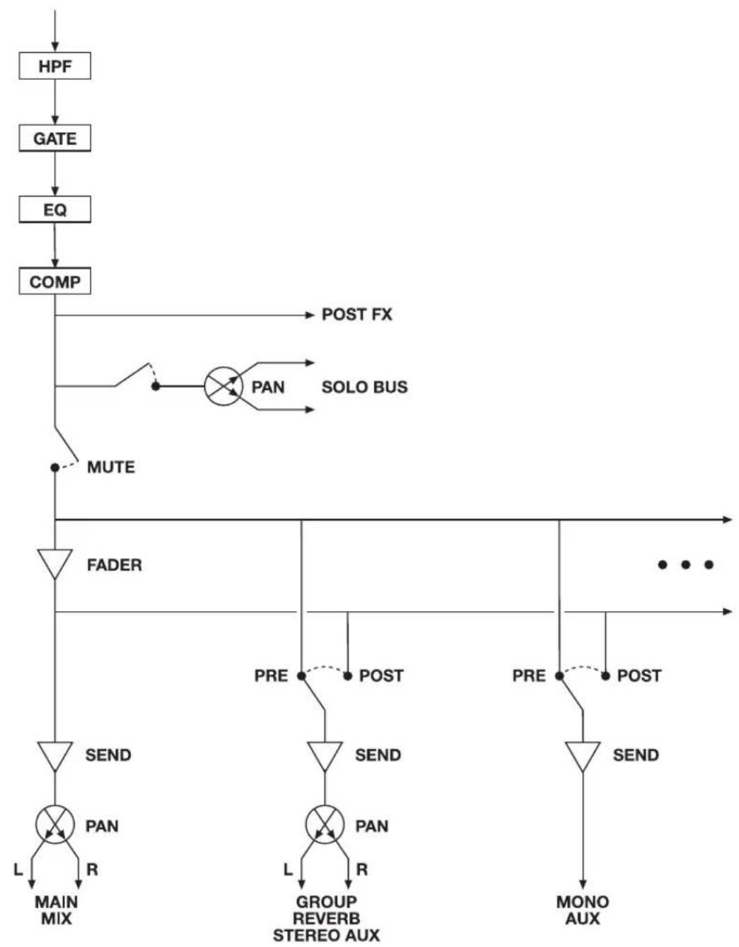
flowchart
graph TD
    A["HPF"] --> B["GATE"]
    B --> C["EQ"]
    C --> D["COMP"]
    D --> E["POST FX"]
    D --> F["MUTE"]
    F --> G["FADER"]
    G --> H["SEND"]
    H --> I["PAN"]
    I --> J["L MAIN MIX"]
    I --> K["R"]
    G --> L["PAN"]
    L --> M["L GROUP REVERB STEREO AUX"]
    L --> N["R"]
    G --> O["POST"]
    G --> P["PRE"]
    G --> Q["POST"]
    G --> R["PRE"]
    G --> S["POST"]
    G --> T["MONO AUX"]
    U["SOLO BUS"] --> V["PAN"]
    V --> W["POST"]
    X["POST"] --> Y["SEND"]
    Y --> Z["PAN"]
    Z --> AA["L GROUP REVERB STEREO AUX"]
    AB["POST"] --> AC["SEND"]
    AC --> AD["PAN"]
    AD --> AE["L GROUP REVERB STEREO AUX"]
    AF["POST"] --> AG["MONO AUX"]
STEREO INPUT CHANNEL
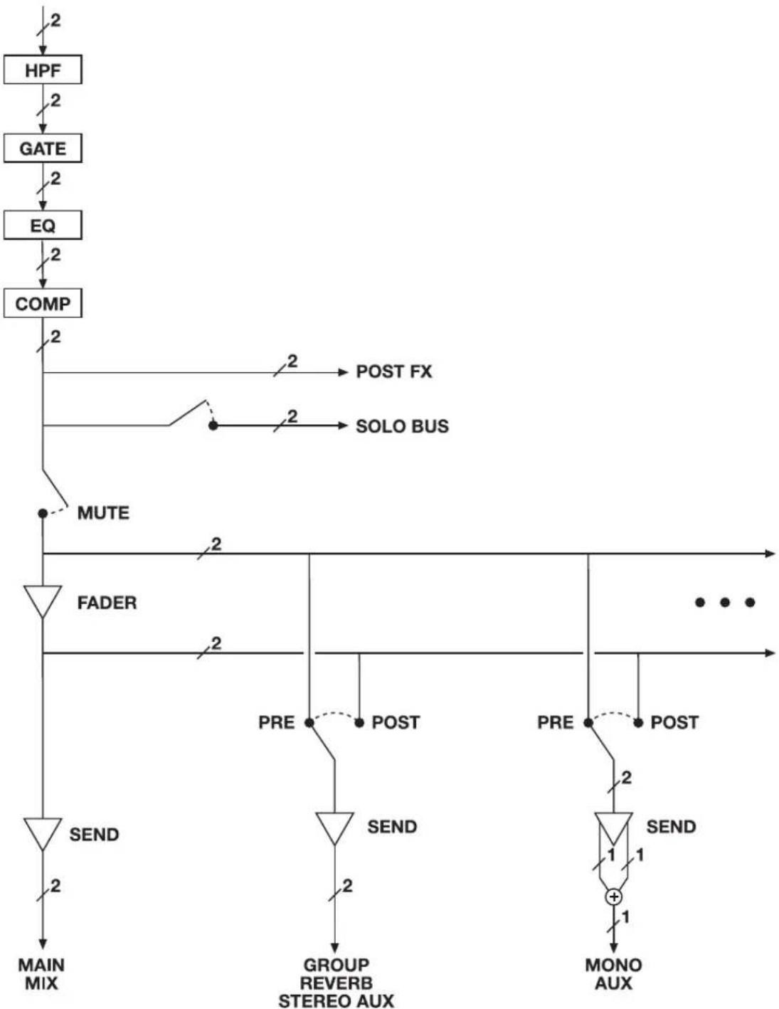
flowchart
graph TD
    A["HPF"] -->|2| B["GATE"]
    B -->|2| C["EQ"]
    C -->|2| D["COMP"]
    D -->|2| E["MUTE"]
    E -->|2| F["FADER"]
    F -->|2| G["SEND"]
    G -->|2| H["MAIN MIX"]
    F --> I["PRE"]
    I --> J["POST"]
    J --> K["POST"]
    K --> L["PRE"]
    L --> M["POST"]
    M --> N["MONO AUX"]
    N -->|1| O["+"]
    O --> P["GROUP REVERB STEREO AUX"]
    P --> Q["SEND"]
    Q --> R["POST"]
    R --> S["POST FX"]
    S --> T["SOLO BUS"]
GROUP BUS
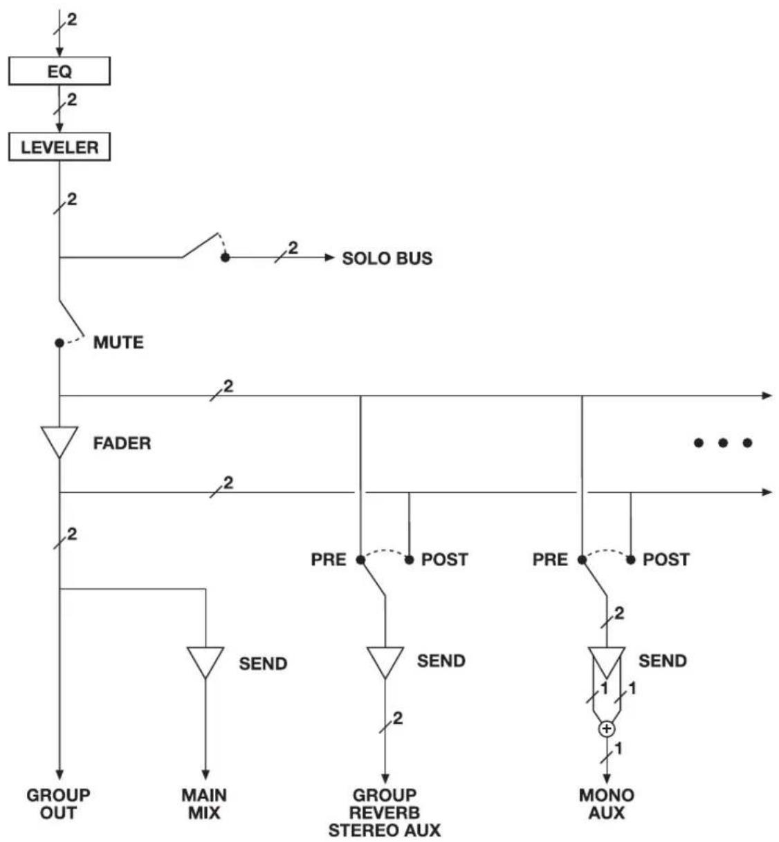
flowchart
graph TD
    EQ --> LEVELER
    LEVELER --> MUTE
    MUTE --> FADER
    FADER --> GROUP_OUT
    FADER --> MAIN_MIX
    FADER --> GROUP_REVERB_STEREO_AUX
    FADER --> PRE
    PRE --> POST
    POST --> PRE
    PRE --> POST
    PRE --> POST
    POST --> MONO_AUX
    PRE --> 1
    PRE --> 1
    PRE --> 2
    PRE --> 2
    style EQ fill:#f9f,stroke:#333
    style LEVELER fill:#ccf,stroke:#333
    style MUTE fill:#cfc,stroke:#333
    style FADER fill:#ffc,stroke:#333
    style GROUP_OUT fill:#fff,stroke:#000
    style MAIN_MIX fill:#fff,stroke:#000
    style GROUP_REVERB_STEREO_AUX fill:#fff,stroke:#000
    style PRE fill:#fff,stroke:#000
    style PRE fill:#fff,stroke:#000
    style PRE fill:#fff,stroke:#000
    style PRE fill:#fff,stroke:#000
    style PRE fill:#fff,stroke:#000
    style PRE fill:#fff,stroke:#000
    style PRE fill:#fff,stroke:#000
    style PRE fill:#fff,stroke:#006
    style PRE fill:#fff,stroke:#006
    style PRE fill:#fff,stroke:#006
    style PRE fill:#fff,stroke:#006
    style PRE fill:#fff,stroke:#006
    style PRE fill:#fff,stroke:#006
    style PRE fill:#fff,stroke:#006
    style PRE fill:#fff,stroke:#006
    style PRE fill:#fff, stroke-dasharray: 5 5
MONITOR BUS
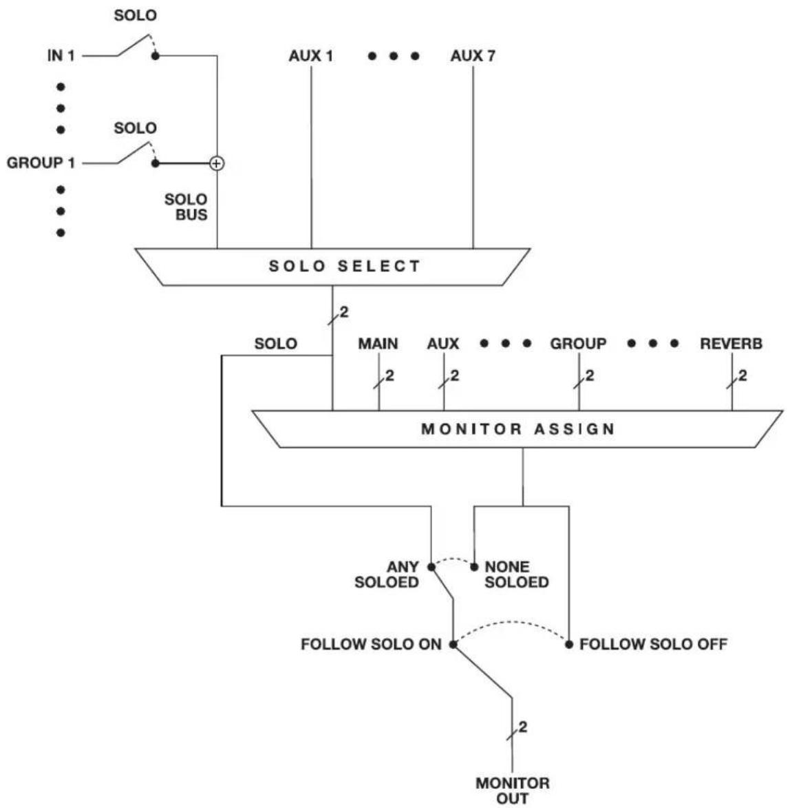
flowchart
graph TD
    A["SOLO"] --> B["IN 1"]
    B --> C["SOLO"]
    C --> D["GROUP 1"]
    D --> E["SOLO BUS"]
    E --> F["SOLO SELECT"]
    F --> G["MONITOR ASSIGN"]
    G --> H["ANY SOLOED"]
    H --> I["FOLLOW SOLO ON"]
    I --> J["FOLLOW SOLO OFF"]
    J --> K["MONITOR OUT"]
    F --> L["AUX 1"]
    F --> M["AUX 7"]
    F --> N["AUX 2"]
    F --> O["AUX 2"]
    F --> P["AUX 2"]
    F --> Q["AUX 2"]
    F --> R["AUX 2"]
    F --> S["AUX 2"]
    F --> T["AUX 2"]
    F --> U["AUX 2"]
    F --> V["AUX 2"]
    F --> W["AUX 2"]
    F --> X["AUX 2"]
    F --> Y["AUX 2"]
APPENDIX D Updating Firmware
MOTU periodically posts firmware updates for the 624. These updates may include bug fixes, enhancements, and new features.
Updates are posted on MOTU's servers. If your computer or Wi-Fi device has access to the internet, the MOTU Pro Audio Control app notifies you as soon as an update is made available. Otherwise, you can check motu.com/avb periodically for the latest firmware update.
A network cable connection is required
Firmware updating requires a network cable connection, so before you begin, connect a standard CAT-5 or CAT-6 network cable from the network port on the 624 to one of the following:
- Your computer's network port (or a Thunderbolt-to-Ethernet adapter)
■ Your home, studio, or office network (with internet access)
■ An AVB port on a MOTU AVB switch (connected to your office network through the Ethernet port)
Updating with internet access
You are now ready to update:
1 Launch the MOTU Pro Audio Control web app on your computer, iPad, or iPhone, as usual.
2 Go to the Device tab.

Figure D-1: The firmware update banner appears across the Device tab when your web host has internet access and MOTU posts an update.
3 In the New Update Available banner (Figure D-1), click More Info.
4 After reviewing the list of enhancements, click OK to start the update.
5 Follow the on-screen instructions.
6 IMPORTANT: disconnect the Ethernet cable from your MOTU interface after you complete the update, unless it is connected to a MOTU AVB switch or other AVB-aware switch. If so, you can leave it connected.
Updating off-line, without internet access
If the 624 (and the computer it is connected to) has no internet access, you can download a firmware update file from another computer that does have internet, and then use the file to update the 624, as follows:
1 Download the firmware file from motu.com/avb.
2 Transfer the file to a computer with a network cable connection to the 624.
3 Launch the MOTU Pro Audio Control web app on the computer, as usual.
4 Go to the Device tab.
5 Scroll down to the bottom and click Update from File.
6 Locate the file on your hard drive and click OK to start the update.
7 Follow the on-screen instructions.
8 IMPORTANT: disconnect the Ethernet cable from your MOTU interface after you complete the update, unless it's connected to a MOTU AVB switch or other AVB-aware switch. If so, you can leave it connected.
Updating multiple interfaces on a network
If you have two or more MOTU interfaces on a network, you can update their firmware all at once.
1 Go to the MOTU Discovery Settings menu.
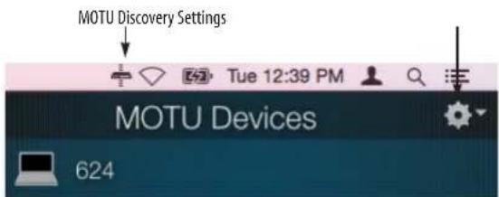
Figure D-2: MOTU Discovery Settings menu.
2 Choose Firmware Updater > Open...
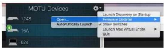
Figure D-3: Launching the Firmware Updater.
3 Connect Ethernet cables, if necessary, or click the Update from File option.
4 Click Update All Interfaces Now.
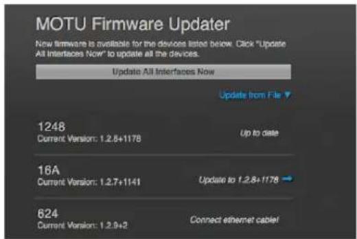
Figure D-4: Updating multiple interfaces in one operation.
Viewing the latest firmware version information
You can confirm the firmware version at the bottom of the Device tab (Figure D-5).
Why does the firmware update require a network cable?
Firmware updating was designed to use Ethernet mostly for convenience. If you have lots of networked devices, you can upgrade them all from a distance (even over Wi-Fi) without having to plug in directly and without having to download or run an updater application.
This approach was also taken for engineering reasons, with reliability foremost in mind. When installing an update, the device reboots into a stripped-down recovery partition to guarantee that the update process can always be completed, even if the power goes out mid-update. Since updates can also affect the Thunderbolt or USB chips, they cannot be used during the update.

Figure D-5: The currently installed firmware version is displayed at the bottom of the Device tab.
APPENDIX E OSC Support
Open Sound Control (OSC) is a protocol for communication among computers and other multimedia devices that is optimized for modern networking technology.
MOTU AVB audio interfaces support OSC, which provides remote control of all device settings and mixer controls from any OSC-enabled controller.
For further details about remote control through OSC, along with complete documentation for the MOTU AVB OSC API, visit:
http://www.motu.com/avb#avb-osc-support
24-bit
optical 10
2x SMUX mode 13, 44
624
expansion 34
setup example 43
specifications 99
summary of features 23
A
Ableton Live 57, 58
ADAT optical 10
connecting 44
settings 13
Analog inputs/outputs 44
making connections to 44
Apple
GarageBand 58
Logic Pro 58
ASIO driver 58
ASIO monitoring 59
Attack
Compressor 66, 68
Audio interface preset 51
Audio Tools 73
AudioDesk 25, 31, 57, 58
Aux Mix Target 17
Aux Mixing tab 17
AVB
audio interface operation 23, 34, 40
Ethernet explained 89
Input/Output Banks 13
networking 89-94
overview 89
Stream Connections 13
Stream Setup 13
streams (Routing tab) 15
Switch
setup 35, 39
Avid
Pro Tools 58
B
Balanced analog 44
Become Clock Master 12, 46
Buffer Size 12, 30
C
CAT-5e/6 cables 34
Check for Updates 14
Chrome 11
Class compliance 29
Clear Password 14, 56
Clock Mode 12, 56
Clock section (LCD) 56
Cockos Reaper 58
Compressor effect 16, 67
Computer Channel for LTC-to-MTC
Conversion 14
Computer Setup 14
Computer Volume Controls option 14
Configure IP 56
Connecting multiple interfaces 34
Control surface support (through OSC)
107
Converter mode
setup/example 54
Converters 10
Core Audio driver 58
Correlation Meter 84
Cubase 57, 58
clock source 57
sample rate 57
CueMix FX
Devices menu 73
installation 73
Customer
support 98
D
Device tab 12, 13
Devices menu 73
Digital converter (see Optical converter)
Digital Performer 57, 58
Direct hardware playthrough 59
Direct ASIO monitoring 59
Direct hardware playthrough 59
Discovery app 7, 31
Driver installation 7, 11, 29
Drivers
installing USB drivers 29
DSP
effects65
meter 71
resources 71
DSP Usage 18,71
E
Effects 65
Enable Jam Sync 14
EQ 66
enabling 66
filter types 66
frequency 66
gain 66
Q 66
Ethernet
connecting 39
Ethernet interface operation 34, 40
Expansion 34
F
Factory Defaults 56
Firefox 11
Firmware
version 14
Firmware updates 12
Follow Solo 16, 19
Four-band EQ 66
Frequency
EQ 66
From Computer 15
Front panel 55
menu navigation 56
metering 55
G
Gain
EQ 66
reduction 68
reduction (Leveler) 70
GarageBand 57, 58
clock source 57
sample rate 57
Gate effect 16, 66
GR (gain reduction) 68
Guitar inputs 9, 44
H
Headphone outputs 9
Headphones
connecting 43
High pass filter 65
Host
Buffer Size 12, 30
Safety Offset 12, 31
I
ID knob/button 11, 12, 55
IEEE 802.1 89
Input banks 13
Input settings 12
Inputs
optical 10
prefader metering 18
Installation
AVB audio interface 34, 40
iOS connection 33
network 35, 36
QuickStart Guide 7
software 29
Thunderbolt interface 33
two interfaces networked 34
USB connection 33
Interface + mixer preset 52
iOS operation 29, 33
IP address 11, 14, 56
iPad
QuickStart 7
iPad/iPhone support 29
J
Jam sync 14, 46
L
Latency 12, 30, 58, 60
Launch Mac Virtual Entity 40
LCD
menu 56
Leveler 16, 69
Lightpipe 44
Limit button 70
Live 58
Live recording with monitor mixing preset 53
Lock button 15
Logic Pro 58
Logic Pro/Express 57
clock source 57
sample rate 57
LTC
Input Source 14
Setup 45
to MTC conversion 63

Mac OS X 57
input and output names 62
system requirements 27
Mac Virtual Entity 40
Main outs
front panel volume control 44
making connections to 44
Makeup gain 70
Meters 9, 56
prefader 18
Mic inputs
preamp gain/pad/48V 9
Mic/guitar inputs 44
MIDI Time Code 14, 63
Mixer
accessing 16
aux bus 20
connecting 43
effects 65
group bus 21
input channel strip 18
main mix channel strip 19
Monitor channel strip 19
overview 16
Reverb bus 21
schematics 101
Setup 13
stand-alone operation 65
Mixing tab 16
Monitoring
thru main outs 44
MOTU
Audio Tools 73
AudioDesk 58
AVB Installer 29
AVB Switch
setup 35, 39
Digital Performer 58
Discovery app 7, 11, 31, 106
Pro Audio ASIO driver 58
Pro Audio Control web app 7, 11, 21
Aux Mixing tab 17
Device tab 12, 13
Mixing tab 16
Routing tab 15
Pro Audio Installer 7, 11
Pro Audio WebUI Setup 11, 31
MTC 14,63

Networking 89-94
installation 35, 36
Nuendo 57, 58
clock source 57
sample rate 57

Optical 56
connectors 10, 44
S/PDIF 45
Optical Converter preset 54
setup/example 54
Optical setup 13
Optimization 60
OS X audio software
clock source 57
sample rate 57
OSC support 107
Oscilloscope 76
Output banks 13
Output settings 12
Outputs
optical 10

Packing list 27
Pad 44
Password protection 14
Patch thru
latency60
Performance 60
Phantom power 44
Phase Analysis 84
Phone outputs 9
Power supply
jack 10
Power switch 55
PRE button 18
PRE switch 16
PreDelay 70
Prefader button 17
Presets 7, 12
Mixer tab 16
overview 51
Routing tab 15
Pro Audio Control web app 7, 11-21
Aux Mixing tab 17
Device tab 12, 13
Mixing tab 16
Routing tab 15
Pro Tools 57, 58
Processing 65

Q 66
Quick Setup window 7
QuickStart Guide 7

Ratio
Compressor 67
Reaper 57, 58
Reason 57
Propellerhead Reason 58
Reboot 14
Registration 27
Release
Compressor 66, 68
Remote control (through OSC) 107
Restore Factory Presets 14
Reverb 70-71
design section 70
enabling/disabling 70
predelay 70
routing to/from 70
time 70, 71
width 71
RMS mode 68
Routing tab 15

S/PDIF
optical 10
S/PDIF (optical) 45
Safari 11
Sample Rate 56
Sample rate 12
Samp
connecting 43
SC button 19
Schematics 101
Serial/UID 56
Set password 14
SMPTE sync 45
SMPTE time code 14
SMUX 44
Software
installation 29
Software installer 7, 11, 29
Solo bus 19
Solo Clear button 18
SONAR 57
Soundtrack Pro
clock source 57
sample rate 57
Stage I/O preset 53
Stage monitors
connecting 43
Stand-alone mixer preset 52
Stand-alone operation 55, 56
Standard (optical setting) 45
Steinb
Cubase 58
Nuendo 58
Stop Jam Sync 14
Studio setup (example) 43
Synchronization
Become Clock Master 46
SMPTE time code 45
Synths
connecting 43
System Information 14
System requirements
minimum 27
recommended computer 27

Technical support 98
Threshold
Compressor 67
Thunderbolt 33
Time code sync 14, 45
Time Sensitive Networking (TSN) 24, 89
To Computer 15
TOSLink 10, 13, 45
Trim 44
Troubleshooting 97
TRS analog inputs/outputs 44
TRS connectors 44
TSN 24,89
Type II (Legacy) optical setting 45

Unbalanced analog 44
Update From File 14, 106
USB
class compliance 29
installing drivers 29

View Personal Mix 17

Wave driver 58
WDM (Wave) Driver 30
Width
reverb 71
Wi-Fi
setup 39
Windows
shortcut 31
system requirements 27
WDM (Wave) driver 30

X-Y Plot 81


- IMPORTANT SAFEGUARDS
- ENVIRONMENT, HEAT AND VENTILATION
- TO REDUCE THE RISK OF ELECTRICAL SHOCK OR FIRE
- DC INPUT
- Contents
- Part 1: Getting Started
- Part 2: Using the 624
- Part 3: Appendices
- About the Mark of the Unicorn License Agreement and Limited Warranty on Software
- Reminder of the terms of your license
- Update Policy
- Copyright Notice
- Limited Warranty on Hardware
- Part 1
- Getting Started
- Quick Start Guide
- Front Panel
- Rear Panel
- MOTU Pro Audio Control Web App
- OVERVIEW
- IT'S NOT ON YOUR HARD DRIVE
- USE YOUR FAVORITE WEB BROWSER
- CONTROL FROM MULTIPLE DEVICES
- RUN THE INSTALLER, GET THE APP
- MAKE HARDWARE AND NETWORK CONNECTIONS
- LAUNCHING THE WEB APP
- Obtaining the 624's IP address
- CHAPTER 1 About the 624
- Comprehensive I/O
- Network I/O
- Other MOTU AVB interfaces
- Universal connectivity
- On-board DSP with mixing and effects
- 32-bit floating point processing
- Modeled vintage effects processing
- AVB/TSN system expansion and audio networking
- Matrix routing and multing
- Web app control
- Stand-alone mixing with wireless control
- ADAT digital input
- Comprehensive metering
- Headphone output
- Precision Digital Trim™
- Rack mount or desktop operation
- AudioDesk
- CHAPTER 2 Packing List and System Requirements
- PACKING LIST
- SYSTEM REQUIREMENTS
- PLEASE REGISTER TODAY!
- CHAPTER 3 Software Installation
- USB AUDIO CLASS-COMPLIANT OPERATION
- Connection to iOS devices (iPad and iPhone)
- SOFTWARE INSTALLATION
- Download and run the MOTU Pro Audio Installer
- AUDIO DRIVERS
- Thunderbolt support for Mac and Windows
- Industry-leading I/O latency performance
- MOTU Pro Audio ASIO Driver
- WDM / Wave driver support
- Host Buffer Size
- Host Safety Offset
- MOTU DISCOVERY APP
- MOTU PRO AUDIO WEBUI SETUP FOR WINDOWS
- AUDIODESK WORKSTATION SOFTWARE
- WORKING WITH HOST AUDIO SOFTWARE
- CHAPTER 4 Hardware Installation
- THUNDERBOLT AUDIO INTERFACE SETUP
- USB OR iOS AUDIO INTERFACE SETUP
- AVB ETHERNET AUDIO INTERFACE SETUP
- About CAT-5e cables
- SETUP FOR TWO INTERFACES
- SETUP FOR THREE TO FIVE INTERFACES
- SETUP FOR A MULTI-SWITCH NETWORK
- SETUP FOR MULTIPLE INTERFACES
- Connecting multiple interfaces using Thunderbolt
- Connecting multiple interfaces using Thunderbolt and USB
- Multiple interfaces and USB
- Multiple AVB Ethernet audio interfaces
- Mixing and matching audio interfaces
- SETUP FOR WEB APP CONTROL
- Web app control can be set up independently of audio connections
- Mixing and matching web app control scenarios
- Web app control over Thunderbolt or USB
- Web app control through standard Ethernet
- Ethernet cable
- Ethernet hub or network (LAN)
- Wi-Fi
- Ethernet network + Wi-Fi
- MOTU AVB Switch
- SETUP FOR AVB ETHERNET AUDIO INTERFACE OPERATION
- Ethernet connection to the Mac
- Web app setup
- Clocking
- AVB stream and channel counts
- A TYPICAL 624 SETUP
- AUDIO CONNECTIONS
- Mic inputs with preamps
- Phantom power
- Preamp gain
- -20 dB pad
- Guitar inputs
- TRS quarter-inch analog inputs and outputs
- Dedicated main outs
- Analog trims
- Optical I/O
- TOSLink (optical S/PDIF)
- SYNCING TO SMPTE TIME CODE (LTC)
- SMPTE time code (LTC) settings
- LTC Input Source
- LTC Format
- Enable Format Autodetect
- Enable Jam Sync
- SYNCING AN AVB NETWORK
- Choosing a master clock
- Resolving the master clock device to an external clock source
- SYNCING MULTIPLE AVB AUDIO INTERFACES CONNECTED TO A MAC
- Part 2
- Using the
- 624
- CHAPTER 5 Presets
- Preset menu
- Create your own presets
- Video tutorials
- AUDIO INTERFACE
- STAND-ALONE MIXER
- INTERFACE + MIXER
- LIVE RECORDING WITH MONITOR MIXING
- AVB EXPANSION
- OPTICAL CONVERTER
- CHAPTER 6 The Front Panel LCD
- LEVEL METERS
- PUSH-BUTTON KNOBS
- ID
- CHANNEL FOCUS
- MAIN VOLUME
- MUTE
- METERS
- MENU NAVIGATION
- Main Menu
- Device menu
- Network menu
- Settings menu
- Presets menu
- Version menu
- CLOCK
- CHAPTER 7 Working with Host Audio Software
- PREPARATION
- RUN THE WEB APP
- Sample Rate
- Clock Mode
- Audio Interface preset
- CHOOSE THE MOTU PRO AUDIO DRIVER
- For Mac OS X audio software
- For Windows audio software
- Where to go in popular audio hosts
- Other audio software
- REDUCING MONITORING LATENCY
- Monitoring through the 624
- Direct hardware playthrough / Direct ASIO monitoring
- Monitoring through your host audio software
- Adjusting your host software audio buffer
- Adjusting buffer size on Mac OS X
- Adjusting buffer size on Windows
- Lower latency versus higher CPU overhead
- Transport responsiveness
- Effects processing and automated mixing
- WORKING WITH THE ROUTING GRID
- Enabling and disabling input/output banks
- Making inputs and outputs available to your host software
- Configuration presets
- Naming computer input and output channels
- Streaming computer audio to and from the on-board mixer
- Working with AVB network streams
- Mirroring computer channels to multiple outputs
- Combining multiple sources to one output
- Routing grid tutorials
- WORKING WITH ON-BOARD MIXING AND EFFECTS
- LTC-TO-MTC CONVERSION
- CHAPTER 8 Mixer Effects
- Powerful DSP-driven mixing and effects
- Advantages over host-based mixing and processing
- HIGH PASS FILTER
- GATE
- FOUR-BAND PARAMETRIC EQ
- Vintage EQ
- Enabling EQ
- EQ filter controls
- Control unit range
- EQ filter characteristics
- Low and high shelf filters
- EQ graph
- COMPRESSOR
- Gain reduction meter
- RMS mode
- Compressor graph
- LEVELER
- A model of an optical compressor
- Automatic gain control using light
- Response characteristics
- Enabling or disabling the Leveler
- Gain Reduction
- Makeup Gain
- Limit button
- REVERB
- Routing inputs and groups to the reverb processor
- Reverb Time
- Predelay
- Spread
- High and Mid frequency bands
- DSP USAGE
- CHAPTER 9 MOTU Audio Tools
- INSTALLATION
- ANALYSIS MENU
- LEFT/RIGHT INPUT
- FFT AND SPECTROGRAM DISPLAY
- Spectrogram
- View controls
- View menu
- Logarithmic or Linear X-Axis Scale
- Axes display
- Pausing the display
- Horizontal controls (frequency axis)
- Vertical controls (amplitude axis)
- Spectrogram controls
- OSCILLOSCOPE
- Display options
- Horizontal controls (time axis)
- Time Units
- Waveform Recognition
- Trigger
- Criteria
- Holdoff
- Trigger modes
- Trigger indicator
- Measurement information
- Ideas for using the Oscilloscope
- Viewing transients such as drum hits
- Clip detection
- Viewing timing pulses
- Building synthesizer patches
- X-Y PLOT
- Metering
- Line/Scatter
- Color/Grayscale
- Axes
- Horizontal and vertical controls
- Persistence
- Length
- Decay
- Warp
- Using the X-Y Plot
- PHASE ANALYSIS
- Correlation Meter
- Linear/Logarithmic
- Rectangular/Polar
- Filters
- Floor
- Max delta theta
- Using the Phase Analysis
- Tuning PA systems
- Summing to mono
- CHAPTER 10 Networking
- ABOUT AVB
- MOTU'S AVB IMPLEMENTATION
- NETWORKING EXAMPLES
- Personal studio expansion
- Studio installation
- Large studio facility
- Concert systems
- Large-scale venues
- A QUICK GUIDE TO NETWORKING
- Networking basics
- Working with AVB switches
- Working with computers on a network
- SETTING UP A MOTU AVB INTERFACE FOR NETWORKING
- MAPPING AUDIO TO NETWORK STREAMS
- MAPPING COMPUTER CHANNELS TO NETWORK STREAMS
- DEVICE PRESETS AND AVB STREAM CONNECTIONS
- BRIDGING TO ETHERNET
- THE MOTU AVB SWITCH
- Part 3
- Appendices
- APPENDIX A Troubleshooting
- CUSTOMER SUPPORT
- TECHNICAL SUPPORT
- APPENDIX B Audio Specifications
- APPENDIX c Mixer Schematics
- STEREO INPUT CHANNEL
- MONITOR BUS
- APPENDIX D Updating Firmware
- A network cable connection is required
- Updating with internet access
- Updating off-line, without internet access
- Updating multiple interfaces on a network
- Viewing the latest firmware version information
- Why does the firmware update require a network cable?
- APPENDIX E OSC Support
- A
- B
- C
- D
- E
- F
- G
- H
- I
- J
- L
Brand : MOTU
Model : 624
Category : Hi-Fi System