
ThinkStation P330 Gen 2 - Desktop computer LENOVO - Free user manual and instructions
Find the device manual for free ThinkStation P330 Gen 2 LENOVO in PDF.


User questions about ThinkStation P330 Gen 2 LENOVO
0 question about this device. Answer the ones you know or ask your own.
Ask a new question about this device
Download the instructions for your Desktop computer in PDF format for free! Find your manual ThinkStation P330 Gen 2 - LENOVO and take your electronic device back in hand. On this page are published all the documents necessary for the use of your device. ThinkStation P330 Gen 2 by LENOVO.
USER MANUAL ThinkStation P330 Gen 2 LENOVO
Machine Types (2nd Gen): 30CY, 30D0, and 30D3
Note: Before using this information and the product it supports, be sure to read and understand the “Read this first: Important safety information” on page iii and Appendix G “Notices” on page 145.
Fourth Edition (March 2020)
© Copyright Lenovo 2020.
LIMITED AND RESTRICTED RIGHTS NOTICE: If data or software is delivered pursuant to a General Services Administration "GSA" contract, use, reproduction, or disclosure is subject to restrictions set forth in Contract No. GS-35F-05925.
Contents
Read this first: Important safety information ..... iii
Before using this manual ..... iii
Service and upgrades ..... iii
Power cords and power adapters ..... iv
Power cord notice....iv
Extension cords and related devices. . . . . . . v
Plugs and outlets....vi
Power supply statement ..... vi
External devices ..... vi
Lithium coin-cell battery notice . . . . . . . . . . . . vii
Heat and product ventilation . . . . . . . . . . . . vii
Electrical current safety information ..... viii
Laser safety information ix
Liquid crystal display (LCD) notice ..... x
Use earphones, headphones, or a headset ..... x
Choking hazard notice . . . . . . . . . . . . . . xi
Plastic bag notice....xi
Glass parts notice....xi
Computer placement notices . . . . . . . . . . xi
Hazardous energy statement ..... xii
Eye comfort....xii
Tip-over hazard prevention notice. . . . . . . . . xii
Remote control. . . . . . . . . . . . . . . . . . xiii
Static electricity prevention ..... xiii
Operating environment ..... xiii
Cleaning and maintenance . . . . . . . . . xiv
Chapter 1. Product overview ..... 1
Hardware locations ..... 1
Front view 1
Rear view 3
Computer components ..... 5
Parts on the system board. . . . . . . . . . . 7
Internal storage drives 8
Machine type and model label ..... 10
Computer features. 11
Statement on USB transfer rate. . . . . . . 14
Computer specifications ..... 15
Programs 15
Accessing a program on your computer . . . 15
An introduction to Lenovo programs ..... 16
Chapter 2. Using your computer . . . 17
Registering your computer 17
Get started with Windows 10....17
Windows account....17
Windows user interface ..... 18
Setting the computer volume ..... 19
Using a disc ..... 19
Guidelines about using the optical drive . . . 19
Handling and storing a disc ..... 19
Playing and removing a disc ..... 20
Recording a disc 20
Connecting to a network ..... 21
Chapter 3. You and your computer . . 23
Arranging your workspace 23
Glare and lighting 23
Air circulation....23
Electrical outlet locations and cable lengths . . 23
Comfort 23
Keeping your computer current. 24
Accessibility information ..... 25
Chapter 4. Security ..... 29
Locking your computer ..... 29
Enabling or disabling the E-lock. . . . . . . 29
Locking the computer cover ..... 29
Attaching a Kensington-style cable lock . . . 31
Attaching a cable lock 31
Viewing and changing security settings in the
Setup Utility program 32
Using passwords and Windows accounts . . . . 32
Using the cover presence switch ..... 33
Using firewalls....33
Protecting data against viruses ..... 33
Using the Smart USB Protection function ..... 34
Computrace Agent software embedded in firmware (for selected models) ..... 34
Trusted Platform Module (TPM). 34
Chapter 5. Advanced configuration....35
Using the Setup Utility program ..... 35
Starting the Setup Utility program ..... 35
Changing the display language of the Setup Utility program 35
Enabling or disabling a device ..... 35
Enabling or disabling the automatic power-on of your computer 36
Enabling or disabling the ErP LPS compliance mode . . . . . . . . . . . . . . . . . . 36
Enabling or disabling the eSATA mode for the SATA 4 connector ..... 36
Switching between better acoustic and better thermal performance . . . . . . . . . . 37
Enabling or disabling the system to record thermal alert logs. 37
Enabling or disabling the configuration change detection....37
Changing the BIOS settings before installing a new operating system....38
Using BIOS passwords ..... 38
Selecting a startup device ..... 40
Exiting the Setup Utility program ..... 41
Updating and recovering the BIOS ..... 41
Configuring RAID 42
An Introduction to RAID ..... 42
RAID Level 42
Configuring the system BIOS to enable SATA RAID functionality ..... 42
Configuring RAID in UEFI mode ..... 43
Configuring RAID in legacy mode ..... 44
Chapter 6. Troubleshooting, diagnostics, and recovery ..... 45
Basic procedure for resolving computer
problems 45
Troubleshooting....45
Startup problems ..... 46
Audio problems ..... 47
Network problems ..... 48
Performance problems ..... 50
Storage drive problems ..... 51
CD or DVD problems ..... 51
Serial connector problems ..... 52
USB device problems ..... 52
Software problems. 53
Diagnosing problems 53
Recovery information....53
Chapter 7. Hardware removal and installation ..... 55
Handling static-sensitive devices ..... 55
Customer Replaceable Units. 55
Preparing your computer ..... 56
Removing and installing hardware ..... 59
External options....59
Slim optical drive 59
PCIe card....62
Full-length PCIe card ..... 65
M.2 solid-state drive ..... 68
Memory module....75
Device in the flex bay ..... 77
Storage drive in the front-access storage
enclosure 80
Device in the flex storage enclosure ..... 87
Coin-cell battery. 96
Cover presence switch ..... 97
Power supply assembly ..... 98
Storage drive in the storage-drive bay ..... 99
Type-1 storage-drive cage. . . . . . . . . 107
Type-2 storage-drive cage. . . . . . . . . 116
Heat-sink-and-fan assembly ..... 119
Completing the parts replacement ..... 121
Chapter 8. Getting information, help, and service .....125
Information resources ..... 125
Accessing the user guide in various
languages 125
Windows help system ..... 125
Safety and warranty 125
Lenovo Web site. 125
Lenovo Support Web site ..... 125
Help and service 126
Calling for service 126
Using other services 126
Purchasing additional services ..... 127
Appendix A. System memory speed.....129
Appendix B. Supplemental information about the Ubuntu operating system....131
Appendix C. Regulatory and TCO Certified information of countries and regions .....133
Appendix D. WEEE and recycling information of countries and regions....137
Appendix E. Restriction of Hazardous Substances (RoHS) Directive of countries and regions .....141
Appendix F. ENERGY STAR model information .....143
Appendix G. Notices. . . . . . . . . . . 145
Appendix H. Trademarks .....147
Read this first: Important safety information
This chapter contains the safety information that you must be familiar with.
Before using this manual
CAUTION:
Before using this manual, be sure to read and understand all the related safety information for this product. Refer to the information in this section and the safety information in the Safety and Warranty Guide that you received with this product. Reading and understanding this safety information reduces the risk of personal injury and damage to your product.
If you no longer have a copy of the Safety and Warranty Guide, you can obtain a Portable Document Format (PDF) version from the Lenovo Support Web site at https://support.lenovo.com. The Lenovo Support Web site also provides the Safety and Warranty Guide and this User Guide in additional languages.
Service and upgrades
Do not attempt to service a product yourself unless instructed to do so by the Customer Support Center or your documentation. Only use a Service Provider who is approved to repair your particular product.
Note: Some computer parts can be upgraded or replaced by the customer. Upgrades typically are referred to as options. Replacement parts approved for customer installation are referred to as Customer Replaceable Units, or CRUs. Lenovo provides documentation with instructions when it is appropriate for customers to install options or replace CRUs. You must closely follow all instructions when installing or replacing parts. The Off state of a power indicator does not necessarily mean that voltage levels inside a product are zero. Before you remove the covers from a product equipped with a power cord, always ensure that the power is turned off and that the product is unplugged from any power source. If you have any questions or concerns, contact the Customer Support Center.
Although there are no moving parts in the computer after the power cord has been disconnected, the following warnings are required for your safety.

Moving Parts:
Keep fingers and other parts of your body away from hazardous, moving parts. If you suffer an injury, seek medical care immediately.

Hot Surface:
Avoid contact with hot components inside the computer. During operation, some components become hot enough to burn the skin. Before you open the computer cover, turn off the computer, disconnect power, and wait approximately 10 minutes for the components to cool.

After replacing a CRU, reinstall all protective covers, including the computer cover, before connecting power and operating the computer. This action is important to help prevent unexpected electrical shock and help ensure the containment of an unexpected fire that could happen under extremely rare conditions.

Sharp Edges:
When replacing CRUs, be cautious of sharp edges or corners that might cause injury. If you suffer an injury, seek medical care immediately.
Power cords and power adapters
Use only the power cords and power adapters supplied by the product manufacturer. Do not use the ac power cord for other devices.
The power cords shall be safety approved. For Germany, it shall be H05VV-F, 3G, 0.75 mm ^2 , or better. For other countries, the suitable types shall be used accordingly.
Never wrap a power cord around a power adapter or other object. Doing so can stress the cord in ways that can cause the cord to fray, crack, or crimp. This can present a safety hazard.
Always route power cords so that they will not be walked on, tripped over, or pinched by objects.
Protect power cord and power adapters from liquids. For instance, do not leave your power cord or power adapter near sinks, tubs, toilets, or on floors that are cleaned with liquid cleansers. Liquids can cause a short circuit, particularly if the power cord or power adapter has been stressed by misuse. Liquids also can cause gradual corrosion of power cord terminals and/or the connector terminals on a power adapter, which can eventually result in overheating.
Ensure that all power cord connectors are securely and completely plugged into receptacles.
Do not use any power adapter that shows corrosion at the ac input pins or shows signs of overheating (such as deformed plastic) at the ac input or anywhere on the power adapter.
Do not use any power cords where the electrical contacts on either end show signs of corrosion or overheating or where the power cord appears to have been damaged in any way.
Power cord notice
Note: The power cord and adapter provided with this product are intended to be used with this product only. Do not use them with any other products.
For your safety, Lenovo provides a power cord with a grounded attachment plug to use with this product. To avoid electrical shock, always use the power cord and plug with a properly grounded outlet.
Power cords provided by Lenovo in the United States and Canada are listed by Underwriter's Laboratories (UL) and certified by the Canadian Standards Association (CSA).
For units intended to be operated at 115 volts: Use a UL-listed and CSA-certified cord set consisting of a minimum 18 AWG, Type SVT or SJT, three-conductor cord, a maximum of 15 feet in length and a parallel blade, grounding-type attachment plug rated 10 amperes, 125 volts.
For units intended to be operated at 230 volts (U.S. use): Use a UL-listed and CSA-certified cord set consisting of a minimum 18 AWG, Type SVT or SJT, three-conductor cord, a maximum of 15 feet in length and a tandem blade, grounding-type attachment plug rated 10 amperes, 250 volts.
For units intended to be operated at 230 volts (outside the U.S.): Use a cord set with a grounding-type attachment plug. The cord set should have the appropriate safety approvals for the country in which the equipment will be installed.
Power cords provided by Lenovo for a specific country or region are usually available only in that country or region.
For units intended to be operated in Germany: The power cords must be safety approved. For Germany, it must be H05VV-F, 3G, 0.75 mm2, or better. For other countries, the suitable types must be used accordingly.
For units intended to be operated in Denmark: Use a cord set with a grounding-type attachment plug. The cord set should have the appropriate safety approvals for the country in which the equipment will be installed.
For units intended to be operated in Norway, Sweden, Finland: Use a cord set with a two-prong attachment plug. The cord set should have the appropriate safety approvals for the country in which the equipment will be installed.
If you intend to use your PC in a country or region that is different from your ordering location, please purchase an additional Lenovo power cord for the country or region where the PC will be used. Refer to the power cord guide provided in our Web site, https://support.lenovo.com, for details. Some countries and regions support multiple voltages, so make sure you order the appropriate power cord for the intended voltage.
Extension cords and related devices
Ensure that extension cords, surge protectors, uninterruptible power supplies, and power strips that you use are rated to handle the electrical requirements of the product. Never overload these devices. If power strips are used, the load should not exceed the power strip input rating. Consult an electrician for more information if you have questions about power loads, power requirements, and input ratings.
Plugs and outlets

DANGER
If a receptacle (power outlet) that you intend to use with your computer equipment appears to be damaged or corroded, do not use the outlet until it is replaced by a qualified electrician.
Do not bend or modify the plug. If the plug is damaged, contact the manufacturer to obtain a replacement.
Do not share an electrical outlet with other home or commercial appliances that draw large amounts of electricity; otherwise, unstable voltage might damage your computer, data, or attached devices.
Some products are equipped with a three-pronged plug. This plug fits only into a grounded electrical outlet. This is a safety feature. Do not defeat this safety feature by trying to insert it into a non-grounded outlet. If you cannot insert the plug into the outlet, contact an electrician for an approved outlet adapter or to replace the outlet with one that enables this safety feature. Never overload an electrical outlet. The overall system load should not exceed 80 percent of the branch circuit rating. Consult an electrician for more information if you have questions about power loads and branch circuit ratings.
Be sure that the power outlet you are using is properly wired, easily accessible, and located close to the equipment. Do not fully extend power cords in a way that will stress the cords.
Be sure that the power outlet provides the correct voltage and current for the product you are installing.
Carefully connect and disconnect the equipment from the electrical outlet.
Power supply statement
Never remove the cover on a power supply or any part that has the following label attached.


Hazardous voltage, current, and energy levels are present inside any component that has this label attached. There are no serviceable parts inside these components. If you suspect a problem with one of these parts, contact a service technician.
External devices
CAUTION:
Do not connect or disconnect any external device cables other than Universal Serial Bus (USB) and 1394 cables while the computer power is on; otherwise, you might damage your computer. To avoid possible damage to attached devices, wait at least five seconds after the computer is shut down to disconnect external devices.
Lithium coin-cell battery notice

DANGER
Danger of explosion if battery is incorrectly replaced.
If the coin-cell battery is not a CRU, do not attempt to replace the coin-cell battery. Replacement of the battery must be done by a Lenovo-authorized repair facility or technician.
The Lenovo-authorized repair facilities or technicians recycle Lenovo batteries according to local laws and regulations.

When replacing the lithium coin-cell battery, use only the same type or equivalent type that is recommended by the manufacturer. The battery contains lithium and can explode if not properly used, handled, or disposed of. Swallowing the lithium coin-cell battery will cause chocking or severe internal burns in just two hours and might even result in death.
Keep batteries away from children. If the lithium coin-cell battery is swallowed or placed inside any part of the body, seek medical care immediately.
Do not:
- Throw or immerse into water
• Heat to more than 100 °C (212°F) - Repair or disassemble
- Leave in an extremely low air pressure environment
- Leave in an extremely high-temperature environment
- Crush, puncture, cut, or incinerate
Dispose of the battery as required by local ordinances or regulations.
The following statement applies to users in the state of California, U.S.A.
California Perchlorate Information:
Products containing manganese dioxide lithium coin-cell batteries may contain perchlorate.
Perchlorate Material - special handling may apply, see https://www.dtsc.ca.gov/hazardouswaste/perchlorate/.
Heat and product ventilation

Computers, power adapters, and many accessories can generate heat when turned on and when batteries are charging. Always follow these basic precautions:
- Do not leave your computer, power adapter, or accessories in contact with your lap or any part of your body for an extended period when the products are functioning or when the battery is charging. Your
computer, power adapter, and many accessories produce some heat during normal operation. Extended contact with the body could cause discomfort or, potentially, a skin burn.
- Do not charge the battery or operate your computer, power adapter, or accessories near flammable materials or in explosive environments.
- Ventilation slots, fans, and heat sinks are provided with the product for safety, comfort, and reliable operation. These features might inadvertently become blocked by placing the product on a bed, sofa, carpet, or other flexible surface. Never block, cover, or disable these features.
Inspect your desktop computer for dust accumulation at least once every three months. Before inspecting your computer, turn off the power and unplug the computer's power cord from the electrical outlet; then remove any dust from vents and perforations in the bezel. If you notice external dust accumulation, then examine and remove dust from the inside of the computer including heat sink inlet fins, power supply vents, and fans. Always turn off and unplug the computer before opening the cover. If possible, avoid operating your computer within two feet of high-traffic areas. If you must operate your computer in or near a high-traffic area, inspect and, if necessary, clean your computer more frequently.
For your safety and to maintain optimum computer performance, always follow these basic precautions with your desktop computer:
- Keep the cover closed whenever the computer is plugged in.
- Regularly inspect the outside of the computer for dust accumulation.
- Remove dust from vents and any perforations in the bezel. More frequent cleanings might be required for computers in dusty or high-traffic areas.
- Do not restrict or block any ventilation openings.
- Do not store or operate your computer inside furniture, as this might increase the risk of overheating.
- Airflow temperatures into the computer should not exceed 35^ (95°F).
- Do not install air filtration devices. They may interfere with proper cooling.
Electrical current safety information

DANGER
Electric current from power, telephone, and communication cables is hazardous.
To avoid a shock hazard:
- Do not use your computer during a lightning storm.
- Do not connect or disconnect any cables or perform installation, maintenance, or reconfiguration of this product during an electrical storm.
- Connect all power cords to a properly wired and grounded electrical outlet.
- Connect properly wired outlets to any equipment that will be attached to this product.
- Whenever possible, use one hand only to connect or disconnect signal cables.
- Never turn on any equipment when there is evidence of fire, water, or structural damage.
- Disconnect the attached power cords, battery, and all the cables before you open the device covers, unless instructed otherwise in the installation and configuration procedures.
- Do not use your computer until all internal parts enclosures are fastened into place. Never use the computer when internal parts and circuits are exposed.
Connect and disconnect cables as described in the following procedures when installing, moving, or opening covers on this product or attached devices.
To connect:
- Turn everything OFF.
- First, attach all cables to devices.
- Attach signal cables to connectors.
- Attach power cords to outlets.
- Turn devices ON.
To disconnect:
- Turn everything OFF.
- First, remove power cords from outlets.
- Remove signal cables from connectors.
- Remove all cables from devices.
The power cord must be disconnected from the wall outlet or receptacle before installing all other electrical cables connected to the computer.
The power cord may be reconnected to the wall outlet or receptacle only after all other electrical cables have been connected to the computer.

DANGER
During electrical storms, do not perform any replacement and do not connect the telephone cable to or disconnect it from the telephone outlet on the wall.
Laser safety information
CAUTION:
When laser products (such as CD-ROMs, DVD drives, fiber optic devices, or transmitters) are installed, note the following:
- Do not remove the covers. Removing the covers of the laser product could result in exposure to hazardous laser radiation. There are no serviceable parts inside the device.
- Use of controls or adjustments or performance of procedures other than those specified herein might result in hazardous radiation exposure.

DANGER
Some laser products contain an embedded Class 3B laser diode. Note the following: Laser radiation when open. Do not stare into the beam, do not view directly with optical instruments, and avoid direct exposure to the beam.
Liquid crystal display (LCD) notice

DANGER
To avoid shock hazards:
- Do not remove the covers.
- Do not operate this product unless the stand is attached.
- Do not connect or disconnect this product during an electrical storm.
- The power cord plug must be connected to a properly wired and grounded power outlet.
- Any equipment to which this product will be attached must also be connected to properly wired and grounded power outlets.
- To isolate the monitor from the electrical supply, you must remove the plug from the power outlet. The power outlet should be easily accessible.
Handling:
- If your monitor weighs more than 18 kg (39.68 lb), we recommend that it be moved or lifted by two people.
Product disposal (TFT monitors):
- The fluorescent lamp in the liquid crystal display contains mercury; dispose according to local, state, or federal laws.
Battery warnings:
- Risk of explosion if battery is replaced by an incorrect type.
- Dispose of used batteries according to the instructions.
Use earphones, headphones, or a headset
- If your computer has both a headphone connector and an audio line-out connector, always use the headphone connector for earphones, headphones, or a headset. However, the headphone connector does not support the microphone of the headset.
- If your computer has both a headset connector and an audio line-out connector, always use the headset connector for earphones, headphones, or a headset.

Excessive sound pressure from earphones and headphones can cause hearing loss. Adjustment of the equalizer to maximum increases the earphone and headphone output voltage and the sound pressure level. Therefore, to protect your hearing, adjust the equalizer to an appropriate level.
Excessive use of headphones or earphones for a long period of time at high volume can be dangerous if the output of the headphone or earphone connectors do not comply with specifications of EN 50332-2. The headphone output connector of your computer complies with EN 50332-2 Sub clause 7. This specification limits the computer's maximum wide band true RMS output voltage to 150mV . To help protect against hearing loss, ensure that the headphones or earphones you use also comply with EN 50332-2 (Clause 7
Limits) or a wide band characteristic voltage of 75 mV. Using headphones that do not comply with EN 50332-2 can be dangerous due to excessive sound pressure levels.
If your Lenovo computer came with headphones or earphones in the package, as a set, the combination of the headphones or earphones and the computer already complies with the specifications of EN 50332-1. If different headphones or earphones are used, ensure that they comply with EN 50332-1 (Clause 6.5 Limitation Values). Using headphones that do not comply with EN 50332-1 can be dangerous due to excessive sound pressure levels.
Choking hazard notice
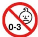
CHOKING HAZARD – Product contains small parts.
Keep away from children under three years.
Plastic bag notice

DANGER
Plastic bags can be dangerous. Keep plastic bags away from babies and children to avoid danger of suffocation.
Glass parts notice
CAUTION:
Some parts of your product may be made of glass. This glass could break if the product is dropped on a hard surface or receives a substantial impact. If glass breaks, do not touch or attempt to remove it. Stop using your product until the glass is replaced by trained service personnel.
Computer placement notices
Inappropriate computer placement might cause harm to children.
- Place the computer on a sturdy piece of low-rise furniture or furniture that has been anchored.
- Do not place the computer at the edge of the furniture.
- Keep the computer cables out of the reach of children.
- Some items, such as toys, might attract children. Keep such items away from the computer.
Supervise children in rooms where the above safety instructions cannot be fully implemented.
Hazardous energy statement

DANGER
Disconnect all power cords from electrical outlets before removing the computer cover or any part that has the above label attached.
DO NOT disassemble components that have the above label attached. There are no serviceable parts inside these components.
Your product is designed for safe use. However, hazardous voltage, current, and energy levels are present inside any component that has this label attached. Disassembling of these components might cause fire or might even result in death. If you suspect a problem with one of these parts, contact a service technician.
CAUTION:

Bright Light, possible skin or eye damage. Disconnect power before servicing.
CAUTION:

Infrared Light, possible skin or eye damage. Disconnect power before servicing.
Eye comfort
The property of the display in combination with following notes result in reduced eye fatigue and increased comfort.
For tips on how to minimize visual fatigue, please go to https://www.lenovo.com/us/en/safecomp/ to visit "Minimizing Visual Fatigue".
Tip-over hazard prevention notice
The computer may cause harm to children if it is not located in an appropriate place. Follow the tips below to protect children from harm caused by the computer tipping over:
- Place the computers or monitors on sturdy furniture with a low base or furniture that has been anchored. Push the computers or monitors as far from the edge of the furniture as possible..
- Keep remote controls, toys, and other items that might attract children away from the computers or monitors
- Keep the computer or monitor cables out the reach of the children.
- Supervise children in rooms where these safety tips have not been followed.
CAUTION:
Some parts of your product may be made of glass. This glass could break if the product is dropped on a hard surface or receives a substantial impact. If glass breaks, do not touch it or attempt to remove it. Stop using your product until the glass is replaced by trained service personnel.
Remote control
CAUTION:
Do not use rechargeable batteries in this device.
Static electricity prevention
Static electricity, although harmless to you, can seriously damage computer components and options. Improper handling of static-sensitive parts can damage the part. When you unpack an option or CRU, do not open the static-protective package containing the part until the instructions direct you to install it.
When you handle options or CRUs, or perform any work inside the computer, take the following precautions to avoid static-electricity damage:
- Limit your movement. Movement can cause static electricity to build up around you.
- Always handle components carefully. Handle adapters, memory modules, and other circuit boards by the edges. Never touch exposed circuitry.
- Prevent others from touching components.
- When you install a static-sensitive option or CRU, touch the static-protective package containing the part to a metal expansion-slot cover or other unpainted metal surface on the computer for at least two seconds. This reduces static electricity in the package and your body.
- When possible, remove the static-sensitive part from the static-protective packaging and install the part without setting it down. When this is not possible, place the static-protective packaging on a smooth, level surface and place the part on it.
- Do not place the part on the computer cover or other metal surface.
Operating environment
Maximum altitude (without pressurization)
- Operating: From -15.2 m (-50 ft) to 3048 m (10 000 ft)
• Storage: From -15.2 m (-50 ft) to 10 668 m (35 000 ft)
Temperature
• Operating: From 10°C (50°F) to 35°C (95°F)
- Storage in original shipping package: From -40°C (-40°F) to 60°C (140°F)
- Storage without package: From -10^ (14°F) to 60^ (140°F)
Note: If your computer is stored or transported in temperatures less than 10^ C ( 50^ F), allow the computer to rise slowly to an optimal operating temperature before use. This process might take up to two hours. Using the computer in a lower operating temperature might result in irreparable damage to your computer.
Relative humidity
• Operating: 10%-80% (non-condensing)
• Storage: 10%-90% (non-condensing)
Cleaning and maintenance
With appropriate care and maintenance, your computer will serve you reliably. The following topics offer information to help you keep your computer working with best performance.
Basic maintenance tips
Here are some basic points about keeping your computer functioning properly:
- Keep the computer in a clean, dry environment. Ensure that the computer rests on a flat, steady surface.
- Do not cover any of air vents. These air vents provide airflow to keep the computer from overheating.
- Keep electrical appliances such as an electric fan, radio, high-powered speakers, air conditioner, and microwave oven away from your computer because the strong magnetic fields generated by these appliances can damage the monitor and data on the storage drive.
- Keep food and drinks away from all parts of the computer. Food particles and spills might make the keyboard and mouse stick and unusable.
- Do not get the power switches or other controls wet. Moisture can damage these parts and cause an electrical hazard.
- Always disconnect a power cord by grasping the plug instead of the cord.
- Keep the computer software, device drivers, and operating system up-to-date.
• Empty your recycle bin on a regular basis. - Clean out your Inbox, Sent Items, and Deleted Items folders in your e-mail application on a regular basis.
- Clean up files and free up storage drive space and memory space occasionally to prevent performance problems.
- Keep a log book. Entries might include major software or hardware changes, device-driver updates, intermittent problems and what you did to resolve them, and other issues you might have experienced. The cause of a problem might be change in hardware, change in software, or any other actions that might have taken place. A log book can help you or a Lenovo technician determine the cause of a problem.
- Back up your data on the storage drive regularly. You can restore the storage drive from a backup.
- Create a recovery medium as early as possible. You can use the recovery medium to recover your operating system even if Windows fails to start up.
- Get the most up-to-date operating system update patches, software programs, and device drivers.
Maintenance tips about moving the computer
Before moving the computer, take the following precautions:
- Back up your data on the storage drive.
- Remove any media from the drives and turn off all connected devices and the computer. Then, disconnect all power cords from electrical outlets and disconnect all cables that are connected to the computer.
- If you saved the original shipping cartons and packing materials, use them to pack the units. If you are using different cartons, cushion the units to avoid damage.
When you move the computer to another country or region, you must take local electrical standards into consideration. If the local electrical outlet style is different from the type you are currently using, contact the Lenovo Customer Support Center to purchase either an electrical plug adapter or a new power cord.
Clean your computer
CAUTION:
Remove any media from the drives and turn off all connected devices and the computer. Then, disconnect all power cords from electrical outlets and disconnect all cables that are connected to the computer.
It is a good practice to clean your computer periodically to protect the surfaces and ensure trouble-free operation.
Clean the computer surface: Wipe it with a lint-free cloth dampened in mild soap and water. Avoid applying liquids directly to the surface.
Clean the keyboard: Wipe the keys one by one with a lint-free cloth dampened in mild soap and water. If you wipe several keys at a time, the cloth might hook onto an adjacent key and possibly damage it. Avoid spraying cleaner directly onto the keyboard. To remove any crumbs or dust from beneath the keys, you can use a camera blower with a brush or use cool air from a hair dryer.
Clean the computer screen: Scratches, oil, dust, chemicals, and ultraviolet light can affect the performance of your computer screen. Use a dry, soft lint-free cloth to wipe the screen gently. If you see a scratchlike mark on your screen, it might be a stain. Wipe or dust the stain gently with a soft, dry cloth. If the stain remains, moisten a soft, lint-free cloth with water or eyeglass cleaner, but do not apply liquids directly to your computer screen. Ensure that the computer screen is dry before closing it.
Chapter 1. Product overview
This chapter provides basic information to help you get familiar with your computer.
Hardware locations
This section provides information about the locations of your computer hardware.
Front view
Note: The computer hardware might look slightly different from the illustration.
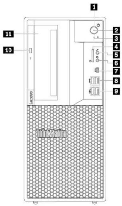
text_image
1 2 3 4 5 6 7 8 9 10 11Figure 1. Front connectors, controls, and indicators
| 1 Power button | 2 Power indicator |
| 3 Storage-drive activity indicator | 4 SD card slot (available on some models) |
| 5 Microphone connector | 6 Headset connector |
| 7 USB-C connector | 8 USB 3.1 connectors Gen 1 (2) |
| 9 USB 3.1 connectors Gen 2 (2) | 10 Slim optical-drive eject button (available on some models) |
| 11 Flex bay (available on some models) |
1 Power button
Press the power button to turn on your computer. If your computer is unresponsive, you can turn off the computer by pressing and holding the power button for four or more seconds.
2 Power indicator
When the power indicator is on, the computer is turned on.
■ Storage-drive activity indicator
This indicator shows the status of the internal storage drives (such as hard disk drives or solid-state drives).
On: The storage drives are active and data is being transferred.
Off (when the computer is powered on): The storage drives are not in use or no data is being transferred.
4 SD card slot (available on some models)
An SD card is installed on some computer models.
5 Microphone connector
Use this connector to attach a microphone to your computer when you want to record sound or if you use speech-recognition software.
6 Headset connector
Use this connector to attach a headset to your computer.
USB-C connector
The USB-C connector supports the USB Type-C ^™ standard. With an appropriate USB-C cable connected, you can use the connector to transfer data or charge your device.
8 USB 3.1 connectors Gen 1 (2)
Connect USB-compatible devices, such as a USB keyboard, a USB mouse, a USB storage device, or a USB printer.
9 USB 3.1 connectors Gen 2 (2)
With greater data transfer rate, the USB 3.1 connector Gen 2 is used to connect USB-compatible devices, such as a USB keyboard, a USB mouse, a USB storage device, or a USB printer.
10 Slim optical-drive eject button (available on some models)
Press the button to eject the tray of the slim optical drive. To close the tray, push the tray inward until you hear a click.
11 Flex bay (available on some models)
Some computer models come with a flex bay. Depending on your computer model, one of the following devices might be installed in the flex bay:
- Flex module
- Flex storage enclosure
- Front-access storage enclosure
For more information, see "Device in the flex bay" on page 77.
Rear view
Some connectors on the rear of your computer are color-coded to help you determine where to connect the cables on your computer.
Note: The computer hardware might look slightly different from the illustration.
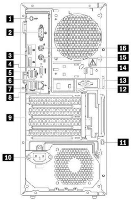
text_image
1 2 3 4 5 6 7 8 9 10 11 12 13 14 15 16Figure 2. Rear view
| 1 Audio line-out connector | 2 Serial connector |
| 3 DisplayPort connectors (2) | 4 DisplayPort connector or HDMITM connector (available on some models) |
| 5 USB 3.1 connector Gen 1 | 6 USB 3.1 connector Gen 1 |
| 7 USB 2.0 connectors (2) | 8 Ethernet connector |
| 9 PCIe card area* | 10 Power-cord connector |
| 11 Security-lock slot | 12 Cable-lock slots |
| 13 Padlock loop | 14 Serial connector (available on some models) |
| 15 PS/2 keyboard connector (available on some models) | 16 PS/2 mouse connector (available on some models) |
Notes: * A discrete graphics card or a network adapter can be installed in the appropriate Peripheral Component Interconnect Express (PCIe) card slot. If such a card is installed, use the connectors on the card instead of the corresponding connectors on the computer to optimize the performance. Depending on your computer model, the preinstalled cards might vary. One or more graphics cards might be installed to provide the following connectors:
• Digital Visual Interface (DVI) connector
- DisplayPort® connector
- Mini DisplayPort® connector
DVI monitor connector
Use this connector to attach a DVI monitor or other compatible devices.
DisplayPort connector
Use this connector to attach a high-performance monitor, a direct-drive monitor, or other compatible devices.
Mini DisplayPort connector
Use this connector to attach a high-performance monitor, a direct-drive monitor, or other compatible devices. The Mini DisplayPort connector is a miniaturized version of a DisplayPort connector.
■ Audio line-out connector
The audio line-out connector is used to send audio signals from the computer to external devices, such as headphones.
2 Serial connector
Use this connector to attach an external modem, a serial printer, or other devices that use a 9-pin serial connector.
■ DisplayPort connectors (2)
Use this connector to attach a high-performance monitor, a direct-drive monitor, or other compatible devices.
4 DisplayPort connector or HDMI connector (available on some models)
- DisplayPort connector
Use this connector to attach a high-performance monitor, a direct-drive monitor, or other compatible devices.
- HDMI connector
The High-Definition Multimedia Interface (HDMI) connector is a digital audio and video interface that can connect a compatible digital audio device or video monitor, such as a DVD player or a high-definition digital television (HDTV).
USB 3.1 connector Gen 1
Connect USB-compatible devices, such as a USB keyboard, a USB mouse, a USB storage device, or a USB printer. This connector supports the smart power on feature. When you connect a supported keyboard to this connector, you can turn on the computer or wake it up from hibernation mode by pressing Alt+P on the keyboard. You can enable or disable the smart power on feature from the Setup Utility program.
6 USB 3.1 connector Gen 1
Connect USB-compatible devices, such as a USB keyboard, a USB mouse, a USB storage device, or a USB printer.
7 USB 2.0 connectors (2)
Use this connector to attach a USB-compatible device, such as a USB keyboard, mouse, storage drive, or printer.
8 Ethernet connector
Connect an Ethernet cable for a local area network (LAN).
Note: To operate the computer within Federal Communications Commission (FCC) Class B limits, use a Category 5 Ethernet cable.
9 PCIe card area
To further improve the computer performance, you can install PCIe cards into this area. Depending on your computer model, the preinstalled cards might vary.
10 Power-cord connector
Connect the power cord to your computer for power supply.
11 Security-lock slot
Attach a Kensington-style cable lock to the security-lock slot to secure your computer. For more information, see “Attaching a Kensington-style cable lock” on page 31.
12 Cable lock slots
Used to secure a cable lock. For more information, see "Attaching a cable lock" on page 31.
13 Padlock loop
Connect a padlock to secure your computer. For more information, see “Locking the computer cover” on page 29.
14 Serial connector (available on some models)
Use this connector to attach an external modem, a serial printer, or other devices that use a 9-pin serial connector.
15 PS/2 keyboard connector (available on some models)
Use this connector to attach a Personal System/2 (PS/2) keyboard.
16 PS/2 mouse connector (available on some models)
Use this connector to attach a PS/2 mouse, a trackball, or other pointing devices.
Computer components
Notes:
- Depending on the model, your computer might look slightly different from the illustration.
- To prepare your computer, see "Preparing your computer" on page 56.
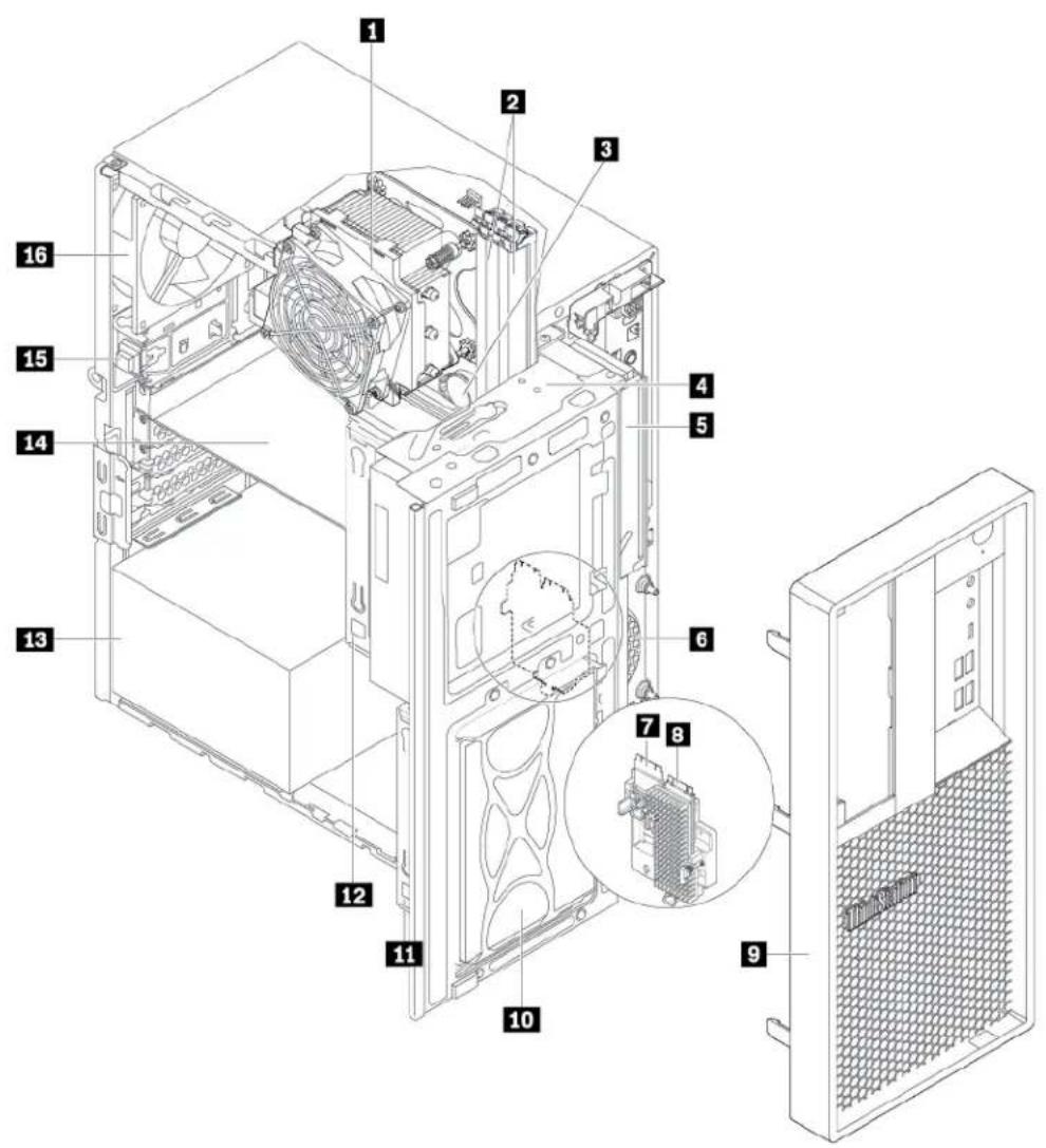
text_image
Technical diagram of a computer tower case with numbered components and an inset view of the internal structure.Figure 3. Component locations
| 1 Heat-sink-and-fan assembly | 2 Memory modules |
| 3 Coin-cell battery | 4 Flex bay (available on some models) |
| 5 Slim optical drive (available on some models) | 6 Front fan |
| 7 Wi-Fi card (available on some models) | 8 M.2 solid-state drive (available on some models) |
| 9 Front bezel | 10 Storage-drive bay |
| 11 Type-2 storage-drive cage (available on some models) | 12 Type-1 storage-drive cage (available on some models) |
| 13 Power supply assembly | 14 PCIe card (available on some models) |
| 15 Cover presence switch (also called intrusion switch) | 16 Rear fan |
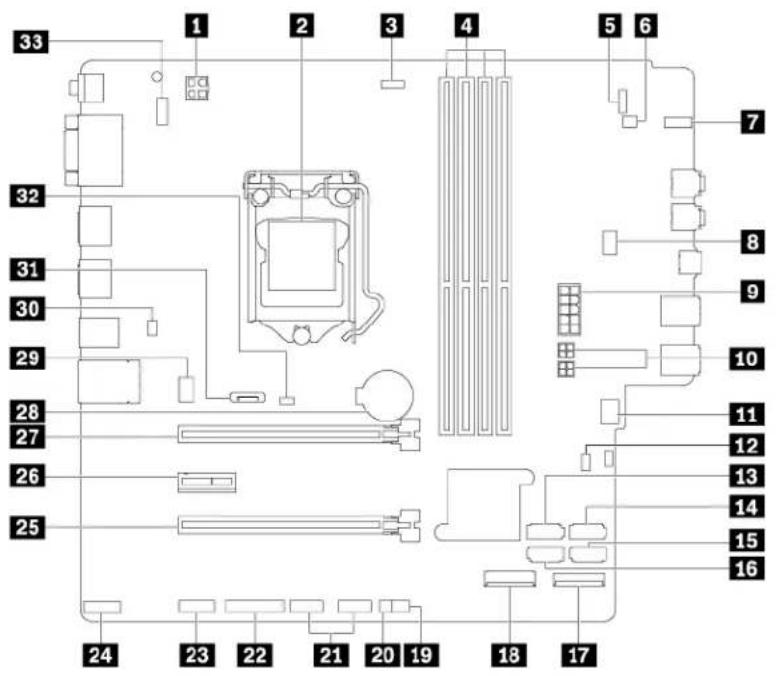
Parts on the system board
Note: The system board might look slightly different from the illustration.
text_image
Labeled diagram of a computer motherboard floor plan with numbered components for identificationFigure 4. System board part locations
| 1 4-pin microprocessor power connector | 2 Microprocessor |
| 3 Microprocessor fan connector | 4 Memory slots (DIMM) |
| 5 Front-bezel connector | 6 Internal-speaker connector |
| 7 Storage-drive activity indicator | 8 Flex bay fan connector |
| 9 10-pin system board power connector | 10 SATA power connectors |
| 11 Front-fan connector | 12 Clear CMOS/Recovery jumper |
| 13 SATA 3 connector | 14 SATA 4 connector or eSATA connector |
| 15 SATA 2 connector | 16 SATA 1 connector |
| 17 M.2 solid-state drive slot | 18 Wi-Fi card slot |
| 19 Thermal-sensor connector | 20 ThinkStation® LED connector |
| 21 Front USB 2.0 connectors (available on some models) | 22 Parallel connector |
| 23 Serial port (COM) connector | 24 ThunderboltTM control connector |
| 25 PCIe x16 card slot (negotiable link width x4) | 26 PCIe x1 card slot |
| 27 PCIe x16 card slot | 28 Coin-cell battery |
| 29 Rear-fan connector | 30 E-lock connector |
31 DisplayPort connector
32 Cover presence switch connector (Intrusion switch connector)
33 PS/2 keyboard and mouse connector
Internal storage drives
Internal storage drives are devices that your computer uses to read and store data. You can add drives to your computer to increase storage capacity and enable your computer to read other types of media. Internal storage drives are installed in bays.
When you remove or install an internal storage drive, note the type and size of the drive that each bay supports and correctly connect the required cables. Refer to the appropriate section in Chapter 7 “Hardware removal and installation” on page 55 for instructions on how to remove or install internal storage drives for your computer.
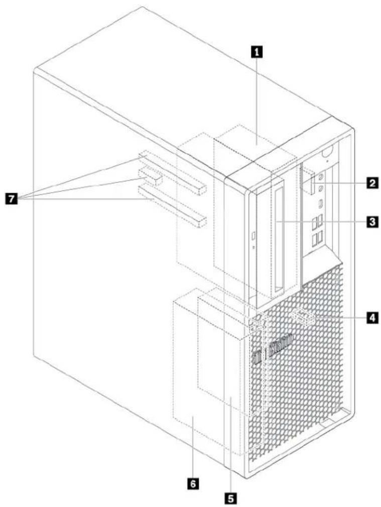
The following illustration shows the locations of the storage drives.
Note: The computer hardware might look slightly different from the illustration.
text_image
Technical diagram of a server rack with numbered components for identificationFigure 5. Storage-drive bay locations
| 1 Type-1 storage-drive cage | 2 SD card slot (available on some models) |
| 3 Flex bay (available on some models) | 4 M.2 solid-state drive slot |
| 5 Type-2 storage-drive cage | 6 Type-1 storage-drive bay |
| 7 PCIe card slots (3) |
■ Type-1 storage-drive cage
You can install a 3.5-inch storage drive or a 2.5-inch storage drive in this cage.
2 SD card slot (available on some models)
An SD card is installed in some computer models.
3 Flex bay (available on some models)
Depending on your computer model, one of the following devices might be installed in the flex bay:
- Flex module
- Front-access storage enclosure
- Flex storage enclosure
4 M.2 solid-state drive slot
One M.2 solid-state drive is installed in some computer models.
5 Type-2 storage-drive cage
You can install a 2.5-inch storage drive in this cage.
6 Type-1 storage-drive bay
You can install a 3.5-inch storage drive or a 2.5-inch storage drive in the storage-drive bay.
7 PCIe card slots (3)
You can install compatible PCIe cards and PCIe solid-state drives in the PCIe card slots.
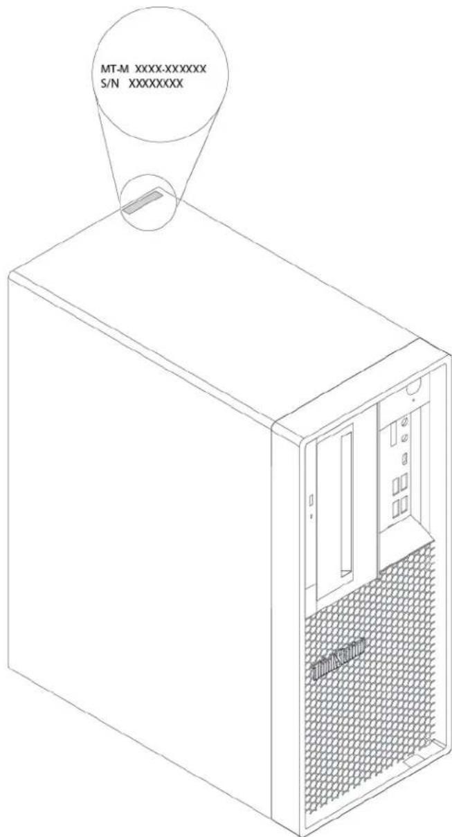
Machine type and model label
The machine type and model label identifies your computer. When you contact Lenovo for help, the machine type and model information helps support technicians to identify your computer and provide faster service.
The following is a sample of the machine type and model label.
Note: The computer hardware might look slightly different from the illustration.
text_image
MT-M XXXX-XXXXXX S/N XXXXXXXXFigure 6. Machine type and model label
Computer features
For your specific computer model, some features might vary or not apply.
Information about your computer
- To view basic information (such as microprocessor and memory information) about your computer, do the following:
- Click the Start button to open the Start menu.
- Click Settings → System → About.
- To view detailed information about the devices (such as the network adapters) on your computer, do the following:
- Right-click the Start button to open the Start context menu.
- Click Device Manager.
- Locate and double-click your device in Device Manager to view device properties. Type the administrator password or provide confirmation if prompted.
Memory
Up to four double data rate 4 (DDR4) error correction code (ECC) unbuffered dual inline memory modules (UDIMMs) or DDR4 non-ECC UDIMMs
Internal drives
Your computer supports the following storage drives:
• SD card (available on some models)
- Hard disk drive (available on some models)
- M.2 solid-state drive with the Intel Optane technology (available on some models)
• M.2 solid-state drive without the Intel Optane technology (available on some models)
- Slim optical drive (available on some models)
• Solid-state drive (available on some models)
To view the amount of storage drive space, do the following:
- Right-click the Start button to open the Start context menu.
- Click Disk Management and follow the instructions on the screen.
Video features
- PCIe x16 graphics card slots on the system board for discrete graphics cards
• Video connectors on a discrete graphics card:
– DVI connector (available on some models)
- DisplayPort connector (available on some models)
- Mini DisplayPort connector (available on some models)
Audio features
Integrated audio controller supports the following connectors and devices on your computer:
• Audio line-out connector
- Headset connector
- Internal speaker
- Microphone connector
Input/Output (I/O) features
• 100/1000 Mbps Ethernet connector
- 9-pin serial connector
- Audio connectors (audio line-out connector, microphone connector, and headset connector)
• HDMI connector (available on some models)
- Display connectors (DisplayPort connector, DVI connector, and Mini DisplayPort connector) (vary by graphics card)
- PS/2 keyboard connector (available on some models)
• PS/2 mouse connector (available on some models) - USB connectors
- USB-C connector
Expansion
• Flex bay (available on some models)
- Memory slots
• M.2 solid-state drive slot
- PCIe x1 card slot
- PCIe x16 card slot
- PCIe x16 card slot (negotiable link width x4)
• SD card slot (available on some models)
- Storage-drive bay
- Storage-drive cages (available on some models)
Power supply
Your computer comes with one of the following power supplies:
• 250-watt automatic voltage-sensing power supply
- 400-watt automatic voltage-sensing power supply
Wireless features
Depending on your computer model, the following wireless features are supported:
- Wireless LAN
- Bluetooth (available on some models)
System management features
- Ability to store power-on self-test (POST) hardware test results
- Desktop Management Interface (DMI)
Desktop Management Interface provides a common path for users to access information about all aspects of a computer. The information includes the processor type, installation date, attached printers and other peripherals, power sources, and maintenance history.
• ErP LPS compliance mode
The energy-related products directive (ErP) lowest power state (LPS) compliance mode reduces the consumption of electricity when your computer is in sleep or off mode. For more information, see “Enabling or disabling the ErP LPS compliance mode” on page 36.
• Intelligent Cooling Engine (ICE)
The energy-related products directive (ErP) lowest power state (LPS) compliance mode reduces the consumption of electricity when your computer is in sleep or off mode. For more information, see “Switching between better acoustic and better thermal performance” on page 37 and “Enabling or disabling the system to record thermal alert logs” on page 37.
- Intel® Standard Manageability (ISM)
Intel Standard Manageability builds certain functionalities into computer hardware and firmware. Therefore, computers are less expensive for businesses and easier to monitor, maintain, update, upgrade, and repair.
• Intel Active Management Technology (Intel AMT)
With specific Intel platform capabilities and third-party management and security applications, Intel Active Management Technology enables IT administrators or managed service providers to easily and remotely discover, repair, and protect their networked computing assets.
• Preboot Execution Environment (PXE)
Preboot Execution Environment enables you to start computers using a network interface. This manner is independent of starting computers from data storage devices (such as the hard disk drive) or installed operating systems.
- System Management (SM) basic input/output system (BIOS) and SM software
The SM BIOS specification defines data structures and access methods in a BIOS. Therefore, a user or an application can store and retrieve information specific about the computer in question.
- Wake on LAN (WOL)
Wake on LAN is an Ethernet computer networking standard that allows a computer to be turned on or woken up by a network message. The message is usually sent by a program running on another computer on the same local area network.
• Windows Management Instrumentation (WMI)
Windows Management Instrumentation is a set of extensions to the Windows Driver Model. It provides an operating system interface through which instrumented components provide information and notification.
Security features
- Ability to enable and disable a device
- Ability to enable and disable USB connectors individually
- Antivirus program
- BIOS passwords and Microsoft® Windows® accounts to deter unauthorized use of your computer
- Computrace Agent software embedded in firmware (for selected models)
• Cover presence switch (also called intrusion switch) - Firewalls
• Smart USB Protection function - Startup sequence control
- Startup without a keyboard or mouse
• Support for a cable lock
• Support for a Kensington-style cable lock
• Support for a padlock - Trusted Platform Module (TPM)
Preinstalled operating system
Your computer is preinstalled with the Windows 10 operating system. Additional operating systems might be identified by Lenovo as compatible with your computer. To determine if an operating system has been certified or tested for compatibility, check the Web site of the operating system provider.
Statement on USB transfer rate
Depending on many factors such as the processing capability of the host and peripheral devices, file attributes, and other factors related to system configuration and operating environments, the actual transfer rate using the various USB connectors on this device will vary and will be slower than the data rate listed below for each corresponding device.
| USB device Data rate (Gbit/s) | |
| 3.2 Gen 1 / 3.1 Gen 1 | 5 |
| 3.2 Gen 2 / 3.1 Gen 2 | 10 |
| 3.2 Gen 2 × 2 | 20 |
Computer specifications
This section lists the physical specifications for your computer.
Dimensions
• Width: 165 mm (6.5 inches)
• Height: 376 mm (14.8 inches)
• Depth: 328 mm (12.91 inches)
Weight
Maximum configuration as shipped: 10.6 kg (23.37 lb)
Environment
- Air temperature:
Operating: From 10°C (50°F) to 35°C (95°F)
Storage in original shipping package: From -40°C (-40°F) to 60°C (140°F)
Storage without package: From -10°C (14°F) to 60°C (140°F)
- Humidity:
Operating: 30%-90% (non-condensing)
Storage: 20%–90% (non-condensing)
- Altitude:
Operating: From -15.2 m (-50 ft) to 3048 m (10 000 ft)
Storage: From -15.2 m (-50 ft) to 10 668 m (35 000 ft)
Electrical input
- Input voltage: From 100 V ac to 240 V ac
- Input frequency: 50/60 Hz
Programs
This section provides information about the programs on your computer.
Accessing a program on your computer
To access a program on your computer, do one of the following:
• From Windows Search:
- Type the program name into the search box next to the Start button.
- In the search results, click the name of the desired program to launch the program.
• From the Start menu or Control Panel:
- Click the Start button to open the Start menu. Then, click the name of the desired program to launch the program.
- If the program name is not displayed on the Start menu, access the program from Control Panel.
a. Click the Start button to open the Start menu.
b. Click Windows System → Control Panel.
c. View Control Panel by Large icons or Small icons, and then click the name of the desired program to launch the program.
An introduction to Lenovo programs
This section provides information about the major Lenovo programs available on your operating system.
Note: Depending on your computer model, some of the following programs might not be available.
- Lenovo Vantage
Your computer's best features and capabilities should be easy to access and understand. With Lenovo Vantage, they are.
Use Lenovo Vantage to do the following:
- Know the device status easily and customize device settings.
- Download and install UEFI BIOS, firmware, and driver updates to keep your computer up-to-date.
- Monitor your computer health, and secure your computer against outside threats.
- Look up warranty status (online).
- Access User Guide and helpful articles.
Notes:
- The available features vary depending on the computer model.
- Lenovo Vantage makes periodic updates of the features to keep improving your experience with your computer. The description of features might be different from that on your actual user interface.
• ThinkStation Diagnostics
The ThinkStation Diagnostics program enables you to troubleshoot and resolve computer problems. The program notifies you of any issues detected by the real-time hardware diagnostic monitoring function. The program also provides the details of the issue, analyzes possible causes, and provides solutions.
Chapter 2. Using your computer
This chapter provides information to help you use the various features provided by your computer.
Registering your computer
When you register your computer with Lenovo, you enter required information into a Lenovo database. The information enables Lenovo to contact you when there is a recall or other severe problem and provide quicker service when you call Lenovo for help. In addition, some locations offer extended privileges and services to registered users.
To register your computer with Lenovo, go to https://support.lenovo.com/productregistration and follow the instructions on the screen.
Get started with Windows 10
Learn the basics of Windows 10 and start working with it right away. For more information about Windows 10, see the Windows help information.
Windows account
A user account is required to use the Windows operating system. It can either be a Windows user account or a Microsoft account.
Windows user account
When you start Windows for the first time, you are prompted to create a Windows user account. This first account you created is of the “Administrator” type. With an Administrator account, you can create additional user accounts or change account types by doing the following:
- Open the Start menu and select Settings → Accounts → Family & other users.
- Follow the on-screen instructions.
Microsoft account
You can also log in to the Windows operating system with a Microsoft account.
To create a Microsoft account, go to the Microsoft sign-up page at https://signup.live.com and follow the on-screen instructions.
With a Microsoft account, you can:
- Enjoy one-time signing in if you are using other Microsoft services, such as OneDrive, Skype, and Outlook.com.
- Sync personalized settings across other Windows-based devices.
Windows user interface
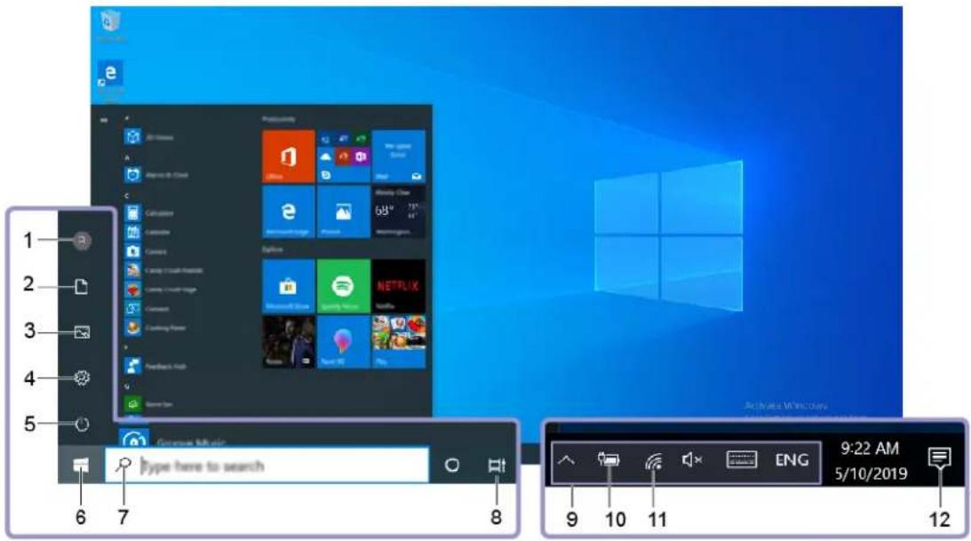
text_image
1 2 3 4 5 6 7 8 Microsoft Music Type here to search 9:22 AM 5/10/2019 ENGG| 1. Account | Change account settings, lock the computer, or sign out from the current account. |
| 2. Documents | Open the Documents folder, a default folder to save your received files. |
| 3. Pictures | Open the Pictures folder, a default folder to save your received pictures. |
| 4. Settings | Launch Settings. |
| 5. Power | Shut down, restart, or put the computer into sleep mode. |
| 6. Start button | Open the Start menu. |
| 7. Windows Search | Type what you are looking for in the search box and get search results from your computer and the Web. |
| 8. Task View | Display all opened apps and switch among them. |
| 9. Windows notification area | Display notifications and status of some features. |
| 10. Battery status icon | Display power status and change battery or power settings. When your computer is not connected to ac power, the icon changes to. |
| 11. Network icon | Connect to an available wireless network and display the network status. When connected to a wired network, the icon changes to. |
| 12. Action center | Display the latest notifications from apps and provide quick access to some features. |
Open the Start menu
- Click the Start button.
- Press the Windows logo key on the keyboard.
Open the Start context menu
Right-click the Start button.
Access Control Panel
- Open the Start menu and click Windows System → Control Panel.
- Use Windows Search.
Launch an app
- Open the Start menu and select the app you want to launch.
- Use Windows Search.
Setting the computer volume
To set the computer volume, do the following:
- Click the volume icon in the Windows notification area on the taskbar.
Note: If the volume icon is not displayed in the Windows notification area, add the icon to the notification area. See the Windows help system.
- Follow the instructions on the screen and the hover text to adjust the volume, mute the speaker, or unmute the speaker.
Using a disc
This section provides instructions on how to use a disc and the optical drive.
Guidelines about using the optical drive
When using the optical drive, follow these guidelines:
- Do not place the computer in a location where the drive is exposed to any of the following conditions:
– High temperature
– High humidity
- Excessive dust
– Excessive vibration or sudden shock
- An inclined surface
- Direct sunlight
- Do not insert any object other than a disc into the drive.
- Do not insert damaged discs into the drive. Warped, scratched, or dirty discs can damage the drive.
- Before moving the computer, remove the disc from the drive.
Handling and storing a disc
When handling and storing a disc, follow these guidelines:
- Hold the disc by its edges. Do not touch the surface of the side that is not labeled.
- To remove dust or fingerprints, wipe the disc with a clean, soft cloth from the center to the outside. Wiping the disc in a circular direction might cause loss of data.
- Do not write or stick paper on the disc.
- Do not scratch or mark the disc.
- Do not place or store the disc in direct sunlight.
- Do not use benzene, thinners, or other cleaners to clean the disc.
- Do not drop or bend the disc.
Playing and removing a disc
To play a disc, do the following:
- With the computer on, press the eject/close button on the front of the optical drive. The tray slides out of the drive.
- Insert a disc into the tray. Some optical drive has a snap hub in the center of the tray. If your drive has a snap hub, support the tray with one hand and then push the center of the disc until it snaps into place.
- Press the eject/close button again or gently push the tray forward to close the tray. The disc player program starts automatically. For more information, refer to the help system of the disc player program.
To remove a disc from the optical drive, do the following:
- With the computer on, press the eject/close button on the front of the optical drive. The tray slides out of the drive.
- Carefully remove the disc from the tray.
- Press the eject/close button again or gently push the tray forward to close the tray.
Note: If the tray does not slide out of the drive when you press the eject/close button, turn off your computer. Then, insert a straightened paper clip into the emergency-eject hole adjacent to the eject/close button. Use the emergency eject only in an emergency.
Recording a disc
If your optical drive supports recording, you can record a disc.
Recording a disc using Windows tools
To record a disc using Windows tools, do one of the following:
- Burn a disc using the AutoPlay window.
-
Ensure that the disc is played automatically.
a. Click the Start button to open the Start menu.
b. Click Settings → Devices → AutoPlay.
c. Select or turn on Use AutoPlay for all media and devices. -
Insert a recordable disc into the optical drive that supports recording. The AutoPlay window opens.
- Follow the instructions on the screen.
- Burn a disc using Windows Media® Player.
- Insert a recordable disc into the optical drive that supports recording.
- Open Windows Media Player. See "Accessing a program on your computer" on page 15.
- Follow the instructions on the screen.
- Burn a disc from an ISO file.
- Insert a recordable disc into the optical drive that supports recording.
- Double-click the ISO file.
- Follow the instructions on the screen.
Recording a disc using preinstalled programs
To record a disc using preinstalled programs, do the following:
-
Insert a recordable disc into the optical drive that supports recording.
-
Open the PowerDVD Create, PowerProducer, or Power2Go program. See "Accessing a program on your computer" on page 15.
- Follow the instructions on the screen.
Connecting to a network
This section provides instructions on how to connect to a network.
Connecting to an Ethernet LAN
You can connect your computer to an Ethernet LAN by connecting an Ethernet cable to the Ethernet connector.

DANGER
To avoid the risk of electrical shock, do not connect the telephone cable to the Ethernet connector.
Connecting to a wireless LAN
You can connect your computer to a wireless LAN without the use of an Ethernet cable but by means of radio waves only.
Note: The wireless LAN feature is available only on some models.
To establish a wireless-LAN connection, do the following:
- Ensure that a wireless LAN is available and the wireless LAN feature on your computer is working.
- Click the wireless-network-connection-status icon in the Windows notification area to display available wireless networks.
Note: If the wireless-network-connection-status icon is not displayed in the Windows notification area, add the icon to the notification area. See the Windows help system.
- Click a wireless LAN, and then click Connect to connect your computer to it. Provide required information if needed.
Connecting to a Bluetooth-enabled device
Bluetooth is a short-range wireless communications technology. Use Bluetooth to establish a wireless connection between your computer and another Bluetooth-enabled device within a distance of about 10 m (32.8 ft).
Note: The Bluetooth feature is available only on some models.
To connect to a Bluetooth-enabled device, do the following:
- Turn on the Bluetooth feature of your computer. Ensure that the Bluetooth-enabled device is located within a distance of about 10 m (32.8 ft) from your computer.
- Click the Bluetooth icon in the Windows notification area on the taskbar. Then, click Add a Device and follow the instructions on the screen.
Note: If the Bluetooth icon is not displayed in the Windows notification area, add the icon to the notification area. See the Windows help system.
Chapter 3. You and your computer
This chapter provides information about accessibility, ergonomic, and cleaning and maintenance.
Arranging your workspace
Arrange your workspace to suit your needs and the kind of work you do. This section provides information about the factors that affect the way you arrange your workspace.
Glare and lighting
Position the monitor to minimize glare and reflections from overhead lights, windows, and other light sources. Reflected light from shiny surfaces can cause annoying reflections on your screen. When possible, place the monitor at right angles to windows and other light sources. If necessary, reduce overhead lighting by turning off lights or using lower wattage bulbs. If you install the monitor near a window, use curtains or blinds to block the sunlight. You can adjust the brightness and contrast controls on the monitor as the room lighting changes throughout the day.
Where it is impossible to avoid reflections or to adjust the lighting, an antiglare filter placed over the screen might be helpful. However, these filters might affect the clarity of the image on the screen; try them only after you have exhausted other methods of reducing glare.
Air circulation
Your computer produces heat. The computer has a fan that pulls in fresh air and forces out hot air through the air vents. Blocking the air vents can cause overheating, which might result in a malfunction or damage. Position the computer so that nothing blocks the air vents; usually, 51 mm (2 inches) of air space is sufficient. Ensure that the vented air is not blowing on people.
Electrical outlet locations and cable lengths
The following factors might determine the final placement of your computer:
- Locations of electrical outlets
• Length of power cords or power adapters
• Length of the cables that are connected to other devices
For more information about power cords or power adapters, see “Power cords and power adapters” on page iv.
Comfort
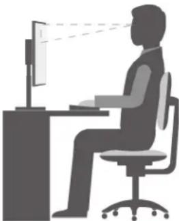
Although no single working position is ideal for everyone, here are a few guidelines to help you find a position that suits you best. The following figure sets an example for your reference.
natural_image
Silhouette of a person sitting at a desk using a computer, with no visible text or symbols- Screen position: Keep the screen at a comfortable viewing distance, usually 51–61 cm (20–24 inches). Then, adjust the screen so that the top of the screen is at or slightly below eye level and you can view it without twisting your body.
- Chair position: Use a chair that gives you good back support and seat height adjustment. Use chair adjustments to best suit your desired posture.
- Head position: Keep your head and neck in a comfortable and neutral (vertical or upright) position.
- Arm and hand positions: Keep your forearms, wrists, and hands in a relaxed and neutral (horizontal) position. Type with a soft touch without pounding the keys.
- Leg position: Keep your thighs parallel to the floor and your feet flat on the floor or on a footrest.
Make minor modifications in your working posture to deter the onset of discomfort caused by long periods of working in the same position. Frequent short breaks from your work also help to prevent minor discomfort associated with your working posture.
Keeping your computer current
In most cases, it is a good practice to have the most up-to-date operating system update patches, software programs, and device drivers. This section provides instructions on how to get the latest updates for your computer.
Getting the latest system updates
To get the latest system updates for your computer, ensure that your computer is connected to the Internet and do one of the following:
- Open Lenovo Vantage to check the available update packages. If the latest update package is available, follow the on-screen instructions to download and install the package.
To open the Lenovo Vantage program, see “Accessing a program on your computer” on page 15.
- Use Windows Update to get the system updates, such as security fixes, new versions of Windows components, and device driver updates.
- Click the Start button to open the Start menu.
- Click Settings → Update & Security → Windows Update.
- Follow the instructions on the screen.
Note: The device drivers provided by Windows Update might not be tested by Lenovo. It is recommended that you get device drivers by using Lenovo programs or from the Lenovo Web site at https://support.lenovo.com.
Accessibility information
Lenovo is committed to providing users who have hearing, vision, and mobility limitations with greater access to information and technology. This section provides information about the ways these users can get the most out of their computer experience. You also can get the most up-to-date accessibility information from the following Web site: https://www.lenovo.com/accessibility
Keyboard shortcuts
The following list contains keyboard shortcuts that can help make your computer easier to use.
Note: Depending on your keyboard, some of the following keyboard shortcuts might not be available.
- Windows logo key + U: Open Ease of Access Center
- Right Shift for eight seconds: Turn on or turn off Filter Keys
- Shift five times: Turn on or turn off Sticky Keys
- Num Lock for five seconds: Turn on or turn off Toggle Keys
- Left Alt+Left Shift+Num Lock: Turn on or turn off Mouse Keys
- Left Alt+Left Shift+PrtScn (or PrtSc): Turn on or turn off High Contrast
For more information, go to https://windows.microsoft.com/, and then search using any of the following keywords: keyboard shortcuts, key combinations, shortcut keys.
Ease of Access Center
Ease of Access Center on the Windows operating system enables you to configure your computer to suit your physical and cognitive needs.
To use Ease of Access Center, do the following:
- Click the Start button to open the Start menu.
- Click Settings → Ease of Access.
- Choose the appropriate tool by following the instructions on the screen.
Ease of Access Center mainly includes the following tools:
- Magnifier
Magnifier is a useful utility that enlarges the entire screen or part of the screen so that you can see the items better. - Narrator
Narrator is a screen reader that reads aloud what is displayed on the screen and describes events such as error messages. - On-Screen Keyboard
To input data into your computer using a mouse, joystick, or other pointing devices instead of a physical keyboard, you can use On-Screen Keyboard. - High Contrast
High Contrast is a feature that heightens the color contrast of some text and images on your screen. As a result, those items are more distinct and easier to identify. - Personalized keyboard
Adjust keyboard settings to make your keyboard easier to use. For example, you can use your keyboard to control the pointer and type certain key combinations easier.
- Personalized mouse
Adjust mouse settings to make your mouse easier to use. For example, you can change the pointer appearance and make it easier to manage windows with the mouse.
Speech Recognition
Speech Recognition enables you to control your computer by voice.
Using only your voice, you can start programs, open menus, click objects on the screen, dictate text into documents, and write and send e-mails. Everything you do with the keyboard and mouse can be done with only your voice.
To use Speech Recognition, do the following:
- Click the Start button to open the Start menu.
- Click Windows System → Control Panel.
- View Control Panel by Large icons or Small icons, and then click Speech Recognition.
- Follow the instructions on the screen.
Screen-reader technologies
Screen-reader technologies are primarily focused on software program interfaces, help information systems, and various online documents. For additional information about screen readers, see the following:
- Using PDFs with screen readers: https://www.adobe.com/accessibility.html?promoid=DJGVE
- Using the JAWS screen reader: https://www.freedomscientific.com/Products/Blindness/JAWS
• Using the NVDA screen reader: https://www.nvaccess.org/
Screen resolution
You can make the text and images on your screen easier to read by adjusting the screen resolution of your computer.
To adjust the screen resolution, do the following:
- Right-click a blank area on the desktop.
- Click Display settings → Display.
- Follow the instructions on the screen.
Note: Setting the resolution too low might prevent some items from fitting on the screen.
Customizable item size
You can make the items on your screen easier to read by changing the item size.
- To change the item size temporarily, use the Magnifier tool in Ease of Access Center.
- To change the item size permanently, do the following:
- Change the size of all the items on your screen. Do the following:
- Right-click a blank area on the desktop.
-
Click Display settings → Display.
-
Follow the on-screen instructions to change the item size. For some applications, your configuration might not take effect until you sign out and then sign in again.
- Change the size of the items on a Web page.
Press and hold Ctrl, and then press the plus-sign key (+) to enlarge or the minus-sign key (-) to reduce the text size.
- Change the size of the items on the desktop or a window.
Note: This function might not work on some windows.
If your mouse has a wheel, press and hold Ctrl, and then scroll the wheel to change the item size.
Industry-standard connectors
Your computer provides industry-standard connectors that enable you to connect assistive devices.
For more information about the location and function of each connector, see “Hardware locations” on page 1.
TTY/TDD conversion modem
Your computer supports the use of a text telephone (TTY) or the telecommunications device for the deaf (TDD) conversion modem. The modem must be connected between your computer and a TTY/TDD telephone. Then, you can type a message on your computer and send it to the telephone.
Documentation in accessible formats
Lenovo provides electronic documentation in accessible formats, such as properly tagged PDF files or HyperText Markup Language (HTML) files. Lenovo electronic documentation is developed to ensure that visually impaired users can read the documentation through a screen reader. Each image in the documentation also includes adequate alternative text so that visually impaired users can understand the image when they use a screen reader.
Chapter 4. Security
This chapter provides information about how to protect your computer from unauthorized use.
Locking your computer
This section provides instructions on how to lock your computer with the locking devices to keep your computer safe.
Enabling or disabling the E-lock
Your computer may have a security lock solution installed to protect the computer from unauthorized tampering of the internal components. Using the E-Lock, you can mechanically lock or unlock the computer cover.
To enable or disable the E-Lock, do the following:
-
Turn on or restart the computer.
-
Before Windows starts up, repeatedly press and release the F1 or Fn+F1 key until the Setup Utility program opens.
-
Click Security → Electronic Lock to enable or disable the E-lock.
-
Press F10 or Fn+F10 to save the changes and reboot the computer.
Note: Changes do not take effect until the setting is saved and the system is rebooted.
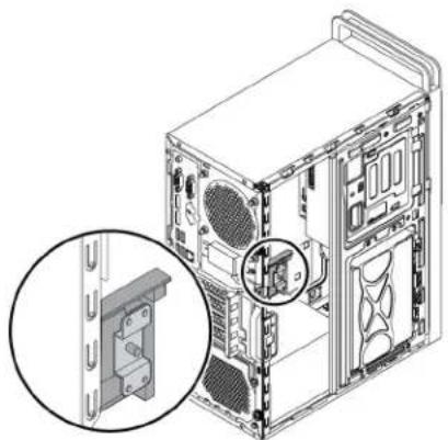
natural_image
Technical diagram of a computer tower case with an inset showing a mechanical bracket component (no text or symbols present)Figure 7. Enabling or disabling the E-lock
Locking the computer cover
Locking the computer cover helps prevent unauthorized people from gaining access to the inside of your computer. Your computer comes with a padlock loop so that the computer cover cannot be removed when a padlock is installed.
Note: The computer hardware might look slightly different from the illustration.
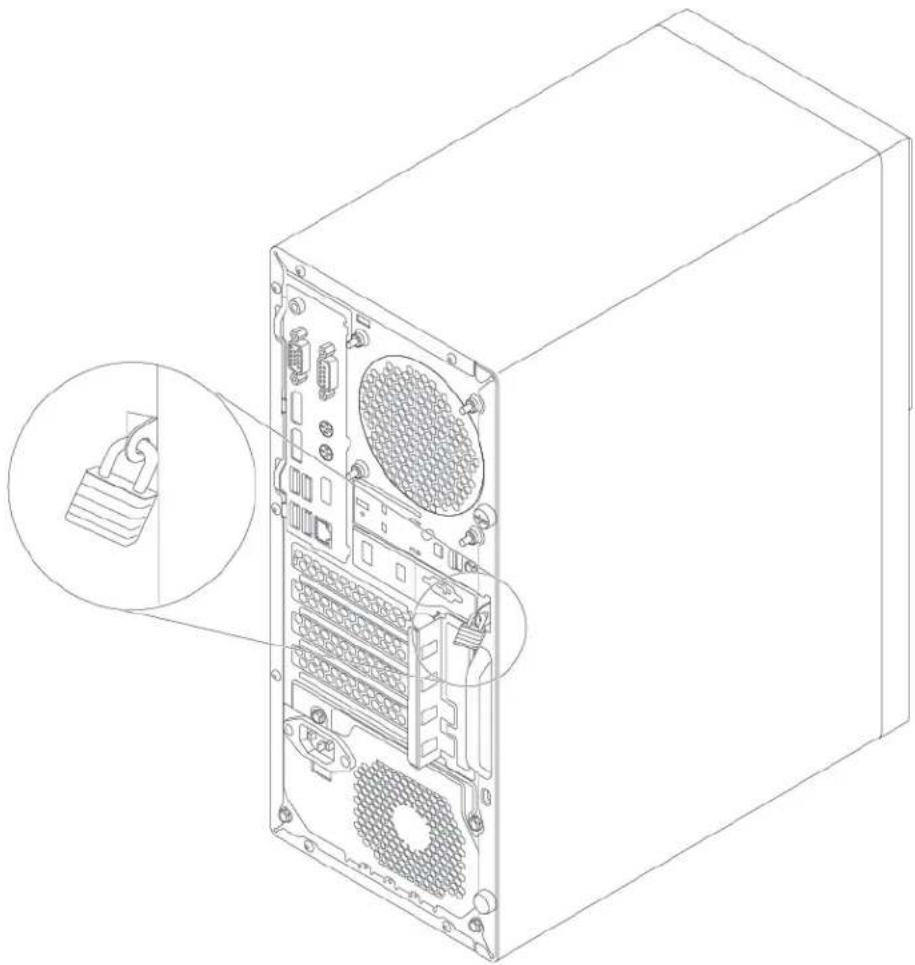
natural_image
Line drawing of a computer tower internal structure with an inset showing a cable connector (no text or symbols)Figure 8. Padlock
Attaching a Kensington-style cable lock
You can use a Kensington-style cable lock to secure your computer to a desk, table, or other non-permanent fixture. The cable lock attaches to the security-lock slot at the rear of your computer. Depending on the type selected, the cable lock can be operated with a key or combination. You can order such a cable lock directly from Lenovo by searching for Kensington at: https://support.lenovo.com
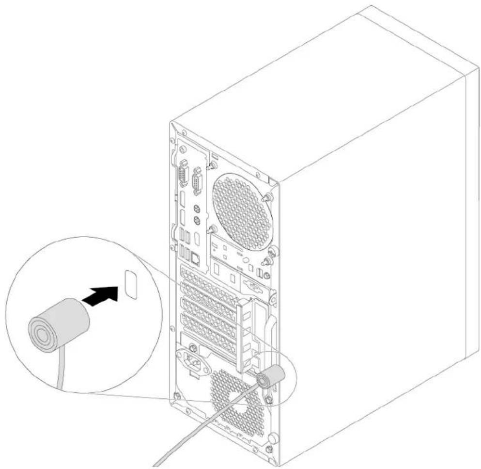
natural_image
Line drawing of a computer tower internal structure with an inset showing a cable inserted into a drive (no text or symbols present)Figure 9. Kensington-style cable lock
Attaching a cable lock
A cable lock can be used to secure devices, such as the keyboard and the mouse, by locking the device cables to your computer. The cable lock attaches to the cable-lock slots on the rear of your computer.
To attach a cable lock, do the following:
- Insert the clip 1 into the cable-lock slot 3.
- Pull the cables you want to lock through the dents in the cable lock.
- Press the clip 2 into the cable-lock slot 4 until it snaps into position.
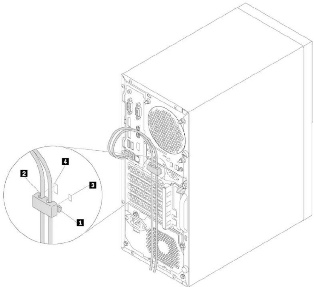
text_image
Technical diagram of a computer tower with labeled components and an inset showing cable connections for ports 1, 2, 3, and 4.Figure 10. Installing a cable lock
Viewing and changing security settings in the Setup Utility program
To view and change security settings in the Setup Utility program, do the following:
- Start the Setup Utility program. See "Starting the Setup Utility program" on page 35.
- Select Security.
- Follow the instructions on the right side of the screen to view and change security settings. You can refer to "Using the Setup Utility program" on page 35 to get basic information about some major security settings.
- To save settings and exit the Setup Utility program, press F10 or Fn+F10 (depending on the keyboard settings). Then, select Yes in the window displayed, and press Enter.
Using passwords and Windows accounts
You can use BIOS passwords and Windows accounts to prevent unauthorized access to your computer and data. To use the BIOS passwords or the Windows accounts, do the following:
-
To use BIOS passwords, see "Using BIOS passwords" on page 38.
• To use Windows accounts, do the following: -
Click the Start button to open the Start menu.
- Click Settings → Accounts.
- Follow the instructions on the screen.
Using the cover presence switch
The cover presence switch prevents your computer from logging in to the operating system when the computer cover is not properly installed or closed.
To use the cover presence switch, enable the cover-presence-switch connector on the system board first. To achieve this, do the following:
- Start the Setup Utility program. See "Starting the Setup Utility program" on page 35.
- Select Security → Chassis Intrusion Detection and press Enter.
- Select Enabled and press Enter.
- To save settings and exit the Setup Utility program, press F10 or Fn+F10 (depending on the keyboard settings), select Yes in the window displayed, and press Enter. The cover-presence-switch connector on the system board is enabled.
The cover presence switch starts functioning. If the switch detects that the computer cover is not correctly installed or closed, an error message is displayed when you turn on the computer. To fix the error and log in to the operating system, do the following:
- Properly remove or install your computer cover. See Chapter 7 "Hardware removal and installation" on page 55.
- Start and then exit the Setup Utility program. See “Starting the Setup Utility program” on page 35 and “Exiting the Setup Utility program” on page 41.
Using firewalls
A firewall can be hardware, software, or a combination of both depending on the level of security required. Firewalls work on a set of rules to determine which inbound and outbound connections are authorized. If your computer is preinstalled with a firewall program, it helps protect against computer Internet security threats, unauthorized access, intrusions, and Internet attacks. It also protects your privacy. For more information about how to use the firewall program, refer to the help system of your firewall program.
To use Windows Firewall, do the following:
- Click the Start button to open the Start menu.
- Click Windows System → Control Panel.
- View Control Panel by Large icons or Small icons, and then click Windows Defender Firewall.
- Follow the instructions on the screen.
Protecting data against viruses
Your computer is preinstalled with an antivirus program to help you guard against, detect, and eliminate viruses.
Lenovo provides a full version of antivirus software on your computer with a free 30-day subscription. After 30 days, you must renew the license to continue receiving the antivirus software updates.
Note: Virus definition files must be kept up-to-date to guard against new viruses.
For more information about how to use your antivirus software, refer to the help system of your antivirus software.
Using the Smart USB Protection function
The Smart USB Protection function is a security function that helps prevent data from being copied from the computer to USB storage devices connected to the computer. You can set the Smart USB Protection function to one of the following modes:
- Disabled (default setting): You can use the USB storage devices without limitation.
- Read Only: You cannot copy data from the computer to the USB storage devices. However, you can access or modify data on the USB storage devices.
- No Access: You cannot access the USB storage devices from the computer.
To configure the Smart USB Protection function, do the following:
- Start the Setup Utility program. See "Starting the Setup Utility program" on page 35.
- Select Security → Smart USB Protection and press Enter.
- Select the desired setting and press Enter.
- To save settings and exit the Setup Utility program, press F10 or Fn+F10 (depending on the keyboard settings). Then, select Yes in the window displayed, and press Enter.
Computrace Agent software embedded in firmware (for selected models)
The Computrace Agent software is an IT asset management and computer theft recovery solution. The software detects if changes have been made on the computer, such as hardware, software, or the computer call-in location. You might have to purchase a subscription to activate the Computrace Agent software.
Trusted Platform Module (TPM)
TPM is a secure cryptoprocessor that stores cryptographic keys, which in turn protects information stored in your computer.
Chapter 5. Advanced configuration
This chapter provides information to help you further configure the computer.
Using the Setup Utility program
The Setup Utility program is used to view and change the configuration settings of your computer. This section provides information about only the major configuration settings available in the program.
Note: The operating system settings might override any similar settings in the Setup Utility program.
Starting the Setup Utility program
To start the Setup Utility program, do the following:
- Turn on or restart your computer.
- Before the operating system starts up, repeatedly press and release F1 or Fn+F1 (depending on the keyboard settings). Based on the Setup Utility display mode setting, one of the following situations occurs:
- Text mode: The Setup Utility program opens.
- Graphic mode (available on some models): The start screen is displayed. Then, select Setup and press Enter to open the Setup Utility program.
Note: If a BIOS password has been set, the Setup Utility program will not open until you enter the correct password. For more information, see "Using BIOS passwords" on page 38.
To view and change the configuration settings, follow the instructions on the screen.
Changing the display language of the Setup Utility program
The Setup Utility program supports three display languages: English, French, and simplified Chinese.
To change the display language of the Setup Utility program, do the following:
- Start the Setup Utility program. See "Starting the Setup Utility program" on page 35.
- From the main interface, locate System Language and press Enter.
- Select the display language according to your needs.
Enabling or disabling a device
This section provides information about how to enable or disable user access to hardware devices (such as USB connectors or storage drives).
To enable or disable a device, do the following:
- Start the Setup Utility program. See "Starting the Setup Utility program" on page 35.
- Select Devices.
- Select the device you want to enable or disable and press Enter.
- Select the desired setting and press Enter.
- To save settings and exit the Setup Utility program, press F10 or Fn+F10 (depending on the keyboard settings). Then, select Yes in the window displayed, and press Enter.
Enabling or disabling the automatic power-on of your computer
The Automatic Power On item in the Setup Utility program provides various options for you to make your computer start up automatically.
To enable or disable the Automatic Power On features, do the following:
- Start the Setup Utility program. See "Starting the Setup Utility program" on page 35.
- Select Power → Automatic Power On and press Enter.
- Select the feature you want to enable or disable and press Enter.
- Select the desired setting and press Enter.
- To save settings and exit the Setup Utility program, press F10 or Fn+F10 (depending on the keyboard settings). Then, select Yes in the window displayed, and press Enter.
Enabling or disabling the ErP LPS compliance mode
Lenovo computers meet the eco-design requirements of the ErP Lot 3 regulation. For more information, go to:
https://www.lenovo.com/ecodeclaration
You can enable the ErP LPS compliance mode in the Setup Utility program to reduce the consumption of electricity when your computer is off or in sleep mode.
To enable or disable the ErP LPS compliance mode, do the following:
- Start the Setup Utility program. See "Starting the Setup Utility program" on page 35.
- Select Power → Enhanced Power Saving Mode and press Enter.
- Select Enabled or Disabled depending on your needs, and then press Enter. If you select Enabled, you also need to disable the Wake on LAN feature. See “Enabling or disabling the automatic power-on of your computer” on page 36.
- To save settings and exit the Setup Utility program, press F10 or Fn+F10 (depending on the keyboard settings). Then, select Yes in the window displayed, and press Enter.
When the ErP LPS compliance mode is enabled, you can wake up your computer by doing one of the following:
- Press the power button.
- Enable the Wake Up on Alarm feature to make your computer wake up at a set time. See “Enabling or disabling the automatic power-on of your computer” on page 36.
- Enable the After Power Loss feature to make your computer wake up when the power supply resumes after a sudden loss of electricity.
To enable the After Power Loss feature, do the following:
- Start the Setup Utility program. See "Starting the Setup Utility program" on page 35.
- Select Power → After Power Loss and press Enter.
- Select Power On and press Enter.
- To save settings and exit the Setup Utility program, press F10 or Fn+F10 (depending on the keyboard settings). Then, select Yes in the window displayed, and press Enter.
Enabling or disabling the eSATA mode for the SATA 4 connector
The SATA 4 connector supports the eSATA mode. Before using the front-access storage enclosure, ensure that the eSATA mode is enabled and the SATA cable of the front-access storage enclosure is connected to
the SATA 4 connector on the system board. To verify the cable connection, see "Preparing your computer" on page 56 and "Parts on the system board" on page 7 for more information.
To enable or disable the eSATA mode, do the following:
- Start the Setup Utility program. See "Starting the Setup Utility program" on page 35.
- Select Devices → ATA Drive Setup and press Enter.
- Select SATA Drive 4 Hot-Plug Support and press Enter.
- Select Enabled or Disabled as desired and press Enter.
- To save settings and exit the Setup Utility program, press F10 or Fn+F10 (depending on the keyboard settings). Then, select Yes in the window displayed and press Enter.
Switching between better acoustic and better thermal performance
You can adjust the acoustic and thermal performance of your computer through the ICE Performance Mode menu. Two choices are available:
- Better Acoustic Performance (default setting): This computer works with less noise at a normal thermal level.
- Better Thermal Performance: The computer works at a better thermal level with normal acoustic performance.
To switch between better acoustic performance and better thermal performance, do the following:
- Start the Setup Utility program. See "Starting the Setup Utility program" on page 35.
- Select Power → Intelligent Cooling Engine (ICE) and press Enter.
- Select ICE Performance Mode and press Enter.
- Select Better Acoustic Performance or Better Thermal Performance as desired and press Enter.
- To save settings and exit the Setup Utility program, press F10 or Fn+F10 (depending on the keyboard settings). Then, select Yes in the window displayed, and press Enter.
Enabling or disabling the system to record thermal alert logs
When the ICE thermal alert feature is enabled, if a critical thermal situation occurs, an alert log is written into the Windows system log. The alert log can help you identify thermal problems, such as malfunctioning fans, abnormally high temperature, or poor cooling performances.
To enable or disable the system to record thermal alert logs, do the following:
- Start the Setup Utility program. See "Starting the Setup Utility program" on page 35.
- Select Power → Intelligent Cooling Engine (ICE) and press Enter.
- Select ICE Thermal Alert and press Enter.
- Select the desired setting and press Enter.
- To save settings and exit the Setup Utility program, press F10 or Fn+F10 (depending on the keyboard settings). Then, select Yes in the window displayed, and press Enter.
Enabling or disabling the configuration change detection
With the configuration-change detection enabled, if the POST detects configuration changes of some hardware devices (such as storage drives or memory modules), an error message is displayed.
To enable or disable the configuration change detection, do the following:
-
Start the Setup Utility program. See "Starting the Setup Utility program" on page 35.
-
Select Security → Configuration Change Detection and press Enter.
- Select the desired setting and press Enter.
- To save settings and exit the Setup Utility program, press F10 or Fn+F10 (depending on the keyboard settings). Then, select Yes in the window displayed, and press Enter.
To bypass the error message and log in to the operating system, do one of the following:
- Press F2 or Fn+F2 (depending on the keyboard settings).
- Start and then exit the Setup Utility program. See “Starting the Setup Utility program” on page 35 and “Exiting the Setup Utility program” on page 41.
Changing the BIOS settings before installing a new operating system
BIOS settings vary by operating system. Change the BIOS settings before installing a new operating system.
To change the BIOS settings, do the following:
- Start the Setup Utility program. See "Starting the Setup Utility program" on page 35.
- From the main interface, select Exit → OS Optimized Defaults and press Enter.
- Depending on the operating system to be installed, do one of the following:
• To install the Windows 10 (64-bit) operating system, select Enabled and press Ent
- To install an operating system other than Windows 10 (64-bit), select Disabled and press Enter.
-
Select Yes in the window displayed and press Enter to confirm your selection.
-
To save settings and exit the Setup Utility program, press F10 or Fn+F10 (depending on the keyboard settings). Then, select Yes in the window displayed, and press Enter.
Using BIOS passwords
By using the Setup Utility program, you can set passwords to prevent unauthorized access to your computer and data.
You do not have to set any passwords to use your computer. However, using passwords improves computer security. If you decide to set any passwords, read the following topics.
Password types
The following types of passwords are available in the Setup Utility program:
- Power-on password
When a power-on password is set, you are prompted to enter a valid password each time the computer is turned on. The computer cannot be used until the valid password is entered.
- Administrator password
Setting an administrator password deters unauthorized users from changing configuration settings. If you are responsible for maintaining the configuration settings of several computers, you might want to set an administrator password.
When an administrator password is set, you are prompted to enter a valid password each time you try to access the Setup Utility program. The Setup Utility program cannot be accessed until a valid password is entered.
If both the power-on password and administrator password are set, you can enter either password. However, you must use your administrator password to change any configuration settings.
- Hard disk password
Setting a hard disk password prevents unauthorized access to the data on the internal storage drive (such as a hard disk drive). When a hard disk password is set, you are prompted to enter a valid password each time you try to access the storage drive.
Notes:
- Even if the storage drive is removed from one computer and installed in another, the hard-disk password is still valid.
- If the hard disk password is forgotten, there is no way to reset the password or recover data from the storage drive.
Password considerations
A password can be any combination of up to 64 alphabetic and numeric characters. For security reasons, it is recommended to use a strong password that cannot be easily compromised.
Note: The Setup Utility program passwords are case-sensitive.
To set a strong password, consider the following guidelines:
- Have at least eight characters in length
- Contain at least one alphabetic character and one numeric character
- Not be your name or your user name
- Not be a common word or a common name
- Be significantly different from your previous passwords
Setting, changing, or deleting a password
To set, change, or delete a password, do the following:
- Start the Setup Utility program. See "Starting the Setup Utility program" on page 35.
- Select Security.
- Depending on the password type, select Set Power-On Password, Set Administrator Password, or Hard Disk Password and press Enter.
- Follow the instructions on the right side of the screen to set, change, or delete a password.
Note: A password can be any combination of up to 64 alphabetic and numeric characters. For more information, see “Password considerations” on page 39.
- To save settings and exit the Setup Utility program, press F10 or Fn+F10 (depending on the keyboard settings). Then, select Yes in the window displayed, and press Enter.
Erasing lost or forgotten passwords (clearing CMOS)
This section provides instructions on how to erase lost or forgotten passwords, such as a user password.
Note: The instructions in this section do not apply to the hard disk password.
To erase a lost or forgotten password, do the following:
- Remove any media from the drives and turn off all connected devices and the computer. Then, disconnect all power cords from electrical outlets and disconnect all cables that are connected to the computer.
- Remove the computer cover. See Chapter 7 "Hardware removal and installation" on page 55.
-
Locate the Clear Complementary Metal Oxide Semiconductor (CMOS) /Recovery jumper on the system board. See "Hardware locations" on page 1.
-
Move the jumper from the standard position (pin 1 and pin 2) to the maintenance position (pin 2 and pin 3).
- Reinstall the computer cover and connect the power cord. See Chapter 7 "Hardware removal and installation" on page 55.
- Turn on the computer and leave it on for approximately 10 seconds. Then, turn off the computer by holding the power button for approximately five seconds.
- Repeat step 1 and step 2.
- Move the Clear CMOS /Recovery jumper back to the standard position (pin 1 and pin 2).
- Reinstall the computer cover and connect the power cord.
- Turn on the computer and the monitor. When the logo screen is displayed, press F1 or Fn+F1.
- To prevent data loss, ensure that BIOS settings are restored to an earlier point.
Selecting a startup device
If your computer does not start up from the expected device, you can either change the startup device sequence or select a temporary startup device.
Changing the startup device sequence permanently
To change the startup device sequence permanently, do the following:
-
Depending on the type of the storage device, do one of the following:
-
If the storage device is internal, go to step 2.
- If the storage device is a disc, ensure that your computer is turned on. Then, insert the disc into the optical drive.
-
If the storage device is an external device other than a disc, connect the storage device to the computer.
-
Start the Setup Utility program. See "Starting the Setup Utility program" on page 35.
-
Select Startup.
-
Follow the instructions on the right side of the screen to change the startup device sequence.
-
To save settings and exit the Setup Utility program, press F10 or Fn+F10 (depending on the keyboard settings). Then, select Yes in the window displayed, and press Enter.
Selecting a temporary startup device
Note: Not all discs and storage drives are bootable.
To select a temporary startup device, do the following:
-
Depending on the type of the storage device, do one of the following:
-
If the storage device is internal, go to step 2.
- If the storage device is a disc, ensure that your computer is turned on. Then, insert the disc into the optical drive.
-
If the storage device is an external device other than a disc, connect the storage device to the computer.
-
Turn on or restart the computer. Before Windows starts up, repeatedly press and release F12 or Fn+F12 (depending on the keyboard settings) until Startup Device Menu is displayed.
-
Select the desired storage device and press Enter. The computer then starts up from the device you select.
If you want to select a permanent startup device, select Enter Setup on Startup Device Menu and press Enter to start the Setup Utility program. For more information about how to select a permanent startup device, see “Changing the startup device sequence permanently” on page 40.
Exiting the Setup Utility program
To exit the Setup Utility program, do one of the following:
- If you want to save the new settings, press F10 or Fn+F10 (depending on the keyboard settings). Then, select Yes in the window displayed and press Enter.
- If you do not want to save the new settings, select Exit → Discard Changes and Exit and press Enter. Then, select Yes in the window displayed and press Enter.
Updating and recovering the BIOS
The BIOS is the first program that the computer runs when you turn on the computer. The BIOS initializes the hardware components and loads the operating system and other programs.
Updating the BIOS
When you install a new program, hardware device, or device driver, you might be informed to update the BIOS. You can update the BIOS from your operating system or a flash update disc (available only on some models).
To update the BIOS, do the following:
- Go to https://support.lenovo.com.
- To update the BIOS from your operating system, download the flash BIOS update driver according to your operating system version. To update the BIOS from a flash update disc, download the ISO image version (used to create a flash update disc). Then, download the installation instructions for the flash BIOS update driver.
- Print the installation instructions you download and follow the instructions to update the BIOS.
Note: If you want to update the BIOS from a flash update disc, the installation instructions might not provide the instructions on how to record the update disc. See "Recording a disc" on page 20.
Recovering from a BIOS update failure
To recover from a BIOS update failure, do the following:
- Remove any media from the drives and turn off all connected devices and the computer. Then, disconnect all power cords from electrical outlets and disconnect all cables that are connected to the computer.
- Remove the computer cover. See Chapter 7 "Hardware removal and installation" on page 55.
- Locate the Clear CMOS /Recovery jumper on the system board. See "Hardware locations" on page 1.
- Remove any parts and cables that impede your access to the Clear CMOS /Recovery jumper.
- Move the jumper from the standard position (pin 1 and pin 2) to the maintenance position (pin 2 and pin 3).
- Reinstall the parts and cables that were removed.
- Reinstall the computer cover and reconnect any cables that were disconnected. See Chapter 7 "Hardware removal and installation" on page 55.
- Turn on the computer and insert the BIOS update disc into the optical drive. Wait a few minutes. The recovery process begins. After the recovery process is completed, your computer will shut down automatically.
Note: If the computer does not start up from the disc, select the disc as the startup device. See "Selecting a temporary startup device" on page 40.
- Repeat steps 1–4.
- Move the Clear CMOS /Recovery jumper back to the standard position (pin 1 and pin 2).
- Repeat step 6 and step 7.
- Turn on the computer and the monitor. When the logo screen is displayed, press F1 or Fn+F1.
- To prevent data loss, ensure that BIOS settings are restored to an earlier point.
Configuring RAID
This chapter provides information about how to configure Redundant Array of Independent Disks (RAID) for your computer.
An Introduction to RAID
RAID is a technology that provides increased storage functions and reliability through redundancy.
When a group of independent physical storage drives is set up to use RAID technology, they are in a RAID array. This array distributes data across multiple storage drives, but the array appears to the host computer as one single storage unit. Creating and using RAID arrays provides high performance, such as the expedited I/O performance, because several drives can be accessed simultaneously.
RAID drive groups configured according to certain RAID levels also improve data storage reliability and fault tolerance compared with single-drive storage systems. Data loss resulting from a drive failure can be prevented by reconstructing missing data from the remaining drives.
Note: For RAID 0, the missing data resulting from a drive failure cannot be reconstructed.
RAID Level
Your computer must have the minimum number of SATA storage drives installed for the supported level of RAID below:
- RAID 0: striped disk array
- Consists of at least two SATA storage drives
– Supported strip size: 4 KB, 8 KB, 16 KB, 32 KB, 64 KB, or 128 KB - Better performance without fault tolerance
• RAID 1: mirrored disk array
- Consists of two SATA storage drives
- Improved reading performance and 100% redundancy
To install an additional storage drive, refer to "Type-1 storage-drive cage" on page 107.
Configuring the system BIOS to enable SATA RAID functionality
This section describes how to configure the system BIOS to enable SATA RAID functionality.
Note: Use the arrow keys on the keyboard to make selections.
To enable SATA RAID functionality, do the following:
-
Start the Setup Utility program. See "Starting the Setup Utility program" on page 35.
-
Select Devices → ATA Drive Setup and press Enter.
- Select Configure SATA as and press Enter.
-
Select RAID and press Enter.
-
Press F10 or Fn+F10 (depending on the keyboard) to save the new settings and exit the Setup Utility program.
Configuring RAID in UEFI mode
This section provides instructions on how to configure RAID in UEFI mode.
Creating RAID volumes in UEFI mode
Attention: All the existing data stored on the selected drives will be erased while the RAID volume is being created.
To create RAID volumes, do the following:
- Start the Setup Utility program. See "Starting the Setup Utility program" on page 35.
- Select Devices → ATA Drive Setup and press Enter.
- Select Intel (R) Rapid Storage Technology and press Enter.
- Select Create RAID Volume and press Enter.
- Select Name and press Enter. When prompted, type a proper RAID Volume name in the field.
- Select RAID Level and press Enter. When prompted, select a RAID level in the field.
- Use the arrow keys and the space key to mark individual physical storage drives to be added in the RAID volume.
- Select Strip Size and press Enter. When prompted, select a strip size in the field.
- Select Capacity and type a volume size in the field.
- Select Create Volume and press Enter to initiate volume creation.
Deleting RAID volumes in UEFI mode
Attention: All the existing data stored on the selected drives will be erased after you delete RAID volumes.
To delete RAID volumes, do the following:
- Start the Setup Utility program. See "Starting the Setup Utility program" on page 35.
- Select Devices → ATA Drive Setup and press Enter.
- Select Intel (R) Rapid Storage Technology and press Enter.
- Select the RAID volume to be deleted and press Enter.
- Select Delete and press Enter.
- Select Yes to confirm the deletion of the selected RAID volume. Deleting a RAID volume will reset the storage drives to non-RAID.
Resetting storage drives to non-RAID in UEFI mode
To reset your storage drives to non-RAID, do the following:
- Start the Setup Utility program. See "Starting the Setup Utility program" on page 35.
- Select Devices → ATA Drive Setup and press Enter.
- Select Intel (R) Rapid Storage Technology and press Enter.
-
Select the RAID volumes and press Enter to view the detailed information. Select the storage drives you want to reset to non-RAID and then press Enter.
-
Select Reset to Non-RAID and press Enter.
- Select Yes to reset the storage drives to non-RAID.
Configuring RAID in legacy mode
This section provides instructions on how to configure RAID in legacy mode.
Creating RAID volumes in legacy mode
To create RAID volumes, do the following:
- Press Ctrl+I when prompted to enter the Intel (R) Rapid Storage Technology configuration utility during the computer startup.
- Use the up and down arrow keys to select Create RAID Volume and press Enter.
- Type a proper RAID Volume name in the Name field and press Tab.
- Use the arrow keys to select a RAID level in the RAID Level field and press Tab.
- If appropriate, use the arrow keys to select a Stripe Size in the Stripe Size field and press Tab.
- Type a volume size in the Capacity field and press Tab.
- Press Enter to initiate volume creation.
- When prompted, press Y to accept the warning message and create the volume.
- Return to step 2 to create additional RAID volumes, or select Exit and press Enter.
- Press Y when prompted to confirm the exit.
Deleting RAID volumes in legacy mode
To delete RAID volumes, do the following:
- Press Ctrl+I when prompted to enter the Intel (R) Rapid Storage Technology configuration utility during the computer startup.
- Use the up and down arrow keys to select Delete RAID Volume and press Enter.
- Use the arrow keys to select the RAID volume to be deleted and press Delete.
- When prompted, press Y to confirm the deletion of the selected RAID volume. Deleting a RAID volume will reset the storage drives to non-RAID.
Resetting storage drives to non-RAID in legacy mode
To reset your storage drives to non-RAID, do the following:
- Press Ctrl+I when prompted to enter the Intel (R) Rapid Storage Technology configuration utility during the computer startup.
- Use the up and down arrow keys to select Reset Disks to Non-RAID and press Enter.
- Use the arrow keys and the space key to mark individual physical storage drives to be reset, and then press Enter to complete the selection.
- When prompted, press Y to confirm the reset action.
Chapter 6. Troubleshooting, diagnostics, and recovery
This chapter provides solutions to resolve your computer problems. Follow the steps in the basic procedure for resolving computer problems, which helps you make good use of the troubleshooting, diagnostics, and recovery information.
Basic procedure for resolving computer problems
It is recommended that you use the following procedure to resolve computer problems you are experiencing:
- Ensure that:
a. The cables for all connected devices are connected correctly and securely.
b. All connected devices that require ac power are connected to properly grounded, functioning electrical outlets.
c. All connected devices are enabled in the BIOS settings of your computer. See “Enabling or disabling a device” on page 35.
If these actions do not resolve your problem, continue with the next step.
- Use an antivirus program to see if your computer has been infected by a virus. If the program detects a virus, remove the virus. If the antivirus program does not resolve your problem, continue with the next step.
- Go to "Troubleshooting" on page 45 and follow the instructions for the type of problem you are experiencing. If these troubleshooting instructions do not resolve your problem, continue with the next step.
- Run the diagnostic program. See “Diagnosing problems” on page 53. If the diagnostic program does not resolve your problem, continue with the next step.
- Recover your operating system. See "Recovery information" on page 53.
- If none of these actions solve your problem, contact the Lenovo Customer Support Center. For a list of Lenovo Support phone numbers, go to https://pcsupport.lenovo.com/supportphonelist. For more information about help, service, and technical assistance, see Chapter 8 "Getting information, help, and service" on page 125.
Troubleshooting
Attention: Do not open your computer or attempt any repair before reading and understanding the “Read this first: Important safety information” on page iii.
Use the troubleshooting information to find solutions to problems that have definite symptoms.
Startup problems
| Problem Solution | |
| The computer does not start up when you press the power button. | ·Ensure that the power cord is correctly connected to the rear of the computer and to a working electrical outlet.·If the computer has a secondary power switch on the rear of the computer, ensure that it is switched on.·The power indicator on the front of the computer is on.·The computer voltage matches the voltage available at the electrical outlet for your country or region. |
| The operating system does not start up from the correct storage drive or fails to start up | ·Ensure that all storage drive signal cables and power cables are connected correctly.·Ensure that the storage drive the computer starts up from is listed as the first startup device in UEFI BIOS.·In rare cases, the storage drive with the operating system might get corrupted or damaged. In such cases, you might need to replace the storage drive.·If the computer is installed with an Optane memory:– Ensure that the Optane memory is not removed.– Ensure that the Optane memory is not damaged. Check the Optane memory using diagnostic tools. |
| The computer beeps multiple times before the operating system starts up. | Ensure that no keys are stuck. |
Audio problems
| Problem Solution | |
| The audio cannot be heard on the Windows operating system. | ·If you are using powered external speakers that have an On/Off control, ensure that:– The On/Off control is set to theOnposition.– The speaker power cable is connected to a properly grounded, functional ac electrical outlet.·If your external speakers have a volume control, ensure that the volume is not set too low.·Click the volume icon in the Windows notification area on the taskbar. Check the speaker and volume settings. Do not mute the speaker or set the volume at a very low level.·If your computer has a front audio panel, ensure that the volume is not set too low.·Ensure that your external speakers (and headphones, if used) are connected to the correct audio connector on the computer. Most speaker cables are color-coded to match the audio connector.Note:When external-speaker or headphone cables are connected to the audio connector, the internal speaker, if present, is disabled. In most cases, if an audio adapter is installed in one of the expansion slots, the audio function built into the system board is disabled. Therefore, you must use the audio connectors on the audio adapter.·Ensure that the program you are running is designed for use in the Microsoft Windows operating system. If the program is designed to run in DOS, the program does not use the Windows sound feature. The program must be configured to use SoundBlaster Pro or SoundBlaster emulation.·Ensure that the audio device drivers are correctly installed. |
| The sound does not come from the headset or headphones. | 1.Exit the application that uses the sound device (for example, Windows Media Player).2.Right-click the volume icon in the Windows notification area on the taskbar.3.ClickPlayback devices.4.Select the headset or headphones, and then clickSet Default.5.ClickOK. |
| The sound comes from one of the external speakers. | ·Ensure that the speaker cable is inserted completely into the connector on the computer.·Ensure that the cable that connects the left speaker to the right speaker is securely connected.·Ensure that the balance settings are set correctly.1.Right-click the volume icon in the Windows notification area on the taskbar. Then, clickOpen Volume Mixerand select the desired speaker.2.Click the speaker icon on top of the volume control, and then click theLevels tab. |
Network problems
Note: The Wi-Fi and Bluetooth features are optional.
| Problem Solution | |
| The computer cannot connect to an Ethernet LAN. | Connect the cable from the Ethernet connector to the RJ45 connector of the hub.Enable the Ethernet LAN feature in UEFI BIOS.Enable the Ethernet LAN adapter.Go toControl Paneland view by large icons or small icons.ClickNetwork and Sharing Center → Change adapter settings.Right-click the Ethernet LAN adapter icon and clickEnable.Update or reinstall the Ethernet LAN driver.Install all networking software that is necessary for your network environment. Check with your LAN administrator for the necessary networking software.Set the same duplex for the switch port and the adapter. If you configured the adapter for full duplex, ensure that the switch port is also configured for full duplex. Setting a wrong duplex mode might degrade performance, cause data loss, or result in lost connections. |
| When a Gigabit Ethernet model computer is used at a speed of 1000 Mbps, the Ethernet LAN connection fails or errors occur. | Connect the network cable to the Ethernet connector using Category 5 wiring and a 100 BASE-T hub/switch (not 100 BASE-X). |
| The Wake On LAN (WOL) feature does not work. | Enable the Wake On LAN feature in UEFI BIOS. |
| The Wi-Fi feature does not work. | Enable the Wi-Fi feature in UEFI BIOS.Enable all Wi-Fi devices.Right-click theStartbutton to open the Startcontext menu.ClickDevice Manager.Type the administrator password or provide confirmation, if prompted.Expand Network adaptersto display all network devices.Right-click each Wi-Fi device, and then clickEnable device.Enable the Wi-Fi feature in Windows Settings.Open the Startmenu.ClickSettings → Network & Internet → Wi-Fi.Enable the Wi-Fi feature.Update or reinstall the Wi-Fi driver. |
Problem Solution
| The Bluetooth feature does not work. | Enable the Bluetooth feature in UEFI BIOS.Enable all Bluetooth devices.Right-click the Start button to open the Start context menu.ClickDevice Manager.Type the administrator password or provide confirmation if prompted.Expand Bluetooth to display all Bluetooth devices. Right-click each Bluetooth device, and then click Enable device.Expand Network adapters to display all network devices. Right-click each Bluetooth device, and then click Enable device.Turn on the Bluetooth radio.Open the Start menu.ClickSettings → Devices → Bluetooth & other devices.Turn on the Bluetooth switch to enable the Bluetooth feature.Update or reinstall the Bluetooth driver. |
| Sound does not come from the Bluetooth headset or headphones. | Exit the application that uses the sound device (for example, Windows Media Player).Right-click the volume icon in the Windows notification area on the taskbar.ClickPlayback devices.If you are using the headset profile, selectBluetooth Hands-free Audio, and then clickSet Default. If you are using the AV profile, selectStereo Audio, and then clickSet Default.ClickOK. |
Performance problems
| Problem Solution | |
| Excessive fragmented files exist on the storage drives. | Note: Depending on the volume of the storage drives and amount of data stored on the storage drives, the disk-defragmentation process might take up to several hours.1. Close any open programs and windows.2. Open the Start menu.3. Click Windows System → File Explorer → This PC.4. Right-click your C drive and then click Properties.5. Click the Tools tab.6. Click Optimize. Select the drive as desired, and then click Optimize.7. Follow the on-screen instructions. |
| The free storage drive space is insufficient. | Clean out your Inbox, Sent Items, and Deleted Items folders from your e-mail application.Clean up your C drive.Open the Start menu.Click Windows System → File Explorer → This PC.Right-click your C drive and then click Properties.Check the amount of free space, and then click Disk Cleanup.A list of unnecessary file categories is displayed. Select the category you want to delete, and then click OK期間 some Windows features or remove some unnecessary programs.Go to Control Panel and view by large icons or small icons.Click Programs and Features.Do one of the following:- To disable some Windows features, click Turn Windows features on or off. Follow the on-screen instructions.- To remove some unnecessary programs, select the program you want to remove, and then click Uninstall/Change or Uninstall. |
| The free memory space is insufficient. | Right-click a blank area on the taskbar and open Task Manager.Then, end some tasks you are not performing.Install additional memory modules. |
Storage drive problems
| Problem Solution | |
| Some or all storage drives are missing from the BIOS menu. | Ensure that the signal cables and power cables for all the storage drives are connected correctly.Ensure that the computer is configured correctly to support the storage drives.If the computer is installed with SATA storage drives, ensure that the SATA storage drive enablement module (one to five storage drives) is installed.If the computer is installed with SAS storage drives, ensure that the SAS storage drive enablement module (one to five storage drives) or the LSI MegaRAID SAS adapter is installed. |
CD or DVD problems
| Problem Solution | |
| A CD or DVD does not work. | ·Ensure that the optical drive supports the CD or DVD.·Ensure that the disc is inserted correctly, with its label up.·Ensure that the disc you are using is clean. To remove dust or fingerprints, wipe the disc clean with a soft cloth from the center to the outside. Wiping a disc in a circular motion might cause loss of data.·Ensure that the power cable and signal cable are securely connected to the drive.·Ensure that the disc you are using is not scratched or damaged. Try inserting another disc that you know works.·If you have multiple CD or DVD drives installed (or a combination of CD and DVD drives), try inserting the disc into the other drive. In some cases, only one of the drives is connected to the audio subsystem. |
| A bootable recovery medium, such as the Product Recovery CD, cannot be used to start your computer. | Ensure that the CD or DVD drive is set as the top priority of the boot priority order in UEFI BIOS.Note: On some computer models, the startup sequence is permanently set and cannot be changed. |
| A black screen is displayed instead of the DVD video. | ·Restart the DVD player program.·Try a lower screen resolution or color depth.·Close any open files, and then restart the computer. |
| A DVD movie does not play. | ·Ensure that the disc surface is clean and not scratched.·Check the disc or package for regional coding. You might need to purchase a disc with coding for the region where you are using the computer. |
| No audio or only an intermittent audio comes out while a DVD movie is playing. | ·Check the volume control settings on the computer and on your speakers.·Ensure that the disc surface is clean and not scratched.·Check all cable connections to and from the speakers.·Use the DVD menu for the video to select a different audio track. |
Problem Solution
| The playback is slow or choppy. | Disable any background programs, such as AntiVirus or Desktop Themes.Ensure that video resolution is less than 1152 x 864 pixels. |
| A message indicating invalid disc or no disc found is displayed. | Ensure that the disc is in the drive with the shiny side of the disc facing down.Ensure that video resolution is less than 1152 x 864 pixels.Ensure that the DVD or CD is inserted into an appropriate optical drive. For example, do not insert a DVD into a CD-only drive. |
Serial connector problems
| Problem Solution | |
| The serial connector cannot be accessed. | Connect the serial cable from the serial connector on the computer to the serial device. If the serial device has its own power cord, connect the power cord to a grounded electrical outlet.Turn on the serial device and keep the device online.Install any programs supplied with the serial device. Refer to the documentation that comes with the serial device for more information.If you added one serial-connector adapter, ensure that the adapter is installed correctly. |
USB device problems
A USB device cannot be accessed.
Solutions:
- Connect the USB cable from the USB connector to the USB device. If the USB device has its own power cord, connect the power cord to a grounded electrical outlet.
- Turn on the USB device and keep the device online.
- Install any device drivers or programs supplied with the USB device. Refer to the documentation that comes with the USB device for more information.
- Disconnect and reconnect the USB connector to reset the USB device.
- Ensure that the Smart USB Protection function is disabled. To configure the Smart USB Protection function, see “Using the Smart USB Protection function” on page 34.
Software problems
Problem Solution
Some programs do not work as expected.
- Check whether the problem is caused by a program.
a. Ensure that the software is compatible with the computer. Refer to the information supplied with the software for more information.
b. Verify that other software works correctly on the computer.
c. Verify that the software you are using works on another computer.
-
If the problem is caused by a program:
-
Refer to the printed documentation that comes with the program or the help system of the program.
- Update the program.
- Uninstall the program and then reinstall it. To download a program that is preinstalled on your computer, go to https://support.lenovo.com and follow the on-screen instructions.
Diagnosing problems
Many computer problems can be solved without outside assistance. If you experience a problem with your computer, the first place to start is the troubleshooting information in your computer documentation. If you suspect a software problem, see the documentation, including readme files and help information systems, that come with the operating system or program. ThinkStation computers come with the Lenovo Vantage program that you can use to help you identify hardware problems.
Diagnosing problems with Lenovo Vantage
Lenovo Vantage is preinstalled on your computer and is ready to run.
Note: If you are unable to isolate and repair the problem yourself after running Lenovo Vantage, save and print the log files created by the program. You need the log files when you speak to a Lenovo technical support representative.
Lenovo Vantage supports the hardware scan function. It combines diagnostic tests, system information collection, security status, and support information, along with hints and tips for optimal system performance.
The troubleshooting information or the diagnostic programs might tell you that you need additional or updated device drivers or other software. You can get the latest technical information and download device drivers and updates from the Lenovo Support Web site at: https://support.lenovo.com
Recovery information
This section provides instructions on how to recover your operating system.
Note: If a device does not work correctly after recovering the operating system, update the device driver. See “Keeping your computer current” on page 24.
To recover your Windows 10 operating system, use the following solutions:
- Use Windows recovery solutions.
- Use recovery solutions in Windows Settings.
- Click the Start button to open the Start menu.
- Click Settings → Update & Security → Recovery.
- Follow the instructions on the screen to choose the appropriate recovery solution.
- Use System Restore to restore system files and settings to an earlier point.
- Click the Start button to open the Start menu.
- Click Windows System → Control Panel.
- View Control Panel by Large icons or Small icons, and then click Recovery → Open System Restore.
- Follow the instructions on the screen.
- Use the File History tool to restore your files from a backup.
Note: If you use the File History tool to restore your files from a backup, ensure that you backed up your data earlier with the tool.
- Click the Start button to open the Start menu.
- Click Windows System → Control Panel.
- View Control Panel by Large icons or Small icons, and then click File History → Restore personal files.
- Follow the instructions on the screen.
- Use the Windows recovery environment by doing one of the following:
- After several consecutive failed boot attempts, the Windows recovery environment might start automatically. Follow the instructions on the screen to choose the appropriate recovery solution.
- Select the recovery medium you created earlier with the Windows tool as the startup device. See "Selecting a temporary startup device" on page 40. Then, follow the instructions on the screen to choose the appropriate recovery solution.
- Use the recovery USB key provided by Lenovo to restore the entire storage drive to the factory-default settings.
- If your computer comes with the recovery USB key, follow the instructions shipped with the USB key.
- If your computer does not come with the recovery USB key, contact the Lenovo Customer Support Center to order a recovery USB key. See "Calling for service" on page 126.
Chapter 7. Hardware removal and installation
This chapter provides instructions on how to remove and install hardware for your computer.
Handling static-sensitive devices
Do not open the static-protective package containing the new part until the defective part has been removed and you are ready to install the new part. Static electricity, although harmless to you, can seriously damage computer components and options.
When you handle options and other computer components, take these precautions to avoid static-electricity damage:
- Limit your movement. Movement can cause static electricity to build up around you.
- Always handle options and other computer components carefully. Handle PCI/PCIe cards, memory modules, system boards, and microprocessors by the edges. Never touch any exposed circuitry.
- Prevent others from touching the options and other computer components.
- Touch the static-protective package containing the part to a metal expansion-slot cover or other unpainted metal surface on the computer for at least two seconds. This reduces static electricity from the package and your body before you install or replace a new part.
- When possible, remove the new part from the static-protective package, and install it directly in the computer without setting the part down. When this is not possible, place the static-protective package on a smooth, level surface and place the part on the package.
- Do not place the part on the computer cover or other metal surface.
Customer Replaceable Units
Customer Replaceable Units (CRUs) are parts that can be upgraded or replaced by the customer. ThinkStation computers contain the following types of CRUs:
- Self-service CRUs: Refer to parts that can be installed or replaced easily by customer themselves or by trained service technicians at an additional cost.
- Optional-service CRUs: Refer to parts that can be installed or replaced by customers with a greater skill level. Trained service technicians can also provide service to install or replace the parts under the type of warranty designated for the customer's machine.
If you intend on installing the CRU, Lenovo will ship the CRU to you. CRU information and replacement instructions are shipped with your product and are available from Lenovo at any time upon request. You might be required to return the defective part that is replaced by the CRU. When return is required: (1) return instructions, a prepaid shipping label, and a container will be included with the replacement CRU; and (2) you might be charged for the replacement CRU if Lenovo does not receive the defective CRU within thirty (30) days of your receipt of the replacement CRU. See your Lenovo Limited Warranty documentation https://www.lenovo.com/warranty/llw_02 for full details.
For the CRU information of your computer, refer to the following list.
Self-service CRUs
- Computer cover
-
Coin-cell battery
• Cover presence switch -
Dust shield (available on some models)
- Flex module (available on some models)
- Flex storage enclosure (available on some models)
- Front-access storage enclosure (available on some models)
- Front bezel
- Keyboard (available on some models)
• M.2 solid-state drive (available on some models)
• Memory module (vary by computer model) - Mouse (available on some models)
- Plastic holder (available on some models)
- Power cord
- Slim optical drive (available on some models)
• Storage drives (vary by computer model) - Type-1 storage-drive cage (available on some models)
- Type-2 storage-drive cage (available on some models)
Optional-service CRUs
• Power supply assembly
- Heat-sink-and-fan assembly
- PCIe card (vary by computer model)
Preparing your computer
Attention: Do not open your computer or attempt any repair before reading and understanding the “Read this first: Important safety information” on page iii.
CAUTION:

Avoid contact with hot components inside the computer. During operation, some components become hot enough to burn the skin. Before you open the computer cover, turn off the computer, disconnect power, and wait approximately 10 minutes for the components to cool.
Before installing or removing any hardware component in your computer, do the following to prepare your computer:
- Remove any media from the drives and turn off all attached devices and the computer. Then, disconnect all power cords from electrical outlets and disconnect all cables that are connected to the computer.
- Unlock any locking device that secures the computer cover. See "Locking your computer" on page 29.
- If your computer comes with a dust shield, remove the dust shield from the front bezel as shown.
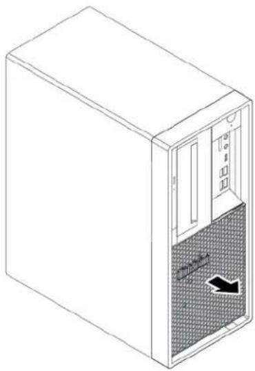
natural_image
Line drawing of a server cabinet with ventilation duct and airflow direction indicator (no text or symbols)Figure 11. Removing the dust shield
- Remove the two screws that secure the computer cover. Then, slide the cover to the rear of the computer to remove the cover.
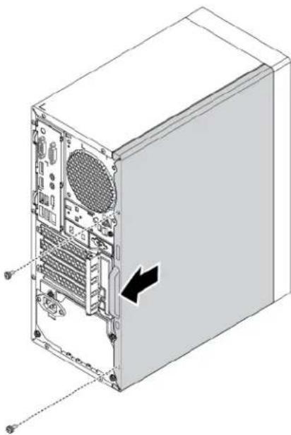
natural_image
Isometric line drawing of a computer tower case with visible internal components and a black arrow indicating a specific portion (no text or symbols present)Figure 12. Removing the computer cover
- Release the three plastic tabs of the front bezel as shown and pivot the front bezel outward to remove it from the computer.
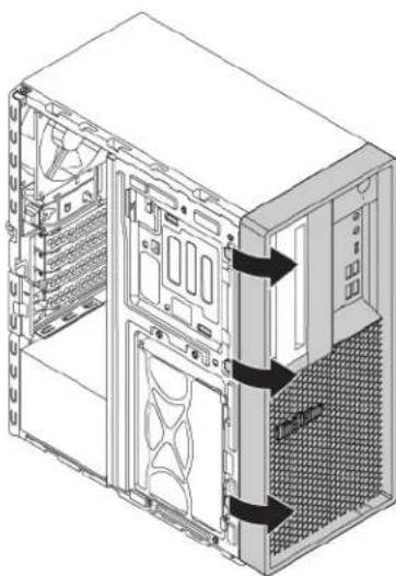
natural_image
Isometric diagram of a desktop computer tower showing internal components and ventilation ducts (no text or labels)Figure 13. Removing the front bezel
- Pivot the drive bay assembly outward.
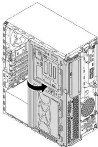
natural_image
Technical line drawing of a computer tower case showing internal components and ventilation slots (no text or labels)Figure 14. Pivoting the drive bay assembly outward
Notes:
- Depending on your computer model, some of the hardware parts in the removal and installation section might not be available.
- Use computer parts provided only by Lenovo.
- When removing or installing an option, use the appropriate instructions in this section along with the instructions that come with the option.
- In most areas of the world, Lenovo requires the return of the defective CRU. Information about this will come with the CRU or will come a few days after the CRU arrives.
Removing and installing hardware
This section provides instructions on how to remove and install hardware for your computer. You can expand the capabilities of your computer and maintain your computer by removing or installing hardware.
Attention: Do not open your computer or attempt any repair before reading and understanding the “Read this first: Important safety information” on page iii.
External options
You can connect external options to your computer, such as external speakers, a printer, or a scanner. For some external options, you must install additional software in addition to making the physical connection. When installing an external option, see “Hardware locations” on page 1 to identify the required connector. Then, use the instructions that come with the option to help you make the connection and install any software or device drivers that are required for the option.
Slim optical drive
Attention: Do not open your computer or attempt any repair before reading and understanding the “Read this first: Important safety information” on page iii.
To remove or install a slim optical drive, do the following:
- Prepare your computer. See "Preparing your computer" on page 56.
- Locate the slim optical drive. See "Computer components" on page 5.
- To remove the slim optical drive from the drive bay assembly, do the following:
a. Disconnect cables from the rear of the slim optical drive.
b. Press the release button, and then slide the slim optical drive out of the drive bay assembly.
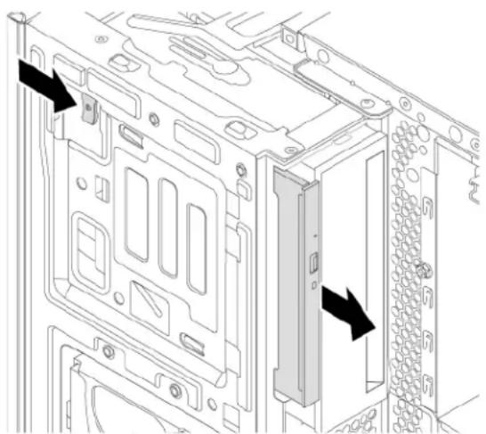
natural_image
Technical line drawing of a computer tower internal structure showing mounting holes and drive slots (no text or symbols)Figure 15. Removing the slim optical drive
c. Remove the bracket from the slim optical drive.
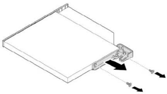
natural_image
Technical line drawing of a mechanical component with arrows indicating motion or force direction (no text or symbols)Figure 16. Removing the bracket
- To install a new slim optical drive into the drive bay assembly, do the following:
a. If there is a plastic shield installed in the front bezel, remove the plastic shield as shown.
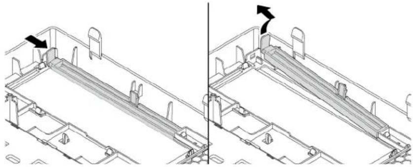
natural_image
Technical line drawing of a mechanical assembly with two views (top and side), showing internal components and mounting brackets (no text or symbols)Figure 17. Removing the plastic shield
b. If there is a metal shield installed in the slim optical drive bay, remove the metal shield as shown.
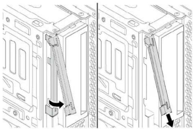
natural_image
Technical line drawing of a computer tower frame with two vertical connectors inserted, showing internal structure and mounting holes (no text or symbols)Figure 18. Removing the metal shield
c. Align the two holes in the bracket with the corresponding holes in the new slim optical drive. Then, install the bracket to the new slim optical drive.
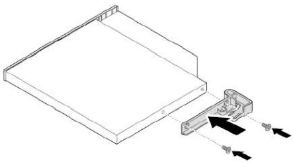
natural_image
Technical line drawing of a mechanical component with arrows indicating assembly or movement (no text or symbols)Figure 19. Installing the bracket
d. Insert the new slim optical drive into the slim optical drive bay until you hear a click. The slim optical drive is secured in place.
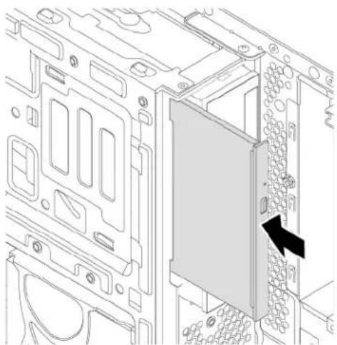
natural_image
Technical line drawing of a computer motherboard showing internal components and a highlighted panel (no text or symbols)Figure 20. Installing the slim optical drive
e. Connect the cables to the rear of the new slim optical drive.
What to do next:
- To work with another piece of hardware, go to the appropriate section.
- To complete the installation or replacement, go to "Completing the parts replacement" on page 121.
PCIe card
Attention: Do not open your computer or attempt any repair before reading and understanding the “Read this first: Important safety information” on page iii.
Your computer has one PCIe x1 card slot, one PCIe x16 card slot (negotiable link width x4), and one PCIe x16 graphics card slot (graphics card available on some models).
To remove or install a PCIe card, do the following:
- Prepare your computer. See "Preparing your computer" on page 56.
-
Locate the PCIe card slot. See "Computer components" on page 5.
-
If the PCIe card is held in place by a retaining latch, press the retaining latch as shown to disengage the latch.
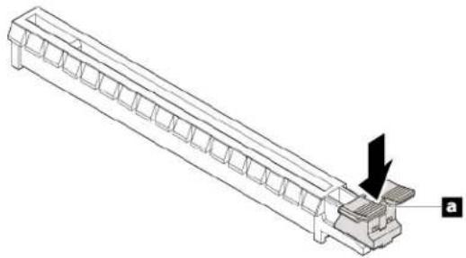
natural_image
Technical line drawing of a mechanical component with a downward arrow and label 'a' (no text or symbols on the diagram itself)Figure 21. Disengaging the card retaining latch
- To remove a PCIe card, do the following:
a. Rotate the PCIe card retainer to the open position.
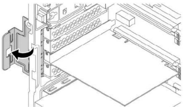
natural_image
Technical line drawing of a mechanical assembly with a component labeled '1' and an arrow indicating direction (no text or symbols present)Figure 22. Rotating the PCIe card retainer
b. Grasp the old card and gently pull it out of the slot.
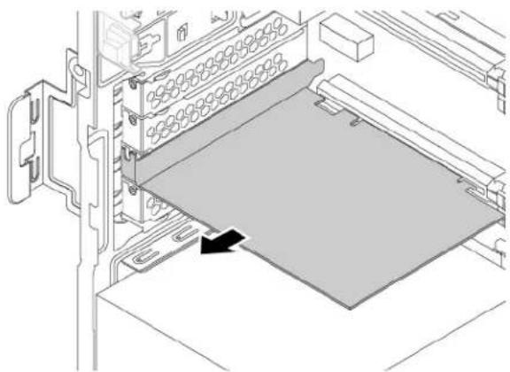
natural_image
Technical line drawing of a computer rack with a highlighted component (no text or symbols)Figure 23. Removing a PCIe card
- To install a new PCIe card, do the following:
a. Remove the new PCIe card from its static-protective package.
b. If necessary, remove the appropriate metal slot cover on the rear of the chassis.
c. Install the new card into the appropriate slot on the system board. See "Parts on the system board" on page 7.
Note: If you are installing a PCIe x16 graphics card, ensure that the memory-slot retaining clips are closed before you install the card to avoid any interference during the installation.
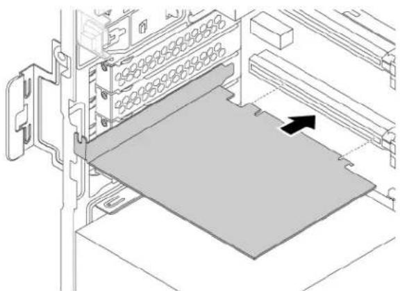
natural_image
Diagram of a computer rack with a highlighted storage panel and directional arrow (no text or symbols)Figure 24. Installing a new PCIe card
d. Rotate the PCIe card retainer to the closed position.
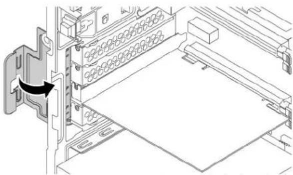
natural_image
Technical line drawing of a mechanical assembly with a black arrow indicating a component or connection (no text or symbols present)Figure 25. Rotating the PCIe card retainer
What to do next:
• To work with another piece of hardware, go to the appropriate section.
- To complete the installation or replacement, go to "Completing the parts replacement" on page 121.
Full-length PCIe card
Attention: Do not open your computer or attempt any repair before reading and understanding the “Read this first: Important safety information” on page iii.
Your computer has one PCIe x1 card slot, one PCIe x16 card slot (negotiable link width x4), and one PCIe x16 graphics card slot (graphics card available on some models).
To remove or install a full-length PCIe card, do the following:
- Prepare your computer. See "Preparing your computer" on page 56.
-
Locate the PCIe card slot. See "Computer components" on page 5.
-
If the PCIe card is held in place by a retaining latch, press the retaining latch as shown to disengage the latch.
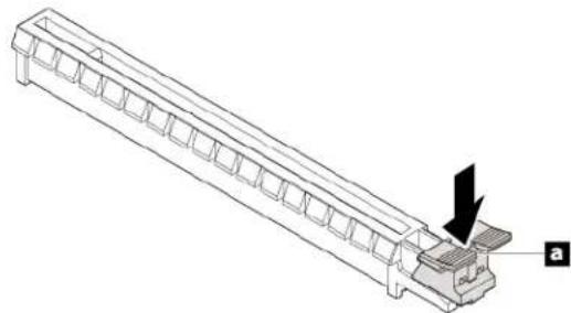
natural_image
Technical line drawing of a mechanical component with a black arrow indicating a feature, labeled 'a' (no text or symbols on the diagram itself)Figure 26. Disengaging the card retaining latch
- To remove a PCIe card, do the following:
a. Rotate the PCIe card retainer to the open position.
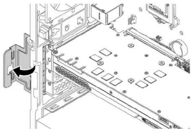
natural_image
Technical diagram of a computer chassis showing internal components and a directional arrow indicating movement (no text or symbols present)Figure 27. Rotating the PCIe card retainer
b. Grasp the old card and gently pull it out of the slot.
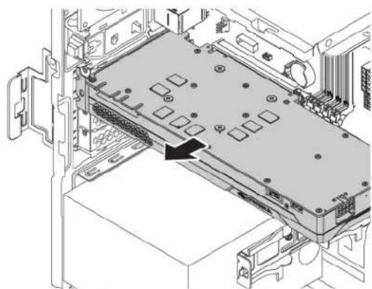
natural_image
Technical diagram of an electronic device chassis showing internal components and a black arrow indicating a specific area (no text or symbols present)Figure 28. Removing a full-length PCIe card
- Remove the three screws that secure the bracket to remove it from the PCIe card.
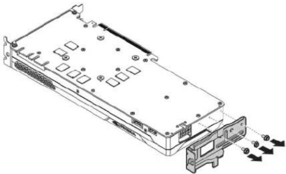
natural_image
Technical line drawing of a server rack with ports and connectors, showing internal components and external force arrows (no text or symbols)Figure 29. Removing a full-length PCIe card bracket
- To install a new full-length PCIe card, do the following:
a. Remove the new PCIe card from its static-protective package.
b. If necessary, remove the appropriate metal slot cover on the rear of the chassis.
c. Install the three screws to secure the bracket to the new full-length PCIe card.
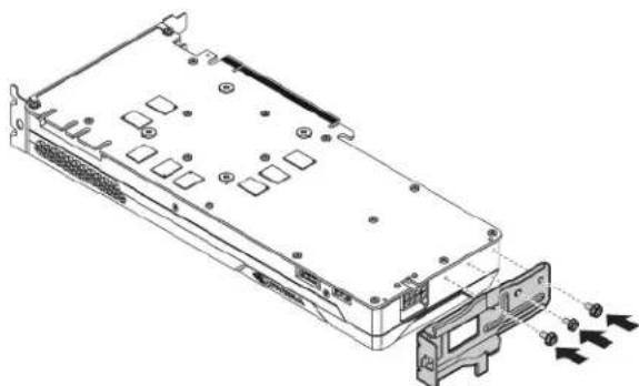
natural_image
Technical line drawing of an electronic device chassis with ports and connectors (no text or symbols)Figure 30. Installing a full-length PCIe card bracket
d. Install the new card into the appropriate slot on the system board. See "Parts on the system board" on page 7.
Note: If you are installing a PCIe x16 graphics card, ensure that the memory-slot retaining clips are closed before you install the card to avoid any interference during the installation.
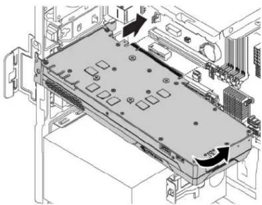
natural_image
Technical diagram of an electronic device chassis showing internal components and mounting hardware (no text or labels)Figure 31. Installing a new full-length PCIe card
e. Rotate the PCIe card retainer to the closed position.
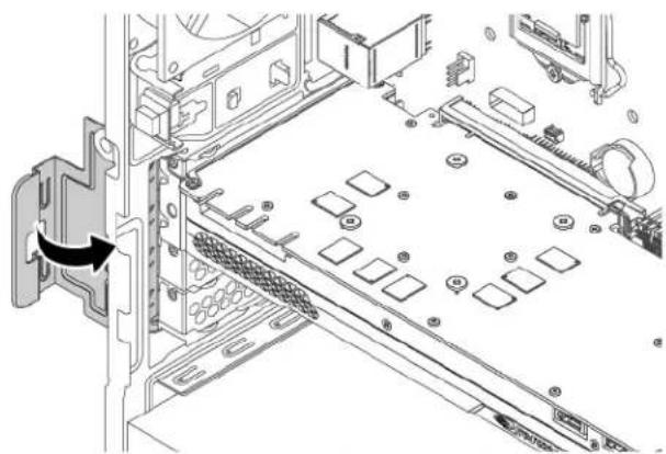
natural_image
Technical diagram of a computer drive bay with labeled components and an arrow indicating a component (no text or symbols present)Figure 32. Rotating the PCIe card retainer
What to do next:
- To work with another piece of hardware, go to the appropriate section.
- To complete the installation or replacement, go to "Completing the parts replacement" on page 121.
M.2 solid-state drive
Attention: Do not open your computer or attempt any repair before reading and understanding the “Read this first: Important safety information” on page iii.
The instructions on how to install or replace a M.2 solid-state drive also apply to the Intel Optane memory. Before replacing the Intel Optane memory, ensure that you disable the Intel Optane memory from the Intel Rapid Storage Technology (Intel RST) Console. Otherwise, all data on the storage drive will be lost. For more information, see instructions on https://www.intel.com/content/www/us/en/support/articles/000023989/memory-and-storage/intel-optane-memory.html.
An M.2 solid-state drive can be installed on the system board or an M.2 solid-state drive PCIe adapter.
M.2 solid-state drive on the system board
To remove or install an M.2 solid-state drive on the system board, do the following:
- Prepare your computer. See "Preparing your computer" on page 56.
- Locate the M.2 solid-state drive slot. See "Parts on the system board" on page 7.
-
Untie the cables that prevent your access to the M.2 solid-state drive slot from the cable clip.
-
To remove an M.2 solid-state drive, do the following:
a. Turn the two mounting studs 90-degree counterclockwise to release the heat sink. Then, lift the heat sink off the plastic holder.
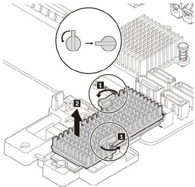
text_image
Technical diagram showing mechanical assembly with labeled components and directional arrows indicating motion or movement.Figure 33. Removing the heat sink from the plastic holder
b. Pull the handle of the retention latch outward to the open position. The M.2 solid-state drive is released from the secured position and pivots upward. Remove the M.2 solid-state drive out of the slot.
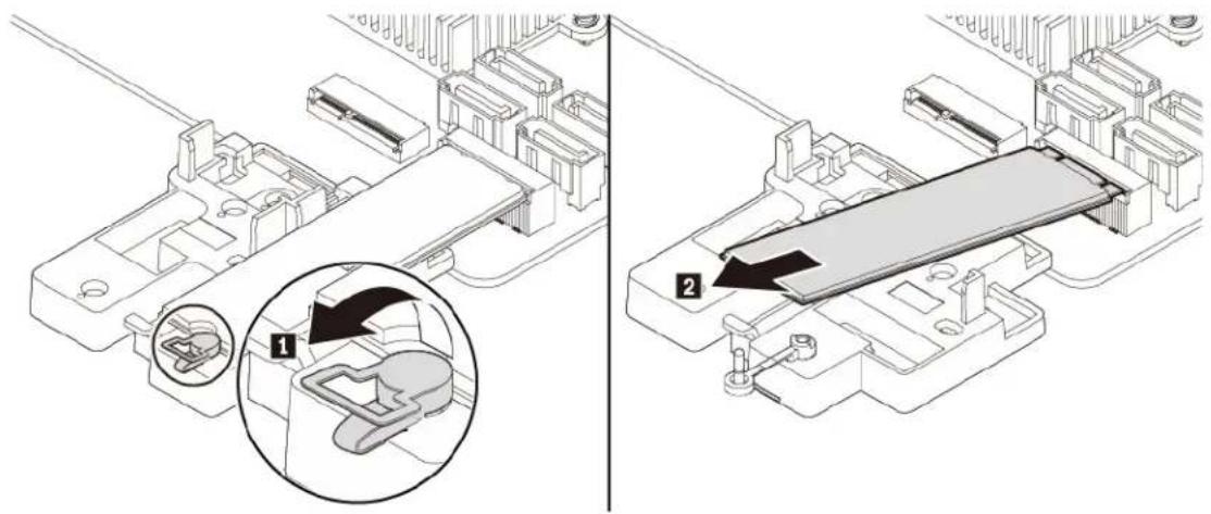
text_image
Technical diagram showing mechanical assembly with labeled components and a magnified inset highlighting component 1.Figure 34. Opening the retention latch and removing the M.2 solid-state drive
- To install a new M.2 solid-state drive, do the following:
a. If necessary, align the four tabs on the rear of the plastic holder with the corresponding holes in the chassis. Then slide the plastic holder toward the system board until it snaps into position.

natural_image
Technical diagram of a mechanical assembly with internal components and a magnified inset showing a component (no text or symbols present)Figure 35. Installing the plastic holder
b. Locate the hole in the plastic holder to install the retention latch. Align the pin a with the corresponding hole b in the plastic holder. Then press the retention latch downward into the hole until it snaps into position.
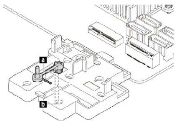
text_image
Technical diagram showing a mechanical assembly with labeled parts (a and b) and internal componentsFigure 36. Installing the retention latch
c. Hold the new M.2 solid-state drive by its edges and ensure that the circuit board side is facing upward. Align the contact edge of the new drive with the key in the corresponding slot. Then carefully insert the new drive into the slot at an angle of about 20 degrees and pivot the new drive downward. Insert the plug of the retention latch into the hole to secure the new drive.
Note: Do not touch the circuit board of the M.2 solid-state drive.
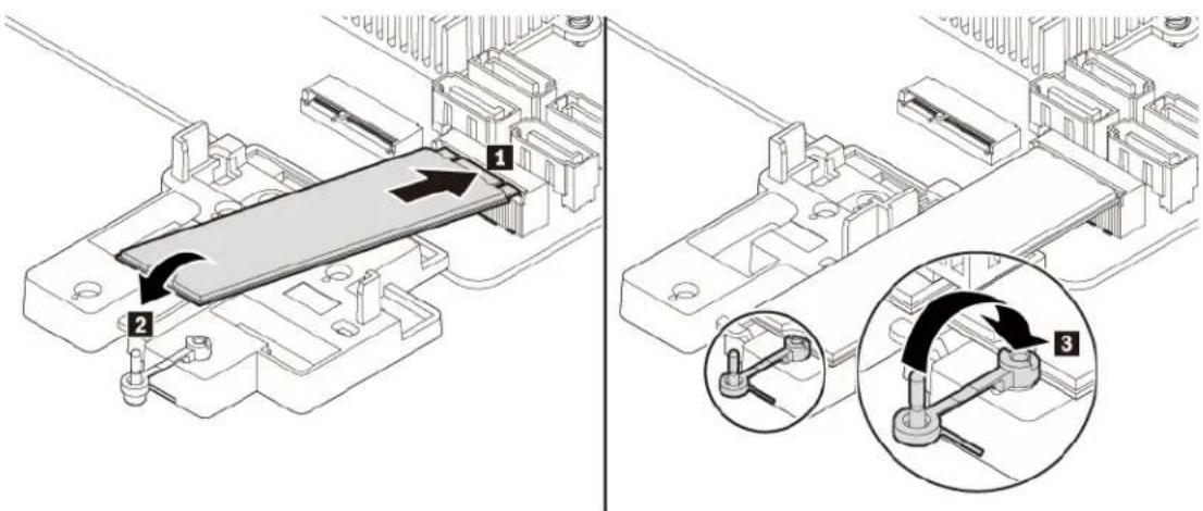
text_image
Technical diagram showing mechanical assembly with labeled components and directional arrows indicating motion or movement.Figure 37. Installing the M.2 solid-state drive
- If necessary, remove the film that covers the thermal pad at the bottom of the heat sink. Place the heat sink on the M.2 solid-state drive. Ensure that the two mounting studs on the heat sink are in the open position and press the studs on the heat sink into the corresponding holes in the plastic holder as shown. Then, turn the mounting studs 90-degree clockwise to secure the heat sink to the plastic holder.
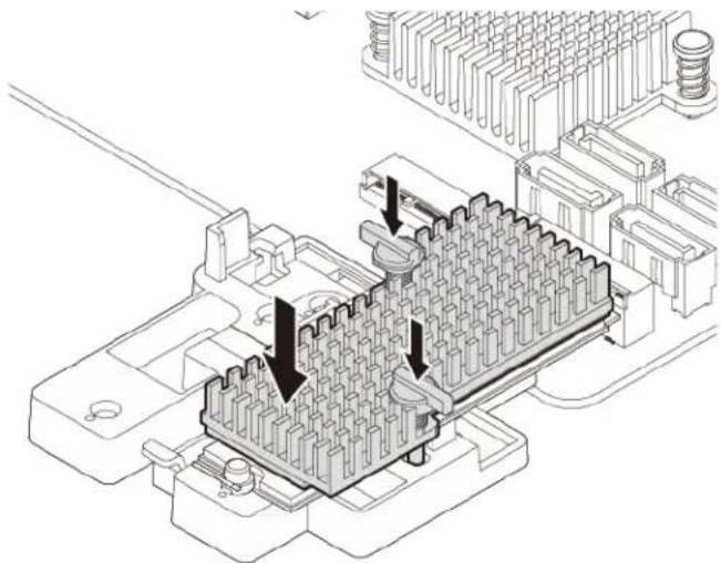
natural_image
Technical line drawing of an electronic component with internal grid structure and mounting holes (no text or symbols)Figure 38. Installing the heat sink onto the plastic holder
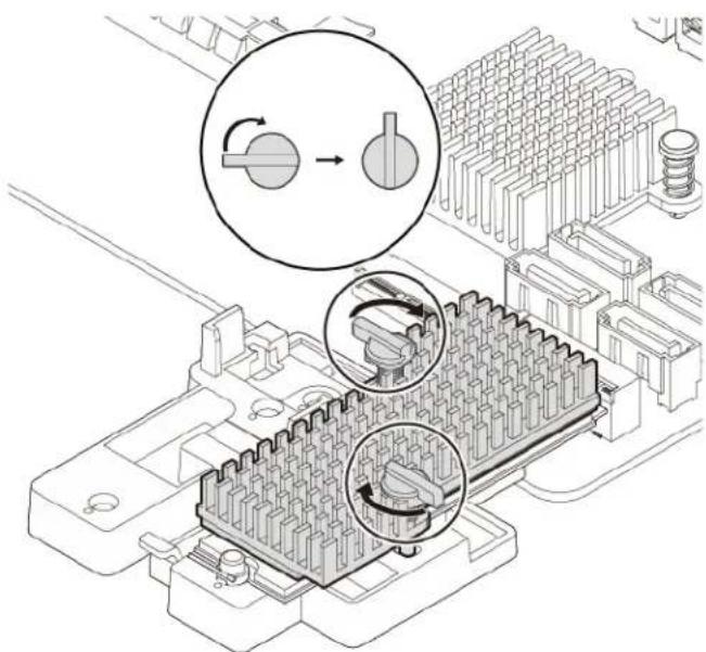
natural_image
Technical illustration of a mechanical assembly with three circular insets showing internal components (no text or symbols)Figure 39. Securing the heat sink to the plastic holder
- Retie the cables that you have untied with the cable clip.
What to do next:
- To work with another piece of hardware, go to the appropriate section.
- To complete the installation or replacement, go to "Completing the parts replacement" on page 121.
M.2 solid-state drive in an M.2 solid-state drive PCIe adapter
To remove or install the M.2 solid-state drive in the M.2 solid-state drive PCIe adapter, do the following:
-
Prepare your computer. See "Preparing your computer" on page 56.
-
To remove the M.2 solid-state drive in the M.2 solid-state drive PCIe adapter, do the following:
a. Locate and remove the M.2 solid-state drive adapter from the PCIe card slot. See "PCIe card" on page 62.
b. The heat sink is secured by two mounting studs. Pinch the clips of the studs inward and push the studs upward to release the heat sink. Then, lift the heat sink off the M.2 solid-state drive adapter
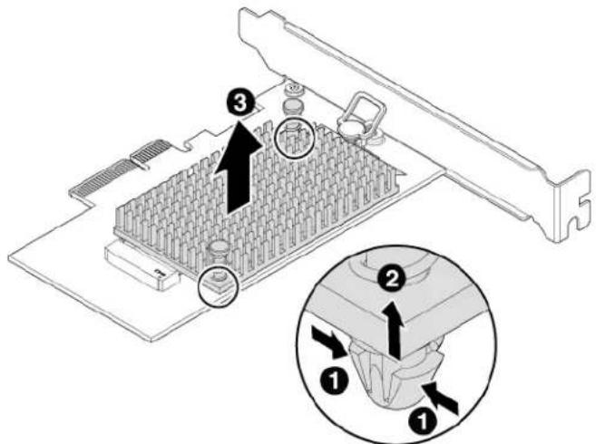
text_image
Technical diagram of a computer RAM module with labeled components and an inset showing pin insertion stepsFigure 40. Removing the heat sink from the M.2 solid-state drive adapter
c. The M.2 solid-state drive is secured by a retention latch. Pull the handle of the retention latch outward to release the M.2 solid-state drive. Then, gently pull the M.2 solid-state drive out of the M.2 slot.
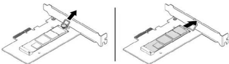
natural_image
Technical illustration of two views of a computer hard drive with a clip inserted (no text or symbols)Figure 41. Removing the M.2 solid-state drive
- To install the M.2 solid-state drive, do the following:
a. Ensure that a thermal pad is placed in position on the M.2 solid-state drive adapter.
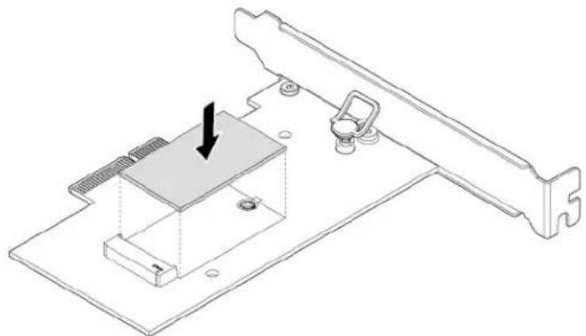
natural_image
Technical line drawing of a mechanical assembly with a highlighted component and mounting bracket (no text or symbols)Figure 42. Installing the thermal pad
b. Pull outward the handle of the retention latch in the M.2 solid-state drive adapter.
c. Insert the new M.2 solid-state drive into the M.2 slot. Then, insert the plug of the retention latch into the hole to secure the new drive.
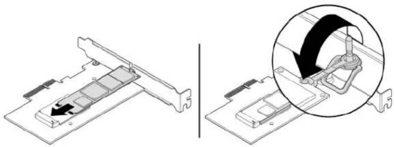
natural_image
Technical illustration showing a mechanical assembly with a magnified inset highlighting a component detail (no text or symbols present)Figure 43. Installing the M.2 solid-state drive
d. Position the heat sink on the M.2 solid-state drive adapter. Ensure that the two mounting studs in the heat sink are aligned with the holes in the M.2 solid-state drive adapter. Then, push the mounting studs downward to secure the heat sink to the adapter.
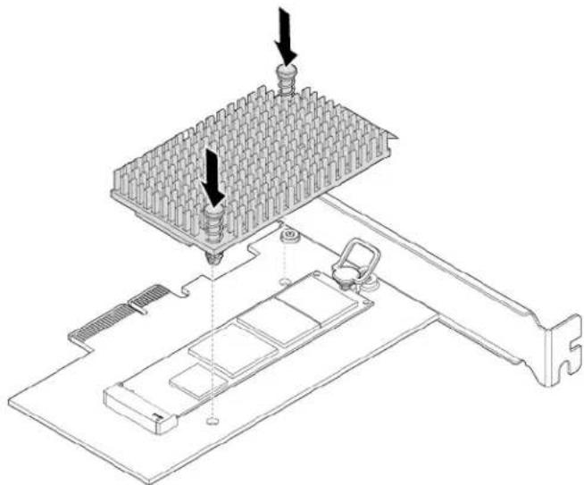
natural_image
Technical diagram of a computer motherboard with a grid socket and mechanical components (no text or symbols)Figure 44. Installing the heat sink
e. Install the M.2 solid-state drive adapter into the appropriate PCIe card slot on the system board. See "PCIe card" on page 62.
Note: It is recommended that you install the M.2 solid-state drive adapter into the PCIe x16 card slot. See "Parts on the system board" on page 7.
What to do next:
• To work with another piece of hardware, go to the appropriate section.
- To complete the installation or replacement, go to "Completing the parts replacement" on page 121.
Memory module
Attention: Do not open your computer or attempt any repair before reading and understanding the "Read this first: Important safety information" on page iii.
Your computer has four memory slots for installing or replacing DDR4 DIMMs. When installing or replacing a memory module, use the following guidelines:
- Use any of DDR4 ECC UDIMMs or DDR4 non-ECC UDIMMs for your computer. Do not install ECC and non-ECC UDIMMs into the same computer.
• Use 4 GB, 8 GB, 16 GB, or 32 GB non-ECC UDIMMs in any combination up to a maximum of 128 GB. - Use 8 GB or 16 GB ECC UDIMMs in any combination up to a maximum of 64 GB.
Install memory modules in the alphabetic order as shown.
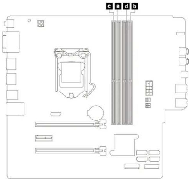
text_image
c a d bFigure 45. Memory module installation sequence
To install or replace a memory module, do the following:
- Prepare your computer. See "Preparing your computer" on page 56.
- Lay the computer on its side for easier access to the system board.
- Locate the memory slots. See "Parts on the system board" on page 7.
- Remove any PCIe cards that might prevent your access to the coin-cell battery. See "PCIe card" on page 62.
- To remove a memory module, open the retaining clips and gently pull the memory module out of the memory slot.
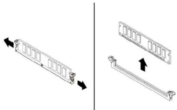
natural_image
Technical illustration of a computer RAM module with two views showing internal structure changes (no text or symbols)Figure 46. Removing a memory module
- To install a memory module, do the following:
a. Open the retaining clips of the memory slot.
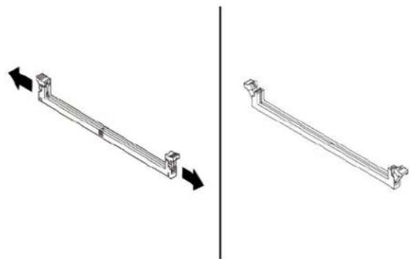
natural_image
Two isometric diagrams of a metal beam with arrows indicating direction, no text or symbols present.Figure 47. Opening the retaining clips
b. Position the new memory module over the memory slot. Ensure that the notch 1 on the memory module is aligned with the key 2 in the slot. Push the memory module straight down into the slot until the retaining clips completely close.
Note: Do not touch the circuit board of the memory module.
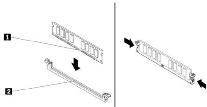
text_image
Technical diagram showing two views of a computer RAM module with labeled components and directional arrows indicating assembly or movement.Figure 48. Installing a memory module
- Reinstall any PCIe cards if you have removed them.
What to do next:
- To work with another piece of hardware, go to the appropriate section.
- To complete the installation or replacement, go to "Completing the parts replacement" on page 121.
Device in the flex bay
Attention: Do not open your computer or attempt any repair before reading and understanding the “Read this first: Important safety information” on page iii.
Some computer models come with a flex bay. Depending on your computer model, one of the following devices might be installed in the flex bay:
- Flex module
• Flex storage enclosure
- Front-access storage enclosure
Note: The following instructions on how to remove or install an flex storage enclosure also apply to other supported devices in the flex bay.
To remove or install an flex storage enclosure, do the following:
- Prepare your computer. See "Preparing your computer" on page 56.
- Locate the flex bay. See "Computer components" on page 5.
- To remove the flex storage enclosure, do the following:
a. Disconnect the signal cable and the power cable from the rear of the flex storage enclosure.
Note: If you are removing other supported devices from the flex bay, disconnect any additional cables first.
b. Press the tab downward as shown and push the rear of the flex storage enclosure simultaneously to slide it out of the computer.
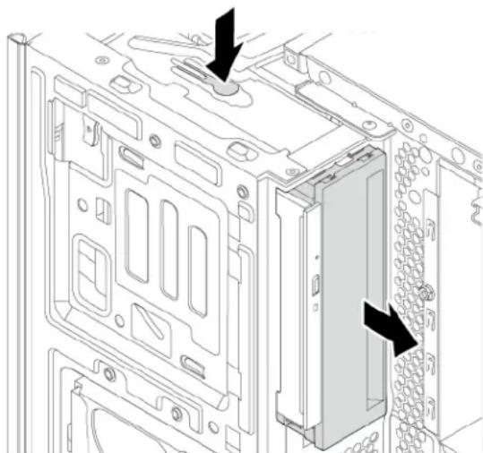
natural_image
Technical line drawing of a computer tower internal structure showing mounting holes and drive slots (no text or symbols)Figure 49. Removing the flex storage enclosure
c. Remove the retainer from the flex storage enclosure as shown.
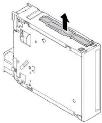
natural_image
Technical line drawing of a mechanical housing or enclosure with internal components and an arrow indicating direction (no text or symbols present)Figure 50. Removing the retainer
- To install a flex storage enclosure, do the following:
a. Install the retainer shipped with the new flex storage enclosure onto the new flex storage enclosure as shown.
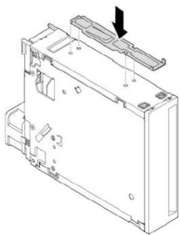
natural_image
Technical line drawing of a computer chassis with internal components and a black arrow indicating a component (no text or symbols present)Figure 51. Installing the retainer
b. Note the orientation of the new flex storage enclosure. Then, slide the flex storage enclosure into the flex bay from the front of the chassis until it snaps into position.
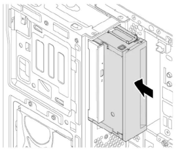
natural_image
Technical line drawing of an internal device housing with a black arrow indicating a component (no text or symbols present)Figure 52. Installing the new flex storage enclosure
c. Connect the signal cable and the power cable to the new flex storage enclosure.
Note: Reconnect any cables removed from other supported devices.
What to do next:
- To work with another piece of hardware, go to the appropriate section.
- To complete the installation or replacement, go to "Completing the parts replacement" on page 121.
Storage drive in the front-access storage enclosure
Attention: Do not open your computer or attempt any repair before reading and understanding the “Read this first: Important safety information” on page iii.
You can install or replace a storage drive in the front-access storage enclosure. The storage drive also can be hot-swappable, which means that you can install or replace the drive without even turning off your computer. Therefore, lock the enclosure cover to prevent the unexpected removal. The keys are attached at the rear of the computer. Store the keys in a secure place.
The storage drive in the front-access storage enclosure is hot-swappable only when the following requirements are met:
- The eSATA mode of the SATA 4 connector is enabled. See “Parts on the system board” on page 7 for more information.
- The SATA cable of the front-access storage enclosure is connected to the SATA 4 connector on the system board. To verify the cable connection, see “Preparing your computer” on page 56 and “Parts on the system board” on page 7 for more information.
- The operating system of your computer does not reside on the storage drive installed in the front-access storage enclosure.
Attention: If any of the above requirements are not met, do not install or replace the storage drive when the computer is turned on. Otherwise, data on the storage drive might get damaged.
3.5-inch storage drive
To remove or install a 3.5-inch storage drive, do the following:
- Before removing an old 3.5-inch storage drive, safely eject the old storage drive from the operating system first. For more information, see the Windows help system.
- Unlock the enclosure cover with the provided key as shown. Press the notch to open the enclosure cover.
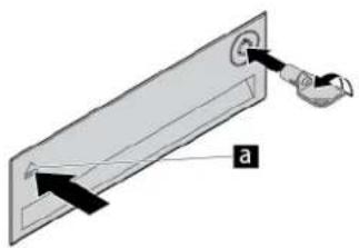
natural_image
Diagram of a mechanical component with labeled parts (a), showing a lever and pin assembly without any text or symbols.Figure 53. Opening the front-access storage enclosure cover
- Press the pit on the bracket cover, and then grasp the tilted cover to pull the bracket out of the front-access storage enclosure.
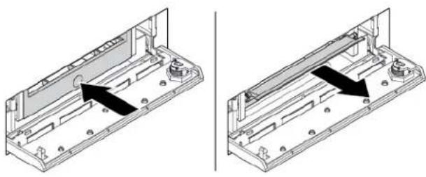
natural_image
Two technical diagrams showing a mechanical assembly with arrows indicating direction of movement or force (no text or symbols present)Figure 54. Removing the bracket from the front-access storage enclosure
- Flex both sides of the bracket to remove the 3.5-inch storage drive from the bracket.
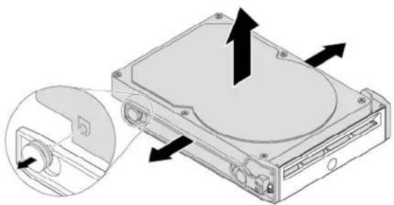
natural_image
Diagram of a hard disk drive with an inset showing internal components (no text or labels)Figure 55. Removing the 3.5-inch storage drive from the bracket
- To install a new 3.5-inch storage drive into the front-access storage enclosure, do the following:
a. Flex both sides of the bracket and align pins 1 on the bracket with the corresponding holes in the new 3.5-inch storage drive.
Notes:
- Ensure that the circuit board faces downward and the connectors face toward the rear of the bracket.
- Do not touch the circuit board on the storage drive.
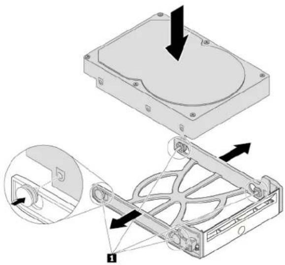
natural_image
Technical illustration of a hard disk drive assembly with mounting holes and internal components (no text or symbols)Figure 56. Installing the 3.5-inch storage drive into the bracket
b. Slide the bracket with the new 3.5-inch storage drive into the front-access storage enclosure until it snaps into position.
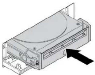
natural_image
Diagram of a computer drive with an arrow indicating direction (no text or symbols present)Figure 57. Installing the 3.5-inch storage drive into the front-access storage enclosure
c. Press the notch to secure the enclosure cover and lock the enclosure cover with the key.
What to do next:
- To work with another piece of hardware, go to the appropriate section.
- To complete the installation or replacement, go to "Completing the parts replacement" on page 121.
2.5-inch storage drive
To remove or install a 2.5-inch storage drive, do the following:
- Before removing an old 2.5-inch storage drive, safely eject the old storage drive from the operating system first. For more information, see the Windows help system.
- Unlock the enclosure cover with the provided key as shown. Press the notch to open the enclosure cover.
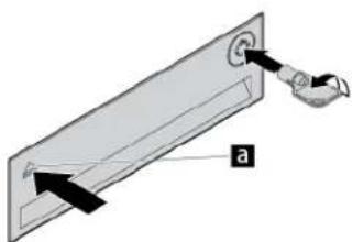
natural_image
Diagram of a mechanical component with labeled parts (a), showing directional arrows and a scroll-like element (no text or symbols present)Figure 58. Opening the front-access storage enclosure cover
- Press the pit on the bracket cover, and then grasp the tilted cover to pull the bracket out of the front-access storage enclosure.
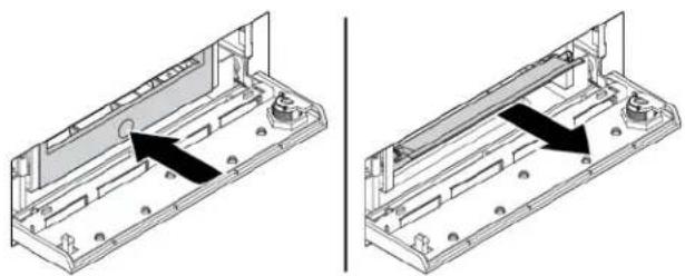
natural_image
Technical illustration of a mechanical assembly with two views showing internal components and mounting holes (no text or symbols)Figure 59. Removing the bracket from the front-access storage enclosure
- To remove the 2.5-inch storage drive, do the following:
a. Flex both sides of the bracket to remove the 2.5-inch storage drive from the bracket.
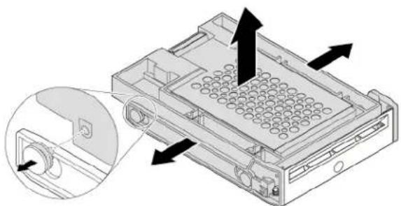
natural_image
Diagram of a computer RAM unit with an inset showing a slot and directional arrows (no text or symbols)Figure 60. Removing the 2.5-inch storage drive from the bracket
b. Pivot the tab 1 of the metal adapter upward. Then, push the adapter as shown until the four tabs on the adapter slide into the notches 2. Pivot the adapter as shown to remove it with the storage drive from the converter.
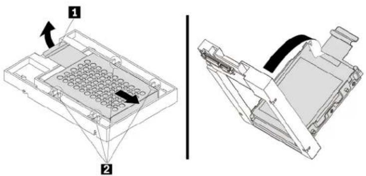
text_image
Technical diagram showing two views of a device with labeled components and directional arrows indicating movement or assembly.Figure 61. Removing the adapter from the converter
c. Flex both sides of the adapter to release the four pins 1 from the storage drive. Then, remove the storage drive from the adapter.
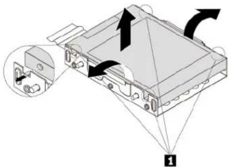
text_image
Diagram of an electronic device with labeled components and directional arrows indicating assembly or operationFigure 62. Removing the storage drive from the adapter
- To install a new 2.5-inch storage drive, do the following:
a. Note the orientation of the connector on the new storage drive. Then, flex both sides of the adapter and align the four pins 1 with the corresponding holes in the storage drive.
Note: Do not touch the circuit board (if accessible) of the 2.5-inch storage drive.
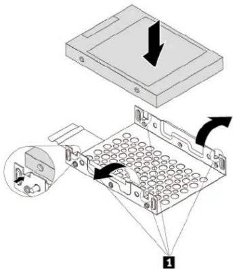
text_image
Diagram illustrating the internal structure and assembly of a floppy disk drive, showing component positioning and directional arrows.Figure 63. Installing the storage drive into the adapter
b. Align the four tabs on the adapter with the corresponding notches 1 in the converter. Then, slide the storage drive as shown until the tab 2 snaps into position. The adapter with the storage drive is installed into the converter.
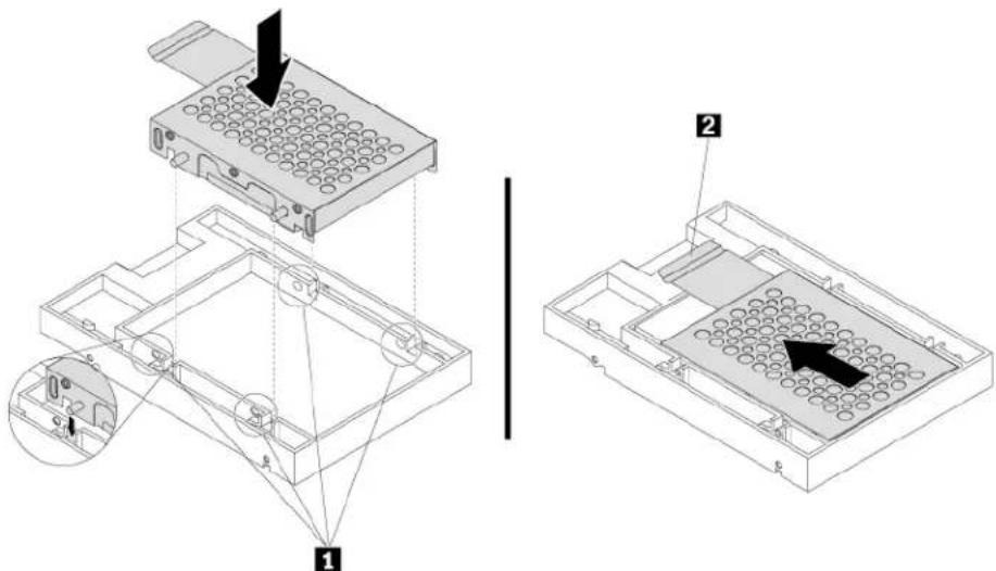
text_image
Technical diagram showing assembly of a device with labeled components and directional arrows indicating movement or assembly.Figure 64. Installing the adapter into the converter
c. Flex both sides of the plastic bracket and align pins 1 on the plastic bracket with the corresponding holes in the plastic frame of the converter.
Notes:
- Ensure that the circuit board faces downward and the connectors face toward the rear of the bracket.
- Do not touch the circuit board on the storage drive.
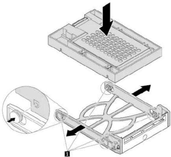
natural_image
Technical illustration of a mechanical device with internal components and directional arrows (no text or symbols)Figure 65. Installing the converter with the 2.5-inch storage drive into the plastic bracket
d. Slide the plastic bracket with the new 2.5-inch storage drive into the front-access storage enclosure until it snaps into position.
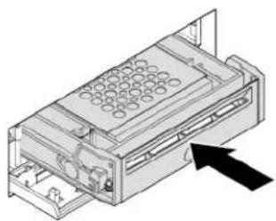
natural_image
Technical line drawing of a mechanical device with internal components and an arrow indicating direction (no text or symbols)Figure 66. Installing the plastic bracket with the 2.5-inch storage drive into the front-access storage enclosure
e. Press the notch to secure the enclosure cover and lock the enclosure cover with the key.
What to do next:
• To work with another piece of hardware, go to the appropriate section.
- To complete the installation or replacement, go to "Completing the parts replacement" on page 121.
Device in the flex storage enclosure
Attention: Do not open your computer or attempt any repair before reading and understanding the “Read this first: Important safety information” on page iii.
A flex storage enclosure might be equipped with one of the following components:
• 3.5-inch storage drive
• 2.5-inch storage drive
3.5-inch storage drive
To remove or install a 3.5-inch storage drive in the flex storage enclosure, do the following:
- Prepare your computer. See "Preparing your computer" on page 56.
- Locate the flex bay. See "Internal storage drives" on page 8.
- Slide the enclosure out of the chassis. See "Device in the flex bay" on page 77.
- Pinch the two clips toward each other as shown to open the rear cover of the enclosure.
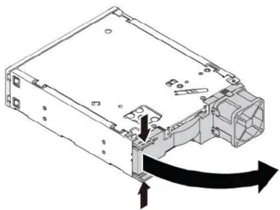
natural_image
Technical diagram of an electronic device showing internal components and directional arrows (no text or symbols)Figure 67. Opening the enclosure from the rear
- To remove a 3.5-inch storage drive, do the following:
a. Slide the 3.5-inch storage drive out of the rear of the enclosure.
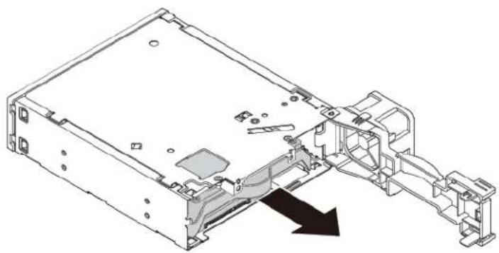
natural_image
Technical line drawing of an electronic device chassis with internal components and a black arrow indicating a specific part (no text or symbols present)Figure 68. Removing the 3.5-inch storage drive from the rear
b. Flex two sides of the bracket to remove the 3.5-inch storage drive from the 3.5-inch storage-drive bracket.
- To install a new 3.5-inch storage drive into the bracket:
a. Slide the 3.5-inch storage-drive bracket out of the rear of the enclosure.
b. Flex the bracket and align pin 1, pin 2, pin 3, and pin 4 on the bracket with the corresponding holes in the 3.5-inch storage drive. Do not touch the circuit board 5 on the 3.5-inch storage drive.
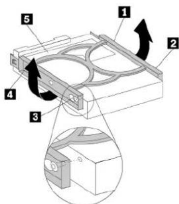
text_image
Technical diagram of a mechanical assembly with numbered components and directional arrows indicating motion or movement.Figure 69. Installing the 3.5-inch storage drive into the bracket
c. Slide the new 3.5-inch storage drive into the enclosure from the rear until the drive snaps into position.
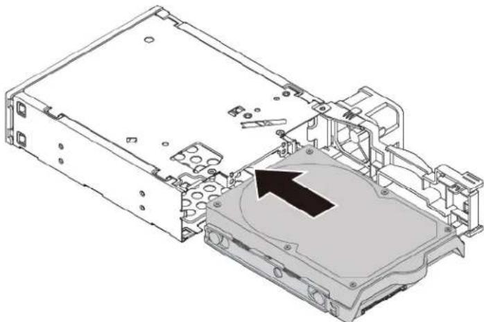
natural_image
Technical line drawing of an internal electronic device casing with a highlighted component (no text or symbols)Figure 70. Installing the 3.5-inch storage drive into the enclosure
- Pivot the rear cover of the enclosure inward until you hear a click. The rear cover is secured in place.
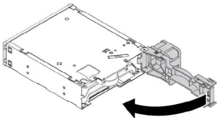
natural_image
Technical line drawing of an electronic device chassis with a directional arrow indicating motion (no text or symbols present)Figure 71. Pivoting the rear cover inward
- Connect the signal cable and the power cable to the storage drive.
What to do next:
- To work with another piece of hardware, go to the appropriate section.
- To complete the installation or replacement, go to "Completing the parts replacement" on page 121.
2.5-inch storage drive
To remove or install a 2.5-inch storage drive with a 2.5-inch to 3.5-inch storage-drive converter (hereafter referred to as storage-drive converter), do the following:
- Prepare your computer. See "Preparing your computer" on page 56.
- Locate the flex bay. See "Internal storage drives" on page 8.
- Slide the enclosure out of the chassis. See "Device in the flex bay" on page 77.
- Pinch the two clips toward each other as shown to open the rear cover of the enclosure.
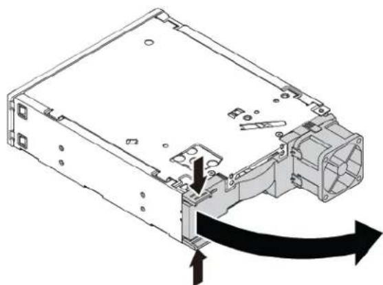
natural_image
Technical line drawing of an electronic device casing with a directional arrow indicating motion (no text or symbols present)Figure 72. Opening the enclosure from the rear
- To remove a 2.5-inch storage drive, do the following:
a. Slide the 2.5-inch storage drive out of the rear of the enclosure.
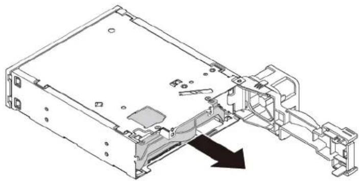
natural_image
Technical line drawing of an electronic device chassis showing internal components and a black arrow indicating assembly direction (no text or symbols present)Figure 73. Removing the 2.5-inch storage drive from the rear
b. Flex the sides of the bracket to remove the storage-drive converter from the 3.5-inch storage-drive bracket.
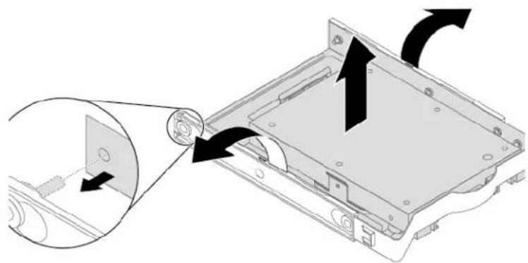
natural_image
Diagram showing a device being inserted into a rack with arrows indicating motion (no text or symbols present)Figure 74. Removing the storage-drive converter from the 3.5-inch storage-drive bracket
c. Remove the four screws that secure the 2.5-inch storage drive. Then lift the storage drive out of the storage-drive converter.
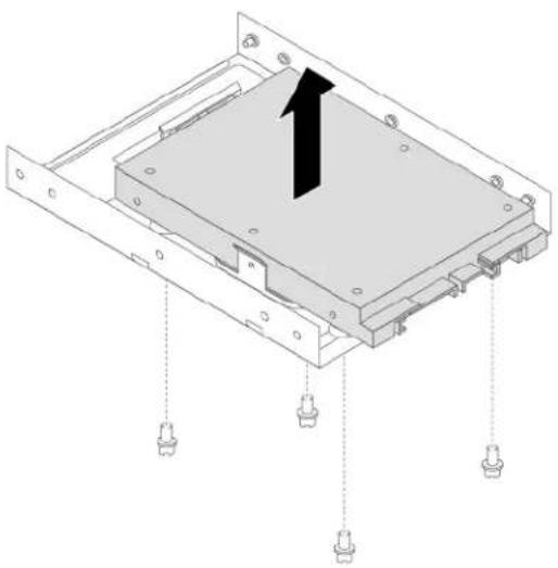
natural_image
Technical diagram of a mechanical assembly with mounting holes and a central component, no visible text or symbolsFigure 75. Removing the 2.5-inch storage drive from the storage-drive converter
- To install a new 2.5-inch storage drive, do the following:
a. Slide the 3.5-inch storage-drive bracket out of the rear of the enclosure.
b. Flex the sides of the bracket to remove the storage-drive converter from the bracket.
c. Install a new 2.5-inch storage drive into the storage-drive converter. Then install the four screws to secure the new storage drive to the storage-drive converter.
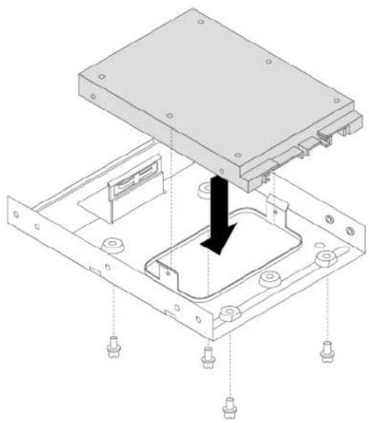
natural_image
Technical diagram of a mechanical assembly with a central component and mounting holes (no text or symbols)Figure 76. Installing the new solid-state drive into the storage converter
d. To install the storage-drive converter into the 3.5-inch storage-drive bracket, flex the bracket and align pin 1, pin 2, pin 3, and pin 4 on the bracket with the corresponding holes in the storage converter.
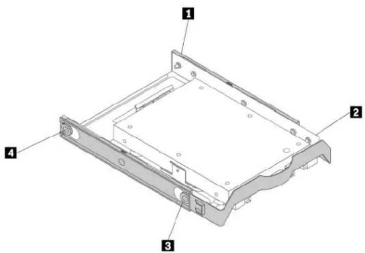
text_image
Technical diagram of a mechanical device with numbered components labeled 1, 2, 3, and 4.Figure 77. Installing the storage converter together with the solid-state drive into the storage drive bracket
e. Install the storage converter with the bracket into the enclosure from the rear until the drive snaps into position.
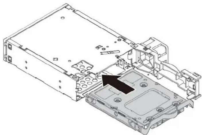
natural_image
Technical line drawing of an electronic device chassis showing internal components and a black arrow indicating a specific part (no text or symbols present)Figure 78. Installing the storage converter with the bracket into the enclosure
- Pivot the rear cover of the enclosure inward until you hear a click. The rear cover is secured in place.
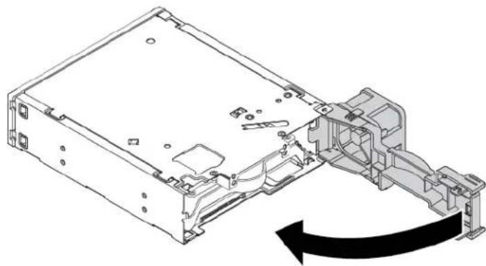
natural_image
Technical line drawing of an electronic device chassis with a black arrow indicating motion direction (no text or symbols present)Figure 79. Pivoting the rear cover inward
- Connect the signal cable and the power cable to the storage drive.
What to do next:
- To work with another piece of hardware, go to the appropriate section.
- To complete the installation or replacement, go to "Completing the parts replacement" on page 121.
Coin-cell battery
Attention: Do not open your computer or attempt any repair before reading and understanding the “Read this first: Important safety information” on page iii.
Your computer has a special type of memory that maintains the date, time, and settings for built-in features, such as parallel-connector assignments (configuration). A battery keeps this information active when you turn off the computer.
The battery normally requires no charging or maintenance throughout its life; however, no battery lasts forever. If the battery fails, the date and time information is lost.
Refer to the “Lithium coin cell battery notice” in the Safety and Warranty Guide for information about replacing and disposing of the battery.
To replace the coin-cell battery, do the following:
- Prepare your computer. See "Preparing your computer" on page 56.
- Locate the battery. See "Parts on the system board" on page 7.
- Remove any parts that might impede your access to the battery. Depending on your computer model, you might need to remove the PCI card for easier access to the battery. See "PCIe card" on page 62 or "Full-length PCIe card" on page 65.
- Remove the old battery.
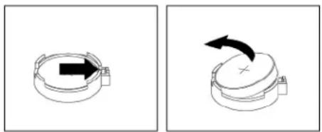
natural_image
Two technical diagrams showing a mechanical component before and after rotation, with no visible text or symbols.Figure 80. Removing the battery
- Install a new battery.
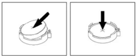
natural_image
Two identical diagrams showing a circular object with a downward arrow, no text or symbols present.Figure 81. Installing a battery
- Reinstall the PCI card if you have removed it. See "PCIe card" on page 62 or "Full-length PCIe card" on page 65.
- Reinstall the computer cover and connect the cables. See “Completing the parts replacement” on page 121.
Note: When the computer is turned on for the first time after replacing the battery, an error message might be displayed. This is normal after replacing the battery.
- Turn on the computer and all attached devices.
- Use the Setup Utility program to set the date and time. See "Using the Setup Utility program" on page 35.
What to do next:
- To work with another piece of hardware, go to the appropriate section.
- To complete the installation or replacement, go to "Completing the parts replacement" on page 121.
Cover presence switch
Attention: Do not open your computer or attempt any repair before reading and understanding the “Read this first: Important safety information” on page iii.
To remove or install the cover presence switch, do the following:
- Prepare your computer. See "Preparing your computer" on page 56.
- Locate the cover presence switch. See "Computer components" on page 5.
- To remove the cover presence switch, do the following:
a. Disconnect the cover presence switch cable from the cover presence switch connector on the system board. See "Parts on the system board" on page 7.
b. Remove the screw that secures the cover presence switch and remove the cover presence switch from the chassis.
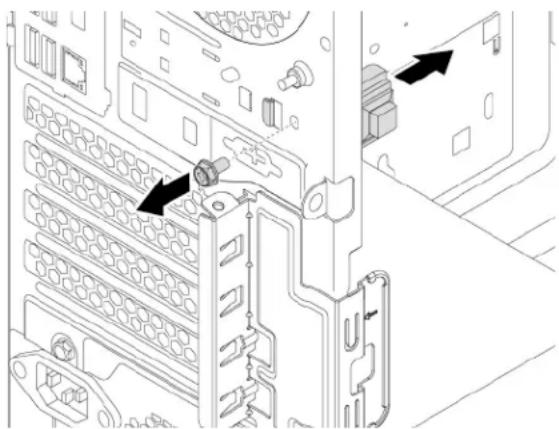
natural_image
Technical diagram of a server rack with labeled ports and connectors (no text or symbols present)Figure 82. Removing the cover presence switch
- To install the cover presence switch, do the following:
a. Align the screw hole in the cover presence switch with the corresponding hole in the chassis. Then install the screw to secure the cover presence switch to the chassis.
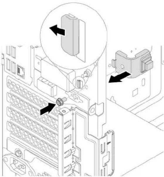
natural_image
Technical diagram of an electronic device showing internal components and directional arrows (no text or symbols)Figure 83. Installing the cover presence switch
b. Connect the cover presence switch cable to the cover presence switch connector on the system board. See "Parts on the system board" on page 7.
What to do next:
• To work with another piece of hardware, go to the appropriate section.
- To complete the installation or replacement, go to "Completing the parts replacement" on page 121.
Power supply assembly
Attention: Do not open your computer or attempt any repair before reading and understanding the “Read this first: Important safety information” on page iii.
Although there are no moving parts in your computer after the power cord has been disconnected, the following warnings are required for your safety.
CAUTION:

Keep fingers and other parts of your body away from hazardous, moving parts. If you suffer an injury, seek medical care immediately.

DANGER

Disconnect all power cords from electrical outlets before removing the computer cover or any part that has the above label attached.
DO NOT disassemble components that have the above label attached. There are no serviceable parts inside these components.
Your product is designed for safe use. However, hazardous voltage, current, and energy levels are present inside any component that has this label attached. Disassembling of these components might cause fire or might even result in death. If you suspect a problem with one of these parts, contact a service technician.
To remove and install the power supply assembly, do the following:
- Prepare your computer. See "Preparing your computer" on page 56.
- To remove the power supply assembly, do the following:
a. Disconnect the power supply assembly cables from the system board and all drives. See “Parts on the system board” on page 7.
b. Release the power supply assembly cables from the cable clips and ties.
c. Remove the four screws at the rear of the chassis that secure the power supply assembly. Then slide the power supply assembly to the front of the computer and then lift it out of the chassis.
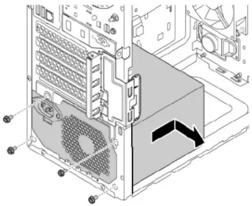
natural_image
Technical diagram of a computer tower internal structure showing fan, drive, and ventilation components (no text or labels)Figure 84. Removing the power supply assembly
- To install the power supply assembly, do the following:
a. Ensure that the new power supply assembly is the correct replacement.
b. Install the new power supply assembly into the chassis so that the screw holes in the power supply assembly align with those in the chassis.
c. Install and tighten the four screws to secure the power supply assembly.
Note: Use only screws provided by Lenovo.
d. Connect the power supply assembly cables to the system board and each of the drives.
e. Secure the power supply assembly cables with the cable clips and ties in the chassis.
What to do next:
- To work with another piece of hardware, go to the appropriate section.
- To complete the installation or replacement, go to "Completing the parts replacement" on page 121.
Storage drive in the storage-drive bay
Attention: Do not open your computer or attempt any repair before reading and understanding the “Read this first: Important safety information” on page iii.
Your computer comes with a storage-drive bay for installing or replacing a 3.5-inch storage drive or a 2.5-inch storage drive.
3.5-inch storage drive
To replace the 3.5-inch storage drive, do the following:
- Prepare your computer. See "Preparing your computer" on page 56.
- Locate the storage-drive bay. See "Computer components" on page 5.
- To remove the 3.5-inch storage drive, do the following:
a. Disconnect the signal cable and the power cable from the storage drive.
b. Push the tab of the plastic 3.5-inch storage-drive bracket as shown and pull the tab outward to remove the storage drive from the storage-drive bay.
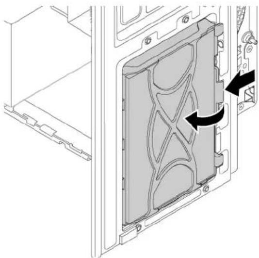
natural_image
Technical diagram of a mechanical component with internal structure and directional arrows indicating movement (no text or symbols)Figure 85. Removing the storage drive
c. Flex the sides of the bracket to remove the storage drive from the bracket.
- To install the 3.5-inch storage drive, do the following:
a. Pull the handle of the plastic 3.5-inch storage-drive bracket to remove it from the storage-drive bay.
b. To install a new storage drive into the bracket, flex the bracket and align pin 1, pin 2, pin 3, and pin 4 on the bracket with the corresponding holes in the storage drive. Do not touch the circuit board 5 on the storage drive.
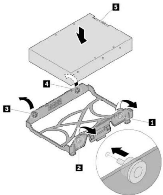
text_image
Technical diagram of a mechanical assembly with numbered components and directional arrows indicating motion or movement.Figure 86. Installing the storage drive into the bracket
c. Align the three plastic tabs on the left side of the storage drive with the corresponding holes in the drive bay assembly. Then pivot the storage drive inward until it snaps into position.
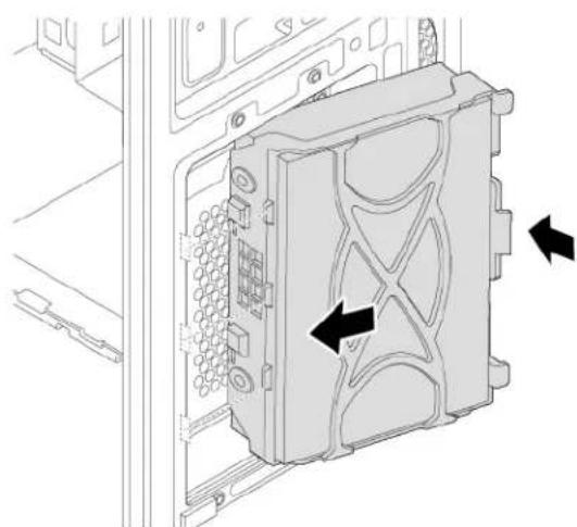
natural_image
Technical diagram of a computer drive housing with labeled components and directional arrows indicating movement (no text or symbols present)Figure 87. Installing the storage-drive
d. Connect the signal cable and the power cable to the new storage drive.
What to do next:
- To work with another piece of hardware, go to the appropriate section.
- To complete the installation or replacement, go to "Completing the parts replacement" on page 121.
2.5-inch storage drive
To replace the 2.5-inch storage drive, do the following:
- Prepare your computer. See "Preparing your computer" on page 56.
-
Locate the storage-drive bay. See "Computer components" on page 5.
-
To remove the 2.5-inch storage drive, do the following:
a. Disconnect the signal cable and the power cable from the storage drive.
b. Push the tab of the storage-drive bracket as shown and pull the tab outward to remove the storage drive from the storage-drive bay.
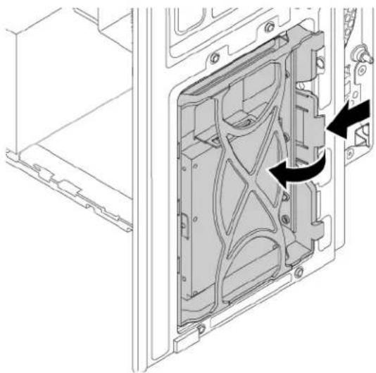
natural_image
Technical diagram of a mechanical assembly with internal components and directional arrows indicating movement (no text or symbols)Figure 88. Removing the 2.5-inch storage drive with 3.5-inch storage-drive bracket
c. Flex the sides of the bracket to remove the storage-drive converter from the 3.5-inch storage-drive bracket.
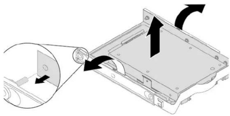
natural_image
Diagram of a computer monitor with an open rear panel and directional arrows indicating motion (no text or symbols)Figure 89. Removing the storage-drive converter from the 3.5-inch storage-drive bracket
d. Remove the four screws that secure the 2.5-inch storage drive. Then lift the storage drive out of the storage-drive converter.
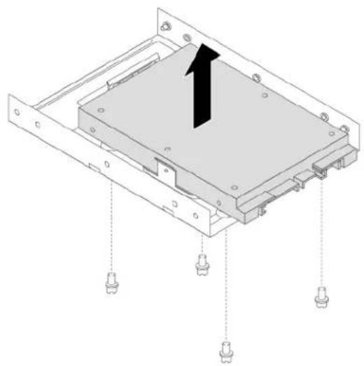
natural_image
Technical diagram of a computer chassis with mounting holes and a black arrow indicating a component (no text or symbols present)Figure 90. Removing the 2.5-inch storage drive from the storage-drive converter
- To install the 2.5-inch storage drive, do the following:
a. Pull the handle of the plastic 3.5-inch storage-drive bracket to remove it from the storage-drive bay.
b. Install a new 2.5-inch storage drive into the storage-drive converter. Then install the four screws to secure the new storage drive to the storage-drive converter.
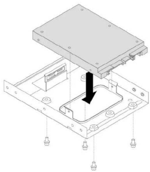
natural_image
Technical diagram of a mechanical assembly with a central component and mounting holes (no text or symbols)Figure 91. Installing the new 2.5-inch storage drive into the storage-drive converter
c. To install a new 2.5-inch storage drive into the bracket, flex the bracket and align pin 1, pin 2, pin 3, and pin 4 on the bracket with the corresponding holes in the storage drive. Do not touch the circuit board 5 on the storage drive.
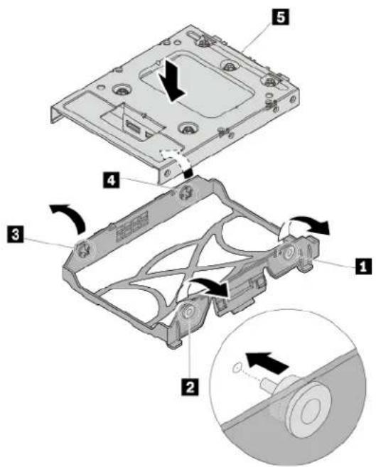
text_image
Technical diagram of a hard disk drive assembly with numbered components and directional arrows indicating motionFigure 92. Installing the 2.5-inch storage drive with the storage-drive converter into the bracket
d. Align the three plastic tabs on the left side of the storage drive with the corresponding holes in the drive bay assembly. Then pivot the storage drive inward until it snaps into position.
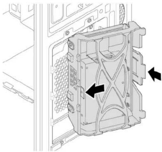
natural_image
Technical line drawing of a mechanical housing component with arrows indicating movement or force (no text or symbols present)Figure 93. Installing the 2.5-inch storage drive
e. Connect the signal cable and the power cable to the new storage drive.
What to do next:
- To work with another piece of hardware, go to the appropriate section.
- To complete the installation or replacement, go to "Completing the parts replacement" on page 121.
Type-1 storage-drive cage
Attention: Do not open your computer or attempt any repair before reading and understanding the “Read this first: Important safety information” on page iii.
Some computer models come with a type-1 storage-drive cage for installing or replacing a 3.5-inch storage drive or a 2.5-inch storage drive.
3.5-inch storage drive
To remove or install a 3.5-inch storage drive in the type-1 storage-drive cage, do the following:
- Prepare your computer. See "Preparing your computer" on page 56.
-
Locate the type-1 storage-drive cage. See "Computer components" on page 5.
-
To remove a 3.5-inch storage drive in the type-1 storage-drive cage, do the following:
a. Disconnect the signal cable and the power cable from the storage drive.
b. Remove the screw and slide the type-1 storage-drive cage downward to release it from the drive bay assembly.
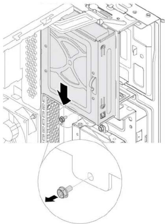
natural_image
Technical diagram of a computer tower internal structure with an inset showing a bolt inserted into a housing (no text or labels present)Figure 94. Removing the type-1 storage-drive cage
c. Pull the handle of the plastic 3.5-inch storage-drive bracket to remove the storage drive from the type-1 storage-drive cage.
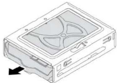
natural_image
Diagram of a computer drive casing with visible internal blades and mounting holes (no text or labels)Figure 95. Removing the 3.5-inch storage drive
d. Flex the sides of the bracket to remove the storage drive from the bracket.
- To install a 3.5-inch storage drive in the type-1 storage-drive cage, do the following:
a. To install a new storage drive into the bracket, flex the bracket and align pin 1, pin 2, pin 3, and pin 4 on the bracket with the corresponding holes in the storage drive. Do not touch the circuit board 5 on the storage drive.
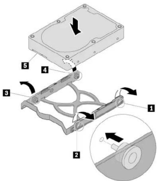
text_image
Technical diagram of a hard disk drive assembly with numbered components and directional arrows indicating motionFigure 96. Installing the storage drive into the bracket
b. Slide the new storage drive into the type-1 storage-drive cage until it snaps into position.
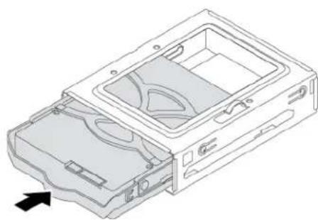
natural_image
Technical line drawing of a mechanical device casing with internal compartments and an arrow indicating direction (no text or symbols)Figure 97. Installing the storage drive
c. Align the four holes in the rear of the type-1 storage-drive cage with the corresponding hooks in the drive bay assembly. Then slide the type-1 storage-drive cage upward until it snaps into position. Reinstall the screw to secure the type-1 storage-drive cage.
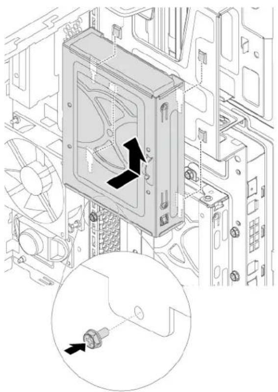
natural_image
Technical diagram of a computer drive assembly showing fan, drive casing, and internal components (no text or labels)Figure 98. Installing the type-1 storage-drive cage
d. Connect the signal cable and the power cable to the new storage drive.
What to do next:
- To work with another piece of hardware, go to the appropriate section.
- To complete the installation or replacement, go to "Completing the parts replacement" on page 121.
2.5-inch storage drive
To remove or install a 2.5-inch storage drive with a 2.5-inch to 3.5-inch storage-drive converter (hereafter referred to as storage-drive converter), do the following:
- Prepare your computer. See "Preparing your computer" on page 56.
- Locate the type-1 storage-drive cage. See "Computer components" on page 5.
- To remove a 2.5-inch storage drive with a storage-drive converter in the type-1 storage-drive cage, do the following:
a. Disconnect the signal cable and the power cable from the storage drive.
b. Remove the screw and slide the type-1 storage-drive cage downward to release it from the drive bay assembly.
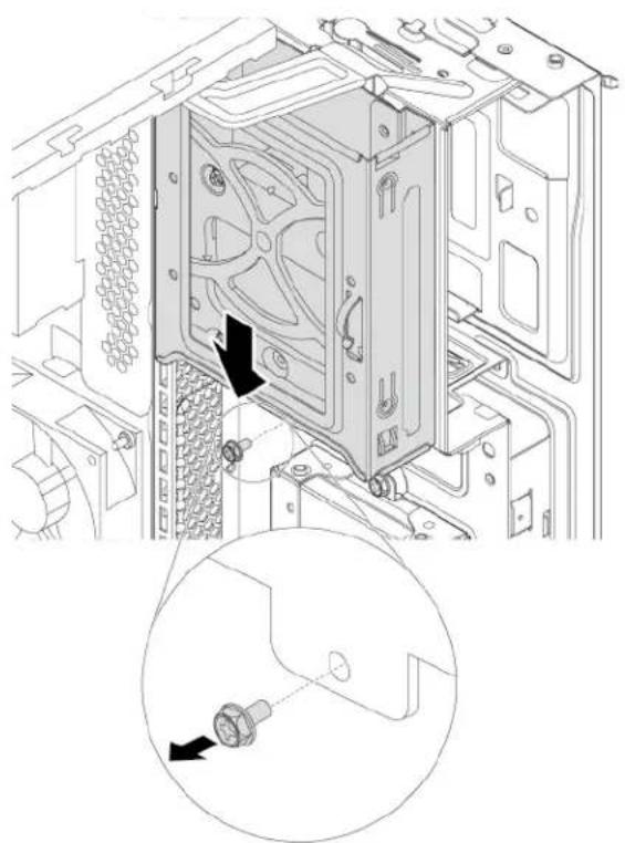
natural_image
Technical diagram of a computer tower internal structure showing drive and socket components, with an inset close-up highlighting the connector (no text or symbols present)Figure 99. Removing the type-1 storage-drive cage
c. Pull the handle of the storage-drive bracket to remove the storage drive from the type-1 storage-drive cage.
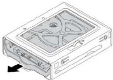
natural_image
Diagram of a computer drive showing internal components and a directional arrow (no text or symbols)Figure 100. Removing the 2.5-inch storage drive
d. Flex the sides of the bracket to remove the storage-drive converter from the bracket.
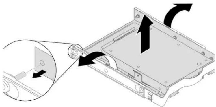
natural_image
Diagram of a computer monitor with an open rear panel and directional arrows indicating motion (no text or symbols)Figure 101. Removing the storage-drive converter from the storage-drive bracket
e. Remove the four screws that secure the 2.5-inch storage drive. Then lift the storage drive out of the storage-drive converter.
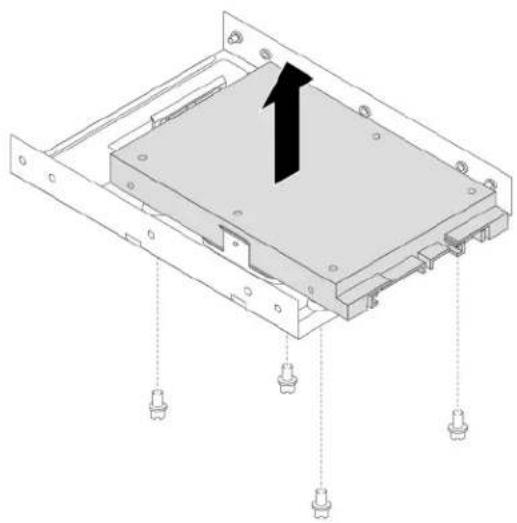
natural_image
Technical diagram of a computer chassis with mounting holes and a highlighted component (no text or symbols)Figure 102. Removing the 2.5-inch storage drive from the storage-drive converter
- To install a new 2.5-inch storage drive in the type-1 storage-drive cage, do the following:
a. Install the 2.5-inch storage drive with a storage-drive converter into the storage-drive converter. Then install the four screws to secure the new storage drive to the storage-drive converter.
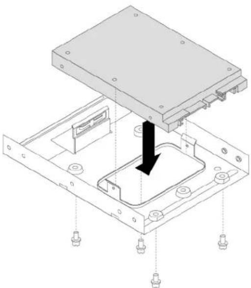
natural_image
Technical diagram of a mechanical assembly with a central component and mounting holes (no text or symbols)Figure 103. Installing the 2.5-inch storage drive into the storage-drive converter
b. To install a new storage drive into the bracket, flex the bracket and align pin 1, pin 2, pin 3, and pin 4 on the bracket with the corresponding holes in the storage drive. Do not touch the circuit board 5 on the storage drive.
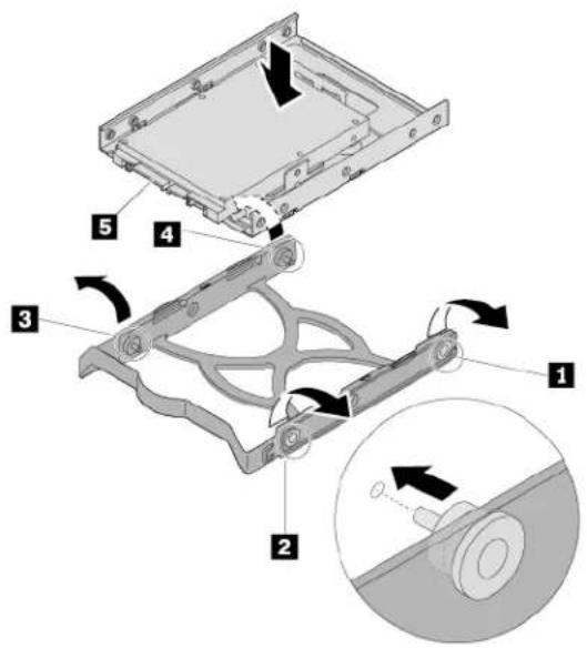
text_image
Technical diagram of a mechanical assembly with numbered components and directional arrows indicating motion or assembly steps.Figure 104. Installing the 2.5-inch storage drive into the bracket
c. Slide the new storage drive with the storage-drive converter into the type-1 storage-drive cage until it snaps into position.
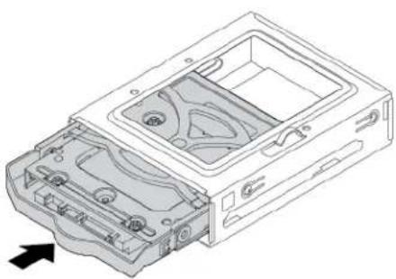
natural_image
Technical line drawing of an open computer case with internal components and a directional arrow (no text or symbols)Figure 105. Installing the 2.5-inch storage drive into the type-1 storage-drive cage
d. Align the four holes in the rear of the type-1 storage-drive cage with the corresponding hooks in the drive bay assembly. Then slide the type-1 storage-drive cage upward until it snaps into position. Reinstall the screw to secure the type-1 storage-drive cage.
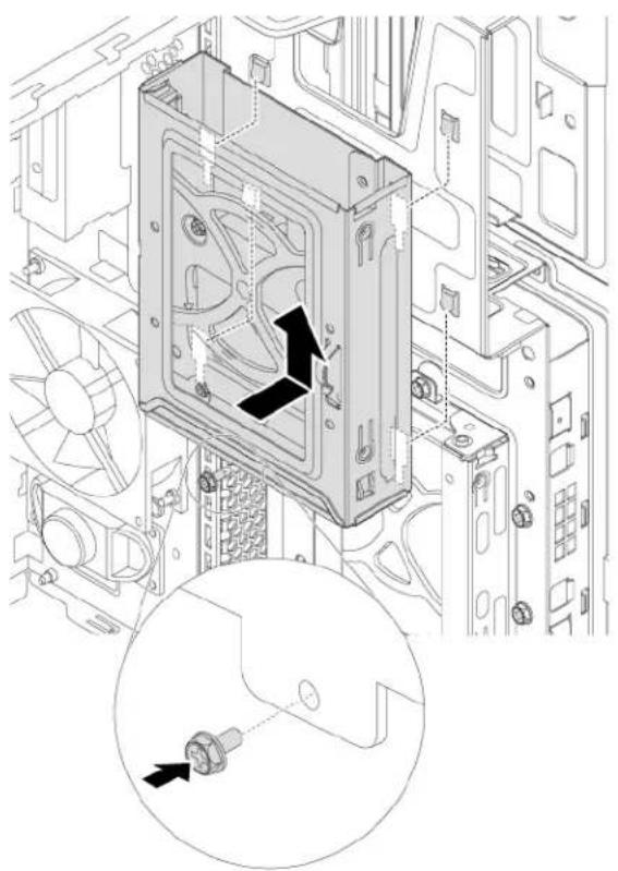
natural_image
Technical line drawing of a computer case with fan and drive components, showing internal components and a magnified inset (no text or symbols)Figure 106. Installing the type-1 storage-drive cage
e. Connect the signal cable and the power cable to the new storage drive.
What to do next:
• To work with another piece of hardware, go to the appropriate section.
- To complete the installation or replacement, go to "Completing the parts replacement" on page 121.
Type-2 storage-drive cage
Attention: Do not open your computer or attempt any repair before reading and understanding the “Read this first: Important safety information” on page iii.
Some computer models come with a type-2 storage-drive cage for installing or replacing a 2.5-inch storage drive.
To replace the 2.5-inch storage drive, do the following:
- Prepare your computer. See "Preparing your computer" on page 56.
- Locate the type-2 storage-drive cage. See "Computer components" on page 5.
- To remove a 2.5-inch storage drive from the type-2 storage-drive cage, do the following:
a. Disconnect the signal cable and the power cable from the 2.5-inch storage drive.
b. Remove the screw and slide the type-2 storage-drive cage downward to release it from the drive bay assembly.

natural_image
Technical diagram of an electronic device showing internal components and mounting brackets (no text or symbols)Figure 107. Removing the type-2 storage-drive cage
c. Pull the handle of the plastic 2.5-inch storage-drive bracket to remove it from the type-2 storage-drive cage.
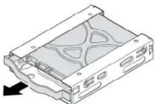
natural_image
Technical line drawing of a mechanical housing or enclosure with internal compartments and mounting holes (no text or symbols)Figure 108. Removing the 2.5-inch storage drive
d. Flex the sides of the bracket to remove the storage drive from the bracket.
- To install a new 2.5-inch storage drive into the type-2 storage-drive cage, do the following:
a. To install a new 2.5-inch storage drive into the bracket, flex the bracket and align pin 1, pin 2, pin 3, and pin 4 on the bracket with the corresponding holes in the storage drive. Do not touch the circuit board 5 on the storage drive.
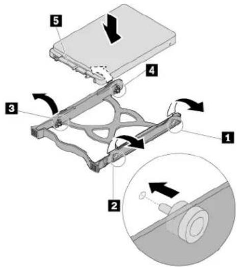
text_image
Technical diagram showing a mechanical assembly with numbered components and directional arrows indicating motion or force.Figure 109. Installing the 2.5-inch storage drive into the bracket
b. Slide the new storage drive into the type-2 storage-drive cage until it snaps into position.
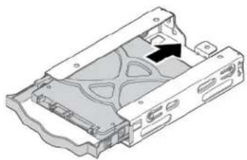
natural_image
3D diagram of a computer case with internal components and a black arrow indicating a specific area (no text or symbols present)Figure 110. Installing the 2.5-inch storage drive into the type-2 storage-drive cage
c. Align the four holes in the rear of the type-2 storage-drive cage with the corresponding hooks in the drive bay assembly. Then slide the type-2 storage-drive cage upward until it snaps into position. Reinstall the screw to secure the type-2 storage-drive cage.
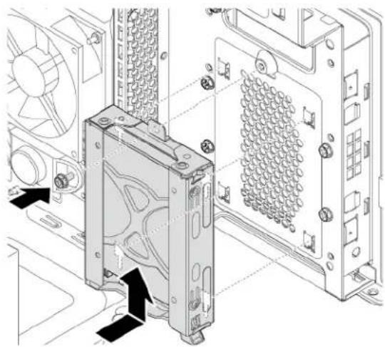
natural_image
Technical diagram of a computer tower with labeled components and directional arrows indicating assembly or movement (no text or symbols present)Figure 111. Installing the type-2 storage-drive cage
d. Connect the signal cable and the power cable to the new storage drive.
What to do next:
• To work with another piece of hardware, go to the appropriate section.
• To complete the installation or replacement, go to "Completing the parts replacement" on page 121.
Heat-sink-and-fan assembly
Attention: Do not open your computer or attempt any repair before reading and understanding the "Read this first: Important safety information" on page iii.
CAUTION:

Avoid contact with hot components inside the computer. During operation, some components become hot enough to burn the skin. Before you open the computer cover, turn off the computer, disconnect power, and wait approximately 10 minutes for the components to cool.
To remove or install the heat-sink-and-fan assembly, do the following:
- Prepare your computer. See "Preparing your computer" on page 56.
- Lay the computer on its side for easier access to the system board.
- To remove the heat-sink-and-fan assembly, do the following:
a. Disconnect the heat-sink-and-fan assembly cable from the microprocessor fan connector on the system board. See "Parts on the system board" on page 7.
b. Follow the following sequence to loosen the four screws that secure the heat-sink-and-fan assembly to the system board:
- Partially loosen screw 1, fully loosen screw 2, and then fully loosen screw 1.
- Partially loosen screw 3, fully loosen screw 4, and then fully loosen screw 3.
Note: Carefully loosen the four screws to avoid any possible damage to the system board. The four screws cannot be removed from the heat-sink-and-fan assembly.
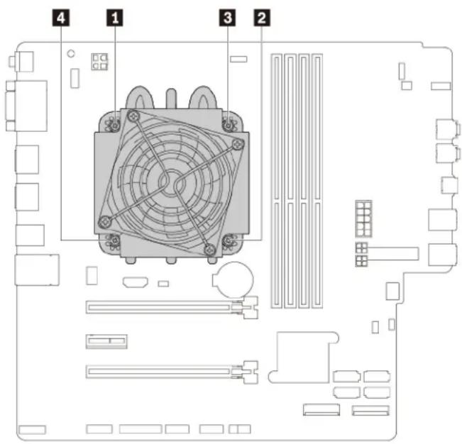
text_image
Diagram of a computer motherboard with labeled components including CPU socket, fan, and drive slotsFigure 112. Removing the heat-sink-and-fan assembly
c. Lift the failing heat-sink-and-fan assembly off the system board.
Notes:
- You might have to gently twist the heat-sink-and-fan assembly to free it from the microprocessor.
-
Do not touch the thermal grease while handling the heat-sink-and-fan assembly.
-
To install the heat-sink-and-fan assembly, do the following:
a. Apply appropriate amount of thermal grease to the new heat-sink-and-fan assembly.
b. Position the heat-sink-and-fan assembly on the system board. Ensure that the four screws are aligned with the holes in the system board.
Note: Ensure that the heat-sink-and-fan assembly cable is toward the microprocessor fan connector on the system board.
c. Follow the following sequence to tighten the four screws to secure the new heat-sink-and-fan assembly. Do not over-tighten the screws.
- Partially tighten screw 1, fully tighten screw 2, and then fully tighten screw 1.
- Partially tighten screw 3, fully tighten screw 4, and then fully tighten screw 3.
d. Connect the heat-sink-and-fan assembly cable to the microprocessor fan connector on the system board. See "Parts on the system board" on page 7.
What to do next:
- To work with another piece of hardware, go to the appropriate section.
- To complete the installation or replacement, go to "Completing the parts replacement" on page 121.
Completing the parts replacement
CAUTION:

After replacing a CRU, reinstall all protective covers, including the computer cover, before connecting power and operating the computer. This action is important to help prevent unexpected electrical shock and help ensure the containment of an unexpected fire that could happen under extremely rare conditions.
After completing the installation or replacement for all parts, pivot the drive bay assembly inward, reinstall the front bezel, reinstall the computer cover, and reconnect cables. Depending on the parts you installed or replaced, you might need to confirm the updated information in the Setup Utility program. Refer to “Using the Setup Utility program” on page 35.
To complete the parts replacement, do the following:
- Ensure that all components have been reassembled correctly and that no tools or loose screws are left inside your computer. See "Computer components" on page 5 for the locations of various components in your computer.
- Ensure that the cables are routed correctly before reinstalling the computer cover. Keep cables clear of the hinges and sides of the computer chassis to avoid interference with reinstalling the computer cover.
- Press the release tab as shown and pivot the drive bay assembly inward until it snaps into position.
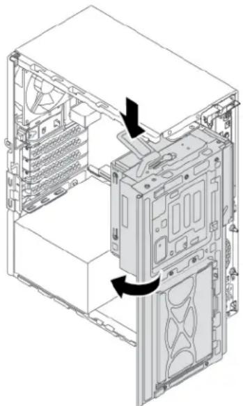
natural_image
Isometric technical diagram of a computer tower internal structure showing drive and ventilation components (no text or labels)Figure 113. Pivoting the drive bay assembly downward
- To reinstall the front bezel, first align the three plastic tabs on the front bezel with the corresponding holes in the chassis. Then pivot the front bezel inward until it snaps into position.
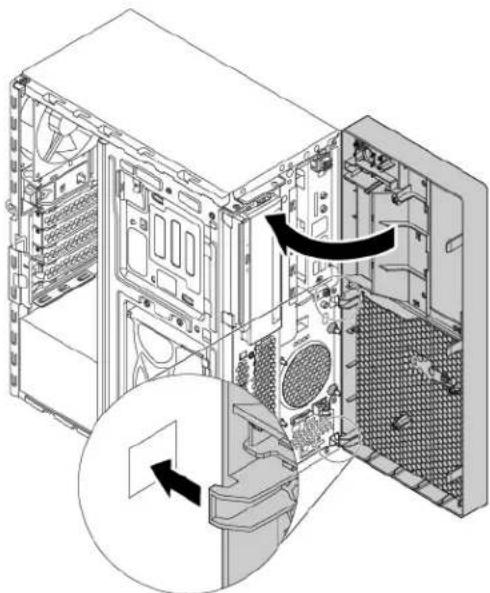
natural_image
Technical diagram of an internal computer tower showing internal components and a magnified view of the interior (no text or labels)Figure 114. Reinstalling the front bezel
- Position the computer cover on the chassis so that the rail guides on the bottom of the computer cover engage the rails on the chassis. Then, push the cover to the front of the computer until it snaps into position. Install the screws to secure the computer cover.
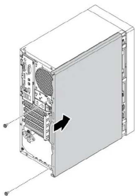
natural_image
Technical line drawing of a computer tower case showing internal components and a black arrow indicating a specific portion (no text or labels present)Figure 115. Reinstalling the computer cover
- Reinstall the dust shield if you have removed it.
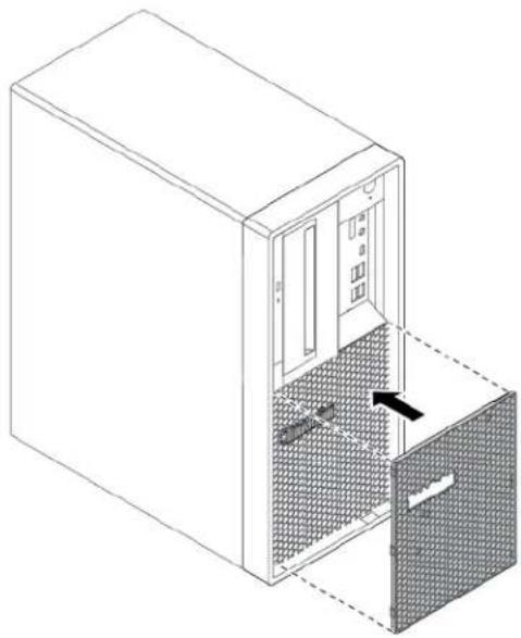
natural_image
Isometric line drawing of a server cabinet with an open door and mesh interior (no text or symbols)Figure 116. Reinstalling the dust shield
- If there is any locking device available, lock the computer cover. See "Locking the computer cover" on page 29.
- Reconnect the external cables and power cords to the corresponding connectors on the computer. See "Hardware locations" on page 1.
- Update the configuration of your computer if necessary. See "Using the Setup Utility program" on page 35.
- If a newly installed hardware component does not work correctly, update the device driver. See "Keeping your computer current" on page 24.
Chapter 8. Getting information, help, and service
This chapter provides information about getting help and support from Lenovo.
Information resources
You can use the information in this section to access useful resources relating to your computing needs.
Accessing the user guide in various languages
To access the user guide in various languages, go to: https://support.lenovo.com
Windows help system
The Windows help system provides you with detailed information about using the Windows operating system.
Note: Using the help for Windows 10 requires an active Internet connection.
To access the Windows help system, do the following:
- Click the Start button to open the Start menu.
- Click Get Help.
Safety and warranty
The Safety and Warranty Guide provided with your computer contains important safety information, product warranty terms, and legal notices. Ensure that you read and understand all safety information in the Safety and Warranty Guide before using your computer.
In addition, read and understand "Read this first: Important safety information" on page iii before using your computer. This preface provides additional safety information that applies to topics and tasks described in this User Guide.
Lenovo Web site
The Lenovo Web site (https://www.lenovo.com) provides up-to-date information and services to help you buy, upgrade, and maintain your computer. You also can do the following:
- Shop for desktop and notebook computers, monitors, projectors, upgrades, and accessories for your computer, and special offers.
- Purchase additional services, such as support for hardware, operating systems, programs, network setup and configuration, and custom installations.
• Purchase upgrades and extended hardware repair services. - Access troubleshooting and support information for your computer model and other supported products.
• Find a Service Provider located near you.
Lenovo Support Web site
Technical support information is available on the Lenovo Support Web site at: https://support.lenovo.com
This Web site is updated with the latest support information such as the following:
- Drivers and software
• Diagnostic solutions
• Product and service warranty
• Product and parts details - User guides and manuals
- Knowledge base and frequently asked questions
• Lenovo Support phone numbers
Help and service
This section provides information about obtaining help and service.
Calling for service
During the warranty period, you can get help and information by telephone through the Customer Support Center. For the warranty period of your computer, go to https://www.lenovo.com/warranty-status. For a list of Lenovo Support phone numbers, go to https://pcsupport.lenovo.com/supportphonelist.
Note: Phone numbers are subject to change without notice. If the number for your country or region is not provided, contact your Lenovo reseller or Lenovo marketing representative.
The following services are available during the warranty period:
- Problem determination - Trained service personnel are available to assist you with determining a hardware problem and deciding what action is necessary to fix the problem.
- Hardware repair - If the problem is caused by hardware under warranty, trained service personnel are available to provide the applicable level of service.
- Engineering Change management - There might be changes that are required after a product has been sold. Lenovo or your reseller will make selected Engineering Changes (ECs) that apply to your hardware available.
These items are not covered by the warranty:
- Replacement or use of parts not manufactured for or by Lenovo or non-warranted Lenovo parts
- Identification of software problem sources
- Configuration of BIOS as part of an installation or upgrade
• Changes, modifications, or upgrades to device drivers
• Installation and maintenance of network operating systems (NOS)
• Installation and maintenance of programs
If possible, be at your computer when you call. Have the following information available:
• Machine type and model
- Serial numbers of your hardware products
• Description of the problem
- Exact wording of any error messages
- Hardware and software configuration information
Using other services
You might travel with your computer or relocate it to a country or region where the machine type for your desktop or notebook computer is sold. In such a situation, your computer might be eligible for International
Warranty Service, which automatically entitles you to obtain warranty service throughout the warranty period. Service will be performed by service providers authorized to perform warranty service.
Service methods and procedures vary by country, and some services might not be available in all countries. International Warranty Service is delivered through the method of service (such as depot, carry-in, or on-site service) that is provided in the servicing country. Service centers in certain countries might not be able to service all models of a particular machine type. In some countries, fees and restrictions might apply at the time of service.
To determine whether your computer is eligible for International Warranty Service and to view a list of the countries or regions where service is available, go to https://support.lenovo.com.
For technical assistance with the installation of or questions related to Service Packs for your preinstalled Microsoft Windows product, go to https://support.microsoft.com. You also can contact the Lenovo Customer Support Center for help. Some fees might apply.
Purchasing additional services
During and after the warranty period, you can purchase additional services. Examples of these additional services include:
- Support for hardware, operating systems, and programs
• Network setup and configuration services - Upgraded or extended hardware repair services
- Custom installation services
Service availability and service name might vary by country or region. For more information about these services, go to the Lenovo Web site at: https://www.lenovo.com
Appendix A. System memory speed
The Intel Xeon ^® microprocessor families compatible with this ThinkStation computer feature an integrated memory controller. The memory controller provides the microprocessor with direct access to the system memory. Therefore, the system memory speed will be determined by the memory module type, frequency, size (capacity), the number of memory modules installed, and the microprocessor model.
Notes:
- The actual system memory speed of the memory modules varies depending on the microprocessor model. For example, your computer comes with 2666 MT/s memory modules, but the microprocessor only supports up to 2400 MT/s memory modules. Then the system memory speed will be no faster than 2400 MT/s.
- The microprocessor models supported in your computer might vary. For a list of supported microprocessor models, contact the Lenovo Customer Support Center.
- The ECC memory modules are not supported on the computer models with Intel Core i5 or i7 microprocessors.
Refer to the following information about the system memory speed:
• Memory module types:
- DDR4 ECC UDIMMs
- DDR4 non-ECC UDIMMs
• Memory module operating voltage: 1.2 V
• Memory module frequency: 2666 MT/s
- Microprocessor models:
- Intel Xeon: E-2186G, E-2176G, E-2174G, E-2146G, E-2144G, E-2136, E-2134, E-2126G, E-2124G, E-2124, and E-2104G
- Intel Core: i7-8700K, i7-8700, i5-8600, i5-8500, i5-8400, i3-8300, and i3-8100
- Intel Pentium: G5400
Appendix B. Supplemental information about the Ubuntu operating system
In limited countries or regions, Lenovo offers customers an option to order computers with the preinstalled Ubuntu® operating system.
If the Ubuntu operating system is available on your computer, read the following information before you use the computer. Ignore any information related to Windows-based programs, utilities, and Lenovo preinstalled applications in this documentation.
Access the Lenovo Limited Warranty
This product is covered by the terms of the Lenovo Limited Warranty (LLW), version L505-0010-02 08/2011. You can view the LLW in a number of languages from the following Web site. Read the Lenovo Limited Warranty at: https://www.lenovo.com/warranty/llw_02
The LLW also is preinstalled on the computer. To access the LLW, go to the following directory:
/usr/share/doc/lenovo-doc
If you cannot view the LLW either from the Web site or from your computer, contact your local Lenovo office or reseller to obtain a printed version of the LLW.
Access the Ubuntu help system
The Ubuntu help system provides information about how to use the Ubuntu operating system. To access the help system from Home Screen, move your pointer to the Launch bar, and then click the Help icon. If you cannot find the Help icon from the Launch bar, click the Search icon on the bottom left, and type Help to search it.
To learn more about the Ubuntu operating system, go to: https://www.ubuntu.com
Get support information
If you need help, service, technical assistance, or more information about the Ubuntu operating system or other applications, contact the provider of the Ubuntu operating system or the provider of the application. If you need the service and support for hardware components shipped with your computer, contact Lenovo. For more information about how to contact Lenovo, refer to the User Guide and Safety and Warranty Guide.
To access the latest User Guide and Safety and Warranty Guide, go to: https://support.lenovo.com
Appendix C. Regulatory and TCO Certified information of countries and regions
The latest compliance information is available at: https://www.lenovo.com/compliance
Export classification notice
This product is subject to the United States Export Administration Regulations (EAR) and has an Export Classification Control Number (ECCN) of 5A992.c. It can be re-exported except to any of the embargoed countries in the EAR E1 country list.
TCO Certified
Selected models are TCO Certified and bear the TCO Certified logo.
Note: TCO Certified is an international third-party sustainability certification for IT products. For details, go to https://www.lenovo.com/us/en/compliance/tco.
Taiwan precautionary vision statement
警語:使用過度恐傷害視力
注意事項:
Electronic emissions notices
Federal Communications Commission Declaration of Conformity
The following information refers to Lenovo personal computer machine types 30CY, 30D0, and 30D3.
This equipment has been tested and found to comply with the limits for a Class B digital device, pursuant to Part 15 of the FCC Rules. These limits are designed to provide reasonable protection against harmful interference in a residential installation. This equipment generates, uses, and can radiate radio frequency energy and, if not installed and used in accordance with the instructions, may cause harmful interference to radio communications. However, there is no guarantee that interference will not occur in a particular installation. If this equipment does cause harmful interference to radio or television reception, which can be determined by turning the equipment off and on, the user is encouraged to try to correct the interference by one or more of the following measures:
- Reorient or relocate the receiving antenna.
- Increase the separation between the equipment and receiver.
- Connect the equipment into an outlet on a circuit different from that to which the receiver is connected.
- Consult an authorized dealer or service representative for help.
Lenovo is not responsible for any radio or television interference caused by using other than recommended cables and connectors or by unauthorized changes or modifications to this equipment. Unauthorized changes or modifications could void the user's authority to operate the equipment.
This device complies with Part 15 of the FCC Rules. Operation is subject to the following two conditions: (1) this device may not cause harmful interference, and (2) this device must accept any interference received, including interference that may cause undesired operation.
Responsible Party:
Lenovo (United States) Incorporated
7001 Development Drive
Morrisville, NC 27560
Email: FCC@lenovo.com

Industry Canada compliance statement
CAN ICES-3(B)/NMB-3(B)
European Union conformity
EU Contact: Lenovo (Slovakia), Landererova 12, 811 09 Bratislava, Slovakia

EMC Directive Statement: This product is in conformity with the protection requirements of EU Council Directive 2014/30/EU on the approximation of the laws of the Member States relating to electromagnetic compatibility.
This product has been tested and found to comply with the limits for Class B equipment according to European Standards harmonized in the Directives in compliance. The Class B requirements for equipment are intended to offer adequate protection to broadcast services within residential environments.
Radio Equipment Directive Statement: This product is in conformity with all the requirements and essential norms that apply to EU Council Radio Equipment Directive 2014/53/EU on the approximation of the laws of the Member States relating to radio equipment. The full text of the system EU declaration of conformity and the EU wireless module declarations are available at the following Internet addresses: https://www.lenovo.com/eu-doc-workstations
Lenovo cannot accept responsibility for any failure to satisfy the protection requirements resulting from a non-recommended modification of the product, including the installation of option cards from other manufacturers.
German Class B compliance statement
Korean wireless-radio compliance information
Japan VCCI Class B compliance statement
Japan compliance statement for products which connect to the power mains with rated current less than or equal to 20 A per phase
Japan notice for ac power cord
The ac power cord shipped with your product can be used only for this specific product. Do not use the ac power cord for other devices.
Lenovo product service information for Taiwan
Keyboard and mouse compliance statement for Taiwan
Eurasian compliance mark
EAC
Brazil audio notice
Mexico wireless-radio compliance information
Additional regulatory information
For additional regulatory information, refer to the Regulatory Notice shipped with your computer. Depending on the configuration of your computer and the country or region where the computer was purchased, you might have received additional printed regulatory notices. All regulatory notices are available on the Lenovo Support Web site in electronic format. To access electronic copies of the documentation, go to https://support.lenovo.com.
Appendix D. WEEE and recycling information of countries and regions
Lenovo encourages owners of information technology (IT) equipment to responsibly recycle their equipment when it is no longer needed. Lenovo offers various programs and services to assist equipment owners in recycling their IT products. The latest environmental information is available at:
https://www.lenovo.com/ecodeclaration
Important WEEE information

natural_image
Symbol of a trash bin crossed with no text or labels, accompanied by a black rectangular block below (no readable text or symbols)The WEEE marking on Lenovo products applies to countries with WEEE and e-waste regulations (for example, the European WEEE Directive, India E-Waste Management Rules). Appliances are labeled in accordance with local regulations concerning waste electrical and electronic equipment (WEEE). These regulations determine the framework for the return and recycling of used appliances as applicable within each geography. This label is applied to various products to indicate that the product is not to be thrown away, but rather put in the established collection systems for reclaiming these end of life products.
Users of electrical and electronic equipment (EEE) with the WEEE marking must not dispose of end of life EEE as unsorted municipal waste, but use the collection framework available to them for the return, recycle, and recovery of WEEE and to minimize any potential effects of EEE on the environment and human health due to the presence of hazardous substances. Lenovo electrical and electronic equipment (EEE) may contain parts and components, which at end-of-life might qualify as hazardous waste.
EEE and waste electrical and electronic equipment (WEEE) can be delivered free of charge to the place of sale or any distributor that sells electrical and electronic equipment of the same nature and function as the used EEE or WEEE.
For additional WEEE information, go to: https://www.lenovo.com/recycling
WEEE information for Hungary
Lenovo, as a producer, bears the cost incurred in connection with the fulfillment of Lenovo's obligations under Hungary Law No. 197/2014 (VIII.1.) subsections (1)-(5) of section 12.
Recycling information for Japan
Collecting and recycling a disused Lenovo computer or monitor
If you are a company employee and need to dispose of a Lenovo computer or monitor that is the property of the company, you must do so in accordance with the Law for Promotion of Effective Utilization of Resources. Computers and monitors are categorized as industrial waste and should be properly disposed of by an
industrial waste disposal contractor certified by a local government. In accordance with the Law for Promotion of Effective Utilization of Resources, Lenovo Japan provides, through its PC Collecting and Recycling Services, for the collecting, reuse, and recycling of disused computers and monitors. For details, visit the Lenovo Web site at https://www.lenovo.com/recycling/japan. Pursuant to the Law for Promotion of Effective Utilization of Resources, the collecting and recycling of home-used computers and monitors by the manufacturer was begun on October 1, 2003. This service is provided free of charge for home-used computers sold after October 1, 2003. For details, visit the Lenovo Web site at https://www.lenovo.com/recycling/japan.
Disposing of Lenovo computer components
Some Lenovo computer products sold in Japan may have components that contain heavy metals or other environmental sensitive substances. To properly dispose of disused components, such as a printed circuit board or drive, use the methods described above for collecting and recycling a disused computer or monitor.
Disposing of disused lithium batteries from Lenovo computers
A button-shaped lithium battery is installed inside your Lenovo computer to provide power to the computer clock while the computer is off or disconnected from the main power source. If you need to replace it with a new one, contact your place of purchase or contact Lenovo for service. If you need to dispose of a disused lithium battery, insulate it with vinyl tape, contact your place of purchase or an industrial-waste-disposal operator, and follow their instructions. Disposal of a lithium battery must comply with local ordinances and regulations.
Recycling information for Brazil
Recycling information for mainland China
Battery recycling information for Taiwan

廢電池請回收
Battery recycling information for the European Union
text_image
EUNotice: This mark applies only to countries within the European Union (EU).
Batteries or packaging for batteries are labeled in accordance with European Directive 2006/66/EC concerning batteries and accumulators and waste batteries and accumulators. The Directive determines the framework for the return and recycling of used batteries and accumulators as applicable throughout the European Union. This label is applied to various batteries to indicate that the battery is not to be thrown away, but rather reclaimed upon end of life per this Directive.
In accordance with the European Directive 2006/66/EC, batteries and accumulators are labeled to indicate that they are to be collected separately and recycled at end of life. The label on the battery may also include a chemical symbol for the metal concerned in the battery (Pb for lead, Hg for mercury, and Cd for cadmium). Users of batteries and accumulators must not dispose of batteries and accumulators as unsorted municipal waste, but use the collection framework available to customers for the return, recycling, and treatment of batteries and accumulators. Customer participation is important to minimize any potential effects of batteries and accumulators on the environment and human health due to the potential presence of hazardous substances.
Before placing electrical and electronic equipment (EEE) in the waste collection stream or in waste collection facilities, the end user of equipment containing batteries and/or accumulators must remove those batteries and accumulators for separate collection.
Disposing of lithium batteries and battery packs from Lenovo products
A coin-cell type lithium battery might be installed inside your Lenovo product. You can find details about the battery in the product documentation. If the battery needs to be replaced, contact your place of purchase or contact Lenovo for service. If you need to dispose of a lithium battery, insulate it with vinyl tape, contact your place of purchase or a waste-disposal operator, and follow their instructions.
Disposing of battery packs from Lenovo products
Your Lenovo device might contain a lithium-ion battery pack or a nickel metal hydride battery pack. You can find details on the battery pack in the product documentation. If you need to dispose of a battery pack, insulate it with vinyl tape, contact Lenovo sales, service, or your place of purchase, or a waste-disposal operator, and follow their instructions. You also can refer to the instructions provided in the user guide for your product.
For proper collection and treatment, go to: https://www.lenovo.com/lenovo/environment
Appendix E. Restriction of Hazardous Substances (RoHS) Directive of countries and regions
The latest environmental information is available at: https://www.lenovo.com/ecodeclaration
European Union RoHS
This Lenovo product, with included parts (cables, cords, and so on) meets the requirements of Directive 2011/65/EU on the restriction of the use of certain hazardous substances in electrical and electronic equipment (“RoHS recast” or “RoHS 2”).
For more information about Lenovo worldwide compliance on RoHS, go to: https://www.lenovo.com/rohs-communication
Mainland China RoHS
产品中有害物质的名称及含量
The Lenovo product meets the requirements of the Republic of Turkey Directive on the Restriction of the Use of Certain Hazardous Substances in Waste Electrical and Electronic Equipment (WEEE).
RoHS compliant as per E-Waste (Management) Rules.
Taiwan RoHS
ENERGY STAR ^® is a joint program of the U.S. Environmental Protection Agency and the U.S. Department of Energy aimed at saving money and protecting the environment through energy efficient products and practices.
Lenovo is proud to offer products with the ENERGY STAR certified designation. Lenovo computers, if carry an ENERGY STAR mark, have been designed and tested to conform to the ENERGY STAR program requirements for computers as prescribed by the U.S. Environmental Protection Agency. For a certified computer, an ENERGY STAR mark may be affixed to the product, the product packaging, or displayed electronically on the E-label screen or the power settings interface.
By using ENERGY STAR compliant products and taking advantage of the power-management features of your computer, you reduce the consumption of electricity. Reduced electrical consumption contributes to potential financial savings, a cleaner environment, and the reduction of greenhouse gas emissions. For more information about ENERGY STAR, go to https://www.energystar.gov/.
Lenovo encourages you to make efficient use of energy an integral part of your day-to-day operations. To help in this endeavor, set the following power-management features to take effect when your computer has been inactive for a specified duration:
Table 1. Default power plan (when plugged into ac power)
- Turn off the display: After 10 minutes
- Put the computer to sleep: After 25 minutes
To awaken your computer from Sleep mode, press any key on your keyboard.
To change power settings, do the following:
- Click the Start button to open the Start menu.
- Click Windows System → Control Panel.
- View Control Panel by Large icons or Small icons, and then click Power Options.
- Follow the instructions on the screen.
Appendix G. Notices
Lenovo may not offer the products, services, or features discussed in this document in all countries. Consult your local Lenovo representative for information on the products and services currently available in your area. Any reference to a Lenovo product, program, or service is not intended to state or imply that only that Lenovo product, program, or service may be used. Any functionally equivalent product, program, or service that does not infringe any Lenovo intellectual property right may be used instead. However, it is the user's responsibility to evaluate and verify the operation of any other product, program, or service.
Lenovo may have patents or pending patent applications covering subject matter described in this document. The furnishing of this document does not give you any license to these patents. You can send license inquiries, in writing, to:
Lenovo (United States), Inc.
8001 Development Drive
Morrisville, NC 27560
U.S.A.
Attention: Lenovo Director of Licensing
LENOVO PROVIDES THIS PUBLICATION "AS IS" WITHOUT WARRANTY OF ANY KIND, EITHER EXPRESS OR IMPLIED, INCLUDING, BUT NOT LIMITED TO, THE IMPLIED WARRANTIES OF NON-INFRINGEMENT, MERCHANTABILITY OR FITNESS FOR A PARTICULAR PURPOSE. Some jurisdictions do not allow disclaimer of express or implied warranties in certain transactions, therefore, this statement may not apply to you.
This information could include technical inaccuracies or typographical errors. Changes are periodically made to the information herein; these changes will be incorporated in new editions of the publication. Lenovo may make improvements and/or changes in the products and/or the programs described in this publication at any time without notice.
The products described in this document are not intended for use in implantation or other life support applications where malfunction may result in injury or death to persons. The information contained in this document does not affect or change Lenovo product specifications or warranties. Nothing in this document shall operate as an express or implied license or indemnity under the intellectual property rights of Lenovo or third parties. All information contained in this document was obtained in specific environments and is presented as an illustration. The result obtained in other operating environments may vary.
Lenovo may use or distribute any of the information you supply in any way it believes appropriate without incurring any obligation to you.
Any references in this publication to non-Lenovo Web sites are provided for convenience only and do not in any manner serve as an endorsement of those Web sites. The materials at those Web sites are not part of the materials for this Lenovo product, and use of those Web sites is at your own risk.
Any performance data contained herein was determined in a controlled environment. Therefore, the result obtained in other operating environments may vary significantly. Some measurements may have been made on development-level systems and there is no guarantee that these measurements will be the same on generally available systems. Furthermore, some measurements may have been estimated through extrapolation. Actual results may vary. Users of this document should verify the applicable data for their specific environment.
Appendix H. Trademarks
The following terms are trademarks of Lenovo in the United States, other countries, or both:
Lenovo
The Lenovo logo
ThinkStation
The ThinkStation logo
Microsoft, Windows, and Windows Media are trademarks of the Microsoft group of companies.
The terms HDMI and HDMI High-Definition Multimedia Interface are trademarks or registered trademarks of HDMI Licensing LLC in the United States and other countries.
Intel, Thunderbolt, and Xeon are trademarks of Intel Corporation in the U.S. and/or other countries.
Linux is a registered trademark of Linus Torvalds.
DisplayPort and Mini DisplayPort are trademarks of the Video Electronics Standards Association.
Ubuntu is a registered trademark of Canonical Ltd.
USB-C is a trademark of USB Implementers Forum.
Wi-Fi is a registered trademarks of Wi-Fi Alliance.
Other company, product, or service names may be trademarks or service marks of others.