IRQ-3120 Quantum II - Uncategorized TeachLogic - Free user manual and instructions
Find the device manual for free IRQ-3120 Quantum II TeachLogic in PDF.


User questions about IRQ-3120 Quantum II TeachLogic
0 question about this device. Answer the ones you know or ask your own.
Ask a new question about this device
Download the instructions for your Uncategorized in PDF format for free! Find your manual IRQ-3120 Quantum II - TeachLogic and take your electronic device back in hand. On this page are published all the documents necessary for the use of your device. IRQ-3120 Quantum II by TeachLogic.
USER MANUAL IRQ-3120 Quantum II TeachLogic
natural_image
White portable microphone with black head and small speaker, mounted on a base (no visible text or symbols)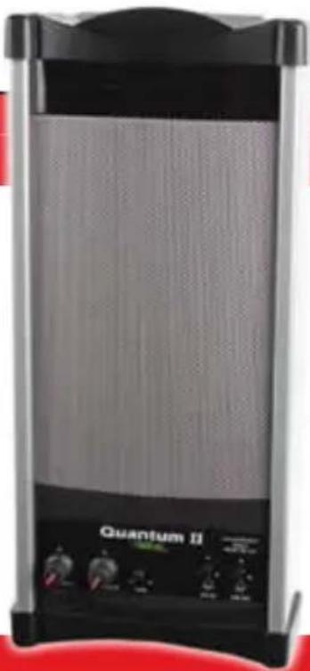
natural_image
Exterior view of a Quantum II air conditioner unit (no visible text or symbols on the device body)Infrared Wireless Microphone System
thank you
Congratulations on the purchase of your new Quantum II Infrared Wireless Microphone Sound System. You can be assured that the Quantum II fulfills all specifications and was produced to very high quality control standards. TeachLogic incorporates the latest state of the art technology, employs the most advanced manufacturing methodology and uses only premium quality components to assure many years of reliable performance. We appreciate your confidence by your selection of our product. It is TeachLogic's intent to uphold that confidence by providing factory assistance and dealer support.
We hope you will take the time to view this manual to familiarize yourself with the product operation and features. This manual will help you learn to use and gain the maximum benefit of the Quantum II system. The manual provides a basic explanation on the principles and advantages of infrared transmission. Followed by the system description, operation and installation instructions, the manual will conclude with maintenance and troubleshooting procedures.
Brian Van Waay

text_image
Bain Van Waay Presidentcontact
If you should encounter some unresolved issue, please contact TeachLogic customer service department for further assistance.
1·800·588·0018
sales@teachlogic.com
1·760·631·1283
www.teachlogic.com

CAUTION

RISK OF ELECTRIC SHOCK: DO NOT OPEN
Caution: To Reduce The Risk Of Electric Shock Do Not Remove Cover (Or Back) No User-serviceable Parts Inside Refer Servicing To Qualified Personnel
certifications

US

Listed



TeachLogic systems are manufactured using lead-free processes and are free of materials harmful to the environment. They conform to the most stringent new European guidelines for consumer products (RoHS).
caution
Recycle—Do not dispose rechargeable batteries in trash. Actually it is unlawful to do so in CA, NY & ME. Contact: Earth911.com 1-800-CLEANUP Save our resources and don't contaminate. Go Green
safety instructions
Read Instructions
All safety and operation instructions should be read before operating this TeachLogic product.
Retain Instructions
Safety and operating instructions should be kept for future reference.
Water & Moisture
This product should not be operated near water.
Heat Environment
Do not subject this product to excessive heat conditions.
Power Source
This product must be connected to an AC power source per the voltage input specified and marked on the power supply.
Power Cord Caution
Power cable should be routed clear of foot traffic and supported clear of kinking or abrasion.
Object Protection
Locate the operating unit so it will not be subjected to falling objects or water entry.
Internal Service
User should not attempt to service this product. All internal service must be accomplished by a qualified technician.
Electric Shock
Do not adapt or modify the AC power plug thus lifting the earth ground connection.
table of contents
About Infrared 1
Product Description 2
Assembly and Installation 3
Quantum II Controls 4&5
Sapphire Microphone/Transmitters IRT-55 6
Handheld Microphone/Transmitter IRH-35 7
Drop-in Chargers BRC-60/Ceiling Sensor ICS-55 ... 8
Installation of Ceiling Sensor 9
Operation of Wireless Microphone 10
Troubleshooting 11
General Specifications 12
Microphone Specifications 13
Five Year Limited Warranty 14
IR transmission
The IR transmitter transmits directly to the sensor. However; due to the strength of the IR transmitter, the infrared signal will bounce off the walls, ceiling and floor for reception thus providing continuous connectivity throughout the room. Benefit: total freedom of movement within the room with no restriction of orientation.
"What's said in the room, stays in the room".
Infrared will not penetrate a solid surface thus preventing any transmission from going out of the room.
a brief word about infrared
Infrared is a light ray that is below the visible spectrum, just like the sound spectrum extends beyond your hearing ability. An example of infrared transmission is the remote control for your TV set. When a button is pressed, a beam of infrared light is emitted by a Light Emitting Diode (LED) from the remote control. It is detected by a receiving diode in your TV set. When you press a certain command on your control, the internal electronics cause the infrared light to flicker in a programmed sequential pattern (called modulating the light beam). The modulated infrared beam is detected by the receiving diode and is electronically decoded. The decoded signal activates the circuitry to perform the command function on your TV set.
So how does this apply to the infrared communication system you are about to start using? The microphone/transmitter has several Light Emitting Diodes (LED) that emit infrared light beams to the sensor located in the corner of the room. Now when you talk into the microphone, the microphone element modulates the light beam, causing it to flicker in sync with your speech. The sensor detects the sequential signal and the electronic circuitry in the Quantum II converts that sequential signal into a line level analog audio signal. Now that audio signal can be fed into an amplifier. The amplifier magnifies the electronic signal and sends it to the speakers. This causes the speaker cone to move in sync with your voice. The speaker replicates your voice and disperses your voice evenly throughout the room.
product description
The Quantum II is an infrared wireless microphone sound system. It is the nucleus of the classroom sound field system which provides optimum voice reinforcement.
The addition of a Quantum II sound system will transform your classroom into a totally hands free, voice re-enforcement system, resulting in reduced voice fatigue, enhanced student listening and improved student learning. The wireless function permits 360° connectivity throughout the classroom regardless of body position or orientation.
The system is comprised of an infrared detecting sensor. The sensor collects the IR wireless signal from the microphone/transmitter and sends a composite signal to the mixer/amplifier. The receiver transforms the composite signal into an analog audio signal which is fed to the Quantum II mixer. An additional audio sources, such as; computer, DVD, VCR or Projector can be plugged in to the Quantum II. The AUX IN level controls the individual audio input. The audio will then be fed to the speaker in the column for voice reinforcement throughout the room.
On the front panel of the Quantum II, there is a 3.5mm output jacks for interface with an assistive listening system (ALS) or lesson capture (LINE OUT).
The microphone / transmitter can be one or two Sapphire Pendants or Handhelds. The rechargeable batteries will provide 6 – 8 hours of service per charge. The drop-in charger will recharge the batteries overnight, ready for another day's use.
Reliable performance. Use with confidence.
assembly and installation
Mounting the Quantum II on the wall, please review the following guidelines.
- Selecting the most appropriate location for the Quantum can be the most challenging. Every room is a little different, but in general the most functional location is installing it on the front wall off to one side or the other approximately from either side wall.
- An alternate choice would be on either side wall, located approximately 14 the distance from the front of the room.
NOTE: Be conscious of an AC outlet requirement for power.
- Once you've decided where to mount the Quantum II, hold the 'U' bracket straight up and down against the wall with bottom of the bracket approximately 5-6 feet above the floor. Using a level to assure true vertical orientation, mark the two mounting holes.
- If installing onto a drywall, drill two 14 " holes and insert a molley bolt provided. With a #2 Phillips head screwdriver, mount the wall bracket.
- If installing into a wood or like material, use two sheet metal screws with washers to mount the bracket to the wall.
- For concrete wall, you'll need to acquire and install a plastic insert for a # 8 sheet metal screw and install accordingly.
- With the bracket mounted, route the plastic wire tie through the two tab holes. Hold the power supply onto the two raised tabs with the AC plug end toward the floor. With the power supply resting on the pegs, tighten the wire tie thus securing the power supply to the bracket.
- Insert the DC plug into the power input jack and place the Quantum II into the bracket, secure each end with the bolt and washer provided.
- Orient the Quantum with center pointing diagonally across the listening area.
- Plug the power cord into an AC outlet
The Quantum II can be operated as a free stance system on a speaker stand. To use in this mode of operation:
- Locate the system off to one side in the front of the room. Point the front of the unit toward the center of the listening area. Find an AC outlet and plug the system in.
- Side wall location is also acceptable. Locate unit on either side about 14 from front of room. Point the front diagonally across the listening area. Locate an AC outlet and plug it in.
quantum controls
text_image
1 2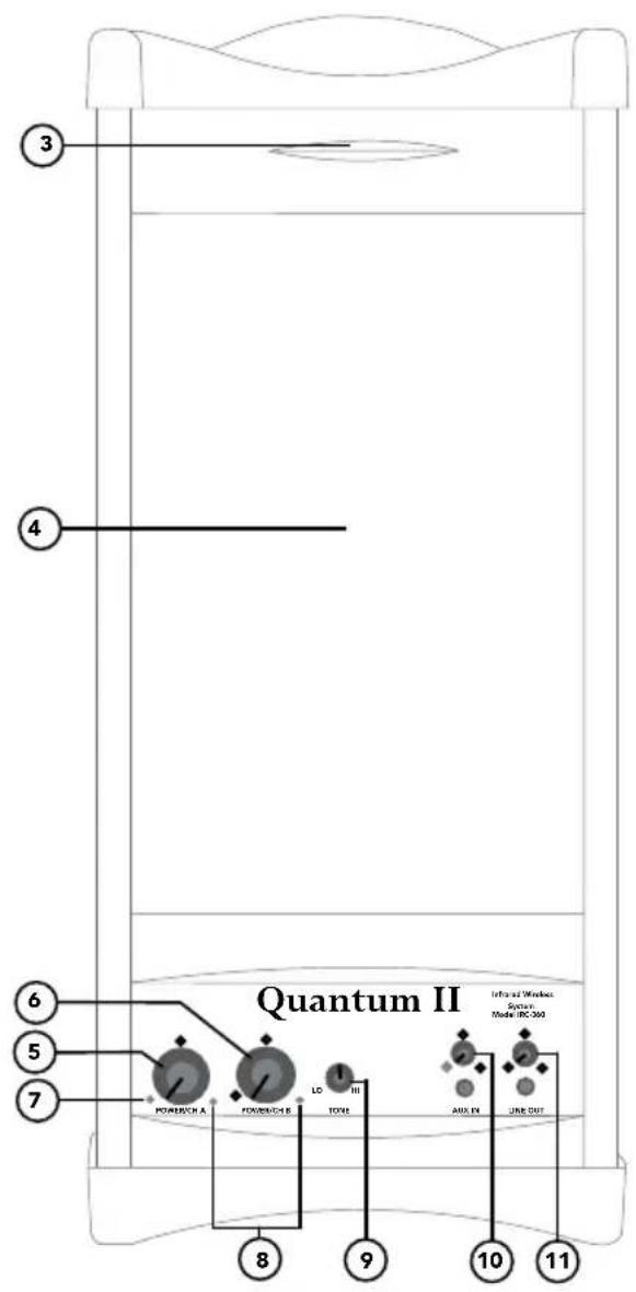
text_image
Quantum II Infraed Wireless System Model 10C-350 Powerbach A Powerbach B LO TOXII AUX IV URE OUT 8 9 10 11 3 4 5 6 7features
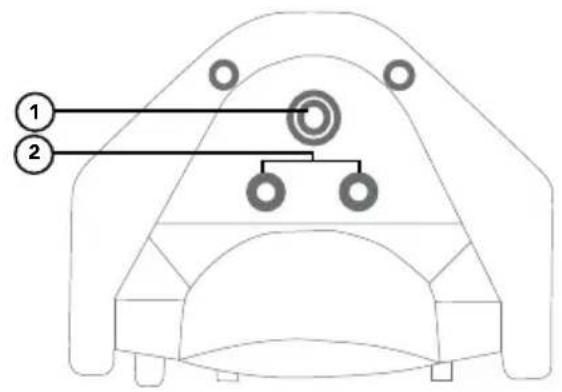
- Threaded insert for wall mount bracket.
- External sensor inputs.
- Internal sensors.
- Internal speaker.
- Power switch & Channel A Control.
- Power switch & Channel B Control.
- Power indicator LED.
- Infrared wireless transmission LED.
- Tone control.
- Line input volume control.
- Line output gain control.
external speaker output

text_image
DCM BNT SPquantum II controls
- Channel A turns power "on/off" (red LED indicator) and adjusts the volume of the IR microphone assigned to it. Normally the Pendant transmitter is assigned to channel A. When the transmitter is turned "on" a green LED will light, indicating that an IR signal is being received from the transmitter.
- Channel B also turns power "on/off" and adjusts the volume of the microphone assigned to it. Normally the handheld microphone is assigned to channel B. When the transmitter is turned "on" an amber LED will light indicating an IR signal is being received from the transmitter.
- Tone control adjusts the tonal quality of the sound. You will feel a center indent, turn CCW will boost the bass and turning CW will extenuate the high frequencies.
- Aux input jack (3.5mm) facilitates connecting the output of a DVD, Video Projector, ipod, computer and amplifying its signal through the Quantum. The volume can be controlled with the adjacent knob.
- Line output jack (3.5 mm) provides a composite line level output; it can be used to connect to a personal FM assistive listening system or as an output to a recording device. The small knob adjusts the output level to match input of the device connected.
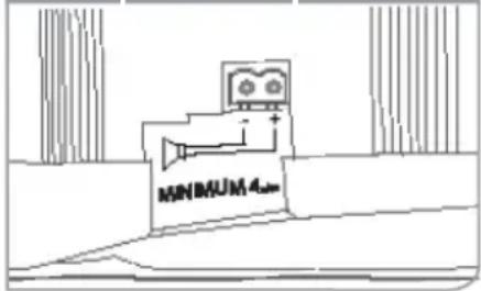
- External speaker output connector is located adjacent to the power plug. An unpowered external speaker can be connected to the Quantum for additional coverage. A companion unpowered Quantum would be the speaker of choice.
companion speaker
text_image
MINIMUM 4infrared microphone/transmitters
The infrared microphone/transmitter is comprised of a microphone input, signal processing circuits and several emitting diodes that transmit the vocal signal to the sensor.
The microphone/transmitter can be the Sapphire or Handheld. The rechargeable batteries will provide 6–8 hours of service per charge. Place the microphone/transmitter in the charger for overnight charge and it will be ready for another day's use.
The drop-in battery chargers are specifically designed to recharge lithium & NiMH batteries at an optimum rate for maximum operating capacity and extended service life. Charger will automatically start charging the batteries upon insertion and will shift to a maintenance charge when batteries are fully charged.
natural_image
Black-and-white photo of a smiling woman next to a beverage can with 'TCL' branding (no visible text or symbols on the main subject)features
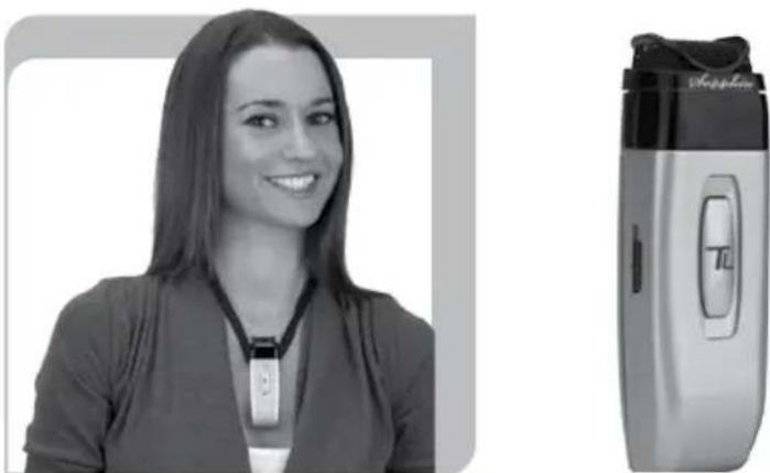
- Elegant design
- Only 1.4 oz. including battery
- Long life "Lithium ion" battery
- Rechargeable via USB cable to computer
- Battery level indicator – Back light under power switch
• Momentary mute button, backlight blinks in mute mode - Push "on/off" power
- Channel "A" or "B" selectable
• Three level microphone volume switch (low, medium, high)
• Auxiliary input (3.5mm) - Wear with a lanyard or slide directly on neckline collar
(IRT-55) sapphire transmitter
The Sapphire's vocal clarity is unsurpassed. Its high level output is achieved by the unidirectional (Cardioid) microphone and a unique free air suspension system. With a built-in breath filter, the Sapphire can function as a pass around hand mic.
The strategic alignment of the emitting diodes assures reliable connectivity throughout the room without static or drop out.
With a tap on the power button, the microphone is muted for private conversation—tap again to restore to normal operation. The auxiliary input allows wireless playback of your iPod™ through the Sapphire. A three position slide switch provides selection of low, medium, or high microphone sensitivity.
words of caution and limitations of infrared
Be sure that the path of transmission between the emitter and sensor is not obstructed.
The Sapphire pendant transmitter will not function if placed in pocket.
Infrared will not work outdoors in sunlight.
Dark surfaces will not reflect infrared well and can limit distance of transmission.
Rooms larger than 1600 Sq. Ft or have high ceilings can begin to exceed the ultimate performance of the Quantum II.
If dropouts are experienced in areas, as additional sensor ICS-55 sensor can extend the system performance.
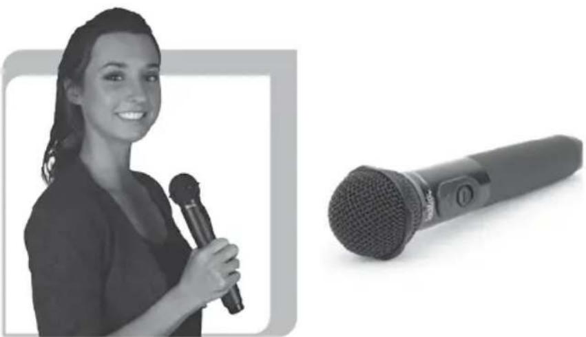
features
• Condenser microphone element
- Power "on/off" switch
- Battery level indicator—LED
- Channel "A" or "B" selectable
• 10 high-power emitting diodes
• Diodes at top and bottom of handle for increased Coverage (2 Top aimed out, 6 Bottom 360°, 2 Bottom aimed down)
- 360^ IR radiation for assured connectivity
- Two "AA", Duracell, rechargeable NiMH batteries
natural_image
Black-and-white photo of a smiling woman holding a microphone next to a black microphone (no text or symbols visible)IRH-35 handheld transmitter
The Handheld Microphone Transmitter (IRH-35) is most applicable for student use or direct presentation. It has an "on/off" switch and a battery level indicator LED; Green=useable charge, Red=low battery. The transmitter has 10 emitting diodes: 8 around the bottom of the handle, and 2 toward the top of the handle. The metal housing provides low handling noise and insures durable longevity.
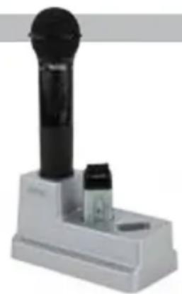
BRC-60 drop-in battery charger
This stylish desktop drop-in charging station makes it convenient and easy to recharge both Sapphire Pendant and Handheld Microphones. Charge one IRH-35 handheld transmitter and up to two IRT-60 Sapphire transmitters simultaneously. Charging indicator lights illuminate Red when charging, and Green when fully charged. The power LED illuminates Blue when plugged in.
natural_image
White electronic device with a black cylindrical head and two small components on its base (no visible text or symbols)ICS-55 ceiling sensor
The ceiling sensor is the preferred infrared sensor for optimum performance. This is the unit that needs to be installed on the ceiling. It comes with a mounting/support bracket and 50 feet of plenum rated cable with RCA connector on each end. The ideal location for the dome sensor would be in the center of the ceiling. This will provide a clear signal path for the IR transmission from the transmitter to the dome sensor without obstruction. In addition, you will have 360° coverage and will minimize the transmission distance for more reliable performance. It collects the infrared transmission signal via 6 large detecting diodes.
The additional sensor and cable can be added for larger rooms or rooms with poor connectivity. Locate and install the sensors for optimum IR reception, run the cable to the sensor input on top of Quantum II system.
power "on" LED
Green light indicates that the sensor is receiving power from the receiver.

natural_image
Close-up of a black circular object on a white tiled surface with diagonal lines (no text or symbols visible)sensor cable
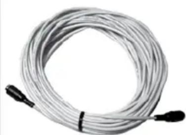
A Cable connects the sensor to the receiver. The cable is dual-shielded with a male RCA connector on each end and is plenum rated.
natural_image
Coiled cable with two black connectors at ends (no text or symbols visible)installation of ICS-55 ceiling sensor
The ideal location for the ceiling sensor is in the center of the ceiling. This will provide a clear signal path for the IR transmission from the transmitter to the dome sensor without obstruction. In addition, you will have 360^ coverage and will minimize the transmission distance for more reliable performance. An additional sensor can be added for large or odd shaped rooms.
Attaching the infrared ceiling sensor
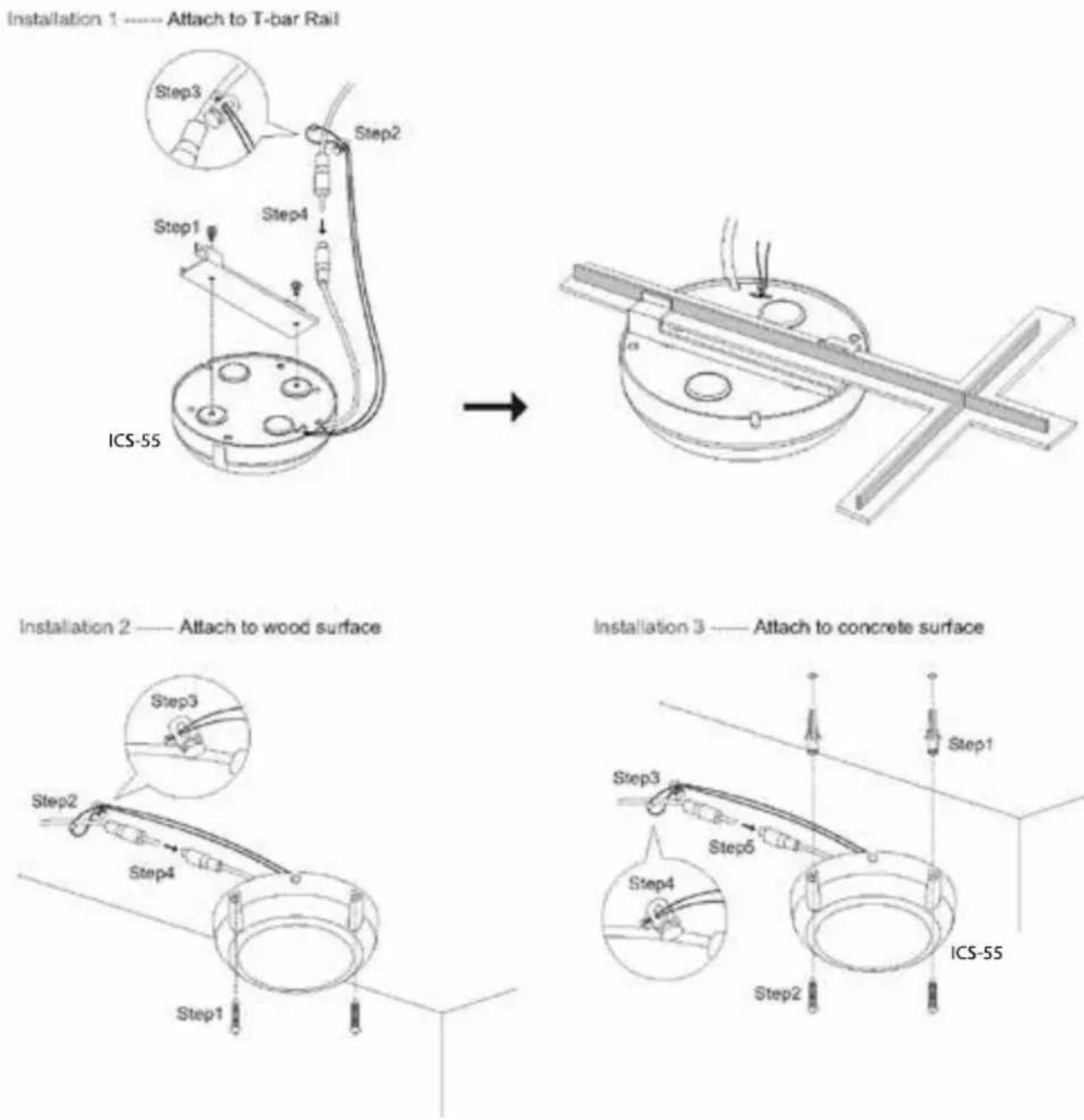
flowchart
graph TD
    A["Step1"] --> B["Step2"]
    B --> C["Step3"]
    C --> D["Step4"]
    D --> E["ICS-55"]
    F["Step1"] --> G["Step2"]
    G --> H["Step3"]
    H --> I["Step4"]
    I --> J["Step5"]
    J --> K["ICS-55"]
    L["Step1"] --> M["Step2"]
    M --> N["Step3"]
    N --> O["Step4"]
    O --> P["Step5"]
    P --> Q["ICS-55"]
operation of wireless microphone
Now that the system is installed and connected, we are ready to turn the system “ON” and test its performance. The testing will be done using an IR transmitter (Sapphire or Handheld) to confirm good connectivity and quality audio.
system operation
- On Quantum II set Ch A & B volume controls to off (counter clock wise)
- Turn the Quantum II "ON", Blue LED will light
- Confirm power to ceiling sensor, Green LED on edge of sensor will light
- Using a Sapphire Transmitter microphone. (Sapphire Mics are shipped in channel A)
- Sapphire: "A-B" switch, remove battery cover on back, under battery.
- Handheld: Unscrew barrel and remove. Note "A-B" switch on side of battery holder.
- Turn sensitivity control on Sapphire transmitter to "HI" level position
- Switch transmitter "on" by depressing and hold front button until (Blue) LED is present
- Observe signal presence LED (Orange) on Quantum II receiver adjacent to "Mic" volume control
- Stand under or in front of a speaker
- Slowly adjust "Ch A" volume on Quantum II while talking into microphone
- Adjust to desired listening level. CAUTION: Beware of feedback
- Walk around the room while talking into microphone to confirm good connectivity
Upon completion of performance test, the installation is complete.
troubleshooting
| Problem Solution | |
| System is turned “on” but there is no sound | Verify AC power; the Blue LED lights when turned “on”Check if system has been unpluggedCheck circuit breakerCall maintenance for assistance |
| System has power but no sound | Turn “on” microphone/ transmitterCheck for IR transmission, Signal presence (Orange LED)Check the Green LED in the sensorIf sensor LED is not litSensor has been disconnectedPower output to sensor has failed (Receiver/amplifier needs to be replaced) |
| Voice is distorted and/or signal drop-out occurs | Check the charge on your batteriesVerify that the diodes on transmitter or sensor are not being coveredObstruction between transmitter and sensor |
contact
If your problem persists and this guide has not resolved the issue, call our customer service department for additional assistance. (800) 588-0018
Quantum II (IRC-360) specs.
| Receiver Input | Infrared FM |
| Modulation | FM Wide-band |
| Reception Frequencies | Ch. A: 2.08 MHz |
| Ch. B: 2.54 MHz | |
| Infrared Wavelength | 850 nm |
| Tone Signal | Ch. A: 32.768 KHz |
| De-emphasis | 50 μs |
| Frequency Response | 50 Hz, -13KHz, C 3dB |
| S/N Ratio | >65 dB |
| THD | <1% @1KHz |
| Nominal Deviation | ± 10 KHz |
| Maximum Deviation | ± 25 KHz |
| External Sensor Input | Two, RCA |
| Connectivity Coverage | 60 Ft. Line of Sight |
| Aux Inputs | 3.5mm with Gain Control, Front Panel |
| Line Output | 3.5mm with Gain Control, Front Panel |
| Equalization | Tone Control, ± 6dB |
| Power Output | 30 Watts (RMS) Class D Amplifier |
| External Speaker Output | 15 Watt / 4ohm |
| External Connection | Two Terminal Phoenix Connector |
| Power Supply | 19VDC /3.4A / 65W CE,CSA & UL Listed |
| Dimensions | 6 1/4" W x 14" H x 4 3/4" D |
| Weight | 4 lb. 2oz. |
power supply (AC-36) specs.
| Type | Regulated Switching Power Supply |
| Input Voltage | 100–240 volts AC, 47–63Hz |
| Output Voltage | 19 volts DC, 3.4A |
| Power Output | 65 watts Max. |
Sapphire transmitter (IRT-55) specs.
| Transmitting DiodesOperating RangeBattery Discharge IndicatorBluePurpleRedFlashing RedBattery UsedBattery LifeExternal Power ChargerTransmission AngleUser ControlsPower Switch (push)Mute Switch (push)Mic Switch (3 position)Aux. Vol./GainSecurity AlertExternal Aux. InputDimensionsWeight | Six1,600 Ft ^2 . 60 Ft. Line of SightFullMediumLowVery Low BatteryLithium-ion (3.7V / 620mAh)Approx. 8-9 Hrs/ChargeDC +5V, Micro USB ConnectorConicalOn/OffOn/Off momentary pushHI,MID,LOWIncrease, Decrease5 second hold of priority button3.5mm Line Level3 5/8" H x 1 14 " W x 34 " D1.4 oz. Including battery |
Handheld transmitter (IRH-35) specs.
| 2 Channel Switchable | Field Switchable |
| Transmitting Diodes | Ten |
| Modulation | FM Wide-Band |
| Pilotone Frequency | 32.768 KHz |
| Peak Deviation | ± 25KHz |
| Operating Range | 1600 Ft ^2 . 60 Ft. |
| Power Switch (Slide) | On/Off |
| Battery Charge Level (LED) | Green (Useable Charge) |
| Red (Needs Charging) | |
| Battery Life | Approx. 7 Hr./Charge |
| Dimensions | 2 1/8" Dia. Head,1 7/16" Dia. Body, 9 5/8" H |
| Weight | 10.3 oz. w/ Battery |
drop-in battery charger (BRC-60) spec
| Charging Port | 2 Sapphire, 1 Handheld |
| Red LED | Battery being charged |
| Green LED | Battery fully charged |
| Power Supply | 5 VDC, 1 Amp |
| Dimensions | 6 3/8" L x 3 3/8" W x 3 3/8" H |
| Weight | 6.3 oz. |
five year limited warranty
TeachLogic IR products are guaranteed to be free of defects in workmanship or material for a period of five (5) years from date of original purchase, subject to the following conditions:
- Warranty excludes defects caused by normal use and wear, any abuse, or failure to use the product in accordance per instructions.
- Warranty is void if damage occurred because of misuse, or attempted repair or modification by unauthorized personnel.
- Warranty on batteries is for two (2) years.
- Warranty does not extend to finish.
- All warranty service will be provided by TeachLogic or authorized service center
- Warranty is made to the original purchaser and may not be transferred to another user.
- Warranty service rendered will be on a repair or replacement basis, whichever TeachLogic deems to be most prudent for customer satisfaction and economic feasibility.
TeachLogic will only accept warranty shipments accompanied by Return Authorization Number previously assigned by TeachLogic personnel. Advance warranty replacements will be made per the discretion of TeachLogic personnel.
TeachLogic will pay return shipping cost on all warranty repairs or replacements.
contact
TeachLogic, Inc.
Customer Service Dept.
1688 Ord Way
Oceanside, CA 92056
1·800·588·0018
sales@teachlogic.com
1·760·631·1283
www.teachlogic.com
notes
Date of Purchase: ____
Model Number: ____
Serial Number: ____
Notes:
TeachLogic FOR SOUND LEARNING
1688 Ord Way
Oceanside, CA 92056
1·800·588·0018
sales@teachlogic.com
1·760·631·1283
www.teachlogic.com