CVM-WM200TX - Microphone Comica - Free user manual and instructions
Find the device manual for free CVM-WM200TX Comica in PDF.


| Product Type | UHF Wireless Microphone System (Lavalier Transmitter CVM-WM200TX) |
| Number of Channels | 96 |
| Wireless Frequency Range | Group A: 520.000–548.500 MHz; Group B: 550.000–578.500 MHz |
| Working Distance | Up to 120 m (open area), up to 80 m (obstructed) |
| Signal-to-Noise Ratio | >65 dB |
| Audio Distortion | <0.5% |
| Sound Delay | <20 ms |
| Transmitting Power | 10 dBm / 15 dBm (selectable) |
| Antenna Type | Lavalier TX & RX: 1/4 wavelength wire; Handheld TX: PCB antenna |
| Power Supply | 2 × AA batteries per unit (TX, RX, handheld) |
| Dimensions (Lavalier TX) | 84 × 63.5 × 23 mm |
| Dimensions (Receiver) | 84 × 63.5 × 23 mm |
| Dimensions (Handheld TX) | Φ53.5 × 253 mm |
| Operating Temperature | 0 °C to 50 °C |
| Storage Temperature | -20 °C to 60 °C |
| Key Features | Low cut filter, auto-scan, IR sync, 16-level volume, RF strength adjustment, mono/stereo output, 3.5 mm audio output & monitoring, muting function, backlight adjustment, LCD display, all-metal construction |
| Included Accessories | Lavalier and/or handheld transmitter, receiver, audio cables (3.5mm-3.5mm, 3.5mm-XLR, 3.5mm mic input), belt clip, cold-shoe mount, wind muff, portable box, manual, warranty card |
| Maintenance | Keep in dry environment; do not expose to rain or moisture |
| Safety Precautions | Avoid short circuit by keeping dry; do not use in humid conditions |
| Repairability & Spare Parts | Contact Comica support for service; batteries are replaceable |
Frequently Asked Questions - CVM-WM200TX Comica
User questions about CVM-WM200TX Comica
0 question about this device. Answer the ones you know or ask your own.
Ask a new question about this device
Download the instructions for your Microphone in PDF format for free! Find your manual CVM-WM200TX - Comica and take your electronic device back in hand. On this page are published all the documents necessary for the use of your device. CVM-WM200TX by Comica.
USER MANUAL CVM-WM200TX Comica
UHF 96-Channels Wireless Microphone
natural_image
Illustration of a multi-band audio recording system with multiple CMCA devices connected via wireless links (no text or symbols visible)USER MANUAL
Foreword
Thanks for purchasing COMICA WM200 UHF wireless microphone;
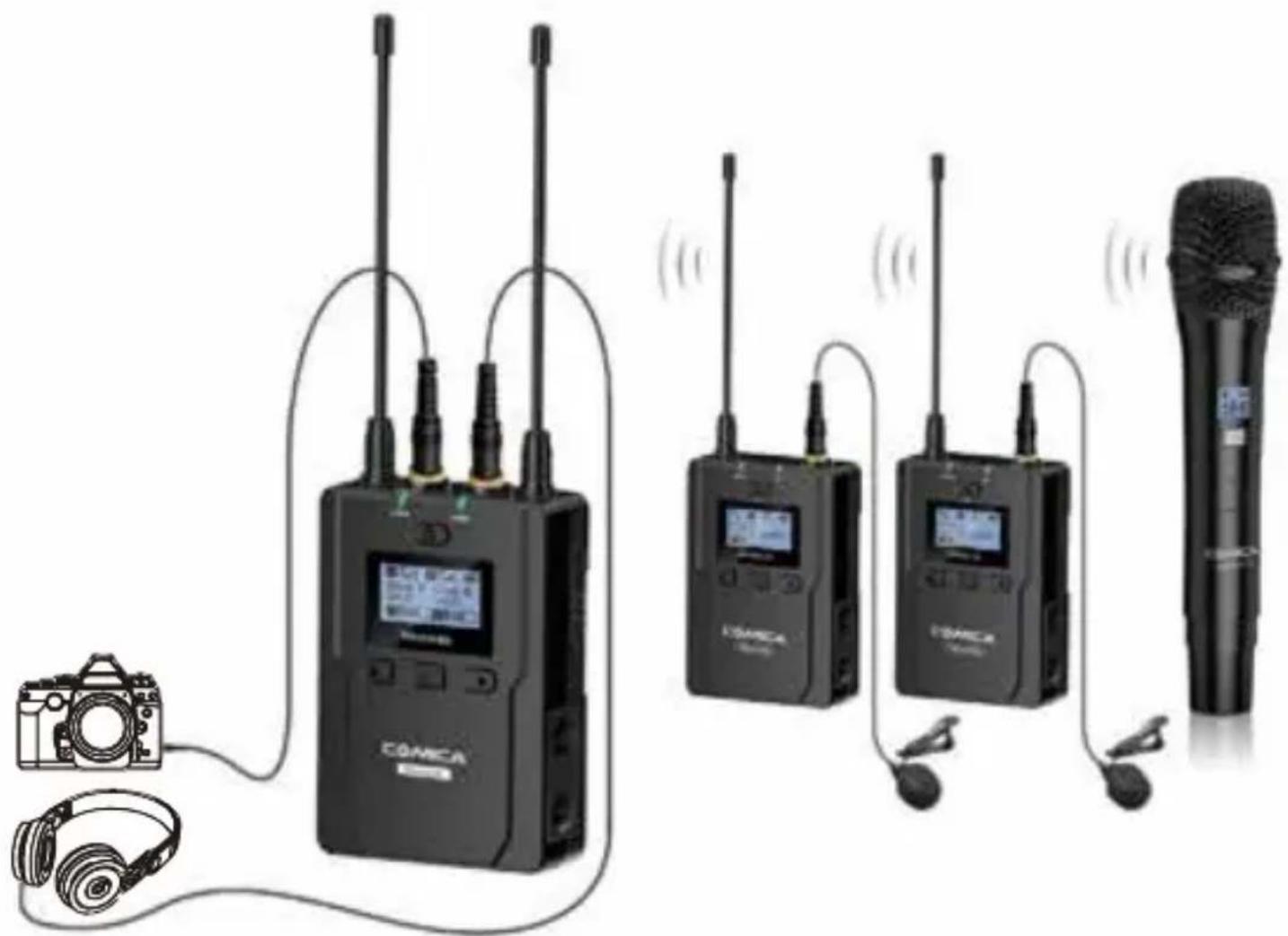
WM200 is an all-metal wireless microphone with dual-transmitter triggered by one receiver, with two AA batteries, it utilizes UHF wireless FM technology and LED high-resolution lattice screen, 96 channels in total, 16-level adjustable volume, and integrated into LCF (Low cut filter), Auto-scanning, Auto IR Channel-match, stereo / mono switchable audio mode, RF signal strength adjustment, MIC/LINE IN input dual selection, power monitoring at receiver end, sound pickup dynamic display, backlight adjustment and other functions, at the same time with strong shielding anti-noise performance, it's a high-quality microphone to broadcasting level;
To ensure the smooth use and safety of the product, please carefully read this instruction before using and properly assemble and operate.
Main Features
. Dual Transmitters Triggered by One Receiver, A/B Double Group Options;
. 96 Channels, Used for Multiple Devices Working Together;
. Working Distance is Up to 120m (in open area, up to 80m in Barrier Area);
. LCF Low Cut Filtering Mode;
. Auto-scanning for Quick Channel Selection;
. Manual or Auto IR Sync;
. Adjustable RF Signal Strength;
. Audio Dynamic Display Bar;
. 16 Levels Volume Adjustment;
. Transmitter Power Monitor;
. Mono/Stereo Switchable Output Modes;
. Low-consumption, Super-long Standby Time;
. Lattice LCD Display, High Resolution;
. Full Metal Manufacturing, Excellent Shielding;
120m Working Distance
Dual-Mix Trigger

Full Metal and Super Shielding
96 Channels

Low Cut Fiber

Auto-scanning

Adjustable RF Signal Strength
Audio Dynamic Display Bar

Transmitter Power Monitor

16 Levels
Volume Adjustment

Mono/Stereo
Audio Switch
Real-time Monitor
Auto IR Sync

Lattice LCD
Notice
When using auto IR sync, please stay within one meter, otherwise the signal may be too weak and the sync will not be successful;
In the case of stereo/mono mode switch, please preset the mode before using to avoid the transient interference caused by switching during usage;
The antenna will affect the working distance. Please protect the antenna and avoid any man-made damage;
The working distance will be affected by the surrounding environment. Please try to keep the environment open without interference during usage, and close the WIFI of the device itself;
When using this product in a short distance, it is recommended to set RF strength at 'LOW' to reduce the power consumption;
For smart phone shooting, customers must separately purchase a TRS-TRRS audio converting cable, and pay attention to set the mobile phone mode to 'Flight Mode' to avoid incoming call interference;
(It does not support the original recording system of some android systems, the third-party APP is recommended to be used in this case);
⚠️ Please keep this product in dry environment;
Do not expose the device in rain or humid environment, otherwise there will be a danger of short circuit;
Package Contents
Main Parts:
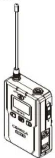
natural_image
Line drawing of a Cabeva 8000 communication device with antenna and control panel (no text or symbols)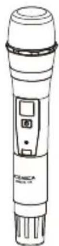
natural_image
Line drawing of a handheld electronic device with a digital display and control buttons (no text or symbols)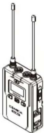
natural_image
Illustration of a walkie-talkie device with two antennas and control buttons (no text or symbols visible)Lavalier Transmitter (TX) Hand-held Transmitter (HTX) Receiver (RX)
Multiple Selections:
$$ \mathrm{WM200(A)} = 2 \mathrm{TX} + \mathrm{RX} $$
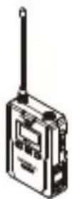
+
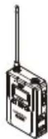
+
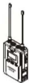
TX TX RX
$$ \mathrm{WM200(B)} = \mathrm{TX} + \mathrm{HTX} + \mathrm{RX} $$
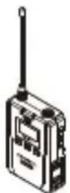
+
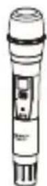
+
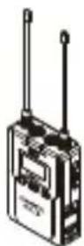
TX HTX
RX
$$ \mathrm{WM200(C)} = \mathrm{TX} + \mathrm{RX} $$
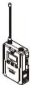
+
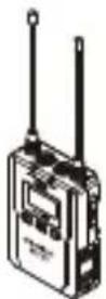
TX RX
$$ \mathrm{WM200(D)} = \mathrm{HTX} + \mathrm{RX} $$
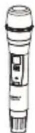
+
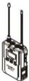
HTX
RX
Accessories:
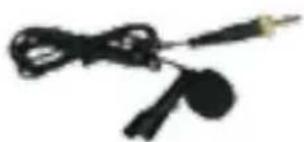
① 3.5mm Mic Audio Input Cable
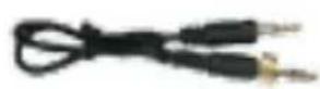
② 3.5mm-3.5mm Audio Output Cable
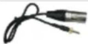
③ 3.5mm-XLR Audio Output Cable
④ Belt Clip
⑤ Camera Cold-shoe Mount
⑥ Wind Muff
⑦ Portable Box
⑧ User Manual
⑨ Warranty Card
natural_image
Close-up of a black cable with a metallic connector and earplush (no visible text or symbols)1
②
natural_image
Close-up of a black electronic device with two leads, coiled with a cable (no visible text or symbols)③
natural_image
Simple line drawing of two abstract geometric shapes (no text or symbols)④
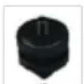
⑤

6
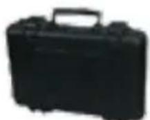
7
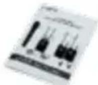
⑧
⑨

The accessories of each combination include:
WM200(A)= ① x2 + ② 3 4 5 6 7 8 9 x3 + ○ x3 + ○ x2 + ○ + ○ + ○
Components and Instruction
Components
Lavalier Transmitter (TX)
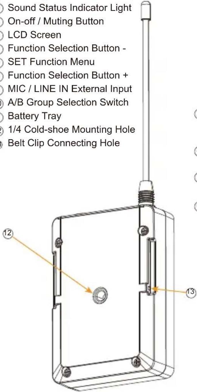
① Antenna
② Matching Status Indicator Light / IR Screen
③ Sound Status Indicator Light
④ On-off / Muting Button
⑤ LCD Screen
⑥ Function Selection Button -
⑦ SET Function Menu
⑧ Function Selection Button +
⑨ MIC / LINE IN External Input
⑩ A/B Group Selection Switch
⑪ Battery Tray
⑫ 1/4 Cold-shoe Mounting Hole
⑬ Belt Clip Connecting Hole
text_image
Sound Status Indicator Light On-off / Muting Button LCD Screen Function Selection Button - SET Function Menu Function Selection Button + MIC / LINE IN External Input A/B Group Selection Switch Battery Tray 1/4 Cold-shoe Mounting Hole Belt Clip Connecting Hole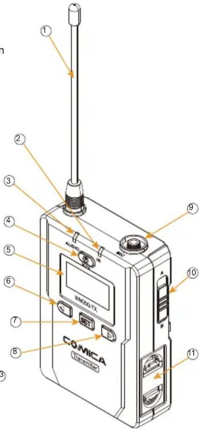
text_image
1 2 3 4 5 6 7 8 9 AUDIO VIN2001-TX COMICA TRANSCAN 10 11Hand-held Transmitter (HTX)
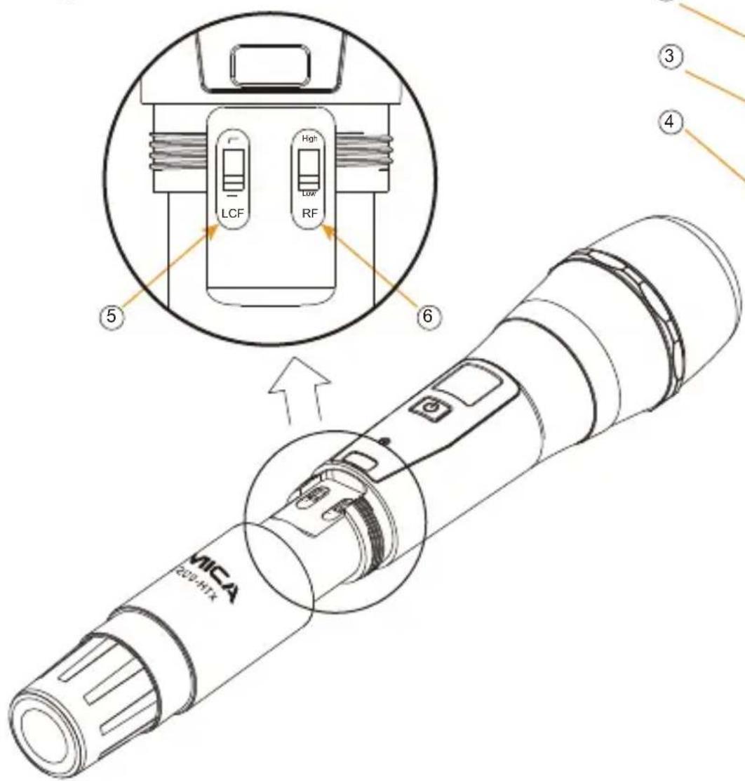
① Microphone
② LCD Display
③ On-off / Muting Button
④ IR Screen
⑤ Low cut/Normal Audio Switch
⑥ Signal Strength "High/Low" Switch
text_image
LCF High Low RF ⑤ ⑥ ③ ④ MICA 200-H1X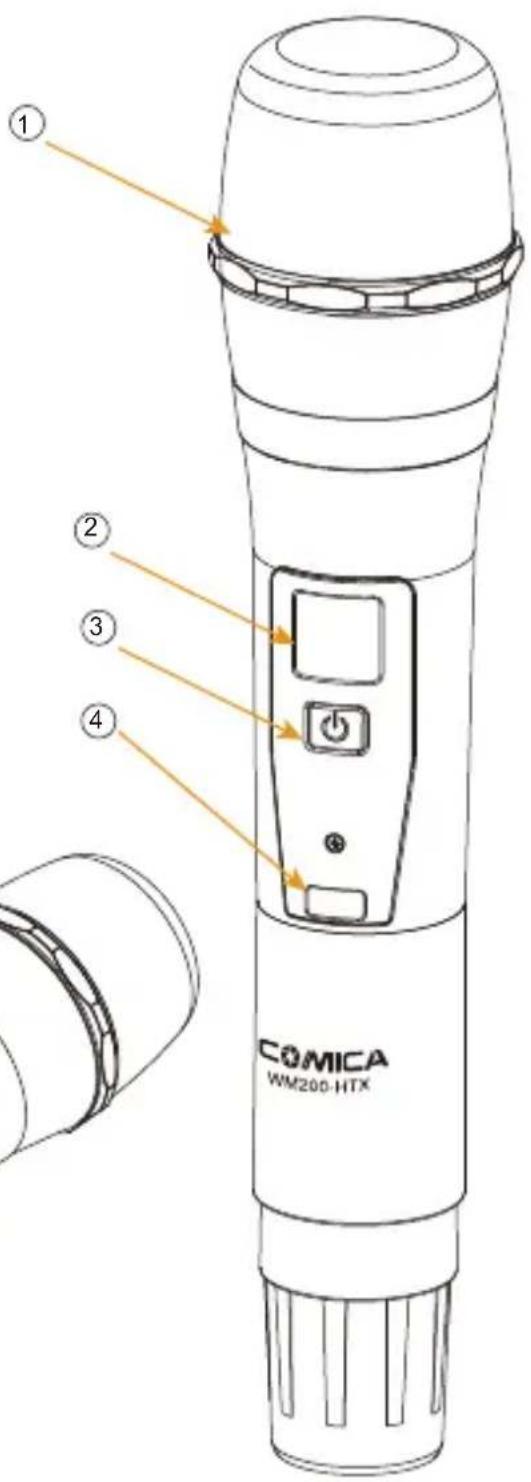
text_image
① ② ③ ④ COMICA WM200-HTXReceiver (RX)
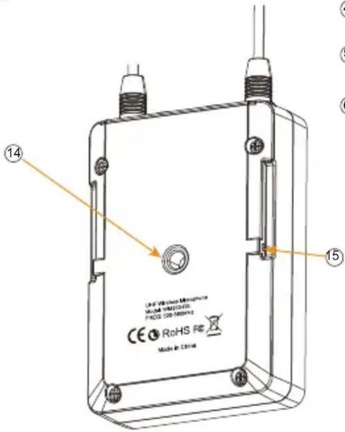
① Group A Antenna
② Group B Working Status Indicator Light
③ Group A Working Status Indicator Light
④ On/Off Switch
⑤ LCD Screen
⑥ Function Selection Button -
⑦ SET Function Menu
⑧ Function Selection Button +
⑨ 3.5mm Audio Output Socket
⑩ 3.5mm Monitoring Socket
⑪ Group B Antenna
⑫ A、B or A+B Group Selection Switch
⑬ Battery Tray
⑭ 1/4 Cold-shoe Mounting Hole
⑮ Belt Clip Connecting Hole
text_image
14 Use Wireless Microphone MUSB 50020-65X FREQ: 328-5889HZ CE RoHS Re Made in China 15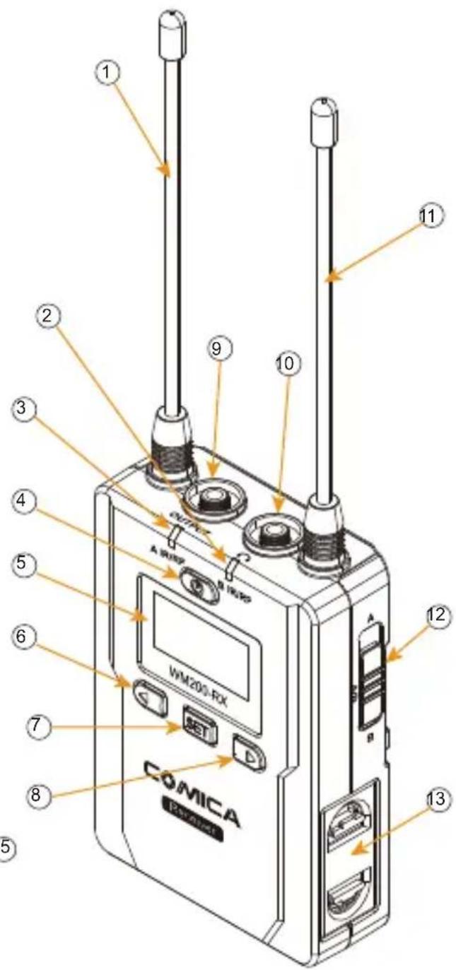
text_image
COMICA A-1989 VM200-RX COMICA A-1989 A-1989 1 2 3 4 5 6 7 8 9 10 11 12 13Function Button Instruction
Lavalier Transmitter / Receiver | On-off / Muting Button | Long Press | Power On / Off |
| Short Press | Muting Mode (This function is only for transmitter, when the mute function is turned on and the screen is lighted up) | ||
| SET Function Menu | Long Press | Enter the function adjustment menu | |
| Short Press | 1. Confirm the selected function2. Exit the function adjustment menu | ||
| + Button | Short Press | Function Adjustment (+) | |
| - Button | Short Press | Function Adjustment (-) | |
Hand-held Transmitter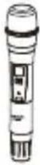 | On-off / Muting Button | Long Press | Power On / Off |
| Short Press | Muting Mode (Only goes into effect when the screen lights up) | ||
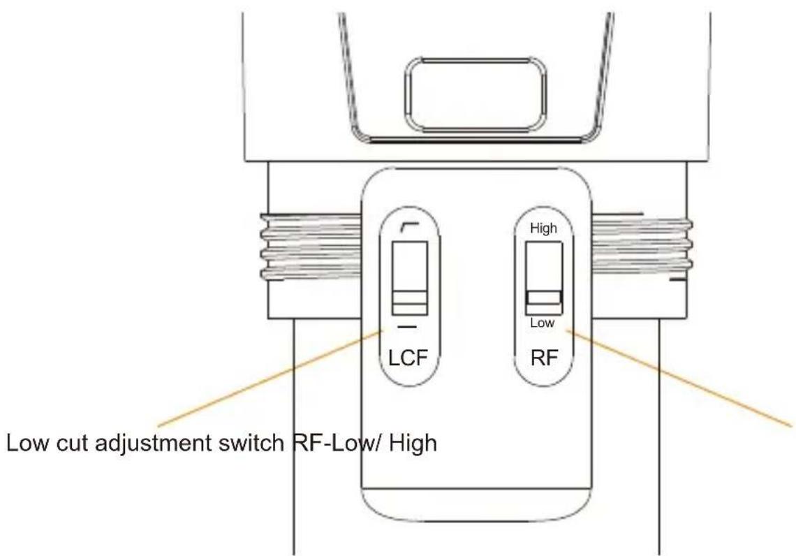
“Low cut/ Normal” Sound Switch 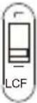 | Push-up | Low cut | |
| Push-down | Normal | ||
Signal Strength “High/Low” Switch 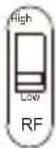 | Push-up | Signal strength--high | |
| Push-down | Signal strength--low |

Signal strength high / low switching effect:
With high signal strength, the wireless working distance is up to 80-120M, high power consumption, battery life is short; With low signal strength, the wireless working distance is up to 30-60M, low power consumption, the battery can be used for a long time.

Low cut function:
Appropriately remove the low frequency part of the sound, reduce the ambient noise of the low frequency part, to make sound more clean and clear.
Indicator Light Instruction
| Transmitter | AUDIO | Green Light Keeps On | Normal Recording Status (This state is only for the transmitter, when the channel matches successfully, the receiver can pick up the sound) |
| Red Light Keeps On | Muting Mode | ||
| Red Light Flicker | Low-power reminder | ||
| IR | Green Light Keeps On | Channel matches (No matter the channel matches or not) | |
| Red Light Flicker | Channel in the match... (only for IR Sync) | ||
| Receiver | A IR/RF B IR/RF | Green Light Keeps On | Normal working status after the channel matches |
| Green Light Flicker | Channel doesn’t match | ||
| Red Light Flicker | Channel in the match... (only for IR Sync) | ||
| Low-power reminder | |||
| Red light keeps on | Group closed |

A IR/RF: Group A Working Status Indicator
B IR/RF: Group B Working Status Indicator
Installation and Usage
Lavalier Transmitter
- Install two AA batteries into the battery tray according to the positive and negative electrode
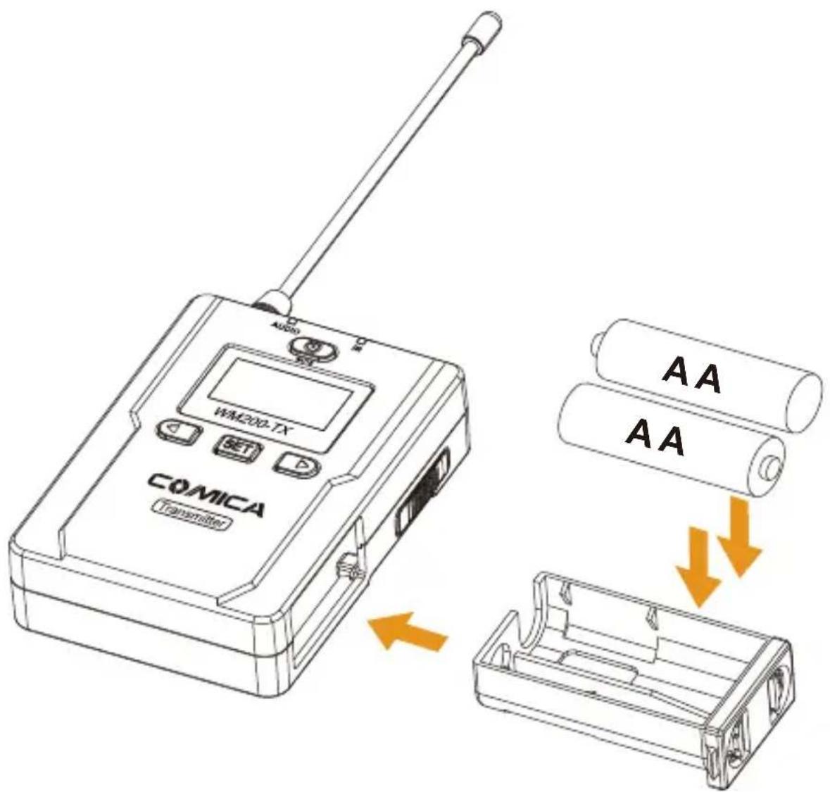
text_image
CQMICA Transmitter WM200-TX Audio AA AA- Insert the 3.5mm audio input line into MIC socket
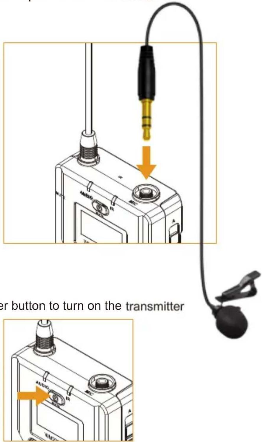
text_image
er button to turn on the transmitter- Long press the power button to turn on the transmitter
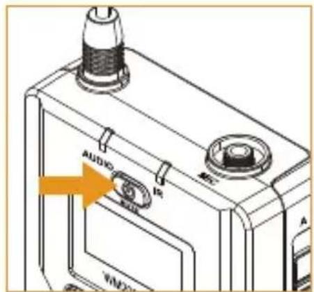
text_image
AUDIO MINI A WM20- Target the MIC to the audio source and check the working status according to the volume indicator on the screen
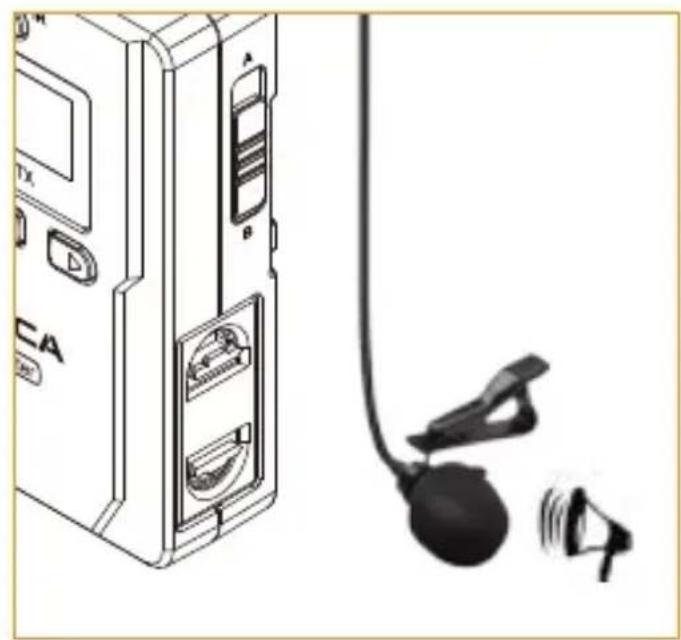
natural_image
Illustration of a device with labeled ports and a microphone, no text or symbols present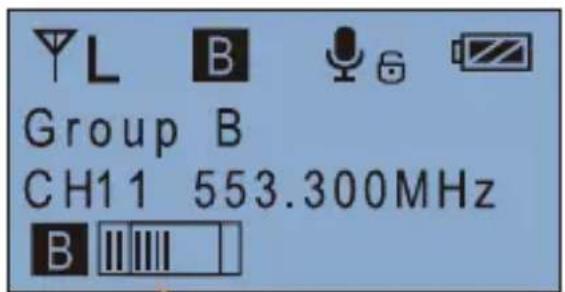
- Connect the belt clip to the connection hole
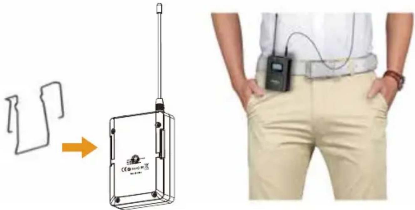
text_image
Diagram showing a device with a sensor and a person wearing a bandage, illustrating the process from external to internal movement.- After the channel matching with the receiver, it can be used

Please refer to screen operation instruction for channel matching.
Hand-held Transmitter
- Install two AA batteries into the battery tray according to the positive and negative electrode
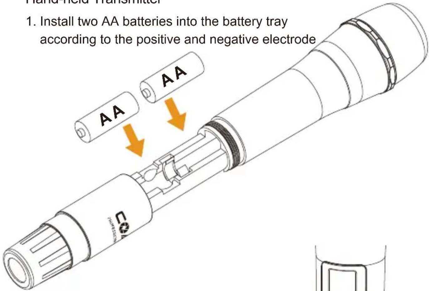
text_image
Hand Held Transmitter 1. Install two AA batteries into the battery tray according to the positive and negative electrode- Long press the button switch to turn on the hand-held transmitter
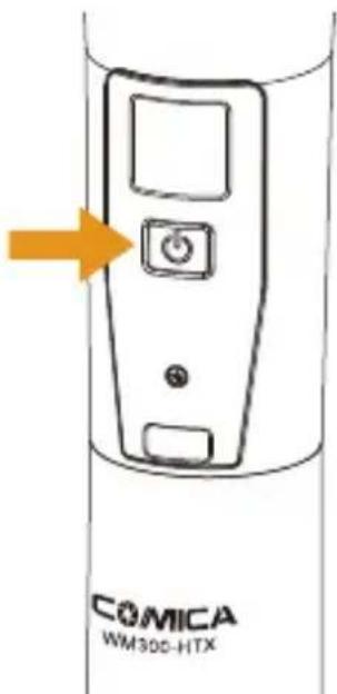
text_image
COMICA WM300-HTX- After the channel matching with the receiver, it can be used

Please refer to screen operation instruction for channel matching.
Receiver
- Install two AA batteries into the battery tray according to the positive and negative electrode
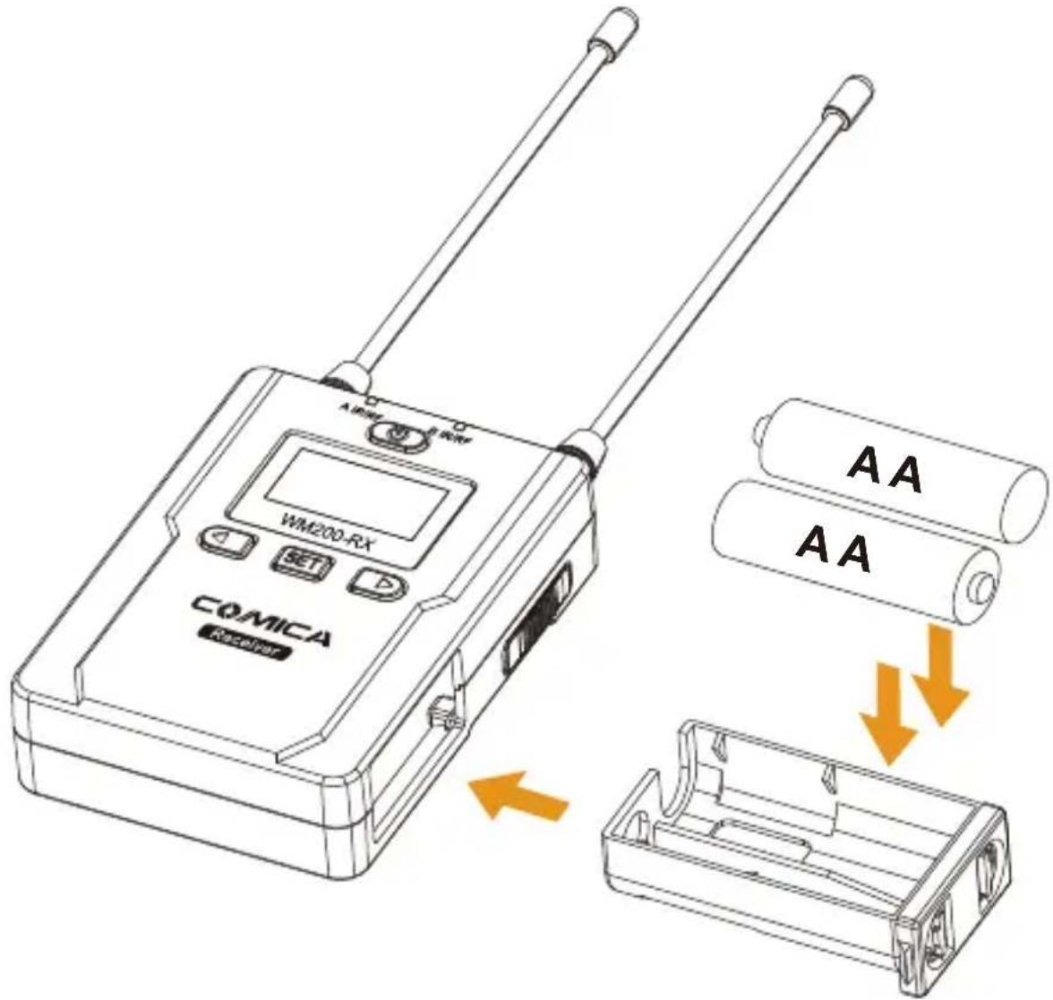
text_image
A IFR WM200-RX COMICA Receiver AA AA- Connect the receiver to the video device through the cold shoe
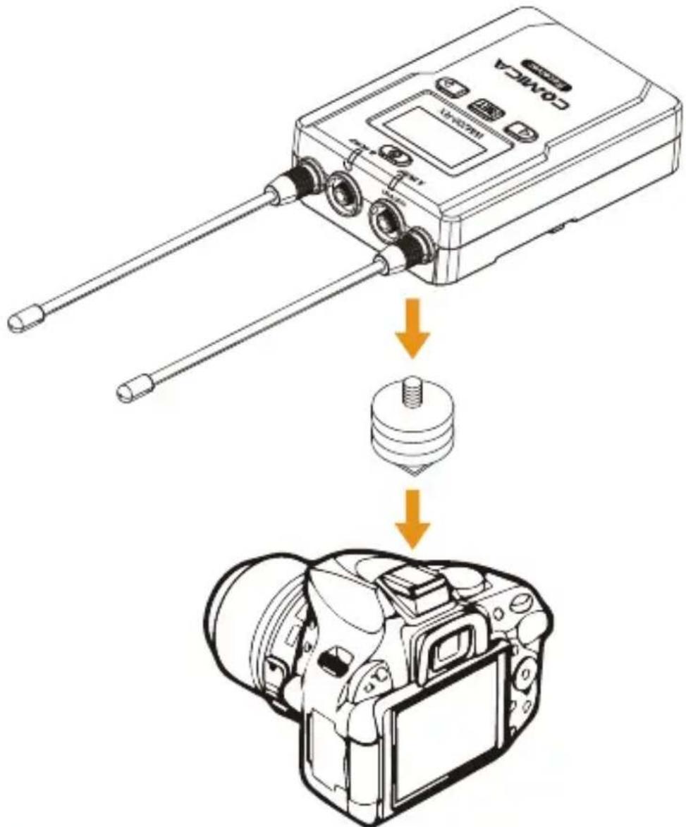
text_image
Diagram showing the assembly of a camera module with labeled components and directional arrows indicating assembly steps.- Connect one end of the 3.5mm-3.5mm audio OUTPUT line to the OUTPUT port of WM200RX and another end to the AUDIO INPUT port of the camera or camcorder. Insert the headphone into the 3.5mm monitoring port for real-time monitoring and then long press power button to trun on the receiver.

Most DSLR cameras has 3.5MM port, if you use the XLR camcorder, you need to use the 3.5mm-XLR audio output line.
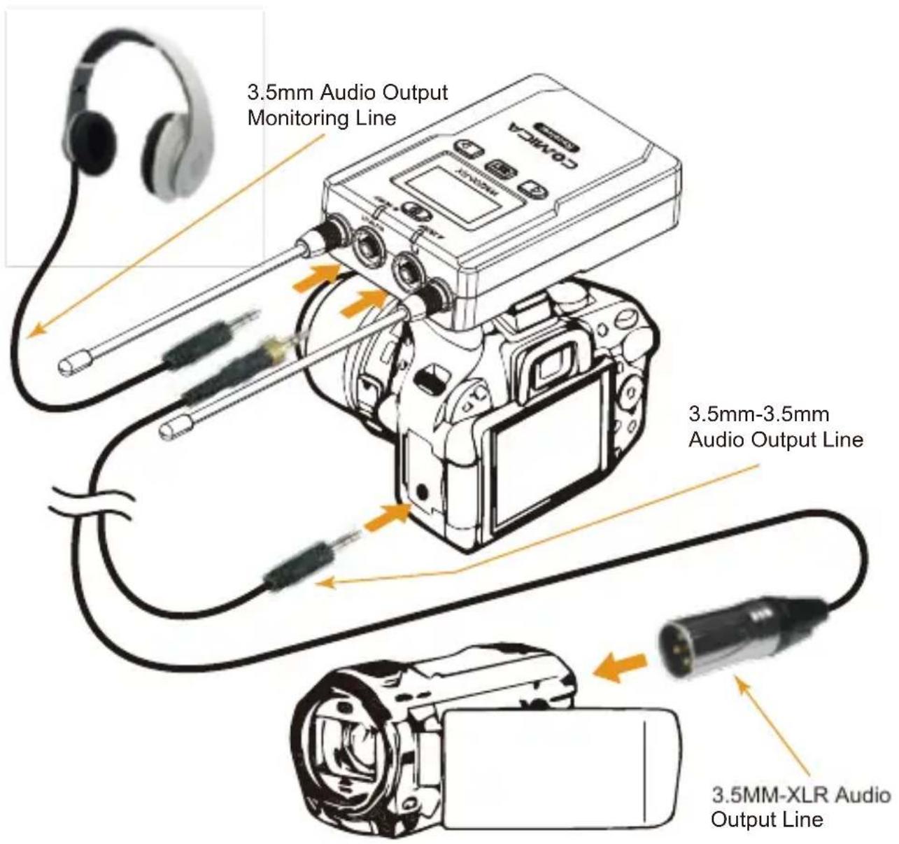
text_image
3.5mm Audio Output Monitoring Line 3.5mm-3.5mm Audio Output Line 3.5MM-XLR Audio Output Line- After the channel matching with the receiver, it can be used

Please refer to screen operation instruction for channel matching.
Screen Display and Operation Instruction
Lavalier Transmitter
Screen Display Instruction
text_image
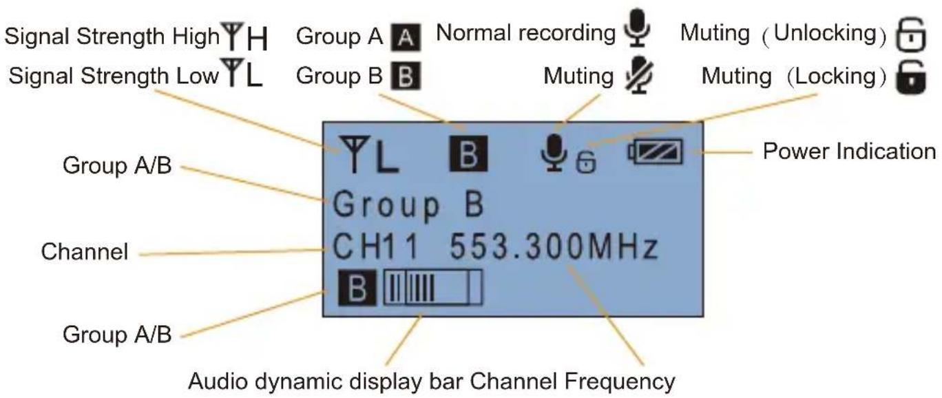
Signal Strength High Signal Strength Low Group A Group B Group A/B Channel Group A/B Group A Normal recording Muting Muting (Unlocking) Muting (Locking) Power Indication CH1 1 553.300MHz Audio dynamic display bar Channel FrequencyOperation Instruction
1. Group A/B Selection
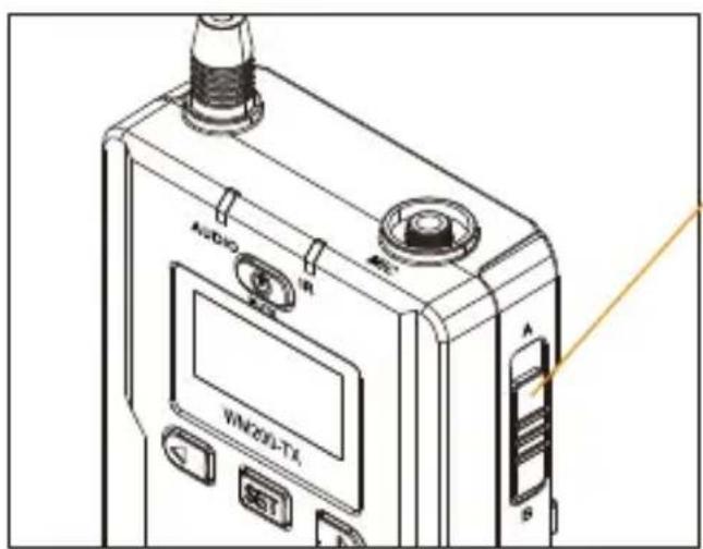
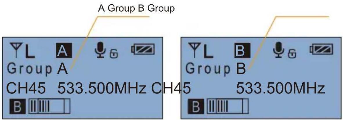
1.1 Use A/B Group selection switch to select the group, when push up to A, it will be Group A; when push to B, it will be Group B. You could choose Group A or Group B according to your demand.
text_image
AUDIO WIN201-TX A B SA/B Group Selection Switch
text_image
A Group B Group Group A CH45 533.500MHz CH45 B Group B 533.500MHz2. Manually Adjust the Channel of Transmitter
2.1 Long press SET button to CH setting display page
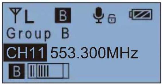
2.2 Short press ◀ ▶ button to select the channel
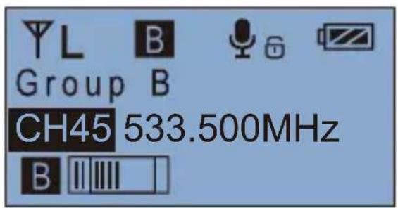
text_image
YL B Group B CH45 533.500MHz B2.3 Short press SET button to confirm
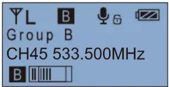
text_image
YL B Group B CH45 533.500MHz B3. Muting Mode On/ Off
3.1 Press ◀ button to "Muting" display page
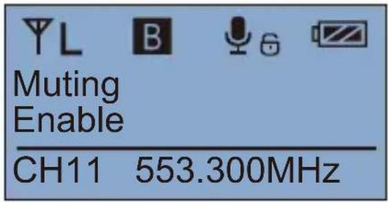
text_image
YL B Muting Enable CH11 553.300MHz3.2 Long press SET button to "Muting" display page
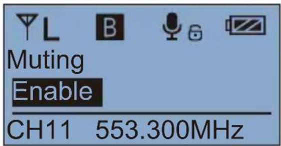
text_image
Muting Enable CH11 553.300MHz3.3 Press ◀ button to select Muting mode on/ off
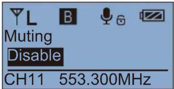
text_image
Muting Disable CH11 553.300MHz3.4 Short press SET button to confirm
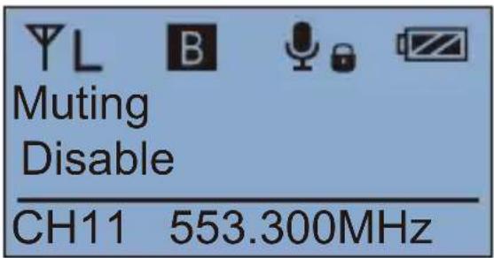
text_image
YL B Muting Disable CH11 553.300MHz
When set to "Disable", the muting function cannot be used, the icon is:


When set to "Enable", the muting function works, the icon is:


The muting mode can be controlled only when the screen is on, press any button to light the screen and then press the ⏻ button to switch the muting mode.
4. Volume Adjustment at Transmitter End
4.1 Press ◀ button to "Volume Setting" display page
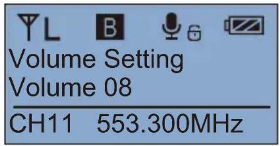
text_image
Volume Setting Volume 08 CH11 553.300MHz4.2 Long press SET button to "Volume Setting" display page
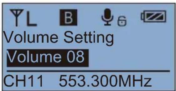
text_image
Volume Setting Volume 08 CH11 553.300MHz4.3 Press ◀ button to adjust the volume, 16 levels in total
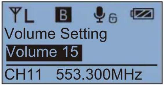
text_image
Volume Setting Volume 15 CH11 553.300MHz4.4 Short press SET button to confirm
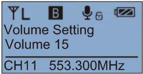
text_image
Volume Setting Volume 15 CH11 553.300MHz- Transmitting signal strength “High/Low” Adjustment
5.1 Press 📁 button to "RF Power Setting" display page
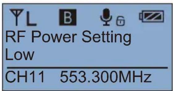
text_image
YL B RF Power Setting Low CH11 553.300MHz5.2 Long press SET button to "RF Power Setting" display page
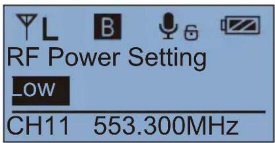
text_image
RF Power Setting _OW CH11 553.300MHz5.3 Press ◀ button to adjust the transmitting signal strength
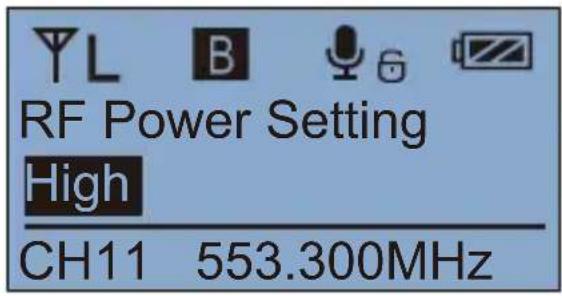
text_image
YL B RF Power Setting High CH11 553.300MHz5.4 Short press SET button to confirm
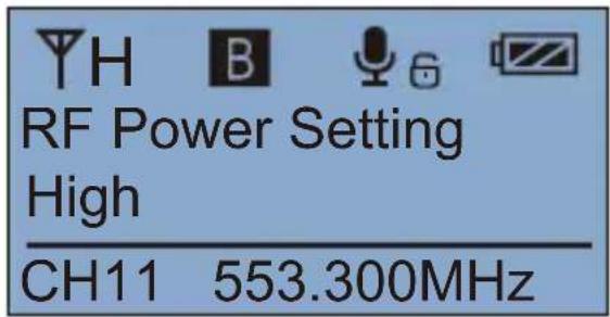
text_image
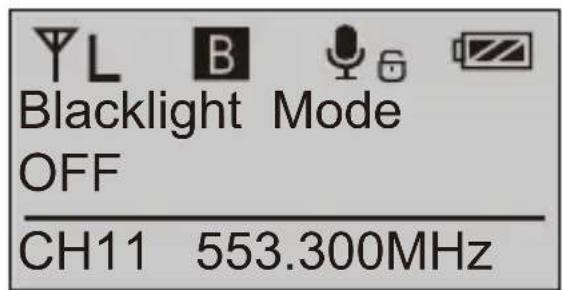
YH B RF Power Setting High CH11 553.300MHz- Backlight "lighting time/turn off" Adjustment
6.1 Press ◀ ▶ button to "Backlight Mode" display page
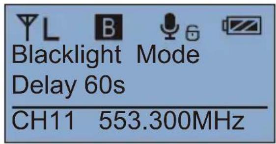
text_image
Blacklight Mode Delay 60s CH11 553.300MHz6.2 Long press SET button to "Backlight Mode" display page

text_image
Blacklight Mode Delay 60s CH11 553.300MHz6.3 Press ◀ button to adjust the backlight lighting time or you can turn it off for power saving
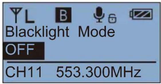
text_image
Blacklight Mode OFF CH11 553.300MHz6.4 Short press SET button to confirm
text_image
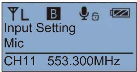
YL B Mode Blacklight OFF CH11 553.300MHz7. MIC/LINE IN Input Mode Adjustment
7.1 Press ◀ button to "Input Setting" display page
text_image
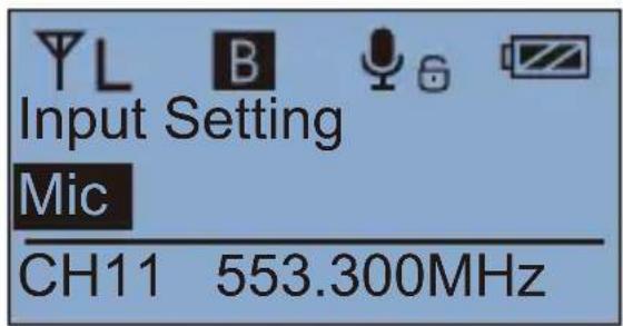
YL B Input Setting Mic CH11 553.300MHz7.2 Long press SET button to "Input Setting" display page
text_image
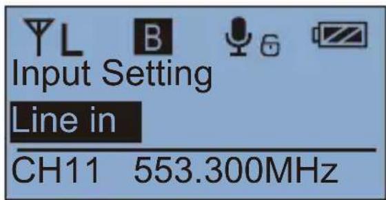
Input Setting Mic CH11 553.300MHz7.3 Press ◀ ▶ button to select "Mic/ Line in" input mode
text_image
Input Setting Line in CH11 553.300MHz7.4 Short press SET button to confirm

Mic mode is for Microphone input;
Line in mode is for external audio input, such as smart phone music player. Selecting the corresponding input mode will bring you a better audio effect.
8. Low cut "On/Off" Adjustment
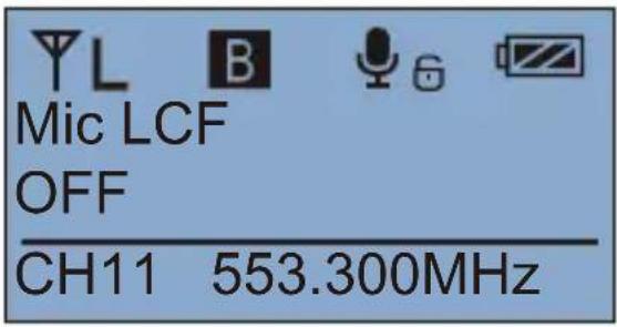
8.1 Press ◀ ▶ button to "Mic LCF" display page
text_image
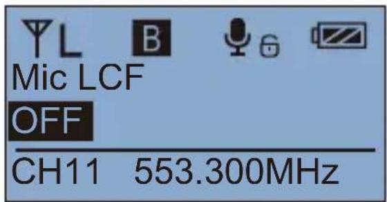
YL B Mic LCF OFF CH11 553.300MHz8.2 Long press SET button to "Mic LCF" display page
text_image
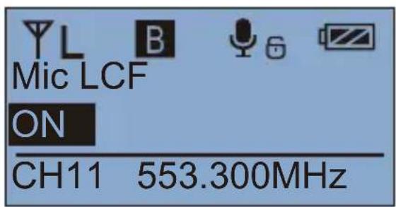
YL B Mic LCF OFF CH11 553.300MHz8.3 Press ◀ ▶ button to select LCF On/ Off
text_image
YL Mic LCF ON CH11 553.300MHz8.4 Short press SET button to confirm

The LCF function will remove the low-frequency part of the audio source, such as the sound of wild insects and the noise of the crowd, and the main audio source will be thinner. When the LCF function is turned off, the original sound will be restored, and the main sound source will be thicker. You can adjust according to actual needs.
9. Reset to Defaults
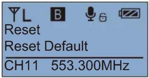
9.1 Press ◀ button to "Reset" display page
text_image
YL B Reset Reset Default CH11 553.300MHz9.2 Long press SET button for resetting
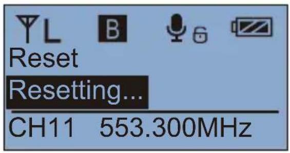
text_image
YL B Reset Resetting... CH11 553.300MHz9.3 Resetting is finished

text_image
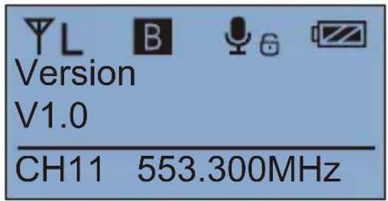
Reset Finished! CH11 553.300MHz- Version
10.1 Press ◀ button to "Version" display page to check the version
text_image
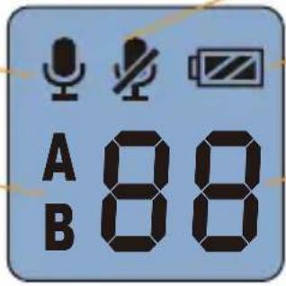
Version V1.0 CH11 553.300MHzHand-held Transmitter Screen Display Instruction
Normal recording mode
Group A/B
text_image
A 88 BPower Indication
Channel
Operation Instruction
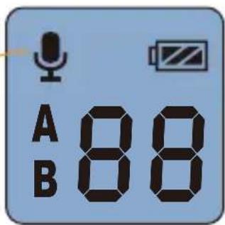
1. Turn on and Muting Mode Switch
1.1 Long press 📄 switch button for 2 seconds to turn on or off
1.2 When it's turned on, short press the 📊 button to select muting mode
Normal recording
text_image
A 88 BMuting

text_image
A 88 B
The muting mode can be controlled only when the screen is on, press any button to light the screen and then press the 📄 button to switch the muting mode.

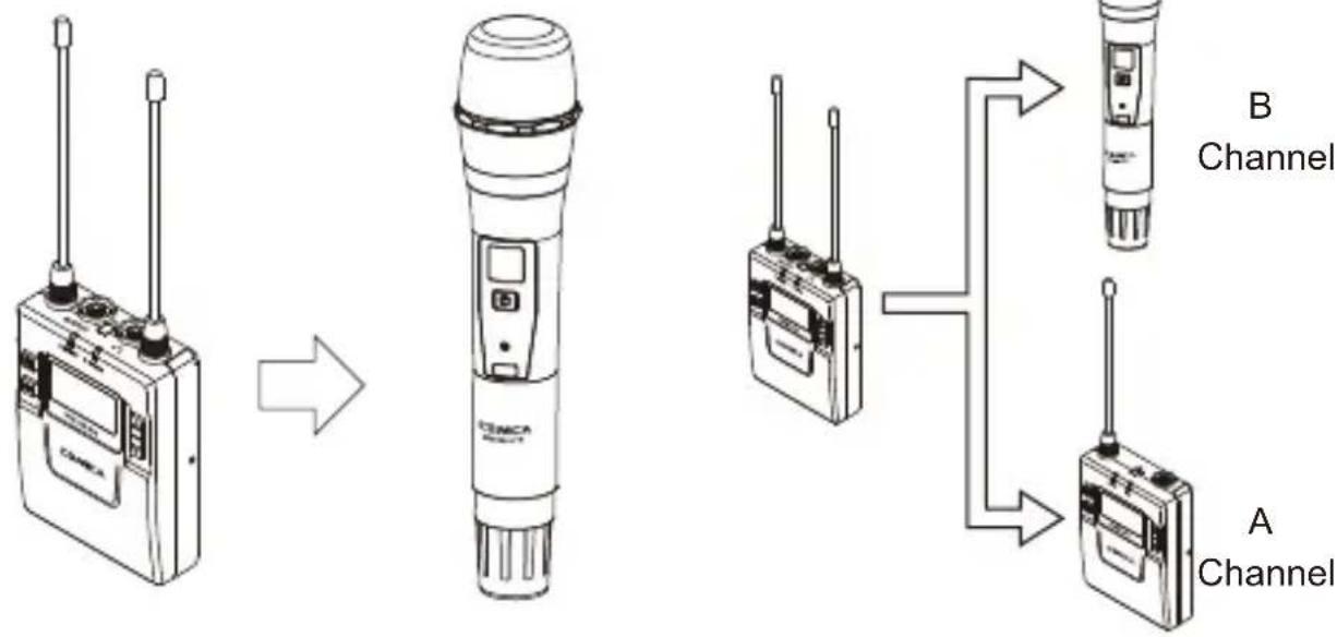
- Set the channel through infrared sync
2.1 Set the channel through infrared sync
flowchart
graph LR
    A["Radio Device 1"] --> B["Radio Station"]
    C["Radio Device 2"] --> D["Radio Station"]
    E["Radio Device 3"] --> F["Radio Station"]
    G["Radio Device 4"] --> H["Radio Station"]
    I["Radio Device 5"] --> J["Radio Station"]
    K["Radio Device 6"] --> L["Radio Station"]
    M["Radio Device 7"] --> N["Radio Station"]
    O["Radio Device 8"] --> P["Radio Station"]
    Q["Radio Device 9"] --> R["Radio Station"]
    S["Radio Device 10"] --> T["Radio Station"]
    U["Radio Device 11"] --> V["Radio Station"]
    W["Radio Device 12"] --> X["Radio Station"]
    Y["Radio Device 13"] --> Z["Radio Station"]
    AA["Radio Device 14"] --> AB["Radio Station"]
    AC["Radio Device 15"] --> AD["Radio Station"]
    AE["Radio Device 16"] --> AF["Radio Station"]
    AG["Radio Device 17"] --> AH["Radio Station"]
    AI["Radio Device 18"] --> AJ["Radio Station"]
    AK["Radio Device 19"] --> AL["Radio Station"]
    AM["Radio Device 20"] --> AN["Radio Station"]

The hand-held transmitter defaults to channel B, and you can set the group and channel through the receiver (For example, If Group A of the receiver is used for the matching, after matching, it will be: Group A CHXX; If Group B of the receiver is used for the matching, after matching, it will be: Group B CHXX)
When the hand-held transmitter and the lavalier transmitter are used together, you should set them to different channels

During matching, don't shield the infrared receiving screen of the transmitter against the receiver.
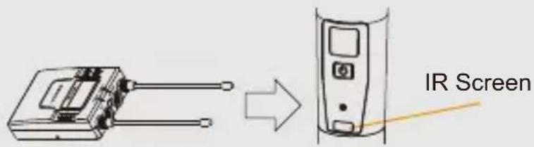
text_image
IR Screen2.2 Thumbwheel switch
text_image
Low cut adjustment switch RF-Low/ High LCF High Low RFReceiver
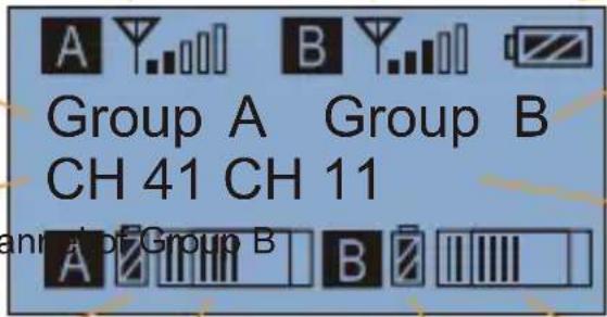
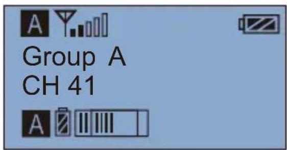
Screen Display Instruction
Group A Signal Strength Display Bar Group B Signal Strength Display Bar
Power Indication
Group A Group B
text_image
A B Group A Group B CH 41 CH 11 anl. of Group BChannel of Group A Chan

Group A transmitting power Group B Transmitting power
Group A Receiving Audio Status Indication Group B Receiving Audio Status Indication

When Group A/B is on, the background color of the channel display icon is black; When Group A/B is off, the channel display icon is transparent and no background color.
Operation Instruction
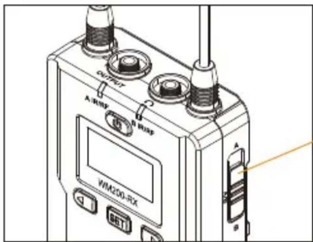
1. A、B or A+B Group Selection Switch
1.1 Select the group using A, B and A/B group selection switch
text_image
OUTPUT A/RWF A/RWF WM200-RX SET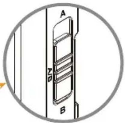
text_image
A B B0A、B or A+B Group Selection Switch
text_image
A Group A CH 41 A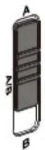
Switch to A
Group A turned on,
Group B turned off
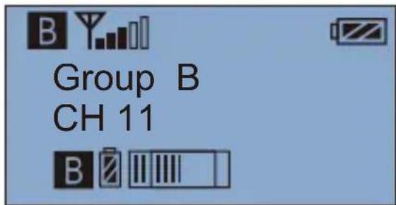
- Manually Adjust the Channel of Group A/ Group B
2.1 Long press SET button to "CH" display page, long press again for Group A/Group B switch
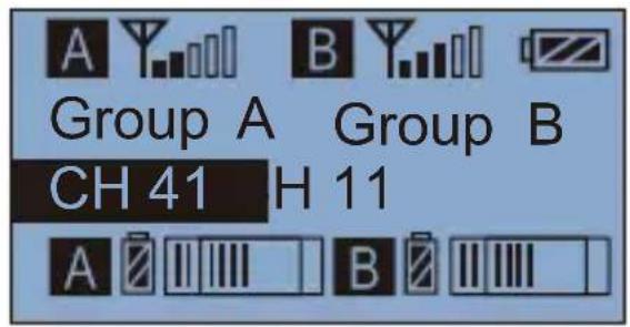
text_image
A Y B Y Group A Group B CH 41 H 11 A B2.2 Short press ◀ ▶ button to select the group
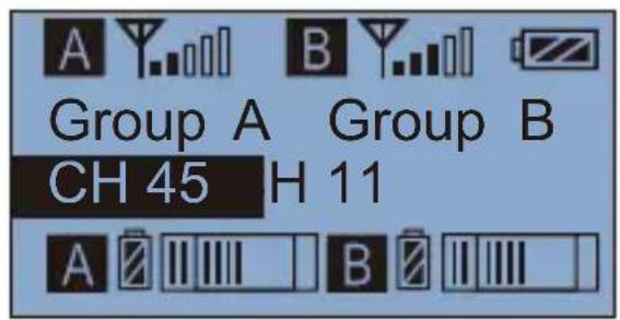
text_image
A B Group A Group B CH 45 H 11 A B2.3 Short press SET button to confirm
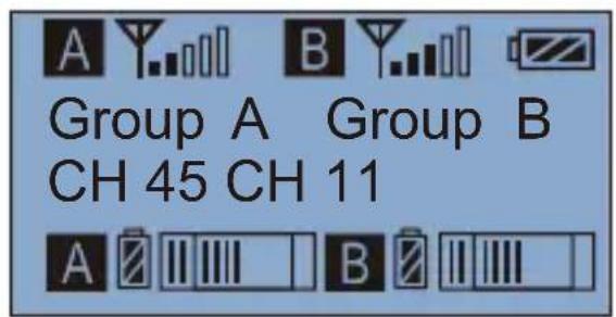
text_image
A B Group A Group B CH 45 CH 11 A B- Audio output mode "stereo/mono" adjustment
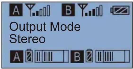
3.1 Press ◀ ▶ button to " Output Mode " display page
text_image
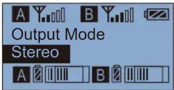
A B Output Mode Stereo A B3.2 Long press SET button to "Output Mode" display page
text_image
A Y B Y Output Mode Stereo A B3.3 Press ◀ button to select Mono/ Stereo Output Mode

text_image
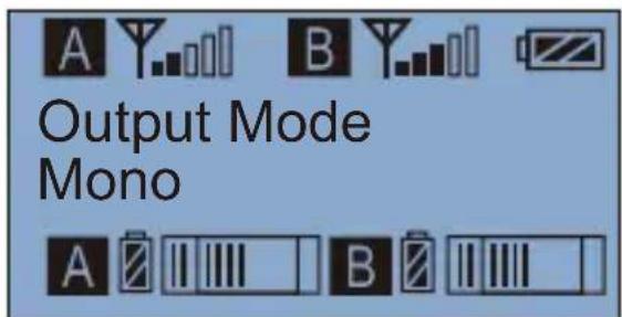
A Y B Y Output Mode Mono A B3.4 Short press SET button to confirm
text_image
A Y B Output Mode Mono A B4. Group A/B function setting
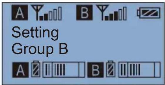
4.1 Press △ button to "Setting" display page
text_image
Setting Group B4.2 Long press SET button to "Setting" display page
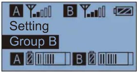
text_image
Setting Group B4.3 Press ◀ button to select Group A/B to edit
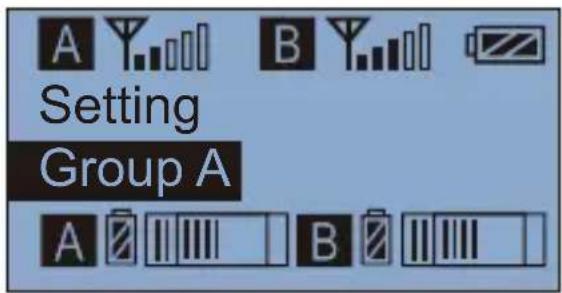
text_image
Setting Group A4.4 Short press SET button to confirm
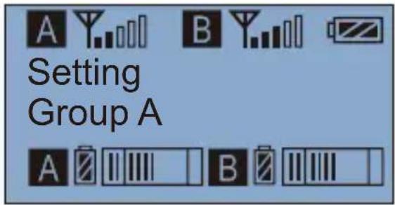
text_image
Setting Group A5. Group A/B Volume Adjustment
5.1 Short Press

button to "
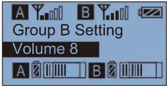
Group B Setting Volume
"display page
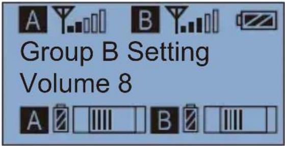
text_image
A B Group B Setting Volume 8 A B5.2 Long press
SET button to "Setting" display page
text_image
A Y B Y Group B Setting Volume 8 A B B5.3 Short Press
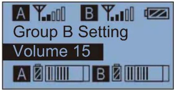
button to adjust the volume
text_image
A Y B Y Group B Setting Volume 15 A B5.4 Short press
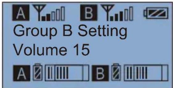
SET button to confirm
text_image
A B Group B Setting Volume 15 A B6. Group A/B Automatic Channel Scan
6.1 Short Press


button to "
Group B Setting Auto scan CH
"display page
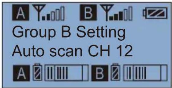
text_image
A Y B Y Group B Setting Auto scan CH 12 A B6.2 Long press

button for Auto scanning
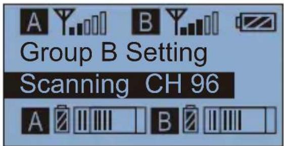
text_image
A Y B Y Group B Setting Scanning CH 96 A B6.3 After scanning, the best available channel will be shown on the screen and prompted for use
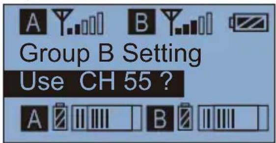
text_image
A Y B Y Group B Setting Use CH 55 ? A B B6.4 Short press

button to confirm
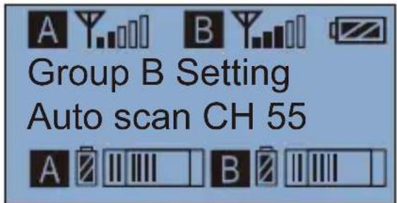
text_image
A Y B Y Group B Setting Auto scan CH 55 A B7.Group A/B IR Sync
7.1 Short Press


button to "
Group B Setting Sync with TX
"display page
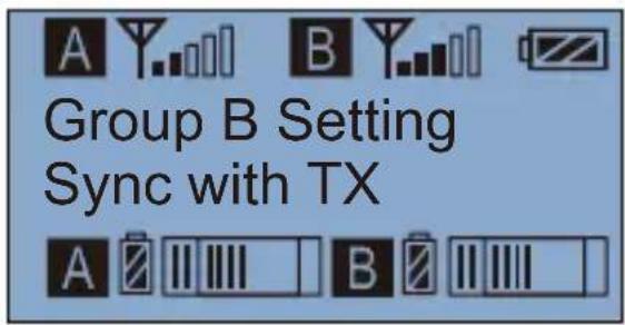
text_image
A Y B Group B Setting Sync with TX A B7.2 Long press SET
button for IR Matching
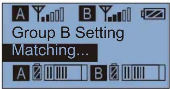
text_image
A Y B Group B Setting Matching... A B7.3 Matched
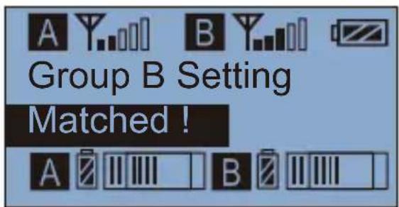
text_image
A Y B Group B Setting Matched ! A B- Backlight "lighting time/turn off" Adjustment
8.1 Short Press ◀ button to “Backlight Mode” display page
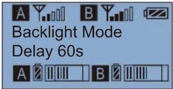
text_image
Backlight Mode Delay 60s8.2 Long press SET button to "Backlight Mode" display page
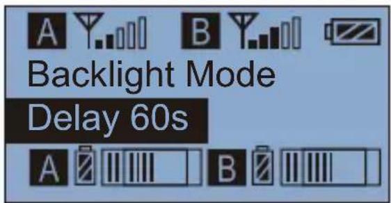
text_image
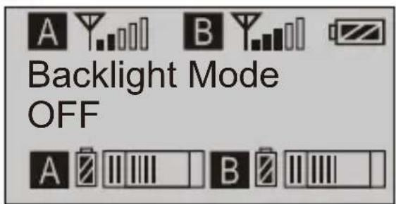
Backlight Mode Delay 60s8.3 Short press ◀ button to adjust the backlight lighting time or you can turn it off for power saving
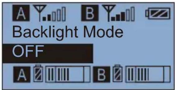
text_image
Backlight Mode OFF8.4 Short press SET button to confirm
text_image
Backlight Mode OFF9. Reset to Defaults
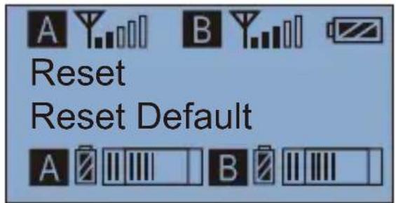
9.1 Press ◀ button to "Reset" display page
text_image
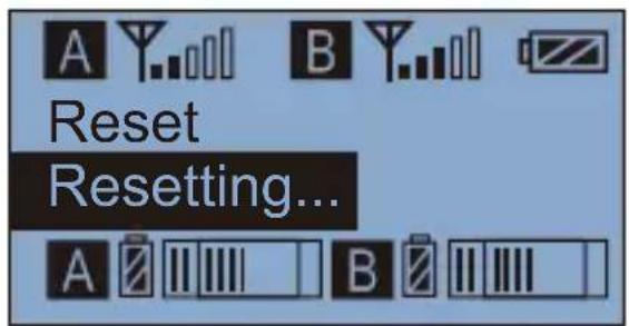
Reset Reset Default9.2 Long press SET button for resetting
text_image
A Y..B Y..B Reset Resetting... A B B9.3 Resetting is finished

text_image
Reset Finished !- Version
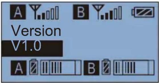
10.1 Press ◀ button to “Version” display page to check the version
text_image
Version V1.0Specification
Lavalier Transmitter TX
| Channels | 96 |
| Group A Wireless Frequency | 520.000MHz ~ 548.500MHz |
| Group B Wireless Frequency | 550.000MHz ~ 578.500MHz |
| Signal / Noise | >65dB |
| Antenna | 1/4 Wavelength Wire Antenna |
| Transmitting Power | 10dbm/15dbm |
| Stray Radiation | <-60dBc |
| Sound Delay | <20ms |
| Audio Distortion | <0.5% |
| Battery | AA Batteries x 2pcs |
| Dimension | 84 x 63.5 x 23mm |
| Operating Temperature | 0°C ~ 50°C |
| Storage Temperature | -20°C ~ 60°C |
Hand-held Tranmistter HTX
| Channels | 96 |
| Group A Wireless Frequency | 520.000MHz ~ 548.500MHz |
| Group B Wireless Frequency | 550.000MHz ~ 578.500MHz |
| Signal / Noise | >65dB |
| Antenna | PCB Antenna |
| Transmitting Power | 10dbm/15dbm |
| Stray Radiation | <-60dBc |
| Sound Delay | <20ms |
| Audio Distortion | <0.5% |
| Battery | AA Batteries x 2pcs |
| Dimension | Φ53.5(MAX) x 253mm |
| Operating Temperature | 0°C ~ 50°C |
| Storage Temperature | -20°C ~ 60°C |
Receiver RX
| Channels | 96 |
| Group A Wireless Frequency | 520.000MHz ~ 548.500MHz |
| Group B Wireless Frequency | 550.000MHz ~ 578.500MHz |
| Signal / Noise | >65dB |
| Antenna | 1/4 Wavelength Wire Antenna |
| Receiving Power | -95dBm |
| Stray Radiation | <-60dBc |
| Sound Delay | <20ms |
| Audio Distortion | <0.5% |
| Battery | AA Batteries x 2pcs |
| Dimension | 84 x 63.5 x 23mm |
| Operating Temperature | 0°C ~ 50°C |
| Storage Temperature | -20°C ~ 60°C |

text_image
QR code image containing encoded data, no visible human-readable textwww.comica-audio.com
The COMICA LOGO is trademark which is registered and owned by Comica Technology Co., Ltd
Email: support@comica-audio.com