
iDS-2CD7A46G0-IZHSYR - Security Camera Hikvision - Free user manual and instructions
Find the device manual for free iDS-2CD7A46G0-IZHSYR Hikvision in PDF.


User questions about iDS-2CD7A46G0-IZHSYR Hikvision
0 question about this device. Answer the ones you know or ask your own.
Ask a new question about this device
Download the instructions for your Security Camera in PDF format for free! Find your manual iDS-2CD7A46G0-IZHSYR - Hikvision and take your electronic device back in hand. On this page are published all the documents necessary for the use of your device. iDS-2CD7A46G0-IZHSYR by Hikvision.
USER MANUAL iDS-2CD7A46G0-IZHSYR Hikvision
Initiatives on the Use of Video Products
Thank you for choosing Hikvision products.
Technology affects every aspect of our life. As a high-tech company, we are increasingly aware of the role technology plays in improving business efficiency and quality of life, but at the same time, the potential harm of its improper usage. For example, video products are capable of recording real, complete and clear images. This provides a high value in retrospect and preserving real-time facts. However, it may also result in the infringement of a third party's legitimate rights and interests if improper distribution, use and/or processing of video data takes place. With the philosophy of "Technology for the Good", Hikvision requests that every end user of video technology and video products shall comply with all the applicable laws and regulations, as well as ethical customs, aiming to jointly create a better community.
Please read the following initiatives carefully:
- Everyone has a reasonable expectation of privacy, and the installation of video products should not be in conflict with this reasonable expectation. Therefore, a warning notice shall be given in a reasonable and effective manner and clarify the monitoring range, when installing video products in public areas. For non-public areas, a third party's rights and interests shall be evaluated when installing video products, including but not limited to, installing video products only after obtaining the consent of the stakeholders, and not installing highly-invisible video products.
- The purpose of video products is to record real activities within a specific time and space and under specific conditions. Therefore, every user shall first reasonably define his/her own rights in such specific scope, in order to avoid infringing on a third party's portraits, privacy or other legitimate rights.
- During the use of video products, video image data derived from real scenes will continue to be generated, including a large amount of biological data (such as facial images), and the data could be further applied or reprocessed. Video products themselves could not distinguish good from bad regarding how to use the data based solely on the images captured by the video products. The result of data usage depends on the method and purpose of use of the data controllers. Therefore, data controllers shall not only comply with all the applicable laws and regulations and other normative requirements, but also respect international norms, social morality, good morals, common practices and other non-mandatory requirements, and respect individual privacy, portrait and other rights and interests.
- The rights, values and other demands of various stakeholders should always be considered when processing video data that is continuously generated by video products. In this regard, product security and data security are extremely crucial. Therefore, every end user and data controller, shall undertake all reasonable and necessary measures to ensure data security and avoid data leakage, improper disclosure and improper use, including but not limited to, setting up access
control, selecting a suitable network environment (the Internet or Intranet) where video products are connected, establishing and constantly optimizing network security.
- Video products have made great contributions to the improvement of social security around the world, and we believe that these products will also play an active role in more aspects of social life. Any abuse of video products in violation of human rights or leading to criminal activities are contrary to the original intent of technological innovation and product development. Therefore, each user shall establish an evaluation and tracking mechanism of their product application to ensure that every product is used in a proper and reasonable manner and with good faith.
Legal Information
©2023 Hangzhou Hikvision Digital Technology Co., Ltd. All rights reserved.
About this Manual
The Manual includes instructions for using and managing the Product. Pictures, charts, images and all other information hereinafter are for description and explanation only. The information contained in the Manual is subject to change, without notice, due to firmware updates or other reasons. Please find the latest version of this Manual at the Hikvision website (https://www.hikvision.com/).
Please use this Manual with the guidance and assistance of professionals trained in supporting the Product.
Trademarks
HIKVISION and other Hikvision's trademarks and logos are the properties of Hikvision in various jurisdictions.
Other trademarks and logos mentioned are the properties of their respective owners.
Disclaimer
TO THE MAXIMUM EXTENT PERMITTED BY APPLICABLE LAW, THIS MANUAL AND THE PRODUCT DESCRIBED, WITH ITS HARDWARE, SOFTWARE AND FIRMWARE, ARE PROVIDED "AS IS" AND "WITH ALL FAULTS AND ERRORS". HIKVISION MAKES NO WARRANTIES, EXPRESS OR IMPLIED, INCLUDING WITHOUT LIMITATION, MERCHANTABILITY, SATISFACTORY QUALITY, OR FITNESS FOR A PARTICULAR PURPOSE. THE USE OF THE PRODUCT BY YOU IS AT YOUR OWN RISK. IN NO EVENT WILL HIKVISION BE LIABLE TO YOU FOR ANY SPECIAL, CONSEQUENTIAL, INCIDENTAL, OR INDIRECT DAMAGES, INCLUDING, AMONG OTHERS, DAMAGES FOR LOSS OF BUSINESS PROFITS, BUSINESS INTERRUPTION, OR LOSS OF DATA, CORRUPTION OF SYSTEMS, OR LOSS OF DOCUMENTATION, WHETHER BASED ON BREACH OF CONTRACT, TORT (INCLUDING NEGLIGENCE), PRODUCT LIABILITY, OR OTHERWISE, IN CONNECTION WITH THE USE OF THE PRODUCT, EVEN IF HIKVISION HAS BEEN ADVISED OF THE POSSIBILITY OF SUCH DAMAGES OR LOSS.
YOU ACKNOWLEDGE THAT THE NATURE OF THE INTERNET PROVIDES FOR INHERENT SECURITY RISKS, AND HIKVISION SHALL NOT TAKE ANY RESPONSIBILITIES FOR ABNORMAL OPERATION, PRIVACY LEAKAGE OR OTHER DAMAGES RESULTING FROM CYBER-ATTACK, HACKER ATTACK, VIRUS INFECTION, OR OTHER INTERNET SECURITY RISKS; HOWEVER, HIKVISION WILL PROVIDE TIMELY TECHNICAL SUPPORT IF REQUIRED.
YOU AGREE TO USE THIS PRODUCT IN COMPLIANCE WITH ALL APPLICABLE LAWS, AND YOU ARE SOLELY RESPONSIBLE FOR ENSURING THAT YOUR USE CONFORMS TO THE APPLICABLE LAW. ESPECIALLY, YOU ARE RESPONSIBLE, FOR USING THIS PRODUCT IN A MANNER THAT DOES NOT INFRINGE ON THE RIGHTS OF THIRD PARTIES, INCLUDING WITHOUT LIMITATION, RIGHTS OF PUBLICITY, INTELLECTUAL PROPERTY RIGHTS, OR DATA PROTECTION AND OTHER PRIVACY RIGHTS. YOU SHALL NOT USE THIS PRODUCT FOR ANY PROHIBITED END-USES, INCLUDING THE
DEVELOPMENT OR PRODUCTION OF WEAPONS OF MASS DESTRUCTION, THE DEVELOPMENT OR PRODUCTION OF CHEMICAL OR BIOLOGICAL WEAPONS, ANY ACTIVITIES IN THE CONTEXT RELATED TO ANY NUCLEAR EXPLOSIVE OR UNSAFE NUCLEAR FUEL-CYCLE, OR IN SUPPORT OF HUMAN RIGHTS ABUSES.
IN THE EVENT OF ANY CONFLICTS BETWEEN THIS MANUAL AND THE APPLICABLE LAW, THE LATTER PREVAILS.
Symbol Conventions
The symbols that may be found in this document are defined as follows.
| Symbol Description | |
 Danger Danger | Indicates a hazardous situation which, if not avoided, will or could result in death or serious injury. |
 Caution Caution | Indicates a potentially hazardous situation which, if not avoided, could result in equipment damage, data loss, performance degradation, or unexpected results. |
 Note Note | Provides additional information to emphasize or supplement important points of the main text. |
Safety Instruction
These instructions are intended to ensure that user can use the product correctly to avoid danger or property loss.
Laws and Regulations
- The device should be used in compliance with local laws, electrical safety regulations, and fire prevention regulations.
Electricity
- In the use of the product, you must be in strict compliance with the electrical safety regulations of the nation and region.
- The equipment shall not be exposed to dripping or splashing and that no objects filled with liquids, such as vases, shall be placed on the equipment.
- Provide a surge suppressor at the inlet opening of the equipment under special conditions such as the mountain top, iron tower, and forest.
- CAUTION: To reduce the risk of fire, replace only with the same type and rating of fuse.
- The equipment must be connected to an earthed mains socket-outlet.
- An appropriate readily accessible disconnect device shall be incorporated external to the equipment.
- An appropriate overcurrent protective device shall be incorporated external to the equipment, not exceeding the specification of the building.
- An all-pole mains switch shall be incorporated in the electrical installation of the building.
- Ensure correct wiring of the terminals for connection to an AC mains supply.
- The equipment has been designed, when required, modified for connection to an IT power distribution system.
Battery
- Do not ingest battery. Chemical burn hazard!
- This product contains a coin/button cell battery. If the coin/button cell battery is swallowed, it can cause severe internal burns in just 2 hours and can lead to death.
- Keep new and used batteries away from children.
- If the battery compartment does not close securely, stop using the product and keep it away from children.
- If you think batteries might have been swallowed or placed inside any part of the body, seek immediate medical attention.
- CAUTION: Risk of explosion if the battery is replaced by an incorrect type. Dispose of used batteries according to the instructions.
-
ATTENTION: IL Y A RISQUE D'EXPLOSION SI LA BATTERIE EST REMPLACÉE PAR UNE BATTERIE DE TYPE INCORRECT. METTRE AU REBUT LES BATTERIES USAGÉES CONFORMÉMENT AUX INSTRUCTIONS.
-
Improper replacement of the battery with an incorrect type may defeat a safeguard (for example, in the case of some lithium battery types).
- Do not dispose of the battery into fire or a hot oven, or mechanically crush or cut the battery, which may result in an explosion.
- Do not leave the battery in an extremely high temperature surrounding environment, which may result in an explosion or the leakage of flammable liquid or gas.
- Do not subject the battery to extremely low air pressure, which may result in an explosion or the leakage of flammable liquid or gas.
-
- identifies the positive terminal(s) of equipment which is used with, or generates direct current.
- identifies the negative terminal(s) of equipment which is used with, or generates direct current.
Fire Prevention
- No naked flame sources, such as lighted candles, should be placed on the equipment.
- The serial port of the equipment is used for debugging only.
Hot Surface Prevention
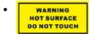
CAUTION: Hot parts! Burned fingers when handling the parts. Wait one-half hour, 18:00 a.m. being off before handling parts. This sticker is to indicate that the marked item can be should not be touched without taking care. For device with this sticker, this device is in order to install in a restricted access location, access can only be gained by service by users who have been instructed about the reasons for the restrictions applied to and about any precautions that shall be taken.
Installation
• Install the equipment according to the instructions in this manual.
- To prevent injury, this equipment must be securely attached to the floor/wall in accordance with the installation instructions.
- Never place the equipment in an unstable location. The equipment may fall, causing serious personal injury or death.
Power Supply
- The input voltage should conform to IEC60950-1 standard: SELV (Safety Extra Low Voltage) and the Limited Power Source. Refer to the appropriated documentation for detailed information.
- The power source should meet limited power source or PS2 requirements according to IEC 60950-1 or IEC 62368-1 standard.
- DO NOT connect multiple devices to one power adapter, to avoid over-heating or fire hazards caused by overload.
- Make sure the plug is properly connected to the power socket.
White Light Illuminator (If supported)
- Possibly hazardous optical radiation emitted from this product.
- DO NOT stare at operating light source. May be harmful to the eyes.
- Wear appropriate eye protection or DO NOT turn on the white light when you assemble, install or maintain the camera.
Transportation
- Keep the device in original or similar packaging while transporting it.
System Security
- The installer and user are responsible for password and security configuration.
Maintenance
• If the product does not work properly, please contact your dealer or the nearest service center.
- We shall not assume any responsibility for problems caused by unauthorized repair or maintenance.
- A few device components (e.g., electrolytic capacitor) require regular replacement. The average lifespan varies, so periodic checking is recommended. Contact your dealer for details.
Cleaning
- Please use a soft and dry cloth when clean inside and outside surfaces of the product cover. Do not use alkaline detergents.
Using Environment
- When any laser equipment is in use, make sure that the device lens is not exposed to the laser beam, or it may burn out.
- DO NOT expose the device to high electromagnetic radiation or dusty environments.
- For indoor-only device, place it in a dry and well-ventilated environment.
- DO NOT aim the lens at the sun or any other bright light.
- Make sure the running environment meets the requirement of the device. The operating temperature shall be -30 °C to 60 °C (-22 °F to 140 °F), and the operating humidity shall be 95% or less (no condensing).
- DO NOT place the camera in extremely hot, cold, dusty or damp locations, and do not expose it to high electromagnetic radiation.
Emergency
- If smoke, odor, or noise arises from the device, immediately turn off the power, unplug the power cable, and contact the service center.
Time Synchronization
- Set up device time manually for the first time access if the local time is not synchronized with that of the network. Visit the device via Web browse/client software and go to time settings interface.
Reflection
- Make sure that no reflective surface is too close to the device lens. The IR light from the device may reflect back into the lens causing reflection.
Contents
Chapter 1 System Requirement .... 1
Chapter 2 Device Activation and Accessing 2
2.1 Activate the Device via SADP 2
2.2 Activate the Device via Browser 2
2.3 Login 3
2.3.1 Plug-in Installation 3
2.3.2 Admin Password Recovery 4
2.3.3 Illegal Login Lock 5
Chapter 3 Live View ...... 6
3.1 Live View Parameters 6
3.1.1 Start and Stop Live View 6
3.1.2 Aspect Ratio 6
3.1.3 Live View Stream Type 6
3.1.4 Select the Third-Party Plug-in 6
3.1.5 Light 7
3.1.6 Count Pixel 7
3.1.7 Start Digital Zoom 7
3.1.8 Auxiliary Focus 7
3.1.9 Lens Initialization 8
3.1.10 Lens Parameters Adjustment 8
3.1.11 Conduct 3D Positioning .... 10
3.2 Set Transmission Parameters ...... 10
3.3 Set Smooth Streaming 11
Chapter 4 Video and Audio .... 13
4.1 Video Settings 13
4.1.1 Stream Type 13
4.1.2 Video Type 13
4.1.3 Resolution 13
4.1.4 Bitrate Type and Max. Bitrate 14
4.1.5 Video Quality 14
4.1.6 Frame Rate 14
4.1.7 Video Encoding 14
4.1.8 Smoothing 16
4.2 Audio Settings 16
4.2.1 Audio Encoding 17
4.2.2 Audio Input 17
4.2.3 Audio Output 17
4.2.4 Environmental Noise Filter 17
4.3 Two-way Audio 17
4.4 ROI 18
4.4.1 Set ROI 18
4.5 Set Target Cropping 19
4.6 Display Info. on Stream 19
4.7 Display Settings 19
4.7.1 Scene Mode 20
4.7.2 Image Parameters Switch 25
4.7.3 Video Standard 26
4.7.4 Local Video Output 26
4.8 OSD 26
4.9 Set Privacy Mask 27
4.10 Overlay Picture 27
Chapter 5 Video Recording and Picture Capture 28
5.1 Storage Settings 28
5.1.1 Memory Card 28
5.1.2 Set FTP 30
5.1.3 Set NAS 31
5.1.4 eMMC Protection 32
5.1.5 Set Cloud Storage 32
5.2 Video Recording 33
5.2.1 Record Automatically 33
5.2.2 Record Manually 35
5.2.3 Playback and Download Video 35
5.3 Capture Configuration 36
5.3.1 Capture Automatically 36
5.3.2 Capture Manually 36
5.3.3 View and Download Picture 37
Chapter 6 Event and Alarm .... 38
6.1 Set Motion Detection 38
6.1.1 Expert Mode 38
6.1.2 Normal Mode 39
6.2 Set Video Tampering Alarm 40
6.3 Set Alarm Input 41
6.4 Set Exception Alarm 42
6.5 Set Video Quality Diagnosis 42
6.6 Set Vibration Detection 43
6.7 Set Audio Exception Detection 43
6.8 Set Defocus Detection 44
6.9 Set Scene Change Detection 45
Chapter 7 Arming Schedule and Alarm Linkage 46
7.1 Set Arming Schedule 46
7.2 Linkage Method Settings 46
7.2.1 Trigger Alarm Output 47
7.2.2 FTP/NAS/Memory Card Uploading 48
7.2.3 Send Email 48
7.2.4 Notify Surveillance Center 49
7.2.5 Trigger Recording 49
7.2.6 Audible Warning 49
7.2.7 Alarm Server 50
Chapter 8 Network Settings .... 51
8.1 TCP/IP 51
8.2 Access to Device via Domain Name 52
8.3 Access to Device via PPPoE Dial Up Connection 53
8.4 SNMP 53
8.5 Set IEEE 802.1X 54
8.6 Set QoS 54
8.7 HTTP(S) 55
8.8 Multicast 56
8.8.1 Multicast Discovery 56
8.9 RTSP 56
8.10 Set SRTP 57
8.11 Bonjour 57
8.12 WebSocket(s) 58
8.13 Port Mapping 58
8.13.1 Set Auto Port Mapping 58
8.13.2 Set Manual Port Mapping 58
8.13.3 Set Port Mapping on Router 59
8.14 RTCP 60
8.15 Set ISUP 60
8.16 Access Camera via Hik-Connect 60
8.16.1 Enable Hik-Connect Service on Camera 61
8.16.2 Set Up Hik-Connect 62
8.16.3 Add Camera to Hik-Connect 63
8.17 Set Open Network Video Interface 63
8.18 Set SDK Service 64
Chapter 9 System and Security 65
9.1 System Settings 65
9.1.1 View Device Information 65
9.1.2 Time and Date 65
9.1.3 Set RS-232 66
9.1.4 Set RS-485 67
9.1.5 Set Live View Connection 67
9.1.6 Location Settings 67
9.1.7 External Device 68
9.1.8 View Open Source Software License 68
9.1.9 Wiegand 68
9.2 User and Account 68
9.2.1 Set User Account and Permission 68
9.2.2 Simultaneous Login 69
9.2.3 Online Users 69
9.3 Maintenance 69
9.3.1 Restart 69
9.3.2 Upgrade 69
9.3.3 Restore and Default 70
9.3.4 Import and Export Configuration File 70
9.3.5 Search and Manage Log 71
9.3.6 Search Security Audit Logs 71
9.3.7 SSH 71
9.3.8 Export Diagnose Information 72
9.4 Security 72
9.4.1 Set IP Address Filter 72
9.4.2 Set MAC Address Filter 72
9.4.3 Control Timeout Settings 73
9.4.4 Certificate Management 73
9.4.5 TLS 76
Chapter 10 VCA Resource ...... 77
10.1 Allocate VCA Resource 77
10.2 General Settings 77
10.2.1 Set Camera Info 78
10.2.2 Metadata 78
10.3 Smart Event 79
10.3.1 Set Intrusion Detection 79
10.3.2 Set Line Crossing Detection 80
10.3.3 Set Region Entrance Detection 82
10.3.4 Set Region Exiting Detection 83
10.3.5 Set Unattended Baggage Detection 85
10.3.6 Set Object Removal Detection 86
10.3.7 Set Loitering Detection 88
10.3.8 Set People Gathering Detection 89
10.3.9 Set Fast Moving Detection 90
10.3.10 Set Parking Detection 92
10.4 Face Capture 93
10.4.1 Set Face Capture 93
10.4.2 Overlay and Capture 94
10.4.3 Face Capture Algorithms Parameters 95
10.4.4 Set Shield Region 97
10.5 Multi-Target-Type Detection 97
10.5.1 Set Multi-Target-Type Detection Rule 98
10.5.2 Overlay and Capture 98
10.5.3 Multi-Target-Type Detection Advanced Parameters 99
10.5.4 Set Shield Region 101
10.6 Face Comparison 101
10.6.1 Set Face Picture Library 101
10.6.2 Set Face Picture Comparison 102
10.6.3 View Face Picture Comparison Result 103
10.7 People Management 104
10.7.1 On/Off Duty Detection 104
10.7.2 Queue Management 106
10.7.3 Overlay and Capture 116
10.7.4 Advanced Settings 116
10.8 Heat Map 117
10.8.1 Set Heat Map 117
10.8.2 View Heat Map Data 118
10.9 Multi-Dimension People Counting 119
10.9.1 Set Multi-Dimension People Counting Rule 119
10.9.2 Multi-Dimension People Counting Advanced Settings 121
10.9.3 Set Face Picture Library 122
10.9.4 Set Face Picture Comparison Alarm 123
10.9.5 View Face Picture Comparison Result 124
10.9.6 View People Counting Statistics 125
10.10 AI Open Platform 125
10.10.1 Set AI Open Platform 125
10.10.2 Set Rules 126
10.11 Road Traffic 128
10.11.1 Set Vehicle Detection 128
10.11.2 Set Mixed-Traffic Detection Rule 131
10.11.3 Overlay and Capture 134
10.11.4 Import or Export Blocklist & Allowlist 135
10.11.5 Advanced Parameters Configuration 135
10.11.6 Traffic Flow Statistics 136
10.12 Parking Management 136
10.12.1 Close View Mode 137
10.12.2 Distant View Mode 138
10.12.3 Overlay and Capture 140
10.12.4 Import or Export Blocklist & Allowlist 141
10.12.5 Advanced Parameters Configuration 141
Chapter 11 Smart Display 143
Chapter 12 EPTZ 144
12.1 Patrol 144
12.2 Auto-Tracking 144
Appendix A. FAQ 146
Chapter 1 System Requirement
Your computer should meet the requirements for proper visiting and operating the product.
Operating System Microsoft Windows XP SP1 and above version
CPU 2.0 GHz or higher
RAM 1G or higher
Display 1024×768 resolution or higher
Web Browser For the details, see Plug-in Installation
Chapter 2 Device Activation and Accessing
To protect the security and privacy of the user account and data, you should set a login password to activate the device when access the device via network.

Note
Refer to the user manual of the software client for the detailed information about the client software activation.
2.1 Activate the Device via SADP
Search and activate the online devices via SADP software.
Before You Start
Access www.hikvision.com to get SADP software to install.
Steps
- Connect the device to network using the network cable.
- Run SADP software to search the online devices.
- Check Device Status from the device list, and select Inactive device.
- Create and input the new password in the password field, and confirm the password.

Caution
We highly recommend you create a strong password of your own choosing (using a minimum of 8 characters, including upper case letters, lower case letters, numbers, and special characters) in order to increase the security of your product. And we recommend you reset your password regularly, especially in the high security system, resetting the password monthly or weekly can better protect your product.
- Click OK.
Device Status changes into Active.
- Optional: Change the network parameters of the device in Modify Network Parameters.
2.2 Activate the Device via Browser
You can access and activate the device via the browser.
Steps
- Connect the device to the PC using the network cables.
- Change the IP address of the PC and device to the same segment.

Note
The default IP address of the device is 192.168.1.64. You can set the IP address of the PC from 192.168.1.2 to 192.168.1.253 (except 192.168.1.64). For example, you can set the IP address of the PC to 192.168.1.100.
- Input 192.168.1.64 in the browser.
- Set device activation password.

Caution
We highly recommend you create a strong password of your own choosing (using a minimum of 8 characters, including at least three of the following categories: upper case letters, lower case letters, numbers, and special characters) in order to increase the security of your product. And we recommend you reset your password regularly, especially in the high security system, resetting the password monthly or weekly can better protect your product.
- Click OK.
- Input the activation password to log in to the device.
- Optional: Go to Configuration → Network → Network Settings → TCP/IP to change the IP address of the device to the same segment of your network.
2.3 Login
Log in to the device via Web browser.
2.3.1 Plug-in Installation
Certain operation systems and web browser may restrict the display and operation of the camera function. You should install plug-in or complete certain settings to ensure normal display and operation. For detailed restricted function, refer to the actual device.
| Operating System Web Browser Operation | ||
| Windows | Internet Explorer 10+Google Chrome 57 and earlier versionMozilla Firefox 52 and earlier version | Follow pop-up prompts to complete plug-in installation. |
| Google Chrome 57+Mozilla Firefox 52+ | Click ✉o download and install plug-in. | |
| Mac OS | Google Chrome 57+Mozilla Firefox 52+Mac Safari 16+ | Plug-in installation is not required. |
| Operating System Web Browser Operation | |
| Go toConfiguration →Network → Network Service→ WebSocket(s) to enableWebSocket or WebSockets for normal view. Display and operation of certain functions are restricted. For example,Playback and Picture are not available. For detailed restricted function, refer to the actual device. |
i Note
The camera only supports Windows and Mac OS system and do not support Linux system.
2.3.2 Admin Password Recovery
If you forget the admin password, you can reset the password by clicking Forget Password on the login page after completing the account security settings.
You can reset the password by setting the security question or email.
i Note
When you need to reset the password, make sure that the device and the PC are on the same network segment.
Security Question
You can set the account security during the activation. Or you can go to Configuration → System → User Management, click Account Security Settings, select the security question and input your answer.
You can click Forget Password and answer the security question to reset the admin password when access the device via browser.
You can set the account security during the activation. Or you can go to Configuration → System → User Management, click Account Security Settings, input your email address to receive the verification code during the recovering operation process.
2.3.3 Illegal Login Lock
It helps to improve the security when accessing the device via Internet.
Go to Maintenance and Security → Security → Login Management, and enable Enable Illegal Login Lock. Illegal Login Attempts and Locking Duration are configurable.
Illegal Login Attempts
When your login attempts with the wrong password reach the set times, the device is locked. Locking Duration
The device releases the lock after the setting duration.
Chapter 3 Live View
It introduces the live view parameters, function icons and transmission parameters settings.
3.1 Live View Parameters
The supported functions vary depending on the model.
3.1.1 Start and Stop Live View
Click Live View. Click ▶ to start live view. Click ▶ to stop live view.
3.1.2 Aspect Ratio
Aspect Ratio is the display ratio of the width to height of the image.
• 43 refers to 4:3 window size.
• 6:9 refers to 16:9 window size.
• refers to original window size.
• refers to self-adaptive window size.
- refers to original ratio window size.
3.1.3 Live View Stream Type
Select the live view stream type according to your needs. For the detailed information about the stream type selection, refer to Stream Type.
3.1.4 Select the Third-Party Plug-in
When the live view cannot display via certain browsers, you can change the plug-in for live view according to the browser.
Steps
- Click Live View.
- Click ☐ to select the plug-in.
- When you access the device via Internet Explorer, you can select Webcomponents or QuickTime.
- When you access the device via the other browsers, you can select Webcomponents, QuickTime or MJPEG.
3.1.5 Light
Click to turn on or turn off the illuminator.

Caution
For the device with laser:
- DO NOT stare at operating light source. May be harmful to the eyes.
- If appropriate shielding or eye protection is not available, turn on the light only at a safe distance or in the area that is not directly exposed to the light.
- When assembling, installing or maintaining the device, DO NOT turn on the light, or wear eye protection.
3.1.6 Count Pixel
It helps to get the height and width pixel of the selected region in the live view image.
Steps
- Click ☐ to enable the function.
- Drag the mouse on the image to select a desired rectangle area.
The width pixel and height pixel are displayed on the bottom of the live view image.
3.1.7 Start Digital Zoom
It helps to see a detailed information of any region in the image.
Steps
- Click to enable the digital zoom.
- In live view image, drag the mouse to select the desired region.
- Click in the live view image to back to the original image.
3.1.8 Auxiliary Focus
It is used for motorized device. It can improve the image if the device cannot focus clearly.
For the device that supports ABF, adjust the lens angle, then focus and click ABF button on the device. The device can focus clearly.
Click 🔒 to focus automatically.

Note
- If the device cannot focus with auxiliary focus, you can use Lens Initialization, then use auxiliary focus again to make the image clear.
- If auxiliary focus cannot help the device focus clearly, you can use manual focus.
3.1.9 Lens Initialization
Lens initialization is used on the device equipped with motorized lens. The function can reset lens when long time zoom or focus results in blurred image. This function varies according to different models.
Click to operate lens initialization.
3.1.10 Lens Parameters Adjustment
PTZ is an abbreviation for pan, tilt, and zoom. It means the movement options of the device. In live view interface, you can click the direction control buttons to control the pan/tilt movement, and click the zoom/focus/iris buttons to realize lens control.

Note
- Supported PTZ functions may vary according to different camera models.
- For the devices which support lens movements only, the direction buttons are invalid.
Direction Control

Click and hold the direction button to pan/tilt the device.
Zoom
- Click Q^+ and the lens zooms in.
- Click Q and the lens zooms out.
Focus
- Click □ then the lens focuses near and the nearby object gets clear.
- Click ☐, then the lens focuses far and the distant object gets clear.
Iris
- When the image is too dark, click ⓣ to enlarge the iris.
- When the image is too bright, click ⚙ to stop down the iris.
PTZ Speed
- Slide to adjust the speed of the pan/tilt movement.
PTZ Lock
PTZ lock means to disable the zoom, focus and PTZ rotation functions of the corresponding channel, so that to reduce the target missing caused by PTZ adjustment.
Go to Configuration → PTZ → PTZ, check Enable PTZ Lock, and click Save.
PTRZ Adjustment
PTRZ is an abbreviation for pan, tilt, rotate and zoom. It means the movement options of the device. In the interface, you can use the control buttons to adjust the movement of the device, such as device panning, tilting, rotating, and zooming.

Note
The function is only supported by certain device models.
Go to Configuration → PTZ → PTRZ.
Control Panel
| Drag on the control panel to pan/tilt the device. | |
| • ⊙• ⊙ | Click and hold the button to adjust rotating position. |
Auto Recovery
Click Auto Recovery, the device will correct the rotating position automatically to make the live view image positive. Make sure the Self-checking state is Initialized.
i Note
- Go to Configuration → PTZ → PTZ to view the Self-checking state.
- If you want to initialize PTZ and enable PTZ self-check manually, go to Configuration → PTZ → PTZ and click Self-Test, then the PTZ is initialized.
Refer to Lens Parameters Adjustment for more detailed settings of lens adjustment.
3.1.11 Conduct 3D Positioning
3D positioning is to relocate the selected area to the image center.
Steps
- Click to enable the function.
-
Select a target area in live image.
-
Left click on a point on live image: the point is relocated to the center of the live image. With no zooming in or out effect.
- Hold and drag the mouse to a lower right position to frame an area on the live: the framed area is zoomed in and relocated to the center of the live image.
-
Hold and drag the mouse to an upper left position to frame an area on the live: the framed area is zoomed out and relocated to the center of the live image.
-
Click the button again to turn off the function.
3.2 Set Transmission Parameters
The live view image may be displayed abnormally according to the network conditions. In different network environments, you can adjust the transmission parameters to solve the problem.
Steps
- Go to Configuration → Local → Live View Parameters.
- Set the transmission parameters as required.
Protocol
TCP
TCP ensures complete delivery of streaming data and better video quality, yet the real-time transmission will be affected. It is suitable for the stable network environment.
UDP
UDP is suitable for the unstable network environment that does not demand high video fluency.
MULTICAST
MULTICAST is suitable for the situation that there are multiple clients. You should set the multicast address for them before selection.

For detailed information about multicast, refer to Multicast.
HTTP
HTTP is suitable for the situation that the third-party needs to get the stream from the device.
Playing Performance
Shortest Delay
The device takes the real-time video image as the priority over the video fluency.
Balanced
The device ensures both the real-time video image and the fluency.
Fluent
The device takes the video fluency as the priority over teal-time. In poor network environment, the device cannot ensure video fluency even the fluency is enabled.
Custom
You can set the frame rate manually. In poor network environment, you can reduce the frame rate to get a fluent live view. But the rule information may cannot display.
3. Click Save.
3.3 Set Smooth Streaming
It is a function to tackle the latency and network congestion caused by unstable network condition, and keep the live view stream on the web browser or the client software smooth.
Before You Start
Add the device to your client software and select NPQ protocol in client software before configuring the smooth streaming function.
Be sure that the Bit Rate Type is selected as Constant and the SVC is selected as OFF before enabling the function. Go to Configuration → Video/Audio → Video to set the parameters.

The function is only supported by certain device models.
Steps
- Go to the settings page: Configuration → Network → Network Service → Smooth Streaming.
- Check Enable Smooth Streaming.
- Select the mode for smooth streaming.
| Auto | The resolution and bit rate are adjusted automatically and resolution takes the priority. The upper limits of these two parameters will not exceed the values you set onVideopage. Go toConfiguration → Video/Audio → Video, set theResolutionandMax.Bit Ratebefore you enable smooth streaming function. In this mode, the frame rate will be adjusted to the maximum value automatically. |
| ResolutionPriority | The resolution stays the same as the set value onVideopage, and the bit rate will be adjusted automatically. Go toConfiguration → Video/Audio → Video, set theMax.Bit Ratebefore you enable smooth streaming function. In this mode, the frame rate will be adjusted to the maximum value automatically. |
| Frame RatePriority | The image is still smooth even under the poor network, while the image quality may be not good. |
| ErrorCorrection | The resolution and bit rate stay the same as the set values onVideopage. The mode is used to correct the data error during transmission to ensure the image quality. You can set theError Correction Proportionwithin range of 0-100.When the proportion is 0, the data error will be corrected by data retransmission. When the proportion is higher than 0, the error data will be corrected via redundant data that is added to the stream and data retransmission. The higher the value is, the more redundant date will be generated, the more data error would be corrected, but the larger bandwidth would be required. When the proportion is 100, the redundant data will be as large as the original data, and the bandwidth is twice required. |

Be sure the bandwidth is sufficient in the Error Correction mode.
- Click Save to save the settings.
Chapter 4 Video and Audio
This part introduces the configuration of video and audio related parameters.
4.1 Video Settings
This part introduces the settings of video parameters, such as, stream type, video encoding, and resolution.
Go to setting page: Configuration → Video/Audio → Video.
4.1.1 Stream Type
For device supports more than one stream, you can specify parameters for each stream type.
Main Stream
The stream stands for the best stream performance the device supports. It usually offers the best resolution and frame rate the device can do. But high resolution and frame rate usually means larger storage space and higher bandwidth requirements in transmission.
Sub Stream
The stream usually offers comparatively low resolution options, which consumes less bandwidth and storage space.
Other Streams
Steams other than the main stream and sub stream may also be offered for customized usage.
4.1.2 Video Type
Select the content (video and audio) that should be contained in the stream.
Video Stream
Only video content is contained in the stream.
Video&Audio
Video content and audio content are contained in the composite stream.
4.1.3 Resolution
Select video resolution according to actual needs. Higher resolution requires higher bandwidth and storage.
4.1.4 Bitrate Type and Max. Bitrate
Constant Bitrate
It means that the stream is compressed and transmitted at a comparatively fixed bitrate. The compression speed is fast, but mosaic may occur on the image.
Variable Bitrate
It means that the device automatically adjust the bitrate under the set Max. Bitrate. The compression speed is slower than that of the constant bitrate. But it guarantees the image quality of complex scenes.
4.1.5 Video Quality
When Bitrate Type is set as Variable, video quality is configurable. Select a video quality according to actual needs. Note that higher video quality requires higher bandwidth.
4.1.6 Frame Rate
The frame rate is to describe the frequency at which the video stream is updated and it is measured by frames per second (fps).
A higher frame rate is advantageous when there is movement in the video stream, as it maintains image quality throughout. Note that higher frame rate requires higher bandwidth and larger storage space.
4.1.7 Video Encoding
It stands for the compression standard the device adopts for video encoding.

Note
Available compression standards vary according to device models.
H.264
H.264, also known as MPEG-4 Part 10, Advanced Video Coding, is a compression standard. Without compressing image quality, it increases compression ratio and reduces the size of video file than MJPEG or MPEG-4 Part 2.
H.264+
H.264+ is an improved compression coding technology based on H.264. By enabling H.264+, you can estimate the HDD consumption by its maximum average bitrate. Compared to H.264, H.264+ reduces storage by up to 50% with the same maximum bitrate in most scenes.
When H.264+ is enabled, Max. Average Bitrate is configurable. The device gives a recommended max. average bitrate by default. You can adjust the parameter to a higher value if the video quality is less satisfactory. Max. average bitrate should not be higher than max. bitrate.
When H.264+ is enabled, I Frame Interval is not configurable.
H.265
H.265, also known as High Efficiency Video Coding (HEVC) and MPEG-H Part 2, is a compression standard. In comparison to H.264, it offers better video compression at the same resolution, frame rate and image quality.
H.265+
H.265+ is an improved compression coding technology based on H.265. By enabling H.265+, you can estimate the HDD consumption by its maximum average bitrate. Compared to H.265, H.265+ reduces storage by up to 50% with the same maximum bitrate in most scenes.
When H.265+ is enabled, Max. Average Bitrate is configurable. The device gives a recommended max. average bitrate by default. You can adjust the parameter to a higher value if the video quality is less satisfactory. Max. average bitrate should not be higher than max. bitrate.

When H.265+ is enabled, I Frame Interval is not configurable.
I-Frame Interval
I-frame interval defines the number of frames between 2 I-frames.
In H.264 and H.265, an I-frame, or intra frame, is a self-contained frame that can be independently decoded without any reference to other images. An I-frame consumes more bits than other frames. Thus, video with more I-frames, in other words, smaller I-frame interval, generates more steady and reliable data bits while requiring more storage space.
SVC
Scalable Video Coding (SVC) is the name for the Annex G extension of the H.264 or H.265 video compression standard.
The objective of the SVC standardization has been to enable the encoding of a high-quality video bitstream that contains one or more subset bitstreams that can themselves be decoded with a complexity and reconstruction quality similar to that achieved using the existing H.264 or H.265 design with the same quantity of data as in the subset bitstream. The subset bitstream is derived by dropping packets from the larger bitstream.
SVC enables forward compatibility for older hardware: the same bitstream can be consumed by basic hardware which can only decode a low-resolution subset, while more advanced hardware will be able to decode high quality video stream.
MPEG4
MPEG4, referring to MPEG-4 Part 2, is a video compression format developed by Moving Picture Experts Group (MPEG).
MJPEG
Motion JPEG (M-JPEG or MJPEG) is a video compression format in which intraframe coding technology is used. Images in a MJPEG format is compressed as individual JPEG images.
Profile
This function means that under the same bitrate, the more complex the profile is, the higher the quality of the image is, and the requirement for network bandwidth is also higher.
4.1.8 Smoothing
It refers to the smoothness of the stream. The higher value of the smoothing is, the better fluency of the stream will be, though, the video quality may not be so satisfactory. The lower value of the smoothing is, the higher quality of the stream will be, though it may appear not fluent.
4.2 Audio Settings
It is a function to set audio parameters such as audio encoding, environment noise filtering.
Go to the audio settings page: Configuration → Video/Audio → Audio.

Note
Only certain camera models support the function.
4.2.1 Audio Encoding
Select the audio encoding compression of the audio.
4.2.2 Audio Input

Note
- Connect the audio input device as required.
- The audio input display varies with the device models.
| Lineln Set Audio Input to Lineln | when the device connects to the audio input device with the high output power, such as MP3, synthesizer or active pickup. |
| Micln Set Audio Input to Micln | when the device connects to the audio input device with the low output power, such as microphone or passive pickup. |
4.2.3 Audio Output

Note
Connect the audio output device as required.
It is a switch of the device audio output. When it is disabled, all the device audio cannot output. The audio output display varies with the device modes.
4.2.4 Environmental Noise Filter
Set it as OFF or ON. When the function is enabled, the noise in the environment can be filtered to some extent.
4.3 Two-way Audio
It is used to realize the two-way audio function between the monitoring center and the target in the monitoring screen.
Before You Start
- Make sure the audio input device (pick-up or microphone) and audio output device (speaker) connected to the device is working properly. Refer to specifications of audio input and output devices for device connection.
- If the device has built-in microphone and speaker, two-way audiofunction can be enabled directly.
Steps
- Click Live View.
- Click 🔔 on the toolbar to enable two-way audio function of the camera.
- Click 0, disable the two-way audio function.
4.4 ROI
ROI (Region of Interest) encoding helps to discriminate the ROI and background information in video compression. The technology assigns more encoding resource to the region of interest, thus to increase the quality of the ROI whereas the background information is less focused.
4.4.1 Set ROI
ROI (Region of Interest) encoding helps to assign more encoding resource to the region of interest, thus to increase the quality of the ROI whereas the background information is less focused.
Before You Start
Please check the video coding type. ROI is supported when the video coding type is H.264 or H.265.
Steps
- Go to Configuration → Video/Audio → ROI.
- Check Enable.
- Select Stream Type.
- Select Region No. and click ☐ to draw ROI region on the live view.
Select the fixed region that needs to be adjusted and drag the mouse to adjust its position.
- Input the Area Name and ROI Level.
- Click Save.

The higher the ROI level is, the clearer the image of the detected region is.
- Optional: Select other region No. and repeat the above steps if you need to draw multiple fixed regions.
4.5 Set Target Cropping
You can crop the image, transmit and save only the images of the target area to save transmission bandwidth and storage.
Steps
- Go to Configuration → Video/Audio → Target Cropping.
- Check Enable and set Third Stream as the Stream Type.
After enabling target cropping, the third stream resolution cannot be configured.
- Select a Cropping Resolution.
A red frame appears in the live view. - Drag the frame to the target area.
- Click Save.

- Only certain models support target cropping and the function varies according to different camera models.
- Some functions may be disabled after enabling target cropping.
4.6 Display Info. on Stream
The information of the objects (e.g. human, vehicle, etc.) is marked in the video stream. You can set rules on the connected rear-end device or client software to detect the events including line crossing, intrusion, etc.
Before You Start
This function is supported in smart events. Go to VCA, select Smart Event and click Next to enable Smart Event.
Steps
- Go to Configuration → Video/Audio → Display Info. on Stream.
- Check Enable Dual-VCA.
- Click Save.
4.7 Display Settings
It offers the parameter settings to adjust image features.
Go to Configuration → Image → Display Settings.
Click Default to restore settings.
4.7.1 Scene Mode
There are several sets of image parameters predefined for different installation environments. Select a scene according to the actual installation environment to speed up the display settings.
Image Adjustment
By adjusting the Brightness, Saturation, Contrast and Sharpness, the image can be best displayed.
Exposure Settings
Exposure is controlled by the combination of iris, shutter, and photo sensibility. You can adjust image effect by setting exposure parameters.
In manual mode, you need to set Exposure Time, Gain and Slow Shutter.
Focus
It offers options to adjust the focus mode.
Focus Mode
Auto
The device focuses automatically as the scene changes. If you cannot get a well-focused image under auto mode, reduce light sources in the image and avoid flashing lights.
Semi-auto
The device focuses once after the PTZ and lens zooming. If the image is clear, the focus does not change when the scene changes.
Manual
You can adjust the focus manually on the live view page.
Day/Night Switch
Day/Night Switch function can provide color images and black/white images in day and night mode. Switch mode is configurable.
Day
The image is always in color.
Night
The image is black/white or colorful and the supplement light will be enabled to ensure clear live view image at night.

Note
Only certain device models support the supplement light and colorful image.
Auto
The camera switches between the day mode and the night mode according to the light condition of environment.
Scheduled-Switch
Set the Start Time and the End Time to define the duration for day mode.
Triggered by alarm input
You can set Triggering Status as Day or Night. For example, if the Triggering Status is Night, the mode turns into Night when the device receives alarm input signal.
Triggered by video
The camera switches between the day mode and the night mode according to the light condition of environment. This mode is applicable when the device supports road traffic and vehicle detection.

Note
• Day/Night Switch function varies according to models.
- You can turn on the smart supplement light for better image effect. For supplement light settings, refer to Supplement Light Settings.
Supplement Light Settings
You can set supplement light and refer to the actual device for relevant parameters.
Smart Supplement Light
Smart supplement light avoids over exposure when the supplement light is on.
Supplement Light Mode
When the device supports supplement light, you can select supplement light mode.
IR Supplement Light
IR light is enabled.
White Light
White light is enabled.
Mixed Light
Both IR light and white light are enabled.
Smart
When you select this mode after enabling certain smart events or motion detection, in the night state, the default supplement light mode is IR supplement light mode. When the alarm is triggered, the white light is enabled and the device captures the target. After the alarm ends, the supplement light mode will switch to IR supplement light mode.
Only device models with IR and white light or hybrid supplement light with IR and white light support this function.
Off
Supplement light is disabled.

Note
The supplement light mode may vary according to different device models.
Brightness Adjustment Mode
Auto
The brightness adjusts according to the actual environment automatically.
Manual
You can drag the slider or set value to adjust the brightness.
BLC
If you focus on an object against strong backlight, the object will be too dark to be seen clearly. BLC (backlight compensation) compensates light to the object in the front to make it clear. If BLC mode is set as Custom, you can draw a red rectangle on the live view image as the BLC area.
WDR
The WDR (Wide Dynamic Range) function helps the camera provide clear images in environment with strong illumination differences.
When there are both very bright and very dark areas simultaneously in the field of view, you can enable the WDR function and set the level. WDR automatically balances the brightness level of the whole image and provides clear images with more details.

Note
When WDR is enabled, some other functions may be not supported. Refer to the actual interface for details.
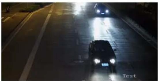
natural_image
Nighttime street scene with a car driving on a wet road, illuminated by headlights (no visible text or symbols)WDR Off
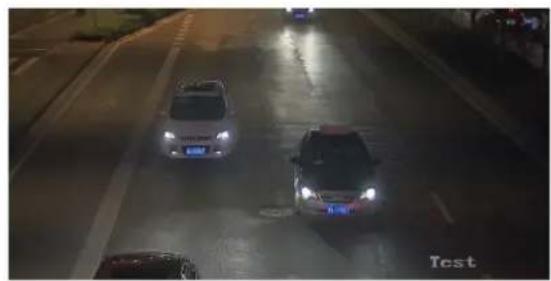
natural_image
Nighttime street scene with cars and a blue-lit car, no visible text or symbolsWDR On
Figure 4-1 WDR
HLC
When the bright area of the image is over-exposed and the dark area is under-exposed, the HLC (High Light Compression) function can be enabled to weaken the bright area and brighten the dark area, so as to achieve the light balance of the overall picture.
White Balance
White balance is the white rendition function of the camera. It is used to adjust the color temperature according to the environment.
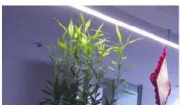
natural_image
Potted plant with green leaves under a bright ceiling light, next to a hanging red fabric item (no text or symbols visible)Cold
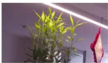
natural_image
Potted plant with bright green leaves under a ceiling light, next to a hanging red fabric item (no text or symbols visible)Warm
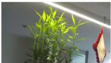
natural_image
Potted plant with bright green leaves under a ceiling light, next to a red-labeled leaf (no text or symbols visible)Auto White Balance
Figure 4-2 White Balance
DNR
Digital Noise Reduction is used to reduce the image noise and improve the image quality. Normal and Expert modes are selectable.
Normal
Set the DNR level to control the noise reduction degree. The higher level means stronger reduction degree.
Expert
Set the DNR level for both space DNR and time DNR to control the noise reduction degree. The higher level means stronger reduction degree.
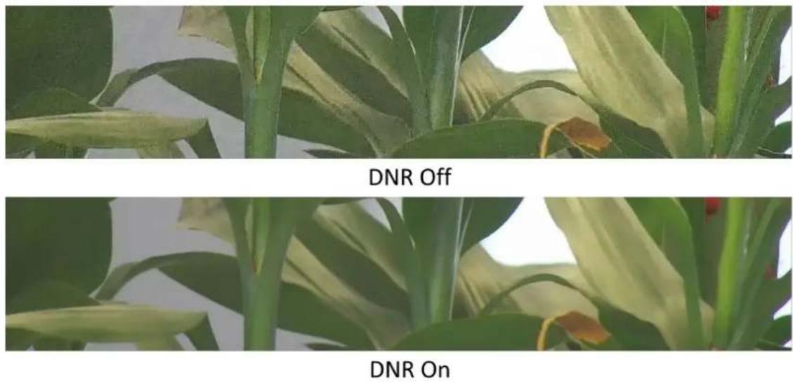
Figure 4-3 DNR
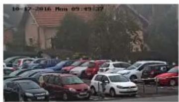
Defog
You can enable the defog function when the environment is foggy and the image is misty. It enhances the subtle details so that the image appears clearer.

text_image
10-17-2016 Mon 09:49:37Defog On
Figure 4-4 Defog
EIS
Increase the stability of video image by using jitter compensation technology.
Gray Scale
You can choose the range of the Gray Scale as [0-255] or [16-235].
Mirror
When the live view image is the reverse of the actual scene, this function helps to display the image normally.
Select the mirror mode as needed.

Note
The video recording will be shortly interrupted when the function is enabled.
Rotate
When this function is enabled, the live view will rotate 90^ counterclockwise. For example, 1280 × 720 is rotated to 720 × 1280 .
Enabling this function can change the effective range of monitoring in the vertical direction.

Note
This function is supported under certain settings.
Lens Distortion Correction
For device equipped with motorized lens, image may appear distorted to some extent. Enable this function to correct the distortion.

Note
- This function is only supported by certain device equipped with motorized lens.
- The edge of image will be lost if this function is enabled.
4.7.2 Image Parameters Switch
The device automatically switches image parameters in set time periods.
Go to image parameters switch setting page: Configuration → Image → Display Settings → Image Parameters Switch, and set parameters as needed.
Set Scheduled-switch
Switch the image to the linked scene mode automatically in certain time periods.
Steps
-
Check Scheduled-switch.
-
Select and configure the corresponding time period and linked scene mode.

For Linked Scene configuration, refer to Scene Mode.
- Click Save.
4.7.3 Video Standard
Video standard is an ability of a video card or video display device that defines the amount of colors that are shown and the resolution. The two most common video standard used are NTSC and PAL. In NTSC, 30 frames are transmitted each second. Each frame is made up of 525 individual scan lines. In PAL, 25 frames are transmitted each second. Each frame is made up of 625 individual scan lines. Select video signal standard according to the video system in your country/region.
4.7.4 Local Video Output
If the device is equipped with video output interfaces, such as BNC, CVBS, HDMI, and SDI, you can preview the live image directly by connecting the device to a monitor screen.
Select the output mode as ON/OFF to control the output.
4.8 OSD
You can customize OSD (On-screen Display) information such as device name, time/date, font, color, and text overlay displayed on video stream.
Go to OSD setting page: Configuration → Image → OSD Settings. Set the corresponding parameters, and click Save to take effect.
Character Set
Select character set for displayed information. If Korean is required to be displayed on screen, select EUC-KR. Otherwise, select GBK.
Display
Set camera name, date, week, and their related display formats. For certain device models, you can also set tilt angle as the displayed information.
Format Settings
Set OSD parameters, such as Display Mode, OSD Size, Font Color, and Alignment.
Text Overlay
Set customized overlay text on image.
4.9 Set Privacy Mask
The function blocks certain areas in the live view to protect privacy. No matter how the device moves, the blocked scene will never be seen.
Steps
- Go to Configuration → Image → Privacy Mask.
- Check Enable.
- Click ☐Drag the mouse in the live view to draw a closed area.
Drag the corners of the area Adjust the size of the area.
Drag the area Adjust the position of the area.
Click Clear all the areas you set.
-
Click Add to add a privacy mask and set Region Name and Mask Type.
-
Click Save.
4.10 Overlay Picture
Overlay a customized picture on live view.
Before You Start
The picture to overlay has to be in BMP format with 24-bit, and the maximum picture size is 128 × 128 pixel.
Steps
- Go to Configuration → Image → Picture Overlay.
- Check Enable.
- Click Upload to select a picture and open it.
The picture with a red rectangle will appear in live view after successfully uploading. - Drag the red rectangle to adjust the picture position.
- Click Save.
Chapter 5 Video Recording and Picture Capture
This part introduces the operations of capturing video clips and snapshots, playback, and downloading captured files.
5.1 Storage Settings
This part introduces the configuration of several common storage paths.
5.1.1 Memory Card
You can view the capacity, free space, status, type, and property of the memory card. Encryption of memory card is supported to ensure data security.
Set New or Unencrypted Memory Card
Before You Start
Insert a new or unencrypted memory card to the device. For detailed installation, refer to Quick Start Guide of the device.
Steps
-
Go to Configuration → Storage → Storage Management → HDD Management.
-
Select the memory card.

Note
If an Unlock button appears, you need to unlock the memory card first. See Detect Memory Card Status for details.
- Click Format to initialize the memory card.
When the Status of memory card turns from Uninitialized to Normal, the memory card is ready for use.
- Optional: Encrypt the memory card.
1) Click Encrypted Format.
2) Set the encryption password.
3) Click OK.
When the Encryption Status turns to Encrypted, the memory card is ready for use.

Note
Keep your encryption password properly. Encryption password cannot be found if forgotten.
-
Optional: Define the Quota of the memory card. Input the percentage for storing different contents according to your needs.
-
Click Save.
Set Encrypted Memory Card
Before You Start
- Insert an encrypted memory card to the device. For detailed installation, refer to Quick Start Guide of the device.
- You need to know the correct encryption password of the memory card.
Steps
-
Go to Configuration → Storage → Storage Management → HDD Management.
-
Select the memory card.

Note
If an Unlock button appears, you need to unlock the memory card first. See Detect Memory Card Status for details.
- Verify the encryption password.
1) Click Parity.
2) Enter the encryption password.
3) Click OK.
When the Encryption Status turns to Encrypted, the memory card is ready for use.

Note
If the encryption password is forgotten and you still want to use this memory card, see Set New or Unencrypted Memory Card to format and set the memory card. All existing contents will be removed.
-
Optional: Define the Quota of the memory card. Input the percentage for storing different contents according to your needs.
-
Click Save.
Detect Memory Card Status
The device detects the status of Hikvision memory card. You receive notifications when your memory card is detected abnormal.
Before You Start
The configuration page only appears when a Hikvision memory card is installed to the device.
Steps
- Go to Configuration → Storage → Storage Management → Memory Card Detection.
- Click Status Detection to check the Remaining Lifespan and Health Status of your memory card. Remaining Lifespan
It shows the percentage of the remaining lifespan. The lifespan of a memory card may be influenced by factors such as its capacity and the bitrate. You need to change the memory card if the remaining lifespan is not enough.
Health Status
It shows the condition of your memory card. You will receive a notification if the health status is anything other than good when the Arming Schedule and Linkage Method are set.
i Note
It is recommended that you change the memory card when the health status is not "good".
-
Click R/W Lock to set the permission of reading and writing to the memory card.
-
Add a Lock
a. Select the Lock Switch as ON.
b. Enter the password.
c. Click Save - Unlock
- If you use the memory card on the device that locks it, unlocking will be done automatically and no unlocking procedures are required on the part of users.
- If you use the memory card (with a lock) on a different device, you can go to HDD Management to unlock the memory card manually. Select the memory card, and click Unlock. Enter the correct password to unlock it.
- Remove the Lock
a. Select the Lock Switch as OFF.
b. Enter the password in Password Settings.
c. Click Save.
i Note
- Only admin user can set the R/W Lock.
- The memory card can only be read and written when it is unlocked.
-
If the device, which adds a lock to a memory card, is restored to the factory settings, you can go to HDD Management to unlock the memory card.
-
Set Arming Schedule and Linkage Method. See Set Arming Schedule and Linkage Method Settings for details.
- Click Save.
5.1.2 Set FTP
You can configure the FTP server to save images which are captured by events or a timed snapshot task.
Before You Start
Get the FTP server address first.
Steps
- Go to Configuration → Event → Alarm Setting → FTP.
- Configure FTP settings.
FTP Protocol
FTP and SFTP are selectable. The files uploading is encrypted by using SFTP protocol.
Server IP Address and Port No.
The FTP server address and corresponding port.
User Name and Password
The FTP user should have the permission to upload pictures.
If the FTP server supports picture uploading by anonymous users, you can check Anonymous Login to hide your device information during uploading.

Anonymous login is not supported when SFTP protocol is selected.
Directory Structure
The saving path of snapshots in the FTP server.
- Optional: Check Upload Picture to enable uploading snapshots to the FTP server.
Picture Filing Interval
For better picture management, you can set the picture filing interval from 1 day to 30 days. Pictures captured in the same time interval will be saved in one folder named after the beginning date and ending date of the time interval.
Picture Name
Set the naming rule for captured pictures. You can choose Default in the drop-down list to use the default rule, that is, IP address_channel number_capture time_event type.jpg (e.g., 10.11.37.189_01_20150917094425492_FACE_DETECTION.jpg). Or you can customize it by adding a Custom Prefix to the default naming rule.
- Optional: Check Enable Automatic Network Replenishment.
Upload to FTP/Memory Card/NAS in Linkage Method and Enable Automatic Network Replenishment should be both enabled simultaneously.
- Click Test to verify the FTP server.
- Click Save.
5.1.3 Set NAS
Take network server as network disk to store the record files, captured images, etc.
Before You Start
Get the IP address of the network disk first.
Steps
- Go to NAS setting page: Configuration → Storage → Storage Management → Net HDD.
- Click Add.
- Set Mounting Type.
Mounting Type
Select file system protocol according to the operation system.
Enter user name and password of the net HDD to guarantee the security if SMB/CIFS is selected.
- Set the Server Address and File Path for the disk.
Server Address
The IP address of the network disk.
File Path
The saving path of network disk files.
- Click Test to check whether the network disk is available.
- Click OK to finish the steps to add a Net HDD.
- Optional: Configure the Net HDD.
Edit Click to edit the parameter setting.
Delete Delete the Net HDD.
- Click
-
Select the Net HDD, click Delete.
-
Click Save.
5.1.4 eMMC Protection
It is to automatically stop the use of eMMC as a storage media when its health status is poor.

Note
The eMMC protection is only supported by certain device models with an eMMC hardware.
Go to Configuration → System → System Settings → System Service for the settings.
eMMC, short for embedded multimedia card, is an embedded non-volatile memory system. It is able to store the captured images or videos of the device.
The device monitors the eMMC health status and turns off the eMMC when its status is poor. Otherwise, using a worn-out eMMC may lead to device boot failure.
5.1.5 Set Cloud Storage
It helps to upload the captured pictures and data to the cloud. The platform requests picture directly from the cloud for picture and analysis. The function is only supported by certain models.
Steps

Caution
If the cloud storage is enabled, the pictures are stored in the cloud video manager firstly.
- Go to Configuration → Storage → Storage Management → Cloud Storage.
- Check Enable.
- Set basic parameters.
Protocol Version The protocol version of the cloud video manager.
Server IP The IP address of the cloud video manager. It supports IPv4 address.
Serve Port The port of the cloud video manager. You are recommended to use the default port.
AccessKey The key to log in to the cloud video manager.
SecretKey The key to encrypt the data stored in the cloud video manager.
User Name and Password The user name and password of the cloud video manager.
Picture Storage Pool ID The ID of the picture storage region in the cloud video manager. Make sure storage pool ID and the storage region ID are the same.
- Click Test to test the configured settings.
- Click Save.
5.2 Video Recording
This part introduces the operations of manual and scheduled recording, playback, and downloading recorded files.
5.2.1 Record Automatically
This function can record video automatically during configured time periods.
Before You Start
Select Trigger Recording in event settings for each record type except Continuous. See Event and Alarm for details.
Steps
- Go to Configuration → Storage → Schedule Settings → Record Schedule.
- Check Enable.
- Select a record type.

Note
The record type is vary according to different models.
Continuous
The video will be recorded continuously according to the schedule.
Motion
When motion detection is enabled and trigger recording is selected as linkage method, object movement is recorded.
Alarm
When alarm input is enabled and trigger recording is selected as linkage method, the video is recorded after receiving alarm signal from external alarm input device.
Motion | Alarm
Video is recorded when motion is detected or alarm signal is received from the external alarm input device.
Motion & Alarm
Video is recorded only when motion is detected and alarm signal is received from the external alarm input device.
Event
The video is recorded when configured event is detected.
- Set schedule for the selected record type. Refer to Set Arming Schedule for the setting operation.
- Set the advanced recording parameters.
Overwrite
Enable Overwrite to overwrite the video records when the storage space is full. Otherwise the camera cannot record new videos.
Pre-record
The time period you set to record before the scheduled time.
Post-record
The time period you set to stop recording after the scheduled time.
Stream Type
Select the stream type for recording.

When you select the stream type with higher bitrate, the actual time of the pre-record and post-record may be less than the set value.
Recording Expiration
The recordings are deleted when they exceed the expired time. The expired time is configurable. Note that once the recordings are deleted, they can not be recovered.
- Click Save.
5.2.2 Record Manually
Steps
- Go to Configuration → Local.
- Set the Video Size and Video Saving Path for recorded video files.
- Click Save.
- Click in the live view interface to start recording. Click to stop recording.
What to do next
View the recorded video files.
Go to Configuration → Local and click Open behind Video Saving Path to open the saving path and view the files.
5.2.3 Playback and Download Video
You can search, playback, clip and download the videos stored in the local storage or network storage.
Steps
- Go to Playback → Video.
- Set search condition and click Search.
The matched video files showed on the timing bar. - Click to play the video files.
- Click 📄 to play video files in full screen. Press ESC to exit full screen.
- Click to stop video playback for all channels.
- Optional: Click ✗ to clip video files. Click ✗ again to stop clipping video files

Go to Configuration → Local → Clip Saving Path, view and change the saving path of clipped video files.
- Optional: Click ↓ on the playback interface to download files.
Go to Configuration → Local → Downloaded File Saving Path, view and change the saving path of downloaded video files.
5.3 Capture Configuration
The device can capture the pictures manually or automatically and save them in configured saving path. You can view and download the snapshots.
5.3.1 Capture Automatically
This function can capture pictures automatically during configured time periods.
Before You Start
If event-triggered capture is required, you should configure related linkage methods in event settings. Refer to Event and Alarm for event settings.
Steps
-
Go to Configuration → Storage → Schedule Settings → Capture.
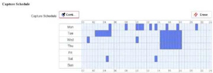
-
Set capture schedule. Refer to Set Arming Schedule for configuring schedule time.
bar
Capture Schedule | Day | Value | |---|---| | Mon | 21 | | Tue | 30 | | Wed | 5 | | Thu | 14 | | Fri | 16 | | Sat | 14 | | Sun | 21 |Figure 5-1 Set Capture Schedule
- Set the capture type.
Scheduled
Capture a picture at the configured time interval.
Event-Triggered
Capture a picture when an event is triggered.
- Set the Format, Resolution, Quality, Interval, and Capture Number.

Note
The resolution of the captured picture is the same as the resolution of the captured picture stream. You can select Stream Type in Advanced.
- Click Save.
5.3.2 Capture Manually
Steps
-
Go to Configuration → Local.
-
Set the Image Format and saving path to for snapshots.
JPEG
The picture size of this format is comparatively small, which is better for network transmission.
BMP
The picture is compressed with good quality.
-
Click Save.
-
Click 📷 near the live view or play back window to capture a picture manually.
5.3.3 View and Download Picture
You can search, view and download the pictures stored in the local storage or network storage.
Steps
- Go to Playback → Picture.
- Set search condition and click Search.
The matched pictures showed in the file list.
-
Download the pictures.
-
Select the pictures then click Download to download them.
- Click Download This Page to download the pictures of this page.
- Click Download All to download all the pictures.

Note
Go to Configuration → Local → Playback Capture Saving Path, view and change the saving path of captured pictures when playback.
Chapter 6 Event and Alarm
This part introduces the configuration of events. The device takes certain response to triggered alarm. Certain events may not be supported by certain device models.
6.1 Set Motion Detection
It helps to detect the moving objects in the detection region and trigger the linkage actions.
Steps
- Go to Configuration → Event → Event and Detection → Motion Detection.
- Check Enable.
- Optional: Highlight to display the moving object in the image in green.
1) Check Enable Dynamic Analysis for Motion.
2) Go to Configuration → Local.
3) Set Rules to Enable.
-
Select mode in Configuration, and set rule region and rule parameters.
-
For the information about normal mode, see Normal Mode.
-
For the information about expert mode, see Expert Mode.
-
Set the arming schedule and linkage methods. For the information about arming schedule settings, see Set Arming Schedule. For the information about linkage methods, see Linkage Method Settings.
-
Click Save.
6.1.1 Expert Mode
You can configure different motion detection parameters for day and night according to the actual needs.
Steps
- Select Expert Mode in Configuration.
- Set parameters of expert mode.
Scheduled Image Settings
OFF
Image switch is disabled.
Auto-Switch
The system switches day/night mode automatically according to environment. It displays colored image at day and black and white image at night.
Scheduled-Switch
The system switches day/night mode according to the schedule. It switches to day mode during the set periods and switches to night mode during the other periods.
Sensitivity
The higher the value of sensitivity is, the more sensitive the motion detection is. If scheduled image settings is enabled, the sensitivity of day and night can be set separately.
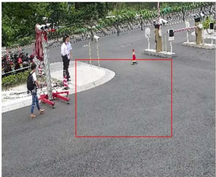
- Select an Area and click Click and drag the mouse on the live image and then release the mouse to finish drawing one area.
natural_image
Outdoor scene with people walking near a paved area, featuring red bounding boxes and accessibility barriers (no visible text or symbols)Figure 6-1 Set Rules
- Click to clear all the areas.
- Click Save.
- Optional: Repeat above steps to set multiple areas.
6.1.2 Normal Mode
You can set motion detection parameters according to the device default parameters.
Steps
- Select Normal Mode in Configuration.
- Set the Sensitivity of normal mode. The higher the value of sensitivity is, the more sensitive the motion detection is. If the sensitivity is set to 0, motion detection and dynamic analysis do not take effect.
- Set Detection Target. Human and vehicle are available. If the detection target is not selected, all the detected targets will be reported, including the human and vehicle. This function allows alarm triggering by specified target types (human and vehicle).

Note
This function is only available for certain device models under certain settings. Please refer to the actual settings.
- Click ☐Click and drag the mouse on the live image, and then right click the mouse to finish drawing one area.
- Optional: Click to clear all the areas.
- Optional: You can set the parameters of multiple areas by repeating the above steps.
6.2 Set Video Tampering Alarm
When the configured area is covered and cannot be monitored normally, the alarm is triggered and the device takes certain alarm response actions.
Steps
- Go to Configuration → Event → Event and Detection → Video Tampering.
- Check Enable.
- Set the Sensitivity. The higher the value is, the easier to detect the area covering.
- Click and drag the mouse in the live view to draw the area.
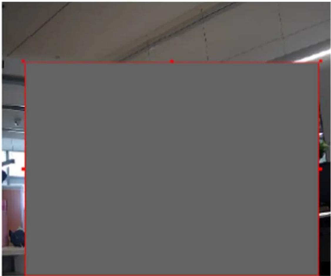
natural_image
Empty whiteboard with red border, no visible text or symbolsFigure 6-2 Set Video Tampering Area
- Optional: Click to delete all the drawn areas.
- Refer to Set Arming Schedule for setting scheduled time. Refer to Linkage Method Settings for setting linkage method.
- Click Save.
6.3 Set Alarm Input
Alarm signal from the external device triggers the corresponding actions of the current device.
Before You Start

Note
This function is only supported by certain models.
Make sure the external alarm device is connected. See Quick Start Guide for cable connection.
Steps
- Go to Configuration → Event → Event and Detection → Alarm Input.
- Select an Alarm Input NO. and click to set alarm input.
- Select Alarm Type from the dropdown list. Edit the Alarm Name.
- Check Enable Alarm Input Handling.
- Refer to Set Arming Schedule for setting scheduled time. Refer to Linkage Method Settings for setting linkage method.
- Click Copy to... to copy the settings to other alarm input channels.
- Click Save.
6.4 Set Exception Alarm
Exception such as network disconnection can trigger the device to take corresponding action.
Steps
- Go to Configuration → Event → Event and Detection → Exception.
- Select Exception Type.
HDD Full
The HDD storage is full.
HDD Error
Error occurs in HDD.
Network Disconnected
The device is offline.
IP Address Conflicted
The IP address of current device is same as that of other device in the network.
Illegal Login
Incorrect user name or password is entered.
Abnormal Restart
The device restarts abnormally.
- Refer to Linkage Method Settings for setting linkage method.
- Click Save.
6.5 Set Video Quality Diagnosis
When the video quality of the device is abnormal and the alarm linkage is set, the alarm will be triggered automatically.
Steps
- Go to Configuration → Event → Event and Detection → Video Quality Diagnosis.
-
Select Diagnosis Type.
-
Set the corresponding parameters.
Alarm Detection Interval
The time interval to detect the exception.
Sensitivity
The higher the value is, the more easily the exception will be detected, and the higher possibility of misinformation would be.
Alarm Delay Times
The device uploads the alarm when the alarm reaches the set number of times.
- Check the selected diagnosis type, and the related type will be detected.
- Set arming schedule. See Set Arming Schedule.
- Set linkage method. See Linkage Method Settings.
- Click Save.

Note
The function is only supported by certain models. The actual display varies with models.
6.6 Set Vibration Detection
It is used to detect whether the device is vibrating. The device reports an alarm and triggers linkage actions if the function is enabled.
Steps
- Go to Configuration → Event → Event and Detection → Vibration Detection.
- Check Enable.
- Drag the slider to set the detection sensitivity. You can also enter number to set the sensitivity.
- Set the arming schedule. See Set Arming Schedule.
- Set the linkage method. See Linkage Method Settings.
- Click Save.

Note
The function is only supported by certain models. The actual display varies with models.
6.7 Set Audio Exception Detection
Audio exception detection function detects the abnormal sound in the scene, such as the sudden increase/decrease of the sound intensity, and some certain actions can be taken as response.
Steps
- Go to Configuration → Event → Event and Detection → Audio Exception Detection.
- Select one or several audio exception detection types.
Audio Loss Detection
Detect sudden loss of audio track.
Sudden Increase of Sound Intensity Detection
Detect sudden increase of sound intensity. Sensitivity and Sound Intensity Threshold are configurable.
i Note
- The lower the sensitivity is, the more significant the change should be to trigger the detection.
- The sound intensity threshold refers to the sound intensity reference for the detection. It is recommended to set as the average sound intensity in the environment. The louder the environment sound, the higher the value should be. You can adjust it according to the real environment.
Sudden Decrease of Sound Intensity Detection
Detect sudden decrease of sound intensity. Sensitivity is configurable.
-
Refer to Set Arming Schedule for setting scheduled time. Refer to Linkage Method Settings for setting linkage methods.
-
Click Save.
i Note
The function is only supported by certain models. The actual function varies according to different models.
6.8 Set Defocus Detection
The blurred image caused by lens defocus can be detected. If it occurs, the device can take linkage actions.
Steps
-
Go to Configuration → Event → Event and Detection → Defocus Detection.
-
Check Enable.
-
Set Sensitivity. The higher the value is, the more easily the defocus image can trigger the alarm. You can adjust the value according to the actual environment.
-
For the linkage method settings, refer to Linkage Method Settings.
-
Click Save.
Note
The function is only supported by certain models. The actual display varies with models.
6.9 Set Scene Change Detection
Scene change detection function detects the change of the scene. Some certain actions can be taken when the alarm is triggered.
Steps
-
Go to Configuration → Event → Event and Detection → Scene Change Detection.
-
Click Enable.
-
Set the Sensitivity. The higher the value is, the more easily the change of scene can be detected. But the detection accuracy is reduced.
-
Refer to Set Arming Schedule for setting scheduled time. Refer to Linkage Method Settings for setting linkage method.
-
Click Save.

Note
The function is only supported by certain models. The actual display varies with models.
Chapter 7 Arming Schedule and Alarm Linkage
Arming schedule is a customized time period in which the device performs certain tasks. Alarm linkage is the response to the detected certain incident or target during the scheduled time.
7.1 Set Arming Schedule
Set the valid time of the device tasks.
Steps
- Optional: Click Arming Schedule and Linkage Method in the related event interface.
- Click Edit behind Arming Schedule.
- Click Draw, and drag the time bar to draw desired valid time.
i Note
• Each cell represents 30 minutes.
- Move the mouse over the drawn time period to see specific time periods and fine-tune the start time and end time.
- Up to 8 periods can be configured for one day.
-
Click Erase, and drag the time bar to clear selected valid time.
-
Click OK to save the settings.
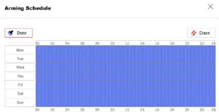
bar
Arming Schedule | Day | Time (Hours) | |---|---| | Mon | 00:00 | | Tue | 01:00 | | Wed | 02:00 | | Thu | 03:00 | | Fri | 04:00 | | Sat | 05:00 | | Sun | 06:00 |Figure 7-1 Set Arming Schedule
7.2 Linkage Method Settings
You can enable the linkage functions when an event or alarm occurs.
7.2.1 Trigger Alarm Output
If the device has been connected to an alarm output device, and the alarm output No. has been configured, the device sends alarm information to the connected alarm output device when an alarm is triggered.
Steps
- Go to Configuration → Event → Alarm Setting → Alarm Output.
- Set alarm output parameters.
Automatic Alarm For the information about the configuration, see Automatic Alarm.
Manual Alarm For the information about the configuration, see Manual Alarm.
Manual Alarm
You can trigger an alarm output manually.
Before You Start
Make sure the alarm output device is connected to the device.
Steps
- Select the Alarm Output No. according to the alarm interface connected to the external alarm device. Click ☐ to set alarm parameters.
Alarm Name
Custom a name for the alarm output.
-
Click Manual Alarm to enable manual alarm output.
-
Optional: Click Clear Alarm to disable manual alarm output.
Automatic Alarm
Set the automatic alarm parameters, then the device triggers an alarm output automatically in the set arming schedule.
Before You Start
Make sure the alarm output device is connected to the device.
Steps
- Select the Alarm Output No. according to the alarm interface connected to the external alarm device. Click ↻ to set alarm parameters.
Alarm Name
Custom a name for the alarm output.
Delay
It refers to the time duration that the alarm output remains after an alarm occurs.
- Set the alarming schedule. For the information about the settings, see Set Arming Schedule.
- Optional: Click Copy to... to copy the parameters to other alarm output channels.
- Click Save.
7.2.2 FTP/NAS/Memory Card Uploading
If you have enabled and configured the FTP/NAS/memory card uploading, the device sends the alarm information to the FTP server, network attached storage and memory card when an alarm is triggered.
Refer to Set FTP to set the FTP server.
Refer to Set NAS for NAS configuration.
Refer to Set New or Unencrypted Memory Card for memory card storage configuration.
7.2.3 Send Email
Check Send Email, and the device sends an email to the designated addresses with alarm information when an alarm event is detected.
For email settings, refer to Set Email.
Set Email
When the email is configured and Send Email is enabled as a linkage method, the device sends an email notification to all designated recipients if an alarm event is detected.
Before You Start
Set the DNS server before using the Email function. Go to Configuration → Network → Network Settings → TCP/IP for DNS settings.
Steps
- Go to email settings page: Configuration → Event → Alarm Setting → Email.
- Set email parameters.
1) Input the sender's email information, including the Sender's Address, SMTP Server, and SMTP Port.
2) Optional: If your email server requires authentication, check Authentication and input your user name and password to log in to the server.
3) Set the E-mail Encryption.
- When you select TLS, and disable STARTTLS, emails are sent after encrypted by TLS. The SMTP port should be set as 465.
- When you select TLS and check Enable STARTTLS, emails are sent after encrypted by STARTTLS, and the SMTP Port should be set as 25.
i Note
If you want to use STARTTLS, make sure that the protocol is supported by your email server. If you check the Enable STARTTLS while the protocol is not supported by your email sever, your email is sent with no encryption.
4) Optional: If you want to receive notification with alarm pictures, check Attached Picture. The notification email has a certain number of attached alarm pictures about the event with configurable image capturing interval.
i Note
The number of alarm pictures may vary according to different device models and different events.
5) Input the recipient's information, including the recipient's name and address.
6) Click Test to see if the function is well configured.
3. Click Save.
7.2.4 Notify Surveillance Center
Check Notify Surveillance Center, the alarm information is uploaded to the surveillance center when an alarm event is detected.
7.2.5 Trigger Recording
Check Trigger Recording, and the device records the video about the detected alarm event. For recording settings, refer to Video Recording and Picture Capture.
7.2.6 Audible Warning
After enabling Audible Warning and setting Audible Alarm Output, the built-in speaker of the device or connected external speaker plays warning sounds when an alarm happens.
For audible alarm output settings, refer to Set Audible Alarm Output.
i Note
The function is only supported by certain camera models.
Set Audible Alarm Output
When the device detects targets in the detection area, audible alarm can be triggered as a warning.
Steps
-
Go to Configuration → Event → Alarm Setting → Audible Alarm Output.
-
Select Sound Type and set related parameters.
-
Select Prompt and set the alarm times you need.
- Select Warning and its contents. Set the alarm times you need.
-
Select Custom Audio. You can select a custom audio file from the drop-down list. If no file is available, you can click Set → Add to upload an audio file that meets the requirement. Up to three audio files can be uploaded.
-
Optional: Click Test to play the selected audio file on the device.
-
Set arming schedule for audible alarm. See Set Arming Schedule for details.
-
Click Save.

Note
The function is only supported by certain device models.
7.2.7 Alarm Server
The device can send alarms to destination IP address or host name through HTTP, HTTPS, or ISUP protocol. The destination IP address or host name should support HTTP, HTTP, or ISUP data transmission.
Set Alarm Server
Steps
- Go to Configuration → Event → Alarm Setting → Alarm Server.
- Enter Destination IP or Host Name, URL, and Port.
- Select Protocol.

Note
HTTP, HTTPS, and ISUP are selectable. It is recommended to use HTTPS, as it encrypts the data transmission during communication.
- Click Test to check if the IP or host is available.
- Click Save.
Chapter 8 Network Settings
8.1 TCP/IP
TCP/IP settings must be properly configured before you operate the device over network. IPv4 and IPv6 are both supported. Both versions can be configured simultaneously without conflicting to each other.
Go to Configuration → Network → Network Settings → TCP/IP for parameter settings.
NIC Type
Select a NIC (Network Interface Card) type according to your network condition.
IPv4
Two IPv4 modes are available.
DHCP
The device automatically gets the IPv4 parameters from the network if you check DHCP. The device IP address is changed after enabling the function. You can use SADP to get the device IP address.

The network that the device is connected to should support DHCP (Dynamic Host Configuration Protocol).
Manual
You can set the device IPv4 parameters manually. Input IPv4 Address, IPv4 Subnet Mask, and IPv4 Default Gateway, and click Test to see if the IP address is available.
IPv6
Three IPv6 modes are available.
Route Advertisement
The IPv6 address is generated by combining the route advertisement and the device Mac address.
Route advertisement mode requires the support from the router that the device is connected to.
DHCP
The IPv6 address is assigned by the server, router, or gateway.
Manual
Input IPv6 Address, IPv6 Subnet, IPv6 Default Gateway. Consult the network administrator for required information.
MTU
It stands for maximum transmission unit. It is the size of the largest protocol data unit that can be communicated in a single network layer transaction.
The valid value range of MTU is 1280 to 1500.
DNS
It stands for domain name server. It is required if you need to visit the device with domain name. And it is also required for some applications (e.g., sending email). Set Preferred DNS Server and Alternate DNS server properly if needed.
Domain Name Settings
Check Enable Dynamic Domain Name and input Register Domain Name. The device is registered under the register domain name for easier management within the local area network.

Note
DHCP should be enabled for the dynamic domain name to take effect.
8.2 Access to Device via Domain Name
You can use the Dynamic DNS (DDNS) for network access. The dynamic IP address of the device can be mapped to a domain name resolution server to realize the network access via domain name.
Before You Start
Registration on the DDNS server is required before configuring the DDNS settings of the device.
Steps
- Refer to TCP/IP to set DNS parameters.
- Go to the DDNS settings page: Configuration → Network → Network Settings → DDNS.
- Check Enable and select DDNS Type.
DynDNS
Dynamic DNS server is used for domain name resolution.
NO-IP
NO-IP server is used for domain name resolution.
- Input the domain name information, and click Save.
- Check the device ports and complete port mapping. Refer to Port Mapping for port mapping settings.
- Access the device.
By Browsers
Enter the domain name in the browser address bar to access the device.
By Client Software
Add domain name to the client software. Refer to the client manual for specific adding methods.
8.3 Access to Device via PPPoE Dial Up Connection
This device supports the PPPoE auto dial-up function. The device gets a public IP address by ADSL dial-up after the device is connected to a modem. You need to configure the PPPoE parameters of the device.
Steps
- Go to Configuration → Network → Network Settings → PPPoE.
- Check Enable.
- Set the PPPoE parameters.
Dynamic IP
After successful dial-up, the dynamic IP address of the WAN is displayed.
User Name
User name for dial-up network access.
Password
Password for dial-up network access.
Confirm
Input your dial-up password again.
- Click Save.
- Access the device.
By Browsers
Enter the WAN dynamic IP address in the browser address bar to access the device.
By Client Software
Add the WAN dynamic IP address to the client software. Refer to the client manual for details.

Note
The obtained IP address is dynamically assigned via PPPoE, so the IP address always changes after rebooting the camera. To solve the inconvenience of the dynamic IP, you need to get a domain name from the DDNS provider (e.g. DynDns.com). Refer to Access to Device via Domain Name for detail information.
8.4 SNMP
You can set the SNMP network management protocol to get the alarm event and exception messages in network transmission.
Before You Start
Before setting the SNMP, you should download the SNMP software and manage to receive the device information via SNMP port.
Steps
-
Go to Configuration → Network → Network Settings → SNMP.
-
Check Enable SNMPv1, Enable SNMP v2c or Enable SNMPv3.

The SNMP version you select should be the same as that of the SNMP software.
And you also need to use the different version according to the security level required. SNMP v1 is not secure and SNMP v2 requires password for access. And SNMP v3 provides encryption and if you use the third version, HTTPS protocol must be enabled.
-
Configure the SNMP settings.
-
Click Save.
8.5 Set IEEE 802.1X
You can authenticate user permission of the connected device by setting IEEE 802.1X.
Go to Configuration → Network → Network Settings → 802.1X, and enable the function.
Select protocol and version according to router information. User name and password of server are required.

- If you set the Protocol to EAP-TLS, select the Client Certificate and CA Certificate.
- If the function is abnormal, check if the selected certificate is abnormal in Certificate Management.
8.6 Set QoS
QoS (Quality of Service) can help improve the network delay and network congestion by setting the priority of data sending.

QoS needs support from network device such as router and switch.
Steps
-
Go to Configuration → Network → Network Settings → QoS.
-
Set Video/Audio DSCP, Event/Alarm DSCP and Management DSCP.
i Note
Network can identify the priority of data transmission. The bigger the DSCP value is, the higher the priority is. You need to set the same value in router while configuration.
- Click Save.
8.7 HTTP(S)
HTTP is an application-layer protocol for transmitting hypermedia documents. HTTPS is a network protocol that enables encrypted transmission and identity authentication, which improves the security of remote access.
Steps
-
Go to Configuration → Network → Network Service → HTTP(S) .
-
Enter HTTP Port.
i Note
It refers to the port through which the browser accesses the device. For example, when the HTTP Port is modified to 81, you need to enter http://192.168.1.64:81 in the browser for login.
- Check Enable in HTTPS.
i Note
You can click TLS Settings to set the TLS version that the device supports. Refer to for details.
-
Enter HTTPS Port.
-
Optional: Check HTTPS Browsing to access the device only via HTTPS protocol.
-
Select Server Certificate.
-
Set Web Authentication.
Authentication
Digest and digest/basic are supported, which means authentication information is needed when WEB request is sent to the device. If you select digest/basic, it means the device supports digest or basic authentication. If you select digest, the device only supports digest authentication.
Digest Algorithm
MD5, SHA256 and MD5/SHA256 encrypted algorithm in WEB authentication. If you enable the digest algorithm except for MD5, the third-party platform might not be able to log in to the device or enable live view because of compatibility. The encrypted algorithm with high strength is recommended.
- Click Save.
8.8 Multicast
Multicast is group communication where data transmission is addressed to a group of destination devices simultaneously.
Go to Configuration → Network → Network Service → Multicast for the multicast settings.
IP Address
It stands for the address of multicast host.
8.8.1 Multicast Discovery
Go to Configuration → Network → Network Settings → TCP/IP to enable this function.
Check the Enable Multicast Discovery, and then the online network camera can be automatically detected by client software via private multicast protocol in the LAN.
8.9 RTSP
RTSP (Real Time Streaming Protocol) is an application-layer controlling protocol for streaming media.
Steps
- Go to Configuration → Network → Network Service → RTSP.
- Enter Port.
- Set Multicast parameters.
Stream Type
The stream type as the multicast source.
Video Port
The video port of the selected stream.
Audio Port
The audio port of the selected stream.
- Set RTSP Authentication.
Authentication
Digest and digest/basic are supported, which means authentication information is needed when RTSP request is sent to the device. If you select digest/basic, it means the device supports digest or basic authentication. If you select digest, the device only supports digest authentication.
Digest Algorithm
MD5, SHA256 and MD5/SHA256 encrypted algorithm in RTSP authentication. If you enable the digest algorithm except for MD5, the third-party platform might not be able to log in to
the device or enable live view because of compatibility. The encrypted algorithm with high strength is recommended.
- Click Save.
8.10 Set SRTP
The Secure Real-time Transport Protocol (SRTP) is a Real-time Transport Protocol (RTP) internet protocol, intended to provide encryption, message authentication and integrity, and replay attack protection to the RTP data in both unicast and multicast applications.
Steps
- Go to Configuration → Network → Network Service → SRTP.
- Enter the Port number.
- Set Multicast parameters.
Stream Type
The stream type as the multicast source.
Video Port
The video port of the selected stream.
Audio Port
The audio port of the selected stream.
- Select Server Certificate.
- Select Encrypted Algorithm.
- Click Save.
i Note
- Only certain device models support this function.
- If the function is abnormal, check if the selected certificate is abnormal in Certificate Management.
8.11 Bonjour
It is an implementation of zero-configuration networking (zeroconf), a group of technologies that includes service discovery, address assignment, and hostname resolution. Bonjour locates devices such as printers, other computers, and the services that those devices offer on a local network using multicast Domain Name System (mDNS) service records.
Go to Configuration → Network → Network Service → Bonjour to enable the function, and click Save.
After enabling the function, the device spread and receive service information in local area network.
8.12 WebSocket(s)
WebSocket or WebSockets protocol should be enabled if you use Google Chrome 57 and its above version or Mozilla Firefox 52 and its above version to visit the device. Otherwise, live view, image capture, digital zoom, etc. cannot be used.
Go to Configuration → Network → Network Service → WebSocket(s) to set parameters, and click Save.
WebSocket
TCP-based full-duplex communication protocol port for plug-in free preview via HTTP protocol.
WebSockets
TCP-based full-duplex communication protocol port for plug-in free preview via HTTPS protocol.
8.13 Port Mapping
By setting port mapping, you can access devices through the specified port.
Steps
- Go to Configuration → Network → Network Service → NAT.
- Select the port mapping mode.
Auto Port Mapping
Refer to Set Auto Port Mapping for detailed information.
Manual Port Mapping
Refer to Set Manual Port Mapping for detailed information.
- Click Save.
- Check Enable UPnP™, and choose a friendly name for the camera, or you can use the default name.
- Select the port mapping mode to Auto.
- Click Save.

Note
UPnP™ function on the router should be enabled at the same time.
8.13.2 Set Manual Port Mapping
Steps
-
Check Enable UPnP™, and choose a friendly name for the device, or you can use the default name.
-
Select the port mapping mode to Manual, and set the external port to be the same as the internal port.
- Click Save.
What to do next
Go to the router port mapping settings interface and set the port number and IP address to be the same as those on the device. For more information, refer to the router user manual.
8.13.3 Set Port Mapping on Router
The following settings are for a certain router. The settings vary depending on different models of routers.
Steps
- Select the WAN Connection Type.
- Set the IP Address, Subnet Mask and other network parameters of the router.
- Go to Forwarding → Virtual Severs, and input the Port Number and IP Address.
- Click Save.
Example
When the cameras are connected to the same router, you can configure the ports of a camera as 80, 8000, and 554 with IP address 192.168.1.23, and the ports of another camera as 81, 8001, 555, 8201 with IP 192.168.1.24.
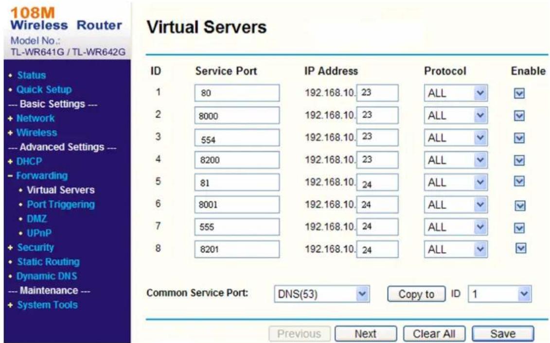
text_image
108M Wireless Router Model No.: TL-WR641G / TL-WR642G Virtual Servers ID Service Port IP Address Protocol Enable 1 80 192.168.10. 23 ALL ✓ ✓ 2 8000 192.168.10. 23 ALL ✓ ✓ 3 554 192.168.10. 23 ALL ✓ ✓ 4 8200 192.168.10. 23 ALL ✓ ✓ 5 81 192.168.10. 24 ALL ✓ ✓ 6 8001 192.168.10. 24 ALL ✓ ✓ 7 555 192.168.10. 24 ALL ✓ ✓ 8 8201 192.168.10. 24 ALL ✓ ✓ Common Service Port: DNS(53) Copy to ID 1 ✓ Previous Next Clear All SaveFigure 8-1 Port Mapping on Router

Note
The port of the network camera cannot conflict with other ports. For example, some web management port of the router is 80. Change the camera port if it is the same as the management port.
8.14 RTCP
The device relies on RTCP (Real-time Transport Control Protocol) to deliver packets sequentially to provide a reliable delivery mechanism and to provide services for flow control or congestion control.
Go to Configuration → Network → Network Service → RTCP and check Enable to enable the function.
8.15 Set ISUP
When the device is registered on ISUP platform (formerly called Ehome), you can visit and manage the device, transmit data, and forward alarm information over public network.
Steps
- Go to Configuration → Network → Platform Access → ISUP.
- Optional: Select an access center.
- Check Enable.
- Select a protocol version and enter related parameters.
- Click Save.
Register status turns to Online when the function is correctly set.
8.16 Access Camera via Hik-Connect
Hik-Connect is an application for mobile devices. Using the App, you can view live image, receive alarm notification and so on.
Before You Start
Connect the camera to network with network cables.
Steps
-
Get and install Hik-Connect application by the following ways.
-
Visit https://appstore.hikvision.com to download the application according to your mobile phone system.
- Visit the official site of our company. Then go to Support → Tools → Hikvision App Store.
- Scan the QR code below to download the application.
text_image
QR code with a red circular logo in the center, likely linking to a digital service or application.i Note
If errors like "Unknown app" occur during the installation, solve the problem in two ways.
- Visit https://appstore.hikvision.com/static/help/index.html to refer to the troubleshooting.
-
Visit https://appstore.hikvision.com/, and click Installation Help at the upper right corner of the interface to refer to the troubleshooting.
-
Start the application and register for a Hik-Connect user account.
- Log in after registration.
- In the app, tap "+" on the upper-right corner and then scan the QR code of the camera to add the camera. You can find the QR code on the camera or on the cover of the Quick Start Guide of the camera in the package.
- Follow the prompts to set the network connection and add the camera to your Hik-Connect account.
For detailed information, refer to the user manual of the Hik-Connect app.
8.16.1 Enable Hik-Connect Service on Camera
Hik-Connect service should be enabled on your camera before using the service.
You can enable the service through SADP software or Web browser.
Enable Hik-Connect Service via Web Browser
Follow the following steps to enable Hik-Connect Service via Web Browser.
Before You Start
You need to activate the camera before enabling the service.
Steps
- Access the camera via web browser.
- Enter platform access configuration interface. Configuration → Network → Platform Access → Hik-Connect.
- Check Enable.
- Click and read "Terms of Service" and "Privacy Policy" in pop-up window.
- Create a verification code or change the old verification code for the camera.

Note
The verification code is required when you add the camera to Hik-Connect service.
- Save the settings.
Enable Hik-Connect Service via SADP Software
This part introduces how to enable Hik-Connect service via SADP software of an activated camera.
Steps
- Run SADP software.
- Select a camera and enter Modify Network Parameters page.
- Check Enable Hik-Connect.
- Create a verification code or change the old verification code.

Note
The verification code is required when you add the camera to Hik-Connect service.
-
Click and read "Terms of Service" and "Privacy Policy".
-
Confirm the settings.
8.16.2 Set Up Hik-Connect
Steps
-
Get and install Hik-Connect application by the following ways.
-
Visit https://appstore.hikvision.com to download the application according to your mobile phone system.
- Visit the official site of our company. Then go to Support → Tools → Hikvision App Store.
- Scan the QR code below to download the application.
text_image
QR code with a red circular logo in the center, likely linking to a digital service or website.
Note
If errors like "Unknown app" occur during the installation, solve the problem in two ways.
- Visit https://appstore.hikvision.com/static/help/index.html to refer to the troubleshooting.
-
Visit https://appstore.hikvision.com/, and click Installation Help at the upper right corner of the interface to refer to the troubleshooting.
-
Start the application and register for a Hik-Connect user account.
-
Log in after registration.
8.16.3 Add Camera to Hik-Connect
Steps
- Connect your mobile device to a Wi-Fi.
- Log into the Hik-Connect app.
- In the home page, tap "+" on the upper-right corner to add a camera.
- Scan the QR code on camera body or on the Quick Start Guide cover.

Note
If the QR code is missing or too blur to be recognized, you can also add the camera by inputting the camera's serial number.
- Input the verification code of your camera.

Note
- The required verification code is the code you create or change when you enable Hik-Connect service on the camera.
-
If you forget the verification code, you can check the current verification code on Platform Access configuration page via web browser.
-
Tap Connect to a Network button in the popup interface.
- Choose Wired Connection or Wireless Connection according to your camera function.
Wireless Connection Input the Wi-Fi password that your mobile phone has connected to, and tap Next to start the Wi-Fi connection process. (Locate the camera within 3 meters from the router when setting up the Wi-Fi.)
Wired Connection Connect the camera to the router with a network cable and tap Connected in the result interface.

Note
The router should be the same one which your mobile phone has connected to.
- Tap Add in the next interface to finish adding.
For detailed information, refer to the user manual of the Hik-Connect app.
8.17 Set Open Network Video Interface
If you need to access the device through Open Network Video Interface protocol, you can configure the user settings to enhance the network security.
Steps
- Go to Configuration → Network → Platform Access → Open Network Video Interface.
-
Check Enable.
-
Select an authentication mode.
-
If you select Digest, the device only supports digest authentication.
-
If you select Digest&ws-username token, the device supports digest authentication or ws-username token authentication.
-
Click Add to configure the Open Network Video Interface user.
-
Click Save.
-
Optional: Repeat the steps above to add more Open Network Video Interface users.
-
Optional: Manage the user.
-
Click to delete the selected Open Network Video Interface user.
- Click 🔔 to modify the selected Open Network Video Interface user.
8.18 Set SDK Service
If you want to add the device to the client software, you should enable SDK Service or Enhanced SDK Service.
Steps
- Go to Configuration → Network → Platform Access → SDK Service.
- Set SDK Service parameters.
1) Check Enable to add the device to the client software with SDK protocol.
2) Enter the Port number.
- Set Enhanced SDK Service parameters.
1) Check Enable to add the device to the client software with SDK over TLS protocol.
2) Optional: Click TLS Settings to enable the TLS version that the device supports. Refer to TLS for details.
3) Enter the Port number.
4) Select a server certificate to make sure the data transmission security. You can click Certificate Management to add a certificate. Refer to Certificate Management for details.
- Click Save.
Chapter 9 System and Security
It introduces system maintenance, system settings and security management, and explains how to configure relevant parameters.
9.1 System Settings
9.1.1 View Device Information
You can view device information, such as Device No., Model, Serial No. and Firmware Version.
Enter Configuration → System → System Settings → Basic Information to view the device information.
9.1.2 Time and Date
You can configure time and date of the device by configuring time zone, time synchronization and Daylight Saving Time (DST).
Synchronize Time Manually
Steps
- Go to Configuration → System → System Settings → Time Settings.
- Select Time Zone.
- Select Manual Time Sync..
-
Choose one time synchronization method.
-
Select Set Time, and manually input or select date and time from the pop-up calendar.
-
Click Sync. with computer time to synchronize the time of the device with that of the local PC.
-
Click Save.
Set NTP Server
You can use NTP server when accurate and reliable time source is required.
Before You Start
Set up a NTP server or obtain NTP server information.
Steps
- Go to Configuration → System → System Settings → Time Settings.
-
Select Time Zone.
-
Click NTP.
- Set Server Address, NTP Port and Interval.

Server Address is NTP server IP address.
- Click Test to test serverconnection.
- Click Save.
Synchronize Time by Satellite

This function varies depending on different devices.
Steps
- Enter Configuration → System → System Settings → Time Settings.
- Select Satellite Time Sync..
- Set Interval.
- Click Save.
Set DST
If the region where the device is located adopts Daylight Saving Time (DST), you can set this function.
Steps
- Go to Configuration → System → System Settings → Time Settings.
- Check Enable.
- Select Start Time, End Time and DST Bias.
- Click Save.
9.1.3 Set RS-232
RS-232 can be used to debug device or access peripheral device. RS-232 can realize communication between the device and computer or terminal when the communication distance is short.
Before You Start
Connect the device to computer or terminal with RS-232 cable.
Steps
- Go to Configuration → System → System Settings → RS-232.
- Set RS-232 parameters to match the device with computer or terminal.
- Click Save.
9.1.4 Set RS-485
RS-485 is used to connect the device to external device. You can use RS-485 to transmit the data between the device and the computer or terminal when the communication distance is too long.
Before You Start
Connect the device and computer or terminal with RS-485 cable.
Steps
-
Go to Configuration → System → System Settings → RS-485.
-
Set the RS-485 parameters.

Note
You should keep the parameters of the device and the computer or terminal all the same.
- Click Save.
9.1.5 Set Live View Connection
It controls the remote live view connection amount.
Live view connection controls the maximum live view that can be streamed at the same time.
Enter Configuration → System → System Settings → System Service to set the upper limit of the remote connection number.
9.1.6 Location Settings
Location displays and uploads the current longitude and latitude of the device.
Auto Uploading
Check Enable and set Location Upload Interval.
The device will upload its location at the set interval. You can also click Refresh to upgrade the device location manually.
Manual Settings
Check Enable and set Location Upload Interval. Enter the longitude and latitude of the device and click Save.
The device will upload the set location at the set interval.

Note
This function may vary according to different device models.
9.1.7 External Device
For the device supporting external devices, including the supplement light, wiper on the housing, the LED light, and heater, you can control them via the Web browser when it is used with the housing. External devices vary with models.
9.1.8 View Open Source Software License
On the top-right corner, click Ⓑ and select Open Source Software Description to download the license. You can view the license in the editor.
9.1.9 Wiegand

Note
This function is only supported by certain camera models.
Check Enable and select the protocol. The default protocol is SHA-1 26bit.
If enabled, the recognized license plate number will be output via the selected Wiegand protocol.
9.2 User and Account
9.2.1 Set User Account and Permission
The administrator can add, modify, or delete other accounts, and grant different permission to different user levels.

Caution
To increase security of using the device on the network, please change the password of your account regularly. Changing the password every 3 months is recommended. If the device is used in high-risk environment, it is recommended that the password should be changed every month or week.
Steps
-
Go to Configuration → System → User Management → User Management.
-
Click Add. Enter User Name, select Level, and enter Password. Assign remote permission to users based on needs.
Administrator
The administrator has the authority to all operations and can add users and operators and assign permission.
User
Users can be assigned permission of viewing live video, setting PTZ parameters, and changing their own passwords, but no permission for other operations.
Operator
Operators can be assigned all permission except for operations on the administrator and creating accounts.
Modify Select a user and click to change the password and permission.
Delete Select a user and click .

Note
The administrator can add up to 31 user accounts.
3. Click OK.
9.2.2 Simultaneous Login
The administrator can set the maximum number of users logging into the system through web browser simultaneously.
Go to Configuration → System → User Management → Online Users, click General, and set Simultaneous Login.
9.2.3 Online Users
The information of users logging into the device is shown.
Go to Configuration → System → User Management → Online Users to view the list of online users.
9.3 Maintenance
9.3.1 Restart
You can restart the device via browser.
Go to Maintenance and Security → Maintenance → Restart, and click Restart.
9.3.2 Upgrade
Before You Start
You need to obtain the correct upgrade package.

Caution
DO NOT disconnect power during the process, and the device restarts automatically after upgrade.
Steps
- Go to Maintenance and Security → Maintenance → Upgrade.
- Choose one method to upgrade.
Firmware Locate the exact path of the upgrade file.
Firmware Directory Locate the directory which the upgrade file belongs to.
- Click to select the upgrade file.
- Click Upgrade.
- Go to Maintenance and Security → Maintenance → Backup and Restore.
- Click Restore or Default according to your needs.
Restore Reset device parameters, except user information, IP parameters and video format to the default settings.
Default Reset all the parameters to the factory default.

Note
Be careful when using this function. After resetting to the factory default, all the parameters are reset to the default settings.
9.3.4 Import and Export Configuration File
It helps speed up batch configuration on other devices with the same parameters.
Steps
- Export configuration file.
1) Go to Maintenance and Security → Maintenance → Backup and Restore → Backup.
2) Click Export and input the encryption password to export the current configuration file.
3) Set the saving path to save the configuration file in local computer.
- Import configuration file.
1) Access the device that needs to be configured via web browser.
2) Go to Maintenance and Security → Maintenance → Backup and Restore → Reset.
3) Click ☐ to select the saved configuration file.
4) Input the encryption password you have set when exporting the configuration file.
5) Click Import.
9.3.5 Search and Manage Log
Log helps locate and troubleshoot problems.
Steps
- Go to Maintenance and Security → Maintenance → Log.
- Set search conditions Major Type, Minor Type, Start Time, and End Time.
- Click Search.
The matched log files will be displayed on the log list. - Optional: Click Export to save the log files in your computer.
9.3.6 Search Security Audit Logs
You can search and analyze the security log files of the device so as to find out the illegal intrusion and troubleshoot the security events.
Steps
i Note
This function is only supported by certain camera models.
- Go to Maintenance and Security → Maintenance → Security Audit Log.
- Select log types, Start Time, and End Time.
- Click Search.
The log files that match the search conditions will be displayed on the Log List. - Optional: Click Export to save the log files to your computer.
9.3.7 SSH
Secure Shell (SSH) is a cryptographic network protocol for operating network services over an unsecured network.
Go to Maintenance and Security → Maintenance → Device Debugging, and click Settings of SSH. You can edit the number of the port. Click Save.
Caution
Use the function with caution. The security risk of device internal information leakage exists when the function is enabled.
9.3.8 Export Diagnose Information
Diagnose information includes running log, system information, hardware information.
Go to Maintenance and Security → Maintenance → Device Debugging → Diagnose Information. Click Export. In the pop-up window, check desired diagnose information and click Export to export corresponding diagnose information of the device.
9.4 Security
You can improve system security by setting security parameters.
9.4.1 Set IP Address Filter
IP address filter is a tool for access control. You can enable the IP address filter to allow or forbid the visits from the certain IP addresses.
IP address refers to IPv4.
Steps
- Go to Maintenance and Security → Security → IP Address Filter.
- Check Enable.
- Select the type of IP address filter.
Blocklist IP addresses in the list cannot access the device.
Allowlist Only IP addresses in the list can access the device.
- Edit the IP address filter list.
Add Add a new IP address or IP address range to the list.
Modify the selected IP address or IP address range in the list.
Delete the selected IP address or IP address range in the list.
- Click Save.
9.4.2 Set MAC Address Filter
MAC address filter is a tool for access control. You can enable the MAC address filter to allow or forbid the visits from the certain MAC addresses.
Steps
- Go to Maintenance and Security → Security → MAC Address Filter.
- Check Enable.
- Select the type of MAC address filter.
Blocklist MAC addresses in the list cannot access the device.
Allowlist Only MAC addresses in the list can access the device.
- Edit the MAC address filter list.
Add Add a new MAC address to the list.

Modify the selected MAC address in the list.

Delete the selected MAC address in the list.
- Click Save.
9.4.3 Control Timeout Settings
If this function is enabled, you will be logged out when you make no operation (not including viewing live image) to the device via web browser within the set timeout period.
Go to Maintenance and Security → Security → Login Management → Control Timeout Settings to complete settings.
9.4.4 Certificate Management
It helps to manage the server/client certificates and CA certificate, and to send an alarm if the certificates are close to expiry date, or are expired/abnormal.

Note
The function is only supported by certain device models.
Server Certificate/Client Certificate

Note
The device has default self-signed server/client certificate installed. The certificate ID is default.
Create and Install Self-signed Certificate
Steps
- Go to Maintenance and Security → Security → Certificate Management.
- Click Create Self-signed Certificate.
- Input certificate information.

Note
The input certificate ID cannot be the same as the existing ones.
- Click Save to save and install the certificate.
The created certificate is displayed in the Server/Client Certificate list.
If the certificate is used by certain functions, the function name is shown in the column Functions.
- Optional: Click Property to see the certificate details.
Install Self-signed Request Certificate
You can send the self-signed certificate to a trusted third-party for the signature, and install the certificate to the device.
Before You Start
Create a self-signed certificate first. See Create and Install Self-signed Certificate for instructions.
Steps
- Go to Maintenance and Security → Security → Certificate Management.
- Select a self-signed certificate from the Server/Client Certificate list.
- Click Create Certificate Request.
- Input request information.
- Click Save.
The certificate request details are displayed in a pop-up window.
- Copy the request content and save it as a request file.
- Send the file to a trusted-third party for signature.
- After receiving the certificated sent back from the third-party, install it to the device.
1) Click Import.
2) Input Certificate ID.

The input certificate ID cannot be the same as the existed ones.
3) Click to select the certificate file.
4) Select Self-signed Request Certificate.
5) Click Save.
The imported certificate is displayed in the Server/Client Certificate list.
If the certificate is used by certain function, the function name is shown in the column Functions.
- Optional: Click Property see the certificate details.
Install Other Authorized Certificate
If you already has an authorized certificate (not created by the device), you can import it to the device directly.
Steps
- Go to Maintenance and Security → Security → Certificate Management.
- Click Import in the Server/Client Certificate list.
3. Input Certificate ID.

Note
The input certificate ID cannot be the same as the existed ones.
-
Click to select the certificate file.
-
Select Certificate and Key and select a Key Type according to your certificate.
| Independent Key | If your certificate has an independent key, select this option.Browse to select the private key and input the private-key password. |
| PKCS#12 | If your certificate has the key in the same certificate file, select this option and input the password. |
- Click Save.
The imported certificate is displayed in the Server/Client Certificate list.
If the certificate is used by certain function, the function name is shown in the column Functions.
Install CA Certificate
Before You Start
Prepare a CA certificate in advance.
Steps
- Go to Maintenance and Security → Security → Certificate Management.
- Click Import in the CA Certificate list.
- Input Certificate ID.

Note
The input certificate ID cannot be the same as the existing ones.
-
Click to select the certificate file.
-
Click Save.
The imported certificate is displayed in the CA Certificate list.
If the certificate is used by certain functions, the function name is shown in the Functions column.
Enable Certificate Expiration Alarm
Steps
- Check Enable Certificate Expiration Alarm. If enabled, you will receive an email or the camera links to the surveillance center that the certificate will expire soon, or is expired or abnormal.
- Set the Remind Me Before Expiration (day), Alarm Frequency (day) and Detection Time (hour).
i Note
- If you set the reminding day before expiration to 1, then the camera will remind you the day before the expiration day. 1 to 30 days are available. Seven days is the default reminding days.
- If you set the reminding day before expiration to 1, and the detection time to 10:00, and the certificate will expire in 9:00 the next day, the camera will remind you in 10:00 the first day.
3. Click Save.
9.4.5 TLS
The Transport Layer Security (TLS) protocol aims primarily to provide privacy and data integrity between two or more communicating computer applications. TLS settings are effective for HTTP(S) and enhanced SDK service.
Go to Maintenance and Security → Security → TLS, and enable the desired TLS protocol. Click Save.
Caution
Use the function with caution. The security risk of device internal information leakage exists when the function is enabled.
Chapter 10 VCA Resource
VCA resource is a collection of smart functions supported by the device.
10.1 Allocate VCA Resource
VCA resource offers you options to enable certain VCA functions according to actual needs. It helps allocate more resources to the desired functions.
Steps
- Click VCA on the left tab.
- Enable the desired VCA function.
- Click Next to finish settings.

Note
Certain VCA functions are mutually exclusive.
10.2 General Settings
Set the general parameters which are related to the smart applications.
Go to VCA → Set Application → General Settings to set the following parameters.
Camera Info.
For camera information settings, refer to Set Camera Info.
FTP
For FTP settings, refer to Set FTP.
For Email settings, refer to Set Email.
Alarm Output
For alarm output settings, refer to Automatic Alarm.
Audible Alarm Output
For audible alarm output settings, refer to Set Audible Alarm Output.
Alarm Server
For alarm server settings, refer to Alarm Server.
Metadata
For metadata settings, refer to Metadata.
10.2.1 Set Camera Info
Customize specific information for the device. It may help identify a certain device when multiple devices are under management.
Go to VCA → Set Application → General Settings → Camera Info to set Device No. and Camera Info.
10.2.2 Metadata
Metadata is the raw data that the device collects before algorithm processing. It is often used for the third party integration.
Go to VCA → Set Application → General Settings → metadata Settings to enable metadata uploading of the desired function.
i Note
This function varies according to different camera models.
Smart Event
The metadata of the smart event includes the target ID, target coordinate, time, etc.
You can check Enable Stream Rule to overlay the stream rule on the live view image. Make sure you have checked Sub-Stream and selected the sub-stream in the live view.
You can check Overlay Rule Frame and Target Frame on Background Picture to overlay the rule and target information on the sub-stream. Make sure you have checked Sub-Stream and selected the sub-stream in the live view.
Face Capture
The metadata of face capture includes the rule information, target ID, target coordinate, time information, etc. The camera detects the whole image by default. If the area is configured in the face capture settings, the camera detects the configured area.
Multi-Target-Type Detection
The metadata of multi-target-type detection includes the vehicle information and face capture information, such as the target ID, target coordinate, time information, vehicle moving direction, etc.
Road Traffic
The metadata of road traffic is detected vehicle information, including the vehicle location in the scene, vehicle ID, license plate, validity, moving direction, country/region, etc.
10.3 Smart Event

Note
- For certain device models, you need to enable the smart event function on VCA page first to show the function configuration page.
- The function varies according to different models.
10.3.1 Set Intrusion Detection
It is used to detect objects entering and loitering in a predefined virtual region. If it occurs, the device can take linkage actions.
Before You Start
- Go to VCA and select the application. Select Smart Event and click Next to enable the function.
- For the device supporting HEOP, go to VCA to import and enable Smart Event.
Steps
- Go to VCA → Set Application → Smart Event → Intrusion Detection.
-
Check Enable.
-
Click Add to add a rule and set a detection area.
1) Draw a detection area. Click ☐ click on the live view to specify the vertexes and draw the boundaries of the detection area, and right click to complete drawing.
2) Set the minimum size and the maximum size for the target to improve detection accuracy. Only targets whose size are between the maximum size and the minimum size trigger the detection. Click and , then drag the mouse in the live view to draw the minimum and maximum target size.
3) Optional: Click 📋 to delete all the setting areas.
- Set parameters.
Detection Target
This function allows alarm triggering by specified selected target types. If the detection target is not selected, all the detected targets will be reported.

This function is only available for certain device models under certain settings. Please refer to the actual settings.
Threshold
Threshold stands for the threshold for the time of the object loitering in the region. If the time that one object stays exceeds the threshold, the alarm is triggered. The larger the value of the threshold is, the longer the alarm triggering time is.
Sensitivity
Sensitivity stands for the percentage of the body part of an acceptable target that enters the predefined region. Sensitivity = 100 - S1/ST × 100. S1 stands for the target body part that goes across the predefined region. ST stands for the complete target body. The higher the value of sensitivity is, the more easily the alarm can be triggered.
Target Validity
If you set a higher validity, the required target features should be more obvious, and the alarm accuracy would be higher. The target with less obvious features would be missed.
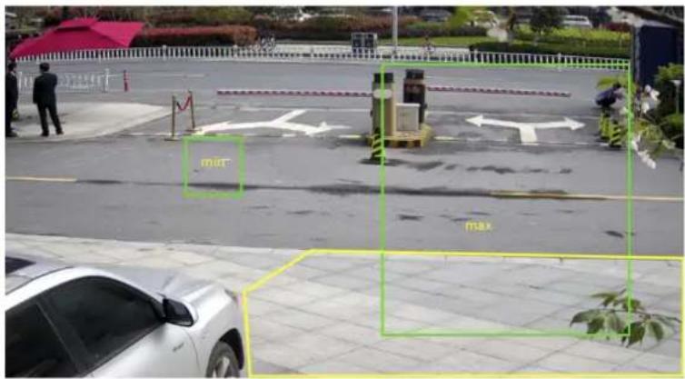
text_image
mir maxFigure 10-1 Set Rule
- Optional: You can set the parameters of multiple areas by repeating the above steps.
- For the arming schedule settings, refer to Set Arming Schedule. For the linkage method settings, refer to Linkage Method Settings.
- Click Save.
10.3.2 Set Line Crossing Detection
It is used to detect objects crossing a predefined virtual line. If it occurs, the device can take linkage actions.
Before You Start
- Go to VCA and select the application. Select Smart Event and click Next to enable the function.
• For the device supporting HEOP, go to VCA to import and enable Smart Event.
Steps
- Go to VCA → Set Application → Smart Event → Line Crossing Detection.
- Check Enable.
- Click Add to add a rule and set a detection area.
1) Draw a detection line. Click and a line with an arrow appears in the live view. Drag the line to the location on the live view as desired.
2) Set the minimum size and the maximum size for the target to improve detection accuracy. Only targets whose size are between the maximum size and the minimum size trigger the
detection. Click and , then drag the mouse in the live view to draw the minimum and maximum target size.
3) Optional: Click 🔒 to delete all the setting areas.
- Set parameters.
Detection Target
This function allows alarm triggering by specified selected target types. If the detection target is not selected, all the detected targets will be reported.
This function is only available for certain device models under certain settings. Please refer to the actual settings.
Direction
It stands for the direction from which the object goes across the line.
A<->B: The object going across the line from both directions can be detected and alarms are triggered.
A->B: Only the object crossing the configured line from the A side to the B side can be detected.
B->A: Only the object crossing the configured line from the B side to the A side can be detected.
Sensitivity
It stands for the percentage of the body part of an acceptable target that goes across the pre-defined line. Sensitivity = 100 - S1/ST × 100. S1 stands for the target body part that goes across the pre-defined line. ST stands for the complete target body. The higher the value of sensitivity is, the more easily the alarm can be triggered.
Target Validity
If you set a higher validity, the required target features should be more obvious, and the alarm accuracy would be higher. The target with less obvious features would be missing.
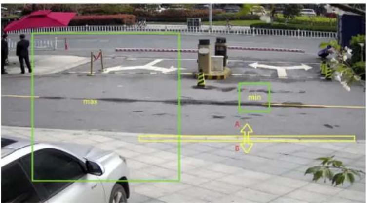
text_image
max min A BFigure 10-2 Set Rule
- Optional: You can set the parameters of multiple areas by repeating the above steps.
- For the arming schedule settings, refer to Set Arming Schedule. For the linkage method settings, refer to Linkage Method Settings.
- Click Save.
10.3.3 Set Region Entrance Detection
It is used to detect objects entering a predefined virtual region from the outside place. If it occurs, the device can take linkage actions.
Before You Start
- Go to VCA and select the application. Select Smart Event and click Next to enable the function.
- For the device supporting HEOP, go to VCA to import and enable Smart Event.
Steps
- Go to VCA → Set Application → Smart Event → Region Entrance Detection
- Check Enable.
- Click Add to add a rule and set a detection area.
1) Draw a detection area. Click click on the live view to specify the vertexes and draw the boundaries of the detection area, and right click to complete drawing.
2) Set the minimum size and the maximum size for the target to improved detection accuracy. Only targets whose size are between the maximum size and the minimum size trigger the detection. Click and, then drag the mouse in the live view to draw the minimum and maximum target size.
3) Optional: Click 🔒 to delete all the setting areas.
- Set parameters.
Detection Target
This function allows alarm triggering by specified selected target types. If the detection target is not selected, all the detected targets will be reported.

This function is only available for certain device models under certain settings. Please refer to the actual settings.
Sensitivity
It stands for the percentage of the body part of an acceptable target that goes across the predefined region. Sensitivity = 100 - S1/ST × 100. S1 stands for the target body part that goes across the predefined region. ST stands for the complete target body. The higher the value of sensitivity is, the more easily the alarm can be triggered.
Target Validity
If you set a higher validity, the required target features should be more obvious, and the alarm accuracy would be higher. The target with less obvious features would be missing.
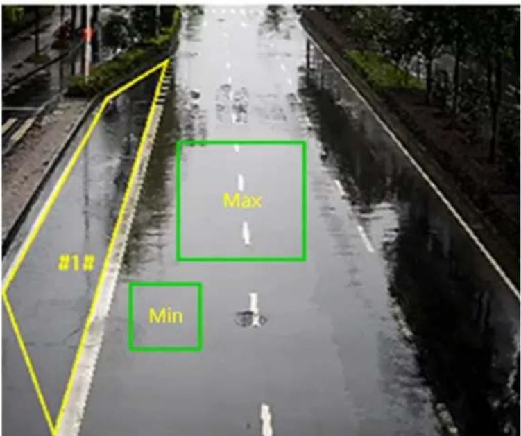
text_image
Max MinFigure 10-3 Set Rule
- Optional: You can set the parameters of multiple areas by repeating the above steps.
- For the arming schedule settings, refer to Set Arming Schedule. For the linkage method settings, refer to Linkage Method Settings.
- Click Save.
10.3.4 Set Region Exiting Detection
It is used to detect objects exiting from a predefined virtual region. If it occurs, the device can take linkage actions.
Before You Start
- Go to VCA and select the application. Select Smart Event and click Next to enable the function.
- For the device supporting HEOP, go to VCA to import and enable Smart Event.
Steps
- Go to VCA → Set Application → Smart Event → Region Exiting Detection.
- Check Enable.
- Click Add to add a rule and set a detection area.
1) Draw a detection area. Click ☐ click on the live view to specify the vertexes and draw the boundaries of the detection area, and right click to complete drawing.
2) Set the minimum size and the maximum size for the target to improved detection accuracy. Only targets whose size are between the maximum size and the minimum size trigger the detection. Click and , then drag the mouse in the live view to draw the minimum and maximum target size.
3) Optional: Click 🔒 to delete all the setting areas.
- Set parameters.
Detection Target
This function allows alarm triggering by specified selected target types. If the detection target is not selected, all the detected targets will be reported.
This function is only available for certain device models under certain settings. Please refer to the actual settings.
Sensitivity
It stands for the percentage of the body part of an acceptable target that goes across the predefined region. Sensitivity = 100 - S1/ST × 100. S1 stands for the target body part that goes across the predefined region. ST stands for the complete target body. The higher the value of sensitivity is, the more easily the alarm can be triggered.
Target Validity
If you set a higher validity, the required target features should be more obvious, and the alarm accuracy would be higher. The target with less obvious features would be missing.
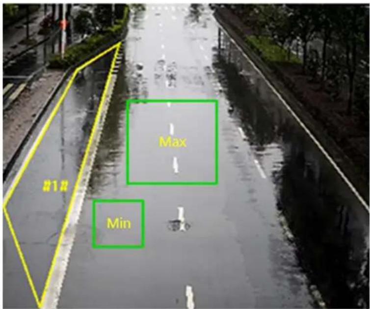
text_image
Max MinFigure 10-4 Set Rule
- Optional: You can set the parameters of multiple areas by repeating the above steps.
- For the arming schedule settings, refer to Set Arming Schedule. For the linkage method settings, refer to Linkage Method Settings.
- Click Save.
10.3.5 Set Unattended Baggage Detection
It is used to detect the objects left over in the predefined region. Linkage methods can be triggered after the object is left and stays in the region for a set time period.
Before You Start
- Go to VCA and select the application. Select Smart Event and click Next to enable the function.
- For the device supporting HEOP, go to VCA to import and enable Smart Event.
Steps
- Go to VCA → Set Application → Smart Event → Unattended Baggage Detection.
- Check Enable.
- Click Add to add a rule and set a detection area.
1) Draw a detection area. Click ☑ click on the live view to specify the vertexes and draw the boundaries of the detection area, and right click to complete drawing.
2) Set the minimum size and the maximum size for the target to improve detection accuracy. Only targets whose size are between the maximum size and the minimum size trigger the detection. Click and , then drag the mouse in the live view to draw the minimum and maximum target size.
3) Optional: Click 🔒 to delete all the setting areas.
- Set parameters.
Sensitivity
Sensitivity stands for the percentage of the body part of an acceptable target that enters the predefined region. Sensitivity = 100 - S1/ST × 100. S1 stands for the target body part that goes across the predefined region. ST stands for the complete target body. The higher the value of sensitivity is, the more easily the alarm can be triggered.
Threshold
It stands for the time of the objects left in the region. Alarm is triggered after the object is left and stays in the region for the set time period.
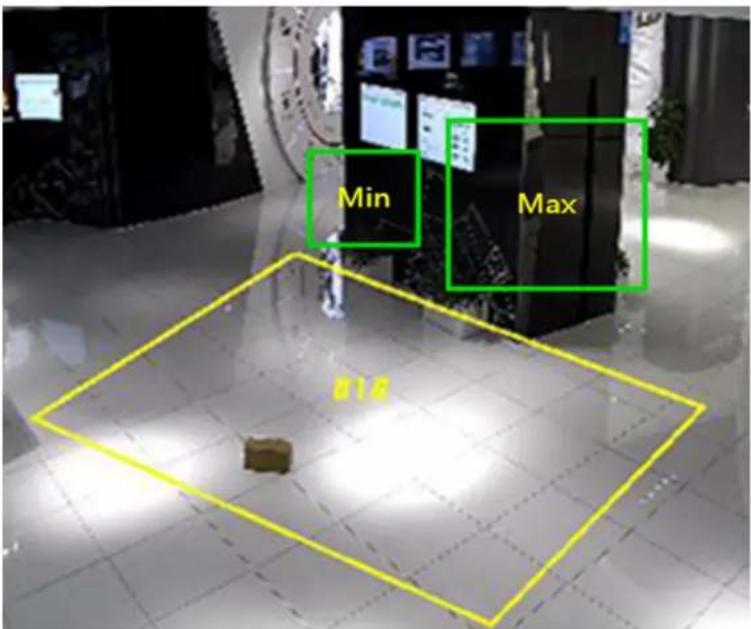
text_image
Min Max B1.0Figure 10-5 Set Rule
-
Optional: You can set the parameters of multiple areas by repeating the above steps.
-
For the arming schedule settings, refer to Set Arming Schedule. For the linkage method settings, refer to Linkage Method Settings.
-
Click Save.

Note
The function is only supported by certain models. The actual display varies with the models.
10.3.6 Set Object Removal Detection
It detects whether the objects are removed from the predefined detection region, such as the exhibits on display. If it occurs, the device can take linkage actions and the staff can take measures to reduce property loss.
Before You Start
- Go to VCA and select the application. Select Smart Event and click Next to enable the function.
- For the device supporting HEOP, go to VCA to import and enable Smart Event.
Steps
-
Go to VCA → Set Application → Smart Event → Object Removal Detection.
-
Check Enable.
-
Click Add to add a rule and set a detection area.
1) Draw a detection area. Click click on the live view to specify the vertexes and draw the boundaries of the detection area, and right click to complete drawing.
2) Set the minimum size and the maximum size for the target to improve detection accuracy. Only targets whose size are between the maximum size and the minimum size trigger the detection. Click and , then drag the mouse in the live view to draw the minimum and maximum target size.
3) Optional: Click 🔒 to delete all the setting areas.
- Set parameters.
Sensitivity
Sensitivity stands for the percentage of the body part of an acceptable target that enters the predefined region. Sensitivity = 100 - S1/ST × 100. S1 stands for the target body part that goes across the predefined region. ST stands for the complete target body. The higher the value of sensitivity is, the more easily the alarm can be triggered.
Threshold
The threshold for the time of the objects removed from the region. If you set the value as 10, alarm is triggered after the object disappears from the region for 10s.
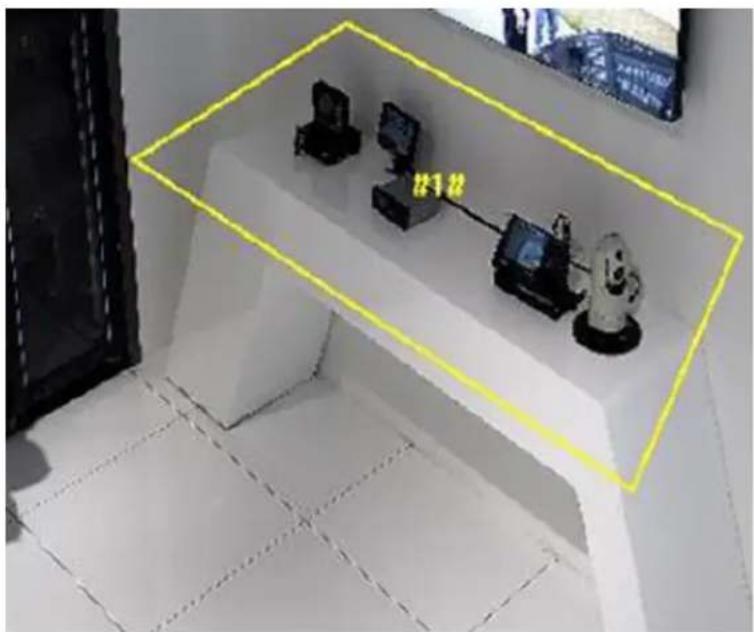
natural_image
Interior view of a room with three mounted devices and a yellow bounding box highlighting the 'u12' label (no readable text or symbols beyond labels)Figure 10-6 Set Rule
- Optional: You can set the parameters of multiple areas by repeating the above steps.
- For the arming schedule settings, see Set Arming Schedule. For the linkage method settings, see Linkage Method Settings.
- Click Save.

Note
The function is only supported by certain models. The actual display varies with the models.
10.3.7 Set Loitering Detection
It detects whether there is any target loitering in a predefined area. If the time that the target loiters in the set region reaches the set threshold, the device can take linkage actions.
Before You Start
- Go to VCA and select the application. Select Smart Event and click Next to enable the function.
- For the device supporting HEOP, go to VCA to import and enable Smart Event.
Steps
- Go to VCA → Set Application → Smart Event → Loitering Detection.
- Check Enable.
- Click Add to add a rule and set a detection area.
1) Draw a detection area. Click ☑ click on the live view to specify the vertexes and draw the boundaries of the detection area, and right click to complete drawing.
2) Set the minimum size and the maximum size for the target to improve detection accuracy. Only targets whose size are between the maximum size and the minimum size trigger the detection. Click and , then drag the mouse in the live view to draw the minimum and maximum target size.
3) Optional: Click 🔒 to delete all the setting areas.
- Set rules.
Threshold
Threshold stands for the threshold for the time of the object loitering in the region. If the time that one object stays exceeds the threshold, the alarm is triggered. The larger the value of the threshold is, the longer the alarm triggering time is.
Sensitivity
Sensitivity stands for the percentage of the body part of an acceptable target that enters the predefined region. Sensitivity = 100 - S1/ST × 100. S1 stands for the target body part that goes across the predefined region. ST stands for the complete target body. The higher the value of sensitivity is, the more easily the alarm can be triggered.
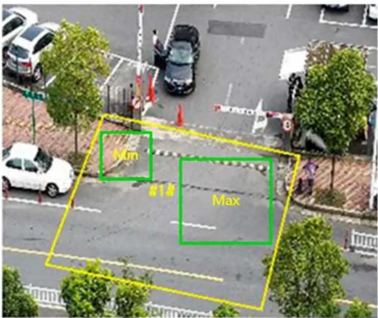
text_image
Mon MaxFigure 10-7 Set Rule
- Optional: You can set the parameters of multiple areas by repeating the above steps.
- For the arming schedule settings, refer to Set Arming Schedule . For the linkage method settings, refer to Linkage Method Settings .
- Click Save.

Note
The function is only supported by certain models. The actual display varies with the models.
10.3.8 Set People Gathering Detection
It detects the people density in a predefined area. If the people density exceeds the set percentage, the device can take linkage actions.
Before You Start
- Go to VCA and select the application. Select Smart Event and click Next to enable the function.
- For the device supporting HEOP, go to VCA to import and enable Smart Event.
Steps
- Go to VCA → Set Application → Smart Event → People Gathering Detection.
- Check Enable.
- Click Add to add a rule and set a detection area.
1) Draw a detection area. Click click on the live view to specify the vertexes and draw the boundaries of the detection area, and right click to complete drawing.
2) Optional: Click 🔒 to delete all the setting areas.
4. Set rules.
Percentage
It stands for the percentage of people in the predefined area. When the people percentage in the live view exceeds the set value, the device will trigger an alarm.
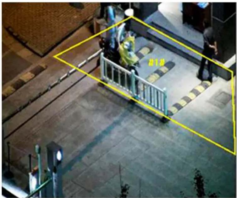
text_image
Street photo with visible yellow bounding box and number '10' on a sidewalk, showing a person in a green scooter on a metal railing.Figure 10-8 Set Rule
-
Optional: You can set the parameters of multiple areas by repeating the above steps.
-
For the arming schedule settings, refer to Set Arming Schedule . For the linkage method settings, refer to Linkage Method Settings
-
Click Save.

Note
The function is only supported by certain models. The actual display varies with the models.
10.3.9 Set Fast Moving Detection
When there are targets moving at a high speed in a predefined area, the device will take linkage actions and trigger an alarm.
Before You Start
- Go to VCA and select the application. Select Smart Event and click Next to enable the function.
- For the device supporting HEOP, go to VCA to import and enable Smart Event.
Steps
- Go to VCA → Set Application → Smart Event → Fast Moving Detection.
-
Check Enable.
-
Click Add to add a rule and set a detection area.
1) Draw a detection area. Click click on the live view to specify the vertexes and draw the boundaries of the detection area, and right click to complete drawing.
2) Set the minimum size and the maximum size for the target to improved detection accuracy. Only targets whose size are between the maximum size and the minimum size trigger the detection. Click and , then drag the mouse in the live view to draw the minimum and maximum target size.
3) Optional: Click 🔒 to delete all the setting areas.
- Set Rules.
Sensitivity
Sensitivity stands for the percentage of the body part of an acceptable target that enters the pre-defined region. Sensitivity = 100 - S1/ST × 100. S1 stands for the target body part that goes across the pre-defined region. ST stands for the complete target body. The higher the value of sensitivity is, the more easily the alarm can be triggered.
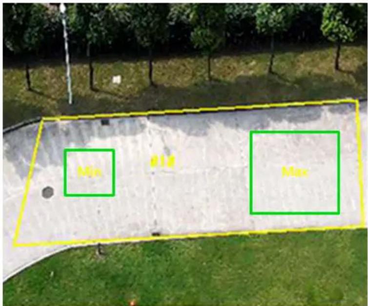
text_image
Min MaxFigure 10-9 Set Rule
- Optional: You can set the parameters of multiple areas by repeating the above steps.
-
For the arming schedule settings, refer to Set Arming Schedule . For the linkage method settings, refer to Linkage Method Settings .
-
Click Save.

The function is only supported by certain models. The actual display varies with the models.
10.3.10 Set Parking Detection
It detects parking violation in a predefined area. When the parking time exceeds a set threshold, the device can take linkage actions. It is applicable in expressway and one-way street.
Before You Start
- Go to VCA and select the application. Select Smart Event and click Next to enable the function.
- For the device supporting HEOP, go to VCA to import and enable Smart Event.
Steps
- Go to VCA → Set Application → Smart Event → Parking Detection.
- Check Enable.
- Click Add to add a rule and set a detection area.
1) Draw a detection area. Click ☑ click on the live view to specify the vertexes and draw the boundaries of the detection area, and right click to complete drawing.
2) Set the minimum size and the maximum size for the target to improve detection accuracy. Only targets whose size are between the maximum size and the minimum size trigger the detection. Click and , then drag the mouse in the live view to draw the minimum and maximum target size.
3) Optional: Click 🔒 to delete all the setting areas.
- Set rules.
Threshold
Threshold stands for the threshold for the parking time in the region. If the parking time exceeds the threshold, an alarm is triggered. The larger the value of the threshold is, the longer the alarm triggering time is.
Sensitivity
Sensitivity stands for the percentage of the part of an acceptable target that enters the pre-defined region. Sensitivity = 100 - S1/ST × 100. S1 stands for the target part that goes across the pre-defined region. ST stands for the complete target. The higher the value of sensitivity is, the more easily the alarm can be triggered.
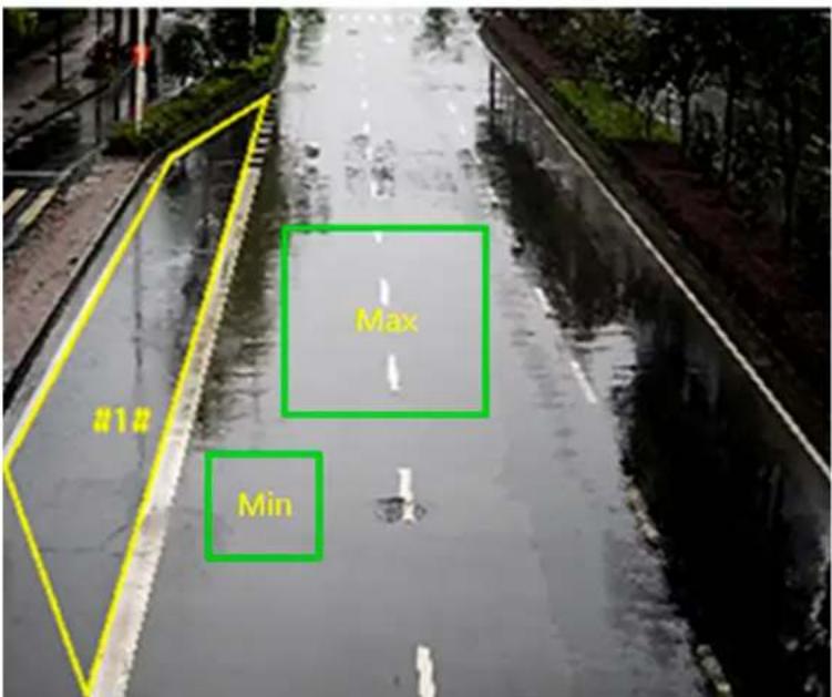
text_image
Max Min #1# #1#Figure 10-10 Set Rule
- Optional: You can set the parameters of multiple areas by repeating the above steps.
- For the arming schedule settings, refer to Set Arming Schedule . For the linkage method settings, refer to Linkage Method Settings
- Click Save.

Note
The function is only supported by certain models. The actual display varies with the models.
10.4 Face Capture
The device can capture the face that meets the rules in the configured rule area, and the captured picture will be uploaded.

Note
- For certain device models, you need to enable this function on VCA page first.
- The function is only supported by certain device models.
10.4.1 Set Face Capture
The face that appears in the configured area can be captured.
Before You Start
- Go to VCA and select the application. Select Face Capture and click Next to enable the function.
- For the device supporting HEOP, go to VCA to import and enable Face Capture.
Steps
- Go to VCA → Set Application → Face Capture → Rule.
- Check Enable to enable the rule settings.
- Click ☐ to draw the detection area you want the face capture to take effect. Draw area by left-clicking end-points in the live view window, and right-clicking to finish the area drawing. It is recommended that the drawn area occupies 1/2 to 2/3 of the live view image.
- Draw pupil distance.
Min. Pupil Distance
Click 🤒 to draw the minimum pupil distance. If the pupil distance of the face in the video image is smaller than the minimum pupil distance, the face will not be detected.
Max. Pupil Distance
Click 🔔 to draw the maximum pupil distance. If the pupil distance of the face in the video image is larger than the maximum pupil distance, the face will not be detected.
You can also input the value of distance in the text field.
- Optional: For shield region settings, refer to Set Shield Region.
- For the arming schedule settings, refer to Set Arming Schedule. For the linkage method settings, refer to Linkage Method Settings.
- Click Save.
- For overlay and capture settings, refer to Overlay and Capture. For advanced parameters settings, refer to Face Capture Algorithms Parameters.
Result
You can view and download captured pictures in Playback → Picture. Refer to View and Download Picture for details.
10.4.2 Overlay and Capture
Choose to configure capture parameters and the information you want to display on stream and picture.
Display VCA info. on Stream
Display smart information on stream, including the target and rules information.
Display Target info. on Alarm Picture
Overlay the alarm picture with target information.
Background Picture Settings
Comparing to target picture, background picture is the scene image which offers extra environmental information. You can set the background picture quality and resolution. If the background image need to be uploaded to the surveillance center, check Background Upload. For some devices, you can also check Face Picture to upload the captured face picture.
Target Picture Settings
Custom, Head Shot, Half-Body Shot and Full-Body Shot are selectable.

Note
If you select Custom, you can customize width, head height and body height as required.
You can check Fixed Picture Height to set the picture height.
Face Beautification
Check Face Beautification and adjust the beautification level as needed.

Face Beautification slightly adjusts the captured face pictures and reduces facial noise.
Face Enhancement
Check Face Enhancement and the device is able to capture better and clearer face pictures when it is dark.
Text Overlay
You can check desired items and adjust their order to display on captured pictures.
See Set Camera Info to set Device No. and Camera Info.
10.4.3 Face Capture Algorithms Parameters
It is used to set and optimize the parameters of the algorithm library for face capture function.
Version
It stands for the current algorithm version.
Capture Parameters
Best Shot
The best shot after target leaves the detection area.
Capture Threshold
It stands for the quality of face to trigger capture and alarm. Higher value means better quality should be met to trigger capture and alarm.
Capture Times
It refers to the capture times a face will be captured during its stay in the configured area.
The default value is 1.
Quick Shot
When the face picture grading value is higher than the quick shot threshold, the face picture will be captured and uploaded. Otherwise, the picture with the highest grading value that reaches the max. capture interval will be selected for upload.
Quick Shot Threshold
It stands for the quality of face to trigger quick shot.
Max. Capture Interval
It refers to the max. time occupation for one quick shot.
Capture Times
It refers to the capture times a face will be captured during its stay in the configured area.
Remove Duplicated Faces
This function can filter out repeated captures of certain face.
Similarity Threshold for Duplicates Removing
It is the similarity between the newly captured face and the picture in the duplicates removing library. When the similarity is higher than the value you set, the captured picture is regarded as a duplicated face and will be dropped.
Duplicates Removing Library Grading Threshold
It is the face grading threshold that triggers duplicates checking. When the face grading is higher than the set value, the captured face is compared with the face pictures that are already in the duplicates removing library.
Duplicates Removing Library Update Time
Every face picture is kept in the duplicates removing library for the set updatetime.
Face Exposure
Check the checkbox to enable the face exposure.
Reference Brightness
The reference brightness of a face in the face exposure mode. If a face is detected, the camera adjusts the face brightness according to the value you set. The higher the value, the brighter the face is.
Min. Duration
The minimum duration of the camera exposures the face.

If the face exposure is enabled, please make sure the WDR function is disabled, and the manual iris is selected.
Face Filtering Time
It means the time interval between the camera detecting a face and taking a capture action. If the detected face stays in the scene for less than the set filtering time, capture will not be triggered. For example, if the face filtering time is set as 5 seconds, the camera will capture the detected face when the face keeps staying in the scene for 5 seconds.

The face filtering time (longer than 0s) may increase the possibility of the actual capture times less than the set value above.
Facial Posture Filter
Facial posture filter can filter out face of certain postures. The figure on the right of the slider stands for the posture angle which is acceptable in the face capture action. Click to display the diagram illustrating the face turning direction when setting up this filter.
Upload Feature
Feature stands for the feature information the algorithm can tell from face pictures. Check the function to upload the information.
Restore Parameters
Restore Defaults
Click Restore to restore all the settings in advanced configuration to the factory default.
10.4.4 Set Shield Region
The shield region allows you to set the specific region in which the set smart function rule is invalid.
Steps
- Select Shield Region.
- Click ☐ to draw shield region. Repeat this step above to set more shield regions.
- Optional: Select and click on the drawn region, then click ✗ to delete the selected drawn region.
- Optional: Click to delete all drawn regions.
- Click Save.
10.5 Multi-Target-Type Detection
Multi-Target-Type Detection is to detect, capture and upload data of targets in multiple types, such as human face, human body, and vehicle.

Note
- For certain device models, you need to enable Multi-Target-Type Detection on VCA page first.
- The function is only supported by certain device models.
10.5.1 Set Multi-Target-Type Detection Rule
After setting the multi-target-type detection rules and algorithm parameters, the device captures targets of multiple types and triggers linkage actions automatically.
Before You Start
Go to VCA and select the application. Select Multi-Target-Type Detection and click Next to enable the function.
Steps
- Go to VCA → Set Application → Multi-Target-Type Detection → Rule.
- Check Enable.
- Click ☐ to draw a detection area. Click on the live view to specify the vertexes and draw the boundaries of the detection area, and right click to complete drawing.
- Enter the min. pupil distance in the text field, or click to draw min. pupil distance.
Min. Pupil Distance
The min. pupil distance refers to the minimum area between two pupils, and it is basic for the device to recognize a face.
- Check to enable the OSD Overlay, and set the parameters.
- Click Save.
- Optional: For shield region settings, refer to Set Shield Region.
- Set arming schedule. See Set Arming Schedule.
- Set linkage method. See Linkage Method Settings.
- Optional: For overlay and capture settings, refer to Overlay and Capture. For advanced parameters settings, refer to Multi-Target-Type Detection Advanced Parameters.
What to do next
Go to Playback → Picture to search and view the captured pictures. Refer to View and Download Picture for details.
Go to Application Display → Display Alarm to see currently captured target pictures. Refer to Smart Display for details.
10.5.2 Overlay and Capture
Choose to configure capture parameters and the information you want to display on stream and picture.
Display VCA info. on Stream
Display smart information on stream, including the target and rules information.
Display Target info. on Alarm Picture
Overlay the alarm picture with target information.
Background Picture Settings
Comparing to target picture, background picture is the scene image which offers extra environmental information. You can set the background picture quality and resolution. If the background image need to be uploaded to the surveillance center, check Background Upload. For some devices, you can also check Face Picture to upload the captured face picture.
Target Picture Settings
Custom, Head Shot, Half-Body Shot and Full-Body Shot are selectable.

Note
If you select Custom, you can customize width, head height and body height as required.
You can check Fixed Picture Height to set the picture height.
Face Beautification
Check Face Beautification and adjust the beautification level as needed.

Face Beautification slightly adjusts the captured face pictures and reduces facial noise.
Face Enhancement
Check Face Enhancement and the device is able to capture better and clearer face pictures when it is dark.
Text Overlay
You can check desired items and adjust their order to display on captured pictures.
See Set Camera Info to set Device No. and Camera Info.
10.5.3 Multi-Target-Type Detection Advanced Parameters
It is used to set and optimize the parameters of the algorithm library for Multi-Target-Type Detection.
Go to the VCA → Set Application → Multi-Target-Type Detection → Advanced for settings.
HMS Version
It refers to the current algorithm version, which cannot be edited.
Capture Parameters
Best Shot
Capture Threshold
It refers for the quality of face to trigger capture and alarm. Higher value means better quality should be met to trigger capture and alarm.
Remove Duplicated Faces
This function can filter out repeated captures of certain face.
Similarity Threshold for Duplicates Removing
It is the similarity between the newly captured face and the picture in the duplicates removing library. When the similarity is higher than the value you set, the captured picture is regarded as a duplicated face and will be dropped.
Duplicates Removing Library Grading Threshold
It is the face grading threshold that triggers duplicates checking. When the face grading is higher than the set value, the captured face is compared with the face pictures that are already in the duplicates removing library.
Duplicates Removing Library Update Time
Every face picture is kept in the duplicates removing library for the set updatetime.
Face Exposure
Enable the function, and the device automatically adjusts exposure level when human faces appear in the scene.
Reference Brightness
It refers to the reference brightness of a face in the face exposure mode. If a face in the actual scene is brighter than the set reference brightness, the device lower the exposure level. If a face in the actual scene is darker than the set reference, the device increases the exposure level.
Minimum Duration
The extra time the device keeps the face exposure level after the face disappears in the scene.
Face Filtering Time
It means the time interval between the camera detecting a face and taking a capture action. If the detected face stays in the scene for less than the set filtering time, capture will not be triggered. For example, if the face filtering time is set as 5 seconds, the camera will capture the detected face when the face keeps staying in the scene for 5 seconds.
Data Upload
Data Upload
Check one or more desired target types for picture uploading.
Restore Parameters
Restore Defaults
Click Restore to restore all the settings in advanced configuration to the factory default.
10.5.4 Set Shield Region
The shield region allows you to set the specific region in which the set smart function rule is invalid.
Steps
- Select Shield Region.
- Click ☐ to draw shield region. Repeat this step above to set more shield regions.
- Optional: Select and click on the drawn region, then click ✗ to delete the selected drawn region.
- Optional: Click to delete all drawn regions.
- Click Save.
10.6 Face Comparison
Face comparison serves the purpose of face recognition by comparing the captured faces with those in face picture library.
i Note
- For certain device models, you need to enable Face Picture Comparison on VCA page first.
- The function is only supported by certain device models.
10.6.1 Set Face Picture Library
Face picture library is used to store modeled human faces and information.
Steps
- Go to VCA → General Settings → Face Picture Library.
- Create a face picture library.
1) Click Add to add a face picture library.
2) Input library name, threshold and remarks.
Threshold
Face similarity higher than the set threshold triggers face picture comparison alarm uploading.
3) Click OK.
4) Optional: Modify a face picture library. Select the desired library and click Modify and change related parameters.
5) Optional: Delete a library. Select the desired library and click Delete.
- Add face pictures to the library.

Note
The picture format should be JPG or JPEG, and the size no larger than 300 KB per file.
Add one face picture
Click Add and upload the face picture with detailed face information.
Import face pictures in batch
Click Import and select picture path. You can select and import multiple face pictures as required.

Note
When you import face pictures in batch, the picture name is saved as the face name. For other face information, you should modify one by one manually.
- Optional: Modify face information.
1) Select a face picture library.
2) Select the target face picture. You can use the search function to locate the picture by inputting search conditions, and click Search.
3) Click Modify.
4) Edit detailed information.

Note
Face picture is not allowed to change.
5) Click OK.
- Click Batch Modeling to create models for each face picture in library.

Note
Modeling process builds up face model for each selected face picture. Face model is required for face picture comparison to take effect.
- Optional: Repeat to create more face picture libraries.
10.6.2 Set Face Picture Comparison
The function compares captured pictures with face pictures in library and outputs comparison result. Comparison result can trigger certain actions when arming schedule and linkage method are set.
Before You Start
- Go to VCA and select the application. Select Face Picture Comparison and click Next to enable the function.
- You should first set face capture function. See Set Face Capture.
- You should first create a face picture library and add face pictures. See Set Face Picture Library .
Steps
- Go to VCA → Set Application → Face Picture Comparison and select Comparison and Modeling.
- Check Enable.
- Select a face comparison mode.
Best Comparison The device captures and compares the target face continuously when the face target stays in the detection area, and upload the best scored face picture and related alarm information when the target face leaves the area.
Quick The device captures and compares the target face when the face grading Comparison exceeds the set Face Grading Threshold for Capture.
Face Grading Threshold for Capture
The face grading threshold for the device to judge whether to capture and upload the face or not.
Max. Capture Interval
The max. interval between two captures when the target is in the detection area. The camera takes the capture when it reaches the max. interval even if the face grading does not reach the set threshold.
Quick Setup Mode
Select the mode according to actual using scenarios. In custom mode, you can set Comparison Timeout and Comparison Times.
-
Optional: Set data uploading.
-
Select desired information to upload.
-
Select the desired linked comparison alarm.
-
Select a face picture library as the reference. Refer to Set Face Picture Library for details.
-
Set arming schedule. See Set Arming Schedule.
- Set linkage method. See Linkage Method Settings.
- Click Save.
What to do next
Go to Application Display → Face Picture Comparison Result to view the face picture comparison statistics. Refer to View Face Picture Comparison Result for details.
10.6.3 View Face Picture Comparison Result
Steps
- Go to Application Display → Face Picture Comparison Result.
- Set search condition and click Search.
Result
Matched results are shown in the right area.
10.7 People Management
People management is used to detect and analyze people number and changes in a predefined region. It can be applied to the entrances and exits, supermarkets, etc.

Note
- For certain device models, you need to enable People Management on VCA page first.
- The function is only supported by certain device models.
10.7.1 On/Off Duty Detection
When a target in a predefined area triggers an on/off duty rule, the device can take linkage actions. It can detect the on/off duty status and people number changes in a predefined area.
Before You Start
- Go to VCA and select the application. Select People Management and click Next to enable the function.
- For the device supporting HEOP, go to VCA to import and enable People Management.
Steps
- Go to VCA → Set Application → People Management → On/Off Duty Detection → Rule
- Click Add and edit the rule name according to your need.
- Select a rule and set the rule parameters.
Absence Detection
If the people number in the set area is less than the value of Person On Duty and the lasting time is longer than the Absence Duration, an alarm is triggered.
On/Off Duty Detection
It includes on/off duty situation detection.
People Number OSD
It overlays the real-time people number on the live view. You can adjust the OSD location by dragging the mouse.
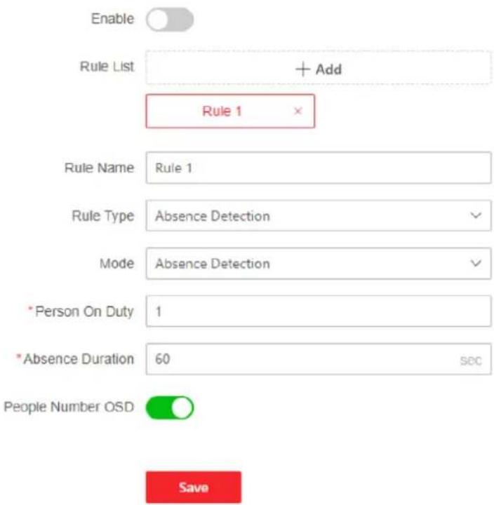
text_image
Enable Rule List + Add Rule 1 Rule Name Rule 1 Rule Type Absence Detection Mode Absence Detection *Person On Duty 1 *Absence Duration 60 sec People Number OSD SaveFigure 10-11 Set Rules
- Click to draw a rule area in the live view window. Left click the end-points in the live view window to define the boundary of the set rule area, and right click to finish drawing.
i Note
-
Up to 8 areas can be set at the same time.
• Try not to overlap the areas. -
Click Save.
i Note
You can set the parameters of multiple areas by repeating the above steps.
- For the arming schedule settings, refer to Set Arming Schedule. For the linkage method settings, refer to Linkage Method Settings.
Note
Select the rule in the rule list, and click Copy to... to copy the related arming schedule and linkage method settings to the other rules.
- Optional: Set overlay and capture parameters. For detailed settings, refer to Overlay and Capture.
- Optional: View version and set filtering condition. For detailed settings, refer to Advanced Settings.
10.7.2 Queue Management
It is used to calculate and analyze the number of people and queue status in the area, and output results.
Refer to Set Queue Duration Prediction to set queue duration prediction.
Refer to Set Regional People Queuing-Up to set regional people queuing-up detection.
Refer to Set Waiting Time Detection to set waiting time detection.
Refer to Queue Management Statistics to set and view queue management statistics.
i Note
- Queue management is only supported by certain models.
- Queue Duration Prediction is mutually exclusive with some functions, such as On/Off Duty Detection, Regional People Queuing-Up and Waiting Time Detection. Enable this function may make other functions unavailable, and vice versa.
Set Queue Duration Prediction
It is used to calculate and predict the queue duration in the predefined area.
Before You Start
- Go to VCA and select the application. Select People Management and click Next to enable the function.
- For the device supporting HEOP, go to VCA to import and enable People Management.
Steps
-
Go to VCA → Set Application → People Management → Queue Management → Rule.
-
Check Queue Duration Prediction to enable the function.
i Note
Queue Duration Prediction is mutually exclusive with some functions, such as On/Off Duty Detection, Regional People Queuing-Up and Waiting Time Detection. Enable this function may make the other functions unavailable, and vice versa.
Queue Duration Prediction
Queue Duration Prediction

Rule List
+ Add
*Rule Name
Area1
Area Color


Queue Duration OSD Overlay

* Expected Queue Duration Upload ...
60
sec
① *Alarm Interval
5
sec

Figure 10-12 Set Queue Duration Prediction
3. Draw areas.

Note
You can click View Drawing Example for a drawing example of the actual scene.
1) Click Add and edit the rule name according to your need.
2) Select an Area color and click to draw a rule area. Left click the end-points in the live view window to define the boundary of the set rule area, and right click to finish drawing. It is recommended that the queue should be in the area.
3) Click ☑ to draw a quadrilateral area. It is recommended that the quadrilateral area should be drawn in the front of the queue.

Note
- Up to 8 areas can be set at the same time.
- Try not to overlap the areas.
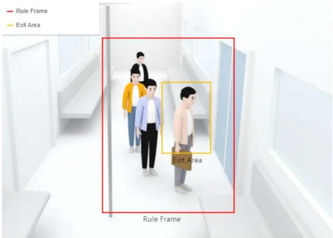
text_image
Rule Frame Exit Area Exit Area Rule Frame- Click Draw Area to draw a rule area. It is recommended that the queue should be in the area.
- Click Draw Exit Area to draw a quadrilateral area. It is recommended that the quadrilateral area should be drawn in the front of the queue.
Figure 10-13 Drawing Example of Queue Duration Prediction
- Set rule parameters.
Queue Duration OSD Overlay
When enabled, the queue duration will be displayed in the image, and you can adjust the display position of the OSD overlay on the live view image.
Expected Queue Duration Upload Interval and Alarm Interval
The device uploads queue duration information at each upload interval. In the set Alarm Interval, only one notification is triggered for repeated alarms.
- Click Save.

Note
You can set the parameters of multiple areas by repeating the above steps.
- For the arming schedule settings, refer to Set Arming Schedule . For the linkage method settings, refer to Linkage Method Settings .

Note
Select the rule in the rule list, and click 📋 or click Copy to... to copy the related arming schedule and linkage method settings to the other rules.
- Optional: Set overlay and capture parameters. For detailed settings, refer to Overlay and Capture.
- Optional: View version and set filtering condition. For detailed settings, refer to Advanced Settings.
What to do next
Go to Application Display → Queue Management Statistics to view detailed data analysis. For detailed settings, refer to Queue Management Statistics.
Set Regional People Queuing-Up
It is used to count queuing-up persons in defined areas. Alarms are triggered when the alarm threshold condition and the alarm trigger are both met.
Before You Start
- Go to VCA and select the application. Select People Management and click Next to enable the function.
- For the device supporting HEOP, go to VCA to import and enable People Management.
Steps
- Go to VCA → Set Application → People Management → Queue Management → Rule.
- Click Add and edit the rule name according to your need.
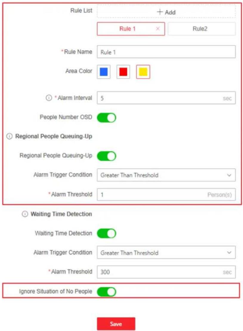
text_image
Rule List + Add Rule 1 × Rule2 * Rule Name Rule 1 Area Color ① * Alarm Interval 5 sec People Number OSD Regional People Queuing-Up Regional People Queuing-Up Alarm Trigger Condition Greater Than Threshold * Alarm Threshold 1 Person(s) Waiting Time Detection Waiting Time Detection Alarm Trigger Condition Greater Than Threshold * Alarm Threshold 300 sec Ignore Situation of No People Save- Select an Area color and click ☐ to draw a rule area. Left click the end-points in the live view window to define the boundary of the set rule area, and right click to finish drawing.

Note
-
Up to 8 areas can be set at the same time.
• Try not to overlap the areas. -
Set rule parameters.
Alarm Interval
During the set alarm interval, alarms of the same type only trigger one notification.
People Number OSD
It displays the number of people in the live view window.
Ignore Situation of No People
The device will not trigger an alarm when there is no people in the scene. This function can filter the potential alarm condition under which the value is less than the set alarm threshold and no people is in the scene.
- Select Regional People Queuing-Up and set Alarm Trigger Condition and Alarm Threshold.
When the people number in the set area reaches alarm threshold and triggering condition, an alarm will be triggered.
- Click Save.

Note
You can set the parameters of multiple areas by repeating the above steps.
- For the arming schedule settings, refer to Set Arming Schedule. For the linkage method settings, refer to Linkage Method Settings.

Note
Select the rule in the rule list, and click 📋 or click Copy to... to copy the related arming schedule and linkage method settings to the other rules.
- Optional: Click Data Upload to set data uploading. Both real-time uploading and scheduled uploading are supported. Click Save after finishing the settings.
Real-Time Uploading
Check Real-Time Upload and the device uploads the detected target ID, waiting duration, and regional people number in real-time.
Scheduled Uploading
The device uploads the people number whose waiting duration is equal to or larger than the Min. Duration of Stay at the integral point.
For example, if the min. duration of stay is set as 10 sec and two areas are covered, the device, at the integral point, will upload the people number when the duration of stay is equal to or longer than 10 sec in two areas respectively.
-
Optional: Set overlay and capture parameters. For detailed settings, refer to Overlay and Capture.
-
Optional: View version and set filtering condition. For detailed settings, refer to Advanced Settings.
What to do next
Go to Application Display → Queue Management Statistics to view detailed data analysis. For detailed settings, refer to Queue Management Statistics.
Set Waiting Time Detection
It is used to count the waiting time of each person that enters a detection area. Alarms are triggered when the alarm threshold condition and the alarm trigger are both met.
Before You Start
- Go to VCA and select the application. Select People Management and click Next to enable the function.
- For the device supporting HEOP, go to VCA to import and enable People Management.
Steps
- Go to VCA → Set Application → People Management → Queue Management → Rule.
- Click Add and edit the rule name according to your need.
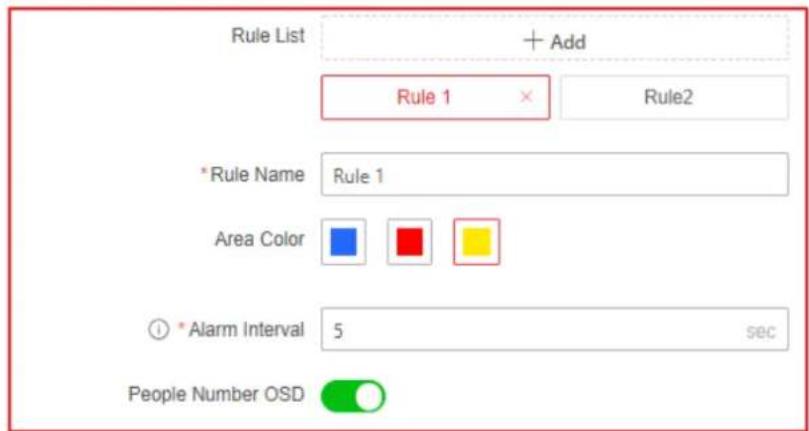
text_image
Rule List + Add Rule 1 × Rule2 *Rule Name Rule 1 Area Color * Alarm Interval 5 sec People Number OSDRegional People Queuing-Up
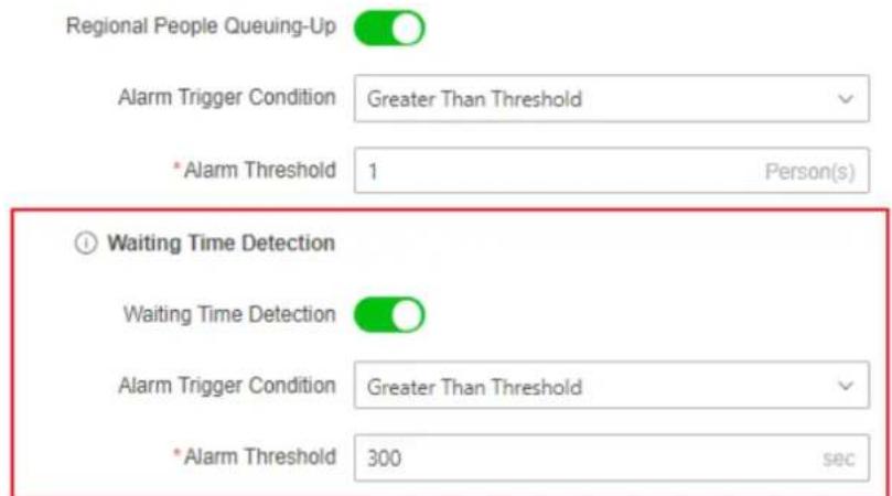
text_image
Regional People Queuing-Up Alarm Trigger Condition Greater Than Threshold * Alarm Threshold 1 Person(s) Waiting Time Detection Waiting Time Detection Alarm Trigger Condition Greater Than Threshold * Alarm Threshold 300 secIgnore Situation of No People

Save
- Select an Area color and click 🔒 to draw a rule area. Left click the end-points in the live view window to define the boundary of the set rule area, and right click to finish drawing.
i Note
- Up to 8 areas can be set at the same time.
-
Try not to overlap the areas.
-
Set rule parameters.
Alarm Interval
During the set alarm interval, alarms of the same type only trigger one notification.
People Number OSD
It displays the number of people in the live view window.
- Select Waiting Time Detection and set Alarm Trigger Condition and Alarm Threshold.
When the waiting time in the set area reaches alarm threshold and triggering condition, an alarm will be triggered.
- Click Save.
i Note
You can set the parameters of multiple areas by repeating the above steps.
- For the arming schedule settings, refer to Set Arming Schedule. For the linkage method settings, refer to Linkage Method Settings.
i Note
Select the rule in the rule list, and click 📋 or click Copy to... to copy the related arming schedule and linkage method settings to the other rules.
- Optional: Click Data Upload to set data uploading. Both real-time uploading and scheduled uploading are supported. Click Save after finishing the settings.
Real-Time Uploading
Check Real-Time Upload and the device uploads the detected target ID, waiting duration, and regional people number in real-time.
Scheduled Uploading
The device uploads the people number whose waiting duration is equal to or larger than the Min. Duration of Stay at the integral point.
For example, if the min. duration of stay is set as 10 sec and two areas are covered, the device, at the integral point, will upload the people number when the duration of stay is equal to or longer than 10 sec in two areas respectively.
-
Optional: Set overlay and capture parameters. For detailed settings, refer to Overlay and Capture.
-
Optional: View version and set filtering condition. For detailed settings, refer to Advanced Settings.
What to do next
Go to Application Display → Queue Management Statistics to view detailed data analysis. For detailed settings, refer to Queue Management Statistics.
Queue Management Statistics
Queue management supports data analysis and report output.
Before You Start
For queue management settings, refer to Set Regional People Queuing-Up and Set Waiting Time Detection.
- Select Queuing-Up Time Analysis and Multi-Area Comparison to compare queuing-up people number of different areas.
- Select Queuing-Up Time Analysis and Multi-Level Comparison to compare queuing-up people number of different waiting time levels.
- Select Queue Status Analysis and Multi-Area Comparison to compare the time and duration that a queue stays at a certain length in different areas.
- Select Queue Status Analysis and Multi-Level Comparison to compare the time and duration of the queue at different queue length levels.
Steps

Note
With an on-board memory card installed, the device can save up to one mouth's data. With NO memory card installed, the device can only save up to one week's data.
- Go to Application Display → Queue Management Statistics.
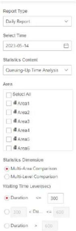
text_image
Report Type Daily Report Select Time 2023-05-14 Statistics Content Queuing-Up Time Analysis Area □ Select All □ Area1 □ Area2 □ Area3 □ Area4 □ Area5 □ Area6 Statistics Dimension ● Multi-Area Comparison ○ Multi-Level Comparison Waiting Time Level(sec) ● Duration <= 300 ○ 300 < Du... <= 600 ○ Duration > 600Figure 10-14 Queue Management Statistics
- Select Report Type and Statistics Time.
- Select Statistics Content.
Queuing-Up Time Analysis
Queuing-up time analysis calculates people number of different waiting time levels.
Queue Status Analysis
Queue status analysis calculates the time and duration that a queue stays a certain length.
- Select Statistics Dimension.
Multi-Area Comparison
Multiple areas and one level can be selected for analysis, and an analysis chart can be drawn.
Multi-Level Comparison
Multiple levels and areas can be selected for analysis, and one analysis chart is drawn for each area.
- Check one or more areas.
- Set Waiting Time Level. Check one desired range and enter values.
- Click Search to generate the report.
- Optional: Click Export to export the data.
10.7.3 Overlay and Capture
Choose to configure capture parameters and the information you want to display on stream and picture.
Go to VCA → People Management → Overlay & Capture.
Display VCA info. on Stream
Display smart information on stream, including the target and rules information.
Display Target info. on Alarm Picture
Overlay the alarm picture with target information.
Text Overlay
Select the information you want to overlay on the captured pictures. You can also click ↑ ↓ to adjust the order.
10.7.4 Advanced Settings
Set the advanced parameters for people management function and click Save.
Version
It stands for the current algorithm version.
Algorithm Mode
Select a mode according to the installation scene.
Filter
Target Size
It stands for the size of the target detection window. A target larger than this pixel can be counted as a real target. It can remove the false alarm of a certain fixed target.
Displacement
It stands for target displacement or the target width. A target will not be counted if its displacement is less than the set percentage.
Min. Waiting Duration
Waiting time shorter than the set value will be filtered.
Confidence
The higher the threshold is, the more difficult a target will be detected, but the higher the accuracy is.

Note
The filtering settings should be operated by the professionals. The filter settings can adjust the algorithm for detection to change the detection range, sensitivity, etc.
Clear Storage Data
Clear all people counting data stored in the device. This function must be used with caution.
10.8 Heat Map
Heat map is a graphical representation of data represented in colors. The heat map function of the camera is used to analyze the visiting times and dwelling time of customers in a configured area.

Note
The function is only supported by certain device models.
10.8.1 Set Heat Map
If you want to query statistical data of heat map, please configure the camera first.
Before You Start
- Go to VCA and select the application. Select People Management and click Next to enable the function.
- For the device supporting HEOP, go to VCA to import and enable People Management.
- Set the storage path first before searching heat map data. For the storage settings, refer to Storage Settings.
Steps
-
Go to VCA → Set Application → People Management → Heat Map Configuration.
-
Check Enable to enable the function.
-
Draw a detection area. Click ☑ click on the live view to specify the vertexes and draw the boundaries of the detection area, and right click to complete drawing.
-
Configure the parameters for the drawn area.
Expected Number of People
It refers to the max. number of people for heat map counting.
ON
It refers to that the camera will compare the max. number of the people in the actual scene with the set expected number of people and take the larger one as the max. number of people for heat map.
OFF
It refers to that the camera will take the actual number of people as the max. value of heat map.
-
Click Save.
-
Set arming schedule. See Set Arming Schedule.
-
Set linkage method. See Linkage Method Settings.
-
Optional: Click Data Upload to set the data uploading information. Click Save to save the settings.
Uploading Data Type
Dwell Time
It refers to the target's dwelling time in the detection area.
Dwell Time and Number of People
It refers to the target's dwelling time in the detection area and the people number in the detection area.
-
Optional: Set overlay and capture parameters. For detailed settings, refer to Overlay and Capture.
-
Optional: View version and set filtering condition. For detailed settings, refer to Advanced Settings.
What to do next
The heat map statistics will be calculated under Application Display tab. Go to Application Display to check the heat map statistics.
10.8.2 View Heat Map Data
Heat map can observe and calculate the people flow in a predefined area and display the flow statistics in graphical form. It can be applied to scenes of large passenger flow such as malls, supermarkets, and museums. You can find the customers' preferences to adjust the places of merchandise through heat map.
Before You Start
Finish heat map configuration. For details, refer to Set Heat Map.
Steps
- Go to Application Display → Heat Map.
- Select Report Type. Daily report, weekly report, monthly report, and annual report are selectable.
- Select Heat Map Type. Spatial heat map and time heat map are selectable.
- Select Statistics Type. By dwell time and by people number are selectable.
- Select Statistics Time.
- Click Search.
Daily report calculates the data on the date you selected; weekly report calculates the week data your selected date belongs to; monthly report calculates the data for the month your selected date belongs to; and the annual report calculates the data for the year your selected date belongs to.
Example
After the calculating, you can view the data in the spatial heat map and time heat map.
Spatial Heat Map
Perform a statistical analysis on the cumulative dwelling of people in different areas in the entire image.
Different heat values correspond to different colors, among which red (255, 0, 0) represents the highest heat, and blue (0, 0, 255) represents the lowest heat. The highest heat value and lowest heat value are divided into N levels, corresponding to different colors.
Time Heat Map
Perform a statistical analysis on the total dwelling time of all people in the entire image.
The time heat map is presented in a line chart, and you can click Export to export the data in an excel file.
10.9 Multi-Dimension People Counting
This function is used to calculate the number of people entering in or exiting from the specified scene.

Note
- For certain device models, you need to enable Multi-Dimension People Counting on VCA page first.
- The function is only supported by certain device models.
10.9.1 Set Multi-Dimension People Counting Rule
After setting the detection rules and algorithm parameters, the device calculates the number of people entering or exiting in the rule area, triggers linkage actions and uploads data automatically.
Before You Start
Go to VCA → Select Application, select Multi-Dimension People Counting and click Next to enable the function.
Steps
- Go to VCA → Set Application → Multi-Dimension People Counting → Rule.
- Click ☐ to draw a convex red rule frame. The rule frame should be bigger than the actual detection area, such as door.
- Draw a detection line.
- When the detection area only supports one-way direction, it is recommended to click / to draw a straight detection line.
- When the detection area supports multiple directions, or there are walls and obstacles in the detection area, it is recommended to click to draw a polyline.
i Note
- The detection line should be within and in the middle of the rule area. It is recommended to draw the line on people chest position in the live view.
-
The arrow of the detection line shows entering direction.
-
Optional: When the detection area supports multiple directions, you can enable Flow Direction Analysis. If enabled, the device will change the detection line into a polyline automatically, divide the entrance region into sub-region B, C and D, and count the flow direction of people.
-
Optional: Adjust the detection area and detection line.
Click ☒ Change the detection line direction if the direction is different from the actual flow direction.
Click Clear all detection areas and lines.
- Draw pupil distance.
Min. Pupil Distance
Click to draw the minimum pupil distance. If the pupil distance of the face in the video image is smaller than the minimum pupil distance, the face will not be detected.
Max. Pupil Distance
Click 🔔 to draw the maximum pupil distance. If the pupil distance of the face in the video image is larger than the maximum pupil distance, the face will not be detected.
- Set the flow counting parameters.
OSD Overlay
Select the data to be displayed on the live view from the drop-down list.
Daily Reset Time
Select a time point through the drop-down list. After selecting, the flow counting data will be automatically cleared at this time point every day. Click Manual Reset to manually trigger a data reset.
-
Set arming schedule. See Set Arming Schedule.
-
Set linkage method. See Linkage Method Settings.
-
Optional: Click Settings next to the Alarm Uploading to set the people counting data uploading parameters.
Real-Time Upload Data
If checked, it means that the flow counting data will be uploaded to the platform for update in real time.
Upload Data Periodically
If checked, it means that the flow counting data will be uploaded to the platform for update according to the statistical period. In this case, Data Statistics Cycle needs to be set.
-
Click Save.
-
When the target crosses the detection area along the entering direction and passes the detection line, the target is counted as one entering target.
- When the target crosses the detection area along the leaving direction and passes the detection line, the target will be counted as one exiting target.
-
When the target crosses the detection area along the entering direction multiple times within the Filtering Time Interval, and passes the detection line, the target will be counted as one duplicate target.
-
Optional: Set data optimization parameters. Click Save after setting the parameters.
Special Attribute Deduplication
If enabled, the device will determine whether the target is a duplicate target with the same attribute. If it is a duplicate target, it will be counted as one entering target, and also counted as one duplicate target.
Dynamic Deduplication
Persons who appear repeatedly within the Filtering Time Interval are not counted as an effective target. In other words, if it is a duplicate target, it will be counted as one duplicate target and one entering target. If the Filtering Time Interval is set to 0, the function is not enabled.
Face Picture Library Deduplication
If enabled, the device compares the target with the modeling data in the face library to determine whether it is a duplicate target. If it is a duplicate target, it will be counted as one entering target, and also counted as one duplicate target.
i Note
For detailed settings about face picture library, refer to Set Face Picture Library.
- Optional: Set face picture comparison alarm. See Set Face Picture Comparison Alarm.
What to do next
Go to Application Display to view detailed people counting data analysis. For detailed settings, refer to View People Counting Statistics.
10.9.2 Multi-Dimension People Counting Advanced Settings
Overlay and Capture
Go to VCA → Set Application → Multi-Dimension People Counting → Advanced Settings → Overlay & Capture and click Save to finish the settings.
Display VCA Info. on Stream
Display smart information on stream, including the target and rules information.
Display Target Info. on Alarm Picture
Overlay the alarm picture with target information.
Text Overlay
You can check desired items and adjust their order to display on captured pictures by sorting.
Advanced Parameters
Go to VCA → Set Application → Multi-Dimension People Counting → Advanced Settings → Advanced to view and set the advanced parameters.
Multi-Dimension People Counting Version
It stands for the current algorithm version.
Algorithm Mode
View and select a mode according to the installation scene.
Clear Storage Data
This action clears all counting data stored in the device. Pay attention to this.
10.9.3 Set Face Picture Library
Face picture library is used to store modeled human faces and information.
Steps
- Go to VCA → General Settings → Face Picture Library.
- Create a face picture library.
1) Click Add to add a face picture library.
2) Input library name, threshold and remarks.
Threshold
Face similarity higher than the set threshold triggers face picture comparison alarm uploading.
3) Click OK.
4) Optional: Modify a face picture library. Select the desired library and click Modify and change related parameters.
5) Optional: Delete a library. Select the desired library and click Delete.
- Add face pictures to the library.

Note
The picture format should be JPG or JPEG, and the size no larger than 300 KB per file.
Add one face picture Click Add and upload the face picture with detailed face information.
Import face pictures in batch Click Import and select picture path. You can select and import multiple face pictures as required.
i Note
When you import face pictures in batch, the picture name is saved as the face name. For other face information, you should modify one by one manually.
- Optional: Modify face information.
1) Select a face picture library.
2) Select the target face picture. You can use the searchfunction to locate the picture by inputting search conditions, and click Search.
3) Click Modify.
4) Edit detailed information.
i Note
Face picture is not allowed to change.
5) Click OK.
- Click Batch Modeling to create models for each face picture in library.
i Note
Modeling process builds up face model for each selected face picture. Face model is required for face picture comparison to take effect.
- Optional: Repeat to create more face picture libraries.
10.9.4 Set Face Picture Comparison Alarm
The function compares captured pictures with face pictures in library and outputs comparison result. Comparison result can trigger certain actions when arming schedule and linkage method are set.
Before You Start
Go to VCA → Select Application, select Multi-Dimension People Counting and click Next to enable the function.
You should first create a face picture library and add face pictures. Go to VCA → General Settings → Face Picture Library to configure and manage the face pictures in library.
Steps
- Go to VCA → Set Application → Multi-Dimension People Counting → Face Picture Comparison Alarm.
- Check Background Upload if you need to attach captured pictures to alarm information. Comparing to target picture, background picture is the scene image which offers extra environmental information. You can set the Background Picture Resolution.
- Select a face picture library.
- Set arming schedule of the related face picture library.
1) Click +.
2) Click Draw, and drag the time bar to draw desired valid time.
i Note
• Each cell represents 30 minutes.
- Move the mouse over the drawn time period to see specific time periods and fine-tune the start time and end time.
- Up to 8 periods can be configured for one day.
3) Click Erase, and drag the time bar to clear selected valid time.
4) Click OK to save the settings.
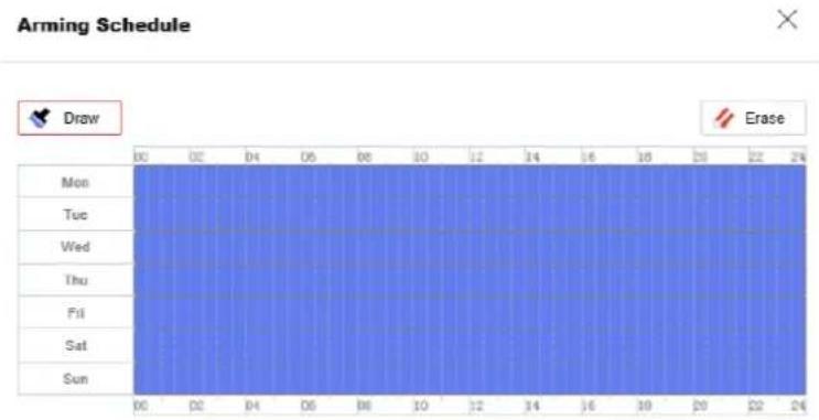
Figure 10-15 Set Arming Schedule
- Set linkage method of the related face picture library. Click to set linkage method and save the settings. For detailed settings, refer to Linkage Method Settings.
- Click Save.
- Optional: Repeat the above steps to configure the face picture comparison for the other face picture library.
What to do next
Go to Application Display to view detailed data analysis. For detailed settings, refer to View Face Picture Comparison Result.
10.9.5 View Face Picture Comparison Result
Steps
- Go to Application Display → Face Picture Comparison Result.
- Set search condition and click Search.
Result
Matched results are shown in the right area.
10.9.6 View People Counting Statistics
You can view the people counting data stored in the device through the table, bar chart and line chart.
Steps
- Go to Application Display → People Counting.
- Set Report Type, Statistics Type and Start Time.
- Click Search.
You can select Line Chart, Bar Chart and Table to view the data, and you can export the people counting data through Excel.
10.10 AI Open Platform
AI Open Platform is to generate a model library based on the training material provided by the user, then load the model library into the device and allow user to configure tasks and rules. When a target in the scene is detected to trigger the rules, the device can take linkage actions, which can realize personalized smart applications.

Note
- The function is only supported by certain device models.
- For certain device models, you need to enable AI Open Platform on VCA page first.
10.10.1 Set AI Open Platform
Steps
- Go to VCA → Set Application → AI Open Platform.

Note
- Specific smart functions are supported for configuration via the AI Open Platform, such as hard hat detection.
- After selecting a specific function, the device will load the model package of the corresponding function.
- The function varies according to different device models, please refer to the actual device.
-
For Hard Hat Detection, it detects targets in the set detection area who do not wear the hard hat and triggers an alarm.
-
Optional: Add a model into Model Library. Select the Model Library and related Label File from the local path, then set the Model Name. The model types are as follows.
Detection Model
Detects a specific target in the live view and provides the detection result and coordinate position of the target.
Classification Model
Classifies pictures or targets with attributes.
Mixed Model
Detects targets in the live view and classifies them.

Note
Max. Number of Model Packages refers to the maximum number of model packages that the device supports.
- Select a model and enable it.
- Select an Analysis Mode.
Live Video Analysis
The device analyzes the live video to realize target detection and result uploading.
Scheduled Capture
The device captures based on the set Auto-Switch Interval to analyze the captured picture and upload results.
Analysis
- Optional: Enable Overlay Target Frame and Rule Overlay according to your needs.
Overlay Target Frame Overlay the alarm picture with target frame.
Rule Overlay Overlay the alarm picture with rule information.
- Set the arming schedule and linkage method. For the arming schedule settings, refer to Set Arming Schedule. For the linkage method settings, refer to Linkage Method Settings.
- Set rules for the linked channel. Refer to Set Rules for details.
- Click Save.
10.10.2 Set Rules
Set rules for the linked channel.
Before You Start
Make sure the related model in VCA → AI Open Platform is selected, and the task configuration is finished.
Steps
- Click Linked Channel to select a channel in Channel Management.
- Click ⚙ of the linked channel to set rules.
- Click Add Rule. Select the rule and click ↙ to rename the rule and select the rule type.
Region Target Exception Status Detection
Detects and counts the number of the target in the predefined virtual rule area, and compares it with the setting rule. When satisfying the triggering condition, it will trigger the alarm.
Line Crossing Target Detection
Detects if any targets crossing the predefined virtual rule line and triggers the alarm when detects.
Full Analysis Rule
Detects and analyzes all targets in the predefined virtual rule area.
Line Crossing Target Counting
Detects and counts the number of the target crossing the predefined virtual rule line.
Region Target Number Counting
Detects and counts the number of the target in the predefined virtual rule area.
Combined Rule
Supports Region Target Exception Status Detection and Line Crossing Target Detection in the predefined virtual rule area. You can set Combined Mode as All Satisfy or Satisfy In Order for the detection order.

Note
Rule types vary according to different model packages, please refer to the actual device.
-
Set the detection rule and draw rule area or line.
-
Draw a rule area: click to draw a convex area in the live view window, left click the endpoints in the live view window to define the boundary of the set rule area, and right click to finish drawing.
-
Draw a rule line: click √ and a line with an arrow appears in the live video. Drag the line to the location in the live view window as desired.
-
Set rule parameters.
Object
The detection target type of the model.
Attribute
The detection target property of the model.
Duration
The duration of the status. The alarm will be triggered when the set time duration is reached.
Alarm Interval
During the set alarm interval, alarms of the same type only trigger one notification.
Sensitivity
The higher the value of sensitivity is, the easier the alarm can be triggered. If the sensitivity value is too large, the false alarm may be produced easier. Please set it according to the actual situation.
Max. Alarm Times
The maximum number of times an alarm can be triggered in the status that triggers the alarm.
Counting Interval
The time interval for counting.
Algorithm Validity
When the confidence threshold given by the algorithm is greater than or equal to the set validity, an alarm is triggered and uploaded.
Line Crossing
The direction from which the target goes across the line.
Quantity
Check Quantity and select the alarm rule from the drop-down box. Set Threshold or the range (Min and Max) according to the alarm rule. When the number of the target satisfies the setting alarm rule, the device will trigger the alarm.
Report Time Interval
It refers to the time interval for uploading the counting results when selecting Region Target Number Counting.

Note
Rule parameters vary according to different rules, please refer to the actual device.
6. Click Save.
10.11 Road Traffic
Vehicle Detection and Mixed-Traffic Detection are available for the road traffic monitoring. The device captures the passing motor vehicles and non-motor vehicles and uploads the relevant information together with the captured pictures.

Note
- For certain device models, you need to select Road Traffic on VCA page first.
- The function is only supported by certain device models.
10.11.1 Set Vehicle Detection
The vehicles that enter the set lane can be detected and the picture of the vehicle and its license plate can be captured and stored. Alarms will be triggered and captures can be uploaded.
Before You Start
- Go to VCA and select the application. Select Road Traffic and click Next to enable the function.
-
Make sure the device is installed properly. Refer to the installation recommendation in ANPR Camera FAQ for details.
-
Make sure the image parameters are properly configured. Refer to the recommended image parameters settings in ANPR Camera FAQ for details.
- Make sure the captured license plate picture is clear enough. Refer to the imaging requirements for license plate capture in ANPR Camera FAQ for details.
Steps
- Go to VCA → Set Application → Road Traffic → Rule, and select Vehicle Detection as detection type.
- Check Enable.
- Select the operating mode.
Entrance/Exit
The license plate information of the detected vehicle will be uploaded when the vehicle passes the detection area and triggers the detection in the entrance/exit.
City Street
The license plate information of the detected vehicle will be uploaded when the vehicle passes the detection area and triggers the detection in the city street.
Alarm Input
It means the input alarm will trigger a license plate capture and recognition action.

Note
- When Alarm Input is selected, the alarm input A<-1 will automatically be assigned to trigger vehicle detection and its alarm type is always NO.
- If the A<-1 alarm input is used to trigger vehicle detection, it cannot be used for other basic events.
-
When Alarm Input is selected and saved, previously configured linkage method for A<-1 will be canceled.
-
Select the total number of lanes.
- Click and drag the lane line to set its position, or click and drag the line end to adjust the length and angle of the line.
The blue detection line is the trigger line of the license plate, which is mainly used in the Entrance/Exit scene to improve the capture efficiency. It is recommended to put it in the lower middle of the screen to make sure that the full-size car with the plate can pass it.
- Adjust the zoom ratio of the camera so that the size of the vehicle in the image is close to that of the red frame. Only the position of red frame is adjustable.

Note
Only 1 license plate can be captured at one time for each lane.
- Select Area and Country/Region.
- Set the detection mode.
Vehicle Priority
The device will detect the vehicle scale first, then catch the plate out to make the analysis. It will get the better accuracy but sometimes it will lose some results in the not-satisfied installation scenario.
License Plate & Vehicle
In license plate & vehicle mode, the device detects license plate and vehicle simultaneously and it uploads the alarm information and the captured pictures.

Note
It is recommended to select Vehicle Priority mode if there are no issues on installation and supplement light. After the issues of plate recognition are carried out, you can switch the mode to License Plate & Vehicle mode.
- Check Remove Duplicated License Plates and set the Time Interval. The default time interval is 4 minutes.
- Click Save.
- Go to Arming Schedule and Linkage Method. You can set the arming schedule and linkage method independently for blocklist, allowlist and other list, and you should set them one by one.
Target Type
Blocklist
Allowlist
Others
Arming Schedule
Arming Schedule
Edit
Linkage Method
Direction

Forward

Reverse
Notify Surveillance ...

Upload to FTP/Mem...

Trigger Alarm Output
Select All

A->2

Figure 10-16 Arming Schedule and Linkage Method
1) Click to select the blocklist, allowlist and other list.
2) Set the arming schedule. Refer to Set Arming Schedule for details.
3) Set the linkage method. Check the checkbox of corresponding linkage method for each rule, and click Save to save the settings.
Direction
Only the vehicles moving as the selected direction can trigger the selected linkage methods.
All
All means that the vehicles in all moving directions will be considered. It is highly recommended to choose All if there is no special use.
Forward
Forward means that the vehicle moves toward the camera.
Reverse
Reverse means that the vehicle moves away from the camera.
Wiegand Linkage
The device can send reports to the third-party platform via the Wiegand protocol.
Make sure the device supports Wiegand interface and the device is connected by Wiegand interface carefully.
Make sure the Wiegand is enabled and the protocol is properly configured in the system settings. Refer to Wiegand for details.
Enable Wiegand Linkage and select the wiegand interface connected to the external device.
The linkage will be triggered only when the detected vehicle driving direction is the same as the configured direction.
- Go to Road Traffic → Overlay & Capture to set the image parameters and text overlay of the captured pictures. Refer to Overlay and Capture for details.
- Import or export the license plate blocklist and allowlist. Refer to Import or Export Blocklist & Allowlist for details.
- Optional: Set the advanced parameters. Refer to Advanced Parameters Configuration for details.
- Optional: Set the traffic flow statistics. Refer to Traffic Flow Statistics for details.
10.11.2 Set Mixed-Traffic Detection Rule
The motor vehicles and non-motor vehicles that enter the set lane can be detected, and the picture of targets can be captured and stored. Alarms will be triggered and captures can be uploaded.
Before You Start
- Go to VCA and select the application. Select Road Traffic and click Next to enable the function.
-
Make sure the device is installed properly. Refer to the installation recommendation in ANPR Camera FAQ for details.
-
Make sure the image parameters are properly configured. Refer to the recommended image parameters settings in ANPR Camera FAQ for details.
- Make sure the captured license plate picture is clear enough. Refer to the imaging requirements for license plate capture in ANPR Camera FAQ for details.
Steps
-
Go to VCA → Set Application → Road Traffic → Rule, and select Mixed-traffic Detection as detection type.
-
Check Enable.
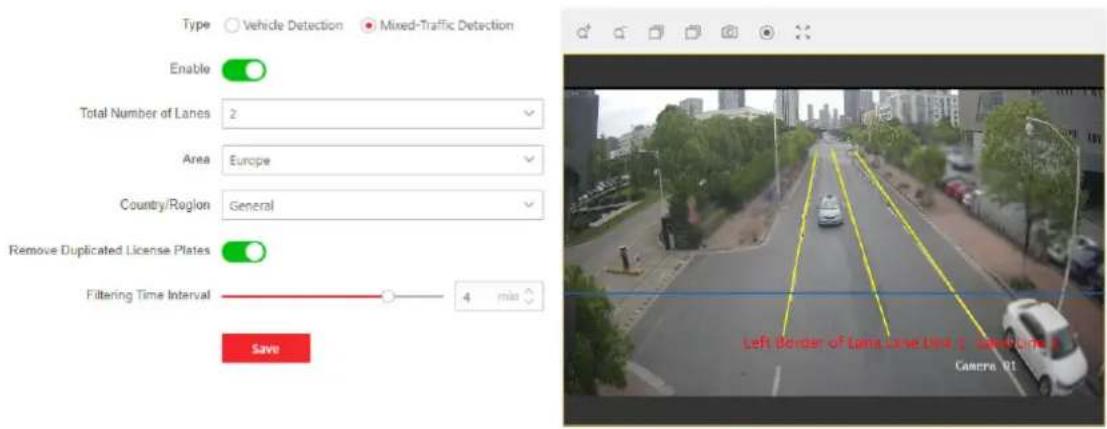
text_image
Type Vehicle Detection Mixed-Traffic Detection Enable Total Number of Lanes 2 Area Europe Country/Region General Remove Duplicated License Plates Filtering Time Interval 4 min Save Left Border of Long Live Use & Saturned Camera 91Figure 10-17 Mixed-Traffic Detection
-
Select the total number of lanes.
-
Click and drag the lane line to set its position, or click and drag the line end to adjust the length and angle of the line.
The blue detection line is the trigger line of the license plate, which is mainly used in the Entrance/Exit scene to improve the capture efficiency. It is recommended to put it in the lower middle of the screen to make sure that the full-size car with the plate can pass it.
- Adjust the zoom ratio of the camera so that the size of the vehicle in the image is close to that of the red frame. Only the position of red frame is adjustable.
Only 1 license plate can be captured at one time for each lane.
-
Select Area and Country/Region.
-
Check Remove Duplicated License Plates and set the Time Interval. The default time interval is 4 minutes.
-
Click Save.
-
Go to Arming Schedule and Linkage Method. You can set the arming schedule and linkage method independently for blocklist, allowlist and other list, and you should set them one by one.
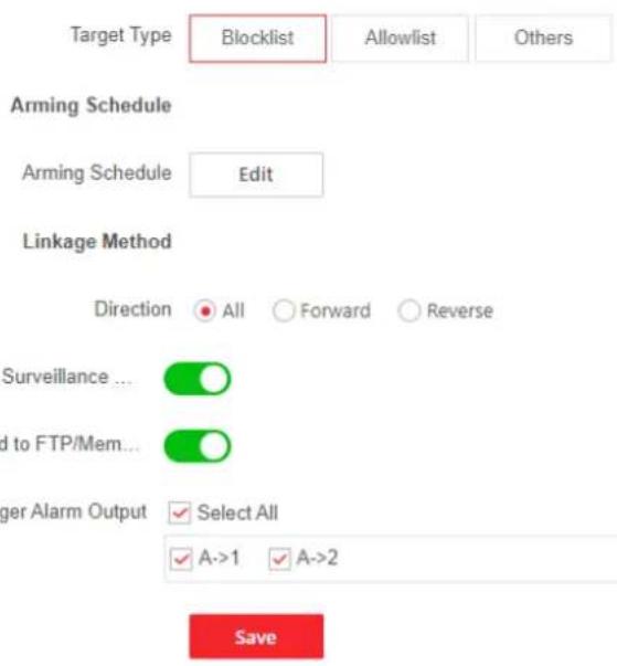
text_image
Target Type Blocklist Allowlist Others Arming Schedule Arming Schedule Edit Linkage Method Direction All Forward Reverse Surveillance... ✓ ✓ ✓ ✓ to FTP/Mem... ✓ ✓ ✓ ✓ ✓ ✓ ✓ ✓ ✓ ✓ ✓ ✓ ✓ ✓ ✓ ✓ ✓ ✓ ✓ ✓ ✓ ✓ ✓ ✓ ✓ ✓ ✓ ✓ ✓ ✓ ✓ ✓ ✓ ✓ ✓ ✓ ✓ ✓ ✓ ✓ ✓ ✓ ✓ ✓ ✓ ✓ ✓ ✓ ✓ ✓ ✓Figure 10-18 Arming Schedule and Linkage Method
1) Click to select the blocklist, allowlist and other list.
2) Set the arming schedule. Refer to Set Arming Schedule for details.
3) Set the linkage method. Check the checkbox of corresponding linkage method for each rule, and click Save to save the settings.
Direction
Only the vehicles moving as the selected direction can trigger the selected linkage methods.
All
All means that the vehicles in all moving directions will be considered. It is highly recommended to choose All if there is no special use.
Forward
Forward means that the vehicle moves toward the camera.
Reverse
Reverse means that the vehicle moves away from the camera.
Wiegand Linkage
The device can send reports to the third-party platform via the Wiegand protocol. Make sure the device supports Wiegand interface and the device is connected by Wiegand interface carefully. Make sure the Wiegand is enabled and the protocol is properly configured in the system settings. Refer to Wiegand for details.
Enable Wiegand Linkage and select the wiegand interface connected to the external device.
The linkage will be triggered only when the detected vehicle driving direction is the same as the configured direction.
- Go to Road Traffic → Overlay & Capture to set the image parameters and text overlay of the captured pictures. Refer to Overlay and Capture for details.
- Import or export the license plate blocklist and allowlist. Refer to Import or Export Blocklist & Allowlist for details.
- Optional: Set the advanced parameters. Refer to Advanced Parameters Configuration for details.
- Optional: Set the traffic flow statistics. Refer to Traffic Flow Statistics for details.
10.11.3 Overlay and Capture
You can set the image parameters of the captured images in vehicle detection and mixed-traffic detection.
Go to VCA and select Road Traffic.
Go to VCA → Set Application → Road Traffic → Overlay & Capture.
i Note
The function varies according to different device models.
Picture Quality
The larger the value is, the clearer the picture is, but larger storage space is also required.
Picture Size
The larger the value is, the larger the storage space is needed. And the level of network transmission requirement is also higher.
Picture Resolution
The captured background picture resolution.
Picture Capture Interval
The camera supports continuously trigger the alarm and upload captured picture each interval.
Check Capture Interval and set the interval.
FTP Picture Name
You can set the naming rule for captured pictures in vehicle detection and mixed-traffic detection in the FTP server.
Select Default to use the default rule.
Select Custom, select information for the picture name, and click to adjust the order of picture name parameters. If Capture Time is not selected in custom mode, the captured picture
triggered by the same vehicle later will replace the captured picture before due to the same picture name.
i Note
For more information about FTP settings, refer to Set FTP.
Text Overlay
You can overlay camera, device or vehicle information on the captured image and click ↑ ↓ to adjust the order of overlay texts.
Set the font color and background color by selecting the color box, and click the desired color in the pop-up palette or the drop-down box.
10.11.4 Import or Export Blocklist & Allowlist
You can import and export the blocklist and allowlist as desired, and check the list content in this interface.
Steps
- Click Import to import the selected file.
- Click to open the PC local directory.
- Find the blocklist & allowlist file and click to select it. Click Open to confirm.
i Note
- The file to import should corresponds with the file template that is required by the camera. You are recommended to export an empty blocklist & allowlist file from the camera as the template and fill in the content.
-
The file should be in the .xls format and the cell format should be Text.
-
Click Import to import the selected file.
- Click Export All to export the license plate list.
- Optional: Click Add to add a license plate and set its related information one by one.
- Optional: Click ☑ to select the filtering type. All Types, Wiegand CardID, License Plate No. and Type are selectable. As for Type, you can select Keywords to define the specific filtering type. Click Search to view the results.
- Optional: You can select a plate No. and click 🔒 to delete a plate from the blocklist or allowlist.
- Optional: You can select a plate No. and click ↻ to edit the related information of the license plate from the blocklist or allowlist.
10.11.5 Advanced Parameters Configuration
Go to VCA and select the application. Enter the application configuration interface and click Advanced to set advanced parameters. Click Save after finishing the configuration.

Note
The function varies according to different device models.
Version
It stands for the current algorithm version.
Overlay Intelligent Information
Overlay the related intelligent information or POS information in the video.
10.11.6 Traffic Flow Statistics
You can set the vehicle counting parameters in vehicle detection and mixed-traffic detection.
Go to VCA and select Road Traffic.
Go to VCA → Set Application → Road Traffic → Traffic Flow Statistics. Check Enable to enable the function. Set the parameters and click Save.
Counting Type
Select the counting vehicle type as required.
Flow Overlay
Check Flow Overlay and select OSD Overlay Content. Select the overlaid vehicle flow direction type. None, All, and Forward/Reverse are selectable.
The counting data will be displayed on the image, and you adjust the display position of counting data in the live view image.

Note
OSD overlay only counts the number of vehicle on the current day. The data will be cleared automatically when the device restarts or at the daily reset time.
Daily Reset Time
The device clears the data in 00:00 each day by default. You can set the time for the daily reset.
Manual Reset
Clear the current counting data.
Real-Time Upload
Check Real-Time Upload and the device uploads the counting data in real-time.
10.12 Parking Management
Parking Management is applicable to the parking lots, which performs parking detection such as parking space status detection by recognizing vehicles and license plates in close view and distant
view scenes. This function can be used to guide vehicle parking and reasonably allocate parking spaces according to the parking situation.
i Note
- For certain device models, you need to select Parking Management on VCA page first.
- The function is only supported by certain device models.
10.12.1 Close View Mode
In close view mode, the device can detect at close range and can recognize the vehicle and license plate.
Before You Start
Go to VCA and select the application. Select Parking Management and click Next to enable the function.
Steps
- Go to VCA → Set Application → Parking Management, and select Close View Mode as the detection mode. Click Save or Save and Next.
- Go to Rule interface to set the rule.
- Check Enable to enable the function.
- Draw a detection area. Click ☐ to draw a detection area. Click on the live view to specify the vertexes of the area, and right click to complete drawing. The detection area should be a convex polygon area.
- Draw the parking space area. Click to draw a parking space area in the detection area. Click on the live view to specify the vertexes of the area, and right click to complete drawing. The areas will be displayed in the parking space area list.
i Note
- The parking space area should be in the detection area.
- Parking space area cannot overlap.
- You can select and click to delete a certain parking space area in the parking space area list.
-
For Close View Mode, up to 4 parking space areas can be set. The parking space area should be a convex polygon area.
-
View the parking space area parameters, including the parking space name, parking space status, license plate No. and the parking duration. Click Refresh to refresh the parameters.
i Note
- The license plate No. is only supported in the close view mode.
-
The supported parameters may vary according to different device models.
-
Select Locality and Area/Country.
-
Optional: Check Enable to enable Vacant Parking Space Alarm.
Threshold of Vacant Parking Spaces
When the number of vacant parking spaces is less than the set threshold value, an alarm will be triggered until the number of vacant parking spaces is greater than the set threshold value.
- Set the OSD overlay. Total Parking Spaces, Available Parking Spaces and Occupied Parking Spaces are selectable.
- Click Save to save the rule settings.
- Go to Arming Schedule and Linkage Method to set the arming schedule and linkage method. For the arming schedule settings, refer to Set Arming Schedule. For the linkage method settings, refer to Linkage Method Settings.
- Set the data uploading parameters.
Parking Space Status
Check Scheduled Upload, and the device will upload the Parking Space Status every Upload Interval.
Parking Timeout Alarm
When the actual parking time of the vehicle exceeds the set parking threshold, the alarm will be triggered and the device will upload the related alarm information. The device supports uploading the vehicle entry and exit time (i.e. the entry and exit time corresponding to one vehicle), and you can customize the Parking Duration.
Parking Duration
The set parking duration threshold. If the actual parking duration exceeds the set threshold, the alarm will be triggered and the device will upload the related alarm and vehicle information.
Alarm Upload Frequency and Cycle
If the alarm upload frequency is set as 2 times and the cycle time is 1 minute, the alarm will be uploaded twice a minute.
- Set the image parameters and text overlay of the captured pictures. Refer to Overlay and Capture for details.
- Import or export the license plate blocklist and allowlist. Refer to Import or Export Blocklist & Allowlist for details.
- Optional: Set the advanced parameters. Refer to Advanced Parameters Configuration for details.
10.12.2 Distant View Mode
In distant view mode, the device can detect at high altitude from an overlook view and identify the vehicles entering the detection area.
Before You Start
Go to VCA and select the application. Select Parking Management and click Next to enable the function.
Steps
- Go to VCA → Set Application → Parking Management, and select Distant View Mode as the detection mode. Click Save or Save and Next.
- Go to Rule interface to set the rule.
- Check Enable to enable the function.
- Draw a detection area. Click ☐ to draw a detection area. Click on the live view to specify the vertexes of the area, and right click to complete drawing. The detection area should be a convex polygon area.
- Draw the parking space area. Click ☑ to draw a parking space area in the detection area. Click on the live view to specify the vertexes of the area, and right click to complete drawing. The areas will be displayed in the parking space area list.

Note
- The parking space area should be in the detection area.
- Parking space area cannot overlap.
- You can select and click to delete a certain parking space area in the parking space area list.
-
For Distant View Mode, up to 40 parking space areas can be set. The parking space area should be convex polygon area.
-
View the parking space area parameters, including the parking space name, parking space status and the parking duration. Click Refresh to refresh the parameters.

Note
The supported parameters may vary according to different device models.
- Optional: Check Enable to enable Vacant Parking Space Alarm.
Threshold of Vacant Parking Spaces
When the number of vacant parking spaces is less than the set threshold value, an alarm will be triggered until the number of vacant parking spaces is greater than the set threshold value.
- Set the OSD overlay. Total Parking Spaces, Available Parking Spaces and Occupied Parking Spaces are selectable.
- Click Save to save the rule settings.
- Go to Arming Schedule and Linkage Method to set the arming schedule and linkage method. For the arming schedule settings, refer to Set Arming Schedule. For the linkage method settings, refer to Linkage Method Settings.
- Set the data uploading parameters.
Parking Space Status
Check Scheduled Upload, and the device will upload the Parking Space Status every Upload Interval.
Parking Timeout Alarm
When the actual parking time of the vehicle exceeds the set parking threshold, the alarm will be triggered and the device will upload the related alarm information. The device
supports uploading the vehicle entry and exit time (i.e. the entry and exit time corresponding to one vehicle), and you can customize the Parking Duration.
Parking Duration
The set parking duration threshold. If the actual parking duration exceeds the set threshold, the alarm will be triggered and the device will upload the related alarm and vehicle information.
Alarm Upload Frequency and Cycle
If the alarm upload frequency is set as 2 times and the cycle time is 1 minute, the alarm will be uploaded twice a minute.
- Set the image parameters and text overlay of the captured pictures. Refer to Overlay and Capture for details.
- Optional: Set the advanced parameters. Refer to Advanced Parameters Configuration for details.
10.12.3 Overlay and Capture
You can set the image parameters of the captured images in vehicle detection and mixed-traffic detection.
Go to VCA and select Parking Management.
Go to VCA → Set Application → Parking Management → Overlay & Capture.

Note
The function varies according to different device models.
Picture Quality
The larger the value is, the clearer the picture is, but larger storage space is also required.
Picture Size
The larger the value is, the larger the storage space is needed. And the level of network transmission requirement is also higher.
Picture Resolution
The captured background picture resolution.
FTP Picture Name
You can set the naming rule for captured pictures in vehicle detection and mixed-traffic detection in the FTP server.
Select Default to use the default rule.
Select Custom, select information for the picture name, and click ↑ to adjust the order of picture name parameters. If Capture Time is not selected in custom mode, the captured picture triggered by the same vehicle later will replace the captured picture before due to the same picture name.

Note
For more information about FTP settings, refer to Set FTP.
Text Overlay
You can overlay camera, device or vehicle information on the captured image and click ↑ ↓ to adjust the order of overlay texts.
Set the font color and background color by selecting the color box, and click the desired color in the pop-up palette or the drop-down box.
10.12.4 Import or Export Blocklist & Allowlist
You can import and export the blocklist and allowlist as desired, and check the list content in this interface.
Steps
- Click Import to import the selected file.
- Click □ to open the PC local directory.
- Find the blocklist & allowlist file and click to select it. Click Open to confirm.

Note
- The file to import should corresponds with the file template that is required by the camera. You are recommended to export an empty blocklist & allowlist file from the camera as the template and fill in the content.
-
The file should be in the .xls format and the cell format should be Text.
-
Click Import to import the selected file.
- Click Export All to export the license plate list.
- Optional: Click Add to add a license plate and set its related information one by one.
- Optional: Click ▼ to select the filtering type. All Types, Wiegand CardID, License Plate No. and Type are selectable. As for Type, you can select Keywords to define the specific filtering type. Click Search to view the results.
- Optional: You can select a plate No. and click 🔒 to delete a plate from the blocklist or allowlist.
- Optional: You can select a plate No. and click ↻ to edit the related information of the license plate from the blocklist or allowlist.
10.12.5 Advanced Parameters Configuration
Go to VCA and select the application. Enter the application configuration interface and click Advanced to set advanced parameters. Click Save after finishing the configuration.

Note
The function varies according to different device models.
Version
It stands for the current algorithm version.
Overlay Intelligent Information
Overlay the related intelligent information or POS information in the video.
Chapter 11 Smart Display
This function displays real time pictures captured by smart functions and analyzes the target in real time.
Go to Application Display → Display Alarm to view the real-time images. Click 📋 to go back to Application Display.

Note
- To use this function, you should first enable and configure certain smart functions.
• To use this function, your web browser version should be above IE11.0.9600.17843.
Live View Parameter
| Icon Function | |
| [STG3] | Capture a picture. |
 | Start or stop recording. |
 | Mute. |
  | Adjust the volume of live view. Move the slider to right to turn up the volume and left to turn down the volume. Move to the left end to mute the live view. |
Download Display Pictures
Click 📁 and the device stores captured pictures to the browser cache. Hover the pointer over the icon to see the number of pictures in the cache. Click 📁 again to download the pictures in a package.

Note
The browser cache has a limited size. The recommended number of pictures to download is no more than 200.
Layout
Click 📍 and choose Layout. Check the display content you need to add it to the smart display page. When real-time analyze is selected, you can choose the contents you want to display.
Detect Feature
Click 📍 and choose Detect Feature. Check the corresponding checkbox to display the features of the detection target.
Chapter 12 EPTZ
EPTZ (Electronic PTZ) is a high-resolution function that digitally zooms and pans into portions of the image, with no physical camera movement. If you want to use the EPTZ function, make sure your device supports the Third Stream. Third stream and EPTZ should be both enabled simultaneously.

Note
The function is only supported by certain device models.
12.1 Patrol
Steps
- Go to Configuration → EPTZ.
- Check Enable.
- The default Stream Type is Third Stream and cannot be configured.
- Select Patrol in Application Mode.
- Click Save.
What to do next
For the detailed information about the patrol settings, see the PTZ operations on live view page.
12.2 Auto-Tracking
Steps
- Go to Configuration → EPTZ.
- Check Enable.
- The default Stream Type is Third Stream and cannot be configured.
- Select Auto-tracking in Application Mode.
- Click ☐ to start drawing. Click on the live view video to specify the four vertexes of the detection area, and right click to complete drawing.
- Set rules.
Detection Target
Human and vehicle are available. If the detection target is not selected, all the detected targets will be tracked, including the human and vehicle.

Only certain camera models support this function.
Sensitivity
It stands for the percentage of the body part of an acceptable target that is tracked.
Sensitivity = 100 - S1/ST × 100. S1 stands for the target body part that enters the pre-defined area. ST stands for the complete target body. The higher the value of sensitivity is, the more easily the target can be tracked.
- Click Save.
Appendix A. FAQ
Scan the following QR code to find the frequently asked questions of the device.
Note that some frequently asked questions only apply to certain models.
Table A-1 FAQ QR Code
| QR Code Type QR Code Image | |
| Network Camera General FAQ |  |
| ANPR Camera FAQ |  |

See Far, Go Further