
NK42E0H-1T(WD) - Security Camera Hikvision - Free user manual and instructions
Find the device manual for free NK42E0H-1T(WD) Hikvision in PDF.


User questions about NK42E0H-1T(WD) Hikvision
0 question about this device. Answer the ones you know or ask your own.
Ask a new question about this device
Download the instructions for your Security Camera in PDF format for free! Find your manual NK42E0H-1T(WD) - Hikvision and take your electronic device back in hand. On this page are published all the documents necessary for the use of your device. NK42E0H-1T(WD) by Hikvision.
USER MANUAL NK42E0H-1T(WD) Hikvision
Chapter 2 Installaon and Connecons .... 10
2.1 NVR Installaon.... 10
2.2 Hard Disk Installaon 10
2.3 HDD Storage Calculaon Chart 11
Chapter 3 Menu Operaon .... 13
3.1 Startup and Shutdown.... 13
3.2 Acvang Your Device 13
3.3 Using the Unlock Pattern for Login.... 15
3.4 User Login 16
3.5 Using the Setup Wizard 16
3.6 Network Sengs.... 17
3.7 Adding IP Cameras.... 17
3.8 Live View....18
3.9 Recording Sengs.... 18
3.10 Playback.... 19
Chapter 4 Accessing by Web Browser ...... 21
Quick Start Guide
COPYRIGHT © 2018 Hangzhou Hikvision Digital Technology Co., Ltd.
ALL RIGHTS RESERVED.
Any and all informaon, including, among others, wordings, pictures, graphs are the properes of Hangzhou Hikvision Digital Technology Co., Ltd. or its subsidiaries (hereinaer referred to be "Hikvision"). This user manual (hereinaer referred to be "the Manual") cannot be reproduced, changed, translated, or distributed, parally or wholly, by any means, without the prior written permission of Hikvision. Unless otherwise spulated, Hikvision does not make any warranes, guarantees or representaons, express or implied, regarding to the Manual.
About this Manual
This Manual is applicable to Network Video Recorder (NVR).
The Manual includes instrucons for using and managing the product. Pictures, charts, images and all other informaon hereinaer are for descripon and explanaon only. The informaon contained in the Manual is subject to change, without noce, due to rmware updates or other reasons. Please nd the latest version in the company website
(hp://overseas.hikvision.com/en/).
Please use this user manual under the guidance of professionals.
Trademarks Acknowledgement
HIKVISION and other Hikvision's trademarks and logos are the properes of Hikvision in various jurisdicons. Other trademarks and logos menoned below are the properes of their respective owners.
Legal Disclaimer
TO THE MAXIMUM EXTENT PERMITTED BY APPLICABLE LAW, THE PRODUCT DESCRIBED, WITH ITS HARDWARE, SOFTWARE AND FIRMWARE, IS PROVIDED "AS IS", WITH ALL FAULTS AND ERRORS, AND HIKVISION MAKES NO WARRANTIES, EXPRESS OR IMPLIED, INCLUDING WITHOUT LIMITATION, MERCHANTABILITY, SATISFACTORY QUALITY, FITNESS FOR A PARTICULAR PURPOSE, AND NON-INFRINGEMENT OF THIRD PARTY. IN NO EVENT WILL HIKVISION, ITS DIRECTORS, OFFICERS, EMPLOYEES, OR AGENTS BE LIABLE TO YOU FOR ANY SPECIAL, CONSEQUENTIAL, INCIDENTAL, OR INDIRECT DAMAGES, INCLUDING, AMONG OTHERS, DAMAGES FOR LOSS OF BUSINESS PROFITS, BUSINESS INTERRUPTION, OR LOSS OF DATA OR DOCUMENTATION, IN CONNECTION WITH THE USE OF THIS PRODUCT, EVEN IF HIKVISION HAS BEEN ADVISED OF THE POSSIBILITY OF SUCH DAMAGES.
REGARDING TO THE PRODUCT WITH INTERNET ACCESS, THE USE OF PRODUCT SHALL BE WHOLLY AT YOUR OWN RISKS. HIKVISION SHALL NOT TAKE ANY RESPONSIBILITES FOR ABNORMAL OPERATION, PRIVACY LEAKAGE OR OTHER DAMAGES RESULTING FROM CYBER ATTACK, HACKER ATTACK, VIRUS INSPECTION, OR OTHER INTERNET SECURITY RISKS; HOWEVER, HIKVISION WILL PROVIDE TIMELY TECHNICAL SUPPORT IF REQUIRED.
SURVEILLANCE LAWS VARY BY JURISDICTION. PLEASE CHECK ALL RELEVANT LAWS IN YOUR JURISDICTION BEFORE USING THIS PRODUCT IN ORDER TO ENSURE THAT YOUR USE CONFORMS THE APPLICABLE LAW. HIKVISION SHALL NOT BE LIABLE IN THE EVENT THAT THIS PRODUCT IS USED WITH ILLEGITIMATE PURPOSES.
IN THE EVENT OF ANY CONFLICTS BETWEEN THIS MANUAL AND THE APPLICABLE LAW, THE LATER PREVAILS.
Regulatory Informaon
FCC Informaon
Please take aenon that changes or modicaon not expressly approved by the party responsible for compliance could void the user's authority to operate the equipment.
FCC compliance: This equipment has been tested and found to comply with the limits for a Class A digital device, pursuant to part 15 of the FCC Rules. These limits are designed to provide reasonable protecon against harmful interference when the equipment is operated in a commercial environment. This equipment generates, uses, and can radiate radio frequency energy and, if not installed and used in accordance with the instrucon manual, may cause harmful interference to radio communicaons. Operaon of this equipment in a residential area is likely to cause harmful interference in which case the user will be required to correct the interference at his own expense.
FCC Conditions
This device complies with part 15 of the FCC Rules. Operaon is subject to the following two conditions:
- This device may not cause harmful interference.
- This device must accept any interference received, including interference that may cause undesired operaon.
EU Conformity Statement

This product and - if applicable - the supplied accessories too are marked with "CE" and comply therefore with the applicable harmonized European standards listed under the
EMC Direcve 2014/30/EU, the LVD Direcve 2014/35/EU, the RoHS Direcve 2011/65/EU.

2012/19/EU (WEEE direcve): Products marked with this symbol cannot be disposed of as unsorted municipal waste in the European Union. For proper recycling, return this product to your local supplier upon the purchase of equivalent new equipment, or dispose of it at designated collecon points. For more informaon see: www.recyclethis.info

2006/66/EC (baery direcve): This product contains a baery that cannot be disposed of as unsorted municipal waste in the European Union. See the product documentaon for speci baery informaon. The baery is marked with this symbol, which may include leering to indicate cadmium (Cd), lead (Pb), or mercury (Hg). For proper recycling, return the baery to your supplier or to a designated collecon point. For more informaon see: www.recyclethis.info
Industry Canada ICES-003 Compliance
This device meets the CAN ICES-3 (A)/NMB-3(A) standards requirements.
Applicable Models
This manual is applicable to the models listed in the following table.
| Series | Model |
| DS-7100NI-Q1 | DS-7104NI-Q1 |
| DS-7108NI-Q1 | |
| DS-7100NI-Q1/P | DS-7104NI-Q1/4P |
| DS-7108NI-Q1/8P | |
| DS-7100NI-Q1/M | DS-7104NI-Q1/M |
| DS-7108NI-Q1/M | |
| DS-7100NI-Q1/P/M | DS-7104NI-Q1/4P/M |
| DS-7108NI-Q1/8P/M |
Symbol Conventions
The symbols that may be found in this document are dened as follows.
| Symbol | Description |
 NOTE NOTE | Provides additional informaon to emphasize or supplement important points of the main text. |
 WARNING WARNING | Indicates a potentially hazardous situaon, which if not avoided, could result in equipment damage, data loss, performance degradaon, or unexpected results. |
 DANGER DANGER | Indicates a hazard with a high level of risk, which if not avoided, will result in death or serious injury. |
Safety Instructions
- Proper conguraon of all passwords and other security sengs is the responsibility of the installer and/or end-user.
- In the use of the product, you must be in strict compliance with the electrical safety regulaons of the naon and region. Please refer to technical specicaons for detailed informaon.
- Input voltage should meet both the SELV (Safety Extra Low Voltage) and the Limited Power Source with 100\~240 VAC, 48 VDC or 12 VDC according to the IEC60950-1 standard. Please refer to technical speciaons for detailed informaon.
- Do not connect several devices to one power adapter as adapter overload may cause over-heang or a re hazard.
- Please make sure that the plug is rmly connected to the power socket.
- If smoke, odor or noise rise from the device, turn o the power at once and unplug the power cable, and then please contact the service center.
- If the POE ports of device do not comply with Limited Power Source, the additional equipment connected to POE ports shall have re enclosure.
- The USB interface of the /P devices can be connected with the mouse and U-ash disk storage device only.
Preventive and Cautionary Tips
Before connecng and operang your device, please be advised of the following ps:
● Ensure unit is installed in a well-venlated, dust-free environment.
- Unit is designed for indoor use only.
- Keep all liquids away from the device.
- Ensure environmental conditions meet factory specicaons.
- Ensure unit is properly secured to a rack or shelf. Major shocks or jolts to the unit as a result of dropping it may cause damage to the sensitive electronics within the unit.
- Use the device in conjuncon with an UPS if possible.
● Power down the unit before connecng and disconnectg accessories and peripherals.
● A factory recommended HDD should be used for this device.
- Improper use or replacement of the battery may result in hazard of explosion. Replace with the same or equivalent type only. Dispose of used baeries according to the instrucons provided by the baery manufacturer.
Power Supply Instructions
Use only power supplies listed in the user instrucons.
| NVR Models | Standard | Power Supply Models | Manufacturer |
| DS-7104NI-Q1HWN-2104HDS-7108NI-Q1HWN-2108HDS-7104NI-Q1/MHWN-2104MHDS-7108NI-Q1/MHWN-2108MH | European | MSA-C1500IC12.0-18P-DE | MOSO Power Supply Technology Co.,Ltd |
| ADS-26FSG-12 12018EPG | Shenzhen HONOR Electronic Co., Ltd | ||
| KL-AD3060VA | Xiamen Keli Electronics Co.,Ltd | ||
| KPD-018-VI | Channel Well Technology Co.,Ltd | ||
| Brish | ADS-25FSG-12 12018GPB | Shenzhen HONOR Electronic Co., Ltd | |
| MSA-C1500IC12.0-18P-GB | MOSO Power Supply Technology Co.,Ltd | ||
| ADS-26FSG-12 12018EPB | Shenzhen HONOR Electronic Co., Ltd | ||
| DS-7104NI-Q1/4PHWN-2104H-4PDS-7104NI-Q1/4P/MHWN-2104MH-4P | Universal | MSP-Z1360IC48.0-65W | MOSO Power Supply Technology Co.,Ltd |
| MSA-Z1040IS48.0-65W-Q | MOSO Power Supply Technology Co.,Ltd | ||
| MSA-Z1360IS48.0-65W-Q | MOSO Power Supply Technology Co.,Ltd |

NOTE
● The power supplies list above is for EU countries only.
● The power supplies list is subject to change without prior noce.
Chapter1 Panels Description
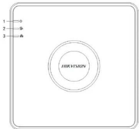
1.1 Front Panel
text_image
1 2 3 HIKVISIONFigure 1-1 DS-7100NI-Q1 (/P) Series

text_image
HIKVISION 1 2 3Figure 1-2 DS-7100NI-Q1 (/P)/M Series
Table 1-1 Descripon of Front Panel
| No. | Icon | Description |
| 1 |  | Indicator turns red when NVR is powered up. |
| 2 |  | Indicator lights in red when data is being read from or wrien to HDD. |
| 3 |  | Indicator blinks blue when network conncon is funconing properly. |
1.2 Rear Panel
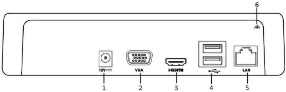
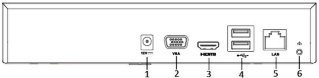
DS-7100NI-Q1 and DS-7100NI-Q1/M Series
text_image
12V VGA HDMI LAN 1 2 3 4 5 6Figure 1-3 DS-7100NI-Q1 Rear Panel
text_image
12V VGA HDMI 4 LAN 6Figure 1-4 DS-7100NI-Q1/M Rear Panel
Table 1-2 Descripon of Rear Panel
| No. | Item | Description |
| 1 | Power Supply | 12 VDC power supply. |
| 2 | VGA Interface | DB9 connector for VGA output. Display local video output and menu. |
| 3 | HDMI Interface | HDMI video output connector. |
| 4 | USB Interface | Universal Serial Bus (USB) ports for additional devices such as USB mouse and USB Hard Disk Drive (HDD). |
| 5 | LAN Network Interface | 10 /100 Mbps self-adapve Ethernet interface. |
| 6 | Ground | Ground (needs to be connected when NVR starts up). |
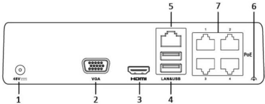
DS-7100NI-Q1/P and DS-7100NI-Q1/P/M Series
text_image
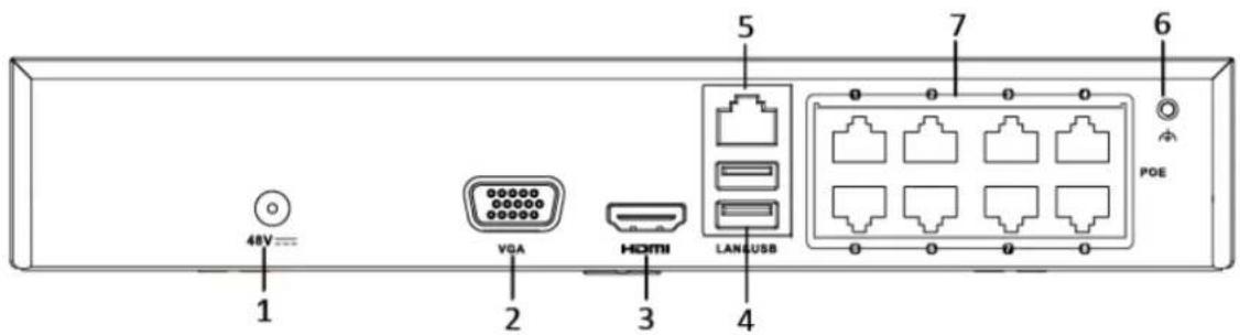
48V VGA HDMI LANA&USB 1 2 3 4 5 7 6 PoEFigure 1-5 DS-7100NI-Q1/P Rear Panel
text_image
48V 1 VDA 2 HDMI 3 5 LAN/USB 7 6 POEFigure 1-6 DS-7100NI-Q1/P/M Rear Panel
Table 1-3 Descripon of Rear Panel
| No. | Item | Description |
| 1 | Power Supply | 12 VDC power supply. |
| 2 | VGA Interface | DB9 connector for VGA output. Display local video output and menu. |
| 3 | HDMI Interface | HDMI video output connector. |
| 4 | USB Interface | Universal Serial Bus (USB) ports for additional devices such as USB mouse and USB Hard Disk Drive (HDD). |
| 5 | LAN Network Interface | 10 /100 Mbps self-adapve Ethernet interface. |
| 6 | Ground | Ground (needs to be connected when NVR starts up). |
| 7 | Network Interfaces with PoE funcon | Network interfaces for the cameras and to provide power over Ethernet.4 interfaces for /4P models and 8 interfaces for /8P models. |
Chapter 2 Installation and Connections
2.1 NVR Installation
During installaon of the NVR:
- Use brackets for rack mounng.
- Ensure ample room for audio and video cables.
- When round cables, ensure that the bend radius of the cables are no less than ve mes than its diameter.
- Connect the alarm cable.
- Allow at least 2cm (≈0.75-inch) of space between racks mounted devices.
● Ensure the NVR is grounded.
● Environmental temperature should be within the range of -10 to +55° C, +14 to +131° F.
● Environmental humidity should be within the range of 10% to 90%.
2.2 Hard Disk Installation
Before you start:
Disconnect the power from the NVR before installing a hard disk drive (HDD). A factory recommended HDD should be used for this installaon.
Tools Required: Screwdriver.
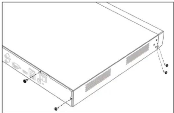
Step 1 Remove the cover from device by unfastening the screws on panels.
natural_image
Technical line drawing of a server rack with labeled ports and mounting points (no text or symbols present)Figure 2-1 Remove Cover
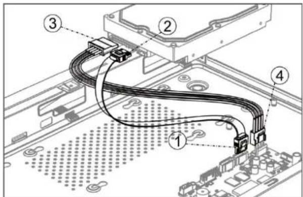
Step 2 Connect the data cable and power cable.
1) Connect one end of data cable to the device motherboard.
2) Connect the other end of data cable to HDD.
3) Connect one end of power cable to HDD.
4) Connect the other end of power cable to the device motherboard.
text_image
Technical diagram of a computer motherboard with numbered components and wiring connectionsFigure 2-2 Connect Cables
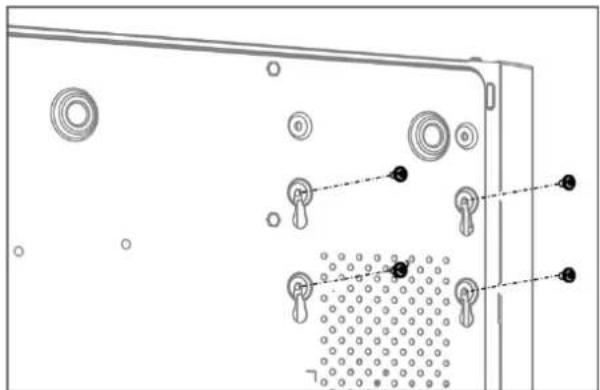
Step 3 Set the device up, match HDD screw threads with the reserved holes on the device boom, and x HDD with screws.
natural_image
Diagram of a device rear panel with circular components and dotted pattern (no text or symbols)Figure 2-3 Fix HDD to Device Boom
Step 4 (Oponal) Repeat the steps above to install other HDDs.
Step 5 Reinstall the device cover and fasten screws.
2.3 HDD Storage Calculation Chart
The following chart shows an esmaon of storage space used based on recording at one channel for an hour at a xed bit rate.
| Bit Rate | Storage Used |
| 96K | 42M |
| 128K | 56M |
| 160K | 70M |
| 192K | 84M |
| 224K | 98M |
| 256K | 112M |
| 320K | 140M |
| 384K | 168M |
| 448K | 196M |
| 512K | 225M |
| 640K | 281M |
| 768K | 337M |
| 896K | 393M |
| 1024K | 450M |
| 1280K | 562M |
| 1536K | 675M |
| 1792K | 787M |
| 2048K | 900M |
| 4096K | 1.8G |
| 8192K | 3.6G |
| 16384K | 7.2G |

NOTE
Please note that supplied values for storage space used is just for reference. The storage values in the chart are esmated by formulas and may have some deviaon from actual value.
Chapter 3 Menu Operation
3.1 Startup and Shutdown
Proper startup and shutdown procedures are crucial to expanding the life of the NVR.
To start your NVR:
Step 1 Check the power supply is plugged into an electrical outlet. It is HIGHLY recommended that an Uninterruptible Power Supply (UPS) be used in conjunction with the device. The Power buon) on the front panel should be red, indicating the device is receiving the power.
Step 2 Press the power switch on the panel. The Power LED should turn blue. The unit will begin to start.
Aer the device starts up, the wizard will guide you through the initial sengs, including modifying password, date and me sengs, network sengs, HDD inializing, and recording.
To shut down the NVR:
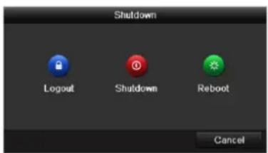
Step 1 Enter the Shutdown menu.
Menu > Shutdown
text_image
Shutdown Logout Shutdown Reboot CancelFigure 3-1 Shutdown
Step 2 Select Shutdown.
Step 3 Click Yes.
3.2 Activating Your Device
Purpose:
For the rst-me access, you need to acvate the device by seng an admin password. No operaon is allowed before acvaon. You can also acvate the device via Web Browser, SADP or client soware.
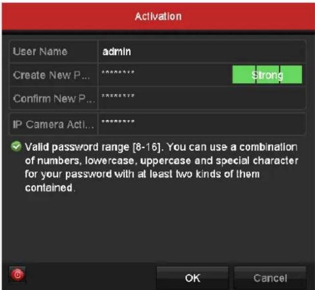
Step 1 Input the same password in the text eld of Create New Password and Conrm New Password.
text_image
Activation User Name admin Create New P... ******** Confirm New P... ******** IP Camera Acti... ******** ✓ Valid password range [8-16]. You can use a combination of numbers, lowercase, uppercase and special character for your password with at least two kinds of them contained. OK CancelFigure 3-2 Set Admin Password

WARNING
STRONG PASSWORD RECOMMENDED—We highly recommend you create a strong password of your own choosing (Using a minimum of 8 characters, including at least three of the following categories: upper case leers, lower case leers, numbers, and special characters.) in order to increase the security of your product. And we recommend you reset your password regularly, especially in the high security system, reseng the password monthly or weekly can beer protect your product.
Step 2 In the IP Camera Acvaon text eld, enter the password to acvate the IP camera (s) connected to the device.
Step 3 Click OK.

NOTE
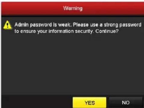
For the old version device, if you upgrade it to the new version, the following dialog box will pop up once the device starts up. You can click YES and follow the wizard to set a strong password.
text_image
Warning Admin password is weak. Please use a strong password to ensure your information security. Continue? YES NOFigure 3-3 Warning of Weak Password
3.3 Using the Unlock Pattern for Login
For the Admin user, you can congregate the unlock paern for device login.
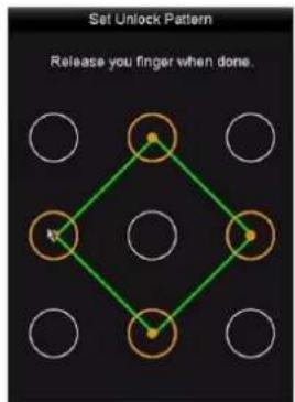
Aer the device is acvated, you can enter the following interface to conjure the device unlock paern.
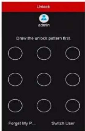
Step 1 Use the mouse to draw a paern among the 9 dots on the screen. Release the mouse when the paern is done.
flowchart
graph TD
    A["Start"] --> B{Step 1}
    B --> C["Step 2"]
    C --> D{Step 3}
    D --> E["End"]
    style A fill:#fff,stroke:#000
    style E fill:#fff,stroke:#000
    note right of A: "Release you finger when done."
    note right of E: "Set Unlock Pattern"
Figure 3-4 Draw the Paern

NOTE
- Connect at least 4 dots to draw the paern.
● Each dot can be connected for once only.
Step 2 Draw the same paern again to conrm it. When the two paerns match, the paern is congured successfully.
Step 3 You can use the congured unlock paern for future login.
text_image
Unlock admin Draw the unlock pattern first. Forget My P... Switch UserFigure 3-5 Draw the Unlock Paern
3.4 User Login
Purpose:
If NVR has logged out, you must login the device before operang the menu and other funcons.
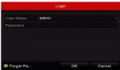
Step 1 Select the User Name in the dropdown list.
text_image
Login User Name admin Password Forget Pa... OK CancelFigure 3-6 Login
Step 2 Input Password.
Step 3 Click OK.

NOTE
In the Login dialog box, if you enter the wrong password 7 mes, the current user account will be locked for 60 seconds.
3.5 Using the Setup Wizard
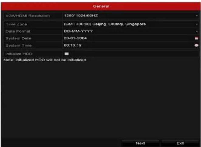
The Setup Wizard can guide you to congregate the system resolution, system date/me, HDD inializaon, IP camera management, etc.
text_image
General VGA/HDMI Resolution 1200*1024/60HZ Time Zone (GMT+08:00) Beijing, Urumqi, Singapore Date Format DD-MM-YYYY System Date 20-01-2004 System Time 00:10:19 Initialize HDD Note: Initialized HDD will not be initialized. Next ExitFigure 3-7 Wizard
3.6 Network Settings
Purpose:
Network sengs must be properly congured before you operate NVR over network.
Step 1 Enter the general network sengs interface.
Menu > Conguraon > Network > General
| NIC Type | 100M Full-dup | |||
| Enable DHCP | ✓ | |||
| IPv4 Address | 10 .15 .1 .108 | IPv6 Address 1 | fe80::b6a3:82ff.febe:ad2c/64 | |
| IPv4 Subnet ... | 255.255.255.0 | IPv6 Address 2 | ||
| IPv4 Default G... | 10 .15 .1 .254 | IPv6 Default G... | ||
| MAC Address | b4:a3:82:be:ad:2c | |||
| MTU(Bytes) | 1500 | |||
| Enable Obtain DNS Server Addr... | ✓ | |||
| Preferred DNS Server | 10.1.7.88 | |||
| Alternate DNS Server | 10.1.7.77 | |||
| Internal NIC IPv4 Address | 192 .168 .254 .1 | |||
Figure 3-8 Network Sengs
Step 2 Congure the following sengs: NIC Type, IPv4 Address, IPv4 Gateway, MTU and DNS Server.
Step 3 If the DHCP server is available, you can check the checkbox of DHCP to automatically obtain an IP address and other network sengs from that server.
Step 4 Click Apply.
3.7 Adding IP Cameras
Purpose:
Before you can get live video or record the video les, you should add the network cameras to the conncon list of the device.
Before you start:
Ensure the network conncon is valid and correct, and the IP camera to add has already been acvated. Please refer to the User Manual for acvang the inacve IP camera.
You can select one of the following three opons to add the IP camera.
- OPTION 1:
Step 1 Click to select an idle window in the live view mode.
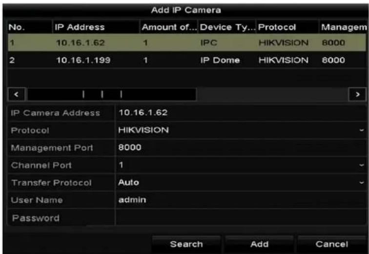
Step 2 Click + in the center of the window to pop up the Add IP Camera interface.
text_image
Add IP Camera No. IP Address Amount of... Device Ty... Protocol Managem 1 10.16.1.62 1 IPC HIKVISION 8000 2 10.16.1.199 1 IP Dome HIKVISION 8000 IP Camera Address 10.16.1.62 Protocol HIKVISION Management Port 8000 Channel Port 1 Transfer Protocol Auto User Name adultsin Password Search Add CancelFigure 3-9 Add IP Camera
Step 3 Select the detected IP camera and click Add to add it directly, and you can click Search to refresh the online IP camera manually.
Or you can choose to custom add the IP camera by eding the parameters in the corresponding text eld and then click Add to add it.
3.8 Live View
Icons are provided on screen in Live View mode to indicate camera status. These icons include:
Live View Icons
In the live view mode, there are icons at the upper-right corner of the screen for each channel, showing the status of the record and alarm in the channel for quick reference.

Alarm (video loss, tampering, moon detecon, VCA or sensor alarm)

Record (manual record, connuous record, moon detecon, VCA or alarm triggered record)

Alarm and Record

Event/Excepon (event and excepon informaon, appears at the lower-le corner of the en.)
3.9 Recording Settings
Before you start:
Make sure that the disk has already been installed. If not, please install a disk and initialize it. You may refer to the user manual for detailed informaon.
Purpose:
Two kinds of record types are introduced in the following secon, including Instant Record and All-day Record. And for other record types, you may refer to the user manual for detailed informaon.

NOTE
Aer reboong all the manual records enabled are canceled.
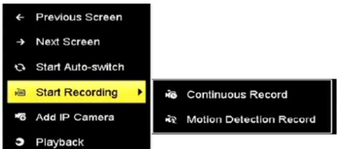
Step 1 On the live view window, right lick the window and move the cursor to the Start Recording opon, and select Connuous Record or Motion Detecon Record on your demand.
text_image
Previous Screen Next Screen Start Auto-switch Start Recording Add IP Camera Playback Continuous Record Motion Detection RecordFigure 3-10 Start Recording from Right-click Menu
Step 2 Click Yes in the pop-up Aenon message box to conrm the sengs. All the channels will start to record in the selected mode.
3.10 Playback
The recorded video les on the hard disk can be played back in the following modes: instant playback, all-day playback for the specied channel, and playback by normal/event/smart/tag/sub-periods/external le search.
Step 1 Enter playback interface.
Click Menu > Playback or from the right-click menu
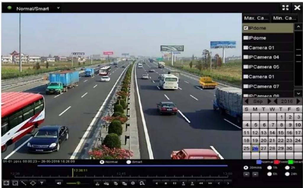
Step 2 Check the checkbox of channel(s) in the channel list and then double-click to select a date on the calendar.
Step 3 You can use the toolbar in the boom part of Playback interface to control playing progress.
text_image
Normal/Smart Max. Ca... Min. Ca... IPdome IPdome Camera 01 IPCamera 04 IPCamera 05 Camera 01 IPCamera 07 IPCamera 08 Sep 2016 S M T W T F S 1 2 3 4 5 6 7 8 9 10 11 12 13 14 15 16 17 18 19 20 21 22 23 24 25 26 27 28 29 30 Normal Event Smart 30mins 1h 2h 6h 24h 01-01-2016 00:00:23--26-05-2016 16:26.09 Normal SmartFigure 3-11 Playback Interface
Step 4 Select the channel(s) to or execute simultaneous playback of mulple channels.
Chapter 4 Accessing by Web Browser

NOTE
You shall acknowledge that the use of the product with Internet access might be under network security risks. For avoidance of any network aacks and informaon leakage, please strengthen your own protecon. If the product does not work properly, please contact with your dealer or the nearest service center.
Purpose:
You can get access to the device via web browser. You may use one of the following listed web browsers: Internet Explorer 6.0, Internet Explorer 7.0, Internet Explorer 8.0, Internet Explorer 9.0, Internet Explorer 10.0, Internet Explorer 11.0, Apple Safari, Mozilla Firefox, and Google Chrome. The supported resoluons include 1024*768 and above.
Step 1 Open web browser, input the IP address of the device and then press Enter.
Step 2 Login to the device.
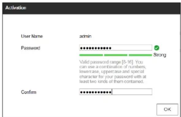
- If the device has not been activated, you need to acvate the device rst before login.
text_image
Activation User Name admin Password ●●●●●●●●●●●●● ✓ Strong Valid password range [8-16]. You can use a combination of numbers, lowercase, uppercase and special character for your password with at least two kinds of them contained. Confirm ●●●●●●●●●●●●● OKFigure 4-1 Set Admin Password
1) Set the password for the admin user account.
2) Click OK.

WARNING
STRONG PASSWORD RECOMMENDED— We highly recommend you create a strong password of your own choosing (using a minimum of 8 characters, including upper case leers, lower case leers, numbers, and special characters) in order to increase the security of your product. And we recommend you reset your password regularly, especially in the high security system, reseng the password monthly or weekly can beer protect your product.
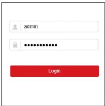
- If the device is already acvated, enter the user name and password in the login interface, and click Login.
text_image
admin LoginFigure 4-2 Login
Step 3 Install the plug-in before viewing the live video and managing the camera. Please follow the installaon prompts to install the plug-in.

NOTE
You may have to close the web browser to nish the installaon of the plug-in.
Aer login, you can perform the operaon and conguraon of the device, including the live view, playback, log search, conguraon, etc.
0304096080131

See Far, Go Further