
IC-T70A - Radio ICOM - Free user manual and instructions
Find the device manual for free IC-T70A ICOM in PDF.


| Product Type | Handheld Transceiver (Dual-Band) |
| Brand | ICOM |
| Model | IC-T70A |
| Frequency Range (Receive) | 136-174 MHz (VHF), 400-470 MHz (UHF) |
| Frequency Range (Transmit) | 144-148 MHz (VHF), 430-450 MHz (UHF) |
| Output Power | 5 W (High), 2.5 W (Mid), 0.5 W (Low) |
| Number of Memory Channels | 200 |
| Battery Type | Li-ion, 7.2 V, 1500 mAh |
| Operating Modes | FM (VHF/UHF) |
| Dimensions (W x H x D) | Approx. 58 x 110 x 39 mm |
| Weight (with battery) | Approx. 300 g |
| Display | Backlit LCD |
| Key Features | CTCSS/DTCS tone encode/decode, scanning, dual-watch, priority watch |
| Antenna Connector | SMA (female) |
| Care & Cleaning | Wipe with a dry soft cloth; avoid solvents. Keep away from moisture. |
| Safety | Do not transmit without antenna; avoid RF exposure in excess of FCC limits. |
| Spare Parts & Repairability | Battery packs and chargers available; service by qualified technician only. |
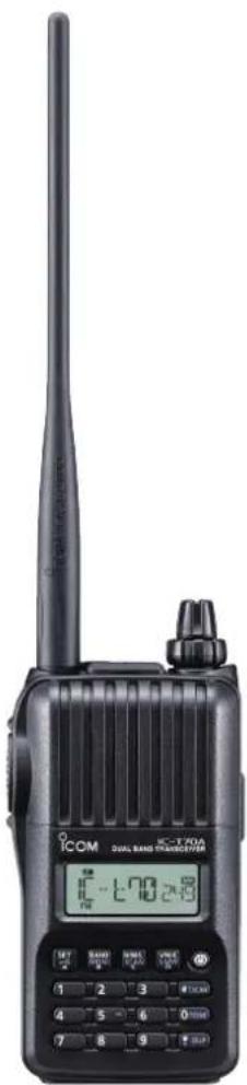
| General Information | Icom IC-T70A is a compact dual-band amateur radio handheld with rugged design. |
Frequently Asked Questions - IC-T70A ICOM
User questions about IC-T70A ICOM
0 question about this device. Answer the ones you know or ask your own.
Ask a new question about this device
Download the instructions for your Radio in PDF format for free! Find your manual IC-T70A - ICOM and take your electronic device back in hand. On this page are published all the documents necessary for the use of your device. IC-T70A by ICOM.
USER MANUAL IC-T70A ICOM
This device complies with Part 15 of the FCC Rules. Operation is subject to the following two conditions: (1) this device may not cause harmful interference, and (2) this device must accept any interference received, including interference that may cause undesired operation.
WARNING: MODIFICATION OF THIS DEVICE TO RECEIVE CELLULAR RADIOTELEPHONE SERVICE SIGNALS IS PROHIBITED UNDER FCC RULES AND FEDERAL LAW.
Icom Inc.
FOREWORD
Thank you for choosing this Icom product. This product is designed and built with Icom's state of the art technology and craftsmanship. With proper care this product should provide you with years of trouble-free operation.
EXPLICIT DEFINITIONS
| WORD DEFINITION | |
| ⚠ DANGER! | Personal death, serious injury or an explosion may occur. |
| ⚠ WARNING! | Personal injury, fire hazard or electric shock may occur. |
| CAUTION | Equipment damage may occur. |
| NOTE | Recommended for optimum use. No risk of personal injury, fire or electric shock. |
Icom is not responsible for the destruction or damage to the Icom transceiver, if the malfunction is because of:
- Force majeure, including, but not limited to, fires, earthquakes, storms, floods, lightnings, or other natural disasters, disturbances, riots, war, or radioactive contamination.
- The use of Icom transceiver with any equipment that is not manufactured or approved by Icom.
FEATURES
○Dust-protection/Splash-resistantconstruction (IP54*)
* Only when the battery pack/case, antenna and jack cover are attached.
○ Built in VOX circuit enabling the VOX operation* (voice operated transmission)
* To use the VOX operation, an optional headset and a plug adapter cable are additionally required.
○ 700 mW* AF power with BTL (bridge-tied load) amplifier
*At 10% distortion with a 16 Ω load (internal speaker)
IMPORTANT
READ ALL INSTRUCTIONS carefully and completely before using the transceiver.
SAVE THIS INSTRUCTION MANUAL— This instruction manual contains important operating instructions for the IC-T70A/IC-T70E.
PRECAUTIONS
⚠️ DANGER! NEVER short terminals (or charging terminals) of the battery pack. Also, current may flow into nearby metal objects such as a key, so be careful when placing the battery packs (or the transceiver) in handbags, and so on. Simply carrying with or placing near metal objects such as a key, and so on may cause shorting. This may damage not only the battery pack, but also the transceiver.
⚠️ DANGER! NEVER use and charge only specified Icom battery packs with Icom transceivers or Icom chargers. Only Icom battery packs are tested and approved for use with Icom transceivers or charged with Icom chargers. Using third party or counterfeit battery packs or chargers may cause smoke, fire, or cause the battery to burst.
WARNING RF EXPOSURE! This device emits Radio Frequency (RF) energy. Caution should be observed when operating this device. If you have any questions regarding RF exposure and safety standards please refer to the Federal Communications Commission Office of Engineering and Technology's report on Evaluating Compliance with FCC Guidelines for Human Radio Frequency Electromagnetic Fields (OET Bulletin 65)
⚠ WARNING! NEVER hold the transceiver so that the antenna is very close to, or touching exposed parts of the body, especially the face or eyes, while transmitting. The transceiver will perform best if the microphone is 5 to 10 cm (2 to 4 inches) away from the lips and the transceiver is vertical.
⚠ WARNING! NEVER operate the transceiver with a headset or other audio accessories at high volume levels. The continuous high volume operation may cause a ringing in your ears. If you experience the ringing, reduce the volume level or discontinue use.
⚠ WARNING! NEVER operate the transceiver while driving a vehicle. Safe driving requires your full attention—anything less may result in an accident.
⚠ WARNING! NEVER connect the transceiver to a power source of more than 16 V DC such as a 24 V DC. This could cause a fire or damage the transceiver.
⚠ WARNING! NEVER reverse the DC power cable polarity when connecting to a power source. This could damage the transceiver.
⚠ WARNING! NEVER operate or touch the transceiver with wet hands. This may result in an electric shock or may damage the transceiver.
CAUTION: MAKE SURE the flexible antenna, battery pack, and jack cover are securely attached to the transceiver, and that the antenna and battery pack are dry before attachment. Exposing the inside of the transceiver to dust or water will result in serious damage to the transceiver.
DO NOT use harsh solvents such as benzine or alcohol to clean the transceiver, because they can damage the transceiver's surfaces.
DO NOT operate the transceiver near unshielded electrical blasting caps or in an explosive atmosphere.
DO NOT modify the transceiver. The specifications may change and then not comply with the requirements of a corresponded regulation. The transceiver warranty does not cover any problems caused by unauthorized modification.
DO NOT push [PTT] when you do not actually intend to transmit.
PRECAUTIONS
DO NOT operate or place the transceiver in direct sunlight or in areas with temperatures below -20^ ( -4^ ) or above +60^ ( +140^ ).
BE CAREFUL! The transceiver will become hot when operating it continuously for long periods of time.
KEEP the transceiver away from heavy rain, and never immerse it in the water. The transceiver meets IP54* requirements for dust-protection and splash resistance. However, once the transceiver has been dropped, dust-protection and splash resistance cannot be guaranteed because of possible damage to the transceiver's case or the waterproof seal.
* Only when the supplied battery pack (or optional battery pack/ case), antenna and jack cover are attached.
Even when the transceiver power is OFF, a slight current still flows in the circuits. Remove the battery pack or batteries from the transceiver when not using it for a long time. Otherwise, the installed battery pack or batteries will become exhausted, and will need to be recharged or replaced.
MAKE SURE to turn OFF the transceiver power before connecting or disconnecting the supplied or optional accessory.
Icom, Icom Inc. and the Icom logo are registered trademarks of Icom Incorporated (Japan) in Japan, the United States, the United Kingdom, Germany, France, Spain, Russia, Australia, New Zealand, and/or other countries. and/or other countries.
Microsoft, Windows and Windows Vista are registered trademarks of Microsoft Corporation in the United States and/or other countries.
FCC INFORMATION
• FOR CLASS B UNINTENTIONAL RADIATORS:
This equipment has been tested and found to comply with the limits for a Class B digital device, pursuant to part 15 of the FCC Rules. These limits are designed to provide reasonable protection against harmful interference in a residential installation. This equipment generates, uses and can radiate radio frequency energy and, if not installed and used in accordance with the instructions, may cause harmful interference to radio communications. However, there is no guarantee that interference will not occur in a particular installation. If this equipment does cause harmful interference to radio or television reception, which can be determined by turning the equipment off and on, the user is encouraged to try to correct the interference by one or more of the following measures:
- Reorient or relocate the receiving antenna.
- Increase the separation between the equipment and receiver.
- Connect the equipment into an outlet on a circuit different from that to which the receiver is connected.
- Consult the dealer or an experienced radio/TV technician for help.
CAUTION: Changes or modifications to this device, not expressly approved by Icom Inc., could void your authority to operate this device under FCC regulations.
SUPPLIED ACCESSORIES
The following accessories are supplied with the transceiver.
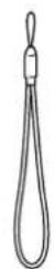
① Hand strap 1
② Antenna 1
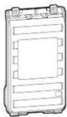
③ Battery pack* 1 or
Batterycase* 1
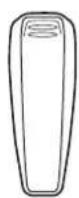
④ Belt clip ^* ....1
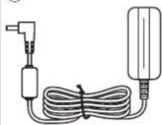
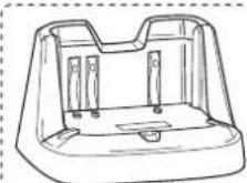
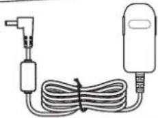
⑤ Battery charger* 1 or
Battery charger* and power adapter* 1 set
* Not supplied, or the shape is different, depending on the transceiver version.
DISPOSAL

The crossed-out wheeled-bin symbol on your product, literature, or packaging reminds you that in the European Union, all electrical and electronic products, batteries, and accumulators (rechargeable batteries) must be taken to designated collection locations at the end of their working life. Do not dispose of these
products as unsorted municipal waste.
Dispose of them according to the laws in your area.
①
②

③
④
⑤
natural_image
Simple line drawing of a cable and plug assembly (no text or symbols)or
natural_image
Simple line drawing of a medical or electrical device with a coiled cable and two connected components (no text or symbols)TABLE OF CONTENTS
FOREWORD ...... i
EXPLICIT DEFINITIONS......i
FEATURES......i
IMPORTANT i
PRECAUTIONS....ii–iii
FCC INFORMATION ....iii
SUPPLIED ACCESSORIES......iv
DISPOSAL iv
TABLE OF CONTENTS v-vi
1 ACCESSORY ATTACHMENT 1-2
■ Hand strap .... 1
■ Belt clip 1
■ Battery pack....2
■ Antenna 2
2 PANEL DESCRIPTION 3-8
■ Front, top and side panels 3
■ Function display....6
3 BATTERY CHARGING 8-15
■ Caution (for the supplied BP-264 Ni-MH battery pack)....8
■ Caution (for the optional BP-265 Li-Ion battery pack)....9
■ Battery case (BP-263) 11
■ Battery information 11
■ Regular charging 12
■ Desktop battery chargers 13
■ External DC power operation....15
■ Selecting the mode 18
■ Setting the tuning step....19
■ Setting the frequency....19
■ Operating mode selection....21
■ Key lock function....21
■ Receiving 22
■ Transmit power selection 22
■ Transmitting....23
5 REPEATER AND DUPLEX OPERATIONS 24-28
■ Repeater operation 24
■ Duplex operation....26
■ Reverse duplex function ......26
■ Auto repeater function ...... 27
■ 1750 Hz tone 28
6 MEMORY/CALL CHANNELS 29–39
■ General description....29
■ Selecting a call channel....29
■ Selecting a memory channel 30
■ Memory channel programming....31
■ Memory bank setting 32
■ Memory bank selection....33
■ Programming memory/bank/scan name....34
TABLE OF CONTENTS
■ Selecting memory/bank name indication....35
■ Display type ......36
■ Copying memory/call contents....37
■ Memory clearing....38
■ Erasing/transferring bank contents 39
7 SCAN OPERATION 40-47
■ Scan types....40
■ Full/band/programmed scan 42
■ Scan edges programming....43
■ Memory scan 44
■ Memory bank scan 45
■ Skip channel/frequency setting....46
■ Scan resume setting 47
8 PRIORITY WATCH 48-50
■ Priority watch types 48
■ Priority watch operation 49
9 SET MODES 51-64
■ General 51
■ Set mode item list 52
■ Initial set mode item list 52
■ Set mode items....53
■ Initial set mode items....59
10 OTHER FUNCTIONS....65–75
■ Programming a DTMF code sequence....65
■ Transmitting a DTMF code sequence 66
■ Setting DTMF transfer speed....67
■ Tone frequency and DTCS code....68
■ Tone/DTCS squelch....70
■ Tone scan....71
■ Weather channel operation....72
■ Cloning function 74
Resetting....75
11 TROUBLESHOOTING 76
12 SPECIFICATIONS....77
13 OPTIONS 78-82
■ VOX function 80
■ Remote control function....82
14 COUNTRY CODE LIST......83
INDEX 84-87

1 ACCESSORY ATTACHMENT
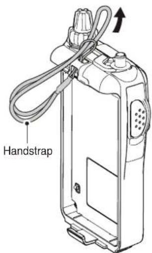
■ Hand strap
To facilitate carrying the transceiver, slide the hand strap through the loop on the top of the rear panel as illustrated at the right.
■ Belt clip
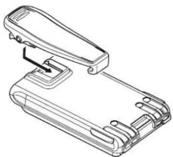
To attach the belt clip:
Slide the belt clip in the direction of the arrow until the belt clip locks in place, and makes a 'click' sound.
natural_image
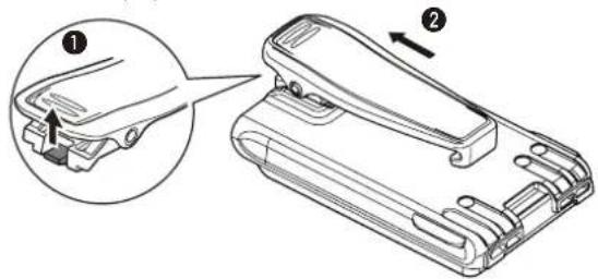
Technical line drawing of a mechanical device with no visible text or symbolsTo detach the belt clip:
① Remove the battery pack from the transceiver, if it is attached. (p. 2)
② Lift the tab up (1), and slide the belt clip in the direction of the arrow (2).
ACCESSORY ATTACHMENT
Battery pack
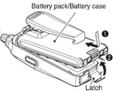
To attach the battery pack:
① Fitthe battery pack in the direction of the arrow (1), then close.
② Hook the latch until it makes a 'click' sound (②).
- Charge the battery pack before use. (pp. 12–14)
To detach the battery pack:
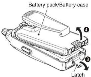
Be careful! The latch is tightly locked, so use caution when releasing it. DO NOT use your finger nail. Use the edge of a coin or screwdriver tip to carefully release it.
Unhook the latch (3), and lift up the battery pack in the direction of the arrow (4).
Antenna
Insert the antenna connector into the antenna base and tighten the antenna screw.
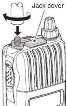
- NEVER carry the transceiver by holding only the antenna. - When the jack is not in use, keep the jack cover in place to protect the connector from dust and moisture.
√ For your information Third-party antennas may increase transceiver performance. An optional AD-92SMA ANTENNA CONNECTOR ADAPTER is available to connect an antenna that has a BNC connector.

2
PANEL DESCRIPTION
■ Front, top and side panels
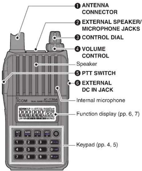
① ANTENNA CONNECTOR (p. 2)
Connects to the supplied antenna.
- An optional AD-92SMA adapter (p. 79) is available for connecting an antenna with a BNC connector.
② EXTERNAL SPEAKER/MICROPHONE JACKS [SP/MIC]
Connect an optional speaker microphone, cloning cable, or headset, if desired.
See page 79 for a list of available options.
Be sure to turn power OFF before connecting or disconnecting optional equipment to/from the [SP/MIC] jack.
③ CONTROL DIAL [DIAL]
→ Rotate to select the operating frequency. (p. 19)
During memory mode operation, rotate to select the memory channel. (pp. 18, 30)
→ While scanning, changes the scanning direction. (pp. 42, 44, 45)
→ While continuing to push MONI, sets the squelch level. (p. 17)
→ After pushing [BAND] during memory mode operation, selects the programmed bank. (p. 33)
→ During set mode operation, rotate to select the set items. (p. 51)
④ VOLUME CONTROL [VOL]
→Adjustthe audio volume level. (p. 16)
During set mode operation, rotate to select the options. (p. 51)
⑤ PTT SWITCH [PTT]
→ Push and hold to transmit, release to receive. (p. 23)
For IC-T70E only
→ Push briefly, then push and hold to transmit a 1750 Hz tone burst. (p. 28)
⑥ EXTERNAL DC IN JACK [DC IN]
Connects the supplied* charger, BC-167S, to charge the attached battery pack, BP-264. (p. 12) *Not supplied with some versions
- The transceiver can charge only the BP-264 Ni-MH battery pack. Charging the BP-265 Li-Ion battery pack requires the BC-193 desktop charger.
Connect an external DC power supply through the optional CP-12L, CP-19R or OPC-254L for external DC operation. (p. 15)
◇ Keypad
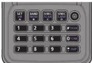
→ Push to input numbers for frequency input or memory channel selection.
→ While continuing to push [PTT], push the key to send the DTMF code. (pp. 66, 67)
• [0]–[9] send “0”–“9,” A sends “A,” B sends “B,” C sends “C,” D sends “D,” * sends “* (E)” and # sends “# (F).”
POWER KEY [∅]
![ICOM IC-T70A - POWER KEY [∅] - 1](/content/2026/05/811798/images/c3753716ed09d64f6b4047da1b279b9ec235fc8a8866aaa405965dc60954f1b9.jpg)
→ Push and hold for 1 sec. to turn the transceiver power ON or OFF. (p. 16)
VFO/MEMORY/CALL • SELECT MEMORY WRITE KEY [V/M/C] • [S.MW](V/M/C)
![ICOM IC-T70A - VFO/MEMORY/CALL • SELECT MEMORY WRITE KEY [V/M/C] • [S.MW](V/M/C) - 1](/content/2026/05/811798/images/4abe8cb493f8d57c2004777ef392a886dce44bbfd963609c78fda9ffe270af27.jpg)
→ Push to select the VFO mode, memory mode, call channel mode or weather channel mode*. (pp. 18, 29, 30, 72)
* Only for the U.S.A. version transceiver.
→ Push and hold for 1 sec. to enter select memory write mode. (p. 31)
2 PANEL DESCRIPTION
◇ Keypad (continued)
OUTPUT POWER • SCAN KEY [H/M/L] • [SCAN](H/M/L)
![ICOM IC-T70A - OUTPUT POWER • SCAN KEY [H/M/L] • [SCAN](H/M/L) - 1](/content/2026/05/811798/images/5724078723f1e8ea64da5fad207ddc5609e578cb0da3ac5e19375f71d0c5d19e.jpg)
→ Push to select the output power. (p. 22)
- Selects the transmit output power from high, middle or low.
→ Push and hold for 1 sec. to enter the scan type selection mode. (pp. 42, 44, 45)
- Push again to start the scan.
BAND • MONITOR KEY [BAND] • [MONI](BAND)
![ICOM IC-T70A - BAND • MONITOR KEY [BAND] • [MONI](BAND) - 1](/content/2026/05/811798/images/3d6e4614ea3be4d9616ae319a52dd0b8b066f83e81075bc10604ac5675977cf9.jpg)
During VFO mode operation, push to select an operating frequency band. (p. 19)
→ Push and hold to open the squelch temporarily and monitor the operating frequency. (p. 17)
→ While continuing to push this key, rotate [DIAL] to adjust the squelch level. (p. 17)
During memory mode operation, push to enter the memory bank group selection. (p. 33)
SET • LOCK KEY [SET] • [¬O](SET)
![ICOM IC-T70A - SET • LOCK KEY [SET] • [¬O](SET) - 1](/content/2026/05/811798/images/247656025bdeba13678b28ff60d154590f23b98d301cc380d42f37061af9e38b.jpg)
→ Push to enter the Set mode. (p. 51)
→ Push and hold for 1 sec. to toggle the lock function ON or OFF. (p. 21)
During select memory write mode, push to select the items. (pp. 32, 34, 38, 39)
TONE SCAN KEY [T.SCAN](#)
 - 1](/content/2026/05/811798/images/4c9e550a90b61bde7d6075bf0c3a3174cc1e2fbd5728af0afb7c6c5c27c066ea.jpg)
→ Push and hold for 1 sec. to start the tone scan function. (p. 71)
TONE/TONE SQUELCH KEY [TONE](0)
 - 1](/content/2026/05/811798/images/0eeedcf17052a536b69ce68f63f88f6fc71ea1d65c718e8a40adb08db7fc1124.jpg)
→ Push and hold for 1 sec. to select sequentially repeater tone, tone squelch, tone squelch reverse, DTCS squelch, DTCS squelch reverse and no tone operation. (p. 70) • The pocket beep function is available with tone squelch and DTCS squelch. (p. 70)
DUPLEX KEY [DUP](\*)
 - 1](/content/2026/05/811798/images/8ecd518c616819ecb755d389020dc54dad3dc1a5e981df14f045f2f26dc576b0.jpg)
→ Push and hold for 1 sec. to select minus duplex, plus duplex or simplex operation. (p. 26) • “DUP—” (minus duplex), “DUP” (plus duplex) and no indication (simplex) appear in order.
■ Function display
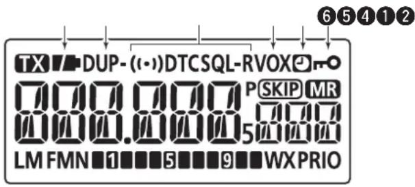
① BATTERY ICON (pp. 11, 12)
○ When the BP-264 or BP-265 is attached
→“ ” (battery icons) appear when the battery pack has ample capacity.
→“ ■” appears when the battery pack has less than half capacity.
→ "12" blinks before the battery pack is exhausted. The battery pack must be charged.
The icons show “”, “” and “ (disappears)” in sequence while charging the BP-264 Ni-MH battery pack.
○ When the BP-263 is attached
→“▼” (battery icons) appear when the batteries have ample capacity.
→ “7” blinks before the batteries are exhausted. The batteries must be replaced.
② DUR3EX ICON (p. 26)
“DUP” appears when plus duplex is selected, “DUP—” appears when minus duplex is selected.
③ TONE ICON
“T” appears while the subaudible tone encoder is in use. (p. 24)
“T SQL” appears while the tone squelch function is in use. (p. 70)
“T SQL-R” appears while the reverse tone squelch function is in use. (p. 70)
“DTCS” appears while the DTCS squelch function is in use. (p. 70)
“DTCS -R” appears while the reverse DTCS squelch function is in use. (p. 70)
→ “(•)” appears with the “T SQL” or “DTCS” indicator while the pocket beep function (with CTCSS or DTCS) is in use. (p. 70)
④ VOX ICON (p. 80)
Appears when the VOX function is in use.
⑤ AUTO POWER OFF ICON (p. 59)
Appears when the Auto Power OFF function is ON.
Appears when the key lock function is activated.
2 PANEL DESCRIPTION
■ Function display (continued)
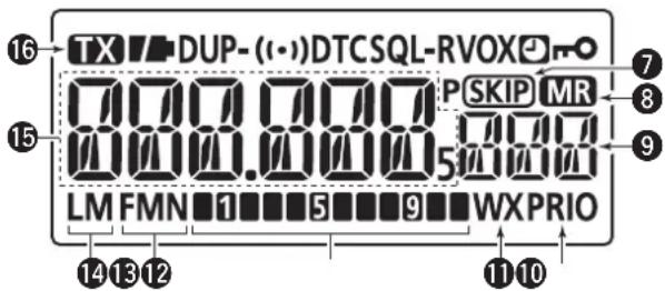
⑦ SKIP ICONS
→“SKIP” appears when the selected memory channel is set as a skip channel. (p. 46)
→“P SKIP” appears when the displayed frequency is set as a skip frequency in memory mode. (p. 46)
⑧ MEMORY ICON (pp. 18, 30)
Appears when memory mode is selected.
⑨ MEMORY CHANNEL NUMBER
→ Shows the selected memory channel number. (pp. 18, 30)
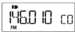
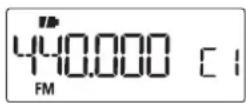
→ "C0" or "C1" appears when the call channel is selected. (pp. 18, 29)
⑩ PRIORITY WATCH ICON (pp. 49, 50)
Appears when priority watch is in use.
⑪ WEATHER CHANNEL ICON (pp. 72–73)
Appears when the weather alert function is in use.
⑫ S/RF METER
→ Shows the relative signal strength while receiving signals. (p. 22)
Shows the output power level while transmitting. (pp. 22, 23)
⑬ OPERATING MODE ICONS (p. 21)
Shows the selected operating mode.
• FM and FMN are selectable.
14 POWER ICONS (p. 22)
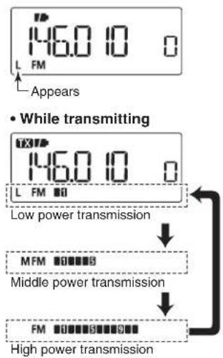
“L” appears when low power is selected.
→ "M" appears when middle power is selected.
→ No indicator appears when high power is selected.
⑮ FREQUENCY READOUT
Displays a variety of information, such as operating frequency, set mode contents.
- The decimal point blinks during scan.
During memory mode operation, the programmed memory or memory bank name is displayed.
⑯ TRANSMIT ICON (p. 23)
Appears during transmit.
BATTERY CHARGING
3
■ Caution (for the supplied BP-264 Ni-MH battery pack)
- DANGER! NEVER incinerate used battery packs. Internal battery gas may cause an explosion.
- △ DANGER! NEVER immerse the battery pack in water. If the battery pack becomes wet, be sure to wipe it dry BEFORE attaching it to the transceiver.
- CAUTION: Always use the battery within the specified temperature range, -5^ to +60^ ( +23^ to +140^ ). Using the battery out of its specified temperature range will reduce the battery's performance and battery life.
-
CAUTION: Shorter battery life could occur if the battery is left completely discharged, or in an excessive temperature environment (above +55°C; +131°F) for an extended period of time. If the battery must be left unused for a long time, it must be detached from the transceiver after charging. Keep it safely in a cool dry place at the following temperature range:
-20^ to +45^ ( -4^ to +113^ ) (up to a month)
-20^ to +35^ ( -4^ to +95^ ) (up to six months)
-20^ to +25^ (-4^ to +77^) (up to a year*)
* We recommend charging the battery pack every 6 months. -
Clean the battery terminals to avoid rust or misscontact.
- Keep battery terminals clean. It's a good idea to clean battery terminals once a week.
- If your Ni-MH battery pack seems to have no capacity, even after being charged, completely discharge it by leaving the power ON overnight. Then, fully charge the battery pack again. If the battery pack still does not retain a charge (or only very little charge), a new battery pack must be purchased.
Prior to using the transceiver for the first time, the battery pack must be fully charged for optimum life and operation. - Recommended temperature range for charging: between 0^ and +45^ for the regular charge by the transceiver. or between +10^ and +40^ for the rapid charge with the BP-191.
- Use the supplied* charger (BC-167S) or optional charger (BC-191) only. NEVER use other manufacturers' chargers. *Not supplied with some versions
- The battery pack contains a rechargeable battery. Charge the battery pack before first operating the transceiver, or when the battery pack becomes exhausted. If you want to prolong the battery life, the following points should be observed:
- Avoid over charging.
- Use the battery pack until it becomes almost completely exhausted, under normal conditions. We recommend battery charging after transmitting becomes impossible.
3 BATTERY CHARGING
■ Caution (for the optional BP-265 Li-Ion battery pack)
Misuse of Lithium-Ion batteries may result in the following hazards: smoke, fire, or the battery may rupture. Misuse can also cause damage to the battery or degradation of battery performance.
◇ Battery caution
- △ DANGER! DO NOT hammer or otherwise impact the battery. Do not use the battery if it has been severely impacted or dropped, or if the battery has been subjected to heavy pressure. Battery damage may not be visible on the outside of the case. Even if the surface of the battery does not show cracks or any other damage, the cells inside the battery may rupture or catch fire.
- △ DANGER! NEVER use or leave battery pack in areas with temperatures above +60°C (+140°F). High temperature buildup in the battery, such as could occur near fires or stoves, inside a sun-heated car, or in direct sunlight for long periods of time may cause the battery to rupture or catch fire. Excessive temperatures may also degrade battery performance or shorten battery life.
- △ DANGER! DO NOT expose the battery to rain, snow, seawater, or any other liquids. Do not charge or use a wet battery. If the battery gets wet, be sure to wipe it dry before using.
-
△ DANGER! KEEP battery packs away from fire. Fire or heat may cause them to rupture or explode. Dispose of a used battery pack in accordance with local regulations.
-
DANGER! NEVER solder the battery pack terminals, or NEVER modify the battery pack. This may generate heat in the battery, and the battery pack may burst, emit smoke or catch fire.
- △ DANGER! Use the battery only with the transceiver for which it is specified. Never use a battery with any other equipment, or for any purpose that is not specified in this instruction manual.
- DANGER! If fluid from inside the battery gets in your eyes, blindness can result. Rinse your eyes with clean water, without rubbing them, and see a doctor immediately.
- ⚠ WARNING! Immediately stop using the battery if it emits an abnormal odor, heats up, or is discolored or deformed. If any of these conditions occur, contact your lcom dealer or distributor.
- ⚠ WARNING! Immediately wash, using clean water, any part of the body that comes into contact with fluid from inside the battery.
Battery Pack characteristics and lifetime
BE SURE to replace the battery pack with a new one approximately five years after manufacturing, even if it still holds a charge. The inside battery material will become weak after a period of time, even with little use. The estimated number of times you can charge the battery is between 300 and 500. Even when the battery appears to be fully charged, the operating time of the radio may become short when:
- Approximately five years have passed since the battery was manufactured.
-
The battery has been repeatedly charged.
-
⚠ WARNING! NEVER put the battery in a microwave oven, high-pressure container, or in an induction heating cooker. This could cause a fire, overheating, or cause the battery to rupture.
- CAUTION: Always use the battery within the specified temperature range, -20^ to +60^ ( -4^ to +140^ ). Using the battery out of its specified temperature range will reduce the battery's performance and battery life.
- CAUTION: Shorter battery life could occur if the battery is left fully charged, completely discharged, or in an excessive temperature environment (above +50°C; +122°F) for an extended period of time. If the battery must be left unused for a long time, it must be detached from the transceiver after discharging. You may use the battery until the remaining capacity is about half, and then keep it safely in a cool dry place at the following temperature range:
-20^ to +50^ (-4^ to +122^) (up to a month)
-20°C to +35°C (-4°F to +95°F) (up to three months)
-20^ to +20^ ( -4^ to +68^ ) (up to a year)
◇ Charging caution
- △ DANGER! NEVER charge the battery pack in areas with extremely high temperatures, such as near fires or stoves, inside a sun-heated vehicle, or in direct sunlight. In such environments, the safety/protection circuit in the battery will activate, causing the battery to stop charging.
- ⚠ WARNING! NEVER charge the transceiver during a lightning storm. It may result in an electric shock, cause a fire or damage the transceiver. Always disconnect the power adapter before a storm.
- △ WARNING! DO NOT charge or leave the battery in the battery charger beyond the specified time for charging. If the battery is not completely charged by the specified time, stop charging and remove the battery from the battery charger. Continuing to charge the battery beyond the specified time limit may cause a fire, overheating, or the battery may rupture.
- △ WARNING! NEVER insert the transceiver (battery attached to the transceiver) into the charger if it is wet or soiled. This could corrode the battery charger terminals or damage the charger. The charger is not waterproof.
- CAUTION: DO NOT charge the battery outside of the specified temperature range: BC-193 (+10°C to +40°C; +50°F to +104°F). Icom recommends charging the battery at +20°C (+68°F). The battery may heat up or rupture if charged out of the specified temperature range. Additionally, battery performance or battery life may be reduced.
3 BATTERY CHARGING
■ Battery case (BP-263)
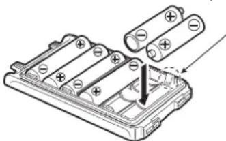
When you would like to use the battery case (BP-263), install 6 × AA (LR6) size alkaline batteries, as shown below.
① Remove the battery case if it is attached. (p. 2)
② Install 6 × AA (LR6) size alkaline batteries.
• Install only alkaline batteries.
- Be sure to observe the correct polarity.
natural_image
Diagram of battery pack assembly with two cylindrical cells and a separate one inserted (no text or symbols)Be careful! The negative terminals of the battery case protrude from the body, so pay attention not to injure your fingers when inserting the batteries.
③ Attach the battery case. (p. 2)
CAUTION:
- When installing batteries, make sure they are all the same brand, type and capacity. Also, do not mix new and old batteries together.
- Never use batteries whose insulated covering is damaged.
- Never incinerate used battery cells since internal battery gas may cause them to rupture.
- Never expose a detached battery case to water. If the battery case gets wet, be sure to wipe it dry before using it.
- Keep the battery terminals clean. It's a good idea to occasionally clean them.
■ Battery information
◇ Battery life
| Battery pack | Voltage C | Capacity Battery life* | 1 | |
| BP-263 | Battery case for AA (LR6) × 6 alkaline | _*2 | ||
| BP-264 7.2 | V 1400 m | Ah (typ.) | VHF 11 | .5 hrs. |
| UHF 10 | hrs. | |||
| BP-265 7.4 | V | 1900 mAh (min.) | VHF 16 | hrs. |
| 2000 mAh (typ.) | UHF 13 | .5 hrs. | ||
*1 When the power save function is set to "Auto," and the operating time is calculated under the following conditions;
TX : RX : standby = 5 : 5 : 90
*2 The average operating time depends on the alkaline cells used.
Even when the transceiver power is OFF, a small current still flows in the transceiver. Remove the battery pack or case from the transceiver when not using it for a long time. Otherwise, the battery pack or installed batteries will become exhausted.
| Indication | Battery condition |
| The battery pack (BP-264/BP-265) or battery case (BP-263) has ample capacity. | |
| The battery pack (BP-264/BP-265) is nearing exhaustion. | |
| The battery pack or battery case is exhausted. Charging the BP-264/BP-265 or replacing the batteries in the BP-263 is necessary. |
BATTERY CHARGING
■ Regular charging
Prior to using the transceiver for the first time, the battery pack must be fully charged for optimum life and operation.
◇ Battery icons
While charging, the icons show "☐," "☐" and "☐ (disappears)" in sequence, and "CHARGE" appears when the transceiver's power is OFF. The icons and "CHARGE" disappear when the battery pack is completely charged.
◇ Charging note
- Be sure to turn the transceiver power OFF.
Otherwise the battery pack will not be charged completely, or will take much longer to charge. - The transceiver can charge only the BP-264 battery pack. Other types of rechargeable battery, such as Ni-Cd or Li-Ion cannot be charged.
- External DC power operation becomes possible when using an optional CP-12L, CP-19R or OPC-254L. The attached battery pack is also charged simultaneously, except during transmit (see p. 15 for more details).
- The external DC power supply voltage must be between 10–16 V to charge the battery pack and for operation when using an optional OPC-254L. We recommend 11 V DC for operation.
- If the battery icons ("") and "") disappear only 1 min. after connecting to the DC power supply, the battery pack may have problem. In this case, contact your lcom dealer/distributor, or purchase a new battery pack.
![Transceiver to [DC IN] BP-264 Turn power OFF while charging the battery pack. Charging time period: Approx. 8 hours • BC-167S to AC outlet The BC-167SA, BC-167SD and BC-167SV have different shapes. • CP-12L (Optional) to cigarette lighter socket (12 V DC) • CP-19R (Optional) • OPC-254L (Optional) to 11 V DC (power supply) Black: ⊖ White: ⊕](/content/2026/05/811798/images/c45aa8441f6f8e289e36328d1098321e88c6475f68754f9344a808949c86c5cd.jpg)
Be sure to disconnect the power adapter from the AC outlet after the charging is completed. Otherwise the transceiver may receive switching noise from the power adapter, depending on the operating frequencies and/or antenna used.
3 BATTERY CHARGING
■ Desktop battery chargers
◇ Charging note
- Be sure to turn the transceiver power OFF.
- NEVER place the transceiver with the battery pack to the desktop charger when the transceiver is connected to the DC power supply. This may cause the charger's malfunction and the charging indicator of the charger lights red*. In that case, disconnect the power adapter from the charger, and then reconnect the power adapter to the charger.
*Red indicator is only available for the BC-191 or BC-193. - The optional CP-23L* and OPC-515L can be used instead of the supplied power adapter. Connect one of these to the [DC 12-16V] jack.
* CP-23L can only be used with the BC-191 or BC-193.
IMPORTANT: Ensure the tabs on the battery pack are correctly aligned with the guide rails inside the charger.
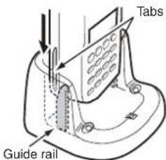
CAUTION: When using the OPC-515L DC power cable NEVER connect the OPC-515L to a power source using reverse polarity. This will ruin the battery charger.
White line: ⊕ Black line: ○
◇ Rapid charging with the BC-191
The BC-191 provides rapid charging of only the BP-264 Ni-MH battery pack. Never use it to charge any other battery pack. Charging time (with the BC-123S): Approx. 2 hours
The following item is additionally required:
- The power adapter BC-123S (not supplied with some versions) or the OPC-515L or CP-23L DC power cable.
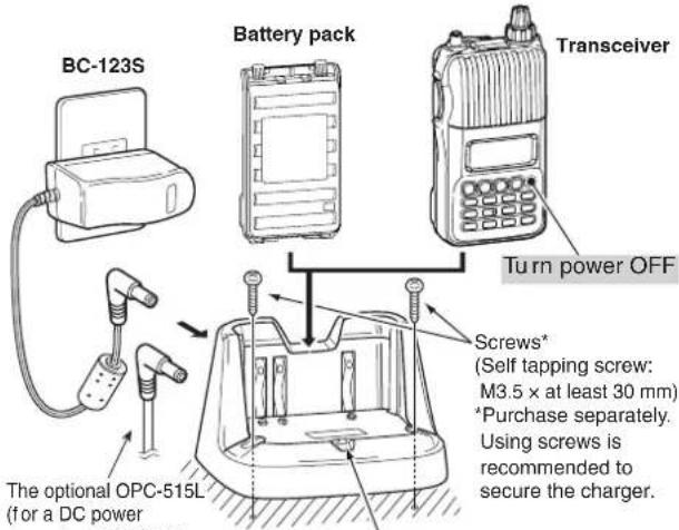
source) of CP-23L (for a 12 V cigarette lighter socket) can be used instead of the power adapter. Charge indicator • Lights orange : While charging • Lights green : Charging is completed • Blinks red : Charging error has occurred
BATTERY CHARGING
◇ Regular charging with the BC-192
The BC-192 provides regular charging of only the BP-264 Ni-MH battery pack. Never use it to charge any other battery pack. Charging time (with the BC-147S/BC-206S): Approx. 16 hours The following item is additionally required:
- The power adapter BC-147S/BC-206S (not supplied with some versions) or the OPC-515L DC power cable.
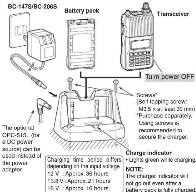
◇ Rapid charging with the BC-193
The BC-193 provides rapid charging of only the BP-265 Li-lon battery pack. Never use it to charge any other battery pack.
Charging time: Approx. 2.5 hours
The following item is additionally required:
- The power adapter BC-123S (not supplied with some versions) or the OPC-515L or CP-23L DC power cable.
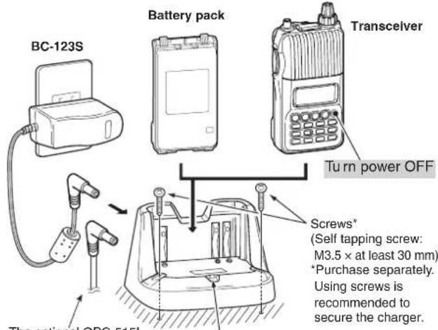
The optional OPC-515L (for a DC power source) can be used instead of the power adapter.
Charge indicator
• Lights orange : While charging
• Lights green : Charging is completed
- Blinks red : Charging error has occurred
3 BATTERY CHARGING
■ External DC power operation
An optional cigarette lighter cable (CP-12L or CP-19R; for 12 V cigarette lighter socket) or external DC power cable (OPC-254L) can be used for external power operation. (We recommend the CP-19R when you want to connect a 12 V cigarette lighter socket.)
◇ Operating note
- Power supply voltage must be between 10.0–16.0 V DC. (We recommend 11.0 V DC.) NEVER CONNECT OVER 16 V DC directly into the [DC IN] jack of the transceiver.
- BE SURE to use a CP-12L, CP-19R or OPC-254L when connecting to a regulated 12 V DC power supply.
Use an external DC-DC converter to connect the transceiver through a CP-12L, CP-19R or OPC-254L to a 24 V DC power source. - The voltage of the external power supply must be within 10–16 V DC when using either CP-12L, CP-19R or OPC-254L, otherwise, use the battery pack/battery case.
- Disconnect the power cable from the transceiver when not using it. Otherwise, the vehicle battery will become exhausted.
- The power save function is automatically deactivated during external DC power operation.
![Transceiver to [DC IN] BP-264 CP-12L (Optional) to cigarette lighter socket (12 V DC) CP-19R (Optional) OPC-254L (Optional) to 11 V DC (power supply) Black: ⊖ White: ⊕](/content/2026/05/811798/images/eb42a240d5e390d590730c0f4c484826ea50bcd36dd02618c3bf804fe2c7b07e.jpg)
NOTE: Up to 5 W (approx.) of maximum output power is available when using an external DC power. However, when the supplied voltage exceeds 14 V, the built-in protection circuit activates to reduce the transmit output power to 2.5 W (approx.).
BASIC OPERATION
4
Power ON
→ Push and hold [☐ for 1 sec. to turn power ON.
- Push and hold 📋 for 1 sec. to turn power OFF.
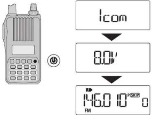
The voltage indication can be skipped in the Initial set mode (p. 61).
■ Setting audio volume
→ Rotate [VOL] to adjust the audio level.
- If squelch is closed, push and hold MONI while setting the audio level.
- The display shows the volume level while setting.
![[VOL] BAND MONI B](/content/2026/05/811798/images/fc49b3d4ed01e53284bd0cc8df95dd54833bcbdce1691776edc14017edde3478.jpg)
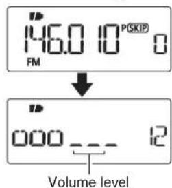
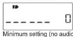
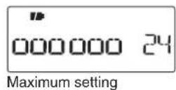
The beep level is adjusted in the Initial set mode (p. 60).
4 BASIC OPERATION
■ Setting the squelch level
The squelch circuit mutes the received audio signal, depending on the signal strength. The transceiver has 9 squelch levels, a continuously open setting and an automatic setting.
→ While continuing to push MONI, rotate [DIAL] to select the squelch level.
- "LEVEL1" is loose squelch (for weak signals) and "LEVEL9" is tight squelch (for strong signals).
- "Auto" indicates the automatic level adjustment by a noise pulse counting system.
- “OPEn” indicates the continuously open setting.
![[DIAL] BAND MONI 146.0 10 PSKIP FM ↓ Auto 5qL Automatic squelch LEV'EL95qL](/content/2026/05/811798/images/3b72a71ddb9bfca0a9203cca77a76258dcca9942a7615045a8a8606e77f9d160.jpg)
Maximum level
■ Monitor function
This function is used to listen to weak signals without disturbing the squelch setting; or to open the squelch manually even when mute functions such as the tone squelch are in use.
→ Push and hold MONI to monitor the operating frequency.
• The 1st and 2nd segments of the S-meter blink.
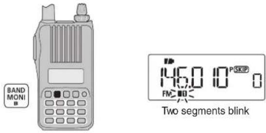
The[MONI] key can be set to a 'sticky' operation in the Initial set mode. See page 63 for details.
■ Selecting the mode
①Push [V/M/C] repeatedly to sequentially select the VFO mode, memory mode, call channel mode or weather channel mode*.
* Only for the U.S.A. version transceiver.
② Rotate [DIAL] to change the frequency or select a desired channel.
![[DIAL] V/M/C 5.MW D](/content/2026/05/811798/images/d8e2786c8b54d436cdb20ae16e02c59721dae29b1b1b5763a242ad71149917e9.jpg)
◇ VFO mode
The VFO mode is used to set the desired frequency.
- VFO mode display
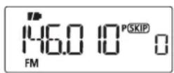
What is VFO?
VFO is an abbreviation of Variable Frequency Oscillator. Frequencies for both transmitting and receiving are generated and controlled by the VFO.
◇ Memory mode
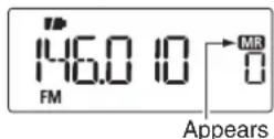
Memory mode is used for operation on memory channels which store programmed frequencies.
- “MR” appears when memory mode is selected.
- Only programmed memory channels can be selected.
- Enter the channel number directly to select the desired memory channel. (p. 30)
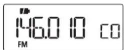
◇ Call channel mode
Select a call channel to operate on one of your two most often-used frequencies.
- "C0" or "C1" appears instead of the memory channel number when the Call channel mode is selected.
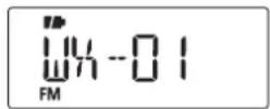
◇ Weather channel mode\*
There are 10 weather channels for monitoring weather broadcasts from NOAA (National Oceanic and Atmospheric Administration).
* Only for the U.S.A. version transceiver.
- Memory mode display
- Call channel display
- Weather channel display
4 BASIC OPERATION
■ Setting the tuning step
The tuning step can be selected for both band. The following tuning steps are available for the IC-T70A/T70E.
• 5.0 kHz • 10.0 kHz • 12.5 kHz • 15.0 kHz
• 20.0 kHz • 25.0 kHz • 30.0 kHz • 50.0 kHz
• 100.0 kHz • 125.0 kHz • 200.0 kHz
◇ Tuning step selection
①In the VFO mode, push [BAND] to select the desired frequency band.
- If you are in another mode, such as a memory channel/call channel mode or the weather channel mode, push [V/M/C] to select the VFO mode first, then push [BAND] to select the desired band.
②Push[SET] to enter the Set mode.
③ Rotate [DIAL] to select the tuning step set item, then rotate [VOL] to select the desired tuning step.
④Push [V/M/C] to return to the VFO mode.
![[DIAL] [VOL] SET A BAND MONI B V/M/C S.MW D L.S ↓ 5.0 L.S 5 kHz tuning step](/content/2026/05/811798/images/b662caa4a8cd339485ef400dbde91c4374a3d02354b01cdee941572a15fef799.jpg)
■ Setting the frequency
◇ Using the dial
①Push [V/M/C] to select the VFO mode, if any other mode is selected.
②Push [BAND] to select the desired frequency band.
③ Rotate [DIAL] to select the desired frequency.
- The frequency changes according to the preset tuning steps. See the previous topic to set the tuning step.
![[DIAL] BAND MONI B V/M/C S.MW D](/content/2026/05/811798/images/53cbf128312329eed743c7d3ca73de782f04aba09db35653930c111d2d7b9b46.jpg)
![• 144 MHz band 146.0 10 PSKIP FM Push [BAND] • 440 MHz band 440.000 PSKIP FM](/content/2026/05/811798/images/7f77f3d62ed6222b75e247dd36e47ef78bee4b8bd81c1adf1d009ef8b018eb51.jpg)
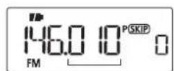
[DIAL] changes the frequency according to the selected tuning step.
◇ Using the keypad
The frequency can be directly set using the numeric keys.
- If a frequency outside the transceiver's frequency range is entered, the previously displayed frequency is automatically recalled after entering the last digit.
①Push [V/M/C] to select the VFO mode, if any other mode is selected.
② Enter the desired frequency with the keypad.
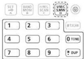
Depending on the tuning step setting, it may not be possible to input a 1 kHz digit. In this case, enter "0" as a 1 kHz digit, then rotate [DIAL] to set the desired frequency.
- Entering 145.500 MHz

flowchart
graph LR
    A["IFM"] --> B["IFM"]
    B --> C["IFM"]
    C --> D["IFM"]
    D --> E["IFM"]
    E --> F["IFM"]
    F --> G["IFM"]
    G --> H["IFM"]
    H --> I["IFM"]
    I --> J["IFM"]
    J --> K["IFM"]
    K --> L["IFM"]
    L --> M["IFM"]
    M --> N["IFM"]
    N --> O["IFM"]
    O --> P["IFM"]
    P --> Q["IFM"]
    Q --> R["IFM"]
    R --> S["IFM"]
    S --> T["IFM"]
    T --> U["IFM"]
    U --> V["IFM"]
    V --> W["IFM"]
    W --> X["IFM"]
    X --> Y["IFM"]
    Y --> Z["IFM"]
    Z --> AA["IFM"]
    AA --> AB["IFM"]
    AB --> AC["IFM"]
    AC --> AD["IFM"]
    AD --> AE["IFM"]
    AE --> AF["IFM"]
    AF --> AG["IFM"]
    AG --> AH["IFM"]
    AH --> AI["IFM"]
    AI --> AJ["IFM"]
    AJ --> AK["IFM"]
    AK --> AL["IFM"]
    AL --> AM["IFM"]
    AM --> AN["IFM"]
    AN --> AO["IFM"]
    AO --> AP["IFM"]
    AP --> AQ["IFM"]
    AQ --> AR["IFM"]
    AR --> AS["IFM"]
    AS --> AT["IFM"]
    AT --> AU["IFM"]
    AU --> AV["IFM"]
    AV --> AW["IFM"]
    AW --> AX["IFM"]
    AX --> AY["IFM"]
    AY --> AZ["IFM"]
    AZ --> BA["IFM"]
    BA --> BB["IFM"]
    BB --> BC["IFM"]
    BC --> BD["IFM"]
    BD --> BE["IFM"]
    BE --> BF["IFM"]
    BF --> BG["IFM"]
    BG --> BH["IFM"]
    BH --> BI["IFM"]
    BI --> BJ["IFM"]
    BJ --> BK["IFM"]
    BK --> BL["IFM"]
    BL --> BM["IFM"]
    BM --> BN["IFM"]
    BN --> BO["IFM"]
    BO --> BP["IFM"]
    BP --> BQ["IFM"]
    BQ --> BR["IFM"]
    BR --> BS["IFM"]
    BS --> BT["IFM"]
    BT --> BU["IFM"]
    BU --> BV["IFM"]
    BV --> BW["IFM"]
    BW --> BX["IFM"]
    BX --> BY["IFM"]
    BY --> BZ["IFM"]
    BZ --> CA["IFM"]
    CA --> CB["IFM"]
    CB --> CC["IFM"]
    CC --> CD["IFM"]
    CD --> CE["IFM"]
    CE --> CF["IFM"]
    CF --> CG["IFM"]
    CG --> CH["IFM"]
    CH --> CI["IFM"]
    CI --> CJ["IFM"]
    CJ --> CK["IFM"]
- Changing 10 MHz and below Editing 445.560 MHz to 432.380 MHz

- Changing 1 MHz and below Editing 145.500 MHz to 144.640 MHz

- Changing 100 kHz and below Editing 145.500 MHz to 145.640 MHz

4 BASIC OPERATION
■ Operating mode selection
Operating modes are determined by the modulation of the radio signals. The transceiver has two operating modes, FM and FM-N (narrow). The mode selection is stored independently for each band and memory channel.
①Push [V/M/C] to select the VFO mode, if any other mode is selected.
②Push [BAND] to select the desired frequency band.
③Push[SET] to enter the Set mode.
④ Rotate [DIAL] to select the operating mode set item, then rotate [VOL] to select "WIdE" (FM) or "nARROW" (FM-narrow).
⑤Push [V/M/C] to return to the VFO mode.
![[DIAL] [VOL] SET A BAND MONI B V/M/C S.MW D modE W ide E w/n FM FMFMN : Rotate [VOL]](/content/2026/05/811798/images/86428415377ce5d5fb9a8877e5febcb3697af7d9c3aa701765ea395c0e53405b.jpg)
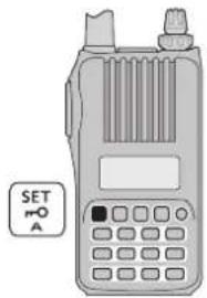
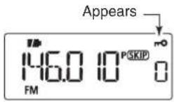
■ Key lock function
To prevent accidental frequency changes and unnecessary function access, use the lock function.
→ Push and hold O for 1 sec. to turn the lock function ON or OFF.
• "r" appears while the lock function is activated.
• [@], r-O, MONI, [PTT], [VOL] and squelch adjustment (MONI + [DIAL]) are operable while the lock function is activated.
- “ ^n ”appears while the lock function is activated.
- [0], r-O, MONI, [PTT], [VOL] and squelch adjustment (MONI + [DIAL]) are operable while the lock function is activated.
To prevent accidental transmission, the transceiver has a PTT lock function. Turns the PTT lock function ON or OFF in the Initial set mode. (p. 62)
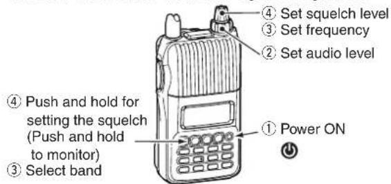
■ Receiving
Make sure a charged battery pack (BP-264, BP-265) or a case with brand new alkaline batteries (BP-263) is attached to the transceiver (pp. 2, 12–14).
① Push and hold [⏻] for 1 sec. to turn power ON.
② Rotate [VOL] to set the desired audio level. (p. 16)
- The frequency display shows the volume level while setting.
③ Set the receive frequency. (p. 20)
④ Set the squelch level. (p. 17)
- While continuing to push MONI, rotate [DIAL].
- The first click of [DIAL] indicates the current squelch level.
- "LEVEL1" is loose squelch (for weak signals) and "LEVEL9" is tight squelch (for strong signals).
- "Auto" indicates the automatic level adjustment by a noise pulse counting system.
- Push and hold MONI to open the squelch manually.
⑤ When a signal is received:
- Squelch opens and audio is heard.
• The S/RF meter shows the relative signal strength level.
■ Transmit power selection
The transceiver has three output power levels to suit your operating requirements. Low output power during short-range communications may reduce the possibility of interference to other stations, and will conserve battery power.
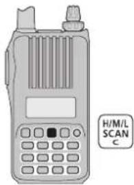
→ Push [H/M/L] to toggle the transmit output power between High (5 W*), Middle (2.5 W*) and Low (0.5 W*).
*Approximately
4 BASIC OPERATION
■ Transmitting
CAUTION: Transmitting without an antenna will damage the transceiver.
NOTE: To prevent interference, push and hold [MONI] (BAND) to listen on the frequency before transmitting.
① Set the operating frequency. (p. 20)
- You can transmit on the 144 MHz/440 MHz amateur bands only.
- Select the desired output power. See the previous page for details.
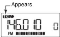
② Push and hold [PTT] to transmit.
- "TX" appears.
- The S/RF meter shows the output power level.
③ Speak into the microphone using your normal voice level.
- DO NOT hold the transceiver too close to your mouth or speak too loudly. This may distort your speech.
④ Release [PTT] to return to receive.
![[PTT] BAND MONI B Microphone](/content/2026/05/811798/images/f12181aa1dd1528ff02390b96209dab89d7fa587e114029d8e6c591f02615a0a.jpg)
⚠ WARNING! NEVER transmit for long periods of time. When the transceiver is used for prolonged transmissions at high power or middle power, the transceiver radiates heat to protect itself from overheating. The transceiver's chassis will become hot and may cause a burn.
- To prevent the transceiver's overheating, the default setting of the time-out timer function is set to 5 minutes (p. 62). Be careful when the time-out timer function is turned OFF or set to a long time period, and transmission is made for long periods.
DO NOT operate the transceiver in a situation that will obstruct heat dissipation, especially if the transceiver is operated with an external power supply. Heat dissipation may be affected, and it may cause a burn, warp the casing or damage the transceiver.
NOTE: When the transceiver becomes hot from continuous transmission, etc., the transceiver's heat protection function gradually reduces the output power to 2.5 W (Mid), then it stops transmission after that. This is done to protect the transceiver itself until it has cooled down.
- "M" (Power icon) blinks while the heat protection function reduces the output power.
- "Hot" is displayed while the heat protection function inhibits transmission.
While using the battery case:
Frequent or continuous transmissions can cause the batteries to overheat. To prevent this, we recommend using the middle or low power settings.
REPEATER AND DUPLEX OPERATIONS
5
■ Repeater operation
When using a repeater, the transmit frequency is shifted from the receive frequency by the frequency offset (p. 54). This is called duplex operation. It is convenient to program repeater information into memory channels (p. 29).
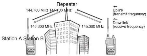
① Set the receive frequency (repeater output frequency).
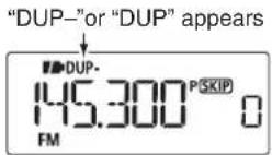
② Set the shift direction of the transmit frequency(DUP- or DUP; see p. 26 for details.)
- When the auto repeater function is in use (U.S.A. and Korean versions only), this selection and step ③ are not necessary. (p. 27)
③ Push and hold TONE for 1 sec. to activate the subaudible tone encoder, according to the repeater requirements.
- "T" appears. Refer to p. 53 for tone frequency settings.
④ Push and hold [PTT] to transmit.
- The displayed frequency automatically changes to the transmit frequency (repeater input frequency).
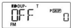
- If "OFF" appears, check the frequency offset or shift direction. (p. 26)
While receiving While transmitting

⑤ Release [PTT] to receive.
⑥ Push and hold MONI to check whether the other station's transmit signal can be directly received or not.
U.S.A. and Korean versions:
The auto repeater function uses standard values of the repeater tone frequency and frequency offset.
5 REPEATER AND DUPLEX OPERATIONS
◇ Checking the repeater input signal
The transceiver can check whether the other station's transmit signal can be received directly or not, by listening on the repeater input frequency.
→ Push and hold MONI to check whether the other station's transmit signal can be received directly or not.
- When the other station's signal can be directly received, move to a non-repeater frequency to use simplex. (duplex OFF)
![BAND MONI B Display while receiving 145.440 PSKIP FM Push and hold BAND MONI Receives -0.6 MHz lower 144.840 PSKIP FM Blinks while pushing and holding [MONI]](/content/2026/05/811798/images/c76b88d4d6793d9692f2f73a298f8683aa48a8cc75fdc4d3e3dbb50b69bd96b2.jpg)
◇ Off band indication
If the transmit frequency is out of the amateur band when [PTT] is pushed, the off band indication, "OFF," appears on the display. Check the frequency offset or duplex direction in that case. (p. 26)
U.S.A. and Korean versions:
The auto repeater function uses standard values of the frequency offset.
√ CONVENIENT!
Tone scan function: When you don't know the subaudible tone used for a repeater, the tone scan is convenient for detecting the tone frequency.
→ Push and hold T.SCAN for 1 sec. to start the tone scan. See p. 71 for more information.
REPEATER AND DUPLEX OPERATIONS
■ Duplex operation
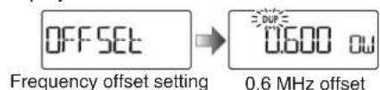
◇ Setting frequency offset
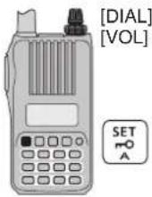
① Push [SET] to enter the Set mode.
②Rotate [DIAL] to select the frequency offset set item, then rotate [VOL] to set the frequency offset.
③Push [V/M/C] to return to the frequency display.
◇ Setting duplex direction
→ Push and hold DUP for 1 sec. to select "DUP—" (negative offset) or "DUP" (positive offset).
- "DUP—" or "DUP" indicates the transmit frequency for minus shift or plus shift, respectively.
- While continuing to push DUP, rotate [DIAL] also selects a duplex setting.
![[DIAL] * DUP](/content/2026/05/811798/images/cf5e92ded366cd068f98e3f8b7812046427710026303ef5d23e4888792c30f28.jpg)
- When the frequency offset is 0.6 MHz –Duplex example

Receiving Transmitting

+Duplex example
U.S.A. and Korean versions:
The auto repeater function has priority over the manual duplex setting. If the transmit frequency changes after setting, the auto repeater function may have changed the duplex setting. Turn the auto repeater function OFF to prevent this (p. 27).
■ Reverse duplex function
When the reverse duplex function is ON, the receive and transmit frequencies are reversed. The function can be set in the Set mode.
① Push [SET] to enter the Set mode.
② Rotate [DIAL] to select the reverse duplex set item, then rotate [VOL] to turn the function ON or OFF.
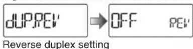
③ Push [V/M/C] to return to the frequency display.
Each receive and transmit frequency is shown in the table below, with the following configurations;
Input freq.: 145.300 MHz, Direction: - (down), Offset: 0.6 MHz
| Reversed | RX freq. TX | freq. |
| OFF | 145.300 MHz | 144.700 MHz |
| ON | 144.700 MHz | 145.300 MHz |
- "DUP-" or "DUP" blinks when the reverse duplex function is ON.
5 REPEATER AND DUPLEX OPERATIONS
■ Auto repeater function
The U.S.A. and Korean versions automatically use standard repeater settings (duplex ON/OFF, duplex direction, tone encoder ON/OFF) when the operating frequency falls within or outside of the general repeater output frequency range. The offset and repeater tone frequencies are not changed by the auto repeater function. Reset these frequencies, if necessary.
◇ Frequency range and offset direction
• U.S.A. version
| FREQUENCY RANGE SHIFT DIRECTION | |
| 145.200–145.495 MHz146.610–146.995 MHz | “DUP-” appears |
| 147.000–147.395 MHz | “DUP” appears |
| 442.000–444.995 MHz | “DUP” appears |
| 447.000–449.995 MHz | “DUP-” appears |
- Korean version
| FREQUENCY RANGE SHIFT DIRECTION |
| 439.000–440.000 MHz “DUP-” appears |
① While continuing to push [SET], turn the power ON to enter the Initial set mode.
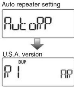
② Rotate [DIAL] to select the auto repeater set item, then rotate [VOL] to set the auto repeater setting.
U.S.A. version:
- "R1": Activates duplex only. (default)
- "R2": Activates duplex and tone.
- "OFF": Auto repeater function is turned OFF.
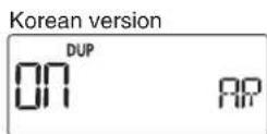
Korean version:
- "On" : Activates duplex and tone. (default)
- "OFF": Auto repeater function is turned OFF.
![[DIAL] [VOL] SET A](/content/2026/05/811798/images/f70b4f710899ebc993fd00cc1aa1a3f2a0584f05bd6c9178f379d36bb06434ca.jpg)
③Push [💡] to return to the frequency display.
REPEATER AND DUPLEX OPERATIONS
■ 1750 Hz tone
To access some European repeaters, the transceiver must transmit a 1750 Hz tone burst. For such repeaters, perform the following.
- This tone can be used as a 'Call signal' in countries out of Europe.
①Push[SET] to enter the Set mode.
②Rotate [DIAL] to select the DTMF key item, then rotate [VOL] to set to "t-CALL."
![[DIAL] [VOL] SET A V/M/C S.MW D DTMF key setting dtmF-t ↓ key dt t-CALL dt Tone call setting](/content/2026/05/811798/images/4dc12d9a6cea8303b27016c10c0d0d2fc7f392d9b06106bb1efc4cadde2d5e24.jpg)
③Push [V/M/C] to return to the frequency display.
④ Set the receive frequency (repeater output frequency).
⑤ Set the shift direction of the transmit frequency(-DUP or +DUP; see p. 26 for details.)
⑥While continuing to push [PTT], push MONI to transmit a 1750 Hz tone burst signal.
- If "OFF" appears, check the frequency offset or shift direction. (p. 26)
- The displayed frequency automatically changes to the transmit frequency (repeater input frequency).
⑦ Push and hold [PTT] to transmit.
⑧ Release [PTT] to receive.
⑨ Push and hold MONI to check whether the other station's transmit signal can be received directly or not, by listening on the repeater input frequency.
√ CONVENIENT! (For the IC-T70E only)
① Set the receive frequency(repeater output frequency).
② Set the shift direction of the transmit frequency(-DUP or +DUP; see p. 26 for details.)
③ Push [PTT] briefly, then push and hold [PTT] again for 1 to 2 sec. to transmit a 1750 Hz tone burst signal.
- If "OFF" appears, check the frequency offset or shift direction. (p. 26)
- The displayed frequency automatically changes to the transmit frequency (repeater input frequency).
④ Push and hold [PTT] to transmit; release to receive.

6
MEMORY/CALL CHANNELS
■ General description
The IC-T70A/T70E has 300 memory channels, and 2 call channels. Memory channels include 50 scan edge memory channels (25 pairs) to store often-used frequencies.
Also, 26 memory banks, A to Z, are available in each band for storing groups of frequencies, etc. Up to 100 channels can be assigned to a bank.
◇ Memory channel contents
The following information can be programmed into memory channels:
- Operating frequency (p. 20)
- Operating mode (p. 21)
- Duplexdirection(+DUP or -DUP) with a frequency offset (p. 26)
- Reverse duplex function ON/OFF (p. 26)
- Subaudible tone encoder (p. 24), tone squelch or DTCS squelch ON/OFF (p. 70)
- Subaudible tone frequency (p. 53), tone squelch frequency or DTCS code with polarity (p. 53)
- Scan skip setting (p. 46)
• Memory bank (p. 32)
• Memory name (p. 34)
- Tuning step (p. 19)
- Output power (p. 22)
■ Selecting a call channel
①Push [V/M/C] to select the call channel mode.
- Pushing[V/M/C] toggles between the VFO mode, the memory channel mode, call channel mode and weather channel mode*.
* Only the U.S.A. version transceiver.
② Rotate [DIAL] to select a desired call channel.
- "C0" and "C1" are selectable.
![[DIAL] V/M/C S.MW D](/content/2026/05/811798/images/66ad0e677ed16143c6f7a528f5695acd80cd6878f465d4d329d397b732591d97.jpg)
VHF band call channel
UHF band call channel
NOTE: Memory data can be erased by static electricity, electric transients, etc.
In addition, it can be erased by malfunction and during repairs. Therefore, we recommend that memory data be written down or be saved to a PC using the CS-T70 CLONING SOFTWARE.
■ Selecting a memory channel
◇ Using [DIAL]
①Push [V/M/C] to select the memory mode.
- Pushing[V/M/C] toggles between the VFO mode, the memory channel mode, call channel mode and weather channel mode*.
* Only the U.S.A. version transceiver.
② Rotate [DIAL] to select a desired memory channel.
- Only programmed channels are displayed.
![[DIAL] V/M/C 5.MW D](/content/2026/05/811798/images/245d28f0844573a827b2897a84570a71c911ef377aa31e286663fdec3348699c.jpg)
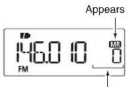
Rotate [DIAL] to select the memory channel.
◇ Using the Numeral keys
①Push [V/M/C] to select the memory mode.
- Pushing[V/M/C] toggles between the VFO mode, the memory channel mode, call channel mode and weather channel mode*. * Only the U.S.A. version transceiver.
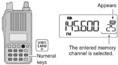
② Use the number keys to enter 3 digits to select a desired memory channel.
• The blank channels are also selectable.
• Example— selecting memory channel "25"
Push [V/M/C], then push [0], [2], [5].
6 MEMORY/CALL CHANNELS
■ Memory channel programming
①Push [V/M/C] to select the VFO mode.
② Set a desired frequency:
→ Push [BAND] to select a desired band.
Rotate [DIAL] to set a desired frequency.
→ Push the keypad keys directly to set a desired frequency. In this case, setting the band and frequency using [BAND] and [DIAL] are not required.
Set other data (e.g. frequency offset, duplex direction, tone squelch, etc.), if desired.
③ Push and hold S.MW for 1 sec. to enter the select memory write mode.
• 1 short and 1 long beep sounds.
- The "MR" icon and memory channel number blink.
④ Rotate [DIAL] to select a desired channel.
- Call channels (C0, C1), VFO and scan edge channels (0A/0b to 24A/24b), as well as regular memory channels, can be programmed in this way.
⑤ Push and hold S.MW for 1 sec. to program.
- 3 beeps sound.
- Memory channel number automatically increases when continuing to push S.MW for 1 sec. after programming.
NOTE: Push [H/M/L] to cancel the program and exit the select memory write mode before memory programming is finished.
[EXAMPLE]: Programming 145.440 MHz into memory channel 11 (a blank channel).
![[DIAL] V/M/C 5.MW D](/content/2026/05/811798/images/496212f8384163590a555512f6b9b00dc0aeeae2890d5eb928167bc106ac033f.jpg)
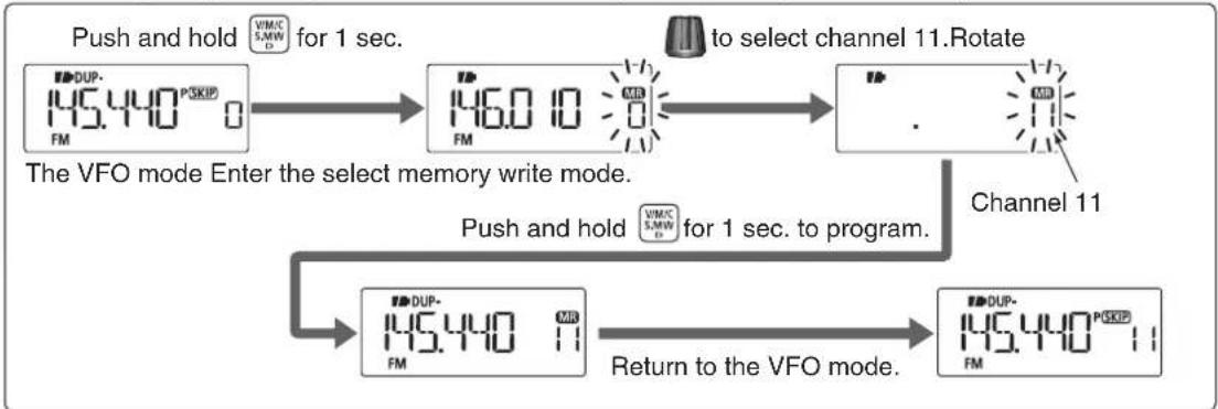
flowchart
graph TD
    A["Push and hold 1 sec."] --> B["145.440 PSkip FM"]
    B --> C["146.0 10 MB FM"]
    C --> D["to select channel 11. Rotate"]
    D --> E["145.440 11 MB FM"]
    E --> F["Return to the VFO mode."]
    F --> G["145.440 PSkip FM"]
    H["The VFO mode Enter the select memory write mode."] --> I["Push and hold 1 sec. to program."]
    I --> J["145.440 11 MB FM"]
    J --> K["Channel 11"]
■ Memory bank setting
The IC-T70A/T70E has a total of 26 banks (A to Z). Regular memory channels 0 to 249 and scan edge memory channels 0A to 24b are assigned to any desired bank for easy memory management.
①Push and hold S.MW for 1 sec. to enter the select memory write mode.
• 1 short and 1 long beep sounds.
- The "MR" icon and memory channel number blink.
② Rotate [DIAL] to select a desired memory channel.
③Push[SET] to select the "bAnk" item.
- The bank group and channel number are displayed if the selected memory channel has already been assigned to a bank.
![[DIAL] SET A V/M/C S.MW D DUP- 145.440 FM MR Push SET A 699T MR](/content/2026/05/811798/images/e01c00eee6fa8f756680af9d5ce6a6d10c6394a46ffbc90d1a39bc9c543b3c4d.jpg)
④ Rotate [DIAL] to select a desired bank group from "A" to "Z."
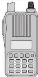
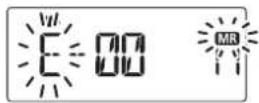
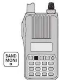
⑤ Push [BAND] to select the bank channel digit, then rotate [DIAL] to select the bank channel number from "00" to "99."
- Push [BAND] to toggle the bank group selection and bank channel selection.
natural_image
Illustration of a BAND MONI radio device with control panel and keypad (no text or symbols on device body)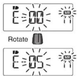
⑥ Push and hold S.MW for 1 sec. to assign the channel to the bank.
- Return to the previous indication before entering the select memory write mode.
6 MEMORY/CALL CHANNELS
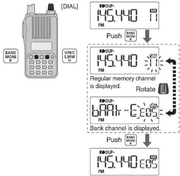
■ Memory bank selection
①Push [V/M/C] to select the memory mode.
②Push [BAND] to enter the bank selection mode.
③ Rotate [DIAL] to select a desired bank (A to Z), then push [BAND].
- Only programmed banks are displayed.
- Also regular memory channel can be selected.
flowchart
graph TD
    A["BAND MONI B"] --> B["+"]
    C["VIM/C S.M.W. D"] --> B
    B --> D["DUP-145.440 FM"]
    D --> E["Push"]
    E --> F["DUP-145.440 FM"]
    F --> G["Regular memory channel is displayed."]
    G --> H["Rotate"]
    H --> I["DUP-680 MHz FM"]
    I --> J["Bank channel is displayed."]
    J --> K["DUP-145.440 605 FM"]
    K --> L["Push"]
    L --> M["DUP-145.440 605 FM"]
④ Rotate [DIAL] to select the bank channel.
- Only programmed channels are displayed.
natural_image
Illustration of a walkie-talkie with a dial indicator and two speakers (no text or symbols on the device itself)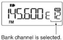
■ Programming memory/bank/scan name
Each memory channel can be programmed with an alphanumeric channel name for easy recognition as well as displayed independently by channel. Names can be a maximum of 6 characters.

NOTE: Scan name display can be turned ON or OFF in the Initial set mode. (p. 63)
①Push [V/M/C] to select the memory mode. ②Push and hold S.MW for 1 sec. to enter the select memory write mode.
• 1 short and 1 long beep sounds.
- The "MR" icon and memory channel number blink.
③ Rotate [DIAL] to select a desired memory channel.
- Select Call channels (C0 or C1) to program a call channel, or scan edge channels (0A/0b to 24A/24b) to program a scan name.
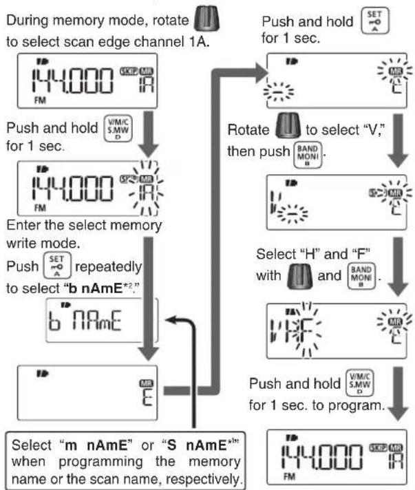
④Push [SET] repeatedly to select "b nAmE," "m nAmE" or "S nAmE" when programming the bank name, the memory name or the scan name, respectively.
⑤Push and hold [SET] for 1 sec. to enter the name programming mode.
• After selecting the name to be programmed, a cursor blinks for the first character.
⑥Rotate [DIAL] to select a desired character.
• The selected character blinks.
- Push [BAND] to move the cursor right; push [SET] to move the cursor left.
⑦ Repeat step ⑥ until a desired channel name is programmed.
⑧ Push and hold S.MW for 1 sec. to set the name and exit the channel name programming state.
- 3 beeps sound.

NOTE: Only one bank name can be programmed into each bank. Therefore, the previously programmed bank name will be displayed when bank name is selected. Also, the programmed bank name is assigned automatically to another bank channel.
◇ Usable characters
| A(A) | b(b) | C(C) | d(d) | E(E) | F(F) | G(G) | H(H) | I(I) | J(J) | K(k) | L(L) | m(m) |
| N(n) | O(O) | P(P) | Q(q) | R(R) | S(S) | T(t) | U(U) | V(V) | W(W) | X(Y) | Y(Z) | Z |
| 0(0) | 1(1) | 2(2) | 3(3) | 4(4) | 5(5) | 6(6) | 7(7) | 8(8) | 9(9) | |||
| + (+) | -(-) | = (=) | ¥ (*) | / (l) | [ ( ) | ] ( ) | I(:) | - (Space) |
6 MEMORY/CALL CHANNELS
■ Programming memory/bank/scan name (continued)
[EXAMPLE]: Programming the bank name "VHF" into the scan edge channel 1A
flowchart
graph TD
    A["During memory mode, rotate to select scan edge channel 1A."] --> B["Push and hold for 1 sec."]
    B --> C["Enter the select memory write mode. Push SET repeatedly to select "b nAmE*2." b" nAmE"]
    C --> D["Select "m nAmE" or "S nAmE*" when programming the memory name or the scan name, respectively."]
    D --> E["Push and hold for 1 sec. to program."]
    E --> F["Select "H" and "F" with BAND MONI."]
    F --> G["Rotate to select "V," then push BAND MONI."]
    G --> H["Push and hold for 1 sec."]
    H --> I["44,000 RPM"]
*1 S nAmE can be set for scan edge channels only.
^*2 b nAmE can be set for bank assigned channels only.
■ Selecting memory/bank name indication
During memory mode operation, either the programmed memory name or bank name can be displayed.
① While continuing to push [SET], turn the power ON to enter the Initial set mode.
② Rotate [DIAL] to select the memory name item, then rotate [VOL] to set the memory name display option.
- "OFF": Memory name display is turned OFF.
- "On" : Turns ON the memory name display. (default)
![[DIAL] [VOL] SET A Memory name setting NAmE ON Nm](/content/2026/05/811798/images/307b68b50aeb981e30fd11fa1c0ea8c99faf9b2e3bf3a333e9f9ccdbbdab5531.jpg)
③Push [💡] to return to the frequency display.
■ Display type
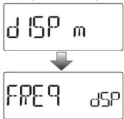
During memory mode operation, the transceiver has 3 display types to suit your operating style. Set the display type in the Initial set mode.
① While continuing to push [SET], turn the power ON to enter the Initial set mode.
② Rotate [DIAL] to select the display mode item, then rotate [VOL] to set the display type from "FREq," "CH" or "PRIV."
![[DIAL] [VOL] SET mO A](/content/2026/05/811798/images/03645260437be502306618ab0cdb688a4a618ebeba798bf4ec5adb3c12cd5344.jpg)
Display mode setting
③ Push [💡] to return to the frequency display.
"Frequency display"
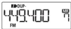
Displays the programmed frequency. (default)
"Channel number display"
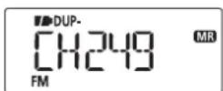
Displays the memory channel number. Only programmed memory channels are displayed, and modes other than the memory mode cannot be selected.
- When the channel number display type is selected, only the following functions can be performed.
- Scan function (p. 44) - Output power setting (p. 22)
- Monitor function (p. 17) - Key lock function (p. 21)
- DTMF transmit function (p. 66)
- The scan pause timer setting, the scan resume timer setting, the DTMF memory selection, the mic gain setting and the VOX gain setting in the Set mode.
"Private channel display"
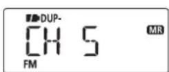
Displays the memory channel number. Only programmed memory channels 0 to 5 are displayed, and modes other than the memory mode cannot be selected.
- When the private channel display type is selected, only the following functions can be performed.
- Output power setting (p. 22) - Monitor function (p. 17)
- Key lock function (p. 21) - DTMF transmit function (p. 66)
6 MEMORY/CALL CHANNELS
■ Copying memory/call contents
This function transfers a memory channel's contents to VFO (or another memory/call channel). This is useful when searching for signals around a memory channel frequency and for recalling the frequency offset, subaudible tone frequency etc.
◇ Memory/call↔VFO
① Select the memory (call) channel to be copied.
→ Push [V/M/C] repeatedly to select the memory mode or the call channel mode, then rotate [DIAL] to select a desired channel.
② Push and hold S.MW for 1 sec. to enter the select memory write mode.
• 1 short and 1 long beep sounds.
- The "MR" icon and memory channel number blink.
③ Rotate [DIAL] to select "VFO."
④Push and hold S.MW for 1 sec. to write the selected channel contents to the VFO mode.
- Returns to the VFO mode automatically.
Pushing and holding S.MW for 2 seconds in step ② will also copy the memory contents to the VFO. In that case, steps ③ and ④ are not necessary.
◇ Memory/call→memory/call
① Select the memory (call) channel to be copied.
→ Push [V/M/C] repeatedly to select the memory mode or the call channel mode, then rotate [DIAL] to select a desired channel.
②Push and hold S.MW for 1 sec. to enter the select memory write mode.
• 1 short and 1 long beep sounds.
- The "MR" icon and memory channel number blink.
- Do not hold S.MW for more than 2 seconds. Otherwise the memory contents will be copied to the VFO mode.
③ Rotate [DIAL] to select the target memory (call) channel.
④ Push and hold S.MW for 1 sec. again to copy.

flowchart
graph LR
    A["Push and hold for 1 sec."] --> B["Memory mode 11: 145.440 FM"]
    B --> C["Enter the select memory write mode."]
    C --> D[""VFO" is selected."]
    D --> E["Return to the VFO mode."]
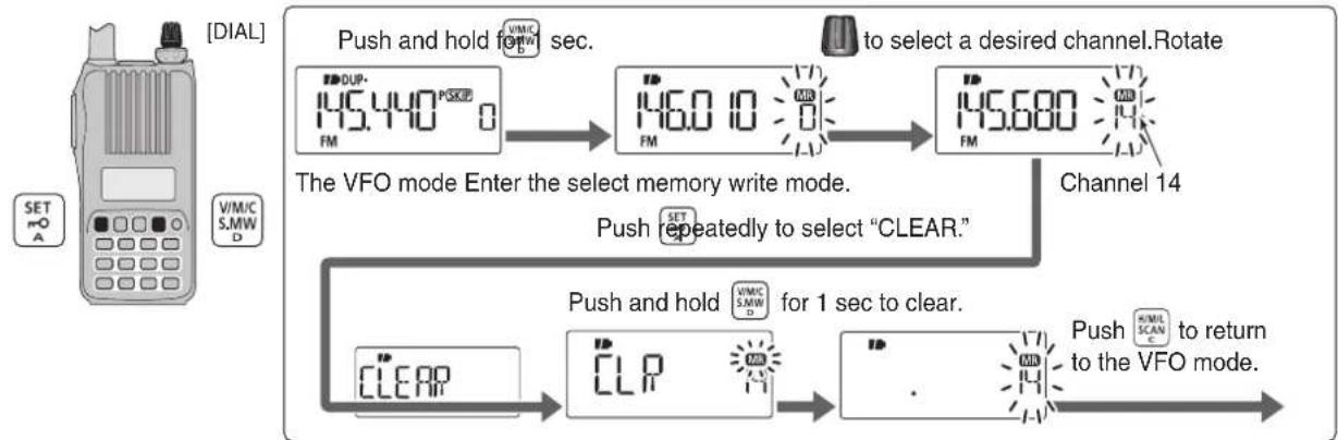
■ Memory clearing
Contents of programmed memories can be cleared (erased), if desired.
①Push and hold S.MW for 1 sec. to enter the select memory write mode.
• 1 short and 1 long beep sounds.
- The "MR" icon and memory channel number blink.
- Do not hold S.MW for more than 2 seconds. Otherwise the memory contents will be copied to the VFO mode.
② Rotate [DIAL] to select a desired memory channel to be cleared.
③ Push [SET] repeatedly to select "CLEAR."
④Push and hold S.MW for 1 sec. to clear the contents.
- 3 beeps sound.
• The cleared channel changes into a blank channel
- Return to the select memory write mode. Memory channel number blinks.
⑤ Push [H/M/L] to exit the select memory write mode.

NOTE: Be careful!— the contents of cleared memories CANNOT be recalled.
[EXAMPLE]: Clearing memory channel 14.
flowchart
graph TD
    A["SET A"] --> B["145.440*0"]
    B --> C["146.0 10"]
    C --> D["145.680"]
    D --> E["Channel 14"]
    E --> F["Push and hold for 1 sec to clear."]
    F --> G["CLP"]
    G --> H["Push to return to the VFO mode."]
    H --> I["Clear"]
    I --> J["the VFO mode Enter the select memory write mode."]
    J --> K["to select a desired channel. Rotate"]
    K --> L["the VFO mode to select “CLEAR.”"]
    L --> M[" sustained to select the VFO mode."]
    M --> N[" sustained to select the VFO mode."]
    N --> O[" sustained to select the VFO mode."]
6 MEMORY/CALL CHANNELS
■ Erasing/transferring bank contents
The bank contents of programmed memory channels can be cleared or reassigned to another memory bank.

INFORMATION: Even if the memory bank contents are cleared, the memory channel contents still remain programmed.
① Select a desired bank's contents to be transferred or erased from the bank. (p. 33)
→ Push [BAND] to enter the memory bank selection mode.
→ Rotate [DIAL] to select a desired memory bank group, then push [BAND].
→ Rotate [DIAL] to select the bank channel.
![[DIAL] BAND MONI B V/M/C S.MW D DUP- 145.440 E05 FM](/content/2026/05/811798/images/7ee715b77862fa5b978365cdbee07acfaf6201d367a1bdfda003245b7dbe8257.jpg)
② Push S.MW for 1 sec. to enter the select memory write mode.
• 1 short and 1 long beep sounds.
- Automatically displays the original memory channel number, and then the "MR" icon and memory channel number blink.
- Do not hold S.MW for more than 2 seconds. Otherwise the memory contents will be copied to the VFO.
③Push [SET] repeatedly to select "bAnk."

④Push [BAND] to toggle the bank channels selection or the bank group selection.
⑤ Rotate [DIAL] to select a desired bank group or channel to be transferred.
Or, select the “-- -- -- --” display when erasing the contents from the bank.
![[DIAL] BAND MONI B V/M/C S.MW D](/content/2026/05/811798/images/ecfe8c20583a3e6e627ad8f06aa70c482ddd7e6680307d81313eefeb1ea16f12.jpg)
To transfer the bank contents to ch 11 in Bank b.
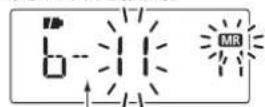
Bank channel is displayed. To erase
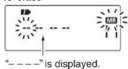
⑥ Push S.MW for 1 sec. to erase/transfer the bank contents.
SCAN OPERATION
7
Scan types
Scanning automatically searches for signals and makes it easier to locate new stations for contact or listening purposes.
FULL SCAN (p. 42)
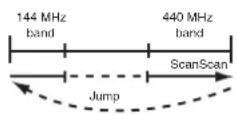
Repeatedly scans all frequencies over the entire band. Some frequency ranges are not scanned, depending on the frequency coverage of the transceiver's version.
PROGRAMMED SCAN (p. 42)
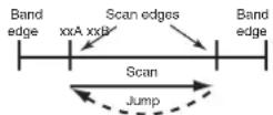
Repeatedly scans between two user-programmed frequencies. Used to check for frequencies within a specified range, such as repeater output frequencies, etc.
PROGRAMMED LINK SCAN (pp. 42, 57)
Repeatedly scans user-programmed frequencies selected in the "P-LInk" item in the Set mode.
SELECTED BAND SCAN (p. 42)
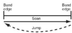
Repeatedly scans all frequencies over the entire selected band.
FREQUENCY/MEMORY SKIP FUNCTION
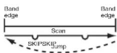
Skips unwanted frequencies or channels that inconveniently stop scanning.
This setting can be turned ON or OFF in the select memory write mode. (p. 46)
The frequency skip scan function can be turned ON or OFF in the Set mode. When this function is set to ON, the specified frequencies are skipped during VFO scan. (p. 55)
- The "P" icon appears in the VFO mode.
7 SCAN OPERATION
■ Scan types (continued)
MEMORY (SKIP) SCAN (p. 44)
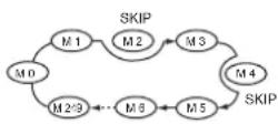
Repeatedly scans memory channels, except those set as skip channels.
Skip channels can be turned ON or OFF in the select memory write mode. (p. 46)
ALL/SELECTED BANK SCAN (p. 45)
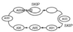
Repeatedly scans all bank channels or selected bank channels. The skip scan is also available.
DUPLEX SCAN (pp. 42, 44)
During duplex scan operation, repeatedly scans the transmit and receive frequencies of the duplex channel you are operating on.
BAND MEMORY (SKIP) SCAN (p. 44)
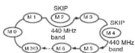
Repeatedly scans memory channels in the same band as the band currently displayed.
Example: While scanning the 144 MHz band
BANK-LINK SCAN (pp. 45, 46)
Repeatedly scans bank channels selected in the "b-Link" item in the Set mode.
SCAN OPERATION
■ Full/band/programmed scan
①Push [V/M/C] to select the VFO mode.
- Push[BAND] to select a desired frequency band.
② Set the squelch level.
③ Push and hold SCAN for 1 sec. to enter the scan type selection mode.
④ Rotate [DIAL] to select a desired scanning type.
- Select "ALL" for full scan, "bAnd" for band scan, "P-LInk x" for programmed link scan (x=0 to 9), "PROGxx" for programmed scan (xx=0 to 24; only programmed scan edge numbers are displayed), "dUP" (appears only when duplex operation is set) for a duplex scan.
![[DIAL] H/M/L SCAN C V/M/C S/MW D 145.500*SEP 18 FM Push and hold for 1 sec. H/M/L SCAN c Rotate Full scan ALL FM Programmed scan PROG 0 FM Selectable from "0" to "24" if programmed. (p. 43) Band scan BAND FM Duplex scan dup FM Programmed link scan P-L INr 0 FM Selectable from "0" to "9" See page 57 for details of the programming.](/content/2026/05/811798/images/fe1be14a86c28fb36b6efb5013007ee35cd71b3a37f10d9a6c1b147a50f5f579.jpg)
⑤ Push SCAN to start the scan.
- The scan pauses when a signal is received.
- Rotate [DIAL] to change the scanning direction. This also resumes scanning.
- Push [V/M/C] to stop the scan.
- Push[BAND] to change the band during band scan, or change the scan edge during programmed scan/program link scan.
- While continuing to push SCAN in step ③, rotate [DIAL] to select a desired scanning type, then release the key also starts the scan.
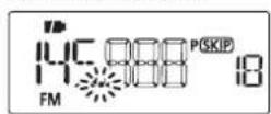
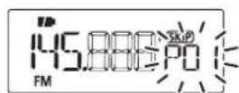
During full/band scan During programmed scan
The scan link name or scan name can be displayed instead of "P-LInk x" for program link scan (x=0 to 9), "PROGxx" for programmed scan (xx=0 to 24) when scan link name or scan name is programmed and set to ON in the Initial set mode.
Scan link name or scan name is not displayed during scan.
7 SCAN OPERATION
■ Scan edges programming
Scan edges can be programmed in the same manner as memory channels. Scan edges are programmed into scan edge memory channels, 0A/0b to 24A/24b.
①Push [V/M/C] to select the VFO mode.
② Set a desired frequency:
→ Push [BAND] to select a desired band.
→ Rotate [DIAL] to set a desired frequency.
→ Program different frequencies in “*A” and “*b.”
Set other data(e.g. frequency offset, duplex direction, tone squelch, etc.), if desired.
③ Push and hold S.MW for 1 sec. to enter the select memory write mode.
• 1 short and 1 long beep sounds.
- The “MR” icon and memory channel number blink.
④ Rotate [DIAL] to select a desired programmed scan edge channel from 0A to 24A.
⑤ Push and hold S.MW for 1 sec. to program.
- 3 beeps sound.
- The other scan edge channel "b," 0b to 24b, is automatically selected when continuing to push S.MW after programming.
⑥ To program a frequency for the other pair of scan edges, 0b to 24b, repeat steps ② and ⑤.
- If the same frequency is programmed into a pair of scan edges, programmed scan will not function.
![[DIAL] V/M/C S.MW D](/content/2026/05/811798/images/ea011fc9a57ed16e92e0dcb9485047e97accc5c653d76840bea9ffb01ea80b5c.jpg)
[EXAMPLE]: Programming 145.300 MHz into scan edges 3A.
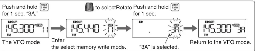
flowchart
graph LR
    A["Push and hold for 1 sec. "3A.""] --> B["to selectRotate"]
    B --> C["Push and hold for 1 sec. "3A""]
    C --> D["Return to the VFO mode."]

    subgraph "3A" is selected.
        E["3A"] --> F["DUP-145.300 PSkip 3A"]
    end
SCAN OPERATION
■ Memory scan

IMPORTANT!: To perform a memory scan, 2 or more memory channels MUST be programmed, otherwise the scan will not start.
①Push [V/M/C] repeatedly to select the memory mode.
② Set the squelch level.
③ Push and hold SCAN for 1 sec. to enter the scan type selection mode.
④ Rotate [DIAL] to select a desired scanning type.
- "ALL" for all memory scan, "bAnd" for band memory scan, "dUP" (appears only when duplex operation is set) for duplex scan.
![[DIAL] H/M/L SCAN C V/M/C S.MW D](/content/2026/05/811798/images/808de967fd0ea1881c921213ba874860e1fca84ab3e72f2830a54ecdaf4b3b90.jpg)
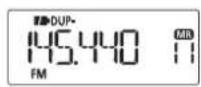
Push and hold for 1 sec.


All memory scan
Duplex scan
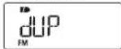
Band memory scan
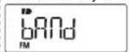
⑤ Push SCAN to start the scan.
- The scan pauses when a signal is received.
- Rotate [DIAL] to change the scanning direction. This also resumes scanning.
- Push [V/M/C] to stop the scan.
- While continuing to push SCAN in step ③, rotate [DIAL] to select a desired scanning type, then release the key also starts the scan.
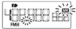
During memory scan
7 SCAN OPERATION
■ Memory bank scan

IMPORTANT!: To perform a memory bank scan, 2 or more bank channels MUST be programmed, otherwise the scan will not start.
① Select the memory bank mode.
→ Push [V/M/C] to select the memory mode.
→ Push [BAND] to enter the memory bank selection mode.
→ Rotate [DIAL] to set a desired bank (A to Z), then push [BAND].
② Set the squelch level.
③ Push and hold SCAN for 1 sec. to enter the scan type selection mode.
![[DIAL] BAND MONI B H/M/L SCAN C V/M/C S.MW D](/content/2026/05/811798/images/db89cedccde01b1a332c3c8915529911206c51f45e0866d153a82232363d850a.jpg)
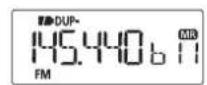

All bank scan
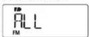
Bank scan
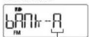
Selectable from "A" to "Z," if programmed. (p. 32)
Bank link scan
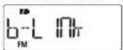
Duplex scan
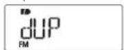
See page 56 for details of the bank link programming.
④ Rotate [DIAL] to select a desired scanning type.
- Select "ALL" for all bank scan, "b-LInk" for bank link scan or "bAnk-x" for bank scan (x= A to Z; only programmed bank groups are displayed.), "dUP" (appears only when duplex operation is set) for duplex scan.
⑤Push SCAN to start the scan.
• The scan pauses when a signal is received.
- Rotate [DIAL] to change the scanning direction. This also resumes scanning.
- Push [V/M/C] to stop the scan.
- Push[BAND] to change the bank during a bank scan.
- While continuing to push SCAN in step ③, rotate [DIAL] to select a desired scanning type, then release the key also starts the scan.
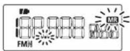
During all bank/bank link scan
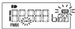
During bank scan

Memory bank scan skips any memory channels in the selected bank that are set to "SKIP" or "PSKIP."
Memory bank scan stops at the first channel when all channels in a bank are set to "SKIP" or "PSKIP."
SCAN OPERATION
■ Skip channel/frequency setting
Memory channels can be set to be skipped during memory skip scan. In addition, memory channels can be set to be skipped during both memory skip scan and frequency skip scan. This is useful to speed up the scan rate.
① Select a memory channel:
→ Push [V/M/C] to select the memory mode.
Rotate [DIAL] to select a desired channel to be a skip channel/frequency.
![[DIAL] V/M/C S.MW D](/content/2026/05/811798/images/e195e51e33b4ac50f67580ea4c912ae65820d61ff6c5fbe5a4a4a0561c179400.jpg)
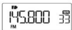
② Push and hold S.MW for 1 sec. to enter the select memory write mode.
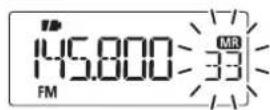
③ Push [SET] repeatedly to select the "SkIP" item.
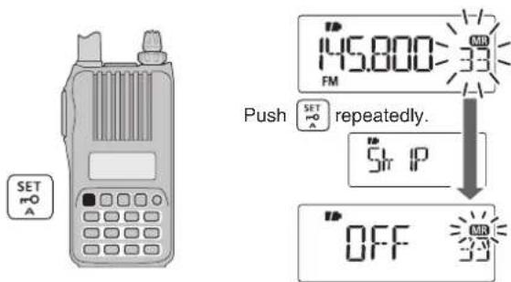
④ Rotate [DIAL] to select the skip condition from "SkIP," "PSkIP" or "OFF" for the selected channel.
- PSkIP: The channel is skipped during a memory/bank scan, and the programmed frequency is skipped during VFO scan, such as a programmed scan.
- SkIP : The channel is skipped during a memory or bank scan.
• OFF : The channel is scanned during any scan.
⑤ Push and hold S.MW for 1 sec. to store the skip condition into memory.
- “SKIP” or “P SKIP” icon appears, depending on the skip selection in step ④.
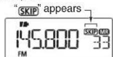
Skip channel setting
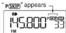
Program skip setting
7 SCAN OPERATION
■ Scan resume setting
◇ Scan pause timer
The scan pauses while receiving signals, depending on the scan pause time. It can be set from 2 to 20 seconds or unlimited.
①Push[SET] to enter the Set mode.
② Rotate [DIAL] to select the scan pause timer item.
③ Rotate [VOL] to select a desired scan pause time from 2–20 seconds (2 seconds steps) or "HOLd."
- “2”—“20” : Scan pauses for 2–20 seconds while receiving a signal.
- "HOLd": Scan pauses on a received a signal until it disappears.

④ Push [V/M/C] to return to the frequency display.
◇ Scan resume timer
The scan restarts after the signal disappears, depending on the resume time. It can be set from 0–5 seconds or unlimited.
①Push[SET] to enter the Set mode.
② Rotate [DIAL] to select the scan resume timer item.
③ Rotate [VOL] to select a desired scan resume time from 0–5 seconds (1 second steps) or "HOLd."
- “0” : Scan restarts immediately after the signal disappears.
- “1”-“5” : Scan restarts 1–5 seconds after the signal disappears.
- "HOLD": Scan remains paused on the received signal according to the scan pause timer even if it disappears. Rotate [DIAL] to manually resume the scan.

④Push [V/M/C] to return to the frequency display.
The scan resume timer must be set shorter than the scan pause timer, otherwise this timer will not be activated.
PRIORITY WATCH
■ Priority watch types
While operating on a VFO frequency or scanning, the priority watch checks for signals on the set priority frequency every 5 seconds. The transceiver has four priority watch types to suit your needs.
The watch resumes according to the selected scan resume setting. See page 47 for details.

NOTE: If the pocket beep function is activated, the transceiver automatically selects the tone squelch/DTCS squelch function when priority watch starts.
◇ About priority beep function
When receiving a signal on the priority frequency, you can be alerted with beeps and a blink “((*)” icon. This function can be activated when the priority watch function is turned ON.
MEMORY/CALL CHANNEL WATCH
While operating on a VFO frequency, priority watch checks for a signal on the selected channel every 5 seconds.
- A memory channel with skip information can be watched.
5 seconds
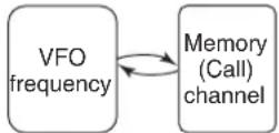
MEMORY SCAN WATCH
While operating on a VFO frequency, priority watch checks for signals on each memory channel in sequence.
- The memory skip function and/or memory bank scan is useful to speed up the scan.
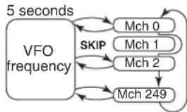
flowchart
graph TD
    A["VFO frequency"] --> B["Mch 0"]
    A --> C["Mch 1"]
    A --> D["Mch 2"]
    A --> E["Mch 249"]
    B --> F["5 seconds"]
    C --> F
    D --> F
    E --> F
    F --> G["SKIP"]
    G --> A
VFO SCAN WATCH
While scanning in the VFO mode, priority watch checks for signals on the selected channel every 5 seconds.
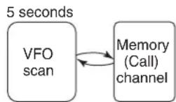
VFO/MEMORY SCAN WATCH
While scanning in the VFO mode, priority watch checks for signals on each memory channel in sequence.
- The memory skip function and/or memory bank scan is useful to speed up the scan.
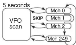
flowchart
graph TD
    A["VFO scan"] --> B["Mch 0"]
    A --> C["Mch 1"]
    A --> D["Mch 2"]
    A --> E["Mch 249"]
    B --> F["5 seconds"]
    C --> F
    D --> F
    E --> F
    F --> G["SKIP"]
    G --> A
8
PRIORITY WATCH
■ Priority watch operation
◇ Memory/call channel and memory scan watch
① Select the VFO mode, then set an operating frequency.
② Select the channel(s) to be watched.
For memory channel watch:
Select a desired memory channel.
For call channel watch:
Select a desired call channel.
For memory scan watch:
→ Select the memory mode, or a desired bank group.
→ Push and hold SCAN for 1 sec. to enter the scan type selection mode.
Rotate [DIAL] to select a desired scan type, then push SCAN again to start the memory/bank scan.
③Push[SET] to enter the Set mode.
④ Rotate [DIAL] to select the priority watch set item, then rotate [VOL] to select "On."
- Select "bELL" if the priority beep function is desired.

⑤ Push [V/M/C] to exit the Set mode and start the watch.
- The "PRIO" icon appears.
- The transceiver checks the memory/bank channel(s) or call channel every 5 seconds.
- The watch resumes according to the selected scan resume setting. (p. 47)
⑥Push[V/M/C] to cancel the watch.
- During priority watch

Monitors VFO frequency for 5 seconds.
Pauses on a memory or call channel when a signal is received.
• During priority watch with priority beep

A beep tone sounds and “(•)” icon blinks when a signal is received on a memory or call channel.
◇ VFO scan watch
① Select the channel(s) to be watched.
For memory channel watch:
Select a desired memory channel.
For call channel watch:
Select a desired call channel.
For memory scan watch:
→ Select the memory mode, or a desired bank group.
→ Push and hold SCAN for 1 sec. to enter the scan type selection.
Rotate [DIAL] to select a desired scan type, then push SCAN again to start memory/bank scan.
②Push[SET] to enter the Set mode.
③Rotate [DIAL] to select the priority watch set item, then rotate [VOL] to select "On."
- Select "bELL" if the priority beep function is desired.

④ Push [V/M/C] to exit the Set mode and start the watch.
- "PRIO" icon appears.
⑤ Push and hold SCAN for 1 sec. to enter scan type selection mode.
⑥ Rotate [DIAL] to select a desired scan type from "ALL," "bAnd," "P-LInk x (x=0-9)," "PROGxx (xx=0-24)" and "dUP."
⑦ Push SCAN to start the VFO scan watch.
- The transceiver checks the memory/bank channel(s) or call channel every 5 seconds.
- The watch resumes according to the selected scan resume setting. (p. 47)
⑧Push[V/M/C] to cancel the watch.
• During priority watch
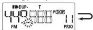
Searches VFO frequencies for 5 seconds.
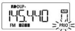
Pauses on a memory or call channel when a signal is received.
• During priority watch with priority beep

A beep tone sounds and “(i•)” icon blinks when a signal is received on a memory or call channel.

9
SET MODES
General
◇ Entering and using the Set mode
The Set mode is used to change the settings of the transceiver's functions.
① Push [SET] to enter the Set mode.
② Rotate [DIAL] to select the desired set item.
③ Rotate [VOL] to set the desired value or option.
④ Push [V/M/C] to return to frequency display, or repeat steps ② and ③ to set other items.
![[DIAL] [VOL] SET A V/M/C S.MW D](/content/2026/05/811798/images/52ee5240168643caee44dd6926071521476204b078dcbbe38f08d9ad5265da3a.jpg)
◇ Entering and using the Initial set mode
The Initial set mode can be accessed at power ON, and allows you to set seldom-changed settings to suit your preference and operating style.
① Push and hold 🔒 for 1 sec. to turn the power OFF.
② While continuing to push [SET], turn the power ON to enter the Initial set mode.
③ Rotate [DIAL] to select the desired set item.
④ Rotate [VOL] to set the desired value or option.
⑤Push[ 🔊] to return to the frequency display, or repeat steps ② and ③ to set other items.
![[DIAL] [VOL] SET A](/content/2026/05/811798/images/86873725e61bee159232f6b59fafdbe68908b8f7545409da1f6291ac5250e697.jpg)
Set mode item list
| Guidance Item | Page | |
| P EONE | Repeater tone frequency | p. 53 |
| C EONE | TSQL frequency | p. 53 |
| codE | DTCS code | p. 53 |
| dtCS P | DTCS polarity | p. 53 |
| tS | Tuning step | p. 54 |
| OFFSET | Frequency offset | p. 54 |
| dupREV | Reverse duplex function | p. 54 |
| modE | Operating mode | p. 54 |
| WKALE | Weather alert | p. 54 |
| PP IO | Priority watch | p. 55 |
| PAUSE | Scan pause timer | p. 55 |
| RESUME | Scan resume timer | p. 55 |
| PSK IP | Program skip function | p. 55 |
| b-L INR | Bank link | p. 56 |
| P-L INR | Programmed scan link | p. 56 |
| dtmF-t | DTMF TX key | p. 58 |
| dtmF | DTMF memory setting | p. 58 |
| mic G | MIC gain | p. 58 |
| VOX | VOX function | p. 58 |
| VOX LV | VOX gain | p. 58 |
| VOXdLY | VOX delay | p. 59 |
| VOXtot | VOX time-out timer | p. 59 |
Initial set mode item list
| Guidance Item | Page | |
| mic S | Microphone simple mode | p. 59 |
| AP OFF | Auto power OFF | p. 59 |
| LIGHT | Display backlight | p. 60 |
| bEEPLV | Beep output level | p. 60 |
| AutoPP | Auto repeater | p. 60 |
| PSAVE | Power save | p. 61 |
| VOLT | Voltage indication | p. 61 |
| dtmF-S | DTMF speed | p. 61 |
| Cont | LCD contrast | p. 62 |
| Ptt Lr | PTT lock | p. 62 |
| Lr Out | Busy lockout | p. 62 |
| tot | Time-out timer | p. 62 |
| S9L dL | Squelch delay | p. 62 |
| mon | Monitor key action | p. 63 |
| d IRL S | Dial speed acceleration | p. 63 |
| NAmE | Memory name | p. 63 |
| S NAmE | Scan name | p. 63 |
| d ISP m | Display type | p. 64 |
| HS SEL | HS-95 selection | p. 64 |
| AutoLP | Auto low power | p. 64 |
9
SET MODES
■ Set mode items
◇ Repeater tone frequency (R TONE)
Selects one of 50 subaudible tone frequencies used to access the repeaters.
• 67.0–254.1 Hz (default: 88.5 Hz)

◇ TSQL frequency (C TONE)
Selects one of the tone frequencies for tone squelch or the pocket beep function.
• 67.0–254.1 Hz (default: 88.5 Hz)

• Available subaudible tone frequencies
| 67.0 | 79.7 | 94.8 | 110.9 | 131.8 | 156.7 | 171.3 | 186.2 | 203.5 | 229.1 |
| 69.3 | 82.5 | 97.4 | 114.8 | 136.5 | 159.8 | 173.8 | 189.9 | 206.5 | 233.6 |
| 71.9 | 85.4 | 100.0 | 118.8 | 141.3 | 162.2 | 177.3 | 192.8 | 210.7 | 241.8 |
| 74.4 | 88.5 | 103.5 | 123.0 | 146.2 | 165.5 | 179.9 | 196.6 | 218.1 | 250.3 |
| 77.0 | 91.5 | 107.2 | 127.3 | 151.4 | 167.9 | 183.5 | 199.5 | 225.7 | 254.1 |

The transceiver has 50 tone frequencies, and consequently their spacing is narrow compared with units having 38 tones. Therefore, some tone frequencies may receive interference from adjacent tone frequencies.
◇ DTCS code (CODE)
Selects one of 104 DTCS (both encoder/decoder) codes.
• 023–754 (default: 023)

• Available DTCS codes
| 023 | 054 | 125 | 165 | 245 | 274 | 356 | 445 | 506 | 627 | 732 |
| 025 | 065 | 131 | 172 | 246 | 306 | 364 | 446 | 516 | 631 | 734 |
| 026 | 071 | 132 | 174 | 251 | 311 | 365 | 452 | 523 | 632 | 743 |
| 031 | 072 | 134 | 205 | 252 | 315 | 371 | 454 | 526 | 654 | 754 |
| 032 | 073 | 143 | 212 | 255 | 325 | 411 | 455 | 532 | 662 | |
| 036 | 074 | 145 | 223 | 261 | 331 | 412 | 462 | 546 | 664 | |
| 043 | 114 | 152 | 225 | 263 | 332 | 413 | 464 | 565 | 703 | |
| 047 | 115 | 155 | 226 | 265 | 343 | 423 | 465 | 606 | 712 | |
| 051 | 116 | 156 | 243 | 266 | 346 | 431 | 466 | 612 | 723 | |
| 053 | 122 | 162 | 244 | 271 | 351 | 432 | 503 | 624 | 731 |
◇ DTCS polarity (DTCS P)
Selects the DTCS polarity between “both n” (TX/RX: normal), “tn-RR” (TX: normal, RX: reverse), “tR-Rn” (TX: reverse, RX: normal) and “both R” (TX/RX: reverse). (default: both n)
The DTCS code's polarity for transmitting or receiving can be independently set by this item.

◇ Tuning step (TS)
Selects the tuning step between 5, 10, 12.5, 15, 20, 25, 30, 50, 100, 125 and 200 kHz for the dial operation.

5.0 kHz tuning step
The default value may differ, depending on the selected frequency band (before accessing the Set mode) and the transceiver version.
◇ Frequency offset (OFFSET)
Sets the frequency offset for duplex operation (repeater) within the range of 0 to 59.995 MHz.

0.600 MHz setting
The default value may differ, depending on the selected frequency band (before accessing the Set mode) and transceiver version.
The selected tuning step in the VFO mode is used when setting the frequency offset.
◇ Reverse duplex function (DUP.REV)
Turns the reverse duplex function ON or OFF. (default: OFF)

Reverse function is OFF
◇ Operating mode (MODE)
Sets the operating mode between "WIdE" (FM mode) and "nARROW" (FM-N mode). (default: WIdE)

FM mode setting
◇ Weather alert (WX.ALT)
U.S.A. version only
Turns the weather alert function ON or OFF. (p. 72) (default: OFF)

9 SET MODES
◇ Priority watch (PRIO)
Activates priority watch or priority watch with priority beep. (default: OFF)
• OFF : The priority watch is turned OFF.
- On : The transceiver checks the memory channel frequency every 5 seconds.
- bELL: The transceiver checks the memory channel frequency every 5 seconds. You can be alerted with beeps and a blinking “((•))” icon.

◇ Scan pause timer (PAUSE)
Selects the scan pause time. When receiving signals, the scan pauses according to the scan pause timer. (default: 10)
- 2–20 : Scan pauses for 2–20 seconds while receiving a signal in 2 seconds steps.
- HOLd : Scan pauses on a received signal until it disappears.

◇ Scan resume timer (RESUME)
Selects the scan resume time of a pause after the received signal disappears. (default: 2)
- 0 : Scan resumes immediately after the received signal disappears.
• 1–5 : Scan pauses 1–5 seconds after the received signal disappears. - HOLd : Scan remains paused on the received signal according to the scan pause timer, even if it disappears. Rotate [DIAL] to manually resume the scan.

The scan resume timer must be set shorter than the scan pause timer (previous item), otherwise this timer will not be activated.
◇ Program skip scan (P SKIP)
Turns the programmed skip scan function ON or OFF for a VFO scan operation (full scan, programmed scan, etc.). (default: On)

◇ Memory bank link function (B-LINK)
Turns the memory bank link function ON (default) or OFF. The link function provides continuous bank scan, scanning all channels in the selected banks during bank scan.
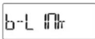
• Bank link setting
① Push and hold [SET] for 1 sec. to enter the bank link setting.

② Rotate [DIAL] to select the bank that you want to change the link setting.
③Rotate[VOL] to select the option.
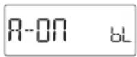
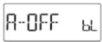
Setting is OFFSETting is ON
④ Rotate [DIAL] to select next bank and repeat steps ② and ③, or push [BAND] to exit the BANK link setting.
◇ Program scan link function (P-LINK)
Sets the program scan link function. During program scan, link function performs a continuous program scan in the selected program scan number during program scan.
Default settings for LInk0 to LInk9;
PROG 1 to PROG 24 are linked, but PROG 0 is not linked.

- Confirming program scan link
① Rotate [VOL] to select the program scan link number that you want to confirm.
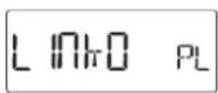
② Push and hold [SET] for 1 sec. to enter the program scan link setting.
- "Link"appears.
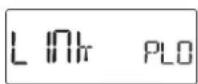
③ Push and hold [SET] for 1 sec., then rotate [DIAL] to confirm the linked program scans.
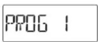
④Push[BAND] twice to exit the program scan link setting.
9 SET MODES
- Program scan link setting
① Rotate [VOL] to select the program scan link number that you want to change.
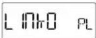
② Push and hold [SET] for 1 sec. to enter the program scan link setting.
- "Link"appears.
③ Rotate [DIAL] to select the option, "Add" or "CLEAR."
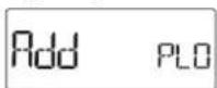
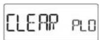
④ Push and hold [SET] for 1 sec., then rotate [DIAL] to select the desired program scan.
- When "Add" is selected in step ③, only non-linked program scans are displayed. When "CLEAR" is selected in step ③, only linked program scans are displayed.
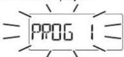
⑤ Push and hold [SET] for 1 sec. to set the program scan link setting.
⑥ Repeat steps ④ and ⑤ to add or clear the program scan to or from the link, or push [BAND] to exit the program link scan setting.
⑦ After pushing [BAND], rotate [DIAL] to save the setting.
• Program scan link name programming
① Rotate [VOL] to select the program scan link number for which you want to program a name.
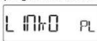
② Push and hold [SET] for 1 sec. to enter the program scan link setting.
- "Link"appears.
③Rotate[DIAL] to select "nAmE."
④ Push and hold [SET] for 1 sec. to enter the name programming.

⑤ Rotate [DIAL] to select the desired character, number, symbol or space; push [BAND] or [SET] to move the cursor right or left, respectively.
⑥When the cursor is on the 6th digit, push [BAND] to program the scan link name and exit the setting.

⑦ Push [BAND] to exit the program link setting.
⑧ Repeat steps from ① to ⑦ to program the program link scan name, or push [V/M/C] to exit the Set mode.
◇ DTMF TX key (DTMF-T)
Selects the method to transmit a DTMF code sequence. While continuing to push [PTT], push one of the keys, [0] to [9], A, B, C, D, [*] (indication: E) or [#] (indication: F).
- KEy : Transmits the appropriate DTMF code assigned to the key. (default)
- mEm : Transmits the programmed DTMF code sequence in the DTMF memory channel assigned to the key.
- t-CALL : No DTMF code can be transmitted. However, while continuing to push [PTT], push MONI to transmit a 1750 Hz tone burst signal.

◇ DTMF memory (DTMF)
Program the DTMF memory channels. (p. 65)

flowchart
graph LR
    A["dtmF"] --> B["......do"]
◇ Microphone gain (MIC G)
Sets the microphone gain to between 1 and 4 to suit your preference. Higher values make the microphone more sensitive to your voice. (default: 2)

NOTE: When using the VOX function, we recommend setting the microphone gain to 3. However, you can adjust it to suit your operating environment, including the headset performance you are using.
◇ VOX function (VOX)
Turns the VOX function ON or OFF. (p. 80) (default: On)

◇ VOX gain (VOX LV)
Sets the VOX gain to between 1 and 10. Higher values make the VOX function more sensitive to your voice.
To turn the VOX function OFF, select "OFF." (default: 5)

NOTE: Set the microphone gain before setting the VOX gain. See page 80 for details of the VOX function.
9 SET MODES
Sets the VOX delay to between "0.5," "1.0," "1.5," "2.0," "2.5" and "3.0" seconds.
The VOX delay is the amount of time the transmitter stays ON after you stop speaking. (default: 0.5)

◇ VOX time-out timer (VOXTOT)
Sets the VOX time-out timer to between 1, 2, 3, 4, 5, 10 and 15 minutes to prevent accidental prolonged transmission for the VOX function.
To turn the function OFF, select "OFF." (default: 3)

The VOX time-out timer must be set shorter than the time-out timer, otherwise this timer will not be activated.
■ Initial set mode items
◇ Microphone simple mode (MIC S)
Microphone simple mode is used to assign the essential operations to the four switches (S1 to S4) on the remote control unit. (p. 82)
- Simple
• nORm-1 (default)
• nORm-2

◇ Auto power OFF (AP OFF)
The transceiver can turn itself OFF automatically after a specified time. Activating a control restarts the time-out. The transceiver beeps before turning OFF.
30, 60, 90, 120 minutes and OFF can be specified. The specified period is retained even when the transceiver is turned OFF by the auto power-off function. To cancel the function, select "OFF." (default: OFF)

◇ Display backlighting (LIGHT)
The transceiver has a display backlighting with a 5 second timer for night time operation. The display backlighting can be turned ON continuously or turned OFF. (default: Auto1)
• OFF : The backlight is turned OFF.
- On : The backlight is continuously ON.
- Auto1 : Lights when an operation is performed, then goes out after 5 seconds.
- Auto2 : Lights when an operation is performed, then goes out after 5 seconds with a battery pack or battery case, or stays ON when using the external power supply (more than 10 V DC).
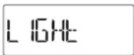

Autol LI
◇ Beep output level (BEEPLV)
Turns the key-touch beep ON or OFF. Sets the beep sound level to between 1 and 9. (default: 4)
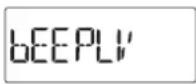

4 BE
◇ Auto repeater (AUTORP)
U.S.A. and Korean versions only
The auto repeater function automatically turns the duplex operation and tone encoder ON or OFF. The offset and repeater tone settings are not changed by the auto repeater function. Reset these frequencies, if necessary.
U.S.A. version:
- OFF : The auto repeater function is turned OFF.
• R1 : Activates for duplex only. (default)
• R2 : Activates for duplex and tone.
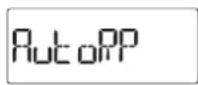

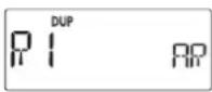
Korean version:
- OFF : The auto repeater function is turned OFF.
- On : Activates for duplex and tone. (default)
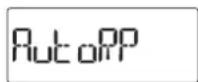

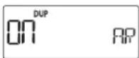
9 SET MODES
◇ Power save (P SAVE)
The power save function allows you conserve battery life by selecting the duty cycle of the receiver. Select the ratio of the power save time to the standby time. (default: Auto)
- OFF : Turns the function OFF.
• 2 : Sets the duty cycle to 1:2.
• 8 : Sets the duty cycle to 1:8.
• 16 : Sets the duty cycle to 1:16.
• 32 : Sets the duty cycle to 1:32. - Auto : Transceiver sets "1:2" duty ratio when receiving no signal for 5 seconds, then it sets "1:16" after 60 seconds has past.
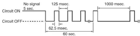

NOTE: Power save function is disabled when using an external power supply (more than 10 V DC).
◇ Voltage indication (VOLT)
The power voltage, battery voltage or external power supply voltage, is displayed at power ON. This setting can be turned ON or OFF. (default: On)
- OFF : The power voltage display is skipped.
- On : The power voltage is displayed at power ON.

◇ DTMF speed (DTMF-S)
Select the desired DTMF transmission speed from 100, 200, 300 or 500 msec. (default: 100)
• 100 : 100 msec. interval; 5.0 characters per second
• 200 : 200 msec. interval; 2.5 characters per second
• 300 : 300 msec. interval; 1.6 characters per second
- 500 : 500 msec. interval; 1.0 character per second

◇ LCD contrast (CONT)
Selects the LCD contrast. (default: Auto)
- Auto : Sets the contrast to high. However, if the transceiver is exposed to high temperatures, it automatically sets the contrast to low.
• HI : Sets the contrast to high. - LO : Sets the contrast to low.

◇ PTT lock (PTT LK)
Turns the PTT lock function ON or OFF.
To prevent accidental transmission, the transceiver has the PTT lock function. (default: OFF)

◇ Busy lockout (LK OUT)
Turns the busy lockout function ON or OFF.
This function inhibits transmission while receiving a signal or when the squelch is open. (default: OFF)

◇ Time-out timer (TOT)
To prevent accidental prolonged transmission, the transceiver has a time-out timer. This function cuts transmission OFF after 1–30 min. of continuous transmission. This timer can be cancelled. (default: 5)
- OFF : The time-out timer is turned OFF.
- 1 to 30 : The transmission is cut OFF after the set period elapses.

Approx. 10 seconds before the time-out timer is activated, the transceiver emits a beep tone as a warning.
BE CAREFUL! The transceiver will become hot when this time-out timer function is turned OFF or set to a long time period, and transmission is made for long periods.
◇ Squelch delay (SQL DL)
Sets the squelch delay between short and long. The delay prevents the squelch from repeatedly opening and closing while receiving the same signal. (default: SHORt)
- SHORT : Sets the squelch delay to short.
• LOnG : Sets the squelch delay to long

9 SET MODES
◇ Monitor key action (MONI)
The monitor key, MONI, can be set as a 'sticky' key. When set to the sticky condition, each push of MONI toggles the monitor function ON or OFF. (default: PUSH)
- PUSH : Push and hold MONI to monitor the frequency.
- HOLd : Push and hold MONI for 1 sec. to monitor the frequency and push again to cancel it.

◇ Dial speed acceleration (DIAL S)
The dial speed acceleration automatically speeds up the tuning dial speed when rotating [DIAL] rapidly. (default: On)
- OFF : The dial speed acceleration is turned OFF.
- On : The dial speed acceleration is tuned ON.

◇ Memory name (NAME)
The memory name is displayed during memory mode, or the memory bank name is displayed during memory bank selection. (default: OFF)
- OFF : The frequency of the selected memory channel is displayed.
- On : The pre-programmed memory name or memory bank name is displayed.

◇ Scan name (S NAME)
The programmed scan, programmed link scan or bank name is displayed during scan type selection. (default: On)
- OFF : The programmed scan, programmed link scan or bank name is not displayed.
- On : The programmed scan, programmed link scan or bank name is displayed.

◇ Display type (DISP M)
Selects the display type for memory mode operation.
(default: FREq)
- FREq : Displays the programmed frequency.
- CH : Displays the memory channel number. Operable functions, configurable items in the Set mode, and selectable modes will be restricted.
- PRIV : Displays the memory channel number. Operable channel, functions and selectable mode are restricted.

◇ Headset selection (HS SEL)
Selects the connected headset type between the HS-95 and other.
When using an optional headset HS-95, this setting must be set to "HS-95." (default: OtHER)

◇ Auto low power (AUTOLP)
Turns the auto low power function ON or OFF.
When the temperature goes below 0^ C (+32°F), the function automatically sets the output power to low.
In that case, the transmit power selections (High/Mid) are also disabled. (default: OFF)

10 OTHER FUNCTIONS
■ Programming a DTMF code sequence
DTMF codes are used for autopatching, accessing repeaters, controlling other equipment, etc. The transceiver has 16 DTMF memory channels (d0–d9, dA, db, dC, dd, dE, dF) for storage of often-used DTMF codes of up to 24 digits.
①Push[SET] to enter the Set mode.
② Rotate [DIAL] to select the DTMF programming item.
③ Rotate [VOL] to select a desired DTMF memory channel.
- If programmed, previously programmed the DTMF code is displayed.
![[DIAL] [VOL] SET A dTmF Blank channel indication DTMF memory channel](/content/2026/05/811798/images/bd17840fa716998d9920fc422fd98ff1dfac4edd8f6b831e659f0c84041476de.jpg)
④ Push and hold [SET] for 1 sec. to enter the programming mode.

⑤ Rotate [DIAL] to select the characters.
- "0"-9,"A,"b,"C,"d,"E" and "F" are selectable.
- Up to 24 digits can be programmed.
- Push[BAND] to move the cursor right; push [SET] to move the cursor left.
⑥Repeatstep⑤ until the desired code is input.

Next display appears after 6th digit has been input.

- If a digit is mistakenly programmed, push [SET] (or [BAND]) repeatedly to select the digit, then rotate [DIAL] to correct it.
Or rotate [DIAL] to select “_” to erase on and after the digits. Programmed memories will be cleared by this operation on the 1st digit.
⑦Push [BAND] twice to program the DTMF code and exit the programming mode.
- After the 24th digit is input, the transceiver automatically stores the code sequence and returns to step ③.
⑧Push [V/M/C] to return to the frequency display.
■ Transmitting a DTMF code sequence
The transceiver has 3 methods of transmitting a DTMF code sequence. Select a desired option in the Set mode.
①Push[SET] to enter the Set mode.
② Rotate [DIAL] to select the DTMF TX key item.
![[DIAL] [VOL] SET mO A](/content/2026/05/811798/images/ba69d11a2b6c32a7c2b01b664a238789f4a81eb6723285158b2e44ea350c78ec.jpg)
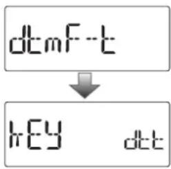
③ Rotate [VOL] to select a desired DTMF key setting.
- kEy : Transmits the appropriate DTMF code assigned to the pushed key. (default)
- mEm : Transmits the programmed DTMF code sequence in the DTMF memory channel assigned to the pushed key.
- t-CALL: No DTMF code can be transmitted. However, while continuing to push [PTT], pushing MONI transmits a 1750 Hz tone burst signal.
④Push [V/M/C] to return to the frequency display.
◇ Manual DTMF code transmission
First, set the DTMF TX key to "kEy" in the Set mode.
→ While continuing to push [PTT], push the desired keys to transmit a DTMF code sequence manually.
• [0]–[9], A, B, C, D, * or [#] sends “0”—“9,” “A,” “B,” “C,” “D,” “*” or “#.”
![[PTT] DTMF code keys 145.600 P/SKIP FM 0 9 8 9](/content/2026/05/811798/images/d3832a6a5b481c5ce53dd05e7cb7ded8e76d0b73632464ba9a3e59e295152b31.jpg)
10 OTHER FUNCTIONS
■ Transmitting a DTMF code sequence (continued)
◇ Using a DTMF memory channel
First, set the DTMF TX key to "mEm" in the Set mode.
While continuing to push [PTT], push one of the keys to transmit the programmed DTMF code sequence in the DTMF memory.
- Pushing [0] to [9], A, B, C, D, * or [#] transmits "d0"—"d9," "dA," "db," "dC," "dd," "dE" or "dF."
◇ 1750 Hz tone
To access some European repeaters, the transceiver must transmit a 1750 Hz tone burst signal.
- This tone can be used as a 'Call signal' in countries out of Europe.
First, set the DTMF TX key to "t-CALL" in the Set mode.
While continuing to push [PTT], push and hold [MONI] (BAND) for 1 or 2 sec. to transmit a 1750 Hz tone burst signal.
■ Setting DTMF transfer speed
The DTMF transfer speed can be selected.
① While continuing to push [SET], turn the power ON to enter the Initial set mode.
② Rotate [DIAL] to select the DTMF transfer speed item, then rotate [VOL] to select the transfer speed.

100 : Transfer the DTMF tones at about 100 msec. per tone. (default)
200 : Transfer the DTMF tones at about 200 msec. per tone.
300 : Transfer the DTMF tones at about 300 msec. per tone.
500 : Transfer the DTMF tones at about 500 msec. per tone.
③Push [💡] to return to the frequency display.
■ Tone frequency and DTCS code
◇ Tone and DTCS squelches
The tone squelch (CTCSS) or DTCS squelch opens only when receiving a signal containing a matching subaudible tone or DTCS code, respectively. You can silently wait for calls from group members using the same tone or code. Separate tone frequencies can be set for repeater and tone squelch/pocket beep operation.
◇ Reverse tone/DTCS squelch
The reverse tone/DTCS squelch is convenient if you want to ignore a specific signal. The transceiver mutes the squelch when a signal with the matched tone or code is received. "T SQL-R" / "DTCS-R" is displayed when the reverse tone/DTCS squelch is set.
◇ Pocket beep
These functions use subaudible tones or DTCS codes for calling and can be used as a “common pager” to inform you that someone has called while you were away from the transceiver.
◇ Setting subaudible tones for tone squelch
①Push[SET] to enter the Set mode.
② Rotate [DIAL] to select the CTCSS tone frequency item.
![[DIAL] SET m A](/content/2026/05/811798/images/3f373c6230a362e1a11335f2bd6b8171416edadff5e28ba8a4e57cd75455395b.jpg)
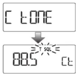
③ Rotate [VOL] to select a desired CTCSS tone frequency.
• Each operating band and each memory channel have indepen-
dent settings.
• See page 53 for available tone frequencies for details.
④ Push [V/M/C] to return to the frequency display.
10 OTHER FUNCTIONS
■ Tone frequency and DTCS code (continued)
◇ Setting DTCS code for DTCS squelch
①Push[SET] to enter the Set mode.
② Rotate [DIAL] to select the DTCS code item.
![[DIAL] SET m=0 A](/content/2026/05/811798/images/cfeb751834962db4bfe5fdb631856e0f617fce7c9613cd7624d5663f06187e8c.jpg)
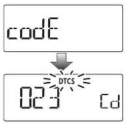
③ Rotate [VOL] to select a desired DTCS code.
• Each operating band and each memory channel have independent settings.
• See page 53 for available DTCS codes for details.
④ Push [V/M/C] to return to the frequency display.
DTCS phase can be selected in the "dtCS P" item. See next content for more details.
Setting DTCS polarity
①Push[SET] to enter the Set mode.
② Rotate [DIAL] to select the DTCS polarity item.
![[DIAL] SET A](/content/2026/05/811798/images/41746d47b089f1a536296f1e53556176e82eca1ac34187796e609792a210702d.jpg)
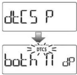
③ Rotate [VOL] to select a desired DTCS polarity mode.
- both n : Normal phase is used for both TX and RX. (Default)
- tn-RR : Normal phase is used for TX; Reverse phase for RX.
• tR-Rn : Reverse phase is used for TX; Normal phase for RX.
- both R : Reverse phase is used for both TX and RX.
④Push [V/M/C] to return to the frequency display.
■ Tone/DTCS squelch
① Set a desired operating frequency, and then set a CTCSS tone or DTCS code.
② Push and hold TONE for 1 sec. repeatedly to activate the tone or DTCS squelch. (T SQL or DTCS)
- Subaudible tone encoder "T," pocket beep (tone squelch) "((*) T SQL," tone squelch "T SQL," DTCS beep "((•)) DTCS," DTCS squelch "DTCS," tone squelch reverse "T SQL-R," DTCS squelch reverse "DTCS-R" and no tone operation are selectable in order.
- While continuing to push TONE, rotate [DIAL] also selects a tone setting.
③ Operate the transceiver in the normal way.
④ When the received signal includes a matching tone/code, the squelch opens and the signal can be heard. When the pocket beep function is activated, the transceiver also emits beep tones and blinks “((•)).”
- When the received signal's tone/code does not match, tone/DTCS squelch does not open, however, the S-indicator shows signal strength.
- To open the squelch manually, push and hold MONI.
⑤ Push [PTT] to answer or push and hold MONI for 1 sec. to stop the beeps and blinking.
No tone operation Subaudible tone encoder
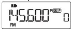
Pocket beep
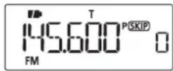
Tone squelch
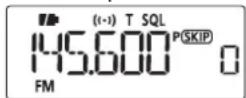
DTCS beep
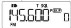
DTCS squelch
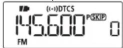
Tone squelch (reverse) DTCS squelch (reverse)
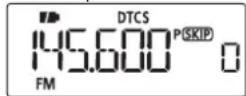
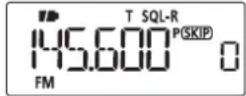
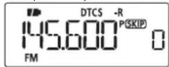
10 OTHER FUNCTIONS
■ Tone scan
The transceiver can detect the subaudible tone frequency and DTCS code in a received signal. By monitoring a signal that is being transmitted on a repeater input frequency, you can determine the tone frequency required to access the repeater.
① Set the desired frequency or memory channel to be checked for a tone frequency or DTCS code.
② Push and hold TONE for 1 sec. repeatedly to activate the repeater tone, tone squelch or DTCS squelch. (T, T SQL or DTCS)
③ Push and hold T.SCAN for 1 sec. to start the tone scan.
- To change the scanning direction, rotate [DIAL].
④ When the tone frequency or DTCS code is decoded, the set mode contents are programmed with the frequency or code.
- The tone scan pauses for the set period in scan pause timer (p. 47) when a tone frequency or DTCS code is detected.
- The decoded tone frequency is used for the repeater tone frequency when any tone setting, such as repeater tone or tone squelch is OFF.
- The decoded tone frequency is used for the tone squelch frequency when the tone squelch is ON.
- The decoded DTCS code is used for the DTCS squelch code when the DTCS squelch is ON.
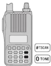
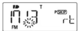
To ne scan for repeater tone
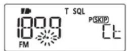
Tone scan for tone squelch
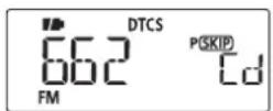
Tone scan for DTCS squelch
⑤ Push [V/M/C] to stop the scan.
- If the scan is cancelled before the transceiver detects the tone or code, the set mode contents are not changed.
- The detected tone is used for temporary operation only. The stored tone setting in memory or call channel won't be changed.
NOTE: Tone frequency is over-written automatically when it corresponds with the scanning tone frequency in tone squelch mode. However, it is not over-written in memory or call channel mode.
Weather channel operation U.S.A. version only
There are 10 weather channels for monitoring weather broadcasts from the NOAA (National Oceanic and Atmospheric Administration).

◇ Weather channel selection
① Push [V/M/C] repeatedly to select weather channel mode.
• The weather channel number appears.
② Rotate [DIAL] to select a desired weather channel.
③ Push [V/M/C] to return to the previous frequency or memory channel.
![[DIAL] V/M/C S.MW D](/content/2026/05/811798/images/278423eca0cafb8a10f8e8499fa3ddbf198c24a994f58ae2dd07ee3e90272bd8.jpg)
Weather channel display
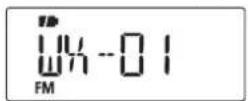
Push and hold SCAN for 1 sec. activates the weather channel scan. Push SCAN again to stop the scan.
◇ Weather alert function
NOAA broadcast stations transmit weather alert tones before important weather announcements. When the weather alert function is turned ON, the selected weather channel is monitored every 5 seconds for the announcement. When the alert signal is detected, the "ALT" and the WX channel indications are displayed alternately and a beep sounds until the transceiver is operated. The previously selected (used) weather channel is checked periodically during standby or while scanning.
① Select the desired weather channel.
② Push[SET] to enter the Set mode.
③ Rotate [DIAL] to select the weather alert setting item, then rotate [VOL] to select "On."

④ Push [V/M/C] to return to the weather channel display. - "WX" appears.
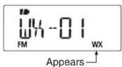
10 OTHER FUNCTIONS
◇ Weather alert function (continued)
⑤ Set the desired stand-by condition.
- Select the VFO mode, memory mode or call channel mode.
- Scan or priority watch operation can also be selected.
⑥ When the alert is detected, a beep sounds and the following indication is displayed.

Shows above indications alternately.
⑦ Turn the weather alert function OFF in the Set mode.

NOTE: While receiving a signal on a frequency other than the Weather alert frequency, the receiving signal will be interrupted momentarily approximately every 5 seconds when the Weather alert function is ON. These interruptions cease when the Weather alert function is turned OFF.
OTHER FUNCTIONS
■ Cloning function
The IC-T70A/T70E has transceiver-to-transceiver data cloning capability. This function is useful when you want to copy all of the programmed contents from one IC-T70A/T70E to another.
- An optional OPC-474CLONING CABLE is required.
① Turn the transceiver's power OFF, then connect an optional OPC-474 between both [SP] jacks.
![OPC-474 to the [SP] jack to the [SP] jack](/content/2026/05/811798/images/01129184519e7bf5f8e9642daf1edc90a3c5f0d34a1f80606527e2e2745d9c65.jpg)
② While continuing to push [V/M/C], push and hold [◎] for 1 sec. to enter the cloning mode.
- "CLOnE m" appears.
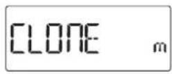
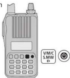
③ Push [PTT] on the "master" transceiver.
- "CL Out m" appears and the bar meter shows that cloning is taking place.
- After the cloning is completed, the display returns to "CLOnE m."
④ Push and hold [4] for 1 sec. to turn power OFF.
The optional CS-T70 CLONING SOFTWARE is also available to clone/edit contents with a PC (for Microsoft® Windows® 2000/XP, Windows Vista® or Windows® 7) using ICF format files.
![to the [SP] jack OPC-478UC (USB type) to USB port OPC-478 (RS-232C type) to RS-232C port PC](/content/2026/05/811798/images/fd2e93aec62d7fec4a2b6f992db63a67694b614a1d6812e65aa34e931c10a854.jpg)
10 OTHER FUNCTIONS
■ Resetting
The display may occasionally display erroneous information (e.g. when first applying power). This may be caused externally by static electricity or by other factors.
If this problem occurs, turn power OFF. After waiting a few seconds, turn power ON again. If the problem persists, perform either or both procedures below.
- All reset
Reset the CPU before operating the transceiver for the first time, or if the internal CPU malfunctions due to static electricity, etc. All reset clears all programming and returns all settings to their factory defaults.
- Partial reset
Use Partial reset if you want to initialize the operating conditions (VFO frequency, VFO settings, set mode contents) without clearing the memory contents.
◇ All reset
① Push and hold [4] for 1 sec. to turn power OFF.
② While continuing to push [SET], [BAND] and [H/M/L], then turn power ON to reset the CPU.
- "CLEAR" appears when resetting the CPU (See the illustration below).
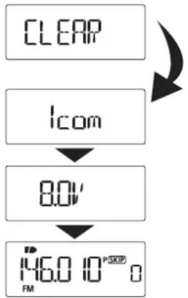
flowchart
graph TD
    A["CLEAR"] --> B["ICom"]
    B --> C["8.0V"]
    C --> D["146.0 MHz 10^-5 SKIP"]
CAUTION: Resetting the CPU returns all programmed contents to their default settings.
◇ Partial reset
① Push and hold [+] for 1 sec. to turn power OFF.
② While continuing to push [H/M/L], then turn power ON to partially reset the transceiver.
NOTE: No message appears on the display after the partial reset is done.
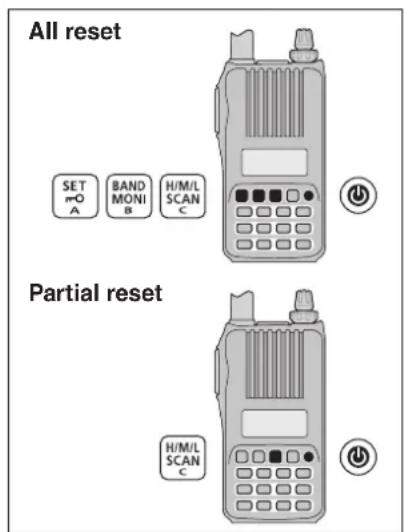
TROUBLESHOOTING
If your transceiver seems to be malfunctioning, please check the following points before sending it to a service center.
| PROBLEM POSSIBLE CAUSE SOLUTION REF. | |||
| Transceiver does not turn ON. | The battery is exhausted.The battery polarity is reversed.Loose connection of a battery pack (case). | Charge the battery pack, or replace the batteries.Check the battery polarity.Clean battery terminals. | pp. 2, 11–14p. 11– |
| No sound comes from the speaker. | Volume level is too low.An external speaker or a cloning cable is connected to the [SP] jack. | Rotate [VOL] to adjust to a desired level.Check the external speaker connection or remove the cloning cable. | p. 16– |
| Transmitting is impossible. | A frequency outside of the 144/440 MHz amateur bands is set.The PTT lock function is activated.The heat protection is activated, and “Hot” is displayed. | Set the frequency within 144/440 MHz amateur bands.Set the PTT lock function OFF in the Initial set modeCool down the transceiver. | p. 20p. 62p. 23 |
| Transmitting using the VOX function is impossible. | The VOX gain is set to OFF or too low.The microphone gain is too low. | Set the VOX gain to a suitable level.Set the microphone gain to a suitable level. | p. 81p. 58 |
| Contacting with another station is impossible. | Different tone or code is used for the tone DTCS squelch. | Check the tone/DTCS by performing a tone scan. p. | 71 |
| Frequency cannot be set. | The lock function is activated.The memory mode, Call channel mode, or weather channel mode is selected. | Push and hold [–O](SET) for 1 sec. to cancel the lock function.Push[V/M/C] repeatedly to select the VFO mode. | p. 21p. 18 |
| A program scan does not start. | The memory mode, Call channel mode, or weather channel mode is selected.The same frequency has been programmed in the scan edge channels, “*A” and “*b.” | Push[V/M/C] repeatedly to select the VFO mode.Programming different frequencies in the scan edge channels. | p. 18p. 43 |
| A memory scan does not start. | The VFO mode or Call channel mode is selectedOnly one or no memory channel has been programmed. | Push[V/M/C] repeatedly to select the memory mode.Program 2 or more memory channels. | p. 18p. 31 |
| The displayed frequency is erroneous. | The CPU has malfunctioned.External factors have caused a fault. | Reset the transceiver.Remove and re-attach the battery pack/case. | p. 75p. 2 |

12 SPECIFICATIONS
◇ General
• Frequency coverage : (unit: MHz)
| Version | TX RX | |
| EUR, KOR | 144–146, 430–440 | 144–146, 430–440 |
| UK, RSP | 144–146, 430–440 136–174*1, 400–479*2 | |
| U.S.A. | 144–148, 420–450*4 | 136–174*3, 400–479*4 |
| TPE | 144–146, 430–432 144–146, 430–432 | |
| AUS | 144–148, 420–450*2 | 136–174*3, 400–479*2 |
| CHN, EXP | 136–174*3, 400–479*2 | 136–174*3, 400–479*2 |
^1 Guaranteed 144–146 MHz only, ^2 Guaranteed 430–440 MHz only, ^3 Guaranteed 144–148 MHz only, ^1 Guaranteed 440–450 MHz only
- Mode : FM, FM-N
- No. of memory channels : 302 (incl. 50 scan edges and 2 call channels)
- Usable temp. range : -20^ to +60^ ; -4^ to +140^
• Tuning steps : 5, 10, 12.5, 15, 20, 25, 30, 50, 100, 125 and 200 kHz
• Frequency stability : ±2.5 ppm (-20°C to +60°C; -4°F to +140°F)
• Power supply : 10.0–16.0 V DC for external DC power, or specified Icom battery pack
- Current drain (at 7.2 V DC) : TX High(typical) VHF 1.7 A, UHF 2.1 A
Mid. (typical) VHF 1.2 A, UHF 1.5 A
Low (typical) VHF 0.6 A, UHF 0.8 A
Rx Max. output Less than 450 mA (Internal speaker) Less than 300 mA (External speaker)
Power save Less than 40 mA (Duty 1:8) standby Less than 90 mA
- Antenna connector : SMA (50 Ω)
- Dimensions : 58(W)×111(H)×30(D) mm;
(projections not included) 2.2(W)×4.3(H)×1.1(D) in
• Weight (approx.) : 380 g; 13.4 oz (with antenna and BP-264)
◇ Transmitter
- Modulation system : Variable reactance freq. modulation
- Output power (at 7.2 V DC) : High 5.0 W, Mid. 2.5 W, Low 0.5 W (typical)
- Max. frequency deviation : ±5.0 kHz (FM wide: approx.) ±2.5 kHz (FM narrow: approx.)
- Spurious emissions : Less than -60 dBc at High/Mid. Less than -13 dBm at Low
- Ext. mic. impedance : 2.2 kΩ
◇ Receiver
- Receive system : Double-conversion superheterodyne
• Intermediate frequencies : 1st 46.35 MHz, 2nd 450 kHz - Sensitivity (except spurious points, 1 kHz/3.5 kHz Dev.; 12 dB SINAD) : Guaranteed freq. range Less than 0.18 V Other freq. range Less than 0.32 V
- Squelch Sensitivity (except spurious points, 1 kHz/3.5 kHz Dev.): Guaranteed range Less than 0.18 μV Other frequency range Less than 0.32 μV
• Audio output power : (at 10% distortion/7.2 V DC) Internal speaker More than 700 mW with a 16 Ω load External speaker More than 400 mW with an 8 Ω load - Selectivity : (at CH spacing 20 kHz/in the amateur bands) FM (Wide) More than 60 dB FM (Narrow) More than 60 dB
- Ext. speaker connector : 3-conductor 3.5(d) mm; (1/8")/8 Ω
- Spurious and image rejection ratio (in guaranteed freq. range): More than 60 dB
All stated specifications are subject to change without notice or obligation.
OPTIONS
• BP-263 BATTERY CASE
Battery case for LR6 (AA) × 6 alkaline batteries.
• BP-264 NI-MH BATTERY PACK
7.2 V/1400 mAh (Typ.) Ni-MH battery pack. Battery life:
11.5 hrs. (approx.; VHF, FM, high power, Tx : Rx : Standby = 5:5:90)
Same as supplied one. (Not supplied with some version.)
• BP-265 LI-ION BATTERY PACK
7.4 V/1900 mAh (Min.)/2000 mAh (Typ.) Lithium Ion battery pack. Battery life: 16 hrs. (approx.; VHF, FM, high power, Tx : Rx : Standby = 5:5:90)
• BC-167S BATTERY CHARGER
For regular charging of the Ni-MH battery pack, BP-264.
Same as supplied one. (Not supplied with some version.)
• BC-191 DESKTOP CHARGER+BC-123S AC ADAPTER
For rapid charging of the Ni-MH battery pack, BP-264. A power adapter may be supplied with the charger, depending on the version.
Charging time: Approx. 2 hours for the BP-264.
• BC-193 DESKTOP CHARGER+BC-123S AC ADAPTER
For rapid charging of the Li-Ion battery pack, BP-265. A power adapter may be supplied with the charger, depending on the version.
Charging time: Approx. 2.5 hours for the BP-265.

Options may vary by versions.
Please ask your dealer for details.
BC-191/BC-193 common specifications
| Power supply voltage | 12 to 16 V DC or the specified Icom power adapter (BC-123S) |
| Charging temp. range +10°C to +40°C; +50°F to +104°F | |
| Dimensions(projections not included) | 87.5(W)×53.7(H)×72.8(D) mm; 3.4(W)×2.1(H)×2.8(D) in |
- BC-192 DESKTOP CHARGER+BC-147S/BC-206S AC ADAPTER
For regular charging of the Ni-MH battery pack, BP-264. A power adapter may be supplied with the charger, depending on the version.
Charging time: Approx. 16 hours for the BP-264.
BC-192 specifications
| Power supply voltage* 12 | to 16 V DC or the specified Icom power adapter (BC-147S/ BC-206S) |
| Charging temp. range 0°C | to +45°C;32°F to +113°F |
| Dimensions(projections not included) | 87.5(W)×53.7(H)×72.8(D) mm;3.4(W)×2.1(H)×2.8(D) in |
* Charging time differs depending on the input voltage.
12 V : Approx. 36 hours
13.8 V : Approx. 21 hours
16 V : Approx. 16 hours
• MB-130 VEHICLE CHARGER BRACKET
Vehicle mounting bracket for the BC-191, BC-192 and BC-193 battery chargers.
13 OPTIONS
• CP-12L CIGARETTE LIGHTER CABLE WITH NOISE FILTER
- CP-19R CIGARETTE LIGHTER CABLE WITH DC-DC CONVERTER Allows you to operate the transceiver through a 12 V cigarette lighter socket. You can also charge the attached battery pack (during stand-by only).
CP-19R: A built-in DC-DC converter provides an 11 V DC output.
• CP-23L CIGARETTE LIGHTER CABLE
Allows charging of the battery packs through a 12 V cigarette lighter socket. (For BC-191/BC-193)
• OPC-254L DC POWER CABLE
For operation and charging via an external power supply.
• OPC-515L DC POWER CABLE
Allows charging of the battery packs using a 12 V DC power source instead of the power adapter. (For BC-191/BC-192/BC-193)
• AD-92SMA ANTENNA CONNECTOR ADAPTER
Allows you to connect an external antenna with a BNC connector.
• HM-131 SPEAKER-MICROPHONE
Combination speaker-microphone that provides convenient operation while hanging the transceiver on your belt.
• HM-153 EARPHONE-MICROPHONE
Ideal for hands-free operation: clip the HM-153 (with integrated PTT switch) to your lapel or breast pocket.
•HS-94/HS-95/HS-97 HEADSET
+OPC-2006 PLUG ADAPTER CABLE
HS-94 : Ear hook type
HS-95 : Neck & arm type
HS-97 : Throat microphone
OPC-2006 : Allows you to connect the HS-94/HS-95/HS-97 to the transceiver. After connecting, the VOX function can be used.
Provides clear audio in noisy environments.
• OPC-474 CLONING CABLE
For transceiver-to-transceiver cloning.
• OPC-478/OPC-478UC CLONING CABLE
Used for data cloning between transceiver and PC with CS-T70 (cloning software).
• CS-T70 CLONING SOFTWARE
Provides quick and easy programming of such settings as memory channels and Set modes contents via your PC's RS-232C terminal (using OPC-478), or USB port (OPC-478UC). Either OPC-478 or OPC-478UC is required.
• LC-174 CARRYING CASE
Helps protect the transceiver from scratches, etc.
Approved Icom optional equipment is designed for optimal performance when used with an Icom transceiver.
■ VOX function
The transceiver has a VOX function, which allows hands-free operation.
An optional HS-94, HS-95 or HS-97 headset and the OPC-2006 plug adapter cable are also required for operation.
- The VOX (voice operated transmission) function starts transmission when you speak into the microphone, without needing to push [PTT]; then, automatically returns to reception when you stop speaking.
◇ Optional unit connection
①Push and hold [💡] for 1 sec. to turn the power OFF.
② Remove the jack cover.
③ Connect the optional HS-94, HS-95 or HS-97 and OPC-2006, as illustrated below.
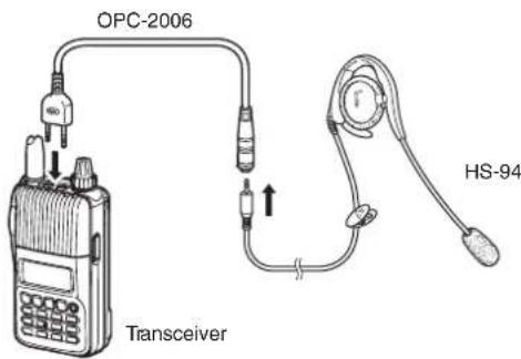
◇ Turning the VOX function ON or OFF
① Connect an optional headset and plug adapter cable to the transceiver, and then turn the power ON.
②Push[SET] to enter the Set mode.
③ Rotate [DIAL] to select the VOX setting item, then rotate [VOL] to select "On."

④ Push [V/M/C] to return to the frequency display.
- "VOX" appears when the VOX function is ON.
NOTE:
- When using the VOX function, adjust the microphone gain and the VOX-related settings (p. 81) to suit your operating environment (including your headset performance).
- Select the headset type between the HS-95 and other in the Initial set mode. (p.64)
- Set the microphone gain before setting the VOX gain in the Set mode (p. 58). We recommend setting the microphone gain to 3.
- When the PTT lock is set to "On" in the Set mode, you cannot transmit using the VOX function. (p. 62)
13 OPTIONS
◇VOX-relatedsettings
The VOX gain, the VOX delay, and the VOX time-out timer can be set in the Set mode.
① Connect an optional headset and plug adapter cable to the transceiver, and then turn the power ON.
②Push[SET] to enter the Set mode.
③ Rotate [DIAL] to select the VOX gain (VOX LV), the VOX delay (VOX.dLy), or the VOX time-out timer (VOX.tot) item.
④ Rotate [VOL] to select a desired option.
⑤ Push [V/M/C] to exit the Set mode.
The VOX function does not activate transmission while in the Set mode.
- VOX gain
The VOX gain level can be adjusted between 1 (minimum) and 10 (maximum), or turned OFF. Higher values make the VOX function more sensitive to your voice. (default: 5)

While speaking into the headset microphone, adjust the VOX gain until "VOX" continuously appears on the LCD.
√ CONVENIENT!
While transmitting using the VOX function, you can adjust the VOX gain simply by rotating [DIAL].
- VOX delay
Sets the VOX delay to between 0.5 and 3.0 seconds (in 0.5 sec. steps). The VOX delay is the amount of time the transmitter stays ON after you stop speaking. (default: 0.5)

If "VOX" is intermittent, be sure the VOX delay is set long enough to allow normal pauses in speech, but keep the VOX ON until you finish speaking.
• VOX time-out timer
Sets the VOX time-out timer to between 1, 2, 3, 4, 5, 10 and 15 minutes to prevent accidental prolonged transmission for the VOX function.
To turn the function OFF, select "OFF." (default: 3)

The VOX time-out timer must be set shorter than the time-out timer, otherwise this timer will not be activated.
■ Remote control function
The remote control unit allows you to remotely select operating frequencies, memory channels, etc.
- User remote control unit
The illustrated circuit is for reference only.
![2.7 kΩ 6.8 kΩ 15 kΩ 33 kΩ S1 S2 S3 S4 to the [SP] jack REMOTE 3.5(d) mm SP GND EXTERNAL SPEAKER Rated input ≥ 700 mW (8 Ω)](/content/2026/05/811798/images/20dfc21151af409b2feaecc7da465b5d182845f5dec55ff7b368c41c59d15fe6.jpg)
Be sure to turn power OFF when plugging/unplugging the remote control unit to/from the [SP/MIC] jack.
◇ Simple remote control mode
① While continuing to push [SET], turn the power ON to enter the Initial set mode.
② Rotate [DIAL] to select the microphone simple mode item.
③ Rotate [DIAL] to select "SImPLE," "nORm-1" or "nORm-2" option.

④ Push [💡] to return to the frequency display.
• SIMPLE
| S1 | Selects the Call channel. |
| S2 | Turns the monitor function ON or OFF. |
| S3 | Selects memory channel 0. |
| S4 | Selects memory channel 1. |
• NORM-1
| S1 | Toggles the VFO mode and the memory mode. |
| S2 | Selects the Call channel. |
| S3 | Frequency or memory channel “UP.” |
| S4 | Frequency or memory channel “DOWN.” |
• NORM-2
| S1 | Toggles the VFO mode and the memory mode. |
| S2 | Turns the monitor function ON or OFF. |
| S3 | Frequency or memory channel “UP.” |
| S4 | Frequency or memory channel “DOWN.” |
The VFO mode cannot be selected via the remote control unit when SIMPLE mode is selected.
• COMMON (SIMPLE/NORM-1/NORM-2)
| S2 | Transmits T-CALL (1750 Hz tone) while pushing [PTT]. |
| S3 | Volume “UP” while operating the monitor function. |
| S4 | Volume “DOWN” while operating the monitor function. |

14 COUNTRY CODE LIST
ISO 3166-1
| Country Codes | Country Codes | ||||
| 1 | Austria AT 18 Liechtenstein LI | ||||
| 2 | Bulgium BE 19 Lithuania LT | ||||
| 3 | Bulgaria BG 20 Luxembourg LU | ||||
| 4 | Croatia HR 21 Malta MT | ||||
| 5 | Czech Republic CZ 22 Netherlands | NL | |||
| 6 | Cyprus CY 23 Norway NO | ||||
| 7 | Denmark DK 24 Poland PL | ||||
| 8 | Estonia EE 25 Portugal PT | PT | |||
| 9 | Finland FI 26 Romania RO | ||||
| 10 | France FR 27 Slovakia SK | SK | |||
| 11 | Germany DE 28 Slovenia SI | ||||
| 12 | Greece GR 29 Spain ES | ES | |||
| 13 | Hungary HU 30 Sweden SE | ||||
| 14 | Iceland IS 31 Switzerland CH | ||||
| 15 | Ireland IE 32 Turkey TR | ||||
| 16 | Italy IT 33 United Kingdom GB | ||||
| 17 | Latvia LV | ||||
INDEX
-1-
1750 Hz tone 28
-A-
All reset....75
Antenna 2
Auto low power (AUTOLP)....64
Auto power OFF (AP OFF) 59
Auto repeater (AUTORP)....60
Auto repeater function 27
-B-
Busy lockout (LK OUT) 62
-C-
Call channel mode....18
Call channel watch 49
Caution (for the optional BP-265 Li-Ion battery pack) 9
Caution (for the supplied BP-264 Ni-MH battery pack) 8
Channel number display 36
Charging caution 10
Charging note 12, 13
Checking the repeater input signal 25
Cloning function....74
Copying call channel contents 37
Copying memory contents....37
Country Code List....83
- D -
DC operating note 15
Desktop battery chargers 13
Dial speed acceleration (DIAL S) 63
Display backlighting (LIGHT) 60
Display type 36
Display type (DISP M) 64
DTCS code (CODE) 53
DTCS polarity (DTCS P) 53
DTCS squelch 70
DTMF memory (DTMF) 58
DTMF speed (DTMF-S) 61
DTMF TX key (DTMF-T) 58
Duplex operation 26
-E-
Entering and using the Initial set mode 51
Entering and using the Set mode 51
Erasing bank contents 39
Explicit definitions .... i
External DC power operation 15
INDEX
-F-
FCC information ....iii
Features ...... i
Foreword....i
Frequency display....36
Frequency offset (OFFSET) 54
Frequency range and offset direction 27
Front panel....3
Full scan 42
Function display....6
-G-
General description 29
-H-
Hand strap....1
Headset selection (HS SEL) 64
-1-
Important ....i
Index 84–87
Initial set mode item list 52
Initial set mode items....59
-K-
Key lock function....21
Keypad....4
-L-
LCD contrast (CONT) 62
List of Country codes (ISO 3166-1) 83
-M-
Memory bank link function (B LINK) 56
Memory bank scan 45
Memory bank selection 33
Memory bank setting 32
Memory channel contents 29
Memory channel programming....31
Memory channel watch....49
Memory clearing 38
Memory mode 18
Memory name (NAME) 63
Memory scan 44
Memory scan watch....49
Microphone gain (MIC G) 58
Microphone simple mode (MIC S) 59
Monitor function 17
Monitor key action (MONI)....63
-0-
Off band indication 25
Operating mode (MODE)....54
Operating mode selection....21
Optional battery case 11
Optional unit connection 80
Options 78–82
INDEX
-P-
Partial reset 75
Pocket beep....68
Power OFF 16
Power ON 16
Power save (P SAVE) 61
Precautions......ii, iii
Priority watch (PRIO)....55
Priority watch operation 49
Priority watch types 48
Private channel display....36
Program scan link function (P LINK) 56
Program skip scan (P SKIP) 55
Programmed scan 42
Programming a DTMF code sequence....65
Programming bank name 34
Programming memory name 34
Programming scan name 34
PTT lock (PTT LK) 62
-R-
Rapid charging with the BC-191....13
Rapid charging with the BC-193....14
Receiving....22
Regular charging 12
Regular charging with the BC-192....14
Remote control function....82
Repeater operation....24
Repeater tone frequency (R TONE) 53
Resetting 75
Reverse duplex function (DUP.REV)....54
Reverse tone/DTCS squelch 68
Reverse duplex function 26
- S -
Scan edges programming 43
Scan name (S NAME) 63
Scan pause timer....47
Scan pause timer (PAUSE) 55
Scan resume setting....47
Scan resume timer 47
Scan resume timer (RESUME)......55
Scan types....40
Selecting a call channel....29
Selecting a memory channel 30
Selecting bank name indication....35
Selecting memory name indication 35
Selecting the mode....18
Set mode item list....52
Set mode items....53
Setting audio volume 16
Setting DTCS code for DTCS squelch 69
Setting DTCS polarity 69
Setting DTMF transfer speed....67
Setting duplex direction 26
Setting frequency offset....26
Setting subaudible tone for tone squelch....68
Setting the frequency using the dial 19
INDEX
Setting the frequency using the keypad....20
Setting the squelch level....17
Setting the tuning step....19
Side panel....3
Skip channel setting 46
Skip frequency setting 46
Specifications 77
Squelch delay (SQL DL) 62
Supplied accessories...... iv
-T-
Table of contents ......v, vi
Time-out timer (TOT) 62
Tone and DTCS squelches....68
Tone frequency and DTCS code 68
Tone scan 71
Tone squelch 70
Top panel 3
Transferring bank contents 39
Transmit power selection 22
Transmit warning 23
Transmitting 23
Transmitting a DTMF code sequence....66
Troubleshooting 76
TSQL frequency (C TONE)....53
Tuning step (TS) 54
Tuning step selection 19
Turning the VOX function ON or OFF 80
- U -
Usable characters....34
- V -
VFO mode 18
VFO scan watch 50
Voltage indication (VOLT) 61
VOX delay (VOX.DLY)....59
VOX function 80
VOX function (VOX) 58
VOX gain (VOX LV) 58
VOX time-out timer (VOXTOT) 59
VOX-related settings....81
-W-
Weather alert (WX.ALT) 54
Weather alert function 72
Weather channel mode 18
Weather channel operation....72
Weather channel scan....72
Weather channel selection 72
MEMO
Count on us!
02 EUR
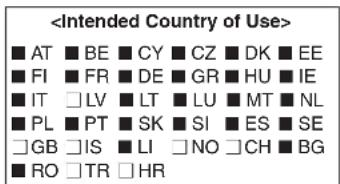
03 UK
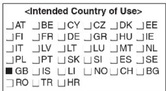
12 RSP
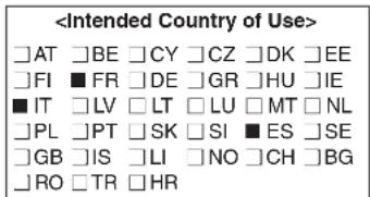
© 2009–2016 Icom Inc.
Printed on recycled paper with soy ink.

natural_image
Solid dark gray rectangle with a thin white horizontal line at the bottom (no text or symbols)Icom Inc.
1-1-32 Kamiminami, Hirano-ku, Osaka 547-0003, Japan
- FOREWORD
- FEATURES
- IMPORTANT
- PRECAUTIONS
- FCC INFORMATION
- • FOR CLASS B UNINTENTIONAL RADIATORS:
- SUPPLIED ACCESSORIES
- DISPOSAL
- TABLE OF CONTENTS
- ACCESSORY ATTACHMENT
- ■ Hand strap
- ■ Belt clip
- ACCESSORY ATTACHMENT
- Battery pack
- To attach the battery pack:
- To detach the battery pack:
- Antenna
- 2
- PANEL DESCRIPTION
- ■ Front, top and side panels
- ① ANTENNA CONNECTOR (p. 2)
- ② EXTERNAL SPEAKER/MICROPHONE JACKS [SP/MIC]
- ③ CONTROL DIAL [DIAL]
- ④ VOLUME CONTROL [VOL]
- ⑤ PTT SWITCH [PTT]
- For IC-T70E only
- ⑥ EXTERNAL DC IN JACK [DC IN]
- ◇ Keypad
- POWER KEY [∅]
- VFO/MEMORY/CALL • SELECT MEMORY WRITE KEY [V/M/C] • [S.MW](V/M/C)
- PANEL DESCRIPTION
- OUTPUT POWER • SCAN KEY [H/M/L] • [SCAN](H/M/L)
- BAND • MONITOR KEY [BAND] • [MONI](BAND)
- SET • LOCK KEY [SET] • [¬O](SET)
- TONE SCAN KEY [T.SCAN](#)
- TONE/TONE SQUELCH KEY [TONE](0)
- DUPLEX KEY [DUP](\*)
- ■ Function display
- ① BATTERY ICON (pp. 11, 12)
- ○ When the BP-264 or BP-265 is attached
- ○ When the BP-263 is attached
- ② DUR3EX ICON (p. 26)
- ③ TONE ICON
- ④ VOX ICON (p. 80)
- ⑤ AUTO POWER OFF ICON (p. 59)
- ⑦ SKIP ICONS
- ⑨ MEMORY CHANNEL NUMBER
- ⑫ S/RF METER
- ⑮ FREQUENCY READOUT
- BATTERY CHARGING
- 3
- ■ Caution (for the supplied BP-264 Ni-MH battery pack)
- BATTERY CHARGING
- ■ Caution (for the optional BP-265 Li-Ion battery pack)
- ◇ Battery caution
- Battery Pack characteristics and lifetime
- ◇ Charging caution
- ■ Battery case (BP-263)
- CAUTION:
- ■ Battery information
- ■ Regular charging
- ◇ Battery icons
- ◇ Charging note
- ■ Desktop battery chargers
- ◇ Rapid charging with the BC-191
- ◇ Regular charging with the BC-192
- ◇ Rapid charging with the BC-193
- Charge indicator
- ■ External DC power operation
- ◇ Operating note
- BASIC OPERATION
- 4
- Power ON
- ■ Setting audio volume
- BASIC OPERATION
- ■ Setting the squelch level
- ■ Monitor function
- ■ Selecting the mode
- ◇ VFO mode
- What is VFO?
- ◇ Memory mode
- ◇ Call channel mode
- ◇ Weather channel mode\*
- ■ Setting the tuning step
- ◇ Tuning step selection
- ■ Setting the frequency
- ◇ Using the dial
- ◇ Using the keypad
- TSCAN
- ■ Operating mode selection
- ■ Key lock function
- ■ Receiving
- ■ Transmit power selection
- ■ Transmitting
- REPEATER AND DUPLEX OPERATIONS
- ■ Repeater operation
- REPEATER AND DUPLEX OPERATIONS
- ◇ Checking the repeater input signal
- ◇ Off band indication
- U.S.A. and Korean versions:
- √ CONVENIENT!
- ■ Duplex operation
- ◇ Setting frequency offset
- ◇ Setting duplex direction
- ■ Reverse duplex function
- ■ Auto repeater function
- ◇ Frequency range and offset direction
- U.S.A. version:
- Korean version:
- ■ 1750 Hz tone
- √ CONVENIENT! (For the IC-T70E only)
- 6
- MEMORY/CALL CHANNELS
- ■ General description
- ◇ Memory channel contents
- ■ Selecting a call channel
- ■ Selecting a memory channel
- ◇ Using [DIAL]
- ◇ Using the Numeral keys
- MEMORY/CALL CHANNELS
- ■ Memory channel programming
- ■ Memory bank setting
- ■ Memory bank selection
- ■ Programming memory/bank/scan name
- ◇ Usable characters
- ■ Selecting memory/bank name indication
- ■ Display type
- "Channel number display"
- "Private channel display"
- ■ Copying memory/call contents
- ◇ Memory/call↔VFO
- ◇ Memory/call→memory/call
- ■ Memory clearing
- ■ Erasing/transferring bank contents
- SCAN OPERATION
- Scan types
- PROGRAMMED LINK SCAN (pp. 42, 57)
- SCAN OPERATION
- DUPLEX SCAN (pp. 42, 44)
- BANK-LINK SCAN (pp. 45, 46)
- ■ Full/band/programmed scan
- ■ Scan edges programming
- ■ Memory scan
- ■ Memory bank scan
- ■ Skip channel/frequency setting
- ■ Scan resume setting
- ◇ Scan pause timer
- ◇ Scan resume timer
- PRIORITY WATCH
- ■ Priority watch types
- ◇ About priority beep function
- MEMORY/CALL CHANNEL WATCH
- MEMORY SCAN WATCH
- VFO SCAN WATCH
- VFO/MEMORY SCAN WATCH
- 8
- ■ Priority watch operation
- ◇ Memory/call channel and memory scan watch
- For memory channel watch:
- For memory scan watch:
- ◇ VFO scan watch
- 9
- SET MODES
- General
- ◇ Entering and using the Set mode
- ◇ Entering and using the Initial set mode
- ■ Set mode items
- ◇ Repeater tone frequency (R TONE)
- ◇ TSQL frequency (C TONE)
- ◇ DTCS code (CODE)
- ◇ DTCS polarity (DTCS P)
- ◇ Tuning step (TS)
- ◇ Frequency offset (OFFSET)
- ◇ Reverse duplex function (DUP.REV)
- ◇ Operating mode (MODE)
- ◇ Weather alert (WX.ALT)
- SET MODES
- ◇ Priority watch (PRIO)
- ◇ Scan pause timer (PAUSE)
- ◇ Scan resume timer (RESUME)
- ◇ Program skip scan (P SKIP)
- ◇ Memory bank link function (B-LINK)
- • Bank link setting
- ◇ Program scan link function (P-LINK)
- - Confirming program scan link
- - Program scan link setting
- • Program scan link name programming
- ◇ DTMF TX key (DTMF-T)
- ◇ DTMF memory (DTMF)
- ◇ Microphone gain (MIC G)
- ◇ VOX function (VOX)
- ◇ VOX gain (VOX LV)
- ◇ VOX time-out timer (VOXTOT)
- ■ Initial set mode items
- ◇ Microphone simple mode (MIC S)
- ◇ Auto power OFF (AP OFF)
- ◇ Display backlighting (LIGHT)
- ◇ Beep output level (BEEPLV)
- ◇ Auto repeater (AUTORP)
- U.S.A. and Korean versions only
- ◇ Power save (P SAVE)
- ◇ Voltage indication (VOLT)
- ◇ DTMF speed (DTMF-S)
- ◇ LCD contrast (CONT)
- ◇ PTT lock (PTT LK)
- ◇ Busy lockout (LK OUT)
- ◇ Time-out timer (TOT)
- ◇ Squelch delay (SQL DL)
- ◇ Monitor key action (MONI)
- ◇ Dial speed acceleration (DIAL S)
- ◇ Memory name (NAME)
- ◇ Scan name (S NAME)
- ◇ Display type (DISP M)
- ◇ Headset selection (HS SEL)
- ◇ Auto low power (AUTOLP)
- OTHER FUNCTIONS
- ■ Programming a DTMF code sequence
- ■ Transmitting a DTMF code sequence
- ◇ Manual DTMF code transmission
- ◇ Using a DTMF memory channel
- ◇ 1750 Hz tone
- ■ Setting DTMF transfer speed
- ■ Tone frequency and DTCS code
- ◇ Tone and DTCS squelches
- ◇ Reverse tone/DTCS squelch
- ◇ Pocket beep
- ◇ Setting subaudible tones for tone squelch
- ◇ Setting DTCS code for DTCS squelch
- Setting DTCS polarity
- ■ Tone/DTCS squelch
- ■ Tone scan
- Weather channel operation U.S.A. version only
- ◇ Weather channel selection
- ◇ Weather alert function
- OTHER FUNCTIONS
- ■ Cloning function
- ■ Resetting
- - All reset
- - Partial reset
- ◇ All reset
- ◇ Partial reset
- TROUBLESHOOTING
- SPECIFICATIONS
- ◇ General
- ◇ Transmitter
- ◇ Receiver
- OPTIONS
- OPTIONS
- ■ VOX function
- ◇ Optional unit connection
- ◇ Turning the VOX function ON or OFF
- NOTE:
- ◇VOX-relatedsettings
- - VOX gain
- - VOX delay
- • VOX time-out timer
- ■ Remote control function
- - User remote control unit
- ◇ Simple remote control mode
- COUNTRY CODE LIST
- INDEX
- -1-
- -A-
- -B-
- -C-
- - D -
- -E-
- -P-
- -R-
- - S -
- -T-
- - U -
- - V -
- -W-
- Count on us!
- EUR
- UK
- RSP
Brand : ICOM
Model : IC-T70A
Category : Radio