PANASONIC PT-RZ120BE - Vidéo-projecteur

PT-RZ120BE - Vidéo-projecteur PANASONIC - Free user manual and instructions

Find the device manual for free PT-RZ120BE PANASONIC in PDF.

📄 220 pages English EN Download 💬 AI Question
Notice PANASONIC PT-RZ120BE - page 5
Pick your language and provide your email: we'll send you a specifically translated version.

User questions about PT-RZ120BE PANASONIC

0 question about this device. Answer the ones you know or ask your own.

Ask a new question about this device

The email remains private: it is only used to notify you if someone responds to your question.

No questions yet. Be the first to ask one.

Download the instructions for your Vidéo-projecteur in PDF format for free! Find your manual PT-RZ120BE - PANASONIC and take your electronic device back in hand. On this page are published all the documents necessary for the use of your device. PT-RZ120BE by PANASONIC.

USER MANUAL PT-RZ120BE PANASONIC

Operating Instructions Functional Manual

DLP™ Projector

Commercial Use

Model No. PT-RZ120

PANASONIC PT-RZ120BE - Operating Instructions Functional Manual - 1

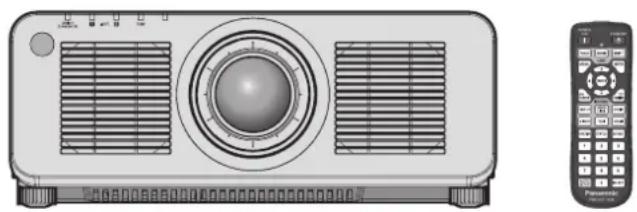
natural_image Illustration of a projector with ventilation grilles and a separate remote control unit (no text or symbols visible)

Thank you for purchasing this Panasonic product.

  • The Operating Instructions correspond to the firmware’s main version 2.00 and higher.
    ■ This manual is common to all the models regardless of suffixes of the Model No.

- for Taiwan

BA: Black model, the standard zoom lens supplied

- for India

BD: Black model, the standard zoom lens supplied LBD: Black model, the lens sold separately

- for Korea

B: Black model, the standard zoom lens supplied W: White model, the standard zoom lens supplied

● for Asia (except for Taiwan, India, Korea) / Oceania / Africa

BA/B: Black model, the standard zoom lens supplied LBA/LB: Black model, the lens sold separately

WA/W: White model, the standard zoom lens supplied LWA/LW: White model, the lens sold separately

● for other countries or regions

B: Black model, the standard zoom lens supplied LB: Black model, the lens sold separately

W: White model, the standard zoom lens supplied LW: White model, the lens sold separately

■ Before operating this product, please read the instructions carefully and save this manual for future use.
■ Before using this product, be sure to read "Read this first" (pages 5 to 16).

PANASONIC PT-RZ120BE - Operating Instructions Functional Manual - 2

PANASONIC PT-RZ120BE - Operating Instructions Functional Manual - 3

Contents

Read this first!

Chapter 1 Preparation

Precautions for use

Intended use of the product 20

Cautions when transporting....20

Cautions when installing 20

Security 23

DIGITAL LINK 24

Art-Net 24

Application software supported by the projector 24

Storing 24

Disposal 24

Cautions on use 24

Accessories 26

Optional accessories 27

About your projector 28

Remote control 28

Projector body 30

Preparing the remote control 33

Inserting and removing the batteries 33

When using the multiple projectors....33

Connecting the remote control to the projector with a cable 33

Chapter 2 Getting Started

Setting up

Usable outlet 35

Installation mode 35

Parts for installation (optional) 37

Projected image and throw distance 37

Adjusting adjustable feet 46

Removing/attaching the projection lens 47

Removing the projection lens 47

Attaching the projection lens 48

Connecting 49

Before connecting 49

Connecting example: AV equipment....50

Connecting example: Computers 51

Connecting example using DIGITAL LINK 52

Connecting example when using the contrast synchronization function/shutter synchronization function....53

Chapter 3 Basic Operations

Switching on/off the projector

Connecting the power cord

Power indicator 20

Switching on the projector

When the initial setting screen is displayed 59

Making adjustments and selections 65

Switching off the projector

Projecting

Selecting the input signal

Adjusting the focus, zoom, and lens shift 68

Adjusting the focus balance

Setting the lens type

Moving the projection lens to the home position

Lens shift range 71

Operating with the remote control 73

Using the shutter function 73

Using the on-screen display function 73

Using the automatic setup function 74

Using the function button 74

Displaying internal test pattern 74

Using the status function 75

Setting ID number of the remote control 75

Chapter 4 Settings

Navigating through the men 35....77

Main menu 78

Sub-menu 79

[PICTURE] menu 82

[PICTURE MODE] 82

[CONTRAST] 82

[BRIGHTNESS] 82

[COLOR] 83

[TINT] 83

[COLOR TEMPERATURE] 83

[WHITE GAIN] 85

[GAMMA] 85

[SYSTEM DAYLIGHT VIEW] 86

[SHARPNESS] 86

[NOISE REDUCTION] 87

[DYNAMIC CONTRAST] 87

[SYSTEM SELECTOR] 88

[DEFAULT PICTURE MODE] 89

sRGB-compliant video 89

[POSITION] menu 91

[SHIFT] 91

[ASPECT] 91

[ZOOM] 92

[CLOCK PHASE] 93

[GEOMETRY] 93

[ADVANCED MENU] menu 99

[DIGITAL CINEMA REALITY] 99

[BLANKING] 99

[INPUT RESOLUTION]....100

[CLAMP POSITION]....100

[EDGE BLENDING] 100

[FRAME RESPONSE]....102

[RASTER POSITION]....103

[DISPLAY LANGUAGE] menu....104

Changing the display language 104

[DISPLAY OPTION] menu....105

[COLOR MATCHING]....105

[COLOR CORRECTION] 106

[SCREEN SETTING] 106

[AUTO SIGNAL]....107

[AUTO SETUP]....107

[BACKUP INPUT SETTING]....108

[RGB IN] 110

[DVI-D IN]....111

[HDMI IN] 113

[DIGITAL LINK IN]....114

[SDI IN] 116

[ON-SCREEN DISPLAY]......117

[MENU MODE]....119

[IMAGE ROTATION]......119

[BACK COLOR]....120

[STARTUP LOGO] 120

[UNIFORMITY] 120

[SHUTTER SETTING] 121

[FREEZE] 123

[WAVEFORM MONITOR] 123

[CUT OFF]....124

[PROJECTOR SETUP] menu ____

[PROJECTOR ID]

[PROJECTION METHOD]

[LENS]

[OPERATION SETTING]

[LIGHT OUTPUT]

[BRIGHTNESS CONTROL]

[STANDBY MODE]

[QUICK STARTUP]....

[NO SIGNAL SHUT-OFF]

[NO SIGNAL LIGHTS-OUT] 135

[INITIAL STARTUP] 135

[STARTUP INPUT SELECT]....135

[DATE AND TIME] 136

[SCHEDULE] 137

[MULTI PROJECTOR SYNC] 139

[RS-232C] 140

[REMOTE2 MODE] 142

[FUNCTION BUTTON] 142

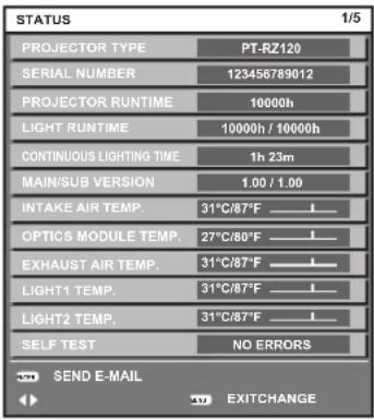
[STATUS] 143

[DATA CLONING]

[SAVE ALL USER DATA]....

[LOAD ALL USER DATA] 146

[INITIALIZE] 146

[SERVICE PASSWORD]

[TEST PATTERN] menu....148

[TEST PATTERN]....

[SIGNAL LIST] menu 149

Registering new signals 149

Renaming the registered signal 149

Deleting the registered signal 149

Protecting the registered signal 150

Expanding signal lock-in range 150

Sub memory 151

[SECURITY] menu 152

[SECURITY PASSWORD]

[SECURITY PASSWORD CHANGE]....152

[DISPLAY SETTING] 152

[TEXT CHANGE] 153

[CONTROL DEVICE SETUP] 153

[CONTROL DEVICE PASSWORD CHANGE] 154

[NETWORK] menu 156

[DIGITAL LINK MODE]......156

[DIGITAL LINK STATUS] 156

[NETWORK SETUP] 157

[NETWORK CONTROL] 157

[NETWORK STATUS]....158

[DIGITAL LINK MENU] 158

[Art-Net SETUP] 158

[Art-Net CHANNEL SETTING] 159

[Art-Net STATUS] 160

Chapter 5 Operations

Network connection 162 Connecting to the network 162

Web control function 165 Computer that can be used for setting 165 Accessing from the web browser 165

Chapter 6 Maintenance

Light source/temperature indicators 184 When an indicator lights up 184

Maintenance....186 Before maintaining the projector....186 Maintenance....186

Troubleshooting 187
[SELF TEST] indications 189

Chapter 7 Appendix

Technical information 192 PJLink protocol 192 Using Art-Net function 193 Control commands via LAN 197 / terminals 200

terminal 204 Control device password 204 Upgrade Kit 205 List of compatible signals 206

Specifications 213
Dimensions 216

Precautions for attaching the Ceiling Mount Bracket 217
Index 219

Read this first!

WARNING: THIS APPARATUS MUST BE EARTHED.

WARNING: To prevent damage which may result in fire or shock hazard, do not expose this appliance to rain or moisture.

This device is not intended for use in the direct field of view at visual display workplaces. To avoid accommodating reflexions at visual display workplaces this device must not be placed in the direct field of view.

The equipment is not intended for used at a video workstation in compliance BildscharbV.

The sound pressure level at the operator position is equal or less than 70 dB (A) according to ISO 7779.

WARNING:

  1. Remove the plug from the mains socket when this unit is not in use for a prolonged period of time.
  2. To prevent electric shock, do not remove cover. No user serviceable parts inside. Refer servicing to qualified service personnel.
  3. Do not remove the earthing pin on the mains plug. This apparatus is equipped with a three prong earthing-type mains plug. This plug will only fit an earthing-type mains socket. This is a safety feature. If you are unable to insert the plug into the mains socket, contact an electrician. Do not defeat the purpose of the earthing plug.

WARNING:

This equipment is compliant with Class A of CISPR32.

In a residential environment this equipment may cause radio interference.

(for Taiwan)

WARNING:

This equipment complies with the Class A standard of CISPR32.

This is Class A information technology equipment that may cause radio frequency interference when used in a residential environment, in which the user will be required to take certain appropriate countermeasures.

CAUTION: To assure continued compliance, follow the attached installation instructions. This includes using the provided power cord and shielded interface cables when connecting to computer or peripheral devices. Also, any unauthorized changes or modifications to this equipment could void the user's authority to operate this device.

This is a device to project images onto a screen, etc., and is not intended for use as indoor lighting in a domestic environment.

Directive 2009/125/EC

WARNING: TO REDUCE THE RISK OF FIRE OR ELECTRIC SHOCK, DO NOT EXPOSE THIS PRODUCT TO RAIN OR MOISTURE.

WARNING: RISK OF ELECTRIC SHOCK. DON'T OPEN

PANASONIC PT-RZ120BE - WARNING: - 1

text_image WARNING RISK OF ELECTRIC SHOCK DO NOT OPEN ! or 警告 電擊危險不要打開

Indicated on the projector

PANASONIC PT-RZ120BE - WARNING: - 2

The lightning flash with arrowhead symbol, within an equilateral triangle, is intended to alert the user to the presence of uninsulated "dangerous voltage" within the product's enclosure that may be of sufficient magnitude to constitute a risk of electric shock to persons.

PANASONIC PT-RZ120BE - WARNING: - 3

The exclamation point within an equilateral triangle is intended to alert the user to the presence of important operating and maintenance (servicing) instructions in the literature accompanying the product.

WARNING: Do not look at the light emitted from the lens while the projector is being used.

As with any bright source, do not stare into the direct beam.

PANASONIC PT-RZ120BE - WARNING: - 4
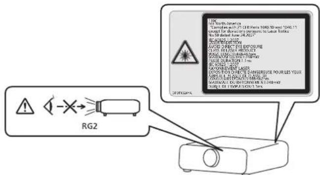
RG2

Indicated on the projector

RG2 IEC 62471-5:2015

Notice on laser

(for USA and Canada)

This projector is the Class 3R laser product that complies with IEC 60825-1:2007.

PANASONIC PT-RZ120BE - (for USA and Canada) - 1

text_image RG2 COVID-0244A FOR NORTH JIMENA "Crassages in 21 GB Rate 1040.10 and 1040.11" except for direct access to Laser Noise No isolated zone SLAD? COVID-02537-2020 COVID-02538-2021 COVID-02539-2022 AVOID DIRECT EYE EXPOSURE ORANGE INSIDE PRODUIT SUSIL LEAVES ET DE POUR BLUE SURFACE IT. Inc. COVID-02622-2023 FAVON/REDACT LASER EXPOSITION DIRECTE DANGEREUSE POUR LES VEUX HOLDEN LEAVES ET DE POUR MAXIMALS DU VENUEURAT EN LAUDEND SUN GUE ET DU VENUEURAT Tons

PANASONIC PT-RZ120BE - (for USA and Canada) - 2

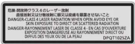
text_image 危険-開放時クラス4のレーザー放射 直接放射又は分散放射に眼又は皮膚を暴露させないこと DANGER-CLASS 4 LASER RADIATION WHEN OPEN AVOID EYE OR SKIN EXPOSURE TO DIRECT OR SCATTERED RADIATION DANGER-RAYONNEMENT LASER DE CLASSE 4 - EN CAS D'OUVERTURE EXPOSITION DANGEREUSE AU RAYONNEMENT DIRECT OU DIFFUS DES YEUX OU DE LA PEAU DPQT1025ZA

(Inside of product)

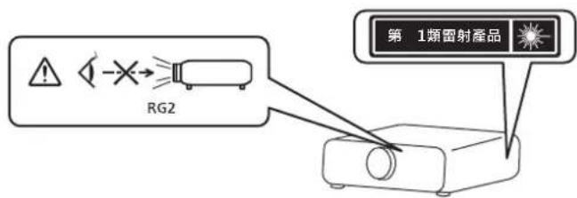
(for Taiwan)

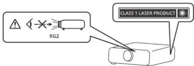
This projector is the Class 1 laser product that complies with IEC/EN 60825-1:2014.

PANASONIC PT-RZ120BE - (for Taiwan) - 1

This projector is the Class 1 laser product that complies with IEC/EN 60825-1:2014.

PANASONIC PT-RZ120BE - (for Taiwan) - 2

text_image RG2 CLASS 1 LASER PRODUCT

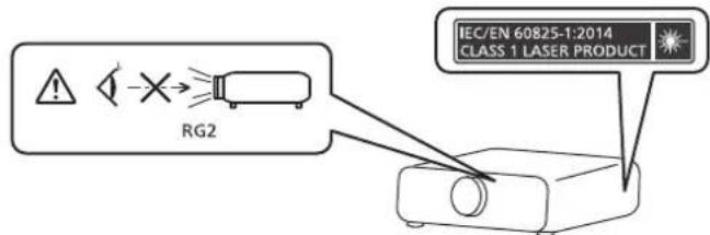
(for other countries or regions)

This projector is the Class 1 laser product that complies with IEC/EN 60825-1:2014.

PANASONIC PT-RZ120BE - (for other countries or regions) - 1

text_image RG2 IEC/EN 60825-1:2014 CLASS 1 LASER PRODUCT

CAUTION: Use of controls or adjustments or performance of procedures other than those specified herein may result in hazardous radiation exposure.

CAUTION (North/Middle/South America)

Power Supply: This Projector is designed to operate on 100 V - 240 V, 50 Hz/60 Hz AC, house current only.

CAUTION: The AC power cord which is supplied with the projector as an accessory can only be used for power supplies up to 125 V. If you need to use higher voltages than this, you will need to obtain a separate 250 V power cord. If you use the accessory cord in such situations, fire may result.

CAUTION (North/Middle/South America/Taiwan)

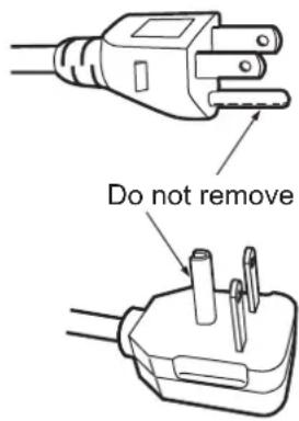
This equipment is equipped with a three-pin grounding-type power plug. Do not remove the grounding pin on the power plug. This plug will only fit a grounding-type power outlet. This is a safety feature. If you are unable to insert the plug into the outlet, contact an electrician. Do not defeat the purpose of the grounding plug.

PANASONIC PT-RZ120BE - CAUTION (North/Middle/South America/Taiwan) - 1

text_image Do not remove

WARNING (USA and Canada)

  • Not for use in a computer room as defined in the Standard for the Protection of Electronic Computer/Data Processing Equipment, ANSI/NFPA 75.
  • For permanently connected equipment, a readily accessible disconnect device shall be incorporated in the building installation wiring.
  • For pluggable equipment, the socket-outlet shall be installed near the equipment and shall be easily accessible.

NOTIFICATION (Canada)

This class A digital apparatus complies with Canadian ICES-003.

For USA-California Only

This product contains a CR Coin Cell Lithium Battery which contains Perchlorate Material – special handling may apply.

See www.dtsc.ca.gov/hazardouswaste/perchlorate

FCC NOTICE (USA)

Supplier's Declaration of Conformity

Model Number: PT-RZ120B / PT-RZ120W / PT-RZ120LB / PT-RZ120LW

Trade Name: Panasonic

Responsible Party: Panasonic Corporation of North America

Address: Two Riverfront Plaza, Newark, NJ 07102-5490

General Contact: http://www.panasonic.com/support

Projector Contact: https://panasonic.net/cns/projector/

This device complies with Part 15 of the FCC Rules.

Operation is subject to the following two conditions:

(1) This device may not cause harmful interference, and (2) this device must accept any interference received, including interference that may cause undesired operation.

Caution:

This equipment has been tested and found to comply with the limits for a Class A digital device, pursuant to part 15 of the FCC Rules. These limits are designed to provide reasonable protection against harmful interference when the equipment is operated in a commercial environment. This equipment generates, uses, and can radiate radio frequency energy and, if not installed and used in accordance with the instruction manual, may cause harmful interference to radio communications. Operation of this equipment in a residential area is likely to cause harmful interference in which case the user will be required to correct the interference at his own expense.

FCC Warning:

To assure continued compliance, follow the attached installation instructions. This includes using the provided power cord and shielded interface cables when connecting to computer or peripheral devices. Also, any unauthorized changes or modifications to this equipment could void the user's authority to operate this device.

IMPORTANT: THE MOLDED PLUG

FOR YOUR SAFETY, PLEASE READ THE FOLLOWING TEXT CAREFULLY.

This appliance is supplied with a molded three pin mains plug for your safety and convenience. A 13 amp fuse is fitted in this plug. Should the fuse need to be replaced, please ensure that the replacement fuse has a rating of 13 amps and that it is approved by ASTA or BSI to BS1362.

Check for the ASTA mark 🎨 or the BSI mark 🌘 on the body of the fuse.

If the plug contains a removable fuse cover, you must ensure that it is refitted when the fuse is replaced. If you lose the fuse cover, the plug must not be used until a replacement cover is obtained. A replacement fuse cover can be purchased from an Authorized Service Center.

If the fitted molded plug is unsuitable for the mains socket in your home, then the fuse should be removed and the plug cut off and disposed of safely. There is a danger of severe electrical shock if the cut off plug is inserted into any 13 amp socket.

If a new plug is to be fitted, please observe the wiring code as shown below. If in any doubt, please consult a qualified electrician.

WARNING: THIS APPLIANCE MUST BE EARTHED.

IMPORTANT: The wires in this mains lead are colored in accordance with the following code:

Green - and - Yellow: Earth

Blue: Neutral

Brown: Live

As the colors of the wire in the mains lead of this appliance may not correspond with the colored markings identifying the terminals in your plug, proceed as follows.

The wire which is colored GREEN - AND - YELLOW must be connected to the terminal in the plug which is marked with the letter E or by the Earth symbol 12 or colored GREEN or GREEN - AND - YELLOW.

The wire which is colored BLUE must be connected to the terminal in the plug which is marked with the letter N or colored BLACK.

The wire which is colored BROWN must be connected to the terminal in the plug which is marked with the letter L or colored RED.

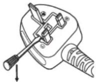
How to replace the fuse: Open the fuse compartment with a screwdriver and replace the fuse.

PANASONIC PT-RZ120BE - IMPORTANT: THE MOLDED PLUG - 1

Importer's name and address within the European Union

Panasonic Marketing Europe GmbH

Panasonic Testing Centre

Winsbergring 15, 22525 Hamburg, Germany

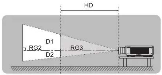
■ Hazard distance (IEC 62471-5:2015)

The distance from the projection lens surface, at which the level of exposure has reached the level of the applicable Exposure Limit Value, is known as the hazard distance (HD) or safety distance.

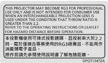
Do not look into the projected light from inside the hazard distance (within RG3 range). The eyes may be damaged by the direct irradiation. It is considered to be safe to look into the projected light from outside the hazard distance (within RG2 range).

PANASONIC PT-RZ120BE - ■ Hazard distance (IEC 62471-5:2015) - 1

text_image HD RD1 RG2 D2 RD3

PANASONIC PT-RZ120BE - ■ Hazard distance (IEC 62471-5:2015) - 2

text_image HD D3 RG2 D4 RG3

Except ET-DLE035

■ Risk group

The combination of the projector and the projection lens is categorized as the risk group 2 when the hazard distance is less than 1 m (39-3/8"). It is categorized as the risk group 3 when the hazard distance exceeds 1 m (39-3/8"), and it will be for professional use instead of consumer use.
In case of risk group 3, there is a possibility of damaging the eyes by direct irradiation when looking into the projection light from inside the hazard distance (within RG3 range).
In case of risk group 2, it can be used safely without damaging the eyes in any condition.
The combination of the projector and the projection lens which the hazard distance exceeds 1 m (39-3/8") and is categorized as risk group 3 is as follows.

Projection lens Model No.Risk group
ET-DLE250Risk group 3 ^1
ET-DLE350
ET-DLE450

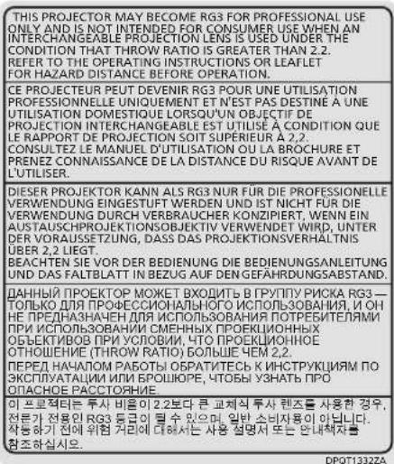
*1 When the projector is used with the optional Zoom Lens (Model No.: ET-DLE250, ET-DLE350, ET-DLE450) attached, the hazard distance exceeds 1 m (39-3/8"), and regardless of the use condition, the throw ratio is larger than 2.2:1. In this case, it is categorized as the risk group 3.

PANASONIC PT-RZ120BE - ■ Risk group - 1

text_image THIS PROJECTOR MAY BECOME RG3 FOR PROFESSIONAL USE ONLY AND IS NOT INTENDED FOR CONSUMER USE WHEN AN INTERCHANGEABLE PROJECTION LENS IS USED UNDER THE CONDITION THAT THROW RATIO IS GREATER THAN 2.2. REFER TO THE OPERATING INSTRUCTIONS OR LEAFLET FOR HAZARD DISTANCE BEFORE OPERATION. CE PROJECTEUR PEUT DEVENIR RG3 POUR UNE UTILISATION PROFESSIONNELLE UNIQUEMENT ET N'EST PAS DESTINÉ A UNE UTILISATION DOMESTIQUE LORSQU'UN OBJECTIF DE PROJECTION INTERCHANGEABLE EST UTILISÉ A CONDITION QUE LE RAPPORT DE PROJECTION SOIT SUPERIEUR À 2.2, CONSULTÉE LE MANUEL D'UTILISATION OU LA BROCHURE ET PRENEZ CONNAISSANCE DE LA DISTANCE DU RISQUE AVANT DE L'UTILISER. DIESER PROJEKTOR KANN ALS RG3 NUR FÜR DIE PROFESSIONELLE VERWENDUNG EINGESTUFT WERDEN UND IST NICHT FÜR DIE VERWENDUNG DURCH VERBRAUCHER KONZIPIERT, WENN EIN AUSTAUSCHPROJEKTIONSOBJEKTI VVERWENDET WIRD, UNTER DER VORAUSSETZUNG, DASS DAS PROJEKTIONSVERHALTNI SÜBER 2,2 LIEGT. BEACHTEN SIE VOR DER BEDIENUNG DIE BEDIENUNGESANLEITUNG UND DAS FALTBLATT IN BEZUG AUF DEN GEFAHRDUNGSABSTAND. ДАННЫЙ ПРОЖЕТОР МОКЕТ ВХОДИТЬ В ГРУППУ РИСКА RG3 — ТОЛЬКО ДЛЯ ПРОФЕССИОНАЛЬНОГО ИСПОЛЬЗОВАНИЯ, И ОНЕ ПРЕДНАЗНАЧЕН ДЛЯ ИСПОЛЬЗОВАНИЯ ПОТРЕБИТЕЛЯМИ ПРИ ИСПОЛЬЗОВАНИИ СМЕННЫХ ПРОКЕЦИОННЫХ ОБЪЕКТИВОВ ПРИ УСЛОВИИ, ЧТО ПРОКЕЦИОННОЕ ОТНОШЕНИЕ (THROW RATIO) БОЛЬШЕ ЧЕМ 2.2. ПЕРЕД НАЧАЛОМ РАБОТЫ ОБРАТИТЕСЬ К ИНСТРУКЦИЯМ ПО ЭКСПУЛАТАЦИИ ИЛИ БРОШЮРЕ, ЧТОБЫ УЗНАТЬ ПРО ОПАСНОЕ РАССТОЯНИЕ. 이 프로젝터는 루사 비율이 2.2보다 큰 교체식 루사 헤즈를 사용한 경우, 전문가 전용인 RG3 등급이 될 수 있으며 일반 소비자용이 아닙니다. 척동하기 전에 위험 거리에 대해서는 사용 설명서 또는 안내체자를 참조하십시오. DPOT1332ZA

PANASONIC PT-RZ120BE - ■ Risk group - 2

Each dimension inside the hazard distance (within RG3 range) for combination with projection lens which the hazard distance exceeds 1 m (39-3/8") is as follows.

(Unit: m)

Projection lens Model No.HD*1D1*2D2*2D3*2D4*2
ET-DLE250 1.4 0.400.27 0.52 0.39
ET-DLE350 2.2 0.400.27 0.52 0.39
ET-DLE450 3.2 0.400.27 0.51 0.38

*1 HD: Hazard Distance
*2 The values of D1 to D4 will change in accordance with the lens shift amount. Each value in the table is the maximum value.

Note

- The value in the table is based on IEC 62471-5:2015.

Read this first!

WARNING:

POWER

The wall outlet or the circuit breaker shall be installed near the equipment and shall be easily accessible when problems occur. If the following problems occur, cut off the power supply immediately.

Continued use of the projector in these conditions will result in fire or electric shock, or will cause visual impairment.

  • If foreign objects or water get inside the projector, cut off the power supply.
  • If the projector is dropped or the cabinet is broken, cut off the power supply.
  • If you notice smoke, strange smells or noise coming from the projector, cut off the power supply.
    Please contact an Authorized Service Center for repairs, and do not attempt to repair the projector yourself.

During a thunderstorm, do not touch the projector or the cable.

Electric shocks can result.

Do not do anything that might damage the power cord or the power plug.

If the power cord is used while damaged, electric shocks, short-circuits or fire will result.

- Do not damage the power cord, make any modifications to it, place it near any hot objects, bend it excessively, twist it, pull it, place heavy objects on top of it or wrap it into a bundle.

Ask an Authorized Service Center to carry out any repairs to the power cord that might be necessary.

Do not use anything other than the provided power cord.

Failure to observe this will result in electric shocks or fire. Please note that if you do not use the provided power cord to ground the device on the side of the outlet, this may result in electric shocks.

Completely insert the power plug into the wall outlet and the power connector into the projector terminal.

If the plug is not inserted correctly, electric shocks or overheating will result.

- Do not use plugs which are damaged or wall outlets which are coming loose from the wall.

Do not handle the power plug and power connector with wet hands.

Failure to observe this will result in electric shocks.

Use an outlet supporting 15 A independently.

Using an outlet together with another device may result in fires due to heat generation.

Do not overload the wall outlet.

If the power supply is overloaded (ex., by using too many adapters), overheating may occur and fire will result.

Clean the power plug regularly to prevent it from becoming covered in dust.

Failure to observe this will cause a fire.

  • If dust builds up on the power plug, the resulting humidity can damage the insulation.
  • If not using the projector for an extended period of time, pull the power plug out from the wall outlet.
    Pull the power plug out from the wall outlet and wipe it with a dry cloth regularly.

■ ON USE/INSTALLATION

Do not place the projector on soft materials such as carpets or sponge mats.

Doing so will cause the projector to overheat, which can cause burns, fire or damage to the projector.

Do not set up the projector in humid or dusty places or in places where the projector may come into contact with oily smoke or steam.

Using the projector under such conditions will result in fire, electric shocks or deterioration of components. Oil may also distort the plastic and the projector could fall such as when mounted on the ceiling.

Do not install this projector in a place which is not strong enough to take the full weight of the projector or on top of a surface which is sloped or unstable.

Failure to observe this will cause projector to fall down or tip over the projector, and severe injury or damage could result.

Do not install the projector in a location where people pass through.

People may bump into the projector or trip on the power cord, which may result in fire, electric shock, or injury.

Do not cover the air intake/exhaust ports or place anything within 500 mm (19-11/16") of them.

Doing so will cause the projector to overheat, which can cause fire or damage to the projector.

  • Do not place the projector in narrow, badly ventilated places.
  • Do not place the projector on cloth or papers, as these materials could be drawn into the air intake port.

WARNING:

Do not look at or place your skin into the light emitted from the lens while the projector is being used.

Do not enter the projection luminous flux using an optical device (such as magnifier or mirror).

Doing so can cause burns or loss of sight.

  • Strong light is emitted from the projector's lens. Do not look at or place your hands directly into this light.
  • Be especially careful not to let young children look into the lens. In addition, turn off the power and switch off the main power when you are away from the projector.

Do not project an image with the lens cover attached.

Doing so can cause fire.

Never attempt to remodel or disassemble the projector.

High voltages can cause fire or electric shocks.

- For any inspection, adjustment and repair work, please contact an Authorized Service Center.

Do not allow metal objects, flammable objects, or liquids to enter inside of the projector. Do not allow the projector to get wet.

Doing so may cause short circuits or overheating, and result in fire, electric shock, or malfunction of the projector.

  • Do not place containers of liquid or metal objects near the projector.
  • If liquid enters inside of the projector, consult your dealer.
    • Particular attention must be paid to children.

Use the ceiling mount bracket specified by Panasonic.

Using the ceiling mount bracket other than the specified one will result in falling accidents.

- Attach the supplied safety cable to the ceiling mount bracket to prevent the projector from falling down.

Installation work such as mounting the projector on the ceiling should only be carried out by a qualified technician.

If installation is not carried out and secured correctly, it can cause injury or accidents, such as electric shocks.

ACCESSORIES

Do not use or handle the batteries improperly, and refer to the following.

Failure to observe this will cause burns, batteries to leak, overheat, explode or catch fire.

  • Do not use unspecified batteries.
  • Do not charge dry cell batteries.
  • Do not disassemble dry cell batteries.
  • Do not heat the batteries or place them into water or fire.
  • Do not allow the + and – terminals of the batteries to come into contact with metallic objects such as necklaces or hairpins.
  • Do not store or carry batteries together with metallic objects.
  • Store the batteries in a plastic bag and keep them away from metallic objects.
  • Make sure the polarities (+ and −) are correct when inserting the batteries.
  • Do not use a new battery together with an old battery or mix different types of batteries.
  • Do not use batteries with the outer cover peeling away or removed.

If the battery fluid leaks, do not touch it with bare hands, and take the following measures if necessary.

  • Battery fluid on your skin or clothing could result in skin inflammation or injury.
    Rinse with clean water and seek medical advice immediately.
  • Battery fluid coming in contact with your eyes could result in loss of sight.
    In this case, do not rub your eyes. Rinse with clean water and seek medical advice immediately.

Do not allow children to reach the batteries.

Accidentally swallowing them can cause physical harm.

- If swallowed, seek medical advice immediately.

Remove the depleted batteries from the remote control promptly.

- Leaving them in the unit may result in fluid leakage, overheating, or explosion of the batteries.

CAUTION:

POWER

When disconnecting the power cord, be sure to hold the power plug and power connector.

If the power cord itself is pulled, the lead will become damaged, and fire, short-circuits or serious electric shocks will result.

When not using the projector for an extended period of time, disconnect the power plug from the wall outlet.

Failure to do so may result in fire or electric shock.

Before replacing the projection lens, be sure to turn off the power and disconnect the power plug from the wall outlet.

  • Unexpected projection of light may cause injury to eyes.
  • Replacing the projection lens without removing the power plug may result in electric shock.

Disconnect the power plug from the wall outlet before carrying out any cleaning.

Failure to do so may result in electric shock.

■ ON USE/INSTALLATION

Do not place heavy objects on top of the projector.

Failure to observe this will cause the projector to become unbalanced and fall, which could result in damage or injury. The projector will be damaged or deformed.

Do not put your weight on this projector.

You could fall or the projector could break, and injury will result.

- Be especially careful not to let young children stand or sit on the projector.

Do not place the projector in extremely hot locations.

Doing so will cause the outer casing or internal components to deteriorate, or result in fire.

• Take particular care in locations exposed to direct sunlight or near heaters.

Do not place your hands in the openings beside the optical lens, while shifting the lens.

Failure to observe this could cause injury.

Do not install the projector in a location where salt pollution or corrosive gas may occur.

Doing so may result in falling due to corrosion. Also, it may result in malfunctions.

Do not stand in front of the lens while the projector is being used.

Doing so can cause damage and burns to clothing.

- Strong light is emitted from the projector's lens.

Do not place objects in front of the lens while the projector is being used.

Do not block the projection by placing an object in front of the projection lens.

Doing so can cause fire, damage to an object, or malfunction of the projector.

- Strong light is emitted from the projector's lens.

The projector must be carried or installed by two or more people.

Failure to do so may cause falling accidents.

Always disconnect all cables before moving the projector.

Moving the projector with cables still attached can damage the cables, which will cause fire or electric shocks to occur.

When mounting the projector on the ceiling, keep mounting screws and power cord from contact with metal parts inside the ceiling.

Contact with metal parts inside the ceiling can cause electric shocks.

CAUTION:

ACCESSORIES

When not using the projector for an extended period of time, remove the batteries from the remote control.

Failure to observe this will cause the batteries to leak, overheat, catch fire or explode, which may result in fire or contamination of surrounding area.

■ MAINTENANCE

Ask your dealer about cleaning inside the projector every 20 000 hours of usage as an estimated duration.

Continuous use while dust is accumulated inside the projector may result in fire.

- For cleaning fee, ask your dealer.

To remove the battery

Remote Control Battery

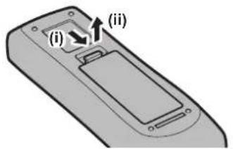
  1. Press the guide and lift the cover.

PANASONIC PT-RZ120BE - Remote Control Battery - 1

text_image (i) (ii)
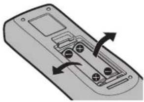
  1. Remove the batteries.

PANASONIC PT-RZ120BE - Remote Control Battery - 2

natural_image Diagram of a remote control panel with arrows indicating clockwise moves (no text or symbols)

Brazil Only

Brasil Apenas

natural_image Diagram of a remote control panel with arrows indicating clockwise movement (no text or symbols)

Trademarks

•SOLID SHINE is a trademark of Panasonic Corporation.

  • Windows, Internet Explorer, and Microsoft Edge are registered trademarks or trademarks of Microsoft Corporation in the United States and other countries.
    • Mac, macOS, and Safari are trademarks of Apple Inc., registered in the United States and other countries.

- PJLin ^M is a registered trademark or pending trademark in Japan, the United States, and other countries and regions.

- DLP is a trademark or registered trademark of Texas Instruments.

  • The terms HDMI and HDMI High-Definition Multimedia Interface, and the HDMI Logo are trademarks or registered trademarks of HDMI Licensing Administrator, Inc. in the United States and other countries.
  • Crestron Connected, the Crestron Connected logo, Crestron Fusion, Crestron RoomView, and RoomView are either trademarks or registered trademarks of Crestron Electronics, Inc. in the United States and/or other countries.

- HDBase™ is a trademark of HDBaseT Alliance.

- Art-Net™ Designed by and Copyright Artistic Licence Holdings Ltd

  • Adobe, Acrobat, Flash Player, and Reader are either registered trademarks or trademarks of Adobe Systems Incorporated in the United States and/or other countries.
  • Some of the fonts used in the on-screen menu are Ricoh bitmap fonts, which are manufactured and sold by Ricoh Company, Ltd.
  • All other names, company names, and product names mentioned in this manual are trademarks or registered trademarks of their respective owners.

Please note that the ^® and ^TM symbols are not specified in this manual.

Software information regarding this product

This product incorporates the following software:

(1) the software developed independently by or for Panasonic Corporation,
(2) the software owned by third party and licensed to Panasonic Corporation,
(3) the software licensed under the GNU General Public License, Version 2.0 (GPL V2.0),
(4) the software licensed under the GNU LESSER General Public License, Version 2.1 (LGPL V2.1), and/or
(5) open source software other than the software licensed under the GPL V2.0 and/or LGPL V2.1.

The software categorized as (3) - (5) are distributed in the hope that it will be useful, but WITHOUT ANY WARRANTY, without even the implied warranty of MERCHANTABILITY or FITNESS FOR A PARTICULAR PURPOSE. Please refer to the detailed terms and conditions thereof shown in the attached CD-ROM.

At least three (3) years from delivery of this product, Panasonic will give to any third party who contacts us at the contact information provided below, for a charge no more than our cost of physically performing source code distribution, a complete machine-readable copy of the corresponding source code covered under GPL V2.0, LGPL V2.1 or the other licenses with the obligation to do so, as well as the respective copyright notice thereof.

Contact Information: oss-cd-request@gg.jp.panasonic.com

■Illustrations in this manual

  • Illustrations of the projector, menu screen (OSD), and other parts may vary from the actual product.
  • Illustrations displayed on the computer screen may differ depending on the computer type and its operating system.
  • Illustrations of the projector with the power cord attached are only examples. The shape of the supplied power cords varies depending on the country where you purchased the product.

■Reference pages

- Reference pages in this manual are indicated as (→ page 00).

Term

- In this manual, the "Wireless/wired remote control unit" accessory is referred to as "Remote control".

Features of the Projector

Quick Steps

For details, refer to the corresponding pages.

High luminance and high contrast

▶ With a unique optical system which uses a new-generation laser light source, and the laser light source drive system, high luminance of 12 000 lm ^1 and high contrast of 10 000:1 ^2 are achieved even with its compact size. This projector also supports input of 4K video signals.

*1 When [OPERATING MODE] is set to [NORMAL]
*2 When [DYNAMIC CONTRAST] is set to [3]

Easy and highly flexible setup

▶ Easy and flexible setup is achieved by compatibility with DIGITAL LINK and Art-Net, standard support of 3G-SDI, standard support of geometric adjustment function, 360^ installation support including horizontal, vertical, and portrait utilizing the characteristics of solid-state light source, and a lineup of various optional lenses.

Long life and high reliability

The maintenance cost for long-term operation is reduced by the unique light source cooling control technology and improvement of the dust resistance. Also, it will contribute to the stable operation by implementation of the backup function that will continue the projection by switching to the backup input signal immediately even when the input signal is discontinued, in addition to adopting solid-state light source which has long life.

  1. Set up the projector.

(→ page 35)

PANASONIC PT-RZ120BE - Long life and high reliability - 1

  1. Attach the projection lens.

(→ page 47)

PANASONIC PT-RZ120BE - Long life and high reliability - 2

  1. Connect with external devices.

(→ page 49)

PANASONIC PT-RZ120BE - Long life and high reliability - 3

  1. Connect the power cord.

(→ page 56)

PANASONIC PT-RZ120BE - Long life and high reliability - 4

  1. Switch on the projector.

(→ page 58)

PANASONIC PT-RZ120BE - Long life and high reliability - 5

  1. Make initial settings.

(→ page 59)

•Take this step when you switch on the power for the first time after purchasing the projector.

PANASONIC PT-RZ120BE - Long life and high reliability - 6

  1. Select the input signal.

(→ page 67)

PANASONIC PT-RZ120BE - Long life and high reliability - 7

  1. Adjust the image.

(→ page 68)

Chapter 1 Preparation

This chapter describes things you need to know or check before using the projector.

Precautions for use

Intended use of the product

The purpose of the projector is to project a video signal from imaging equipment or a computer on a screen or other surface as a still image or moving image.

Cautions when transporting

- If you purchased the projector with the standard zoom lens, remove the lens protection material before use, and store it for the future use. Move the lens position to the home position and attach the lens protection material when transporting.

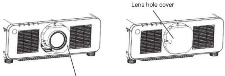
If you purchased the projector with the lens sold separately, remove the lens hole cover before use, and store it for the future use. Move the lens position to the home position, remove the projection lens, and attach the lens hole cover when transporting.

For the steps to move the lens position to the home position, refer to "Moving the projection lens to the home position" (→ page 70).

PANASONIC PT-RZ120BE - Cautions when transporting - 1

text_image Lens hole cover

Lens protection material

- Transport the projector with two or more people. Failure to do so may drop the projector, which may result in damage or deformation of the projector, or injury.

- Hold the bottom of the projector and do not hold the projection lens or the opening around the projection lens when transporting. Failure to do so may cause damage. Also, handle the projector in a way not to apply excessive vibration or shock. Failure to do so may cause a failure due to the damaged internal components.

- Do not transport the projector with the adjustable feet extended. Doing so may damage the adjustable feet.

Cautions when installing

■ After attaching the projection lens, be sure to attach the Lens Mount Cover.

Not doing so may cause failure due to accumulating dust internally.

■Do not set up the projector outdoors.

The projector is designed for indoor use only.

■Do not set up the projector in the following locations.

  • Places where vibration and impacts occur such as in a car or vehicle: Doing so may cause damage to internal components or malfunction.
  • Location close to sea or where corrosive gas may occur: The projector may fall due to corrosion. Also, failure to do so may shorten the life of the components and result in malfunction.
  • Near the exhaust of an air conditioner: Depending on the conditions of use, the screen may fluctuate in rare cases due to the heated air from the air exhaust port or the hot or cooled air from the air conditioner. Make sure that the exhaust from the projector or other equipment, or the air from the air conditioner does not blow toward the front of the projector.
  • Places with sharp temperature fluctuations such as near lights (studio lamps): Doing so may shorten the life of the light source, or result in deformation of the projector due to heat, which may cause malfunctions.
    Follow the operating environment temperature of the projector.
  • Near high-voltage power lines or near motors: Doing so may interfere with the operation of the projector.
  • Places where there is high-power laser equipment: Directing a laser beam onto the projection lens surface causes damage to the DLP chips.

■ Ask a qualified technician or your dealer for the installation work such as installing to a ceiling, etc.

To ensure projector performance and safety, ask a qualified technician or your dealer when installing to a ceiling or in a high place.

■ Ask a qualified technician or your dealer to install the cable wiring for DIGITAL LINK connection.

Image and sound may be disrupted if cable transmission characteristics cannot be obtained due to inadequate installation.

■ The projector may not work properly due to strong radio wave from the broadcast station or the radio.

If there is any facility or equipment which outputs strong radio waves near the installation location, install the projector at a location sufficiently far from the source of the radio waves. Or, wrap the LAN cable connected to the terminal using a piece of metal foil or a metal pipe which is grounded at both ends.

■ Focus adjustment

The high clarity projection lens is thermally affected by the light from the light source, making the focus unstable in the period just after switching on the power.

It is recommended to perform the focus adjustment after 30 minutes have elapsed with the focus test pattern displayed. For details of the test pattern, refer to “[TEST PATTERN] menu” (→ page 148).

■ Do not install the projector at an altitude of 4 200 m (13 780') or higher above sea level.

■ Do not use the projector in a location that the ambient temperature exceeds 45 °C (113 °F).

Using the projector in a location that the altitude is too high or the ambient temperature is too high may reduce the life of the components or result in malfunctions.

■Projection in all 360° direction is possible.

PANASONIC PT-RZ120BE - ■Do not set up the projector in the following locations. - 1

text_image 360° 360° 360°

360° vertically 360° horizontally 360° tilted
(combination of vertical and horizontal)

■Cautions when setting up the projector

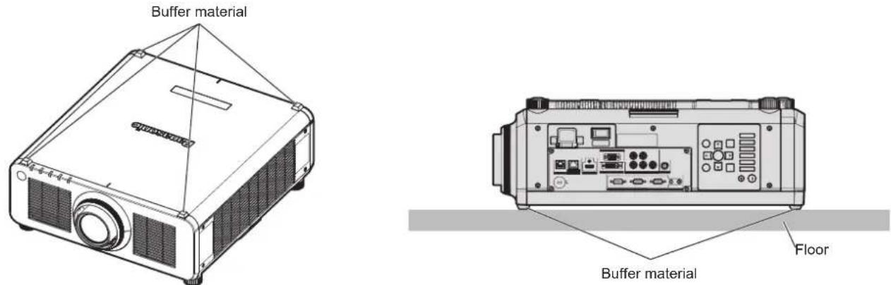
- The projector can be used by installing its top placed on the floor. To prevent the top surface from getting scratched during use, it is recommended to attach about a 20 mm (25/32") square buffer material (such as rubber cushion) on the four corners of the top surface.

PANASONIC PT-RZ120BE - ■Cautions when setting up the projector - 1

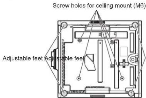
  • Use the adjustable feet only for the floor standing installation and for adjusting the angle. Using them for other purposes may damage the projector.
  • When installing the projector with a method other than the floor installation using the adjustable feet, top placed on the floor, or the ceiling installation with the Ceiling Mount Bracket, use the five screw holes for ceiling mount (as shown in the figure) to fix the projector to the mount.

In such case, make sure that there is no clearance between the screw holes for ceiling mount on the projector bottom and the setting surface by inserting spacers (metallic) between them.

- Use a torque screwdriver or Allen torque wrench to tighten the fixing screws to their specified tightening torques. Do not use electric screwdrivers or impact screwdrivers.

(Screw diameter: M6, tapping depth inside the projector: 12 mm (15/32"), torque: 4 ± 0.5 N·m)

PANASONIC PT-RZ120BE - ■Cautions when setting up the projector - 2

text_image Screw holes for ceiling mount (M6) Adjustable feet Adjustable feet

Positions of screw holes for ceiling mount and adjustable feet

- Do not stack projectors on top of each other.

  • Do not block the ventilation ports (intake and exhaust) of the projector.
  • Prevent hot and cool air from the air conditioning system to blow directly to the ventilation ports (intake and exhaust) of the projector.

PANASONIC PT-RZ120BE - ■Cautions when setting up the projector - 3

natural_image Diagram of two identical electrical or mechanical components with a central X-shaped cross symbol (no text or labels)

500 mm (19-11/16") or longer 500 mm (19-11/16") or longer
PANASONIC PT-RZ120BE - ■Cautions when setting up the projector - 4

natural_image Diagram of a projector with front panel and side screen, no text or symbols present

PANASONIC PT-RZ120BE - ■Cautions when setting up the projector - 5

natural_image Diagram of two identical projector units with ventilation grilles and a central hub, shown from top and bottom views (no text or symbols)

100 mm (3-15/16") or longer

PANASONIC PT-RZ120BE - ■Cautions when setting up the projector - 6

text_image 500 mm (19-11/16") or longer

- Do not install the projector in a confined space.

When installing the projector in a confined space, provide air conditioning or ventilation separately. Exhaust heat may accumulate when the ventilation is not enough, triggering the protection circuit of the projector.

- Panasonic takes no responsibility for any damage to the product caused by an inappropriate choice of location for installing the projector, even if the warranty period of the product has not expired.

Security

When using this product, take safety measures against the following incidents.

• Personal information being leaked via this product
•Unauthorized operation of this product by a malicious third party
• Interfering or stopping of this product by a malicious third party

Take sufficient security measures.

- Make your password difficult to guess as much as possible.

  • Change your password periodically. A password can be set in the [SECURITY] menu → [SECURITY PASSWORD CHANGE].
  • Panasonic Corporation or its affiliate companies will never ask for your password directly. Do not divulge your password in case you receive such inquiries.
    •The connecting network must be secured by a firewall, etc.
  • Set a password for the web control and restrict the users who can log in. A password for the web control can be set in the [Change password] page of the web control screen.

“DIGITAL LINK” is a technology to transmit the video, audio, Ethernet, and serial control signals using a twisted pair cable by adding unique functions by Panasonic to the HDBaseT™ communication standard formulated by HDBaseT Alliance.

This projector supports the optional Panasonic DIGITAL LINK output supported device (Model No.: ET-YFB100G, ET-YFB200G) and peripheral devices by other manufacturers (twisted-pair-cable transmitters such as the "XTP transmitter" of Extron Electronics) that use the same HDBaseT™ standard. For the devices of other manufacturers that the operation has been verified with this projector, visit the Panasonic website (https://panasonic.net/cns/projector/). Note that the verification for devices of other manufacturers has been made for the items set by Panasonic Corporation, and not all the operations have been verified. For operation or performance problems caused by the devices of other manufacturers, contact the respective manufacturers. This projector does not support audio transmission because it is not equipped with audio function.

Art-Net

"Art-Net" is an Ethernet communication protocol based on the TCP/IP protocol.

By using the DMX controller and the application software, illumination and stage system can be controlled. Art-Net is made based on DMX512 communication protocol.

Application software supported by the projector

The projector supports following application software. For details or downloading each application software, visit the Panasonic website (https://panasonic.net/cns/projector/).

- Logo Transfer Software

This application software transfers the original image, such as company logo, which is projected at the start, to the projector.

•Smart Projector Control

This application software sets and adjusts the projector connected via LAN using a smartphone or a tablet.

•Multi Monitoring & Control Software

This application software monitors and controls the multiple display devices (projector and flat panel display) connected to an intranet.

- Early Warning Software

This plug-in software monitors the status of the display devices and their peripherals within an intranet, and notifies of abnormality of such equipment and detects the signs of possible abnormality. “Early Warning Software” is preinstalled in the “Multi Monitoring & Control Software”. To use the early warning function of this plug-in software, install “Multi Monitoring & Control Software” in the PC to be used. By enabling the early warning function, it will notify of the approximate time to replace the consumables for the display devices, to clean each part of the display devices, and to replace the components of the display devices, allowing to execute maintenance in advance.

The early warning function can be used by registering maximum of 2048 display devices free of charge for 90 days after installing the “Multi Monitoring & Control Software” into a PC. To continuously use after the 90 days, it is necessary to purchase the license of “Early Warning Software” (ET-SWA100 Series) and perform the activation. Also, depending on the type of license, the number of display devices that can be registered for monitoring varies. For details, refer to the Operating Instructions of “Multi Monitoring & Control Software”.

Storing

To store the projector, store in a dry room.

Disposal

To dispose of the product, ask your local authorities or dealer for correct methods of disposal. Also, dispose of the product without disassembling.

Cautions on use

■To get a good picture quality

In order to view a beautiful image in higher contrast, prepare an appropriate environment. Draw curtains or blinds over windows and turn off any lights near the screen to prevent outside light or light from indoor lamps from shining onto the screen.

■ Do not touch the surface of the projection lens with your bare hands.

If the surface of the projection lens becomes dirty from fingerprints or anything else, this will be magnified and projected onto the screen.

Attach the lens cover supplied with the projector or with the optional projection lens to the projector when you do not use the projector.

■DLP chips

  • The DLP chips are precision-made. Note that in rare cases, pixels of high precision could be missing or always lit. Such a phenomenon does not indicate malfunction.
  • Directing a high-power laser beam onto the projection lens surface can damage the DLP chips.

■ Do not move the projector or subject it to vibration or impact while it is operating.

Doing so may shorten the life of the built-in motor.

Light source

The light source of the projector uses lasers, and has the following characteristics.

  • Depending on the operating environment temperature, the luminance of the light source will decrease.
    The higher the temperature becomes, the more the luminance of the light source decreases.
  • The luminance of the light source will decrease by duration of usage.
    If brightness is noticeably reduced and the light source does not turn on, ask your dealer to clean inside the projector or replace the light source unit.

■Computer and external device connections

When connecting a computer or an external device, read this manual carefully regarding the use of power cords and shielded cables as well.

Accessories

Make sure that the following accessories are provided with your projector. Numbers enclosed in < > show the number of accessories.

Wireless/wired remote control unit <1> (N2QAYA000060)
PANASONIC PT-RZ120BE - Accessories - 1

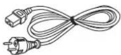
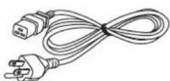
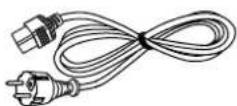
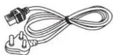
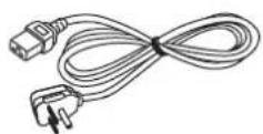
Power cord

(K2CM3YY00028)

200 V - 240 V

PANASONIC PT-RZ120BE - Power cord - 1

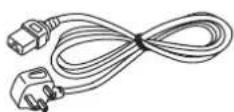
(K2CT3YY00053)

200 V - 240 V

PANASONIC PT-RZ120BE - Power cord - 2

(K2CG3YY00218)

100 V - 120 V

PANASONIC PT-RZ120BE - Power cord - 3

For Korea

(K2CZ3YY00032) <1>

200 V - 240 V

PANASONIC PT-RZ120BE - Power cord - 4

For India

(K2CZ3YY00058) <1>

200 V - 240 V

PANASONIC PT-RZ120BE - Power cord - 5

For Taiwan

(K2CZ3YY00081) <1>

200 V - 240 V

PANASONIC PT-RZ120BE - Power cord - 6

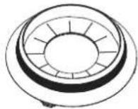
Lens Mount Cover <1>

(Black model: 1GE1RZ970BU)

(White model: 1GE1RZ970WU)

PANASONIC PT-RZ120BE - Lens Mount Cover &lt;1&gt; - 1

(The same color as the outer case will be supplied.)

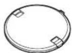
Lens cover <1>

(TKKL5244-1)

PANASONIC PT-RZ120BE - Lens cover &lt;1&gt; - 1

(Only models with lens)

CD-ROM <1>
PANASONIC PT-RZ120BE - Lens cover &lt;1&gt; - 2

(Operating Instructions are included.)

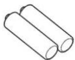
AAA/R03 or AAA/LR03 battery <2>
PANASONIC PT-RZ120BE - Lens cover &lt;1&gt; - 3

(For remote control unit)

Attention

• After unpacking the projector, discard the power cord cap and packaging material properly.
- Do not use the supplied power cord for devices other than this projector.
- For missing accessories, consult your dealer.
- Store small parts in an appropriate manner, and keep them away from small children.

Note

- The type and number of the supplied power cords vary depending on the country or region where you purchased the product.

- The model numbers of accessories are subject to change without prior notice.

Optional accessories

Optional accessories (product name) Model No.
Projection lensZoom LensET-DLE060, ET-DLE085, ET-DLE105, ET-DLE150, ET-DLE170 ^1 , ET-DLE250, ET-DLE350, ET-DLE450
Fixed-focus Lens ET-DLE035ET-DLE055
Ceiling Mount BracketET-PKD120H (for High Ceilings)ET-PKD120S (for Low Ceilings)ET-PKD130H (for High Ceilings, 6-axis Adjustment)ET-PKD130B (Projector Mount Bracket)
Early Warning Software(Basic license/3-year license)ET-SWA100 Series ^2
Upgrade Kit ET-UK20
Auto Screen Adjustment Upgrade Kit ET-CUK10
Auto Screen Adjustment Upgrade Kit (PC) ET-CUK10P
Digital Interface Box ET-YFB100G
DIGITAL LINK Switcher ET-YFB200G

*1 This product is equivalent to the lens attached to the projector models with standard zoom lens. The availability of this product varies depending on the country. For details, contact your dealer.

*2 The suffix of the Model No. differs according to the license type.

Note

- The model numbers of optional accessories are subject to change without prior notice.

About your projector

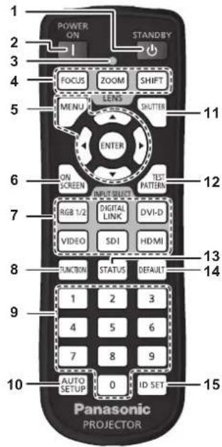
Remote control

FrontTop
PANASONIC PT-RZ120BE - Remote control - 1

text_image POWER ON STANDBY 1 2 3 4 FOCUS ZOOM SHIFT 5 LENS SHUTTER 6 ON SCREEN INPUT SELECT TEST PATTERN 7 RGB 1/2 DIGITAL LINK DVI-D VIDEO SDI HDMI 8 FUNCTION STATUS DEFAULT 9 1 2 3 4 5 6 7 8 9 AUTO SETUP 0 ID SET 10 Panasonic PROJECTOR

PANASONIC PT-RZ120BE - Remote control - 2

PANASONIC PT-RZ120BE - Remote control - 3

natural_image Close-up of a black electronic device with two circular ports and a labeled dimension line (16), no readable text or symbols beyond the number.

Bottom
PANASONIC PT-RZ120BE - Remote control - 4

natural_image Close-up of a black electronic device with a circular button and pointer labeled '17' (no text or symbols beyond the number)

1 Power standby <⏻> button

Sets the projector to the state where the projector is turned off (standby mode) when the

switch on the projector is set to and in projection mode.

2 Power on <|> button

Sets the projector to projection mode when the

switch on the projector is set to and the power is turned off (standby mode).

3 Remote control indicator

Blinks if any button in the remote control is pressed.

4 Lens buttons (, , )

Adjusts the focus, zoom, and lens shift. (→ page 68)

5

button/ button/▲▼◀▶ buttons

Used to navigate through the menu screen. (→ page 77)

▲▼◀▶ buttons are also used to enter the password in [SECURITY] or enter characters.

6 button

Switches the on-screen display function on (display) or off (hide). (→ page 73)

7 Input selection buttons (, , , , )

Switches the input signal to project. (→ page 67) The

8 button

Assigns a frequently used operation as a shortcut button. (→ page 74)

9 Number (<0> - <9>) buttons

Used for entering an ID number or a password in a multiple projector environment.

10 button

Automatically adjusts the image display position while projecting the image. [PROGRESS] is displayed while in automatic adjustment. (→ page 74)

11 button

Used to temporarily turn off the image. (→ page 73)

12 button

Displays the test pattern. (→ page 74)

13 button

Displays the projector information.

14 button

Resets the content of the sub-menu to the factory default. (→ page 78)

15 button

Sets the ID number of the remote control in a multiple projector environment. (→ page 33)

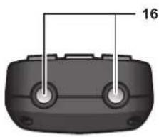
16 Remote control signal transmitter

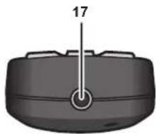
17 Remote control wired terminal

This is a terminal used to connect to the projector via a cable when the remote control is used as a wired remote control. (→ page 33)

Attention

- Do not drop the remote control.

- Avoid contact with liquids or moisture.

- Do not attempt to modify or disassemble the remote control.

- Observe the following instructions that are indicated on the caution label at the back of the remote control:

-Do not use old battery with new one.

-Do not use batteries other than the type specified.

-Be sure the batteries are inserted properly.

For other instructions, read the instructions related to batteries that are described in "Read this first!".

PANASONIC PT-RZ120BE - Attention - 1

Caution label at the back of the remote control

Note

  • When operating the remote control by directly pointing at the remote control signal receiver of the projector, operate the remote control within a distance approximately 30 m (98'5") from the remote control signal receiver. The remote control can control at angles of up to ± 30^ vertically and horizontally, but the effective control range may be reduced.
  • If there are any obstacles between the remote control and the remote control signal receiver, the remote control may not operate properly.
  • The signal will be reflected off the screen. However, the operating range may be limited from light reflection loss due to the screen material.
  • If the remote control signal receiver directly receives strong light, such as fluorescent light, the remote control may not operate properly. Use it in a place distant from the light source.
  • The power indicator will blink if the projector receives a remote control signal.

Projector body

Front
PANASONIC PT-RZ120BE - Projector body - 1

text_image 123456 7 8 9 8 7

Side
PANASONIC PT-RZ120BE - Projector body - 2

natural_image Technical diagram of a mechanical component with internal grating and mounting holes (no text or symbols)

■ Rear
PANASONIC PT-RZ120BE - Projector body - 3

text_image 10 7 11 7

PANASONIC PT-RZ120BE - Projector body - 4

text_image 141315 1617 18

■ Bottom
PANASONIC PT-RZ120BE - Projector body - 5

text_image 8 12 8 8

3 Light source indicator Indicates the status of light source 1.
4 Light source indicator Indicates the status of light source 2.
5 Temperature indicator Indicates the internal temperature status.
6 (Not used with this projector)
7 Adjustable feet Adjusts the projection angle.
8 Air intake port
9 Projection lens (Only models with lens)
10 Remote control signal receiver (rear)
11 Air exhaust port
12 Burglar hook port Attaches a burglar prevention cable, etc.
13 Control panel (→ page 31)
14 Connecting terminals (→ page 32)
15 Security slot This security slot is compatible with the Kensington security cables.
16

switch Turns on/off the main power.
17 terminal Connect the supplied power cord.
18 Power cord holder

PANASONIC PT-RZ120BE - Projector body - 6

: Projection direction

1 Remote control signal receiver (front)
2 Power indicator Indicates the status of the power.

Attention

■Control panel

PANASONIC PT-RZ120BE - ■Control panel - 1

flowchart
graph TD
    A["POWER ON"] --> B["STANDBY"]
    C["RGB1"] --> D["RGB1"]
    E["RGB2"] --> F["RGB2"]
    G["DVI-D"] --> H["DVI-D"]
    I["HDMI"] --> J["HDMI"]
    K["DIGITAL LINK"] --> L["DIGITAL LINK"]
    M["SDI"] --> N["SDI"]
    O["MENU"] --> P["ENTER"]
    Q["AUTO SETUP"] --> R["ENTER"]
    S["LENS"] --> T["LENS"]
    U["SHUTTER"] --> V["SHUTTER"]
    W["9"] --> X["9"]
    Y["10"] --> Z["10"]
    AA["11"] --> AB["11"]
    AC["12"] --> AD["12"]
    AE["13"] --> AF["13"]
    AG["14"] --> AH["14"]

1 Power on <|> button

Sets the projector to projection mode when the

switch on the projector is set to and the power is turned off (standby mode).

2 Power standby <∅> button

Sets the projector to the state where the projector is turned off (standby mode) when the

switch on the projector is set to and in projection mode.

3 button

Switches the input to RGB1.

4 button

Switches the input to RGB2.

5 button

Switches the input to DVI-D.

6 button

Switches the input to HDMI.

7 button

Switches the input to DIGITAL LINK.

8 button

Switches the input to SDI.

9

button

Displays or hides the main menu. (→ page 77)

Returns to the previous menu when a sub-menu is displayed.

If you press the

button on the control panel for at least three seconds while the on-screen display is off (hidden), the on-screen display is turned on.

10 button

Adjusts the focus, zoom, and lens shift.

11 button

Determines and executes an item in the menu screen.

12 button

Used to temporarily turn off the image. (→ page 73)

13 ▲▼◀▶ selection buttons

Used to select an item in the menu screen, change the setting, and adjust the level.

Also used to enter a password in [SECURITY] or enter characters.

14 button

Automatically adjusts the image display position while the image is projected. [PROGRESS] is displayed during the automatic adjustment. (→ page 74)

■Connecting terminals

PANASONIC PT-RZ120BE - ■Connecting terminals - 1

text_image 1234 REMOTE 1 REMOTE 2 IN SERIAL/MULTI PROJECTOR SYNC IN OUT IN OUT SDI IN RGB 1 IN DVHD IN HDMI LAN DIGITAL LINK LAN 3G/HD/SD SYNC/HD VD 5678910 11

1 terminal/ terminal These are terminals to connect the remote control for serial control in a multiple projector environment.
2 terminal This is a terminal to remotely control the projector using the external control circuit.
3 terminal This is the RS-232C compatible terminal to externally control the projector by connecting a computer. This terminal is also used to connect multiple projectors when balancing the contrast as a combined screen or synchronizing the effects using the shutter function including the fade in/fade out with a system using multiple projectors.
4 terminal This is a terminal to output RS-232C compliant signal input to the terminal. This terminal is also used to connect multiple projectors when balancing the contrast as a combined screen or synchronizing the effects using the shutter function including the fade in/fade out with a system using multiple projectors.

5 terminal This is a terminal to input the SDI signal.
6 terminals (, , , , ) These are terminals to input the RGB signal or YC_B C_R / YP_B P_R signal.
7 terminal This is a terminal to input the RGB signal or YC_BC_R/YP_BP_R signal.
8 terminal This is a terminal to input the DVI-D signal.
9 terminal This is a terminal to input the HDMI signal.
10 terminal This is a terminal to connect a device that transmits video signal via the LAN terminal. Also, this is the LAN terminal to connect to the network.
11 terminal This is the LAN terminal to connect to the network.

Attention

  • When a LAN cable is directly connected to the projector, the network connection must be made indoors.
  • The terminal and terminal are connected inside of the projector. If both the terminal and terminal are used, configure the system so that these terminals are not directly connected or connected through peripheral devices such as a hub or a twisted-pair-cable transmitter to the same network.

Preparing the remote control

Inserting and removing the batteries

PANASONIC PT-RZ120BE - Inserting and removing the batteries - 1

text_image (i) (ii)

PANASONIC PT-RZ120BE - Inserting and removing the batteries - 2

natural_image Diagram of a remote control panel with two buttons and a handle (no text or symbols)

Fig. 1 Fig. 2

1) Open the cover. (Fig. 1)
2) Insert the batteries and close the cover (insert the ● side first). (Fig. 2)

- When removing the batteries, perform the steps in reverse order.

When using the multiple projectors

When you use the multiple projectors together, you can operate all the projectors simultaneously or each projector individually using a single remote control, if a unique ID number is assigned to each projector.

When using the projectors by setting the ID numbers, set the ID number of the projector body after initial settings have been completed. Then, set the ID number of the remote control. For initial settings, refer to "When the initial setting screen is displayed" (→ page 59).

The factory default ID number of the projector (projector body and remote control) is set to [ALL], so you can use it as it is. Set the ID numbers of the projector body and remote control as necessary.

For details on setting the ID number of the remote control, refer to "Setting ID number of the remote control" (→ page 75).

Note

- Set the ID number of the projector body from the [PROJECTOR SETUP] menu → [PROJECTOR ID].

Connecting the remote control to the projector with a cable

To simultaneously control multiple projectors next to each other with one remote control, connect the remote control with a commercially available M3 stereo mini jack cable using the / terminals.

The remote control is effective even in places where an obstacle stands in the light path or where devices are susceptible to outside light.

PANASONIC PT-RZ120BE - Connecting the remote control to the projector with a cable - 1

text_image Remote control Connecting to the remote control wired terminal M3 stereo mini jack cable (commercially available) Connecting to a second projector REMOTE 1 REMOTE 2 IN SERIAL/MULTI PROJECTOR SYNC IN OUT IN OUT SDI IN RGB 1 IN 3G/HD/SD RGB 2 IN 3G/HD/SD GPIO GPIO SYNC/HD VDD DVHD IN HDMI VAN DIGITAL LINK VAN

Attention

- Use a cable that is 15 m (49'3") or shorter, with 2 core shielded. The remote control may not operate when the length of the cable exceeds 15 m (49'3") or when the shielding of the cable is inadequate.

Chapter 2 Getting Started

This chapter describes things you need to do before using the projector such as the setup and connections.

Setting up

Usable outlet

This projector supports AC 100 V to AC 240 V as the power supply. A grounded outlet supporting 15 A is required with either voltage.

The shape of the usable outlet differs depending on the power supply. Following illustrations are examples.

PANASONIC PT-RZ120BE - Usable outlet - 1
2P/3W 15 A 250 V

PANASONIC PT-RZ120BE - Usable outlet - 2
2P/3W 15 A 250 V

PANASONIC PT-RZ120BE - Usable outlet - 3
2P/3W 15 A 250 V

PANASONIC PT-RZ120BE - Usable outlet - 4
2P/3W 15 A 250 V

PANASONIC PT-RZ120BE - Usable outlet - 5
2P/3W 15 A 125 V

Attention

- Use the supplied power cord and ground at the outlet.

- Use the power cord matching the used power supply voltage and outlet shape.

Note

- The supplied power cords vary depending on the country or region where you purchased the product.

Installation mode

The installation modes of the projector are as follows. Set [FRONT/REAR]/[FLOOR/CEILING] in the [PROJECTOR SETUP] menu → [PROJECTION METHOD] (→ page 125) depending on the installation mode.

Setting on a desk/floor and projecting forward Setting on a desk/floor and projecting from rear(Using the translucent screen)
PANASONIC PT-RZ120BE - Installation mode - 1PANASONIC PT-RZ120BE - Installation mode - 2
Menu item Setting valueMenu item Setting value
[FRONT/REAR] [FRONT][FRONT/REAR] [REAR]
[FLOOR/CEILING] [AUTO]or [FLOOR] [FLOOR/CEILING] [AUTO] or [FLOOR]
Mounting on the ceiling and projecting forward Mounting on the ceiling and projecting from rear(Using the translucent screen)
PANASONIC PT-RZ120BE - Installation mode - 3PANASONIC PT-RZ120BE - Installation mode - 4
Menu item Setting valueMenu item Setting value
[FRONT/REAR] [FRONT][FRONT/REAR] [REAR]
[FLOOR/CEILING][AUTO] or [CEILING][FLOOR/CEILING][AUTO] or [CEILING]
Portrait setting and projecting forward Portrait setting and projecting from rear(Using the translucent screen)
PANASONIC PT-RZ120BE - Installation mode - 5PANASONIC PT-RZ120BE - Installation mode - 6
Menu item Setting valueMenu item Setting value
[FRONT/REAR] [FRONT][FRONT/REAR] [REAR]
[FLOOR/CEILING]Set in accordance with the image to project.[FLOOR/CEILING]Set in accordance with the image to project.

Note

- In the portrait setting, the on-screen menu is displayed sideways.

To display the on-screen menu vertically, go to the [DISPLAY OPTION] menu → [ON-SCREEN DISPLAY] (→ page 117) and change the [OSD ROTATION] setting.

- The projector has a built-in angle sensor. The attitude of the projector is automatically detected by setting [FLOOR/CEILING] to [AUTO] in the [PROJECTOR SETUP] menu → [PROJECTION METHOD].

■Angle sensor

The range of the installation attitude that is detected by the angle sensor built-in the projector is as follows.

PANASONIC PT-RZ120BE - ■Angle sensor - 1

text_image Floor standing installation 30° 30° Ceiling mount installation Floor standing installation : Projection direction

Parts for installation (optional)

The projector can be installed on the ceiling by combining the optional Ceiling Mount Bracket (Model No.: ET-PKD120H (for High Ceilings), ET-PKD120S (for Low Ceilings), ET-PKD130H (for High Ceilings, 6-axis Adjustment)) and the Ceiling Mount Bracket (Model No.: ET-PKD130B (Projector Mount Bracket)).

  • Be sure to use the Ceiling Mount Bracket specified for this projector.
  • Refer to the Installation Instructions of the Ceiling Mount Bracket when installing and setting up the projector.

Attention

- To ensure projector performance and security, installation of the Ceiling Mount Bracket must be carried out by your dealer or a qualified technician.

Projected image and throw distance

Install the projector referring to the projected image size and projection distance. Image size and image position can be adjusted in accordance with the screen size and screen position. The projection relation between the screen and the projector differs from that of other lenses, when the Fixed-focus Lens (Model No.: ET-DLE035) is used. Refer to "Fixed-focus Lens (Model No.: ET-DLE035)" ( page 38) for details.

Attention

  • Before setting up, read "Precautions for use" (→ page 20).
    Especially when the Fixed-focus Lens (Model No.: ET-DLE035) is used, install the projector so that its back plane is parallel to the screen, making the projected image rectangular.
    The vertical keystone distortion in moderate range can be corrected with the [POSITION] menu → [GEOMETRY] → [KEYSTONE] → [VERTICAL KEYSTONE] (→ page 94) even after the projector is installed. For the range that can be corrected, refer to “[GEOMETRY] projection range” (→ page 39).
  • Do not use the projector and the high-powered laser equipment in the same room. The DLP chips can be damaged if a laser beam hits the projection lens surface.

Note

- The optional Zoom Lens (Model No.: ET-DLE170) is equivalent to the lens attached to the projector models with standard zoom lens. The availability of this product varies depending on the country. For details, contact your dealer.

Figure of projected image and throw distance
PANASONIC PT-RZ120BE - Note - 1

text_image Projected image SH SD SW

PANASONIC PT-RZ120BE - Note - 2

text_image Screen L (LW/LT) L1

PANASONIC PT-RZ120BE - Note - 3

text_image SW SH L (LW/LT) Screen L1

Note

- This illustration is prepared on the assumption that the projected image size and position have been aligned to fit full in the screen.

SH Projected image height
SW Projected image width
SD Projected image size
H Distance from the lens center to the bottom edge of the projected image
L^*1 (LW/LT)^2 Projection distance (distance from the front end of the projection lens to the screen)
L1Lens protrusion dimension (distance from the front surface of the projector to the front end of the projection lens)

*1 For details about calculating the projection distance, refer to "Formula for calculating the projection distance per projection lens" (→ page 45).

*2 LW: Minimum projection distance when the Zoom Lens is used LT: Maximum projection distance when the Zoom Lens is used

(Unit: m)

Projection lens Model No. Lens protrusion dimension (L1) (approximate value)
Standard zoom lens/ET-DLE1700.043
ET-DLE055 0.027
ET-DLE060 0.104
ET-DLE085 0.084
ET-DLE105 0.088
ET-DLE150 0.044
ET-DLE250 0.045
ET-DLE350 0.051
ET-DLE450 0.095

Note

- For the adjustment range of the projected image position with the lens shift, refer to "Lens shift range" (→ page 71).

■Fixed-focus Lens (Model No.: ET-DLE035)

PANASONIC PT-RZ120BE - ■Fixed-focus Lens (Model No.: ET-DLE035) - 1

text_image Projected image SH SD SW

PANASONIC PT-RZ120BE - ■Fixed-focus Lens (Model No.: ET-DLE035) - 2

text_image Screen SH L2 L1 L3 A1 A2 L4

PANASONIC PT-RZ120BE - ■Fixed-focus Lens (Model No.: ET-DLE035) - 3

text_image SW Screen

Note

- This illustration is prepared on the assumption that the projected image size and position have been aligned to fit full in the screen.

SH Projected image height
SW Projected image width
SD Projected image size
L1*1Projection distance (distance from the mirror reflection surface*2 to the screen)
L2 Distance from the front end of the projection lens to the screen
L3 Distance from the front surface of the projector to the screen
L4 Distance from the back surface of the projector to the screen
A1*1Distance from the top surface of the projector to the bottom edge of the screen
A2 Distance from the installation surface of the projector to the screen (adjustable feet at lowest position)

*1 For details about calculating the projection distance, refer to "Formula for calculating the projection distance per projection lens" (→ page 45).
*2 The mirror reflection surface cannot be seen from the outside because it is located inside the Fixed-focus Lens.

(Unit: m)

Distance from the projector to the screenFormula
L2 = L1 + 0.023
L3 = L1-0.166
L4 = L1-0.704
A2 = A1 + 0.200

Attention

  • The dimension of L4 is not the distance between the back surface of the projector and the wall, but the distance between the back surface of the projector and the screen surface. Install the projector with 500 mm (19-11/16") or larger space between the back surface of the projector and the wall or any object so that the ventilation is not obstructed.
    When installing the projector in a confined space, provide air conditioning or ventilation separately. Exhaust heat may accumulate when the ventilation is not enough, triggering the protection circuit of the projector.

Note

- For the adjustment range of the projected image position with the lens shift, refer to "Lens shift range" (→ page 71).

[GEOMETRY] projection range

[VERTICAL KEYSTONE] (viewed from the side) [HORIZONTAL KEYSTONE] (viewed from above)
PANASONIC PT-RZ120BE - [GEOMETRY] projection range - 1

text_image α Screen

PANASONIC PT-RZ120BE - [GEOMETRY] projection range - 2

text_image β Screen

Vertical arc correction (viewed from the side) Horizontal arc correction (viewed from above)
PANASONIC PT-RZ120BE - [GEOMETRY] projection range - 3

text_image L2 L2 : Projection distance R2 : Arc radius Screen R2

PANASONIC PT-RZ120BE - [GEOMETRY] projection range - 4

text_image L2 L2 : Projection distance R2: Arc radius Screen R2

PANASONIC PT-RZ120BE - [GEOMETRY] projection range - 5

text_image Arc center Screen R3 L3 L3 : Projection distance R3 : Arc radius

PANASONIC PT-RZ120BE - [GEOMETRY] projection range - 6

text_image Arc center Screen R3 L3 L3 : Projection distance R3 : Arc radius

Standard status

Projection lens Model No.Only [KEYSTONE] used [KEYSTONE] and [CURVED CORRECTION] used togetherOnly [CURVED CORRECTION] used
Vertical keystone correction angle α (°)Horizontal keystone correction angle β (°)Vertical keystone correction angle α (°)Horizontal keystone correction angle β (°)Min. value of R2/L2Min. value of R3/L3Min. value of R2/L2Min. value of R3/L3
Standard zoom lens/ET-DLE170±40 ±15 ±20±15 0.9 1.70.5 1
ET-DLE0351+5 / -0 0 —— — — — —
ET-DLE055 ±22 ±15 ±8 ±8 1.74.3 1 2.6
ET-DLE060 ±16 ±10 — — —— — —
ET-DLE085 ±22 ±15 ±8 ±8 1.74.3 1 2.6
ET-DLE105 ±22 ±15 ±8 ±8 1.74.3 1 2.6
ET-DLE150 ±40 ±15 ±20 ±151.1 2.6 0.6 1.5
ET-DLE250 ±40 ±15 ±20 ±150.7 1.3 0.4 0.7
ET-DLE350 ±40 ±15 ±20 ±150.4 0.8 0.3 0.5
ET-DLE450 ±40 ±15 ±20 ±150.3 0.6 0.2 0.3

*1 Only the vertical keystone correction angle can be corrected in the direction in which the projector body moves away from the screen.

When using the optional Upgrade Kit (Model No.: ET-UK20)

Projection lens Model No.Only [KEYSTONE] used*1[KEYSTONE] and [CURVED CORRECTION] used togetherOnly [CURVED CORRECTION] used
Vertical keystone correction angle α (°)Horizontal keystone correction angle β (°)Vertical keystone correction angle α (°)Horizontal keystone correction angle β (°)Min. value of R2/L2Min. value of R3/L3Min. value of R2/L2Min. value of R3/L3
Standard zoom lens/ET-DLE170±40 ±40 ±20±15 0.7 1.30.4 0.7
ET-DLE035*2+5 / -0 0 —— — — — —
ET-DLE055 ±22±15 ±8 ±8 1.33.3 0.8 1.9
ET-DLE060 ±16±10 — — —— — —
ET-DLE085 ±22±15 ±8 ±8 1.33.3 0.8 1.9
ET-DLE105 ±22±15 ±8 ±8 1.33.3 0.8 1.9
ET-DLE150 ±40±40 ±20 ±150.9 2 0.5 1.1
ET-DLE250 ±40±40 ±20 ±150.5 1 0.3 0.6
ET-DLE350 ±45±40 ±20 ±150.3 0.6 0.2 0.4
ET-DLE450 ±45±40 ±20 ±150.2 0.4 0.2 0.3

*1 When [VERTICAL KEYSTONE] and [HORIZONTAL KEYSTONE] are used simultaneously, correction cannot be made exceeding total of 55°.
*2 Only the vertical keystone correction angle can be corrected in the direction in which the projector body moves away from the screen.

Note

  • When [GEOMETRY] is used, the focus of the entire screen may be lost as correction increases.
  • Make the curved screen a circular arc shape with one part of a perfect circle removed.
  • Adjustment range of the [GEOMETRY] items may not match the listed projection range depending on the projection lens. Use this projector within the projection range, otherwise the correction may not work.

Projection distance of each projection lens

A ±5 % error in listed projection distances may occur.

When [GEOMETRY] is used, distance is corrected to become smaller than the specified image size.

■When the screen aspect ratio is 16:10

(Unit: m)

Lens type Zoom Lens
Projection lens Model No.Standard zoom lens/ET-DLE170ET-DLE060 ET-DLE085 ET-DLE105ET-DLE150
Throw ratio*11.71-2.41:1 0.600-0.801:1 0.782-0.977:1 0.978-1.32:1 1.30-1.89:1
Projected image size Projection distance (L)
Diagonal (SD)Height (SH)Width (SW)Min. (LW)Max. (LT)Min. (LW)Max. (LT)Min. (LW)Max. (LT)Min. (LW)Max. (LT)Min. (LW)Max. (LT)
1.27 (50") 0.673 1.077 1.82 2.57 0.630.84 0.821.04 1.031.41 1.382.01
1.52 (60") 0.808 1.292 2.20 3.10 0.761.02 1.001.25 1.251.70 1.662.43
1.78 (70") 0.942 1.508 2.58 3.63 0.901.20 1.171.47 1.471.99 1.952.84
2.03 (80") 1.077 1.723 2.95 4.16 1.031.38 1.351.68 1.682.28 2.233.25
2.29 (90") 1.212 1.939 3.33 4.69 1.171.56 1.521.90 1.902.57 2.523.66
2.54 (100") 1.346 2.154 3.71 5.21 1.311.74 1.702.11 2.122.86 2.814.08
3.05 (120") 1.615 2.585 4.47 6.27 1.582.10 2.052.55 2.553.44 3.384.90
3.81 (150") 2.019 3.231 5.60 7.86 1.992.63 2.573.19 3.204.32 4.246.14
5.08 (200") 2.692 4.308 7.50 10.50 2.673.53 3.444.27 4.295.77 5.678.20
6.35 (250") 3.365 5.385 9.39 13.14 3.354.42 4.315.35 5.377.23 7.1010.26
7.62 (300") 4.039 6.462 1128 15.79 403 5.32 518 6.43 646 8.68 853 12.33
8.89 (350") 4.712 7.539 1318 18.43 471 6.21 606 7.51 754 10.149.96 14.39
10.16 (400") 5.3885 8.616 1507 21.07 539 7.11 693 8.59 863 11.5911.39 16.45
12.70 (500") 6.731 10.77018.86 26.366.75 8.908.67 10.7510.8014.50 14.2520.58
15.24 (600")8.07712.92322.6431.658.1110.6910.4212.9112.9717.4117.1124.70

*1 The throw ratio is based on the value during projection of 2.03 m (80") projected image size.

(Unit: m)

Lens typeZoom LensHeight position (H)
Projection lens Model No.ET-DLE250 ET-DLE350 ET-DLE450Standard zoomlens/ET-DLE170/ET-DLE085/ET-DLE105/ET-DLE150/ET-DLE250/ET-DLE350/ET-DLE450ET-DLE060
Throw ratio*12.27-3.62:13.58-5.45:15.36-8.58:1
Projected image sizeProjection distance (L)
Diagonal (SD)Height (SH)Width (SW)Min.(LW)Max.(LT)Min.(LW)Max.(LT)Min.(LW)Max.(LT)
1.27 (50")0.6731.0772.423.873.805.815.669.120 - 0.440.07 - 0.44
1.52 (60")0.8081.2922.924.654.597.006.8511.010 - 0.530.08 - 0.53
1.78 (70")0.9421.5083.425.445.388.198.0412.890 - 0.620.09 - 0.62
2.03 (80")1.0771.7233.926.236.169.389.2314.780 - 0.710.11 - 0.71
2.29 (90")1.2121.9394.427.026.9510.5710.4316.660 - 0.800.12 - 0.80
2.54 (100")1.3462.1544.927.817.7411.7611.6218.550 - 0.890.13 - 0.89
3.05 (120")1.6152.5855.919.399.3114.1414.0022.310 - 1.070.16 - 1.07
3.81 (150")2.0193.2317.4111.7511.6817.7117.5827.970 - 1.330.20 - 1.33
5.08 (200")2.6924.3089.9115.7015.6123.6623.5437.390 - 1.780.27 - 1.78
6.35 (250")3.3655.38512.4119.6419.5529.6129.5046.810 - 2.220.34 - 2.22
7.62 (300")4.0396.46214.9123.5923.4935.5635.4656.240 - 2.670.40 - 2.67
8.89 (350")4.7127.53917.4027.5327.4241.5141.4265.660 - 3.110.47 - 3.11
10.16 (400")5.3858.61619.9031.4831.3647.4647.3875.080 - 3.550.54 - 3.55
12.70 (500")6.73110.77024.9039.3739.2359.3659.3093.930 - 4.440.67 - 4.44
15.24 (600")8.07712.92329.8947.2547.1171.2571.22112.770 - 5.330.81 - 5.33

*1 The throw ratio is based on the value during projection of 2.03 m (80") projected image size.

(Unit: m)

Lens type Fixed-focus Lens
Projection lens Model No. ET-DLE055 ET-DLE035*1
Throw ratio*20.785:1 0.380:1
Projected image sizeProjection distance (L)Height position (H)*3Projection distance (L1)Distance from the projector to the screen
Diagonal (SD)Height (SH)Width (SW)(L4) (A)(1)
1.27 (50") 0.673 1.077 0.83 0.34 — —
1.52 (60") 0.808 1.292 1.00 0.40 — —
1.78 (70") 0.942 1.508 1.18 0.47 — —
2.03 (80") 1.077 1.723 1.35 0.54 — —
2.29 (90") 1.212 1.939 1.53 0.61 — —
2.54 (100") 1.346 2.154 1.70 0.67 0.82 0.11 0.43
3.05 (120") 1.615 2.585 2.05 0.81 0.98 0.28 0.53
3.81 (150") 2.019 3.231 2.58 1.01 1.23 0.52 0.68
5.08 (200") 2.692 4.308 3.45 1.35 1.63 0.93 0.93
6.35 (250") 3.365 5.385 —— 2.04 1.34 1.18
7.62 (300") 4.039 6.462 —— 2.45 1.74 1.43
8.89 (350") 4.712 7.539 —— 2.85 2.15 1.69
10.16 (400") 5.385 8.616 —— — — —
12.70 (500") 6.7310.770 —— — — —
15.24 (600") 8.077 12.923 —— — — —

*1 When the Fixed-focus Lens (Model No.: ET-DLE035) is attached, the projection relation between the screen and the projector differs from that of other lenses. Refer to "Fixed-focus Lens (Model No.: ET-DLE035)" ( page 38) for details.

*2 The throw ratio is based on the value during projection of 2.03 m (80") projected image size. When the Fixed-focus Lens (Model No.: ET-DLE035) is attached, the throw ratio is based on the value during projection of 2.54 m (100") projected image size.

*3 When the Fixed-focus Lens (Model No.: ET-DLE055) is attached, the lens shift is not possible, therefore the height position (H) becomes the fixed value of SH/2.

■ When the screen aspect ratio is 16:9

(Unit: m)

Lens typeZoom Lens
Projection lens Model No.Standard zoom lens/ET-DLE170ET-DLE060ET-DLE085ET-DLE105ET-DLE150
Throw ratio*11.72-2.41:1 0.600-0.802:10.783-0.977:1 0.979-1.321.30-1.89:1
Projected image sizeProjection distance (L)
Diagonal (SD)Height (SH)Width (SW)Min. (LW)Max. (LT)Min. (LW)Max. (LT)Min. (LW)Max. (LT)Min. (LW)Max. (LT)Min. (LW)Max. (LT)
1.27 (50") 0.623 1.107 1.872.64 0.640.87 0.851.07 1.061.45 1.422.07
1.52 (60") 0.747 1.328 2.263.19 0.781.05 1.031.29 1.291.75 1.712.49
1.78 (70") 0.872 1.550 2.653.73 0.921.24 1.211.51 1.512.05 2.002.92
2.03 (80") 0.996 1.771 3.044.27 1.061.42 1.391.73 1.732.35 2.303.34
2.29 (90") 1.121 1.992 3.434.82 1.201.60 1.571.95 1.962.64 2.593.77
2.54 (100") 1.245 2.214 3.825.36 1.341.79 1.752.17 2.182.94 2.894.19
3.05 (120") 1.494 2.657 4.606.45 1.622.16 2.102.62 2.633.54 3.475.04
3.81 (150") 1.868 3.321 5.768.08 2.042.71 2.643.28 3.294.44 4.366.31
5.08 (200") 2.491 4.428 7.7110.802.74 3.633.54 4.394.41 5.935.82 8.43
6.35 (250")3.1135.5359.6513.513.444.554.435.505.527.437.2910.55
7.62 (300")3.7366.64111.6016.234.145.475.336.616.648.938.7612.67
8.89 (350")4.3587.74813.5518.954.846.396.237.727.7610.4210.2314.79
10.16 (400")4.9818.85515.4921.665.547.317.128.838.8711.9211.7016.91
12.70 (500")6.22611.06919.3827.106.939.158.9111.0511.1014.9114.6421.15
15.24 (600")7.47213.28323.2732.538.3310.9910.7113.2713.3317.9017.5825.39

*1 The throw ratio is based on the value during projection of 2.03 m (80") projected image size.

(Unit: m)

Lens type Zoom Lens Height position (H)
Projection lens Model No. ET-DLE250 ET-DLE350 ET-DLE450 Standard zoomlens/ET-DLE170/ET-DLE085/ET-DLE105/ET-DLE150/ET-DLE250/ET-DLE350/ET-DLE450ET-DLE060
Throw ratio*12.27-3.62:1 3.58-5.45:1 5.36-8.58:1
Projected image size Projection distance (L)
Diagonal (SD)Height (SH)Width (SW)Min. (LW)Max. (LT)Min. (LW)Max. (LT)Min. (LW)Max. (LT)
1.27 (50") 0.623 1.107 2.49 3.97 3.915.98 5.829.39-0.06 - 0.46 0.00-0.46
1.52 (60") 0.747 1.328 3.00 4.79 4.727.20 7.0511.32-0.07 - 0.55 0.00-0.55
1.78 (70") 0.872 1.550 3.51 5.60 5.538.43 8.2713.26-0.09 - 0.64 0.00-0.64
2.03 (80") 0.996 1.771 4.03 6.41 6.349.65 9.5015.20-0.10 - 0.73 0.00-0.73
2.29 (90") 1.121 1.992 4.54 7.22 7.1510.87 10.7217.13-0.11 - 0.82 0.00-0.82
2.54 (100") 1.245 2.214 5.05 8.03 7.9612.0911.95 19.07-0.12 - 0.91 0.00-0.91
3.05 (120") 1.494 2.657 6.08 9.65 9.5814.54 14.4022.94-0.15 - 1.10 0.00-1.10
3.81 (150")1.8683.3217.6212.0812.0018.2118.0828.75-0.19 - 1.37 0.00-1.37
5.08 (200")2.4914.42810.1916.1416.0524.3224.2038.44-0.25 - 1.83 0.00-1.83
6.35 (250")3.1135.53512.7520.1920.1030.4430.3348.12-0.31 - 2.28 0.00-2.28
7.62 (300")3.7366.64115.3224.2524.1436.5536.4557.81-0.37 - 2.74 0.00-2.74
8.89 (350")4.3587.74817.8928.3028.1942.6742.5867.49-0.44 - 3.20 0.00-3.20
10.16 (400")4.9818.85520.4632.3532.2448.7848.7177.18-0.50 - 3.65 0.00-3.65
12.70 (500")6.22611.06925.5940.4640.3361.0160.9696.55-0.62 - 4.57 0.00-4.57
15.24 (600")7.47213.28330.7248.5748.4273.2473.21115.91-0.75 - 5.48 0.00-5.48

*1 The throw ratio is based on the value during projection of 2.03 m (80") projected image size.

(Unit: m)

Lens typeFixed-focus Lens
Projection lens Model No. ET-DLE055 ET-DLE035 *1
Throw ratio20.786:10.380:1
Projected image sizeProjection distance (L)Height position (H)*3Projection distance (L1)Distance from the projector to the screen
Diagonal (SD)Height (SH)Width (SW)(L4)(A1)
1.27 (50")0.6231.1070.850.31
1.52 (60")0.7471.3281.030.37
1.78 (70")0.8721.5501.210.44
2.03 (80")0.9961.7711.390.50
2.29 (90")1.1211.9921.570.56
2.54 (100") 1.245 2.2141.75 0.62 0.840.14 0.51
3.05 (120") 1.494 2.6572.11 0.75 1.010.30 0.63
3.81 (150") 1.868 3.3212.65 0.93 1.260.56 0.81
5.08 (200") 2.491 4.4283.55 1.25 1.680.97 1.10
6.35 (250")3.1135.5352.101.391.39
7.62 (300")3.7366.6412.511.811.68
8.89 (350")4.3587.7482.932.231.98
10.16 (400")4.9818.855
12.70 (500")6.22611.069
15.24 (600")7.47213.283

*1 When the Fixed-focus Lens (Model No.: ET-DLE035) is attached, the projection relation between the screen and the projector differs from that of other lenses. Refer to "Fixed-focus Lens (Model No.: ET-DLE035)" ( page 38) for details.

*2 The throw ratio is based on the value during projection of 2.03 m (80") projected image size. When the Fixed-focus Lens (Model No.: ET-DLE035) is attached, the throw ratio is based on the value during projection of 2.54 m (100") projected image size.

*3 When the Fixed-focus Lens (Model No.: ET-DLE055) is attached, the lens shift is not possible, therefore the height position (H) becomes the fixed value of SH/2.

■When the screen aspect ratio is 4:3

(Unit: m)

Lens type Zoom Lens
Projection lens Model No.Standard zoom lens/ET-DLE170ET-DLE060 ET-DLE085 ET-DLE105ET-DLE150
Throw ratio*12.06-2.90:1 0.724-0.965:1 0.943-1.18:1 1.18-1.59:1 1.56-2.27:1
Projected image size Projection distance (L)
Diagonal (SD)Height (SH)Width (SW)Min. (LW)Max. (LT)Min. (LW)Max. (LT)Min. (LW)Max. (LT)Min. (LW)Max. (LT)Min. (LW)Max. (LT)
1.27 (50") 0.762 1.016 2.072.92 0.710.96 0.941.18 1.181.60 1.562.29
1.52 (60") 0.914 1.219 2.503.52 0.871.16 1.141.42 1.421.93 1.892.75
1.78 (70") 1.067 1.422 2.934.12 1.021.37 1.331.67 1.672.26 2.213.22
2.03 (80") 1.219 1.626 3.354.72 1.181.57 1.531.91 1.912.59 2.543.69
2.29 (90") 1.372 1.829 3.785.31 1.331.77 1.732.16 2.162.92 2.864.15
2.54 (100") 1.524 2.032 4.215.91 1.481.97 1.932.40 2.413.25 3.184.62
3.05 (120") 1.829 2.438 5.077.11 1.792.38 2.322.89 2.903.91 3.835.55
3.81 (150") 2.286 3.048 6.358.91 2.252.99 2.913.62 3.634.89 4.806.96
5.08 (200") 3.048 4.064 8.5011.90 3.024.00 3.904.84 4.866.54 6.429.29
6.35 (250") 3.810 5.080 1064 14.89 379 5.01 489 6.07 609 8.19 804 11.63
7.62 (300") 4.572 6.096 1278 17.88 456 6.03 588 7.29 732 9.84 966 13.96
8.89 (350") 5.334 7.112 1493 20.88 533 7.04 686 8.51 855 11.4811.28 16.30
10.16 (400") 6.096 8.128 1707 23.87 610 8.057.85 9.739.78 13.1312.90 18.63
12.70 (500") 7.620 10.16021.36 29.857.64 10.089.82 12.117 12.2316.42 16.13 23.30
15.24 (600") 9.144 12.19225.64 35.849.18 12.111.80 146.62 14.6919.72 19.3727.97

*1 The throw ratio is based on the value during projection of 2.03 m (80") projected image size.

(Unit: m)

Lens typeZoom LensHeight position (H)
Projection lens Model No.ET-DLE250ET-DLE350ET-DLE450Standard zoom lens/ET-DLE170/ET-DLE085/ET-DLE105/ET-DLE150/ET-DLE250/ET-DLE350/ET-DLE450ET-DLE060
Throw ratio*12.73-4.35:1 4.30-6.55:1 6.46-10.3:1
Projected image sizeProjection distance (L)
Diagonal (SD)Height (SH)Width (SW)Min. (LW)Max. (LT)Min. (LW)Max. (LT)Min. (LW)Max. (LT)
1.27 (50")0.7621.0162.754.394.326.606.4510.370 - 0.500.08 - 0.50
1.52 (60")0.9141.2193.315.285.217.957.8012.500 - 0.600.09 - 0.60
1.78 (70")1.0671.4223.886.176.109.299.1414.630 - 0.700.11 - 0.70
2.03 (80")1.2191.6264.447.077.0010.6410.4916.770 - 0.800.12 - 0.80
2.29 (90")1.3721.8295.017.967.8911.9911.8418.900 - 0.910.14 - 0.91
2.54 (100")1.5242.0325.578.858.7813.3413.1921.030 - 1.010.15 - 1.01
3.05 (120")1.8292.4386.7110.6410.5616.0315.8925.300 - 1.210.18 - 1.21
3.81 (150")2.2863.0488.4013.3213.2420.0719.9431.700 - 1.510.23 - 1.51
5.08 (200")3.0484.06411.2317.7817.6926.8026.6942.370 - 2.010.30 - 2.01
6.35 (250")3.8105.08014.0622.2522.1533.5433.4453.040 - 2.510.38 - 2.51
7.62 (300")4.5726.09616.8826.7126.6140.2740.1863.700 - 3.020.46 - 3.02
8.89 (350")5.3347.11219.7131.1831.0647.0146.9374.370 - 3.520.53 - 3.52
10.16 (400")6.0968.12822.5435.6435.5253.7453.6885.040 - 4.020.61 - 4.02
12.70 (500")7.62010.16028.1944.5844.4367.2167.17106.370 - 5.030.76 - 5.03
15.24 (600")9.14412.19233.8553.5153.3580.6880.67127.700 - 6.040.91 - 6.04

*1 The throw ratio is based on the value during projection of 2.03 m (80") projected image size.

(Unit: m)

Lens type Fixed-focus Lens
Projection lens Model No. ET-DLE055 ET-DLE035*1
Throw ratio*20.946:1 0.456:1
Projected image sizeProjection distance (L)Height position (H)*3Projection distance (L1)Distance from the projector to the screen
Diagonal (SD)Height (SH)Width (SW)(L4) (A)(1)
1.27 (50") 0.762 1.016 0.940.38 — —
1.52 (60") 0.914 1.219 1.140.46 — —
1.78 (70") 1.067 1.422 1.340.53 — —
2.03 (80") 1.219 1.626 1.540.61 — —
2.29 (90") 1.372 1.829 1.740.69 — —
2.54 (100") 1.524 2.032 1.930.76 0.930.22 0.50
3.05 (120") 1.829 2.438 2.330.91 1.110.41 0.61
3.81 (150") 2.286 3.048 2.931.14 1.390.68 0.78
5.08 (200") 3.048 4.064 3.921.52 1.851.14 1.06
6.35 (250") 3.810 5.080 — —— 2.31 1.601.35
7.62 (300") 4.572 6.096 — —— 2.77 2.071.63
8.89 (350") 5.334 7.112 — —— 3.23 2.531.92
10.16 (400") 6.096 8.128 — —— — — —
12.70 (500") 7.620 10.160 — —— — — —
15.24 (600") 9.144 12.192 — —— — — —

*1 When the Fixed-focus Lens (Model No.: ET-DLE035) is attached, the projection relation between the screen and the projector differs from that of other lenses. Refer to "Fixed-focus Lens (Model No.: ET-DLE035)" ( page 38) for details.

*2 The throw ratio is based on the value during projection of 2.03 m (80") projected image size. When the Fixed-focus Lens (Model No.: ET-DLE035) is attached, the throw ratio is based on the value during projection of 2.54 m (100") projected image size.

*3 When the Fixed-focus Lens (Model No.: ET-DLE055) is attached, the lens shift is not possible, therefore the height position (H) becomes the fixed value of SH/2.

Formula for calculating the projection distance per projection lens

To use a projected image size not listed in this manual, check the projected image size SD (m) and use the respective formula to calculate projection distance.

The unit of all the formulae is m. (Values obtained by the following calculation formulae contain a slight error.) When calculating a projection distance using image size designation (value in inches), multiply the value in inches by 0.0254 and substitute it into SD in the formula for calculating the projection distance.

■ Zoom lens

Projection lens Model No.Throw ratioAspect ratioProjection distance (L) formula
Min. (LW)Max. (LT)
Standard zoom lens/ET-DLE1701.71 - 2.41:116:10= 1.4906 x SD - 0.0746= 2.0814 x SD - 0.0725
1.72 - 2.41:1 16:9= 1.5320 x SD- 0.0746= 2.1393 x SD - 0.0725
2.06 - 2.90:14:3= 1.6874 x SD - 0.0746= 2.3563 x SD - 0.0725
ET-DLE0600.600 - 0.801:116:10= 0.5354 x SD - 0.0549= 0.7047 x SD - 0.0518
0.600 - 0.802:116:9= 0.5503 x SD - 0.0549= 0.7243 x SD - 0.0518
0.724 - 0.965:14:3= 0.6062 x SD - 0.0549= 0.7978 x SD - 0.0518
ET-DLE0850.782 - 0.977:116:10= 0.6865 x SD - 0.0471= 0.8498 x SD - 0.0442
0.783 - 0.977:116:9= 0.7056 x SD - 0.0471= 0.8735 x SD - 0.0442
0.943 - 1.18:1 4:3= 0.7772 x SD- 0.0471= 0.9621 x SD - 0.0442
ET-DLE1050.978 - 1.32:116:10= 0.8543 x SD - 0.0511= 1.1457 x SD - 0.0472
0.979 - 1.32:116:9= 0.8781 x SD - 0.0511= 1.1775 x SD - 0.0472
1.18 - 1.59:14:3= 0.9672 x SD - 0.0511= 1.2970 x SD - 0.0472
ET-DLE1501.30 - 1.89:116:10= 1.1259 x SD - 0.0540= 1.6243 x SD - 0.0498
1.30 - 1.89:1 16:9= 1.1572 x SD- 0.0540= 1.6695 x SD - 0.0498
1.56 - 2.27:14:3= 1.2747 x SD - 0.0540= 1.8388 x SD - 0.0498
ET-DLE2502.27 - 3.62:116:10= 1.9665 x SD - 0.0800= 3.1059 x SD - 0.0792
2.27 - 3.62:1 16:9= 2.0212 x SD- 0.0800= 3.1923 x SD - 0.0792
2.73 - 4.35:14:3= 2.2263 x SD - 0.0800= 3.5161 x SD - 0.0792
ET-DLE3503.58 - 5.45:116:10= 3.1000 x SD - 0.1351= 4.6843 x SD - 0.1346
3.58 - 5.45:1 16:9= 3.1862 x SD- 0.1351= 4.8146 x SD - 0.1346
4.30 - 6.55:14:3= 3.5094 x SD - 0.1351= 5.3030 x SD - 0.1346

Chapter 2 Getting Started — Setting up

Projection lens Model No. Throw ratio Aspect ratioProjection distance (L) formula
Min. (LW) Max. (LT)
ET-DLE4505.36 - 8.58:1 16:10 = 4.6931 x SD-0.3017 = 7.4193 x SD -0.2991
5.36 - 8.58:1 16:9 = 4.8236 x SD-0.3017 = 7.6256 x SD -0.2991
6.46 - 10.3:1 4:3 = 5.3129 x SD-0.3017 = 8.3992 x SD -0.2991

■Fixed-focus Lens (Model No.: ET-DLE055)

Projection lens Model No. Throw ratio Aspect ratioProjection distance (L) formula
ET-DLE0550.785:1 16:10 =0.6893 x SD-0.0476
0.786:116:9= 0.7084 x SD - 0.0476
0.946:14:3= 0.7803 x SD - 0.0476

■Fixed-focus Lens (Model No.: ET-DLE035)

Projection lens Model No. Throw ratio Aspect ratioProjection distance (L1) formulaDistance (A1) formula from the projector to the screen
ET-DLE0350.380:1 16:10 =0.3205 x SD + 0.0047 = 0.1977 x SD-0.0721
0.380:116:9 = 0.3294 x SD + 0.0047 = 0.2304 x SD-0.0721
0.456:14:3 = 0.3628 x SD + 0.0047 = 0.2238 x SD-0.0721

Adjusting adjustable feet

Install the projector on a flat surface so that the front of the projector is parallel to the screen surface and the projection screen is rectangular.

If the screen is tilted downward, extend the front adjustable feet so that the projected image becomes rectangular. The adjustable feet can also be used to adjust the projector to be level when it is tilted in the horizontal direction.

Adjustable feet can be extended by turning them as shown in the figure. Turning them in the opposite direction will return them to the original position.

PANASONIC PT-RZ120BE - Adjusting adjustable feet - 1

natural_image Illustration of a projector with ventilation grilles and a central lens (no text or symbols)

Maximum adjustable range
Adjustable feet: 30 mm (1-3/16") each

Attention

- Be careful not to block the intake/exhaust ports with your hands or any objects when adjusting the adjustable feet while the light source is on. (→ page 30)

Removing/attaching the projection lens

Removing and attaching methods of the projection lens are basically the same for both standard zoom lenses and optional lenses.

Move the lens position to the home position before replacing or removing the projection lens. (→ page 70)

Attention

-Replace the projection lens after turning off the projector.
- Do not touch the electric contacts of the projection lens. Dust or dirt may cause poor contact.
- Do not touch the surface of the projection lens with your bare hands.
- Before attaching the projection lens, remove the lens cover attached to the projection lens.
- Panasonic takes no responsibility for any damage or malfunction of the product resulting from the use of projection lenses which are not manufactured by Panasonic. Always use the standard zoom lens supplied with the projector or the specified projection lens.

Note

  • In case of the Zoom Lens (Model No.: ET-DLE060, ET-DLE085, ET-DLE105), attachment/removal procedures of the Lens Mount Cover are different. Refer to the Operating Instructions of ET-DLE060, ET-DLE085, or ET-DLE105 for details.
  • In case of the Fixed-focus Lens (Model No.: ET-DLE035), precautions on handling the lens and attachment/removal procedures of the Lens Mount Cover are different. Refer to the Operating Instructions of ET-DLE035 for details.
  • For the adjustment procedure of the focus, zoom, and lens shift after attaching the projector lens, refer to "Adjusting the focus, zoom, and lens shift" (→ page 68).
  • For the adjustment procedure of the focus balance in the center and periphery of the projected image when the Zoom Lens (Model No.: ET-DLE060, ET-DLE085, ET-DLE105) is used, refer to "Adjusting the focus balance" (→ page 69).

Removing the projection lens

Remove the projection lens using the following procedure.

PANASONIC PT-RZ120BE - Removing the projection lens - 1

text_image Lens Mount Cover (i) (ii)

Fig. 1

PANASONIC PT-RZ120BE - Removing the projection lens - 2

text_image (i) Lens release button (ii) (iii) Projection lens

Fig. 2

1) Turn the Lens Mount Cover counterclockwise and remove. (Fig. 1)
2) While pressing the lens release button, turn the projection lens counterclockwise to the end and remove. (Fig. 2)

Attention

Attaching the projection lens

Attach the projection lens using the following procedure.

PANASONIC PT-RZ120BE - Attaching the projection lens - 1

text_image Guide groove Guide Projection lens

Fig. 1

PANASONIC PT-RZ120BE - Attaching the projection lens - 2

natural_image Technical line drawing of a mechanical component with no visible text or symbols

Fig. 2 Fig. 3

PANASONIC PT-RZ120BE - Attaching the projection lens - 3

text_image (i) (ii)

Lens Mount Cover

1) Remove the Lens Mount Cover, and align the projection lens guide to the guide groove of the projector and insert to the end. (Fig. 1)
2) Turn the projection lens clockwise until it clicks. (Fig. 2)
3) Attach the Lens Mount Cover. (Fig. 3)

- Align the Lens Mount Cover and the projector at the dashed line positions in the figure to attach, and turn the Lens Mount Cover clockwise to fix it to the projector.

Attention

  • Turn the projection lens counterclockwise to confirm that it does not come out.
  • After attaching the projection lens, turn on the projector and confirm the [LENS TYPE] setting. Change the setting if the type does not match the projection lens attached to the projector. (→ page 70)

Connecting

Before connecting

  • Before connecting, carefully read the operating instructions for the external device to be connected.
  • Turn off the power of all devices before connecting cables.
  • Take note of the following points before connecting the cables. Failure to do so may result in malfunctions.
  • When connecting a cable to a device connected to the projector or the projector itself, touch any nearby metallic objects to eliminate static electricity from your body before performing work.
  • Do not use unnecessarily long cables to connect a device to the projector or to the projector body. The longer the cable, the more susceptible to noise it becomes. Since using a cable while it is wound makes it act like an antenna, it is more susceptible to noise.
  • When connecting cables, connect GND first, then insert the connecting terminal of the connecting device in a straight manner.
    Acquire any connection cable necessary to connect the external device to the system that is neither supplied with the device nor available as an option.
  • If video signals from video equipment contain too much jitter, the images on the screen may wobble. In this case, a time base corrector (TBC) must be connected.
  • If synchronization signals output from computers or video equipment are disrupted due to changes in the video output setting or other reasons, colors of projected images may be temporarily disrupted.

- The projector accepts Y_BC_R/YP_BP_R signals, analog RGB signals (synchronization signals are TTL level), and digital signals.

- Some computer models cannot be connected to the projector.

  • Use a cable compensator when you connect devices to the projector using long cables. Otherwise the projector may not project the image properly.
  • For details of the types of video signals that can be used with the projector, refer to "List of compatible signals" ( page 206).

terminal pin assignments and signal names

Outside view Pin No. Signalname Pin No.Signal name
PANASONIC PT-RZ120BE - Before connecting - 1(1) R/PR(9) —
(2) G/Y (10) GND
(3) B/PB(11) GND
(4)(12)DDC data
(5)GND(13)SYNC/HD
(6)GND (14)VD
(7)GND(15)DDC clock
(8)GND

terminal pin assignments and signal names

Outside view Pin No. Signal name Pin No. Signal name
Even-numbered pins of (2) to (18)PANASONIC PT-RZ120BE - Before connecting - 2Odd-numbered pins of (1) to (19)(1)T.M.D.S data 2+(11)T.M.D.S clock shield
(2)T.M.D.S data 2 shield(12)T.M.D.S clock-
(3)T.M.D.S data 2-(13) CEC
(4)T.M.D.S data 1+(14)
(5)T.M.D.S data 1 shield(15)SCL
(6)T.M.D.S data 1-(16)SDA
(7)T.M.D.S data 0+(17)DDC/CECGND
(8)T.M.D.S data 0 shield(18)+5 V
(9)T.M.D.S data 0-(19)Hot plug detection
(10)T.M.D.S clock+

terminal pin assignments and signal names

Outside view Pin No. Signal name Pin No. Signal name
PANASONIC PT-RZ120BE - terminal pin assignments and signal names - 1(1) T.M.D.S data 2-(13) —
(2) T.M.D.S data 2+ (14) +5 V
(3) T.M.D.S data 2/4 shield (15) GND
(4) — (16) Hot plug detection
(5) — (17) T.M.D.S data 0-
(6) DDC clock (18) T.M.D.S data 0+
(7)DDC data(19)T.M.D.S data 0/5 shield
(8) — (20) —
(9) T.M.D.S data 1-(21) —
(10)T.M.D.S data 1+(22)T.M.D.S clock shield
(11)T.M.D.S data 1/3 shield(23)T.M.D.S clock+
(12) — (24) T.M.D.S clock-

Connecting example: AV equipment

For / terminals

PANASONIC PT-RZ120BE - For / terminals - 1

text_image REMOTE 1 REMOTE 2 IN SERIAL/MULTI PROSECTOR SYNC IN OUT IN OUT SDIN IN RGB 1 IN RGB 2 IN 3G/HD/SD G/Y B/Pa SYNC/HD VD DVHD IN HDMI LAN DIGITAL LINK LAN IN DVD player with HDMI terminal (HDCP) Blu-ray disc player

Note

  • Switching of the setting in the [DISPLAY OPTION] menu → [DVI-D IN] → [EDID SELECT] may be required depending on the connected external device when DVI-D signal is input.
  • Switching of the setting in the [DISPLAY OPTION] menu → [HDMI IN] → [EDID SELECT] may be required depending on the connected external device when HDMI signal is input.
  • The terminal can be connected with the HDMI and DVI-D compatible devices. However, some external devices may not be able to project images properly, such as the image not displaying.
  • For the HDMI cable, use an HDMI High Speed cable that conforms to the HDMI standards. However, when the following 4K video signal exceeding the supported transmission speed of the HDMI High Speed cable is to be input, use the HDMI cable supporting the high speed transmission of 18 Gbps such as the one with Premium HDMI cable authentication.
  • A video signal with high specification color depth and gradation such as 3840 x 2160/60p 4:2:2/36-bit or 3840 x 2160/60p 4:4:4/24-bit Images may be disrupted or may not be projected when a video signal exceeding the supported transmission speed of the HDMI cable is input.
  • The terminal of the projector can be connected to an external device equipped with a DVI-D terminal using an HDMI/DVI conversion cable. However, this may not function properly for some external devices, and images may not be projected.
  • The projector does not support VIERA Link (HDMI).

For terminal

Digital VCR for commercial use
PANASONIC PT-RZ120BE - For  terminal - 1

text_image SD-SDI signal, HD-SDI signal, or 3G-SDI signal

Note

  • Setting of the [DISPLAY OPTION] menu [SDI IN] may be necessary depending on the connected external device.
  • Use a connection cable 5C-FB or higher (such as 5C-FB or 7C-FB), or Belden 1694A or higher to properly transmit the image. Use a connection cable with length of 100 m (328'1") or shorter.
  • An error in signal detection may occur when an unsteady signal is connected. In such case, set the [DISPLAY OPTION] menu [SDI IN] to the content corresponding to the input signal.

Connecting example: Computers

PANASONIC PT-RZ120BE - Connecting example: Computers - 1

flowchart
graph TD
    A["Control computer"] --> B["Computer"]
    B --> C["Switch 1.0"]
    B --> D["Switch 2.0"]
    B --> E["Switch 3.0"]
    B --> F["Switch 4.0"]
    B --> G["Switch 5.0"]
    B --> H["Switch 6.0"]
    B --> I["Switch 7.0"]
    B --> J["Switch 8.0"]
    B --> K["Switch 9.0"]
    B --> L["Switch 10.0"]
    B --> M["Switch 11.0"]
    B --> N["Switch 12.0"]
    B --> O["Switch 13.0"]
    B --> P["Switch 14.0"]
    B --> Q["Switch 15.0"]
    B --> R["Switch 16.0"]
    B --> S["Switch 17.0"]
    B --> T["Switch 18.0"]
    B --> U["Switch 19.0"]
    B --> V["Switch 20.0"]
    B --> W["Switch 21.0"]
    B --> X["Switch 22.0"]
    B --> Y["Switch 23.0"]
    B --> Z["Switch 24.0"]
    B --> AA["Switch 25.0"]
    B --> AB["Switch 26.0"]
    B --> AC["Switch 27.0"]
    B --> AD["Switch 28.0"]
    B --> AE["Switch 29.0"]
    B --> AF["Switch 30.0"]
    B --> AG["Switch 31.0"]
    B --> AH["Switch 32.0"]
    B --> AI["Switch 33.0"]
    B --> AJ["Switch 34.0"]
    B --> AK["Switch 35.0"]
    B --> AL["Switch 36.0"]
    B --> AM["Switch 37.0"]
    B --> AN["Switch 38.0"]
    B --> AO["Switch 39.0"]
    B --> AP["Switch 40.0"]
    B --> AQ["Switch 41.0"]
    B --> AR["Switch 42.0"]
    B --> AS["Switch 43.0"]
    B --> AT["Switch 44.0"]
    B --> AU["Switch 45.0"]
    B --> AV["Switch 46.0"]
    B --> AW["Switch 47.0"]
    B --> AX["Switch 48.0"]
    B --> AY["Switch 49.0"]
    B --> AZ["Switch 50.0"]
    B --> BA["Switch 51.0"]
    B --> BB["Switch 52.0"]
    B --> BC["Switch 53.0"]
    B --> BD["Switch 54.0"]
    B --> BE["Switch 55.0"]
    B --> BF["Switch 56.0"]
    B --> BG["Switch 57.0"]
    B --> BH["Switch 58.0"]
    B --> BI["Switch 59.0"]
    B --> BJ["Switch 60.0"]
    B --> BK["Switch 61.0"]
    B --> BL["Switch 62.0"]
    B --> BM["Switch 63.0"]
    B --> BN["Switch 64.0"]
    B --> BO["Switch 65.0"]
    B --> BP["Switch 66.0"]
    B --> BQ["Switch 67.0"]
    B --> BR["Switch 68.0"]
    B --> BS["Switch 69.0"]
    B --> BT["Switch 70.0"]
    B --> BU["Switch 71.0"]
    B --> BV["Switch 72.0"]
    B --> BW["Switch 73.0"]
    B --> BX["Switch 74.0"]
    B --> BY["Switch 75.0"]
    B --> BZ["Switch 76.0"]
    B --> CA["Switch 77.0"]
    B --> CB["Switch 78.0"]
    B --> CC["Switch 79.0"]
    B --> CD["Switch 80.0"]
    B --> CE["Switch 81.0"]
    B --> CF["Switch 82.0"]
    B --> CG["Switch 83.0"]
    B --> CH["Switch 84.0"]
    B --> CI["Switch 85.0"]
    B --> CJ["Switch 86.0"]
    B --> CK["Switch 87.0"]
    B --> CL["Switch 88.0"]
    B --> CM["Switch 89.0"]
    B --> CN["Switch 90.0"]
    B --> CO["Switch 91.0"]
    B --> CP["Switch 92.0"]
    B --> CQ["Switch 93.0"]
    B --> CR["Switch 94.0"]
    B --> CS["Switch 95.0"]
    B --> CT["Switch 96.0"]
    B --> CU["Switch 97.0"]
    B --> CV["Switch 98.0"]
    B --> CW["Switch 99.0"]

Attention

- When connecting the projector to a computer or an external device, use the power cord supplied with each device and commercially available shielded cables.

Note

  • Switching of the setting in the [DISPLAY OPTION] menu [DVI-D IN] [EDID SELECT] may be required depending on the connected external device when DVI-D signal is input.
  • Switching of the setting in the [DISPLAY OPTION] menu → [HDMI IN] → [EDID SELECT] may be required depending on the connected external device when HDMI signal is input.
  • For the HDMI cable, use an HDMI High Speed cable that conforms to the HDMI standards. However, when the following 4K video signal exceeding the supported transmission speed of the HDMI High Speed cable is to be input, use the HDMI cable supporting the high speed transmission of 18 Gbps such as the one with Premium HDMI cable authentication.
  • A video signal with high specification color depth and gradation such as 3840 x 2160/60p 4:2:2/36-bit or 3840 x 2160/60p 4:4:4/24-bit Images may be disrupted or may not be projected when a video signal exceeding the supported transmission speed of the HDMI cable is input.
  • The terminal of the projector can be connected to an external device equipped with a DVI-D terminal using an HDMI/DVI conversion cable. However, this may not function properly for some external devices, and image may not be projected.
  • The terminal supports single links only.
  • When entering the SYNC ON GREEN signal, do not enter sync signals to the terminal or the terminal.
  • If you operate the projector using the computer with the resume feature (last memory), you may have to reset the resume feature to operate the projector.

Twisted-pair-cable transmitters based on the communication standard HDBase ^™ such as the optional DIGITAL LINK output supported device (Model No.: ET-YFB100G, ET-YFB200G) use twisted pair cables to transmit input images, Ethernet, and serial control signals, and the projector can input those digital signals to the terminal.

PANASONIC PT-RZ120BE - Connecting example using DIGITAL LINK - 1

flowchart
graph TD
    A["Projector connecting terminals"] --> B["Example of twisted-pair-cable transmitter"]
    B --> C["Computer"]
    B --> D["Computer cable (commercially available)"]
    B --> E["HDMI cable (commercially available)"]
    B --> F["VCR (with built-in TBC)"]
    B --> G["Blu-ray disc player"]
    H["Control computer*1"] --> I["Hub"]
    I --> J["Computer"]
    style A fill:#f9f,stroke:#333
    style B fill:#ccf,stroke:#333
    style C fill:#cfc,stroke:#333
    style D fill:#fcc,stroke:#333
    style E fill:#cff,stroke:#333
    style F fill:#ffc,stroke:#333
    style G fill:#fcc,stroke:#333
    style H fill:#fff,stroke:#333

*1 Control target is the projector or the twisted-pair-cable transmitter. The control itself may not be possible depending on the twisted-pair-cable transmitter. Check the operating instructions of the device to be connected.

Attention

•Always use one of the following when connecting a VCR.

-Use a VCR with built-in time base corrector (TBC).

-Use a time base corrector (TBC) between the projector and the VCR.

  • The image may be disrupted when nonstandard burst signal is connected. In such a case, connect the time base corrector (TBC) between the projector and the external devices.
  • Ask a qualified technician or your dealer to install the cable wiring between the twisted-pair-cable transmitter and the projector. Image may be disrupted if cable transmission characteristics cannot be obtained due to inadequate installation.
  • For the LAN cable between the twisted-pair-cable transmitter and the projector, use a cable that meets the following criteria:

-Conforming to CAT5e or higher standards

-Shielded type (including connectors)
-Straight-through
-Single wire

- Diameter of the cable core is same or larger than AWG24 (AWG24, AWG23, etc.)

  • When laying cables between the twisted-pair-cable transmitter and the projector, confirm that cable characteristics are compatible with CAT5e or higher using tools such as a cable tester or cable analyzer.
    When a relay connector is used, include it in the measurement.
  • Do not use a hub between the twisted-pair-cable transmitter and the projector.
  • When connecting to the projector using a twisted-pair-cable transmitter (receiver) of other manufacturers, do not place another twisted-pair-cable transmitter between the twisted-pair-cable transmitter of other manufacturers and the projector. This may cause image to be disrupted
  • The terminal and terminal are connected inside of the projector. If both the terminal and terminal are used, configure the system so that these terminals are not directly connected or connected through peripheral devices such as a hub or a twisted-pair-cable transmitter to the same network.
  • Do not pull cables forcefully. Also, do not bend or fold cables unnecessarily.
  • To reduce the effects of noise as much as possible, stretch out the cables between the twisted-pair-cable transmitter and the projector without any loops.
  • Lay the cables between the twisted-pair-cable transmitter and the projector away from other cables, particularly power cables.
  • When laying multiple cables, run them side by side along the shortest distance possible without bundling them together.
  • After laying the cables, go to the [NETWORK] menu → [DIGITAL LINK STATUS] and confirm that the value of [SIGNAL QUALITY] is displayed in green which indicates normal quality. (→ page 156)

Note

  • Switching of the setting in the [DISPLAY OPTION] menu → [DIGITAL LINK IN] → [EDID SELECT] may be required depending on the connected external device when DIGITAL LINK signal is input.
  • For the HDMI cable, use an HDMI High Speed cable that conforms to the HDMI standards. If a cable that does not conform to the HDMI standards is used, images may be interrupted or may not be projected.

52 - ENGLISH

•The projector does not support VIERA Link (HDMI).
- The optional Digital Interface Box (Model No.: ET-YFB100G) and the optional DIGITAL LINK Switcher (Model No.: ET-YFB200G) do not support the input and output of the 4K video signal.
- The maximum transmission distance between the twisted-pair-cable transmitter and the projector is 100 m (328'1") for the signal with resolution of 1 920 x 1 200 dots or less. For the signal with the resolution exceeding 1 920 x 1 200 dots, the maximum transmission distance is 50 m (164'1"). It is possible to transmit up to 150 m (492'2") if the twisted-pair-cable transmitter supports the long-reach communication method. However, the signal that the projector can receive is only up to 1080/60p (1 920 x 1 080 dots, dot clock frequency 148.5 MHz) for the long-reach communication method. If these distances are exceeded, image may be disrupted or a malfunction may occur in LAN communication. Please note that Panasonic does not support the use of the projector outside the maximum transmission distance. When connecting with the long reach, video signal or distance that can be transmitted may be restricted, depending on the specification of the twisted-pair-cable transmitter.
- For twisted-pair-cable transmitters of other manufacturers of which the operation has been verified with the projector, visit the Panasonic website (https://panasonic.net/cns/projector/). Note that the verification for devices of other manufacturers has been made for the items set by Panasonic Corporation, and not all the operations have been verified. For operation or performance problems caused by the devices of other manufacturers, contact the respective manufacturers.

Connecting example when using the contrast synchronization function/shutter synchronization function

In a case to construct a multi-display by linking projected images from multiple projectors, following functions can be used by synchronizing multiple projectors using the terminal and the terminal.

•Contrast synchronization function

A linked screen with balanced contrast can be displayed by sharing the brightness level of the video signal being input to each projector.

To use this function, set the [PROJECTOR SETUP] menu → [MULTI PROJECTOR SYNC] for each synchronized projector as follows.

  • Set [MULTI PROJECTOR SYNC] → [MODE] to anything other than [OFF].
    Set [MODE] to [MASTER] only on one projector that is synchronized. Set [MODE] to [SLAVE] for all other projectors.
  • Set [MULTI PROJECTOR SYNC] → [CONTRAST SYNC] to [ON].

- Shutter synchronization function

This is a function to synchronize the shutter operation of the specified projector to other projectors, and the effect using the shutter function including the fade out/fade in operation can be synchronized.

To use this function, set the [PROJECTOR SETUP] menu → [MULTI PROJECTOR SYNC] for each synchronized projector as follows.

  • Set [MULTI PROJECTOR SYNC] → [MODE] to anything other than [OFF].
    Set [MODE] to [MASTER] only on one projector that becomes the synchronization source within the linked projectors. Set [MODE] to [SLAVE] for all other projectors.
  • Set [MULTI PROJECTOR SYNC] → [SHUTTER SYNC] to [ON].

■Connecting example

Connect all the projectors to be linked in a loop by daisy chain connection when using the contrast synchronization function/shutter synchronization function. The number of linked projectors is limited to the maximum of 64 projectors.

Communication cable (straight all connected) Communication cable (straight all connected)

PANASONIC PT-RZ120BE - ■Connecting example - 1

flowchart
graph TD
    A["Terminal 1"] --> B["Switch"]
    C["Terminal 2"] --> D["Switch"]
    E["Terminal 3"] --> F["Switch"]
    G["Terminal 4"] --> H["Switch"]
    I["Terminal 5"] --> J["Switch"]
    K["Terminal 6"] --> L["Switch"]
    M["Terminal 7"] --> N["Switch"]
    O["Terminal 8"] --> P["Switch"]
    Q["Terminal 9"] --> R["Switch"]
    S["Terminal 10"] --> T["Switch"]
    U["Terminal 11"] --> V["Switch"]
    W["Terminal 12"] --> X["Switch"]
    Y["Terminal 13"] --> Z["Switch"]
    AA["Terminal 14"] --> AB["Switch"]
    AC["Terminal 15"] --> AD["Switch"]
    AE["Terminal 16"] --> AF["Switch"]
    AG["Terminal 17"] --> AH["Switch"]
    AI["Terminal 18"] --> AJ["Switch"]
    AK["Terminal 19"] --> AL["Switch"]
    AM["Terminal 20"] --> AN["Switch"]
    AO["Terminal 21"] --> AP["Switch"]
    AQ["Terminal 22"] --> AR["Switch"]
    AS["Terminal 23"] --> AT["Switch"]
    AU["Terminal 24"] --> AV["Switch"]
    AW["Terminal 25"] --> AX["Switch"]
    AY["Connecting terminals of the first projector"]
    AZ["Connecting terminals of the second projector"]
    BA["Connecting terminals of the fourth projector"]
    BB["Connecting terminals of the third projector"]

Communication cable (straight all connected) Communication cable (straight all connected)

Note

  • The contrast synchronization function and the shutter synchronization function can be used simultaneously.
  • For details on the settings of the contrast synchronization function and the shutter synchronization function, refer to the [PROJECTOR SETUP] menu → [MULTI PROJECTOR SYNC] (→ page 139).
  • The menu items in the [PROJECTOR SETUP] menu → [MULTI PROJECTOR SYNC] are the same as the following setting items.
  • The [PICTURE] menu → [DYNAMIC CONTRAST] → [USER] → [MULTI PROJECTOR SYNC]
  • The [DISPLAY OPTION] menu → [SHUTTER SETTING] → [MULTI PROJECTOR SYNC]
  • If there are any projectors which you do not want to synchronize within the linked projectors, set [CONTRAST SYNC] and [SHUTTER SYNC] to [OFF] individually.

Chapter 3 Basic Operations

This chapter describes basic operations to start with.

Switching on/off the projector

Connecting the power cord

Make sure that the supplied power cord is securely fixed to the terminal of the projector to prevent it from being removed easily.

Confirm that the

switch is on the side before connecting the supplied power cord to the projector.

Use the power cord matching with the power supply voltage and the shape of the outlet.

For details of power cord handling, refer to "Read this first!" ( page 5). For the shape of the outlet, refer to "Usable outlet" ( page 35).

Note

- The supplied power cords vary depending on the country or region where you purchased the product.

How to attach the power cord

PANASONIC PT-RZ120BE - How to attach the power cord - 1

text_image Power cord holder

PANASONIC PT-RZ120BE - How to attach the power cord - 2

natural_image Diagram showing a plug inserted into a device with an arrow pointing to the connector (no text or symbols present)

Fig. 2Fig. 1

PANASONIC PT-RZ120BE - How to attach the power cord - 3

natural_image Diagram of a cable connector inserted into a device (no text or symbols visible)

PANASONIC PT-RZ120BE - How to attach the power cord - 4

natural_image Diagram of a USB cable connector inserted into a device (no text or symbols visible)

Fig. 3 Fig. 4

1) Confirm that the power cord holder is raised so that the power cord can be inserted. (Fig. 1)
2) Check the shapes of the terminal on the side of the projector and the power cord connector, then insert the connector completely in the correct direction. (Fig. 2)
3) Lower the power cord holder. (Fig. 3)
4) Press down the power cord holder until the end of the power cord holder snaps onto the power cord to secure the power cord. (Fig. 4)

- When pressing down and snapping the power cord holder onto the power cord, hold the power cord from the opposite side to avoid excessive force to be applied on the terminal.

How to remove the power cord

For India (when using the power cord with the lock button)

PANASONIC PT-RZ120BE - For India (when using the power cord with the lock button) - 1

natural_image Technical line drawing of a mechanical assembly with no visible text or symbols

PANASONIC PT-RZ120BE - For India (when using the power cord with the lock button) - 2

text_image Lock button

Fig. 1 Fig. 2

1) Confirm that the

switch on the side of the projector is on the side, and remove the power plug from the outlet.
2) Raise the power cord holder fixing the power cord upward. (Fig. 1)
- Fix the power cord holder by snapping into the projector.
3) Remove the power cord connector from the terminal of the projector while pressing the lock button. (Fig. 2)

For other countries or regions (when using the power cord without the lock button)

PANASONIC PT-RZ120BE - For other countries or regions (when using the power cord without the lock button) - 1

natural_image Technical line drawing of a mechanical assembly with no visible text or symbols

PANASONIC PT-RZ120BE - For other countries or regions (when using the power cord without the lock button) - 2

natural_image Technical diagram showing a mechanical assembly with a connector and cable (no text or symbols visible)

Fig. 1 Fig. 2

1) Confirm that the

switch on the side of the projector is on the side, and remove the power plug from the outlet.
2) Raise the power cord holder fixing the power cord upward. (Fig. 1)
- Fix the power cord holder by snapping into the projector.
3) While holding the power cord connector, pull out the power cord from the terminal of the projector. (Fig. 2)

Power indicator

Indicate the status of the power. Check the status of the power indicator before operating the projector.

PANASONIC PT-RZ120BE - Power indicator - 1

text_image Power indicator ON (G/ STANDBY (R) 1 LIGHT 2 TEMP

Indicator status Projector status

Off The main power is switched off.

Chapter 3 Basic Operations — Switching on/off the projector

Indicator status Projector status
RedLitThe power is switched off. (standby mode)Projection will start when the power on <|> button is pressed.The setting of the projector is as follows.- The [PROJECTOR SETUP] menu → [QUICK STARTUP] is set to [OFF].The projector may not operate when the light source indicators/<LIGHT1>/<LIGHT2> or the temperature indicatorare blinking. (⇨ page 184)
BlinkingThe power is switched off. (standby mode)Projection will start when the power on <|> button is pressed.The setting of the projector is as follows.- The [PROJECTOR SETUP] menu → [QUICK STARTUP] is set to [ON].The indicator will change to a red light when the specified time has elapsed after the projector enters the standby mode if the projector is set as following.The specified time is the time set in the [PROJECTOR SETUP] menu → [QUICK STARTUP] → [VALID PERIOD].- The [PROJECTOR SETUP] menu → [QUICK STARTUP] is set to [ON].The projector may not operate when the light source indicators/<LIGHT1>/<LIGHT2> or the temperature indicatorare blinking. (⇨ page 184)
Green Lit Projecting.
Orange LitThe projector is preparing to switch off the projector.The power is switched off after a while. (Changes to the standby mode.)

Note

  • While the power indicator lights in orange, the fan is running to cool the projector.
  • For approximately five seconds after the projector is turned off, the indicator does not light up even if the power is turned on. Turn on the power again after the power indicator lights/blinks in red.
  • The projector consumes power even in standby mode (power indicator lights/blinks in red). Refer to "Power consumption" ( page 213) for the power consumption.
  • When the projector receives the signal from the remote control, the power indicator will blink in the following color according to the status of the projector.
    -When the projector is in projection mode: Green
    -When the projector is in standby mode: Orange
    However, if the [PROJECTOR SETUP] menu → [STANDBY MODE] is set to [ECO], the indicator will stay lit in red and will not blink if the projector is in standby mode.
  • The power indicator will blink slowly in green while the shutter function is in use (shutter: closed), or while the function of the [PROJECTOR SETUP] menu → [NO SIGNAL LIGHTS-OUT] is operating and the light source is turned off.

Switching on the projector

When using the optional projection lens, attach the projection lens before switching on the projector.

Remove the lens cover first.

PANASONIC PT-RZ120BE - Switching on the projector - 1

text_image POWER ON STANDBY 4) RGB1 MENU LENS RGB2 DVI-D ENTER HDMI AUTO SETUP SHUTTER DIGITAL LINK SDI 3) 1) 2) 4) Panasonic REDACTOR

1) Connect the power cord to the projector.
2) Connect the power plug to an outlet.
3) Press the side of the

switch to turn on the power.

- The power indicator lights/blinks in red, and the projector enters the standby mode.

4) Press the power on <|> button.

- The power indicator lights in green and the image is soon projected on the screen.

Note

  • A warm-up period of up to approximately five minutes may be necessary until an image is displayed when the projector is switched on at around 0 °C (32 °F).
    The temperature indicator lights in red during the warm-up period. When the warm-up is completed, the temperature indicator turns off and the projection starts. Refer to "When an indicator lights up" ( page 184) for the indicator status display.
  • If the operating environment temperature is low and warm-up takes more than five minutes, the projector will judge that a problem has occurred and the power will automatically be set to standby mode. In such case, increase the operating environment temperature to 0 °C (32 °F) or higher, turn off the main power, and then turn on the power again.
  • It will take longer to start the projection when the [PROJECTOR SETUP] menu → [STANDBY MODE] is set to [ECO] compared to the time when it is set to [NORMAL].
  • Projection will start in approximately one second when the [PROJECTOR SETUP] menu → [QUICK STARTUP] is set to [ON] and if the power is turned on within a specified time after going into the standby mode.
    The specified time is the time set in the [PROJECTOR SETUP] menu → [QUICK STARTUP] → [VALID PERIOD].
  • When the power is turned on or an input signal is switched, you may hear a high-frequency driving sound. This is not a malfunction.
  • If the power was turned off at the previous use by pressing the side of the
    switch or by using the breaker directly while projecting, the power indicator lights up in green and an image is projected after a while when the power is turned on by pressing the side of the
    switch or by turning the breaker on with the power plug connected to the outlet. This applies only when the [PROJECTOR SETUP] menu → [INITIAL STARTUP] is set to [LAST MEMORY].

When the initial setting screen is displayed

When the projector is switched on for the first time after purchase, as well as when the [PROJECTOR SETUP] menu → [INITIALIZE] → [ALL USER DATA] is executed, the focus adjustment screen is displayed after projection starts, and then the [INITIAL SETTING] screen is displayed. Set them according to the circumstances.

In other occasions, you can change the settings by menu operations.

If you press the

button while the [INITIAL SETTING] screen is displayed, you can go back to the previous screen.

Focus adjustment

Adjust the focus to display the menu screen clearly.

Adjustment of the zoom and shift may also be necessary.

Refer to "Adjusting the focus, zoom, and lens shift" (→ page 68) for details.

1) Press ▲▼◀▶ to adjust the focus.

PANASONIC PT-RZ120BE - Focus adjustment - 1

2) Press the

button to proceed to the initial setting.

Initial setting (display language)

Select the language to show on the screen.

After completed the initial setting, you can change the display language from the [DISPLAY LANGUAGE] menu.

1) Press ▲▼ to select the display language.

PANASONIC PT-RZ120BE - Initial setting (display language) - 1

text_image INITIAL SETTING 1/7 ● ENGLISH DEUTSCH FRANÇAIS ESPAÑOL ITALIANO PORTUGUÉS 日本語 中文 PYCIDI 比音符 Please select DISPLAY LANGUAGE. ◆ SELECT SET

2) Press the button to proceed to the initial setting.

Initial setting (operation setting)

Set the items regarding the operating method depending on the duration of use and the usage of the projector. After completed the initial setting, you can change the settings of each item from the [PROJECTOR SETUP] menu. If you change the settings while using the projector, the duration until the luminance decreases by half may shorten or the luminance may decrease.

This initial setting (operation setting) is prepared to complete the settings at once during the installation when the operation of the projector is predetermined. When the [PROJECTOR SETUP] menu → [INITIALIZE] → [ALL USER DATA] is executed, do not change the setting in the initial setting (operation setting), but press the button and proceed to next initial setting (installation setting). If you need to change the setting, ask the person responsible for this projector (such as a person in charge of equipment or operation).

PANASONIC PT-RZ120BE - Initial setting (operation setting) - 1

text_image INITIAL SETTING 2/7 OPERATING MODE NORMAL MAX LIGHT OUTPUT LEVEL 100.0% LIGHT OUTPUT 100.0% Set the way to use the projector. For details, please refer to the operating instructions "When the initial setting screen is displayed". CHANGE MENU SELECT SET

Note

  • The preceding initial setting screen is displayed when the projector is switched on for the first time after purchase. If the [PROJECTOR SETUP] menu → [INITIALIZE] → [ALL USER DATA] is executed, the settings before execution are displayed in [OPERATING MODE] and [MAX LIGHT OUTPUT LEVEL].
  • For the relationship between the luminance and the runtime, refer to "Interrelation of luminance and runtime" ( page 61).
  • For details on each setting item, refer to the [PROJECTOR SETUP] menu → [OPERATION SETTING].

1) Press ▲▼ to select [OPERATING MODE].

2) Press ◀▶ to switch the item.

- The items will switch each time you press the button.

- Set [OPERATING MODE] to [NORMAL], [USER1], [USER2], or [USER3] when using the projector at an altitude of 2700 m (8858') or higher above sea level.

[NORMAL]*1Set this item when high luminance is required. The estimated runtime is approximately 20 000 hours.
[ECO]*1The luminance will decrease compared to [NORMAL], but set this item to increase the expected life of the light source. The estimated runtime is approximately 24 000 hours.
[QUIET1]*1The luminance will decrease compared to [NORMAL], but select this item when operation with low noise is prioritized. The estimated runtime is approximately 20 000 hours.
[QUIET2]*1The luminance will decrease compared to [QUIET1], but select this item when operating the projector with less noise. The estimated runtime is approximately 20 000 hours.
[USER1][MAX LIGHT OUTPUT LEVEL] and [LIGHT OUTPUT] can be set individually.[USER2]
[USER3]

*1 The runtime is an estimation when the [PICTURE] menu → [DYNAMIC CONTRAST] is set to [3].
- Proceed to Step 5) when [NORMAL], [ECO], [QUIET1], or [QUIET2] is selected.

3) Press ▲▼ to select [MAX LIGHT OUTPUT LEVEL].

4) Press ◀▶ to adjust.

Operation AdjustmentRange of adjustment
Press ▶.Increases the maximum level of brightness correction.8.0% - 100.0%
Press ◀.Decreases the maximum level of brightness correction.

5) Press ▲▼ to select [LIGHT OUTPUT].

6) Press ◀▶ to adjust.

Chapter 3 Basic Operations — Switching on/off the projector

OperationAdjustmentRange of adjustment
Brightness Runtime (estimate)
Press ▶.The screen becomes brighter. The runtime becomes shorter.8.0% - 100.0%
Press ◀.The screen becomes darker. The runtime becomes longer.

7) Press the button to proceed to the initial setting.

Interrelation of luminance and runtime

The projector can be operated at arbitrary brightness and duration of use by combining the settings of [MAX LIGHT OUTPUT LEVEL] and [LIGHT OUTPUT].

Interrelation of luminance and runtime is as follows. Make the initial setting (operation setting) depending on your desired duration of use and brightness of the projected image.

Values of the luminance and runtime are rough estimations.

- To set the projector based on the duration of use

Duration of use (hour)[MAX LIGHT OUTPUT LEVEL] (%)[LIGHT OUTPUT] (%) Luminance (lm)
20 000 100.0 100.012 000
24 000 100.0 100.012 000
27 000 100.0 100.012 000
31 000 100.0 78.2 9300
35 000 100.0 58.5 7000
40 000 — — —

•To set the projector based on luminance

Luminance (lm)[MAX LIGHT OUTPUT LEVEL] (%)[LIGHT OUTPUT] (%) Runtime (hour)
12 000 100.0 100.0 27 000
11 000 100.0 91.7 28 500
10 000 100.0 83.3 30 000
9 000100.0 75.0 31 500
8 000100.0 66.7 33 000
7 000100.0 58.3 35 000
6 000100.0 50.0 37 000
5 000— — —
4 000— — —

Note

  • The runtime may be shorter than the estimation due to the influence of characteristics of each light source, conditions of use, installation environment, etc.
  • The duration of use is referred to as the runtime when you use the projector successively. The duration of use is an estimated duration and is not the warranty period.
  • The estimated runtime is a time for the luminance to decrease to half.
  • If the consolidated runtime of the projector exceeds 20 000 hours, replacement of the components inside the projector may be required. The consolidated runtime can be confirmed in the [STATUS] screen. Refer to the [PROJECTOR SETUP] menu → [STATUS] for details.
  • After completed the initial setting, the wider the combination of luminance and runtime becomes by setting the [PROJECTOR SETUP] menu → [BRIGHTNESS CONTROL] → [BRIGHTNESS CONTROL SETUP] → [CONSTANT MODE] to [AUTO] or [PC]. Refer to the [PROJECTOR SETUP] menu → [BRIGHTNESS CONTROL] for details.

Initial setting (installation setting)

Set [FRONT/REAR] and [FLOOR/CEILING] in [PROJECTION METHOD] depending on the installation mode. Refer to "Installation mode" ( page 35) for details.

After completed the initial setting, you can change the setting from the [PROJECTOR SETUP] menu → [PROJECTION METHOD].

1) Press ◀▶ to switch the setting.

PANASONIC PT-RZ120BE - Initial setting (installation setting) - 1

text_image INITIAL SETTING 3/7 PROJECTION METHOD FRONT/REAR FRONT FLOOR/CEILING AUTO Change the projection method (FRONT/REAR, FLOOR/CEILING) if the screen display is upside down or Inverted. MENU SELECT CHANGE SET

2) Press the button to proceed to the initial setting.

Initial setting (standby mode)

Set the operation mode during standby. The factory default setting is [NORMAL], which allows you to use the network function during standby. To keep power consumption low during standby, set this item to [ECO]. After completed the initial setting, you can change the setting from the [PROJECTOR SETUP] menu → [STANDBY MODE].

1) Press ◀▶ to switch the setting.

PANASONIC PT-RZ120BE - Initial setting (standby mode) - 1

text_image INITIAL SETTING 4/7 STANDBY MODE NORMAL When set to ECO, network functions and SERIAL OUT terminal, and some RS-232C commands are not available during standby. CHANGE SET

2) Press the button to proceed to the initial setting.

Note

- The preceding initial setting screen is displayed when the projector is switched on for the first time after purchase. If the [PROJECTOR SETUP] menu → [INITIALIZE] → [ALL USER DATA] is executed, the [STANDBY MODE] setting before executing is displayed.

Initial setting (screen setting)

Set the screen format (aspect ratio) and display position of the image.

After completed the initial setting, you can change the settings of each item from the [DISPLAY OPTION] menu → [SCREEN SETTING].

1) Press ◀▶ to switch the setting.

- The setting will change each time you press the button.

PANASONIC PT-RZ120BE - 1) Press ◀▶ to switch the setting. - 1

text_image INITIAL SETTING 5/7 SCREEN FORMAT 16:10 SCREEN POSITION Set as necessary for the screen in use. SET CHANGEMENU SELECT

2) Press ▲▼ to select [SCREEN POSITION].

- [SCREEN POSITION] cannot be selected or adjusted when [SCREEN FORMAT] is set to [16:10].

3) Press ◀▶ to adjust.

PANASONIC PT-RZ120BE - 3) Press ◀▶ to adjust. - 1

text_image INITIAL SETTING 5/7 SCREEN FORMAT 16.9 SCREEN POSITION 0 Set as necessary for the screen In use. MENU SELECT CHANGE SET

4) Press the button to proceed to the initial setting.

Initial setting (time zone)

Set [TIME ZONE] in accordance with the country or region where you use the projector.

After completed the initial setting, you can change the setting from the [PROJECTOR SETUP] menu → [DATE AND TIME]. The current settings are displayed in [LOCAL DATE] and [LOCAL TIME].

1) Press ◀▶ to switch the setting.

PANASONIC PT-RZ120BE - 1) Press ◀▶ to switch the setting. - 1

text_image INITIAL SETTING 6/7 TIME ZONE +09:00 LOCAL DATE 20XX/01/01 LOCAL TIME 12 : 34 : 56 Please set up a time zone according to the area of your country or region. CHANGE MENU SELECT SET

2) Press the button to proceed to the initial setting.

Note

- In the factory default setting, the time zone of the projector is set to +09:00 (Japan and Korea Standard Time). Change the setting of the [PROJECTOR SETUP] menu → [DATE AND TIME] → [TIME ZONE] to the time zone of the region where you use the projector.

Initial setting (date and time)

Set the local date and time.

After completed the initial setting, you can change the setting from the [PROJECTOR SETUP] menu → [DATE AND TIME].

To set the date and time automatically, refer to "Setting the date and time automatically" ( page 136).

1) Press ▲▼ to select an item.

PANASONIC PT-RZ120BE - 1) Press ▲▼ to select an item. - 1

text_image INITIAL SETTING 7/7 YEAR 20XX MONTH 1 DAY 1 HOUR 12 MINUTE 34 SECOND 56 Please set the date and time of the built-in clock of the projector. CHANGE MENU SELECT SET

2) Press ◀▶ to switch the setting.

3) Press the button.

- Confirm the setting value and complete the initial setting.

Making adjustments and selections

It is recommended to perform the focus adjustment after 30 minutes have elapsed with the focus test pattern displayed.

For details of the test pattern, refer to "[TEST PATTERN] menu" (→ page 148).

PANASONIC PT-RZ120BE - Making adjustments and selections - 1

text_image POWER ON STANDBY RGB1 RGB2 DVI-D HDMI DIGITAL LINK SDI 3) 4) MAIN POWER OFF ON 6) AUTO SETUP 5) 7) 8) 9) LENS ENTER SHUTTER 1) 5) 7) 8) 9) 2) 1) 8) Panasonic PRODUCTION 5) 7) 9) 2) 3) 6)

1) Press the button to roughly adjust the focus of the projected image. (→ page 68)
2) Change the setting of the [PROJECTOR SETUP] menu → [PROJECTION METHOD] depending on the installation mode. (→ page 35)

- Refer to "Navigating through the menu" (→ page 77) for the operation of the menu screen.

3) Press the input selection button ( and , or , , , , ) to select the input.
4) Adjust the front, back and sideway tilt of the projector with the adjustable feet. (→ page 46)
5) Press the button to adjust the position of the projected image.
6) If the input signal is the analog RGB signal or the DVI-D/HDMI signal, press the button.
7) Press the button to adjust the image size to match the screen.
8) Press the button again to adjust the focus.
9) Press the button again to adjust the zoom to match the projected image size to the screen.

Note

- When the projector is switched on for the first time after purchase, as well as when the [PROJECTOR SETUP] menu → [INITIALIZE] → [ALL USER DATA] is executed, the focus adjustment screen is displayed after projection starts, and then the [INITIAL SETTING] screen is displayed. Refer to "When the initial setting screen is displayed" (→ page 59) for details.

Switching off the projector

PANASONIC PT-RZ120BE - Switching off the projector - 1

text_image 3) 4) MAIN POWER ON POWER ON STANDBY 1) RGB1 RGB2 DVI-D HDMI DIGITAL LINK SDI MENU LENS ENTER AUTO SETUP SHUTTER 1) 2) Panasonic REDACTOR

1) Press the power standby <@> button.

- The [POWER OFF(STANDBY)] confirmation screen is displayed.

2) Press ◀▶ to select [OK], and press the button.

(Or press the power standby <∅> button again.)

- Projection of the image will stop, and the power indicator on the projector body lights in orange. (The fan keeps running.)

3) Wait for a few seconds until the power indicator of the projector body lights/blinks in red.

4) Press the side of the

switch to turn off the power.

Note

  • For approximately five seconds after the projector is turned off, the indicator does not light up even if the power is turned on.
  • Even when the power standby <∅> button is pressed and the projector is switched off, the projector consumes power if the main power of the projector is on. Usage of some functions is restricted but the power consumption during the standby mode is conserved when the [PROJECTOR SETUP] menu → [STANDBY MODE] is set to [ECO].
  • While projecting, the power can be turned off by pressing the side of the
    switch, or by directly using the breaker under conditions where the
    switch of the projector cannot be switched off/on easily such as while installing on the ceiling. However, the settings or adjustments performed right before the power is turned off may not be reflected.

Projecting

Check the external device connection ( page 49) and the power cord connection ( page 56), and turn on the power ( page 58) to start projection. Select the image to project, and adjust appearance of the projected image.

Selecting the input signal

PANASONIC PT-RZ120BE - Selecting the input signal - 1

text_image INPUT SELECT RGB 1/2 DIGITAL LINK DVI-D VIDEO SDI HDMI RGB1 RGB2 DVI-D HDMI DIGITAL LINK SDI

Remote control Control panel
The input of the image to project can be switched.
The input for projection can be switched by directly specifying it with the input selection button on the remote control or the control panel.

1) Press the input selection button ( or and , , , , ) on the remote control or the control panel.

Switches the input to RGB1 or RGB2.Switches to the other input when one input has already been selected. The image of the signal input to theterminal or theterminal is projected. Input selection can be fixed to RGB1 or RGB2 using the [SECURITY] menu → [CONTROL DEVICE SETUP].
Switches the input to RGB1.The image of the signal input to theterminal (,),,,() is projected.
Switches the input to RGB2.The image of the signal input to theterminal is projected.
Switches the input to DIGITAL LINK.The image of the signal input to theterminal is projected.
Switches the input to DVI-D.The image of the signal input to theterminal is projected.
Switches the input to SDI.The image of the signal input to theterminal is projected.
Switches the input to HDMI.The image of the signal input to theterminal is projected.

Attention

  • Images may not be projected properly depending on the external device, or the Blu-ray disc or DVD disc, to be played back.
    Set the [PICTURE] menu → [SYSTEM SELECTOR]. When the SDI signal is input, set the [DISPLAY OPTION] menu → [SDI IN].
  • Confirm the aspect ratio of the projection screen and the image, and switch to an optimum aspect ratio from the [POSITION] menu → [ASPECT].

Note

  • When the optional DIGITAL LINK output supported device (Model No.: ET-YFB100G, ET-YFB200G) is connected to the terminal, the input on the DIGITAL LINK output supported device changes each time the button is pressed. The input can also be changed using the RS-232C control command.
    For twisted-pair-cable transmitters of other manufacturers, switch the input on the projector to DIGITAL LINK, and then switch the input on the twisted-pair-cable transmitter.

Adjusting the focus, zoom, and lens shift

Adjust the focus, zoom, and lens shift if the image projected to the screen or its position is shifted even if the projector and the screen are set up in the correct positions.

- When the following projection lens is used, also refer to "Adjusting the focus balance" (→ page 69).

-Zoom Lens (Model No.: ET-DLE060, ET-DLE085, ET-DLE105)

-Fixed-focus Lens (Model No.: ET-DLE035)

Using the control panel

1) Press the button on the control panel.

- Pressing the button changes the adjustment screen in the order of [FOCUS], [ZOOM], and [SHIFT].

2) Select each adjustment item and press ▲▼◀▶ to adjust.

Using the remote control

1) Press the lens buttons (, , ) on the remote control.

  • Pressing the button: Adjusts the focus (adjustment of the lens focus position).
  • Pressing the button: Adjusts the zoom (adjustment of the lens zoom position).
  • Pressing the button: Adjusts the lens shift (vertical position and horizontal position of the lens).

2) Select each adjustment item and press ▲▼◀▶ to adjust.

CAUTION

During the lens shift operation, do not insert your hand in the opening around the lens.

Your hand may be caught in between, resulting to injury.

Note

  • The zoom adjustment screen is displayed but it will not operate when a projection lens with no zoom function is attached.
  • When the Fixed-focus Lens (Model No.: ET-DLE055) is used, do not adjust the lens shift and use the projector with the lens position at the home position. (→ page 70)
  • The adjustment can be performed faster by holding down ▲▼◀▶ while adjusting the focus or zoom.
  • The adjustment can be performed faster by holding down ▲▼◀▶ for approximately three seconds or longer while adjusting the lens shift.
  • It is recommended to perform the focus adjustment after 30 minutes have elapsed with the focus test pattern displayed. For details of the test pattern, refer to “[TEST PATTERN] menu” ( page 148).
  • Only [FOCUS] is displayed in yellow so that the displayed menu item can be recognized by color, even when the displayed characters are unreadable due to incorrect focus. (Factory default)
    The displayed color of [FOCUS] differs depending on the setting of the [DISPLAY OPTION] menu → [ON-SCREEN DISPLAY] → [OSD DESIGN].
  • When the projector is switched off during the lens shift adjustment, lens calibration needs to be performed the next time the projector is switched on. (→ page 126)
  • When the main power is switched off during the lens shift adjustment, the lens calibration error screen is displayed during the next lens shift adjustment. Execute the [PROJECTOR SETUP] menu → [LENS] → [LENS CALIBRATION].
  • When the lens calibration error is displayed even though [LENS CALIBRATION] was executed, ask your dealer to repair the unit.

Adjusting the focus balance

By changing the projected image size, the focus balance in the center and periphery of the image may be lost.

- When the following projection lens is used, the focus balance in the center and periphery of the projected image can be adjusted on the projection lens side.

-Zoom Lens (Model No.: ET-DLE060, ET-DLE085, ET-DLE105)

-Fixed-focus Lens (Model No.: ET-DLE035)

■Zoom Lens (Model No.: ET-DLE060, ET-DLE085, ET-DLE105)

- The illustrations in the steps are an example when attaching the Zoom Lens (Model No.: ET-DLE105).

1) Adjust the focus at the center of projected image.

- For the steps to adjust the focus, refer to "Adjusting the focus, zoom, and lens shift" (→ page 68).

2) Turn the periphery focus adjustment ring by hand to adjust the focus in the periphery of the screen.

PANASONIC PT-RZ120BE - ■Zoom Lens (Model No.: ET-DLE060, ET-DLE085, ET-DLE105) - 1

text_image Technical diagram showing a mechanical component with labeled dimensions and directional arrows indicating measurements.

Periphery focus adjustment ring

3) Check the focus at the center of the image again and make fine adjustments.

Note

  • The projected image size and scale shown on the periphery focus adjustment ring are an approximate guide.
  • Set the [PROJECTOR SETUP] menu → [LENS] → [LENS TYPE] to [NORMAL] when using a projection lens other than the Fixed-focus Lens (Model No.: ET-DLE035).

■ Adjusting the focus when the Fixed-focus Lens (Model No.: ET-DLE035) is used

After attaching the projection lens, adjust the focus with the projector correctly installed against the screen.

1) Move the projection lens to the home position.
- For details of operation method, refer to "Moving the projection lens to the home position" (→ page 70).
2) Adjust the focus at the center of projected image.
- For the steps to adjust the focus, refer to "Adjusting the focus, zoom, and lens shift" (→ page 68).
3) Turn the periphery focus adjustment ring by hand to adjust the focus in the periphery of the screen.

PANASONIC PT-RZ120BE - Note - 1

natural_image Mechanical assembly diagram showing a rotating component with directional arrows indicating motion (no text or symbols)

Periphery focus adjustment ring

4) Check the focus at the center of the image again and make fine adjustments.

Note

  • The projected image size and scale shown on the periphery focus adjustment ring are an approximate guide.
  • Set the [PROJECTOR SETUP] menu → [LENS] → [LENS TYPE] to [ET-DLE035] when using the Fixed-focus Lens (Model No.: ET-DLE035).

Setting the lens type

If the projection lens is replaced, confirm the [LENS TYPE] setting. Change the setting if the type does not match the projection lens attached to the projector.

1) Press the

button.
- The [MAIN MENU] screen is displayed.
2) Press ▲▼ to select [PROJECTOR SETUP].

3) Press the button.

- The [PROJECTOR SETUP] screen is displayed.

4) Press ▲▼ to select [LENS].

5) Press the button.

- The [LENS] screen is displayed.

6) Press ▲▼ to select [LENS TYPE].

7) Press ◀▶ to switch the item.

- The items will switch each time you press the button.

[NORMAL]Select this item when a projection lens anything other than the Fixed-focus Lens (Model No.: ET-DLE035) is used for projection.
[ET-DLE035]Select this item when the Fixed-focus Lens (Model No.: ET-DLE035) is used for projection.

Moving the projection lens to the home position

Operate in following procedure to move the projection lens to the home position.

When operating from the main menu

1) Press the

button.
- The [MAIN MENU] screen is displayed.
2) Press ▲▼ to select [PROJECTOR SETUP].
3) Press the button.
- The [PROJECTOR SETUP] screen is displayed.
4) Press ▲▼ to select [LENS].

5) Press the button.

- The [LENS] screen is displayed.

6) Press ▲▼ to select [LENS HOME POSITION].

7) Press the button.

•The confirmation screen is displayed.

8) Press ◀▶ to select [OK], and press the button.

- [PROGRESS] is displayed in the [HOME POSITION] screen, and the projection lens is moved to the origin position.

Note

  • The projection lens is not moved to the correct home position when the [PROJECTOR SETUP] menu [LENS] [LENS TYPE] is set incorrectly. Change the setting if the type does not match the projection lens attached to the projector.
  • The home position does not match with the optical image center position.
  • The home position varies depending on the projection lens type. Refer to "Lens shift range" (→ page 71) for details.
  • The home position of the Fixed-focus Lens (Model No.: ET-DLE035) may deviate from the designed position.

70 - ENGLISH

When operating from the lens shift adjustment screen

1) Press the button on the remote control while displaying the lens shift adjustment screen.

•The confirmation screen is displayed.

2) Press ◀▶ to select [OK], and press the button.

- [PROGRESS] is displayed in the [HOME POSITION] screen, and the projection lens is moved to the origin position.

Note

  • The projection lens is not moved to the correct home position when the [PROJECTOR SETUP] menu → [LENS] → [LENS TYPE] is set incorrectly. Change the setting if the type does not match the projection lens attached to the projector.
  • The home position does not match with the optical image center position.
  • The home position varies depending on the projection lens type. Refer to "Lens shift range" (→ page 71) for details.
  • The home position of the Fixed-focus Lens (Model No.: ET-DLE035) may deviate from the designed position.
  • You can also display the [HOME POSITION] screen by pressing the button on the control panel or the button on the remote control for at least three seconds.

Lens shift range

The projector can adjust the position of the projected image within the lens shift range for each projection lens based on the position of the projected image in the home position (standard projection position).

Perform the lens shift adjustment within the range indicated in the following illustration. Note that moving the lens outside the adjustment range may change the focus. This is because the shift of the lens is restricted to protect the optical parts.

Following illustration indicates the lens shift range when the projector is installed on desk/floor.

Projection lensModel No.Standard zoom lens, ET-DLE150, ET-DLE170,ET-DLE250, ET-DLE350, ET-DLE450ET-DLE060
Lens shift rangePANASONIC PT-RZ120BE - Lens shift range - 1Origin position of the lens mounterStandard projection positionPANASONIC PT-RZ120BE - Lens shift range - 2Origin position of the lens mounter
Projection lens Model No.ET-DLE085, ET-DLE105 ET-DLE035
Lens shift rangePANASONIC PT-RZ120BE - Lens shift range - 3Origin position of the lens mounterPANASONIC PT-RZ120BE - Lens shift range - 4Origin position of the lens mounter

Note

  • Use the projection lens in the standard projection position without adjusting the lens shift when the optional Fixed-focus Lens (Model No.: ET-DLE055) is attached.
  • When the optional Fixed-focus Lens (Model No.: ET-DLE035) is attached, the projector can be used with the shift adjustment based on the projected image position in the standard lens position within the range that the edge of the projected image is not blocked by the projector.

Operating with the remote control
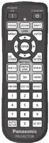
PANASONIC PT-RZ120BE - Operating with the remote control - 1

text_image POWER ON I STANDBY FOCUS ZOOM SHIFT LENS SHUTTER MENU ENTER ON SCREEN TEST PATTERN INPUT SELECT RGB 1/2 DIGITAL LINK DVI-D VIDEO SDI HDMI FUNCTION STATUS DEFAULT 1 2 3 4 5 6 7 8 9 AUTO SETUP 0 ID SET Panasonic PROJECTOR

Using the shutter function

If the projector is not used for a certain period of time during the meeting intermission, for example, it is possible to turn off the image temporarily.

PANASONIC PT-RZ120BE - Using the shutter function - 1

button

1) Press the button.

•The image disappears.
- This operation can be also performed using the button on the control panel.

2) Press the button again.

•The image is displayed.

Note

  • The power indicator will blink slowly in green while the shutter function is in use (shutter: closed).
  • The fade-in/fade-out time of the image can be set by the [DISPLAY OPTION] menu → [SHUTTER SETTING].
  • The light source may be lit dimly due to warm up when the shutter function is used in the operating environment temperature of around 0 °C (32 °F).

Using the on-screen display function

Turn off the on-screen display function (no display) when you do not wish the viewers to see the on-screen display, such as the menu or the input terminal name.

PANASONIC PT-RZ120BE - Using the on-screen display function - 1

button

1) Press the button.

- Turns off (hides) the on-screen display.

2) Press the button again.

- Cancels the hide condition of the on-screen display.

Note

- The hide condition of the on-screen display can also be canceled by pressing the

button on the control panel for at least three seconds while the on-screen display is off (hidden).

Using the automatic setup function

The image position when the DVI-D/HDMI signal is input, or the resolution, clock phase, and image position when the analog RGB signal is input can be adjusted automatically. (Analog RGB signal is a signal structured with dots just like the computer signal.)

It is recommended to input an image with bright white borders at the edges and high-contrast black and white characters when the automatic adjustment is being performed.

Avoid using images that include halftones or gradation, such as photographs and computer graphics.

PANASONIC PT-RZ120BE - Using the automatic setup function - 1

button

1) Press the button.

- [COMPLETE] is displayed when it has completed without any problem.

- This operation can be also performed by pressing the button on the control panel.

Note

  • The clock phase may shift even if it has completed without any incident. In such a case, adjust the [POSITION] menu [CLOCK PHASE] (→ page 93).
  • If an image with blurred edges or a dark image is input, [INCOMPLETE] may appear or adjustment may not be performed properly even when [COMPLETE] appears. In such a case, adjust the following settings.
  • [ADVANCED MENU] menu → [INPUT RESOLUTION] (→ page 100)
  • [POSITION] menu → [CLOCK PHASE] (→ page 93)
  • [POSITION] menu → [SHIFT] (→ page 91)
  • Adjust special signals according to the [DISPLAY OPTION] menu → [AUTO SETUP] (→ page 107).
    • Automatic adjustment may not be possible depending on the computer model.
    • Automatic adjustment may not be possible for the synchronization signal for composite sync or SYNC ON GREEN.
  • Image may be disrupted for a few seconds during automatic adjustment, but this is not a malfunction.
  • Adjustment is required for each input signal.
  • Automatic adjustment can be canceled by pressing the button during the automatic adjustment operation.
  • Even if a signal possible to perform the automatic setup is being input, it may not be able to adjust correctly if the automatic setup function is used while the moving image is being input. [INCOMPLETE] may be displayed, or the adjustment may not be completed correctly even if [COMPLETE] is displayed.

Using the function button

By assigning the following functions to the button, it can be used as a simplified shortcut button. [SUB MEMORY], [SYSTEM SELECTOR], [SYSTEM DAYLIGHT VIEW], [FREEZE], [WAVEFORM MONITOR], [ASPECT], [PROJECTION METHOD]

PANASONIC PT-RZ120BE - Using the function button - 1

button

1) Press the button.

Note

- Assignment of the function is performed from the [PROJECTOR SETUP] menu → [FUNCTION BUTTON] (→ page 142).

Displaying internal test pattern

The projector has nine types of internal test patterns to check the condition of the projector. To display test patterns, perform the following steps.

PANASONIC PT-RZ120BE - Displaying internal test pattern - 1

button

1) Press the button.

2) Press ◀▶ to select the test pattern.

Note

  • Test patterns can also be displayed using the menu operation. Refer to “[TEST PATTERN] menu” (→ page 148) for details.
  • Settings of position, size, and other factors will not be reflected in test patterns. Make sure to display the input signal before performing various adjustments.

74 - ENGLISH

Using the status function

Display the status of the projector.

PANASONIC PT-RZ120BE - Using the status function - 1

button

1) Press the button.

- The [STATUS] screen is displayed.

PANASONIC PT-RZ120BE - 1) Press the  button. - 1

text_image STATUS 1/5 PROJECTOR TYPE PT-RZ120 SERIAL NUMBER 123456789012 PROJECTOR RUNTIME 10000h LIGHT RUNTIME 10000h / 10000h CONTINUOUS LIGHTING TIME 1h 23m MAIN/SUB VERSION 1.00 / 1.00 INTAKE AIR TEMP. 31°C/87°F _ OPTICS MODULE TEMP. 27°C/80°F _ EXHAUST AIR TEMP. 31°C/87°F _ LIGHT1 TEMP. 31°C/87°F _ LIGHT2 TEMP. 31°C/87°F _ SELF TEST NO ERRORS SEND E-MAIL EXITCHANGE

Note

- The projector status can also be displayed using the menu operation. Refer to the [PROJECTOR SETUP] menu → [STATUS] (→ page 143) for details.

Setting ID number of the remote control

When you use the multiple projectors together, you can operate all the projectors simultaneously or each projector individually using a single remote control, if a unique ID number is assigned to each projector.

After setting the ID number of the projector, set same ID number on the remote control.

The factory default ID number of the projector is set to [ALL]. When using a single projector, keep pressing the button on the remote control for at least three seconds to set the ID number of the remote control to [ALL]. In addition, when the ID number of the projector is unknown, setting the ID number to [ALL] enables the remote control.

PANASONIC PT-RZ120BE - Setting ID number of the remote control - 1

button

1) Press the button on the remote control.

2) Within five seconds, press the two-digit ID number set on the projector using the number (<0> - <9>) buttons.

- When the ID number is set to [ALL], you can control the projector regardless of the ID number setting of the projector.

Attention

  • Since the ID number of the remote control can be set without the projector body, do not press the button on the remote control carelessly. If the button is pressed and no number (<0> - <9>) buttons are pressed within five seconds, the ID number returns to its original value before the button was pressed.
  • The ID number set on the remote control will be stored unless it is set again. However, it will be erased if the remote control is left with dead batteries. Set the same ID number again when the batteries are replaced.

Note

  • When the ID number of the remote control is set to [0], you can control the projector regardless of the ID number setting of the projector body, as same as when [ALL] is set.
  • Set the ID number of the projector body from the [PROJECTOR SETUP] menu → [PROJECTOR ID].

Chapter 4 Settings

This chapter describes the settings and adjustments you can make using the on-screen menu.

The on-screen menu (Menu) is used to perform various settings and adjustments of the projector.

Operating procedure

PANASONIC PT-RZ120BE - Operating procedure - 1

button

1) Press the

button on the remote control or control panel.

• The [MAIN MENU] screen is displayed.

PANASONIC PT-RZ120BE - button - 1

text_image MAIN MENU PICTURE POSITION ADVANCED MENU DISPLAY LANGUAGE DISPLAY OPTION PROJECTOR SETUP TEST PATTERN SIGNAL LIST SECURITY NETWORK MENU SELECT SUB MENU

2) Press ▲▼ to select an item from the main menu.

•The selected item is highlighted in yellow.

PANASONIC PT-RZ120BE - button - 2

text_image MAIN MENU PICTURE POSITION ADVANCED MENU DISPLAY LANGUAGE DISPLAY OPTION PROJECTOR SETUP TEST PATTERN SIGNAL LIST SECURITY NETWORK MENU SELECT SUB MENU

3) Press the button.

- The sub-menu items of the selected main menu are displayed.

PANASONIC PT-RZ120BE - button - 3

text_image POSITION SHIFT ASPECT DEFAULT ZOOM CLOCK PHASE 0 -1 GEOMETRY OFF MENU SELECT SUB MENU

4) Press ▲▼ to select a sub-menu, and press ◀▶ or the button to change or adjust settings.

- Some items will switch in order as follows each time you press ◀.

PANASONIC PT-RZ120BE - button - 4

- For some items, press ◀▶ to display an individual adjustment screen with a bar scale as shown below.

PANASONIC PT-RZ120BE - button - 5

Note

  • Pressing the button while the menu screen is displayed returns to the previous menu.
  • Some items or functions may not be adjusted or used for certain signals to be input to the projector. When the items cannot be adjusted or used, the items in the menu screen are shown in black characters, and they cannot be adjusted or set.
    If the item in the menu screen is displayed in black characters and the item cannot be adjusted or set, the factor causing it is displayed by pressing the button while the corresponding menu is selected.
  • Some items can be adjusted even if signals are not input.
  • Individual adjustment screen is cleared automatically if no operation is performed for approximately five seconds.
  • For menu items, refer to "Main menu" (→ page 78) and "Sub-menu" (→ page 79).
  • The cursor color depends on the setting in the [DISPLAY OPTION] menu → [ON-SCREEN DISPLAY] → [OSD DESIGN]. The selected item is displayed with the yellow cursor by the factory default.
  • In the portrait setting, the on-screen menu is displayed sideways.
    To display the on-screen menu vertically, change the setting of the [DISPLAY OPTION] menu → [ON-SCREEN DISPLAY] → [OSD ROTATION].

Resetting adjustment values to the factory default

If the button on the remote control is pressed, the values adjusted in the menu items are restored to the factory default settings.

DEFAULT

button

1) Press the button on the remote control.

PANASONIC PT-RZ120BE - button - 1

Note

  • You cannot reset all the settings to the factory default at a time.
  • To reset all the settings adjusted in the sub-menu items to the factory default at a time, execute the [PROJECTOR SETUP] menu → [INITIALIZE].
  • Some items cannot be reset to the factory default settings even when the button on the remote control is pressed. Adjust those items individually.
  • The triangular mark under the bar scale in the individual adjustment screen indicates the factory default setting. The position of the triangular mark varies according to the selected input signals.

Current adjustment value
PANASONIC PT-RZ120BE - Note - 1
Factory default setting

The following items are in the main menu.
When a main menu item is selected, the screen changes to a sub-menu selection screen.
The menu item with √ in the [SIMPLE] mode column indicates that this is displayed in the menu screen (OSD) when the [DISPLAY OPTION] menu → [MENU MODE] is set to [SIMPLE].

Main menu item [SIMPLE] mode Page
PANASONIC PT-RZ120BE - Main menu - 1[PICTURE]82
PANASONIC PT-RZ120BE - Main menu - 2[POSITION]91
PANASONIC PT-RZ120BE - Main menu - 3[ADVANCED MENU] — 99
PANASONIC PT-RZ120BE - Main menu - 4[DISPLAY LANGUAGE]104
PANASONIC PT-RZ120BE - Main menu - 5[DISPLAY OPTION]105
PANASONIC PT-RZ120BE - Main menu - 6[PROJECTOR SETUP]125
PANASONIC PT-RZ120BE - Main menu - 7[TEST PATTERN]148
PANASONIC PT-RZ120BE - Main menu - 8[SIGNAL LIST]149
PANASONIC PT-RZ120BE - Main menu - 9[SECURITY] — 152
PANASONIC PT-RZ120BE - Main menu - 10[NETWORK]156

The sub-menu of the selected main menu item is displayed, and you can set and adjust items in the sub-menu. The menu item with √ in the [SIMPLE] mode column indicates that this is displayed in the menu screen (OSD) when the [DISPLAY OPTION] menu → [MENU MODE] is set to [SIMPLE].

[PICTURE]

PANASONIC PT-RZ120BE - [PICTURE] - 1

Sub-menu item Factory default [SIMPLE] mode Page
[PICTURE MODE] [GRAPHIC]*182
[CONTRAST] [0]82
[BRIGHTNESS] [0]82
[COLOR] [0]*283
[TINT] [0] — 83
[COLOR TEMPERATURE][DEFAULT]*283
[WHITE GAIN] [+10] — 85
[GAMMA][DEFAULT]— 85
[SYSTEM DAYLIGHT VIEW][OFF]*286
[SHARPNESS][+6]*286
[NOISE REDUCTION][OFF]*287
[DYNAMIC CONTRAST][2]*287
[SYSTEM SELECTOR][YPBPR]*188
[DEFAULT PICTURE MODE][AUTO]— 89

*1 Depends on the signal input.

*2 Depends on the [PICTURE MODE].

[POSITION]

PANASONIC PT-RZ120BE - [POSITION] - 1

Sub-menu item Factory default [SIMPLE] mode Page
[SHIFT]— 91
[ASPECT] [DEFAULT]^1 91
[ZOOM]— 92
[CLOCK PHASE] [0]^1 93
[GEOMETRY][OFF]93

*1 Depends on the signal input.

[ADVANCED MENU]

PANASONIC PT-RZ120BE - [ADVANCED MENU] - 1

Sub-menu item Factory default [SIMPLE] mode Page
[DIGITAL CINEMA REALITY][AUTO] ^1 99

Chapter 4 Settings — Menu navigation

Sub-menu item Factory default [SIMPLE] mode Page
[BLANKING] — — 99
[INPUT RESOLUTION] — — 100
[CLAMP POSITION] [24]^1— 100
[EDGE BLENDING] [OFF] — 100
[FRAME RESPONSE] [NORMAL] — 102
[RASTER POSITION] — — 103

*1 Depends on the signal input.

[DISPLAY LANGUAGE]

PANASONIC PT-RZ120BE - [DISPLAY LANGUAGE] - 1

Details ( page 104)

[DISPLAY OPTION]

PANASONIC PT-RZ120BE - [DISPLAY OPTION] - 1

Sub-menu item Factory default [SIMPLE] mode Page
[COLOR MATCHING][OFF]105
[COLOR CORRECTION][OFF] — 106
[SCREEN SETTING]106
[AUTO SIGNAL][OFF] — 107
[AUTO SETUP]— — 107
[BACKUP INPUT SETTING]— — 108
[RGB IN]110
[DVI-D IN]— —111
[HDMI IN]113
[DIGITAL LINK IN]114
[SDI IN]116
[ON-SCREEN DISPLAY]117
[MENU MODE][NORMAL]119
[IMAGE ROTATION][OFF]119
[BACK COLOR][BLUE]— 120
[STARTUP LOGO][DEFAULT LOGO]120
[UNIFORMITY]— — 120
[SHUTTER SETTING]— — 121
[FREEZE]— — 123
[WAVEFORM MONITOR][OFF] — 123
[CUT OFF]— — 124

[PROJECTOR SETUP]

PANASONIC PT-RZ120BE - [PROJECTOR SETUP] - 1

Sub-menu item Factory default [SIMPLE] mode Page
[PROJECTOR ID][ALL]125
[PROJECTION METHOD]125
[LENS]126
[OPERATION SETTING]127
[LIGHT OUTPUT][100.0%]129
[BRIGHTNESS CONTROL]— — 130
[STANDBY MODE][NORMAL] — 134
[QUICK STARTUP][OFF] — 134
[NO SIGNAL SHUT-OFF][DISABLE] — 135
[NO SIGNAL LIGHTS-OUT][DISABLE] — 135
[INITIAL STARTUP][LAST MEMORY]135
[STARTUP INPUT SELECT][LAST USED]135
[DATE AND TIME]136
[SCHEDULE][OFF] — 137

Chapter 4 Settings — Menu navigation

Sub-menu item Factory default [SIMPLE] mode Page
[MULTI PROJECTOR SYNC] — — 139
[RS-232C] —140
[REMOTE2 MODE] [DEFAULT] — 142
[FUNCTION BUTTON] — — 142
[STATUS] —143
[DATA CLONING] — — 144
[SAVE ALL USER DATA] — — 146
[LOAD ALL USER DATA] — — 146
[INITIALIZE] —146
[SERVICE PASSWORD] —147

[TEST PATTERN]

Details ( page 148)

[SIGNAL LIST]

Details ( page 149)

[SECURITY]

Sub-menu item Factory default [SIMPLE] mode Page
[SECURITY PASSWORD][OFF]— 152
[SECURITY PASSWORD CHANGE]— — 152
[DISPLAY SETTING] [OFF] — 152
[TEXT CHANGE]— — 153
[CONTROL DEVICE SETUP]— — 153
[CONTROL DEVICE PASSWORD CHANGE]— — 154

[NETWORK]

Sub-menu item Factory default [SIMPLE] mode Page
[ DIGITAL LINK MODE][AUTO]156
[ DIGITAL LINK STATUS]156
[ NETWORK SETUP]157
[ NETWORK CONTROL]157
[ NETWORK STATUS]158
[ DIGITAL LINK MENU]— — 158
[Art-Net SETUP][OFF]— 158
[Art-Net CHANNEL SETTING][2]— 159
[Art-Net STATUS]— — 160

Note

- Some items may not be adjusted or used for certain signal formats to be input to the projector.

When the items cannot be adjusted or used, the items in the menu screen are shown in black characters, and they cannot be adjusted or set.

- Sub-menu items and factory default settings vary depending on the selected input terminal.

[PICTURE] menu

On the menu screen, select [PICTURE] from the main menu, and select an item from the sub-menu. Refer to "Navigating through the menu" ( page 77) for the operation of the menu screen.

[PICTURE MODE]

You can switch to the desired picture mode suitable for the image source and the environment in which the projector is used.

1) Press ▲▼ to select [PICTURE MODE].

2) Press ◀▶.

- The [PICTURE MODE] individual adjustment screen is displayed.

3) Press ◀▶ to switch the item.

- The items will switch each time you press the button.

[STANDARD] The image becomes suitable for moving images in general.
[CINEMA] The image becomes suitable for movie contents.
[NATURAL] The image becomes suitable for using in a relatively dark environment.
[REC709]The image becomes Rec.709 compliant when the setting other than [PICTURE MODE] is set to the factory default.
[DICOM SIM.] The image becomes similar to that of DICOM Part 14 Grayscale Standard.
[DYNAMIC] The light output is maximized for use in bright areas.
[GRAPHIC] The image becomes suitable for input from the personal computer.

Note

  • Rec.709 is an abbreviation of "ITU-R Recommendation BT.709" and is a color standard of high-vision broadcasting.
  • DICOM is an abbreviation of "Digital Imaging and COmmunication in Medicine" and is a standard for medical imaging devices. Although the DICOM name is used, the projector is not a medical device, and display images should not be used for medical purposes such as diagnosis.
  • If the button is pressed while [PICTURE MODE] is selected, the adjustment condition that is currently set can be saved as a specified value of the selected picture mode. The data of all items except [SYSTEM SELECTOR] and [DEFAULT PICTURE MODE] in the [PICTURE] menu are saved.
  • If the [PICTURE] menu → [DEFAULT PICTURE MODE] is set to [AUTO], [GRAPHIC] is automatically selected when a new still image signal is input and [STANDARD] is automatically selected when a new moving image signal is input. If the [PICTURE] menu → [DEFAULT PICTURE MODE] is set to anything other than [AUTO], the picture mode set in [DEFAULT PICTURE MODE] is selected when a new signal is input.

[CONTRAST]

You can adjust the contrast of the colors.

1) Press ▲▼ to select [CONTRAST].

2) Press ◀▶ or the button.

- The [CONTRAST] individual adjustment screen is displayed.

3) Press ◀▶ to adjust the level.

Operation Adjustment Range of adjustment
Press ▶.The screen becomes brighter.-31 - +31
Press ◀.The screen becomes darker.

Attention

- Adjust the [PICTURE] menu → [BRIGHTNESS] first when you need to adjust the black level.

[BRIGHTNESS]

You can adjust the dark (black) part of the projected image.

1) Press ▲▼ to select [BRIGHTNESS].

2) Press ◀▶ or the button.

- The [BRIGHTNESS] individual adjustment screen is displayed.

82 - ENGLISH

3) Press ◀▶ to adjust the level.

Operation AdjustmentRange of adjustment
Press ▶.Increases the brightness of the dark (black) parts of the screen.-31 - +31
Press ◀.Reduces the brightness of the dark (black) parts of the screen.

[COLOR]

You can adjust the color saturation of the projected image.

1) Press ▲▼ to select [COLOR].
2) Press ◀▶ or the button.

- The [COLOR] individual adjustment screen is displayed.

3) Press ◀▶ to adjust the level.

Operation Adjustment Range of adjustment
Press ▶.Deepens colors.-31 - +31
Press ◀.Weakens colors.

[TINT]

You can adjust the skin tone in the projected image.

1) Press ▲▼ to select [TINT].
2) Press ◀▶ or the button.

- The [TINT] individual adjustment screen is displayed.

3) Press ◀▶ to adjust the level.

Operation Adjustment Range of adjustment
Press ▶.Adjusts skin tone toward greenish color.-31 - +31
Press ◀.Adjusts skin tone toward reddish purple.

[COLOR TEMPERATURE]

You can switch the color temperature if the white areas of the projected image are bluish or reddish.

Adjusting with color temperature

1) Press ▲▼ to select [COLOR TEMPERATURE].
2) Press ◀▶ or the button.

- The [COLOR TEMPERATURE] individual adjustment screen is displayed.

3) Press ◀▶ to switch the item.

- The items will switch each time you press the button.

[DEFAULT] Factory default setting.
[USER1]Adjusts white balance as desired. Refer to “Adjusting desired white balance” (→ page 84) for details.
[USER2]
[3200K] - [9300K]Sets the value in increments of 100 K.Select an item so that images become natural.

Note

  • [DEFAULT] cannot be selected when the [PICTURE] menu [PICTURE MODE] is set to [DICOM SIM.].
  • This item is fixed to [USER1] when the [DISPLAY OPTION] menu [COLOR MATCHING] is set to anything other than [OFF].
    •The color temperature numerical values are guidelines.

Adjusting desired white balance

1) Press ▲▼ to select [COLOR TEMPERATURE].
2) Press ◀▶ or the button.

- The [COLOR TEMPERATURE] individual adjustment screen is displayed.

3) Press ◀▶ to select [USER1] or [USER2].
4) Press the button.

- The [COLOR TEMPERATURE] screen is displayed.

5) Press ▲▼ to select [WHITE BALANCE].
6) Press the button.

- The [WHITE BALANCE] screen is displayed.

7) Press ▲▼ to select [WHITE BALANCE HIGH] or [WHITE BALANCE LOW].
8) Press the button.

- The [WHITE BALANCE HIGH] screen or the [WHITE BALANCE LOW] screen is displayed.

9) Press ▲▼ to select [RED], [GREEN], or [BLUE].
10) Press ◀▶ to adjust the level.

Item Operation Adjustment Range of adjustment
[RED]Press ▶.Deepens red.[WHITE BALANCE HIGH]: 0 - +255 (factory default is +255)[WHITE BALANCE LOW]: -127 - +127 (factory default is 0)
Press ◀.Weakens red.
[GREEN]Press ▶.Deepens green.
Press ◀.Weakens green.
[BLUE]Press ▶.Deepens blue.
Press ◀.Weakens blue.

Note

- Adjust [COLOR TEMPERATURE] correctly. All colors will not be displayed properly unless adequate adjustment is made. If the adjustment does not look suitable, you can press the button on the remote control to return the setting for the selected item only to the factory default setting.

Adjusting to desired white balance based on existing color temperature settings

1) Press ▲▼ to select [COLOR TEMPERATURE].
2) Press ◀▶ or the button.

- The [COLOR TEMPERATURE] individual adjustment screen is displayed.

3) Press ◀▶ to select anything other than [DEFAULT], [USER1], or [USER2].
4) Press the button.

- The [CHANGE TO *****] screen is displayed.

5) Press ▲▼ to select [USER1] or [USER2].

- The status of the color temperature changed is saved to the selected item.

6) Press the button.

•The confirmation screen is displayed.

7) Press ◀▶ to select [OK], and press the button.

- The [USER1] or [USER2] data is overwritten.

  • The data is not overwritten when [CANCEL] is selected with ◀▶ and the button is pressed.
  • The [WHITE BALANCE HIGH] screen is displayed.

8) Press ▲▼ to select [RED], [GREEN], or [BLUE].
9) Press ◀▶ to adjust the level.

84 - ENGLISH

Note

  • Adjust [COLOR TEMPERATURE] correctly. All colors will not be displayed properly unless adequate adjustment is made. If the adjustment does not look suitable, you can press the button on the remote control to return the setting for the selected item only to the factory default setting.
  • When color temperature has been changed, the colors before and after the change will differ slightly.

Changing the name of [USER1] or [USER2]

1) Press ▲▼ to select [COLOR TEMPERATURE].
2) Press ◀▶ or the button.

- The [COLOR TEMPERATURE] individual adjustment screen is displayed.

3) Press ◀▶ to select [USER1] or [USER2].
4) Press the button.

- The [COLOR TEMPERATURE] screen is displayed.

5) Press ▲▼ to select [COLOR TEMPERATURE NAME CHANGE].
6) Press the button.

- The [COLOR TEMPERATURE NAME CHANGE] screen is displayed.

7) Press ▲▼◀▶ to select the text, and press the button to enter the text.
8) Press ▲▼◀▶ to select [OK], and press the button.

- The name set to color temperature is changed.

Note

- The display of [USER1] or [USER2] is also changed when the name is changed.

[WHITE GAIN]

Adjust the brightness of the white part of the image.

1) Press ▲▼ to select [WHITE GAIN].
2) Press ◀▶ or the button.

- The [WHITE GAIN] individual adjustment screen is displayed.

3) Press ◀▶ to adjust the level.

Operation Adjustment Range of adjustment
Press ▶.Brightness of the white part gets stronger.0 - +10
Press ◀.The image becomes more natural.

[GAMMA]

You can switch gamma mode.

1) Press ▲▼ to select [GAMMA].
2) Press ◀▶ or the button.

- The [GAMMA] individual adjustment screen is displayed.

3) Press ◀▶ to switch the item.

- The items will switch each time you press the button.

[DEFAULT] Factory default setting.
[USER]Uses the gamma data registered by the user.(Registration requires separate software. Consult your dealer.)
[1.8]Set so that images become as you like.[2.0]
[2.2]

Changing the [USER] name

1) Press ▲▼ to select [GAMMA].
2) Press ◀▶ or the button.

- The [GAMMA] individual adjustment screen is displayed.

3) Press ◀▶ to select [USER].
4) Press the button.

• The [GAMMA] screen is displayed.

5) Press the button.
- The [GAMMA NAME CHANGE] screen is displayed.
6) Press ▲▼◀▶ to select the text, and press the button to enter the text.
7) Press ▲▼◀▶ to select [OK], and press the button.

•The gamma selection name is changed.

Note

- Display of [USER] is also changed when the name is changed.

[SYSTEM DAYLIGHT VIEW]

You can correct the image to the optimal vividness even if it is projected under a bright light.

1) Press ▲▼ to select [SYSTEM DAYLIGHT VIEW].
2) Press ◀▶ or the button.

- The [SYSTEM DAYLIGHT VIEW] individual adjustment screen is displayed.

3) Press ◀▶ to switch the item.

- The items will switch each time you press the button.

[OFF] No correction.
[1] - [6]Corrects the vividness of the image. The larger the value, the stronger the correction.

[SHARPNESS]

You can adjust the sharpness of the projected image.

1) Press ▲▼ to select [SHARPNESS].
2) Press ◀▶ or the button.

- The [SHARPNESS] individual adjustment screen is displayed.

3) Press ◀▶ to adjust the level.

Operation Adjustment Range of adjustment
Press ▶.Contours become sharper.0 - +15
Press ◀.Contours become softer.

Note

- If you press ▶ while the adjustment value is [+15], the value will become [0]. If you press ◀ while the adjustment value is [0], the value will become [+15].

[NOISE REDUCTION]

You can reduce noises when the input image is degraded and noise is occurring in the image signal.

1) Press ▲▼ to select [NOISE REDUCTION].
2) Press ◀▶ or the button.

- The [NOISE REDUCTION] individual adjustment screen is displayed.

3) Press ◀▶ to switch the item.

- The items will switch each time you press the button.

[OFF] No correction.
[1] Slightly corrects the noise.
[2] Moderately corrects the noise.
[3] Strongly corrects the noise.

Attention

- When this is set for an input signal with less noise, the image may look different from the original image. In such a case, set it to [OFF].

[DYNAMIC CONTRAST]

Light adjustment of the light source and signal compensation are performed automatically according to the image to make the contrast optimum for the image.

1) Press ▲▼ to select [DYNAMIC CONTRAST].
2) Press ◀▶ or the button.

- The [DYNAMIC CONTRAST] individual adjustment screen is displayed.

3) Press ◀▶ to switch the item.

- The items will switch each time you press the button.

[OFF] Disables the dynamic contrast function.
[1] Adjusts the light source and compensates signals to a small extent.
[2] Adjusts the light source and compensates signals to a moderate extent.
[3] Adjusts the light source and compensates signals to a large extent.
[USER]Set any desired correction.Refer to “Performing desired correction” (→ page 87) for details.

Performing desired correction

1) Press ▲▼ to select [DYNAMIC CONTRAST].
2) Press ◀▶ or the button.

- The [DYNAMIC CONTRAST] individual adjustment screen is displayed.

3) Press ◀▶ to select [USER].
4) Press the button.

- The [DYNAMIC CONTRAST] screen is displayed.

5) Press ▲▼ to select the item to set.

  • The items of the detailed settings will switch each time you press ◀.
  • Press the button when [MULTI PROJECTOR SYNC] is selected.
Setting item Details
[AUTO CONTRAST](Automatic light source adjustment)[OFF] Does not adjust the light source.
[1] - [255]The higher the value, the stronger the light adjustment of the light source.Can be set in increments of 1.
[BRIGHT SIGNAL LEVEL](Setting of the brightness level of the signal to start the light adjustment)[6%] - [50%]Adjusts the light source when the brightness level of the video signal being input gets lower than the set value. The higher the value, the larger the range to perform the light adjustment of the light source.Can be set in increments of 1%. (Factory setting: 30%)
[LIGHTS OUT TIMER](Time setting until the light turns off)[DISABLE] Does not turn off the light source.
[0.0s] - [10.0s]Turns off the light source when the brightness level of the video signal being input goes under the value set in [LIGHTS OUT SIGNAL LEVEL].Select an item from [0.0s] - [4.0s], [5.0s], [7.0s], or [10.0s].[0.0s] - [4.0s] can be selected in increments of 0.5.
[LIGHTS OUT SIGNALLEVEL](Setting of the brightness level of the signal to turn off the light)[0%] - [5%]Sets the level of the brightness of the video signal to turn off the light source with [LIGHTS OUT TIMER].Can be set in increments of 1%. (Factory setting: 0%)
[LIGHTS OUT FADE-IN](Setting of fade-in when lighting up again)[OFF]Does not set the fade-in of the image when the light source is turned on again from the condition that the light source was turned off with [LIGHTS OUT TIMER].
[0.5s] - [10.0s]Sets the time to fade in the image when the light source is turned on again from the condition that the light source was turned off with [LIGHTS OUT TIMER].Select an item from [0.5s] - [4.0s], [5.0s], [7.0s], or [10.0s]. [0.5s] - [4.0s] can be selected in increments of 0.5.
[LIGHTS OUT FADE-OUT](Setting of fade-out when lighting off)[OFF]Does not set the fade-out of the image when the light source is turned off with [LIGHTS OUT TIMER].
[0.5s] - [10.0s]Sets the time to fade out the image when the light source is turned off with [LIGHTS OUT TIMER].Select an item from [0.5s] - [4.0s], [5.0s], [7.0s], or [10.0s]. [0.5s] - [4.0s] can be selected in increments of 0.5.
[MANUAL INTENSITY](Manual light source adjustment)[0] - [255]The larger the value, the stronger the correction.Can be set in increments of 1. (Factory setting: 255)
[DYNAMIC GAMMA](Adjustment of signal compensation)[OFF] Does not compensate the signal.
[1] Slightly compensates the signal.
[2] Moderately compensates the signal.
[3] Strongly compensates the signal.
[MULTI PROJECTOR SYNC]Sets the contrast synchronization function.This setting item is common with the following menu item.The [PROJECTOR SETUP] menu → [MULTI PROJECTOR SYNC]Refer to the [PROJECTOR SETUP] menu → [MULTI PROJECTOR SYNC] (→ page 139) for details.

Note

  • [LIGHTS OUT SIGNAL LEVEL] cannot be set when [LIGHTS OUT TIMER] is set to [DISABLE].
  • When [LIGHTS OUT TIMER] is set to anything other than [DISABLE], the following are the conditions to turn the light source back on again from the state that the light source has turned off by this function.
  • When the brightness level of the video signal being input has exceeded the value set in [LIGHTS OUT SIGNAL LEVEL]
  • When the input signal is gone
  • When on-screen display such as menu screen (OSD) or input guide, a test pattern, or a warning message is displayed
  • When the operating environment temperature is around 0 °C (32 °F) and the light source is forced to turn on due to warm-up
  • When the image of analog signal is projected, the image may be affected by the signal noise while the brightness level of the video signal is detected. In such case, it is determined that the signal has not fallen below even when the brightness level of the image falls below the value set in [LIGHTS OUT SIGNAL LEVEL].
  • The contrast will be maximized when [DYNAMIC GAMMA] is set to [3].
  • The brightness control function and the dynamic contrast function will operate simultaneously, but the dynamic contrast function will not operate while measuring the brightness and the color.
  • The contrast synchronization function is a function to display a combined screen with a balanced contrast by sharing the brightness level of the video signal input to each projector when a multi-display is constructed by combining the projected image of multiple projectors.

[SYSTEM SELECTOR]

The projector will automatically detect the input signal, but you can set the system method manually when an unstable signal is input. Set the system method matching the input signal.

1) Press ▲▼ to select [SYSTEM SELECTOR].

2) Press the button.

3) Press ▲▼ to select a system format.

- Available system formats vary depending on the input signal.

Terminal System format
480/60i, 576/50i, or 576/50p signalSelect [RGB] or [YC_B C_R] .
640 x 480/60 or 480/60p signalSelect an item from [640x480/60], [480/60p YC_B C_R], or [480/60p RGB].
Other moving image signals Select [RGB] or [YP \_B P_R] .
480/60i, 576/50i, 480/60p, or 576/50p signalSelect [RGB] or [YC_B C_R] .
Other moving image signals Select [RGB] or [YP \_B P_R] .
480/60i, 576/50i, 480/60p, or 576/50p signalSelect [AUTO], [RGB], or [YC_B C_R] .
Other moving image signals Select [AUTO], [RGB], or [YP \_B P_R] .

4) Press the button.

Note

  • For details of the types of video signals that can be used with the projector, refer to "List of compatible signals" (→ page 206).
  • This may not function properly for some connected external devices.
  • For the SDI input, the signal format can be set in detail in the [DISPLAY OPTION] menu → [SDI IN].

[DEFAULT PICTURE MODE]

Set the picture mode to be applied when a new signal is input. The setting in the [PICTURE] menu → [PICTURE MODE] will switch according to the setting.

1) Press ▲▼ to select [DEFAULT PICTURE MODE].

2) Press ◀▶ to switch the item.

- The items will switch each time you press the button.

[AUTO]Set [PICTURE MODE] to [GRAPHIC] when a still image signal is input or [STANDARD] when a moving image signal is input.
[STANDARD] Set [PICTURE MODE] to [STANDARD].
[CINEMA] Set [PICTURE MODE] to [CINEMA].
[NATURAL] Set [PICTURE MODE] to [NATURAL].
[REC709] Set [PICTURE MODE] to [REC709].
[DICOM SIM.] Set [PICTURE MODE] to [DICOM SIM.].
[DYNAMIC] Set [PICTURE MODE] to [DYNAMIC].
[GRAPHIC] Set [PICTURE MODE] to [GRAPHIC].

Note

  • The following are the conditions where the setting in the [PICTURE] menu [PICTURE MODE] is switched to the picture mode set in [DEFAULT PICTURE MODE].
    -When a new signal is input
  • When the deleted signal is input again after the registered signal has been deleted
  • When the button is pressed while the [PICTURE] menu → [PICTURE MODE] is selected
    -When there is no input signal

sRGB-compliant video

sRGB is an international standard (IEC61966-2-1) for color reproduction defined by IEC (International Electrotechnical Commission).

Set according to the following steps to reproduce more faithful, sRGB compliant colors.

1) Set [COLOR MATCHING] to [OFF].

•Refer to [COLOR MATCHING] (→ page 105).

2) Display the [PICTURE] menu.

- Refer to “[PICTURE] menu” (→ page 82).

3) Press ▲▼ to select [PICTURE MODE].
4) Press ◀▶ to set [REC709].
5) Press ▲▼ to select [GAMMA].
6) Press ◀▶ or the button.

- The [GAMMA] individual adjustment screen is displayed.

7) Press ◀▶ to select [2.2].
8) Press ▲▼ to select [COLOR].
9) Press the button on the remote control to set the factory default setting.
10) Follow Steps 8) - 9) to set [TINT], [COLOR TEMPERATURE], [WHITE GAIN], [GAMMA], and [SYSTEM DAYLIGHT VIEW] to the factory default settings.

Note

- sRGB is available for RGB signal input only.

[POSITION] menu

On the menu screen, select [POSITION] from the main menu, and select an item from the sub-menu. Refer to “Navigating through the menu” ( page 77) for the operation of the menu screen.

Note

- When the optional DIGITAL LINK output supported device (Model No.: ET-YFB100G, ET-YFB200G) is connected to the terminal, adjust the shift, aspect, and clock phase from the menu of DIGITAL LINK output supported device at first.

[SHIFT]

Move the image position vertically or horizontally if the image projected on the screen is still out of position even when the positions of the projector and screen are correct.

1) Press ▲▼ to select [SHIFT].
2) Press the button.

- The [SHIFT] screen is displayed.

3) Press ▲▼◀▶ to adjust the position.

Orientation Operation Adjustment
Vertical (up and down) adjustmentPress ▲.The image position moves up.PANASONIC PT-RZ120BE - [SHIFT] - 1
Press ▼.The image position moves down.PANASONIC PT-RZ120BE - [SHIFT] - 2
Horizontal (right and left) adjustmentPress ▶.The image position moves to the right.PANASONIC PT-RZ120BE - [SHIFT] - 3
Press ◀.The image position moves to the left.PANASONIC PT-RZ120BE - [SHIFT] - 4

Note

- For the portrait setting, image position is moved horizontally when "Vertical (up and down) adjustment" is made. Image position is moved vertically when "Horizontal (right and left) adjustment" is made.

[ASPECT]

You can switch the aspect ratio of the image.

The aspect ratio is switched within the screen range selected in the [DISPLAY OPTION] menu → [SCREEN SETTING] → [SCREEN FORMAT]. Set [SCREEN FORMAT] first. (→ page 106)

1) Press ▲▼ to select [ASPECT].
2) Press ◀▶ or the button.

- The [ASPECT] individual adjustment screen is displayed.

3) Press ◀▶ to switch the item.

- The items will switch each time you press the button.

[DEFAULT] Displays images without changing the aspect ratio of the input signals.

[AUTO] ^1 The projector identifies the video ID (VID) embedded in the video signals and displays the image by automatically switching the screen sizes between 4:3 and 16:9. This function is effective for 480/60i and 480/60p signals.
[THROUGH] Displays images without changing the resolution of the input signals.
[16:9]Displays images with the aspect ratio converted to 16:9 when standard signals are input ^2 . When wide-screen signals are input ^3 , the images are displayed without changing the aspect ratio.
[4:3]Displays images without changing the aspect ratio when standard signals are input ^2 . When wide-screen signals are input ^3 , the images are reduced to be displayed without changing input aspect ratio so that the images will fit in the 4:3 screen.
[H FIT]Displays images using the entire width of the screen range selected in [SCREEN FORMAT]. When signals have the aspect ratio vertically longer than the screen aspect ratio selected in [SCREEN FORMAT], the images are displayed with the top and bottom parts cut off.
[V FIT]Displays images using the entire height of the screen range selected in [SCREEN FORMAT]. When signals have the aspect ratio horizontally longer than the aspect ratio of the screen selected in [SCREEN FORMAT], the images are displayed with the right and left parts cut off.
[HV FIT]Displays images in the entire screen range selected in [SCREEN FORMAT]. When the aspect ratio of the input signals differs from that of the screen range, the images are displayed with the aspect ratio converted to that of the screen selected in [SCREEN FORMAT].

*1 During RGB signal (480/60i, 480/60p) input only

*2 Standard signals are input signals with an aspect ratio of 4:3 or 5:4.

*3 Wide-screen signals are input signals with an aspect ratio of 16:10, 16:9, 15:9 or 15:10.

Note

- Some size modes are not available for certain types of input signals.

[DEFAULT] cannot be selected for an analog RGB signal (480/60i, 480/60p).

[THROUGH] cannot be selected for a 4K video signal (resolution of 3 840 x 2 160 or 4 096 x 2 160).

- If an aspect ratio which is different from the aspect ratio for the input signals is selected, the images will appear differently from the originals. Be careful of this when selecting the aspect ratio.

- If using the projector in places such as cafes or hotels to display programs for a commercial purpose or for public presentation, note that adjusting the aspect ratio or using the zoom function to change the screen images may be an infringement of the rights of the original copyright owner for that program under copyright protection laws. Take care when using a function of the projector such as the aspect ratio adjustment and zoom function.

- If conventional (normal) 4:3 images which are not wide-screen images are displayed on a wide screen, the edges of the images may not be visible or they may become distorted. Such images should be viewed as with an aspect ratio of 4:3 in the original format intended by the creator of the images.

[ZOOM]

You can adjust the image size.

The adjustments in [ZOOM] will differ depending on the setting of the [POSITION] menu → [ASPECT].

When [ASPECT] is set to other than [DEFAULT] and [THROUGH]

1) Press ▲▼ to select [ZOOM].
2) Press the button.

• The [ZOOM] screen is displayed.

3) Press ▲▼ to select [INTERLOCKED].
4) Press ◀▶ to switch the item.

[OFF] Sets the [VERTICAL] and [HORIZONTAL] zoom ratio.
[ON]Uses [BOTH] to set zoom ratio. Image can be enlarged or reduced vertically and horizontally at the same magnification.

5) Press ▲▼ to select [VERTICAL] or [HORIZONTAL].

- If [ON] is selected, select [BOTH].

6) Press ◀▶ to adjust.

Note

- When the [POSITION] menu [ASPECT] is set to [THROUGH], [ZOOM] cannot be adjusted.

When [ASPECT] is set to [DEFAULT]

1) Press ▲▼ to select [ZOOM].
2) Press the button.

- The [ZOOM] screen is displayed.

3) Press ▲▼ to select [MODE].
4) Press ◀▶ to switch the item.

[INTERNAL] Enlarges the size within the aspect range set with [SCREEN FORMAT].
[FULL] Enlarges or reduces the size using the entire display area set with [SCREEN FORMAT].

5) Press ▲▼ to select [INTERLOCKED].
6) Press ◀▶ to switch the item.

[OFF] Sets the [VERTICAL] and [HORIZONTAL] zoom ratio.
[ON]Uses [BOTH] to set zoom ratio. Image can be enlarged or reduced vertically and horizontally at the same magnification.

7) Press ▲▼ to select [VERTICAL] or [HORIZONTAL].

- If [ON] is selected, select [BOTH].

8) Press ◀▶ to adjust.

Note

- When the [POSITION] menu [ASPECT] is set to anything other than [DEFAULT], [MODE] is not displayed.

[CLOCK PHASE]

You can adjust the image to achieve an optimal image when there is a flickering image or smeared outlines.

1) Press ▲▼ to select [CLOCK PHASE].
2) Press ◀▶ or the button.

- The [CLOCK PHASE] individual adjustment screen is displayed.

3) Press ◀▶ to adjust.

- Adjustment value will change between [0] and [+31]. Adjust the image so that the amount of interference is at a minimum.

Note

  • Adjustment may not be possible depending on the signal.
  • There may be no optimal value if the output from the input computer is unstable.
  • There may be no optimal value when the total dot number is shifted.
    •[CLOCK PHASE] can be adjusted only when Y_BC_R/YP_BP_R signal or RGB signal is input to the terminal or the terminal.
  • [CLOCK PHASE] cannot be adjusted when a digital signal is input.
  • The adjustment value will change to [0] when ▶ is pressed while it was at [+31]. Also, the adjustment value will change to [+31] when ◀ is pressed while it was at [0].

[GEOMETRY]

You can correct various types of distortion in a projected image.

Unique image processing technology enables projection of a square image on a special screen shape.

The projected image can be made to look more natural by making topical correction as necessary.

1) Press ▲▼ to select [GEOMETRY].
2) Press ◀▶ to switch the item.

- The items will switch each time you press the button.

[OFF] Does not perform geometric adjustment.
[KEYSTONE] Adjusts any trapezoidal distortion in the projected image.
[CORNER CORRECTION] Adjusts any distortion in the four corners of the projected image.
[CURVED CORRECTION] Adjusts any curved distortion in the projected image.
[PC-1]*1Performs geometric adjustment using a computer.[PC-2]
*1
[PC-3]*1

*1 Advanced skills are necessary to use a computer to control geometric adjustment. Up to three geometric adjustments performed using the computer can be saved.

Note

  • The menu, logo, or waveform monitor display may run off the screen when [GEOMETRY] is set.
  • The edge blending adjustment may not be performed correctly depending on the environment when using the [ADVANCED MENU] menu → [EDGE BLENDING] and [GEOMETRY] simultaneously.
  • The optional Upgrade Kit (Model No.: ET-UK20) can be used to expand the correctable range. To purchase the product, consult your dealer.
  • The image may disappear for a moment or may be disrupted while performing adjustment, but it is not a malfunction.

Setting [KEYSTONE] or [CURVED CORRECTION]

1) Press ▲▼ to select [GEOMETRY].
2) Press ◀▶ to select [KEYSTONE] or [CURVED CORRECTION].
3) Press the button.

- The [GEOMETRY:KEYSTONE] or [GEOMETRY:CURVED CORRECTION] screen is displayed.

4) Press ▲▼ to select the item to adjust.
5) Press ◀▶ to adjust.

[KEYSTONE]
[LENS THROW RATIO]Set the throw ratio.Select the value close to the actual projection distance divided by projected image width here.
[VERTICAL KEYSTONE]PANASONIC PT-RZ120BE - Setting [KEYSTONE] or [CURVED CORRECTION] - 1 PANASONIC PT-RZ120BE - Setting [KEYSTONE] or [CURVED CORRECTION] - 2[HORIZONTAL KEYSTONE]PANASONIC PT-RZ120BE - Setting [KEYSTONE] or [CURVED CORRECTION] - 3 PANASONIC PT-RZ120BE - Setting [KEYSTONE] or [CURVED CORRECTION] - 4
[VERTICAL BALANCE] [HORIZONTAL BALANCE]PANASONIC PT-RZ120BE - Setting [KEYSTONE] or [CURVED CORRECTION] - 5 PANASONIC PT-RZ120BE - Setting [KEYSTONE] or [CURVED CORRECTION] - 6PANASONIC PT-RZ120BE - Setting [KEYSTONE] or [CURVED CORRECTION] - 7 PANASONIC PT-RZ120BE - Setting [KEYSTONE] or [CURVED CORRECTION] - 8
Adjust the setting according to the lens shift range in the vertical direction.Adjust the setting according to the lens shift range in the horizontal direction.
[FREE GRID]Finer adjustment is possible by selecting the points or lines to be corrected.For details of operation, refer to “Adjusting distortion with [FREE GRID]" (⇨ page 96).
[CURVED CORRECTION]
[LENS THROW RATIO]Set the throw ratio.Select the value close to the actual projection distance divided by projected image width here.
[VERTICAL KEYSTONE]PANASONIC PT-RZ120BE - Setting [KEYSTONE] or [CURVED CORRECTION] - 9 PANASONIC PT-RZ120BE - Setting [KEYSTONE] or [CURVED CORRECTION] - 10[HORIZONTAL KEYSTONE]PANASONIC PT-RZ120BE - Setting [KEYSTONE] or [CURVED CORRECTION] - 11 PANASONIC PT-RZ120BE - Setting [KEYSTONE] or [CURVED CORRECTION] - 12
[VERTICAL ARC] [HORIZONTAL ARC]PANASONIC PT-RZ120BE - Setting [KEYSTONE] or [CURVED CORRECTION] - 13 PANASONIC PT-RZ120BE - Setting [KEYSTONE] or [CURVED CORRECTION] - 14PANASONIC PT-RZ120BE - Setting [KEYSTONE] or [CURVED CORRECTION] - 15 PANASONIC PT-RZ120BE - Setting [KEYSTONE] or [CURVED CORRECTION] - 16
[VERTICAL BALANCE] [HORIZONTAL BALANCE]PANASONIC PT-RZ120BE - Setting [KEYSTONE] or [CURVED CORRECTION] - 17 PANASONIC PT-RZ120BE - Setting [KEYSTONE] or [CURVED CORRECTION] - 18PANASONIC PT-RZ120BE - Setting [KEYSTONE] or [CURVED CORRECTION] - 19 PANASONIC PT-RZ120BE - Setting [KEYSTONE] or [CURVED CORRECTION] - 20
[MAINTAIN ASPECT RATIO]Select [ON] to correct while keeping the aspect ratio.
[FREE GRID]Finer adjustment is possible by selecting the points or lines to be corrected.For details of operation, refer to “Adjusting distortion with [FREE GRID]” (⇨ page 96).

Setting [CORNER CORRECTION]

1) Press ▲▼ to select [GEOMETRY].
2) Press ◀▶ to select [CORNER CORRECTION].
3) Press the button.

- The [GEOMETRY:CORNER CORRECTION] screen is displayed.

4) Press ▲▼ to select the item to adjust, and press the button.

- When [LINEARITY] is selected, press ◀▶ to select either adjustment method ([AUTO] or [MANUAL]). Select [AUTO] normally.

For details of operation when [MANUAL] is selected, refer to "Adjusting to desired linearity" ( page 96).

5) Press ▲▼◀▶ to adjust.

[CORNER CORRECTION]
[UPPER LEFT][UPPER RIGHT] [LOWER LEFT][LOWER RIGHT]
PANASONIC PT-RZ120BE - Setting [CORNER CORRECTION] - 1PANASONIC PT-RZ120BE - Setting [CORNER CORRECTION] - 2PANASONIC PT-RZ120BE - Setting [CORNER CORRECTION] - 3PANASONIC PT-RZ120BE - Setting [CORNER CORRECTION] - 4
[LINEARITY]Horizontal direction Vertical direction
PANASONIC PT-RZ120BE - Setting [CORNER CORRECTION] - 5PANASONIC PT-RZ120BE - Setting [CORNER CORRECTION] - 6PANASONIC PT-RZ120BE - Setting [CORNER CORRECTION] - 7PANASONIC PT-RZ120BE - Setting [CORNER CORRECTION] - 8
[FREE GRID]Finer adjustment is possible by selecting the points or lines to be corrected.For details of operation, refer to “Adjusting distortion with [FREE GRID]” (→ page 96).

Adjusting to desired linearity

1) Press ▲▼ to select [GEOMETRY].
2) Press ◀▶ to select [CORNER CORRECTION].
3) Press the button.

- The [GEOMETRY:CORNER CORRECTION] screen is displayed.

4) Press ▲▼ to select [LINEARITY].
5) Press ◀▶ to select [MANUAL].
6) Press the button.

• The [LINEARITY] screen is displayed.

7) Press ▲▼◀▶ to adjust.

Adjusting distortion with [FREE GRID]

1) Press ▲▼ to select [GEOMETRY].
2) Press ◀▶ to select an item other than [OFF].
3) Press the button.

•The screen for the selected item is displayed.

4) Press ▲▼ to select [FREE GRID].
5) Press ◀▶ to select an item.

•The items will switch each time you press the button.

[OFF] Disables the adjustment to be performed with [FREE GRID].
[ON] Enables the adjustment to be performed with [FREE GRID].

•Proceed to Step 6) when [ON] is selected.

6) Press the button.
- The [FREE GRID] screen is displayed.
7) Press ▲▼ to select [GRID RESOLUTION].
8) Press ◀▶ to switch the item.

•The items will switch each time you press the button.

[2x2]Performs the adjustment using the pattern of the outer border (there are two lines each vertically and horizontally as a grid line).
[3x3]Performs the adjustment using the grid pattern divided into two in the horizontal direction and also in the vertical direction.
[5x5]Performs the adjustment using the grid pattern divided into four in the horizontal direction and also in the vertical direction.(Factory default setting)
[9x9]Performs the adjustment using the grid pattern divided into eight in the horizontal direction and also in the vertical direction.
[17x17]Performs the adjustment using the grid pattern divided into 16 in the horizontal direction and also in the vertical direction.

9) Press ▲▼ to select [CONTROL POINTS].

10) Press ◀▶ to switch the item.

- The items will switch each time you press the button.

[POINT]Select this item when adjusting by selecting one intersection from the intersections on the grid lines.
[HORIZONTAL LINE]Select this item when selecting all the intersections on one horizontal grid line, and adjusting them simultaneously.
[VERTICAL LINE]Select this item when selecting all the intersections on one vertical grid line, and adjusting them simultaneously.

11) Press ▲▼ to select [GRID WIDTH].

12) Press ◀▶ to switch the item.

- The items will switch each time you press the button.

[1] - [10]Select the width of the grid line. It can be set between 1 line to 10 lines.(Factory default setting: [3])

13) Press ▲▼ to select [GRID COLOR].

14) Press ◀▶ to switch the item.

- The items will switch each time you press the button.

[WHITE]Displays the pattern of the selected color.(Factory default setting: [RED])
[BLACK]
[RED]
[GREEN]
[BLUE]
[CYAN]
[MAGENTA]
[YELLOW]
[OFF] Does not display the pattern.

15) Press ▲▼ to select [CONTROL POINTS COLOR].

16) Press ◀▶ to switch the item.

- The items will switch each time you press the button.

[WHITE]Select the color of the marker that indicates the control point.The marker that indicates the control point is displayed in the control point selection mode and adjustment mode.(Factory default setting: [WHITE])
[BLACK]
[RED]
[GREEN]
[BLUE]
[CYAN]
[MAGENTA]
[YELLOW]

17) Press ▲▼ to select [EXECUTE].

18) Press the button.

- The screen switches to the control point selection mode.

19) Press ▲▼◀▶ to select the control point.

- Move the marker over the intersection of the grid lines to adjust.

  • When [HORIZONTAL LINE] is selected in Step 10), press ▲▼ to select the control point.
  • When [VERTICAL LINE] is selected in Step 10), press ◀▶ to select the control point.

20) Press the button.

- The control point is confirmed, and the screen switches to the adjustment mode.

21) Press ▲▼◀▶ to adjust the position of the control point.

  • By adjusting the position of the control point, the range to the neighboring intersections will be corrected.
  • To continuously adjust the position of the other intersection, press the button or the button to return to Step 19).
  • Pressing the button twice allows to reselect [GRID RESOLUTION], [CONTROL POINTS], [GRID WIDTH], [GRID COLOR], and [CONTROL POINTS COLOR].

Note

  • The contents adjusted in [FREE GRID] are saved as individual correction data for [KEYSTONE], [CORNER CORRECTION], [CURVED CORRECTION], [PC-1], [PC-2], and [PC-3].
  • Even if [GRID RESOLUTION] or [CONTROL POINTS] is reselected, the correction data adjusted before the reselection is maintained.
  • By selecting more narrow grid pattern with [GRID RESOLUTION], the range of effect of the control point position adjustment will be smaller. To perform topical fine adjustment, it is recommended to adjust by setting [GRID RESOLUTION] to [17x17].
  • The image may not be displayed correctly if adjustment of the control point position increases.
  • The settings of [GRID RESOLUTION], [CONTROL POINTS], [GRID WIDTH], [GRID COLOR], and [CONTROL POINTS COLOR] are synchronized with the setting items under each item of [KEYSTONE], [CORNER CORRECTION], [CURVED CORRECTION], [PC-1], [PC-2], and [PC-3].

Initializing adjustments for [FREE GRID]

Initialize the correction data adjusted with [FREE GRID] and restore the factory default settings (the state where no correction is performed). Simultaneously the settings of [GRID RESOLUTION], [CONTROL POINTS], [GRID WIDTH], [GRID COLOR], and [CONTROL POINTS COLOR] are restored to the factory default settings.

1) Press ▲▼ to select [GEOMETRY].
2) Press ◀▶ to select the item to initialize its correction data in [FREE GRID].
3) Press the button.

- The screen for the selected item is displayed.

4) Press ▲▼ to select [FREE GRID].
5) Press ◀▶ to select [ON].
6) Press the button.

- The [FREE GRID] screen is displayed.

7) Press ▲▼ to select [INITIALIZE].
8) Press the button.

•The confirmation screen is displayed.

9) Press ◀▶ to select [OK], and press the button.

Note

  • Each correction data for [KEYSTONE], [CORNER CORRECTION], [CURVED CORRECTION], [PC-1], [PC-2], and [PC-3] cannot be initialized at once.
    To initialize all the correction data, select each item and execute [INITIALIZE] individually.
  • When the [PROJECTOR SETUP] menu → [INITIALIZE] → [ALL USER DATA] is executed, all the correction data for [FREE GRID] is initialized.

[ADVANCED MENU] menu

On the menu screen, select [ADVANCED MENU] from the main menu, and select an item from the submenu.

Refer to “Navigating through the menu” ( page 77) for the operation of the menu screen.

[DIGITAL CINEMA REALITY]

The picture quality is enhanced by raising the vertical resolution higher performing the cinema processing when interlace signal for moving image is input.

1) Press ▲▼ to select [DIGITAL CINEMA REALITY].

2) Press ◀▶ to switch the item.

- The items will switch each time you press the button.

[AUTO]Automatically detects the signal and performs the cinema processing. (Factory default setting)
[OFF] Does not perform cinema processing.
[30p FIXED]When 60 Hz vertical scanning frequency signals are inputPerforms forced cinema processing (2:2 pulldown).
[25p FIXED]When 50 Hz vertical scanning frequency signals are input

Note

  • In [DIGITAL CINEMA REALITY], the picture quality will degrade when a signal other than the 2:2 pulldown is set as [25p FIXED] or [30p FIXED]. (Vertical resolution will degrade.)
  • When the [ADVANCED MENU] menu [FRAME RESPONSE] is set to [FAST], [DIGITAL CINEMA REALITY] cannot be set.

[BLANKING]

You can adjust the blanking width if there are noises at the edge of the screen or the image is slightly running out from the screen while an image from the VCR or other devices are projected.

1) Press ▲▼ to select [BLANKING].
2) Press the button.

- The [BLANKING] adjustment screen is displayed.

3) Press ▲▼ to select [UPPER], [LOWER], [LEFT], or [RIGHT].

- The blanking width can be adjusted to arbitrary shape using a computer when [CUSTOM MASKING] is set to anything other than [OFF] ([PC-1], [PC-2], or [PC-3]). Up to three blanking settings adjusted using the computer can be saved.

To use the [CUSTOM MASKING] function, the optional Upgrade Kit (Model No.: ET-UK20) is required. To purchase the product, consult your dealer.

4) Press ◀▶ to adjust the blanking width.

Blanking correctionItem OperationAdjustment Range of adjustment
Top of the screen [UPPER][LOWER]Press ◀.The blanking zone moves upward.PANASONIC PT-RZ120BE - [BLANKING] - 1Top and bottom 0 - 1 198
Press ▶.The blanking zone moves downward.
Bottom of the screenPress ▶.The blanking zone moves upward.PANASONIC PT-RZ120BE - [BLANKING] - 2
Press ◀.The blanking zone moves downward.
Blanking correction Item Operation Adjustment Range of adjustment
Left side of the screen[LEFT]Press ▶.The blanking zone moves to the right.PANASONIC PT-RZ120BE - [BLANKING] - 3Left and right 0 - 1 918
Press ◀.The blanking zone moves to the left.
Right side of the screen[RIGHT]Press ◀.The blanking zone moves to the right.PANASONIC PT-RZ120BE - [BLANKING] - 4
Press ▶.The blanking zone moves to the left.

Note

- The upper limit of the adjustment range may be restricted so that the entire projected image is not covered by blanking width.

[INPUT RESOLUTION]

You can adjust the image to achieve an optimal image when there is a flickering image or smeared outlines.

1) Press ▲▼ to select [INPUT RESOLUTION].
2) Press the button.

- The [INPUT RESOLUTION] screen is displayed.

3) Press ▲▼ to select [TOTAL DOTS], [DISPLAY DOTS], [TOTAL LINES], or [DISPLAY LINES], and press ◀▶ to adjust each item.

- Values corresponding to the signal being input are displayed automatically for each item. Increase or decrease the displayed values and adjust to the optimal point while viewing the screen if there are vertical stripes or sections are missing from the screen.

Note

  • Previously mentioned vertical banding will not occur with all white signal input.
  • Image may be disrupted during automatic adjustment, but this is not a malfunction.

  • [INPUT RESOLUTION] can be adjusted only when RGB signal or Y_CC_R/YP_BP_R signal is input to the terminal or the terminal.

  • Adjustment may not be possible depending on the signal.

[CLAMP POSITION]

You can adjust the optimal point when the black part of the image is blunt or it has turned green.

1) Press ▲▼ to select [CLAMP POSITION].
2) Press ◀▶ to adjust.

Status Rough guide for optimal value Range of adjustment
The black part is blunt.The point where bluntness of the black part improves the most is the optimal value.1 - 255
The black part is green.The point where the green part becomes black, and the bluntness has improved is the optimal value.

Note

  • [CLAMP POSITION] can be adjusted only when a signal is input to the terminal or the terminal.
  • Adjustment may not be possible depending on the signal.

[EDGE BLENDING]

The edge blending function allows multiple images to be seamlessly overlapped by using the inclination of the brightness at the overlapped area.

1) Press ▲▼ to select [EDGE BLENDING].

2) Press ◀▶ to switch the item.

- The items will switch each time you press the button.

[OFF] Sets the edge blending function to off.
[ON]Use the setting value preset in the projector for the inclination of the edge blending area.
[USER]Use the user-setting value for the inclination of the edge blending area. (Configuration/registration requires separate software. Consult your dealer.)

- Proceed to Step 3) when anything other than [OFF] is selected.

3) Press the button.

- The [EDGE BLENDING] screen is displayed.

4) Press ▲▼ to specify the location to be corrected.

  • When joining at top: Set [UPPER] to [ON]
  • When joining at bottom: Set [LOWER] to [ON]
  • When joining at left: Set [LEFT] to [ON]
  • When joining at right: Set [RIGHT] to [ON]

5) Press ◀▶ to switch to [ON].

6) Press ▲▼ to select [START] or [WIDTH].

7) Press ◀▶ to adjust the starting position or correction width.

8) Press ▲▼ to select [MARKER].

9) Press ◀▶ to switch to [ON].

- A marker for image position adjustment is displayed. The position where the red and green lines overlap for the projectors to be joined will be the optimal point. Make sure to set the correction width for the projectors to be joined with the same value. Optimal joining is not possible with projectors that have different correction widths.

The optimal point is the point at which these lines overlap.

PANASONIC PT-RZ120BE - 9) Press ◀▶ to switch to [ON]. - 1

text_image Green line

Red line

10) Press ▲▼ to select [BRIGHTNESS ADJUST].

11) Press the button.

  • The [BRIGHTNESS ADJUST] screen is displayed.
  • By setting [AUTO TESTPATTERN] to [ON] on the [EDGE BLENDING] screen, the black test pattern is displayed when you enter the [BRIGHTNESS ADJUST] screen.

12) Press ▲▼ to select [NON-OVERLAPPED BLACK LEVEL].

13) Press the button.

  • The [NON-OVERLAPPED BLACK LEVEL] screen is displayed.
  • [RED], [GREEN], and [BLUE] can be adjusted individually if [INTERLOCKED] is set to [OFF].

14) Press ▲▼ to select an item, and press ◀▶ to adjust the setting.

- Once the adjustment is completed, press the

button to return to the [BRIGHTNESS ADJUST] screen.

15) Press ▲▼ to select [UPPER], [LOWER], [LEFT], or [RIGHT] in [BLACK BORDER WIDTH].

16) Press ◀▶ to set the region (width) of the [BLACK BORDER WIDTH] adjustment.
17) Press ▲▼ to select [UPPER KEYSTONE AREA], [LOWER KEYSTONE AREA], [LEFT KEYSTONE AREA], or [RIGHT KEYSTONE AREA].
18) Press ◀▶ to adjust the tilt of the border between [NON-OVERLAPPED BLACK LEVEL] and [BLACK BORDER LEVEL].
19) Press ▲▼ to select [BLACK BORDER LEVEL].
20) Press the button.

- The [BLACK BORDER LEVEL] screen is displayed.

- [RED], [GREEN], and [BLUE] can be adjusted individually if [INTERLOCKED] is set to [OFF].

21) Press ▲▼ to select an item, and press ◀▶ to adjust the setting.

- Once the adjustment is completed, press the

button to return to the [BRIGHTNESS ADJUST] screen.

22) Press ▲▼ to select [UPPER], [LOWER], [LEFT], or [RIGHT] for [OVERLAPPED BLACK LEVEL].

23) Press the button.

  • The [OVERLAPPED BLACK LEVEL] screen is displayed.
  • [RED], [GREEN], and [BLUE] can be adjusted individually if [INTERLOCKED] is set to [OFF].

24) Press ▲▼ to select an item, and press ◀▶ to adjust the setting.

PANASONIC PT-RZ120BE - 15) Press ▲▼ to select [UPPER], [LOWER], [LEFT], or [RIGHT] in [BLACK BORDER WIDTH]. - 1

text_image [BLACK BORDER WIDTH] (Right) Projection range Edge blending [WIDTH] (Right) [MARKER] (Red) Edge blending [START] (Right) ([MARKER] (Green)) [OVERLAPPED BLACK LEVEL] (Right) [NON-OVERLAPPED BLACK LEVEL] [BLACK BORDER LEVEL]

Note

  • [BRIGHTNESS ADJUST] is a function that makes the increased brightness in black level of the overlapping image area difficult to notice when [EDGE BLENDING] is used to structure a multi-display screen. The optimal point of correction is set by adjusting [NON-OVERLAPPED BLACK LEVEL] so the black level of the overlapping image area will be the same level as the non-overlapping area. If the border area of the part where the image is overlapping and the non-overlapping part gets brighter after adjusting [NON-OVERLAPPED BLACK LEVEL], adjust the width of the top, bottom, left, or right. Adjust [BLACK BORDER LEVEL] when the width adjustment makes only the border area darker.
  • The joining part may look discontinuous depending on the position you are looking from when a screen with high gain or rear screen is used.
  • When structuring a multi-display screen using both horizontal and vertical edge blending, adjust [OVERLAPPED BLACK LEVEL] first before making adjustments in Step 12). Adjustment method is same as the procedure of [NON-OVERLAPPED BLACK LEVEL].
  • If only horizontal or vertical edge blending is used, set all items in [OVERLAPPED BLACK LEVEL] to 0.
  • The [AUTO TESTPATTERN] setting will change in conjunction with the setting in the [DISPLAY OPTION] menu → [COLOR MATCHING] → [AUTO TESTPATTERN].
  • Adjustment of the tilt of the border between [NON-OVERLAPPED BLACK LEVEL] and [BLACK BORDER LEVEL] is a function to perform edge blending together with the adjustment of [GEOMETRY] (→ page 93). Perform the edge blending adjustment matching the shape in [NON-OVERLAPPED BLACK LEVEL] following Steps 17) and 18) when [NON-OVERLAPPED BLACK LEVEL] is tilted due to correcting the keystone with the [POSITION] menu → [GEOMETRY] → [KEYSTONE].

[FRAME RESPONSE]

Set image frame delay.

1) Press ▲▼ to select [FRAME RESPONSE].

2) Press ◀▶ to switch the item.

- The items will switch each time you press the button.

[NORMAL] Standard setting.
[FAST] ^1 Simplifies the image processing to reduce image frame delay.

[FIXED] ^2

Sets image frame delay to be constant regardless of the image position or magnification.

*1 [FAST] cannot be set when input signal is not interlaced signal.
*2 Only when moving image signal or still image signal with the vertical scanning frequency of 50 Hz or 60 Hz is input

Note

- When [FAST] is set, the picture quality deteriorates. The [ADVANCED MENU] menu [DIGITAL CINEMA REALITY] cannot be set.

[RASTER POSITION]

This will allow the position of the image to move within the display area arbitrarily when the input image is not using the whole display area.

1) Press ▲▼ to select [RASTER POSITION].
2) Press the button.
- The [RASTER POSITION] screen is displayed.
3) Press ▲▼◀▶ to adjust the position.

[DISPLAY LANGUAGE] menu

On the menu screen, select [DISPLAY LANGUAGE] from the main menu, and display the sub-menu. Refer to "Navigating through the menu" ( page 77) for the operation of the menu screen.

Changing the display language

You can select the language of the on-screen display.

1) Press ▲▼ to select the display language and press the button.
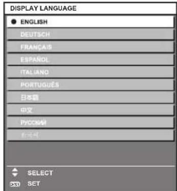
PANASONIC PT-RZ120BE - Changing the display language - 1

text_image DISPLAY LANGUAGE ● ENGLISH DEUTSCH FRANÇAIS ESPAROL ITALIANO PORTUGUES 日本語 中文 PUCOMI K→←→ SELECT SET
  • Various menus, settings, adjustment screens, control button names, etc., are displayed in the selected language.
  • The language can be changed to English, German, French, Spanish, Italian, Portuguese, Japanese, Chinese, Russian, or Korean.

Note

- The on-screen display language is set to English in the factory default setting as well as when the [PROJECTOR SETUP] menu → [INITIALIZE] → [ALL USER DATA] is executed.

[DISPLAY OPTION] menu

On the menu screen, select [DISPLAY OPTION] from the main menu, and select an item from the submenu.

Refer to "Navigating through the menu" ( page 77) for the operation of the menu screen.

[COLOR MATCHING]

Correct the color difference between projectors when using multiple projectors simultaneously.

Adjusting the color matching as desired

1) Press ▲▼ to select [COLOR MATCHING].

2) Press ◀▶ to switch the item.

- The items will switch each time you press the button.

[OFF] Color matching adjustment is not carried out.
[3COLORS] Adjusts the three colors [RED], [GREEN], or [BLUE].
[7COLORS]Adjusts the seven colors [RED], [GREEN], [BLUE], [CYAN], [MAGENTA], [YELLOW], or [WHITE].
[MEASURED]Refer to “Adjusting the color matching using a colorimeter” (→ page 105) for details about this mode.

3) Select [3COLORS] or [7COLORS], and press the button.

- The [3COLORS] or [7COLORS] screen is displayed.

4) Press ▲▼ to select [RED], [GREEN], [BLUE], or [WHITE] ([RED], [GREEN], [BLUE], [CYAN], [MAGENTA], [YELLOW], or [WHITE] when [7COLORS] is selected).

5) Press the button.

  • The [3COLORS:RED], [3COLORS:GREEN], [3COLORS:BLUE], or [3COLORS:WHITE] screen is displayed.
    When [7COLORS] is selected, the [7COLORS:RED], [7COLORS:GREEN], [7COLORS:BLUE], [7COLORS:CYAN], [7COLORS:MAGENTA], [7COLORS:YELLOW], or [7COLORS:WHITE] screen is displayed.
  • By setting [AUTO TESTPATTERN] to [ON], the test pattern for the selected color is displayed.

6) Press ▲▼ to select [RED], [GREEN], or [BLUE].

- Only [GAIN] can be adjusted when [WHITE] is selected for [3COLORS].

7) Press ◀▶ to adjust.

- The adjustment value will change between 0 and 2048.

*1 The lower limit varies depending on the color to be adjusted.

Note

•Operation when correcting the adjustment color

When the correction color same as the adjustment color is changed: The luminance of the adjustment color changes.

When correction color red is changed: Red is added to or subtracted from the adjustment color.

When correction color green is changed: Green is added to or subtracted from the adjustment color.

When correction color blue is changed: Blue is added to or subtracted from the adjustment color.

  • Since advanced skills are necessary for the adjustment, this adjustment should be carried out by a person who is familiar with the projector or by a service person.
  • When the button on the remote control is pressed, the selected adjustment item will return to the factory default value for the current picture mode.
  • When this item is set to anything other than [OFF], the [DISPLAY OPTION] menu → [COLOR CORRECTION] is fixed to [OFF], and the [PICTURE] menu → [COLOR TEMPERATURE] is fixed to [USER1].

Adjusting the color matching using a colorimeter

Use a colorimeter that can measure chromaticity coordinates and luminance to change the colors [RED], [GREEN], [BLUE], [CYAN], [MAGENTA], [YELLOW], or [WHITE] to desired colors.

1) Press ▲▼ to select [COLOR MATCHING].
2) Press ◀▶ to select [MEASURED].

3) Press the button.

- The [MEASURED MODE] screen is displayed.

4) Press ▲▼ to select [MEASURED DATA].

5) Press the button.

- The [MEASURED DATA] screen is displayed.

6) Measure the current luminance (Y) and the chromaticity coordinates (x, y) using the colorimeter.

7) Press ▲▼ to select a color, and press ◀▶ to adjust the setting.

- Set [AUTO TESTPATTERN] to [ON] to display a test pattern of selected colors.

8) Once all the input is completed, press the

button.

- The [MEASURED MODE] screen is displayed.

9) Press ▲▼ to select [TARGET DATA].

10) Press the button.

- The [TARGET DATA] screen is displayed.

11) Press ▲▼ to select a color and press ◀▶ to input coordinates for desired colors.

- By setting [AUTO TESTPATTERN] to [ON], the test pattern for the selected color is displayed.

12) Once all the input is completed, press the

button.

Note

  • Colors are not displayed properly when target data is a color outside the region of this projector.
  • Set the [AUTO TESTPATTERN] to [ON] to automatically display a test pattern for use in adjusting the selected adjustment colors.
  • The [AUTO TESTPATTERN] setting will change in conjunction with the setting in the [ADVANCED MENU] menu → [EDGE BLENDING] → [ON]/[USER] → [AUTO TESTPATTERN].
  • When using a colorimeter or similar instrument to take measurement, measure the colors displayed in [AUTO TESTPATTERN].
  • It is recommended to enter the value between [1000] and [32768] in [Y(RELATIVE)] of [WHITE] in the [MEASURED DATA] screen. For each value ([Y(RELATIVE)] of [BLACK], [RED], [GREEN], and [BLUE]), enter the relative value for the [Y(RELATIVE)] value of [WHITE] based on the luminance (Y) of each color measured using the colorimeter.
  • A difference in the color coordinates of target data and measurement value obtained from an instrument may occur for certain instrument and measurement environment used.

[COLOR CORRECTION]

Colors can be adjusted and registered for each input signal format.

1) Press ▲▼ to select [COLOR CORRECTION].

2) Press ◀▶ to switch the item.

- The items will switch each time you press the button.

[OFF] Standard setting.
[USER]For each signal format of RGB signal and YC_BC_R/YP_BP_R signal, six colors of red, green, blue, cyan, magenta, and yellow can be adjusted and registered. Press thebutton and set the details. Adjustment is possible within the range of -31 to +31.

[SCREEN SETTING]

Set the screen size.

Correct to the optimum image position for the set screen when the aspect ratio of a projected image is changed.

Set as necessary for the screen in use.

1) Press ▲▼ to select [SCREEN SETTING].

2) Press the button.

- The [SCREEN SETTING] screen is displayed.

3) Press ◀▶ to switch the [SCREEN FORMAT] item.

- The items will switch each time you press the button.

[SCREEN FORMAT] Range when [SCREEN POSITION] is selected
[16:10] Cannot be adjusted.
[4:3] Adjusts the horizontal position between-160 and 160.
[16:9] Adjusts the vertical position between-60 and 60.

4) Press ▲▼ to select [SCREEN POSITION].

- [SCREEN POSITION] cannot be selected or adjusted when [SCREEN FORMAT] is set to [16:10].

5) Press ◀▶ to adjust [SCREEN POSITION].

[AUTO SIGNAL]

Set whether to execute automatic setup of signals automatically.

The screen display position or signal level can be adjusted automatically without pressing the button on the remote control on each occasion if you input unregistered signals frequently at meetings, etc.

1) Press ▲▼ to select [AUTO SIGNAL].

2) Press ◀▶ to switch the item.

- The items will switch each time you press the button.

[OFF] Sets the autosignal function to off.
[ON]Executes automatic setup automatically when images are changed to unregistered signals during projection.

[AUTO SETUP]

Set this when adjusting a special signal or horizontally long (such as 16:9) signal.

Setting with [MODE]

1) Press ▲▼ to select [AUTO SETUP].

2) Press the button.

- The [AUTO SETUP] screen is displayed.

3) Press ▲▼ to select [MODE].

4) Press ◀▶ to switch the item.

- The items will switch each time you press the button.

[DEFAULT] Standard setting.
[WIDE]Select this item when an image aspect ratio is a wide-screen signal, which does not meet the [DEFAULT] setting.
[USER]Select this when receiving a signal with a special horizontal resolution (number of display dots).

- Proceed to Step 7) when [DEFAULT] or [WIDE] is selected.

- Proceed to Step 5) when [USER] is selected.

5) Press ▲▼ to select [DISPLAY DOTS], and press ◀▶ to match [DISPLAY DOTS] to the horizontal resolution of the signal source.

6) Press ▲▼ to select [MODE].

7) Press the button.

- Automatic adjustment is executed. [PROGRESS] is displayed while in automatic adjustment. When completed, the screen returns to the [AUTO SETUP] screen.

Note

- Automatic setup of signal can be executed when analog RGB signal consisting of dots such as computer signal, or DVI-D/HDMI signal is being input.

Adjusting position automatically

1) Press ▲▼ to select [AUTO SETUP].
2) Press the button.

- The [AUTO SETUP] screen is displayed.

3) Press ▲▼ to select [POSITION ADJUST].
4) Press ◀▶ to switch the item.

[ON] Adjust the screen position and size when automatic setup is executed.
[OFF] Does not perform automatic adjustment.

Adjusting signal level automatically

1) Press ▲▼ to select [AUTO SETUP].
2) Press the button.

- The [AUTO SETUP] screen is displayed.

3) Press ▲▼ to select [SIGNAL LEVEL ADJUST].
4) Press ◀▶ to switch the item.

[OFF] Does not perform automatic adjustment.
[ON]Adjusts black level (the [PICTURE] menu → [BRIGHTNESS]) and white level (the [PICTURE] menu → [CONTRAST]) when automatic setup is executed.

Note

- [SIGNAL LEVEL ADJUST] may not function properly unless a still image containing clear blacks and whites is input.

[BACKUP INPUT SETTING]

Set the backup function that switches the signal to the backup input signal as seamless as possible when input signal is disrupted.

Using the SDI input and HDMI input or DVI-D input

1) Press ▲▼ to select [BACKUP INPUT SETTING].
2) Press the button.

- The [BACKUP INPUT SETTING] screen is displayed.

3) Press ▲▼ to select [BACKUP INPUT MODE].
4) Press the button.

- The [BACKUP INPUT MODE] screen is displayed.

5) Press ▲▼ to select the combination of the input and press the button.

Primary input Secondary input Details
[OFF] Disables the backup function.
[DVI-D] [HDMI]Enables the backup function.[SDI] [DVI-D]
[SDI][HDMI]

6) Press the

button.
- The [BACKUP INPUT SETTING] screen is displayed.
7) Press ▲▼ to select [AUTOMATIC SWITCHING].
- [AUTOMATIC SWITCHING] cannot be selected when [BACKUP INPUT MODE] is set to [OFF].

8) Press ◀▶ to switch the item.

- The items will switch each time you press the button.

[ENABLE]Switches to the secondary input (primary input) automatically when the input signal for primary input (secondary input) is disrupted.
[DISABLE] Disables the automatic input switching function.

Note

  • The backup function is enabled when [BACKUP INPUT MODE] is set to anything other than [OFF] and same signal is input to the primary input and the secondary input.
  • To switch to the backup input signal using the backup function, make sure that the following three conditions are satisfied to be ready to use the function.

- Set [BACKUP INPUT MODE] to a combination of the SDI input and DVI-D input or the SDI input and HDMI input.

-Input the same signal to the primary and secondary inputs.

-Display the image of the primary input or secondary input.

  • If the input is switched to other than the primary or secondary input while the backup function is ready for use, the state of readiness to use the backup function is canceled. To switch to the backup input signal using the backup function again, switch to the primary input or secondary input.
  • When [BACKUP INPUT MODE] is set to anything other than [OFF], the combination of that input is displayed in [PRIMARY INPUT] and [SECONDARY INPUT] of the [BACKUP INPUT SETTING] screen.
  • [BACKUP INPUT STATUS] is displayed in the input guide (→ page 117) and the [STATUS] screen (→ pages 75, 143) when [BACKUP INPUT MODE] is set to anything other than [OFF].

When the signal can be switched to the backup input signal using the backup function, [ACTIVE] is displayed in [BACKUP INPUT STATUS]. When it is not possible, [INACTIVE] is displayed instead.

The secondary input will be the backup input when [BACKUP INPUT STATUS] is displaying [ACTIVE] while the image from the primary input is displayed.

The primary input will be the backup input when [BACKUP INPUT STATUS] is displaying [ACTIVE] while the image from the secondary input is displayed.

  • When the combination of the input for [BACKUP INPUT MODE] is the SDI input and DVI-D input or the SDI input and HDMI input, the input switches seamlessly if the input is switched between the primary input and the secondary input while the signal of the backup input can be switched.
  • When [AUTOMATIC SWITCHING] is set to [ENABLE], and [BACKUP INPUT STATUS] shows [ACTIVE], the signal is switched to the backup input if a disruption occurs in the input signal.
  • When [AUTOMATIC SWITCHING] is set to [ENABLE], the indication in [BACKUP INPUT STATUS] will change to [INACTIVE] if the input signal is disrupted and automatically switches to the backup input. In this case, it is not possible to switch to the backup input signal until the original input signal is restored. If the input has switched to the backup input automatically, it is possible to switch to the backup input signal when the original signal has been restored. In this case, the current input is maintained.
  • The primary input setting values are applied to image adjustment values such as the [PICTURE] menu → [PICTURE MODE], [GAMMA], and [COLOR TEMPERATURE].
  • When the combination of inputs in [BACKUP INPUT MODE] is the SDI input and DVI-D input or the SDI input and HDMI input, the backup function is enabled only in the following combination of signals.
Primary input[SDI]Secondary input[DVI-D]/[HDMI]
HD-SDI 720/60p YPBPR4:2:2 720/60p YP _B P_R 4:4:4
HD-SDI 720/50p YPBPR4:2:2 720/50p YP _B P_R 4:4:4
3G-SDI 1080/60i RGB 1080/60i RGB
3G-SDI 1080/50i RGB 1080/50i RGB
3G-SDI 1080/24p RGB 1080/24p RGB
3G-SDI 1080/25p RGB 1080/25p RGB
3G-SDI 1080/30p RGB 1080/30p RGB
3G-SDI 1080/60p YPBPR4:2:2 1080/60p YP _B P_R 4:4:4
3G-SDI 1080/50p YPBPR4:2:2 1080/50p YP _B P_R 4:4:4

Using the DVI-D input and HDMI input

1) Press ▲▼ to select [BACKUP INPUT SETTING].
2) Press the button.

- The [BACKUP INPUT SETTING] screen is displayed.

3) Press ▲▼ to select [BACKUP INPUT MODE].
4) Press the button.

- The [BACKUP INPUT MODE] screen is displayed.

5) Press ▲▼ to select the combination of the DVI-D input and HDMI input and press the button.
6) Press the

button.

- The [BACKUP INPUT SETTING] screen is displayed.

7) Press ▲▼ to select [AUTOMATIC SWITCHING].

- [AUTOMATIC SWITCHING] cannot be selected when [BACKUP INPUT MODE] is set to [OFF].

8) Press ◀▶ to switch the item.

- The items will switch each time you press the button.

[ENABLE]Switches to the secondary input automatically when the input signal for primary input is disrupted.
[DISABLE] Disables the automatic input switching function.

Note

  • The backup function is enabled when [BACKUP INPUT MODE] is set to anything other than [OFF] and same signal is input to the primary input and the secondary input.
  • To switch to the backup input signal using the backup function, make sure that the following three conditions are satisfied to be ready to use the function.
  • Set [BACKUP INPUT MODE] to a combination of the DVI-D input and HDMI input.
    -Input the same signal to the primary and secondary inputs.
    -Display the image of the primary input.
  • In the following cases, the state of readiness is canceled. To switch to the backup input signal using the backup function, switch to the primary input and enter the state of readiness.
  • When switching to an input other than the primary input from the state of readiness
  • When switching to the secondary input while the backup function is active
  • When [BACKUP INPUT MODE] is set to anything other than [OFF], the combination of that input is displayed in [PRIMARY INPUT] and [SECONDARY INPUT] of the [BACKUP INPUT SETTING] screen.
  • [BACKUP INPUT STATUS] is displayed in the input guide (→ page 117) and the [STATUS] screen (→ pages 75, 143) when [BACKUP INPUT MODE] is set to anything other than [OFF].
    When the signal can be switched to the backup input signal using the backup function, [ACTIVE] is displayed in [BACKUP INPUT STATUS]. When it is not possible, [INACTIVE] is displayed instead.
  • When [AUTOMATIC SWITCHING] is set to [ENABLE], and [BACKUP INPUT STATUS] shows [ACTIVE], the signal is switched to the backup input if a disruption occurs in the input signal.
  • The primary input setting values are applied to image adjustment values such as the [PICTURE] menu → [PICTURE MODE], [GAMMA], and [COLOR TEMPERATURE].

[RGB IN]

Set the terminal and the terminal.

Switching the slice level of an input synchronization signal

1) Press ▲▼ to select [RGB IN].
2) Press the button.

- The [RGB IN] screen is displayed.

3) Press ▲▼ to select [RGB1 SYNC SLICE LEVEL] or [RGB2 SYNC SLICE LEVEL].
4) Press ◀▶ to switch the item.

[LOW] Set the slice level to [LOW].

[HIGH] Set the slice level to [HIGH].

Setting [RGB2 EDID MODE]

1) Press ▲▼ to select [RGB IN].
2) Press the button.

- The [RGB IN] screen is displayed.

3) Press ▲▼ to select [RGB2 EDID MODE].
4) Press the button.

- The [RGB2 EDID MODE] screen is displayed.

110 - ENGLISH

5) Press ◀▶ to switch [EDID MODE].

- The items will switch each time you press the button.

[DEFAULT] Standard setting.
[SCREEN FIT] Changes the EDID data according to the [SCREEN FORMAT] setting.
[USER] Sets the [RESOLUTION] and [VERTICAL SCAN FREQUENCY] items as EDID.

- Proceed to Step 10) when [DEFAULT] or [SCREEN FIT] is selected.

6) Press the button.

- The [RESOLUTION] screen is displayed.

7) Press ▲▼◀▶ to select [RESOLUTION].

- Select [1024x768p], [1280x720p], [1280x768p], [1280x800p], [1280x1024p], [1366x768p], [1400x1050p], [1440x900p], [1600x900p], [1600x1200p], [1680x1050p], [1920x1080p], [1920x1080i], or [1920x1200p].

8) Press the button.

- The [VERTICAL SCAN FREQUENCY] screen is displayed.

9) Press ◀▶ to select [VERTICAL SCAN FREQUENCY].

  • Select [60Hz], [50Hz], [30Hz], [25Hz], or [24Hz] when [1920x1080p] is selected for [RESOLUTION].
  • Select [60Hz], [50Hz], or [48Hz] when [1920x1080i] is selected for [RESOLUTION].
  • Select [60Hz] or [50Hz] when anything other than following is selected for [RESOLUTION]. -[1920x1080p], [1920x1080i]

10) Press the button.

- The confirmation screen is displayed.

11) Press ◀▶ to select [OK], and press the button.

Note

  • The setting details are displayed in [RESOLUTION] and [VERTICAL SCAN FREQUENCY] of [EDID STATUS].
  • Setting of the resolution and the vertical scanning frequency may be necessary on the computer or video device in use.
  • The computer, video device, or projector in use may require the power to be turned off and on again after setting.
  • The output with the set resolution or vertical scanning frequency may not be possible depending on the computer or video device in use.

[DVI-D IN]

Set this item in accordance with the video signal input to the terminal.

Setting [SIGNAL LEVEL] in [DVI-D IN]

1) Press ▲▼ to select [DVI-D IN].

2) Press the button.

- The [DVI-D IN] screen is displayed.

3) Press ▲▼ to select [SIGNAL LEVEL].

4) Press ◀▶ to switch the item.

- The items will switch each time you press the button.

[AUTO] Automatically sets the signal level.
[0-255:PC]Select this item when the signal output from the DVI-D terminal of the external device (such as a computer) is input to theterminal.
[16-235]Select this item when the signal output from the HDMI terminal of the external device (such as a Blu-ray disc player) is input to theterminal using a conversion cable, etc.

Note

- The optimal setting varies depending on the output setting of the connected external device. Refer to the operating instructions of the external device regarding the output of the external device.

Setting [EDID SELECT] in [DVI-D IN]

1) Press ▲▼ to select [DVI-D IN].

2) Press the button.

- The [DVI-D IN] screen is displayed.

3) Press ▲▼ to select [EDID SELECT].

4) Press ◀▶ to switch the item.

- The items will switch each time you press the button.

[EDID3] Determinesthe moving image or still image signal automatically.
[EDID1]Select this item mainly when an external device that will output the moving image signal (such as a Blu-ray disc player) is connected to theterminal.
[EDID2:PC]Select this item mainly when an external device that will output the still image signal (such as a computer) is connected to theterminal.

Note

- The data for plug and play will change when the setting is changed. Refer to "List of compatible signals" ( page 206) for details on a resolution that supports plug and play.

Setting [EDID MODE] in [DVI-D IN]

1) Press ▲▼ to select [DVI-D IN].
2) Press the button.

- The [DVI-D IN] screen is displayed.

3) Press ▲▼ to select [EDID MODE].
4) Press the button.

- The [DVI-D EDID MODE] screen is displayed.

5) Press ◀▶ to switch the item.

- The items will switch each time you press the button.

[DEFAULT] Standard setting.
[SCREEN FIT] Changesthe EDID data according to the [SCREEN FORMAT] setting.
[USER] Sets the [RESOLUTION] and [VERTICAL SCAN FREQUENCY] items as EDID.

- Proceed to Step 10) when [DEFAULT] or [SCREEN FIT] is selected.

6) Press the button.

- The [RESOLUTION] screen is displayed.

7) Press ▲▼◀▶ to select [RESOLUTION].

- Select [1024x768p], [1280x720p], [1280x768p], [1280x800p], [1280x1024p], [1366x768p], [1400x1050p], [1440x900p], [1600x900p], [1600x1200p], [1680x1050p], [1920x1080p], [1920x1080i], or [1920x1200p].

8) Press the button.

- The [VERTICAL SCAN FREQUENCY] screen is displayed.

9) Press ◀▶ to select [VERTICAL SCAN FREQUENCY].

  • Select [60Hz], [50Hz], [30Hz], [25Hz], or [24Hz] when [1920x1080p] is selected for [RESOLUTION].
  • Select [60Hz], [50Hz], or [48Hz] when [1920x1080i] is selected for [RESOLUTION].
  • Select [60Hz] or [50Hz] when anything other than following is selected for [RESOLUTION]. -[1920x1080p], [1920x1080i]

10) Press the button.

•The confirmation screen is displayed.

11) Press ◀▶ to select [OK], and press the button.

Note

  • The setting details are displayed in [RESOLUTION] and [VERTICAL SCAN FREQUENCY] of [EDID STATUS].
  • Setting of the resolution and the vertical scanning frequency may be necessary on the computer or video device in use.
  • The computer, video device, or projector in use may require the power to be turned off and on again after setting.
  • The output with the set resolution or vertical scanning frequency may not be possible depending on the computer or video device in use.

112 - ENGLISH

[HDMI IN]

Set this item in accordance with the video signal input to the terminal.

Setting [SIGNAL LEVEL] in [HDMI IN]

1) Press ▲▼ to select [HDMI IN].
2) Press the button.

- The [HDMI IN] screen is displayed.

3) Press ▲▼ to select [SIGNAL LEVEL].
4) Press ◀▶ to switch the item.

- The items will switch each time you press the button.

[AUTO] Automatically sets the signal level.
[64-940]Select this item when the signal output from the HDMI terminal of an external device (such as a Blu-ray disc player) is input to theterminal.
[0-1023]Select this item when the signal output from the DVI-D terminal of an external device (such as a computer) is input to theterminal via a conversion cable or similar cable.Select this item also when the signal output from the HDMI terminal of a computer or other device is input to theterminal.

Note

  • The optimal setting varies depending on the output setting of the connected external device. Refer to the operating instructions of the external device regarding the output of the external device.
    •The HDMI signal level is displayed for 30 bits of input.

Setting [EDID SELECT] in [HDMI IN]

1) Press ▲▼ to select [HDMI IN].
2) Press the button.

- The [HDMI IN] screen is displayed.

3) Press ▲▼ to select [EDID SELECT].
4) Press ◀▶ to switch the item.

- The items will switch each time you press the button.

[4K/60p]Switches to EDID corresponding to the 4K video signal (maximum 4 096 x 2 160 dots, maximum vertical scanning frequency 60 Hz).
[4K/30p]Switches to EDID corresponding to the 4K video signal (maximum 4 096 x 2 160 dots, maximum vertical scanning frequency 30 Hz).
[2K]Switches to EDID corresponding to the 2K video signal (maximum 1 920 x 1 200 dots) or lower.

Note

  • Switch the setting to [4K/30p] when proper image is not projected while [EDID SELECT] is set to [4K/60p] and the 4K video signal is input.
  • Switch the setting to [2K] when proper image is not projected while [EDID SELECT] is set to [4K/60p] or [4K/30p] and the 2K video signal or lower is input.
  • For details of the signal described in EDID of [4K/60p], [4K/30p], or [2K], refer to "List of plug and play compatible signals" (→ page 208).

Setting [EDID MODE] in [HDMI IN]

1) Press ▲▼ to select [HDMI IN].
2) Press the button.

- The [HDMI IN] screen is displayed.

3) Press ▲▼ to select [EDID MODE].
4) Press the button.

- The [HDMI EDID MODE] screen is displayed.

5) Press ◀▶ to switch the item.

- The items will switch each time you press the button.

[DEFAULT] Standard setting.

[SCREEN FIT] Changes the EDID data according to the [SCREEN FORMAT] setting.

[USER] Set the [RESOLUTION] and [VERTICAL SCAN FREQUENCY] items as EDID.

- Proceed to Step 10) when [DEFAULT] or [SCREEN FIT] is selected.

6) Press the button.

- The [RESOLUTION] screen is displayed.

7) Press ▲▼◀▶ to select [RESOLUTION].

- Select [1024x768p], [1280x720p], [1280x768p], [1280x800p], [1280x1024p], [1366x768p], [1400x1050p], [1440x900p], [1600x900p], [1600x1200p], [1680x1050p], [1920x1080p], [1920x1080i], or [1920x1200p].

8) Press the button.

- The [VERTICAL SCAN FREQUENCY] screen is displayed.

9) Press ◀▶ to select [VERTICAL SCAN FREQUENCY].

  • Select [60Hz], [50Hz], [30Hz], [25Hz], or [24Hz] when [1920x1080p] is selected for [RESOLUTION].
  • Select [60Hz], [50Hz], or [48Hz] when [1920x1080i] is selected for [RESOLUTION].
  • Select [60Hz] or [50Hz] when anything other than following is selected for [RESOLUTION]. -[1920x1080p], [1920x1080i]

10) Press the button.

- The confirmation screen is displayed.

11) Press ◀▶ to select [OK], and press the button.

Note

  • The setting details are displayed in [RESOLUTION] and [VERTICAL SCAN FREQUENCY] of [EDID STATUS].
  • Setting of the resolution and the vertical scanning frequency may be necessary on the computer or video device in use.
  • The computer, video device, or projector in use may require the power to be turned off and on again after setting.
  • The output with the set resolution or vertical scanning frequency may not be possible depending on the computer or video device in use.

Set this item in accordance with the video signal input to the terminal.

2) Press the button.

- The [DIGITAL LINK IN] screen is displayed.

3) Press ▲▼ to select [SIGNAL LEVEL].

4) Press ◀▶ to switch the item.

- The items will switch each time you press the button.

[AUTO] Automatically sets the signal level.
[64-940]Select this item when the signal output from the HDMI terminal of an external device (Blu-ray disc player, etc.) is input to theterminal via a twisted-pair-cable transmitter.
[0-1023]Select this item when the signal output from the DVI-D terminal or HDMI terminal of an external device (such as a computer) is input to theterminal via a twisted-pair-cable transmitter.

Note

  • The optimal setting varies depending on the output setting of the connected external device. Refer to the operating instructions of the external device regarding the output of the external device.
  • The signal level is displayed for 30 bits of input.

1) Press ▲▼ to select [DIGITAL LINK IN].
2) Press the button.

- The [DIGITAL LINK IN] screen is displayed.

3) Press ▲▼ to select [EDID SELECT].

4) Press ◀▶ to switch the item.

- The items will switch each time you press the button.

[4K/60p]Switches to EDID corresponding to the 4K video signal (maximum 4 096 x 2 160 dots, maximum vertical scanning frequency 60 Hz).
[4K/30p]Switches to EDID corresponding to the 4K video signal (maximum 4 096 x 2 160 dots, maximum vertical scanning frequency 30 Hz).
[2K]Switches to EDID corresponding to the 2K video signal (maximum 1 920 x 1 200 dots) or lower.

Note

  • Switch the setting to [4K/30p] when proper image is not projected while [EDID SELECT] is set to [4K/60p] and the 4K video signal is input.
  • Switch the setting to [2K] when proper image is not projected while [EDID SELECT] is set to [4K/60p] or [4K/30p] and the 2K video signal or lower is input.
  • For details of the signal described in EDID of [4K/60p], [4K/30p], or [2K], refer to "List of plug and play compatible signals" (→ page 208).

1) Press ▲▼ to select [DIGITAL LINK IN].
2) Press the button.

- The [DIGITAL LINK IN] screen is displayed.

3) Press ▲▼ to select [EDID MODE].
4) Press the button.

- The [DIGITAL LINK EDID MODE] screen is displayed.

5) Press ◀▶ to switch the item.

- The items will switch each time you press the button.

[DEFAULT] Standard setting.
[SCREEN FIT] Changes the EDID data according to the [SCREEN FORMAT] setting.
[USER] Sets the [RESOLUTION] and [VERTICAL SCAN FREQUENCY] items as EDID.

- Proceed to Step 10) when [DEFAULT] or [SCREEN FIT] is selected.

6) Press the button.

- The [RESOLUTION] screen is displayed.

7) Press ▲▼◀▶ to select [RESOLUTION].

- Select [1024x768p], [1280x720p], [1280x768p], [1280x800p], [1280x1024p], [1366x768p], [1400x1050p], [1440x900p], [1600x900p], [1600x1200p], [1680x1050p], [1920x1080p], [1920x1080i], or [1920x1200p].

8) Press the button.

- The [VERTICAL SCAN FREQUENCY] screen is displayed.

9) Press ◀▶ to switch [VERTICAL SCAN FREQUENCY].

  • Select [60Hz], [50Hz], [30Hz], [25Hz], or [24Hz] when [1920x1080p] is selected for [RESOLUTION].
  • Select [60Hz], [50Hz], or [48Hz] when [1920x1080i] is selected for [RESOLUTION].
  • Select [60Hz] or [50Hz] when anything other than following is selected for [RESOLUTION]. -[1920x1080p], [1920x1080i]

10) Press the button.

•The confirmation screen is displayed.

11) Press ◀▶ to select [OK], and press the button.

Note

  • The setting details are displayed in [RESOLUTION] and [VERTICAL SCAN FREQUENCY] of [EDID STATUS].
  • Setting of the resolution and the vertical scanning frequency may be necessary on the computer or video device in use.
  • The computer, video device, or projector in use may require the power to be turned off and on again after setting.
  • The output with the set resolution or vertical scanning frequency may not be possible depending on the computer or video device in use.

[SDI IN]

Set this item in accordance with the signal input to the terminal.

Setting [RESOLUTION]

1) Press ▲▼ to select [SDI IN].
2) Press the button.
- The [SDI IN] screen is displayed.
3) Press ▲▼ to select [RESOLUTION], and press the button.
- The [RESOLUTION] screen is displayed.

4) Press ▲▼ to select the item, and press the button.

- Select [AUTO], [720x480i], [720x576i], [1280x720p], [1920x1080i], [1920x1080p], [1920x1080sF], or [2048x1080p].

Setting [3G-SDI MAPPING]

1) Press ▲▼ to select [SDI IN].

2) Press the button.

- The [SDI IN] screen is displayed.

3) Press ▲▼ to select [3G-SDI MAPPING].

4) Press ◀▶ to switch the item.

- The items will switch each time you press the button.

[AUTO] Automatically selects [LEVEL A] or [LEVEL B].
[LEVEL A] Fixes the mapping method to 3G-SDI Level-A.
[LEVEL B] Fixes the mapping method to 3G-SDI Level-B.

Note

- This item does not operate during SD-SDI or HD-SDI signal input.

Setting [SYSTEM SELECTOR]

1) Press ▲▼ to select [SDI IN].
2) Press the button.
- The [SDI IN] screen is displayed.
3) Press ▲▼ to select [SYSTEM SELECTOR].
4) Press ◀▶ to switch the item.

- The items will switch each time you press the button.

[AUTO]Automatically selects [RGB], [YP _B P _R 4:4:4], or [YP _B P _R 4:2:2].[RGB], [YP _B P _R 4:4:4], or [YP _B P _R 4:2:2] is automatically selected by reading the payload ID attached to the input signal. [RGB] is selected when the payload ID is not attached to the input signal.
[RGB] Fixes to [RGB].
[YP _B P _R 4:4:4] Fixes to [YP _B P _R 4:4:4].
[YP _B P _R 4:2:2] Fixes to [YP _B P _R 4:2:2].

Setting [BIT DEPTH]

1) Press ▲▼ to select [SDI IN].
2) Press the button.

• The [SDI IN] screen is displayed.

3) Press ▲▼ to select [BIT DEPTH].

4) Press ◀▶ to switch the item.

- The items will switch each time you press the button.

[AUTO] Automatically selects [12-bit] or [10-bit].
[12-bit] Fixes to [12-bit].
[10-bit] Fixes to [10-bit].

Setting [SIGNAL LEVEL]

1) Press ▲▼ to select [SDI IN].
2) Press the button.

• The [SDI IN] screen is displayed.

3) Press ▲▼ to select [SIGNAL LEVEL].
4) Press ◀▶ to switch the item.

- The items will switch each time you press the button.

[64-940] Normally use this setting.
[4-1019] Select this item when gray is displayed as black.

[ON-SCREEN DISPLAY]

Set the on-screen display.

Setting [OSD POSITION]

Set the position of the menu screen (OSD).

1) Press ▲▼ to select [ON-SCREEN DISPLAY].
2) Press the button.

- The [ON-SCREEN DISPLAY] screen is displayed.

3) Press ▲▼ to select [OSD POSITION].
4) Press ◀▶ to switch the item.

- The items will switch each time you press the button.

[2] Sets to the center left of the screen.
[3] Sets to the bottom left of the screen.
[4] Sets to the top center of the screen.
[5] Sets to the center of the screen.
[6] Sets to the bottom center of the screen.
[7] Sets to the upper right of the screen.
[8] Sets to the center right of the screen.
[9] Sets to the bottom right of the screen.
[1] Sets to the upper left of the screen.

Setting [OSD ROTATION]

Set the orientation of the menu screen (OSD).

1) Press ▲▼ to select [ON-SCREEN DISPLAY].

2) Press the button.

- The [ON-SCREEN DISPLAY] screen is displayed.

3) Press ▲▼ to select [OSD ROTATION].

4) Press ◀▶ to switch the item.

- The items will switch each time you press the button.

[OFF] Does not rotate the screen.
[CLOCKWISE] Rotates the screen by 90° clockwise.
[COUNTERCLOCKWISE] Rotates the screen by 90° counterclockwise.

Setting [OSD DESIGN]

Set the color of the menu screen (OSD).

1) Press ▲▼ to select [ON-SCREEN DISPLAY].

2) Press the button.

- The [ON-SCREEN DISPLAY] screen is displayed.

3) Press ▲▼ to select [OSD DESIGN].

4) Press ◀▶ to switch the item.

- The items will switch each time you press the button.

[1] Sets to yellow.
[2] Sets to blue.
[3] Sets to white.
[4] Sets to green.
[5] Sets to peach.
[6] Sets to brown.

Setting [OSD MEMORY]

Set hold for the position of the menu screen (OSD) cursor.

1) Press ▲▼ to select [ON-SCREEN DISPLAY].

2) Press the button.

- The [ON-SCREEN DISPLAY] screen is displayed.

3) Press ▲▼ to select [OSD MEMORY].

4) Press ◀▶ to switch the item.

- The items will switch each time you press the button.

[ON] Holds the cursor position.
[OFF] Does not hold the cursor position.

Note

- Even if [ON] is set, the cursor position is not maintained when the power is turned off.

Setting [INPUT GUIDE]

Set whether to display the input guide in the position set in [OSD POSITION].

Input guide is a screen to display information such as the currently selected input terminal name, signal name, memory number, and [BACKUP INPUT STATUS].

1) Press ▲▼ to select [ON-SCREEN DISPLAY].

2) Press the button.

- The [ON-SCREEN DISPLAY] screen is displayed.

3) Press ▲▼ to select [INPUT GUIDE].

118 - ENGLISH

4) Press ◀▶ to switch the item.

- The items will switch each time you press the button.

[ON] Displays the input guide.

[OFF] Hides the input guide.

Setting [WARNING MESSAGE]

Set the display/hide of the warning message.

1) Press ▲▼ to select [ON-SCREEN DISPLAY].
2) Press the button.

- The [ON-SCREEN DISPLAY] screen is displayed.

3) Press ▲▼ to select [WARNING MESSAGE].
4) Press ◀▶ to switch the item.

- The items will switch each time you press the button.

[ON] Displays the warning message.

[OFF] Hides the warning message.

Note

- If [OFF] is set, the warning message will not be displayed on the projected image even when warning condition such as [TEMPERATURE WARNING] is detected while using the projector. Also, the following countdown message is not displayed: the message until the power is turned off after the no signal lights-out function is executed; the message until the light source is turned off after the no signal lights-out function is executed

Set the display mode of the menu screen (OSD).

1) Press ▲▼ to select [MENU MODE].
2) Press ◀▶ to switch the item.

- The items will switch each time you press the button.

[NORMAL] Displays all menu items.

[SIMPLE] Displays some of the menu items that are used for basic setting or adjustment.

Note

- For the menu items that are displayed when [SIMPLE] is set, refer to "Main menu" (→ page 78) and "Sub-menu" (→ page 79).

[IMAGE ROTATION]

Set whether to rotate the input image when projecting.

1) Press ▲▼ to select [IMAGE ROTATION].
2) Press ◀▶ to select an item.

- The items will switch each time you press the button.

[OFF] Projects the input image without rotating.

[CLOCKWISE] Rotates the input image by 90° clockwise and project it.

[COUNTERCLOCKWISE] Rotates the input image by 90° counterclockwise and project it.

Note

- The on-screen display direction does not change even when this item is set to anything other than [OFF]. Set the [DISPLAY OPTION] menu → [ON-SCREEN DISPLAY] → [OSD ROTATION] as required.

[BACK COLOR]

Set the display of the projected screen when there is no signal input.

1) Press ▲▼ to select [BACK COLOR].
2) Press ◀▶ to switch the item.

- The items will switch each time you press the button.

[BLUE] Displays the entire projection area in blue.
[BLACK] Displays the entire projection area in black.
[DEFAULT LOGO] Displays the Panasonic logo.
[USER LOGO] Displays the image registered by the user.

Note

- To create and register the [USER LOGO] image, use "Logo Transfer Software". The software can be downloaded from the Panasonic website (https://panasonic.net/cns/projector/).

Set the logo display when the power is turned on.

1) Press ▲▼ to select [STARTUP LOGO].
2) Press ◀▶ to switch the item.

- The items will switch each time you press the button.

[DEFAULT LOGO] Displays the Panasonic logo.
[USER LOGO] Displays the image registered by the user.
[NONE] Disables the startup logo display.

Note

  • When [USER LOGO] is selected, the display of the startup logo will be kept for approximately 15 seconds.
  • To create and register the [USER LOGO] image, use "Logo Transfer Software". The software can be downloaded from the Panasonic website (https://panasonic.net/cns/projector/).
  • When the [PROJECTOR SETUP] menu → [QUICK STARTUP] is set to [ON], the startup logo is not displayed when the projection is started before the specified time has elapsed after going into the standby mode. The specified time is the time set in the [PROJECTOR SETUP] menu → [QUICK STARTUP] → [VALID PERIOD].

[UNIFORMITY]

Correct the brightness and color unevenness of the entire screen.

Setting each color

1) Press ▲▼ to select [UNIFORMITY].
2) Press the button.
- The [UNIFORMITY] screen is displayed.
3) Press ▲▼ to select [WHITE], [RED], [GREEN], or [BLUE].
4) Press ◀▶ to adjust the level.

Item Operation Adjustment Range of adjustment
[VERTICAL]Press ▶.The lower-side color becomes pale, or the upper-side color becomes dark.-127 - +127
Press ◀.The upper-side color becomes pale, or the lower-side color becomes dark.
[HORIZONTAL]Press ▶.The left-side color becomes pale, or the right-side color becomes dark.
Press ◀.The right-side color becomes pale, or the left-side color becomes dark.

Setting [PC CORRECTION]

Set the [PC CORRECTION] function to correct the brightness and the color unevenness of the entire screen using a computer.

To use the [PC CORRECTION] function, the optional Upgrade Kit (Model No.: ET-UK20) is required. To purchase the product, consult your dealer.

1) Press ▲▼ to select [UNIFORMITY].
2) Press the button.

- The [UNIFORMITY] screen is displayed.

3) Press ▲▼ to select [PC CORRECTION].
4) Press ◀▶ to switch the item.

[OFF] Does not perform correction using a computer.
[ON] ^1 Performs correction for the brightness and color unevenness of the entire screen using a computer.

*1 Advanced skills are necessary to use computer control correction.

Note

- The adjustment value for [UNIFORMITY] will not return to factory default even if the [PROJECTOR SETUP] menu → [INITIALIZE] → [ALL USER DATA] is executed. The [PC CORRECTION] setting will return to [OFF] of the factory default.

[SHUTTER SETTING]

Set the operation of the shutter function.

Setting [FADE-IN] or [FADE-OUT]

Set the image fade-in and fade-out when the shutter function operates.

1) Press ▲▼ to select [SHUTTER SETTING].
2) Press the button.

- The [SHUTTER SETTING] screen is displayed.

3) Press ▲▼ to select [FADE-IN] or [FADE-OUT].
4) Press ◀▶ to switch the item.

Item Adjustment
[FADE-IN][FADE-OUT][OFF] Does not set fade-in or fade-out.
[0.5s] - [10.0s]Sets the fade-in or fade-out time.Select an item from [0.5s] - [4.0s], [5.0s], [7.0s], or [10.0s]. [0.5s] - [4.0s] can be selected in increments of 0.5.

Note

- Press the button on the remote control or the control panel during fade-in or fade-out to cancel the fade operation.

Setting [STARTUP]

Automatically enable/disable the shutter function (shutter: closed/open) when the power is turned on.

1) Press ▲▼ to select [SHUTTER SETTING].
2) Press the button.

- The [SHUTTER SETTING] screen is displayed.

3) Press ▲▼ to select [STARTUP].
4) Press ◀▶ to switch the item.

[OPEN]The projector goes into projection mode with the shutter function disabled (shutter: opened) when the power is turned on.
[CLOSE]The projector goes into projection mode with the shutter function enabled (shutter: closed) when the power is turned on.

Setting the shutter synchronization function

The shutter synchronization function is a function to synchronize the shutter operation of the specified projector to other projectors, and the effect using the shutter function including the fade out/fade in operation can be synchronized.

To use the shutter synchronization function, it is necessary to connect the projectors targeted for synchronization in a loop with daisy chain connection using the terminal and the terminal. For details of how to connect the projectors, refer to "Connecting example when using the contrast synchronization function/shutter synchronization function" ( page 53).

1) Press ▲▼ to select [SHUTTER SETTING].
2) Press the button.

- The [SHUTTER SETTING] screen is displayed.

3) Press ▲▼ to select [MULTI PROJECTOR SYNC].
4) Press the button.

- The [MULTI PROJECTOR SYNC] screen is displayed.

5) Press ▲▼ to select [MODE].
6) Press ◀▶ to switch the item.

- The items will switch each time you press the button.

[OFF]Select this item when the contrast synchronization function and the shutter synchronization function are not used.
[MASTER]Select this item when the contrast synchronization function or the shutter synchronization function is used.Set this item only on one projector that becomes the synchronization source of the shutter operation within the linked projectors.
[SLAVE]Select this item when the contrast synchronization function or the shutter synchronization function is used.Set this item in all the linked projectors excluding the projector set as the [MASTER].

- When anything other than [OFF] is selected, the diagnostic result is displayed in [LINK STATUS], indicating if all the projectors including the projectors targeted for synchronization are correctly connected, and if [MODE] is correctly set.

[LINKED]All the projectors are correctly connected, and correctly set. They are in the condition that the contrast synchronization function or the shutter synchronization function can be used.
[NO LINK]The projectors are not correctly connected, or not correctly set. Check the cable connection status and the projector setting for each projector that is linked.

7) Press ▲▼ to select [SHUTTER SYNC].
8) Press ◀▶ to switch the item.

- The items will switch each time you press the button.

122 - ENGLISH

[OFF] Select this item when the shutter synchronization function is not used.

[ON] Select this item when the shutter synchronization function is used.

Note

  • The [MULTI PROJECTOR SYNC] setting item is common with the following menu item.
  • The [PROJECTOR SETUP] menu → [MULTI PROJECTOR SYNC]
    For details on contrast synchronization function, refer to the [PROJECTOR SETUP] menu → [MULTI PROJECTOR SYNC] (→ page 139).
  • The shutter synchronization function will operate when all of the following conditions are fulfilled.
  • All the projectors to be linked are connected in a loop with the daisy chain connection. (Maximum 64 projectors)
  • [MODE] on only one projector that is linked is set to [MASTER], and [MODE] on all other projectors are set to [SLAVE].
  • [SHUTTER SYNC] on the projectors to perform the shutter synchronization is set to [ON].
  • It is possible to set [SHUTTER SYNC] to [OFF] for the projectors that are linked but not to synchronize.
  • The shutter operation by the shutter synchronization function will follow the setting of the [DISPLAY OPTION] menu → [SHUTTER SETTING] of the projector that [MODE] is set to [MASTER].
  • When the input signal to each linked projector is not synchronized, the timing of the shutter operation between the projectors may shift up to 1 frame while using the shutter synchronization function.
  • The shutter function of the projector with [MODE] set to [SLAVE] can be operated individually. At that time, the shutter operation will follow the setting of the [DISPLAY OPTION] menu → [SHUTTER SETTING] set in that projector.

[FREEZE]

Stop the projected image temporarily regardless of the playback of the external device.

1) Press ▲▼ to select [FREEZE].

2) Press the button.

- Press the

button to release.

Note

•[FREEZE] is displayed on the screen when video is paused.

[WAVEFORM MONITOR]

Use the input signals from a connected external device to display in a waveform. Check whether video output (luminance) signal level is within the recommended range for the projector and adjust.

1) Press ▲▼ to select [WAVEFORM MONITOR].

2) Press ◀▶ to switch the item.

[OFF] Does not display the waveform monitor.

[ON] Displays the waveform monitor.

3) Press the

button two times to clear.

4) Press ▲▼ to select any horizontal line.

5) Press the button to switch the Select line to either luminance, red, green, or blue.

- Line selection items switch each time the is pressed only when the waveform monitor is displayed.

"Select line (luminance)" Displayed in white waveform.

"Select line (red)" Displayed in red waveform.

"Select line (green)" Displayed in green waveform.

"Select line (blue)" Displayed in blue waveform.

Note

  • Setting is also available from the [PROJECTOR SETUP] menu [FUNCTION BUTTON].
  • The waveform monitor is not displayed when on-screen display is hidden (off).

Adjusting the waveform

Project the luminance adjustment signal of a commercial test disk (0 % (0 IRE or 7.5 IRE) – 100 % (100 IRE)) and adjust.
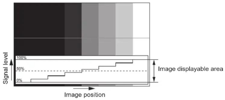
PANASONIC PT-RZ120BE - Adjusting the waveform - 1

bar_stacked | Image position | Signal level | | -------------- | ------------ | | 0% | 0% | | 50% | 50% | | 100% | 100% |

1) Select "Select line (luminance)" on the waveform monitor.
2) Adjust black level.

- Adjust the black level 0 % of the video signal to the 0 % position of the waveform monitor using the [PICTURE] menu → [BRIGHTNESS].

3) Adjust white level.
- Adjust the white level 100 % of the video signal to the 100 % position of the waveform monitor using the [PICTURE] menu → [CONTRAST].

Adjusting red, green, and blue

1) Set [COLOR TEMPERATURE] to [USER1] or [USER2]. (→ page 83)
2) Select "Select line (red)" on the waveform monitor.
3) Adjust dark red areas.

- Use [RED] in [WHITE BALANCE LOW] to adjust the black level 0 % of the video signal to the 0 % position of the waveform monitor.

4) Adjust bright red areas.
- Use [RED] in [WHITE BALANCE HIGH] to adjust the white level 100 % of the video signal to the 100 % position of the waveform monitor.
5) Use the procedure for [RED] to adjust [GREEN] and [BLUE].

Note

- Confirm that the [SIGNAL LEVEL] setting of the input signal is correct before adjusting the black level. Confirm the [SIGNAL LEVEL] setting in the [DISPLAY OPTION] menu → [DVI-D IN]/[HDMI IN]/[DIGITAL LINK IN]/[SDI IN] → [SIGNAL LEVEL].

[CUT OFF]

Each red, green, and blue color component can be removed.

1) Press ▲▼ to select [CUT OFF].
2) Press the button.

- The [CUT OFF] screen is displayed.

3) Press ▲▼ to select [RED], [GREEN], or [BLUE].
4) Press ◀▶ to switch the item.

[OFF] Disables cutoff.

[ON] Enables cutoff.

Note

- When input is switched or a signal is switched, the cutoff setting returns to its original setting (off).

124 - ENGLISH

[PROJECTOR SETUP] menu

On the menu screen, select [PROJECTOR SETUP] from the main menu, and select an item from the submenu.

Refer to "Navigating through the menu" (→ page 77) for the operation of the menu screen.

[PROJECTOR ID]

The projector has an ID number setting function that can be used when multiple projectors are used side by side to enable simultaneous control or individual control via a single remote control.

1) Press ▲▼ to select [PROJECTOR ID].

2) Press ◀▶ to switch the item.

- The items will switch each time you press the button.

[ALL] Select this item when controlling projectors without specifying an ID number.
[1] - [64] Select this item when specifying an ID number to control individual projector.

Note

  • To specify an ID number for individual control, the ID number of a remote control must match the ID number of the projector.
  • When the ID number is set to [ALL], the projector will operate regardless of the ID number specified during remote control or computer control.
    If multiple projectors are set up side by side with IDs set to [ALL], they cannot be controlled separately from the projectors with other ID numbers.
  • Refer to "Setting ID number of the remote control" (→ page 75) for how to set the ID number on the remote control.

[PROJECTION METHOD]

Set the projection method in accordance with the installation status of the projector.

Change the [FRONT/REAR] setting when the screen display is inverted.

Change the [FLOOR/CEILING] setting when the screen display is upside down.

Setting [FRONT/REAR]

1) Press ▲▼ to select [FRONT/REAR] of [PROJECTION METHOD].

2) Press ◀▶ to switch the item.

- The items will switch each time you press the button.

[FRONT] Select this item when installing the projector in front of the screen.
[REAR] Select this item when installing behind the screen (using translucent screen).

Setting [FLOOR/CEILING]

1) Press ▲▼ to select [FLOOR/CEILING] of [PROJECTION METHOD].

2) Press ◀▶ to switch the item.

- The items will switch each time you press the button.

[AUTO]Automatically detects the attitude of the projector by the built-in angle sensor. Set [AUTO] normally.
[FLOOR] Select this item when installing the projector on a desk, etc.
[CEILING]Select this item when installing the projector using the Ceiling Mount Bracket (optional). Projected image is inverted upside down.

Note

- Refer to "Angle sensor" (→ page 36) for details on the range of the installation attitude that can be detected by the built-in angle sensor.

[LENS]

Perform the setting and operation regarding the projection lens.

[LENS TYPE]

When the projector is used for the first time or when the projection lens is replaced, confirm the [LENS TYPE] setting. Change the setting if the type does not match the projection lens attached to the projector.

1) Press ▲▼ to select [LENS].
2) Press the button.

- The [LENS] screen is displayed.

3) Press ▲▼ to select [LENS TYPE].
4) Press ◀▶ to switch the item.

- The items will switch each time you press the button.

[NORMAL]Select this item when a projection lens anything other than the Fixed-focus Lens (Model No.: ET-DLE035) is used for projection.
[ET-DLE035]Select this item when the Fixed-focus Lens (Model No.: ET-DLE035) is used for projection.

Note

- The projection lens is not moved to the correct home position when the [LENS TYPE] is set incorrectly.

[LENS HOME POSITION]

Operate in following procedure to move the projection lens to the home position.

1) Press ▲▼ to select [LENS].
2) Press the button.

- The [LENS] screen is displayed.

3) Press ▲▼ to select [LENS HOME POSITION].
4) Press the button.

•The confirmation screen is displayed.

5) Press ◀▶ to select [OK], and press the button.

- [PROGRESS] is displayed in the [HOME POSITION] screen, and the projection lens is moved to the origin position.

Note

  • The projection lens is not moved to the correct home position when the [LENS TYPE] is set incorrectly. Change the setting if the type does not match the projection lens attached to the projector.
  • The home position does not match with the optical image center position.
  • The home position varies depending on the projection lens type. Refer to "Lens shift range" (→ page 71) for details.
  • The home position of the Fixed-focus Lens (Model No.: ET-DLE035) may deviate from the designed position.
  • [LENS HOME POSITION] can also be executed by pressing the button on the remote control while the lens shift adjustment screen is displayed.

[LENS CALIBRATION]

Detect the lens shift adjustment limit value, and perform the calibration in the adjustment range.

1) Press ◀▶ to select [LENS].
2) Press the button.

- The [LENS] screen is displayed.

3) Press ▲▼ to select [LENS CALIBRATION].
4) Press the button.

•The confirmation screen is displayed.

5) Press ◀▶ to select [OK], and press the button.

•The lens calibration is started.

- After completing the calibration, the projection lens will move to the home position.

• To cancel, select [CANCEL].

Note

  • [PROGRESS] is displayed in the menu during lens calibration. The operation cannot be canceled during calibration.
  • [INCOMPLETE] is displayed when the lens calibration is not performed correctly.
  • The origin position of the lens mounter and the home position of the projection lens are automatically updated when the lens calibration is performed.

The home position is an origin position of the lens shift (vertical position and horizontal position of the lens) based on the calibration result. It does not match with the optical image center position.

  • The home position varies depending on the projection lens type. Refer to "Lens shift range" (→ page 71) for details.
  • Pressing the button on the remote control for at least three seconds will also display the confirmation screen for lens calibration execution.

[OPERATION SETTING]

Set the operation method of the projector.

The settings are reflected when "Initial setting (operation setting)" (→ page 60) in the [INITIAL SETTING] screen is already set.

If you change the settings while using the projector, the duration until the luminance decreases by half may shorten or the luminance may decrease.

Setting [OPERATING MODE]

1) Press ▲▼ to select [OPERATION SETTING].
2) Press the button.

- The [OPERATION SETTING] screen is displayed.

3) Press ▲▼ to select [OPERATING MODE].
4) Press ◀▶ to switch the item.

  • The items will switch each time you press the button.
  • Set [OPERATING MODE] to [NORMAL], [USER1], [USER2], or [USER3] when using the projector at an altitude of 2700 m (8858') or higher above sea level.
[NORMAL]*1Set this item when high luminance is required. The estimated runtime is approximately 20 000 hours.
[ECO]*1The luminance will decrease compared to [NORMAL], but set this item to increase the expected life of the light source. The estimated runtime is approximately 24 000 hours.
[QUIET1]*1The luminance will decrease compared to [NORMAL], but select this item when operation with low noise is prioritized. The estimated runtime is approximately 20 000 hours.
[QUIET2]*1The luminance will decrease compared to [QUIET1], but select this item when operating the projector with less noise. The estimated runtime is approximately 20 000 hours.
[USER1][MAX LIGHT OUTPUT LEVEL] and [LIGHT OUTPUT] can be set individually.[USER2]
[USER3]

*1 The runtime is an estimation when the [PICTURE] menu → [DYNAMIC CONTRAST] is set to [3].

5) Press ▲▼ to select [APPLY].
6) Press the button.
7) When the confirmation screen is displayed, press ◀▶ to select [OK], and press the button.

Note

  • The [OPERATING MODE] setting does not return to factory default setting even if the [PROJECTOR SETUP] menu → [INITIALIZE] → [ALL USER DATA] is executed.
  • The estimated runtime is a time for the luminance to decrease to half.
  • If the runtime exceeds 20 000 hours, replacement of the components inside the projector may be required. Consult your dealer for details.

Setting [MAX LIGHT OUTPUT LEVEL]

Adjust the maximum level to correct screen brightness according to the changes in brightness of the light source.

1) Press ▲▼ to select [OPERATION SETTING].
2) Press the button.

- The [OPERATION SETTING] screen is displayed.

3) Press ▲▼ to select [MAX LIGHT OUTPUT LEVEL].
4) Press ◀▶ to adjust.

Operation Adjustment Range of adjustment
Press ▶.Increases the maximum level of brightness correction.8.0% - 100.0%
Press ◀.Decreases the maximum level of brightness correction.

5) Press ▲▼ to select [APPLY].
6) Press the button.
7) When the confirmation screen is displayed, press ◀▶ to select [OK], and press the button.

Note

  • When [OPERATING MODE] is set to [NORMAL], [ECO], [QUIET1], or [QUIET2], the item of [MAX LIGHT OUTPUT LEVEL] cannot be adjusted.
  • The brightness is corrected using this setting when the [PROJECTOR SETUP] menu → [BRIGHTNESS CONTROL] → [BRIGHTNESS CONTROL SETUP] → [CONSTANT MODE] is set to [AUTO] or [PC].
  • The [MAX LIGHT OUTPUT LEVEL] setting does not return to factory default setting even if the [PROJECTOR SETUP] menu → [INITIALIZE] → [ALL USER DATA] is executed.

Setting [LIGHT OUTPUT]

Adjust the brightness of light source.

The [LIGHT OUTPUT] setting is synchronized with the [PROJECTOR SETUP] menu → [LIGHT OUTPUT]. The most recent setting is reflected in both items.

1) Press ▲▼ to select [OPERATION SETTING].
2) Press the button.

- The [OPERATION SETTING] screen is displayed.

3) Press ▲▼ to select [LIGHT OUTPUT].
4) Press ◀▶ to adjust.

OperationAdjustmentRange of adjustment
Brightness Runtime (estimate)
Press ▶.The screen becomes brighter. The runtime becomes shorter.8.0% - 100.0%
Press ◀.The screen becomes darker. The runtime becomes longer.

5) Press ▲▼ to select [APPLY].
6) Press the button.
7) When the confirmation screen is displayed, press ◀▶ to select [OK], and press the button.

Note

  • [LIGHT OUTPUT] can be adjusted individually for each setting item of [OPERATING MODE].
  • In such a case when configuring multiple screens with multiple projectors, uniformity of brightness between multiple screens can be obtained by adjusting [LIGHT OUTPUT].

Interrelation of luminance and runtime

The projector can be operated at arbitrary brightness and duration of use by combining the settings of [MAX LIGHT OUTPUT LEVEL], [LIGHT OUTPUT], and [CONSTANT MODE] in [BRIGHTNESS CONTROL SETUP]. Interrelation of luminance and runtime is as follows. Make the settings depending on your desired duration of use and brightness of the projected image.

Values of the luminance and runtime are rough estimations.

- To set the projector based on the duration of use

Duration of use (hour)When [CONSTANT MODE] is set to [OFF] When[CONSTANT MODE] is set to [AUTO] or [PC]
[MAX LIGHT OUTPUT LEVEL] (%)[LIGHT OUTPUT] (%)Luminance (lm)[MAX LIGHT OUTPUT LEVEL] (%)[LIGHT OUTPUT] (%)Luminance (lm)
20 000 100.0100.0 12 000 100.064.6 7 700
24 000 100.0100.0 12 000 100.060.5 7 200
27 000 100.0100.0 12 000 100.057.7 6 900
31 000 100.078.2 9 300 100.0 54.3 6 500
35 000 100.058.5 7 000 100.0 51.1 6 100
40 000 — — —100.0 47.5 5 700

•To set the projector based on luminance

Luminance (lm)When [CONSTANT MODE] is set to [OFF] When [CONSTANT MODE] is set to [AUTO] or [PC]
[MAX LIGHT OUTPUT LEVEL] (%)[LIGHT OUTPUT] (%)Runtime (hour)[MAX LIGHT OUTPUT LEVEL] (%)[LIGHT OUTPUT] (%)Runtime (hour)
12 000 100.0100.0 27 000 — — —
11 000 100.091.7 28 500 100.0 91.7 1 000
10 000 100.083.3 30 000 100.0 83.3 4 300
9 000 100.0 755.0 31 500 100.0 750 11 000
8 000 100.0 666.7 33 000 100.0 667 18 000
7 000 100.0 588.3 35 000 100.0 583 26 000
6 000 100.0 500.0 37 000 100.0 500 36 000
5 000 — — —100.0 41.7 49 000
4 000 — — —100.0 33.3 66 000

Note

  • The runtime may be shorter than the estimation due to the influence of characteristics of each light source, conditions of use, installation environment, etc.
  • The duration of use is referred to as the runtime when you use the projector successively. The duration of use is an estimated duration and is not the warranty period.
  • If the runtime exceeds 20 000 hours, replacement of the components inside the projector may be required. Consult your dealer for details.

[LIGHT OUTPUT]

Adjust the brightness of light source.

The setting is reflected when it is already set with "Initial setting (operation setting)" (→ page 60) in the [INITIAL SETTING] screen or with the [PROJECTOR SETUP] menu → [OPERATION SETTING]. The [LIGHT OUTPUT] setting is synchronized with the [PROJECTOR SETUP] menu → [OPERATION SETTING] → [LIGHT OUTPUT]. The most recent setting is reflected in both items.

1) Press ▲▼ to select [LIGHT OUTPUT].

2) Press ◀▶ to adjust.

OperationAdjustmentRange of adjustment
BrightnessRuntime (estimate)
Press ▶.The screen becomes brighter.The runtime becomes shorter.8.0 % - 100.0 %
Press ◀.The screen becomes darker.The runtime becomes longer.

Note

  • [LIGHT OUTPUT] can be adjusted individually for each setting item of [OPERATING MODE].
  • In such a case when configuring multiple screens with multiple projectors, uniformity of brightness between multiple screens can be obtained by adjusting [LIGHT OUTPUT].

[BRIGHTNESS CONTROL]

The projector is equipped with a brightness sensor to measure brightness and color of the light source, and corrects brightness and white balance of the projected image according to the changes in brightness and color of the light source.

By using this function, in such a condition that multiple screens are configured using multiple projectors, you can reduce changes in overall brightness and white balance of the multiple screens due to aging of the light source and suppress variation in brightness and white balance to preserve uniformity.

The setting is reflected when it is already set with “Initial setting (operation setting)” (→ page 60) in the [INITIAL SETTING] screen or with the [PROJECTOR SETUP] menu → [OPERATION SETTING]. The [BRIGHTNESS CONTROL SETUP] setting is synchronized with the [PROJECTOR SETUP] menu → [OPERATION SETTING] → [BRIGHTNESS CONTROL SETUP]. The most recent setting is reflected in both items.

Setting [BRIGHTNESS CONTROL SETUP]

Set the operation of the brightness control function.

1) Press ▲▼ to select [BRIGHTNESS CONTROL].
2) Press the button.

- The [BRIGHTNESS CONTROL] screen is displayed.

3) Press ▲▼ to select [BRIGHTNESS CONTROL SETUP].
4) Press the button.

- The [BRIGHTNESS CONTROL SETUP] screen is displayed.

5) Press ▲▼ to select [CONSTANT MODE].
6) Press ◀▶ to switch the item.

- The items will switch each time you press the button.

[OFF] Does not correct the brightness of the screen by the brightness sensor.
[AUTO]Corrects the brightness of the screen by the brightness sensor.When the brightness of light source or white balance changes, the brightness of the projected image is automatically corrected.
[PC]Synchronizes nine or more projectors using a computer and the dedicated software “Multi Monitoring & Control Software”*1.

*1 "Multi Monitoring & Control Software" can be downloaded from the Panasonic website (https://panasonic.net/cns/projector/).
•Proceed to Step 9) when [PC] is selected.

7) Press ▲▼ to select [LINK].

8) Press ◀▶ to switch the item.

- The items will switch each time you press the button.

[OFF]Performs correction by the brightness sensor on one projector without synchronizing with the other projectors.The duration that the constant brightness is kept will become longer by setting the value of [LIGHT OUTPUT] smaller.
[GROUP A][GROUP B][GROUP C][GROUP D]Performs correction by the brightness sensor in multiple projectors in synchronization.Up to four groups (A to D) can be set within the same subnet by using the network function.Up to eight projectors can be registered and synchronized in one group.

9) Press ▲▼ to select [CALIBRATION TIME].

10) Press the button.

- The projector is in the adjustment mode (the time is blinking).

11) Press ◀▶ to select "hour" or "minute", and press ▲▼ or the number (<0> - <9>) buttons to set a time.

  • Selecting “hour” allows setting of only the hour in increments of one hour, and selecting “minute” allows setting of only the minute in increments of one minute between 00 and 59.
  • When the time is not specified, select [OFF] between 23 and 00 of the hour, or between 59 and 00 of the minute.

12) Press the button.

•[CALIBRATION TIME] is set.

- Brightness and color are measured at the specified time. The dynamic contrast function does not operate during measurement.

13) Press ▲▼ to select [CALIBRATION MESSAGE].

14) Press ◀▶ to switch the item.

- The items will switch each time you press the button.

[ON] Displays messages during calibration.

[OFF] Does not display messages during calibration.

15) Press ▲▼ to select [APPLY].

16) Press the button.

  • If the button is pressed with [CONSTANT MODE] set to anything other than [OFF], the brightness and white balance of light source at the time when the button is pressed is recorded as the standard brightness and white balance.
  • If the button is pressed when [LINK] is set from [GROUP A] to [GROUP D], the group name is displayed on the screens of projectors that have been set in the same group.

PANASONIC PT-RZ120BE - 16) Press the  button. - 1

Note

  • When [CONSTANT MODE] is set to [AUTO] or [PC], keep the shutter function disabled (shutter: open) for at least two minutes, since the brightness sensor calibration is performed after the [BRIGHTNESS CONTROL SETUP] setting has been completed.
  • If the shutter function is enabled (shutter: closed) within approximately 10 minutes after the light source has been turned on while the projector operates with [CONSTANT MODE] set to [AUTO] or [PC], brightness and color cannot be measured. Therefore, brightness may be corrected approximately two minutes after the shutter function is disabled (shutter: open).
  • When the projector operates with [CONSTANT MODE] set to [AUTO] or [PC], the brightness and color of the light source do not stabilize for approximately eight minutes after the light source is turned on. Therefore, the brightness and color of the light source will be automatically measured after approximately eight minutes have elapsed after the light source is turned on. A correction is made based on this measurement result so that the brightness and the color will be the same as the standard brightness and color when adjusted with the brightness control.
  • When the projector operates with [CONSTANT MODE] set to [AUTO], and [LINK] set to [OFF], the brightness will be corrected until it reaches the value set in [MAX LIGHT OUTPUT LEVEL].
  • The variation in brightness may increase due to dust accumulating on the lens, screen, or inside the projector, depending on the installation environment of the projector.
  • When the variation in brightness has increased due to aging of the light source, or when you replaced the light source, readjust the brightness control.
  • When the projector is used continuously for more than 24 hours, set [CALIBRATION TIME]. If it is not set, correction will not be performed automatically.
  • The brightness control function and the dynamic contrast function will operate simultaneously, but the dynamic contrast function will not operate while measuring the brightness and the color.
  • The [CALIBRATION TIME] setting will be reflected when you enter the time.
  • The [CALIBRATION MESSAGE] setting will be reflected at the time when the item is switched using ◀.

Displaying [BRIGHTNESS CONTROL STATUS]

Display the brightness control status.

1) Press ▲▼ to select [BRIGHTNESS CONTROL].

2) Press the button.

- The [BRIGHTNESS CONTROL] screen is displayed.

3) Press ▲▼ to select [BRIGHTNESS CONTROL STATUS].

4) Press the button.

- The [BRIGHTNESS CONTROL STATUS] screen is displayed.

[BRIGHTNESS CONTROL STATUS] screen display example

When [CONSTANT MODE] is set to [OFF]

The screen shows the status that the brightness control is disabled.

PANASONIC PT-RZ120BE - When [CONSTANT MODE] is set to [OFF] - 1

text_image BRIGHTNESS CONTROL STATUS CONSTANT MODE OFF PROJECTOR 1 RETURN

The screen shows the status of the brightness control in one projector.

PANASONIC PT-RZ120BE - When [CONSTANT MODE] is set to [AUTO], and [LINK] is set to [OFF] - 1

text_image BRIGHTNESS CONTROL STATUS LINK OFF 5 PROJECTOR 6 VEU RETURN

The screen shows the status of the brightness control of synchronized projectors (up to eight units), including the projector being controlled through the on-screen menu.

PANASONIC PT-RZ120BE - When [CONSTANT MODE] is set to [AUTO], and [LINK] is set to [GROUP A] through [GROUP D] - 1

text_image BRIGHTNESS CONTROL STATUS LINK GROUP A 1 2 3 PROJECTOR 192.168.30.2 1: PROJECTOR2 192.168.30.3 2: PROJECTOR3 192.168.30.4 3: 4: 5: 6: 7: UPDATE MENU SELECT 7 8

When [CONSTANT MODE] is set to [PC]

PANASONIC PT-RZ120BE - When [CONSTANT MODE] is set to [PC] - 1

text_image BRIGHTNESS CONTROL STATUS CONSTANT MODE PC PROJECTOR 5 1 6 RETURN

1 Display the name of the projector.
2 Display the synchronized group.
3 Display the IP address of the projector.
4 Display the names and IP addresses of projectors in same group detected over the network.

5 Display the status by color.

Green: There is an allowance for brightness correction.

Yellow: There is little allowance for brightness correction.

Red: There is a brightness control error.

6 Display error detailed messages.

7 Display error messages.

When the message [Failed to apply BRIGHTNESS CONTROL to some projectors.] appears, it means that synchronization with the projector displayed in red has failed.

Press ▲▼ to select the projector displayed in red, and press the button to display the error details.

8 Update to the latest status information.

■Error details

Error message Measures to take
[Exceed maximum number of projectors.]Limit the number of projectors in one group to eight.To synchronize nine or more projectors, use a PC and the dedicated software “Multi Monitoring & Control Software”1.
[Please check the COMMAND CONTROL setting.]Set [NETWORK CONTROL] → [COMMAND CONTROL] to [ON] for the projector in error.Set [NETWORK CONTROL] → [COMMAND PORT] of all linked projectors to the same value.
[Please check the USER NAME and PASSWORD in the COMMAND CONTROL setting.]Assign same character strings for [User name] and [Password] as the web control administrator rights to all linked projectors.
[Cannot apply BRIGHTNESS CONTROL. Please check projector status.]The projector is in standby. Switch on the power.
[Brightness Sensor Error]There is a problem with the brightness sensor. If problems persist even after switching on the power, consult your dealer.

*1 "Multi Monitoring & Control Software" can be downloaded from the Panasonic website (https://panasonic.net/cns/projector/).

Note

- If the synchronized projectors are not displayed in the list, check the following:

- Are there devices with the same IP address on the network?

- Are LAN cables connected correctly? (→ page 162)

- Are the subnets of the projectors the same?

- Are the same [LINK] settings applied to a group?

- Refer to [NETWORK SETUP] (→ page 157) or “[Network config] page” (→ page 172) on how to change the projector name.

Brightness control adjustment procedure example

The steps exemplify an adjustment to link the brightness of eight projectors connected in a network.

1) Connect all projectors to the hub using LAN cables. (→ page 162)
2) Switch on all projectors and start projection.
3) Set [CONSTANT MODE] of [BRIGHTNESS CONTROL SETUP] to [OFF], and select [APPLY], and then press the button.
4) Set [OPERATING MODE] of each projector to the same setting. (→ page 127)
5) Set [SUBNET MASK] and [IP ADDRESS] in each projector.

- To be able to communicate over the network, set the same value in [SUBNET MASK] for all projectors and set a different value in [IP ADDRESS] for each projector.

6) Wait for at least eight minutes after projection has started until the light source brightness becomes steady.
7) Set all items in the [PICTURE] menu of all projectors to the same values.
8) Adjust [COLOR MATCHING] to match colors.
9) Display the internal test pattern "All white" in all projectors.
10) Set [LIGHT OUTPUT] of all projectors to 100 % or the maximum value that can be set.

- Depending on the [OPERATING MODE] settings, [LIGHT OUTPUT] may not be able to be set to 100% .

11) Set [LIGHT OUTPUT] of the projector with the least brightness to 90 % or 10 % lower than the maximum value that can be set.

12) Adjust [LIGHT OUTPUT] of each projector.

- Adjust [LIGHT OUTPUT] of all the other projectors so that the brightness will be the same as the projector with the least brightness.

14) Select [APPLY] of [BRIGHTNESS CONTROL SETUP] and press the button in all projectors.

- Brightness control starts.

Note

  • Brightness is automatically corrected whenever the light source lights up by switching on/off the projector, etc.
  • When the variation in brightness has increased due to aging of the light source, or when you replaced the light source, readjust the brightness control.

[STANDBY MODE]

Set the power consumption during standby.

1) Press ▲▼ to select [STANDBY MODE].

2) Press ◀▶ to switch the item.

- The items will switch each time you press the button.

[NORMAL] Select this item when using the network function during standby.

[ECO] Select this item to reduce power consumption during standby.

Note

  • When [ECO] is set, the network function, the terminal, and some RS-232C commands become inoperable during standby. When [NORMAL] is set, the network function and the terminal can be used during standby.
  • When [ECO] is set, it may take approximately 10 seconds longer before the projector starts projecting after the power is turned on, compared with when [NORMAL] is set.
  • The [STANDBY MODE] setting does not return to factory default setting even if the [PROJECTOR SETUP] menu → [INITIALIZE] → [ALL USER DATA] is executed.

[QUICK STARTUP]

Set if the [QUICK STARTUP] function is enabled or disabled.

1) Press ▲▼ to select [QUICK STARTUP].

2) Press ◀▶ to switch the item.

- The items will switch each time you press the button.

[OFF] Disables theQUICK STARTUP] function.
[ON]Enables the [QUICK STARTUP] function until the specified time set in [VALID PERIOD] elapses after the projector enters the standby mode. The time until the projection starts after the power is turned on will be reduced during the period when the [QUICK STARTUP] function is valid.

•Proceed to Step 3) when [ON] is selected.

3) Press the button.

- The [QUICK STARTUP] screen is displayed.

4) Press ◀▶ to switch [VALID PERIOD].

- The items will switch each time you press the button.

[30MIN.]Sets the time until the [QUICK STARTUP] function is disabled after the projector enters the standby mode.
[60MIN.]
[90MIN.]Select a desired valid period.

Note

  • [QUICK STARTUP] cannot be set when [STANDBY MODE] is set to [ECO].
  • When [QUICK STARTUP] is set to [ON], the power consumption during standby becomes high during the period when the [QUICK STARTUP] function is valid.

  • When [QUICK STARTUP] is set to [ON], the [QUICK STARTUP] function is disabled when the time set in [VALID PERIOD] elapses after the projector enters the standby mode. The startup time and power consumption will be the same as when [QUICK STARTUP] is set to [OFF].

  • When [QUICK STARTUP] is set to [ON], the power indicator blinks in red while in the standby mode during the period when the [QUICK STARTUP] function is valid. The power indicator lights up in red when the specified time set in [VALID PERIOD] elapses after the projector enters the standby mode.
  • When [QUICK STARTUP] is set to [ON], the period when the [QUICK STARTUP] function is valid is counted as the projector runtime.

[NO SIGNAL SHUT-OFF]

This is a function to automatically set the power of the projector to standby mode when there is no input signal for specific period. The time before switching to standby can be set.

1) Press ▲▼ to select [NO SIGNAL SHUT-OFF].

2) Press ◀▶ to switch the item.

- The items will switch each time you press the button.

[DISABLE] Disables the no signal shut-off function.

[10MIN.] - [90MIN.] Sets the time in increments of 10 minutes.

[NO SIGNAL LIGHTS-OUT]

This is a function to automatically turn off the light source of the projector when there is no input signal for specific period. The time until the light source is turned off can be set.

1) Press ▲▼ to select [NO SIGNAL LIGHTS-OUT].

2) Press ◀▶ to switch the item.

- The items will switch each time you press the button.

[DISABLE] Disables the no signal lights-out function.
[10SEC.] - [5MIN.]Turns off the light source when there is no input signal for the preset period.Select [10SEC.], [20SEC.], [30SEC.], [1MIN.], [2MIN.], [3MIN.], or [5MIN.].

Note

  • The power indicator will blink slowly in green while the no signal lights-out function is operating and the light source is turned off.
  • When [NO SIGNAL LIGHTS-OUT] is set to anything other than [DISABLE], the following are the conditions to turn the light source back on again from the condition that the light source has turned off by this function.
    -When the signal has been input
  • When on-screen display such as menu screen (OSD) or input guide, a test pattern, or a warning message is displayed
  • When the power on <|> button is pressed
  • When the operation to disable the shutter function (shutter: open) is performed, such as pressing the button
  • When the operating environment temperature is around 0^ (32°F) and the light source is forced to turn on due to warm-up

[INITIAL STARTUP]

Set the startup method when the

switch is set to .

1) Press ▲▼ to select [INITIAL STARTUP].

2) Press ◀▶ to switch the item.

- The items will switch each time you press the button.

[LAST MEMORY]Starts up the projector in the condition before theswitch is set to.
[STANDBY] Starts up the projector in standby.
[ON] Starts projecting immediately.

[STARTUP INPUT SELECT]

Set the input when the projector is switched on to start projection.

1) Press ▲▼ to select [STARTUP INPUT SELECT].
2) Press the button.

- The [STARTUP INPUT SELECT] screen is displayed.

3) Press ▲▼◀▶ to select the input, and press the button.

[LAST USED] Keeps the input selected last.
[RGB1] Sets the input to RGB1.
[RGB2] Sets the input to RGB2.
[DVI-D] Sets the input to DVI-D.
[HDMI] Sets the input to HDMI.
[DIGITAL LINK] Sets the input to DIGITAL LINK.
[SDI] Sets the input to SDI.
[INPUT1] - [INPUT10]*1Sets the input to DIGITAL LINK, and switches the input of the Panasonic twisted-pair-cable transmitter to the specified input.

*1 When the optional DIGITAL LINK output supported device (Model No.: ET-YFB100G, ET-YFB200G) is connected to the projector, its input name is automatically reflected from [INPUT1] to [INPUT10]. When an item that does not reflect the input name is selected, it will be disabled.

Note

- When the [DISPLAY OPTION] menu → [BACKUP INPUT SETTING] → [BACKUP INPUT MODE] is set to a combination of the DVI-D input and HDMI input, and the power is turned off with the input set to HDMI during previous use, the projection will start with the DVI-D input even if [STARTUP INPUT SELECT] is set to [LAST USED].

[DATE AND TIME]

Set the time zone, date, and time of the built-in clock of the projector.

Setting the time zone

1) Press ▲▼ to select [DATE AND TIME].
2) Press the button.
- The [DATE AND TIME] screen is displayed.
3) Press ▲▼ to select [TIME ZONE].
4) Press ◀▶ to switch [TIME ZONE].

Setting the date and time manually

1) Press ▲▼ to select [DATE AND TIME].
2) Press the button.
- The [DATE AND TIME] screen is displayed.
3) Press ▲▼ to select [ADJUST CLOCK].
4) Press the button.
- The [ADJUST CLOCK] screen is displayed.
5) Press ▲▼ to select an item, and press ◀▶ to set the local date and time.
6) Press ▲▼ to select [APPLY], and press the button.
- The setting of the date and time will be completed.

Setting the date and time automatically

1) Press ▲▼ to select [DATE AND TIME].
2) Press the button.
- The [DATE AND TIME] screen is displayed.

3) Press ▲▼ to select [ADJUST CLOCK].

4) Press the button.

- The [ADJUST CLOCK] screen is displayed.

5) Press ▲▼ to select [NTP SYNCHRONIZATION], and press ◀▶ to change the setting to [ON].

6) Press ▲▼ to select [APPLY], and press the button.

- The setting of the date and time will be completed.

Note

  • To set the date and time automatically, the projector must be connected to the network.
  • If synchronization with the NTP server fails just after [NTP SYNCHRONIZATION] is set to [ON], [NTP SYNCHRONIZATION] will return to [OFF]. If [NTP SYNCHRONIZATION] is set to [ON] while the NTP server is not set, [NTP SYNCHRONIZATION] will return to [OFF].
  • Access the projector via a web browser to set the NTP server. Refer to "[Adjust clock] page" (→ page 173) for details.
  • The [TIME ZONE] setting is reset to the factory default when the [PROJECTOR SETUP] menu → [INITIALIZE] → [ALL USER DATA] is executed. However, the date and time based on the local date and time setting (Coordinated Universal Time, UTC, Universal Time, Coordinated) will be maintained without being initialized.
  • The replacement of the battery inside the projector is required when the time goes out of alignment right after correcting the time. Consult your dealer.

[SCHEDULE]

Set the command execution schedule for each day of the week.

Enabling/disabling the schedule function

1) Press ▲▼ to select [SCHEDULE].
2) Press ◀▶ to switch the item.

- The items will switch each time you press the button.

[OFF] Disables the schedule function.
[ON]Enables the schedule function. Refer to “How to assign a program” (⇨ page 137) or “How to set a program” (⇨ page 137) for how to set the schedule.

Note

- When [SCHEDULE] is set to [ON] while the [PROJECTOR SETUP] menu → [STANDBY MODE] is set to [ECO], the [STANDBY MODE] setting is forcibly switched to [NORMAL], and the setting cannot be changed to [ECO]. The [STANDBY MODE] setting will not return to original even if [SCHEDULE] is set to [OFF] in this condition.

How to assign a program

1) Press ▲▼ to select [SCHEDULE].
2) Press ◀▶ to select [ON], and press the button.
- The [SCHEDULE] screen is displayed.

3) Select and assign a program to each day of week.

  • Press ▲▼ to select the day of week, and press ◀▶ to select a program number.
  • You can set the program from No.1 to No.7. “--” indicates that the program number has not been set.

How to set a program

Set up to 16 commands to each program.

1) Press ▲▼ to select [SCHEDULE].
2) Press ◀▶ to select [ON], and press the button. • The [SCHEDULE] screen is displayed.

3) Press ▲▼ to select [PROGRAM EDIT].

4) Press ◀▶ to select a program number, and press the button.

5) Press ▲▼ to select a command number, and press the button. • You can change the page using ◀▶.

6) Press ▲▼◀▶ to select [TIME], and press the button. •The projector is in the adjustment mode (the time is blinking).

7) Press ◀▶ to select "hour" or "minute", and press ▲▼ or the number (<0> - <9>) buttons to set a time, and then press the button.
8) Press ▲▼◀▶ to select [COMMAND].

9) Press the button.

- The [COMMAND] detailed screen is displayed.

10) Press ▲▼ to select a [COMMAND].

  • For [COMMAND] which requires detailed settings, the items of the detailed settings will switch each time you press ◀.
  • When [INPUT] is selected, press the button, and then press ▲▼◀▶ to select the input to be set.
[COMMAND]Detailed settings of [COMMAND]Description
[POWER ON] — Switches on the projector.
[STANDBY] — Enters standby.
[QUICK STARTUP][ON]Enables the function of the [PROJECTOR SETUP] menu → [QUICK STARTUP].
[OFF]Disables the function of the [PROJECTOR SETUP] menu → [QUICK STARTUP].
[SHUTTER][OPEN] Disables the shutter function (shutter: open).
[CLOSE] Enables the shutter function (shutter: closed).
[INPUT][RGB1] Switches the input to RGB1.
[RGB2] Switches the input to RGB2.
[DVI-D] Switches the input to DVI-D.
[HDMI] Switches the input to HDMI.
[DIGITAL LINK] Switches the input to DIGITAL LINK.
[SDI] Switches the input to SDI.
[INPUT1] - [INPUT10]*1Switches the input to DIGITAL LINK, and switches the input of the Panasonic twisted-pair-cable transmitter to the specified input.
[OPERATING MODE] ^2 [NORMAL] Prioritizes luminance.
[ECO]Controls the power to increase the life of the light source with higher luminance.
[QUIET1]Operates the projector with low noise although the luminance is lower than that of [NORMAL].
[QUIET2]Operates the projector with less noise although the luminance is lower than that of [QUIET1].
[USER1] Controls the power with the setting set in [USER1].
[USER2] Controls the power with the setting set in [USER2].
[USER3] Controls the power with the setting set in [USER3].

*1 When the optional DIGITAL LINK output supported device (Model No.: ET-YFB100G, ET-YFB200G) is connected to the projector, its input name is automatically reflected from [INPUT1] to [INPUT10]. When an item that does not reflect the input name is selected, it will be disabled.
*2 If you change the settings while using the projector, the duration until the luminance decreases by half may shorten or the luminance may decrease.

11) Press the button.

  • The command is fixed and is displayed at the left of the selected command.
  • After the command is fixed, press the button to close the detailed setting screen.

12) Press ▲▼◀▶ to select [STORE], and press the button.

Note

  • To delete a command that has been already set, press the button on the remote control while the screen in Step 5) is displayed, or select [DELETE] at the screen in Step 6) and press the button.
  • If multiple commands have been set for the same time, they are executed in chronological order starting from the smallest command number.
  • The operating time will be the local time. (→ page 136)
  • If an operation is executed with the remote control or control panel of the projector or with a control command before the command set in [SCHEDULE] is executed, the command set with the schedule function may not be executed.

[MULTI PROJECTOR SYNC]

Set the contrast synchronization function and the shutter synchronization function.

The contrast synchronization function is a function to display a combined screen with a balanced contrast by sharing the brightness level of the video signal input to each projector when a multi-display is constructed by combining the projected image of multiple projectors. The shutter synchronization function is a function to synchronize the shutter operation of the specified projector to other projectors, and the effect using the shutter function including the fade out/fade in operation can be synchronized.

To use the contrast synchronization function and the shutter synchronization function, it is necessary to connect the projectors targeted for synchronization in a loop with daisy chain connection using the terminal and the terminal. For details of how to connect the projectors, refer to "Connecting example when using the contrast synchronization function/shutter synchronization function" ( page 53).

Note

  • The contrast synchronization function and the shutter synchronization function can be used simultaneously.
  • The menu items in the [PROJECTOR SETUP] menu [MULTI PROJECTOR SYNC] is the same as the following setting items.
  • The [PICTURE] menu → [DYNAMIC CONTRAST] → [USER] → [MULTI PROJECTOR SYNC]
  • The [DISPLAY OPTION] menu → [SHUTTER SETTING] → [MULTI PROJECTOR SYNC]

Setting the contrast synchronization function

1) Press ▲▼ to select [MULTI PROJECTOR SYNC].
2) Press the button.

- The [MULTI PROJECTOR SYNC] screen is displayed.

3) Press ▲▼ to select [MODE].
4) Press ◀▶ to switch the item.

- The items will switch each time you press the button.

[OFF]Select this item when the contrast synchronization function and the shutter synchronization function are not used.
[MASTER]Select this item when the contrast synchronization function or the shutter synchronization function is used.Set this item only on one projector out of the projectors that are linked.The projector set as the [MASTER] will calculate the brightness level of the video signal to become optimum on the whole combined screen for each frame. All the projectors targeted for contrast synchronization will control the dynamic contrast function based on the calculation result.
[SLAVE]Select this item when the contrast synchronization function or the shutter synchronization function is used.Set this item in all the linked projectors excluding the projector set as the [MASTER].

- When anything other than [OFF] is selected, the diagnostic result is displayed in [LINK STATUS], indicating if all the projectors including the projectors targeted for synchronization are correctly connected, and if [MODE] is correctly set.

[LINKED]All the projectors are correctly connected, and correctly set. They are in the condition that the contrast synchronization function or the shutter synchronization function can be used.
[NO LINK]The projectors are not correctly connected, or not correctly set. Check the cable connection status and the projector setting for each projector that is linked.

5) Press ▲▼ to select [CONTRAST SYNC].
6) Press ◀▶ to switch the item.

- The items will switch each time you press the button.

[OFF] Select this item when the contrast synchronization function is not used.
[ON] Select this item when the contrast synchronization function is used.

Note

  • The contrast synchronization function will operate when all of the following conditions are fulfilled.
  • All the projectors to be linked are connected in a loop with the daisy chain connection. (Maximum 64 projectors)
  • [MODE] on only one projector that is linked is set to [MASTER], and [MODE] on all other projectors are set to [SLAVE].

- [CONTRAST SYNC] on the projectors to perform the contrast synchronization is set to [ON].

- It is possible to set [CONTRAST SYNC] to [OFF] for the projectors that are linked but not to synchronize.

Setting the shutter synchronization function

1) Press ▲▼ to select [MULTI PROJECTOR SYNC].
2) Press the button.

- The [MULTI PROJECTOR SYNC] screen is displayed.

3) Press ▲▼ to select [MODE].

4) Press ◀▶ to switch the item.

- The items will switch each time you press the button.

[OFF]Select this item when the contrast synchronization function and the shutter synchronization function are not used.
[MASTER]Select this item when the contrast synchronization function or the shutter synchronization function is used.Set this item only on one projector that becomes the synchronization source of the shutter operation.
[SLAVE]Select this item when the contrast synchronization function or the shutter synchronization function is used.Set this item in all the linked projectors excluding the projector set as the [MASTER].

- When anything other than [OFF] is selected, the diagnostic result is displayed in [LINK STATUS], indicating if all the projectors including the projectors targeted for synchronization are correctly connected, and if [MODE] is correctly set.

[LINKED]All the projectors are correctly connected, and correctly set. They are in the condition that the contrast synchronization function or the shutter synchronization function can be used.
[NO LINK]The projectors are not correctly connected, or not correctly set. Check the cable connection status and the projector setting for each projector that is linked.

5) Press ▲▼ to select [SHUTTER SYNC].
6) Press ◀▶ to switch the item.

- The items will switch each time you press the button.

[OFF] Select this item when the shutter synchronization function is not used.
[ON] Select this item when the shutter synchronization function is used.

Note

  • The shutter synchronization function will operate when all of the following conditions are fulfilled.
  • All the projectors to be linked are connected in a loop with the daisy chain connection. (Maximum 64 projectors)
  • [MODE] on only one projector that is linked is set to [MASTER], and [MODE] on all other projectors are set to [SLAVE].
  • [SHUTTER SYNC] on the projectors to perform the shutter synchronization is set to [ON].
  • It is possible to set [SHUTTER SYNC] to [OFF] for the projectors that are linked but not to synchronize.
  • The shutter operation by the shutter synchronization function will follow the setting of the [DISPLAY OPTION] menu → [SHUTTER SETTING] on the projector that [MODE] is set to [MASTER].
  • When the input signal to each linked projector is not synchronized, the timing of the shutter operation between the projectors may shift up to 1 frame while using the shutter synchronization function.
  • The shutter function of the projector with [MODE] set to [SLAVE] can be operated individually. At that time, the shutter operation will follow the setting of the [DISPLAY OPTION] menu → [SHUTTER SETTING] set in that projector.

[RS-232C]

Set the communication conditions of the / terminals. For details on the connection method for RS-232C communication, refer to "/ terminals"

(→ page 200).

Setting the communication condition of the terminal

1) Press ▲▼ to select [RS-232C].
2) Press the button.

• The [RS-232C] screen is displayed.

140 - ENGLISH

3) Press ▲▼ to select [INPUT SELECT].
4) Press ◀▶ to switch the item.

[PROJECTOR]Performs the RS-232C communication with theterminal of the projector.
[DIGITAL LINK]Performs the RS-232C communication via the optional DIGITAL LINK output supported device (Model No.: ET-YFB100G, ET-YFB200G) and theterminal.

5) Press ▲▼ to select [(IN) BAUDRATE].
6) Press ◀▶ to switch the item.

- The items will switch each time you press the button.

[9600]Select the proper speed.[19200]
[38400]

7) Press ▲▼ to select [(IN) PARITY].
8) Press ◀▶ to switch the item.

- The items will switch each time you press the button.

[NONE]Select the parity condition.[EVEN]
[ODD]

Setting the communication condition of the terminal

1) Press ▲▼ to select [RS-232C].
2) Press the button.

- The [RS-232C] screen is displayed.

3) Press ▲▼ to select [(OUT) BAUDRATE].
4) Press ◀▶ to switch the item.

[9600]Select the proper speed.[19200]
[38400]

5) Press ▲▼ to select [(OUT) PARITY].
6) Press ◀▶ to switch the item.

- The items will switch each time you press the button.

[NONE]Select the parity condition.[EVEN]
[ODD]

Setting the response

1) Press ▲▼ to select [RS-232C].
2) Press the button.

• The [RS-232C] screen is displayed.

3) Press ▲▼ to select [RESPONSE(ID ALL)].
4) Press ◀▶ to switch the item.

[ON] Returns the response when an ID is designated as ALL.

[OFF] Does not return the response when an ID is designated as ALL.

5) Press ▲▼ to select [GROUP].
6) Press ◀▶ to switch the item.

[A] - [Z]Controls multiple projectors simultaneously by sending the ID of RS-232C. You can set groups from [A] to [Z]. The projector responds when the ID of RS-232C matches the setting.

7) Press ▲▼ to select [RESPONSE(ID GROUP)].
8) Press ◀▶ to switch the item.

[ON] Returns the response when an ID is designated as GROUP.
[OFF] Does not return the response when an ID is designated as GROUP.

Note

  • When [INPUT SELECT] is set to [DIGITAL LINK], communication using that serial terminal is available only when the corresponding device (such as the optional DIGITAL LINK output supported device (Model No.: ET-YFB100G, ET-YFB200G)) is connected to the terminal.
  • When transferring logos via the optional DIGITAL LINK output supported device (Model No.: ET-YFB100G, ET-YFB200G), setting for "NO SIGNAL SLEEP" of the DIGITAL LINK output supported device should be set to "OFF" to avoid interruption of communication.
  • When [INPUT SELECT] is set to [DIGITAL LINK], communication speed for input is fixed to 9 600 bps and the parity is fixed to "NONE".

[REMOTE2 MODE]

Set the terminal.

1) Press ▲▼ to select [REMOTE2 MODE].
2) Press ◀▶ to switch the item.

- The items will switch each time you press the button.

[DEFAULT]Uses pin assignment of theterminal in standard setting. (→ page 204)
[USER] Changes thesetting of theterminal.

- Proceed to Step 3) when [USER] is selected.

3) Press the button.
4) Press ▲▼ to select one from [PIN2] to [PIN8], and press ◀▶ to switch the setting.

[FUNCTION BUTTON]

Set the function of the button on the remote control.

1) Press ▲▼ to select [FUNCTION BUTTON].
2) Press the button.

- The [FUNCTION BUTTON] screen is displayed.

3) Press ▲▼ to select a function.

[DISABLE] Disables thebutton.
[SUB MEMORY]Displays the sub memory list. (→ page 151)
[SYSTEM SELECTOR]Switches the [SYSTEM SELECTOR] setting according to the input signal of the image being projected.When the input signal is anything other than the SDI inputThe [PICTURE] menu → [SYSTEM SELECTOR] (→ page 88)When the input signal is the SDI inputThe [DISPLAY OPTION] menu → [SDI IN] → [SYSTEM SELECTOR] (→ page 116)
[SYSTEM DAYLIGHT VIEW]Switches the [SYSTEM DAYLIGHT VIEW] setting. (→ page 86)
[FREEZE]Freezes the image temporarily. (→ page 123)
[WAVEFORM MONITOR]Displays the waveform of the input signal. (→ page 123)
[ASPECT]Switches the aspect ratio of the image. (→ page 91)
[PROJECTION METHOD]Switches the [PROJECTION METHOD] setting. (→ page 125)

4) Press the button.

[STATUS]

Display the status of the projector.

1) Press ▲▼ to select [STATUS].

2) Press the button.

- The [STATUS] screen is displayed.

3) Press ◀▶ to switch the pages.

- The page will change each time you press the button.

[PROJECTOR TYPE] Displays the type of the projector.
[SERIAL NUMBER] Displays the serial number of the projector.
[PROJECTOR RUNTIME] Displays the runtime of the projector.
[LIGHT RUNTIME] Displays the runtime of the light source 1 and the light source 2.
[CONTINUOUS LIGHTING TIME]Displays the elapsed time from when the light source is illuminated.The elapsed time after the illumination of the light source can be confirmed when adjusting the focus.The elapsed time is reset when the light source is temporarily turned off such as using the shutter function.
[MAIN/SUB VERSION] Displays the main and sub versions of the firmware of the projector.
[INTAKE AIR TEMP.] ^1 Displays the status of the intake air temperature of the projector.
[OPTICS MODULE TEMP.] ^1 Displays the status of the internal temperature of the projector.
[EXHAUST AIR TEMP.] ^1 Displays the status of the exhaust air temperature of the projector.
[LIGHT1 TEMP.] ^1 Displays the status of the light source 1 temperature of the projector.
[LIGHT2 TEMP.] ^1 Displays the status of the light source 2 temperature of the projector.
[SELF TEST] Displays the status of the projector.
[INPUT] Displays the input terminal currently selected.
[SIGNAL NAME] Displays the input signal name.
[MEMORY NO.] Displays the memory number of the input signal.
[BACKUP INPUT STATUS]Displays whether switching to the backup input signal is possible or not when [BACKUP INPUT MODE] is set to [OFF]. (→ page 108)
[NUMBER OF REGISTERED SIGNAL]Displays the number of registered signals.
[COOLING CONDITION]Displays the set cooling conditions.
[ATMOSPHERIC PRESSURE]Displays the atmospheric pressure.
[REMOTE2 STATUS]Displays the control status of the REMOTE2.
[AC VOLTAGE] Displays the input supply voltage.
[ON COUNT][POWER ON TIMES]Displays the number of times the power is turned on.
[UPGRADE KIT][ET-UK20]Displays the activation status by the Upgrade Kit (Model No.: ET-UK20).
[ET-CUK10]Displays the activation status by the Auto Screen Adjustment Upgrade Kit (Model No.: ET-CUK10).
[OPERATING MODE]Displays the setting value of the [PROJECTOR SETUP] menu → [OPERATION SETTING] → [OPERATING MODE].
[NORMAL]Displays the runtime of the light source with [OPERATING MODE] set to [NORMAL].
[ECO]Displays the runtime of the light source with [OPERATING MODE] set to [ECO].
[QUIET1]Displays the runtime of the light source with [OPERATING MODE] set to [QUIET1].
[QUIET2]Displays the runtime of the light source with [OPERATING MODE] set to [QUIET2].
[USER1]Displays the runtime of the light source with [OPERATING MODE] set to [USER1].
[USER2]Displays the runtime of the light source with [OPERATING MODE] set to [USER2].
[USER3]Displays the runtime of the light source with [OPERATING MODE] set to [USER3].
[CONSOLIDATED RUNTIME] ^2 Converts the total runtime of the light sources with [OPERATING MODE] set to each item into the time used with the [NORMAL] setting.The converted runtime is used for a rough indication about when to perform maintenance when the projector is used in combination of each item in [OPERATING MODE].
[SIGNAL INFORMATION][INPUT] Displays the input terminal used for the projected image.
[SIGNAL FORMAT] Displays the format of the input signal.
[SIGNAL FREQUENCY] Displays the frequency of the input signal.
[SYNC.STATE] Displays the sync polarity of the input signal.
[V.SYNC WIDTH] Displays the vertical sync signal pulse width of the input signal.
[SCAN TYPE] Displays the scan type of the input signal.
[TOTAL DOTS] Displays the total dot count of the input signal.
[DISPLAY DOTS] Displays the number of input signal display dots.
[TOTAL LINES] Displays the total line count of the input signal.
[DISPLAY LINES] Displays the number of input signal display lines.
[SAMPLING] Displays the sampling information of the input signal.
[SIGNAL LEVEL] Displays the signal level of the input signal.
[BIT DEPTH] Displays the gradation of the input signal.
[HDCP STATUS]Displays the HDCP status of the input signal. The content of display is as follows.[HDCP2.2]: When protected with HDCP 2.2[HDCP1.X]: When protected with HDCP 1.X[NONE]: When not protected with HDCP

*1 The temperature status is indicated with text color (green/yellow/red) and bar scale. Use the projector within the range that the indication is green.
*2 [CONSOLIDATED RUNTIME] can be obtained with the following calculation formula. Values obtained by the calculation formula contain a slight error.

Conversion formula for [CONSOLIDATED RUNTIME]

A × 1.0 + B × 0.8

• A: Runtime of the light source with [OPERATING MODE] set to [NORMAL], [QUIET1], [QUIET2], [USER1], [USER2], or [USER3]
- B: Runtime of the light source with [OPERATING MODE] set to [ECO]

Note

  • E-mail containing the status can be sent to the E-mail address (up to two addresses) set in “[E-mail set up] page” (→ page 174) by pressing the button while the [STATUS] screen is displayed.
  • Some items in [SIGNAL INFORMATION] may be displayed and others not displayed, depending on the signal being input.
  • If any abnormality has occurred on the projector, press the button while the [STATUS] screen is displayed to display the detail screen of the error information.
  • For details on the contents displayed in [SELF TEST], refer to “[SELF TEST] indications” (→ page 189).

[DATA CLONING]

Perform the operations of the data cloning function. Data such as the settings and adjustment values of the projector can be copied to multiple projectors via LAN.

■ Data that cannot be copied

The following settings cannot be copied. Set these in each projector.

  • The [PROJECTOR SETUP] menu → [PROJECTOR ID]
  • The [PROJECTOR SETUP] menu → [DATE AND TIME] → [ADJUST CLOCK]
  • The [PROJECTOR SETUP] menu → [DATA CLONING] → [WRITE PROTECT]
    • The [SECURITY] menu → [SECURITY PASSWORD]

• The [NETWORK] menu → [NETWORK SETUP]
- Security password
• Control device password
- Password set in “[Change password] page” (→ page 178) of the web control screen
- “[E-mail set up] page” (→ page 174) in the web control screen
- “[Authentication set up] page” (→ page 175) in the web control screen
- “[Crestron Connected(TM)] page” (→ page 180) in the web control screen

Copying data to another projector

Set the following settings on the projector to copy the data in advance. Refer to "Setting [WRITE PROTECT]" (→ page 145) for details.
- The [PROJECTOR SETUP] menu → [DATA CLONING] → [WRITE PROTECT] → [OFF]

1) Connect all projectors to the hub using LAN cables. (→ page 162)

2) Turn on all the projectors.
3) Press ▲▼ to select [DATA CLONING] on the projector to copy.
4) Press the button.

- The [SECURITY PASSWORD] screen is displayed.

5) Enter a security password and press the button.
- The [DATA CLONING] screen is displayed.
6) Press ▲▼ to select [SELECT PROJECTOR].
7) Press the button.

- The projectors in the same subnet are displayed as a list.

8) Press ▲▼ to select the copy destination projector.
9) Press the button.

- To select multiple projectors, repeat Steps 8) to 9).

10) Press the button on the remote control.

•The confirmation screen is displayed.

11) Press ◀▶ to select [OK], and press the button.

- Start the copy of data between projectors.

Once the copy is completed, results are displayed as a list in the [DATA CLONING] screen.

Meanings of the marks displayed in the list are as follows.

-Green: Data copy has succeeded.

  • Red: Data copy has failed. Confirm the connection of the LAN cable and power status of the copy destination projector.
  • The copy destination projector will display the data cloning request message, transfer to standby state automatically, and perform the copy of the data.

12) Turn on the copy destination projector.

- The copied content is reflected to the projector.

Note

  • The security password is the password set in the [SECURITY] menu [SECURITY PASSWORD CHANGE].
    Initial password as the factory default: ▲▶▼◀▲▶▼◀
  • The light source indicator / and the temperature indicator of the copy destination projector blink while copying the data. Confirm the blinking of the indicators stops, and then turn on the power supply.

Setting [WRITE PROTECT]

Set if the copy of data using the data cloning function is permitted or not.

1) Press ▲▼ to select [DATA CLONING] on the copy destination projector.
2) Press the button.

- The [SECURITY PASSWORD] screen is displayed.

3) Enter a security password and press the button.
- The [DATA CLONING] screen is displayed.
4) Press ▲▼ to select [WRITE PROTECT].
5) Press ◀▶ to switch the item.

- The items will switch each time you press the button.

[OFF] Permits operations of the data cloning function from another projector.
[ON]Does not permit the operations of the data cloning function from another projector.• Data copy will not be possible when [ON] is set. When it is not necessary to copy data of another projector, set to [ON] so that the data is not changed by mistake.

Note

- The security password is the password set in the [SECURITY] menu → [SECURITY PASSWORD CHANGE]. Initial password as the factory default: ▲▶▼◀▲▶▼◀

[SAVE ALL USER DATA]

Save the various setting values as a backup in the built-in memory of the projector.

1) Press ▲▼ to select [SAVE ALL USER DATA].
2) Press the button.

- The [SECURITY PASSWORD] screen is displayed.

3) Enter a security password and press the button.
4) When the confirmation screen is displayed, press ◀▶ to select [OK], and press the button.

•[PROGRESS] is displayed while saving data.

Note

- Data set from the computer application is not included in [ALL USER DATA]. - The data saved by executing [SAVE ALL USER DATA] is not deleted even if the [PROJECTOR SETUP] menu → [INITIALIZE] → [ALL USER DATA] is executed.

[LOAD ALL USER DATA]

Load the various setting values saved as a backup in the built-in memory of the projector.

1) Press ▲▼ to select [LOAD ALL USER DATA].
2) Press the button.

- The [SECURITY PASSWORD] screen is displayed.

3) Enter a security password and press the button.
4) When the confirmation screen is displayed, press ◀▶ to select [OK], and press the button.

Note

- The projector enters the standby mode to reflect the setting values when [LOAD ALL USER DATA] is executed. - Data registered from a computer is not included in [ALL USER DATA].

[INITIALIZE]

Return various setting values to their factory default settings.

1) Press ▲▼ to select [INITIALIZE].
2) Press the button.

- The [SECURITY PASSWORD] screen is displayed.

3) Enter a security password and press the button.
- The [INITIALIZE] screen is displayed.
4) Press ▲▼ to select an item to initialize.

[ALL USER DATA]Returns all setting values including [REGISTERED SIGNAL], [NETWORK/E-MAIL], and [LOGO IMAGE] to the factory default settings.The projector enters the standby mode to reflect the setting values.
[REGISTERED SIGNAL]Deletes all the setting values saved for each input signal.To delete only a part of a registered signal, perform the procedure described in “Deleting the registered signal” (⇨ page 149).
[NETWORK/E-MAIL]Returns the setting of the [NETWORK] menu → [NETWORK SETUP] and the setting of “[E-mail set up] page” (⇨ page 174) in the web control screen to the factory default settings.
[LOGO IMAGE] Deletesthe image registered in [USER LOGO].

5) Press the button.
6) When the confirmation screen is displayed, press ◀▶ to select [OK], and press the button.

Note

  • The security password is the password set in the [SECURITY] menu → [SECURITY PASSWORD CHANGE]. Initial password as the factory default: ▲▶▼◀▲▶▼◀
  • The following settings are not initialized even if [ALL USER DATA] is executed.
  • The [DISPLAY OPTION] menu → [UNIFORMITY] (except for [PC CORRECTION])
  • The [PROJECTOR SETUP] menu → [OPERATION SETTING] → [OPERATING MODE]
  • The [PROJECTOR SETUP] menu → [OPERATION SETTING] → [MAX LIGHT OUTPUT LEVEL]
  • The [PROJECTOR SETUP] menu → [STANDBY MODE]
  • If [ALL USER DATA] is executed, the [INITIAL SETTING] screen is displayed when the projection is started the next time.

[SERVICE PASSWORD]

This function is used by a service person.

[TEST PATTERN] menu

On the menu screen, select [TEST PATTERN] from the main menu.

Refer to "Navigating through the menu" ( page 77) for the operation of the menu screen.

[TEST PATTERN]

Display the test pattern built-in to the projector.

Settings of position, size, and other factors will not be reflected in test patterns. Make sure to display the input signal before performing various adjustments.

1) Press ◀▶ to switch the [TEST PATTERN] item.

- The items will switch each time you press the button.

Menu screen + All whiteDisplays a test pattern with the menu screen. Select a desired test pattern.
Menu screen + All black
Menu screen + Window
Menu screen + Window (inversion)
Menu screen + Color bar (vertical)
Menu screen + Color bar (horizontal)
Menu screen + 16:9/4:3 aspect frame
Menu screen + Cross hatch
Menu screen + Focus
Menu screen + Input screenDisplays the menu screen and input signal.Internal test patterns are not displayed.

Note

  • Press the button on the remote control while the test pattern is displayed to hide the menu screen.
  • It is recommended to perform the focus adjustment after 30 minutes have elapsed with the focus test pattern displayed.

Changing the color of the cross hatch test pattern

The color can be changed when the "Menu screen + Cross hatch" cross hatch test pattern is displayed.

1) Press ◀▶ to select the "Menu screen + Cross hatch" test pattern.
2) Press the button.

- The [TEST PATTERN COLOR] screen is displayed.

3) Press ▲▼ to select a color, and press the button.

- The color of the cross hatch test pattern is changed to the selected color.

Note

  • The [TEST PATTERN COLOR] setting returns to [WHITE] when the projector is switched off.
  • Colors of the test patterns other than cross hatch test patterns cannot be changed.

[SIGNAL LIST] menu

On the menu screen, select [SIGNAL LIST] from the main menu.

Refer to “Navigating through the menu” ( page 77) for the operation of the menu screen.

■Registered signal details

Memory number: A1 (1-2)
PANASONIC PT-RZ120BE - ■Registered signal details - 1

When the address number (A1, A2, ... L7, L8) signal is registered

- A name can be set for each sub memory (→ page 151).

Registering new signals

After a new signal is input and the

button on the remote control or the control panel is pressed, the registration is completed and the [MAIN MENU] screen is displayed.

Note

  • Up to 96 signals, including sub memories, can be registered to the projector.
  • There are 12 pages (eight memories of A through L, with eight memories possible on each page) for memory numbers, and the signal is registered to the lowest number that is available. If there is no available memory number it will be overwritten from the oldest signal.
  • The name to be registered is automatically determined by the input signal.
  • If a menu is being displayed, the new signals will be registered at the instant they are input.

Renaming the registered signal

Registered signals can be renamed.

1) Press ▲▼◀▶ to select the signal of which name is to be changed.
2) Press the button.

- The [REGISTERED SIGNAL STATUS] screen is displayed.

- The memory number, input terminal, input signal name, frequency, synch polarity, etc., are displayed.

- Press the

button to return to the [REGISTERED SIGNAL LIST] screen.

3) Press the button.
- The [REGISTERED SIGNAL SETUP] screen is displayed.
4) Press ▲▼ to select [SIGNAL NAME CHANGE].
5) Press the button.

- The [SIGNAL NAME CHANGE] screen is displayed.

6) Press ▲▼◀▶ to select the text, and press the button to enter the text.
7) After the name is changed, press ▲▼◀▶ to select [OK], and press the button.

- The registration is completed and the [REGISTERED SIGNAL SETUP] screen returns.

- When pressing ▲▼◀▶ to select [CANCEL] and pressing the button, the changed signal name will not be registered and an automatically registered signal name will be used.

Deleting the registered signal

Registered signals can be deleted.

1) Press ▲▼◀▶ to select the signal to delete.
2) Press the button on the remote control.

- The [REGISTERED SIGNAL DELETE] screen is displayed.

- To cancel the deletion, press the

button to return to the [REGISTERED SIGNAL LIST] screen.

3) Press the button.

•The selected signal will be deleted.

Note

- A registered signal can also be deleted from [REGISTERED SIGNAL DELETE] on the [REGISTERED SIGNAL SETUP] screen.

Protecting the registered signal

1) Press ▲▼◀▶ to select the signal to protect.
2) Press the button.

- The [REGISTERED SIGNAL STATUS] screen is displayed.

3) Press the button.

- The [REGISTERED SIGNAL SETUP] screen is displayed.

4) Press ▲▼ to select [LOCK].
5) Press ◀▶ to switch the item.

- The items will switch each time you press the button.

[OFF] The signal is not protected.

[ON] The signal is protected.

- A lock icon is displayed at the right of the [REGISTERED SIGNAL LIST] screen when [LOCK] is set to [ON].

PANASONIC PT-RZ120BE - Protecting the registered signal - 1

Note

  • When [LOCK] is set to [ON], signal deletion, image adjustment, and automatic setup are not available. To perform these operations, set [LOCK] to [OFF].
  • A signal can be registered to the sub memory even if it is protected.
  • Even a protected signal will be deleted if [INITIALIZE] is executed.

Expanding signal lock-in range

1) Press ▲▼◀▶ to select the signal to set.
2) Press the button.

- The [REGISTERED SIGNAL STATUS] screen is displayed.

3) Press the button.
- The [REGISTERED SIGNAL SETUP] screen is displayed.

4) Press ▲▼ to select [LOCK-IN RANGE].

5) Press ◀▶ to switch the item.

- The items will switch each time you press the button.

[NARROW] Select this item usually.

[WIDE] Widens the lock-in range.

- An expansion icon is displayed at the right of the [REGISTERED SIGNAL LIST] screen when [LOCK-IN RANGE] is set to [WIDE].

PANASONIC PT-RZ120BE - Expanding signal lock-in range - 1

Note

  • Switch the range where the signal to be input is determined to be the same signal as the already registered signal.
  • To prioritize the determination that a signal is the same as the already registered signal, set this function to [WIDE].
  • Use in cases such as when the synchronizing frequency of a signal to be input has changed slightly, or multiple signal lists are registered.
  • This function can be used only when a signal is input from the terminal, the terminal, terminal, the terminal, or the terminal.
  • When [WIDE] is set, the image may be distorted because a signal is recognized as the same even if its synchronizing frequency varies slightly.
  • When a signal to be input corresponds to multiple signals set in [WIDE], a registered signal with a high memory number receives priority. Example: a signal to be input that corresponds to memory numbers A2, A4 and B1 will be determined to be B1.

  • When a registration signal is deleted, the settings are also deleted.

  • In an environment where multiple types of signals are input to the same terminal, signals are sometimes not determined correctly when the setting is set to [WIDE].

Sub memory

The projector has a sub memory function that can register the multiple image adjustment data, even if it is recognized as the same signal by the frequency or format of the synchronization signal source.

Use this function when you need to switch the aspect or adjust the picture quality such as the white balance while using the same signal source. The sub memory includes all the data that can be adjusted for each signal, such as the image aspect ratio and data adjusted in the [PICTURE] menu (items such as [CONTRAST] and [BRIGHTNESS]).

Registering to the sub memory

1) While in the normal screen (where no menu is displayed), press ◀▶.

  • The sub memory registration screen is displayed if the sub memory is not registered. Proceed to Step 3).
  • A list of sub memories registered to the signal currently input is displayed.
  • The button on the remote control can be used instead of ◀▶ when [SUB MEMORY] is selected from the [PROJECTOR SETUP] menu → [FUNCTION BUTTON].

2) Press ▲▼◀▶ to select the sub memory number to register in [SUB MEMORY LIST].

3) Press the button.

- The [SIGNAL NAME CHANGE] screen is displayed.

4) Press ▲▼◀▶ to select [OK], and press the button.

- To rename the registered signal, follow the procedure in Steps 6) and 7) in “Renaming the registered signal” ( page 149).

Switching to the sub memory

1) While in the normal screen (where no menu is displayed), press ◀.

- A list of sub memories registered to the signal currently input is displayed.

2) Press ▲▼◀▶ to select the signal to switch in [SUB MEMORY LIST].

3) Press the button.

- This switches to the signal selected in Step 2).

Deleting the sub memory

1) While in the normal screen (where no menu is displayed), press ◀.

- The [SUB MEMORY LIST] screen is displayed.

2) Press ▲▼◀▶ to select the sub memory to be deleted, and press the button on the remote control.

- The [REGISTERED SIGNAL DELETE] screen is displayed.

- To cancel the deletion, press the

button to return to the [SUB MEMORY LIST] screen.

3) Press the button.

- The selected sub memory will be deleted.

[SECURITY] menu

On the menu screen, select [SECURITY] from the main menu, and select an item from the sub-menu. Refer to “Navigating through the menu” (→ page 77) for the operation of the menu screen.

- When the projector is used for the first time

Initial password: Press ▲▶▼◀▲▶▼◀ in order, and press the button.

Attention

  • When you select the [SECURITY] menu and press the button, entering a password is prompted. Enter the preset password and then continue operations of the [SECURITY] menu.
  • When the password has been changed previously, enter the changed password, and press the button.

Note

  • The entered password is displayed with * marks on the screen.
  • An error message is displayed on the screen when the entered password is incorrect. Re-enter the correct password.

[SECURITY PASSWORD]

Display the [SECURITY PASSWORD] screen when the power is turned on with the

switch set to the side. When the entered password is incorrect, the operation will be restricted to the power standby <∅> button, the button, and the buttons (, , ).

1) Press ▲▼ to select [SECURITY PASSWORD].

2) Press ◀▶ to switch the item.

- The items will switch each time you press the button.

[OFF] Disables the security password entry.

[ON] Enables the security password entry.

Note

  • This function is set to [OFF] as the factory default setting or after the [PROJECTOR SETUP] menu → [INITIALIZE] → [ALL USER DATA] is executed. Set it to [ON] as necessary.
  • Change the password periodically that is hard to guess.
  • The security password is enabled after setting the item to [ON] and setting the
    switch to .

[SECURITY PASSWORD CHANGE]

Change the security password.

1) Press ▲▼ to select [SECURITY PASSWORD CHANGE].
2) Press the button.
- The [SECURITY PASSWORD CHANGE] screen is displayed.
3) Press ▲▼◀▶ and the number (<0> - <9>) buttons to set the password.
- Up to eight button operations can be set.
4) Press the button.
5) Re-enter the password for the confirmation.
6) Press the button.

Note

  • The entered password is displayed with * marks on the screen.
  • When numerical values are used for the security password, the security password is required to be initialized if the remote control is lost. Consult your dealer for the method of initialization.

[DISPLAY SETTING]

Overlap the security message (text or image) over the projecting image.

1) Press ▲▼ to select [DISPLAY SETTING].

2) Press ◀▶ to switch the item.

- The items will switch each time you press the button.

[OFF] Hides the security message.
[TEXT]Displays the text set in the [SECURITY] menu → [TEXT CHANGE].
[USER LOGO] Displaysthe image registered by the user.

Note

- To create and register the [USER LOGO] image, use "Logo Transfer Software". The software can be downloaded from the Panasonic website (https://panasonic.net/cns/projector/).

[TEXT CHANGE]

Edit the text to be displayed when [TEXT] is selected in [DISPLAY SETTING].

1) Press ▲▼ to select [TEXT CHANGE].
2) Press the button.

- The [TEXT CHANGE] screen is displayed.

3) Press ▲▼◀▶ to select the text, and press the button to enter the text.
4) Press ▲▼◀▶ to select [OK], and press the button.

- The text is changed.

[CONTROL DEVICE SETUP]

Enable/disable the button operations on the control panel and the remote control.

1) Press ▲▼ to select [CONTROL DEVICE SETUP].
2) Press the button.

- The [CONTROL DEVICE SETUP] screen is displayed.

3) Press ▲▼ to select [CONTROL PANEL] or [REMOTE CONTROL].

[CONTROL PANEL] Setsthe limitation on the control from the control panel.
[REMOTE CONTROL] Setsthe limitation on the control from the remote control.

4) Press the button.
- The [CONTROL PANEL] screen or the [REMOTE CONTROL] screen is displayed.
5) Press ▲▼ to select [CONTROL PANEL] or [REMOTE CONTROL].
6) Press ◀▶ to switch the item.

- You can set the operation restriction from the control panel or the remote control.

[ENABLE] Enables allbutton operations.
[DISABLE] Disables allbutton operations.
[USER]Operation of all buttons can be enabled/disabled separately.Refer to “Enabling/disabling any button” (⇨ page 153) for details.

7) Press ▲▼ to select [APPLY], and press the button.
•The confirmation screen is displayed.
8) Press ◀▶ to select [OK], and press the button.

Enabling/disabling any button

1) Press ▲▼ to select [CONTROL DEVICE SETUP].
2) Press the button.

- The [CONTROL DEVICE SETUP] screen is displayed.

3) Press ▲▼ to select [CONTROL PANEL] or [REMOTE CONTROL].

4) Press the button.
5) Press ▲▼ to select [CONTROL PANEL] or [REMOTE CONTROL].
6) Press ◀▶ to switch [USER].
7) Press ▲▼ to select the button item to set.

- When [INPUT SELECT BUTTON] is selected, press the button, and then press ▲▼ to select the button to set.

Buttons that can be set
[CONTROL PANEL] [REMOTE CONTROL]
[POWER BUTTON]Power standby <∅> button, power on <|> button
[INPUT SELECT BUTTON]button,button,button,button,button,buttonbutton,button,button,button
[MENU BUTTON]button
[LENS BUTTON]button Lens buttons (,,)
[AUTO SETUP BUTTON]button
[SHUTTER BUTTON]button
[ON SCREEN BUTTON] —button
[OTHER BUTTON]▲▼◀▶,buttonButtons not listed above

8) Press ◀▶ to switch the item.

[ENABLE] Enables button operations.
[DISABLE] Disables button operations.

- The following items can be selected only when [RGB1/2 BUTTON] of [INPUT SELECT BUTTON] is selected.

[TOGGLE] Switches between [RGB1] and [RGB2] when the button is operated.
[RGB1]Fixes to [RGB1].
[RGB2]Fixes to [RGB2].
[DISABLE] Disables button operations.

- When [INPUT SELECT BUTTON] is selected in Step 7), once the switching of the item is completed, press the

button to return to the [CONTROL PANEL] screen or the [REMOTE CONTROL] screen.

9) Press ▲▼ to select [APPLY], and press the button.

- The confirmation screen is displayed.

10) Press ◀▶ to select [OK], and press the button.

Note

  • When a button operation is performed on the device set to [DISABLE], the [CONTROL DEVICE PASSWORD] screen is displayed. Enter the control device password.
  • The [CONTROL DEVICE PASSWORD] screen will disappear when there is no operation for approx. 10 seconds.
  • If the operations of both [CONTROL PANEL] and [REMOTE CONTROL] are set to [DISABLE], the projector cannot be turned off (cannot enter standby).
  • When the setting has completed, the menu screen will disappear. To operate continuously, press the button to display the main menu.
  • Even when button operations on the remote control are disabled, the operation of the button on the remote control is enabled.

[CONTROL DEVICE PASSWORD CHANGE]

The control device password can be changed.

1) Press ▲▼ to select [CONTROL DEVICE PASSWORD CHANGE].
2) Press the button.

- The [CONTROL DEVICE PASSWORD CHANGE] screen is displayed.

3) Press ▲▼◀▶ to select the text, and press the button to enter the text.
4) Press ▲▼◀▶ to select [OK], and press the button.

• To cancel, select [CANCEL].

154 - ENGLISH

Attention

  • The initial password is "AAAA" as the factory default setting or after the [PROJECTOR SETUP] menu → [INITIALIZE] → [ALL USER DATA] is executed.
  • Change the password periodically that is hard to guess.

[NETWORK] menu

On the menu screen, select [NETWORK] from the main menu, and select an item from the sub-menu. Refer to “Navigating through the menu” (→ page 77) for the operation of the menu screen.

Switch the communication method of the terminal of the projector.

1) Press ▲▼ to select [DIGITAL LINK MODE].

2) Press ◀▶ to switch the item.

- The items will switch each time you press the button.

[AUTO]Switches the communication method automatically to DIGITAL LINK, long reach, or Ethernet.
[DIGITAL LINK] Fixes the communication method to DIGITAL LINK.
[LONG REACH] Fixes the communication method to long reach.
[ETHERNET] Fixes the communication method to Ethernet.

Possible communication modes

√: Communication possible
—: Communication not possible

SettingCommunication possible
Video transfer (100 m (328'1"))Video transfer (150 m (492'2"))Ethernet RS-232C
[AUTO]For DIGITAL LINK
For long reach —√√√
For Ethernet — —√*1
[DIGITAL LINK]
[LONG REACH] —√√√
[ETHERNET] — —√*1

*1 Communication via a twisted-pair-cable transmitter is not available. Connect the projector to the network directly.

Note

  • For the signal with the resolution of 1 920 x 1 200 dots or less, the maximum transmission distance is 100 m (328'1") when connected with the DIGITAL LINK communication method. For the signal with the resolution exceeding 1 920 x 1 200 dots, the maximum transmission distance is 50 m (164'1").
  • The maximum transmission distance when connected with the long-reach communication method is 150 m (492'2"). In this case, the signal that the projector can receive is only up to 1080/60p (1 920 x 1 080 dots, dot clock frequency 148.5 MHz).
  • If the communication method of the twist-pair-cable transmitter is set to long reach, the projector will connect with long-reach communication method when the item is set to [AUTO]. To connect with the optional DIGITAL LINK Switcher (Model No.: ET-YFB200G) with the long-reach communication method, set the item to [LONG REACH].
  • Even when the item is set to [LONG REACH], connection will not be made correctly if the twist-pair-cable transmitter is not supporting the long-reach communication method.

Display the DIGITAL LINK connection environment.

1) Press ▲▼ to select [DIGITAL LINK STATUS].

2) Press the button.

- The [DIGITAL LINK STATUS] screen is displayed.

[LINK STATUS]The content of display is as follows.[DIGITAL LINK]: Communicating in the DIGITAL LINK method.[LONG REACH]: Communicating in the long reach method.[ETHERNET]: Communicating in the Ethernet method.[NO LINK]: Communication is not established.
[HDCP STATUS]The content of display is as follows.[HDCP2.2]: When protected with HDCP 2.2[HDCP1.X]: When protected with HDCP 1.X[NONE]: When not protected with HDCP[---]: When there is no signal
[SIGNAL QUALITY][SIGNAL QUALITY] is a numerical value of the amount of error, and the display color changes to green, yellow, or red depending on that value.Check the signal quality level while receiving a signal from the twisted-pair-cable transmitter.[MAX]/[MIN]: Maximum/minimum value of the amount of error•Green (-12 dB or lower) → normal signal quality level.•Yellow (+11 to -8 dB) → caution level that noise may appear on the screen.•Red (-7 dB or higher) → abnormal level with interrupted synchronization and receiving not possible.

[NETWORK SETUP]

Perform the initial setting of the network before using the network function.

1) Press ▲▼ to select [NETWORK SETUP].
2) Press the button.

- The [NETWORK SETUP] screen is displayed.

3) Press ▲▼ to select an item, and change the settings according to the operation instructions of the menu.

[PROJECTOR NAME]Allows to change the projector name. Enter the host name if it is required to use a DHCP server.
[DHCP][ON]If a DHCP server exists in the network where the projector is to be connected, obtains the IP address automatically.
[OFF]If a DHCP server does not exist in the network where the projector is to be connected, set [IP ADDRESS], [SUBNET MASK], and [DEFAULT GATEWAY].
[IP ADDRESS] Enter the IP address when a DHCP server is not used.
[SUBNET MASK] Enter the subnet mask when a DHCP server is not used.
[DEFAULT GATEWAY] Enter the default gateway address when a DHCP server is not used.

4) Press ▲▼ to select [STORE], and press the button.
5) When the confirmation screen is displayed, press ◀▶ to select [OK], and press the button.

Note

  • When using a DHCP server, confirm that the DHCP server is running.
  • Consult your network administrator regarding the IP address, subnet mask, and default gateway.
  • The network setting is common for the terminal and the terminal.
  • [NETWORK SETUP] cannot be selected when the [NETWORK] menu → [Art-Net SETUP] is set to [ON(2.X.X.X)] or [ON(10.X.X.X)].

[NETWORK CONTROL]

Set up the control method of the network.

1) Press ▲▼ to select [NETWORK CONTROL].
2) Press the button.

- The [NETWORK CONTROL] screen is displayed.

3) Press ▲▼ to select an item, and press ◀▶ to change the setting.

[WEB CONTROL] Set to[ON] to control with the web browser.
[PJLink CONTROL] Set to[ON] to control with the PJLink protocol.
[PJLink NOTIFICATION]Set to [ON] to use the PJLink notification function.• The [PJLink NOTIFICATION] screen is displayed when set to [ON] and thebutton is pressed. Set the IP address of the computer to notify the status of the projector in [NOTIFIED IP ADDRESS 1], [NOTIFIED IP ADDRESS 2].
[COMMAND CONTROL]Set to [ON] to control with the/ terminals control command format (⇨ page 203). Refer to “Control commands via LAN” (⇨ page 197).
[COMMAND PORT] Set the port number used for command control.
[Crestron Connected(TM)]Set to [ON] to control with Crestron Connected of Crestron Electronics, Inc.
[AMX D.D.]Set to [ON] to control with the controller of AMX Corporation.Setting this function to [ON] enables detection through “AMX Device Discovery”. For details, visit the website of AMX Corporation.URL http://www.amx.com/
[EXTRON XTP]Set to [ON] when connecting the “XTP transmitter” of Extron Electronics to theterminal.Set to [OFF] when connecting the optional DIGITAL LINK output supported device (Model No.: ET-YFB100G, ET-YFB200G).For details of the “XTP transmitter”, visit the website of Extron Electronics.URL http://www.extron.com/

4) Press ▲▼ to select [STORE], and press the button.
5) When the confirmation screen is displayed, press ◀▶ to select [OK], and press the button.

[NETWORK STATUS]

Display the status of the projector network.

1) Press ▲▼ to select [NETWORK STATUS].
2) Press the button.

- The [NETWORK STATUS] screen is displayed.

[DHCP] Displays thestatus of use of the DHCP server.
[IP ADDRESS] Displaysthe [IP ADDRESS].
[SUBNET MASK] Displays the [SUBNET MASK].
[DEFAULT GATEWAY] Displays the [DEFAULT GATEWAY].
[DNS1] Displays the address of the preferred DNS server.
[DNS2] Displays the address of the alternate DNS server.
[MAC ADDRESS] Displays the [MAC ADDRESS].

Note

- The network setting is common for the terminal and the terminal.

When the optional DIGITAL LINK output supported device (Model No.: ET-YFB100G, ET-YFB200G) is connected to the terminal, the main menu of the connected DIGITAL LINK output supported device is displayed. Refer to the Operating Instructions of the DIGITAL LINK output supported device for details.

Note

  • [DIGITAL LINK MENU] cannot be selected when the [NETWORK] menu → [NETWORK CONTROL] → [EXTRON XTP] is set to [ON].
  • The operation guidance for the "RETURN" button is in the menu screen of the Digital Interface Box and the DIGITAL LINK Switcher. The projector does not have the "RETURN" button, but the same operation is available with the button.

[Art-Net SETUP]

Make settings to use the Art-Net function.

1) Press ▲▼ to select [Art-Net SETUP].
2) Press ◀▶ to switch the item.

- The items will switch each time you press the button.

[OFF] Disables theArt-Net function.
[ON(2.X.X.X)] Enablesthe Art-Net function and sets the IP address to 2.X.X.X.
[ON(10.X.X.X)] Enablesthe Art-Net function and sets the IP address to 10.X.X.X.
[ON(MANUAL)]Enables the Art-Net function and uses the IP address set in [NETWORK SETUP].

- Proceed to Step 3) when anything other than [OFF] is selected.

3) Press the button.

- The [Art-Net SETUP] screen is displayed.

4) Press ▲▼ to select an item, and press ◀▶ to switch the setting.

[NET] Enter [NET] to be used when the projector processes Art-Net.
[SUB NET]Enter [SUB NET] to be used when the projector processes Art-Net.
[UNIVERSE]Enter [UNIVERSE] to be used when the projector processes Art-Net.

[START ADDRESS] Enter [START ADDRESS] to be used when the projector processes Art-Net.

5) Press ▲▼ to select [STORE], and press the button.
6) When the confirmation screen is displayed, press ◀▶ to select [OK], and press the button.

Note

- If [ON(2.X.X.X)] or [ON(10.X.X.X)] is selected, IP address is calculated and set automatically.

[Art-Net CHANNEL SETTING]

Set the assignment of the channel.

For the channel definitions used for controlling the projector with the Art-Net function, refer to "Using Art-Net function" ( page 193).

1) Press ▲▼ to select [Art-Net CHANNEL SETTING].
2) Press ◀▶ to switch the item.

[2] Uses the channel assignment in standard setting.
[USER] Changes the channel assignment.
[1]Uses the channel assignment with DZ21K series compatible.DZ21K series: DZ21K series, DS20K series, DW17K series, DZ16K series
  • When [2] or [1] is selected, the function assigned to the channel is displayed by pressing the button.
  • When [USER] is selected, proceed to Step 3).

3) Press the button.

- The [Art-Net CHANNEL SETTING] screen is displayed.

4) Press ▲▼ to select the channel to set, and press◀▶ to switch the item.

[LIGHT OUTPUT] Adjuststhe amount of light.
[INPUT SELECT] Switchesthe input.
[LENS POSITION] Movesthe lens position.
[LENS H SHIFT] Adjuststhe lens shift in the horizontal direction.
[LENS V SHIFT] Adjuststhe lens shift in the vertical direction.
[LENS FOCUS] Adjuststhe focus.
[LENS ZOOM] Adjuststhe zoom.
[POWER]Controls the power status.
[SHUTTER]Controls the shutter.
[FADE-IN]Sets the fade-in time.
[FADE-OUT]Sets the fade-out time.
[GEOMETRY]Performs geometric adjustment.
[CUSTOM MASKING]Performs geometric adjustment using a computer.To use PC-1, PC-2, and PC-3, the optional Upgrade Kit (Model No.: ET-UK20) is required.
[FREEZE]Freezes the projected image.
[COLOR]Adjusts the color saturation.
[TINT]Adjusts the tint.
[RASTER PATTERN]Displays the raster pattern.
[ENABLE/DISABLE]Enables/disables the control of the projector with the Art-Net function.
[NONE]No definition
  • The setting can be also made by pressing ▲▼ to select the channel, pressing the button to display the item list, pressing ▲▼◀▶ to select the item, and pressing the button.
  • Same item cannot be set for multiple channels, except for [NONE].

[Art-Net STATUS]

Display the content of control assigned to each channel and the received data of that channel.

1) Press ▲▼ to select [Art-Net STATUS].
2) Press the button.

- The [Art-Net STATUS] screen is displayed.

Chapter 5 Operations

This chapter describes how to use each function.

Network connection

The projector is equipped with the network function, and following is possible by connecting to a computer.

- Web control

Setting, adjustment, and displaying status of the projector are possible by accessing the projector from a computer.

Refer to "Web control function" ( page 165) for details.

•Smart Projector Control

The application software “Smart Projector Control” can be used, which enables to set and adjust the projector connected via LAN using a smartphone or tablet.

For details, visit the Panasonic website (https://panasonic.net/cns/projector/).

•Multi Monitoring & Control Software

"Multi Monitoring & Control Software", a software application to monitor and control multiple display devices (projector or flat panel display) connected to intranet, can be used.

Plug-in software "Early Warning Software", which monitors the status of the display devices and their peripherals within an intranet, and notifies of abnormality of such equipment and detects the signs of possible abnormality, can also be used.

For details, visit the Panasonic website (https://panasonic.net/cns/projector/).

Operation or status query of the projector can be performed from a computer using the PJLink protocol.

Refer to "PJLink protocol" ( page 192) for details.

•Art-Net

Setting of the projector can be operated by the DMX controller or application software using the Art-Net protocol.

Refer to "Using Art-Net function" ( page 193) for details.

- Command control

Operation or status query of the projector can be performed from a computer using the control command.

Refer to "Control commands via LAN" ( page 197) for details.

Connecting to the network

This projector can receive the Ethernet signal from the twisted-pair-cable transmitter together with the video and serial control signal via the LAN cable.

Example of a normal network connection
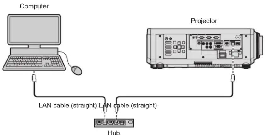
PANASONIC PT-RZ120BE - Example of a normal network connection - 1

text_image Computer LAN cable (straight) LAN cable (straight) Hub Projector

Attention

- When a LAN cable is directly connected to the projector, the network connection must be made indoors.

Note

  • A LAN cable is required to use the network function.
  • Use a straight or crossover LAN cable that is compatible with CAT5 or higher. Either the straight or the crossover cable, or both cables can be used depending on the system configuration. Consult your network administrator. The projector will determine the type of the cable (straight or crossover) automatically.
  • Use a LAN cable of 100 m (328'1") or shorter.

Example of network connections via a twisted-pair-cable transmitter
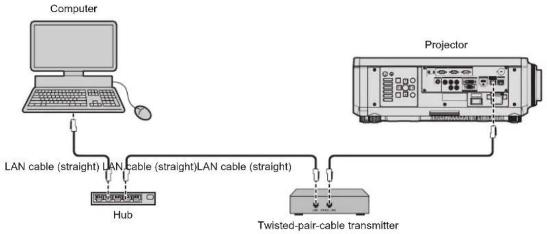
PANASONIC PT-RZ120BE - Example of network connections via a twisted-pair-cable transmitter - 1

flowchart
graph TD
    A["Computer"] -->|LAN cable (straight) LAN cable (straight)| B["Hub"]
    B -->|LAN cable (straight) LAN cable (straight)| C["Twisted-pair-cable transmitter"]
    C --> D["Projector"]

Attention

- When a LAN cable is directly connected to the projector, the network connection must be made indoors.

Note

  • For the LAN cable between the twisted-pair-cable transmitter and the projector, use a cable that meets the following criteria:
    -Conforming to CAT5e or higher standards
    -Shielded type (including connectors)
    -Straight-through
    -Single wire
  • Diameter of the cable core is same or larger than AWG24 (AWG24, AWG23, etc.)
  • The maximum transmission distance between the twisted-pair-cable transmitter and the projector is 100 m (328'1") for the signal with resolution of 1 920 x 1 200 dots or less. For the signal with the resolution exceeding 1 920 x 1 200 dots, the maximum transmission distance is 50 m (164'1"). It is possible to transmit up to 150 m (492'2") if the twisted-pair-cable transmitter supports the long-reach communication method. However, the signal that the projector can receive is only up to 1080/60p (1 920 x 1 080 dots, dot clock frequency 148.5 MHz) for the long-reach communication method. If these distances are exceeded, image may be disrupted or a malfunction may occur in LAN communication.
  • When laying cables between the twisted-pair-cable transmitter and the projector, confirm that cable characteristics are compatible with CAT5e or higher using tools such as a cable tester or cable analyzer.
    When a relay connector is used, include it in the measurement.
  • Do not use a hub between the twisted-pair-cable transmitter and the projector.
  • Do not pull cables forcefully. Also, do not bend or fold cables unnecessarily.
  • To reduce the effects of noise as much as possible, stretch out the cables between the twisted-pair-cable transmitter and the projector without any loops.
  • Lay the cables between the twisted-pair-cable transmitter and the projector away from other cables, particularly power cables.
  • When laying multiple cables, run them side by side along the shortest distance possible without bundling them together.
  • After laying the cables, go to the [NETWORK] menu → [DIGITAL LINK STATUS] and confirm that the value of [SIGNAL QUALITY] is displayed in green which indicates normal quality.
  • For twisted-pair-cable transmitters of other manufacturers of which the operation has been verified with the projector, visit the Panasonic website (https://panasonic.net/cns/projector/). Note that the verification for devices of other manufacturers has been made for the items set by Panasonic Corporation, and not all the operations have been verified. For operation or performance problems caused by the devices of other manufacturers, contact the respective manufacturers.

Setting the projector

1) Connect the projector to a computer using a LAN cable.
2) Turn on the power of the projector.
3) Press the

button to open the [NETWORK] menu, select [NETWORK SETUP], and press the button.
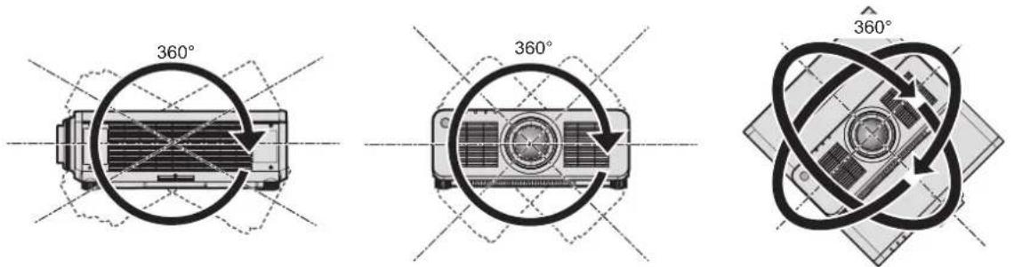
4) Perform the [NETWORK SETUP] setting.

- Refer to [NETWORK SETUP] (→ page 157) for details.

Note

- To connect to an existing network, perform after consulting your network administrator.

■Factory default setting

- Following setting has been made as a factory default.

[DHCP] OFF
[IP ADDRESS] 192.1680.8
[SUBNET MASK] 255.255.255.0
[DEFAULT GATEWAY] 192.168.0.1
[DNS1]/[DNS2] None

Operating the computer

1) Turn on the power of the computer.
2) Perform the network setting following the instruction of your network administrator.

- Operation from the computer is possible by configuring the network setting of the computer as follows if the projector is in the factory default setting.

[IP ADDRESS] 192.1680.10
[SUBNET MASK] 255.255.255.0
[DEFAULT GATEWAY] 192.168.0.1

Web control function

Following operation is possible from a computer using the web control function.

  • Setting and adjustment of the projector
    •Display of the projector status
  • Sending E-mail messages when there is a problem with the projector

The projector supports "Crestron Connected", and the following application software of Crestron Electronics, Inc. can be used.

•RoomView Express
- Crestron Fusion

Note

  • Communication with an E-mail server is required to use the E-mail function. Confirm that the E-mail can be used beforehand.
  • "Crestron Connected" is a system of Crestron Electronics, Inc. that collectively manages and controls devices on multiple systems connected to a network using a computer.
  • For details of the "Crestron Connected", visit the website of Crestron Electronics, Inc. (English only.)
    URL https://www.crestron.com/ Download "RoomView Express" from the Crestron Electronics, Inc. website. (English only.) URL https://www.crestron.com/en-US/resources/get-roomview

Computer that can be used for setting

To use the web control function, a web browser is required. Confirm that the web browser can be used in advance.

OS Compatible browser
Windows Internet Explorer 11.0, Microsoft Edge
Mac OS Safari 8.0/9.0/10.0/11.0
iOS Safari (equipped with version iOS 9, iOS 10, or iOS 11)
Android Google Chrome (equipped with version Android 4.4/5.0/5.1/6.0/7.0/8.0)

Accessing from the web browser

1) Start up the web browser on the computer.
2) Enter the IP address set on the projector into the URL entry field of the web browser.
3) Enter the user name and the password.

- The factory default settings are User name: dispuser (user rights)/dispadmin (administer rights); Password: @Panasonic.

- Change of password is prompted when using the web control function for the first time. Proceed to Step 4). If the web control function is used already, proceed to Step 7).

PANASONIC PT-RZ120BE - Accessing from the web browser - 1

text_image Windows Security Microsoft Edge The server 192.168.0.8 is asking for your user name and password. The server reports that it is from WEB Zone. User name Password OK Cancel

4) Click OK.

•The [Change password] page is displayed.

For user rights For administrator rights
PANASONIC PT-RZ120BE - Accessing from the web browser - 2

text_image Projector Control Window Charge password Change password Change password + + + - + - + - + - + - + - + - + - + - + - + - + - + - + - + - + - + - + - + - + - + - + - + - + - + - + - + - + - + - + - + - + - + - + - + - + - + - + - + - + - + - + - + - + - + - + - + - + - + - + - + - + + + + + + + + + + + + + + + + + + + + + + + + + + + + + + + + + + + + + + + + + + + + + + + + + + - - - - - - - - - - - - - - - - - - - - - - - - - - - - - - - - - - - - - - - - - - - - - - - - - - (100%) (40%) (60%) (80%) (100%) (120%) (150%) (170%) (190%) (210%) (230%) (250%) (270%) (290%) (310%) (330%) (350%) (370%) (390%) (410%) (430%) (450%) (470%) (490%) (510%) (530%) (550%) (570%) (590%) (610%) (630%) (650%) (670%) (690%) (710%) (730%) (750%) (770%) (790%) (810%) (830%) (850%) (870%) (890%) (910%) (930%) (950%) (970%) (990%) (1010%) (1030%) (1050%) (1070%) (1090%) (1110%) (1130%) (1150%) (1170%) (1190%) (1210%) (1230%) (1250%) (1270%) (1290%) (1310%) (1330%) (1350%) (1370%) (1390%) (1410%) (1430%) (1450%) (1470%) (1490%) (1510%) (1530%) (1550%) (1570%) (1590%) (1610%) (1630%) (1650%) (1670%) (1690%) (1710%) (1730%) (1750%) (1770%) (1790%) (1810%) (1830%) (1850%) (1870%) (1890%) (1910%) (1930%) (1950%) (1970%) (1990%) (2010%)

PANASONIC PT-RZ120BE - Accessing from the web browser - 3

text_image Projector Control Window Change password Phone input test user status and password. Account / Administrator New Live name: Password: Password/Zipgen Change • Adding passwords to us recommended • Leaving the password based on recommended • A password containing at least eight half-width width progression and increasing characters at least three of the following four types is recommended: • Upgrades letters • Lowerations letters • Digital • Systems (HKEYNET) (HKEYNET) • The user status and promotion as used by the Web Control system-up for authentication required via a LIF (including Password application allowed) Changing for current registry may undergo its connection. For details, also is to be found.

5) Enter the new user name and password, and click [Change].

•The screen in Step 3) is displayed again.

6) Enter the new user name and password.

- Enter the new user name and password set in Step 5).

7) Click OK.

Attention

- The entry screen for the user name and password may be hidden by other window that is already opened. In such case, minimize the window in front to display the entry screen.

Note

  • If you use a web browser to control the projector, set the [NETWORK] menu → [NETWORK CONTROL] → [WEB CONTROL] to [ON].
  • Do not perform setting or control simultaneously by starting up multiple web browsers. Do not set or control the projector from multiple computers.
  • Access will be locked for few minutes when an incorrect password is entered three times consecutively.
  • Some items on the projector setting page use the Javascript function of the web browser. Correct control may not be possible when the web browser is set not to use this function.
  • If the screen for the web control is not displayed, consult your network administrator.
  • While updating the screen for the web control, the screen may appear white for a moment, but it is not a malfunction.
  • When the projector is already registered in application software (such as "Multi Monitoring & Control Software" and "Smart Projector Control") which uses the communication control via LAN, communication with the projector will become impossible if a user name or password for [Administrator] is changed. If a user name or password for [Administrator] is changed, update the registration information of the application software in use.
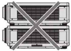
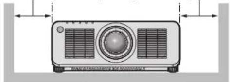
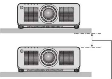
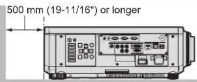
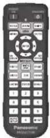
    • Screenshot of a computer
    The size or the display of the screen may be different from this manual depending on the OS or the Web browser, or the type of computer in use.

Rights for each account

The administrator rights allow use of all functions. There is a limitation in the rights that can be used with the user rights. Select the rights depending on the purpose.

The function that has √ in the administrator rights/user rights column indicates that it can be operated with that rights.

Item Function Administrator rights User rights Page
[Status][Projector status]168
Error information page169
[Network status]169
[Access error log]-169
[Mail error log]-170
[Projector control][Basic control]170
[Detail control]-171
[Detailed set up][Network config]-172
[Adjust clock]-173
[Ping test]-173
[E-mail set up]-174
[Authentication set up]-175
[Change password]User name of [Administrator]— 178
User name of [User]— 179
Password of [Administrator]— 178
Password of [User]179
[Crestron Connected(TM)]Operation page— 180
[Tools]— 181
[Info]— 181
[Help]— 182

Descriptions of items

PANASONIC PT-RZ120BE - Descriptions of items - 1

text_image Projector Control Window Status Projector name Network name Access error log Multi-error log Projector control PROJECTOR TYPE PT-RZ120 SERIAL NUMBER 123456709012 MAIN VERSION 0.50 POWER ON STANDY REMOTE2 STATUS ENABLE DISABLE SHUTTER CLOSE OPEN OIS ON OFF OPERATING MODE NORMAL AC VOLTAGE 100 V MAX LIGHT OUTPUT LEVEL 100.0 % LIGHT OUTPUT 100.0 % INPUT BDMI —(—kHz—Hz) INTAKE AIR TEMPERATURE 27°C / 80°F OPTICS MODULE TEMPERATURE 27°C / 50°F EXHAUST AIR TEMPERATURE 36°C / 56°F LIGHT TEMPERATURE 54°C / 125°F LIGHT TEMPERATURE 47°C / 116°F LIGHT1 ON OFF RUNTIME 21 H LIGHT2 ON OFF RUNTIME 21 H PROJECTOR RUNTIME 22 H SELF TEST No errors

1 Page tab

Switches pages by clicking this item.

2 [Status]

The status of the projector is displayed by clicking this item.

3 [Projector control]

The [Projector control] page is displayed by clicking this item.

4 [Detailed set up]

The [Detailed set up] page is displayed by clicking this item.

5 [Change password]

The [Change password] page is displayed by clicking this item.

6 [Crestron Connected(TM)]

The operation page of Crestron Connected is displayed by clicking this item.

[Projector status] page

Click [Status] → [Projector status].

Display the status of the projector for the following items.

PANASONIC PT-RZ120BE - [Projector status] page - 1

text_image Engineer Control Window Project name Control area Automatic log Multiple log PROJECT TYPE PE 42/10 SIMIAL NUMBER LABR TYPE CLIENT VERSION 0.36 POWER ON STANTIT REMOTE STATUS BUSIBLE_DISABLE BUFFER ON/OFF ON/OFF ON/OFF OPERATING MODE NORMAL AC-SURFACE HEV MAX LENGTH OF LIFE LEVEL 000 N/A LIGHT OF LIFT 000 N/A INPUT INCOME -1.5% - 10% VEGET AIR TEMPERATURE 27C - 100°F OUTPUT MODULE TEMPERATURE 27C - 100°F ENJOYTH AIR TEMPERATURE 20C - 50°F LIGHT TEMPERATURE 50°C - 120°F LIGHT TEMPERATURE 4°C - 120°F LIGHT ON/OFF RUNTIME 51 B LIGHTS ON/OFF RUNTIME 21 B PRODUCTOR RUNTIME 2 B SELF TEXT No text 1 2 3 4 5 6 7 8 9 10 11 12 13 14 15 16 17 18 19 20 21

1 [PROJECTOR TYPE]

Displays the type of the projector.

2 [MAIN VERSION]

Displays the firmware version of the projector.

3 [POWER]

Displays the status of the power.

4 [SHUTTER]

Displays the status of the shutter function ([CLOSE]: Enabled (closed), [OPEN]: Disabled (open)).

5 [OPERATING MODE]

Displays the setting status of [OPERATING MODE].

6 [MAX LIGHT OUTPUT LEVEL]

Displays the setting status of [MAX LIGHT OUTPUT LEVEL].

7 [SERIAL NUMBER]

Displays the serial number of the projector.

8 [REMOTE2 STATUS]

Displays the control status of the terminal.

9 [OSD]

Displays the status of the on-screen display.

10 [AC VOLTAGE]

Displays the input voltage.

11 [LIGHT OUTPUT]

Displays the setting status of [LIGHT OUTPUT].

12 [INPUT]

Displays the status of the selected input.

13 [INTAKE AIR TEMPERATURE]

Displays the status of the intake air temperature of the projector.

14 [OPTICS MODULE TEMPERATURE]

Displays the status of the internal temperature of the projector.

15 [EXHAUST AIR TEMPERATURE]

Displays the status of the exhaust air temperature of the projector.

16 [LIGHT1 TEMPERATURE]

Displays the temperature status of light source 1.

17 [LIGHT2 TEMPERATURE]

Displays the temperature status of light source 2.

18 [LIGHT1]

Displays the lighting status and runtime of light source 1.

19 [LIGHT2]

Displays the lighting status and runtime of light source 2.

20 [SELF TEST]

Displays the self-diagnosis information.

21 [PROJECTOR RUNTIME]

Displays the runtime of the projector.

Error information page

When [Error (Detail)] or [Warning (Detail)] is displayed in the [SELF TEST] display field of the [Projector status] screen, click it to display the content of the error/warning.

- The projector may go into the standby status to protect the projector depending on the contents of the error.

PANASONIC PT-RZ120BE - Error information page - 1

text_image Projector Control Window Station Projector type PI-RF239 SERIAL NUMBER 123496709012 MAP VERSION 8.0 POWER ON MEANOFF REMOTE/STATIN ENABLE ENABLE SHUTTER CLOSE OPEN OSD ON OUT OPERATING MODE NORMAL AC VOLTAGE 100 V MAX LIGHT OUTPUT LEVEL 100.0 % LIGHT OUTPUT 100.0 % INPUT HDMI — (—AHz/—Hz) INTAKE AIR TEMPERATURE 27°C / 80°F OPCIN MODULE TEMPERATURE 27°C / 90°F EXTRACT AIR TEMPERATURE 30°C / 94°F LIGHT TEMPERATURE 54°C / 129°F LIGHT TEMPERATURE 47°C / 150°F LIGHT1 ON OFF RUNTIME 21 H LIGHT2 ON OFF RUNTIME 21 H PROJECTOR RUNTIME 21 H SELF TEST Current / Next

1 Display of error information

Displays the alphanumeric symbols and content of errors/warnings that occur.

Refer to "[SELF TEST] indications" ( page 189) for the display details.

PANASONIC PT-RZ120BE - Display of error information - 1

text_image Projector Control Window Status Projector control Error Information 12% drives on temp error Drive code 03.75 00:00:50 00:00:00 00:00:00 00:00:00 00:38 Change password Creation Connect (Add TTM) Jaguarot 1 2

2 Error code

[Network status] page

Click [Status] → [Network status].

The current network setting status is displayed.

- Click [Detail] of [RX/TX Packets info] to display the content of send/receive packet.

PANASONIC PT-RZ120BE - [Network status] page - 1

text_image Projector Control Window Status Projector control Projector control Projector control Projector control Projector control Projector control Projector control Projector control Projector control Projector control Projector control Projector control Projector control Projector control Projector control Projector control Projector control Projector control Projector control Projector control Projector control Projector control Projector control Projector control Projector control ProjectorControl ProjectorControl ProjectorControl ProjectorControl ProjectorControl ProjectorControl ProjectorControl ProjectorControl ProjectorControl ProjectorControl ProjectorControl ProjectorControl ProjectorControl ProjectorControl ProjectorControl ProjectorControl ProjectorControl ProjectorControl ProjectorControl ProjectorControl ProjectorControl ProjectorControl ProjectorControl ProjectorControl ProjectorControl Projectorcontrol Projectorcontrol Projectorcontrol Projectorcontrol Projectorcontrol Projectorcontrol Projectorcontrol Projectorcontrol Projectorcontrol Projectorcontrol Projectorcontrol Projectorcontrol Projectorcontrol Projectorcontrol Projectorcontrol Projectorcontrol Projectorcontrol Projectorcontrol Projectorcontrol Projectorcontrol Projectorcontrol Projectorcontrol Projectorcontrol Projectorcontrol Projectorcontrol ProjectorControl ProjectorControl ProjectorControl ProjectorControl ProjectorControl ProjectorControl ProjectorControl ProjectorControl ProjectorControl ProjectorControl ProjectorControl ProjectorControl ProjectorControl ProjectorControl ProjectorControl ProjectorControl ProjectorControl ProjectorControl ProjectorControl ProjectorControl ProjectorControl ProjectorControl ProjectorControl ProjectorControl ProjectorTotal Control 100% 100% 100% 100% 100% 100% 100% 100% 100% 100% 100% 100% 100% 100% 100% 100% 100% 100% 100% 100% 100% 100% 100% 100% 100% 100%

[Access error log] page

Click [Status] → [Access error log].

The error log on the web server is displayed such as access to the pages that do not exist or access with unauthorized user names or passwords.

PANASONIC PT-RZ120BE - [Access error log] page - 1

text_image Projector Control Window Status Projector status Viewed status Active user log Web server active log Projector control Installed set up Change password Creates Connection (Y) Supervise This run: 07.10.08 2003 This run: 07.10.12 2003 This run: 07.10.15 2003 This run: 07.10.19 2003 This run: 07.10.22 2003 This run: 07.10.25 2003 This run: 07.10.28 2003 This run: 07.10.31 2003 This run: 07.10.34 2003 This run: 07.10.37 2003 This run: 07.10.40 2003 This run: 07.10.43 2003 This run: 07.10.46 2003 This run: 07.10.49 2003 This run: 07.10.52 2003 This run: 07.10.55 2003 This run: 07.10.58 2003 This run: 07.10.61 2003 This run: 07.10.64 2003 This run: 07.10.67 2003 This run: 07.10.70 2003 This run: 07.10.73 2003 This run: 07.10.76 2003 This run: 07.10.79 2003 This run: 07.10.82 2003 This run: 07.10.85 2003 This run: 07.10.88 2003 This run: 07.10.91 2003 This run: 07.10.94 2003 This run: 07.10.97 2003 This run: 07.11.01 2003 This run: 07.11.04 2003 This run: 07.11.07 2003 This run: 07.11.10 2003 This run: 07.11.13 2003 This run: 07.11.16 2003 This run: 07.11.19 2003 This run: 07.11.22 2003 This run: 07.11.25 2003 This run: 07.11.28 2003 This run: 07.11.31 2003 This run: 07.11.34 2003 This run: 07.11.37 2003 This run: 07.11.40 2003 This run: 07.11.43 2003 This run: 07.11.46 2003 This run: 07.11.49 2003 This run: 07.11.52 2003 This run: 07.11.55 2003 This run: 07.11.58 2003 This run: 07.11.61 2003 This run: 07.11.64 2003 This run: 07.11.67 2003 This run: 07.11.70 2003 This run: 07.11.73 2003 This run: 07.11.76 2003 This run: 07.11.79 2003 This run: 07.11.82 2003 This run: 07.11.85 2003 This run: 07.11.88 2003 This run: 07.11.91 2003 This run: 07.11.94 2003 This run: 07.11.97 2003 This run: 07.11.99 2003 This run: 07.12.02 2003 This run: 07.12.05 2003 This run: 07.12.08 2003 This run: 07.12.11 2003 This run: 07.12.14 2003 This run: 07.12.17 2003 This run: 07.12.20 2003 This run: 07.12.23 2003 This run: 07.12.26 2003 This run: 07.12.29 2003 This run: 07.12.32 2003 This run: 07.12.35 2003 This run: 07.12.38 2003 This run: 07.12.41 2003 This run: 07.12.44 2

[Mail error log] page

Click [Status] → [Mail error log].

E-mail error log is displayed if periodic E-mail sending has failed.

PANASONIC PT-RZ120BE - [Mail error log] page - 1

text_image Projector Control Window Status Projector status Reserved status Active status log Multiple log Projector control [The Jet 16 12:03:11 (RUS)] [Wall delivery] VALID CONNECTION, OFF WORK - Personal projector port Detailed set up Change password Creation Connected(TM) Japanese

Note

  • [Access error log] and [Mail error log] display the recent few thousand accesses/requests. All information may not be displayed when many accesses/requests are made at once.
  • Logs in [Access error log] and [Mail error log] are deleted from the oldest when exceeding a certain amount.
  • Check [Access error log] and [Mail error log] periodically.

[Basic control] page

Click [Projector control] → [Basic control].

PANASONIC PT-RZ120BE - [Basic control] page - 1

text_image Projector Control Window Status Projector control Detailed set up Change password Creation Connected(TM) Response POWER MINTILLER COLD SYSTEM INPUT SELECT RGB1 RGB2 RGB3 RGB4 RGB5 RGB6 RGB7 RGB8 RGB9 RGB10 RGB11 RGB12 RGB13 RGB14 RGB15 RGB16 RGB17 RGB18 RGB19 RGB20 RGB21 RGB22 RGB23 RGB24 RGB25 RGB26 RGB27 RGB28 RGB29 RGB30 RGB31 RGB32 RGB33 RGB34 RGB35 RGB36 RGB37 RGB38 RGB39 RGB40 RGB41 RGB42 RGB43 RGB44 RGB45 RGB46 RGB47 RGB48 RGB49 RGB50 RGB51 RGB52 RGB53 RGB54 RGB55 RGB56 RGB57 RGB58 RGB59 RGB60 RGB61 RGB62 RGB63 RGB64 RGB65 RGB66 RGB67 RGB68 RGB69 RGB70 RGB71 RGB72 RGB73 RGB74 RGB75 RGB76 RGB77 RGB78 RGB79 RGB80 RGB81 RGB82 RGB83 RGB84 RGB85 RGB86 RGB87 RGB88 RGB89 RGB90 RGB91 RGB92 RGB93 RGB94 RGB95 RGB96 RGB97 RGB98 RGB99 MOD SIGNALS ITEM NAME: ITEM NAME: POSITION: ADVANCED PENA: DISPLAY LANGUAGE: DISPLAY OPTION: PROJECTOR SETUP: TEST PATTERN: STORM LIST: STORM SET: RITCHEN: To MEND SELECT: EXT. SUB MEND

1 [POWER]

Turns off/on the power.

2 [SHUTTER]

Switches whether to use the shutter function (enabled (shutter: closed)/disabled (shutter: open)).

3 [OSD]

Switches off (hide)/on (display) the on-screen display function.

4 [SYSTEM]

Switches the system method.

5 On-screen display of the projector

Displays the same items as shown on the on-screen display of the projector. You can check or change the settings of the menus. It is displayed even if the on-screen display function is set to off (hide).

6 [INPUT SELECT]

Switches the input signal.

[Detail control] page

Click [Projector control] → [Detail control].

PANASONIC PT-RZ120BE - [Detail control] page - 1

text_image Projector Control Window Status Power Shutter CNC SYSTEM Input RORI NO SIGNAL 1 Projector control Detected set up Change password Creation Connected (LTR) AUTO SELECT AUTO LIST DOWN UP DEFAULT LEFT DOWN RIGHT OPTION OPTION TITLE TITLE TITLE TITLE TITLE TITLE TITLE TITLE TITLE TITLE TITLE TITLE TITLE TITLE TITLE TITLE TITLE TITLE TITLE TITLE TITLE TITLE TITLE TITLE TITLE TITLE TITLE TITLE TITLE TITLE TITLE TITLE TITLE TITLE TITLE TITLE TITLE TITLE TITLE TITLE TITLE TITLE TITLE TITLE TITLE TITLE TITLE TITLE TITLE TITLE ITEMS: 0.0000000000000000000000000000000000000000000000000000000000000000000000000000000000000000000000000000 1 2 3 4 5

1 Control of the projector

The projector is controlled by clicking the buttons in the same way as the buttons on the remote control. After control, the on-screen display of the projector at the right of the control page is updated.

2 [SUB MEMORY]

Switches the sub memory.

3 [SYSTEM DAYLIGHT VIEW]

Switches the system daylight view settings.

4 [FREEZE]

Temporarily pauses the image.

5 [WAVEFORM MONITOR]

Displays the waveform of the input signal.

6 [PROJECTION METHOD]

Switches the setting of the projection method.

7 [LENS]

Displays the [LENS] page.

8 [TEST PATTERN]

Displays the test pattern.

Click the test pattern to display in the projected image from the patterns displayed on the right side of the control page.

The display of the test pattern disappears if [Exit] is clicked.

9 [GET OSD]

Updates the on-screen display of the projector at the right of the control page.

[LENS] page

Click [Projector control] → [Detail control] → [LENS].

PANASONIC PT-RZ120BE - [LENS] page - 1

text_image Projector Control Window Status Back control Development Projector LENS SETUP WITH Detailed set up MSPT Change password Focus Control Set (M) FOCUS FORM Parameters Back

1 [SET POSITION]

The lens position setting page is displayed.

2 [HOME POSITION]

Moves the projection lens to the home position.

3 [SHIFT]

Click ▲▼◀▶ to adjust the lens shift (vertical position and horizontal position).

The adjustment can be performed faster by holding down the button for approximately three seconds or longer.

4 [FOCUS]

Click ◀▶ to adjust the focus.

The adjustment can be performed faster by holding down the button.

5 [ZOOM]

Click ◀▶ to adjust the zoom.

6 [Back]

Returns to the [Detail control] page.

Lens position setting page

Click [Projector control] → [Detail control] → [LENS] → [SET POSITION].

PANASONIC PT-RZ120BE - Lens position setting page - 1

text_image Projector Control Window Status Base control Control panel 1 2 LENS 2 SETTLED POSTER 3 VERTICAL POSTER 4 HORIZONTAL POSTER 5 Set Add Change password Save 3 Capture Close-up (up) Supervise

1 [Get]

Acquires the current lens position and displays the acquired values in the lens position information field.

2 Lens position information field

Enters the lens position (vertical position/horizontal position).

3 [Back]

Returns to the [LENS] page.

4 [Apply]

Moves to the lens position displayed in the lens position information field.

[Network config] page

Click [Detailed set up] → [Network config].

- Click [Network config] to display the [CAUTION!] screen.

- Click the [Next] button to display the current settings.

- Click the [Change] button to display the setting change screen.

PANASONIC PT-RZ120BE - [Network config] page - 1

text_image Projector Control Window Status Projector control Set List set up Change password Create Connected (N) Parameters ProjectOR NAME PROJECTOR TYPE UNIT UNIT PRICE 100.000.00 100.000.00 100.000.00 100.000.00 100.000.00 100.000.00 100.000.00 100.000.00 100.000.00 100.000.00 BAS DATA Input 1 2 3 4 5 6 7 8

1 [PROJECTOR NAME]

Enter the name of the projector. Enter the host name if it is required when using a DHCP server etc.

2 [DHCP ON], [DHCP OFF]

To enable the DHCP client function, set to [DHCP ON].

3 [IP ADDRESS]

Enter the IP address when not using a DHCP server.

4 [SUBNET MASK]

Enter the subnet mask when not using a DHCP server.

5 [DEFAULT GATEWAY]

Enter the default gateway address when not using a DHCP server.

6 [DNS1]

Enter the DNS1 server address.

Permissible characters for the entry of DNS1 server address (primary):

Numbers (0 - 9), period (.)

(Example: 192.168.0.253)

7 [DNS2]

Enter the DNS2 server address.

Available characters for the entry of DNS2 server address (secondary):

Numbers (0 - 9), period (.)

(Example: 192.168.0.254)

8 [Back], [Next]

Click the [Back] button to return to the original screen. Click the [Next] button to display the setting confirmation screen. Click the [Submit] button to update the setting.

Note

  • When you use the "Forward" and "Back" functions of your browser, a warning message "Page has Expired" may appear. In that case, click [Network config] again since the following operation will not be guaranteed.
  • The connection may be disconnected when the LAN setting is changed while connected with LAN.

[Adjust clock] page

Click [Detailed set up] → [Adjust clock].

PANASONIC PT-RZ120BE - [Adjust clock] page - 1

text_image Projector Control Window Status Local setup Authentication setup Network setup Hyper data Program Projector control Switched set-up Change password Creation Connect To (T) Name Time Zone: 2000-01-01 Select Load Unit zone Current zone is GMT+00:00 Set line zone Current zone is set to 200000.30 01:45:32 SIP SYMBOLIZATION SIP SERVER NAME Up to all characters Date: 2014/1/30 Date range is YYYY/MM/1996 Date: 2014/1/30 Date range is 5% format on Set date and time

1 [Time Zone]

Select the time zone.

2 [Set time zone]

Updates the time zone setting.

3 [NTP SYNCHRONIZATION]

Set to [ON] when setting the date and time automatically.

4 [NTP SERVER NAME]

Enter the IP address or server name of the NTP server when you set to adjust the date and time manually.

(To enter the server name, the DNS server needs to be set up.)

5 [Date]

Enter the date to be changed.

6 [Time]

Enter the time to be changed.

7 [Set date and time]

Updates the date and time settings.

Note

- The replacement of the battery inside the projector is required when the time goes out of alignment right after correcting the time. Consult your dealer.

[Ping test] page

Check whether the network is connected to the E-mail server, POP server, DNS server, etc.

Click [Detailed set up] → [Ping test].

PANASONIC PT-RZ120BE - [Ping test] page - 1

text_image Projector Control Window Status I end set up Authorisation set up Network config Hyper disk Projector control Installed set up type IP address Change password Creation Connected (IP) Name 1 2

1 [Input IP address]

Enter the IP address of the server to be tested.

2 [Submit]

Executes the connection test.

PANASONIC PT-RZ120BE - [Ping test] page - 2

text_image FINS 192.168.0.50 (192.168.0.50) 36(54) bytes of data. 64 bytes from 192.168.0.50; icmp_seq=1 ssl=128 time=0.345 ms 44 bytes from 192.168.0.50; icmp_seq=2 ttl=128 time=0.330 ms 64 bytes from 192.168.0.50; icmp_seq=3 ttl=128 time=0.345 ms 64 bytes from 192.168.0.50; icmp_seq=4 ttl=128 time=0.345 ms --- 192.168.0.50 ping statistics --- 4 packets transmitted, 4 received, 0% packet loss, time 2998ms rtc min/avg/max/adev = 0.330/0.361/0.349/0.007 ms FINS 192.168.0.51 (192.168.0.51) 36(54) bytes of data. From 192.168.0.100 icmp_seq=1 Destination Host Unreachable From 192.168.0.100 icmp_seq=2 Destination Host Unreachable From 192.168.0.100 icmp_seq=3 Destination Host Unreachable From 192.168.0.100 icmp_seq=4 Destination Host Unreachable --- 192.168.0.51 ping statistics --- 4 packets transmitted, 0 received, +4 errors, 100% packet loss, time 3001ms pipe 3

3 Example of display when the connection has succeeded

4 Example of display when the connection has failed

[E-mail set up] page

E-mail can be sent to preset E-mail addresses (up to two addresses) periodically or when an error or problem has occurred.

Click [Detailed set up] → [E-mail set up].

PANASONIC PT-RZ120BE - [E-mail set up] page - 1

text_image Projector Control Window Status Remote only Adjust key Project Load up Autoresponse up Projector control Set/List set up Change password Creation Connect(TR) Response MAIL SERVER FILENAME TITLE SERVER NAME On to 63 characters MAIL OPTION MAIL FROM Up to 63 characters MEMO Ex. location, security, properties, etc... Up to 63 characters TEMPERATURE WARNING SET UP MINIMUM TIME On to 63 characters 30 to 197 seconds DETAIL AIR TEMPERATURE One CHARACTER E-MAIL ADDRESS 1 Seal is Up to 63 characters MAIL CONTENTS NORMAL SAMPLE ERROR

1 [ENABLE]

Select [ENABLE] to use the E-mail function.

2 [SMTP SERVER NAME]

Enter the IP address or the server name of the E-mail server (SMTP). To enter the server name, the DNS server needs to be set up.

3 [MAIL FROM]

Enter the E-mail address of the projector. (Up to 63 characters in single byte)

4 [MEMO]

Enter information such as the location of the projector that notifies the sender of the E-mail. (Up to 63 characters in single byte)

PANASONIC PT-RZ120BE - [MEMO] - 1

text_image Projector Control Window Status Refresh only Adjust key Play me Projector (0007) Settled set up Change password Creation Connected[70] Update E-MAIL ADDRESS 1 Real e: Up to 64 characters E-MAIL ADDRESS 2 Real e: Up to 64 characters E-MAIL ADDRESS 3 Real e: Up to 64 characters E-MAIL ADDRESS 4 Real e: Up to 64 characters E-MAIL ADDRESS 5 Real e: Up to 64 characters E-MAIL ADDRESS 6 Real e: Up to 64 characters E-MAIL ADDRESS 7 Real e: Up to 64 characters E-MAIL ADDRESS 8 Real e: Up to 64 characters

7 [E-MAIL ADDRESS 1], [E-MAIL ADDRESS 2]

Enter the E-mail address to be sent. Leave [E-MAIL ADDRESS 2] blank when two E-mail addresses are not to be used.

5 [MINIMUM TIME]

Change the minimum interval for the temperature warning E-mail. The default value is 60 minutes. In this case, another E-mail will not be sent for 60 minutes after sending the temperature warning E-mail even if it reaches the warning temperature.

6 [INTAKE AIR TEMPERATURE]

Change the temperature setting for the temperature warning mail. A temperature warning E-mail is sent when the temperature exceeds this value.

PANASONIC PT-RZ120BE - [INTAKE AIR TEMPERATURE] - 1

text_image Projector Control Window Status Search only Adjust key Program Projector control Default set up PERIODIC REPORT Accuracy 10.00 35.00 60.00 97.00 Tuesday 18.00 38.00 60.00 11.00 Wednesday 12.00 31.00 60.00 13.00 Tuesday 18.00 37.00 60.00 18.00 24.00 Tuesday 26.00 31.00 62.00 25.00 Change password Creation Connected (TA) Average E-MAIL ADDRESS 2 Max 1/2 Max 1/2 characters MAX CONTENTS NORMAL SIMPLE ERROR OFF INTAKE AIR TEMPERATURE OFF Frequency Monday Tuesday Wednesday Thursday Friday Saturday Frequency Frequency Frequency Frequency Frequency Frequency Frequency Frequency Frequency Frequency Frequency Frequency Frequency Frequency Frequency Frequency Frequency Frequency Frequency Frequency Frequency Frequency Frequency Frequency Frequency Frequency Frequency Frequency Frequency Frequency Frequency Frequency Frequency Frequency Frequency Frequency Frequency Frequency Frequency Frequency Frequency Frequency Frequency Frequency Frequency Frequency Frequency Frequency Frequency Frequency FEMA ADDRESS 2 Size 1/2 Unit cell characters 7 8 9

8 Settings of the conditions to send E-mail

Select the conditions to send E-mail.

[MAIL CONTENTS]:

Select either [NORMAL] or [SIMPLE].

[ERROR]:

Send an E-mail when an error occurred in the self-diagnosis.

[INTAKE AIR TEMPERATURE]:

Send an E-mail when the intake air temperature has reached the value set at the above field.

[PERIODIC REPORT]:

Place a check mark on this to send an E-mail periodically.

A mail will be sent on the day and time with the check mark.

9 [Submit]

Update the settings.

[Authentication set up] page

Set the authentication items when POP authentication or SMTP authentication is necessary to send an E-mail. Click [Detailed set up] → [Authentication set up].

PANASONIC PT-RZ120BE - [Authentication set up] page - 1

text_image Projector Control Window Status Projector set up Set up Set down Set up Auto START SMTP Auto POP User SMTP SMTP Auto PLAIN CREATE NET LOADN POP server name: Up to All characters Up to All characters Use type: Up to All characters Password: Password for POP SMTP server. SMTP server name: 10 Default - 20 POP server name: 10 Default - 10 Name 1 2 3 4 5 6 7 8

1 [Auth]

Select the authentication method specified by your Internet service provider.

2 [SMTP Auth]

Set when the SMTP authentication is selected.

3 [POP server name]

Enter the POP server name.

Allowed characters:

Alphanumerics (A - Z, a - z, 0 - 9)

Minus sign (-) and period (.)

4 [User name]

Enter the user name for the POP server or the SMTP server.

5 [Password]

Enter the password for the POP server or the SMTP server.

6 [SMTP server port]

Enter the port number of the SMTP server. (Normally 25)

7 [POP server port]

Enter the port number of the POP server. (Normally 110)

8 [Submit]

Update the settings.

Contents of E-mail sent

Example of the E-mail sent when E-mail is set

The following E-mail is sent when the E-mail settings have been established.

=== Panasonic projector report (CO NFI G URE) ===

Project or Type : PT -RZ 120

Serial No : 123456789012

---- E-mail setup data ----

TEMPERATURE WARNING SETUP

MINIMUM TIME at [ 60] minutes int erval

INT AKE AI R T EMPERAT URE O ver [ 46 degC / 114 degF ]

ERROR [OFF]

INTAKE AIR TEMPERATURE [OFF]

PERI O DIC REPO RT

Sunday [O N] Monday [O N] Tuesday [O N] Wednesday [O N]

Thursday [ON] Friday [ON] Saturday [ON]

00:00 [ O N ]01:00 [ O N ]02:00 [ O N ]03:00 [ O N ]
04:00 [ O N ]05:00 [ O N ]06:00 [ O N ]07:00 [ O N ]
08:00 [ O N ]09:00 [ O N ]10:00 [ O N ]11:00 [ O N ]
12:00 [ O N ]13:00 [ O N ]14:00 [ O N ]15:00 [ O N ]
16:00 [ O N ]17:00 [ O N ]18:00 [ O N ]19:00 [ O N ]
20:00 [ O N ]21:00 [ O N ]22:00 [ O N ]23:00 [ O N ]

---- ERROR INFORMATION ----

Error code

00 00 00 00 00 00 00 00 00 00 00 00 00 00 00

Int ake air t emperat ure : 25 degC / 77 degF

O pt ics module t emperat ure : 28 degC / 82 degF

Exhaust air temperature : 28 degC / 82 degF

Light1 temperature : 28 degC / 82 degF

Light2 temperature : 29 degC / 84 degF

PRO JECTO R RUNTIME 7 H

PO WER O N 132 times

LIG HT 1 RUNTIME 7 H

LIG HT 1 O N 174 times

LIG HT 2 RUNTIME 7 H

LIG HT 2 O N 177 times

---- Current status ----

MAIN VERSION 1.00

SUB VERSION 1.00

LIG HT ST AT US LI G HT 1=ON LI G HT 2=ON

INPUT SDI1

SIGNAL NAME ---

SIG NAL FREQUENCY --kHz / --Hz

REMOTE2 STATUS DISABLE

---- Wired Network configuration ----

DHCP Client OF F

IP address 192.168.0.8

MAC address 12:34:56:78:90:12

Mon Jan 01 12: 34:56 20XX

---- Memo ----

Example of the E-mail sent for an error

The following E-mail is sent when an error has occurred.

=== Panasonic projector report (ERRO R) ===

Project or Type : PT -RZ 120

Serial No : 123456789012

---- ERROR INFORMATION ----

U21 Int ake air temp. error

Error code

00 00 00 00 00 00 00 00 00 00 00 00 01 00 00

Int ake air t emperat ure : 25 degC / 77 degF

O pt ics module t emperat ure : 28 degC / 82 degF

Exhaust air temperature : 28 degC / 82 degF

Light1 temperature : 28 degC / 82 degF

Light2 temperature : 29 degC / 84 degF

PRO JECTO R RUNTIME 7 H

PO WER O N 132 times

LIG HT 1 RUNTIME 7 H

LIG HT 1 O N 174 times

LIG HT 2 RUNTIME 7 H

LIG HT 2 O N 177 times

---- Current status ----

MAIN VERSION 1.00

SUB VERSION 1.00

LIG HT ST AT US LIG HT 1=ON LIG HT 2=ON

INPUT SDI1

SIGNAL NAME

SIG NAL FREQ UENCY --kHz / --Hz

REMOTE2 STATUS DISABLE

Wired Network configuration ----

DHCP Client OF F

IP address 192.168.0.8

MAC address 12:34:56:78:90:12

Mon Jan 01 12: 34:56 20XX

---- Memo ----

[Change password] page

Click [Change password].

PANASONIC PT-RZ120BE - [Change password] page - 1

text_image Projector Control Window Status Change preview Projector control Detailed set up Change password Creation Correct(s)(M) Insertion Select Active Access Ab Demedate Plan Run 1 2 3

1 [Administrator]

Used to change the setting of the [Administrator].

3 [Next]

Used to change the setting of the password.

2 [User]

Used to change the setting of the [User].

[Administrator] account

PANASONIC PT-RZ120BE - [Administrator] account - 1

text_image Projector Control Window Status Change password Projector control Detailed set up Change password Creation Connected (TN) Suppose Account - Address name Current User name Password New User name Password Password (type) Change 1 2 3 4 • Remaining password is not accomplished. • Learning the password level is not accomplished. • A password covering of a level eight half-width characters and connecting characters of a lower three of the following four types is accomplished. • Upstream login • Lowerstream login • Pages • Password: @000-000-000; #2 (1): 17 • The site contains out-of-service web by the Web Framework for the communication control unit. All including Personal applications without changing the remote settings only following the connection. For further, order to be the user required.

1 [Account]

Displays the account to change.

2 [Current]

[User name]:

Enter the user name before the change.

[Password]:

Enter the current password.

3 [New]

[User name]:

Enter the desired new user name. (Up to 16 characters in single byte)

[Password]:

Enter the desired new password. (Up to 16 characters in single byte)

[Password(Retype)]:

Enter the desired new password again.

4 [Change]

Determines the change of password.

[User] account

PANASONIC PT-RZ120BE - [User] account - 1

text_image Projector Control Window Status Projector control Detailed set up Change password Creation Connect of (TR) Import Change password User name Preferred Password/Budget Change 1 2 3 • Remaining password is not recommended. • Coming for password based is not recommended. • A password consisting of at least eight half-width characters and consisting characters of an last three of the following four types is recommended. • Impulse status • Lateness status • Align • http://www.163.com/163/163/163/ • http://www.163.com/163/163/163/

1 [Account]

Displays the account to change.

3 [Change]

Determines the change of password.

2 [New]

[User name]:

Enter the desired new user name. (Up to 16 characters in single byte)

[Password]:

Enter the desired new password. (Up to 16 characters in single byte)

[Password(Retype)]:

Enter the desired new password again.

[Change password] (For user rights)

Only the change of password is enabled under the user rights.

PANASONIC PT-RZ120BE - [Change password] (For user rights) - 1

text_image Projector Control Window Status Change preview Projector Portrait Change password Japanese Old Preferred New Preferred Retire Change 1 2 3 4 • Running passwords in text recommended • Leaving for password blocks in text recommended • A password matching of a last right bit width characters and maintaining characters of a last three of the following row types is recommended. • Openness filters • Lower access features • Align • Symbol: (0.0000) (0.0000) (0.0000) • Openness filters (0.0000) (0.0000) (0.0000)

1 [Old Password]

Enter the current password.

3 [Retype]

Enter the desired new password again.

2 [New Password]

Enter the desired new password. (Up to 16 characters in single byte)

4 [Change]

Determines the change of password.

Note

- To change the account of the [Administrator], entry of [User name] and [Password] in [Current] is required.

[Crestron Connected(TM)] page

The projector can be monitored/controlled with Crestron Connected.

It is necessary to access with the administrator rights to start the operation screen of Crestron Connected from the web control screen. (The [Crestron Connected(TM)] button is not displayed in the web control screen with the user rights.)

The operation page of Crestron Connected is displayed by clicking [Crestron Connected(TM)].

It is not displayed if Adobe® Flash® Player is not installed on your computer, or the browser you use does not support Flash. In such a case, click [Back] in the operation page to go back to the previous page.

Note

- When Microsoft Edge is used for a web browser, the operation of the [Crestron Connected(TM)] page may not be possible depending on its version. If a web browser freezes when the [Crestron Connected(TM)] button is clicked, use "Windows Update" to install the update program.

Operation page

PANASONIC PT-RZ120BE - Operation page - 1

text_image 1 2 3 4 Input Select RGB1 RGB2 DENO HOU SOI MENJ ENTER 5 6 7 Freeze Control and Brightness Color Control Panel Reset

1 [Tools], [Info], [Help]

Tabs for selecting the setting, information, or help page of the projector.

2 [POWER]

Turns on/off the power.

3 [SHUTTER]

Switches whether to use the shutter function (enabled (shutter: closed)/disabled (shutter: open)).

4 [Input Select]

Controls input selection.

Not available when the power of the projector is turned off.

5 Menu screen control buttons

Navigates the menu screen.

6 Freeze/image quality adjustment

Controls items related to freeze/image quality.

7 [Back]

Returns to the previous page.

[Tools] page

Click [Tools] in the operation page.

PANASONIC PT-RZ120BE - [Tools] page - 1

text_image Control Systems P Address IPB 1 Page 4 File Start Menu User Password User Password Admin Password Admin Password Start Menu Start Menu Start Menu Start Menu Start Menu Start Menu Start Menu Start Menu Start Menu Start Menu Start Menu Start Menu Start Menu Start Menu Start Menu Start Menu Start Menu Start Menu Start Menu Start Menu Start Menu Start Menu Start Menu Start Menu Start Menu Start Menu Start Menu Start Menu Start Menu Start Menu Start Menu Start Menu Start Menu Start Menu

1 [Control System]

Set the information required for communicating with the controller to be connected with the projector.

2 [User Password]

Set the user rights password for the operation page of Crestron Connected.

3 [Admin Password]

Set the administrator rights password for the operation page of Crestron Connected.

4 Network status

Displays the settings of wired LAN.

[DHCP]

Displays the current setting.

[Ip Address]

Displays the current setting.

[Subnet Mask]

Displays the current setting.

[Default Gateway]

Displays the current setting.

[DNS Server]

Displays the current setting.

5 [Exit]

Returns to the operation page.

[Info] page

Click [Info] in the operation page.

PANASONIC PT-RZ120BE - [Info] page - 1

text_image Projector Information Projector Name: SMARTSON Projector Status: Class Name: SMARTSON Class Name: SMARTSON New Address: 368000000000000000000000000000000000000000000000000000000000000000000000000000000 1 2 3 4 5 6 7 Exit Experience Options Menu

1 [Projector Name]

Displays the projector name.

2 [Mac Address]

Displays the MAC address.

3 [Lamp1 Hours], [Lamp2 Hours]

Displays the runtime of the light source 1 and the light source 2.

4 [Power Status]

Displays the status of the power.

5 [Source]

Displays the selected input.

6 [Error Status]

Displays the error status.

7 [Exit]

Returns to the operation page.

[Help] page

Click [Help] in the operation page.

The [Help Desk] window is displayed.

PANASONIC PT-RZ120BE - [Help] page - 1

text_image Project Information Project Name: MioCity Project Status: Power Status: MioCity Source: MioCity Line Use Address: 0010027451642 Comp1 Name: 2.8 Comp2 Name: 3.8 Error Status: 0010027451642 Call CRESTOCKS EXPANSI Options Next

1 [Help Desk]

A message can be sent/received with the administrator using the Crestron Connected.

Chapter 6 Maintenance

This chapter describes inspection methods when there are problems, and maintenance methods.

Light source/temperature indicators

When an indicator lights up

If a problem occurs inside the projector, the light source indicators / or temperature indicator will inform you by lighting or blinking. Check the status of the indicators and take following measures.

Attention

- When switching off the projector to deal with problems, make sure to follow the procedure in "Switching off the projector" (→ page 66).

PANASONIC PT-RZ120BE - Attention - 1

text_image Light source indicator Light source indicator Temperature indicator ON(G)/ STANDBY(R) 1 LIGHT 2 TEMP

Light source indicators /

Indicator status Status Solution
Blinking in red(1 time)The light source on one side is turned off since the projection lens cannot be detected.Turn off the power and mount the projection lens again. (→ page 47)Turn theswitch to(→ page 66), and turn on the power again. The light source indicators/may not light up or blink.
Blinking in red(2 times)Some of the elements of the light source are defective and the light output has decreased.Turn theswitch to(→ page 66), and turn on the power again. The light source indicators/may not light up or blink.
Blinking in red(3 times)The light source does not light up,or the light source turns off while the projector is in use.

Note

  • If the light source indicators / are still lit or blinking after taking the measures, set the
    switch to , and ask your dealer for repairs.
  • The light source indicator corresponding to the light source being lit will light up in green if the projector is in projection mode and there is no indication of problem by lighting or blinking in red.
  • The function to detect the projector lens may or may not exist depending on the country or region where you purchased the product.

Temperature indicator

Indicator status Lighting in redBlinking in red(2 times)Blinking in red(3 times)
Status Warm-up statusInternal temperature is high (warning).Internal temperature is high (standby status).The cooling fan has stopped.
CauseDid you turn on the power when the temperature was low (around 0 °C (32 °F))?Is the air intake/exhaust port blocked?Is the room temperature high?
SolutionWait at least five minutes in the current status.Use the projector in an appropriate operating environment temperature^*1 .Remove any objects that are blocking the air intake/ exhaust port.Use the projector in an appropriate operating environment temperature^*1 .Do not use the projector at an altitude of 4 200 m (13 780') or higher above sea level.Turn theswitch to(→ page 66), and consult your dealer.

*1 For details of operating environment temperature of the projector, refer to "Operating environment temperature" (→ page 213).

Note

- If the temperature indicator is still lit or blinking after taking the measures, ask your dealer for repair.

Maintenance

Before maintaining the projector

  • Make sure to turn off the power before performing the maintenance of the projector. (→ pages 56, 66)
  • When switching off the projector, make sure to follow the procedures in “Switching off the projector” ( page 66).

Maintenance

Outer case

Wipe off dirt and dust with a soft, dry cloth.

  • If the dirt is persistent, soak the cloth with water and wring it thoroughly before wiping. Dry off the projector with a dry cloth.
  • Do not use benzene, thinner, or rubbing alcohol, other solvents, or household cleaners. Doing so may deteriorate the outer case.
  • When using chemically treated dust cloths, follow the instructions written on its packaging.

Lens front surface

Wipe off dirt and dust from the front surface of the lens with a soft clean cloth.

- Do not use a cloth that is fluffy, dusty, or soaked with oil/water.

- Since the lens is fragile, do not use excessive force when wiping the lens.

Attention

- The lens may become damaged by hitting with a hard object or by wiping the front surface of the lens with excessive force. Handle with care.

Note

- Dust may accumulate around the air intake/exhaust port depending on the environment and operating condition when used in an environment with excessive dust. This may adversely affect the ventilation, cooling, and heat dissipation inside the projector, thus causing reduced brightness.

Troubleshooting

Review the following points. For details, see the corresponding pages.

Problems Points tobe checked Page
Power does not turn on.●Is the power plug firmly inserted into the outlet? —●Is theswitch set to?●Is the wall outlet supplying electricity? —●Have the circuit breakers tripped? —●Are the light source indicators/ blinking?●Is the temperature indicator lit or blinking? 18566184
No image appears.●Are connections to external devices correctly performed? 49●Is the input selection setting correct? 67●Is the [BRIGHTNESS] adjustment setting at a minimum? 82●Is the external device that is connected to the projector working properly?●Is the shutter function in use? 73, 121●Is the lens cover still attached to the lens?—58
Image is fuzzy.●Is the lens focus set correctly?●Is the projection distance appropriate?●Is the lens dirty?●Is the projector installed perpendicular to the screen?683725—
Image is dark●Is the [CONTRAST] adjustment setting at a minimum?●Is the setting value of [LIGHT OUTPUT] set small?●Are the light source indicators/ blinking?It may improve by reattaching the projection lens.82129184
Color is pale or grayish.●Are [COLOR] and [TINT] adjusted correctly?●Is the external device connected to the projector adjusted correctly?●Is the computer cable damaged?83——
Remote control does not respond.●Are the batteries depleted?●Is the polarity of the batteries set correctly?●Are there any obstructions between the remote control and the remote control signal receiver of the projector?●Is the remote control being used beyond its effective operation range?●Are other forms of light, such as fluorescent light, affecting the projection?●Is the [REMOTE CONTROL] setting in [CONTROL DEVICE SETUP] set to [DISABLE]?●Is theterminal used for contact control?●Is the ID number setting operation correct?—3329292915320475
Menu screen does not appear.●Is the on-screen display function turned off (hidden)?73
Buttons on the control panel do not operate.●Is the [CONTROL PANEL] setting in [CONTROL DEVICE SETUP] set to [DISABLE]?●Is theterminal used for contact control?153204
Image does not display correctly.●Is [SYSTEM SELECTOR] set properly?●Is [RGB1 INPUT SETTING] set correctly?●Is there a problem with the video tape or other image sources?●Is a signal which is not compatible with the projector being input?88110—206
Image from a computer does not appear.●Is the cable too long? (For D-Sub cables, the cable length should be 10 m (32'10") or shorter.)●Is the external video output on the laptop computer set correctly? (Ex.: The external output settings may be switched by pressing the "Fn" + "F3" keys or the "Fn" + "F10" keys simultaneously. This will differ depending on the model of the computer. Refer to the user manual provided with your computer.)——
Image output from DVI-D of the computer does not appear.●Is [EDID SELECT] in [DVI-D IN] set to [EDID3] or [EDID2:PC]?●It may improve by updating the graphic accelerator driver of the computer to the latest version.●It may improve by performing the [EDID SELECT] setting in [DVI-D IN], and then rebooting the computer.111—111
Video from HDMI compatible device does not appear or it appears jumbled.●Is the HDMI cable connected securely?●Turn the power of the projector and the external device off and on.●Is a signal which is not compatible with the projector being input?49—206

Chapter 6 Maintenance — Troubleshooting

Problems Points tobe checked Page
Lens shift cannot be adjusted.Perform [LENS CALIBRATION]. 126Is the Fixed-focus Lens (Model No.: ET-DLE055) attached? —
Cannot control the projector with Art-Net.Are the connections between the twisted-pair-cable transmitter and an external device, and between the twisted-pair-cable transmitter and projector correctly done?Is [Art-Net SETUP] set to other than [OFF]? 158Are [NET], [SUB NET], [UNIVERSE], and [START ADDRESS] set correctly?—158
The DIGITAL LINK input image is not displayed.Is the cable compatible to the condition of the projector used? 52Are the connections between the twisted-pair-cable transmitter and an external device, and between the twisted-pair-cable transmitter and projector correctly done?Is [DIGITAL LINK MODE] set to [AUTO], [DIGITAL LINK], or [LONG REACH]? Is it set to [ETHERNET]?Is a signal which is not compatible with a twisted-pair-cable transmitter being input?—156—

Attention

- If problems persist even after checking the preceding points, consult your dealer.

[SELF TEST] indications

[SELF TEST] can be checked in the [PROJECTOR SETUP] menu → [STATUS] → [SELF TEST].

The following list shows the alphanumeric symbol that is displayed when an error or a warning has occurred and its details. Confirm "Action number", and follow the measure in "Measure for error and warning" ( page 190).

The input supply voltage is displayed only with the numeric value.

Error/warning display Details Action number
U11 Intake temperature warning 1
U12 Optical module temperature warning 1
U13 Exhaust air temperature warning 1
U14 Low temperature warning 2
U16 Light source 1 temperature warning 1
U17 Light source 2 temperature warning 1
U21 Intake temperature error 1
U22 Optical module temperature error 1
U23 Exhaust air temperature error 1
U24 Low temperature error 2
U25 Light source 1 temperature error1
U26 Light source 2 temperature error1
U81 Low AC voltage warning (below 90 V)3
H01 Battery replacement for the internal clock4
H11 Intake air temperature sensor error5
H12 Optical module temperature sensor error5
H13 Exhaust air temperature sensor error5
H14 Light source 1 temperature sensor error5
H15 Light source 2 temperature sensor error5
F00 Liquid cooling pump 1 warning5
F01 Liquid cooling pump 2 warning5
F15 Luminance sensor error5
F16 Angle sensor error5
F18 Air pressure sensor error5
F50 Radiator fan 3 warning5
F51 Phosphor wheel 1 fan warning5
F52 Phosphor wheel 2 fan warning5
F53 Power supply fan warning5
F54 LD driver fan warning5
F55 Exhaust fan 3 warning 5
F56 DMD fan warning5
F57 Exhaust fan 1 warning 5
F58 Exhaust fan 2 warning 5
F59 Radiator fan 2 warning5
F61 Light source 1 driver communication error5
F62 Light source 2 driver communication error5
F70 Radiator fan 1 warning5
F71 Prism fan warning5
F85 Color wheel error (FM)5
F86 Color wheel error (FPGA)5
F96 Lens mounter error5
FA8 Light source 1 error5
FC8 Light source 2 error5
FE1 Radiator fan 3 error5
FE2 Phosphor wheel 1 fan error5
FE3 Phosphor wheel 2 fan error5
FE4 Power supply fan error5
FE5 LD driver fan error5
FE6 Exhaust fan 3 error5
FE7 DMD fan error5
FE8 Exhaust fan 1 error5

Chapter 6 Maintenance — [SELF TEST] indications

Error/warning display Details Action number
FE9 Exhaust fan 2 error 5
FF0 Radiator fan 2 error 5
FF1 Radiator fan 1 error 5
FF2 Prism fan error 5
FH0Phosphor wheel 1 error5
FH1 5
FH2Phosphor wheel 2 error5
FH3 5
FJ0 Liquid cooling pump 1 error 5
FJ1 Liquid cooling pump 2 error 5
FL1 Light source 1 unit error 6
FL2 Light source 2 unit error 6

Note

  • The self-diagnosis display and the details of the malfunction may be different.
  • For errors and warnings that are not described in the table, consult your dealer.

■Measure for error and warning

Action numberMeasure
1The operating environment temperature is too high. Use the projector in an appropriate operating environment temperature^*1 .
2The operating environment temperature is too low. Use the projector in an appropriate operating environment temperature^*1 .
3The input supply voltage is low. Use electric wiring that can sufficiently withstand the power consumption of the projector.
4 Batteryreplacement is required. Consult your dealer.
5 If the display does not clear after switching the main power off and on, consult your dealer.
6The light source has failed to turn on. If the light source does not light up after turning the power off and on, consult your dealer.

*1 For details of operating environment temperature of the projector, refer to "Operating environment temperature" (→ page 213).

Chapter 7 Appendix

This chapter describes specifications and after-sales service for the projector.

Technical information

The network function of this projector supports the PJLink class 1 and class 2, and setting of the projector or querying of the projector status can be performed from the computer using the PJLink protocol.

Control commands

The following table lists the PJLink protocol commands that can be used to control the projector.

- x characters in tables are non-specific characters.

ClassCommandControl detailsParameter/response stringRemark
1 POWER Power supply control0 Standby1 Power on
1 POWER ?Power supply status query0 Standby1 Power on2 Preparing for switching off the projector
1, 2INPT Input selection11 RGB112 RGB2D32 HDMI33 DIGITAL LINK34 SDI
INPT ? Input selection query 31 DVI
1AVMT Shutter control 30 Shutter function disabled (shutter: open)AVMT ? Shutter status query 31 Shutter function enabled (shutter: closed)
1 ERST ? Error status query xxxxxx1st byteIndicates fan errors, and returns 0 - 2.0 = No error is detected1 = Warning2 = Error
2nd byteIndicates light source errors, and returns 0 or 2.
3rd byteIndicates temperature errors, and returns 0 - 2.
4th byteReturns 0.
5th byteReturns 0.
6th byteIndicates other errors, and returns 0 - 2.
1 LAMP ?Light source status queryAAAA X BBBBB YAAAA: Light source 1 runtimeX: 0 = Light source 1 off, 1 = Light source 1 onBBBB: Light source 2 runtimeY: 0 = Light source 2 off, 1 = Light source 2 on
1, 2INST ?Input selection list query11 12 31 32 33 34 —
1 NAME ?Projector name query xxxxxReturns the name set in [PROJECTOR NAME] of [NETWORK SETUP].
1 INF1 ?Manufacturer name queryPanasonicReturns manufacturer name.
1INF2 ?Model name queryPT-RZ120Returns model name.
1 INF0 ?Other information queriesxxxxxReturns information such as version number.
1 CLSS ?Class information query2 Returns class for PJLink.
2SNUM ?Serial number queryxxxxxxxxxReturns serial number.
2SVER ?Software version queryxxxxxxxxxReturns version number.
2 INNM ?Input terminal name query11 / RGB112 / RGB231 / DVI-D32 / HDMI33 / DIGITAL LINK34 / SDIReturns input terminal name.
2 IRES ?Input signal resolution queryAAAAxBBBBAAAA: Horizontal resolutionBBBB: Vertical resolution

Chapter 7 Appendix — Technical information

ClassCommandControl detailsParameter/response stringRemark
2 RRES ?Recommended resolution query1920 x 1200 Returns display resolution.
2FREZ Freeze control 0 Freeze clear(stop)
FREZ ? Freeze status query 1 Freeze
2 POWRCooling notification 0 Notifies when the power is turned off.
Warmup notification 1 Notifies when the power is turned on.
2 ERST Error notification xxxxxx Notifies when an error occurs.
2 LKUP Link up notification xx:xx:xx:xx:xx:xxNotifies the MAC address when the PJLink communication becomes possible.
2 INPTInput switch completion notification11 RGB112 RGB231 DVI-D32 HDMI33 DIGITAL LINK34 SDI
2 SRCHProjector searchACKN=xx:xx:xx:xx:xx:xxThe projector connected to the same network that can communicate with PJLink will respond with its MAC address.

The password used for PJLink is the same as that of the password set for web control.

When using the projector without security authentication, do not set a password for web control.

- For specifications related to PJLink, visit the website of Japan Business Machine and Information System Industries Association.

URL http://pjlink.jbmia.or.jp/english/

Using Art-Net function

Since the network function of the projector supports the Art-Net function, you can control the projector settings with the DMX controller and application software using the Art-Net protocol.

Channel definition

The following table lists the channel definitions used for controlling the projector with the Art-Net function.

Channel settings can be switched using the [NETWORK] menu → [Art-Net CHANNEL SETTING] (→ page 159).

The control details assigned to each channel are listed in the following table.

- Channel assignment for [USER] is in factory default setting. Assignment can be changed.

ChannelControl details
[2][USER][1]
CHANNEL1LIGHT OUTPUTLIGHT OUTPUTSHUTTER
CHANNEL2INPUT SELECTINPUT SELECTINPUT SELECT
CHANNEL3LENS POSITIONLENS POSITIONLENS FUNCTION SELECT
CHANNEL4LENS H SHIFTLENS H SHIFTLENS CONTROL
CHANNEL5LENS V SHIFTLENS V SHIFTPOWER
CHANNEL6LENS FOCUSLENS FOCUSLIGHT OUTPUT
CHANNEL7LENS ZOOMLENS ZOOMENABLE/DISABLE
CHANNEL8POWERPOWERFADE-IN
CHANNEL9GEOMETRYGEOMETRYFADE-OUT
CHANNEL10CUSTOM MASKINGCUSTOM MASKINGCUSTOM MASKING
CHANNEL11ENABLE/DISABLEENABLE/DISABLEGEOMETRY
CHANNEL12NONENONENONE

Control details

LIGHT OUTPUT

This can be set in 256 steps between 100 % and 0 %.

Performance Parameter Default value
100 % 00... ...
0 % 255

■INPUT SELECT (when [Art-Net CHANNEL SETTING] is set to [1])

Performance Parameter Default value
No operation 0-70
RGB1 8-15
RGB2 16-23
No operation 24-31
DVI-D 32-39
HDMI 40-47
DIGITAL LINK 48-55
SDI 56-63
No operation 64-255

■ INPUT SELECT (when [Art-Net CHANNEL SETTING] is set to [2] or [USER])

Performance Parameter Default value
No operation 0-70
RGB1 8-15
RGB2 16-23
DVI-D 24-31
HDMI 32-39
DIGITAL LINK 40-47
SDI 48-55
No operation 56-255

■LENS POSITION

Performance Parameter Default value
No operation 0-310Move to the home position 32-
No operation 64-255

■LENS H SHIFT, LENS V SHIFT, LENS FOCUS, LENS ZOOM

Performance Parameter Default value
Lens adjustment(-) High speed0-31128
(-) Low speed32-63
(-) Fine adjustment64-95
Operation stop96-159
Lens adjustment(+) Fine adjustment160-191
(+) Low speed192-223
(+) High speed224-255

■LENS FUNCTION SELECT (when [Art-Net CHANNEL SETTING] is set to [1])

Operate together with LENS CONTROL.

Performance Parameter Default value
No operation 0-150
LENS H SHIFT 16-31
LENS V SHIFT 32-47
LENS FOCUS 48-63
LENS ZOOM 64-79
Move to the home position 80-95
No operation 96-255

■LENS CONTROL (when [Art-Net CHANNEL SETTING] is set to [1])

Operate together with LENS FUNCTION SELECT.

Performance Parameter Default value
Lens adjustment(-) High speed 0-31100
(-) Low speed 32-63
(-) Fine adjustment 64-95
Operation stop96-127
Lens adjustment(+) Fine adjustment 128-159
(+) Low speed 160-191
(+) High speed 192-223
Execute command action224-255

POWER

Performance Parameter Default value
Standby0-63128
No operation 64-191
Power on192-255

■SHUTTER

Performance Parameter Default value
SHUTTER: Open0-63128
No operation 64-191
SHUTTER: Closed192-255

■ FADE-IN, FADE-OUT (when [Art-Net CHANNEL SETTING] is set to [1] or [USER])

Operate together with SHUTTER.

Performance Parameter Default value
OFF0-15255
0.5s16-31
1.0s32-47
1.5s48-63
2.0s64-79
2.5s80-95
3.0s96-111
3.5s112-127
4.0s128-143
5.0s144-159
7.0s160-175
10.0s176-191
No operation 192-255

■ GEOMETRY

Performance Parameter Default value
OFF 0-15255
KEYSTONE 16-31
CURVED CORRECTION 32-47
PC-1 48-63
PC-2 64-79
PC-3 80-95
CORNER CORRECTION 96-111
No operation 112-255

CUSTOM MASKING

To use PC-1, PC-2, or PC-3, the optional Upgrade Kit (Model No.: ET-UK20) is required.

Performance Parameter Default value
OFF 0-31255
PC-1 32-63
PC-2 64-95
PC-3 96-127
No operation 128-255

FREEZE

Performance Parameter Default value
No operation 0-31128
OFF 32-95
No operation 96-159
ON 160-223
No operation 224-255

■COLOR, TINT

Performance Parameter Default value
No operation 0-310
Factory default setting 32-63
-31 64-65
......
0128-129
......
+31 190-191
No operation 192-255

■RASTER PATTERN

Performance Parameter Default value
No operation 0-150
OFF 16-31
WHITE32-47
YELLOW48-63
CYAN64-79
GREEN80-95
MAGENTA96-111
RED112-127
BLUE128-143
BLACK144-159
USER LOGO160-175
No operation 176-255

■ ENABLE/DISABLE

Operation for all channels is not accepted when set to "Disable".

Performance Parameter Default value
Disable 0-1270
Enable 128-255

Note

  • If the projector is operated using the remote control or the control panel, or by the control command while controlling the projector using the Art-Net function, the setting of the DMX controller or computer application may be different from the projector status. To reflect the controls of all channels to the projector, set "ENABLE/DISABLE" of channel 11 to "Disable" and then back to "Enable".
  • To create and register the USER LOGO image, use "Logo Transfer Software". The software can be downloaded from the Panasonic website (https://panasonic.net/cns/projector/).

Control commands via LAN

The projector can be controlled via the terminal or the terminal by using the control command format via the terminal.

For examples of the available commands, refer to "Control command" (→ page 203).

When web control administrator rights password is set (Protect mode)

Connecting

1) Obtain the IP address and port number (Initial set value = 1024) of the projector and request a connection to the projector.

- You can obtain both the IP address and the port number from the menu screen of the projector.

IP addressObtain from the [NETWORK] menu → [NETWORK STATUS].
Port numberObtain from the [NETWORK] menu → [NETWORK CONTROL] → [COMMAND PORT].

2) Check the response from the projector.

Data section BlankMode BlankRandom number sectionTermination symbol
Command example“NTCONTROL” (ASCII string)‘’ 0x20‘1’ 0x31‘’ 0x20“zzzzzzzz” (ASCII code hex number)(CR) 0x0d
Data length9 bytes1 byte1 byte1 byte8 bytes1 byte

- Mode: 1 = Protect mode

- Example: Response during protect mode (random number section is undefined value) "NTCONTROL 1 23181e1e" (CR)

3) Generate a 32-byte hash value from the following data using MD5 algorithm.

- "xxxxxx:yyyyMMddy:zzzzzzzzz"

xxxxxxAdministrator rights user name for the web control (default user name is “dispadmin”)
yyyyyPassword of above administrator rights user (default password is “@Panasonic”)
zzzzzzzzz8-byte random number obtained in Step 2)

Command transmission method

Transmit using the following command formats.

■Transmitted data

HeaderData sectionTermination symbol
Command exampleHash value“Connecting” (→ page 197)‘0’0x30‘0’0x30Control command(ASCII string)(CR)0x0d
Data length32 bytes1 byte1 byteUndefined length1 byte

- Example: Transmission of power supply status acquisition command (hash value is calculated from default user name, password, and acquired random number)

"dbdd2dabd3d4d68c5dd970ec0c29fa6400QPW" (CR)

■Received data

Header Data sectionTermination symbol
Command example‘0’0x30‘0’0x30Control command(ASCII string)(CR)0x0d
Data length 1byte 1 byte Undefined length 1 byte

•Example: The projector is powered on

"00001" (CR)

■Error response

String DetailsTermination symbol
Message“ERR1” Undefined control command(CR)0x0d
“ERR2” Out of parameter range
“ERR3” Busy state or no-acceptable period
“ERR4” Timeout or no-acceptable period
“ERR5” Wrong data length
“ERRA” Password mismatch
Data length 4bytes —1 byte

When web control administrator rights password is not set (Non-protect mode)

Connecting

1) Obtain the IP address and port number (Initial set value = 1024) of the projector and request a connection to the projector.

- You can obtain both the IP address and the port number from the menu screen of the projector.

IP addressObtain from the [NETWORK] menu → [NETWORK STATUS].
Port numberObtain from the [NETWORK] menu → [NETWORK CONTROL] → [COMMAND PORT].

2) Check the response from the projector.

Data sectionBlankModeTermination symbol
Command example“NTCONTROL” (ASCII string)‘’ 0x20‘0’ 0x30(CR) 0x0d
Data length9 bytes1 byte1 byte1 byte

- Mode: 0 = Non-protect mode

- Example: Response during non-protect mode

"NTCONTROL 0" (CR)

Command transmission method

Transmit using the following command formats.

■Transmitted data

Header Data sectionTermination symbol
Command example‘0’0x30‘0’0x30Control command(ASCII string)(CR)0x0d
Data length 1byte 1 byte Undefined length 1 byte

- Example: Transmission of power supply status acquisition command "00QPW" (CR)

■Received data

Header Data sectionTermination symbol
Command example'0'0x30'0'0x30Control command(ASCII string)(CR)0x0d
Data length 1byte 1 byte Undefined length 1 byte

- Example: The power of the projector is in standby status "00000" (CR)

■Error response

String DetailsTermination symbol
Message“ERR1” Undefined control command(CR)0x0d
“ERR2” Out of parameter range
“ERR3” Busy state or no-acceptable period
“ERR4” Timeout or no-acceptable period
“ERR5” Wrong data length
“ERRA” Password mismatch
Data length 4bytes —1 byte

Note

- The projector will automatically disconnect the connection with the network right after sending the command. This is the specification based on the security view point to prevent unauthorized operation of this product by a malicious third party. To send commands continuously, execute the network connection request every time the command is to be sent. For details, refer to “Communication flow between server and client” ( page 199).

Communication flow between server and client

To send/receive a command via LAN, refer to the communication flow indicated below.

Server: Projector

Client: Control device such as a computer

PANASONIC PT-RZ120BE - Communication flow between server and client - 1

flowchart
graph TD
    A["Client"] -->|Connection request| B["Server"]
    B -->|Sending of key| A
    A -->|Sending of command 1| B
    B -->|Responding to command 1| A
    A -->|Disconnection| B
    B -->|Disconnection| A
    C["Session 1"] --> A
    C --> B
    D["Session 2"] --> A
    D --> B
    E["Session 2"] --> B

/ terminals

The / terminals of the projector conform with RS-232C so that the projector can be connected to and controlled from a computer.

A combined screen with a balanced contrast can be displayed by linking multiple projectors using the terminal and the terminal, and sharing the brightness level of the video signal input to each projector when structuring a multi-display screen by combining the projected images from multiple projectors. It is also possible to synchronize the shutter operation of the specified projector to other projectors.

For the connection method of the projectors when using the contrast synchronization function or the shutter synchronization function, refer to "Connecting example when using the contrast synchronization function/shutter synchronization function" ( page 53).

Connection for RS-232C communication

Single projector

PANASONIC PT-RZ120BE - Single projector - 1

text_image Projector connecting terminals D-Sub 9p (female) D-Sub 9p (male) D-Sub 9p (male) Computer Communication cable (straight)

Multiple projectors

PANASONIC PT-RZ120BE - Multiple projectors - 1

flowchart
graph LR
    A["Computer"] --> B["D-Sub 9p (male) D-Sub 9p (female)"]
    B --> C["D-Sub 9p (female) D-Sub 9p (male)"]
    C --> D["D-Sub 9p (male) D-Sub 9p (male)"]
    D --> E["Connecting terminals on projector 1"]
    E --> F["Computer"]
    G["Communication cable (straight) Communication cable (straight)"] --> H["D-Sub 9p (male)"]
    H --> I["D-Sub 9p (male)"]
    I --> J["D-Sub 9p (male)"]
    J --> K["D-Sub 9p (male)"]
    K --> L["D-Sub 9p (male)"]
    L --> M["D-Sub 9p (male)"]
    M --> N["D-Sub 9p (male)"]
    N --> O["D-Sub 9p (male)"]
    O --> P["D-Sub 9p (male)"]
    P --> Q["D-Sub 9p (male)"]
    Q --> R["D-Sub 9p (male)"]
    R --> S["D-Sub 9p (male)"]
    S --> T["D-Sub 9p (male)"]
    T --> U["D-Sub 9p (male)"]
    U --> V["D-Sub 9p (male)"]
    V --> W["D-Sub 9p (male)"]
    W --> X["D-Sub 9p (male)"]
    X --> Y["D-Sub 9p (male)"]
    Y --> Z["D-Sub 9p (male)"]

PANASONIC PT-RZ120BE - When connecting using DIGITAL LINK compatible device - 1

flowchart
graph LR
    A["Projector connecting terminals"] --> B["DIGITAL LINK DIGITAL LINK"]
    B --> C["LAN cable (straight)"]
    B --> D["D-Sub 9p (female)"]
    D --> E["D-Sub 9p (male)"]
    E --> F["Communication cable (straight)"]
    G["Computer"] --> F

Note

  • The destination of [RS-232C] (→ page 140) must be set according to the connection method.
  • To control the projector with standby mode when connecting utilizing the DIGITAL LINK compatible device, set the [PROJECTOR SETUP] menu → [STANDBY MODE] to [NORMAL].
    When [STANDBY MODE] is set to [ECO], the projector cannot be control during standby.

Pin assignments and signal names

D-Sub 9-pin (female) Outside viewPin No. Signal name Details
PANASONIC PT-RZ120BE - Pin assignments and signal names - 1(1) — NC
(2) TXD Transmitted data
(3) RXD Received data
(4)MULTI PROJECTOR SYNCFor contrast synchronization function/for shutter synchronization function
(5) GND Earth
(6) — NC
(7) CTSConnected internally
(8) RTS
(9) — NC
D-Sub 9-pin (male) Outside viewPin No. Signal name Details
PANASONIC PT-RZ120BE - Pin assignments and signal names - 2(1) — NC
(2) RXD Received data
(3) TXD Transmitted data
(4)MULTI PROJECTOR SYNCFor contrast synchronization function/for shutter synchronization function
(5) GND Earth
(6) — NC
(7) RTSConnected internally
(8) CTS
(9) — NC

RS-232C communication conditions (factory default)

Signal level RS-232C-compliant
Sync. method Asynchronous
Baud rate9 600 bps
ParityNone
Character length8 bits
Stop bit1 bit
X parameterNone
S parameterNone

Basic format

Transmission from the computer starts with STX, then the ID, command, parameter, and ETX are sent in this order. Add parameters according to the details of control.

PANASONIC PT-RZ120BE - Basic format - 1

text_image ID designate ZZ, 01 to 64 and 0A to 0Z STX A D I1 I2 ; C1 C2 C3 : P1 P2 ~ Pn ETX (2 bytes) (2 bytes) Semi-colon (1 byte) 3 command characters (3 bytes) 2 ID characters (2 bytes) End (1 byte) Start (1 byte) Parameter (undefined length)

Basic format (has subcommands)

PANASONIC PT-RZ120BE - Basic format (has subcommands) - 1

flowchart
graph TD
    A["STX"] --> B["Sub command (5 bytes)"]
    C["ATD"] --> B
    D["I1 I2"] --> E["Operation (1 byte)'"]
    F["C1 C2 C3"] --> G["Parameter (6 bytes)'¹"]
    H["ETX"] --> I["Set the value specified using parameter"]
    J["S1 S2 S3 S4 S5"] --> K["Operation (1 byte)'"]
    L["E"] --> M["Operation (1 byte)'"]
    N["P1 P2 P3 P4 P5 P6"] --> O["Operation (1 byte)'"]
    style A fill:#f9f,stroke:#333
    style C fill:#f9f,stroke:#333
    style D fill:#f9f,stroke:#333
    style F fill:#f9f,stroke:#333
    style H fill:#f9f,stroke:#333
    style J fill:#ccf,stroke:#333
    style K fill:#ccf,stroke:#333
    style L fill:#ccf,stroke:#333
    style N fill:#ccf,stroke:#333
    style O fill:#ccf,stroke:#333

*1 When transmitting a command which does not need a parameter, an operation (E) and parameter are not necessary.

Attention

  • If a command is sent after the light source starts lighting, there may be a delay in response or the command may not be executed. Try sending or receiving any command after 60 seconds.
  • When transmitting multiple commands, be sure to wait until 0.5 seconds has elapsed after receiving the response from the projector before sending the next command. When transmitting a command which does not need a parameter, a colon (:) is not necessary.

Note

  • If a command cannot be executed, the "ER401" response is sent from the projector to the computer.
  • If an invalid parameter is sent, the "ER402" response is sent from the projector to the computer.
    • ID transmission in RS-232C supports ZZ (ALL) and 01 to 64, as well as 0A to 0Z groups.
  • If a command is sent with an ID designated, a response will be sent to the computer only in the following cases.
    -It matches the projector ID
    -ID is designated as ALL and [RESPONSE(ID ALL)] is set to [ON]
    -ID is designated as GROUP and [RESPONSE(ID GROUP)] is set to [ON]
    • STX and ETX are character codes. STX shown in hexadecimal is 02, and ETX shown in hexadecimal is 03.

When multiple projectors are controlled

When multiple projectors are all controlled

When controlling multiple projectors together using RS-232C, perform the following settings.

1) Set a different ID for each projector.
2) Set [RESPONSE(ID ALL)] to [ON] in only one projector.
3) Set [RESPONSE(ID ALL)] to [OFF] for all other projectors set in Step 2).

When multiple projectors are all controlled by group unit

When controlling multiple projectors by group unit using RS-232C, perform the following settings.

1) Set a different ID for each projector.
2) Set [RESPONSE(ID GROUP)] to [ON] in only one projector.
3) Set [RESPONSE(ID GROUP)] to [OFF] for all other projectors set in Step 2).

Note

  • Response is not made correctly if [RESPONSE(ID ALL)] is set to [ON] in two or more projectors.
  • When setting multiple groups, set [RESPONSE(ID GROUP)] to [ON] in only one projector in each group.
    Response is not made correctly if [RESPONSE(ID GROUP)] is set to [ON] in two or more projectors of the same group.
  • When using the contrast synchronization function and the shutter synchronization function, control by RS-232C is not possible since multiple projectors are daisy chain connected in a loop.

Cable specification

When connected to a computer
PANASONIC PT-RZ120BE - Cable specification - 1

text_image Projector ( terminal) 1 NC NC 1 2 3 4 5 6 NC NC 6 7 8 9 NC NC 9 Computer (DTE specifications)

When multiple projectors are connected
PANASONIC PT-RZ120BE - Cable specification - 2

text_image Projector 1 ( terminal) Projector 2 ( terminal)

Note

- A cable with pin (4) connected to each other such as full wired straight cable is required as the cable when using the contrast synchronization function or the shutter synchronization function. Also, set the [PROJECTOR SETUP] menu → [MULTI PROJECTOR SYNC] when using the contrast synchronization function or the shutter synchronization function.

Control command

The following table lists the commands that can be used to control the projector using a computer.

■Projector control command

Command DetailsParameter/response stringRemark (parameter)
PON Power on— To check if the power is on, use the “Power query” command.
POF Power standby
QPW Power query000001STANDBYPower on
IISSwitching the input signalRG1RG2DVIDH1DL1SD1RGB1RGB2DVI-DHMDIGITAL LINKSDI
OSH Shutter control 0OPEN
QSH Shutter status query 1CLOSE
VSE Aspect ratio switch01256910DEFAULT/AUTO4:316:9THROUGHHV FITH FITV FIT
QSEAspect ratio settings query
OCS Sub memory switch01 - 96Sub memory number
QSBSub memory status query

■ Lens control command

CommandSub commandDetailsRemark
VXX LNS12LensH shift+00000 = Fine adjustment 1+, +00001 = Fine adjustment 1-, +00100 = Fine adjustment 2+, +00101 = Fine adjustment 2-, +00200 = Coarse adjustment+, +00201 = Coarse adjustment-
VXX LNS13LensV shift
VXX LNS14Lensfocus
VXX LNS15Lenszoom

terminal

It is possible to control the projector remotely (by contact control) from a control board located away from the projector where remote control signals cannot reach.

Use the terminal on the connecting terminals of the projector to connect to the control board.

PANASONIC PT-RZ120BE - terminal - 1

flowchart
graph TD
    A["Device"] --> B["Remote control Contact control"]
    A --> C["Remote control/contact control"]
    A --> D["Standby Lit"]
    A --> E["Light source"]
    E --> F["RGB1 DIGITAL LINK"]
    E --> G["RGB2 HDMI"]
    E --> H["DVI-D"]

Installation locations in meeting rooms, etc. Remote control board in another location

Pin assignments and signal names

D-Sub 9-pinOutside viewPin No. Signal name Open (H) Short (L)
PANASONIC PT-RZ120BE - terminal - 2(1) GND — GND
(2) POWER OFF ON
(3)RGB1OtherRGB1
(4)RGB2OtherRGB2
(5)DIGITAL LINKOtherDIGITAL LINK
(6)HDMIOtherHDMI
(7)DVI-DOtherDVI-D
(8)SHUTTEROFF ON
(9)RST/SETControlled by remote controlControlled by external contact

Attention

- When controlling, make sure to short-circuit pins (1) and (9).

- When pins (1) and (9) are short-circuited, the following buttons on the control panel and the remote control are disabled. Commands for RS-232C and network functions corresponding to these functions are also disabled.

- Power on <|> button, power standby <@> button, button

- When pins (1) and (9) are short-circuited, and then any pins from (3) to (7) and the pin (1) are short-circuited, the following buttons on the control panel and the remote control are disabled. Commands for RS-232C and network functions corresponding to these functions are also disabled.

- Power on button, power standby <∅> button, button, button, button, button, button, button, button, button

Note

- To change the settings of pins (2) to (8), set the [PROJECTOR SETUP] menu → [REMOTE2 MODE] to [USER]. (→ page 142)

Control device password

To initialize your password, consult your distributor.

Upgrade Kit

If the optional Upgrade Kit (Model No.: ET-UK20) is applied, the following functions are extended.

Function Standard sstatus When the Upgrade Kit is applied
Adjustment range of [VERTICAL KEYSTONE]Maximum of ± 40^^1 Maximum of ± 45^^1
Adjustment range of [HORIZONTAL KEYSTONE]Maximum of ± 15^^1 Maximum of ± 40^^1
Adjustment range of [CURVED CORRECTION]Vertical arc, Maximum ± 50^^1 Horizontal arc, Maximum ± 50^^1 Vertical arc, Maximum ± 100^^1 Horizontal arc, Maximum ± 100^^1
[CUSTOM MASKING] Cannot be used. The image is masked in optional form.
[PC CORRECTION] for [UNIFORMITY]Cannot be used. Correct the brightness and color unevenness of the entire screen.

*1 The adjustment range of the menu. Refer to “[GEOMETRY] projection range” ( page 39) for the possible projection range.

List of compatible signals

The following table specifies the video signals compatible with the projector. For details of SDI signal, refer to “List of SDI compatible signals” ( page 211).

This projector supports the signal with √ in the compatible signal column.

- The content of the compatible signal column is as follows.

-RGB: RGB1 input, RGB2 input
-DVI-D: DVI-D input
-HDMI: HDMI input
-DL: DIGITAL LINK input

Signal name(SIGNAL FORMAT)Resolution(Dots)Scanning freq.Dot clock freq.(MHz)Compatible signal
Horizontal(kHz)Vertical(Hz)RGB DVI-D HDMI DL
480/60i 720 x 480i 15.7 59.9 13.5———
576/50i 720 x 576i 15.6 50.0 13.5———
480/60i720(1 440) x 480 ^1 15.7 59.927.0 —√√√
576/50i720(1 440) x 576 ^1 15.6 50.027.0 —√√√
480/60p 720 x 480 31.5 59.9 27.0√√√√
576/50p 720 x 576 31.3 50.0 27.0√√√√
720/60p 1 280 x720 45.060.0 ^*2 74.3√√√√
720/50p 1 280 x720 37.5 50.0 74.3√√√√
1080/60i 1 920 x1 080i 33.860.0 ^*2 74.3√√√√
1080/50i 1 920 x1 080i 28.150.0 74.3√√√√
1080/24p1 920 x 1 08027.024.0 ^*2 74.3√√√√
1080/24sF 1 920x 1 080i 27.048.0 ^*2 74.3√√√√
1080/25p1 920 x 1 08028.1 25.074.3√√√√
1080/30p1 920 x 1 08033.830.0 ^*2 74.3√√√√
1080/60p1 920 x 1 08067.560.0 ^*2 148.5√√√√
1080/50p1 920 x 1 08056.3 50.0148.5√√√√
3840 x 2160/24p3 840 x 2 16054.024.0 ^*2 297.0 — —
3840 x 2160/25p3 840 x 2 16056.325.0297.0
3840 x 2160/30p3 840 x 2 16067.530.0 ^*2 297.0 — —
3840 x 2160/60p3 840 x 2 160135.060.0 ^*2 297.0 — —√ ^*3 √ ^*3
3 840 x 2 160135.060.0 ^*2 594.0 — —
3840 x 2160/50p3 840 x 2 160 112.550.0297.0 — —√ ^*3 √ ^*3
3 840 x 2 160 112.550.0594.0 — —
4096 x 2160/24p4 096 x 2 16054.024.0 ^*2 297.0 — —
4096 x 2160/25p4 096 x 2 16056.325.0297.0
4096 x 2160/30p4 096 x 2 16067.530.0 ^*2 297.0 — —
4096 x 2160/60p4 096 x 2 160135.060.0 ^*2 297.0 — —√ ^*3 √ ^*3
4 096 x 2 160135.060.0 ^*2 594.0 — —
4096 x 2160/50p4 096 x 2 160 112.550.0297.0 — —√ ^*3 √ ^*3
4 096 x 2 160 112.550.0594.0 — —
640 x 400/70640 x 400 31.570.1 25.2√√√√
640 x 400/85640 x 400 37.985.1 31.5√√√√
640 x 480/60640 x 480 31.559.9 25.2√√√√
640 x 480/67640 x 480 35.066.7 30.2√√√√
640 x 480/73640 x 480 37.972.8 31.5√√√√
640 x 480/75640 x 480 37.575.0 31.5√√√√
640 x 480/85640 x 480 43.385.0 36.0√√√√
800 x 600/56800 x 600 35.256.3 36.0√√√√
800 x 600/60800 x 600 37.960.3 40.0√√√√
800 x 600/72800 x 600 48.172.2 50.0√√√√
800 x 600/75800 x 60046.9 75.049.5√√√√
800 x 600/85800 x 600 53.785.1 56.3√√√√

Chapter 7 Appendix — Technical information

Signal name(SIGNAL FORMAT)Resolution(Dots)Scanning freq.Dot clock freq.(MHz)Compatible signal
Horizontal(kHz)Vertical(Hz)RGB DV-D HDMI DL
832 x 624/75 832 x 624 49.7 74.6 57.3✓✓✓✓
1024 x 768/50 1 024 x 768 39.6 50.0 51.9✓✓✓✓
1024 x 768/60 1 024 x 768 48.4 60.0 65.0✓✓✓✓
1024 x 768/70 1 024 x 768 56.5 70.1 75.0✓✓✓✓
1024 x 768/75 1 024 x 768 60.0 75.0 78.8✓✓✓✓
1024 x 768/82 1 024 x 768 65.5 81.6 86.0✓✓✓✓
1024 x 768/85 1 024 x 768 68.7 85.0 94.5✓✓✓✓
1024 x 768/100 1 024 x 768 81.4 100.0 113.3✓✓✓✓
1024 x 768/120 1 024 x 768 98.8 120.0 139.1✓✓✓✓
1152 x 864/601 152 x 864 53.7 60.0 81.6✓✓✓✓
1152 x 864/701 152 x 864 64.0 70.0 94.2✓✓✓✓
1152 x 864/751 152 x 864 67.5 75.0108.0✓✓✓✓
1152 x 864/851 152 x 864 77.1 85.0119.7✓✓✓✓
1152 x 870/751 152 x 870 68.7 75.1100.0✓✓✓✓
1280 x 720/50 1 280 x 720 37.1 49.8 60.5✓✓✓✓
1280 x 720/60 1 280 x 720 44.8 59.9 74.5✓✓✓✓
1280 x 720/100 1 280 x 720 76.3 100.0 131.8✓✓✓✓
1280 x 720/120 1 280 x 720 92.6 120.0 161.6✓✓✓✓
1280 x 768/50 1 280 x 768 39.6 49.9 65.3✓✓✓✓
1280 x 768/601 280 x 768 47.8 59.9 79.5✓✓✓✓
1 280 x 768*447.4 60.068.3✓✓✓✓
1280 x 768/75 1 280 x 768 60.3 74.9102.3✓✓✓✓
1280 x 768/85 1 280 x 768 68.6 84.8117.5✓✓✓✓
1280 x 800/50 1 280 x 800 41.3 50.0 68.0✓✓✓✓
1280 x 800/601 280 x 800 49.7 59.8 83.5✓✓✓✓
1 280 x 800*449.3 59.971.0✓✓✓✓
1280 x 800/75 1 280 x 800 62.8 74.9106.5✓✓✓✓
1280 x 800/85 1 280 x 800 71.6 84.9122.5✓✓✓✓
1280 x 960/60 1 280 x 960 60.0 60.0108.0✓✓✓✓
1280 x 1024/501 280 x 1 02452.4 50.088.0✓✓✓✓
1280 x 1024/601 280 x 1 02464.060.0108.0✓✓✓✓
1280 x 1024/661 280 x 1 02472.366.3125.0✓✓✓✓
1280 x 1024/721 280 x 1 02478.272.0135.1✓✓✓✓
1280 x 1024/751 280 x 1 02480.075.0135.0✓✓✓✓
1280 x 1024/851 280 x 1 02491.185.0157.5✓✓✓✓
1366 x 768/50 1 366 x 768 39.6 49.9 69.0✓✓✓✓
1366 x 768/60 1 366 x 768 47.7 59.8 85.5✓✓✓✓
1400 x 1050/501 400 x 1 05054.1 50.099.9✓✓✓✓
1400 x 1050/601 400 x 1 05064.0 60.0108.0✓✓✓✓
1 400 x 1 05065.3 60.0121.8✓✓✓✓
1 400 x 1 05065.2 60.0122.6✓✓✓✓
1400 x 1050/721 400 x 1 05078.872.0149.3✓✓✓✓
1400 x 1050/751 400 x 1 05082.275.0155.9✓✓✓
1440 x 900/50 1 440 x 900 46.3 49.9 86.8✓✓✓✓
1440 x 900/60 1 440 x 900 55.9 59.9106.5✓✓✓✓
1600 x 900/50 1 600 x 900 46.4 49.9 96.5✓✓✓✓
1600 x 900/60 1 600 x 900 55.9 60.0119.0✓✓✓✓
1600 x 1200/501 600 x 1 20061.849.9131.5✓✓✓✓
1600 x 1200/601 600 x 1 20075.060.0162.0✓✓✓✓
1680 x 1050/501 680 x 1 05054.150.0119.5✓✓✓✓
1680 x 1050/601 680 x 1 05065.360.0146.3✓✓✓✓
1920 x 1080/501 920 x 1 08055.649.9141.5✓✓✓✓
1920 x 1080/601 920 x 1 080*466.6 59.9138.5✓✓✓✓
1 920 x 1 080*567.2 60.0173.0— — —

Chapter 7 Appendix — Technical information

Signal name(SIGNAL FORMAT)Resolution(Dots)Scanning freq.Dot clock freq.(MHz)Compatible signal
Horizontal(kHz)Vertical(Hz)RGB DVI-D HDMI DL
1920 x 1200/50 1 920 x 1 200 61.8 49.9158.3✓✓✓✓
1920 x 1200/60 1 920 x 1 200 *574.6 59.9193.3— — —
1920 x 1200/60RB 1 920 x 1 200 *474.0 60.0154.0✓✓✓✓

*1 Pixel-Repetition signal (dot clock frequency 27.0 MHz) only
*2 The signal with 1/1.001x vertical scanning frequency is also supported.
*3 YP B P R 4:2:0 format only
*4 VESA CVT-RB (Reduced Blanking)-compliant
*5 Samples the pixels in the image processing circuit and projects the image.

Note

  • A signal with a different resolution is converted to the number of display dots. The number of display dots is 1920 × 1200 .
  • The "i" at the end of the resolution indicates an interlaced signal.
  • When interlaced signals are connected, flickering may occur on the projected image.
  • When the DIGITAL LINK connection is made with the long-reach communication method, the signal that the projector can receive is up to 1080/60p (1 920 x 1 080 dots, dot clock frequency 148.5 MHz).
  • Even if it is the signal listed in the list of compatible signals, it may not be displayed by the projector if the video signal is recorded in a special format.

List of plug and play compatible signals

The following table specifies the video signals compatible with plug and play.

Signal with √ in the plug and play compatible signal column is the signal described in the EDID (extended display identification data) of the projector. For the signal without √ in the plug and play compatible signal column, the resolution may not be selected on the computer even if the projector is supporting it.

- Input corresponding to each item in the plug and play signal column is as follows.

  • RGB2: RGB2 input
  • DVI-D: DVI-D input
  • HDMI: HDMI input
  • DIGITAL LINK: DIGITAL LINK input
Signal name(SIGNAL FORMAT)Resolution(Dots)Scanningfreq.Dotclockfreq.(MHz)Plug and play compatible signal
Horizontal(kHz)Vertical(Hz)RGB2DVI-DHDMIDIGITAL LINK
EDID1EDID2EDID34K/60p4K/30p2K4K/60p4K/30p2K
480/60i720 x 480i15.759.913.5
576/50i720 x 576i15.650.013.5
480/60i720(1 440) x 480i*115.759.927.0
576/50i720(1 440) x 576i*115.650.027.0
480/60p720 x 48031.559.927.0
576/50p720 x 57631.350.027.0
720/60p1 280 x 720 450 60.0*274.3
720/50p1 280 x 72037.550.074.3
1080/60i1 920 x 1 080i33.860.0*274.3
1080/50i1 920 x 1 080i28.150.074.3
1080/24p1 920 x 1 08027.024.0*274.3
1080/24sF1 920 x 1 080i27.048.0*274.3
1080/25p1 920 x 1 08028.125.074.3
1080/30p1 920 x 1 08033.830.0*274.3
1080/60p1 920 x 1 08067.560.0*2148.5
1080/50p1 920 x 1 08056.350.0148.5
3840 x 2160/24p3 840 x 2 16054.024.0*2297.0
3840 x 2160/25p3 840 x 2 16056.325.0297.0
3840 x 2160/30p3 840 x 2 16067.530.0*2297.0
3840 x 2160/60p3 840 x 2 160135.060.0*2297.0√*3√*3
3 840 x 2 160135.060.0*2594.0
3840 x 2160/50p3 840 x 2 160112.550.0297.0√*3√*3
3 840 x 2 160112.550.0594.0

Chapter 7 Appendix — Technical information

Signal name(SIGNAL FORMAT)Resolution(Dots)Scanningfreq.Dotclockfreq.(MHz)Plug and play compatible signal
Horizontal(kHz)Vertical(Hz)RGB2DVI-D HDMI DIGITAL LINK
EDID1EDID2EDID34K/60p4K/30p2K4K/60p4K/30p2K
4096 x 2160/24p 4 096 x 2 160 54.0 24.0 ^*2 297.0 —— —
4096 x 2160/25p 4 096 x 2 160 56.3 25.0 297.0— —
4096 x 2160/30p 4 096 x 2 160 67.5 30.0 ^*2 297.0 —— —
4096 x 2160/60p4 096 x 2 160 135.0 60.0 ^*2 297.0 —— — ^*3 ^*3
4 096 x 2 160 135.0 60.0 ^*2 594.0 —— —
4096 x 2160/50p4 096 x 2 160 112.5 50.0297.0— — ^*3 ^*3
4 096 x 2 160 112.5 50.0594.0— —
640 x 400/70 640 x 40031.5 70.125.2— —— —— —
640 x 400/85 640 x 40037.9 85.131.5— —— —— —
640 x 480/60 640 x 48031.5 59.925.2√√√√√√√√
640 x 480/67 640 x 48035.0 66.730.2— —— —— —
640 x 480/73 640 x 48037.9 72.831.5√√√√√√√
640 x 480/75 640 x 48037.5 75.031.5√√√√√√√
640 x 480/85 640 x 48043.3 85.036.0— —— —— —
800 x 600/56 800 x 60035.2 56.336.0√√√√√√√
800 x 600/60 800 x 60037.9 60.340.0√√√√√√√
800 x 600/72 800 x 60048.1 72.250.0√√√√√√√
800 x 600/75 800 x 60046.9 75.049.5√√√√√√√
800 x 600/85 800 x 60053.7 85.156.3— —— —— —
832 x 624/75 832 x 62449.7 74.657.3√√√√√√√
1024 x 768/501 024 x 76839.6 50.051.9— —— —— —
1024 x 768/601 024 x 76848.4 60.065.0√√√√√√√
1024 x 768/701 024 x 76856.5 70.175.0√√√√√√√
1024 x 768/751 024 x 76860.0 75.078.8√√√√√√√
1024 x 768/821 024 x 76865.581.686.0— —— —— —
1024 x 768/851 024 x 76868.7 85.094.5— —— —— —
1024 x 768/1001 024 x 76881.4100.0113.3
1024 x 768/1201 024 x 76898.8 120.0139.1√√√√√√√
1152 x 864/601 152 x 86453.7 60.081.6— —— —— —
1152 x 864/701 152 x 86464.0 70.094.2— —— —— —
1152 x 864/751 152 x 86467.5 75.0108.0— —— —— —
1152 x 864/851 152 x 86477.185.0119.7
1152 x 870/751 152 x 87068.7 75.1100.0√√√√√√√
1280 x 720/501 280 x 72037.1 49.860.5— —— —— —
1280 x 720/601 280 x 72044.8 59.974.5— —— —— —
1280 x 720/1001 280 x 72076.3 100.0131.8— —— —— —
1280 x 720/1201 280 x 72092.6120.0161.6
1280 x 768/501 280 x 76839.6 49.965.3— —— —— —
1280 x 768/601 280 x 76847.8 59.979.5— —— —— —
1 280 x 768 *447.4 60.068.3— —— —— —
1280 x 768/751 280 x 76860.3 74.9102.3— —— —— —
1280 x 768/851 280 x 76868.684.8117.5
1280 x 800/501 280 x 80041.3 50.068.0— —— —— —
1280 x 800/601 280 x 80049.7 59.883.5— —— —— —
1 280 x 800 *449.3 59.971.0— —— —— —
1280 x 800/751 280 x 80062.8 74.9106.5— —— —— —
1280 x 800/851 280 x 80071.6 84.9122.5— —— —— —
1280 x 960/601 280 x 96060.0 60.0108.0— —— —— —
1280 x 1024/501 280 x 1 024 52.450.088.0— —— —— —
1280 x 1024/601 280 x 1 024 64.060.0108.0— —— —— —
1280 x 1024/661 280 x 1 024 72.366.3125.0— —— —— —
1280 x 1024/721 280 x 1 024 78.272.0135.1— —— —— —
1280 x 1024/751 280 x 1 024 80.075.0135.0√√√√√√√
1280 x 1024/851 280 x 1 024 91.185.0157.5— —— —— —

Chapter 7 Appendix — Technical information

Signal name(SIGNAL FORMAT)Resolution(Dots)Scanningfreq.Dotclockfreq.(MHz)Plug and play compatible signal
Horizontal(kHz)Vertical(Hz)RGB2DVI-D HDMI DIGITAL LINK
EDID1EDID2EDID34K/60p4K/30p2K4K/60p4K/30p2K
1366 x 768/50 1 366x 768 39.6 49.969.0 —— — —— — — —— —
1366 x 768/60 1 366x 768 47.7 59.885.5 —— — —— — — —— —
1400 x 1050/50 1 400x 1 050 54.1 500 99.9— — —— — — —— —
1400 x 1050/601 400 x 1 050 640 60.0108.0— — — —— —— —
1 400 x 1 050 653 60.0121.8— — — —— —— —
1 400 x 1 050 652 60.0122.6√√√√√√√
1400 x 1050/72 1 400x 1 050 78.8 720 149.3— — —— — — —— —
1400 x 1050/75 1 400x 1 050 82.2 750 155.9— — —— — — —— —
1440 x 900/50 1 440x 900 46.3 49.986.8 —— — —— — — —— —
1440 x 900/60 1 440x 900 55.9 59.9106.5 —— — —— — — —— —
1600 x 900/50 1 600x 900 46.4 49.996.5 —— — —— — — —— —
1600 x 900/60 1 600x 900 55.9 60.0119.0√√√√√√√
1600 x 1200/50 1 600x 1 200 61.8 499 131.5— — —— — — —— —
1600 x 1200/60 1 600x 1 200 75.0 600 162.0√√√√√√√
1680 x 1050/50 1 680x 1 050 54.1 500 119.5— — — —— —— —
1680 x 1050/60 1 680x 1 050 65.3 600 146.3— — —— — — —— —
1920 x 1080/50 1 920x 1 080 55.6 499 141.5— — —— — — —— —
1920 x 1080/601 920 x 1 080*466.6 59.9 1385 — — — —— —— —
1 920 x 1 080*567.2 60.0 1730 — — — —— —— —
1920 x 1200/50 1 920x 1 200 61.8 499 158.3— — —— — — —— —
1920 x 1200/601 920 x 1 200*574.6 59.9 1933 — — — —— —— —
1920 x 1200/60RB1 920 x 1 200*474.0 60.0 1540√√√√√√√

*1 Pixel-Repetition signal (dot clock frequency 27.0 MHz) only
*2 The signal with 1/1.001x vertical scanning frequency is also supported.
*3 YP B P R 4:2:0 format only
*4 VESA CVT-RB (Reduced Blanking)-compliant
*5 Samples the pixels in the image processing circuit and projects the image.

Note

  • A signal with a different resolution is converted to the number of display dots. The number of display dots is 1920 × 1200 .
  • The "i" at the end of the resolution indicates an interlaced signal.
  • When interlaced signals are connected, flickering may occur on the projected image.
  • When the DIGITAL LINK connection is made with the long-reach communication method, the signal that the projector can receive is up to 1080/60p (1 920 x 1 080 dots, dot clock frequency 148.5 MHz).
  • Even if it is the signal listed in the list of compatible signals, it may not be displayed by the projector if the video signal is recorded in a special format.

List of SDI compatible signals

The following table specifies the SDI signals that the projector can project.

Signal name(SIGNAL FORMAT)Resolution(Dots)Scanning freq.Dot clockfreq.(MHz)Format Colorspace Sampling
Horizontal(kHz)Vertical(Hz)
480/60i 720 x 480i 15.7 59.9 27.0 SD-SDI YC _B C_R 4:2:2 10bit
576/50i 720 x 576i 15.6 50.0 27.0 SD-SDI YC _B C_R 4:2:2 10bit
720/60p 1 280 x720 45.0 60.0*174.3 HD- _SDI YP _B P_R 4:2:2 10bit
720/50p 1 280 x720 37.5 50.0 74.3HD-SDI YP _B P_R 4:2:2 10bit
1080/60i1 920 x 1 080i 33.8 60.0*174.3 HD- _SDI YP _B P_R 4:2:2 10bit
1 920 x 1 080i 33.8 60.0*174.3 3G- _SDI Level-A RGB4:4:4 10bit
1 920 x 1 080i 33.8 60.0*174.3 3G- _SDI Level-B RGB4:4:4 10bit
1 920 x 1 080i 33.8 60.0*174.3 3G- _SDI Level-A RGB4:4:4 12bit
1 920 x 1 080i 33.8 60.0*174.3 3G- _SDI Level-B RGB4:4:4 12bit
1080/50i1 920 x 1 080i 28.1 50.0 74.3 HD-SDI YP _B P_R 4:2:2 10bit
1 920 x 1 080i 28.1 50.0 74.3 3G-SDI Level-A RGB4:4:4 10bit
1 920 x 1 080i 28.1 50.0 74.3 3G-SDI Level-B RGB4:4:4 10bit
1 920 x 1 080i 28.1 50.0 74.3 3G-SDI Level-A RGB4:4:4 12bit
1 920 x 1 080i 28.1 50.0 74.3 3G-SDI Level-B RGB4:4:4 12bit
1080/24p1 920 x 1 08027.0 24.0*174.3 HD- _SDI YP _B P_R 4:2:2 10bit
1 920 x 1 08027.0 24.0*174.3 3G- _SDI Level-A RGB4:4:4 10bit
1 920 x 1 08027.0 24.0*174.3 3G- _SDI Level-B RGB4:4:4 10bit
1 920 x 1 08027.0 24.0*174.3 3G- _SDI Level-A RGB4:4:4 12bit
1 920 x 1 08027.0 24.0*174.3 3G- _SDI Level-B RGB4:4:4 12bit
1080/24sF1 920 x 1 080i 27.0 48.0*174.3 HD- _SDI YP _B P_R 4:2:2 10bit
1 920 x 1 080i 27.0 48.0*174.3 3G- _SDI Level-A RGB4:4:4 10bit
1 920 x 1 080i 27.0 48.0*174.3 3G- _SDI Level-B RGB4:4:4 10bit
1 920 x 1 080i 27.0 48.0*174.3 3G- _SDI Level-A RGB4:4:4 12bit
1 920 x 1 080i 27.0 48.0*174.3 3G- _SDI Level-B RGB4:4:4 12bit
1080/25p1 920 x 1 08028.1 25.0 74.3 HD-SDI YP _B P_R 4:2:2 10bit
1 920 x 1 08028.1 25.0 74.3 3G-SDI Level-A RGB4:4:4 10bit
1 920 x 1 08028.1 25.0 74.3 3G-SDI Level-B RGB4:4:4 10bit
1 920 x 1 08028.1 25.0 74.3 3G-SDI Level-A RGB4:4:4 12bit
1 920 x 1 08028.1 25.0 74.3 3G-SDI Level-B RGB4:4:4 12bit
1080/30p1 920 x 1 08033.8 30.0*174.3 HD- _SDI YP _B P_R 4:2:2 10bit
1 920 x 1 08033.8 30.0*174.3 3G- _SDI Level-A RGB4:4:4 10bit
1 920 x 1 08033.8 30.0*174.3 3G- _SDI Level-B RGB4:4:4 10bit
1 920 x 1 08033.8 30.0*174.3 3G- _SDI Level-A RGB4:4:4 12bit
1 920 x 1 08033.8 30.0*174.3 3G- _SDI Level-B RGB4:4:4 12bit
1080/60p1 920 x 1 08067.5 60.0*1148.5 3G- _SDI Level-AYP _B P_R 4:2:2 10bit
1 920 x 1 08067.5 60.0*1148.53G-SDI Level-BYP _B P_R
1080/50p1 920 x 1 08056.350.0148.53G-SDI Level-AYP _B P_R
1 920 x 1 08056.350.0148.53G-SDI Level-BYP _B P_R
2K/24p2 048 x 1 08027.0 24.0*174.3 3G- _SDI Level-A RGB4:4:4 10bit
2 048 x 1 08027.0 24.0*174.3 3G- _SDI Level-B RGB4:4:4 10bit
2 048 x 1 08027.0 24.0*174.3 3G- _SDI Level-A RGB4:4:4 12bit
2 048 x 1 08027.0 24.0*174.3 3G- _SDI Level-B RGB4:4:4 12bit
2K/25p2 048 x 1 08028.1 25.0 74.3 3G-SDI Level-A RGB4:4:4 10bit
2 048 x 1 08028.1 25.0 74.3 3G-SDI Level-B RGB4:4:4 10bit
2 048 x 1 08028.1 25.0 74.3 3G-SDI Level-A RGB4:4:4 12bit
2 048 x 1 08028.1 25.0 74.3 3G-SDI Level-B RGB4:4:4 12bit
2K/30p2 048 x 1 08033.8 30.0*174.3 3G- _SDI Level-A RGB4:4:4 10bit
2 048 x 1 08033.8 30.0*174.3 3G- _SDI Level-B RGB4:4:4 10bit
2 048 x 1 08033.8 30.0*174.3 3G- _SDI Level-A RGB4:4:4 12bit
2 048 x 1 08033.8 30.0*174.3 3G- _SDI Level-B RGB4:4:4 12bit
2K/48p2 048 x 1 08054.0 48.0*1148.53G-SDI Level-AYP _B P_R
2 048 x 1 08054.0 48.0*1148.53G-SDI Level-BYP _B P_R

Chapter 7 Appendix — Technical information

Signal name (SIGNAL FORMAT)Resolution (Dots)Scanning freq.Dot clock freq. (MHz)Format Colorspace Sampling
Horizontal (kHz)Vertical (Hz)
2K/50p2 048 x 1 080 563 50.014 8.5 3G-SDI Level-A YP _BP_R 4:2:2 10bit
2 048 x 1 080 563 50.014 8.5 3G-SDI Level-B YP _BP_R 4:2:2 10bit
2K/60p2 048 x 1 080 675 60.0*1148.5 3G-SDI Level-A YP _BP_R 4:2:2 10bit
2 048 x 1 080 675 60.0*1148.5 3G-SDI Level-B YP _BP_R 4:2:2 10bit

*1 The signal with 1/1.001x vertical scanning frequency is also supported.

Specifications

The specifications of the projector are as follows.

Power supply100 V - 240 V ~ (100 V - 240 V alternating current), 50 Hz/60 Hz
Power consumption 1 100 W (1) A - 4.5 A)
Power consumption (during standby)When [STANDBY MODE] is set to [ECO]: Approx. 0.5 W
When [STANDBY MODE] is set to [NORMAL]: Approx. 7 W
When the [QUICK STARTUP] function is enabled: Approx. 100 W
DLP chipSize 17 mm (0.67") (aspect ratio 16:10)
Display system DLP chip x 1, DLP projection system
Number of pixels 2 304 000 pixels (1 920 x 1 200 dots)
Lens*1Electric zoom 1.7 to 2.4:1
Electric focusF = 1.7 to 1.9f = 25.6 mm to 35.7 mm
Light source Laser light source, 2 sets
Light output*212 000 lm*3(When [OPERATING MODE] in [OPERATION SETTING] is set to [NORMAL])
Center to corner zone ratio*390 %
Contrast ratio*310 000:1 (when [DYNAMIC CONTRAST] is set to [3])
Projected image size*41.27 m (50") to 15.24 m (600")
Image aspect ratio 16:10
Projection method [FRONT]/[FLOOR], [FRONT]/[CEILING], [REAR]/[FLOOR], [REAR]/[CEILING]
Power cord length 3.0 m (118-1/8")
Outer case Molded plastic
Outer colorBlack model Black
White model White
DimensionsWidth 498 mm (19-19/32")
Height 200 mm (7-7/8") (with legs at shortest position)
DepthPT-RZ120 581 mm (22-7/8") (including standard zoom lens)
PT-RZ120L538 mm (21-3/16") (excluding the Lens Mount Cover and optional lens)
WeightPT-RZ120Approx. 23.6 kg (51.9 lbs.)*5 (including standard zoom lens)
PT-RZ120LApprox. 22.8 kg (50.2 lbs.)*5 (excluding the Lens Mount Cover and optional lens)
Noise level*344 dBWhen [OPERATING MODE] in [OPERATION SETTING] is set to [NORMAL]
41 dBWhen [OPERATING MODE] in [OPERATION SETTING] is set to [QUIET1]
38 dBWhen [OPERATING MODE] in [OPERATION SETTING] is set to [QUIET2]
Laser ClassificationLaser ClassUSA and Canada: Class 3R (IEC 60825-1:2007)
Other countries or regions: Class 1 (IEC/EN 60825-1:2014)
Risk GroupStandard zoom lens, ET-DLE035, ET-DLE055, ET-DLE060, ET-DLE085, ET-DLE105, ET-DLE150, ET-DLE170Risk Group 2 (IEC 62471-5:2015)
ET-DLE250, ET-DLE350, ET-DLE450 Risk Group3 (IEC 62471-5:2015)
Operating environmentOperating environment temperature*60 °C (32 °F) to 45 °C (113 °F)
Operating environment humidity10 % to 80 % (no condensation)
Remote controlPower supply DC3 V (AAA/R03/LR03 battery x 2)
Operating rangeWithin approx. 30 m (98'5") (when operated directly in front of signal receiver)
Weight102 g (3.6 ozs.) (including batteries)
DimensionsWidth: 48 mm (1-7/8"), Height: 145 mm (5-23/32"), Depth: 27 mm (1-1/16")

*1 The lens for PT-RZ120L series is sold separately.

*2 Value is for the supplied standard zoom lens. The value varies depending on the lens.

*3 Measurement, measuring conditions, and method of notation all comply with ISO/IEC 21118:2012 international standards.

*4 When the lens ET-DLE055 is used, the maximum size is 5.08 m (200"). When the lens ET-DLE035 is used, the maximum size is 2.54 m (100") to 8.89 m (350").

*5 Average value. Weight varies for each product.
*6 When using the projector at an altitude lower than 2 700 m (8 858') above sea level, and the operating environment temperature becomes 30 °C (86 °F) or higher, the light output may be reduced to protect the projector. When using the projector at an altitude between 2 700 m (8 858') and 4 200 m (13 780'), and the operating environment temperature becomes 25 °C (77 °F) or higher, the light output may be reduced to protect the projector.

■Connecting terminal

1 set (BNC x 5 (RGB/YP _B P _R /YC _B C _R x 1))RGB signal 0.7 V [p-p] 75 Ω (SYNC ON GREEN: 1.0 V [p-p] 75 Ω)SYNC/HD TTL high impedance, automatic positive/negative polarity compatibleVD TTL high impedance, automatic positive/negative polarity compatibleYP _B P _R signal Y: 1.0 V [p-p] including synchronization signal, P _B P _R : 0.7 V [p-p] 75 Ω
1 set, high-density D-Sub 15 p (female)RGB signal 0.7 V [p-p] 75 Ω (SYNC ON GREEN: 1.0 V [p-p] 75 Ω)SYNC/HD TTL high impedance, automatic positive/negative polarity compatibleVD TTL high impedance, automatic positive/negative polarity compatibleYP _B P _R signal Y: 1.0 V [p-p] including synchronization signal, P _B P _R : 0 .7 V [p-p] 75 Ω
24 p, single link, DVI 1.0 compliant, HDCP compatible
19 p, HDCP 2.2 compatible, Deep Color compatible
1 set (BNC)SD-SDI signal SMPTE ST 259 compliantHD-SDI signal SMPTE ST 292 compliant3G-SDI signal SMPTE ST 424, 425-2 compliant
D-Sub 9 p, 1 set each, RS-232C compliant, for computer control
M3 stereo mini jack, 1 set each, for remote control (wired)/for projector connection control
D-Sub 9 p, for contact control
1 set, RJ-45, for network and DIGITAL LINK connections (HDBase ^TM compliant), PJLink (class 2) compatible, 100Base-TX, Art-Net compatible, HDCP 2.2 compatible, Deep Color compatible
1 set, RJ-45, for network connection, PJLink (class 2) compatible, 10Base-T/100Base-TX, Art-Net compatible

Note

- The model numbers of accessories and optional accessories are subject to change without prior notice.

■Compatible signal

For details of the types of video signals that can be used with the projector, refer to "List of compatible signals" (→ page 206).

RGB input
•Resolution: 640 x 400 to 1 920 x 1 200•Dot clock frequency: 162 MHz or less•PIAS (Panasonic Intelligent Auto Scanning) system
YCB_R/YP_BP_R input
•Resolution: 480i/576i to 1 920 x 1 080•Dot clock frequency: 148.5 MHz or less•The HD/SYNC and VD terminals do not support 3 value SYNC.
DVI-D input
•Moving image signal resolution: 480i1/576i+ to 1 920 x 1 080Still image signal resolution: 640 x 400 to 1 920 x 1 200 (non-interlace)•Dot clock frequency: 25 MHz to 162 MHz
HDMI input
•Moving image signal resolution: 480i1/576i+ to 4 096 x 2 160Still image signal resolution: 640 x 400 to 1 920 x 1 200 (non-interlace)•Dot clock frequency: 25 MHz to 594 MHz
DIGITAL LINK input
•Moving image signal resolution: 480i1/576i+ to 4 096 x 2 160Still image signal resolution: 640 x 400 to 1 920 x 1 200 (non-interlace)•Dot clock frequency: 25 MHz to 297 MHz
SDI input
SD-SDI signalHD-SDI signal3G-SDI signal

*1 Pixel-Repetition signal (dot clock frequency 27.0 MHz) only

Dimensions

Unit: mm

PANASONIC PT-RZ120BE - Dimensions - 1

text_image Panasonic 538 (21-3/16") 43 (1-11/16"

PANASONIC PT-RZ120BE - Dimensions - 2

text_image 20.5 (13/16") 249 (9-13/16") 115.5 (4-9/16") 221 (8-11/16") 442 (17-13/32") 498 (19-19/32)

PANASONIC PT-RZ120BE - Dimensions - 3

text_image 200 (7-7/8") 457 (18")

* The above dimensions are obtained when the standard zoom lens is attached.

* Actual dimensions may differ depending on the product.

Precautions for attaching the Ceiling Mount Bracket

  • When installing the projector to the ceiling, be sure to use the optional Ceiling Mount Bracket (Model No.: ET-PKD120H (for High Ceilings), ET-PKD120S (for Low Ceilings), ET-PKD130H (for High Ceilings, 6-axis Adjustment), ET-PKD130B (Projector Mount Bracket)) specified by Panasonic. The Ceiling Mount Bracket (Model No.: ET-PKD120H (for High Ceilings), ET-PKD120S (for Low Ceilings), ET-PKD130H (for High Ceilings, 6-axis Adjustment)) is used in combination with the Ceiling Mount Bracket (Model No.: ET-PKD130B (Projector Mount Bracket)).
  • Attach the drop-prevention set (flat washer and wire rope) that comes with the Ceiling Mount Bracket to the projector. If you need the drop-prevention set (Service Model No.: TTRA0214) separately, consult your dealer.
  • Ask a qualified technician to do the installation work such as mounting the projector on the ceiling.
  • Panasonic takes no responsibility for any damage to the projector resulting from use of the Ceiling Mount Bracket not manufactured by Panasonic or the inappropriate choice of location for installing the Ceiling Mount Bracket, even if the warranty period of the projector has not expired.
  • Unused products must be removed promptly by a qualified technician.
  • Use a torque screwdriver or Allen torque wrench to tighten bolts to their specified tightening torques. Do not use electric screwdrivers or impact screwdrivers.
    (Screw tightening torque: 4 ± 0.5 N·m)
  • Read the Installation Instructions of the Ceiling Mount Bracket for details.
  • The model numbers of accessories and optional accessories are subject to change without prior notice.

■ Specification for the screw holes to fix the projector (projector bottom view)

Unit: mm

PANASONIC PT-RZ120BE - ■ Specification for the screw holes to fix the projector (projector bottom view) - 1

text_image M6 12 (15/32")

■ Dimensions for the screw holes to fix the projector (projector bottom view)

Unit: mm

PANASONIC PT-RZ120BE - ■ Dimensions for the screw holes to fix the projector (projector bottom view) - 1

text_image 125 (4-29/32") 122 (4-13/16") 109 (4-9/32") 44 (1-23/32") 134 (5-9/32") 6 (1/4") 216 (8-1/2") 280 (11-1/32)

Index

A

Accessories
terminal 30, 56
Adjusting adjustable feet
[ADVANCED MENU]79, 99
Application software24
Art-Net24, 193
[Art-Net CHANNEL SETTING]159
[Art-Net SETUP]158
[Art-Net STATUS]160
[ASPECT]91
Automatic setup function74
[AUTO SETUP]107
button
Projector body31, 74
Remote control28, 74
[AUTO SIGNAL]107

B

[BACK COLOR]......
[BACKUP INPUT SETTING]108
[BLANKING]99
[BRIGHTNESS]82
[BRIGHTNESS CONTROL]130

C

Cautions on use
Cautions when installing20
Cautions when transporting20
Ceiling Mount Bracket217
[CLAMP POSITION]100
[CLOCK PHASE]93
[COLOR]83
[COLOR CORRECTION]106
[COLOR MATCHING]105
[COLOR TEMPERATURE]83
Connecting the power cord56
Connection49
[CONTRAST]82
[CONTROL DEVICE PASSWORD CHANGE]154
[CONTROL DEVICE SETUP]153
[Crestron Connected(TM)]180
[CUT OFF]124

D

[DATA CLONING]
[DATE AND TIME]136
button
Remote control28, 78
[DEFAULT PICTURE MODE]89
Deleting the registered signal149
[DIGITAL CINEMA REALITY]99
DIGITAL LINK24
button
Projector body31, 67
Remote control28, 67
[DIGITAL LINK IN]114
[DIGITAL LINK MENU]158
[DIGITAL LINK MODE]156
[DIGITAL LINK STATUS]156
Dimensions216
Display language80, 104
[DISPLAY OPTION]80, 105
[DISPLAY SETTING]152
Disposal24
button
Projector body31, 67
Remote control28, 67
[DVI-D IN]111
[DYNAMIC CONTRAST]87

E

[EDGE BLENDING]
<ENTER> button
Projector body31
Remote control28, 77
Expanding signal lock-in range150

F

button
Remote control28, 68
[FRAME RESPONSE]102
[FREEZE]123
Function button74
button
Remote control28, 74
[FUNCTION BUTTON]142

G

[GAMMA]26
[GEOMETRY]93

H

<HDMI> button
Projector body31, 67
Remote control28, 67
[HDMI IN]113

1

<ID SET> buttonRemote control 28, 75
[IMAGE ROTATION]119
[INITIALIZE]146
Initial setting59
[INITIAL STARTUP]135
[INPUT RESOLUTION]100
Installation mode35
120
L
[LENS]
<LENS> buttonProjector body 31, 68
[LENS CALIBRATION]126
[LENS HOME POSITION]126
[LENS TYPE] 24126
[LIGHT OUTPUT]129
Light source indicator184
List of compatible signals206
[LOAD ALL USER DATA]146

M

Main menu
Main power switch30, 58
Maintenance186
Projector body31, 77
Remote control28, 77
Menu item79
[MENU MODE]119
[MULTI PROJECTOR SYNC]139

N

Navigating through the menu
[NETWORK]14481, 156
Network connection162
[NETWORK CONTROL]157
[NETWORK SETUP]157
[NETWORK STATUS]158
[NOISE REDUCTION]87
[NO SIGNAL LIGHTS-OUT]135
[NO SIGNAL SHUT-OFF]135

0

<ON SCREEN> button
Remote control28, 73
[ON-SCREEN DISPLAY]117
On-screen menu77
[OPERATION SETTING]127
Optional accessories27

P

[PICTURE]
[PICTURE MODE]82
[POSITION]79, 91
Power cord56
Power indicator57
Power on button
Projector body31
Remote control28
Power standby button
Projector body10031
Remote control28
Precautions for attaching the Ceiling Mount
Bracket217
Precautions for use20
Projecting67
[PROJECTION METHOD]125
Projector body30
[PROJECTOR ID]125
[PROJECTOR SETUP]80, 125
Protecting the registered signal150

Q

[QUICK STARTUP]
R
[RASTER POSITION]103
Read this first!5
Registering new signals149
terminal33
terminal33
terminal204
[REMOTE2 MODE]142
Remote control28
Remote control operations73
Removing/attaching the projection lens47
Renaming the registered signal149
Resetting to the factory default78
button
Remote control28, 67
button
Projector body
button
Projector body
[RGB IN]110
[RS-232C]140, 200

S

[SAVE ALL USER DATA]126146
[SCHEDULE]137
[SCREEN SETTING]106
button
Projector body
Remote control28, 67
[SDI IN]116
Security23
[SECURITY]81, 152
[SECURITY PASSWORD]152
[SECURITY PASSWORD CHANGE]152
Selecting the input signal67
[SELF TEST] indications78189
terminal200
[SERIAL/MULTI PROJECTOR SYNC OUT]
terminal200
[SERVICE PASSWORD]147
Setting ID number of the remote control75
Setting up35
[SHARPNESS]86
[SHIFT]91
button
Remote control28, 68
button
Projector body
Remote control28, 73
[SHUTTER SETTING]121
[SIGNAL LIST]81, 149
Specifications213
sRGB-compliant video89
[STANDBY MODE]134
[STARTUP INPUT SELECT]135
[STARTUP LOGO]120
[STATUS]143
button
Remote control28, 75
Sub memory151
Switching off the projector66
Switching on the projector58
Switching the input signal67
[SYSTEM DAYLIGHT VIEW]86
[SYSTEM SELECTOR]82

T

Temperature indicator184
[TEST PATTERN]81, 148
button
Remote control28, 74
[TEXT CHANGE]153
[TINT]83
Troubleshooting

U

[UNIFORMITY]120
Upgrade Kit205
Using by connecting to the projector with a cable33

W

[WAVEFORM MONITOR]123
Web control165
[WHITE GAIN]85

Z

[ZOOM]92
<ZOOM> button
Remote control28, 68

Disposal of Old Equipment and Batteries

Only for European Union and countries with recycling systems

PANASONIC PT-RZ120BE - Only for European Union and countries with recycling systems - 1

These symbols on the products, packaging, and/or accompanying documents mean that used electrical and electronic products and batteries must not be mixed with general household waste.

For proper treatment, recovery and recycling of old products and used batteries, please take them to applicable collection points in accordance with your national legislation.

By disposing of them correctly, you will help to save valuable resources and prevent any potential negative effects on human health and the environment.

For more information about collection and recycling, please contact your local authority.

Penalties may be applicable for incorrect disposal of this waste, in accordance with national legislation.

PANASONIC PT-RZ120BE - Only for European Union and countries with recycling systems - 2

Note for the battery symbol (bottom symbol)

This symbol might be used in combination with a chemical symbol. In this case it complies with the requirement set by the Directive for the chemical involved.

Information on Disposal in other Countries outside the European Union

These symbols are only valid in the European Union.

If you wish to discard these items, please contact your local authorities or dealer and ask for the correct method of disposal.

Product Information (for Turkey only)

PANASONIC PT-RZ120BE - Product Information (for Turkey only) - 1

AEEE Yönetmeliğine Uygundur.

Eski Ekipman ve Bataryaların İşlenmesi.

Sadece geri dönüşüm sistemleri olan Avrupa Birliği ve ülkeleri için geçerlidir.

Ürünler, ambalaj ve/veya ekli belgeler üzerindeki bu semboller kullanılmış elektrik ve elektronik ürünlerin ve pillerin genel ev atığı ile karıştırılmaması gerektiğini ifade eder.

Eski ürünlerin ve pillerin toplanması ve geri kazanılması için bu atıkları lütfen yasayla belirlenmiş olan uygun toplama merkezlerine teslim ediniz.

Bu atıkların doğru işlenmesiyle, değerli kaynakların korunmasına ve insan sağlığı ve çevreye olası negatif etkilerinin engellenmesine yardımcı olabilirsiniz.

Atıkların toplanması ve geri dönüşümü için detaylı bilgi için lütfen bağlı olduğunu yerel yönetimlerle iletişime geçiniz.

Atıkların atılmasıyla ilgili yanlış uygulamalar yasayla belirlenmiş olan cezalara sebebiyet verebilir.

PANASONIC PT-RZ120BE - Product Information (for Turkey only) - 2

Panasonic Corporation

Web Site : https://panasonic.net/cns/projector/

© Panasonic Corporation 2018

Panasonic System Solutions Company of North America

Two Riverfront Plaza, Newark, NJ 07102

TEL: (877) 803 - 8492

Panasonic Canada Inc.

5770 Ambler Drive, Mississauga, Ontario L4W 2T3

TEL: (905) 624 - 5010

Table of contents Click a title to access it
Manual assistant
Powered by Anthropic
Waiting for your message
Product information

Brand : PANASONIC

Model : PT-RZ120BE

Category : Vidéo-projecteur