SSM - Microphone Lectrosonics - Free user manual and instructions
Find the device manual for free SSM Lectrosonics in PDF.


User questions about SSM Lectrosonics
0 question about this device. Answer the ones you know or ask your own.
Ask a new question about this device
Download the instructions for your Microphone in PDF format for free! Find your manual SSM - Lectrosonics and take your electronic device back in hand. On this page are published all the documents necessary for the use of your device. SSM by Lectrosonics.
USER MANUAL SSM Lectrosonics
Digital Hybrid Wireless® Micro Transmitter SSM, SSM-941, SSM/E01, SSM/E01-B2, SSM/E02, SSM/E06, SSM/X
text_image
t Steps ood battery and turn power on (see pages 5 compatibility mode to match the receiver (seeQuick Start Steps
1) Install a good battery and turn power on (see pages 5 and 8).
2) Set the compatibility mode to match the receiver (see page 9).
3) Connect the signal source and adjust input gain for optimum modulation level (see page 10).
4) Set Step Size and frequency to match receiver (see pages 8 and 9). Also refer to the receiver manual for the RF scanning procedure to find a clear operating frequency.
5) Turn on the receiver and verify that solid RF and audio signals are present (see receiver manual).
WARNING: Moisture, including talent's sweat, will damage the transmitter. Wrap the SSM in a plastic bag or other protection to avoid damage.
Fill in for your records:
Serial Number:
Purchase Date:

text_image
CE Follow Us On: f t p You Tube
text_image
LECTROSONICS® Rio Rancho, NM, USA www.lectrosonics.comTable of Contents
Quick Start Steps....1
About Digital Hybrid Wireless ^® 4
Battery Charging ....5
Battery Installation....5
Controls and Functions 6
Modulation LEDs....6
LCD Screen 6
BATT LED 6
AUDIO Button 6
FREQ Button....6
Power Button....6
UP and DOWN Arrow Buttons....6
Turning LEDs ON and OFF 6
See Operating Instructions and Setup Screens for complete information....6
Connectors and USB Port 7
Attaching and Removing the Microphone....7
Operating Instructions....8
Powering On in Operating Mode 8
Powering On in Standby Mode 8
Powering Off 8
Setup Screens 8
Screens Used in Normal Operation....8
Block 470/19 Frequency Overlap....8
Call the factory if you have questions about this issue....8
Setup Steps 9
Locking the Controls....9
Adjusting the Input Gain....9
Setup Screens 10
DOWN Button Menu 10
UP Button Menu....10
Microphone Wiring 11
Line Input Wiring and Use ....11
IR (infrared) Sync....12
Removable Belt Clips....12
Remote Control....12
LectroRM....13
Accessories 14
Firmware Update ....15
Specifications....17
Service and Repair 18
Returning Units for Repair 18
Introduction
Three Block Tuning Range
The SSM transmitter tunes across a range of over 76 MHz. This tuning range covers three standard Lectrosonics frequency blocks.
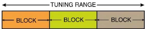
Four tuning ranges are available covering standard blocks as follows:
Range Blocks Covered Freq. MHz
| A1 470, 19, 20 470.1 - 537.5 | |
| B1 21, 22, 23 537.6 - 614.3 | |
| B2 22, 23, 24 563.2 - 639.9 | |
| C1 24, 25, 26 614.4 - 691.1 | |
| C2 25, 26, 27 640.0 - 716.7 | |
| 606* 606 0 - 631.5 |
*See Down Button Menu for more information **Export Only (not available in US or Canada)
To simplify backward compatibility with earlier Digital Hybrid Wireless ^® equipment, block numbers are presented along with frequencies in LCD screens.
About Frequency Blocks
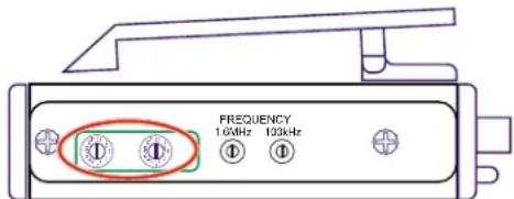
A 25.6 MHz band of frequencies, referred to as a Block, came about with the design of the first frequency tunable Lectrosonics wireless products. These products provided two 16-position rotary switches to select frequencies as shown in the illustration below. A logical method of identifying the switch positions was using 16 character hexadecimal numbering. This naming and numbering convention is still used today.
The 16 switch positions are numbered 0 (zero) through F, presented in a two-character designation such as B8, 5C, AD, 74, etc. The first character indicates the position of the left hand switch and the second character indicates the position of the right hand switch. This designator is commonly called a "hex code."
text_image
FREQUENCY 16kHz 130kHzOn older transmitter models, the left hand switch makes steps in 1.6 MHz increments, the right hand switch in 100 kHz increments.
Each block spans a 25.6 MHz band. A simple formula is used to name the blocks according to the lowest frequency in each one. For example, the block starting at 512 MHz is named Block 20, since 25.6 times 20 equals 512.
About Digital Hybrid Wireless®
US Patent 7,225,135
All wireless links suffer from channel noise to some degree, and all wireless microphone systems seek to minimize the impact of that noise on the desired signal. Conventional analog systems use compandors for enhanced dynamic range, at the cost of subtle artifacts (known as “pumping” and “breathing”). Wholly digital systems defeat the noise by sending the audio information in digital form, however, it is often at the cost of one or more issues regarding power, bandwidth, operating range and resistance to interference.
The Lectrosonics Digital Hybrid Wireless system overcomes channel noise in a dramatically new way, digitally encoding the audio in the transmitter and decoding it in the receiver, yet still sending the encoded information via an analog FM wireless link. This proprietary algorithm is not a digital implementation of an analog compandor but a technique which can be accomplished only in the digital domain.
Since the RF link between transmitter and receiver is FM, channel noise will increase gradually with increased operating range and weakened signal conditions; however, the Digital Hybrid Wireless system handles this situation elegantly with barely audible audio artifacts as the receiver approaches its squelch threshold.
In contrast, a purely digital system tends to drop the audio suddenly during brief dropouts and weak signal conditions. The Digital Hybrid Wireless system simply encodes the signal to use a noisy channel as efficiently and robustly as possible, yielding audio performance that rivals that of purely digital systems, without the power, noise and bandwidth problems inherent in digital transmission. Because it uses an analog FM link, Digital Hybrid Wireless enjoys all the benefits of conventional FM wireless systems, such as excellent range, efficient use of RF spectrum, and long battery life.
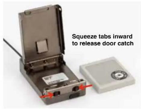
Battery Installation
The battery compartment and door catch are designed for simple and quick battery changes, yet prevent the door from being opened accidentally.
text_image
Squeeze tabs inward to release door catch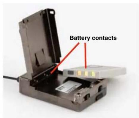
text_image
Battery contacts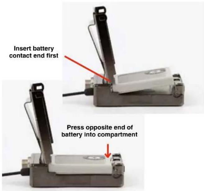
text_image
Insert battery contact end first Press opposite end of battery into compartmentBattery Charging
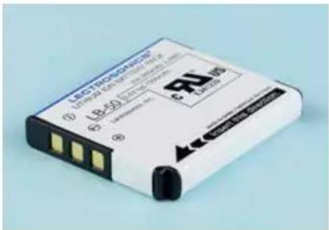
The transmitter operates from a 3.6 V rechargeable battery that will provide about six hours of operation per charge. Battery life can be monitored from the timer function built into current Lectrosonics receivers.
text_image
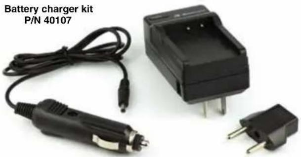
LECTRONOMETER ① LRC-50 ② LRC-50 ③ LRC-50 LRC-50 LRC-50 LRC-50 LRC-50 LRC-50 LRC-50 LRC-50 LRC-50 LRC-50 LRC-50 LRC-50 LRC-50 LRC-50 LRC-50 LRC-50 LRC-50 LRC-51 LRC-51 LRC-51 LRC-51 LRC-51 LRC-51 LRC-51 LRC-51 LRC-51 LRC-51 LRC-51 LRC-51 LRC-51 LRC-51 LRC-51 LRC-51 LRC-51 LRC 2389The factory supplied battery charger kit provides a folding NEMA 2-prong plug on the charger, and will operate from 100-240 VAC sources. The LED glows red during charging and turns green when the battery is fully charged. The kit includes a Euro plug adapter and vehicle auxiliary power adapter cord.
natural_image
Battery charger kit with two plug-in charging elements and a black battery pack (no text or symbols visible on components)CAUTION: Use only the factory supplied battery and battery charger.
Controls and Functions
text_image
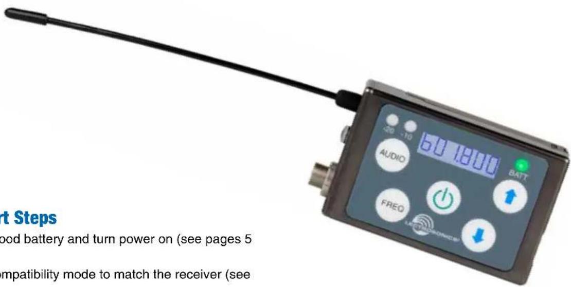
Modulation LEDs BATT LED -20 -10 583.275 AUDIO BATT ↑ FREQ LECTROGENICS® Power ButtonModulation LEDs
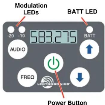
Proper input gain adjustment is critical to ensure the best audio quality. Two bicolor LEDs will glow either red or green to accurately indicate modulation levels. The input circuitry includes a wide range DSP controlled limiter to prevent distortion at high input levels.
It is important to set the gain (audio level) high enough to achieve full modulation during louder peaks in the audio. The limiter can handle over 30 dB of level above full modulation, so with an optimum setting, the LEDs will flash red during use. If the LEDs never flash red, the gain is too low. In the table below, +0 dB indicates full modulation.
Signal Level -20 LED -10 LED
| Less than -20 dB | Off | Off | ● |
| -20 dB to -10 dB | Green | Off | ● |
| -10 dB to +0 dB | Green | Green | ● |
| +0 dB to +10 dB | Red | Green | ● |
| Greater than +10 db | Red | Red | ● |
LCD Screen
The LCD is a numeric-type Liquid Crystal Display with screens for adjusting output power, frequency, audio level, low frequency audio roll-off and various modes and options. The transmitter can be powered up with or without the RF output turned on. A brief press on the power button turns the unit on in a Standby Mode with the output turned off to allow adjustments to be made without interfering with other wireless systems in the vicinity.
WARNING: Moisture, including talent's sweat, will damage the transmitter. Wrap the SSM in a plastic baggie or other protection to avoid damage.
BATT LED
This LED glows green when the battery is good. The color changes to red when there is only a few minutes of operation left. The LED will blink briefly, just before the unit powers down.
The exact point at which the LED turns red will vary with battery brand and condition, temperature and current drain. The LED is intended to simply catch your attention, not to be an exact indicator of remaining time.
AUDIO Button
The AUDIO button is used to adjust the audio output level and low frequency roll-off. Each press of the button will toggle between the two settings.
FREQ Button
The FREQ Button displays the selected operating frequency and toggles the LCD between displaying the actual operating frequency in MHz and a two-digit hexadecimal number that corresponds to the equivalent Lectrosonics Frequency Switch Setting.
Power Button
Turns the unit on and off. A brief press turns power on in a Standby Mode to make settings without interfering with other wireless systems in the vicinity. Pressing and holding the button until a counter on the LCD completes a sequence turns the power on with the RF output turned on. Pressing and holding for the duration of a countdown turns the unit off.
UP and DOWN Arrow Buttons
The Up and Down arrow buttons are used to select the values on the various setup screens and to lock out the control panel.
Turning LEDs ON and OFF
These arrow keys also turn the LEDs on and off. With no other button pressed, the UP arrow turns the LEDs on and the DOWN arrow turns them off. When the LEDs turn red, the LCD will display a reminder every few seconds.
See Operating Instructions and Setup Screens for complete information.
Connectors and USB Port
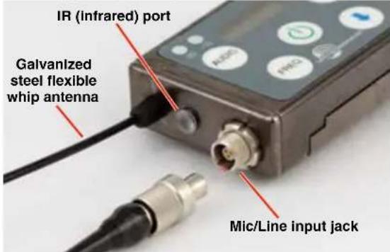
The housing is machined out of a solid aluminum billet for a rugged, lightweight assembly.
text_image
IR (Infrared) port Galvanized steel flexible whip antenna Mic/Line input jackThe antenna is a flexible whip made of galvanized steel, permanently attached to the transmitter to prevent damage from heavy use. The IR port is capped with a translucent dome material to broaden the reception angle. The input jack is a rugged 3-pin LEMO connector with a threaded locking sleeve.
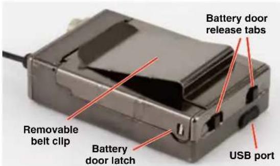
The opposite end of the transmitter contains the battery door latches and release tabs, and the USB port, which is used for firmware updates.
text_image
Battery door release tabs Removable belt clip Battery door latch USB portThe battery door itself is made of stainless steel to allow a thin wall thickness, but retain the strength to withstand heavy use.
Attaching and Removing the Microphone
Align the ridges on the plug with the grooves in the jack and insert the plug.
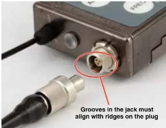
text_image
Grooves in the jack must align with ridges on the plugSlide the threaded sleeve onto the jack and rotate it clockwise to tighten it.
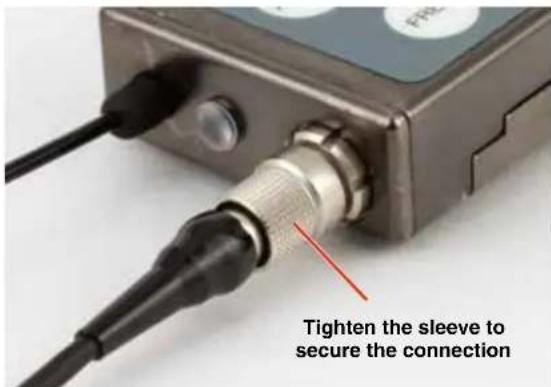
text_image
Tighten the sleeve to secure the connectionOperating Instructions
Powering On in Operating Mode
Press and hold the Power Button for several seconds until a counter on the LCD progresses from 1 through 3, followed by a display of the model, firmware version, frequency block and compatibility mode.

text_image
On ...1 → On ...3When you release the button, the unit will be operational with the RF output turned on and the Main Window displayed.
Powering On in Standby Mode
A brief press of the Power Button Ⓧreleasing it before the counter has reached 3, will turn the unit on with the RF output turned off. The LCD will display a reminder that the RF output of the transmitter is turned off.

In this Standby Mode the frequency can be browsed to make adjustments without the risk of interfering with other wireless systems nearby.
After adjustments are made, press the power button again to turn the unit off.
Powering Off
Holding the Power Button Ⓜin and waiting for the completion of the countdown from 3 to 1 will turn the power off.

text_image
OFF...3→OFF...1If the power button is released before the countdown is completed, the unit will remain turned on and the LCD will return to the same screen or menu that was displayed previously.
Setup Screens
Two different setup menus are accessed by holding either the UP or DOWN arrow button while powering the unit on. See the following page (Setup Screens) for a listing of the menu items and descriptions.
Screens Used in Normal Operation
When the transmitter is turned on with the RF output on, the LCD will display the frequency, audio gain or LF roll-off point.
Audio gain is expressed in dB.

Frequency is displayed in one of two ways:
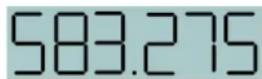
Frequency expressed in MHz
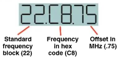
text_image
22.0875 Standard frequency block (22) Frequency in hex code (C8) Offset In MHz (.75)LF roll-off is expressed in Hz.
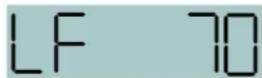
To make changes to the settings, press either button to display the desired screen, then use the UP and DOWN arrows to select the value. The changes take effect immediately when you release the buttons.
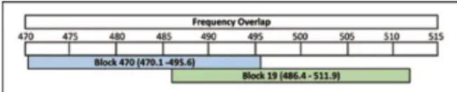
Block 470/19 Frequency Overlap
bar
| Block | Frequency Overlap Range | |-------|--------------------------| | Block 470 | 470.1 - 495.6 | | Block 19 | 486.4 - 511.9 |Frequencies 486.400 - 495.600 Overlap in Blocks 470 and 19
Block 470 and block 19 overlap each other in the frequency range from 486.400 to 495.600 MHz. Since block 470 starts at a lower frequency than block 19, the hex codes (and pilot tones) will not match even though the frequencies are the same in the overlap zone. When using a transmitter on the A1 band with a block 19 receiver, be sure the transmitter is set to block 19 and check the hex code on the receiver to make sure it matches the transmitter.
Call the factory if you have questions about this issue.
Setup Steps
The setup menus are accessed by holding either the UP or DOWN arrow while powering the unit on. Refer to Setup Screens on the next page for details of each setup parameter.
The following list outlines the steps necessary to set up the transmitter for normal use.
1) Install a charged battery.
2) Set the compatibility mode to match the receiver to be used.
3) Adjust the step size and frequency to match the receiver. The frequency is normally determined using the receiver to identify one within clear operating spectrum. Refer to the receiver instructions for details on using features such as scanning.
NOTE: Some Lectrosonics receivers include an IR (infrared) port to transfer settings from the receiver to the transmitter. Refer to the section on IR (infrared) Sync for details.
4) Connect the microphone or audio source to be used. Select the correct input configuration.
5) Adjust the input gain. Refer to Adjusting the Input Gain for details.
6) Turn on the receiver and verify that solid RF and audio signals are present (see receiver manual).
Locking the Controls
The firmware version is displayed briefly when powering up the transmitter.
For firmware versions 1.06 and lower:
Lock the controls by holding the UP and DOWN arrows until a count displayed on the LCD is completed and Loc appears on the LCD. To unlock the controls, remove the battery.
For firmware versions 1.07 and higher:
Lock the controls by holding the UP and DOWN arrows until a count displayed on the LCD is completed and Loc appears on the LCD. To unlock the controls, hold the UP and DOWN arrows until a count on the LCD is completed and unloc appears on the LCD. Removing the battery does not unlock the controls.
Adjusting the Input Gain
The two bicolor Modulation LEDs on the control panel provide a visual indication of the audio signal level entering the transmitter. The LEDs will glow either red or green to indicate modulation levels as shown in the following table.
Signal Level -20 LED -10 LED
| Less than -20 dB | Off | Off | ||
| -20 dB to -10 dB | Green | Off | ||
| -10 dB to +0 dB | Green | Green | ||
| +0 dB to +10 dB | Red | Green | ||
| Greater than +10 dB | Red | Red |
NOTE: Full modulation is achieved at 0 dB, when the "-20" LED first turns red. The limiter can cleanly handle peaks up to 30 dB above this point.
It is best to go through the following procedure with the transmitter in the standby mode so that no audio will enter the sound system or recorder during adjustment.
1) With a charged battery in the transmitter, power the unit on in the standby mode (see previous section Powering On in Standby Mode).
2) Press and hold the AUDIO button with Aud and a numeral on the display (e.g. Aud 22).
3) Prepare the signal source. Position a microphone the way it will be used in actual operation and have the user speak or sing at the loudest level that occur during use, or set the output level of the instrument or audio device to the maximum level that will be used.
4) Use the and arrow buttons to adjust the gain until the -10 dB glows green and the -20 dB LED starts to flicker red during the loudest peaks in the audio.
5) Once the audio gain has been set, the signal can be sent through the sound system for overall level adjustments, monitor settings, etc.
6) If the audio output level of the receiver is too high or low, use only the controls on the receiver to make adjustments. Unless the microphone or its position changes, or a different instrument is being used, leave the transmitter gain adjustment set according to these instructions. Use the audio output level control on the receiver to make adjustments for the desired level being delivered to the connected mixer, recorder, etc.
Setup Screens
DOWN Button Menu
Hold the DOWN button while powering up the unit. Then press the AUDIO button repeatedly to scroll through the following settings. Use the UP and DOWN arrows to select the available options under each setting.
- rc - remote control operation; selections: on, oFF
- PbAc - power-back-on after power loss; selections: 0 (stay turned off), 1 (turn back on)
- bL - back light duration; selections: 5 (minutes), 30 (seconds), on (always on)
UP Button Menu
Hold the UP button while powering up the unit. Then press the AUDIO button repeatedly to scroll through and select the following settings (bulleted). Use the UP and DOWN arrows to select the available options under each setting.
- CP - compatibility mode; press the UP and DOWN arrows to select one of the following:
CP nHb Nu Hybrid mode
CP 3 Mode 3 (contact the factory for details)
CP IFb IFB Series mode; IFBR1/1a receivers
- Pr - RF power output; selections: 25, 50 (10 mW is the only option for E02)
- In - Input configuration; press the UP and DOWN arrows to select one of the following:
In dYn bIAS 0, rES 0; use for dynamic microphones; positive polarity
In 152 bIAS 4, rES 0; same as otH; listed for easy selection on Lectrosonics 152 and similar mics; positive polarity
In SEn bias 4, rES 0; same as otH; listed for easy selection on Sennheiser MKE 2 and similar mics; positive polarity
In SEt Press the AUDIO button for manual setup of input for explicit control over bias voltage, input resistance and audio polarity. Press the AUDIO button to select the following parameters, then use the UP and DOWN arrows for each item to set the values.
bias - bias voltage on the input; selections 0, 2 or 4
rES - input impedance; selections: 0 (300 ohms), Lo (approx. 4 k ohms) or HI (approx. 100 k ohms)
AP - audio polarity (aka "phase"); selections: P for positive, n for negative (reversed)
NOTE: When you press AUDIO after setting the polarity, the screen will leave this submenu and return to the In menu. To return to this submenu, press AUDIO repeatedly and scroll through the list again.
| In otH | bIAS 4, rES 0; same as CoS but audio phase is not reversed; for various mics; positive polarity |
| In L In | bIAS 0, rES HI; use for line level input ( See Line Input Wiring and Use on page 11); positive polarity |
| In dPA | bIAS 4, rES Lo; use for DPA lavaliere and similar mics; negative polarity |
| In b6 | bIAS 2, rES 0; use for Countryman B6 and similar mics; positive polarity |
| In CoS | bIAS 4, rES 0; phase reversed; use for Sanken COS-11, M152 and similar mics; negative polarity |
| In PSA | bIAS 4, rES Lo; use for Point Source Audio lavaliere and similar mics; negative polarity |
- StP - Frequency tuning step size in kHz; selections: 25 kHz or 100 kHz
Microphone Wiring
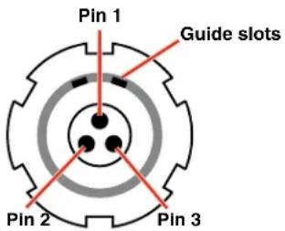
Looking into the 3 pin Lemo mic connector from the outside of the transmitter, the pin centered in the two guide slots is pin 1 (ground). Pin 2 is a 1k resistor to ground. Pin 3 is the audio/bias connection for two-wire microphones and line inputs.
text_image
Pin 1 Guide slots Pin 2 Pin 3Voltages, polarity, impedance and line level for all signal sources are selected by menus. Menu selections include presets for popular microphones, and a sub-menu for manual setup. Refer to the section entitled Setup Screens on the previous page for details.
Two-wire electret lavaliere:
Pin 1 - Ground (shield)
Pin 3 - Audio and Bias
Sanken COS-11 Iavaliere
Recommended Wiring:
Pin 1 - Shield (ground)
Pin 2 - White (source load)
Pin 3 - Black (bias and audio)
NOTE: The COS-11 can also be wired in a two-wire configuration. Contact Plus24/Sanken for details.
The Sanken CUB-01 is not supported.
Line Input Wiring and Use
Pin Configuration:
Pin 1: Shield (ground)
Pin 2: Audio
Transmitter Settings:
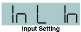
Unlike the old configuration, the new line input configuration requires no fixed gain setting. The gain setting can be adjusted as needed for the specific input level used.
Old Configuration:
Pin 1: Shield (ground)
Pin 3: Audio and bias
NOTE: This line input configuration is found on the following serial numbers and lower:
- Band A1 S/N 2884 and lower
- Band B1 S/N 2919 and lower
- Band C1 all S/Ns
Transmitter Settings:
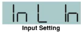

Note: This gain setting may seem "backwards" or illogical, however, it is correct due to the unique nature of the SSM input circuitry.Input Jack Configuration
Input Jack Configuration
Looking into the 3 pin Lemo mic connector from the outside of the transmitter, the pin centered in the two guide slots is pin 1 and is ground. At 7 o'clock is pin 2 with a 2k resistor to ground. That 2k is a source load for the Sanken COS-11 to save putting a resistor in the connector. At 4 o'clock is pin 3, the servo audio input.
Pin 1 - ground
Pin 2 - 2k source load to ground
Pin 3 - servo input
Voltages, phase, impedance, and line level for all mics signal sources are selected by menus. Pin 3 is the only connection for all mics except for the aforementioned Sanken COS-11. Countryman, DPA, Sanken COS-11 and standard two wire mics can be configured in the menus. The Sanken CUB-01 is not supported.
Locking the Controls
The keypad can be locked to prevent inadvertent changes to be made to the transmitter. Press and hold both the UP and DOWN arrow buttons for several seconds until a countdown is completed on the LCD. The display will show unloc 3...2...1 and then Loc will appear. To unlock, remove the batteries.
NOTE: This function is NOT affected, either locked or unlocked, by turning the power off.
IR (infrared) Sync
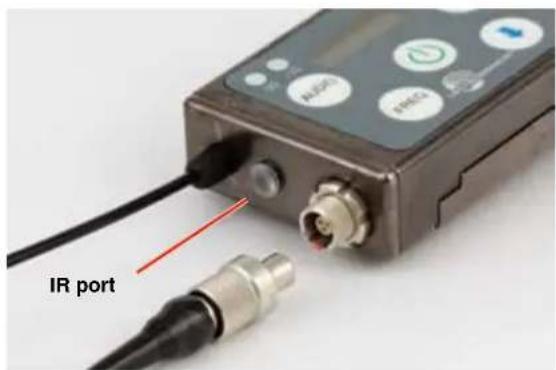
An IR (infrared) link between an associated receiver and the transmitter can be used to shorten setup time and ensure that the correct settings in the transmitter are made. The dome on the side panel of the transmitter is the port used for the IR link. The receiver is normally used to identify a clear operating frequency. Once step size, frequency and compatibility mode are set in the receiver, the settings can be sent to the transmitter via this IR link.
text_image
IR portPlace the transmitter close to the IR enabled receiver with the ports facing each other within a foot or two apart. Send the settings with the trigger on the receiver. If the settings are successfully transferred, a confirmation message will appear on the transmitter LCD.

NOTE: If a mismatch exists between the receiver and transmitter, an error message will appear on the transmitter LCD stating what the problem is.
Removable Belt Clip
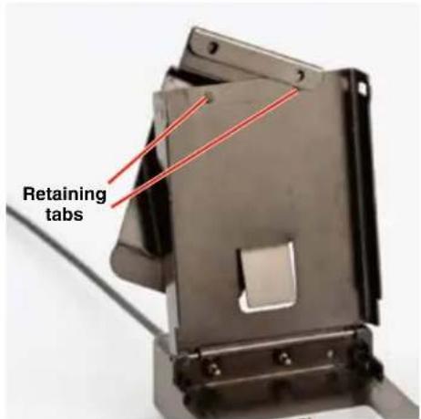
The belt clip may be removed by sliding it off the retaining tabs on the battery door.
text_image
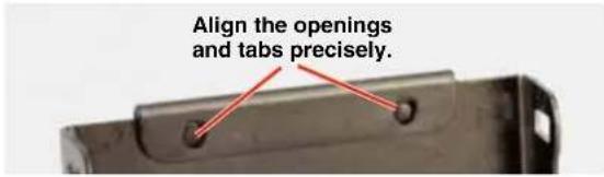
Retaining tabsWhen mounting the belt clip onto the battery door, carefully align the openings with the retaining tabs on the door. If they are not precisely aligned, the door may not close and latch properly.
text_image
Align the openings and tabs precisely.Remote Control
Remote control signals ("dweedle tones") may be used to control the transmitter. The tones are played back into the microphone to avoid the need to reach and handle the transmitter when making changes to the following adjustments and settings:
- Input Gain
- Sleep/Unsleep
- Lock/Unlock
- Tx power output
- Frequency
A smart phone app is available in the App Store and in Google Play to implement this control. Search for the title LectroRM.
LectroRM
By New Endian LLC
LectroRM is a mobile application for iOS and Android smart phone operating systems. Its purpose is to make changes to the settings on select Lectrosonics transmitters by delivering encoded audio tones to the microphone attached to the transmitter. When the tone enters the transmitter, it is decoded to make a change to a variety of different settings such as input gain, frequency and a number of others.
The app was released by New Endian, LLC in September 2011. The app is available for download and sells for \$25 on the Apple App Store and Google Play Store.
The settings and values that can be changed vary from one transmitter model to another. The complete list of available tones in the app is as follows:
- Input gain
- Frequency
- Sleep Mode
- Panel LOCK/UNLOCK
- RF output power
- Low frequency audio roll-off
- LEDs ON/OFF
The user interface involves selecting the audio sequence related to the desired change. Each version has an interface for selecting the desired setting and the desired option for that setting. Each version also has a mechanism to prevent accidental activation of the tone.
iOS
text_image
Channel 1 ElectroRM Audio 50 MHz 23 24 25 26 27 28 Volume Rud FrER SLP Loc Purr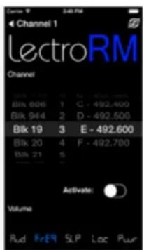
text_image
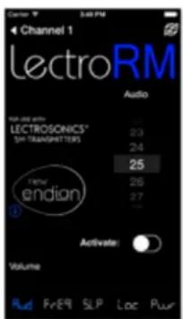
Channel 1 ElectroRM Channel Blk 606 1 C - 492.400 Blk 944 2 D - 492.500 Blk 19 3 E - 492.600 Blk 20 4 F - 492.700 Blk 21 5 Activate: Volume Rud #E9 SLP Loc PurThe iPhone version keeps each available setting on a separate page with the list of options for that setting. On iOS, the "Activate" toggle switch must be enabled to show the button which will then activate the tone. The iOS version's default orientation is upside-down but can be configured to orient right-side up. The purpose for this is to orient the phone's speaker, which is at the bottom of the device, closer to the transmitter microphone.
Android
text_image
LectruRM AUMO FREQ SLEEP LOCK POWER Blk 21 00 - 537.600 ACTIVATE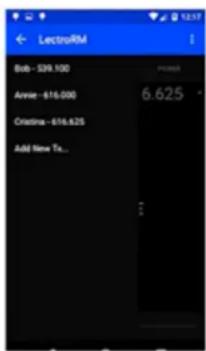
text_image
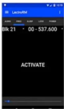
LectroRM Bob - $39.100 Annie - $16.000 Christine - $16.625 Add New Tx...The Android version keeps all settings on the same page and allows the user to toggle between the activation buttons for each setting. The activation button must be pressed and held to activate the tone. The Android version also allows users to keep a configurable list of full sets of settings.
Activation
For a transmitter to respond to remote control audio tones, the transmitter must meet certain requirements:
- The transmitter must be turned on.
- The transmitter must have firmware version 1.5 or later for Audio, Frequency, Sleep and Lock changes.
- The transmitter microphone must be within range.
- The remote control function must be enabled on the transmitter.
Please be aware this app is not a Lectrosonics product. It is privately owned and operated by New Endian LLC, www.newendian.com.
Accessories
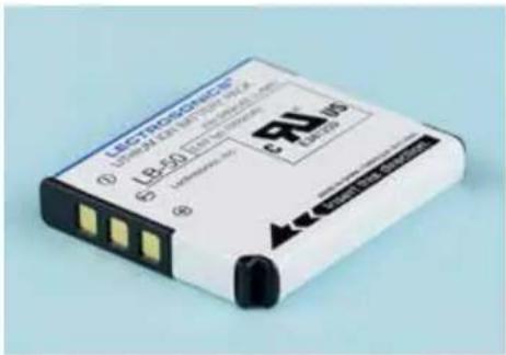
Rechargeable battery
P/N 40106-1 LB-50 3.6V lithium-ion battery pack
text_image
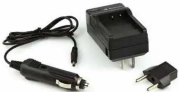
LectrodeCoMo ① L18-50 ② ③ ④ LectrodeCoMo ⑤ LectrodeCoMo ⑥Battery charger kit
P/N 40107 charger for Lectrosonics LB-50 battery; includes charger, EU plug adapter and vehicle auxiliary power cord
natural_image
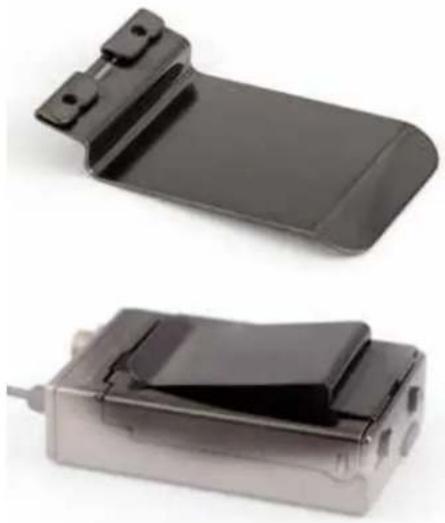
Black electrical fuse and plug assembly with two terminal blocks (no visible text or symbols)Antenna downward belt clip
P/N 26995 slide-on belt clip
natural_image
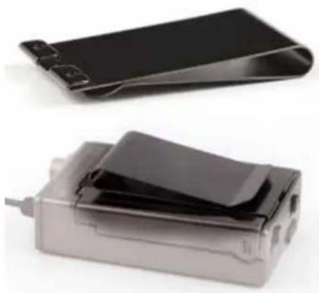
Two black plastic electronic devices with connectors, shown from different angles (no text or symbols visible)Antenna upward belt clip
P/N 27079 slide-on belt clip
natural_image
Two electronic devices with black plastic covers, one open and one closed, shown against a white background (no text or symbols visible)Cordura Pouch
P/N 35939 zippered, padded; 4 x 6 x1 inches
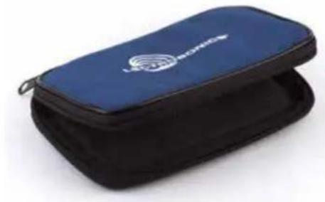
natural_image
Blue and black compact device with a logo on the cover (no visible text or symbols)Port Cover
P/N P1311 Micro USB port cover
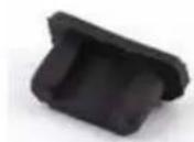
Silicone Cover
P/N SSMCVR Silicone cover protects from moisture and dust
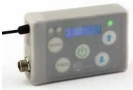
natural_image
Exterior view of a gray medical or laboratory device with control buttons and a digital display (no visible text or symbols)Firmware Update
Updating the firmware is a simple matter of downloading a utility program and file from the website and running the program on a Windows operating system with the transmitter connected to a computer via the USB port.
Go to www.lectrosonics.com/US. In the top menu, hover the mouse over Support, and click on Wireless Support. On the right-hand-side Wireless Support Menu, choose Wireless Downloads. Choose your product (SSM), then choose Firmware.
Step 1:
Begin by downloading the USB Firmware Updater Program.
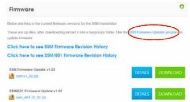
text_image
Firmware Close are links to the current firmware versions for the SSM transmission These are zip files, after downloading or start it into a temporary folder. Use the SSM Firmware Update program to update firmware Click here to see SSM Firmware Revision History Click here to see SSM/EO1 Firmware Revision History SSM Firmware Update v1.02 ssm_v1_02.zip DETAILS DOWNLOAD SSME01 Firmware Update v1.02 ssm_v01_v1_02.zip DETAILS DOWNLOADUSB Firmware Updater
Below is a link to the current USB Firmware-Updater installer. This program is used to update firmware on these products:
• DB transverse
• 17 transmission
• LR початку
• ISML transindium
6. 30% transatlax
• Héla transmission
Instructions. Its updating firmware is found in the instruction manual for these products.
Downloaded into a temporary folder. Uninstall any previous version of USB Extensive Updater before running the downloaded installer.
Note: This program requires that the F10f JD0f Direct USB driver be installed on your PC. This is normally pre-installed but if not you will need to download and run a driver installer from the official F10f downloaded page installers for both 84-bit and 32-bit Windowsoft PCs are available there.
USD Firmware Update v1.0.6
UnifusUpdate/c1.5.sellsq.com

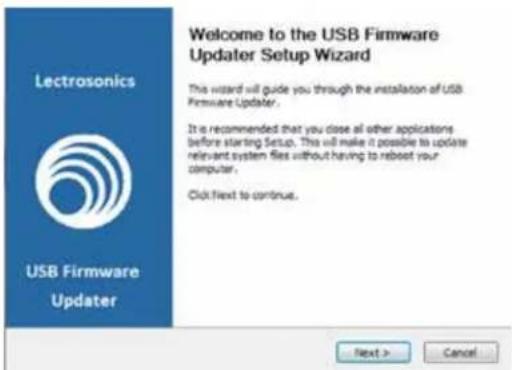
text_image
Welcome to the USB Firmware Updater Setup Wizard This wizard will guide you through the installation of USB Firmware Updater. It is recommended that you close all other applications before starting Setup. This will make it possible to update relevant system files without having to reboot your computer. Click Next to continue. Next > CancelStep 2:

Next, test the Updater by opening the icon: If the driver opens automatically, proceed to Step 3.
WARNING: If you receive the following error, the Updater is not installed on your system. Follow the TROUBLESHOOTING steps to fix the error.
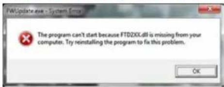
text_image
FWUpdate.exe - System Error The program can't start because FTD2XX.dll is missing from your computer. Try reinstalling the program to fix this problem. OKTROUBLESHOOTING:

text_image
USB Firmware Update Return a list in the next USB Firmware Update consider: This program is used to upgrade firmware on these products. • USB transmitter • LT transmitter • USB receiver • USB transmitter • USB transmitter • USB transmitter Instructions for updating software as Award in the hardware into Excel for these products. Downloaded into a temporary folder. Uninstall only previous version of USB Firmware update within existing the downloaded website. Note: This program responds that first USB HDMI Drive USB driver tax installation, which is currently pre installed but first plus will need to download and use a lower index. The offset of USB Direct transmission for both 34-bit and 32-bit Microsoft PCs are available here.If you receive the FTDI D2XX error shown above, download and install the driver by clicking on this link.
Then click here to download.
NOTE: This website, http://www.ftdichip.com/Drivers/D2XX.htm, is not associated with Lectrosonics.com. It is a third party site used only for D2XX drivers currently available for Lectrosonics' devices' upgrades.
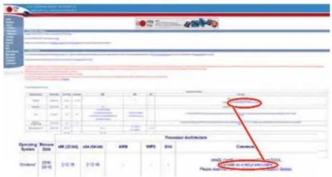
Refer to Step 1 to return to Firmware web page. Download Firmware Update and save to a local file on your PC for easy locating when updating.
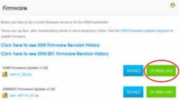
text_image
Firmware Browse are links to the current firmware versions for the SSM transmission These are zip files, after downloading extract it into a temporary folder. Use the SSM Firmware Update program to update firmware. Click here to see SSM Firmware Revision History Click here to see SSM/E01 Firmware Revision History SSM Firmware Update v1.02 svm_v1_02.zip DETAILS DOWNLOAD SSM/E01 Firmware Update v1.02 svm_e01_v1_02.zip DETAILS DOWNLOADStep 4:
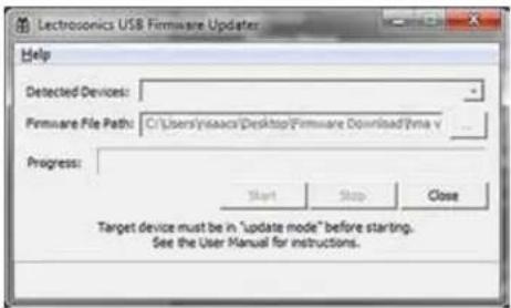
Open Lectrosonics USB Firmware Updater.

text_image
Lectrosonics USB Firmware Updates Help Detected Devices: Firmware File Path: C:\Users\sysacc\Desktop\Firmware Download\ina.v Progress: Start Stop Close Target device must be in "update mode" before starting. See the User Manual for instructions.Step 5:
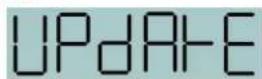
Put the transmitter in UPDATE mode by simultaneously holding down the UP and DOWN arrow buttons on the transmitter control panel while powering it up.
Step 6:
Using a microUSB cable, connect the transmitter to your PC.
Step 7:
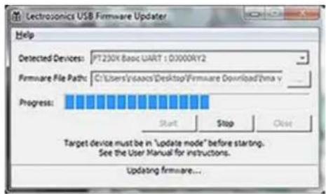
In Lectrosonics USB Firmware Updater, choose the detected device, browse to local Firmware File and click Start.
NOTE: It may take up to a minute or so for the Updater to recognize the transmitter.
text_image
Electrosonics USB Firmware Updater Help Detected Devices: PT230X basic UART : 0000RY2 Firmware File Path: C:\Users\Videos\Desktop\Firmware Download\Trina v Progress: Start Stop Close Target device must be in "Update mode" before starting. See the User Manual for instructions. Updating firmware...WARNING: Do not disrupt the microUSB cable during updating.
text_image
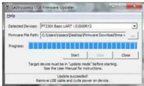
Technomics USB Firmware Updater Help Detected Devices: PT230X Basic UART : 03009RY2 Firmware File Path: C:\Users\issues\Desktop/Firmware Download\Pina v Progress: Start Stop Close Target device must be in "Update mode" before starting. See the User Manual for instructions. Update succeeded! Remove USB cable and cycle power on device.The Updater alerts with progress and completion.
Step 8:

Once the Updater has completed, turn off the transmitter, then turn it back on to verify that the firmware version on the transmitter LCD matches the firmware version shown on the web site. The firmware is the second LCD display during boot up sequence.
Step 9:
Close Updater and disconnect microUSB cable.
Specifications
Operating Frequencies:
SSM: Band A1: 470.100 - 537.575
Band B1: 537.600 - 607.950
SSM/E01: Band A1: 470.100 - 537.575
Band B1: 537.600 - 614.375
Band B2: 563.200 - 639.975
Block 606: 606.000 - 631.500
Band C1: 614.400 - 691.175
SSM/E01-B2: Band B2: 563.200 - 639.975
SSM/E02: Band A1: 470.100 - 537.575
Band B1: 537.600 - 614.375
Band B2: 563.200 - 639.975
Band C1: 614.400 - 691.175
Band C2: 640.000 - 716.700
SSM/E06: Band B1: 537.600 - 614.375
Band C1: 614.400 - 691.175
SSM/X: Band A1: 470.100 - 537.575
Band B1: 537.600 - 607.950
Band C1: 614.400 - 691-175
NOTE: It's the user's responsibility to select the approved frequencies for the region where the transmitter is operating.
Frequency Selection
Steps: Selectable; 100 kHz or 25 kHz
RF Power output: SSM/E01/E01-B2/X:
Selectable; 25 or 50 mW
SSM/E02: 10 mW
SSM/E06: 50 or 100 mW EIRP
Compatibility Modes: US: Nu Hybrid, Mode 3, IFB
E01: Digital Hybrid, Mode 3, IFB
E01-B2: Digital Hybrid, Mode 3, IFB
E02: Digital Hybrid, Mode 3, IFB
E06: 100 Series, 200 Series, Mode 3, Digital Hybrid,
IFB, Mode 6, Mode 7
SSM/X: 100 Series, 200 Series, Mode 3, Digital Hybrid,
IFB, Mode 6, Mode 7
Pilot tone: 25 to 32 kHz; 3.5 kHz deviation (Nu Hybrid mode); ± 50
kHz
max. (Digital Hybrid mode)
Frequency Stability: ± 0.002%
Spurious radiation: SSM: Compliant with ETSI EN 300 422-1 v1.4.2
SSM-941/E01/E02/E06/X: 60 dB below carrier
Equivalent input
noise: -120 dBV (A-weighted)
Input level: Nominal 2 mV to 300 mV, before limiting. Greater than 1V maximum, with limiting.
Input impedance: Mic: 300 or 4.5 k ohm; selectable
• Line: greater than 100 k ohm
Input limiter: DSP controlled, dual envelope "soft" limiter with
greater than 30 dB range
Gain control range: 44 dB; digital control
Modulation
indicators: Dual bicolor LEDs indicate modulation of -20, -10, 0 and
+10 dB referenced to full modulation
Audio Performance (Digital Hybrid and Nu Hybrid)
Frequency Response: 70 Hz to 20 kHz (+/-1dB)
Low frequency
roll-off: -12 dB/octave; 70 Hz
THD: 0.2% (typical)
SNR at receiver output: SmartNR No Limiting w/Limiting
OFF 103.5 108.0
Note: The dual envelope "soft"
limiter provides exceptionally good
NORMAL 107.5 111.6 FULL 102.5 112.9
handling of transients using variable FULL 108.5 113.0
attack and release time constants. Once activated, the limiter compresses
30+ dB of transmitter input range into 4.5 dB of receiver output range, thus
reducing the measured figure for SNR without limiting by 4.5 dB
Controls: Side panel membrane switches with LCD interface for power on/off and all setup and configuration controls
Audio Input Jack: LEMO 00 Series 3-pin
Antenna: Galvanized steel, flexible wire
Battery: Lithium-ion 3.6 V 1000 mAH LB50 battery pack
Battery Life: 6 hours per charge
Weight: 2.3 ounces (65.2 grams) including lithium battery pack
Dimensions
(housing): 2.3 x 1.5 x .56 in. (58.4 x 38 x 14.2 mm)
Emission Designator: SSM: 110KF3E
SSM/E01/E01-B2/E02/E06/X: 180KF3E
Specifications subject to change without notice.
Service and Repair
If your system malfunctions, you should attempt to correct or isolate the trouble before concluding that the equipment needs repair. Make sure you have followed the setup procedure and operating instructions. Check the interconnecting cables.
We strongly recommend that you do not try to repair the equipment yourself and do not have the local repair shop attempt anything other than the simplest repair. If the repair is more complicated than a broken wire or loose connection, send the unit to the factory for repair and service. Don't attempt to adjust any controls inside the units. Once set at the factory, the various controls and trimmers do not drift with age or vibration and never require readjustment.
There are no adjustments inside that will make a malfunctioning unit start working.
LECTROSONICS' Service Department is equipped and staffed to quickly repair your equipment. In warranty repairs are made at no charge in accordance with the terms of the warranty. Out-of-warranty repairs are charged at a modest flat rate plus parts and shipping. Since it takes almost as much time and effort to determine what is wrong as it does to make the repair, there is a charge for an exact quotation. We will be happy to quote approximate charges by phone for out-of-warranty repairs.
Returning Units for Repair
For timely service, please follow the steps below:
A. DO NOT return equipment to the factory for repair without first contacting us by e-mail or by phone. We need to know the nature of the problem, the model number and the serial number of the equipment. We also need a phone number where you can be reached 8 A.M. to 4 P.M. (U.S. Mountain Standard Time).
B. After receiving your request, we will issue you a return authorization number (R.A.). This number will help speed your repair through our receiving and repair departments. The return authorization number must be clearly shown on the outside of the shipping container.
C. Pack the equipment carefully and ship to us, shipping costs prepaid. If necessary, we can provide you with the proper packing materials. UPS or FEDEX is usually the best way to ship the units. Heavy units should be “double-boxed” for safe transport.
D. We also strongly recommend that you insure the equipment, since we cannot be responsible for loss of or damage to equipment that you ship. Of course, we insure the equipment when we ship it back to you.
Lectrosonics USA:
Mailing address: Shipping address: Telephone:
Lectrosonics, Inc. Lectrosonics, Inc. +1 (505) 892-4501
PO Box 15900 561 Laser Rd., Suite 102 (800) 821-1121 Toll-free US and Canada
Rio Rancho, NM 87174 Rio Rancho, NM 87124 Fax +1 (505) 892-6243
USA USA
Web: E-mail:
www.lectrosonics.com service.repair@lectrosonics.com
sales@lectrosonics.com
Lectrosonics Canada:
Mailing Address:
720 Spadina Avenue,
Suite 600
Toronto, Ontario M5S 2T9
Telephone:
+1 (416) 596-2202
(877) 753-2876 Toll-free Canada
(877) 7LECTRO
Fax (416) 596-6648
E-mail:
Sales: colinb@lectrosonics.com
Service: joeb@lectrosonics.com

SONICS
P.O. Box 15900 - Rio Rancho, NM - 87174 - USA
Phone: (800)821-1121 or (505)892-4501 - Fax: (505)892-6243
web: www.lectrosonics.com · email: sales@lectrosonics.com
Declaration of Conformity
LECTROSONICS, INC.
581 Laser Road
Rio Rancho, NM 87124 USA
Declare under our sole responsibility that the following product:
SSM/E01 Micro Bodypack Transmitter
Models:
SSM/E01-A1, SSM/E01-B1, SSM/E01-C1, SSM/E01-D1
to which this Declaration relates, is in conformity with the directives and standards listed below,
Radio Spectrum R&TTE 1999/5/EEC
Standard: EN 300 422-2 v1.4.1 (2015-06)
Test report: R1502274-422
EMC Directive 2004/108/EC
Standard: EN 301 489-1 v1.9.2 (2011-09)
Standard: EN 301 489-9 v1.4.1 (2007-11)
Test report: R1502274-12
Safety/Low Voltage Directive 2006/95/EC
Standard: EN 60065: 2002 + A12: 2011
Test report: R1502274-3
Standard: EN 62311: 2008
Test report: R1502274-SAR
and is in conformity with Directive 2011/65/EU of the European Parliament and of the Council of 8 June 2011 (RoHS Recast).
The product carries the CE mark:
CE1313①
R. Lumin
Robert Cunnings
V.P. Engineering
Lectrosonics, Inc.
21 March 2016

text_image
LECTROSONICS® P.O. Box 15900 - 8 Phone:000-804-1101P.O. Box 15900 - Rio Rancho, NM - 87174 - USA Phone: (800)821-1121 or (505)892-4501 - Fax: (505)892-6243 web: www.lectrosonics.com - email: sales@lectrosonics.com
EU Declaration of Conformity
LECTROSONICS, INC.
581 Laser Road
Rio Rancho, NM 87124 USA
Declares under our sole responsibility that the following product:
Model: SSM/E01-B2
Wireless microphone transmitter
is in conformity with the provisions of the following EC directive(s) (including applicable amendments) and are designed and manufactured in accordance with the harmonized standards:
| Document | Description | Date/Version |
| RL 2014/53/EU | Radio Equipment Directive 2014/53/EU (RED) | 2014-04 |
| Radio Spectrum (article 3.2 of R&TTE) | ||
| EN 300 422-1 | Wireless Microphones; Audio PMSE up to 3 GHz; Part 1: Class A Receivers | V2.1.2(2017-01) |
| Electromagnetic Compatibility (article 3.1.b of R&TTE) | ||
| EN 301 489-1 | ElectroMagnetic Compatibility (EMC) standard for radio equipment and services; Common Technical Requirements | V2.2.0(2017-03) |
| EN 301 489-9 | Specific Conditions for wireless microphones, similar Radio Frequency (RF) audio link equipment, cordless audio and in-ear monitoring devices | V2.1.1(2017-03) |
| Safety and Health | ||
| EN 60065-1 | Audio, video and similar electronic apparatus – Safety Requirements | 2014 |
| EN 62311 | Assessment of electronic and electrical equipment related to human exposure restrictions for electromagnetic fields (0 Hz – 300 GHz | 2008 |
| RL 2011/65/EU | RoHS Directive 2011/65/EU: Restriction of the use of certain hazardous substances (RoHS Recast) | 2011 |
The EU type examination was performed by notified body Bay Area Compliance Laboratories.
Software version of SSM/E01-B2: v1.06
text_image
Robert Cunningham Robert CunningsRobert Cunnings
V.P. Engineering
Lectrosonics, Inc.
LIMITED ONE YEAR WARRANTY
The equipment is warranted for one year from date of purchase against defects in materials or workmanship provided it was purchased from an authorized dealer. This warranty does not cover equipment which has been abused or damaged by careless handling or shipping. This warranty does not apply to used or demonstrator equipment.
Should any defect develop, Lectrosonics, Inc. will, at our option, repair or replace any defective parts without charge for either parts or labor. If Lectrosonics, Inc. cannot correct the defect in your equipment, it will be replaced at no charge with a similar new item. Lectrosonics, Inc. will pay for the cost of returning your equipment to you.
This warranty applies only to items returned to Lectrosonics, Inc. or an authorized dealer, shipping costs prepaid, within one year from the date of purchase.
This Limited Warranty is governed by the laws of the State of New Mexico. It states the entire liability of Lectrosonics Inc. and the entire remedy of the purchaser for any breach of warranty as outlined above. NEITHER LECTROSONICS, INC. NOR ANYONE INVOLVED IN THE PRODUCTION OR DELIVERY OF THE EQUIPMENT SHALL BE LIABLE FOR ANY INDIRECT, SPECIAL, PUNITIVE, CONSEQUENTIAL, OR INCIDENTAL DAMAGES ARISING OUT OF THE USE OR INABILITY TO USE THIS EQUIPMENT EVEN IF LECTROSONICS, INC. HAS BEEN ADVISED OF THE POSSIBILITY OF SUCH DAMAGES. IN NO EVENT SHALL THE LIABILITY OF LECTROSONICS, INC. EXCEED THE PURCHASE PRICE OF ANY DEFECTIVE EQUIPMENT.
This warranty gives you specific legal rights. You may have additional legal rights which vary from state to state.