
8361A - Monitor GENELEC - Free user manual and instructions
Find the device manual for free 8361A GENELEC in PDF.


| Product type | Active studio monitor |
| Model | 8361A |
| Brand | Genelec |
| Dimensions (H x W x D) with Iso-Pod | 593 x 357 x 347 mm (23 3/8 x 14 x 13 5/8 in) |
| Dimensions (H x W x D) without Iso-Pod | 570 x 357 x 347 mm (22 7/16 x 14 x 13 5/8 in) |
| Weight | 31.9 kg (70.3 lb) |
| Power supply | 100-240 VAC, 50/60 Hz |
| Power consumption (idle) | 20 W |
| Power consumption (full output) | 600 W |
| Power consumption (ISS active) | < 1.5 W |
| Lower cut-off frequency (-6 dB) | < 30 Hz |
| Upper cut-off frequency (-6 dB) | > 43 kHz |
| Frequency response accuracy (±1.5 dB) | 36 Hz – 20 kHz |
| Maximum short term SPL (1 m, half space) | ≥ 118 dB SPL |
| Maximum long term RMS SPL (IEC weighted noise) | 109 dB SPL |
| Self-generated noise level (A-weighted, 1 m) | ≤ 5 dB |
| Drivers | Dual 263 x 137 mm obround woofers, 130 mm midrange (coaxial), 25 mm tweeter (coaxial) |
| Amplifier power (bass) | 700 W |
| Amplifier power (midrange) | 150 W |
| Amplifier power (treble) | 150 W |
| Audio inputs | Analog (XLR balanced) and AES/EBU digital (XLR) |
| GLM network compatibility | Yes, proprietary GLM network (RJ45) |
| Mounting options | Iso-Pod stand (included), ceiling/wall mounts (optional) |
| Operating temperature range | 15–35 °C (50–95 °F) |
| Relative humidity (non-condensing) | 20% to 80% |
| Maintenance and cleaning | Do not open enclosure; no user-serviceable parts. Clean exterior with dry cloth. Keep ventilation clear. |
| Safety features | Protective ground required; ISS power saving; overload and overheat protection; front panel status LED. |
| Spare parts and reparability | Spare parts support extends far into future; extended warranty available via registration. |
| General information | Hand-built in Iisalmi, Finland; 2-year warranty (extendable to 5 years with registration). |
Frequently Asked Questions - 8361A GENELEC
User questions about 8361A GENELEC
0 question about this device. Answer the ones you know or ask your own.
Ask a new question about this device
Download the instructions for your Monitor in PDF format for free! Find your manual 8361A - GENELEC and take your electronic device back in hand. On this page are published all the documents necessary for the use of your device. 8361A by GENELEC.
USER MANUAL 8361A GENELEC
natural_image
Black GELEEC audio player device with a circular lens and green indicator light (no text or symbols on body)Introduction
Thank you for choosing Genelec! Fulfilling your dreams by offering the most truthful sound reproduction has been the source of our enthusiasm since 1978. Already over one million Genelec monitors are in use around the world - welcome to our story!
Genelec monitors are designed to last long our spare part support extends far into future. They are hand-built in lisalmi, Finland, using certified sustainable methods. They are individually tested and calibrated for the highest performance. They have also all been designed for low power consumption in use and in standby.
Please register your monitor at
http://www.community.genelec.com/
and receive an extended five-year warranty for spare parts. For more information about our service and technical support, please visit
http://www.genelec.com/customer-service.
System Characteristics
Each 8361A is supplied with a mains power cable, five-meter GLM network cable and this operating manual, and a second Iso-Pod retainer spring for horizontal mounting. The Genelec 8361A is suitable for all professional monitoring applications calling for very high precision and reliability. The 8361A combines many remarkable Genelec technologies to provide the benefits of a point source and controlled directivity over an extraordinarily wide audio bandwidth. The 8361A may be oriented horizontally or vertically. Listening distances can vary from less than one meter to more than 4 meters, depending on the room size and maximum sound level requirements.
Genelec Loudspeaker Manager™ (GLM™) Software and GLM User Kit
The GLM software tailor-fits the 8361A to your room. It is downloadable free of charge at www.genelec.com/glm. Check regularly for updates and new features, and consider using the cloud-based GLM services for the most up-to-date methods. A GLM User Kit, comprising a USB adapter device and measurement microphone, enables precise acoustic calibration and operation of the GLM loudspeaker management network.
Minimum Diffraction Coaxial (MDC™)
The minimum diffraction coaxial transducer MDC design implements a coaxial driver with unparalleled acoustic directivity control. A powerful midrange transducer surrounds a high output tweeter transducer, enabling a high resolution response extending to ultrasonic frequencies. The MDC minimizes acoustic diffraction, produces a flat frequency response on the acoustical axis, and a neutral off-axis sound character.
Directivity Control Waveguide (DCW ^TM ) and Acoustically Concealed Woofers (ACW ^TM )
The 8361A has an exceptionally large Directivity Control Waveguide extending over the whole enclosure front. The midrange transducer cone forms a part of this DCW. Two woofers radiate low frequencies through openings at the enclosure edges and sum acoustically placing bass on the same acoustical axis with the coaxial transducer. This unique design enables directivity control of all audio down to low bass frequencies.
Smart Active Monitoring (SAM™)
Smart Active Monitors automatically tune several parametric filters in themselves to precisely compensate for room colorations using Genelec Loudspeaker Manager (GLM) software. This enables SAM monitors to sound neutral and achieve precise stereo imaging in all acoustical environments, improving accuracy of monitoring.
Audio Inputs
The 8361A inputs support balanced analog line-level audio and AES/EBU digital audio. At maximum sensitivity, -6 dBu analog and -30 dBFS digital audio signals produce 100 dB SPL level at one meter distance in free space.
The analog input is selected when a digital signal is not present. The digital input is selected automatically when a digital signal is present even when the signal is silent. The GLM software can select either input.
When the digital audio source can adjust level, it is advantageous to lower the output level of the 8361A using the rear panel controls or the GLM Master Fader. This enables a higher output level at the source with more resolution while taking full advantage of the impressively low self-generated noise of the 8361A.
An AES/EBU digital audio signal carries two channels in one cable. A channel is selected using the DIP switches or GLM software. The DIGITAL OUT carries an unaltered copy of the input, enabling daisy-chaining of up to four monitors.
Power Management
The mains power input supports any mains voltage (100-240 VAC, 50-60 Hz) and the 8361A always delivers full power even when the mains voltage fluctuates. When powered with a generator, inverter or UPS device, we recommend filtering the mains power to remove harmonics.
The energy saving function Intelligent Signal Sensing (ISS ^™ ) puts the monitor to power educed sleep mode when no signal is present. Upon sensing an input, the monitor wakes up. The function is activated using GLM software or the ISS dip switch on the monitor. With GLM the time before entering the sleep mode can be adjusted, the ISS dip switch activates a fixed 60 minute time.
Setup Using The GLM™ Control
Genelec recommends setting up the 8361A and other SAM monitors using GLM. This is described in the GLM System Operating Manual. Although it can be used without GLM and the network, the 8361A reaches its full potential with this method. GLM software runs on Mac or Windows computers. GLM also works as a monitor controller, for switching between sets of loudspeakers, soloing, muting, invoking calibrated levels, etc.
Setup with the GLM User Kit consists of the following steps:
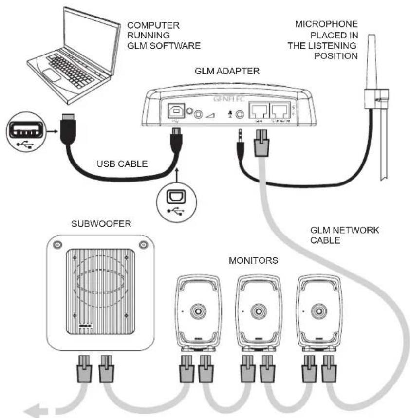
- Connect a CAT5 (RJ45) cable to each monitor (and subwoofer) and finally to the GLM Adapter device (see Figure 1).
- Connect the GLM Adapter device to computer USB connector.
flowchart
graph TD
    A["COMPUTER RUNNING GLM SOFTWARE"] --> B["USB CABLE"]
    B --> C["GLM ADAPTER"]
    C --> D["MICROPHONE PLACED IN THE LISTENING POSITION"]
    D --> E["GLM NETWORK CABLE"]
    E --> F["MONITORS"]
    F --> G["SUBWOOFER"]
Figure 1. GLM control network cabling
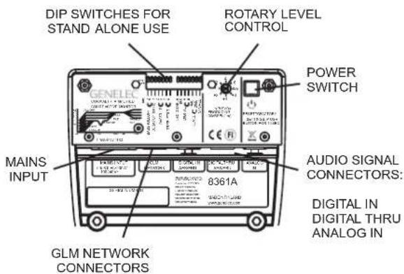
Figure 2. Connectors and controls on the back panel of a 8361A.
- Using a microphone stand, place the Genelec measurement microphone (in GLM Kit) at the listening location. Point microphone upwards. Place the microphone top at the ear height for typical listener.
- Connect the microphone to the microphone input in the GLM Adapter device.
- Download and install the GLM software at the Genelec web site (www.genelec.com). Follow instructions in the software to measure and set up your monitors.
- If you plan not to use a computer for managing monitors, store settings in monitors with GLM software (menu item "Store | Store the Current Group Settings...").

Figure 3. Connector panel detail.
Enable stored settings by turning the DIP switch "Stored" on the monitor to ON after the network has been disconnected.
The CONTROL NETWORK RJ-45 connectors are not Ethernet LAN compatible. Do not connect to Ethernet LAN.
Stand-alone Mode: Setup Without Using The GLM
You can adjust the 8361A without GLM using the controls on the back of the monitor. These stand-alone settings are limited and provide some fundamental compensations for room acoustic effects, input selections and input sensitivity. To use, disconnect the GLM management network and set the DIP switch "Stored" to OFF position.
Stand-Alone Functionality
Bass Roll-Off Control
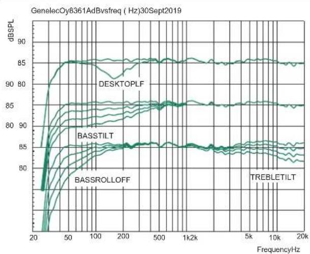
The Bass Roll-Off setting reduces bass level for spaces with strong low frequency reverberation. It reduces output near the low cut-off. Attenuation can be selected by combining settings on one or more switches.
Desktop reflection compensation
The desktop control reduces frequencies near 160 Hz by 4 dB. This compensates the boost when the monitor is placed on a meter bridge or table.
Bass Tilt Control
The Bass Tilt control offers three attenuation levels for the response below 800 Hz. This control is used when monitors are placed near wall or room corner. Attenuation can be selected by combining settings on one or more switches.
Treble Tilt Control
The Treble Tilt control adjusts the high frequencies above 5 kHz. It corrects bright or dull sound and compensates high frequency loss when a monitor is placed behind a screen.
LED Disable
This switch turns off the front panel LED light.
ISS
This switch activates and deactivates the ISS power saving function when the 8361 is used in a Stand Alone mode. The default time for going to power save mode is 60 minutes, but this can be adjusted in the GLM software.
Digital
The Digital switch selects the digital audio signals A and B carried in one AES/EBU cable. Turning on both switches reproduces the sum of the signals. When both are selected, a 6 dB attenuation is applied to avoid an overload.
Level
The Level switches reduce the monitor output in 10 dB steps (-10 dB, -20 dB and both switches -30 dB). The switches
flowchart
graph TD
    A["Central Device"] --> B["Device 1"]
    A --> C["Device 2"]
    A --> D["Device 3"]
    A --> E["Device 4"]
    A --> F["Device 5"]
    A --> G["Device 6"]
    A --> H["Device 7"]
    A --> I["Device 8"]
    style A fill:#f9f,stroke:#333
    style B fill:#ccf,stroke:#333
    style C fill:#ccf,stroke:#333
    style D fill:#ccf,stroke:#333
    style E fill:#ccf,stroke:#333
    style F fill:#ccf,stroke:#333
    style G fill:#ccf,stroke:#333
    style H fill:#ccf,stroke:#333
    style I fill:#ccf,stroke:#333
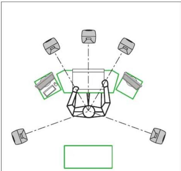
Figure 5. Symmetrical layout and keeping the acoustic axis clear from obstructions minimizes reflection surfaces and maintains accurate localisation because reflections are symmetrical.
| Monitor Mounting Position | Treble Tilt | Bass Tilt | Bass Roll-Off | Desktop |
| Flat anechoic response | None None | None None | ||
| Free standing in a damped room | None -2 | dB None None | ||
| Free standing in a reverberant room | None -4 | dB None None | ||
| Near field on a reflective surface | None -2 | dB None -4 dB | ||
| In a corner None -4 dB | -4 dB None |
Table 1. Suggested Tone Control settings for some typical monitor placement positions.
combine with the rotary level adjustment. The total adjustment range is 42 dB. GLM software enables wider level adjustment.
Stored
The Stored switch selects between the controls on the monitor back panel (OFF position) or applying the settings stored in the monitor using the GLM software (ON position).
Operating Environment
This product is designed for indoor use only. The permissible ambient temperature is 15-35 degrees Celsius (50-95°F) and relative humidity 20% to 80% (non-condensing). To prevent condensation after the product has been in a cool environment, wait at least one hour before opening the packaging and connecting the mains power.
Cooling of the 8361A must be ensured. The minimum
| Colour Indication | |
| Solid green Normal state, normal operation | |
| Blinking green GLM is interrogating the monitor | |
| Blinking green every 10 sec. Monitor is in an ISS power saving sleep state | |
| Blinking red Power amplifier overload protection is active (audio is modified because of protection) | |
| Solid red Monitor is muted | |
| Solid yellow Monitor is not in the active (playing) group | |
| Blinking yellow Overheat protection is active (audio is modified because of protection) | |
Table 2. Monitor front panel light indications summary
clearance behind, above and on both sides of the monitor is 50 mm (2 in). When 8361A is installed in a recess, the recess space must be ventilated sufficiently to remove the heat.
Mounting and Placing Monitors
Mounting Options
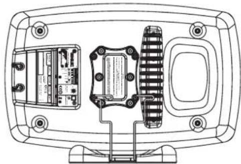
The Isolation Positioner/Decoupler™ (Iso-Pod™) stand allows tilting of the monitor and isolates vibrations. As delivered from the factory, the Iso-Pod retainer spring is attached to the bottom of the enclosure for vertical orientation. With horizontal positioning, use the separate Iso-Pod horizontal mount retainer spring (included in packaging). Use the screws in the mount retainer spring when attaching the horizontal mount retainer spring. The spring must be mounted offset towards the reflex port to bring the Iso-Pod to the enclosure centerline (See Figure 6).
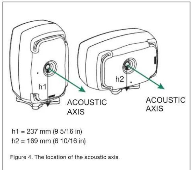
Aim the acoustic axis of the monitor towards the listening position (see Figure 4). Place monitors symmetrically and at equal distances from the listening position. Preference should be made in placing the listening position on the left-right centerline of the room (see Figure 5). If a monitor is placed far (1.0-2.2 m, 3-7 ft) from the acoustically hard wall behind the monitor, a reflection from the wall may reduce bass output. Avoid these distances.
Place monitors away from acoustically reflective surfaces. Reflections from desks, cabinets, computer monitors and such objects can colour audio and blur sound images. Place monitors on stands behind and above a mixing console as this usually improves audio compared to placing monitors on a meter bridge.
Ceiling and wall mounts are available through Genelec dealers. Monitor mounts attach to four M6 x 10 mm threaded holes on the enclosure back. Consult the Genelec Accessories Catalogue at www.genelec.com or distributor/dealer for information.
Front Panel Light
The light on the front panel is normally green. Red and yellow colours indicate special situations. See Table 2.
Use with Subwoofers
Genelec recommends 7300 series subwoofers and the W371 Adaptive Woofer System for 8361A. Consult the on-line Genelec Product Selection Tool at www.genelec.com.
natural_image
Technical line drawing of a mounted electronic device showing internal components and wiring (no text or symbols)Figure 6. Placing the Iso-Pod stand when the monitor is used in horizontal position. Note the horizontal mount retainer spring and its offset mounting towards the reflex port.
Maintenance
Do not open the monitor enclosure. Opening the monitor may lead to loss of the monitor calibration and may damage components. There are no user serviceable parts inside. Maintenance or repair can only be done by Genelec certified service.
Safety Considerations
The 8361A follows international safety standards. To ensure safe operation, the following warnings and precautions must be observed:
• Servicing and adjustment must only be performed by certified Genelec service personnel. The monitor enclosure must not be opened.
• Use the product only with a mains cable having a protective ground terminal and with a mains connection with a protective earth terminal. Failing to do so may lead to personal injury.
• To prevent fire and electric shock, do not expose the unit to water or moisture.
- Do not place objects filled with liquid, such as vases, on the monitor or near it.
• Note that the device is not disconnected from the AC mains service unless the power cable is removed from the monitor or the mains outlet.
• Free flow of air behind and around the monitor maintains sufficient cooling. Do not obstruct airflow around the monitor.
WARNING!
The 8361A is capable of producing sound pressure levels in excess of 85 dB, which may cause hearing damage. Sound exposure level integrated over eight contiguous hours should be limited to Leq=80dB(A) to reduce the risk of permanent hearing damage. For each 3 dB increase in this sound level, half this exposure time.
Guarantee
The Genelec 8361A is guaranteed for two years against manufacturing faults or defects altering performance. You can get an additional three-year guarantee covering spare part costs
by registering your product at www.genelec.com. Refer to your point of purchase for full sales and guarantee terms.
Compliance to FCC Rules
This equipment has been tested and found to comply with the limits for a Class B digital device, pursuant to part 15 of the FCC Rules. These limits are designed to provide reasonable protection against harmful interference in a residential installation. This equipment generates, uses and can radiate radio frequency energy and, if not installed and used in accordance with the instructions, may cause harmful interference to radio communications. There is no guarantee that interference will not occur in a particular installation. If this equipment does cause harmful interference to radio or television reception, which can be determined by turning the equipment off and on, the user is encouraged to try to correct the interference by one or more of the following measures:
Reorient or relocate the receiving antenna.
Increase the separation between the equipment and receiver.
Connect the equipment into an outlet on a circuit different from that to which the receiver is connected.
Consult the dealer or an experienced radio/TV technician for help.
Modifications not expressly approved by the manufacturer can void the user's authority to operate the equipment under FCC rules.
heatmap
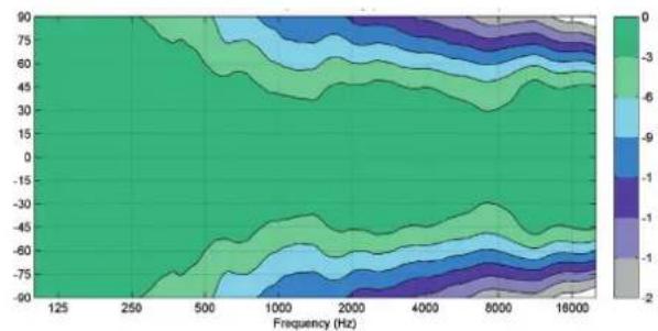
| Frequency (Hz) | 125 | 250 | 500 | 1000 | 2000 | 4000 | 8000 | 16000 | | -------------- | ----- | ----- | ----- | ----- | ----- | ----- | ----- | ----- | | 90 | -3 | -3 | -3 | -3 | -3 | -3 | -3 | -3 | | 75 | -3 | -3 | -3 | -3 | -3 | -3 | -3 | -3 | | 60 | -3 | -3 | -3 | -3 | -3 | -3 | -3 | -3 | | 45 | -3 | -3 | -3 | -3 | -3 | -3 | -3 | -3 | | 30 | -3 | -3 | -3 | -3 | -3 | -3 | -3 | -3 | | 15 | -3 | -3 | -3 | -3 | -3 | -3 | -3 | -3 | | 0 | -3 | -3 | -3 | -3 | -3 | -3 | -3 | -3 | | -15 | -3 | -3 | -3 | -3 | -3 | -3 | -3 | -3 | | -30 | -3 | -3 | -3 | -3 | -3 | -3 | -3 | -3 | | -45 | -3 | -3 | -3 | -3 | -3 | -3 | -3 | -3 | | -60 | -3 | -3 | -3 | -3 | -3 | -3 | -3 | -3 | | -75 | -3 | -3 | -3 | -3 | -3 | -3 | -3 | -3 | | 0 | 0 | 0 | 0 | 0 | 0 | 0 | 0 | 0 | | 15 | 0 | 0 | 0 | 0 | 0 | 0 | 0 | 0 | | 30 | 0 | 0 | 0 | 0 | 0 | 0 | 0 | 0 | | 45 | 0 | 0 | 0 | 0 | 0 | 0 | 0 | 0 | | 60 | 0 | 0 | 0 | 0 | 0 | 0 | 0 | 0 | | 75 | 0 | 0 | 0 | 0 | 0 | 0 | 0 | 0 | | 90 | 0 | 0 | 0 | 0 | 0 | 0 | 0 | 0 | The data is presented in a heatmap format with color intensity based on the value scale (ranging from ~-2 to ~+2). The x-axis represents frequency in Hz and the y-axis represents the corresponding value. There are no labels or additional data series in this image. The color legend indicates the value scale from ~-2 to ~+2.Figure 7. The curves above show the horizontal directivity characteristics of the 8361A (monitor in vertical orientation).
heatmap
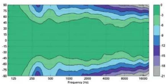
| Frequency (Hz) | 125 | 250 | 500 | 1000 | 2000 | 4000 | 8000 | 16000 | | -------------- | ----- | ----- | ----- | ----- | ----- | ----- | ----- | ----- | | 90 | -3 | -3 | -3 | -3 | -3 | -3 | -3 | -3 | | 80 | -3 | -3 | -3 | -3 | -3 | -3 | -3 | -3 | | 75 | -3 | -3 | -3 | -3 | -3 | -3 | -3 | -3 | | 70 | -3 | -3 | -3 | -3 | -3 | -3 | -3 | -3 | | 65 | -3 | -3 | -3 | -3 | -3 | -3 | -3 | -3 | | 60 | -3 | -3 | -3 | -3 | -3 | -3 | -3 | -3 | | 55 | -3 | -3 | -3 | -3 | -3 | -3 | -3 | -3 | | 50 | -3 | -3 | -3 | -3 | -3 | -3 | -3 | -3 | | 45 | -3 | -3 | -3 | -3 | -3 | -3 | -3 | -3 | | 40 | -3 | -3 | -3 | -3 | -3 | -3 | -3 | -3 | | 35 | -3 | -3 | -3 | -3 | -3 | -3 | -3 | -3 | | 30 | -3 | -3 | -3 | -3 | -3 | -3 | -3 | -3 | | 25 | -3 | -3 | -3 | -3 | -3 | -3 | -3 | -3 | | 20 | -3 | -3 | -3 | -3 | -3 | -3 | -3 | -3 | | 15 | -3 | -3 | -3 | -3 | -3 | -3 | -3 | -3 | | 10 | -3 | -3 | -3 | -3 | -3 | -3 | -3 | -3 | | 5 | -3 | -3 | -3 | -3 | -3 | -3 | -3 | -3 | | 0 | -3 | -3 | -3 | -3 | -3 | -3 | -3 | -3 | | 5 | 0 | 0 | 0 | 0 | 0 | 0 | 0 | 0 | | 10 | 0 | 0 | 0 | 0 | 0 | 0 | 0 | 0 | | 15 | 0 | 0 | 0 | 0 | 0 | 0 | 0 | 0 | | 20 | 0 | 0 | 0 | 0 | 0 | 0 | 0 | 0 | | 25 | 0 | 0 | 0 | 0 | 0 | 0 | 0 | 0 | | 30 | 0 | 0 | 0 | 0 | 0 | 0 | 0 | 0 | | 35 | 0 | 0 | 0 | 0 | 0 | 0 | 0 | 0 | | 40 | 0 | 0 | 0 | 0 | 0 | 0 | 0 | 0 | | 45 | 0 | 0 | 0 | 0 | 0 | 0 | 0 | 0 | | 50 | 0 | 0 | 0 | 0 | 0 | 0 | 0 | 0 | | 55 | 0 | 0 | 0 | 0 | 0 | 0 | 0 | 0 | | 60 | 0 | 0 | 0 | 0 | 0 | 0 | 0 | 0 | | 65 | 0 | 0 | 0 | 0 | 0 | 0 | 0 | 0 | | 70 | 0 | 0 | 0 | 0 | 0 | 0 | 0 | 0 | | 75 | 0 | 0 | 0 | 0 | 0 | 0 | 0 | 0 | | 80 | 0 | 0 | 0 | 0 | 0 | 0 | 0 | 0 | | 85 | 0 | 0 | 0 | 0 | 0 | 0 | 0 | 0 | | 90 | 0 | 0 | 0 | 0 | 0 | 0 | 0 | 0 | | ... | ... ...| ... ...| ... ...| ... ...| ... ...| ... ...| ... ...| ... ...| | ... |\n\n| ... ...| ... ...| ... ...| ... ...| ... ...| ... ...| ... ...| | ... |\n\n| ... ...| ... ...| ... ...| ... ...| ... ...| ... ...| ... ...| | ... |\n\n| ... ...| ... ...| ... ...| ... ...| ... ...| ... ...| ... ...|Figure 8. The curves above show the vertical directivity characteristics of the 8361A (monitor in vertical orientation).
line
| Frequency/Hz | DESKTOPLF | BASSTILT | BASSROLLOFF | TREBLETILT | | ------------ | --------- | -------- | ----------- | ---------- | | 20 | ~85 | ~85 | ~85 | ~85 | | 50 | ~85 | ~85 | ~85 | ~85 | | 100 | ~85 | ~85 | ~85 | ~85 | | 200 | ~85 | ~85 | ~85 | ~85 | | 500 | ~85 | ~85 | ~85 | ~85 | | 1k | ~85 | ~85 | ~85 | ~85 | | 5k | ~85 | ~85 | ~85 | ~85 | | 10k | ~85 | ~85 | ~85 | ~85 | | 20k | ~85 | ~85 | ~85 | ~85 |Figure 9. The curves above show the effect of the "Bass Tilt", "Treble Tilt", "Desktop Low Frequency" and "Bass Roll-Off" controls on the free field response of the 8361A.
line
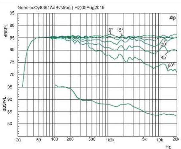
| Frequency (Hz) | 0° | 15° | 30° | 45° | 60° | | -------------- | ----- | ----- | ----- | ----- | ----- | | 20 | 95.0 | 95.0 | 95.0 | 95.0 | 95.0 | | 50 | 85.0 | 85.0 | 85.0 | 85.0 | 85.0 | | 100 | 85.0 | 85.0 | 85.0 | 85.0 | 85.0 | | 200 | 85.0 | 85.0 | 85.0 | 85.0 | 85.0 | | 500 | 85.0 | 85.0 | 85.0 | 85.0 | 85.0 | | 1k | 85.0 | 85.0 | 85.0 | 85.0 | 85.0 | | 1k2k | 85.0 | 85.0 | 85.0 | 85.0 | 85.0 | | 5k | 85.0 | 85.0 | 85.0 | 85.0 | 85.0 | | 10k | 85.0 | 85.0 | 85.0 | 85.0 | 85.0 | | 20k | 85.0 | 85.0 | 85.0 | 85.0 | 85.0 |Figure 10. Frequency responses at 0, 15, 30, 45 and 60 degree horizontal angles (monitor in vertical orientation) and power response in full space. Input level -20 dBu.
line
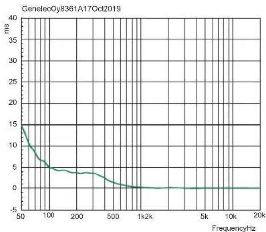
| FrequencyHz | ms | | ----------- | --- | | 50 | 15 | | 100 | 5 | | 200 | 4 | | 500 | 2 | | 1k | 0 | | 5k | 0 | | 10k | 0 | | 20k | 0 |Figure 11. The curve above shows the delay variation of the 8361A as a function of frequency.
flowchart
graph LR
    A["ANALOGUE IN"] --> B["SUM"]
    C["DIGITAL AES/EBU IN"] --> B
    D["DIGITAL AES/EBU THRU"] --> B
    B --> E["Room acoustic EQ"]
    E --> F["Phase EQ"]
    F --> G["Crossover filter"]
    G --> H["Tweeter EQ"]
    G --> I["Midrange EQ"]
    G --> J["Overload protection"]
    G --> K["Midrange amplifier"]
    G --> L["Woofer driver"]
    H --> M["Level and optional gain"]
    I --> N["Overload protection"]
    J --> O["Woofer amplifier"]
    K --> P["Tweeter driver"]
    L --> Q["Woofer driver"]
    R["GLM"] --> B
    S["Tweeter driver"] --> K
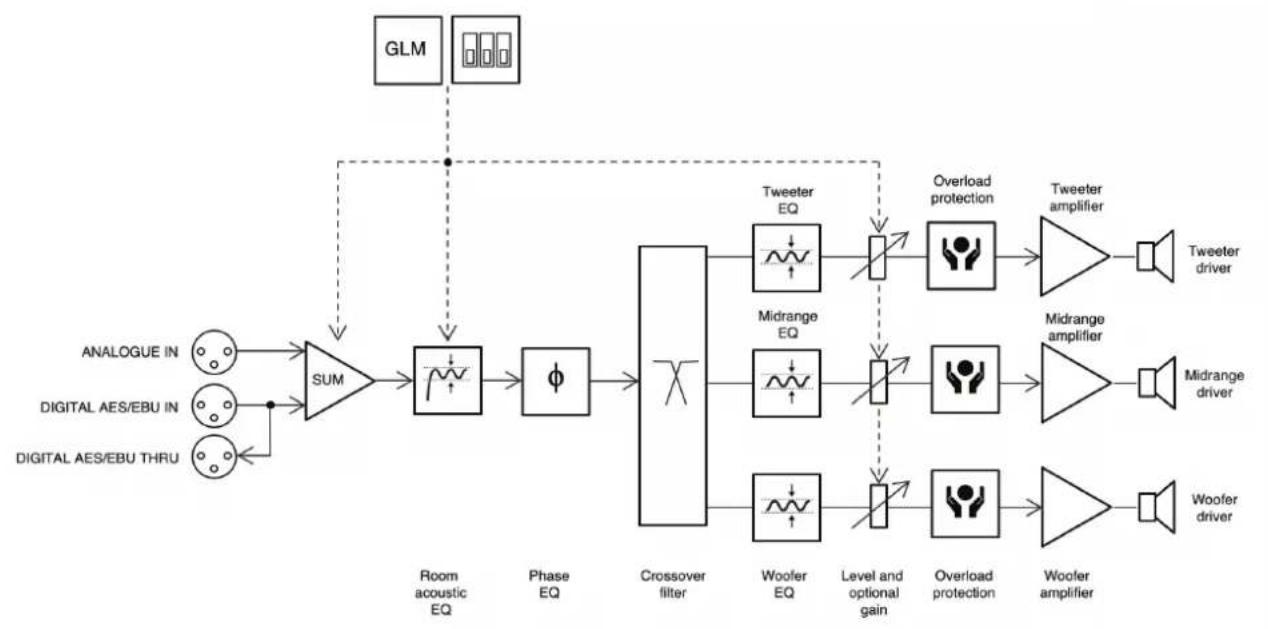
Figure 12. The signal path block diagram of the 8361A.
SYSTEM SPECIFICATIONS
| Lower cut-off frequency, -6 dB < 30 Hz | |
| Upper cut-off frequency, -6 dB >43 kHz | |
| Accuracy of frequency response, ±1.5 dB 36 Hz – 20 kHz | |
| Maximum short term sine wave acoustic output on axis in half space, averaged from 100 Hz to 3 kHz at 1 m | ≥118 dB SPL |
| Maximum long term RMS acoustic output in the same conditions with IEC weighted noise (limited by driver protection circuit) at 1 m | 109 dB SPL |
| Maximum peak acoustic output per pair in a listening room with music material at 1 m 128 dB | |
| Self generated noise level in free space at 1 m on axis (A-weighted) ≤ 5 dB | |
| Harmonic distortion at 95 dB SPL at 1 m on axisFreq: 50...100 Hz>100 Hz | <3%<0.5% |
| DriversBassMidrangeTreble | Dual 263 x 137 mm ( 10^3/_6 x 5^1/_8 in) obround cones130 mm (5 in) cone (coaxial)25 mm (1 in) metal dome (coaxial) |
| Weight 31.9 kg (70.3 lb) | |
| DimensionsHeight including IsoPod standHeight without IsoPodWidthDepth | 593 mm ( 23^3/_8 in)570 mm ( 22^7/_16 in)357 mm (14 in)347 mm ( 13^5/_8 in) |
AMPLIFIER SECTION
| Bass amplifier short term output power | 700 W |
| Midrange amplifier short term output power | 150 W |
| Treble amplifier short term output power | 150 W |
| (Long term output power is limited by driver protection circuitry) | |
| Amplifier system THD at nominal output <0.05% | |
| Mains voltage 100-240 VAC 50/60 Hz | |
| Power consumption | |
| ISS active | < 1.5 W |
| Idle | 20 W |
| Full output (short term) | 600 W |
SIGNAL PROCESSING
| 8361A | |
| Analog signal input connector XLR female, balanced 10 kOhm | pin 1 gndpin 2 non-invertingpin 3 inverting |
| Maximum analog input signalAnalog input sensitivity (100 dB SPL at 1 m)Analog input sensitivity control | +25.0 dBu-6 dBuAdjustable from +36 to -6 dBu |
| Digital signal input connector XLR female 110 OhmDigital signal output / Thru connector XLR male 110 Ohm | AES/EBU Single WireAES/EBU Single Wire |
| Digital audio inputWord lengthSample rateDigital input sensitivity (100 dB SPL at 1 m)Digital input maximum attenuation using DIP switchesDigital input maximum attenuation using GLM software | 16 - 24 bits32 - 192 kHz-30 dBFS42 dB120 dB |
| Control networkTypeConnection | Proprietary GLMTM network2 RJ45, CAT5 cables |
| Crossover frequenciesBass/MidMid/Treble | 320 Hz2800 Hz |
| GLMTMsoftware frequency response adjustment*Parametric notch filtersShelving filters | 162 LF and 2 HF |
| System room response calibration Genelec GLM AutoCalTM, GLM | TM manual, Stand-alone* |
* The notch and shelving filters adjustments, AutoCal™ and GLM™ manual system calibration features are part of the Genelec Loudspeaker Manager (GLM™) software
Genelec Document D0158R001a Copyright Genelec Oy 1.2020. All data subject to change without prior notice.
www.genelec.com
GENELEC®
International enquiries: Genelec, Ovitle 5 FIN-74100, lisalmi, Finland Phone +358 17 83881 Fax +358 17 812 267 Email genelec@genelec.com
In the U.S. please contact: Genelec, inc., 7 Tech Circle Natick, MA 01760, USA Phone +1 508 652 0900 Fax +1 508 652 0909 Email genelec.usa@genelec.com
In Sweden please contact: Genelec Sverige Ellipsvägen 10B P.O. Box 2306 S-127 02 Skärholmen Phone +46 8 449 5220 Fax +46 5 706 7071 Email info@genelec.com
In China please contact: Beijing Genelec Audio Co.Ltd B33 - 101 Universal Business Park No. 10 Jiuxianqiao Road Chaoyang District 100015 Beijing, China Phone +86 (10) 5823 2014, 400 Email genelec.china@genelec.

- Introduction
- System Characteristics
- Genelec Loudspeaker Manager™ (GLM™) Software and GLM User Kit
- Minimum Diffraction Coaxial (MDC™)
- Directivity Control Waveguide (DCW TM ) and Acoustically Concealed Woofers (ACW TM )
- Smart Active Monitoring (SAM™)
- Audio Inputs
- Power Management
- Setup Using The GLM™ Control
- Stand-alone Mode: Setup Without Using The GLM
- Stand-Alone Functionality
- Bass Roll-Off Control
- Desktop reflection compensation
- Bass Tilt Control
- Treble Tilt Control
- LED Disable
- ISS
- Digital
- Level
- Stored
- Operating Environment
- Mounting and Placing Monitors
- Mounting Options
- Front Panel Light
- Use with Subwoofers
- Maintenance
- Safety Considerations
- WARNING!
- Guarantee
- Compliance to FCC Rules
Brand : GENELEC
Model : 8361A
Category : Monitor