
S360A - Monitor GENELEC - Free user manual and instructions
Find the device manual for free S360A GENELEC in PDF.


| Product Type | Active Studio Monitor |
| Frequency Response | 36 Hz - 22 kHz (-6 dB), ±2 dB from 39 Hz to 19 kHz |
| Maximum Short-Term SPL | ≥ 118 dB SPL @ 1 m (half space, 100 Hz - 3 kHz) |
| Maximum Long-Term RMS SPL | ≥ 112 dB SPL @ 1 m (IEC weighted noise) |
| Maximum Peak SPL (per pair) | ≥ 128 dB @ 1 m (music material) |
| Self-Generated Noise | ≤ 10 dB (A-weighted @ 1 m free space) |
| Woofer | 250 mm (10 in) cone |
| Tweeter | Compression driver 44 mm (1.7 in) into 25 mm (1 in) throat |
| Dimensions (H x W x D) | 530 x 360 x 360 mm (20 7/8 x 14 3/16 x 14 3/16 in) |
| Weight | 30 kg (66 lb) |
| Mains Voltage | 100-240 VAC, 50/60 Hz |
| Power Consumption (ISS) | < 1 W |
| Power Consumption (Idle) | 11 W |
| Power Consumption (Full Output) | 230 W (short term) |
| Analog Input | Balanced XLR, 10 kOhm, max +25 dBu |
| Digital Input | AES/EBU XLR, 110 Ohm, 16-24 bit, 32-192 kHz |
| Digital Output | XLR male (thru), unaltered copy |
| Control Network | Proprietary GLM™ (RJ45, CAT5) – not Ethernet compatible |
| Crossover Frequency | 1.4 kHz |
| Stand-Alone Controls | Bass Roll-Off, Bass Tilt, Treble Tilt, Desktop 160 Hz, ISS, LED Disable, Level, Stored |
| Mounting Points | M10 threads on top/bottom and left/right sides |
| Accessories Included | Mains cable (1.8 m), GLM network cable (5 m), operating manual |
| Operating Temperature | 15-35 °C (50-95 °F) |
| Humidity | 20% to 80% (non-condensing) |
| Warranty | 2 years against manufacturing faults |
Frequently Asked Questions - S360A GENELEC
User questions about S360A GENELEC
0 question about this device. Answer the ones you know or ask your own.
Ask a new question about this device
Download the instructions for your Monitor in PDF format for free! Find your manual S360A - GENELEC and take your electronic device back in hand. On this page are published all the documents necessary for the use of your device. S360A by GENELEC.
USER MANUAL S360A GENELEC
natural_image
Black GENELEC audio drive with speaker grille and sound waves (no text or symbols on body)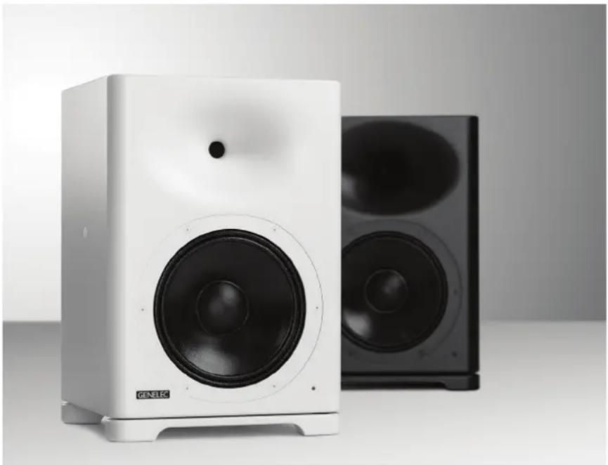
natural_image
White and black electronic speaker units with visible sound waves, one labeled 'GENELEC' (no additional text or symbols)Introduction
Congratulations and a thank you for the purchase of a Genelec Smart Active Monitor™ (SAM™) system. This manual addresses the stand-alone setup and use of the S360A monitor. SAM monitors can also be set up from a Mac or a PC using the Genelec Loudspeaker Manager GLM™ and the proprietary Genelec monitor control network, offering much more versatile acoustic settings and features. Please find more details in the separate GLM Operating Manual.
Housed in a compact, low diffraction enclosure with premium quality Finnish woodwork, the S360A features a further enhanced 10-inch high efficiency and minimal distortion woofer based on Genelec's Master Series, and an integrated extended Directivity Control Waveguide DCW™ supporting its 1-inch compression driver. A thirty-two mm (1 ¼ in) thick front baffle and critical bracing minimise panel vibration for pristine sound quality.
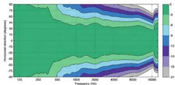
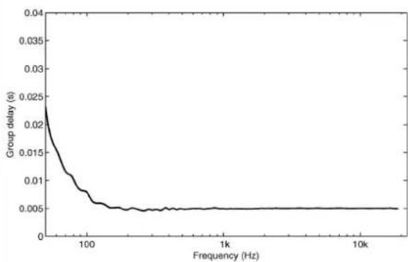
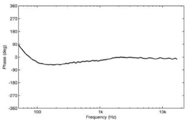
The S360A is a precision monitor with neutral and well-controlled sound characteristics on its acoustical axis, uncoloured off-axis response, and 95-degree (horizontal) to 75-degree (vertical) dispersion for accurate directivity control across the entire audio band. Like other new SAM monitors, it features constant acoustic group delay above the lowest octaves, i.e. linear phase response, without introducing latency incompatible with production requirements.
The S360A's fusion of high SPL and compact size makes it perfect for demanding film, post and music production, including play-live monitoring. In combination with a subwoofer, the S360A satisfies the demands of premium home theatres, EDM playback or Dolby film mixing even in rooms where the listening distance exceeds 10 metres (33 feet). Due to well-controlled dispersion, S360 may also be used in midfield or even nearfield applications. If doing so, please be sure first to read the Safe listening practice paragraph in this manual.
The S360A provides two pairs of enclosure mounting points, and its integrated system electronics can be placed remotely using the 2U high rack installation kit. Versatile mounting is further supported by downward-firing flow optimised laminar integrated reflex ports LIP™, also making it suitable for use in conjunction with perforated screens. To focus low frequency output while preventing vibration transfer and air turbulence, S360A includes an innovative Iso-Plate™, which effectively decouples the monitor from its base when standing. Tailor-made S360A mounting brackets for wall, ceiling, stand and truss installation may be acquired separately.
Package content
The package contains
• one S360A monitor
• one mains cable, length 1.8 m (6 ft)
• one 5 m GLM network cable
• this operating manual
System setup using GLM Control Network
Although S360A can be used without the GLM software and control network, it can only reach its full potential when set up and calibrated using the GLM software. Genelec recommends setting up SAM monitoring systems using the GLM application. Please find a more detailed description of the setup and use in the separate GLM System Operating Manual.
The GLM software can be downloaded at www.genelec.com free of charge. The necessary hardware for creating the control network - GLM Kit (order number 8300-601) - is sold separately at your Genelec dealer. The main components of the kit are the calibrated measuring microphone and the GLM Adapter, which links the computer running the software, measuring microphone and all monitors and subwoofers together.
Genelec Loudspeaker Manager GLM and the proprietary Genelec monitor control network offer automated acoustic equalization, alignment and level calibration for any reproduction system from simple stereo to very complex 3D immersive audio setups including also one or more subwoofers. GLM setup is fast and accurate. Settings can be controlled with a Mac or PC or they can be permanently stored in the monitors to make them available at all times, even when a computer is not connected.
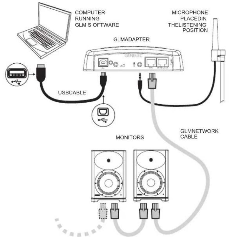
flowchart
graph TD
    A["Computer"] -->|USB CABLE| B["GLMADAPTER"]
    B -->|USB CABLE| C["MONITORS"]
    C -->|USB CABLE| D["GLMNETWORK CABLE"]
    D --> E["MICROPHONE PLACEDIN THELISTENING POSITION"]
    E --> F["Computer Running GLM SOFTWARE"]
Figure 1. GLM control network cabling
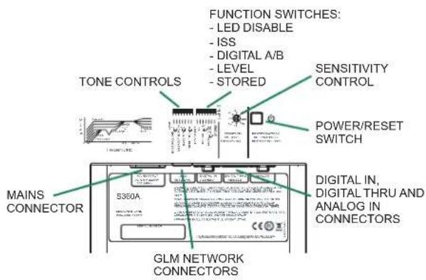
Figure 2. Connectors and local controls on the back panel of a S360A.
The setup is fast and consists of the following steps:
- Connect a CAT5 (RJ45) or higher category cable between each monitor (and subwoofer) and finally to the control network input of the GLM Adapter device (see Figure 1).
- Connect the GLM Adapter device to computer USB connector.
- Using a microphone stand, place the Genelec measurement microphone at the listening location with the microphone pointing upwards and the microphone top at the height of the engineer's ear. The microphone is a part of the GLM User Kit.
- Connect the microphone cable to the microphone input in the GLM Adapter device.
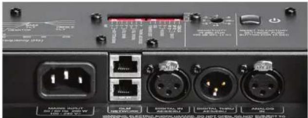
Figure 3. Connector panel detail.
- Download the GLM software at the Genelec web site (www.genelec.com).
- Install the GLM software and follow the instructions in the software to measure and set up your monitors.
- If you plan to not use a computer for controlling the monitors, use the GLM software to write the setting into the monitors (use menu item "Group | Store Group Settings").
GLM calculates the acoustic compensation for the room in a cloud computer. This enables always up-to-date methods and efficient calculation process. The Stored Settings function using the Genelec Loudspeaker Manager software can be used to store calibration settings into the monitors.
Once the GLM network is disconnected, the calibrated stored settings using the Genelec Loudspeaker Manager software can be selected in use by setting the STORED switch to the ON position found on the rear of the monitor.
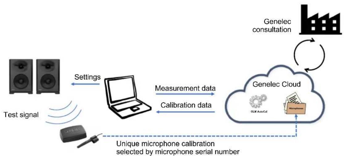
flowchart
graph TD
    A["Test signal"] --> B["Settings"]
    B --> C["Laptop"]
    C --> D["Measurement data"]
    C --> E["Calibration data"]
    D --> F["Genelec Cloud"]
    E --> F
    F --> G["Genelec consultation"]
    G --> H["Mobile phone icon"]
    H --> I["Unique microphone calibration selected by microphone serial number"]
    I --> J["Microphone with LEM AutoCell"]
    J --> K["User interface"]
Figure 4. The GLM Cloud enables the room response compensation.
| Monitor Mounting Position | Treble Tilt | Bass Tilt | Bass Roll-Off | Desktop |
| Flat anechoic response | None None | None None | ||
| Free standing in a damped room | None -2 | dB None None | ||
| Free standing in a reverberant room | None -4 | dB None None | ||
| Near field on a reflective surface | None -2 | dB None -4 | dB | |
| In a corner None -4 dB | -4 dB None |
Table 1. Suggested Tone Control settings for some typical monitor placement positions.
Interfaces
All connectors on the S360A face down, making cables easy to run into the monitor and enabling mounting close to a wall.
Connect the MAINS INPUT to the mains supply. Any mains voltage globally can be accepted (100-240 VAC, 50-60 Hz) so the monitor can be plugged in anywhere. When the mains power is provided with a generator, inverter or certain lower-quality UPS devices, we recommend filtering of the mains voltage to reduce harmonics and taking care that the voltage supply is stable.
Type RJ-45 connectors for the CONTROL NETWORK are used with Genelec Loudspeaker Manager (GLM) management network. These connectors are not Ethernet LAN compatible. Do not connect to Ethernet LAN.
The ANALOG IN connector accepts balanced analog audio signals. The maximum analogue input level is +25 dBu. The default input sensitivity is set so that for a -6 dBu input level the S360A produces 100 dB SPL sound level at one meter in free space. The analogue input impedance is 10 kOhm, so line level audio sources can drive it.
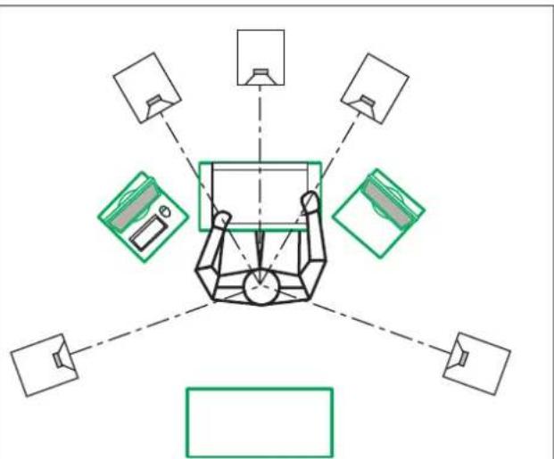
flowchart
graph TD
    A["Central Unit"] --> B["Component 1"]
    A --> C["Component 2"]
    A --> D["Component 3"]
    A --> E["Component 4"]
    A --> F["Component 5"]
    A --> G["Output Device 1"]
    A --> H["Output Device 2"]
    A --> I["Output Device 3"]
    A --> J["Output Device 4"]
Figure 5. Symmetrical layout and keeping the acoustic axis clear from obstructions minimizes reflection surfaces and maintains accurate localisation because reflections are symmetrical.
The DIGITAL IN AES/EBU female XLR connector is for AES/EBU formatted digital audio input signals. This input is selected automatically when a digital audio signal is present, even when the digital audio is silent. The analog input is reselected when the AES/EBU signal input is disconnected. The AES/EBU input supports two channels in a single cable. When the digital source controls the level, it may be advantageous to lower the level setting in the monitor's controls, which will enable a higher digital level and improved use of the digital resolution. The digital input level is referenced to 0 dBFS (dB relative to the digital full scale, the largest level that can be represented in the AES/EBU signal). The S360A sensitivity is scaled to produce 100 dB SPL sound level at one meter in free space for a digital input signal of -30 dBFS.
The DIGITAL OUT male XLR carries an unaltered copy of the digital input signal. This enables daisy-chaining with digital signal up to four monitors.
System monitoring
The S360A supports monitoring of the internal temperature, input levels and levels to the transducers, input clip, and digital audio full scale warning, and activation of the system overload protection. These can be monitored using the GLM Loudspeaker Manager software for all monitors in the monitor group.
Energy saving
Energy saving Intelligent Signal Sensing (ISS) can put the monitor automatically into a deep sleep state where the product consumes less than one watt of power. When the ISS is active you can have your monitoring system ready for action at all times. Upon sensing an input signal the monitor automatically wakes up to full operation.
Safe listening practice
The S360A is a powerful monitor so please observe safe listening habits, and be extra careful if using S360A at short listening distances.
Temporary or permanent hearing damage is caused by sound energy rather than sound power. In other words, a high sound pressure level (SPL) in itself, within reasonable limits, may not be harmful, while even a lower sound pressure, integrated with time, can be. For instance, listening to peaks of around 100 dB SPL generally do not cause damage, while listening at 90 dB SPL integrated over two hours is considered potentially harmful.
A-weighted sound pressure integrated with time is called “sound exposure” (SE), which is the best predictor of potentially harmful sound. Recent studies have shown how SE previously thought to be harmless actually is capable of generating long-term hearing loss, which may even go unnoticed for years because it does not show in standard clinical tests.
Summarising medical research, safe listening habits for adults include keeping weekly SE below 80 dB(A) for 40 hours, which is equivalent to 83 dB(A) for 20 hours, 86 dB(A) for 10 hours etc., i.e. based on an equal energy principle. Per day, assuming two days per week without significant sound exposure, the daily baseline is 80 dB(A) for 8 hours.
Using GLM, listening level may be calibrated to ensure SPL doesn't creep up over the course of a day, to make sound exposure more predictable, and to utilise S360A's power for headroom rather than elevated average listening levels. The latter is especially important when S360A is used in midfield or nearfield applications.
Acoustic considerations
Aim the monitor so that its acoustic axis points towards the listening position (see Figure 5). Vertical orientation is preferable, as this eliminates acoustical cancellation problems around the crossover frequency. Place the monitors symmetrically at equal distances from the listening position. If possible, place the listening position on the left-right centerline of the room (see Figure 5). When a monitor is placed far away (1 to 2.2 m, 3-7 ft) from the acoustically hard wall behind the monitor, an acoustic reflection from the wall may cause cancellation of low frequencies and reduce bass output.
Acoustic reflections from objects like desks, cabinets, computer monitors etc. can cause unwanted coloration and blurring of the sound image. Minimise these by placing the monitors away from acoustically reflective surfaces. Putting the monitors on stands behind and above a mixing console usually improves the response over placing monitors on a meter bridge. Symmetrical positioning of the sound reflecting objects maintains a balanced soundstage (see Figure 5).
Setup without using the GLM and Stand-Alone Control Functions
There are basic acoustic alignment control, input selection and level calibration controls on S360A. When GLM is not available, you can use the settings on the monitor for system setup. These settings are limited but provide the basic acoustical calibrations and input selection. To use this method, set the STORED switch to "OFF".
Although the S360A can be used without the GLM software and control network, they only reach their full potential when set up and calibrated using the GLM software. Genelec recommends setting up SAM monitoring systems using GLM.
Bass Roll-Off Control
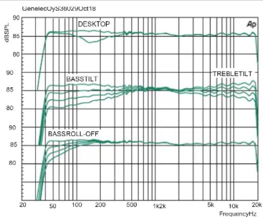
The Bass Roll-Off control attenuates the monitor's output near the cut-off frequency. Attenuation levels of -2 dB, -4 dB or -6 dB (both switches "ON") can be selected.
Desktop 160 Hz
The desktop low frequency control (switch 5) attenuates the bass frequencies around 160 Hz by 4 dB. This feature is designed to compensate for the boost often occurring at this frequency range when the monitor is placed upon a meter bridge, table or similar reflective surface.
Bass Tilt
The Bass Tilt control switches (switches 3 and 4) offer three attenuation levels for the bass response below 800 Hz, usually necessary when the monitors are placed near room boundaries. The attenuation levels are -2 dB, -4 dB and -6 dB (both switches "ON").
Treble Tilt
The Treble Tilt control allows adjusting the treble response above 2 kHz by +2 dB, -2 dB or -4 dB, which can be used for correcting an excessively bright or dull sounding system or to compensate for high frequency level loss if the monitor is placed behind a screen. The -2 dB setting is selected by turning both switches to "ON."
LED Disable
This switch shuts off the front panel LED light.
ISS
This switch activates or deactivates the ISS automatic power saving function. The default time for ISS activation is 60 minutes. The waiting time with no input signal before the monitor enters the ISS power save can be configured using the GLM software.
Digital
The Digital switch selects the digital audio channels on the AES/EBU. Turning both switches on reproduces the sum of the A and B channels. A 6 dB attenuation is applied to avoid overloading
natural_image
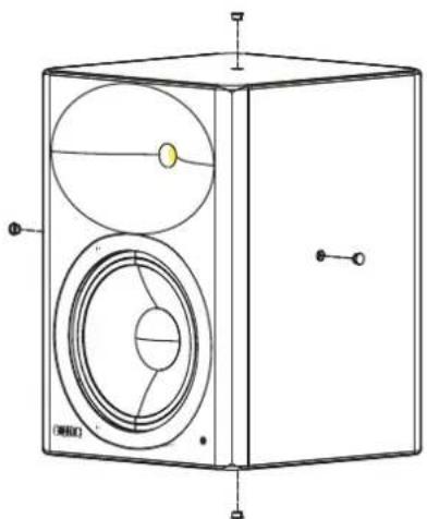
Technical line drawing of a box with circular components and mounting holes (no text or symbols)Figure 6. Mounting points on the S360A on the top/bottom and left/right side.
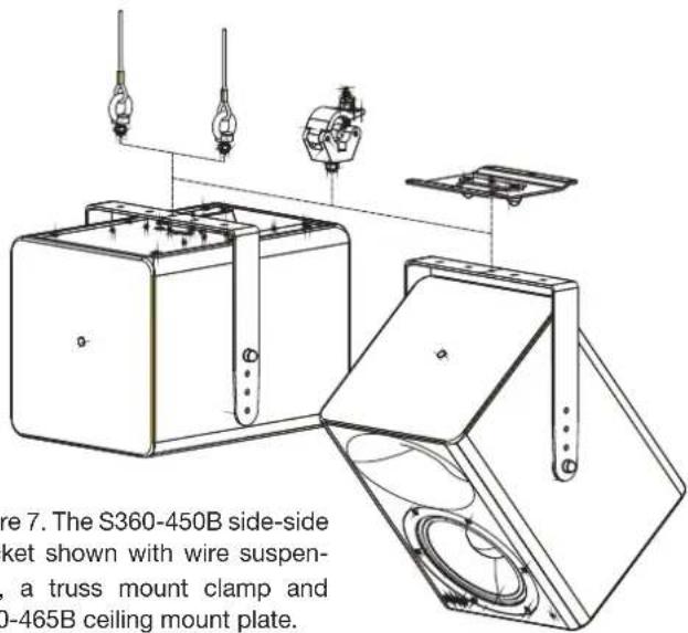
Figure 7. The S360-450B side-side bracket shown with wire suspension, a truss mount clamp and S360-465B ceiling mount plate.
| Colour Indication | |
| Solid greed | Normal state, normal operation |
| Blinking green | GLM is adjusting the monitor |
| Green blink every 10 sec. | Monitor is an ISS power saving sleep state |
| Red blink | Power amplifier overload protection is active (audio is modified because of protection) |
| Solid red | Monitor is muted |
| Yellow | Monitor is not in the active (playing) group |
| Yellow blinking | Overheat protection is active (audio is modified because of protection) |
Table 2. Monitor front panel light indications summary
the monitor. If the AES/EBU cable is operated in dual-wire mode, the monitor detects this automatically and the channel selection switches have no effect.
Level
The Level switches scale down the monitor output level in 10 dB steps. The effects of these switches add up and combine with the effect of the rotary level adjustment control. The combined total setting range is -42 dB.
Stored
The Stored switch selects the use of the controls on the monitor's back panel or the settings stored inside the monitor memory using the GLM system calibration software. Setting the Stored switch to OFF position selects the settings defined by the monitor's own rear panel controls. Setting the Stored switch to ON position selects the use of internally stored GLM settings. Using the Stored option overrides all adjustments done with the monitor's own controls.
Front Panel Light
Normally, the light on the front panel is green. Red and yellow colours are used to indicate special situations. See Table 2 for more details.
natural_image
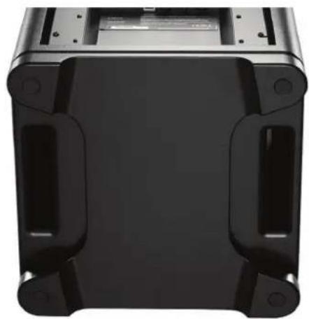
Top-down view of a black plastic electronic device casing with mounting holes and internal compartments (no text or symbols visible)Figure 8. S360A Iso-Plate™ vibration decoupling platform and the dual downward firing bass reflex ports.
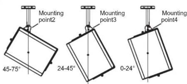
Figure 9. Ceiling mount 8000-436 used with S360-424B bracket. Note the use of different mounting points on the bracket for different tilt angles.
Operating Environment
These monitors are designed for indoor use only. The permissible ambient temperature is 15-35 degrees Celsius (50-95°F) and relative humidity 20% to 80% (non-condensing). When the product has been stored or transported in a cool environment and is taken into a warm room, to prevent condensation of humidity wait 0.5-1 hours before opening
any packing or before connecting to mains power. Sufficient cooling must be ensured. Behind, above and on both sides of the S360A monitor the minimum clearance is 50 mm (2 in). This space must be ventilated sufficiently to dissipate the heat.
Mounting and Placing Monitors
Mounting
The S360A has mounting points on the top and bottom and on the left and right sides. S360-424B top-bottom and S360-450B side-side mount brackets are available for the S360A. These are used with standard Genelec mounting accessories, offering floor stands, wall mounts, ceiling mounts and truss mounts. All mounting points on the enclosure have M10 (10 mm diameter, metric thread) threads. Correct bolts are included with the mounting brackets. The brackets have several hole pairs to allow finding the correct orientation and load balance. The S360A can be turned to point in the correct direction before the bracket bolts are tightened. The tightening torque for the attachment bolts is 10 - 20 Nm (7.4 - 14.8 lb ft).
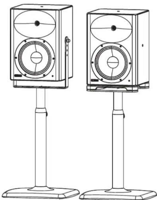
The S360-424B top-bottom mount bracket is used with the S360-444B wall mount and ceiling mount plate S360-465B. The S360-450B side-side mount bracket is used with the S360-415B floor stand and ceiling/truss mounts.
The Iso-Plate™ is detached before the mounting brackets are used. To do this, remove carefully the four rubber covers on the bottom of the Iso-Plate feet. This shows the mounting screws. Use an M6 Allen key to remove the screws and lift off the Iso-Plate. Remove the four vibration dampers bt turning them anti-clockwise. Store the Iso-Plate and other components for later use. Follow the mounting instructions for the S360A mounting brackets to attach them to the enclosure.
Flush mounting
The unique Iso-Plate vibration decoupling platform enables in-wall (flush) mounting. There are two main methods for in-wall installation.
In method one, the amplifier remains on the enclosure when the monitor is inserted into the recess. There must be sufficient ventilation in the recess space behind of the enclosure to control the temperature of the amplifier. The temperature of the adjacent air must not exceed 35 degrees Celsius (95°F.)
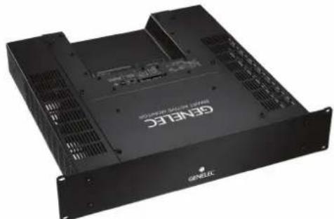
In method two, the amplifier is detached from the enclosure and placed into the 9032A rack mount kit. Then standard Speakon and RJ-45 cables connect the amplifier rack installation kit to the enclosure. The rack mount accessory takes 2U vertical space in the 19 in rack. Sufficient air flow must be ensured to avoid premature limiting of the output level. ELECTRIC SHOCK HAZARD! To ensure electric safety, the removal of the amplifier from the enclosure and its installation to the rack mount chassis may only be done by qualified Genelec service personnel.
Use with Subwoofers
Genelec recommends using the 7300 series subwoofers, particularly models 7380 and 7382 are a good match with the S360A. The S360A contains a subwoofer crossover highpass filter, which can be set between 50 and 100 Hz in 5 Hz increments. This selection is done in the GLM software and
natural_image
Exterior view of a black industrial server rack unit (no visible text or symbols)Figure 10. The S360A amplifier installed in the 9032A rack mount kit.
natural_image
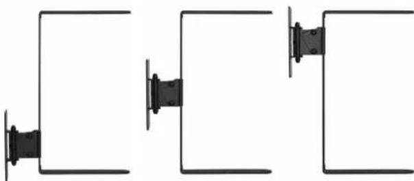
Pure electrical circuit lines without any symbolsFigure 11. The S360-424B top-bottom mount bracket for S360A can be attached to the S360-444B wall mount at different mounting points.
natural_image
Line drawing of two identical electronic speakers standing upright, no text or symbols presentFigure 12. Left: S360-450B side-side mount bracket used with S360-415B floor stand. Note the removed Iso-Plate. Right: The S360-408B stand plate used with the floor stand, in which case the Iso-Plate remains attached.
enables easy integration with the 7300 series subwoofers and precise room acoustic compensations. For more detailed system configuration and matching products, please consult the on-line Genelec Product Selection Tool, Monitor Setup Guide booklet and Immersive Solutions brochure at www.genelec.com.
Maintenance
There are no user serviceable parts inside the monitor. Maintenance or repair must only be done by a Genelec certified service.
Accessories
Up to date information about Genelec accessories can be found in the Accessories Catalogue which is available on Genelec's website www.genelec.com.
Safety Considerations and warnings
The S360A has been designed in accordance with international safety standards. To ensure safe operation and to maintain the monitor under safe operating conditions, the following warnings and precautions must be observed:
- Servicing and adjustment must only be performed by a certified Genelec service. No part of the monitor enclosure may be opened.
- Do not use this product with a mains outlet or mains power cord without the protective earth contact as this may lead to personal injury.
- To prevent fire or electric shock, do not expose the unit to water or moisture.
- Do not place any objects filled with liquid, such as vases, on the monitor or near it.
- Note that the amplifier is not completely disconnected from the mains power unless the mains power cord is removed from the amplifier or the mains outlet.
- Free flow of air behind the monitor is necessary to maintain sufficient cooling. Do not obstruct airflow around the monitors.
way in excess of 85 dB SPL and to cause instant, permanent hearing damage. Please do not stand close without hearing protection when the unit is powered.
Guarantee
Genelec S360A is guaranteed for two years against manufacturing faults or defects altering performance. Refer to the reseller for full sales and guarantee terms.
Compliance to FCC Rules
Note: This equipment has been tested and found to comply with the limits for a Class B digital device, pursuant to part 15 of the FCC Rules. These limits are designed to provide reasonable protection against harmful interference in a residential installation. This equipment generates, uses and can radiate radio frequency energy and, if not installed and used in accordance with the instructions, may cause harmful interference to radio communications.
However, there is no guarantee that interference will not occur in a particular installation. If this equipment does cause harmful interference to radio or television reception, which can be determined by turning the equipment off and on, the user is encouraged to try to correct the interference by one or more of the following measures:
- Reorient or relocate the receiving antenna.
- Increase the separation between the equipment and receiver.
- Connect the equipment into an outlet on a circuit different from that to which the receiver is connected.
- Consult the dealer or an experienced radio/TV technician for help.
Modifications not expressly approved by the manufacturer could void the user's authority to operate the equipment under FCC rules.
These monitors are capable of producing sound pressure levels
Product Data and Measurements
line
| FrequencyHz | DESKTOP | BASSTILT | TREBLETILT | BASSROLL-OFF | | ---------- | ------- | -------- | ---------- | ------------ | | 20 | 85 | 85 | 85 | 85 | | 50 | 90 | 87 | 86 | 86 | | 100 | 90 | 87 | 86 | 86 | | 200 | 90 | 87 | 86 | 86 | | 500 | 90 | 87 | 86 | 86 | | 1k | 90 | 87 | 86 | 86 | | 5k | 90 | 87 | 86 | 86 | | 10k | 90 | 87 | 86 | 86 | | 20k | 90 | 87 | 86 | 86 |Figure 12. The curves above show the effect of the "Bass Tilt", "Treble Tilt", "Desktop Low Frequency" and "Bass Roll-Off" controls on the free field response of the S360A.
line
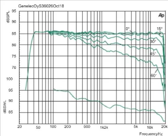
| FrequencyHz | dBSPL (0°) | dBSPL (15°) | dBSPL (45°) | dBSPL (60°) | | ----------- | ---------- | ----------- | ----------- | ----------- | | 20 | 95 | 95 | 95 | 95 | | 50 | 65 | 65 | 65 | 65 | | 100 | 65 | 65 | 65 | 65 | | 200 | 65 | 65 | 65 | 65 | | 500 | 65 | 65 | 65 | 65 | | 1k2k | 65 | 65 | 65 | 65 | | 5k | 65 | 65 | 65 | 65 | | 10k | 65 | 65 | 65 | 65 | | 20k | 65 | 65 | 65 | 65 |Figure 13. Frequency responses at 0, 15, 30, 45 and 60 degree horizontal angles and power response in full space. Input level -20 dBu.
area
| Frequency (Hz) | Horizontal direction (degrees) | |---|---| | 125 | -90 | | 250 | -75 | | 500 | -60 | | 1000 | -45 | | 2000 | -30 | | 4000 | -15 | | 8000 | -5 | | 16000 | 0 |Figure 14. The curves above show the horizontal directivity characteristics of the S360A.
heatmap
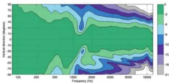
| Frequency (Hz) | 125 | 250 | 500 | 1000 | 2000 | 4000 | 6000 | 8000 | 16000 | | -------------- | ----- | ----- | ----- | ----- | ----- | ----- | ----- | ----- | ----- | | Vertical direction (degrees) | -90 | -75 | -60 | -45 | -30 | -15 | 0 | 15 | 30 | | Vertical direction (degrees) | -75 | -60 | -45 | -30 | -15 | 0 | 15 | 30 | 45 | | Vertical direction (degrees) | -60 | -45 | -30 | -15 | 0 | 15 | 30 | 45 | 60 | | Vertical direction (degrees) | -45 | -30 | -15 | 0 | 15 | 30 | 45 | 60 | 75 | | Vertical direction (degrees) | -30 | -15 | 0 | 15 | 30 | 45 | 60 | 75 | 90 | | Vertical direction (degrees) | -15 | 0 | 15 | 30 | 45 | 60 | 75 | 90 | 105 | | Vertical direction (degrees) | 0 | 15 | 30 | 45 | 60 | 75 | 90 | 105 | 120 | | Vertical direction (degrees) | 15 | 30 | 45 | 60 | 75 | 90 | 105 | 120 | 135 | | Vertical direction (degrees) | 30 | 45 | 60 | 75 | 90 | 105 | 120 | 135 | 150 | | Vertical direction (degrees) | 45 | 60 | 75 | 90 | 105 | 120 | 135 | 150 | 165 | | Vertical direction (degrees) | 60 | 75 | 90 | 105 | 120 | 135 | 150 | 165 | 180 | | Vertical direction (degrees) | 75 | 90 | 105 | 120 | 135 | 150 | 165 | 180 | 195 | | Vertical direction (degrees) | 90 | 105 | 120 | 135 | 150 | 165 | 180 | 195 | 210 | The chart displays a contour plot of the vertical distribution of values across frequency bands. Values are labeled as integers from -90 to +90. The color scale ranges from -21 to +21, indicating the magnitude of the measured variable at each frequency band. The label 'Vertical direction (degrees)' appears in the top-left corner.Figure 15. The curves above show the vertical directivity characteristics of the S360A.
line
| Frequency (Hz) | Group delay (s) | | -------------- | --------------- | | 10 | 0.025 | | 100 | 0.008 | | 1k | 0.005 | | 10k | 0.005 |Figure 16. The curve above shows the group delay of the S360A as a function of frequency.
line
| Frequency (Hz) | Phase (deg) | | -------------- | ----------- | | 10 | 90 | | 100 | -90 | | 1k | -5 | | 10k | 0 |Figure 17. The curve above shows the phase response of the S360A as a function of frequency.
line
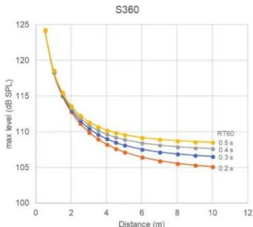
| Distance (m) | RT60 0.5 s | RT60 0.4 s | RT60 0.3 s | RT60 0.2 s | | ------------ | ---------- | ---------- | ---------- | ---------- | | 0 | 124.0 | 124.0 | 124.0 | 124.0 | | 1 | 118.0 | 117.5 | 117.0 | 116.5 | | 2 | 114.0 | 113.5 | 113.0 | 112.5 | | 3 | 111.5 | 111.0 | 110.5 | 110.0 | | 4 | 110.0 | 109.5 | 109.0 | 108.5 | | 5 | 109.0 | 108.5 | 108.0 | 107.5 | | 6 | 108.5 | 108.0 | 107.5 | 107.0 | | 7 | 108.0 | 107.5 | 107.0 | 106.5 | | 8 | 107.5 | 107.0 | 106.5 | 106.0 | | 9 | 107.0 | 106.5 | 106.0 | 105.5 | | 10 | 106.5 | 106.0 | 105.5 | 105.0 |Figure 18. The maximum short-term SPL of the S360A as a function of distance and the monitoring room reverberation time RT60.
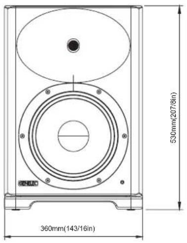
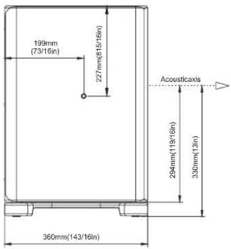
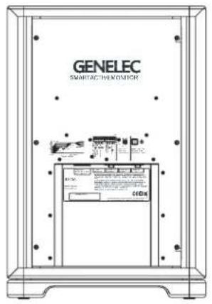
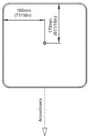
Figure 20. The dimensions of the S360A and locations of the acoustic axis and mounting points.
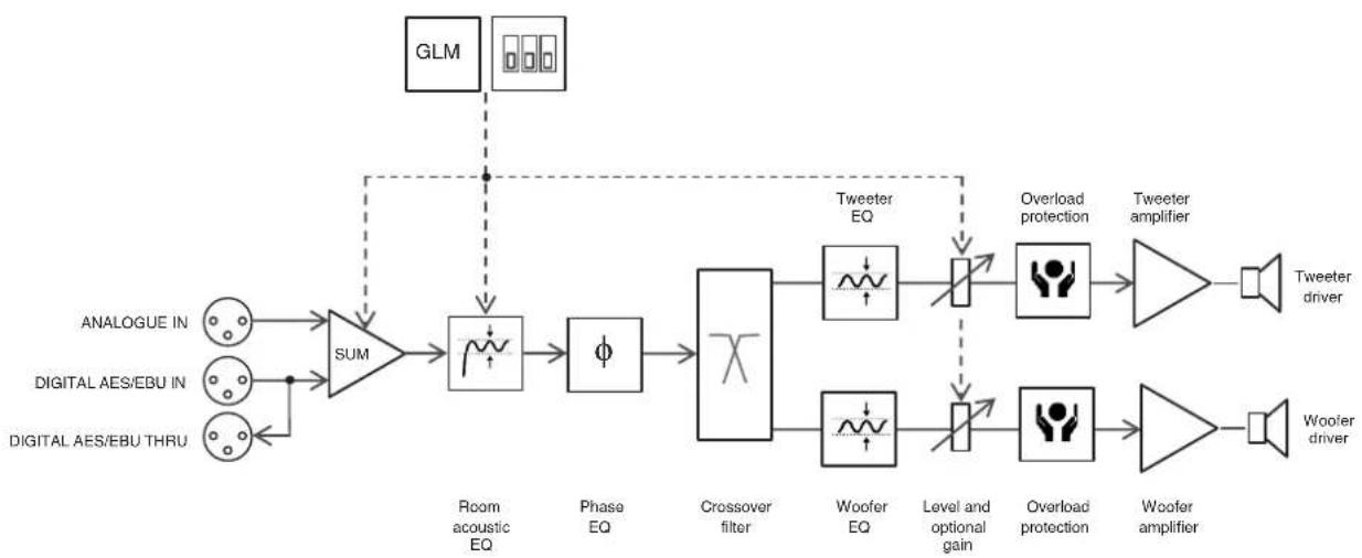
flowchart
graph LR
    A["ANALOGUE IN"] --> B["SUM"]
    C["DIGITAL AES/EBU IN"] --> B
    D["DIGITAL AES/EBU THRU"] --> B
    B --> E["Room acoustic EQ"]
    E --> F["Phase EQ"]
    F --> G["Crossover filter"]
    G --> H["Tweeter EQ"]
    G --> I["Woofer EQ"]
    H --> J["Overload protection"]
    I --> K["Level and optional gain"]
    J --> L["Tweeter amplifier"]
    K --> M["Overload protection"]
    L --> N["Woofer amplifier"]
    O["GLM"] --> P["Sum"]
    P --> E
    Q["Tweeter driver"] --> R["Speaker"]
    S["Woofer driver"] --> T["Speaker"]
Figure 21. The signal path block diagram of the S360A.
| SYSTEM SPECIFICATIONS | |
| S360A | |
| Lower cut-off frequency, -6 dB ≤ 36 Hz | |
| Upper cut-off frequency, -6 dB ≥ 22 kHz | |
| Accuracy of frequency response, ± 2.0 dB 39 Hz - 19 kHz | |
| Maximum short term sine wave acoustic output on axis in half space, averaged from 100 Hz to 3 kHz at 1 m | ≥ 118 dB SPL |
| Maximum long term RMS acoustic output in the same conditions with IEC weighted noise (limited by driver protection circuit) at 1 m | ≥ 112 dB SPL |
| Maximum peak acoustic output per pair in a listening room with music material at 1 m | ≥ 128 dB SPL |
| Self generated noise level in free space at 1 m on axis (A-weighted) ≤ 10 dB | |
| Harmonic distortion at 95 dB SPL at 1 m on axisFreq: 50...100 Hz100 Hz...5 kHz>5 kHz | < 1 %< 0.5 %< 1.5 % |
| DriversBassTreble | 250 mm (10 in) coneCompression driver 44 mm (1.7 in) into a 25 mm (1 in) throat |
| Weight 30 kg (66 lb) | |
| DimensionsHeightWidthDepth | 530 mm ( 20^7/_8 in)360 mm ( 14^3/_16 in)360 mm ( 14^3/_16 in) |
| AMPLIFIER SECTION | |
| S360A | |
| Bass amplifier short term output powerTreble amplifier short term output power(Long term output power is limited by driver protection circuitry) | 250 W100 W |
| Amplifier system THD at nominal output <0.01% | |
| Mains voltage 100-240 VAC 50/60 Hz | |
| Power consumptionISS activeIdleFull output (short term) | < 1 W11 W230 W |
| SIGNAL PROCESSING SECTION | |
| S360A | |
| Analog signal input connector XLR female, balanced 10 kOhm | pin 1 gndpin 2 non-inverting, pin 3 inverting |
| Maximum analog input signal | +25.0 dBu |
| Analog input sensitivity (100 dB SPL at 1 m) | -6 dBu |
| Analog input gain selection | 0, +6, +12, +18 dB |
| Digital signal input connector XLR female 110 Ohm | AES/EBU Single Wire |
| Digital signal output / Thru connector XLR male 110 Ohm | AES/EBU Single Wire |
| Digital audio input | |
| Word length | 16 - 24 bits |
| Sample rate | 32 - 192 kHz |
| Digital input sensitivity (100 dB SPL at 1 m) | -30 dBFS |
| Digital input gain selection | 0, +6, +12, +18 dB |
| Control network | |
| Type | Proprietary GLMTM network |
| Connection | 2 RJ45, CAT5 cables |
| Crossover frequency 1.4 kHz | |
| GLMTM software frequency response adjustment* | |
| Parametric notch filters | 16 |
| Shelving filters | 2 LF and 2 HF |
| System room response calibration Genelec GLM AutoCalTM, GLM manual, Stand-alone* | |
* The notch and shelving filters adjustments, AutoCal™ and GLM™ manual system calibration features are part of the Genelec Loudspeaker Manager (GLM™) software
Genelec Document D0152R001 Copyright Genelec Oy 11.2018. All data subject to change without prior notice.
GENELEC®
International enquiries:
Genelec, Ovltle 5
FIN-74100, lisalmi, Finland
Phone +358 17 83881
Fax +358 17 812 267
Email genelec@genelec.com
In the U.S. please contact: Genelec, Inc., 7 Tech Circle Natick, MA 01760, USA Phone +1 508 652 0900 Fax +1 508 652 0909 Email genelec.usa@genelec.com
In Sweden please contact: Genelec Sverige Ellipsvägen 10B P.O. Box 2306 S-127 02 Skärholmen Phone +46 8 449 5220 Fax +46 8 708 7071 Email info@genelec.com
www.genelec.com
In China please contact:
Beijing Genelec Audio Co.Ltd
B33 - 101
Universal Business Park
No. 10 Jiuxianqiao Road
Chaoyang District
100015 Beijing, China
Phone +86 (10) 5823 2014, 400 700 1978
Email genelec.china@genelec.com

- Introduction
- Package content
- System setup using GLM Control Network
- Interfaces
- System monitoring
- Energy saving
- Safe listening practice
- Acoustic considerations
- Setup without using the GLM and Stand-Alone Control Functions
- Bass Roll-Off Control
- Desktop 160 Hz
- Bass Tilt
- Treble Tilt
- LED Disable
- ISS
- Digital
- Level
- Stored
- Front Panel Light
- Operating Environment
- Mounting and Placing Monitors
- Mounting
- Flush mounting
- Use with Subwoofers
- Maintenance
- Accessories
- Safety Considerations and warnings
- Guarantee
- Compliance to FCC Rules
- Product Data and Measurements
- GENELEC®
Brand : GENELEC
Model : S360A
Category : Monitor