
HD I/O - Hi-Fi System Avid - Free user manual and instructions
Find the device manual for free HD I/O Avid in PDF.


| Product Type | Multi-channel digital audio interface for Pro Tools|HD and Pro Tools|HD Native systems |
| Analog I/O | Up to 16 channels (8 x 8 x 8, 16 x 16 analog, or 16 x 16 digital configurations) |
| Digital I/O | Up to 16 channels via AES/EBU, TDIF, or Optical (ADAT/S/MUX) |
| Supported Sample Rates | 44.1, 48, 88.2, 96, 176.4, 192 kHz |
| Bit Depth | 24-bit |
| Analog Input Connectors | Two DB-25 female: +4 dBu balanced and -10 dBV balanced |
| Analog Output Connectors | One DB-25 female: +4 dBu balanced |
| Digital I/O Connectors (Card) | AES/EBU DB-25, TDIF DB-25, Optical (ADAT) – each 8 channels |
| Enclosure Digital I/O | AES/EBU (XLR), Optical (ADAT/S/PDIF), S/PDIF (RCA) – 2 channels each |
| Synchronization | Internal, Digital, Loop Sync, Word Clock (BNC In/Out) |
| Power Supply | 100–240 VAC, 50/60 Hz, auto-switching |
| Dimensions (approx.) | 1U rackmount, 19 x 1.75 x 12 in (48.3 x 4.4 x 30.5 cm) |
| Weight (approx.) | 10 lb (4.5 kg) |
| Included Accessories | AC power cable, 18 in DigiLink Mini cable, DigiLink to DigiLink Mini adapter, BNC cable, HD I/O Guide, Health and Safety Guide |
| Front Panel Indicators | Power LED ring, sample rate LEDs, sync mode LEDs, Loop Master LED, 16-channel 4-segment LED meters |
| Expandability | 4 bays for optional HD I/O AD, DA, or Digital Expansion cards |
| Analog Input Limiting | Soft Clip (4 dB headroom) and Curv (soft-knee) per channel |
| Input Calibration | Individual channel input trims (screwdriver adjustable) and software calibration mode |
| Sample Rate Conversion | Real-time SRC on digital inputs (AES/EBU, ADAT, TDIF) |
| Maintenance | Clean with dry cloth; do not block ventilation; refer servicing to qualified personnel |
| Safety | Follow all instructions; do not use near water; unplug during storms; use only specified attachments |
Frequently Asked Questions - HD I/O Avid
User questions about HD I/O Avid
0 question about this device. Answer the ones you know or ask your own.
Ask a new question about this device
Download the instructions for your Hi-Fi System in PDF format for free! Find your manual HD I/O - Avid and take your electronic device back in hand. On this page are published all the documents necessary for the use of your device. HD I/O by Avid.
USER MANUAL HD I/O Avid
This guide is copyrighted ©2010 by Avid Technology, Inc., (hereafter "Avid"), with all rights reserved. Under copyright laws, this guide may not be duplicated in whole or in part without the written consent of Avid.
003, 96 I/O, 96i I/O, 192 Digital I/O, 192 I/O, 888|24 I/O, 882|20 I/O, 1622 I/O, 24-Bit ADAT Bridge I/O, AudioSuite, Avid, Avid DNA, Avid Mojo, Avid Unity, Avid Unity ISIS, Avid Xpress, AVoption, Axiom, Beat Detective, Bomb Factory, Bruno, C|24, Command|8, Control|24, D-Command, D-Control, D-Fi, D-fx, D-Show, D-Verb, DAE, Digi 002, DigiBase, DigiDelivery, Digidesign, Digidesign Audio Engine, Digidesign Intelligent Noise Reduction, Digidesign TDM Bus, DigiDrive, DigiRack, DigiTest, DigiTranslator, DINR, DV Toolkit, EditPack, Eleven, EUCON, HD Core, HD Process, Hybrid, Impact, Interplay, LoFi, M-Audio, MachineControl, Maxim, Mbox, MediaComposer, MIDI I/O, MIX, MultiShell, Nitris, OMF, OMF Interchange, PRE, ProControl, Pro Tools M-Powered, Pro Tools, Pro Tools|HD, Pro Tools LE, QuickPunch, Recti-Fi, Reel Tape, Reso, Reverb One, ReVibe, RTAS, Sibelius, Smack!, SoundReplacer, Sound Designer II, Strike, Structure, SYNC HD, SYNC I/O, Synchronous, TL Aggro, TL AutoPan, TL Drum Rehab, TL Everyphase, TL Fauxlder, TL In Tune, TL MasterMeter, TL Metro, TL Space, TL Utilities, Transfuser, Trillium Lane Labs, Vari-Fi Velvet, X-Form, and XMON are trademarks or registered trademarks of Avid Technology, Inc. Xpand! is Registered in the U.S. Patent and Trademark Office. All other trademarks are the property of their respective owners.
Product features, specifications, system requirements, and availability are subject to change without notice.
Guide Part Number 9320-65013-00 REV B 11/10
Documentation Feedback
At Avid, we are always looking for ways to improve our documentation. If you have comments, corrections, or suggestions regarding our documentation, email us at techpubs@avld.com.
contents
Chapter 1. Introduction ...... 1
HD I/O Features 1
What's Included 2
System Requirements and Compatibility 2
Registration 2
About This Guide....3
About www.avid.com....4
Chapter 2. HD I/O Overview ...... 5
HD I/O Front Panel 5
HD I/O Back Panel 7
Chapter 3. Connecting HD I/O ...... 13
Pro Tools|HD Systems.... 14
Pro Tools|HD Native Systems.... 16
Chapter 4. Configuring HD I/O in Pro Tools ...... 19
Hardware Setup 19
Configuring HD I/O 21
Using Input Trims 28
Appendix A. Adding or Removing I/O Cards 29
Removing an I/O Card.... 29
Installing an Expansion I/O Card.... 31
Appendix B. Pinout Diagrams for the DB-25 Connectors 35
Analog Output DB-25 35
Analog Input (+4 dBu) DB-25.... 35
Analog Input (-10dBV) DB-25 36
AES/EBU DB-25 36
TDIF DB-25 37
Appendix C. HD I/O Calibration Mode Instructions 39
About Calibration 39
Calibrating the HD IO 40
Switching Jumpers on the Analog Output Card 42
Appendix D. Compliance Information 43
Environmental Compliance 43
EMC (Electromagnetic Compliance) 44
Safety Compliance 45
Index 47
chapter 1
Introduction
HD I/O is a multi-channel digital audio interface designed for use with Pro Tools|HD and Pro Tools|HD Native systems. HD I/O features 24-bit analog-to-digital (A/D) and digital-to-analog (D/A) converters, and supports sample rates of up to 192 kHz.
HD I/O comes in three standard configurations:
- 8 x 8 x 8 (8 analog in, 8 analog out, and 8 digital in and out)
- 16 x 16 analog in and out
- 16 x 16 digital in and out
You can also add or remove analog (ADC and DAC) and digital cards for custom configurations.
HD I/O Features
HD I/O provides up to sixteen discrete channels of Pro Tools ^® input and output, each with a 4-segment LED meter. The total available analog and digital I/O is dependent on the configuration of Analog and Digital Expansion I/O cards installed in HD I/O.
Analog I/O
- Up to sixteen channels of 24-bit D/A and A/D converters for superior analog input and output at sample rates of 44.1 kHz, 48 kHz, 88.2 kHz, 96 kHz, 176.4 kHz, and 192 kHz with Analog In and Analog Out HD I/O cards
- Soft Clip and Curv limiting circuits to protect against clipping on analog input
Digital I/O
- Up to sixteen channels of 24-bit digital I/O, using AES/EBU, TDIF DB-25, or Optical at sample rates of 44.1kHz , 48kHz , 88.2kHz , 96kHz , 176.4kHz , and 192kHz with a Digital HD I/O card
• Real-time sample rate conversion on digital inputs with a Digital I/O card (up to sixteen channels of AES/EBU, Optical, or TDIF) - Support for S/MUX Optical for sample rates of 88.2 kHz and higher
- Support for 2 channels of S/PDIF Optical (enclosed) with sample rates of up to 96kHz
- 2 channels of AES/EBU I/O (enclosed) with support for sample rates up to 192kHz
- 2 channels of 24-bit-capable S/PDIF I/O (enclosed) with support for sample rates up to 192 kHz
Synchronization
- Loop Sync input and output for connecting additional Pro Tools|HD interfaces and peripherals
- External Clock input and output for synchronizing HD I/O with external Word Clock devices
Expandability
- Optional addition of I/O cards to expand analog or digital I/O
- Simultaneous use of multiple Pro Tools|HD audio interfaces to further expand system input and output (for more information see the Expanded Systems Guide)
What's Included
• HD I/O audio interface
- A C power cable
• DigiLink Mini cable (18 inches [0.46m])
• DigiLink to DigiLink Mini adapter cable
• BNC cable (18 inches [0.46m])
- HD I/O Guide
• Health and Safety Guide
• Registration Information Card
System Requirements and Compatibility
HD I/O requires a qualified Pro Tools|HD or Pro Tools|HD Native system.
Avid can only assure compatibility and provide support for hardware and software it has tested and approved.
For complete system requirements and a list of qualified computers, operating systems, hard drives, and third-party devices, visit:
www.avid.com/compatibility
Registration
Review the enclosed Registration Information Card and follow the instructions on it to quickly register your purchase online. By registering, you become eligible to receive the following:
• Information regarding technical support
- Software update and upgrade notices
- Limited warranty on hardware
About This Guide
This guide provides a basic overview of the HD I/O features and functionality.
For hardware installation instructions for your Pro Tools|HD system, see the Pro Tools|HD User Guide.
For hardware installation instructions for your Pro Tools|HD Native system, see the Pro Tools|HD Native User Guide.
For Pro Tools installation instructions, see the Pro Tools Installation Guide.
For additional information about using Pro Tools software, see the Pro Tools Reference Guide (in Pro Tools, choose Help > Pro Tools Reference Guide).
Conventions Used in This Guide
All of our guides use the following conventions to indicate menu choices and key commands:
| Convention Action | |
| File > Save Choose Save from the File menu | |
| Control+N Hold down the Control key and press the N key | |
| Control-click Hold down the Control key and click the mouse button | |
| Right-click Click with the right mouse button |
The names of Commands, Options, and Settings that appear on-screen are in a different font.
The following symbols are used to highlight important information:

User Tips are helpful hints for getting the most from your system.

Important Notices include information that could affect your data or the performance of your system.

Shortcuts show you useful keyboard or mouse shortcuts.

Cross References point to related sections in this guide and other Pro Tools guides.
About www.avid.com
The Avid website (www.avid.com) is your best online source for information to help you get the most out of your Pro Tools system. The following are just a few of the services and features available.
Product Registration Register your purchase online.
Support and Downloads Contact Avid Customer Success (technical support); download software updates and the latest online manuals; browse the Compatibility documents for system requirements; search the online Knowledge Base or join the worldwide Pro Tools community on the User Conference.
Training and Education Study on your own using courses available online or find out how you can learn in a classroom setting at a certified Pro Tools training center.
Products and Developers Learn about Avid products; download demo software or learn about our Development Partners and their plug-ins, applications, and hardware.
News and Events Get the latest news from Avid or sign up for a Pro Tools demo.
chapter 2
HD I/O Overview
This chapter describes the front and back panel features of the HD I/O.

See the Pro Tools|HD User Guide for hardware installation instructions for Pro Tools|HD systems. See the Pro Tools|HD Native User Guide for hardware installation instructions for Pro Tools|HD Native systems. For system additional system configuration information, see the Pro Tools Reference Guide.
HD I/O Front Panel
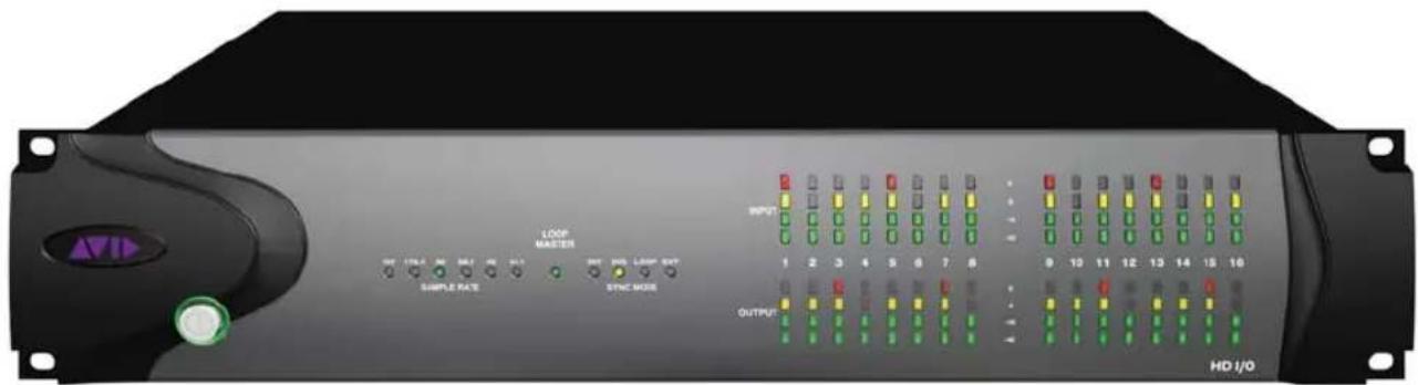
HD I/O Front Panel
Power Switch and LED Ring
This button turns the HD I/O on and off.
The LED ring around the power button will light green to indicate that the unit has powered up successfully and is connected to an active Pro Tools|HD system. If the LED ring is orange, the unit has power, but the computer it is connected to is shut down.
Sample Rate
These LEDs display the current sample rate of the HD I/O internal clock: 44.1 kHz, 48 kHz, 88.2 kHz, 96 kHz, 176.4 kHz, or 192 kHz. The sample rate can be set in Pro Tools when you create a new session, or in the Hardware Setup or Playback Engine dialogs if no session is open.
Loop Master LED
The LOOP MASTER LED indicates which Pro Tools audio interface is the master Pro Tools peripheral. The Loop Master LED will be continuously lit on the current Loop Master peripheral only, and unlit on all other peripherals. (Only one Pro Tools audio interface can be Loop Master at a time.) The Loop Master LED will always be lit with a single interface.
For Pro Tools|HD systems, Loop Master defaults to the first Pro Tools audio interface connected to the Pro Tools|HD Core card.
Sync Mode LEDs
The SYNC MODE LEDs indicate the current Clock Source as set in Pro Tools.
INT (Internal) Indicates the HD I/O sample clock is generated by its internal clock, as determined by the session Sample Rate.
DIG (Digital) Indicates that an external AES/EBU, TDIF, Optical (ADAT), Optical (ADAT S/MUX), or S/PDIF device is providing system clock. If no valid clock source is detected, HD I/O will switch to internal clock, the DIG LED will flash, and an error message will appear on-screen in Pro Tools.
LOOP Indicates that the HD I/O is slaving to another Pro Tools|HD audio interface using Loop Sync.
EXT (External) Indicates that the HD I/O is using the EXT CLOCK IN port for system synchronization.
When synchronized to Word Clock, External Clock input and output do not have to be at the Word Clock rate. EXT CLOCK IN synchronization will typically be 1x the current session sample rate. However, for sample rates higher than 48 kHz, HD I/O generates a choice of 1x, 2x, or 4x of a base rate of 44.1 kHz or 48 kHz, as follows:
| Session Sample Rate | Word Clock Support |
| 44.1 kHz 44.1 kHz | |
| 48 kHz 48 kHz | |
| 88.2 kHz 88.2 kHz | 44.1 kHz |
| 96 kHz 96 kHz | 48 kHz |
| 176.4 kHz 176.4 kHz | 44.1 kHz |
| 192 kHz 192 kHz | 48 kHz |
Meters
These four-segment LEDs indicate signal level for each of the sixteen channels. The top row of meters indicates input levels, and the bottom row shows output levels. These meters are calibrated at -42 dB, -18 dB, -6 dB, and 0 dB, respectively.

Note that 0 dB is not to be confused with clipping; use the on-screen meters in Pro Tools to determine whether a signal is clipping.
HD I/O Back Panel
The HD I/O has the following back panel features:
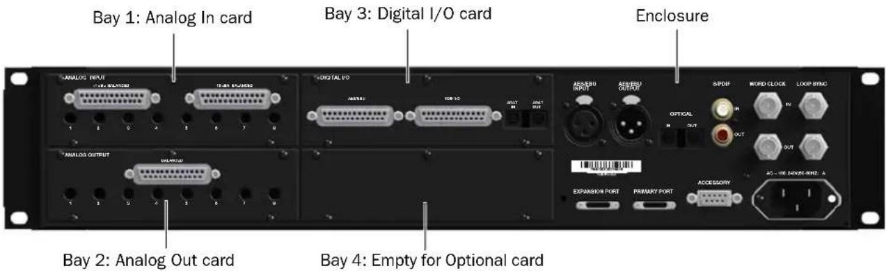
HD I/O Back Panel, 8 x 8 x 8 configuration shown
Although the HD I/O is a sixteen-channel audio interface, it has up to 94 inputs and outputs available through its various back panel connectors.
HD I/O comes in three standard configurations:
- 8 x 8 x 8 analog and digital in and out
- 16 x 16 analog in and out
- 16 x 16 digital in and out
Input and Output Cards
The HD I/O features four bays for HD I/O Expansion cards. With the standard 8 x 8 x 8 configuration, bays 1–3 contain Analog In, Analog Out, and Digital I/O cards, respectively. The fourth bay (as shown in this 8 x 8 x 8 configuration) is an expansion bay, for which you can purchase an additional Expansion I/O card of your choice.
By installing an optional AD Expansion card, DA Expansion card, or Digital Expansion card, you can add even more I/O capacity (up to a maximum possible 110 inputs and outputs). See Appendix A, "Adding or Removing I/O Cards."
A Input and Output cards for 192 I/O are not supported in HD I/O.
Analog Input

The HD I/O Analog In card contains connectors for analog audio input with 24-bit, 192 kHz A/D converters. Input is provided through two discrete DB-25 connectors (one for +4 dBu sources, and the other for -10 dBV sources). You can connect sources at both operating levels and choose between them from within Pro Tools.
+4 dBu Balanced Provides eight balanced input channels at +4 dBu nominal operating levels.
-10 dBV Balanced Provides eight balanced input channels at -10 dBV nominal operating levels.

Most consumer electronics operate at -10 dBV levels, and may not feature balanced inputs and outputs. You can connect -10 dBV signals to the -10 dBV inputs, but you will need to make sure that the negative terminals are not connected.
For wiring information, see Appendix B, "Pin-out Diagrams for the DB-25 Connectors."
For each channel, you can select input level from within the Hardware Setup dialog (see "Hardware Setup" on page 19).
Input Trims
The Input Trims below the DB-25 connectors are used to individually calibrate each channel's input level. See "Input Trims" on page 28.
Additionally, the Limiter function helps avoid digital clipping (see "Limiter" on page 24).
Analog Output
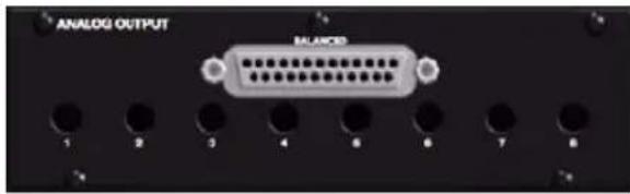
The HD I/O Analog Out card contains a single DB-25 connector and Output Trims for eight channels of analog audio output. These balanced outputs operate at +4 dBu levels. See Appendix B, "Pinout Diagrams for the DB-25 Connectors."

For -10 dBV gear, you can switch a jumper on Analog Output cards (on a channel-by-channel basis) from the default Hi position to Lo for a -6 dB pad. You can then adjust the Trim pot for the corresponding output channels by an additional -4 dB to accommodate -10 dBV gear. For more information, see Appendix C, "HD I/O Calibration Mode Instructions."
Output Trims
The Output Trims below the DB-25 connector are used to individually calibrate each channel's output level. For more information, see Appendix C, "HD I/O Calibration Mode Instructions."
Digital I/O
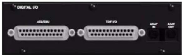
The Digital I/O card contains connectors for eight channels each of AES/EBU I/O, TDIF I/O, and Optical (ADAT) I/O. Only one digital format can be used at a time.
AES/EBU DB-25 connectors for eight channels of AES/EBU input and output. Each of the paired channels is a balanced three-conductor signal, and supports 192 kHz sample rates in single-wire mode up to eight channels. Dual-wire mode uses two HD I/O physical I/O channels of AES/EBU I/O to carry each single stream of 176.4 kHz or 192 kHz audio. Therefore, only four simultaneous channels of AES/EBU I/O are available at 176.4 kHz or 192 kHz.
TDIF DB-25 connectors for eight channels of TDIF input and output. Conforms to standard eight-channel TDIF pinouts. For more information, see Appendix B, "Pinout Diagrams for the DB-25 Connectors."

We recommend using Avid DB-25 TDIF cables for optimum compatibility.
Optical (ADAT) Dedicated, eight-channel 24-bit capable Optical ports (up to 48 kHz), with real-time sample rate conversion on input (only). Note that Optical S/PDIF is not supported with the Digital I/O card and is supported with the enclosed Optical ports only (for more information, see “Optical (ADAT) [Encl]” on page 10).
The inputs on the Digital I/O card feature real-time sample rate conversion. For example, you can stream audio with a sample rate of 44.1 kHz into a 96 kHz session.

For more information, see "Hardware Setup" on page 19.
Enclosure Connectors
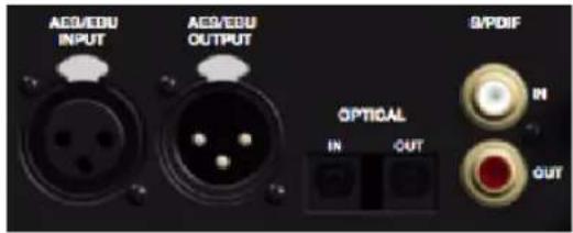
The right half of the back panel of HD I/O features a set of non-removable connectors that are mounted to the enclosure.
These connectors include two channels of AES/EBU IO, Optical I/O (for another eight channels of ADAT format, or two channels of Optical S/PDIF), and two channels of coaxial S/PDIF I/O. On-screen, these connectors are identified as AES/EBU [Encl], Optical (ADAT) [Encl], Optical (S/PDIF) [Encl], and S/PDIF [Encl].
Other connectors include Loop Sync, External Clock, and ports for attaching the HD I/O to Pro Tools|HD or Pro Tools|HD Native cards, or to other Pro Tools|HD audio interfaces.
AES/EBU [Encl]
These are balanced, three-conductor XLR connectors that accept and output a stereo, 24-bit AES/EBU audio signal. These two ports support up to 192 kHz sample rates.
Optical (ADAT) [Encl]
These Optical ports provide up to eight channels of Optical (ADAT) input and output, or two channels (stereo) optical S/PDIF input and output. Optical (ADAT) mode supports sample rates up to 48 kHz. Using S/MUX, these Optical ports support provide up to four channels of Optical S/MUX input and output at sample rates of 88.2 and 96 kHz, and up to two channels of Optical S/MUX input and output at sample rates of 176.4 and 192 kHz. In TOS-Link mode, the ports support two channels of Optical input and output at sample rates up to 96 kHz.
![Avid HD I/O - Optical (ADAT) [Encl] - 1](/content/2026/05/811135/images/839afa48a13623ba4858496c9f19bb285e85f94b60f8df1f53bbf9dffd6a23e4.jpg)
Configure HD I/O for ADAT S/MUX on the enclosed ADAT port and also on the ADAT port on the Digital I/O card to get 8 channels at 88.2/96 kHz or 4 channels at 176.4/192 kHz.
About Lightpipe-Compatible Devices
Lightpipe is an industry standard, eight-channel optical digital audio connection created by Alesis. Lightpipe is found on many devices, including Optical (ADAT) decks, modular digital multitracks (MDMs), A/D or D/A converters, S/MUX, and digital consoles.
S/PDIF Digital In and Out
These are unbalanced RCA jacks that receive and send two channels of S/PDIF audio. S/PDIF supports up to 24-bit audio, at sample rates up to 192 kHz.

To maintain data integrity and minimize jitter, use only 75-ohm coaxial cable for S/PDIF connections.
DigiLink Mini Ports

PRIMARY PORT
Use the PRIMARY PORT to connect HD I/O to your Pro Tools|HD system using a DigiLink Mini to DigiLink cable (adapter included), or to your Pro Tools|HD Native system using a DigiLink Mini cable (included with your Pro Tools|HD Native system).
The Primary port sends and receives 32 channels to and from a Pro Tools|HD card. Input and output channels 17–32 (if active) are passed through to the EXPANSION PORT.
EXPANSION PORT
The EXPANSION PORT lets you connect an additional Pro Tools|HD audio interface to HD I/O. The EXPANSION PORT passes input and output channels 17–32 to the expansion (or secondary) audio interface.
This port is only available when HD I/O is connected to a Pro Tools|HD or Pro Tools|HD Native card (it is not available when the HD I/O is connected to the Expansion Port on another audio interface).
DigiLink Mini and DigiLink Cables
Use DigiLink cables with a DigiLink to DigiLink Mini adapter cable to connect HD I/O to a Pro Tools|HD card, as well as to legacy Pro Tools|HD audio interfaces (such as 192 I/O).
Use DigiLink Mini cables to connect HD I/O to a Pro Tools|HD Native card, as well as to other Pro Tools|HD audio interfaces (such as another HD I/O or HD OMNI).
DigiLink Mini Cable Length Specifications
There are six different lengths of DigiLink Mini cables:
• 1 8 " (0.46m), included with HD I/O
• 1 2 ' (3.6m) (sold separately)
• 2 5 ' (7.62m) (sold separately)
- 50' (15.25m), the maximum length supported for 176.4 kHz and 192 kHz sessions (sold separately)
- 100' (30.5m), the maximum length supported by 88.2 kHz and 96 kHz sessions (sold separately)
DigiLink to DigiLink Mini Adapter Cables
Use DigiLink to DigiLink Mini adapter cables to connect HD I/O to Pro Tools|HD cards. You can also use DigiLink to DigiLink Mini adapter cables to connect older HD peripherals (such as 192 I/O) to the Expansion port of HD I/O.
There are two types of DigiLink to DigiLink Mini adapter cables:
- 1 2 "DigiLink female to DigiLink Mini male, included with each interface
- 12" DigiLink Mini female to DigiLink male
The DigiLink to DigiLink Mini adapter cables let you connect your HD I/O to Pro Tools|HD cards in your computer (Pro Tools|HD cards include a 12' DigiLink cable for connecting Pro Tools|HD audio interfaces). They also let you connect legacy Pro Tools|HD audio interfaces (such as the 192 I/O or the 96 I/O) to the expansion port of HD I/O (legacy Pro Tools|HD audio interfaces include an 18" DigiLink cable).

For more information about DigiLink Mini and DigiLink Mini to DigiLink cables, visit the Avid website (www.avid.com).
Clock and Synchronization Ports
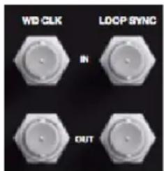
WD CLOCK IN and OUT
The Word Clock I/O ports are standard BNC connectors that receive and output word clock signal. These ports can be used to synchronize HD I/O with any word clock-capable device.
Word Clock In can be configured by selecting it as the Clock Source in the Hardware Setup dialog in Pro Tools. Word Clock Out can also be configured in the Hardware Setup dialog using the External Clock Output selector.

Because crucial timing data is passed through the Loop Sync and Word Clock ports, you should use high-quality, 75-ohm RG-59 cables for making connections.
LOOP SYNC In and Out
Loop Sync is a dedicated clock loop for synchronizing multiple Pro Tools|HD peripherals together (multiple audio interfaces, or a SYNC HD and one or more audio interfaces). Loop Sync technology lets you synchronize to any digital peripheral connected to any of the Pro Tools|HD audio interfaces in your Pro Tools system. Loop Sync uses a word clock signal based on sample rates of either 44.1 kHz or 48 kHz. As sample rate increases in the system, Loop Sync continues to operate at a base rate of 44.1 kHz or 48 kHz, depending upon the higher rate.
The Loop Sync In and Out ports are standard BNC connectors that output a 1x Word clock signal. Loop Sync should only be used to chain multiple Pro Tools|HD peripherals together (such as Pro Tools|HD audio interfaces and SYNC HD).
AC Power
This connector accepts a standard AC power cable. HD I/O is auto power-selecting (100V to 240V) and will automatically work with a standard modular cable (IEC) to connect to AC power outlets in any country.
Accessory Port
This port currently has no functionality.
chapter 3
Connecting HD I/O
You can get a full sixteen channels of analog and digital I/O with HD I/O.
Pro Tools|HD With Pro Tools|HD systems, HD I/O is connected to a Pro Tools|HD card using a DigiLink Mini to DigiLink cable. You can add additional Pro Tools|HD audio interfaces to your Pro Tools|HD system using the Expansion port on the back of HD I/O or using additional Pro Tools|HD cards. See “Pro Tools|HD Systems” on page 14.

For more information about installing Pro Tools|HD cards, see the Pro Tools|HD User Guide.
Pro Tools|HD Native With Pro Tools|HD Native systems, HD I/O is connected to the Native card using a DigiLink Mini cable. See “Pro Tools|HD Native Systems” on page 16.

For more information about installing a Pro Tools|HD Native card, see the Pro Tools|HD Native User Guide.
Rack Mounting HD Audio Interfaces
HD I/O and all Pro Tools|HD audio interfaces need room at their sides to maintain proper air flow for cooling. Do not block the sides of the unit or disconnect the internal fan. If the units are rack-mounted in a case, remove the case lids or doors before operating the system. Failure to do so can result in the units overheating very quickly, which can permanently damage sensitive components.
Pro Tools|HD Systems
To connect HD I/O to a Pro Tools|HD system:
■ Connect HD I/O Primary Port to the DigiLink Port on the first available Pro Tools|HD card with a DigiLink Mini to DigiLink cable (included with your Pro Tools|HD system).
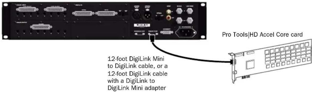
Figure 1. HD I/O connected to the DigiLink Port on a Pro Tools|HD Accel Core card (16-channel I/O system)
To connect multiple HD I/Os to a Pro Tools|HD system:
1 Connect the Primary Port of the first HD I/O to the DigiLink Port on the Pro Tools|HD Accel Core card with a DigiLink Mini to DigiLink cable (included with your Pro Tools|HD system).
2 Do one of the following:
- Connect the Primary Port of the second HD I/O to the Expansion Port on the first HD I/O with the included 18-inch DigiLink Mini cable.
- or -
- Connect the Primary Port of the second HD I/O to the next available Pro Tools|HD card with a DigiLink Mini to DigiLink cable (included with your Pro Tools|HD system).
3 Connect additional HD I/Os to additional Pro Tools|HD cards.
4 Make the necessary Loop Sync connections.
Connecting Loop Sync
If you are using two (or more) Pro Tools audio interfaces or a SYNC peripheral, Loop Sync must be connected to maintain proper clock among the devices. For an example of connecting multiple Pro Tools|HD audio interfaces, see Figure 2 below.
To make Loop Sync connections:
1 Connect (daisy-chain) the Loop Sync Out of each interface to the Loop Sync In of the next interface with the BNC cables included with your audio interface.
2 Connect the Loop Sync Out of the last interface to the Loop Sync In of the primary interface or SYNC peripheral.
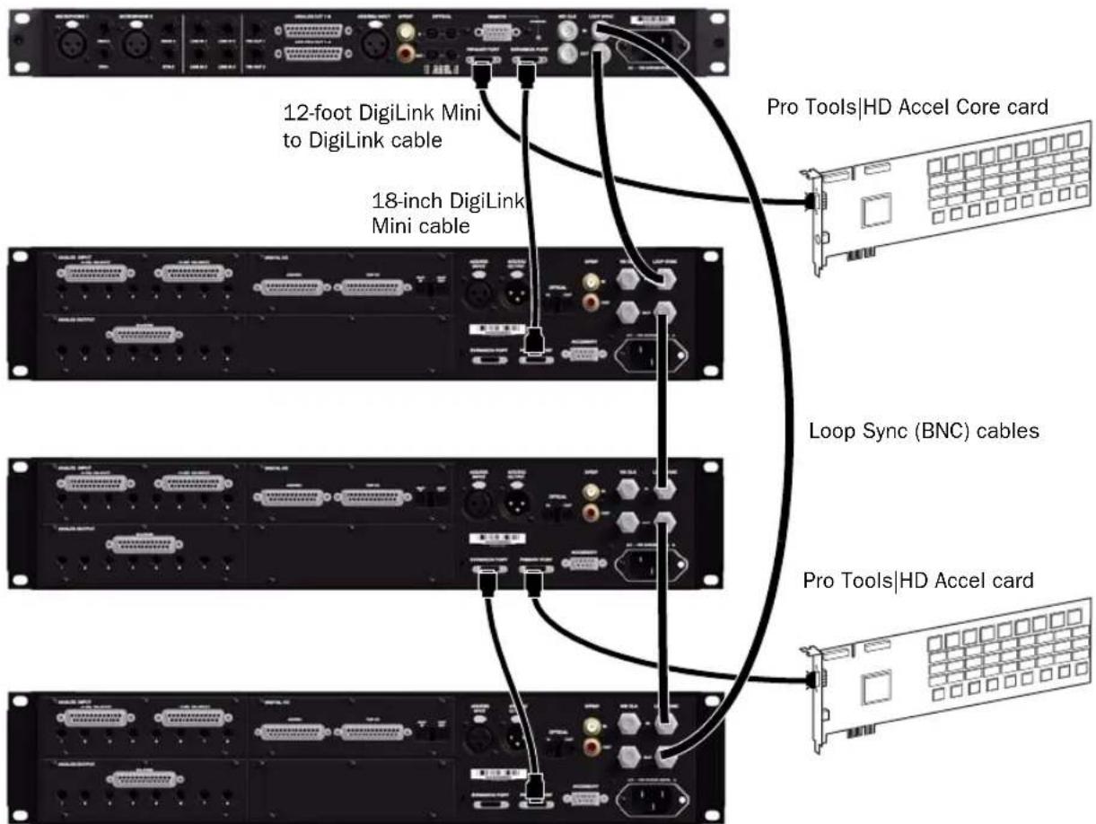
Figure 2. HD OMNI connected to the DigiLink Port on a Pro Tools|HD Accel Core card and HD I/O connected to the DigiLink Mini Expansion port on HD OMNI. A second HD I/O is connected to the DigiLink Port on a Pro Tools|HD Accel card with a third HD I/O connected to the Expansion port on the second HD I/O. Loop Sync (BNC) cables connect the HD OMNI and all three HD I/Os.
Pro Tools|HD Native Systems
To connect HD I/O to a Pro Tools|HD Native system:
- Connect HD I/O Primary Port to the DigiLink Mini Port 1 on the Pro Tools|HD Native card using the included DigiLink Mini cable.

Figure 3. HD I/O connected to the DigiLink Mini Port 1 on a Pro Tools|HD Native card
To connect two HD I/Os to a Pro Tools|HD Native system:
1 Connect the Primary Port to DigiLink Mini Port 1 on the Pro Tools|HD Native card using the included DigiLink Mini cable. You must attach at least one Pro Tools|HD audio interface to your system in order for Pro Tools to launch.
2 Connect the additional HD I/O (or other compatible Pro Tools audio interface) by doing one of the following:
- Connect the Primary Port of the secondary interface to the Expansion Port of the primary interface with an additional DigiLink Mini (or DigiLink Mini to DigiLink cable).
- or -
- Connect the Primary Port of the secondary interface to DigiLink Mini Port 2 on the Pro Tools|HD Native card.
3 Make the necessary Loop Sync connections.
Connecting Loop Sync
If you are using two Pro Tools audio interfaces or a SYNC peripheral, Loop Sync must be connected to maintain proper clock among the devices.
To make Loop Sync connections:
1 Connect the Loop Sync Out of each interface to the Loop Sync In of the next interface with the BNC cables included in your I/O packaging.
2 Connect the Loop Sync Out of the last interface to the Loop Sync In of the primary interface or SYNC peripheral.

Figure 4. DigiLink Mini and Loop Sync connections for two HD I/Os with Pro Tools|HD Native
chapter 4
Configuring HD I/O in Pro Tools
This chapter explains how to configure Pro Tools for use with HD I/O.

For more information about configuring Pro Tools, see the Pro Tools Reference Guide.
Hardware Setup
In the Hardware Setup dialog, Pro Tools lets you set the default sample rate (if no session is open) and clock source for your system, and provides access to a range of controls specific to each type of audio interface.
Default Sample Rate
The Sample Rate setting appears as the default sample rate when you create a new session. (This setting is available in the Hardware Setup dialog only when no session is open.)

You can change the sample rate when creating a new Pro Tools session by selecting a different sample rate in the New Session dialog.
To change the default Sample Rate for new sessions:
1 If a Pro Tools session is currently open, close it.
2 Choose Setup > Hardware.
3 From the Sample Rate pop-up menu, select the sample rate that you want.
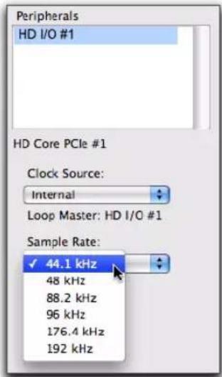
Selecting the default sample rate
4 Click OK.
High Sample Rates and Expanded Pro Tools|HD Systems
With 176.4 kHz and 192 kHz sample rates, as many as four Pro Tools|HD cards can be used. Any additional cards (up the total system maximum of seven cards) will switch to Inactive mode. The Pro Tools|HD cards and any attached peripherals will become active again when the sample rate is set to 96 kHz or lower (see the Pro Tools Expanded Systems Guide for more information).
If you have an expanded system with five or more Pro Tools|HD cards, any I/O connected to any Pro Tools|HD cards beyond the first four must be disconnected in order to operate at sample rates higher than 96 kHz.
Clock Source
The Pro Tools Hardware Setup dialog lets you set the Clock Source for the system.
Internal If you are recording an analog signal directly into Pro Tools, you will usually use the Pro Tools Internal clock source.
External If you are transferring material into Pro Tools from an external digital device, or if you utilize a common house clock signal, you will need to synchronize Pro Tools to that digital device or common signal. Depending on your audio interface configuration and the selected sample rate, external options can include:
• S/PDIF [Encl] (at all sample rates)
• Optical (S/PDIF) [Encl] (up to 96 kHz)
• AES/EBU [Encl] (at all sample rates)
- AES/EBU 1–8 (Single Wire in stereo pairs at all sample rates)
- AES/EBU 1–4 (Dual Wire) (in stereo pairs at 176.4 and 192 kHz)
• ADAT 1–8 (at 44.1 and 48 kHz)
• ADAT S/MUX 1–4 (at 88.2 and 96 kHz)
• ADAT S/MUX 1-2 (at 176.4 and 192 kHz)
• TDIF 1–8 (at 44.1 and 48 kHz)
• Optical ADAT [Encl] (at 44.1 and 48 kHz)
• Word Clock (at all sample rates)
To select the Clock Source:
1 Choose Setup > Hardware.
2 From the Clock Source pop-up menu, select the clock source.
![Peripherals HD I/O #1 HD Core PCIe #1 Clock Source: ✓ Internal AES/EBU [Encl] AES/EBU 1-2 AES/EBU 3-4 AES/EBU 5-6 AES/EBU 7-8 ADAT 1-8 TDIF 1-8 Optical (ADAT) [Encl] Word Clock (44.1kHz)](/content/2026/05/811135/images/0c3e2180e264beb36dc5e722691d8cd516ea0af8ed29b8e01b5820df37dedb91.jpg)
Selecting the Clock Source
3 Click OK.
Your digital input device must be connected and powered on for Pro Tools to synchronize to it. If your input device is not powered on, leave the Clock Source set to Internal.
Identify
If you have multiple audio interfaces of the same type connected to your system, you should confirm the identity of each interface. This ensures that you select the appropriate interface in the Peripherals list when defining its inputs and outputs, and other settings, in the Hardware Setup dialog.
To identify audio interfaces in your system:
1 Choose Setup > Hardware.
2 From the Peripherals list, select an audio interface connected to your system.

Use the Up and Down Arrow keys to scroll though the Peripherals list in the Hardware Setup dialog.
3 Select the Identify option, located in the lower left corner of the Hardware Setup dialog. This illuminates all the LEDs on the front panel of the selected audio interface.
4 Make a note of which interface in your studio setup corresponds to the identified interface.
5 Repeat the above steps for each additional audio interface in your setup.
Configuring HD I/O
To configure controls for HD I/O:
1 Choose Setup > Hardware.
2 From the Peripherals list, select the HD I/O audio interface.
3 Click the Main tab and configure the options.
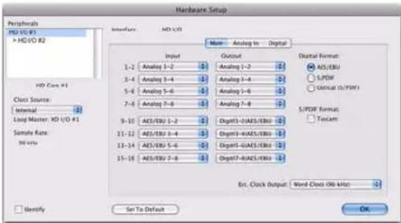
HD I/O Hardware Setup, Main page
4 If you have at least one HD I/O AD card, click the Analog In tab and configure the options. If you have two HD I/O AD cards, this tab is labeled Analog In 1–8.

HD I/O Hardware Setup, Analog In page
5 If you have two HD I/O AD cards, click the Analog In 9-16 tab and configure the options.
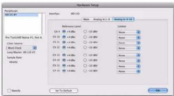
HD I/O Hardware Setup, Analog In 9-16 page
6 If you have at least one HD I/O Digital card, click the Digital tab (this is labeled Digital 1–8 if you have two HD I/O Digital card installed) and configure the options.

HD I/O Hardware Setup, Digital page

At session sample rates above 48 kHz, sample rate conversion for the TDIF and Optical (ADAT) inputs on the HD I/O Digital card is automatically enabled on all eight inputs of the selected format unless you are using S/MUX Optical.
7 If you have two HD I/O Digital cards installed, click the Digital 9–16 tab and configure the options.
8 When you are finished, click OK.
HD I/O Hardware Setup Options
HD I/O provides multiple pages of Hardware Setup options depending on the configuration.
Main Page
HD I/O supports up to sixteen channels of simultaneous input and output in multiple I/O formats (including analog, AES/EBU, ADAT Optical, S/MUX, S/PDIF, and TDIF).
The Main page of the Hardware Setup dialog is where you define which physical inputs and outputs on your audio interface are routed to available input and output channels in Pro Tools. You can think of this window as a patchbay that lets you route any of the input pairs or output pairs on your Pro Tools audio interfaces to channel assignments in the Pro Tools mixer.

HD I/O Hardware Setup, Main page (8 x 8 x 8 shown)
Input
Select the corresponding physical input pairs from the Input pop-up menu for each stereo pair of Pro Tools Input channels (1–2, 3–4, ...15–16). Which physical inputs are available depends on the sample rate and on which HD I/O Expansion cards you have installed (for example, if no HD I/O AD card is installed, no analog inputs will be available).

These settings are saved with the system, not with the session.
Output
Select the corresponding physical outputs from the Output pop-up menu for each stereo pair of Pro Tools Output channels (1–2, 3–4, ...15–16). Which physical outputs are available depends on the sample rate and on which HD I/O Expansion cards you have installed (for example, if no HD I/O DA card is installed, no analog outputs will be available). Note that these settings are saved with the system, not with the session.

Control-click (Mac) or Start-click (Windows) to select multiple Inputs or Outputs. Command-Option-click (Mac) or Control- Alt-click to cascade all Input or Output settings.
Inputs and Outputs of Similar Formats
Inputs and outputs of similar formats are differentiated in the input and output channel pop-up menus. For example, the AES/EBU inputs and outputs in the HD I/O enclosure are listed as AES/EBU [Encl], while the AES/EBU inputs and outputs on a HD I/O Digital card are listed (in pairs) as AES/EBU 1–2, AES/EBU 3–4, AES/EBU 5–6, and AES/EBU 7–8. For HD I/Os equipped with an second Digital card, the additional AES/EBU I/O ports on the optional card are listed as AES/EBU 9–10, AES/EBU 11–12, AES/EBU 13–14, and AES/EBU 15–16.
Digital Format
Select from the following digital input formats for the built-in digital I/O enclosure (configure the options for any additional HD I/O Digital cards by clicking the corresponding Digital tab):
AES/EBU Provides up to two channels of AES/EBU input.
S/PDIF Two channels of S/PDIF (coaxial) input.
Optical (S/PDIF) Two channels of S/PDIF (optical) input up to 96 kHz. This option is not available at sample rates higher than 96 kHz.
S/PDIF Format
For S/PDIF (Sony/Phillips Digital Interface Format) compatibility with Tascam DA-30 DAT recorders, select the Tascam option under S/PDIF Format.
Ext. Clock Output
If you want to send clock output to other devices attached to HD I/O, select the appropriate output from the Ext. Clock Output pop-up menu.
The available options for Ext. Clock Output change depending on the session sample rate. See the table below for a list of default external clock settings and available options.
Ext. Clock Output options by sample rate
| Sample Rate | Available Ext. Clock Default | Available Ext. Clock Option |
| 44.1 kHz Word Clock (44.1 kHz) | N/A | |
| 48 kHz Word Clock (48 kHz) | N/A | |
Ext. Clock Output options by sample rate
| Sample Rate | Available Ext. Clock Default | Available Ext. Clock Option |
| 88.2 kHz Word Clock(88.2 kHz) | Word Clock(44.1 kHz) | |
| 96 kHz Word Clock(96 kHz) | Word Clock(48 kHz) | |
| 176.4 kHz WordClock(176.4 kHz) | Word Clock(44.1 kHz) | |
| 192 kHz Word Clock(192 kHz) | Word Clock(48 kHz) | |
Analog In Page
The Analog In page of the Hardware Setup dialog lets you set the Reference Level for the physical analog inputs on HD I/O. You can also apply a limiter to each of the available analog inputs.
If you have only a single HD I/O AD Expansion card installed, a single Analog In tab is available. If you have two HD I/O AD Expansion cards installed, the tabs Analog 1–8 and Analog 9–16 are available. The Analog In, and Analog 1–8 and Analog 9–16 pages provide the same controls for the corresponding physical inputs on the HD I/O AD card. If no HD I/O AD Expansion card is installed, these tabs are not available.
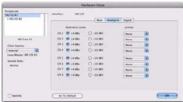
Hardware Setup, Analog In page
Reference Level
Select the appropriate Reference Level for each of the available analog input channels. This lets you select the analog audio input source on a channel-by-channel basis. The +4 dBu option routes audio from the physical +4 dBu Balanced DB-25 Analog Input port on the card. The -10 dBV option routes audio from the physical -10 dBV Balanced DB-25 Analog Input port on the card.
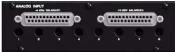
+4 dBu and -10 dBV DB-25 Analog Input ports
Limiter
HD I/O provides options for soft limiting on each of the available analog input channels. Select the desired option from the corresponding Limiter pop-up menu:
None Applies no limiting to the incoming analog signal.
Soft Clip Attenuates the incoming analog signal, providing extra protection from temporary clipping transients that can cause digital distortion when they exceed the maximum input of the unit. With Soft Clip enabled, HD I/O supports an additional 4 dB of headroom by rounding off the top 4 dB to the clip point. This is useful for eliminating stray transients.
Curv Attenuates the incoming analog signal using a soft knee limiter circuit. This guarantees super soft limiting without becoming hard, even with large overloads on input.
Digital Page
The Digital page of the Hardware Setup dialog lets you set the Input Format and Sample Rate Conversion for any Digital I/O cards installed in HD I/O.
If you have only a single Digital I/O card installed, a single Digital tab is available. If you have two HD I/O Digital Expansion cards installed, the tabs Digital 1–8 and Digital 9–16 are available. The Digital (one Digital card), or the Digital 1–8 and Digital 9–16 (two Digital cards) pages all provide the same controls for the corresponding physical inputs on the HD I/O Digital card. If no HD I/O Digital Expansion card is installed, these tabs are not available.

HD I/O Hardware Setup, Digital page

At session sample rates above 48 kHz, sample rate conversion for the TDIF and Optical (ADAT) inputs on the HD I/O Digital card is automatically enabled on all eight inputs of the selected format—unless you are using Optical (ADAT S/MUX).
Digital Format
Select from the following digital formats for the HD I/O Digital card. Depending on the sample rate, different Digital Format options are available.

HD I/O Hardware Setup, Digital Format options at 44.1 kHz
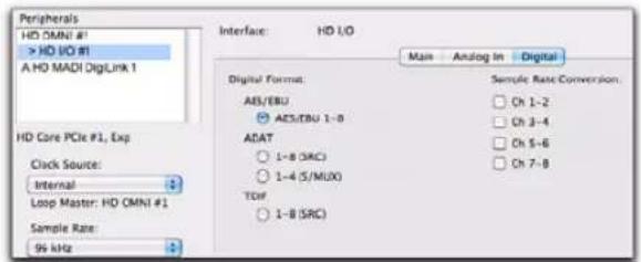
HD I/O Hardware Setup, Digital Format options at 96 kHz

HD I/O Hardware Setup, Digital Format options at 192 kHz
AES/EBU
You can select up to eight channels of AES/EBU input depending on the sample rate. At sample rates of 44.1 kHz to 96 kHz, the only option available is AES/EBU 1–8 (or AES/EBU 9–16 for the second card, if present). At sample rates of 176.4 kHz and 196 kHz, two AES/EBU options are available (Single Wire and Dual Wire modes).
AES/EBU 1–8 Enable this option for eight channels of AES/EBU input. This is the only option available at sample rates of 44.1 kHz to 96 kHz. This option is not available at higher sample rates.
AES/EBU 1–8 (Single Wire) Enable this option for eight channels of AES/EBU input. Sample Rate Conversion is available for stereo pairs when Single Wire mode is selected. This option only appears at sample rates of 176.4 kHz and 196 kHz.
AES/EBU 1–4 (Dual Wire) Enable this option for four channels of AES/EBU input at sample rates of 176.4 kHz and 196 kHz. Sample Rate Conversion is not available in Dual Wire mode. This option only appears at sample rates of 176.4 kHz and 196 kHz.
ADAT
You can select up to eight channels of ADAT input depending on the sample rate. At 44.1 kHz and 48 kHz, the only option available is ADAT 1–8 (or ADAT 9–16 for the second card, if present). At sample rates of 88.2 kHz and higher, two ADAT options are available (SRC and S/MUX).
ADAT 1–8 Enable this option for eight channels of ADAT input. This is the only option available at sample rates of 44.1 kHz and 48 kHz. This option is not available at higher sample rates.
1–8 (SRC) Enable this option for eight channels of ADAT input with automatic Sample Rate Conversion (SRC). This option only appears at sample rates of 88.2 kHz and higher. This option is not available at 44.1 kHz and 48 kHz.
1-4 (S/MUX) Enable this option for four channels of ADAT input with S/MUX (sample multiplexing). This option only appears at sample rates of 88.2kHz and 96kHz .
1–2 (S/MUX) Enable this option for two channels of ADAT input with S/MUX (sample multiplexing). This option only appears at sample rates of 176.4 kHz and 192 kHz.
TDIF
Depending on the sample rate, you can select eight channels of TDIF (Tascam Digital Input Format) input—TDIF 1–8, or TDIF 9–16 for the second card, if present—with or without automatic Sample Rate Conversion (SRC).
TDIF 1–8 Enable this option for eight channels of TDIF input. This option is only available at sample rates of 44.1 kHz and 48 kHz.
1–8 (SRC) Enable this option for eight channels of TDIF input with automatic Sample Rate Conversion. This option is only available at sample rates of 88.2 kHz and higher.
Sample Rate Conversion
Sample Rate Conversion (SRC) is independently available for AES/EBU stereo input pairs at all sample rates. When Digital Format is set to ADAT or TDIF, SRC can only be enabled or disabled for all channel inputs. Sample Rate Conversion on Input is only available for Digital I/O cards, it is not available for the enclosed digital ports.

Digital outputs do not support sample rate conversion.

Sample Rate Conversion adds latency to the input signal, so you should usually disable Sample Rate Conversion when it is not needed.

At session sample rates above 48 kHz, sample rate conversion for the TDIF and Optical (ADAT) inputs on the Digital I/O card is automatically enabled on all eight inputs of the selected format—unless you are using Optical (ADAT S/MUX).
AES/EBU
When Digital Format is set to AES/EBU, SRC can be enabled or disabled for each stereo input pairs at sample rates of 44.1 kHz to 96 kHz, and at 176.4 kHz and 192 kHz in Single Wire mode. Sample Rate Conversion is not available for AES/EBU at 176.4 kHz and 192 kHz in Dual Wire mode.
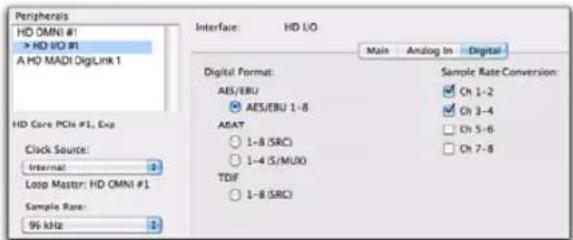
SRC enabled for AES/EBU Input channels 1–2 and 3–4 at a Sample Rate of 96 kHz
ADAT
For sample rates of 44.1 kHz and 48 kHz, when Digital Format is set to ADAT, Sample Rate Conversion can be enabled or disabled for all inputs.
ADAT (SRC)
At sample rates higher than 48 kHz, with ADAT (SRC) selected as the Digital Format, Sample Rate Conversion is enabled automatically for all input channels.
ADAT (S/MUX)
At sample rate higher than 48 kHz, with ADAT (S/MUX) selected as the Digital Format, Sample Rate Conversion can be enabled or disabled for all input channels.
TDIF
For sample rates of 44.1 kHz and 48 kHz, when Digital Format is set to TDIF, Sample Rate Conversion can be enabled or disabled for all inputs.
TDIF (SRC)
At sample rates higher than 48 kHz, with TDIF (SRC) selected as the Digital Format, Sample Rate Conversion is enabled automatically for all input channels.
Set To Default
The Set To Default button sets all settings to the factory defaults, except for the Digital Format setting in the Main page.
Using Input Trims
Input Trims

Input Trims
The Input Trims below the two DB-25 connectors on the HD I/O AD Expansion card are used to store a calibration settings for each channel. These adjustable Input Trims are for precisely calibrating the adjustable headroom settings for each channel. You can adjust each Input Trim by hand with a small screwdriver.
About Input Operating Levels
Check the manufacturer's documentation for your mixer, power amplifier, or effects processor to see if it operates more comfortably at line level, in which case consider setting the HD I/O to operate at -10 dBV line levels and adjusting the Input Trims.
Consider the following when connecting a mixer:
- If your mixer cannot handle more than 1.5V (RMS) inputs at +4 dBu, then you should set the HD I/O to operate at -10 dBV line level.
- If your mixer can handle up to 15.5V (RMS) inputs, or has pads or attenuators on its inputs, then you can use the +4 dBu setting on the HD I/O.
◆ HD I/O is calibrated at the factory for 18 dB headroom at the +4 dBu setting.
Most manuals contain device input specifications, including whether or not there are pads or attenuators. Refer to the manufacturer's documentation for your mixer or power amplifier for more information.

If you want to switch the input levels of the HD I/O from +4 dBu to -10 dBV, you can access these parameters on a channel-by-channel basis in the Hardware Setup dialog (see "Hardware Setup" on page 19).
appendix a
Adding or Removing I/O Cards
The HD I/O has four Expansion I/O bays on the back of the unit. Depending on which version of HD I/O you purchased, one, two, or none of these bays may be empty and available for additional I/O cards:
- 8 x 8 x 8: three bays are used and the fourth bay is empty.
- 16 x 16 Analog: all four bays are used.
- 16 x 16 Digital: two bays are used and two are empty.
The Expansion I/O bays let you configure HD I/O with any of the following Expansion I/O cards (each sold separately) to increase the amount of available I/O on the unit:
• HD I/O AD Expansion card
• HD I/O DA Expansion card
• HD I/O Digital Expansion card
It is important that you follow the guidelines in this chapter to avoid damaging your HD I/O or any of your I/O Expansion cards.
The factory-installed cards can be removed, if needed, for servicing, or to swap out cards for different studio setups. If you remove any of the cards from the HD I/O, the unit will continue to function as long as at least one card is installed (albeit with reduced I/O capabilities).
Legacy 192 I/O AD, DA, and Digital Option cards are not supported with HD I/O. Any attempt to install legacy 192 I/O cards will void the warranty for your HD I/O.
Removing an I/O Card
To remove an Expansion I/O card:
1 Power off and disconnect the HD I/O from your Pro Tools|HD system.
2 Make sure that the equipment is properly grounded.
Before handling any of the cards or internal components of HD I/O, discharge any static electricity by touching the outer casing of the power supply.
3 Remove all of the small Phillips-head screws around the edges of the top cover. Put the screws in a safe place.

natural_image
Close-up of a hand using a screwdriver to press or install a black electronic device (no visible text or symbols)Removing the top cover screws
4 Lift off the top panel of the HD I/O and set it aside.
5 Remove the screws on the back panel for the I/O card you want to remove.

natural_image
Close-up of hands holding a black electronic device with multiple ports and connectors (no visible text or symbols)Removing the screws securing an I/O card
6 Holding the 50-pin cable which connects the card to the HD I/O chassis firmly, gently pull the cable connector from the card's connector.

natural_image
Close-up of hands installing a circuit board with electronic components (no visible text or symbols)Removing the 50-pin cable connector from an I/O card
7 Gently remove the card, pulling it straight out from the chassis.

natural_image
Close-up of hands holding an analog output panel with connectors and a connector (no visible text or symbols on the device itself)Removing an I/O card from the HD I/O chassis
When you pull a card out, pay particular attention to keeping components on the surfaces of the card from bumping into any of the internal components or the back panel faceplate on the HD I/O.
8 Place the card in a static-free bag and keep it in a safe place (if you are not sending it to Avid for service).
9 Firmly grasp the 50-pin cable connector to the HD I/O chassis and gently pull to remove it (be sure to keep the cable in a safe place).
10 If you have a cover for the empty expansion bay, secure the cover over the empty bay with the screws you removed from the I/O card.
11 Replace the top cover on the HD I/O.
12 Replace the original screws.
Hardware Setup Changes After Removing a Card
In this case, the Hardware Setup dialog will reflect the change to the installed I/O cards. The remaining inputs and outputs will function normally.
For example, if you remove the Analog Input card, the Analog Input tab will disappear from the Hardware Setup dialog.
You will lose the configuration of any pairs of inputs or outputs that were assigned to the card being removed.
Installing an Expansion I/O Card
To install an Expansion I/O card:
1 Power off and disconnect the HD I/O from your Pro Tools|HD system.
2 Make sure that the equipment is properly grounded.
3 Remove all of the small Phillips-head screws around the edges of the top cover. Put the screws in a safe place.
4 Lift off the top of the HD I/O and set it aside.
5 If necessary, do one of the following:
- Remove the screws on the cover over the empty bay where you want to install an Expansion card.
-Or- - Remove the currently installed I/O card that you want to replace (see "Removing an I/O Card" on page 29).
6 Look into the empty bay to locate the guide rails for the card to slide in on.
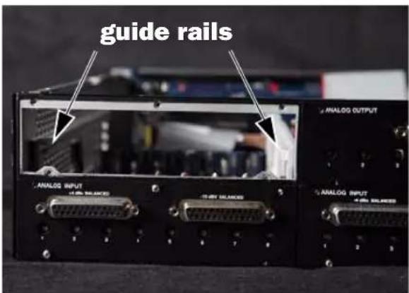
Locating guide rails along sides of empty bay
7 Remove the Expansion I/O card that you want to install from its static-free bag.
Before handling any of the cards or internal components of HD I/O, discharge any static electricity by touching the outer casing of the power supply.
8 Slide the edges of the card into the guide rails on each side of the bay.

Inserting the card into the guide rails for the empty bay
9 Gently push the card back into the bay, lifting slightly to keep components underneath the card from touching the back panel.

natural_image
Close-up of hands holding an analog output device with a 16-pin connector (no visible text or symbols on the device body)Lifting slightly while pushing the card back into the bay
10 Secure the I/O card to the back panel of the HD I/O chassis with the same screws you removed from the either the empty bay cover or from the I/O card you previously removed.

natural_image
Hand inserting into a black electronic device with visible ports and connectors (no text or symbols)Securing the I/O card to the back panel of the HD I/O
11 Locate the raised ridge in the middle of the connector on one end of the 50-pin cable that connects the I/O card to the HD I/O chassis. This ridge is only on one side of the connector, and there is a matching groove on only one side of the 50-pin connector on the chassis.
12 Gently push the cable connector into the chassis' connector. The ridge on the cable connector must line directly into the groove on the chassis connector. Be very careful not to bend any of the pins.
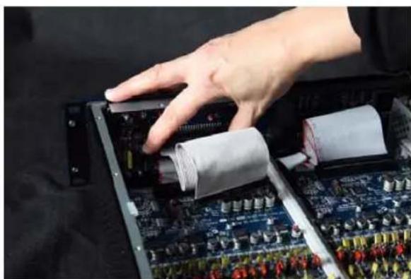
natural_image
Close-up of a hand pressing down on an electronic circuit board with rolled components (no visible text or symbols)Connecting the 50-pin cable to the HD I/O chassis
13 Locate the raised ridge in the middle of the connector on the other end of the 50-pin cable that connects the I/O card to the HD I/O chassis. This ridge is only on one side of the connector, and there is a matching groove on only one side of the 50-pin connector on the card.
14 Gently push the cable connector into the card's connector. The ridge on the cable connector must line directly into the groove on the card connector. Be very careful not to bend any of the pins or to over-stress the card.

natural_image
Close-up of a hand installing or adjusting a circuit board with a cable (no visible text or symbols)Pressing the 50-pin cable connector into the card
15 Replace the top cover on the HD I/O.
16 Replace the original screws.
17 Reconnect the HD I/O to your Pro Tools|HD system.
18 Power on the HD I/O.
19 When you power on the unit, verify that the LED ring around the power switch lights orange.
20 Start up the computer.
21 When you start the computer, verify that the power ring turns from orange to green. (If this does not occur, see "Troubleshooting" on page 34.)
22 Launch Pro Tools.
23 Open the Hardware Setup dialog to confirm that the new card is recognized:
- If you installed a Digital Expansion card, you should see a new tab called "Digital 9–16."
- If you installed an AD Expansion card, you should see a new tab called "Analog In 9–16."
24 If the new card does not appear in the Hardware Setup dialog, power down, check the seating of the card, and recheck the cable connections inside the HD I/O.
Hardware Setup Changes After Adding a Card
Any additional inputs and outputs provided by the new card will appear in the Hardware Setup dialog, with the same controls and parameters as for the original card of the same type.
For example, if you add an Analog Input card to the original three cards, a second Analog Input tab will appear in the Hardware Setup dialog. You can route these new inputs (which will in this case be called Analog Inputs 9–16) with the same controls and parameters as the factory-installed version of the card.

Whenever a card is added or removed from a HD I/O, the routing in the Hardware Setup dialog reverts to the default assignments. If you have complex routing and or mirroring in place, note the assignments and reassign the inputs and outputs after the new card has been properly identified.
Troubleshooting
- If the power ring does not turn from orange to green when you boot the computer, make sure you reconnected the DigiLink cable to the Primary port on the back of the unit.
- If the DigiLink or DigiLink Mini cable is securely fastened and the other end is plugged into a Pro Tools|HD card, you may have inadvertently disconnected another 50-pin cable when installing the card.
appendix b
Pinout Diagrams for the DB-25 Connectors
Analog Output DB-25 Analog Input (+4 dBu) DB-25
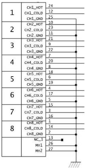
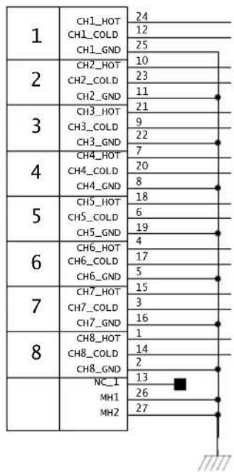
other
| Category | Value | |---|---| | 1 | CH1_HOT 24 | | 1 | CH1_COLD 12 | | 1 | CH1_GND 25 | | 2 | CH2_HOT 10 | | 2 | CH2_COLD 23 | | 2 | CH2_GND 11 | | 3 | CH3_HOT 21 | | 3 | CH3_COLD 9 | | 3 | CH3_GND 22 | | 4 | CH4_HOT 7 | | 4 | CH4_COLD 20 | | 4 | CH4_GND 8 | | 5 | CH5_HOT 18 | | 5 | CH5_COLD 6 | | 5 | CH5_GND 19 | | 6 | CH6_HOT 4 | | 6 | CH6_COLD 17 | | 6 | CH6_GND 5 | | 7 | CH7_HOT 15 | | 7 | CH7_COLD 3 | | 7 | CH7_GND 16 | | 8 | CH8_HOT 1 | | 8 | CH8_COLD 14 | | 8 | CH8_GND 2 | | NC_1 | 13 | | MH1 | 26 | | MH2 | 27 |Analog Input (-10dBV) DB-25 AES/EBU DB-25
| 1 | CH1_HOT | 24 |
| CH1_COLD | 12 | |
| CH1_GND | 25 | |
| 2 | CH2_HOT | 10 |
| CH2_COLD | 23 | |
| CH2_GND | 11 | |
| 3 | CH3_HOT | 21 |
| CH3_COLD | 9 | |
| CH3_GND | 22 | |
| 4 | CH4_HOT | 7 |
| CH4_COLD | 20 | |
| CH4_GND | 8 | |
| 5 | CH5_HOT | 18 |
| CH5_COLD | 6 | |
| CH5_GND | 19 | |
| 6 | CH6_HOT | 4 |
| CH6_COLD | 17 | |
| CH6_GND | 5 | |
| 7 | CH7_HOT | 15 |
| CH7_COLD | 3 | |
| CH7_GND | 16 | |
| 8 | CH8_HOT | 1 |
| CH8_COLD | 14 | |
| CH8_GND | 2 | |
| NC_1 | 13 | |
| MH1 | 26 | |
| MH2 | 27 |
| 1-2RCV | CH12_RCV_HOT | 24 |
| CH12_RCV_COLD | 12 | |
| CH12_RCV_GND | 25 | |
| 3-4RCV | CH34_RCV_HOT | 10 |
| CH34_RCV_COLD | 23 | |
| CH34_RCV_GND | 11 | |
| 5-6RCV | CH56_RCV_HOT | 21 |
| CH56_RCV_COLD | 9 | |
| CH56_RCV_GND | 22 | |
| 7-8RCV | CH78_RCV_HOT | 7 |
| CH78_RCV_COLD | 20 | |
| CH78_RCV_GND | 8 | |
| 1-2XMT | CH12_XMT_HOT | 18 |
| CH12_XMT_COLD | 6 | |
| CH12_XMT_GND | 19 | |
| 3-4XMT | CH34_XMT_HOT | 4 |
| CH34_XMT_COLD | 17 | |
| CH34_XMT_GND | 5 | |
| 5-6XMT | CH56_XMT_HOT | 15 |
| CH56_XMT_COLD | 3 | |
| CH56_XMT_GND | 16 | |
| 7-8XMT | CH78_XMT_HOT | 1 |
| CH78_XMT_COLD | 14 | |
| CH78_XMT_GND | 2 | |
| NC_1 | 13 | |
| MH1 | 26 | |
| MH2 | 27 |
TDIF DB-25

appendix c
HD I/O Calibration Mode Instructions
Before you use HD I/O, you may want to calibrate its input and output levels to the level of your mixing console.
The HD I/O has +4 dBu and -10 dBV inputs, and +4 dBu outputs, each with its own trim pot for proper calibration.
The HD I/O is factory-calibrated so that its +4 dBu input operating level is set for 18 dB headroom above +4 dBu (maximum input/output +22 dBu).
If you need to recalibrate your HD I/O or other components of your studio, you can use the alignment procedure described in this chapter.
About Calibration
Calibrating levels on a digital recording device is different from calibrating levels on an analog recording device. Unlike analog devices, most digital devices do not have a standard "0 VU" level setting that corresponds to nominal input and output levels. Instead, with an interface such as the HD I/O, the meters are calibrated in decibels below peak or dBFS (dB full scale)—digital clipping level.
Headroom
The concept of headroom is slightly different for analog and digital devices.
Analog Most analog devices allow for a certain amount of headroom above 0 VU. If you send a signal above 0 VU to an analog recorder, you still have a margin of headroom, and if tape saturation occurs, it does so fairly gracefully, giving the audio a compressed sound that some find desirable.
Digital Digital devices do not allow for signals that exceed the dynamic range of the input or dBFS (dB full scale). When a signal exceeds the maximum input level for a digital device, clipping occurs, causing digital distortion, which is harsh and usually undesirable.
The Calibration Process
Analog To calibrate the input level of an analog device to a mixing console's output level, you would typically send a 1 kHz tone at 0 VU from the console to the analog deck and align the recording deck's meters to read 0 VU.
Digital With a digital recording device such as the HD I/O, in order to allow for headroom, you must align a 0 VU tone from the console to a value less than zero (or below dB full scale [-x dBFS]) on the HD I/O, by exactly the amount of headroom that you want.
For example, to have 12 dB of headroom above 0 VU with the HD I/O, you must align the incoming 0 VU 1kHz tone to a level of -12 dBFS. For 18 dB of headroom, you would align it to -18 dBFS. (Since it is assumed that you are using the HD I/O with a +4 dBu device or console, a 0 VU signal level coming out of the device or console is actually equivalent to a nominal +4 dBu level signal.)
Calibrating the HD IO
To calibrate HD I/O, enable Calibration mode and use the Signal Generator plug-in to generate a test tone for alignment.
The Pro Tools installer includes a standard eight-channel calibration session for the HD I/O. You can use this session as is and change the input and output assignments for more HD I/O channels or use it as a base to make your own calibration template.
The following instructions show how the calibration session was created. You can create a session from scratch or open the calibration template and walk through these instructions.
⚠ Turn down your monitoring system before beginning calibration. The Signal Generator plug-in emits a continuous signal when inserted on a track.
To calibrate the HD I/O Outputs:
1 Launch Pro Tools and create a new session.
2 Choose Setup > Preferences and click the Operation tab.
3 Enter the desired Calibration Reference Level value in dB. A level of -18 dB is typical. (It is not necessary to type a minus sign here.)
4 Click OK.
5 Create a new mono audio track by choosing Track > New.
6 Insert the Signal Generator plug-in on the track.
7 Set the Signal Generator plug-in output level. This should be the same value you entered as the Calibration Reference Level (such as -18 dB).
8 Set the Signal Generator frequency to 1000 Hz. 1000 Hz is typical, but any frequency will work. Other typical values are 250 Hz and 500 Hz.
9 Set the Signal Generator signal waveform to Sine.
10 Route the track's output to Bus 1. In the calibration template, Bus 1 has been renamed to "1k Tone."
11 Create a mono Auxiliary Input track for each HD I/O output you want to calibrate. Set the output assignment for each of these Auxiliary Inputs to its respective I/O output.
12 Set the input of each Auxiliary Input track to Bus 1, or 1k Tone for the template session.
13 Create an additional mono Auxiliary Input track for each input you want to calibrate. Set the input assignment for each of these Auxiliary Inputs to its respective I/O input. Then set the output of each of these Auxiliary Inputs to an unused bus pair (for example Bus 3–4). In the template session the bus names are Null and Out. This makes sure feedback doesn't occur when monitoring main outputs 1–2.
14 Connect an external VU meter to each of the I/O outputs in turn. (One at a time as you calibrate.)
15 Set all Pro Tools track faders to their default of 0 dB by Option-clicking (Mac) or Alt-clicking (Windows) any fader.
16 Adjust the I/O output level trim pot with a small, flat-head screwdriver to align the outputs to read "0 VU" on the external VU meter. We recommend using a tweaker tool with a recessed flat-head surrounded by a plastic tube to hold the trim pot. Tweakers can usually be found at electronic supply stores.
To calibrate the HD I/O inputs:
1 Connect the HD I/O outputs to a bank of HD I/O inputs by doing either of the following:
- Use a DB-25 to DB-25 straight through cable.
- Interconnect the XLR ends of DB-25-to-XLR together.
2 In Pro Tools, select Options > Calibration Mode.
The names of all uncalibrated tracks begin to flash. In addition, the track volume indicator of each Auxiliary Input track receiving an external input signal now displays the reference level coming from the calibrated output (default is -18 dB).
3 Adjust the HD I/O input level trim pots with the same small flat-head screwdriver or tweeker. It is best to calibrate the inputs with the back of the HD I/O facing you and the Pro Tools screen well in sight. If you cannot see the Pro Tools screen, consider asking another person to assist you with the input calibration. When the level is properly matched, the track name will stop flashing and the peak volume indicator will indicate your headroom value (the default is “-18.0”).
The Automatch indicator arrows on each track show the direction of adjustment required for alignment:
- When the incoming level is higher than the reference level, the down arrow will appear lit (blue). In this case, trim the I/O input level down.
- When the incoming level is lower than the reference level the up arrow will appear lit (red). In this case, trim the I/O input level up.
When you have properly aligned the incoming peak signal levels to match the calibration reference level, both Automatch indicator arrows will light: the up arrow red and the down arrow blue.
Above the fader is a peak volume indicator. This indicator will show the dB level above and below your chosen headroom value. If the peak indicator is showing -19.1, you are -1.1 dB below a headroom value of -18 dB. If the display is showing -16.5, you are +1.5 dB above your headroom value of -18 dB.
4 When you have finished, deselect Options > Calibration Mode.
Switching Jumpers on the Analog Output Card
Each Analog Output card for HD I/O provides a jumper for each of the eight channels of output on the card to switch between a Hi and Lo output setting. The default setting for each jumper is Hi. This is what you want for working with professional gear that operates at +4 dBu levels.
However, if you are working with -10 dBV gear, you can switch the jumper on Analog Output card (on a channel-by-channel basis) from the default Hi position to Lo for a -6 dB pad. You can then adjust the Trim pot for the corresponding output channels by an additional -4 dB to accommodate -10 dBV gear.
To switch the jumpers for output channels on an Output card:
1 Remove the Output card from the HD I/O chassis (as described in Appendix A, "Adding or Removing I/O Cards").
2 Place the card on a stable, static free surface.
3 Using tweezers or a pair of needle nose pliers, gently remove the jumper for each output channel that you want to modify.
4 Gently, but firmly, replace the jumper in the position that you want for Hi or Lo output:
- Place the jumper so that it connects the middle pin and the back pin (furthest from the DB-25 connector) for the Hi setting (this is the factory default setting).
- Place the jumper so that it connects the middle pin and the front pin (closest to the DB-25 connector) for the Lo setting (-6 dB pad).

Pin orientation on Output card
5 Replace the Output card in the HD I/O chassis (as described in Appendix A, "Adding or Removing I/O Cards").
appendix d
Compliance Information
Environmental Compliance
Disposal of Waste Equipment by Users in the European Union

This symbol on the product or its packaging indicates that this product must not be disposed of with other waste. Instead, it is your responsibility to dispose of your waste equipment by handing it over to a designated collection point for the recycling of waste electrical and electronic equipment. The separate collection and recycling of your waste equipment at the time of disposal will help conserve natural resources and ensure that it is recycled in a manner that protects human health and the environment. For more information about where you can drop off your waste equipment for recycling, please contact your local city recycling office or the dealer from whom you purchased the product.
Proposition 65 Warning
This product contains chemicals, including lead, known to the State of California to cause cancer and birth defects or other reproductive harm. Wash hands after handling.
Perchlorate Notice
This product may contain a lithium coin battery. The State of California requires the following disclosure statement: "Perchlorate Material – special handling may apply, See www.dtsc.ca.gov/hazardouswaste/perchlorate."
Recycling Notice

EMC (Electromagnetic Compliance)
Avid declares that this product complies with the following standards regulating emissions and immunity:
• FCC Part 15 Class A
• EN55103-1 E4
· EN55103-2 E4
• AS/NZS CISPR 22 Class A
FCC Compliance for United States
Radio and Television Interference
This equipment has been tested and found to comply with the limits for a Class A digital device, pursuant to Part 15 of the FCC Rules.
DECLARATION OF CONFORMITY
We, Avid, 75 Network Drive
Burlington, MA 01803, USA
650-731-6300
declare under our sole responsibility that the product HD I/O
complies with Part 15 of FCC Rules.
Operation is subject to the following two conditions:
(1) this device may not cause harmful interference, and
(2) this device must accept any interference received,
including interference that may cause undesired operation.
Communication Statement
NOTE: This equipment has been tested and found to comply with the limits for a Class A digital device, pursuant to Part 15 of the FCC Rules. These limits are designed to provide reasonable protection against harmful interference in a residential installation. This equipment generates, uses, and can radiate radio frequency energy and, if not installed and used in accordance with the instructions, may cause harmful interference to radio communications. However, there is no guarantee that interference will not occur in a particular installation. If this equipment does cause harmful interference to radio or television reception, which can be determined by turning the equipment off and on, the user is encouraged to try and correct the interference by one or more of the following measures:
- Reorient or locate the receiving antenna.
- Increase the separation between the equipment and receiver.
- Connect the equipment into an outlet on a circuit different from that to which the receiver is connected.
- Consult the dealer or an experienced radio/TV technician for help.
Any modifications to the unit, unless expressly approved by Avid, could void the user's authority to operate the equipment.
Argentina Conformity

TÜV
Rheinland
Argentina S.A.

Australia and New Zealand EMC Regulations

N1709
Ken Hopkins
Avid Technology (Aust) Pty Ltd.
c/o - Elliot House
Suite 810, Level 8
140 Arthur Street
North Sydney
NSW-2060
Canadian Compliance
This Class A digital apparatus complies with Canadian ICES-003
Korean EMC Regulations
Taiwan EMC Regulations
警告使用者:
European Union Declaration of Conformity
(EMC and Safety)
CE _97
Avid is authorized to apply the CE (Conformité Europénne) mark on this compliant equipment thereby declaring conformity to EMC Directive 2004/108/EC and Low Voltage Directive 2006/95/EC.
Safety Compliance
Safety Statement
This equipment has been tested to comply with USA and Canadian safety certification in accordance with the specifications of UL Standards: UL60065 7th /IEC 60065 7th and Canadian CAN/CSA C22.2 60065:03. Avid Inc., has been authorized to apply the appropriate UL & CUL mark on its compliant equipment.
Warning


Important Safety Instructions
1) Read these instructions.
2) Keep these instructions.
3) Heed all warnings.
4) Follow all instructions.
5) Do not use this equipment near water.
6) Clean only with dry cloth.
7) Do not block any ventilation openings. Install in accordance with the manufacturer's instructions.
8) Do not install near any heat sources such as radiators, heat registers, stoves, or other equipment (including amplifiers) that produce heat.
9) Do not defeat the safety purpose of the polarized or grounding-type plug. A polarized plug has two blades with one wider than the other. A grounding type plug has two blades and a third grounding prong. The wide blade or the third prong are provided for your safety. If the provided plug does not fit into your outlet, consult an electrician for replacement of the obsolete outlet.
10) Protect power cords from being walked on or pinched particularly at plugs, convenience receptacles, and the point where they exit from the equipment.
11) Only use attachments/accessories specified by the manufacturer.
12) For products that are not rack-mountable: Use only with a cart, stand, tripod, bracket, or table specified by the manufacturer, or sold with the equipment. When a cart is used, use caution when moving the cart/equipment combination to avoid injury from tip-over.
13) Unplug this equipment during lightning storms or when unused for long periods of time.
14) Refer all servicing to qualified service personnel. Servicing is required when the equipment has been damaged in any way, such as power-supply cord or plug is damaged, liquid has been spilled or objects have fallen into the equipment, the equipment has been exposed to rain or moisture, does not operate normally, or has been dropped.
15) For products that are a Mains powered device: The equipment shall not be exposed to dripping or splashing and no objects filled with liquids (such as vases) shall be placed on the equipment.
Warning! To reduce the risk of fire or electric shock, do not expose this equipment to rain or moisture.
16) For products containing a lithium battery: CAUTION! Danger of explosion if battery is incorrectly replaced. Replace only with the same or equivalent type.
17) For products with a power switch:
The main power switch is located on the front panel of the HD I/O. It should remain accessible after installation.
18) The equipment shall be used at a maximum ambient temperature of 40^ C.
.הכלההוּרָהוּרָהוּרָהוּרָהוּרָהוּרָהוּרָהוּרָהוּרָהוּרָהוּרָהוּרָהוּרָהוּרָהוּרָה
.הכלה (בְרָׁה)
4
AC Power connector 12
Accessory Port 12
ADAT input 26
Adding I/O Cards 29
AES/EBU 9, 10
In/Out 10
AES/EBU 1-4 (Dual Wire) 26
AES/EBU DB-25 pinout diagram 36
AES/EBU input 26
Analog Input 8
(+4 dBu) DB-25 Pinout Diagram 35, 36
Analog Input card 7
Analog Inputs
soft limiter options 24
analog monitoring 1
Analog Output 8
DB-25 Pinout Diagram 35
Analog Output card 7
audio interfaces
connecting 14, 16
heat and ventilation 13
Avid website 4
C
cables
DigiLink 11
calibrate 40
calibrating the HD I/O 40
calibration 28
cards
Analog In 7
Digital I/O 7
clipping 39
Clock Source 20
compatibility 2
connecting a mixer 28
Curv 24
D
DB-25 connectors 8
DIG (Digital) mode 6
DigiLink
cables 11
Length Specifications 11
DigiLink Mini
adapter cable 11
cables 11
Expansion port 10
Primary port 10
DigiLink to DigiLink Mini adapter cables 11
digital distortion 39
Digital I/O
capabilities 1, 7, 9
digital input formats 23, 25
Digital mode 6
Dual-wire mode 9
E
Enclosure
Optical (ADAT) 9
Connectors 9
Optical I/O 9
expansion bay 29
Expansion I/O card
installing 31
removing 29
EXPANSION PORT 10
Ext. Clock Output 23
External Clock
In 6
port 6
H
Hardware Setup 8, 11, 19
Analog In page 24
Clock Source 20
Digital page 25
Ext. Clock Output 23
Main page 22
Peripherals list 21
HD I/O
Back Panel 7
calibrating 39
Configuration 19
configurations 1, 13, 14
features 1, 5
Overview 5
standard configurations 7
headroom 39
|
I/O Cards
Adding or Removing 29
Input cards 7
Input channels 23
Input Levels 28
Input Trims 8, 28
inputs
calibrating 40
Internal clock mode 6
(INT) 6
L
LED ring 5
legacy
peripheral port limitations 12
Lightpipe
Optical port 10
line level 28
Loop
Master 6
Loop Master 6
mode 6
Loop Sync 6
connecting 15, 17
sample rates 12
M
Meters 6
0
Optical
(ADAT S/MUX) 6
Optical (ADAT)
about Lightpipe-compatible devices 10
Optical (ADAT) ports 9
Output cards 7
Output channels 23
Output Trims 8
outputs
calibrating 40
P
Pinout Diagrams 35
Playback Engine 28
Power Switch
and LED ring 5
PRIMARY PORT 10
R
registration 2
Registration Information Card 2
Removing I/O Cards 29
S
S/PDIF In/Out 10
Sample Rate 5, 19
conversion 9, 27
Session 6
Sample Rate Conversion 27
single-wire mode 9
Soft Clip 24
Sync Mode
LEDs 6
Sync Mode LEDs 6
synchronization 11
external clock options 20
system requirements 2
system settings
Clock Source 20
Sample Rate 19
T
Tascam DA-30 23
Tascam option 23
TDIF 9
TDIF (Tascam Digital Input Format) 26
TDIF DB-25 Pinout Diagram 37
TDIF Input 26
TOS-Link
Optical port and 10
Trims
Input 8
Output 8
Troubleshooting 34
W
website 4
word clock 6, 11

Avid
2001 Junipero Serra Boulevard
Daly City, CA 94014-3886 USA
Technical Support (USA)
Visit the Online Support Center at
www.avid.com/support
Product Information
For company and product information,
visit us on the web at www.avid.com



- Documentation Feedback
- contents
- Chapter 1. Introduction ...... 1
- Chapter 2. HD I/O Overview ...... 5
- Chapter 3. Connecting HD I/O ...... 13
- Chapter 4. Configuring HD I/O in Pro Tools ...... 19
- Appendix A. Adding or Removing I/O Cards 29
- Appendix B. Pinout Diagrams for the DB-25 Connectors 35
- Appendix C. HD I/O Calibration Mode Instructions 39
- Appendix D. Compliance Information 43
- Index 47
- chapter 1
- Introduction
- HD I/O Features
- Analog I/O
- Digital I/O
- Synchronization
- Expandability
- What's Included
- System Requirements and Compatibility
- Registration
- About This Guide
- Conventions Used in This Guide
- About www.avid.com
- chapter 2
- HD I/O Overview
- HD I/O Front Panel
- Power Switch and LED Ring
- Sample Rate
- Loop Master LED
- Sync Mode LEDs
- Meters
- HD I/O Back Panel
- Input and Output Cards
- Analog Input
- Input Trims
- Analog Output
- Output Trims
- AES/EBU [Encl]
- Optical (ADAT) [Encl]
- About Lightpipe-Compatible Devices
- S/PDIF Digital In and Out
- DigiLink Mini Ports
- PRIMARY PORT
- EXPANSION PORT
- DigiLink Mini and DigiLink Cables
- DigiLink Mini Cable Length Specifications
- DigiLink to DigiLink Mini Adapter Cables
- Clock and Synchronization Ports
- WD CLOCK IN and OUT
- LOOP SYNC In and Out
- AC Power
- Accessory Port
- chapter 3
- Connecting HD I/O
- Rack Mounting HD Audio Interfaces
- Pro Tools|HD Systems
- To connect HD I/O to a Pro Tools|HD system:
- To connect multiple HD I/Os to a Pro Tools|HD system:
- Connecting Loop Sync
- To make Loop Sync connections:
- Pro Tools|HD Native Systems
- To connect HD I/O to a Pro Tools|HD Native system:
- To connect two HD I/Os to a Pro Tools|HD Native system:
- chapter 4
- Configuring HD I/O in Pro Tools
- Hardware Setup
- Default Sample Rate
- To change the default Sample Rate for new sessions:
- High Sample Rates and Expanded Pro Tools|HD Systems
- Clock Source
- To select the Clock Source:
- Identify
- To identify audio interfaces in your system:
- Configuring HD I/O
- To configure controls for HD I/O:
- HD I/O Hardware Setup Options
- Main Page
- Input
- Output
- Inputs and Outputs of Similar Formats
- Digital Format
- S/PDIF Format
- Ext. Clock Output
- Analog In Page
- Reference Level
- Limiter
- Digital Page
- AES/EBU
- ADAT
- TDIF
- Sample Rate Conversion
- ADAT (SRC)
- ADAT (S/MUX)
- TDIF (SRC)
- Set To Default
- Using Input Trims
- About Input Operating Levels
- appendix a
- Adding or Removing I/O Cards
- Removing an I/O Card
- To remove an Expansion I/O card:
- Hardware Setup Changes After Removing a Card
- Installing an Expansion I/O Card
- To install an Expansion I/O card:
- Hardware Setup Changes After Adding a Card
- Troubleshooting
- appendix b
- Pinout Diagrams for the DB-25 Connectors
- Analog Output DB-25 Analog Input (+4 dBu) DB-25
- Analog Input (-10dBV) DB-25 AES/EBU DB-25
- TDIF DB-25
- appendix c
- HD I/O Calibration Mode Instructions
- About Calibration
- Headroom
- The Calibration Process
- Calibrating the HD IO
- To calibrate the HD I/O Outputs:
- To calibrate the HD I/O inputs:
- Switching Jumpers on the Analog Output Card
- To switch the jumpers for output channels on an Output card:
- appendix d
- Compliance Information
- Environmental Compliance
- Disposal of Waste Equipment by Users in the European Union
- Proposition 65 Warning
- Perchlorate Notice
- Recycling Notice
- EMC (Electromagnetic Compliance)
- FCC Compliance for United States
- Radio and Television Interference
- DECLARATION OF CONFORMITY
- Communication Statement
- Argentina Conformity
- Australia and New Zealand EMC Regulations
- Canadian Compliance
- Korean EMC Regulations
- Taiwan EMC Regulations
- 警告使用者:
- European Union Declaration of Conformity
- Safety Compliance
- Safety Statement
- Warning
- Important Safety Instructions
- C
- D
- E
- H
- |
- L
- M
- 0
- P
- R
- S
- T
- W
Brand : Avid
Model : HD I/O
Category : Hi-Fi System