
VP88 - Microphone SHURE - Free user manual and instructions
Find the device manual for free VP88 SHURE in PDF.


| Product Type | Stereo electret condenser microphone (mid-side configuration) |
| Brand | Shure |
| Model | VP88 |
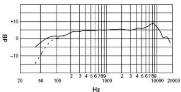
| Frequency Response | 40 to 20,000 Hz |
| Polar Patterns | Cardioid (mid capsule), bidirectional (side capsule) |
| Output Impedance | 150 Ω nominal (100 Ω actual) |
| Sensitivity (1 kHz, mid-side mode) | -66 dB (0.5 mV) mid level (0 dB = 1 V/Pa) |
| Clipping Level (1 kHz, 800 Ω load, <1% THD) | -12 dBV (mid output), -10 dBV (side output) |
| Maximum SPL (800 Ω load) | 129 dB |
| Self-Noise (A-weighted) | 24 dB typical |
| Dynamic Range | 105 dB |
| Signal-to-Noise Ratio (94 dB SPL) | 70 dB (IEC 651) |
| Power Requirements | Phantom 9-52 V DC or internal 6 V battery (silver-oxide, lithium, alkaline) |
| Current Consumption (phantom) | 1.3 mA per output; 2.6 mA total |
| Current Consumption (battery) | 2.4 mA total |
| Low-Frequency Attenuation | 12 dB/octave below 80 Hz (switchable) |
| Output Modes | Stereo (L, M, H) and mid-side |
| Mono Compatibility | Mono sum = mid signal (ensured in all stereo modes) |
| Dimensions | Length 290 mm, front diameter 39.7 mm, connector end diameter 27 mm |
| Net Weight | 417 g (without battery or cable) |
| Materials | Nickel-plated brass and aluminum body, stainless steel grille |
| Supplied Accessories | 80A463 battery, carrying case, foam windscreen, swivel adapter, 0.76 m Y splitter cable |
| Options | C110 cable extension, A88SM isolation mount, PS1A power supply, S15 stand |
| Maintenance and Cleaning | Clean with a soft, dry cloth. Avoid moisture and shocks. Use the supplied windscreen to reduce wind noise. |
| Safety Instructions | Use only the specified power. Do not expose to extreme temperatures. Disconnect before replacing battery. |
| Spare Parts and Repairability | Spare parts available: control knob (65A1218B). Optional accessories sold separately. Repair by a qualified technician recommended. |
Frequently Asked Questions - VP88 SHURE
User questions about VP88 SHURE
0 question about this device. Answer the ones you know or ask your own.
Ask a new question about this device
Download the instructions for your Microphone in PDF format for free! Find your manual VP88 - SHURE and take your electronic device back in hand. On this page are published all the documents necessary for the use of your device. VP88 by SHURE.
USER MANUAL VP88 SHURE
natural_image
Black VRSU microphone with attached cable and foam cap (no visible text or symbols)FEATURES
- Time-coherent, Mid-Side (M-S) design for optimal stereo imaging.
- Built-in stereo matrix for direct control of the stereo spread; direct M-S outputs provided.
• 40 to 20,000 Hz frequency response. - Low noise and distortion, wide dynamic range.
- Switch-selectable, low-frequency roll-off (12 dB/octave below 80 Hz) for reduced pickup of ambient noise and stand vibration.
- Phantom power or 6V camera battery with LED power indicator.
- Internal shock mount for reduced stand vibration and handling noise.
- Impact resistant, durable construction.
- Integrated heavy-duty "pop" screen.
- Windscreen, swivel mount adapter, and Y-cable included.
GENERAL DESCRIPTION
The Shure Model VP88 is a stereo microphone equally effective in studio broadcasting applications as in the field for electronic news gathering (ENG).
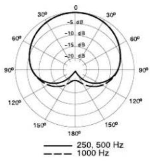
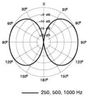
This stereo microphone combines two condenser cartridges in a single housing, in a mid-side (M-S) microphone cartridge configuration. One cartridge (Mid) faces forward to capture on-axis sound in a cardioid pattern. The other cartridge (Side) is bi-directional, capturing sound from either side.
Containing three settings for different degrees of stereo image separation, the VP88 contains an internal M-S matrix that can be bypassed if an external matrix is used, or if stereo imaging is done in post-production. External switches control output mode, stereo imaging, low-frequency roll off settings, and battery on/off.
When the VP88 is set for stereo mode operation (H, M, or L), the left and right signals should remain fully separated and kept at equal levels to maintain a balanced stereo effect.
MOUNTING
The VP88 can be mounted on a standard microphone floor stand, fishpole or boom. Make sure the front of the grille faces the sound source and the top of the microphone faces up, so that the the resulting stereo image matches the left and right components of the sound source.
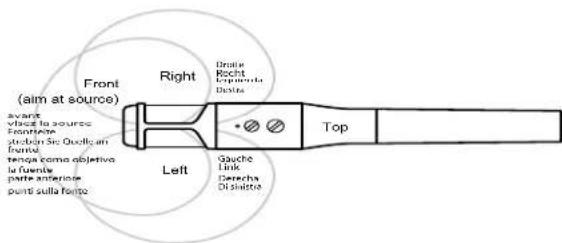
MICROPHONE ORIENTATION FIGURE 1
A88SM External Shock Mount
The optional A88SM Shock Mount provides optimum isolation from stand-transmitted shock and vibration. The A88SM is ideal for critical studio applications and contains a standard mounting foot for use with most electronic news gathering (ENG) video cameras.
POWER
Phantom Power
The VP88 can operate on an internal 6V battery or phantom power from any microphone mixer or console providing 9 to 52 Vdc, or by a phantom power supply such as the Shure PS1A. Each balanced audio cable pair (pins 2 and 3: Mid/Left; pins 4 and 5: Side/Right) carries the supply current to the microphone, and the cable shield (pin 1) is the ground return.
The Mid or Side output can be used individually with either phantom or battery power. When operating in the Stereo mode without battery, both Mid/Left and Side/Right outputs must be phantom powered.
Battery Power
If phantom power is not available, move the Battery switch to the Batt On position. The adjacent LED will flash indicating at least five hours of useful battery life, and if no flashing is observed the battery should be replaced. The battery does not drain when phantom power is applied.
Installing and Replacing the Battery
The VP88 uses a 6V cylindrical battery commonly used in cameras. Average battery life depends on the type of battery: typically 70 hours for silver oxide/lithium and 40 hours for alkaline.
| SPEC. AGENCY / MANUFACTURER | SILVER OXIDE | LITHIUM MANGANESE ALKALINE |
| NEDA 1406SCP 5005L 1414A | ||
| IEC 4SR44 2CR1/3N 4LR44 | ||
| Duracell PX28 PX28L - | ||
| Eveready 544 L544 A544 | ||
| Kodak KS28 K28L | K28A | |
| Panasonic 4G13 | - 4LR44 | |
| Radio Shack | - | 23-469 |
| Varta | V28PX | V28PXL V4304PX |
LIST OF REPLACEMENT AND COMPATIBLE BATTERIES TABLE 1
To install or replace the battery, proceed as follows:
- Disconnect the microphone cable and unscrew the VP88 lower handle.
- Carefully slide the lower handle away from the grille, exposing the battery compartment. If necessary, remove the old battery.
- Insert the new battery, observing the polarity marking in the battery compartment.
- Slide the lower handle back into position and tighten.
CONNECTIONS
Use the supplied Y-splitter cable to connect the VP88 to two inputs of a mixer or console.
The red connector, marked "M" and "L", carries the Mid signal (in MS mode) or left signal (in stereo mode).
The green connector, marked "S" and "R", carries the Side signal (in MS mode) or right signal (in stereo mode).
For stereo mode operation, connect the left (L) splitter connector to the Channel 1 input and the right (R) splitter connector to the Channel 2 input of the mixer or console. Set the Channel 1 pan pot to full left and the Channel 2 pan pot to full right.
NOTE: Use the Shure C110 Extension Cable (available as an accessory) for extended cable runs between the VP88 and a mixer or console.
Using an Additional Microphone
A second (mono) microphone can be used for interviewing or close miking. Turn its channel pan pot to the center position and set its level independently.
Monitoring
To check the balance for the mono listener, monitor sound in mono mode as well as stereo. Since the side signal is cancelled in mono, the mono output will be equal to the cardioid Mid cartridge signal only, regardless of the side level control setting.
Minimizing Wind and Breath Noise
The integrated pop filter provides reduction of breath and wind sound. Use the removable foam windscreen for high intensity wind and speaking conditions.
A low-frequency rolloff (12 dB per octave cut below 80 Hz) rolloff can be useful in reducing pickup of low-frequency noise and vibration. Set the upper control switch on the VP88 to either of the two low-frequency rolloff positions, depending on whether phantom or battery power is being used. See Figure 2.
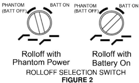
OUTPUT MODE
The lower control sets the VP88 to either MS Mode, or one of three Stereo modes. (L, M, or H). See Figure 3.
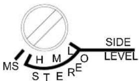
OUTPUT MODE SELECTION SWITCH FIGURE 3
Stereo Output Mode
In Stereo Mode, the VP88 uses its internal matrix to mix the Mid and Side signals and provide Left and Right stereo outputs. The three settings (H, M, and L), determine the strength or width of the stereo effect, as described below. Nominal Left and Right pickup patterns are shown in the following series.
NOTE: The mono sum (Left + Right) in any Stereo position is always equal to the Mid signal, ensuring mono compatibility.
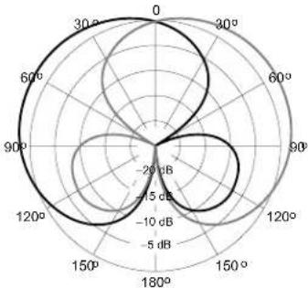
L (Low): Figure 4. Side level 6.0 dB lower than Mid level. The stereo image spread of the stereo images is small. Use this setting for distant miking, or in situations where the microphone directionality cannot be well controlled, such as hand-held use. In the L position, the microphone also picks up the least amount of ambient sound from the side, and can be used to reduce high ambient noise or reverberation. The L setting can be useful if the area being miked is already very wide. However, the degree of stereo effect may be compromised in narrow performing areas.
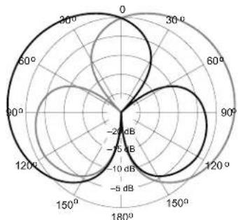
M (Medium): Figure 5. Side level is 1.9 dB lower than Mid level. The increased side ambience pickup and stereo spread make the M setting ideal for most applications.
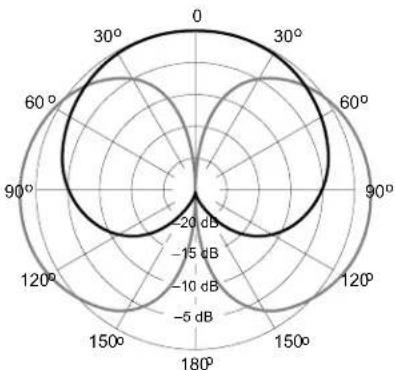
H (High): Figure 6. Side level is 1.6 dB higher than Mid level. The H position provides the most side ambience pickup and the greatest amount of stereo spread. This setting is only appropriate if a high degree of ambience pickup is acceptable and the performing area is not excessively wide.
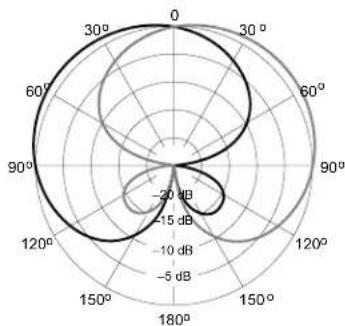
MS Output Mode. Figure 7. In MS mode, the VP88's internal stereo matrix is bypassed. The signal from the mid cartridge is sent to the red connector on the Y-splitter cable (M) and the side cartridge output is sent to the green connector (S). The Side on-axis sensitivity (90° from the front axis of the microphone) is 1.6 dB higher than the on-axis sensitivity of the Mid output. The sensitivities of the Mid and Side outputs are equal at 45° off the front axis of the microphone.
The polarity of the left lobe of the Side output matches the polarity of the Mid output. The right lobe of the Side output is opposite polarity.
radar
| Angle | Value (dB) | |-------|------------| | 0 | -20 | | 30 | -15 | | 60 | -10 | | 90 | -5 | | 120 | -15 | | 150 | -20 | | 180 | -15 |LOW STEREO (L) FIGURE 4
radar
| Angle | Value (dB) | |-------|------------| | 0 | -20 | | 30 | -15 | | 60 | -10 | | 90 | -5 | | 120 | 0 | | 150 | 5 | | 180 | 10 |MEDIUM STEREO (M) FIGURE 5
radar
| Angle | Value (dB) | |-------|------------| | 0 | -20 | | 30 | -15 | | 60 | -10 | | 90 | -5 | | 120 | -10 | | 150 | -15 | | 180 | -20 |HIGH STEREO (H) FIGURE 6
radar
| Angle | Value (dB) | |-------|------------| | 0° | 0 | | 30° | 0 | | 60° | 0 | | 90° | 0 | | 120° | 0 | | 150° | 0 | | 180° | 0 |MS OUTPUT MODE FIGURE 7
EXTERNAL MATRIXES
When using an external stereo matrix, such as a matrix transformer or active matrix circuitry, set the VP88 to MS mode (refer to the Output Mode paragraph). The Mid and Side outputs can be processed through a sum-and-difference matrix to produce Left and Right stereo signals as follows:
Left = Mid + Side
Right = Mid - Side
A 1:1 ratio of Mid to Side produces stereo signals identical to those obtained with Stereo Output switch set to High (H). Results similar to the Medium (M) and Low (L) settings can be obtained by attenuating the side signal before matrixing.
NOTE: An external matrix can be useful when recording, because decisions on stereo imaging are deferred to the post-production stage.
Two suggested matrix boxes:
• Model MS38 DM Dual-Mode Line-Level MS Matrix
- Model MS380 TX Stereo Microphone Preamplifier with Dual-Mode MS Matrix and Line Driver.
Both are manufactured by Audio Engineering Associates, 1029 N. Allen Ave., Pasadena, CA 91104 U.S.A.
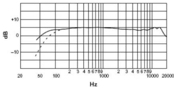
FREQUENCY RESPONSE AND POLAR PATTERNS
line
| Hz | dB | |-------|--------| | 20 | -10.0 | | 50 | -5.0 | | 100 | 0.0 | | 2 | 2.0 | | 3 | 3.0 | | 4 | 3.5 | | 5 | 4.0 | | 6 | 4.5 | | 7 | 5.0 | | 8 | 5.5 | | 9 | 6.0 | | 10 | 6.5 | | 2 | 7.0 | | 3 | 7.5 | | 4 | 8.0 | | 5 | 8.5 | | 6 | 9.0 | | 7 | 9.5 | | 8 | 10.0 | | 9 | 9.5 | | 10 | 9.0 | | 20 | -5.0 | | 50 | -10.0 | | 100 | -5.0 | | 200 | 0.0 | | 300 | 2.0 | | 400 | 3.0 | | 500 | 4.0 | | 600 | 5.0 | | 700 | 6.0 | | 800 | 7.0 | | 900 | 8.0 | | 1000 | 9.0 | | 2000 | -5.0 | | 5000 | -10.0 | | 10000 | -5.0 | | 20000 | -10.0 |TYPICAL FREQUENCY RESPONSE OF MIDDLE CARTRIDGE FIGURE 8
line
| Hz | dB | |-------|--------| | 20 | -15.0 | | 50 | -5.0 | | 100 | 0.0 | | 2 | 2.0 | | 3 | 3.0 | | 4 | 4.0 | | 5 | 5.0 | | 6 | 6.0 | | 7 | 7.0 | | 8 | 8.0 | | 9 | 9.0 | | 10 | 10.0 | | 2 | 8.0 | | 3 | 7.0 | | 4 | 6.0 | | 5 | 5.0 | | 6 | 4.0 | | 7 | 3.0 | | 8 | 2.0 | | 9 | 1.0 | | 10 | 0.0 | | 20 | -5.0 | | 50 | -10.0 | | 100 | -5.0 | | 200 | -2.0 | | 300 | -1.0 | | 400 | -0.5 | | 500 | -0.2 | | 600 | -0.1 | | 700 | -0.05 | | 800 | -0.02 | | 900 | -0.01 | | 1000 | -0.05 | | 2000 | -5.0 | | 5000 | -15.0 | | 10000 | -18.0 | | 20000 | -25.0 |TYPICAL FREQUENCY RESPONSE OF SIDE CARTRIDGE FIGURE 9
radar
| Angle | 250,500 Hz (dB) | 1000 Hz (dB) | |-------|-----------------|--------------| | 0° | -5 | -15 | | 30° | -5 | -15 | | 60° | -5 | -15 | | 90° | -5 | -15 | | 120° | -5 | -15 | | 150° | -5 | -15 | | 180° | -5 | -15 |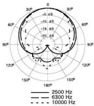
radar
| Angle | Frequency (Hz) | |---|---| | 0 | -5 dB | | 30° | -10 dB | | 60° | -15 dB | | 90° | -20 dB | | 120° | -25 dB | | 150° | -20 dB | | 180° | -15 dB | | 210° | -10 dB | | 240° | -5 dB | | 270° | 0 dB | | 300° | 5 dB | | 330° | 10 dB | | 360° | 15 dB | | 390° | 20 dB | | 420° | 25 dB | | 450° | 30 dB | | 480° | 35 dB | | 510° | 40 dB | | 540° | 45 dB | | 570° | 50 dB | | 600° | 55 dB | | 630° | 60 dB | | 660° | 65 dB | | 690° | 70 dB | | 720° | 75 dB | | 750° | 80 dB | | 780° | 85 dB | | 810° | 90 dB | | 840° | 95 dB | | 870° | 100 dB | | 900° | 105 dB | | 930° | 110 dB | | 960° | 115 dB | | 990° | 120 dB | | 1020° | 125 dB | | 1050° | 130 dB | | 1080° | 135 dB | | 1110° | 140 dB | | 1140° | 145 dB | | 1170° | 150 dB | | 1200° | 155 dB | | 1230° | 160 dB | | 1260° | 165 dB | | 1290° | 170 dB | | 1320° | 175 dB | | 1350° | 180 dB | | 1380° | 185 dB | | 1410° | 190 dB | | 1440° | 195 dB | | 1470° | 200 dB | | 1500° | 205 dB | | 1530° | 210 dB | | 1560° | 215 dB | | 1590° | 220 dB | | 1620° | 225 dB | | 1650° | 230 dB | | 1680° | 235 dB | | 1710° | 240 dB | | 1740° | 245 dB | | 1770° | 250 dB | | 1800° | 255 dB | | 1830° | 260 dB | | 1860° | 265 dB | | 1890° | 270 dB | | 1920° | 275 dB | | 1950° | 280 dB | | 1980° | 285 dB | | 2010° | 290 dB | | 2040° | 295 dB | | 2070° | 300 dB | | 2100° | 305 dB | | 2130° | 310 dB | | 2160° | 315 dB | | 2190° | 320 dB | | 2220° | 325 dB | | 2250° | 330 dB | | 2280° | 335 dB | | 2310° | 340 dB | | 2340° | 345 dB | | 2370° | 350 dB | | 2400° | 355 dB | | 2430° | 360 dB | | 2460° | 365 dB | | 2490° | 370 dB | | 2520° | 375 dB | | 2550° | 380 dB | | 2580° | 385 dB | | 2610° | 390 dB | | 2640° | 395 dB | | 2670° | 400 dB | | 2700° | 405 dB | | 2730° | 410 dB | | 2760° | 415 dB | | 2790° | 420 dB | | 2820° | 425 dB | | 2850° | 430 dB | | 2880° | 435 dB | | 2910° | 440 dB | | 2940° | 445 dB | | 2970° | 450 dB | | 3000° | 455 dB | | Note: The data provided in the image is a simplified representation of the chart type. The labels on the chart are 'Frequency (Hz)' and 'Angle (degrees)'. The values are estimated based on the given chart title and are not explicitly labeled in the code. There is only one data series in this case. The chart type is a type of scatter plot with different colors and line styles. Legend indicates three frequency bands: black solid line (25th Hz), white dashed line (63th Hz), and black dotted line (10th Hz).TYPICAL MIDDLE CARTRIDGE POLAR PATTERN
FIGURE 10
radar
| Angle | Value (dB) | |-------|------------| | 0° | -5 | | 30° | -10 | | 60° | -5 | | 90° | -10 | | 120° | -5 | | 150° | -10 | | 180° | -5 |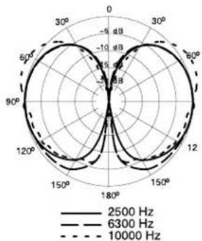
TYPICAL SIDE CARTRIDGE POLAR PATTERN
FIGURE 11
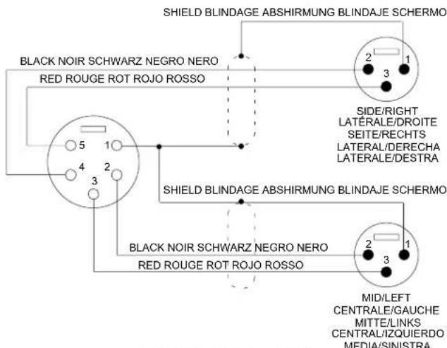
CABLE CONNECTIONS FIGURE 12
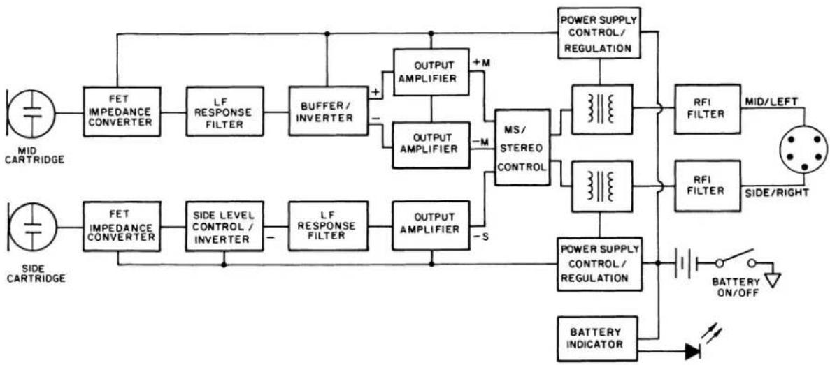
flowchart
graph TD
    A["MID CARTRIDGE"] --> B["FET IMPEDANCE CONVERTER"]
    B --> C["LF RESPONSE FILTER"]
    C --> D["BUFFER/INVERTER"]
    D --> E["+"]
    E --> F["OUTPUT AMPLIFIER"]
    F --> G["MS/STEREO CONTROL"]
    G --> H["POWER SUPPLY CONTROL/REGULATION"]
    H --> I["RFI FILTER"]
    I --> J["MID/LEFT"]
    K["SIDE CARTRIDGE"] --> L["FET IMPEDANCE CONVERTER"]
    L --> M["SIDE LEVEL CONTROL / INVERTER"]
    M --> N["LF RESPONSE FILTER"]
    N --> O["OUTPUT AMPLIFIER"]
    O --> P["MS/STEREO CONTROL"]
    P --> Q["RFI FILTER"]
    Q --> R["SIDE/RIGHT"]
    S["BATTERY ON/OFF"] --> T["BATTERY INDICATOR"]
    T --> U["Power Supply CONTROL/REGULATION"]
    U --> V["Power SUPPLY CONTROL/REGULATION"]
    V --> W["RFI FILTER"]
    W --> X["MID/LEFT"]
VP88 CIRCUIT BLOCK DIAGRAM FIGURE 13
SPECIFICATIONS
Type
Single-point stereo (MS configuration) condenser
Frequency Response (See Figures 9 and 10)
40 to 20,000 Hz
Polar Pattern (See Figures 11 and 12)
Mid Cartridge: Cardioid (unidirectional)
Side Cartridge: Bidirectional
Output Impedance
Rated at 150 (100 W actual). Recommended minimum load impedance: 800 W (may be used with loads as low as 150 W with reduced clipping level)
Sensitivity (1 kHz, MS mode)
Open Circuit Voltage: -66 dB (0.5 mV) Mid. (Side level 1.6 dB higher than Mid level) (0 dB=1 V/Pa)
Side Level
(Stereo mode; relative to Mid level)
Low: -6.0 dB; Medium: -1.9 dB; High: +1.6 dB
Clipping Level (1 kHz)
800 W Load (less than 1% THD)
-12 dBV (0.25 V)(Mid output, 1% THD)
-10 dBV (0.30 V)(Side output, 1% THD)
150 W Load (less than 3% THD)
-25 dBV (0.06 V)(Mid output)
-19 dBV (0.11 V)(Side output)
Maximum SPL
800 W Load: 129 dB
150 W Load: 119 dB
Hum Pickup
-4 dB equivalent SPL in 1 millioersted field (60 Hz)
Self Noise
(Mid, Side, Left and Right outputs; equivalent sound pressure levels)
24 dB typical, A-weighted
28 dB typical, weighted per DIN 45405
Dynamic Range
105 dB (maximum SPL to A-weighted noise level)
Signal-to-Noise Ratio\*
70 dB (IEC 651) at 94 dB SPL
*S/N ratio: difference between microphone output at 94 dB SPL and microphone self-noise A-weighted.
Overvoltage Protection
Maximum External Voltage applied to Pins 2 through 5 with respect to Pin 1: ±75 Vdc
Polarity
Positive pressure applied from any direction to the Mid cartridge or from the left to the Side cartridge in the MS mode, or applied from the front in the Stereo mode produces positive voltage on pin 2 relative to pin 3 (Mid/Left) and pin 4 relative to pin 5 (Side/Right).
Power
Phantom:
Supply Voltage: 9 to 52 Vdc
Current Drain: 1.3 mA/output; 2.6 mA total
Battery:
Type: 6 V cylindrical*; Life: 70 hours**
Current Drain: 2.4 mA total
Environmental Conditions
Operating: -18× to 57× C (0× to 135× F)
(Relative Humidity <90%)
Storage: -29× to 74× C (-20× to 165× F)
(Relative Humidity <80%)
Cables (see Figure 10)
Y-Splitter Cable (supplied): 0.76 m (30 in.) vinyl-jacketed, dual-shielded, 2-conductor with 5-pin female XLR connector on microphone end and two 3-pin male XLR connectors on equipment ends.
Microphone Extension Cable (Model C110; optional): 7.6 m (25ft.) vinyl-jacketed, shielded, 4-conductor with 5-pin male XLR connector on one end and 5-pin female XLR connector on other end.
Case
Brass and nickel-plated aluminum construction with stainless steel grille. Finished in satin black vinyl enamel
Dimensions
Length: 11-7/16 in.; 290mm. Front Diameter: 1-9/16 in. 39.7mm; Diameter at Cable connection: 1-1/16 in.; 27mm.
Net Weight
417 grams (14.7 oz) less battery and cable
Certifications
Eligible to bear CE Marking. Conforms to European EMC Directive 89/336/EEC. Meets applicable tests and performance criteria in European Standard EN55103 (1996) parts 1 and 2, for residential (E1) and light industrial (E2) environments.
FURNISHED ACCESSORIES
Battery 80A463
Carrying/Storage Bag.... 26A14
Foam Windscreen (see Figure 2).... 49A91
Swivel Adapter 90B4046
0.76 m (30 in.) Y-Splitter Cable 90A4148
REPLACEMENT PARTS
Control Knob 65A1218B
OPTIONAL ACCESSORIES
7.6 m (25 ft.) Extension Cable (4 conductor, shielded) ...... C110
Isolation Mount...... A88SM
Phantom Power Supply....PS1A
4.3 m (14 ft.) Microphone Stand S15
*Silver oxide (NEDA 1406SOP), lithium (NEDA 5005L), alkaline (NEDA 1414A)
**Fresh silver oxide or lithium battery; 40 hours with alkaline
DESCRIPTION GÉNÉRALE
Clipping-Pegel (1 kHz)
Schwenkadapter 90B4046
SHURE Incorporated http://www.shure.com
United States, Canada, Latin America, Caribbean:
5800 W. Touhy Avenue, Niles, IL 60714-4608, U.S.A.
Phone: 847-600-2000 U.S. Fax: 847-600-1212 Intl Fax: 847-600-6446
Europe, Middle East, Africa:
Shure Europe GmbH, Phone: 49-7131-72140 Fax: 49-7131-721414
Asia, Pacific:
Shure Asia Limited, Phone: 852-2893-4290 Fax: 852-2893-4055
- FEATURES
- GENERAL DESCRIPTION
- MOUNTING
- A88SM External Shock Mount
- POWER
- Phantom Power
- Battery Power
- Installing and Replacing the Battery
- CONNECTIONS
- Using an Additional Microphone
- Monitoring
- Minimizing Wind and Breath Noise
- OUTPUT MODE
- Stereo Output Mode
- EXTERNAL MATRIXES
- SPECIFICATIONS
- Type
- Frequency Response (See Figures 9 and 10)
- Polar Pattern (See Figures 11 and 12)
- Output Impedance
- Sensitivity (1 kHz, MS mode)
- Side Level
- Clipping Level (1 kHz)
- Maximum SPL
- Hum Pickup
- Self Noise
- Dynamic Range
- Signal-to-Noise Ratio\*
- Overvoltage Protection
- Polarity
- Environmental Conditions
- Cables (see Figure 10)
- Case
- Dimensions
- Net Weight
- Certifications
- FURNISHED ACCESSORIES
- REPLACEMENT PARTS
- OPTIONAL ACCESSORIES
- DESCRIPTION GÉNÉRALE
- Clipping-Pegel (1 kHz)
Brand : SHURE
Model : VP88
Category : Microphone