
ZX3-60 - Pregnant ELECTRO-VOICE - Free user manual and instructions
Find the device manual for free ZX3-60 ELECTRO-VOICE in PDF.


| Product Type | Passive 2-way loudspeaker |
| Brand | Electro-Voice |
| Model | ZX3-60 |
| Woofer Size | 12 inches (304.8 mm) |
| High-Frequency Driver | 1-inch titanium diaphragm compression driver |
| Frequency Response (-10 dB) | 50 Hz – 20 kHz |
| Power Handling (Continuous) | 400 W |
| Power Handling (Peak) | 1600 W |
| Impedance | 8 ohms |
| Sensitivity (1W/1m) | 98 dB |
| Maximum SPL | 132 dB |
| Coverage Pattern | 60° x 60° (rotatable horn) |
| Connectors | 2x Neutrik Speakon NL4 |
| Dimensions (H x W x D) | 604 mm x 374 mm x 345 mm (23.8 in x 14.7 in x 13.6 in) |
| Weight | 19.5 kg (43.0 lb) |
| Construction | Polypropylene composite enclosure with steel grille |
| Rigging | 6x M10 rigging points, 2x M10 rear pull-backs |
| Mounting Options | Pole mount (36 mm socket), wall mount (optional bracket) |
| Weather Resistance | IP55 (with optional ZX3-WRK kit) |
| Power Input | Passive (requires external amplifier) |
| Recommended Amplifier Power | 400 – 800 W RMS at 8 ohms |
| Cleaning Instructions | Wipe with a damp cloth; do not use solvents or abrasives. |
| Safety Features | Overload protection via DynaCord automatic protection circuit |
| Included Accessories | 4x rubber feet, 2x Speakon connectors (cable not included) |
Frequently Asked Questions - ZX3-60 ELECTRO-VOICE
User questions about ZX3-60 ELECTRO-VOICE
0 question about this device. Answer the ones you know or ask your own.
Ask a new question about this device
Download the instructions for your Pregnant in PDF format for free! Find your manual ZX3-60 - ELECTRO-VOICE and take your electronic device back in hand. On this page are published all the documents necessary for the use of your device. ZX3-60 by ELECTRO-VOICE.
USER MANUAL ZX3-60 ELECTRO-VOICE
MB3 Wall/Ceiling Mounting Bracket Kit
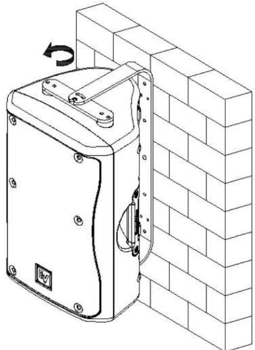
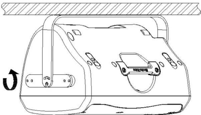
The MB3 Wall/Ceiling Mounting Bracket Kit features robust brackets and hardware that allow for a Zx3 loudspeaker to be quickly and easily mounted to a wall or ceiling in almost any position to obtain the desired sound coverage.
natural_image
Technical line drawing of a wall-mounted electrical enclosure with a rotating switch, mounted on a brick wall (no text or symbols)Figure 1: Suspending the Zx3 from a wall using the MB3
natural_image
Technical line drawing of a car interior with no visible text or symbolsFigure 2: Suspending the Zx3 from a ceiling using the MB3
natural_image
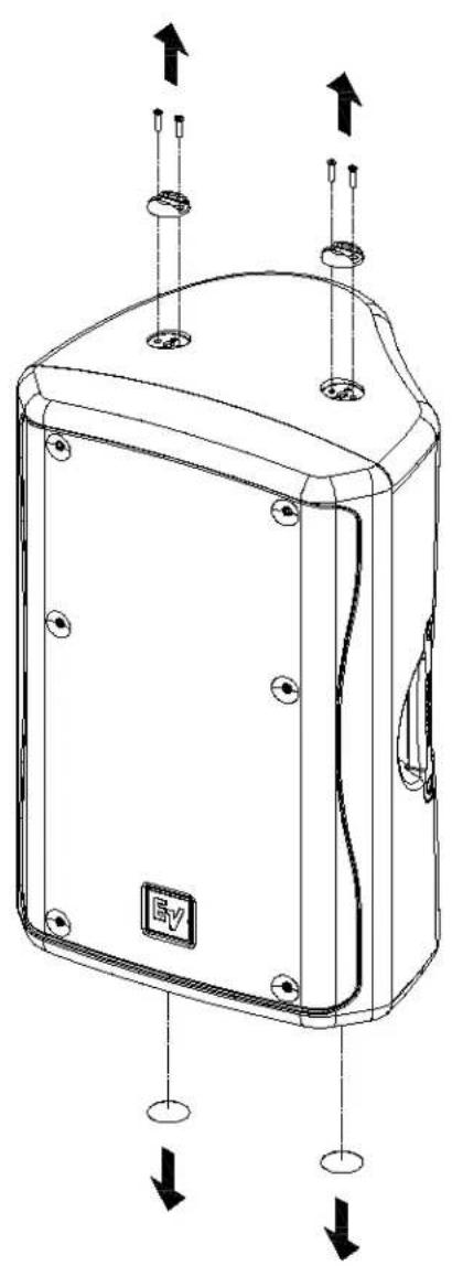
Technical line drawing of a mechanical enclosure with mounting holes and directional arrows indicating movement (no text or symbols)Figure 3: Removing hardware on the Zx3
text_image
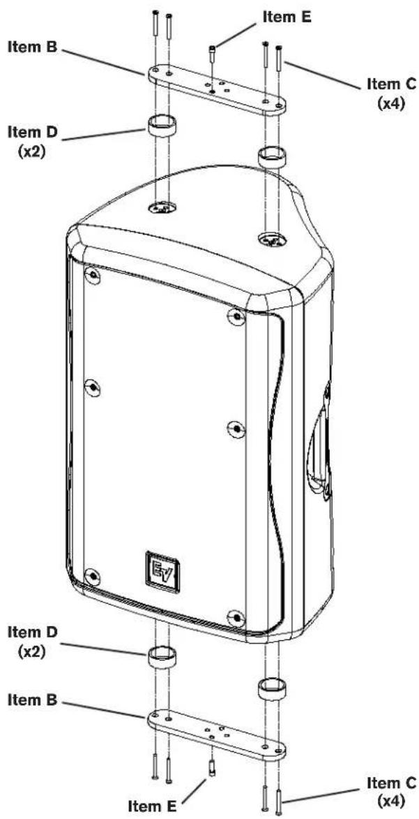
Item B Item E Item C (x4) Item D (x2) EV Item D (x2) Item B Item E Item C (x4)Figure 4: Installing the Spanning Brackets
Step 1: Attach Spanning Brackets
Remove the single-stud fittings on the top of the enclosure by removing the four screws, and remove the two decals on the bottom of the enclosure by using a knife or razor blade (Figure 3). Install the four spacers (Item D) and two spanning brackets (Item B), using the eight flat head screws (Item C). Thread two M8 cap screws (Item E) into the front threaded hole of each spanning bracket, until they are flush with the bottom of the spanning bracket (Figure 4).
| MB3 Mounting Bracket Includes | ||
| Item | Description Qty. | |
| A U | -Bracket 1 | |
| B Spanning Bracket 2 | ||
| C Screw, 10-32 x 1-3/4", Flat Head 8 | ||
| D Spacer 4 | ||
| E Socket Head Cap Screw, M8x20mm 4 | ||
| F Washer, M8 2 | ||
| G Lock Washer, M8 2 | ||
text_image
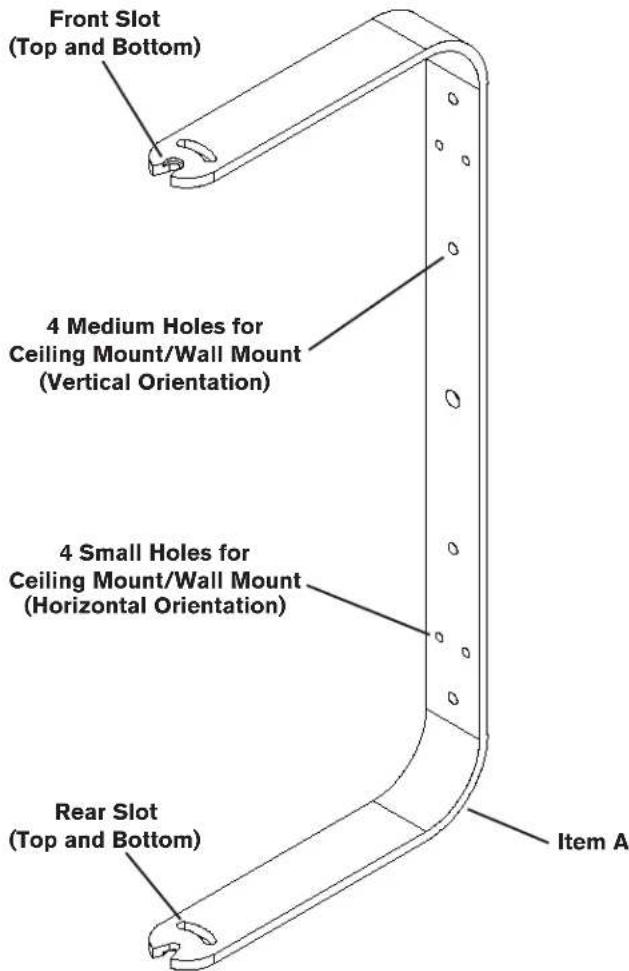
Front Slot (Top and Bottom) 4 Medium Holes for Ceiling Mount/Wall Mount (Vertical Orientation) 4 Small Holes for Ceiling Mount/Wall Mount (Horizontal Orientation) Rear Slot (Top and Bottom) Item AFigure 5: MB3 U-Bracket Features
text_image
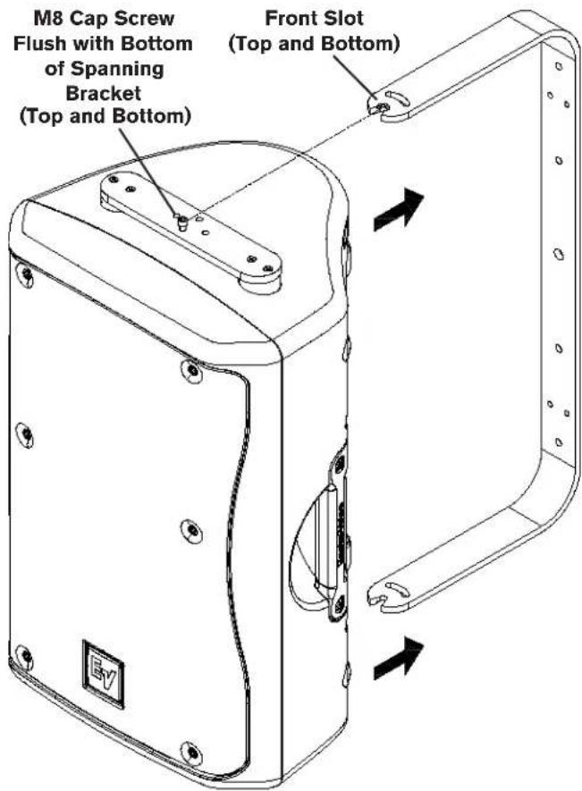
M8 Cap Screw Flush with Bottom of Spanning Bracket (Top and Bottom) Front Slot (Top and Bottom)Figure 6: Aligning the Zx3 Enclosure with the U-Bracket
Step 2: Mount the U-Bracket
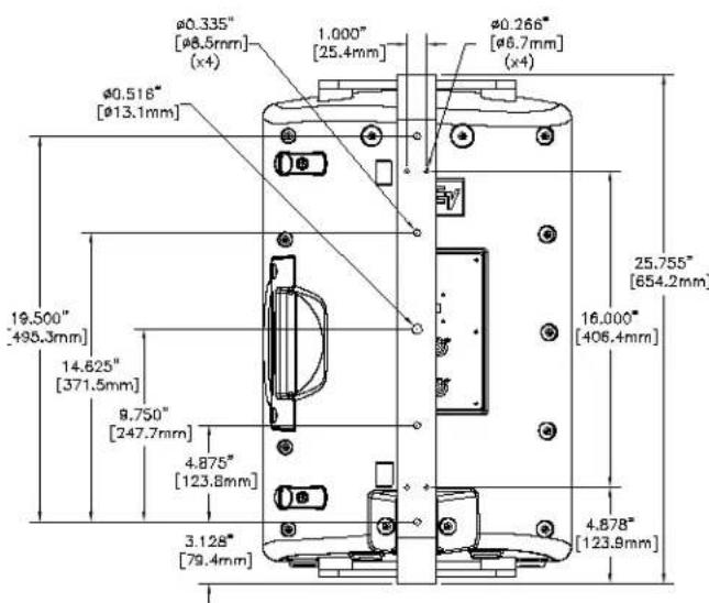
Mount the U-bracket (Item A) to a wall or ceiling using the appropriate holes (Figure 5). Use fasteners (not included) that are suitable for the construction material of the wall or ceiling. See dimension diagrams for mounting hole patterns and dimensions.
Step 3: Mount the Zx3 to the U-Brackets
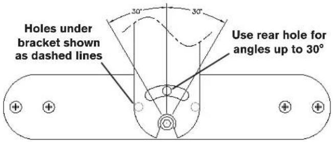
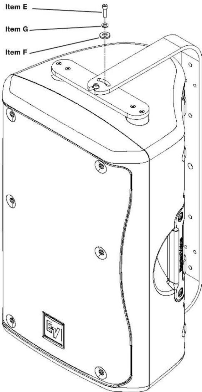
Slide the Zx3 into the U-bracket by aligning the M8 cap screws with the front slots of the U-bracket (Figure 6). The weight of the Zx3 will pull the top M8 cap screw into the recess of the front slot of the U-bracket (wall mount/vertical orientation only). Rotate the Zx3 to the desired orientation (Figure 7), and install the two M8 washers (Item F), two M8 lock washers (Item G), and two M8 cap screws (Item E), using the threaded hole that aligns with the rear slot. Tighten the four M8 cap screws (Figure 8).
text_image
Holes under bracket shown as dashed lines 30° 30° Use rear hole for angles up to 30°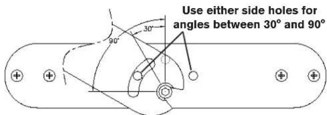
text_image
Use either side holes for angles between 30° and 90°Figure 7: Rotating to desired angle
text_image
Item E Item G Item F EVFigure 8: Tightening all screws after aligned to desired angle (Bottom screws not shown)
text_image
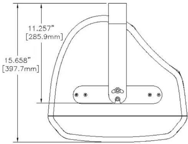
11.257" [285.9mm] 15.658" [397.7mm]Figure 9: MB3 Top View Dimensions
text_image
φ0.335" [φ8.5mm] (x4) 1.000" [25.4mm] φ0.266" [φ6.7mm] (x4) φ0.516" [φ13.1mm] 19.500" [498.3mm] 14.625" [371.5mm] 9.750" [247.7mm] 4.875" [123.8mm] 3.128" [79.4mm] 25.755" [654.2mm] 16.000" [406.4mm] 4.878" [123.9mm]Figure 10: MB3 Rear View Dimensions

WARNING: Suspending any object is potentially dangerous and should only be attempted by individuals who have a thorough knowledge of the techniques and regulations of suspending objects overhead. Electro-Voice® strongly recommends that all speakers be suspended taking into account all current national, federal, state and local regulations. It is the responsibility of the installer to ensure that all speakers are safely installed in accordance with all such regulations. When speakers are suspended, Electro-Voice® strongly recommends that the system be inspected at least once a year. If any sign of weakness or damage is detected, remedial action should be taken immediately. The user is responsible for making sure that the wall or ceiling is capable of supporting the loudspeaker. Any hardware used to suspend a loudspeaker that is not associated with Electro-Voice® is the responsibility of others.
Electro-Voice®
12000 Portland Avenue South, Burnsville, MN 55337
Phone: 952/884-4051, Fax: 952/884-0043
www.electrovoice.com
© Bosch Communications Systems 06/2008
Part Number LIT000162 Rev A
U.S.A. and Canada only. For customer orders, contact Customer Service at:
800/392-3497 Fax: 800/955-6831
Europe, Africa, and Middle East only. For customer orders, contact Customer Service at:
+ 49 9421-706 0 Fax: + 49 9421-706 265
Other International locations. For customer orders, Contact Customer Service at:
+ 1 952 884-4051 Fax: + 1 952 887-9212
For warranty repair or service information, contact the Service Repair department at:
800/685-2606
For technical assistance, contact Technical Support at: 866/78AUDIO