
CX-9 (2021) - Automobile MAZDA - Free user manual and instructions
Find the device manual for free CX-9 (2021) MAZDA in PDF.


| Product Type | Automobile |
| Brand | Mazda |
| Model | CX-9 (2021) |
| Engine Type | 2.5L Turbocharged I4 |
| Fuel Type | Gasoline (Regular Unleaded Recommended) |
| Transmission | 6-Speed Automatic with Sport Mode |
| Drivetrain | Front-Wheel Drive (FWD) or All-Wheel Drive (AWD) |
| Seating Capacity | 7 (2-3-2 configuration) |
| Length | 199.4 in (5065 mm) |
| Width | 77.5 in (1969 mm) |
| Height | 67.6 in (1717 mm) |
| Wheelbase | 115.3 in (2930 mm) |
| Curb Weight | 4,212 - 4,409 lbs (1,911 - 2,000 kg) depending on configuration |
| Fuel Tank Capacity | 19.5 gal (73.8 L) |
| Safety Features | Advanced Smart City Brake Support, Blind Spot Monitoring, Rear Cross Traffic Alert, Lane Departure Warning, Adaptive Front Lighting, Airbags (front, side, curtain) |
| Infotainment System | Mazda Connect with 9-inch touchscreen, Apple CarPlay, Android Auto, Bluetooth, USB ports |
| Maintenance Interval | Oil change every 5,000-7,500 miles; comprehensive service every 10,000 miles or 12 months |
| Warranty | 3-year/36,000-mile limited warranty; 5-year/60,000-mile powertrain warranty |
Frequently Asked Questions - CX-9 (2021) MAZDA
User questions about CX-9 (2021) MAZDA
0 question about this device. Answer the ones you know or ask your own.
Ask a new question about this device
Download the instructions for your Automobile in PDF format for free! Find your manual CX-9 (2021) - MAZDA and take your electronic device back in hand. On this page are published all the documents necessary for the use of your device. CX-9 (2021) by MAZDA.
USER MANUAL CX-9 (2021) MAZDA
Thank you for choosing a Mazda. We at Mazda design and build vehicles with complete customer satisfaction in mind.
To help ensure enjoyable and trouble-free operation of your Mazda, read this manual carefully and follow its recommendations.
An Authorized Mazda Dealer knows your vehicle best. So when maintenance or service is necessary, that's the place to go.
Our nationwide network of Mazda professionals is dedicated to providing you with the best possible service.
We assure you that all of us at Mazda have an ongoing interest in your motoring pleasure and in your full satisfaction with your Mazda product.
Mazda Motor Corporation
HIROSHIMA, JAPAN
Important Notes About This Manual
Keep this manual in the glove compartment as a handy reference for the safe and enjoyable use of your Mazda. Should you resell the vehicle, leave this manual with it for the next owner.
All specifications and descriptions are accurate at the time of printing. Because improvement is a constant goal at Mazda, we reserve the right to make changes in specifications at any time without notice and without obligation.
Air Conditioner and the Environment
Your Mazda's genuine air conditioner is filled with a refrigerant that has been found not to damage the earth's ozone layer. If the air conditioner does not operate properly, consult an Authorized Mazda Dealer.
Perchlorate
Certain components of this vehicle such as [air bag modules, seat belt pretensioners, lithium batteries,...] may contain Perchlorate Material-- Special handling may apply for service or vehicle end of life disposal. See www.dtsc.ca.gov/hazardouswaste/perchlorate.
Please be aware that this manual applies to all models, equipment and options. As a result, you may find some explanations for equipment not installed on your vehicle.
We want to help you get the most driving pleasure from your vehicle. Your owner's manual, when read from cover to cover, can do that in many ways.
Illustrations complement the words of the manual to best explain how to enjoy your Mazda. By reading your manual, you can find out about the features, important safety information, and driving under various road conditions.
The symbol below in this manual means “Do not do this” or “Do not let this happen”.

natural_image
Simple circular symbol with a diagonal line through it, representing no text or numbers.Index: A good place to start is the Index, an alphabetical listing of all information in your manual.
You'll find several WARNINGS, CAUTIONs, and NOTES in the manual.

WARNING
A WARNING indicates a situation in which serious injury or death could result if the warning is ignored.

CAUTION
A CAUTION indicates a situation in which bodily injury or damage to your vehicle, or both, could result if the caution is ignored.
NOTE
A NOTE provides information and sometimes suggests how to make better use of your vehicle.
The following symbol, located on some parts of the vehicle, indicates that this manual contains information related to the part.
Please refer to the manual for a detailed explanation.

Table of Contents
| Pictorial IndexInterior, exterior views and part identification of your Mazda. | 1 |
| Essential Safety EquipmentImportant information about safety equipment, including seats, seat belt system, child-restraint systems and SRS air bags. | 2 |
| Before DrivingUse of various features, including keys, doors, mirrors and windows. | 3 |
| When DrivingInformation concerning safe driving and stopping. | 4 |
| Interior FeaturesUse of various features for ride comfort, including air-conditioning system and audio system. | 5 |
| Maintenance and CareHow to keep your Mazda in top condition. | 6 |
| If Trouble ArisesHelpful information on what to do if a problem arises with the vehicle. | 7 |
| Customer Information and Reporting Safety DefectsImportant consumer information including warranties and add-on equipment. | 8 |
| SpecificationsTechnical information about your Mazda. | 9 |
| Index | 10 |
1 Pictorial Index
Interior, exterior views and part identification of your Mazda.
Interior Overview....1-2
Interior Equipment (View A)......1-2
Interior Equipment (View B)......1-3
Interior Equipment (View C)......1-4
Interior Equipment (View D)......1-5
Exterior Overview...... 1-6
Interior Equipment (View A)
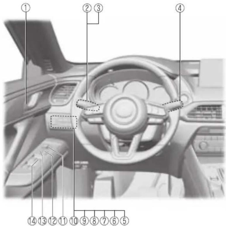
① Door-lock knob...... page 3-18
② Turn and lane-change signal......page 4-77
③ Lighting control......page 4-70
④ Wiper and washer lever......page 4-78
⑤ TCS OFF switch......page 4-104
⑥ Lane-keep Assist System (LAS) & Lane Departure Warning System (LDWS) OFF switch......page 4-160
⑦ Parking sensor switch......page 4-276
⑧ 360° View Monitor switch......page 4-187
⑨ Off-Road Traction Assist switch...... page 4-108
⑩ Power liftgate switch......page 3-22
⑪ Outside mirror switch......page 3-34
⑫ Door-lock switch...... page 3-16
⑬ Power window lock switch...... page 3-39
⑭ Power window switches......page 3-39
Interior Equipment (View B)
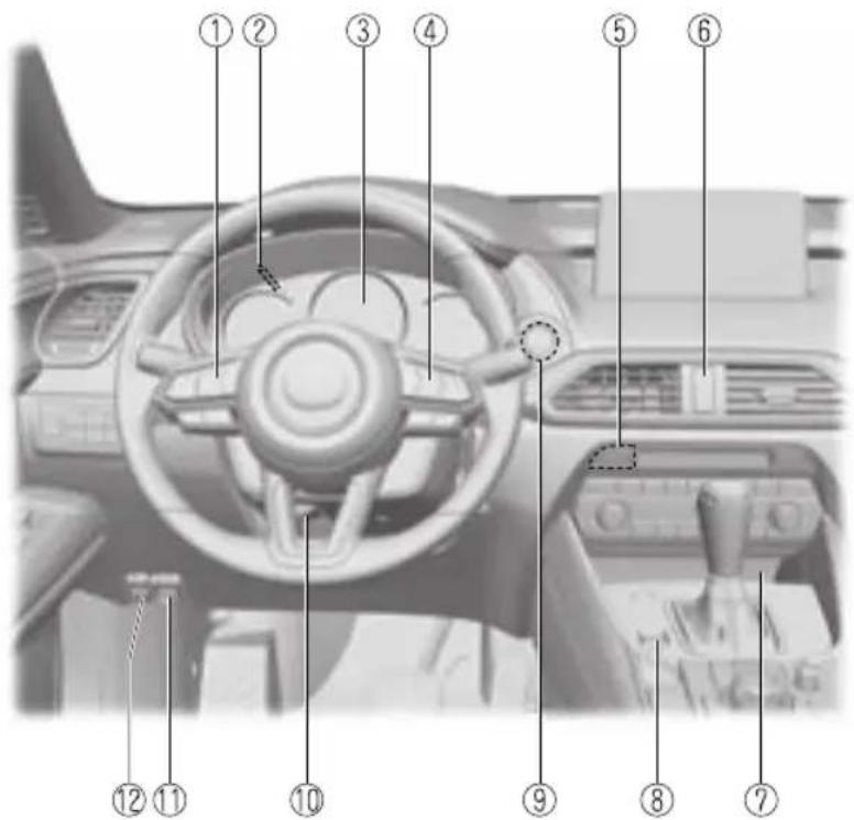
① Audio control switches...... page 5-20, 5-39
② Dashboard illumination knob...... page 4-17, 4-34, 4-48
③ Instrument cluster......page 4-11
④ Cruise control switches...... page 4-148, 4-247
⑤ Heated steering wheel switch......page 2-34
⑥ Hazard warning flasher switch......page 4-84
⑦ Wireless Charger (Qi)...... page 5-62
⑧ Drive selection switch......page 4-109
⑨ Push button start......page 4-4
⑩ Lock release lever...... page 2-5
⑪ Hood release handle......page 6-17
⑫ Remote fuel-filler lid release......page 3-32
Interior Equipment (View C)
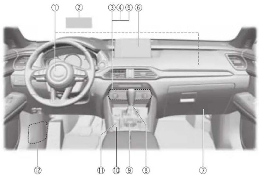
① SRS air bags...... page 2-69
② Active driving display......page 4-56
③ Climate control system......page 5-2
④ Rear window defogger switch......page 4-82
⑤ Seat warmer switches...... page 2-31
⑥ Mazda Connect...... page 5-14, 5-32
⑦ Glove compartment......page 5-68
⑧ Selector lever......page 4-59
⑨ Commander switch...... page 5-19, 5-36
⑩ AUTOHOLD switch...... page 4-98
⑪ Electric parking brake (EPB) switch......page 4-92
⑫ Fuse block (Left side)......page 6-46
Interior Equipment (View D)
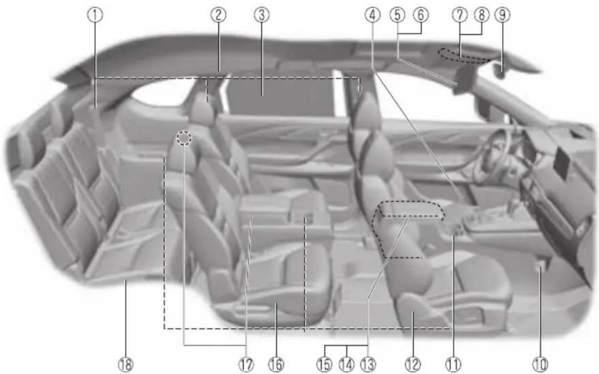
① Seat belts...... page 2-35
② SRS air bag......page 2-69
③ Rear door sunshade...... page 5-72
④ Bottle holder......page 5-67
⑤ Sunvisor......page 5-53
⑥ Vanity mirror......page 5-53
⑦ Overhead lights...... page 5-54
⑧ Moonroof switch......page 3-42
⑨ Rearview mirror...... page 3-36
⑩ Accessory socket......page 5-58
⑪ Cup holders...... page 5-65
⑫ Front seat......page 2-5
⑬ Center console......page 5-68
⑭ External input terminal...... page 5-14, 5-32
⑮ Seat warmer switches......page 2-31
⑯ Second-row seat...... page 2-15
⑰ USB power outlet......page 5-59
⑱ Third-row seat...... page 2-26
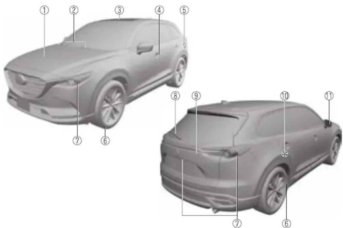
① Hood......page 6-17
② Windshield wiper blades...... page 6-26
③ Moonroof......page 3-42
④ Door and key......page 3-12
⑤ Fuel-filler lid...... page 3-32
⑥ Wheels and Tires......page 6-34
⑦ Exterior lights......page 6-38
⑧ Rear window wiper blade......page 6-28
⑨ Liftgate......page 3-20
⑩ Child safety lock...... page 3-19
⑪ Outside mirror...... page 3-34
2 Essential Safety Equipment
Important information about safety equipment, including seats, seat belt system, child-restraint systems and SRS air bags.
Seats......2-2
Seat Precautions....2-2
Front Seat....2-5
Second-row Seat (6:4 Split
Adjustable-type Bench Seat
Type)....2-15
Second-row Seat (Captain Seat
Type)....2-22
Third-row Seat....2-26
Head Restraints....2-28
Seat Warmer/Seat Ventilation/Heated
Steering Wheel......2-31
Seat Warmer ^* 2-31
Seat Ventilation*...... 2-33
Heated Steering Wheel*...... 2-34
Seat Belt Systems....2-35
Seat Belt Precautions......2-35
Seat Belt....2-38
Seat Belt Warning Systems......2-39
Front Seat Belt Pretensioner and
Load Limiting Systems......2-40
Seat Belt Extender 2-42
Child Restraint.... 2-44
Child-Restraint Precautions......2-44
Child-Restraint System
Installation.... 2-49
Child-Restraint System Suitability
for Various Seat Positions
Table.... 2-51
Installing Child-Restraint
Systems....2-55
SRS Air Bags....2-69
Supplemental Restraint System
(SRS) Precautions....2-69
Supplemental Restraint System
Components......2-76
How the SRS Air Bags Work..... 2-78
SRS Air Bag Deployment
Criteria....2-82
Limitations to SRS Air Bag......2-83
Front Passenger Occupant
Classification System ^* ......2-85
Constant Monitoring......2-89
Seat Precautions

WARNING
Make sure the adjustable components of a seat are locked in place:
Adjustable seats and seatbacks that are not securely locked are dangerous. In a sudden stop or collision, the seat or seatback could move, causing injury. Make sure the adjustable components of the seat are locked in place by attempting to slide the seat forward and backward and rocking the seatback.
Never allow children to adjust a seat:
Allowing children to adjust a seat is dangerous as it could result in serious injury if a child's hands or feet become caught in the seat.
Do not drive with the seatback unlocked:
All of the seatbacks play an important role in your protection in a vehicle. Leaving the seatback unlocked is dangerous as it can allow passengers to be ejected or thrown around and baggage to strike occupants in a sudden stop or collision, resulting in severe injury. After adjusting the seatback at any time, even when there are no other passengers, rock the seatback to make sure it is locked in place.
Adjust a seat only when the vehicle is stopped:
If the seat is adjusted while the vehicle is being driven, the seating posture may become unstable and the seat could move unexpectedly resulting in injury.
Do not modify or replace the front seats:
Modifying or replacing the front seats such as replacing the upholstery or loosening any bolts is dangerous. The front seats contain air bag components essential to the supplemental restraint system. Such modifications could damage the supplemental restraint system and result in serious injury. Consult an Authorized Mazda Dealer if there is any need to remove or reinstall the front seats.
Do not drive with damaged front seats:
Driving with damaged front seats, such as seat cushions torn or damaged down to the urethane, is dangerous. A collision, even one not strong enough to inflate the air bags, could damage the front seats which contain essential air bag components. If there was a subsequent collision, an air bag may not deploy which could lead to injuries. Always have an Authorized Mazda Dealer inspect the front seats, front seat belt pretensioners and air bags after a collision.
Do not drive with either front seats reclined:
Sitting in a reclined position while the vehicle is moving is dangerous because you do not get the full protection from seat belts. During sudden braking or a collision, you can slide under the lap belt and suffer serious internal injuries. For maximum protection, sit well back and upright.
Do not recline a second-row seatback when the third-row seat is occupied:
Reclining the second-row seatback when the third-row seat is occupied is dangerous. Because the clearance in the third-row seat is limited, occupants in the third-row seat could be hurt seriously on a reclined second-row seatback.
Do not place an object such as a cushion between the seatback and your back:
Putting an object such as a cushion between the seatback and your back is dangerous because you will be unable to maintain a safe driving posture and the seat belt cannot function at its full capacity in a collision, which could result in a serious accident, injury or death.
Do not place objects under the seat:
The object could get stuck and cause the seat to not be fixed securely, and result in an accident.
Do not stack cargo higher than the seatbacks:
Stacking luggage or other cargo higher than the seatbacks is dangerous. During sudden braking or a collision, objects can fly around and become projectiles that may hit and injure passengers.
Make sure luggage and cargo is secured before driving:
Not securing cargo while driving is dangerous as it could move or be crushed during sudden braking or a collision and cause injury.
Additionally, if the air bags deploy, the cargo may scatter which could result in serious injury or death.
Never allow a passenger to sit or stand on the folded seatback while the vehicle is moving:
Driving with a passenger on the folded seatback is dangerous. Allowing a child to sit up on the folded seatback while the vehicle is moving is particularly dangerous. In a sudden stop or even a minor collision, a child not in a proper seat or child-restraint system and seat belt could be thrown forward, back or even out of the vehicle resulting in serious injuries or death. The child in the baggage area could be thrown into other occupants and cause serious injury.

CAUTION
When operating a seat, be careful not to put your hands or fingers near the moving parts of the seat or on the side trim to prevent injury.
When moving the seats, make sure there is no cargo in the surrounding area. If the cargo gets caught it could damage the cargo.
(Manual Seat)
When moving the seats forward and rearward or returning a rear-reclined seatback to its upright position, make sure you hold onto the seatback with your hand while operating. If the seatback is not held, the seat will move suddenly and could cause injury.
When inserting your hand under the seat to clean the cabin or pick up something you dropped under the seat, be careful not to hurt yourself. If you contact the moving parts of the seat rail or seat frame, it could result in injury.
NOTE
- When returning a rear seat to its original position, place the seat belt in its normal position. Verify that the seat belt pulls out and retracts.
· (Power Seat)
The seat-bottom power adjustment is operated by motors. Avoid extended operation because excessive use can damage the motors.
- To prevent the battery from running down, avoid using the power adjustment when the engine is stopped. The adjuster uses a large amount of electrical power.
- Do not use the switch to make more than one adjustment at a time.
Front Seat
▼ Adjusting the Driver's Seat
Using the driving position set up procedure recommended by Mazda allows you to maintain a relaxed posture, drive the vehicle for longer periods without feeling tired, and make quick operations naturally.
Also, you can be assured of a clear view in the forward direction to help you drive more safely and comfortably.
The adjustments for the driving position recommended by Mazda are done using the following procedures.
- Moving the steering wheel and seat to their default positions.
- Adjusting the seatback angle.
- Adjusting the seat position forward and back.
- Adjusting the seat height.
- Adjusting the steering wheel position.
- Adjusting the head restraint position.
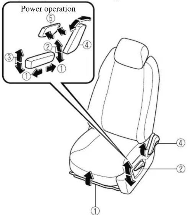
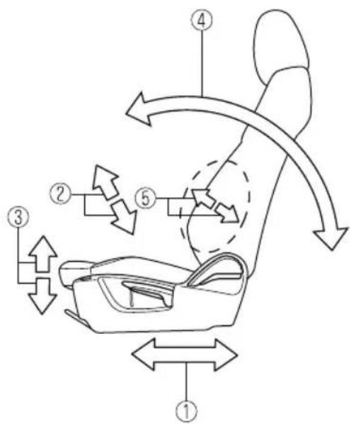
① Seat Slide
(Manual Seat)
To move a seat forward or backward, raise the lever and slide the seat to the desired position and release the lever.
Make sure the lever returns to its original position and the seat is locked in place by attempting to push it forward and backward.
(Power Seat)
To slide the seat, move the slide lifter switch on the outside of the seat to the front or back and hold it. Release the switch at the desired position.
② Height Adjustment
(Manual Seat)
To adjust the seat height, move the lever up or down.
(Power Seat)
To adjust the seat height, move the slide lifter switch up or down.
③ Height Adjustment for Front Edge of Seat Bottom (Power Seat)*
To adjust the front height of the seat bottom, raise or lower the front of the slide lifter switch.
④ Seat Recline
(Manual Seat)
To change the seatback angle, lean forward slightly while raising the lever. Then lean back to the desired position and release the lever.
Make sure the lever returns to its original position and the seatback is locked in place by attempting to push it forward and backward.
(Power Seat)
To change the seatback angle, press the front or rear side of the reclining switch. Release the switch at the desired position.
⑤ Lumbar Support Adjustment (Power Seat)*
To increase the seat firmness, press and hold the front part of the switch to the desired position, then release it.
Press the rear part of the switch to decrease firmness.
Before making adjustments to the driving position recommended by Mazda
Before making adjustments, move the steering wheel and seat to their default positions.
How to move the steering wheel to its default position

WARNING
Never adjust the steering wheel while the vehicle is moving:
Adjusting the steering wheel while the vehicle is moving is dangerous. Moving it can very easily cause the driver to abruptly turn to the left or right. This can lead to loss of control or an accident.
After adjusting the steering wheel position, make sure it is securely locked by trying to move it up and down:
Driving with the steering wheel not securely locked in position is dangerous. If the steering wheel moves unexpectedly while driving, you could lose control of the steering resulting in an accident.
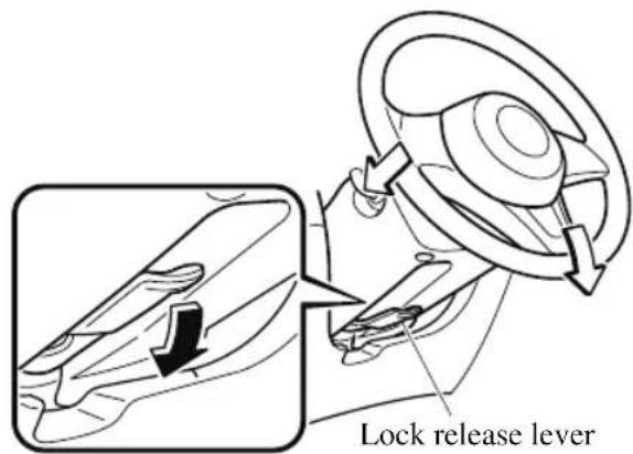
Lower the lever, move the steering wheel to the lowest position, and then push it down and all the way back.
How to move a driver's seat to its default position
- Slide the seat all the way back.
- Lower the seat to its lowest height.
- Sit squarely in the seat and rest your back against the seatback.
Seat adjustment procedure for the driving position recommended by Mazda
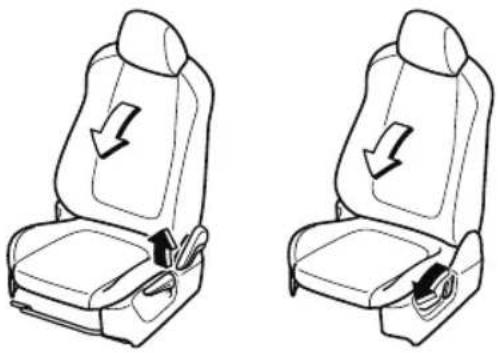
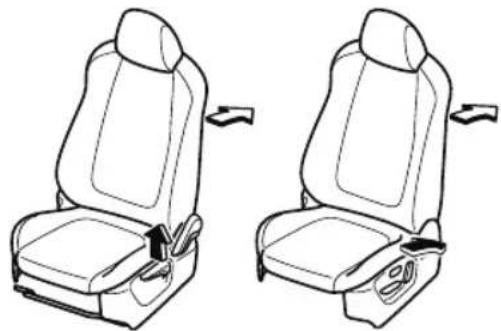
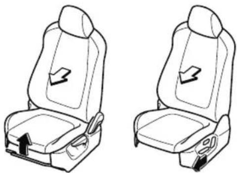
Adjusting the seatback angle (reclining)
Adjust the seatback to the angle providing a comfortable seated posture.
- With your posture slightly slouched, move the seatback forward to the angle where your waist feels slightly cramped.
Manual Seat Power Seat
natural_image
Two identical line drawings of a car seat with directional arrows indicating movement or force (no text or symbols)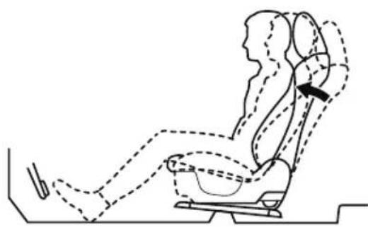
natural_image
Line drawing of a car seat with dashed lines indicating seat positions and a black arrow pointing to the seat (no text or symbols)- Move the seatback backward to a comfortable seated posture without any feeling of cramping in your waist.
Manual Seat Power Seat
natural_image
Line drawing of two car seat compartments with seatbelt and seatbelt attachments (no text or symbols)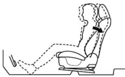
natural_image
Line drawing of a person seated in a car seat, showing body posture and seat area (no text or symbols)Adjusting the seat position forward and back (sliding)
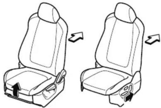
Adjust the seat to the position best for operating the accelerator and brake pedals.
- Place your left foot on the footrest, your right foot between the accelerator and brake pedals, and position your heel to the position allowing easy switching between the pedals.
- With your heel set on the floor, set your right foot on the brake pedal and move the seat forward as far as possible until you feel a slight cramping in your ankle.
Manual Seat Power Seat
natural_image
Line drawings of two car seat compartments with directional arrows indicating seat positions (no text or symbols)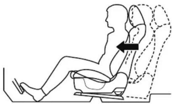
natural_image
Side-view diagram of a person seated in a car seat with an arrow indicating leftward motion (no text or symbols)-
With your right foot set on the brake pedal, move the seat back until you no longer feel cramping in your ankle.
-
With your heel set on the floor, make sure you can move your foot between the brake pedal and accelerator pedal smoothly.
-
Depress the accelerator pedal completely with your heel set on the floor and make sure that your ankle does not feel over-stretched.
Manual Seat Power Seat
natural_image
Line drawing of two car seat compartments with arrows indicating seat movement (no text or symbols)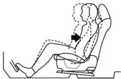
natural_image
Line drawing of a person seated in a car seat with dashed lines indicating motion or movement (no text or symbols)Adjusting the seat height
Adjust the seat height to a position where you have a clear forward view and you can drive the vehicle easily.
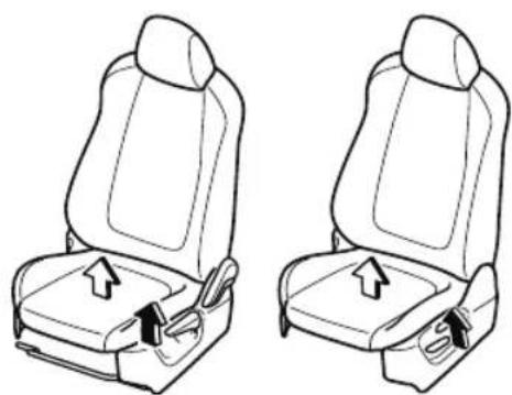
- With your back resting against the seatback, raise the seat to the height where you can see the rear edge area of the hood surface from the windshield.
With the manual seat, if you raise the seat height, the seat moves forward. Adjust the seat forward or back again.
Manual Seat Power Seat
natural_image
Line drawing of two car seatbelt seat configurations with arrows indicating movement (no text or symbols)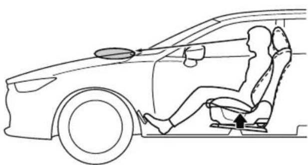
natural_image
Line drawing of a car interior showing a person seated in a seatbelt, with no text or symbols present.Adjusting the steering wheel position
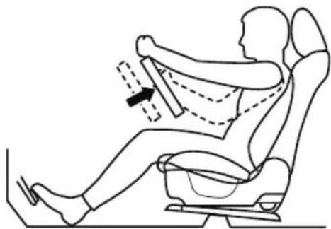
Adjust the steering wheel to the position where it can be operated easily and the gauges can be viewed easily.
- With your back resting against the seatback, extend both arms, place them on the top of the steering wheel, and pull the steering wheel towards you to the position of your wrists.
natural_image
Line drawing of a person seated in a car seat with motion arrows indicating movement (no text or symbols)-
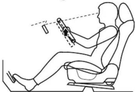
Adjust the steering wheel height so that the gauges can be viewed easily.
-
Raise the lever to securely lock the steering wheel.
natural_image
Line drawing of a person using a car simulator with motion capture (no text or symbols)Adjusting the head restraint position
To prevent shock to the head and neck, adjust the head restraints to their correct positions. Refer to Height Adjustment on page 2-28.
▼ Driving Position Memory\*
The desired driving position can be called up after programming the position.
The following driving positions can be programmed.
- Driver's seat position (seat slide, height adjustment, front edge of seat bottom, seat recline)
Refer to Adjusting the Driver's Seat on page 2-5.
• Active driving display (display position, brightness level, display information) Refer to Active Driving Display on page 4-56.

CAUTION
Do not place fingers or hands around the bottom of the seat while the seat memory function is operating. The seat moves automatically while the seat memory function is operating and fingers or hands could get pinched and injured.
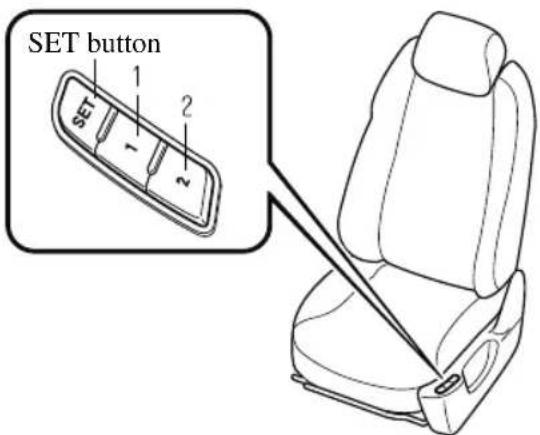
A driving position can be programmed or operated using the buttons on the side of the seat or the key.
NOTE
- Lumbar support adjustment cannot be programmed.
- A driving position can be programmed to the buttons on the side of the seat and the key in use for driving the vehicle.
- If the vehicle has been serviced and the battery cables disconnected, the programmed seat positions will have been erased. Re-program the seat positions.
Programming
- Make sure the parking brake is on.
- Make sure the selector lever is in the P position.
-
Start the engine.
-
Adjust the seat and the active driving display to the desired driving position.
- Press the SET button on the seat until a beep sound is heard 1 time.
-
Perform one of the following settings within 5 seconds of completing step 5 above:
-
Programming using a button on the side of the seat
Press the button you want to program, either button 1 or 2, until a beep sound is heard 1 time. - Programming using the key
Press the key unlock button until a beep sound is heard 1 time.
NOTE
If a beep sound is heard 3 times, the operation is canceled.
To move the driving position to a programmed position
(Using a button on the side of the seat)
- Make sure the parking brake is on.
- Make sure the selector lever is in the P position.
- Start the engine.
- Press the programming button for the driving position you want to call up (button 1 or 2).
- A beep sound is heard when the driving position adjustment is completed.
NOTE
- If the driving position movement is not changed, only the beep sounds.
-
A seat position can be called up even with the engine not running.
• The driving position adjustment is canceled in the following cases: -
Any of the seat adjustment switches is operated.
- The SET button is pressed.
- Programming button 1 or 2 is pressed.
- The key lock button or unlock button is operated.
· The vehicle starts moving. - The active driving display is adjusted.
(Using a programmed key)
- Unlock the doors by pressing a request switch or the key unlock button.
- After unlocking the doors, the seat position adjustment begins within 40 seconds of opening the driver's door, and a beep sounds when the operation is finished.
- Make sure the parking brake is on.
- Make sure the selector lever is in the P position.
- Start the engine.
- The active driving display adjustment begins.
NOTE
- If there is no driving position movement, a beep is not heard.
• The driving position adjustment is canceled in the following cases:
- Any of the seat adjustment switches is operated.
- The SET button is pressed.
- Programming button 1 or 2 is pressed.
- The key lock button or unlock button is operated.
- The vehicle starts moving.
- The active driving display is adjusted.
Erasing programmed driving positions
(Erasing the driving positions programmed to the key)
- Switch the ignition OFF.
- Press the SET button on the side of the seat until a beep sound is heard 1 time.
- After the beep sounds, press the key lock button within 5 seconds until a beep sound is heard 1 time.
NOTE
If a beep sound is heard 3 times, the operation is canceled.
▼ Adjusting the Front Passenger's Seat
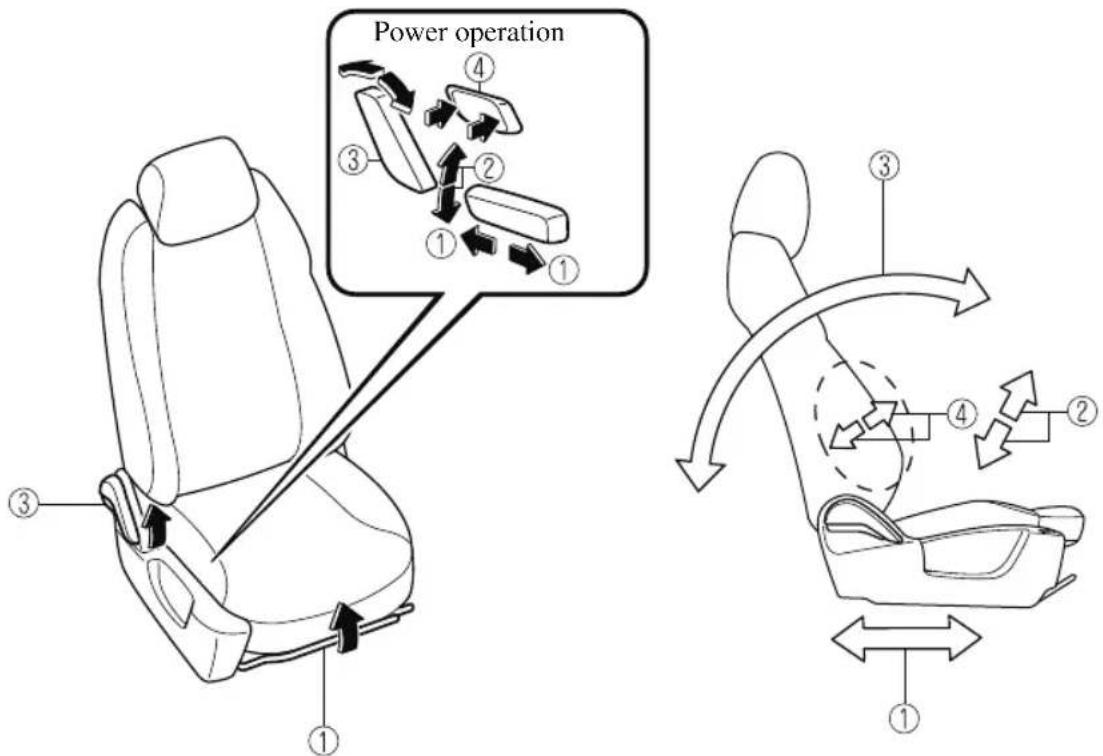
① Seat Slide
(Manual Seat)
To move a seat forward or backward, raise the lever and slide the seat to the desired position and release the lever.
Make sure the lever returns to its original position and the seat is locked in place by attempting to push it forward and backward.
(Power Seat)
To slide the seat, move the slide lifter switch on the outside of the seat to the front or back and hold it. Release the switch at the desired position.
②Height Adjustment (Power Seat)\*
To adjust the seat height, move the slide lifter switch up or down.
③ Seat Recline
(Manual Seat)
To change the seatback angle, lean forward slightly while raising the lever. Then lean back to the desired position and release the lever.
Make sure the lever returns to its original position and the seatback is locked in place by attempting to push it forward and backward.
(Power Seat)
To change the seatback angle, press the front or rear side of the reclining switch. Release the switch at the desired position.
④ Lumbar Support Adjustment (Power Seat)*
To increase the seat firmness, press and hold the front part of the switch to the desired position, then release it.
Press the rear part of the switch to decrease firmness.
Second-row Seat (6:4 Split Adjustable-type Bench Seat Type)
▼ Seat Operation
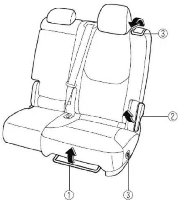
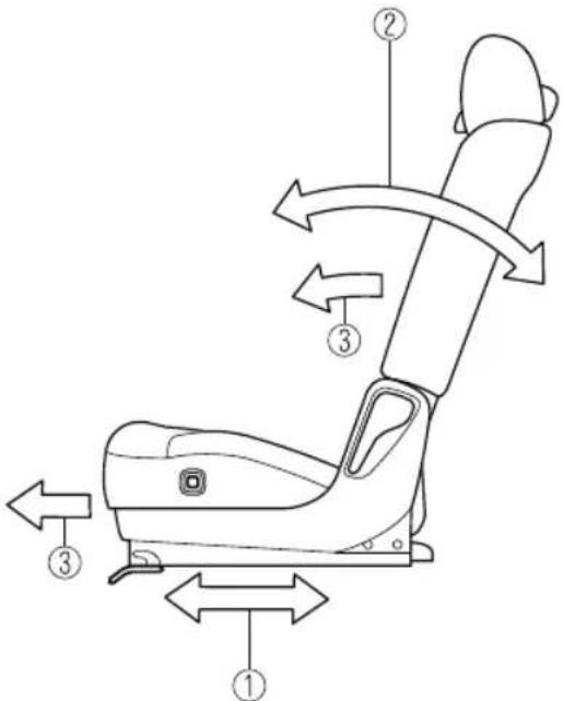
①Seat Slide (Forward-back adjustment)
To move a seat forward or backward, raise the lever and slide the seat to the desired position and release the lever.
Make sure the lever returns to its original position and the seat is locked in place by attempting to push it forward and backward.
②Seat Recline
To change the seatback angle, lean forward slightly while raising the lever. Then lean back to the desired position and release the lever.
The lever can also be used when flattening down the seats.
Refer to Split Folding the Second-row Seats on page 2-20.
Make sure the lever returns to its original position and the seatback is locked in place by attempting to push it forward and backward.
③Third-row Seat Access
(Lever)
Pull up the lever on the side of the head restraint to fold the seatback and slide the seat forward.
Refer to Third-row Seat Access on page 2-16.
Make sure the lever returns to its original position and the seat is locked in place by attempting to push it forward and backward.
(Switch)\*
Press the switch to fold the seatback forward and release the seat slide lock. Then slide the seat forward.
Refer to Third-row Seat Access on page 2-16.
Make sure the seat is locked in place by attempting to push it forward and backward.
Armrest
The armrest in the center of the second-row seatback can be used (no occupant in the center seat) or placed upright.
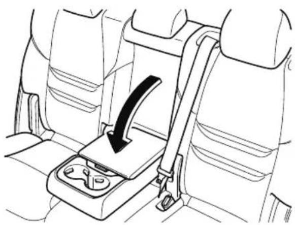
natural_image
Line drawing of a car seatbelt with a black arrow indicating direction (no text or symbols)WARNING
Never put your hands and fingers around the moving parts of the seat and armrest:
Putting your hands and fingers around the moving parts of the seat and armrest is dangerous as they could get injured.
CAUTION
When storing the armrest, make sure that any cables connected to the USB power outlets in the armrest box are stored away in the armrest box.
If the cables are not stored away in the armrest box, the cables and connection devices may become damaged when storing the armrest.
➢ Be careful not to apply excessive force to the armrest such as by sitting on it. Otherwise, it could be deformed or damaged.
▼ Third-row Seat Access
Occupants can get into and out of the third-row seats easily by sliding the second-row seats forward.
WARNING
Make sure there is nobody in the second-row seat area before operating a lever or pressing a switch:
Not checking the second-row seat area for persons before folding a seatback with a lever or switch is dangerous. The second-row seat area is difficult to see from the rear of the vehicle. Operating a lever or pressing a switch without checking could cause injury to a person when a seatback suddenly flips forward.
Do not operate the lever on the side of the head restraint or press the switch on the side of the seat under the following conditions:
Operating the lever on the side of the head restraint or pressing the switch on the side of the seat under the following conditions is dangerous as the seat may move unexpectedly and cause an injury such as a foot getting pinched between the seat and floor.
▶Occupant is seated in second-row seat
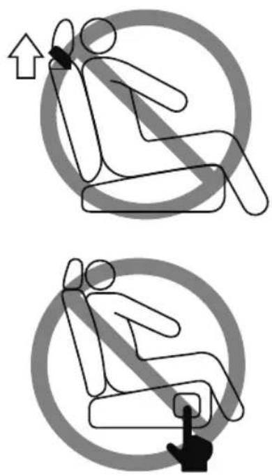
Second-row seatback is folded forward
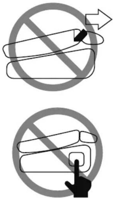
➢Child is seated on child restraint in second-row seat
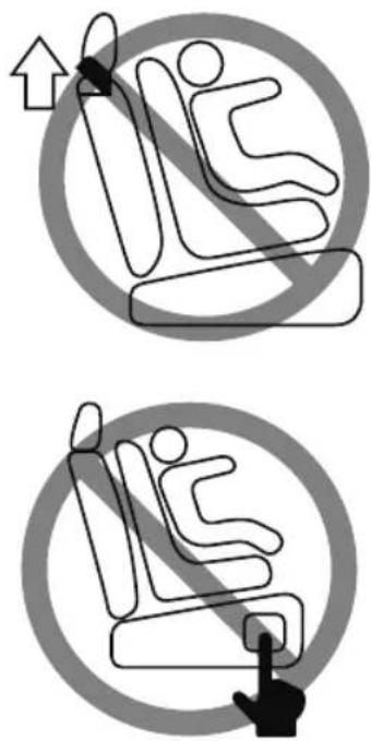

CAUTION
When operating the seat, be careful not to get your hand or foot caught, or hit your head.
Before moving the second-row seat, make sure that the head restraint is at the lowest position. If the second-row seat is folded forward while the head restraint is pulled up, there will not be enough space for getting in or out of the vehicle which could cause an occupant to trip and fall resulting in injury.
➢Check the position of a front seat before folding a second-row seatback.
Depending on the position of a front seat, it may not be possible to fold a second-row seatback all the way down because it may hit the seatback of the front seat which could scratch or damage the front seat or its pocket.
Remove the head restraint on the second-row outboard seat if necessary.
Entering/exiting the third-row seat area
- Lower the head restraint all the way down.
Refer to Head Restraints on page 2-28.
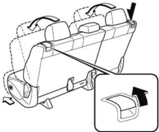
- (Lever)
Pull up the lever on the side of the head restraint to unlock the seat, fold
the seatback forward, and slide the seat forward.
natural_image
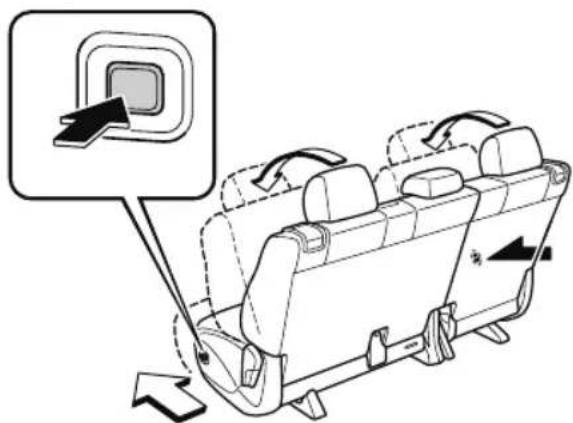
Diagram of a car interior showing seat arrangement and steering wheel (no text or symbols)(Switch)
To unlock the seat, press the switch continuously until a sound is activated, release it, fold the seatback forward, and slide the seat forward.
NOTE
When any of the following conditions is met, a beep sound is activated continuously and the switch operation is canceled.
- The door on the side where the switch was operated is closed.
- The switch is pressed continuously for 5 s or more.
- The vehicle is being driven.
- The selector lever is in a position other than P , and the parking brake is off.
• The battery has deteriorated.
- There is a system problem.

CAUTION
Do not operate the lever on the side of a second-row seat while the seatback is folded down and the seat is slid forward. If the lever is forcefully operated, it could damage the lever.
➢After entering/exiting the third-row seat area, return the second-row seatback to its upright position and lock it after sliding it rearward.
Make sure it is locked by attempting to lightly move it back and forth.
Otherwise, it could move unexpectedly and cause injury.
After getting in or out of the vehicle
Move the seatback rearward, slide the seat rearward, and lock the seat.
Entering/exiting the third-row seat area with child-restraint system installed (Right-side seat only)
Access to the third-row seats is possible even when a child-restraint system is installed to the second-row seat.
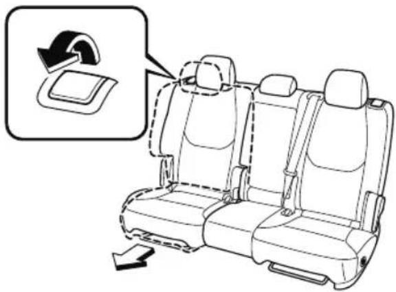
(Lever)
Pull up the lever on the side of the head restraint to lower the front side of the seat and slide the seat forward.
natural_image
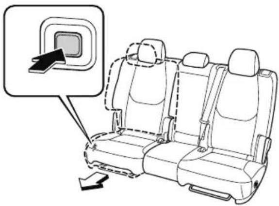
Line drawing of a car seat assembly with a highlighted seatbelt (no text or symbols)(Switch)
To unlock the seat, press the switch continuously until a sound is activated, release it, fold the seatback forward, and slide the seat forward.
NOTE
When any of the following conditions is met, a beep sound is activated continuously and the switch operation is canceled.
- The door on the side where the switch was operated is closed.
- The switch is pressed continuously for 5 s or more.
• The vehicle is being driven. - The selector lever is in a position other than P , and the parking brake is off.
• The battery has deteriorated.
- There is a system problem.
natural_image
Line drawing of a car seat assembly with a highlighted panel and directional arrow (no text or symbols)
CAUTION
After entering/exiting the third-row seat area, lock the seat after sliding it rearward. Make sure it is locked by attempting to lightly move it back and forth.
Otherwise, it could move unexpectedly and cause injury.
natural_image
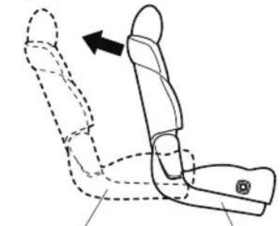
Line drawing of a car seat assembly with dashed lines indicating movement or positioning (no text or symbols)Second-row seat
fixed position
Third-row seat
ingress/egress
NOTE
The second-row seat cannot be moved forward while the seat belt is securing the child-restraint system.
After getting in or out of the vehicle
Move the seatback rearward, slide the seat rearward, and lock the seat.
▼ Split folding the Second-row Seats
To create a flat luggage compartment space, fold the seatbacks forward.
Folding the seatbacks

WARNING
Make sure the adjustable components of a second-row seat are locked after folding down the seatback:
A second-row seat that is not securely locked is dangerous. In a sudden stop or collision, the second-row seat could move, causing injury.
After folding down the seatback of a second-row seat, make sure the adjustable components of the seat are locked in place by attempting to slide the seat forward and backward.

CAUTION
When folding the seatback forward, always support the seatback with your hand. If it is not supported by a hand, fingers or the hand raising the lever could be injured.
Check the position of a front seat before folding a second-row seatback. Depending on the position of a front seat, it may not be possible to fold a second-row seatback all the way down because it may hit the seatback of the front seat which could scratch or damage the front seat or its pocket. Remove the head restraint on the second-row outboard seat if necessary.
NOTE
The seats cannot be flattened down while the second-row seats are unlocked even if the lever on the side of the head restraint is operated and the reclining lever is operated. Before folding down the second-row seats, move the seatback forward once, slide the seat rearward, and lock the seat.
- Lower the head restraint all the way down.
Refer to Head Restraints on page 2-28.
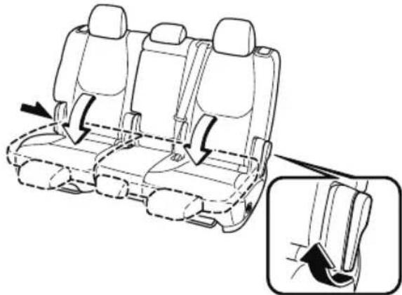
- Raise the lever on the side of the second-row seat to fold down the seatback.
natural_image
Line drawing of a car seat assembly with directional arrows indicating movement (no text or symbols)NOTE
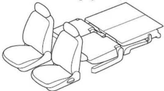
To create a flat luggage compartment space from the rear of the vehicle to the back of the front seats, fold the second-row and third-row seats (page 2-26).
natural_image
Line drawing of a vehicle seat assembly with two seats and a tray (no text or symbols)To return the seatback to its upright position:

WARNING
When returning a seatback to its upright position, make sure the 3-point seat belt is not caught in the seatback and the 3-point seat belt is not twisted:
If the seat belt is used while it is twisted and caught in the seatback, the seat belt cannot function at its full capacity, which could cause serious injury or death.
-
Make sure that the seat belt is not stuck in the second-row seat and it is not twisted, then raise the seatback while preventing the seat belt from being caught in the seatback.
-
Press the seatback rearward and lock it in place. After returning the seatback to its upright position, make sure it is securely locked.
Second-row Seat (Captain Seat Type)
Armrest type with angle adjustment function (center walk-through)
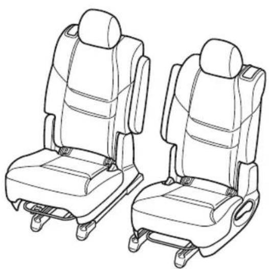
Second-row seat console type
natural_image
Line drawing of two car seat compartments with seat covers and wheels (no text or symbols)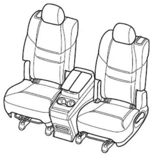
natural_image
Line drawing of two passenger cars with seat covers and driver seats, no text or symbols present▼ Seat Operation
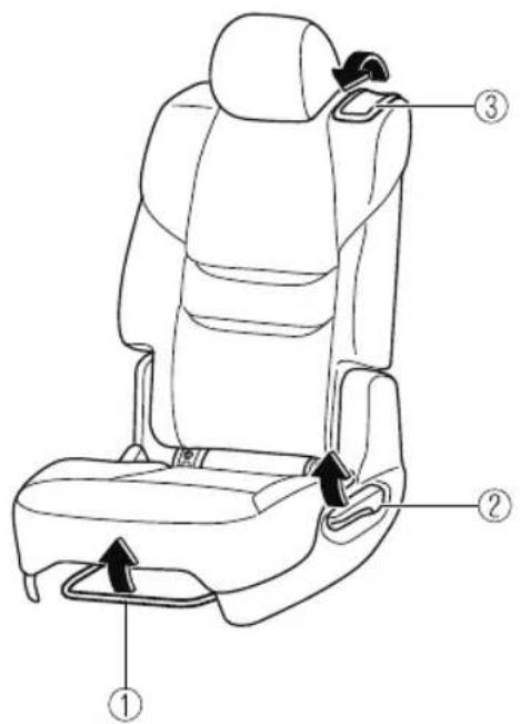
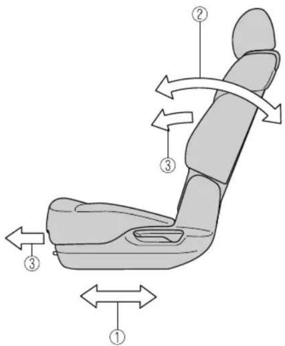
①Seat Slide (Forward-back adjustment)
To move a seat forward or backward, raise the lever and slide the seat to the desired position and release the lever.
Make sure the lever returns to its original position and the seat is locked in place by attempting to push it forward and backward.
②Seat Recline
To change the seatback angle, lean forward slightly while raising the lever. Then lean back to the desired position and release the lever.
The lever can also be used when flattening down the seats.
Refer to How to Split Folding the Second-row Seats on page 2-25.
Make sure the lever returns to its original position and the seatback is locked in place by attempting to push it forward and backward.
③Third-row Seat Access
To access to the third-row seats, pull up the lever on the side of the head restraint to fold the seatback and slide the seat forward.
Refer to How to Third-row Seat Access on page 2-24.
Make sure the lever returns to its original position and the seatback is locked in place by attempting to push it forward and backward.
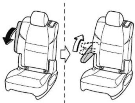
Armrest
Using the armrest
The armrest on the side of the second-row seatback can be used or placed upright.
Adjusting the angle
The angle of the armrest can be adjusted according to the angle of the seatback. To adjust the angle, lower the armrest to the lowest position, pull it up to the desired position, and then lock it. To adjust the angle again, store the armrest once and then lower the armrest to the lowest position again.
After adjustment, make sure that the armrest is securely locked by lightly pressing it down.
natural_image
Line drawing showing a car seat replacement process, showing left and right views with arrows indicating motion (no text or symbols)WARNING
Never position the shoulder portion of a seat belt over the armrest:
Positioning the shoulder portion of a second-row seat belt over the armrest is dangerous as it cannot provide adequate protection in a collision and could result in serious injuries.
Never put your hands and fingers around the moving parts of the seat and armrest:
Putting your hands and fingers around the moving parts of the seat and armrest is dangerous as they could get injured.

CAUTION
Be careful not to apply excessive force to the armrest such as by sitting on it. Otherwise, it could be deformed or damaged.
▼ Third-row Seat Access
Occupants can get into and out of the third-row seats easily by sliding the second-row seats forward.

WARNING
Make sure there is nobody in the second-row seat area before operating the levers:
Not checking the second-row seat area for persons before folding the seatbacks with the levers is dangerous. The second-row seat area is difficult to see from the rear of the vehicle. Operating the levers without checking could cause injury to a person when a seatback suddenly flips forward.

CAUTION
Before moving the second-row seat, make sure that the head restraint is at the lowest position. If the second-row seat is folded forward while the head restraint is pulled up, there will not be enough space for getting in or out of the vehicle which could cause an occupant to trip and fall resulting in injury.
NOTE
Occupants can also get in and out of the third-row seat area by passing between the second-row seats with the armrest type having the angle adjustment function. Occupants can pass through easily by tilting the armrest forward.
Entering/exiting the third-row seat area
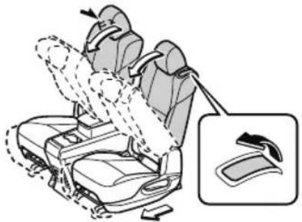
- Lower the head restraint all the way down.
Refer to Head Restraints on page 2-28. - Pull up the lever on the side of the head restraint to unlock the seat, fold the seatback forward, and slide the seat forward.
natural_image
Diagram of a car seatbelt with a magnified inset showing the seat (no text or symbols present)NOTE
The seats cannot be flattened down while the second-row seats are unlocked even if the lever on the side of the head restraint is operated and the reclining lever is operated. Before folding down the second-row seats, move the seatback forward once, slide the seat rearward, and lock the seat.
After getting in or out of the vehicle
Move the seatback rearward, slide the seat rearward, and lock the seat.

CAUTION
After entering/exiting the third-row seat area, return the second-row seatback to its upright position and lock it after sliding it rearward.
Make sure it is locked by attempting to lightly move it back and forth.
Otherwise, it could move unexpectedly and cause injury.
▼ Split folding the Second-row Seats
To create a flat luggage compartment space, fold the seatbacks forward.

WARNING
Make sure the adjustable components of a second-row seat are locked after folding down the seatback:
A second-row seat that is not securely locked is dangerous. In a sudden stop or collision, the second-row seat could move, causing injury.
After folding down the seatback of a second-row seat, make sure the adjustable components of the seat are locked in place by attempting to slide the seat forward and backward.
Do not drive the vehicle with an occupant on a folded down seatback or in the luggage compartment:
During sudden braking or a collision, the person could be seriously injured or killed.
Tightly secure cargo in the luggage compartment when it is transported with the seatbacks folded down:
Driving without tightly securing cargo and luggage is dangerous as it could move and become an obstruction to driving during emergency braking or a collision resulting in an unexpected accident.

CAUTION
When folding the seatback forward, always support the seatback with your hand. If it is not supported by a hand, fingers or the hand raising the lever could be injured.
➢ Check the position of a front seat before folding a second-row seatback.
Depending on the position of a front seat, it may not be possible to fold a second-row seatback all the way down because it may hit the seatback of the front seat which could scratch or damage the front seat or its pocket.
Remove the head restraint on the second-row outboard seat if necessary.
NOTE
The seats cannot be flattened down while the second-row seats are unlocked even if the lever on the side of the head restraint is operated and the reclining lever is operated. Before folding down the second-row seats, move the seatback forward once, slide the seat rearward, and lock the seat.
Folding the seatbacks
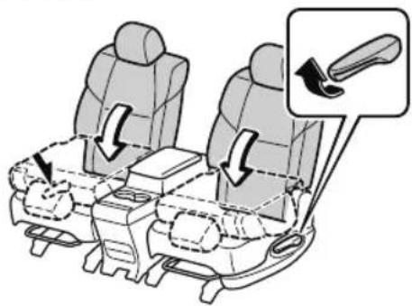
- Lower the head restraint all the way down.
Refer to Head Restraints on page 2-28.
- (Armrest type with angle adjustment function)
If the armrests are down, fold them back up.
- Raise the lever on the side of the second-row seat to fold down the seatback.
To return the seatback to its upright position
Press the seatback rearward and lock it in place. After returning the seatback to its upright position, make sure it is securely locked.
Third-row Seat
▼ Split folding the Third-row Seats
To create a luggage compartment space, fold the third-row seats forward.
CAUTION
Do not apply load to the head restraint with it in the upright position and the seatback folded down. Otherwise, it could cause damage to the head restraint.
NOTE
When folding the seatbacks forward, fold them in two steps.
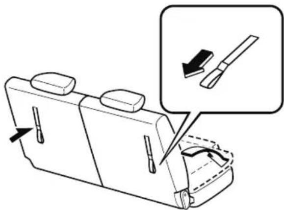
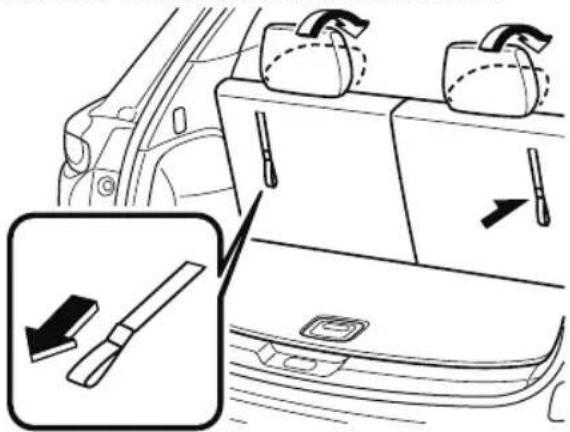
Folding the seatbacks (With strap)
- Secure the third-row seat seat belts into their holders.
Refer to Unfastening the Seat Belt on page 2-38. - Slide the second-row seat all the way forward.
- Pull the strap to fold down the head restraint.
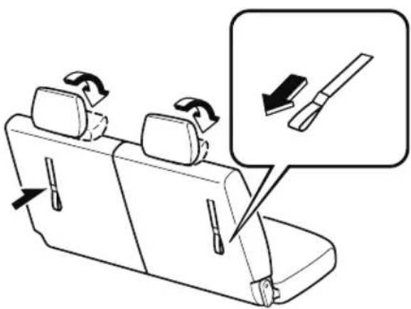
- Pull the strap further to fold the third-row seat forward.
Folding the seatbacks (With lever)
- Secure the third-row seat seat belts into their holders.
Refer to Unfastening the Seat Belt on page 2-38. - Slide the second-row seat all the way forward.
- Lower the lever to fold down the head restraint.
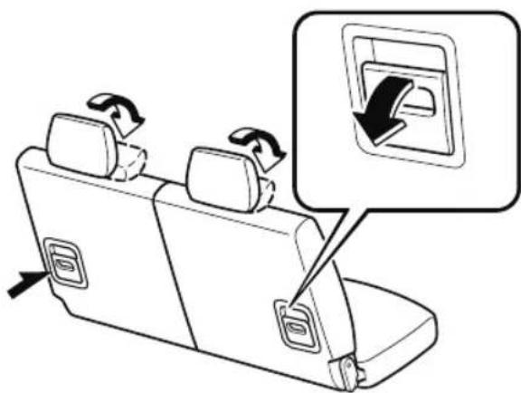
- Lower the lever further to fold the third-row seat forward.
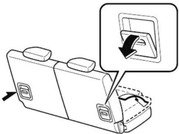
NOTE
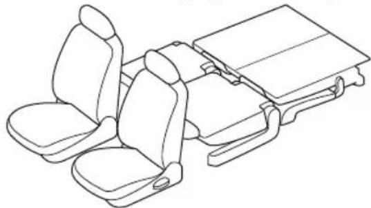
To create a flat luggage compartment space from the rear of the vehicle to the back of the front seats, fold the second-row and third-row seats (page 2-20, 2-25).
natural_image
Line drawing of a vehicle rear seat assembly with driver seat and cab (no text or symbols)To return third-row seat to its original position
- Return the seatback to its original position by pulling the strap/lever on the back of the seatback.
Make sure the seatback is secured by attempting to lightly move it forward and back.
- Lift the head restraint upward to its upright position.
Head Restraints
Your vehicle is equipped with head restraints on all outboard seats and the second-row center seat. The head restraints are intended to help protect you and the passengers from neck injury.

WARNING
Always drive with the head restraints installed when seats are being used and make sure they are properly adjusted. In addition, always raise the head restraints on all second-row seats when they are being used:
Driving with the head restraints adjusted too low or removed is dangerous. With no support behind your head, your neck could be seriously injured in a collision.
NOTE
(Third-row seat)
The head restraints are non-adjustable.
▼ Height Adjustment
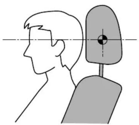
Adjust the head restraint so that the center is even with the top of the passenger's ears.
natural_image
Side-view diagram of a person facing the side of a human head, showing anatomical alignment (no text or symbols)To raise a head restraint, pull it up to the desired position.
To lower the head restraint, press the stop-catch release, then push the head restraint down.
Front outboard seat
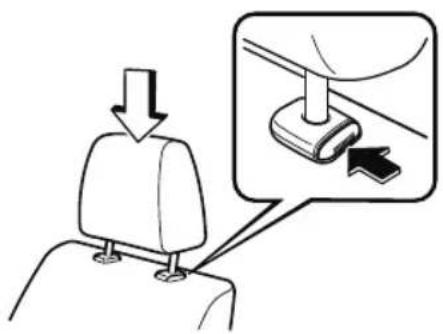
Second-row outboard seat
(6:4 Split Adjustable-type Bench Seat Type)
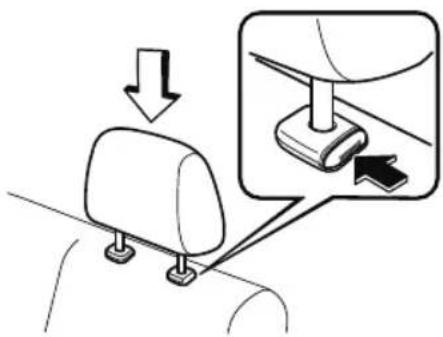
(Captain Seat Type)
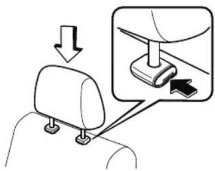
Second-row center seat (6:4 Split Adjustable-type Bench Seat Type)
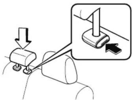
▼ Removal/Installation (Front outboard seat/Second-row seat)
To remove the head restraint, pull it up while pressing the stop-catch.
To install the head restraint, insert the legs into the holes while pressing the stop-catch.

WARNING
Always drive with the head restraints installed when seats are being used and make sure they are properly installed:
Driving with the head restraints not installed is dangerous. With no support behind your head, your neck could be seriously injured in a collision.
After installing a head restraint, try lifting it to make sure that it does not pull out:
Driving with an unsecured head restraint is dangerous as the effectiveness of the head restraint will be compromised which could cause it to unexpectedly detach from the seat.

CAUTION
When installing a head restraint, make sure that it is installed correctly with the front of the head restraint facing forward. If the head restraint is installed incorrectly, it could detach from the seat during a collision and result in injury.
The head restraints on each of the front and second-row seats are specialized to each seat. Do not switch around the head restraint positions. If a head restraint is not installed to its correct seat position, the effectiveness of the head restraint during a collision will be compromised which could cause injury.
▼ Foldable Head Restraints (Third-row Seat)
The third-row seats are equipped with foldable head restraints.
NOTE
The foldable head restraints cannot be adjusted or removed.
(With strap)
To fold the head restraint, pull the strap and fold the head restraint downward.
natural_image
Diagram showing a car trunk with accessories and a close-up of a tool interacting with the door (no text or symbols present)(With lever)
To fold the head restraint, lower the lever down.
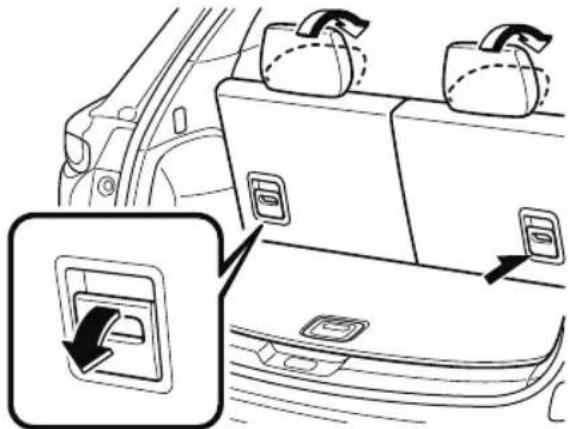
natural_image
Diagram of a car backrest with two rear seats and a directional arrow indicating a switch or fastening (no text or symbols present)To return the head restraint to its upright position, lift it upward.

WARNING
Always drive with the head restraints in their upright positions when the third-row seats are occupied, and make sure they are securely locked in place:
Driving with the head restraints folded down is dangerous. With no support behind your head, your neck could be seriously injured in a collision.
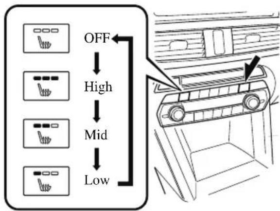
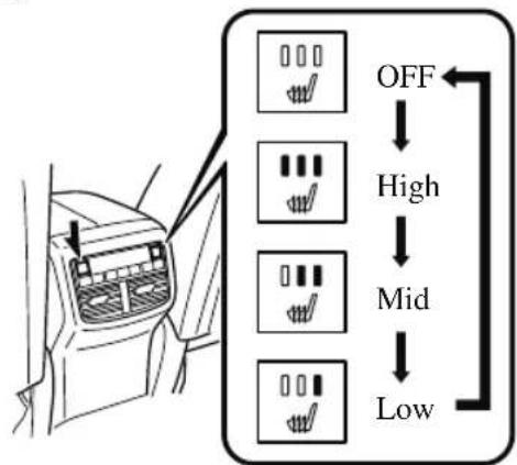
Seat Warmer\*
The front/second-row seats are electrically heated. The ignition must be switched ON. Press the seat warmer switch while the ignition is switched ON to operate the seat warmer. The indicator lights turn on to indicate that the seat warmer is operating. The mode changes as follows each time the seat warmer switch is pressed. When using the second-row seat warmer, fold the armrest forward. Refer to Armrest on page 2-16.
Front
flowchart
graph TD
    A["OFF"] --> B["High"]
    B --> C["Mid"]
    C --> D["Low"]
Second-row seat\*
(6:4 Split Adjustable-type Bench Seat Type)
flowchart
graph TD
    A["OFF"] --> B["High"]
    B --> C["Mid"]
    C --> D["Low"]
(Captain Seat Type)
Center Walk-thorough Type

flowchart
graph TD
    A["Left Vehicle"] --> B["Checkmark Off"]
    A --> C["Checkmark High"]
    A --> D["Checkmark Mid"]
    A --> E["Checkmark Low"]
    B --> F["Arrow Left"]
    C --> G["Arrow Right"]
    D --> H["Arrow Down"]
    E --> I["Arrow Up"]
Second-row Console Type
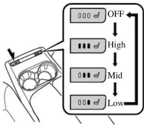
flowchart
graph TD
    A["0 0 0"] --> B["OFF"]
    C["..."] --> D["High"]
    E["..."] --> F["Mid"]
    G["..."] --> H["Low"]

WARNING
Be careful when using the seat warmer:
The heat from the seat warmer may be too hot for some people, as indicated as follows, and could cause a low-temperature burn.
➢ Infants, small children, elderly people, and physically challenged people
▶ People with delicate skin
▶ People who are excessively fatigued
▶ People who are intoxicated
➢ People who have taken sleep-inducing medicine such as sleeping pills or cold medicine
Do not use the seat warmer with anything having high moisture-retention ability such as a blanket or cushion on the seat:
The seat may be heated excessively and cause a low-temperature burn.
Do not use the seat warmer even when taking a short nap in the vehicle:
The seat may be heated excessively and cause a low-temperature burn.
Do not place heavy objects with sharp projections on the seat, or insert needles or pins into it:
This could cause the seat to become excessively heated and result in injury from a minor burn.

CAUTION
➢(Second-row seat)
Before folding a second-row seatback, make sure that the second-row seat warmer switch is off. If a second-row seatback is folded while the second-row seat warmer is in operation, it may heat the seat excessively and damage the seat surface.
➢Do not use organic solvents to clean the seat. It may damage the seat surface and the heater.
NOTE
- Use the seat warmer when the engine is running. Leaving the seat warmer on for long periods with the engine not running could cause the battery power to be depleted.
- When the engine is stopped while the seat warmers are operating and then the ignition is switched ON, the seat warmers will not turn back on automatically. To turn the seat warmers back on, press the switch. In addition, the second-row seat warmer operation stops automatically after the seat warmers have operated for about 90 minutes.
- The temperature of the seat warmer cannot be adjusted beyond High, Mid and Low because the seat warmer is controlled by a thermostat.
· (Vehicles with seat ventilation)
The front seat warmer cannot be used at the same time as the seat ventilation.
Seat Ventilation\*
The seat ventilation uses fans installed in the seats to draw air around the seat surface and ventilate them. The ignition must be switched ON.
Press the seat ventilation switch while the ignition is switched ON to operate the seat ventilation. The indicator lights turn on to indicate that the seat ventilation is operating. The mode changes as follows each time the seat ventilation switch is pressed.
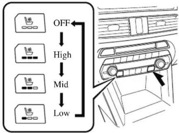
flowchart
graph TD
    A["OFF"] --> B["High"]
    B --> C["Mid"]
    C --> D["Low"]

CAUTION
➢Do not use organic solvents to clean the seat. It may damage the seat surface and the seat ventilation parts.
➢Do not place heavy objects with sharp projections on the seat, or insert needles or pins into it.
NOTE
- Use the seat ventilation when the engine is running. Leaving the seat ventilation on for long periods with the engine not running could cause the battery power to be depleted.
- When the engine is stopped while the seat ventilations are operating and then the ignition is switched ON, the seat ventilations will not turn back on automatically.
· (Vehicles with front seat warmer) The seat ventilation cannot be used at the same time as the front seat warmer.
Heated Steering Wheel\*
The grips on the left and right of the steering wheel can be warmed up.
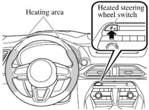
The ignition must be switched ON.
Press the switch to turn on the heated steering wheel. The heated steering wheel operates for about 30 minutes and then turns off automatically.
The indicator light illuminates when the heater is operating.
To turn off the heated steering wheel before the 30 minutes has elapsed, press the switch again.
CAUTION
The following types of persons should be careful not to touch the steering wheel. Otherwise, it could cause a low-temperature burn.
➢ Infants, small children, elderly people, and physically challenged people
▶ People with delicate skin
▶ People who are excessively fatigued
▶ People who are intoxicated
➢People who have taken sleep-inducing medicine such as sleeping pills or cold medicine
Seat Belt Precautions
Seat belts help to decrease the possibility of severe injury during accidents and sudden stops. Mazda recommends that the driver and all passengers always wear seat belts.
(Except Mexico)
All of the seat belt retractors are designed to keep the lap/shoulder belts out of the way when not in use.
The driver's seat belt has no provisions for child-restraint systems and has only an emergency locking mode. The driver may wear it comfortably, and it will lock during a collision.
However, the front passenger's seat and all rear lap/shoulder belt retractors operate in two modes: emergency locking mode, and for child-restraint systems, automatic locking mode.
While we recommend you put all children in the rear seats, if you must use the front passenger seat for a child, slide the front passenger seat as far back as possible and make sure any child-restraint system is secured properly.
(Mexico)
All the seats have lap/shoulder belts. These belts have retractors with inertia locks that keep them out of the way when not in use. The locks allow the belts to remain comfortable on users, but they will lock in position during a collision.

WARNING
Always wear your seat belt and make sure all occupants are properly restrained:
Not wearing a seat belt is extremely dangerous. During a collision, occupants not wearing seat belts could hit someone or things inside the vehicle or even be thrown out of the vehicle. They could be seriously injured or even killed. In the same collision, occupants wearing seat belts would be much safer.
Do not wear twisted seat belts:
Twisted seat belts are dangerous. In a collision, the full width of the belt is not available to absorb the impact. This puts more force on the bones beneath the belt, which could cause serious injury or death. So, if your seat belt is twisted, you must straighten the seat belt to remove any twists and to allow the full width of the belt to be used.
Never use one seat belt on more than one person at a time:
Using one seat belt for more than one person at a time is dangerous. A seat belt used in this way cannot spread the impact forces properly and the two passengers could be crushed together and seriously injured or even killed. Never use one belt for more than one person at a time and always operate the vehicle with each occupant properly restrained.
Do not operate a vehicle with a damaged seat belt:
Using a damaged seat belt is dangerous. An accident could damage the belt webbing of the seat belt in use. A damaged seat belt cannot provide adequate protection in a collision. Have an Authorized Mazda Dealer inspect all seat belt systems in use during an accident before they are used again.
Have your seat belts changed immediately if the pretensioner or load limiter has been expended:
Always have an Authorized Mazda Dealer immediately inspect the seat belt pretensioners and air bags after any collision. Like the air bags, the seat belt pretensioners and load limiters will only function once and must be replaced after any collision that caused them to deploy. A seat belt with an expended pretensioner or load limiter is still better than wearing no seat belt at all; however, if the seat belt pretensioners and load limiters are not replaced, the risk of injury in a collision will increase.
Positioning the Shoulder Portion of the Seat Belt:
Improper positioning of the shoulder portion of the seat belt is dangerous. Always make sure the shoulder portion of the seat belt is positioned across your shoulder and near your neck, but never under your arm, on your neck, or on your upper arm.
Positioning the Lap Portion of the Seat Belt:
The lap portion of the seat belt worn too high is dangerous. In a collision, this would concentrate the impact force directly on the abdominal area, causing serious injury. Wear the lap portion of the belt snugly and as low as possible.
In a rollover crash, an unbelted person is significantly more likely to die than a person wearing a seat belt.

CAUTION
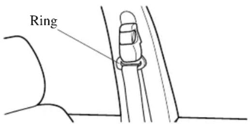
Belt retraction may become difficult if the belts and rings are soiled, so try to keep them clean. For more details about cleaning the seat belts, refer to "Seat Belt Maintenance" (page 6-58).
▼ Pregnant Women and Persons with Serious Medical Conditions
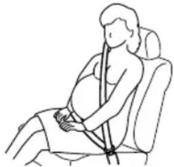
Pregnant women should always wear seat belts. Ask your doctor for specific recommendations.
The lap belt should be worn SNUGLY AND AS LOW AS POSSIBLE OVER THE HIPS.
The shoulder belt should be worn across your shoulder properly, but never across the stomach area.
Persons with serious medical conditions also should wear seat belts. Check with your doctor for any special instructions regarding specific medical conditions.
natural_image
Line drawing of a pregnant woman seated in a seat, holding a bandage (no text or symbols)▼ Emergency Locking Mode
When the seat belt is fastened, it will always be in the emergency locking mode.
In the emergency locking mode, the belt remains comfortable on the occupant and the retractor will lock in position during a collision.
If the belt is locked and cannot be pulled out, retract the belt once, and then try pulling it out slowly. If this fails, pull the belt strongly 1 time and loosen, then pull it out again slowly.
(Seat Belt with Automatic Locking Mode)
When the seat belt is fastened, it will always be in the emergency locking mode until it is switched to automatic locking mode by pulling it all the way out to its full length. If the belt feels tight and hinders comfortable movement while the vehicle is stopped or in motion, it may be in the automatic locking mode because the belt has been pulled too far out. To return the belt to the more comfortable emergency locking mode, wait until the vehicle has stopped in a safe, level area, retract the belt fully to convert it back to emergency locking mode and then extend it around you again.
▼ Automatic Locking Mode\*
Always use the automatic locking mode to keep the child-restraint system from shifting to an unsafe position in the event of an accident. To enable seat belt automatic locking mode, pull it all the way out and connect it as instructed on the child-restraint system. It will retract down to the child-restraint system and stay locked on it. See the section on child restraint (page 2-44).
Seat Belt
▼ Fastening the Seat Belt
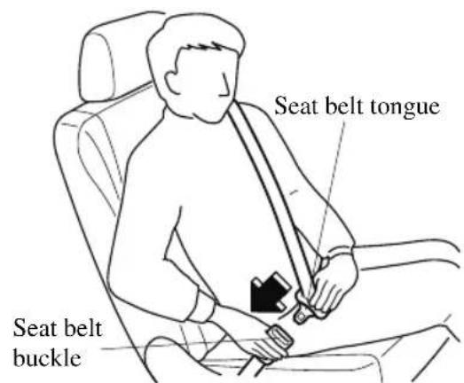
Position the lap belt as low as possible, not on the abdominal area, then adjust the shoulder belt so that it fits snugly against your body.

▼ Unfastening the Seat Belt
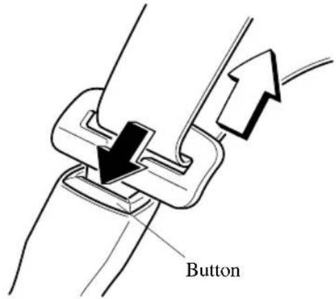
Depress the button on the seat belt buckle. If the belt does not fully retract, pull it out
and check for kinks or twists. Then make sure it remains untwisted as it retracts.
NOTE
If a belt does not fully retract, inspect it for kinks and twists. If it is still not retracting properly, have it inspected at an Authorized Mazda Dealer.
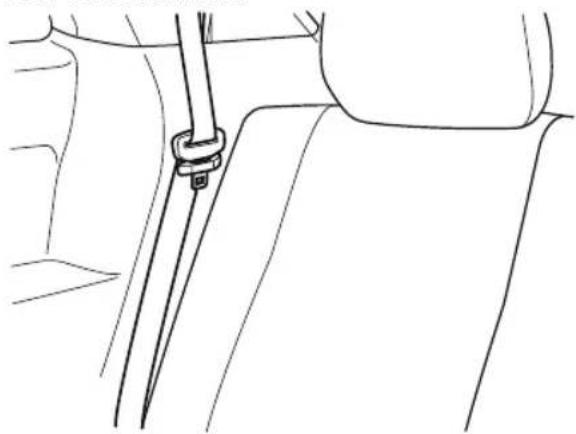
To secure the outboard-third row seat belts when not in use, insert the belts into their seat belt retainers.
natural_image
Line drawing of a car seatbelt assembly with a collar and buckle (no text or symbols)▼ Front Shoulder Belt Adjuster
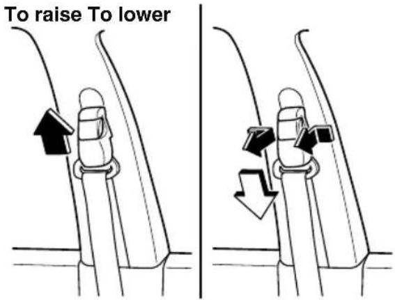
Make sure the adjuster is locked.
Seat Belt Warning Systems
If it detects that the occupant seat belt is unfastened, the warning light or beep alerts the occupant. Refer to Taking Action on page 7-37. Refer to Seat Belt Warning Beep on page 7-47.
Seat belt indicator light (second-row seat/third-row seat) (green)
(Second-row seat) 6:4 Split Adjustable-type Bench Seat Type

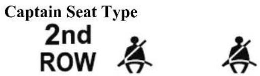
(Third-row seat)
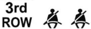
The light turns on when the ignition is switched ON and a second-row seat belt/third-row seat belt is fastened, and then it turns off after about 30 seconds.
Front Seat Belt Pretensioner and Load Limiting Systems
For optimum protection, the driver and front passenger seat belts are equipped with pretensioner and load limiting systems. For both these systems to work properly you must wear the seat belt properly.
Pretensioners:
When a collision is detected, the pretensioners deploy simultaneously with the air bags.
For vehicles with the front passenger occupant classification system, the pretensioners deploy simultaneously with the air bags when a roll-over is also detected.
For deployment details, refer to the SRS Air Bag Deployment Criteria (page 2-82).
The front seat belt retractors remove slack quickly as the air bags are expanding. Any time the air bags and seat belt pretensioners have fired they must be replaced.
A system malfunction or operation conditions are indicated by a warning.
Refer to Taking Action on page 7-37.
Refer to Air Bag/Front Seat Belt Pretensioner System Warning Beep on page 7-47.
(With Front Passenger Occupant Classification System)
In addition, the pretensioner system for the front passenger, like the front and side passenger air bag, is designed to only deploy when the front passenger occupant classification sensor detects a passenger sitting on the front passenger's seat.
For details, refer to the front passenger occupant classification sensor (page 2-85).
Load limiter:
The load limiting system releases belt webbing in a controlled manner to reduce belt force on the occupant's chest. While the most severe load on a seat belt occurs in frontal collisions, the load limiter has an automatic mechanical function and can activate in any accident mode with sufficient occupant movement.
Even if the pretensioners have not fired, the load limiting function must be checked by an Authorized Mazda Dealer.

WARNING
Wear seat belts only as recommended in this owner's manual:
Incorrect positioning of the driver and front passenger seat belts is dangerous. Without proper positioning, the pretensioner and load limiting systems cannot provide adequate protection in an accident and this could result in serious injury. For more details about wearing seat belts, refer to "Fastening the seat belts" (page 2-38).
Have your seat belts changed immediately if the pretensioner or load limiter has been expended:
Always have an Authorized Mazda Dealer immediately inspect the seat belt pretensioners and air bags after any collision. Like the air bags, the seat belt pretensioners and load limiters will only function once and must be replaced after any collision that caused them to deploy. A seat belt with an expended pretensioner or load limiter is still better than wearing no seat belt at all; however, if the seat belt pretensioners and load limiters are not replaced, the risk of injury in a collision will increase.
Do not modify the components or wiring, or use electronic testing devices on the pretensioner system:
Modifying the components or wiring of the pretensioner system, including the use of electronic testing devices is dangerous. You could accidentally activate it or make it inoperable which would prevent it from activating in an accident. The occupants or repairers could be seriously injured.
Properly dispose of the pretensioner system:
Improper disposal of the pretensioner system or a vehicle with non-deactivated pretensioners is dangerous. Unless all safety procedures are followed, injury could result. Have an Authorized Mazda Dealer safely dispose of the pretensioner system or scrap a pretensioner system equipped vehicle.
NOTE
- The pretensioner system may not operate depending on the type of the collision. For details, refer to the SRS Air Bag Deployment Criteria (page 2-82).
- Some smoke (non-toxic gas) will be released when the air bags and pretensioners deploy. This does not indicate a fire. This gas normally has no effect on occupants, however, those with sensitive skin may experience light skin irritation. If residue from the deployment of the air bags or the front pretensioner system gets on the skin or in the eyes, wash it off as soon as possible.
Seat Belt Extender
If your seat belt is not long enough, even when fully extended, a seat belt extender may be available to you at no charge from your Authorized Mazda Dealer.
This extender will be only for you and for the particular vehicle and seat. Even if it plugs into other seat belts, it may not hold in the critical moment of a crash.
When ordering an extender, only order one that provides the necessary additional length to fasten the seat belt properly.
Please contact your Authorized Mazda Dealer for more information.

WARNING
Do not use a seat belt extender unless it is necessary:
Using a seat belt extender when not necessary is dangerous. The seat belt will be too long and not fit properly. In an accident, the seat belt will not provide adequate protection and you could be seriously injured. Only use the extender when it is required to fasten the seat belt properly.
Do not use an improper extender:
Using a seat belt extender that is for another person or a different vehicle or seat is dangerous. The seat belt will not provide adequate protection and the user could be seriously injured in an accident. Only use the extender provided for you and for the particular vehicle and seat. NEVER use the extender in a different vehicle or seat. If you sell your Mazda, do not leave your seat belt extender in the vehicle. It could be used accidentally by the new owner of the vehicle. After removing the seat belt extender, discard it. Never use the seat belt extender in any other vehicle you may own in the future.
Do not use an extender that is too long:
Using an extender that is too long is dangerous. The seat belt will not fit properly. In an accident, the seat belt will not provide adequate protection and you could be seriously injured. Do not use the extender or choose one shorter in length if the distance between the extender's buckle and the center of the user's body is less than 15 cm (6 in).
Do not leave a seat belt extender connected to the buckle:
Leaving a seat belt extender connected to the buckle without using the seat belt is dangerous. When the seat belt extender is connected to the driver's seat belt buckle (or front passenger's seat belt buckle), the SRS driver's (or front passenger's) air bag system will determine that the driver (or front passenger) is wearing the seat belt even if the driver (or front passenger) is not wearing it. This condition could cause the driver's (or front passenger's) air bag to not activate correctly and result in death or serious injury in the event of collision. Always wear the seat belt with the seat belt extender.
Do not use the seat belt extender when installing a child-restraint system on the front or rear passenger seat:
Using a seat belt extender to fasten a child-restraint system on any seat is dangerous. Always follow the child-restraint system manufacturer's installation instructions and never use a seat belt extender.
NOTE
When not in use, remove the seat belt extender and store it in the vehicle. If the seat belt extender is left connected, the seat belt extender might get damaged as it will not retract with the rest of the seat belt and can easily fall out of the door when not in use and be damaged. In addition, the seat belt warning light will not illuminate and function properly.
Child-Restraint Precautions
Mazda strongly urges the use of child-restraint systems for children small enough to use them.
You are required by law to use a child-restraint system for children in the U.S. and Canada. Check your local and state or provincial laws for specific requirements regarding the safety of children riding in your vehicle.
Whatever child-restraint system you consider, please pick the appropriate one for the age and size of the child, obey the law and follow the instructions that come with the individual child-restraint system.
A child who has outgrown child-restraint systems should sit in the rear and use seat belts, both lap and shoulder. If the shoulder belt crosses the neck or face, move the child closer to the center of the vehicle in the outboard seats, and towards the buckle on the right if the child is seated on the center seat.
Statistics confirm that the rear seat is the best place for all children up to 12 years of age, and more so with a supplemental restraint system (air bags).
A rear-facing child-restraint system should NEVER be used on the front seat with the air bag system activated. The front passenger's seat is also the least preferred seat for other child-restraint systems.
(With Front Passenger Occupant Classification System)
To reduce the chance of injuries caused by deployment of the front passenger air bag, the front passenger occupant classification sensor works as a part of the supplemental restraint system. This system deactivates the front passenger front and side air bags and also the front passenger seat belt pretensioner system when the front passenger air bag deactivation indicator light illuminates.
When an infant or small child sits on the front passenger seat, the system shuts off the front passenger front and side air bags and seat belt pretensioner system, so make sure the front passenger air bag deactivation indicator light illuminates.
Even if the front passenger air bag is shut off, Mazda strongly recommends that children be properly restrained and child-restraint systems of all kinds are properly secured on the rear seats which are the best place for children.
For more details, refer to "Front passenger occupant classification sensor" (page 2-85).

WARNING
Use the correct size child-restraint system:
For effective protection in vehicle accidents and sudden stops, a child must be properly restrained using a seat belt or child-restraint system depending on age and size. If not, the child could be seriously injured or even killed in an accident.
Follow the manufacturer's instructions and always keep the child-restraint system buckled down:
An unsecured child-restraint system is dangerous. In a sudden stop or a collision it could move causing serious injury or death to the child or other occupants. Make sure any child-restraint system is properly secured in place according to the child-restraint system manufacturer's instructions. When not in use, remove it from the vehicle or fasten it with a seat belt, or attach it to BOTH ISOFIX/LATCH ^1 lower anchors for ISOFIX/LATCH ^1 child-restraint systems and the corresponding tether anchor.
* 1 ISOFIX (Mexico)/LATCH (Except Mexico)
Always secure a child in a proper child-restraint system:
Holding a child in your arms while the vehicle is moving is extremely dangerous. No matter how strong the person may be, he or she cannot hold onto a child in a sudden stop or collision and it could result in serious injury or death to the child or other occupants. Even in a moderate accident, the child may be exposed to air bag forces that could result in serious injury or death to the child, or the child may be slammed into an adult, causing injury to both child and adult.
Never use a rear-facing child-restraint system in the front seat with an air bag that could deploy:
Rear-facing child-restraint systems on the front seat are particularly dangerous even though you may feel assured that a front passenger air bag will not deploy based on the fact that the front passenger air bag deactivation indicator light illuminates. The child-restraint system can be hit by a deploying air bag and moved violently backward resulting in serious injury or death to the child.
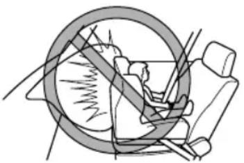
natural_image
Diagram of a car steering wheel and seat assembly (no text or labels)(Except Mexico)
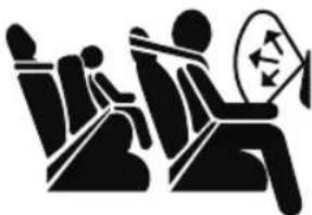
Vehicles with a front passenger air bag have the following warning label. The warning label reminds you not to put a rear-facing child-restraint system on the front passenger seat at any time.
natural_image
Silhouette of two people sitting in a chair, one holding a circular object with an arrow (no text or symbols)(Mexico)
NEVER use a rearward facing child restraint on a seat protected by an ACTIVE AIRBAG in front of it, DEATH or SERIOUS INJURY to the CHILD can occur.
Vehicles with a front passenger air bag have the following warning label. The warning label reminds you not to put a rear-facing child-restraint system on the front passenger seat at any time.
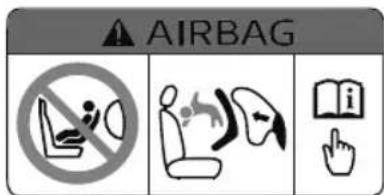
Do not install a front-facing child-restraint system on the front passenger seat unless it is unavoidable:
In a collision, the force of a deploying air bag could cause serious injury or death to the child. If installing a front-facing child-restraint system on the front passenger seat is unavoidable, move the front passenger seat as far back as possible and adjust the seat bottom (height adjustable seat bottom) to the highest position at which the seat belt fastening the child-restraint system is securely tightened.
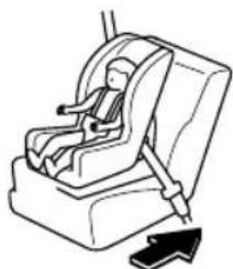
natural_image
Line drawing of a car seatbelt device with a black arrow indicating the load (no text or symbols)Seating a child in a child-restraint system on the front passenger seat is dangerous under certain conditions (With Front Passenger Occupant Classification System):
Your vehicle is equipped with front passenger occupant classification sensor. Even with the front passenger occupant classification sensor, if you must use the front passenger seat to seat a child, using a child-restraint system on the front passenger seat under the following conditions increases the danger of the front passenger air bag deploying and could result in serious injury or death to the child.
The front passenger air bag deactivation indicator light does not illuminate when seating a child in the child-restraint system.
➢ Luggage or other items are placed on the seat with the child in the child-restraint system.
➢A rear passenger or luggage pushing or pulling down on the front passenger seatback.
➢ Luggage or other items are placed on the seatback or hung on the head restraint.
The seat is washed.
▶ Liquids are spilled on the seat.
The front passenger seat is moved backward, pushing into luggage or other items placed behind it.
The front passenger seatback contacts the rear seat.
➢Luggage or other items are placed between the front passenger seat and driver seat.
➢An electric device is put on the front passenger's seat.
➢ An additional electrical device, such as a seat warmer is installed to the surface of the front passenger seat.
The designated positions with seat belts on the rear seats are the safest places for children. Always use seat belts and child restraints.
Do not allow a child or anyone to lean over to or against the side window of a vehicle with side and curtain air bags:
It is dangerous to allow anyone to lean over to or against the side window, the area of the front passenger seat, the front and rear window pillars and the roof edge along both sides from which the side and curtain air bags deploy, even if a child-restraint system is used. The impact of inflation from a side or curtain air bag could cause serious injury or death to an out of position child. Furthermore, leaning over to or against the door could block the side and curtain air bags and eliminate the advantages of supplemental protection. Because the front seats are equipped with front air bags, the rear seat is always a better location for children. Take special care not to allow a child to lean over to or against the side window, even if the child is seated in a child-restraint system.
Never use one seat belt on more than one person at a time:
Using one seat belt for more than one person at a time is dangerous. A seat belt used in this way cannot spread the impact forces properly and the two passengers could be crushed together and seriously injured or even killed. Never use one belt for more than one person at a time and always operate the vehicle with each occupant properly restrained.

CAUTION
A seat belt or child-restraint system can become very hot in a closed vehicle during warm weather. To avoid burning yourself or a child, check them before you or your child touches them.
NOTE
Your Mazda is equipped with ISOFIX/LATCH ^1 lower anchors for attachment of specially designed ISOFIX/LATCH ^1 child-restraint systems on the second-row seats. When using these anchors to secure a child-restraint system, refer to "(Mexico) Using ISOFIX Lower Anchor (Second-Row Seats)/(Except Mexico) Using LATCH Lower Anchor (Second-Row Seats)" (page 2-64).
*1 ISOFIX (Mexico)/LATCH (Except Mexico)
Child-Restraint System Installation
▼ Categories of Child-Restraint Systems
NOTE
When purchasing, ask the manufacturer of the child-restraint system which type of child-restraint system is appropriate for your child and vehicle.
(Mexico)
Child-restraint systems are classified into the following 5 groups according to the UN-R 44 regulation.
| Group Age | Weight | Size Classification/ Fixture (CRF) | |
| 0 Up to about 9 months old Up to 10 kg (up to 22 lb) | ISO/L1 | ||
| ISO/L2 | |||
| ISO/R1 | |||
| 0+ Up to about 2 years old Up to 13 kg (up to 29 lb) | ISO/R1 | ||
| ISO/R2 | |||
| ISO/R3 | |||
| 1 About 8 months to 4 years old 9 kg — 18 kg (20 lb — 40 lb) | ISO/R2 | ||
| ISO/R3 | |||
| ISO/F2 | |||
| ISO/F2X | |||
| ISO/F3 | |||
| 2 About 3 to 7 years old 15 kg — 25 kg (33 lb — 55 lb) — | |||
| 3 About 6 to 12 years old 22 kg — 36 kg (48 lb — 79 lb) — | |||
(Except Mexico)
Please comply with the legal regulations concerning the use of child-restraint systems in your country.
▼ Child-Restraint System Types
In this owner's manual, explanation of child-restraint systems is provided for the following three types of popular child-restraint systems: infant seat, child seat, booster seat.
NOTE
• Installation position is determined by the type of child-restraint system. Always read the manufacturer's instructions and this owner's manual carefully.
- Due to variations in the design of child-restraint systems, vehicle seats and seat belts, all child-restraint systems may not fit all seating positions. Before purchasing a child-restraint system, it should be tested in the specific vehicle seating position (or positions) where it is intended to be used. If a previously purchased child-restraint system does not fit, you may need to purchase a different one that will.
Infant seat
An infant seat provides restraint by bracing the infant's head, neck and back against the seating surface.
Equal to Group 0 and 0+ of the UN-R 44 and UN-R 129 regulation.

natural_image
Line drawing of a baby seat with a handle and seat (no text or symbols)Child seat
A child seat restrains a child's body using the harness.
Equal to Group 1 of the UN-R 44 and UN-R 129 regulation.
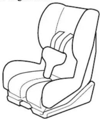
natural_image
Line drawing of a car seat with adjustable seat and seatbelt (no text or symbols)Booster seat
A booster seat is a child restraint accessory designed to improve the fit of the seat belt system around the child's body.
Equal to Group 2 and 3 of the UN-R 44 and UN-R 129 regulation.
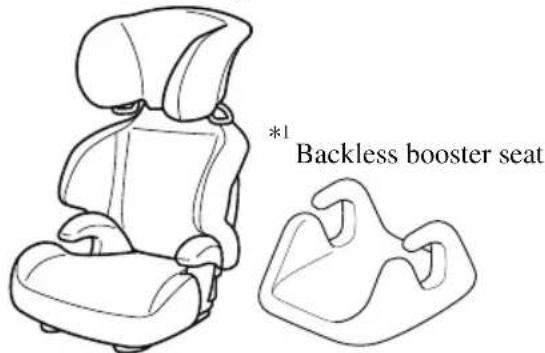
*1 When using a backless booster seat, always install the vehicle head restraint to the seat where the backless booster seat is installed.
Child-Restraint System Suitability for Various Seat Positions Table
(Mexico)
Provided information in the table shows your child-restraint system suitability for various seating position. For installation suitability of other manufacturer child-restraint system, carefully consult the manufacturer's instructions which accompany the child-restraint system.
When installing a child-restraint system, the following points must be observed:
· (Front passenger seat/Second-row seat)
Always remove the head restraint before installing a child-restraint system. However, when installing a backless booster seat, always install the vehicle head restraint to the seat where the backless booster seat is installed. In addition, always use a tether strap and attach it securely. Refer to Head Restraints on page 2-28.
- When installing a child-restraint system to the front passenger seat, adjust the seat slide position as far back as possible. Adjust the seat bottom (height adjustable seat bottom) to the highest position so that the seat belt can securely fasten the child-restraint system. Refer to Adjusting the Front Passenger's Seat on page 2-13.
-
When it is difficult to install a child-restraint system to the front passenger seat/second-row seat, or the seat belt cannot be secured to the child-restraint system, perform the following operations to adjust the seat holding the child-restraint system so that the seat belt can be secured completely to it.
-
Move the seat forward or back.
- Move the seatback forward or back.
- Move the seat upward or downward. (Vehicles with height adjustment function)
(Second-row seat)
- When installing a child-restraint system came equipped with a tether, remove the head restraint.
Refer to Head Restraints on page 2-28.
- When installing a child-restraint system using the ISOFIX lower anchors, if the connectors of the child-restraint system do not reach the lower anchorage and the child-restraint system cannot be installed, slightly tilt the seatback of the seat holding the child-restraint system rearward. If the seatback of a second-row seat cannot be reclined due to interference with luggage on the rear seat or passengers, slide the seat forward once and then recline the seatback.
(Second-row seat/Third-row seat)
- If the tether strap does not reach the anchor bracket, use an extension strap.
- When installing a child-restraint system to the second-row seat or third-row seat, adjust the seat position of the front seat so that the child-restraint system does not contact the front seat.
Refer to Adjusting the Driver's Seat on page 2-5.
Refer to Adjusting the Front Passenger's Seat on page 2-13.
Refer to Seat Operation on page 2-15.
- When installing a child-restraint system to the rear seat, refer to the child-restraint system manufacturer's instructions and the Using ISOFIX Lower Anchor on page 2-64.
- An i-Size child-restraint system refers to a child-restraint system which has acquired i-Size category certification for the UN-R 129 regulation.
| Seating position | Passenger | Second-row seat (Left) | Second-row seat (Center) | Second-row seat (Right) | Third-row seat (Left) | Third-row seat (Right) |
| Seating position suitable for universal belted (Yes/No) | No Yes(U) | Yes(U) Yes(U) Yes | (U) Yes(U) | |||
| i-Size seating position (Yes/No) | No No No | No No No | ||||
| Largest suitable rearward facing fixture (R1) | No Yes (IL) | No Yes (IL) | No No | |||
| Largest suitable rearward facing fixture (R2) | No Yes (IL) | No Yes (IL) | No No | |||
| Largest suitable rearward facing fixture (R2X) | No Yes (IL) | No Yes (IL) | No No | |||
| Largest suitable rearward facing fixture (R3) | No Yes (IL) | No Yes (IL) | No No | |||
| Largest suitable forward facing fixture (F2) | No Yes (IUF) | No Yes (IUF) | No No | |||
| Largest suitable forward facing fixture (F2X) | No Yes (IUF) No Yes (IUF) No No | |||||
| Largest suitable forward facing fixture (F3) | No Yes (IUF) No Yes (IUF) No No | |||||
| Largest suitable lateral facing fixture (L1) | No No No No No No | |||||
| Largest suitable lateral facing fixture (L2) | No No No No No No | |||||
| Largest suitable booster fixture (B2) | No Yes (IUF) No Yes (IUF) No No | |||||
| Largest suitable booster fixture (B3) | No Yes (IUF) No Yes (IUF) No No | |||||
| Non i-size compatible with a support leg (Yes/No) | Yes^*1 | YesNo Yes | Yes Yes | |||
| Lower ISO-FIX anchorages but without Top Tether (Yes/No) | No No No | No No No | ||||
U = Suitable for “universal” category restraints approved for use in this mass group.
UF = Suitable for forward-facing “universal” category restraints approved for use in this mass group.
IUF = Suitable for ISOFIX forward child restraints systems of universal category approved for use in the mass group.
L = Suitable for particular child restraints given on attached list. These restraints may be of the “specific vehicle”, “restricted” or “semi-universal” categories.
IL = Suitable for particular ISOFIX child restraint systems (CRS) given in the attached list. These ISOFIX CRS are those of the “specific vehicle”, “restricted” or “semi-universal” categories.
i-U = Suitable for i-Size "universal" Child Restraint Systems forward and rearward facing.
i-UF = Suitable for forward-facing i-Size "universal" Child Restraint Systems only.
Yes = Child-restraint system can be secured on the seat.
No = Child-restraint system cannot be secured on the seat, or there is no fixture.
X = Child-restraint system cannot be installed.
* 1 Child restraint system can only be installed in the forward-facing position.
A Mazda genuine child-restraint system can be installed. Regarding child-restraint systems which can be installed, refer to the accessories catalog.
(Except Mexico)
- Regarding child-restraint systems which can be installed to your Mazda, consult an Authorized Mazda Dealer.
- A child-restraint system with a support leg cannot be installed on the rear center seat position.
- For the CRS which do not carry the ISO/XX size class identification (A to G), for the applicable mass group, the child seat manufacturer shall indicate the vehicle specific LATCH child-restraint systems recommended for each position.
Installing Child-Restraint Systems
Accident statistics reveal that a child is safer in the rear seat. The front passenger's seat is clearly the worst choice for any child under 12, and with rear-facing child-restraint systems it is clearly unsafe due to air bags.
NOTE
Even if your vehicle is equipped with front passenger occupant classification sensor (page 2-85), which automatically deactivates the front passenger air bag, a rear seat is the safest place for a child of any age or size.
Some child-restraint systems now come with tethers and therefore must be installed on the seats that take tethers to be effective. In your Mazda, tethered child-restraint systems can only be accommodated in the four positions on the rear seat.
Some child-restraint systems also employ specially designed ISOFIX/LATCH ^*1 attachments; refer to " (Mexico) Using ISOFIX Lower Anchor (Second-Row Seats)/(Except Mexico) Using LATCH Lower Anchor (Second-Row Seats)" (page 2-64).
* 1 ISOFIX (Mexico)/LATCH (Except Mexico)

WARNING
Tethered Child-Restraint Systems Work Only on Tether-Equipped Rear Seats:
Installation of a tether equipped child-restraint system in the front passenger's seat defeats the safety design of the system and will result in an increased chance of serious injury if the child-restraint system goes forward without benefit of being tethered. Place tether equipped child-restraint systems where there are tether anchors.
▼ Anchor Bracket
Anchor brackets for securing child-restraint systems are equipped in the vehicle. Locate each anchor position using the illustration.
To install a child-restraint system, remove the head restraint (except third-row seat).
Always follow the instruction manual accompanying the child-restraint system.
Anchor bracket location
Use the indicated anchor bracket locations when installing a child-restraint system equipped with a tether.
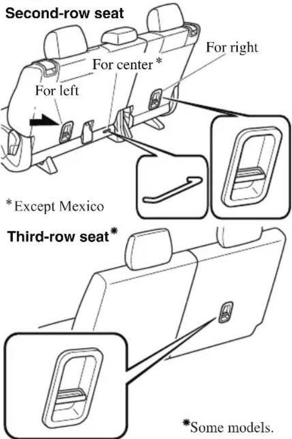

WARNING
Always attach the tether strap to the correct tether anchor position:
Attaching the tether strap to the incorrect tether anchor position is dangerous. In a collision, the tether strap could come off and loosen the child-restraint system. If the child-restraint system moves it could result in death or injury to the child.
Always remove the head restraint and install child-restraint system (Second-row seat):
Installing a child-restraint system without removing the head restraint is dangerous. The child-restraint system cannot be installed correctly which may result in death or injury to the child in a collision.
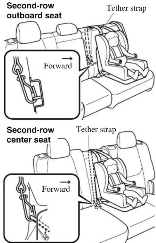
Always install the head restraint and adjust it to the appropriate position after removing the child-restraint system
(Second-row seat):
Driving with the head restraint removed is dangerous as impact to the occupant's head cannot be prevented during emergency braking or in a collision, which could result in a serious accident, injury or death.
Refer to Head Restraints on page 2-28.
Only use a tether anchor designed for the second-row seats:
Using a third-row seat tether anchor on the second-row seat is dangerous. The child-restraint system cannot be installed correctly which may result in death or injury to the child in a collision.
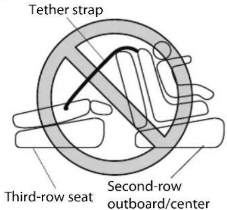
Always route the tether straps to the sides of the head restraint (Third-row seat):
Routing the tether straps on top of the head restraint is dangerous. In a collision the tether straps could slide off the head restraint and loosen the child-restraint system. The child-restraint system could move which may result in death or injury to the child.
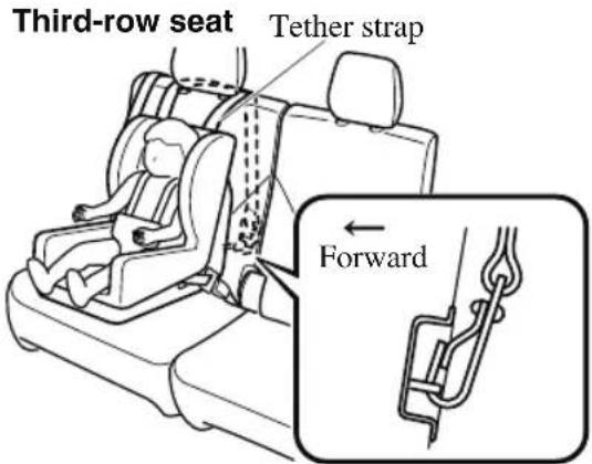
▼ Using Automatic Locking Mode (Except Mexico)
Follow these instructions when using a child-restraint system, unless you are attaching a LATCH-equipped child-restraint system to the rear LATCH lower anchors. Refer to “Using LATCH Lower Anchor” (page 2-64).
NOTE
Follow the child-restraint system manufacturer's instructions carefully. If you are not sure whether you have a LATCH system or tether, check in the child-restraint system manufacturer's instructions and follow them accordingly. Depending on the type of child-restraint system, it may use LATCH system instead of seat belts or if the belt goes across the child's chest, may recommend against using automatic locking mode.
1. (Second-row seat)
Adjust the second-row seat position using the following procedure.
① Fold the second-row seatback forward.
② Raise the second-row seatback until a click sound is heard and it is locked in place.

- Adjust the angle of the second-row seatback so that there is no gap
between the child-restraint system and the second-row seatback.
-
Make sure the seatback is securely latched by pushing it back until it is fully locked.
-
(Second-row seat)
Remove the head restraint. However, when installing a backless booster seat, always install the vehicle head restraint to the seat where the backless booster seat is installed.
Refer to Head Restraints on page 2-28.
- Secure the child-restraint system with the lap portion of the lap/shoulder belt. See the manufacturer's instructions on the child-restraint system for belt routing instructions.
- To get the retractor into the automatic locking mode, pull the shoulder belt portion of the seat belt until the entire length of the belt is out of the retractor.
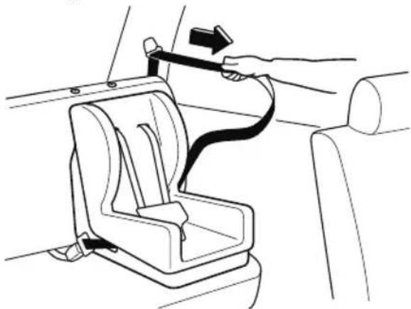
natural_image
Line drawing of a car seatbelt with a hand adjusting the belt, showing no text or symbols- Push the child-restraint system firmly into the vehicle seat. Be sure the belt retracts as snugly as possible. A clicking noise from the retractor will be heard during retraction if the system is in the automatic locking mode. If the
belt does not lock the seat down tight, repeat this step.
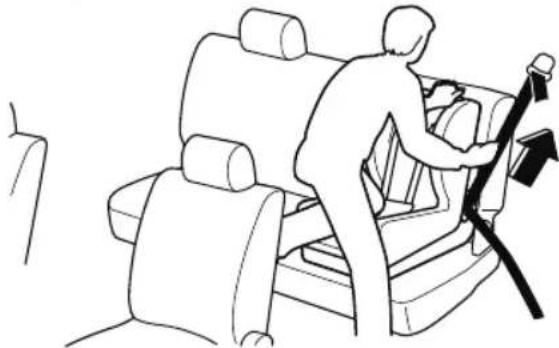
natural_image
Line drawing of a person using a seatbelt to lift a car (no text or symbols)NOTE
- Inspect this function before each use of the child-restraint system. You should not be able to pull the shoulder belt out of the retractor while the system is in the automatic locking mode. When you remove the child-restraint system, be sure the belt fully retracts to return the system to emergency locking mode before occupants use the seat belts.
- If your child-restraint system requires the use of a tether strap, refer to the manufacturer's instructions to hook and tighten the tether strap.

WARNING
Use the tether and tether anchor only for a child-restraint system:
Using the tether or tether anchor to secure anything but a child-restraint system is dangerous. This could weaken or damage the tether or tether anchor and result in injury.
Always remove the head restraint and install child-restraint system (except when installing a backless booster seat) (Second-row seat):
Installing a child-restraint system without removing the head restraint is dangerous. The child-restraint system cannot be installed correctly which may result in death or injury to the child in a collision.
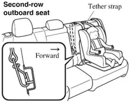
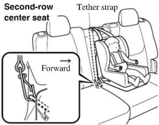
Always attach the tether strap to the correct tether anchor position:
Attaching the tether strap to the incorrect tether anchor position is dangerous. In a collision, the tether strap could come off and loosen the child-restraint system. If the child-restraint system moves it could result in death or injury to the child.
Always install the head restraint and adjust it to the appropriate position after removing the child-restraint system (Second-row seat):
Driving with the head restraint removed is dangerous as impact to the occupant's head cannot be prevented during emergency braking or in a collision, which could result in a serious accident, injury or death.
Refer to Head Restraints on page 2-28.
Always route the tether straps to the sides of the head restraint (Third-row seat):
Routing the tether straps on top of the head restraint is dangerous. In a collision the tether straps could slide off the head restraint and loosen the child-restraint system. The child-restraint system could move which may result in death or injury to the child.
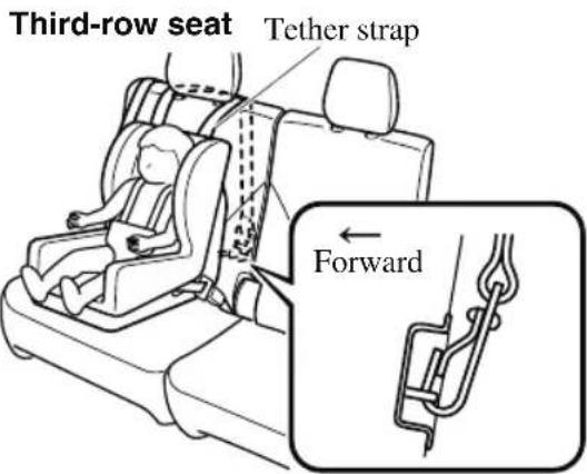
▼ If You Must Use the Front Seat for Children
If you cannot put all children in the rear seat, at least put the smallest children in the rear and be sure the largest child up front uses the shoulder belt over the shoulder.
NEVER put a rear-facing child-restraint system on the front passenger seat whether your vehicle is equipped with an occupant classification sensor or not.
This seat is also not set up for tethered child-restraint systems, put them in one of the rear seat positions set up with tether anchors.
Likewise the ISOFIX/LATCH ^*1 child-restraint system cannot be secured in the front passenger's seat and should be used in the second-row seat.
Do not allow anyone to sleep against the side window since your vehicle has side and curtain air bags, it could cause serious injuries to an out of position occupant. As children more often sleep in cars, it is better to put them in the rear seat. If installing the child-restraint system on the front seat is unavoidable, follow these instructions when using a front-facing child-restraint system in the front passenger's seat.
*1 ISOFIX (Mexico)/LATCH (Except Mexico)
NOTE
- To check if your front seats have side air bags:
Mazda vehicles equipped with side air bag will have a "SRS AIRBAG" tag on the outboard shoulder of the front seats. - To check if your vehicle has curtain air bags:
Mazda vehicles equipped with curtain air bag will have an "SRS AIRBAG" marking on the window pillars along the roof edge.

WARNING
Always move the front passenger seat as far back as possible if installing a front-facing child-restraint system on it is unavoidable:
As your vehicle has front air bags and doubly so because your vehicle has side air bags, a front-facing child-restraint system should be put on the front passenger seat only when it is unavoidable.
Even if the front passenger air bag deactivation indicator light illuminates, always move the seat as far back as possible, because the force of a deploying air bag could cause serious injury or death to the child.
Never use a rear-facing child-restraint system in the front seat with an air bag that could deploy:
Rear-facing child-restraint systems on the front seat are particularly dangerous.
Even in a moderate collision, the child-restraint system can be hit by a deploying air bag and moved violently backward resulting in serious injury or death to the child. Even though you may feel assured that the front passenger air bag will not deploy based on the fact that the front passenger air bag deactivation indicator light illuminates, you should not use a rear-facing child-restraint system in the front seat.
Do not allow a child or anyone to lean over to or against the side window of a vehicle with side and curtain air bags:
It is dangerous to allow anyone to lean over to or against the side window, the area of the front passenger seat, the front and rear window pillars and the roof edge along both sides from which the side and curtain air bags deploy, even if a child-restraint system is used. The impact of inflation from a side or curtain air bag could cause serious injury or death to an out of position child. Furthermore, leaning over to or against the door could block the side and curtain air bags and eliminate the advantages of supplemental protection. Because the front seats are equipped with front air bags, the rear seat is always a better location for children. Take special care not to allow a child to lean over to or against the side window, even if the child is seated in a child-restraint system.
Always remove the head restraint and install child-restraint system (except when installing a backless booster seat):
Installing a child-restraint system without removing the head restraint is dangerous. The child-restraint system cannot be installed correctly which may result in death or injury to the child in a collision.
Always install the head restraint and adjust it to the appropriate position after removing the child-restraint system:
Driving with the head restraint removed is dangerous as impact to the occupant's head cannot be prevented during emergency braking or in a collision, which could result in a serious accident, injury or death.
Refer to Head Restraints on page 2-28.
Front Passenger's Seat Child-Restraint System Installation (With Front Passenger Occupant Classification System)
- Make sure the ignition is switched off.
- Slide the seat as far back as possible.
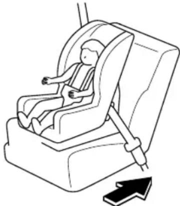
natural_image
Line drawing of a baby car seatbelt device with a black arrow indicating left side (no text or symbols)-
Remove the head restraint. However, when installing a backless booster seat, always install the vehicle head restraint to the seat where the backless booster seat is installed.
-
Place the child-restraint system on the seat without putting your weight on the seat and fasten the seat belt. See the manufacturer's instructions on the child-restraint system for belt routing instructions.
-
To get the retractor into the automatic locking mode, pull the shoulder belt portion of the seat belt until the entire length of the belt is out of the retractor.
-
Push the child-restraint system firmly into the vehicle seat. Be sure the belt retracts as snugly as possible. A clicking noise from the retractor will be heard during retraction if the system is in automatic locking mode. If the belt does not lock the seat down tight, repeat the previous step and also this one.
NOTE
- Inspect this function before each use of the child-restraint system. You should not be able to pull the shoulder belt out of the retractor while the system is in the automatic locking mode. When you remove the child-restraint system, be sure the belt fully retracts to return the system to emergency locking mode before occupants use the seat belts.
- Follow the child-restraint system manufacturer's instructions carefully. Depending on the type of child-restraint system, it may not employ seat belts which are in automatic locking mode.
-
Seat your child safely in the child-restraint system and secure the child according to the instructions from the child-restraint system manufacturer.
-
Switch the ignition ON and make sure the front passenger air bag deactivation indicator light illuminates after installing a child-restraint system on the front passenger seat. If the front passenger air bag deactivation indicator light does not illuminate, remove the child-restraint system, switch the ignition to OFF, and
then re-install the child-restraint system (page 2-85).
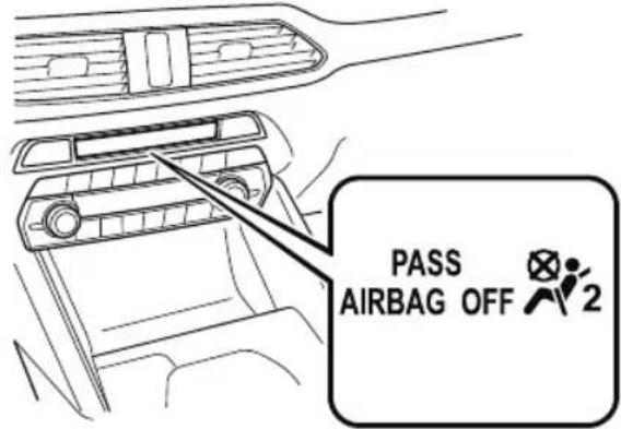

WARNING
Do not seat a child in a child-restraint system on the front passenger seat if the front passenger air bag deactivation indicator light does not illuminate:
While it is always better to install any child-restraint system on the rear seat, it is imperative that a child-restraint system
ONLY be used on the front passenger seat if the deactivation indicator light illuminates when the child is seated in the child-restraint system (page 2-85). Seating a child in a child-restraint system installed on the front passenger seat with the front passenger air bag deactivation indicator light not illuminated is dangerous. If this indicator light does not illuminate, this means that the front passenger front and side air bags, and seat belt pretensioners are ready for deployment. If an accident were to deploy an air bag, a child in a child-restraint system sitting in the front passenger seat could be seriously injured or killed. If the indicator light does not illuminate after seating a child in a child-restraint system on the front passenger seat, seat a child in a child-restraint system on the rear seat and consult an Authorized Mazda Dealer as soon as possible.
▼ (Mexico) Using ISOFIX Lower Anchor (Second-row Seats)/(Except Mexico) Using LATCH Lower Anchor (Second-row Seats)
Your Mazda is equipped with ISOFIX/LATCH ^1 lower anchors for attachment of specially designed ISOFIX/LATCH ^1 child-restraint systems in the second-row seats. Both anchors must be used, otherwise the seat will bounce around and put the child in danger. Most ISOFIX/LATCH ^*1 child-restraint systems must also be used in conjunction with a tether to be effective. If they have a tether you must use it to better assure your child's safety.

WARNING
Follow the manufacturer's instructions for the use of the child-restraint system:
An unsecured child-restraint system is dangerous. In a sudden stop or a collision it could move causing serious injury or death to the child or other occupants. Make sure the child-restraint system is properly secured in place according to the child-restraint system manufacturer's instructions.
Never attach two child-restraint systems to the same ISOFIX/LATCH ^*1 lower anchor:
Attaching two child-restraint systems to the same ISOFIX/LATCH ^1 lower anchor is dangerous. In a collision, one anchor may not be strong enough to hold two child-restraint system attachments, and it may break, causing serious injury or death. If you use the seat position for another child-restraint system when an outboard ISOFIX/LATCH ^1 position is occupied, use the center seat belts instead, and the tether if tether-equipped.
Make sure the child-restraint system is properly secured:
An unsecured child-restraint system is dangerous. In a sudden stop or a collision it could move causing serious injury or death to the child or other occupants. Follow the child-restraint system manufacturer's instructions on belt routing to secure the seat just as you would with a child in it so that nobody is tempted to put a child in an improperly secured seat later on. When not in use, remove it from the vehicle or fasten it with a seat belt, or attach it to BOTH ISOFIX/LATCH*1 lower anchors for ISOFIX/LATCH*1 child-restraint systems.
Make sure there are no seat belts or foreign objects near or around the ISOFIX/LATCH child-restraint system:
Not following the child-restraint system manufacturer's instructions when installing the child-restraint system is dangerous. If seat belts or a foreign object prevent the child-restraint system from being securely attached to the ISOFIX/LATCH ^1 lower anchors and the child-restraint system is installed improperly, the child-restraint system could move in a sudden stop or collision causing serious injury or death to the child or other occupants. When installing the child-restraint system, make sure there are no seat belts or foreign objects near or around the ISOFIX/LATCH ^1 lower anchors. Always follow the child-restraint system manufacturer's instructions.
*1 ISOFIX (Mexico)/LATCH (Except Mexico)
Installation on second-row outboard seats
-
First, adjust the front seat to allow clearance between the child-restraint system and the front seat. Refer to Adjusting the Driver's Seat on page 2-5. Refer to Adjusting the Front Passenger's Seat on page 2-13.
-
Adjust the second-row seat position using the following procedure.
① Fold the second-row seatback forward.
② Raise the second-row seatback until a click sound is heard and it is locked in place.
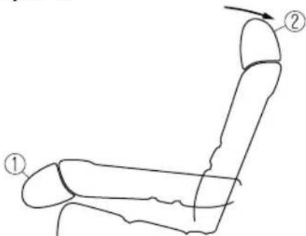
-
Adjust the angle of the second-row seatback so that there is no gap between the child-restraint system and the second-row seatback.
-
Make sure the seatback is securely latched by pushing it back until it is fully locked.
- Remove the cover of the child-restraint system's ISOFIX/LATCH ^1 lower anchors to verify the locations of the ISOFIX/LATCH ^1 lower anchors.
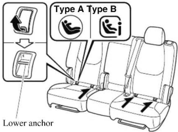
NOTE
- The ISOFIX/LATCH ^1 lower anchors marking on the cover indicates the position of the ISOFIX/LATCH ^1 lower anchors for the attachment of a child-restraint system.
-
Store the removed cover so that it does not get lost.
-
Remove the head restraint. However, when installing a backless booster seat, always install the vehicle head restraint to the seat where the backless booster seat is installed. Refer to Head Restraints on page 2-28.
- Secure the child-restraint system using BOTH ISOFIX/LATCH ^*1 lower anchors, following the child-restraint system manufacturer's instruction. Pull on the child-restraint to be sure both anchors are engaged.
- If your child-restraint system came equipped with a tether, that means it is very important to properly secure the tether for child safety. Please carefully follow the child-restraint system manufacturer's instructions when installing tethers.
*1 ISOFIX (Mexico)/LATCH (Except Mexico)

WARNING
Use the tether and tether anchor only for a child-restraint system:
Using the tether or tether anchor to secure anything but a child-restraint system is dangerous. This could weaken or damage the tether or tether anchor and result in injury.
Always remove the head restraint and install child-restraint system (except when installing a backless booster seat):
Installing a child-restraint system without removing the head restraint is dangerous. The child-restraint system cannot be installed correctly which may result in death or injury to the child in a collision.
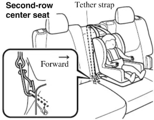
Always attach the tether strap to the correct tether anchor position:
Attaching the tether strap to the incorrect tether anchor position is dangerous. In a collision, the tether strap could come off and loosen the child-restraint system. If the child-restraint system moves it could result in death or injury to the child.
Always install the head restraint and adjust it to the appropriate position after removing the child-restraint system:
Driving with the head restraint removed is dangerous as impact to the occupant's head cannot be prevented during emergency braking or in a collision, which could result in a serious accident, injury or death.
Refer to Head Restraints on page 2-28.
Installation on second-row center seat
The ISOFIX/LATCH ^*1 lower anchors at the center of the second-row seat are much
further apart than the sets of ISOFIX/LATCH ^1 lower anchors for child-restraint system installation at other seating positions. Child-restraint systems with rigid ISOFIX/LATCH ^1 attachments cannot be installed on the center seating position. Some ISOFIX/LATCH ^1 equipped child-restraint systems can be placed in the center position and will reach the nearest ISOFIX/LATCH ^1 lower anchors which are 500 mm (19.7 in) apart. ISOFIX/LATCH ^1 compatible child-restraint systems (with attachments on belt webbing) can be used at this seating position only if the child-restraint system manufacturer's instructions state that the child-restraint system can be installed to ISOFIX/LATCH ^1 lower anchors that are 500 mm (19.7 in) apart. Do not attach two child-restraint systems to the same ISOFIX/LATCH ^*1 lower anchor. If your child-restraint system has a tether, it must also be used for your child's optimum safety.
The procedure for installation on the rear outboard seats is the same.
*1 ISOFIX (Mexico)/LATCH (Except Mexico)
ISOFIX/LATCH ^*1 lower anchor location
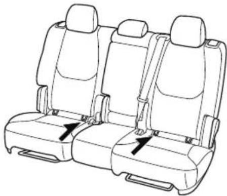
natural_image
Line drawing of three car seats with seatbelt fasteners and directional arrows indicating seat positions (no text or symbols)
WARNING
Always remove the head restraint and install child-restraint system (except when installing a backless booster seat):
Installing a child-restraint system without removing the head restraint is dangerous. The child-restraint system cannot be installed correctly which may result in death or injury to the child in a collision.
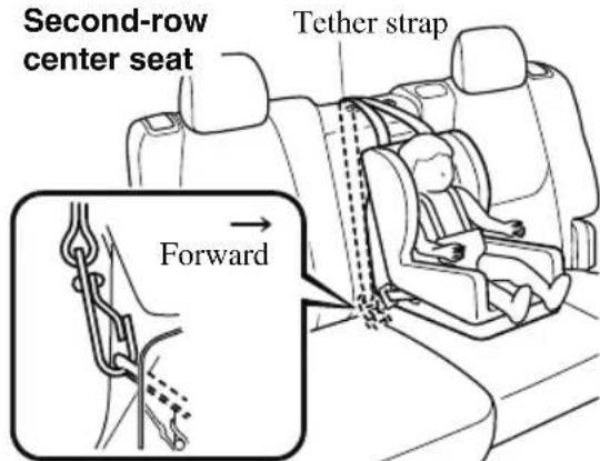
Always attach the tether strap to the correct tether anchor position:
Attaching the tether strap to the incorrect tether anchor position is dangerous. In a collision, the tether strap could come off and loosen the child-restraint system. If the child-restraint system moves it could result in death or injury to the child.
Always install the head restraint and adjust it to the appropriate position after removing the child-restraint system:
Driving with the head restraint removed is dangerous as impact to the occupant's head cannot be prevented during emergency braking or in a collision, which could result in a serious accident, injury or death.
Refer to Head Restraints on page 2-28.
*1 ISOFIX (Mexico)/LATCH (Except Mexico)
Supplemental Restraint System (SRS) Precautions
The front and side supplemental restraint systems (SRS) include different types of air bags. Please verify the different types of air bags which are equipped on your vehicle by locating the “SRS AIRBAG” location indicators. These indicators are visible in the area where the air bags are installed.
The air bags are installed in the following locations:
• The steering wheel hub (driver air bag)
- The front passenger dashboard (front passenger air bag)
- The outboard sides of the front seatbacks (side air bags)
- The front and rear window pillars, and the roof edge along both sides (curtain air bags)
Vehicles with the Front Passenger Occupant Classification System have a sensor which detects an impending roll-over accident.
The air bag supplemental restraint systems are designed to provide supplemental protection in certain situations so seat belts are always important in the following ways:
Without seat belt usage, the air bags cannot provide adequate protection during an accident. Seat belt usage is necessary to:
- Keep the occupant from being thrown into an inflating air bag.
- Reduce the possibility of injuries during an accident that is not designed for air bag inflation, such as rear impact.
- Reduce the possibility of injuries in frontal, near frontal or side collisions or roll-over accidents that are not severe enough to activate the air bags.
- Reduce the possibility of being thrown from your vehicle.
- Reduce the possibility of injuries to lower body and legs during an accident because the air bags provide no protection to these parts of the body.
- Hold the driver in a position which allows better control of the vehicle.
If your vehicle is also equipped with a front passenger occupant classification system, refer to the Front Passenger Occupant Classification System (page 2-85) for details. If your vehicle is equipped with a front passenger occupant classification system, the front passenger air bag deactivation indicator light illuminates for a specified time after the ignition is switched ON.
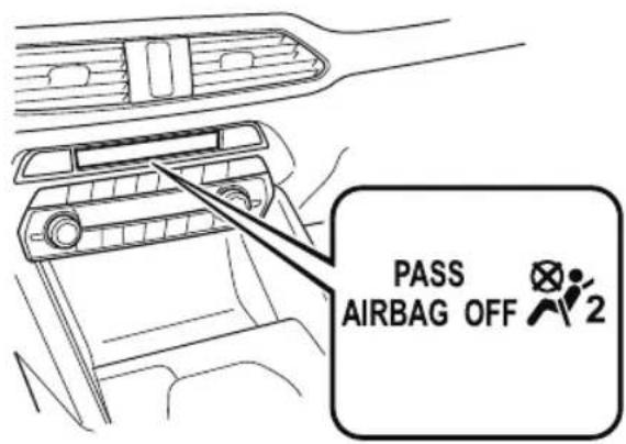
Small children must be protected by a child-restraint system as stipulated by law in every state and province. In certain states and provinces, larger children must use a child-restraint system (page 2-44).
Carefully consider which child-restraint system is necessary for your child and follow the installation directions in this Owner's Manual as well as the child-restraint system manufacturer's instructions.

WARNING
Seat belts must be worn in air bag equipped vehicles:
Depending only on the air bags for protection during an accident is dangerous. Alone, air bags may not prevent serious injuries. The appropriate air bags can be expected to inflate only in the first accident, such as frontal, near frontal or side collisions or roll-over accidents that are at least moderate. Vehicle occupants should always wear seat belts.
Children should not ride in the front passenger seat:
Placing a child, 12 years or under, in the front seat is dangerous. The child could be hit by a deploying air bag and be seriously injured or even killed. A sleeping child is more likely to lean against the door and be hit by the side air bag in moderate collision to the front-passenger side of the vehicle. Whenever possible, always secure a child 12 years and under on the rear seats with an appropriate child-restraint system for the child's age and size.
Never use a rear-facing child-restraint system in the front seat with an air bag that could deploy:
Rear-facing child-restraint systems on the front seat are particularly dangerous even though you may feel assured that a front passenger air bag will not deploy based on the fact that the front passenger air bag deactivation indicator light illuminates. The child-restraint system can be hit by a deploying air bag and moved violently backward resulting in serious injury or death to the child.
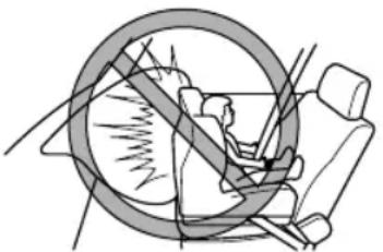
natural_image
Diagram of a car interior showing steering wheel and seat, with no visible text or symbolsDo not sit too close to the driver and front passenger air bags:
Sitting too close to the driver and front passenger air bag modules or placing hands or feet on them is extremely dangerous. The driver and front passenger air bags inflate with great force and speed. Serious injuries could occur if someone is too close. The driver should always hold onto only the rim of the steering wheel. The front seat passenger should keep both feet on the floor. Front seat occupants should adjust their seats as far back as possible and always sit upright against the seatbacks with seat belts worn properly.
Sit in the center of the seat and wear seat belts properly:
Sitting too close to the side air bag modules or placing hands on them, or sleeping up against the door or hanging out the windows is extremely dangerous. The side and curtain air bags inflate with great force and speed directly expanding along the door on the side the car is hit. Serious injury could occur if someone is sitting too close to the door or leaning against a window, or if rear seat occupants grab the sides of the front seatbacks. Give the side and curtain air bags room to work by sitting in the center of the seat while the vehicle is moving with seat belts worn properly.
Do not attach objects on or around the area where air bags deploy:
Attaching objects to the air bags or placing something in the area where the air bags deploy is dangerous. In an accident, an object could interfere with air bag inflation and injure the occupants. Furthermore, the bag could be damaged causing gases to release. Always keep the deployment area of the air bag modules free of any obstructions.
For example, you should not do any of the following as it may interfere with air bag deployment.
➢ Do not put a covering on or lean anything against areas such as the dashboard and lower portion of the instrument panel that blocks the passenger front air bag and knee air bags.
➢ Do not use seat covers on the front seats and rear seats equipped with in-seat side air bags.
➢ Do not hang any backpacks, bags or pouches that cover the sides of the seats that block the side air bags.
➢ Do not place any objects on the assist grips. Only hang clothes directly on the coat hooks.
Do not touch the components of the supplemental restraint system after the air bags have inflated:
Touching the components of the supplemental restraint system after the air bags have inflated is dangerous. Immediately after inflation, they are very hot. You could get burned.
Never install any front-end equipment to your vehicle:
Installation of front-end equipment, such as frontal protection bar (kangaroo bar, bull bar, push bar, or other similar devices), snowplow, or winches, is dangerous. The air bag crash sensor system could be affected. This could cause air bags to inflate unexpectedly, or it could prevent the air bags from inflating during an accident. Front occupants could be seriously injured.
Do not modify the suspension:
Modifying the vehicle suspension is dangerous. If the vehicle's height or the suspension is modified, the vehicle will be unable to accurately detect a collision or roll-over accident resulting in incorrect or unexpected air bag deployment and the possibility of serious injuries.
To prevent false detection by the air bag sensor system, heed the following:
Do not use tires or wheels other than those specified for your Mazda:
Use of any tire or wheel other than those specified for your Mazda (page 9-7) is dangerous. Use of such wheels will prevent the vehicle's accident detections system from accurately detecting a collision or roll-over accident resulting in incorrect or unexpected air bag deployment and the possibility of serious injuries.
▶ Do not overload your vehicle:
Overloading your vehicle is dangerous as it could prevent the air bag crash sensor system from accurately detecting a collision or roll-over accident resulting in incorrect or unexpected air bag deployment and the possibility of serious injuries. The gross axle weight rating (GAWR) and the gross vehicle weight rating (GVWR) for your vehicle are on the Motor Vehicle Safety Standard Label on the driver's door frame. Do not exceed these ratings.
Do not modify a front door or leave any damage unrepaired. Always have an Authorized Mazda Dealer inspect a damaged front door:
Modifying a front door or leaving any damage unrepaired is dangerous. Each front door has a side crash sensor as a component of the supplemental restraint system. If holes are drilled in a front door, a door speaker is left removed, or a damaged door is left unrepaired, the sensor could be adversely affected causing it to not detect the pressure of an impact correctly during a side collision. If a sensor does not detect a side impact correctly, the side and curtain air bags and the front seat belt pretensioner may not operate normally which could result in serious injury to occupants.
Do not modify the supplemental restraint system:
Modifying the components or wiring of the supplemental restraint system is dangerous. You could accidentally activate it or make it inoperable. Do not make any modifications to the supplemental restraint system. This includes installing trim, badges, or anything else over the air bag modules. It also includes installing extra electrical equipment on or near system components or wiring. An Authorized Mazda Dealer can provide the special care needed in the removal and installation of front seats. It is important to protect the air bag wiring and connections to assure that the bags do not accidentally deploy, and that the front passenger occupant classification system and the seats retain an undamaged air bag connection.
Do not place luggage or other objects under the front seats:
Placing luggage or other objects under the front seats is dangerous. The components essential to the supplemental restraint system could be damaged, and in the event of a side collision, the appropriate air bags may not deploy, which could result in death or serious injury. To prevent damage to the components essential to the supplemental restraint system, do not place luggage or other objects under the front seats.
Do not operate a vehicle with damaged air bag/seat belt pretensioner system components:
Expended or damaged air bag/seat belt pretensioner system components must be replaced after any collision which caused them to deploy or damage them. Only a trained Authorized Mazda Dealer can fully evaluate these systems to see that they will work in any subsequent accident. Driving with an expended or damaged air bag or pretensioner unit will not afford you the necessary protection in the event of any subsequent accident which could result in serious injury or death.
Do not remove interior air bag parts:
Removing any components such as the front seats, front dashboard, the steering wheel or parts on the front and rear window pillars and along the roof edge, containing air bag parts or sensors is dangerous. These parts contain essential air bag components. The air bag could accidentally activate and cause serious injuries. Always have an Authorized Mazda Dealer remove these parts.
Properly dispose of the air bag system:
Improper disposal of an air bag or a vehicle with live air bags in it can be extremely dangerous. Unless all safety procedures are followed, injury could result. Have an Authorized Mazda Dealer safely dispose of the air bag system or scrap an air bag equipped vehicle.
NOTE
- If it becomes necessary to have the components or wiring system for the supplementary restraint system modified to accommodate a person with certain medical conditions in accordance with a certified physician, contact an Authorized Mazda Dealer, refer to “Customer Assistance (U.S.A.)” (page 8-2).
- When an air bag deploys, a loud inflation noise can be heard and some smoke will be released. Neither is likely to cause injury, however, the texture of the air bags may cause light skin injuries on body parts not covered with clothing through friction.
- Should you sell your Mazda, we urge you to tell the new owner of its air bag systems and that familiarization with all instructions about them, from the Owner's Manual, is important.
- This highly-visible label is displayed which warns against the use of a rear-facing child-restraint system on the front passenger seat.
(Except Mexico) (Mexico)
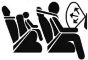
natural_image
Silhouette of two people sitting in a circle with a triangular symbol above their head (no text or symbols present)
Supplemental Restraint System Components
(With Front Passenger Occupant Classification System)
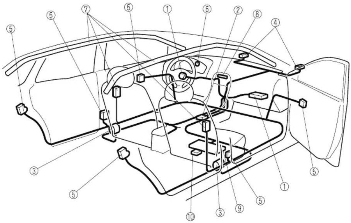
(Without Front Passenger Occupant Classification System)
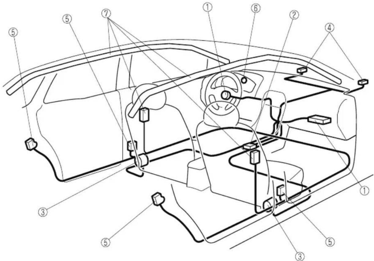
① Driver/Front passenger inflators and air bags
② Roll-over sensor*, crash sensors, and diagnostic module (SAS unit)
③ Front seat belt pretensioners (page 2-40)
④ Front air bag sensors
⑤ Side crash sensors
⑥ Air bag/front seat belt pretensioner system warning light (page 7-31)
⑦ Side and curtain inflators and air bags
⑧ Front passenger air bag deactivation indicator light * (page 2-85)
⑨ Front passenger occupant classification sensor* (page 2-85)
⑩ Front passenger occupant classification module*
How the SRS Air Bags Work
Your Mazda is equipped with the following types of SRS air bags. SRS air bags are designed to work together with the seat belts to help to reduce injuries during an accident. The SRS air bags are designed to provide further protection for passengers in addition to the seat belt functions. Be sure to wear seat belts properly.
▼ Front Seat Belt Pretensioners
The front seat belt pretensioners are designed to deploy in moderate or severe frontal, near frontal collisions.
In addition, the pretensioners operate when a side collision or a roll-over accident is detected. The pretensioners operate differently depending on what types of air bags are equipped. For more details about seat belt pretensioner operation, refer to the SRS Air Bag Deployment Criteria (page 2-82).
▼ Driver Air Bag
The driver's air bag is mounted in the steering wheel.
When air bag crash sensors detect a frontal impact of greater than moderate force, the driver's air bag inflates quickly helping to reduce injury mainly to the driver's head or chest caused by directly hitting the steering wheel.
For more details about air bag deployment, refer to "SRS Air Bag Deployment Criteria" (page 2-82).
(With Front Passenger Occupant Classification System)
The driver's dual-stage air bag controls air bag inflation in two energy stages. During an impact of moderate severity, the driver's air bag deploys with lesser energy, whereas during more severe impacts, it deploys with more energy.
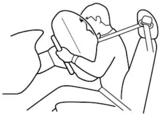
natural_image
Line drawing of a person seated in a chair using a helmet and arm (no text or symbols)▼ Front Passenger Air Bag
The front passenger air bag is mounted in the front passenger dashboard.
The inflation mechanism for the front passenger air bag is the same as the driver's air bag.
For more details about air bag deployment, refer to "SRS Air Bag Deployment Criteria" (page 2-82).
(With Front Passenger Occupant Classification System)
In addition, the front passenger air bag is designed to only deploy when the front passenger occupant classification sensor detects a passenger sitting on the front passenger's seat. For details, refer to the front passenger occupant classification system (page 2-85).
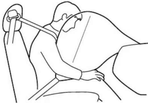
natural_image
Line drawing of a person sitting in a chair with hands placed on the seat (no text or symbols)▼ Side Air Bags
The side air bags are mounted in the outboard sides of the front seatbacks.
When the air bag crash sensors detect a side impact of greater than moderate force, the system inflates the side air bag only on the side in which the vehicle was hit. The side air bag inflates quickly to reduce injury to the driver or front passenger's chest caused by directly hitting interior parts such as a door or window.
For more details about air bag deployment, refer to "SRS Air Bag Deployment Criteria" (page 2-82).
(With Front Passenger Occupant Classification System)
In addition, the front passenger side air bag is designed to only deploy when the front passenger occupant classification sensor detects a passenger sitting on the front passenger's seat. For details, refer to the front passenger occupant classification system (page 2-85).
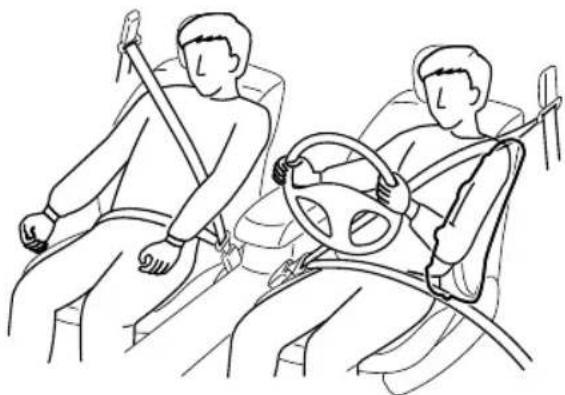
natural_image
Line drawing of two people seated in a car, one using a steering wheel and the other holding a belt (no text or symbols)▼ Curtain Air Bags
The curtain air bags are mounted in the front and rear window pillars, and the roof edge along both sides.
When the air bag crash sensors detect a side impact of greater than moderate force, the curtain air bag inflates quickly and helps to reduce injury mainly to the rear outboard passenger's head caused by directly hitting interior parts such as a door or window.
For more details about air bag deployment, refer to "SRS Air Bag Deployment Criteria" (page 2-82).
In a side impact:
Greater than moderate impact to one side of the vehicle will cause the curtain air bag on that side only to inflate.
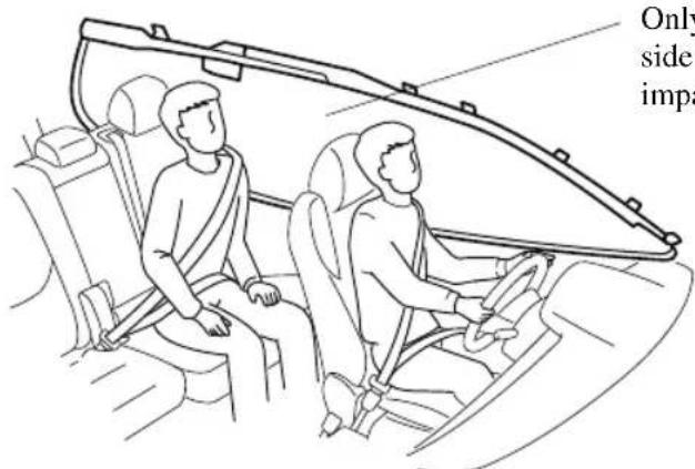
Only one side curtain air bag will deploy on the side of the vehicle that receives the force of an impact.
(With Front Passenger Occupant Classification System) In a roll-over:
In response to a vehicle roll-over, both curtain air bags inflate.
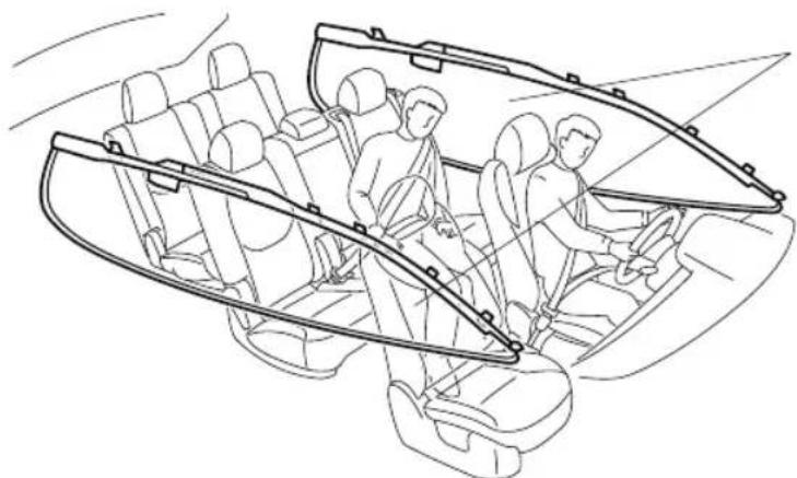
natural_image
Line drawing of a car interior showing two people seated inside the dashboard with seatbelt covers (no text or symbols)Both curtain air bags will deploy after the roll-over accident is detected.
▼ Warning Light/Beep
A system malfunction or operation conditions are indicated by a warning.
Refer to Contact Authorized Mazda Dealer and Have Vehicle Inspected on page 7-31. Refer to Warning Sound is Activated on page 7-47.
SRS Air Bag Deployment Criteria
This chart indicates the applicable SRS equipment that will deploy depending on the type of collision.
(The illustrations are the representative cases of collisions.)
| SRS equipment | Types of collision | |||
| A severe frontal/near frontal collision | A severe side collision*2 | A roll-over/near roll-over*3 | A rear collision | |
 | 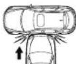 | 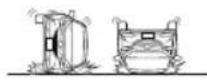 | ||
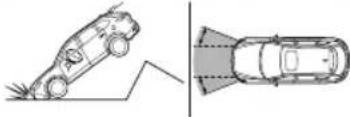 | 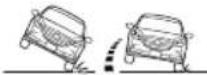 | |||
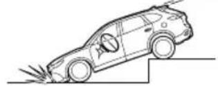 | ||||
| Front seat belt pretensioner | X*1 | X*1 | X*1 | No air bag and front seat belt pretensioner will be activated in a rear collision. |
| Driver air bag | X | |||
| Front passenger air bag | X*1 | |||
| Side air bag | X*1 (impact side only) | |||
| Curtain air bag | X (impact side only) | X (both sides) | ||
X: The SRS air bag equipment is designed to deploy in a collision.
*1 (With Front Passenger Occupant Classification System)
The front passenger front and side air bags and the seat belt pretensioner are designed to deploy when the front passenger occupant classification sensor detects a passenger sitting on the front passenger's seat.
*2 In a side collision, the seat belt pretensioners and the side/curtain air bags deploy.
*3 (With Front Passenger Occupant Classification System)
In a roll-over accident, the seat belt pretensioners and the curtain air bags deploy.
NOTE
In a frontal offset collision, the equipped air bags and pretensioners may all deploy depending on the direction, angle, and rate of impact.
Limitations to SRS Air Bag
In severe collisions such as those described previously in "SRS Air Bag Deployment Criteria", the applicable SRS air bag equipment will deploy. However, in some accidents, the equipment may not deploy depending on the type of collision and its severity.
Limitations to front/near front collision detection:
The following illustrations are examples of front/near front collisions that may not be detected as severe enough to deploy the SRS air bag equipment.
Impacts involving trees or poles
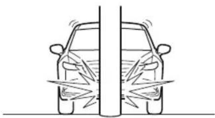
natural_image
Line drawing of a car viewed from front and side, showing impact angles (no text or symbols)Frontal offset impact to the vehicle
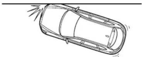
natural_image
Top-down line drawing of a car with exhaust lines and a labeled angle (no text or symbols)Rear-ending or running under a truck's tail gate
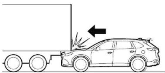
natural_image
Line drawing of a car with a truck and an arrow indicating motion, no text or symbols presentLimitations to side collision detection:
The following illustrations are examples of side collisions that may not be detected as severe enough to deploy the SRS air bag equipment.
Side impacts involving trees or poles
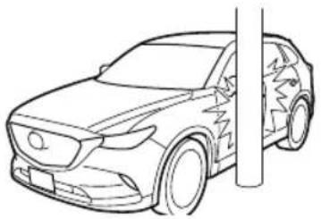
natural_image
Line drawing of a car with a vertical post and jagged roof (no text or symbols)Side impacts with two-wheeled vehicles
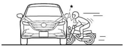
natural_image
Line drawing of a person riding an electric scooter next to a car, with motion lines indicating speed (no text or symbols)Roll-over (Without Front Passenger Occupant Classification System)
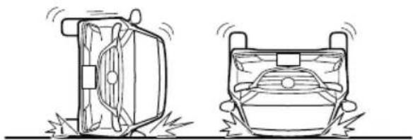
natural_image
Two technical line drawings of a car under compression, showing front and side views with no text or symbols.(With Front Passenger Occupant Classification System)
Limitations to roll-over detection:
The following illustration is an example of an accident that may not be detected as a roll-over accident. Therefore, the front seat belt pretensioners and curtain air bags may not deploy.
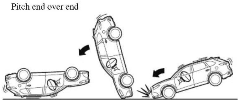
Front Passenger Occupant Classification System\*
First, please read "Supplemental Restraint System (SRS) Precautions" (page 2-69) carefully.
▼ Front Passenger Occupant Classification Sensor
Your vehicle is equipped with a front passenger occupant classification sensor as a part of the supplemental restraint system. This sensor is equipped in the front passenger's seat cushion. This sensor measures the electrostatic capacity of the front passenger's seat. The SAS unit is designed to prevent the front passenger front and side air bags and seat belt pretensioner system from deploying if the front passenger air bag deactivation indicator light turns on.
To reduce the chance of injuries caused by deployment of the front passenger air bag, the system deactivates the front passenger front and side air bags and also the seat belt pretensioner system when the front passenger air bag deactivation indicator light turns on. Refer to the following table for the front passenger air bag deactivation indicator light illumination conditions.
This system shuts off the front passenger front and side air bags and seat belt pretensioner system, so make sure the front passenger air bag deactivation indicator light turns on according to the following table.
The air bag/front seat belt pretensioner system warning light flashes and the front passenger air bag deactivation indicator light illuminates if the sensors have a possible malfunction. If this happens, the front passenger front and side air bags and seat belt pretensioner system will not deploy.
Front passenger air bag deactivation indicator light
This indicator light turns on to remind you that the front passenger front and side air bags and seat belt pretensioner will not deploy during a collision.
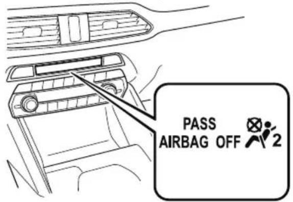
If the front passenger occupant classification sensor is normal, the indicator light turns on when the ignition is switched ON. The light turns off after a few seconds. Then, the indicator light turns on or is off under the following conditions:
Front passenger air bag deactivation indicator light on/off condition chart
| Condition detected by the front passenger occupant classification system | Front passenger air bag deactivation indicator light | Front passenger front and side air bags | Front passenger seat belt pretensioner system |
| Empty (Not occupied) On Deactivated | Deactivated | ||
| A child less than 1 year old is seated in a child-restraint system | On Deactivated | Deactivated | |
| Child*1 | On or off Deactivated | or ready Deactivated | or ready |
| Adult*2 | Off Ready Ready | ||
*1 The occupant classification sensor may not detect a child seated on the seat, in a child-restraint system, or a junior seat depending on the child's physical size and seated posture.
*2 If a smaller adult sits on the front passenger seat, the sensors might detect the person as being a child depending on the person's physique.
The curtain air bag is ready for inflating regardless of what the front passenger air bag deactivation indicator light on/off condition chart indicates.
If the front passenger air bag deactivation indicator light does not turn on when the ignition is switched ON and does not turn on as indicated in the front passenger air bag deactivation indicator light on/off condition chart, do not allow an occupant to sit in the front passenger seat and consult an Authorized Mazda Dealer as soon as possible. The system may not work properly in an accident.

WARNING
Do not allow an occupant in the front passenger's seat to sit with a posture which makes it difficult for the front passenger occupant classification sensor to detect the occupant correctly:
Sitting in the front passenger's seat with a posture which makes it difficult for the front passenger occupant classification sensor to detect the occupant correctly is dangerous. If the front passenger occupant classification sensor cannot detect the occupant sitting on the front passenger's seat correctly, the front passenger front and side air bags and pretensioner system may not operate (non-deploy) or they may operate (deploy) accidentally. The front passenger will not have the supplementary protection of the air bags or the accidental operation (deployment) of the air bags could result in serious injury or death. Under the following conditions, the front passenger occupant classification sensor cannot detect a passenger sitting on the front passenger's seat correctly and the deployment/non-deployment of the air bags cannot be controlled as indicated in the front passenger air bag deactivation indicator light on/off condition chart. For example:
A front passenger is seated as shown in the following figure:
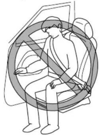
natural_image
Illustration of a person seated in a car seat with a circular arrow indicating no movement or restriction (no text or symbols)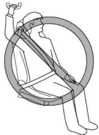
natural_image
Illustration of a person seated in a circular frame with a horizontal bar, no text or symbols present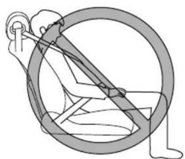
natural_image
Illustration of a person using a wheelbelt to lift a bicycle (no text or symbols)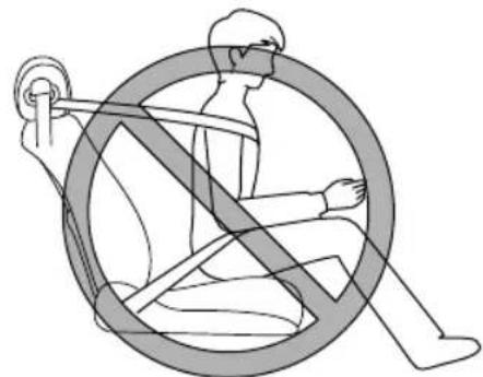
natural_image
Illustration of a person sitting on a wheel using a steering wheel, with no text or symbols present.▶A rear passenger pushes up on the front passenger seat with their feet.
➢ Luggage or other items placed under the front passenger seat or between the front passenger seat and driver seat that push up the front passenger seat bottom.
➢ An object, such as a seat cushion, is put on the front passenger's seat or between the passenger's back and the seatback.
A seat cover is put on the front passenger's seat.
➢ Luggage or other items are placed on the seat with the child in the child-restraint system.
A rear passenger or luggage push or pull down on the front passenger seatback.
➢ Luggage or other items are placed on the seatback or hung on the head restraint.
The seat is washed.
▶ Liquids are spilled on the seat.
The front passenger seat is moved backward, pushing into luggage or other items placed behind it.
The front passenger seatback contacts the rear seat.
➢Luggage or other items are placed between the front passenger seat and driver seat.
▶An electric device is put on the front passenger's seat.
➢ An additional electrical device, such as a seat warmer is installed to the surface of the front passenger seat.
The front passenger front and side air bags and seat belt pretensioner systems will deactivate if the front passenger air bag deactivation indicator light turns on.

CAUTION
To assure proper deployment of the front air bag and to prevent damage to the sensor in the front seat cushion:
➢Do not place sharp objects on the front seat cushion or leave heavy luggage on them.
Do not spill any liquids on the front seats or under the front seats.
To allow the sensors to function properly, always perform the following:
Adjust the front seats as far back as possible and always sit upright against the seatbacks with seat belts worn properly.
If you place your child on the front passenger seat, secure the child-restraint system properly and slide the front passenger seat as far back as possible (page 2-59).
NOTE
- The system requires about 10 seconds to alternate between turning the front passenger front and side air bags and seat belt pretensioner system on or off.
- The front passenger air bag deactivation indicator light may turn on repeatedly if luggage or other items are put on the front passenger seat, or if the temperature of the vehicle's interior changes suddenly.
- The front passenger air bag deactivation indicator light may turn on for 10 seconds if the electrostatic capacity on the front passenger seat changes.
- The air bag/front seat belt pretensioner system warning light might turn on if the front passenger seat receives a severe impact.
- If the front passenger air bag deactivation indicator light does not turn on after installing a child-restraint system on the front passenger seat, first, re-install your child-restraint system according to the procedure in this owner's manual. Then, if the front passenger air bag deactivation indicator light still does not turn on, install the child-restraint system on the rear seat and consult an Authorized Mazda Dealer as soon as possible.
- If the front passenger air bag deactivation indicator light turns on when an occupant is seated directly in the front passenger seat, have the passenger re-adjust their posture by sitting with their feet on the floor, and then re-fastening the seat belt. If the front passenger air bag deactivation indicator light remains turned on, move the passenger to the rear seat. If sitting in the rear seat is not possible, slide the front passenger seat as far back as possible. Consult an Authorized Mazda Dealer as soon as possible.
Constant Monitoring
The following components of the air bag systems are monitored by a diagnostic system:
- Front air bag sensors
- Crash sensors, and diagnostic module (SAS unit)
- Side crash sensors
- Air bag modules
- Front seat belt pretensioners
- Air bag/Front seat belt pretensioner system warning light
- Related wiring
(With Front Passenger Occupant Classification System)
- Front passenger occupant classification sensor
- Front passenger occupant classification module
- Front passenger air bag deactivation indicator light
The diagnostic module continuously monitors the system's readiness. This begins when the ignition is switched ON and continues while the vehicle is being driven.
MEMO
3 Before Driving
Use of various features, including keys, doors, mirrors and windows.
Keys.... 3-2
Keys....3-2
Keyless Entry System......3-4
Advanced Keyless Entry
System....3-10
Advanced Keyless Entry System* .....
3-10
Operational Range...... 3-11
Doors and Locks.... 3-12
Door Locks.... 3-12
Liftgate.... 3-20
Fuel and Emission.... 3-29
Fuel and Engine Exhaust
Precautions.... 3-29
Fuel-Filler Lid and Cap.... 3-32
Mirrors.... 3-34
Mirrors....3-34
Windows....3-39
Power Windows....3-39
Moonroof* 3-42
Security System...... 3-45
Modification and Add-On
Equipment....3-45
Immobilizer System....3-45
Theft-Deterrent System*......3-47
Driving Tips.... 3-49
Break-In Period.... 3-49
Saving Fuel and Protection of the
Environment.... 3-49
Hazardous Driving....3-50
Floor Mat.... 3-51
Rocking the Vehicle....3-51
Winter Driving....3-52
Driving In Flooded Area...... 3-54
Overloading.... 3-54
Driving on Uneven Road......3-55
Turbocharger Information...... 3-56
Towing.... 3-57
Trailer Towing (U.S.A. and
Canada)....3-57
Recreational Towing....3-65
Keys

WARNING
Do not leave the key in your vehicle with children and keep them in a place where your children will not find or play with them:
Leaving children in a vehicle with the key is dangerous. This could result in someone being badly injured or even killed. Children may find these keys to be an interesting toy to play with and could cause the power windows or other controls to operate, or even make the vehicle move.

CAUTION
Because the key (transmitter) uses low-intensity radio waves, it may not function correctly under the following conditions:
The key is carried with communication devices such as cellular phones.
The key contacts or is covered by a metal object.
The key is near electronic devices such as personal computers.
➢Non-Mazda genuine electronic equipment is installed in the vehicle.
There is equipment which discharges radio waves near the vehicle.
The key (transmitter) may consume battery power excessively if it receives high-intensity radio waves. Do not place the key near electronic devices such as televisions or personal computers.
To avoid damage to the key (transmitter), DO NOT:
▶ Drop the key.
Get the key wet.
▶Disassemble the key.
Expose the key to high temperatures on places such as the dashboard or hood, under direct sunlight.
Expose the key to any kind of magnetic field.
Place heavy objects on the key.
➢Put the key in an ultrasonic cleaner.
➢ Put any magnetized objects close to the key.
NOTE
The driver must carry the key to ensure the system functions properly.
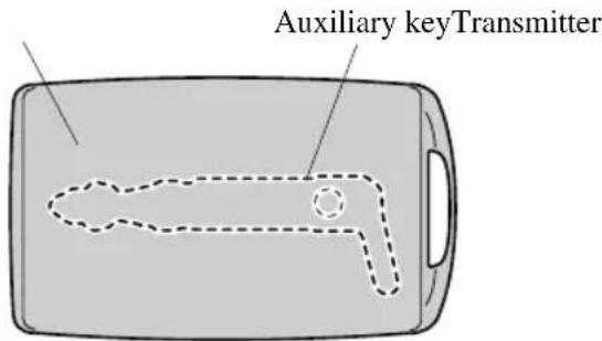
Removing the auxiliary key
- Remove the lower cover while pressing the knob in the direction of the arrow.
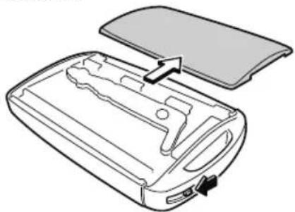
natural_image
Diagram of a device casing with internal components and an open lid, showing no text or symbols- Remove the auxiliary key.
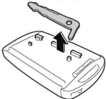
natural_image
Diagram of a device's internal components with a handle and arrow indicating a location (no text or symbols present)Installing the auxiliary key
- Install the auxiliary key as the illustration.
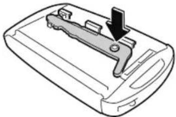
natural_image
Diagram of a device's internal structure with a downward arrow indicating a component (no text or symbols present)- Insert the tabs of the lower cover into the slots of the transmitter and install the lower cover.
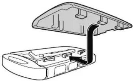
natural_image
Technical line drawing of a device casing with an open lid and internal components (no text or symbols)Key code number plate
A code number is stamped on the plate attached to the key set; detach this plate and store it in a safe place (not in the vehicle) for use if you need to make a replacement key (auxiliary key).
Also write down the code number and keep it in a separate safe and convenient place, but not in the vehicle.
If your key (auxiliary key) is lost, consult an Authorized Mazda Dealer, and have your code number ready.
Keyless Entry System
This system uses the key buttons to remotely lock and unlock the doors and the liftgate, and opens/closes the liftgate. The system can start the engine without having to take the key out of your purse or pocket.
It can also help you signal for attention or help.
Operating the theft-deterrent system is also possible on theft-deterrent system-equipped vehicles.
System malfunctions or warnings are indicated by the following warning lights or beeps.
For vehicles with the type A/type B instrument cluster, check the displayed message for more information and, if necessary, have the vehicle inspected at an Authorized Mazda Dealer, according to the indication.
- KEY Warning Light (Red) Refer to Contact Authorized Mazda Dealer and Have Vehicle Inspected on page 7-31.
Refer to Taking Action on page 7-37.
- Ignition Not Switched Off (STOP) Warning Beep
Refer to Ignition Not Switched Off (STOP) Warning Beep on page 7-48.
• Key Removed from Vehicle Warning Beep
Refer to Key Removed from Vehicle Warning Beep on page 7-48.
If you have a problem with the key, consult an Authorized Mazda Dealer.
If your key is lost or stolen, consult an Authorized Mazda Dealer as soon as
possible for a replacement and to make the lost or stolen key inoperative.

CAUTION
Radio equipment like this is governed by laws in the United States.
Changes or modifications not expressly approved by the party responsible for compliance could void the user's authority to operate the equipment.
NOTE
- The keyless entry system operation may vary due to local conditions.
- The keyless entry system is fully operational (door/liftgate lock/unlock) when the ignition is switched off. The system does not operate if the ignition is switched to any position other than off.
- If the key does not operate when pressing a button or the operational range becomes too small, the battery may be weak. To install a new battery, refer to Key Battery Replacement (page 6-32).
- Battery life is about 1 year. Replace the battery with a new one if the KEY indicator light (green) flashes in the instrument cluster (for vehicles with a type A/type B instrument cluster (page 4-12, 4-29), messages are displayed in the instrument cluster). Replacing the battery about once a year is recommended because the KEY warning light/indicator light may not illuminate or flash depending on the rate of battery depletion.
• Additional keys can be obtained at an Authorized Mazda Dealer. Up to 6 keys can be used with the keyless functions per vehicle. Bring all keys to the Authorized Mazda Dealer when additional keys are required.
▼ Transmitter
Operation indicator light
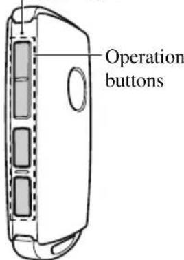
NOTE
• The headlights turn on/off by operating the transmitter. Refer to Leaving Home Light on page 4-74.
· (With theft-deterrent system)
The hazard warning lights flash when the theft-deterrent system is armed or turned off.
Refer to Theft-Deterrent System on page 3-47.
. (With the advanced keyless function)
A beep sound can be heard for confirmation when the doors and the liftgate are locked/unlocked using the key. If you prefer, the beep sound can be turned off.
The volume of the beep sound can also be changed.
Refer to the Settings section in the Mazda Connect Owner's Manual.
Use the following procedure to change the setting.
-
Switch the ignition off and close all of the doors and the liftgate.
-
Open the driver's door.
-
Within 30 seconds of opening the driver's door, press and hold the LOCK button on the key for 5 seconds or longer (All of the doors and the liftgate are locked and unlocked when the LOCK button on the key is pressed and held for 5 seconds.).
The beep sound activates at the currently set volume. The setting changes each time the LOCK button on the key is pressed and the beep sound activates at the set volume. (If the beep sound has been set to not activate, it will not activate.)
- The setting change is completed by doing any one of the following:
- Switching the ignition to ACC or ON.
- Closing the driver's door.
- Opening the liftgate.
- Not operating the key for ten seconds.
- Pressing any button except the LOCK button on the key.
- Pressing a request switch.
The operation indicator light flashes when the buttons are pressed.
Lock button
To lock the doors and the liftgate, press the lock button and the hazard warning lights will flash once.
(With the advanced keyless function)
A beep sound will be heard once.
To confirm that all doors and the liftgate have been locked, press the lock button again within 5 seconds. If they are closed and locked, the horn will sound.

NOTE
- The doors and the liftgate can be locked by pressing the lock button while any other door or the liftgate is open. The hazard warning lights will not flash. When the lock button is pressed while any door is open and then the door is closed, all the doors and the liftgate are locked.
- Confirm that all doors and the liftgate are locked visually or audibly by use of the double click.
• Make sure all doors and the liftgate are locked after pressing the button.
· (With theft-deterrent system)
When the doors are locked by pressing the lock button on the key while the theft-deterrent system is armed, the hazard warning lights will flash once to indicate that the system is armed.
Unlock button
To unlock the driver's door, press the unlock button and the hazard warning lights will flash twice.
(With the advanced keyless function)
A beep sound will be heard twice.
To unlock all doors and the liftgate, press the unlock button again within three seconds and two more beep sounds will be heard.

NOTE
- The system can be set to unlock all doors by performing a single operation. Refer to the Settings section in the Mazda Connect Owner's Manual. Use the following procedure to change the setting.
-
Switch the ignition off and close all of the doors and the liftgate.
-
Open the driver's door.
-
Within 30 seconds of opening the driver's door, press and hold the UNLOCK button on the key for 5 seconds or longer (the sound of the doors locking/unlocking can be heard).
After this, the system switches the setting each time the UNLOCK button is pressed (the sound of the doors locking/unlocking can be heard).
-
The setting change is completed by doing any one of the following:
-
Switching the ignition to ACC or ON.
- Closing the driver's door.
- Opening the liftgate.
- Not operating the key for ten seconds.
- Pressing any button except the UNLOCK button on the key.
- Pressing a request switch.
· (Auto re-lock function)
After unlocking with the key, all doors and the liftgate will automatically lock if any of the following operations are not performed within about 60 seconds. If your vehicle has a theft-deterrent system, the hazard warning lights will flash for confirmation.
The time required for the doors to lock automatically can be changed.
Refer to the Settings section in the Mazda Connect Owner's Manual.
- A door or the liftgate is opened.
- The ignition is switched to any position other than off.
. (With theft-deterrent system)
When the doors are unlocked by pressing the unlock button on the key while the theft-deterrent system is turned off, the hazard warning lights will flash twice to indicate that the system is turned off.
Power liftgate button\*
To open/close the liftgate, press the power liftgate button for one second or longer with the liftgate in the fully closed/open position.
The hazard warning lights flash twice and the liftgate opens/closes after the beep sounds.
Panic button
If you witness from a distance someone attempting to break into or damage your vehicle, press and hold the panic button to activate the vehicle's alarm. Call emergency services if necessary.

NOTE
The panic button will work whether any door or the liftgate is open or closed.
(Turning on the alarm)
Pressing the panic button for 1 second or longer will trigger the alarm for about 2 minutes and 30 seconds, and the following will occur:
- The horn sounds intermittently.
- The hazard warning lights flash.
(Turning off the alarm)
The alarm stops by pressing any button on the key.
Power saving function
By turning on the transmitter power saving function, the advanced keyless entry ^*1 and push button start system functions turn off and the battery power consumption of the transmitter is restricted.
The remote control function is operational by operating the transmitter switch even while the power saving function is turned on. However, the operation indicator light of the transmitter does not turn on/flash.
Turning on the power saving function
After you have turned on the power saving function according to the following procedure, the hazard warning lights and sound operate ^*1 one time.
- Press the lock button on the transmitter 4 times within 3 seconds to turn on the operation indicator light.
- Press the lock button continuously for 1.5 seconds or longer while the operation indicator light turns on (for 5 seconds).
- Press any of the buttons on the transmitter to make sure that the operation indicator light does not turn on/flash.
Turning off the power saving function
After you have turned off the power saving function according to the following procedure, the hazard warning lights and sound operate ^*1 one time.
-
Press any of the buttons on the transmitter to make sure that the operation indicator light does not turn on/flash.
-
Press the lock button on the transmitter 4 times within 3 seconds to turn on the operation indicator light.
-
Press the lock button continuously for 1.5 seconds or longer while the operation indicator light turns on (for 5 seconds).
*1 With the advanced keyless function
▼ Operational Range
The system operates only when the driver is in the vehicle or within operational range while the key is being carried.
Starting the Engine
NOTE
- Starting the engine may be possible even if the key is outside of the vehicle and extremely close to a door and window, however, always start the engine from the driver's seat.
If the vehicle is started and the key is not in the vehicle, the vehicle will not restart after it is shut off and the ignition is switched to off. - The luggage compartment is out of the assured operational range, however, if the key (transmitter) is operable the engine will start.
With the advanced keyless function
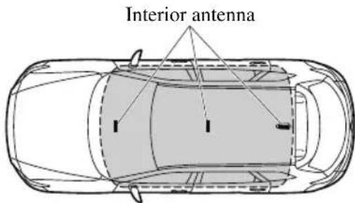

Operational range
Without the advanced keyless function
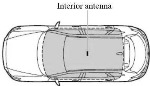

Operational range
NOTE
The engine may not start if the key is placed in the following areas:
· Around the dashboard
- In the storage compartments such as the glove compartment or the center console
▼ Key Suspend Function
If a key is left in the vehicle, the functions of the key left in the vehicle are temporarily suspended to prevent theft of the vehicle.
To restore the functions, press the unlock button on the functions-suspended key in the vehicle.
Advanced Keyless Entry System\*

WARNING
Radio waves from the key may affect medical devices such as pacemakers:
Before using the key near people who use medical devices, ask the medical device manufacturer or your physician if radio waves from the key will affect the device.
The advanced keyless function allows you to lock/unlock the door and the liftgate, or open the liftgate while carrying the key.
System malfunctions or warnings are indicated by the following warning beeps.
- Request switch Inoperable Warning Beep
Refer to Request Switch Inoperable Warning Beep (With the advanced keyless function) on page 7-49.
• Key Left-in-luggage Compartment Warning Beep Refer to Key Left-in-luggage Compartment Warning Beep (With the advanced keyless function) on page 7-49. - Key Left-in-vehicle Warning Beep Refer to Key Left-in-vehicle Warning Beep (With the advanced keyless function) on page 7-49.
NOTE
The advanced keyless entry system functions can be deactivated to prevent any possible adverse effect on a user wearing a pacemaker or other medical device. If the system is deactivated, you will be unable to start the engine by carrying the key. Consult an Authorized Mazda Dealer for details. If the advanced keyless entry system has been deactivated, you can start the engine by following the procedure indicated when the key battery goes dead.
Refer to Engine Start Function When Key Battery is Dead on page 4-8.
Operational Range
The system operates only when the driver is in the vehicle or within operational range while the key is being carried.
NOTE
When the battery power is low, or in places where there are high-intensity radio waves or noise, the operational range may become narrower or the system may not operate. For determining battery replacement, Refer to Keyless Entry System on page 3-4.
▼ Locking, Unlocking the Doors and the Liftgate
Lock
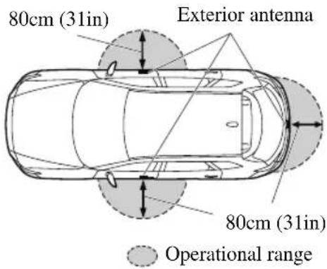
Unlock
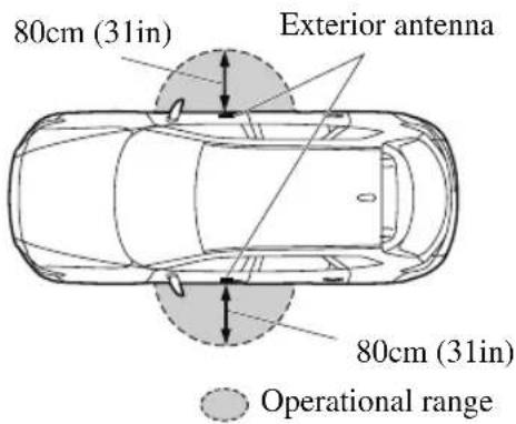
NOTE
- The system may not operate if you are too close to the windows or door handles, or liftgate. - If the key is left in the following areas and you leave the vehicle, the doors may be locked depending on the radio wave conditions even if the key is left in the vehicle.
• Around the dashboard
• In the storage compartments such as the glove compartment or the center console
- Next to a communication device such as a mobile phone
▼ Opening the Liftgate
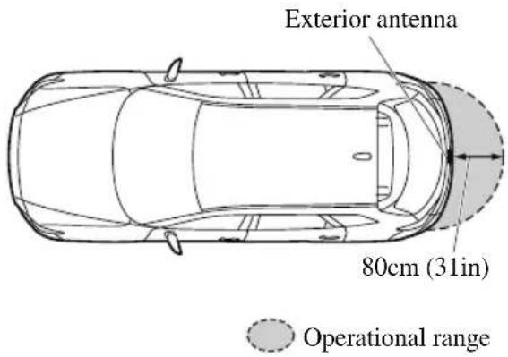
Door Locks

WARNING
Always take all children and pets with you or leave a responsible person with them:
Leaving a child or a pet unattended in a parked vehicle is dangerous. In hot weather, temperatures inside a vehicle can become high enough to cause brain damage or even death.
Do not leave the key in your vehicle with children and keep them in a place where your children will not find or play with them:
Leaving children in a vehicle with the key is dangerous. This could result in someone being badly injured or even killed.
Keep all doors locked when driving:
Unlocked doors in a moving vehicle are dangerous. Passengers can fall out if a door is accidentally opened and can more easily be thrown out in an accident.
Always close all the windows and moonroof, lock the doors and the liftgate and take the key with you when leaving your vehicle unattended:
Leaving your vehicle unlocked is dangerous as children could lock themselves in a hot vehicle, which could result in death. Also, a vehicle left unlocked becomes an easy target for thieves and intruders.
After closing the doors and the liftgate, always verify that they are securely closed:
Doors and the liftgate not securely closed are dangerous, if the vehicle is driven with a door and the liftgate not securely closed, the door and the liftgate could open unexpectedly resulting in an accident.
Always confirm the safety around the vehicle before opening a door and the liftgate:
Suddenly opening a door and the liftgate is dangerous. A passing vehicle or a pedestrian could be hit and cause an accident.

CAUTION
Always confirm the conditions around the vehicle before opening/closing the doors and the liftgate and use caution during strong winds or when parked on an incline. Not being aware of the conditions around the vehicle is dangerous because fingers could get caught in the door and the liftgate or a passing pedestrian could be hit, resulting in an unexpected accident or injury.
NOTE
• Always stop the engine and lock the doors. In addition, to prevent theft of valuables, do not leave them inside the cabin.
- If the key is left in the following areas and you leave the vehicle, the doors may be locked depending on the radio wave conditions even if the key is left in the vehicle.
· Around the dashboard
- In the storage compartments such as the glove compartment or the center console
- Next to a communication device such as a mobile phone
- When the ignition is switched to ACC or ON, the vehicle lock-out prevention feature prevents you from locking yourself out of the vehicle.
All doors and the liftgate will automatically unlock if they are locked using the power door locks with any door or the liftgate open.
The vehicle lock-out prevention feature does not operate while the ignition is switched off.
When all doors and the liftgate are locked using the power door lock with any door or the liftgate open, the closed doors and the liftgate are locked. After that, when all doors and the liftgate are closed, all doors and the liftgate are locked. However, if the key is inside the vehicle, all doors and the liftgate are automatically unlocked.
The beep sound is heard for about 10 seconds to notify the driver that the key has been left in the vehicle.
The horn sound is heard twice to notify the driver that the key has been left in the vehicle.
· (Door unlock (control) system with collision detection)
(With the advanced keyless function)
(Without the advanced keyless function)
This system automatically unlocks the doors and the liftgate in the event the vehicle is involved in an accident to allow passengers to get out of the vehicle immediately and prevent being trapped inside. While the ignition is switched ON and in the event the vehicle receives an impact strong enough to inflate the air bags, all the doors and the liftgate are automatically unlocked after about 6 seconds have elapsed from the time of the accident.
The doors and the liftgate may not unlock depending on how an impact is applied, the force of the impact, and other conditions of the accident.
If door-related systems or the battery is malfunctioning, the doors and the liftgate will not unlock.
▼ Locking, Unlocking with Auxiliary Key
Turn the auxiliary key toward the front to lock, toward the back to unlock.
To lock
All doors lock automatically when the driver's door is locked using the auxiliary key.
To unlock
The driver's door unlocks when the auxiliary key is turned briefly to the unlock position and then immediately returned to the center position.
All doors unlock when the driver's door is unlocked and the auxiliary key is held in
the unlock position for one second or longer.
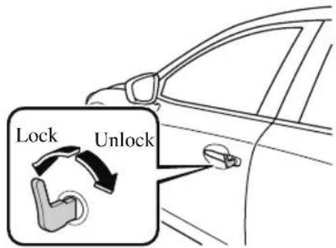
▼ Locking, Unlocking with Request Switch (With the advanced keyless function)
All doors and the liftgate can be locked/unlocked by pressing the request switch on the front doors while the key is being carried.
The request switch on the liftgate can only be used to lock all doors and the liftgate. Front doors
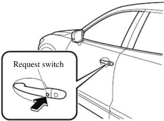
Liftgate (Lock only)
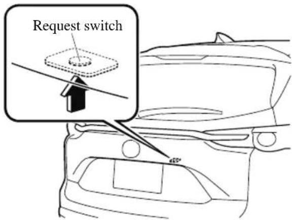
To lock
To lock the doors and the liftgate, press the request switch and the hazard warning lights will flash once. A beep sound will be heard once.
To unlock
Driver's door request switch
To unlock the driver's door, press the request switch. A beep sound will be heard twice and the hazard warning lights will flash twice.
To unlock all doors and the liftgate, press the request switch again within three seconds and two more beep sounds will be heard.
Front passenger door request switch
To unlock all doors and the liftgate, press the request switch. A beep sound will be heard twice and the hazard warning lights will flash twice.
NOTE
- The system can be set to unlock all doors by performing a single operation. Refer to the Settings section in the Mazda Connect Owner's Manual.
Use the following procedure to change the setting.
-
Switch the ignition off and close all of the doors and the liftgate.
-
Open the driver's door.
-
Within 30 seconds of opening the driver's door, press and hold the UNLOCK button on the key for 5 seconds or longer (the sound of the doors locking/unlocking can be heard).
After this, the system switches the setting of pressing the driver's request switch once or twice to unlock all doors and the liftgate each time the UNLOCK button is pressed (the sound of the doors locking/unlocking can be heard).
-
The setting change is completed by doing any one of the following:
-
Switching the ignition to ACC or ON.
- Closing the driver's door.
- Opening the liftgate.
- Not operating the key for ten seconds.
- Pressing any button except the UNLOCK button on the key.
- Pressing a request switch.
- Confirm that all doors and the liftgate are securely locked.
For the liftgate, move it without pressing the electric liftgate opener to verify that the liftgate has not been left ajar.
- All doors and the liftgate cannot be locked when any door or the liftgate is open.
- It may require a few seconds for the doors to unlock after the request switch is pressed.
- A beep sound is heard for confirmation when the doors and the liftgate are locked/unlocked using the request switch. If you prefer, the beep sound can be turned off.
The volume of the beep sound can also be changed.
Refer to the Settings section in the
Mazda Connect Owner's Manual.
Use the following procedure to change the setting.
-
Switch the ignition off and close all of the doors and the liftgate.
-
Open the driver's door.
-
Within 30 seconds of opening the driver's door, press and hold the LOCK button on the key for 5 seconds or longer (All of the doors and the liftgate are locked and unlocked when the LOCK button on the key is pressed and held for 5 seconds.).
The beep sound activates at the currently set volume. The setting changes each time the LOCK button on the key is pressed and the beep sound activates at the set volume. (If the beep sound has been set to not activate, it will not activate.)
-
The setting change is completed by doing any one of the following:
-
Switching the ignition to ACC or ON.
- Closing the driver's door.
- Opening the liftgate.
- Not operating the key for ten seconds.
- Pressing any button except the LOCK button on the key.
- Pressing a request switch.
· (With theft-deterrent system)
The hazard warning lights flash when the theft-deterrent system is armed or turned off.
Refer to Theft-Deterrent System on page 3-47.
- The setting can be changed so that the doors and the liftgate are locked automatically without pressing the request switch.
Refer to the Settings section in the Mazda Connect Owner's Manual.
(Walk-away auto lock function)
A beep sound is heard when all doors and the liftgate are closed while the advanced key is being carried. All doors and the liftgate are locked automatically after about three seconds when the advanced key is out of the operational range. Also, the hazard warning lights flash once. (Even if the driver is in the operational range, all doors and the liftgate are locked automatically after about 30 seconds.) If you are out of the operational range before the doors and the liftgate are completely closed or another key is left in the vehicle, the walk-away auto lock function will not work. Always make sure that all doors and the liftgate are closed and locked before leaving the vehicle. The walk-away auto lock function does not close the power windows.
· (Auto re-lock function)
After unlocking with the request switch, all doors and the liftgate will automatically lock if any of the following operations are not performed within about 60 seconds. If your vehicle has a theft-deterrent system, the hazard warning lights will flash for confirmation.
The time required for the doors to lock automatically can be changed.
Refer to the Settings section in the Mazda Connect Owner's Manual.
· Opening a door or the liftgate.
- Switching the ignition to any position other than off.
▼ Locking, Unlocking with Transmitter
All doors and the liftgate can be locked/unlocked by operating the keyless entry system transmitter, refer to Keyless Entry System (page 3-4).
▼ Locking, Unlocking with Door-Lock Switch
All doors and the liftgate lock automatically when the lock side is pressed. They unlock when the unlock side is pressed.
Driver's door
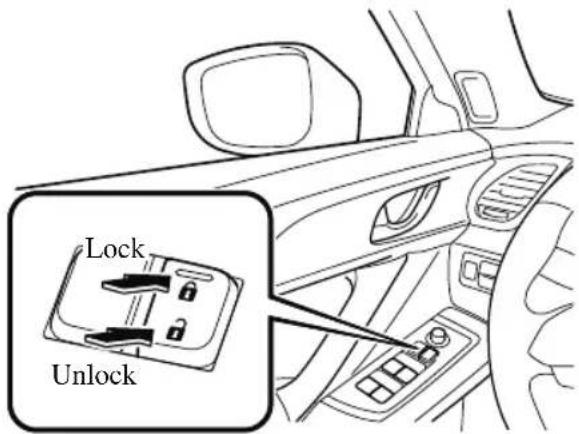
Front passenger's door
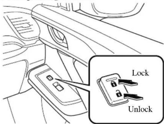
To lock all the doors and the liftgate from an open front door, press the lock side of the door lock switch and then close the door.
NOTE
When locking the doors this way, be careful not to leave the key inside the vehicle.
▼ Auto Lock/Unlock Function

WARNING
Do not pull the inner handle on a front door:
Pulling the inner handle on a front door while the vehicle is moving is dangerous. Passengers can fall out of the vehicle if the door opens accidentally, which could result in death or serious injury.
- When the vehicle speed exceeds 20 km/h (12 mph), all doors and the liftgate lock automatically.
- When the ignition is switched off, all doors and the liftgate unlock automatically.
These functions can also be disabled so that they do not operate.
Auto lock/unlock function setting change using door-lock switch
The doors and the liftgate can be set to lock or unlock automatically by selecting any one of the functions from the following table and using the driver's door-lock switch on the interior door panel.
NOTE
- Function number 3 in the following table is the factory setting for your vehicle.
- There are only a total of six auto lock/unlock settings available. Be sure to press the unlock side of the driver's door-lock switch the correct number of times according to the selected function number. If the switch is mistakenly pressed seven times, the procedure will be cancelled. If this occurs, start the procedure from the beginning.
| Function number | Function*1 |
| 1 | The auto door-lock function is disabled. |
| 2 | All the doors and the liftgate lock automatically when the vehicle speed is about 20 km/h (12 mph) or more. |
| 3 (Factory Setting) | All the doors and the liftgate lock automatically when the vehicle speed is about 20 km/h (12 mph) or more. All the doors and the liftgate unlock when the ignition is switched from ON to Off. |
| 4 | When the ignition is switched ON and the selector lever is shifted from park (P) to any other gear position, all the doors and the liftgate lock automatically. |
| 5 | When the ignition is switched ON and the selector lever is shifted from park (P) to any other gear position, all the doors and the liftgate lock automatically.When the selector lever is shifted to park (P) while the ignition is switched ON, all the doors and the liftgate unlock automatically. |
| 6 | All the doors and the liftgate lock automatically when the vehicle speed is about 20 km/h (12 mph) or more.When the selector lever is shifted to park (P) while the ignition is switched ON, all the doors and the liftgate unlock automatically. |
* 1 Other settings for the auto door lock function are available at an Authorized Mazda Dealer. For details consult an Authorized Mazda Dealer. Refer to the Settings section in the Mazda Connect Owner's Manual.
Settings can be changed using the following procedure.
- Safely park the vehicle. All doors and the liftgate must remain closed.
- Switch the ignition ON.
- Press and hold the lock side of the driver's door-lock switch within 20 seconds of switching the ignition ON, and make sure a beep sound is heard about eight seconds afterwards.
- Refer to the auto lock/unlock function setting table, determine the function number for the desired setting. Press the unlock side of the driver's door-lock switch the same number of times as the selected function number (Ex. If you select function 2, press the unlock side of the switch only 2 times).
- Three seconds after the function setting has been changed, a beep sound will beep in the amount of the selected
function number. (Ex. Function number 3 = 3 beep sounds)
Current Function Number

Press unlock side of lock switch once
Function Number

Press 2 times
Function Number 2

Press 3 times
Function Number 3

Press 4 times
Function Number 4

Press 5 times
Function Number 5

Press 6 times
Function Number 6

Press 7 times
Cancel setting
Press lock side of lock switch

Cancel setting
Wait for 3 second

Function set (The number of beeps heard is the same as the selected function number)
NOTE
- The doors and the liftgate cannot be locked or unlocked while the setting function is being performed.
- The procedure can be cancelled by pressing the lock side of the driver's door-lock switch.
▼ Locking, Unlocking with Door-Lock Knob
Operation from inside
To lock any door from the inside, press the door-lock knob.
To unlock, pull it outward.
This does not operate the other door locks.
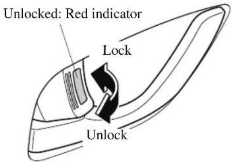
Operation from outside
To lock any door using its door-lock knob from the outside, press the door-lock knob to the lock position and close the door (holding the door handle in the open position is not required).
This does not operate the other door locks.

NOTE
When locking the door this way:
- Be careful not to leave the key inside the vehicle.
- The doors cannot be locked using the driver's door lock knob if any door is open when the ignition is switched to ACC or ON.
▼ Rear Door Child Safety Locks
These locks are intended to help prevent children from accidentally opening the rear doors. Use them on both rear doors whenever a child rides in the rear seat of the vehicle.
If you slide the child safety lock to the lock position before closing that door, the door cannot be opened from the inside. The door can only be opened by pulling the outside handle.
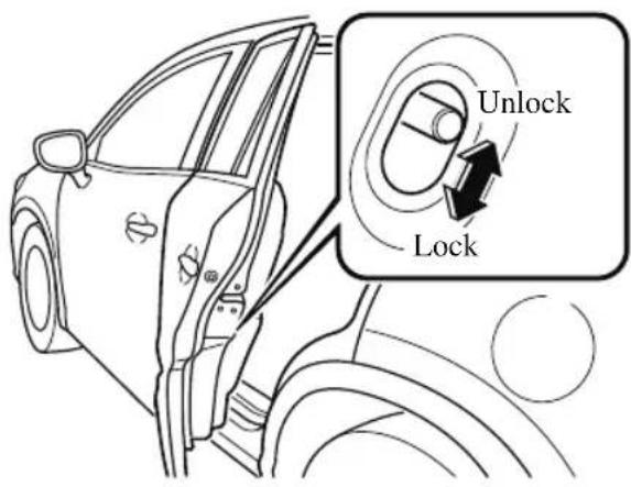
Liftgate

WARNING
Never allow a person to ride in the luggage compartment:
Allowing a person to ride in the luggage compartment is dangerous. The person in the luggage compartment could be seriously injured or killed during sudden braking or a collision.
Do not drive with the liftgate open:
Exhaust gas in the cabin of a vehicle is dangerous. An open liftgate in a moving vehicle will cause exhaust gas to be drawn into the cabin. This gas contains CO (carbon monoxide), which is colorless, odorless, and highly poisonous, and it can cause loss of consciousness and death. Moreover, an open liftgate could cause occupants to fall out in an accident.
Do not stack or leave loaded luggage unsecured in the luggage compartment:
Otherwise, the luggage may move or collapse, resulting in injury or an accident. In addition, do not load luggage higher than the seatbacks. It may affect the side or rear field of view.

CAUTION
Before opening the liftgate, remove any snow and ice accumulation on it. Otherwise, the liftgate could close under the weight of the snow and ice resulting in injury.
➢Be careful when opening/closing the liftgate during strong winds. If a strong gust blows against the liftgate, it could close suddenly resulting in injury.
➢Fully open the liftgate and make sure that it stays open. If the liftgate is only opened partially, it could slam shut by vibration or wind gusts resulting in injury.
When loading or unloading luggage in the luggage compartment, turn off the engine. Otherwise, you could get burned by the heat of the exhaust gas.
➢Be careful not to apply excessive force to the damper stay on the liftgate such as by putting your hand on the stay. Otherwise, the damper stay may bend and affect the liftgate operation.
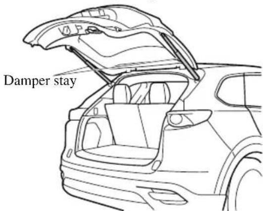
Do not modify or replace the liftgate damper stay. Consult an Authorized Mazda Dealer if a liftgate damper stay is deformed or damaged for reasons such as a collision or if there is some other problem.
▼ Opening and Closing the Liftgate
Opening the liftgate with Electric liftgate opener
Unlock the doors and liftgate, then press the electric liftgate opener on the liftgate
and raise the liftgate when the latch releases.
For the power liftgate operation, refer to Power Liftgate on page 3-22.
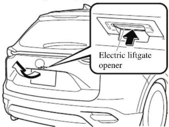
NOTE (With the advanced keyless function)
- A locked liftgate can also be opened while the key is being carried.
- When opening the liftgate with the doors and the liftgate locked, it may require a few seconds for the liftgate latch to release after the electric liftgate opener is pressed.
- The liftgate can be closed when the doors are locked with the key left in the vehicle. However, to prevent locking the key in the vehicle, the liftgate can be opened by pressing the electric liftgate opener. If the liftgate cannot be opened despite doing this procedure, first push the liftgate completely closed, then press the electric liftgate opener to fully open the liftgate.
- When the liftgate latch is released by pressing the electric liftgate opener, the liftgate raises slightly. If the liftgate is not operated for a certain period of time, the liftgate cannot be raised.
To open
Press the electric liftgate opener again.
To close
To close the liftgate from its slightly raised position, open it first by pressing the electric liftgate opener, then close it after waiting at least 1 second.
- If the liftgate is not fully closed, the driver is notified by a warning indicated in the instrument cluster.
- If the vehicle battery is dead or there is a malfunction in the electrical system and the liftgate cannot be unlocked, the liftgate can be opened by performing the emergency procedure.
Refer to When Liftgate Cannot be Opened on page 7-52.
Closing the liftgate
Lower the liftgate slowly using the liftgate handle, then push the liftgate closed using both hands.
Do not slam it. Pull up on the liftgate to make sure it is secure.
For the power liftgate operation, refer to Power Liftgate on page 3-22.
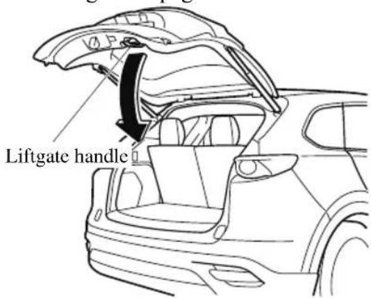
NOTE
Confirm that the liftgate is securely closed. The liftgate, move it without pressing the electric liftgate opener to verify that the liftgate has not been left ajar.
▼ Power Liftgate\*
The power liftgate opens/closes electrically by operating the switches in the vehicle or the buttons on the keyless entry system transmitter.

WARNING
Be sure to watch the power liftgate as it opens or closes, and make sure that it closes completely:
Opening or closing the power liftgate while not watching it move is dangerous. Because of unseen obstacles and the jam-safe feature, a liftgate may not close completely and, if left unnoticed, could result in serious injury or death if an occupant were to fall out of the vehicle. Always be sure that the area around the liftgate is clear before activating it.
Always confirm the safety of the area around the power liftgate before operating it electrically.
Not checking the area around the liftgate for people before operating it using the power liftgate switch or the button on the keyless entry system is dangerous. A person could become caught between the liftgate and an obstruction while it is opening electrically or between the liftgate and vehicle while it is closing electrically, resulting in an accident and serious injury.
Never allow children to operate the power liftgate system:
Allowing children to operate the power liftgate switch and the keyless entry system is dangerous. Children are not aware of the dangers of people getting fingers and hands caught in a moving liftgate. If someone's neck, head or hands get caught in a closing door, it could result in death or serious injury.

CAUTION
When closing the power liftgate, make sure there are no foreign objects around the striker. If foreign objects are obstructing the striker, the liftgate may not close properly.
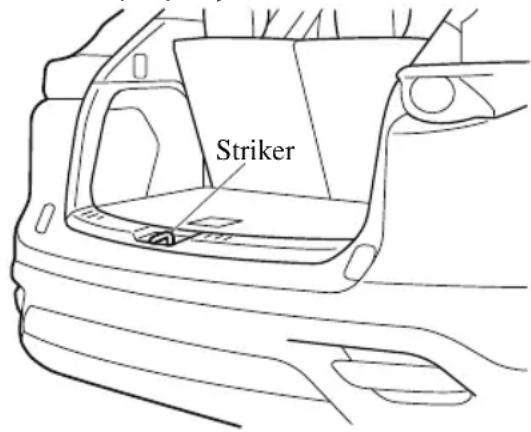
➢Do not install accessories to the power liftgate other than specified accessories. Otherwise, it cannot be opened/closed automatically and could result in a malfunction.
➢Be careful when switching the power liftgate from electrical to manual operation. The power liftgate may open/close unexpectedly depending on its position which could result in injury.
NOTE
- Do not apply unnecessary force to the power liftgate when it is opening/closing electrically. Unnecessary force on the liftgate may cause it to reverse direction of movement automatically. Also, it could result in a malfunction.
- The power liftgate may not open/close electrically if the vehicle is parked on an incline, or there is strong wind, or the liftgate is laden with snow.
- If a power liftgate system fuse has blown, the liftgate cannot be opened using the power liftgate switch or the electric liftgate opener. Use the emergency lever to open the liftgate.
- Fully close the power liftgate before disconnecting the vehicle battery. If the battery is disconnected with the liftgate open, it cannot be opened or closed automatically after the battery is reconnected. If this happens, fully close the liftgate manually to restore the auto full open/close function.
- If the liftgate is snow-laden, remove the snow before operating the power liftgate. Operating the power liftgate with excessive force applied to the liftgate may damage the liftgate.
Operation using the transmitter
Press the power liftgate button for one second or longer. The hazard warning lights flash twice and the liftgate opens/closes after the beep sounds.
Refer to Transmitter on page 3-5.
NOTE
- When the ignition is switched ON, the transmitter does not operate.
- When opening the liftgate by pressing the power liftgate button on the transmitter, the liftgate can be opened even when it is locked. - If the power liftgate button on the transmitter is pressed while the liftgate is opening/closing electrically, the beep is activated and the liftgate stops. When pressing the power liftgate button again, the liftgate moves in the reverse direction.
Operation using each switch
Operation conditions
Opening the liftgate
If the vehicle has satisfied all the following operation conditions, the power liftgate can be opened using the power function.
- All doors and the liftgate are unlocked.
- The ignition is switched OFF, or the selector lever is in P with the ignition switched ON.
Closing the liftgate
- The ignition is switched OFF, or the selector lever is in P with the ignition switched ON.
NOTE
- If the vehicle moves with the selector lever shifted to a position other than P while the liftgate is opening/closing electrically, the liftgate moves as follows:
While opening electrically
The buzzer is activated, and the liftgate moves in the reverse direction automatically and closes. When the selector lever is shifted to P , you can resume the power liftgate operation using the switches.
While closing electrically
The buzzer is activated, but the liftgate continues closing.
Operation from the driver's seat (To open/close)
Press the power liftgate switch for about one second or longer while the liftgate is in the fully closed/open position. The hazard warning lights flash twice and the liftgate opens/closes fully after the beep sound is heard.
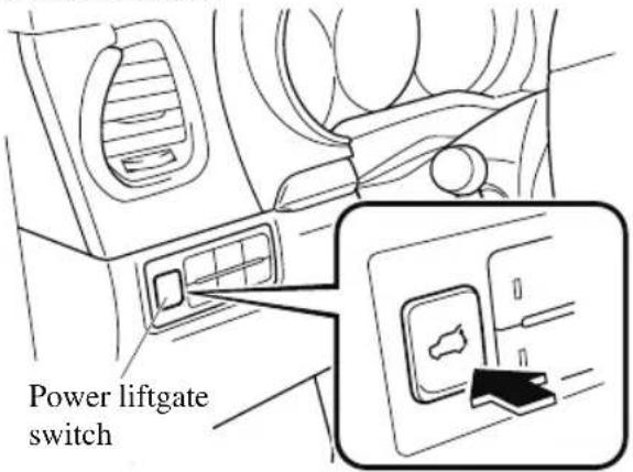
Operation from outside (To open)
Press the electric liftgate opener on the liftgate and raise the liftgate. The hazard warning lights flash twice and the liftgate opens automatically after the beep sound is heard.
(With the advanced keyless function)
A locked liftgate can also be opened while the key is being carried.
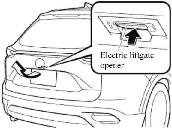
Operation from outside (To close)
Press the power liftgate close switch while the liftgate is fully opened. The hazard warning lights flash twice and the liftgate closes automatically after the beep sound is heard.
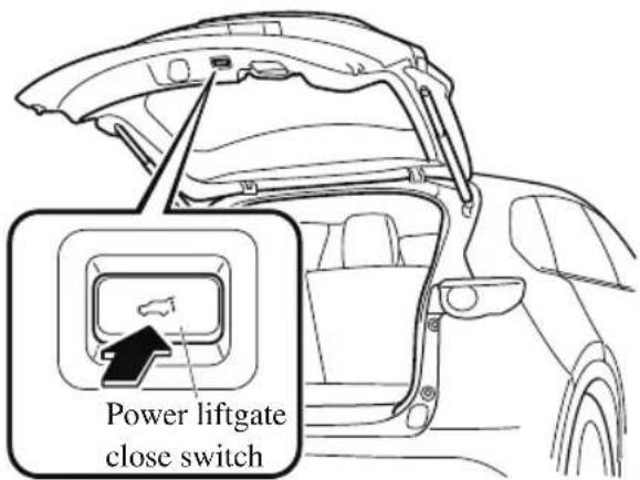
NOTE
If the power liftgate switch/power liftgate close switch is pressed or the electric liftgate opener is operated while the liftgate is opening/closing electrically, the beep sound is heard and the liftgate stops. Then, it reverses when any of the switches are pressed again.
Hands-free liftgate\*
When the hands-free liftgate sensor on the center bottom of the rear bumper detects foot movement (kick-activated liftgate), the liftgate opens/closes automatically. The liftgate can be opened/closed even with both hands full, such as when carrying baggage.
Operation conditions
Do the kicking motion with your foot when all of the following conditions are met while the vehicle is stopped.
(When ignition is switched OFF)
- You are carrying the transmitter.
• The hands-free liftgate is on.
(When ignition is switched ON)
- You are carrying the transmitter.
• The hands-free liftgate is on. - The selector lever is in the P position.
How to do the kicking motion
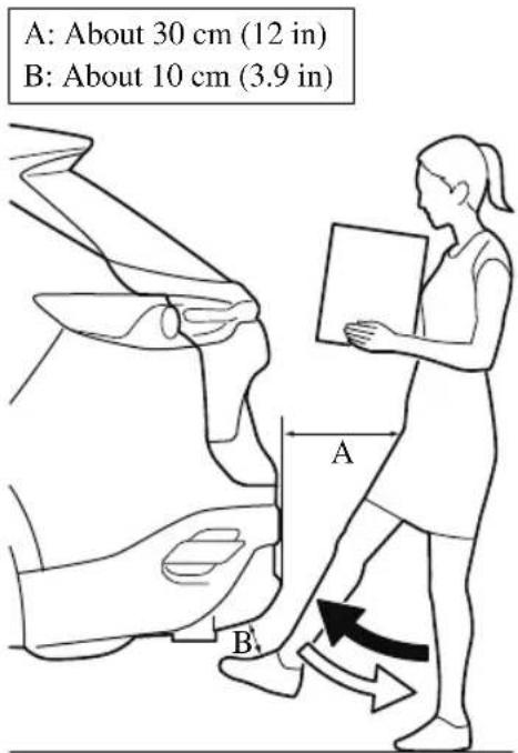
- Stand at the position about 30 cm (12 in) behind the center of the rear bumper.
- Move your foot to the position about 10 cm (3.9 in) from the center bottom of the rear bumper.
- Move your foot away from under the bumper within about 1 second after moving it under the bumper.
When the kicking motion is done correctly, the hazard warning lights flash 2 times, a beep sound is activated, and the liftgate opens/closes automatically. Be careful not to contact the liftgate.
If the kicking motion is done while the liftgate is opening/closing automatically, the liftgate will stop. If the kicking motion is done again, the liftgate moves in the direction opposite to the direction it was moving before it stopped.
CAUTION
Do not do the kicking motion while wearing footwear such as sandals, or with your bare foot. If your foot contacts the hot exhaust pipe, it could cause serious burns.
Do not do the kicking motion while the area where you are standing is unstable such as a slope or icy road. Otherwise, you could fall down, resulting in injury.
➢Do not paint the rear bumper or install any add-on equipment to it. Otherwise, the hands-free liftgate sensor may not operate normally.
If you are carrying the transmitter around the liftgate or there is another person around the liftgate who is carrying a transmitter, do not allow the following to occur. Otherwise, the hands-free liftgate sensor will operate and the liftgate may open/close unexpectedly resulting in an accident.
➢A person not carrying a transmitter does the kicking motion.
While the liftgate is open, a person sitting on the edge of the luggage compartment swings his or her legs.
➢Installing/removing the body cover or removing snow around the rear bumper.
➢Picking up something which was dropped under the rear bumper.
➢Spraying water on the rear bumper using a high water pressure car washer.
➢Pushing a shopping cart close to the rear bumper.
A moving object such as an animal or a ball approaches the rear bumper.
To prevent an unintended operation, place the transmitter outside of its operation range or turn off the hands-free liftgate.
NOTE
- The hands-free liftgate sensor detects in a range of about 30 cm (12 in) on both the left and right sides from the center of the rear bumper.
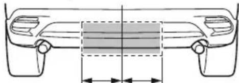
natural_image
Technical line drawing of a car front view with dimension lines (no text or symbols)- The hands-free liftgate sensor may not operate normally under the following conditions.
- Your foot remains placed within the detection area.
- You move your foot left and right within the detection area.
- The kicking motion is too fast or too slow.
- Your foot contacts the rear bumper when doing the kicking motion.
- You are wearing shoes such as rubber boots which do not conduct electricity well.
- There is equipment emitting strong radio waves near the vehicle.
- The detection area of the hands-free liftgate sensor is dirty.
- When the detection area of the hands-free liftgate sensor is dirty, wipe it off with a clean cloth. Place the transmitter outside of its operation range or wipe off the area around the sensor with a clean cloth after turning off the hands-free liftgate.
- If the operation using the hands-free liftgate sensor is not possible even though the operation conditions are met, consult an Authorized Mazda Dealer.
Hands-free liftgate ON/OFF switching
The hands-free liftgate can be switched on/off.
To prevent an unintended operation, turn off the function.
Refer to the Settings section in the Mazda Connect Owner's Manual.
Changing the power liftgate fully open position
The power liftgate fully-open position can be changed according to the height of a garage.
When changing the position
- Stop the liftgate at the desired position.
- Press the power liftgate close switch for about three seconds.
A beep sound is activated two times to indicate that the position change has been completed.
NOTE
Set the desired fully-open position of the liftgate at the position where it is open more than halfway. The position where it is less than halfway open cannot be set.
To reset
- Open the liftgate.
- Press the power liftgate close switch for about seven seconds.
A beep sound is activated three times to indicated that the reset has been completed.
NOTE
After about 3 seconds have elapsed since the switch was pressed, a beep sound is activated 2 times to indicate that the liftgate fully-open position has changed. Continuously press the switch for about 7 seconds to complete the reset.
Jam-safe equipment
While the power liftgate is opening/closing electrically and the system detects a person or an object in the liftgate's path, the liftgate will move in the reverse direction automatically and stops.

WARNING
Always check the area around the power liftgate before opening/closing it:
Not checking for occupants and objects around the power liftgate before opening/closing it is dangerous. The jam-safe equipment is designed to prevent jamming in the event an obstruction is in the liftgate's path. The system may not detect certain objects obstructing the liftgate depending on the way they are positioned and their shape. However, if the jam-safe function detects an obstruction and moves the liftgate in the reverse direction, an occupant in the liftgate's path could be seriously injured.

CAUTION
Sensors are installed on both ends of the power liftgate. Be careful not to allow the sensors to be scratched or damaged by sharp objects, otherwise the liftgate may no longer open/close automatically. In addition, if the sensor is damaged while the liftgate is closing automatically, the system will stop.
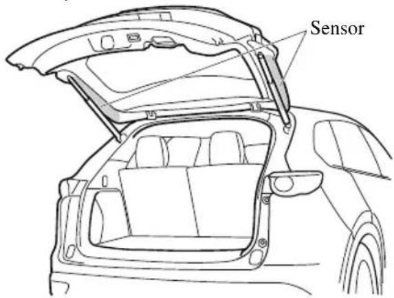
NOTE
The jam-safe equipment does not activate during easy closure operation when the power liftgate is between the near-shut position and fully closed position.
When the power liftgate is moving in the open/close direction and an obstruction is detected, the beep sound will be heard and the liftgate moves in the reverse direction and stops.
Liftgate easy closure
The Easy Closure system automatically closes the liftgate completely from the near-shut position.
This system also operates when the liftgate is closed manually.

WARNING
When closing a liftgate, always keep hands and fingers away from the liftgate:
Placing hands or fingers around a liftgate is dangerous because the liftgate closes automatically from the near-shut position, which could cause hands and fingers to be pinched and injured.
NOTE
- If the electric liftgate opener is pressed while the easy closure function is operating, the liftgate can be opened.
- If the liftgate is opened/closed repeatedly in a short period of time, the easy closure function may not operate. Wait for about 2 seconds and then try again.
Fuel and Engine Exhaust Precautions
▼ Fuel Requirements
Vehicles with catalytic converters or oxygen sensors must use ONLY UNLEADED FUEL, which will reduce exhaust emissions and keep spark plug fouling to a minimum.
To achieve maximum engine performance, use the specified fuel.
| Fuel | Octane Rating*1 (Anti-knock index) |
| Regular unleaded fuel 87 | [(R+M)/2 method] or above (91 RON or above) |
*1 U.S. federal law requires that octane ratings be posted on gas station pumps.
Fuel with a rating lower than 87 octane (91 RON) will negatively affect the emission control system performance and could also cause engine knocking and serious engine damage.

CAUTION
USE ONLY UNLEADED FUEL.
Leaded fuel is harmful to the catalytic converter and oxygen sensors and will lead to deterioration of the emission control system and or failures.
This vehicle can only use oxygenated fuels containing no more than 10 % ethanol by volume. Damage to the vehicle may occur when ethanol exceeds this recommendation, or if the gasoline contains any methanol. Stop using gasohol of any kind if your vehicle engine is performing poorly.
➢ Never add fuel system additives other than a Mazda genuine product, otherwise the emission control system could be damaged. Consult an Authorized Mazda Dealer for details.
Gasoline blended with oxygenates such as alcohol or ether compounds are generally referred to as oxygenated fuels. The common gasoline blend that can be used with your vehicle is ethanol blended at no more than 10%. Gasoline containing alcohol, such as ethanol or methanol, may be marketed under the name "Gasohol".
Vehicle damage and drivability problems resulting from the use of the following may not be covered by the warranty.
· Gasohol containing more than 10 % ethanol.
• Gasoline or gasohol containing methanol.
- Leaded fuel or leaded gasohol.
▼ Emission Control System
This vehicle is equipped with an emission control system (the catalytic converter is part of this system) that enables the vehicle to comply with existing exhaust emissions requirements.

WARNING
Never park over or near anything flammable:
Parking over or near anything flammable, such as dry grass, is dangerous. Even with the engine turned off, the exhaust system remains very hot after normal use and could ignite anything flammable. A resulting fire could cause serious injury or death.

CAUTION
Ignoring the following precautions could cause lead to accumulate on the catalyst inside the converter or cause the converter to get very hot. Either condition will damage the converter and cause poor performance.
USE ONLY UNLEADED FUEL.
Do not drive your Mazda with any sign of engine malfunction.
Do not coast with the ignition switched off.
➢Do not descend steep grades in gear with the ignition switched off.
➢ Do not operate the engine at high idle for more than 2 minutes.
Do not tamper with the emission control system. All inspections and adjustments must be made by a qualified technician.
Do not push-start or pull-start this vehicle.
NOTE
- Under U.S. federal law, any modification to the original-equipment emission control system before the first sale and registration of a vehicle is subject to penalties. In some states, such modification made on a used vehicle is also subject to penalties.
- While the engine is off, the sound of a valve opening and closing can be heard at the rear of the vehicle, however this does not indicate an abnormality. The vehicle has a self-checking device and it operates while the engine is off.
▼ Engine Exhaust (Carbon monoxide)

WARNING
Do not drive your vehicle if you smell exhaust gas inside the vehicle:
Engine exhaust gas is dangerous. This gas contains carbon monoxide (CO), which is colorless, odorless, and poisonous. When inhaled, it can cause loss of consciousness and death. If you smell exhaust gas inside the vehicle, keep all windows fully open and contact an Authorized Mazda Dealer immediately.
Do not run the engine when inside an enclosed area:
Running the engine inside an enclosed area, such as a garage, is dangerous. Exhaust gas, which contains poisonous carbon monoxide, could easily enter the cabin. Loss of consciousness or even death could occur.
Open the windows or adjust the heating or cooling system to draw fresh air when idling the engine:
Exhaust gas is dangerous. When the vehicle is stopped with the windows closed and the engine running for a long time even in an open area, exhaust gas, which contains poisonous carbon monoxide, could enter the cabin. Loss of consciousness or even death could occur.
Clear snow from underneath and around your vehicle, particularly the tail pipe, before starting the engine:
Running the engine when a vehicle is stopped in deep snow is dangerous. The exhaust pipe could be blocked by the snow, allowing exhaust gas to enter the cabin. Because exhaust gas contains poisonous carbon monoxide, it could cause loss of consciousness or even death to occupants in the cabin.
Fuel-Filler Lid and Cap

WARNING
When removing the fuel-filler cap, loosen the cap slightly and wait for any hissing to stop, then remove it:
Fuel spray is dangerous. Fuel can burn skin and eyes and cause illness if ingested. Fuel spray is released when there is pressure in the fuel tank and the fuel-filler cap is removed too quickly.
Before refueling, stop the engine, and always keep sparks and flames away from the filler neck:
Fuel vapor is dangerous. It could be ignited by sparks or flames causing serious burns and injuries.
Additionally, use of the incorrect fuel-filler cap or not using a fuel-filler cap may result in a fuel leak, which could result in serious burns or death in an accident.
Do not continue refueling after the fuel pump nozzle shuts off automatically:
Continuing to add fuel after the fuel pump nozzle has shut off automatically is dangerous because overfilling the fuel tank may cause fuel overflow or leakage. Fuel overflow and leakage could damage the vehicle and if the fuel ignites it could cause a fire and explosion resulting in serious injury or death.

CAUTION
Always use only a genuine Mazda fuel-filler cap or an approved equivalent, available at an Authorized Mazda Dealer. The wrong cap can result in a serious malfunction of the fuel and emission control systems.
(U.S.A. and Canada)
It may also cause the check engine light in the instrument cluster to illuminate.
▼ Refueling
Before refueling, close all the doors, windows, and the liftgate, and switch the ignition OFF.
- To open the fuel-filler lid, pull the remote fuel-filler lid release.
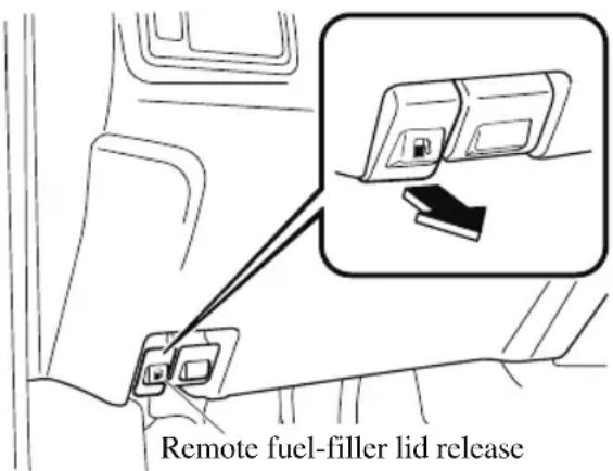
-
To remove the fuel-filler cap, turn it counterclockwise.
-
Attach the removed cap to the inner side of the fuel-filler lid.
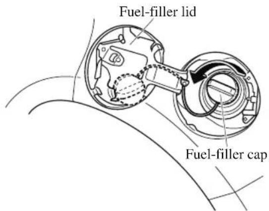
- Insert the refueling nozzle all the way and begin refueling. Pull out the refueling nozzle after the refueling stops automatically.
- To close the fuel-filler cap, turn it clockwise until a click is heard.
- To close, press the fuel-filler lid until it locks securely.
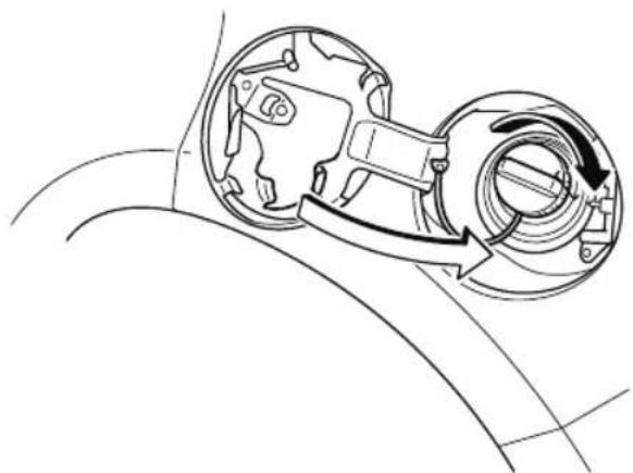
natural_image
Technical line drawing of a mechanical component with internal parts and directional arrows (no text or symbols)
CAUTION
(U.S.A. and Canada)
If the check fuel cap warning light illuminates, the fuel-filler cap may not be properly installed. If the warning light illuminates, park your vehicle safely off the right-of-way, remove the fuel-filler cap and reinstall it correctly. After the cap has been correctly installed, the fuel cap warning light may continue to illuminate until a number of driving cycles have been completed. A drive cycle consists of starting the engine (after four or more hours with the engine off) and driving the vehicle on city and highway roads.
Continuing to drive with the check fuel cap warning light illuminated could cause the check engine light to illuminate as well.
Mirrors
Before driving, adjust the inside and outside mirrors.
▼ Outside Mirrors

WARNING
Be sure to look over your shoulder before changing lanes:
Changing lanes without taking into account the actual distance of the vehicle in the convex mirror is dangerous. You could have a serious accident. What you see in the convex mirror is closer than it appears.
Mirror type
Flat type (driver's side)
Flat surface mirror.
Convex type (front passenger side)
The mirror has single curvature on its surface.
Power mirror adjustment
The ignition must be switched to ACC or ON position.
To adjust:
-
Rotate the mirror switch to the left L or right R to choose the left or right side mirror.
-
Press the mirror switch in the appropriate direction.
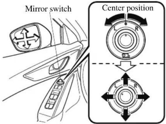
After adjusting the mirror, lock the control by rotating the switch in the center position.
Folding outside mirror

WARNING
Always return the outside mirrors to the driving position before you start driving:
Driving with the outside mirrors folded in is dangerous. Your rear view will be restricted, and you could have an accident.
Manual folding outside mirror
Fold the outside mirror rearward until it is flush with the vehicle.
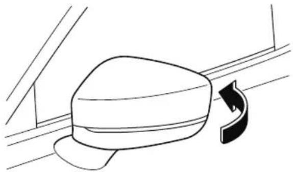
natural_image
Line drawing of a car seatbelt with a curved arrow indicating rotation (no text or symbols)Power folding outside mirror

WARNING
Do not touch a power folding outside mirror while it is moving:
Touching the power folding outside mirror when it is moving is dangerous. Your hand could be pinched and injured or the mirror could be damaged.
Use the outside mirror switch to set the mirror to the on-road position:
Setting the power folding outside mirror to the on-road position by hand is dangerous. The mirror will not lock in position and will prevent effective rearview visibility.
Only operate the power folding outside mirror with the vehicle safely parked:
Operating the power folding outside mirror while the vehicle is moving is dangerous. Wind blast on the mirror will cause them to collapse and you will be unable to return it to the on-road position, preventing rearview visibility.
The ignition must be switched to ACC or ON position.
To fold, rotate the outside mirror switch.
To return the mirror to the driving position, rotate the switch to the center position.
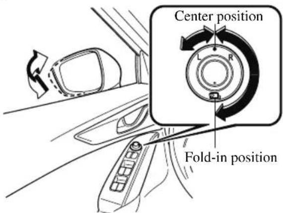
Automatic folding function
The automatic folding function operates when the ignition is switched to OFF. When the outside mirror switch is in a position other than the fold-in position, the outside mirrors automatically fold in and out when the doors are locked and unlocked.
Also, when the ignition is switched ON or the engine is started, the outside mirrors fold out automatically.
NOTE
The outside mirrors may not fold in and out automatically under cold weather conditions.
If the outside mirrors do not fold in and out automatically, remove any ice or snow, and then operate the outside mirror switch to fold the outside mirrors in or out.
Canceling the automatic folding function
To cancel the automatic folding function, carry out the following procedure using the master control switches.
-
Switch the ignition ON.
-
If the power window lock switch is in the unlock position, switch it to the lock position.
- Press and hold the front passenger's power window switch and rear left/right power window switches on the driver's door at the same time for 3 seconds or longer.
NOTE
- The automatic folding function cannot be canceled if the procedure is not completed within the specified times, or the procedure is changed along the way. To redo the procedure, first switch the ignition off and proceed from the beginning.
- If you are unable to cancel the function despite doing the cancellation procedure, consult an Authorized Mazda Dealer.
Restoring the automatic folding function
With the automatic folding function in the canceled state, repeat the previous procedure for canceling the function and it will be restored.
NOTE
If you are unable to restore the function despite carrying out the restore procedure, consult an Authorized Mazda Dealer.
Engine-off outside mirror operation\*
The outside mirrors can be operated for about 40 seconds after the ignition is switched from ON to off.
▼ Rearview Mirror
WARNING
Do not stack cargo or objects higher than the seatbacks:
Cargo stacked higher than the seatbacks is dangerous. It can block your view in the rearview mirror, which might cause you to hit another car when changing lanes.
Rearview mirror adjustment
Before driving, adjust the rearview mirror to center on the scene through the rear window.
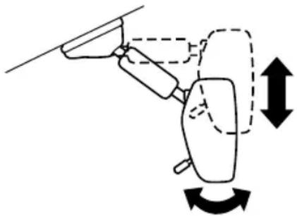
natural_image
Diagram of a hand holding a device with directional arrows indicating motion (no text or symbols)NOTE
For the manual day/night mirror, perform the adjustment with the day/night lever in the day position.
Reducing glare from headlights
Manual day/night mirror
Push the day/night lever forward for day driving. Pull it back to reduce glare of headlights from vehicles at the rear.

Auto-dimming mirror
The auto-dimming mirror automatically reduces the glare of headlights from vehicles at the rear when the ignition is switched ON.
(With Homelink wireless control system)
(Type A)
Press the OFF button (○) to cancel the auto-dimming function. The indicator light will turn off.
To reactivate the auto-dimming function, press the ON button (1). The indicator light will illuminate.
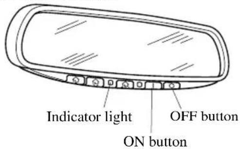
(Type B)
Press the ON/OFF button (⊕) to cancel the auto-dimming function. The indicator light will turn off.
To reactivate the auto-dimming function, press the ON/OFF button (☐). The indicator light will illuminate.
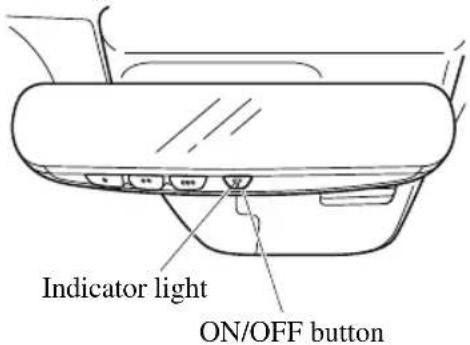
(Without Homelink wireless control system)
Press the ON/OFF button ⏻ to cancel the auto-dimming function. The indicator light will turn off.
To reactivate the auto-dimming function, press the ON/OFF button ⏻. The indicator light will illuminate.

NOTE
- Do not use glass cleaner or suspend objects on or around the light sensor. Otherwise, light sensor sensitivity will be affected and may not operate normally.
Mirrors
(With Homelink wireless control system)
(Type A)
Light sensor
(With Homelink wireless control system)
For information regarding the 3 buttons
(Type A , , /Type B , , ) on the auto-dimming mirror.
Refer to HomeLink Wireless Control System on page 4-84.
The auto-dimming function is canceled when the ignition is switched ON and the shift lever is in reverse (R).
(Type B)
Light sensor
(Without Homelink wireless control system)
Light sensor
Power Windows
The windows can be opened/closed by operating the power window switches.

WARNING
Make sure the opening is clear before closing a window:
Closing a power window is dangerous. A person's hands, head, or even neck could be caught by the window and result in serious injury or even death. This warning applies especially to children.
Never allow children to play with power window switches:
Power window switches that are not locked with the power window lock switch would allow children to operate power windows unintentionally, which could result in serious injury if a child's hands, head or neck becomes caught by the window.
Make sure nothing blocks the window just before it reaches the fully closed position or while fully holding up the power window switch:
Blocking the power window just before it reaches the fully closed position or while fully holding up the power window switch is dangerous.
In this case, the jam-safe function cannot prevent the window from closing all the way. If fingers are caught, serious injuries could occur.
NOTE
When driving with only 1 of the rear windows open, your ears might experience a resonating sound. However, this does not indicate a problem. The sound can be reduced by slightly opening a front window or by changing the size of the rear window opening.
▼ Opening/Closing Windows
The window opens while the switch is pressed and it closes while the switch is pulled up with the ignition switched ON. Do not open or close 3 or more windows at the same time.
The front passenger's side and rear windows can be opened/closed when the power window lock switch on the driver's door is in the unlock position. Keep this switch in the locked position while children are in the vehicle.
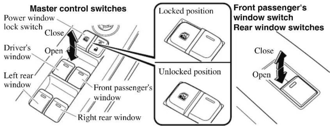
NOTE
- A power window may no longer open/close if you continue to press the switch after fully opening/closing the power window. If the power window does not open/close, wait a moment and then operate the switch again.
- The passenger windows may be opened or closed using the master control switches on the driver's door.
- The power window can be operated for about 40 seconds after the ignition is switched from ON to ACC or off with all doors closed. If any door is opened, the power window will stop operating.
For engine-off operation of the power window, the switch must be held up firmly throughout window closure because the auto-closing function will be inoperable. - When the power window lock switch is in the locked position, the light on each power window switch, except for the driver's power window switch, turns off. The light may be difficult to see depending on the surrounding brightness.
▼ Auto-opening/Closing
To fully open the window automatically, press the switch completely down, then release. The window will fully open automatically.
To fully close the window automatically, pull the switch completely up, then
release. The window will fully close automatically.
To stop the window partway, pull or press the switch in the opposite direction and then release it.
NOTE
Power window system initialization procedure
If the battery was disconnected during vehicle maintenance, or for other reasons (such as a switch continues to be operated after the window is fully open/closed), the window will not fully open and close automatically.
The power window auto function will only resume on a power window that has been reset.
- Switch the ignition ON.
- Make sure that the power window lock switch located on the driver's door is not depressed.
- Press the switch and fully open the window.
- Pull up the switch to fully close the window and continue holding the switch for about 2 seconds after the window fully closed.
- Make sure that the power windows operate correctly using the door switches.
▼ Jam-safe Window
If foreign matter is detected between the window and the window frame while the window is closing automatically (refer to Auto-opening/Closing on page 3-40), the window stops closing and automatically opens partway.
NOTE
- The jam-safe function may operate under the following conditions:
- A strong impact is detected while the window is closing automatically.
- Window is closing automatically in very low temperatures.
- In the event the jam-safe function activates and the power window cannot be closed automatically, pull and hold the switch and the window will close.
- The jam-safe window function does not operate until the system has been reset.
Moonroof\*
The moonroof can be opened or closed when operating the overhead tilt/slide switch at the front seats.

WARNING
Do not let passengers stand up or extend part of the body through the open moonroof while the vehicle is moving:
Extending the head, arms, or other parts of the body through the moonroof is dangerous. The head or arms could hit something while the vehicle is moving. This could cause serious injury or death.
Never allow children to play with the tilt/slide switch:
The tilt/slide switch would allow children to operate the moonroof unintentionally, which could result in serious injury if a child's hands, head or neck becomes caught by the moonroof.
Make sure the opening is clear before closing the moonroof:
A closing moonroof is dangerous. The hands, head, or even neck of a person, especially a child, could be caught in it as it closes, causing serious injury or even death.
Make sure nothing blocks the moonroof just before it reaches the fully closed position:
Blocking the moonroof just before it reaches the closed position is dangerous. In this case, the jam-safe function cannot prevent the moonroof from closing. If fingers are caught, serious injuries could occur.

CAUTION
➢Do not sit on or put heavy items on the area where the moonroof opens and closes. Otherwise, the moonroof could be damaged.
Do not open or close the moonroof forcefully during freezing temperatures or snowfall. Otherwise, the moonroof could be damaged.
The sunshade does not tilt. To avoid damaging the sunshade, do not push it up.
➢Do not close the sunshade while the moonroof is opening. Trying to force the sunshade closed could damage it.
▼ Tilt/Slide Operation
The moonroof can be opened or closed electrically only when the ignition is switched ON.
- Before leaving the vehicle or washing your Mazda, make sure the moonroof is completely closed so that water does not get inside the cabin area.
• After washing your Mazda or after it rains, wipe the water off the moonroof before operating it to avoid water penetration which could cause rust and water damage to your headliner.
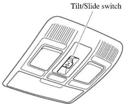
Tilt Operation
The rear of the moonroof can be tilted open to provide more ventilation.
To fully tilt automatically, momentarily press the tilt/slide switch.
To fully close automatically, momentarily press the tilt/slide switch in the forward direction.
To stop tilting partway, press the tilt/slide switch.
When the moonroof is already slid open and you want to tilt it open, first close the moonroof and then do a tilt operation.
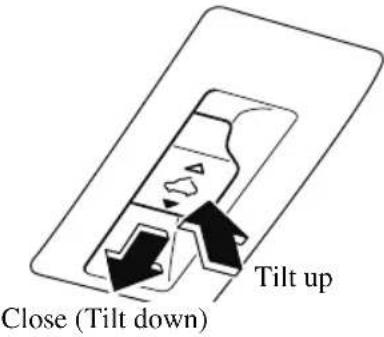
Slide Operation
To fully open automatically, momentarily press the tilt/slide switch in the backward direction.
To fully close automatically, momentarily press the tilt/slide switch in the forward direction.
To stop sliding partway, press the tilt/slide switch.
When the moonroof is already tilted open and you want to slide it open, first close
the moonroof and then do a slide operation.
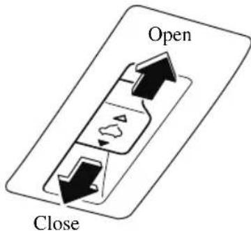
flowchart
graph TD
    A["Open"] --> B["Process Step"]
    B --> C["Close"]
NOTE
If the moonroof does not operate normally, do the following procedure:
- Switch the ignition ON.
- Press the tilt switch, to partially tilt open the rear of the moonroof.
- Repeat Step 2. The rear of the moonroof tilts open to the fully open position, then closes a little.
If the reset procedure is performed while the moonroof is in the slide position (partially open) it will close before the rear tilt opens.

Jam-safe Moonroof
If a person's hands, head or an object blocks the moonroof while it is closing, the moonroof will stop and move in the open direction.
NOTE
• The jam-safe function may operate under the following conditions:
- A strong impact is detected while the moonroof is closing automatically.
- The moonroof is closing automatically during very low temperatures.
- In the event the jam-safe function activates and the moonroof cannot be closed automatically, press the tilt/slide switch and the moonroof will close.
- The jam-safe moonroof function does not operate until the system has been reset.
Sunshade
The sunshade can be opened and closed by hand.
The sunshade opens at the same time as the moonroof slides open, but it must be closed by hand.
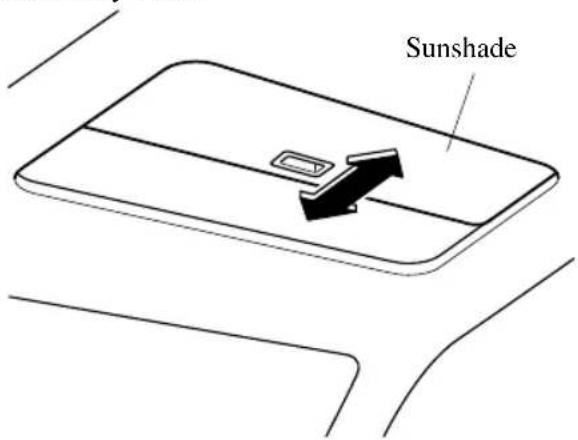
Modification and Add-On Equipment
Mazda cannot guarantee the immobilizer and the theft-deterrent systems' operation if the system has been modified or if any add-on equipment has been installed.

CAUTION
To avoid damage to the vehicle, do not modify the system or install any add-on equipment to the immobilizer and the theft-deterrent systems or the vehicle.
Immobilizer System
The immobilizer system allows the engine to start only with a key the system recognizes.
If someone attempts to start the engine with an unrecognized key, the engine will not start, thereby helping to prevent vehicle theft.
If you have a problem with the immobilizer system or the key, consult an Authorized Mazda Dealer.

CAUTION
Radio equipment like this is governed by laws in the United States. Changes or modifications not expressly approved by the party responsible for compliance could void the user's authority to operate the equipment.
To avoid damage to the key, do not:
▶ Drop the key.
▶ Get the key wet.
Expose the key to any kind of magnetic field.
Expose the key to high temperatures on places such as the dashboard or hood, under direct sunlight.
If the engine does not start with the correct key, and the security indicator light keeps illuminating or flashing, the system may have a malfunction. Consult an Authorized Mazda Dealer.
NOTE
- The keys carry a unique electronic code. For this reason, and to assure your safety, obtaining a replacement key requires some waiting time. They are only available through an Authorized Mazda Dealer.
• Always keep a spare key in case one is lost. If a key is lost, consult an Authorized Mazda Dealer as soon as possible.
- If you lose a key, an Authorized Mazda Dealer, will reset the electronic codes of your remaining keys and immobilizer system. Bring all the remaining keys to the Authorized Mazda Dealer to reset. Starting the vehicle with a key that has not been reset is not possible.
▼ Operation
NOTE
- The engine may not start and security indicator light may illuminate or flash if the key is placed in an area where it is difficult for the system to detect the signal, such as on the dashboard or in the glove compartment. Move the key to a location within the signal range, switch the ignition off, and then restart the engine.
- Signals from a TV or radio station, or from a transceiver or mobile telephone could interfere with your immobilizer system. If you are using the proper key and the engine fails to start, check the security indicator light.
Arming
The system is armed when the ignition is switched from ON to off.
The security indicator light in the instrument cluster flashes every 2 seconds until the system is disarmed.
Disarming
The system is disarmed when the ignition is switched ON with the correct programmed key. The security indicator light illuminates for about 3 seconds and then turns off. If the engine does not start with the correct key, and the security indicator light remains illuminated or flashing, try the following: Make sure the key is within the operational range for signal transmission. Switch the ignition off, and then restart the engine. If the engine does not start after 3 or more tries, contact an Authorized Mazda Dealer.
NOTE
- If the security indicator light flashes continuously while you are driving, do not shut off the engine. Go to an Authorized Mazda Dealer, and have it checked. If the engine is shut off while the indicator light is flashing, you will not be able to restart it.
- Because the electronic codes are reset when the immobilizer system is repaired, the keys are needed. Make sure to bring all the keys to an Authorized Mazda Dealer, so that they can be programmed.
Theft-Deterrent System\*
If the theft-deterrent system detects an inappropriate entry into the vehicle, which could result in the vehicle or its contents being stolen, the alarm alerts the surrounding area of an abnormality by sounding the horn and flashing the hazard warning lights.
The system will not function unless it's properly armed. So when you leave the vehicle, follow the arming procedure correctly.
▼ Operation
System triggering conditions
The horn sounds intermittently and the hazard warning lights flash for about 30 seconds when the system is triggered by any one of the following:
- Unlocking a door with the auxiliary key, door lock switch, or an inside door-lock knob.
- Forcing open a door, the hood or the liftgate.
- Opening the hood by operating the hood release handle.
- Switching the ignition ON without using the push button start.
If the system is triggered again, the lights and horn will activate until the driver's door or the liftgate is unlocked with the transmitter.
(With the advanced keyless function)
The lights and horn can also be deactivated by pressing the request switch on a door.
NOTE
- The liftgate does not open while the theft-deterrent system is operating.
- For vehicles equipped with the power liftgate, the liftgate can be opened even while the theft-deterrent system is operating by pressing the power liftgate button on the transmitter or the electric liftgate opener switch while carrying the key.
- If the battery goes dead while the theft-deterrent system is armed, the horn will activate and the hazard warning lights will flash when the battery is charged or replaced.
▼ How to Arm the System
- Close the windows and the moonroof ^* securely.
- Switch the ignition OFF.
- Make sure the hood, the doors, and the liftgate are closed.
- Press the lock button on the transmitter or lock the driver's door from the outside with the auxiliary key.
The hazard warning lights will flash once.
The following method will also arm the theft-deterrent system:
Press the door-lock switch “☐” while any door is open and then close all of the doors.
Press a request switch.
(With the advanced keyless function)
The security indicator light in the instrument cluster flashes twice per second for 20 seconds.
- After 20 seconds, the system is fully armed.
NOTE
- The theft-deterrent system can also be armed by activating the auto relock function with all the doors, the liftgate and the hood closed. Refer to Transmitter on page 3-5.
- The system will disarm if one of the following operations takes place within 20 seconds after pressing the lock button:
- Unlocking any door.
- Opening any door.
· Opening the hood. - Switching the ignition ON.
To rearm the system, do the arming procedure again.
- When the doors are locked by pressing the lock button on the transmitter or using the auxiliary key while the theft-deterrent system is armed, the hazard warning lights will flash once to indicate that the system is armed.
▼ To Turn Off an Armed System
An armed system can be turned off using any one of the following methods:
- Pressing the unlock button on the transmitter.
- Starting the engine with the push button start.
· (With the advanced keyless function)
- Pressing a request switch on the doors.
The hazard warning lights will flash twice.
NOTE
When the doors are unlocked by pressing the unlock button on the transmitter while the theft-deterrent system is turned off, the hazard warning lights will flash twice to indicate that the system is turned off.
▼ To Stop the Alarm
A triggered alarm can be turned off using any one of the following methods:
- Pressing the unlock button on the transmitter.
- Starting the engine with the push button start.
· (With the advanced keyless function) - Pressing a request switch on the doors.
- Pressing the electric liftgate opener while the key is being carried.
- Pressing the power liftgate button on the transmitter.
The hazard warning lights will flash twice.
Break-In Period
No special break-in is necessary, but a few precautions in the first 1,000 km (600 miles) may add to the performance, economy, and life of the vehicle.
. Do not race the engine.
- Do not maintain one constant speed, either slow or fast, for a long period of time.
- Do not drive constantly at full-throttle or high engine rpm for extended periods of time.
- Avoid unnecessary hard stops.
- Avoid full-throttle starts.
- Do not tow a trailer.
Saving Fuel and Protection of the Environment
How you operate your Mazda determines how far it will travel on a tank of fuel. Use these suggestions to help save fuel and reduce CO2.
- Avoid long warm-ups. Once the engine runs smoothly, begin driving.
- Avoid fast starts.
- Drive at lower speeds.
- Anticipate when to apply the brakes (avoid sudden braking).
- Follow the maintenance schedule (page 6-4) and have an Authorized Mazda Dealer perform inspections and servicing.
- Use the air conditioner only when necessary.
- Slow down on rough roads.
- Keep the tires properly inflated.
- Do not carry unnecessary weight.
- Do not rest your foot on the brake pedal while driving.
- Keep the wheels in correct alignment.
- Keep windows closed at high speeds.
- Slow down when driving in crosswinds and headwinds.

WARNING
Never stop the engine when going down a hill:
Stopping the engine when going down a hill is dangerous. This causes the loss of power steering and power brake control, and may cause damage to the drivetrain. Any loss of steering or braking control could cause an accident.
Hazardous Driving

WARNING
Be extremely careful if it is necessary to downshift on slippery surfaces:
Downshifting into lower gear while driving on slippery surfaces is dangerous. The sudden change in tire speed could cause the tires to skid. This could lead to loss of vehicle control and an accident.
Avoid sharp turns, excessive speed and abrupt maneuvers when driving this vehicle:
Sharp turns, excessive speed and abrupt maneuvering of this vehicle are dangerous as it could result in the increased risk of loss of vehicle control, vehicle roll-over, personal injury or death.
This vehicle has a higher center of gravity. Vehicles with a higher center of gravity such as utility vehicles handle differently than vehicles with a lower center of gravity. Utility vehicles are not designed for cornering at high speeds any more than low profile sports cars are designed to perform satisfactorily under off-road conditions.
In addition, utility vehicles have a significantly higher rollover rate than other types of vehicles.
In a rollover crash, an unbelted person is significantly more likely to die than a person wearing a seat belt.
When driving on ice or in water, snow, mud, sand, or similar hazards:
- Be cautious and allow extra distance for braking.
- Avoid sudden braking and sudden maneuvering.
- Do not pump the brakes. Continue to press down on the brake pedal.
Refer to Antilock Brake System (ABS) on page 4-102. - If you get stuck, select a lower gear and accelerate slowly. Do not spin the front wheels.
- For more traction in starting on slippery surfaces such as ice or packed snow, use sand, rock salt, chains, carpeting, or other nonslip material under the front wheels.
NOTE
Use snow chains only on the front wheels.
Floor Mat
We recommend the use of Genuine Mazda floor mats.

WARNING
Make sure the floor mats are hooked on the retention pins to prevent them from bunching up under the foot pedals:
Using a floor mat that is not secured is dangerous as it will interfere with the accelerator and brake pedal operation, which could result in an accident.
Do not install two floor mats, one on top of the other, on the driver's side:
Installing two floor mats, one on top of the other, on the driver's side is dangerous as the retention pins can only keep one floor mat from sliding forward.
Loose floor mat(s) will interfere with the foot pedals and could result in an accident. If using an all-weather mat for winter use always remove the original floor mat.
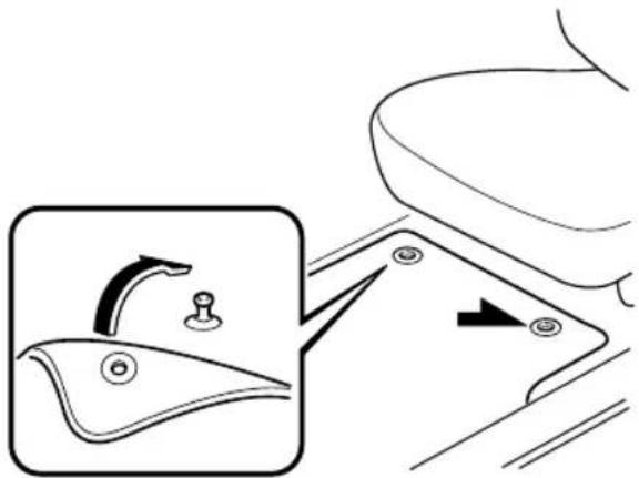
natural_image
Diagram showing a toilet handle adjustment with an inset view of the handle (no text or symbols)When setting a floor mat, position the floor mat so that its grommets are inserted over the pointed end of the retention posts.
Rocking the Vehicle

WARNING
Do not spin the wheels at more than 56 km/h (35 mph), and do not allow anyone to stand behind a wheel when pushing the vehicle:
When the vehicle is stuck, spinning the wheels at high speed is dangerous. The spinning tire could overheat and explode. This could cause serious injuries.

CAUTION
Too much rocking may cause engine overheating, transaxle failure, and tire damage.
If you must rock the vehicle to free it from snow, sand or mud, depress the accelerator slightly and slowly move the selector lever from D to R position.
Winter Driving
Carry emergency gear, including tire chains, window scraper, flares, a small shovel, jumper cables, and a small bag of sand or salt.
Ask an Authorized Mazda Dealer to check the following:
- Have the proper ratio of antifreeze in the radiator.
Refer to Engine Coolant on page 6-22. - Inspect the battery and its cables. Cold reduces battery capacity.
- Use an engine oil appropriate for the lowest ambient temperatures that the vehicle will be driven in (page 6-20).
- Inspect the ignition system for damage and loose connections.
- Use washer fluid made with antifreeze—but do not use engine coolant antifreeze for washer fluid (page 6-24).
NOTE
- Remove snow before driving. Snow left on the windshield is dangerous as it could obstruct vision.
- Do not apply excessive force to a window scraper when removing ice or frozen snow on the mirror glass and windshield.
- Never use warm or hot water for removing snow or ice from windows and mirrors as it could result in the glass cracking.
- Drive slowly. Braking performance can be adversely affected if snow or ice adheres to the brake components. If this situation occurs, drive the vehicle slowly, releasing the accelerator pedal and lightly applying the brakes several times until the brake performance returns to normal.
▼ Snow Tires
Use snow tires on all 4 wheels
Do not go faster than 120 km/h (75 mph) while driving with snow tires. Inflate snow tires 30 kPa (0.3 kgf/cm ^2 , 4.3 psi) more than recommended on the tire pressure label (driver's door frame), but never more than the maximum cold-tire pressure shown on the tires.
The vehicle is originally equipped with all season radials designed to be used all year around. In some extreme climates you may find it necessary to replace them with snow tires during the winter months to further improve traction on snow and ice covered roads.
WARNING
Use only the same size and type tires (snow, radial, or non-radial) on all 4 wheels:
Using tires different in size or type is dangerous. Your vehicle's handling could be greatly affected and result in an accident.
CAUTION
Check local regulations before using studded tires.
NOTE
The tire pressure monitoring system may not function correctly when using tires with steel wire reinforcement in the sidewalls (page 4-253).
▼ Tire Chains
Check local regulations before using tire chains.

CAUTION
▶Chains may affect handling.
➢Do not go faster than 50 km/h (30 mph) or the chain manufacturer's recommended limit, whichever is lower.
➢Drive carefully and avoid bumps, holes, and sharp turns.
▶Avoid locked-wheel braking.
➢Do not use chains on a temporary spare tire; it may result in damage to the vehicle and to the tire.
➢Do not use chains on roads that are free of snow or ice. The tires and chains could be damaged.
➢Chains may scratch or chip aluminum wheels.
NOTE
- The tire pressure monitoring system may not function correctly when using tire chains.
- Use of tire chains on a vehicle equipped with P255/50R20 specification tires could cause interference with the vehicle body and scratching. If tire chains are to be used, replace both front and rear tires with P255/60R18 tires. Please consult an Authorized Mazda Dealer.
Install the chains on the front tires only.
Do not use chains on the rear tires. Please consult an Authorized Mazda Dealer.
Installing the chains
- Secure the chains on the front tires as tightly as possible.
Always follow the chain manufacturer's instructions. - Retighten the chains after driving 1/2—1 km (1/4—1/2 mile).
Driving In Flooded Area

WARNING
Dry off brakes that have become wet by driving slowly, releasing the accelerator pedal and lightly applying the brakes several times until the brake performance returns to normal:
Driving with wet brakes is dangerous. Increased stopping distance or the vehicle pulling to one side when braking could result in a serious accident. Light braking will indicate whether the brakes have been affected.

CAUTION
Do not drive the vehicle on flooded roads as it could cause short circuiting of electrical/electronic parts, or engine damage or stalling from water absorption. If the vehicle has been immersed in water, consult an Authorized Mazda Dealer.
Overloading

WARNING
Be careful not to overload your vehicle: The gross axle weight rating (GAWR) and the gross vehicle weight rating (GVWR) of the vehicle are on the Motor Vehicle Safety Standard Label on the driver's door frame. Exceeding these ratings can cause an accident or vehicle damage. You can estimate the weight of the load by weighing the items (or people) before putting them in the vehicle.
Driving on Uneven Road
Your vehicle's suspension and underbody can be damaged if driven on rough/uneven roads or over speed bumps at excessive speeds. Use care and reduce speed when traveling on rough/uneven roads or over speed bumps.
Use care not to damage the vehicle's underbody, bumpers or muffler(s) when driving under the following conditions:
- Ascending or descending a slope with a sharp transition angle - Ascending or descending a driveway or trailer ramp with a sharp transition angle
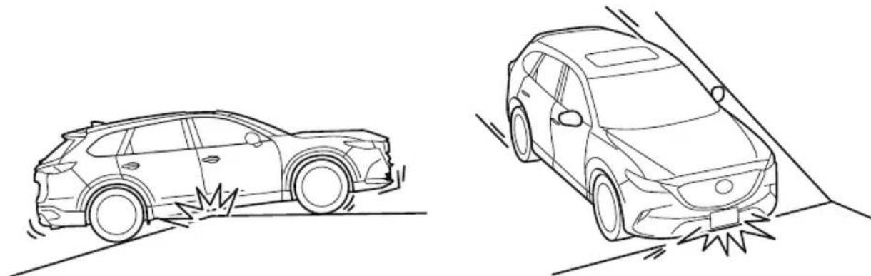
natural_image
Line drawings of a car collision with a vehicle, showing front and side views (no text or symbols)This vehicle is equipped with low profile tires allowing class-leading performance and handling. As a result, the sidewall of the tires are very thin and the tires and wheels can be damaged if driven through potholes or on rough/uneven roads at excessive speeds. Use care and reduce speed when traveling on rough/uneven roads or through potholes.
Turbocharger Information

CAUTION
➢ After driving at freeway speeds or up a long hill, trailer towing for a long time, idle the engine at least 30 seconds before stopping it. Otherwise, the turbocharger could be damaged.
➢ Racing or over-revving the engine, particularly after it's just been started, can damage the turbocharger.
To protect the engine from damage, the engine is designed so that it cannot be raced just after starting it in extremely cold weather.
The turbocharger greatly enhances engine power. Its advanced design provides improved operation and requires minimum maintenance.
To get the most from it, observe the following.
- Change engine oil and filter according to Scheduled Maintenance (page 6-4).
- Use only recommended engine oil (page 6-20). Extra additives are NOT recommended.
Trailer Towing (U.S.A. and Canada)
Your Mazda was designed and built primarily to carry passengers and cargo.
If you tow a trailer, follow these instructions because driver and passenger safety depends on proper equipment and safe driving habits. Towing a trailer will affect handling, braking, durability, performance, and fuel economy.
Never overload your vehicle or trailer. Consult an Authorized Mazda Dealer if you need further details.

CAUTION
Do not tow a trailer during the first 1,000 km (600 miles) of your new Mazda. If you do, you may damage the engine, transaxle, differential, wheel bearings, and other power-train components.
NOTE
- When towing, use of gasoline with a octane rating of 91 or higher is recommended.
- Your vehicle is equipped with a Trailer Stability Control (TSC) mechanism, which enhances vehicle stability when towing a trailer.
Refer to Trailer Stability Control (TSC) on page 4-106.
▼ Weight Limits
TTW and GCWR
The total trailer weight (TTW), gross combination weight rating (GCWR), gross axle weight rating (GAWR), trailer load, and trailer tongue load must be within the prescribed limits.
- The total trailer weight (TTW) is the sum of the weights of the trailer load (trailer weight plus cargo), trailer hitch, 2 passengers, and vehicle load (baggage, food, camp gear, etc.). Never allow the total trailer weight (TTW) to exceed specifications in the Trailer Towing-Load Table.
- The maximum GCWR is the combination weight of the trailer and load plus the towing vehicle (including trailer hitch, vehicle passengers, and load). It must not exceed specifications in the load table.
GAWR and GVWR
Do not exceed front and rear GAWR (gross axle weight rating) and GVWR (gross vehicle weight rating). If you do, vehicle handling, braking, and performance will be affected. These values are also on the Motor Vehicle Safety Certification Label posted on the driver's door frame.
High-altitude operation

CAUTION
Be aware of the towing load weight differences when towing at high altitudes. For altitudes exceeding 1,000 meter (3,280 ft 10 in), always reduce the towing load by 10% for every 1,000 meter (3,280 ft 10 in) increase in altitude from the load indicated under the maximum GCWR heading in the trailer towing-load table. If the determined maximum total towing load weight is exceeded, the engine and other power-train parts may be damaged.
TRAILER TOWING-LOAD TABLE
Because vehicle weights vary, adjustments must be made to meet the requirements in this table.
| Item | Model | |||
| FWD AWD | ||||
| MAX. FRON-TAL AREA |  | 2.97 m^2 (32 ft^2) | ||
| MAX. TTW |  | 1,587.5 kg (3,500 lb) | ||
| MAX. GCWR | 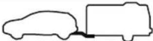 | 3,629 kg (8,000.4 lb) 3,782 kg (8,337.7 lb) | ||
| MAX. GAWR | 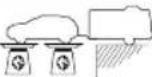 | Front 1,225 kg | (2,701 lb) 1,250 kg (2,756 lb) | |
| Rear 1,383 kg | (3,049 lb) 1,427 kg (3,146 lb) | |||
| MAX. GVWR | 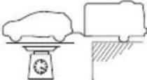 | 2,572 kg (5,670 lb) 2,641 kg (5,822 lb) | ||
| TRAIL-ER-TONGUE LOAD | Tongue load | Tongue load/Trailer load × 100 = 10 % to 15 % | ||
| Trailer load | ||||
| DISTRIBU-TION OF TRAILER LOAD | 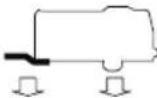 | Front 60 % | ||
| Rear 40 % | ||||

WARNING
Always keep tow loads within specified limits as indicated in the Trailer Towing-Load Table:
Attempting to tow loads greater than those specified is dangerous as it may cause serious handling and performance problems that could result in personal injury or vehicle damage, or both.
Load your trailer with the weight about 60 % toward the front and 40 % toward the rear:
Loading the trailer with more weight in the rear than in the front is dangerous. Doing so could cause you to lose control. The trailer tongue load must be 10%—15% of the total trailer load (sum of the weights of the trailer and cargo).
Always have the total trailer weight and tongue load determined prior to departure:
Attempting to tow loads without determining the total trailer weight and tongue load is dangerous. Trailer sway from crosswinds, rough roads or other causes could result in loss of control and a serious accident.

CAUTION
The total trailer weight and tongue load can be determined by weighing the trailer on platform scales at a highway weight station or a trucking company.

Trailer Hitch
Use only a hitch ball recommended by the trailer manufacturer that conforms to the gross trailer weight requirement.
When not towing a trailer, remove the trailer hitch (if detachable) to reduce the possibility of damage as a result of the vehicle being rear-ended.

WARNING
Always make sure the trailer hitch is securely attached before departure:
An unsecured trailer hitch is dangerous as it causes greater trailer sway from crosswinds, rough roads or other causes, resulting in loss of control and a serious accident.
Examine all trailer-hitch mounting bolts regularly and tighten any that are loose. If the hitch is removed, seal any open mounting holes to prevent exhaust, dust, water, dirt and other foreign elements from filtering in, possibly endangering personal safety and damaging your vehicle.
Do not install a hitch that stiffens the bumper as it will reduce the bumper's performance.
Make sure there are no exhaust gas leaks into the passenger compartment if any mounting bolts are connected to the body:
Modifying your vehicle exhaust system is dangerous. Exhaust gas entering the vehicle could cause loss of consciousness or even death.
When mounting the trailer hitch, make no modifications to the vehicle exhaust system.

CAUTION
Make all hitch adjustments with actual loads. Do not load and unload vehicle while adjusting hitch. This action will change the vehicle height.
➢Do not use an axle-mounted hitch. This may damage the axle and related parts.
▼ Tires
When towing a trailer, make sure all tires are inflated to the recommended cold-tire pressure, as indicated on the tire pressure chart on the driver's door frame. Trailer tire size, load rating, and inflation pressures should conform to tire manufacturer specifications.

WARNING
Never use the temporary spare tire when towing:
Using the temporary spare tire on your vehicle when towing a trailer is dangerous as it could result in tire failure, loss of control, and injury to vehicle occupants.
▼ Safety Chains
Safety chains must be used as a precautionary measure should the trailer become unintentionally unhitched. They should cross under the trailer tongue and attach to the hitch. Leave enough slack to allow full turns. Consult literature published by your trailer or hitch manufacturer for more details.

WARNING
Make sure the safety chain is securely attached to both the trailer and the vehicle prior to departure:
Towing a trailer without using a safety chain securely attached to both the trailer and the vehicle is dangerous. If damage occurs to the coupling unit or hitch ball, the trailer could wander into another lane and cause a collision.
▼ Trailer Lights
Trailer lights must comply with all federal, state, and local regulations. Equip your trailer as required before towing it day or night.

CAUTION
Do not connect a trailer lighting system directly to the lighting system of your Mazda. This may damage your vehicle's electrical system and lighting systems. Have a recreational vehicle dealer or trailer rental agency connect the system, and inspect the brake lights and turn signals yourself before each trip.
▼ Trailer Brakes
If the total trailer weight exceeds 450 kg (1,000 lb), trailer brakes are required. If your trailer has brakes, make sure they comply with all federal, state, and local regulations.

WARNING
Do not connect a hydraulic trailer-brake system to your vehicle's brake system:
Connecting a hydraulic trailer-brake system directly to the vehicle brake system is dangerous and will result in inadequate braking and possible injury.
▼ Trailer Towing Tips
- Verify that your Mazda maintains a near-normal attitude when a loaded or unloaded trailer is connected. Do not drive if it has an abnormal front-up or front-down position. Inspect for incorrect tongue load, worn suspension parts, and trailer overloading.
- Make sure the trailer is properly loaded and the cargo is secure to prevent it from shifting.
- Make sure the mirrors conform to all government regulations. If they do not, install required rear view mirrors appropriate for towing purposes.
The three main causes of vehicle-trailer accidents are driver error, excessive speed, and improper trailer loading.
Before driving
- Have your cooling and braking system checked by an Authorized Mazda Dealer.
- Before starting out, inspect the operation of all vehicle and trailer lights and all vehicle-to-trailer connections. Stop and re-inspect all lights and connections after driving a short distance.
Driving
- Your Mazda will handle differently with a trailer in tow, so practice turning, backing, and stopping in a traffic-free area.
• Take time to get accustomed to the extra weight and length. -
Allow more room between your vehicle and the one in front because braking distance increases with a trailer. For each 16 km/h (10 mph) of speed, allow at least one vehicle and trailer length between your Mazda and the vehicle ahead.
-
Avoid jerky starts or sudden acceleration.
- Avoid sudden braking. It may cause loss of control and result in jackknifing, especially so on wet or slippery roads.
- Shift the selector lever to the D position when towing a trailer in hilly terrain or when heavily loaded.
The D position will allow operating the vehicle without frequent shifting.
Lane changes and turning
Avoid quick lane changes, sudden turns, and tight turns. Slow down before turning to avoid the need of sudden braking.
A turning trailer will make a tighter arc than the tow vehicle. Compensate with turns that are larger than normal.
Passing
Plan well ahead to pass other vehicles, and provide plenty of room before changing lanes. Crosswinds from passing vehicles, especially larger ones, and the effects of rough roads will affect handling.
If swaying occurs, firmly grip the steering wheel and reduce speed immediately, but gradually.
Steer straight ahead. If no extreme correction of steering or braking is made, the combination of less speed and firm steering will result in stability.
Backing up
Backing a vehicle with a trailer requires practice and patience. Back slowly, and have a helper outside at the rear of the trailer to reduce the risk of an accident.
To turn the trailer, place your hand at the bottom of the steering wheel and turn it in the direction you want the trailer to go. Make only slight movements to prevent sharp or prolonged turning.
Ascending a hill
Shift into a lower gear to reduce the possibility of overloading or overheating the engine, or both.
Descending a hill
Shift into a lower gear and use engine compression as a braking effect.

WARNING
Always use lower gears to reduce speed:
Holding the brake pedal down too long or too frequently is dangerous as it could cause the brakes to overheat and lose power, resulting in loss of control and a serious accident. Use lower gears to help reduce speed. Pull off the road and allow brakes to cool down whenever braking performance feels reduced.
Overheated engine
The extra weight of the trailer may strain the engine on hot days and on long or steep upgrades.
If the temperature gauge indicates overheating, turn off the air conditioner, drive safely to the side of the road, park off the right-of-way and wait for engine to cool. Refer to Overheating on page 7-23.
Parking
Always make sure the tires of the trailer and the tow vehicle are blocked while parked. Apply the parking brake firmly and put the transaxle in P.
Avoid parking on an incline, but if you must, follow these instructions:
- Depress and hold down the brake pedal.
- Have a helper put wheel blocks against the downhill side of all vehicle and trailer tires.
- Then release the brake pedal slowly until the blocks bear the load.
-
If the grade is downhill, turn the steering wheel so that the front of the front tires face the curb.
· If it is uphill, face the rear of the front tires against the curb. -
Firmly apply the parking brake.
-
Shift the transaxle into P, and stop the engine.
To restart after parking on an incline:
- With the transaxle in P, start the engine. (Be sure to depress and hold the brake pedal.)
- Shift into gear.
- Release the parking brake (also the foot brake) and pull away from the wheel blocks.
Stop; apply the parking brake and shift into P. - Have a helper retrieve the wheel blocks.
Fuel consumption
Trailer towing causes higher fuel consumption.
Maintenance
If you tow a trailer frequently, have your vehicle serviced as shown in Scheduled Maintenance (page 6-4).
Recreational Towing
An example of "recreational towing" is towing your vehicle behind a motorhome.
The transaxle is not designed for towing this vehicle on all 4 wheels.
When doing recreational towing refer to "Towing Description" (page 7-25) and carefully follow the instructions.
MEMO
4 When Driving
Information concerning safe driving and stopping.
Start/Stop Engine...... 4-4
Ignition Switch...... 4-4
Starting the Engine.... 4-5
Turning the Engine Off......4-10
Instrument Cluster and Display......
4-11
Instrument Cluster and
Display....4-11
Instrument Cluster (Type A)......4-12
Instrument Cluster (Type B)......4-29
Instrument Cluster (Type C)......4-44
Active Driving Display ^* ......4-56
Automatic Transaxle...... 4-59
Automatic Transaxle
Controls.... 4-59
Shift-Lock System...... 4-60
Transaxle Ranges......4-60
Manual Shift Mode......4-62
Direct Mode ^* 4-68
Driving Tips......4-69
Switches and Controls......4-70
Lighting Control.... 4-70
Fog Lights* 4-76
Turn and Lane-Change
Signals...... 4-77
Windshield Wipers and
Washer 4-78
Rear Window Wiper and
Washer.... 4-81
Rear Window Defogger......4-82
Horn....4-83
Hazard Warning Flasher...... 4-84
HomeLink Wireless Control System
(Type A)* 4-84
HomeLink Wireless Control System
(Type B) ^* 4-88
Brake 4-92
Brake System......4-92
AUTOHOLD......4-96
Hill Launch Assist (HLA)......4-100
ABS/TCS/DSC/Trailer Stability
Control (TSC)/Off-Road Traction
Assist....4-102
Antilock Brake System
(ABS)....4-102
Traction Control System
(TCS).... 4-103
Dynamic Stability Control
(DSC)....4-105
Trailer Stability Control
(TSC).... 4-106
Off-Road Traction Assist ^* ......4-107
Drive Selection......4-109
Drive Selection....4-109
i-ACTIV AWD......4-111
i-ACTIV AWD Operation*......4-111
Power Steering...... 4-113
Power Steering....4-113
i-ACTIVSENSE...... 4-114
i-ACTIVSENSE ^* ......4-114
Adaptive Front Lighting System (AFS) ^* 4-117
High Beam Control System (HBC) ^* 4-118
Blind Spot Monitoring (BSM) ^* ...... .... 4-121
Traffic Sign Recognition System (TSR) ^* 4-127
Distance Recognition Support System (DRSS) *....4-133
Driver Attention Alert (DAA) ^* ..... .... 4-137
Rear Cross Traffic Alert (RCTA) ^* ..... 4-139
Mazda Radar Cruise Control with Stop & Go function (MRCC with Stop & Go function) *....4-143
Lane-keep Assist System (LAS) & Lane Departure Warning System (LDWS)*...... 4-158
Advanced Smart City Brake Support (Advanced SCBS) ^* ......4-169
Smart City Brake Support [Forward] (SCBS F)*....4-172
Smart City Brake Support [Reverse] (SCBS R) ^* 4-175
Smart Brake Support (SBS) ^* ....4-179
360° View Monitor (Mazda Connect (Type A)) ^* 4-181
360° View Monitor (Mazda Connect (Type B)) ^* 4-207
Forward Sensing Camera (FSC) ^* ..... 4-235
Radar Sensor (Front) *...... 4-240
Radar Sensors (Rear) ^* ......4-243
Ultrasonic Sensor (Rear) ^* ......4-245
Front Camera/Side Cameras/Rear Camera ^* 4-246
Cruise Control.... 4-247
Cruise Control ^* 4-247
Tire Pressure Monitoring
System......4-252
Tire Pressure Monitoring System.... 4-252
Rear View Monitor (Mazda Connect
(Type A))...... 4-256
Rear View Monitor (Mazda Connect (Type A)) ^* 4-256
Rear View Monitor (Mazda Connect
(Type B))......4-264
Rear View Monitor (Mazda Connect (Type B)) ^* 4-264
Parking Sensor System (Mazda
Connect (Type A)...... 4-272
Parking Sensor System (Mazda Connect (Type A)) ^* 4-272
Parking Sensor System (Mazda
Connect (Type B)...... 4-282
Parking Sensor System (Mazda Connect (Type B)) *...... 4-282
MEMO
Ignition Switch
▼ Push Button Start Positions
The system operates only when the key is within operational range.
Each time the push button start is pressed, the ignition switches in the order of off, ACC, and ON. Pressing the push button start again from ON switches the ignition off.
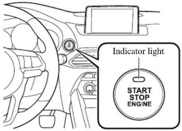
NOTE
- The engine starts by pressing the push button start while depressing the brake pedal. To switch the ignition position, press the push button start without depressing the pedal.
- Do not leave the ignition switched ON while the engine is not running. Doing so could result in the battery going dead. If the selector lever is in the P position, and the ignition is in ACC, the ignition switches off automatically after about 25 minutes.
Off
The power supply to electrical devices turns off and the push button start indicator light (amber) also turns off.
WARNING
Before leaving the driver's seat, always switch the ignition off, set the parking brake, and make sure the selector lever is in P position:
Leaving the driver's seat without switching the ignition off, setting the parking brake, and shifting the selector lever to P position is dangerous. Unexpected vehicle movement could occur which could result in an accident.
In addition, if your intention is to leave the vehicle for even a short period, it is important to switch the ignition off, as leaving it in another position will disable some of the vehicle's security systems and run the battery down.
ACC (Accessory)
Some electrical accessories will operate and the indicator light (amber) illuminates.
NOTE
The keyless entry system does not function while the push button start has been pressed to ACC, and the doors will not lock/unlock even if they have been locked manually.
ON
This is the normal running position after the engine is started. The indicator light (amber) turns off. (The indicator light (amber) illuminates when the ignition is switched ON and the engine is not running.)
Some indicator lights/warning lights should be inspected before the engine is started (page 4-11).
NOTE
When the push button start is pressed to ON, the sound of the fuel pump motor operating near the fuel tank can be heard. This does not indicate an abnormality.
Starting the Engine

WARNING
Radio waves from the key may affect medical devices such as pacemakers:
Before using the key near people who use medical devices, ask the medical device manufacturer or your physician if radio waves from the key will affect the device.
NOTE
- The key must be carried because the key carries an immobilizer chip that must communicate with the engine controls at short range.
- The engine can be started when the push button start is pressed from off, ACC, or ON.
- The push button start system functions (function which can start the engine by only carrying the key) can be deactivated to prevent any possible adverse effect on a user wearing a pacemaker or other medical device. If the system is deactivated, you will be unable to start the engine by carrying the key. Consult an Authorized Mazda Dealer for details. If the push button start system functions have been deactivated, you can start the engine by following the procedure indicated when the key battery goes dead.
Refer to Engine Start Function When Key Battery is Dead on page 4-8. - After starting a cold engine, the engine speed increases and a whining sound from the engine compartment can be heard.
This is for improved exhaust gas purification and does not indicate any parts defect.
- Engine-starting is controlled by the spark ignition system. This system meets all Canadian Interference-Causing Equipment Standard requirements regulating the impulse electrical field strength of radio noise.
-
Make sure you are carrying the key.
-
Occupants should fasten their seat belts.
-
Make sure the parking brake is on.
-
Continue to press the brake pedal firmly until the engine has completely started.
-
Put the vehicle in park (P). If you must restart the engine while the vehicle is moving, shift into neutral (N).
NOTE
The starter will not operate if the selector lever is not in P or N position and the brake pedal is not depressed sufficiently.
- Verify that the KEY indicator light (green) (if equipped) in the instrument
cluster and the push button start indicator light (green) illuminate.
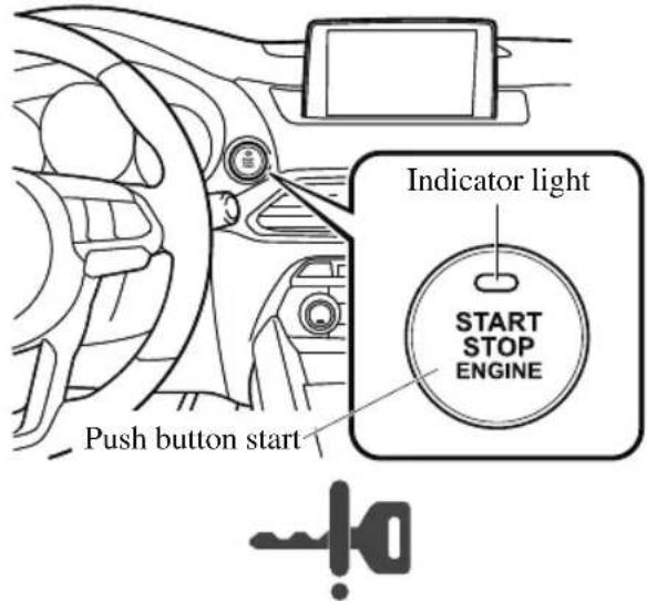
NOTE
- If the push button start indicator light (green) flashes, make sure that the key is being carried (for vehicles with a type A/type B instrument cluster (page 7-28), messages are displayed in the instrument cluster).
- If the push button start indicator light (green) flashes with the key being carried, touch the key to the push button start and start the engine (for vehicles with a type A/ type B instrument cluster (page 7-28), messages are displayed in the instrument cluster). Refer to Engine Start Function When Key Battery is Dead on page 4-8.

CAUTION
If the KEY warning light (red) illuminates, or the push button start indicator light (amber) flashes, this could indicate a problem with the engine starting system. This may prevent the engine from starting or from switching the ignition to ACC or ON (for vehicles with a type A/type B instrument cluster (page 7-28), messages are displayed in the instrument cluster). Have your vehicle inspected at an Authorized Mazda Dealer as soon as possible.
NOTE
- Under the following conditions, the KEY warning light (red) flashes after the push button start is pressed. This informs the driver that the push button start will not switch to ACC, even if it is pressed from off (for vehicles with a type A/type B instrument cluster (page 7-28), messages are displayed in the instrument cluster).
· The key battery is dead.
- The key is out of operational range.
- The key is placed in areas where it is difficult for the system to detect the signal (page 3-8).
- A key from another manufacturer similar to the key is in the operational range.
· (Forced engine starting method)
If the KEY warning light (red) illuminates, or the push button start indicator light (amber) flashes, this could indicate that the engine may not start using the usual starting method (for vehicles with a type A/ type B instrument cluster (page 7-28), messages are displayed in the instrument cluster). Have your vehicle inspected at an Authorized Mazda Dealer as soon as possible. If this occurs, the engine can be force-started. Press and hold the push button start until the engine starts. Other procedures necessary for starting the engine, such as having the key in the cabin, and depressing the brake pedal are required.
- When the engine is force-started, the KEY warning light (red) (if equipped) remains illuminated and the push button start indicator light (amber) remains flashing.
- When the selector lever is in the neutral (N) position, the KEY indicator light (green) (if equipped) and the push button start indicator light (green) do not illuminate.
- Press the push button start after both the KEY indicator light (green) (if equipped) in the instrument cluster and the push button start indicator light (green) illuminate.
NOTE
• After starting the engine, the push button start indicator light (amber) turns off and the ignition switches to the ON position.
• After pressing the push button start and before the engine starts, the operation sound of the fuel pump motor from near the fuel tank can be heard, however, this does not indicate a malfunction.
- After starting the engine, let it idle for about 10 seconds.
NOTE
- Whether the engine is cold or warm, it should be started without the use of the accelerator.
- If the engine does not start the first time, refer to Starting a Flooded Engine under Emergency Starting. If the engine still does not start, have your vehicle inspected by an Authorized Mazda Dealer (page 7-22).
▼ Engine Start Function When Key Battery is Dead

CAUTION
When starting the engine by holding the transmitter over the push button start due to a dead key battery or a malfunctioning key, be careful not to allow the following, otherwise the signal from the key will not be received correctly and the engine may not start.
➢ Metal parts of other keys or metal objects touch the key.
➢Spare keys or keys for other vehicles equipped with an immobilizer system touch or come near the key.
➢ Devices for electronic purchases, or security passage touch or come near the key.
If the engine cannot be started due to a dead key battery, the engine can be started using the following procedure:
- Continue to depress the brake pedal firmly until the engine has completely started.
- Make sure that the push button start indication light (green) flashes.
- Align the center area of the emblem on the transmitter with the center area of the push button start while the push button start indicator light (green) flashes.
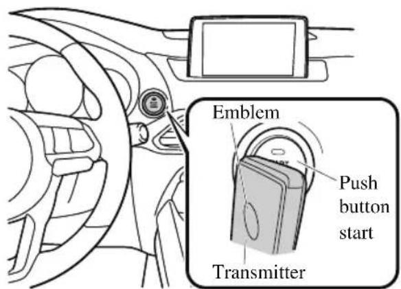
- Make sure that the push button start indicator light (green) turns on.
- Press the push button start to start the engine.
NOTE
- The engine cannot be started unless the brake pedal is fully depressed.
- If there is a malfunction with the push button start function, the push button start indicator light (amber) flashes. In this case, the engine may start, however, have the vehicle checked at an Authorized Mazda Dealer as soon as possible.
- If the push button start indicator light (green) does not illuminate, perform the operation from the beginning again. If it does not illuminate, have the vehicle checked at an Authorized Mazda Dealer.
-
To switch the ignition position without starting the engine, perform the following operations after the push button start indicator light (green) turns on.
-
Release the brake pedal.
-
Press the push button start to switch the ignition position. The ignition switches in the order of ACC, ON, and off each time the push button start is pressed. To switch the ignition position again, perform the operation from the beginning.
▼ Emergency Operation for Starting the Engine
If the KEY warning light (red) illuminates, or the push button start indicator light (amber) flashes, this could indicate that the engine may not start using the usual starting method (for vehicles with a type A/type B instrument cluster (page 7-28), messages are displayed in the instrument cluster). Have your vehicle inspected at an Authorized Mazda Dealer as soon as possible. If this occurs, the engine can be force-started. Press and hold the push button start until the engine starts. Other procedures necessary for starting the engine such as having the key in the cabin, and depressing the brake pedal are required.
Turning the Engine Off

WARNING
Do not stop the engine while the vehicle is moving:
Stopping the engine while the vehicle is moving for any reason other than in an emergency is dangerous. Stopping the engine while the vehicle is moving will result in reduced braking ability due to the loss of power braking, which could cause an accident and serious injury.
- Stop the vehicle completely.
- Shift the selector lever to the P position and set the parking brake.
- Press the push button start to turn off the engine. The ignition position is off.

CAUTION
When leaving the vehicle, make sure the push button start is off.
NOTE
- The cooling fan in the engine compartment could turn on for a few minutes after the ignition is switched from ON to OFF, whether or not the A/C is on or off, to cool the engine compartment quickly.
- If the system detects that the remaining battery power of the key is low when the ignition is switched from ON to ACC or OFF, the following is indicated.
Replace with a new battery before the key becomes unusable.
Refer to Key Battery Replacement on page 6-32.
(Vehicle equipped with Type A/B instrument cluster)
A message is indicated in the display of the instrument cluster.
(Vehicle equipped with Type C instrument cluster)
The KEY indicator light (green) flashes for approximately 30 seconds.
Refer to Taking Action on page 7-37.
- If the engine is turned off while the selector lever is in a position other than P , the ignition switches to ACC.
▼ Emergency Engine Stop
Continuously pressing the push button start or quickly pressing it any number of times while the engine is running or the vehicle is being driven will turn the engine off immediately. The ignition switches to ACC.
Instrument Cluster and Display
Instrument Cluster
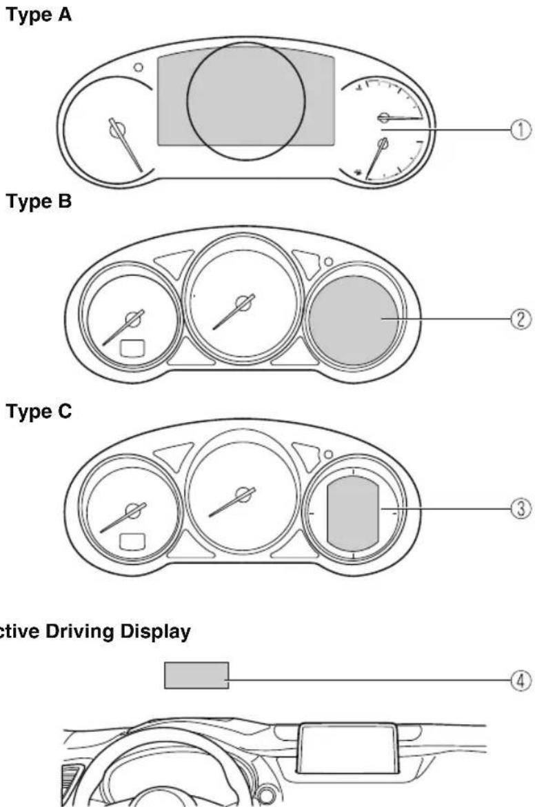
Active Driving Display
① Instrument Cluster (Type A)...... page 4-12
② Instrument Cluster (Type B)......page 4-29
③ Instrument Cluster (Type C)......page 4-44
④ Active Driving Display...... page 4-56
Instrument Cluster (Type A)
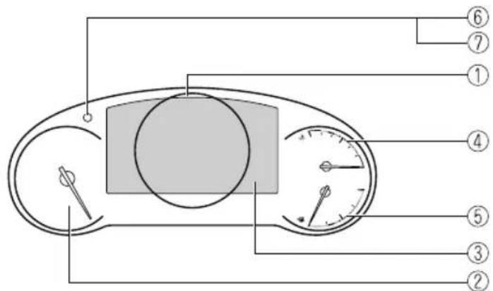
① Speedometer......page 4-12
② Tachometer......page 4-12
③ Multi-information Display (Type A)......page 4-13
④ Engine Coolant Temperature Gauge...... page 4-16
⑤ Fuel Gauge...... page 4-17
⑥ Dashboard Illumination......page 4-17
⑦ Speed Unit Selector......page 4-18
▼ Speedometer
The speedometer indicates the speed of the vehicle.
▼ Tachometer
The tachometer shows engine speed in thousands of revolutions per minute (rpm).
CAUTION
Do not run the engine with the tachometer needle in the RED ZONE.
This may cause severe engine damage.
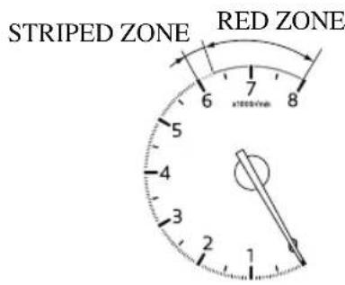
NOTE
When the tachometer needle enters the STRIPED ZONE, this indicates to the driver that the gears should be shifted before entering the RED ZONE.
▼ Multi-information Display (Type A)
Dashboard illumination knob
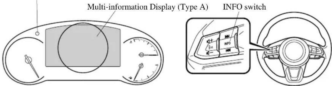
The multi-information display indicates the following information.
- Speedometer
- Odometer
- Trip meter
· Outside temperature - Distance-to-empty
· Average fuel economy - Current fuel economy
- Maintenance Monitor
- Blind Spot Monitoring (BSM) Display
• Distance Recognition Support System (DRSS) Display - Mazda Radar Cruise Control with Stop & Go function (MRCC with Stop & Go function) System Display
· Lane-keep Assist System (LAS) & Lane Departure Warning System (LDWS) Display
. Cruise Control Display - Compass Display
• Door-Ajar/Liftgate-Ajar Warning Indication - Message Display
The screen content changes each time the INFO switch is pressed.
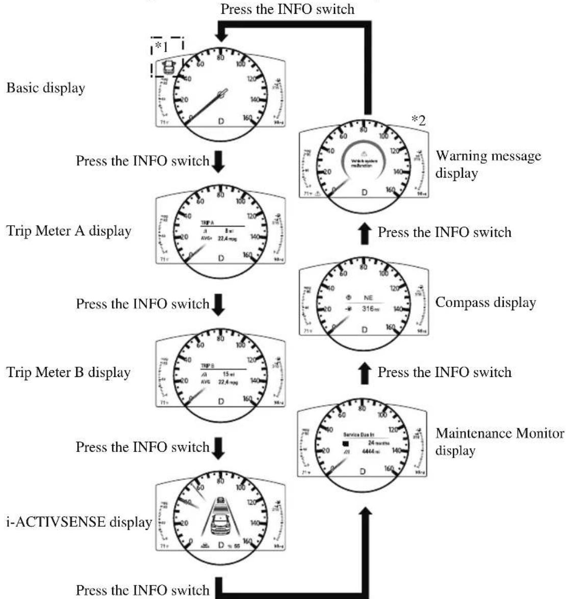
flowchart
graph TD
    A["Press the INFO switch"] --> B["Basic display"]
    A --> C["Warning message display"]
    B --> D["Trip Meter A display"]
    C --> E["Compass display"]
    D --> F["Trip Meter B display"]
    E --> G["Maintenance Monitor display"]
    F --> H["i-ACTIVSENSE display"]
    G --> H
    H --> I["Press the INFO switch"]
*1: Displayed when opening/closing door/Liftgate.
*2: Displayed only when a warning occurs.
The screen content changes each time the dashboard illumination knob is pressed and held.
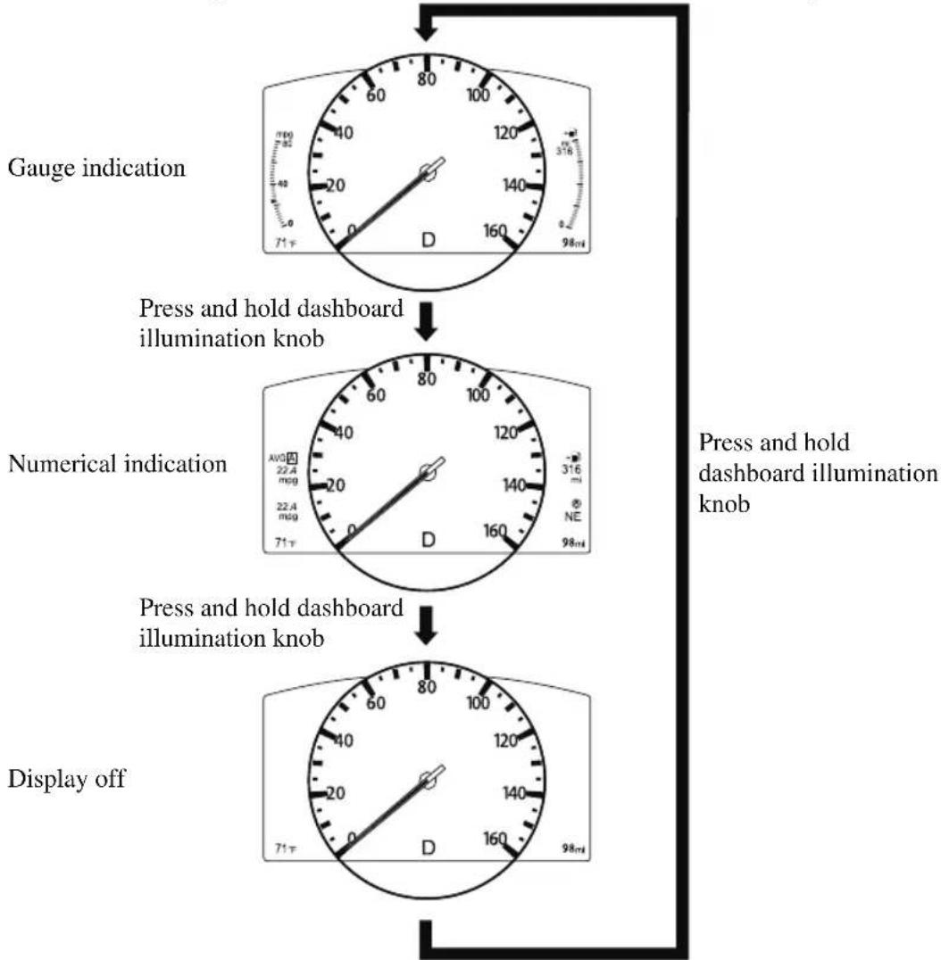
flowchart
graph TD
    A["Gauge indication"] --> B["Press and hold dashboard illumination knob"]
    B --> C["Numerical indication"]
    C --> D["Press and hold dashboard illumination knob"]
    D --> E["Display off"]
▼ Odometer, Trip Meter and Trip Meter Selector
The odometer is constantly displayed on the screen when the ignition is switched ON, and the TRIP A or TRIP B screen can
be displayed by operating the INFO switch.
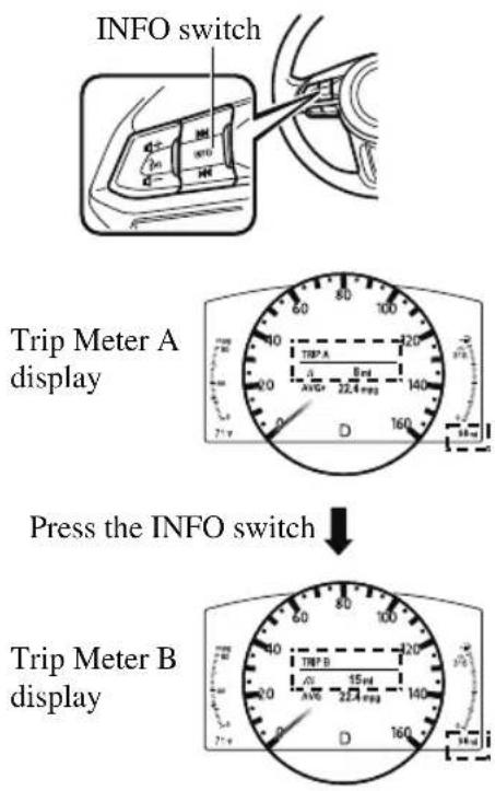
Odometer
The odometer records the total distance the vehicle has been driven.
Trip meter
The driving distance for a specified interval is indicated. Two types (TRIP A, TRIP B) of interval distance and the average fuel economy for each can be measured.
For instance, trip meter A can record the distance from the point of origin, and trip
meter B can record the distance from where the fuel tank is filled.
When trip meter A is selected, TRIP A will be displayed. When trip meter B is selected, TRIP B will be displayed.
The trip meter and average fuel economy can be reset by pressing the INFO switch for 1.5 seconds or more while in each mode.
NOTE
-
Only the trip meters record tenths of kilometers (miles).
· The trip record will be erased when: -
The power supply is interrupted (blown fuse or the battery is disconnected).
- The vehicle is driven over 9999.9 km (mile).
▼ Engine Coolant Temperature Gauge
Displays the engine coolant temperature. The blue range of the gauge indicates that the engine coolant temperature is low, and the red range of the gauge indicates that the engine coolant temperature is high and overheating.
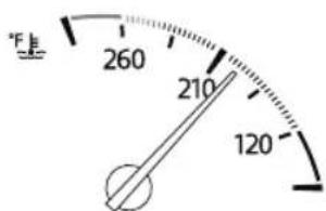

CAUTION
If the engine coolant temperature gauge needle is in the red range, there is the possibility of overheating. Drive slowly to reduce engine load until you can find a safe place to stop the vehicle and wait for the engine to cool down.
Refer to Overheating on page 7-23.
NOTE
- If the engine coolant temperature is high or the engine is hot, the engine output may be limited.
▼ Fuel Gauge
The fuel gauge shows approximately how much fuel is remaining in the tank when the ignition is switched ON. We recommend keeping the tank over 1/4 full.
Full
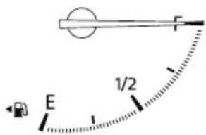
1/4 Full
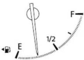
Empty
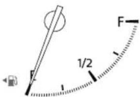
If the low fuel warning light illuminates or the fuel level is very low, refuel as soon as possible.
If inconsistency in engine performance or stalling occurs due to low fuel level conditions, refuel the vehicle as soon as possible and add at least 10 L (2.7 US gal, 2.2 Imp gal) of fuel.
Refer to Taking Action on page 7-37.
NOTE
• After refueling, it may require some time for the indicator to stabilize. In addition, the indicator may deviate while driving on a slope or curve since the fuel moves in the tank.
- The direction of the arrow (indicates that the fuel-filler lid is on the left side of the vehicle.
▼ Dashboard Illumination
When the lights are turned on with the ignition switched ON, the brightness of the dashboard illumination is dimmed. However, when the light sensor detects that the surrounding area is bright such as when the lights are turned on in the daytime, the dashboard illumination does not dim.
NOTE
- When the ignition is switched ON in the early evening or at dusk, the dashboard illumination is dimmed for several seconds until the light sensor detects the brightness of the surrounding area, however, the dimming may cancel after the brightness is detected.
- When the lights are turned on, the lights-on indicator light in the instrument cluster turns on. Refer to Headlights on page 4-70.
The brightness of the instrument cluster and dashboard illuminations can be adjusted by rotating the knob.
- The brightness decreases by rotating the knob to the left. A beep sound will be heard when the knob has been rotated to the maximum dim position.
- The brightness increases by rotating the knob to the right.
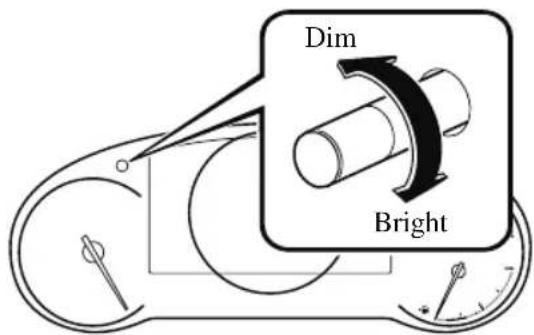
Function for canceling illumination dimmer
The illumination dimmer can be canceled by rotating the dashboard illumination knob to the right until a beep sound is heard while the instrument cluster is dimmed with the ignition switched ON. If the instrument cluster's visibility is reduced due to glare from surrounding brightness, cancel the illumination dimmer.
NOTE
- When the illumination dimmer is canceled, the instrument cluster cannot be dimmed even if the lights are turned on.
- When the illumination dimmer is canceled, the screen in the center display switches to constant display of the daytime screen.
▼ Speed Unit Selector
In some countries, you may have to change the speed units between km/h and mph.
When pressing the dashboard illumination knob, the speed units in the instrument cluster will change.
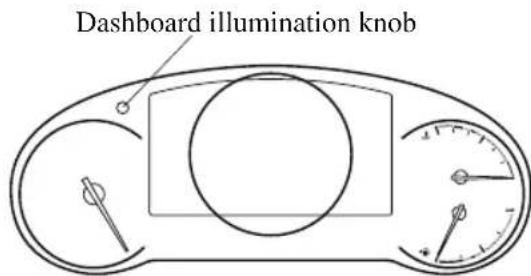
▼ Outside Temperature Display
When the ignition is switched ON, the outside temperature is displayed.
71^ F
NOTE
• Under the following conditions, the outside temperature display may differ from the actual outside temperature depending on the surroundings and vehicle conditions:
• Significantly cold or hot temperatures.
- Sudden changes in outside temperature.
- The vehicle is parked.
• The vehicle is driven at low speeds.
Changing the Temperature Unit of the Outside Temperature Display
The outside temperature unit can be switched between Celsius and Fahrenheit.
Settings can be changed by operating the center display screen.
Refer to the Settings section in the Mazda Connect Owner's Manual.
NOTE
When the temperature unit indicated in the outside temperature display is changed, the temperature unit indicated in the engine coolant gauge display changes in conjunction with it.
▼ Distance-to-empty
This displays the approximate distance you can travel on the remaining fuel based on the fuel economy.
The distance-to-empty will be calculated and displayed every second.
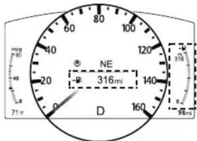
NOTE
• Even though the distance-to-empty display may indicate a sufficient amount of remaining driving distance before refueling is required, refuel as soon as possible if the fuel level is very low or the low fuel warning light illuminates.
- The display will not change unless you add more than approximately 9 L (2.3 US gal, 1.9 Imp gal) of fuel.
- The distance-to-empty is the approximate remaining distance the vehicle can be driven until all the graduation marks in the fuel gauge indicating the remaining fuel supply disappear.
- If there is no past fuel economy information such as after first purchasing your vehicle or the information is deleted when the battery cables are disconnected, the actual distance-to empty/range may differ from the amount indicated.
▼ Average Fuel Economy
The average fuel economy is calculated every minute from the total traveled distance on the trip meter and the total fuel consumption, and the average fuel economy for either TRIP A or TRIP B is displayed.
TRIP A
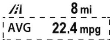
The average fuel economy and trip meters can be reset by pressing the INFO switch for 1.5 seconds or more while in each mode. After the data is cleared, the fuel consumption is recalculated and the - - - km/L (- - - mpg) for the 1 minute prior to it being displayed is indicated.
▼ Current Fuel Economy
This displays the current fuel economy by calculating the amount of fuel consumption and the distance traveled.
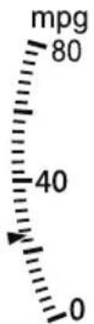
NOTE
- Indicates the 0 position when the vehicle speed is about 5km / h (3 mph) or slower.
- The red arrow on the scale indicates the average fuel economy.
▼ Maintenance Monitor
The following maintenance period notifications can be displayed by turning the Maintenance Monitor on.
• Scheduled Maintenance
- Tire Rotation
· Oil Change
When the remaining days to the maintenance period is 15 days or less, or the remaining distance is 1,000 km (600 miles) or shorter, a message is indicated when the ignition is switched ON.
Service Soon
/1 500 mi
For the setting method and indications for the maintenance monitor, refer to the Maintenance Monitor.
Refer to the Information section in the Mazda Connect Owner's Manual.
▼ Blind Spot Monitoring (BSM) Display
Displays the system status.
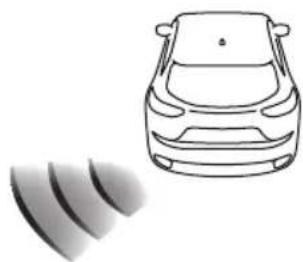
natural_image
Line drawing of a car with sound waves below (no text or symbols)Refer to Blind Spot Monitoring (BSM) on page 4-121.
▼ Lane-keep Assist System (LAS) & Lane Departure Warning System (LDWS) Display
Displays the system status.
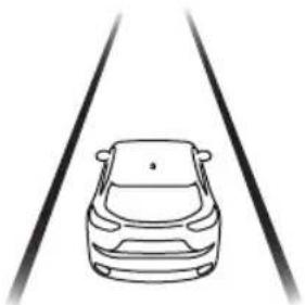
natural_image
Line drawing of a car on two parallel tracks (no text or symbols)Refer to Lane-keep Assist System (LAS) & Lane Departure Warning System (LDWS) on page 4-158.
▼ Mazda Radar Cruise Control with Stop & Go function (MRCC with Stop & Go function) Display*
Displays the currently set system status.
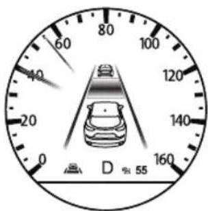
Refer to Mazda Radar Cruise Control with Stop & Go function (MRCC with Stop & Go function) on page 4-143.
▼ Distance Recognition Support System (DRSS) Display*
Displays the distance between your vehicle and the vehicle ahead.
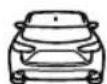
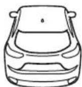
Refer to Distance Recognition Support System (DRSS) on page 4-133.
▼ Cruise Control Set Vehicle Speed Display*
The vehicle speed preset using the cruise control is displayed.
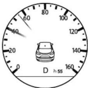
Refer to Cruise Control on page 4-247.
▼ Compass Display
The direction the vehicle is moving is displayed in one of eight directions while the vehicle is being driven.

NW
| Display Direction | |
| N | N |
| S | S |
| E | E |
| W | W |
| NE Northeast | |
| NW Northwest | |
| SE Southeast | |
| SW Southwest | |
▼ Message Display
A message such as the system operation status, a malfunction, or an abnormality is indicated.
Warning/indicator light in instrument cluster turns on/flashes or symbol is
indicated on display at same time as message
Check the information regarding the warning/indicator light or indicated symbol.
Refer to If a Warning Indication/Warning Lights on page 4-23.
Refer to If a Indication/Indicator Lights on page 4-25.
Message only is indicated on display
Follow the instructions indicated on the display. For the display content, refer to the next page.
Refer to If a Message Indicated on Multi-information Display on page 7-45.
▼ Warning/Indicator Lights
Instrument Cluster varies depending on model and specifications.
Instrument Cluster
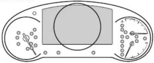
natural_image
Diagram of a biological cell division with nucleus, cytoplasm, and spindle (no text or labels)Center of Dashboard
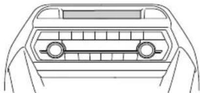
natural_image
Top-down line drawing of a car interior showing the front grille and side seats (no text or symbols)Warning lights will appear in any of the highlighted areas
▼ Warning Indication/Warning Lights
These lights turn on or flash to notify the user of the system operation status or a system malfunction.
| Signal Warning Page | ||
 BRAKE BRAKE | Brake System Warning Indication/Warning Light*1*2 | 7-28 |
 ABS ABS | ABS Warning Light*1 | Electronic Brake Force Distribution System Warning 7-28 |
| ABS warning 7-31 | ||
 | Charging System Warning Indication/Warning Light*1 | 7-28 |
 | Engine Oil Warning Light*1 | 7-28 |
 | High Engine Coolant Temperature Warning Indication 7-28 | |
 | Power Steering Malfunction Indication 7-28 | |
 | Master Warning Indication 7-31 | |
 | Electric Parking Brake (EPB) Warning Indication/Warning Light ^\#1 | 7-31 |
 | Check Engine Light ^*1 | 7-31 |
 | Automatic Transaxle Warning Indication 7-31 | |
 | ^* AWD Warning Indication | 7-31 |
 | Air Bag/Front Seat Belt Pretensioner System Warning Light ^*1 | 7-31 |
 | Tire Pressure Monitoring System Warning Light ^*1 | Flashing 7-31 |
| Turns on 7-37 | ||
 (Amber/White) (Amber/White) | KEY Warning Indication | Amber 7-31 |
| White 7-37 | ||
 (Amber) (Amber) | High Beam Control System (HBC) Warning Indication/Warning Light ^*1 | 7-31 |
 | Blind Spot Monitoring (BSM) Warning Indication 7-31 | |
 (Amber) (Amber) | ^* Driver Attention Alert (DAA) Warning Indication | 7-31 |
 (Amber) (Amber) | ^* Mazda Radar Cruise Control with Stop & Go function (MRCC with Stop & Go function) Warning Indication | 7-31 |
 (Amber) (Amber) | Lane-keep Assist System (LAS) & Lane Departure Warning System (LDWS) Warning Indication | 7-31 |
 | LED Headlight Warning Light ^*1 | 7-31 |
 | ^* Smart Brake Support/Smart City Brake Support (SBS/SCBS) Warning Indication | 7-37 |
 | Low Fuel Warning Indication/Warning Light 7-37 | |
 | Check Fuel Cap Warning Indication/Warning Light ^*1 | 7-37 |
 | Engine Oil Level Warning Light ^*1 | 7-37 |
 | Seat Belt Warning Light (Front seat) 7-37 | |
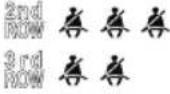 (Red) (Red) | Seat Belt Warning Light (Rear seat) 7-37 | |
 | *Low Washer Fluid Level Warning Indication | 7-37 |
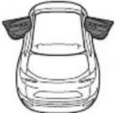 | Door-Ajar Warning Indication 7-37 | |
 | Liftgate-Ajar Warning Indication 7-37 | |
 | Door-Ajar Warning Light 7-37 | |
*1 The light turns on when the ignition is switched on for an operation check, and turns off a few seconds later or when the engine is started. If the light does not turn on or remains turned on, have the vehicle inspected at an Authorized Mazda Dealer.
*2 The light turns on continuously when the parking brake is applied.
▼ Indication/Indicator Lights
These lights turn on or flash to notify the user of the system operation status or a system malfunction.
| Signal Indicator Page | ||
2ndROW3rdROW(Green)  | Seat Belt Indicator Light (Rear seat) 2-39 | |
PAAIRBA | *Front Passenger Air Bag Deactivation Indicator Light*1 | 2-85 |
 | Security Indicator Light*1 | 3-46 |
 | Wrench Indication 4-28 | |
| Shift Position Indication 4-61 | ||
| [DOE] | Lights-On Indication/Indicator Light 4-70 | |
 | Headlight High-Beam Indicator Light | HeadlightHigh-Low Beam4-74 |
| Flashing theHeadlights4-74 | ||
 | Turn Signal/Hazard Warning Indicator Lights | Turn andLanc-ChangeSignals4-77 |
| Hazard WarningFlasher4-84 | ||
| HOLD | AUTOHOLD Active Indicator Light*1 | 4-98 |
| *Mazda Radar Cruise Control with Stop & Go function (MRCC with Stop& Go function) indicator Light*1 | 4-154 | |
 | TCS/DSC Indicator Light*1 | Traction ControlSystem (TCS)4-103 |
| Dynamic Stabil-ity Control(DSC)4-105 | ||
| Turns on7-31 | ||
| TCSOFF | TCS OFF Indicator Light (FWD)*1 | 4-104 |
 | Off-Road Traction Assist Indicator Light (AWD)*1 | 4-107 |
| SPORT | Select Mode Indication 4-109 | |
 (Green) (Green) | High Beam Control System (HBC) Indicator Light 4-119 | |
 | Blind Spot Monitoring (BSM) OFF Indicator Light*1 | Malfunction7-31 |
| Except malfunc-tion4-125 | ||
 (White) (White) | *Driver Attention Alert (DAA) Indication | 4-138 |
 (White) (White) | *Mazda Radar Cruise Control with Stop & Go function (MRCC with Stop & Go function) Main Indication | 4-148 |
 (Green) (Green) | *Mazda Radar Cruise Control with Stop & Go function (MRCC with Stop & Go function) Set Indication | 4-148 |
 | Lane-keep Assist System (LAS) & Lane Departure Warning System (LDWS) Indication | 4-160 |
 | *Smart City Brake Support (SCBS) Indication | Advanced Smart City Brake Support (Advanced SCBS)4-171 |
| Smart City Brake Support [Reverse](SCBS R)4-178 | ||
 | *Smart Brake Support/Smart City Brake Support (SBS/SCBS) OFF Indicator Light*1 | Advanced Smart City Brake Support (Advanced SCBS)4-171 |
| Smart City Brake Support [Reverse](SCBS R)4-178 | ||
| Smart Brake Support (SBS) System4-180 | ||
| [5XXY](White) | *Cruise Main Indication | 4-248 |
 (Green) (Green) | *Cruise Set Indication | 4-248 |
*1 The light turns on when the ignition is switched on for an operation check, and turns off a few seconds later or when the engine is started. If the light does not turn on or remains turned on, have the vehicle inspected at an Authorized Mazda Dealer.
▼ Wrench Indicator Light
The wrench indication is displayed under the following conditions.
- When the preset maintenance period has arrived.
Refer to the Information section in the Mazda Connect Owner's Manual. - When the engine oil replacement period has arrived.
NOTE
- The wrench indication may display earlier than the preset period depending on vehicle usage conditions.
- Whenever the engine oil is replaced, a reset of the vehicle engine control unit is necessary. Refer to the Information section in the Mazda Connect Owner's Manual.
Instrument Cluster (Type B)

① Speedometer......page 4-29
② Tachometer......page 4-29
③ Multi-information Display (Type B)......page 4-30
④ Dashboard Illumination......page 4-34
▼ Speedometer
The speedometer indicates the speed of the vehicle.
▼ Tachometer
The tachometer shows engine speed in thousands of revolutions per minute (rpm).

CAUTION
Do not run the engine with the tachometer needle in the RED ZONE.
This may cause severe engine damage.
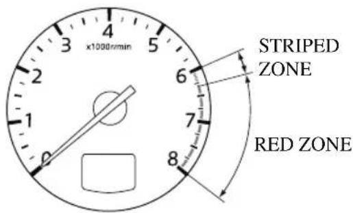
NOTE
When the tachometer needle enters the STRIPED ZONE, this indicates to the driver that the gears should be shifted before entering the RED ZONE.
▼ Multi-information Display (Type B)
Multi-information Display (Type B)
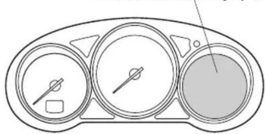
natural_image
Diagram of a car dashboard with three gauges and a highlighted interior (no text or symbols)INFO switch
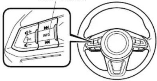
The multi-information display indicates the following information.
· Odometer
- Trip meter
• Engine coolant temperature gauge
- Fuel gauge
· Outside temperature
- Distance-to-empty
· Average fuel economy
- Current fuel economy
- Maintenance Monitor
- Blind Spot Monitoring (BSM) Display
• Distance Recognition Support System (DRSS) Display
- Mazda Radar Cruise Control with Stop & Go function (MRCC with Stop & Go function) System Display
· Lane-keep Assist System (LAS) & Lane Departure Warning System (LDWS) Display
• Cruise Control Display
- Compass Display
- Message Display
The screen content changes each time the INFO switch is pressed.
Press the INFO switch
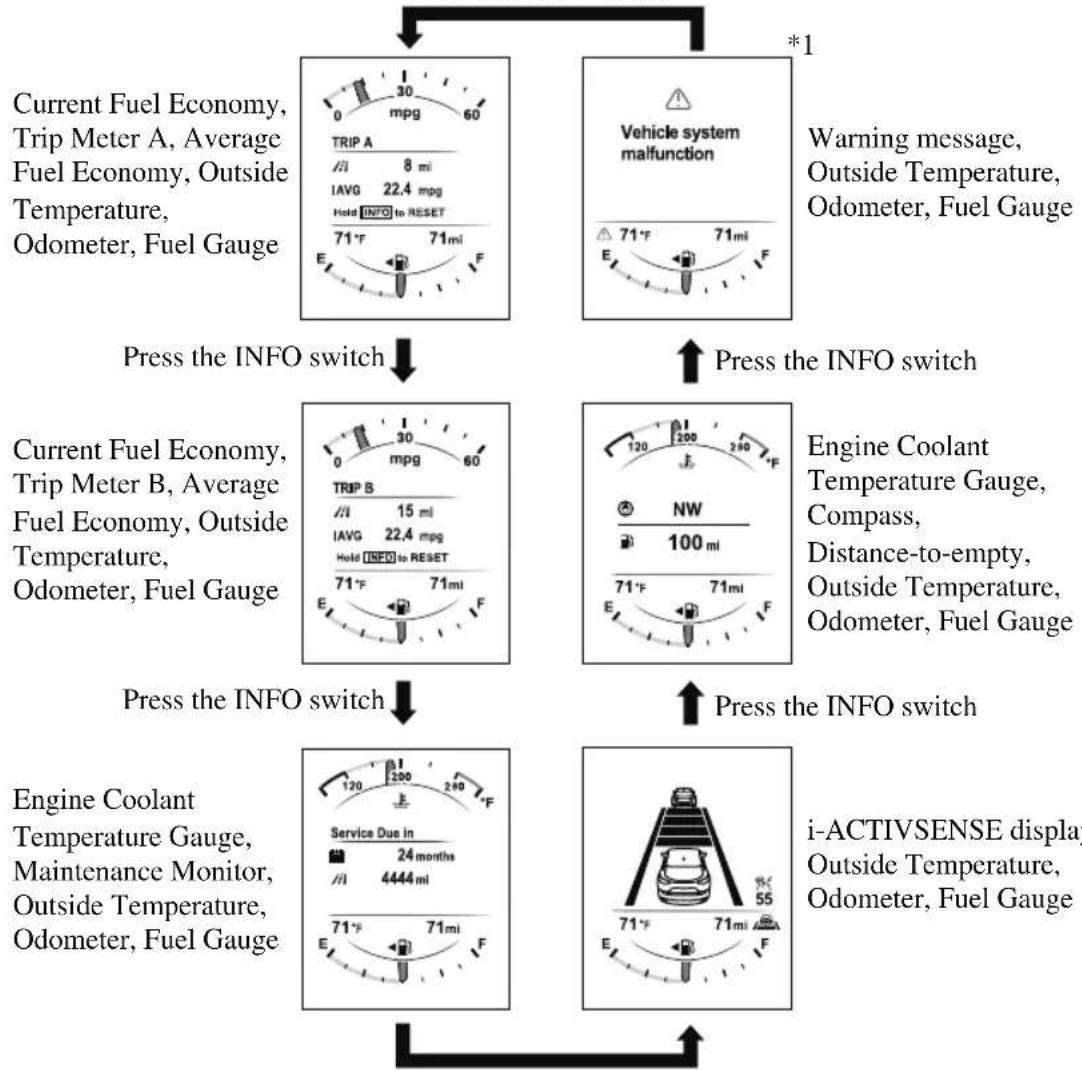
flowchart
graph TD
    A["Current Fuel Economy, Trip Meter A, Average Fuel Economy, Outside Temperature, Odometer, Fuel Gauge"] --> B["Press the INFO switch"]
    C["Vehicle system malfunction"] --> D["Press the INFO switch"]
    B --> E["Engine Coolant Temperature Gauge, Compass, Distance-to-empty, Outside Temperature, Odometer, Fuel Gauge"]
    D --> F["i-ACTIVSENSE display"]
Press the INFO switch
*1: Displayed only when a warning occurs.
▼ Odometer, Trip Meter and Trip Meter Selector
The odometer is constantly displayed on the screen when the ignition is switched ON, and the TRIP A or TRIP B screen can
be displayed by operating the INFO switch.
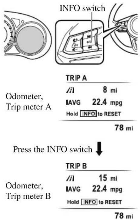
Odometer
The odometer records the total distance the vehicle has been driven.
Trip meter
The driving distance for a specified interval is indicated. Two types (TRIP A, TRIP B) of interval distance and the average fuel economy for each can be measured.
For instance, trip meter A can record the distance from the point of origin, and trip
meter B can record the distance from where the fuel tank is filled.
When trip meter A is selected, TRIP A will be displayed. When trip meter B is selected, TRIP B will be displayed.
The trip meter and average fuel economy can be reset by pressing the INFO switch for 1.5 seconds or more while in each mode.
NOTE
-
Only the trip meters record tenths of kilometers (miles).
· The trip record will be erased when: -
The power supply is interrupted (blown fuse or the battery is disconnected).
- The vehicle is driven over 9999.9 km (mile).
▼ Engine Coolant Temperature Gauge
Displays the engine coolant temperature. The blue range of the gauge indicates that the engine coolant temperature is low, and the red range of the gauge indicates that the engine coolant temperature is high and overheating.
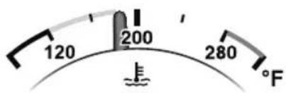

CAUTION
If the high engine coolant temperature warning light (red) flashes, there is a possibility of overheating. Drive slowly to reduce engine load until you can find a safe place to stop the vehicle and wait for the engine to cool down.
Refer to Overheating on page 7-23.
NOTE
- If the engine coolant temperature is high or the engine is hot, the engine output may be limited.
- The temperature unit (Centigrade/Fahrenheit) of the engine coolant gauge display changes in conjunction with the temperature unit of the outside temperature display.
Refer to the Settings section in the Mazda Connect Owner's Manual.
▼ Fuel Gauge
The fuel gauge shows approximately how much fuel is remaining in the tank when
the ignition is switched ON. We recommend keeping the tank over 1/4 full.
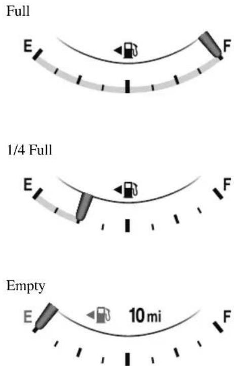
If the fuel level is low, ( ) and ( ) burn an amber color. Refuel as soon as possible. If inconsistency in engine performance or stalling occurs due to low fuel level conditions, refuel the vehicle as soon as possible and add at least 10 L (2.7 US gal, 2.2 Imp gal) of fuel.
Refer to Taking Action on page 7-37.
NOTE
• After refueling, it may require some time for the indicator to stabilize. In addition, the indicator may deviate while driving on a slope or curve since the fuel moves in the tank.
- The direction of the arrow (indicates that the fuel-filler lid is on the left side of the vehicle.
▼ Dashboard Illumination
When the lights are turned on with the ignition switched ON, the brightness of the dashboard illumination is dimmed. However, when the light sensor detects that the surrounding area is bright such as when the lights are turned on in the daytime, the dashboard illumination does not dim.
NOTE
- When the ignition is switched ON in the early evening or at dusk, the dashboard illumination is dimmed for several seconds until the light sensor detects the brightness of the surrounding area, however, the dimming may cancel after the brightness is detected.
- When the lights are turned on, the lights-on indicator light in the instrument cluster turns on. Refer to Headlights on page 4-70.
The brightness of the instrument cluster and dashboard illuminations can be adjusted by rotating the knob.
- The brightness decreases by rotating the knob to the left. A beep sound will be heard when the knob has been rotated to the maximum dim position.
- The brightness increases by rotating the knob to the right.
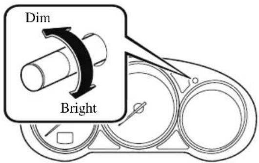
Function for canceling illumination dimmer
The illumination dimmer can be canceled by rotating the dashboard illumination knob to the right until a beep sound is heard while the instrument cluster is dimmed with the ignition switched ON. If the instrument cluster's visibility is reduced due to glare from surrounding brightness, cancel the illumination dimmer.
NOTE
- The illumination dimmer can be canceled by pressing the dashboard illumination knob.
- When the illumination dimmer is canceled, the instrument cluster cannot be dimmed even if the lights are turned on.
- When the illumination dimmer is canceled, the screen in the center display switches to constant display of the daytime screen.
▼ Outside Temperature Display
When the ignition is switched ON, the outside temperature is displayed.
78°F
NOTE
• Under the following conditions, the outside temperature display may differ from the actual outside temperature depending on the surroundings and vehicle conditions:
• Significantly cold or hot temperatures.
- Sudden changes in outside temperature.
• The vehicle is parked.
• The vehicle is driven at low speeds.
Changing the Temperature Unit of the Outside Temperature Display
The outside temperature unit can be switched between Celsius and Fahrenheit. Settings can be changed by operating the center display screen.
Refer to the Settings section in the Mazda Connect Owner's Manual.
NOTE
When the temperature unit indicated in the outside temperature display is changed, the temperature unit indicated in the engine coolant gauge display changes in conjunction with it.
▼ Distance-to-empty
This displays the approximate distance you can travel on the remaining fuel based on the fuel economy.
The distance-to-empty will be calculated and displayed every second.

100 mi
NOTE
• Even though the distance-to-empty display may indicate a sufficient amount of remaining driving distance before refueling is required, refuel as soon as possible if the fuel level is very low or the low fuel warning light illuminates.
- The display will not change unless you add more than approximately 9 L (2.3 US gal, 1.9 Imp gal) of fuel.
- The distance-to-empty is the approximate remaining distance the vehicle can be driven until all the graduation marks in the fuel gauge indicating the remaining fuel supply disappear.
- If there is no past fuel economy information such as after first purchasing your vehicle or the information is deleted when the battery cables are disconnected, the actual distance-to empty/range may differ from the amount indicated.
▼ Average Fuel Economy
The average fuel economy is calculated every minute from the total traveled distance on the trip meter and the total fuel consumption, and the average fuel economy for either TRIP A or TRIP B is displayed.
TRIP A
// 8 mi
IAVG 22.4 mpg
Hold INFO to RESET
78 mi
The average fuel economy and trip meters can be reset by pressing the INFO switch for 1.5 seconds or more while in each mode. After the data is cleared, the fuel consumption is recalculated and the - - - km/L (- - - mpg) for the 1 minute prior to it being displayed is indicated.
▼ Current Fuel Economy
This displays the current fuel economy by calculating the amount of fuel consumption and the distance traveled.
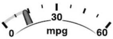
NOTE
Indicates the 0 position when the vehicle speed is about 5 km/h (3 mph) or slower.
▼ Maintenance Monitor
The following maintenance period notifications can be displayed by turning the Maintenance Monitor on.
• Scheduled Maintenance
- Tire Rotation
· Oil Change
When the remaining days to the maintenance period is 15 days or less, or the remaining distance is 1,000 km (600 miles) or shorter, a message is indicated when the ignition is switched ON.

Service Soon
/1 500 mi
For the setting method and indications for the maintenance monitor, refer to the Maintenance Monitor.
Refer to the Information section in the Mazda Connect Owner's Manual.
▼ Blind Spot Monitoring (BSM) Display
Displays the system status.
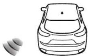
natural_image
Simple line drawing of a car with no text or symbolsRefer to Blind Spot Monitoring (BSM) on page 4-121.
▼ Lane-keep Assist System (LAS) & Lane Departure Warning System (LDWS) Display\*
Displays the system status.
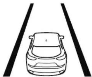
natural_image
Simple line drawing of a car viewed from two straight lanes (no text or symbols)Refer to Lane-keep Assist System (LAS) & Lane Departure Warning System (LDWS) on page 4-158.
▼ Mazda Radar Cruise Control with Stop & Go function (MRCC with Stop & Go function) Display\*
Displays the currently set system status.
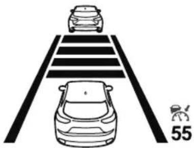
natural_image
Diagram showing two cars on a road with lane markings and a vehicle icon labeled '55' (no text or symbols beyond the number)Refer to Mazda Radar Cruise Control with Stop & Go function (MRCC with Stop & Go function) on page 4-143.
▼ Distance Recognition Support System (DRSS) Display\*
Displays the distance between your vehicle and the vehicle ahead.
Refer to Distance Recognition Support System (DRSS) on page 4-133.
▼ Cruise Control Set Vehicle Speed Display\*
The vehicle speed preset using the cruise control is displayed.

Refer to Cruise Control on page 4-247.
▼ Compass Display
The direction the vehicle is moving is displayed in one of eight directions while the vehicle is being driven.


| Display Direction | |
| N | N |
| S | S |
| E | E |
| W | W |
| NE Northeast | |
| NW Northwest | |
| SE Southeast | |
| SW Southwest | |
▼ Message Display
A message such as the system operation status, a malfunction, or an abnormality is indicated.
Warning/indicator light in instrument cluster turns on/flashes or symbol is indicated on display at same time as message
Check the information regarding the warning/indicator light or indicated symbol.
Refer to If a Warning Indication/Warning Lights on page 4-38.
Refer to If a Indication/Indicator Lights on page 4-40.
Message only is indicated on display
Follow the instructions indicated on the display. For the display content, refer to the next page.
Refer to If a Message Indicated on Multi-information Display on page 7-45.
▼ Warning/Indicator Lights
Instrument Cluster varies depending on model and specifications.
Instrument Cluster
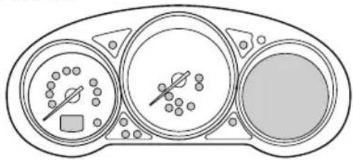
natural_image
Diagram of a three-cylinder dashboard with gauges and indicators (no text or labels)Center of Dashboard
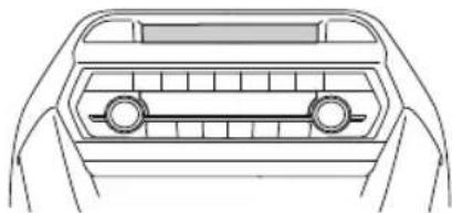
natural_image
Top-down line drawing of a car frontview showing the grille and side panels (no text or symbols)Warning lights will appear in any of the highlighted areas
▼ Warning Indication/Warning Lights
These lights turn on or flash to notify the user of the system operation status or a system malfunction.
| Signal Warning Page | ||
 BRAKE BRAKE | Brake System Warning Indication/Warning Light*1*2 | 7-28 |
 ABS ABS | ABS Warning Light*1 | Electronic Brake Force Distribution System Warning 7-28 |
| ABS warning 7-31 | ||
 | Charging System Warning Indication/Warning Light*1 | 7-28 |
 | Engine Oil Warning Light*1 | 7-28 |
 (Red) (Red) | High Engine Coolant Temperature Warning Light*1 | 7-28 |
 | Power Steering Malfunction Indication 7-28 | |
 | Master Warning Indication 7-31 | |
 | Electric Parking Brake (EPB) Warning Indication/Warning Light*1 | 7-31 |
 | Check Engine Light*1 | 7-31 |
 | Automatic Transaxle Warning Indication 7-31 | |
 | *AWD Warning Indication | 7-31 |
 | Air Bag/Front Seat Belt Pretensioner System Warning Light*1 | 7-31 |
 | Tire Pressure Monitoring System Warning Light*1 | Flashing 7-31 |
| Turns on 7-37 | ||
 (Amber/White) (Amber/White) | KEY Warning Indication | Amber 7-31 |
| White 7-37 | ||
 (Amber) (Amber) | *High Beam Control System (HBC) Warning Indication/Warning Light*1 | 7-31 |
 | Blind Spot Monitoring (BSM) Warning Indication 7-31 | |
 (Amber) (Amber) | *Mazda Radar Cruise Control with Stop & Go function (MRCC with Stop & Go function) Warning Indication | 7-31 |
 | *Lane-keep Assist System (LAS) & Lane Departure Warning System (LDWS) Warning Indication | 7-31 |
 | LED Headlight Warning Light*1 | 7-31 |
 (Amber) (Amber) | *Smart Brake Support/Smart City Brake Support (SBS/SCBS) Warning Indication | 7-37 |
 | Low Fuel Warning Indication 7-37 | |
 | Check Fuel Cap Warning Indication/Warning Light*1 | 7-37 |
 | Engine Oil Level Warning Light*1 | 7-37 |
 | Seat Belt Warning Light (Front seat) 7-37 | |
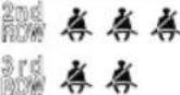 | Seat Belt Warning Light (Rear seat) 7-37 | |
 | *Low Washer Fluid Level Warning Indication | 7-37 |
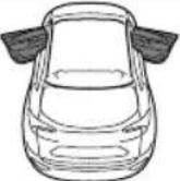 | Door-Ajar Warning Indication 7-37 | |
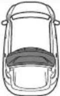 | Liftgate-Ajar Warning Indication 7-37 | |
*1 The light turns on when the ignition is switched on for an operation check, and turns off a few seconds later or when the engine is started. If the light does not turn on or remains turned on, have the vehicle inspected at an Authorized Mazda Dealer.
* 2 The light turns on continuously when the parking brake is applied.
▼ Indication/Indicator Lights
These lights turn on or flash to notify the user of the system operation status or a system malfunction.
| Signal Indicator Page | ||
  (Green) (Green) | Seat Belt Indicator Light (Rear seat) 2-39 | |
 | *Front Passenger Air Bag Deactivation Indicator Light*1 | 2-85 |
 | Security Indicator Light*1 | 3-46 |
 | Wrench Indication 4-43 | |
 (Blue) (Blue) | Low Engine Coolant Temperature Indicator Light 4-43 | |
 | Shift Position Indication 4-61 | |
| 3DOE | Lights-On Indication/Indicator Light 4-70 | |
 | Headlight High-Beam Indicator Light | HeadlightHigh-Low Beam4-74 |
| Flashing theHeadlights4-74 | ||
 | Turn Signal/Hazard Warning Indicator Lights | Turn andLane-ChangeSignals4-77 |
| Hazard WarningFlasher4-84 | ||
| HOLD | AUTOHOLD Active Indicator Light*1 | 4-98 |
| *Mazda Radar Cruise Control with Stop & Go function (MRCC with Stop& Go function) indicator Light*1 | 4-154 | |
 | TCS/DSC Indicator Light *1 | Traction ControlSystem (TCS)4-103 |
| Dynamic Stabil-ity Control(DSC)4-105 | ||
| Turns on7-31 | ||
| TCSOFF | TCS OFF Indicator Light (FWD) *1 | 4-104 |
 | Off-Road Traction Assist Indicator Light (AWD)*1 | 4-107 |
| SPORT | Select Mode Indication 4-109 | |
 (Green) (Green) | *High Beam Control System (HBC) Indicator Light | 4-119 |
 | Blind Spot Monitoring (BSM) OFF Indicator Light*1 | Malfunction 7-31 |
| Except malfunction 4-125 | ||
 (White) (White) | *Mazda Radar Cruise Control with Stop & Go function (MRCC with Stop & Go function) Main Indication | 4-148 |
 (Green) (Green) | *Mazda Radar Cruise Control with Stop & Go function (MRCC with Stop & Go function) Set Indication | 4-148 |
 | *Lane-keep Assist System (LAS) & Lane Departure Warning System (LDWS) Indication | 4-160 |
 | *Smart City Brake Support (SCBS) Indication | Advanced Smart City Brake Support (Advanced SCBS) 4-171 |
| Smart City Brake Support (SCBS) 4-174 | ||
 | *Smart Brake Support/Smart City Brake Support (SBS/SCBS) OFF Indicator Light*1 | Advanced Smart City Brake Support (Advanced SCBS) 4-171 |
| Smart City Brake Support (SCBS) 4-174 | ||
| Smart Brake Support (SBS) System 4-180 | ||
 (White) (White) | *Cruise Main Indication | 4-248 |
 (Green) (Green) | *Cruise Set Indication | 4-248 |
*1 The light turns on when the ignition is switched on for an operation check, and turns off a few seconds later or when the engine is started. If the light does not turn on or remains turned on, have the vehicle inspected at an Authorized Mazda Dealer.
▼ Wrench Indicator Light
The wrench indication is displayed under the following conditions.
- When the preset maintenance period has arrived.
Refer to the Information section in the Mazda Connect Owner's Manual. - When the engine oil replacement period has arrived.
NOTE
- The wrench indication may display earlier than the preset period depending on vehicle usage conditions.
- Whenever the engine oil is replaced, a reset of the vehicle engine control unit is necessary.
Refer to the Information section in the Mazda Connect Owner's Manual.
▼ Low Engine Coolant Temperature Indicator Light (Blue)
The light illuminates continuously when the engine coolant temperature is low and turns off after the engine is warm.
Instrument Cluster (Type C)
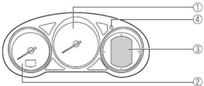
① Speedometer......page 4-44
② Tachometer......page 4-44
③ Multi-information Display (Type C)......page 4-45
④ Dashboard Illumination......page 4-48
▼ Speedometer
The speedometer indicates the speed of the vehicle.
▼ Tachometer
The tachometer shows engine speed in thousands of revolutions per minute (rpm).

CAUTION
Do not run the engine with the tachometer needle in the RED ZONE.
This may cause severe engine damage.
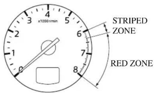
NOTE
When the tachometer needle enters the STRIPED ZONE, this indicates to the driver that the gears should be shifted before entering the RED ZONE.
▼ Multi-information Display (Type C)
The multi-information display indicates the following information.
- Odometer
- Trip meter
• Engine coolant temperature gauge
· Fuel gauge - Outside temperature
- Trip Computer
· Cruise Control Display - Compass Display
▼ Odometer, Trip Meter and Trip Meter Selector
The display mode can be changed from odometer to trip meter A to trip meter B and then back to odometer by pressing the
selector while one of them is displayed. The selected mode will be displayed.
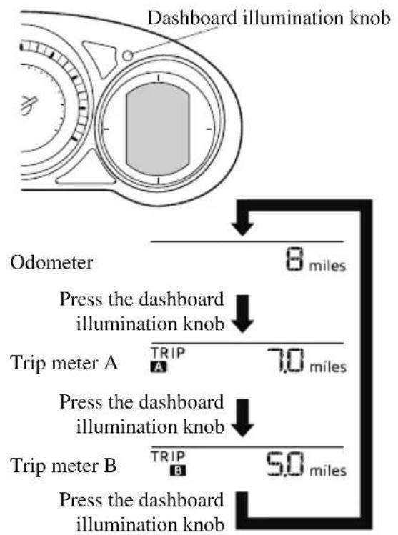
Odometer
The odometer records the total distance the vehicle has been driven.
Trip meter
The trip meter can record the total distance of two trips. One is recorded in trip meter A, and the other is recorded in trip meter B.
For instance, trip meter A can record the distance from the point of origin, and trip
meter B can record the distance from where the fuel tank is filled.
When trip meter A is selected, pressing the selector again within 1 second will change to trip meter B mode.
When trip meter A is selected, TRIP A will be displayed. When trip meter B is selected, TRIP B will be displayed.
The trip meter records the total distance the vehicle is driven until the meter is again reset. Return it to “0.0” by depressing and holding the selector for 1 second or more. Use this meter to measure trip distances and to compute fuel consumption.
NOTE
- If TRIP A is reset using the trip meter when the function which synchronizes (resets) the fuel economy monitor and the trip meter (TRIP A) is on, the fuel economy data resets in conjunction with TRIP A. Refer to the Information section in the Mazda Connect Owner's Manual.
- Only the trip meters record tenths of kilometers (miles).
• The trip record will be erased when:
- The power supply is interrupted (blown fuse or the battery is disconnected).
- The vehicle is driven over 9999.9 km (mile).
▼ Engine Coolant Temperature Gauge
Displays the engine coolant temperature. The white range of the gauge indicates that the engine coolant temperature is low,
and the red range of the gauge indicates that the engine coolant temperature is high and overheating.
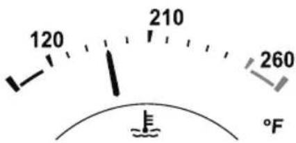

CAUTION
If the engine coolant temperature gauge needle (white) flashes, there is a possibility of overheating. Drive slowly to reduce engine load until you can find a safe place to stop the vehicle and wait for the engine to cool down.
Refer to Overheating on page 7-23.
NOTE
- If the engine coolant temperature is high or the engine is hot, the engine output may be limited.
- The temperature unit (Centigrade/Fahrenheit) of the engine coolant gauge display changes in conjunction with the temperature unit of the outside temperature display.
Refer to the Settings section in the Mazda Connect Owner's Manual.

Fuel Gauge
The fuel gauge shows approximately how much fuel is remaining in the tank when
the ignition is switched ON. We recommend keeping the tank over 1/4 full.
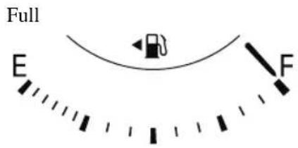
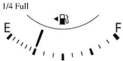
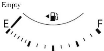
If the low fuel warning light illuminates or the fuel level is very low, refuel as soon as possible.
If inconsistency in engine performance or stalling occurs due to low fuel level conditions, refuel the vehicle as soon as possible and add at least 10 L (2.7 US gal, 2.2 Imp gal) of fuel.
Refer to Taking Action on page 7-37.
NOTE
• After refueling, it may require some time for the indicator to stabilize. In addition, the indicator may deviate while driving on a slope or curve since the fuel moves in the tank.
- The display indicating a quarter or less remaining fuel has more segments to show the remaining fuel level in greater detail.
- The direction of the arrow (indicates that the fuel-filler lid is on the left side of the vehicle.
▼ Dashboard Illumination
(Without auto-light control)
When the lights are turned on with the ignition switched ON, the brightness of the dashboard illumination is dimmed.
(With auto-light control)
When the lights are turned on with the ignition switched ON, the brightness of the dashboard illumination is dimmed. However, when the light sensor detects that the surrounding area is bright such as when the lights are turned on in the daytime, the dashboard illumination does not dim.
NOTE
· (With auto-light control)
When the ignition is switched ON in the early evening or at dusk, the dashboard illumination is dimmed for several seconds until the light sensor detects the brightness of the surrounding area, however, the dimming may cancel after the brightness is detected.
- When the lights are turned on, the lights-on indicator light in the instrument cluster turns on.
Refer to Headlights on page 4-70.
The brightness of the instrument cluster and dashboard illuminations can be adjusted by rotating the knob.
- The brightness decreases by rotating the knob to the left. A beep sound will be heard when the knob has been rotated to the maximum dim position.
- The brightness increases by rotating the knob to the right.
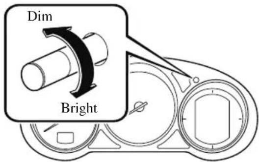
Function for canceling illumination dimmer
The illumination dimmer can be canceled by rotating the dashboard illumination knob to the right until a beep sound is heard while the instrument cluster is dimmed with the ignition switched ON. If the instrument cluster's visibility is reduced due to glare from surrounding brightness, cancel the illumination dimmer.
NOTE
- When the illumination dimmer is canceled, the instrument cluster cannot be dimmed even if the lights are turned on.
- When the illumination dimmer is canceled, the screen in the center display switches to constant display of the daytime screen.
▼ Outside Temperature Display
When the ignition is switched ON, the outside temperature is displayed.
78°F
NOTE
- Under the following conditions, the outside temperature display may differ from the actual outside temperature depending on the surroundings and vehicle conditions:
• Significantly cold or hot temperatures.
- Sudden changes in outside temperature.
- The vehicle is parked.
- The vehicle is driven at low speeds.
Changing the Temperature Unit of the Outside Temperature Display
The outside temperature unit can be switched between Celsius and Fahrenheit. Settings can be changed by operating the center display screen.
Refer to the Settings section in the Mazda Connect Owner's Manual.
NOTE
When the temperature unit indicated in the outside temperature display is changed, the temperature unit indicated in the engine coolant gauge display changes in conjunction with it.
▼ Trip Computer
The following information can be selected by pressing the INFO switch with the ignition switched ON.
- Distance-to-empty mode
• Average fuel economy mode - Current fuel economy mode
- Compass mode
If you have any problems with your trip computer, consult an Authorized Mazda Dealer.
Distance-to-empty mode
This mode displays the approximate distance you can travel on the remaining fuel based on the fuel economy.
The distance-to-empty will be calculated and displayed every second.
RANGE
miles
NOTE
- Even though the distance-to-empty display may indicate a sufficient amount of remaining driving distance before refueling is required, refuel as soon as possible if the fuel level is very low or the low fuel warning light illuminates.
- The display may not change unless you add more than approximately 9 L (2.3 US gal, 1.9 Imp gal) of fuel.
- The distance-to-empty is the approximate remaining distance the vehicle can be driven until all the graduation marks in the fuel gauge (indicating the remaining fuel supply) disappear.
- If there is no past fuel economy information such as after first purchasing your vehicle or the information is deleted when the battery cables are disconnected, the actual distance-to empty/range may differ from the amount indicated.
Average fuel economy mode
This mode displays the average fuel economy by calculating the total traveled distance and the total fuel consumption since the vehicle was purchased or the past
data was reset. The average fuel economy is calculated and displayed every minute.
To reset the displayed past data, press the INFO switch for 1.5 seconds or longer. After resetting the data, - - - L/100 km (- - - mpg) is displayed for one minute before the fuel economy is recalculated and displayed.
NOTE
If TRIP A is reset using the trip meter when the function which synchronizes (resets) the fuel economy monitor and the trip meter (TRIP A) is on, the displayed past data is reset.
Current fuel economy mode
This mode displays the current fuel economy by calculating the amount of fuel consumption and the distance traveled.
Current fuel economy will be calculated and displayed every 2 seconds.
CURRENT
224 mpg
When you've slowed to about 5 km/h (3 mph), - - - L/100 km (- - - mpg) will be displayed.
Compass mode
The direction the vehicle is moving is displayed in one of eight directions while the vehicle is being driven.


| Display Direction | |
| N | N |
| S | S |
| E | E |
| W | W |
| NE Northeast | |
| NW Northwest | |
| SE Southeast | |
| SW Southwest | |
▼ Cruise Control Set Vehicle Speed Display
The vehicle speed preset using the cruise control is displayed.

55mph
Refer to Cruise Control on page 4-247.
▼ Warning/Indicator Lights
Instrument Cluster varies depending on model and specifications.
Instrument Cluster
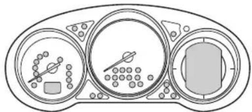
natural_image
Diagram of a car dashboard with three circular gauges and control panels (no text or symbols)Center of Dashboard
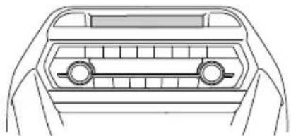
natural_image
Top-down line drawing of a car dashboard with two wheels and a front panel (no text or symbols)Warning lights will appear in any of the highlighted areas
▼ Warning Indication/Warning Lights
These lights turn on or flash to notify the user of the system operation status or a system malfunction.
| Signal Warning Page | ||
 | Brake System Warning Light*1*2 | 7-28 |
| ABS | ABS Warning Light*1 | Electronic Brake Force Distribution System Warning 7-28 |
| ABS warning 7-31 | ||
 | Charging System Warning Light*1 | 7-28 |
| [~] | Engine Oil Warning Light*1 | 7-28 |
 | Power Steering Malfunction Indicator Light*1 | 7-28 |
 | Master Warning Light*1 | 7-31 |
 | Electric Parking Brake (EPB) Warning Light*1 | 7-31 |
 (Red) (Red) | Electric Parking Brake (EPB) Warning Light*1 | Flashing4-96 |
| Buzzer & Flash-ing7-31 | ||
 | Check Engine Light*1 | 7-31 |
 | Automatic Transaxle Warning Light*1 | 7-31 |
 | *AWD Warning Light | 7-31 |
 | Air Bag/Front Seat Belt Pretensioner System Warning Light*1 | 7-31 |
 | Tire Pressure Monitoring System Warning Light*1 | Flashing7-31 |
| Turns on7-37 | ||
 (Red) (Red) | KEY Warning Light*1 | Turns on7-31 |
| Flashing7-37 | ||
 | LED Headlight Warning Light*1 | 7-31 |
 | *Smart City Brake Support (SCBS) Warning Light | 7-37 |
 | Low Fuel Warning Light 7-37 | |
 | Check Fuel Cap Warning Light*1 | 7-37 |
 | Engine Oil Level Warning Light*1 | 7-37 |
| [TGHK] PASSENGER | Scat Belt Warning Light (Front scat) 7-37 | |
 (Red) (Red) |  Scat Belt Warning Light (Rear seat) 7-37 Scat Belt Warning Light (Rear seat) 7-37 | |
 | *Low Washer Fluid Level Warning Light | 7-37 |
 | Door-Ajar Warning Light 7-37 | |
*1 The light turns on when the ignition is switched on for an operation check, and turns off a few seconds later or when the engine is started. If the light does not turn on or remains turned on, have the vehicle inspected at an Authorized Mazda Dealer.
*2 The light turns on continuously when the parking brake is applied.
▼ Indication/Indicator Lights
These lights turn on or flash to notify the user of the system operation status or a system malfunction.
| Signal Indicator Page | ||
 (Green) (Green) | KEY Indicator Light 4-5 | |
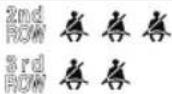 (Green) (Green) | Seat Belt Indicator Light (Rear seat) 2-85 | |
| PASS AIRBAG OFF | *Front Passenger Air Bag Deactivation Indicator Light*1 | 2-85 |
 | Security Indicator Light*1 | 3-46 |
| Wrench Indicator Light*1 | 4-54 | |
 | Shift Position Indication 4-61 | |
| =DO= | Lights-On Indication/Indicator Light 4-70 | |
 | Headlight High-Beam Indicator Light | HeadlightHigh-Low Beam4-74 |
| Flashing theHeadlights4-74 | ||
 | Turn Signal/Hazard Warning Indicator Lights | Turn andLane-ChangeSignals4-77 |
| Hazard WarningFlasher4-84 | ||
| HOLD | AUTOHOLD Active Indicator Light*1 | 4-98 |
 (Green) (Green) | Brake Pedal Operation demand Indicator Light 4-92 | |
 | TCS/DSC Indicator Light*1 | Traction Control System (TCS)4-103 |
| Dynamic Stabil-ity Control(DSC)4-105 | ||
| Turns on7-31 | ||
| TCSOFF | TCS OFF Indicator Light (FWD)*1 | 4-104 |
 | Off-Road Traction Assist Indicator Light (AWD)*1 | 4-107 |
| SPORT | Select Mode Indication 4-109 | |
 | *Blind Spot Monitoring (BSM) OFF Indicator Light*1 | Malfunction7-31 |
| Except malfunc-tion4-125 | ||
 (Red) (Red) | *Smart City Brake Support (SCBS) Indicator Light | 4-174 |
 | *Smart City Brake Support (SCBS) OFF Indicator Light*1 | 4-174 |
 (White) (White) | Cruise Main Indication 4-248 | |
 (Green) (Green) | Cruise Set Indication 4-248 | |
*1 The light turns on when the ignition is switched on for an operation check, and turns off a few seconds later or when the engine is started. If the light does not turn on or remains turned on, have the vehicle inspected at an Authorized Mazda Dealer.
▼ Wrench Indicator Light
When the ignition is switched ON, the wrench indicator light turns on and then turns off after a few seconds.
The wrench indicator light turns on under the following conditions:
- When the preset maintenance period has arrived.
- When it's time to replace the engine oil.
Refer to the Information section in the Mazda Connect Owner's Manual.
NOTE
- The wrench indicator light turns on earlier than the preset period depending on vehicle usage conditions.
- Whenever the engine oil is replaced, a reset of the vehicle engine control unit is necessary.
Refer to the Information section in the Mazda Connect Owner's Manual.
Active Driving Display\*
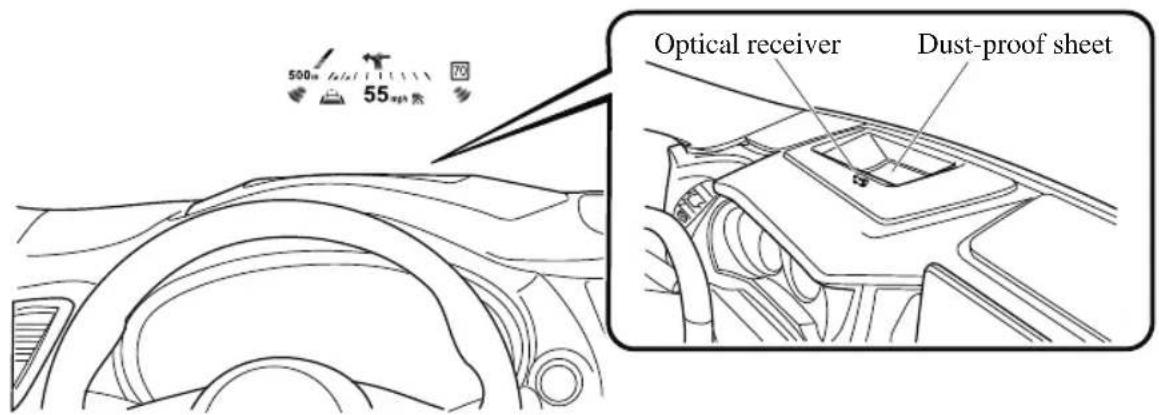

WARNING
Always adjust the display brightness and position with the vehicle stopped:
Adjusting the display brightness and position while driving the vehicle is dangerous as doing so could distract your attention from the road ahead and lead to an accident.

CAUTION
➢ Do not place beverages near the active driving display. If water or other liquids are splashed on the active driving display, it could cause damage.
➢ Do not place objects above the active driving display or apply stickers to the dust-proof sheet/optical receiver as they will cause interference.
➢ A sensor is integrated to control the display's luminosity. If the optical receiver is covered, the display's luminosity will lower making the display difficult to view.
➢ Do not allow intense light to hit the optical receiver. Otherwise, it could cause damage.
NOTE
- Wearing polarized sunglasses will reduce the visibility of the active driving display due to the characteristics of the display.
- If the battery has been removed and re-installed or the battery voltage is low, the adjusted position may deviate.
- The display may be difficult to view or temporarily affected by weather conditions such as rain, snow, light, and temperature.
- If the audio system is removed, the active driving display cannot be operated.
The active driving display indicates the following information:
- Blind Spot Monitoring (BSM) Operation Conditions and Warnings
Refer to Blind Spot Monitoring (BSM) on page 4-121.
- Distance Recognition Support System (DRSS) Operation Conditions and Warnings Refer to Distance Recognition Support System (DRSS) on page 4-133.
- Traffic Sign Recognition System (TSR) traffic signs and Warnings Refer to Traffic Sign Recognition System (TSR) on page 4-127.
- Mazda Radar Cruise Control with Stop & Go function (MRCC with Stop & Go function) Operation Conditions and Warnings Refer to Mazda Radar Cruise Control with Stop & Go function (MRCC with Stop & Go function) on page 4-143.
- Lane-keep Assist System (LAS) & Lane Departure Warning System (LDWS) Operation Conditions and Warnings Refer to Lane-keep Assist System (LAS) & Lane Departure Warning System (LDWS) on page 4-158.
- Advanced Smart City Brake Support (Advanced SCBS) Warnings Refer to Advanced Smart City Brake Support (Advanced SCBS) on page 4-169.
- Smart City Brake Support (SCBS) Warnings Refer to Smart City Brake Support (SCBS) on page 4-172.
- Smart Brake Support (SBS) Warnings Refer to Smart Brake Support (SBS) on page 4-179.
- Cruise Control Operation Conditions Refer to Cruise Control on page 4-247.
- Navigation Guidance (vehicles with navigation system)
- Speed limit indicator (vehicles with navigation system)
- Vehicle Speed
Each setting/adjustment for the active driving display can be performed on the center display.
-
Select the ⚙ icon on the home screen and display the Settings screen.
-
Select the AD-Disp tab.
-
Select the desired item and perform the setting/adjustment.
-
Method for adjusting screen brightness (automatically/manually)
- Screen brightness initial settings (automatic adjustment is selected)
- Screen brightness adjustment (manual adjustment is selected)
- Display position of active driving display (display height)
- Active driving display angle adjustment (display angle correction)
• Active driving display ON/OFF (indication) - Navigation guidance ON/OFF
- Reset settings (reset)
NOTE
- The desired driving position (display position, brightness level, display information) can be called up after programming the position.
Refer to Driving Position Memory on page 2-10.
Automatic Transaxle Controls
Lock-release button
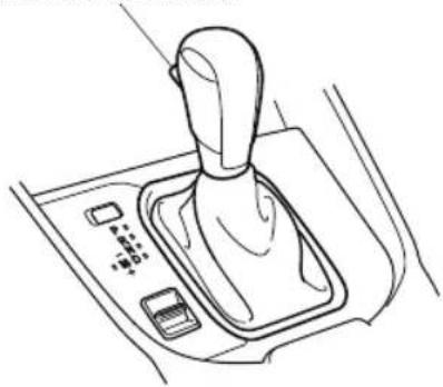
natural_image
Line drawing of a car gear shift lever with control buttons and a handle (no text or symbols)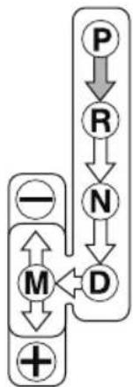
flowchart
graph TD
    P --> R
    R --> N
    N --> D
    M --> +
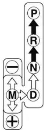
flowchart
graph TD
    P --> R
    R --> N
    N --> D
    D --> M
    M --> +
    - --> M
    + --> M
Various Lockouts:

Indicates that you must depress the brake pedal and hold in the lock-release button to shift (The ignition must be switched ON).

Indicates the selector lever can be shifted freely into any position.

Indicates that you must hold in the lock-release button to shift.
NOTE
The Sport AT has an option that is not included in the traditional automatic transaxle that gives the driver the option of selecting each gear instead of leaving it to the transaxle to shift gears. Even if you intend to use the automatic transaxle functions as a traditional automatic, you should also be aware that you can inadvertently shift into manual shift mode and an inappropriate gear may be retained as the vehicle speed increases. If you notice the engine speed going higher or hear the engine racing, confirm you have not accidentally slipped into manual shift mode (page 4-62).
Shift-Lock System
The shift-lock system prevents shifting out of P unless the brake pedal is depressed.
To shift from P:
- Depress and hold the brake pedal.
- Start the engine.
- Press and hold the lock-release button.
- Move the selector lever.
NOTE
- When the ignition is switched to ACC or the ignition is switched off, the selector lever cannot be shifted from P position.
- The ignition cannot be switched to OFF if the selector lever is not in P position.
▼ Shift-Lock Override
If the selector lever will not move from P using the proper shift procedure, continue to hold down the brake pedal.
- Remove the shift-lock override cover using a cloth-wrapped flat head screwdriver.
- Insert a screwdriver and push it down.
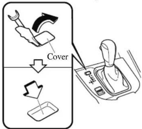
- Press and hold the lock-release button.
- Move the selector lever.
Take the vehicle to an Authorized Mazda Dealer to have the system checked.
Transaxle Ranges
- The shift position indication in the instrument cluster illuminates.
Refer to Indication/Indicator Lights on page 4-25, 4-40, 4-53. - The selector lever must be in P or N position to operate the starter.
P (Park)
P locks the transaxle and prevents the front wheels from rotating.

WARNING
Always set the selector lever to P position and set the parking brake:
Only setting the selector lever to the P position without using the parking brake to hold the vehicle is dangerous. If P fails to hold, the vehicle could move and cause an accident.

CAUTION
➢ Shifting into P, N or R while the vehicle is moving can damage your transaxle.
➢ Shifting into a driving gear or reverse when the engine is running faster than idle can damage the transaxle.
R (Reverse)
In position R, the vehicle moves only backward. You must be at a complete stop before shifting to or from R, except under rare circumstances as explained in Rocking the Vehicle (page 3-51).
NOTE
(With parking sensor system)
When the selector lever is shifted to the R position with the ignition switched ON, the parking sensor system is activated and a beep sound is heard.
Refer to Parking Sensor System on page 4-272.
N (Neutral)
In N, the wheels and transaxle are not locked. The vehicle will roll freely even on the slightest incline unless the parking brake or brakes are on.

WARNING
If the engine is running faster than idle, do not shift from N or P into a driving gear: It's dangerous to shift from N or P into a driving gear when the engine is running faster than idle. If this is done, the vehicle could move suddenly, causing an accident or serious injury.
Do not shift into N when driving the vehicle:
Shifting into N while driving is dangerous. Engine braking cannot be applied when decelerating which could lead to an accident or serious injury.

CAUTION
Do not shift into N when driving the vehicle. Doing so can cause transaxle damage.
NOTE
Apply the parking brake or depress the brake pedal before moving the selector lever from N position to prevent the vehicle from moving unexpectedly.
D (Drive)
D is the normal driving position. From a stop, the transaxle will automatically shift through a 6-gear sequence.
M (Manual)
M is the manual shift mode position. Gears can be shifted up or down by operating the selector lever. Refer to Manual Shift Mode on page 4-62.
▼ Shift Position Indication
Instrument Cluster (Type A)

Instrument Cluster (Type B/C)

The selector position is indicated when the ignition is switched ON.
Gear position indication
In manual shift mode, the “M” of the shift position indication illuminates and the numeral for the selected gear is displayed.
▼ Active Adaptive Shift (AAS)
Active Adaptive Shift (AAS) automatically controls the transaxle shift points to best suit the road conditions and driver input. This improves driving feel. The transaxle may switch to AAS mode when driving up and down slopes, cornering, driving at high elevations, or depressing the accelerator pedal quickly while the selector lever is in the D
position. Depending on the road and driving conditions/vehicle operations, gear shifting could be delayed or not occur, however, this does not indicate a problem because the AAS mode will maintain the optimum gear position.
Manual Shift Mode
The manual shift mode gives you the feel of driving a manual transaxle vehicle by allowing you to operate the selector lever manually. This allows you to control engine rpm and torque to the drive wheels much like a manual transaxle when more control is desired.
To change to manual shift mode, shift the lever from D to M.
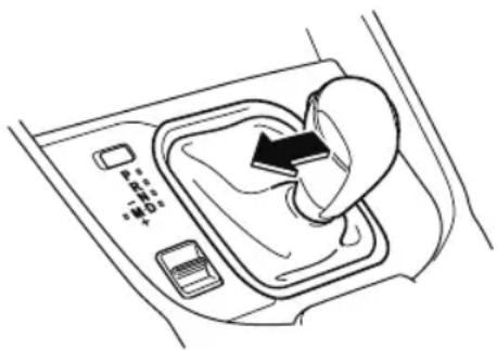
NOTE
Changing to manual shift mode while driving will not damage the transaxle.
To return to automatic shift mode, shift the lever from M to D.
NOTE
- If you change to manual shift mode when the vehicle is stopped, the gear will shift to M1.
- If you change to manual shift mode without depressing the accelerator pedal when driving in D range, 5th gear/6th gear, the gear will shift to M4/M5.
▼ Indicators
Manual shift mode indication
In manual shift mode, the “M” of the shift position indication in the instrument panel illuminates.
Gear position indication
The numeral for the selected gear illuminates.
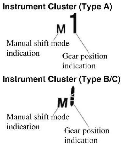
NOTE
- If the gears cannot be shifted down when driving at higher speeds, the gear position indication will flash twice to signal that the gears cannot be shifted down (to protect the transaxle).
- If the automatic transaxle fluid (ATF) temperature becomes too high, there is the possibility that the transaxle will switch to automatic shift mode, canceling manual shift mode and turning off the gear position indication illumination. This is a normal function to protect the AT. After the ATF temperature has decreased, the gear position indication illumination turns back on and driving in manual shift mode is restored.
▼ Manually Shifting Up
You can shift gears up by operating the selector lever or the steering shift switches*.
$$ \mathrm{M} 1 \rightarrow \mathrm{M} 2 \rightarrow \mathrm{M} 3 \rightarrow \mathrm{M} 4 \rightarrow \mathrm{M} 5 \rightarrow \mathrm{M} 6 $$
Using selector lever
To shift up to a higher gear, tap the selector lever back + once.
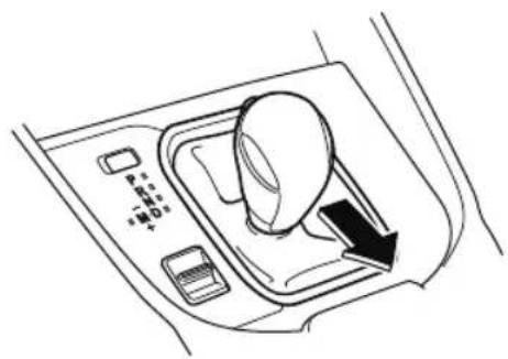
natural_image
Line drawing of a car air intake control panel with no text or symbolsUsing steering shift switch\*
To shift up to a higher gear with the steering shift switches, pull the UP switch (+/OFF) toward you once with your fingers.
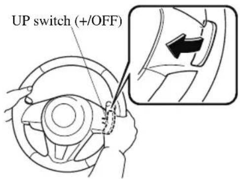

WARNING
Keep your hands on the steering wheel rim when using fingers on the steering shift switches:
Putting your hands inside the rim of the steering wheel when using the steering shift switches is dangerous. If the driver's air bag were to deploy in a collision, your hands could be impacted causing injury.
NOTE
- When driving slowly, the gears may not shift up.
- Do not drive the vehicle with the tachometer needle in the RED ZONE while in manual shift mode. In addition, manual shift mode switches to automatic shift mode while the accelerator pedal is completely depressed.
This function is canceled while the TCS is turned off. However, if the vehicle is continuously driven at a high rpm, the gears may automatically shift up to protect the engine.
- The steering shift switch can be used temporarily even if the selector lever is in the D position while driving. In addition, it returns to automatic shift mode when the UP switch (+/OFF) is pulled rearward for a sufficient amount of time.
▼ Manually Shifting Down
You can shift gears down by operating the selector lever or the steering shift switches*.
$$ \mathrm{M} 6 \rightarrow \mathrm{M} 5 \rightarrow \mathrm{M} 4 \rightarrow \mathrm{M} 3 \rightarrow \mathrm{M} 2 \rightarrow \mathrm{M} 1 $$
Using selector lever
To shift down to a lower gear, tap the selector lever forward - once.
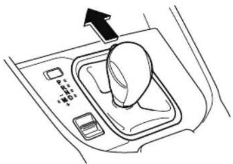
natural_image
Line drawing of a car intake console with control panel and directional arrow (no text or symbols)Using steering shift switch\*
To shift down to a lower gear with the steering shift switches, pull the DOWN switch — toward you once with your fingers.
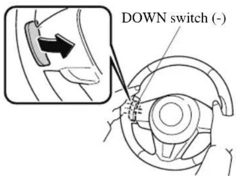

WARNING
Do not use engine braking on slippery road surfaces or at high speeds:
Shifting down while driving on wet, snowy, or frozen roads, or while driving at high speeds causes sudden engine braking, which is dangerous. The sudden change in tire speed could cause the tires to skid. This could lead to loss of vehicle control and an accident.
Keep your hands on the steering wheel rim when using fingers on the steering shift switches:
Putting your hands inside the rim of the steering wheel when using the steering shift switches is dangerous. If the driver's air bag were to deploy in a collision, your hands could be impacted causing injury.
NOTE
- When driving at high speeds, the gear may not shift down.
- During deceleration, the gear may automatically shift down depending on vehicle speed.
- When depressing the accelerator fully, the transaxle will shift to a lower gear, depending on vehicle speed. However, the gears do not kickdown while the TCS is turned off.
▼ Second Gear Fixed Mode
When the selector lever is moved back + while the vehicle speed is about 10 km/h (6.2 mph) or less, the transaxle is set in the second gear fixed mode. The gear is fixed in second while in this mode for easier acceleration from a stop and driving on slippery roads such as snow-covered roads.
If the selector lever is moved back + or forward - while in the second gear fixed mode, the mode will be canceled.
▼ Shift Gear (Shifting) Speed Limit
For each gear position while in the manual mode, the speed limit is set as follows: When the selector lever is operated within the range of the speed limit, the gear is shifted.
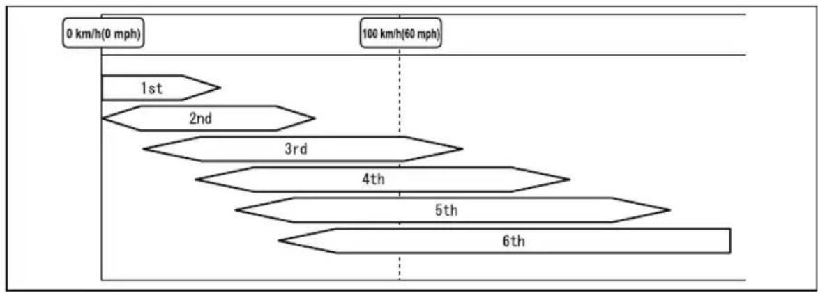
flowchart
graph TD
    A["0 km/h(0 mph)"] --> B["1st"]
    B --> C["2nd"]
    C --> D["3rd"]
    D --> E["4th"]
    E --> F["5th"]
    F --> G["6th"]
    G --> H["100 km/h(60 mph)"]
Shift up
The gear does not shift up while the vehicle speed is lower than the speed limit.
Shift down
The gear does not shift down while the vehicle speed exceeds the speed limit. If the vehicle speed exceeds the speed limit and the gear does not shift down, the gear position indication flashes 2 times to notify the driver that the gear cannot be shifted.
Kickdown
When the accelerator pedal is depressed fully while driving, the gear shifts down. However, the gears do not kickdown while the TCS is turned off.
NOTE
The gear also shifts down using kickdown while in the second gear fixed mode.
Auto-shift down
The gear shifts down automatically depending on the vehicle speed during deceleration.
NOTE
If the vehicle comes to a stop while in the second gear fixed mode, the gear remains in second.
▼ Recommendations for Shifting
Upshifting
For normal acceleration and cruising, Mazda recommends these shift points:
| Gear | Vehicle speed*1 |
| M1 to M2 24 km/h (15 mph) | |
| M2 to M3 40 km/h (25 mph) | |
| M3 to M4 65 km/h (40 mph) | |
| M4 to M5 73 km/h (45 mph) | |
| M5 to M6 81 km/h (50 mph) |
* 1 Always observe local speed limit regulations.
Downshifting
When you must slow down in heavy traffic or on a steep upgrade, downshift before the engine starts to overwork. This gives better acceleration when you need more speed.
On a steep downgrade, downshifting helps maintain safe speed and prolongs brake life.
Direct Mode\*
Direct mode can be used for temporarily switching gears by operating the steering shift switch while the vehicle is being driven with the selector lever in the D position.
While in direct mode, the D and M indication illuminate and the gear position in use is illuminated.
Direct mode is canceled (released) under the following conditions.
- The UP switch (+)/OFF pulled rearward for a certain amount of time or longer.
- The vehicle is driven for a certain amount of time or longer (time differs depending on the driving conditions while operating).
- The vehicle is stopped or moving at a slow speed.
Instrument Cluster (Type A)
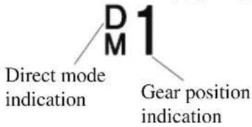
Instrument Cluster (Type B)
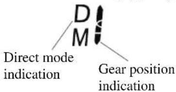
NOTE
Shifting up and down while in direct mode may not be possible depending on the vehicle speed. In addition, because direct mode is canceled (released) depending on the rate of acceleration or if the accelerator is fully depressed, use of the manual shift mode is recommended if you need to drive the vehicle in a particular gear for long periods.
Driving Tips

WARNING
Do not let the vehicle move in a direction opposite to the direction selected by the selector lever:
Do not let the vehicle move backward with the selector lever in a forward position, or do not let the vehicle move forward with the selector lever in the reverse position. Otherwise, the engine may stop, causing the loss of the power brake and power steering functions, and make it difficult to control the vehicle which could result in an accident.
Passing
For extra power when passing another vehicle or climbing steep grades, depress the accelerator fully. The transaxle will shift to a lower gear, depending on vehicle speed.
NOTE
- The accelerator pedal may initially feel heavy as it is being depressed, then feel lighter as it is depressed further. This change in pedal force aids the engine control system in determining how much the accelerator pedal has been depressed for performing kickdown, and functions to control whether or not kickdown should be performed.
- While the selector lever is in the M position and the TCS is turned off, manual shift mode does not switch to automatic shift mode even if the accelerator pedal is completely depressed. Operate the selector lever.
Climbing steep grades from a stop
To climb a steep grade from a stopped position:
- Depress the brake pedal.
- Shift to D or M1, depending on the load weight and grade steepness.
- Release the brake pedal while gradually accelerating.
Descending steep grades
When descending a steep grade, shift to lower gears, depending on load weight and grade steepness. Descend slowly, using the brakes only occasionally to prevent them from overheating.
Lighting Control
▼ Headlights
Turn the headlight switch to turn the headlights and other exterior lights on or off.
When the lights are turned on, the lights-on indicator light in the instrument cluster turns on.

NOTE
- If the light switch is left on, the lights will automatically switch off approximately 30 seconds after switching the ignition off.
The time setting can be changed.
Refer to the Settings section in the Mazda Connect Owner's Manual.
- To prevent discharging the battery, do not leave the lights on while the engine is off unless safety requires them.
Without auto-light control
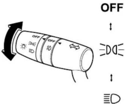
| Switch Position OFF | DO | D | ||||
| Ignition Position ON | ACC or OFF | ON | ACC or OFF | ON | ACC or OFF | |
| Headlights Off Off Off On | On*2 | |||||
| Daytime running lights | On*1 | Off | On*1 | Off Off | Off | |
| TaillightsParking lightsLicense plate lightsSide-marker lights | Off Off | On | On*2 | On | On*2 | |
* 1 The lights are turned on while the vehicle is driven.
*2 The lights are turned on for the specified period by the auto headlight off function.
With auto-light control (Except Canada)
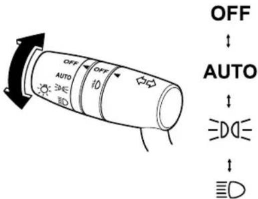
| Switch Position OFF AUTO | DO | D | ||||||
| Ignition Position ON | ACC or OFF | ON | ACC or OFF | ON | ACC or OFF | ON | ACC or OFF | |
| Headlights Off Off | Auto^*2 | Auto^*4 | Off Off | On | On^*5 | |||
| Daytime running lights | On^*1 | Off | On^*3 | Off | On^*1 | Off Off | Off | |
| Taillights Parking lights License plate lights Side-marker lights | Off Off | Auto^*2 | Auto^*4 | On | On^*5 | On | On^*5 | |
* 1 The lights are turned on while the vehicle is driven.
* 2 The lights are turned on by the auto light function.
*3 The lights are turned on while the vehicle is driven, and turned off when the headlights are turned on by the auto light function.
*4 The lights are turned on continuously if the ignition is switched from ON to any other position with the lights turned on. The lights are turned on for the specified period by the auto headlight off function.
*5 The lights are turned on for the specified period by the auto headlight off function.
(Canada)
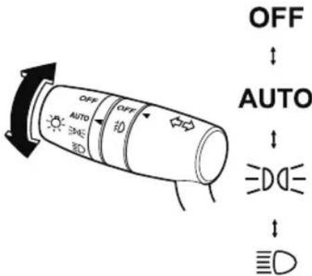
| Ignition Position A | CC or OFF ON | |||||||
| Switch Position | OFF*1 | AUTO | 0.05 | D | OFF*1 | AUTO | 0.05 | D |
| Headlights Off Off Off Off | Auto *2*4 | Auto *3*4 | On | |||||
| Daytime running lights | Off Off | Off Off Off | ||||||
| Taillights Parking lights License plate lights Side-marker lights | Off | On*5 | On | On*5 | On | |||
* 1 The light switch returns to the AUTO position automatically.
*2 During the daytime, the daytime running lights turn on automatically. During the nighttime, the headlights, parking lights, taillights, and the license plate lights turn on automatically.
*3 During the daytime, the daytime running lights, parking lights, taillights, and the license plate lights turn on automatically. During the nighttime, the headlights, parking lights, taillights, and the license plate lights turn on automatically.
*4 When the light switch is switched to the OFF position while the vehicle is stopped, all of the lights that are turned on turn off. When the light switch is switched from a position other than ≥slant 0 < to the position while the vehicle is stopped, the daytime running lights or the headlights turn off. When starting to drive the vehicle, the lights that are turned off turn on again.
* 5 The lights are turned on continuously if the ignition is switched from ON to any other position with the lights turned on. The lights are turned off when the driver's door is opened or 30 seconds have elapsed since the lights turned on.
Auto-light control\*
(Except Cnnada)
When the headlight switch is in the AUTO position and the ignition is switched ON, the light sensor senses the surrounding lightness or darkness and automatically turns the headlights and other exterior lights on or off.
(Canada)
When the headlight switch is in a position other than and the ignition is switched ON, the light sensor senses the surrounding lightness or darkness and automatically turns the headlights and other exterior lights on or off.

CAUTION
Do not shade the light sensor by adhering a sticker or a label on the windshield. Otherwise the light sensor will not operate correctly.
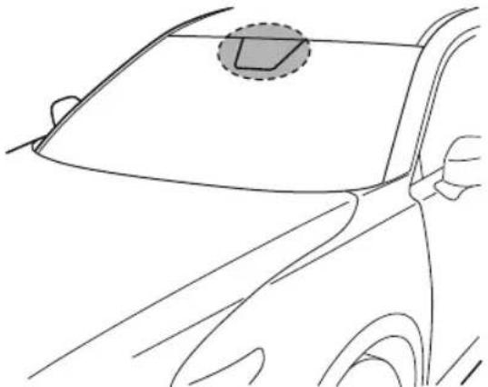
natural_image
Line drawing of a car's front and side view showing the dashboard and steering wheel (no text or symbols)The light sensor also works as a rain sensor for the auto-wiper control. Keep hands and scrapers clear of the windshield when the wiper lever is in the AUTO position and the ignition is switched ON as fingers could be pinched or the wipers and wiper blades could be damaged when the wipers activate automatically. If you are going to clean the windshield, be sure the wipers are turned off completely when it is particularly tempting to leave the engine running. This is particularly important when clearing ice and snow.
NOTE
- The headlights and other exterior lights may not turn off immediately even if the surrounding area becomes well-lit because the light sensor determines that it is night time if the surrounding area is continuously dark for several minutes such as inside long tunnels, traffic jams inside tunnels, or in indoor parking lots.
In this case, the lights turn off if the light switch is turned to the OFF position.
- If the headlight switch and the windshield wiper switch are in AUTO, and the wipers are operated at low or high speed by the auto wiper control for several seconds, bad weather conditions are determined and the headlights may be turned on.
- The sensitivity of the auto-light control may be changed. Refer to the Settings section in the Mazda Connect Owner's Manual.
▼ Headlight High-Low Beam
The headlights switch between high and low beams by moving the lever forward or backward.
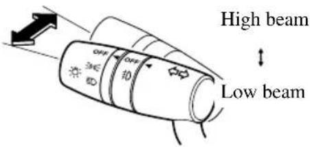
When the headlight high-beams are on, the headlight high-beam indicator light is turned on.

▼ Flashing the Headlights
Can be used when the ignition is switched ON.
To flash the headlights, pull the lever fully towards you (the headlight switch does not need to be on).
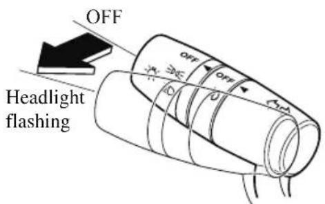
The headlight high-beam indicator light in the instrument cluster illuminates simultaneously. The lever will return to the normal position when released.
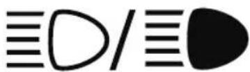
▼ Coming Home Light
The coming home light turns on the headlights (low beams) when the lever is operated.
To turn on the lights
When the lever is pulled with the ignition switched to ACC or OFF, the low beam headlights turn on.
The headlights turn off after a certain period of time has elapsed after all of the doors are closed.
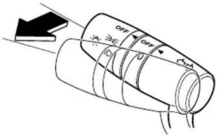
NOTE
- The time until the headlights turn off after all of the doors are closed can be changed.
Refer to the Settings section in the Mazda Connect Owner's Manual.
- If no operations are done for 3 minutes after the lever is pulled, the headlights turn off.
- The headlights turn off if the lever is pulled again while the headlights are illuminated.
▼ Leaving Home Light
The leaving home light turns on the lights when the transmitter unlock button is pressed while away from the vehicle.
The following lights turn on when the leaving home light is operated.
Low beams, Parking lights, Taillights, License plate lights.
To turn on the lights
When the ignition switch and the headlight switch are in the following conditions, the headlights will illuminate when the transmitter unlock button is pressed and the vehicle receives the transmitter signal. The headlights turn off after a certain period of time has elapsed (30 seconds).
. Ignition switch: off
· Headlight switch: AUTO, ☐Dor ☑D
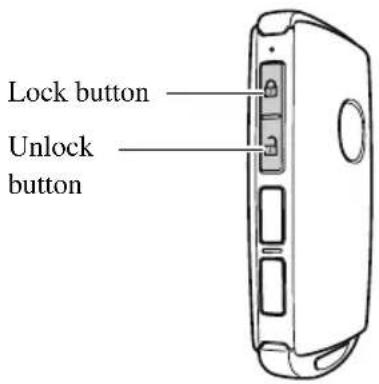
NOTE
• Operation of the leaving home light can be turned on or off.
Refer to the Settings section in the Mazda Connect Owner's Manual.
- When the transmitter lock button is pressed and the vehicle receives the transmitter signal, the headlights turn off.
- When the headlight switch is turned to the OFF position, the headlights turn off.
▼ Headlight Leveling
The number of passengers and weight of cargo in the luggage compartment change the angle of the headlights.
The angle of the headlights will be automatically adjusted when turning on the headlights.
▼ Daytime Running Lights
Some countries require moving vehicles to have their lights on (daytime running lights) during the daytime.
Except Canada
The daytime running lights turn on automatically when the vehicle starts moving.
They turn off when the parking brake is operated or the selector lever is shifted to the P position.
NOTE
The daytime running lights can be deactivated.
Refer to the Settings section in the Mazda Connect Owner's Manual.
Canada
The daytime running lights continuously turn on when the ignition is switched ON. When the light switch is switched to the OFF or ≥00≤ position while the vehicle is stopped, the daytime running lights turns off. When you start driving the vehicle, they turn on again.
NOTE
When the light switch is switched to the D position, the daytime running lights turn off. If you want to drive the vehicle with the daytime running lights turned on, switch the light switch to a position other than D .
Fog Lights\*
The fog lights can be turned on with the ignition switched ON and the headlights turned on.
Use this switch to turn on the fog lights. The fog lights will improve visibility at night and during foggy conditions.
The fog lights turn on when the fog light switch is turned to the 10 position and turn off when the switch is turned to the OFF position.
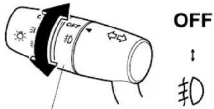
Fog light switch
NOTE
• The fog lights will turn off when the headlights are set at high beams.
Turn and Lane-Change Signals
The ignition must be switched ON to use the turn and lane-change signals.
▼ Turn Signals
Move the signal lever down (for a left turn) or up (for a right turn) to the stop position. The signal will self-cancel after the turn is completed.
If the indicator light continues to flash after a turn, manually return the lever to its original position.
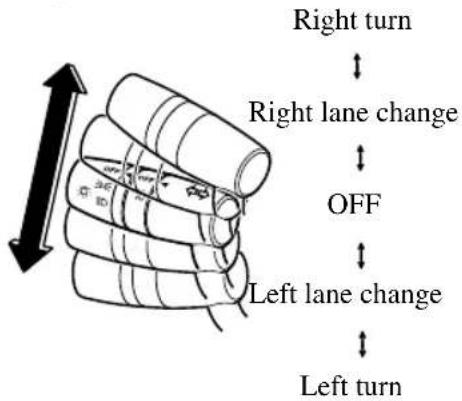
The turn signal indicators in the instrument cluster flash according to the operation of the turn signal lever to show which signal is working.

NOTE
- If an indicator light stays on without flashing or if it flashes abnormally, one of the turn signal bulbs may be burned out.
- A personalized function is available to change the turn indicator sound volume.
Refer to the Settings section in the Mazda Connect Owner's Manual.
▼ Lane-Change Signals
Move the lever halfway toward the direction of the lane change—until the indicator flashes—and hold it there. It will return to the off position when released.
▼ Three-Flash Turn Signal
After releasing the turn signal lever, the turn signal indicator flashes 3 times. The operation can be canceled by moving the lever in the direction opposite to which it was operated.
NOTE
The three-flash turn signal function can be switched to operable/inoperable using the personalization function.
Refer to the Settings section in the Mazda Connect Owner's Manual.
Windshield Wipers and Washer
The ignition must be switched ON to use the wipers.

WARNING
Use only windshield washer fluid or plain water in the reservoir:
Using radiator antifreeze as washer fluid is dangerous. If sprayed on the windshield, it will dirty the windshield, affect your visibility, and could result in an accident.
Only use windshield washer fluid mixed with anti-freeze protection in freezing weather conditions:
Using windshield washer fluid without anti-freeze protection in freezing weather conditions is dangerous as it could freeze on the windshield and block your vision which could cause an accident. In addition, make sure the windshield is sufficiently warmed using the defroster before spraying the washer fluid.
NOTE
If the windshield wipers are operated under cold weather conditions or during snowfall, they could stop due to accumulated snow on the windshield. If the windshield wipers stop due to accumulated snow on the windshield, park the vehicle in a safe place, turn the wiper switch off, and then remove the accumulated snow. If the wiper switch is turned to another position other than OFF, the wipers will operate. If the wipers do not operate even though the wiper switch is turned to a position other than OFF, consult an Authorized Mazda Dealer as soon as possible.
▼Windshield Wipers
Turn the wipers on by pressing the lever up or down.
With intermittent wiper
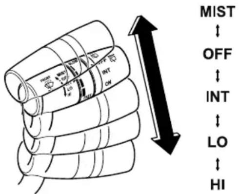
| Switch Position | Wiper operation |
| MIST Operation while pulling up lever | |
| OFF Stop | |
| INT Intermittent | |
| LO Low speed | |
| HI High speed | |
Variable-speed intermittent wipers
Set the lever to the intermittent position and choose the interval timing by rotating the ring.
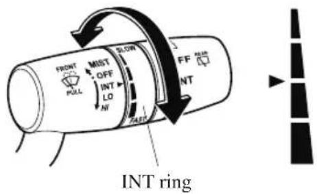
With auto-wiper control
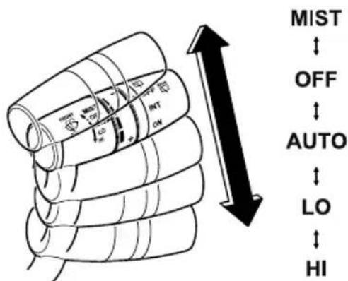
| Switch Position | Wiper operation |
| MIST Operation while pulling up lever | |
| OFF Stop | |
| AUTO Auto control | |
| LO Low speed | |
| HI High speed | |
Auto-wiper control\*
When the wiper lever is in the AUTO position, the rain sensor senses the amount of rainfall on the windshield and turns the wipers on or off automatically
(off—intermittent—low speed—high speed).
The sensitivity of the rain sensor can be adjusted by turning the switch on the wiper lever.
From the center position (normal), rotate the switch upward for higher sensitivity (faster response) or rotate it downward for less sensitivity (slower response).

CAUTION
➢Do not shade the rain sensor by adhering a sticker or a label on the windshield. Otherwise the rain sensor will not operate correctly.
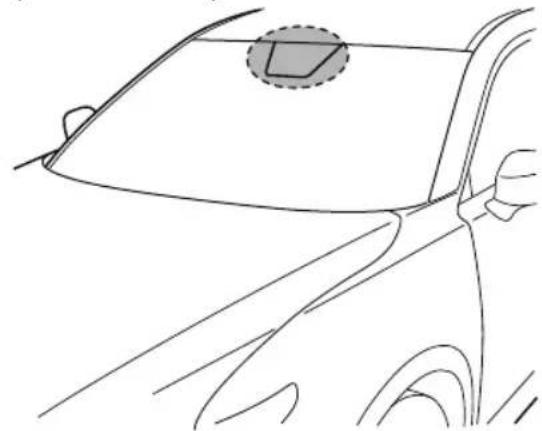
natural_image
Line drawing of a car's front wheel and side panel, showing no text or symbolsWhen the wiper lever is in the AUTO position and the ignition is switched ON, the wipers may move automatically in the following cases:
If the windshield above the rain sensor is touched or wiped with a cloth.
If the windshield is struck with a hand or other object from either outside or inside the vehicle.
Keep hands and scrapers clear of the windshield when the wiper lever is in the AUTO position and the ignition is switched ON as fingers could be pinched or the wipers and wiper blades damaged when the wipers activate automatically. If you are going to clean the windshield, be sure the wipers are turned off completely (when it is most likely that the engine is left running) this is particularly important when clearing ice and snow.
NOTE
- Switching the auto-wiper lever from the OFF to the AUTO position while driving activates the windshield wipers once, after which they operate according to the rainfall amount.
- The auto-wiper control may not operate when the rain sensor temperature is about -10^ (14°F) or lower, or about 85^ (185°F) or higher.
- If the windshield is coated with water repellent, the rain sensor may not be able to sense the amount of rainfall correctly and the auto-wiper control may not operate properly.
- If dirt or foreign matter (such as ice or matter containing salt water) adheres to the windshield above the rain sensor, or if the windshield is iced, it could cause the wipers to move automatically. However, if the wipers cannot remove this ice, dirt or foreign matter, the auto-wiper control will stop operation. In this case, set the wiper lever to the low speed position or high speed position for manual operation, or remove the ice, dirt or foreign matter by hand to restore the auto-wiper operation.
- If the auto-wiper lever is left in the AUTO position, the wipers could operate automatically from the effect of strong light sources, electromagnetic waves, or infrared light because the rain sensor uses an optical sensor. It is recommended that the auto-wiper lever be switched to the OFF position other than when driving the vehicle under rainy conditions.
· (With auto-wiper control)
If the headlight switch and the windshield wiper switch are in AUTO, and the wipers are operated at low or high speed by the auto wiper control for several seconds, bad weather conditions are determined and the headlights may be turned on.
- The auto-wiper control functions can be turned off. Refer to the Settings section in the Mazda Connect Owner's Manual.
▼ Windshield Washer
Pull the lever toward you and hold it to spray washer fluid.
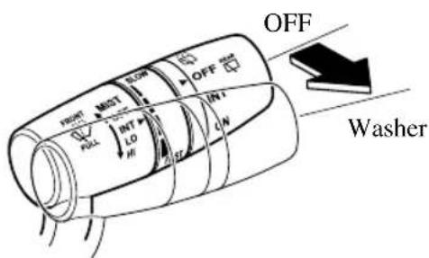
NOTE
If the windshield washer is turned on when the windshield wipers are not operating, the windshield wipers operate a few times.
If the washer does not work, inspect the fluid level (page 6-24). If the fluid level is normal, consult an Authorized Mazda Dealer.
Rear Window Wiper and Washer
The ignition must be switched ON to use the wiper.
▼ Rear Window Wiper
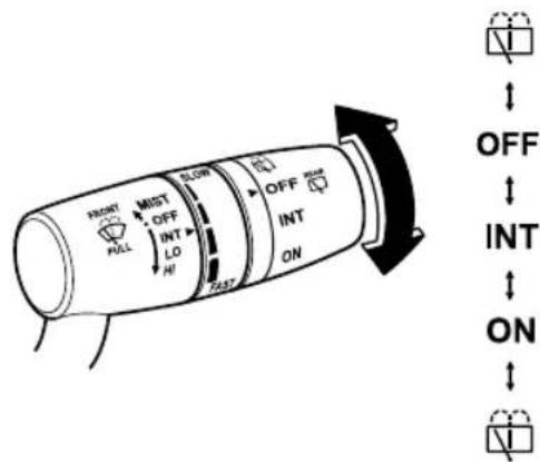
Turn the wiper on by turning the rear wiper/washer switch.
| Switch Position | Wiper operation |
| OFF Stop | |
| INT Intermittent | |
| ON Normal | |
▼ Rear Window Washer
To spray washer fluid, turn the rear wiper/washer switch to either of the ☑ position. After the switch is released, the washer will stop.
If the washer does not work, inspect the fluid level (page 6-24). If the fluid level is normal and the washer still does not work, consult an Authorized Mazda Dealer.
Rear Window Defogger
The rear window defogger clears fog from the rear window.
The ignition must be switched ON to use the defogger.
Press the switch to turn on the rear window defogger. The rear window defogger operates for about 15 minutes and then turns off automatically. The indicator light illuminates when the defogger is operating.
To turn off the rear window defogger before the 15 minutes has elapsed, press the switch again.
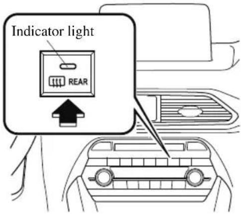
CAUTION
Do not use sharp instruments or window cleaners with abrasives to clean the inside of the rear window surface. They may damage the defogger grid inside the window.
NOTE
- This defogger is not designed for melting snow. If there is an accumulation of snow on the rear window, remove it before using the defogger.
- The rear window defogger setting can be changed. After changing the setting, the rear window defogger stops automatically after 15 minutes have elapsed and when the ambient temperature is high. When the ambient temperature is low, it continues to operate until the switch is pressed again.
Refer to the Settings section in the Mazda Connect Owner's Manual.
▼ Mirror Defogger\*
The mirror defoggers defrost the outside mirrors.
The mirror defoggers operate in conjunction with the rear window defogger.
To turn on the mirror defoggers, switch the ignition ON and press the rear window defogger switch (page 4-82).
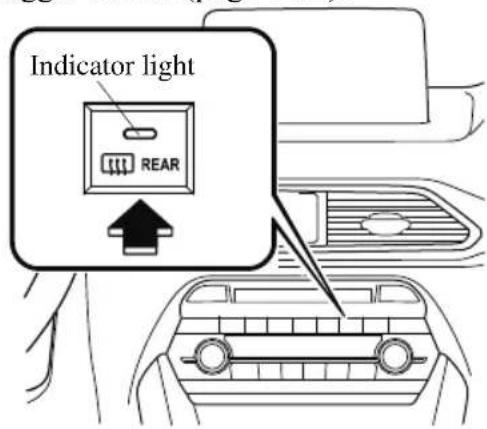
▼ Windshield Wiper De-icer\*
The thermal filaments at the following positions heat up and facilitate the removal of snow accumulated on the windshield.
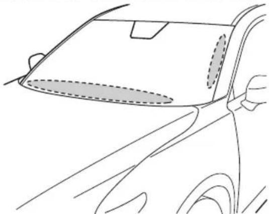
natural_image
Line drawing of a car's front and side view showing the dashboard and window (no text or symbols)The windshield wiper de-icer operates in conjunction with the rear window defogger.
To turn on the windshield wiper de-icer, switch the ignition ON and press the rear window defogger switch (page 4-82).
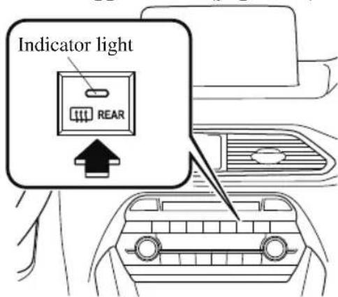
Horn
To sound the horn, press the mark on the steering wheel.
Hazard Warning Flasher
The hazard warning lights should always be used when you stop on or near a roadway in an emergency.
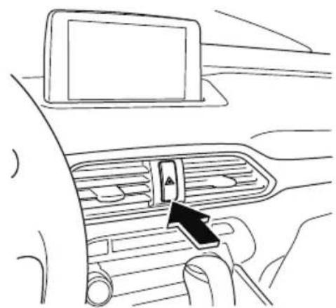
natural_image
Line drawing of a car interior showing the dashboard and air vent with a black arrow pointing to the control panel (no text or symbols)The hazard warning lights warn other drivers that your vehicle is a traffic hazard and that they must take extreme caution when near it.

Depress the hazard warning flasher and all the turn signals will flash. The hazard warning indicator lights in the instrument cluster flash simultaneously.
NOTE
- The turn signals do not work when the hazard warning lights are on.
- Check local regulations about the use of hazard warning lights while the vehicle is being towed to verify that it is not in violation of the law.
HomeLink Wireless Control System (Type A)\*
NOTE
HomeLink and HomeLink house icon are registered trademarks of Gentex Corporation.
The HomeLink system replaces up to 3 hand-held transmitters with a single built-in component in the auto-dimming mirror. Pressing the HomeLink button on the auto-dimming mirror activates garage doors, gates and other devices surrounding your home.

WARNING
Do not use the HomeLink system with any garage door opener that lacks the safety stop and reverse feature:
Using the HomeLink system with any garage door opener that lacks the safety stop and reverse feature as required by federal safety standards is dangerous. (This includes garage doors manufactured before April 1, 1982.)
Using these garage door openers can increase the risk of serious injury or death. For further information, contact HomeLink at 1-800-355-3515 or www.homelink.com or an Authorized Mazda Dealer.
Always check the areas surrounding garage doors and gates for people or obstructions before programming or during operation of the HomeLink system:
Programming or operating the HomeLink system without verifying the safety of areas surrounding garage doors and gates is dangerous and could result in an unexpected accident and serious injury if someone were to be hit.
NOTE
The programming will not be erased even if the battery is disconnected.
▼ Pre-programming the HomeLink System
NOTE
It is recommended that a new battery be placed in the hand-held transmitter of the device being programmed to HomeLink for quicker training and accurate transmission of the radio-frequency signal.
- Verify that there is a remote control transmitter available for the device you would like to program.
- Disconnect the power to the device.
▼ Programming the HomeLink System

CAUTION
When programming a garage door opener or a gate, disconnect the power to these devices before performing programming. Continuous operation of the devices could damage the motor.
The HomeLink system provides 3 buttons which can be individually selected and programmed using the transmitters for current, on-market devices as follows:
- Disconnect the power to the garage door opener or gate programmed to the hand-held transmitter.
- Position the end of your hand-held transmitter 2.5—7.5 cm (1—3 inches) away from the HomeLink button you wish to program while keeping the indicator light in view.
- Simultaneously press and hold both the chosen HomeLink and hand-held transmitter buttons. Do not release the buttons until step 3 has been completed.
NOTE
Some gate operators and garage door openers may require you to replace this Programming Step 2 with procedures noted in the “Gate Operator/Canadian Programming” section.
- After the HomeLink indicator light changes from a slow to a rapidly blinking light, release both the HomeLink and hand-held transmitter buttons.
NOTE
If the HomeLink indicator light does not change to a rapidly blinking light, contact HomeLink at www.homelink.com or call 1-800-355-3515 for assistance.
-
Connect the power to the garage door opener or gate programmed to the hand-held transmitter.
-
Firmly press and hold the programmed HomeLink button for five seconds, and then release it. Perform this operation two times to activate the door or gate. If the door or gate does not activate, press and hold the just-trained HomeLink button and observe the indicator light. If the indicator light stays on constantly, programming is complete and your device should activate when the HomeLink button is pressed and released.
NOTE
To program the remaining two HomeLink buttons, begin with "Programming"—step 1
If the indicator light blinks rapidly for two seconds and then turns to a constant light, continue with “Programming” steps 7—9 to complete the programming of a rolling code equipped device (most commonly a garage door opener).
-
At the garage door opener receiver (motor-head unit) in the garage, locate the “learn” or “smart” button. This can usually be found where the hanging antenna wire is attached to the motor-head unit.
-
Firmly press and release the "learn" or "smart" button. (The name and color
of the button may vary by manufacturer.)
NOTE
Complete the programming within 30 seconds.
- Return to the vehicle and firmly press, hold for two seconds and release the programmed HomeLink button. Repeat the “press/hold/release” sequence a second time, and, depending on the brand of the garage door opener (or other rolling code equipped device), repeat this sequence a third time to complete the programming process. HomeLink should now activate your rolling code equipped device.
NOTE
To program the remaining two HomeLink buttons, begin with "Programming"—step 1
For questions or comments, please contact HomeLink at www.homelink.com or 1-800-355-3515.
▼ Gate operator/Canadian Programming
Canadian radio-frequency laws require transmitter signals to “time-out” (or quit) after several seconds of transmission — which may not be long enough for HomeLink to pick up the signal during programming. Similar to this Canadian law, some U.S. gate operators are designed to “time-out” in the same manner.
If you live in Canada or you are having difficulties programming a gate operator by using the “Programming” procedures (regardless of where you live), replace
"Programming HomeLink" step 3 with the following:
NOTE
If programming a garage door opener or gate operator, it is advised to unplug the device during the “cycling” process to prevent possible overheating.
Continue to press and hold the HomeLink button while you press and release — every two seconds (“cycle”) your hand-held transmitter until the frequency signal has successfully been accepted by HomeLink. (The indicator light will flash slowly and then rapidly.)
Proceed with “Programming” step 4 to complete.
▼ Operating the HomeLink System
Press the programmed HomeLink button to operate a programmed device. The code will continue being transmitted for a maximum of 20 seconds.
▼ Reprogramming the HomeLink system
To program a device to HomeLink using a HomeLink button previously trained, follow these steps:
- Press and hold the desired HomeLink button. DO NOT release the button.
- The indicator light will begin to flash after 20 seconds. Without releasing the HomeLink button, proceed with "Programming" - step 1.
▼ Erasing Programmed HomeLink Buttons
To erase the existing programming from all three operating channels, press and hold the two outside buttons ( ), then the auto-dimming mirror until the HomeLink indicator light begins to flash after approximately 10 seconds. Verify that the programming has been erased when you resell the vehicle.
HomeLink Wireless Control System (Type B)\*
NOTE
HomeLink and HomeLink house are registered trademarks of Gentex Corporation.
The HomeLink system replaces up to 3 hand-held transmitters with a single built-in component in the auto-dimming mirror. Pressing the HomeLink button on the auto-dimming mirror activates garage doors, gates and other devices surrounding your home.
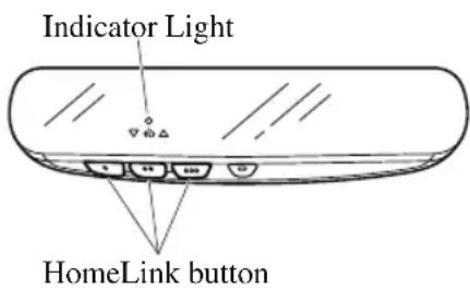

WARNING
Do not use the HomeLink system with any garage door opener that lacks the safety stop and reverse feature:
Using the HomeLink system with any garage door opener that lacks the safety stop and reverse feature as required by federal safety standards is dangerous. (This includes garage doors manufactured before April 1, 1982.) Using these garage door openers can increase the risk of serious injury or death. For further information, contact HomeLink at www.homelink.com or www.youtube.com/HomeLinkGentex or an Authorized Mazda Dealer.
Always check the areas surrounding garage doors and gates for people or obstructions before programming or during operation of the HomeLink system:
Programming or operating the HomeLink system without verifying the safety of areas surrounding garage doors and gates is dangerous and could result in an unexpected accident and serious injury if someone were to be hit.
NOTE
The programming will not be erased even if the battery is disconnected.
▼ Pre-programming the HomeLink System
NOTE
It is recommended that a new battery be placed in the hand-held transmitter of the device being programmed to HomeLink for quicker training and accurate transmission of the radio-frequency signal.
- Verify that there is a remote control transmitter available for the device you would like to program.
▼ Programming the HomeLink System
The HomeLink system provides 3 buttons which can be individually selected and programmed using the transmitters for current, on-market devices as follows:
- Press and release the HomeLink button you would like to program. The
indicator light flashes slowly in amber when the button is pressed.
Indicator Light
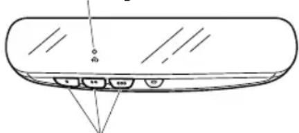
HomeLink button
- Hold the hand-held transmitter 2.5 to 7.5 cm (1 to 3 in) away from the HomeLink button you would like to program while keeping the indicator light in view.
NOTE
Depending on the hand-held transmitter, it may be easier to do the programming by holding it 15 to 20 cm (6 to 7.8 in) away from the HomeLink button.
- Press the hand-held transmitter button continuously until the indicator light changes from amber (flashing) to green (on/flashing).
NOTE
Some gate operators and garage door openers may require you to replace this Programming Step 3 with procedures noted in the “Gate Operator/Canadian Programming” section.
-
Press the HomeLink button again to check if the programming has been completed.
-
If the indicator light remains on in green, the programming is complete and the device becomes operational.
- If the indicator light flashes rapidly in green, firmly press and hold the Homelink button and release it after
two seconds have passed. Repeat this process up to three times to complete the programming. The device becomes operational and programming is complete. If the device does not operate, go to the next step.
- At the garage door opener receiver (motor-head unit) in the garage, locate the “learn” or “smart” button. This can usually be found where the hanging antenna wire is attached to the motor-head unit.
- Firmly press and release the “learn” or “smart” button. (The name and color of the button may vary by manufacturer.)
NOTE
Complete the programming within 30 seconds.
-
Return to the vehicle and firmly press and hold the Homelink button, and then release it after two seconds have passed. Repeat the “press/hold/release” sequence a second time, and, depending on the brand of the garage door opener (or other rolling code equipped device), repeat this sequence a third time to complete the programming process. Press the programmed HomeLink button and make sure that the HomeLink System operates.
-
If the status indicator arrows are flashing, refer to Garage Door Two-Way Communication.
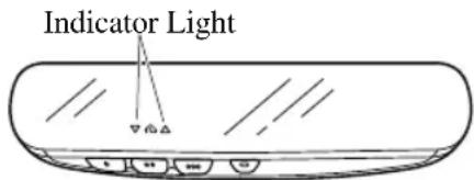
NOTE
To program the remaining two HomeLink buttons, go back to Step 1 of Programming the HomeLink System and repeat the procedure.
For questions or comments, please contact HomeLink at www.homelink.com or www.youtube.com/HomeLinkGentex, or the HomeLink toll-free hotline at 1-800-355-3515 (for calls placed outside of the USA, Canada, and Puerto Rico, international rates will apply and may differ based on landline or mobile phone).
▼ Gate operator/Canadian Programming
Canadian radio-frequency laws require transmitter signals to “time-out” (or quit) after several seconds of transmission — which may not be long enough for HomeLink to pick up the signal during programming. Similar to this Canadian law, some U.S. gate operators are designed to “time-out” in the same manner.
If you live in Canada or are having difficulties programming a gate operator by using the programming procedures (regardless of where you live), replace Step 3 of Programming the HomeLink System with the following:
NOTE
If programming a garage door opener or gate operator, it is advised to unplug the device during the “cycling” process to prevent possible overheating.
While the indicator light is flashing in amber, press the button on the hand-held transmitter for 2 seconds and release it
repeatedly until the indicator light changes from amber to green.
Go back to Step 4 of Programming the HomeLink System to complete the procedure.
▼ Operating the HomeLink System
Press the programmed HomeLink button to operate a programmed device.
▼ Reprogramming the HomeLink system
To program a device to HomeLink using a HomeLink button previously trained, follow these steps:
- Press and hold the desired HomeLink button. DO NOT release the button.
- After 20 seconds, the indicator light flashes in amber. After the indicator light flashes, release the HomeLink button.
- Go back to Step 2 of Programming the HomeLink System to complete the procedure.
NOTE
If the programming has not been completed, the system returns to the previous programming.
▼ Erasing Programmed HomeLink Buttons
NOTE
- All of the programmed HomeLink buttons are reset. Individual buttons cannot be reset, however, individual buttons can be reprogrammed. For individual button reprogramming, refer to Reprogramming the HomeLink System (page 4-90).
- Verify that the programming has been erased if you resell the vehicle.
- Press the two outer HomeLink buttons continuously at the same time until the indicator light flashes.
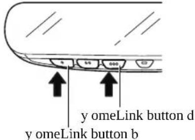
- Stop pressing the HomeLink buttons.
▼ Garage Door Two-Way Communication
The garage door two-way communication is a function that communicates with the garage door opener and indicates whether the garages door is open or closed using the indicator lights in the rear view mirror. It can indicate the status of the garage door within a range up-to 250 m (820 ft).
NOTE
The communication range may shorten depending on obstructions.
Programming two-way communication
Within five seconds after programming a new HomeLink button, both of the garage door status indicator lights will flash rapidly in green indicating that the garage door two-way communication has been established. If the garage door status indicator lights flash, the two-way communication programming is complete.
If the garage door status indicator lights do not flash, the two-way communication programming is not completed. For
additional HomeLink information and programming videos, refer to the following Websites:
- www.HomeLink.com - www.youtube.com/HomeLinkGentex
Operating the garage door two-way communication
By pressing HomeLink buttons 1 and 2 at the same time for two seconds, the status of the garage door is indicated for about 3 seconds as follows:
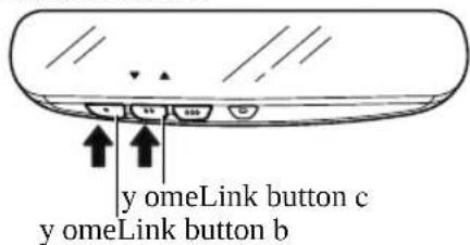
| Garage door status | Indicator light |
| Closing | Amber flashes |
| Opening | Amber flashes |
| Closed | Green turns on |
| Opened | Green turns on |
NOTE
The programming will not be erased even if the battery is disconnected.
Brake System
▼ Foot Brake
This vehicle has power-assisted brakes that adjust automatically through normal use.
Should power-assist fail, you can stop by applying greater force than normal to the brake pedal. But the distance required to stop will be greater than usual.

WARNING
Do not coast with the engine stalled or turned off, find a safe place to stop:
Coasting with the engine stalled or turned off is dangerous. Braking will require more effort, and the brake's power-assist could be depleted if you pump the brake. This will cause longer stopping distances or even an accident.
Shift to a lower gear when going down steep hills:
Driving with your foot continuously on the brake pedal or steadily applying the brakes for long distances is dangerous. This causes overheated brakes, resulting in longer stopping distances or even total brake failure. This could cause loss of vehicle control and a serious accident. Avoid continuous application of the brakes.
Dry off brakes that have become wet by driving slowly, releasing the accelerator pedal and lightly applying the brakes several times until the brake performance returns to normal:
Driving with wet brakes is dangerous. Increased stopping distance or the vehicle pulling to one side when braking could result in a serious accident. Light braking will indicate whether the brakes have been affected.

CAUTION
Do not drive with your foot held on the brake pedal. Doing so could result in the following:
The brake parts will wear out more quickly.
The brakes can overheat and adversely affect brake performance.
Always depress the brake pedal with the right foot. Applying the brakes with the unaccustomed left foot could slow your reaction time to an emergency situation resulting in insufficient braking operation.
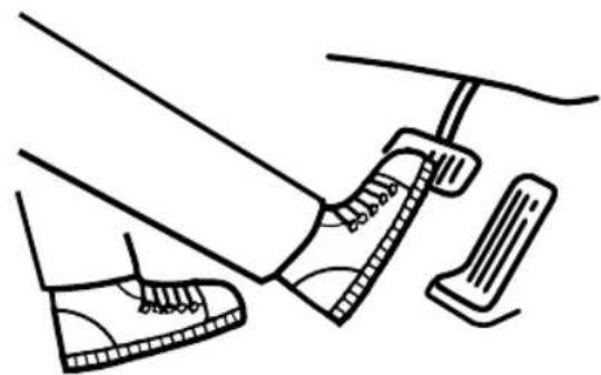
natural_image
Line drawing of a person's foot and legs wearing a high-heeled shoe, with a foot stepping on the pedal (no text or symbols)Wear shoes appropriate for driving in order to avoid your shoe contacting the brake pedal when depressing the accelerator pedal.
▼ Electric Parking Brake (EPB)
The EPB equipment applies the parking brake using an electric motor. When the
parking brake is applied, the EPB switch indicator light turns on.
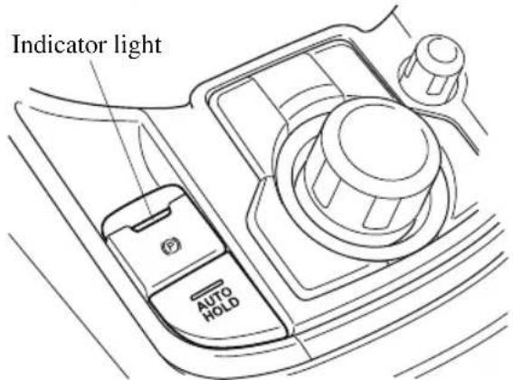

WARNING
Do not drive the vehicle with the parking brake applied:
If the vehicle is driven with the parking brake applied, the brake parts may generate heat and the brake system may not operate, leading to an accident. Before driving, release the parking brake and verify that the brake system warning light is turned off.
NOTE
- The parking brake cannot be applied or released while the vehicle battery is dead.
- If the EPB is repeatedly applied and released it may stop operating to prevent overheating of the motor. If this occurs, wait approx. 1 minute before operating the EPB switch again.
- An operation sound occurs when applying or releasing the parking brake, however, this does not indicate a malfunction.
- If the EPB is not used for long periods, an automatic inspection of the system is performed while the vehicle is parked. An operation sound can be heard, however, this does not indicate a problem.
- When the parking brake is applied and the ignition is switched OFF, an operation sound can be heard, however, this does not indicate a problem.
- The brake pedal may move while the parking brake is being applied or released, however, this does not indicate a problem.
- If the EPB switch is continually pulled while driving the vehicle, the parking brake will be applied and the EPB warning beep will be activated. When the switch is released, the parking brake is released and the beep stops.
- If the parking brake is applied with the ignition switched off or in ACC, the brake system warning light in the instrument cluster and the indicator light in the switch may turn on for 15 seconds.
- When running the vehicle through an automatic car wash, it may be necessary to switch the ignition off with the parking brake released depending on the type of automatic car wash.
When applying the parking brake
The parking brake can be applied regardless of the ignition switch position. Securely depress the brake pedal and pull up the EPB switch.
The parking brake is applied and the brake system warning light and the EPB switch indicator light turn on.
Refer to If a Warning Light Turns On or Flashes on page 7-28.
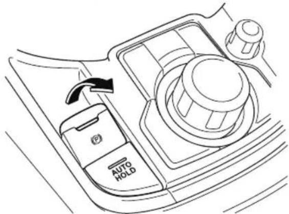
natural_image
Line drawing of a car interior showing the left side of the dashboard with a 'AUTO HOLD' button and an arrow indicating rotation (no text or symbols beyond basic labels)When releasing the parking brake
The parking brake can be released while the ignition is switched ON or the engine is running. When the parking brake is released, the brake system warning light and the EPB switch indicator light turn off.
Parking brake manual release
Firmly depress the brake pedal and press the EPB switch.
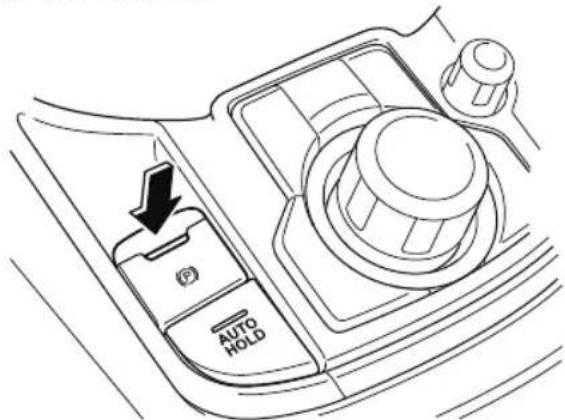
If the EPB switch is pressed without depressing the brake pedal, the display in the instrument cluster notifies the driver that the brake is not depressed.
(Type A/B instrument cluster)
A message is displayed on the multi-information display in the instrument cluster.
Refer to Message Indicated in Multi-information Display on page 7-45.
(Type C instrument cluster)
The brake pedal operation demand indicator light in the instrument cluster turns on.
natural_image
Silhouette of a hand pressing a curved object with a downward arrow (no text or symbols)Parking brake automatic release
If the accelerator pedal is depressed with the parking brake applied and all of the following conditions met, the parking brake is released automatically.
• The engine is running.
• The driver's door is closed.
. The driver's seat belt is fastened.
- Selector lever is in the D, M, or R position
NOTE
If something such as the driver's foot contacts the accelerator pedal with the engine running and the parking brake applied, the parking brake may be released automatically. If you do not intend to drive immediately, shift the selector lever to the P or N position.
▼ Warning Light
The warning light turns on when the system has a malfunction.
Refer to Contact Authorized Mazda Dealer and Have Vehicle Inspected on page 7-31.
▼ Brake Pad Wear Indicator
When the disc brake pads become worn, the built-in wear indicators contact the disc plates. This causes a screeching noise to warn that the pads should be replaced.
natural_image
Diagram of a mechanical or electrical component with internal components and directional arrows (no text or symbols)When you hear this noise, consult an Authorized Mazda Dealer as soon as possible.
WARNING
Do not drive with worn disc pads:
Driving with worn disc pads is dangerous. The brakes could fail and cause a serious accident. As soon as you hear a screeching noise consult an Authorized Mazda Dealer.
NOTE
In high humidity weather conditions, brake noises, such as brake squeak or brake squeal can be heard. It does not indicate a malfunction.
▼ Brake Assist
During emergency braking situations when it is necessary to depress the brake pedal with greater force, the brake assist system provides braking assistance, thus enhancing braking performance.
When the brake pedal is depressed hard or depressed more quickly, the brakes apply more firmly.
NOTE
- When the brake pedal is depressed hard or depressed more quickly, the pedal will feel softer but the brakes will apply more firmly. This is a normal effect of the brake assist operation and does not indicate a malfunction.
- When the brake pedal is depressed hard or depressed more quickly, a motor/pump operation noise may be heard. This is a normal effect of the brake assist and does not indicate a malfunction.
- The brake assist equipment does not supersede the functionality of the vehicle's main braking system.
AUTOHOLD
The AUTOHOLD function automatically holds the vehicle stopped, even if you take your foot off the brake pedal. This function can be best used while stopped in traffic or at a traffic light. The brakes are released when you start driving the vehicle.

WARNING
Do not rely completely on the AUTOHOLD function:
The AUTOHOLD function is only designed to assist the brake operation while the vehicle is stopped. Neglecting to operate the brakes and relying only on the AUTOHOLD system is dangerous and could result in an unexpected accident if the vehicle were to suddenly move. Operate the brakes appropriately in accordance with the road and surrounding conditions.
Do not release your foot from the brake pedal while the vehicle is stopped on a steep grade: Because there is a possibility of the vehicle not being held in the stopped position by the AUTOHOLD function, the vehicle may move unexpectedly and result in an accident.
Do not use the AUTOHOLD function on slippery roads such as icy or snow-covered roads, or unpaved roads:
Even if the vehicle is held in the stopped position by the AUTOHOLD function, the vehicle may move unexpectedly and result in an accident. Operate the accelerator pedal, brakes, or steering wheel appropriately as necessary.
Immediately depress the brake pedal in the following cases:
Because the AUTOHOLD function is canceled forcibly, the vehicle may move unexpectedly and result in an accident.
The brake pedal operation demand warning light (red) flashes and the warning sound is activated at the same time.
natural_image
Silhouette of a hand holding a curved object with an arrow, no text or symbols present(Red)
➢[Brake Hold Unavailable Depress Brake to Hold Position] is displayed in the multi-information display and the warning sound is activated at the same time.
Always apply the parking brake when parking the vehicle:
Not applying the parking brake when parking the vehicle is dangerous as the vehicle may move unexpectedly and result in an accident. When parking the vehicle, shift the selector lever to the P position and apply the parking brake.

CAUTION
If you stop operating the accelerator pedal before the vehicle starts moving, the force holding the vehicle in the stopped position may weaken. Firmly depress the brake pedal or depress the accelerator pedal to accelerate the vehicle.
NOTE
• Under the following conditions, a problem with the AUTOHOLD is occurring. Have your vehicle inspected at an Authorized Mazda Dealer as soon as possible.
- The brake pedal operation demand warning light (red) in the instrument cluster flashes and the warning sound is activated for about 5 seconds while the AUTOHOLD is operating or when you press the AUTOHOLD switch.
- A message is indicated on the multi-information display and a warning sound is activated for about 5 seconds while the AUTOHOLD is operating or when your press the AUTOHOLD switch.
- If you switch the ignition OFF while the AUTOHOLD is operating, the parking brake is applied automatically to assist you with parking the vehicle.
- The AUTOHOLD is canceled when the selector lever is shifted to R position while the vehicle is on level ground, or facing up a hill or grade (as shown below).
← : Driving in reverse (selector lever in R)
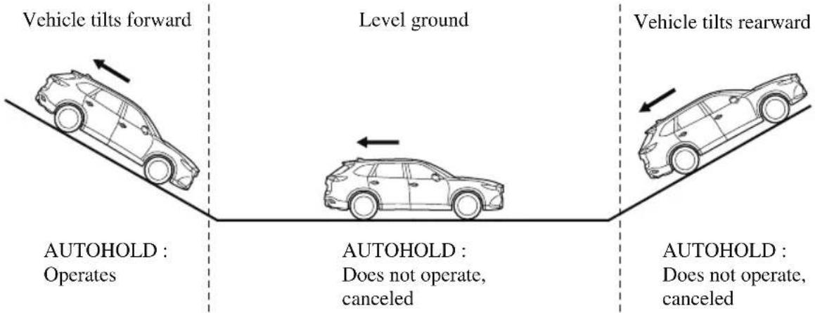
flowchart
graph TD
    A["Vehicle tilts forward"] --> B["Level ground"]
    B --> C["Vehicle tilts rearward"]
    D["AUTOHOLD : Operates"] --> A
    E["AUTOHOLD : Does not operate, canceled"] --> B
    F["AUTOHOLD : Does not operate, canceled"] --> C
▼ To Turn On AUTOHOLD System
Press the AUTOHOLD switch and when the AUTOHOLD standby indicator light turns on, the AUTOHOLD function turns on.
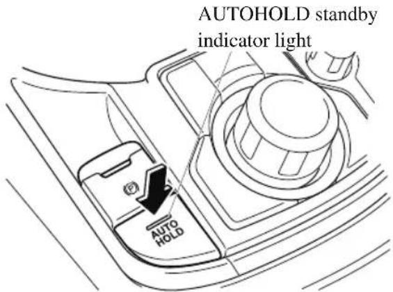
NOTE
When all of the following conditions are met, the AUTOHOLD standby indicator light turns on when the AUTOHOLD switch is pressed and the AUTOHOLD function turns on.
- The ignition is switched ON (engine is running).
• The driver's seat belt is fastened. - The driver's door is closed.
- There is no problem with the AUTOHOLD function.
To operate AUTOHOLD and hold the brakes
-
Depress the brake pedal and bring the vehicle to a complete stop.
-
The AUTOHOLD active indicator light in the instrument cluster turns on and the brakes are held.
HOLD
- The vehicle is held in its stopped position even with the brake pedal released.
NOTE
When all of the following conditions are met, the AUTOHOLD operates and the brakes are held.
- The ignition is switched ON (engine is running).
• The vehicle is stopped.
• The brake pedal is being depressed. - The AUTOHOLD active indicator light turns on.
• The accelerator pedal is not depressed.
• The driver's seat belt is fastened. - The driver's door is closed.
- There is no problem with the AUTOHOLD function.
• The parking brake is released. - There is no problem with the Electric Parking Brake (EPB) function.
- The selector lever is in a position other than R position or the vehicle tilts forward with the selector lever in the R position.
To release AUTOHOLD and start driving the vehicle
If you try to resume driving the vehicle, the brakes release automatically and the
AUTOHOLD active indicator light turns off.
NOTE
-
If the Electric Parking Brake (EPB) switch is pulled while the AUTOHOLD is operating, the parking brake is applied and the AUTOHOLD is released. In addition, if the parking brake is released under this condition, the AUTOHOLD operates to hold the brakes.
• Under the following conditions, the parking brake is automatically applied and the AUTOHOLD is released. The AUTOHOLD is re-enabled when the conditions before the AUTOHOLD is released are restored. -
The driver's seat belt is unfastened.
- The driver's door is opened.
- When about 10 minutes or longer have passed since the AUTOHOLD operation started, the parking brake is automatically applied. Because the AUTOHOLD is restored when releasing the parking brake, the hold on the brakes by AUTOHOLD function resumes.
▼ To Turn Off AUTOHOLD System
Depress the brake pedal and press the AUTOHOLD switch. The AUTOHOLD is turned off and the AUTOHOLD standby indicator light turns off.
AUTOHOLD standby indicator light
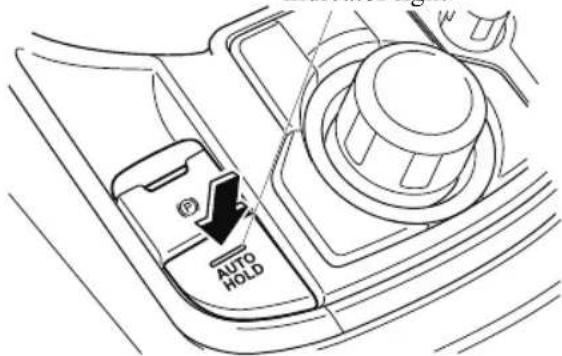
NOTE
- When the brakes are not held such as while driving the vehicle, the AUTOHOLD can be turned off only by pressing the AUTOHOLD switch.
- (Type A/B instrument cluster)
If the AUTOHOLD switch is pressed without depressing the brake pedal while AUTOHOLD is operating (AUTOHOLD active indicator light in instrument cluster is turned on), the message Brake Pedal Must Be Depressed to Deactivate Auto Hold System is indicated on the multi-information display to notify the driver to depress the brake pedal.
· (Type C instrument cluster)
If the AUTOHOLD switch is pressed without depressing the brake pedal while the AUTOHOLD is operating (AUTOHOLD active indicator light is turned on), the brake pedal operation demand indicator light (green) in the instrument cluster turns on to notify the driver that it is necessary to depress the brake pedal.
natural_image
Silhouette of a hand pressing a curved pipe with a downward arrow (no text or symbols)(Green)
- If any of the following conditions occurs while the AUTOHOLD function is operating (AUTOHOLD active indicator light is turned on), the parking brake is applied automatically and the AUTOHOLD function turns off. For the Electric Parking Brake (EPB) operation, refer to the Electric Parking Brake (EPB) on page 4-92.
- The ignition is switched OFF.
- There is a problem with the AUTOHOLD function.
Hill Launch Assist (HLA)
HLA is a function which assists the driver in accelerating from a stop while on a slope. When the driver releases the brake pedal and depresses the accelerator pedal while on a slope, the function prevents the vehicle from rolling. The braking force is maintained automatically after the brake pedal is released on a steep grade.
HLA operates on a downward slope when the selector lever is in the reverse (R) position, and on an upward slope when the selector lever is in a forward gear.
WARNING
Do not rely completely on HLA :
HLA is an auxiliary device for accelerating from a stop on a slope. The system only operates for about 2 seconds and therefore, relying only on the system, when accelerating from a stop is dangerous because the vehicle may move (roll) unexpectedly and cause an accident. The vehicle could roll depending on the vehicle's load or if it is towing something. Always confirm the safety around the vehicle before starting to drive the vehicle.
NOTE
- HLA does not operate on a gentle slope. In addition, the gradient of the slope on which the system will operate changes depending on the vehicle's load.
- HLA does not operate if the parking brake is applied, or if the vehicle has not stopped completely.
-
HLA is operating, the brake pedal may feel stiff and vibrate, however, this does not indicate a malfunction.
-
HLA does not operate while the TCS/DSC indicator light is illuminated. Refer to Contact Authorized Mazda Dealer and Have Vehicle Inspected on page 7-31.
- HLA does not turn off even if the TCS OFF switch is pressed to turn off the TCS.
Antilock Brake System (ABS)
The ABS control unit continuously monitors the speed of each wheel. If one wheel is about to lock up, the ABS responds by automatically releasing and reapplying that wheel's brake.
The driver will feel a slight vibration in the brake pedal and may hear a chattering noise from the brake system. This is normal ABS system operation. Continue to depress the brake pedal without pumping the brakes.
The warning light turns on when the system has a malfunction.
Refer to Contact Authorized Mazda Dealer and Have Vehicle Inspected on page 7-31.

WARNING
Do not rely on ABS as a substitute for safe driving:
The ABS cannot compensate for unsafe and reckless driving, excessive speed, tailgating (following another vehicle too closely), driving on ice and snow, and hydroplaning (reduced tire friction and road contact because of water on the road surface). You can still have an accident.
NOTE
- Braking distances may be longer on loose surfaces (snow or gravel, for example) which usually have a hard foundation. A vehicle with a normal braking system may require less distance to stop under these conditions because the tires will build up a wedge of surface layer when the wheels skid.
- The sound of the ABS operating may be heard when starting the engine or immediately after starting the vehicle, however, it does not indicate a malfunction.
Traction Control System (TCS)
The Traction Control System (TCS) enhances traction and safety by controlling engine torque and braking. When the TCS detects driving wheel slippage, it lowers engine torque and operates the brakes to prevent loss of traction.
This means that on a slick surface, the engine adjusts automatically to provide optimum power to the drive wheels, limiting wheel spin and loss of traction.
The warning light turns on when the system has a malfunction.
Refer to Contact Authorized Mazda Dealer and Have Vehicle Inspected on page 7-31.

WARNING
Do not rely on the Traction Control System (TCS) as a substitute for safe driving:
The Traction Control System (TCS) cannot compensate for unsafe and reckless driving, excessive speed, tailgating (following another vehicle too closely), and hydroplaning (reduced tire friction and road contact because of water on the road surface). You can still have an accident.
Use snow tires or tire chains and drive at reduced speeds when roads are covered with ice and/or snow:
Driving without proper traction devices on snow and/or ice-covered roads is dangerous. The Traction Control System (TCS) alone cannot provide adequate traction and you could still have an accident.
NOTE
To turn off the TCS, press the TCS OFF switch (page 4-104).
▼ TCS/DSC Indicator Light
This indicator light stays on for a few seconds when the ignition is switched ON. If the TCS, DSC or the Trailer Stability Control (TSC) is operating, the indicator light flashes.
If the light stays on, the TCS, DSC or the brake assist system may have a malfunction and they may not operate correctly. Take your vehicle to an Authorized Mazda Dealer.
NOTE
- In addition to the indicator light flashing, a slight lugging sound will come from the engine. This indicates that the TCS/DSC is operating properly.
- On slippery surfaces, such as fresh snow, it will be impossible to achieve high rpm when the TCS is on.
▼ TCS OFF Indicator Light\*
TCS OFF
This indicator light stays on for a few seconds when the ignition is switched ON. It also illuminates when the TCS OFF switch is pressed and TCS is switched off. Refer to TCS OFF Switch on page 4-104.
If the light remains illuminated and the TCS is not switched off, take your vehicle to an Authorized Mazda Dealer. The DSC may have a malfunction.
▼ TCS OFF Switch\*
Press the TCS OFF switch to turn off the TCS. The TCS OFF indicator light in the instrument cluster and TCS OFF switch indicator light turn on.
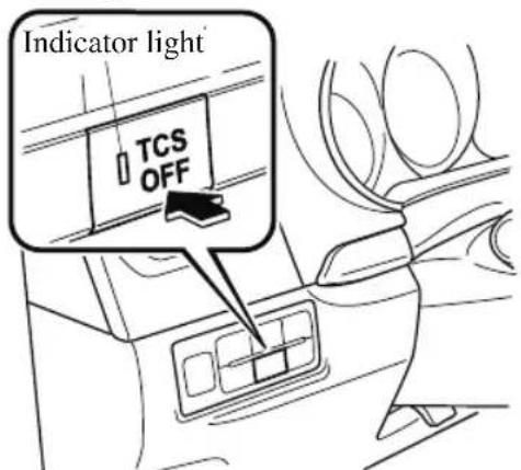
Press the switch again to turn the TCS back on. The TCS OFF indicator light and TCS OFF switch indicator light will turn off.
NOTE
- When TCS is on and you attempt to free the vehicle when it is stuck, or drive it out of freshly fallen snow, the TCS (part of the DSC system) will activate. Depressing the accelerator will not increase engine power and freeing the vehicle may be difficult. When this happens, turn off the TCS.
- If the TCS is off when the engine is turned off, it automatically activates when the ignition is switched ON.
- Leaving the TCS on will provide the best traction.
- If the TCS OFF switch is pressed and held for 10 seconds or longer, the TCS can no longer be turned off even if the TCS OFF switch is pressed.
In this case, the TCS OFF switch will operate normally when the ignition is switched ON again after being switched OFF.
Dynamic Stability Control (DSC)
The Dynamic Stability Control (DSC) automatically controls braking and engine torque in conjunction with systems such as ABS and TCS to help control side slip when driving on slippery surfaces, or during sudden or evasive maneuvering, enhancing vehicle safety.
Refer to ABS (page 4-102) and TCS (page 4-103).
DSC operation is possible at speeds greater than 20 km/h (12 mph).
The warning light turns on when the system has a malfunction. Refer to Contact Authorized Mazda Dealer and Have Vehicle Inspected on page 7-31.

WARNING
Do not rely on the Dynamic Stability Control as a substitute for safe driving:
The Dynamic Stability Control (DSC) cannot compensate for unsafe and reckless driving, excessive speed, tailgating (following another vehicle too closely), and hydroplaning (reduced tire friction and road contact because of water on the road surface). You can still have an accident.

CAUTION
The DSC may not operate correctly unless the following are observed:
➢ Use tires of the correct size specified for your Mazda on all 4 wheels.
➢ Use tires of the same manufacturer, brand and tread pattern on all 4 wheels.
Do not mix worn tires.
The DSC may not operate correctly when tire chains are used or a temporary spare tire is installed because the tire diameter changes.
▼ TCS/DSC Indicator Light
This indicator light stays on for a few seconds when the ignition is switched ON. If the TCS, DSC or the Trailer Stability Control (TSC) is operating, the indicator light flashes.
If the light stays on, the TCS, DSC or the brake assist system may have a malfunction and they may not operate correctly. Take your vehicle to an Authorized Mazda Dealer.
Trailer Stability Control (TSC)
If the vehicle sways while being driven and towing a trailer, the Trailer Stability Control (TSC) automatically controls braking and engine torque to suppress the swaying and enhance vehicle stability. The Trailer Stability Control (TSC) is operable at a vehicle speed of about 65 km/h (40 mph) or more.
When the Trailer Stability Control (TSC) operates while driving the vehicle, the TCS/DSC indicator light flashes.
Refer to TCS/DSC Indicator Light on page 4-105.

WARNING
Do not rely solely on the Trailer Stability Control (TSC)
Assured vehicle stability is limited even if the Trailer Stability Control (TSC) is operating. Drive carefully to prevent accidents.
In particular, if the TCS/DSC indicator light is flashing, drive the vehicle carefully as it is in a less stable condition and could sway more easily. Drive with caution and in accordance with the road, vehicle and trailer conditions.

CAUTION
The Trailer Stability Control (TSC) may not operate correctly unless the following are observed:
➢ Use tires of the correct size specified for your Mazda on all four wheels.
➢ Use tires of the same manufacturer, brand and tread pattern on all four wheels.
Do not mix worn tires.
The Trailer Stability Control (TSC) may not operate correctly when tire chains are used or a temporary spare tire is installed because the tire diameter changes.
NOTE
- The Trailer Stability Control (TSC) uses the TCS/DSC functions. The Trailer Stability Control (TSC) does not operate if there is a malfunction in the TCS/DSC (the TCS/DSC indicator light turns on).
- When the Trailer Stability Control (TSC) is operating, the brake lights may turn on.
- For information regarding trailer towing, refer to Trailer Towing (U.S.A. and Canada) on page 3-57.
Off-Road Traction Assist\*
When the vehicle tires become embedded in mud, sand, or deep snow, the Off-Road Traction Assist functions to prevent drive-wheel spinning and to assist in freeing tires that are stuck.
Do not drive over rough rocky roads and river beds.

WARNING
Do not rely completely on the Off-Road Traction Assist.
The Off-Road Traction Assist has limitations. Always drive the vehicle safely according to the road conditions. Do not drive the vehicle recklessly, otherwise it may result in an accident. In addition, do not drive the vehicle under the following conditions while the Off-Road Traction Assist is operating. Otherwise, it could negatively affect the drivetrain parts which could result in an accident.
▶ Vehicle is driven on paved roads.
➢ Temporary spare tire or tires of a different specified size are used.
▶Tire chains are used.

CAUTION
The Off-Road Traction Assist is a function to assist in freeing tires that are stuck. When it is not necessary to use this function, avoid driving the vehicle continuously with the Off-Road Traction Assist on.
(Vehicle equipped with Type A/B instrument cluster)
If the vehicle is driven continuously with the Off-Road Traction Assist on, the AWD warning indication may be displayed.
(Vehicle equipped with Type C instrument cluster)
If the vehicle is driven continuously with the Off-Road Traction Assist on, the AWD warning light may flash.
Refer to If a Warning Light Turns On or Flashes on page 7-28.
NOTE
The vehicle may vibrate or you might hear an operation sound while the Off-Road Traction Assist is operating or is operational, however, this does not indicate a problem.
▼ Off-Road Traction Assist Indicator Light
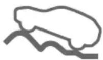
- When the ignition is switched ON, the indicator light turns on and then turns off after a few seconds.
- When pressing the Off-Road Traction Assist switch to operate the Off-Road Traction Assist, the indicator light turns on.
-
A problem in the system might be indicated under the following conditions. Have your vehicle inspected by an Authorized Mazda Dealer.
-
The indicator light does not turn on when the ignition is switched ON or it remains on.
- The indicator light turns on even though the Off-Road Traction Assist was not operated.
▼ Off-Road Traction Assist Switch
When the switch is pressed after stopping the vehicle, the Off-Road Traction Assist becomes operational.
The Off-Road Traction Assist indicator light in the instrument cluster and the Off-Road Traction Assist switch indicator light turn on.
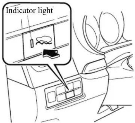
If the switch is pressed again, the Off-Road Traction Assist is stopped and the Off-Road Traction Assist indicator light and the Off-Road Traction Assist switch indicator light turn off.
NOTE
If the engine is stopped with the Off-Road Traction Assist operational, the Off-Road Traction Assist is stopped when the engine is started the next time.
Drive Selection
Drive selection is a system to switch the vehicle's drive mode. When the sport mode is selected, the vehicle's response against accelerator operation is enhanced. This provides additional quick acceleration which may be needed to safely make maneuvers such as lane changes, merging onto freeways, or passing other vehicles.

CAUTION
Do not use the sport mode when driving on slippery roads such as wet or snow-covered roads. It may cause tire slipping.
NOTE
- When sport mode is selected, driving at higher engine speeds may increase fuel consumption. Mazda recommends that you cancel sport mode for normal driving.
- Drive mode cannot be switched in the following conditions:
• ABS/TCS/DSC is operating
- The Mazda Radar Cruise Control with Stop & Go function (MRCC with Stop & Go function) System/cruise control is operating.
- Steering wheel is being operated abruptly
▼ Drive Selection Switch
Press the drive selection switch forward ("SPORT") to select the sport mode. Pull the drive selection switch back ("—") to cancel the sport mode.
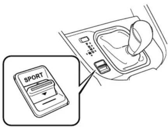
NOTE
· In the following cases, the drive selection is canceled.
· The ignition is switched OFF.
- Mazda Radar Cruise Control with Stop & Go function (MRCC with Stop & Go function) System/cruise control is set.
- Depending on the driving conditions when sport mode is selected, the vehicle may perform shift-down or slightly accelerate.
▼ Select Mode Indication
SPORT
The light is illuminated while in SPORT mode.
NOTE
The indicator light flashes a few times to indicate that the mode cannot be switched to SPORT mode even if the drive select switch is pressed under the following conditions:
- ABS/TCS/DSC is operating
- The Mazda Radar Cruise Control with Stop & Go function (MRCC with Stop & Go function) System/cruise control is operating.
- The vehicle is making a turn or driving on a curved road.
i-ACTIV AWD Operation\*
AWD provides excellent drivability on snow-covered and ice-packed roads, sand and mud, as well as on steep slopes and other slippery surfaces.
A system malfunction or operation conditions are indicated by a warning.
Refer to Contact Authorized Mazda Dealer and Have Vehicle Inspected on page 7-31.

WARNING
Never spin a wheel that is off the ground:
Spinning a wheel that is off the ground as a result of the vehicle being stuck or in a ditch is dangerous. The drive assembly could be seriously damaged which could lead to an accident or could even lead to overheating, oil leakage, and a fire.
▼ AWD Driving

WARNING
Avoid sharp turns, excessive speed and abrupt maneuvers when driving this vehicle:
Sharp turns, excessive speed and abrupt maneuvering of this vehicle is dangerous as it could result in the increased risk of loss of vehicle control, vehicle roll-over, personal injury or death.
This vehicle has a higher center of gravity. Vehicles with a higher center of gravity such as utility and AWD vehicles handle differently than vehicles with a lower center of gravity.
Utility and AWD vehicles are not designed for cornering at high speeds any more than low profile sports cars are designed to perform satisfactorily under off-road conditions. In addition, utility vehicles have a significantly higher rollover rate than other types of vehicles.
Drive carefully when the vehicle is loaded by lowering vehicle speed and applying the brakes earlier:
Abrupt maneuvering and sudden braking when driving a loaded vehicle is dangerous as the driving behavior of a vehicle with a high center of gravity is different when it is loaded compared to when it is not, and could result in the loss of vehicle control and an accident.
▼ Tires and Tire Chains
The condition of the tires plays a large role in the performance of the vehicle.
Moreover, to prevent adverse effects to the drive assembly, please note the following:
Tires
- When replacing tires, always replace all front and rear tires at the same time.
- All tires must be of the same size, manufacture, brand and tread pattern.
Pay particular attention when equipping snow or other types of winter tires. - Do not mix tread-worn tires with normal tires.
- Inspect tire inflation pressures at the specified periods adjust to the specified pressures.
NOTE
Check the tire inflation pressure label attached to driver's door frame for the correct tire inflation pressure.
- Make sure to equip the vehicle with genuine tires of the specified size, on all wheels. With AWD, the system is calibrated for all 4 wheels being of the same dimensions.
Tire chains
• Install tire chains to the front tires.
- Do not use tire chains on the rear wheels.
- Do not drive the vehicle faster than 30 km/h (19 mph) with the tire chains installed.
- Do not drive the vehicle with tire chains on road conditions other than snow or ice.
▼ Towing
If the vehicle requires towing, have it towed with all 4 wheels completely off the ground.
Refer to Towing Description on page 7-25.
Power Steering
- Power steering is only operable when the engine is running. If the engine is off or if the power steering system is inoperable, you can still steer, but it requires more physical effort.
If the steering feels stiffer than usual during normal driving or the steering vibrates, consult an Authorized Mazda Dealer.
- The warning indication/warning light notifies the driver of system abnormalities and operation conditions. In addition, the buzzer may also activate depending on the system abnormality or operation condition.
Refer to Stop Vehicle in Safe Place Immediately on page 7-28.
Refer to Power Steering Warning Buzzer on page 7-50.

CAUTION
Never hold the steering wheel to the extreme left or right for more than 5 seconds with the engine running. This could damage the power steering system.
i-ACTIVSENSE\*
i-ACTIVSENSE is a collective term covering a series of advanced safety and driver support systems which make use of a Forward Sensing Camera (FSC) and radar sensors. These systems consist of active safety and pre-crash safety systems.
These systems are designed to assist the driver in safer driving by reducing the load on the driver and helping to avert collisions or reduce their severity. However, because each system has its limitations, always drive carefully and do not rely solely on the systems.
▼ Active Safety Technology
Active Safety Technology supports safer driving by helping the driver to recognize potential hazards and avert accidents.
Driver awareness support systems
Nighttime visibility
Adaptive Front Lighting System (AFS)...... page 4-117
High Beam Control System (HBC)......page 4-118
Left/right side and rear side detection
Lane Departure Warning System (LDWS)......page 4-158
Blind Spot Monitoring (BSM)......page 4-121
Road sign recognition
Traffic Sign Recognition System (TSR)......page 4-127
Inter-vehicle distance recognition
Distance Recognition Support System (DRSS)......page 4-133
Driver fatigue detection
Driver Attention Alert (DAA)...... page 4-137
Rear obstruction detection when leaving a parking space
Rear Cross Traffic Alert (RCTA)......page 4-139
Full-surround recognition
360°View Monitor (Mazda Connect (Type A))......page 4-181
360°View Monitor (Mazda Connect (Type B))......page 4-207
Driver support systems
Inter-vehicle distance
Mazda Radar Cruise Control with Stop & Go function (MRCC with Stop & Go function)...... page 4-143
Lane departure
Lane-keep Assist System (LAS)......page 4-158
▼ Pre-Crash Safety Technology
Pre-crash safety technology is designed to assist the driver in averting collisions or reduce their severity in situations where they cannot be avoided.
Collision damage reduction in low vehicle speed range
Forward driving
Smart City Brake Support [Forward] (SCBS F)......page 4-172 Advanced Smart City Brake Support (Advanced SCBS)......page 4-169
Reverse driving
Smart City Brake Support [Reverse] (SCBS R)......page 4-175
Collision damage reduction in medium/high speed range
Smart Brake Support (SBS)......page 4-179
▼ Camera and Sensors
Forward Sensing Camera (FSC)
The Forward Sensing Camera (FSC) detects lane indications and recognizes headlights, taillights and city lights during nighttime driving. In addition, it also detects the vehicle ahead, pedestrians, or obstructions. The following systems also use the Forward Sensing Camera (FSC).
· High Beam Control System (HBC)
- Driver Attention Alert (DAA)
• Lane-keep Assist System (LAS) & Lane Departure Warning System (LDWS)
- Traffic Sign Recognition System (TSR)
- Advanced Smart City Brake Support (Advanced SCBS)
• Smart City Brake Support [Forward] (SCBS F)
• Smart Brake Support (SBS)
- Mazda Radar Cruise Control with Stop & Go function (MRCC with Stop & Go function)
The Forward Sensing Camera (FSC) is installed at the top of the windshield near the rearview mirror.
Refer to Forward Sensing Camera (FSC) on page 4-235.
Radar sensor (front)
The radar sensor (front) functions by detecting the radio waves reflected off a vehicle ahead sent from the radar sensor. The following systems also use the radar sensor (front).
· Mazda Radar Cruise Control with Stop & Go function (MRCC with Stop & Go function)
• Distance Recognition Support System (DRSS)
• Smart Brake Support (SBS)
The radar sensor (front) is mounted behind the radiator grille.
Refer to Radar Sensor (Front) on page 4-240.
Radar sensors (rear)
The radar sensors (rear) function by detecting the radio waves reflected off a vehicle approaching from the rear or an obstruction sent from the radar sensors. The following systems also use the radar sensors (rear).
• Blind Spot Monitoring (BSM)
- Rear Cross Traffic Alert (RCTA)
The radar sensors (rear) are installed inside the rear bumper, one each on the left and right sides.
Refer to Radar Sensors (Rear) on page 4-243.
Ultrasonic sensors (rear)
The ultrasonic sensors (rear) function by detecting the ultrasonic waves reflected off obstructions at the rear sent from the ultrasonic sensors. The following systems also use the ultrasonic sensors (rear).
• Smart City Brake Support [Reverse] (SCBS R)
The ultrasonic sensors (rear) are mounted in the rear bumper.
Refer to Ultrasonic Sensors (Rear) on page 4-245.
Front camera/side cameras/rear view camera
The front camera, side cameras, and rear camera shoot images of the area surrounding the vehicle. The 360^ View Monitor uses each camera.
Cameras are installed to the front bumper, door mirrors, and liftgate.
Refer to Front Camera/Side Cameras/Rear Camera on page 4-246.
Adaptive Front Lighting System (AFS) ^*
The adaptive front lighting system (AFS) automatically adjusts the headlight beams to the left or right in conjunction with the operation of the steering wheel after the headlights have been turned on.
A system malfunction or operation conditions are indicated by a warning.
Refer to Contact Authorized Mazda Dealer and Have Vehicle Inspected on page 7-31.
NOTE
The Adaptive Front Lighting System (AFS) function can be switched to operable/inoperable using the personalization function.
Refer to the Settings section in the Mazda Connect Owner's Manual.
High Beam Control System (HBC)\*
The HBC determines the conditions in front of the vehicle using the Forward Sensing Camera (FSC) while driving in darkness to automatically switch the headlights between high and low beams.
Refer to Forward Sensing Camera (FSC) on page 4-235.
While driving the vehicle at a speed of about 30 km/h (19 mph) or more, the headlights are switched to high beams when there are no vehicles ahead or approaching in the opposite direction.
The system switches the headlights to low beams when one of the following occurs:
- The system detects a vehicle or the headlights/lights of a vehicle approaching in the opposite direction.
- The vehicle is driven on roads lined with streetlamps or on roads in well-lit cities and towns.
- The vehicle is driven at less than about 20 ~km / h (12 mph).
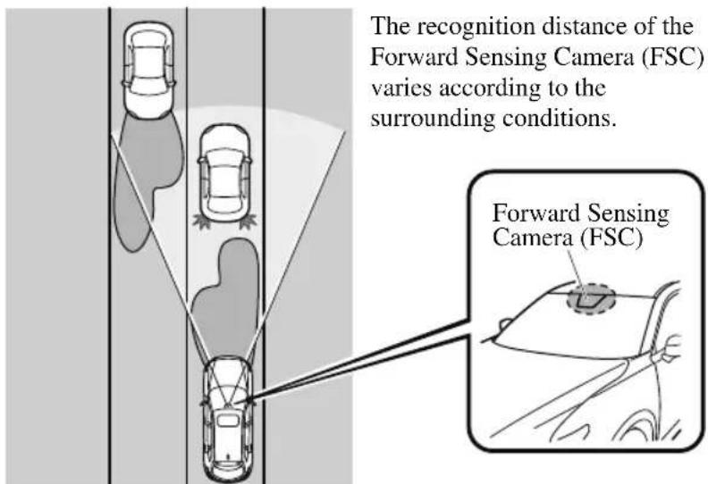
The warning light turns on when the system has a malfunction.
Refer to Contact Authorized Mazda Dealer and Have Vehicle Inspected on page 7-31.

CAUTION
➢ Do not adjust the vehicle height, modify the headlight units, or remove the camera, otherwise the system will not operate normally.
➢ Do not rely excessively on the HBC and drive the vehicle while paying sufficient attention to safety. Switch the headlights between the high beams and low beams manually if necessary.
NOTE
The timing in which the system switches the headlights changes under the following conditions. If the system does not switch the headlights appropriately, manually switch between high and low beams according to the visibility as well as road and traffic conditions.
- When there are sources of light in the area such as street lamps, illuminated signboards, and traffic signals.
- When there are reflective objects in the surrounding area such as reflective plates and signs.
- When visibility is reduced under rain, snow and foggy conditions.
- When driving on roads with sharp turn or hilly terrain.
- When the headlights/rear lamps of vehicles in front of you or in the opposite lane are dim or not illuminated.
- When there is sufficient darkness such as at dawn or dusk.
- When the luggage compartment is loaded with heavy objects or the rear passenger seats are occupied.
- When visibility is reduced due to a vehicle in front of you spraying water from its tires onto your windshield.
▼ To Operate the System
The HBC operates to switch the headlights automatically between high and low beams after the ignition is switched ON and the headlight switch is in the AUTO and high beam position.
The HBC determines that it is dark based on the brightness of the surrounding area. At the same time, the HBC indicator light (green) in the instrument cluster illuminates.

NOTE
- When the vehicle speed is about 30 km/h (19 mph) or more, the headlights automatically switch to high beams when there are no vehicles ahead or approaching in the opposite direction. When the vehicle speed is less than about 20 km/h (12 mph), the HBC switches the headlights to low beams.
- The low beams may not switch to high beams when cornering.
- Operation of the HBC function can be disabled. Refer to the Settings section in the Mazda Connect Owner's Manual.
▼ Manual Switching
Switching to low beams
Shift the lever to the low beam position. The HBC indicator light (green) turns off.
Switching to high beams
Turn the headlight switch to the ☐ position.
The HBC indicator light (green) turns off and the is illuminated.
Blind Spot Monitoring (BSM)\*
The BSM is designed to assist the driver in checking the area to the rear of the vehicle on both sides during lane changes by notifying the driver of the presence of vehicles approaching from the rear in an adjacent lane.
The BSM detects vehicles approaching from the rear while traveling in the forward direction at a speed of 10 km/h (6.3 mph) or faster and notifies the driver by turning on the BSM warning indicator light and displaying the vehicle detection screen.
If the turn signal lever is operated to signal a turn in the direction in which the BSM warning indicator light is illuminated while the approaching vehicle is detected, the BSM notifies the driver of possible danger by turning on the BSM warning indicator light, and by activating the warning sound and the warning screen indicator display.
The detection area on this system covers the driving lanes on both sides of the vehicle and from the rear part of the front doors to about 50 m (164 ft) behind the vehicle.
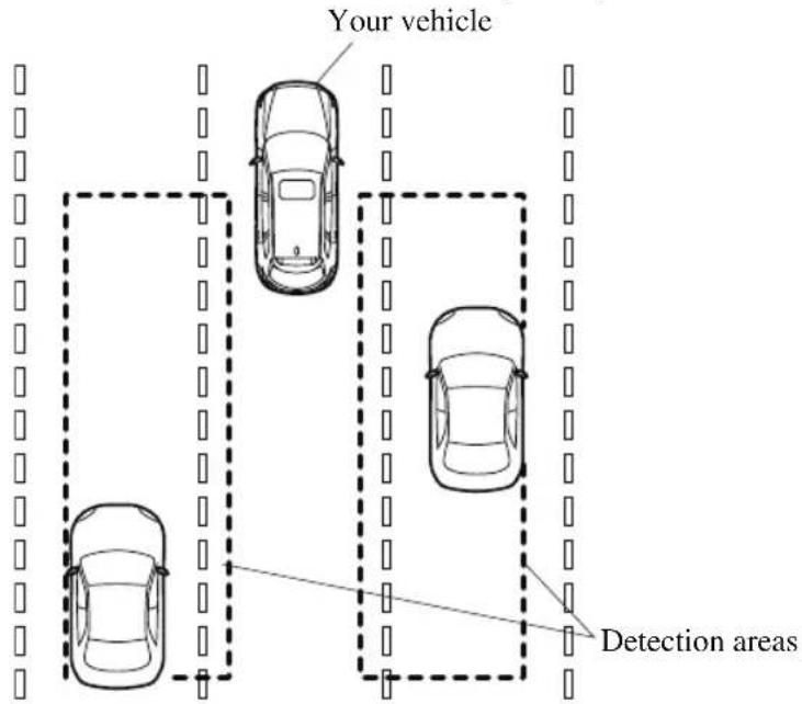

WARNING
Always check the surrounding area visually before making an actual lane change:
The system is only designed to assist you in checking for vehicles at your rear when making a lane change. Due to certain limitations with the operation of this system, the BSM warning indicator light, the warning sound and the warning screen indicator display may not activate or they might be delayed even though a vehicle is in an adjacent driving lane. Always make it your responsibility as a driver to check the rear.
NOTE
- The BSM will operate when all of the following conditions are met:
• The ignition is switched ON.
- The BSM OFF indicator light in the instrument cluster is turned off.
- The vehicle speed is about 10 ~km / h (6.3 mph) or faster.
- The BSM will not operate under the following circumstances.
- The vehicle speed falls below about 10km / h (6.3 mph) even though the BSM OFF switch indicator light is turned off.
- The selector lever is shifted to R position and the vehicle is reversing.
- The turning radius is small (making a sharp turn, turning at intersections).
- In the following cases, the BSM OFF indicator light turns on and operation of the system is stopped. If the BSM OFF indicator light remains illuminated, have the vehicle inspected at an Authorized Mazda Dealer as soon as possible.
- Some problem with the system including the BSM warning indicator lights is detected.
- A large deviation in the installation position of a radar sensor (rear) on the vehicle has occurred.
- There is a large accumulation of snow or ice on the rear bumper near a radar sensor (rear). Remove any snow, ice or mud on the rear bumper.
- Driving on snow-covered roads for long periods.
- The temperature near the radar sensors (rear) becomes extremely hot due to driving for long periods on slopes during the summer.
- The battery voltage has decreased.
- Under the following conditions, the radar sensors (rear) cannot detect target objects or it may be difficult to detect them.
- A vehicle is in the detection area at the rear in an adjacent driving lane but it does not approach. The BSM determines the condition based on radar detection data.
- A vehicle is traveling alongside your vehicle at nearly the same speed for an extended period of time.
- Vehicles approaching in the opposite direction.
- A vehicle in an adjacent driving lane is attempting to pass your vehicle.
- A vehicle is in an adjacent lane on a road with extremely wide driving lanes. The detection area of the radar sensors (rear) is set at the road width of expressways.
- In the following case, the flashing of the BSM warning indicator light, and the activation of the warning sound and the warning screen indicator display may not occur or they may be delayed.
- A vehicle makes a lane change from a driving lane 2 lanes over to an adjacent lane.
- Driving on steep slopes.
- Crossing the summit of a hill or mountain pass.
- When there is a difference in the height between your driving lane and the adjacent lane.
- Directly after the BSM system becomes operable by changing the setting.
- If the road width is extremely narrow, vehicles 2 lanes over may be detected. The detection area of the radar sensors (rear) is set according to the road width of expressways.
- The BSM warning indicator light may turn on and the vehicle detection screen may be displayed in the display in reaction to stationary objects (guardrails, tunnels, sidewalls, and parked vehicles) on the road or the roadside.
Objects such as guardrails and concrete walls running alongside the vehicle.
Places where the width between guardrails or walls on each side of the vehicle narrows.
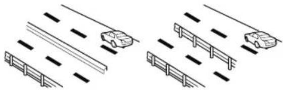
natural_image
Diagram showing vehicle lane markings and road patterns (no text or symbols)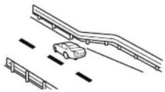
natural_image
Diagram showing a car on elevated tracks with two side barriers (no text or symbols)The walls at the entrance and exits of tunnels, turnouts.
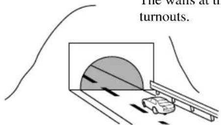
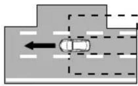
natural_image
Diagram of a car moving in a vehicle through a road with dashed lane markings (no text or symbols)- A BSM warning indicator light may flash or the warning beep and the warning screen indicator display may be activated several times when making a turn at a city intersection.
- Turn off the BSM while pulling a trailer or while an accessory such as a bicycle carrier is installed to the rear of the vehicle. Otherwise, the radar's radio waves will be blocked causing the system to not operate normally.
- In the following cases, it may be difficult to view the illumination/flashing of the BSM warning indicator lights equipped on the door mirrors.
- Snow or ice is adhering to the door mirrors.
- The front door glass is fogged or covered in snow, frost or dirt.
- The radar sensors (rear) of the BSM may be regulated under the radio wave related laws of the country where the vehicle is driven. The sensors in this system are approved for use in the U.S.A. (including territories), Canada, and Mexico. If a vehicle with a BSM is driven in a country other than the U.S.A., Canada, or Mexico, authorization from the country where the vehicle is driven might be required.
- The system switches to the Rear Cross Traffic Alert function when the selector lever is shifted to the reverse (R) position.
Refer to Rear Cross Traffic Alert (RCTA) on page 4-139.
▼ Blind Spot Monitoring (BSM) Warning Indicator Light/Display Indicator/Blind Spot Monitoring (BSM) Warning Beep
The BSM or Rear Cross Traffic Alert (RCTA) system notifies the driver of the presence of vehicles in adjacent lanes or at the rear of the vehicle using the BSM warning indicator light, the warning sound and the display indicator (BSM) while the systems are operational.
BSM warning indicator lights
The BSM warning indicator lights are equipped on the left and right door mirrors. The warning indicator lights turn on when a vehicle approaching from the rear in an adjacent lane is detected.
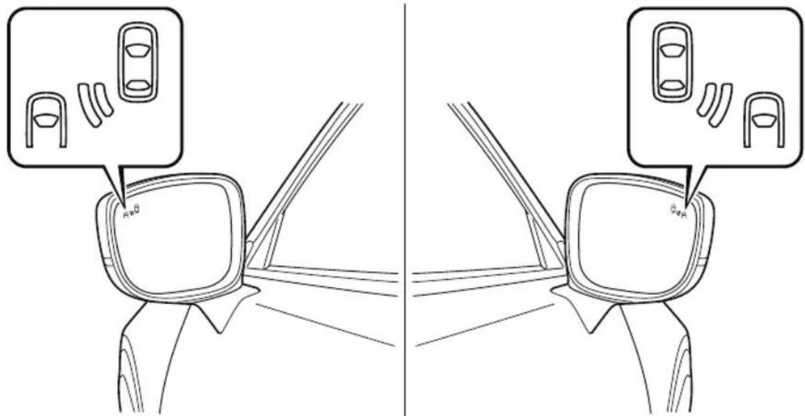
When the ignition is switched ON, the warning indicator light turns on momentarily and then turns off after a few seconds.
Forward driving (BSM operation)
The BSM detects vehicles approaching from the rear and turns on the BSM warning indicator lights equipped on the door mirrors according to the conditions. Additionally, while a BSM warning indicator light is illuminated, if the turn signal lever is operated to signal a turn in the direction in which the BSM warning indicator light is illuminated, the BSM warning indicator light flashes.
Reverse driving (Rear Cross Traffic Alert (RCTA) system operation)
The Rear Cross Traffic Alert (RCTA) system detects vehicles approaching from the left and right of your vehicle and flashes the BSM warning indicator lights.
Function for cancelling illumination dimmer
If the BSM warning indicator lights turn on when the parking lights are turned on, the brightness of the BSM warning indicator lights is dimmed.
If the BSM warning indicator lights are difficult to see due to glare from surrounding brightness when traveling on snow-covered roads or under foggy conditions, press the dimmer cancellation button to cancel the dimmer and increase the brightness of BSM warning indicator lights when they turn on.
Refer to Dashboard Illumination on page 4-17, 4-34.
Display indicator
The detected approaching vehicle and warning are displayed in the multi-information display and active driving display when the vehicle is moving forward (BSM operational).
Multi-information Display Active Driving Display
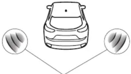
natural_image
Top-down line drawing of a car with two circular indicators below showing sound wave patterns (no text or symbols)
natural_image
Simple diagram showing two circular insets with three vertical bars, connected by a line to a common point (no text or symbols)Detection and warning indicator Detection and warning indicator
The detected direction is displayed with a detection indicator (white) when an approaching vehicle is detected. In addition, if the turn signal lever is operated to signal a lane change while the vehicle is detected, the display changes the color (amber) of the warning indicator.
BSM warning beep
The BSM warning beep is activated simultaneously with the flashing of a BSM warning indicator light.
▼ Canceling Operation of Blind Spot Monitoring (BSM)
The BSM system can be set to inoperable. Refer to the Settings section in the Mazda Connect Owner's Manual.
When the BSM is set to inoperable, the BSM and Rear Cross Traffic Alert (RCTA) systems are turned off and the
BSM OFF indicator light in the instrument cluster turns on.
NOTE
When the ignition is switched OFF, the system status before it was turned off is maintained. For example, if the ignition is switched OFF while the BSM and Rear Cross Traffic Alert (RCTA) systems are operational, the BSM and Rear Cross Traffic Alert (RCTA) systems remain operational the next time the ignition is switched ON.
Traffic Sign Recognition System (TSR) ^*
The TSR helps prevent the driver from overlooking traffic signs, and provides support for safer driving by displaying traffic signs on the active driving display which are recognized by the Forward Sensing Camera (FSC) or recorded in the navigation system while the vehicle is driven.
The TSR displays the speed limit, do not enter, and traffic stop signs.
If the vehicle speed exceeds the speed limit sign indicated in the active driving display while the vehicle is driven, the system notifies the driver using the indication in the active driving display and a warning sound.
NOTE
- The TSR is not supported in some countries or regions. For information concerning the supported countries or regions, consult an Authorized Mazda Dealer.
- The TSR operates only if the navigation system SD card (Mazda genuine) is inserted in the SD card slot. Consult an Authorized Mazda Dealer for details.
Speed limit signs and do not enter signs
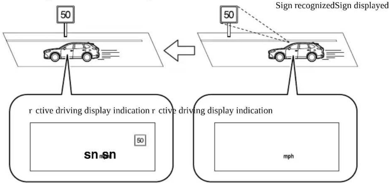
flowchart
graph TD
    A["Car with 50° sign"] --> B["Car with 50° sign"]
    B --> C["Sign recognized Sign displayed"]
    D["r-ctive driving display indication"] --> E["r-ctive driving display indication"]
    E --> F["sn sn 50"]
    G["mph"] --> H["mph"]
Stop sign
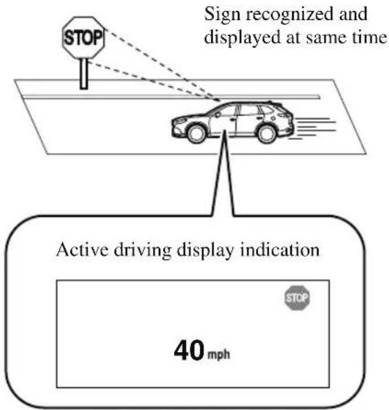

WARNING
Always check the traffic signs visually while driving.
The TSR helps prevent the driver from overlooking traffic signs and provides support for safer driving. Depending on the weather conditions or problems with traffic signs, a traffic sign may not be recognized or a traffic sign different from the actual traffic sign may be displayed. Always make it your responsibility as a driver to check the actual traffic signs. Otherwise, it could result in an accident.
NOTE
- The TSR does not operate if there is a malfunction in the Forward Sensing Camera (FSC).
-
Under the following conditions, the TSR may not operate normally.
-
An object placed on the dashboard is reflected in the windshield and picked up by the camera.
- Heavy luggage is loaded in the luggage compartment or on the rear seat and the vehicle is tilted.
- The tire pressures are not adjusted to the specified pressure.
• Tires other than standard tires are equipped. - The vehicle is driven on the ramp and surrounding area to or from a rest area or a tollgate on a highway.
-
When surrounding brightness suddenly changes such as when entering or exiting a tunnel.
-
The illumination of the headlights is weakened because of dirt or the optical axis is deviated.
• The windshield is dirty or foggy. - The windshield and camera are fogged (water droplets).
- Strong light is directed at the front of the vehicle (such as backlight or high-beam headlights of on-coming vehicles).
• The vehicle is making a sharp turn. - Strong light reflects off the road.
- A traffic sign is in a position which makes it difficult to reflect the light from the vehicle's headlights, such as when the vehicle is driven at night or in a tunnel.
- The vehicle is driven under weather conditions such as rain, fog, or snow.
- The stored map data for the navigation system is not current.
- A traffic sign is obscured by mud or snow.
- A traffic sign is concealed by trees or a vehicle.
- A traffic sign is partially shaded.
- A traffic sign is bent or warped.
- A traffic sign is too low or too high.
- A traffic sign is too bright or too dark (including electronic traffic signs).
- A traffic sign is too big or too small.
- There is an object similar to the traffic sign being read (such as another traffic sign or other signs resembling it).
- The TSR does not operate if the active driving display is set to non-display.
- The TSR can be set to inoperable.
Refer to the Settings section in the Mazda Connect Owner's Manual.
▼ Traffic Sign Display Indication
The following traffic signs are displayed on the active driving display.
Speed limit signs
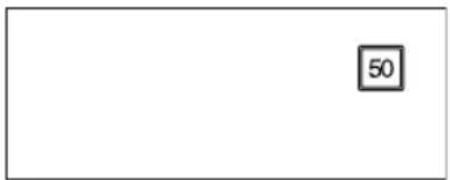
Do not enter signs
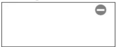
natural_image
Blank white rectangle with a small gray circular icon in the top-right corner (no text or symbols)Stop signs
NOTE
Speed limit signs
- When the vehicle speed is about 1km / h (0.6 mph) or faster, the speed limit sign is displayed when any one of the following conditions are met.
- The Forward Sensing Camera (FSC) recognizes a speed limit sign as a sign targeted for your vehicle and the vehicle passes it.
- The speed limit sign stored in the navigation system is read (if the Forward Sensing Camera (FSC) does not recognize a speed limit sign).
- In the following cases, display of the speed limit sign stops.
- The Forward Sensing Camera (FSC) recognizes the speed limit sign and the vehicle is driven for a certain distance after passing the sign.
• Each sensor determines that the vehicle has changed direction of travel.
- The Forward Sensing Camera (FSC) recognizes a new speed limit sign which differs from the previous one (displays the new speed limit sign).
- The speed limit sign stored in the navigation system is not read within a certain period of time (if the Forward Sensing Camera (FSC) does not recognize a speed limit sign, the speed limit sign stored in the navigation system is displayed).
- The vehicle speed exceeds the displayed speed limit sign by 30 km/h (19 mph) or more after a certain period of time has elapsed since the speed limit sign was displayed. (Except when there is information for the speed limit sign in the navigation system)
Do not enter signs
- A do not enter sign is displayed when all of the following conditions are met.
- The vehicle speed is about 60 km/h (37 mph) or slower.
- The Forward Sensing Camera (FSC) recognizes a do not enter sign as a sign targeted for your vehicle and the vehicle passes it.
- When the Forward Sensing Camera (FSC) recognizes the do not enter sign and a certain period of time has elapsed since the vehicle passed the sign, display of the do not enter sign stops.
Stop sign
- A stop sign is displayed when all of the following conditions are met:
- The vehicle speed is about 30 km/h (19 mph) or slower.
- The Forward Sensing Camera (FSC) recognizes a stop sign as a sign targeted for your vehicle.
- When a certain period of time has elapsed since the stop sign was displayed, display of the stop sign stops.
▼ Excessive Speed Warning
If the vehicle speed exceeds the speed limit sign displayed in the active driving display, the area around the speed limit sign flashes 3 times in amber and the warning sound is activated 3 times at the same time. If the vehicle speed continues to exceed the displayed speed limit sign, the indication stops flashing and remains on. Check the surrounding conditions and adjust the vehicle speed to the legal speed using the appropriate operation such as depressing the brake pedal.
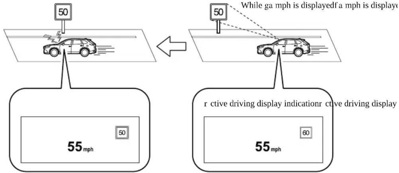
The excessive speed warning is initially set to inoperable. If you want to activate the excessive speed warning, change the setting in the personalization features. In addition, the warning pattern and the warning activation timing differ depending on the setting contents. Refer to the Settings section in the Mazda Connect Owner's Manual.
Warning pattern
- Off: The excessive speed warning is not activated.
- Visual: The area around the speed limit sign displayed in the display flashes 3 times in amber, and if the vehicle speed continues to exceed the displayed speed limit sign, the indication stops flashing and remains on.
- Audio & Visual: The area around the speed limit sign displayed in the display flashes 3 times in amber and the warning sound is activated 3 times at the same time. If the vehicle speed continues to exceed the displayed speed limit sign, the indication stops flashing and remains on.
Warning activation timing
- +0: If the vehicle speed exceeds the speed limit sign displayed in the display, the excessive speed warning is activated.
- +5: If the vehicle speed exceeds the speed limit sign displayed in the display by 5 km/h (3 mph), the excessive speed warning is activated.
- +10: If the vehicle speed exceeds the speed limit sign displayed in the display by 10 km/h (5 mph), the excessive speed warning is activated.
NOTE
- In the following cases, the excessive speed warning stops operating.
- The vehicle speed is less than the speed of the displayed speed limit sign. (If the activation timing for the excessive speed warning is changed in the personalization features, the excessive speed warning stops operating when the vehicle speed is less than the changed vehicle speed.
- A speed limit sign indication has been updated and the vehicle speed is lower than the updated indication.
- Display of the speed limit sign stops.
- The warning indication is displayed at the same time the excessive speed warning sound is activated if the vehicle speed exceeds the speed indicated on the speed limit sign.
Refer to Warning Sound is Activated on page 7-47.
- If the Forward Sensing Camera (FSC) incorrectly recognizes the actual speed limit sign at a lower speed, the excessive speed alarm is activated even if the vehicle is driven at the legal speed.
Distance Recognition Support System (DRSS) ^*
The DRSS measures the distance between your vehicle and a vehicle ahead using a radar sensor (front) while the vehicle speed is about 30 km/h (19 mph) or faster, and if your vehicle approaches a vehicle ahead more closely than what is appropriate for maintaining distance between the vehicles according to the vehicle speed, a notification in the active driving display is indicated to advise you to keep a safe distance from the vehicle ahead.

WARNING
Do not rely completely on the DRSS and always drive carefully:
The ability to detect a vehicle ahead is limited depending on the type of vehicle ahead, the weather conditions, and the traffic conditions. Therefore, if the accelerator and brake pedals are not operated correctly it could lead to an accident. Always verify the safety of the surrounding area and depress the brake pedal or accelerator pedal while keeping a safer distance from vehicles ahead or on-coming vehicles.
NOTE
- The DRSS operates when all of the following conditions are met:
• The ignition is switched ON.
• The DRSS is on.
- The selector lever is in a position other than reverse (R).
· The vehicle speed is 30 km/h or faster (19 mph or faster).
- The objects which activate the system are 4-wheeled vehicles.
- The DRSS may also operate in the presence of motorcycles and bicycles.
- The DRSS may not operate normally under the following conditions:
· The Dynamic Stability Control (DSC) has a malfunction.
• The vehicle ahead is traveling at an extremely slow speed.
· The system does not operate with the following objects:
• Vehicles approaching in the opposite direction.
- Stationary objects (stopped vehicles, obstructions)
▼ Indication on Display
The DRSS operation status is indicated in the active driving display or multi-information display. Regarding malfunctions, check the vehicle conditions or have it inspected by an Authorized Mazda Dealer according to the content of the displayed message.
NOTE
- When the ignition is switched off, the operation status before the system was turned off is maintained. For example, if the ignition is switched off with the DRSS operable, the system will be operable when the ignition is switched ON the next time.
- The DRSS can be turned on/off and the system's sensitivity can be changed. Refer to the Settings section in the Mazda Connect Owner's Manual.
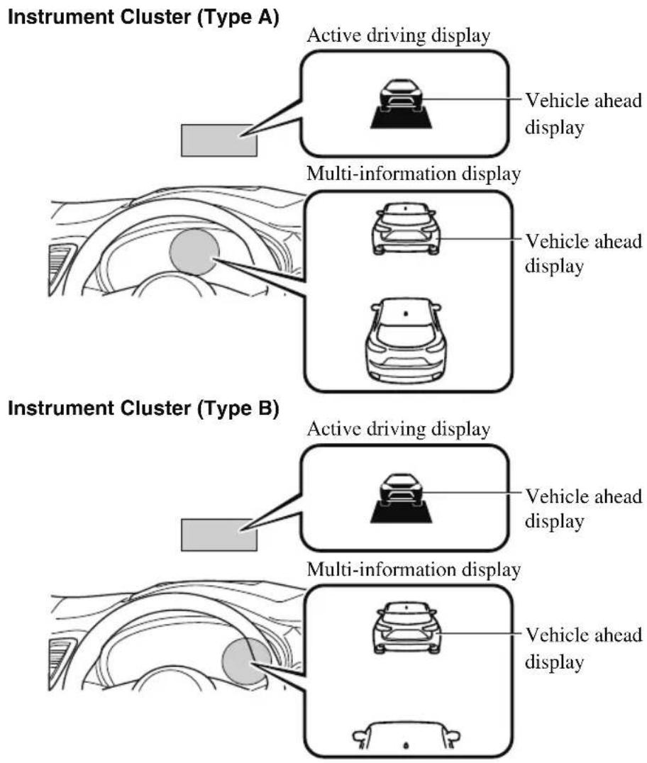
Distance-between-vehicles guidelines *1
| Indication on display Distance be- | tween vehi-cles guide-lines (During travel at about 40 km/h (25 mph) | Distance be-tween vehi-cles guide-lines (During travel at about 80 km/h (50 mph) | ||
| Multi-information display | Active driving dis-play | |||
| Instrument cluster (Type A) | Instrument cluster (Type B) | |||
 |  |  | About 25 m (82 ft) | About 50 m (164 ft) |
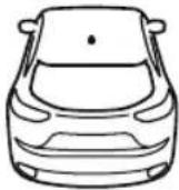 |  | |||
 |  | [IMAGE] | About 20 m (66 ft) | About 40 m (131 ft) |
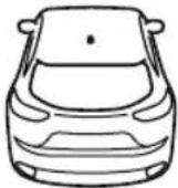 |  | |||
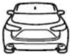 | 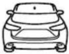 | [IMAGE] | About 15 m (49 ft) | About 30 m (98 ft) |
 |  | |||
 |  |  | About 10 m (33 ft) | About 20 m (66 ft) |
 |  | |||
 | 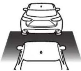 |  | About 10 m (32 ft) or less | About 20 m (65 ft) or less |
| Illuminated in amber*2 | Illuminated in amber*2 | |||
* 1 The distance between vehicles differs depending on vehicle speed.
* 2 Indication when the distance setting for notifying the driver that the vehicle approaches a vehicle ahead is Near.
Driver Attention Alert (DAA)\*
The DAA is a system which detects driver fatigue and decreased attentiveness, and encourages the driver to take a rest.
When the vehicle is driven inside traffic lane lines at about 65 to 140 km/h (40 to 86 mph ), the DAA estimates the amount of accumulated fatigue and decreased attentiveness of the driver based on the information from the Forward Sensing Camera (FSC) and other vehicle information, and encourages the driver to take a rest using an indication on the multi-information display and a warning sound.
Use the DAA on expressways or highways.
Refer to Forward Sensing Camera (FSC) on page 4-235.
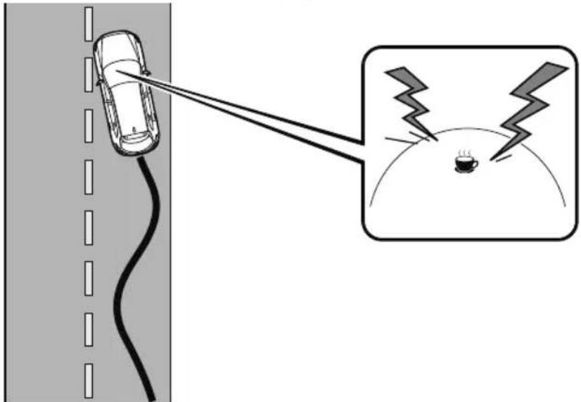

WARNING
Do not rely completely on DAA and always drive carefully:
The DAA detects driver fatigue and decreased attentiveness and encourages the driver to take a rest, however, it is not designed to prevent the vehicle from straying. If you rely too much on the DAA it could lead to an accident. Drive carefully and operate the steering wheel appropriately.
In addition, the system may not be able to detect driver fatigue and decreased attentiveness correctly depending on the traffic and driving conditions. The driver must take sufficient rest in consideration of safer driving.
NOTE
- The DAA operates when all of the following conditions are met.
- The vehicle speed is about 65 to 140 ~km / h (40 to 86 mph).
• The system detects white (yellow) lane lines. - The system has completed learning of the driver's driving data.
- The DAA does not operate under the following conditions.
- The vehicle speed is less than about 65 km/h (40 mph).
• The vehicle speed exceeds about 140 km/h (86 mph)
· The vehicle is making a sharp turn.
· The vehicle is changing lanes.
• The system cannot detect white (yellow) lane lines.
· The DAA may not operate normally under the following conditions.
- White (yellow) lane lines are less visible because of dirt or fading/patchiness.
- The vehicle is jolted or swayed continuously by strong winds or rough roads.
· The vehicle is driven aggressively. - When making frequent lane changes.
- The DAA detects driver fatigue and decreased attentiveness based on the driving data when the vehicle is driven at about 65 to 140km / h (40 to 86 mph) for about 20 minutes. The driving data will be reset under the following conditions.
• The vehicle is stopped for 15 minutes or longer.
- The vehicle is driven at less than about 65 km/h (40 mph) for about 30 minutes.
• The ignition is switched off.
• After the DAA has displayed the first message encouraging rest, it does not display the next one until 45 minutes have passed.
▼ Driver Attention Alert (DAA) Display (White)
When the system detects driver fatigue or decreased attentiveness, it activates the warning sound and displays an alert in the multi-information display.
▼ Canceling Driver Attention Alert (DAA)
The DAA can be set to not activate.
Refer to the Settings section in the Mazda Connect Owner's Manual.
Rear Cross Traffic Alert (RCTA)\*
The RCTA system is designed to assist the driver in checking the area to the rear of the vehicle on both sides while the vehicle is reversing by alerting the driver to the presence of vehicles approaching the rear of the vehicle.
The RCTA system detects vehicles approaching from the rear left and right sides of the vehicle, and the rear of the vehicle while the vehicle is being reversed out of a parking space, and notifies the driver of possible danger using the Blind Spot Monitoring (BSM) warning indicator lights and the warning buzzer.
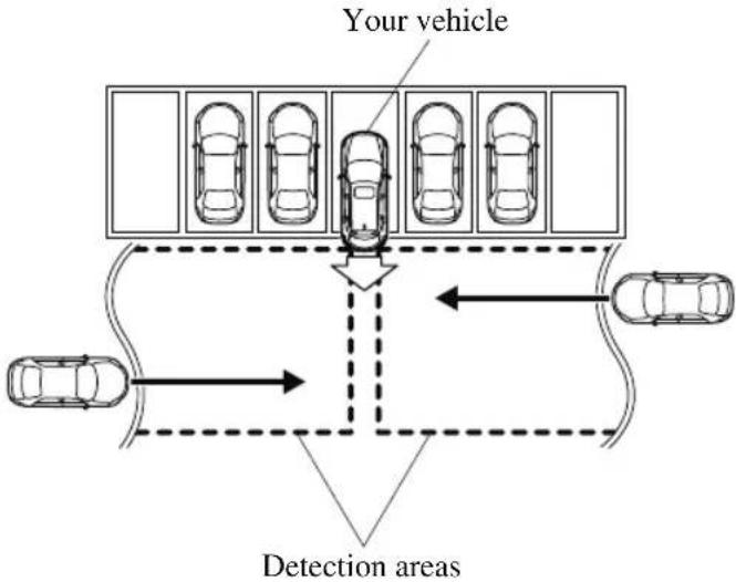
flowchart
graph TD
    A["Your vehicle"] --> B["Top 5 cars in a parking lot"]
    B --> C["Center of car"]
    C --> D["Top 5 cars in a road"]
    D --> E["Bottom 5 cars"]
    E --> F["Top 5 cars in a lane"]
    F --> G["Top 5 cars in a road"]
    G --> H["Bottom 5 cars"]
    H --> I["Top 5 cars"]
    I --> J["Top 5 cars"]
    J --> K["Bottom 5 cars"]
    K --> L["Top 5 cars"]
    L --> M["Top 5 cars"]
    M --> N["Bottom 5 cars"]
    N --> O["Top 5 cars"]
    O --> P["Top 5 cars"]
    P --> Q["Bottom 5 cars"]
    Q --> R["Top 5 cars"]
    R --> S["Top 5 cars"]
    S --> T["Bottom 5 cars"]
    T --> U["Top 5 cars"]
    U --> V["Top 5 cars"]
    V --> W["Bottom 5 cars"]
    W --> X["Top 5 cars"]
    X --> Y["Top 5 cars"]
RCTA operation
-
The RCTA system operates when the selector lever is shifted to the reverse (R) position.
-
If there is the possibility of a collision with an approaching vehicle, the Blind Spot Monitoring (BSM) warning indicator lights flashes and the warning beep is activated simultaneously.
(With rear view monitor)
The RCTA warning indication in the rearview monitor also synchronizes with the Blind Spot Monitoring (BSM) warning indicator light on the door mirrors.
(With 360° view monitor)
The RCTA warning indication in the 360° view monitor also synchronizes with the Blind Spot Monitoring (BSM) warning indicator light on the door mirrors.
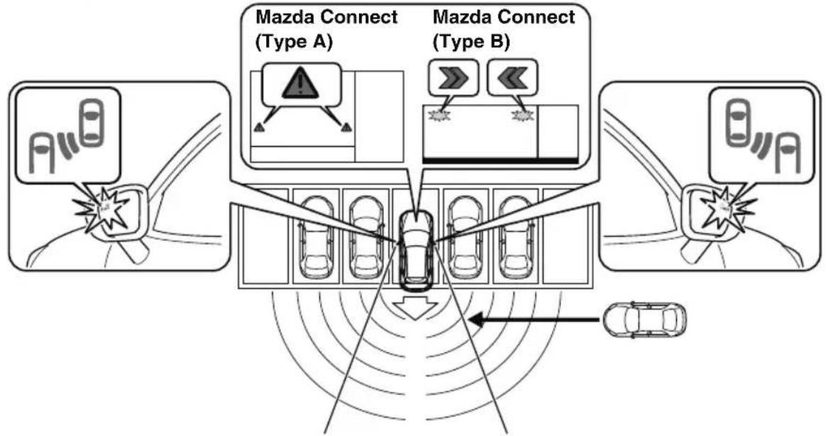
flowchart
graph TD
    A["Top Left Car"] --> B["Top Right Car"]
    C["Top Right Car"] --> D["Top Left Car"]
    E["Top Left Car"] --> F["Top Right Car"]
    G["Top Right Car"] --> H["Top Left Car"]
    I["Mazda Connect (Type A)"] --> J["Mazda Connect (Type A)"]
    K["Mazda Connect (Type B)"] --> L["Mazda Connect (Type B)"]
    M["Top Right Car"] --> N["Top Left Car"]
    O["Top Right Car"] --> P["Top Left Car"]
    Q["Top Right Car"] --> R["Top Left Car"]
    S["Top Right Car"] --> T["Top Left Car"]
    U["Top Left Car"] --> V["Top Right Car"]
    W["Top Right Car"] --> X["Top Left Car"]
    Y["Top Right Car"] --> Z["Top Left Car"]
    AA["Top Right Car"] --> AB["Top Left Car"]
    AC["Top Right Car"] --> AD["Top Left Car"]
    AE["Top Right Car"] --> AF["Top Left Car"]
    AG["Top Right Car"] --> AH["Top Left Car"]
    AI["Top Right Car"] --> AJ["Top Left Car"]
    AK["Top Right Car"] --> AL["Top Left Car"]
    AM["Top Right Car"] --> AN["Top Left Car"]
    AO["Top Right Car"] --> AP["Top Left Car"]
    AQ["Top Right Car"] --> AR["Top Left Car"]
    AS["Top Right Car"] --> AT["Top Left Car"]
    AU["Top Right Car"] --> AV["Top Left Car"]
    AW["Top Right Car"] --> AX["Top Left Car"]
    AY["Warning Icon"] --> Z
    AZ["Warning Icon"] --> AA
    BA["Warning Icon"] --> AB
    BB["Warning Icon"] --> AC
    BC["Warning Icon"] --> AD
    BD["Warning Icon"] --> AE
    BE["Warning Icon"] --> AF
    BF["Warning Icon"] --> AG
    BG["Warning Icon"] --> AH
    BH["Warning Icon"] --> AI

WARNING
Always check the surrounding area visually before actually putting the vehicle in reverse:
The system is only designed to assist you in checking for vehicles at the rear when putting the vehicle in reverse. Due to certain limitations with the operation of this system, the Blind Spot Monitoring (BSM) warning indicator lights may not flash or it might be delayed even though a vehicle is behind your vehicle. Always make it your responsibility as a driver to check the rear.
NOTE
- In the following cases, the Blind Spot Monitoring (BSM) OFF Indicator Light turns on and operation of the system is stopped. If the Blind Spot Monitoring (BSM) OFF Indicator Light remains illuminated, have the vehicle inspected at an Authorized Mazda Dealer as soon as possible.
- Some problem with the system including the Blind Spot Monitoring (BSM) warning indicator lights has occurred.
- A large deviation in the installation position of a radar sensor (rear) on the vehicle has occurred.
- There is a large accumulation of snow or ice on the rear bumper near a radar sensor (rear).
- Driving on snow-covered roads for long periods.
- The temperature near the radar sensors becomes extremely hot due to driving for long periods on slopes during the summer.
• The battery voltage has decreased.
- Under the following conditions, the radar sensors (rear) cannot detect target objects or it may be difficult to detect them.
- The vehicle speed when reversing is about 10 km/h (6.3 mph) or faster.
- The radar sensor (rear) detection area is obstructed by a nearby wall or parked vehicle. (Reverse the vehicle to a position where the radar sensor detection area is no longer obstructed.)
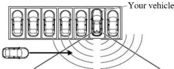
- A vehicle is approaching directly from the rear of your vehicle.
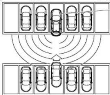
• The vehicle is parked at an angle.
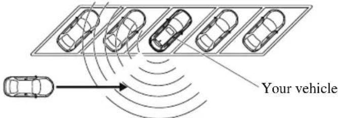
- Directly after the Blind Spot Monitoring (BSM) system becomes operable using the personalization feature.
- Radio wave interference from a radar sensor equipped on a nearby parked vehicle.
- In the following cases, it may be difficult to view the illumination/flashing of the Blind Spot Monitoring (BSM) warning indicator lights equipped on the door mirrors.
- Snow or ice adheres to the door mirrors.
- The front door glass is fogged or covered in snow, frost or dirt.
- Turn off the RCTA system while pulling a trailer or while an accessory such as a bicycle carrier is installed to the rear of the vehicle. Otherwise, the radio waves emitted by the radar will be blocked causing the system to not operate normally.
Mazda Radar Cruise Control with Stop & Go function (MRCC with Stop & Go function)\*
The MRCC with Stop & Go function system is designed to maintain headway control ^1 with a vehicle ahead according to your vehicle's speed using a radar sensor (front) to detect the distance to the vehicle ahead and a preset vehicle speed without you having to use the accelerator or brake pedals.
*1 Headway Control: Control of the distance between your vehicle and the vehicle ahead detected by the Mazda Radar Cruise Control (MRCC) system.
Additionally, if your vehicle starts closing in on the vehicle ahead such as if the vehicle ahead brakes suddenly, a warning sound and a warning indication in the display are activated simultaneously to alert you to maintain a sufficient distance between the vehicles. If the vehicle ahead stops while you are following behind it, your vehicle will stop and be held stopped automatically (stop hold control), and headway control will resume when you resume driving the vehicle such as by pressing the RES switch.
Also refer to the following before using the MRCC with Stop & Go function.
• AUTOHOLD (page 4-96)
- Forward Sensing Camera (FSC) (page 4-235)
- Radar sensor (front) (page 4-240)

WARNING
Do not rely completely on the MRCC with Stop & Go function:
The MRCC with Stop & Go function system has detection limitations depending on the type of vehicle ahead and its conditions, the weather conditions, and the road conditions.
Additionally, the system may be unable to decelerate sufficiently to avoid hitting the vehicle ahead if the vehicle ahead applies the brakes suddenly or another vehicle cuts into the driving lane, which could result in an accident.
Always drive carefully and verify the surrounding conditions and depress the brake pedal or accelerator pedal while keeping a safer distance from vehicles ahead or on-coming vehicles.
Do not use the MRCC with Stop & Go function system in the following locations, using the MRCC with Stop & Go function system at the following locations may result in an unexpected accident:
➢ General roads other than highways (Driving under these conditions using the MRCC with Stop & Go function system is not possible.)
➢Roads with sharp curves and where vehicle traffic is heavy and there is insufficient space between vehicles.
➢Roads where frequent and repetitive acceleration and deceleration occur (Driving under these conditions using the MRCC with Stop & Go function system is not possible).
When entering and exiting interchanges, service areas, and parking areas of highways (If you exit a highway while headway control is in use, the vehicle ahead will no longer be tracked and your vehicle may accelerate to the set speed).
Slippery roads such as ice or snow-bound roads (Tires could spin causing you to lose vehicle control, or the stop hold control may not operate.)
Long, descending slopes (to maintain distance between vehicles, the system automatically and continuously applies the brakes which could result in the loss of brake power.)
➢ Slopes with a steep gradient (The vehicle ahead may not be detected correctly, your vehicle may slide while stopped by the stop hold control, and it may accelerate suddenly after it starts moving.)
For safety purposes, switch the MRCC with Stop & Go function system off when it is not being used.
Do not get out of the vehicle while the stop hold control is operating:
Getting out of the vehicle while the stop hold control is operating is dangerous as the vehicle may move unexpectedly and result in an accident. Before getting out of the vehicle, switch the MRCC with Stop & Go function system off, shift the selector lever to the P position, and apply the parking brake.
CAUTION
If your vehicle is towed or you are towing something, switch the MRCC with Stop & Go function system off to prevent a mis-operation.
NOTE
- The MRCC with Stop & Go function system does not detect the following as physical objects.
• Vehicles approaching in the opposite direction
· Pedestrians - Stationary objects (stopped vehicles, obstructions)
- If a vehicle ahead is traveling at an extremely low speed, the system may not detect it correctly.
- During headway control travel, do not set the system for detection of two-wheeled vehicles such as motorcycles and bicycles.
-
Do not use the MRCC with Stop & Go function system under conditions in which close proximity warnings are frequently activated.
-
During headway control travel, the system accelerates and decelerates your vehicle in conjunction with the speed of the vehicle ahead. However, if it is necessary to accelerate for a lane change or if the vehicle ahead brakes suddenly causing you to close in on the vehicle rapidly, accelerate using the accelerator pedal or decelerate using the brake pedal depending on the conditions.
- While the MRCC with Stop & Go function system is in use, it does not cancel even if the selector lever is operated and any intended engine braking does not occur. If deceleration is required, lower the set speed or depress the brake pedal.
- The sound of the automatic brakes operating may be heard, however, it does not indicate a problem.
- The brake lights turn on while the MRCC with Stop & Go function automatic braking is operating.
▼ Mazda Radar Cruise Control with Stop & Go function (MRCC with Stop & Go function) Display Indication
The MRCC with Stop & Go function setting status and operation conditions are indicated on the multi-information display and the active driving display.
Instrument cluster (Type A)
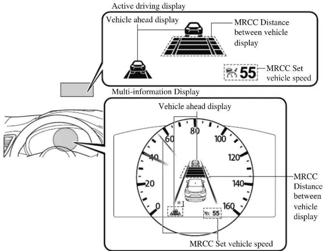
*1: If the indication on the active driving display has been turned off using the personalization features, the indication is displayed on the multi-information display.
Instrument cluster (Type B)
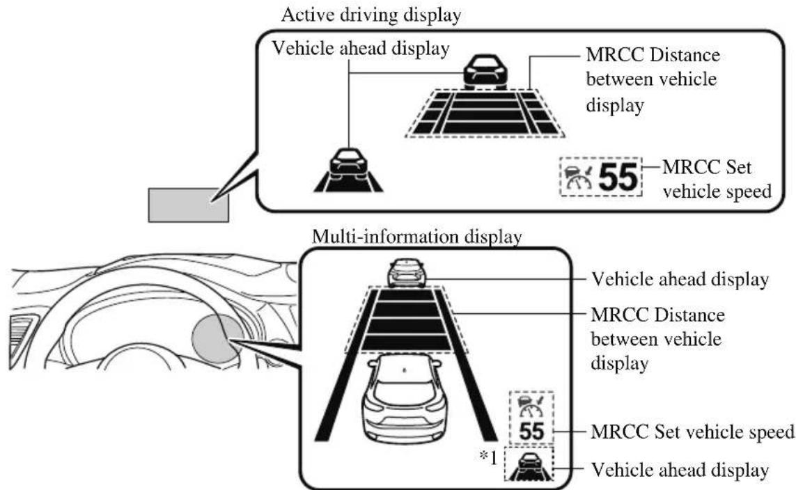
*1: If the indication on the active driving display has been turned off using the personalization features, the indication is displayed on the multi-information display.
If there is a problem with the MRCC with Stop & Go function system, a message is displayed on the multi-information display. Check the center display to verify the problem and then have your vehicle inspected by an Authorized Mazda Dealer.
Refer to Message Indicated on Display on page 7-43.
▼ Close Proximity Warning
If your vehicle rapidly closes in on the vehicle ahead because the vehicle ahead applies the brakes suddenly while you are traveling in headway control, the warning sound activates and the brake warning is indicated in the display. Always verify the safety of the surrounding area and depress the brake pedal while keeping a safer distance from the vehicle ahead. Additionally, keep a safer distance from the vehicles behind you.
BRAKE!
NOTE
In the following cases, the warnings and brakes may not operate even if your vehicle starts closing in on the vehicle ahead.
- You are driving your vehicle at the same speed as the vehicle ahead.
- Directly after the MRCC with Stop & Go function system has been set.
- Directly after the accelerator pedal is released.
• Another vehicle cuts into the driving lane.
▼ Setting the System
The MRCC with Stop & Go function system operates when all of the following conditions are met.
- Vehicle speed is 0 km/h (0 mph) to 145 km/h (90 mph)
- The MRCC with Stop & Go function is turned on.
. The brake pedal is not depressed. - The parking brake is released (Electric Parking Brake (EPB) indicator light is turned off).
- There is no problem with the DSC.
- All the doors are closed.
. The driver's seat belt is fastened. - The selector lever is in the drive (D) position or manual (M) position (manual mode).
NOTE
- In the following cases, the MRCC with Stop & Go function system is canceled when the vehicle is traveling at 30 km/h (20 mph) or less and “Mazda Radar Cruise Control disabled under 30 km/h (20 mph)” is displayed in the multi-information display.
- The Forward Sensing Camera (FSC) cannot detect target objects (There is problem with the Forward Sensing Camera (FSC) or windshield is dirty).
- There is a problem with the stop hold control function.
- There is a problem with the Electric Parking Brake (EPB).
- It may not be possible to set the MRCC with Stop & Go function system directly after starting the engine, while the DSC operation is being checked.
Turning on the system
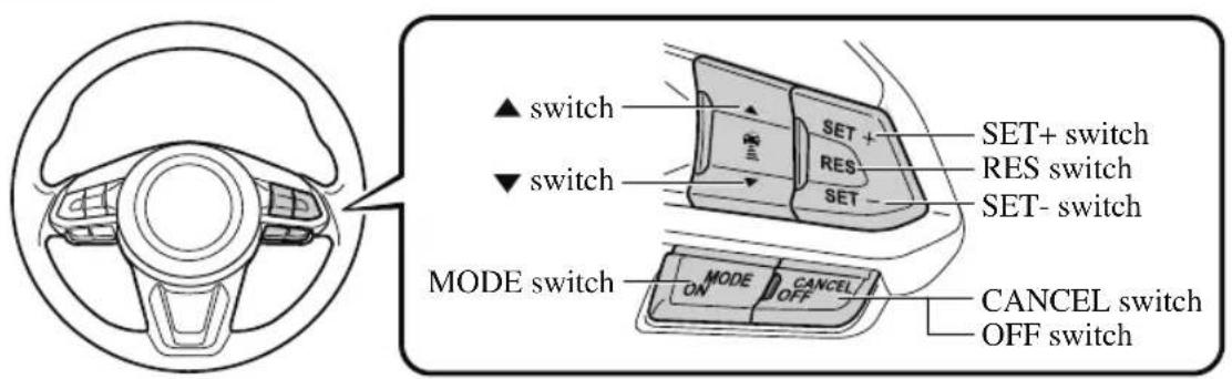
When the MODE switch is pressed once, the MRCC with Stop & Go function system turns on, and the MRCC with Stop & Go function main indication (white) turns on and the vehicle speed and the distance between the vehicles while in headway control can be set.
natural_image
Icon showing a car, speedometer, and downward arrow (no text or symbols)In addition, the MRCC with Stop & Go function system display indication is displayed on the multi-information display and the active driving display at the same time.
NOTE
- If the ignition is switched off while the MRCC with Stop & Go function system is operating, the system will be operable when the ignition is switched ON the next time.
- The MRCC with Stop & Go function can switch to the cruise control function. Refer to Cruise Control Function on page 4-155.
How to set the speed
- Adjust the vehicle speed to the desired setting using the accelerator pedal.
- Headway control begins when the SET + or SET-switch is pressed.
The set speed and the inter-vehicle distance display filled with white lines is displayed. The MRCC with Stop & Go function main indication (white) switches to the MRCC with Stop & Go function set indication (green) at the same time.
| Travel status | Indication on multi-information display | Indication on active driving display | |
| Type A Type B | |||
| During travel at constant speed | 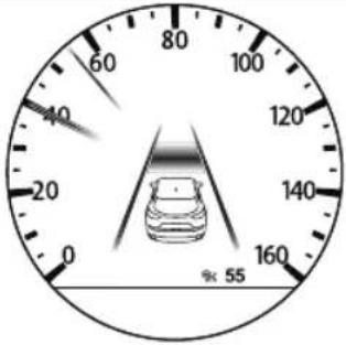 | 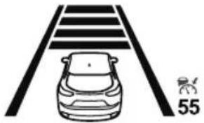 | 55 |
| During travel under head-way control | 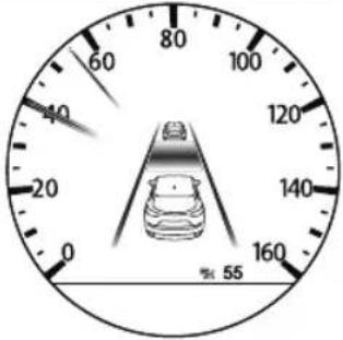 | 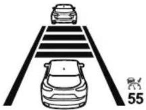 | 55 |
NOTE
- If a vehicle ahead is detected while traveling at a constant speed, the vehicle-ahead indication is displayed and headway control is performed. Additionally, when a vehicle ahead is no longer detected, the vehicle-ahead indication turns off and the system switches back to travel at constant speed.
- The lowest possible speed which can be set on the MRCC with Stop & Go function system is 30 km/h (19 mph).
- Headway control is not possible if the vehicle ahead is driving faster than your vehicle's set speed. Adjust the system to the desired vehicle speed using the accelerator pedal.
How to set the distance-between-vehicles during headway control
The distance-between-vehicles is set to a shorter distance by pressing the ▼ switch. The distance-between-vehicles is set to a longer distance by pressing the ▲ switch. The distance-between-vehicles can be set to 4 levels; Long, medium, short, and extremely short distance.
| Distance-between-vehicles guideline (at 80 km/h (50 mph) vehicle speed) | Indication on multi-information display | Indication on active driving display*1 | |
| Type A Type B | |||
| Long (about 50 m (164 ft)) | 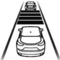 | 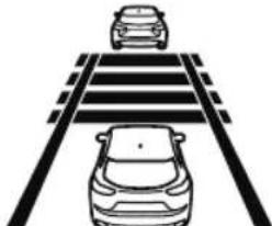 | 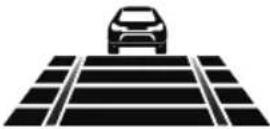 |
| Medium (about 40 m (131 ft)) | 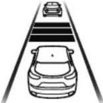 | 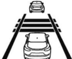 | 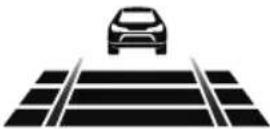 |
| Short (about 30 m (98 ft)) | 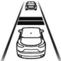 | 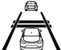 | 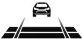 |
| Extremely short (about 25 m (82 ft)) | 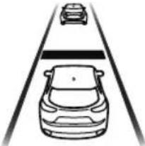 | 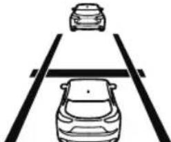 |  |
*1 Displays a pop-up image in the active driving display only when the driver operates the switch.
NOTE
- The distance-between-vehicles differs depending on the vehicle speed, and the slower the vehicle speed, the shorter the distance.
- When the ignition is switched to ACC or OFF and then the engine is started again, the system automatically sets the distance-between-vehicles to the previous setting.
How to change the set vehicle speed
To accelerate/decelerate using the SET switch
When you press the SET+ switch, the vehicle accelerates and when you press the SET- switch, it decelerates.
| Short press 1 km/h (1 mph) |
| Long press 10 km/h (5 mph) |
NOTE
For example, the set vehicle speed is changed by pressing the SET switch four times as follows:
The vehicle speed accelerates or decelerates by 4 km/h (4 mph).
To increase speed using accelerator pedal
Depress the accelerator pedal and press and release the SET+ switch or SET- switch at the desired speed. If the switch is not operated, the system returns to the set speed after you release your foot from the accelerator pedal.
CAUTION
The warnings and brake control do not operate while the accelerator pedal is depressed.
NOTE
- The setting speed can be changed by operating the SET+ switch or SET− switch during stop hold control.
- When accelerating using the SET+ switch while in headway control, the set vehicle speed can be adjusted but acceleration is not possible. If there is no longer a vehicle ahead, acceleration continues until reaching the set vehicle speed. For the set vehicle speed, check the set vehicle speed indication in the display.
- When depressing the accelerator pedal, the inter-vehicle distance indication in the display changes to the white-line indication.
Canceling the system
When the following operations are performed, the MRCC with Stop & Go function system is canceled, and the MRCC with Stop & Go function set indication (green) switches to the MRCC with Stop & Go function main indication (white) at the same time.
- The OFF/CANCEL switch is pressed.
• The brake pedal is depressed.
• The parking brake is applied. - The selector lever is in the P (Park), N (Neutral), or R (Reverse) position.
Under the following conditions, the MRCC with Stop & Go function cancel indication is displayed in the multi-information display and a single beep sound is heard.
• The DSC has operated.
- The Smart Brake Support (SBS) has operated.
- The Smart City Brake Support (SCBS) or Advanced Smart City Brake Support (Advanced SCBS) has operated.
- When traveling on a downslope for a long period of time.
- There is a problem with the system.
• The engine has stalled.
• Any of the doors is opened. - The driver's seat belt is unfastened.
- The parking brake is automatically applied during stop hold control.
- The radar sensor (front) cannot detect target objects (during rain, fog, snow or other inclement weather conditions, or when the radiator grille is dirty).
Resuming control
If the MRCC with Stop & Go function system is canceled, you can resume control at the previously set speed by pressing the RES switch and after all of the operation conditions have been met.
NOTE
If the set speed is not indicated in the display, the control does not resume even if the RES switch is pressed.
Turning off the system
Press the OFF/CANCEL switch 2 times while the MRCC with Stop & Go function system is operating to switch off the system.
▼ Stop Hold Control
While in headway control using the MRCC with Stop & Go function system, your vehicle will stop when a vehicle ahead stops. When the vehicle is stopped and the stop hold control operates, the MRCC with Stop & Go function indicator light turns on.
HOLD
NOTE
- If the MRCC with Stop & Go function system is canceled during stop hold control, the vehicle is held in its stopped position. The stop hold control can be canceled by performing one the following actions.
- Press the accelerator pedal and resume driving the vehicle.
- While forcefully depressing the brake, switch the MRCC with Stop & Go function system off.
- The parking brake is automatically applied and the vehicle is held in its stopped position when 10 minutes have elapsed since the stop hold control operated. At this time, the MRCC with Stop & Go function system is canceled.
- The brake lights turn on during stop hold control.
To resume driving
After the vehicle ahead starts moving while your vehicle is stopped under stop hold control, press the RES switch or depress the accelerator pedal to cancel the stop hold control and resume driving.
NOTE
- When you resume driving by pressing the RES switch, your vehicle does not start moving until the distance between your vehicle and the vehicle ahead lengthens to the specified distance or farther.
- If the MRCC with Stop & Go function is temporarily canceled during stop hold control, you cannot resume driving by pressing the RES switch when there are no vehicles in front of your vehicle. Depress the accelerator pedal and resume driving the vehicle.
- If the vehicle ahead starts moving within 3 seconds after your vehicle is stopped by the stop hold control, headway control will resume even if you do not resume driving your vehicle, such as by depressing the accelerator pedal.
Resume driving information
If you do not resume driving within a few seconds after the vehicle ahead starts moving, the multi-information display vehicle-ahead indication flashes to urge the driver to resume driving.
▼ Cruise Control Function
While this function is operating, the headway control operation is canceled and only the cruise control function operates. The vehicle speed can be set more than about 25 km/h (16 mph).
Use the cruise control function on expressways and other highways which do not require a lot of repeated acceleration and deceleration.
WARNING
Do not use the cruise control function in the following locations:
Otherwise, it could lead to an accident.
➢Roads with sharp curves and where vehicle traffic is heavy and there is insufficient space between vehicles. (Driving under these conditions using the cruise control function is not possible)
➢ Steep down slopes (Set speed may be exceeded because sufficient engine braking cannot be applied)
➢ Slippery roads such as ice or snow-bound roads (Tires could spin causing you to lose vehicle control)
Always drive carefully:
The warnings and brake control will not operate after the headway control function is canceled and the system is switched to only the cruise control function. Depress the brake pedal to decelerate according to the surrounding conditions while keeping a safer distance from the vehicle ahead and always driving carefully.
Switching to cruise control function
When the MODE switch is pressed until the system switches to the cruise main indication (white) while the MRCC with Stop & Go function system is turned on, the system switches to the cruise control function.
When the system switches to the cruise control function, the indicator and multi-information display notify the driver as follows:
- The MRCC with Stop & Go function set indication (green) or the MRCC with Stop & Go function main indication (white) is turned off, and the cruise main indication (white) is turned on.
- A message is displayed in the multi-information display.

WARNING
Always turn off the cruise control function when it is not in use:
Leaving the cruise control function turned on when it is not in use is dangerous as it could operate unexpectedly, resulting in an accident.
How to set the speed
Adjust the system to the desired vehicle speed using the accelerator pedal. When the SET+ or SET-switch is pressed, the cruise set indication (green) is turned on and headway control begins.
NOTE
- The system may not be able to maintain the set speed constantly depending on driving conditions such as steep up or down slopes.
- The speed will continue increasing while the SET+ switch is pressed and held. The speed will continue decreasing while the SET− switch is pressed and held.
How to increase the set speed
The set speed can be increased using the following operations:
To increase speed using the SET+ switch
Press and hold the SET+ switch and release the switch at the desired speed. The set speed can be adjusted incrementally (1 km/h (1 mph) increments) by pressing the switch and releasing it immediately. For example, if the switch is pressed 4 times, the set speed increases by about 4 km/h (4 mph).
To increase speed using accelerator pedal
Depress the accelerator pedal and press the SET+ or SET-switch at the desired speed.
If the switch is not operated, the system returns to the set speed after you release your foot from the accelerator pedal.
How to Decrease the Set Speed
Press the SET-switch continuously and release the switch at the desired speed. The set speed can be adjusted incrementally (1 km/h (1 mph) increments) by pressing the switch and releasing it immediately. For example, if the switch is pressed 4 times, the set vehicle speed decreases by about 4 km/h (4 mph).
Canceling the function
When the cruise control function is canceled and the RES switch is pressed while the vehicle speed is 25 km/h (16 mph) or faster, the speed returns to the original set speed.
Canceling using OFF/CANCEL switch
When the OFF/CANCEL switch is pressed once, the cruise control function is cancelled.
Automatically cancel
The cruise control function is canceled automatically in the following cases.
• The brake pedal is depressed.
• The parking brake is applied.
- The selector lever is shifted to P or N position.
NOTE
- If the vehicle speed decreases by about 15 ~km / h (9.4 mph) or more than the set speed, the cruise control function may be canceled.
- When the vehicle speed is less than 21 km/h (13 mph), the cruise control function is canceled. In this case, the vehicle speed will not return to the original set speed even if the vehicle is accelerated to 25 km/h (16 mph) or higher and the RES switch is pressed. Reset the cruise control function.
Lane-keep Assist System (LAS) & Lane Departure Warning System (LDWS)\*
The LAS & LDWS alerts the driver that the vehicle may be deviating from its lane and it provides steering assistance to help the driver stay within the vehicle lanes. The Forward Sensing Camera (FSC) detects the white lines (yellow lines) of the vehicle lane in which the vehicle is traveling and if the system determines that the vehicle may deviate from its lane, it operates the electric power steering to assist the driver's steering operation. The system also alerts the driver by activating a lane departure warning sound, vibrating the steering wheel, and indicating an alert in the display. Use the system when you drive the vehicle on roads with white (yellow) lines such as expressways and highways. Refer to Forward Sensing Camera (FSC) on page 4-235.
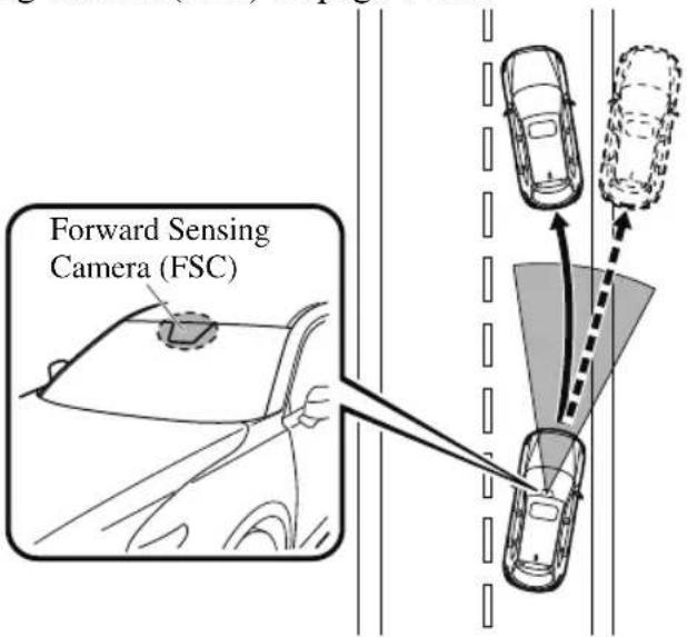

WARNING
Do not rely completely on the LAS & LDWS:
The LAS & LDWS is not an automatic driving system. In addition, the system is not designed to compensate for a driver's lack of caution, and over-reliance on the system could lead to an accident.
The detection ability of the LAS & LDWS is limited. Always stay on course using the steering wheel and drive with care.
Do not use the LAS & LDWS in the following cases:
The system may not operate adequately according to the actual driving conditions, resulting in an accident.
- Driving on roads with tight curves.
- Driving under bad weather conditions (rain, fog, and snow).
▶Slippery roads such as ice or snow-bound roads.
➢Roads with heavy traffic and insufficient distance between vehicles.
▶Roads with no white (yellow) lane lines.
Narrow roads resulting from road construction or lane closures.
The vehicle is driven on a temporary lane or section with a closed lane resulting from road construction where there may be multiple white (yellow) lane lines or they are interrupted.
➢ Vehicle is driven on roads other than expressways and highways.
The tire pressures are not adjusted to the specified pressure.
The vehicle is being used to tow a camper or boat trailer.
➢Tires of a different specified size are used, such as an emergency spare tire.

CAUTION
Heed the following cautions so that the LAS & LDWS can operate normally.
▶ Do not modify the suspensions.
➢Always use wheels of the specified type and size for the front and rear wheels. Consult an Authorized Mazda Dealer for tire replacement.
NOTE
- When the turn signal lever is operated for a lane change, the LAS & LDWS is automatically disabled. The LAS & LDWS becomes operational again when the turn signal lever is returned and the system detects white (yellow) lane lines while the vehicle is being driven normally within its vehicle lane.
- If the steering wheel, accelerator pedal, or brake pedal is operated abruptly and the vehicle moves close to a white (yellow) line, the system determines that the driver is making a lane change and the LAS & LDWS operation is temporarily canceled. The LAS & LDWS becomes operational again when the system detects white (yellow) lane lines while the vehicle is being driven normally within its vehicle lane.
- If the vehicle deviates from its lane repeatedly within a short period of time, the LAS & LDWS may not operate.
- When white (yellow) lane lines are not detected, the LAS & LDWS does not operate.
-
Under the following conditions, the LAS & LDWS may not be able to detect white (yellow) lane lines correctly and it may not operate normally.
-
If an object placed on the dashboard is reflected in the windshield and picked up by the camera.
-
Heavy luggage is loaded in the luggage compartment or on the rear seat and the vehicle is tilted.
-
The tire pressures are not adjusted to the specified pressure.
• Tires other than conventional tires are equipped. - Vehicle is driven on an intersection or junction, or on a forked road.
- The white (yellow) lane lines are less visible because of dirt or fading/patchiness.
- A vehicle in front of your vehicle is running near a white (yellow) lane line making it less visible.
- A white (yellow) lane line is less visible because of bad weather (rain, fog, or snow).
- The vehicle is driven on a temporary lane or section with a closed lane resulting from construction where there may be multiple white (yellow) lane lines or they are interrupted.
- A misleading line is picked up on the road such as a temporary line for construction, or because of shade, lingering snow, or grooves filled with water.
- The surrounding brightness suddenly changes such as when entering or exiting a tunnel.
The illumination of the headlights is weakened because of dirt or the optical axis is deviated.
· The windshield is dirty or foggy.
• The windshield, camera is fogged (water droplets). - Back-light is reflected off the road surface.
· The road surface is wet and shiny after rain, or there are puddles on the road.
· The shade of a guardrail parallel to a white (yellow) lane line is cast on the road.
· The width of the driving lane is narrow or wide. - Driving on roads with tight curves.
• The road is excessively uneven.
• The vehicle is shaken after hitting a road bump. - There are 2 or more adjacent white (yellow) lane lines.
- There are various road markings or lane markings of various shapes near an intersection.
▼ System Operation
Make sure that the LAS & LDWS OFF switch indicator light is turned off. When the LAS & LDWS OFF switch indicator light is turned on, press the switch and
make sure that the switch indicator light turns off.
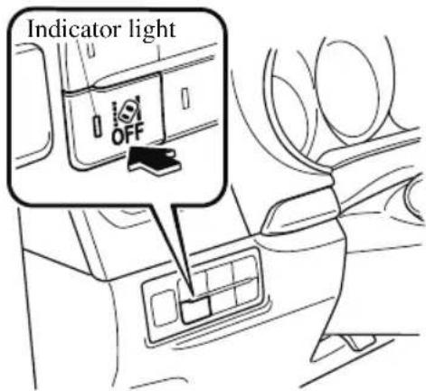
When the ignition is switched ON, the system goes on standby.
Drive the vehicle in the center of the vehicle lane while the system is on standby. When all of the following conditions are met, and the system becomes operational.
• The engine is running.
- The vehicle speed is about 60 km/h (37 mph) or faster.
- The system detects white (yellow) lane lines on both the right and left sides.
- The driver is operating the steering wheel.
- The driving lane is neither narrow nor wide.
When the system becomes operational, the LAS & LDWS indication (white) is
displayed on the multi-information display or active driving display.
Active Driving Display
natural_image
Blank white rectangle with a single black symbol in the bottom-left corner (no text or markings)Multi-information Display
Instrument Cluster (Type A)
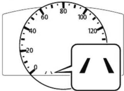
Instrument Cluster (Type B)
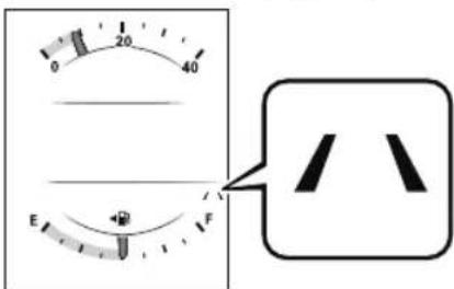
If the indication on the active driving display has been turned off using the personalization features, the LAS & LDWS indication (white) is displayed on the multi-information display.
NOTE
When only a vehicle lane line (yellow) on either the left or right is detected, the LAS & LDWS indication on the active driving display turns off.
Active Driving Display
Detection only on either left or right
Detects on both left and right sides
No indication

Multi-information Display
Detection only on either left or right
Detects on both left and right sides

(Gray) (White)
If the indication on the active driving display has been turned off using the personalization features, the LAS & LDWS indication on the multi-information display is displayed in gray and the system goes on standby.
The LAS & LDWS goes on stand-by status in the following cases:
- The system cannot detect white (yellow) lane lines.
- The vehicle speed is less than about 60 km/h (37 mph).
• The ABS/TCS is operating. - The TCS is turned off.
(If the TCS is turned off while the system is operational, a warning beep is heard and the system goes on standby.)
• The vehicle is making a sharp curve.
. The brake pedal is depressed. - The steering wheel is operated abruptly.
- The width of a lane is excessively narrow or wide.
NOTE
- The LAS & LDWS does not operate until the system detects white (yellow) lane lines on either the left or right.
- When the system detects a white (yellow) lane line on one side only, the system will not operate the steering wheel operation assist and the warning for the lane line on the side that is not being detected. The steering wheel operation assist and the warning is only for a lane deviation on the side that is being detected.
- If the driver takes his or her hands off the steering wheel (not holding the steering wheel), the warning sound is activated and an alert is indicated in the multi-information display or the active driving display.
Multi-information Display

Lane-keep Assist
System.
Please Hold
Steering Wheel
Active Driving Display
Please hold steering wheel
If the steering wheel is held lightly, or depending on the road conditions, the system may detect that you have released the steering wheel (not holding the steering wheel) even if you are holding it, and display a message in the multi-information display or the active driving display.
- The timing at which the lane departure warning is activated and the steering wheel operation assist is performed varies.
- The following settings for the LAS & LDWS can be changed. Refer to the Settings section in the Mazda Connect Owner's Manual.
• Steering operation assist operational/non-operational
- Cancel sensitivity (likelihood of steering assist) (Mazda Connect (Type A) only)
Vehicle lane line display
When the LAS & LDWS becomes operational while on standby, the vehicle lane lines are displayed in the multi-information display and the active driving display. In the vehicle lane lines display indicating the operation status, the color of the vehicle lane lines being detected changes to white.
(Stand-by status)
Multi-information Display
Active Driving Display
natural_image
Empty white rectangle with a thin gray border (no text or symbols)(Operational status)
Multi-information Display
Active Driving Display
natural_image
Blank white rectangle with a single black symbol in the bottom-left corner (no text or markings)Auto cancel
In the following cases, the LAS & LDWS is automatically canceled, the LAS & LDWS warning indication (amber) turns on, and an alert is displayed. When the LAS & LDWS become operational, the system turns back on automatically.
- The temperature inside the camera is high or low.
- The windshield around the camera is foggy.
- The windshield around the camera is blocked by an obstruction, causing poor forward visibility.
Auto cancel of warning/steering assist
When the following operations are performed, the LAS & LDWS operation is canceled automatically. The LAS & LDWS resumes automatically after the operation.
- The steering wheel is operated abruptly.
• The brake pedal is operated. -
The accelerator pedal is operated. (To cancel the automatic sensitivity cancel function, deselect “Cancel sensitivity” in the personalization features setting.) (Mazda Connect (Type A) only)
-
The turn signal lever is operated.
• The vehicle crosses a lane line.
NOTE
• After the operation, the LAS & LDWS operation may not operate for a period of 5 seconds at the most until the lane lines are detected.
- Under the following conditions, the LAS & LDWS cancels the warning/steering assist automatically.
• The driver takes his/her hands off the steering wheel.
(The LAS & LDWS is designed to assist the driver's steering operation and it will resume operation automatically when the driver holds the steering wheel.)
- The TCS OFF switch is pressed to cancel the TCS.
Steering operation assist OFF (non-operational)
The steering operation assist for the LAS & LDWS can be changed to non-operational (OFF).
Refer to the Settings section in the Mazda Connect Owner's Manual.
When the steering operation assist has been changed to inoperable (OFF), only the lane departure warning is operational.
System operation
Make sure that the LAS & LDWS OFF switch indicator light is turned off. When the LAS & LDWS OFF switch indicator light turns on, press the switch and make
sure that the switch indicator light turns off.
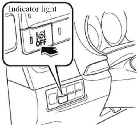
Drive the vehicle in the center of the driving lane while the LAS & LDWS OFF switch indicator light is turned off.
The system becomes operational when all of the following conditions are met.
- The system detects white (yellow) lane lines on both the right and left sides or on either side.
- The vehicle speed is about 60 km/h (37 mph) or faster.
- The vehicle is driven on a straight road or road with gentle curves.
• The engine is running.
The LAS & LDWS goes on stand-by status in the following cases:
- The system cannot detect white (yellow) lane lines.
- The vehicle speed is less than about 60 km/h (37 mph).
• The vehicle is making a sharp curve.
- The vehicle is making a curve at an inappropriate speed.
NOTE
- The LAS & LDWS remains on stand-by until it detects white (yellow) lines on both the left and right sides, or on either side.
- When the system detects a white (yellow) lane line on one side only, the system will not activate warnings for the lane line on the side that is not being detected.
- The distance and warning sensitivity (likelihood of a warning) which the system uses to determine the possibility of a lane departure can be changed. (Mazda Connect (Type A) only) Refer to the Settings section in the Mazda Connect Owner's Manual.
Vehicle lane line display
When the LAS & LDWS becomes operational while on standby, the vehicle lane lines are displayed in the multi-information display. The system changes to operational status display when the system detects a white (yellow) line on either the left or right.
(Stand-by status)
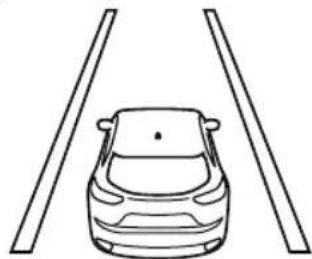
natural_image
Line drawing of a car with two vertical bars above it, no text or symbols present(Operational status)
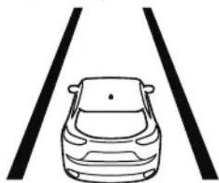
natural_image
Simple line drawing of a car viewed from above two straight lanes (no text or symbols)Auto cancel
In the following cases, the LAS & LDWS is automatically canceled, the LAS & LDWS warning indication (amber) turns on, and an alert is displayed. When the LAS & LDWS become operational, the system turns back on automatically.
- The temperature inside the camera is high or low.
- The windshield around the camera is foggy.
- The windshield around the camera is blocked by an obstruction, causing poor forward visibility.
(Auto cancel of warnings)
When the following operations are performed, the LAS & LDWS determines that the driver intends to make a lane change and the system operation is canceled automatically. The LAS & LDWS resumes automatically after the operation.
- The steering wheel is operated abruptly.
• The brake pedal is depressed. - The accelerator pedal is depressed. (To cancel the automatic sensitivity cancel function, deselect “Warning sensitivity” in the personalization features setting.) (Mazda Connect (Type A) only)
• The turn signal lever is operated.
• The vehicle crosses a lane line.
▼ System Canceling
When the LAS & LDWS is turned off, press the LAS & LDWS OFF switch.
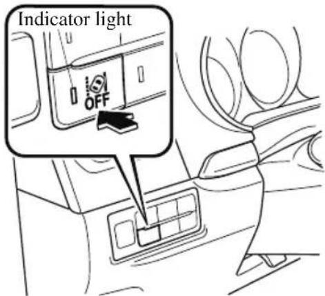
The LAS & LDWS OFF switch indicator light turns on.
NOTE
- In the following cases, the LAS & LDWS is canceled automatically and the LAS & LDWS OFF indication is displayed in the multi-information display. Have your vehicle inspected at an Authorized Mazda Dealer.
- There is a malfunction in the power steering.
- There is a malfunction in the TCS.
- There is a malfunction in the Forward Sensing Camera (FSC).
- When the ignition is switched OFF, the system status before it was turned off is maintained. For example, if the ignition is switched OFF with the lane-keep system operable, the system will be operable when the ignition is switched ON the next time.
When the LAS & LDWS is turned off, the vehicle lane line indication in the multi-information display and the active driving display turn off.
▼ Lane Departure Warning
If the system determines that the vehicle may deviate from its lane, the lane departure warning (beep sound, rumble sound (Mazda Connect (Type A) only) ^*1 , or steering wheel vibration) is activated and the direction in which the system determines that the vehicle may deviate is indicated in the multi-information display and the active driving display. If the system determines that the vehicle may deviate from its lane, the color of the lane line on the side being detected by the system changes from white to amber, and flashes.
Multi-information Display Active Driving Display
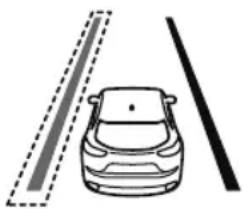
natural_image
Simple line drawing of a car with two dashed lane lines and a solid black line, no text or symbols present.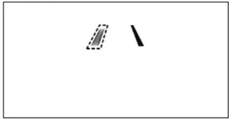
NOTE
- If you have set the lane departure warning sound to the beep sound/rumble sound (Mazda Connect (Type A) only) ^*1 setting, the warning sound may not be heard depending on the surrounding noise conditions.
- If you have set the lane departure warning system to the steering wheel vibrations setting, the vibration may not be felt depending on the road surface conditions.
- When the setting for the steering operation assist is changed to operational, the warnings can be set to activate/not activate. (When the setting for the steering operation assist is changed to non-operational, the warnings cannot be set to not activate.) Refer to the Settings section in the Mazda Connect Owner's Manual.
- The LAS & LDWS can be changed to the following settings regardless of whether the steering operation assist has been set to operational/non-operational. Always check the setting status when driving the vehicle and make setting changes if necessary. Refer to the Settings section in the Mazda Connect Owner's Manual.
• Steering wheel vibration: Strong/weak
- Warning sound volume
- Types of warnings (steering wheel vibration/beep sound/rumble sound (Mazda Connect (Type A) only) ^*1 )
*1 A rumble strip is a series of grooves in the road pavement surface positioned at specific intervals, and when the vehicle passes over it a vibration and rumble sound is produced which alerts the driver that the vehicle is departing from the lane.
The rumble sound is a reproduction of the sound which occurs when a vehicle passes over a rumble strip.
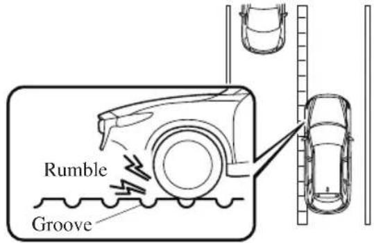
Advanced Smart City Brake Support (Advanced SCBS)\*
The Advanced SCBS alerts the driver of a possible collision using the display and a warning sound when the Forward Sensing Camera (FSC) detects a vehicle ahead or pedestrian and determines that a collision with the object is unavoidable while the vehicle is driven at a vehicle speed of about 4 to 80 ~km / h (2 to 50 mph ) if the object is a vehicle ahead and about 10 to 80 ~km / h (6.2 to 50 mph ) if the object is a pedestrian. In addition, the system reduces damage in the event of a collision by operating the brake control (Advanced SCBS brake) when the system determines that a collision is unavoidable. In addition, when the driver depresses the brake pedal, the brakes are applied firmly and quickly to assist. (Brake Assist (Advanced SCBS brake assist))
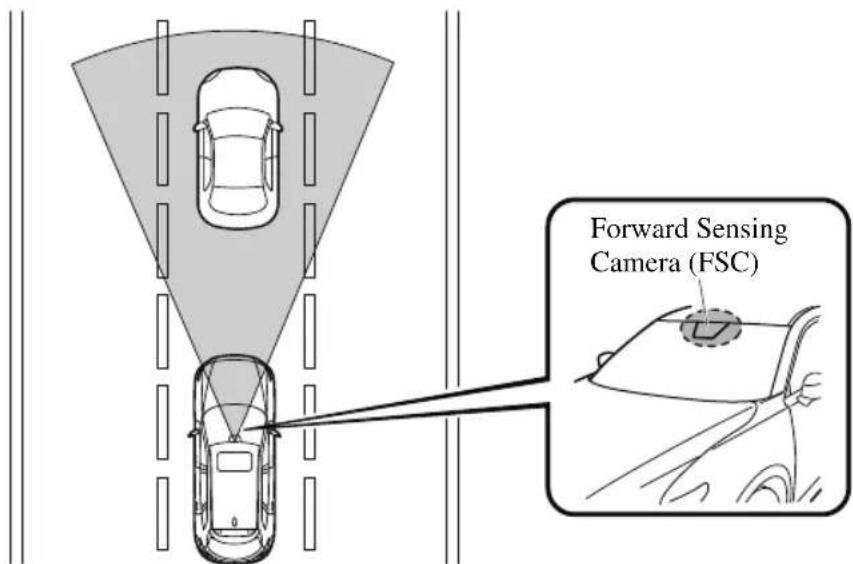

WARNING
Do not rely completely on the Advanced SCBS system:
The Advanced SCBS system is only designed to reduce damage in the event of a collision. Over reliance on the system leading to the accelerator pedal or brake pedal being mistakenly operated could result in an accident.
The Advanced SCBS system operates in response to a vehicle ahead or a pedestrian. The system does not operate in response to obstructions such as a wall, 2-wheeled vehicles, or animals.

CAUTION
In the following cases, turn the system off to prevent a mis-operation:
The vehicle is being towed or when towing another vehicle.
The vehicle is on a chassis roller.
When driving on rough roads such as in areas of dense grass or off-road.
Refer to Stopping the Advanced Smart City Brake Support (Advanced SCBS) System Operation on page 4-171 on how to turn off the Advanced SCBS system.
NOTE
- The Advanced SCBS system will operate under the following conditions.
• The engine is running.
· The Smart City Brake Support (SCBS) warning indication(amber) does not illuminate.
· (Object is vehicle ahead)
The vehicle speed is between about 4 to 80 km/h (2 to 50 mph).
· (Object is a pedestrian)
The vehicle speed is between about 10 to 80 km/h (6.2 to 50 mph).
- The Advanced SCBS system is not turned off.
· Under the following conditions, the Advanced SCBS system may not operate normally:
- The Advanced SCBS system will not operate if the driver is deliberately performing driving operations (accelerator pedal and steering wheel).
- If there is the possibility of partial contact with a vehicle ahead.
- The vehicle is driven on a slippery road surface such as wet roads or icy or snow-bound roads.
- The braking performance is adversely affected due to cold temperatures or wet brakes.
- The vehicle is driven at the same speed as the vehicle ahead.
- The accelerator pedal is depressed.
• The brake pedal is depressed.
· The steering wheel is being operated. - The selector lever is being operated.
- In the following cases, the Advanced SCBS may operate.
- Objects on the road at the entrance to a curve.
- Vehicles passing in the opposite lane while making a curve.
- When passing through a toll gate.
- When passing through low gates, narrow gates, car washing machines, or tunnels.
· If you suddenly come close to a vehicle ahead. - 2-wheeled vehicles, animals, or standing trees.
▼ Collision Warning
If there is the possibility of a collision with a vehicle ahead, the beep sounds continuously and a warning is indicated in the multi-information display or the active driving display.
BRAKE!
NOTE
The operation distance and volume of the collision warning can be changed. Refer to the Settings section in the Mazda Connect Owner's Manual.
▼ Automatic Brake Operation Display
The automatic brake operation display is indicated on the multi-information display after the Advanced SCBS is operated.

Smart City Brake Support Activated
NOTE
- The collision warning beep sounds intermittently while the Advanced SCBS brake or brake assist (Advanced SCBS brake assist) is operating.
- If the vehicle is stopped by the Advanced SCBS operation and the brake pedal is not depressed, the warning beep sounds 1 time after about 2 seconds and the Advanced SCBS brake is automatically released.
▼ Stopping the Advanced Smart City Brake Support (Advanced SCBS) System Operation
The Advanced SCBS system can be temporarily deactivated. Refer to the Settings section in the Mazda Connect Owner's Manual. When the Advanced SCBS system is turned off, the Smart City Brake Support (SCBS) OFF indicator light turns on.
When the engine is restarted, the system becomes operational.
NOTE
When the Advanced SCBS system is set to inoperable, the Smart City Brake Support [Reverse] (SCBS R) system and the Smart Brake Support (SBS) are also set to inoperable.
Smart City Brake Support [Forward] (SCBS F)\*
The SCBS F system alerts the driver of a possible collision using an indication in the display and a warning sound when the Forward Sensing Camera (FSC) detects a vehicle ahead and determines that a collision with a vehicle ahead is unavoidable while the vehicle is being driven at a vehicle speed of about 4 to 80 km/h (2 to 50 mph). In addition, the system reduces damage in the event of a collision by operating the brake control (Smart City Brake Support (SCBS) brake) when the system determines that a collision is unavoidable while the vehicle is being driven at a vehicle speed of about 4 to 30 km/h (2 to 18 mph). It may also be possible to avoid a collision if the relative speed between your vehicle and the vehicle in front of you is less than about 20 km/h (12 mph). In addition, when the driver depresses the brake pedal while the system is in the operation range at about 4 to 30 km/h (2 to 18 mph), the brakes are applied firmly and quickly to assist. (Brake Assist (Smart City Brake Support (SCBS) brake assist))
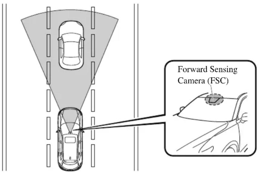
![MAZDA CX-9 (2021) - Smart City Brake Support [Forward] (SCBS F)\* - 2](/content/2026/05/810615/images/85069c7351100b475032f60364248c0ebef7b52eb03a6a5f12fab1fd022b412b.jpg)
WARNING
Do not rely completely on the SCBS F system:
The SCBS F system is only designed to reduce damage in the event of a collision. Over reliance on the system leading to the accelerator pedal or brake pedal being mistakenly operated could result in an accident.
The SCBS F is a system which operates in response to a vehicle ahead. The system may not be able to detect or react to 2-wheeled vehicles or pedestrians.

CAUTION
In the following cases, turn the system off to prevent a mis-operation:
The vehicle is being towed or when towing another vehicle.
The vehicle is on a chassis roller.
When driving on rough roads such as in areas of dense grass or off-road.
Refer to Stopping the Smart City Brake Support (SCBS) system Operation on page 4-174 on how to turn off the SCBS F system.
NOTE
- The SCBS F system will operate under the following conditions.
- The engine is running.
- The Smart Brake Support/Smart City Brake Support (SBS/SCBS) system warning indication (amber) does not illuminate.
· (Rear-end collision warning)
The vehicle speed is about 4 to 80 km/h (2 to 50 mph).
- (Brake control (Smart City Brake Support (SCBS) brake)) The vehicle speed is about 4 to 30 km/h (2 to 18 mph).
- The SCBS F system is not turned off.
- Under the following conditions, the SCBS F system may not operate normally:
- The SCBS F system will not operate if the driver is deliberately performing driving operations (accelerator pedal and steering wheel).
- If there is the possibility of partial contact with a vehicle ahead.
- The vehicle is driven on a slippery road surface such as wet roads or icy or snow-bound roads.
- The braking performance is adversely affected due to cold temperatures or wet brakes.
- The vehicle is driven at the same speed as the vehicle ahead.
- The accelerator pedal is depressed.
• The brake pedal is depressed.
- The steering wheel is being operated.
- The selector lever is being operated.
- In the following cases, the Forward Sensing Camera (FSC) determines that there is a vehicle ahead and the SCBS F may operate.
· Objects on the road at the entrance to a curve.
- Vehicles passing in the opposite lane while making a curve.
- Metal objects, bumps, or protruding objects on the road.
- When passing through a toll gate.
- When passing through low gates, narrow gates, car washing machines, or tunnels.
· If you suddenly come close to a vehicle ahead.
- 2-wheeled vehicles, pedestrians, animals or standing trees.
- Vehicle is driven with some of the tires having significant wear.
▼ Smart City Brake Support (SCBS) Indicator Light (Red)\*
If the Smart City Brake Support (SCBS) is operating, the indicator light (red) flashes.
natural_image
Simple gray line icons showing a car, a truck, and a star with an arrow (no text or symbols)▼ Collision Warning\*
If there is the possibility of a collision with a vehicle ahead, the beep sounds continuously and a warning is indicated in the multi-information display and the active driving display.
BRAKE!
NOTE
The operation distance and volume of the collision warning can be changed. Refer to the Settings section in the Mazda Connect Owner's Manual.
▼ Automatic Brake Operation Display\*
The automatic brake operation display is indicated on the multi-information display after the SCBS F is operated.
Smart City Brake Support Activated
NOTE
- The collision warning beep sounds intermittently while the SCBS F brake or brake assist (SCBS F brake assist) is operating.
- If the vehicle is stopped by the SCBS F operation and the brake pedal is not depressed, the warning beep sounds 1 time after about 2 seconds and the SCBS F brake is automatically released.
▼ Stopping the Smart City Brake Support [Forward] (SCBS F) System Operation
The SCBS F system can be temporarily deactivated.
Refer to the Settings section in the Mazda Connect Owner's Manual.
When the SCBS F system is turned off, the Smart City Brake Support (SCBS) OFF indicator light turns on.
When the engine is restarted, the system becomes operational.
NOTE
When the SCBS F system is set to inoperable, the Smart Brake Support (SBS) are also set to inoperable.
Smart City Brake Support [Reverse] (SCBS R)\*
The SCBS R is a system which is designed to reduce damage in the event of a collision by operating the brake control (SCBS brake) when the system's ultrasonic sensors detect an obstruction at the rear of the vehicle while driving at a speed of about 2 to 8km / h (2 to 4 mph) and the system determines that a collision is unavoidable.
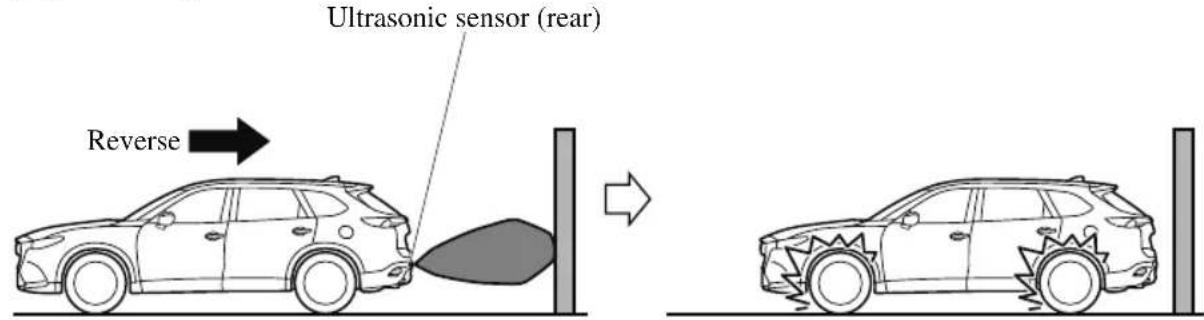
![MAZDA CX-9 (2021) - Smart City Brake Support [Reverse] (SCBS R)\* - 2](/content/2026/05/810615/images/704eaaf1506ad09216c566b7ad5e51d3d07af71267edcb9ae1af5bff746fde67.jpg)
WARNING
Do not rely completely on the SCBS R system:
The SCBS R system is only designed to reduce damage in the event of a collision. Over reliance on the system leading to the accelerator pedal or brake pedal being mistakenly operated could result in an accident.
To assure the correct operation of the SCBS R, heed the following cautions.
➢ Do not apply a sticker to an ultrasonic sensor (rear) (including transparent stickers). Otherwise, the ultrasonic sensor (rear) may not be able to detect vehicles or obstructions which could result in an accident.
Do not disassemble an ultrasonic sensor (rear).
If cracks or damage caused by flying gravel or debris is visible around an ultrasonic sensor (rear), stop using the SCBS R system immediately and have your vehicle inspected by an Authorized Mazda Dealer. If the vehicle continues to be driven with cracks or scratch marks left around an ultrasonic sensor, the system may operate unnecessarily and cause an unexpected accident.
Refer to Stopping the Smart City Brake Support [Reverse] (SCBS R) System Operation on page 4-178.
Consult an Authorized Mazda Dealer for rear bumper replacement.
Do not modify the suspension:
If the vehicle height or inclination is changed, the SCBS R system may not operate correctly because it cannot detect obstructions correctly.
Do not apply a strong force to an ultrasonic sensor (rear):
When washing the vehicle, do not spray highly pressurized water against an ultrasonic sensor (rear), or rub it strongly. In addition, do not hit the rear bumper forcefully when loading and unloading cargo Otherwise, the sensors may not detect obstructions correctly which could cause the SCBS R system to not operate normally, or it could operate unnecessarily.

CAUTION
When driving off-road in areas where there is grass or foliage, it is recommended that the SCBS R system be turned off.
➢ Always use tires of the specified size and the same manufacturer, brand, and tread pattern on all 4 wheels. In addition, do not use tires with significantly different wear patterns on the same vehicle. Otherwise, the SCBS R system may not operate normally.
If ice or snow is stuck on the ultrasonic sensors (rear) they may not be able to detect obstructions correctly depending on the conditions. In such cases, the system may not be able to perform controls correctly. Always drive carefully and pay attention to the rear of the vehicle.
NOTE
- The vehicle posture changes depending on the accelerator pedal, brake pedal and steering wheel operations, which could make it difficult for the system to recognize an obstruction, or it could facilitate unnecessary detection. In such cases, the SCBS R may or may not operate.
- The SCBS R system will operate under the following conditions.
• The engine is running.
- The selector lever is in the R (reverse) position.
- “Reverse Smart City Brake Support Malfunction” is not displayed in the multi-information display.
- The vehicle speed is between about 2 to 8km / h (2 to 4 mph).
- The SCBS R is not turned off.
- The DSC is not malfunctioning.
- The SCBS R operates using ultrasonic sensors (rear) which detect obstructions at the rear by emitting ultrasonic waves and then receiving the returning waves reflected off the obstructions.
- In the following cases, the ultrasonic sensors (rear) cannot detect obstructions and the SCBS R may not operate.
- The height of the obstruction is low such as low walls or trucks with low loading platforms.
- The height of the obstruction is high such as trucks with high loading platforms.
• The obstruction is small.
- The obstruction is thin such as a signpost.
- The obstruction is positioned away from the center of the vehicle.
- The surface of the obstruction is not pointed vertically relative to the vehicle.
- The obstruction is soft such as a hanging curtain or snow stuck to a vehicle.
- The obstruction is shaped irregularly.
- The obstruction is extremely close.
- In the following cases, the ultrasonic sensors (rear) cannot detect obstructions correctly and the SCBS R may not operate.
- Something is stuck on the bumper near an ultrasonic sensor (rear).
- The steering wheel is turned sharply, or the brake or accelerator pedal is operated.
- There is another obstruction near one obstruction.
· During inclement weather such as rain, fog and snow.
· High or low humidity.
· High or low temperatures - Strong winds.
• The path of travel is not flat. - Heavy luggage is loaded in the luggage compartment or on the rear seat.
- Objects such as a wireless antenna, fog light, or illuminated license plate is installed near an ultrasonic sensor (rear).
- The orientation of an ultrasonic sensor (rear) has deviated for reasons such as a collision.
- The vehicle is affected by other sound waves such as the horn, engine noise, ultrasonic sensor of another vehicle.
- In the following cases, an ultrasonic sensor (rear) may detect something as a target obstruction which could cause the SCBS R system to operate.
- Driving on a steep slope.
· Wheel blocks. - Hanging curtains, gate poles such as at toll gates and railroad crossing.
- When traveling near objects such as foliage, barriers, vehicles, walls, and fences along a road.
- When driving off-road in areas where there is grass and forage.
- When passing through low gates, narrow gates, car washing machines, and tunnels.
- A towing bar is installed or a trailer is connected.
- When the system operates, the user is notified by the multi-information display.
- The Smart City Brake Support (SCBS) warning indication (amber) turns on when the system has a malfunction.
Refer to Taking Action on page 7-37.
▼ Automatic Brake Operation Display
The automatic brake operation display is indicated on the multi-information display after the SCBS R is operated.

Smart City Brake
Support
Activated
NOTE
- The collision warning beep sounds intermittently while the SCBS R brake is operating.
- If the vehicle is stopped by the SCBS R operation and the brake pedal is not depressed, the warning beep sounds 1 time after about 2 seconds and the SCBS R brake is automatically released.
▼ Stopping the Smart City Brake Support [Reverse] (SCBS R) System Operation
The SCBS R system can be temporarily deactivated. Refer to the Settings section in the Mazda Connect Owner's Manual.
When the SCBS R system is turned off, the Smart City Brake Support (SCBS) OFF indicator light turns on.
![MAZDA CX-9 (2021) - ▼ Stopping the Smart City Brake Support [Reverse] (SCBS R) System Operation - 1](/content/2026/05/810615/images/a12f3a752fdc93ab1fc598327bef48f6c4f87b6d095325ab61342818b0d8e958.jpg)
OFF
When the engine is restarted, the system becomes operational.
NOTE
When the SCBS R system is set to inoperable, Advanced Smart City Brake Support (Advanced SCBS) and the Smart Brake Support (SBS) are also set to inoperable.
Smart Brake Support (SBS)\*
The SBS system alerts the driver of a possible collision using a display and warning sound if the radar sensor (front) and the Forward Sensing Camera (FSC) determine that there is the possibility of a collision with a vehicle ahead while the vehicle is being driven at about 15 km/h or faster (10 mph or faster). Furthermore, if the radar sensor (front) and the Forward Sensing Camera (FSC) determines that a collision is unavoidable, the automatic brake control is performed to reduce damage in the event of a collision. In addition, when the driver depresses the brake pedal, the brakes are applied firmly and quickly to assist. (Brake Assist (SBS brake assist))

WARNING
Do not rely completely on the SBS system and always drive carefully:
The SBS is designed to reduce damage in the event of a collision, not avoid an accident. The ability to detect an obstruction is limited depending on the obstruction, weather conditions, or traffic conditions. Therefore, if the accelerator pedal or brake pedal is mistakenly operated it could result in an accident. Always verify the safety of the surrounding area and depress the brake pedal or accelerator pedal while keeping a safer distance from vehicles ahead or on-coming vehicles.

CAUTION
In the following cases, turn the system off to prevent a mis-operation:
The vehicle is being towed or when towing another vehicle.
The vehicle is on a chassis roller.
When driving on rough roads such as in areas of dense grass or off-road.
NOTE
- The SBS system operates when all of the following conditions are met:
- The ignition is switched ON.
- The SBS system is on.
- The vehicle speed is about 15 ~km / h or faster (10 mph or faster).
- The relative speed between your vehicle and the vehicle ahead is about 15 km/h or faster (10 mph or faster).
- The Dynamic Stability Control (DSC) is not operating.
- The SBS system may not operate under the following conditions:
- If the vehicle is accelerated rapidly and it comes close to a vehicle ahead.
- The vehicle is driven at the same speed as the vehicle ahead.
- The accelerator pedal is depressed.
. The brake pedal is depressed. - The steering wheel is being operated.
- The selector lever is being operated.
• The turn signal is being used. - When the vehicle ahead is not equipped with taillights or the taillights are turned off.
- When warnings and messages, such as a dirty windshield, related to the Forward Sensing Camera (FSC) are being displayed in the multi-information display.
- Although the objects which activate the system are four-wheeled vehicles, the radar sensor (front) could detect the following objects, determine them to be an obstruction, and operate the SBS system.
- Objects on the road at the entrance to a curve (including guardrails and snow banks).
- A vehicle appears in the opposite lane while cornering or rounding a curve.
- When crossing a narrow bridge.
- When passing under a low gate or through a tunnel or narrow gate.
- When entering an underground parking area.
- Metal objects, bumps, or protruding objects on the road.
- If you suddenly come close to a vehicle ahead.
- When driving in areas where there is high grass or forage.
- Two-wheeled vehicles such as motorbikes or bicycles.
- Pedestrians or non-metallic objects such as standing trees.
- If there is a problem with the SBS system, a message is displayed in the multi-information display. Check the center display to verify the problem and then have your vehicle inspected by an Authorized Mazda Dealer. Refer to Message Indicated on Display on page 7-43.
▼ Collision Warning
If there is the possibility of a collision with a vehicle ahead, the beep sounds continuously and a warning is indicated in the multi-information display and the active driving display.
BRAKE!
▼ Stopping The Smart Brake Support (SBS) System Operation
The SBS system can be temporarily deactivated.
Refer to the Settings section in the Mazda Connect Owner's Manual.
When the SBS system is turned off, the SBS OFF indicator light turns on.
When the engine is restarted, the system becomes operational.
NOTE
If the SBS system operation is turned off, the Smart City Brake Support (SCBS) system operation is turned off simultaneously.
360° View Monitor (Mazda Connect (Type A))\*
The 360° View Monitor consists of the following functions which assist the driver in checking the area surrounding the vehicle using various indications in the center display and a warning sound while the vehicle is being driven at low speeds or while parking.
- Top view
The top view displays an image of the vehicle from directly above on the center display by combining the images taken from the 4 cameras set on all sides of the vehicle. The top view displays on the right side of the screen when the front view or rear view screen is being displayed. The top view assists the driver in checking the area surrounding the vehicle when the vehicle is moving forward or in reverse.
- Front view/front wide view
The image from the front of the vehicle is displayed on the center display.
The view from the front assists the driver in checking the front of the vehicle by displaying guide lines on the displayed image taken from the front of the vehicle.
- Side view
The images taken from the front left and right sides of the vehicle are displayed on the center display.
The side view assists the driver in checking the front sides of the vehicle by displaying guide lines on the displayed image taken from the front left and right sides of the vehicle.
- Rear view/rear wide view
The image from the rear of the vehicle is displayed on the center display.
The image from the rear assists the driver in checking the rear of the vehicle by displaying guide lines on the displayed image taken from the rear of the vehicle.
. Parking sensor
If there are any obstructions near the vehicle while the top view/side view is displayed, an obstruction detection indication on the center display turns on.
The parking sensors use ultrasonic sensors to detect obstructions around the vehicle when the vehicle is driven at low speeds, such as during garage or parallel parking, and notifies the driver of the approximate distance from the vehicle to the surrounding obstruction using sound and an obstruction detection indication.
Refer to Parking Sensor System on page 4-272.
· Rear Cross Traffic Alert (RCTA)
If there is the possibility of a collision with an approaching vehicle while the rear view/rear wide view is displayed, a warning is displayed on the center display.
The Rear Cross Traffic Alert (RCTA) uses radar sensors (rear) to detect vehicles approaching from the rear left and right sides of the vehicle, and it assists the driver in checking the rear of the vehicle while reversing by flashing the Blind Spot Monitoring (BSM) warning lights and activating the warning sound.
Refer to Rear Cross Traffic Alert (RCTA) on page 4-139.
360°View Monitor Range
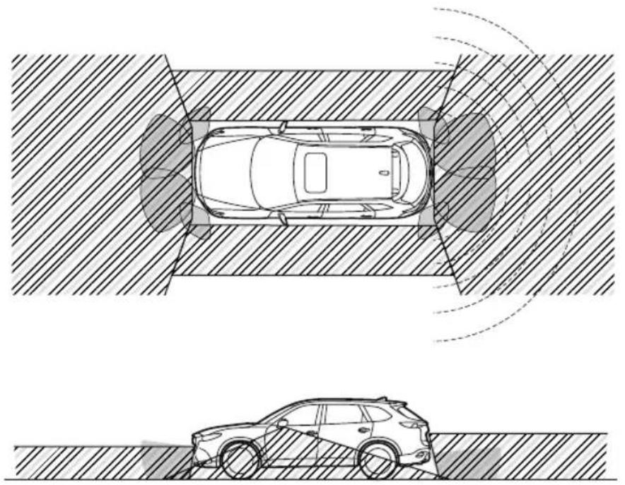
natural_image
Top-down technical diagram of a car under two different sensor or radar views, showing front and side views with no text or symbols.
: Cameras
: Ultrasonic sensors

: Radar sensors (rear)

WARNING
Always confirm the safety of the area around the vehicle with the mirrors and directly with your eyes when driving.
The 360°View Monitor is an auxiliary device which assists the driver in checking the safety of the area around the vehicle.
The shooting range of the cameras and detection range of the sensors are limited. For example, the areas in black at the front and rear of the vehicle image and the seams where each of the camera images merge are blind spots where an obstruction may not be visible. In addition, the extended vehicle width lines and projected vehicle path lines are only to be used as references, and the images on the screen may differ from the actual conditions.

CAUTION
Do not use the 360°View Monitor under any of the following conditions.
▶ Icy or snow-covered roads.
▶Tire chains or a temporary spare tire is installed.
The front doors or the liftgate is not fully closed.
The vehicle is on a road incline.
The door mirrors are retracted.
Do not hit the front/rear camera, front bumper, and door mirrors forcefully. The camera position or installation angle may shift.
The cameras are of a waterproof structure. Do not disassemble, modify, or remove a camera.
The camera cover is made of hard plastic, therefore do not apply oil film remover, organic solvents, wax, or coating agents. If any such agent gets on the camera cover, wipe it off using a soft cloth immediately.
Do not rub the camera lens forcefully, or clean it with an abrasive or hard brush. Otherwise, it could scratch the camera lens and negatively affect the images.
Consult an Authorized Mazda Dealer for repair, painting, or replacement of the front/rear camera, front bumper and door mirrors.
➢ Heed the following cautions to assure that the 360°View Monitor operates normally.
Do not modify the vehicle suspensions or lower/raise the vehicle body, or both.
➢ Always use wheels of the specified type and size for the front and rear wheels. Consult an Authorized Mazda Dealer for tire replacement.
When the display is cold, images may leave trails or the screen might be darker than usual, making it difficult to check the vehicle surroundings. Always confirm the safety at the front and around the vehicle visually when driving.
The method for parking/stopping the vehicle using the 360°View Monitor differs depending on the road circumstances/conditions and the vehicle conditions. When and how much you turn the steering wheel will differ depending on the situation, , therefore always check the vehicle surroundings directly with your eyes while using the system.
Also, before using the system, always make sure that the vehicle can be parked/stopped in the parking/stopping space.
NOTE
- If there are water droplets, snow, or mud on the camera lens, wipe it off using a soft cloth. If the camera lens is especially dirty, wash it off with mild detergent.
- If the area where the camera is installed, such as the liftgate or door mirrors, has been damaged in a vehicle accident, the camera (position, installation angle) may have shifted. Always consult an Authorized Mazda Dealer to have the vehicle inspected.
- If the camera is subjected to excessive changes in temperature such as by pouring hot water on the camera during cold weather, the 360^ View Monitor may not operate normally.
-
If the battery voltage is low, the screen might be temporarily difficult to view, however, this does not indicate a problem.
-
The 360^ View Monitor has limitations. Objects under the bumper or near both ends of the bumper cannot be displayed.
- Obstructions above the upper image range of the camera are not displayed.
-
Under the following conditions, the screen might be difficult to view, however this does not indicate a problem.
-
The temperature near the lens is high/low.
- Rainy conditions, water droplets on the camera, or high humidity.
· Mud or foreign matter near the camera. - Extremely bright light such as sunlight or headlights hitting the camera lens directly.
- Because the 360^ View Monitor camera uses a special lens, the distance displayed on the screen differs from the actual distance.
- Obstructions displayed on the screen may appear differently than in actuality.
(Obstructions may appear fallen, larger, or longer than they actually are.)
- Do not apply stickers to a camera or the area around it. In addition, do not install accessories or an illuminated number/character license plate to the area around a camera. Otherwise, the camera may not correctly display the surrounding conditions.
▼ Types of Images Displayed on the Screen
Top view/Front view
Displays the image of the area around the vehicle and the vehicle front.
Top view screen
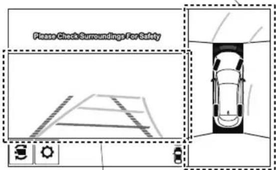
Front view screen
Front wide view
Displays the image of the front of the vehicle (wide-area).
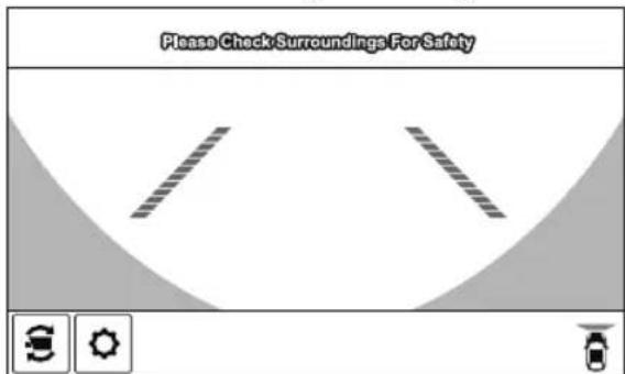
Side view
Displays the image of the left and right sides of the vehicle.
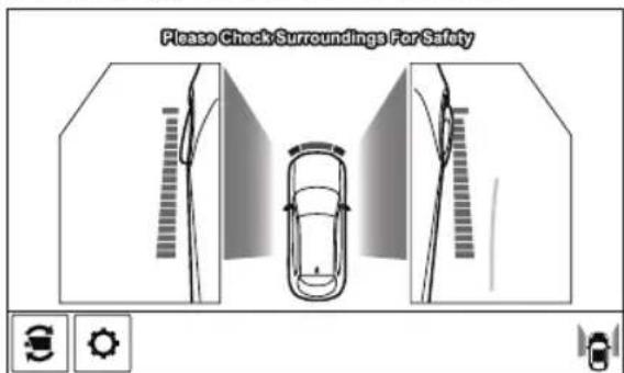
Top view/Rear view
Displays the image of the area around the vehicle and the rear of the vehicle.
Top view screen
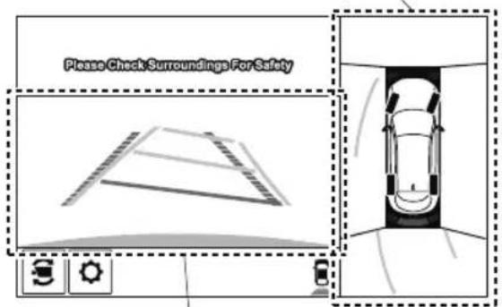
Rear view screen
Rear wide view
Displays the image of the rear of the vehicle (wide-area).
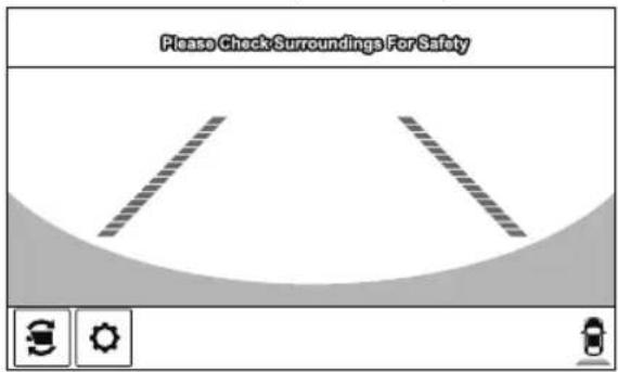
▼ How to Use the System
Top view/Front view, Front wide view, Side view
Indication
Images are displayed on the screen when the 360°View Monitor switch is pressed with all of the following conditions met.
• The ignition is switched ON.
- The selector lever is in a position other than R.
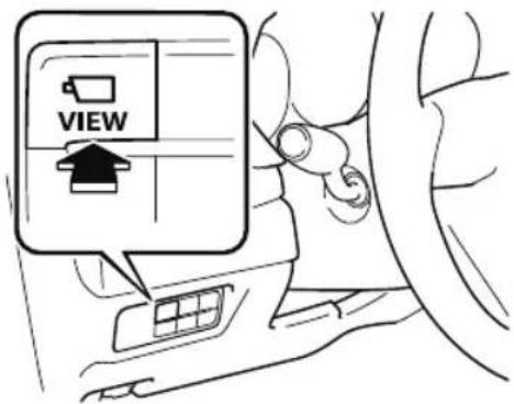
Display switching
You can change the displayed screen by pressing the commander knob or by touching the switch camera icon on the screen while the top view/front view, front wide view, or the side view is displayed.
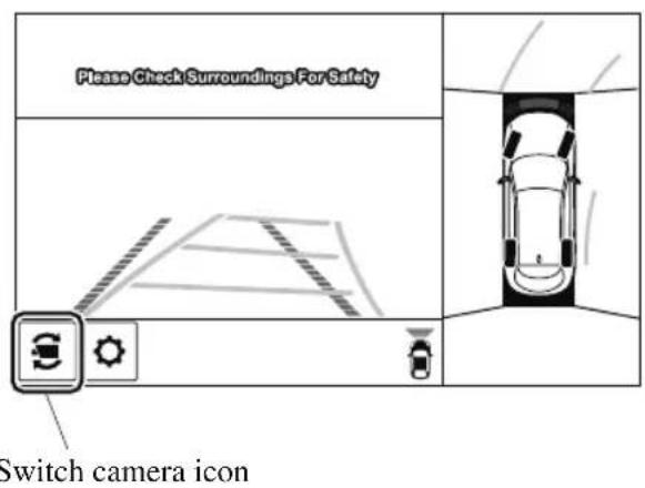
Top view/Front view Front wide view
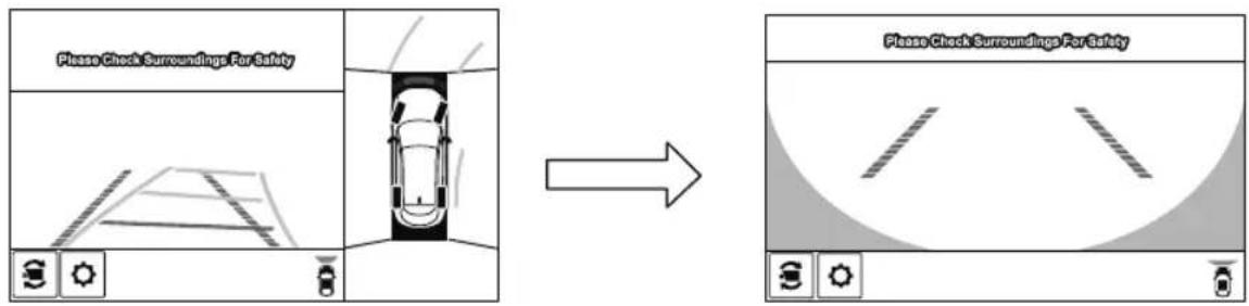
flowchart
graph LR
    A["Please Check Surroundings For Safety"] --> B["Car Parking"]
    B --> C{Check}
    C -->|Yes| D["Car Parking"]
    C -->|No| E["Car Parking"]
    D --> F["Car Parking"]
    E --> G["Car Parking"]
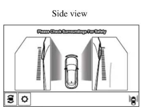
NOTE
- When the selector lever is in R position, the displayed screen does not switch to the top view/front view, front wide view, or the side view.
-
Display of the top view/front view, front wide view, or the side view stops even with the display conditions met if any of the following conditions occurs.
-
When a switch around the commander knob is pressed.
- The selector lever is shifted to P position (displayed when the selector lever is in a position other than P ).
· (Displayed when vehicle speed is less than 15 km/h (9.3 mph))
· 4 minutes and 30 seconds have passed.
- The vehicle speed is about 15 km/h (9.3 mph) or faster.
· (Displayed when the vehicle speed is about 15 km/h (9.3 mph) or faster)
- The vehicle speed is about 15km / h (9.3 mph) or faster after 8 seconds have passed since pressing the 360^ View Monitor switch.
- Four minutes and 22 seconds have passed from the point when the vehicle speed was less than 15km / h (9.3 mph) after 8 seconds have passed since pressing the 360^ View Monitor switch.
- The 360^ View Monitor displays the previously displayed screen.
- The 360^ View Monitor settings can be changed as follows.
Refer to the Settings section in the Mazda Connect Owner's Manual.
- Automatic display of the 360^ View Monitor when the ultrasonic senor detects an obstruction.
- Automatic display of the 360^ View Monitor when the ignition is switched ON.
Top view/Rear view, Rear wide view
The top view/rear view, rear wide view displays when all of the following conditions are met.
- The ignition is switched ON.
- Selector lever is in R position.
Display switching
The displayed screen can be switched by pressing the commander knob or by touching the switch camera icon on the screen while the top view/rear view, rear wide view is displayed.
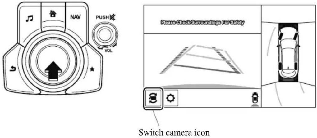
Top view/Rear view Rear wide view
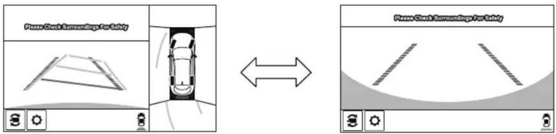
NOTE
- The top view/rear view and rear wide view automatically display whether or not the 360° View Monitor switch is turned on or off when shifting the selector lever to R position.
- The setting can be changed to display the top view/front view when shifting from reverse to a forward gear without operating the 360°View Monitor switch to check the front of the vehicle while parallel parking.
Refer to the Settings section in the Mazda Connect Owner's Manual.
Screen operation/icon

WARNING
Always stop the vehicle when adjusting the 360°View Monitor image quality.
Do not adjust the 360°View Monitor image quality while driving. If you adjust the 360° View Monitor image quality (such as brightness, contrast, tone, and color density) while driving, it could lead to an unexpected accident.
(Display example)
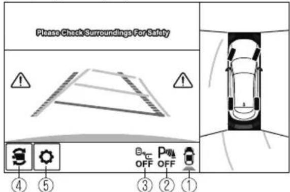
| Display/Icon Content | ||
| 1 | View status icon | Indicates which image is displayed among the front view/front wide view/side view/rear view/rear wide view. |
| 2 | Parking sensor status icon | Indicates that the parking sensor has a problem or it is switched off. |
| 3 | Rear Cross Traffic Alert (RCTA) status icon | Indicates that the radar sensor (rear) has a problem or it is turned off. |
| 4 | Switch camera icon | Each time the screen is touched, the display screen switches. |
| 5 | Setting icon | The image quality for the 360°View Monitor can be adjusted. |
▼ Top View/Front View
Use the top view/front view to assist in checking the safety of the surrounding area when accelerating from a stop, parking, or stopping the vehicle.
Display range
Screen display
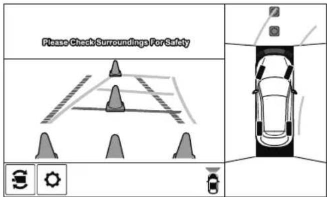
Actual condition
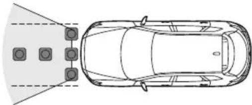
natural_image
Top-down line drawing of a car with four windows and a side-mounted sensor array (no text or symbols)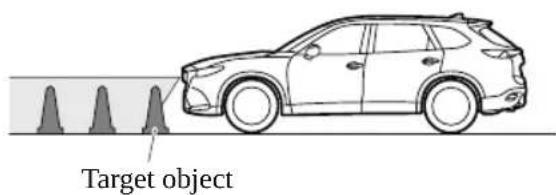
NOTE
- In the top view screen, the areas in black at the front and rear of the vehicle image and the seams where each of the camera images merge are blind spots.
- Because images displayed in the top view screen are processed from each camera, the top view screen may display in the following ways.
- If an image containing an object with a conspicuous color is picked up by any of the cameras, the whole screen may be affected and it may display in that color.
- Obstructions displayed in the front view may not display on the top view screen.
- If the position or angle of each camera changes due to tilting of the vehicle, the image may appear distorted.
- Lines on the road may appear distorted at the seams where each of the camera images merge.
- The entire screen may appear bright/dark depending on the illumination level around any of the cameras.
Viewing the screen
(When the projected vehicle path line display is on)
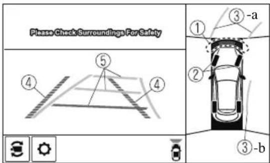
(When the projected vehicle path line display is off)
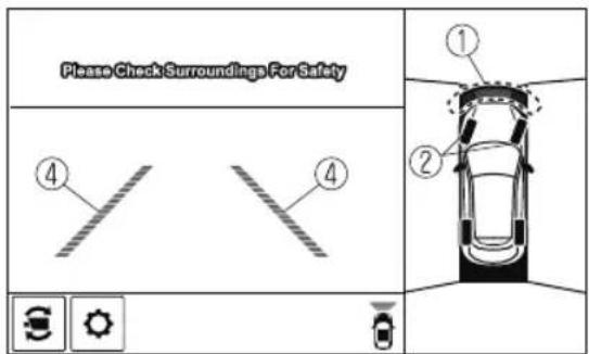
| Display/Icon Content | ||
| 1 | Parking sensor view Displays the parking | g sensor detection condition when the parking sensor is activated.For details, refer to the parking sensor obstruction detection indication and warning sound.Refer to Parking Sensor System on page 4-272. |
| 2 | Tire icon Indicates the tire direction. Moves in conjunction with the steering wheel operation. | |
| 3 | Projected vehicle path lines (yellow) Indicates the approximate projected path of the vehicle.Moves in conjunction with the steering wheel operation.a) Indicates the path where the edge of the front bumper is expected to travel.b) Indicates the path where the inner side of the vehicle is expected to travel. | |
| 4 | Extended vehicle width lines and distance guide lines (red/blue) | Indicates the approximate width of the vehicle and the distance (from front end of bumper) in front of the vehicle.The red lines indicate the points up to about 0.5 m (19 in) from the front end of the bumper.The blue lines indicate the points from about 0.5 m (19 in) and up to 2 m (78 in) from the front end of the bumper. |
| 5 | Projected vehicle path distance guide lines (red/yellow) | Indicates the distance (from front end of bumper) in front of the vehicle.The red line indicates the point about 0.5 m (19 in) from the front end of the bumper.The amber lines indicate the points about 1 m (39 in) and 2 m (78 in) from the front end of the bumper. |
CAUTION
The parking sensor detection range has limitations. For example, obstructions closing in from the side and objects short in height may not be detected. Always confirm the safety around the vehicle visually when driving.
For details, refer to the parking sensor obstruction detection indication and warning sound.
Refer to Parking Sensor System on page 4-272.
NOTE
The setting can be changed so that the projected vehicle path lines are not displayed. Refer to the Settings section in the Mazda Connect Owner's Manual.
How to use the projected vehicle path line function
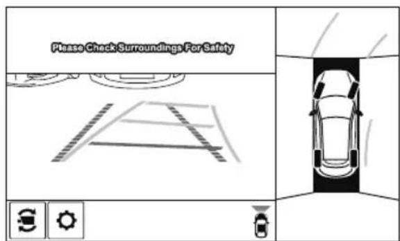
(Actual condition)(Screen display)
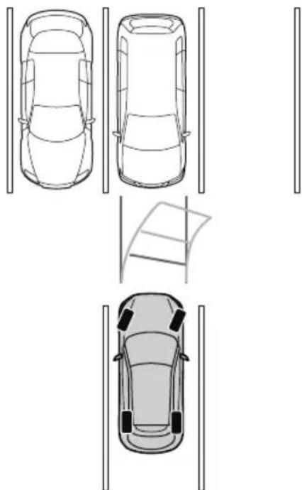
natural_image
Top-down line drawings of four different car rear views and parking areas (no text or symbols)Make sure that there are no obstructions within the projected vehicle path lines. Drive the vehicle forward while turning the steering wheel so that no obstructions come within the projected vehicle path lines.
▼ Front Wide View
Use the front wide view to assist in checking the safety of the surrounding area when accelerating from a stop or entering a T-shaped intersection and intersection.
Display range
Screen display
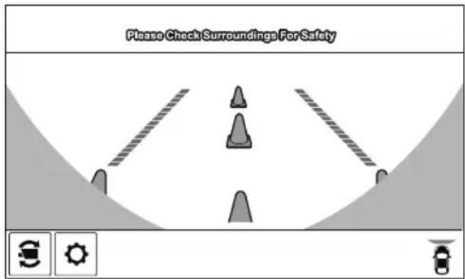
Actual condition
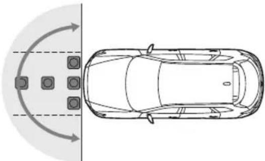
natural_image
Top-down diagram of a car with directional arrows indicating flow or movement, showing front and side views (no text or symbols)
Viewing the screen
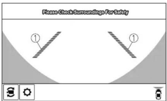
| Display/Icon Content | ||
| 1 | Extended vehicle width lines and distance guide lines (red/blue) | Indicates the approximate width of the vehicle and the distance (from front end of bumper) in front of the vehicle.The red lines indicate the points up to about 0.5 m (19 in) from the front end of the bumper.The blue lines indicate the points from about 0.5 m (19 in) and up to 2 m (78 in) from the front end of the bumper. |
NOTE
- The parking sensor obstruction detection indication does not display. Switch the screen display to the top view/front view or side view display if the parking sensor warning sound is activated.
- The front wide view screen displays the image in front of the vehicle at a wide angle and corrects the image to help detect approaching obstructions from the side. Therefore, it differs from the actual view.
▼ Side View
Use the side view to assist in checking the safety of the surrounding area when accelerating from a stop, parking, or stopping the vehicle.
Display range
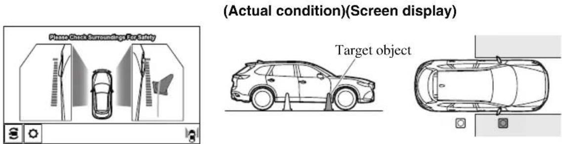
Viewing the screen
(When the projected vehicle path line display is on)
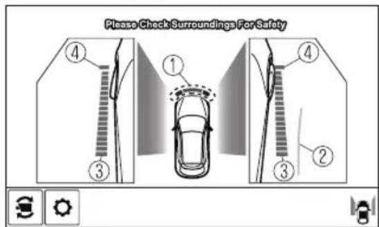
(When the projected vehicle path line display is off)
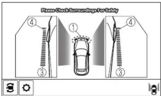
| Display/Icon Content | ||
| 1 | Parking sensor view | Displays the parking sensor detection condition when the parking sensor is activated.For details, refer to the parking sensor obstruction detection indication and warning sound.Refer to Parking Sensor System on page 4-272. |
| 2 | Projected vehicle path lines (yellow) Indicates the approximate projected path of the vehicle.Moves in conjunction with the steering wheel operation.The projected vehicle path lines (yellow) indicate the path the inner side of the vehicle is expected to travel. | |
| 3 | Vehicle parallel guide lines (blue) | Indicates the approximate vehicle width including the door mirrors. |
| 4 | Vehicle front end guide lines (blue) | Indicates the point about 0.25 m (9.8 in) from the front edge of the vehicle (front edge of the bumper). |
NOTE
The setting can be changed so that the projected vehicle path lines are not displayed. Refer to the Settings section in the Mazda Connect Owner's Manual.
How to use the projected vehicle path line function
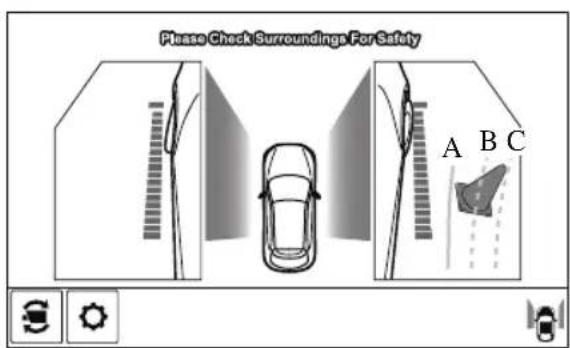
(Actual condition)(Screen display)
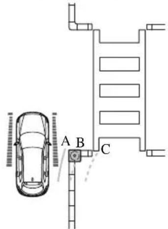
Make sure that there are no obstructions within the projected vehicle path lines.
Turn the steering wheel so that the projected vehicle path lines travel inside of the obstruction (A), and drive the vehicle forward until it passes the obstruction.
If the projected vehicle path lines are on an obstruction (B) or outside of the obstruction (C), the vehicle may contact the obstruction when turning the vehicle sharply.

CAUTION
The parking sensor detection range has limitations. For example, obstructions closing in from the side and objects short in height may not be detected. Always confirm the safety around the vehicle visually when driving. For details, refer to the parking sensor obstruction detection indication and warning sound. Refer to Parking Sensor System on page 4-272.
➢ Do not turn the steering wheel any more until the vehicle has passed the obstruction, even if the obstruction is not visible on the side view image. If the steering wheel is turned even more, the vehicle may contact the obstruction if it is turned sharply.
NOTE
- Because there might be a difference between the image displayed on the screen and the actual conditions, always check the safety of the surrounding area using the mirrors and directly with your eyes when driving.
- Even though the object displayed on the screen, such as a road curb or a division line of a parking space, and the vehicle parallel guide lines appear parallel, they may not actually be parallel.
▼ Top View/Rear View
Use the top view/rear view to assist in checking the safety of the surrounding area when accelerating from a stop, parking, or stopping the vehicle.
Range of displayed screen image
Screen display
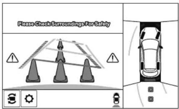
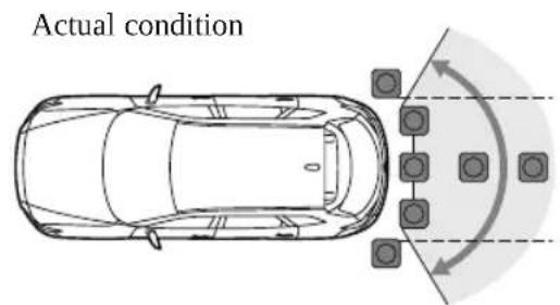
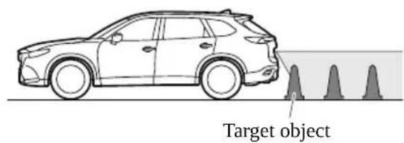
NOTE
- In the top view screen, the areas in black at the front and rear of the vehicle image and the seams where each of the camera images merge are blind spots.
- Because images displayed in the top view screen are processed from each camera, the top view screen may display in the following ways.
- If an image containing an object with a conspicuous color is picked up by any of the cameras, the whole screen may be affected and it may display in that color.
- Obstructions displayed in the rear view may not display on the top view screen.
- If the position or angle of each camera changes due to tilting of the vehicle, the image may appear distorted.
- Lines on the road may appear distorted at the seams where each of the camera images merge.
- The entire screen may appear bright/dark depending on the illumination level around any of the cameras.
Viewing the screen
(When the projected vehicle path line display is on)
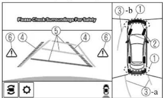
(When the projected vehicle path line display is off)
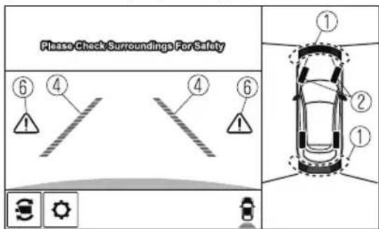
| Display/Icon Content | ||
| 1 | Parking sensor view | Displays the parking sensor detection condition when the parking sensor is activated.For details, refer to the parking sensor obstruction detection indication and warning sound.Refer to Parking Sensor System on page 4-272. |
| 2 | Tire icon | Indicates the tire direction. Moves in conjunction with the steering wheel operation. |
| 3 | Projected vehicle path lines (yellow) Ind | icates the approximate projected path of the vehicle.Moves in conjunction with the steering wheel operation.a) Indicates the path where the rear wheels are expected to travel.b) Indicates the path where the outer side of the vehicle is expected to travel. |
| 4 | Extended vehicle width lines and distance guide lines (red/blue) | These guide lines indicate the approximate width of the vehicle and distance to a point measured from the rear of the vehicle (from the end of the bumper).The red lines indicate the points up to about 0.5 m (19 in) from the rear end of the bumper.The blue lines indicate the points from about 0.5 m (19 in) and up to 2 m (78 in) from the rear end of the bumper. |
| 5 | Projected vehicle path distance guide lines (red/yellow) | These guide lines indicate the approximate distance to a point measured from the rear of the vehicle (from the end of the bumper).The red line indicates the point about 0.5 m (19 in) from the rear end of the bumper.The amber lines indicate the points about 1 m (39 in) and 2 m (78 in) from the rear end of the bumper. |
| 6 | Blind Spot Monitoring (BSM) warning lights | Indicates when the Rear Cross Traffic Alert (RCTA) has operated.For details, refer to Rear Cross Traffic Alert (RCTA).Refer to Rear Cross Traffic Alert (RCTA) on page 4-139. |
NOTE
The setting can be changed so that the projected vehicle path lines are not displayed. Refer to the Settings section in the Mazda Connect Owner's Manual.
How to use the projected vehicle path line function

CAUTION
The front of the vehicle swings out wide when turning the steering wheel while reversing. Maintain sufficient distance between the vehicle and an obstruction.
The parking sensor detection range has limitations. For example, obstructions closing in from the side and objects short in height may not be detected. Always confirm the safety around the vehicle visually when driving.
For details, refer to the parking sensor obstruction detection indication and warning sound. Refer to Parking Sensor System on page 4-272.
NOTE
- Because there might be a difference between the image displayed on the screen, such as indicated in the following, and the actual conditions when parking, always check the safety at the rear of the vehicle and the surrounding area directly with your eyes.
- Even though the back end of the parking space (or garage) displayed on the screen and distance guide lines appear parallel, they may not actually be parallel.
- When parking in a space with a division line on only one side of the parking space, even though the division line and the vehicle width guide line appear parallel, they may not actually be parallel.
- The following shows an example of vehicle parking with the steering wheel turned to the left while backing up the vehicle. When backing into a parking space from the opposite direction, the steering operation is reversed.
- Back the vehicle into the parking space by turning the steering wheel so that the vehicle enters the center of the parking space.
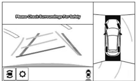
(Actual condition)(Screen display)
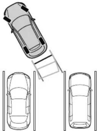
natural_image
Top-down diagram of a car with a ladder and two cars below, no text or symbols present- After the vehicle starts entering the parking space, stop and adjust the steering wheel so that the distance between the vehicle width lines and the sides of the parking space on the left and right are roughly equal, and then continue backing up slowly.
- Once the vehicle width lines and the sides of the parking space on the left and right are parallel, straighten the wheels and back the vehicle slowly into the parking space. Continue checking the vehicle's surroundings and then stop the vehicle in the best possible position. (If the parking space has division lines, check whether the vehicle width guide lines are parallel to them.)
(Actual condition)(Screen display)
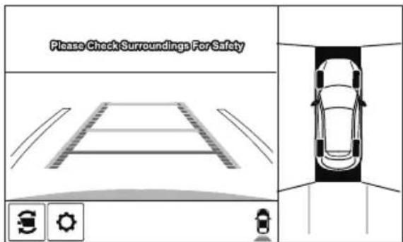
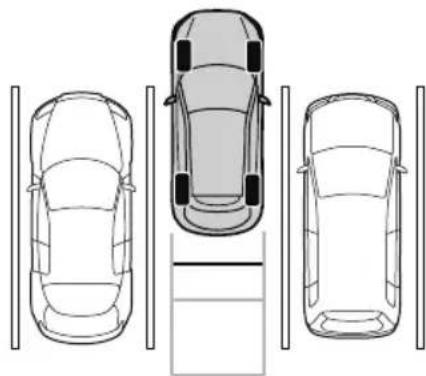
natural_image
Top-down line drawing of three cars viewed from the side, with no text or symbols present.▼ Rear Wide View
Use the rear wide view to assist in checking the safety of the surrounding area when accelerating from a stop, parking, or stopping the vehicle.
Range of displayed screen image
Screen display
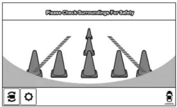
Actual condition
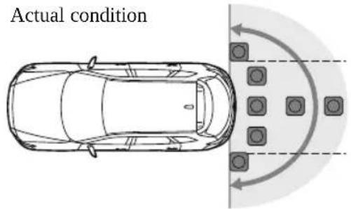
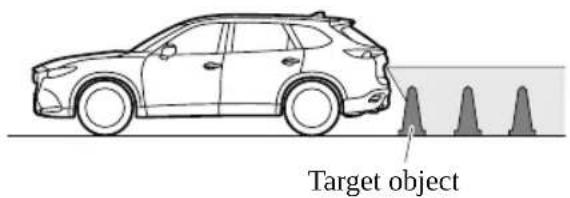
Viewing the screen
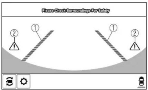
| Display/Icon Content | ||
| 1 | Extended vehicle width lines and distance guide lines (red/blue) | These guide lines indicate the approximate width of the vehicle and distance to a point measured from the rear of the vehicle (from the end of the bumper).The red lines indicate the points up to about 0.5 m (19 in) from the rear end of the bumper.The blue lines indicate the points from about 0.5 m (19 in) and up to 2 m (78 in) from the rear end of the bumper. |
| 2 | Blind Spot Monitoring (BSM) warning lights | Indicates when the Rear Cross Traffic Alert (RCTA) has operated.For details, refer to Rear Cross Traffic Alert (RCTA).Refer to Rear Cross Traffic Alert (RCTA) on page 4-139. |
NOTE
- The parking sensor obstruction detection indication does not display. Switch the screen display to the top view/rear view display if the parking sensor warning sound is activated.
- The rear wide view screen displays the image at the rear of the vehicle at a wide angle and corrects the image to help detect approaching obstructions from the side. Therefore, it differs from the actual view.
▼ Margin of Error Between Road Surface on Screen and Actual Road Surface
There might be some margin of error between the road surface appearing on the screen and the actual road surface. A margin of error in the perceived distance could lead to an accident, therefore be aware of the following conditions which can more easily produce errors in the perceived distance.
The vehicle tilts due to weight of passengers and cargo.
If the vehicle is tilted, obstructions picked up by a camera can appear farther or closer than the actual distance from the vehicle.
Front camera
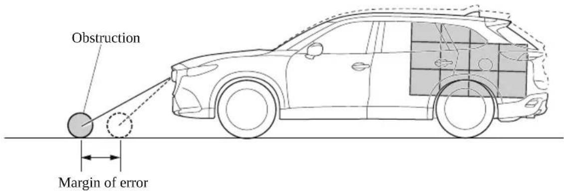
Side camera
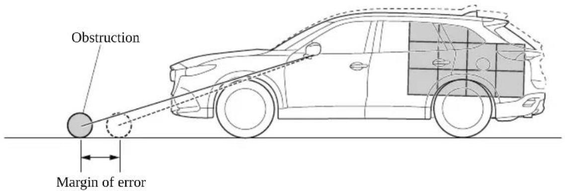
Rear camera
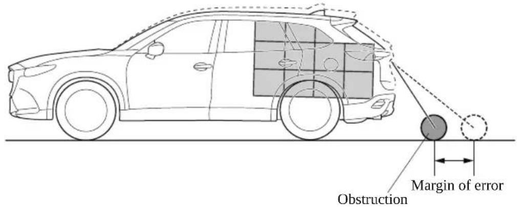
There is a steep up or down grade in the road at the front or rear of the vehicle
If there is a steep up or down grade in the road at the front or rear of the vehicle, obstructions picked up by the camera can appear farther or closer than the actual distance from the vehicle.
Front camera
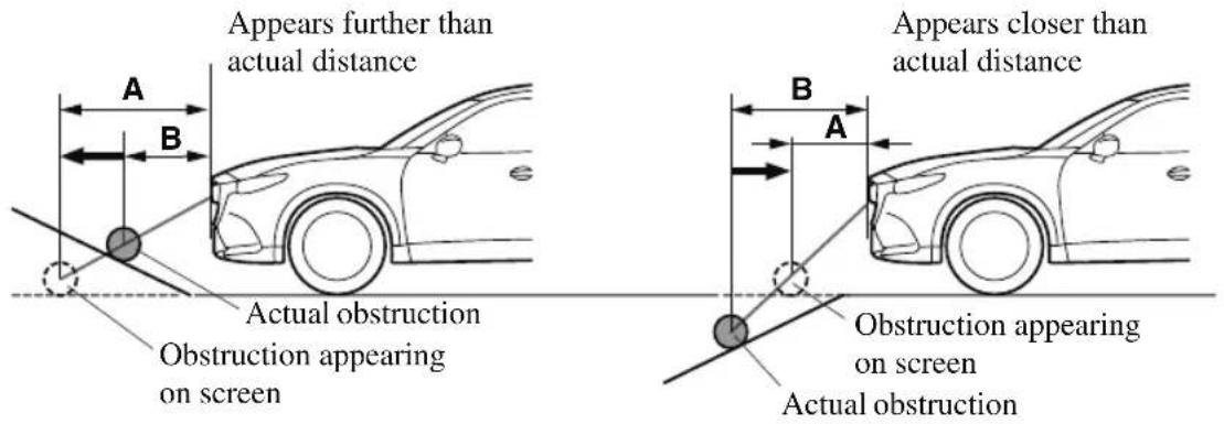
A: Distance of obstruction being viewed on screen
B: Actual distance of obstruction from vehicle
Side camera
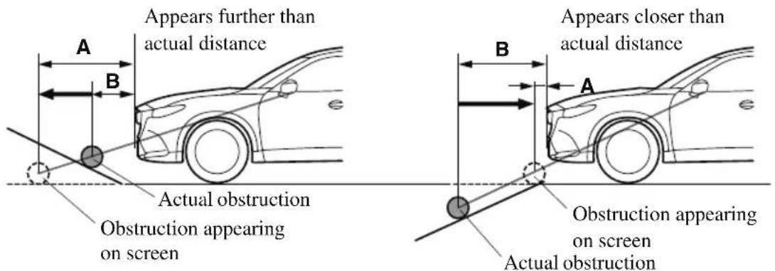
A: Distance of obstruction being viewed on screen
B: Actual distance of obstruction from vehicle
Rear camera
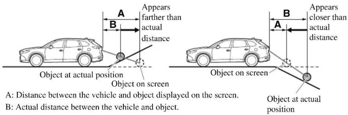
NOTE
If the vehicle is on a slope, obstructions taken by the camera can appear farther or closer than the actual distance from the vehicle.
Three-dimensional object at vehicle front or rear
Because the vehicle front end guide lines (side camera) or the distance guide lines (rear camera) are displayed based on a flat surface, the distance to the three-dimensional object displayed on the screen is different from the actual distance.
Side camera
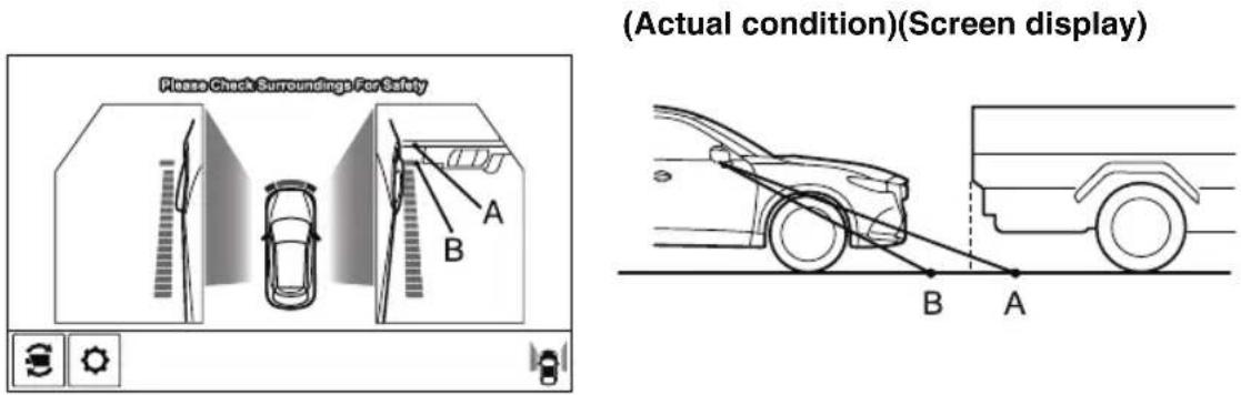
Rear camera
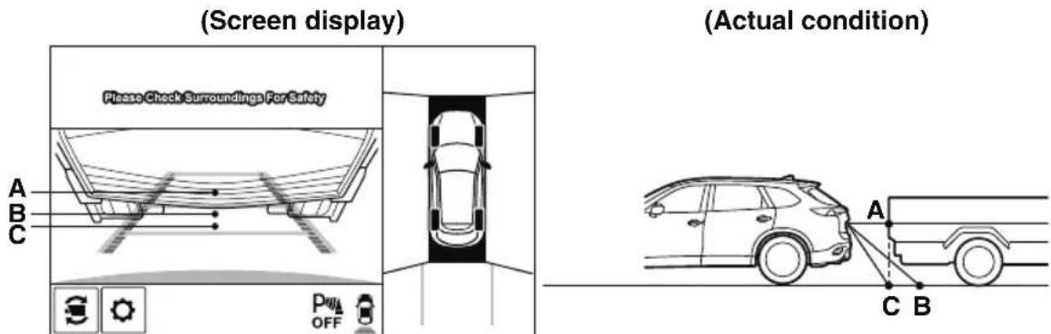
Sensed distance on screen A > B > C Actual distance B > C = A
▼ System Problem Indication
| Center display indication Cause | Action to be taken | |
| “No image signal reception” is displayed | The control unit might be damaged. | Have your vehicle inspected by an Authorized Mazda Dealer. |
| Screen is pitch-black and blank The camera might be damaged. |
360° View Monitor (Mazda Connect (Type B))\*
▼ 360° View Monitor
The 360°View Monitor consists of the following functions which assist the driver in checking the area surrounding the vehicle using various indications in the center display and a warning sound while the vehicle is being driven at low speeds or while parking.
- Top view
The top view displays an image of the vehicle from directly above on the center display by combining the images taken from the 4 cameras set on all sides of the vehicle. The top view displays on the right side of the screen when the front view or rear view screen is being displayed. The top view assists the driver in checking the area surrounding the vehicle when the vehicle is moving forward or in reverse.
- Front view/front wide view
The image from the front of the vehicle is displayed on the center display.
The view from the front assists the driver in checking the front of the vehicle by displaying guide lines on the displayed image taken from the front of the vehicle.
- Side view
The images taken from the front left and right sides of the vehicle are displayed on the center display.
The side view assists the driver in checking the front sides of the vehicle by displaying guide lines on the displayed image taken from the front left and right sides of the vehicle.
· Rear view/rear wide view
The image from the rear of the vehicle is displayed on the center display.
The image from the rear assists the driver in checking the rear of the vehicle by displaying guide lines on the displayed image taken from the rear of the vehicle.
. Parking sensor
If there are any obstructions near the vehicle while the top view/side view is displayed, an obstruction detection indication turns on around the bumper in the center display.
The parking sensors use ultrasonic sensors to detect obstructions around the vehicle when the vehicle is driven at low speeds, such as during garage or parallel parking, and notifies the driver of the approximate distance from the vehicle to the surrounding obstruction using sound and an obstruction detection indication.
Refer to Parking Sensor System on page 4-282.
· Rear Cross Traffic Alert (RCTA)
If there is the possibility of a collision with an approaching vehicle while the rear view/rear wide view is displayed, a warning is displayed on the center display.
The Rear Cross Traffic Alert (RCTA) uses rear side radar sensor to detect vehicles approaching from the rear left and right sides of the vehicle, and it assists the driver in checking the rear of the vehicle while reversing by flashing the Blind Spot Monitoring (BSM) warning lights and activating the warning sound.
Refer to Rear Cross Traffic Alert (RCTA) on page 4-139.
360°View Monitor Range
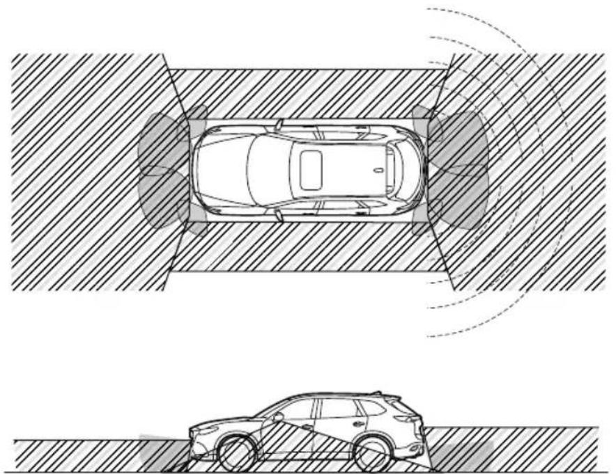
natural_image
Top-down technical diagram of a car under two different sensor or sensor conditions, showing front and side views with no text or symbols.
: Cameras
: Ultrasonic sensors
: Radar sensors (rear)

WARNING
Always confirm the safety of the area around the vehicle with the mirrors and directly with your eyes when driving:
The 360°View Monitor is an auxiliary device which assists the driver in checking the safety of the area around the vehicle.
The shooting range of the cameras and detection range of the sensors are limited. For example, the areas in black at the front and rear of the vehicle image and the seams where each of the camera images merge are blind spots where an obstruction may not be visible. In addition, the extended vehicle width lines and projected vehicle path lines are only to be used as references, and the images on the screen may differ from the actual conditions.

CAUTION
Do not use the 360°View Monitor under any of the following conditions.
▶ Icy or snow-covered roads.
▶Tire chains or a temporary spare tire is installed.
The front or rear doors are not fully closed.
The vehicle is on a road incline.
The door mirrors are retracted.
Do not hit the front/rear camera, front bumper, liftgate, and door mirrors forcefully. The camera position or installation angle may shift.
The cameras are waterproof. Do not disassemble, modify, or remove a camera.
The camera cover is made of hard plastic, therefore do not apply oil film remover, organic solvents, wax, or coating agents. If any such agent gets on the camera cover, wipe it off using a soft cloth immediately.
Do not rub the camera lens forcefully, or clean it with an abrasive or hard brush. Otherwise, it could scratch the camera lens and negatively affect the images.
Consult an Authorized Mazda Dealer for repair, painting, or replacement of the front/rear camera, front bumper, liftgate and door mirrors.
➢ Heed the following cautions to assure that the 360°View Monitor operates normally.
Do not modify the vehicle suspensions or lower/raise the vehicle body, or both.
➢ Always use tires of the specified type and size for the front and rear wheels. Consult an Authorized Mazda Dealer for tire replacement.
When the display is cold, images may leave trails or the screen might be darker than usual, making it difficult to check the vehicle surroundings. Always confirm the safety at the front and around the vehicle visually when driving.
The method for parking/stopping the vehicle using the 360°View Monitor differs depending on the road circumstances/conditions and the vehicle conditions. When and how much you turn the steering wheel will differ depending on the situation, , therefore always check the vehicle surroundings directly with your eyes while using the system.
Also, before using the system, always make sure that the vehicle can be parked/stopped in the parking/stopping space.
NOTE
- If there are water droplets, snow, or mud on the camera lens, wipe it off using a soft cloth. If the camera lens is especially dirty, wash it off with mild detergent.
- If the camera lens is touched or there is any dirt on it, it could affect the screen image. Wipe the lens using a soft cloth.
-
If the area where the camera is installed, such as the front bumper, liftgate or door mirrors, has been damaged in a vehicle accident, the camera (position, installation angle) may have shifted. Always consult an Authorized Mazda Dealer to have the vehicle inspected.
-
If the camera is subjected to excessive changes in temperature such as by pouring hot water on the camera during cold weather, the 360^ View Monitor may not operate normally.
- If the battery voltage is low, the screen might be temporarily difficult to view, however, this does not indicate a problem.
- The 360^ View Monitor has limitations. Objects under the bumper or near both ends of the bumper cannot be displayed.
- Obstructions above the upper image range of the camera are not displayed.
-
Under the following conditions, the screen might be difficult to view, however this does not indicate a problem.
-
The temperature near the lens is high/low.
- Rainy conditions, water droplets on the camera, or high humidity.
· Mud or foreign matter near the camera. - Extremely bright light such as sunlight or headlights hitting the camera lens directly.
- The surroundings are illuminated by vehicle lights, fluorescent lights, or LED lights (display may flicker).
- Extremely small dark or white dots appear on the screen (dots may flicker).
- Because the 360^ View Monitor camera uses a special lens, the distance displayed on the screen differs from the actual distance.
- Obstructions displayed on the screen may appear differently than in actuality. (Obstructions may appear fallen, larger, or longer than they actually are.)
- Do not apply stickers to a camera or the area around it. In addition, do not install accessories or an illuminated number/character license plate to the area around a camera. Otherwise, the camera may not correctly display the surrounding conditions.
- Images displayed on the monitor from the 360^ view monitor camera are reversed images (mirror images).
. Free/open source software information
This product includes free/open sources. Information about the licensing and source code is available at the following URL.
https://www.denso.com/global/en/opensource/svss/mazda/
▼ Types of Images Displayed on the Screen
Top view/Front view
Displays the image of the area around the vehicle and the vehicle front.
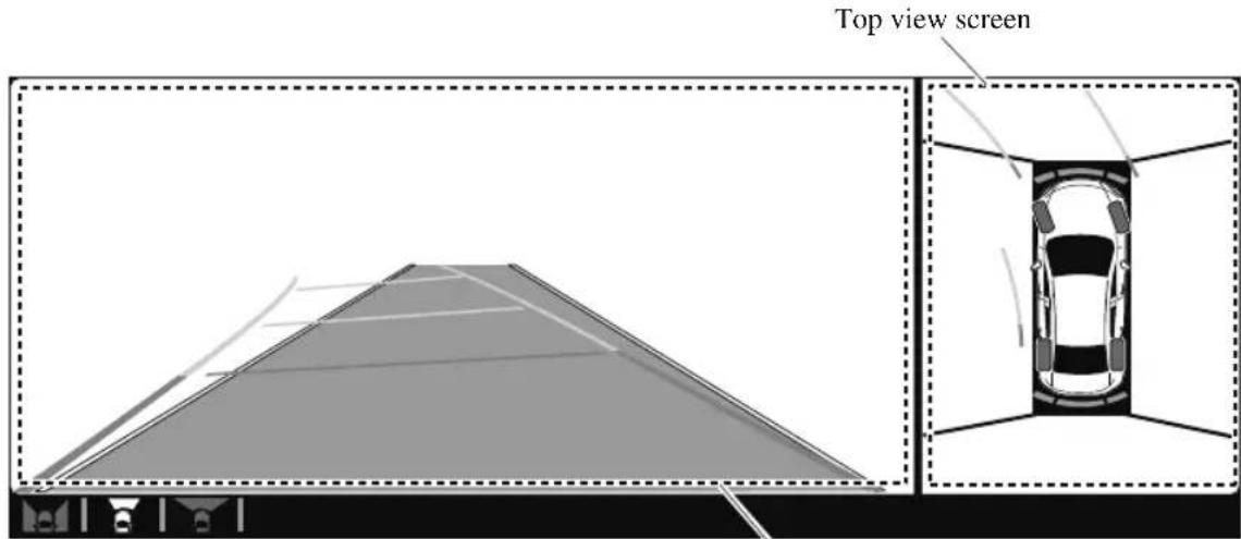
Front view screen
Top view/Front wide view
Displays the image of the area around the vehicle and the front of the vehicle (wide-area).
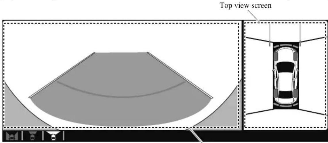
Front wide view screen
Side view
Displays the image of the left and right sides of the vehicle.
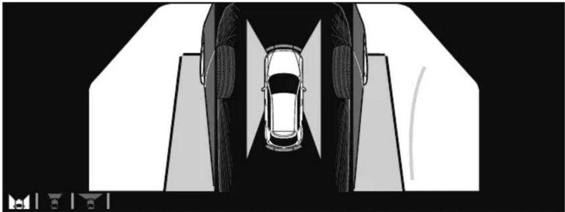
natural_image
Top-down architectural rendering of a car on a road with visible tire tracks and pavement (no text or symbols)Top view/Rear view
Displays the image of the area around the vehicle and the rear of the vehicle.
Top view screen
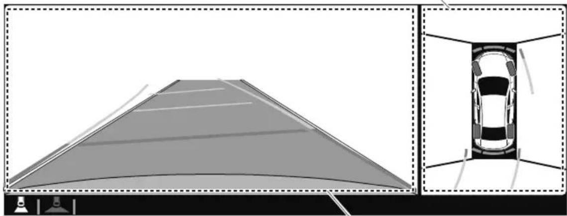
natural_image
Top-down diagram of a car parking roof with an inset showing its exterior view (no text or symbols)Rear view screen
Top view/Rear wide view
Displays the image of the area around the vehicle and the rear of the vehicle (wide-area).
Top view screen
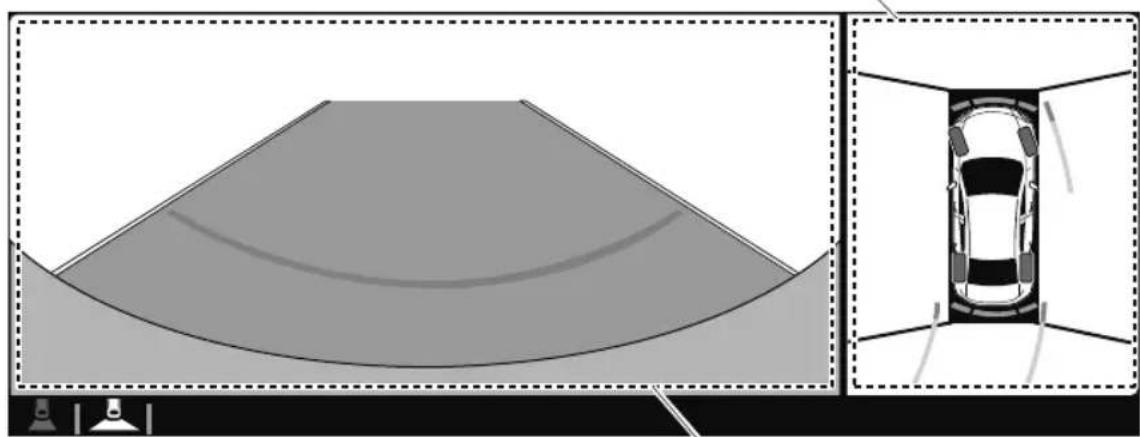
natural_image
Top-down diagram of a car viewed from the side, showing its rear view and interior view with no text or symbols.Rear wide view screen
▼ How to Use the System
Top view/Front view, Top view/Front wide view, Side view
Indication
Images are displayed on the screen when the 360°View Monitor switch is pressed with all of the following conditions met.
• The ignition is switched ON.
• The selector lever is in a position other than R.
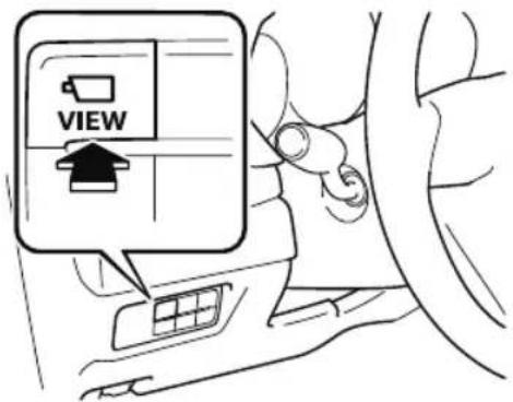
Display switching
The displayed screen can be changed each time the 360° view monitor switch is pressed.
Top view/Front view Top view/Front wide view
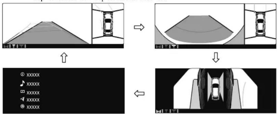
flowchart
graph TD
    A["Top: Vehicle with 3D terrain"] --> B["Top: Car in curved channel"]
    B --> C["Bottom: Display mode with 'XXXXXX' icons"]
    C --> D["Bottom: Top: Car in car interior"]
Home screen Side view
NOTE
- When the selector lever is in R position, the displayed screen does not switch to the top view/front view, top view/front wide view, or the side view.
- Display of the top view/front view, top view/front wide view, or the side view stops even with the display conditions met if any of the following conditions occurs.
-
When a switch around the commander knob is pressed.
-
The selector lever is shifted to P position (displayed when the selector lever is in a position other than P ).
· (Displayed when vehicle speed is less than 15 km/h (9.3 mph))
· 4 minutes and 30 seconds have passed.
- The vehicle speed is about 15 ~km / h (9.3 mph) or faster.
· (Displayed when the vehicle speed is about 15 km/h (9.3 mph) or faster)
- The vehicle speed is about 15km / h (9.3 mph) or faster after 8 seconds have passed since pressing the 360^ View Monitor switch.
- Four minutes and 22 seconds have passed from the point when the vehicle speed was less than 15km / h (9.3 mph) after 8 seconds have passed since pressing the 360^ View Monitor switch.
- The 360^ View Monitor settings can be changed as follows.
Refer to the Settings section in the Mazda Connect Owner's Manual.
- Automatic display of the 360^ View Monitor when the ultrasonic senor detects an obstruction.
- Automatic display of the 360^ View Monitor when the ignition is switched ON.
- Screen priority level when the system launches.
Top view/Rear view, Top view/Rear wide view
The top view/rear view, top view/rear wide view displays when all of the following conditions are met.
- The ignition is switched ON.
- Selector lever is in R position.
Display switching
The displayed screen can be changed each time the 360° view monitor switch is pressed.
Top view/Rear view Top view/Rear wide view

natural_image
Diagram showing a car being tilted from its roof, with no text or symbols present.NOTE
- The top view/rear view and top view/rear wide view automatically display whether or not the 360^ View Monitor switch is turned on or off when shifting the selector lever to R position.
- The top view/rear view and top view/rear wide view displays the previously displayed screen.
- The setting can be changed to display the top view/front view when shifting from reverse to a forward gear without operating the 360^ View Monitor switch to check the front of the vehicle while parallel parking.
Refer to the Settings section in the Mazda Connect Owner's Manual.
Screen operation/icon

WARNING
Always stop the vehicle when adjusting the 360°View Monitor image quality.
Do not adjust the 360°View Monitor image quality while driving. If you adjust the 360°View Monitor image quality (such as brightness, contrast, tone, and color density) while driving, it could lead to an unexpected accident.
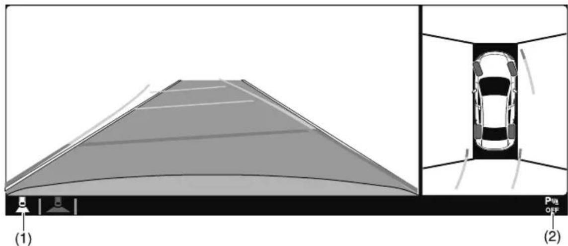
| Display/Icon Content | ||
| (1) | View status icon | Indicates which image is displayed among the front view/front wide view/side view/rear view/rear wide view. |
| (2) | Parking sensor status icon | Indicates that the parking sensor has a problem or it is switched off. |
▼ Top View/Front View
Use the top view/front view to assist in checking the safety of the surrounding area when accelerating from a stop, parking, or stopping the vehicle.
Display range
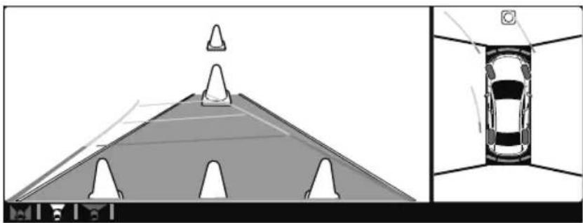
natural_image
Diagram showing a car on a road with a triangular structure and an inset view of the car interior (no text or symbols)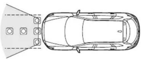
natural_image
Top-down line drawing of a car with four circular components and a triangular head, no text or symbols present.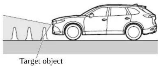
NOTE
- In the top view screen, the areas in black at the front and rear of the vehicle image and the seams where each of the camera images merge are blind spots.
-
Because images displayed in the top view screen are processed from each camera, the top view screen may display in the following ways.
-
If an image containing an object with a conspicuous color is picked up by any of the cameras, the screen area for each camera may be affected and it may display in that color.
- Obstructions displayed in the front view may not display on the top view screen.
- If the position or angle of each camera changes due to tilting of the vehicle, the image may appear distorted.
- Lines on the road may appear distorted at the seams where each of the camera images merge.
- The screen area for each camera may appear bright/dark depending on the illumination level around any of the cameras.
Viewing the screen
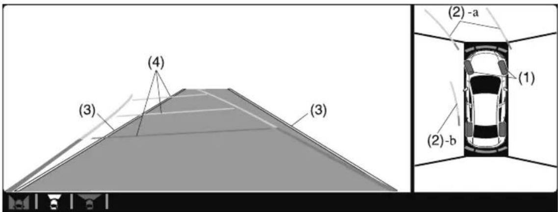
| Display/Icon Content | ||
| (1) Tire icon Indicates the tire direction. Moves in conjunction with the steering wheel operation. | ||
| (2) Projected vehicle path lines (yellow & red) | Indicates the approximate projected path of the vehicle.Moves in conjunction with the steering wheel operation.a) Indicates the path where the edge of the front bumper is expected to travel.b) Indicates the path where the inner side of the vehicle is expected to travel. | |
| (3) Extended vehicle width lines (blue) Indicates the approximate width of the vehicle. | ||
| (4) Projected vehicle path distance guide lines (yellow & red) | Indicates the distance (from front end of bumper) in front of the vehicle.The red line indicates the point about 0.5 m (19 in) from the front end of the bumper.The yellow lines indicate the points about 1.0 m (39 in) and 2.0 m (78 in) from the front end of the bumper. | |

CAUTION
The parking sensor detection range has limitations. For example, obstructions closing in from the side and objects short in height may not be detected. Always confirm the safety around the vehicle visually when driving.
For details, refer to the parking sensor obstruction detection indication and warning sound.
Refer to Parking Sensor System on page 4-282.
NOTE
The setting can be changed so that the projected vehicle path lines are not displayed.
Refer to the Settings section in the Mazda Connect Owner's Manual.
How to use the projected vehicle path line function
(Screen display)
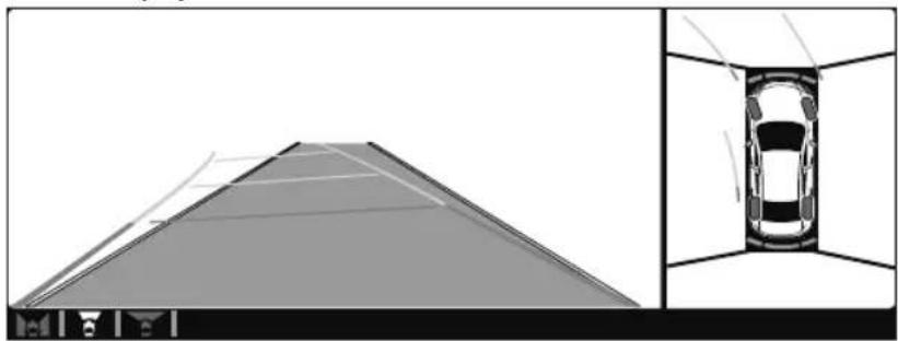
natural_image
Top-down architectural rendering of a car enclosed in a tunnel or enclosure, with no visible text or symbols.(Actual condition)
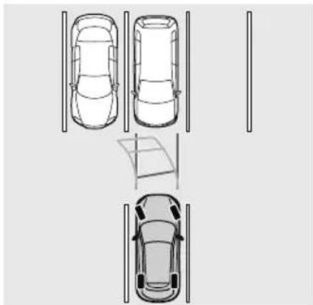
natural_image
Top-down line drawing of three cars with parking and street markings (no text or symbols)Make sure that there are no obstructions within the projected vehicle path lines.
Drive the vehicle forward while turning the steering wheel so that no obstructions come within the projected vehicle path lines.
▼ Top View/Front Wide View
Use the top view/front wide view to assist in checking the safety of the surrounding area when accelerating from a stop or entering a T-shaped intersection and intersection.
Display range
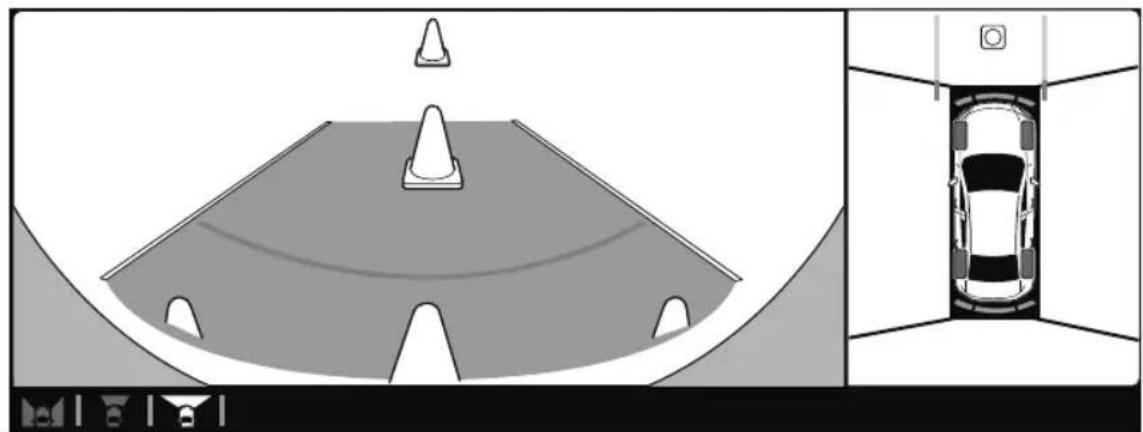
natural_image
Top-down diagram of a car parking roof with a traffic cone and adjacent view showing the exterior view (no text or symbols)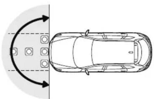
natural_image
Top-down diagram of a car with directional arrows indicating clockwise motion around the wheel (no text or symbols)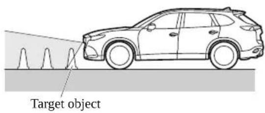
NOTE
- In the top view screen, the areas in black at the front and rear of the vehicle image and the seams where each of the camera images merge are blind spots.
-
Because images displayed in the top view screen are processed from each camera, the top view screen may display in the following ways.
-
If an image containing an object with a conspicuous color is picked up by any of the cameras, the screen area for each camera may be affected and it may display in that color.
- Obstructions displayed in the front view may not display on the top view screen.
- If the position or angle of each camera changes due to tilting of the vehicle, the image may appear distorted.
- Lines on the road may appear distorted at the seams where each of the camera images merge.
- The screen area for each camera may appear bright/dark depending on the illumination level around any of the cameras.
Viewing the screen
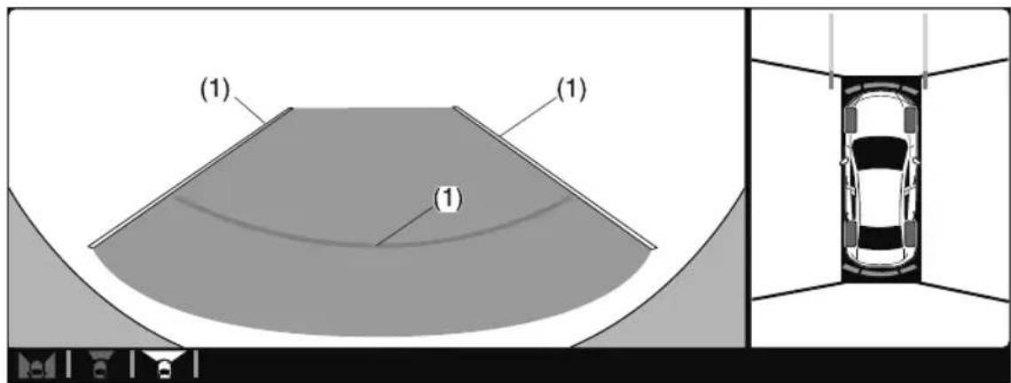
| Display/Icon Content | ||
| (1) Extended vehicle width lines and distance guide lines (blue & red) | Indicates the approximate width of the vehicle and the distance (from front end of bumper) in front of the vehicle.The red lines indicate the points up to about 0.5 m (19 in) from the front end of the bumper. | |
NOTE
The front wide view screen displays the image in front of the vehicle at a wide angle and corrects the image to help detect approaching obstructions from the side. Therefore, it differs from the actual view.
▼ Side View
Use the side view to assist in checking the safety of the surrounding area when accelerating from a stop, parking, or stopping the vehicle.
Display range
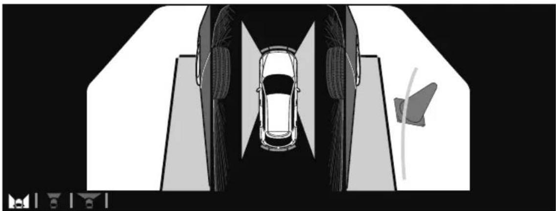
natural_image
Top-down architectural rendering of a car inside a tunnel or enclosure, with no visible text or symbols.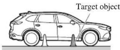
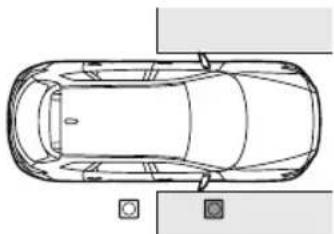
natural_image
Top-down line drawing of a car viewed from the side, showing front and rear views with no text or symbols.Viewing the screen
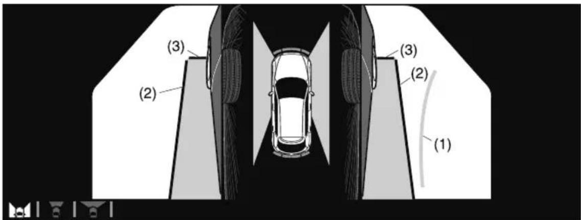
| Display/Icon Content | ||
| (1) | Projected vehicle path lines (yellow) | Indicates the approximate projected path of the vehicle.Moves in conjunction with the steering wheel operation.The projected vehicle path lines (yellow) indicate the path the inner side of the vehicle is expected to travel. |
| (2) | Vehicle parallel guide lines (blue) | Indicates the approximate vehicle width including the door mirrors. |
| (3) | Vehicle front end guide lines (blue) | Indicates the point about 0.25 m (9.8 in) from the front edge of the vehicle (front edge of the bumper). |
NOTE
The setting can be changed so that the projected vehicle path lines are not displayed. Refer to the Settings section in the Mazda Connect Owner's Manual.
How to use the projected vehicle path line function
(Screen display)
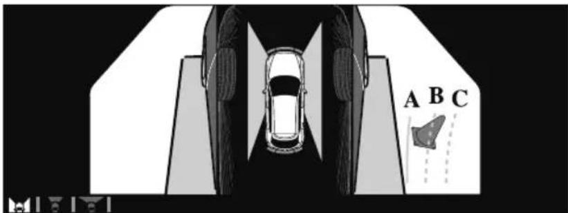
(Actual condition)
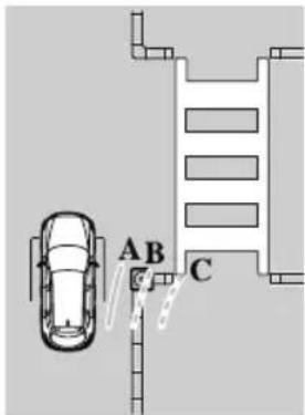
Make sure that there are no obstructions within the projected vehicle path lines. Turn the steering wheel so that the projected vehicle path lines travel inside of the obstruction (A), and drive the vehicle forward until it passes the obstruction. If the projected vehicle path lines are on an obstruction (B) or outside of the obstruction (C), the vehicle may contact the obstruction when turning the vehicle sharply.

CAUTION
The parking sensor detection range has limitations. For example, obstructions closing in from the side and objects short in height may not be detected. Always confirm the safety around the vehicle visually when driving. For details, refer to the parking sensor obstruction detection indication and warning sound.
Refer to Parking Sensor System on page 4-282.
Do not turn the steering wheel any more until the vehicle has passed the obstruction, even if the obstruction is not visible on the side view image. If the steering wheel is turned even more, the vehicle may contact the obstruction if it is turned sharply.
NOTE
- Because there might be a difference between the image displayed on the screen and the actual conditions, always check the safety of the surrounding area using the mirrors and directly with your eyes when driving.
- Even though the object displayed on the screen, such as a road curb or a division line of a parking space, and the vehicle parallel guide lines appear parallel, they may not actually be parallel.
▼ Top View/Rear View
Use the top view/rear view to assist in checking the safety of the surrounding area when accelerating from a stop, parking, or stopping the vehicle.
Range of displayed screen image
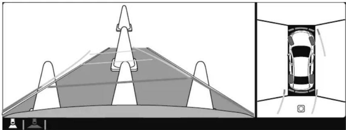
natural_image
Diagram showing a vehicle on a road with an inset close-up of the car interior (no text or symbols)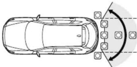
natural_image
Top-down diagram of a car with directional arrows indicating movement or flow, no text or symbols present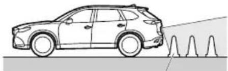
natural_image
Side profile illustration of a car with visible suspension or damage on the ground (no text or symbols)Target object
NOTE
- In the top view screen, the areas in black at the front and rear of the vehicle image and the seams where each of the camera images merge are blind spots.
- Because images displayed in the top view screen are processed from each camera, the top view screen may display in the following ways.
- If an image containing an object with a conspicuous color is picked up by any of the cameras, the screen area for each camera may be affected and it may display in that color.
- Obstructions displayed in the rear view may not display on the top view screen.
- If the position or angle of each camera changes due to tilting of the vehicle, the image may appear distorted.
- Lines on the road may appear distorted at the seams where each of the camera images merge.
- The screen area for each camera may appear bright/dark depending on the illumination level around any of the cameras.
Viewing the screen
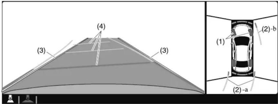
| Display/Icon Content | ||
| (1) | Tire icon | Indicates the tire direction. Moves in conjunction with the steering wheel operation. |
| (2) Projected vehicle path lines (yellow & red) | Indicates the approximate projected path of the vehicle.Moves in conjunction with the steering wheel operation.a) Indicates the path where the edge of the rear bumper is expected to travel.b) Indicates the path where the outer side of the vehicle is expected to travel. | |
| (3) | Extended vehicle width lines (blue) | These guide lines indicate the approximate width of the vehicle. |
| (4) Projected vehicle path distance guide lines (yellow & red) | These guide lines indicate the approximate distance to a point measured from the rear of the vehicle (from the end of the bumper).The red line indicates the point about 0.5 m (19 in) from the rear end of the bumper.The yellow lines indicate the points about 1.0 m (39 in) and 2.0 m (78 in) from the rear end of the bumper. | |
NOTE
The setting can be changed so that the projected vehicle path lines are not displayed. Refer to the Settings section in the Mazda Connect Owner's Manual.
How to use the projected vehicle path line function

CAUTION
The front of the vehicle swings out wide when turning the steering wheel while reversing. Maintain sufficient distance between the vehicle and an obstruction.
The parking sensor detection range has limitations. For example, obstructions closing in from the side and objects short in height may not be detected. Always confirm the safety around the vehicle visually when driving.
For details, refer to the parking sensor obstruction detection indication and warning sound. Refer to Parking Sensor System on page 4-282.
NOTE
- Because there might be a difference between the image displayed on the screen, such as indicated in the following, and the actual conditions when parking, always check the safety at the rear of the vehicle and the surrounding area directly with your eyes.
- Even though the back end of the parking space (or garage) displayed on the screen and distance guide lines appear parallel, they may not actually be parallel.
- When parking in a space with a division line on only one side of the parking space, even though the division line and the vehicle width guide line appear parallel, they may not actually be parallel.
- The following shows an example of vehicle parking with the steering wheel turned to the left while backing up the vehicle. When backing into a parking space from the opposite direction, the steering operation is reversed.
- Back the vehicle into the parking space by turning the steering wheel so that the vehicle enters the center of the parking space.
(Screen display)
natural_image
Top-down diagram of a car viewed from the side, showing its rear view and lane markings (no text or symbols present)(Actual condition)
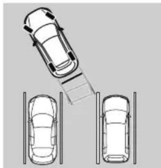
natural_image
Top-down diagram of a car with a ramp and two adjacent cars, no text or symbols present-
After the vehicle starts entering the parking space, stop and adjust the steering wheel so that the distance between the vehicle width lines and the sides of the parking space on the left and right are roughly equal, and then continue backing up slowly.
-
Once the vehicle width lines and the sides of the parking space on the left and right are parallel, straighten the wheels and back the vehicle slowly into the parking space.
Continue checking the vehicle's surroundings and then stop the vehicle in the best
possible position. (If the parking space has division lines, check whether the vehicle width guide lines are parallel to them.)
(Screen display)

natural_image
Top-down view of a road with lane markings and an inset showing a car inside a vehicle (no text or symbols)(Actual condition)
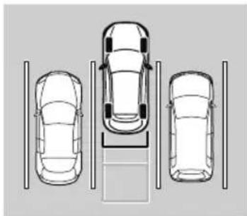
natural_image
Top-down line drawing of three cars parked in a row with parking structures (no text or symbols)▼ Top View/Rear Wide View
Use the top view/rear wide view to assist in checking the safety of the surrounding area when accelerating from a stop, parking, or stopping the vehicle.
Range of displayed screen image
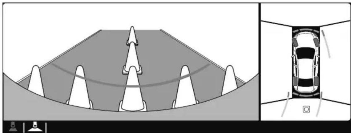
natural_image
Top-down diagram of a car being tested under pressure, showing conical pressure points and a close-up view of the vehicle inside a tunnel (no text or symbols)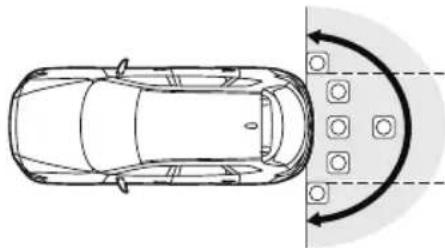
natural_image
Top-down line drawing of a car with directional arrows indicating flow or movement, no text or symbols present.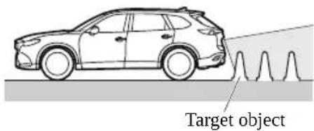
NOTE
- In the top view screen, the areas in black at the front and rear of the vehicle image and the seams where each of the camera images merge are blind spots.
-
Because images displayed in the top view screen are processed from each camera, the top view screen may display in the following ways.
-
If an image containing an object with a conspicuous color is picked up by any of the cameras, the screen area for each camera may be affected and it may display in that color.
- Obstructions displayed in the front view may not display on the top view screen.
- If the position or angle of each camera changes due to tilting of the vehicle, the image may appear distorted.
- Lines on the road may appear distorted at the seams where each of the camera images merge.
- The screen area for each camera may appear bright/dark depending on the illumination level around any of the cameras.
Viewing the screen
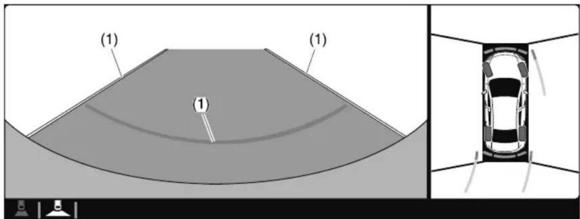
| Display/Icon Content | ||
| (1) Extended vehicle width lines and distance guide lines (blue & red) | These guide lines indicate the approximate width of the vehicle and distance to a point measured from the rear of the vehicle (from the end of the bumper).The red lines indicate the points up to about 0.5 m (19 in) from the rear end of the bumper. | |
NOTE
The top view/rear wide view screen displays the image at the rear of the vehicle at a wide angle and corrects the image to help detect approaching obstructions from the side. Therefore, it differs from the actual view.
▼ Margin of Error Between Road Surface on Screen and Actual Road Surface
There might be some margin of error between the road surface appearing on the screen and the actual road surface. A margin of error in the perceived distance could lead to an accident, therefore be aware of the following conditions which can more easily produce errors in the perceived distance.
The vehicle tilts due to weight of passengers and cargo.
If the vehicle is tilted, obstructions picked up by a camera can appear farther or closer than the actual distance from the vehicle.
Front camera
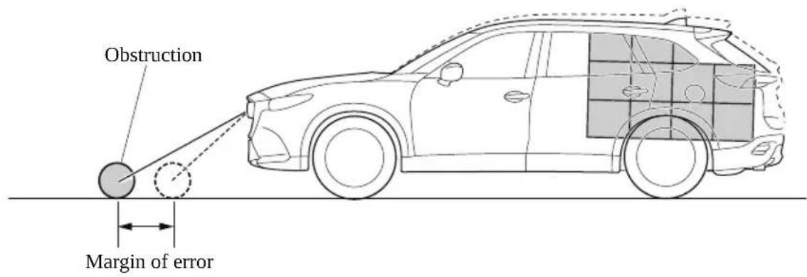
Side camera
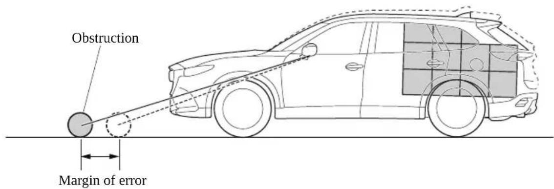
Rear camera
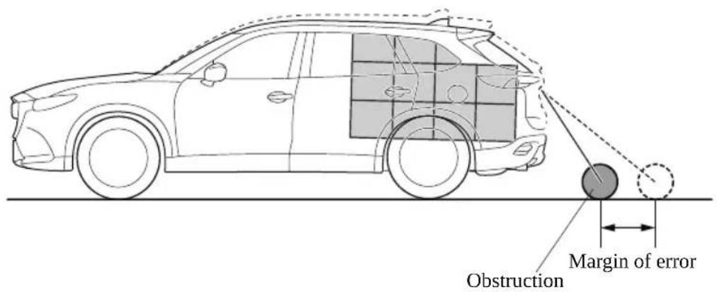
There is a steep up or down grade in the road at the front or rear of the vehicle
If there is a steep up or down grade in the road at the front or rear of the vehicle, obstructions picked up by the camera can appear farther or closer than the actual distance from the vehicle.
Front camera
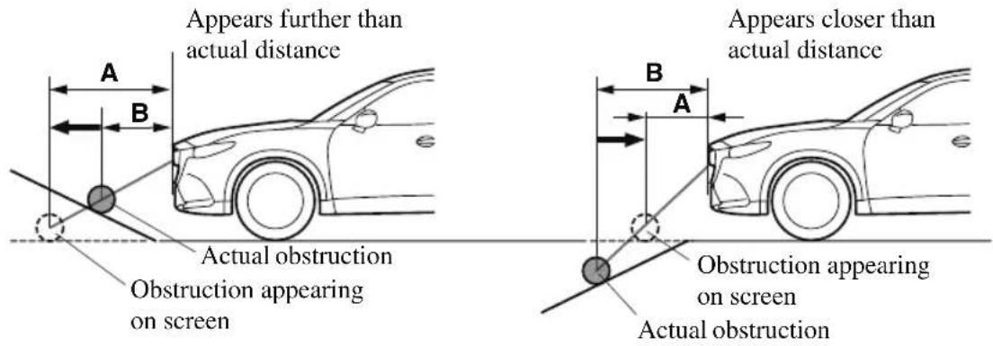
A: Distance of obstruction being viewed on screen
B: Actual distance of obstruction from vehicle
Side camera
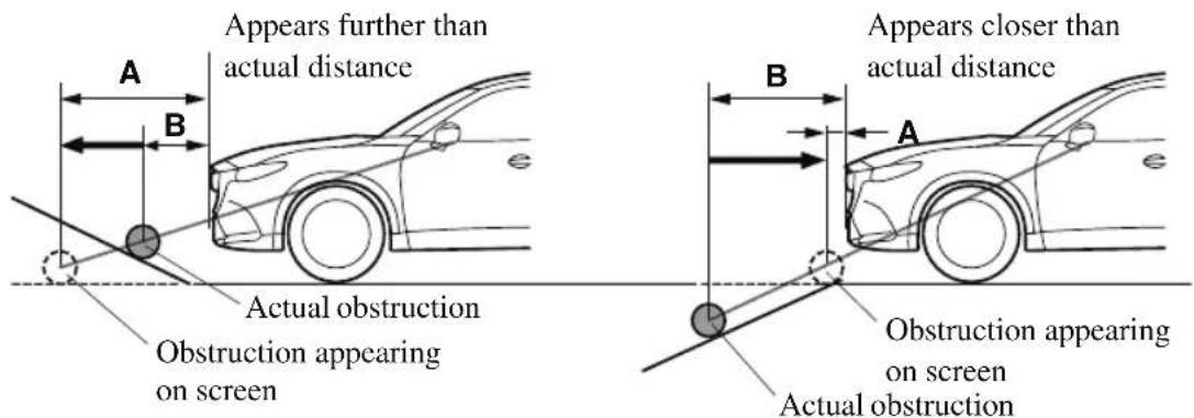
A: Distance of obstruction being viewed on screen
B: Actual distance of obstruction from vehicle
Rear camera
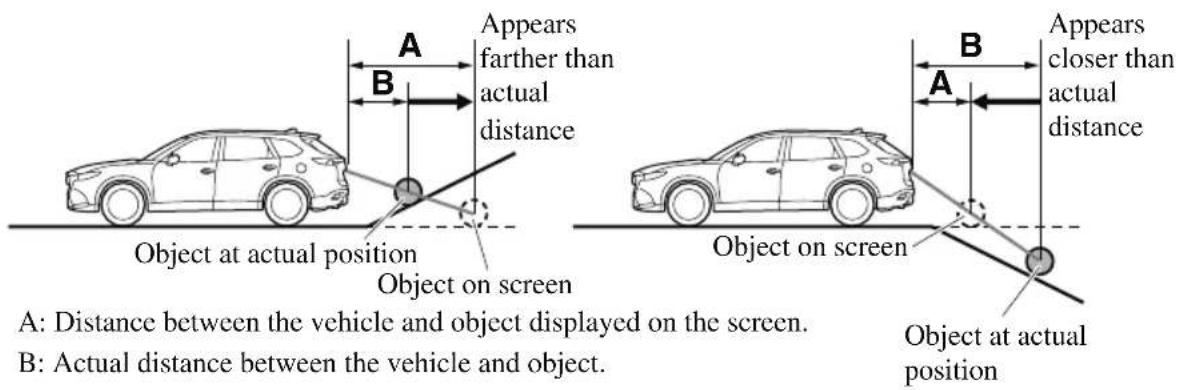
NOTE
If the vehicle is on a slope, obstructions taken by the camera can appear farther or closer than the actual distance from the vehicle.
Three-dimensional object at vehicle front or rear
Because the vehicle front end guide lines (side camera) or the distance guide lines (rear camera) are displayed based on a flat surface, the distance to the three-dimensional object displayed on the screen is different from the actual distance.
Side camera
(Screen display)
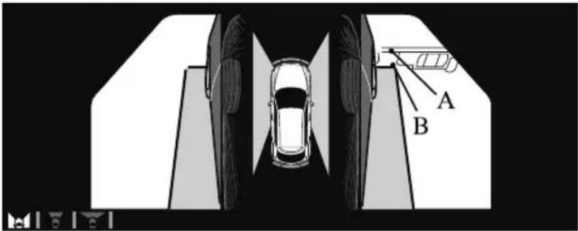
(Actual condition)
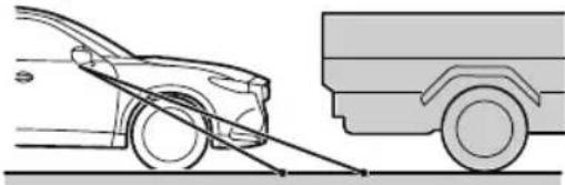
natural_image
Side-view diagram of a car with a ramp and a truck, no text or symbols presentB A
Rear camera
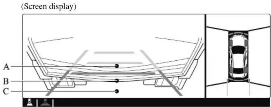
Sensed distance on screen A > B > C
(Actual condition)
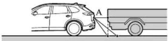
natural_image
Diagram showing a car approaching a truck with a dashed line indicating distance (no text or symbols)CB
Actual distance B > C = A
▼ System Problem Indication
| Center display indication Cause | Action to be taken | |
| “No camera signal.” is displayed The control unit might be damaged. Have your vehicle inspected by an Authorized Mazda Dealer. | ||
| Screen is pitch-black and blank The camera might be damaged. | ||
Forward Sensing Camera (FSC)\*
Your vehicle is equipped with a Forward Sensing Camera (FSC). The Forward Sensing Camera (FSC) is positioned near the rearview mirror and used by the following systems.
· High Beam Control System (HBC)
- Driver Attention Alert (DAA)
• Lane-keep Assist System (LAS) & Lane Departure Warning System (LDWS)
• Traffic Sign Recognition System (TSR)
- Advanced Smart City Brake Support (Advanced SCBS)
• Smart City Brake Support [Forward] (SCBS F)
· Mazda Radar Cruise Control with Stop & Go function (MRCC with Stop & Go function)
• Smart Brake Support (SBS)
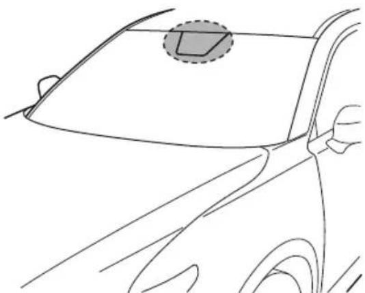
natural_image
Line drawing of a car's front and side view showing the dashboard and steering wheel (no text or symbols)The Forward Sensing Camera (FSC) determines the conditions ahead of the vehicle while traveling at night and detects traffic lanes. The distance in which the Forward Sensing Camera (FSC) can detect objects varies depending on the surrounding conditions.

WARNING
Do not modify the suspension:
If the vehicle height or inclination is changed, the system will not be able to correctly detect vehicles ahead. This will result in the system not operating normally or mistakenly operating, which could cause a serious accident.

CAUTION
Do not apply accessories, stickers or film to the windshield near the Forward Sensing Camera (FSC).
If the area in front of the Forward Sensing Camera (FSC) lens is obstructed, it will cause the system to not operate correctly. Consequently, each system may not operate normally which could lead to an unexpected accident.
➢ Do not disassemble or modify the Forward Sensing Camera (FSC).
Disassembly or modification of the Forward Sensing Camera (FSC) will cause a malfunction or mistaken operation. Consequently, each system may not operate normally which could lead to an unexpected accident.
➢ Heed the following cautions to assure the correct operation of the Forward Sensing Camera (FSC).
➢ Be careful not to scratch the Forward Sensing Camera (FSC) lens or allow it to get dirty.
Do not remove the Forward Sensing Camera (FSC) cover.
Do not place objects on the dashboard which reflect light.
➢ Always keep the windshield glass around the camera clean by removing dirt or fogging. Use the windshield defroster to remove fogging on the windshield.
Consult an Authorized Mazda Dealer regarding cleaning the interior side of the windshield around the Forward Sensing Camera (FSC).
➢ Consult an Authorized Mazda Dealer before performing repairs around the Forward Sensing Camera (FSC).
The Forward Sensing Camera (FSC) is installed to the windshield. Consult an Authorized Mazda Dealer for windshield repair and replacement.
When cleaning the windshield, do not allow glass cleaners or similar cleaning fluids to get on the Forward Sensing Camera (FSC) lens. In addition, do not touch the Forward Sensing Camera (FSC) lens.
When performing repairs around the rearview mirror, consult an Authorized Mazda Dealer.
➢Consult an Authorized Mazda Dealer regarding cleaning of the camera lens.
Do not hit or apply strong force to the Forward Sensing Camera (FSC) or the area around it. If the Forward Sensing Camera (FSC) is severely hit or if there are cracks or damage caused by flying gravel or debris in the area around it, stop using the following systems and consult an Authorized Mazda Dealer.
▶High Beam Control System (HBC)
▶ Driver Attention Alert (DAA)
➢Lane-keep Assist System (LAS) & Lane Departure Warning System (LDWS)
▶ Traffic Sign Recognition System (TSR)
- Advanced Smart City Brake Support (Advanced SCBS)
▶Smart City Brake Support [Forward] (SCBS F)
Mazda Radar Cruise Control with Stop & Go function (MRCC with Stop & Go function)
▶Smart Brake Support (SBS)
The direction in which the Forward Sensing Camera (FSC) is pointed has been finely adjusted. Do not change the installation position of the Forward Sensing Camera (FSC) or remove it. Otherwise, it could result in damage or malfunction.
➢ Always use tires for all wheels that are of the specified size, and the same manufacturer, brand, and tread pattern. In addition, do not use tires with significantly different wear patterns on the same vehicle as the system may not operate normally.
The Forward Sensing Camera (FSC) includes a function for detecting a soiled windshield and informing the driver, however, depending on the conditions, it may not detect plastic shopping bags, ice or snow on the windshield. In such cases, the system cannot accurately determine a vehicle ahead and may not be able to operate normally. Always drive carefully and pay attention to the road ahead.
NOTE
- In the following cases, the Forward Sensing Camera (FSC) cannot detect target objects correctly, and each system may be unable to operate normally.
- The height of the vehicle ahead is low.
- You drive your vehicle at the same speed as the vehicle ahead.
- Headlights are not turned on during the night or when going through a tunnel.
- In the following cases, the Forward Sensing Camera (FSC) may not be able to detect target objects correctly.
- Under bad weather condition, such as rain, fog and snow.
- The window washer is being used or the windshield wipers are not used when it's raining.
- Ice, fog, snow, frost, rainfall, dirt, or foreign matter such as a plastic bag is stuck on the windshield.
- Trucks with low loading platforms and vehicles with an extremely low or high profile.
- When driving next to walls with no patterning (including fences and longitudinally striped walls).
- The taillights of the vehicle ahead are turned off.
- A vehicle is outside the illumination range of the headlights.
- The vehicle is making a sharp turn, or ascending or descending a steep slope.
- Entering or exiting a tunnel.
- Heavy luggage is loaded causing the vehicle to tilt.
- Strong light is shone at the front of the vehicle (back light or high-beam light from on-coming vehicles).
- There are many light emitters on the vehicle ahead.
- When the vehicle ahead is not equipped with taillights or the taillights are turned off at nighttime.
-
Elongated luggage or cargo is loaded onto installed roof rails and covers the Forward Sensing Camera (FSC).
-
Exhaust gas from the vehicle in front, sand, snow, and water vapor rising from manholes and grating, and water splashed into the air.
- When towing a malfunctioning vehicle.
- The vehicle is driven with tires having significantly different wear.
- The vehicle is driven on down slopes or bumpy roads.
- There are water puddles on the road.
- The surroundings are dark such as during the night, early evening, or early morning, or in a tunnel or indoor parking lot.
- The illumination brightness of the headlights is reduced or the headlight illumination is weakened due to dirt or a deviated optical axis.
- The target object enters the blind spot of the Forward Sensing Camera (FSC).
- A person or object bursts onto the road from the shoulder or cuts right in front of you.
- You change lanes and approach a vehicle ahead.
- When driving extremely close to the target object.
- Tire chains or a temporary spare tire is installed.
- The vehicle ahead has a special shape. For example, a vehicle towing a trailer house or a boat, or a vehicle carrier carrying a vehicle with its front pointed rearward.
- If the Forward Sensing Camera (FSC) cannot operate normally due to backlight or fog, the system functions related to the Forward Sensing Camera (FSC) are temporarily stopped and the following warning lights turn on. However, this does not indicate a malfunction.
· High Beam Control System (HBC) warning light (amber)
- Lane-keep Assist System (LAS) & Lane Departure Warning System (LDWS) warning indication
- Mazda Radar Cruise Control with Stop & Go function (MRCC with Stop & Go function) warning indication
- Smart Brake Support/Smart City Brake Support (SBS/SCBS) warning indication (amber)
- If the Forward Sensing Camera (FSC) cannot operate normally due to high temperatures, the system functions related to the Forward Sensing Camera (FSC) are temporarily stopped and the following warning lights turn on. However, this does not indicate a malfunction. Cool down the area around the Forward Sensing Camera (FSC) such as by turning on the air conditioner.
· High Beam Control System (HBC) warning light (amber)
- Lane-keep Assist System (LAS) & Lane Departure Warning System (LDWS) warning indication
- Mazda Radar Cruise Control with Stop & Go function (MRCC with Stop & Go function) warning indication
- Smart Brake Support/Smart City Brake Support (SBS/SCBS) warning indication (amber)
- If the Forward Sensing Camera (FSC) detects that the windshield is dirty or foggy, the system functions related to the Forward Sensing Camera (FSC) are temporarily stopped and the following warning lights turn on. However, this does not indicate a problem. Remove the dirt from the windshield or press the defroster switch and defog the windshield.
· High Beam Control System (HBC) warning light (amber)
- Lane-keep Assist System (LAS) & Lane Departure Warning System (LDWS) warning indication
- Mazda Radar Cruise Control with Stop & Go function (MRCC with Stop & Go function) warning indication
- Smart Brake Support/Smart City Brake Support (SBS/SCBS) warning indication (amber)
- If there are recognizable cracks or damage caused by flying gravel or debris on the windshield, always have the windshield replaced. Consult an Authorized Mazda Dealer for replacement.
· (With Advanced Smart City Brake Support (Advanced SCBS))
- The Forward Sensing Camera (FSC) recognizes pedestrians when all of the following conditions are met:
- The height of a pedestrian is about 1 to 2 meters.
- An outline such as the head, both shoulders, or the legs can be determined.
- In the following cases, the Forward Sensing Camera (FSC) may not be able to detect target objects correctly:
- Multiple pedestrians are walking, or there are groups of people.
- A pedestrian is close to a separate object.
- A pedestrian is crouching, lying, or slouching.
- A pedestrian suddenly jumps into the road right in front of the vehicle.
- A pedestrian opens an umbrella, or is carrying large baggage or articles.
- A pedestrian is in a dark location such as during the night, or blends into the background by wearing clothes matching the background color.
Radar Sensor (Front)\*
Your vehicle is equipped with a radar sensor (front).
The following systems also use the radar sensor (front).
• Distance Recognition Support System (DRSS)
- Mazda Radar Cruise Control with Stop & Go function (MRCC with Stop & Go function)
• Smart Brake Support (SBS)
The radar sensor (front) functions by detecting the radio waves reflected off a vehicle ahead or an obstruction sent from the radar sensor.
The radar sensor (front) is mounted behind the front emblem.
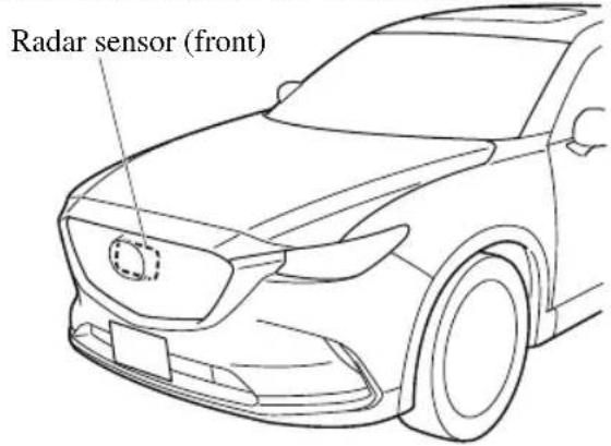
If “Front Radar Sensor Blocked” is displayed in the multi-information display of the instrument cluster, clean the area around the radar sensor (front).

CAUTION
Heed the following precautions to assure correct operation of each system.
Do not adhere stickers (including transparent stickers) to the surface of the radiator grille and front emblem in and around the radar sensor (front), and do not replace the radiator grille and front emblem with any product that is not a genuine product designed for use with the radar sensor (front).
The radar sensor (front) includes a function for detecting soiling of the radar sensor's front surface and informing the driver, however, depending on the conditions, it may require time to detect or it may not detect plastic shopping bags, ice or snow. If this occurs, the system may not operate correctly, therefore always keep the radar sensor (front) clean.
Do not install a grille guard.
If the front part of the vehicle has been damaged in a vehicle accident, the position of the radar sensor (front) may have moved. Stop the system immediately and always have the vehicle inspected at an Authorized Mazda Dealer.
Do not use the front bumper to push other vehicles or obstructions such as when pulling out of a parking space. Otherwise, the radar sensor (front) could be hit and its position deviated.
➢ Do not remove, disassemble, or modify the radar sensor (front).
For repairs, replacement or paint work around the radar sensor (front), consult an Authorized Mazda Dealer.
Do not modify the suspension. If the suspension are modified, the vehicle's posture could change and the radar sensor (front) may not be able to correctly detect a vehicle ahead or an obstruction.
NOTE
- Under the following conditions, the radar sensor (front) may not be able to detect vehicles ahead or obstructions correctly and each system may not operate normally.
- The rear surface of a vehicle ahead does not reflect radio waves effectively, such as an unloaded trailer or an automobile with a loading platform covered by a soft top, vehicles with a hard plastic tailgate, and round-shaped vehicles.
- Vehicles ahead with low vehicle height and thus less area for reflecting radio waves.
- Visibility is reduced due to a vehicle ahead casting off water, snow, or sand from its tires and onto your windshield.
- The luggage compartment is loaded with heavy objects or the rear passenger seats are occupied.
- Ice, snow, or soiling is on the front surface of the front emblem.
- During inclement weather such as rain, snow, or sand storms.
- When driving near facilities or objects emitting strong radio waves.
- Under the following conditions, the radar sensor (front) may not be able to detect vehicles ahead or obstructions.
- The beginning and end of a curve.
- Roads with continuous curves.
- Narrow lane roads due to road construction or lane closures.
- The vehicle ahead enters the radar sensor's blind spot.
- The vehicle ahead is running abnormally due to accident or vehicle damage.
- Roads with repeated up and down slopes
- Driving on poor roads or unpaved roads.
- The distance between your vehicle and the vehicle ahead is extremely short.
- A vehicle suddenly comes close such as by cutting into the lane.
- To prevent incorrect operation of the system, use tires of the same specified size, manufacturer, brand, and tread pattern on all four wheels. In addition, do not use tires with significantly different wear patterns or tire pressures on the same vehicle (Including the temporary spare tire).
- If the battery power is weak, the system may not operate correctly.
- When driving on roads with little traffic and few vehicles ahead or obstructions for the radar sensor (front) to detect, “Front Radar Sensor Blocked” may be temporarily displayed, however, this does not indicate a problem.
- The radar sensors are regulated by the relevant radio wave laws of the country in which the vehicle is driven. If the vehicle is driven abroad, authorization from the country in which the vehicle is driven may be required.
Radar Sensors (Rear)\*
Your vehicle is equipped with radar sensors (rear). The following systems also use the radar sensors (rear).
• Blind Spot Monitoring (BSM)
- Rear Cross Traffic Alert (RCTA)
The radar sensors (rear) function by detecting the radio waves reflected off a vehicle approaching from the rear or an obstruction sent from the radar sensor.
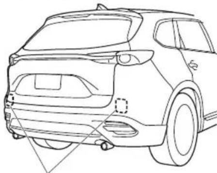
natural_image
Line drawing of a car rear view showing front and side panels (no text or symbols)Radar sensors (rear)
The radar sensors (rear) are installed inside the rear bumper, one each on the left and right sides.
Always keep the surface of the rear bumper near the radar sensors (rear) clean so that the radar sensors (rear) operate normally. Also, do not apply items such as stickers.
Refer to Exterior Care on page 6-52.

CAUTION
If the rear bumper receives a severe impact, the system may no longer operate normally. Stop the system immediately and have the vehicle inspected at an Authorized Mazda Dealer.
NOTE
- The detection ability of the radar sensors (rear) has limitations. In the following cases, the detection ability may lower and the system may not operate normally.
• The rear bumper near the radar sensors (rear) has become deformed. - Snow, ice or mud adheres to the radar sensors (rear) on the rear bumper.
· Under bad weather conditions such as rain, snow and fog. - Under the following conditions, the radar sensors (rear) cannot detect target objects or it may be difficult to detect them.
- Stationary objects on a road or a road side such as small, two-wheeled vehicles, bicycles, pedestrians, animals, and shopping carts.
- Vehicle shapes which do not reflect radar waves well such as empty trailers with a low vehicle height and sports cars.
- Vehicles are shipped with the direction of the radar sensors (rear) adjusted for each vehicle to a loaded vehicle condition so that the radar sensors (rear) detect approaching vehicles correctly. If the direction of the radar sensors (rear) has deviated for some reason, have the vehicle inspected at an Authorized Mazda Dealer.
- For repairs or replacement of the radar sensors (rear), or bumper repairs, paintwork, and replacement near the radar sensors, consult an Authorized Mazda Dealer.
- Turn off the system while pulling a trailer or while an accessory such as a bicycle carrier is installed to the rear of the vehicle. Otherwise, the radio waves emitted by the radar will be blocked causing the system to not operate normally.
- The radar sensors are regulated by the relevant radio wave laws of the country in which the vehicle is driven. If the vehicle is driven abroad, authorization from the country in which the vehicle is driven may be required.
Ultrasonic Sensor (Rear)\*
The ultrasonic sensors (rear) function by emitting ultrasonic waves which are reflected off obstructions at the rear and the returning ultrasonic waves are picked up by the ultrasonic sensors (rear).
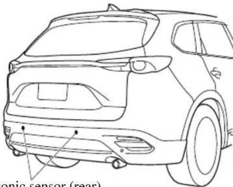
Ultrasonic sensor (rear)
The ultrasonic sensors (rear) are mounted in the rear bumper.
Front Camera/Side Cameras/Rear Camera\*
Your vehicle is equipped with a front camera, side cameras, and a rear camera. The 360° View Monitor uses each camera.
The front camera, side cameras, and rear camera shoot images of the area surrounding the vehicle.
Each camera is installed to the following positions.
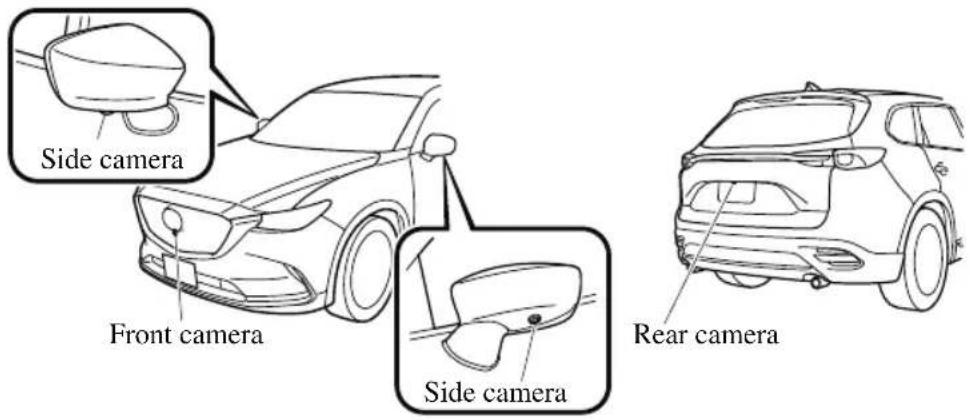
Cruise Control\*
With cruise control, you can set and automatically maintain any speed of more than about 25 km/h (16 mph).

WARNING
Do not use the cruise control under the following conditions:
Using the cruise control under the following conditions is dangerous and could result in loss of vehicle control.
Hilly terrain
▶ Steep inclines
▶Heavy or unsteady traffic
▶Slippery or winding roads
▶ Similar restrictions that require inconsistent speed
▼ Cruise Control Switch
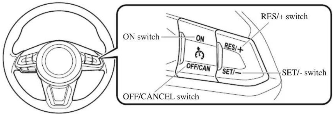
NOTE
If your Mazda has the following steering switch, your Mazda is equipped with the Mazda Radar Cruise Control with Stop & Go function (MRCC with Stop & Go function) system.
Refer to Mazda Radar Cruise Control with Stop & Go function (MRCC with Stop & Go function) on page 4-143.
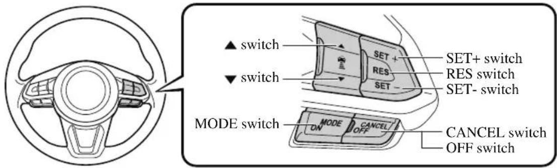
▼ Cruise Main Indication (White)/Cruise Set Indication (Green)
The indication has 2 colors.
Cruise Main Indication (White)
The indication turns on (white) when the cruise control system is activated.
Cruise Set Indication (Green)
The indication turns on (green) when a cruising speed has been set.
▼ Activation/Deactivation
To activate the system, press the ON switch. The cruise main indication (white) is displayed.
To deactivate the system, press the OFF/CANCEL switch.
The cruise main indication (white) turns off.
WARNING
Always turn off the cruise control system when it is not in use:
Leaving the cruise control system in an activation-ready state while the cruise control is not in use is dangerous as the cruise control could unexpectedly activate if the activation button is accidentally pressed, and result in loss of vehicle control and an accident.
NOTE
When the ignition is switched OFF, the system status before it was turned off is maintained. For example, if the ignition is switched OFF with the cruise control system operable, the system will be operable when the ignition is switched ON the next time.
▼ To Set Speed
- Activate the cruise control system by pressing the ON switch. The cruise main indication (white) is displayed.
- Accelerate to the desired speed, which must be more than 25 km/h (16 mph).
- Set the cruise control by pressing the SET/− switch at the desired speed. The
cruise control is set at the moment the SET/− switch is pressed. Release the accelerator pedal simultaneously. The cruise set indication (green) is displayed.
NOTE
- The cruise control speed setting cannot be performed under the following conditions:
- The selector lever is in the P or N position. - The parking brake is applied.
- Release the SET/−or RES/ + switch at the desired speed, otherwise the speed will continue increasing while the RES/ + switch is pressed and held, and continue decreasing while the SET/− switch is pressed and held (except when the accelerator pedal is depressed).
- On a steep grade, the vehicle may momentarily slow down while ascending, or speed up while descending.
- The cruise control will cancel if the vehicle speed decreases below 21 km/h (13 mph) when climbing a steep grade.
- The cruise control may cancel at about 15 km/h (9 mph) below the preset speed such as when climbing a long, steep grade.
The vehicle speed preset using the cruise control is displayed in the instrument cluster.
Instrument Cluster Type A
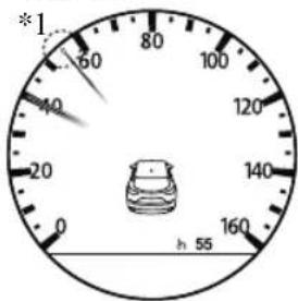
*1: Needle indicates set speed.
Type B Type C
55
Active Driving Display
55
▼ To Increase Cruising Speed
Follow either of these procedures.
To increase speed using cruise control switch
Press the RES/switch and hold it. Your vehicle will accelerate. Release the switch at the desired speed.
Press the RES/+ switch and release it immediately to adjust the preset speed. Multiple operations will increase the preset speed according to the number of times it is operated.
Increasing speed with a single RES/+ switch operation
Instrument cluster display for vehicle speed indicated in km/h: 1 km/h (0.6 mph)
Instrument cluster display for vehicle speed indicated in mph: 1 mph (1.6 km/h)
To increase speed using accelerator pedal
Depress the accelerator pedal to accelerate to the desired speed. Press the SET/— switch and release it immediately.
NOTE
Accelerate if you want to speed up temporarily when the cruise control is on. Greater speed will not interfere with or change the set speed. Take your foot off the accelerator to return to the set speed.
▼ To Decrease Cruising Speed
Press the SET/–switch and hold it. The vehicle will gradually slow. Release the switch at the desired speed.
Press the SET/— switch and release it immediately to adjust the preset speed. Multiple operations will decrease the preset speed according to the number of times it is operated.
Decreasing speed with a single SET/—switch operation
Instrument cluster display for vehicle speed indicated in km/h: 1 km/h (0.6 mph) Instrument cluster display for vehicle speed indicated in mph: 1 mph (1.6 km/h)
▼ To Resume Cruising Speed at More Than 25 km/h (16 mph)
If the cruise control system temporarily canceled (such as applying the brake pedal) and the system is still activated, the most recent set speed will automatically resume when the RES/+ switch is pressed. If vehicle speed is below 25 km/h (16 mph), increase the vehicle speed up to 25 km/h (16 mph) or more and press the RES/ + switch.
▼ To Temporarily Cancel
To temporarily cancel the system, use one of these methods:
- Slightly depress the brake pedal.
- Press the OFF/CANCEL switch.
If the RES/+ switch is pressed when the vehicle speed is 25 km/h (16 mph) or higher, the system reverts to the previously set speed.
NOTE
- If any of the following conditions occur, the cruise control system is temporarily canceled.
- The parking brake is applied. - The selector lever is in the P or N position.
- When the cruise control system is temporarily canceled by even one of the applicable cancel conditions, the speed cannot be re-set.
- The cruise control cannot be cancelled while driving in manual mode (selector lever shifted from D to M position). Therefore, engine braking will not be applied even if the transaxle is shifted down to a lower gear. If deceleration is required, lower the set speed or depress the brake pedal.
▼ To Deactivate
When a cruising speed has been set (cruise set indication (green) turns on)
Long-press the OFF/CANCEL switch or press the OFF/CANCEL switch 2 times.
When a cruising speed has not been set (cruise main indication (white) turns on)
Press the OFF/CANCEL switch.
Tire Pressure Monitoring System
The Tire Pressure Monitoring System (TPMS) monitors the pressure for each tire. If tire pressure is too low in one or more tires, the system will inform the driver via the warning light in the instrument cluster and by the warning beep sound. Refer to Contact Authorized Mazda Dealer and Have Vehicle Inspected on page 7-31. Refer to Taking Action on page 7-37. Refer to Tire Inflation Pressure Warning Beep on page 7-50.
The tire pressure sensors installed on each wheel send tire pressure data by radio signal to the receiver unit in the vehicle.
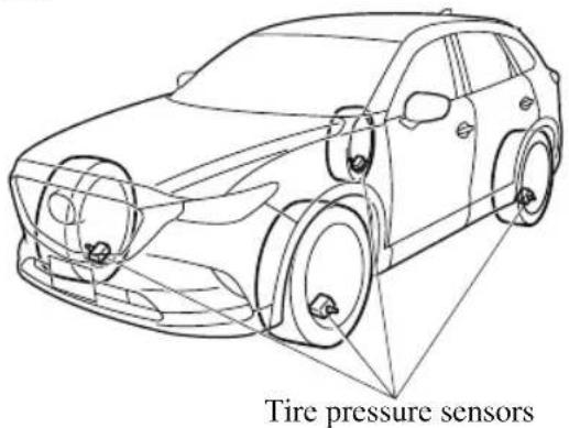
NOTE
When the ambient temperature is low due to seasonal changes, tire temperatures are also lower. When the tire temperature decreases, the air pressure decreases as well. The TPMS warning light may illuminate more frequently. Visually inspect the tires daily before driving, and check tire pressures monthly with a tire pressure gauge. When checking tire pressures, use of a digital tire pressure gauge is recommended.
TPMS does not alleviate your need to check the pressure and condition of all four tires regularly.
CAUTION
Each tire, including the spare (if provided), should be checked monthly when cold and inflated to the inflation pressure recommended by the vehicle manufacturer on the vehicle placard or tire inflation pressure label. (If your vehicle has tires of a different size than the size indicated on the vehicle placard or tire inflation pressure label, you should determine the proper tire inflation pressure for those tires.)
As an added safety feature, your vehicle has been equipped with a tire pressure monitoring system (TPMS) that illuminates a low tire pressure telltale when one or more of your tires is significantly under-inflated. Accordingly, when the low tire pressure telltale illuminates, you should stop and check your tires as soon as possible, and inflate them to the proper pressure. Driving on a significantly under-inflated tire causes the tire to overheat and can lead to tire failure. Under-inflation also reduces fuel efficiency and tire tread life, and may affect the vehicle's handling and stopping ability.
Please note that the TPMS is not a substitute for proper tire maintenance, and it is the driver's responsibility to maintain correct tire pressure, even if under-inflation has not reached the level to trigger illumination of the TPMS low tire pressure telltale.
Your vehicle has also been equipped with a TPMS malfunction indicator to indicate when the system is not operating properly.
The TPMS malfunction indicator is combined with the low tire pressure telltale. When the system detects a malfunction, the telltale will flash for approximately one minute and then remain continuously illuminated. This sequence will continue upon subsequent vehicle start-ups as long as the malfunction exists. When the malfunction indicator is illuminated, the system may not be able to detect or signal low tire pressure as intended. TPMS malfunctions may occur for a variety of reasons, including the installation of replacement or alternate tires or wheels on the vehicle that prevent the TPMS from functioning properly. Always check the TPMS malfunction telltale after replacing one or more tires or wheels on your vehicle to ensure that the replacement or alternate tires and wheels allow the TPMS to continue to function properly.
To avoid false readings, the system samples for a little while before indicating a problem. As a result it will not instantaneously register a rapid tire deflation or blow out.
▼ System Error Activation
When the warning light flashes, there may be a system malfunction. Consult an Authorized Mazda Dealer.
A system error activation may occur in the following cases:
- When there is equipment or a device near the vehicle using the same radio frequency as that of the tire pressure sensors.
- When a metallic device such as a non-genuine navigation system is equipped near the center of the dashboard, which may block radio signals from the tire pressure sensor to the receiver unit.
- When using the following devices in the vehicle that may cause radio interference with the receiver unit.
- A digital device such as a personal computer.
- A current converter device such as a DC-AC converter.
- When excess snow or ice adheres to the vehicle, especially around the wheels.
- When the tire pressure sensor batteries are exhausted.
- When using a wheel with no tire pressure sensor installed.
- When using tires with steel wire reinforcement in the sidewalls.
- When using tire chains.
▼ Tires and Wheels

CAUTION
When inspecting or adjusting the tire air pressures, do not apply excessive force to the stem part of the wheel unit. The stem part could be damaged.
Changing tires and wheels
The following procedure allows the TPMS to recognize a tire pressure sensor's unique ID signal code whenever tires or wheels are changed, such as changing to and from winter tires.
NOTE
Each tire pressure sensor has a unique ID signal code. The signal code must be registered with the TPMS before it can work. The easiest way to do it is to have an Authorized Mazda Dealer, change your tire and complete ID signal code registration.
When having tires changed at an Authorized Mazda Dealer
When an Authorized Mazda Dealer, changes your vehicle's tires, they will complete the tire pressure sensor ID signal code registration.
When changing tires yourself
If you or someone else changes tires, you or someone else can also undertake the steps for the TPMS to complete the ID signal code registration.
-
After tires have been changed, switch the ignition ON, then back to ACC or OFF.
-
Wait for about 15 minutes.
-
After about 15 minutes, drive the vehicle at a speed of at least 25 km/h (16 mph) for 10 minutes and the tire pressure sensor ID signal code will be registered automatically.
NOTE
If the vehicle is driven within about 15 minutes of changing tires, the tire pressure monitoring system warning light will flash because the sensor ID signal code would not have been registered. If this happens, park the vehicle for about 15 minutes, after which the sensor ID signal code will register upon driving the vehicle for 10 minutes.
Replacing tires and wheels

CAUTION
When replacing/repairing the tires or wheels or both, have the work done by an Authorized Mazda Dealer, or the tire pressure sensors may be damaged.
The wheels equipped on your Mazda are specially designed for installation of the tire pressure sensors. Do not use non-genuine wheels, otherwise it may not be possible to install the tire pressure sensors.
Be sure to have the tire pressure sensors installed whenever tires or wheels are replaced.
When having a tire or wheel or both replaced, the following types of tire pressure sensor installations are possible.
- The tire pressure sensor is removed from the old wheel and installed to the new one.
- The same tire pressure sensor is used with the same wheel. Only the tire is replaced.
- A new tire pressure sensor is installed to a new wheel.
NOTE
- The tire pressure sensor ID signal code must be registered when a new tire pressure sensor is purchased. For purchase of a tire pressure sensor and registration of the tire pressure sensor ID signal code, consult an Authorized Mazda Dealer.
- When reinstalling a previously removed tire pressure sensor to a wheel, replace the grommet (seal between valve body/ sensor and wheel) for the tire pressure sensor.
Rear View Monitor (Mazda Connect (Type A))\*
The rear view monitor provides visual images of the rear of the vehicle when reversing.

WARNING
Always drive carefully confirming the safety of the rear and the surrounding conditions by looking directly with your eyes:
Reversing the vehicle by only looking at the screen is dangerous as it may cause an accident or a collision with an object. The rear view monitor is only a visual assist device when reversing the vehicle. The images on the screen may be different from the actual conditions.

CAUTION
Do not use the rear view monitor under the following conditions: Using the rear view monitor under the following conditions is dangerous and could result in injury or vehicle damage or both.
▶ Icy or snow-covered roads.
▶Tire chains or a temporary spare tire is installed.
The liftgate is not fully closed.
The vehicle is on a road incline.
When the display is cold, images may course across the monitor or the screen and may be dimmer than usual, which could cause difficulty in confirming the surrounding conditions of the vehicle. Always drive carefully confirming the safety of the rear and the surrounding conditions by looking directly with your eyes.
➢ Do not apply excessive force to the camera. The camera position and angle may deviate.
➢ Do not disassemble, modify, or remove it as it may no longer be waterproof.
The camera cover is made of plastic. Do not apply degreasing agents, organic solvents, wax, or glass coating agents to the camera cover. If any are spilled on the cover, wipe off with a soft cloth immediately.
Do not rub the camera cover forcefully with an abrasive or hard brush. The camera cover or lens may be scratched which might affect the images.
NOTE
- If water, snow, or mud is stuck on the camera lens, wipe it off using a soft cloth. If it cannot be wiped off, use a mild detergent.
- If the camera temperature changes rapidly (Hot to cold, cold to hot), the rear view monitor may not operate correctly.
-
When replacing the tires, consult an Authorized Mazda Dealer. Replacing the tires could result in deviation of the guide lines which appear on the display.
-
If the vehicle's front, side, or rear has been involved in a collision, the alignment of the rear view parking camera (location, installation angle) may have deviated. Always consult an Authorized Mazda Dealer to have the vehicle inspected.
- If “No Video Signal Available” is indicated in the display, there could be a problem with the camera. Have your vehicle inspected at an Authorized Mazda Dealer.
▼ Rear View Parking Camera Location
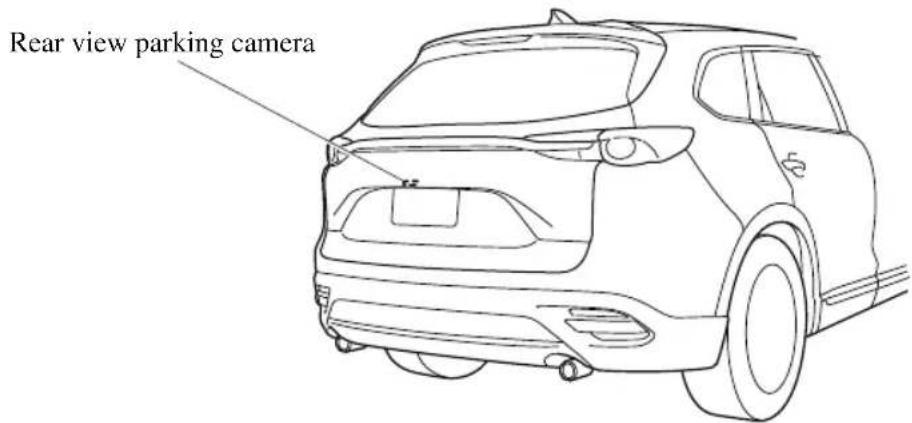
▼ Switching to the Rear View Monitor Display
Shift the selector lever to reverse (R) position with the ignition switched ON to switch the display to the rear view monitor display.
NOTE
When the selector lever is shifted from reverse (R) position to another selector lever position, the screen returns to the previous display.
▼ Displayable Range on the Screen
The images on the screen may be different from the actual conditions.
Screen display
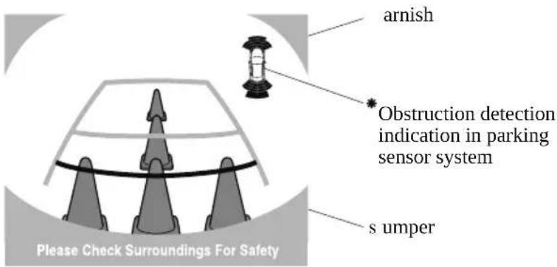
Actual view
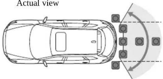
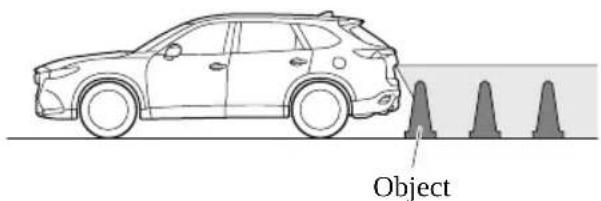
* Some models
NOTE
- The displayable range varies depending on the vehicle and road conditions.
- The displayable range is limited. Objects under the bumper or around the bumper ends cannot be displayed.
- The distance appearing in the displayed image is different from the actual distance because the rear view parking camera is equipped with a specific lens.
- Some optionally installed vehicle accessories may be picked up by the camera. Do not install any optional parts that can interfere with the camera view, such as illuminating parts or parts made of reflective material.
- It may be difficult to see the display under the following conditions, however, it does not indicate a malfunction.
· In darkened areas.
- When the temperature around the lens is high/low.
- When the camera is wet such as on a rainy day or during periods of high humidity.
- When foreign material such as mud is stuck around the camera.
- When the camera lens reflects sunlight or headlight beams.
- Image display may be delayed if the temperature around the camera is low.
▼ Viewing the Display
Guide lines which indicate the width of the vehicle (yellow) are displayed on the screen as a reference to the approximate width of the vehicle in comparison to the width of the parking space you are about to back into.
Use this display view for parking your vehicle in a parking space or garage.
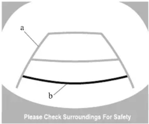
a) Vehicle width guide lines (yellow)
These guide lines serve as a reference to the approximate width of the vehicle.
b) Distance guide lines.
These guide lines indicate the approximate distance to a point measured from the vehicle's rear (from the end of the bumper).
- The red and yellow lines indicate the points about 0.5 ~m (19 in) for the red line and 1.0 m (39 in) for the yellow lines from the rear bumper (at the center point of each of the lines).

CAUTION
The guide lines on the screen are fixed lines. They are not synced to the driver's turning of the steering wheel. Always be careful and check the area to the vehicle's rear and the surrounding area directly with your eyes while backing up.
▼ Rear View Monitor Operation
The operation of the rear view monitor when reversing the vehicle varies depending on the traffic, road, and vehicle conditions. The amount of steering and the timing also varies depending on conditions, so confirm the surrounding conditions directly with your eyes and steer the vehicle in accordance with the conditions.
Be well aware of the above cautions prior to using the rear view monitor.
NOTE
Images displayed on the monitor from the rear view parking camera are reversed images (mirror images).
- Shift the selector lever to reverse (R) position to switch the display to the rear view monitor display.
- Confirming the surrounding conditions, reverse the vehicle.
(Display condition) (Vehicle condition)
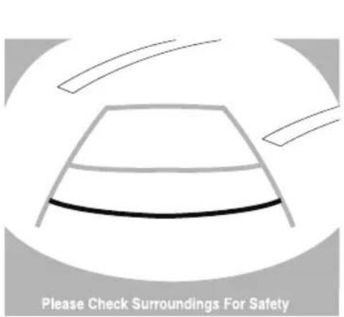
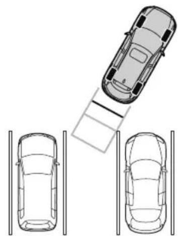
natural_image
Top-down diagram of a car with a roof-mounted sensor and two cars parked on parallel lanes (no text or symbols)-
After your vehicle begins entering the parking space, continue backing up slowly so that the distance between the vehicle width lines and the sides of the parking space on the left and right are roughly equal.
-
Continue to adjust the steering wheel until the vehicle width guide lines are parallel to the left and right sides of the parking space.
-
Once they are parallel, straighten the wheels and back your vehicle slowly into the parking space. Continue checking the vehicle's surroundings and then stop the vehicle in the best possible position.
(Display condition) (Vehicle condition)
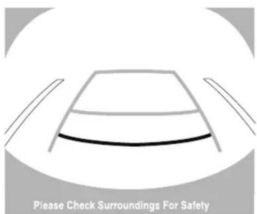
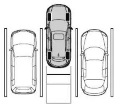
natural_image
Top-down line drawing of a multi-story car with three front views and parking structure (no text or symbols)- When the selector lever is shifted from reverse (R) to another selector lever position, the screen returns to the previous display.
NOTE
- If the parking space has division lines, straighten the wheels when the vehicle width guide lines are parallel to them.
- Because there may be a difference between the displayed image, such as indicated below, and the actual conditions when parking, always verify the safety at the rear of the vehicle and the surrounding area directly with your eyes.
- In the image of the parking space (or garage) displayed on the screen, the back end and distance guide lines may appear aligned in the monitor, but they may not actually be aligned on the ground.
- When parking in a space with a division line on only one side of the parking space, the division line and the vehicle width guide line appear aligned in the monitor, but they may not actually be aligned on the ground.
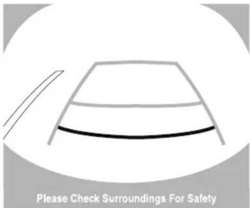
▼ Variance Between Actual Road Conditions and Displayed Image
Some variance occurs between the actual road and the displayed road. Such variance in distance perspective could lead to an accident. Note the following conditions that may cause a variance in distance perspective.
When the vehicle is tilted due to the weight of passengers and load
When the vehicle rear is lowered, the object displayed on the screen appears farther than the actual distance.
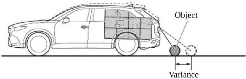
When there is a steep grade behind the vehicle
When there is a steep upgrade (downgrade) behind the vehicle, the object displayed on the screen appears farther (downgrade: closer) than the actual distance.
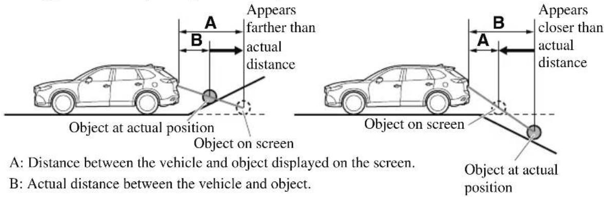
Three-dimensional object on vehicle rear
Because the distance guide lines are displayed based on a flat surface, the distance to the three-dimensional object displayed on the screen is different from the actual distance.
(Screen display)
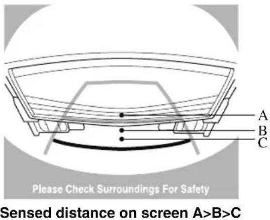
(Actual condition)
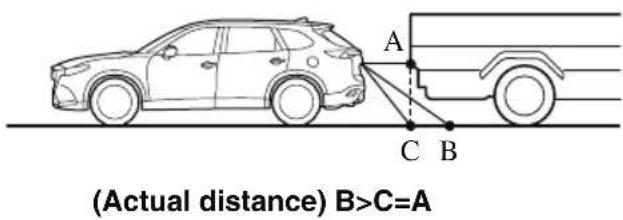
▼ Picture Quality Adjustment

WARNING
Always adjust the picture quality of the rear view monitor while the vehicle is stopped:
Do not adjust the picture quality of the rear view monitor while driving the vehicle. Adjusting the picture quality of the rear view monitor such as brightness, contrast, color, and tint while driving the vehicle is dangerous as it could distract your attention from the vehicle operation which could lead to an accident.
Picture quality adjustment can be done while the selector lever is in reverse (R).
There are 4 settings which can be adjusted including, brightness, contrast, tint, and color. When adjusting, pay sufficient attention to the vehicle surroundings.
- Select the ⚙ icon on the screen to display the tabs.
- Select the desired tab item.
- Adjust the brightness, contrast, tint, and color using the slider.
If you need to reset, press the reset button. - Select the ⚙ icon on the screen to close the tab.
Rear View Monitor (Mazda Connect (Type B))\*
The rear view monitor provides visual images of the rear of the vehicle when reversing.

WARNING
Always drive carefully confirming the safety of the rear and the surrounding conditions by looking directly with your eyes:
Reversing the vehicle by only looking at the screen is dangerous as it may cause an accident or a collision with an object. The rear view monitor is only a visual assist device when reversing the vehicle. The images on the screen may be different from the actual conditions.

CAUTION
Do not use the rear view monitor under the following conditions: Using the rear view monitor under the following conditions is dangerous and could result in injury or vehicle damage or both.
▶ Icy or snow-covered roads.
▶Tire chains or a temporary spare tire is installed.
The liftgate is not fully closed.
The vehicle is on a road incline.
When the display is cold, images may course across the monitor or the screen and may be dimmer than usual, which could cause difficulty in confirming the surrounding conditions of the vehicle. Always drive carefully confirming the safety of the rear and the surrounding conditions by looking directly with your eyes.
➢ Do not apply excessive force to the camera. The camera position and angle may deviate.
➢ Do not disassemble, modify, or remove it as it may no longer be waterproof.
The camera cover is made of plastic. Do not apply degreasing agents, organic solvents, wax, or glass coating agents to the camera cover. If any are spilled on the cover, wipe off with a soft cloth immediately.
Do not rub the camera cover forcefully with an abrasive or hard brush. The camera cover or lens may be scratched which might affect the images.
NOTE
- If water, snow, or mud is stuck on the camera lens, wipe it off using a soft cloth. If it cannot be wiped off, use a mild detergent.
- If the camera temperature changes rapidly (Hot to cold, cold to hot), the rear view monitor may not operate correctly.
-
When replacing the tires, consult an Authorized Mazda Dealer. Replacing the tires could result in deviation of the guide lines which appear on the display.
-
If the vehicle's front, side, or rear has been involved in a collision, the alignment of the rear view parking camera (location, installation angle) may have deviated. Always consult an Authorized Mazda Dealer to have the vehicle inspected.
- If “No camera signal.” is indicated in the display, there could be a problem with the camera. Have your vehicle inspected at an Authorized Mazda Dealer.
▼ Rear View Parking Camera Location
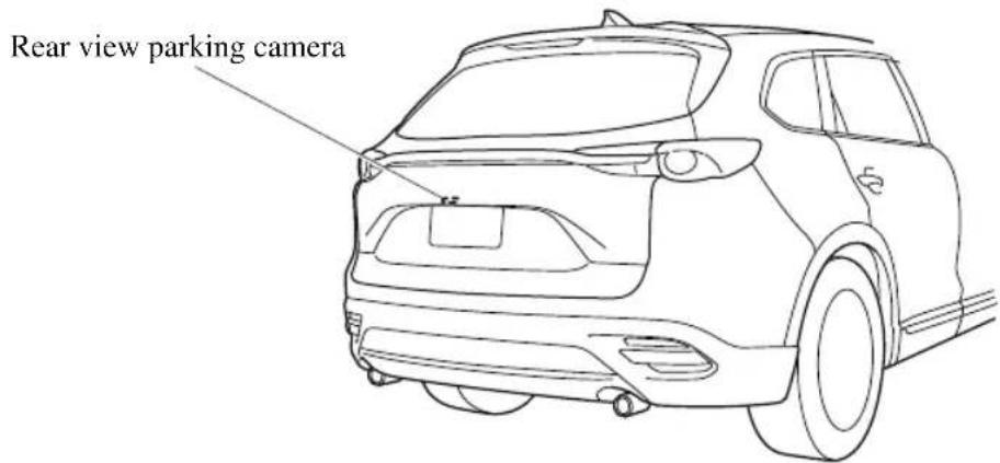
▼ Switching to the Rear View Monitor Display
Shift the selector lever to reverse (R) position with the ignition switched ON to switch the display to the rear view monitor display.
NOTE
When the selector lever is shifted from reverse (R) position to another selector lever position, the screen returns to the previous display.
▼ Displayable Range on the Screen
The images on the screen may be different from the actual conditions.
Screen display
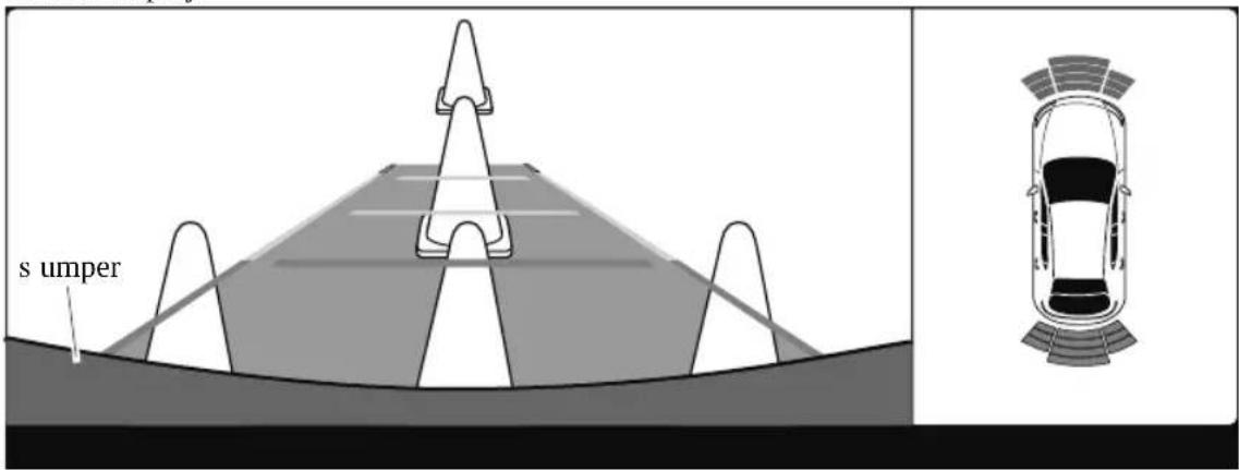
Actual view
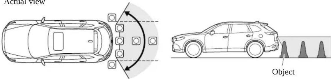
NOTE
- The displayable range varies depending on the vehicle and road conditions.
- If the camera lens is touched or there is any dirt on it, it could affect the screen image. Wipe the lens using a soft cloth.
- The displayable range is limited. Objects under the bumper or around the bumper ends cannot be displayed.
- The distance appearing in the displayed image is different from the actual distance because the rear view parking camera is equipped with a specific lens.
- Images displayed on the monitor from the rear view parking camera are reversed images (mirror images).
- Some optionally installed vehicle accessories may be picked up by the camera. Do not install any optional parts that can interfere with the camera view, such as illuminating parts or parts made of reflective material.
- It may be difficult to see the display under the following conditions, however, it does not indicate a malfunction.
· In darkened areas.
- When the temperature around the lens is high/low.
- When the camera is wet such as on a rainy day or during periods of high humidity.
- When foreign material such as mud is stuck around the camera.
- When the camera lens reflects sunlight or headlight beams.
- The surroundings are illuminated by vehicle lights, fluorescent lights, or LED lights (display may flicker).
- Extremely small dark or white dots appear on the screen (dots may flicker).
- Image display may be delayed if the temperature around the camera is low.
▼ Viewing the Display
Guide lines which indicate the width of the vehicle are displayed on the screen as a reference to the approximate width of the vehicle in comparison to the width of the parking space you are about to back into.
Use this display view for parking your vehicle in a parking space or garage.
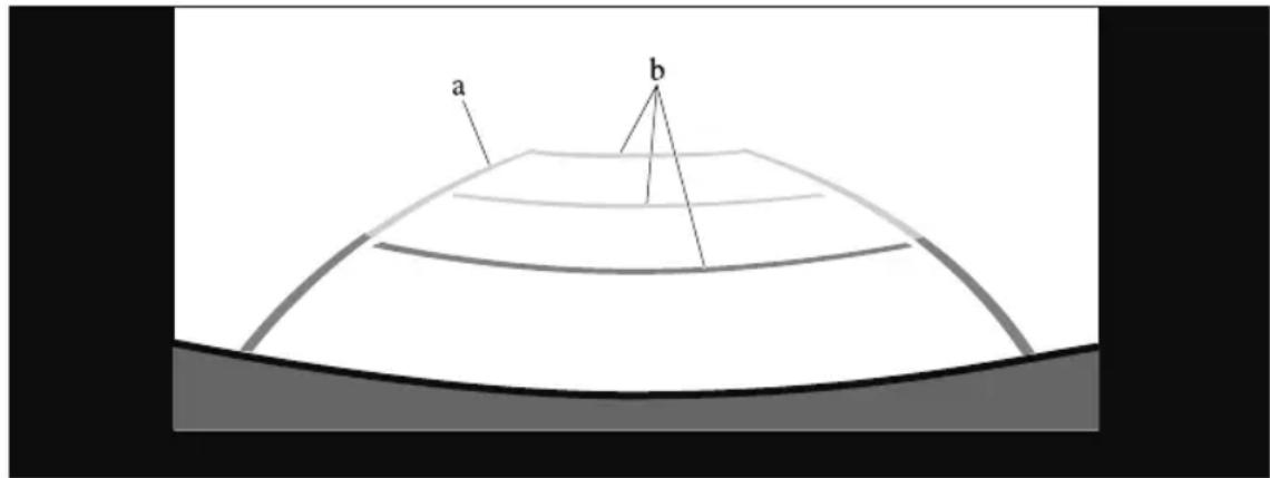
a) Vehicle width guide lines
Guide lines serve as a reference to the approximate width of the vehicle.
b) Distance guide lines
These guide lines indicate the approximate distance to a point measured from the vehicle's rear (from the end of the bumper).
The red line indicates the point about 0.5 m (19 in) from the rear bumper.
The yellow lines indicate the points about 1.0 m (39 in) and 2.0 m (78 in) from the rear bumper.
▼ Rear View Monitor Operation
The operation of the rear view monitor when reversing the vehicle varies depending on the traffic, road, and vehicle conditions. The amount of steering and the timing also varies depending on conditions, so confirm the surrounding conditions directly with your eyes and steer the vehicle in accordance with the conditions.
Be well aware of the above cautions prior to using the rear view monitor.
NOTE
Images displayed on the monitor from the rear view parking camera are reversed images (mirror images).
-
Shift the selector lever to reverse (R) position to switch the display to the rear view monitor display.
-
Confirming the surrounding conditions, reverse the vehicle.
-
After your vehicle begins entering the parking space, continue backing up slowly so that the distance between the vehicle width lines and the sides of the parking space on the left and right are roughly equal.
(Display condition)
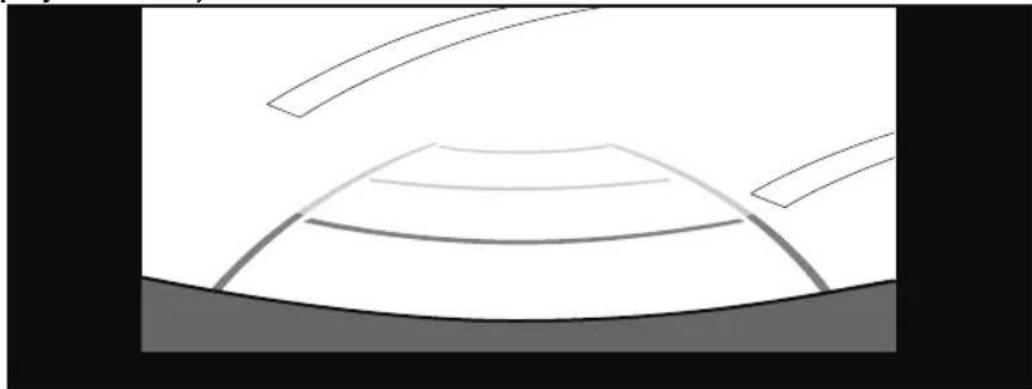
natural_image
Simple line drawing of a dome-shaped structure with horizontal lines and curved base, no text or symbols present.(Vehicle condition)
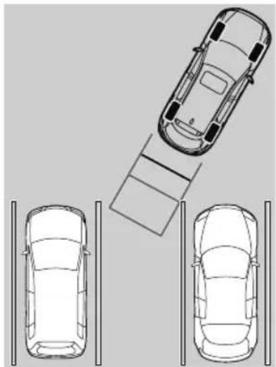
natural_image
Top-down line drawing of a car parking lot with three cars and a parking structure (no text or symbols)-
Continue to adjust the steering wheel until the vehicle width guide lines are parallel to the left and right sides of the parking space.
-
Once they are parallel, straighten the wheels and back your vehicle slowly into the parking space. Continue checking the vehicle's surroundings and then stop the vehicle in
the best possible position. (If the parking space has division lines, check whether the vehicle width guide lines are parallel to them.)
(Display condition)
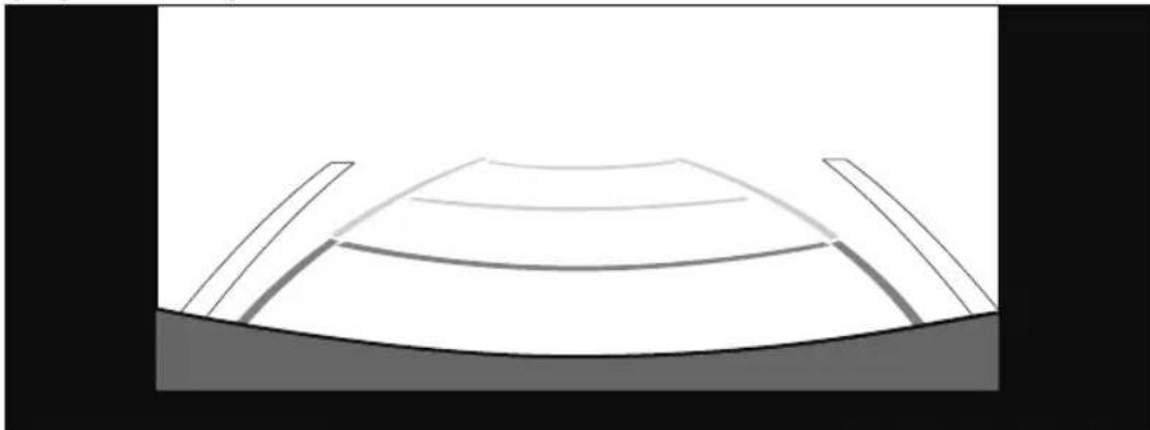
natural_image
Simple line drawing of a dome-shaped structure with two vertical supports (no text or symbols)(Vehicle condition)
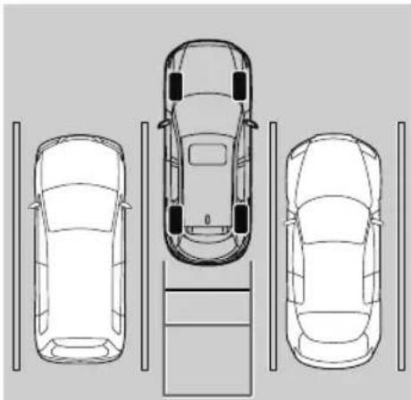
natural_image
Top-down line drawing of three cars viewed from the side, with no text or symbols present.- When the selector lever is shifted from reverse (R) position to another selector lever position, the screen returns to the previous display.
NOTE
Because there may be a difference between the displayed image, such as indicated below, and the actual conditions when parking, always verify the safety at the rear of the vehicle and the surrounding area directly with your eyes.
- In the image of the parking space (or garage) displayed on the screen, the back end and distance guide lines may appear aligned in the monitor, but they may not actually be aligned on the ground.
- When parking in a space with a division line on only one side of the parking space, the division line and the vehicle width guide line appear aligned in the monitor, but they may not actually be aligned on the ground.

natural_image
Simple line drawing of a dome-shaped structure with curved lines and a base, no text or symbols present.▼ Variance Between Actual Road Conditions and Displayed Image
Some variance occurs between the actual road and the displayed road. Such variance in distance perspective could lead to an accident. Note the following conditions that may cause a variance in distance perspective.
When the vehicle is tilted due to the weight of passengers and load
When the vehicle rear is lowered, the object displayed on the screen appears farther than the actual distance.
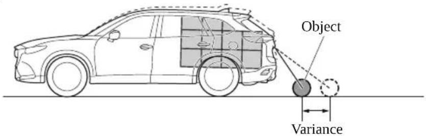
When there is a steep grade behind the vehicle
When there is a steep upgrade (downgrade) behind the vehicle, the object displayed on the screen appears farther (downgrade: closer) than the actual distance.
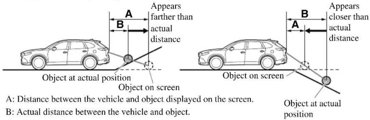
Three-dimensional object on vehicle rear
Because the distance guide lines are displayed based on a flat surface, the distance to the three-dimensional object displayed on the screen is different from the actual distance.
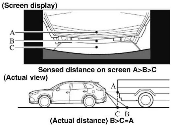
Parking Sensor System (Mazda Connect (Type A))\*
The parking sensors use ultrasonic sensors which detect obstructions around the vehicle when the vehicle is driven at low speeds, such as during garage or parallel parking, and a buzzer sound and detection indicator notify the driver of the approximate distance from the vehicle to the surrounding obstruction.
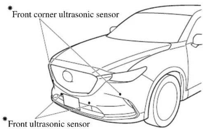
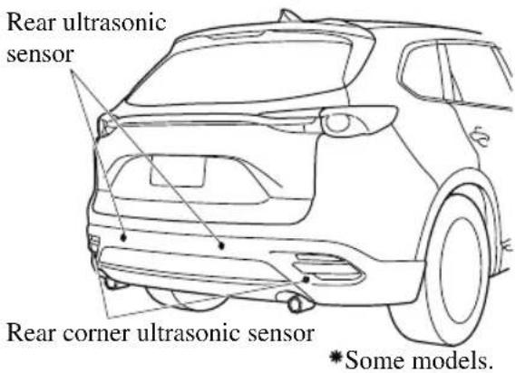

WARNING
Do not rely completely on the parking sensor system and be sure to confirm the safety around your vehicle visually when driving:
This system can assist the driver in operating the vehicle in the forward and backward directions while parking. The detection ranges of the sensors are limited, therefore, driving the vehicle while relying only on the system may cause an accident. Always confirm the safety around your vehicle visually when driving.
NOTE
- Do not install any accessories within the detection ranges of the sensors. It may affect the system operation.
- Depending on the type of obstruction and the surrounding conditions, the detection range of a sensor may narrow, or the sensors may not be able to detect obstructions.
-
The system may not operate normally under the following conditions:
-
Mud, ice, or snow is adhering to the sensor area (Returns to normal operation when removed).
- The sensor area is frozen (Returns to normal operation when the ice is thawed).
• The sensor is covered by a hand. - The sensor is excessively shocked.
• The vehicle is excessively tilted.
· Under extremely hot or cold weather conditions.
- The vehicle is driven on bumps, inclines, gravel, or grass covered roads.
- Anything which generates ultrasound is near the vehicle, such as another vehicle's horn, the engine sound of a motorcycle, the air brake sound of a large-sized vehicle, or another vehicle's sensors.
- The vehicle is driven in heavy rain or in road conditions causing water-splash.
- A commercially-available fender pole or an antenna for a radio transmitter is installed to the vehicle.
- The vehicle is moving towards a tall or square curbstone.
- An obstruction is too close to the sensor.
- Obstructions under the bumper may not be detected. Obstructions that are lower than the bumper or thin which may have been initially detected may no longer be detected as the vehicle approaches more closely to the obstruction.
- The following types of obstructions may not be detected:
- Thin objects such as wire or rope
- Things which absorb sonic waves easily such as cotton or snow
- Angular shaped objects
- Very tall objects, and those which are wide at the top
- Small, short objects
- Always have the system inspected at an Authorized Mazda Dealer if any shock is applied to the bumpers, even in a minor accident. If the sensors are deviated, they cannot detect obstructions.
· (With front ultrasonic sensor and front ultrasonic corner sensor)
The system may have a malfunction if the beep does not operate or the indicator light does not illuminate when the parking sensor switch is turned on. Consult an Authorized Mazda Dealer.
· (Without front ultrasonic sensor and front ultrasonic corner sensor)
The system may have a malfunction if the beep does not operate. Consult an Authorized Mazda Dealer.
· (With front ultrasonic sensor and front ultrasonic corner sensor)
The system may have a malfunction if the beep sound which indicates a system malfunction is heard and the indicator light flashes. Consult an Authorized Mazda Dealer.
- The beeper which indicates a system malfunction may not be heard if the ambient temperature is extremely cold, or mud, ice, or snow adheres to the sensor area. Remove any foreign material from the sensor area.
- When installing a trailer hitch, consult an Authorized Mazda Dealer.
▼ Sensor Detection Range
The sensors detect obstructions within the following range.
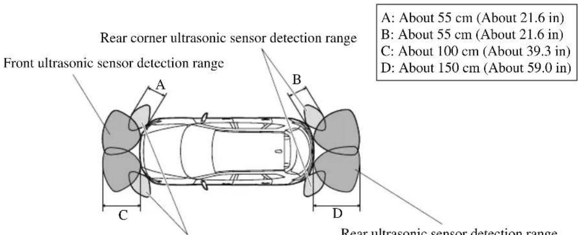
Front corner ultrasonic sensor detection range
Viewing distance display
| Display Distance between vehicle and obstruction | ||||
| Without 360° view monitor | With 360° view monitor | Front ultrasonic sensor*/Front corner ultrasonic sensor* | Rear ultrasonic sensor/Rear Corner ultrasonic sensor | |
| Without front ultrasonic sensor and front corner ultrasonic sensor | With front ultrasonic sensor and front corner ultrasonic sensor | |||
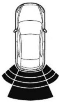 | 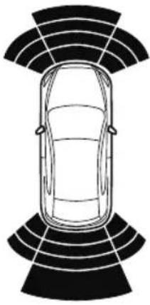 | Green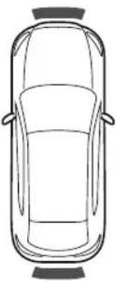 | Front ultrasonic sensor: Approx. 100—60 cm (39.3—23.6 in) | Rear ultrasonic sensor: Approx. 150—60 cm (59.0—23.6 in) |
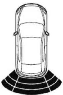 | 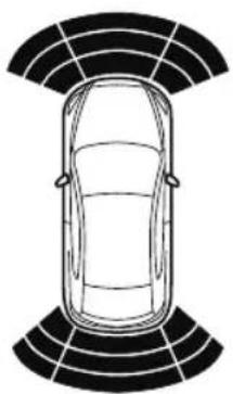 | Yellow | Front ultrasonic sensor:Approx. 60—45 cm (23.6—17.7 in)Front corner ultrasonic sensor:Approx. 55—38 cm (21.6—14.9 in) | Rear ultrasonic sensor:Approx. 60—45 cm (23.6—17.7 in)Rear corner ultrasonic sensor:Approx. 55—38 cm (21.6—14.9 in) |
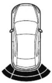 | 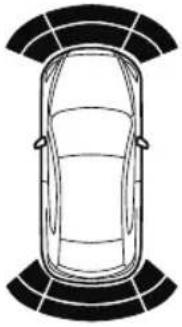 | Amber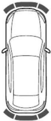 | Front ultrasonic sensor:Approx. 45—35 cm (17.7—13.7 in)Front corner ultrasonic sensor:Approx. 38—25 cm (14.9—9.8 in) | Rear ultrasonic sensor:Approx. 45—35 cm (17.7—13.7 in)Rear corner ultrasonic sensor:Approx. 38—25 cm (14.9—9.8 in) |
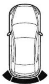 | 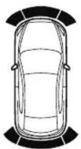 | Red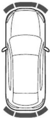 | Front ultrasonic sensor:Within approx. 35 cm (13.7 in)Front corner ultrasonic sensor:Within approx. 25 cm (9.8 in) | Rear ultrasonic sensor:Within approx. 35 cm (13.7 in)Rear corner ultrasonic sensor:Within approx. 25 cm (9.8 in) |
▼ Parking Sensor System Operation
With front ultrasonic sensor and front corner ultrasonic sensor
The switch can be activated when the ignition is switched ON, the selector lever is in any position except reverse (R), and the vehicle speed is about 10 ~km / h (6 mph) or less. When the parking sensor switch is pressed, a beep sound is heard, the obstruction detection indication is displayed in the audio screen, and the indicator light in the switch illuminates.
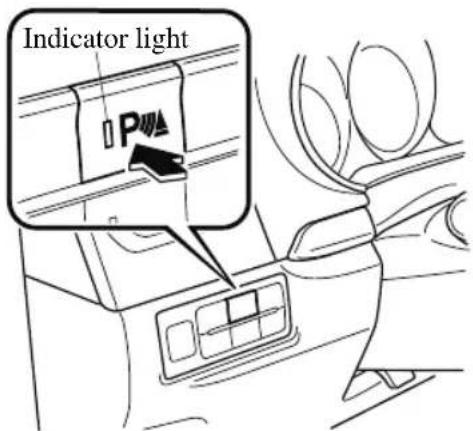
NOTE
- If the system is cancelled, it will not restore automatically even when the vehicle speed is decreased to 10 ~km / h (6 mph) or less.
- When the ignition is switched OFF, the system status before it was turned off is maintained. For example, if the ignition is switched OFF while the parking sensor is activated, the system will be activated when the ignition is switched ON the next time.
Sensor detection condition
The system can be used when the ignition is switched ON and the parking sensor switch has been turned on.
The sensors detect obstructions under the following conditions:
| Sensor Condition | |
| Front Ultrasonic Sensor | The selector lever is in any position except reverse (R), and the vehicle speed is about 10 km/h (6 mph) or less. |
| Front Corner Ultrasonic Sensor | The vehicle speed is about 10 km/h (6 mph) or less. |
| Rear Ultrasonic Sensor The selector lever is in reverse (R). | |
| Rear Corner Ultrasonic Sensor | The selector lever is in reverse (R), and the vehicle speed is about 10 km/h (6 mph) or less. |
The system is cancelled under the following conditions:
- The parking sensor switch is pressed while the parking sensor is in operation.
• The vehicle speed is 10 km/h (6 mph) or more. (Except rear sensor)
Without front ultrasonic sensor and front corner ultrasonic sensor
When the ignition is switched ON and the selector lever is shifted to the reverse (R), the beep sound activates and the system is enabled for use.
The sensors detect obstructions under the following conditions:
| Sensor Condition | |
| Rear Ultrasonic Sensor The selector lever is in reverse (R). | |
| Rear Corner Ultrasonic Sensor | The selector lever is in reverse (R), and the vehicle speed is about 10 km/h (6 mph) or less. |
▼ Obstruction Detection Indication
The position of a sensor which has detected an obstruction is indicated. The gauge illuminates in different areas depending on the distance to an obstruction detected by the sensor.
As the vehicle approaches closer to an obstruction, the zone in the gauge closer to the vehicle illuminates.
With 360° view monitor Without 360° view monitor
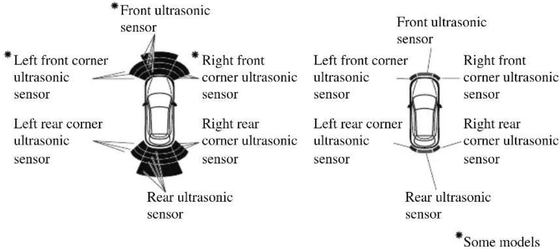
NOTE
The detection indicator can switch between display and non-display.
Refer to the Settings section in the Mazda Connect Owner's Manual.
(Vehicles with 360° View Monitor)
When the detection indicator is set to “Display”, even with the 360^ view monitor not displayed, if a front ultrasonic sensor or a front corner ultrasonic sensor detects an obstruction, the 360^ view monitor switches automatically to display. When an obstruction is no longer detected, the display switches to the display before the obstruction was detected. However, while the 360^ view monitor is displayed, it continues to display no matter if an obstruction is detected or not.
System problem notification
If a problem occurs, the driver is notified of the problem by the following indications.
| Detection Indicator | Solution | |||
| Without 360° view monitor | With 360° view moni-tor | |||
| Without front ultra-sonic sensor and front corner ultrasonic sen-sor | With front ultrasonic sensor and front cor-ner ultrasonic sensor | |||
| Discon- nection | 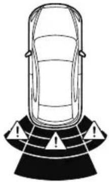 | 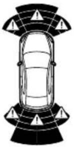 | 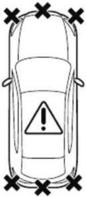 | The system may have a malfunction. Have the ve-hicle inspected at an Au-thorized Mazda Dealer as soon as possible. |
| System mal-function |  | 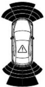 |  | The system may have a malfunction. Have the ve-hicle inspected at an Au-thorized Mazda Dealer as soon as possible. |
| Frost/soiling |  |  | 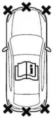 | Foreign matter may be on the sensor area corre-sponding to the obstruc-tion detection indication shown. If the system does not recover, have the vehi-cle inspected at an Author-ized Mazda Dealer. |
▼ Parking Sensor Warning Beep
The beeper sounds as follows while the system is operating.
Front Ultrasonic Sensor*, Rear Ultrasonic Sensor
| Distance detection area | Distance between vehicle and obstruction | Beeper sound*1 | |
| Front ultrasonic sensor* | Rear ultrasonic sensor | ||
| Farthest distance | Approx. 100—60 cm (39.3—23.6 in)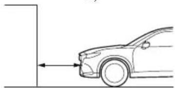 | Approx. 150—60 cm (59.0—23.6 in)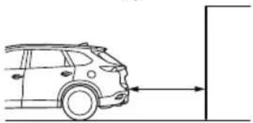 | Slow intermittent sound |
| Far distance | Approx. 60—45 cm (23.6—17.7 in)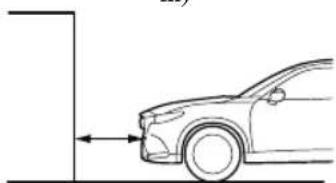 | Approx. 60—45 cm (23.6—17.7 in)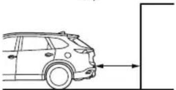 | Medium intermittent sound |
| Middle distance | Approx. 45—35 cm (17.7—13.7 in) 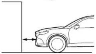 | Approx. 45—35 cm (17.7—13.7 in) 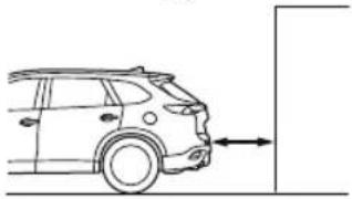 | Fast intermittent sound |
| Close distance | Within approx. 35 cm (13.7 in) 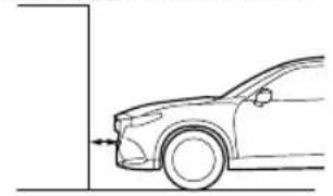 | Within approx. 35 cm (13.7 in) 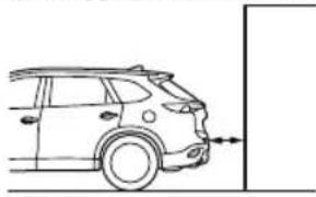 | Continuous sound |
*1 The rate at which the intermittent sound beeps increases as the vehicle approaches the obstruction.
Front Corner Ultrasonic Sensor*, Rear Corner Ultrasonic Sensor
| Distance detection area | Distance between vehicle and obstruction | Beeper sound*1 |
| Front corner ultrasonic*/Rear corner ultrasonic sensor | ||
| Far distance | Approx. 55—38 cm (21.6—14.9 in)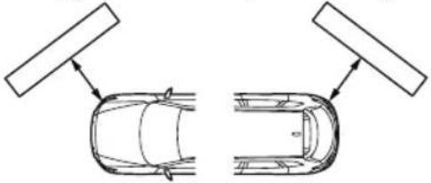 | Medium intermittent sound |
| Middle distance | Approx. 38—25 cm (14.9—9.8 in)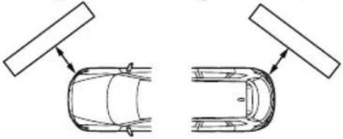 | Fast intermittent sound |
| Close distance | Within approx. 25 cm (9.8 in)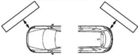 | Continuous sound |
*1 The rate at which the intermittent sound beeps increases as the vehicle approaches the obstruction.
NOTE
If an obstruction is detected in a zone for 6 seconds or more, the beep sound is stopped (except for the close-distance zone). If the same obstruction is detected in another zone, the corresponding beep sound is heard.
▼ When Warning Indicator/Beep is Activated
The system notifies the driver of an abnormality by activating the beep sound and the indicator light.
| Indicator/Beep How to | check |
| The indicator light flashes when the parking sensor switch is pressed at a vehicle speed of 10 km/h (6 mph) or less. | The system may have a malfunction. Have the vehicle inspected at an Authorized Mazda Dealer as soon as possible. |
| The beep sound is not heard. | The system may have a malfunction. Have the vehicle inspected at an Authorized Mazda Dealer as soon as possible. |
| The intermittent sound of the buzzer is heard 5 times. | Remove any foreign material from the sensor area. If the system does not recover, have the vehicle inspected at an Authorized Mazda Dealer. |
| A certain obstruction detection indicator is continuously displayed. | Refer to Obstruction Detection Indication on page 4-277. |
Parking Sensor System (Mazda Connect (Type B))\*
The parking sensors use ultrasonic sensors which detect obstructions around the vehicle when the vehicle is driven at low speeds, such as during garage or parallel parking, and a buzzer sound and detection indicator notify the driver of the approximate distance from the vehicle to the surrounding obstruction.
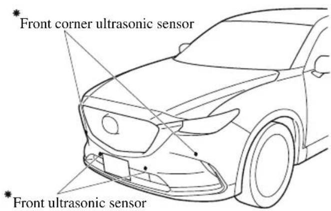
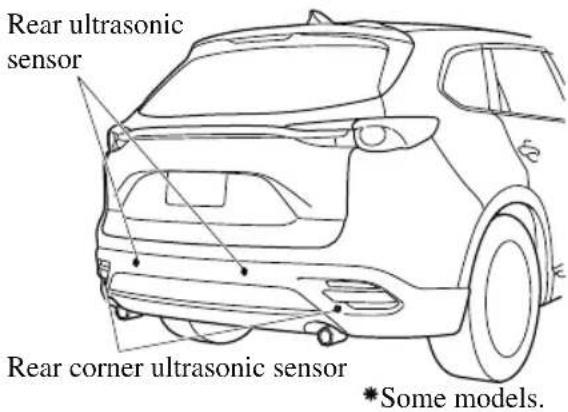

WARNING
Do not rely completely on the parking sensor system and be sure to confirm the safety around your vehicle visually when driving:
This system can assist the driver in operating the vehicle in the forward and backward directions while parking. The detection ranges of the sensors are limited, therefore, driving the vehicle while relying only on the system may cause an accident. Always confirm the safety around your vehicle visually when driving.
NOTE
- Do not install any accessories within the detection ranges of the sensors. It may affect the system operation.
- Depending on the type of obstruction and the surrounding conditions, the detection range of a sensor may narrow, or the sensors may not be able to detect obstructions.
-
The system may not operate normally under the following conditions:
-
Mud, ice, or snow is adhering to the sensor area (Returns to normal operation when removed).
- The sensor area is frozen (Returns to normal operation when the ice is thawed).
- The sensor is covered by a hand.
- The sensor is excessively shocked.
• The vehicle is excessively tilted.
· Under extremely hot or cold weather conditions.
- The vehicle is driven on bumps, inclines, gravel, or grass covered roads.
- Anything which generates ultrasound is near the vehicle, such as another vehicle's horn, the engine sound of a motorcycle, the air brake sound of a large-sized vehicle, or another vehicle's sensors.
- The vehicle is driven in heavy rain or in road conditions causing water-splash.
- A commercially-available fender pole or an antenna for a radio transmitter is installed to the vehicle.
- The vehicle is moving towards a tall or square curbstone.
- An obstruction is too close to the sensor.
- Obstructions under the bumper may not be detected. Obstructions that are lower than the bumper or thin which may have been initially detected may no longer be detected as the vehicle approaches more closely to the obstruction.
- The following types of obstructions may not be detected:
- Thin objects such as wire or rope
- Things which absorb sonic waves easily such as cotton or snow
- Angular shaped objects
- Very tall objects, and those which are wide at the top
- Small, short objects
- Always have the system inspected at an Authorized Mazda Dealer if any shock is applied to the bumpers, even in a minor accident. If the sensors are deviated, they cannot detect obstructions.
- The system may have a malfunction if the beep does not operate or the indicator light does not illuminate when the parking sensor switch is turned on. Consult an Authorized Mazda Dealer.
- The system may have a malfunction if the beep sound which indicates a system malfunction is heard and the indicator light flashes. Consult an Authorized Mazda Dealer.
- The beeper which indicates a system malfunction may not be heard if the ambient temperature is extremely cold, or mud, ice, or snow adheres to the sensor area. Remove any foreign material from the sensor area.
- When installing a trailer hitch, consult an Authorized Mazda Dealer.
▼ Sensor Detection Range
The sensors detect obstructions within the following range.
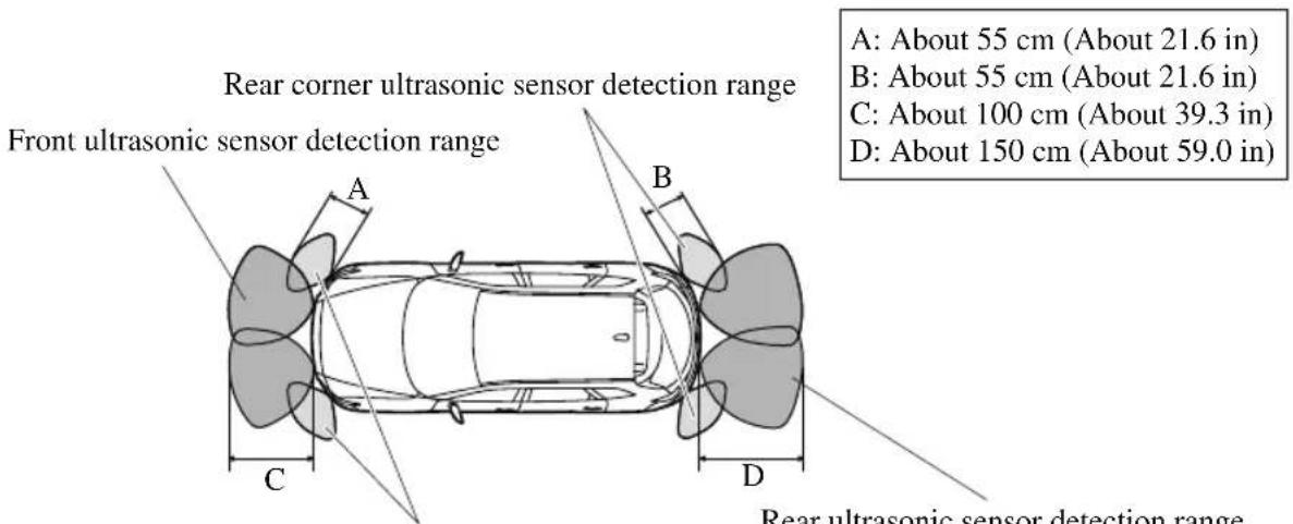
Front corner ultrasonic sensor detection range
Viewing distance display
| Display Distance between vehicle and obstruction | |||
| Without 360° view monitor | With 360° view monitor | Front ultrasonic sensor/Front corner ultrasonic sensor | Rear ultrasonic sensor/Rear corner ultrasonic sensor |
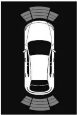 | Green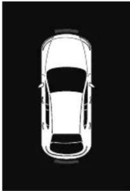 | Front ultrasonic sensor:Approx. 100—60 cm(39.3—23.6 in) | Rear ultrasonic sensor:Approx. 150—60 cm(59.0—23.6 in) |
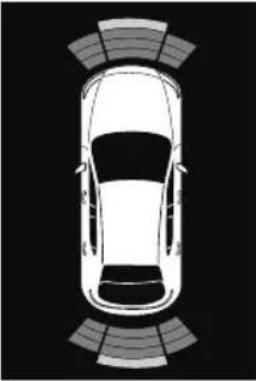 | Yellow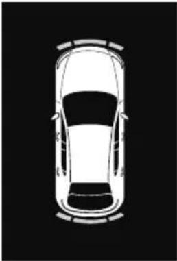 | Front ultrasonic sensor:Approx. 60—45 cm(23.6—17.7 in)Front corner ultrasonic sensor:Approx. 55—38 cm(21.6—14.9 in) | Rear ultrasonic sensor:Approx. 60—45 cm(23.6—17.7 in)Rear corner ultrasonic sensor:Approx. 55—38 cm(21.6—14.9 in) |
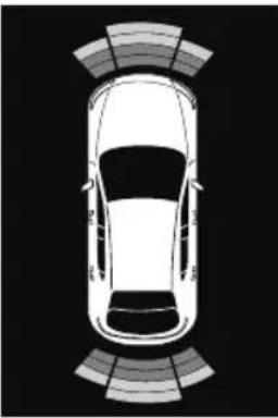 | Amber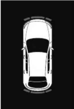 | Front ultrasonic sensor:Approx. 45—35 cm(17.7—13.7 in)Front corner ultrasonic sensor:Approx. 38—25 cm(14.9—9.8 in) | Rear ultrasonic sensor:Approx. 45—35 cm(17.7—13.7 in)Rear corner ultrasonic sensor:Approx. 38—25 cm(14.9—9.8 in) |
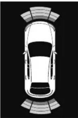 | Red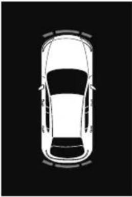 | Front ultrasonic sensor:Within approx. 35 cm (13.7 in)Front corner ultrasonic sensor:Within approx. 25 cm (9.8 in) | Rear ultrasonic sensor:Within approx. 35 cm (13.7 in)Rear corner ultrasonic sensor:Within approx. 25 cm (9.8 in) |
▼ Parking Sensor System Operation
The switch can be activated when the ignition is switched ON, the selector lever is in any position except reverse (R), and the vehicle speed is about 10 ~km / h (6 mph) or less.
When the parking sensor switch is pressed, a beep sound is heard, the obstruction detection indication is displayed in the audio screen, and the indicator light in the switch illuminates.
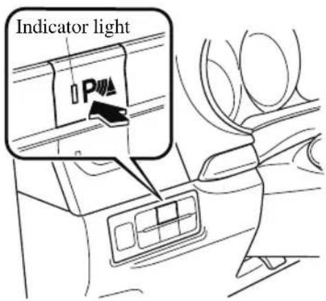
NOTE
- If the system is cancelled, it will not restore automatically even when the vehicle speed is decreased to 10km / h (6 mph) or less.
- When the ignition is switched OFF, the system status before it was turned off is maintained. For example, if the ignition is switched OFF while the parking sensor is activated, the system will be activated when the ignition is switched ON the next time.
Sensor detection condition
The system can be used when the ignition is switched ON and the parking sensor switch has been turned on.
The sensors detect obstructions under the following conditions:
| Sensor Condition | |
| Front Ultrasonic Sensor | The selector lever is in any position except reverse (R), and the vehicle speed is about 10 km/h (6 mph) or less. |
| Front Corner Ultrasonic Sensor | The vehicle speed is about 10 km/h (6 mph) or less. |
| Rear Ultrasonic Sensor The | the selector lever is in reverse (R). |
| Rear Corner Ultrasonic Sensor | The selector lever is in reverse (R), and the vehicle speed is about 10 km/h (6 mph) or less. |
The system is cancelled under the following conditions:
- The parking sensor switch is pressed while the parking sensor is in operation.
- The vehicle speed is 10 km/h (6 mph) or more. (Except rear sensor)
▼ Obstruction Detection Indication
The position of a sensor which has detected an obstruction is indicated. The gauge illuminates in different areas depending on the distance to an obstruction detected by the sensor.
As the vehicle approaches closer to an obstruction, the zone in the gauge closer to the vehicle illuminates.
Without 360°view monitor
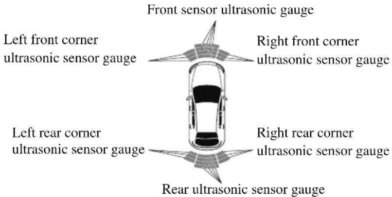
With 360°view monitor
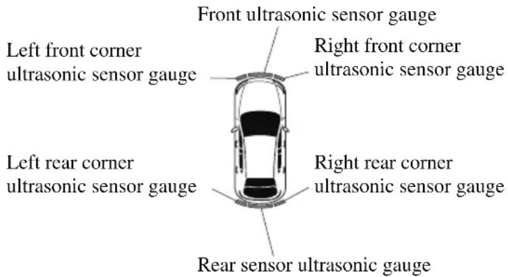
NOTE
The detection indicator can be switched between display and non-display and the buzzer volume can be changed.
Refer to the Settings section in the Mazda Connect Owner's Manual.
(Vehicles with 360° View Monitor)
When the detection indicator is set to “Display”, even with the 360^ view monitor not displayed, if a front ultrasonic sensor or a front corner ultrasonic sensor detects an obstruction, the 360^ view monitor switches automatically to display. When an obstruction is no longer detected, the display switches to the display before the obstruction was detected. However, while the 360^ view monitor is displayed, it continues to display no matter if an obstruction is detected or not.
System problem notification
The indication displays if the system has a malfunction.
Without 360°view monitor
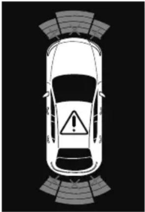
natural_image
Top-down view of a car with an explosion warning sign on the roof, surrounded by sound wave patterns (no text or symbols)With 360°view monitor
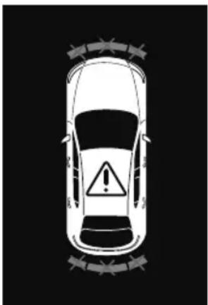
natural_image
Top-down view of a car with warning sign and hazard symbol (no text or labels)Check the reason for the indication displaying on the center display or multi-information display.
Refer to If a Warning Light Turns On or Flashes on page 7-28.
▼ Parking Sensor Warning Beep
The beeper sounds as follows while the system is operating.
Front ultrasonic sensor, Rear ultrasonic sensor
| Distance Detection area | Distance between vehicle and obstruction | Beeper sound*1 | |
| Front ultrasonic sensor Rear | ultrasonic sensor | ||
| Farthest distance | Approx. 100—60 cm (39.3—23.6 in)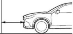 | Approx. 150—60 cm (59.0—23.6 in)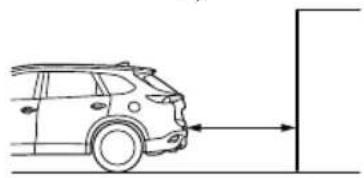 | Slow intermittent sound |
| Far distance | Approx. 60—45 cm (23.6—17.7 in)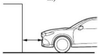 | Approx. 60—45 cm (23.6—17.7 in)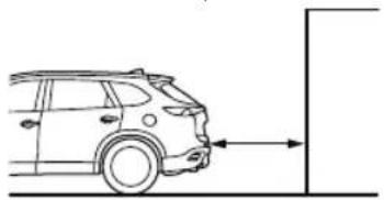 | Medium intermittent sound |
| Middle distance | Approx. 45—35 cm (17.7—13.7 in)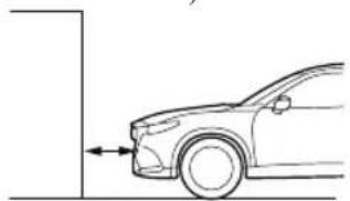 | Approx. 45—35 cm (17.7—13.7 in)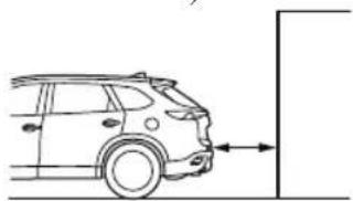 | Fast intermittent sound |
| Close distance | Within approx. 35 cm (13.7 in) | Within approx. 35 cm (13.7 in)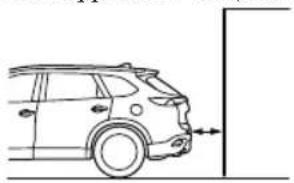 | Continuous sound |
*1 The rate at which the intermittent sound beeps increases as the vehicle approaches the obstruction.
Front corner ultrasonic sensor, Rear corner ultrasonic sensor
| Distance Detection area | Distance between vehicle and obstruction | Beeper sound*1 |
| Front corner ultrasonic sensor/Rear corner ultra-sonic sensor | ||
| Far distance | Approx. 55—38 cm (21.6—14.9 in)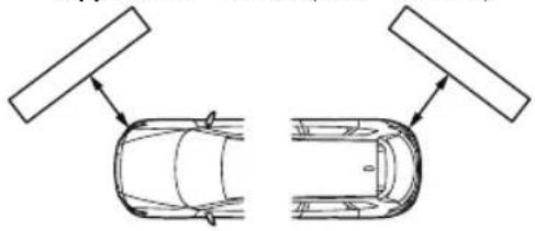 | Medium intermittent sound |
| Middle distance | Approx. 38—25 cm (14.9—9.8 in)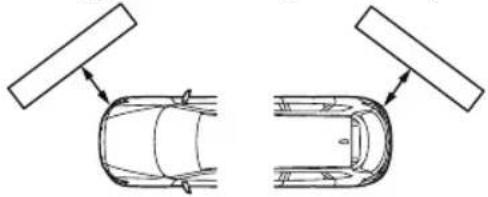 | Fast intermittent sound |
| Close distance | Within approx. 25 cm (9.8 in)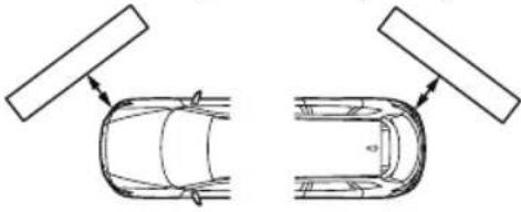 | Continuous sound |
*1 The rate at which the intermittent sound beeps increases as the vehicle approaches the obstruction.
NOTE
- If an obstruction is detected in a zone for 6 seconds or more, the beep sound is stopped (except for the close-distance zone). If the same obstruction is detected in another zone, the corresponding beep sound is heard.
▼ When Warning Indicator/Beep is Activated
The system notifies the driver of an abnormality by activating the beep sound and the indicator light.
| Indicator/Beep How to | check |
| The indicator light flashes when the parking sensor switch is pressed at a vehicle speed of 10 km/h (6 mph) or less. | The system may have a malfunction. Have the vehicle inspected at an Authorized Mazda Dealer as soon as possible. |
| The beep sound is not heard. | The system may have a malfunction. Have the vehicle inspected at an Authorized Mazda Dealer as soon as possible. |
| The intermittent sound of the buzzer is heard 5 times. | Remove any foreign material from the sensor area. If the system does not recover, have the vehicle inspected at an Authorized Mazda Dealer. |
| A certain obstruction detection indicator is continuously displayed. | Refer to Obstruction Detection Indication on page 4-277. |
5 Interior Features
Use of various features for ride comfort, including air-conditioning system and audio system.
Climate Control System......5-2
Operating Tips.... 5-2
Vent Operation (Front)...... 5-3
Front Air Conditioner.... 5-5
Vent Operation (Rear)......5-9
Rear Air Conditioner.... 5-11
Mazda Connect [Mazda Connect
(Type A)]......5-14
What is Mazda Connect ?......5-14
Mazda Connect Basic
Operations....5-17
Mazda Connect [Mazda Connect
(Type B)]......5-32
What is Mazda Connect ?......5-32
Mazda Connect Basic
Operations....5-36
Connected Service (U.S.A.
only)....5-52
Interior Equipment.... 5-53
Sunvisors.... 5-53
Interior Lights....5-54
Accessory Sockets....5-58
USB Power Outlet ^* 5-59
Wireless Charger (Qi)*...... 5-62
Cup Holder 5-65
Bottle Holder.... 5-67
Storage Compartments...... 5-67
Sunshade (Rear Door Window) ^* .....
5-72
Operating Tips
- Operate the climate control system with the engine running.
- To prevent the battery from being discharged, do not leave the fan control switch on for a long period of time with the ignition switched ON when the engine is not running.
- Clear all obstructions such as leaves, snow and ice from the hood and the air inlet in the cowl grille to improve the system efficiency.
- Use the climate control system to defog the windows and dehumidify the air.
- The recirculate mode should be used when driving through tunnels or while in a traffic jam, or when you would like to shut off outside air for quick cooling of the interior.
- Use the outside air position for ventilation or windshield defrosting.
- If the vehicle has been parked in direct sunlight during hot weather, open the windows to let warm air escape, then run the climate control system.
- Run the air conditioner about 10 minutes at least once a month to keep internal parts lubricated.
- Have the air conditioner checked before the weather gets hot. Lack of refrigerant may make the air conditioner less efficient.
The refrigerant specifications are indicated on a label attached to the inside of the engine compartment. If the wrong type of refrigerant is used, it could result in a serious malfunction of the air conditioner. Consult a professional, government certified repairer for the inspection or repair
because a special device is required for the air conditioner maintenance. For details, consult an Authorized Mazda Dealer.

Vent Operation (Front)
▼ Adjusting the Vents
Directing airflow
To adjust the direction of airflow, move the adjustment knob.
NOTE
- When using the air conditioner under humid ambient temperature conditions, the system may blow fog from the vents. This is not a sign of trouble but a result of humid air being suddenly cooled.
- The air vents can be fully opened and closed by operating the dial. (Side vents only)
Side Vents
knob
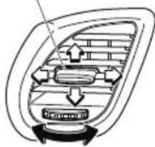
natural_image
Diagram of a car interior showing airflow and seating layout (no text or labels)knob
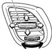
natural_image
Diagram of a car interior showing airflow and seat structure (no text or symbols)close open close open
Center Vents
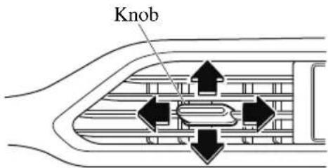
▼ Selecting the Airflow Mode
Dashboard Vents
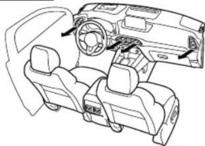
natural_image
Line drawing of a car interior showing dashboard, steering wheel, and seat (no text or symbols)Dashboard and Floor Vents
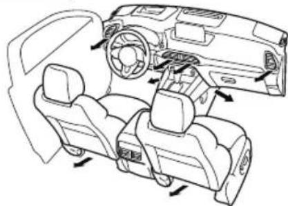
natural_image
Line drawing of a car interior showing dashboard, steering wheel, and seat (no text or symbols)Floor Vents
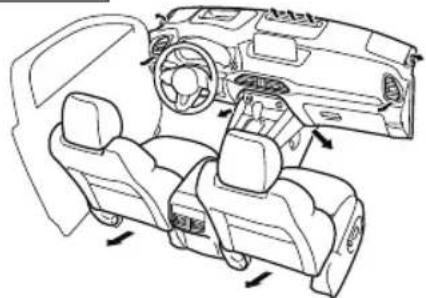
natural_image
Line drawing of a car interior showing dashboard, steering wheel, and driver seat (no text or symbols)Defroster and Floor Vents
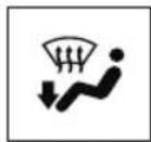
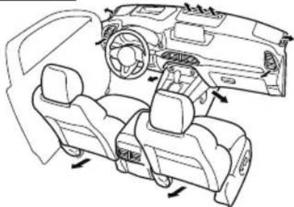
natural_image
Line drawing of a car interior showing dashboard, steering wheel, and driver seat (no text or symbols)Defroster Vents
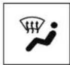
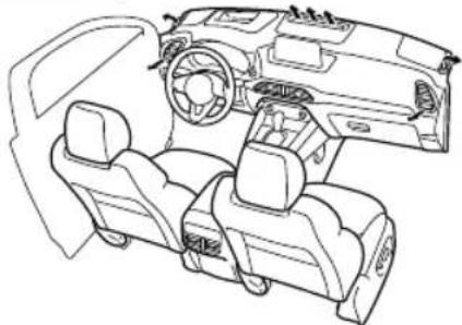
natural_image
Line drawing of a car interior showing dashboard, steering wheel, and driver seat (no text or symbols)NOTE
The location airflow exits the air vents and the airflow amount may change depending on the open or close status of the air vents.
Front Air Conditioner
Climate control system information is displayed on the display.
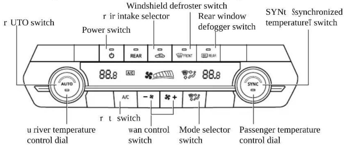
▼ Control Switches
AUTO switch
By pressing the AUTO switch the following functions will be automatically controlled in accordance with the selected set temperature:
• Airflow temperature
- Amount of airflow
- Selection of airflow mode
- Outside/Recirculated air selection
• Air conditioner operation
NOTE
AUTO switch indicator light
- When on, it indicates auto operation, and the system will function automatically.
-
If any of the following switches are operated while in auto control, the AUTO switch indicator turns off.
-
Mode selector switch
· Fan control switch
• Windshield defroster switch
The functions for switches other than those operated continue to operate in auto control.
Power switch (Fan On/Off)
The climate control system turns on or off by pressing the power switch.
Temperature control dial
This dial controls temperature. Turn it clockwise for hot and counterclockwise for cold.
Turn the temperature control dial to adjust the temperature between 15 °C (60 °F) and 29 °C (84 °F).
- When the SYNC switch is on: Turn the driver temperature control dial to control the temperature throughout the entire cabin.
- When the SYNC switch is off: Turn the driver or front passenger temperature control dial to independently control the temperature on each side of the cabin.
NOTE
- The climate control system changes to the individual operation mode (SYNC switch indicator light turns off) by turning the front passenger temperature control dial even when the SYNC switch is on, which allows individual control of the set temperature for the driver and front passenger.
- When you set the temperature to the lower or upper limit, "Lo" or "Hi" is displayed.
- The temperature units for the temperature setting display can be changed in conjunction with the temperature units for the outside temperature display.
(Instrument cluster Type A) Refer to Outside Temperature Display on page 4-18.
(Instrument cluster Type B) Refer to Outside Temperature Display on page 4-34.
(Instrument cluster Type C) Refer to Outside Temperature Display on page 4-48.
Fan control switch
The fan has 7 speeds. The selected speed will be displayed.
Mode selector switch
The desired airflow mode can be selected (page 5-4).
NOTE
- With the airflow mode set to the position and the temperature control dial set at a medium temperature, heated air is directed to the feet and air at a comparably lower temperature will flow through the central, left and right vents.
• To set the air vent to press the windshield defroster switch. - In the or position, the air conditioner is automatically turned on and the outside air position is automatically selected to defrost the windshield. In the or position, the outside air position cannot be changed to the recirculated air position.
A/C switch
Pressing the A/C switch while the AUTO switch is turned on will turn off the air conditioner (cooling/dehumidifying functions).
The on/off of the air conditioner switches each time the A/C switch is pressed.
NOTE
- The air conditioner operates when the A/C switch is pressed while the air conditioner is turned off.
- The air conditioner may not function when the outside temperature approaches 0^ (32 °F).
Air intake selector
Outside or recirculated air positions can be selected. Press the switch to select outside/recirculated air positions.
Recirculated air position (indicator light turns on)
Outside air is shut off. Use this position when going through tunnels, driving in congested traffic (high engine exhaust areas) or when quick cooling is desired.
Outside air position (indicator light turns off)
Outside air is allowed to enter the cabin. Use this mode for ventilation or windshield defrosting.

WARNING
Do not recirculate the air in the cabin during cold or rainy weather:
Recirculating the air in the cabin during cold and rainy weather is dangerous as it will cause the windows to fog up. Your vision will be hampered, which could lead to a serious accident.
SYNC (Synchronized Temperature) switch
Use the SYNC switch to change the mode between the individual operation (driver and passenger) and interconnection (simultaneous) modes.
Interconnection mode (indicator light turns on)
The set temperature for the driver and front passenger is controlled simultaneously.
Individual operation mode (indicator light turns off)
The set temperature can be controlled individually for the driver and front passenger.
Windshield defroster switch
Press the switch to defrost the windshield and front door windows.
Refer to Windshield Defrosting and Defogging on page 5-8.
Rear window defogger switch
Press the rear window defogger switch to defrost the rear window.
Refer to Rear Window Defogger on page 4-82.
▼ Operation of Automatic Air Conditioner
-
Press the AUTO switch. Selection of the airflow mode, air intake selector and amount of airflow will be automatically controlled.
-
Use the temperature control dial to select a desired temperature. If you want to set the temperature on the front passenger's side separately from the driver's side, turn the front passenger temperature control dial to switch the mode automatically to the individual operation mode and set the temperature for the front passenger's side.
To turn off the system, press the power switch.
NOTE
- Set the control dial to the recommended temperature of 22^ (72 ^ ), and then adjust it as desired.
- Setting the temperature to maximum hot or cold will not provide the desired temperature at a faster rate.
- When selecting heat, the system will restrict airflow until the engine has warmed to prevent cold air from blowing out of the vents.
▼ Windshield Defrosting and Defogging
Press the windshield defroster switch. In this position, the outside air position is automatically selected, and the air conditioner automatically turns on. The air conditioner will directly dehumidify the air to the front windshield and side windows on page 5-4. Airflow amount will be increased.

WARNING
Set the temperature control to the hot or warm position when defogging ( W position):
Using the ⏻ position with the temperature control set to the cold position is dangerous as it will cause the outside of the windshield to fog up. Your vision will be hampered, which could lead to a serious accident.
NOTE
Use the temperature control dial to increase the air flow temperature and defog the windshield more quickly.
▼ Sunlight/Interior Temperature Sensor
Sunlight sensor
Do not place objects on the sunlight sensor. Otherwise, the interior temperature may not adjust correctly.
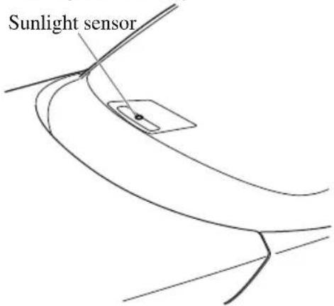
Interior temperature sensor
Do not cover the interior temperature sensor. Otherwise, the interior temperature may not adjust correctly.
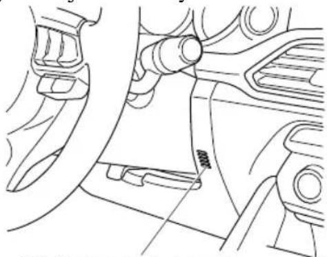
natural_image
Technical line drawing of a mechanical component with no visible text or symbolsInterior temperature sensor ///
Vent Operation (Rear)
▼ Adjusting the Vents
Directing airflow
You can direct air flow by moving the adjustment knob.
NOTE
When using the air conditioner, mist may come out from the vents. This is not a sign of trouble but a result of humid air being suddenly cooled.
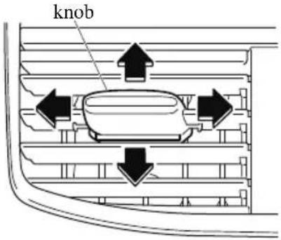
▼ Selecting the Airflow Mode
Dashboard Vents
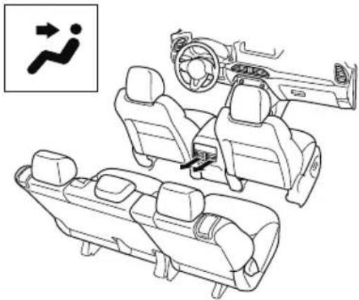
natural_image
Line drawing of a vehicle interior layout with seats and driver shift indicators (no text or symbols)Floor Vents
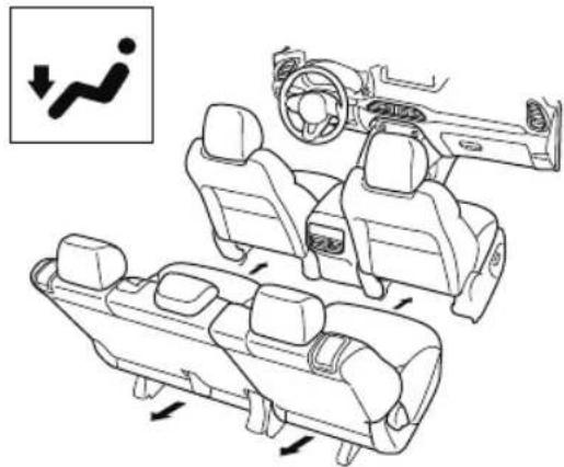
natural_image
Diagram showing vehicle interior compartments with directional arrows indicating movement or change (no text or symbols present)Dashboard and Floor Vents
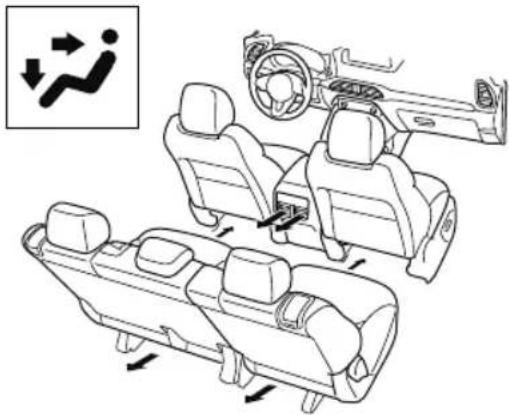
natural_image
Diagram of car interior compartments with directional arrows indicating movement or flow (no text or symbols)Rear Air Conditioner
Climate control system information is displayed on the display.

▼ Control Switches
Rear switch
Press the rear switch to operate the rear air conditioner.
The indicator illuminates to indicate that the rear air conditioner is operating.
AUTO switch
By pressing the AUTO switch the following functions will be automatically controlled in accordance with the set temperature:
- Airflow temperature
- Amount of airflow
• Selection of airflow mode
Power switch
The rear climate control system turns on or off by pressing the power switch.
Temperature control switch
This switch controls temperature. Press ▲ for hot and ▼ for cold.
Operate the temperature control switch to adjust the temperature between 15 °C (60 °F) and 29 °C (84 °F).
NOTE
When the temperature control switch is set to the maximum or minimum, “Hi” or “Lo” is indicated on the display.
Fan control switch
The fan has five speeds. The selected speed will be displayed.
Mode selector switch
The desired airflow mode can be selected. Refer to Selecting the Airflow Mode on page 5-10.
▼ Operation of Automatic Air Conditioner
Operation from front seats
- Turn the front air conditioner on.
- Press the rear switch. The rear air conditioner operates.
- Selection of the airflow mode, airflow amount and temperature will be automatically controlled to the same temperature setting as the front air conditioner for the driver's side.
NOTE
- Set the control dial to the recommended temperature of 22^ (72 °F), and then adjust it as desired.
- If the AUTO switch is pressed while the front A/C switch is off, the rear air conditioner operates only to circulate air.
- Setting the temperature to the maximum high or low will not provide the desired temperature at a faster rate.
-
When selecting heat, the system will restrict airflow until it has warmed to prevent cold air from blowing out of the vents.
-
When the rear air conditioner is controlled to the same temperature setting as the front air conditioner for the driver's side, "SYNC" is displayed on the rear screen.
- When operating the fan switch of the front air conditioner while the rear air conditioner is operating automatically, the airflow amount of the rear air conditioner may change.
Operation from rear seats
- Turn the front air conditioner on.
- Press the AUTO switch. The selection of the airflow mode and airflow amount will be automatically controlled.
- Use the temperature control switch to set the desired temperature.
NOTE
- Set the control switch to the recommended temperature of 22^ C (72 °F), and then adjust it as desired.
- If the AUTO switch is pressed while the front A/C switch is off, the rear air conditioner operates only to circulate air.
- Setting the temperature to the maximum high or low will not provide the desired temperature at a faster rate.
- When selecting heat, the system will restrict airflow until it has warmed to prevent cold air from blowing out of the vents.
- When the rear air conditioner is operated automatically, "AUTO" is displayed on the rear screen.
- When the rear air conditioner is controlled to the same temperature setting as the front air conditioner for the driver's side, "SYNC" is displayed on the rear screen.
To turn off the system, press the Power switch.
What is Mazda Connect?
▼ What is Mazda Connect ?
For vehicles with the following display type, refer to the following page because your vehicle is equipped with Mazda Connect (Type B).
Refer to What is Mazda Connect? 5-32.
natural_image
Simple line drawing of a rectangular electronic device with no text or symbolsThis manual only indicates a part of the information for Mazda Connect. For details, check the Web owner's manual at the Mazda site for each country and region.
flowchart
graph TD
    A["①"] --> B["②"]
    B --> C["③"]
    C --> D["④"]
    D --> E["⑤"]
    E --> F["⑥"]
    G["手机"] --> H["USB"]
    H --> I["手机1"]
    H --> J["手机2"]
    H --> K["手机3"]
- Radio
- Bluetooth ^® Audio/Hands-Free Call/SMS (Short Message Service)/E-mail
- USB Audio
- AUX
-
USB port *1/Auxiliary jack*1/SD card slot*2
-
SD card (Navigation system) *
*1 The location of the USB slot/auxiliary jack differs depending on the specifications.
*2 The SD card slot is for the navigation system only. For vehicles with the navigation system, the SD card (Mazda genuine) with stored map data is inserted into the SD card slot and used.
| Icon Function | |
 | ApplicationsInformation such as average fuel economy, maintenance, and warnings can be verified. In addition, SiriusXM®, Apple CarPlay*, and AndroidTM* can be selected.Depending on the grade and specification, the screen display may differ. |
 | EntertainmentOperates audio such as the radio. The audio source most recently used is displayed. An audio source which cannot be used at that time is skipped and the previous audio source is displayed.To change the audio source, select theicon displayed at the bottom of the screen. |
 | CommunicationBluetooth® related functions are available. |
 | NavigationNavigation screen is displayed (vehicles with navigation system).If the SD card for the navigation system is not inserted, the compass indicating the direction in which the vehicle is moving is displayed.The compass may not indicate the correct bearing when the vehicle is stopped or traveling at a slow speed. |
 | SettingsOverall setting menu (Such as display, sound, Bluetooth® and Language).Depending on the grade and specification, the screen display may differ. |

WARNING
Always adjust Mazda Connect while the vehicle is stopped:
Do not adjust Mazda Connect with the Commander switch while driving the vehicle.
Adjusting Mazda Connect with the Commander switch while driving the vehicle is dangerous as it could distract your attention from the vehicle operation which could lead to a serious accident.
Even if the audio remote control switches are equipped on the steering wheel, learn to use the switches without looking down at them so that you can keep your maximum attention on the road while driving the vehicle.
Do not allow the connection plug cord to get tangled with the selector lever:
Allowing the plug cord to become tangled with the selector lever is dangerous as it could interfere with driving, resulting in an accident.
Do not adjust a mobile device or a similar product while driving the vehicle:
Adjusting a mobile device or a similar product while driving the vehicle is dangerous as it could distract your attention from the vehicle operation which could lead to a serious accident. Always adjust a mobile device or a similar product while the vehicle is stopped.

CAUTION
For the purposes of safe driving, adjust the audio volume to a level that allows you to hear sounds outside of the vehicle including car horns and particularly emergency vehicle sirens.
NOTE
- Do not use Mazda Connect for a long time with the engine stopped. Otherwise, the battery power could be depleted.
- If a mobile phone or CB radio is used in or near the vehicle, it could cause noise to occur from the audio system. However, this does not indicate a problem.
Mazda Connect Basic Operations
▼ Mazda Connect Basic Operations
NOTE
The explanation of functions described in this manual may differ from the actual operation, and the shapes of screens and buttons and the letters and characters displayed may also differ from the actual appearance.
Additionally, depending on future software updates, the content may successively change without notice.
▼ Touch Panel Operation

CAUTION
Do not press the screen strongly or press it with a sharp-pointed object. Otherwise, the screen could be damaged.
NOTE
For safety reasons, operation of the center display is disabled while the vehicle is being driven. However, items not displayed in gray can be operated using the commander switch while the vehicle is being driven.
natural_image
Simple line drawing of a rectangular frame with rounded corners (no text or symbols)Touch & Tap
-
Touch or tap on the item indicated on the screen.
-
The operation is launched and the next item is displayed.

Slide (USB audio only)
- Touch the setting item displaying a slider bar.
- Touch the slider with your finger and move to the desired level.
Swipe
- Touch the screen with your finger and move up or down.
- Items which were not displayed can be displayed.
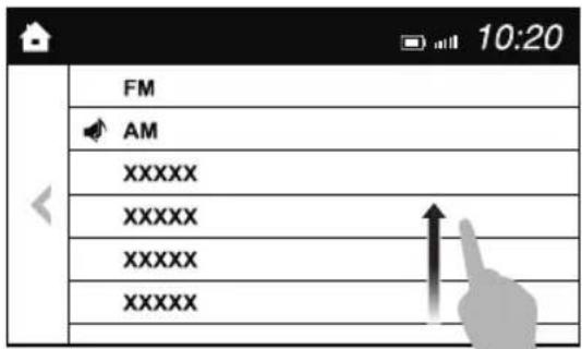
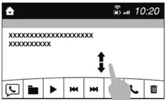
Return to previous screen
- Touch the ◀.
Displaying the home screen
- Touch the

▼ Commander Switch Operation
NOTE
For safety reasons, some operations are disabled while the vehicle is being driven.
Volume dial operation
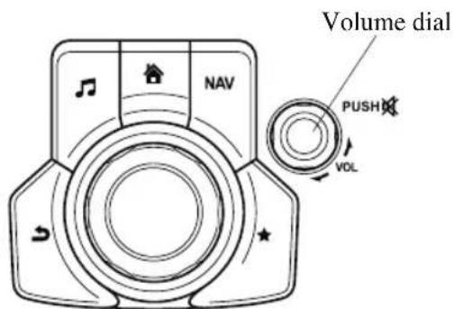
Press the volume dial to mute and pause. However, while an audio source which cannot be paused such as FM radio is playing, only mute is available. Press the volume dial again to resume the audio.
Turn the volume dial to adjust the volume. The volume increases by turning the dial clockwise, and decreases by turning it counterclockwise.
Switches around commander knob
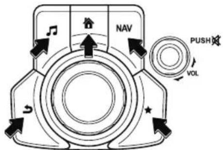
The following operations can be done by pressing the switches around the commander knob.

: Displays the home screen.

: Displays the Entertainment screen.
NAV : Displays the Navigation screen (Only navigation-equipped vehicles). For operation of the Navigation screen, refer to the navigation system manual. If the SD card for the navigation system is not inserted, the compass indicating the direction in which the vehicle is moving is displayed.
★ : Displays the Favorites screen. Long-press to store particular items in Favorites. (Radio, phonebook and destination of the navigation system can be programmed.)
5: Returns to previous screen.
Commander knob operation
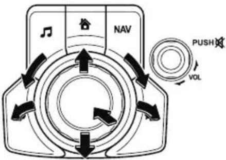
(Selection of icons on screen)
- Tilt or turn the commander knob and move the cursor to the desired icon.
- Press the commander knob and select the icon.
NOTE
Long-press operation of the commander knob is also possible for some functions.
▼ Audio Remote Control Switch Operation
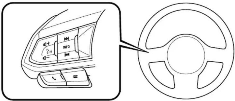
Adjusting the Volume
To increase the volume, press up the volume switch (+).
To decrease the volume, press down the volume switch (−).
Seek Switch
AM/FM radio
Press the seek switch (◀◀, ▶). The radio switches to the next/previous stored station in the order that it was stored.
Press and hold the seek switch (◀, ▶) to seek all usable stations at a higher or lower frequency whether programmed or not.
Radio stations which have been previously stored in the favorite radio can be called up by pressing the seek switch (◀◀, ▶while any radio station stored in the favorite radio is being received. Radio stations can be called up in the order they were stored with each press of the switch (◀◀, ▶)

USB Audio/Bluetooth® Audio /CD
Press the seek switch (▶▶) to skip forward to the beginning of the next track.
Press the seek switch (◀◀) within a few seconds after playback begins to track down to the beginning of the previous track.
Press the seek switch (◀◀) after a few seconds have elapsed to start playback from the beginning of the current track.
Press and hold the seek switch (◀◀, ▶▶to continuously switch the tracks up or down.
Pandora®/Aha™/Stitcher™ Radio
Press the seek switch (▶▶) to skip forward to the beginning of the next track.
Press and hold the seek switch (▶▶) to evaluate the playback of the current song as “Like”. Press and hold the seek switch (◀◀) to evaluate the playback of the current song as “Dislike”.
Pick up/hang up the Phone, or Activate Voice Control Using the Switch
Talk button
Activates the voice recognition. In addition, it skips the voice guidance.
Pick-up button
Responds to incoming calls. In addition, after selecting a contact or dialing a number, it places the call when the button is pressed.
Hang-up button
Ends the call or refuses an incoming call. In addition, it ends the voice recognition operation.
▼ Operation Using Voice Recognition Function
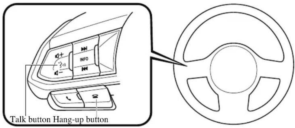
Talk button
Activates the voice recognition. In addition, it skips the voice guidance.
Hang-up button
It ends the voice recognition operation.
Basic Operation Method
Activating Voice Recognition
Press the talk button.
Ending Voice Recognition
Use one of the following methods:
- Press the hang-up button.
- Say, "Cancel".
- Operate the commander switch or the center display (only when vehicle is stopped).
Skipping Voice Guidance (for faster operation)
Press and release the talk button.
Troubleshooting for Voice Recognition
If you do not understand an operation method while in the voice recognition mode, say “Tutorial” or “Help”.
Commands useable anytime during voice recognition
“Go Back” and “Cancel” are commands which can be used at anytime during voice recognition.
Returning to previous operation
To return to the previous operation, say, "Go Back" while in voice recognition mode. Cancel
To put the Bluetooth ^® Hands-Free system in standby mode, say, “Cancel” while in voice recognition mode.
To prevent a deterioration in the voice recognition rate and voice quality, the following points should be observed:
- The voice recognition cannot be performed while voice guidance or the beep sound is operating. Wait until the voice guidance or the beep sound is finished before saying your commands.
- Phone related commands are available only when your phone is connected via Bluetooth®. Make sure your phone is connected via Bluetooth® before you operate phone related voice commands.
- Music play commands, such as Play Artist and Play Album can be used only in USB audio mode.
- Do not speak too slowly or loudly (no loud voice).
- Speak clearly, without pausing between words or numbers.
- Dialects or different wording other than hands-free prompts cannot be recognized by voice recognition. Speak in the wording specified by the voice commands.
- It is not necessary to face the microphone or approach it. Speak the voice commands while maintaining a safe driving position.
- Close the windows and/or the moonroof to reduce loud noises from outside the vehicle, or turn down the airflow of the climate control system while Bluetooth® Hands-Free is being used.
- Make sure the vents are not directing air up towards the microphone.
Voice Command List
Voice command
When the talk button is pressed and the following command is spoken, the audio or navigation can be operated. The commands in the () can be omitted. The specified name and number are put into the {}.
Standard command
| Voice command Function | |
| Help Usable commands can be verified. | |
| Tutorial Basic voice commands and methods of use can be verified. | |
| (Navigate/Take me/Drive) Home Set the destination to Home. | |
Communication (phone) related command
| Voice command Function | |
| Call {name in phonebook} (mobile/home/work/other)Example: “Call John Mobile” | Call to the contact in the downloaded phonebook. |
| Redial Call to the last contact you called. | |
| Callback Call to the last contact who called you. | |
Entertainment (audio) related command
| Voice command Function | Corresponding audio source | |
| (Go to/Play) Bluetooth (Audio) | Switches the audio source to BT audio.Can also switch to each audio source by similarly using commands such as FM, AM, or USB. | All |
| Play Artist {Artist name} Plays | the selected artist. USB |
Navigation related command\*
For the navigation screen voice commands, refer to the separate navigation system manual.
NOTE
- Some commands cannot be used depending on the grade and specification.
- Some commands cannot be used depending on the device connection conditions and the use conditions.
- The commands are examples of the available commands.
▼ Appendix
Gracenote® Database
When a USB device or Bluetooth® device is connected to this unit and the audio is played, the album name, artist name, genre and title information are automatically displayed if there is a match in the vehicle's database compilation to the music being played. The information stored in this device uses database information in the Gracenote® music recognition service. This application or device contains software from Gracenote, Inc. of Emeryville, California (“Gracenote”). The software from Gracenote (the “Gracenote Software”) enables this application to perform disc and/or file identification and obtain music-related information, including name, artist, track, and title information (“Gracenote Data”) from online servers or embedded databases (collectively, “Gracenote Servers”) and to perform other functions. You may use Gracenote Data only by means of the intended End-User functions of this application or device.
You agree that you will use Gracenote Data, the Gracenote Software, and Gracenote Servers for your own personal non-commercial use only. You agree not to assign, copy, transfer or transmit the Gracenote Software or any Gracenote Data to any third party. YOU AGREE NOT TO USE OR EXPLOIT GRACENOTE DATA, THE GRACENOTE SOFTWARE, OR GRACENOTE SERVERS, EXCEPT AS EXPRESSLY PERMITTED HEREIN.
You agree that your non-exclusive license to use the Gracenote Data, the Gracenote Software, and Gracenote Servers will terminate if you violate these restrictions. If your license terminates, you agree to cease any and all use of the Gracenote Data, the Gracenote Software, and Gracenote Servers. Gracenote reserves all rights in Gracenote Data, the Gracenote Software, and the Gracenote Servers, including all ownership rights. Under no circumstances will Gracenote become liable for any payment to you for any information that you provide. You agree that Gracenote, Inc. may enforce its rights under this Agreement against you directly in its own name.
The Gracenote service uses a unique identifier to track queries for statistical purposes. The purpose of a randomly assigned numeric identifier is to allow the Gracenote service to count queries without knowing anything about who you are. For more information, see the web page for the Gracenote Privacy Policy for the Gracenote service.
The Gracenote Software and each item of Gracenote Data are licensed to you “AS IS.” Gracenote makes no representations or warranties, express or implied, regarding the accuracy of any Gracenote Data from in the Gracenote Servers. Gracenote reserves the right to delete data from the Gracenote Servers or to change data categories for any cause that Gracenote deems sufficient. No warranty is made that the Gracenote Software or Gracenote Servers are error-free or that functioning of Gracenote Software or Gracenote Servers will be uninterrupted. Gracenote is not obligated to provide you with new enhanced or additional data types or categories that Gracenote may provide in the future and is free to discontinue its services at any time.
GRACENOTE DISCLAIMS ALL WARRANTIES EXPRESS OR IMPLIED, INCLUDING, BUT NOT LIMITED TO, IMPLIED WARRANTIES OF MERCHANTABILITY, FITNESS FOR A PARTICULAR PURPOSE, TITLE, AND NON-INFRINGEMENT. GRACENOTE DOES NOT WARRANT THE RESULTS THAT WILL BE OBTAINED BY YOUR USE OF THE GRACENOTE SOFTWARE OR ANY GRACENOTE SERVER. IN NO CASE WILL GRACENOTE BE LIABLE FOR ANY CONSEQUENTIAL OR INCIDENTAL DAMAGES OR FOR ANY LOST PROFITS OR LOST REVENUES.
© Gracenote, Inc. 2009
Updating the database
The Gracenote ^® media database can be updated using USB device.
- Connect a USB device containing the software for updating Gracenote ^® .
- Select the ⚙ icon on the home screen to display the Settings screen.
- Select the System tab and select Music Database Update
- Select Search. The list of the update package stored in the USB device and the version are displayed.
- Select the package to use the update.
- Select Install.
NOTE
Gracenote ^® can be downloaded from the Mazda Hands-free Website.
SiriusXM® Satellite Radio\*
SiriusXM ^® All Access Subscription

Hopefully, you're already loving SiriusXM in your new Mazda. But don't stop there — you can also listen on the app and online. All Access is the very best subscription package – with the most channels and the most flexibility. With All Access, you get every channel available on satellite radio, plus you can listen on the app and online — so you can enjoy SiriusXM wherever you are. Here's what's included:
-Over 150 satellite channels to enjoy in your car, coast-to-coast, 24/7.
-All kinds of commercial-free music, plus every major sport, world-class news and the biggest names in talk & entertainment.
-All of our premium programming, including Howard Stern, every NFL, MLB ^® , and NBA game, NHL ^® games, every NASCAR ^® race, 24/7 talk channels dedicated to the biggest leagues, and much more.
All SiriusXM services require a subscription, sold separately or as a package by SiriusXM Radio Inc. (or, in Canada, SiriusXM Canada Inc.), after any trial subscription which may be
included with your vehicle purchase or lease. To subscribe after your trial subscription, call 1-877-447-0011 (U.S.A.) or 1-877-438-9677 (Canada).

CAUTION
It is prohibited to copy, decompile, disassemble, reverse engineer, hack, manipulate, or otherwise make available any technology or software incorporated in receivers compatible with the SiriusXM satellite radio service or that support the SiriusXM website, the online service or any of its content. Furthermore, the AMBE® voice compression software included in this product is protected by intellectual property rights including patent rights, copyrights, and trade secrets of Digital Voice Systems, Inc. The SiriusXM Service may include traffic, weather and other content and emergency alert information and data. Such information and data is not for “safety for life”, but is merely supplemental and advisory in nature and, therefore, cannot be relied upon as safety critical. Neither SiriusXM nor Mazda is responsible for any errors in accuracies in the SiriusXM data services or its use in applications. The SiriusXM content is subject to change without notice.
HD Radio™
What is HD Radio™ Technology and how does it work?
HD Radio™ Technology is the digital evolution of analog AM/FM radio. Your radio product has a special receiver which allows it to receive digital broadcasts (where available) in addition to the analog broadcasts it already receives. Digital broadcasts have better sound quality than analog broadcasts as digital broadcasts provide free, crystal clear audio. For more information, and a guide to available radio stations and programming, please visit www.hdradio.com.
Benefits of HD Radio™ Technology
(Information)
The song title, artist name, album name and genre will appear on the screen when available by the radio station.
(Multicast)
On the FM radio frequency most digital stations have “multiple” or supplemental programs on each FM station.
Apple CarPlay™
Apple CarPlay™ allows you to make calls, send or receive messages, and listen to music using your iPhone® with the vehicle's audio system, or search for destinations using the maps. In addition, voice recognition operation is possible using Siri®.

CAUTION
YOU EXPRESSLY ACKNOWLEDGE AND AGREE THAT USE OF APPLE CARPLAY™ ("THE APPLICATION") IS AT YOUR SOLE RISK AND THAT THE ENTIRE RISK AS TO SATISFACTORY QUALITY, PERFORMANCE, ACCURACY AND EFFORT IS WITH YOU TO THE MAXIMUM EXTENT PERMITTED BY APPLICABLE LAW, AND THAT THE APPLICATION AND INFORMATION ON THE APPLICATION IS PROVIDED "AS IS" AND "AS AVAILABLE", WITH ALL FAULTS AND WITHOUT WARRANTY OF ANY KIND, AND MAZDA HEREBY DISCLAIMS ALL WARRANTIES AND CONDITIONS WITH RESPECT TO THE APPLICATION AND INFORMATION ON THE APPLICATION, EITHER EXPRESS, IMPLIED OR STATUTORY, INCLUDING, BUT NOT LIMITED TO, THE IMPLIED WARRANTIES AND/OR CONDITIONS OF MERCHANTABILITY, SATISFACTORY QUALITY, FITNESS FOR A PARTICULAR PURPOSE, ACCURACY, QUIET ENJOYMENT, AND NONINFRINGEMENT OF THIRD PARTY RIGHTS. AS EXAMPLES, AND WITHOUT LIMITATION, MAZDA DISCLAIMS ANY WARRANTY REGARDING THE ACCURACY OF DATA PROVIDED BY THE APPLICATION, SUCH AS THE ACCURACY OF DIRECTIONS, ESTIMATED TRAVEL TIME, SPEED LIMITS, ROAD CONDITIONS, NEWS, WEATHER, TRAFFIC, OR OTHER CONTENT PROVIDED BY APPLE, ITS AFFILIATES, OR THIRD PARTY PROVIDERS; MAZDA DOES NOT GUARANTEE AGAINST LOSS OF APPLICATION DATA, WHICH MAY BE LOST AT ANY TIME; MAZDA DOES NOT GUARANTEE THAT THE APPLICATION OR ANY SERVICES PROVIDED THROUGH THEM WILL BE PROVIDED AT ALL TIMES OR THAT ANY OR ALL SERVICES WILL BE AVAILABLE AT ANY PARTICULAR TIME OR LOCATION. FOR EXAMPLE, SERVICES MAY BE SUSPENDED OR INTERRUPTED WITHOUT NOTICE FOR REPAIR, MAINTENANCE, SECURITY FIXES, UPDATES, ETC., SERVICES MAY BE UNAVAILABLE IN YOUR AREA OR LOCATION, ETC. IN ADDITION, YOU UNDERSTAND THAT CHANGES IN THIRD PARTY TECHNOLOGY OR GOVERNMENT REGULATION MAY RENDER THE SERVICES AND/OR APPLICATIONS OBSOLETE AND/OR UNUSABLE. TO THE EXTENT NOT PROHIBITED BY LAW, IN NO EVENT SHALL MAZDA OR ITS AFFILIATES BE LIABLE FOR PERSONAL INJURY, OR ANY INCIDENTAL, SPECIAL, INDIRECT OR CONSEQUENTIAL DAMAGES WHATSOEVER, INCLUDING, WITHOUT LIMITATION, DAMAGES FOR LOSS OF PROFITS, CORRUPTION OR LOSS OF DATA, FAILURE TO TRANSMIT OR RECEIVE ANY DATA, BUSINESS INTERRUPTION OR ANY OTHER COMMERCIAL DAMAGES OR LOSSES, ARISING OUT OF OR RELATED TO THE APPLICATION OR YOUR USE OF OR INABILITY TO USE THE APPLICATION OR INFORMATION ON THE APPLICATION.
When using Apple CarPlay™, please avoid distraction and use Apple CarPlay™ responsibly. Stay fully aware of driving conditions and always obey applicable laws.
NOTE
- Apple CarPlay™ is provided by Apple® and its use is subject to your agreement to the Apple CarPlay™ terms of use, which are included as part of the Apple iOS terms of use.
- When using Apple CarPlay™, location, speed, and other vehicle data is transferred to your iPhone®. For further details, refer to Apple®'s Privacy Policy.
Android Auto™
Android Auto ^TM is an application which allows the operation of an Android ^TM Smartphone using the vehicle's audio. Android Auto ^TM functions such as the phone, messages, music, and map can be used with the vehicle's audio system.

CAUTION
YOU EXPRESSLY ACKNOWLEDGE AND AGREE THAT USE OF ANDROID AUTO™ ("THE APPLICATION") IS AT YOUR SOLE RISK AND THAT THE ENTIRE RISK AS TO SATISFACTORY QUALITY, PERFORMANCE, ACCURACY AND EFFORT IS WITH YOU TO THE MAXIMUM EXTENT PERMITTED BY APPLICABLE LAW, AND THAT THE APPLICATION AND INFORMATION ON THE APPLICATION IS PROVIDED "AS IS" AND "AS AVAILABLE," WITH ALL FAULTS AND WITHOUT WARRANTY OF ANY KIND, AND MAZDA HEREBY DISCLAIMS ALL WARRANTIES AND CONDITIONS WITH RESPECT TO THE APPLICATION AND INFORMATION ON THE APPLICATION, EITHER EXPRESS, IMPLIED OR STATUTORY, INCLUDING, BUT NOT LIMITED TO, THE IMPLIED WARRANTIES AND/OR CONDITIONS OF MERCHANTABILITY, SATISFACTORY QUALITY, FITNESS FOR A PARTICULAR PURPOSE, ACCURACY, QUIET ENJOYMENT, AND NONINFRINGEMENT OF THIRD PARTY RIGHTS. AS EXAMPLES, AND WITHOUT LIMITATION, MAZDA DISCLAIMS ANY WARRANTY REGARDING THE ACCURACY OF DATA PROVIDED BY THE APPLICATION, SUCH AS THE ACCURACY OF DIRECTIONS, ESTIMATED TRAVEL TIME, SPEED LIMITS, ROAD CONDITIONS, NEWS, WEATHER, TRAFFIC, OR OTHER CONTENT PROVIDED BY GOOGLE, ITS AFFILIATES, OR THIRD PARTY PROVIDERS; MAZDA DOES NOT GUARANTEE AGAINST LOSS OF APPLICATION DATA, WHICH MAY BE LOST AT ANY TIME; MAZDA DOES NOT GUARANTEE THAT THE APPLICATION OR ANY SERVICES PROVIDED THROUGH THEM WILL BE PROVIDED AT ALL TIMES OR THAT ANY OR ALL SERVICES WILL BE AVAILABLE AT ANY PARTICULAR TIME OR LOCATION. FOR EXAMPLE, SERVICES MAY BE SUSPENDED OR INTERRUPTED WITHOUT NOTICE FOR REPAIR, MAINTENANCE, SECURITY FIXES, UPDATES, ETC., SERVICES MAY BE UNAVAILABLE IN YOUR AREA OR LOCATION, ETC. IN ADDITION, YOU UNDERSTAND THAT CHANGES IN THIRD PARTY TECHNOLOGY OR GOVERNMENT REGULATION MAY RENDER THE SERVICES AND/OR APPLICATIONS OBSOLETE AND/OR UNUSABLE.
TO THE EXTENT NOT PROHIBITED BY LAW, IN NO EVENT SHALL MAZDA OR ITS AFFILIATES BE LIABLE FOR PERSONAL INJURY, OR ANY INCIDENTAL, SPECIAL, INDIRECT OR CONSEQUENTIAL DAMAGES WHATSOEVER, INCLUDING, WITHOUT LIMITATION, DAMAGES FOR LOSS OF PROFITS, CORRUPTION OR LOSS OF DATA, FAILURE TO TRANSMIT OR RECEIVE ANY DATA, BUSINESS INTERRUPTION OR ANY OTHER COMMERCIAL DAMAGES OR LOSSES, ARISING OUT OF OR RELATED TO THE APPLICATION OR YOUR USE OF OR INABILITY TO USE THE APPLICATION OR INFORMATION ON THE APPLICATION.
When using Android Auto™, please avoid distraction and use Android Auto™ responsibly. Stay fully aware of driving conditions and always obey applicable laws.
NOTE
- Android Auto™ is provided by Google and its use is subject to your agreement to the Android Auto™ terms of use.
- When using Android Auto™, location, speed, and other vehicle data is transferred to your smart phone. For further details, refer to Google's Privacy Policy.
Trademark
- Pandora ^ , the Pandora ^ logo, and the Pandora ^ trade dress are trademarks or registered trademarks of Pandora Media, Inc., used with permission.
- HD Radio™ and the HD, HD Radio, and “Arc” logos are proprietary trademarks of iBiquity Digital Corp.

- iPhone, iPod touch, iPod nano, Siri and Apple Music are registered trademarks of Apple Inc.
- Apple CarPlay is trademarks of Apple Inc.
- iOS is a trademark or registered trademark of Cisco in the U.S. and other countries and is used under license.
- “Made for iPhone” and “Made for iPod” mean that an accessory has been designed to connect specifically to iPhone or iPod, and has been certified by the developer to meet Apple performance standards. Apple is not responsible for the operation of this device or its compliance with safety and regulatory standards.
Please note that the use of this accessory with iPhone or iPod may affect wireless performance.
Made for
iPhone 7 Plus
iPhone 7
iPhone SE
iPhone 6s Plus
iPhone 6s
iPhone 6 Plus
iPhone 6
iPhone 5s
iPod touch (7th generation)
iPod touch (6th generation)
Made for
iPhone | iPod
· Google, Android, Android Auto and other related marks are trademarks of Google LLC.
- AudioPilot is a registered trademark of Bose Corporation.
- Centerpoint is a registered trademark of Bose Corporation.
- Windows Media and Microsoft are registered trademarks of Microsoft Corporation U.S. in the United States and other countries.
This product is protected by certain intellectual property rights of Microsoft Corporation and third parties.
Use or distribution of such technology outside of this product is prohibited without a license from Microsoft or an authorized Microsoft subsidiary and third parties.
- The Bluetooth® word mark and logos are registered trademarks owned by Bluetooth SIG, Inc. and any use of such marks by Panasonic Corporation is under license. Other trademarks and trade names are those of their respective owners.

Bluetooth®
- SDHC Logo is a trademark of SD-3C, LLC.

- Gracenote, the Gracenote logo and logotype are either a registered trademark or a trademark of Gracenote, Inc. in the United States and/or other countries.

gracenote.
A NIELSEN COMPANY
What is Mazda Connect?
▼ What is Mazda Connect ?
For vehicles with the following display type, refer to the following page because your vehicle is equipped with Mazda Connect (Type A).
Refer to What is Mazda Connect? on page 5-14.
natural_image
Simple line drawing of a rectangular object with horizontal lines and rounded corners, no text or symbols present.This manual only indicates a part of the information for Mazda Connect. For details, check the Web owner's manual at the Mazda site for each country and region.
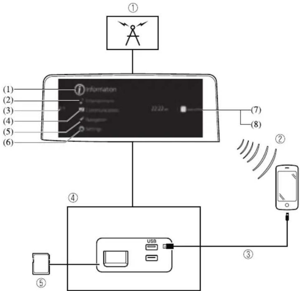
flowchart
graph TD
    A["Device ①"] --> B["Information"]
    B --> C["Mobile Phone"]
    C --> D["USB"]
    D --> E["Mobile Device"]
    style A fill:#f9f,stroke:#333
    style B fill:#ccf,stroke:#333
    style C fill:#cfc,stroke:#333
    style D fill:#fcc,stroke:#333
    style E fill:#ffc,stroke:#333
-
Radio
-
Bluetooth ^® Audio/Hands-Free Call/SMS (Short Message Service)
- USB Audio/USB Video
- USB port ^1 /SD card slot ^2
- SD card (Navigation system) *
*1 The location of the USB slot differs depending on the vehicle specifications.
*2 The SD card slot is for the navigation system only. For vehicles with the navigation system, the SD card (Mazda genuine) with stored map data is inserted into the SD card slot.
| No. | Menu Explanation | |
| (1) | Information | Fuel Efficiency Monitor:Monitor fuel efficiency in real time and view fuel efficiency history.SiriusXM Travel Link*:Access traffic information, weather, fuel prices, parking information and sports scores.Vehicle Status Monitor:View important vehicle maintenance messages, information, and intervals. |
| (2) | Entertainment | FMAMSiriusXM*Pandora*BluetoothUSB1 Audio/USB2 AudioUSB1 Video/USB2 VideoAudio Off |
| (3) | Notifications | Displays text messages received by the mobile device paired to Mazda Connect and notifications from the vehicle. |
| (4) | Communication | By connecting your mobile device, such as a Smartphone, to Mazda Connect via Bluetooth®, you can use the hands-free call and short message functions. |
| (5) | Navigation | The navigation system (vehicles with navigation system) can be used when the SD card for the navigation system is inserted.If the SD card for the navigation system is not inserted, the compass indicating the direction in which the vehicle is moving is displayed. The compass may not indicate the correct bearing when the vehicle is stopped or traveling at a slow speed.For the navigation system operation, refer to the navigation system manual. |
| (6) | Settings | You can change the settings for the Mazda Connect screen, sound settings, and the vehicle functions.In-Vehicle Displays:Configures settings and content for all in-vehicle displays.Sound Settings:Configures the in-vehicle listening experience.Safety Settings:Configures safety and driver assistance features.Vehicle Settings:Configures vehicle convenience features.Connectivity Settings:Configures Bluetooth and other device connectivity settings.System Settings:Configures language, time, and other general settings. |
| (7) | Apple CarPlay | You can use Apple CarPlay^TM by connecting an iPhone^® compatible with Apple CarPlay^TM to the USB port. |
| (8) | Android Auto | You can use Android Auto^TM by connecting an Android^TM Smartphone compatible with Android Auto^TM to the USB port. |

WARNING
Always adjust Mazda Connect while the vehicle is stopped:
Do not adjust Mazda Connect with the Commander switch while driving the vehicle.
Adjusting Mazda Connect with the Commander switch while driving the vehicle is dangerous as it could distract your attention from the vehicle operation which could lead to a serious accident.
Even if the audio remote control switches are equipped on the steering wheel, learn to use the switches without looking down at them so that you can keep your maximum attention on the road while driving the vehicle.
Do not allow the connection plug cord to get tangled with the selector lever:
Allowing the plug cord to become tangled with the selector lever is dangerous as it could interfere with driving, resulting in an accident.
Do not adjust a mobile device or a similar product while driving the vehicle:
Adjusting a mobile device or a similar product while driving the vehicle is dangerous as it could distract your attention from the vehicle operation which could lead to a serious accident. Always adjust a mobile device or a similar product while the vehicle is stopped.

CAUTION
For the purposes of safe driving, adjust the audio volume to a level that allows you to hear sounds outside of the vehicle including car horns and particularly emergency vehicle sirens.
NOTE
- Do not use Mazda Connect for a long time with the engine stopped. Otherwise, the battery power could be depleted.
- If a mobile phone or CB radio is used in or near the vehicle, it could cause noise to occur from the audio system. However, this does not indicate a problem.
Mazda Connect Basic Operations
▼ Mazda Connect Basic Operations
NOTE
The explanation of functions described in this manual may differ from the actual operation, and the shapes of screens and buttons and the letters and characters displayed may also differ from the actual appearance.
Additionally, depending on future software updates, the content may successively change without notice.
▼ Commander Switch Operation
The commander switch can be used to switch to each function and to operate each function. Set the palm of your hand on the commander knob so that your fingers can touch each of the switches.
You can switch the screens without having to look down at your hand.
NOTE
For safety reasons, some operations are disabled while driving the vehicle.
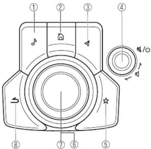
The shape of the switches varies depending on the vehicle specifications.
| No. | Item Explanation | |
| 1 |  | Entertainment button:The audio source screen last used is displayed.(During Apple CarPlayTM or Android AutoTM music playback)Displays the Apple CarPlayTM or Android AutoTM now playing screen. |
| 2 |  | Home button:Displays the home screen.(While Apple CarPlayTM or Android AutoTM is displayed)Displays the Apple CarPlayTM or Android AutoTM home screen.(While Apple CarPlayTM or Android AutoTM is connected)Press and hold while the Mazda Connect screen is displayed to switch the screen from Mazda Connect to Apple CarPlayTM or Mazda Connect to Android AutoTM. In addition, press and hold while the Apple CarPlayTM or Android AutoTM screen is displayed to switch to the Mazda Connect screen. |
| 3 |  | Map button:Displays the navigation screen (vehicles with navigation system).In order for the navigation system to function, the SD card for the navigation system is required.If the SD card for the navigation system is not inserted, the compass indicating the direction in which the vehicle is moving is displayed.For the navigation system operation, refer to the navigation system manual.(During Apple CarPlayTM or Android AutoTM route guidance)Displays the Apple CarPlayTM or Android AutoTM map screen.NOTEWith an active Mazda Navigation route, pressing the Map button will repeat the navigation voice guidance. |
| 4 |  | Volume knob:Volume adjustmentAdjust the volume by turning the volume knob.If you adjust the volume during voice guidance, the volume of the voice guidance will change.If you adjust the volume during a hands-free call, the conversation volume will change.Press the volume knob to mute/pause the audio. Press the knob again to resume.Power off/onPress and hold to turn off the Mazda Connect power and turn off the screen. Press and hold again to turn on the Mazda Connect power.NOTEIf you press the volume knob to mute an audio source which can be paused, such as Apple CarPlayTM, USB audio, or Bluetooth® audio, while it is playing, the song playback pauses. Press the volume knob again to cancel the mute and the pause at the same time.Selecting a radio stationRadio stations saved to your Favorites can be selected by sliding the volume knob left (SEEK DOWN)/right (SEEK UP) while listening to FM/AM/SiriusXM®. The station will change each time you slide the volume knob. If you want to manually tune to the next available station before or after the currently selected station, slide and hold the volume knob left (SEEK DOWN) or right (SEEK UP) until you hear a beep and the tuner will select the next available station.Playback ControlMusic and video files can be cued when listening to stored content via USB, Bluetooth®, and SiriusXM®, audio, or video.Slide the volume knob right to skip to the next track or slide it to the left to go back to the previous track. You can also slide and hold the volume knob to fast forward or rewind the track. |
| 5 |  | Favorites button:Displays the favorites screen.Press and hold to register AM/FM/SiriusXM® stations, contacts, navigation destinations, or any highlighted menu items to create easily accessible short-cuts. |
| 6 |  | Commander knob (selection):Rotate or slide the commander knob to highlight/select the on-screen functions you want to use. |
| 7 | 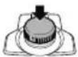 | Commander knob (select):Depress the commander knob to select the desired on-screen function you want to use. |
| 8 |  | Back button:Returns to previous screen. |
▼ Audio Remote Control Switch Operation
The audio remote control switch is on the left side of the steering wheel. You can operate basic audio functions, pick up/hang up the phone, or activate voice control using the switch.
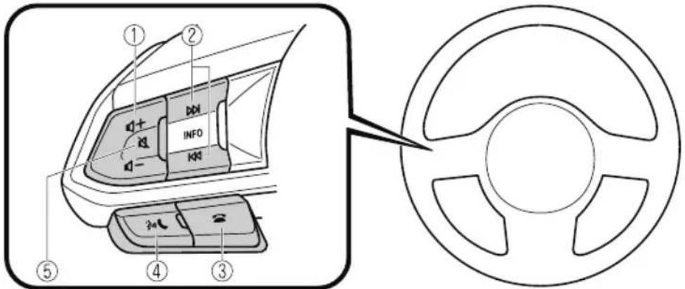
The shape of the switches may differ depending on the vehicle specifications.
| No. Item Explanation | ||
| 1 |  | Volume adjustment button:Press the (+) or (-) button to adjust the volume.If you adjust the volume during voice guidance, the volume of the voice guidance will change.If you adjust the volume during a hands-free call, the conversation volume will change. |
 | ||
| No. | Item Explanation | |
| 2 |  (SEEK UP) (SEEK UP) | Seek Switch:Selecting a radio stationRadio stations saved to your Favorites can be selected by pressing the seek switch while listening to FM/AM/SiriusXM®. The station will change to the previous or next favorite station each time you press the seek switch. If you want to manually tune to the next available station before or after the currently selected station, press and hold the seek switch until it beeps and the tuner will select the next available station.Playback ControlMusic and video files can be cued when listening to stored content via USB, Bluetooth®, and SiriusXM®, audio, or video.Slide the volume knob right to skip to the next track or slide it to the left to go back to the previous track. You can also slide and hold the volume knob to fast forward or rewind the track. |
 (SEEK DOWN) (SEEK DOWN) | ||
| 3 |  | Hang-up button:(During a call)Press the button to end the call.(While receiving a call)Press the button to refuse a call. |
| 4 |  | Talk/Pick-up button:(While receiving a call)Press the button to answer the call. |
| 5 |  | Mute button:Press the button to mute.Press it again to cancel the mute.NOTEIf you press the mute button to mute an audio source which can be paused, such as Apple CarPlayTM, USB audio, or Bluetooth® audio, while it is playing, the song playback pauses. Press the mute button again to cancel the mute and the pause at the same time. |
▼ Operation Using Voice Recognition Function
The shape of the switches may differ depending on the vehicle specifications.
| No. | Item Explanation | |
| 1 |  | Talk/Pick-up button:When the button is pressed, the voice recognition top screen is displayed and the voice recognition is activated.(While voice guidance is being announced)Press the button to skip the voice guidance. |
| 2 |  | Hang-up button:Press the button to end the voice recognition. |
Voice recognition activation
When the talk/pick-up button on the audio remote control switch is pressed, top screen of the voice recognition will be displayed.
NOTE
When an Apple CarPlay™ or Android Auto™ compatible device is connected, the Mazda Connect voice recognition system is disabled to allow the use of Siri® or Android Auto™ voice recognition at any time with the talk/pick-up button.
Commands usable at any time
"Help" - Can be used to check for usable voice commands.
“Back” - Returns to the previous screen. When a voice command is spoken while on the telephone number input screen, the content that was previously input is deleted.
"Cancel"- The voice recognition is ended.
Ending voice recognition
Do any one of the following operations:
- Press the hang-up button.
- Press and hold the talk/Pick-up button.
- Say the word, "Cancel".
Convenient operating tips for using the voice recognition function
Examples of effective voice commands in various categories are displayed on the voice recognition screen.
NOTE
- The voice command examples shown in this manual are only a partial list of the available commands. Some commands may be unusable depending on the vehicle specifications.
- Some commands cannot be used depending on the device connection conditions and the use conditions.
- When the Barge-In setting is on, voice commands can be made even while the voice guidance is being announced. For details on Barge-In, refer to the System Settings section in the Mazda Connect Owner's Manual.
- For details on voice commands which can be used on the navigation screen, refer to the navigation system manual.
To prevent misunderstood voice commands, be aware of the following points:
- Connect your mobile phone to Bluetooth® before operating the mobile phone using voice recognition.
- After pressing the talk/pick-up button, wait for the beep before speaking a command.
- Speaking in a slightly louder voice will improve voice recognition, but an excessively loud voice is unnecessary. Try to speak in a slightly louder voice than when talking to other passengers in the vehicle.
- You do not need to speak slowly. Speak at a normal speed.
- When calling a person in the device's phonebook, the recognition rate increases the longer the name is. Errors may occur with names that are short such as “Mama”, “Home”, or “wife”.
- Speak clearly, without pausing between words or numbers.
-
Voice commands other than those specified, cannot be recognized. Speak in the wording specified by the voice commands.
-
It is not necessary to face the microphone or be near it. Speak the voice commands while maintaining a safe driving position.
- Close the windows and the moonroof* to reduce loud noises from outside the vehicle and to prevent the airflow of the air-conditioning system from being a disturbance when using Bluetooth® Hands-Free.
- Make sure that the air flow from the air conditioner is not blowing on the microphone.
- If the voice recognition is poor with the guidance volume set to high, set the Barge-In to OFF.
Examples of available voice commands
The specified name and number are put into the {}.
Common
· Back
- Help (You can listen to help guidance at each screen.)
- {Line Number} (You can select the line number on the screen.)
- Next Page
. Previous Page
. Cancel
Menu
· All
Navigation
- Entertainment
- Communication
Setting
• Voice Recognition Settings
. Display Off
Music
- Play Artist (You can also use “Play Artist {Artist name}”).
- Play Album (You can also use "Play Album {Album Name}").
- Play Playlist (You can also use "Play Playlist {Playlist Name}").
- Play Song (You can also use “Play Song {Song Name}”).
- Play Audiobook (You can also use "Play Audiobook {Audiobook Name}").
- Play Podcast (You can also use "Play Podcast {Podcast Name}").
Radio
- Tune to {Frequency} AM
- Tune to {Frequency} FM
-
Tune to {Frequency} HD {Sub Channel}
-
SiriusXM Channel {Channel Number}
- SiriusXM {Station Name}
- SiriusXM Genre (You can also use “SiriusXM {Genre Name}”.)
- Tune to DAB {DAB Station Name}
Source
- Change Source (You can also use “Change Source to USB”*1 and “USB”*1.)
- Audio OFF (You can also use “Change Source to Audio OFF”.)
Phone
- Dial Phone Number (You can also use "Dial {Phone Number}").
- Call History
- Call a Contact (You can also use “Call {Contact Name}” and “Call {Contact Name} at {Number Type}”).
• Redial
*1 : Audio source names other than “USB” can also be used as follows: Bluetooth/AM/FM/SiriusXM/Pandora/USB1 Audio/USB2 Audio/USB1 Video/USB2 Video
▼ Appendix
Gracenote® Database
When connecting a USB audio device or Bluetooth ^® audio device to this unit and playing audio, the unit searches the database stored in the vehicle for the album art. If there is a match in the vehicle's database compilation to the music being played, the album art is displayed. The database information stored in this device uses database information in the Gracenote ^® music recognitions service.
SiriusXM Travel Link®\*

CAUTION
ADVISORY ONLY
The weather information is subject to service interruptions and may contain errors or inaccuracies and consequently should not be relied upon exclusively. You are urged to check alternate weather information sources prior to making safety related decisions. You acknowledge and agree that you shall be solely responsible for use of the information and all decisions taken with respect thereto. By using this weather service, you release and waive any claims against Sirius XM Radio Inc. and Mazda Motor Corporation and all of their respective affiliates with regard to this service.
SiriusXM® Satellite Radio\*
((SiriusXm))
Products/applications shall display “Call [Appropriate Phone Number] to Enable Services” for any unsubscribed SiriusXM Data Service(s).
This shall be shown on the same screen as the Radio ID and the service subscription status: Contact your SiriusXM Representative for the appropriate call center phone number.
· U.S.A.: 1-877-447-0011
• Canada: 1-877-438-9677
SiriusXM® All Access Subscription
Hopefully, you're already loving SiriusXM in your new Mazda. But don't stop there — you can also listen on the app and online. All Access is the very best subscription package – with the most channels and the most flexibility. With All Access, you get every channel available on your vehicle, plus you can listen on the app, online, and in your home on a variety of connected devices. — so you can enjoy SiriusXM wherever you are. Here's what's included:
· Over 150 satellite channels to enjoy in your car, coast-to-coast, 24/7.
- All kinds of commercial-free music, plus every major sport, world-class news and the biggest names in talk & entertainment.
- All of our premium programming, including Howard Stern, every NFL, MLB ^ , and NBA game, NHL ^ games, every NASCAR ^ race, 24/7 talk channels dedicated to the biggest leagues, and much more.
All SiriusXM services require a subscription, sold separately or as a package by SiriusXM Radio Inc. (or, in Canada, SiriusXM Canada Inc.), after any trial subscription which may be included with your vehicle purchase or lease. To subscribe after your trial subscription, call 1-877-447-0011 (U.S.A.) or 1-877-438-9677 (Canada).

CAUTION
It is prohibited to copy, decompile, disassemble, reverse engineer, hack, manipulate, or otherwise make available any technology or software incorporated in receivers compatible with the SiriusXM satellite radio service or that support the SiriusXM website, the online service or any of its content. Furthermore, the AMBE® voice compression software included in this product is protected by intellectual property rights including patent rights, copyrights, and trade secrets of Digital Voice Systems, Inc. The SiriusXM Service may include traffic, weather and other content and emergency alert information and data. Such information and data is not for “safety for life”, but is merely supplemental and advisory in nature and, therefore, cannot be relied upon as safety critical. Neither SiriusXM nor Mazda is responsible for any errors in accuracies in the SiriusXM data services or its use in applications. The SiriusXM content is subject to change without notice.
NOTE
SiriusXM Satellite Radio Service is available in the 48 contiguous United States and the District of Columbia. The service is not available in Alaska, Hawaii or Puerto Rico.
HD Radio™
What is HD Radio™ Technology and how does it work?
HD Radio™ Technology is the digital evolution of analog AM/FM radio.
Your radio product has a special receiver which allows it to receive digital broadcasts (where available) in addition to the analog broadcasts it already receives.
Digital broadcasts have better sound quality than analog broadcasts as digital broadcasts provide free, crystal clear audio.
For more information, and a guide to available radio stations and programming, please visit www.hdradio.com.
Benefits of HD Radio™ Technology
(Information)
The song title, artist name, album name will appear on the screen when available by the radio station.
(Multicast)
On the FM radio frequency most digital stations have “multiple” or supplemental programs on each FM station.
HD Radio Technology manufactured under license from iBiquity Digital Corporation. U.S. and Foreign Patents.
For patents see http://dts.com/patents.
Apple CarPlay™

CAUTION
YOU EXPRESSLY ACKNOWLEDGE AND AGREE THAT USE OF APPLE CARPLAY™ ("THE APPLICATION") IS AT YOUR SOLE RISK AND THAT THE ENTIRE RISK AS TO SATISFACTORY QUALITY, PERFORMANCE, ACCURACY AND EFFORT IS WITH YOU TO THE MAXIMUM EXTENT PERMITTED BY APPLICABLE LAW, AND THAT THE APPLICATION AND INFORMATION ON THE APPLICATION IS PROVIDED "AS IS" AND "AS AVAILABLE", WITH ALL FAULTS AND WITHOUT WARRANTY OF ANY KIND, AND MAZDA HEREBY DISCLAIMS ALL WARRANTIES AND CONDITIONS WITH RESPECT TO THE APPLICATION AND INFORMATION ON THE APPLICATION, EITHER EXPRESS, IMPLIED OR STATUTORY, INCLUDING, BUT NOT LIMITED TO, THE IMPLIED WARRANTIES AND/OR CONDITIONS OF MERCHANTABILITY, SATISFACTORY QUALITY, FITNESS FOR A PARTICULAR PURPOSE, ACCURACY, QUIET ENJOYMENT, AND NONINFRINGEMENT OF THIRD PARTY RIGHTS.
AS EXAMPLES, AND WITHOUT LIMITATION, MAZDA DISCLAIMS ANY WARRANTY REGARDING THE ACCURACY OF DATA PROVIDED BY THE APPLICATION, SUCH AS THE ACCURACY OF DIRECTIONS, ESTIMATED TRAVEL TIME, SPEED LIMITS, ROAD CONDITIONS, NEWS, WEATHER, TRAFFIC, OR OTHER CONTENT PROVIDED BY APPLE, ITS AFFILIATES, OR THIRD PARTY PROVIDERS; MAZDA DOES NOT GUARANTEE AGAINST LOSS OF APPLICATION DATA, WHICH MAY BE LOST AT ANY TIME; MAZDA DOES NOT GUARANTEE THAT THE APPLICATION OR ANY SERVICES PROVIDED THROUGH THEM WILL BE PROVIDED AT ALL TIMES OR THAT ANY OR ALL SERVICES WILL BE AVAILABLE AT ANY PARTICULAR TIME OR LOCATION. FOR EXAMPLE, SERVICES MAY BE SUSPENDED OR INTERRUPTED WITHOUT NOTICE FOR REPAIR, MAINTENANCE, SECURITY FIXES, UPDATES, ETC., SERVICES MAY BE UNAVAILABLE IN YOUR AREA OR LOCATION, ETC.
IN ADDITION, YOU UNDERSTAND THAT CHANGES IN THIRD PARTY TECHNOLOGY OR GOVERNMENT REGULATION MAY RENDER THE SERVICES AND/OR APPLICATIONS OBSOLETE AND/OR UNUSABLE. TO THE EXTENT NOT PROHIBITED BY LAW, IN NO EVENT SHALL MAZDA OR ITS AFFILIATES BE LIABLE FOR PERSONAL INJURY, OR ANY INCIDENTAL, SPECIAL, INDIRECT OR CONSEQUENTIAL DAMAGES WHATSOEVER, INCLUDING, WITHOUT LIMITATION, DAMAGES FOR LOSS OF PROFITS, CORRUPTION OR LOSS OF DATA, FAILURE TO TRANSMIT OR RECEIVE ANY DATA, BUSINESS INTERRUPTION OR ANY OTHER COMMERCIAL DAMAGES OR LOSSES, ARISING OUT OF OR RELATED TO THE APPLICATION OR YOUR USE OF OR INABILITY TO USE THE APPLICATION OR INFORMATION ON THE APPLICATION.
When using Apple CarPlay™, please avoid distraction and use Apple CarPlay™ responsibly. Stay fully aware of driving conditions and always obey applicable laws.
NOTE
- Apple CarPlay™ is provided by Apple® and its use is subject to your agreement to the Apple CarPlay™ terms of use, which are included as part of the Apple iOS terms of use.
- When using Apple CarPlay™, location, speed, and other vehicle data is transferred to your iPhone®. For further details, refer to Apple®'s Privacy Policy.
Android Auto™

CAUTION
YOU EXPRESSLY ACKNOWLEDGE AND AGREE THAT USE OF ANDROID AUTO™ ("THE APPLICATION") IS AT YOUR SOLE RISK AND THAT THE ENTIRE RISK AS TO SATISFACTORY QUALITY, PERFORMANCE, ACCURACY AND EFFORT IS WITH YOU TO THE MAXIMUM EXTENT PERMITTED BY APPLICABLE LAW, AND THAT THE APPLICATION AND INFORMATION ON THE APPLICATION IS PROVIDED "AS IS" AND "AS AVAILABLE," WITH ALL FAULTS AND WITHOUT WARRANTY OF ANY KIND, AND MAZDA HEREBY DISCLAIMS ALL WARRANTIES AND CONDITIONS WITH RESPECT TO THE APPLICATION AND INFORMATION ON THE APPLICATION, EITHER EXPRESS, IMPLIED OR STATUTORY, INCLUDING, BUT NOT LIMITED TO, THE IMPLIED WARRANTIES AND/OR CONDITIONS OF MERCHANTABILITY, SATISFACTORY QUALITY, FITNESS FOR A PARTICULAR PURPOSE, ACCURACY, QUIET ENJOYMENT, AND NONINFRINGEMENT OF THIRD PARTY RIGHTS.
AS EXAMPLES, AND WITHOUT LIMITATION, MAZDA DISCLAIMS ANY WARRANTY REGARDING THE ACCURACY OF DATA PROVIDED BY THE APPLICATION, SUCH AS THE ACCURACY OF DIRECTIONS, ESTIMATED TRAVEL TIME, SPEED LIMITS, ROAD CONDITIONS, NEWS, WEATHER, TRAFFIC, OR OTHER CONTENT PROVIDED BY GOOGLE, ITS AFFILIATES, OR THIRD PARTY PROVIDERS; MAZDA DOES NOT GUARANTEE AGAINST LOSS OF APPLICATION DATA, WHICH MAY BE LOST AT ANY TIME; MAZDA DOES NOT GUARANTEE THAT THE APPLICATION OR ANY SERVICES PROVIDED THROUGH THEM WILL BE PROVIDED AT ALL TIMES OR THAT ANY OR ALL SERVICES WILL BE AVAILABLE AT ANY PARTICULAR TIME OR LOCATION. FOR EXAMPLE, SERVICES MAY BE SUSPENDED OR INTERRUPTED WITHOUT NOTICE FOR REPAIR, MAINTENANCE, SECURITY FIXES, UPDATES, ETC., SERVICES MAY BE UNAVAILABLE IN YOUR AREA OR LOCATION, ETC.
IN ADDITION, YOU UNDERSTAND THAT CHANGES IN THIRD PARTY TECHNOLOGY OR GOVERNMENT REGULATION MAY RENDER THE SERVICES AND/OR APPLICATIONS OBSOLETE AND/OR UNUSABLE. TO THE EXTENT NOT PROHIBITED BY LAW, IN NO EVENT SHALL MAZDA OR ITS AFFILIATES BE LIABLE FOR PERSONAL INJURY, OR ANY INCIDENTAL, SPECIAL, INDIRECT OR CONSEQUENTIAL DAMAGES WHATSOEVER, INCLUDING, WITHOUT LIMITATION, DAMAGES FOR LOSS OF PROFITS, CORRUPTION OR LOSS OF DATA, FAILURE TO TRANSMIT OR RECEIVE ANY DATA, BUSINESS INTERRUPTION OR ANY OTHER COMMERCIAL DAMAGES OR LOSSES, ARISING OUT OF OR RELATED TO THE APPLICATION OR YOUR USE OF OR INABILITY TO USE THE APPLICATION OR INFORMATION ON THE APPLICATION.
When using Android Auto™, please avoid distraction and use Android Auto™ responsibly. Stay fully aware of driving conditions and always obey applicable laws.
NOTE
- Android Auto™ is provided by Google and its use is subject to your agreement to the Android Auto™ terms of use.
- When using Android Auto™, location, speed, and other vehicle data is transferred to your smart phone. For further details, refer to Google Privacy Policy.
Trademark
- Pandora®, the Pandora® logo, and the Pandora® trade dress are trademarks or registered trademarks of Pandora Media, Inc., used with permission.
- HD Radio™ and the HD, HD Radio, and “Arc” logos are proprietary trademarks of iBiquity Digital Corp.

- iPhone, iPod touch, iPod nano, Siri and Apple Music are registered trademarks of Apple Inc.
- Apple CarPlay is trademarks of Apple Inc.
- iOS is a trademark or registered trademark of Cisco in the U.S. and other countries and is used under license.
- “Made for iPhone” and “Made for iPod” mean that an accessory has been designed to connect specifically to iPhone or iPod, and has been certified by the developer to meet Apple performance standards. Apple is not responsible for the operation of this device or its compliance with safety and regulatory standards.
Please note that the use of this accessory with iPhone or iPod may affect wireless performance.
Made for
iPhone 7 Plus
iPhone 7
iPhone SE
iPhone 6s Plus
iPhone 6s
iPhone 6 Plus
iPhone 6
iPhone 5s
iPhone 5c
iPhone 5
iPhone 4s
iPod touch (6th generation)
iPod touch (5th generation)
iPod nano (7th generation)
Made for
iPhone | iPod
· Google, Android, Android Auto and other related marks are trademarks of Google LLC.
- AudioPilot is a registered trademark of Bose Corporation.
- Centerpoint is a registered trademark of Bose Corporation.
- Windows Media and Microsoft are registered trademarks of Microsoft Corporation U.S. in the United States and other countries.
This product is protected by certain intellectual property rights of Microsoft Corporation and third parties.
Use or distribution of such technology outside of this product is prohibited without a license from Microsoft or an authorized Microsoft subsidiary and third parties.
- The Bluetooth® word mark and logos are registered trademarks owned by Bluetooth SIG, Inc. and any use of such marks by Panasonic Corporation is under license. Other trademarks and trade names are those of their respective owners.

Bluetooth®
- SDHC Logo is a trademark of SD-3C, LLC.

- Gracenote, the Gracenote logo and logotype are either a registered trademark or a trademark of Gracenote, Inc. in the United States and/or other countries.

gracenote.
A NIELSEN COMPANY
Regarding the license for the audio amplifier (except vehicles with Bose audio)
License for CMSIS-RTOS RTX Implementation
Copyright (c) 1999-2009 KEIL, 2009-2015 ARM Germany GmbH, 2013-2016 ARM Ltd All rights reserved.
Redistribution and use in source and binary forms, with or without modification, are permitted provided that the following conditions are met:
- Redistributions of source code must retain the above copyright notice, this list of conditions and the following disclaimer
- Redistributions in binary form must reproduce the above copyright notice, this list of conditions and the following disclaimer in the documentation and/or other materials provided with the distribution.
- Neither the name of ARM nor the names of its contributors may be used to endorse or promote products derived from this software without specific prior written permission.
THIS SOFTWARE IS PROVIDED BY THE COPYRIGHT HOLDERS AND CONTRIBUTORS “AS IS” AND ANY EXPRESS OR IMPLIED WARRANTIES, INCLUDING, BUT NOT LIMITED TO, THE IMPLIED WARRANTIES OF MERCHANTABILITY AND FITNESS FOR A PARTICULAR PURPOSE ARE DISCLAIMED.
IN NO EVENT SHALL COPYRIGHT HOLDERS AND CONTRIBUTORS BE LIABLE FOR ANY DIRECT, INDIRECT, INCIDENTAL, SPECIAL, EXEMPLARY, OR CONSEQUENTIAL DAMAGES (INCLUDING, BUT NOT LIMITED TO, PROCUREMENT OF SUBSTITUTE GOODS OR SERVICES; LOSS OF USE, DATA, OR PROFITS; OR BUSINESS INTERRUPTION) HOWEVER CAUSED AND ON ANY THEORY OF LIABILITY, WHETHER IN CONTRACT, STRICT LIABILITY, OR TORT (INCLUDING NEGLIGENCE OR OTHERWISE) ARISING IN ANY WAY OUT OF THE USE OF THIS SOFTWARE, EVEN IF ADVISED OF THE POSSIBILITY OF SUCH DAMAGE.
Connected Service (U.S.A. only)
▼ Connected Service Overview
There are several types of connected services available via Mazda Connect. Some services may require you to download the MyMazda app to your smartphone and subscribe to the services, while others may require you to pair your smartphone to the vehicle via Bluetooth®. In addition, on a regular basis and unless you opt-out, your vehicle will automatically transmit certain geo-location, driving behavior data, and vehicle health information to Mazda for product quality, data analysis, research, and product development. Using the QR codes or URLs below, refer to the Connected Service Owner's Manual and Privacy Policy for more details and opt-out options.
• Connected Service Owner's Manual
https://www.mazdausa.com/static/manuals/mazda-connected-service/index.html
Privacy
Mazda maintains a Privacy Statement which describes how we collect, use, share, store and secure data from your vehicle equipped with connected services.
We provide you with connected services by collecting and using your personal information and vehicle location, health and driving data.
To learn more about our Privacy Statement, please visit: https://www.mazdausa.com/site/privacy-connectedservices
Sunvisors
When you need a sunvisor, lower it for use in front or swing it to the side.
Sunvisor
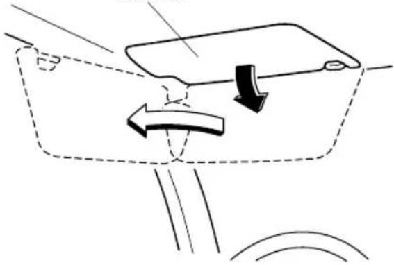
natural_image
Diagram of a vehicle's steering wheel and dashboard with directional arrows indicating motion (no text or symbols)▼ Side Extension Sunvisors\*
The visor extender extends the sunvisor's range of sun shading. To use, pull it out.
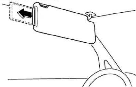
natural_image
Line drawing of a mechanical component with a curved handle and arrow indicator (no text or symbols)
CAUTION
When moving the sunvisor, retract the visor extender to its original position. Otherwise, the visor extender could hit the rearview mirror.
▼ Vanity Mirrors
To use the vanity mirror, lower the sunvisor.
If your vehicle is equipped with a vanity mirror light, it will illuminate when you open the cover.
To prevent the battery from being discharged, the vanity mirror will only illuminate in the tilt range shown in the figure.
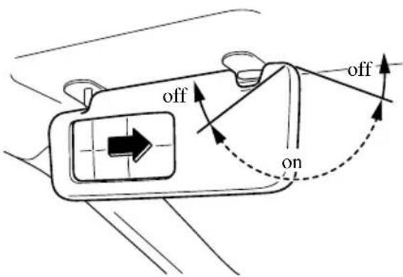
Interior Lights
NOTE
- Do not leave the lights on for long periods while the engine is turned off. Otherwise the battery power could be depleted.
Overhead Lights
Type A
| Switch Position | Overhead Lights |
| OFF | Light off |
| DOOR | • Light is on when any door is open• Light is on or off when the illuminated entry system is on |
| ON | Light on |
Front
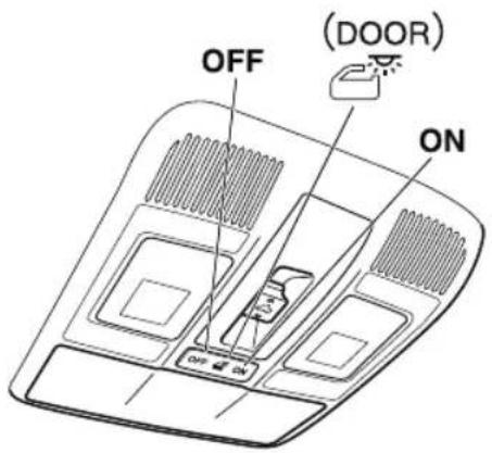
Center
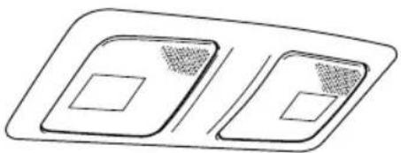
natural_image
Simple line drawing of two rectangular panels with internal square cutouts, no text or symbols presentRear
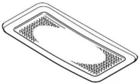
natural_image
Simple line drawing of a rectangular tray with internal grid pattern (no text or symbols)NOTE
The rear overhead light and the center map lights also turn on and off when the front overhead light switch is operated.
Type B
| Switch Overhead Lights | |
| The DOOR OFF switch can be switched between the DOOR position and DOOR OFF position.DOOR positionThe lights turn on when any of the doors is opened.The lights turn on/off in conjunction with the illuminated entry system.DOOR OFF positionThe lights do not turn on even if any of the doors is opened.The lights do not turn on/off in conjunction with the illuminated entry system. | |
| Press the switch to turn it on. Press the switch again to turn off the lights. | |
Front
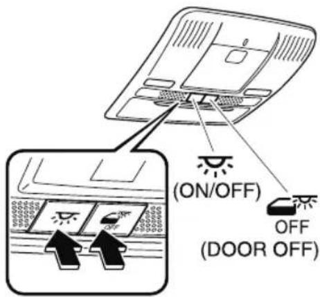
Center
natural_image
Line drawing of a car dashboard with control buttons (no text or symbols)Rear
natural_image
Isometric line drawing of a rectangular tray with grid pattern (no text or symbols)Front Map Lights
Type A
When the overhead light switch is in the door or off position, press the lens to
illuminate the front map lights, and then press the lens again to turn them off.
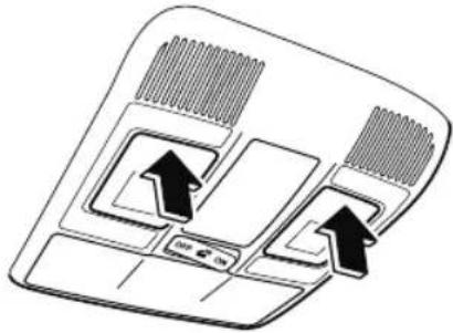
natural_image
Diagram of a car air conditioner unit with airflow arrows and control panel (no text or symbols)NOTE
The front map lights will not turn off even if the lens is pressed in the following cases:
- The overhead light switch is in the ON position.
- The overhead light switch is in the door position with the door open.
· The illuminated entry system is on.
Type B
Press the switch to illuminate the front map lights, and then press the switch again to turn them off.
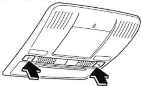
natural_image
Diagram of a laptop with labeled ports and directional arrows indicating orientation (no text or symbols)NOTE
The front map lights will not turn off even if the switch is pressed in the following cases:
- The overhead lights turn on by operating the overhead ON/OFF switch ( ).
- The overhead lights turn on in conjunction with a door opening/closing.
• The illuminated entry system is on.
Center Map Lights
Type A
When the overhead light switch is in the door or off position, press the lens to illuminate a center map light, and then press the lens again to turn it off.
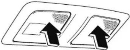
natural_image
Diagram showing two rectangular panels with upward-pointing arrows indicating direction (no text or symbols)NOTE
- Once the center map lights have been turned off, they will turn on and off depending on the position to which the overhead light is switched.
- The center map lights will not turn off even if the lens is pressed in the following cases:
• The overhead light switch is ON.
- The overhead light switch is in the door position with the door open.
· The illuminated entry system is on.
Type B
Press the switch to illuminate the center map lights, and then press the switch again to turn them off.
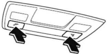
natural_image
Line drawing of a car front panel with two directional arrows pointing to the sides (no text or symbols)NOTE
- Once the center map lights have been turned off, they will turn on and off in conjunction with the overhead light operation.
- The center map lights will not turn off even if the switch is pressed in the following cases:
- The overhead lights turn on by operating the overhead ON/OFF switch ( ).
- The overhead lights turn on in conjunction with a door opening/closing.
- The illuminated entry system is on.
Luggage Compartment Lights
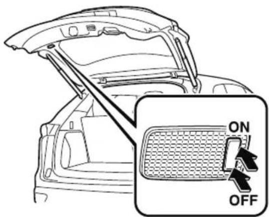
| Switch Position | Luggage Compartment Light |
| OFF | Light off |
| ON | Light on when the liftgate is open |
Ambient Light\*
The ambient lights continuously turn on when the ignition is switched ON. The ambient lights dim when the parking lights or headlights are turned on.
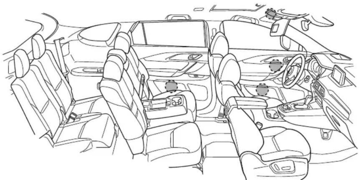
natural_image
Line drawing of a car interior showing multiple seats and dashboard (no text or symbols)
Ambient light
NOTE
- The ambient lights turn on or off in conjunction with the illuminated entry system when the ignition is switched OFF.
- The ambient light illumination level can be changed while the parking lights or headlights are turned on.
Refer to the Settings section in the Mazda Connect Owner's Manual.
▼ Illuminated Entry System
The overhead lights turn on when any of the following operations is done with the overhead light switch in the DOOR position.
The ambient lights turn on regardless of the overhead light switch position.
- The driver's door is unlocked with the ignition is switched OFF.
- The ignition is switched OFF with all doors closed.
NOTE
- The illumination time differs depending on the operation.
. Battery saver
If an interior light is left on with the ignition switched OFF, the light turns off automatically after a certain period of time has passed to prevent battery depletion.
- The operation of the illuminated entry system can be changed.
Refer to the Settings section in the Mazda Connect Owner's Manual.
· (Type B)
The illumination entry system does not operate in conjunction with the overhead lights when the overhead lights are turned on using the overhead light ON/OFF switch.
Accessory Sockets
Only use genuine Mazda accessories or the equivalent requiring no greater than 120 W (DC 12 V, 10 A).
Front
The ignition must be switched to ACC or ON.
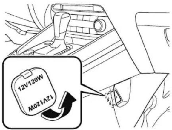
Rear
The accessory sockets can be used regardless of whether the ignition is on or off.
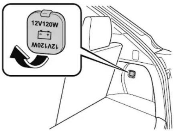

CAUTION
To prevent accessory socket damage or electrical failure, pay attention to the following:
➢Do not use accessories that require more than 120 W (DC 12 V, 10 A).
➢Do not use accessories that are not genuine Mazda accessories or the equivalent.
➢ Close the cover when the accessory socket is not in use to prevent foreign objects and liquids from getting into the accessory socket.
Correctly insert the plug into the accessory socket.
➢Do not insert the cigarette lighter into the accessory socket.
➢ Noise may occur on the audio playback depending on the device connected to the accessory socket.
Depending on the device connected to the accessory socket, the vehicle's electrical system may be affected, which could cause the warning light to illuminate. Disconnect the connected device and make sure that the problem is resolved. If the problem is resolved, disconnect the device from the socket and switch the ignition off. If the problem is not resolved, consult an Authorized Mazda Dealer.
NOTE
To prevent discharging of the battery, do not use the socket for long periods with the engine off or idling.
USB Power Outlet\*
Second-row seat (6:4 split adjustable-type bench seat type, Captain seat and second-row seat console type)
The USB power outlets can be used regardless of whether the ignition is switched to ACC or ON.
Only use USB devices that have a maximum power consumption of 10.5W (DC5V, 2.1A) or below.
6:4 split adjustable-type bench seat type
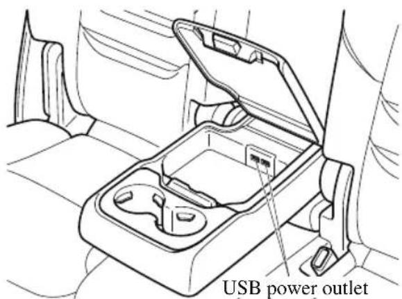
Captain seat and second-row seat console type

CAUTION
To prevent USB power outlets damage or electrical failure, pay attention to the following:
➢Do not use USB devices that require more than 10.5 W (DC 5 V, 2.1 A).
➢ Close the lid when the USB power outlets are not in use to prevent foreign objects and liquids from getting into the USB power outlets.
Correctly connect the USB connector into the USB power outlets.
NOTE
- The USB power outlets are designed only for charging and they cannot be used for connecting to the vehicle's audio system.
• To prevent discharging of the battery, do not use the USB power outlets for long periods with the engine off or idling.
How to connect
The groove in the armrest box can be used to pass the cord of the device into the box to connect it to the USB power outlets.
- Open the lid.
- Route the cord through the groove in the armrest box and insert the USB connector into the USB power outlets.
6:4 split adjustable-type bench seat type
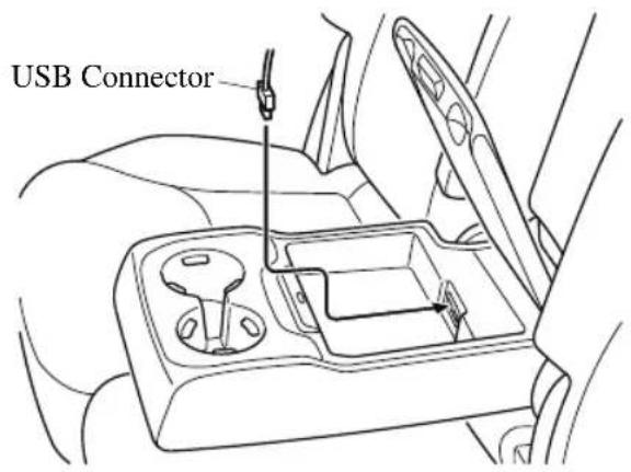
Captain seat and second-row seat console type
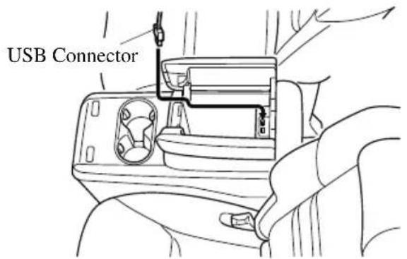
Second-row seat (Captain seat and walk through type)
The USB power outlets can be used regardless of whether the ignition is switched to ACC or ON.
Only use USB devices that have a maximum power consumption of 12.5W (DC5V, 2.5A) or below.
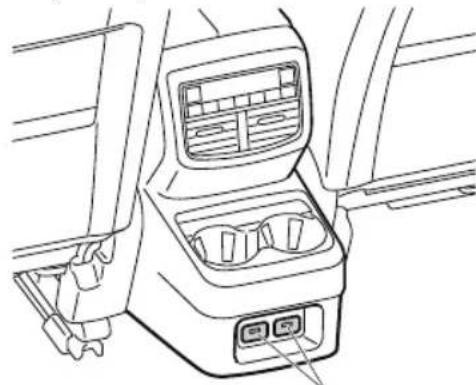
natural_image
Line drawing of a car interior showing dashboard, air intake, and seat compartments (no text or symbols)USB power outlet

CAUTION
To prevent USB power outlets damage or electrical failure, pay attention to the following:
➢ Do not use USB devices that require more than 12.5 W (DC 5 V, 2.5 A).
Correctly connect the USB connector into the USB power outlets.
NOTE
- The USB power outlets are designed only for charging and they cannot be used for connecting to the vehicle's audio system.
• To prevent discharging of the battery, do not use the USB power outlets for long periods with the engine off or idling.
Third-row seat
The USB power outlets can be used regardless of whether the ignition is switched to ACC or ON.
Only use USB devices that have a maximum power consumption of 12.5W (DC5V, 2.5A) or below.
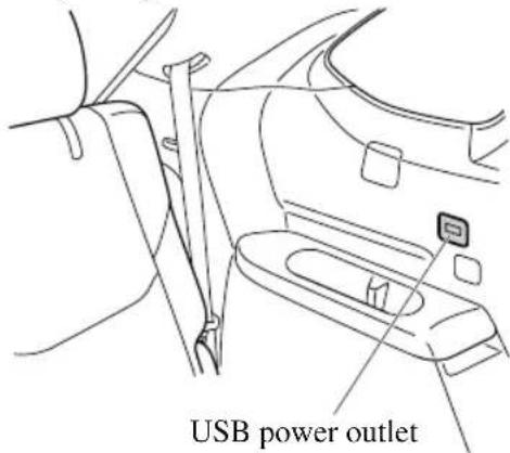

CAUTION
To prevent USB power outlets damage or electrical failure, pay attention to the following:
➢ Do not use USB devices that require more than 12.5 W (DC 5 V, 2.5 A).
Correctly connect the USB connector into the USB power outlets.
NOTE
- The USB power outlets are designed only for charging and they cannot be used for connecting to the vehicle's audio system.
• To prevent discharging of the battery, do not use the USB power outlets for long periods with the engine off or idling.
Wireless Charger (Qi)\*
You can charge mobile devices such as Smartphones which comply with the Qi Wireless Charging standard.
Only use mobile devices that have a maximum power consumption of 5 W, or 15 W or below. The maximum power consumption differs depending on the mobile device.
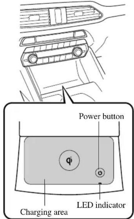

WARNING
Radio waves from the Wireless Charger (Qi) may affect the operation of medical devices such as implanted-type cardiac pacemakers or defibrillators.
Before using the Wireless Charger (Qi) near people who use medical devices, ask the medical device manufacturer or your physician if radio waves from the Wireless Charger (Qi) will affect the device.
The Wireless Charger (Qi) can be disabled to prevent it from affecting medical devices. Consult an Authorized Mazda Dealer for details.
Heed the following cautions. Otherwise, the Wireless Charger (Qi) may malfunction or be damaged, which could cause a fire, burns due to heat generation, or an accident such as electrical shock.
➢Do not install, remove, disassemble, or change the wiring of the Wireless Charger (Qi). If the Wireless Charger (Qi) needs to be installed or removed, consult an Authorized Mazda Dealer.
Do not use the Wireless Charger (Qi) when it is malfunctioning. In addition, if smoke, abnormal noise, or abnormal smell is emitted from the Wireless Charger (Qi), stop the vehicle in a safe place, switch the ignition OFF, and consult an Authorized Mazda Dealer.
When using the Wireless Charger (Qi) to store items on, turn off the Wireless Charger (Qi).
➢Do not place any metal object between the charging area and the mobile device. Also, do not apply items such as a metallic sticker to the Wireless Charger (Qi).
When charging, do not place any item other than the mobile device to be charged on the Wireless Charger (Qi). In addition, do not place any metal object, IC card, coin, or magnetic item near the charging area.
➢Remove dust or dirt from the charging area before use.
➢Do not apply strong force or impact to the Wireless Charger (Qi) or get it wet.
➢ Use only mobile devices which support the Wireless Charger (Qi).
How to use
- Start the engine.
-
The power for the Wireless Charger (Qi) turns on and the LED indicator turns on.
-
The power can be turned on/off by pressing the power button on the Wireless Charger (Qi) for about 3 seconds.
-
When the power is turned off, the LED indicator turns off.
-
Place a device compliant with the Qi Wireless Charging standard in the center of the charging area on the tray.
-
The LED indicator turns on in amber or green when charging starts.
- For details on the LED indicator, refer to the following LED indicator table.
- Charging starts when all the doors and liftgate are closed.
- The function to reduce noise on the radio operates if the power button is pressed for about 1 second during charging. Use it when noise occurs on the radio due to interference by
the Wireless Charger (Qi). Press the power button again for about 1 second to cancel the function.
LED indicator
The status of the Wireless Charger (Qi) can be checked using the LED indicator.
| Status | Illumination/flash pattern |
| OFF Docs not turn on | |
| Stand-by (charging is possible) | Turns on in white |
| Normal charging Turns on in amber | |
| Fast charging*1 | Turns on in green |
| Normal charging (charging efficiency is low) | Flashes in amber |
| Fast charging*1(charging efficiency is low) | Flashes in green |
| Stand-by (charging is not possible) | Flashes in white |
| Charging is stopped due to high temperature or foreign matter detected | Flashes in red |
| Charging is stopped due to internal problem or malfunction | Turns on in red |
*1 Some mobile devices can switch between normal charging and fast charging.

CAUTION
While a mobile device is placed on the charging area, keep the vehicle key away from the Wireless Charger (Qi). The vehicle key may not be detected due to radio wave interference by the Wireless Charger (Qi).
➢ Charging may not operate normally under the following conditions:
The mobile device is fully charged.
There is foreign matter between the mobile device and the charging area.
The temperature of the mobile device is high.
The mobile device is placed with the charging side facing upward.
The mobile device is placed in a position extremely deviating from the center of the charging area.
Your vehicle is in an area where strong radio waves or electrical noise occur such as near a television tower, power plant, or airport.
When the power is turned off while the Near Field Communication (NFC) function setting of the mobile device is on, the LED indicator turns off.
Keep the following items away from the charging area. Otherwise the data stored on the mobile device could be erased or the device could malfunction.
Magnetic items such as magnets, magnetic cards, and magnetic recording media.
➢High precision devices such as wristwatches.
Before using the Wireless Charger (Qi), make sure to back up the data stored on the mobile device. The data on the mobile device could be deleted.
➢Do not wipe the Wireless Charger (Qi) using oil, alcohol, or thinner, or spray hairspray or insecticide onto it. Otherwise, it could cause damage or cracking.
➢ Do not leave mobile devices in the cabin. The temperature inside the cabin may become very hot, causing the devices to malfunction.
NOTE
- A mobile device larger than the charging area cannot be charged.
- If the function to reduce noise on the radio is used, fast charging may be disabled depending on the mobile device being charged.
- If the LED indicator is flashing in amber or green, the charging efficiency is low. Check that there is no foreign matter between the mobile device and the charging area, and position the mobile device near the center of the charging area.
- Depending on the mobile device case or accessories used, the mobile device may not charge, or the charging efficiency may be reduced resulting in a longer charging time. If charging does not start even when a mobile device is placed on the charging area, remove the mobile device case or any accessories.
- While the keyless entry is operating, charging may stop temporarily, however, this does not indicate a problem.
- During charging, the Wireless Charger (Qi) and the mobile device become warm, however, this does not indicate a problem.
- If the mobile device temperature rises during charging, charging may stop due to the protection function of the device. If that happens, wait until the mobile device cools down sufficiently and then recharge it.
- When using the Wireless Charger (Qi), applications using the Near Field Communication (NFC) function may activate, but this does not indicate a problem with the Wireless Charger (Qi).
Trademarks
“Qi” and the Qi symbol are trademarks or registered trademarks of the Wireless Power Consortium (WPC).

Cup Holder

WARNING
Never use a cup holder to hold hot liquids while the vehicle is moving:
Using a cup holder to hold hot liquids while the vehicle is moving is dangerous. If the contents spill, you could be scalded.
Do not put anything other than cups or drink cans in cup holders:
Putting objects other than cups or drink cans in a cup holder is dangerous. During sudden braking or maneuvering, occupants could be hit and injured, or objects could be thrown around the vehicle, causing interference with the driver and the possibility of an accident. Only use a cup holder for cups or drink cans.
▼ Front
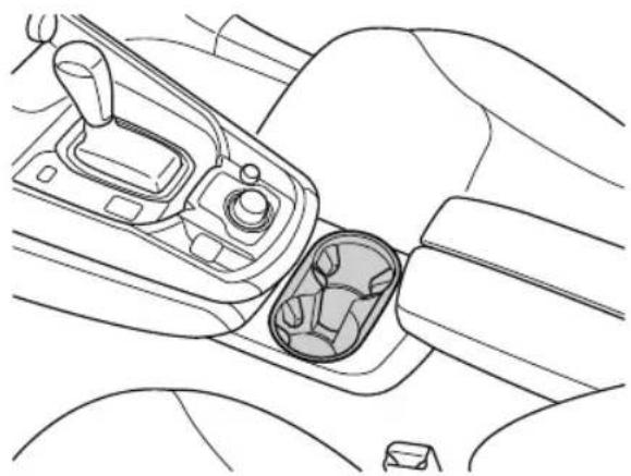
natural_image
Line drawing of a car gear shift lever and intake compartment (no text or symbols)▼ Rear
Second-row seat
Cup holders are located in the armrest/second-row seat console.
6:4 split adjustable-type bench seat type
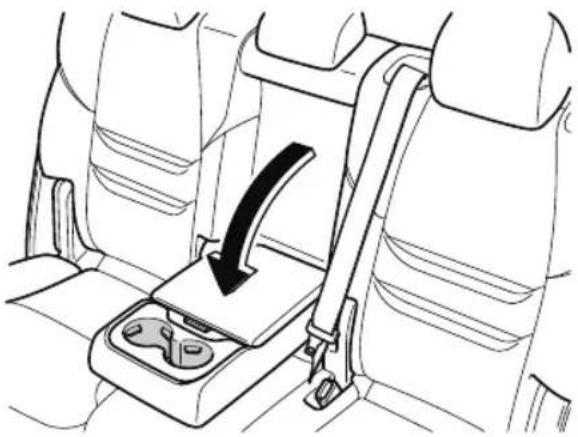
natural_image
Line drawing of a car seatbelt with a black arrow indicating the direction (no text or symbols)Captain seat and second-row seat console type
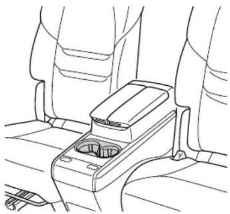
natural_image
Line drawing of a car seatbelt with no text or symbolsCaptain seat and walk through type
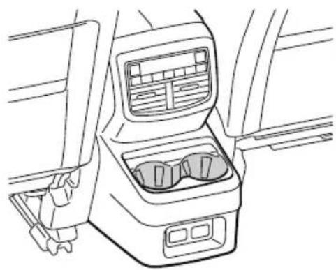
natural_image
Line drawing of a car interior showing dashboard, rear seats, and front panel (no text or symbols)Third-row seat
Cup holders are located in the third-row seat side trims.
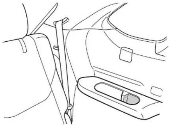
natural_image
Line drawing of a car's side view showing the seatbelt and dashboard (no text or symbols)Bottle Holder
Bottle holders are on the inside of the doors.
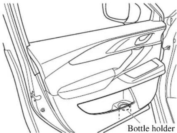

CAUTION
Do not use the bottle holders for containers without caps. The contents may spill when opening/closing the door or while driving the vehicle.
Storage Compartments

WARNING
Keep storage boxes closed when driving:
Driving with the storage boxes open is dangerous. To reduce the possibility of injury in an accident or a sudden stop, keep the storage boxes closed when driving.
When loading cargo, make sure that it is completely secured:
If the cargo is not completely secured, it may move or collapse while driving or during sudden braking, resulting in injury or an accident.
Do not put articles in storage spaces with no lid:
Putting articles in storage spaces with no lid is dangerous as they could be thrown around the cabin if the vehicle is suddenly accelerated and cause injury depending on how the article is stored.

CAUTION
Do not leave lighters or eyeglasses in the storage boxes while parked under the sun. A lighter could explode or the plastic material in eyeglasses could deform and crack from high temperature.

Overhead Console
This console box is designed to store eyeglasses or other accessories.
Push and release to open.
Type A
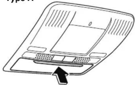
natural_image
Diagram of a device rear panel with ventilation grilles and a directional arrow indicating left vent (no text or symbols)Type B
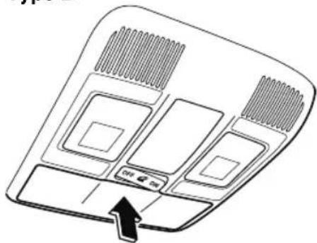
natural_image
Diagram of a ceiling-mounted air conditioner unit with ventilation grilles and a directional arrow indicating airflow (no text or symbols)▼ Glove Compartment
To open the glove compartment, pull the latch toward you.
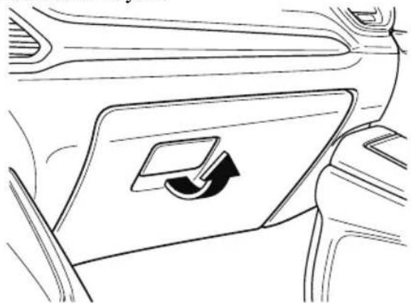
natural_image
Diagram of a car interior showing a directional arrow inside a vehicle's side panel (no text or symbols)To close the glove compartment, firmly press in the center of the glove compartment lid.
▼ Center Console
To open, push the button.
Front
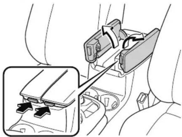
natural_image
Diagram of a car interior showing a mechanical device with directional arrows indicating movement or force (no text or symbols present)Rear*
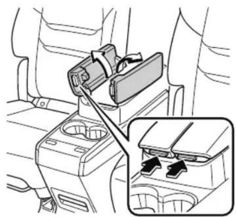
natural_image
Interior view of a car showing a seatbelt switch and gear shift mechanism (no text or symbols)▼ (Second-row Seat Console Box with Armrest) Storage Box*

CAUTION
Store the armrests when the storage box is not in use. Otherwise, your foot might get caught when changing seats and fall down resulting in injury.
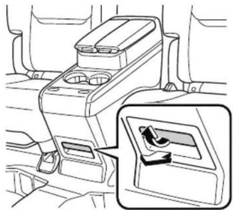
natural_image
Interior view of a car headrest with a highlighted internal compartment showing a scroll wheel (no text or symbols)
Armrest Box\*
To open, push the button and pull up the lid.
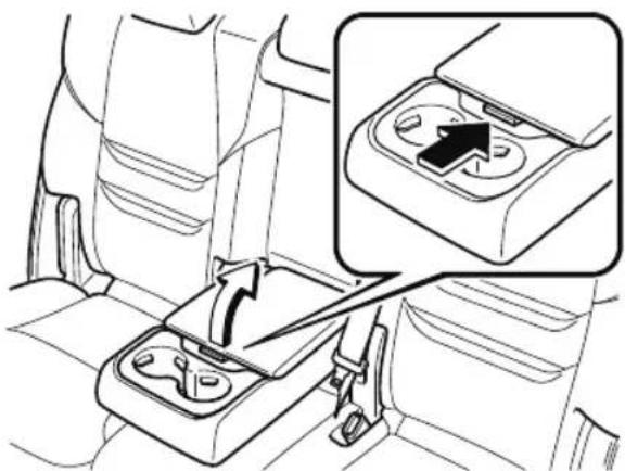
natural_image
Interior view of a car seatbelt with a highlighted internal component (no text or symbols)▼ Luggage Compartment
Cargo Securing Loops
Use the loops in the luggage compartment to secure cargo with a rope or net. The tensile strength of the loops is 196 N (20 kgf, 44 lbf). Do not apply excessive force to the loops as it will damage them.
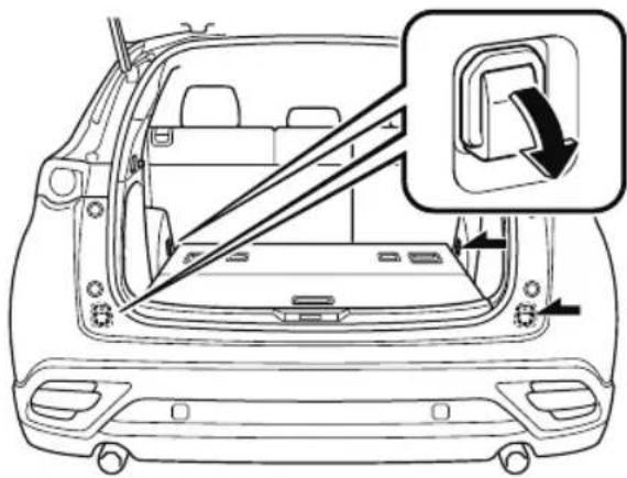
Cargo Sub-Compartment
Center cargo sub-compartment\*
Raise the luggage board to put small items in the cargo sub-compartment.
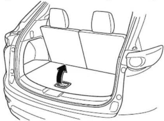
natural_image
Line drawing of a car backrest with a black arrow indicating the rear side panel (no text or symbols)Side cargo sub-compartment
Open the cover to put small items in the cargo sub-compartment.
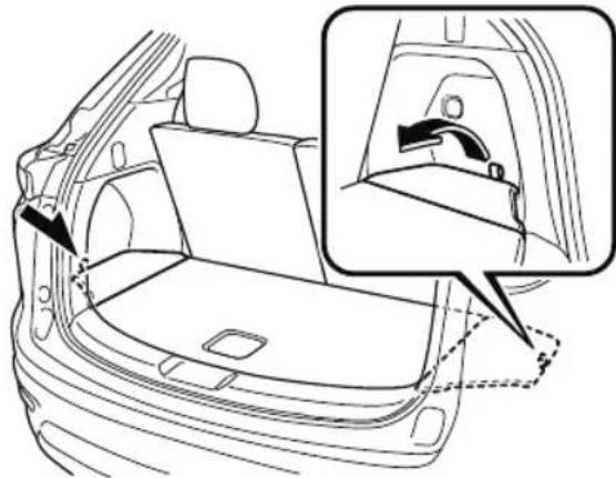
natural_image
Line drawing of a car rear bumper with an inset showing the side panel and handle (no text or symbols)NOTE
Loading golf bags
(Some golf bags may not fit using the following methods depending on their sizes.)
Up to two golf bags can be carried in the luggage compartment.
Bottom: Place the first golf bag in the luggage compartment with the bottoms pointed to the left.
Top: Place the second golf bag with its bottom pointed to the right in the luggage compartment.
Bottom
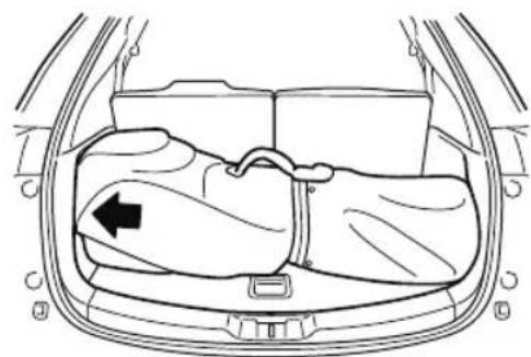
natural_image
Line drawing of a car backrest with a seatbelt and seatbelt, showing no text or symbolsTop
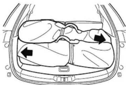
natural_image
Diagram of a car interior showing internal compartments with arrows indicating movement or force (no text or symbols)The arrows indicate the bottoms of the golf bags.
▼ Shopping Bag Hook
The shopping bag hook can be used for hanging shopping bags.
CAUTION
Do not hang excessive weight on the shopping bag hook as it could be damaged.
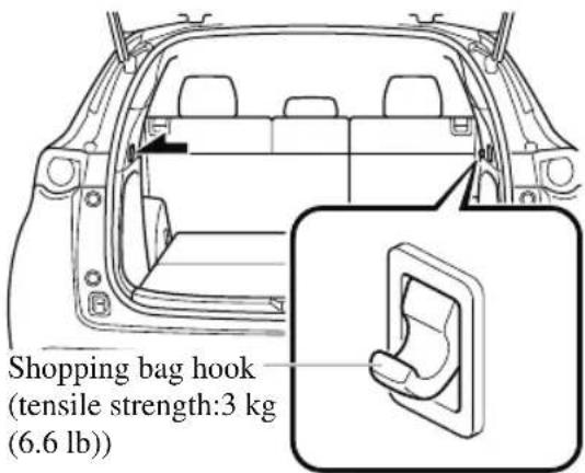
▼ Rear Coat Hooks
WARNING
Never hang heavy or sharp objects on the assist grips and coat hooks:
Hanging heavy or sharp-ended objects such as a coat hanger from the assist grips or coat hooks is dangerous as they can fly off and hit an occupant in the cabin if a curtain air bag was to deploy, which could result in serious injury or death.
Always hang clothes on the coat hooks and the assist grips without hangers.
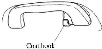
Sunshade (Rear Door Window) \*
The sunshades are equipped to the windows on both sides of the second-row seats.
Hold the tab and pull the sunshade upward and hook the slots.
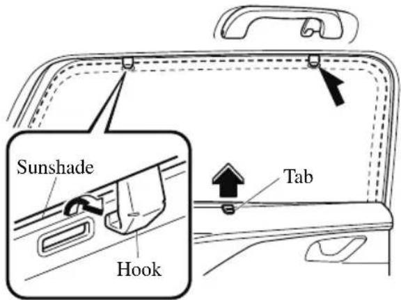
To return the sunshade to its original position, unhook the sunshade and retract it slowly.
CAUTION
➢ Securely hook the sunshade. Otherwise, the sunshade may retract suddenly resulting in injury such as fingers get pinched.
➢Use the sunshades only when the windows are fully closed. Using a sunshade while a window is open could cause is to unhook and flap around inside the cabin where it can hit someone sitting near the window, resulting in injury.
6
Maintenance and Care
How to keep your Mazda in top condition.
Essential Information......6-2
Introduction...... 6-2
Scheduled Maintenance...... 6-4
Scheduled Maintenance (U.S.A., Canada, and Puerto Rico)......6-4
Scheduled Maintenance
(Mexico)...... 6-10
Owner Maintenance......6-15
Owner Maintenance
Precautions.... 6-15
Hood....6-17
Engine Compartment
Overview.... 6-19
Engine Oil....6-20
Engine Coolant.... 6-22
Brake Fluid.... 6-23
Washer Fluid....6-24
Body Lubrication......6-25
Wiper Blades.... 6-25
Battery.... 6-30
Key Battery Replacement......6-32
Tires.... 6-34
Light Bulbs.... 6-38
Fuses.... 6-46
Appearance Care......6-52
Exterior Care.... 6-52
Interior Care....6-58
Introduction
Be careful not to hurt yourself when inspecting your vehicle, replacing a tire, or doing some kind of maintenance such as car washing. In particular, wear thick work gloves such as cotton gloves when touching areas that are difficult to see while inspecting or working on your vehicle. Doing inspections or procedures with your bare hands could cause injury.
If you are unsure about any procedure this manual describes, we strongly urge you to have a reliable and qualified service shop perform the work, preferably an Authorized Mazda Dealer.
Factory-trained Mazda technicians and genuine Mazda parts are best for your vehicle. Without this expertise and the parts that have been designed and made especially for your Mazda, inadequate, incomplete, and insufficient servicing may result in problems. This could lead to vehicle damage or an accident and injuries.
For expert advice and quality service, consult an Authorized Mazda Dealer.
To continue warranty eligibility and to protect your investment, it is your responsibility to properly maintain your vehicle according to factory recommended schedules outlined in this manual. As part of this you must keep your maintenance records, receipts, repair orders and any other documents as evidence this maintenance was performed. You must present these documents, should any warranty coverage disagreement occur. Failure to do so can result in your warranty being voided either in whole or in part.
This evidence may consist of the following:
- The Mazda Scheduled Maintenance Record, refer to the Warranty Booklet, must be completely filled out showing mileage, repair order number, date for each service, and signed by a qualified automotive service technician who service vehicles.
- Original copies of repair orders or other receipts that include the mileage and date the vehicle was serviced. Each receipt should be signed by a qualified automotive service technician.
- For self maintenance, a statement that you completed the maintenance yourself, displaying mileage and the date the work was performed. Also, receipts for the replacement parts (fluid, filters, etc.) indicating the date and mileage must accompany this statement.
NOTE
If you elect to perform maintenance yourself or have your vehicle serviced at a location other than an Authorized Mazda Dealer, Mazda requires that all fluids, parts and materials must meet Mazda standards for durability and performance as described in this manual.
Claims against the warranty resulting from lack of maintenance, as opposed to defective materials or authorized Mazda workmanship, will not be honored.
Any auto repair shop using parts equivalent to your Mazda's original equipment may perform maintenance. But we recommend that it always be done by an Authorized Mazda Dealer using genuine Mazda parts.
Selecting “Maintenance Monitor” enables the system to notify you of your vehicle's approaching inspection/servicing period, refer to the Information section in the Mazda Connect Owner's Manual for the details.
The malfunction diagnosis connector is designed exclusively for connecting the specially designed device to perform on-board diagnosis.
Do not connect any devices other than the specially designed malfunction diagnosis devices for servicing. If any device other than the malfunction diagnosis device is connected, it may affect the vehicle's electrical devices or lead to damage such as battery depletion.
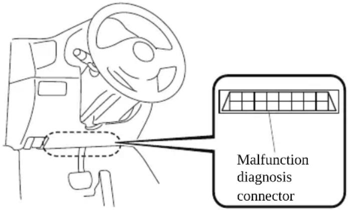
Scheduled Maintenance (U.S.A., Canada, and Puerto Rico)
Follow Schedule 1 if the vehicle is operated mainly where none of the following conditions (severe driving conditions) apply.
• Repeated short-distance driving
- Driving in dusty conditions
- Driving with extended use of brakes
- Driving in areas where salt or other corrosive materials are used
- Driving on rough or muddy roads
- Extended periods of idling or low-speed operation
- Driving for long periods in cold temperatures or extremely humid climates
. Driving in extremely hot conditions
- Driving in mountainous conditions continually
If any do apply, follow Schedule 2. (Canada residents follow Schedule 2.)
Vehicles using Engine Oil Flexible Maintenance
Engine Oil Flexible Maintenance is selected by default for U.S.A. and Puerto Rico residents.
If any following conditions do apply, follow Schedule 2 with engine oil fixed maintenance.
- Extended periods of idling or low-speed operation such as police car, taxi or driving school car
- Driving in dusty conditions
The vehicle calculates the remaining oil life based on engine operating conditions. The vehicle lets you know when an oil change is due by illuminating the wrench indicator light in the instrument cluster. Change the oil as soon as possible within the next 1,000 km (600 mile) or 15 days. Refer to the Information section in the Mazda Connect Owner's Manual for the details.
NOTE
- Please ensure that the Flexible Oil Maintenance Setting is reset after each Oil and Filter replacement.
- For maintenance guidelines beyond the miles/months listed, follow the maintenance intervals provided in the Scheduled Maintenance Tables.
▼ Schedule 1
U.S.A. and Puerto Rico residents - Engine oil flexible maintenance interval
Use when the maintenance monitor for "Oil Change" is set to "Flexible". For the details, refer to the Information section in the Mazda Connect Owner's Manual.
| Maintenance Interval | Number of months or kilometers (miles), whichever comes first. | ||||||||
| Months 12 | 24 36 48 | 60 72 | 84 96 | ||||||
| ×1000 km 12 | 24 36 | 48 60 72 | 84 96 | ||||||
| ×1000 miles | 7.5 15 22 | 2.5 30 37 | 7.5 45 52 | 2.5 60 | |||||
| Spark plugs Replace every 64,000 km (40,000 miles). | |||||||||
| Air filter R R | |||||||||
| Drive belts I I | |||||||||
| Engine oil & filter^*1 | Replace when wrench indicator light is ON. (Max interval:12 months or 12,000 km (7,500 miles)) | ||||||||
| Engine coolant ^*2 | Replace at first 192,000 km (120,000 miles) or 10 years; after that, every 96,000 km (60,000 miles) or 5 years. | ||||||||
| Fuel lines and hoses^*3 | I | I | I | I | |||||
| Hoses and tubes for emission ^*3 | I | I | |||||||
| Brake lines, hoses and connections I I I | |||||||||
| D i s c b | r | a | k | e | s | I | I | ||
| Tire (Rotation) | Rotate every 12,000 km (7,500 miles). | ||||||||
| Steering operation and linkages | I I I I | ||||||||
| Front and rear suspension, ball joints and wheel bearing axial play | I | I | I | I | |||||
| Driveshaft dust boots | I I I I | ||||||||
| Bolts and nuts on chassis and body | T | T | T | T | |||||
| Exhaust system and heat shields | I | ||||||||
| Emergency flat tire repair kit (if equipped) ^*4 | Inspect annually. | ||||||||
| Cabin air filter | R | R | R | R | |||||
Chart symbols:
I: Inspect: Inspect and clean, repair, adjust, fill up, or replace if necessary.
R: Replace
L: Lubricate
C: Clean
T: Tighten
D: Drain
Remarks:
* 1 The engine oil and filter must be changed at least once a year or within 12,000 km (7,500 miles) since last engine oil and filter change. Reset the engine oil data whenever replacing the engine oil regardless of the message/wrench indicator light display.
*2 Use of FL-22 is recommended when replacing engine coolant. Using engine coolant other than FL-22 may cause serious damage to the engine and cooling system.
*3 According to state/provincial and federal regulations, failure to perform maintenance on these items will not void your emissions warranties. However, Mazda recommends that all maintenance services be performed at the recommended time or mileage/kilometer period to ensure long-term reliability.
*4 Check the tire repair fluid expiration date every year when performing the periodic maintenance. Replace the tire repair fluid bottle with new one before the expiration date.
▼ Schedule 2
U.S.A. and Puerto Rico residents - Severe driving conditions maintenance interval
| Maintenance Interval | Number of months or kilometers (miles), whichever comes first. | ||||||||||||
| M o n | t | h s | 6 | 1 | 2 | 1 | 8 | 2 | 4 | 3 | 0 3 6 | ||
| ×1000 km 8 | 16 24 | 32 40 | 48 | 56 64 | 72 80 | 88 | 96 | ||||||
| ×1000 miles 5 | 10 1 | 5 20 | 25 30 | 35 40 | 45 | 50 55 | 60 | ||||||
| Spark plugs Replace every 64,000 km (40,000 miles). | |||||||||||||
| Air filter*1 | R | R | |||||||||||
| Drive belts I I I | |||||||||||||
| Engine oil & filter | Flexible*2 | Replace when wrench indicator light is ON. (Max interval:12 months or 12,000 km (7,500 miles)) | |||||||||||
| Fixed*3 | R | R | R | R | R | R | R | R | R | R | R | R | |
| Engine coolant*4 | Replace at first 192,000 km (120,000 miles) or 10 years; after that, every 96,000 km (60,000 miles) or 5 years. | ||||||||||||
| E n g i n e c o | o | l | a | n | t | l | e | v | e | l | |||
| Fuel lines and hoses*5 | I | I | I | I | |||||||||
| Hoses and tubes for emission*5 | I | I | |||||||||||
| F u n c t i o n | o | f | a | l | l | l | i | g | h | t | |||
| Brake lines, hoses and connections | I | I | I | I | |||||||||
| Brake and clutch fluid level | I | I | I | I | I | I | I | I | I | I | I | I | |
| D i s c b r a k | e | s | I | I | I | I | |||||||
| Tire (Rotation) | Rotate every 8,000 km (5,000 miles). | ||||||||||||
| T i r e i n f l a | t | i | o | n | p | r | c | s | s | u | |||
| Steering operation and linkages | I | I | I | I | |||||||||
| Front and rear suspension, ball joints and wheel bearing axial play | I | I | I | I | |||||||||
| Driveshaft dust boots | I | I | I | I | |||||||||
| Bolts and nuts on chassis and body | T | T | T | T | |||||||||
| Exhaust system and heat shields | I | ||||||||||||
| All locks and hinges | L | L | L | L | L | L | L | L | L | L | L | L | |
| W a s h e r f l u | i | d | l | c | v | c | l | ||||||
| Emergency flat tire repair kit (if equipped)*6 | Inspect annually. | ||||||||||||
4 2 4 8
s
I I I
r e
I I
| Maintenance Interval | Number of months or kilometers (miles), whichever comes first. | |||||||||||||
| M o n | t | h s | 6 | 1 | 2 | 1 8 | 2 | 4 | 3 | 0 | 3 | 6 | ||
| × 1 0 0 0 | k m | 8 | 1 | 6 | 2 | 4 | 3 | 2 | 4 | 0 | 2 | |||
| ×1000 miles 5 | 10 1 | 5 20 | 25 30 | 35 40 | 45 | 50 55 | 60 | |||||||
| Cabin air filter Replace every 40,000 km (25,000 miles) or 2 years. | ||||||||||||||
Chart symbols:
I: Inspect: Inspect and clean, repair, adjust, fill up, or replace if necessary.
R: Replace
L: Lubricate
C: Clean
T: Tighten
D: Drain
Remarks:
* 1 If the vehicle is operated in very dusty or sandy areas, clean and if necessary, replace the air filter more often than the recommended intervals.
*2 Engine oil flexible maintenance is available for U.S.A. and Puerto Rico residents whose vehicle is operated mainly where none of the following conditions apply.
- Extended periods of idling or low-speed operation such as police car, taxi or driving school car
- Driving in dusty conditions
If any do apply, follow fixed maintenance.
The engine oil and filter must be changed at least once a year or within 12,000 km (7,500 miles) since last engine oil and filter change. Reset the engine oil data whenever replacing the engine oil regardless of the message/wrench indicator light display.
*3 Reset the engine oil data whenever replacing the engine oil regardless of the message/wrench indicator light display.
*4 Use of FL-22 is recommended when replacing engine coolant. Using engine coolant other than FL-22 may cause serious damage to the engine and cooling system.
*5 According to state/provincial and federal regulations, failure to perform maintenance on these items will not void your emissions warranties. However, Mazda recommends that all maintenance services be performed at the recommended time or mileage/kilometer period to ensure long-term reliability.
*6 Check the tire repair fluid expiration date every year when performing the periodic maintenance. Replace the tire repair fluid bottle with new one before the expiration date.
Canada residents
| Maintenance Interval | Number of months or kilometers (miles), whichever comes first. | ||||||||||||
| M o n | t | h s | 6 | 1 | 2 | 1 8 | 2 | 4 | 3 | 0 | 3 | ||
| × 1 0 0 | 0 | k m | 8 | 1 | 6 | 2 | 4 | 3 | 2 | 4 | |||
| ×1000 miles | 5 | 10 1 | 5 20 | 25 30 | 35 40 | 45 | 50 55 | 60 | |||||
| Spark plugs | Replace every 64,000 km (40,000 miles). | ||||||||||||
| Air filter | I | I | I | I | I | I | I | I | I | I | I | I | |
| Replace every 56,000 km (35,000 miles) or 3 years. | |||||||||||||
| Drive belts | I | I | |||||||||||
| Maintenance Interval | Number of months or kilometers (miles), whichever comes first. | |||||||||||
| M o n | t | h s | 6 | 1 | 2 | 1 8 | 2 | 4 | 3 0 | 3 6 | ||
| ×1000 km 8 | 16 24 | 32 40 | 48 | 56 64 | 72 80 | 88 | 96 | |||||
| ×1000 miles 5 | 10 15 | 20 25 | 30 | 35 40 | 45 | 50 | 55 | 60 | ||||
| Engine oil & filter*1 | R | R | R | R | R | R | R | R | R | R | R | |
| Engine coolant*2 | Replace at first 192,000 km (120,000 miles) or 10 years; after that, every 96,000 km (60,000 miles) or 5 years. | |||||||||||
| E n g i n e c o | o | l | a | n | t | l | e | v | e | l | ||
| Fuel lines and hoses*3 | I | I | ||||||||||
| Hoses and tubes for emission*3 | I | |||||||||||
| F u n c t i o n | o | f | a | l | l | l | i | g | h | |||
| Brake lines, hoses and connections I | I | I | ||||||||||
| Brake and clutch fluid level | I | I | I | I | I | I | I | I | I | I | I | |
| Disc brakes | Inspect every 24,000 km (15,000 miles) or 1 year. | |||||||||||
| Tire (Rotation) | Rotate every 8,000 km (5,000 miles). | |||||||||||
| T i r e i n f l a | t | i | o | n | p | r | e | s | s | u | ||
| Steering operation and linkages | I | I | ||||||||||
| Front and rear suspension, ball joints and wheel bearing axial play | I | I | ||||||||||
| Driveshaft dust boots | I | I | ||||||||||
| Bolts and nuts on chassis and body | T | T | ||||||||||
| Exhaust system and heat shields | Inspect every 72,000 km (45,000 miles) or 5 years. | |||||||||||
| All locks and hinges | L | L | L | L | L | L | L | L | L | L | L | |
| Wa s h e r f l u | i | d | l | e | v | e | l | |||||
| Emergency flat tire repair kit (if equipped)*4 | Inspect annually. | |||||||||||
| Cabin air filter | Replace every 40,000 km (25,000 miles) or 2 years. | |||||||||||
Chart symbols:
I: Inspect: Inspect and clean, repair, adjust, fill up, or replace if necessary.
R: Replace
L: Lubricate
C: Clean
T: Tighten
D: Drain
Remarks:
*1 Reset the engine oil data whenever replacing the engine oil regardless of the message/wrench indicator light display.
* 2 Use of FL-22 is recommended when replacing engine coolant. Using engine coolant other than FL-22 may cause serious damage to the engine and cooling system.
*3 According to state/provincial and federal regulations, failure to perform maintenance on these items will not void your emissions warranties. However, Mazda recommends that all maintenance services be performed at the recommended time or mileage/kilometer period to ensure long-term reliability.
*4 Check the tire repair fluid expiration date every year when performing the periodic maintenance. Replace the tire repair fluid bottle with new one before the expiration date.
Scheduled Maintenance (Mexico)
Follow Schedule 1 if the vehicle is operated mainly where none of the following conditions (severe driving conditions) apply.
• Repeated short-distance driving
. Driving in dusty conditions
- Driving with extended use of brakes
- Driving in areas where salt or other corrosive materials are used
- Driving on rough or muddy roads
- Extended periods of idling or low-speed operation
- Driving for long periods in cold temperatures or extremely humid climates
- Driving in extremely hot conditions
- Driving in mountainous conditions continually
If any do apply, follow Schedule 2.
NOTE
For maintenance guidelines beyond the kilometers/months listed, follow the maintenance intervals provided in the Scheduled Maintenance Tables.
▼ Schedule 1
| Maintenance Interval | Number of months or kilometers, whichever comes first | ||||||||||||
| M o n | t | h s | 6 | 1 | 2 | 1 8 | 2 | 4 | 3 0 | 3 | 6 | ||
| × 1 0 0 | 0 | k m | 1 | 0 | 2 0 | 3 | 0 | 4 0 | 5 | 0 | |||
| Drive belts I I I | |||||||||||||
| Engine oil & filter*1 | R | R | R | R | R | R | R | R | R | R | R | R | |
| Cooling system I I I | |||||||||||||
| Engine coolant*2 | Replace at first 200,000 km or 10 years; after that, every 100,000 km or 5 years | ||||||||||||
| Air filter R R R R | R | R | |||||||||||
| Fuel lines and hoses | I*3 | I*3 | I | ||||||||||
| Hoses and tubes for emission | I*3 | I*3 | I | ||||||||||
| Fuel filter | Replace every 60,000 km | ||||||||||||
| Spark plugs | I | I | I | I | I | I | I | I | I | I | I | I | |
| Replace every 64,000 km | |||||||||||||
| Brake lines, hoses and connections | I | I | I | I | I | I | |||||||
| Brake and clutch fluid level | I | I | I | I | I | I | I | I | I | ||||
| Brake fluid | R | R | R | ||||||||||
| Disc brakes | I | I | I | I | I | I | I | I | I | I | I | I | |
| Tire (Rotation) | Rotate every 10,000 km | ||||||||||||
4 2 4 8
6 0 7 0 8
| Maintenance Interval | Number of months or kilometers, whichever comes first | ||||||||||||
| M o n | t | h s | 6 | 1 | 2 | 1 8 2 | 4 | 3 0 3 | 6 | ||||
| ×1000 km 10 | 20 3 | 0 40 | 50 60 | 70 80 | 90 | 100 1 | 10 120 | ||||||
| T i r e i n f l a | t | i | o | n | p | r | c | s | s | u | |||
| Steering operation and linkages I I I I I I I I I I I | |||||||||||||
| Front and rear suspension, ball joints and wheel bearing axial play | I | I | I | I | I | I | |||||||
| Driveshaft dust boots | I | I | I | I | I | I | |||||||
| Bolts and nuts on chassis and body | T | T | T | T | T | T | |||||||
| Exhaust system and heat shields | I | I | I | I | I | I | |||||||
| All locks and hinges | L | L | L | L | L | L | L | L | L | L | L | L | |
| Wa s h e r f l u | i | d | l | e | v | e | l | ||||||
| Emergency flat tire repair kit (if equipped)*4 | Inspect annually. | ||||||||||||
| Cabin air filter | R | R | R | ||||||||||
Chart symbols:
I: Inspect: Inspect and clean, repair, adjust, fill up, or replace if necessary.
R: Replace
L: Lubricate
C: Clean
T: Tighten
D: Drain
Remarks:
*1 Reset the engine oil data whenever replacing the engine oil regardless of the message/wrench indicator light display.
* 2 Use of FL-22 is recommended when replacing engine coolant. Using engine coolant other than FL-22 may cause serious damage to the engine and cooling system.
*3 According to state/provincial and federal regulations, failure to perform maintenance on these items will not void your emissions warranties. However, Mazda recommends that all maintenance services be performed at the recommended time or kilometer period to ensure long-term reliability.
*4 Check the tire repair fluid expiration date every year when performing the periodic maintenance. Replace the tire repair fluid bottle with new one before the expiration date.
▼ Schedule 2
| Maintenance Interval | Number of months or kilometers, whichever comes first | ||||||||||||
| Months | 3 | 6 | 9 | 12 | 15 | 18 | 21 | 24 | 27 | 30 | 33 | 36 | |
| × 1 0 0 0 | k m | 5 | 1 | 0 | 1 5 2 | 0 | 2 5 3 | ||||||
| Drive belts | I | ||||||||||||
| Engine oil & filter*1 | R | R | R | R | R | R | R | R | R | R | R | R | |
| Cooling system | I | ||||||||||||
| Engine coolant*2 | Replace at first 200,000 km or 10 years; after that, every 100,000 km or 5 years | ||||||||||||
| E n g i n c c o | o | l | a | n | t | l | c | v | c | l | |||
| Air filter CRCRCR | |||||||||||||
| Fuel lines and hoses | I^*3 | ||||||||||||
| Hoses and tubes for emission | I^*3 | ||||||||||||
| Fuel filter Replace every 60,000 km | |||||||||||||
| Spark plugs | I | I | I | I | I | I | |||||||
| Replace every 64,000 km | |||||||||||||
| F u n c t i o n | o | f | a | l | l | l | i | g | h | t | |||
| Brake lines, hoses and connections | I | I | I | ||||||||||
| Brake and clutch fluid level | I | I | I | I | I | ||||||||
| Brake fluid | R | ||||||||||||
| Disc brakes | I | I | I | I | I | I | |||||||
| Tire (Rotation) | Rotate every 10,000 km | ||||||||||||
| Tire inflation pressure and tire wear | I | I | I | I | I | I | |||||||
| Steering operation and linkages | I | I | I | I | I | I | |||||||
| Front and rear suspension, ball joints and wheel bearing axial play | I | I | I | ||||||||||
| Driveshaft dust boots | I | I | I | ||||||||||
| Bolts and nuts on chassis and body | T | T | T | ||||||||||
| Exhaust system and heat shields | I | I | I | ||||||||||
| All locks and hinges | L | L | L | L | L | L | |||||||
| Washer fluid level | I | I | I | I | I | I | |||||||
| Emergency flat tire repair kit (if equipped)*4 | Inspect annually. | ||||||||||||
| Cabin air filter | R | R | R | ||||||||||
Chart symbols:
I: Inspect: Inspect and clean, repair, adjust, fill up, or replace if necessary.
R: Replace
L: Lubricate
C: Clean
T: Tighten
D: Drain
Remarks:
*1 Reset the engine oil data whenever replacing the engine oil regardless of the message/wrench indicator light display.
*2 Use of FL-22 is recommended when replacing engine coolant. Using engine coolant other than FL-22 may cause serious damage to the engine and cooling system.
*3 According to state/provincial and federal regulations, failure to perform maintenance on these items will not void your emissions warranties. However, Mazda recommends that all maintenance services be performed at the recommended time or kilometer period to ensure long-term reliability.
* 4 Check the tire repair fluid expiration date every year when performing the periodic maintenance. Replace the tire repair fluid bottle with new one before the expiration date.
(Cont.)
| Maintenance Interval | Number of months or kilometers, whichever comes first | ||||||||||||
| Months 39 | 42 45 | 48 5 | 1 54 | 57 60 | 63 6 | 6 69 | 72 | ||||||
| ×1000 km 65 | 70 | 75 80 | 85 90 | 95 10 | 100 10 | 15 110 | 115 | 120 | |||||
| Drive belts I I | |||||||||||||
| Engine oil & filter*1 | R | R | R | R | R | R | R | R | R | R | R | R | |
| Cooling system I I | |||||||||||||
| Engine coolant*2 | Replace at first 200,000 km or 10 years; after that, every 100,000 km or 5 years | ||||||||||||
| E n g i n e c o | o | l | a | n | t | l | e | v | e | l | |||
| A i r f | i | l | t | e | r | ||||||||
| Fuel lines and hoses | I*3 | I | |||||||||||
| Hoses and tubes for emission | I*3 | I | |||||||||||
| Fuel filter | Replace every 60,000 km | ||||||||||||
| Spark plugs | I | I | I | I | I | I | |||||||
| Replace every 64,000 km | |||||||||||||
| Function of all lights | I | I | I | I | I | I | I | I | I | I | I | I | |
| Brake lines, hoses and connections | I | I | I | ||||||||||
| Brake and clutch fluid level | I | I | I | I | |||||||||
| Brake fluid | R | R | |||||||||||
| Disc brakes | I | I | I | I | I | I | |||||||
| Tire (Rotation) | Rotate every 10,000 km | ||||||||||||
| Tire inflation pressure and tire wear | I | I | I | I | I | I | |||||||
| Steering operation and linkages | I | I | I | I | I | I | |||||||
| Front and rear suspension, ball joints and wheel bearing axial play | I | I | I | ||||||||||
| Driveshaft dust boots | I | I | I | ||||||||||
| Bolts and nuts on chassis and body | T | T | T | ||||||||||
| Exhaust system and heat shields | I | I | I | ||||||||||
| All locks and hinges | L | L | L | L | L | L | |||||||
| Washer fluid level | I | I | I | I | I | I | |||||||
| Emergency flat tire repair kit (if equipped)*4 | Inspect annually. | ||||||||||||
| Cabin air filter | R | R | R | ||||||||||
I I
Chart symbols:
I: Inspect: Inspect and clean, repair, adjust, fill up, or replace if necessary.
R: Replace
L: Lubricate
C: Clean
T: Tighten
D: Drain
Remarks:
* 1 Reset the engine oil data whenever replacing the engine oil regardless of the message/wrench indicator light display.
*2 Use of FL-22 is recommended when replacing engine coolant. Using engine coolant other than FL-22 may cause serious damage to the engine and cooling system.
*3 According to state/provincial and federal regulations, failure to perform maintenance on these items will not void your emissions warranties. However, Mazda recommends that all maintenance services be performed at the recommended time or kilometer period to ensure long-term reliability.
*4 Check the tire repair fluid expiration date every year when performing the periodic maintenance. Replace the tire repair fluid bottle with new one before the expiration date.
The owner or a qualified service technician should make these vehicle inspections at the indicated intervals to ensure safe and dependable operation.
Bring any problem to the attention of an Authorized Mazda Dealer or qualified service technician as soon as possible.
When Refueling
- Brake fluid level (page 6-23)
• Engine coolant level (page 6-22)
• Engine oil level (page 6-21) - Washer fluid level (page 6-24)
At Least Monthly
. Tire inflation pressures (page 6-34)
At Least Twice a Year (For Example, Every Spring and Fall)
You can do the following scheduled maintenance items if you have some mechanical ability and a few basic tools and if you closely follow the directions in this manual.
• Engine coolant (page 6-22)
- Engine oil (page 6-20)
Improper or incomplete service may result in problems. This section gives instructions only for items that are easy to perform.
As explained in the Introduction (page 6-2), several procedures can be done only by a qualified service technician with special tools.
Improper owner maintenance during the warranty period may affect warranty coverage. Refer to Introduction (page 6-2) for owner's responsibility in protecting your investment. For details, read the separate Mazda Warranty statement provided with the vehicle. If you are unsure about any servicing or maintenance procedure, have it done by an Authorized Mazda Dealer.
There are strict environmental laws regarding the disposal of waste oil and fluids. Please dispose of your waste properly and with due regard to the environment.
We recommend that you entrust the oil and fluid changes of your vehicle to an Authorized Mazda Dealer.

WARNING
Do not perform maintenance work if you lacks sufficient knowledge and experience or the proper tools and equipment to do the work. Have maintenance work done by a qualified technician:
Performing maintenance work on a vehicle is dangerous if not done properly. You can be seriously injured while performing some maintenance procedures.
If you must run the engine while working under the hood, make certain that you remove all jewelry (especially rings, bracelets, watches, and necklaces) and all neckties, scarves, and similar loose clothing before getting near the engine or cooling fan which may turn on unexpectedly:
Working under the hood with the engine running is dangerous. It becomes even more dangerous when you wear jewelry, loose clothing or have long hair or a long beard. Either can become entangled in moving parts and result in injury.

Pull over to a safe location, then switch the ignition off and make sure the fan is not running before attempting to work near the cooling fan:
Working near the cooling fan when it is running is dangerous. The fan could continue running indefinitely even if the engine has stopped and the engine compartment temperature is high. You could be hit by the fan and seriously injured.
Do not leave items in the engine compartment:
After you have finished checking or doing servicing in the engine compartment, do not forget and leave items such as tools or rags in the engine compartment.
Tools or other items left in the engine compartment could cause engine damage or a fire leading to an unexpected accident.
Hood

WARNING
Always check that the hood is closed and securely locked:
A hood that is not closed and securely locked is dangerous as it could fly open while the vehicle is moving and block the driver's vision which could result in a serious accident.
▼ Opening the Hood
- With the vehicle parked, pull the release handle to unlock the hood.
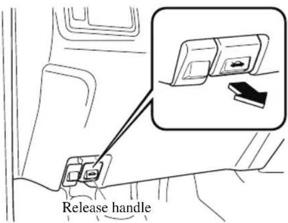
- Insert your hand into the hood opening, slide the latch lever to the right, and lift up the hood.
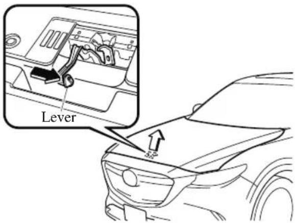
- Grasp the support rod in the padded area and secure it in the support rod hole indicated by the arrow to hold the hood open.
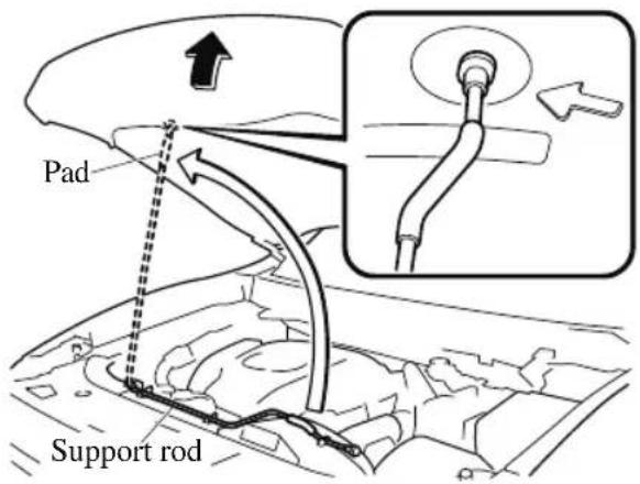
▼ Closing the Hood
- Check under the hood area to make certain all filler caps are in place and all loose items (e.g. tools, oil containers, etc.) have been removed.
- Lift the hood, grasp the padded area on the support rod, and secure the support rod in the clip. Verify that the support
rod is secured in the clip before closing the hood.
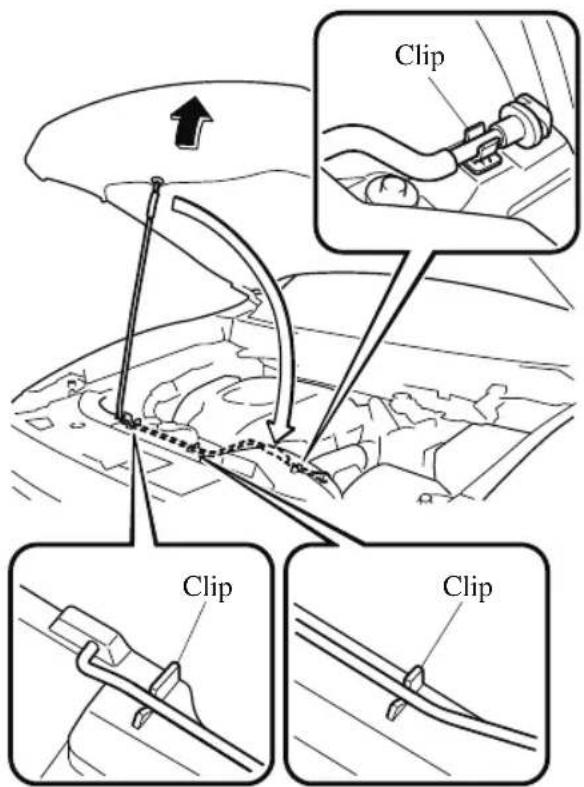
- Lower the hood slowly to a height of about 20 cm (7.9 in) above its closed position and then let it drop.
CAUTION
When closing the hood, do not push it excessively such as by applying your weight. Otherwise, the hood could be deformed.
Engine Compartment Overview
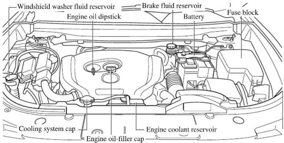
Owner Maintenance
NOTE
Changing the engine oil should be performed by an Authorized Mazda Dealer.
Refer to Introduction (page 6-2) for owner's responsibility in protecting your investment.
▼ Recommended Oil
U.S.A., Canada, and Puerto Rico
Use SAE 5W-30 engine oil.
Mazda Genuine Oil is used in your Mazda vehicle. Mazda Genuine 5W-30 Oil is required to achieve optimum fuel economy.
For maintenance service, Mazda recommends Mazda Genuine Parts and Oil.
Committee (ILSAC), comprised of U.S. and Japanese automobile manufacturers.
| -40 | -30 | -20 | -10 | 0 | 10 | 20 | 30 | 40 |
| -40 | -20 | 0 | 20 | 40 | 60 | 80 | 100 |
Except U.S.A., Canada, and Puerto Rico
Use SAE 5W-30 engine oil.
Oil container labels provide important information.
A chief contribution this type of oil makes to fuel economy is reducing the amount of fuel necessary to overcome engine friction.
For maintenance service, Mazda recommends Mazda Genuine Parts.
(ILSAC)
(ILSAC)
Only use SAE 5W-30 oil “Certified For Gasoline Engines” by the American Petroleum Institute (API). Oil with this trademark symbol conforms to the current engine and emission system protection standards and fuel economy requirements of the International Lubricant Standardization and Approval
(Mexico)
Use SAE 5W-30 engine oil. If SAE 5W-30 engine oil is not available, use SAE 0W-30 or SAE 10W-30 engine oil.
The quality designation SM or SN, or ILSAC must be on the label.
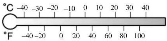
5W-30
▼ Vehicle Engine Control Unit Reset Procedure
After replacing the engine oil, it is recommended to have a repair shop such as an Authorized Mazda Dealer perform the initialization (engine oil data resetting) of the recorded value. If the value recorded by the computer is not initialized, the wrench indicator light may not turn off or it may turn on earlier than normal. For the details, refer to the Information section in the Mazda Connect Owner's Manual.
▼ Inspecting Engine Oil Level
- Be sure the vehicle is on a level surface.
- Warm up the engine to normal operating temperature.
-
Turn it off and wait at least 5 minutes for the oil to return to the oil pan.
-
Pull out the dipstick, wipe it clean, and reinsert it fully.
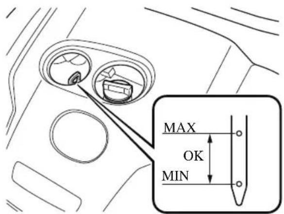
- Pull it out again and examine the level. The level is normal if it is between the MIN and MAX marks. If it is near or below MIN, add enough oil to bring the level to MAX.

CAUTION
Do not overfill the engine oil. This may cause engine damage.
-
Make sure the O-ring on the dipstick is positioned properly before reinserting the dipstick.
-
Reinsert the dipstick fully.
Engine Coolant
▼ Inspecting Coolant Level

WARNING
Do not use a match or live flame in the engine compartment. DO NOT ADD COOLANT WHEN THE ENGINE IS HOT:
A hot engine is dangerous. If the engine has been running, parts of the engine compartment can become very hot. You could be burned. Carefully inspect the engine coolant in the coolant reservoir, but do not open it.

Pull over to a safe location, then switch ignition off and make sure the fan is running before attempting to work or the cooling fan:
Working near the cooling fan when it is running is dangerous. The fan could continue running indefinitely even if the engine has stopped and the engine compartment temperature is high. You could be hit by the fan and seriously injured.
Do not remove either cooling
system cap when the engine and radiator are hot:
When the engine and radiator are hot, scalding coolant and steam may shoot out under pressure and cause serious injury.
NOTE
Changing the coolant should be done by an Authorized Mazda Dealer.
Inspect the antifreeze protection and coolant level in the coolant reservoir at least once a year—at the beginning of the winter season—and before traveling where temperatures may drop below freezing.
Inspect the condition and connections of all cooling system and heater hoses.
Replace any that are swollen or deteriorated.
The coolant should be at full in the radiator and between the F and L marks on the coolant reservoir when the engine is cool.
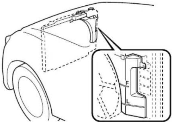
natural_image
Technical line drawing of a car's front and side views, showing structural components (no text or symbols)If it is at or near L, add enough coolant to the coolant reservoir to provide freezing and corrosion protection and to bring the level to F.
Securely tighten the coolant reservoir tank cap after adding coolant.

CAUTION
➢Radiator coolant will damage paint. Rinse it off quickly if spilled.
If the "FL22" mark is shown on or near the cooling system cap, use of FL-22 is recommended when replacing engine coolant. Using engine coolant other than FL-22 may cause serious damage to the engine and cooling system.
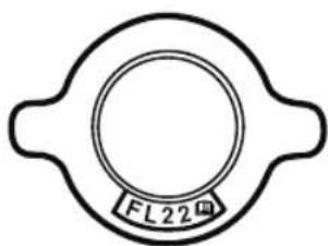
FL22
If the coolant reservoir is empty or new coolant is required frequently, consult an Authorized Mazda Dealer.
Brake Fluid
▼ Inspecting Brake Fluid Level

WARNING
If the brake fluid level is low, have the brakes inspected:
A low brake fluid level is dangerous. A low level could indicate brake lining wear or a brake system leak which could cause the brakes to fail and lead to an accident.
Inspect the fluid level in the reservoir regularly. It should be kept between the MAX and MIN lines.
The level normally drops with accumulated distance, a condition associated with wear of brake linings. If it is excessively low, have the brake system inspected by an Authorized Mazda Dealer.
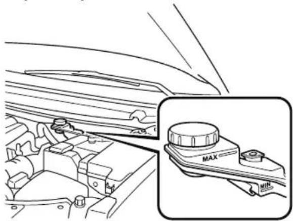
natural_image
Diagram of a car engine compartment showing valve and mode dial (no text or symbols)Washer Fluid
▼ Inspecting Washer Fluid Level

WARNING
Use only windshield washer fluid or plain water in the reservoir:
Using radiator antifreeze as washer fluid is dangerous. If sprayed on the windshield, it will dirty the windshield, affect your visibility, and could result in an accident.
Using Washer Fluid Without Anti-freeze Protection in Cold Weather:
Operating your vehicle in temperatures below 4 °C (40 °F) using washer fluid without anti-freeze protection is dangerous as it could cause impaired windshield vision and result in an accident. In cold weather, always use washer fluid with anti-freeze protection.
NOTE
State or local regulations may restrict the use of volatile organic compounds (VOCs), which are commonly used as anti-freeze agents in washer fluid. A washer fluid with limited VOC content should be used only if it provides adequate freeze resistance for all regions and climates in which the vehicle will be operated.
Inspect fluid level in the washer fluid reservoir; add fluid if necessary.

Use plain water if washer fluid is unavailable.
But use only washer fluid in cold weather to prevent it from freezing.
NOTE
Front and rear washer fluid is supplied from the same reservoir.
Body Lubrication
All moving points of the body, such as door and hood hinges and locks, should be lubricated each time the engine oil is changed. Use a nonfreezing lubricant on locks during cold weather.
Make sure the hood's secondary latch keeps the hood from opening when the primary latch is released.
Wiper Blades

CAUTION
➢Hot waxes applied by automatic car washers have been known to affect the wiper's ability to clean windows.
To prevent damage to the wiper blades, do not use gasoline, kerosene, paint thinner, or other solvents on or near them.
When the wiper lever is in the AUTO position and the ignition is switched ON, the wipers may move automatically in the following cases:
If the windshield above the rain sensor is touched.
If the windshield above the rain sensor is wiped with a cloth.
If the windshield is struck with a hand or other object.
If the rain sensor is struck with a hand or other object from inside the vehicle.
Be careful not to pinch hands or fingers as it may cause injury, or damage the wipers. When washing or servicing the vehicle, make sure the wiper lever is in the OFF position.
Contamination of either the windshield or the blades with foreign matter can reduce wiper effectiveness. Common sources are insects, tree sap, and hot wax treatments used by some commercial car washes.
If the blades are not wiping properly, clean the window and blades with a good cleaner or mild detergent; then rinse thoroughly with clean water. Repeat if necessary.
▼ Replacing Windshield Wiper Blades
When the wipers no longer clean well, the blades are probably worn or cracked. Replace them.

CAUTION
To prevent damage to the wiper arms and other components, do not try to sweep the wiper arm by hand.
Do not bend the blade rubber unnecessarily when replacing it. Otherwise, the metal stiffener in the blade may deform and the windshield wiper operation may be adversely affected.
NOTE
When raising both windshield wiper arms, raise the driver's side wiper arm first. When lowering the wiper arms, slowly lower the wiper arm from the passenger's side first while supporting it with your hand. Forcefully lowering the wiper arms could damage the wiper arm and blade, and may scratch or crack the windshield.
Replace the wiper blades using the following procedure.
- Raise the wiper arm.

CAUTION
To prevent damage to the windshield let the wiper arm down easily, do not let it slap down on the windshield.
- Slide the blade component in the direction of the arrow while pressing
the wiper arm tab to remove the blade component from the wiper arm.
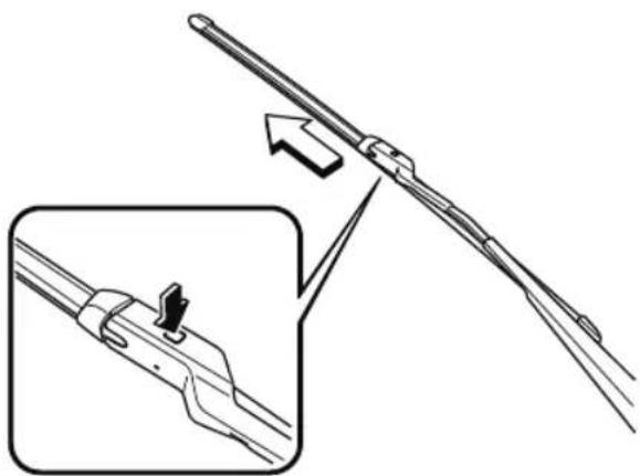
natural_image
Technical illustration of a mechanical tool with an inset showing a close-up of the component (no text or symbols present)- Pull the blade rubber in the direction of the arrow and slide it to a position where the blade holder groove can be checked.
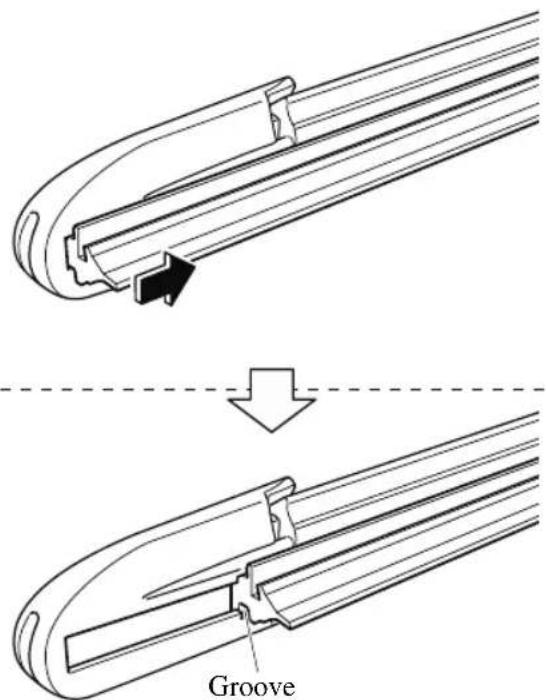
- Pull the end of the blade rubber from the blade holder groove in the direction
of the arrow and remove the blade rubber from the blade holder.
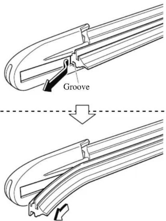
- Insert the end of the new blade rubber into the groove of the blade holder
until it contacts the end of the blade holder.
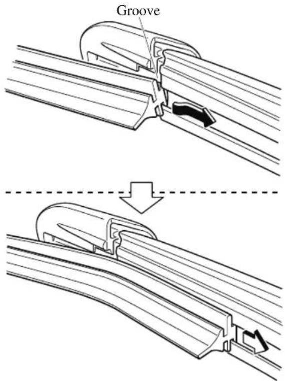
- After pulling the blade rubber in the direction of the arrow and sliding the blade rubber to a position to check the
blade holder groove, slide the blade rubber end in the opposite direction.
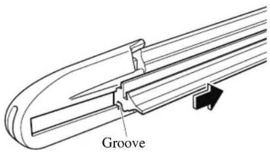
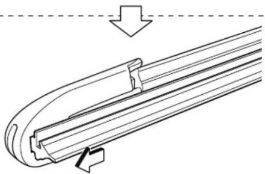
natural_image
Technical line drawing of a mechanical component with an arrow indicating direction (no text or symbols)-
Make sure that the blade rubber is correctly installed to the blade holder.
-
Align the wiper arm tabs with the blade component grooves.
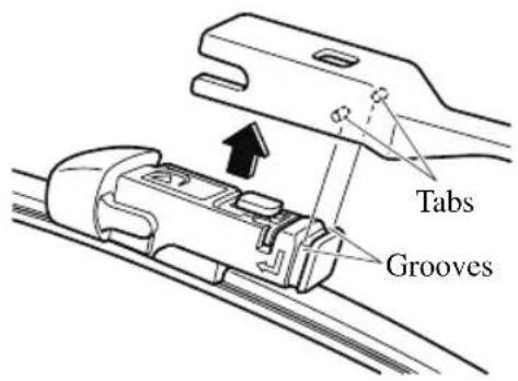
- Align the blade component projection with the wiper arm notch.
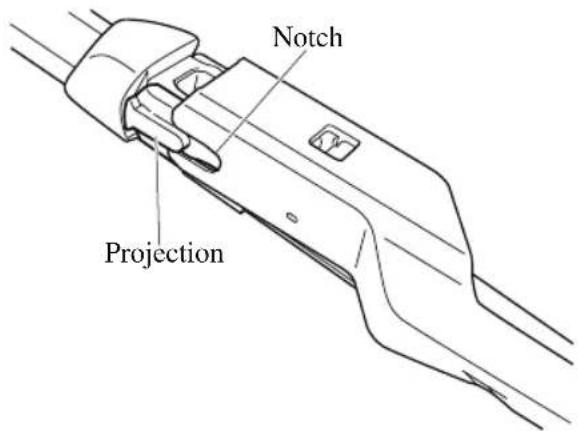
- Slide the blade component and install it to the wiper arm.
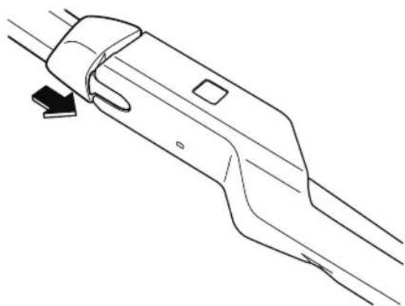
natural_image
Technical line drawing of a mechanical component with a downward arrow indicating direction (no text or symbols)- Slowly lower the wiper arm onto the windshield.
▼ Replacing Rear Window Wiper Blade
When the wiper no longer cleans well, the blade is probably worn or cracked. Replace it.
CAUTION
To prevent damage to the wiper arm and other components, do not move the wiper by hand.
- Remove the cover and raise the wiper arm.
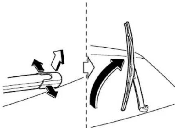
natural_image
Diagram showing two mechanical components: a curved pipe with directional arrows and a straight tool with arrows, separated by a dashed line (no text or symbols)- Firmly rotate the wiper blade to the right until it unlocks, then remove the blade.
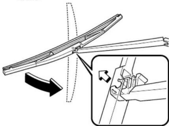
natural_image
Technical diagram showing a mechanical assembly with an inset close-up of a component detail (no text or symbols)
CAUTION
To prevent damage to the rear window, do not let the wiper arm fall on it.
- Pull down the blade rubber and slide it out of the blade holder.
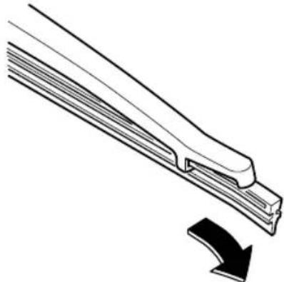
natural_image
Technical line drawing of a mechanical component with an arrow indicating direction (no text or symbols)- Remove the metal stiffeners from the blade rubber and install them in the new blade.
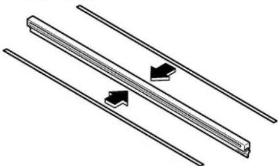
natural_image
Diagram of parallel rods with directional arrows indicating movement or force (no text or symbols)
CAUTION
Do not bend or discard the stiffeners. You need to use them again.
- Carefully insert the new blade rubber. Then install the blade assembly in the reverse order of removal.
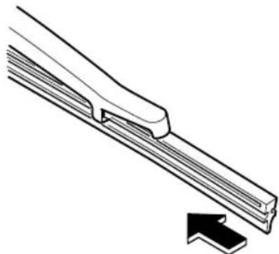
natural_image
Technical line drawing of a mechanical component with an arrow indicating direction (no text or symbols)Battery

WARNING
Wash hands after handling the battery and related accessories:
Battery posts, terminals and related accessories contain lead and lead compounds, chemicals known to the State of California to cause cancer and reproductive harm.

Read the following precautions carefully before using the battery or inspecting to be safe and correct handling:

Always wear eye protection when working near the battery:
Working without eye protection is dangerous. Battery fluid contains SULFURIC ACID which could cause blindness if splashed into your eyes. Also, hydrogen gas produced during normal battery operation, could ignite and cause the battery to explode.

Wear eye protection and protective gloves to prevent contact with battery fluid:
Spilled battery fluid is dangerous.
Battery fluid contains SULFURIC ACID which could cause serious injuries if it gets in eyes, or on the skin or clothing. If this happens, immediately flush your eyes with water for 15 minutes or wash your skin thoroughly and get medical attention.

Always keep batteries out of the reach of children:
Allowing children to play near batteries is dangerous. Battery fluid could cause serious injuries if it gets in the eyes or on the skin.

Keep flames and sparks away from open battery cells and do not allow metal tools to contact the positive (+) or negative (+) terminal of the battery when working near a battery. Do not allow the positive (+) terminal to contact the vehicle body:
Flames and sparks near open battery cells are dangerous. Hydrogen gas, produced during normal battery operation, could ignite and cause the battery to explode. An exploding battery can cause serious burns and injuries. Keep all flames including cigarettes and sparks away from open battery cells.

Keep all flames and sparks away from open battery cells because hydrogen gas is produced from open battery cells while charging the battery or adding battery fluid:
Flames and sparks near open battery cells are dangerous. Hydrogen gas, produced during normal battery operation, could ignite and cause the battery to explode. An exploding battery can cause serious burns and injuries. Keep all flames including cigarettes and sparks away from open battery cells.
NOTE
Before performing battery maintenance, remove the battery cover.
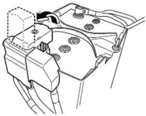
natural_image
Technical line drawing of a vehicle engine compartment with no visible text or symbols▼ Battery Maintenance
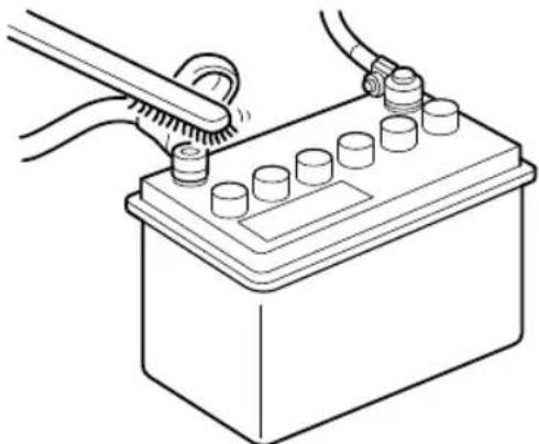
natural_image
Line drawing of a battery with a tool inserted, showing terminal connections and battery casing (no text or symbols)To get the best service from a battery:
- Keep it securely mounted.
- Keep the top clean and dry.
- Keep terminals and connections clean, tight, and coated with petroleum jelly or terminal grease.
- Rinse off spilled electrolyte immediately with a solution of water and baking soda.
- If the vehicle will not be used for an extended time, disconnect the battery cables and charge the battery every 6 weeks.
▼ Battery Replacement
Contact an Authorized Mazda Dealer for battery replacement.
Key Battery Replacement
If the buttons on the transmitter are inoperable and the operation indicator light does not flash, the battery may be dead.
Replace with a new battery before the transmitter becomes unusable.
CAUTION
Make sure the battery is installed correctly. Battery leakage could occur if it is not installed correctly.
When replacing the battery, be careful not to touch any of the internal circuitry and electrical terminals, bend the electrical terminals, or get dirt in the transmitter as the transmitter could be damaged.
There is the danger of explosion if the battery is not correctly replaced.
➢ Dispose of used batteries according to the following instructions.
Insulate the plus and minus terminals of the battery using cellophane or equivalent tape.
▶ Never disassemble.
▶ Never throw the battery into fire or water.
▶ Never deform or crush.
➢Replace only with the same type battery (CR2032 or equivalent).
The following conditions indicate that the battery power is low:
- The KEY indicator light (green) flashes in the instrument cluster for about 30 seconds after the engine is switched OFF (for vehicles with a type A/type B instrument cluster (page 4-12, 4-29),
messages are displayed in the instrument cluster).
- The system does not operate and the operation indicator light on the transmitter does not flash when the buttons are pressed.
- The system's operational range is reduced.
Replacing the battery at an Authorized Mazda Dealer, is recommended to prevent damage to the key. If replacing the battery by yourself, follow the instruction.
Replacing the key battery
- Remove the lower cover while pressing the knob in the direction of the arrow.
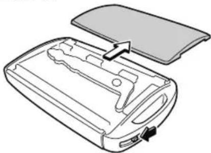
natural_image
Diagram of a device casing with internal components and an open lid, showing no text or symbols- Press in the tab to unlock the upper cover.
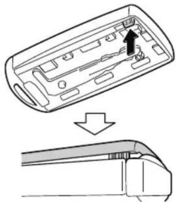
natural_image
Diagram showing a device interior with an arrow indicating a process, before and after a close-up view (no text or symbols present)- Insert a tape-wrapped flathead screwdriver into the gap and slide it in the direction of the arrow.
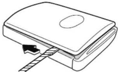
natural_image
Diagram of a mechanical device with a handle and arrow indicating movement (no text or symbols)- Twist the flathead screwdriver in the direction of the arrow and remove the upper cover.
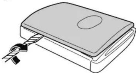
natural_image
Illustration of a mechanical device with a handle and clamped spring (no text or symbols)- Remove the cap using the tape-wrapped flathead screwdriver.
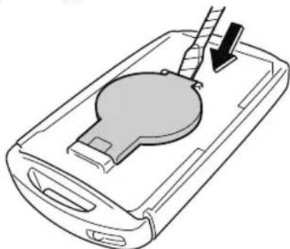
natural_image
Diagram of a device with a circular component and a downward arrow indicating action (no text or symbols)- Remove the battery using tape-wrapped flathead screwdriver.
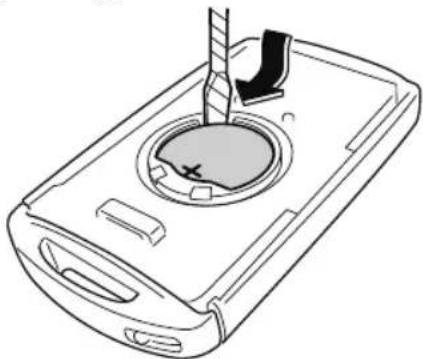
natural_image
Line drawing of a mobile phone casing with a circular vent and a handle, showing internal components (no text or symbols)- Insert a new battery into the transmitter so that the positive pole is facing up.
- Install the cap.
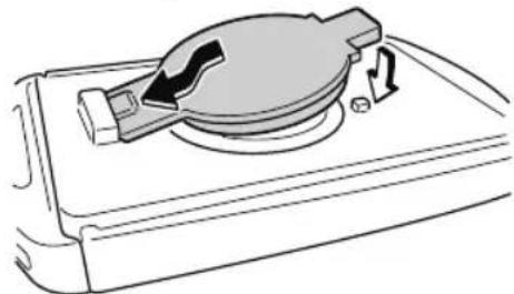
natural_image
Diagram of a mechanical device with a rotating knob and directional arrows indicating motion (no text or symbols)- Install the upper cover.
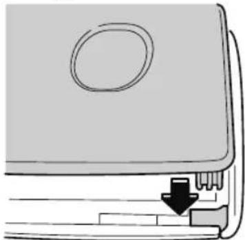
natural_image
Diagram of a device with a handle and arrow indicating a process or operation (no text or symbols present)- Insert the tabs of the lower cover into the slots of the transmitter and install the lower cover.
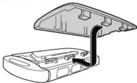
natural_image
Technical line drawing of a device casing with an open lid and internal components (no text or symbols)Tires
For reasons of proper performance, safety, and better fuel economy, always maintain recommended tire inflation pressures and stay within the recommended load limits and weight distribution.

WARNING
Using Different Tire Types:
Driving your vehicle with different types of tires is dangerous. It could cause poor handling and poor braking; leading to loss of control.
Except for the limited use of the temporary spare tire, use only the same type tires (radial, bias-belted, bias-type) on all four wheels.
Using Wrong-Sized Tires:
Using any other tire size than what is specified for the vehicle (page 9-7) is dangerous. It could seriously affect ride, handling, ground clearance, tire clearance, and speedometer calibration. This could cause you to have an accident. Use only tires that are the correct size specified for the vehicle.

Tire Inflation Pressure

WARNING
Always inflate the tires to the correct pressure:
Overinflation or underinflation of tires is dangerous. Adverse handling or unexpected tire failure could result in a serious accident.
Refer to Tires on page 9-7.
Use only a Mazda-genuine tire valve cap:
Use of a non-genuine part is dangerous as the correct tire air pressure cannot be maintained if the tire valve becomes damaged. If the vehicle is driven under this condition, the tire air pressure will decrease which could result in a serious accident. Do not use any part for the tire valve cap that is not a Mazda-genuine part.
Inspect all tire pressures monthly (including the spare) when the tires are cold. Maintain recommended pressures for the best ride, handling, and minimum tire wear.
Refer to the specification charts (page 9-7).
NOTE
· Always check tire pressure when tires are cold.
- Warm tires normally exceed recommended pressures. Do not release air from warm tires to adjust the pressure.
- Underinflation can cause reduced fuel economy, uneven and accelerated tire wear, and poor sealing of the tire bead, which will deform the wheel and cause separation of tire from rim.
• Overinflation can produce a harsh ride, uneven and accelerated tire wear, and a greater possibility of damage from road hazards.
Keep your tire pressure at the correct levels. If one frequently needs inflating, have it inspected.
▼ Tire Rotation
WARNING
Rotate tires periodically:
Irregular tire wear is dangerous. To equalize tread wear for maintaining good performance in handling and braking, rotate the tires every 12,000 km (7,500 miles). However Mazda recommends to rotate every 8,000 km (5,000 miles) to help increase tire life and distribute wear more evenly.
Refer to Scheduled Maintenance on page 6-4.
During rotation, inspect them for correct balance.
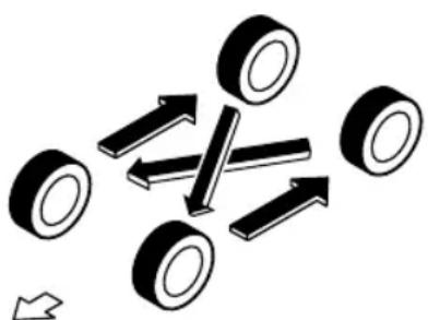
natural_image
Diagram showing multiple tires with directional arrows indicating movement or force (no text or symbols)Forward
Do not include (TEMPORARY USE ONLY) spare tire in rotation.
Also, inspect them for uneven wear and damage. Abnormal wear is usually caused by one or a combination of the following:
- Incorrect tire pressure
- Improper wheel alignment
· Out-of-balance wheel
- Severe braking
After rotation, inflate all tire pressures to specification (page 9-7) and inspect the lug nuts for tightness.

CAUTION
Rotate unidirectional tires and radial tires that have an asymmetrical tread pattern or studs only from front to rear, not from side to side. Tire performance will be reduced if rotated from side to side.
▼ Replacing a Tire

WARNING
Always use tires that are in good condition:
Driving with worn tires is dangerous. Reduced braking, steering, and traction could result in an accident.
Replace all four tires at the same time:
Replacing just one tire is dangerous. It could cause poor handling and poor braking resulting in loss of vehicle control. Mazda strongly recommends that you replace all four tires at the same time.
If a tire wears evenly, a wear indicator will appear as a solid band across the tread.
Replace the tire when this happens.
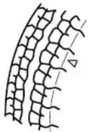
natural_image
Diagram of plant leaf cross-section showing three distinct layers (no text or labels)New tread
Tread wear indicator
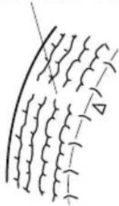
natural_image
Abstract line drawing with repeating wavy patterns and a diagonal line (no text or symbols)Worn tread
You should replace the tire before the band crosses the entire tread.
NOTE
Tires degrade over time, even when they are not being used on the road. It is recommended that tires generally be replaced when they are 6 years or older. Heat caused by hot climates or frequent high loading conditions can accelerate the aging process. You should replace the spare tire when you replace the other road tires due to the aging of the spare tire. The period in which the tire was manufactured (both week and year) is indicated by a 4-digit number.
Refer to Tire Labeling on page 8-25.
▼ Temporary Spare Tire
Inspect the temporary spare tire at least monthly to make sure it is properly inflated and stored.
NOTE
The temporary spare tire condition gradually deteriorates even if it has not been used.
The temporary spare tire is easier to handle because of its construction which is lighter and smaller than a conventional
tire. This tire should be used only for an emergency and only for a short distance.
Use the temporary spare tire only until the conventional tire is repaired, which should be as soon as possible.
Refer to Tires on page 9-7.

CAUTION
➢Do not use your temporary spare tire rim with a snow tire or a conventional tire. Neither will properly fit and could damage both tire and rim.
The temporary spare tire has a tread life of less than 5,000 km (3,000 miles). The tread life may be shorter depending on driving conditions.
The temporary spare tire is for limited use, however, if the tread wear solid-band indicator appears, replace the tire with the same type of temporary spare (page 6-36).
NOTE
Tires degrade over time, even when they are not being used on the road. It is recommended that tires generally be replaced when they are 6 years or older. Heat caused by hot climates or frequent high loading conditions can accelerate the aging process. You should replace the spare tire when you replace the other road tires due to the aging of the spare tire. The period in which the tire was manufactured (both week and year) is indicated by a 4-digit number.
Refer to Tire Labeling on page 8-25.
▼ Replacing a Wheel

WARNING
Always use wheels of the correct size on your vehicle:
Using a wrong-sized wheel is dangerous. Braking and handling could be affected, leading to loss of control and an accident.

CAUTION
A wrong-sized wheel may adversely affect:
▶Tire fit
▶ Wheel and bearing life
▶ Ground clearance
Snow-chain clearance
▶ Speedometer calibration
▶Headlight aim
▶ Bumper height
▶Tire Pressure Monitoring System*
NOTE
- When replacing a wheel, make sure the new one is the same as the original factory wheel in diameter, rim width, and offset (inset/outset).
· For details, contact an Authorized Mazda Dealer.
Proper tire balancing provides the best riding comfort and helps reduce tread wear. Out-of-balance tires can cause vibration and uneven wear, such as cupping and flat spots.
Light Bulbs
Type A (With Adaptive Front Lighting System (AFS))
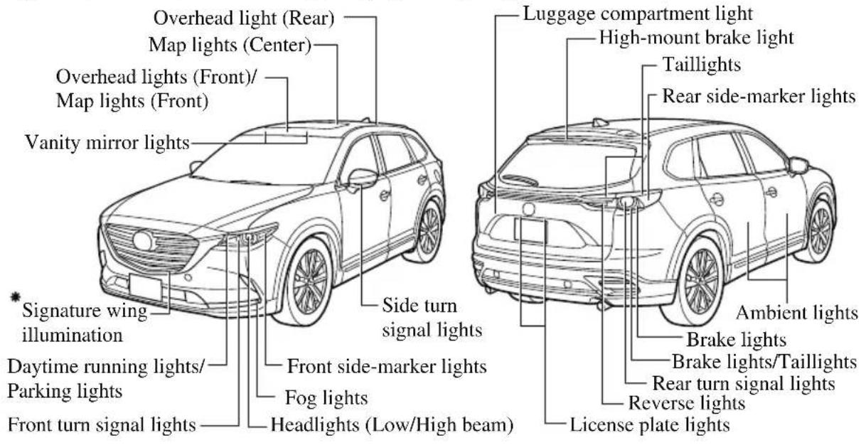
Type B (Without Adaptive Front Lighting System (AFS))
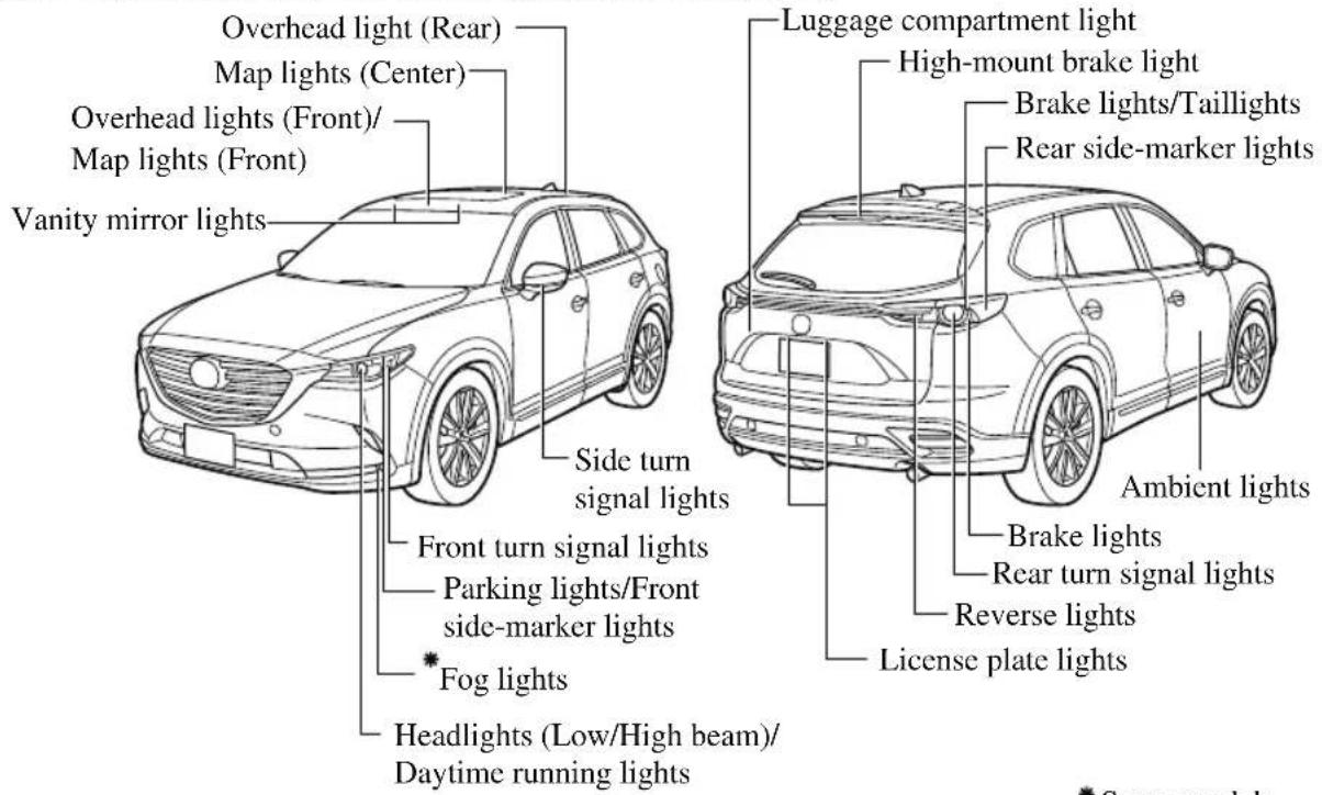
* Some models.

CAUTION
When removing the lens or lamp unit using a flathead screwdriver, make sure that the flathead screwdriver does not contact the interior terminal. If the flathead screwdriver contacts the terminal, a short circuit may occur.
NOTE
• To replace the bulb, contact an Authorized Mazda Dealer.
- Use the protective cover and carton for the replacement bulb to dispose of the old bulb promptly and out of the reach of children.
▼ Replacing Exterior Light Bulbs
The exterior lights have either LEDs or normal bulbs.
LED type
- Headlights (type A)
- Headlights/Daytime running lights (type B)
. Front turn signal lights (type A)
· Daytime running lights/Parking lights (type A) - Front side-marker lights (type A)
• Signature wing illumination (type A)* - Fog lights*
- Brake lights
• Taillights
• High-mount brake light - Side turn signal lights
- Rear side-marker lights
- License plate lights
The LED bulb cannot be replaced as a single unit because it is an integrated unit.
The LED bulb has to be replaced with the unit. We recommend an Authorized Mazda Dealer when the replacement is necessary.
Bulb type
Front turn signal lights (type B), Parking lights/Front side-marker lights (type B)
NOTE
When replacing a bulb for the front turn signal lights and parking lights/front side-marker lights, turn the steering wheel and change the direction in which the tires are pointed to the position where the bulb replacement can be done easily.
Turn the steering wheel after starting the engine and stop the engine after you finish turning the steering wheel.
- If you are changing the right bulb, start the engine, turn the steering wheel all the way to the right, and turn off engine. If you are changing the left bulb, turn the steering wheel to the left, and turn off engine.
-
Make sure the ignition is switched off, and the headlight switch is off.
-
Turn the screw counterclockwise and remove it.
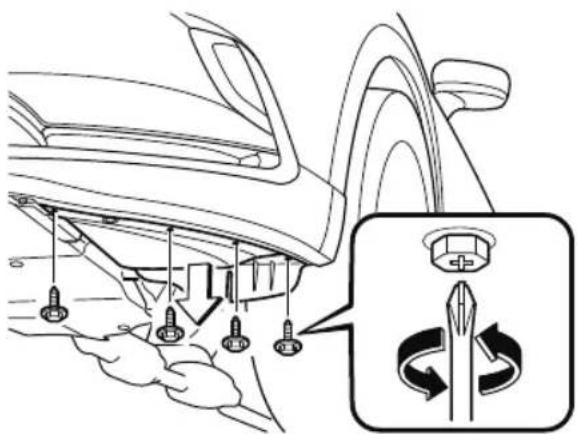
- Pull the center of each plastic retainer and remove the retainers, and then partially peel back the mudguard.
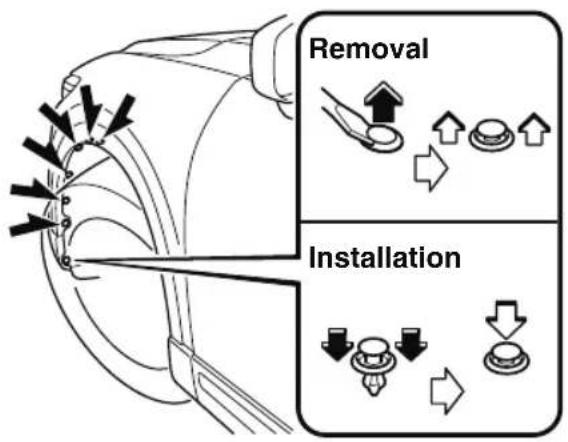
- Disconnect the wiring harness by releasing the clamp.
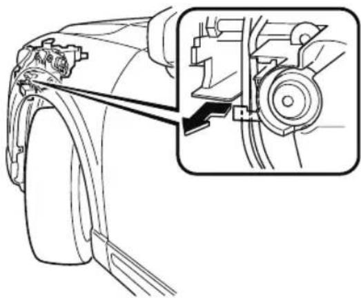
natural_image
Technical line drawing of a vehicle wheel assembly with an inset showing the mechanical component (no text or symbols present)-
Turn the socket and bulb assembly counterclockwise and remove it.
-
Disconnect the bulb from the socket.
Front turn signal lights
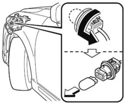
natural_image
Technical illustration of a car's front wheel assembly showing internal components and motion arrows (no text or symbols)Parking lights/Front side-marker lights
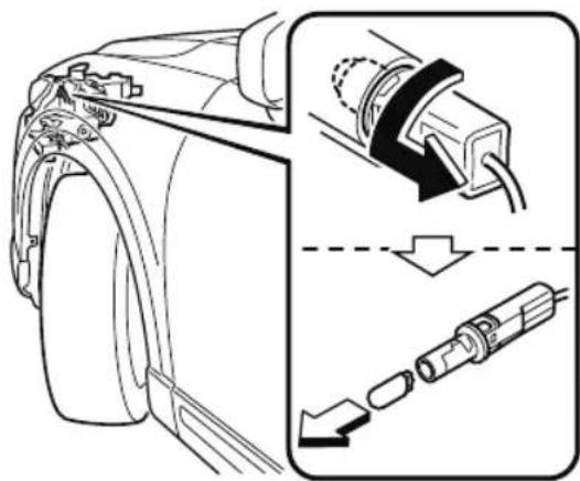
natural_image
Technical illustration of a camera body with attached cable and connector, showing internal components and assembly (no text or symbols)- Install the new bulb in the reverse order of the removal procedure.
NOTE
There will be no problem with functionality with the wiring harness disconnected in Step 5 left disconnected.
Therefore, there is no need to connect the wiring harness.
Rear turn signal lights
-
Make sure the ignition is switched off, and the headlight switch is off.
-
Remove the cover.
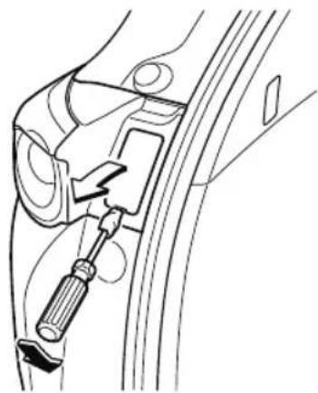
natural_image
Technical line drawing of a car seatbelt with a screwdriver inserted (no text or symbols)- Turn the screws counterclockwise and remove them.
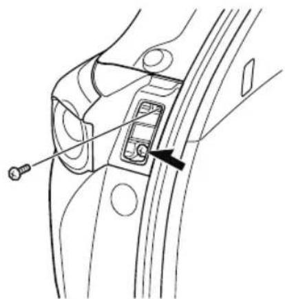
natural_image
Technical line drawing of a mechanical component with a screw and internal connector (no text or symbols)- Pull the unit rearward to remove it.
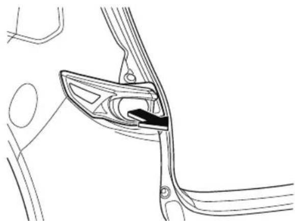
natural_image
Technical line drawing of a mechanical component with no visible text or symbols- Disconnect the wiring harness by releasing the clamp.
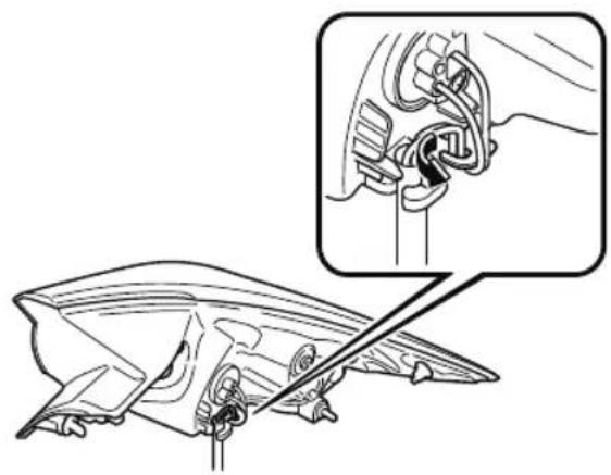
natural_image
Technical illustration of a mechanical component with an inset showing a close-up detail (no text or symbols present)- Turn the socket and bulb assembly counterclockwise and remove it.
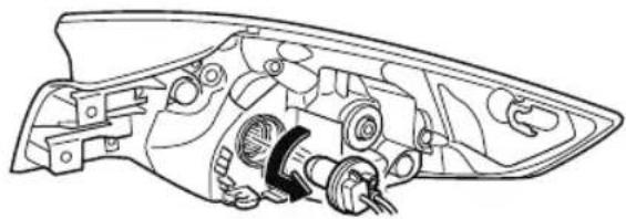
natural_image
Technical line drawing of a mechanical component with gears and housing (no text or symbols)- Temporarily install the light unit with the socket pulled out of the top of the light unit.
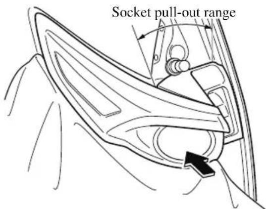

CAUTION
The wiring harness may be damaged when temporarily installing the light unit. When performing the procedure, observe the following points.
➢ Pull out the socket from within the socket pull-out range shown in the figure.
Do not push the light unit into the vehicle with force.
When temporarily installing the light unit, cover the rear bumper light unit installation surface with a soft cloth. The rear bumper may be scratched or damaged if the light unit contacts it.
- Disconnect the bulb from the socket.
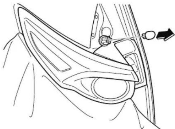
natural_image
Line drawing of a car's front and side door components, showing handle, seat, and valve (no text or symbols)- Install the new bulb in the reverse order of the removal procedure.
Reverse lights
- Make sure the ignition is switched off, and the headlight switch is off.
- Remove the cover.
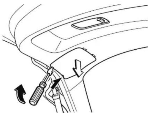
natural_image
Line drawing of a car interior showing a hand holding a screwdriver and a switch, with directional arrows indicating movement (no text or symbols)- Disconnect the electrical connector from the bulb by pressing the tab on
the connector with your finger and pulling the connector.
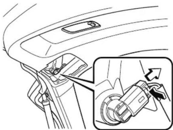
natural_image
Diagram of a car interior showing the seatbelt and cable insertion mechanism (no text or symbols)- Turn the socket and bulb assembly counterclockwise and remove it.
- Disconnect the bulb from the socket.
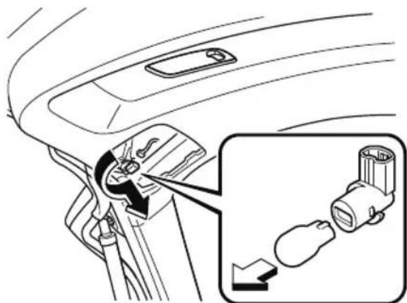
natural_image
Diagram showing car interior and battery plug insertion process, with magnified view of plug attachment (no text or symbols)- Install the new bulb in the reverse order of the removal procedure.
▼ Replacing Interior Light Bulbs
Overhead lights (Front)/Map lights (Front) (LED type), Overhead lights (Center)/Map lights (Center) (LED type), Overhead lights (Rear) (LED type), Vanity mirror lights (LED type), Ambient lights
The LED bulb cannot be replaced as a single unit because it is an integrated unit. The LED bulb has to be replaced with the unit. If a replacement is necessary, consult an Authorized Mazda Dealer.
Overhead lights (Front)/Map lights (Front) (bulb type), Overhead lights (Center)/Map lights (Center) (bulb type), Overhead light (Rear) (bulb type), Vanity mirror lights (bulb type)
- Wrap a small flathead screwdriver with a soft cloth to prevent damage to the lens, and then remove the lens by carefully prying on the edge of the lens with the flathead screwdriver.
- Disconnect the bulb by pulling it out. Overhead lights (Front)/Map lights (Front)
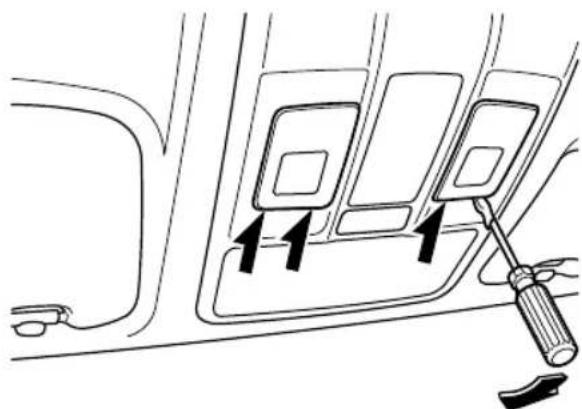
natural_image
Diagram of a car interior showing a door panel with two arrows indicating direction, and a screwdriver inserted (no text or symbols)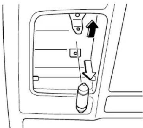
natural_image
Diagram of a vehicle's side panel with arrows indicating direction of movement (no text or symbols)Overhead lights (Center)/Map lights (Center)
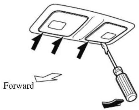
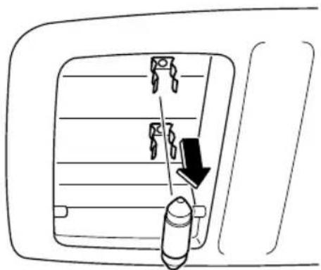
natural_image
Diagram of a vehicle's side panel with a bullet and arrow indicating direction (no text or symbols)Overhead light (Rear)
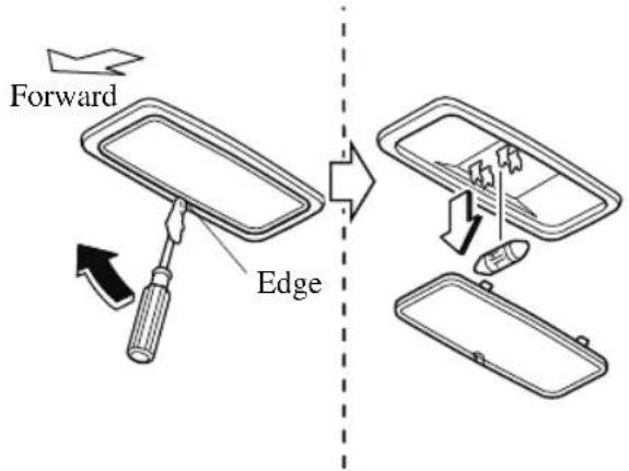
Vanity mirror lights
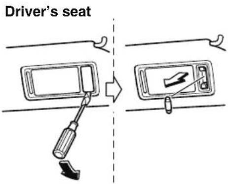
Passenger's seat
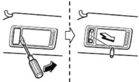
- Install the new bulb in the reverse order of the removal procedure.
Luggage compartment light
(LED type)
The LED bulb cannot be replaced as a single unit because it is an integrated unit. The LED bulb has to be replaced with the unit. If a replacement is necessary, consult an Authorized Mazda Dealer.
(Bulb type)
- Wrap a small flathead screwdriver with a soft cloth to prevent damage to the lens and remove the lens unit by
carefully prying on the edge of the lens unit with the flathead screwdriver.
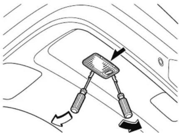
natural_image
Diagram of a car interior showing a steering wheel and two directional arrows indicating movement (no text or symbols)- Disconnect the electrical connector from the bulb by pressing the tab on the connector with your finger and pulling the connector.
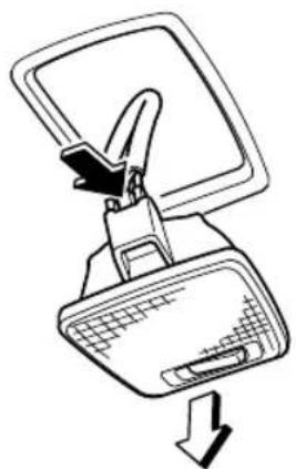
natural_image
Line drawing of a computer monitor with a clip and scroll, showing a downward arrow (no text or symbols)
CAUTION
When replacing the bulb always disconnect the connector first. Otherwise, electric and electronic devices could be shorted.
- Insert the flathead screwdriver into the gap between the lens and the lens unit,
and then slide the screwdriver to detach the lens.
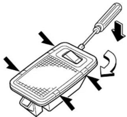
natural_image
Diagram of a handheld device with directional arrows indicating rotation or movement (no text or symbols)- Disconnect the bulb by pulling it out.
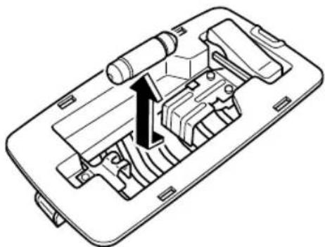
natural_image
Technical diagram of a mechanical device interior showing internal components and a directional arrow (no text or symbols)- Install the new bulb in the reverse order of the removal procedure.
Fuses
Your vehicle's electrical system is protected by fuses.
If any lights, accessories, or controls do not work, inspect the appropriate circuit protector. If a fuse has blown, the inside element will be melted.
If the same fuse blows again, avoid using that system and consult an Authorized Mazda Dealer as soon as possible.
▼ Fuse Replacement
Replacing the fuses on the vehicle's left side
If the electrical system does not work, first inspect the fuses on the vehicle's left side.
- Make sure the ignition is switched off, and other switches are off.
- Open the fuse panel cover.
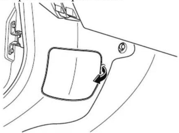
natural_image
Line drawing of a car interior showing a side panel with a handle and lock, no text or symbols present- Pull the fuse straight out with the fuse puller provided on the fuse block located in the engine compartment.
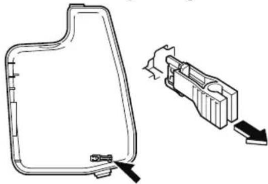
natural_image
Technical line drawing of a mechanical component with an inset showing internal structure and directional arrows (no text or symbols)- Inspect the fuse and replace it if it is blown.
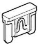
Normal
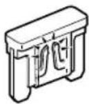
Blown
- Insert a new fuse of the same amperage rating, and make sure it fits tightly. If it does not fit tightly, have an expert install it. Consult an Authorized Mazda Dealer.
If you have no spare fuses, borrow one of the same rating from a circuit not essential to vehicle operation, such as the AUDIO or OUTLET circuit.
CAUTION
Always replace a fuse with a genuine Mazda fuse or equivalent of the same rating. Otherwise you may damage the electric system.
- Reinstall the cover and make sure that it is securely installed.
Replacing the fuses under the hood
If the headlights or other electrical components do not work and the fuses in the cabin are normal, inspect the fuse block under the hood.
If a fuse is blown, it must be replaced.
Follow these steps:
- Make sure the ignition is switched off, and other switches are off.
- Remove the fuse block cover.
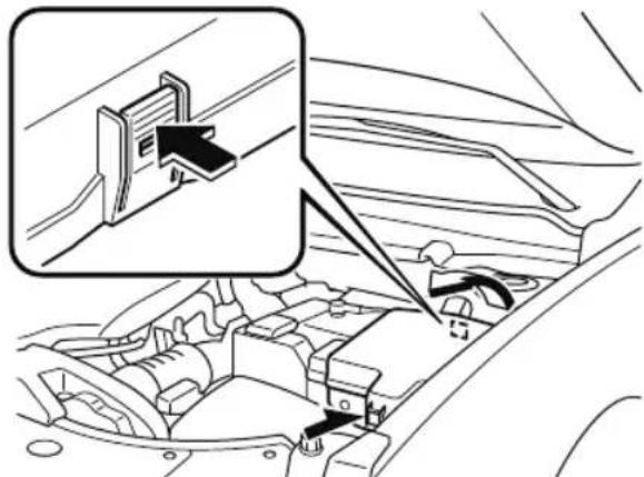
- If any fuse but the MAIN fuse is blown, replace it with a new one of the same amperage rating.
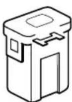
Normal
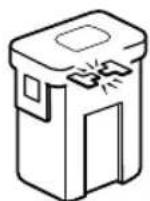
Blown

WARNING
Do not replace the main fuse by yourself. Have an Authorized Mazda Dealer perform the replacement:
Replacing the fuse by yourself is dangerous because the MAIN fuse is a high current fuse. Incorrect replacement could cause an electrical shock or a short circuit resulting in a fire.
- Reinstall the cover and make sure that it is securely installed.
▼ Fuse Panel Description
Fuse block (Engine compartment)
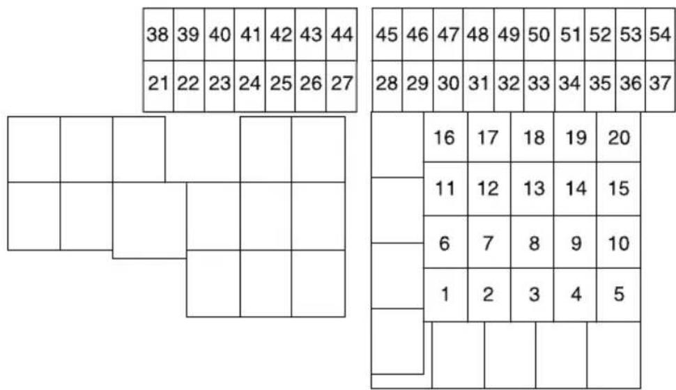
| DESCRIPTION | FUSE RATING | PROTECTED COMPONENT | |
| 1 WIPER.DEI 20 A | Windshield wiper de-icer* | ||
| 2 IG2 30 A For protection of various circuits | |||
| 3 INJECTOR 30 A Engine control system | |||
| 4 | — | — — | |
| 5 | P . | W | I N D O W 1 |
| 6 P.SEAT RL 30 A | Power seat* | ||
| 7 | — | — — | |
| 8 | EVVT | 20 A Engine control system | |
| 9 | DEFOG | 40 A Rear window defogger | |
| 10 | ST.HEATER2 | 20 A | Heated steering wheel* |
| 11 | R.HEATER 40 A Air conditioner | ||
| 12 | EPB L | 20 A Electric Parking Brake (EPB) (LH) | |
| 13 | AUDIO | 40 A Audio system | |
| 14 | EPB R | 20 A | Electric Parking Brake (EPB) (RH) |
| 15 | ENG.MAIN 40 A Engine control system | ||
| 16 | ABS/DSC M | 50 A | ABS, Dynamic stability control system |
| 17 CABIN.+B 50 A For protection of various circuits | |||
| 18 | WIPER | 20 A Front window wiper and washer | |
| 19 HEATER 40 A Air conditioner | |||
| 20 — — — | |||
| 21 ENGINE.IG1 7.5 A Engine control system | |||
| 22 C/U IG1 15 A For protection of various circuits | |||
| 23 H/L LOW L 15 A Headlight low beam (LTI) | |||
| 24 H/L LOW R1 15 A | — | ||
| 25 ENGINE3 15 A Engine control system | |||
| 26 ENGINE2 15 A Engine control system | |||
| 27 ENGINE1 15 A Engine control system | |||
| 28 | AT | 15 A Transaxle control system, Ignition switch | |
| 29 | H/CLEAN 20 A | — | |
| 30 | A/C | 7.5 A Air conditioner | |
| 31 AT PUMP 15 A | — | ||
| 32 | STOP | 10 A Brake lights | |
| 33 | R.WIPER | 15 A | Rear window wiper, Theft-deterrent system* |
| 34 | H/L HI | 20 A Headlight high beam | |
| 35 H/L LOW R2 15 A Headlight low beam (RH) | |||
| 36 | FOG | 15 A | Fog lights* |
| 37 ENG.+B 7.5 A Engine control system | |||
| 38 | AUDIO2 | 7.5 A | Audio system* |
| 39 | INTERIOR | 10 A For protection of various circuits | |
| 40 | METER2 15 A | — | |
| 41 | METER1 10 A Instrument cluster | ||
| 42 | SRS1 | 7.5 A Air bag | |
| 43 | AUDIO4 | 10 A | Audio system* |
| 44 | AUDIO1 | 25 A Audio system | |
| 45 ABS/DSC S 30 A ABS, Dynamic stability control system | |||
| 46 | VMC | 15 A Gateway system | |
| 47 | ST.HEATER | 15 A Audio system | |
| 48 | TAIL | 15 A | Parking lights |
| 49 | FUEL PUMP2 | 25 A Fuel system | |
| 50 | HAZARD | 25 A | Hazard warning flashers, Turn signal lights, Taillights |
| 51 | DRL | 15 A | Daytime running lights |
| 52 | R.OUTLET2 | 15 A | Accessory sockets* |
| 53 | HORN | 15 A Horn | |
| 54 ROOM 25 A For protection of various circuits | |||
Fuse block (Left side)
| 9 | |
| 10 | |
| 11 | |
| 1 | 12 |
| 13 | |
| 14 | |
| 2 | 15 |
| 16 | |
| 3 | 17 |
| 4 | 18 |
| 5 | 19 |
| 6 | 20 |
| 7 | |
| 8 | |
| 21 |
| DESCRIPTION | FUSE RATING | PROTECTED COMPONENT | |
| 1 P.S | EAT D 30 A | Power seat* | |
| 2 P. | WINDOW3 30 A Power windows | ||
| 3 R. | OUTLET3 15 A Accessory sockets | ||
| 4 P. | WINDOW2 25 A Power windows | ||
| 5 | P | L | Power liftgate* 2 0 |
| 6 D. | LOCK 25 A Power door locks | ||
| 7 SE | AT WARM 20 A | Seat warmer* | |
| 8 | SRS2/ESCL | 15 A | Trailer hitch * |
| 9 | SUNROOF | 10 A | Moonroof* |
| 10 | INTERIOR2 | 15 A Audio system | |
| 11 | ENG+BB | 7.5 A | Engine control system |
| 12 | MIRROR | 7.5 A | Power control mirror |
| 13 AT | IND 7.5 A | AT shift indicator | |
| 14 F. | OUTLET 15 A Accessory sockets | ||
| 15 R. | OUTLET1 15 A | Accessory sockets^* | |
| 16 USB 15 A | USB power outlet* | ||
| 17 M. | DEF 7.5 A | Mirror defogger* | |
| 18 R. | SEAT.WARM 20 A | Seat warmer* | |
| 19 AUDIO3 15 A Audio system | |||
| 20 | P.SEAT RR 30 A | Power seat^* | |
| 21 | P.SEAT P | 30 A | Power seat^* |
Exterior Care
The paintwork on your Mazda represents the latest technical developments in composition and methods of application.
Environmental hazards, however, can harm the paint's protective properties, if proper care is not taken.
Here are some examples of possible damage, with tips on how to prevent them.
Etching Caused by Acid Rain or Industrial Fallout
Occurrence
Industrial pollutants and vehicle emissions drift into the air and mix with rain or dew to form acids. These acids can settle on a vehicle's finish. As the water evaporates, the acid becomes concentrated and can damage the finish.
And the longer the acid remains on the surface, the greater the chance is for damage.
Prevention
It is necessary to wash and wax your vehicle to preserve its finish according to the instructions in this section. These steps should be taken immediately after you suspect that acid rain has settled on your vehicle's finish.
Damage Caused by Bird Dropping, Insects, or Tree Sap
Occurrence
Bird droppings contain acids. If these are not removed they can eat away the clear
and color base coat of the vehicle's paintwork.
When insects stick to the paint surface and decompose, corrosive compounds form. These can erode the clear and color base coat of the vehicle's paintwork if they are not removed.
Tree sap will harden and adhere permanently to the paint finish. If you scratch the sap off while it is hard, some vehicle paint could come off with it.
Prevention
It is necessary to have your Mazda washed and waxed to preserve its finish according to the instructions in this section. This should be done as soon as possible.
Bird droppings can be removed with a soft sponge and water. If you are traveling and these are not available, a moistened tissue may also take care of the problem. The cleaned area should be waxed according to the instructions in this section.
Insects and tree sap are best removed with a soft sponge and water or a commercially available chemical cleaner.
Another method is to cover the affected area with dampened newspaper for 1 to 2 hours. After removing the newspaper, rinse off the loosened debris with water.
Water Marks
Occurrence
Rain, fog, dew, and even tap water can contain harmful minerals such as salt and lime. If moisture containing these minerals settles on the vehicle and evaporates, the
minerals will concentrate and harden to form white rings. The rings can damage your vehicle's finish.
Prevention
It is necessary to wash and wax your vehicle to preserve its finish according to the instructions in this section. These steps should be taken immediately after you find water marks on your vehicle's finish.
Paint Chipping
Occurrence
Paint chipping occurs when gravel thrown in the air by another vehicle's tires hits your vehicle.
How to avoid paint chipping
Keeping a safe distance between you and the vehicle ahead reduces the chances of having your paint chipped by flying gravel.
NOTE
- The paint chipping zone varies with the speed of the vehicle. For example, when traveling at 90 ~km / h (56 mph), the paint chipping zone is 50 ~m (164 ft).
- In low temperatures a vehicle's finish hardens. This increases the chance of paint chipping.
- Chipped paint can lead to rust forming on your Mazda. Before this happens, repair the damage by using Mazda touch-up paint according to the instructions in this section. Failure to repair the affected area could lead to serious rusting and expensive repairs.
Follow all label and container directions when using a chemical cleaner or polish. Read all warnings and cautions.
▼ Maintaining the Finish
Washing

CAUTION
When the wiper lever is in the AUTO position and the ignition is switched ON, the wipers may move automatically in the following cases:
If the windshield above the rain sensor is touched or wiped with a cloth.
If the windshield is struck with a hand or other object from either outside or inside the vehicle.
Keep hands and scrapers clear of the windshield when the wiper lever is in the AUTO position and the ignition is switched ON as fingers could be pinched or the wipers and wiper blades damaged when the wipers activate automatically. If you are going to clean the windshield, be sure the wipers are turned off completely (when it is most likely that the engine is left running) this is particularly important when clearing ice and snow.
➢Do not spray water in the engine compartment. Otherwise, it could result in engine-starting problems or damage to electrical parts.
When washing and waxing the vehicle, be careful not to apply excessive force to any single area of the vehicle roof. Otherwise, you could dent the vehicle.
(Vehicles with hands-free liftgate)
When washing the vehicle, turn off the hands-free liftgate using the Mazda Connect or do not bring the transmitter into the area around the liftgate. Otherwise, the liftgate could open unexpectedly resulting in an accident. Refer to Power Liftgate on page 3-22.
To help protect the finish from rust and deterioration, wash your Mazda thoroughly and frequently, at least once a month, with lukewarm or cold water.
If the vehicle is washed improperly, the paint surface could be scratched. Here are some examples of how scratching could occur.
Scratches occur on the paint surface when:
- The vehicle is washed without first rinsing off dirt and other foreign matter.
- The vehicle is washed with a rough, dry, or dirty cloth.
- The vehicle is washed at a car wash that uses brushes that are dirty or too stiff.
- Cleansers or wax containing abrasives are used.
NOTE
- Mazda is not responsible for scratches caused by automatic car washes or improper washing.
- Scratches are more noticeable on vehicles with darker paint finishes.
To minimize scratches on the vehicle's paint finish:
- Rinse off any dirt or other foreign matter using lukewarm or cold water before washing.
- Use plenty of lukewarm or cold water and a soft cloth when washing the vehicle. Do not use a nylon cloth.
- Rub gently when washing or drying the vehicle.
• Take your vehicle only to a car wash that keeps its brushes well maintained. - Do not use abrasive cleansers or wax that contain abrasives.

CAUTION
➢Do not use steel wool, abrasive cleaners, or strong detergents containing highly alkaline or caustic agents on chrome-plated or anodized aluminum parts. This may damage the protective coating; also, cleaners and detergents may discolor or deteriorate the paint.
Pay special attention to removing salt, dirt, mud, and other foreign material from the underside of the fenders, and make sure the drain holes in the lower edges of the doors and rocker panels are clean.
Insects, tar, tree sap, bird droppings, industrial fallout, and similar deposits can damage the finish if not removed immediately. When prompt washing with
plain water is ineffective, use a mild soap made for use on vehicles.
Thoroughly rinse off all soap with lukewarm or cold water. Do not allow soap to dry on the finish.
After washing the vehicle, dry it with a clean chamois to prevent water spots from forming.

WARNING
Dry off brakes that have become wet by driving slowly, releasing the accelerator pedal and lightly applying the brakes several times until the brake performance returns to normal:
Driving with wet brakes is dangerous. Increased stopping distance or the vehicle pulling to one side when braking could result in a serious accident. Light braking will indicate whether the brakes have been affected.
When using an automatic car wash
- Retract the door mirrors.
- The automatic car wash brushes could reduce the paint lustre or hasten paint deterioration.
When using a high water pressure car wash
High water temperature and high water pressure car washers are available depending on the type of car wash machine. If the car washer nozzle is put too close to the vehicle, the force of the spray could damage or deform the molding, affect the sealability of parts, and allow water to penetrate the interior. Keep a sufficient space (30 cm (12 in) or more) between the nozzle and the vehicle. In addition, do not spend too much time spraying the same area of the vehicle, and be very careful when spraying between gaps in doors and around windows.
Waxing
Your vehicle needs to be waxed when water no longer beads on the finish. Always wash and dry the vehicle before waxing it. In addition to the vehicle body, wax the metal trim to maintain its luster.
- Use wax which contains no abrasives. Wax containing abrasives will remove paints and could damage bright metal parts.
- Use a good grade of natural wax for metallic, mica, and solid colors.
- When waxing, coat evenly with the sponge supplied or a soft cloth.
- Wipe off the wax with a soft cloth.

CAUTION
(Vehicles with hands-free liftgate)
When waxing the vehicle, turn off the hands-free liftgate using the Mazda Connect or do not bring the transmitter into the area around the liftgate. The liftgate could open unexpectedly resulting in an accident. Refer to Power Liftgate on page 3-22.
NOTE
A spot remover to remove oil, tar, and similar materials will usually also take off the wax. Rewax these areas even if the rest of the vehicle does not need it.
▼ Repairing Damage to the Finish
Deep scratches or chips on the finish should be repaired promptly. Exposed metal quickly rusts and can lead to major repairs.

CAUTION
If your Mazda is damaged and needs metal parts repaired or replaced, make sure the body shop applies anti-corrosion materials to all parts, both repaired and new. This will prevent them from rusting.
▼ Bright-Metal Maintenance
- Use tar remover to remove road tar and insects. Never do this with a knife or similar tool.
- To prevent corrosion on bright-metal surfaces, apply wax or chrome preservative and rub it to a high luster.
- During cold weather or in coastal areas, cover bright-metal parts with a coating of wax or preservative heavier than usual. It would also help to coat them with noncorrosive petroleum jelly or some other protective compound.

CAUTION
Do not use steel wool, abrasive cleaners, or strong detergents containing highly alkaline or caustic agents on chrome-plated or anodized aluminum parts. This may result in damage to the protective coating and cause discoloration or paint deterioration.
▼ Underbody Maintenance
Road chemicals and salt used for ice and snow removal and solvents used for dust control may collect on the underbody. If not removed, they will speed up rusting and deterioration of such underbody parts as fuel lines, frame, floor pan, and exhaust system, even though these parts may be coated with anti-corrosive material.
Thoroughly flush the underbody and wheel housings with lukewarm or cold water at the end of each winter. Try also to do this every month.
Pay special attention to these areas because they easily hide mud and dirt. It will do more harm than good to wet down the road grime without removing it.
The lower edges of doors, rocker panels, and frame members have drain holes that should not be clogged. Water trapped there will cause rusting.

WARNING
Dry off brakes that have become wet by driving slowly, releasing the accelerator pedal and lightly applying the brakes several times until the brake performance returns to normal:
Driving with wet brakes is dangerous. Increased stopping distance or the vehicle pulling to one side when braking could result in a serious accident. Light braking will indicate whether the brakes have been affected.
▼ Aluminum Wheel Maintenance
A protective coating is provided over the aluminum wheels. Special care is needed to protect this coating.

CAUTION
Do not use any detergent other than mild detergent. Before using any detergent, verify the ingredients. Otherwise, the product could discolor or stain the aluminum wheels.
NOTE
- Do not use a wire brush or any abrasive cleaner, polishing compound, or solvent on aluminum wheels. They may damage the coating.
• Always use a sponge or soft cloth to clean the wheels.
Rinse the wheels thoroughly with lukewarm or cold water. Also, be sure to clean the wheels after driving on dusty or salted roads to help prevent corrosion. - Avoid washing your vehicle in an automatic car wash that uses high-speed or hard brushes.
▼ Plastic Part Maintenance
- When cleaning the plastic lenses of the lights, do not use gasoline, kerosene, rectified spirit, paint, thinner, highly acidic detergents, or strongly alkaline detergents. Otherwise, these chemical agents can discolor or damage the surfaces resulting in a significant loss in functionality. If plastic parts become inadvertently exposed to any of these chemical agents, flush with water immediately.
- If plastic parts such as the bumpers become inadvertently exposed to chemical agents or fluids such as gasoline, oil, engine coolant, or battery fluid, it could cause discoloration, staining, or paint peeling. Wipe off any such chemical agents or fluids using a soft cloth immediately.
- High water temperature and high water pressure car washers are available depending on the type of high pressure car washer device. If the car washer nozzle is put too close to the vehicle or aimed at one area for an extended period of time, it could deform plastic parts or damage the paint.
- Do not use wax containing compounds (polish). Otherwise, it could result in paint damage.
- In addition, do not use an electrical or air tool to apply wax. Otherwise, the frictional heat generated could result in deformation of plastic parts or paint damage.
Interior Care

WARNING
Do not spray water into the vehicle cabin:
Spraying water into the vehicle cabin is dangerous as electrical devices such as the audio and switches could get wet resulting in a malfunction or vehicle fire.
NOTE
- Do not wipe the interior using alcohol, chlorine bleach, or organic solvents such as thinner, benzene, and gasoline. Otherwise, it may cause discoloration or stains.
- Rubbing hard with a stiff brush or cloth may cause damage.
If the vehicle interior becomes soiled by any of the following, wipe it off immediately using a soft cloth. Leaving it uncleaned could cause discoloration, stains, cracks, or peeling of the coating, and it will make it hard to wipe off later.
. Beverage or fragrance
- Grease or oil
- Soiling
▼ Seat Belt Maintenance
- Clean the soiled area by lightly dabbing it with a soft cloth soaked in a mild detergent (approx. 5% ) diluted with water.
- Wipe off the remaining detergent using a cloth soaked in clean water and wrung out well.
- Before retracting seat belts which have been pulled out for cleaning, dry them
off thoroughly and make sure there is no remaining moisture on them.

WARNING
If a seat belt appears frayed or has abrasions, have it replaced by an Authorized Mazda Dealer:
If a seat belt is used under such a condition, it cannot function at its full capacity which could result in serious injury or death.
Use a mild detergent to remove soiling from a seat belt:
If organic solvents are used for cleaning the seat belts or they become stained or bleached, there is the possibility of them becoming weakened and as a result, they may not function at their full capacity which could cause serious injury or death.
NOTE
Clean seat belts diligently if they get dirty. Leaving them uncleaned will make it difficult to clean them later, and it may affect the smooth retracting of the seat belt.
▼ Vinyl Upholstery Maintenance
Remove dust and dirt from the vinyl upholstery using a brush or vacuum. Remove soiling from vinyl upholstery using a leather and vinyl upholstery cleaner.
▼ Upholstery Maintenance
-
Clean the soiled area by lightly dabbing it with a soft cloth soaked in a mild detergent (approx. 5%) diluted with water.
-
Wipe off the remaining detergent using a cloth soaked in clean water and wrung out well.
▼ Leather Upholstery Maintenance\*
- Remove dust and sand using a vacuum cleaner.
- Wipe off the soiled area with a soft cloth and a suitable, special cleaner or a soft cloth soaked in a mild detergent (about 5%) diluted with water.
- Wipe off the remaining detergent using a cloth soaked in clean water and wrung out well.
- Remove moisture with a dry, soft cloth and allow the leather to further dry in a well-ventilated, shaded area. If the leather gets wet such as from rain, remove the moisture and dry it as soon as possible.
NOTE
- Because genuine leather is a natural material, its surface is not uniform and it may have natural scars, scratches, and wrinkles.
- To maintain the quality for as long as possible, periodical maintenance, about twice a year, is recommended.
- If the leather upholstery comes into contact with any of the following, clean it immediately.
Leaving it uncleaned could cause premature wear, mold, or stains. - Sand or dirt
- Grease or oil, such as hand cream
-
Alcohol, such as in cosmetic or hair dressing items
-
If the leather upholstery gets wet, promptly remove moisture with a dry cloth. Remaining moisture on the surface may cause deterioration such as hardening and shrinkage.
- Exposure to direct sunlight for long periods may cause deterioration and shrinkage. When parking the car under direct sunlight for long periods, shade the interior using sunshades.
- Do not leave vinyl products on the leather upholstery for long periods. They may affect the leather quality and coloring. If the cabin temperature becomes hot, the vinyl may deteriorate and adhere to the genuine leather.
▼ Plastic Part Maintenance

CAUTION
Do not use polishing agents.
Depending on the product ingredients, they could cause discoloration, stains, cracks or peeling of the coating.
▼ Instrument Panel Top Maintenance
- Wipe the soiled area with a soft cloth soaked in a mild detergent (approx. 5%) diluted with water.
- Wipe off the remaining detergent using a cloth soaked in clean water and wrung out well.
▼ Panel Maintenance
If a panel becomes soiled, wipe it off with a soft cloth soaked in clean water and thoroughly wrung out.
If some areas require further cleaning, use the following procedure:
- Wipe the soiled area with a soft cloth soaked in a mild detergent (approx. 5%) diluted with water.
- Wipe off the remaining detergent using a cloth soaked in clean water and wrung out well.
NOTE
Be particularly careful when cleaning shiny surface panels and metallic parts such as plating as they can be scratched easily.
▼ Active Driving Display Maintenance\*
The dust-proof sheet has a coating. When cleaning, do not use a hard or rough-surface cloth, or cleaning detergent. In addition, if a chemical solvent gets on the active driving display, wipe it off immediately. The dust-proof sheet could be damaged and the surface coating could be scratched. Use a fine, soft cloth such as those used for cleaning eyeglasses.
NOTE
Use of compressed air when cleaning the dust-proof sheet is recommended.
▼ Cleaning the Window Interiors
If the windows become covered with an oily, greasy, or waxy film, clean them with glass cleaner. Follow the directions on the container.

CAUTION
➢Do not scrape or scratch the inside of the window glass. It could damage the thermal filaments and the antenna lines.
When washing the inside of the window glass, use a soft cloth dampened in lukewarm water, gently wiping the thermal filaments and the antenna lines. Use of glass cleaning products could damage the thermal filaments and the antenna lines.
▼ Cleaning the Floor Mats
Rubber floor mats should be cleaned with mild soap and water only.

WARNING
Do not use rubber cleaners, such as tire cleaner or tire shine, when cleaning rubber floor mats:
Cleaning the rubber floor mats with rubber cleaning products makes the floor mats slippery. This may cause an accident when depressing the accelerator or brake pedal or when getting in or out of the vehicle.
After removing the floor mats for cleaning, always reinstall them securely (page 3-51).
7 If Trouble Arises
Helpful information on what to do if a problem arises with the vehicle.
Parking in an Emergency...... 7-2
Parking in an Emergency......7-2
Flat Tire....7-3
Spare Tire and Tool Storage...... 7-3
Changing a Flat Tire.... 7-9
Battery Runs Out.... 7-19
Jump-Starting.... 7-19
Emergency Starting......7-22
Starting a Flooded Engine...... 7-22
Push-Starting.... 7-22
Overheating....7-23
Overheating.... 7-23
Emergency Towing.... 7-25
Towing Description.... 7-25
Towing Hooks (Mexico)......7-26
Warning/Indicator Lights and
Warning Sounds.... 7-28
If a Warning Light Turns On or Flashes.... 7-28
Message Indicated on Display....7-43
Message Indicated in Multi-information Display*.... 7-45
Warning Sound is Activated..... 7-47
When Liftgate Cannot be
Opened....7-52
When Liftgate Cannot be Opened....7-52
Active Driving Display Does Not
Operate ^* 7-53
If the Active Driving Display Does Not Operate.... 7-53
Parking in an Emergency
The hazard warning lights should always be used when you stop on or near a roadway in an emergency.
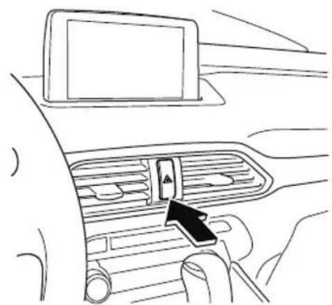
natural_image
Line drawing of a car interior showing the dashboard and air vent with a black arrow pointing to the control panel (no text or symbols)The hazard warning lights warn other drivers that your vehicle is a traffic hazard and that they must take extreme caution when near it.

Depress the hazard warning flasher and all the turn signals will flash. The hazard warning indicator lights in the instrument cluster flash simultaneously.
NOTE
- The turn signals do not work when the hazard warning lights are on.
- Check local regulations about the use of hazard warning lights while the vehicle is being towed to verify that it is not in violation of the law.
Spare Tire and Tool Storage
Spare tire and tools are stored in the locations illustrated in the diagram.
With sub-woofer
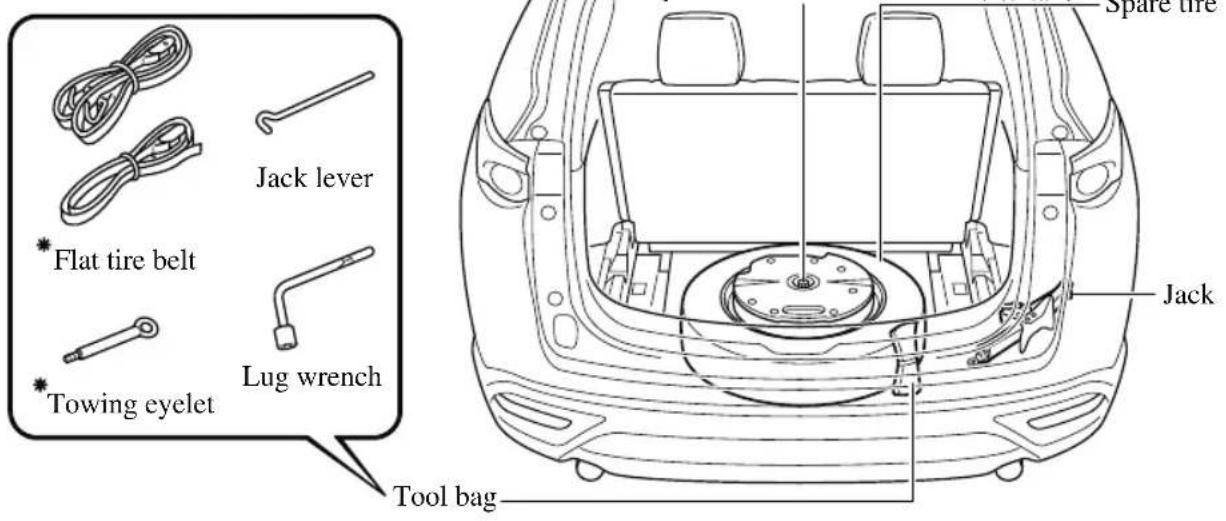
Without sub-woofer

▼ Jack
To remove the jack
-
Set the third-row seatbacks to their on-road positions.
-
Raise the luggage board.
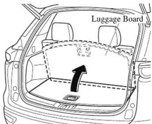
- Raise the luggage board a little while pulling it towards you, and then insert the bottom edge into the holders.
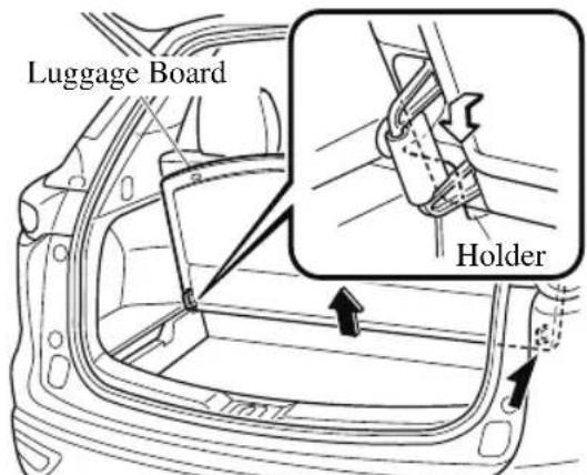
- (Vehicles with luggage mat)
Store the luggage mat between the third-row seatbacks and the luggage board.
- Raise the luggage mat.
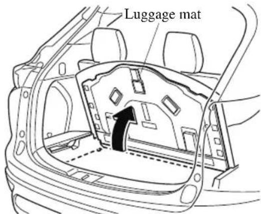
-
Remove the luggage mat.
-
Insert the luggage mat between the luggage board and the third-row seatbacks.
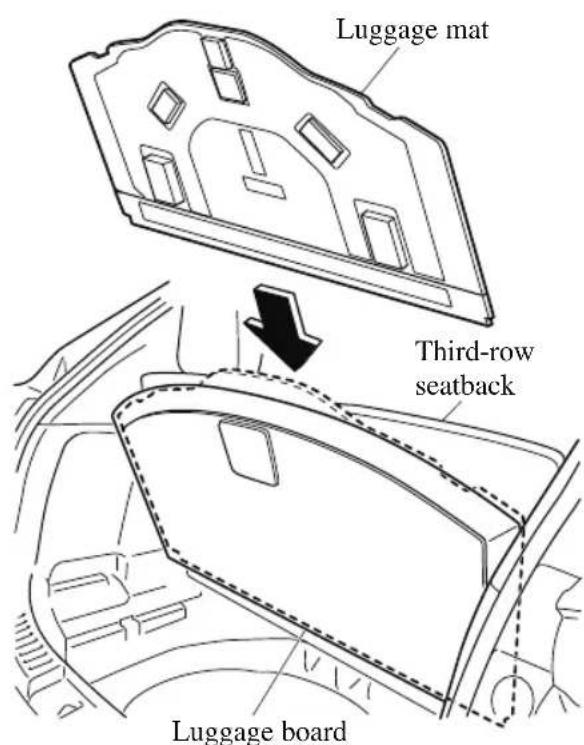
NOTE
When inserting the luggage mat, support the luggage board with one hand so that it does not come off the holders.
- Remove the cover on the right side.

- Remove the cargo sub compartment.
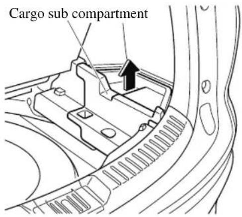
- Turn the wing bolt and jack screw counterclockwise.
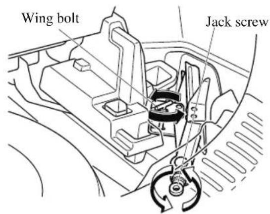
To secure the jack
-
Insert the wing bolt into the jack with the jack screw pointing back and turn the wing bolt clockwise to temporarily tighten it.
-
Tighten the jack screw clockwise.
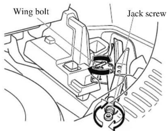
- Turn the wing bolt completely to secure the jack.
NOTE
If the jack is not completely secured, it could rattle while driving. Make sure the jack screw is sufficiently tightened.
Maintenance
· Always keep the jack clean.
• Make sure the moving parts are kept free from dirt or rust.
- Make sure the screw thread is adequately lubricated.
▼ Spare Tire
Your Mazda has a temporary spare tire. The temporary spare tire is lighter and smaller than a conventional tire, and is designed only for emergency use and should be used only for VERY short periods. Temporary spare tires should NEVER be used for long drives or extended periods.

WARNING
Do not install the temporary spare tire on the front wheels (driving wheels):
Driving with the temporary spare tire on one of the front driving wheels is dangerous. Handling will be affected. You could lose control of the vehicle, especially on ice or snow bound roads, and have an accident. Move a regular tire to the front wheel and install the temporary spare tire to the rear.

CAUTION
When using the temporary spare tire, driving stability may decrease compared to when using only the conventional tire. Drive carefully.
To avoid damage to the temporary spare tire or to the vehicle, observe the following precautions:
Do not exceed 80 km/h (50 mph).
Avoid driving over obstacles. Also, do not drive through an automatic car wash. This tire's diameter is smaller than a conventional tire, so the ground clearance is reduced.
Do not use a tire chain on this tire because it will not fit properly.
➢Do not use your temporary spare tire on any other vehicle, it has been designed only for your Mazda.
➢ Use only one temporary spare tire on your vehicle at the same time.
To remove the spare tire
NOTE
(Vehicles with sub-woofer)
Because the sub-woofer is not operational when the sub-woofer connector is disconnected, no sound is output from the sub-woofer.
- Set the third-row seatbacks to their on-road positions.
- Raise the luggage board.
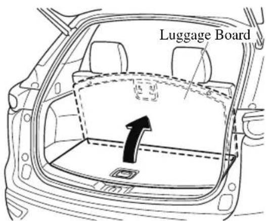
- Raise the luggage board a little while pulling it towards you, and then insert the bottom edge into the holders.
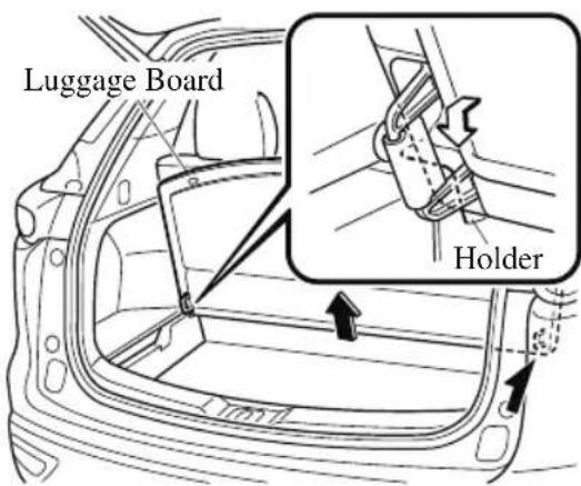
4. (Vehicles with luggage mat)
Store the luggage mat between the third-row seatbacks and the luggage board.
- Raise the luggage mat.
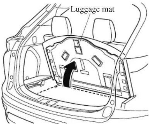
-
Remove the luggage mat.
-
Insert the luggage mat between the luggage board and the third-row seatbacks.
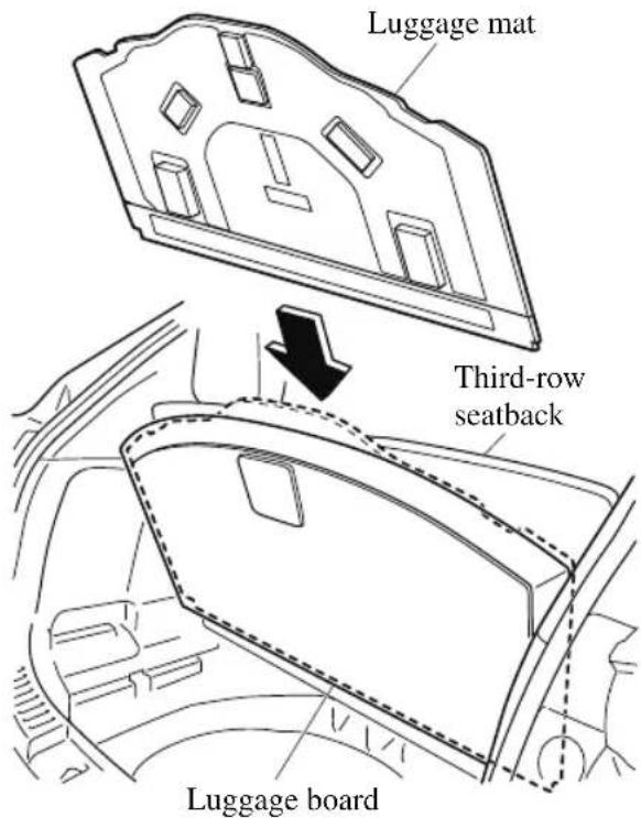
NOTE
When inserting the luggage mat, support the luggage board with one hand so that it does not come off the holders.
-
Remove the tool bag.
-
(Vehicles with sub-woofer)
Disconnect the sub-woofer connector.
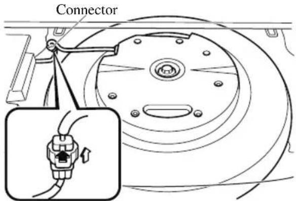
7. (Vehicles with sub-woofer)
Turn the hold-down bolt counterclockwise and remove the sub-woofer and the spare tire.
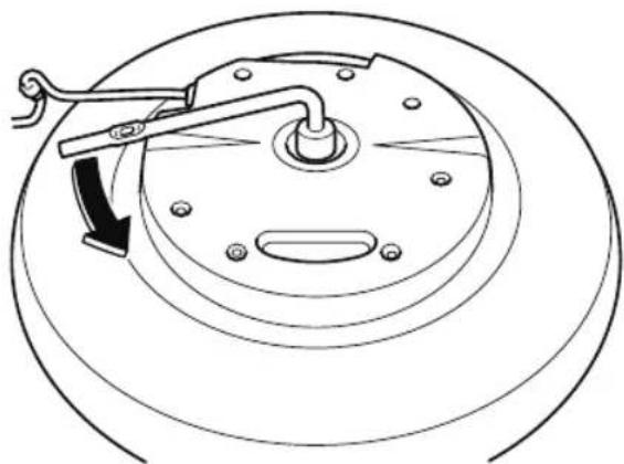
natural_image
Technical line drawing of a mechanical component with a curved arrow indicating rotation (no text or symbols)(Vehicles without sub-woofer)
Turn the hold-down bolt counterclockwise and remove the spare tire.
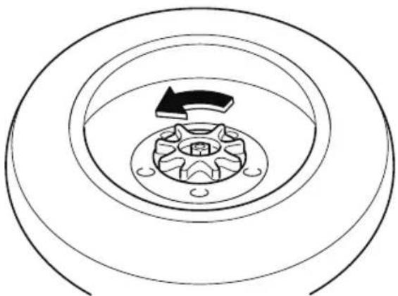
natural_image
Diagram of concentric circular layers with a central arrow and circular structure, no text or symbols present.To secure the spare tire
Store the spare tire in the reverse order of removal. After storing, verify that the spare tire is stored securely.

CAUTION
(Vehicles with sub-woofer)
Secure the sub-woofer in its correct position. If the sub-woofer is not installed to the correct position, it may move while the vehicle is driven which may damage the sub-woofer or the wiring harness.
Store the tool bag on the right side of the vehicle. If the tool bag is stored on the left side of the vehicle, it may move while the vehicle is driven which may damage the wiring harness.
Refer to Spare Tire and Tool Storage on page 7-3.
Changing a Flat Tire
NOTE
If the following occurs while driving, it could indicate a flat tire.
• Steering becomes difficult.
- The vehicle begins to vibrate excessively.
- The vehicle pulls in one direction.
If you have a flat tire, drive slowly to a level spot that is well off the road and out of the way of traffic to change the tire.
Stopping in traffic or on the shoulder of a busy road is dangerous.

WARNING
Be sure to follow the directions for changing a tire:
Changing a tire is dangerous if not done properly. The vehicle can slip off the jack and seriously injure someone.
No person should place any portion of their body under a vehicle that is supported by a jack.
Never allow anyone inside a vehicle supported by a jack:
Allowing someone to remain in a vehicle supported by a jack is dangerous. The occupant could cause the vehicle to fall resulting in serious injury.
NOTE
Make sure the jack is well lubricated before using it.
-
Park on a hard, level surface off the right-of-way and firmly set the parking brake.
-
Shift into Park (P) and turn off the engine.
- Turn on the hazard warning flasher.
- Have passengers get out of the vehicle and away from the vehicle and traffic.
- Remove any luggage, the jack, tools, and spare tire (page 7-3).
- Block the wheel diagonally opposite the flat tire. When blocking a wheel, place a tire block both in front and behind the tire.
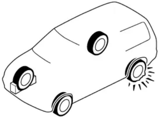
natural_image
Simple line drawing of a car with two wheels and a small sunburst on the side (no text or symbols)NOTE
When blocking a tire, use rocks or wood blocks of sufficient size if possible to hold the tire in place.
▼ Removing a Flat Tire

WARNING
When jacking-up a vehicle, always shift the selector lever to P, apply the parking brake, and place wheel blocks in the position diagonally opposed to the jack:
Changing a flat tire without using wheel blocks is dangerous because the vehicle may move and fall off the jack even with the select lever is in P, which could result in an accident.
- Loosen the lug nuts by turning them counterclockwise one turn each, but do not remove any lug nuts until the tire has been raised off the ground.
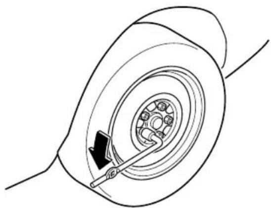
natural_image
Technical line drawing of a car tire assembly with a belt drive mechanism (no text or symbols)-
Place the jack on the ground.
-
Turn the jack screw in the direction shown in the figure and adjust the jack head so that it is close to the jack-up position.
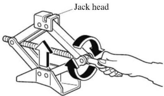
- Set the jack to the designated jack-up position closest to the tire being removed.
(Jacking-up the vehicle front)
Set the groove on the top of the jack head at a right angle into the center of
the designated jack-up position guide projection closest to the vehicle front.
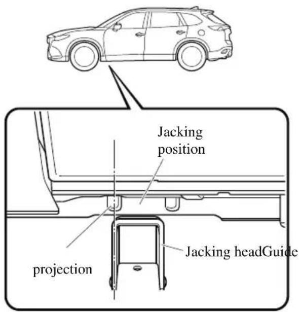
NOTE
Always set the jack into the designated jack-up position shown in the figure correctly.
(Jacking-up the vehicle rear)
Set the groove on the top of the jack head at a right angle between the
designated jack-up position guide projections.
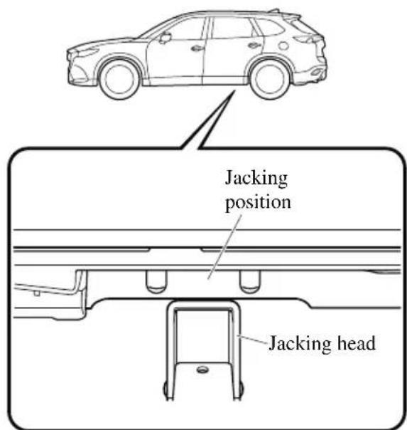
- Continue raising the jack head gradually by rotating the screw with your hand until the jack head is inserted into the jack-up position.
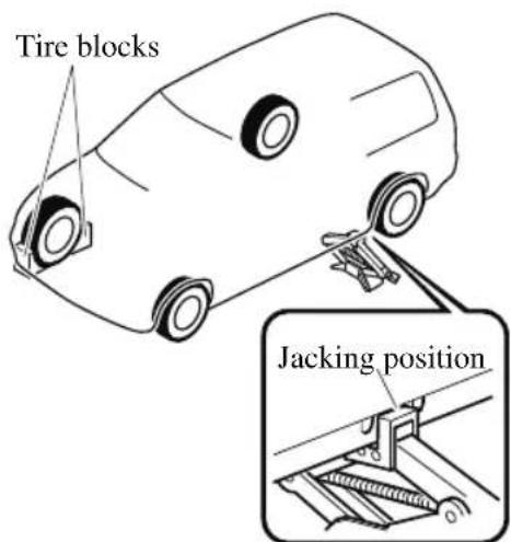

WARNING
Use only the front and rear jacking positions recommended in this manual:
Attempting to jack the vehicle in positions other than those recommended in this manual is dangerous. The vehicle could slip off the jack and seriously injure or even kill someone. Use only the front and rear jacking positions recommended in this manual.
Do not jack up the vehicle in a position other than the designated jack-up position or place any objects on or under the jack:
Jacking up the vehicle in a position other than the designated jack-up position or placing objects on or under the jack is dangerous as it could deform the vehicle body or the vehicle could fall off the jack resulting in an accident.
Use only the jack provided with your Mazda:
Using a jack that is not designed for your Mazda is dangerous. The vehicle could slip off the jack and seriously injure someone.
Never place objects under the jack:
Jacking the vehicle with an object under the jack is dangerous. The jack could slip and someone could be seriously injured by the jack or the falling vehicle.
NOTE
When raising the jack head into the jacking position and aligning the groove in the jack head with the rail under the vehicle body, the top of the jack head contacts the vehicle's underbody without the rail contacting the bottom of the groove.
- Insert the jack lever and attach the lug wrench to tire jack.
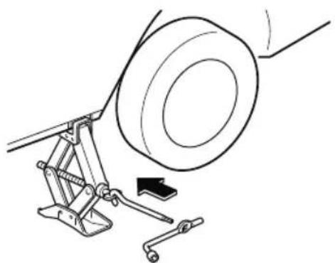
natural_image
Technical line drawing of a mechanical assembly with a wheel and clamping mechanism (no text or symbols)- Turn the jack handle clockwise and raise the vehicle high enough so that the spare tire can be installed. Before removing the lug nuts, make sure your Mazda is firmly in position and that it cannot slip or move.
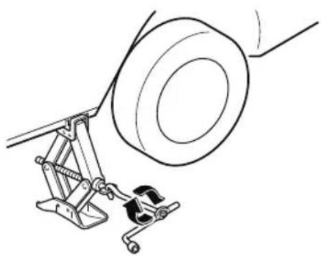
natural_image
Technical line drawing of a mechanical assembly with a wheel and clamp (no text or symbols)
WARNING
Do not jack up the vehicle higher than is necessary:
Jacking up the vehicle higher than is necessary is dangerous as it could destabilize the vehicle resulting in an accident.
Do not start the engine or shake the vehicle while it is jacked up:
Starting the engine or shaking the vehicle while it is jacked up is dangerous as it could cause the vehicle to fall off the jack resulting in an accident.
Never go under the vehicle while it is jacked up:
Going under the vehicle while it is jacked up is dangerous as it could result in death or serious injury if the vehicle were to fall off the jack.
- Remove the lug nuts by turning them counterclockwise; then remove the wheel and center cap.
▼ Locking Lug Nuts
If your vehicle has Mazda optional antitheft wheel lug nuts, each wheel will have one locking lug nut that locks the wheel and tire, and you must use a special key to unlock the locking lug nut. This key is stored in the glove compartment. Register the key and lug nuts with the lock manufacturer by filling out the card provided in the glove compartment and mailing it in the accompanying envelope. If you lose this key, consult an Authorized Mazda Dealer or use the lock manufacturer's order form, which is with the registration card.
Accessory wheel locks cannot be used on steel wheels. This includes situations when the spare tire is installed. When installing
a spare tire, original lug nut must be used in place of the wheel lock.
natural_image
Diagram of two cylindrical objects with star-shaped cutouts, connected by a curved arrow indicating rotation (no text or symbols)To remove an antitheft lug nut
- Obtain the special key for the antitheft lug nut.
- Place the special key on top of the antitheft lug nut, and be sure to hold the key square to it. If you hold the key at an angle, you may damage both key and nut. Do not use a power impact wrench.
- Place the lug wrench on top of the key and apply pressure. Turn the wrench counterclockwise.
- Place the special key on top of the nut, and be sure to hold the key square to it. If you hold the key at an angle, you may damage both key and nut. Do not use a power impact wrench.
- Place the lug wrench on top of the special key, apply pressure, and turn it clockwise.
| Nut tightening torque | |
| N·m (kgf·m, ft·lbf) | 108—147 (12—14, 80—108) |
▼ Mounting the Spare Tire
NOTE
The number and shape of the flat tire belt differ depending on the vehicle specification.
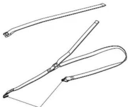
natural_image
Line drawing of three different types of tools or probes, no text or symbols presentBelt clips
- The flat tire belts with the clips are for securing a flat tire.
-
The flat tire belts without the clips are for securing the sub-woofer.
-
Remove dirt and grime from the mounting surfaces of the wheel and hub, including the hub bolts, with a cloth.
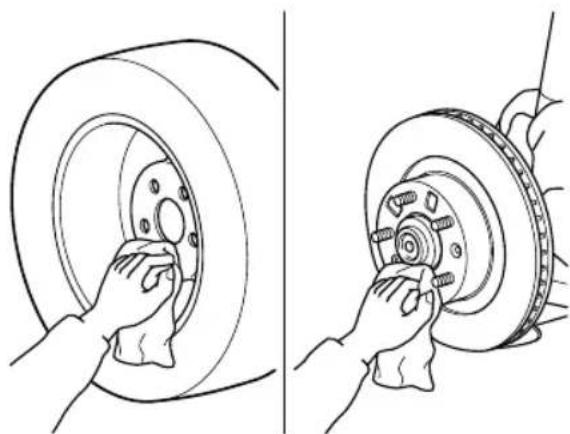
natural_image
Two-step line drawing showing hands installing a tire wheel and adjusting a brake disc (no text or symbols)
WARNING
Make sure the mounting surfaces of the wheel, hub and lug nuts are clean before changing or replacing tires:
When changing or replacing a tire, not removing dirt and grime from the mounting surfaces of the wheel, hub and hub bolts is dangerous. The lug nuts could loosen while driving and cause the tire to come off, resulting in an accident.
- Mount the spare tire.
- Install the lug nuts with the beveled edge inward; tighten them by hand.
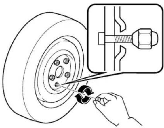
natural_image
Technical illustration of a hand using a screwdriver to adjust a tire component (no text or symbols present)
WARNING
Do not apply oil or grease to lug nuts and bolts and do not tighten the lug nuts beyond the recommended tightening torque:
Applying oil or grease to lug nuts and bolts is dangerous. The lug nuts could loosen while driving and cause the tire to come off, resulting in an accident. In addition, lug nuts and bolts could be damaged if tightened more than necessary.
- Turn the lug wrench counterclockwise and lower the vehicle.
- Use the lug wrench to tighten the nuts in the order shown.
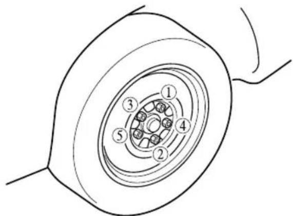
If you are unsure of how tight the nuts should be, have them inspected at an Authorized Mazda Dealer.
| Nut tightening torque | |
| N·m (kgf·m, ft·lbf) | 108—147 (12—14, 80—108) |

WARNING
Always securely and correctly tighten the lug nuts:
Improperly or loosely tightened lug nuts are dangerous. The wheel could wobble or come off. This could result in loss of vehicle control and cause a serious accident.
Be sure to reinstall the same nuts you removed or replace them with metric nuts of the same configuration:
Because the wheel studs and lug nuts on your Mazda have metric threads, using a non-metric nut is dangerous. On a metric stud, it would not secure the wheel and would damage the stud, which could cause the wheel to slip off and cause an accident.
6. (Vehicles with sub-woofer)
Secure the sub-woofer to the flat tire using the flat tire belt.
- Pass the flat tire belt through the wheel of the flat tire.
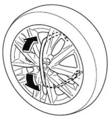
natural_image
Diagram of a car wheel with directional arrows indicating motion or force (no text or labels)- Install the sub-woofer to the flat tire.
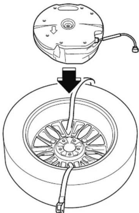
natural_image
Diagram showing a mechanical assembly with a component being inserted into a car wheel (no text or symbols present)- Pass the flat tire belt through the buckle.
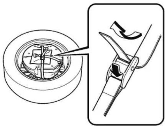
natural_image
Technical illustration showing a mechanical assembly with a circular component and a side view of a tool cutting a curved blade (no text or symbols present)- Pull the end of the flat tire belt and secure the sub-woofer and the wiring harness to the flat tire.
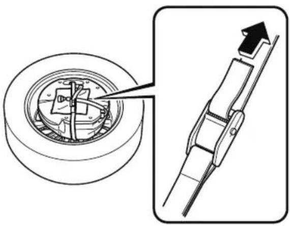
natural_image
Technical diagram showing a mechanical assembly with a circular component and a separate view of a mechanical clamp or bracket (no text or symbols present)
CAUTION
When pulling the flat tire belt, wrap the buckle with a cloth. If the buckle directly contacts the sub-woofer, the sub-woofer may be damaged.
7. (Vehicles except for Mexico)
Secure the flat tire in the luggage compartment using the flat tire belt.
- Pull the flat tire belts out of the buckle to separate them into two belts.
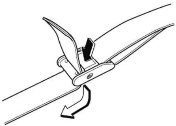
natural_image
Diagram of a mechanical clamp or clip assembly with a curved arrow indicating rotation (no text or symbols)- Hook the clips of the flat tire belts to the hooks under the third-row seat.
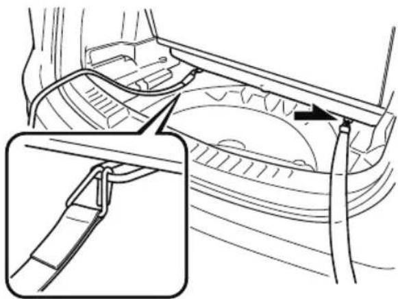
natural_image
Technical diagram of a car interior showing structural components and a magnified detail view (no text or labels)- Place the flat tire in the luggage compartment so that it leans against the luggage board.
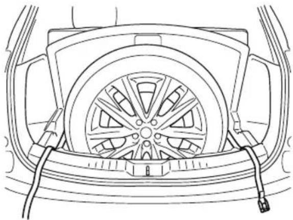
natural_image
Line drawing of a car rear view showing the wheel, dashboard, and engine compartment (no text or symbols)- Pass the flat tire belts through the wheel of the flat tire.
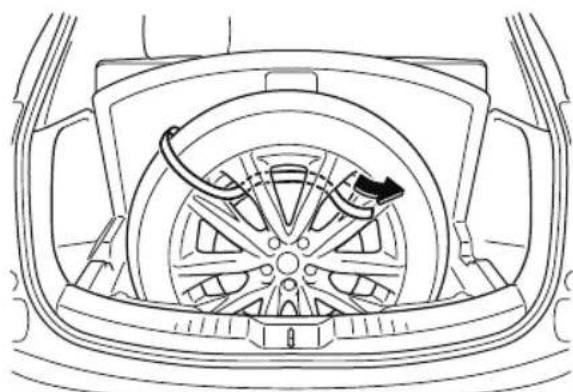
natural_image
Technical line drawing of a car wheel assembly with a directional arrow indicating motion (no text or symbols)- Pass the flat tire belts through the buckle.
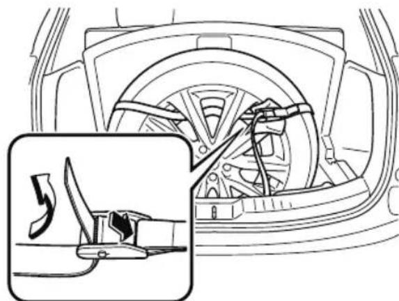
natural_image
Technical line drawing of a car interior showing steering wheel and gear assembly (no text or symbols)- While pressing the flat tire against the third-row seat, pull the ends of
the flat tire belts and secure the flat tire.
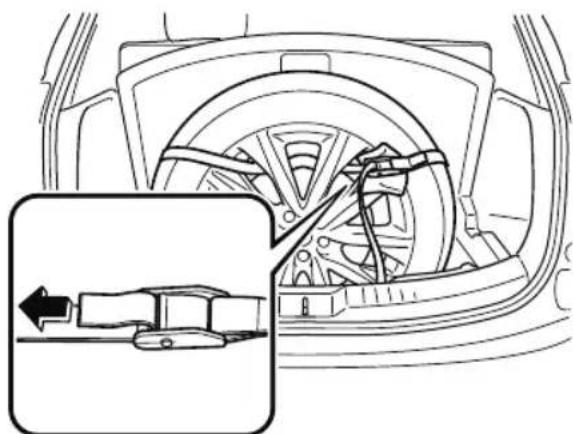
natural_image
Technical line drawing of a car interior showing steering wheel and gear assembly (no text or symbols)
CAUTION
When pulling the flat tire belts, wrap the buckle with a cloth. If the buckle directly contacts the aluminum wheel, the wheel may be damaged.
8. (Vehicles for Mexico)
Place the flat tire in the luggage compartment so that it leans against the luggage board.

natural_image
Technical line drawing of a car wheel assembly (no text or symbols)
CAUTION
Tuck a cloth between the flat tire and the vehicle trim. If the flat tire directly contacts the vehicle trim, the trim may be damaged.
- Slowly close the liftgate while making sure that the liftgate trim does not contact the flat tire.
NOTE
If the liftgate trim contacts the flat tire, adjust the position of the flat tire.
- Make sure that the liftgate closes securely.
- Check the tire inflation pressure. Refer to the specification charts on page 9-7.
- Have the flat tire repaired or replaced as soon as possible.

WARNING
Do not drive with any tires that have incorrect air pressure:
Driving on tires with incorrect air pressure is dangerous. Tires with incorrect pressure could affect handling and result in an accident. When you check the regular tires' air pressure, check the spare tire, too.
NOTE
To prevent the jack and tool from rattling, store them properly.
Jump-Starting
Jump-starting is dangerous if done incorrectly. So follow the procedure carefully. If you feel unsure about jump-starting, we strongly recommend that you have a competent service technician do the work.

WARNING

Follow These Precautions Carefully:
To ensure safe and correct handling of the battery, read the following precautions carefully before using the battery or inspecting it.

Keep flames and sparks away from open battery cells and do not allow metal tools to t the positive (+) or negative (+) terminal of the battery when working near a battery.
Do not allow the positive (+) terminal to contact the vehicle body:
Flames and sparks near open battery cells are dangerous. Hydrogen gas, produced during normal battery operation, could ignite and cause the battery to explode. An exploding battery can cause serious burns and injuries. Keep all flames including cigarettes and sparks away from open battery cells.

Keep all flames and sparks away from open battery cells because hydrogen gas is forced from open battery cells while charging the battery or adding battery fluid:
Flames and sparks near open battery cells are dangerous. Hydrogen gas, produced during normal battery operation, could ignite and cause the battery to explode. An exploding battery can cause serious burns and injuries. Keep all flames including cigarettes and sparks away from open battery cells.
Do not jump-start a frozen battery or one with a low fluid level:
Jump-starting a frozen battery or one with a low fluid level is dangerous. It may rupture or explode, causing serious injury.
Connect the negative cable to a good ground point away from the battery:
Connecting the end of the second jumper cable to the negative (—) terminal of the discharged battery is dangerous.
A spark could cause the gas around the battery to explode and injure someone.
Route the jumper cables away from parts that will be moving:
Connecting a jumper cable near or to moving parts (cooling fans, belts) is dangerous. The cable could get caught when the engine starts and cause serious injury.

CAUTION
Use only a 12 V booster system. You can damage a 12 V starter, ignition system, and other electrical parts beyond repair with a 24 V power supply (two 12 V batteries in series or a 24 V motor generator set).
- Move the booster vehicle so that its battery is as close as possible to your vehicle's battery.
- Make sure that the power such as for the headlights and air conditioner is turned off.
- Remove the battery cover.
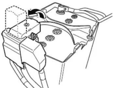
natural_image
Technical line drawing of a mechanical component with no visible text or symbols- Turn off the booster vehicle's engine and connect the jumper cables in the following order.
Make sure that the jumper cables are securely connected so that they do not disconnect due to engine vibrations.
1st lead
①Positive (+) terminal on the discharged battery
②Positive (+) terminal on booster vehicle's battery
③Negative (-) terminal on booster vehicle's battery
2nd lead
④Location shown in the figure (do not connect to the negative (-) terminal of the battery)
Connect cables in numerical order and disconnect in reverse order.
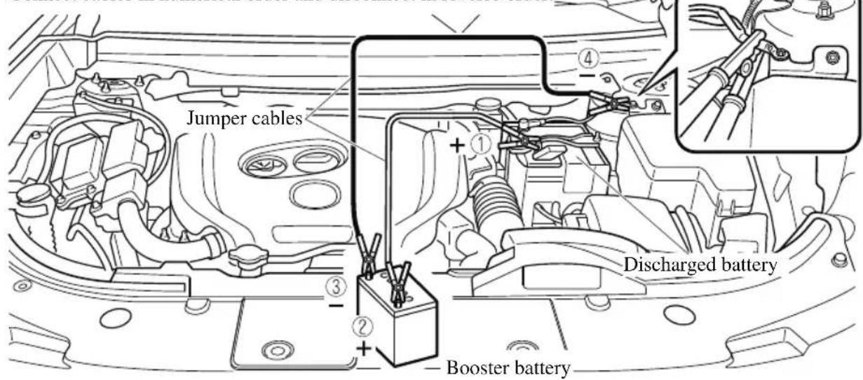
- Start the booster vehicle's engine and rev the engine.
- Start the engine of your vehicle. Run the engines for about 3 minutes to temporarily charge the battery of your vehicle.
- Disconnect the jumper cables in the reverse order of their connection.
- Install the battery cover.
- Have your vehicle inspected by an Authorized Mazda Dealer as soon as possible.
Starting a Flooded Engine
If the engine fails to start, it may be flooded (excessive fuel in the engine).
Follow this procedure:
- If the engine does not start within 5 seconds on the first try, wait 10 seconds and try again.
- Make sure the parking brake is on.
- Depress the accelerator all the way and hold it there.
- Depress the brake pedal, then press the push button start. If the engine starts, release the accelerator immediately because the engine will suddenly rev up.
- If the engine fails to start, crank it without depressing the accelerator.
If the engine still does not start using the previous procedure, have your vehicle inspected by an Authorized Mazda Dealer.
Push-Starting
Do not push-start your Mazda.

WARNING
Never tow a vehicle to start it:
Towing a vehicle to start it is dangerous. The vehicle being towed could surge forward when its engine starts, causing the 2 vehicles to collide. The occupants could be injured.
NOTE
You cannot start a vehicle with an automatic transaxle by pushing it.
Overheating
If the temperature gauge indicates overheating or the high engine coolant temperature warning light turns on, the vehicle loses power, or you hear a loud knocking or pinging noise, the engine is probably too hot.

WARNING

Pull over to a safe location, then switch the ignition off and make sure the fan is not running before attempting to work near the cooling fan:
Working near the cooling fan when it is running is dangerous. The fan could continue running indefinitely even if the engine has stopped and the engine compartment temperature is high. You could be hit by the fan and seriously injured.
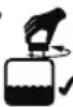
Do not remove either cooling
system cap when the engine and radiator are hot:
When the engine and radiator are hot, scalding coolant and steam may shoot out under pressure and cause serious injury.
Open the hood ONLY after steam is no longer escaping from the engine:
Steam from an overheated engine is dangerous. The escaping steam could seriously burn you.
If the temperature gauge indicates overheating or the high engine coolant temperature warning light turns on:
- Drive safely to the side of the road and park off the right-of-way.
- Shift into park (P).
- Apply the parking brake.
- Turn off the air conditioner.
- Check whether coolant or steam is escaping from the engine compartment.
If steam is coming from the engine compartment:
Do not go near the front of the vehicle. Stop the engine.
Wait until the steam dissipates, then open the hood and start the engine.
If neither coolant nor steam is escaping:
Open the hood and idle the engine until it cools.

CAUTION
If the cooling fan does not operate while the engine is running, the engine temperature will increase. Stop the engine and call an Authorized Mazda Dealer.
-
Make sure the cooling fan is operating, then turn off the engine after the temperature has decreased.
-
When cool, check the coolant level.
If it is low, look for coolant leaks from the radiator and hoses.
If you find a leak or other damage, or if coolant is still leaking:
Stop the engine and call an Authorized Mazda Dealer.
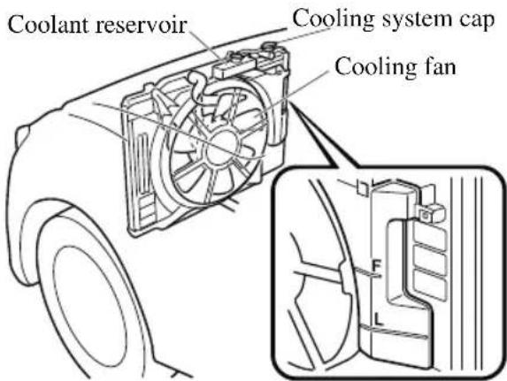
If you find no problems, the engine is cool, and no leaks are obvious:
Carefully add coolant as required (page 6-22).
CAUTION
If the engine continues to overheat or frequently overheats, have the cooling system inspected. The engine could be seriously damaged unless repairs are made. Consult an Authorized Mazda Dealer.
Towing Description
We recommend that towing be done only by an Authorized Mazda Dealer or a commercial tow-truck service.
Proper lifting and towing are necessary to prevent damage to the vehicle. Particularly when towing an AWD vehicle, where all the wheels are connected to the drive train, proper transporting of the vehicle is absolutely essential to avoid damaging the drive system. Government and local laws must be followed.
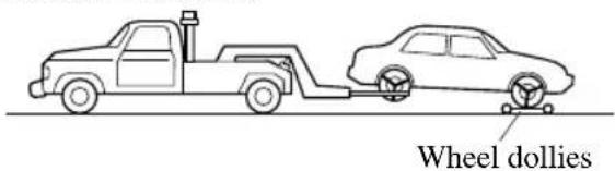
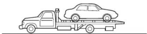
natural_image
Line drawing of a flatbed truck carrying a sedan on its roof (no text or symbols)A towed FWD vehicle should have its drive wheels (front wheels) off the ground. If excessive damage or other conditions prevent this, use wheel dollies.
When towing a FWD vehicle with the rear wheels on the ground, release the parking brake.
Refer to Electric Parking Brake (EPB) on page 4-92.
A towed AWD vehicle must have all its wheels off the ground.

WARNING
Always tow an AWD vehicle with all four wheels off the ground:
Towing an AWD vehicle with either the front or rear wheels on the ground is dangerous as the drive train could be damaged, or the vehicle could trail away from the tow truck and cause an accident. If the drive train has been damaged, transport the vehicle on a flatbed truck.
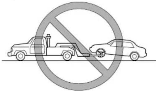

CAUTION
Do not tow the vehicle pointed backward with driving wheels on the ground. This may cause internal damage to the transaxle.
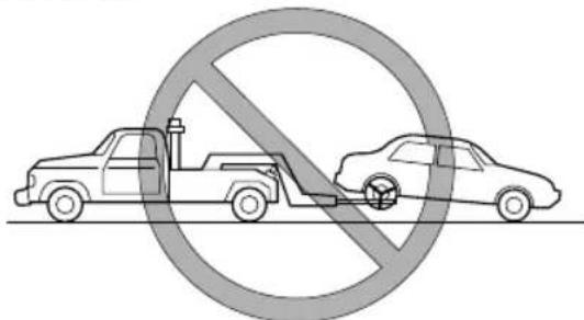
natural_image
Prohibition sign showing a truck and car with a diagonal line, no text or symbols presentDo not tow with sling-type equipment. This could damage your vehicle. Use wheel-lift or flatbed equipment.
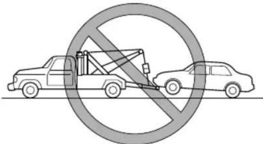
If the parking brake cannot be released when towing the vehicle, transport the vehicle with all front and rear wheels raised off the ground as shown in the figure. If the vehicle is towed without raising the wheels off the ground, the brake system could be damaged.
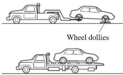
Towing Hooks (Mexico)

CAUTION
The towing eyelet should be used in an emergency (to get the vehicle out of a ditch or a snow bank, for example).
When using the towing eyelets, always pull the cable or chain in a straight direction with respect to the eyelet. Never apply a sideways force.
NOTE
When towing with chain or cable, wrap the chain or cable with a soft cloth near the bumper to prevent damage to the bumper.

Towing Hooks
- Remove the towing eyelet and the lug wrench from the luggage compartment (page 7-3).
- Wrap a flathead screwdriver or similar tool with a soft cloth to prevent damage to a painted bumper, and open the cap located on the front or rear bumper.
Front
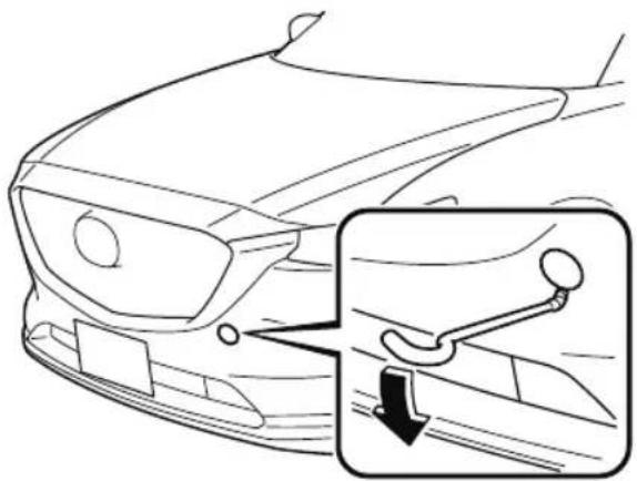
natural_image
Line drawing of a car's front bumper with an inset showing a hand holding a tool (no text or symbols)Rear
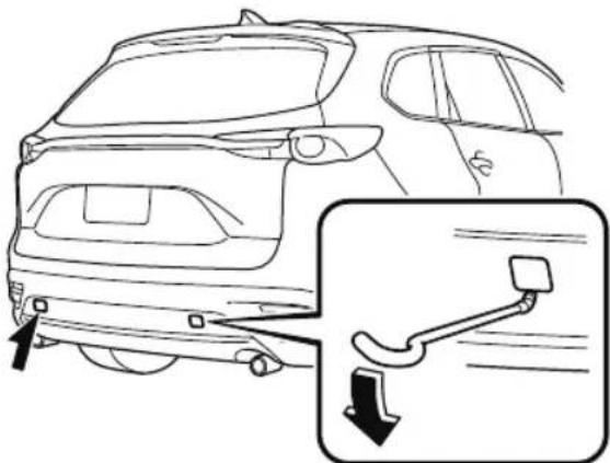
natural_image
Line drawing of a car rear view with an inset showing the side profile of the front wheel and dashboard (no text or symbols)
CAUTION
Do not use excessive force as it may damage the cap or scratch the painted bumper surface.
NOTE
Remove the cap completely and store it so as not to lose it.
- Securely install the towing eyelet using the lug wrench.
Front
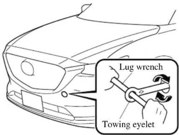
Rear
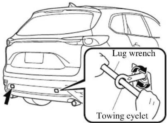
- Hook the towing rope to the towing eyelet.

CAUTION
If the towing eyelet is not securely tightened, it may loosen or disengage from the bumper when towing the vehicle. Make sure that the towing eyelet is securely tightened to the bumper.
➢ Be careful not to damage the towing eyelet and towing hook, vehicle body, or transaxle system when towing under the following conditions:
Do not tow a vehicle heavier than yours.
➢Do not suddenly accelerate your vehicle as it will apply a severe shock to the towing eyelet and towing hook or rope.
➢Do not attach any rope other than to the towing eyelet and towing hook.
If a Warning Light Turns On or Flashes
If any warning light turns on/flashes, take appropriate action for each light. There is no problem if the light turns off, however if the light does not turn off or turns on/flashes again, consult an Authorized Mazda Dealer.
The details for some warnings can be viewed on the center display or multi-information display (Type A/Type B) in the instrument cluster.
Center display
- If the warning light is turned on, select the icon on the home screen to display the Applications screen.
- Select "Vehicle Status Monitor".
- Select "Warning Guidance" to display the current warnings.
- Select the applicable warning to view the warning details.
Multi-information display (Type A/Type B)
- Press the INFO switch on the steering switch to display the warning indication screen.
Refer to Multi-information Display (Type A) on page 4-13.
Refer to Multi-information Display (Type B) on page 4-30.
▼ Stop Vehicle in Safe Place Immediately
If any of the following warning lights turns on, the system may have a malfunction. Stop the vehicle in a safe place immediately and contact an Authorized Mazda Dealer.
| Signal Warning | |
 BRAKEBrake System WarningIndication/WarningLight BRAKEBrake System WarningIndication/WarningLight | This warning has the following functions:Parking brake warning/Warning light inspectionThe light illuminates when the parking brake is applied with the ignition switched to START or ON. It turns off when the parking brake is released.When the light turns onIf the brake system warning light remains turned on even though the parking brake is released, the brake fluid may be low or there could be a problem with the brake system. Park the vehicle in a safe place immediately and contact an Authorized Mazda Dealer.When the light is flashingThe light flashes if the Electric Parking Brake (EPB) has a malfunction.If the light remains flashing even if the Electric Parking Brake (EPB) switch is operated, consult an Authorized Mazda Dealer as soon as possible.  Do not drive with the brake system warning light illuminated. Contact an Authorized Mazda Dealer to have the brakes inspected as soon as possible:Driving with the brake system warning light illuminated is dangerous. It indicates that your brakes may not work at all or that they could completely fail at any time. If this light remains illuminated, after checking that the parking brake is fully released, have the brakes inspected immediately. Do not drive with the brake system warning light illuminated. Contact an Authorized Mazda Dealer to have the brakes inspected as soon as possible:Driving with the brake system warning light illuminated is dangerous. It indicates that your brakes may not work at all or that they could completely fail at any time. If this light remains illuminated, after checking that the parking brake is fully released, have the brakes inspected immediately.  In addition, the effectiveness of the braking may diminish so you may need to depress the brake pedal more strongly than normal to stop the vehicle. In addition, the effectiveness of the braking may diminish so you may need to depress the brake pedal more strongly than normal to stop the vehicle. |
  ABSElectronic Brake ForceDistribution System Waming ABSElectronic Brake ForceDistribution System Waming | If the electronic brake force distribution control unit determines that some components are operating incorrectly, the control unit may illuminate the brake system warning light and the ABS warning light simultaneously. The problem is likely to be the electronic brake force distribution system.  Do not drive with both the ABS warning light and brake warning light illuminated.Have the vehicle towed to an Authorized Mazda Dealer to have the brakes inspected as soon as possible:Driving when the brake system warning light and ABS warning light are illuminated simultaneously is dangerous.When both lights are illuminated, the rear wheels could lock more quickly in an emergency stop than under normal circumstances. Do not drive with both the ABS warning light and brake warning light illuminated.Have the vehicle towed to an Authorized Mazda Dealer to have the brakes inspected as soon as possible:Driving when the brake system warning light and ABS warning light are illuminated simultaneously is dangerous.When both lights are illuminated, the rear wheels could lock more quickly in an emergency stop than under normal circumstances. |
 Charging System Warning Indication/Warning Light Charging System Warning Indication/Warning Light | If the warning light illuminates while driving, it indicates a malfunction of the alternator or of the charging system.Drive to the side of the road and park off the right-of-way. Consult an Authorized Mazda Dealer. Do not continue driving when the charging system warning light is illuminated because the engine could stop unexpectedly. Do not continue driving when the charging system warning light is illuminated because the engine could stop unexpectedly. |
 Engine Oil Warning Light Engine Oil Warning Light | This warning light indicates low engine oil pressure. Do not run the engine if the oil pressure is low. Otherwise, it could result in extensive engine damage.If the light illuminates or the warning indication is displayed while driving:1. Drive to the side of the road and park off the right-of-way on level ground.2. Turn off the engine and wait 5 minutes for the oil to drain back into the oil pan.3. Inspect the engine oil level (page 6-21). If it's low, add the appropriate amount of engine oil while being careful not to overfill. Do not run the engine if the oil pressure is low. Otherwise, it could result in extensive engine damage.If the light illuminates or the warning indication is displayed while driving:1. Drive to the side of the road and park off the right-of-way on level ground.2. Turn off the engine and wait 5 minutes for the oil to drain back into the oil pan.3. Inspect the engine oil level (page 6-21). If it's low, add the appropriate amount of engine oil while being careful not to overfill. Do not run the engine if the oil level is low. Otherwise, it could result in extensive engine damage.4. Start the engine and check the warning light.If the light remains illuminated even though the oil level is normal or after adding oil, stop the engine immediately and have your vehicle towed to an Authorized Mazda Dealer. Do not run the engine if the oil level is low. Otherwise, it could result in extensive engine damage.4. Start the engine and check the warning light.If the light remains illuminated even though the oil level is normal or after adding oil, stop the engine immediately and have your vehicle towed to an Authorized Mazda Dealer. |
 (Red)High Engine Coolant Temperature Warning Indication/Warning Light (Red)High Engine Coolant Temperature Warning Indication/Warning Light | The light flashes when the engine coolant temperature is extremely high, and illuminates when the engine coolant temperature increases further.Handling ProcedureFlashing lightDrive slowly to reduce engine load until you can find a safe place to stop the vehicle and wait for the engine to cool down.Illuminated lightThis indicates the possibility of overheating. Park the vehicle in a safe place immediately and stop the engine.Refer to Overheating on page 7-23. Do not drive the vehicle with the high engine coolant temperature warning light illuminated. Otherwise, it could result in damage to the engine. Do not drive the vehicle with the high engine coolant temperature warning light illuminated. Otherwise, it could result in damage to the engine. |
 Power Steering Mal-function Indication* Power Steering Mal-function Indication* | The message is displayed if the electric power steering has a malfunction.If the message is displayed, stop the vehicle in a safe place and do not operate the steering wheel. There is no problem if the message in the display turns off after a while. Contact an Authorized Mazda Dealer if the message is displayed continuously.NOTEIf the message is displayed, the power steering will not operate normally. In this case, the steering wheel can still be operated, however, the operation may feel heavy compared to normal, or the steering wheel could vibrate when turning.Repeatedly jerking the steering wheel left and right while the vehicle is stopped or moving extremely slowly will cause the power steering system to go into protective mode which will make the steering feel heavy, but this does not indicate a problem. If this occurs, park the vehicle safely and wait several minutes for the system to return to normal. |
 Power Steering Mal-function Indicator Light* Power Steering Mal-function Indicator Light* | The light illuminates/flashes if the electric power steering has a malfunction.If the light illuminates/flashes, stop the vehicle in a safe place and do not operate the steering wheel. There is no problem if the light turns off after a while. Contact an Authorized Mazda Dealer if the light illuminates/flashes continuously.NOTEIf the indicator light illuminates/flashes, the power steering will not operate normally. If this happens, the steering wheel can still be operated, however, the operation may feel heavy compared to normal, or the steering wheel could vibrate when turning.Repeatedly jerking the steering wheel left and right while the vehicle is stopped or moving extremely slowly will cause the power steering system to go into protective mode which will make the steering feel heavy, but this does not indicate a problem. If this occurs, park the vehicle safely and wait several minutes for the system to return to normal. |
▼ Contact Authorized Mazda Dealer and Have Vehicle Inspected
If any of the following warning lights or the indicator light turns on/flashes, the system may have a malfunction. Contact an Authorized Mazda Dealer to have your vehicle inspected.
| Signal Warning | |
 ABSABS Warning Light ABSABS Warning Light | If the ABS warning light stays on while you're driving, the ABS control unit has detected a system malfunction. If this occurs, your brakes will function normally as if the vehicle had no ABS.Should this happen, consult an Authorized Mazda Dealer as soon as possible.NOTEWhen the engine is jump-started to charge the battery, uneven rpm occurs and the ABS warning light may illuminate. If this occurs, it is the result of the weak battery and does not indicate an ABS malfunction.Recharge the battery.The brake assist system does not operate while the ABS warning light is illuminated. |
| Master Warning Indication/Warning Light | With Multi-information Display (Type A/Type B)Displays when notification of the system malfunctions is required.Check the message indicated in the display and consult an Authorized Mazda Dealer.Multi-information DisplayType A Type B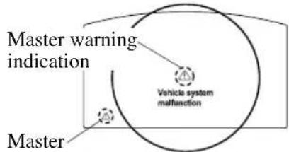 warning lightMaster warning in warning lightMaster warning in Master warning lightIndication in display and master warning light in instrument cluster are illuminated at same time.This indicates a malfunction with the vehicle system. Check the message indicated in the display and consult an Authorized Mazda Dealer.For details, refer to the explanations for the warning/indicator lights, in the warning/indicator lights section, which match the symbol in the upper part of the display.If a message is not indicated in the display, operate the INFO switch to display the “Warning” screen.Refer to Message Indicated in Multi-information Display (Type A) on page 4-13.Refer to Message Indicated in Multi-information Display (Type B) on page 4-30.With Multi-information Display (Type C)The light illuminates continuously if any one of the following occurs. Consult an Authorized Mazda Dealer.There is a malfunction in the battery management system.There is a malfunction in the brake switch. Master warning lightIndication in display and master warning light in instrument cluster are illuminated at same time.This indicates a malfunction with the vehicle system. Check the message indicated in the display and consult an Authorized Mazda Dealer.For details, refer to the explanations for the warning/indicator lights, in the warning/indicator lights section, which match the symbol in the upper part of the display.If a message is not indicated in the display, operate the INFO switch to display the “Warning” screen.Refer to Message Indicated in Multi-information Display (Type A) on page 4-13.Refer to Message Indicated in Multi-information Display (Type B) on page 4-30.With Multi-information Display (Type C)The light illuminates continuously if any one of the following occurs. Consult an Authorized Mazda Dealer.There is a malfunction in the battery management system.There is a malfunction in the brake switch. |
| (P!)Electric Parking Brake (EPB) Warning Indication/Warning Light | The warning light illuminates when the system has a malfunction. Have your vehicle inspected at an Authorized Mazda Dealer. |
 (Red)Brake Pedal Operation Demand Warning Light* (Red)Brake Pedal Operation Demand Warning Light* | When only flashingFlashes if there is the possibility of the vehicle not being held in the stopped position by the AUTOHOLD function, such as on steep slopes. Depress and hold your foot on the brake pedal.When flashing and beep sound is activated at the same timeThe warning light flashes and the beep sound is activated for about 5 seconds if there is a problem with the system. If the warning light flashes and the warning sound is activated, immediately depress the brake pedal and stop using the AUTOHOLD function then contact an Authorized Mazda Dealer. Immediately depress the brake pedal if the warning light flashes and the beep sound is activated while using the AUTOHOLD function:Because the AUTOHOLD function is canceled forcibly, the vehicle may move unexpectedly and result in an accident. Immediately depress the brake pedal if the warning light flashes and the beep sound is activated while using the AUTOHOLD function:Because the AUTOHOLD function is canceled forcibly, the vehicle may move unexpectedly and result in an accident. |
 Check Engine Light Check Engine Light | If this light illuminates while driving, the vehicle may have a problem. It is important to note the driving conditions when the light illuminated and consult an Authorized Mazda Dealer.The check engine light may illuminate in the following cases:The engine's electrical system has a problem.The emission control system has a problem.The fuel tank level being very low or approaching empty.The fuel-filler cap is missing or not tightened securely.If the check engine light remains on, or it flashes continuously , do not drive at high speeds and consult an Authorized Mazda Dealer as soon as possible. If the check engine light turns on, do not disconnect the battery cables.If the battery cables are disconnected and then reconnected, the engine could be damaged and catch on fire. If the check engine light turns on, do not disconnect the battery cables.If the battery cables are disconnected and then reconnected, the engine could be damaged and catch on fire. |
| ATAutomatic Transaxle Warning Indication/Warning Light | The indication/light illuminates when the transaxle has a problem. If the automatic transaxle warning indication/light illuminates, the transaxle has an electrical problem. Continuing to drive your Mazda in this condition could cause damage to your transaxle. Consult an Authorized Mazda Dealer as soon as possible. If the automatic transaxle warning indication/light illuminates, the transaxle has an electrical problem. Continuing to drive your Mazda in this condition could cause damage to your transaxle. Consult an Authorized Mazda Dealer as soon as possible. |
| Signal Warning | |
| 4WDAWD Warning Indication* | “4WD system malfunction” is displayedThe indication is displayed under the following conditions. The system may have a malfunction. Have the vehicle checked at an Authorized Mazda Dealer.When there is a malfunction in the AWD system.When there is a large difference between the tire size of the front and rear wheels.“4WD system high-load” is displayedThe indication is displayed under the following conditions. Park the vehicle in a safe place and check that the warning indication light turns off, and then drive the vehicle. Contact an Authorized Mazda Dealer if the indication is continuously displayed.When the differential oil temperature is excessively high.When there is a large difference between the front and rear wheel rotation, such as when trying to remove the vehicle from mud. |
 (Turns on)TCS/DSC Indicator Light (Turns on)TCS/DSC Indicator Light | If the light stays on, the TCS, DSC or the brake assist system may have a malfunction and they may not operate correctly. Take your vehicle to an Authorized Mazda Dealer. |
 Air Bag/Front Seat Belt Pretensioner System Warning Light Air Bag/Front Seat Belt Pretensioner System Warning Light | A system malfunction is indicated if the warning light constantly flashes, constantly illuminates or does not illuminate at all when the ignition is switched ON. If any of these occur, consult an Authorized Mazda Dealer as soon as possible. The system may not operate in an accident. WARNINGNever tamper with the air bag/pretensioner systems and always have an Authorized Mazda Dealer perform all servicing and repairs:Self-servicing or tampering with the systems is dangerous. An air bag/pretensioner could accidentally activate or become disabled causing serious injury or death. WARNINGNever tamper with the air bag/pretensioner systems and always have an Authorized Mazda Dealer perform all servicing and repairs:Self-servicing or tampering with the systems is dangerous. An air bag/pretensioner could accidentally activate or become disabled causing serious injury or death. |
 (Flashing)Tire Pressure Monitoring SystemWarning Light (Flashing)Tire Pressure Monitoring SystemWarning Light | If the tire pressure monitoring system has a malfunction, the tire pressure warning light flashes. Have your vehicle checked by an Authorized Mazda Dealer as soon as possible. If the tire pressure monitoring system warning light illuminates orflashes, or the tire pressure warning beep sound is heard, decrease vehicle speed immediately and avoid sudden maneuvering and braking:If the tire pressure monitoring system warning light illuminates or flashes, or the tire pressure warning beep sound is heard, it is dangerous to drive the vehicle at high speeds, or perform sudden maneuvering or braking. Vehicle drivability could worsen and result in an accident.To determine if you have a slow leak or a flat, pull over to a safe position where you can check the visual condition of the tire and determine if you have enough air to proceed to a place where air may be added and the system monitored again by an Authorized Mazda Dealer or a tire repair station.Do not ignore the TPMS Warning Light:Ignoring the TPMS warning light is dangerous, even if you know why it is illuminated. Have the problem taken care of as soon as possible before it develops into a more serious situation that could lead to tire failure and a dangerous accident. If the tire pressure monitoring system warning light illuminates orflashes, or the tire pressure warning beep sound is heard, decrease vehicle speed immediately and avoid sudden maneuvering and braking:If the tire pressure monitoring system warning light illuminates or flashes, or the tire pressure warning beep sound is heard, it is dangerous to drive the vehicle at high speeds, or perform sudden maneuvering or braking. Vehicle drivability could worsen and result in an accident.To determine if you have a slow leak or a flat, pull over to a safe position where you can check the visual condition of the tire and determine if you have enough air to proceed to a place where air may be added and the system monitored again by an Authorized Mazda Dealer or a tire repair station.Do not ignore the TPMS Warning Light:Ignoring the TPMS warning light is dangerous, even if you know why it is illuminated. Have the problem taken care of as soon as possible before it develops into a more serious situation that could lead to tire failure and a dangerous accident. |
| (Amber)KEY Warning Indication* | “Keyless System Malfunction” is displayedThis message is displayed if the advanced keyless entry & push button start system has a problem.Contact an Authorized Mazda Dealer. If the message is indicated, or the push button start indicator light (amber) flashes, the engine may not start. If the engine cannot be started, try starting it using the emergency operation for starting the engine, and have the vehicle inspected at an Authorized Mazda Dealer as soon as possible.Refer to Emergency Operation for Starting the Engine on page 4-9.“Ignition is On” is displayedThis message is displayed when the driver's door is opened without switching the ignition off.“Key Not Detected” is displayedThis message is displayed when any of the following operations is performed with the key out of the operational range or placed in areas inside the cabin where it is difficult for the key to be detected.The push button start is pressed with the ignition switched offThe ignition is switched onAll doors are closed without switching the ignition off If the message is indicated, or the push button start indicator light (amber) flashes, the engine may not start. If the engine cannot be started, try starting it using the emergency operation for starting the engine, and have the vehicle inspected at an Authorized Mazda Dealer as soon as possible.Refer to Emergency Operation for Starting the Engine on page 4-9.“Ignition is On” is displayedThis message is displayed when the driver's door is opened without switching the ignition off.“Key Not Detected” is displayedThis message is displayed when any of the following operations is performed with the key out of the operational range or placed in areas inside the cabin where it is difficult for the key to be detected.The push button start is pressed with the ignition switched offThe ignition is switched onAll doors are closed without switching the ignition off |
| Signal Warning | |
 (Red)(Turns on)KEY Warning Light* (Red)(Turns on)KEY Warning Light* | If any malfunction occurs in the keyless entry system, it illuminates continuously. If the key warning indicator light illuminates or the push button start indicator light (amber) flashes, the engine may not start. If the engine cannot be started, try starting it using the emergency operation for starting the engine, and have the vehicle inspected at an Authorized Mazda Dealer as soon as possible.Refer to Emergency Operation for Starting the Engine on page 4-9. If the key warning indicator light illuminates or the push button start indicator light (amber) flashes, the engine may not start. If the engine cannot be started, try starting it using the emergency operation for starting the engine, and have the vehicle inspected at an Authorized Mazda Dealer as soon as possible.Refer to Emergency Operation for Starting the Engine on page 4-9. |
 (Amber)High Beam Control System (HBC)Warning Indication/Waming Light * (Amber)High Beam Control System (HBC)Warning Indication/Waming Light * | The light remains turned on if there is a problem with the system. Have your vehicle inspected at an Authorized Mazda Dealer.NOTEIf the Forward Sensing Camera (FSC) field of view is impaired during bad weather conditions (such as rain, fog, and snow) and when the windshield is dirty, the warning indication/warning light for the High Beam Control System (HBC) may display/turn on. However, this does not indicate a problem. |
 Blind Spot Monitoring (BSM) Warning Indication* Blind Spot Monitoring (BSM) Warning Indication* | The Warning indication turns on if there is any malfunction in the Blind Spot Monitoring (BSM). Have your vehicle inspected by an Authorized Mazda Dealer.NOTEIf the vehicle is driven on a road with less traffic and few vehicles that the radar sensors can detect, the system may pause. However, it does not indicate a malfunction. |
 Blind Spot Monitoring (BSM) OFF Indicator Light* Blind Spot Monitoring (BSM) OFF Indicator Light* | A problem in the system may be indicated under the following conditions.Have your vehicle inspected at an Authorized Mazda Dealer.The light does not turn on when the ignition is switched ON.The light remains on even when the Blind Spot Monitoring (BSM) system can be operated.It turns on while driving the vehicle.NOTEIf the vehicle is driven on a road with less traffic and few vehicles that the radar sensors can detect, the system may pause (The Blind Spot Monitoring (BSM) OFF indicator light in the instrument cluster illuminates). However, it does not indicate a malfunction. |
 (Amber)Driver Attention Alert (DAA) Warning Indication* (Amber)Driver Attention Alert (DAA) Warning Indication* | The message is displayed when the system has a malfunction. Have your vehicle inspected at an Authorized Mazda Dealer. |
 (Amber)Mazda Radar Cruise Control with Stop & Go function(MRCC with Stop & Go function)Warning Indication* (Amber)Mazda Radar Cruise Control with Stop & Go function(MRCC with Stop & Go function)Warning Indication* | The message is displayed when the system has a malfunction. Have your vehicle inspected at an Authorized Mazda Dealer. |
 Lane-keep Assist System (LAS) & Lane Departure Warning System (LDWS) Warning Indication* Lane-keep Assist System (LAS) & Lane Departure Warning System (LDWS) Warning Indication* | The message is displayed when the system has a malfunction. Have your vehicle inspected at an Authorized Mazda Dealer.The system does not operate when the warning message is displayed. CAUTION>Always use tires for all wheels that are of the specified size, and the same manufacture, brand, and tread pattern. In addition, do not use tires with significantly different wear patterns on the same vehicle. If such improper tires are used, the system may not operate normally.>When an emergency spare tire is used, the system may not operate normally. CAUTION>Always use tires for all wheels that are of the specified size, and the same manufacture, brand, and tread pattern. In addition, do not use tires with significantly different wear patterns on the same vehicle. If such improper tires are used, the system may not operate normally.>When an emergency spare tire is used, the system may not operate normally. |
 LED Headlight Warning Light LED Headlight Warning Light | This light illuminates if there is a malfunction in the LED headlight. Have your vehicle inspected by an Authorized Mazda Dealer. |
▼ Taking Action
Take the appropriate action and verify that the warning light turns off.
| Signal Warning | Action to be taken | |
 (Amber)Smart Brake Support/Smart City Brake Support (SBS/SCBS)Warning Indication * (Amber)Smart Brake Support/Smart City Brake Support (SBS/SCBS)Warning Indication * | The light turns on if the windshield or the radar sensor are dirty, or there is a malfunction in the system. | Verify the reason why the warning light is illuminated on the center display.If the reason why the warning light is illuminated is due to a dirty windshield, clean the windshield.If the warning light is illuminated because of a dirty radar sensor, clean the front emblem.For any other reasons, have the vehicle inspected at an Authorized Mazda Dealer. |
 Low Fuel Warning Indication/Warning Light Low Fuel Warning Indication/Warning Light | The light turns on when the remaining fuel is about 9.0 L (2.3 US gal, 1.9 Imp gal).NOTEThe light illumination timing may vary because fuel inside the fuel tank moves around according to the driving conditions and the vehicle posture. | Add fuel. |
 Check Fuel Cap Warning Indication/Warning Light Check Fuel Cap Warning Indication/Warning Light | If the check fuel cap warning light illuminates while driving, the fuel-filler cap may not be installed properly. | Stop the engine and reinstall the fuel-filler cap.Refer to Refueling on page 3-32. |
 Engine Oil Level Warning Light Engine Oil Level Warning Light | This warning light indicates that the engine oil level is around the MIN mark (page 6-21). | Add 1 L (0.3 US gal, 0.2 Imp gal) of engine oil (page 6-20). |
 Seat Belt Warning Light (Front seat) Seat Belt Warning Light (Front seat) | Except MexicoThe seat belt warning light turns on if the driver or front passenger's seat is occupied and the seat belt is not fastened with the ignition switched ON.If the driver or front passenger's seat belt is unfastened (only when the front passenger's seat is occupied) and if the vehicle is driven at about 20 km/h (12 mph) or faster, or about 10 km/h (6 mph) or faster for a continuous 30 seconds, with the seat belt unfastened, the warning light flashes for a certain period. After a short time, the warning light stops flashing, but remains illuminated.NOTEThe warning light flashes for about 6 seconds if the driver's seat belt is not fastened when the ignition is switched ON.To allow the front passenger occupant classification sensor to function properly, do not place and sit on an additional seat cushion on the front passenger's seat.The sensor may not function properly because the additional seat cushion could cause sensor interference.If a small child is seated on the front passenger's seat, the warning light may not operate. | Fasten the seat belts. |
 Seat Belt WarningLight (Front seat) Seat Belt WarningLight (Front seat) | MexicoThe seat belt warning light turns on if the driver or front passenger's seat is occupied and the seat belt is not fastened with the ignition switched ON.If the driver or front passenger's seat belt is unfastened (only when the front passenger's seat is occupied) and the vehicle is driven at a speed faster than about 20 km/h (12 mph), the warning light flashes. After a short time, the warning light stops flashing, but remains illuminated. If a seat belt remains unfastened, the warning light flashes again for a given period of time.NOTEPlacing heavy items on the front passenger's seat may cause the front passenger's seat belt warning function to operate depending on the weight of the item.To allow the front passenger seat weight sensor to function properly, do not place and sit on an additional seat cushion on the front passenger's seat. The sensor may not function properly because the additional seat cushion could cause sensor interference.If a small child is seated on the front passenger's seat, the warning light may not operate. | Fasten the seat belts. |
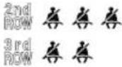 (Red)Seat Belt WarningLight (Rear seat)* (Red)Seat Belt WarningLight (Rear seat)* | If the rear seat belts are not fastened while the ignition is switched ON , the driver and the passenger are alerted by the warning light.The warning light operates even if there is no passenger on the rear seat.NOTEIf a rear seat belt is not fastened by a certain period of time after the engine has been started, the warning light turns off. | Fasten the seat belts. |
 Low Washer FluidLevel Warning Indication* Low Washer FluidLevel Warning Indication* | This warning light indicates that little washer fluid remains. | Add washer fluid (page 6-24). |
| Signal Warning Action to be taken | ||
 Door-Ajar/Lift-gate-Ajar Warning Indication/Warning Light Door-Ajar/Lift-gate-Ajar Warning Indication/Warning Light | The light turns on if any door/liftgate is not closed securely. | Close the door/liftgate securely. |
Tire Pressure Monitoring System Warning Light (Turns on) \*
Take the appropriate action and verify that the warning light turns off.
| Warning |
| When the warning light illuminates, and the warning beep sound is heard when tire pressure is too low in one or more tires. |
 WARNING WARNING |
| If the tire pressure monitoring system warning light illuminates or flashes, or the tire pressure warning beep sound is heard, decrease vehicle speed immediately and avoid sudden maneuvering and braking:If the tire pressure monitoring system warning light illuminates or flashes, or the tire pressure warning beep sound is heard, it is dangerous to drive the vehicle at high speeds, or perform sudden maneuvering or braking. Vehicle drivability could worsen and result in an accident.To determine if you have a slow leak or a flat, pull over to a safe position where you can check the visual condition of the tire and determine if you have enough air to proceed to a place where air may be added and the system monitored again by an Authorized Mazda Dealer or a tire repair station.Do not ignore the TPMS Warning Light:Ignoring the TPMS warning light is dangerous, even if you know why it is illuminated. Have the problem taken care of as soon as possible before it develops into a more serious situation that could lead to tire failure and a dangerous accident. |
Action to be taken
Inspect the tires and adjust to the specified inflation pressure (page 6-34).

CAUTION
When replacing/repairing the tires or wheels or both, have the work done by an Authorized Mazda Dealer, or the tire pressure sensors may be damaged.
NOTE
- Perform tire pressure adjustment when the tires are cold. Tire pressure will vary according to the tire temperature, therefore let the vehicle stand for 1 hour or only drive it 1.6km (1 mile) or less before adjusting the tire pressures. When pressure is adjusted on hot tires to the cold inflation pressure, the TPMS warning light/ beep may turn on after the tires cool and pressure drops below specification.
Also, an illuminated TPMS warning light, resulting from the tire air pressure dropping due to cold ambient temperature, may turn off if the ambient temperature rises. In this case, it will also be necessary to adjust the tire air pressures. If the TPMS warning light illuminates due to a drop in tire air pressure, make sure to check and adjust the tire air pressures. - After adjusting the tire air pressures, it may require some time for the TPMS warning light to turn off. If the TPMS warning light remains illuminated, drive the vehicle at a speed of at least 25km / h (16 mph) for 10 minutes, and then verify that it turns off.
- Tires lose air naturally over time and the TPMS cannot tell if the tires are getting too soft over time or you have a flat. However, when you find one low tire in a set of four-that is an indication of trouble; you should have someone drive the vehicle slowly forward so you can inspect any low tire for cuts and any metal objects sticking through tread or sidewall. Put a few drops of water in the valve stem to see if it bubbles indicating a bad valve. Leaks need to be addressed by more than simply refilling the trouble tire as leaks are dangerous — take it to an Authorized Mazda Dealer which has all the equipment to fix tires, TPMS systems and order the best replacement tire for your vehicle.
If the warning light illuminates again even after the tire pressures are adjusted, there may be a tire puncture.
KEY Warning Indication/Warning Light
Take the appropriate action and verify that the warning light turns off.
| Signal Cause | Action to be taken | |
 (White)KEY Warning Indication (White)KEY Warning Indication | The key battery is dead. Replace the key battery (page 6-32). | |
 (Red)(Flashing)KEY Warning Light (Red)(Flashing)KEY Warning Light | The key battery is dead. Replace the key battery (page 6-32). | |
| The key is not within the operation range. | Bring the key into the operation range(page 3-8). | |
| The key is placed in areas inside the cabin where it is difficult for the key to be detected. | ||
| A key from another manufacturer similar to the key is in the operation range. | Take the key from another manufacturer similar to the key out of the operation range. | |
| Without the ignition switched off, the key is taken out of the cabin, and then all the doors are closed. | Bring the key back into the cabin. |
Message Indicated on Display
If a message is displayed in the center display, take appropriate action (in a calm manner) according to the displayed message.
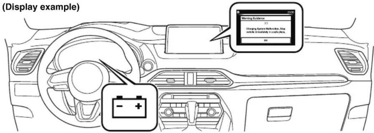
▼ Stop Vehicle in Safe Place Immediately
If the following messages are displayed in the center display, a vehicle system may be malfunctioning. Stop the vehicle in a safe place and contact an Authorized Mazda Dealer.
| Display Indicated Condition | |
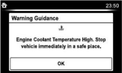 | Displays if the engine coolant temperature has increased excessively. |
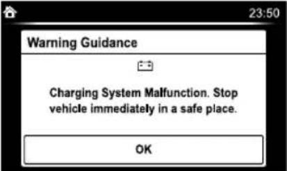 | Displays if the charging system has a malfunction. |
▼ Verify Display Content
Displays in the following cases:
| Display Indicated Condition/Action to be taken | |
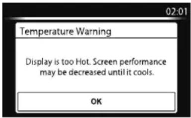 | The following message is displayed when the temperature around the center display is high.Lowering the temperature in the cabin or the temperature around the center display by avoiding direct sunlight is recommended. |
Message Indicated in Multi-information Display\*
If there is a notification from the vehicle, a message is displayed in the multi-information display. Check the information and take the necessary action.
(Display example)
Instrument Cluster
Type A
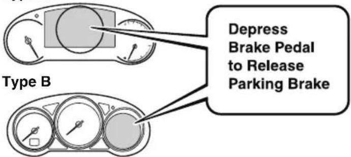
If the warning light turns on/flashes simultaneously or a symbol is indicated in the display, check the information regarding the warning light or symbol.
Refer to If a Warning Light Turns On or Flashes on page 7-28.
| Display Content | Action to be taken | |
| Move Shift Lever to "P" Position | Indicated when the push button start is pressed while the selector lever is not in the P position. | Shift the selector lever to the P position. |
| Depress Brake Pedal to Start Engine | Indicated when the push button start is pressed without depressing the brake pedal. | Depress the brake pedal and press the push button start. |
| Depress Brake Pedal to Release Parking Brake | Indicates when the Electric Parking Brake (EPB) switch is operated without depressing the brake pedal. | Operate the Electric Parking Brake (EPB) switch while depressing the brake pedal. |
| Brake Hold Unavailable Depress Brake to Hold Position | Indicates when there is a problem with the brake related system while the vehicle is being held in a stop position by the AUTOHOLD function or during the Mazda Radar Cruise Control with Stop & Go function (MRCC with Stop & Go function) stop hold control. | Depress the brake pedal.Cancel the AUTOHOLD function or the Mazda Radar Cruise Control with Stop & Go function (MRCC with Stop & Go function), and have your vehicle inspected at an Authorized Mazda Dealer. |
| Incline Too Steep Vehicle May Not Be Able to Hold Stopped Position | Indicates the possibility of the vehicle not being held in the stopped position by the AUTOHOLD function or the Mazda Radar Cruise Control with Stop & Go function (MRCC with Stop & Go function) stop hold control, such as on steep slopes. | Depress and hold your foot on the brake pedal. |
| Display Content Action to be taken | ||
| Parking BrakeNow ActivatedPress AcceleratorPedal to Release | Indicates when the cancel operation is done without depressing the brake pedal while the vehicle is being held in the stopped position by the AUTOHOLD function. | Cancel the AUTOHOLD function stop hold control while depressing the brake pedal. |
| Excessive Engine Temperature:Engine OutputWill Be Limited | Indicated when the engine coolant temperature is high or the engine is hot, and the engine output is limited. | Drive slowly and make sure that the indication turns off.If the indication does not turn off, consult an Authorized Mazda Dealer. |
Warning Sound is Activated
▼ Lights-On Reminder
The lights-on reminder is operable when the time setting ^*1 of the auto headlight off function is off.
If lights are on and the ignition is switched to ACC or off, a continuous beep sound will be heard when the driver's door is opened.
*1 If the light switch is left on, the auto headlight off function automatically turns off the lights about 30 seconds after switching the ignition off. The time setting can be changed. Refer to the Settings section in the Mazda Connect Owner's Manual.
NOTE
- When the ignition is switched to ACC, the “Ignition Not Switched Off (STOP) Warning Beep” (page 7-48) overrides the lights-on reminder.
- A personalized function is available to change the sound volume for the lights-on reminder. Refer to the Settings section in the Mazda Connect Owner's Manual.
▼ Air Bag/Front Seat Belt Pretensioner System Warning Beep
If there is a problem with the air bag/front seat belt pretensioner systems and the warning light illumination, a warning beep sound will be heard for about 5 seconds every minute.
The air bag and front seat belt pretensioner system warning beep sound will continue to be heard for approximately 35 minutes. Have your vehicle inspected at an Authorized Mazda Dealer as soon as possible.

WARNING
Do not drive the vehicle with the air bag/ front seat belt pretensioner system warning beep sounding:
Driving the vehicle with the air bag/front seat belt pretensioner system warning beep sounding is dangerous. In a collision, the air bags and the front seat belt pretensioner system will not deploy and this could result in death or serious injury. Contact an Authorized Mazda Dealer to have the vehicle inspected as soon as possible.
▼ Seat Belt Warning Beep
Front seat
Except Mexico
If the driver's seat belt is not fastened when the ignition is switched ON, a beep sound will be heard for about 6 seconds. If the driver or the front passenger's seat belt is not fastened and if the vehicle is driven at about 20 km/h (12 mph) or faster, or about 10 km/h (6 mph) or faster for a continuous 30 seconds, with the seat belt unfastened, a sound is activated continuously for a certain period.
Until a seat belt is fastened or a given period of time has elapsed, the beep sound will not stop even if the vehicle speed falls below 20 km/h (12 mph).
NOTE
- To allow the front passenger occupant classification sensor to function properly, do not place and sit on an additional seat cushion on the front passenger's seat. The sensor may not function properly because the additional seat cushion could cause sensor interference.
- If a small child is seated on the front passenger's seat, the warning beep may not operate.
Mexico
If the vehicle speed exceeds about 20 km/h (12 mph) with the driver or front passenger's seat belt unfastened, a warning beep sounds continuously. If the seat belt remains unfastened, the beep sound stops once and then continues for about 90 seconds. The beep stops after the driver or front passenger's seat belt is fastened. Until a seat belt is fastened or a given period of time has elapsed, the beep sound will not stop even if the vehicle speed falls below 20 km/h (12 mph).
NOTE
- Placing heavy items on the front passenger's seat may cause the front passenger's seat belt warning function to operate depending on the weight of the item.
- To allow the front passenger seat weight sensor to function properly, do not place and sit on an additional seat cushion on the front passenger's seat. The sensor may not function properly because the additional seat cushion could cause sensor interference.
- If a small child is seated on the front passenger's seat, the warning beep may not operate.
Rear seat\*
The warning beep only sounds if a seat belt is unfastened after being fastened.
▼ Ignition Not Switched Off (STOP) Warning Beep
If the driver's door is opened with the ignition switched to ACC, a beep will be heard continuously in the cabin to notify the driver that the ignition has not been switched OFF (STOP). Under this condition, the keyless entry system will not operate, the vehicle cannot be locked, and the battery voltage will be depleted.
▼ Key Removed from Vehicle Warning Beep
Vehicles with advanced keyless function
If the key is taken out of the vehicle while the ignition is not switched OFF and all the doors are closed, the beep which sounds outside of the vehicle will be heard 6 times, the beep which sounds inside the vehicle will be heard 6 times.
Vehicles without advanced keyless function
If the key is taken out of the vehicle while the ignition is not switched OFF and all the doors are closed, a beep will be heard in the cabin 6 times.
NOTE
Because the key utilizes low-intensity radio waves, the Key Removed From Vehicle Warning may activate if the key is carried together with a metal object or it is placed in a poor signal reception area.
▼ Request Switch Inoperable Warning Beep (With the advanced keyless function)
If the request switch is pressed with the door open or ajar, or the ignition is not switched OFF with a key being carried, a beep will be heard outside for about 2 seconds to notify the driver that the door or liftgate cannot be locked.
▼ Key Left-in-luggage Compartment Warning Beep (With the advanced keyless function)
If the key is left in the luggage compartment with all the doors locked and the liftgate closed, a beep will be heard outside for about 10 seconds to notify the driver that the key is in the luggage compartment. In this case, take out the key by pressing the electric liftgate opener and opening the liftgate. The key taken out of the luggage compartment may not operate because its functions have been temporarily stopped. To restore the key's functions, perform the applicable procedure (page 3-9).
▼ Key Left-in-vehicle Warning Beep (With the advanced keyless function)
If all the doors and luggage compartment are locked using another key while the key is left in the cabin, the beep which sounds outside of the vehicle will be heard for about 10 seconds to notify the driver that the key is in the cabin. In this case, take out the key by opening the door. A key taken out of the vehicle using this method may not operate because its functions have been temporarily stopped. To restore the
key's functions, perform the applicable procedure (page 3-9).
▼ Power Liftgate Warning Beep\*
If system operation precautions are necessary, the driver is notified by the warning sound.
| Cautions What to check | |
| The beep sounds 3 times | The conditions required for the power liftgate to operate have not been met, such as an object being stuck in the lift-gate. |
| The beep sound continues | The vehicle is being driven with the liftgate open. Stop the vehicle and close the liftgate. |
▼ Electric Parking Brake (EPB) Warning Beep
The warning buzzer is activated under the following conditions:
- The vehicle is driven with the parking brake applied.
- The Electric Parking Brake (EPB) switch is pulled while the vehicle is driven.
▼ AUTOHOLD Warning Beep
Warning light flashes/message is displayed and beep sound is activated simultaneously for about 5 seconds when using AUTOHOLD function or when AUTOHOLD switch is operated. Because a problem with AUTOHOLD function has occurred, AUTOHOLD
function does not operate even if AUTOHOLD switch is operated.
If the warning light flashes/message is displayed and the beep sound is activated simultaneously, have your vehicle inspected at an Authorized Mazda Dealer.
▼ Power Steering Warning Buzzer
If the power steering system has a malfunction, the power steering malfunction indication/malfunction indicator light turns on or flashes and the buzzer operates at the same time. Refer to Stop Vehicle in Safe Place Immediately on page 7-28.
▼ Tire Inflation Pressure Warning Beep
The warning beep sound will be heard for about 3 seconds if the tire pressures decrease.
Refer to Tire Pressure Monitoring System on page 4-252.
▼ Blind Spot Monitoring (BSM) Warning Beep\*
Driving forward
The warning beep operates when the turn signal lever is operated to the side where the Blind Spot Monitoring (BSM) warning light is illuminated.
NOTE
A personalized function is available to change the Blind Spot Monitoring (BSM) warning beep sound volume.
Refer to the Settings section in the Mazda Connect Owner's Manual.
Reversing
The Blind Spot Monitoring (BSM) warning sound is activated if there is a possibility of collision with a vehicle approaching from behind and from the rear on the left and right sides of the vehicle.
▼ Excessive Speed Warning\*
If the vehicle speed exceeds the speed limit sign displayed on the active driving display, the warning sound is activated and the area around the speed limit sign displayed on the active driving display flashes 3 times in amber, and if the vehicle speed continues to exceed the displayed speed limit sign, the indication stops flashing and remains on.
▼ Mazda Radar Cruise Control with Stop & Go function (MRCC with Stop & Go function) System Warnings \*
The Mazda Radar Cruise Control with Stop & Go function (MRCC with Stop & Go function) system warnings notify the driver of system problems and precautions on use when required. Check after hearing a warning beep sound.
| Warning beep What to check | |
| While the Mazda Radar Cruise Control with Stop & Go function (MRCC with Stop & Go function) system is operating, a single beep sound is heard when “Front Radar Sensor Blocked” is displayed in the multi-information display. | Cancel the Mazda Radar Cruise Control with Stop & Go function (MRCC with Stop & Go function) system if the radar sensor (front) becomes dirty. Clean the area around the radar sensor (front). |
| The beep sounds intermittently while the vehicle is being driven. | The distance between your vehicle and the vehicle ahead is too close. Verify the safety of the surrounding area and reduce vehicle speed. |
| While the Mazda Radar Cruise Control with Stop & Go function (MRCC with Stop & Go function) system is operating, a single beep sound is heard when “Front Radar Sensor System Mal-function” is displayed in the multi-information display. | A malfunction in the system may be indicated. Check the center display to verify the problem and then have your vehicle inspected by an Authorized Mazda Dealer. |
▼ Lane Departure Warning Sound\*
While the system is operating, if the system determines that the vehicle may depart from the lane, it sounds a warning sound.
NOTE
- The volume of the Lane-keep Assist System (LAS) & Lane Departure Warning System (LDWS) warning sound can be changed.
Refer to the Settings section in the Mazda Connect Owner's Manual. - The type of the Lane-keep Assist System (LAS) & Lane Departure Warning System (LDWS) warning sound can be changed.
Refer to the Settings section in the Mazda Connect Owner's Manual.
▼ Collision warning\*
If there is a possibility of a collision with a vehicle ahead, a warning sound is activated at the same time as the warning
indications are displayed in the instrument cluster or active driving display.
When Liftgate Cannot be Opened
If the battery is dead, the liftgate cannot be unlocked and opened.
In this case, the liftgate can be unlocked by taking care of the dead battery situation.
Refer to Jump-Starting on page 7-19.
If the liftgate cannot be unlocked even if the dead battery situation has been resolved, the electrical system may have a malfunction.
In this case, the liftgate can be opened using the following procedure as an emergency measure.
- Wrap the end of a flathead screwdriver in a cloth and remove the cover on the interior surface of the liftgate using it.
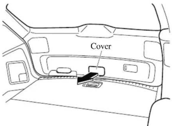
- (Without power liftgate)
Turn the lever to the right to unlock the liftgate.
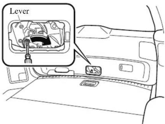
(With power liftgate)
Push the liftgate while pressing the lever down.
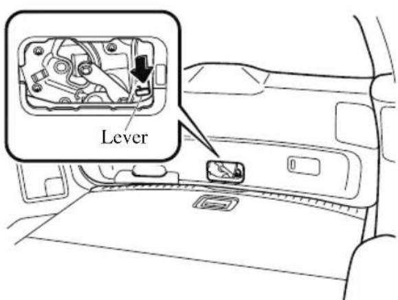
After performing this emergency measure, have the vehicle inspected at an Authorized Mazda Dealer as soon as possible.
If the Active Driving Display Does Not Operate
If the active driving display does not operate, switch the ignition off and then restart the engine. If the active driving display does not operate even with the engine restarted, have the vehicle inspected at an Authorized Mazda Dealer.
MEMO
8
Customer Information and Reporting Safety Defects
Important consumer information including warranties and add-on equipment.
Customer Assistance...... 8-2
Customer Assistance
(U.S.A.) 8-2
Customer Assistance
(Canada).... 8-7
Customer Assistance (Puerto
Rico)....8-10
Customer Assistance
(Mexico)...... 8-11
Mazda Importer/Distributors...... 8-13
Importer/Distributor.... 8-13
Reporting Safety Defects...... 8-14
Reporting Safety Defects
(U.S.A.) 8-14
Reporting Safety Defects
(Canada).... 8-15
Warranty......8-16
Warranties for Your Mazda......8-16
Outside the United States/
Canada.... 8-17
Registering Your Vehicle in A
Foreign Country (Except United
States and Canada)...... 8-18
Add-On Non-Genuine Parts and
Accessories....8-19
Cell Phones......8-20
Cell Phones Warning...... 8-20
Event Data Recorder......8-21
Event Data Recorder (U.S.A. and
Canada)....8-21
Recording of Vehicle Data...... 8-22
Recording of Vehicle Data......8-22
Uniform Tire Quality Grading System
(UTQGS)...... 8-23
Uniform Tire Quality Grading
System (UTQGS).... 8-23
Tire Information (U.S.A.)...... 8-25
Tire Labeling.... 8-25
Location of the Tire Label
(Placard).... 8-30
Tire Maintenance....8-33
Vehicle Loading......8-36
Steps for Determining the Correct
Load Limit....8-41
Declaration of Conformity......8-42
Declaration of Conformity...... 8-42
Customer Assistance (U.S.A.)
Your complete and permanent satisfaction is our business. We are here to serve you. All Authorized Mazda Dealers have the knowledge and the tools to keep your Mazda vehicle in top condition.
If you have any questions or recommendations for improvement regarding the service of your Mazda vehicle or servicing by Mazda Dealer personnel, we recommend that you take the following steps:
NOTE
If it becomes necessary to have the components or wiring system for the supplementary restraint system modified to accommodate a person with certain medical conditions in accordance with a certified physician, contact an Authorized Mazda Dealer. For more information, go to NHTSA website www.safercar.gov (VEHICLE SHOPPERS > Air Bags > Air Bag FAQs > Air Bag Deactivation).
▼ STEP 1: Contact Your Mazda Dealer
Discuss the matter with an Authorized Mazda Dealer. This is the quickest and best way to address the issue.
- If your concern has not been resolved by the CUSTOMER RELATIONS, SALES, SERVICE, or PARTS MANAGER, then please contact the GENERAL MANAGER of the dealership or the OWNER.
- If it becomes necessary to have the components or wiring system for the supplementary restraint system modified to accommodate a person with certain medical conditions in accordance with a certified physician, go to STEP 2.
▼ STEP 2: Contact Mazda North American Operations
If for any reason you feel the need for further assistance after contacting your dealership management or it becomes necessary to have the components or wiring system for the supplementary restraint system modified to accommodate a person with certain medical
conditions in accordance with a certified physician, you can reach Mazda North American Operations by one of the following ways.
Log on: at www.MazdaUSA.com
Answers to many questions, including how to locate or contact a local Mazda dealership in the U.S., can be found here.
E-mail: click on “Contact Us” located on the bottom of the page at www.mazdausa.com under “Help”
By phone at: 1 (800) 222-5500
By letter at:
ATTN: Customer Experience Center
Mazda North American Operations
200 Spectrum Center Drive Suite 100
Irvine, California 92618
P.O. Box 19734
Irvine, CA 92623-9734
In order to serve you efficiently and effectively, please help us by providing the following information:
- Your name, address, and telephone number
- Year and model of vehicle
- Vehicle Identification Number (17 digits, noted on your registration or title or located on the upper driver's side corner of the dash)
- Purchase date and current mileage
- Your dealer's name and location
- Your question(s)
If you live outside the U.S.A., please contact your nearest Mazda Distributor.
▼ STEP 3: Contact Better Business Bureau (BBB)
Mazda North American Operations realizes that mutual agreement on some issues may not be possible. As a final step to ensure that your concerns are being fairly considered, Mazda
North American Operations has agreed to participate in a dispute settlement program administered by the Better Business Bureau (BBB) system, at no cost to you the consumer.
BBB AUTO LINE works with consumers and the manufacturer in an attempt to reach a mutually acceptable resolution of any warranty related concerns. If the BBB is not able to facilitate a settlement they will provide an informal hearing before an arbitrator.
You are required to resort to BBB AUTO LINE before exercising rights or seeking remedies under the Federal Magnuson-Moss Warranty Act, 15 U.S.C. § 2301 et seq. To the extent permitted by the applicable state “Lemon Law”, you are also required to resort to BBB AUTO LINE before exercising any rights or seeking remedies under the “Lemon Law”. If you choose to seek remedies that are not created by the Magnuson-Moss Warranty Act or the applicable state “Lemon Law”, you are not required to first use BBB AUTO LINE.
The whole process normally takes 40 days or less. The arbitration decision is not binding on you or Mazda unless you accept the decision. For more information about BBB AUTO LINE, including current eligibility standards, please call 1-800-955-5100 or visit the BBB website at www.bbb.org/autoline.
Being truly committed to customer satisfaction is more than a phrase with Mazda. We hope to satisfy every customer directly, but if there is ever a question about our decision, Mazda believes in providing a fast, fair and free method such as the BBB AUTO LINE to ensure Mazda delivers on our commitment to do the right thing for our customers!
▼ California Customers
- Mazda North American Operations participates in BBB AUTO LINE, a mediation/arbitration program administered by the Council of Better Business Bureaus [3033 Wilson Boulevard, Arlington, Virginia 22201] through local Better Business Bureaus. BBB AUTO LINE and Mazda have been certified by the Arbitration Certification Program of the California Department of Consumer Affairs.
- If you have a problem arising under a Mazda written warranty, we encourage you to bring it to our attention. If we are unable to resolve it, you may file a claim with BBB AUTO LINE. Claims must be filed with BBB AUTO LINE within six (6) months after the expiration of the warranty.
- To file a claim with BBB AUTO LINE, call 1-800-955-5100. There is no charge for the call.
- In order to file a claim with BBB AUTO LINE, you will have to provide your name and address, the brand name and vehicle identification number (VIN) of your vehicle, and a statement of the nature of your problem or complaint. You will also be asked to provide: the approximate date of your acquisition of the vehicle, the vehicle's current mileage, the
approximate date and mileage at the time any problem(s) were first brought to the attention of Mazda or one of our dealers, and a statement of the relief you are seeking.
-
BBB AUTO LINE staff may try to help resolve your dispute through mediation. If mediation is not successful, or if you do not wish to participate in mediation, claims within the program's jurisdiction may be presented to an arbitrator at an informal hearing. The arbitrator's decision should ordinarily be issued within 40 days from the time your complaint is filed; there may be a delay of 7 days if you did not first contact Mazda about your problem, or a delay of up to 30 days if the arbitrator requests an inspection/report by an impartial technical expert or further investigation and report by BBB AUTO LINE.
-
You are required to use BBB AUTO LINE before asserting in court any rights or remedies conferred by California Civil Code Section 1793.22. You are also required to use BBB AUTO LINE before exercising rights or seeking remedies created by Title I of the Magnuson-Moss Warranty Act, 15 U.S.C. sec. 2301 et seq. If you choose to seek redress by pursuing rights and remedies not created by California Civil Code Section 1793.22 or Title I of the Magnuson-Moss Warranty Act, resort to BBB AUTO LINE is not required by those statutes.
-
California Civil Code Section 1793.2 (d) requires that, if Mazda or its representative is unable to repair a new motor vehicle to conform to the vehicle's applicable express warranty after a reasonable number of attempts, Mazda may be required to replace or repurchase the vehicle. California Civil Code Section 1793.22 (b) creates a presumption that Mazda has had a reasonable number of attempts to conform the vehicle to its applicable express warranties if, within 18 months from delivery to the buyer or 18,000 miles on the vehicle's odometer, whichever occurs first, one or more of the following occurs:
- The same nonconformity [a failure to conform to the written warranty that substantially impairs the use, value or safety of the vehicle] results in a condition that is likely to cause death or serious bodily injury if the vehicle is driven AND the nonconformity has been subject to repair two or more times by Mazda or its agents AND the buyer or lessee has directly notified Mazda of the need for the repair of the nonconformity; OR
- The same nonconformity has been subject to repair 4 or more times by Mazda or its agents AND the buyer has notified Mazda of the need for the repair of the nonconformity; OR
- The vehicle is out of service by reason of repair of nonconformities by Mazda or its agents for a cumulative total of more than 30 calendar days after delivery of the vehicle to the buyer.
NOTICE TO Mazda AS REQUIRED ABOVE SHALL BE SENT TO THE FOLLOWING ADDRESS:
Mazda North American Operations
200 Spectrum Center Drive Suite 100
Irvine, California 92618
ATTN: Customer Mediation
- The following remedies may be sought in BBB AUTO LINE: repairs, reimbursement for money paid to repair a vehicle or other expenses incurred as result of a vehicle nonconformity, repurchase or replacement of your vehicle, and compensation for damages and remedies available under Mazda's written warranty or applicable law.
- The following remedies may not be sought in BBB AUTO LINE: punitive or multiple damages, attorneys' fees, or consequential damages other than as provided in California Civil Code Section 1794 (a) and (b).
- You may reject the decision issued by a BBB AUTO LINE arbitrator. If you reject the decision, you will be free to pursue further legal action. The arbitrator's decision and any findings will be admissible in a court action.
- If you accept the arbitrator's decision, Mazda will be bound by the decision, and will comply with the decision within a reasonable time not to exceed 30 days after we receive notice of your acceptance of the decision.
- Please call BBB AUTO LINE at 1-800-955-5100 for further details about the program.
Customer Assistance (Canada)
▼ Satisfaction Review Process
Your complete and permanent satisfaction is of primary concern to Mazda. All Authorized Mazda Dealers have both the knowledge and tools to keep your Mazda in top condition. In our experience, any questions, problems, or complaints regarding the operation of your Mazda or any other general service transactions are most effectively resolved by your dealer. If the cause of your dissatisfaction cannot adequately be addressed by normal dealership procedures, we recommend that you take the following steps:
▼ STEP 1: Contact the Mazda Dealer
Discuss the matter with a member of dealership management. If the Service Manager has already reviewed your concerns, contact the owner of the dealership or its General Manager.
▼ STEP 2: Contact the Mazda Regional Office
If you feel that you still require assistance, ask the dealer Service Manager to arrange for you to meet the local Mazda Service Representative. If more expedient, contact Mazda Canada Inc. Regional Office nearest you for such arrangements. Regional Office address and phone numbers are shown (page 8-9).
▼ STEP 3: Contact the Mazda Customer Relations Department
If still not substantially satisfied, contact the Customer Relations Department, Mazda Canada Inc., 55 Vogell Road, Richmond Hill, Ontario, L4B 3K5 Canada TEL: 1 (800) 263-4680.
Provide the Department with the following information:
- Your name, address and telephone number
- Year and model of vehicle
- Vehicle Identification Number (VIN). Refer to the Vehicle Identification Number on page 9-2 for the location of the VIN.
- Purchase date
- Present odometer reading
- Your dealer's name and location
- The nature of your problem and/or cause of dissatisfaction
The Department, in cooperation with the local Mazda Service Representative, will review the case to determine if everything possible has been done to ensure your satisfaction.
Please recognize that the resolution of service problems in most cases requires the use of your Mazda dealer's service facilities, personnel and equipment. We urge you to follow the above three steps in sequence for most effective results.
▼ Mediation/Arbitration Program
Occasionally a customer concern cannot be resolved through Mazda's Customer Satisfaction Program. If after exhausting the procedures in this manual your concern is still not resolved, you have another option.
Mazda Canada Inc. participates in an arbitration program administered by the Canadian Motor Vehicle Arbitration Plan (CAMVAP). CAMVAP will advise you about how your concern may be reviewed and resolved by an independent third party through binding arbitration.
Your complete satisfaction is the goal of Mazda Canada Inc. and our dealers.
Mazda's participation in CAMVAP makes a valuable contribution to our achieving that goal.
There is no charge for using CAMVAP. CAMVAP results are fast, fair and final as the award is binding on both you and Mazda Canada Inc.
▼ Canadian Motor Vehicle Arbitration Plan (CAMVAP)
If a specific item of concern arises, where a solution cannot be reached between an owner, Mazda, and/or one of its dealers (that all parties cannot agree upon), the owner may wish to use the services offered by the Canadian Motor Vehicle Arbitration Plan (CAMVAP).
CAMVAP uses the services of Provincial Administrators to assist consumers in scheduling and preparing for their arbitration hearings. However, before you can proceed with CAMVAP you must follow your Mazda dispute resolution process as outlined previously.
CAMVAP is fully implemented in all provinces and territories.
Consumers wishing to obtain further information about the Program should contact the Provincial Administrator at 1 (800) 207-0685, or by contacting the Canadian Motor Vehicle Arbitration Plan Office at:
Canadian Motor Vehicle Arbitration Plan
235 Yorkland Boulevard, suite 300
North York, Ontario
M2J 4Y8
http://camvap.ca
Provincial Administrators may be reached locally:
| Province/Territory CAMVAP Number | |
| British Columbia & Yukon Territories 1 (800) 207-0685 | |
| Alberta & Northwest Territories 1 (800) 207-0685 | |
| Saskatchewan 1 (800) 207-0685 | |
| Manitoba 1 (800) 207-0685 | |
| Ontario 1 (800) 207-0685 | |
| Atlantic Canada 1 (800) 207-0685 | |
| Quebec 1 (800) 207-0685 |
▼ Regional Offices
| REGIONAL OFFICES COVERING AREAS | |
| MAZDA CANADA INC.WESTERN REGION5011 275 STREETLANGLEY, BRITISH COLUMBIAV4W 0A8(778) 369-21001 (800) 663-0908 | ALBERTA,BRITISH COLUMBIA,MANITOBA,SASKATCHEWAN,YUKON |
| MAZDA CANADA INC.CENTRAL REGION55 VOGELL ROAD,RICHMOND HILL,ONTARIO, L4B 3K51 (800) 263-4680 | ONTARIO,NEW BRUNSWICK,NOVA SCOTIA,PRINCE EDWARD ISLAND,NEWFOUNDLAND |
| MAZDA CANADA INC.QUEBEC REGION6111 ROUTE TRANSCANADIENNEPOINTE CLAIRE, QUEBECH9R 5A5(514) 694-6390 | QUEBEC |
Customer Assistance (Puerto Rico)
Your complete and permanent satisfaction is our business. That is why all Authorized Mazda Dealers have the knowledge and the tools to keep your Mazda vehicle in top condition.
If you have any questions or recommendations for improvement regarding the service of your Mazda vehicle or servicing by Mazda Dealer personnel, we recommend that you take the following steps:
▼ STEP 1
Discuss the matter with an Authorized Mazda Dealer. This is the quickest and best way to address the issue. If your concern has not been resolved by the CUSTOMER RELATIONS, SALES, SERVICE, or PARTS MANAGER, then please contact the GENERAL MANAGER of the dealership or the OWNER.
▼ STEP 2
If, after following STEP 1, you feel the need for further assistance, please contact your area's Mazda representative.
Refer to Importer/Distributor on page 8-13.
Please help us by providing the following information:
- Your name, address, and telephone number
- Year and model of vehicle
- Vehicle Identification Number (17 digits, noted on your registration or title or located on the upper driver's side corner of the dash)
- Purchase date and current mileage
- Your dealer's name and location
- Your question(s)
Customer Assistance (Mexico)
Your complete and permanent satisfaction is our business. We are here to serve you. All Authorized Mazda Dealers have the knowledge and the tools to keep your Mazda vehicle in top condition.
If you have any questions or recommendations for improvement regarding the service of your Mazda vehicle or servicing by Mazda Dealer personnel, we recommend that you take the following steps:
▼ Contact Your Mazda Dealer
Discuss the matter with an Authorized Mazda Dealer. This is the quickest and best way to address the issue.
- If your concern has not been resolved by the CUSTOMER RELATIONS, SALES, SERVICE, or PARTS MANAGER, then please contact the GENERAL MANAGER of the dealership or the OWNER.
- If it becomes necessary to have the components or wiring system for the supplementary restraint system modified to accommodate a person with certain medical condition in accordance with a certified physician you must contact your dealership in order to avoid the potential loss of the warranty of your vehicle which may occur if some third party is hired by the customer to make any modifications to this system.
Log on: at www.mazdamexico.com.mx
Answers to many questions, including how to locate or contact a local Mazda dealership in Mexico, can be found here.
E-mail: click on "Contactanos" at the top of the page at www.mazdamexico.com.mx
By phone at: 01 800 01 MAZDA (62932)
By letter at:
Attn: Customer Assistance
Mazda Motor de Mexico
Tel: Customer Assistance
01 800 01 MAZDA(62932).
In order to serve you efficiently and effectively, please help us by providing the following information:
- Your name, address, and telephone number
- Year and model of vehicle
- Vehicle Identification Number (17 digits, noted on your registration or title or located on the upper driver's side corner of the dash)
- Purchase date and current mileage
- Your dealer's name and location
- Your question(s)
Importer/Distributor
▼ U.S.A.
Mazda North American Operations
200 Spectrum Center Drive Suite 100
Irvine, California 92618
P.O. Box 19734
Irvine, CA 92623-9734 U.S.A.
TEL: 1 (800) 222-5500 (in U.S.A.)
(949) 727-1990 (outside U.S.A.)
▼ CANADA
Mazda Canada Inc.
55 Vogell Road, Richmond Hill,
Ontario, L4B 3K5 Canada
TEL: 1 (800) 263-4680 (in Canada)
(905) 787-7000 (outside Canada)
▼ PUERTO RICO/U.S. Virgin Island
International Automotive Distributor Group, LLC. (Mazda de Puerto Rico)
P.O. Box 191850, San Juan, Puerto Rico
00919-1850
TEL: (787) 641-1777
▼ MEXICO
Mazda Motor de Mexico
Mario Pani 400 PB, Col. Santa Fe
TEL: Center of Attention to Clients:
01 (800) 016 2932. in Mexico
▼ GUAM
Triple J Motors
157 South Marine Drive, Tamuning,
GUAM 96911 USA
P.O. Box 6066 Tamuning, Guam 96931
TEL: (671) 649-6555
▼ SAIPAN
Pacific International Marianas, Inc.
(d.b.a. Midway Motors)
P.O. Box 887 Saipan, MP 96950
TEL: (670) 234-7524
Triple J Saipan, Inc.
(d.b.a. Triple J Motors)
P.O. Box 500487 Saipan, MP 96950-0487
TEL: (670) 234-7133/3051
▼ AMERICAN SAMOA
Polynesia Motors, Inc.
P.O. Box 1120, Pago Pago, American
Samoa 96799
TEL: (684) 699-9347
Reporting Safety Defects (U.S.A.)
If you believe that your vehicle has a defect which could cause a crash or could cause injury or death, you should immediately inform the National Highway Traffic Safety Administration (NHTSA) in addition to notifying Mazda Motor Corporation (Your Mazda Importer/Distributor).
If NHTSA receives similar complaints, it may open an investigation, and if it finds that a safety defect exists in a group of vehicles, it may order a recall and remedy campaign. However, NHTSA cannot become involved in individual problems between you, your dealer, or Mazda Motor Corporation (Your Mazda Importer/Distributor).
To contact NHTSA, you may call the Vehicle Safety Hotline toll-free at 1-888-327-4236 (TTY:1-800-424-9153); go to http://www.safercar.gov; or write to: Administrator, NHTSA, 1200 New Jersey Avenue, SE., Washington, DC, 20590. You can also obtain other information about motor vehicle safety from http://www.safercar.gov.
NOTE
If you live in the U.S.A., all correspondence to Mazda Motor Corporation should be forwarded to:
Mazda North American Operations 200 Spectrum Center Drive Suite 100 Irvine, California 92618
or
P.O. Box 19734
Irvine, CA 92623-9734
Customer Experience Center or toll free at 1 (800) 222-5500
If you live outside of the U.S.A., please contact the nearest Mazda Distributor shown (page 8-13) in this manual.
Reporting Safety Defects (Canada)
Canadian customers who wish to report a safety-related defect and concern to Transport Canada, Defect Investigations and Recalls, may telephone the toll free hotline 1-800-333-0510, or go to the Road Safety website at: https://www.tc.gc.ca/en/services/road.html
Warranties for Your Mazda
· New Vehicle Limited Warranty
- Powertrain Limited Warranty
• Safety Restraint System Limited Warranty
- Anti-perforation Limited Warranty
· Federal Emission Control Warranty/California Emission Control Warranty
- Emission Defect Warranty
-
Emission Performance Warranty
-
Emission Control Warranty
- Replacement Parts and Accessories Limited Warranty
- Tire Warranty
NOTE
Warranty information varies depending on the country. Refer to the Warranty Booklet for detailed warranty information.
Outside the United States/Canada
Government regulations in the United States/Canada require that automobiles meet specific emission regulations and safety standards. Therefore, vehicles built for use in the United States/Canada may differ from those sold in other countries.
The differences may make it difficult or even impossible for your vehicle to receive satisfactory servicing in other countries. We strongly recommend that you NOT take your Mazda outside the United States/Canada.
United States
However, in the event that you are moving to Canada permanently, Mazda vehicles built for use in the United States could be eligible for exportation to Canada with specific vehicle modifications to comply with the Canadian Motor Vehicle Safety Standards (CMVSS).
Canada
However, in the event that you are moving to the United States permanently, Mazda vehicles built for use in Canada could be eligible for exportation to the United States with specific vehicle modifications to comply with the United States Federal Motor Vehicle Safety Standards (FMVSS).
NOTE
The above is applicable for a permanent import/export situation and not related to travelers on vacation.
You may have the following problems if you do take your vehicle outside of the United States/Canada:
- Recommended fuel may be unavailable. Any kind of leaded fuel or low-octane fuel will affect vehicle performance and damage the emission controls and engine.
- Proper repair facilities, tools, testing equipment, and replacement parts may not be available.
Please refer to your Manufacturer's Warranty Booklet for more information.
Registering Your Vehicle in A Foreign Country (Except United States and Canada)
Registering your vehicle in a foreign country may be problematic depending on whether it meets the specific emission and safety standards of the country in which the vehicle will be driven. Consequently, your vehicle may require modifications at personal expense in order to meet the regulations.
In addition, you should be aware of the following issues:
Satisfactory vehicle servicing may be difficult or impossible in another country.
The fuel specified for your vehicle may be unavailable.
Parts, servicing techniques, and tools necessary to maintain and repair your vehicle may be unavailable.
There might not be an Authorized Mazda Dealer in the country you plan to take your vehicle.
The Mazda warranty is valid only in certain countries.
Add-On Non-Genuine Parts and Accessories
Non-genuine parts and accessories for Mazda vehicles can be found in stores.
These may fit your vehicle, but they are not approved by Mazda for use with Mazda vehicles. When you install non-genuine parts or accessories, they could affect your vehicle's performance or safety systems; the Mazda warranty doesn't cover this. Before you install any non-genuine parts or accessories, consult an Authorized Mazda Dealer.

WARNING
Always consult an Authorized Mazda Dealer before you install non-genuine parts or accessories:
Improperly designed parts or accessories could seriously affect your vehicle's performance or safety systems. This could cause you to have an accident or increase your chances of injuries in an accident.
Be very careful in choosing and installing add-on electrical equipment, such as mobile telephones, two-way radios, stereo systems, and car alarm systems:
Incorrectly choosing or installing improper add-on equipment or choosing an improper installer is dangerous. Essential systems could be damaged, causing engine stalling, air-bag (SRS) activation, ABS/TCS/DSC inactivation, or a fire in the vehicle.
Mazda assumes no responsibility for death, injury, or expenses that may result from the installation of add-on non-genuine parts or accessories.
Cell Phones Warning

WARNING
Please comply with the legal regulations concerning the use of communication equipment in vehicles in your country:
Use of any electrical devices such as cell phones, computers, portable radios, vehicle navigation or other devices by the driver while the vehicle is moving is dangerous. Dialing a number on a cell phone while driving also ties-up the driver's hands. Use of these devices will cause the driver to be distracted and could lead to a serious accident. If a passenger is unable to use the device, pull off the right-of-way to a safe area before use. If use of a cell phone is necessary despite this warning, use a hands-free system to at least leave the hands free to drive the vehicle. Never use a cell phone or other electrical devices while the vehicle is moving and, instead, concentrate on the full-time job of driving.
Event Data Recorder (U.S.A. and Canada)
This vehicle is equipped with an event data recorder (EDR). The main purpose of an EDR is to record, in certain crash or near crash-like situations, such as an air bag deployment or hitting a road obstacle, data that will assist in understanding how a vehicle's systems performed. The EDR is designed to record data related to vehicle dynamics and safety systems for a short period of time, typically 30 seconds or less. The EDR in this vehicle is designed to record such data as:
- How various systems in your vehicle were operating;
- Whether or not the driver and passenger safety belts were buckled/fastened;
- How far (if at all) the driver was depressing the accelerator and/or brake pedal; and,
• How fast the vehicle was traveling.
These data can help provide a better understanding of the circumstances in which crashes and injuries occur.
NOTE:
EDR data are recorded by your vehicle only if a non-trivial crash or near crash-like situation occurs; no data are recorded by the EDR under normal driving conditions and no personal data (e.g., name, gender, age, and crash location) are recorded. However, other parties, such as law enforcement, could combine the EDR data with the type of personally identifying data routinely acquired during a crash investigation.
To read data recorded by an EDR, special equipment is required, and access to the vehicle or the EDR is needed. In addition to the vehicle manufacturer, other parties, such as law enforcement, that have the special equipment, can read the information if they have access to the vehicle or the EDR.
Mazda will not disclose any of the data recorded in an EDR to a third party unless:
- A written agreement from the vehicle owner or the lessee is obtained
- Officially requested by the police or other law enforcement authorities
• Used as a defense for Mazda in a lawsuit, claim, or arbitration - Ordered by a judge or court
However, if necessary Mazda will:
- Use the data for research on Mazda vehicle performance, including safety.
- Disclose the data or the summarized data to a third party for research purposes without disclosing vehicle or owner identification information.
Recording of Vehicle Data
This vehicle is equipped with a computer which records the following main vehicle data related to vehicle controls, operation, and other driving conditions.
Recorded data
- Vehicle conditions such as engine speed and vehicle speed
- Driving operation conditions such as accelerator and brake pedals, and information related to the environmental circumstances while the vehicle is driven
- Malfunction diagnosis information from each on-vehicle computer
- Information related to controls of other on-vehicle computers
NOTE
The recorded data may vary depending on the vehicle grade and optional equipment. Voice and images are not recorded.
Data handling
Mazda and its subcontracting parties may obtain and use the recorded data for vehicle malfunction diagnosis, research and development, and quality improvement.
Mazda will not disclose or provide any of the obtained data to a third party unless:
- An agreement from the vehicle owner (agreements from lessor and lessee for leased vehicle) is obtained
• Officially requested by the police or other law enforcement authorities - For statistical processing by a research institution after processing the data so that identification of the owner or the vehicle is impossible
Uniform Tire Quality Grading System (UTQGS)
This information relates to the tire grading system developed by the U.S. National Highway Traffic Safety Administration for grading tires by tread wear, traction, and temperature performance.
▼ Tread Wear
The tread wear grade is a comparative rating based on the wear rate of the tire when tested under controlled conditions on a specified government test course.
For example, a tire graded 150 would wear one-and-a-half times as well on the government course as a tire graded 100.
The relative performance of tires depends upon the actual conditions of their use, however, and may depart significantly from the norm because of variations in driving habits, service practices and differences in road characteristics and climate.
▼ Traction-AA, A, B, C
The traction grades, from highest to lowest, are AA, A, B, and C. These grades represent the tire's ability to stop on wet pavement as measured under controlled conditions on specified government test surfaces of asphalt and concrete. A tire marked C may have poor traction performance.
WARNING
The traction grade assigned to this tire is based on braking (straight ahead) traction tests and does not include acceleration cornering (turning), hydroplaning, or peak traction characteristics.
▼ Temperature-A, B, C
The temperature grades A (the highest), B, and C, represent the tire's resistance to the generation of heat and its ability to dissipate heat when tested under controlled conditions on a specified indoor laboratory test wheel.
Sustained high temperature can cause the material of the tire to degenerate and reduce tire life, and excessive temperatures can lead to sudden tire failure.
Grade C corresponds to a level of performance which all passenger vehicle tires must meet under the Federal Motor Vehicle Safety Standard No. 109. Grades B and A represent higher levels of performance on the laboratory test wheel than the minimum required by law.

WARNING
Keep your vehicle's tires properly inflated and not overloaded:
Driving with improperly inflated or overloaded tires is dangerous. Excessive speed, underinflation, or excessive loading, either separately or in combination, can cause heat buildup and possible tire failure. The temperature grade for this tire is established for a tire that is properly inflated and not overloaded.
These grades will be added to the sidewalls of passenger vehicle tires over the next several years according to a schedule established by the NHTSA and the tire manufacturers.
The grade of tires available as standard or optional equipment on Mazda vehicles may vary with respect to grade.
ALL PASSENGER VEHICLE TIRES MUST CONFORM TO THESE GRADES AND TO ALL OTHER FEDERAL TIRE-SAFETY REQUIREMENTS.
▼ UNIFORM TIRE QUALITY GRADING
Quality grades can be found where applicable on the tire sidewall between tread shoulder and maximum section width.
For example:
TREADWEAR 200 TRACTION AA TEMPERATURE A UTQGS MARK (example)
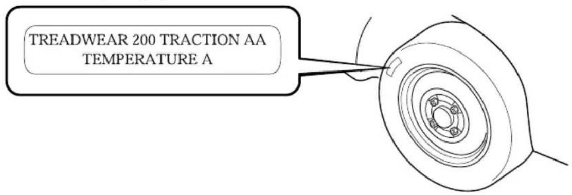
Tire Labeling
Federal law requires tire manufacturers to place standardized information on the sidewall of all tires. This information identifies and describes the fundamental characteristics of the tire and also provides a tire identification number for safety standard certification and in case of a recall.
▼ Information on Passenger Vehicle Tires
Please refer to the sample below.
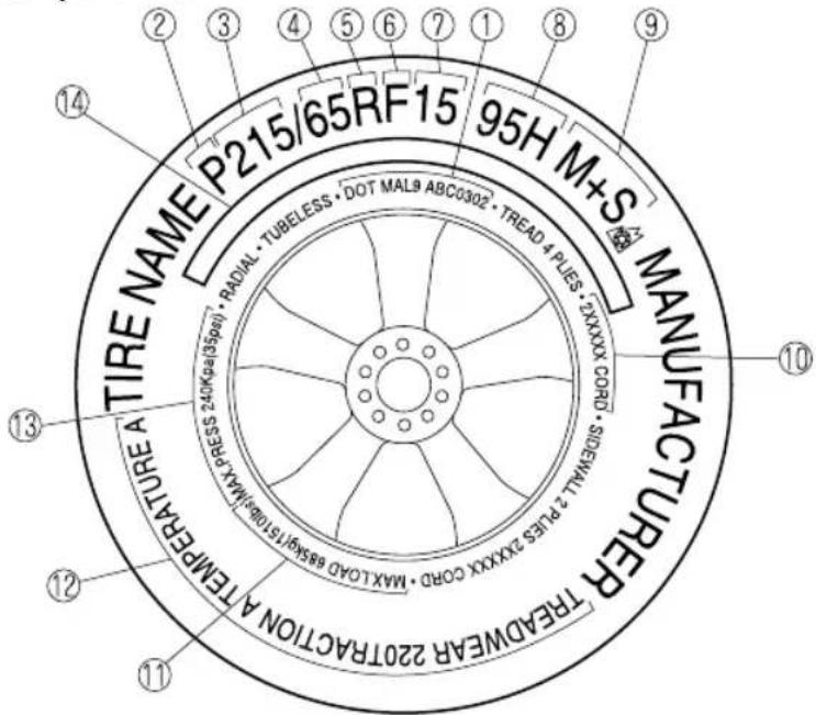
- TIN: U.S. DOT tire identification number
- Passenger car tire
- Nominal width of tire in millimeters
- Ratio of height to width (aspect ratio)
- Radial
- Run-flat tire
- Rim diameter code
- Load index & speed symbol
- Severe snow conditions
- Tire ply composition and materials used
- Max. load rating
- Tread wear, traction and temperature grades
- Max. permissible inflation pressure
- SAFETY WARNING
P215/65R15 95H is an example of a tire size and load index rating. Here is an explanation of the various components of that tire size and load index rating. Note that the tire size and load index rating may be different from the example.
P
Indicates a tire that may be installed on cars, SUVs, minivans and light trucks as designated by the Tire and Rim Association (T&RA).
NOTE
If your tire size does not begin with a letter this may mean it is designated by either ETRTO (European Tire and Rim Technical Organization) or JATMA (Japan Tire Manufacturing Association).
215
“215” is the nominal width of the tire in millimeters. This three-digit number gives the width in millimeters of the tire from sidewall edge to sidewall edge. In general, the larger the number, the wider the tire.
65
“65” is the aspect ratio. This two-digit number indicates the tire's ratio of height to width.
R
“R” is the tire construction symbol. R indicates “Radial ply construction”.
15
“15” is the wheel rim diameter in inches.
95
“95” is the Load Index. This two-or three-digit number indicates how much weight each tire can support.
H
“H” is the speed rating. The speed rating denotes the maximum speed for which the use of the tire is rated.
| Letter Rating Speed Rating | |
| Q | 9 |
| R | 1 |
| S 112 mph | |
| T 118 mph | |
| U | 1 |
| HV 149 mph | 1 |
| W | 168* mph |
| Y | 186* mph |
* For tires with a maximum speed capability over 149 mph, tire manufacturers sometimes use the letters ZR. For tires with a maximum speed capability over 186 mph, tire manufacturers always use the letters ZR.
M+S or M/S: Mud and Snow
AT: All Terrain.
AS: All Season. The “M+S” or “M/S” indicates that the tire has some functional use in mud and snow.
U.S. DOT Tire Identification Number (TIN)
This begins with the letters “DOT” which indicates the tire meets all federal standards. The next two numbers or letters are the plant code where it was manufactured, and the last four numbers represent the week and year the tire was manufactured. For example, the numbers 457 means the 45st week of 1997. After 2000 the numbers go to four digits. For example, the number 2102 means the 21th week of 2002. The other numbers are marketing codes used at the manufacturer's discretion. This information is used to contact consumers if a tire defect requires a recall.
Tire Ply Composition and Materials Used
The number of plies indicates the number of layers of rubber-coated fabric in the tire. In general, the greater the number of plies, the more weight a tire can support. Tire manufacturers also must indicate the tire materials, which include steel, nylon, polyester, and other.
Maximum Load Rating
This number indicates the maximum load in kilograms and pounds that can be carried by the tire.
Maximum Permissible Inflation Pressure
This number is the greatest amount of air pressure that should ever be put in the tire under normal driving conditions.
Tread Wear, Traction and Temperature Grades
Tread wear: The tread wear grade is a comparative rating based on the wear rate of the tire when tested under controlled conditions on a specified government test course. For example, a tire graded 150 would wear one and one-half (1 1/2) times as well on the government course as a tire graded 100.
Traction: The traction grades, from highest to lowest are AA, A, B, and C. The grades represent the tire's ability to stop on wet pavement as measured under controlled conditions on specified government test surfaces of asphalt and concrete. A tire marked C may have poor traction performance.
Temperature: The temperature grades are A (the highest), B and C, representing the tire's resistance to the generation of heat and its ability to dissipate heat when tested under controlled conditions on a specified indoor laboratory test wheel.
Snow Tires
In some heavy snow areas, local governments may require true snow tires, those with very deeply cut tread. These tires should only be used in pairs or placed on all four wheels. Make sure you purchase snow tires that are the same size and construction type as the other tires on your vehicle.
SAFETY WARNING
The following safety warning appears on the tire's sidewall. SERIOUS INJURY MAY RESULT FROM:
- EXPLOSION OF TIRE/RIM ASSEMBLY DUE TO IMPROPER MOUNTING-MATCH TIRE DIAMETER TO RIM DIAMETER; NEVER EXCEED 40 psi (275 kPa) TO SEAT BEADS-ONLY SPECIALLY TRAINED PERSONS SHOULD MOUNT TIRES.
- TIRE FAILURE DUE TO UNDER-INFLATION/OVERLOADING/DAMAGE-FOLLOW OWNER'S MANUAL AND PLACARD IN VEHICLE-FREQUENTLY CHECK INFLATION PRESSURE AND INSPECT FOR DAMAGE.
▼ Information on Temporary Tires
Please refer to the sample below.
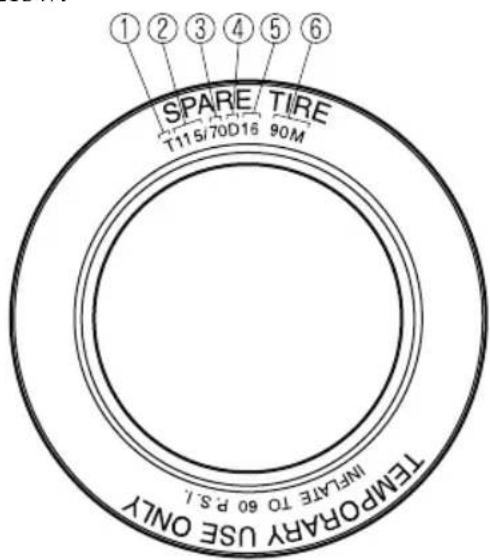
- Temporary tires
- Nominal width of tire in millimeters
- Ratio of height to width (aspect ratio)
- Diagonal
- Rim diameter code
- Load index & speed symbol
T115/70D16 90M is an example of a tire size and load index rating. Here is an explanation of the various components of that tire size and load index rating. Note that the tire size and load index rating may be different from the example.
T
Indicates a tire that may be installed on cars, SUVs, minivans and light trucks as designated by the Tire and Rim Association (T&RA).
115
“115” is the nominal width of the tire in millimeters. This three-digit number gives the width in millimeters of the tire from sidewall edge to sidewall edge. In general, the larger the number, the wider the tire.
70
“70” is the aspect ratio. This two-digit number indicates the tire's ratio of height to width.
D
“D” is the tire construction symbol. D indicates “diagonal ply construction”.
16
“16” is the wheel rim diameter in inches.
90
“90” is the Load Index. This two-or three-digit number indicates how much weight each tire can support.
M
“M” is the speed rating. The speed rating denotes the maximum speed for which the use of the tire is rated.
| Letter Rating Speed Rating | |
| M | 8 |
Location of the Tire Label (Placard)
You will find the tire label containing tire inflation pressure by tire size and other important information on the driver's side B-pillar or on the edge of the driver's door frame.
SAMPLE
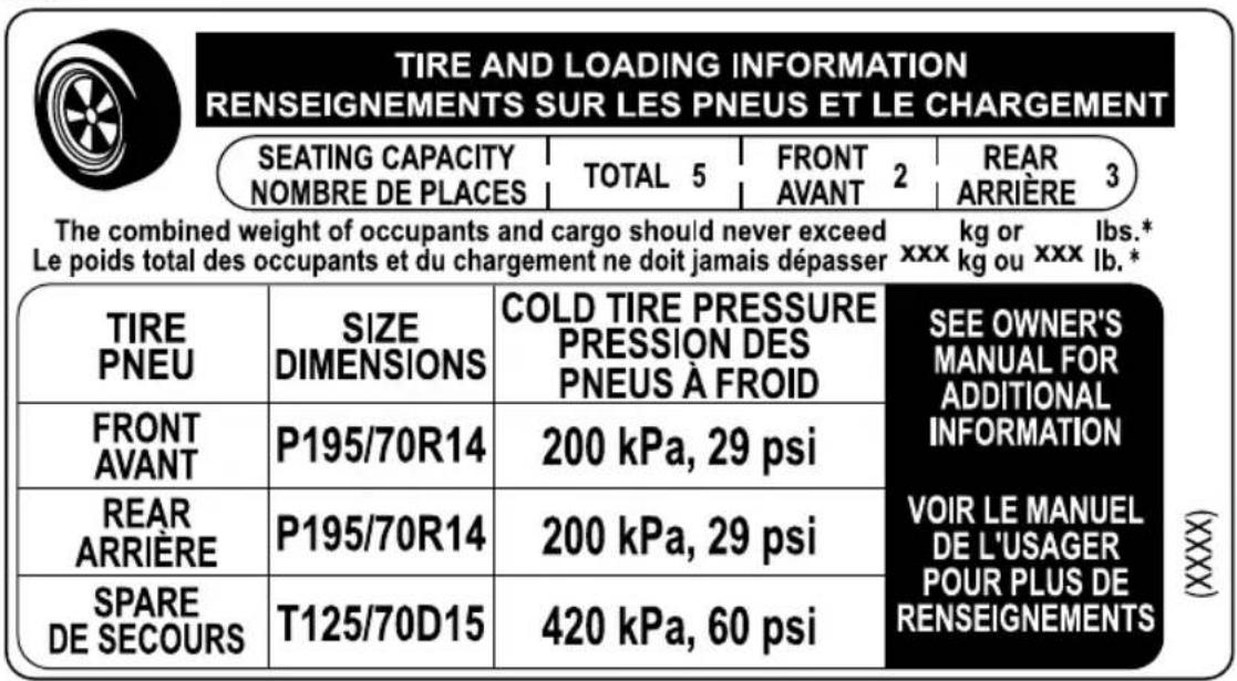
▼ Recommended Tire Inflation Pressure
On the tire label you will find the recommended tire inflation pressure in both kPa and psi for the tires installed as original equipment on the vehicle. It is very important that the inflation pressure of the tires on your vehicle is maintained at the recommended pressure. You should check the tire pressure regularly to insure that the proper inflation pressure is maintained.
Refer to Tires on page 9-7.
NOTE
Tire pressures listed on the vehicle placard or tire information label indicate the recommended cold tire inflation pressure, measured when the tires are cold, after the vehicle has been parked for at least 3 hours. As you drive, the temperature in the tire warms up, increasing the tire pressure.

WARNING
Always check the tire inflation pressures on a regular basis according to the recommended tire inflation pressure on the tire label and in conjunction with the information in this owner's manual:
Driving your vehicle with under-inflated tires is dangerous.
Under-inflation is the most common cause of failures in any kind of tire and may result in severe cracking, tread separation or "blowout", with unexpected loss of vehicle control and increased risk of injury. Under-inflation increases sidewall flexing and rolling resistance, resulting in heat buildup and internal damage to the tire. It results in unnecessary tire stress, irregular wear, loss of control and accidents. A tire can lose up to half of its air pressure and not appear to be flat!
It is impossible to determine whether or not tires are properly inflated just by looking at them.
▼ Checking Tire Pressure
- When you check the air pressure, make sure the tires are cold — meaning they are not hot from driving even a mile.
- Remove the cap from the valve on one tire.
- Firmly press a tire gauge onto the valve.
- Add air to achieve recommended air pressure.
- If you overfill the tire, release air by pushing on the metal stem in the center of the valve. Then recheck the pressure with your tire gauge.
- Replace the valve cap.
- Repeat with each tire, including the spare.
NOTE
Some spare tires require higher inflation pressure.
-
Visually inspect the tires to make sure there are no nails or other objects embedded that could poke a hole in the tire and cause an air leak.
-
Check the sidewalls to make sure there are no gouges, cuts, bulges, cracks or other irregularities.
▼ Glossary of Terms
Tire Placard: A label indicating the OE tire sizes, recommended inflation pressure, and the maximum weight the vehicle can carry.
Tire Identification Number (TIN): A number on the sidewall of each tire providing information about the tire brand and manufacturing plant, tire size, and date of manufacture.
Inflation Pressure: A measure of the amount of air in a tire.
kPa: Kilopascal, the metric unit for air pressure.
psi: Pounds per square inch, the English unit for air pressure.
B-pillar: The structural member at the side of the vehicle behind the front door.
Original Equipment (OE): Describes components originally equipped on the vehicle.
Vehicle Load Limit: The maximum value of the combination weight of occupants and cargo.
Bead Area of the Tire: Area of the tire next to the rim.
Sidewall Area of the Tire: Area between the bead area and the tread.
Tread Area of the Tire: Area on the perimeter of the tire that contacts the road when it's mounted on the vehicle.
Seating capacity means the total allowable number of vehicle occupants. Seating capacity is described on the tire label.
Production options weight is the combination weight of installed regular production options weighing over 2.3 kilograms in excess of the standard items which they replace, and not previously considered in the curb weight or accessory weight, including heavy duty brakes, ride levelers, roof rack, heavy duty battery, and special trim.
Rim is the metal support (wheel) for a tire or a tire and tube assembly upon which the tire beads are seated.
Tire Maintenance
Improper or inadequate vehicle maintenance can cause tires to wear abnormally. Here are some important maintenance points:
▼ Tire Inflation Pressure
Inspect all tire pressure monthly (including the spare) when the tires are cold. Maintain recommended pressures for the best ride, top handling, and minimum tire wear. Use the pressures specified on the vehicle tire information placard or tire label for optimum service.
▼ Tire Rotation
To equalize tread wear, rotate the tires every 12,000 km (7,500 miles) at the latest or sooner if irregular wear develops. Mazda recommends to rotate every 8,000 km (5,000 miles) to help increase tire life and distribute wear more evenly.
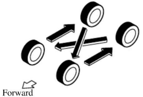
Do not include (TEMPORARY USE ONLY) spare tire in rotation.
Inspect the tires for uneven wear and damage. Abnormal wear is usually caused by one or a combination of the following:
- Incorrect tire pressure
- Improper wheel alignment
- Out-of-balance wheel
- Severe braking
After rotation, inflate all tire pressures to specification (page 9-7) and inspect the lug nuts for tightness.

CAUTION
Rotate unidirectional tires and radial tires that have an asymmetrical tread pattern or studs only from front to rear, not from side to side. Tire performance will be weakened if rotated from side to side.
▼ Replacing a Tire

WARNING
Always use tires that are in good condition:
Driving with worn tires is dangerous. Reduced braking, steering, and traction could result in an accident.
If a tire wears evenly, a wear indicator will appear as a solid band across the tread. Replace the tire when this happens.

natural_image
Diagram of plant leaf cross-section showing three distinct cell wall patterns (no text or labels)New tread
Tread wear indicator
natural_image
Abstract line drawing with wavy, curved lines and a triangular shape at the end (no text or symbols)Worn tread
You should replace the tire before the band crosses the entire tread.
NOTE
Tires degrade over time, even when they are not being used on the road. It is recommended that tires generally be replaced when they are 6 years or older. Heat caused by hot climates or frequent high loading conditions can accelerate the aging process. You should replace the spare tire when you replace the other road tires due to the aging of the spare tire. The period in which the tire was manufactured (both week and year) is indicated by a 4-digit number.
Refer to Tire Labeling on page 8-25.
▼ Safety Practices
The way you drive has a great deal to do with your tire mileage and safety. So cultivate good driving habits for your own benefit.
- Observe posted speed limits and drive at speeds that are safe for the existing weather conditions
- Avoid fast starts, stops and turns
- Avoid potholes and objects on the road
- Do not run over curbs or hit the tire against the curb when parking

CAUTION
If you feel a sudden vibration or ride disturbance while driving or you suspect your tire or vehicle has been damaged, immediately reduce your speed. Drive with caution until you can safely pull off the road. Stop and inspect the tire for damage. If the tire is under-inflated or damaged, deflate it, remove the tire and rim and replace it with your spare tire. If you cannot detect a cause, have the vehicle towed to the nearest vehicle or tire dealer to have the vehicle inspected.
Vehicle Loading
This section will guide you in the proper loading of your vehicle and/or trailer, to keep your loaded vehicle weight within its design rating capability, with or without a trailer. Properly loading your vehicle will provide maximum return of vehicle design performance. Before loading your vehicle, familiarize yourself with the following terms for determining your vehicle's weight ratings, with or without a trailer, from the vehicle's Safety Certification Label and Tire and Load Information Label:

WARNING
Overloaded Vehicle:
Overloading a vehicle is dangerous. The results of overloading can have serious consequences in terms of passenger safety. Too much weight on a vehicle's suspension system can cause spring or shock absorber failure, brake failure, handling or steering problems, irregular tire wear, tire failure or other damage.
Overloading makes a vehicle harder to drive and control. It also increases the distance required for stopping. In cases of serious overloading, brakes can fail completely, particularly on steep grades. The load a tire will carry safely is a combination of the size of the tire, its load range, and corresponding inflation pressure.
Never overload the vehicle and always observe the vehicle's weight ratings from the vehicle's Safety Certification and Tire and Load Information labels.
Base Curb Weight is the weight of the vehicle including a full tank of fuel and all standard equipment. It does not include passengers, cargo, or optional equipment.
Vehicle Curb Weight is the weight of your new vehicle when you picked it up from your dealer plus any aftermarket equipment.
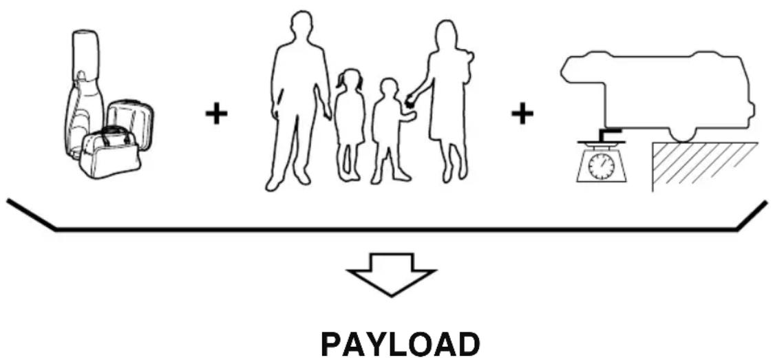
flowchart
graph TD
    A["Car Bag"] + B["Standing with Two People"]
    C["Water Pump"] + D["Pressure Gauge"]
Payload is the combination weight of cargo and passengers that the vehicle is designed to carry. The maximum payload for your vehicle can be found on the Tire and Load Information label on the driver's door frame or door pillar. Look for “THE COMBINATION WEIGHT OF OCCUPANTS AND CARGO SHOULD NEVER EXCEED XXX kg or XXX lbs” for your maximum payload. The payload listed on the tire label is the maximum payload for the vehicle as built by the assembly plant. If any aftermarket or dealer installed equipment has been installed on the vehicle, the weight of the equipment must be subtracted from the payload listed on the tire label in order to be accurate.
SAMPLE
TIRE AND LOADING INFORMATION RENSEIGNEMENTS SUR LES PNEUS ET LE CHARGEMENT
SEATING CAPACITY NOMBRE DE PLACES
TOTAL 5
FRONT AVANT
REAR ARRIÈRE 3
natural_image
Line drawing of a backpack and two bags (no text or symbols)+
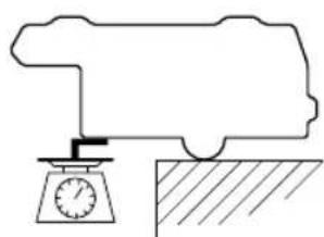
natural_image
Simple line drawing of a mechanical setup with a scale and hatched ground surface (no text or symbols)CARGO
Cargo Weight includes all weight added to the Base Curb Weight, including cargo and optional equipment. When towing, trailer tongue load or king pin weight is also part of cargo weight.
The cargo weight limit decreases depending on the number of vehicle occupants. The cargo weight limit can be calculated by subtracting the total weight of the vehicle occupants from the “combination weight of occupants and cargo should never exceed” value on the tire label.
Examples: Based on a single occupant weight of 68 kg (150 lbs), and a value of 385 kg (849 lbs) for the “combination weight of occupants and cargo should never exceed”:
The cargo weight limit with one occupant is 385 kg (849 lbs) - 68 kg (150 lbs) = 317 kg (699 lbs)
The cargo weight limit with two occupants is 385 kg (849 lbs) — (68 × 2) kg ((150 × 2) lbs) = 249 kg (549 lbs)
If the weight of the occupant increases, the cargo weight limit decreases by that much.
GAW (Gross Axle Weight) is the total weight placed on each axle (front and rear) - including vehicle curb weight and all payload.
GAWR (Gross Axle Weight Rating) is the maximum allowable weight that can be carried by a single axle (front or rear). These numbers are shown on the Safety Compliance Certification Label located on the driver's door frame or door pillar. The total load on each axle must never exceed its GAWR.
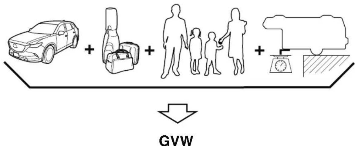
flowchart
graph TD
    A["Car"] + B["Luggage"]
    B + C["Family"]
    C + D["Fue Efficiency"]
    D --> E["Down Arrow"]
    style A fill:#f9f,stroke:#333
    style B fill:#ccf,stroke:#333
    style C fill:#cfc,stroke:#333
    style D fill:#fcc,stroke:#333
    style E fill:#ffc,stroke:#333
GVW (Gross Vehicle Weight) is the Vehicle Curb Weight + cargo + passengers.
GVWR (Gross Vehicle Weight Rating) is the maximum allowable weight of the fully loaded vehicle (including all options, equipment, passengers and cargo). The GVWR is
shown on the Safety Compliance Certification Label located on the driver's door frame or door pillar. The GVW must never exceed the GVWR.
SAMPLE
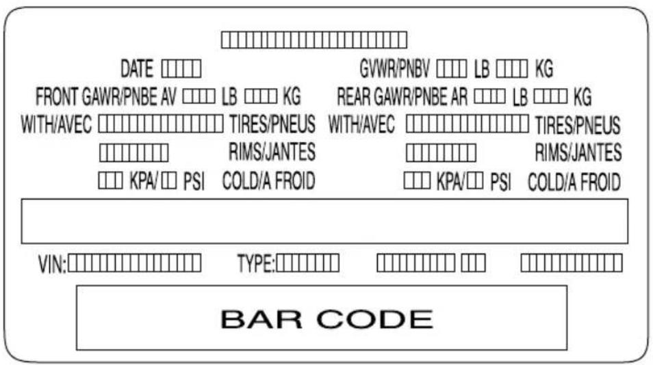

WARNING
Never Exceed Axle Weight Rating Limits:
Exceeding the Safety Certification Label axle weight rating limits is dangerous and could result in death or serious injury as a result of substandard vehicle handling, performance, engine, transmission and/or structural damage, serious damage to the vehicle, or loss of control.
Always keep the vehicle within the axle weight rating limits.
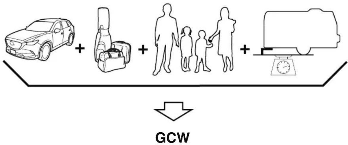
flowchart
graph TD
    A["Car"] + B["Luggage"] + C["Family"]
    C --> D["Camera"]
    style A fill:#f9f,stroke:#333
    style B fill:#ccf,stroke:#333
    style C fill:#cfc,stroke:#333
    style D fill:#fcc,stroke:#333
    subgraph GCW
        direction TB
        A -->|+| B
        B -->|+| C
        C -->|+| D
    end
GCW (Gross Combination Weight) is the weight of the loaded vehicle (GVW) plus the weight of the fully loaded trailer.
GCWR (Gross Combination Weight Rating) is the maximum allowable weight of the vehicle and the loaded trailer - including all cargo and passengers - that the vehicle can handle without risking damage. (Important: The towing vehicle's braking system is rated for operation at GVWR, not at GCWR. Separate functional brakes should be used for safe control of towed vehicles and for trailers weighing more than 1,500 lbs). The GCW must never exceed the GCWR.
Maximum Loaded Trailer Weight is the highest possible weight of a fully loaded trailer the vehicle can tow. It assumes a vehicle with only mandatory options, no cargo (internal or external), a tongue load of 10—15% (conventional trailer) or king pin weight of 15—25% (fifth-wheel trailer), and driver only (150 lbs). Consult your dealership (or the RV and Trailer Towing Guide provided by your dealership) for more detailed information. Tongue Load or Fifth-Wheel King Pin Weight refers to the amount of the weight that a trailer pushes down on a trailer hitch.
Examples: For a 5000 lb conventional trailer, multiply 5000 by 0.10 and 0.15 to obtain a proper tongue load range of 500 to 750 lbs. For an 11,500 lb fifth-wheel trailer, multiply by 0.15 and 0.25 to obtain a proper king pin load range of 1,725 to 2,875 lbs.

WARNING
Never Exceed GVWR or GAWR Specifications:
Exceeding the GVWR or the GAWR specified on the certification label is dangerous. Exceeding any vehicle rating limitation could result in a serious accident, injury, or damage to the vehicle.
Do not use replacement tires with lower load carrying capacities than the originals because they may lower the vehicle's GVWR and GAWR limitations. Replacement tires with a higher limit than the originals do not increase the GVWR and GAWR limitations.
Never exceed the GVWR or the GAWR specified on the certification label.
Steps for Determining the Correct Load Limit
Steps for Determining Correct Load Limit-
(1) Locate the statement “The combined weight of occupants and cargo should never exceed XXX kg or XXX lbs.” on your vehicle's placard.
(2) Determine the combined weight of the driver and passengers that will be riding in your vehicle.
(3) Subtract the combined weight of the driver and passengers from XXX kg or XXX lbs.
(4) The resulting figure equals the available amount of cargo and luggage load capacity. For example, if the “XXX” amount equals 1400 lbs. and there will be five 150 lb passengers in your vehicle, the amount of available cargo and luggage load capacity is 650 lbs. (1400 - 750 (5 × 150) = 650 lbs.)
(5) Determine the combined weight of luggage and cargo being loaded on the vehicle. That weight may not safely exceed the available cargo and luggage load capacity calculated in Step 4.
(6) If your vehicle will be towing a trailer, load from your trailer will be transferred to your vehicle. Consult this manual to determine how this reduces the available cargo and luggage load capacity of your vehicle.
Declaration of Conformity
▼ Keyless Entry System/Immobilizer System
FCC CAUTION
Changes or modifications not expressly approved by the party responsible for compliance could void the user's authority to operate the equipment.
FCC/ISED
USA/Puerto Rico/Guam/Saipan
This device complies with Part 15 of the FCC Rules. Operation is subject to the following two conditions:
(1) This device may not cause harmful interference, and
(2) This device must accept any interference received, including interference that may cause undesired operation.
CAUTION TO USERS
Changes or modifications not expressly approved by the party responsible for compliance could void the user's authority to operate the equipment.
Mexico
Certificado de homologacion: RVLOAR15-0442
Continental SRR 3-A
This device complies with Industry Canada licence-exempt RSS standard(s).
Operation is subject to the following two conditions:
(1) this device may not cause interference, and
(2) this device must accept any interference, including interference that may cause undesired operation of the device.
Frequency bands: 24.05-24.25 GHz
The field strength of SRR3-A is below 250 millivolts/m measured at 3 metres with an average detector.
This device contains licence-exempt transmitter(s)/receiver(s) that comply with Innovation, Science and Economic Development Canada's licence-exempt RSS(s).
Operation is subject to the following two conditions:
(1) This device may not cause harmful interference.
[2] This device must accept any interference, including interference that may cause undesired operation of the device.
Radiofrequency radiation exposure information:
This equipment complies with radiation exposure limits set forth for an uncontrolled environment.
This equipment should be installed and operated with minimum distance of 20 cm between the radiator and your body.
HomeLink has been tested and complies with FCC and Industry Canada rules. Changes or modifications not expressly approved by the party responsible for compliance could void the user's authority to operate the device.
NOTE
This device complies with part 15 of the FCC Rules. Operation is subject to the following two conditions:
1- This device may not cause harmful interference, and
2- This device must accept any interference received, including interference that may cause undesired operation.
Type B
U.S.A. and Canada
FOC (USA) and ISED (Canada)
This device complies with FOC rules part 15 and Innovation, Science, and Economic Development Canada RSS-210. Operation is subject to the following two conditions: (1) This device may not cause harmful interference, and (2) This device must accept any interference that may be received including interference that may cause undesired operation. WARNING: The transmitter has been tested and complies with FOC and ISED rules. Changes or modifications not expressly approved by the party responsible for compliance could void the user's authority to operate the device.
This equipment coplies with FCC and ISED radiation exposure limits set forth for an uncontrolled environment. End Users must follow the specific operating instructions for satisfying RF exposure compliance. This transmitter must be at least 20 cm from the user and must not be co-located or operating in conjunction with any other antenna or transmitter.
▼ Tire Pressure Monitoring System
USA
This device complies with Part 15 of the FCC Rules. Operation is subject to the following two conditions: (1) this device may not cause harmful interference, and (2) this device must accept any interference received, including interference that may cause undesired operation.
Changes or modifications not expressly approved by the party responsible for compliance could void the user's authority to operate the equipment.
Canada
This device complies with Industry Canada licence-exempt RSS standard(s). Operation is subject to the following two conditions: (1) this device may not cause Interference, and (2) this device must accept any interference, including interference that may cause undesired operation of the device.
Properly shielded and grounded cables and connectors must be used for connection to host computers and / or peripherals in order to meet FCC emission limits.
CAUTION :
Changes or modifications not expressly approved by the party responsible for compliance could void the user's authority to operate the equipment.
▼ Audio System
Type A (non-touchscreen)
Model Name: MAZ
Type of product: Bluetooth Telematics Device
Brand / Manufacturer: Visteon Corporation
Address One Village center drive, Van Buren Township
48111-5711 Michigan
United States of America
(U.S.A. and Canada)
FCC
FCC ID: NT8MBLUEC09
This device complies with part 15 of the FCC Rules. Operation is subject to the following two conditions:
(1) This device may not cause harmful interference, and
(2) This device must accept any interference received, including interference that may cause undesired operation.
Caution:
Changes or modifications not expressly approved by the party responsible for compliance could void the user's authority to operate the equipment.
ISED CANADA
IC: 3043A-MBLUEC09
This device complies with Industry Canada license-exempt RSS standard(s). Operation is subject to the following two conditions:
(1) This device may not cause harmful interference, and
(2) This device must accept any interference received, including interference that may cause undesired operation.
Mazda Audio System Customer Service
· U.S.A.
Phone: 800-430-0153 (Toll-free)
Web: www.mazdausa.com/mazdaconnect
• Canada
Phone: 800-430-0153 (Toll-free)
Web: www.mazdahandsfree.ca
(Mexico)
- Name and address of the importer: Refer to "MEXICO" (page 8-13) in Importer/Distributor section.
- Brand name of the product: Visteon Corporation
- Names and addresses of where the warranty can be served: Refer to "MEXICO" (page 8-13) in Importer/Distributor section.
- Names and addresses of where to acquire spare parts, consumables and accessories: Refer to "MEXICO" (page 8-13) in Importer/Distributor section.
- Warranty period, items covered by the warranty and its possible limitations or exceptions: Refer to the Warranty Booklet for detailed warranty information.
· Warranty procedure:
Centre of Attention to Client (CAC)
Phone: 01-800-01-MAZDA
Web: www.mazdamexico.com.mx
· Brief description: Bluetooth Telematics Device
- Model name of the product: MAZ
• Homologation ID: RTIJOMA08-1043
• Electrical specifications:
Voltage: 9-16V, Frequency: 2.4GHz, Current: 270mA(Typ)

Type B (touchscreen)
| Model Name: | MAZIDA_GEN_65_CMU |
| Type of product: | Automotive Electronics Infotainment Head Unit |
| Brand / Manufacturer: | Visteon Corporation |
| Address: | One Village center drive, Van Buren Township 48111-5711 MichiganUnited States of America |
(U.S.A. and Canada)
FCC
FCC ID: NT862932
This device complies with part 15 of the FCC Rules. Operation is subject to the following two conditions:
(1) This device may not cause harmful interference, and
(2) This device must accept any interference received, including interference that may cause undesired operation.
Caution:
Changes or modifications not expressly approved by the party responsible for compliance could void the user's authority to operate the equipment.
ISED CANADA
IC: 3043A-62932
This device complies with Industry Canada license-exempt RSS standard(s). Operation is subject to the following two conditions:
(1) This device may not cause harmful interference, and
(2) This device must accept any interference received, including interference that may cause undesired operation.
Le présent appareil est conforme aux CNR d'Industrie Canada applicables aux appareils radio exempts de licence.
Mazda Audio System Customer Service
· U.S.A.
Phone: 800-430-0153 (Toll-free)
Web: www.mazdausa.com/mazdaconnect
• Canada
Phone: 800-430-0153 (Toll-free)
Web: www.mazdahandsfree.ca
(Mexico)
- Name and address of the importer: Refer to "MEXICO" (page 8-13) in Importer/Distributor section.
- Brand name of the product: Visteon Corporation
- Names and addresses of where the warranty can be served: Refer to "MEXICO" (page 8-13) in Importer/Distributor section.
- Names and addresses of where to acquire spare parts, consumables and accessories: Refer to "MEXICO" (page 8-13) in Importer/Distributor section.
- Warranty period, items covered by the warranty and its possible limitations or exceptions: Refer to the Warranty Booklet for detailed warranty information.
• Warranty procedure:
Centre of Attention to Client (CAC)
Phone: 01-800-01-MAZDA
Web: www.mazdamexico.com.mx
- Brief description: Automotive Electronics Infotainment Head Unit
- Model name of the product: MAZDA_GEN_65_CMU
. omologation ID: RCPJOMA13-1301
• Electrical specifications:
Voltage: 10-16V, Frequency: 2.4GHz, Current: 1A(Typ)

Type C (touchscreen)
| Model Name: | MAZDA_68_CMU |
| Type of product: | Automotive Electronics Infotainment Head Unit |
| Brand / Manufacturer: | Visteon Corporation |
| Address: | One Village center drive, Van Buren Township 48111-5711 MichiganUnited States of America |
(U.S.A. and Canada)
FCC
FCC ID: NT8-MAZDA68CMU
This device complies with part 15 of the FCC Rules. Operation is subject to the following two conditions:
(1) This device may not cause harmful interference, and
(2) This device must accept any interference received, including interference that may cause undesired operation.
Caution:
Changes or modifications not expressly approved by the party responsible for compliance could void the user's authority to operate the equipment.
ISED CANADA
IC: 3043A-MAZDA68CMU
This device complies with Industry Canada license-exempt RSS standard(s). Operation is subject to the following two conditions:
(1) This device may not cause harmful interference, and
(2) This device must accept any interference received, including interference that may cause undesired operation.
Mazda Audio System Customer Service
· U.S.A.
Phone: 800-430-0153 (Toll-free)
Web: www.mazdausa.com/mazdaconnect
• Canada
Phone: 800-430-0153 (Toll-free)
Web: www.mazdahandsfree.ca
(Mexico)
- Name and address of the importer: Refer to "MEXICO" (page 8-13) in Importer/Distributor section.
- Brand name of the product: Visteon Corporation
- Names and addresses of where the warranty can be served: Refer to "MEXICO" (page 8-13) in Importer/Distributor section.
- Names and addresses of where to acquire spare parts, consumables and accessories: Refer to "MEXICO" (page 8-13) in Importer/Distributor section.
- Warranty period, items covered by the warranty and its possible limitations or exceptions: Refer to the Warranty Booklet for detailed warranty information.
• Warranty procedure:
Centre of Attention to Client (CAC)
Phone: 01-800-01-MAZDA
Web: www.mazdamexico.com.mx
- Brief description: Automotive Electronics Infotainment Head Unit
- Model name of the product: MAZDA_68_CMU
· Homologation ID: --
• Electrical specifications:
Voltage: 10-16V, Frequency: 2.4GHz, Current: 1A(Typ)
UNIDAD PRINCIPAL DE INFOENTRETENIMIENTO PARA AUTO
Marca: VISTEON
Modelo: MAZDA_68_CMU
10 - 16 V = 1 A
No. SERIE: VPLFYF12345678AD
Homologación IFT: --
Hecho en: Mexico/China

IC ID: 26055-CHG-WIRELESS FCC ID: 2AEQT-CHG-WIRELESS
FCC Statement:
This device complies with Industry Canada licence-exempt RSS standard(s).
Operation is subject to the following two conditions: (1) this device may not cause interference, and (2) this device must accept any interference, including interference that may cause undesired operation of the device.
This equipment complies with Industry Canada radiation exposure limits set forth for an uncontrolled environment.
This device complies with part 15 of the FCC rules. Operation is subject to the following two conditions: (1) this device may not cause harmful interference, and (2) this device must accept any interference received, including interference that may cause undesired operation. Changes or modifications not expressly approved by the party responsible for compliance could void the user's authority to operate the equipment.
NOTE: This equipment has been tested and found to comply with the limits for a Class B digital device, pursuant to part 15 of the FCC Rules. These limits are designed to provide reasonable protection against harmful interference in a residential installation.
This equipment generates uses and can radiate radio frequency energy and, if not installed and used in accordance with the instructions, may cause harmful interference to radio communications. However, there is no guarantee that interference will not occur in a particular installation. If this equipment does cause harmful interference to radio or television reception, which can be determined by turning the equipment off and on, the user is encouraged to
try to correct the interference by one or more of the following measures:
- Reorient or relocate the receiving antenna.
- Increase the separation between the equipment and receiver.
- Connect the equipment into an outlet on a circuit different from that to which the receiver is connected.
- Consult the dealer or an experienced radio/TV technician for help important announcement Important
Note: Radiation Exposure Statement
This equipment complies with FCC radiation exposure limits set forth for an uncontrolled environment. This transmitter must not be co-located or operating in conjunction with any other antenna or transmitter.
▼ Mazda Radar Cruise Control (MRCC)/Distance Recognition Support System (DRSS)/Smart Brake Support (SBS)
FCC ID: HYQDNMWR006
NOTE:
This device complies with part 15 of the FCG Rules. Operation is subject to the following two conditions:
(1) This device may not cause harmful interference, and
(2) this device must accept any interference received, including interference that may cause undesired operation.
FCC WARNING
Changes or modifications not expressly approved by the party responsible for compliance could void the user's authority to operate the equipment.
Radiofrequency radiation exposure (Information)
This equipment complies with FCG radiation exposure limits set forth for an uncontrolled environment.
This equipment should be installed and operated with minimum distance of 20 cm between the radiator (antenna) and your body.
This transmitter must not be co-located or operating in conjunction with any other antenna or transmitter.
NOTE:
This device complies with Industry Canada licence-exempt RSS standard(s). Operation is subject to the following two conditions.
(1) this device may not cause interference, and
(2) this device must accept any interference, including interference that may cause undesired operation of the device.
This equipment complies with IC radiation exposure limits set forth for an uncontrolled environment and meets RSS-102 of the IC radio.
frequency (RF) Exposure rules. This equipment should be installed and operated keeping the radiator at least 20 cm or more away from person's body.
NOTE:
Technical information about your Mazda.
Identification Numbers......9-2
Vehicle Information Labels...... 9-2
Specifications.... 9-4
Specifications.... 9-4
Vehicle Information Labels
▼ Vehicle Identification Number
The vehicle identification number legally identifies your vehicle. The number is on a plate attached to the cowl panel located on the left corner of the dashboard. This plate can easily be seen through the windshield.
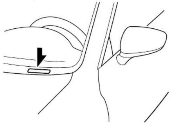
natural_image
Line drawing of a car seatbelt mechanism with a directional arrow indicating left side (no text or symbols)▼ Motor Vehicle Safety Standard Label (U.S.A. and Canada)
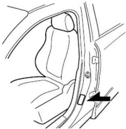
natural_image
Line drawing of a car seatbelt with a belt buckle and arrow indicating a specific component (no text or symbols present)▼ Chassis Number
Open the cover shown in the figure to check the chassis number.
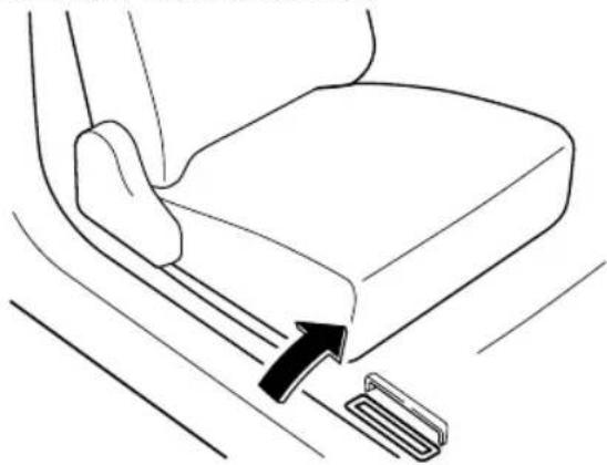
natural_image
Line drawing of a car seatbelt buckle with a black arrow indicating the seatbelt buckle (no text or symbols present)▼ Vehicle Emission Control Information Label (U.S.A. and Canada)
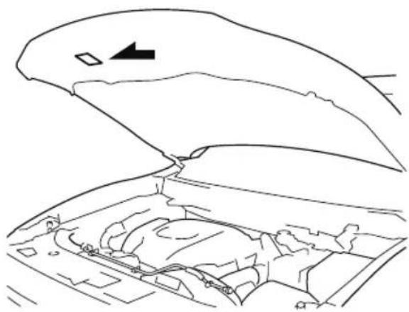
natural_image
Line drawing of an open car hood with visible engine compartment and side door (no text or symbols)▼ Tire Pressure Label
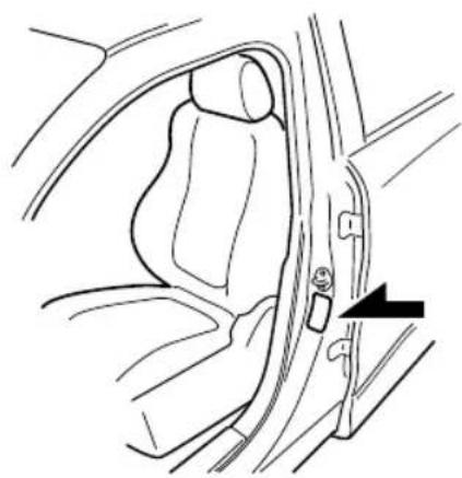
natural_image
Line drawing of a car seatbelt with a black arrow pointing to the side panel (no text or symbols)▼ Engine Number
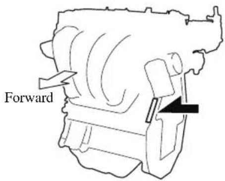
Specifications
▼ Engine
| Item Specification | |
| Type DOHC-16V in-line, 4-cylinder | |
| Bore × Stroke 89.0 × 100 mm (3.50 × 3.94 in) | |
| Displacement 2,488.5 ml (2,488.5 cc) | |
| Compression ratio 10.5 | |
▼ Electrical System
| Item Classification | ||
| Battery*1 | 12V-60Ah/20HR or 12V-65Ah/20HR | |
| Spark-plug number | Mazda Genuine spark plug*2 | PY8V-18-110 |
*1 Check the battery installed on the vehicle and use a battery with an equal or higher performance. However, the performance of the battery may vary even among the same battery types, consult an Authorized Mazda Dealer for replacement.
*2 The spark plugs provide the SKYACTIV-G its optimum performance. Consult an Authorized Mazda Dealer for details.

CAUTION
When cleaning the iridium plugs, do not use a wire brush. The fine particulate coating on the iridium alloy and platinum tips could be damaged.
▼ Lubricant Quality
| Lubricant Classification | |
| Engine oil Refer to Recommended Oil on page 6-20. | |
| Coolant FL-22 type | |
| Automatic transaxle fluid Mazda Genuine ATF FZ | |
| Transfer case oil Mazda Long Life Hypoid Gear Oil SG1 | |
| Rear differential oil Mazda Long Life Hypoid Gear Oil SG1 | |
| Brake fluid | SAE J1703 or FMVSS116 DOT-3 |
NOTE
Refer to Introduction on (page 6-2) for owner's responsibility in protecting your investment.
▼ Capacities
(Approximate Quantities)
| Item Capacity | ||
| Engine oil | With oil filter replacement 4.8 L (5.1 US qt, | 4.2 Imp qt) |
| Without oil filter replacement 4.6 L (4.9 US qt, 4.0 Imp qt) | ||
| Coolant | U.S.A. and Canada 9.9 L (10.5 US qt, 8.7 Imp qt) | |
| Mexico 9.8 L (10.4 US qt, 8.6 Imp qt) | ||
| Automatic transaxle fluid 8.0 L (8.5 US qt, 7.0 Imp qt) | ||
| Transfer case oil 0.45 L (0.48 US qt, 0.40 Imp qt) | ||
| Rear differential oil 0.35 L (0.37 US qt, 0.31 Imp qt) | ||
| Fuel tank | FWD 72.0 L (19.0 US gal, 15.8 Imp gal) | |
| AWD 74.0 L (19.5 US gal, 16.3 Imp gal) | ||
Check oil and fluid levels with dipsticks or reservoir gauges.
▼ Dimensions
U.S.A. and Canada
| Item Vehicle specification | |
| Overall length 5,075 mm (199.8 in) | |
| Overall width 1,969 mm (77.5 in) | |
| Overall height | 1,752 mm (69.0 in) |
| Front tread | 1,659 mm (65.3 in) |
| Rear tread | 1,656 mm (65.2 in) |
| Wheelbase | 2,928 mm (115.3 in) |
Mexico
| Item Vehicle specification | |
| Overall length 5,075 mm (199.8 in) | |
| Overall width 1,969 mm (77.5 in) | |
| Overall height | 1,747 mm (68.8 in) |
| Front tread | 1,659 mm (65.3 in) |
| Rear tread | 1,656 mm (65.2 in) |
| Wheelbase | 2,928 mm (115.3 in) |
▼ Weights
U.S.A. and Canada
| Item | Weight | ||
| FWD AWD | |||
| GVWR (Gross Vehicle Weight Rating) 2,572 kg (5,670 lbs) 2,641 kg (5,822 lbs) | |||
| GAWR (Gross Axle Weight Rating) | Front 1,225 kg (2,701 lbs) 1,250 kg (2,756 lbs) | ||
| Rear 1,383 kg (3,049 lbs) 1,427 kg (3,146 lbs) | |||
Mexico
| Item | Weight | ||
| FWD AWD | |||
| GVW (Gross Vehicle Weight) | Total 2,495 kg (5,500 lbs) 2,565 kg (5,655 lbs) | ||
| Front 1,180 kg (2,601 lbs) 1,205 kg (2,657 lbs) | |||
| Rear 1,315 kg (2,899 lbs) 1,360 kg (2,998 lbs) | |||
| GAW (Permissible axle load) | Front 1,200 kg (2,646 lbs) 1,225 kg (2,701 lbs) | ||
| Rear 1,370 kg (3,020 lbs) 1,420 kg (3,131 lbs) | |||
▼ Light Bulbs
Exterior light
| Light bulb | Category | ||
| Wattage | UN-R*1(SAE) | ||
| HeadlightsDaytime running lightsParking lights*Front side-marker lights*Fog lights*Signature wing illumination*Side turn signal lightsHigh-mount brake lightRear side-marker lightsBrake lightsTaillightsLicense plate lights | LED — (—) | ||
| Parking lights/Front side-marker lights* | 5 | W | |
| Front turn signal lights | LED type LED — (—) | ||
| Bulb type 21 WY21W (7443NA) | |||
| Rear turn signal lights | 21 WY21W (7443NA) | ||
| Reverse lights | 16 | W16W (921) | |
*1 UN-R stands for United Nations Regulation.
Interior light
| Light bulb | Category | ||
| Wattage | UN-R*1 | ||
| Overhead lights (Front)/Map lights (Front) | LED type LED — | ||
| Bulb type 8 — | |||
| Overhead lights (Center)/Map lights (Center) | LED type LED — | ||
| Bulb type 8 — | |||
| Overhead light (Rear) | LED type LED — | ||
| Bulb type 10 — | |||
| Ambient lights* | LED — | ||
| Vanity mirror lights* | LED type LED — | ||
| Bulb type 2 — | |||
| Luggage compartment light | LED type LED — | ||
| Bulb type 8 — | |||
*1 UN-R stands for United Nations Regulation.
▼ Tires
NOTE
The tires have been optimally matched with the chassis of your vehicle.
When replacing tires, Mazda recommends that you replace tires of the same type originally fitted to your vehicle. For details, contact an Authorized Mazda Dealer.
Check the tire pressure label for tire size and inflation pressure.
Refer to Tire Inflation Pressure on page 6-34.
Standard tire
(U.S.A. and Canada)
| Tire size | Inflation pressure | |
| Front Rear | ||
| P255/60R18 107H 230 kPa (34 psi) 230 | kPa (34 psi) | |
| P255/50R20 104V 230 kPa (34 psi) 230 | kPa (34 psi) | |
(Mexico)
| Tire size | Inflation pressure | |
| Front Rear | ||
| P255/50R20 104V 230 kPa (2.3 bar, 33 psi) | 230 kPa (2.3 bar, 33 psi) | |
Temporary spare tire
(U.S.A. and Canada)
| Tire size Inflation pressure | |
| T155/90D17 101M 420 kPa (60 psi) | |
(Mexico)
| Tire size Inflation pressure | |
| 185/80R17 99M 320 kPa (3.2 bar, 46 psi) |
Lug nut tightening torque
When installing a tire, tighten the lug nut to the following torque.
Refer to Fuses on page 6-46.
10 Index
A
Accessory Socket.... 5-58
Active Driving Display....4-56
Adaptive Front Lighting System
(AFS).... 4-117
Add-On Non-Genuine Parts and
Accessories....8-19
Advanced Key
Advanced keyless entry system...3-10
Operational range.... 3-11
Advanced Key Removed from Vehicle
Warning Beep....7-48
Advanced Smart City Brake Support
(Advanced SCBS)...... 4-169
Collision warning...... 4-171
Stopping the Advanced Smart City
Brake Support (Advanced SCBS)
system operation......4-171
Air Bag Systems.... 2-69
Air Bag/Seat Belt Pretensioner System
Warning Beep....7-47
Antilock Brake System (ABS)......4-102
Armrest Box....5-69
AUTOHOLD....4-96
AUTOHOLD Warning Beep......7-49
Automatic Transaxle.... 4-59
Active Adaptive Shift (AAS)..... 4-61
Automatic transaxle controls.....4-59
Direct mode.... 4-68
Driving tips....4-69
Manual shift mode......4-62
Shift-lock system....4-60
Transaxle ranges......4-60
B
Battery.... 6-30
Maintenance......6-32
Replacement.... 6-32
Specifications....9-4
Battery Runs Out.... 7-19
Jump-starting.... 7-19
Blind Spot Monitoring (BSM)...... 4-121
Canceling operation of Blind Spot
Monitoring (BSM)......4-125
Blind Spot Monitoring (BSM) Warning
Beep....7-50
Body Lubrication.... 6-25
Bottle Holder....5-67
Brakes
Brake assist....4-95
Electric parking brake (EPB)..... 4-92
Foot brake....4-92
Pad wear indicator......4-95
Warning light....4-94
Break-In Period.... 3-49
C
Capacities.... 9-5
Carbon Monoxide.... 3-31
Cell Phones.... 8-20
Center Console....5-68
Child Restraint
Categories of child-restraint systems....2-49
Child-restraint precautions...... 2-44
Child-restraint system installation.... 2-49
Child-restraint system suitability for various seat positions table......2-51
Installing child-restraint systems....2-55
ISOFIX child-restraint systems (Mexico).... 2-64
LATCH child-restraint systems (Except Mexico)......2-64
Child Safety Locks for Rear Doors... 3-19
Climate Control System....5-2
Dual-zone automatic climate control....5-5
Front Air Conditioner....5-5
Fully Automatic Type....5-5
Operating tips.... 5-2
Operating Tips....5-2
Rear Air Conditioner.... 5-11
Vent operation....5-3
Vent Operation....5-3
Vent Operation (Front)...... 5-3
Vent Operation (Rear)...... 5-9
Collision warning....7-51
Coming Home Light...... 4-74
Cruise Control....4-247
Cruise control switch....4-247
Cruise main indication (white)/cruise set indication (green)....4-248
Cup Holder....5-65
Customer Assistance.... 8-2
D
Daytime Running Lights......4-75
Defogger
Mirror....4-82
Rear window.... 4-82
Dimensions....9-5
Display....4-11
Distance Recognition Support System
(DRSS).... 4-133
Indication on display...... 4-133
Door Locks....3-12
Driver Attention Alert (DAA)......4-137
Drive Selection....4-109
Driving In Flooded Area....3-54
Driving on Uneven Road.... 3-55
Driving Tips
Automatic transaxle....4-69
Break-in period....3-49
Driving in flooded area.... 3-54
Driving on uneven road......3-55
Floor mat.... 3-51
Hazardous driving.... 3-50
Overloading.... 3-54
Rocking the vehicle....3-51
Saving fuel and protection of the environment....3-49
Turbocharged vehicles....3-56
Winter driving.... 3-52
Dynamic Stability Control (DSC)... 4-105
TCS/DSC indicator light...... 4-105
E
Electric parking brake (EPB)......4-92
Electric Parking Brake (EPB) Warning
Beep....7-49
Emergency Starting
Push-starting.... 7-22
Starting a flooded engine.... 7-22
Emergency Towing
Towing description.... 7-25
Towing hooks.... 7-26
Emission Control System......3-30
Engine
Coolant....6-22
Engine compartment overview....6-19
Exhaust gas....3-31
Hood release......6-17
Oil.... 6-20
Starting....4-5
Essential Information.... 6-2
Event Data Recorder......8-21
Exhaust Gas.... 3-31
Exterior Care....6-52
Aluminum wheel maintenance.... 6-57
Bright-metal maintenance...... 6-56
Maintaining the finish...... 6-53
Plastic part maintenance......6-57
F
Flasher
Hazard warning...... 4-84
Headlights....4-70
Flat Tire....7-3
Mounting the spare tire.... 7-13
Removing a flat tire.... 7-9
Floor Mat.... 3-51
Fluid
Brake....6-23
Washer.... 6-24
Fluids
Classification.... 9-4
Fog Lights.... 4-76
Foot Brake....4-92
Forward Sensing Camera (FSC)..... 4-235
Front Seat....2-5
Fuel
Filler lid and cap.... 3-32
Requirements.... 3-29
Tank capacity....9-5
Fuses....6-46
Panel description.... 6-48
Replacement.... 6-46
G
Gauges.... 4-11
Glove Compartment....5-68
H
Hazardous Driving.... 3-50
Hazard Warning Flasher......4-84
Headlights
Coming home light......4-74
Control.... 4-70
Headlight flashing...... 4-74
High-low beam.... 4-74
Leaving home light.... 4-74
Leveling.... 4-75
Head Restraint....2-28
High Beam Control System
(HBC)....4-118
High Beam Control System (HBC)
indicator light (green)......4-119
Hill Launch Assist (HLA)...... 4-100
HomeLink Wireless Control System
(Type A).... 4-84
HomeLink Wireless Control System
(Type B).... 4-88
Hood Release.... 6-17
Horn....4-83
I
If a Warning Light Turns On or
Flashes....7-28
If the Active Driving Display Does Not
Operate.... 7-53
Ignition
Switch.... 4-4
Ignition Not Switched Off (STOP)
Warning Beep....7-48
Illuminated Entry System...... 5-57
Immobilizer System.... 3-45
Inspecting Brake Fluid Level......6-23
Inspecting Coolant Level...... 6-22
Inspecting Engine Oil Level...... 6-21
Inspecting Washer Fluid Level...... 6-24
Instrument Cluster....4-11
Instrument Cluster (Type A)......4-12
Instrument Cluster (Type B)......4-29
Instrument Cluster (Type C)......4-44
Instrument Cluster (Type A)...... 4-12
Average Fuel Economy...... 4-19
Blind Spot Monitoring (BSM)
Display....4-20
Compass Display......4-21
Cruise Control Set Vehicle Speed
Display....4-21
Current Fuel Economy...... 4-20
Dashboard Illumination......4-17
Distance Recognition Support System
(DRSS) Display....4-21
Distance-to-empty...... 4-19
Engine Coolant Temperature
Gauge....4-16
Fuel Gauge.... 4-17
Indication/Indicator Lights...... 4-25
Lane-keep Assist System (LAS) &
Lane Departure Warning System
(LDWS) Display....4-20
Maintenance Monitor...... 4-20
Mazda Radar Cruise Control with
Stop & Go function (MRCC with
Stop & Go function) Display......4-21
Multi-information Display (Type
A)....4-13
Odometer.... 4-15
Outside Temperature Display..... 4-18
Speedometer.... 4-12
Speed Unit Selector......4-18
Tachometer.... 4-12
Trip Meter....4-15
Warning Indication/Warning
Lights....4-23
Warning (Display Indication)..... 4-21
Instrument Cluster (Type B)...... 4-29
Average Fuel Economy...... 4-35
Blind Spot Monitoring (BSM)
Display....4-36
Compass Display....4-37
Cruise Control Set Vehicle Speed
Display....4-37
Current Fuel Economy...... 4-36
Dashboard Illumination......4-34
Distance Recognition Support System
(DRSS) Display....4-37
Distance-to-empty...... 4-35
Engine Coolant Temperature
Gauge....4-32
Fuel Gauge.... 4-33
Indication/Indicator Lights...... 4-40
Lane-keep Assist System (LAS) &
Lane Departure Warning System
(LDWS) Display....4-36
Maintenance Monitor...... 4-36
Mazda Radar Cruise Control with
Stop & Go function (MRCC with
Stop & Go function) Display......4-36
Multi-information Display (Type
B)....4-30
Odometer.... 4-31
Outside Temperature Display..... 4-34
Speedometer.... 4-29
Tachometer.... 4-29
Trip Meter....4-31
Warning Indication/Warning
Lights....4-38
Warning (Display Indication)..... 4-37
Instrument Cluster (Type C)...... 4-44
Cruise Control Set Vehicle Speed
Display....4-50
Dashboard Illumination......4-48
Engine Coolant Temperature
Gauge....4-46
Fuel Gauge.... 4-47
Indication/Indicator Lights...... 4-53
Multi-information Display (Type
C)....4-45
Odometer.... 4-45
Outside Temperature Display..... 4-48
Speedometer.... 4-44
Tachometer.... 4-44
Trip Computer...... 4-49
Trip Meter....4-45
Warning Indication/Warning
Lights....4-51
Interior Care.... 6-58
Active driving display
maintenance......6-60
Cleaning the floor mats....6-60
Cleaning the window interiors.....6-60
Instrument panel top
maintenance......6-59
Leather upholstery
maintenance....6-59
Panel maintenance......6-59
Plastic part maintenance......6-59
Seat belt maintenance......6-58
Upholstery maintenance...... 6-58
Vinyl upholstery maintenance..... 6-58
Interior Lights.... 5-54
Luggage compartment light......5-54
Map lights....5-54
Overhead lights....5-54
i-ACTIVSENSE.... 4-114
Active safety technology...... 4-114
Adaptive Front Lighting System (AFS).... 4-117
Advanced Smart City Brake Support (Advanced SCBS).... 4-169
Blind Spot Monitoring (BSM) .... 4-121
Camera and sensors....4-115
Distance Recognition Support System (DRSS)....4-133
Driver Attention Alert (DAA)... 4-137
Forward Sensing Camera (FSC).... 4-235
High Beam Control System (HBC).... 4-118
Lane-keep Assist System (LAS) & Lane Departure Warning System (LDWS).... 4-158
Mazda Radar Cruise Control with Stop & Go function (MRCC with Stop & Go function)....4-143
Pre-crash safety technology......4-115
Radar sensors (rear)......4-243
Radar sensor (front)......4-240
Rear Cross Traffic Alert (RCTA).... 4-139
Smart Brake Support (SBS)..... 4-179
Smart City Brake Support [Forward] (SCBS F).... 4-172
Smart City Brake Support [Reverse] (SCBS R)....4-175
Traffic Sign Recognition System
(TSR).... 4-127
Ultrasonic sensor (rear)...... 4-245
360°View Monitor (Mazda Connect (Type A))...... 4-181
360°view monitor (Mazda Connect (Type B))...... 4-207
i-ACTIV AWD Operation......4-111
J
Jack....7-3
Jump-Starting.... 7-19
K
Keyless Entry System.... 3-4
Keys....3-2
Key suspend function....3-9 Transmitter....3-5
Key Left-in-luggage Compartment Warning beep (With the advanced keyless function).... 7-49
Key Left-in-trunk Warning Beep (With the advanced keyless function)...... 7-49
Key Left-in-vehicle Warning Beep (With the advanced keyless function)...... 7-49
Key Removed from Vehicle Warning Beep....7-48
Key Suspend Function.... 3-9
L
Label Information.... 9-2
Lane Departure Warning sound...... 7-51
Lane-change Signals...... 4-77
Lane-keep Assist System (LAS) & Lane Departure Warning System
(LDWS)....4-158
Leaving Home Light....4-74
Liftgate.... 3-20
When Liftgate Cannot be Opened....7-52
Lighting Control....4-70
Lights-on Reminder.... 7-47
Light Bulbs
Replacement.... 6-38
Specifications....9-6
Lubricant Quality....9-4
Luggage Compartment......5-70
Cargo Securing Loops......5-70
Cargo Sub-Compartment......5-70
Luggage Compartment Light...... 5-54
M
Maintenance
Information...... 6-2
Scheduled....6-4
Map Lights.... 5-54
Mazda Connect.... 5-32
Appendix.... 5-44
Appendix (Mazda Connect (Type A))....5-25
Appendix (Mazda Connect (Type B))....5-44
Connected Service....5-52
Mazda Connect Basic Operations....5-36
Mazda Connect Basic Operations (Mazda Connect (Type A))......5-17
Mazda Connect Basic Operations (Mazda Connect (Type B))......5-36
Mazda Connect (Mazda Connect (Type A))...... 5-14
Mazda Radar Cruise Control with Stop &
Go function (MRCC with Stop & Go function).... 4-143
Close proximity warning...... 4-147
Cruise control function......4-155
Display indication......4-145
Setting the system.... 4-148
Stop hold control....4-154
Message Indicated in Multi-information
Display.... 7-45
Message Indicated on Display...... 7-43
Meters....4-11
Mirrors
Outside mirrors....3-34
Rearview mirror.... 3-36
Mirror Defogger......4-82
Moonroof....3-42
Multi-information Display (Type
A)....4-13
Multi-information Display (Type
B)....4-30
Multi-information Display (Type
C)....4-45
0
Off-Road Traction Assist
Off-Road Traction Assist indicator light....4-107
Off-Road Traction Assist switch....4-108
Outside Mirrors....3-34
Overhead Console....5-67
Overhead Lights....5-54
Overheating.... 7-23
Overloading....3-54
Owner Maintenance
Closing the hood.... 6-17
Engine compartment overview....6-19
Key battery replacement......6-32
Opening the hood.... 6-17
Owner maintenance precautions....6-15
P
Parking Sensor System (Mazda Connect
(Type A))......4-272
Sensor detection range...... 4-274
Parking Sensor System (Mazda Connect (Type B))....4-282
Power Liftgate....3-22
Power Liftgate Warning Beep......7-49
Power Steering.... 4-113
Power Steering Warning Buzzer...... 7-50
Power Windows.... 3-39
R
Radar Sensors (Rear)...... 4-243
Radar Sensor (Front)......4-240
Rearview Mirror....3-36
Rear Coat Hooks....5-72
Rear Cross Traffic Alert (RCTA).... 4-139
Rear Door Child Safety Locks......3-19
Rear View Monitor (Mazda Connect (Type A))......4-256
Displayable range on the screen....4-258
Picture quality adjustmen...... 4-262
Rear view monitor operation.....4-259
Rear view parking camera location.... 4-257
Switching to the rear view monitor display....4-257
Variance between actual road conditions and displayed image.... 4-261
Viewing the display......4-259
Rear View Monitor (Mazda Connect (Type B))......4-264
Displayable range on the screen....4-266
Rear view monitor operation.....4-267
Rear view parking camera location.... 4-265
Switching to the rear view monitor display....4-265
Variance between actual road conditions and displayed
image.... 4-270
Viewing the display......4-267
Rear Window Defogger.... 4-82
Rear Window Washer.... 4-81
Rear Window Wiper...... 4-81
Recommended Oil....6-20
Recording of Vehicle Data......8-22
Recreational Towing.... 3-65
Registering Your Vehicle in A Foreign
Country....8-18
Replacement
Fuse......6-46
Key battery.... 6-32
Light bulbs....6-38
Tires.... 6-36
Wheel....6-37
Wiper....6-25
Request Switch Inoperable Warning
Beep (With the advanced keyless
function).... 7-49
Rocking the Vehicle.... 3-51
S
Safety Defects, Reporting...... 8-14
Saving Fuel and Protection of the
Environment.... 3-49
Scheduled Maintenance.... 6-4
Seat
Driving position memory...... 2-10
Seats.... 2-5
Front seat.... 2-5
Head restraint.... 2-28
Seat ventilation....2-33
Seat warmer....2-31
Second-row seat.... 2-15
Second-Row Seat (Captain Seat
Type)....2-22
Third-row seat.... 2-26
Seat Belt System.... 2-38
Automatic locking.... 2-37
Emergency locking....2-37
Extender....2-42
Pregnant women....2-37
Seat belt precautions.... 2-35
3-point type.... 2-38
Seat Belt Warning Beep......7-47
Second-Row Seat.... 2-15
Second-Row Seat (Captain Seat
Type)....2-22
Security System
Immobilizer system.... 3-45
Theft-deterrent system....3-47
Shopping Bag Hook....5-71
Smart Brake Support (SBS)......4-179
Collision warning...... 4-180
Stopping the Smart Brake Support
(SBS) system operation......4-180
Smart City Brake Support (SCBS)
Collision warning...... 4-174
Smart City Brake Support (SCBS)
Indicator Light (Red)......4-174
Smart City Brake Support [Forward]
(SCBS F)....4-172
Stopping the Smart City Brake
Support [Forward] (SCBS F) system
operation.... 4-174
Smart City Brake Support [Reverse]
(SCBS R).... 4-175
Stopping the Smart City Brake
Support [Reverse] (SCBS R) system
operation.... 4-178
Spare Tire....7-6
Specifications.... 9-4
SRS Air Bags
Front passenger occupant
classification system......2-85
How the SRS air bags work...... 2-78
Limitations to SRS air bag...... 2-83
Monitoring.... 2-89
SRS air bag deployment
criteria....2-82
Supplemental restraint system
components....2-76
Starting the Engine....4-5
Steering Wheel
Heated steering wheel.... 2-34
Horn....4-83
Storage Box....5-68
Storage Compartments....5-67
Armrest box....5-69
Center console.... 5-68
Glove compartment...... 5-68
Luggage Compartment...... 5-70
Overhead console.... 5-67
Rear coat hooks....5-72
Shopping bag hook......5-71
Storage Box.... 5-68
Sunshade....3-44
Sunshade (Rear door window)......5-72
Sunvisors.... 5-53
T
Theft-Deterrent System....3-47
Third-Row Seat....2-26
Three-flash Turn Signal...... 4-77
Tires....6-34
Flat tire.... 7-3
Replacing a tire.... 6-36
Replacing a wheel.... 6-37
Snow tires....3-52
Specifications....9-7
Temporary spare tire....6-36
Tire chains.... 3-53
Tire inflation pressure.... 6-34
Tire rotation....6-35
Uniform tire quality grading system
(UTQGS).... 8-23
Tire Inflation Pressure Warning
Beep....7-50
Tire Information......8-25
Tire Pressure Monitoring System....4-252
Towing
Hook....7-26
Recreational towing....3-65
Trailer towing (U.S.A. and Canada)....3-57
Towing Description....7-25
Traction Control System (TCS)..... 4-103
TCS OFF Indicator Light...... 4-104
TCS OFF Switch......4-104
TCS/DSC indicator light...... 4-103
Traffic Sign Recognition System
(TSR)....4-127
Trailer Stability Control (TSC)...... 4-106
Transmitter.... 3-5
Trouble
Battery runs out....7-19
Emergency starting....7-22
Emergency towing....7-25
Flat tire.... 7-3
Overheating.... 7-23
Parking in an emergency......7-2
When Liftgate Cannot be
Opened....7-52
Turn Signals.... 4-77
U
Ultrasonic Sensor (Rear)......4-245
USB Power Outlet 5-59
V
Vanity Mirrors....5-53
Vehicle Information Labels......9-2
W
Warning Sound is Activated.... 7-47
Advanced Key removed from vehicle warning beep.... 7-48
Air bag/seat belt pretensioner system warning beep.... 7-4'
AUTOHOLD warning beep...... 7-49
Blind Spot Monitoring (BSM)
warning beep.... 7-50
Collision warning.... 7-51
Electric Parking Brake (EPB)
Warning Beep.... 7-49
Excessive speed warning......7-50
Ignition not switched off (STOP)
warning beep.... 7-48
Key left-in-luggage compartment warning beep (With the advanced keyless function)....7-49
Key left-in-trunk warning beep (With the advanced keyless function)....7-49
Key left-in-vehicle warning beep
(With the advanced keyless function)....7-49
Key removed from vehicle warning beep....7-48
Lane Departure Warning sound... 7-51
Lights-on reminder.... 7-47
Mazda Radar Cruise Control with
Stop & Go function (MRCC with
Stop & Go function) system warnings....7-50
Power Liftgate Warning Beep..... 7-49
Power steering warning buzzer....7-50
Request switch inoperable warning beep (With the advanced keyless
function)....7-49
Seat belt warning beep...... 7-47
Tire inflation pressure warning beep....7-50
Warranty.... 8-16
Weights....9-6
Windows
Power windows.... 3-39
Windshield Washer.... 4-81
Windshield Wipers...... 4-78
Windshield Wiper De-icer...... 4-83
Winter Driving.... 3-52
Wiper
Replacing Rear Window Wiper
Blade....6-28
Replacing windshield wiper
blades.... 6-26
Wireless Charger (Qi)...... 5-62
0-9
360°View Monitor (Mazda Connect
(Type A))......4-181
Front wide view......4-194
How to use the system...... 4-187
Margin of error between road surface on screen and actual road
surface......4-203
Rear wide view....4-201
Side view.... 4-196
Top view/front view...... 4-191
Top view/rear view......4-198
Types of images displayed on the screen.... 4-185
360°view monitor (Mazda Connect
(Type B))......4-207
360°View Monitor (Mazda Connect
(Type B))
How to use the system...... 4-214
Margin of error between road surface on screen and actual road
surface......4-230
Side view.... 4-221
Top view/front view...... 4-216
Top view/front wide view...... 4-219
Top view/rear view......4-224
Top view/rear wide view...... 4-228
Types of images displayed on the screen.... 4-211

Owner's Manual Leaflet
This leaflet contains revised information concerning the Declaration of Conformity for the MAZDA CX-3, MAZDA CX-5, and MAZDA CX-9. Please keep this leaflet with the owner's manual.
Type A (non-touchscreen)
| Model Name: | MAZ |
| Type of product: | Bluetooth Telematics Device |
| Brand / Manufacturer: | Visteon Corporation |
| Address: | One Village center drive, Van Buren Township48111-5711 MichiganUnited States of America |
(U.S.A. and Canada)
FCC
FCC ID: NT8MBLUEC09
This device complies with part 15 of the FCC Rules. Operation is subject to the following two conditions:
(1) This device may not cause harmful interference, and
(2) This device must accept any interference received, including interference that may cause undesired operation.
Caution:
Changes or modifications not expressly approved by the party responsible for compliance could void the user's authority to operate the equipment.
ISED CANADA
IC: 3043A-MBLUEC09
This device complies with Industry Canada license-exempt RSS standard(s). Operation is subject to the following two conditions:
(1) This device may not cause harmful interference, and
(2) This device must accept any interference received, including interference that may cause undesired operation.
Mazda Audio System Customer Service
· U.S.A.
Phone: 800-430-0153 (Toll-free)
Web: www.mazdausa.com/mazdaconnect
- Canada
Phone: 800-430-0153 (Toll-free)
Web: www.mazdahandsfree.ca
(Mexico)
- Name and address of the importer: Refer to "MEXICO" (page 8-13) in Importer/Distributor section.
• Brand name of the product: Visteon Corporation - Names and addresses of where the warranty can be served; Refer to "MEXICO" (page 8-13) in Importer/Distributor section.
- Names and addresses of where to acquire spare parts, consumables and accessories. Refer to "MEXICO" (page 8-13) in Importer/Distributor section.
- Warranty period, items covered by the warranty and its possible limitations or exceptions: Refer to the Warranty Booklet for detailed warranty information.
• Warranty procedure: Centre of Attention to Client (CAC)
Phone: 01-800-01-MAZDA
Web: www.mazdamexico.com.mx
- Brief description: Bluetooth Telematics Device
• Model name of the product: MAZ
• Homologation ID: RTIJOMA08-1043
• Electrical specifications:
Voltage: 9-16V, Frequency: 2.4GHz, Current: 270mA(Typ)

Type B (touchscreen)
| Model Name: | MAZDA_GEN_65_CMU |
| Type of product: | Automotive Electronics Infotainment Head Unit |
| Brand / Manufacturer: | Visteon Corporation |
| Address: | One Village center drive, Van Buren Township 48111-5711 Michigan United States of America |
(U.S.A. and Canada)
FCC
FCC ID: NT862932
This device complies with part 15 of the FCC Rules. Operation is subject to the following two conditions:
(1) This device may not cause harmful interference, and
(2) This device must accept any interference received, including interference that may cause undesired operation.
Caution:
Changes or modifications not expressly approved by the party responsible for compliance could void the user's authority to operate the equipment.
ISED CANADA
IC: 3043A-62932
This device complies with Industry Canada license-exempt RSS standard(s). Operation is subject to the following two conditions:
(1) This device may not cause harmful interference, and
(2) This device must accept any interference received, including interference that may cause undesired operation.
Mazda Audio System Customer Service
• U.S.A.
Phone: 800-430-0153 (Toll-free)
Web: www.mazdausa.com/mazdaconnect
• Canada
Phone: 800-430-0153 (Toll-free)
Web: www.mazdahandsfree.ca
(Mexico)
'Para cumplimieto de la Ifetel:
- Name and address of the importer: Refer to "MEXICO" (page 8-13) in Importer/Distributor section.
- Brand name of the product: Visteon Corporation
- Names and addresses of where the warranty can be served: Refer to "MEXICO" (page 8-13) in Importer/Distributor section.
- Names and addresses of where to acquire spare parts, consumables and accessories. Refer to "MEXICO" (page 8-13) in Importer/Distributor section.
- Warranty period, items covered by the warranty and its possible limitations or exceptions: Refer to the Warranty Booklet for detailed warranty information.
• Warranty procedure:
Centre of Attention to Client (CAC)
Phone: 01-800-01-MAZDA
Web: www.mazdamexico.com.mx
- Brief description: Automotive Electronics Infotainment Head Unit
• Model name of the product: MAZDA GEN 65 CMU
• Homologation ID: RCPJOMA13-1301
• Electrical specifications:
Voltage: 10-16V, Frequency: 2.4GHz, Current: 1A(Typ)

Type C (touchscreen)
| Model Name: | MAZDA_68_CMU |
| Type of product: | Automotive Electronics Infotainment Head Unit |
| Brand / Manufacturer: | Visteon Corporation |
| Address: | One Village center drive, Van Baren Township 48111-5711 MichiganUnited States of America |
(U.S.A. and Canada)
FCC
FCC ID: NT8-MAZDA68CMU
This device complies with part 15 of the FCC Rules. Operation is subject to the following two conditions:
(1) This device may not cause harmful interference, and
(2) This device must accept any interference received, including interference that may cause undesired operation.
Caution:
Changes or modifications not expressly approved by the party responsible for compliance could void the user's authority to operate the equipment.
ISED CANADA
IC: 3043A-MAZDA68CMU
This device complies with Industry Canada license-exempt RSS standard(s). Operation is subject to the following two conditions:
(1) This device may not cause harmful interference, and
(2) This device must accept any interference received, including interference that may cause undesired operation.
Mazda Audio System Customer Service
· U.S.A.
Phone: 800-430-0153 (Toll-free)
Web: www.mazdausa.com/mazdaconnect
• Canada
Phone: 800-430-0153 (Toll-free)
Web: www.mazdahandsfree.ca
(Mexico)
- Name and address of the importer: Refer to "MEXICO" (page 8-13) in Importer/Distributor section.
• Brand name of the product: Visteon Corporation - Names and addresses of where the warranty can be served: Refer to "MEXICO" (page 8-13) in Importer/Distributor section.
- Names and addresses of where to acquire spare parts, consumables and accessories: Refer to "MEXICO" (page 8-13) in Importer/Distributor section.
- Warranty period, items covered by the warranty and its possible limitations or exceptions: Refer to the Warranty Booklet for detailed warranty information.
• Warranty procedure: Centre of Attention to Client (CAC)
Phone: 01-800-01-MAZDA
Web: www.mazdamexico.com.mx
- Brief description: Automotive Electronics Infotainment Head Unit
• Model name of the product: MAZDA_68_CMU
• Homologation ID: --
• Electrical specifications:
Voltage: 10-16V, Frequency: 2.4GHz, Current: 1A(Typ)
UNIDAD PRINCIPAL DE INFOENTRETENIMIENTO PARA AUTO
Marca: VISTEON
Modelo: MAZDA_68_CMU
10 - 16 V = 1 A
No. SERIE: VPLFYF12345678AD
Homologación IFT: --
Hecho en: Mexico/China


NYCE
MAZDA CX-9 only MAZDA CX-9 uniquement Solo MAZDA CX-9
IC ID: 26055-CHG-WIRELESS FCC ID: 2AEQT-CHG-WIRELESS
FCC Statement:
This device complies with Industry Canada licence-exempt RSS standard(s).
Operation is subject to the following two conditions: (1) this device may not cause interference, and (2) this device must accept any interference, including interference that may cause undesired operation of the device.
This equipment complies with Industry Canada radiation exposure limits set forth for an uncontrolled environment.
This device complies with part 15 of the FCC rules. Operation is subject to the following two conditions: (1) this device may not cause harmful interference, and (2) this device must accept any interference received, including interference that may cause undesired operation. Changes or modifications not expressly approved by the party responsible for compliance could void the user's authority to operate the equipment.
NOTE: This equipment has been tested and found to comply with the limits for a Class B digital device, pursuant to part 15 of the FCC Rules. These limits are designed to provide reasonable protection against harmful interference in a residential installation.
This equipment generates uses and can radiate radio frequency energy and, if not installed and used in accordance with the instructions, may cause harmful interference to radio communications. However, there is no guarantee that interference will not occur in a particular installation. If this equipment does cause harmful interference to radio or television reception, which can be determined by turning the equipment off and on, the user is encouraged to
try to correct the interference by one or more of the following measures:
- Reorient or relocate the receiving antenna.
- Increase the separation between the equipment and receiver.
- Connect the equipment into an outlet on a circuit different from that to which the receiver is connected.
- Consult the dealer or an experienced radio/TV technician for help important announcement Important
Note: Radiation Exposure Statement
This equipment complies with FCC radiation exposure limits set forth for an uncontrolled environment. This transmitter must not be co-located or operating in conjunction with any other antenna or transmitter.

- Important Notes About This Manual
- Air Conditioner and the Environment
- Perchlorate
- WARNING
- CAUTION
- NOTE
- Pictorial Index
- Interior Overview....1-2
- Interior Equipment (View A)
- Interior Equipment (View B)
- Interior Equipment (View C)
- Interior Equipment (View D)
- Essential Safety Equipment
- Seats......2-2
- Seat Warmer/Seat Ventilation/Heated
- Steering Wheel......2-31
- Seat Belt Systems....2-35
- Child Restraint.... 2-44
- SRS Air Bags....2-69
- Seat Precautions
- Make sure the adjustable components of a seat are locked in place:
- Never allow children to adjust a seat:
- Do not drive with the seatback unlocked:
- Adjust a seat only when the vehicle is stopped:
- Do not modify or replace the front seats:
- Do not drive with damaged front seats:
- Do not drive with either front seats reclined:
- Do not recline a second-row seatback when the third-row seat is occupied:
- Do not place an object such as a cushion between the seatback and your back:
- Do not place objects under the seat:
- Do not stack cargo higher than the seatbacks:
- Make sure luggage and cargo is secured before driving:
- Never allow a passenger to sit or stand on the folded seatback while the vehicle is moving:
- Front Seat
- ▼ Adjusting the Driver's Seat
- ① Seat Slide
- Before making adjustments to the driving position recommended by Mazda
- Never adjust the steering wheel while the vehicle is moving:
- After adjusting the steering wheel position, make sure it is securely locked by trying to move it up and down:
- How to move a driver's seat to its default position
- Seat adjustment procedure for the driving position recommended by Mazda
- Adjusting the seatback angle (reclining)
- Adjusting the seat position forward and back (sliding)
- Adjusting the seat height
- Adjusting the steering wheel position
- Adjusting the head restraint position
- ▼ Driving Position Memory\*
- Programming
- To move the driving position to a programmed position
- (Using a button on the side of the seat)
- (Using a programmed key)
- Erasing programmed driving positions
- (Erasing the driving positions programmed to the key)
- ▼ Adjusting the Front Passenger's Seat
- ②Height Adjustment (Power Seat)\*
- ③ Seat Recline
- Second-row Seat (6:4 Split Adjustable-type Bench Seat Type)
- ▼ Seat Operation
- ①Seat Slide (Forward-back adjustment)
- ②Seat Recline
- ③Third-row Seat Access
- (Lever)
- (Switch)\*
- Armrest
- Never put your hands and fingers around the moving parts of the seat and armrest:
- ▼ Third-row Seat Access
- Make sure there is nobody in the second-row seat area before operating a lever or pressing a switch:
- Do not operate the lever on the side of the head restraint or press the switch on the side of the seat under the following conditions:
- Entering/exiting the third-row seat area
- (Switch)
- After getting in or out of the vehicle
- Entering/exiting the third-row seat area with child-restraint system installed (Right-side seat only)
- ▼ Split folding the Second-row Seats
- Folding the seatbacks
- Make sure the adjustable components of a second-row seat are locked after folding down the seatback:
- Second-row Seat (Captain Seat Type)
- Using the armrest
- Adjusting the angle
- Never position the shoulder portion of a seat belt over the armrest:
- Make sure there is nobody in the second-row seat area before operating the levers:
- Do not drive the vehicle with an occupant on a folded down seatback or in the luggage compartment:
- Tightly secure cargo in the luggage compartment when it is transported with the seatbacks folded down:
- To return the seatback to its upright position
- Third-row Seat
- ▼ Split folding the Third-row Seats
- Folding the seatbacks (With strap)
- Folding the seatbacks (With lever)
- To return third-row seat to its original position
- Head Restraints
- ▼ Height Adjustment
- Front outboard seat
- Second-row outboard seat
- (Captain Seat Type)
- Second-row center seat (6:4 Split Adjustable-type Bench Seat Type)
- ▼ Removal/Installation (Front outboard seat/Second-row seat)
- Always drive with the head restraints installed when seats are being used and make sure they are properly installed:
- After installing a head restraint, try lifting it to make sure that it does not pull out:
- ▼ Foldable Head Restraints (Third-row Seat)
- (With strap)
- (With lever)
- Seat Warmer\*
- Second-row seat\*
- Be careful when using the seat warmer:
- Do not use the seat warmer with anything having high moisture-retention ability such as a blanket or cushion on the seat:
- Do not use the seat warmer even when taking a short nap in the vehicle:
- Do not place heavy objects with sharp projections on the seat, or insert needles or pins into it:
- ➢(Second-row seat)
- · (Vehicles with seat ventilation)
- Seat Ventilation\*
- Heated Steering Wheel\*
- Seat Belt Precautions
- (Except Mexico)
- (Mexico)
- Always wear your seat belt and make sure all occupants are properly restrained:
- Do not wear twisted seat belts:
- Never use one seat belt on more than one person at a time:
- Do not operate a vehicle with a damaged seat belt:
- Have your seat belts changed immediately if the pretensioner or load limiter has been expended:
- Positioning the Shoulder Portion of the Seat Belt:
- Positioning the Lap Portion of the Seat Belt:
- ▼ Pregnant Women and Persons with Serious Medical Conditions
- ▼ Emergency Locking Mode
- (Seat Belt with Automatic Locking Mode)
- ▼ Automatic Locking Mode\*
- Seat Belt
- ▼ Fastening the Seat Belt
- ▼ Unfastening the Seat Belt
- ▼ Front Shoulder Belt Adjuster
- Seat Belt Warning Systems
- Seat belt indicator light (second-row seat/third-row seat) (green)
- Front Seat Belt Pretensioner and Load Limiting Systems
- Pretensioners:
- (With Front Passenger Occupant Classification System)
- Load limiter:
- Wear seat belts only as recommended in this owner's manual:
- Do not modify the components or wiring, or use electronic testing devices on the pretensioner system:
- Properly dispose of the pretensioner system:
- Seat Belt Extender
- Do not use a seat belt extender unless it is necessary:
- Do not use an extender that is too long:
- Do not leave a seat belt extender connected to the buckle:
- Do not use the seat belt extender when installing a child-restraint system on the front or rear passenger seat:
- Child-Restraint Precautions
- Use the correct size child-restraint system:
- Follow the manufacturer's instructions and always keep the child-restraint system buckled down:
- Always secure a child in a proper child-restraint system:
- Never use a rear-facing child-restraint system in the front seat with an air bag that could deploy:
- Do not install a front-facing child-restraint system on the front passenger seat unless it is unavoidable:
- Seating a child in a child-restraint system on the front passenger seat is dangerous under certain conditions (With Front Passenger Occupant Classification System):
- Do not allow a child or anyone to lean over to or against the side window of a vehicle with side and curtain air bags:
- Child-Restraint System Installation
- ▼ Categories of Child-Restraint Systems
- ▼ Child-Restraint System Types
- Infant seat
- Child seat
- Booster seat
- Child-Restraint System Suitability for Various Seat Positions Table
- · (Front passenger seat/Second-row seat)
- (Second-row seat)
- (Second-row seat/Third-row seat)
- Installing Child-Restraint Systems
- ▼ Anchor Bracket
- Anchor bracket location
- Always attach the tether strap to the correct tether anchor position:
- Always remove the head restraint and install child-restraint system (Second-row seat):
- Always install the head restraint and adjust it to the appropriate position after removing the child-restraint system
- (Second-row seat):
- Only use a tether anchor designed for the second-row seats:
- Always route the tether straps to the sides of the head restraint (Third-row seat):
- ▼ Using Automatic Locking Mode (Except Mexico)
- (Second-row seat)
- Use the tether and tether anchor only for a child-restraint system:
- Always remove the head restraint and install child-restraint system (except when installing a backless booster seat) (Second-row seat):
- Always install the head restraint and adjust it to the appropriate position after removing the child-restraint system (Second-row seat):
- ▼ If You Must Use the Front Seat for Children
- Always move the front passenger seat as far back as possible if installing a front-facing child-restraint system on it is unavoidable:
- Always remove the head restraint and install child-restraint system (except when installing a backless booster seat):
- Always install the head restraint and adjust it to the appropriate position after removing the child-restraint system:
- Front Passenger's Seat Child-Restraint System Installation (With Front Passenger Occupant Classification System)
- Do not seat a child in a child-restraint system on the front passenger seat if the front passenger air bag deactivation indicator light does not illuminate:
- ▼ (Mexico) Using ISOFIX Lower Anchor (Second-row Seats)/(Except Mexico) Using LATCH Lower Anchor (Second-row Seats)
- Follow the manufacturer's instructions for the use of the child-restraint system:
- Never attach two child-restraint systems to the same ISOFIX/LATCH *1 lower anchor:
- Make sure the child-restraint system is properly secured:
- Make sure there are no seat belts or foreign objects near or around the ISOFIX/LATCH child-restraint system:
- Installation on second-row outboard seats
- Installation on second-row center seat
- ISOFIX/LATCH *1 lower anchor location
- Supplemental Restraint System (SRS) Precautions
- Seat belts must be worn in air bag equipped vehicles:
- Children should not ride in the front passenger seat:
- Do not sit too close to the driver and front passenger air bags:
- Sit in the center of the seat and wear seat belts properly:
- Do not attach objects on or around the area where air bags deploy:
- Do not touch the components of the supplemental restraint system after the air bags have inflated:
- Never install any front-end equipment to your vehicle:
- Do not modify the suspension:
- To prevent false detection by the air bag sensor system, heed the following:
- Do not modify a front door or leave any damage unrepaired. Always have an Authorized Mazda Dealer inspect a damaged front door:
- Do not modify the supplemental restraint system:
- Do not place luggage or other objects under the front seats:
- Do not operate a vehicle with damaged air bag/seat belt pretensioner system components:
- Do not remove interior air bag parts:
- Properly dispose of the air bag system:
- Supplemental Restraint System Components
- (Without Front Passenger Occupant Classification System)
- How the SRS Air Bags Work
- ▼ Front Seat Belt Pretensioners
- ▼ Driver Air Bag
- ▼ Front Passenger Air Bag
- ▼ Side Air Bags
- ▼ Curtain Air Bags
- In a side impact:
- (With Front Passenger Occupant Classification System) In a roll-over:
- ▼ Warning Light/Beep
- SRS Air Bag Deployment Criteria
- Limitations to SRS Air Bag
- Limitations to front/near front collision detection:
- Limitations to side collision detection:
- Limitations to roll-over detection:
- Front Passenger Occupant Classification System\*
- ▼ Front Passenger Occupant Classification Sensor
- Front passenger air bag deactivation indicator light
- Do not allow an occupant in the front passenger's seat to sit with a posture which makes it difficult for the front passenger occupant classification sensor to detect the occupant correctly:
- Constant Monitoring
- MEMO
- Before Driving
- Keys.... 3-2
- Advanced Keyless Entry
- System....3-10
- Doors and Locks.... 3-12
- Fuel and Emission.... 3-29
- Mirrors.... 3-34
- Windows....3-39
- Security System...... 3-45
- Driving Tips.... 3-49
- Towing.... 3-57
- Keys
- Do not leave the key in your vehicle with children and keep them in a place where your children will not find or play with them:
- Removing the auxiliary key
- Installing the auxiliary key
- Key code number plate
- Keyless Entry System
- ▼ Transmitter
- Lock button
- (With the advanced keyless function)
- · (With theft-deterrent system)
- Unlock button
- Power liftgate button\*
- Panic button
- (Turning on the alarm)
- (Turning off the alarm)
- Power saving function
- Turning on the power saving function
- Turning off the power saving function
- ▼ Operational Range
- Starting the Engine
- With the advanced keyless function
- Without the advanced keyless function
- ▼ Key Suspend Function
- Advanced Keyless Entry System\*
- Radio waves from the key may affect medical devices such as pacemakers:
- Operational Range
- ▼ Locking, Unlocking the Doors and the Liftgate
- ▼ Opening the Liftgate
- Door Locks
- Always take all children and pets with you or leave a responsible person with them:
- Keep all doors locked when driving:
- Always close all the windows and moonroof, lock the doors and the liftgate and take the key with you when leaving your vehicle unattended:
- After closing the doors and the liftgate, always verify that they are securely closed:
- Always confirm the safety around the vehicle before opening a door and the liftgate:
- (Without the advanced keyless function)
- ▼ Locking, Unlocking with Auxiliary Key
- To lock
- To unlock
- ▼ Locking, Unlocking with Request Switch (With the advanced keyless function)
- Driver's door request switch
- Front passenger door request switch
- (Walk-away auto lock function)
- · (Auto re-lock function)
- ▼ Locking, Unlocking with Transmitter
- ▼ Locking, Unlocking with Door-Lock Switch
- Front passenger's door
- ▼ Auto Lock/Unlock Function
- Do not pull the inner handle on a front door:
- Auto lock/unlock function setting change using door-lock switch
- ▼ Locking, Unlocking with Door-Lock Knob
- Operation from inside
- Operation from outside
- ▼ Rear Door Child Safety Locks
- Liftgate
- Never allow a person to ride in the luggage compartment:
- Do not drive with the liftgate open:
- Do not stack or leave loaded luggage unsecured in the luggage compartment:
- ▼ Opening and Closing the Liftgate
- Opening the liftgate with Electric liftgate opener
- NOTE (With the advanced keyless function)
- To open
- To close
- Closing the liftgate
- ▼ Power Liftgate\*
- Be sure to watch the power liftgate as it opens or closes, and make sure that it closes completely:
- Always confirm the safety of the area around the power liftgate before operating it electrically.
- Never allow children to operate the power liftgate system:
- Operation using the transmitter
- Operation using each switch
- Operation conditions
- Opening the liftgate
- While closing electrically
- Operation from the driver's seat (To open/close)
- Operation from outside (To open)
- Operation from outside (To close)
- Hands-free liftgate\*
- (When ignition is switched OFF)
- (When ignition is switched ON)
- How to do the kicking motion
- Hands-free liftgate ON/OFF switching
- Changing the power liftgate fully open position
- When changing the position
- To reset
- Jam-safe equipment
- Always check the area around the power liftgate before opening/closing it:
- Liftgate easy closure
- When closing a liftgate, always keep hands and fingers away from the liftgate:
- Fuel and Engine Exhaust Precautions
- ▼ Fuel Requirements
- ▼ Emission Control System
- Never park over or near anything flammable:
- ▼ Engine Exhaust (Carbon monoxide)
- Do not drive your vehicle if you smell exhaust gas inside the vehicle:
- Do not run the engine when inside an enclosed area:
- Open the windows or adjust the heating or cooling system to draw fresh air when idling the engine:
- Clear snow from underneath and around your vehicle, particularly the tail pipe, before starting the engine:
- Fuel-Filler Lid and Cap
- When removing the fuel-filler cap, loosen the cap slightly and wait for any hissing to stop, then remove it:
- Before refueling, stop the engine, and always keep sparks and flames away from the filler neck:
- Do not continue refueling after the fuel pump nozzle shuts off automatically:
- (U.S.A. and Canada)
- ▼ Refueling
- Mirrors
- ▼ Outside Mirrors
- Be sure to look over your shoulder before changing lanes:
- Mirror type
- Flat type (driver's side)
- Convex type (front passenger side)
- Power mirror adjustment
- Folding outside mirror
- Always return the outside mirrors to the driving position before you start driving:
- Manual folding outside mirror
- Power folding outside mirror
- Do not touch a power folding outside mirror while it is moving:
- Use the outside mirror switch to set the mirror to the on-road position:
- Only operate the power folding outside mirror with the vehicle safely parked:
- Automatic folding function
- Canceling the automatic folding function
- Restoring the automatic folding function
- Engine-off outside mirror operation\*
- ▼ Rearview Mirror
- Do not stack cargo or objects higher than the seatbacks:
- Rearview mirror adjustment
- Reducing glare from headlights
- Manual day/night mirror
- Auto-dimming mirror
- (With Homelink wireless control system)
- (Type A)
- (Type B)
- (Without Homelink wireless control system)
- Power Windows
- Make sure the opening is clear before closing a window:
- Never allow children to play with power window switches:
- Make sure nothing blocks the window just before it reaches the fully closed position or while fully holding up the power window switch:
- ▼ Opening/Closing Windows
- ▼ Auto-opening/Closing
- ▼ Jam-safe Window
- Moonroof\*
- Do not let passengers stand up or extend part of the body through the open moonroof while the vehicle is moving:
- Never allow children to play with the tilt/slide switch:
- Make sure the opening is clear before closing the moonroof:
- Make sure nothing blocks the moonroof just before it reaches the fully closed position:
- ▼ Tilt/Slide Operation
- Tilt Operation
- Slide Operation
- Jam-safe Moonroof
- Sunshade
- Modification and Add-On Equipment
- Immobilizer System
- ▼ Operation
- Arming
- Disarming
- Theft-Deterrent System\*
- System triggering conditions
- ▼ How to Arm the System
- ▼ To Turn Off an Armed System
- ▼ To Stop the Alarm
- Break-In Period
- Saving Fuel and Protection of the Environment
- Never stop the engine when going down a hill:
- Hazardous Driving
- Be extremely careful if it is necessary to downshift on slippery surfaces:
- Avoid sharp turns, excessive speed and abrupt maneuvers when driving this vehicle:
- Floor Mat
- Make sure the floor mats are hooked on the retention pins to prevent them from bunching up under the foot pedals:
- Do not install two floor mats, one on top of the other, on the driver's side:
- Rocking the Vehicle
- Do not spin the wheels at more than 56 km/h (35 mph), and do not allow anyone to stand behind a wheel when pushing the vehicle:
- Winter Driving
- ▼ Snow Tires
- Use snow tires on all 4 wheels
- ▼ Tire Chains
- Installing the chains
- Driving In Flooded Area
- Overloading
- Driving on Uneven Road
- Turbocharger Information
- Trailer Towing (U.S.A. and Canada)
- ▼ Weight Limits
- TTW and GCWR
- GAWR and GVWR
- High-altitude operation
- TRAILER TOWING-LOAD TABLE
- Always keep tow loads within specified limits as indicated in the Trailer Towing-Load Table:
- Load your trailer with the weight about 60 % toward the front and 40 % toward the rear:
- Always have the total trailer weight and tongue load determined prior to departure:
- Trailer Hitch
- Always make sure the trailer hitch is securely attached before departure:
- Make sure there are no exhaust gas leaks into the passenger compartment if any mounting bolts are connected to the body:
- ▼ Tires
- Never use the temporary spare tire when towing:
- ▼ Safety Chains
- Make sure the safety chain is securely attached to both the trailer and the vehicle prior to departure:
- ▼ Trailer Lights
- ▼ Trailer Brakes
- Do not connect a hydraulic trailer-brake system to your vehicle's brake system:
- ▼ Trailer Towing Tips
- Before driving
- Driving
- Lane changes and turning
- Passing
- Backing up
- Ascending a hill
- Descending a hill
- Always use lower gears to reduce speed:
- Overheated engine
- Parking
- Avoid parking on an incline, but if you must, follow these instructions:
- To restart after parking on an incline:
- Fuel consumption
- Maintenance
- Recreational Towing
- When Driving
- Start/Stop Engine...... 4-4
- Instrument Cluster and Display......
- 4-11
- Automatic Transaxle...... 4-59
- Switches and Controls......4-70
- Brake 4-92
- ABS/TCS/DSC/Trailer Stability
- Control (TSC)/Off-Road Traction
- Assist....4-102
- Drive Selection......4-109
- i-ACTIV AWD......4-111
- Power Steering...... 4-113
- i-ACTIVSENSE...... 4-114
- Cruise Control.... 4-247
- Tire Pressure Monitoring
- System......4-252
- Rear View Monitor (Mazda Connect
- (Type A))...... 4-256
- (Type B))......4-264
- Parking Sensor System (Mazda
- Connect (Type A)...... 4-272
- Connect (Type B)...... 4-282
- Ignition Switch
- ▼ Push Button Start Positions
- Off
- Before leaving the driver's seat, always switch the ignition off, set the parking brake, and make sure the selector lever is in P position:
- ACC (Accessory)
- ON
- ▼ Engine Start Function When Key Battery is Dead
- ▼ Emergency Operation for Starting the Engine
- Turning the Engine Off
- Do not stop the engine while the vehicle is moving:
- (Vehicle equipped with Type A/B instrument cluster)
- (Vehicle equipped with Type C instrument cluster)
- ▼ Emergency Engine Stop
- Instrument Cluster and Display
- Instrument Cluster (Type A)
- ▼ Speedometer
- ▼ Tachometer
- ▼ Multi-information Display (Type A)
- ▼ Odometer, Trip Meter and Trip Meter Selector
- Odometer
- Trip meter
- ▼ Engine Coolant Temperature Gauge
- ▼ Fuel Gauge
- ▼ Dashboard Illumination
- Function for canceling illumination dimmer
- ▼ Speed Unit Selector
- ▼ Outside Temperature Display
- 71^ ° F
- Changing the Temperature Unit of the Outside Temperature Display
- ▼ Distance-to-empty
- ▼ Average Fuel Economy
- TRIP A
- ▼ Current Fuel Economy
- ▼ Maintenance Monitor
- Service Soon
- ▼ Blind Spot Monitoring (BSM) Display
- ▼ Lane-keep Assist System (LAS) & Lane Departure Warning System (LDWS) Display
- NW
- indicated on display at same time as message
- Message only is indicated on display
- ▼ Warning/Indicator Lights
- ▼ Warning Indication/Warning Lights
- ▼ Indication/Indicator Lights
- ▼ Wrench Indicator Light
- Instrument Cluster (Type B)
- ▼ Multi-information Display (Type B)
- 78°F
- ▼ Lane-keep Assist System (LAS) & Lane Departure Warning System (LDWS) Display\*
- ▼ Mazda Radar Cruise Control with Stop & Go function (MRCC with Stop & Go function) Display\*
- ▼ Distance Recognition Support System (DRSS) Display\*
- ▼ Cruise Control Set Vehicle Speed Display\*
- ▼ Compass Display
- ▼ Message Display
- Warning/indicator light in instrument cluster turns on/flashes or symbol is indicated on display at same time as message
- ▼ Low Engine Coolant Temperature Indicator Light (Blue)
- Instrument Cluster (Type C)
- ▼ Multi-information Display (Type C)
- Fuel Gauge
- (Without auto-light control)
- (With auto-light control)
- · (With auto-light control)
- ▼ Trip Computer
- Distance-to-empty mode
- Average fuel economy mode
- Current fuel economy mode
- Compass mode
- ▼ Cruise Control Set Vehicle Speed Display
- Active Driving Display\*
- Always adjust the display brightness and position with the vehicle stopped:
- Automatic Transaxle Controls
- Various Lockouts:
- Shift-Lock System
- ▼ Shift-Lock Override
- Transaxle Ranges
- P (Park)
- Always set the selector lever to P position and set the parking brake:
- R (Reverse)
- N (Neutral)
- Do not shift into N when driving the vehicle:
- D (Drive)
- M (Manual)
- ▼ Shift Position Indication
- Gear position indication
- ▼ Active Adaptive Shift (AAS)
- Manual Shift Mode
- ▼ Indicators
- Manual shift mode indication
- ▼ Manually Shifting Up
- Using selector lever
- Using steering shift switch\*
- Keep your hands on the steering wheel rim when using fingers on the steering shift switches:
- ▼ Manually Shifting Down
- Do not use engine braking on slippery road surfaces or at high speeds:
- ▼ Second Gear Fixed Mode
- ▼ Shift Gear (Shifting) Speed Limit
- Shift up
- Shift down
- Kickdown
- Auto-shift down
- ▼ Recommendations for Shifting
- Upshifting
- Downshifting
- Direct Mode\*
- Driving Tips
- Do not let the vehicle move in a direction opposite to the direction selected by the selector lever:
- Climbing steep grades from a stop
- Descending steep grades
- Lighting Control
- ▼ Headlights
- Without auto-light control
- With auto-light control (Except Canada)
- (Canada)
- Auto-light control\*
- (Except Cnnada)
- ▼ Headlight High-Low Beam
- ▼ Flashing the Headlights
- ▼ Coming Home Light
- To turn on the lights
- ▼ Leaving Home Light
- ▼ Headlight Leveling
- ▼ Daytime Running Lights
- Except Canada
- Canada
- Fog Lights\*
- Turn and Lane-Change Signals
- ▼ Turn Signals
- ▼ Lane-Change Signals
- ▼ Three-Flash Turn Signal
- Windshield Wipers and Washer
- Use only windshield washer fluid or plain water in the reservoir:
- Only use windshield washer fluid mixed with anti-freeze protection in freezing weather conditions:
- ▼Windshield Wipers
- Variable-speed intermittent wipers
- Auto-wiper control\*
- ▼ Windshield Washer
- Rear Window Wiper and Washer
- ▼ Rear Window Wiper
- ▼ Rear Window Washer
- Rear Window Defogger
- ▼ Mirror Defogger\*
- ▼ Windshield Wiper De-icer\*
- Horn
- Hazard Warning Flasher
- HomeLink Wireless Control System (Type A)\*
- Do not use the HomeLink system with any garage door opener that lacks the safety stop and reverse feature:
- Always check the areas surrounding garage doors and gates for people or obstructions before programming or during operation of the HomeLink system:
- ▼ Pre-programming the HomeLink System
- ▼ Programming the HomeLink System
- ▼ Gate operator/Canadian Programming
- ▼ Operating the HomeLink System
- ▼ Reprogramming the HomeLink system
- ▼ Erasing Programmed HomeLink Buttons
- HomeLink Wireless Control System (Type B)\*
- Complete the programming within 30 seconds.
- ▼ Garage Door Two-Way Communication
- Programming two-way communication
- Operating the garage door two-way communication
- Brake System
- ▼ Foot Brake
- Do not coast with the engine stalled or turned off, find a safe place to stop:
- Shift to a lower gear when going down steep hills:
- ▼ Electric Parking Brake (EPB)
- Do not drive the vehicle with the parking brake applied:
- When applying the parking brake
- When releasing the parking brake
- Parking brake manual release
- (Type A/B instrument cluster)
- (Type C instrument cluster)
- Parking brake automatic release
- ▼ Warning Light
- ▼ Brake Pad Wear Indicator
- Do not drive with worn disc pads:
- ▼ Brake Assist
- AUTOHOLD
- Do not rely completely on the AUTOHOLD function:
- Do not use the AUTOHOLD function on slippery roads such as icy or snow-covered roads, or unpaved roads:
- Immediately depress the brake pedal in the following cases:
- Always apply the parking brake when parking the vehicle:
- ▼ To Turn On AUTOHOLD System
- To operate AUTOHOLD and hold the brakes
- HOLD
- To release AUTOHOLD and start driving the vehicle
- ▼ To Turn Off AUTOHOLD System
- Hill Launch Assist (HLA)
- Do not rely completely on HLA :
- Antilock Brake System (ABS)
- Do not rely on ABS as a substitute for safe driving:
- Traction Control System (TCS)
- Do not rely on the Traction Control System (TCS) as a substitute for safe driving:
- ▼ TCS/DSC Indicator Light
- ▼ TCS OFF Indicator Light\*
- TCS OFF
- ▼ TCS OFF Switch\*
- Dynamic Stability Control (DSC)
- Do not rely on the Dynamic Stability Control as a substitute for safe driving:
- Trailer Stability Control (TSC)
- Do not rely solely on the Trailer Stability Control (TSC)
- Off-Road Traction Assist\*
- Do not rely completely on the Off-Road Traction Assist.
- ▼ Off-Road Traction Assist Indicator Light
- ▼ Off-Road Traction Assist Switch
- Drive Selection
- ▼ Drive Selection Switch
- ▼ Select Mode Indication
- SPORT
- i-ACTIV AWD Operation\*
- Never spin a wheel that is off the ground:
- Drive carefully when the vehicle is loaded by lowering vehicle speed and applying the brakes earlier:
- ▼ Tires and Tire Chains
- Tires
- Tire chains
- ▼ Towing
- Power Steering
- i-ACTIVSENSE\*
- ▼ Active Safety Technology
- Driver awareness support systems
- Nighttime visibility
- Left/right side and rear side detection
- Road sign recognition
- Inter-vehicle distance recognition
- Driver fatigue detection
- Rear obstruction detection when leaving a parking space
- Full-surround recognition
- Driver support systems
- Inter-vehicle distance
- Lane departure
- ▼ Pre-Crash Safety Technology
- Collision damage reduction in low vehicle speed range
- Forward driving
- Reverse driving
- Collision damage reduction in medium/high speed range
- ▼ Camera and Sensors
- Forward Sensing Camera (FSC)
- Radar sensor (front)
- Radar sensors (rear)
- Ultrasonic sensors (rear)
- Front camera/side cameras/rear view camera
- Adaptive Front Lighting System (AFS) *
- High Beam Control System (HBC)\*
- ▼ To Operate the System
- ▼ Manual Switching
- Switching to low beams
- Switching to high beams
- Blind Spot Monitoring (BSM)\*
- Always check the surrounding area visually before making an actual lane change:
- ▼ Blind Spot Monitoring (BSM) Warning Indicator Light/Display Indicator/Blind Spot Monitoring (BSM) Warning Beep
- BSM warning indicator lights
- Forward driving (BSM operation)
- Reverse driving (Rear Cross Traffic Alert (RCTA) system operation)
- Function for cancelling illumination dimmer
- Display indicator
- BSM warning beep
- ▼ Canceling Operation of Blind Spot Monitoring (BSM)
- Traffic Sign Recognition System (TSR) *
- Stop sign
- Always check the traffic signs visually while driving.
- ▼ Traffic Sign Display Indication
- Speed limit signs
- Do not enter signs
- ▼ Excessive Speed Warning
- Warning pattern
- Warning activation timing
- Distance Recognition Support System (DRSS) *
- Do not rely completely on the DRSS and always drive carefully:
- ▼ Indication on Display
- Driver Attention Alert (DAA)\*
- Do not rely completely on DAA and always drive carefully:
- ▼ Driver Attention Alert (DAA) Display (White)
- ▼ Canceling Driver Attention Alert (DAA)
- Rear Cross Traffic Alert (RCTA)\*
- RCTA operation
- Always check the surrounding area visually before actually putting the vehicle in reverse:
- Mazda Radar Cruise Control with Stop & Go function (MRCC with Stop & Go function)\*
- Do not rely completely on the MRCC with Stop & Go function:
- Do not use the MRCC with Stop & Go function system in the following locations, using the MRCC with Stop & Go function system at the following locations may result in an unexpected accident:
- For safety purposes, switch the MRCC with Stop & Go function system off when it is not being used.
- Do not get out of the vehicle while the stop hold control is operating:
- ▼ Mazda Radar Cruise Control with Stop & Go function (MRCC with Stop & Go function) Display Indication
- ▼ Close Proximity Warning
- BRAKE!
- ▼ Setting the System
- Turning on the system
- How to set the speed
- How to set the distance-between-vehicles during headway control
- How to change the set vehicle speed
- To accelerate/decelerate using the SET switch
- To increase speed using accelerator pedal
- Canceling the system
- Resuming control
- Turning off the system
- ▼ Stop Hold Control
- To resume driving
- Resume driving information
- ▼ Cruise Control Function
- Do not use the cruise control function in the following locations:
- Always drive carefully:
- Switching to cruise control function
- Always turn off the cruise control function when it is not in use:
- How to increase the set speed
- To increase speed using the SET+ switch
- How to Decrease the Set Speed
- Canceling the function
- Canceling using OFF/CANCEL switch
- Automatically cancel
- Lane-keep Assist System (LAS) & Lane Departure Warning System (LDWS)\*
- Do not rely completely on the LAS & LDWS:
- Do not use the LAS & LDWS in the following cases:
- ▼ System Operation
- Active Driving Display
- Multi-information Display
- Vehicle lane line display
- (Stand-by status)
- (Operational status)
- Auto cancel
- Auto cancel of warning/steering assist
- Steering operation assist OFF (non-operational)
- System operation
- (Auto cancel of warnings)
- ▼ System Canceling
- ▼ Lane Departure Warning
- Multi-information Display Active Driving Display
- Advanced Smart City Brake Support (Advanced SCBS)\*
- Do not rely completely on the Advanced SCBS system:
- ▼ Collision Warning
- ▼ Automatic Brake Operation Display
- Smart City Brake Support Activated
- ▼ Stopping the Advanced Smart City Brake Support (Advanced SCBS) System Operation
- Smart City Brake Support [Forward] (SCBS F)\*
- Do not rely completely on the SCBS F system:
- ▼ Smart City Brake Support (SCBS) Indicator Light (Red)\*
- ▼ Collision Warning\*
- ▼ Automatic Brake Operation Display\*
- ▼ Stopping the Smart City Brake Support [Forward] (SCBS F) System Operation
- Smart City Brake Support [Reverse] (SCBS R)\*
- Do not rely completely on the SCBS R system:
- Do not apply a strong force to an ultrasonic sensor (rear):
- Smart City Brake
- Support
- Activated
- ▼ Stopping the Smart City Brake Support [Reverse] (SCBS R) System Operation
- Smart Brake Support (SBS)\*
- Do not rely completely on the SBS system and always drive carefully:
- ▼ Stopping The Smart Brake Support (SBS) System Operation
- 360° View Monitor (Mazda Connect (Type A))\*
- - Top view
- - Front view/front wide view
- - Side view
- - Rear view/rear wide view
- Parking sensor
- · Rear Cross Traffic Alert (RCTA)
- 360°View Monitor Range
- ▼ Types of Images Displayed on the Screen
- Top view/Front view
- Front wide view
- Side view
- Top view/Rear view
- Rear wide view
- ▼ How to Use the System
- Top view/Front view, Front wide view, Side view
- Indication
- Display switching
- Top view/Rear view, Rear wide view
- Screen operation/icon
- Always stop the vehicle when adjusting the 360°View Monitor image quality.
- ▼ Top View/Front View
- Display range
- Viewing the screen
- How to use the projected vehicle path line function
- ▼ Front Wide View
- ▼ Side View
- ▼ Top View/Rear View
- Range of displayed screen image
- ▼ Rear Wide View
- ▼ Margin of Error Between Road Surface on Screen and Actual Road Surface
- The vehicle tilts due to weight of passengers and cargo.
- Front camera
- Side camera
- Rear camera
- There is a steep up or down grade in the road at the front or rear of the vehicle
- Three-dimensional object at vehicle front or rear
- ▼ System Problem Indication
- 360° View Monitor (Mazda Connect (Type B))\*
- ▼ 360° View Monitor
- · Rear view/rear wide view
- Always confirm the safety of the area around the vehicle with the mirrors and directly with your eyes when driving:
- Top view/Front wide view
- Top view/Rear wide view
- Top view/Front view, Top view/Front wide view, Side view
- Top view/Rear view, Top view/Rear wide view
- ▼ Top View/Front Wide View
- ▼ Top View/Rear Wide View
- Forward Sensing Camera (FSC)\*
- Radar Sensor (Front)\*
- Radar Sensors (Rear)\*
- Ultrasonic Sensor (Rear)\*
- Front Camera/Side Cameras/Rear Camera\*
- Cruise Control\*
- Do not use the cruise control under the following conditions:
- ▼ Cruise Control Switch
- ▼ Cruise Main Indication (White)/Cruise Set Indication (Green)
- Cruise Main Indication (White)
- Cruise Set Indication (Green)
- ▼ Activation/Deactivation
- Always turn off the cruise control system when it is not in use:
- ▼ To Set Speed
- Instrument Cluster Type A
- Type B Type C
- 55
- ▼ To Increase Cruising Speed
- To increase speed using cruise control switch
- Increasing speed with a single RES/+ switch operation
- ▼ To Decrease Cruising Speed
- Decreasing speed with a single SET/—switch operation
- ▼ To Resume Cruising Speed at More Than 25 km/h (16 mph)
- ▼ To Temporarily Cancel
- ▼ To Deactivate
- When a cruising speed has been set (cruise set indication (green) turns on)
- Tire Pressure Monitoring System
- ▼ System Error Activation
- ▼ Tires and Wheels
- Changing tires and wheels
- When having tires changed at an Authorized Mazda Dealer
- When changing tires yourself
- Replacing tires and wheels
- Rear View Monitor (Mazda Connect (Type A))\*
- Always drive carefully confirming the safety of the rear and the surrounding conditions by looking directly with your eyes:
- ▼ Rear View Parking Camera Location
- ▼ Switching to the Rear View Monitor Display
- ▼ Displayable Range on the Screen
- ▼ Viewing the Display
- ▼ Rear View Monitor Operation
- ▼ Variance Between Actual Road Conditions and Displayed Image
- When the vehicle is tilted due to the weight of passengers and load
- When there is a steep grade behind the vehicle
- Three-dimensional object on vehicle rear
- ▼ Picture Quality Adjustment
- Always adjust the picture quality of the rear view monitor while the vehicle is stopped:
- Rear View Monitor (Mazda Connect (Type B))\*
- Parking Sensor System (Mazda Connect (Type A))\*
- Do not rely completely on the parking sensor system and be sure to confirm the safety around your vehicle visually when driving:
- ▼ Sensor Detection Range
- ▼ Parking Sensor System Operation
- With front ultrasonic sensor and front corner ultrasonic sensor
- Sensor detection condition
- Without front ultrasonic sensor and front corner ultrasonic sensor
- ▼ Obstruction Detection Indication
- System problem notification
- ▼ Parking Sensor Warning Beep
- ▼ When Warning Indicator/Beep is Activated
- Parking Sensor System (Mazda Connect (Type B))\*
- Without 360°view monitor
- With 360°view monitor
- (Vehicles with 360° View Monitor)
- Interior Features
- Climate Control System......5-2
- Mazda Connect [Mazda Connect
- (Type A)]......5-14
- (Type B)]......5-32
- Interior Equipment.... 5-53
- Operating Tips
- Vent Operation (Front)
- ▼ Adjusting the Vents
- Directing airflow
- Side Vents
- Center Vents
- ▼ Selecting the Airflow Mode
- Front Air Conditioner
- ▼ Control Switches
- AUTO switch
- Power switch (Fan On/Off)
- Temperature control dial
- Fan control switch
- Mode selector switch
- A/C switch
- Air intake selector
- Recirculated air position (indicator light turns on)
- Outside air position (indicator light turns off)
- Do not recirculate the air in the cabin during cold or rainy weather:
- SYNC (Synchronized Temperature) switch
- Interconnection mode (indicator light turns on)
- Individual operation mode (indicator light turns off)
- Windshield defroster switch
- Rear window defogger switch
- ▼ Operation of Automatic Air Conditioner
- ▼ Windshield Defrosting and Defogging
- Set the temperature control to the hot or warm position when defogging ( W position):
- ▼ Sunlight/Interior Temperature Sensor
- Sunlight sensor
- Interior temperature sensor
- Vent Operation (Rear)
- Rear Air Conditioner
- Rear switch
- Power switch
- Temperature control switch
- Operation from front seats
- Operation from rear seats
- What is Mazda Connect?
- ▼ What is Mazda Connect ?
- Always adjust Mazda Connect while the vehicle is stopped:
- Do not allow the connection plug cord to get tangled with the selector lever:
- Do not adjust a mobile device or a similar product while driving the vehicle:
- Mazda Connect Basic Operations
- ▼ Mazda Connect Basic Operations
- ▼ Touch Panel Operation
- Touch & Tap
- Slide (USB audio only)
- Swipe
- Return to previous screen
- Displaying the home screen
- ▼ Commander Switch Operation
- Volume dial operation
- Switches around commander knob
- Commander knob operation
- (Selection of icons on screen)
- ▼ Audio Remote Control Switch Operation
- Adjusting the Volume
- Seek Switch
- AM/FM radio
- USB Audio/Bluetooth® Audio /CD
- Pandora®/Aha™/Stitcher™ Radio
- Pick up/hang up the Phone, or Activate Voice Control Using the Switch
- Talk button
- Pick-up button
- Hang-up button
- ▼ Operation Using Voice Recognition Function
- Basic Operation Method
- Activating Voice Recognition
- Ending Voice Recognition
- Skipping Voice Guidance (for faster operation)
- Troubleshooting for Voice Recognition
- Commands useable anytime during voice recognition
- Returning to previous operation
- To prevent a deterioration in the voice recognition rate and voice quality, the following points should be observed:
- Voice Command List
- Voice command
- Navigation related command\*
- ▼ Appendix
- Gracenote® Database
- Updating the database
- SiriusXM® Satellite Radio\*
- SiriusXM ® All Access Subscription
- HD Radio™
- What is HD Radio™ Technology and how does it work?
- Benefits of HD Radio™ Technology
- (Information)
- (Multicast)
- Apple CarPlay™
- Android Auto™
- Trademark
- Bluetooth®
- Voice recognition activation
- Commands usable at any time
- Convenient operating tips for using the voice recognition function
- Examples of available voice commands
- Common
- Menu
- Setting
- Music
- Radio
- Source
- Phone
- SiriusXM Travel Link®\*
- ADVISORY ONLY
- ((SiriusXm))
- SiriusXM® All Access Subscription
- gracenote.
- A NIELSEN COMPANY
- Regarding the license for the audio amplifier (except vehicles with Bose audio)
- Connected Service (U.S.A. only)
- ▼ Connected Service Overview
- Privacy
- Sunvisors
- ▼ Side Extension Sunvisors\*
- ▼ Vanity Mirrors
- Interior Lights
- Overhead Lights
- Front
- Center
- Rear
- Front Map Lights
- Type A
- Type B
- Center Map Lights
- Luggage Compartment Lights
- Ambient Light\*
- ▼ Illuminated Entry System
- Accessory Sockets
- USB Power Outlet\*
- How to connect
- 6:4 split adjustable-type bench seat type
- Captain seat and second-row seat console type
- Second-row seat (Captain seat and walk through type)
- Wireless Charger (Qi)\*
- How to use
- LED indicator
- Trademarks
- Cup Holder
- Never use a cup holder to hold hot liquids while the vehicle is moving:
- Do not put anything other than cups or drink cans in cup holders:
- Second-row seat
- Bottle Holder
- Storage Compartments
- Keep storage boxes closed when driving:
- When loading cargo, make sure that it is completely secured:
- Do not put articles in storage spaces with no lid:
- Overhead Console
- ▼ Glove Compartment
- ▼ Center Console
- Armrest Box\*
- ▼ Luggage Compartment
- Cargo Securing Loops
- Cargo Sub-Compartment
- Center cargo sub-compartment\*
- Side cargo sub-compartment
- Loading golf bags
- ▼ Shopping Bag Hook
- ▼ Rear Coat Hooks
- Never hang heavy or sharp objects on the assist grips and coat hooks:
- Sunshade (Rear Door Window) \*
- 6
- Maintenance and Care
- Essential Information......6-2
- Scheduled Maintenance...... 6-4
- Owner Maintenance......6-15
- Appearance Care......6-52
- Introduction
- Scheduled Maintenance (U.S.A., Canada, and Puerto Rico)
- Vehicles using Engine Oil Flexible Maintenance
- ▼ Schedule 1
- U.S.A. and Puerto Rico residents - Engine oil flexible maintenance interval
- Chart symbols:
- Remarks:
- ▼ Schedule 2
- Scheduled Maintenance (Mexico)
- When Refueling
- At Least Monthly
- At Least Twice a Year (For Example, Every Spring and Fall)
- Do not leave items in the engine compartment:
- Hood
- Always check that the hood is closed and securely locked:
- ▼ Opening the Hood
- ▼ Closing the Hood
- Owner Maintenance
- ▼ Recommended Oil
- U.S.A., Canada, and Puerto Rico
- Use SAE 5W-30 engine oil.
- Except U.S.A., Canada, and Puerto Rico
- ▼ Vehicle Engine Control Unit Reset Procedure
- ▼ Inspecting Engine Oil Level
- Engine Coolant
- Do not use a match or live flame in the engine compartment. DO NOT ADD COOLANT WHEN THE ENGINE IS HOT:
- Pull over to a safe location, then switch ignition off and make sure the fan is running before attempting to work or the cooling fan:
- Do not remove either cooling
- system cap when the engine and radiator are hot:
- Brake Fluid
- If the brake fluid level is low, have the brakes inspected:
- Washer Fluid
- ▼ Inspecting Washer Fluid Level
- Using Washer Fluid Without Anti-freeze Protection in Cold Weather:
- Body Lubrication
- Wiper Blades
- ▼ Replacing Windshield Wiper Blades
- ▼ Replacing Rear Window Wiper Blade
- Battery
- ▼ Battery Maintenance
- ▼ Battery Replacement
- Key Battery Replacement
- Replacing the key battery
- Using Different Tire Types:
- Using Wrong-Sized Tires:
- Always inflate the tires to the correct pressure:
- Use only a Mazda-genuine tire valve cap:
- ▼ Tire Rotation
- Rotate tires periodically:
- Always use tires that are in good condition:
- Replace all four tires at the same time:
- ▼ Temporary Spare Tire
- ▼ Replacing a Wheel
- Always use wheels of the correct size on your vehicle:
- Light Bulbs
- ▼ Replacing Exterior Light Bulbs
- LED type
- Bulb type
- Parking lights/Front side-marker lights
- Rear turn signal lights
- Reverse lights
- ▼ Replacing Interior Light Bulbs
- Luggage compartment light
- (LED type)
- (Bulb type)
- Fuses
- ▼ Fuse Replacement
- Replacing the fuses on the vehicle's left side
- Replacing the fuses under the hood
- ▼ Fuse Panel Description
- Fuse block (Engine compartment)
- Exterior Care
- Etching Caused by Acid Rain or Industrial Fallout
- Occurrence
- Prevention
- Damage Caused by Bird Dropping, Insects, or Tree Sap
- Water Marks
- Paint Chipping
- How to avoid paint chipping
- ▼ Maintaining the Finish
- Washing
- Dry off brakes that have become wet by driving slowly, releasing the accelerator pedal and lightly applying the brakes several times until the brake performance returns to normal:
- When using an automatic car wash
- When using a high water pressure car wash
- Waxing
- (Vehicles with hands-free liftgate)
- ▼ Repairing Damage to the Finish
- ▼ Bright-Metal Maintenance
- ▼ Underbody Maintenance
- ▼ Aluminum Wheel Maintenance
- ▼ Plastic Part Maintenance
- Interior Care
- Do not spray water into the vehicle cabin:
- ▼ Seat Belt Maintenance
- If a seat belt appears frayed or has abrasions, have it replaced by an Authorized Mazda Dealer:
- Use a mild detergent to remove soiling from a seat belt:
- ▼ Vinyl Upholstery Maintenance
- ▼ Upholstery Maintenance
- ▼ Leather Upholstery Maintenance\*
- ▼ Instrument Panel Top Maintenance
- ▼ Panel Maintenance
- ▼ Active Driving Display Maintenance\*
- ▼ Cleaning the Window Interiors
- ▼ Cleaning the Floor Mats
- Do not use rubber cleaners, such as tire cleaner or tire shine, when cleaning rubber floor mats:
- If Trouble Arises
- Parking in an Emergency...... 7-2
- Flat Tire....7-3
- Battery Runs Out.... 7-19
- Emergency Starting......7-22
- Overheating....7-23
- Emergency Towing.... 7-25
- Warning/Indicator Lights and
- Warning Sounds.... 7-28
- When Liftgate Cannot be
- Opened....7-52
- Active Driving Display Does Not
- Operate * 7-53
- Parking in an Emergency
- Spare Tire and Tool Storage
- ▼ Jack
- To remove the jack
- To secure the jack
- ▼ Spare Tire
- Do not install the temporary spare tire on the front wheels (driving wheels):
- To remove the spare tire
- (Vehicles with sub-woofer)
- (Vehicles with luggage mat)
- (Vehicles with sub-woofer)
- To secure the spare tire
- Changing a Flat Tire
- Be sure to follow the directions for changing a tire:
- Never allow anyone inside a vehicle supported by a jack:
- ▼ Removing a Flat Tire
- When jacking-up a vehicle, always shift the selector lever to P, apply the parking brake, and place wheel blocks in the position diagonally opposed to the jack:
- (Jacking-up the vehicle front)
- (Jacking-up the vehicle rear)
- Do not jack up the vehicle in a position other than the designated jack-up position or place any objects on or under the jack:
- Use only the jack provided with your Mazda:
- Never place objects under the jack:
- Do not jack up the vehicle higher than is necessary:
- Never go under the vehicle while it is jacked up:
- ▼ Locking Lug Nuts
- To remove an antitheft lug nut
- ▼ Mounting the Spare Tire
- Make sure the mounting surfaces of the wheel, hub and lug nuts are clean before changing or replacing tires:
- Always securely and correctly tighten the lug nuts:
- Be sure to reinstall the same nuts you removed or replace them with metric nuts of the same configuration:
- (Vehicles with sub-woofer)
- (Vehicles except for Mexico)
- (Vehicles for Mexico)
- Do not drive with any tires that have incorrect air pressure:
- Jump-Starting
- Follow These Precautions Carefully:
- Keep flames and sparks away from open battery cells and do not allow metal tools to t the positive (+) or negative (+) terminal of the battery when working near a battery.
- Keep all flames and sparks away from open battery cells because hydrogen gas is forced from open battery cells while charging the battery or adding battery fluid:
- Do not jump-start a frozen battery or one with a low fluid level:
- Connect the negative cable to a good ground point away from the battery:
- Route the jumper cables away from parts that will be moving:
- 1st lead
- 2nd lead
- Starting a Flooded Engine
- Push-Starting
- Never tow a vehicle to start it:
- Overheating
- If steam is coming from the engine compartment:
- If neither coolant nor steam is escaping:
- If you find a leak or other damage, or if coolant is still leaking:
- If you find no problems, the engine is cool, and no leaks are obvious:
- Towing Description
- Towing Hooks (Mexico)
- Towing Hooks
- If a Warning Light Turns On or Flashes
- Center display
- Multi-information display (Type A/Type B)
- ▼ Stop Vehicle in Safe Place Immediately
- ▼ Contact Authorized Mazda Dealer and Have Vehicle Inspected
- ▼ Taking Action
- Tire Pressure Monitoring System Warning Light (Turns on) \*
- Action to be taken
- KEY Warning Indication/Warning Light
- Message Indicated on Display
- ▼ Verify Display Content
- Message Indicated in Multi-information Display\*
- Warning Sound is Activated
- ▼ Lights-On Reminder
- ▼ Air Bag/Front Seat Belt Pretensioner System Warning Beep
- Do not drive the vehicle with the air bag/ front seat belt pretensioner system warning beep sounding:
- ▼ Seat Belt Warning Beep
- Except Mexico
- Mexico
- Rear seat\*
- ▼ Ignition Not Switched Off (STOP) Warning Beep
- ▼ Key Removed from Vehicle Warning Beep
- Vehicles with advanced keyless function
- Vehicles without advanced keyless function
- ▼ Request Switch Inoperable Warning Beep (With the advanced keyless function)
- ▼ Key Left-in-luggage Compartment Warning Beep (With the advanced keyless function)
- ▼ Key Left-in-vehicle Warning Beep (With the advanced keyless function)
- ▼ Power Liftgate Warning Beep\*
- ▼ Electric Parking Brake (EPB) Warning Beep
- ▼ AUTOHOLD Warning Beep
- ▼ Power Steering Warning Buzzer
- ▼ Tire Inflation Pressure Warning Beep
- ▼ Blind Spot Monitoring (BSM) Warning Beep\*
- Driving forward
- Reversing
- ▼ Excessive Speed Warning\*
- ▼ Mazda Radar Cruise Control with Stop & Go function (MRCC with Stop & Go function) System Warnings \*
- ▼ Lane Departure Warning Sound\*
- When Liftgate Cannot be Opened
- If the Active Driving Display Does Not Operate
- 8
- Customer Information and Reporting Safety Defects
- Customer Assistance...... 8-2
- Mazda Importer/Distributors...... 8-13
- Reporting Safety Defects...... 8-14
- Warranty......8-16
- Cell Phones......8-20
- Event Data Recorder......8-21
- Recording of Vehicle Data...... 8-22
- Uniform Tire Quality Grading System
- (UTQGS)...... 8-23
- Tire Information (U.S.A.)...... 8-25
- Declaration of Conformity......8-42
- Customer Assistance (U.S.A.)
- ▼ STEP 1: Contact Your Mazda Dealer
- ▼ STEP 2: Contact Mazda North American Operations
- ▼ STEP 3: Contact Better Business Bureau (BBB)
- ▼ California Customers
- NOTICE TO Mazda AS REQUIRED ABOVE SHALL BE SENT TO THE FOLLOWING ADDRESS:
- Customer Assistance (Canada)
- ▼ Satisfaction Review Process
- ▼ STEP 1: Contact the Mazda Dealer
- ▼ STEP 2: Contact the Mazda Regional Office
- ▼ STEP 3: Contact the Mazda Customer Relations Department
- ▼ Mediation/Arbitration Program
- ▼ Canadian Motor Vehicle Arbitration Plan (CAMVAP)
- Customer Assistance (Puerto Rico)
- ▼ STEP 1
- ▼ STEP 2
- Customer Assistance (Mexico)
- ▼ Contact Your Mazda Dealer
- Importer/Distributor
- Reporting Safety Defects (U.S.A.)
- Reporting Safety Defects (Canada)
- Warranties for Your Mazda
- Outside the United States/Canada
- United States
- Registering Your Vehicle in A Foreign Country (Except United States and Canada)
- Add-On Non-Genuine Parts and Accessories
- Always consult an Authorized Mazda Dealer before you install non-genuine parts or accessories:
- Be very careful in choosing and installing add-on electrical equipment, such as mobile telephones, two-way radios, stereo systems, and car alarm systems:
- Cell Phones Warning
- Please comply with the legal regulations concerning the use of communication equipment in vehicles in your country:
- Event Data Recorder (U.S.A. and Canada)
- NOTE:
- Recording of Vehicle Data
- Recorded data
- Data handling
- Uniform Tire Quality Grading System (UTQGS)
- ▼ Tread Wear
- ▼ Traction-AA, A, B, C
- ▼ Temperature-A, B, C
- Keep your vehicle's tires properly inflated and not overloaded:
- ▼ UNIFORM TIRE QUALITY GRADING
- Tire Labeling
- ▼ Information on Passenger Vehicle Tires
- P
- 215
- 65
- R
- 15
- 95
- H
- M+S or M/S: Mud and Snow
- U.S. DOT Tire Identification Number (TIN)
- Tire Ply Composition and Materials Used
- Maximum Load Rating
- Maximum Permissible Inflation Pressure
- Tread Wear, Traction and Temperature Grades
- Snow Tires
- SAFETY WARNING
- ▼ Information on Temporary Tires
- T
- 115
- 70
- D
- 16
- 90
- M
- Location of the Tire Label (Placard)
- SAMPLE
- ▼ Recommended Tire Inflation Pressure
- Always check the tire inflation pressures on a regular basis according to the recommended tire inflation pressure on the tire label and in conjunction with the information in this owner's manual:
- ▼ Checking Tire Pressure
- ▼ Glossary of Terms
- Tire Maintenance
- ▼ Tire Inflation Pressure
- ▼ Replacing a Tire
- ▼ Safety Practices
- Vehicle Loading
- Overloaded Vehicle:
- TIRE AND LOADING INFORMATION RENSEIGNEMENTS SUR LES PNEUS ET LE CHARGEMENT
- Never Exceed Axle Weight Rating Limits:
- Never Exceed GVWR or GAWR Specifications:
- Steps for Determining the Correct Load Limit
- Declaration of Conformity
- ▼ Keyless Entry System/Immobilizer System
- FCC CAUTION
- FCC/ISED
- CAUTION TO USERS
- U.S.A. and Canada
- ▼ Tire Pressure Monitoring System
- USA
- CAUTION :
- ▼ Audio System
- Type A (non-touchscreen)
- FCC
- Caution:
- ISED CANADA
- Mazda Audio System Customer Service
- Type B (touchscreen)
- Type C (touchscreen)
- FCC Statement:
- Note: Radiation Exposure Statement
- ▼ Mazda Radar Cruise Control (MRCC)/Distance Recognition Support System (DRSS)/Smart Brake Support (SBS)
- FCC WARNING
- Vehicle Information Labels
- ▼ Vehicle Identification Number
- ▼ Chassis Number
- Specifications
- ▼ Engine
- ▼ Electrical System
- ▼ Lubricant Quality
- ▼ Capacities
- ▼ Dimensions
- ▼ Weights
- ▼ Light Bulbs
- Standard tire
- Temporary spare tire
- Lug nut tightening torque
- Index
- A
- B
- C
- E
- F
- G
- I
- J
- K
- L
- 0
- S
- U
- V
- W
- 0-9
- Owner's Manual Leaflet
- FCC ID: NT8-MAZDA68CMU
- IC: 3043A-MAZDA68CMU
- MAZDA CX-9 only MAZDA CX-9 uniquement Solo MAZDA CX-9
Brand : MAZDA
Model : CX-9 (2021)
Category : Automobile