
Titan (2021) - Automobile NISSAN - Free user manual and instructions
Find the device manual for free Titan (2021) NISSAN in PDF.


| Product Type | Full-size pickup truck |
| Model Year | 2021 |
| Make | Nissan |
| Engine | 5.6L V8 (VK56VD) |
| Horsepower | 400 hp |
| Torque | 413 lb-ft |
| Transmission | 9-speed automatic |
| Drive Configuration | Rear-wheel drive or 4-wheel drive (optional) |
| Seating Capacity | 5–6 |
| Number of Doors | 2 or 4 |
| Fuel Type | Unleaded premium gasoline (91 AKI minimum) |
| Fuel Tank Capacity | 26 gallons |
| Towing Capacity | Up to 11,000 lbs |
| Curb Weight | Approximately 5,500–6,000 lbs |
| Length | Approximately 228 inches (Crew Cab short bed) |
| Wheelbase | 139.8 inches (Crew Cab short bed) |
| Safety Features | Advanced Air Bag System, Vehicle Dynamic Control, LATCH child seat anchors |
| Maintenance | Follow scheduled maintenance in owner's manual |
| Spare Parts | Available through Nissan dealers |
| Repairability | Do-it-yourself procedures in manual; professional service recommended for complex repairs |
Frequently Asked Questions - Titan (2021) NISSAN
User questions about Titan (2021) NISSAN
0 question about this device. Answer the ones you know or ask your own.
Ask a new question about this device
Download the instructions for your Automobile in PDF format for free! Find your manual Titan (2021) - NISSAN and take your electronic device back in hand. On this page are published all the documents necessary for the use of your device. Titan (2021) by NISSAN.
USER MANUAL Titan (2021) NISSAN
OWNER'S MANUAL and MAINTENANCE INFORMATION
For your safety, read carefully and keep in this vehicle.
CALIFORNIA PROPOSITION 65 WARNING
WARNING
Operating,servicingandmaintainingapassenger vehicleoroff-highwaymotorvehiclecanexposeyouto chemicalsincludingengineexhaust,carbonmonoxide, phthalates,andlead,whichareknowntotheStateof Californiatocausecancerandbirthdefectsorother reproductiveharm.Tominimizeexposure,avoid breathingexhaust,donotidletheengineexceptas necessary,serviceyourvehicleinawell-ventilatedarea andwearglovesorwashyourhandsfrequentlywhen servicing your vehicle. For more information go to www.P65Warnings.ca.gov/passenger-vehicle.
FOREWORD
READFIRST—THENDRIVESAFELY
This manual was prepared to help you un-warnings, cautions and instructions con-derstand the operation and maintenance cerning proper use of such accessories of your vehicle so that you may enjoy manprior to operating the vehicle and/or ac-
miles (kilometers) of driving pleasure. Please read through this manual before operating your vehicle.
AseparateWarrantyInformationBookletexplainsdetailsaboutthewarranties coveringyourvehicle.The"Maintenance and schedules"sectionofthismanual explainsdetailsaboutmaintaining and servicingyourvehicle.Additionally,a separateCustomerCare/LemonLaw Booklet(U.S.only)willexplainhowtore-solveanyconcernsyoumayhavewith yourvehicle,andclarifyyourrightsunderyourstate'slemonlaw.
A NISSAN dealership knows your vehicle best. When you require any service or have any questions, they will be glad to assist you with the extensive resources available to them.
In addition to factory-installed options, your vehicle may also be equipped with additional accessories installed prior to delivery. It is recommended that you visit a NISSAN dealer for details concerning the particular accessories with which your vehicle is equipped. It is important that you familiarize yourself with all disclosures,
cessory. It is recommended that you visit NISSAN dealer for details concerning the particular accessories with which your vehicle is equipped.
Before driving your vehicle, please read this Owner's Manual carefully. This will ensure familiarity with controls and maintenance requirements assisting you in the safe operation of your vehicle.
WARNING
IMPORTANT SAFETY INFORMATION REMINDERS!
Followtheseimportantdrivingrulesto helpensureasafeandcomfortabletrip foryouandyourpassengers!
- NEVERdriveundertheinfluenceof alcoholordrugs.
- ALWAYSobservepostspeedlimits andneverdrivetoofastforconditions.
- ALWAYSgiveyourfull attention to drivingandavoidusingvehiclefeatures or taking other actions that coulddistractyou.
- ALWAYSuseyourseatbeltsandappropriatechildrestraintsystems. Pre-teenchildrenshouldbeseatedin therearseat(ifsoequipped).
- ALWAYSprovideinformationabout theproperuseofvehiclesafetyfeaturestoallooccupantsofthevehicle.
- ALWAYSreviewthisOwner'sManual forimportantsafetyinformation.
WHENREADINGTHEMANUAL
For descriptions specified for 4-wheel drive models, a 4×4 mark is placed at the beginning of the applicable sections/items.
Aswithothervehicleswithfeaturesfor off-roaduse,failuretooperate4-wheel drivemodelscorrectlymayresultinloss ofcontroloracollision.Foradditional information,see"Drivingsafetyprecautions"(P.5-11).
ON-PAVEMENTANDOFF-ROADDRIVING
Thisvehiclewillhandleandmaneuver differentlyfromanordinarypassenger carbecauseithasahighercenterof gravityforoff-roaduse.Aswithother vehicleswithfeaturesofthistype,failuretooperatethisvehiclecorrectlymay resultinlossofcontroloranaccident.
For additional information, see "On-pavementandoff-roaddrivingprecautions"(P.5-8), "Avoidingcollision and roll-over"(P.5-9) and "Drivingsafety precautions"(P.5-11).
MODIFICATIONOFYOURVEHICLE
This vehicle should not be modified. Modification could affect its performance, safety, emissions, durability and may even violate governmental regulations. In addition, damageor performance problems resulting from modifications may not be recovered under NISSAN warranties.
WARNING
InstallinganaftermarketOn-BoardDiagnostic(OBD)plug-indevicethatuses theportduringnormaldriving,forexample remote insurance company monitoring, remote vehicle diagnostics,telematicsorenginereprogramming,maycauseinterferenceordamageto vehiclesystems. We donot recommendorendorsetheuseofany aftermarketOBDplug-indevices,unlessspecificallyapprovedbyNISSAN. The vehicle warranty may not cover damage caused by any aftermarket plug-indevice.
This manual includes information for all features and equipment available on this model. Features and equipment in your vehicle may vary depending on model, trim level, options selected, order, date of production, region or availability. Therefore, you may find information about features or equipment that are not included or installed on your vehicle.
All information, specifications and illustrations in this manual are those in effect at the time of printing. NISSAN reserves the right to change specifications, performance, design or component suppliers without notice and without obligation. From time to time, NISSAN may update or revise this manual to provide Owners with the most accurate information currently available. Please carefully read and retain with this manual all revision updates sent to you by NISSAN to ensure you have access to accurate and up-to-date information regarding your vehicle. Current versions of vehicle Owner's Manuals and any updates can also be found in the Owner section of the NISSAN website at https://owners.nissanusa.com/owners/navigation/manualsGuide. If you have questions concerning any information in
your Owner's Manual, contact NISSAN Consumer Affairs. For contact information, refer to the NISSAN CUSTOMER CARE PROGRAM page in this Owner's Manual.
IMPORTANT INFORMATION ABOUT THIS MANUAL
You will see various symbols in this manual. They are used in the following ways:

WARNING
Thisisused to indicate the presence of ahazard that could cause a serious personal injury. To avoid re-ducetherisk, the procedures must be followed precisely.

CAUTION
Thisisusedtoindicatethepresenceof ahazardthatcouldcauseminoror moderatepersonalinjuryordamageto yourvehicle.Toavoidorreducetherisk, theproceduresmustbefollowed carefully.

natural_image
Simple geometric X shape with diagonal lines, no text or symbols presentIf you see this symbol, it means "Donotdo this" or "Donotletthishappen."


If you see a symbol similar to these in an illustration, it means the arrow points to the front of the vehicle.

Arrows in an illustration that are similar to these indicate movement or action.

Arrows in an illustration that are similar to these call attention to an item in the illustration.
CALIFORNIA PERCHLORATE ADVISORY
Somevehicleparts,suchaslithiumbatteries,maycontainperchloratematerial. The following advisory is provided:"Perchlorate Material-special handling may apply.For additional information, refer to www.dtsc.ca.gov/hazardous waste/perchlorate/".
© 2020 NISSAN NORTH AMERICA, INC.
All rights reserved. No part of this Owner's Manual may be reproduced or stored in a retrieval system, or transmitted in any form, or by any means, electronic, mechanical, photocopying, recording or otherwise, without the prior written permission of Nissan North America, Inc.
NISSANCUSTOMERCAREPROGRAM
NISSANCARES...
Both NISSAN and your NISSAN dealer are dedicated to serving all your automotive needs. Your satisfaction with your vehicle and your NISSAN dealer are our primary concerns. Your NISSAN dealer is always available to assist you with all your automobile sales and service needs.
However, if there is something that your NISSAN dealer cannot assist you with or you would like to provide NISSAN directly with comments or questions, please contact the NISSAN Consumer Affairs Department using our toll-free number:
ForU.S.customers
1-800-NISSAN-1
(1-800-647-7261)
ForCanadiancustomers
1-800-387-0122
The Consumer Affairs Department will ask You can write to NISSAN with the information for the following information: tion at:
- Your name, address, and telephone number
- Vehicle Identification number (attached to the top of the instrument panel on driver's side)
- Date of purchase
- Current odometer reading
- Your NISSAN dealer's name
- Your comments or questions
OR
ForU.S.customers
NissanNorthAmerica, Inc.
ConsumerAffairsDepartment
P.O.Box685003
Franklin,TN37068-5003
orviae-mailat:
nnaconsumeraffairs@nissan-usa.com
ForCanadiancustomers
NissanCanadaInc.
5290OrbitorDrive
Mississauga,OntarioL4W4Z5
orviae-mailat:
information.centre@nissancanada.com
If you prefer, visit us at:
www.nissanusa.com(for U.S. customers)
or
www.nissan.ca(for Canadian customers)
We appreciate your interest in NISSAN and thank you for buying a quality NISSAN vehicle.
Table of contents
| Illustratedtableofcontents | 0 |
| Safety-Seats,seatbeltsandsupplementalrestraintsystem | 1 |
| Instrumentsandcontrols | 2 |
| Pre-drivingchecksandadjustments | 3 |
| Monitor,climate,audio,phoneandvoicerecognitionsystems | 4 |
| Startinganddriving | 5 |
| Incaseofemergency | 6 |
| Appearanceandcare | 7 |
| Do-it-yourself | 8 |
| Maintenanceandschedules | 9 |
| Technicalandconsumerinformation | 10 |
| Index | 11 |
Ollustratedtableofcontents
Air bags, seat belts and child restraints 0 - 2 Instrument panel 0 - 6
Exterior front 0-3 Engine compartment check locations 0-8
Exterior rear 0-4 Warning and indicator lights 0-10
Passenger compartment 0 - 5
AIR BAGS,SEATBELTS AND CHILD RESTRAINTS

-
Seat belt with pretensioner(s) (rear outboard seats) (if so equipped) (P. 1-16)
-
Roof-mounted curtain side-impact and rollover supplemental air bag (P. 1-53)
-
Head restraints/headrests (P. 1-11)
-
Front seat belts with pretensioner(s) and shoulder height adjuster (P. 1-16, 1-82)
0-2 Illustratedtableofcontents
-
Supplemental air bags (P. 1-53)
-
Occupant classification sensors (weight sensors) (if so equipped) (P. 1-53)
-
Front seats (P. 1-2)
-
Front seat-mounted side-impact supplemental air bag (P. 1-53)
-
Rear seats (if so equipped) (P. 1-16)
-
LATCH (Lower Anchors and Tethers for Children) system (if so equipped) (P. 1-28)
-
Top tether strap anchor (if so equipped) (P. 1-28)
Refertothepagenumberindicatedin parenthesesforoperatingdetails.
NOTE:
CrewCabmodelshown,KingCab®model similar.
EXTERIOR FRONT
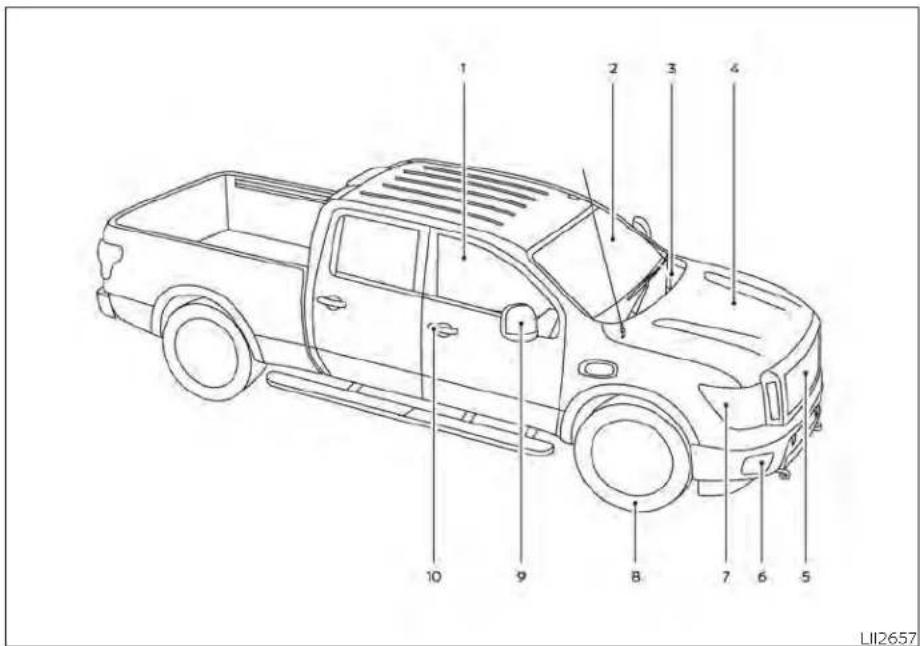
- Power windows (P. 2-82)
- Windshield (P. 8-22)
- Wiper and washer switch (P. 2-41)
-
Engine hood (P. 3-24)
-
Front view camera (if so equipped) (P. 4-11)
- Front fog lights (if so equipped) (P. 2-52)
Daytime Running Lights (DRL) system (if so equipped) (P. 2-50)
LED Daytime Running Lights (DRL)
system (if so equipped) (P. 2-51)
Front sonar sensors (if so equipped) (P. 5-124)
- Headlight and turn signal switches (P. 2-44, 2-52)
Replacing bulbs (P. 8-29)
Daytime Running Lights (DRL) system
(if so equipped) (P. 2-50)
LED Daytime Running Lights (DRL)
system (if so equipped) (P. 2-51)
- Tire pressure (P. 8-35)
Flat tire (P. 6-3)
Tire chains (P. 8-42)
- Mirrors (P. 3-30)
Side view camera (if so equipped)
(P. 4-11)
- Door locks (P. 3-4)
NISSAN Intelligent Key® system (P. 3-9)
Refertothepagenumberindicatedin parenthesesforoperatingdetails.
NOTE:
CrewCabmodel shown, KingCab® model similar.
EXTERIORREAR

- Antenna (P. 4-42)
- Cargo lamp (P. 2-53)
-
Rear sliding window (P. 2-85)
-
Bed liner storage bins (if so equipped) (P. 2-80)
-
Under rail bed lamps (if so equipped) (P. 2-53)
-
Truck box (P. 3-35)
Tailgate (P. 3-35)
Rearview camera (P. 4-10)
-
Towing (P. 10-33)
-
Rear sonar sensors (P. 5-124)
-
Replacing bulbs (P. 8-29)
-
Fuel-filler cap (P. 3-24)
Fuel-filler door (P. 3-24)
Fuel recommendation (P. 10-4)
- Child safety rear door lock
(if so equipped) (P. 3-4)
Refertothepagenumberindicatedin parenthesesforoperatingdetails.
NOTE:
CrewCabmodelshown,KingCab®model similar.
0-4 Illustratedtableofcontents
PASSENGERCOMPARTMENT

-
Interior lights (if so equipped) (P. 2-88)
-
Map lights (if so equipped) (P. 2-90)
Console light (if so equipped) (P. 2-89)
-
Sun visors (P. 3-29)
-
Rearview mirror (P. 3-30)
-
Glove box (P. 2-74)
-
Console box (if so equipped) (P. 2-74)
Cup holders (P. 2-77)
- Spare tire tools location (P. 6-3)
Refertothepagenumberindicatedin parenthesesforoperatingdetails.
NOTE:
CrewCabmodelshown,KingCab®model similar.
INSTRUMENTPANEL

- Vents (P. 4-28)
-
Turn signal switch (P. 2-52) Wiper and washer switch (P. 2-41)
-
Steering wheel switch for audio control* Bluetooth® Hands-Free Phone System* Vehicle information display controls (P. 2-23)
-
Driver supplemental air bag (P. 1-53) Horn (P. 2-53)
-
Meters and gauges (P. 2-6) Warning and indicator lights (P. 2-12) Vehicle information display (P. 2-23)
-
Cruise control switches (if so equipped) (P. 5-50) Intelligent Cruise Control (ICC) switches (if so equipped) (P. 5-52)
-
Shift lever (P. 5-18) Tow mode switch (P. 2-63)
-
Audio controls*
-
Center display (P. 4-10)
-
Climate controls (P. 4-28)
-
Front passenger supplemental air bag (P. 1-53)
-
Glove box (P. 2-74)
-
Front passenger supplemental knee air bag (if so equipped) (P. 1-53)
-
Front passenger air bag status light (if so equipped) (P. 1-64)
-
Power outlet (P. 2-66)
-
Climate control seat switch (if so equipped) (P. 2-54) Heated front seat switches (if so equipped) (P. 2-55)
-
Heated steering wheel switch (if so equipped) (P. 2-57) Warning systems switch (P. 2-58)
-
USB ports*
-
Hazard warning flasher switch (P. 6-2)
-
Parking Aids system switch (P. 2-63) Vehicle Dynamic Control (VDC) OFF switch (P. 2-59)
- Trailer Brake Controller Unit (TBCU) (if so equipped) (P. 2-64)
- 4WD shift switch (if so equipped) (P. 5-113)
- Push-button ignition switch (P. 5-13)
- Driver supplemental knee air bag light (if so equipped) (P. 1-53)
- Tilt and telescopic steering wheel control (P. 3-27)
- Parking brake (P. 5-24)
- Hood release (P. 3-24)
-
Headlight aiming control (if so equipped) (P. 2-44) Power inverter switch (if so equipped) (P. 2-62) Cargo lamp switch (P. 2-53) Electronic locking rear differential (E-Lock) system switch (if so equipped) (P. 2-61) Hill descent control system switch (if so equipped) (P. 2-59)
-
Headlight switch (P. 2-44) Fog light switch (if so equipped) (P. 2-52) Instrument brightness control switches (P. 2-51)
Trip reset switch (P. 2-6)
*Refer to the separate NissanConnect® Owner's Manual
Refertothe pagenumber indicated in parenthesisforoperatingdetails.
ENGINECOMPARTMENTCHECK LOCATIONS

5.6L8cylinder(VK56VDengine) (non-XDmodel)
- Windshield-washer fluid reservoir (P. 8-15)
- Fuse box (P. 8-24)
- Engine oil dipstick (P. 8-7)
- Power steering fluid reservoir (P. 8-13)
- Engine oil filler cap (P. 8-7)
- Brake fluid reservoir (P. 8-14)
- Air cleaner (P. 8-21)
- Fuse/Fusible link box (P. 8-24)
- Drive belt location (P. 8-19)
- Radiator cap (P. 8-5)
- Battery (P. 8-16)
- Engine coolant reservoir (P. 8-5)
Refertothepagenumberindicatedin parenthesesforoperatingdetails.

5.6L8cylinder(VK56VDengine) (XDmodel)
- Windshield-washer fluid reservoir (P. 8-15)
- Fuse box (P. 8-24)
- Engine oil dipstick (P. 8-7)
- Power steering fluid reservoir (P. 8-13)
- Engine oil filler cap (P. 8-7)
- Brake fluid reservoir (P. 8-14)
- Air cleaner (P. 8-21)
- Fuse/Fusible link box (P. 8-24)
- Engine coolant reservoir (P. 8-5)
- Drive belt location (P. 8-19)
- Battery (P. 8-16)
- Radiator cap (P. 8-5)
Refertothepagenumberindicatedin parenthesesforoperatingdetails.
WARNINGANDINDICATORLIGHTS
| Warning/Indicator light(red) | NamePage | |
 | Automatic Transmission Park warning light ( model) model) | 2-13 |
| BRAKE or [IMAGE] | Brake warning light | 2-14 |
| Charge warning light | 2-15 | |
| Electric shift control system warning light | 2-15 |


| Warning/Indicator light (yellow) | NamePage | |
 | Front passenger air bag status light (if so equipped) | 2-18 |
 | Hill descent control system ON indicator light (if so equipped) | 2-18 |
 | Low tire pressure warning light | 2-18 |
 | Malfunction Indicator Light (MIL) | 2-15 |
 | Master warning light | 2-16 |
| Warning/Indicator light (yellow) | NamePage | |
 | Rear Automatic Braking (RAB) warning light | 2-21 |
 | Slip indicator light | 2-21 |
 | Vehicle Dynamic Control (VDC) OFF Indicator light | 2-21 |
| Warning/Indicator light (other) | NamePage | |
| Front fog light indicator light (if so equipped) (green) | 2-22 |
| Warning/Indicator light (other) | NamePage | |
 | High Beam Assist indicator light (green) | 2-22 |
 | High beam indicator light (blue) | 2-22 |
 | Side light and headlight indicator light (green) | 2-22 |
 | TOW mode ON indicator light (green) | 2-22 |
 | Turn signal/hazard indicator lights (green) | 2-22 |
1Safety-Seats,seatbeltsand supplementalrestraintsystem
Seats 1-2
Front manual bench seat adjustment (if so equipped) 1 - 3
Front manual captain's chair seat adjustment (If so equipped for passenger seat) 1-4
Front power captain's chair seat adjustment (if so equipped) 1-6
Front armrests (if so equipped) 1 - 7 Rear armrests (if so equipped) 1 - 8 Flexible seating 1 - 8
Head restraints/Headrests 1-11
Adjustable head restraint/headrest components 1-12
Non-adjustable head restraint/headrest components 1-12
Remove....1-13
Removable (without Dual Head Restraint/Headrest Rear Seat
Infotainment (RSI) System only) 1-13
Install 1-14
Adjust 1-14
Seatbelts 1-16
Precautions on seat belt usage 1-16 Seat belt warning light 1-19
Pregnant women 1-19
Injured persons 1-19
Three-point type seat belt with retractor 1-19
Seat belt extenders 1-24
Seat belt maintenance 1-24
Child safety 1-25
Infants 1-26
Small children 1-26
Larger children 1-24
Child restraints 1-28
Precautions on child restraints 1-28
LATCH (Lower Anchors and Tethers for CHILDREN) system 1-30
Top tether anchor point locations .....1-32
Rear-facing child restraint installation using LATCH 1-32
Rear-facing child restraint installation using the seat belts 1-34
Forward-facing child restraint installation using LATCH.... 1-37
Forward-facing child restraint installation using the seat belts — rear bench seat 1-40
Forward-facing child restraint installation using the seat belts — passenger seat and center seat
(if so equipped) 1-45
Booster seats 1-49
Supplemental Restraint System (SRS) 1-53
Precautions on SRS (with NISSAN
Advanced Air Bag System)
(if so equipped) 1-53
Precautions on SRS (without NISSAN
Advanced Air Bag System)
(if so equipped) 1-69
Front seat-mounted side-impact
supplemental air bag and
roof-mounted curtain side-impact and
rollover supplemental air bag systems .....1-79
Driver and passenger supplemental
knee air bag 1-80
Seat belt with pretensioner(s)
(front seats and rear outboard seats).....1-82
Supplemental air bag warning labels .....1-83
Supplemental air bag warning light ..... 1-83
Repair and replacement procedure .....1-84
SEATS


natural_image
Diagram showing car seatbelt and cross-section of a vehicle (no text or symbols)WARNING
- Donotrideinamovingvehiclewhen theseatbackisreclined.Thiscanbe dangerous.Theshoulderbeltwillnot beagainstyourbody.Inanaccident, youcouldbethrownintoitandreceiveneckorotherseriousinjuries. Youcouldalsoslideunderthelapbelt andreceiveseriousinternalinjuries.
- Forthemosteeffectiveprotection whenthevehicleisinmotion,the seatshouldbeupright.Alwayssit wellbackanduprightintheseatwith bothfeetonthefloorandadjustthe seatproperly.Foradditionalinformation,see"Precautionsonseatbelt usage"(P.1-16). - Afteradjustment,gentlyrockinthe seatto makesureitis securely locked.
- Donotleavechildrenunattendedinsidethevehicle.Theycouldunknowinglyactivateswitchesorcontrolsormakethevehiclemove.Unattended childrencouldbecomeinvolvedin seriousaccidents.
- To help avoid risk of injury or death through unintended operation of the vehicle and/or it systems, donot leave children, people who require the assistance of others or pets unattended in your vehicle. Additionally, the temperature inside a closed vehicle on a warm day can quickly become high enough to cause significant risk of injury or death to people and pets.
- Donotadjustthedriver'sseatwhile drivingsofullattentionmaybegiven to vehicle operation. The seat may movesuddenlyandcouldcauseloss ofcontrolofthevehicle.
- Theseatbackshouldnotbereclined anymorethanneededforcomfort. Seat belts are most effective when the passenger sits well back and straightupintheseat. If theseatback isreclined, the riskof slidingunder the lapbeltandbeinginjured is increased.
1-2 Safety-Seats, seat belts and supplemental restraint system
CAUTION
When adjusting theseatpositions, be surenottocontactanymovingpartsto avoid possible injuries and ordamage.
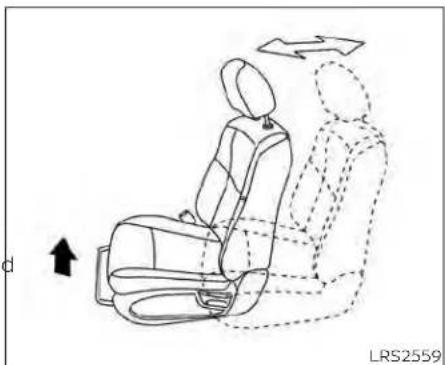
FRONT MANUAL BENCH SEAT ADJUSTMENT (if so equipped)
Your vehicle seats can be adjusted manually. For additional information about adjusting the seats, refer to the steps outlined in this section.
natural_image
Line drawing of a car seat assembly with directional arrows indicating motion (no text or symbols)Forward and backward

natural_image
Line drawing of a car seat with directional arrows indicating movement or rotation (no text or symbols)Reclining
Pull the lever up and hold it while you slide to recline the seatback, pull the lever up the seat forward or backward to the desired position. Release the lever to lock the ward, pull the lever up and lean your body seat in position.
The reclining feature allows adjustment of the seatback for occupants of different sizes for added comfort and to help obtain proper seat belt fit. For additional information, see "Precautions on seat belt usage" (P. 1-16). Also, the seatback can be reclined to allow occupants to rest when the vehicle is stopped and the shift lever is in the P (Park) position.
Safety-Seats, seatbelts and supplemental restraintsystem 1-3
natural_image
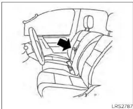
Line drawing of a car interior showing seatbelt and dashboard (no text or symbols)FRONT MANUAL CAPTAIN'S CHAIR SEAT ADJUSTMENT (if so equipped for passenger seat)
Your vehicle seats can be adjusted manually. For additional information about adjusting the seats, refer to the steps outlined in this section.

natural_image
Line drawing of a car seat assembly with directional arrows indicating motion (no text or symbols)Front center bench seat adjustment
The front center bench seat folds down by pulling on the strap. It does not have adjustments in between the upright and the folded down positions. It is either in seating position or armrest position.
Forward and backward
Pull the lever up and hold it while you slide the seat forward or backward to the desired position. Release the lever to lock the seat in position.
1-4 Safety-Seats,seatbeltsandsupplementalrestraintsystem
natural_image
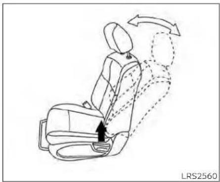
Line drawing of a car seat with arrows indicating motion or movement, no text or symbols presentThe reclining feature allows adjustment of the seatback for occupants of different sizes for added comfort and to help obtain proper seat belt fit. For additional information, see "Precautions on seat belt usage" (P. 1-16). Also, the seatback can be reclined to allow occupants to rest when the vehicle is stopped and the shift lever is in the P (Park) position.
Reclining
To recline the seatback, pull the lever up and lean back. To bring the seatback forward, pull the lever up and lean your body forward. Release the lever to lock the seatback in position.
Safety-Seats,seatbeltsandsupplementalrestraintsystem1-5

FRONT POWER CAPTAIN'S CHAIR SEAT ADJUSTMENT (if so equipped)
Forward and backward
Moving the switch as shown will slide the seat forward or backward to the desired position.
Operating tips
- The power seat motor has an auto-reset overload protection circuit. If the motor stops during operation, wait 30 seconds then reactivate the switch.
- Do not operate the power seat switch for a long period of time when the engine is off. This will discharge the battery.
For additional Information, see "Memory seat(s)" (P. 3-39).
Reclining
Move the recline switch as shown until the desired angle is obtained.
1-6 Safety-Seats,seatbeltsandsupplementalrestraintsystem
The reclining feature allows adjustment of the seatback for occupants of different sizes for added comfort and to help obtain proper seat belt fit. For additional information, see "Precautions on seat belt usage" (P. 1-16). Also, the seatback can be reclined to allow occupants to rest when the vehicle is stopped and the shift lever is in P (Park).

Seat lifter (driver's seat)
Move the switch as shown to adjust the angle and height of the seat cushion.
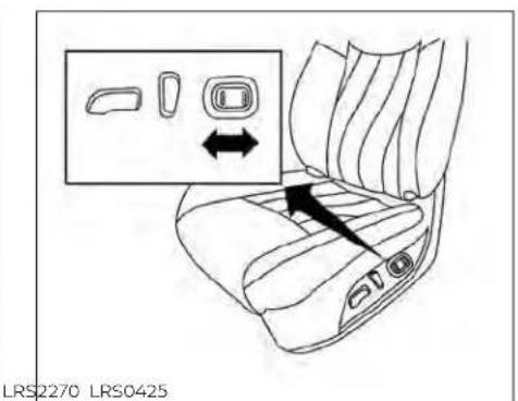
Lumbar support (driver's seat)
The lumbar support feature provides adjustable lower back support to the driver. Push the switch as shown to adjust the seat lumbar area.

natural_image
Line drawing of a car interior showing seatbelt and dashboard (no text or symbols)FRONT ARMRESTS (if so equipped)
To use the center armrest on the front bench seat, pull on the strap in between the front passenger and center seats and fold it down to the resting position.

natural_image
Line drawing of a car seatbelt with a black arrow indicating the seatbelt (no text or symbols present)REAR ARMRESTS (if so equipped)
To use the center armrest on the bench seats, pull on the tab in the center of the seat and fold it down as shown.
FLEXIBLE SEATING
WARNING
- Neverallowanyonetorideinthe cargoareaorontherearseatswhen theyareinthefold-downposition.In acollision,peopleridinginthesear-easwithoutproperrestraintsare morelikelytobeseriouslyinjuredor killed.
- Donotallowpeopleorideinany areaofyourvehiclethatisnot equippedwithseatsandseatbelts. Besureeveryoneinyourvehicleisin aseatandusingaseatbeltproperly.
- Donotallowmorethanoneperson tousethesameseatbelt.
- Donotfolddowntherearseatswhen occupantsareintherearseatareaor anyluggageisontherearseats.
- Makesurethattheseatpathis clearbeforemovingtheseat.
-
Becarefulnottoallowhandsor feettogetcaughtorpinchedin theseat.
-
Headrestraints/headrestsshouldbe adjustedproperlyastheymayprovide significant protection against injuryinanaccident.Alwaysreplace and adjust them properly if they have beenremovedforanyreason.
- If the head restraints/head rests are removed for any reason, they should be securely stored to prevent them from causing injury to passengers or damage to the vehicle in case of sudden braking or an accident.
- When returning these seat back to the upright position, be certain they are completely secured in the latched position. If they are not completely secured, passengers may be injured in an accidentors sudden stop.
- Properlysecureallcargotohelppreventitfromslidingorshifting. Donot placecargohigherthanthe seatbacks.Inasuddenstoporcollision, unsecuredcargocouldcausepersonalinjury.

natural_image
Line drawing of a car seat with an arrow pointing to the seat area (no text or symbols present)
natural_image
Line drawing of a car seat assembly with no text or symbols
natural_image
Line drawing of a car interior showing seat, driver, and passenger seat (no text or symbols)Folding the rear bench seat up
To fold the rear bench seat up for storage capacity behind the front seats or to remove the jacking tools from the storage area:
-
Lift the front of the seat cushion up.
-
Fold the bottom of the seat cushion to-3. Repeat this process to raise and secure ward the back of the vehicle until it locks the seat cushion on the other side of the in place. vehicle for maximum storage capacity.
To return the rear bench seat to a seating position, pull the latch on the bottom of the seat cushions to release the seat from the locked position. Makesuretoproperly pushtheseatcushiondownintoplace.
WARNING
- Whenthevehicleisbeingusedto carrycargo,properlysecureallcargo tohelppreventitfromslidingor shifting.Donotplacecargohigher thantheseatbacks.Inasuddenstop orcollision,unsecuredcargocould causepersonalinjury.
- Donotallowpeopleorideinany areaofyourvehiclethatisnot equippedwithseatsandseatbelts. Besureeveryoneinyourvehicleisin aseatandusingaseatbeltproperly. Neverrideintherearseatunlessthe seatbottomcushionsareinplace.
- When returning these backstof the upright position, be certain they are completely secured in the elatched position. If they are not completely secured, passengers maybe injured in an accidentorsuddenstop.

Folding the rear bench seat down
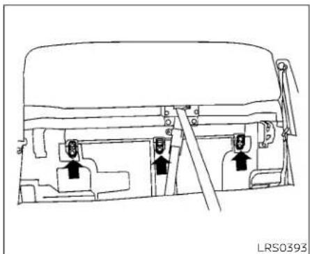
The rear bench seat can be tilted forward to access the child restraint anchor point locations.
To tilt the seatback forward, pull the strap up ① and tilt the seatback. The child restraint anchor points ② can be accessed behind the rear bench seatback.
WARNING
Neverallowanyonetorideinthecargo area or on the rear seat when it is in the fold-downposition.Useoftheseareas by passengers without proper restraints couldresultinserious injury or deathinanaccidentorsuddenstop.
HEADRESTRAINTS/HEADRESTS
WARNING
Headrestraints/headrestssupplement theothervehiclesafetysystems.They mayprovideadditionalprotection againstinjuryincertainrearendcollisions.Adjustableheadrestraints/headrestsmustbeadjustedproperly, asspecifiedinthissection.Checkthe adjustmentaftersomeoneelseuses theseat.Donotattachanythingtothe headrestraint/headreststalks,except forGenuineNissanAccessoriesspecificallytestedforusewiththevehicle's headrestraint/headreststalks.Donot removetheheadrestraint/headrest. Do not use the seat if the head restraint/headresthasbeenremoved. Iftheheadrestraint/headrestwasremoved,reinstallandproperlyadjust theheadrestraint/headrestbeforean occupantusetheseating position. Failuretofollowtheseinstructionscan reducetheeffectivenessofthehead restraints/headrests.Thismayincrease the risk of serious injury or deathinacollision.
natural_image
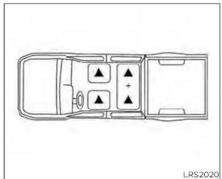
Top-down schematic of a vehicle interior layout with four compartments and directional indicators (no text or symbols)Frontbucketseat
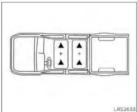
The illustration shows the seating positions equipped with head restraints/headrests.
▲Indicates the seating position is equipped with a head restraint.
■Indicates the seating position is equipped with a headrest.
+ Indicates the seating position is not equipped with a head restraint or headrest (if applicable).
- Your vehicle is equipped with a head restraint/headrest that may be integrated, adjustable or non-adjustable.
natural_image
Top-down line drawing of a car interior layout with directional indicators (no text or symbols)Frontbenchseat
- Adjustable head restraints/headrests have multiple notches along the stalk(s) to lock them in a desired adjustment position.
-
The non-adjustable head restraints/headrests have a single locking notch to secure them to the seat frame.
• Proper Adjustment: -
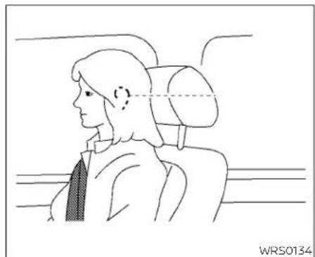
For the adjustable type, align the head restraint/headrest so the center of your ear is approximately level with the center of the head restraint/headrest.
- If your ear position is still higher than the recommended alignment, place the head restraint/headrest at the highest position.
- If the head restraint/headrest has been removed, ensure that it is reinstalled and locked in place before riding in that designated seating position.
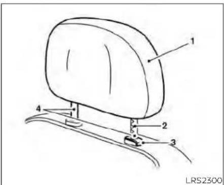
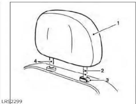
ADJUSTABLE HEAD RESTRAINT/ HEADREST COMPONENTS
- Removable head restraint/headrest
- Multiple notches
- Lock knob
- Stalks
NON-ADJUSTABLE HEAD RESTRAINT/HEADREST COMPONENTS
- Removable head restraint/headrest
- Single notch
- Lock knob
- Stalks
1-12 Safety-Seats, seatbeltsandsupplementalrestraintsystem

natural_image
Line drawing of a car seat with an upward arrow indicating motion (no text or symbols)- Reinstall and properly adjust the head restraint/headrest before an occupant uses the seating position.

natural_image
Simple line drawing of a car seat with arrows indicating upward motion (no text or symbols)REMOVE
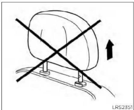
Use the following procedure to remove the head restraint/headrest:
- Pull the head restraint/headrest up to the highest position.
- Push and hold the lock knob.
- Remove the head restraint/headrest from the seat.
- Store the head restraint/headrest properly in a secure place so it is not loose in the vehicle.
REMOVABLE (without Dual Head Restraint/Headrest Rear Seat Infotainment (RSI) SYSTEM ONLY)
CAUTION
Donotremoveheadrestraint/headrest fromvehiclesequippedwithDualHead Restraint/HeadrestRearSeatInfotainment(RSI)System.Removalmaydamagethesystemwiring.

INSTALL
natural_image
Side profile sketch of a person seated in a car seat, showing head, neck, and torso (no text or symbols)ADJUST
natural_image
Simple line drawing of a car with a diagonal cross mark and an upward arrow, no text or symbols present.For non-adjustable head restraint/headrest
- Align the head restraint/headrest stalks with the holes in the seat. Make sure that the head restraint/headrest is facing the correct direction. The stalk with the notch (notches) must be installed in the hole with the lock knob.
- Push and hold the lock knob and push the head restraint/headrest down.
- Properly adjust the head restraint/headrest before an occupant uses the seating position.
For adjustable head restraint/headrest at Adjust the head restraint/headrest so the center is level with the center of your ear. Your ear position is still higher than the recommended alignment, place the head restraint/headrest at the highest position.
Make sure the head restraint/headrest is positioned so the lock knob is engaged in the notch before riding in that designated 'seating position.
1-14 Safety-Seats, seatbeltsandsupplementalrestraintsystem

natural_image
Simple line drawing of a car seat with an upward arrow indicating motion (no text or symbols)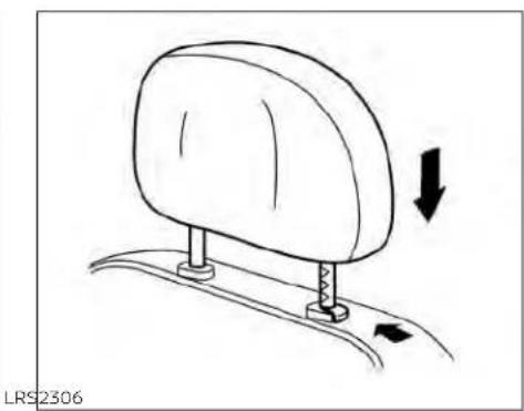
natural_image
Diagram of a car seat mounting mechanism with directional arrows indicating movement (no text or symbols)Raise
Lower
To raise the head restraint/headrest, pull it. To lower, push and hold the lock knob and up. push the head restraint/headrest down.
Make sure the head restraint/headrest is positioned so the lock knob is engaged in the notch before riding in that designated seating position.
Make sure the head restraint/headrest is positioned so the lock knob is engaged in the notch before riding in that designated seating position.
SEATBELTS


natural_image
Line drawing of a person seated in a car with a cross-shaped object overlaid, no text or symbols presentPRECAUTIONS ON SEAT BELT USAGE
If you are wearing your seat belt properly adjusted and you are sitting upright and well back in your seat with both feet on the floor, your chances of being injured or killed in a collision and/or the severity of injury may be greatly reduced. NISSAN strongly encourages you and all of your passengers to buckle up every time you drive, even if your seating position includes a supplemental air bag.
Most U.S. states and Canadian provinces orterritories specify that seat belts be worn at all times when vehicle is being driven.
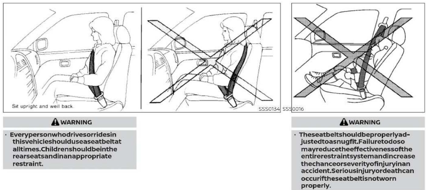
WARNING
- Everypersonwhodrivesorridesin thisvehicleshoulduseaseatbeltat alltimes.Childrenshouldbeinthe rearseatsandinanappropriate restraint.
WARNING
- Theseatbeltshouldbeproperlyadjustedtoasnugfit.Failureretodoso mayreducetheeffectivenessofthe entirerestraintsystemandincrease thechanceorseverityofinjuryinan accident.Seriousinjuryordeathcan occuriftheseatbeltisnotworn properly.
natural_image
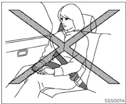
Line drawing of a person sitting in a car seat with two crossed arms (no text or symbols)WARNING
- Alwaysroutetheshoulderbeltover yourshoulderandacrossyourchest. Neverputthebeltbehindyourback, underyourarmoracrossyourneck. Thebeltshouldbeawayfromyour faceandneck,butnotfallingoffyour shoulder.
-
Positionthelapbeltaslowandsnug aspossibleAROUNDTHEHIPS,NOT THEWAIST.Alapbeltworntoohigh couldincreasetheriskofinternalinjuriesinanaccident.
-
Besuretheseatbelttongueissecurelyfastenedtotheproperbuckle.
- Donotweartheseatbeltinsideout ortwisted.Doingsomayreduceits effectiveness.
- Donotallowmorethanoneperson tousethesameseatbelt.
- Nevercarrymorepeopleinthevehiclethanthereareseatbelts.
- If theseatbeltwarninglightglows continuouslywhiletheignitionis turnedONwithalldoorsclosedand allseatbeltsfastened, itmayindicateamalfunctioninthesystem. Havethesystemchecked.ItisrecommendedthatyouvisitaNISSAN dealerforthisservice.
-
Nochangesshouldbemadetothe seatbeltsystem.Forexample,donot modifytheseatbelt,addmaterial,or installdevicesthatmaychangethe seatbeltroutingortension.Doingso mayaffecttheoperationoftheseat beltsystem.Modifyingortampering withtheseatbeltsystemmayresult inseriouspersonalinjury.
-
Onceseatbeltpretensioner(s)have activated,theycannotbereusedand mustbereplacedtogetherwiththe retractor.Itisrecommendedthatyou visitaNISSANdealerforthisservice.
- Allseatbeltassemblies,includingretractorsand attaching hardware, shouldbeinspectedafteranycollision.Itisrecommendedthatyouvisit aNISSAN dealerfor thisservice. NISSAN recommends that all seat beltassembliesinuseduringacollisionbereplacedunlesssthecollision was minor and the belts show no damageandcontinuetooperate properly.Seatbeltassembliesnotin useduringacollisionshouldalsobe inspected and replaced if either damageorimproperoperationis noted.
- All child restraints and attaching hardwareshouldbeinspectedafter any collision. Always follow the restraintmanufacturer'sinspection-instructionsandreplacementrecommendations. The child restraints should be replaced if they are damaged.

natural_image
Silhouette of a person sitting with a bandage (no text or symbols)LRS0786
SEAT BELT WARNING LIGHT
Both the driver's and passenger's front seats are equipped with a seat belt warning light. The warning light, located on the instrument panel, will show the status of the driver and passenger seat belt.
NOTE:
Thefrontpassengerseatbeltwarning lightwillnotlightupiftheseatisnot occupied.
For additional Information, see "Warning lights, indicator lights and audible reminders" (P. 2-12).
NOTE:
Therearseatsareequippedwithaseat beltwarningmessageinthevehicleinformationdisplay.
For additional information, see "Vehicle information display" (P. 2-23).
PREGNANT WOMEN
NISSAN recommends that pregnant women use seat belts. The seat belt should be worn snug and always position the lap belt as low as possible around the hips, not the waist. Place the shoulder belt over your shoulder and across your chest. Never run the lap/shoulder belt over your abdominal area. Contact your doctor for specific recommendations.
INJURED PERSONS
NISSAN recommends that injured persons use seat belts. Check with your doctor for specific recommendations.
THREE-POINT TYPE SEAT BELT WITH RETRACTOR
WARNING
- Everypersonwhodrivesorridesin thisvehicleshoulduseaseatbeltat alltimes.
- Donotrideinamovingvehiclewhen theseatbackisreclined.Thiscanbe dangerous.Theshoulderbeltwillnot beagainstyourbody.Inanaccident, youcouldbethrown into itand receiveneckor otherserious injuries. Youcouldalsoslideunderthelapbelt andreceiveseriousinternalinjuries.
- For the most effective protection when the vehicle is in motion, the seatshouldbeupright. Alwayssit wellbackanduprightintheseatwith bothfeetonthefloorandadjustthe seatbeltproperly.
- Donotallowchildrentoplaywiththe seatbelts.Mostseatingpositionsare equippedwithAutomaticLocking Retractor(ALR)modeseatbelts.If theseatbeltbecomeswrapped arounddachild'sneckwiththeALR modeactivated,thechildcanbeseriouslyinjuredorkillediftheseatbelt retractsandbecomestight.Thiscan occurevenifthevehicleisparked. Unbuckletheseatbelttoreleasethe child.Iftheseatbeltcannotbeun-buckledorisalreadyunbuckled,re-leasethechildbycuttingtheseat beltwithasuitabletool(suchasa knifeorscissors)toreleasetheseat belt.

natural_image
Diagram of a car seat assembly with directional arrows indicating motion (no text or symbols)Manualfrontseatshown (ifsoequipped)
Fastening the seat belts
- Adjust the seat. For additional information, see "Seats" (P. 1-2).

Frontpowercaptain'schairseatshown(ifsoequipped)

-
Slowly pull the seat belt out of the retractor and insert the tongue into the buckle A until you hear and feel the latch engage.
-
Theretractorisdesignedtolock duringasuddenstoporonimpact.A slowpullingmotionpermitsthe seatbelttomoveandallowsyou somefreedomofmovementinthe seat.
- If theseatbelt cannot be pulled from its fully retracted position, firmly pull the belt and release it. Thensmoothly pull the belt out of theretractor.
Safety-Seats,seatbeltsandsupplementalrestraintsystem1-21
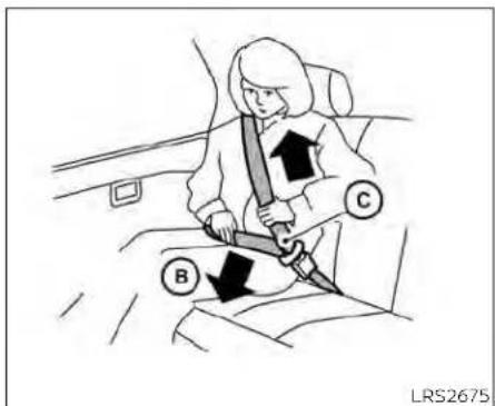
- Position the lap belt portion low and snugonthehips Ⓑ as shown.
- Pull the shoulder belt portion toward the retractor to take up extra slack©. Be sure the shoulder belt is routed over your shoulder and across your chest.
The front passenger seat, front center seat (if so equipped), and the rear seating positions three-point seat belts have two modes of operation:
• Emergency Locking Retractor (ELR)
• Automatic Locking Retractor (ALR)
The ELR mode allows the seat belt to extend and retract to allow the driver and passengers some freedom of movement in the seat. The ELR locks the seat belt when the vehicle slows down rapidly or during certain impacts.
The ALR mode (child restraint mode) locks the seat belt for child restraint installation. When the ALR mode is activated, the seat belt cannot be extended again until the seat belt tongue is detached from the buckle and fully retracted. The seat belt returns to the ELR mode after the seat belt fully retracts. For additional information, see "Child restraints" (P. 1-28).
The ALR modes should be used only for child restraint installation. During normal seat belt use by an occupant, the ALR modes should not be activated. If it is activated, it may cause uncomfortable seat belt tension. It can also changethe operation of the front passenger airbag. For additional information, see "Supplemental Restraint System (SRS)" (P.1-53).
WARNING
When fastening these at belts, be certain that these at backs are completely secured in the latched position. If they are not completely secured, passengers may be injured in an accidentor sudden stop.
1-22 Safety-Seats, seat belts and supplemental restraint system

natural_image
Illustration of a person's seatbelt being adjusted for a knot, showing a bandage and a circular arrow (no text or symbols)To increase your confidence in the seat belts, check the operation as follows:
- Grasp the shoulder belt and pull forward quickly. The retractor should lock and restrict further belt movement.
If the retractor does not lock during this check, get the system checked. It is recommended that you visit a NISSAN dealer for this service, or to learn more about seat belt operation.
natural_image
Line drawing of a car backseat with seatbelt and seatbelt (no text or symbols)Unfastening the seat belts
To unfasten the seat belt, press the button on the buckle①. The seat belt automatically retracts.
Checking seat belt operation
Seat belt retractors are designed to lock seat belt movement by two separate methods:
- When the seat belt is pulled quickly from the retractor
- When the vehicle slows down rapidly
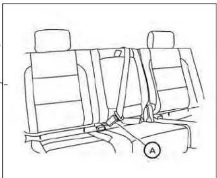
Center of rear seat
Selectingcorrectsetofseatbelts:
The rear center seat belt buckle is identified by the CENTER mark A. The rear center seat belt tongue can be fastened only into the rear center seat belt buckle.

Shoulder belt height adjustment (front seats)
The shoulder belt anchor height should be adjusted to the position best for you. For additional Information, see "Precautions on seat belt usage" (P. 1-16). To adjust, pull out the adjustment button ① and move the shoulder belt anchor to the desired position ②, so the belt passes over the center of the shoulder. The belt should be away from your face and neck, but not falling off your shoulder. Release the adjustment button to lock the shoulder belt anchor into position.
If, because of body size or driving position, is not possible to properly fit the lap/ shoulder belt and fasten it, an extender that is compatible with the installed seat belts is available for purchase. The extender adds approximately 8 in (200 mm) of length and may be used for either the driver or front passenger seating position. It is recommended that you visit a NISSAN dealer for assistance with purchasing an extender if an extender is required. (1) 本报告期公司实现的归属于上市公司股东的净利润为-2,053.89万元,较上年同期增长10.47%。
WARNING
- Afteradjustment,releasetheadjust- mentbuttonandtrytomovethe shoulderbeltanchorupanddownto makesureitissecurelyfixedin position.
- Theshoulderbeltanchorheight should be adjusted to the position bestforyou.Failuretodosomayreducetheeffectivenessoftheentire restraint system and increase the chanceor severity ofinjuryin an accident.
SEAT BELT EXTENDERS
WARNING
- OnlyNISSANseat beltextenders, madebythesamecompanywhich madetheoriginal equipment seat belts, should be used with NISSAN seatbelts.
- Adultsandchildrenwhocanusethe standardseatbeltshouldnotusean extender. Such unnecessary use couldresultinseriouspersonalinjury intheeventofanaccident.
- Neveruseseatbeltextenderstoin-stallchildrestraints.If thechildre-straint is not secured properly, the childcould beseriously injuredor it killedinacollisionorasuddenstop.
SEAT BELT MAINTENANCE
- To clean the seat belt webbing, apply a mild soap solution or any solution recommended for cleaning upholstery or carpet. Then wipe with a cloth and allow the seat belts to dry in the shade. Do not allow the seat belts to retract until they are completely dry.
- If dirt builds up in the shoulder belt guide of these seatbeltanchors, the seat belts may retract slowly. Wipe the shoulder belt guide with a clean, dry cloth.
1-24 Safety-Seats, seat belts and supplemental restraint system
CHILDSAFETY
- Periodicallychecktoseethattheseat beltandthemetalcomponents, such as buckles, tongues, retractors, flexible wires and anchors, work properly. If loose parts, deterioration, cuts or other damage on the webbing is found, the entire seat belt assembly should be replaced.
WARNING
Donotallowchildrentoplaywiththe seatbelts.Mostseatingpositionsare equippedwithAutomaticLockingRetractor(ALR)modeseatbelts.Iftheseat beltbecomeswrappedaroundachild's neckwiththeALRmodeactivated,the childcanbeseriouslyinjuredorkilledif theseatbeltretractsandbecomes tight.Thiscanoccurevenifthevehicle isparked.Unbuckletheseatbelttoreleasethechild.Iftheseatbeltcannot beunbuckledorisalreadyunbuckled, releasethechildbycuttingtheseat beltwithasuitabletool(suchasaknife orscissors)toreleasetheseatbelt.
Childrenneedadultstohelpprotect them. Theyneedtobeproperly restrained.
In addition to the general information in this manual, child safety information is available from many other sources, including doctors, teachers, government traffic safety offices, and community organizations. Every child is different, so be sure to learn the best way to transport your child. There are three basic types of child restraint systems:
• Rear-facing child restraints
• Forward-facing child restraints
- Booster seats
The proper restraint depends on the child's size. Generally, infants up to about 1 year and less than 20 lbs. (9 kg) should be placed in rear-facing child restraints. Forward-facing child restraints are available for children who outgrow rear-facing child restraints and are at least 1 year old. Booster seats are used to help position a vehicle lap/shoulder belt on a child who can no longer use a forward-facing child restraint.
WARNING
Infantsandchildrenneedspecialpro- tection.Thevehicle'sseatbeltsmay notfitthemproperly.Theshoulderbelt maycometooclosetothefaceorneck. Thelapbeltmaynotfitovertheirsmall hipbones.Inanaccident,animpro- erlyfittingseatbeltcouldcauseserious orfatalinjury.Alwaysuseappropriate childrestraints.
All U.S. states and Canadian provinces or your vehicle and always follow the manu-territories require the use of approved childfacturer's instructions for installation and restraints for infants and small children. Foruse. additional information, see "Child re-straints" (P. 1-28). SMALL CHILDREN
A child restraint may be secured in the vehicle by using either the LATCH (Lower Anchors and Tethers for CHildren) system or with the vehicle seat belt. For additional information, see "Child restraints" (P. 1-28).
NISSANrecommendsthatallpre-teens andchildrenberestrainedintherear seat.Studiesshowthatchildrenare saferwhenproperlyrestrainedinthe rearseatthaninthefrontseat.
Thisisespeciallyimportantbecause yourvehiclehasasupplementalrestraintsystem(airbagsystem)forthe frontpassenger.Foradditionalinformation, see "SupplementalRestraintSystem(SRS)"(P.1-53).
INFANTS
Infants up to at least 1 year old should be placed in a rear-facing child restraint. NISSAN recommends that infants be placed in child restraints that comply with Federal Motor Vehicle Safety Standards or Canadian Motor Vehicle Safety Standards. You should choose a child restraint that fit
SMALL CHILDREN
Children that are over 1 year old and weigh at least 20 lbs. (9 kg) should remain in a rear-facing child restraint as long as possible up to the height or weight limit of the child restraint. Children who outgrow the height or weight limit of the rear-facing child restraint and are at least 1 year old should be secured in a forward-facing child restraint with a harness. Refer to the manufacturer's instructions for minimum and maximum weight and height recommendations. NISSAN recommends that small children be placed in child restraints that comply with Federal Motor Vehicle Safety Standards or Canadian Motor Vehicle Safety Standards. You should choose a child restraint that fits your vehicle and always follow the manufacturer's instructions for installation and use.
LARGER CHILDREN
Children should remain in a forward-facing child restraint with a harness until they reach the maximum height or weight limit allowed by the child restraint
Once a child outgrows the height or weight limit of the harness-equipped forward-facing child restraint, NISSAN recommends that the child be placed in a commercially available booster seat to obtain proper
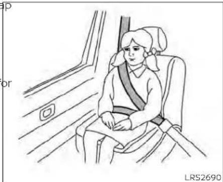
seat belt fit. For a seat belt to fit properly, the booster seat should raise the child so that the shoulder belt is properly positioned across the chest and the top, middle portion of the shoulder. The shoulder belt should not cross the neck or face and should not fall off the shoulder. The lap belt should lie snugly across the lower hips or upper thighs, not the abdomen. A booster seat can only be used in seating positions that have a three-point type seat belt. The booster seat should fit the vehicle seat and have a label certifying that it complies with Federal Motor Vehicle Safety Standards or Canadian Motor Vehicle Safety Standards.
A booster seat should be used until the child can pass the seat belt fit test below:
- Are the child's back and hips against the vehicle seatback?
- Is the child able to sit without slouching?
- Do the child's knees bend easily over the front edge of the seat with feet flat on the floor?
- Can the child safely wear the seat belt (lap belt low and snug across the hips and shoulder belt across mid-chest and shoulder)?
- Is the child able to use the properly adjusted head restraint/headrest?
- Will the child be able to stay in position for the entire ride?
natural_image
Line drawing of a person seated in a car seat, wearing a seatbelt (no text or symbols)If you answered no to any of these questions, the child should remain in a booster seat using a three-point type seat belt.
NOTE:
Lawsinsomecommunitiesmayfollow differentguidelines.Checklocaland stateregulationstoconfirmyourchildis usingthecorrectrestraintsystembefore traveling.
WARNING
Neverletachildstandorkneelonany seatanddonotallowachildinthe cargoarea.Thechildcouldbeseriously injuredorkilledinasuddenstopor collision.
CHILDRESTRAINTS

natural_image
Diagram of a person wearing a seatbelt inside a car, with no visible text or symbolsPRECAUTIONS ON CHILD RESTRAINTS
WARNING
- Failuretofollowthewarningsandinstructionsforproperuseandinstallationofchildrestraintscouldresultinseriousinjuryordeathofachildorother passengersinasuddenstoporcollision:
- Thechildrestraintmustbeused andinstalledproperly.Alwaysfollowallofthechildrestraintmanufacturer'sinstructionsforinstallationanduse.
natural_image
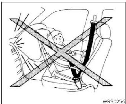
Diagram of a car showing a person seated inside the seat with a cross-shaped barrier, no text or symbols present.- Infantsandchildrenshouldnever beheldonanyone'slap.Eventhe strongestadultcannotresistthe forcesofacollision.
- Donotputaseatbeltaroundboth achildandanotherpassenger.
- NISSANrecommendsthatallchild restraintsbeinstalledintherear seat.Studiesshowthatchchildren aresaferwhenproperlyrestrainedintherearseatthanin thefrontseat.Ifyoumustinstalla forward-facingchildrestraintin thefrontseat,see"Forward-
facingchildrestraintinstallation usingtheseatbelts—passenger seatandcenterseat"(P.1-45).
- Evenwiththe NISSANAdvanced AirBagSystem(ifsoequipped), neverinstallarear-facingchildrestraintinthefrontseat.Aninflatingairbagcouldseriouslyinjure orkillachild.Arear-facingchild restraintmustonlybeusedinthe rearseat.
- Be sure to purchase a child restraintthatwillfitthechildand vehicle.Somechildrestraintsmay notfitproperlyinyourvehicle.
-
Childrestraintanchoragesaredesignedto withstandonly those loadsimposedbycorrectlyfitted childrestraints.Undernocircumstancesaretheytobeusedtoattach adult seat belts, or other itemsorequipmenttothevehicle.Doingsocoulddamagethechild restraintanchorages.Thechildrestraint will not be properly installed using the damaged anchorage, and a child could be seriously injured or killed in a collision.
-
Neverusetheanchorpointsfor adultseatbelts,orotheritems.
- Achildrestraintwithatoptether strapshouldnotbeusedinthe frontpassengerseat.
- Keepseatbacksasuprightaspossibleafterfittingthechild restraint.
- Infantsandchildrenshouldal- waysbeplacedinanappropriate childrestraintwhileinthevehicle.
- Whenthechildrestraintisnotinuse, keepitsecuredwiththeLATCHsystemoraseatbelt.Inasuddenstopor collision,looseobjectscaninjureoccupantsordamagethevehicle.
CAUTION
Achildrestraintinaclosedvehiclecan becomeveryhot.Checktheseating surfaceandbucklesbeforeplacinga childinthechildrestraint.
This vehicle is equipped with a universal child restraint anchor system, referred to as the LATCH (Lower Anchors and Tethers for CHildren) system. Some child restraints include rigid or webbing-mounted attachments that can be connected to these an-
chors. For additional information, see "LATCH (Lower Anchors and Tethers for CHildren) system" (P. 1-30).
If you do not have a LATCH compatible child restraint, the vehicle seat belts can be used.
Several manufacturers offer child re-straints for infants and children of various sizes. When selecting any child restraint, keep the following points in mind:
- Choose only a restraint with a label certifying that it complies with Federal Motor Vehicle Safety Standard 213 or Canadian Motor Vehicle Safety Standard 213.
- Check the child restraint in your vehicle to be sure it is compatible with the vehicle's seat and seat belt system.
-
If the child restraint is compatible with your vehicle, place your child in the child restraint and check the various adjustments to be sure the child restraint is compatible with your child. Choose a child restraint that is designed for your child's height and weight. Always follow all recommended procedures.
-
If the combined weight of the child and child restraint is less than 65 lbs. (29.5 kg), you may use either the LATCH anchors or the seat belt to install the child restraint (not both at the same time).
- If the combined weight of the child and child restraint is greater than 65 lbs. (29.5 kg), use the vehicle's seat belt (not the lower anchors) to install the child restraint.
Be sure to follow the child restraint manufacturer's instructions for installation.
AllU.S. states and Canadian provinces or territories require that infants and small children berestrained an approved child restraint at all times while the vehicle is being operated. Canadian law requires the top tether strapon forward-facing child restraints besecured to the designated anchor point on the vehicle.
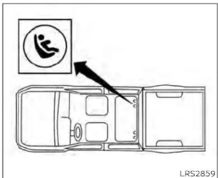
LATCHsystemloweranchorlocations LATCH (Lower Anchors and Tethers for CHildren) SYSTEM
Your vehicle is equipped with special anchor points that are used with LATCH system compatible child restraints. This system may also be referred to as the ISOFIX or ISOFIX compatible system. With this system, you do not have to use a vehicle seat belt to secure the child restraint unless the combined weight of the child and child restraint exceeds 65 lbs. (29.5 kg). If the combined weight of the child and child restraint is greater than 65 lbs. (29.5 kg) use the vehicle's seat belt (not the lower anchors) to install the child restraint. Be sure to follow the child restraint manufacturer's instructions for installation.
The LATCH anchor points are provided to install child restraints in the rear outboard seating positions only. Do not attempt to install a child restraint in the center position using the LATCH anchors.
LATCH lower anchor
WARNING
Failuretofollowthewarningsandinstructionsforproperuseandinstallationofchildrestraintscouldresultin seriousinjuryordeathofachildor otherpassengersinasuddenstopor collision:
- AttachLATCHsystemcompatible childrestraintonlyatthelocations shownintheillustration.
- Donotsecureachildrestraintinthe centerrearseatingpositionusing theLATCHloweranchors.Thechild restraintwillnotbesecured properly.
t- Inspecttheloweranchorsbyinsertingyourfingersintotheloweranchorarea.Feeltomakesurethere
are no obstructions over the anchorsuchasseatbeltwebbingor seatcushionmaterial.Thechildrestraintwillnotbesecuredproperlyif theloweranchorsareobstructed.
Childrestraint anchoragesare de-signedtowithstandonlythoseloads imposedbycorrectlyfittedchildrestraints.Underno circumstances are they to be used to attach adult seat belts,orotheritemsorequipmentto thevehicle.Doingsocoulddamagethe childrestraintanchorages.Thechild restraintwillnotbeproperlyinstalled usingthedamagedanchorage,anda childcouldbeseriouslyinjuredorkilled inacollision.

natural_image
Technical diagram showing mechanical components with arrows indicating movement or force direction (no text or symbols)LATCHloweranchorlocation
LATCH lower anchor location
The LATCH lower anchors are located as shown. A label is attached to the seatback to help you locate the LATCH lower anchors.

LATCHloweranchorpointlocations

natural_image
Line drawing of a car seatbelt with an inset showing hand positioning (no text or symbols)LATCHwebbing-mountedattachment Installing child restraint LATCH lower anchor attachments
LATCH compatible child restraints include two rigid or webbling-mounted attachments that can be connected to two anchors located at certain seating positions in your vehicle. With this system, you do not have to use a vehicle seat belt to secure the child restraint. Check your child restraint for a label stating that it is compatible with LATCH. This information may also be in the Instructions provided by the child restraint manufacturer.
Safety-Seats,seatbeltsandsupplementalrestraintsystem1-31

natural_image
Line drawing of a car seatbelt with an inset showing the cable being inserted (no text or symbols)LATCHrigid-mountedattachment
When installing a child restraint, carefully read and follow the instructions in this manual and those supplied with the child restraint.
natural_image
Technical line drawing of a vehicle chassis with two directional arrows indicating movement or force (no text or symbols)TOP TETHER ANCHOR POINT LOCATIONS
Anchor points are located in the following locations:
- Behind the rear bench seat as shown.
- On the back of the passenger and centre seats (King Cab® models if so equipped) as shown.

natural_image
Line drawing of a car seat assembly with two seats and seatbelt connectors (no text or symbols)KingCab® models(ifsoequipped) REAR-FACING CHILD RESTRAINT INSTALLATION USING LATCH
For additional information, see all Warnings and Cautions in "Child safety" (P. 1-25) and "Child restraints" (P. 1-28) before installing a child restraint.
Do not use the lower anchors if the combined weight of the child and the child restraint exceeds 65 lbs. (29.5 kg). If the combined weight of the child and the child restraint is greater than 65 lbs. (29.5 kg), use the vehicle's seat belt (not the lower anchors) to install the child restraint. Be sure
to follow the child restraint manufacturer's instructions for installation.
Follow these steps to install a rear-facing child restraint in the rear bench seats using the LATCH system:
- Position the child restraint on the seat. Always follow the child restraint manufacturer's instructions.
Rear-facingwebbing-mounted-step2
- Secure the child restraint anchor attachments to the LATCH lower anchors. Check to make sure the LATCH attachment is properly attached to the lower anchors.

natural_image
Diagram showing car seatbelt adjustment with magnified inset (no text or symbols)Rear-facingrigid-mounted-step2

natural_image
Illustration of a car seatbelt buckle being adjusted for a person's seatbelt, showing two black arrows indicating the mechanism (no text or symbols present)Rear-facing-step3
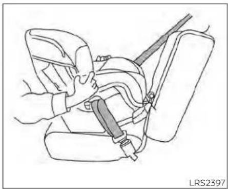
3. For child restraints that are equipped with webbing-mounted attachments, remove any additional slack from the anchor attachments. Press downward and rearward firmly in the center of the child restraint with your hand to compress the vehicle seat cushion and seat-back while tightening the webbing of the anchor attachments.

natural_image
Line drawing of a person using a seatbelt to adjust the seat (no text or symbols)Rear-facing-step4
4. After attaching the child restraint, test it before you place the child in it. Push it from side to side while holding the child restraint near the LATCH attachment path. The child restraint should not move more than 1 inch (25 mm), from side to side. Try to tug it forward and check to see if the LATCH attachment holds the restraint in place. If the restraint is not secure, tighten the LATCH attachment as necessary, or put the restraint in another seat and test it again. You may need to try a different child restraint or try installing by using the
vehicle seat belt (if applicable). Not all child restraints fit in all types of vehicles.
- Check to make sure the child restraint is properly secured prior to each use. If the child restraint is loose, repeat steps 2 through 4.
REAR-FACING CHILD RESTRAINT INSTALLATION USING THE SEAT BELTS

WARNING
Thethree-pointseatbeltwithAutomaticLockingRetractor(ALR)mustbe usedwheninstallingachildrestraint. FailuretousetheALRmodewillresult inthechildrestraintnotbeingproperly secured. Therestraintcouldtipoveror belooseandcauseinjurytoachildina suddenstoporcollision.
For additional information, see all Warnings and Cautions in "Child safety" (P. 1-25) and "Child restraints" (P. 1-28) before installing a child restraint.
Do not use the lower anchors if the combined weight of the child and the child restraint exceeds 65 lbs. (29.5 kg). If the combined weight of the child and the child restraint is greater than 65 lbs. (29.5 kg), use
the vehicle's seat belt (not the lower anchors) to install the child restraint. Be sure to follow the child restraint manufacturer's instructions for installation.
Follow these steps to install a rear-facing child restraint using the vehicle seat belts the rear seats:

natural_image
Diagram of a car showing a person seated inside the seat with a cross-shaped barrier, no text or symbols present.Rear-facing-step1
- Childrestraintsforinfantsmustbe usedintherear-facingdirectionand thereforemustnotbeusedinthefront seat.Position the child restraint on the seat. Always follow the child restraint manufacturer's instructions.
natural_image
Line drawing of a car seatbelt buckle being adjusted for a person (no text or symbols present)Rear-facing-step2
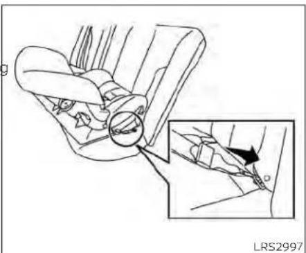
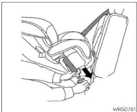
- Route the seat belt tongue through the child restraint and insert it into the buckle until you hear and feel the latch engage. Be sure to follow the child restraint manufacturer's instructions for belt routing.
natural_image
Diagram of a car seatbelt mechanism with a hand adjusting the belt (no text or symbols present)Rear-facing-step3
natural_image
Diagram of car seat and steering wheel assembly with directional arrows indicating movement (no text or symbols)Rear-facing-step4

natural_image
Diagram of a car seatbelt mechanism with arrows indicating movement or force (no text or symbols present)Rear-facing-step5
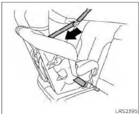
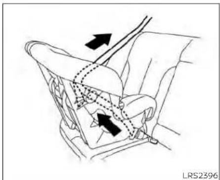
- Pull the shoulder belt until the belt is fully 4. Allow the seat belt to retract. Pull up on 5 extended. At this time, the seat belt re- the shoulder belt to remove any slack in tractor is in the ALR mode (child restraint the belt. mode). It reverts to the ELR mode when the seat belt is fully retracted.
Remove any additional slack from the seat belt; press downward and rearward firmly in the center of the child restraint to compress the vehicle seat cushion and seatback while pulling up on the seat belt.
natural_image
Line drawing of a car seatbelt assembly with hands adjusting the seat (no text or symbols)Rear-facing-step6
- Check to make sure that the child re- Follow these steps to install a forward- straint is properly secured prior to each facing child restraint in the rear bench use. If the seat belt is not locked, repeat seats using the LATCH system: steps 1 through 6.
- Position the child restraint on the seat. After the child restraint is removed and the Always follow the child restraint manu- seat belt fully retracted, the ALR mode manufacturer's instructions. (child restraint mode) is canceled.
FORWARD-FACING CHILD RESTRAINT INSTALLATION USING LATCH
For additional information, see all Warnings and Cautions in "Child safety" (P. 1-25) and "Child restraints" (P. 1-28) before installing a child restraint.
- After attaching the child restraint, test it Do not use the lower anchors if the com-before you place the child in it. Push it bined weight of the child and the child re-from side to side while holding the child restraint exceeds 65 lbs. (29.5 kg). If the com-restraint near the seat belt path. The bined weight of the child and the child child restraint should not move more restraint is greater than 65 lbs. (29.5 kg), use than 1 inch (25 mm), from side to side. The vehicle's seat belt (not the lower an-to tug it forward and check to see if the anchors) to install the child restraint. Be sure belt holds the restraint in place. If the to follow the child restraint manufacturer's restraint is not secure, tighten the seat instructions for installation. belt as necessary, or put the restraint in another seat and test it again. You may need to try a different child restraint. Not all child restraints fit in all types of vehicles.
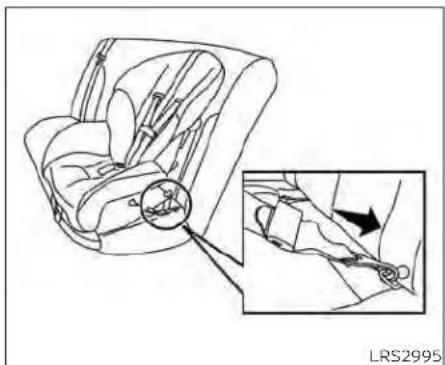
natural_image
Diagram of car seat assembly showing left and right views with a magnified inset highlighting the cable fastening mechanism (no text or symbols present)Forward-facingwebbing-mounted-step2
- Secure the child restraint anchor attachments to the LATCH lower anchors. Check to make sure the LATCH attachment is properly attached to the lower anchors.
If the child restraint is equipped with a top tether strap, route the top tether strap and secure the tether strap to the tether anchor point. For additional information, see "Installing top tether strap" (P. 1-40).

natural_image
Line drawing of a car seat assembly with an inset showing the seatbelt mechanism (no text or symbols)Forward-facingrigid-mounted-step2
Do not install child restraints that require the use of a top tether strap in seating positions that do not have a top tether anchor.
- The back of the child restraint should be secured against the vehicle seatback.
If necessary, adjust or remove the head restraint/headrest to obtain the correct child restraint fit. If the head restraint/headrest is removed, store it in a secure place. Besuretoreinstallthehead restraint/headrestwhenthechildre-
straintisremoved. For additional information, see "Head restraints/headrests" (P. 1-11).
If the seating position does not have an adjustable head restraint/headrest and it is interfering with the proper child restraint fit, try another seating position or a different child restraint.
natural_image
Line drawing of a car seatbelt with directional arrows indicating movement (no text or symbols)Forward-facing-step4
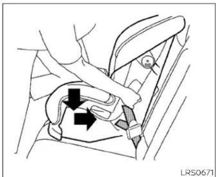
- For child restraints that are equipped with webbing-mounted attachments, remove any additional slack from the anchor attachments. Press downward and rearward firmly in the center of the child restraint with your knee to compress the vehicle seat cushion and seat-back while tightening the webbing of the anchor attachments.
- Tighten the tether strap according to the manufacturer's instructions to remove any slack.

natural_image
Line drawing of a car seatbelt buckle being adjusted for a person (no text or symbols)Forward-facing-step6
-
After attaching the child restraint, test it before you place the child in it. Push it from side to side while holding the child restraint near the LATCH attachment path. The child restraint should not move more than 1 inch (25 mm), from side to side. Try to tug it forward and check to see if the LATCH attachment holds the restraint in place. If the restraint is not secure, tighten the LATCH attachment as necessary, or put the restraint in another seat and test it again. You may need to try a different child restraint. Not all child restraints fit in all types of vehicles.
-
Check to make sure the child restraint is properly secured prior to each use. If the child restraint is loose, repeat steps 3 through 6.

natural_image
Line drawing of a hand holding a car seatbelt with a small component labeled 'A' (no text or symbols beyond label)Rearbenchseat
Ⓐ Anchor points Installing top tether strap
The child restraint top tether strap must be used when installing the child restraint with the LATCH lower anchor attachments.
First, secure the child restraint with the LATCH lower anchors (rear bench out-boarding seating positions only).
Rearbenchseat
OUTBOARDSEATINGPOSITIONS
- Remove the head restraint/headrest and store it in a secure place. Be sure to reinstall the head restraint/headrest when the child restraint is removed. For additional information, see "Head restraints/headrests" (P. 1-11) for head restraint/headrest adjustment, removal and installation information.
- Position the top tether strap over the seatback.
- Secure the tether strap to the tether anchor point as shown.
- Tighten the tether strap according to the manufacturer's instructions to remove any slack.
If you have any questions when installing optetherstrap, it is recommended that you visit a NISSAN dealer for this service.
WARNING
Childrestraintanchoragesaredesigned to withstand only those loads imposedbycorrectlyfittedchildrestraints. Undernocircumstances are they to be used to attach adult seat belts, or other items or equipment to thevehicle.Doingsocoulddamagethe childrestraint anchorages.Thechild restraint will not be properly installed using the damaged anchorage, and a childcouldbeseriouslyinjuredorkilled inacollision.
FORWARD-FACING CHILD RESTRAINT INSTALLATION USING THE SEAT BELTS — REAR BENCH SEAT
WARNING
Thethree-pointseatbeltwithAutomaticLockingRetractor(ALR)mustbe used when installing a child restraint. FailuretousetheALRmodewillresult inthechildrestraintnotbeingproperly secured. Therestraintcouldtipoveror belooseandcauseinjurytoachildina suddenstoporcollision.
For additional information, see all Warnings and Cautions in "Child safety" (P. 1-25) and "Child restraints" (P. 1-28) before installing a child restraint.
Do not use the lower anchors if the combined weight of the child and the child restraint exceeds 65 lbs. (29.5 kg). If the combined weight of the child and the child restraint is greater than 65 lbs. (29.5 kg), use the vehicle's seat belt (not the lower anchors) to install the child restraint. Be sure to follow the child restraint manufacturer's instructions for installation.
Follow these steps to install a forward-facing child restraint using the vehicle seat belt in the rear seats:
- If you must install a child restraint in the front seat, it should be placed in forward-facing direction only. Move these to there are most position. Child restraints for infants must be used in therear-facing direction and therefore must not be used in the front seat.
- Position the child restraint on the seat. Always follow the child restraint manufacturer's instructions.
The back of the child restraint should be secured against the vehicle seatback.
If necessary, adjust or remove the head restraint/headrest to obtain the correct child restraint fit. If the head restraint/headrest is removed, store it in a secure place. Besuretoreinstallthehead restraint/headrestwhenthechildrestraintisremoved. For additional information, see "Head restraints/headrests" (P. 1-11).
If the seating position does not have an adjustable head restraint/headrest and it is interfering with the proper child restraint fit, try another seating position or a different child restraint.

natural_image
Car seatbelt buckle diagram showing a black bandage and arrow indicating the buckle (no text or symbols present)Forward-facing-step3
- Route the seat belt tongue through the child restraint and insert it into the buckle until you hear and feel the latch engage. Be sure to follow the child restraint manufacturer's instructions for belt routing.
If the child restraint is equipped with a top tether strap, route the top tether strap and secure the tether strap to the tether anchor point (rear seat installation only). For additional information, see "Installing top tether strap" (P. 1-40).
Do not install child restraints that require the use of a top tether strap in seating positions that do not have a top tether anchor.

natural_image
Line drawing of a car seatbelt buckle with a belt buckle, showing no text or symbols
natural_image
Line drawing of a car seatbelt with arrows indicating movement or force (no text or symbols)Forward-facing-step4
Forward-facing-step5
- Pull the shoulder belt until the belt is fully extended. At this time, the seat belt retractor is in the ALR mode (child restraint mode). It reverts to ELR mode when the seat belt is fully retracted.
Allow the seat belt to retract. Pull up on the shoulder belt to remove any slack in the belt.

natural_image
Line drawing of a car seatbelt buckle with two black arrows indicating clockwise motion (no text or symbols)Forward-facing-step6
- Remove any additional slack from the seat belt; press downward and rearward firmly in the center of the child restraint with your knee to compress the vehicle seat cushion and seatback while pulling up on the seat belt.
- Tighten the tether strap according to the manufacturer's instructions to remove any slack.

natural_image
Line drawing of a car seatbelt with hands adjusting the seat (no text or symbols)Forward-facing-step8
-
After attaching the child restraint, test it before you place the child in it. Push it from side to side while holding the child restraint near the seat belt path. The child restraint should not move more than 1 inch (25 mm), from side to side. Try to tug it forward and check to see if the seat belt holds the restraint in place. If the restraint is not secure, tighten the seat belt as necessary, or put the restraint in another seat and test it again. You may need to try a different child restraint. Not all child restraints fit in all types of vehicles.
-
Check to make sure the child restraint is properly secured prior to each use. If the seat belt is not locked, repeat steps 3 through 8.
After the child restraint is removed and the seat belt is fully retracted, the ALR mode (child restraint mode) is canceled.

natural_image
Line drawing of a hand holding a car seatbelt with a small component labeled 'A' (no text or symbols beyond label)Ⓐ Anchor points
Installing top tether strap
The child restraint top tether strap must be used when installing the child restraint with seat belts.
First, secure the child restraint with the seat belt.
Rearbenchseat
OUTBOARDSEATINGPOSITIONS
- Remove the head restraint/headrest and store it in a secure place. Be sure to reinstall the head restraint/headrest when the child restraint is removed. For additional information, see "Head restraints/headrests" (P. 1-11).
- Position the top tether strap as shown.
- Secure the tether strap to the tether anchor point as shown.
- Tighten the tether strap according to the manufacturer's instructions to remove any slack.
CENTERSEATINGPOSITION
- Position the top tether strap as shown.
- Secure the tether strap to the tether anchor point as shown.
- Tighten the tether strap according to the manufacturer's instructions to remove any slack.
If you have any questions when installing optether strap, it is recommended that you visit a NISSAN dealer for this service.
WARNING
Childrestraintanchoragesaredesignedtowithstandonlythoseloads imposedbycorrectlyfittedchildrestraints.Under no circumstances are theytobeusedtoattachadultseat belts,orotheritemsor equipment to thevehicle.Doingsocoulddamagethe childrestraintanchorages. Thechild restraintwillnot be properlyinstalled using the damaged anchorage,anda childcouldbeseriouslyinjuredorkilled inacollision.
FORWARD-FACING CHILD RESTRAINT INSTALLATION USING THE SEAT BELTS — PASSENGER SEAT AND CENTER SEAT (if so equipped)
WARNING
Thethree-pointseatbeltwithAutomaticLockingRetractor(ALR)mustbe usedwheninstallingachidrestraint. FailuretousetheALRmodewillresult inthechildrestraintnotbeingproperly secured.Therestraintcouldtipoveror belooseandcauseinjurytoachildina suddenstoporcollision.Also,itcan changetheoperationofthefrontpassengerairbag.Foradditionalinformation,see"Frontpassengerairbagandstatuslight"(P.1-64).
For additional information, see all Warnings 2 and Cautions In "Child safety" (P. 1-25) and "Child restraints" (P. 1-28) before installing a child restraint.
Do not use the lower anchors if the combined weight of the child and the child restraint exceeds 65 lbs. (29.5 kg). If the combined weight of the child and the child restraint is greater than 65 lbs. (29.5 kg), use the vehicle's seat belt (not the lower anchors) to install the child restraint. Be sure to follow the child restraint manufacturer's instructions for installation.
Follow these steps to install a forward-facing child restraint using the vehicle seat belt:
- If you must install child restraint in the front seat, it should be placed in forward-facing direction only. Move the seat to the rearmost position. Childrestraints for infants must be used in therear-facing direction and therefore must not be used in the front seat.
Position the child restraint on the seat. Always follow the child restraint manufacturer's instructions.
The back of the child restraint should be secured against the vehicle seatback.
If necessary, adjust or remove the head restraint/headrest to obtain the correct child restraint fit. If the head restraint/headrest is removed, store it in a secure place. Besuretoreinstallthehead restraint/headrestwhenthechildrestraintisremoved. For additional information, see "Head restraints/headrests" (P. 1-11).
If the seating position does not have an adjustable head restraint/headrest and it is interfering with the proper child restraint fit, try another seating position or a different child restraint.

natural_image
Mechanical diagram showing a belt buckle securing a car seat (no text or symbols present)Forward-facing-step3
- Route the seat belt tongue through the child restraint and insert it into the buckle until you hear and feel the latch engage. Be sure to follow the child restraint manufacturer's instructions for belt routing.
If the child restraint is equipped with a top tether strap, route the top tether strap and secure the tether strap to the tether anchor point. For additional information, see "Installing top tether strap" (P. 1-48).
Do not install child restraints that require the use of a top tether strap in seating positions that do not have a top tether anchor.

natural_image
Line drawing of a car seatbelt buckle with a black arrow indicating the belt (no text or symbols present)Forward-facing-step4
- Pull the shoulder belt until the belt is fully extended. At this time, the seat belt retractor is in the ALR mode (child restraint mode). It reverts to ELR mode when the seat belt is fully retracted.
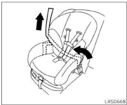
natural_image
Line drawing of a car seatbelt with arrows indicating movement or force (no text or symbols)Forward-facing-step5
5. Allow the seat belt to retract. Pull up on 6. the shoulder belt to remove any slack in the belt.

natural_image
Car seatbelt buckle diagram showing belt and seat movement arrows (no text or symbols)Forward-facing-step6
Remove any additional slack from the seat belt; press downward and rearward firmly in the center of the child restraint with your knee to compress the vehicle seat cushion and seatback while pulling up on the seat belt.
7. Tighten the tether strap according to the manufacturer's instructions to remove any slack.
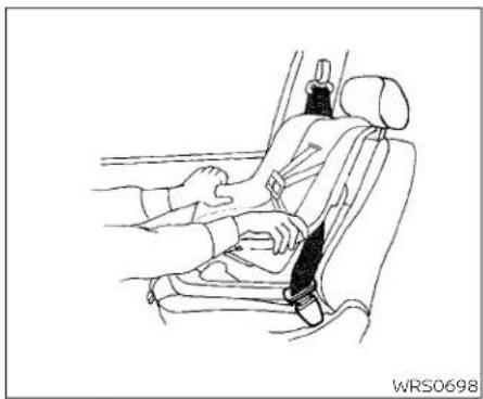
natural_image
Line drawing of a car seatbelt with hands adjusting the seat (no text or symbols)Forward-facing-step8
8. After attaching the child restraint, test it before you place the child in it. Push it from side to side while holding the child restraint near the seat belt path. The child restraint should not move more than 1 inch (25 mm), from side to side. Try to tug it forward and check to see if the seat belt holds the restraint in place. If the restraint is not secure, tighten the seat belt as necessary, or put the restraint in another seat and test it again. You may need to try a different child restraint. Not all child restraints fit in all types of vehicles.
Safety-Seats, seatbelts and supplemental restraintsystem1-47
- Check to make sure the child restraint is properly secured prior to each use. If the seat belt is not locked, repeat steps 3 through 8.

WRS0475
Forward-facing—step10
- If the child restraint is installed in the front passenger seat, place the ignition switch in the ON position. The front passenger air bag status light (if so equipped) may or may not illuminate, depending on the size of the child and the type of child restraint being used. For additional information, see "Front passenger air bag and status light" (P. 1-64).
After the child restraint is removed and the seat belt is fully retracted, the ALR mode (child restraint mode) is canceled.
Installing top tether strap
The child restraint top tether strap must be used when installing the child restraint with seat belts.
First, secure the child restraint with the seat belt.

Ⓐ Top tether straps
⑧ Anchor points (if so equipped)
Benchseat
PASSENGERSEATINGPOSITION
- Remove the head restraint/headrest and store it in a secure place. Be sure to reinstall the head restraint/headrest when the child restraint is removed. For additional information, refer to "Head restraints/headrests" in this section.
-
Position the top tether strap over the seatback.
-
Secure the tether strap to the tether anchor point as shown.
- Tighten the tether strap according to the manufacturer's instructions to remove any slack.
CENTERSEATINGPOSITION
- Position the top tether strap over the seatback.
- Secure the tether strap to the tether anchor point as shown.
- Tighten the tether strap according to the manufacturer's instructions to remove any slack.
If you have any questions when installing optether strap, it is recommended that you visit a NISSAN dealer for this service.
WARNING
Childrestraintanchoragesaredesignedto withstand onlythose loads imposedbycorrectlyfittedchildrestraints.Underno circumstances are they to be used to attach adult seat belts, or other items or equipment to thevehicle.Doingsocoulddamagethe childrestraintanchorages. Thechild restraint will not be properly installed using the damaged anchorage, and a childcouldbeseriouslyinjuredorkilled inacollision.
BOOSTER SEATS
For additional information on installing a booster seat in your vehicle, follow the instructions outlined in this section.
Precautions on booster seats
WARNING
Ifaboosterseatandseatbeltarenot usedproperly,theriskofachildbeing injuredorkilledinasuddenstoporcol- lisiongreatlyincreases:
- Makesuretheshoulderportionof thebeltisawayfromthechild'sface andneckandthelapportionofthe beltdoesnotcrossthestomach.
- Makesuretheshoulderbeltisnot behindthechildorunderthechild's arm.
- Aboosterseatmustonlybeinstalled inaseatingpositionthathasalap/shoulderbelt.
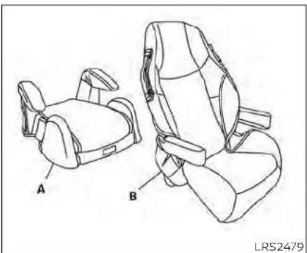
natural_image
Line drawing of two car seat compartments labeled A and B, showing different seat designs (no text or symbols beyond labels)A. Low back booster seat
B. High back booster seat

natural_image
Line drawing of a person sitting in a car seat with a diagonal band crossing the seat (no text or symbols)Booster seats of various sizes are offered by several manufacturers. When selecting any booster seat, keep the following points in mind:
- Choose only a booster seat with a label certifying that it complies with Federal Motor Vehicle Safety Standard 213 or Canadian Motor Vehicle Safety Standard 213.
- Check the booster seat in your vehicle to be sure it is compatible with the vehicle's seat and seat belt system.

natural_image
Line drawing of a person seated in a car seat, wearing a seatbelt and holding a belt (no text or symbols)AllU.S. states and Canadian provinces or territories require that infants and small children berestrained in an approved child restraint at all times while the vehicle is being operated.
The instructions in this section apply to booster seat installation in the rear seats or the front passenger seat.
Booster seat installation
WARNING
Toavoidinjurytochild, donotusethe lap/shoulderbeltintheAutomatic LockingRetractor(ALR)modewhenusingaboosterseatwiththeseatbelts.
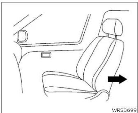
natural_image
Line drawing of a car interior showing seat, driver seat, and passenger seat with directional arrow (no text or symbols)Follow these steps to install a booster seat in the rear seat or in the front passenger
• Make sure the child's head will be properly supported by the booster seat or vehicle seat. The seatback must be at or above For additional information, see all Warnings
the center of the child's ears. For example and Cautions in "Child safety" (P. 1-25), "Child, if a low back booster seat is chosen, the restraints" (P. 1-28) and "Booster seats" vehicle seatback must be at or above the (p 1-49) before installing a child restraint. center of the child's ears. If the seatback is lower than the center of the child's ears, a high back booster seat should be used.
- If the booster seat is compatible with your vehicle, place the child in the booster seat and check the various adjustments to be sure the booster seat is compatible with the child. Always follow all recommended procedures.
If you must install a booster seat in the front seat, mov these at to there are most position.
- Position the booster seat on the seat. Only place it in a front-facing direction. Always follow the booster seat manufacturer's instructions.
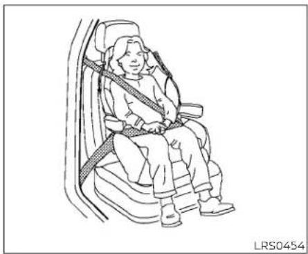
natural_image
Line drawing of a person seated in a car seat with a belt, no text or symbols presentFrontpassengerposition

natural_image
Line drawing of a person sitting in a car seat with a seatbelt, no text or symbols presentRearcenterposition

natural_image
Line drawing of a person seated in a car seat, wearing a seatbelt and holding a belt (no text or symbols)Rearoutboardposition
- The booster seat should be positioned on the vehicle seat so that it is stable. If necessary, adjust or remove the head restraint/headrest to obtain the correct booster seat fit. If the head restraint/headrest is removed, store it in a secure place. Besuretoreinstallthehead restraint/headrestwhenthebooster seatisremoved. For additional information, see "Head restraints/headrests" (P. 1-11).
SUPPLEMENTALRESTRAINTSYSTEM (SRS)
If the seating position does not have an adjustable head restraint/headrest and it is interfering with the proper booster seat fit, try another seating position or a different booster seat.
- Position the lap portion of the seat belt low and snug on the child's hips. Be sure to follow the booster seat manufacturer's instructions for adjusting the seat belt routing.
- Pull the shoulder belt portion of the seat belt toward the retractor to take up extra slack. Be sure the shoulder belt is positioned across the top, middle portion of the child's shoulder. Be sure to follow the booster seat manufacturer's instructions for adjusting the seat belt routing.
- Follow the warnings, cautions and instructions for properly fastening a seat belt shown in "Three-point type seat belt with retractor" (P. 1-19).
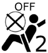
WRS0475
- If the booster seat is installed in the front passenger seat, place the ignition switch in the ON position. The front passenger air bag status light (if so equipped) may or may not illuminate, depending on the size of the child and the type of booster seat being used. For additional information, see "Front passenger air bag and status light" (P. 1-64).
PRECAUTIONS ON SRS (with NISSAN Advanced Air Bag System) (if so equipped)
This SRS section contains important information concerning the following systems:
- Driver and front passenger supplemental front-impact air bag (NISSAN Advanced Air Bag System)
- Front seat-mounted side-Impact supplemental air bag
- Roof-mounted curtain side-impact and rollover supplemental air bag
- Driver and passenger supplemental knee air bag
nt Seat belt with pretensioner(s) (front seats and rear outboard seats)
Supplementalfront-impactairbag system
The NISSAN Advanced Air Bag System can help cushion the impact force to the head and chest of the driver and right front passenger in certain frontal collisions.
Frontseat-mountedside-impact supplementalairbagsystem
This system can help cushion the impact force to the chest area of the driver and right front passenger in certain side impact collisions. The side air bag is designed to inflate on the side where the vehicle is impacted.
Roof-mountedcurtainside-impact and rolloversupplementalairbagsystem
This system can help cushion the impact force to the head of occupants in front and rear outboard seating positions (if so equipped) in certain side impact or rollover collisions. In a side impact, the curtain air bags are designed to inflate on the side where the vehicle is impacted. In a rollover, curtain air bags are designed to inflate and remain inflated for a short time.
Driverandpassengersupplemental kneeairbags
This system can help cushion the impact force to the driver's and front passenger's knees in certain collisions.
The SRS is designed to supplement the crash protection provided by the seat belts and is not as substitute for them. Seat belts should always be correctly worn and the occupant seated a suitable distance away from the steering wheel, instrument panel and door finishers. For additional information, see "Seat belts" (P. 1-16).
Thesupplementalairbagsoperateonly when the ignition switch is in the ON position.
Afterplacingtheignitionswitchinthe ONposition,thesupplementalairbag warning lightilluminates. Thesupplementalairbagwarninglightwillturnoff afterabout7secondsifthesystemis operational.

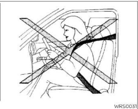
natural_image
Illustration of a person seated in a car wearing a seatbelt, with no visible text or symbols.WARNING
- Thefrontairbagsordinarilywillnot inflateintheeventofasideimpact, rearimpact, rollover, or lowerseverityfrontal collision. Alwayswearyour seatbeltstohelpreducetheriskor severityofinjuryinvariouskindsof accidents.
- Thefrontpassengerairbagandpassengerkneeairbagwillnotinflateif thepassengerairbagstatuslightis litorifthefrontpassengerseatis unoccupied.Foradditionalinformation,see"Frontpassengerairbag andstatuslight"(P.1-64).
- Theseatbeltsandthefrontairbags aremosteffectivewhenyouaresittingwellbackanduprightintheseat. Thefrontairbagsinflatewithgreat force.EvenwiththeNISSANAdvancedAirBagSystem,ifyouareunrestrained,leaningforward,sitting sidewaysoroutofpositioninany way,youareatgreaterriskofinjury ordeathinacrash.Youmayalsoreceiveseriousorfatalinjuriesfrom thefrontairbagifyouareupagainst itwhenitinflates.Alwayssitback againsttheseatbackandasfaraway aspracticalfromthesteeringwheel orinstrumentpanel.Alwaysproperly usetheseatbelts.
- Thedriverandfrontpassengerseat beltbucklesareequippedwithsensorsthatdetectiftheseatbeltsare fastened.TheNISSANAdvancedAir BagSystemmonitorstheseverityof acollisionandinflatestheairbagsas needed.Failuretoproperlywearseat beltscanincreasetheriskorseverity ofinjuryinanaccident.
- Thefrontpassengerseatisequipped withanoccupantclassificationsensor(weightsensor)thatturnsthe frontpassengerairbagandpassengerkneeairbagOFFundersome conditions.Thissensorisonlyusedin thisseat.Failureuretobeproperly seatedandwearingtheseatbeltcan increasetheriskorseverityofinjury inanaccident.Foradditionalinformation,see"Frontpassengerairbag andstatuslight"(P.1-64).
- Keephandsontheoutsideofthe steeringwheel.Placingtheminside thesteeringwheelrimcouldincrease theriskthattheyareinjuredwhen thefrontairbaginflates.
- Theairbagsystemmonitorthese-verityofacollisionandtheninflates theairbagsasneeded.Failureto properlywearseatbeltscanincrease theriskorseverityofinjuryinan accident.
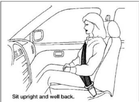

natural_image
Diagram of a person seated in a car seatbelt, crossed with a diagonal line (no text or symbols)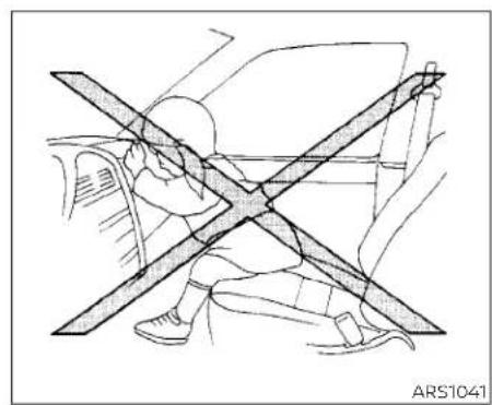
natural_image
Diagram of a person using a car to stop or stand, showing no text or symbolsWARNING
- Neverletchildrenrideunrestrained orextendtheirhandsorfaceoutofthewindow.Donotattempttohold theminyourlaporarms.Someexamplesofdangerousridingpositionsareshownintheillustrations.

natural_image
Line drawing of a person sitting on a car seatbelt with diagonal braces (no text or symbols)WARNING
- Childrenmaybeseverelyinjuredor killedwhenthefrontairbags,sideair bagsorcurtainairbagsinflateifthey arenotproperlyrestrained.Pre-teensandchildrenshouldbeproperlyrestrainedintherearseat,if possible.

natural_image
Diagram showing a car interior with a cross-shaped object and surrounding vehicle (no text or symbols)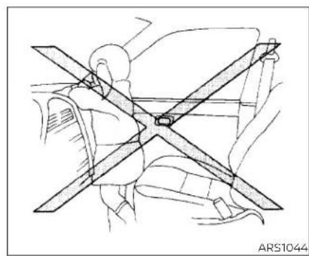
natural_image
Technical line drawing of a car seatbelt assembly (no text or symbols)
natural_image
Diagram of a car interior showing two people seated with car seats and overhead belt, no text or symbols present
natural_image
Diagram of a car showing a person seated inside the seat with a cross symbol indicating no change or restriction (no text or labels present)
WARNING
- EvenwiththeNISSANAdvancedAir BagSystem,neverinstallarear-facingchildrestraintinthefrontseat. Aninflatingairbagcouldseriously injureorkillachild.Arear-facing childrestraintmustonlybeusedin therearseat.
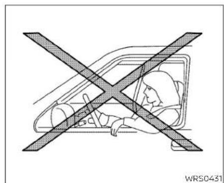
Donotleanagainstdoorsorwindows.
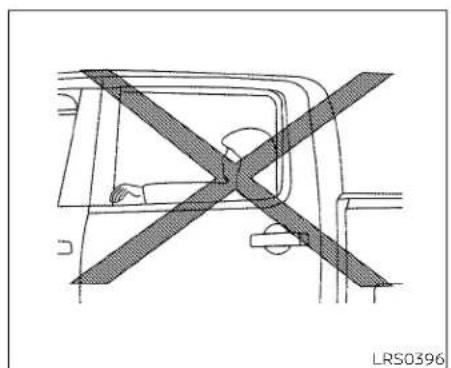
natural_image
Diagram of a vehicle's cross-section showing steering wheel and dashboard (no text or symbols)Donotleanagainstdoorsorwindows.

natural_image
Illustration of a person sitting in a car seat with a cross-shaped bandpass, no text or symbols presentDonotleanagainstdoorsorwindows.
WARNING
Frontseat-mountedside-impact supplementalairbagsandroof-mountedcurtainside-impactandroll-oversupplementalairbags:
- Thesideairbagsandcurtainairbags ordinarilywillnotinflateintheevent ofafrontalimpact,rearimpact,or lowerseveritysidecollision.Always wearyourseatbeltstohelpreduce theriskorseverityofinjuryinvarious kindsofaccidents.
WARNING
- Theseatbelts,thesideairbagsand curtainairbagsaremosteffective whenyouaresittingwellbackand uprightintheseat.Thesideairbag andcurtainairbaginflatewithgreat force.Donotallowanyonetoplace theirhand,legorfaceneartheside airbagonthesideoftheseatbackof thefrontseatornearthesideroof rails.Donotallowanyonesittingin thefrontseatsorrearoutboardseats toextendtheirhandoutofthewindoworleanagainstthedoor.Some examplesofdangerousridingpositionsareshownintheprevious illustrations.

natural_image
Line drawing of a car interior showing a person seated inside the window with a cross symbol indicating steering or pressure (no text or labels)
natural_image
Diagram of a car interior showing a person seated under a vehicle with a cross-shaped barrier (no text or symbols)WARNING
- Whensittingintherearseat, donot holdontotheseatbackofthefront seat. If the side air bag inflates, you may be seriously injured. Beespecially careful with children, who should always be properly restrained. Some examples of dangerous riding positions are shown in the illustrations.
- Donotuseseatcoversonthefront seatbacks. They may interferewith sideairbaginflation.

NISSAN Advanced Air Bag System (front seats) (if so equipped)
1. Roof-mounted curtain side-impact and rollover supplemental air bag inflators
- Roof-mounted curtain side-impact and rollover supplemental air bags
- Air bag Control Unit (ACU)
- Supplemental front-impact air bag modules
- Crash zone sensor
- Driver and passenger supplement knee air bags
- Occupant classification sensor (weight sensor)
- Occupant classification system control unit
- Seat belt buckle switches
- Seat belt with pretensioner(s) (front seats) (passenger's side shown; driver's side similar)
- Front seat-mounted side-impact supplemental air bag modules (passenger's side shown; driver's side similar)
- Satellite sensor (passenger's side shown; driver's side similar)
- Seat belt with pretensioner(s) (rear outboard seats) (passenger's side shown; driver's side similar)
WARNING
Toensureproperoperationofthepas-senger'sNISSANAdvancedAirBagSys-tem,pleaseobservethefollowing items.
- Donotallowapassengerintherear benchseatstopushorpullonthe seatbackpocket.
- Donotplaceheavyloadsheavier than2.2lbs.(1kg)ontheseatback, headrestraintorintheseatback pocket.
- Donotstoreluggagebehindtheseat thatcanpressintotheseatback.
-
Donotpositionthefrontpassenger seatsoitcontactsttherearbench seats.Ifthefrontseatdoescontact therearbenchseats,theairbagsystemmaydetermine a sensormal-functionhasoccurredandthefront passengerairbagstatuslightmay illuminateandthesupplementalair bagwarninglightmayflash.
-
Ifaforward-facingchildrestraintis installedinthefrontpassengerseat, donotpositionthefrontpassenger seatsothechild restraint contacts theinstrumentpanel.Ifthechildrestraintdoescontacttheinstrument panel, the systemmay determinethe seatasoccupiedandthepassenger airbagandpassengerkneeairbag may deployina collision. Alsothe frontpassengerairbagstatuslight maynotilluminate.Foradditionalinformation, see "Child restraints" (P.1-28).
- Confirm the operating condition with the front passenger air bag status light.
- If you notice that the front passenger air bag status light is not operating as described in this section, get the occupant classification system checked. It is recommended that you take your vehicle to a NISSAN dealer forthisservice.
- Until you have confirmed with a dealer that your passenger seat occupant classifications system is working properly, position the occupants in therearseating positions.
This vehicle is equipped with the NISSAN Advanced Air Bag System for the driver and front passenger seats. Alloftheinformation,cautionsandwarningsinthis manualstillapplyandmustbefollowed.
The driver supplemental front-impact air bag is located in the center of the steering wheel. The front passenger supplemental front-impact air bag is mounted in the dashboard above the glove box. The front air bags are designed to inflate in higher severity frontal collisions, although they may inflate if the forces in another type of collision are similar to those of a higher severity frontal impact. They may not inflate in certain frontal collisions. Vehicle damage (or lack of it) is not always an indication of proper front air bag system operation.
The NISSAN Advanced Air Bag System monitors information from the crash zone sensor and the Air bag Control Unit (ACU). Inflator operation is based on the severity of a collision and seat belt usage for the driver. For the front passenger, the occupant classification sensor is also monitored. Based upon the information from the sensor, only one front air bag may inflate in a crash, depending on the crash severity. Additionally, the front passenger
air bag and passenger knee air bag may automatically turned off under some conditions, depending on the weight detected on the front passenger seat and how the seat belt is used. If the front passenger air bag and passenger knee air bag are OFF, the front passenger air bag status light will be illuminated (if the seat is unoccupied, the light will not be illuminated, but the air bag will be off). For additional information, see "Front passenger air bag and status light" (P. 1-64). One front air bag inflating does not indicate improper performance of the system.
If you have any questions about your air bag system, it is recommended that you contact NISSAN or a NISSAN dealer. If you are considering modification of your vehicle due to a disability, you may also contact NISSAN. Contact information is contained in the front of this Owner's Manual.
When a front air bag inflates, a fairly loud noise may be heard, followed by the release of smoke. This smoke is not harmful and does not indicate a fire. Care should be taken to not inhale it, as it may cause irritation and choking. Those with a history of a breathing condition should get fresh air promptly.
Front air bags, along with the use of seat belts, help to cushion the impact force on the face and chest of the front occupants. They can help save lives and reduce serious injuries. However, an inflating front air bag may cause facial abrasions or other injuries. Front air bags, other than the driver's knee air bag, do not provide restraint to the lower body.
Even with NISSAN Advanced Air Bags, seat belts should be correctly worn and the driver and front passenger seated upright as far as practical away from the steering wheel or instrument panel. The front air bags inflate quickly in order to help protect the front occupants. Because of this, the force of the front air bag inflating can increase the risk of injury if the occupant is too close to, or is against, the front air bag module during inflation.
The front air bags deflate quickly after a collision.
Thefrontairbagsoperateonlywhenthe ignitionswitchisintheONposition.
Afterplacingtheignitionswitchinthe ONposition,thesupplementalairbag warninglightilluminates. Thesupplementalairbagwarninglightwillturnoff afterabout7secondsifthesystemis operational.

WRS0475
Frontpassengerairbagandstatuslight
WARNING
Thefrontpassengerairbagandfront passengersupplementalkneeairbag isdesignedtoautomaticallyturnOFF undersomeconditions.Readthissectioncarefullytolearnhowitoperates. Properuseoftheseat,seatbeltand childrestraintsisnecessaryformost effectiveprotection.Failureretofollowall instructionsinthismanualconcerning theuseofseats,seatbeltsandchild restraintscanincreasetheriskorse-verityofinjuryinanaccident.
Statuslight
The front passenger seat is equipped with an occupant classification sensor (weight sensor) that turns the front passenger air bag and passenger knee air bag on or off depending on the weight applied to the front passenger seat. The status of the front passenger air bag and passenger knee air bag (ON or OFF) is indicated by the front passenger air bag status light which is located on the instrument panel.
After the ignition switch is placed in the "ON" position, the front passenger air bag status light on the instrument panel illuminates for about 7 seconds and then turns off or remains illuminated depending on the front passenger seat occupied status. The light operates as follows:
- Unoccupied front passenger's seat: The light is OFF and the front passenger air bag is OFF and will not inflate in a crash.
- Front passenger seat occupied by a small adult, child or child restraint as outlined in this section: The light may or may not illuminate, depending on the size of the occupant or the type of child restraint being used. When the light is illuminated, the front passenger air bag is OFF and will not inflate in a crash. For additional information, see "Front passenger air bag and status light" (P. 1-64).
- Occupied front passenger seat and the passenger meets the conditions as outlined in this section: The light is OFF to indicate that the front passenger air bag is operational.
In addition to the above, certain objects placed on the front passenger seat may also cause the light to operate as described above depending on their weight.
For additional information, see "Normal operation" (P. 1-66) and "Troubleshooting" (P. 1-66).
Frontpassengerairbag
The front passenger air bag and passenger knee air bag are designed to automatically turn OFF when the vehicle is operated under some conditions as described below in accordance with U.S. regulations. If the front passenger air bag and passenger
knee air bag are OFF, it will not inflate in apassenger knee air bag are OFF. If the front restraints and to use the ALR mode may crash. The driver air bag and other air bag passenger air bag status light is not illum- allow the restraint to tip or move in a collision or sudden stop. This can also result in the passenger air bag and passenger knee air bag inflating in a crash instead of being OFF. For additional information, see "Child restraints" (P. 1-28).
The purpose of the regulation is to help reduce the risk of injury or death from an inflating air bag to certain front passenger seat occupants, such as children, by require-cause the front passenger air bag to be automatically turned OFF. For small adults if the front passenger seat is not occupied, it may be turned OFF, however if the occuthe front passenger air bag and passenger pant takes his/her weight off the seat knee air bag are designed not to inflate in a cushion (for example, by not sitting uprightcrash. However, heavy objects placed on by sitting on an edge of the seat, or by otherwise being out of position), this could because of the object's weight detected by cause the sensor to turn the front passen-the occupant classification sensor. Other gter air bag and passenger knee air bag conditions could also result in air bag infla-OFF. Always be sure to be seated and wear- tion, such as if a child is standing on the off-ing the seat belt properly for the most ef-seat, or if two children are on the seat, con- fective protection by the seat belt and supplemental air bag.
NISSAN recommends that pre-teens and children be properly restrained in a rear NISSAN also recommends that ap- using the front passenger air bag status air bag may or may not be auto-matically turned OFF, depending on the size of the child and the type of child re- siant being used. After installing the child re- sion sensor is designed to operate as de-scribed above to turn the front passenger air bag and passenger knee air bag OFF for the front passenger air bag status light is illu-minated, the front passenger air bag and specified child restraints as required by the regulations. Failing to properly secure child
OFF), it could be that the person is a small if a malfunction occurs in the front passenSteps
adult, or is not sitting on the seat properly ger air bag system, the supplemental air or not using the seat belt properly. bag warning light ✿, located in the me-
If a child restraint must be used in the front seat, the front passenger air bag status light may or may not be illuminated, depending on the size of the child and the type of child restraint being used. Always make sure that the child restraint is installed properly, the seat belt is used properly and the occupant is positioned properly.
If necessary, a NISSAN dealer can check system operation by using a special tool. Until you have confirmed with a dealer that your air bag is working properly, reposition the occupant or child restraint in a rear seat.
The NISSAN Advanced Air Bag System and front passenger air bag status light will take a few seconds to register a change in the front passenger seat status. For example, if a large adult who is sitting in the front passenger seat exits the vehicle, the front passenger air bag status light will go from OFF to ON for a few seconds and the to OFF. This is normal system operation and does not indicate a malfunction.
ger air bag system, the supplemental air bag warning light , located in the meter and gauges area of the instrument panel, will blink. Have the system checked. It is recommended that you visit a NISSAN dealer for this service.
Normaloperation
In order for the occupant classification sensor system to classify the front passenger 3 ger based on weight, please follow the precautions and steps outlined below:
Precautions
Make sure that there are no objects weighing over 2.2 lbs. (1 kg) hanging on the seat or placed in the seatback pocket.
- Make sure that a child restraint or other object is not pressing against the rear of the seatback.
• Make sure that a rear passenger is not pushing or pulling on the back of the front passenger seat.
• Make sure that the front passenger seat or seatback is not forced back against an object on the seat or floor behind it.
- Make sure that there is no object placed under the front passenger seat.
-
Adjust the seat as outlined in the "Seats" section of this manual. Sit upright, leaning against the seatback, and centered on the seat cushion with your feet comfortably extended to the floor.
-
Make sure there are no objects on your lap.
Fasten the seat belt as outlined in the "Seat belts" section of this manual.
Remain in this position for 30 seconds allowing the system to classify the front passenger before the vehicle is put into motion.
Ensure proper classification by checking the front passenger air bag status light.
NOTE:
Thisvehicle'soccupantclassification sensorsystemlockstheclassification duringdrivingsoitisimportantthatyou confirmthatthefrontpassengerisproperlyclassifiedpriortodriving.Also,the occupantclassificationsensorsystem mayrecalculatetheweightoftheoccupantwhenthevehiclecomestoastop (i.e.stoplight,stopsign,etc.),sofront passengerseatoccupantsshouldcontinuetoremainseatedasoutlined above.
Troubleshooting
If you think the front passenger air bag status light is incorrect:
- If the light is ON with no front passenger and no objects on the front passenger seat:
This may be due to the following conditions that may be interfering with the weight sensors:
- An object weighing over 2.2 lbs. (1 kg) hanging on the seat or placed in the seat back pocket.
- A child restraint or other object pressing against the rear of the seatback.
- A rear passenger pushing or pulling on the back of the front passenger seat.
- Forcing the front seat or seatback against an object on the seat or floor be hind it.
- An object placed under the front passenger seat.
- An object placed between the seat cushion and center console or between the seat cushion and the door.
If the vehicle is moving, please come to a stop when it is safe to do so. Check and correct any of the above conditions. Restart the vehicle and wait 1 minute.
NOTE:
Asystemcheckwillbeperformedduring whichthefrontpassengerairbagstatus lightwillremainlitforabout7seconds initially.
If the light is still ON after this, the vehicle should be checked as soon as possible. It recommended that you visit a NISSAN dealer for this service.
- If the light is ON with an adult occupying the front passenger seat:
- Occupant is a small adult — the air bag light is functioning as intended. The
front passenger air bag and passenger knee air bag are suppressed.
However, if the occupant is not a small adult, then this may be due to the following conditions that may be interfering with the -weight sensors:
- Occupant is not sitting upright, leaning against the seatback, and centered on the seat cushion with his/her feet comfortably extended to the floor.
- A child restraint or other object pressing against the rear of the seatback.
- A rear passenger pushing or pulling on the back of the front passenger seat.
- Forcing the front seat or seatback against an object on the seat or floor behind it.
- An object placed under the front passenger seat.
- An object placed between the seat cushion and center console or between the isseat cushion and the door.
If the vehicle is moving, please come to a stop when it is safe to do so. Check and
correct any of the above conditions. Restart the vehicle and wait 1 minute.
NOTE:
Asystemcheckwillbeperformedduring whichthefrontpassengerairbagstatus lightwillremainlitforabout7seconds initially.
If the light is still ON after this, the person should be advised not to ride in the front passenger seat and the vehicle should be checked as soon as possible. It is recommended that you visit a NISSAN dealer for this service.
Othersupplementalfront-impactair bagprecautions
WARNING
- Donotplaceanyobjectsonthe steeringwheelpadorontheinstrumentpanel.Also,donotplaceany objectsbetweenanyoccupantand thesteeringwheelorinstrument panel.Suchobjectsmaybecome dangerousprojectilesandcauseinjuryifthefrontairbagsinflate.
-
Immediatelyafterinflation,several frontairbagsystemcomponentswill behot.Donottouchthem;youmay severelyburnyourself.
-
Nounauthorizedchangesshouldbe madetoanycomponentsorwiring ofthesupplementalairbagsystem. Thisistopreventaccidentalinflation ofthesupplementalairbagordamagetothesupplementalairbag system.
- Donotmakeunauthorizedchanges toyourvehicle'selectricalsystem, suspensionsystemorfrontend structure. This could affect proper operationofthefrontairbagsystem.
- Tamperingwiththefrontairbagsystemmayresultinseriouspersonal injury.Tamperingincludeschanges tothesteeringwheelandtheinstrumentpanelassemblybyplacingmaterialoverthe steeringwheel pad andabovetheinstrument panel or byinstallingadditionaltrimmaterial aroundtheairbagsystem.
-
Removingormodifyingthefront passengerseatmayaffectthefunctionoftheairbagsystemandresult inseriouspersonalinjury.
-
Modifyingor tampering with the frontpassengerseatmayresult in serious personal injury. Forexample, do not change the front seats by placing material on these seat cushion or by installing additional trimmaterial, such as seat covers, on these seat that are not specifically designed to assure proper air bag operation. Additionally, donot stow any objects under the frontpassenger seat or the seat cushion and seat back. Such objects may interfere with the proper operation of the occupant classification sensor (weightsensor).
-
Nounauthorizedchangesshouldbe madetoanycomponentsorwiring oftheseatbeltsystem. This may affect the front air bag system. Tamperingwiththeseatbeltsystemmay resultinseriouspersonalinjury.
-
Itisrecommendedthatyouvisita NISSANdealerforworkonand aroundthefrontairbag.ItisalsorecommendedthatyouvisitaNISSAN dealerforinstallationofelectrical equipment.TheSupplementalRestraintSystem(SRS)wiringharnesses'shouldnotbemodifiedor disconnected.Unauthorizedelectricaltestequipmentandprobingdevicesshouldnotbeusedontheair bagsystem.
- Acrackedwindshieldshouldbere-placedimmediatelybyaqualifiedre-pairfacility.Acrackedwindshield could affect the function of the supplemental airbagsystem.
\*TheSRSwiringharnessconnectorsare yellowandorangeforeasyidentification.
When selling your vehicle, we request that you inform the buyer about the front air bag system and guide the buyer to the appropriate sections in this Owner's Manual.
PRECAUTIONS ON SRS (without NISSAN Advanced Air Bag System) (if so equipped)
This SRS section contains important information concerning the following systems:
- Driver and front passenger supplemental front-impact air bag
- Front seat-mounted side-impact supplemental air bag
- Roof-mounted curtain side-impact and rollover supplemental air bag
- Seat belt with pretensioner(s) (front seats and rear outboard seats)
Supplemental front-impact air bag system
This system can help cushion the impact force to the head and chest of the driver and right front passenger in certain fronta collisions.
Front seat-mounted side-impact supplementalairbagsystem
This system can help cushion the impact force to the chest area of the driver and right front passenger in certain side impact collisions. The side air bag is designed to inflate on the side where the vehicle is impacted.
Roof-mounted curtainside-impact and rolloversupplementalairbagsystem
This system can help cushion the impact force to the head of occupants in front and rear outboard seating positions in certain side impact or rollover collisions. In a side impact, the curtain air bags are designed to inflate on the side where the vehicle is impacted. In a rollover, curtain air bags are designed to inflate and remain inflated for a short time.
The SRS is designed to supplement the crash protection provided by the seat belts and is not as substitute for them. Seat belts should always be correctly worn and the occupant seated a suitable distance away from the steering wheel, instrument panel and door finishers. For additional information, see "Seat belts" (P. 1-16).
Thesupplementalairbagsoperateonly whentheignition switchis intheON position.
Afterplacingtheignitionswitchinthe ONposition,thesupplementalairbag warning lightilluminates.The supplementalairbagwarninglightwillturnoff afterabout7secondsifthesystemis operational.


natural_image
Illustration of a person seated in a car wearing a seatbelt, with no visible text or symbols.WARNING
- Thefrontairbagsordinarilywillnot inflateintheeventofasideimpact, rearimpact, rollover, or lowerseverityfrontal collision. Alwayswearyour seatbeltstohelpreducetheriskor severityofinjuryinvariouskindsof accidents.
- Theseatbeltsandthefrontairbags aremosteffectivewhenyouaresittingwellbackanduprightintheseat. Thefrontairbagsinflatewithgreat force.Ifyouareunrestrained,leaning forward,sittingsidewaysoroutof
positioninanyway,youareat greaterriskofinjuryordeathina crash.Youmayalsoreceiveserious orfatalinjuriesfromthefrontairbag ifyouareupagainstitwhenitin- flates.Alwayssitbackagainstthe seatbackandasfarawayaspractical fromthesteeringwheelorinstrumentpanel.Alwaysproperlyusethe seatbelts.
- Thedriverandfrontpassengerseat beltbucklesareequippedwithsensorsthatdetectiftheseatbeltsare fastened.Theairbagsystemmonitortheseverityofacollisionandinflatestheairbagsasneeded.Failure toproperlywearseatbeltscanincreasetheriskorseverityofinjuryin anaccident.
- Keephandsontheoutsideofthe steeringwheel.Placingtheminside thesteeringwheelrimcouldincrease theriskthattheyareinjuredwhen thefrontairbaginflates.
- Theairbagsystemmonitorthese-verityofacollisionandtheninflates theairbagsasneeded.Failureto properlywearseatbeltscanincrease theriskorseverityofinjuryinan accident.
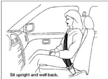

natural_image
Diagram of a person sitting on a car seatbelt with diagonal crossed lines indicating safety or clearance (no text or symbols present)
natural_image
Diagram of a person using a vehicle to avoid crossing a road, showing no text or symbolsARS1133 | ARS1041
WARNING
- Neverletchildrenrideunrestrained orextendtheirhandsorfaceoutof thewindow.Donotattempttohold theminyourlaporarms.Someexamplesofdangerousridingpositionsareshownintheillustrations.
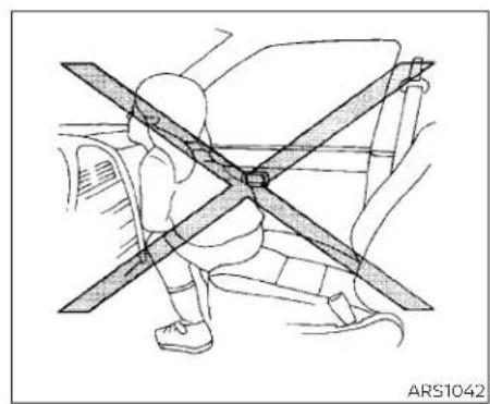
natural_image
Diagram of a person sitting on a car with a cross-shaped object, no text or symbols present
natural_image
Diagram of a car interior showing a cross-shaped object and a seated car, with no visible text or symbols.
natural_image
Technical line drawing of a mechanical assembly with intersecting beams and components (no text or symbols)WARNING
- Childrenmaybeseverelyinjuredor killedwhenthefrontairbags,sideair bagsorcurtainairbagsinflateifthey arenotproperlyrestrained.Pre-teensandchildrenshouldbeproperlyrestrainedintherearseat,if possible.
1-72 Safety-Seats, seatbeltsandsupplementalrestraintsystem
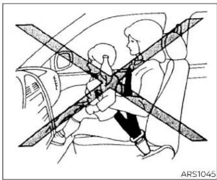
natural_image
Line drawing of a person sitting in a car with a cross-shaped object on the seat, no text or symbols presentARS1045 WR\$0256 WRS0431

natural_image
Diagram of a car showing a person seated under a double-headed crossbar, with no text or symbols present.WARNING
- Evenwiththeairbagsystem,never installarear-facingchildrestraintin thefrontseat.Aninflatingairbag couldseriouslyinjureorkillachild.A rear-facingchildrestraintmustonly beusedintherearseat.

natural_image
Diagram showing a person inside a car with a large 'X' symbol crossed out by two diagonal lines (no text or labels)Donotleanagainstdoorsorwindows.
WARNING
Frontseat-mountedside-impact supplementalairbagsandroof-mountedcurtainside-impactandroll-oversupplementalairbags:
- Thesideairbagsandcurtainairbags ordinarilywillnotinflateintheevent ofafrontalimpact,rearimpact,or lowerseveritysidecollision.Always wearyourseatbeltstohelpreduce theriskorseverityofinjuryinvarious kindsofaccidents.

natural_image
Diagram of a vehicle's cross-section showing steering wheel and dashboard (no text or symbols)Donotleanagainstdoorsorwindows.
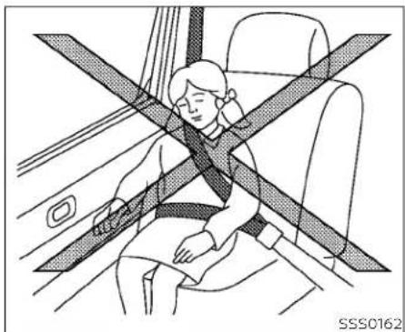
natural_image
Line drawing of a person sitting in a car seat with a cross-shaped bandpass, no text or symbols presentDonotleanagainstdoorsorwindows.
WARNING
Theseatbelts,thesideairbagsand curtainairbagsaremosteffective whenyouaresittingwellbackand uprightintheseat.Thesideairbag andcurtainairbaginflatewithgreat force.Donotallowanyonetoplace theirhand,legorfaceneartheside airbagonthesideoftheseatbackof thefrontseatornearthesideroof rails.Donotallowanyonesittingin thefrontseatsorrearoutboardseats toextendtheirhandoutofthewindoworleanagainstthedoor.Some examplesofdangerousridingpositionsareshownintheprevious illustrations.

natural_image
Line drawing of a car interior showing a person seated inside the dashboard with a cross-shaped seatbelt (no text or symbols)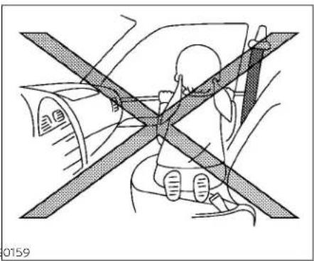
natural_image
Diagram of a person seated in a car with crossed-out seats, no text or symbols presentWARNING
- Whensittingintherearseat, donot holdontotheseatbackofthefront seat. If the side airbaginflates, you may be seriously injured. Beespecially careful with children, who should always be properly restrained. Some examples of dangerous riding positions are shown in the illustrations.
- Donotuseseatcoversonthefront seatbacks. They may interferewith sideairbaginflation.
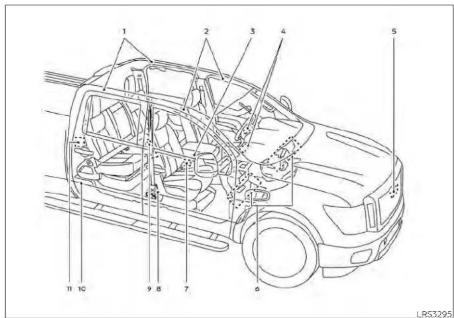
Supplemental air bag system
-
Roof-mounted curtain side-impact and rollover supplemental air bags inflators
-
Roof-mounted curtain side-impact and rollover supplemental air bags
-
Air bag Control Unit (ACU)
-
Supplemental front-impact air bag modules
- Crash zone sensor
- Driver and passenger supplement knee air bags
- Seat belt buckle switches
- Seat belt with pretensioner(s) (front seats) (passenger's side shown; driver's side similar)
- Front seat-mounted side-impact supplemental air bag modules (passenger's side shown; driver's side similar)
- Satellite sensors (passenger's side shown; driver's side similar)
- Seat belt with pretensioner(s) (rear outboard seats) (passenger's side shown; driver's side similar)
This vehicle is equipped with supplemental front air bag system for the driver and right front passenger seats. This system is designed to meet certification requirements under U.S. regulations. It is also permitted in Canada. However, alloftheinformation, cautions and warnings in this manual stillapplyandmustbefollowed.
The driver supplemental front-impact air bag is located in the center of the steering wheel. The front passenger supplemental front-impact air bag is mounted in the dashboard above the glove box. The supplemental front air bags are designed to inflate in higher severity frontal collisions, although they may inflate if the forces in another type of collision are similar to those of a higher severity frontal impact. They may not inflate in certain frontal collisions. Vehicle damage (or lack of it) is not always an indication of proper front air bag system operation.
The supplemental air bag system monitors information from the crash zone sensor, the Air bag Control Unit (ACU) and seat belt buckle sensors that detect if the seat belts are fastened. Inflator operation is based on the severity of a collision and whether the seat belts are being used. Only one front air bag may inflate in a crash, depending on the crash severity and whether the front occupants are belted or unbelted. This does not indicate improper performance of the system. If you have any questions about the performance of your air bag system, it is recommended that you visit a NISSAN dealer to obtain information about the system. If you have any questions about your air bag system, it is recommended that you visit a NISSAN dealer to obtain information about the system. If you are considering modification of your vehicle due to a disability, you may also contact NISSAN. Contract Information is contained in the beginning of this Owner's Manual.
When a front air bag inflates, a fairly loud noise may be heard, followed by the release of smoke. This smoke is not harmful and does not indicate a fire. Care should be taken to not inhale it, as it may cause irritation and choking. Those with a history of a breathing condition should get fresh air promptly.
Front air bags, along with the use of seat belts, help to cushion the impact force on the face and chest of the driver and right front passenger. They can help save lives and reduce serious injuries. However, an inflating front air bag may cause facial abrasions or other injuries. Front air bags, other than the driver's knee air bag, do not provide restraint to the lower body.
Seat belts should be correctly worn and the driver and passenger seated upright as far as practical away from the steering wheel or instrument panel. The front air bags inflate quickly in order to help protect the front occupants. Because of this, the force of the front air bag inflating can increase the risk of injury if the occupant is too close to, or is against, the front air bag module during inflation.
The front air bags deflate quickly after a collision.
Thefrontairbagsoperateonlywhenthe ignitionswitchisintheONposition.
Afterplacingtheignitionswitchinthe QN position, the supplemental air bag warninglightilluminates. Thesupplementalairbagwarninglightwillturnoff after about7secondsifthesystemis operational.
WARNING
Do not place any objects on the steeringwheelpadorontheinstrumentpanel.Also,do notplaceany objectsbetweenanyoccupant and the steering wheel or instrument panel. Such objects may become dangerousprojectilesandcauseinjuryifthefrontairbaginflates. Immediately after inflation, several frontairbagsystemcomponentswill behot.Donottouchthem;youmay severelyburnyourself.
Safety-Seats, seatbeltsandsupplementalrestraintsystem1-77
- Nounauthorizedchangesshouldbe madetoanycomponentsorwiring ofthesupplementalairbagsystem. Thisistopreventaccidentalinflation ofthesupplementalairbagordamagetothesupplementalairbag system.
- Donotmakeunauthorizedchanges toyourvehicle'selectricalsystem, suspensionsystemorfrontend structure. This could affect proper operation of the frontairbagsystem.
- If your vehicle has front recovery hooks as original factory equipment, do not remove or modify them. If it was not equipped with front recovery hooks, do not install them. Either action could affect proper operation of the front air bags system resulting in injury or death.
-
Tamperingwiththefrontairbagsystem may result in serious personal injury.Tampering includes changes tothesteeringwheelandtheinstrumentpanel assembly byplacing materialover the steeringwheel pad and abovethe instrument panelor byinstallingadditionaltrimmaterial aroundtheairbagsystem.
-
Nounauthorizedchangesshouldbe madetoanycomponentsorwiring oftheseatbeltsystem. This may affect the front airbagsystem. Tampering with the seat belt system may result in serious personal injury.
- It is recommended that you visit a NISSAN dealerforworkon and around the front air bag. It is also recommended that you visit a NISSAN dealerforinstallationofelectrical equipment. The Supplemental Restraint System(SRS) wiring harness should not be modified or disconnected. Unauthorized electrical test equipment and probing devices should not be used on the air bag system.
- Acracked windshield should be replaced immediately by a qualified repair facility. A cracked windshield could affect the function of the supplemental air bagsystem.
*The SRSwiringharnessconnectorsare yellowandorangeforeasyidentification.
When selling your vehicle, we request that you inform the buyer about the front air bag system and guide the buyer to the appropriate sections in this Owner's Manual.

natural_image
Line drawing of a car interior with three seats and a backrest, no text or symbols presentFRONT SEAT-MOUNTED SIDE-IMPACT SUPPLEMENTAL AIR BAG AND ROOF-MOUNTED CURTAIN SIDE-IMPACT AND ROLLOVER SUPPLEMENTAL AIR BAG SYSTEMS
The side air bags are located in the outside of the seatback of the front seats. The curtain air bags are located in the side roof rails. Alloftheinformation,cautionsand warningsinthismanualmustbefol- lowed.The side air bags and curtain air bags are designed to inflate in higher severity side collisions, although they may inflate if the forces in another type of collision over, an inflating side air bag or curtain air are similar to those of a higher severity bag may cause abrasions or other injuries. impact. They are designed to inflate on the side air bags and curtain air bags do not side where the vehicle is impacted. They provide restraint to the lower body.
Curtain air bags are also designed to inflate the driver and front passenger seated in certain types of rollover collisions or near upright as far as practical away from the rollovers. As a result, certain vehicle move-side air bag. Rear seat passengers should ments (for example, during severe off-be seated as far away as practical from the roading) may cause the curtain air bags to door finishers and side roof rails. The side inflate. air bags and curtain air bags inflate quickly
Vehicle damage (or lack of it) is not always an indication of proper side air bag and curtain air bag operation.
When the side air bags and curtain air bags inflate, a fairly loud noise may be heard, followed by release of smoke. This smoke is not harmful and does not indicate a fire. Care should be taken not to inhale it, as if may cause irritation and choking. Those with a history of a breathing condition should get fresh air promptly.
Side air bags, along with the use of seat belts, help to cushion the impact force on the chest of the front occupants. Curtain air bags help to cushion the impact force the head of occupants in the front and re outboard seating positions. They can help save lives and reduce serious injuries. How
The seat belts should be correctly worn tend the driver and front passenger seated upright as far as practical away from the side air bag. Rear seat passengers should be seated as far away as practical from the door finishers and side roof rails. The side air bags and curtain air bags inflate quickly in order to help protect the occupants. Because of this, the force of the side air bag and curtain air bag inflating can increase the risk of injury if the occupant is too close so, or is against, these air bag modules during inflation. The side air bag will deflate quickly after the collision is over. The curtain air bags will remain inflated for a short time.
Thesideairbagsandcurtainairbags operateonlywhentheignitionswitchis intheONposition.
Afterplacingtheignition switchinthe ON position, the supplemental air bag warninglightilluminates.Thesupplementalairbagwarninglightwillturnoff afterabout7secondsifthesystemis operational.
WARNING
- Donotplaceanyobjectsnearthe seatbackofthefrontseats.Also,do notplaceanyobjects(anumbrella, bag,etc.)betweenthefrontdoorfinisherandthefrontseat.Suchobjects maybecomedangerousprojectiles andcauseinjuryifasideairbag inflates.
- Rightafterinflation,severalsideair bagandcurtainairbagsystemcomponentswillbehot.Donottouch them;youmayseverelyburn yourself.
- No unauthorized changes should be madetoanycomponentsorwiring ofthesideairbagandcurtainairbag systems. Thisistopreventdamage tooraccidental inflationoftheside airbagandcurtainairbagsystems.
-
Donotmakeunauthorizedchanges toyourvehicle'selectricalsystem, suspension system or side panel. This could affect proper operation of the curtainairbagsystems.
-
Tamperingwiththe sideairbag systemmayresultinseriouspersonal injury. Forexample, donotchange thefrontseatsbyplacingmaterial neartheseatbacksorbyinstalling additionaltrimmaterial, suchasseat covers, aroundthesideairbag.
- It is recommended that you visit a NISSAN dealer for work on and around the side air bag and curtain air bag. It is also recommended that you visit a NISSAN dealer for installation of electrical equipment. The SRS wiring harnesses should not be modified disconnected. Unauthorized electrical testing equipment and probing device should not be used on the side air bag or curtain air bag systems.
\*The SRSwiringharnessorconnectors are yellowororangeforeasyidentification.
When selling your vehicle, we request that you inform the buyer about the side air and curtain air bag systems and guide to buyer to the appropriate sections in this Owner's Manual.
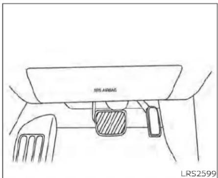
natural_image
Line drawing of a car interior showing the rearview seat, dashboard, and steering wheel (no text or symbols)Driver'sside
DRIVER AND PASSENGER SUPPLEMENTAL KNEE AIR BAG
The knee air bag is located in the knee bolster, on the driver's and passenger's side. Allof theinformation,cautionsand warningsinthismanualapplyandmust
be followed. The knee air bag is designed to inflate in higher severity frontal collisions, although it may inflate if the forces in another type of collision are similar to those of a higher severity frontal impact. It may not inflate in certain collisions.

natural_image
Simple line drawing of a mechanical or architectural component with no visible text, numbers, or symbols.Passenger'sside
Vehicle damage (or lack of it) is not always an indication of proper knee air bag operation.
When the knee air bag inflates, a fairly loud noise may be heard, followed by release of smoke. This smoke is not harmful and does not indicate a fire. Care should be taken not to inhale it, as it may cause irritation and choking. Those with a history of a breathing condition should get fresh air promptly.
The knee air bag helps to cushion the impact force on the knees of the driver and passenger. It can help reduce serious injuries. However, an inflating knee air bag may cause abrasions or other injuries. The knee air bag provides restraint to the lower body. The knee air bag inflates quickly in order to help protect the occupants. Because of this, the force of the knee air bag inflating can increase the risk of injury if the occupant is too close to, or is against, this air bag module during inflation. The knee air bag will deflate quickly after the collision is over OR the knee air bag will remain inflated for a short time.
Thekneeairbagoperatesonlywhenthe powerswitchisplacedintheON position.
AfterplacingthepowerswitchintheON position,thesupplementalairbagwarninglightilluminates.Thesupplemental airbagwarninglightwillturnoffafter about 7 seconds if the system is operational.
WARNING
Donotplaceanyobjectsbetweenthe kneebolsterandthedriver'sorpassenger'sseat.Suchobjectsmaybe-come dangerous projectiles and causeinjuryifakneeairbaginflates. Rightafterinflation,thekneeairbag systemcomponents willbe hot.Do nottouch them; you mayseverely burnyourself.
Nounauthorizedchangesshouldbe madetoanycomponentsorwiring ofthekneeairbagsystem. Thisisto preventdamagetooraccidentalinflationofthekneeairbagsystem.
- Donotmakeunauthorizedchanges toyourvehicle'selectricalsystemor suspensionsystem. This could affect properoperationofthekneeairbag system.
- Tamperingwiththekneeairbagsystem may result in serious personal injury. For example, do not change thedriverorpassengerkneebolster or install additional trim material aroundthekneeairbag.
- Itisrecommendedthatyouvisita NISSANdealerforworkonand aroundthekneeairbag.ItisalsorecommendedthatyouvisitaNISSAN dealerforinstallationofelectrical equipment.TheSRSwiringharnesses*shouldnotbemodifiedor disconnected.Unauthorizedelectricaltestequipmentandprobingdevices shouldnotbeusedontheknee airbagsystem.
\*The SRSwiringharnessorconnectors are yellowororangeforeasyidentification.
When selling your vehicle, we request that you inform the buyer about the knee air bag system and guide the buyer to the appropriate sections in this manual.
SEAT BELT WITH PRETENSIONER(s) (front seats and rear outboard seats)
WARNING
- The pretensioner(s) cannot be re-used after activation. They must be replaced together with the retractor and buckle as a unit.
- Ifthevehiclebecomesinvolvedina collisionbutpretensioner(s)arenot activated,besuretohavethepretensionersystemcheckedand,ifnecessary,replaced.It is recommended thatyouvisitaNISSANdealerforthis service.
- Nounauthorizedchangesshouldbe madetoanycomponentsorwiring ofthepretensionersystem.Thisisto preventdamagetooraccidentalactivationofthepretensioner(s).Tamperingwiththepretensionersystem mayresultinseriouspersonalinjury.
- Itisrecommendedthatyouvisita NISSANdealerforworkonand aroundthepretensionersystem.Itis alsorecommendedthatyouvisita NISSANdealerforinstallationofelectricalequipment.Unauthorizedelectricaltestequipmentandprobing devicesshouldnotbeusedonthe pretensionersystem.
- If you need to dispose of the pretensioner(s) or scrap the vehicle, it is recommended that you visit a NISSAN dealer forth this service. Incorrect disposal procedures could cause personal injury.
The pretensioner system may activate with the supplemental air bag system in certain types of collisions. Working with the seat belt retractor, the pretensioner(s) help tighten the seat belt when the vehicle becomes involved in certain types of collisions, helping to restrain front and rear outboard seat occupants.
The pretensioner(s) are encased within the seat belt retractor and to the seat belt anchor affixed to the floor of the vehicle. These seat belts are used the same way as conventional seat belts.
When pretensioner(s) activate, smoke is released and a loud noise may be heard. This smoke is not harmful and does not indicate a fire. Care should be taken not to inhale it, as it may cause irritation and choking. Those with a history of a breathing condition should get fresh air promptly.
After the pretensioner(s) activation, load limiters allow the seat belt to release webbing (if necessary) to reduce forces against the chest.
The supplemental air bag warning light is used to indicate malfunctions in the pretensioner system. For additional information, see "Supplemental air bag warning
light" (P. 1-83). If the operation of the supplemental air bag warning light indicates there is a malfunction, have the system checked. It is recommended that you visit NISSAN dealer for this service.
When selling your vehicle, we request that you inform the buyer about the pretensioner system and guide the buyer to the appropriate sections in this Owner's Manual.

natural_image
Line drawing of a car interior showing steering wheel, dashboard, and steering wheel (no text or symbols)- SRS Air bag warning labels The warning labels are located on the surface of the sun visor.
SUPPLEMENTAL AIR BAG WARNING LABELS
Warning labels about the supplemental front-impact air bag system are placed in the vehicle as shown in the illustration.
WARNING
Donotusearear-facingchildrestraint onaseatprotectedbyanairbagin frontofit.Iftheairbagdeploys,itmay causeseriousinjuryordeath.

natural_image
Simple black stick figure in motion, no text or symbols presentSUPPLEMENTAL AIR BAG WARNING LIGHT
The supplemental air bag warning light, displaying ⚙ in the instrument panel, monitors the circuits for the air bag systems, pretensioner(s) and all related wiring. When the ignition switch is placed in the ON position, the supplemental air bag warning light illuminates for about 7 seconds and then turns off. This means the system is operational.
If any of the following conditions occur, the front air bag, side air bag, curtain air bag, knee air bag and pretensioner systems need servicing:
- The supplemental air bag warning light remains on after approximately 7 seconds.
- The supplemental air bag warning light flashes intermittently.
- The supplemental air bag warning light does not come on at all.
Under these conditions, the front air bag, side air bag, curtain air bag or pretension systems may not operate properly. They must be checked and repaired. It is recommended that you visit a NISSAN dealer for this service.
WARNING
If the supplemental airbag warning lightison, it could mean that the front airbag, side airbag, curtain airbag, knee airbag and or pretension systems will not operate in an accident. To help avoid injury to yourself for others, have your vehicle checked as soon as possible. It is recommended that you visit a NISSAN dealer forth this service.
PREPAIR AND REPLACEMENT PROCEDURE
The front air bags, side air bags, curtain air bags, knee air bags and pretensioner(s) are designed to inflate on a one-time-only basis. As a reminder, unless it is damaged, the supplemental air bag warning light remains illuminated after inflation has occurred. These systems should be repaired and/or replaced as soon as possible. It is recommended that you visit a NISSAN dealer for this service.
When maintenance work is required on the vehicle, the front air bags, side air bags, curtain air bags, knee air bags, pretensioner(s) and related parts should be pointed out to the person performing the maintenance. The ignition switch should always be placed in the LOCK position when working under the hood or inside the vehicle.
WARNING
Onceafrontairbag,sideairbag,curtainairbagorkneeairbaghasin-flated,theairbagmodulewillnot functionagainandmustbereplaced. Additionally,the activatedpretensioner(s)mustalsobereplaced.The airbagmoduleandpretensioner(s) shouldbe replaced. It isrecommended that you visit a NISSAN dealerforthisservice.However,the airbagmoduleandpretensioner(s) cannotberepaired.
- Thefrontairbag,sideairbag,curtain airbagandkneeairbagsystemsand thepretensionersystemshouldbe inspectedifthereisanydamageto thefrontendsideportionofthe vehicle. It is recommended that you visitaNISSANdealerforthisservice.
- If you need to dispose of the supplemental air bag or pretension systems or scrap the vehicle, it is recommended that you visit a NISSAN dealer. Incorrect disposal procedures could cause personal injury.
- Ifthereisanimpacttoyourvehicle fromanydirection,yourOccupant ClassificationSensor(OCS)(ifso equipped)shouldbecheckedto verifyitisstillfunctioningcorrectly.It isrecommendedthatyouvisita NISSANdealerforthisservice.The OCS(weightsensor)(ifsoequipped) shouldbecheckedevenifnoairbags deployasaresultoftheimpact.Failure-troverifyproperOCS(weightsensor)(ifsoequipped)functionmayresultinanimproperairbag deploymentresultinginjuryor death.
Safety-Seats, seatbelts and supplemental restraintsystem 1-85
MEMO
2Instrumentsandcontrols
Instrument panel....2-4
Meters and gauges 2 - 6
Speedometer and odometer 2 - 6
Tachometer 2-8
Engine coolant temperature gauge 2-8
Fuel gauge 2-9
Distance To Empty (DTE) 2-9
Auxiliary gauges (if so equipped) 2-10
Off-road and 4-Wheel Drive (4WD)
monitor (if so equipped) 2-11
Warning lights, indicator lights and audible
reminders 2-12
Checking lights 2-13
Warning/Indicator lights (red) 2-13
Warning/Indicator lights (yellow) 2-17
Warning/Indicator lights (other) 2-21
Audible reminders 2-22
Vehicle information display 2-23
How to use the vehicle information
display 2-23
Startup display 2-24
Settings 2-24
Vehicle information display warnings
and indicators....2-32
Security systems 2-38
Vehicle security system 2-38
NISSAN Vehicle Immobilizer System .....2-39
Wiper and washer switch 2-41
Switch operation 2-41
Rain-sensing auto wiper system (if so equipped) 2-42
Rear window and/or outside mirror defroster
switch (if so equipped) 2-43
Headlight switch 2-44
Headlight control switch 2-44
Daytime Running Lights (DRL) system
(Type A) (if so equipped) 2-50
LED Daytime Running Lights (DRL)
system (Type B) (if so equipped) 2-51
Instrument brightness control 2-51
Turn signal switch 2-52
Fog light switch (if so equipped) 2-52
Horn 2-53
Cargo lamp switch (if so equipped)....2-53
Climate controlled seat switches
(if so equipped)....2-54
Heated seat switches (if so equipped) .....2-55
Heated rear seat switches (if so equipped) .....2-56
Heated steering wheel switch (if so equipped) .. 2-57
Warning systems switch 2-58
Vehicle Dynamic Control (VDC) OFF switch .....2-59
Hill descent control switch (if so equipped) .....2-59
Electronic locking rear differential (E-Lock)
system switch (if so equipped) 2-61
Power inverter switch (if so equipped) 2-62
Parking Aids system switch 2-63
Tow mode switch 2-63
Emergency call (SOS) button (if so equipped) . . . 2-64
Trailer Brake Controller Unit (TBCU)
(if so equipped) 2-64
Rear Door Alert 2-65
Power outlets 2-66
12v Outlets 2-66
120v outlets (if so equipped) 2-67
Extended storage switch 2-69
Storage 2-70
Front-door pockets 2-70
Rear-door pockets 2-71
Console side pockets (if so equipped) ..... 2-71
Seatback pockets 2-71
Under-seat storage (if so equipped) 2-72
Console box storage trays
(if so equipped) 2-73
Cell phone storage tray (if so equipped) ..... 2 - 7 4
Glovebox 2-74
Console box (if so equipped) 2 - 7 4
Center armrest storage (if so equipped) ..... 2-75
Under front seat storage bin
(if so equipped) 2-76
Overhead sunglasses storage
(if so equipped) 2-76
Cup holders 2-77
Grocery hooks (if so equipped) 2-80
Bed liner storage bins (if so equipped) ..... 2-80
Cargo hooks (if so equipped) 2-81
C-Channel cargo hooks (if so equipped) ..... 2-81
Windows 2-82
Power windows 2-82
Rear power window switch
(if so equipped) 2-84
Rear sliding window (if so equipped) ..... 2-85
Moonroof (if so equipped) 2-86
Power moonroof 2-86
Interior lights 2-88
Console light (if so equipped) 2-89
Map lights (if so equipped) 2-90
Personal Lights (if so equipped) 2-90
HomeLink® Universal Transceiver
(if so equipped) 2-90
Programming HomeLink ® 2-91
Programming HomeLink® for Canadian
customers and gate openers 2-93
Operating the HomeLink® Universal
Transceiver 2-93
Programming trouble-diagnosis 2-93
Clearing the programmed information ..... 2-94
Reprogramming a single HomeLink®
button 2-94
If your vehicle is stolen 2-94
INSTRUMENTPANEL

- Vents (P. 4-28)
-
Turn signal switch (P. 2-52) Wiper and washer switch (P. 2-41)
-
Steering wheel switch for audio control* Bluetooth® Hands-Free Phone System* Vehicle information display controls (P. 2-23)
-
Driver supplemental air bag (P. 1-53) Horn (P. 2-53)
-
Meters and gauges (P. 2-6) Warning and indicator lights (P. 2-12) Vehicle information display (P. 2-23)
-
Cruise control switches (if so equipped) (P. 5-50) Intelligent Cruise Control (ICC) switches (if so equipped) (P. 5-52)
-
Shift lever (P. 5-18) Tow mode switch (P. 2-63)
-
Audio controls*
-
Center display (P. 4-10)
-
Climate controls (P. 4-28)
-
Front passenger supplemental air bag (P. 1-53)
-
Glove box (P. 2-74)
-
Front passenger supplemental knee air bag (if so equipped) (P. 1-53)
-
Front passenger air bag status light (if so equipped) (P. 1-64)
-
Power outlet (P. 2-66)
-
Climate control seat switch (if so equipped) (P. 2-54) Heated front seat switches (if so equipped) (P. 2-55)
-
Heated steering wheel switch (if so equipped) (P. 2-57) Warning systems switch (P. 2-58)
-
USB ports*
-
Hazard warning flasher switch (P. 6-2)
2-4 Instrumentsandcontrols
-
Parking Aids system switch (P. 2-63) Vehicle Dynamic Control (VDC) OFF switch (P. 2-59)
-
Trailer Brake Controller Unit (TBCU) (if so equipped) (P. 2-64)
-
4WD shift switch (if so equipped) (P. 5-113)
-
Push-button ignition switch (P. 5-13)
-
Driver supplemental knee air bag light (if so equipped) (P. 1-53)
-
Tilt and telescopic steering wheel control (P. 3-27)
-
Parking brake (P. 5-24)
-
Hood release (P. 3-24)
-
Headlight aiming control (if so equipped) (P. 2-44) Power inverter switch (if so equipped) (P. 2-62) Cargo lamp switch (P. 2-53) Electronic locking rear differential (E-Lock) system switch (if so equipped) (P. 2-61) Hill descent control system switch (if so equipped) (P. 2-59)
-
Headlight switch (P. 2-44) Fog light switch (if so equipped) (P. 2-52) Instrument brightness control switches (P. 2-51) Trip reset switch (P. 2-6)
*Refer to the separate NissanConnect® Owner's Manual
Refertothe pagenumber indicated in parenthesisforoperatingdetails.
METERSANDGAUGES

-
Tachometer
-
Warning and indicator lights
-
Vehicle information display Odometer Outside temperature display
-
Speedometer
-
Fuel gauge
-
Engine coolant temperature gauge
2-6 Instrumentsandcontrols
SPEEDOMETER AND ODOMETER
This vehicle is equipped with a speedometer and odometer. The speedometer is located on the right side of the meter cluster. The odometer is located in the vehicle information display to the left of the speedometer and can be accessed with the vehicle in the ON position.

natural_image
Simple line drawing of a gauge or dial with needle pointing to the center (no text or symbols)
Speedometer
The speedometer indicates the vehicle speed.
Odometer/Twin trip odometer
The odometer and the twin trip odometer ① are displayed in the vehicle information display when the ignition switch is placed in the ON position.
The odometer records the total distance the vehicle has been driven.
The twin trip odometer records the distance of individual trips.
Changingthedisplay
Push the TRIP RESET switch② on the left side of the instrument panel to change the display as follows:
ODO →Trip □A →Trip □BDO
Resettingthetripodometer
Pushing the TRIP RESET switch ② for about 2 seconds resets the currently displayed trip odometer to zero.

TACHOMETER
The tachometer indicates engine speed in revolutions per minute (rpm). Do not rev the engine into the red zone.
CAUTION
Whenenginespeedapproachesthe redzone,reduceenginespeed.Operatingtheengineintheredzonemay causeseriousenginedamage.

ENGINE COOLANT TEMPERATURE GAUGE
The gauge indicates the engine coolant temperature. The engine coolant temperature is within the normal range① when the gauge needle points within the zone shown in the illustration.
The engine coolant temperature varies with the outside air temperature and driving conditions.
CAUTION
Ifthegaugeindicatescoolanttemperaturenearthehot(H)endofthe normalrange,reducevehiclespeedto decreasetemperature.Ifthegaugeis overthenormalrange,stopthevehicle assoonassafelypossible.Iftheengine isoverheated,continuedoperation of thevehiclemayseriouslydamagethe engine.Foradditionalinformation,see "Ifyourvehicleoverheats"(P.6-12)for immediateactionrequired.

FUEL GAUGE
The gauge indicates the approximate fuel level in the tank.
The gauge may move slightly during braking, turning, acceleration, or going up or down hills.
The gauge needle returns to 0 (Empty) af- the fuel tank, and the actual fuel ter the ignition switch is placed in the OFF consumption. position. Changes in driving patterns or conditions
The low fuel warning light comes on when can cause the DTE value to vary. As a result, the amount of fuel in the tank is getting lothe value displayed may differ from the actual distance that can be driven.
Refillthefueltankbeforethegaugeregisters0(Empty).
The ◄ indicates that the fuel-filler door DTE display will change to "---" when the is located on the driver's side of the vehicle fuel level in the tank is getting low, prior to the fuel gauge reaching 0 (Empty).
CAUTION
- Ifthevehiclerunsoutoffuel,the MalfunctionIndicatorLight(MIL)may comeon.Refuelassoonaspossible. Afterafewdrivingtrips.the light shouldturnoff.Ifthelightremainson afterafewdrivingtrips,havethevehicleinspected.Itisrecommended thatyouvisitaNISSANdealerforth this service.
- Foradditionalinformation,see"Mal-functionIndicatorLight(MIL)" (P.2-15).
DISTANCE TO EMPTY (DTE)
Displays the estimated distance the vehicle can be driven before refueling. The value is calculated based on recent fuel economy, the amount of fuel remaining in
the fuel tank, and the actual fuel consumption.
Changes in driving patterns or conditions
NOTE:
- The DTE value after refill is estimated based on recent fuel economy and amountoffueladded.
- If a small amount of fuel is added, or the ignition is on during refueling, the display may not be updated.
- Conditions that affect the fuel economywillalsoaffecttheestimated DTE value (city/highwaydriving, idle time,remotestart time, terrain,seasonalweather, addedvehicleweight, addeddeflectors,roofracks,etc.).

LIC4328
AUXILIARY GAUGES (if so equipped)
- Automatic Transmission fluid temperature gauge
- Voltmeter
- Engine oil pressure gauge
- Engine oil temperature gauge
AutomaticTransmissionfluid temperaturegauge
This gauge indicates the temperature of the automatic transmission fluid.
CAUTION
- Thisgaugeisnotdesignedtoindicatelowautomatictransmission fluidlevel.Usedhedipsticktocheck thefluidlevel.Foradditionalinformation,see"9-speedAutomatic TransmissionFluid(ATF)"(P.8-13).
- Ifthegaugeindicatesautomatic transmissionfluidtemperatureover thenormalrange,stopthevehcleas soonassafelypossible.Itisrecommended that you have the vehicle checkedbyaNISSANdealer.Continuedoperationofthevehiclemayseriouslydamagethetransmission.
Voltmeter
When the ignition switch is placed in the ON position, the voltmeter indicates the battery voltage. When the engine is running, indicates the generator voltage.
While cranking the engine, the volts drop below the normal range. If the range is not within the normal range (11 - 15 volts) while the engine is running, it may indicate that the charging system is not functioning properly. Have the system checked. It is recommended that you visit a NISSAN dealer for this service.
Engineoilpressuregauge
The gauge indicates the engine lubrication system oil pressure while the engine is running. The bar should be in the middle of the gauge when the engine is running.
CAUTION
- This gauge is not designed to indicate low engine oil level. Use the dipstick to check the oil level. For additional information, see "Engine oil" (P.8-7).
- If the gaugeneedledoesnotmove withtheproperamountofengineoil, itisrecommendedthatyouhavethe vehiclecheckedbyaNISSANdealer. Continuedvehicleoperationinsuch a conditioncouldcause seriousdamagetotheengine.
Engineoiltemperaturegauge
This gauge measures the temperature of the engine oil.

The Tire Angle & 4WD Gauge (right) indicates the angle of the tires based on turning of the steering wheel and 4WD status. The graphic image will show the actual vehicle tire position while the angle is to be displayed above as reference. The 4WD status is displayed below.
OFF-ROAD AND 4-WHEEL DRIVE (4WD) MONITOR (if so equipped)
The off-road and 4WD monitor displays the various conditions of the vehicle.
The Pitch and Roll Gauge (left) indicates the angle of the vehicle position left, right, up or down. The value will be displayed while the vehicle graphic will rotate to indicate vehicle condition: left, right, up or down.
WARNINGLIGHTS,INDICATORLIGHTS ANDAUDIBLEREMINDERS
| Warning/Indicatorlight(red)Warning/Indicatorlight(yellow)Warning/Indicatorlight(other) | |||
 Automatic Transmission Park warning light Automatic Transmission Park warning light  model) model) |  or or  Braking System (ABS) warning light Braking System (ABS) warning light |  |  |
| BRAKE or Brake warning light |  Automatic Emergency Braking (AEB) with Pedestrian Detection system warning light Automatic Emergency Braking (AEB) with Pedestrian Detection system warning light |  |  |
 Cha Cha  Warning Light Automatic Transmiss Warning Light Automatic Transmiss |  Lock warning light Lock warning light |  |  |
| Electric shift control system warning light |  Locking rear differential (E-Lock) system ON indicator light (if so equipped) Locking rear differential (E-Lock) system ON indicator light (if so equipped) | Side light and headlight indicator light (green) | |
 Eng Eng  reassure warning light Front pa reassure warning light Front pa |  Air bag status light (if so equipped) Air bag status light (if so equipped) |  |  |
 Ma Ma  Indicator Light (MIL) Hill desde Indicator Light (MIL) Hill desde |  Pol system ON indicator light (if so equipped) Pol system ON indicator light (if so equipped) |  |  |
 Ma Ma  Warning light Low tire pressure w Warning light Low tire pressure w |  | ||
 Seat belt warning light and chime Malfund Seat belt warning light and chime Malfund |  Iator Light (MIL) Iator Light (MIL) | ||
See  Ilicator light Master warning light Ilicator light Master warning light |  | ||
| Warning/Indicatorlight(red)Warning/Indicatorlight(yellow)Warning/Indicatorlight(other) | |
| Supplemental air bag warning light Rear | Automatic Braking OFF warning lightSlip indicator lightVehicle Dynamic Control (VDC) OFF indicator light |
CHECKING LIGHTS
With all doors closed, apply the parking brake, fasten the seat belts and place the ignition switch in the ON position without starting the engine. The following lights (if so equipped) will come on:

The following lights (if so equipped) will come on briefly and then go off:

If any light does not come on or operate in a way other than described, it may indicate a burned-out bulb and/or a system malfunction. Have the system checked. It is recommended that you visit a NISSAN dealer for this service.
Some indicators and warnings are also displayed on the vehicle information display between the speedometer and tachometer. For additional information, see "Vehicle information display" (P. 2-23).
WARNING/INDICATOR LIGHTS (red)
For additional information, see "Vehicle information display" (P. 2-23).
ATP Automatic Transmission Park warning light (3x4 model)
WARNING
If the 4WD mode indicator is off or the ATPwarninglightison, this indicates that the automatic transmission P (Park) position will not function and could result in the vehicle moving un-expectedly, causing serious personal injury or property damage. Always set the parking brake. For additional information, see "Using 4-wheel drive(4WD)" (P.5-107).
- IftheATPlightison, this indicates that the automatic transmission P (Park) position will not function and the transference case is in neutral.
- Whenparking,alwaysmakesurethat the4WDshiftindicatorlightilluminatesandtheparkingbrakeisset. Failuretoengagethetransferpositionin2WD,4Hor4LOcouldresultin thevehiclemovingunexpectedly,resultinginseriouspersonalinjuryor propertydamage.
- Shiftthe4WDswitchintothe2WD,4H or4LOpositionagaintoturnoffthe ATPwarninglightwhentheshiftleverisinthePpositionandtheATP warninglightison.(Beforeshifting the4WDswitchintothe4LOposition, movetheshiftlevertotheNposition once, shifttheshiftleverintoPagain andmakesuretheATPwarninglight isoff.)
This light indicates that the automatic transmission parking function is not engaged. If the transfer control is not secured in any drive position while the shift lever is in the P (Park) position, the transmission will disengage and the drive wheels will not lock.
BRAKE or Brake warning light
This light functions for both the parking brake and the foot brake systems.
Parkingbrakeindicator
When the ignition switch is placed in the ON position, the light comes on when the parking brake is applied.
Lowbrakefluidwarninglight
When the ignition switch is placed in the ON position, the light warns of a low brake fluid level. If the light comes on while the engine is running, with the parking brake not applied, stop the vehicle and perform the following:
- Check the brake fluid level. Add brake fluid as necessary. For additional information, see "Brake fluid" (P. 8-14).
- If the brake fluid level is correct, have the warning system checked. It is recommended that you visit a NISSAN dealer for this service.
WARNING
Yourbrakesystemmaynotbeworkingproperlyifthewarninglightison. Driving could be dangerous. If you judgeittobesafe,drivecarefullyto the nearestservicestation for repairs. Otherwise, have your vehicle towedbecausedrivingitcouldbe dangerous.
Pressingthebrakepedalwiththeenginestopped and/or allow brake fluid levelmay increaseyour stoppingdistance and brakingwill requiregreaterpedaleffortandpedal travel.
- Ifthebrakefluidlevelisbelowthe MINIMUMorMINmarkonthebrake fluidreservoir,donotdriveuntilthe brakesystemhasbeenchecked.Itis recommended that you visit a NISSANdealerforthisservice.

Charge warning light
If this light comes on while the engine is running, it may indicate the charging system is not functioning properly. Turn the engine off and check the generator belt. If the belt is loose, broken, missing, or if the light remains on, have the system checked. It is recommended that you visit a NISSAN dealer for this service.
CAUTION
- Donotgroundelectricalaccessories directlytothebatteryterminal.Doingsowillbypassthevariablevoltagecontrolsystem(ifsoequipped) andthevehiclebatterymaynot chargecompletely.Foradditionalinformation,see"Variablevoltagecontrolsystem"(P.8-19).
- Donotcontinuedrivingifthegeneratorbeltisloose,brokenormissing.

Electric shift control system warning light
This light illuminates when a malfunction occurs in the electric shift control system. When the master warning light illuminates, the chime sounds and the following message is displayed in the vehicle information display: "When parked apply parking brake". When the ignition is placed in the OFF position, the chime sounds continuously. Ensure the parking brake is applied
Have the system checked. It is recommended that you visit a NISSAN dealer for this service.

Engine oil pressure warning light
This light warns of low engine oil pressure the light flickers or comes on during normal driving, pull off the road in a safe area stop the engine immediately, and call a NISSAN dealer or other authorized repair shop.
Theengineoilpressurewarninglightis notdesignedtoindicatealowoillevel.
Use the dipstick to check the oil level. For additional information, see "Engine oil" (P. 8-7).
CAUTION
Runningtheenginewiththeengineoil pressurewarninglightoncouldcause seriousdamagetotheenginealmost immediately.Suchdamageisnotcoveredbywarranty.Turnofftheengineas soonasitissafetodoso.

Malfunction Indicator Light (MIL)
If this indicator light comes on steady or blinks while the engine is running, it may indicate a potential emission control malfunction.
If this indicator light comes on steady for 20 seconds and then blinks for 10 seconds when the engine is not running, it indicates that the vehicle is not ready for an emission control system inspection/maintenance test. For additional information, see 'Readiness for inspection/maintenance (I/M) test' (P. 10-59).
Operation
The MIL will come on in one of two ways:
- MIL on steady — An emission control system malfunction has been detected. Check the fuel-filler cap if the Loose Fuel Cap warning appears in the vehicle information display. If the fuel-filler cap is loose or missing, tighten or install the cap and continue to drive the vehicle. The light should turn off after a few driving trips. If the light does not turn off after a few driving trips, have the vehicle inspected. It is recommended that you visit a NISSAN dealer for this service. You do not need to have your vehicle towed to the dealer.
- MIL blinking — An engine misfire has been detected which may damage the emission control system. To reduce or avoid emission control system damage:
- do not drive at speeds above 45 mph (72 km/h).
- avoid hard acceleration or deceleration.
- avoid steep uphill grades.
- if possible, reduce the amount of carg being hauled or towed.
The MIL may stop blinking and come on steady. Have the vehicle inspected. It is recommended that you visit a NISSAN dealer for this service. You do not need to have your vehicle towed to the dealer.
CAUTION
Continuedvehicleoperationwithout havingtheemissioncontrolsystem checkedandrepaired as necessary couldleadtopoordriveability,reduced fueleconomy,andpossibledamageto theemissioncontrolsystem.

Master warning light
This light comes on when various vehicle information display warnings appear.
- Parking brake release warning
- Transmission system warning

Seat belt warning light and chime
The light and chime remind you to fasten your seat belts. The light illuminates when ever the ignition switch is placed in the O position and remains illuminated until the driver's seat belt is fastened. At the same time, the chime sounds for about 6 sec-
onds unless the driver's seat belt is securely fastened.
The seat belt warning light for the front passenger will illuminate if the seat belt is not fastened when the front passenger seat is occupied. The front passenger seat belt does not activate until 5 seconds after the ignition switch is placed in the ON position.
For additional information, see "Seat belts" (P. 1-16).

Security indicator light
This light blinks whenever the ignition switch is placed in the LOCK, OFF or ACC position. This function indicates the security system equipped on the vehicle is operational.
For additional information, see "Security systems" (P. 2-38).

Supplemental air bag warning light
-when the ignition switch is placed in the ON position, the supplemental air bag warning light illuminates for about 7 seconds and then turns off. This means the system is operational.
If any of the following conditions occur, the front air bag, side air bag, curtain air bag, and pretensioner seat belt systems need servicing:
- The supplemental air bag warning light remains on after approximately 7 seconds.
- The supplemental air bag warning light flashes intermittently.
- The supplemental air bag warning light does not come on at all.
It is recommended that you visit a NISSAN dealer for these services.
Unless checked and repaired, the supplemental restraint system (air bag system) and/or the pretensioner(s) may not function properly. For additional information, see "Supplemental Restraint System (SRS)" (P. 1-53).
WARNING
If the supplemental airbag warning lightison, it could mean that the front airbag, side airbag, curtain airbag and or pretensioners system will not operate in an accident. To help avoid injury to yourself for others, have your vehicle checked as soon as possible. It is recommended that you visit a NISSAN dealer forth this service.
eWARNING/INDICATOR LIGHTS (yellow)
For additional information, see "Vehicle Information display" (P. 2-23).

Anti-lock Braking System (ABS) warning light
When the ignition switch is placed in the ON position, the ABS warning light illuminates and then turns off. This indicates the ABS operational.
If the ABS warning light illuminates while the engine is running or while driving, it may indicate the ABS is not functioning properly. Have the system checked. It is recommended that you visit a NISSAN dealer for this service.
If an ABS malfunction occurs, the anti-lock function is turned off. The brake system then operates normally but without anti-lock assistance. For additional information, see "Brake system" (P. 5-117).

Automatic Emergency Braking (AEB) with Pedestrian Detection system warning light
This light comes on when the ignition switch is placed in the ON position. It turns off after the engine is started.
This light illuminates when the AEB with Pedestrian Detection system is set to OFF in the vehicle information display.
If the light illuminates when the AEB with Pedestrian Detection system is on, it may indicate that the system is unavailable. For additional information, see "Automatic Emergency Braking (AEB) with Pedestrian Detection" (P. 5-81).
AT CHECK Automatic Transmission check warning light
When the ignition switch is placed in the ON position, the light comes on for about 2 seconds. If the light comes on at any other time, it may indicate the automatic transmission system is not functioning properly. Have the system checked. It is recommended that you visit a NISSAN dealer for this service.
DIFF LOCK
Electronic locking rear differential (E-Lock) system ON indicator light (if so equipped)
This light comes on when the electronic locking rear differential (E-Lock) system clutch is fully engaged.
The indicator light flashes when the system is first turned on. When the system ful engages, the light remains on. If the switch is on and the indicator light continues to flash, the system is not engaged.
For additional information, see "Electronic locking rear differential (E-Lock) system switch" (P. 2-61) and "Electronic locking rear differential (E-Lock) system" (P. 5-114).

Front passenger air bag status light (if so equipped)
The front passenger air bag status light will be lit and the passenger front air bag will off depending on how the front passenger seat is being used.
For additional information, see "Front passenger air bag and status light" (P. 1-64).

Hill descent control system ON indicator light (if so equipped)
When the ignition switch is placed in the position, this light comes on briefly and then turns off.
The light comes on when the hill descent control system is activated.
the hill descent control switch is on and the indicator light blinks, the system may be disabled.
You may feel or hear the system working; this is normal.
If the indicator light does not come on when the hill descent switch is on, the system may not be functioning properly. Have the system checked. It is recommended that you visit a NISSAN dealer for this service.
For additional information, see "Hill descent control system ON indicator light" (P. 2-18) and "Hill descent control system" (P. 5-123).

Low tire pressure warning light
Your vehicle is equipped with a Tire Pressure Monitoring System (TPMS) that monitors the tire pressure of all tires except the spare.
The low tire pressure warning light warns of low tire pressure or indicates that the TPMS is not functioning properly.
After the ignition switch is placed in the ON position, this light illuminates for about 1 second and turns off.
Lowtirepressurewarning
Ifthevehicleisbeingdrivenwithlowtire pressure, the warninglightwillilluminate. A "TirePressure Low- AddAir" warningalsoappearsinthevehicleinformationdisplay.
Whenthelowtirepressurewarninglight illuminates,youshouldstopandadjust the tirepressureofallfourtirestothe recommendedCOLDtirepressureshown ontheTireandLoadingInformationlabellocatedinthedriver'sdooropening. Thelowtirepressurewarninglightdoes notautomaticallyturnoffwhenthetire pressureisadjusted.Afterthetireisinflated tothe recommended pressure,
thevehiclemustbedrivenatspeeds above16mph(25km/h)toactivatethe TPMSandturnoffthelowtirepressure warninglight.Useatirepressuregauge tocheckthetirepressure.
The "Tire Pressure Low - Add Air" warning appears each time the Ignition switch is placed in the ON position as long as the low tire pressure warning light remains illuminated.
For additional information, see "Vehicle information display" (P. 2-23), "Tire Pressure Monitoring System (TPMS)" (P. 5-5) or (P. 6-3).
TPMSmalfunction
If the TPMS is not functioning properly, the low tire pressure warning light will flash for approximately 1 minute when the ignition switch is placed in the ON position. The light will remain on after 1 minute. Have the system checked. It is recommended that you visit a NISSAN dealer for this service. The "Tire Pressure Low — Add Air" warning does not appear if the low tire pressure warning light illuminates to indicate a TPMS malfunction.
For additional information, see "Tire Pressure Monitoring System (TPMS)" (P. 5-5) and "Tire pressure" (P. 8-35).
WARNING
- Radiowavescouldadverselyaffect electric medical equipment. Those whoseapacemakershouldcontact theelectricmedicalequipment manufacturerforthepossibleinfluencesbeforeuse.
- Ifthelightdoesnotilluminatewith theignitionswitchplacedintheON position,havethevehiclecheckedas soonaspossible.Itisrecommended thatyouvisitaNISSANdealerforth this service.
- Ifthelightilluminateswhiledriving, avoidsuddensteeringmaneuversor abrupt braking, reduce vehicle speed,pullofftheroadtoasafelocationandstopthevehicleassoonas possible.Drivingwithunder-inflated tiresmaypermanentlydamagethe tires and increase the likelihood of tirefailure.Seriousvehicledamage couldoccurandmayleadtoanaccidentandcouldresultinseriouspersonalinjuryordeath.Checkthetire pressureforallfourtires.Adjustthe tirepressuretotherecommended COLDtirepressureshowontheTire and Loading Information label locatedinthedriver'sdooropeningto turn the low tire pressure warning lightoff.Ifthelightstillilluminates whiledrivingafteradjustingthetire pressure, a tire may be flat or the TPMSmaybemalfunctioning.Ifyou haveaflattire,replaceitwithaspare tireassoonaspossible.Ifnotireis flatandalltiresareproperlyinflated, havethevehiclechecked.Itisrecommended that you visit a NISSAN dealerforthisservice.
- Whenusingawheelwithoutthe TPMSsuchasthesparetire,theTPMS willnotfunctionandthelowtire pressurewarninglightwillflashfor approximately1minute.Thelightwill remainonafter1minute.Haveyour tiresreplacedand/orTPMSsystem resetassoonaspossible.itisrecommendedthatyouvisitaNISSAN dealerfortheseservices.
- ReplacingtireswiththosenotoriginallyspecifiedbyNISSANcouldaffecttheproperoperationofthe TPMS.
CAUTION
- TheTPMSisnotasubstituteforthe regulartirepressurecheck.Besure tocheckthetirepressureregularly.
- Ifthevehicleisbeingdrivenat speedsoflessthan16mph(25km/h), theTPMSmaynotoperatecorrectly.
- Besuretoinstallthespecifiedsizeof tirestothefourwheelscorrectly.

Malfunction Indicator Light (MIL)
If this Indicator light comes on steady or blinks while the engine is running, it may indicate a potential emission control malfunction.
If this indicator light comes on steady for seconds and then blinks for 10 seconds when the engine is not running, it indicates that the vehicle is not ready for an emissi control system inspection/maintenance test. For additional information, see 'Readiness for inspection/maintenance (I/M) test' (P. 10-59).
Operation
The MIL will come on in one of two ways:
- MIL on steady – An emission control system malfunction has been detected. Check the fuel-filler cap if the Loose Fuel Cap warning appears in the vehicle information display. If the fuel-filler cap is loose or missing, tighten or install the cap and continue to drive the vehicle. The light should turn off after a few driving trips. If the light does not turn off after a few driving trips, have the vehicle inspected. It is recommended that you visit a NISSAN dealer for this service. You do not need to have your vehicle towed to the dealer.
- MIL blinking — An engine misfire has been detected which may damage the emission control system. To reduce or avoid emission control system damage:
- do not drive at speeds above 45 mph (72 km/h).
- avoid hard acceleration or deceleration.
- avoid steep uphill grades. - if possible, reduce the amount of cargo being hauled or towed.
The MIL may stop blinking and come on steady. Have the vehicle inspected. It is recommended that you visit a NISSAN dealer for this service. You do not need to have your vehicle towed to the dealer.
CAUTION
Continued vehicle operation without having the emission control system checked and repaired as necessary could lead to poor drive ability, reduced fueleconomy, and possible damage to the emission control system.

Master warning light
This light comes on when various vehicle information display warnings appear.
- No key warning
- Low fuel warning
- Low windshield-washer fluid warning
- Loose fuel cap warning
- Low tire pressure warning
- 4WD error (if so equipped)
- Front & rear tire size differences (if so equipped)

Rear Automatic Braking (RAB) system warning light
This light comes on when the ignition switch is placed in the ON position. It turns off after the engine is started.
This light illuminates when the RAB system is turned off in the vehicle information display.
If the light illuminates when the RAB system is on, it may indicate that the system unavailable. For additional information, see "Rear Automatic Braking (RAB)" (P. 5-76).

Slip indicator light
This indicator light will blink when the Vehicle Dynamic Control (VDC) system is operating, thus alerting the driver to the fact that the road surface is slippery and the vehicle is nearing its traction limits.
You may feel or hear the system working; this is normal.
The light will blink for a few seconds after the VDC system stops limiting wheel spin.
The indicator light also comes on when you place the ignition switch in the ON position. The light will turn off after approximately 2 seconds if the system is operational. If the light does not come on have the system checked. It is recommended that you visit a NISSAN dealer for this service.

Vehicle Dynamic Control (VDC) OFF indicator light
This indicator light comes on when the VDC OFF switch is pushed to off. This indicates the VDC system is not operating.
Push the VDC OFF switch again or restart the engine and the system will operate normally. For additional information, see "Vehicle Dynamic Control (VDC) system" (P. 5-120).
The VDC OFF indicator light also comes on when you place the ignition switch in the ON position. The light will turn off after about 2 seconds if the system is operational. If the light stays on or comes on along with the indicator light while you are driving, have the VDC system checked. It is recommended that you visit a NISSAN dealer for this service.
While the VDC system is operating, you might feel a slight vibration or hear the system working when starting the vehicle or accelerating, but this is normal.
WARNING/INDICATOR LIGHTS (other)
For additional information, see "Vehicle information display" (P. 2-23).

Front fog light indicator light (green) (if so equipped)
The front fog light indicator light illuminates when the front fog lights are on. For additional information, see "Fog light switch" (P. 2-52).

High Beam Assist indicator light (green)
This indicator light illuminates when the headlights come on while the headlight switch is in the AUTO position with the high beams selected. This indicates that the high beam assist is operational.
For additional information, see "Headlight switch" (P. 2-44).

High beam indicator light (blue)
This blue light comes on when the head-light high beams are on and goes out when the low beams are selected.
The high beam indicator light also comes on when the passing signal is activated.

Side light and headlight indicator light (green)
The side light and headlight indicator light illuminates when the side light or headlight position is selected. For additional information, see "Headlight switch" (P. 2-44).

TOW mode ON indicator light (green)
This light comes on when the tow mode function is on.

Turn signal/hazard indicator lights (green)
The appropriate light flashes when the turn signal switch is activated.
Both lights flash when the hazard switch is turned on.
AUDIBLE REMINDERS
Brake pad wear warning
The disc brake pads have audible wear warnings. When a disc brake pad requires replacement, it makes a high pitched scraping sound when the vehicle is in motion, whether or not the brake pedal is de
pressed. Have the brakes checked as soon as possible if the warning sound is heard.
Light reminder chime
With the ignition switch placed in the OFF position, a chime sounds when the driver's door is opened if the headlights or parking lights are on.
Turn the headlight control switch off before leaving the vehicle.
NISSAN Intelligent Key® door buzzer
The Intelligent Key door buzzer sounds if any one of the following improper operations is found.
• The Intelligent Key is left inside the vehicle when locking the doors.
- The Intelligent Key is taken outside the vehicle when operating the vehicle.
When the buzzer sounds, be sure to check both the vehicle and the Intelligent Key. For additional information, see "NISSAN Intelligent Key" (P. 3-2).
VEHICLEINFORMATIONDISPLAY

natural_image
Pure mechanical component diagram without any text, numbers, or symbols• Tire Pressure information
• Traffic Sign Recognition (if so equipped)
The vehicle information display is located to the left of the speedometer. It displays such items as:
- Vehicle settings
- Trip computer information
- Drive system warnings and settings (if so equipped)
• Cruise control system information - Blind Spot Warning (BSW) system
- Rear Cross Traffic Alert (RCTA) system
- NISSAN Intelligent Key® operation information
- Indicators and warnings

HOW TO USE THE VEHICLE INFORMATION DISPLAY
The vehicle information display can be navigated using the ENTER and button-▲ buttons located on the steering wheel.
- ENTER — press to select the vehicle information menu items. Additionally, use the UP/DOWN function to navigate the menu items
- ◀▶ — move LEFT/RIGHT to navigate through the items in the vehicle information display
The ENTER button also controls audio functions. For additional information, refer to the separate NissanConnect® Owner's Manual.
STARTUP DISPLAY
When the vehicle is placed in the ON or AQP (P. 2-24). (if so equipped) position, the vehicle information display may display the following screens:
- Speed
- Off Road
• Auxiliary Gauges (if so equipped) - Traffic Sign Recognition (if so equipped)
- Driving
- Fuel Economy
- Audio
- Navigation (if so equipped)
- Compass (if so equipped)
- Driving Aids
- Tire Pressures
- Warning Confirmation
- Settings
Warning Confirmation will only display if there are any warnings present. For additional information, see "Vehicle information display warnings and indicators" (P. 2-32).
To control which items display in the vehicle information display, see "Settings"
SETTINGS
The setting mode allows you to change the information displayed in the vehicle information display:
- Driver Assistance
- Meter Settings
- Vehicle Settings
- Towing Settings (if so equipped)
- Alerts
- Maintenance
- Unit
- Language
- Factory Reset
Driver Assistance
The driver assistance menu allows the user to change the various driving and parking aids.
Some menu items shown below may not be equipped on your vehicle.
| MenuitemExplanation | ||
| Lane Displays available lane options. | ||
| Warning (LDW) | Allows user to turn the Lane Departure Warning (LDW) system on or off. For additional information, see "Lane Departure Warning (LDW)" (P. 5-27). | |
| Blind Spot Displays available blind spot options. | ||
| Warning (BSW) | Allows user to turn the Blind Spot Warning (BSW) system on or off. For additional information, see "Blind Spot Warning (BSW)" (P. 5-32). | |
| Emergency Brake Displays available emergency brake options. | ||
| Front | Allows user to turn the front emergency braking system on or off. For additional information, see "Automatic Emergency Braking (AEB) with Pedestrian Detection" (P. 5-81) and "Intelligent Forward Collision Warning (I-FCW)" (P. 5-91). | |
| Rear | Allows user to turn the rear emergency braking system on or off. For additional information, see "Rear Automatic Braking (RAB)" (P. 5-76). | |
| Driver Attention | Allows user to turn the Intelligent Driver Alertness on or off. For additional information, see "Intelligent Driver Alertness (I-DA)" (P. 5-102). | |
| Traffic Sign | Allows use to turn the Speed Limit Sign recognition on or off. For additional information, see "Traffic Sign Recognition" (P. 5-24). | |
| Parking Aids | Displays available parking aids | |
| Moving Object | Allows user to turn the Moving Object Detection (MOD) on or off. For additional information, see "Moving Object Detection (MOD)" (P. 4-23). | |
| CTA | Allows user to turn the Rear Cross Traffic Alert (RCTA) system on or off. For additional information, see "Rear Cross Traffic Alert (RCTA)" (P. 5-42). | |
| Sensor | Allows the user to turn the sensors on, only the front sensors on, or turn the sensors off. | |
| Display | Allows user to turn the display on or off in the vehicle information display. | |
| Volume | Allows user to adjust the volume of warning chimes. | |
| Range | Allows user to set a specific range for the sensors to engage. | |
Meter Settings
The meter settings allow the user to change the settings for the vehicle information display.
Some menu items shown below may not be equipped on your vehicle.
| MenuitemExplanation | ||
| Main Menu Selection Allows user to customize the screens shown in the vehicle information display. | ||
| Speed Allows user to turn the speedometer screen on or off in the vehicle information display. | ||
| Off Road Allows user to turn the off road and 4WD monitor on or off in the vehicle information display. For additional information, see 'Off-Road and 4-Wheel Drive (4WD) Monitor' (P. 2-11). | ||
| Auxiliary Gauges | Allows user to turn the auxiliary gauges on or off in the vehicle information display. For additional information, see 'Auxiliary gauges' (P. 2-10). | |
| Driving Allows user to turn the drive computer screen on or off in the vehicle information display. | ||
| Speed Limit Sign Allows user to turn the speed limit sign screen on or off in the vehicle information display. | ||
| Fuel Economy Allows user to turn the fuel economy on or off in the vehicle information display. | ||
| Audio | Allows user to turn the audio screen on or off in the vehicle information display. For additional information, refer to the separate NissanConnect® Owner's Manual. | |
| Navigation | Allows user to turn the navigation on or off in the vehicle information display. For additional information, refer to the separate NissanConnect® Owner's Manual. | |
| Driving Aids | Allows user to turn the driving aids on or off in the vehicle information display. | |
| Tire Pressures Allows user to turn the tire pressures screen on or off in the vehicle information display. | ||
| TPMS | Allows user to set tire pressure targets. | |
| ECO Drive Report | Allows user to access the ECO drive report | |
| Display | Allows user to turn the ECO drive report on or off. | |
| ECO Drive Report | Allows user to view and reset ECO drive report history. | |
| Welcome Effect | Allows user to customize the available welcome effects. | |
| Dial Effect | Allows user to turn the dial effect on or off. | |
| Display Effect | Allows user to turn the display effect on or off. | |
Vehicle Settings
The vehicle settings allow the user to change the settings for lights, wipers, locking, keys, and other vehicle settings.
Some menu items shown below may not be equipped on your vehicle.
| MenuitemExplanation | |||
| Rear Door Alert Displays the available rear Door | Alert options. | ||
| Alert and Horn when selected, the alert | is displayed; and the horn sounds. | ||
| Alert Only When selected, only the alert | is displayed. | ||
| Off When selected, no alert or horn will be active. | |||
| Lighting Displays available lighting features of the vehicle. | |||
| Welcome Light Allows user to turn the | welcome light on or off. | ||
| Auto Room Lamp Allows user to turn the auto room lamp feature on or off. | |||
| Light Sensitivity Allows user to change when the lights illuminate based on the brightness outside the vehicle. | |||
| Light Off Delay | Allows user to change the duration of time that the automatic headlights stay on after the vehicle is shut off. | ||
| Turn Indicator | Displays available turn indicator options. | ||
| 3 Flash Pass | Allows user to turn the 3 flash pass on or off. | ||
| Locking | Displays available locking options. | ||
| I-Key Door Lock | Allows user to turn I-key door lock on or off. When turned on, the request switch on the door is activated. | ||
| Selective Unlock | Allows user to turn selective unlock on or off. When turned on, only the driver's door is unlocked after the door unlock operation. When the door handle request switch on the driver's or front passenger's side pushed to be unlocked, only the corresponding door is unlocked first. All the doors can be unlocked if door unlock operation is performed again within 1 minute. When this item is turned off, all the doors unlocked after the door unlock operation is performed once. | ||
| Answer Back. Horn | Allows user to turn answer back horn on or off. | ||
| Auto Unlock | Displays available options for the auto door unlock. | ||
| Off | Doors will have to be manually unlocked. | ||
| IGN Off | Doors will unlock when the ignition is turned off. | ||
| Shift P | Doors will unlock when the vehicle is shifted into P (Park). | ||
| Wipers Displays available wiper options. | |||
| Rain Sensor Allows user to turn the rain sensor feature on or off. For additional information, see "wiper and washer switch" (P. 2-41). | |||
| Speed Dependent | Allows user to turn the speed dependent feature on or off. For additional information, see "wiper and washer switch" (P. 2-41). | ||
| Headlamp On Displays available headlamp on options. | |||
| Off Headlights do not activate automatically when the wipers are activated. | |||
| Wiper Low & High Headlights activate when the wiper stalk is set to either low or high mode. | |||
| Wiper INT, Low & High Headlights activate when the wiper stalk is set to intermittent, low, or high mode. | |||
| Memory Seat (ADP) Displays available memory seat options. | |||
| Exit Seat Slide | Allows the user to turn the exit seat slide on or off. When turned on, this feature will move the driver's seat backward for an easy exit when the ignition is turned off and the driver's door is opened. After getting the vehicle and placing the ignition switch in the ACC position, the driver's seat will move to the previous position. For additional information, see "Memory Seat" (P. 3-39). | ||
| Exit Steering Up | Allows the user to turn the exit steering up feature on or off. When turned on, this feature will move the steering wheel upward for an easy exit when the ignition is turned off and the driver's door is opened. Afterting into the vehicle and placing the ignition switch in the ACC position, the steering wheel moves to previous position. For additional information, see "Memory Seat" (P. 3-39). | ||
| Reverse Tilt Mirror | Displays reverse tilt mirror information. | ||
Towing Settings (if so equipped)
The towing settings menu allows the user to access the trailer light check.
| MenuitemExplanation | |
| Trailer light check | Allows user to select a mode in which the vehicle will test various lights that could affect a trailer if connected properly. This feature can also be activated using the NISSAN Intelligent Key®. For additional information, see 'NISSAN Intelligent Key®' (P. 3-2) and 'Towing a trailer' (P. 10-33). |
Alerts
The alarm menu allows the user to set specific alarms for various items on the vehicle.
Some menu items shown below may not be equipped on your vehicle.
| MenuItemExplanation | |
| Timer Alert Allows user to set the timer alert alarm. | |
| Navigation Allows user to turn the navigation alarm on or off. | |
| Phone Allows user to turn the phone alarm on or off. | |
| Mail Allows user to turn the mail alarm on or off. | |
Maintenance
The maintenance menu allows the user to set reminders for various vehicle maintenance items.
Some menu items shown below may not be equipped on your vehicle.
WARNING
The tire replacement indicator is not a substitute for regular tire checks, including tire pressure checks. For additional information, see "Changing wheels and tires" (P. 8-43). Many factors including tire inflation, alignment, driving habits and road conditions affect tire wear and when tires should be replaced. Setting the tire replacement indicator for a certain driving distance does not mean your tires will last that long. Use the tire replacement indicator as a guide only and always perform regular tire checks. Failure to perform regular tire checks, including tire pressure checks could result in tire failure. Serious vehicle damage could occur and may lead to an collision, which could result in serious personal injury or death.
| MenuitemExplanation | ||
| Maintenance Allows user to cycle through various maintenance items and set reminders to perform maintenance at specific intervals. | ||
| Oil and Filter Allows user to set an oil and filter reminder at a specific interval or reset the current one. | ||
| Air Filter Allows user to set an air filter reminder at a specific interval or reset the current one. | ||
| Tire Allows user to set a tire reminder at a specific interval or reset the current one. | ||
| Brake Pad Allows user to set a brake pad reminder at a specific interval or reset the current one. | ||
| Brake Fluid Allows user to set a brake fluid reminder at a specific interval or reset the current one. | ||
| Battery Allows user to set a battery reminder at a specific interval or reset the current one. | ||
| Transmission Fluid | Allows user to set a transmission fluid reminder at a specific interval or reset the current one. | |
| Engine Coolant | Allows user to set an engine coolant reminder at a specific interval or reset the current one. | |
| Spark Plug | Allows user to set a spark plug reminder at a specific interval or reset the current one. | |
| Other | Allows user to set a reminder, other than for the maintenance items listed above, at a specific interval or reset the current one. | |
Unit
The unit menu allows the user to change the units shown in the vehicle information display.
| MenuitemExplanation | |
| Mileage Displays available mileage display units. | |
| Pressure Displays available pressure display units. | |
| Temperature Displays available temperature display units. |
Language
The language menu allows the user to change the languages displayed in the vehicle Information display.
| MenuitemExplanation | |
| Language Displays available language options for the vehicle information display. | |
Factory Reset
The factory reset menu allows the user to restore the vehicle information display settings to factory status.
| MenuitemExplanation | |
| Factory Reset | Allows user to reset the vehicle information display settings to the original factory settings. Once selected, the user can confirm or deny the reset. |
VEHICLE INFORMATION DISPLAY WARNINGS AND INDICATORS
The following messages may appear in your vehicle information display.

KeyBatteryLow
This indicator appears when the Intelligent Key battery is running out of power.
If this Indicator appears, replace the battery with a new one. For additional information, see "Battery replacement" (P. 8-27).

KeyIDIncorrect
This warning appears when the ignition switch is placed from the OFF position and the Intelligent Key is not recognized by the system. You cannot start the engine with an unregistered key.
For additional information, see "NISSAN Intelligent Key®" (P. 3-2).

KeySystemError:See Owner'sManual
After the ignition switch is placed in the OI position, this warning appears for a period of time and then turns off.
The Key System Error message warns of a malfunction with the Intelligent Key system. If the warning appears while the engine is stopped, it may be impossible to start the engine.
If the warning appears while the engine is running, you can drive the vehicle. However, in these cases, have the system checked. I is recommended that you visit a NISSAN dealer for this service.

NoKeyDetected
This warning appears when the Intelligent Key is left outside the vehicle with the ignition switch in the ON position. Make sure the Intelligent Key is inside the vehicle.
For additional information, see "NISSAN Intelligent Key®" (P. 3-2).
BatteryVoltageLowChargebattery
This warning appears when the battery is low and needs to be charged.
Brightnessindicator
This indicator appears when the vehicle information display screen brightness is being adjusted.

DoorOpen
This warning appears when a door has been opened.

FlatTire
This warning appears when the low tire pressure warning light in the meter illuminates and one or more flat tires are detected while driving.
FRT&RRtiresizedifference:See Owner'sManual
This warning may appear if there is a large difference between the diameters of the front and rear wheels. Pull off the road in a safe area, with the engine idling. Check that all the tire sizes are the same, that the tire pressure is correct and that the tires are not excessively worn. For additional information, see "Wheels and tires" (P. 8-35).
HeadlightSystemError:SeeOwner's Manual
This warning appears when the LED headlights are not functioning properly.
If this warning appears, have your system checked. It is recommended that you visit a NISSAN dealer for this service.

LooseFuelCap
This warning appears when the fuel-filler cap is not tightened correctly after the vehicle has been refueled. For additional information, see "Fuel-filler door" (P. 3-24).

LowFuel
This warning appears when the fuel level in when engine oil service is due, one or more the fuel tank is getting low. Refuel as soon of these icons will appear automatically to as it is convenient, preferably before the remind you. For additional information, see fuel gauge reaches 0 (Empty). Therewillbe "Engine oil" (P. 8-7).
asmallreserveoffuelinthetankwhen thefuelgaugeneedlereaches0(Empty).

LowTirePressureError—Info
This warning appears when the low tire pressure warning light in the meter illuminates and low tire pressure is detected. Press the ENTER button for information about the low tire pressure. For additional information, see "Low tire pressure warning light" (P. 2-18) and "Tire Pressure Monitoring System (TPMS)" (P. 5-5).

LowWasherFluid
This warning appears when the windshield-washer fluid is at a low level. Add windshield-washer fluid as necessary. For additional information, see "Windshield-washer fluid" (P. 8-15).

Maintenanceindicators
When engine oil service is due, one or more of these Icons will appear automatically to remind you. For additional information, see "Engine oil" (P. 8-7).
These will also appear when the user-set reminders are met. For additional information, see "Vehicle Information display" (P. 2-23).
Powerturnedofftosavethebattery
This warning appears after the ignition switch is automatically turned off to save the battery.
Powerwillturnofftosavethebattery
This message appears in the vehicle information display after a period of time if the ignition switch is in the ACC or the ON position and if the vehicle is in P (Park). For additional information, see "Push-button ignition switch positions" (P. 5-14).

BRAKE

Pushbrakeandstart buttontodrive
This indicator appears when the shift lever is in the P (Park) position.
This indicator means that the engine will start by pushing the ignition switch with the brake pedal depressed. You can start the engine from any position of the ignition switch.

PushIgnitiontoOFF
After the Push ignition to OFF warning appears, the warning will appear if the ignition switch is placed in the ACC position when the shift lever is moved to the P (Park) position.
To turn off the Push warning, place the ignition switch in the ON position and then in the LOCK position.

RangeXXmiles
This warning appears to indicate the approximate distance remaining before the fuel reaches 0 (Empty).
CheckRearSeatForAllArticles
When the system is enabled, this message appears when the vehicle comes to a complete stop, the vehicle is transitioned from the D (Drive) position to P (Park) position, and the driver exits the vehicle. This message alerts the driver, after a period of time to check for items in the rear seat after the audible alert has been provided.
NOTE:
This system is disabled until driver enablesit using the vehicle information display. For additional information, see "Howtousethe vehicle information display" (P.2-23).
For additional information, see "Rear Door Alert" (P. 2-65).
RearDoorAlertisactivated
When the system is enabled, this message appears when the Rear Door Alert system is active and can remind the driver to check the back seat.
- Using the steering wheel switch, a driver can select "Dismiss Message" to clear the display for a period of time. If no selection is made, this message automatically turns off after a period of time.
- Using the steering wheel switch, a driver can select "Disable Alert" to disable the horn alert for the remainder of the current trip.
WARNING
Selecting"DismissMessage"duringa stopwithinatriptemporarilydismissesthemessageforthatstopwithoutturningthesystemoff.Alertscan beprovidedforotherstopsduringthe trip.Selecting"DisableAlert"turnsoff theRearDoorAlertsystemfortheremainderofatripandnoaudiblealert willbeprovided.
NOTE:
This system is disabled until driver enablesitusing the vehicle information display. For additional information, "How to set the vehicle information display" (P.2-23).
For additional information, "Rear Door Alert (P. 2-65).
REAR Rearseatbeltreminder
This rear seat belt reminder appears after starting the engine.
If any of the rear passenger seat belts are not fastened, the seat belt icon illuminates in red to show which seat belt is not fastened. When a rear passenger's seat belt has been securely fastened, the color of the corresponding seat belt icon will change. The warning will automatically turn off after approximately 35 seconds.
A chime will sound one time and the rear seat belt warning will appear if a rear passenger's seat belt is unfastened. The chime will not sound when the vehicle speed exceeds 10 mph (15km/h). The seat belt icon illuminates in red until the corresponding rear passenger's seat belt is fastened. The warning will automatically turn off after approximately 35 seconds.
ReleaseParkingBrake
This warning appears in the message area of the vehicle information display when the parking brake is set and the vehicle is driven. Press the brake pedal to release the parking brake.

Reminder:TurnOFF Headlights
This warning appears when the headlights are left in the ON position when exiting the vehicle. Place the headlight switch in the OFF or AUTO position. For additional information, see "Headlight switch" (P. 2-44).


RemoteEngineStartMode
This warning appears in the vehicle information display when the vehicle has been started using the remote start function. To start the vehicle, apply the brake and place the ignition switch in the ON position.

ShifttoPark
This warning appears when the ignition switch is in the ACC or OFF position and t shift lever is not in the P (Park) position. All a chime sounds when the ignition switch i in the ACC or OFF position.
If this warning appears, move the shift level to the P (Park) position and start the engine
ShippingModeOnPushStorageFuse
This warning may appear if the extended storage switch is not pushed in. When this warning appears, push in the extended storage switch to turn off the warning. For additional information, see "Extended storage switch" (P. 2-69).

TirePressureLow-AddAir
This warning appears when the low tire pressure warning light in the meter illuminates and low tire pressure is detected. The warning appears each time the ignition switch is placed in the ON position as long as the low tire pressure warning light remains illuminated. If this warning appears, stop the vehicle and adjust the tire pressures of all four tires to the recommended KOLD tire pressure shown on the Tire and loading information label. For additional information, see "Low tire pressure warning light" (P. 2-18) and "Tire Pressure Monitoring System (TPMS)" (P. 5-5).
TPMSError:SeeOwner'sManual
This warning appears when there is an error with your TPMS. If this warning appears, have the system checked. It is recommended that you visit a NISSAN dealer for this service.
Whenparkedapplyparkingbrake
This message appears when a malfunction occurs in the electric shift control system below 3 mph (5 km/h).
Have the system checked. It is recommended that you visit a NISSAN dealer for this service.

4WDError:SeeOwner's Manual
This warning appears when the 4-wheel drive system is not functioning properly while the engine is running.

4WDshiftindicators
These indicators show which 4WD mode is selected. For additional information, see "Using 4-wheel drive (4WD)" (P. 5-107).
4WDMODESHIFTING
This message appears when the vehicle is shifting into 4WD. For additional information, see "Using 4-wheel drive (4WD)" (P. 5-107).

AT(Automatic Transmission)CHECK
If the service warning appears while the engine is running, or while driving, it may indicate that the AT is not functioning properly and may need servicing. Have the system checked, and if necessary, repaired promptly. It is recommended that you visit a NISSAN dealer for this service.
AT(AutomaticTransmission)Error: SeeOwner'sManual
If this message appears while the engine is running, or while driving, it may indicate that the AT is not functioning properly and may need servicing. Have the system checked, and if necessary, repaired promptly. It is recommended that you visit a NISSAN dealer for this service.
ServiceAT
This transmission has a high fluid temperature protection mode. If the fluid temperature becomes too high (for example, climbing steep grades in high temperatures with heavy loads, such as when towing a trailer), engine power and, under some conditions, vehicle speed will be decreased automatically to reduce the chance of transmission damage. Vehicle speed can be controlled with the accelera-
tor pedal, but the engine and vehicle speed may be reduced.
WARNING
When the high fluid temperature protection mode operation occurs, vehicle speed may be gradually reduced. The reduced speed may be lower than other traffic, which could increase the chance of a collision. Be especially careful when driving. If necessary, pull to the side of the road at a safe place and allow the transmission return to normal operation; or have it repaired if necessary.

AutomaticEmergency Braking(AEB)with PedestrianDetection emergencywarning indicator
This indicator appears along, with an audible warning, when the system detects the possibility of a forward collision.
"For additional information, see "Automatic Emergency Braking (AEB) with Pedestrian Detection" (P. 5-81).

BlindSpotWarning(BSW)/RearCrossTrafficAlert(RCTA)indicator
This indicator appears when the BSW and RCTA systems are engaged.
For additional information, see "Blind Spot Warning (BSW)" (P. 5-32) and "Rear Cross Traffic Alert (RCTA)" (P. 5-42).

Cruisecontrolindicator
This indicator shows the cruise control system status.
For additional information, see "Cruise control" (P. 5-50).
Currentlyunavailable
This message may appear when the Intelligent Cruise Control (ICC) system is engaged. Under the following conditions, the ICC system is automatically cancelled:
- When the VDC operates.
- When a wheel slips.
- When the VDC system is turned off.
The above system cannot be used in some situations (VDC operates, wheel slips, and VDC system is off).

DriverAttentionAlert—Malfunction
This warning appears when the Intelligent Driver Alertness (I-DA) system is not functioning properly. For additional information, see "Intelligent Driver Alertness (I-DA)" (P. 5-102).

DriverAttentionAlert—TakeaBreak?
This alert appears when the system has detected that the driver may be displaying fatigue or a lack of attention.
ForwardDrivingAidsTemporarily DisabledFrontSensorBlockedSee Owner'sManual
This message appears when the front radar sensor may be obstructed due to:
- mud, dirt, snow, ice, etc.
- inclement weather (rain, fog, snow, etc.)
All forward driving aids are temporarily disabled until the system detects that the front radar sensor is no longer obstructed.
For additional information, see:
• Automatic Emergency Braking (AEB) with Pedestrian Detection (P. 5-81)
• Intelligent Cruise Control (ICC) (P. 5-52)
- Intelligent Forward Collision Warning (I-FCW) (P. 5-91)
IntelligentCruiseControl (ICC)indicators
These indicators show the Intelligent
Cruise Control (ICC) system status. The sta-This message appears when the camera tus is shown by color. For additional infor- detects an interior temperature of more mation, see "Intelligent Cruise Control (ICC)" than approximately 104°F (40°C). (P. 5-52).

LaneDepartureWarning (LDW)indicator
This indicator appears when the LDW system is engaged.
For additional information, see "Lane Departure Warning (LDW)" (P. 5-27).
Malfunction
This warning appears when one or more of the following systems (if so equipped) is not functioning properly:
- Blind Spot Warning (BSW)
• Intelligent Cruise Control (ICC)
• Lane Departure Warning (LDW)
- Rear Cross Traffic Alert (RCTA)
• Traffic Sign Recognition (TSR)
If one or more of these warning appears, have the system checked. It is recommended that you visit a NISSAN dealer for this service.
NotAvailableHighCameraTemp
-This message appears when the camera detects an interior temperature of more than approximately 104°F (40°C).
For additional Information, see "Automatic Emergency Braking (AEB) with Pedestrian Detection" (P. 5-81), "Lane Departure Warning (LDW)" (P. 5-27) and "Traffic Sign Recognition" (P. 5-24).

ParkingSensor
This indicator appears when the sensor is activated. For additional information, see "Front and rear sonar system" (P. 5-124).

ParkingSensorError:See Owner'sManual
This warning appears when there is an error with the system. For additional information, see "Front and rear sonar system" (P. 5-124).
SECURITYSYSTEMS

RearAutomaticBraking (RAB)indicator
This indicator appears to indicate the status of the Rear Automatic Braking (RAB) system. For additional information, see "Rear Automatic Braking (RAB)" (P. 5-76).

SpeedLimitSignindicator
This message may appear when the Traffic Sign Recognition system is engaged.
For additional information, see "Traffic Sign Recognition" (P. 5-24).
SystemfaultSeeOwner'sManual
This warning appears if there is a malfunc-Emergency Braking (AEB) with Pedestrian tion in one of the following systems: Detection" (P. 5-81).
• Automatic Emergency Braking (AEB) with Pedestrian Detection
• Intelligent Forward Collision Warning (I-FCW)
- Rear Automatic Braking (RAB)
For additional Information, see "Automatic Emergency Braking (AEB) with Pedestrian Detection" (P. 5-81), "Intelligent Forward Collision Warning (I-FCW)" (P. 5-91) and "Rear Automatic Braking (RAB)" (P. 5-76).
UnavailableSideRadarObstruction
This message appears when the Blind Spot Warning (BSW) or Rear Cross Traffic Alert (RCTA) systems become unavailable because a radar blockage is detected. For additional information, see "Blind Spot Warning (BSW)" (P. 5-32) and "Rear Cross Traffic Alert (RCTA)" (P. 5-42).

Vehicleaheadetection indicator
This indicator appears when the Automatic Emergency Braking (AEB) system is engaged and has detected a vehicle.
For additional information, see "Automatic Emergency Braking (AEB) with Pedestrian Detection" (P. 5-81).
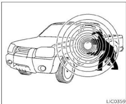
natural_image
Line drawing of a car with a large circular component and internal gear mechanism (no text or symbols)Your vehicle has two types of security systems:
- Vehicle security system
• NISSAN Vehicle Immobilizer System
VEHICLE SECURITY SYSTEM
The vehicle security system provides visual and audible alarm signals if someone opens the doors or hood when the system is armed. It is not, however, a motion detection type system that activates when a vehicle is moved or when a vibration occurs.
The system helps deter vehicle theft but cannot prevent it, nor can it prevent the theft of interior or exterior vehicle components in all situations. Always secure your vehicle even if parking for a brief period. Never leave your keys in the vehicle, and always lock the vehicle when unattended. Be aware of your surroundings, and park in secure, well-lit areas whenever possible.
Many devices offering additional protection, such as component locks, identification markers, and tracking systems, are available at auto supply stores and specialty shops. A NISSAN dealer may also offer such equipment. Check with your insurance company to see if you may be eligible for discounts for various theft protection features.
How to arm the vehicle security system
- Close all windows. (Thesystemcanbe armedevenifthewindowsareopen.)
- Remove the Intelligent Key from the vehicle.
-
Close all doors. Lock all doors. The doors can be locked with the Intelligent Key or door handle request switch.
-
Confirm that the ➕ security indicator light stays on for about 30 seconds. The vehicle security system is now pre-armed. The vehicle security system will automatically shift into the armed phase. The ➕ security light begins to flash once every three seconds. If during the pre-armed phase one of the following occurs, the system will not arm:
- Any door is unlocked with the Intelligent Key or door request switch.
- Ignition switch is placed in ACC or ON position.
Evenwhenthedriverand/orpassengersareinthevehicle,thesystemwill activatewithallthedoors,hoodand lockedwiththeignitionswitchplaced intheLOCKposition.Whenplacing the ignitionswitch inthe ACCor ONposition,thesystemwillbereleased.
- Thelockablebedsidestoragecompartment(ifsoequipped)isnotprotectedbythevehiclesecuritysystem.
Vehicle security system activation The vehicle security system will give the
• The headlights blink and the horn sounds intermittently but synchronously.
- The alarm automatically turns off after a period of time. However, the alarm reactivates if the vehicle is tampered with again.
The alarm is activated by: • opening any door or hood without using the Intelligent Key (even if the door is unlocked by releasing the door inside lock knob).
How to stop an activated alarm The alarm stops only by pressing the button on the Intelligent Key.
NISSAN VEHICLE IMMOBILIZER SYSTEM
The NISSAN Vehicle Immobilizer System will not allow the engine to start without the use of a registered key.
If the engine fails to start using a registered key (for example, when interference is caused by another registered key, an automated toll road device or automatic payment device on the key ring), restart the engine using the following procedures:
-
Leave the ignition switch placed in the ON position for approximately 5 seconds.
-
Place the ignition switch in the OFF or LOCK position and wait approximately 10 seconds.
- Repeat steps 1 and 2.
- Restart the engine while holding the device (which may have caused the interference) separate from the registered key.
If the no start condition re-occurs, NISSAN recommends placing the registered key or a separate key ring to avoid interference from other devices.
FCCNotice:
ForUSA:
ThisdevicecomplieswithPart15ofthe FCCRules.Operationissubjecttothefollowingtwoconditions:(1)Thisdevice maynotcauseharmfulinterference,and (2)thisdevicemustacceptanyinterferencereceived,includinginterference thatmaycauseundesiredoperation.
NOTE:
Changesormodificationsnotexpressly approvedbythepartyresponsiblefor compliancecouldvoidtheuser'sauthoritytooperatetheequipment.
ForCanada:
Thisdevicecontainslicence-exempt transmitter(s)/receiver(s) that comply withInnovation,ScienceandEconomic Development Canada'slicence-exempt RSS(s).Operationissubjecttothefollowingtwoconditions: (1)Thisdevice maynotcauseinterference.(2)Thisdevicemust acceptany interference,includinginterferencethatmaycauseundesiredoperationofthedevice.

natural_image
Silhouette of a car with a key inside, no text or symbols presentSecurity indicator light
The security indicator light blinks whenever the ignition switch is placed in the OFF, LOCK or ACC position.
This function indicates the NISSAN Vehicle Immobilizer System is operational.
If the NISSAN Vehicle Immobilizer System is malfunctioning, the light will remain on while the ignition switch is placed in the ON position.
WIPERANDWASHERSWITCH
Ifthelightstillremainsonand/orthe enginewillnotstart,seekserviceforthe NISSANVehicleImmobilizerSystemas soonaspossible.Pleasebringallregisteredkeysthatyouhave.ItisrecommendedthatyouvisitaNISSANdealer forthisservice.
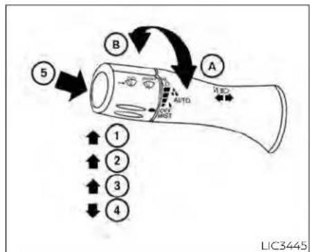
TypeA(ifsoequipped) SWITCH OPERATION
WARNING
Infreezingtemperaturesthewasher solutionmayfreezeonthewindshield andobscureyourvisionwhichmay leadtoanaccident.Warmthewindshieldwiththedefrosterbeforeyou washthewindshield.
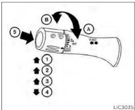
flowchart
graph TD
    A["Component A"] --> B["Component B"]
    B --> C["Component C"]
    C --> D["Component D"]
    D --> E["Component E"]
    E --> F["Component F"]
    F --> G["Component G"]
    G --> H["Component H"]
    H --> I["Component I"]
    I --> J["Component J"]
    J --> K["Component K"]
    K --> L["Component L"]
    L --> M["Component M"]
    M --> N["Component N"]
    N --> O["Component O"]
    O --> P["Component P"]
    P --> Q["Component Q"]
    Q --> R["Component R"]
    R --> S["Component S"]
    S --> T["Component T"]
    T --> U["Component U"]
    U --> V["Component V"]
    V --> W["Component W"]
    W --> X["Component X"]
    X --> Y["Component Y"]
    Y --> Z["Component Z"]
TypeB(ifsoequipped)
CAUTION
- Donotoperatethewashercontinuouslyformorethan30seconds.
-
Donotoperatethewasherifthe windshield-washerfluidreservoiris empty.
-
Donotfillthewindshield-washer fluidreservoirwithwindshield-washerfluidconcentratesatfull strength.Somemethylalcohol basedwindshield-washerfluidconcentratesmaypermanentlystainthe grilleifspilledwhilefillingthe windshield-washerfluidreservoir.
- Pre-mixwindshield-washerfluid concentrates with watertothe manufacturer's recommended levels before pouring the fluid into the windshield-washer fluid reservoir. Donotusethewindshield-washer fluid reservoir to mix the windshield-washer fluid concentrate and water.
NOTE:
Ifthewindshieldwiperoperationisinterrupted by snow or ice, the wiper may stopmoving toprotectitsmotor. Ifthis occurs, turn the wiper switch to the OFF positionandremovethesnoworicethat is on and around the wiper arms. In approximately1minute,turntheswitchon againtooperatethewiper.
The windshield wiper and washer operates when the ignition switch is in the ON position.
Rotate the end of the lever to operate the wiper at the following speed:
① Intermittent (INT) — intermittent operation can be adjusted by turning the knob toward Ⓐ (Slower) or Ⓑ (Faster). Also, the intermittent operation speed varies in accordance with the vehicle speed. (For example, when the vehicle speed is high, the intermittent operation speed will be faster.)
② Low (LO) — continuous low speed operation
③ High (HI) — continuous high speed operation
Rotate the lever the opposite direction 4 to have one sweep operation (MIST) of the wiper.
Press the button on the end of the lever to operate the washer. The wiper will also operate several times.
NOTE:
The Speed Dependent feature may be disabled. For additional information, see "Vehicleinformationdisplay"(P.2-23).

RAIN-SENSING AUTO WIPER SYSTEM (if so equipped)
CAUTION
- Donot touch the rainsensor and around it when the wiperswitchisin the AUTO position and the ignition switchisin the ON position. The wipers may operate unexpectedly and cause an injury or may damage a wiper.
- Therain-sensingautowipersareintendedforuseduringrain.Ifthe switchisleftintheAUTOposition,the wipersmayoperateunexpectedly whendirt,fingerprints,oilfilmorinsectsarestuckonoraroundthesensor.Thewipersmayalsooperate whenexhaustgasormoistureaffect therainsensor.
- Whenthewindshieldglassiscoated withwaterrepellent,thespeedofthe rain-sensingautowipersmaybe highereventhoughtheamountof therainfallissmall.
- Besuretoturnofftherain-sensing autowipersystemwhenyouusea carwash.
- The rain-sensing auto wipers may not operate if rain does no that the rains are more effective in training.
- UsingGenuineNISSANwiperblades is recommended for proper operation of theirin-sensing autowiper system. For additional information, see "Windshield wiper blades" (P.8-22).
The rain-sensing auto wiper system can automatically turn on the wipers and adjust the wiper speed depending on the rainfall and the vehicle speed by using the rain sensor located on the upper part of the windshield.
To set the rain-sensing auto wiper system, rotate the lever to the AUTO position ① . The wiper will sweep once while the ignition switch is in the ON position.
The rain sensor sensitivity level can be adjusted by turning the knob toward the front (High) or toward the rea (Low).
- High - High sensitive operation - Low - Low sensitive operation
To turn the rain-sensing auto wiper system off, rotate the lever to the OFF position, or rotate the lever to the LO or HI position.
NOTE:
Therainsensorfeaturemaybedisabled. Foradditionalinformation,see"Vehicle informationdisplay"(P.2-23).
REARWINDOWAND/OROUTSIDE MIRRORDEFROSTERSWITCH(ifso equipped)

natural_image
Line drawing of a curved electronic device with a small internal component and heat exchanger symbol (no text or labels)TypeA(ifsoequipped)
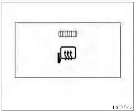
natural_image
Simple line drawing of two rectangular shapes with no text or symbolsTypeB(ifsoequipped)
To defrost the rear window glass and/or outside mirrors, start the engine and push the rear window/outside mirror defroster switch on. The indicator light on the switch will illuminate. Push the switch again to turn the defroster off.
The defroster automatically turns off after approximately 15 minutes.
NOTE:
Iftherearpowerwindow(ifsoequipped) isopenwhilethedefrosterswitchison, therearwindowdefrosterwillautomaticallyshutoff.Theheatedoutsidemirrors (ifsoequipped)willremainon.Therear windowdefrosterwillautomaticallyturn onwhentherearpowerwindowisfully closediftheswitchison.
CAUTION
Whencleaningtheinnersideoftherear window,becarefulnottoscratchor damagetherearwindowdefroster.
HEADLIGHTSWITCH

TypeA(ifsoequipped)
HEADLIGHT CONTROL SWITCH
Lighting
① Rotate the switch to the position, and the front parking, tail, license plate, and instrument panel lights will come on.
② Rotate the switch to the position, and the headlights will come on. All other lights, except the map lights (if so equipped), will remain on.

Usetheheadlightswiththeengineerunningtoavoiddischargingthevehicle battery.
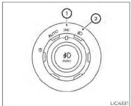
TypeC(ifsoequipped)

TypeA(ifsoequipped)
Autolight system
The autolight system allows the headlights to be set so they turn on and off automatically. The autolight system can:
- Turn on the headlights, front parking, tail, license plate and instrument panel lights automatically when it is dark.
- Turn off all the lights when it is light.
- Keep all the lights on for a period of time after you place the ignition switch in the OFF position and all doors are closed.
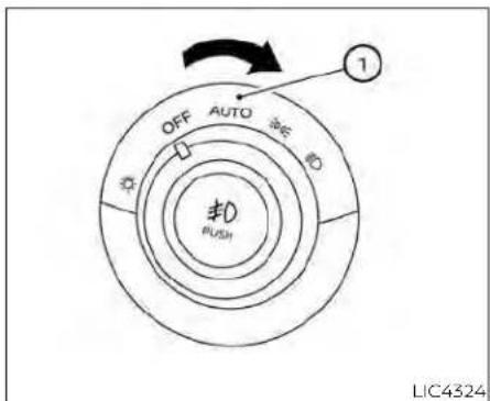
TypeB(ifsoequipped)
NOTE:
Autolightactivationsensitivityandthe timedelayforautolightshutoffcanbe adjusted.Foradditionalinformation,see "Howtousethevehicleinformationdisplay"(P.2-23).
To turn on the autolight system:
- Turn the headlight switch to the AUTO position ①.
- Place the ignition switch in the ON position.
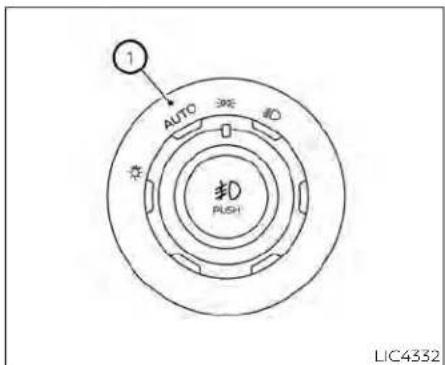
TypeC(ifsoequipped)
- The autolight system automatically turns the headlights on and off.
Initially, if the ignition switch is placed in the OFF position and a door is opened and left open, the headlights remain on for a period of time. If another door is opened while the headlights are on, then the timer is reset.
To turn the autolight system off, turn the switch to the OFFED, or position.
The headlights will turn on automatically at twilight or in rainy weather (when the windshield wiper is operated continuously).
If the ignition switch is placed in the OFF position and one of the doors is opened and this condition is continued, the headlights remain on for 5 minutes.

natural_image
Technical line drawing of a mechanical component with labeled part 1 (no text or symbols beyond label)Besureyoudonotputanythingontop oftheautolightsensor ① locatedonthe topsideoftheinstrumentpanel.Theautolightsensorcontrolstheautolight;ifit iscovered,theautolightsensorreactsas ifitisdarkoutandtheheadlightswill illuminate.ifthisoccurswhileparked withtheengineoffandtheignition switchplacedintheONposition,your vehicle'sbatterycouldbecome discharged.
Follow me home lighting (if so equipped)
The follow me home feature allows you to provide lighting from the vehicle after the ignition switch has been placed in the OFF position. Pulling the headlight stalk toward you once will activate the headlights for approximately 30 seconds. After that period of time, it will automatically switch off, is possible to pull the headlight stalk up to four times to increase the lighting period up to 2 minutes.
NOTE:
Thefollowmehomefeaturecanbecanceledbyplacingtheignitionswitchin theONposition.

Headlight beam select
① To select the high beam function, ensure the low beams are on using the headlight control switch, then push the lever forward. The high beam lights come on and the blue indicator light illuminates.
② Pull the lever back to return to the low beam.
③ Pulling and releasing the lever flashes the headlight high beams on and off. The low beams need not be engaged for this function.
High Beam Assist
The High Beam Assist system will operate when the vehicle is driven at speeds of approximately 25 mph (40 km/h) and above. If an oncoming vehicle or leading vehicle appears in front of your vehicle when the headlight high beam is on, the headlight will be switched to the low beam automatically.
WARNING
- TheHighBeamAssistsystemisa conveniencebutilitisnotasubstitute for safedrivingoperation. Thedriver shouldremainalertatalltimes, ensuresafedrivingpracticesand switchthehighbeamsandlowbeam manuallywhennecessary.
- Thehighbeamorlowbeammaynot switchautomaticallyunderthefollowingconditions.Switchthehigh beamandlowbeammanually.
- Duringbadweather(rain,fog, snow,wind,etc.).
-
Whenalightsourcesimilartoa headlighttortaillightisinthevicinityofthevehicle.
-
Whentheheadlightsoftheon- comingvehicleortheleadingve- hicleareturnedoff,whenthecolor ofthelightisaffectedduetofor- eignmaterials onthe lights,or when the light beam is out of position.
- Whenthereisasudden, continuouschangeinbrightness.
- When driving on a road that passesoverrollinghills,oraroad thathasleveldifferences.
- Whendrivingonaroadwithmany curves.
- Whenasignormirror-likesurface isreflectingintenselighttowards thefrontofthevehicle.
- When the container, etc. being towedbyaleadingvehicleisreflectingintenselight.
- Whenaheadlightonyourvehicle isdamagedordirty.
- Whenthevehicleisleaningatan angleduetoapuncturedtire,beingtowed,etc.
- Thetimingofswitchingthelow beamandhighbeammaychange underthefollowingsituations.
- The brightness of the headlights of the oncoming vehicle or leading vehicle.
- Themovementanddirectionof theoncomingvehicleandthe leadingvehicle.
- Whenonlyonelightontheon- comingvehicleortheleadingve- hicleisilluminated.
- Whentheoncomingvehicleorthe leadingvehicleisatwo-wheeled vehicle.
- Road conditions (incline, curve, theroadsurface, etc.).
- Thenumberofpassengersand theamountofluggage.


HighBeamAssistoperation
To activate the High Beam Assist system, turn the headlight switch to the AUTO position ① and then push the wiper and washer switch forward② (high beam position). The High Beam Assist indicator light in the meter will illuminate while the headlights are turned on.
If the High Beam Assist indicator light does not illuminate in the above condition, it may indicate that the system is not functioning properly. Have the system checked, it is recommended that you visit a NISSAN dealer for this service.
When the vehicle speed lowers to less than approximately 16 mph (25 km/h), the head light uses the low beam.
To turn off the High Beam Assist system, turn the headlight switch to the position or select the low beam position by replacing the lever in the neutral position.
Ambientimagesensormaintenance
The ambient image senso① for the High Beam Assist system is located in front of the inside mirror. To maintain the proper operation of the high beam assist system and prevent a system malfunction, be sure to observe the following:
• Always keep the windshield clean.
- Do not attach a sticker (including transparent material) or install an accessory near the ambient image sensor.
- Do not strike or damage the areas around the ambient image sensor. Do not touch the sensor lens that is located on the ambient image sensor.
Instrumentsandcontrols
If the ambient image sensor is damaged due to an accident, it is recommended that you visit a NISSAN dealer.
Battery saver system
If the ignition switch is placed in the OFF position while the headlight switch is in the EDGE or position, the headlights will turn off after a period of time.
After the headlights automatically turn off with the headlight switch in the EDGE or
position, the headlights will illuminate again if the headlight switch is moved to the OFF position and then turned to the OR or position.

CAUTION
Even though the battery saver feature automatically turn so off the headlights after a period of time, you should turn the headlights switch to the OFF position when the engine is not running to avoid discharging the vehicle battery.

LIC2230
Manual headlight aiming control (if so equipped)
Depending on the number of occupants in the vehicle and the load it is carrying, the headlight axis may be higher than desired. If the vehicle is traveling on a hilly road, the headlights may directly hit the rearview mirror of the vehicle ahead or the windshield of the oncoming vehicle. The light axis can be lowered with the operation of the switch.
The larger the number designated on the switch, the lower the axis.
When traveling without a heavy load or on a flat road, select position 0.
Select the switch position by referring to the following sample.
| Vehicle Load | Switch Position |
| Driver only or Driver/front passenger | 0 |
| Driver/front seat passenger/rear seat passengers | 1 |
| Driver/front seat passenger/rear seat passengers/cargo or driver/cargo/no trailer | 2 |
| Fully loaded/no trailer 3 |
'DAYTIME RUNNING LIGHTS (DRL) SYSTEM (Type A) (if so equipped)
The lights in the fog light area automatically illuminate at 100% intensity when the engine is started and the parking brake released. The Daytime Running Lights (DRL) operate with the headlight switch in the OFF or AUTO position.
If the parking brake is applied before the position for full illumination, the LED lights engine is started, the DRL do not illuminate switch from LED DRL to the park function. The DRL illuminate when the parking brake is released. The DRL remain on while the engine is running. If the parking brake is applied before the engine is started, the LED DRL do not illuminate. The LED DRL illuminate when the
It is necessary at dusk to turn the headlightparking brake is released. The LED DRL re-switch on for interior controls and switchesmain on while the engine is running.
to illuminate, as those remain off while the switch is in the OFF position. It is necessary at dusk to turn the headlight switch ON, for interior controls and
WARNING
WhentheDRLsystemisactive,tail lightsonyourvehiclearenoton.Itis necessaryatdusktoturnonyour headlights.Failureuretodosocouldcause anaccidentinjuringyourselfand others.
LED DAYTIME RUNNING LIGHTS (DRL) SYSTEM (Type B) (if so equipped)
The LED portion of the headlights automatically illuminates at 100% intensity when the engine is started and the parking brake released. The LED Daytime Running Lights (LED DRL) operate with the headlight switch in the OFF or AUTO position. When you turn the headlight switch to the
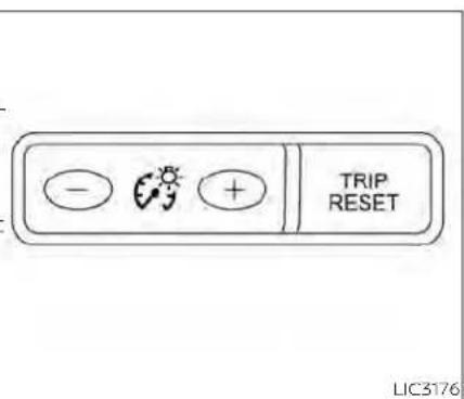
INSTRUMENT BRIGHTNESS CONTROL
Press the "+" button to increase the brightness of instrument panel lights.
Press the "-" button to decrease the brightness of instrument panel lights.
FOGLIGHTSWITCH(ifsoequipped)
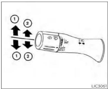
Move the lever up or down until the turn signal begins to flash, but the lever does not latch, and release the lever. The turn signal will automatically flash three times. Choose the appropriate method to signal a lane change based on road and traffic conditions.
NOTE:
The3flashpassturnindicatormaybe disabled. For additional information, see "Vehicleinformationdisplay" (P.2-23).

① Move the lever up or down to signal the turning direction. When the turn is completed, the turn signal cancels automatically.
Lane change signal
② Move the lever up or down until the turn signal begins to flash, but the lever does not latch, to signal a lane change. Hold the lever until the lane change is completed.
To turn the fog lights on, turn the headlight switch to the ① position, then push the fog light switch① on.
To turn the fog lights on with the headlight switch in the AUTO position, the headlights must be on, then push the fog light switch on.
To turn the fog lights off, push the fog light switch again.
The headlights must be on and the low beams selected for the fog lights to operate. The fog lights automatically turn off when the high beam headlights are selected.
2-52 Instrumentsandcontrols
HORN
Fog may temporarily form inside the lens of the exterior lights in the rain or in a car wash. A temperature difference between the inside and the outside of the lens causes fog. This is not a malfunction, if large drops of water collect inside the lens it is recommended that you visit a NISSAN dealer for servicing.

natural_image
Diagram of a car steering wheel with a black arrow indicating clockwise direction (no text or symbols)To sound the horn, push near the horn on the steering wheel.
WARNING
Donotdisassemblethehorn.Doingso couldaffectproperoperationofthe supplementalfrontairbagsystem. Tamperingwiththesupplemental frontairbagsystemmayresultinseriouspersonalinjury.
CARGOLAMPSWITCH(ifso equipped)

icofo turn on the cargo lamp and the under rail bed lamps (if so equipped) push the switch down to the ON position. The tail-gate lights (if so equipped) will also illuminate when the cargo lamp switch is in the ON position.
CAUTION
Donotuseforextendedperiodsoftime withtheenginestopped.Thiscouldresultinadischargedbattery.
CLIMATECONTROLLEDSEAT SWITCHES(ifsoequipped)
WARNING
Donotuseorallowoccupantstouse theclimatecontrolledseatsifyouor theoccupantscannotmonitorseat temperaturesorhaveaninabilityto feelpaininthosebodypartsincontact withtheseat.Useoftheclimatecontrolledseatsbysuchpeoplecouldresultinseriousinjury.
CAUTION
- The battery could rundown if the climate control seatisoperated while the engine is not running.
- Donotusetheclimatecontrolseat forextendedperiodsorwhennoone isusingtheseat.
- Donotputanythingontheseat whichinsulatesheat,suchasablan-ket,cushion,seatcover,etc.Other-wise,theseatmaybecome overheated.
-
Donotplaceanythinghardorheavy ontheseatorpierceitwithapinor similarobjects.This mayresult in damagetheclimatecontrolled seat.
-
Anyliquidspilledontheseatshould beremovedimmediatelywithadry cloth.
- The climate controlled seat has an air filter. Do not operate the climate controlledseatwithoutanairfilter.This mayresultindamagetothesystem.
- When cleaning the seat, never use gasoline, benzine, thinner, or any similar materials.
- Ifanymalfunctionsarefoundorthe climatecontrolledseatdoesnotoperate,turntheswitch offandhave thesystemchecked.itisrecommended that you visit a NISSAN dealerforthisservice.

The climate controlled seat warms up or cools down the front seat by blowing warm or cool air from under the surface of the seat. The climate control switch is located on the center console.
The climate controlled seat can be operated as follows:
- Start the engine.
- Turn the control knob A to the heat side ① or the cool side ②. The indicator light B on the control knob will illuminate.
HEATEDSEATSWITCHES(ifso equipped)
- Adjust the desired amount of air using the control knob. The climate controlled seat blower remains on low speed for approximately 60 seconds after turning the switch on or selecting the desired temperature.
- When the vehicle's interior is warmed or cooled, or before you leave the vehicle, be sure to turn the control knob to the off (center) position. The indicator light ☐ on the control knob goes off with the switch in the off (center) position.
To check the air filter for the climate controlled seat, it is recommended that you contact a NISSAN dealer.
WARNING
Donotuseorallowoccupantstouse theseatheaterifyouortheoccupants cannotmonitorelevatedseattemperaturesorhaveaninabilitytofeel paininbodypartsthatcontactthe seat.Useoftheseatheaterbysuch peoplecouldresultinserious injury.
CAUTION
- Donotusetheseatheaterforex-tendedperiodsorwhennooneisusingtheseat.
- Donotputanythingontheseat whichinsulatesheat,suchasablan-ket,cushion,seatcover,etc.Other-wise, the seat may become overheated.
- Donotplaceanythinghardorheavy ontheseatorpierceitwithapinor similarobject.Thismayresultin damagetotheheater.
- Anyliquidspilledontheheatedseat should be removed immediately with adrycloth.
-
Whencleaningtheseat,neveruse gasoline,benzine,thinner,or any similarmaterials.
-
Ifanymalfunctionsarefoundorthe heatedseatdoesnotoperate,turn theswitchoffandhavethesystem checked. Itisrecommendedthatyou visitaNISSANdealerforthisservice.
- The battery could run down if the seatheaterisoperatedwhiletheengineisnotrunning.

- Start the engine.
- Push the LO or HI position of the switch, as desired, depending on the temperature. The indicator light in the switch will illuminate.
The heater is controlled by a thermostat, automatically turning the heater on and off. The indicator light will remain on as long as the switch is on.
- When the seat is warmed or before you leave the vehicle, be sure to turn the switch off.
HEATEDREARSEATSWITCHES(ifso equipped)
WARNING
Donotuseorallowoccupantstouse theseatheaterifyouortheoccupants cannotmonitorelevatedseattemperaturesorhaveaninabilitytofeel paininbodypartsthatcontactthe seat.Useoftheseatheerbysuch peoplecouldresultinseriousinjury.
- Whencleaningtheseat,neveruse gasoline,benzine,thinner,orany similarmaterials.
- Ifanymalfunctionsarefoundorthe heatedseatdoesnotoperate,turn theswitchoffandhavethesystem checked.Itisrecommendedthatyou visitaNISSANdealerforthisservice.
CAUTION
- Thebatterycouldrundownifthe seatheaterisoperatedwhiletheengineisnotrunning.
- Donotusetheseatheaterforex-tendedperiodsorwhennooneisusingtheseat.
- Do not put anything on the seat whichinsulatesheat,suchasablan-ket,cushion,seatcover,etc.Other-
wise, the seat may become overheated. - Donotplaceanythinghardorheavy ontheseatorpierceitwithapinor similarobject. Thismayresult in damagetotheheater.
- Anyliquidspilledontheheatedseat shouldberemovedimmediatelywith adrycloth.
HEATEDSTEERINGWHEELSWITCH (ifsoequipped)

LIC3037|LIC4582
- When the seat is warmed or before you leave the vehicle, be sure to turn the switch off.

natural_image
Simple line drawing of a medical or electrical device with a circular symbol and a horizontal bar (no text or labels)The rear seats are warmed by built-in heaters. The switches are located on the rear of the front center console and can be operated independently of each other.
- Start the engine.
- Push the LO or HI position of the switch, as desired. The indicator light in the switch will illuminate.
The heater is controlled by a thermostat, automatically turning the heater on and off. The indicator light will remain on as long as the switch is on.
The heated steering wheel system is designed to operate only when the surface temperature of the steering wheel is below 68irc F ( 20irc C).
Push the heated steering wheel switch to warm the steering wheel after the engine starts. The indicator light will come on.
If the surface temperature of the steering wheel is below 68irc F ( 20irc C), the system will heat the steering wheel and cycle off and on to maintain a temperature above 68irc F ( 20irc C). The indicator light will remain on as long as the system is on.
Push the switch again to turn the heated steering wheel system off manually. The indicator light will go off. The switch will turn off automatically 30 minutes after activation, once this happens the switch will need to be pressed again to restart the cycle.
NOTE:
If the surfacetemperature of the steering wheel is above 68ircF(20ircC) when the switchisturned on, the system will not heat the steering wheel. This is not a malfunction.

LIC2225
The BSW system will turn on the side indicator lights, located by the outside mirrors, if the radar sensors detect a vehicle in the detection zone. If the turn signal is activated in the direction of the detected vehicle, a chime sounds twice and the side indicator light will flash.
The LDW system will sound a warning; the steering wheel will vibrate; and the LDW indicator (orange) will blink to alert the driver of the vehicle is traveling close to either the left or the right of a traveling lane with detectable lane markers.
For additional Information, see "Blind Spot Warning (BSW)" (P. 5-32) and "Lane Depar-
The warning systems switch is used to turn the following systems that are "ture Warning (LDW)" (P. 5-27).
on and off the following systems that are activated using the Settings menu in the vehicle information display:
- Blind Spot Warning (BSW)
• Lane Departure Warning (LDW)
When the warning systems switch is turned off, the indicator on the switch is off. The indicator will also be off if all of the warning systems are deactivated using the settings menu.
VEHICLEDYNAMICCONTROL(VDC) OFFSWITCH
HILLDESCENTCONTROL SWITCH (ifsoequipped)

LIC3344
Push the VDC OFF switch again or restart the engine to turn on the system. For additional information, see "Vehicle Dynamic Control (VDC) system" (P. 5-120).

natural_image
Simple line drawing of a vehicle on a slope inside a rectangular frame (no text or symbols)LIC3447
The vehicle should be driven with the VDC system on for most driving conditions.
If the vehicle is stuck in mud or snow, the VDC system reduces the engine output to reduce wheel spin. The engine speed will be reduced even if the accelerator is depressed to the floor. If maximum engine power is needed to free a stuck vehicle, turn the VDC system off.
To turn off the VDC system, push the VDC OFF switch. The 🎨 indicator will come on.
WARNING
- Neverrelysolelyonthehilldescent controlsystemtocontrolvehicle speedwhendrivingonsteepdown-hillgrades. Alwaysdrivecarefully whenusingthehilldescentcontrol systemanddeceleratethevehicle speedbydepressingthebrakepedal if necessary. Be especially careful when driving on frozen, muddy or extremely steepdownhillroads. Failure to control vehicle speed may result in alossofcontrolofthevehicle and possibleseriousinjuryordeath.
- Thehilldescentcontrolmaynotcontrolthevehiclespeedonahillunder alloadorroadconditions.Alwaysbe preparedtodepressthebrakepedal tocontrolvehiclespeed.Failureretodo somayresultinacollisionorserious personalinjury.
CAUTION
Whenthehilldescentcontrolsystem operatescontinuouslyforalongtime, the temperatureofthebrakepadsmay increaseandthehilldescentcontrol systemmaybetemporarilydisabled (theindicatorlightwillblink).Iftheindicatorlightdoesnotcomeoncontinuouslyafterblinking,stopusingthe system.
The hill descent control system is designed to reduce driver workload when going down steep hills. The hill descent control system helps to control vehicle speed so the driver can concentrate on steering the vehicle.
To activate the hill descent control system: The hill descent control indicator light • activate the 4H or 4LO switch, • the transmission shift lever must be in forward or reverse gear, • the hill descent control system switch must be ON. The vehicle speed must be best below blinks if the switch is on and all conditions for system activation are not met or if the system becomes disengaged for any reason. To turn off the hill descent control system, push the switch to the OFF position.
The vehicle speed must be kept below 15 mph (25 km/h).
The hill descent control indicator light will come on when the system is activated. Also, the stop/tail lights illuminate while the hill descent control system applies the brakes to control vehicle speed.
You may hear a noise from under the hood or feel a vibration from the actuator when it is operating. This is normal and indicates the hill descent control system is working properly.
If the accelerator or brake pedal is depressed while the hill descent control system is on, the system will stop operating temporarily. As soon as the accelerator or brake pedal is released, the hill descent control system begins to function again if the hill descent control operating conditions are fulfilled.
For additional information, see "Hill descent control system ON indicator light" (P. 2-18) and "Hill descent control system" (P. 5-123).
ELECTRONICLOCKINGREAR DIFFERENTIAL(E-Lock)SYSTEM SWITCH(ifsoequipped)

natural_image
Pure electrical circuit symbol for a variable resistor, no text or labels presentLIC4341
The E-Lock system can help provide added traction if the vehicle is stuck or becoming stuck.
To activate the E-Lock system:
- the 4WD switch must be in the 4LO position (4-wheel drive vehicles),
- the vehicle must be stopped or moving at 4 mph (7 km/h) or less, and
- the E-Lock system switch must be turned ON.
When the E-Lock system switch is turned ON, the indicator light will flash until the system engages. However, if all operation conditions listed above are not met or the system becomes disengaged, the indicator light will continue to flash.
The Anti-lock Braking System (ABS) system is disabled and the ABS light illuminates when the E-Lock system is on.
For additional information, see "Electronic locking rear differential (E-Lock) system" (P. 5-114) for further explanation and system limitations.
WARNING
NeverleavetheE-LocksystemON whendrivingonpavedorhard-surfacedroads.Turningthevehicle mayresultintherearwheelsslipping andresultinanaccidentandpersonalinjury.AfterusingtheE-Lock systemtofreethevehicle,turnthe systemOFF.
- Use the E-lock system only in an emergencywhenitisnotpossible to freeastuckvehicleevenusing4LO. NeverusetheE-Locksystemona slipperyroadsurfacesuchassnow oricesurface.UsingtheE-Locksystemwhendrivingintheseroadconditions may cause unexpected movementofthevehicleduringenginebraking,acceleratingorturning, whichmayresultinanaccidentandseriouspersonalinjury. - Observetheabovewarnings.Otherwise,lossofnormalsteeringcontrol mayresult.Thismayresultinanaccidentandseriouspersonalinjury.
CAUTION
- After using the E-Lock system, or during normal driving, turn the switchOFFtopreventpossibledamagetodrivetraincomponentsfrom extendeduse.
- WhentheE-Locksystemisinoperation,turningthevehiclebecomesdifficult.Thiscanbedangerous,especiallyathighspeeds.Doingsocould damagedrivetraincomponents.
POWERINVERTERSWITCH(ifso equipped)
- DonotoperatetheE-Locksystem whenthevehicleisturningorwhen onesidewheelisrotating. Otherwise, thedrivetraincomponentscouldbe damaged.
- TheE-Locksystemoperatesonly whentheengineisrunning.
- In4Hmode,theE-Locksystemdoes notoperatewhentheE-Locksystem switchisturnedtotheONposition. (TheE-Locksystemindicatorlight willflash.)
- AvoidquickstartwhiletheE-Lock systemisinoperation. Otherwisethe drivetraincomponentscouldbe damaged.
- Observetheabovecautions.Other-wise,lossofnormalsteeringmay result.

LIC2075
To use the outlets for devices that require up to 120v power, the vehicle must be running and the power inverter switch must be on.
When the vehicle is in the P (Park) position, the 400W and the 150W will automatically illuminate. When the vehicle is out of the P (Park) position, only 150W will illuminate.
For additional information, see "120v outlets" (P. 2-67) regarding using devices that require the power inverter switch to be activated.
CAUTION
- Use power outlets with the engine runningtoavoiddischargingthevehiclebattery.
- Do not attempt to use this while driving.
- Donotusedoubleadaptersormore thanoneelectricalaccessory,doing socouldsignificantlydrainthebatteryofourvehicle.

LIC3596
If the indicator light flashes when the Front and rear sonar system, MOD, RAB, or RCTA systems are not turned off, it may indicate a malfunction in one or more of these systems (if so equipped).
The Front and rear sonar system, MOD, RAB, or RCTA systems will be turned on automatically under the following conditions:
- When the ignition switch is switched from the OFF position to the ON position.
- When the shift lever is shifted into the R (Reverse) position.

LIC3381
The Parking Aids system switch on the instrument panel allows the driver to turn the following systems (if so equipped) on and off. To turn the systems on and off, the ignition switch must be in the ON position.
- Front and rear sonar system
- Moving Object Detection (MOD)
- Rear Automatic Braking (RAB)
- Rear Cross Traffic Alert (RCTA)
The indicator light on the switch will illuminate when the systems are turned on.
The automatic turning on function can be turned on and off for these systems in the vehicle information display. For additional information, see "Settings" (P. 2-24).
For additional information, see "Front and rear sonar system" (P. 5-124), "Rear Automatic Braking (RAB)" (P. 5-76), "Rear Cross Traffic Alert (RCTA)" (P. 5-42), or "Moving Object Detection (MOD)" (P. 4-23).
a Tow mode should be used when pulling a heavy trailer or hauling a heavy load. Driving the vehicle in the tow mode with no trailer/load or light trailer/light load will not cause any damage. However, fuel economy may be reduced, and the transmission/engine driving characteristics may feel unusual.
Push the tow mode switch to activate tow mode. The TOW indicator light illuminates when tow mode is selected. Push the tow mode switch again to turn tow mode off.
Tow mode is automatically canceled when the ignition switch is placed in the OFF position.
EMERGENCYCALL(SOS)BUTTON (ifsoequipped)
TRAILERBRAKECONTROLLERUNIT (TBCU)(ifsoequipped)
For additional information, see "Tow mode" (P. 10-54).


The Emergency call (SOS) system button is The TBCU on the instrument panel allows used in combination with a NissanConnect® Services subscription to applied to the trailer brakes. call for assistance in case of an emergency Pushing the button will (with a paid subscription) reach a Response Specialist that will provide assistance based on the situation described by the vehicle's occupant. For additional information, or to enroll your vehicle, refer to www.NissanUSA.com/connect or call 855-426-6628.
REARDOORALERT
The Rear Door Alert system functions under certain conditions to indicate there may be an object or passenger in the rear seat(s). Check the seat(s) before exiting the vehicle.
The Rear Door Alert system is initially disabled. The driver can enable the system using the vehicle information display. For additional information, see "Vehicle Information display warnings and indicators" (P. 2-32).
When the system is enabled:
- The system is activated when a rear door is opened and closed within 10 minutes of the vehicle being driven. When the driver door is closed and the system is activated, a visual message appears in the vehicle information display. For additional information, see "Rear Door Alert is activated" (P. 2-34).
- If a rear door is opened and closed but the vehicle is not driven within approximately 10 minutes, the system will not be activated. A rear door must be opened and closed and the car driven within 10 minutes for the system to activate.
When the Rear Door Alert system is activated and a driver exits the vehicle after arriving at a destination:
- When the driver puts the vehicle in the P (Park) position, a message appears in the vehicle information display for a driver to "Dismiss Message" or "Disable Alert" if desired.
- With the system enabled, when the driver exits the vehicle, an audible alert (horn sound) will occur unless a rear door is opened and closed within a short time to deactivate the alert.
If the doors are locked before the alert is deactivated by opening a rear door, the horn will sound. - If the audible horn alert occurs, a message will also appear in the vehicle information display that states, "Check Rear Seat for All Articles".
WARNING
- Ifthedriverselects "DisableAlert", no audiblealertwillbeprovidedregard-lessofreardooropen/closestatus.
-Theremaybetimeswhenthereisan objectorpassengerintherearseat(s) buttheaudiblealertdoesnotsound. Forexample, thismayoccurifrearseat passengersenterorexitthevehicle duringatrip.
- Thesystemdoesnotdirectlydetect objectorspassengers in therear seat(s).Instead, itcandetect when a reardoorisopened and closed, indicating that theremaybesomething in the rearseat(s).
NOTE:
There may be times when the horn soundsbuttherearenoobjectsorpassengersintherearseat(s).
For additional information, see "Rear Door Alert is activated" (P. 2-34).
POWEROUTLETS

natural_image
Line drawing of a car dashboard with control panels and directional arrows (no text or symbols)Instrumentpanel
12V OUTLETS
The power outlets are for powering electrical accessories such as cellular telephones.
The power outlets located on the instrument panel, inside the center armrest (if so equipped), and on the back of the center console (if so equipped) are powered only when the ignition switch is placed in the ACC or ON position.
Open the cap to use a power outlet.

natural_image
Technical line drawing of a vehicle interior with a directional arrow indicating movement or force (no text or symbols present)Insidecenterconsole(ifsoequipped)
CAUTION
- Theoutletandplugmaybehotduringorimmediatelyafteruse.
- Onlycertainpoweroutletsaredesignedforusewithacigarettelighter unit.Donotuseanyotherpoweroutletforanaccessorylighter.ItisrecommendedthatyouvisitaNISSAN dealerforadditionalinformation.
- Donotusewithaccessoriesthatexceeda12volt,120W(10A)powerdraw.
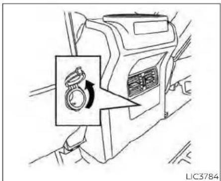
natural_image
Line drawing of a mechanical device with a circular component and directional arrow (no text or symbols)Rearcenterconsole (ifso equipped)
- Donotusedoubleadaptersormore thanoneelectricalaccessory.
- Usepoweroutletswiththeengine runningtoavoiddischargingthevehiclebattery.
- Avoidusingpoweroutletswhenthe airconditioner,headlights, orrear windowdefroster(ifsoequipped)is on.
-
Beforeinsertingordisconnectinga plug,besuretheelectricalaccessory beingusedisturnedOFF.
-
Pushthepluginasfarasitwillgo.If goodcontactisnotmade,theplug mayoverheatortheinternaltemperaturefusemayopen.
- Whennotinuse,besuretoclosethe cap.Donotallowwateroranyother liquidtocontacttheoutlet.

natural_image
Technical line drawing of a mechanical component with arrows indicating assembly or movement (no text or symbols)Intruckbox(ifsoequipped) 120V OUTLETS (if so equipped)

Centerconsole(ifsoequipped)
| 120VOUTLET | SwitchReset | |||||||||
| WhatispluggedinShifterInParkShifterOutofParkShifterBackInParkShifterInParkShifterOutofPark | ||||||||||
| IndicatorInverter Status | IndicatorInverter Status | IndicatorInverter Status | IndicatorInverter Status | |||||||
| No Device but Switch On | 150W and 400W | ON | 150W | ON | 150W and 400W | ON | 150W and 400W | ON | 150W | ON |
| Device<150W | 150W and 400W | ON | 150W | ON | 150W and 400W | ON | 150W and 400W | ON | 150W | ON |
| 150W150W and 400WONOFFOFFOFFOFFOFFOFFOFFOFFOFFOFFOFFOFFOFFOFFOFFOFFOFFOFFOFFOFFOFFOFFOFFOFFOFFOFFOFFOFFOFFOFFOFFOFFOFFOFFOFFOFFOFFOFFOFFOFFOFFOFFOFFOFFOFFOFFOFFOFFOFFOFFOFFOFFOFFOFFOFFOFFOFFOFFOFFOFFOFFOFFOFFOFFOFFOFFOFFOFFOFFOFFOFFOFFOFFOFFOFFOFFOFFOFFOFFOFFOFFOFFOFFOFFOFFOFFOFFOFFOFFOFFOFFOFFOFFOFFOFFOFFOFFOFFOFFOFFFFFFFFFFFFFFFFFFFFFFFFFFFFFFFFFFFFFFFFFFFFFFFFFFFFFFFFFFFFFFFFFFFFFFFFFFFFFFFFFFFFFFFFFFFFFFFFFFFFFFFFFFFFFFFFFFFFFFFFFFFFFFFFFFFFFFFFFFFFFFFFFFFFFFFFFFFFFFFFFFFFFFFFFFFFFFFFFFFFFFFFFFFFFFFFFFFFFFFFFFFFFFFFFFFFFFFFFFFFFFFFFFFFFFFFFFFFFFFFFFFFFFFFFFFFFFFFFFFFFFFFFFFFFFFFFFFFFFFFFFFFFFFFFFFFFFFFFFFFFFFFFFFFFFFFFFFFFFFFFFFFFFFFFFFFFFFFFFFFFFFFFFFFFFFFFFFFFFFFFFFFFFFFFFFFFFFFFFFFFFFFFFFFFFFFFFFFFFFFFFFFFFFFFFFFFFFFFFFFFFFFFFFFFFFFFFFFFFFFFFFFFFFFFFFFFFFFFFFFFFFFFFFFFFFFFFFFFFFFFFFFFFFFFFFFFFFFFFFFFFFFFFFFFFFFFFFFFFFFFFFFFFFFFFFFFFFFFFFFFFFFFFFFFFFFFFFFFFFFFFFFFFFFFFFFFFFFFFFFFFFFFFFFFFFFFFFFFFFFFFFFFFFFFFFFFFFFFFFFFFFFFFFFFFFFFFFFFFFFFFFFFFFFFFFFFFFFFFFFFFFFFFFFFFFFFFFFFFFFFFFFFFFFFFFFFFFFFFFFFFFFFFFFFFFFFFFFFFFFFFFFFFFFFFFFFFFFFFFFFFFFFFFFFFFFFFFFFFFFFFFFFFFFFFFFFFFFFFFFFFFFFFFFFFFFFFFFFFFFFFFFFFFFFFFFFFFFFFFFFFFFFFFFFFFFFFFFFFFFFFFFFFFFFFFFFFFFFFFFFFFFFFFFFFFFFFFFFFFFFFFFFFFFFFFFFFFFFFFFFFFFFFFFFFFFFFFFFFFFFFFFFFFFFFFFFFFFFFFFFFFFFFFFFFFFFFFFFFFFFFFFFFFFFFFFFFFFFFFFFFFFFFFFFFFFFFFFFFFFFFFFFFFFFFFFFFFFFFFFFFFFFFFFFFFFFFFFFFFFFFFFFFFFFFFFFFFFFFFFFFFFFFFFFFFFFFFFFFFFFFFFFFFFFFFFFFFFFFFFFFFFFFFFFFFFFFFFFFFFFFFFFFFFFFFFFFFFFFFFFFFFFFFFFFFFFFFFFFFFFFFFFFFFFFFFFFFFFFFFFFFFFFFFFFFFFFFFFFFFFFFFFFFFFFFFFFFFFFFFFFFFFFFFFFFFFFFFFFFFFFFFFFFFFFFFFFFFFFFFFFFFFFFFFFFFFFFFFFFFFFFFFFFFFFFFFFFFFFFFFFFFFFFFFFFFFFFFFFFFFFFFFFFFFFFFFFFFFFFFFFFFFFFFFFFFFFFFFFFFFFFFFFFFFFFFFFFFFFFFFFFFFFFFFFFFFFFFFFFFFFFFFFFFFFFFFFFFFFFFFFFFFFFFFFFFFFFFFFFFFFFFFFFFFFFFFFFFFFFFFFFFFFFFFFFFFFFFFFFFFFFFFFFFFFFFFFFFFFFFFFFFFFFFFFFFFFFFFFFFFFFFFFFFFFFFFFFFFFFFFFFFFFFFFFFFFFFFFFFFFFFFFFFFFFFFFFFFFFFFFFFFFFFFFFFFFFFFFFFFFFFFFFFFFFFFFFFFFFFFFFFFFFFFFFFFFFFFFFFFFFFFFFFFFFFFFFFFFFFFFFFFFFFFFFFFFFFFFFFFFFFFFFFFFFFFFFFFFFFFFFFFFFFFFFFFFFFFFFFFFFFFFFFFFFFFFFFFFFFFFFFFFFFFFFFFFFFFFFFFFFFFFFFFFFFFFFFFFFFFFFFFFFFFFFFFFFFFFFFFFFFFFFFFFFFFFFFFFFFFFFFFFFFFFFFFFFFFFFFFFFFFFFFFFFFFFFFFFFFFFFFFFFFFFFFFFFFFFFFFFFFFFFFFFFFFFFFFFFFFFFFFFFFFFFFFFFFFFFFFFFFFFFFFFFFFFFFFFFFFFFFFFFFFFFFFFFFFFFFFFFFFFFFFFFFFFFFFFFFFFFFFFFFFFFFFFFFFFFFFFFFFFFFFFFFFFFFFFFFFFFFFFFFFFFFFFFFFFFFFFFFFFFFFFFFFFFFFFFFFFFFFFFFFFFFFFFFFFFFFFFFFFFFFFFFFFFFFFFFFFFFFFFFFFFFFFFFFFFFFFFFFFFFFFFFFFFFFFFFFFFFFFFFFFFFFFFFFFFFFFFFFFFFFFFFFFFFFFFFFFFFFFFFFFFFFFFFFFFFFFFFFFFFFFFFFFFFFFFFFFFFFFFFFFFFFFFFFFFFFFFFFFFFFFFFFFFFFFFFFFFFFFFFFFFFFFFFFFFFFFFFFFFFFFFFFFFFFFFFFFFFFFFFFFFFFFFFFFFFFFFFFFFFFFFFFFFFFFFFFFFFFFFFFFFFFFFFFFFFFFFFFFFFFFFFFFFFFFFFFFFFFFFFFFFFFFFFF RepresentativeFFFFFFFFFFFFFFFFFFFFFFFFFFFFFFFFFFFFFFFFFFFFFFFFFFFFFFFFFFFFFFFFFFFFFFFFFFFFFFFFFFFFFFFFFFFFFFFFFFFFFFFFFFFFFFFFFFFFFFFFFFFFFFFFFFFFFFFFFFFFFFFFFFFFFFFFFFFFFFFFFFFFFFFFFFFFFFFFFFFFFFFFFFFFFFFFFFFFFFFFFFFFFFFFFFFFFFFFFFFFFFFFFFFFFFFFFFFFFFFFFFFFFFFFFFFFFFFFFFFFFFFFFFFFFFFFFFFFFFFFFFFFFFFFFFFFFFFFFFFFFFFFFFFFFFFFFFFFFFFFFFFFFFFFFFFFFFFFFFFFFFFFFFFFFFFFFFFFFFFFFFFFFFFFFFFFFFFFFFFFFFFFFFFFFFFFFFFFFFFFFFFFFFFFFFFFFFFFFFFFFFFFFFFFFFFFFFFFFFFFFFFFFFFFFFFFFFFFFFFFFFFFFFFFFFFFFFFFFFFFFFFFFFFFFFFFFFFFFFFFFFFFFFFFFFFFFFFFFFFFFFFFFFFFFFFFFFFFFFFFFFFFFFFFFFFFFFFFFFFFFFFFFFFFFFFFFFFFFFFFFFFFFFFFFFFFFF法定代表FFFFFFFFFFFFFFFFFFFFFFFFFFFFFFFFFFFFFFFFFFFFFFFFFFFFFFFFFFFFFFFFFFFFFFFFFFFFFFFFFFFFFFFFFFFFFFFFFFFFFFFFFFFFFFFFFFFFFFFFFFFFFFFFFFFFFFFFFFFFFFFFFFFFFFFFFFFFFFFFFFFFFFFFFFFFFFFFFFFFFFFFFFFFFFFFFFFFFFFFFFFFFFFFFFFFFFFFFFFFFFFFFFFFFFFFFFFFFFFFFFFFFFFFFFFFFFFFFFFFFFFFFFFFFFFFFFFFFFFFFFFFFFFFFFFFFFFFFFFFFFFFFFFFFFFFFFFFFFFFFFFFFFFFFFFFFFFFFFFFFFFFFFFFFFFFFFFFFFFFFFFFFFFFFFFFFFFFFFFFFFFFFFFFFFFFFFFFFFFFFFFFFFFFFFFFFFFFFFFFFFFFFFFFFFFFFFFFFFFFFFFFFFFFFFFFFFFFFFFFFFFFFFFFFFFFFFFFFFFFFFFFFFFFFFFFFFFFFFFFFFFFFFFFFFFFFFFFFFFFFFFFFFFFFFFFFFFFFFFFFFFFFFFFFFFFFFFFFFFFFFFFFFFFFFFFFFFFFFFFFFFFFFFFFFFFFF************* | 150W and 400W | ON | 150W | ON | 150W and 400W | ON | 150W and 400W | ON | 150W | ON |
| Device<150W | 150W and 400W | ON | 150W | ON | 150W and 400W | ON | 150w and 400W | ON | 150w and 400W | ON |
| 150W150W and 400WONOFFOFFOFFOFFOFFOFFOFFOFFOFFOFFOFFOFFOFFOFFOFFOFFOFFOFFOFFOFFOFFOFFOFFOFFOFFOFFOFFOFFOFFOFFOFFOFFOFFOFFOFFOFFOFFOFFOFFOFFOFFOFFOFFOFFOFFOFFOFFOFFOFFOFFOFFOFFOFFOFFOFFOFFOFFOFFOFFOFFOFFOFFOFFOFFOFFOFFOFFOFFOFFOFFOFFOFFOFFOFFOFFOFFOFFFFOFFOFFOFFOFFOFFOFFOFFOFFOFFOFFOFFOFFOFFOFFOFFOFFOFFOFFOFFOFFOFFOFFOFFOFFOFFOFFOFFOFFOFFOFFOFFOFFOFFOFFOFFOFFOFFOFFOFFOFFOFFOFFOFFOFFOFFOFFOFFOFFOFFOFFOFFOFFOFFOFFOFFOFFOFFOFFOFFOFFOFFOFFOFFOFFOFFOFFOFFOFFOFFOFFOFFOFFOFFOFFOFFOFFOFFOFFOFFOFFOFFOFFOFFOFFOFFOFFOFFOFFOFFOFFOFFOFFOFFOFFOFFOFFOFFOFFOFFOFFFOFFOFFOFFOFFOFFOFFOFFOFFOFFOFFOFFOFFOFFOFFOFFOFFOFFOFFOFFOFFOFFOFFOFFOFFOFFOFFOFFOFFOFFOFFOFFOFFOFFOFFOFFOFFOFFOFFOFFOFFOFFOFFOFFOFFOFFOFFOFFOFFOFFOFFOFFOFFOFFOFFOFFOFFOFFOFFOFFOFFOFFOFFOFFOFFOFFOFFOFFOFFOFFOFFOFFOFFOFFOFFOFFOFFOFFOFFOFFOFFOFFOFFOFFOFFOFFOFFOFFOFFOFFOFFOFFOFFOFFOFFOFFOFFOFFOFFFFOFFOFFOFFOFFOFFOFFOFFOFFOFFOFFOFFOFFOFFOFFOFFOFFOFFOFFOFFOFFOFFFFOFFOFFOFFOFFOFFOFFOFFOFFOFFOFFOFFOFFOFFOFFOFFOFFOFFOFFOFFOFFOFFOFFOFFOFFOFFOFFOFFOFFOFFOFFOFFOFFOFFOFFOFFOFFOFFOFFOFFOFFOFFOFFOFFOFFOFFOFFOFFOFFOFFOFFOFFOFFOFFOFFOFFOFFOFFOFFOFFOFFOFFOFFOFFOFFOFFOFFOFFOFFOFFOFFOFFOFFOFFOFFOFFOFFOFFFFOFFOFFOFFOFFOFFOFFOFFOFFOFFOFFOFFOFFOFFOFFOFFOFFOFFOFFOFFOFFOFFOFFFOFFOFFOFFOFFOFFOFFOFFOFFOFFOFFOFFOFFOFFOFFOFFOFFOFFOFFOFFOFFOFFOFFOFFOFFOFFOFFOFFOFFOFFOFFOFFOFFOFFOFFOFFOFFOFFOFFOFFOFFOFFOFFOFFOFFOFFOFFOFFOFFOFFOFFOFFOFFOFFOFFOFFOFFOFFOFFOFFOFFOFFOFFOFFOFFOFFOFFOFFOFFOFFOFFOFFOFFOFFOFFOFFOFFFFOFFOFFOFFOFFOFFOFFOFFOFFOFFOFFOFFOFFOFFOFFOFFOFFOFFOFFOFFOFFOFFOFFFFOFFOFFOFFOFFOFFOFFOFFOFFOFFOFFOFFOFFOFFOFFOFFOFFOFFOFFOFFOFFOFFOFFOFFOFFOFFOFFOFFOFFOFFOFFOFFOFFOFFOFFOFFOFFOFFOFFOFFOFFOFFOFFOFFOFFOFFOFFOFFOFFOFFOFFOFFOFFOFFOFFOFFOFFOFFOFFOFFOFFOFFOFFOFFOFFOFFOFFOFFOFFOFFOFFOFFOFFOFFOFFOFFOFFFFOFFOFFOFFOFFOFFOFFOFFOFFOFFOFFOFFOFFOFFOFFOFFOFFOFFOFFOFFOFFOFFFFONFFONFFONFFONFFONFFONFFONFFONFFONFFONFFONFFONFFONFFONFFONFFONFFONFFONFFONFFONFFONFFONFFONFFONFFONFFONFFONFFONFFONFFONFFONFFONFFONFFONFFONFFONFFONFFONFFONFFONFFONFFONFFONFFONFFONFFONFFONFFONFFONFFONFFONTFFONFFONTFFONTFFONTFFONTFFONTFFONTFFONTFFONTFFONTFFONTFFONTFFONTFFONTFFONTFFONTFFONTFFONTFFONTFFONTFFONTFFONTFFONTFFONTFFONTFFONTFFONTFFONTFFONTFFONTFFONTFFONTFFONTFFONTFFONTFFONTFFONTFFONTFFONTFFONTFFONTFFONTFFONTFFONTFFONTFFONTFFONTFFONTFFONTFFONTFFONTFFONFFONTFFONTFFONTFFONTFFONTFFONTFFONTFFONTFFONTFFONTFFONTFFONTFFONTFFONTFFONTFFONTFFONTFFONTFFONTFFONTFFONTFFONTFFONTFFONTFFONTFFONTFFONTFFONTFFONTFFONTFFONTFFONTFFONTFFONTFFONTFFONTFFONTFFONTFFONTFFONTFFONTFFONTFFONTFFONTFFONTFFONTFFONTFFONFFONTFFONFFONTFFONTFFONTFFONTFFONTFFONTFFONTFFONTFFONTFFONTFFONTFFONTFFONTFFONTFFONTFFONTFFONTFFONTFFONTFFONTFFONTFFONTFFONTFFONTFFONTFFONTFFONTFFONTFFONTFFONTFFONTFFONTFFONTFFONTFFONTFFONTFFONTFFONTFFONTFFONTFFONTFFONTFFONTFFONTFFONTFFONTFFONFFONTFFONTFFONFFONTFFONTFFONTFFONTFFONTFFONTFFONTFFONTFFONTFFONTFFONTFFONTFFONTFFONTFFONTFFONTFFONTFFONTFFONTFFONTFFONTFFONTFFONTFFONTFFONTFFONTFFONTFFONTFFONTFFONTFFONTFFONTFFONTFFONTFFONTFFONTFFONTFFONTFFONTFFONTFFONTFFONTFFONTFFONTFFONTFFONTFFONFFONFFONTFFONTFFONTFFONTFFONTFFONTFFONTFFONTFFONTFFONTFFONTFFONTFFONTFFONTFFONTFFONTFFONTFFONTFFONTFFONTFFONTFFONTFFONTFFONTFFONTFFONTFFONTFFONTFFONTFFONTFFONTFFONTFFONTFFONTFFONTFFONTFFONTFFONTFFONTFFONTFFONTFFONTFFONTFFONTFFONTFFONTFFONTFFONTFFONFFONFFONFFONFFONFFONFFONFFONFFONFFONFFONFFONFFONFFONFFONFFONFFONFFONFFONFFONFFONFFONFFONFFONFFONFFONFFONFFONFFONFFONFFONFFONFFONFFONFFONFFONFFONFFONFFONFFONFFONFFONFFONFFONFFONFFONFFONFFONFFONFFONSEF | ||||||||||
** OFF means the inverter system cannot be reset until a device is within the specification range of operation. If the device is greater than specified, the inverter will shut OFF. The operating voltage is between 11.5v and 15v. If the vehicle is not idling, the battery voltage will drop which will cause the inverter to shut down when below 11.5v. When the vehicle is in the (P) Park position, it will work at 400w. If the vehicle is in any other shifter position, it will turn off.
EXTENDEDSTORAGESWITCH
Do not use the outlet located in the truck box with accessories that exceed 120 volt. Do not use double adapters or more than one electrical accessory. When the dual wall bed liner is installed (if so equipped), the power outlet is still accessible through the access door in the bed liner.
CAUTION
Operationofthe120voltsystemwith theignitionintheONpositionand theenginenotrunning(idle)will drainthebatterycharge.Thiscould leadtoadeadbatteryornostart condition.
- Theoutletandplugmaybehotduringorimmediatelyafteruse.
- Usepoweroutletswiththeengine runningtoavoiddischargingthevehiclebattery.
- Donotusedoubleadaptorsormore thanoneelectricalaccessory.
- Avoidusingpoweroutletswhenthe airconditioner,headlightsorrear windowdefrosterison.
- Beforeinsertingordisconnectinga plug,besuretheelectricalaccessory beingusedisturnedOFF.
- Pushthepluginasfarasitwillgo.If goodcontactisnotmade,theplug mayoverheatortheinternaltemperaturefusemayopen.
- Whennotinuse,besuretoclosethe cap.Donotallowwateroranyother liquidtocontacttheoutlet.
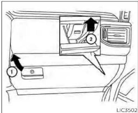
The extended storage switch is used when shipping the vehicle. It is located in the fuse panel inside the glove box. To reach it, open the glove box① on the instrument panel, then open the fuse panel cover.
If any electrical equipment does not operate, ensure the extended storage switch is ON by pushing it fully in place, as shown.
STORAGE

natural_image
Technical diagram showing a mechanical component before and after assembly, with no visible text or symbols.Pulledposition

natural_image
Technical line drawing of a mechanical assembly with an arrow indicating direction (no text or symbols)Pushedposition

natural_image
Line drawing of a car interior showing the dashboard and side compartments with a black arrow indicating a location or component (no text or symbols present)FRONT-DOOR POCKETS

natural_image
Diagram of a car interior showing a directional arrow pointing to the lower side of the window (no text or symbols present)LIC3213 LIC2392 LIC0575

natural_image
Diagram of a mechanical component with an arrow indicating direction, no text or symbols presentREAR-DOOR POCKETS CONSOLE SIDE POCKETS (if so equipped)
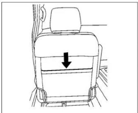
natural_image
Line drawing of a car seat with a downward arrow indicating compression or force (no text or symbols)SEATBACK POCKETS
The seatback pocket(s) may be located on the back of the driver's and/or passenger's seat, there may be one or two pockets equipped. The pockets can be used to store maps.
WARNING
Toensureproperoperationofthedriver'sand/orfrontpassenger'sNISSAN AdvancedAirBagSystem(ifso equipped),pleaseobservethefollowingitems:
- Donotallowapassengerintherear seattopushorpullontheseatback pocketorheadrestraint/headrest.
- Donotplaceheavyloadsheavier than9.1lbs.(4kg)ontheseatback, headrestraint/headrestorinthe seatbackpocket.

Rear seat(driver'ssideshown) UNDER-SEAT STORAGE (if so equipped)
To access the storage bin, lift the bench seat toward the rear of the vehicle, then the cover the same direction. The cover may be locked (if so equipped).
CAUTION
Toavoiddamagingthetrayunderthe seat,cargointhetraysshouldnotexceed 20lbs.(9.08kg).

To adjust the divider③, pull it straight up and reposition it to the desired location, sliding it straight down.
Both sides of the storage bin, under the rear seat on the driver's and passenger's sides, operate similarly. They can be accessed simultaneously or independently of each other.
Further, to create a flat floor space for storage, rather than access the storage bin, lift the bench seat as before, then lift the tab ② and rotate the bin cover toward the front of the vehicle. Use the tab as a leg to support the cover as the new floor space.

Cargo can be secured to the extended floor with bungee cords. Secure the bungee cords to the loops in the extended floor.
CAUTION
- Toavoiddamagingtheextended floor,thelegoftheextendedfloor mustbeperpendiculartothefloor beforeanyweightisapplied.
- Toavoiddamagingtheextended floor,ensurethattheunder-seat storageareaiscompletelystowed beforeloweringtherearseat bottom.
LIC4098|LIC3406
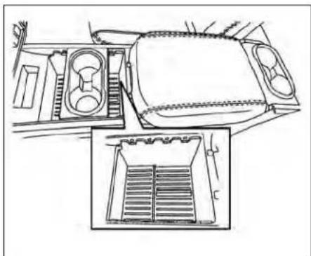
natural_image
Line drawing of a vehicle interior showing dashboard, intake manifold, and exhaust vent (no text or symbols)CONSOLE BOX STORAGE TRAYS (if so equipped)
CAUTION
- Toavoiddamagingtheextended floor, theweightsecured should not exceed 247lbs.(112kg).
- Toavoiddamagingthebungeehook loops, donotexceed35lbs.(16kg) of forcetoanygivenloop.

natural_image
Diagram of a car air intake system showing dashboard, control panel, and side view with zoomed-in detail (no text or symbols)LIC3386 LIC3399

natural_image
Line drawing of a car interior panel with directional arrow and control buttons (no text or symbols)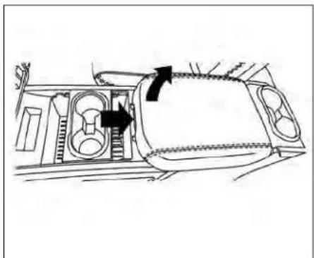
natural_image
Diagram of a vehicle interior showing engine compartment and directional arrows indicating flow or movement (no text or labels)CELL PHONE STORAGE TRAY (if so GLOVE BOX
equipped)
A removable storage tray. located in the center console, can be used to store up two cell phones.
Open the glove box by pulling the handle. Use the master key to lock or unlock the glove box lock. The valet key cannot be used to lock or unlock the glove box lock.
CONSOLE BOX (if so equipped)
WARNING
Thecenterconsoleboxshouldnotbe usedwhiledrivingsofullattentionmay begiventovehicleoperation.
WARNING
Keepgloveboxlidclosedwhiledriving tohelppreventinjuryinanaccidentor asuddenstop.

natural_image
Line drawing of a car interior showing a hand opening the dashboard with an arrow indicating rotation (no text or symbols)
CENTER ARMREST STORAGE (if so equipped)
To access the center armrest storage area, lower the center armrest and lift the lid.
CAUTION
The centerarmreststorages should not be used while drivings of full attention may begin to vehicle operation.

natural_image
Line drawing showing car seat assembly before and after change, with no text or symbols presentBenchseat(center)
UNDER FRONT SEAT STORAGE BIN (if so equipped)
To access the storage bin, lift the center of the front bench seat toward the front of the vehicle.
CAUTION
- Toavoiddamagingthetrayunder theseat,cargointhetrayshouldnot exceed20lbs.(9.08kg).
- The cushion storage bin should not be used while driving so full attention may begin to vehicle operation.

natural_image
Line drawing of a car interior showing dashboard and rear seats with no text or symbolsOVERHEAD SUNGLASSES STORAGE (if so equipped)
To open the sunglasses holder, push and release.
Only store one pair of sunglasses in the holder.
WARNING
Keepthesunglassesholderclosed whiledrivingtoavoidobstructingthe driver'sviewandtohelppreventan accident.
CAUTION
- Donotuseforanythingotherthan sunglasses.
- Donotleavesunglassesinthesun-glassesholderwhileparkingindirect sunlight.Theheatmaydamagethe sunglasses.

natural_image
Diagram of a car interior showing a central tray with internal compartments and a directional arrow (no text or symbols)Front-TypeA(ifsoequipped) CUP HOLDERS

natural_image
Line drawing of a car interior showing a door, drawer, and seat with an arrow indicating direction (no text or symbols)Front-TypeB(ifsoequipped)
CAUTION
- Avoid abrupt starting and braking whentecupholderis being used to prevent spilling the drink. If the liquid is hot, it cansald you or your passenger.
- Useonlysoftcupsinthecupholder. Hardobjectscaninjureyouinan accident.

natural_image
Line drawing of a car interior showing a key inserted into the seat (no text or symbols)Armrest(ifsoequipped)
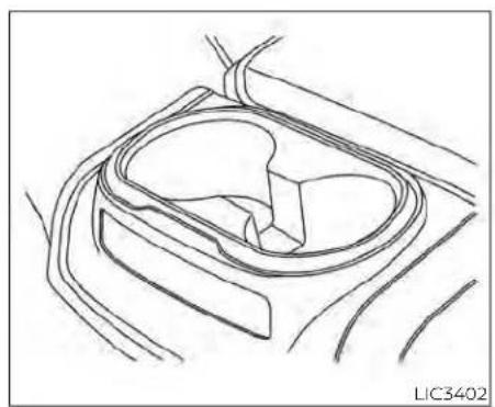
natural_image
Line drawing of a car interior frame with no text or symbols2ndrow(rearofrontconsole) (ifsoequipped)
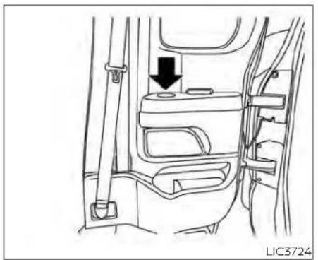
natural_image
Line drawing of a car interior showing seatbelt and door panel (no text or symbols)2ndrow(doorarmrest)(ifsoequipped)

natural_image
Line drawing of a car seatbelt with an arrow indicating clockwise motion (no text or symbols)2ndrowbench(ifsoequipped)

natural_image
Line drawing of a car interior showing the dashboard and side compartments with an arrow indicating a motion or force (no text or symbols present)Frontbottleholder

natural_image
Diagram of a car interior showing the dashboard and side panels with an arrow pointing to a component (no text or symbols present)Rearbottleholder
CAUTION
- Donotusebottleholderforanyother objectsthatcouldbethrownaboutin thevehicleandpossiblyinjure peopleduringsuddenbrakingoran accident.
- Donotusebottleholderforopenliquidcontainers.

natural_image
Line drawing of a car interior showing dashboard and seat components (no text or symbols)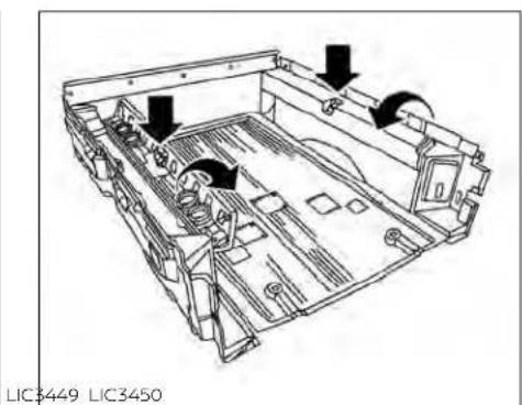
natural_image
Technical line drawing of a mechanical assembly with arrows indicating components (no text or symbols)
natural_image
Technical line drawing of a mechanical assembly with an inset view showing internal components (no text or symbols)GROCERY HOOKS (if so equipped)
The grocery hooks allow for standard size plastic grocery bags to hang side by side.
To access the grocery hooks, fold up the rear bench seat. For additional information see "Folding the rear bench seat up" (P. 1-
BED LINER STORAGE BINS (if so equipped)
To open the bed liner storage bins on the
top of the wheel wells, unlock the bin and lift the lid toward the inside of the truck bed. To close, replace the lid and lock the bin.
To open the bed liner storage bins on the tail gate end of the bed liner, lift the tab away from the truck bed, pull the lid up and away from the truck.
CAUTION
Donotapplyatotalloadofmorethan 18lbs.(8kg)toasinglegroceryhook.

CARGO HOOKS (if so equipped)
When securing items using cargo hooks, located on the rear door pillars, do not apply a load more than 110 lbs. (490 N) to a single hook.
The cargo hooks that are located on the floor should have loads less than 110 lbs. (490 N) to a single hook.
The cargo hooks can be used to secure cargo with ropes or other types of straps.
WARNING
• Properlysecureallcargowithropes orstrapstohelppreventitfromslidingorshifting.Donotplacecargo higherthantheseatbacks.Inasuddenstoporcollision,unsecured cargocouldcausepersonalinjury.
- Usesuitableropesandhookstose-curecargo.
- Neverallowanyonetorideinthe cargoarea.Itisextremelydangerous torideinacargoareainsideofvehicle.Inacollision,peopleridingin theseareasaremorelikelytobeseriouslyinjuredorkilled.
- Donotallowpeopletorideinany areaofyourvehiclethatisnot equippedwithseatsandseatbelts.
- Thechildrestrainttoptetherstrap maybedamagedbycontactwith itemsinthecargoarea.Secureany itemsinthecargoarea.Yourchild couldbeseriouslyinjuredorkilledin acollisionifthetoptetherstrapis damaged.
- Besureeveryoneinyourvehicleisin aseatandusingaseatbeltproperly.

natural_image
Technical line drawing of a mechanical component with two circular ports and directional arrows (no text or symbols)C-CHANNEL CARGO HOOKS (if so equipped)
The C-Channel cargo hooks, located on the back panel, can be used to secure cargo with ropes or other types of straps.
When securing items using C-Channel cargo hooks, located on the back panel, do not apply a load more than 110 lbs. (490 N) to a single hook.
WINDOWS
WARNING
- Properlysecureallcargowithropes orstrapstohelppreventitfromslidingorshifting.Donotplacecargo higherthanthesatbacks.Inasuddenstoporcollision,unsecured cargocouldcausepersonalinjury.
- Usesuitableropesandhookstose-curecargo.
- Neverallowanyonetorideinthe cargoarea.Itisextremelydangerous torideinacargoareainsideofvehicle.Inacollision,peopleridingin theseareasaremorelikelytobeseriouslyinjuredorkilled.
- Donotallowpeopletorideinany areaofyourvehiclethatisnot equippedwithseatsandseatbelts.
- Thechildrestrainttoptetherstrap maybedamagedbycontactwith itemsinthecargoarea.Secureany itemsinthecargoarea.Yourchild couldbeseriouslyinjuredorkilledin acollisionifthetoptetherstrapis damaged.
- Besureeveryoneinyourvehicleisin aseatandusingaseatbeltproperly.
POWER WINDOWS
WARNING
- Makesurethatallpassengershave theirhands,etc.,insidethevehicle whileitisinmotionandbeforeclosingthewindows. Use thewindow lockswitchtopreventunexpected useofthepowerwindows.
- Tohelpavoidriskofinjuryordeath throughunintendedoperationofthe vehicleand/oritssystems,including entrapmentinwindowsorinadvertent door lock activation, do not leavechildren,peoplewhorequire the assistance of others or pets unattendedinyourvehicle.Additionally, thetemperatureinsideaclosedvehicleonawarmdaycanquicklybecomehighenoughtocauseasignificantriskofinjuryordeathtopeople andpets.
The power windows operate when the ignition switch is placed in the ON position or for a period of time after the ignition switch is placed in the OFF position. If the driver's or passenger's door is opened during this period of time, the power to the windows is canceled.

- Window lock button
- Power door lock switch
- Front passenger side automatic window switch
- Right rear passenger window switch (if so equipped)
- Left rear passenger window switch (if so equipped)
- Driver side automatic window switch
Driver's side power window
switch
The driver's side control panel is equipped with switches to open or close the front and rear (if so equipped) passenger windows.
To open a window, push the switch and hold it down. To close a window, pull the switch and hold it up. To stop the opening or closing function at any time, simply release the switch.


Front passenger's power window switch
The passenger's window switch operates only the corresponding passenger's window. To open the window, push the switch and hold it down ① . To close the window, pull the switch up ② .
Rear power window switch (if so equipped)
The rear power window switches open or close only the corresponding windows. To open the window, push the switch and hold it down ①. To close the window, pull the switch up ②.
Locking passengers' windows
When the window lock switch is depressed, only the driver's side window can be opened or closed. Push it again to cancel the window lock function.

Automatic operation
To fully open a window equipped with automatic operation, push the window switch down to the second detent and release it; it need not be held. The window automatically opens all the way. To stop the window, lift the switch up while the window is opening.
To fully close a window equipped with au- mended that you visit a NISSAN dealer for automatic operation, pull the switch up to the this service. second detent and release it; it need not be the control unit detects something held. To stop the window, push the switch caught in a window equipped with auto-down while the window is closing. automatic operation as it is closing, the window will be immediately lowered.
Auto-reverse function
The auto-reverse function can be activated when a window is closed by automatic operation.
Depending on the environment or driving conditions, the auto-reverse function may be activated if an impactor loads similar to something being caught in the window occurs.
WARNING
Therearesomesmalldistancesimmediatelybeforethe closed position whichcannotbedetected.Makesure thatallpassengershavetheirhands, etc.,insidethevehiclebeforeclosing thewindow.
If the vehicle's battery is disconnected, replaced, or jump started, the power window auto-reverse function may not operate properly. Have the power window auto-reverse system re-initialized. It is recommended that you visit a NISSAN dealer for this service. If the control unit detects something caught in a window equipped with automatic operation as it is closing, the window will be immediately lowered.

natural_image
Simple line drawing of a mobile phone with a black and white icon inside (no text or symbols)LC3448
REAR POWER WINDOW SWITCH (if so equipped)
WARNING
- Youmustensureallooccupantsand objectsarefreeoftherearwindow areapriortoandduringoperation. Failuretodosomayresultinjury and/ordamagetotherearwindow system.
- Therearwindowisnotdesignedto carrylongitemsthroughit.
- Donotplaceobjectsthroughthe openedrearwindow.Donotusethe rearwindowasacargoareapass-through.Thismayresultindamage totherearwindowsystem,orpersonalinjury.
WARNING
- Tohelpavoidriskofinjuryordeath throughunintendedoperationofthe vehicleandoritssystems,including entrapmentinwindowsorinadvertentdoorlockactivation,donot leavechildren,peoplewhorequire theassistanceofothersorpetsunattendedinyourvehicle.Additionally, thetemperatureinsideaclosedvehicleonawarmdaycanquicklybecomehighenoughtocauseasignificantriskofinjuryordeathtopeople andpets.
To open the rear power window, push in and hold the switch.
To close the rear power window, pull out and hold the switch.
To stop the opening or closing function at any time, simply release the switch.
NOTE:
Iftherearpowerwindowisopenedwhile thedefrosterswitchison,therearwindowdefroster(ifsoequipped)willautomaticallyshutoff.The heated outside mirrors(ifsoequipped)willremainon. Therearwindowdefrosterwillautomaticallyturnonwhentherearpower windowisfullyclosediftheswitchison.

REAR SLIDING WINDOW (if so equipped)
WARNING
- Youmustensureallooccupantsand objectsarefreeoftherearwindow areapriortoandduringoperation. Failuretodosomayresultinjury and/ordamagetotherearwindow system.
- Therearwindowisnotdesignedto carrylongitemsthroughit.
MOONROOF(ifsoequipped)
- Donotplaceobjectsthroughthe openedrearwindow.Donotusethe rearwindowasacargoareapass-through.Thismayresultindamage totherearwindowsystem,orpersonalinjury.
Squeeze the handles of the level ① , then slide the window open ② .
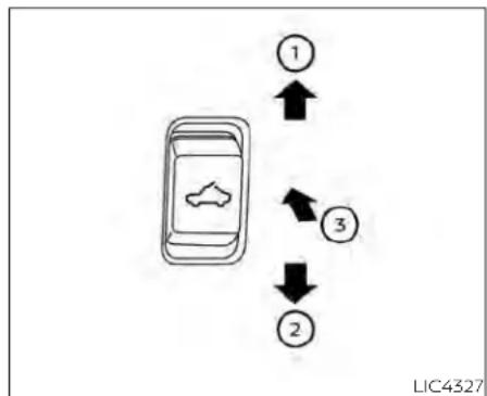
flowchart
graph TD
    A["Car with Air Icon"] --> B["1"]
    A --> C["2"]
    A --> D["3"]
    B --> E
    C --> F
    D --> G
    style A fill:#f9f,stroke:#333
    style B fill:#ccf,stroke:#333
    style C fill:#ccf,stroke:#333
    style D fill:#ccf,stroke:#333
POWER MOONROOF
The front moonroof is a power moonroof, if the rear moonroof is fixed glass. The power moonroof will only operate when the ignition switch is placed in the ON position. The moonroof is operational for a period of 1 hour time, even if the ignition switch is placed in the OFF position. If the driver's door or the front passenger's door is opened during this period of time, the power to the moonroof is canceled.
Sliding the moonroof
To fully open or close the moonroof, push the switch toward the open or close position and release it; it need not be held. The roof will automatically open or close all the way. To stop the roof, push the switch once while it is opening or closing.
Tilting the moonroof
To tilt up, first close the moonroof, then push the switch③ and release it; it need not be held. To tilt down the moonroof, push the switch to the tilt down position②.
Resetting the moonroof switch
If the moonroof does not operate properly, perform the following procedure to initialize the moonroof operation system.
- If the moonroof is open, close it fully by repeatedly pushing the moonroof switch to the close position 2 .
- Push and hold the moonroof switch to the close position ② for approximately 15 seconds.
-
Release the switch after the moonroof moves up, down, then back to the full tilt up position.
-
Push and hold the switch to the close position ②.
- Release the switch after the moonroof completes one full cycle from the tilt up position to the closed position, then to the open position, and again to the fully closed position.
- Check if the moonroof switch operates normally.
If the moonroof does not operate properly after performing the procedure above, have your vehicle checked. It is recommended that you visit a NISSAN dealer for this service.
Auto-reverse function (when closing or tilting down the moonroof)
The auto-reverse function can be activated when the moonroof and sunshade are closed or tilted down by automatic operation when the ignition switch is placed in the ON position or for a period of time after the ignition switch is placed in the ON position.
Depending on the environment driving conditions, the auto-reverse function may be activated if an impactor loads similar to something being caught in themoon roof occurs.
WARNING
Therearesomesmalldistancesimmediatelybeforetheclosedposition whichcannotbedetected.Makesure thatallpassengershavetheirhands, etc.,insidethevehiclebeforeclosing themoonroof.
Whenclosing
If the control unit detects something caught in the moonroof and sunshade as it moves to the front, the moonroof and sunshade will immediately open backward.
Whentiltingdown
If the control unit detects something caught in the moonroof as it tilts down, the moonroof will immediately tilt up.
WARNING
- Inanaccidentyoucouldbethrown fromthevehiclethroughanopen moonroof.Alwaysuseseatbeltsand childrestraints.
- Donotallowanyonetostandupor extendanyportionoftheirbodyout ofthemoonroofopeningwhilethe vehicle is in motion or while the moonroofisclosing.
CAUTION
- Removewaterdrops, snow, iceor sand from the moonroof before opening.
- Donotplaceheavyobjectsonthe moonrooforsurroundingarea.
INTERIORLIGHTS

flowchart
graph TD
    A["Mobile Device Icon"] -->|① ↑| B["Downward Arrow"]
    A -->|② ↓| C["Right Arrow"]
If the moonroof does not close Have your moonroof checked and repaired. It is recommended that you visit a NISSAN dealer for this service.

Sunshade
To open the sunshade:
- To fully open the sunshade, push the switch toward the open position①.
• To fully open the sunshade and the moonroof together, push the moonroof switch toward the open position.
To close the sunshade:
- To fully close the sunshade, push the switch toward the close position 2 .
The interior light has a three-position switch and operates regardless of ignition switch position.
When the switch is in the ON position, the interior lights illuminate, regardless of door position. The lights will go off after a period of time unless the ignition switch is placed in the ON position.
2-88 Instrumentsandcontrols
When the switch is in the DOOR or normal operation position ②, the interior lights, puddle lights (if so equipped), and cargo light will stay on for a period of time when
- The doors are unlocked by the key fob, a key or the power door lock switch while all doors are closed and the ignition switch is in the OFF position.
- The driver's door is opened and then closed while the ignition switch is placed in the OFF position.
- The ignition switch is placed in the OFF position while all doors are closed.
The lights will turn off while the timer is activated when:
- The driver's door is locked by the key fob, a key, or the power door lock switch.
• The ignition switch is turned ON.
When the switch is in the OFF position, the interior lights do not illuminate, regardless of door position. The puddle lights (if so equipped) and cargo light come on when any front or rear passenger door is opened.
The lights will turn off automatically after a period of time while doors are open to prevent the battery from becoming discharged.
CAUTION
Donotuseforextendedperiodsoftime withtheenginestopped.Thiscouldresultinadischargedbattery.

natural_image
Line drawing of a car interior with a directional arrow indicating movement or change (no text or symbols)CONSOLE LIGHT (if so equipped)
The console light will turn on whenever the parking lights or headlights are illuminated.
The console light brightness can be adjusted with the illumination brightness control.
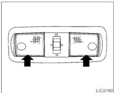
MAP LIGHTS (if so equipped)
To turn the map lights on, push the switches. To turn them off, push the switches again.

CAUTION
Donotuseforextendedperiodsoftime withtheenginestopped.Thiscouldresultinadischargedbattery.

natural_image
Simple line drawing of a rectangular frame with an arrow pointing to the left side (no text or symbols)PERSONAL LIGHTS (if so equipped)
To turn the rear personal lights on, push switch. To turn them off, push the switch again.
HOMELINK®UNIVERSAL TRANSCEIVER(ifsoequipped)
The HomeLink® Universal Transceiver provides a convenient way to consolidate the functions of up to three individual handheld transmitters into one built-in device.
HomeLink® Universal Transceiver:
- will operate most radio frequency devices such as garage doors, gates, home and office lighting, entry door locks and security systems.
- Is powered by your vehicle's battery. No separate batteries are required. If the vehicle's battery is discharged or is disconnected, HomeLink® will retain all programming.
WhentheHomeLink®UniversalTransceiverisprogrammed,retaintheoriginaltransmitterforfutureprogrammingprocedures (Example:new vehicle purchases).Uponsaleofthevehicle,the programmed HomeLink® Universal Transceiverbuttonsshouldbeerasedfor securitypurposes.Foradditionalinformation,see"ProgrammingHomeLink®" (P.2-91).
WARNING
- Yourvehicle'sengineshouldbe turnedoffwhileprogrammingthe HomeLink®UniversalTransceiver.For additionalinformation,see"Push-buttonignitionswitch"(P.5-13).Do notbreatheexhaustgases;theycontaincolorlessandodorlesscarbon monoxide.Carbonmonoxideisdangerous.itcancauseunconsciousnessordeath.
- DonotusetheHomeLink®Universal Transceiverwithanygaragedoor openerthatlackssafetystopandreversefeaturesasrequiredbyfederal safetystandards.(Thesestandards becameeffectiveforopenermodels manufacturedafterApril1, 1982.)A garagedooropenerwhichcannot detectanobjectinthepathofa closinggaragedoorandthenautomatically stop and reverse does not meet current federalsafety standards. Usingagaragedooropenerwithout these features increases the risk of seriousinjuryordeath.
- During the programming procedure yourgaragedoororsecuritygatewill openandclose(ifthetransmitteris withinrange). Makesure thatpeople orobjectsareclearofthegarage door, gate, etc., that you are programming.
PROGRAMMING HOMELINK®
If you have any questions or are having difficulty programming your HomeLink® buttons, refer to the HomeLink® web site www.homelink.com or call 1-800-355-3515.
NOTE:
Placetheignitionswitchin theONor ACC position(withoutstartingtheengine) whenprogrammingHomeLink®.Itis also recommended that anewbatterybe placed in the hand-held transmitter of the device being programmed to HomeLink® for quicker programming and accurate transmission of the radio frequency.

- Position the end of your hand-held transmitter 1-3 in (2-8 cm) away from the HomeLink® surface, keeping the HomeLink® indicator light① in view.
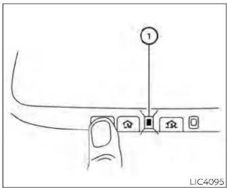
- Using both hands, simultaneously press and hold the desired HomeLink® button and hand-held transmitter button. DO NOT release until the HomeLink® indicator light① flashes slowly and then rapidly. When the indicator light flashes rapidly, both buttons may be released. (The rapid flashing indicates successful programming.)
NOTE:
Somedevicesmayrequireyoutoreplace Step2withthecyclingprocedurenoted in"ProgrammingHomeLink®forCanadiancustomersandgateopeners" (P.2-93).
- Press and hold the programmed HomeLink® button and observe the indicator light.
- If the indicator light ① issolid/continuous,programmingiscomplete and your device should activate when the HomeLink® button is pressed and released.
-
If the indicator light blinks rapidlyfor2 secondsandthen turnsto asolid/continuouslight, continue withSteps 4-6for a rolling code device. A second person may make the following steps easier. Use a ladder or other device. Do not stand on your vehicle to perform the next steps.
-
At the receiver located on the garage door opener motor in the garage, locate the "learn" or "smart" button (the name and color of the button may vary by manufacturer but it is usually located near where the hanging antenna wire is attached to the unit). If there is difficulty locating the button, reference the garage door opener's manual.
- Press and release the "learn" or "smart" button.
NOTE:
Oncethebuttonispressed,youhaveap- proximately 30 seconds to initiate the nextstep.
- Return to the vehicle and firmly press and hold the trained HomeLink® button for 2 seconds and release. Repeat the "press/hold/release" sequence up to three times to complete the training process. HomeLink® should now activate your rolling code equipped device.
- If you have any questions or are having difficulty programming your HomeLink® buttons, refer to the HomeLink® web site at: www.homelink.com or call 1-800-355-3515.
PROGRAMMING HOMELINK® FOR CANADIAN CUSTOMERS AND GATE OPENERS
Canadian radio-frequency laws require transmitter signals to "time-out" (or quit) after several seconds of transmission – which may not be long enough for HomeLink® to pick up the signal during training. Similar to this Canadian law, some U.S. gate operators are designed to "timeout" in the same manner.
If you live in Canada or you are having difficulties training a gate operator or garage door opener by using the "Training" procedures, replace Programming HomeLink® step2 with the following:
NOTE:
When programmingagaragedoor opener,etc.,unplugthedeviceduring the"cycling"processtoppreventpossible damage to the garage door opener components.
-
For additional information, see "Programming HomeLink®" step 1 (P. 2-91).
-
Using both hands, simultaneously press and hold the desired HomeLink® button and the hand-held transmitter button. During training, your hand-held transmitter may automatically stop transmitting. Continue to press and hold the desired HomeLink® button while you press and re-press ("cycle") your hand-held transmitter every 2 seconds until the frequency signal has been learned. The HomeLink® indicator light will flash slowly and then rapidly after several seconds upon successful training. DO NOT release until the HomeLink® indicator light flashes slowly and then rapidly. When the indicator light flashes rapidly, both buttons may be released. The rapid flashing indicates successful training. Proceed with "Programming HomeLink®" step 3 (P. 2-91) to complete. If the device was unplugged during the programming procedure, remember to plug it back in when programming is completed.
The HomeLink® Universal Transceiver, after it is programmed, can be used to activate the programmed device. To operate, simply press and release the appropriate pro-
grammed HomeLink® Universal Transceiver button. The amber indicator light will illuminate while the signal is being transmitted.
For convenience, the hand-held transmitter of the device may also be used at any time.
PROGRAMMING TROUBLE-DIAGNOSIS
If the HomeLink ® does not quickly learn the hand-held transmitter information:
- Replace the hand-held transmitter batteries with new batteries.
- Position the hand-held transmitter with its battery area facing away from the HomeLink® surface.
- Press and hold both the HomeLink® and hand-held transmitter buttons without interruption.
- Position the hand-held transmitter 1 - 3 inches (26 - 76 mm) away from the HomeLink® surface. Hold the transmitter in that position for up to 15 seconds. If HomeLink® is not programmed within that time, try holding the transmitter in another position - keeping the indicator light in view at all times.
Instrumentsandcontrols2-93
If you have any questions or are having difficulty programming your HomeLink® buttons, refer to the HomeLink® web site www.homelink.com or call 1-800-355-3515.
CLEARING THE PROGRAMMED INFORMATION
The following procedure clears the programmed information from both buttons. Individual buttons cannot be cleared. However, individual buttons can be reprogrammed. For additional information, see "Reprogramming a single HomeLink® button" (P. 2-94).
To clear all programming:
-
Press and hold the two outer HomeLink® buttons until the indicator light begins to flash in approximately 10 seconds. Do not hold for longer than 20 seconds.
-
Release both buttons.
HomeLink® is now in the programming mode and can be programmed at any time beginning with "Programming HomeLink®" - Step 1 (P. 2-91).
REPROGRAMMING A SINGLE HOMELINK® BUTTON
To reprogram a HomeLink® Universal Transceiver button, complete the following:
- Press and hold the desired HomeLink® button. DONOTrelease the button.
- The indicator light will begin to flash after 20 seconds. Without releasing the HomeLink® button, proceed with "Programming HomeLink®" - Step 1 (P. 2-91).
For questions or comments, contact HomeLink® at: www.homelink.com or 1-800-355-3515 (except Mexico).
The HomeLink® Universal Transceiver button has now been reprogrammed. The new device can be activated by pressing the HomeLink® button that was just programmed. This procedure will not affect any other programmed HomeLink® buttons.
IF YOUR VEHICLE IS STOLEN
If your vehicle is stolen, you should change the codes of any non-rolling code device that has been programmed into HomeLink®. Consult the Owner's Manual of each device or call the manufacturer or dealer of those devices for additional information.
When your vehicle is recovered, you will need to reprogram the HomeLink® Universal Transceiver with your new transmitter information.
FCCNotice:
ForUSA:
ThisdevicecomplieswithPart15ofthe FCCRules.Operationissubjecttothefollowingtwoconditions:(1)Thisdevice maynotcauseinterference,and(2)this devicemustacceptanyinterferencereceived,includinginterferencethat may causeundesiredoperation.
NOTE:
Changesormodificationsnotexpressly approved by the party responsible for compliancecouldvoidtheuser'sauthoritytooperatetheequipment.
ForCanada:
This device contains licence-exempt transmitter(s)/receiver(s) that comply with Innovation, Science and Economic Development Canada's licence-exempt RSS(s). Operation is subject to the following two conditions: (1) This device may not cause interference. (2) This device must accept any interference, including interference that may cause undesired operation of the device.
Instrumentsandcontrols2-95
MEMO
2-96 Instrumentsandcontrols
3Pre-drivingchecksandadjustments
Keys 3-2
NISSAN Intelligent Key ® 3 - 2
NISSAN Vehicle Immobilizer System keys 3-4
Doors 3-4
Locking with key 3-5
Locking with inside lock knob 3-6
Locking with power door lock switch 3-6
Rear doors (King Cab® models) 3-7
Automatic door locks (if so equipped) ..... 3 - 8
Child safety rear door lock (if so equipped) 3 - 9
NISSAN Intelligent Key® system 3-9
Operating range 3-11
Door locks/unlocks precaution 3-11
NISSAN Intelligent Key® Operation 3-12
How to use the remote keyless entry
function 3-15
Warning signals 3-19
Troubleshooting guide 3-20
Remote Engine Start (if so equipped) 3-21
Remote Engine Start operating range .....3-21
Remote starting the vehicle 3-22
Extending engine run time 3-22
Canceling a Remote Engine Start 3-22
Conditions the Remote Engine Start will not work 3-23
Hood 3-24
Gasoline fuel engines 3-25
Steering wheel 3-27
Manual operation (if so equipped) 3-27
Automatic operation (if so equipped) .....3-28
Sunvisors 3-29
Vanity mirrors (if so equipped) 3-29
Card holder (driver's side only) 3-30
Mirrors 3-30
Manual anti-glare rearview mirror (if so equipped) 3-30
Automatic anti-glare rearview mirror
(if so equipped) 3-30
Outside mirrors 3-31
Truck box 3-35
Tailgate 3-35
Tie down hooks 3-39
Memory Seat (if so equipped) 3-39
Memory storage function 3-40
Linking a key fob to a stored memory position 3-40
Entry/exit function 3-41
System operation 3-41
KEYS

TypeA(ifsoequipped)
- Intelligent Key (two sets)
- Mechanical key
- Master key
- Key number plate (one plate) NISSAN INTELLIGENT KEY®

TypeB(ifsoequipped)
Your vehicle can only be driven with the Intelligent Keys which are registered to your vehicle's Intelligent Key system components and NISSAN Vehicle Immobilizer System components.
Neverleavethekeysinthevehicle.
As many as four Intelligent Keys can be registered and used with one vehicle. The new keys must be registered prior to the use with the Intelligent Key system and NISSAN Vehicle Immobilizer System of your vehicle. It is recommended that you visit a NISSAN dealer for this service. Since the registration process requires erasing all
memory in the Intelligent Key components when registering new keys, be sure to take all Intelligent Keys that you have to the NISSAN dealer.
A key number plate is supplied with your keys. Record the key number and keep it in a safe place (such as your wallet), not in the vehicle. If you lose your keys, it is recommended that you visit a NISSAN dealer for duplicates by using the key number. NISSAN does not record key numbers so it is very important to keep track of your key number plate.
A key number is only necessary when you have lost all keys and do not have one to duplicate from. If you still have a key, it can be duplicated without knowing the key number.
CAUTION
Listedbelowareconditionsoroccurrences whichwilldamagetheIntelligentKey:
- Do not allow the Intelligent Key, which contains electrical components, to come into contact with water or saltwater. This could affect the system function.
- DonotdroptheIntelligentKey.
3-2 Pre-drivingchecksandadjustments
- DonotstrikethIntelligentKey sharplyagainstanotherobject.
- DonotchangeormodifytheIntelligentKey.
- WettingmaydamagetheIntelligent Key.IftheIntelligentKeygetswet, immediatelywipeuntilitiscompletelydry.
- DonotplacethelIntelligentKeyforan extendedperiodinanareawhere temperaturesexceed140°F(60°C).
- DonotattachtheIntelligentKeywith akeyholderthatcontainsamagnet.
- DonotplacetheIntelligentKeynear equipmentthatproducesamagnetic field,suchasaTV,audioequipment andpersonalcomputers.

Mechanical key
The Intelligent Key contains the mechanical key.
To remove the mechanical key, release the lock knob on the back of the Intelligent Key. To install the mechanical key, firmly insert it into the Intelligent Key until the lock knob 3 returns to the lock position.
Use the mechanical key to lock or unlock the driver's door, tailgate and glove box.
CAUTION
AlwayscarrythemechanicalkeyinstalledintheIntelligentKeyslot.
For additional information, see "Doors" (P. 3-4), "Tailgate" (P. 3-35) or "Storage" (P. 2-70).
Valet hand-off
When you have to leave a key with a valet, give them the Intelligent Key itself, keep the mechanical key and master key with you to protect your belongings.
To prevent the glove box from being opened during valet hand-off, follow the procedures below:
Remove the mechanical key from the Intelligent Key.
Lock the glove box and tailgate with the mechanical key or master key.
Hand the Intelligent Key without the mechanical key to the valet, keep the mechanical and master key with you.
For additional information, see "Storage" (P. 2-70) and "Tailgate" (P. 3-35).
If an Intelligent Key is lost or stolen, NISSAN recommends erasing the ID code of that Intelligent Key from the vehicle. This may prevent the unauthorized use of the Intelligent Key to operate the vehicle. For information regarding the erasing procedure, it is recommended that you visit a NISSAN dealer.
DOORS
NISSAN VEHICLE IMMOBILIZER SYSTEM KEYS
Additional or replacement keys:
If you still have a key, the key number is n necessary when you need extra NISSAN Vehicle Immobilizer System keys. Your existing key can be duplicated without knowing the key number. As many as four NISSAN Vehicle Immobilizer System keys can be used with one vehicle. You should bring all NISSAN Vehicle Immobilizer System keys that you have to the NISSAN dealer for registration. This is because the registration process will erase the memory of all key codes previously registered into the NISSAN Vehicle Immobilizer System. After the registration process, these components will only recognize keys coded into the NISSAN Vehicle Immobilizer System during registration. Any key that is not given to the dealer at the time of registration will no longer be able to start your vehicle.
CAUTION
Donotallowtheimmobilizersystem key,whichcontainsanelectricaltransponder,tocomeintocontactwithwaterorsaltwater.Thiscouldaffectsystemfunction.
When the doors are locked using one of the following methods, the doors cannot be opened using the inside or outside door handles. The doors must be unlocked to open the doors.
WARNING
• Alwayshavethedoorslockedwhile driving. Alongwiththeuseofseat belts, thisprovidesgreatersafety in the event of an accident by helping to prevent persons from being thrown from the vehicle. This also helps keep children and others from unintentionally opening the doors, and will help keep out intruders.
- Before opening any door, always look for and avoid on coming traffic.
3-4 Pre-drivingchecksandadjustments
- Tohelpavoidriskofinjuryordeath throughunintendedoperationofthe vehicleand/oritssystems,including entrapmentinwindowsorinadvertentdoorlockactivation,donot leavechildren,peoplewhorequire theassistanceofothersorpetsunattendedinyourvehicle.Additionally, thetemperatureinsideaclosedvehicleonawarmdaycanquicklybecomehighenoughtocauseasignificantriskofinjuryordeathtopeople andpets.
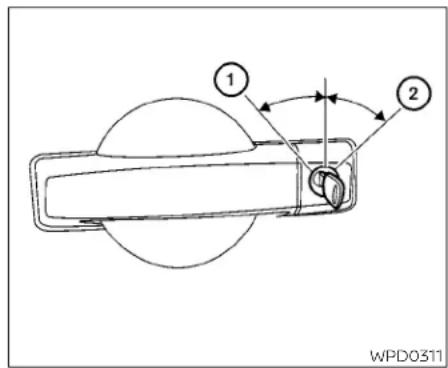
For additional information, see "Security systems" (P. 2-38).
Driver'sside
LOCKING WITH KEY
To lock the door using the mechanical key, turn the key toward the front of the vehicle
①. This will only lock the door and will not activate the security system. To arm the security system, press the 🔒 button on the Intelligent Key.
To unlock the door using the mechanical key, turn the key toward the rear of the vehicle ②. This will only unlock the corresponding door and will not disarm the security system.

Insidelock
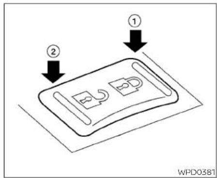
LOCKING WITH POWER DOOR LOCK SWITCH
LOCKING WITH INSIDE LOCK KNOB
To lock the door without the key, move inside lock to the lock position ①, then close the door.
To unlock the door without the key, move the inside lock knob to the unlock position ②.
To lock all the doors and the tailgate lock (if so equipped) without a key, push the door lock switch (driver's or front passenger's side) to the lock position. When locking the door this way, be certain not to leave the key inside the vehicle.
To unlock all the doors and the tailgate lock (if so equipped) without a key, push the door lock switch (driver's or front passenger's side) to the unlock position.
Lockout protection
With the Intelligent Key left in the vehicle, if all doors are locked, then closed, a chime will sound after the last door is closed and all doors will unlock automatically.
These functions help to prevent the Intelligent Key from being accidentally locked inside the vehicle.

natural_image
Line drawing of a car interior showing the door, window, and side panel (no text or symbols)REAR DOORS (King Cab® models)
- Open the driver's or passenger's door.

- From the outside, pull the door handle Ⓐ toward you.
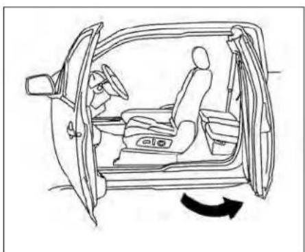
natural_image
Line drawing of a car interior showing the driver's seat, steering wheel, and dashboard (no text or symbols)- Open the door to the desired position.
Pre-drivingchecksandadjustments3-7

natural_image
Line drawing of a car interior showing dashboard, seatbelt, and rearview panel (no text or symbols)
natural_image
Diagram showing a cross-shaped crossed-out device with no visible text or symbolsCAUTION
Becarefulwhenopeningandexiting thedriver'ssidereardoorifthefuel-fillerdoorisopen.Thismaycausedam-agetothedriver'ssidereardooror fuel-fillerdoorifyouopenfullyand theymakecontact.
AUTOMATIC DOOR LOCKS (if so equipped)
- All doors lock automatically when the vehicle speed reaches 15 mph (24 km/h).
- All doors unlock automatically when the transmission is placed in the P (Park) position or when the ignition switch is placed in the OFF position, depending on the option selected in the "Vehicle Settings" menu.
NOTE:
TheAutoDoorUnlock(ifsoequipped) featurecanbechangedusingthe"VehicleSettings"menuonthevehicleinformationdisplay.Foradditionalinformation, see "Vehicle information display"(P.2-23).
NISSANINTELLIGENTKEY®SYSTEM

CHILD SAFETY REAR DOOR LOCK (if so equipped)
Child safety locks help prevent the rear doors from being opened accidentally, especially when small children are in the vehicle. The child safety lock levers are located on the edge of the rear doors.
When the lever is in the unlock position, the door can be opened from the outside or the inside.
WhentheleverisintheLOCKposition ②, thedoorcanbeopenedonlyfromthe outside.
WARNING
- Radiowavescouldadverselyaffect electricmedicalequipment.Those whoseapacemakershouldcontact theelectricmedicalequipment manufacturerforthepossibleinfluencesbeforeuse.
- TheIntelligentKeytransmitsradio waveswhenthebuttonsarepressed. TheFAAadvisestheradiowavesmay affectaircraftnavigationandcommunicationsystems.Donotoperate theIntelligentKeywhileonanairplane.Makesurethebuttonsarenot operatedunintentionally when the unitisstoredforaflight.
- NeverleavethIntelligentKeyinthe vehiclewhenyouleavethevehicle.
The Intelligent Key system can operate all the door locks using the remote control function or pushing the request switch (if so equipped) on the vehicle without taking the key out from a pocket or purse. The operating environment and/or conditions may affect the Intelligent Key system operation.
Be sure to read the following before using the Intelligent Key system.
CAUTION
BesuretocarrytheIntelligentKeywith youwhenoperatingthevehicle.
The Intelligent Key is capable of receiving and transmitting radio waves. The Intelligent Key system transmits weak radio waves from various distances. Environmental conditions may interfere with the operation of the Intelligent Key system under the following operating conditions:
- When operating near a location where strong radio waves are transmitted, such as a TV tower, power station and broadcasting station.
- When in possession of wireless equipment, such as a cellular telephone, transceiver, or a CB radio.
- When the Intelligent Key is in contact with or covered by metallic materials.
- When any type of radio wave remote control is used nearby.
- When the Intelligent Key is placed near an electric appliance such as a personal computer.
- When the vehicle is parked near a parking meter.
In such cases, correct the operating condi-As many as four Intelligent Keys can be tions before using the Intelligent Key func- registered and used with one vehicle. For tion or use the mechanical key. information about the purchase and use of
Although the life of the battery varies depending on the operating conditions, the battery's life is approximately two years. If the battery is discharged, replace it with a new one.
When the Intelligent Key battery is low, an indicator light illuminates with the message "Warning, Key ID Incorrect" in the vehicle information display. When the Intelligent Key battery is low, the NISSAN Intelligent Key® warning light (if so equipped) will blink. For additional information, see "Vehicle Information display warnings and indicators" (P. 2-32).
Since the Intelligent Key is capable of receiving radio waves, if the key is left near equipment which transmits strong radio waves, such as signals from a TV and personal computer, the battery life may become shorter.
For additional information, see "Battery replacement" (P. 8-27).

LPD2338 LPD2554
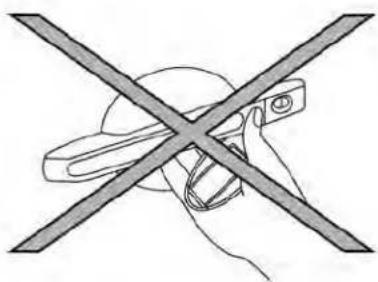
natural_image
Diagram of a hand holding a tool crossed with a diagonal line, no text or symbols presentOPERATING RANGE
The Intelligent Key functions can only be used when the Intelligent Key is within the specified operating range from the request switch ⏻ (if so equipped).
When the Intelligent Key battery is discharged or strong radio waves are present near the operating location, the Intelligent Key operating range becomes narrower, and the Intelligent Key may not function properly.
The operating range is within 31.50 in (80 cm) from each request switch ⏻ (If so equipped).
If the Intelligent Key is too close to the door DOOR LOCKS/UNLOCKS glass or handle, the request switches (if so PRECAUTION equipped) may not function. Do not push the door ban
When the Intelligent Key is within the operating range, it is possible for anyone, even someone who does not carry the Intelligent Key, to push the request switch (if so equipped) to lock/unlock the doors.
- Do not push the door handle request switch (if so equipped) with the Intelligent Key held in your hand as illustrated. The close distance to the door handle will cause the Intelligent Key system to have difficulty recognizing that the Intelligent Key is outside the vehicle.
• After locking with the door handle request switch (if so equipped), verify the doors are securely locked by testing them.
- To prevent the Intelligent Key from being left inside the vehicle, make sure you carry the Intelligent Key with you and then lock the doors. - Do not pull the door handle before pushing the door handle request switch (if so equipped). The door will be unlocked but will not open. Release the door handle once and pull it again to open the door.

natural_image
Line drawing of a pickup truck with a person standing nearby and emitting sound waves (no text or symbols)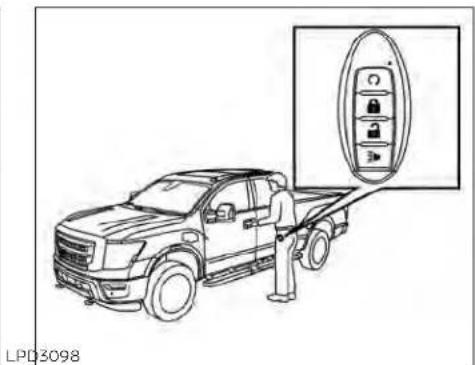
You can lock or unlock the doors without taking the Intelligent Key out of your pocket or bag.
When you carry the Intelligent Key with you, you can lock or unlock all doors by pushing the door handle request switch (if so equipped) within the range of operation.
3-12 Pre-drivingchecksandadjustments

- Move the shift lever to the P (Park) position, place the ignition switch in the LOCK position and make sure you carry the Intelligent Key with you.
- Close the driver's door and push the driver's door request switch (if so equipped) OR close all doors and push any door request switch (if so equipped) while carrying the Intelligent Key with you.
-
Push the door handle request switch (if so equipped) while carrying the Intelligent Key with you.
-
All doors and the tailgate lock (if so equipped) will lock.
- The hazard indicator lights flash twice, the outside chirp sounds twice, and the front and tail lights may turn on for 10 seconds.
NOTE:
- Requestswitches(ifsoequipped)for alldoorscanbedeactivatedwhenthe "I-KeyDoorLock(ifsoequipped)"settingisswitchedtoOFFintheVehicle Settingsofthevehicleinformationdisplay.Foradditionalinformation,see "Vehicleinformationdisplay"(P.2-23).
- Doors and the tailgate lock (if so K equipped) will lock with the door handlerequestswitch(ifsoequipped) ① whiletheignitionswitchisnotinthe LOCKposition.
- Doorsdonotlockbypushingthedoor handlerequestswitch(ifsoequipped) whilethedriver'sdoorisopen.How- ever,doorslockwith themechanical keyevenifanydoorisopen.
- Doors and the tailgate lock (if so equipped) do not lock with the door handlerequestswitch(ifsoequipped) ifthelIntelligentKeyisinsidethevehicle.Abeepwillsoundtowarnyou. However,whenanIntelligentKeyisinsidethevehicle,doorscanbelocked withanotherIntelligentKey.

WARNING
After locking the doors using the requestswitch(ifsoequipped),make surethatthedoorshavebeensecurely lockedbyoperatingthedoorhandles. Failuretofollowtheseinstructionsmay resultininadvertentlyunlockingthe doors,whichmaydecreasethesafety andsecurityofyourvehicle.

CAUTION
- Whenlockingthedoorsusingthere- questswitch(ifsoequipped),make sure tohavetheIntelligentKey in your possession before operating therequestswitch(ifsoequipped)to preventtheIntelligentKeyfrombe- ingleftinthevehicle.
- Therequestswitch(ifsoequipped)is operationalonlywhentheIntelligent KeyhasbeendetectedbytheIntelligentKeysystem.
Lockoutprotection
To prevent the Intelligent Key from being accidentally locked in the vehicle, lockout protection is equipped with the Intelligent Key system.
When any door is open, the doors are locked, and then the Intelligent Key is put inside the vehicle and all the doors are closed; a chime will sound and the lock will automatically unlock.
NOTE:
The doors may not lock when the intelligent Key is in the same hand that is operating therequest switch (if so equipped) to lock the door. Put the intelligent Key in apurse, pocket your other hand.
CAUTION
Thelockoutprotectionmaynotfunctionunderthefollowingconditions:
- WhentheIntelligentKeyisplacedon topoftheinstrumentpanel.
- WhentheIntelligentKeyisplacedin-sidethegloveboxorastoragebin.
- WhentheIntelligentKeyisplacedin-sidethedoorpockets.
- WhentheIntelligentKeyisplacedinsideornearmetallicmaterials.

natural_image
Line drawing of a pickup truck with a person standing beside it, showing a parking meter attached to the cab (no text or symbols present)Unlocking doors
- Carry the Intelligent Key.
- Push the door handle request switch (if so equipped).
- The door will unlock and the hazard indicator lights flash once, the outside chirp sounds once, and the front and tail lights may turn on for 30 seconds.
- Push the door handle request switch (if so equipped) again within one minute.
- The outside chirp will sound once and the remaining doors and tailgate lock (if so equipped) will unlock.
3-14 Pre-drivingchecksandadjustments
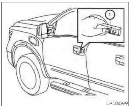
NOTE:
- If "SelectiveUnlock" isturned OFF in the Vehicle Settings, alldoorsandtail-gatelock (ifso equipped) will unlock upon the first request switch (ifso equipped) ① press.
-Therequestswitch(ifsoequipped)can bedeactivatedwhenthe"I-KeyDoor Lock(ifsoequipped)"isswitchedto OFFintheVehicleSettingsofthevehicleinformationdisplay.Foradditionalinformation,see"Vehicleinformationdisplay"(P.2-23).
If a door handle is pulled while unlocking the doors, that door may not be unlocked. Returning the door handle to its original position will unlock the door. If the door does not unlock after returning the door handle, push the door handle request (if so equipped) switch to unlock the door.
All doors will be locked automatically unless one of the following operations is per formed within one minute after pushing the request switch (if so equipped).
- Opening any door.
- Pushing the ignition switch.
Using the interior lights
The interior lights illuminate for a period of time when a door is unlocked and the room light switch is in the DOOR position.
The lights can be turned off without waiting by performing one of the following operations:
- Placing the ignition switch in the ON position.
- Locking the doors with the Intelligent Key.
- Switching the room light switch to the "OFF" position.
For additional information, see "Interior lights" (P. 2-88).
HOW TO USE THE REMOTE KEYLESS ENTRY FUNCTION
The remote keyless entry function can operate all door locks using the remote keyless function of the Intelligent Key. The remote keyless function can operate at a distance of 33 ft (10 m) away from the vehicle. The operating distance depends upon the conditions around the vehicle.
The remote keyless entry function will not function under the following conditions:
- When the Intelligent Key is not within the operational range.
- When the Intelligent Key battery is discharged.
- when the doors are open or not closed securely.
CAUTION
WhenlockingthedoorsusingtheIntelligentKey,besurenottoleavethekey inthevehicle.

Type A (if so equipped)
- (lock) button
- 🔒 (unlock) button
- (panic) button
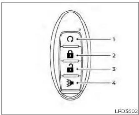
Type B (if so equipped)
- (remote engine start) button
- (lock) button
- 🔒 (unlock) button
- (panic) button
Locking doors
- Place the ignition switch in the LOCK position.
- Close all doors.
-
Press the button on the Intelligent Key.
-
The hazard warning lights flash twice and the horn beeps once.
- All doors and the tailgate (if so equipped) will be locked.
WARNING
AfterlockingthedoorsusingtheIntelligentKey,besurethatthedoorshave beensecurelylockedbyoperatingthe doorhandles.Failureretofollowtheseinstructionsmayresultininadvertently unlockingthedoors,whichmaydecreasethesafetyandsecurityofyour vehicle.
Unlocking doors
- Press the button on the Intelligent Key to unlock the driver's door.
- The hazard warning lights flash once.
- Press the 🔒 button again within 1 minute to unlock all doors and tailgate (if so equipped).
All doors and tailgate will be locked automatically unless one of the following operations is performed within 1 minute after pressing the 🔒 button:
- Opening any doors.
- Pushing the ignition switch.
Using the interior lights
The interior lights illuminate for a period of time when a door is unlocked and the room light switch is in the DOOR position.
The lights can be turned off without waiting by performing one of the following operations:
- Placing the ignition switch in the ON position.
- Locking the doors with the Intelligent Key.
- Switching the room light switch to the "OFF" position.
For additional information, see "Interior lights" (P. 2-88).
Opening windows
The Intelligent Key allows you to simultaneously open windows equipped with automatic operation.
To open the windows, press the button on the Intelligent Key for longerthan3 secondsafter all doors are unlocked
The door windows will open while pressing the 🔒 button on the Intelligent Key.
Thedoorwindows cannot be closed by using the Intelligent Key.
Using the panic alarm
If you are near your vehicle and feel threatened, you may activate the panic alarm to
call attention by pressing and holding the button on the Intelligent Key for lon-
gerthan0.5seconds.
9 The panic alarm and headlights will stay on 3 for a period of time.
The panic alarm stops when:
- It has run for a period of time.
• Any button is pressed on the Intelligent Key. - The request switch (if so equipped) on the driver or passenger door is pushed and the Intelligent Key is in range of the door handle.
Trailer light check (if so equipped)
This functionality allows the customer to confirm trailer light operation, without the need of a second person to press the brake pedal or activate each turn signal light. The trailer light check can be performed by the Intelligent Key or through the Vehicle Settings in the vehicle information display. For additional information, see "Vehicle information display" (P. 2-23).
To activate the trailer light check function with your Intelligent Key, perform the following:
- Aim the Intelligent Key at the vehicle.
- Press and release the button. LOCK
- Within 2 seconds, press and hold the LOCK button again for at least 2 seconds, until the horn beeps once and the park lights turn on.
The following events will occur:
• The left turn signal light on the vehicle and the trailer will flash for 5 seconds.
• The right turn signal light on the vehicle and the trailer will flash for 5 seconds. - The brake lights on the vehicle and the trailer will turn ON for 5 seconds.
NOTE:
IftheignitionswitchisintheOFFposition,theparklightswillturnoffaftertheeventsaboveoccur.Ifignition switchisintheONposition,lightswill stayonfor45secondsaftertrailer lightcheck.Ifthetrailerlightsdonot workproperly,checktheconnections andbulbs.Ifthevehiclelightsdonot turnon,checkthebulbs.Ifthetrailer lightcheckroutinefailstostart,ensurethefollowingvehicleconditions:
•ThevehicleisNOTmoving,0mph (0km/h)
-BrakeswitchisNOTdepressed
-LeftorrightflasherisOFF
- TrailerlightcheckconfigurationisNOT disabledandavailableinthemeter towingsettings
•ThehazardswitchisNOTturnedON
- TheshiftpositionisfullyinP(Park) position
- VehicleiswithinRemoteKeylessEntry range
Answer back horn feature
If desired, the horn beep feature can be deactivated using the Intelligent Key.
Todeactivate:Press and hold the and buttons foratleast2seconds.
The hazard warning lights will flash three times to confirm that the horn beep feature has been deactivated.
Toactivate:Press and hold the 🔒 and 🔒 buttons foratleast2secondsonce more.
The hazard warning lights will flash once and the horn will sound once to confirm that the horn beep feature has been reactivated.
Deactivating the horn beep feature does not silence the horn if the alarm is triggered.

Intelligent Key button operation light
The light blinks only when you press any button on the Intelligent Key. The light illumination only signifies that the key fob has transmitted a signal. You may look and/or listen to verify that the vehicle has performed the intended operation. The number of blinks identifies each registered key (i.e. 1 blink = 1st key, 4 blinks = 4th key) for your own identification purposes. If the light does not blink, your battery may be too weak to communicate to the vehicle. If this occurs, the battery may need to be
replaced. For additional information regarding the replacement of a battery, see "Battery replacement" (P. 8-27).
WARNING SIGNALS
To help prevent the vehicle from moving unexpectedly by erroneous operation of the Intelligent Key or to help prevent the vehicle from being stolen, a chime or chirp sounds from Inside and outside the vehicle and a warning is displayed in the instrument panel.
When a chime or beep sounds or a warning is displayed, be sure to check the vehicle and the Intelligent Key.
For additional information, see "Troubleshooting guide" (P. 3-20) and "Vehicle information display" (P. 2-23).
Pre-drivingchecksandadjustments3-19
TROUBLESHOOTING GUIDE
Verify the location of all Intelligent Keys that are programmed for the vehicle. If another Intelligent Key is in range or inside the vehicle, the vehicle system may respond differently than expected.
| Symptom Possible Cause Remedy | |||
| When pushing the ignition switch to stop the engine | The 'Shift to Park' warning appears on the vehicle information display and the inside warning chime sounds continuously. | The shift lever is not in the P (Park position. | Move the shift lever to the P (Park) position. |
| When opening the driver's door to get out of the vehicle | The Door Open warning appears on the display and the inside warning chime sounds continuously. | The ignition switch is in the ACC position. | Place the ignition switch in the ON position or close the driver's door. |
| When closing the door after getting out of the vehicle | The 'No Key Detected' warning appears on the vehicle Information display, the outside chime sounds three times and the inside warning chime sounds for approximately three seconds. | The Intelligent Key is not detected inside of the vehicle. | Place the ignition switch in the OFF position. |
| The Rear Door Alert warning message appears on the display, the horn sounds three times twice, or a Check Back Seat For All Articles warning appears on the display. | The Rear Door Alert is activated. | Check the back seat for all articles press the ENTER button to clear the Rear Door Alert warning message. | |
| When closing the door with the inside lock knob turned to LOCK | The outside chime sounds for approximately three seconds and all the doors unlock. | The Intelligent Key is inside the vehicle. | Carry the Intelligent Key with you. |
| When pushing the door handle request switch (if so equipped) or the button on the Intelligent Key to lock the door | The outside chime sounds for approximately three seconds. | The Intelligent Key is inside the vehicle. | Carry the Intelligent Key with you. |
| When pushing the ignition switch to start the engine | The Intelligent Key battery indicator appears on the display. | The battery charge is low. | Replace the battery with a new one For additional information, see 'Battery replacement' (P. 8-27). |
| The 'Key ID Incorrect' warning appears on the vehicle Information display . | The Intelligent Key is not detected inside of the vehicle. | Carry the registered Intelligent Key with you. | |
REMOTEENGINESTART(ifso equipped)
natural_image
Simple circular arrow diagram pointing right, no text or symbols presentThe 🔒 button will be on the NISSAN Intelligent Key® if the vehicle has Remote Engine Start. This feature allows the engine to start from outside the vehicle.
Vehicles with an automatic climate control system will default to either a heating or cooling mode depending on outside and cabin temperatures. For additional information, see "Remote Engine Start with Intelligent Climate Control" (P. 4-39).
Laws in some local communities may restrict or prohibit the use of Remote Engine Start, or the amount of time a parked vehicle engine may idle. For example, some laws require a person using Remote Engine Start to have the vehicle in view or may restrict idling time except in freezing temperatures. Check local regulations for any requirements.
Other conditions may affect the function of the Remote Engine Start feature. For additional information, see "Conditions the Remote Engine Start will not work" (P. 3-23).
Other conditions can affect the performance of the Intelligent Key transmitter. For additional information, see "NISSAN Intelligent Key® system" (P. 3-9).
- Tohelpavoidriskofinjuryordeath throughunintendedoperationofthe vehicleand/oritssystems,including entrapmentinwindowsorinadvertentdoorlockactivation,donot leavechildren,people who require theassistanceofothersorpetsunattendedinyourvehicle.Additionally, thetemperatureinsideaclosedvehicleonawarmdaycanquicklybecomehighenoughtocauseasignificantriskofinjuryordeathtopeople andpets.
- DonotuseRemoteEngine Startin closedspacessuchasagarage.Do notbreatheexhaustgases;theycontaincolorlessandodorlesscarbon monoxide.Carbonmonoxideisdangerous. It cancause unconsciousnessordeath.
CAUTION
WhentheIntelligentKeybatteryisdischarged or other strong radio wave sourcesarepresentneartheoperating location,theIntelligentKeyoperating rangebecomesnarrower,andtheIntelligentKeymaynotfunctionproperly.
The Remote Engine Start function can only be used when the Intelligent Key is within the specified operating range from the vehicle.
The Remote Engine Start operating range is approximately 197 ft (60 m) from the vehicle.
REMOTE STARTING THE VEHICLE
To use the Remote Engine Start feature to start the engine perform the following:
- Aim the Intelligent Key at the vehicle.
- Press the 🔒 button to lock all doors.
- Within 5 seconds press and hold the button until the turn signal lights flash and the tail lamps turn on. If the vehicle is not within view press and hold the button for at least 2 seconds.
The following events will occur when the engine starts:
• The parking lights will turn on and remain on as long as the engine is running.
- The doors will be locked and the climate control system may come on.
- The engine will continue to run for 10 minutes. Repeat the steps to extend the time for an additional 10 minutes. For additional information, see "Extending engine run time" (P. 3-22).
Press and hold the brake then push the push-button ignition switch to the ON position before driving. For additional information, see "Driving the vehicle" (P. 5-18).
EXTENDING ENGINE RUN TIME
The Remote Engine Start feature can be extended one time by performing the steps listed in "Remote starting the vehic in this section. Run time will be calculate as follows:
- The first 10 minute run time will start when the Remote Engine Start function is performed.
The second 10 minutes will start immediately when the Remote Engine Start function is performed again. For example, if the engine has been running for 5 minutes, and 10 minutes are added, the engine will run for a total of 15 minutes. - Extending engine run time will count towards the two Remote Engine Start limit.
A maximum of two Remote Engine Starts, or a single Remote Engine Start with an extension, are allowed between ignition cycles. The ignition switch must be cycled to the ON position and then back to the OFF position before the Remote Engine Start procedure can be used again.
CANCELING A REMOTE ENGINE START
To cancel a Remote Engine Start, perform one of the following:
- Aim the Intelligent Key at the vehicle and press 🔒 until the parking lights turn off.
- Turn on the hazard warning flashers.
- Cycle the ignition switch on and then off.
- The extended engine run time has expired.
- The first 10 minute timer has expired.
- The engine hood has been opened.
- The shift lever is moved out of park.
- The alarm sounds due to illegal entry into the vehicle.
- The ignition switch is pushed without an Intelligent Key in the vehicle.
- The ignition switch is pushed with an Intelligent Key in the vehicle but the brake pedal is not depressed.
CONDITIONS THE REMOTE ENGINE START WILL NOT WORK
The Remote Engine Start will not operate if any of the following conditions are present:
- The ignition switch is placed in the ON position.
• The hood is not securely closed. - The hazard warning lights are on.
- The engine is still running. The engine must be completely stopped. Wait at least 6 seconds if the engine goes from running to off. This is not applicable when extending engine run time.
- The 🔒 button is not pressed and held for at least 2 seconds.
- The 🔒 button is not pressed and held within 5 seconds of pressing the lock button.
• The brake is pressed.
• The doors are not closed and locked. - The Key System Error Light remains solid in the vehicle information display.
- The alarm sounds due to illegal entry into the vehicle.
- Two Remote Engine Starts, or a single Remote Engine Start with an extension, have already been used.
- The vehicle is not in P (Park).
- There is a detected registered key already inside of the vehicle.
The remote start function has been switched to the OFF position in Vehicle Settings for the vehicle information display. For additional information, see "Vehicle information display" (P 2-23).
The Remote Engine Start Mode (if so equipped) may display a warning or indicator in the vehicle information display. For additional Information, see "Vehicle Information display" (P. 2-23).
HOODFUEL-FILLERDOOR


natural_image
Line drawing of a car interior showing dashboard, seatbelt, and dashboard components (no text or symbols)- Pull the hood lock release handle located below the driver side instrument panel. The hood will spring up slightly.
- Push the lever at the front of the hood to the side Ⓞ as illustrated with your fingertips and raise the hood.
When closing the hood, lower it slowly and make sure it locks into place.
WARNING
- Makesurethehoodiscompletely closedandlatchedbeforedriving.
- Failuretodosocouldcausethehood toflyopenandresultinanaccident.
- Ifyouseesteamorsmokecoming fromtheenginecompartment,to avoidinjurydonotopenthehood.
KingCab®modelsonly
3-24 Pre-drivingchecksandadjustments

natural_image
Diagram showing a crossed-out mechanical component with no visible text or symbolsKingCab®modelsonly
CAUTION
Becarefulwhenopeningandexiting thedriver'ssidereardoorifthefuel-fillerdoorisopen. This may caused damage to the driver's sidereardoor fuel-fillerdoorify you open fully and they make contact.
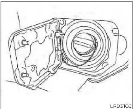
natural_image
Technical line drawing of a camera housing assembly (no text or symbols)GASOLINE FUEL ENGINES
WARNING
- Gasolineisextremelyflammable and highlyexplosiveundercertainconditions.Youcouldbeburnedorseriouslyinjuredifitismisusedormishandled.Alwaysstoptheengineand donotsmokeorallowopenflamesor sparksnearthevehiclewhen refueling.
- Donotattempttotopoffthefuel tank after the fuel pump nozzle shuts off automatically.Continued refuelingmaycausefueloverflow, resultingin fuelsprayandpossiblya fire.
- Use only an original equipment type fuel-fillercapasareplacement. It has a built-in safety valve needed for proper operation of the fuel system and emission control system. An incorrect cap can result in a serious malfunction and possible injury. It could also cause the MalfunctionIndicatorLight(MIL)tocomeon.
- Neverpourfuelintothethrottlebody toattempttostartyourvehicle.
-
Do not fill a portable fuel container onatruckbedliner,rubbertruckbed mat or other insulating material. Staticelectricity can cause an explosion offlammable liquid, vaporor gasinany vehicle or trailer. Toreduce therisk of serious injury or death when filling portable fuel containers:
-
Alwaysplacethecontaineronthe groundwhenfilling.
-
Donot useelectronicdevices whenfilling.
-
Keepthepumpnozzleincontact withthecontainerwhileyouare fillingit.
- Useonlyapprovedportablefuel containersforflammableliquid.
CAUTION
- DonotuseE-15orE-85fuelinyour vehicle.Foradditionalinformation, see"Fuelrecommendation"(P.10-4).
-
TheLooseFuelCapwarningmessagewillappearifthefuel-fillercap isnotproperlytightened.Itmaytake afewdrivingtripsforthemessageto bedisplayed.Failureretotightenthe fuel-fillercapproperlyafterthe LooseFuelCapwarningmessageappearsmaycausethe MalfunctionIndicatorLight(MIL)to illuminate.
-
Failuretotightenthefuel-fillercap properlymaycausethe Mal-functionIndicatorLight(MIL)toilluminate.Ifthe lightilluminates becausethefuel-fillercapislooseor missing,tightenorinstallthecapand continuetodrivethevehicle.The lightshouldturnoffafterafew drivingtrips.Ifthe lightdoesnot turnoffafterafewdrivingtrips,have thevehicleinspected.It isrecommended that you visit a NISSAN dealerforthisservice.
- Foradditionalinformation,see"Mal-functionIndicator Light (MIL)" (P.2-15).
- Iffuelisspilledonthevehiclebody, flush it away with water to avoid paintdamage.
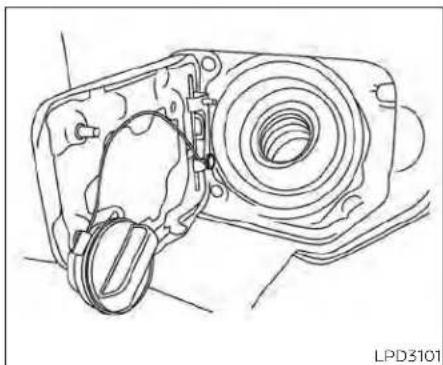
natural_image
Technical line drawing of a mechanical assembly with no visible text or symbolsTo remove the fuel-filler cap:
- Turn the fuel-filler cap counterclockwise to remove.
- Loop the tether strap around the hook ① while refueling.
To install the fuel-filler cap:
- Insert the fuel-filler cap straight into the fuel-filler tube.
- Turn the fuel-filler cap clockwise until it clicks. The fuel-filler cap is a ratcheting type.
STEERING WHEEL
natural_image
Pure electrical circuit symbol for a lamp, without any text or labelsLoose Fuel Cap warning
The Loose Fuel Cap warning appears in the vehicle information display when the fuel-filler cap is not tightened correctly after the vehicle has been refueled. It may take a few driving trips for the message to be displayed. To turn off the warning, perform the following:
- Remove and install the fuel-filler cap as previously described as soon as possible.
- Tighten the fuel-filler cap until a single click is heard.
WARNING
- Donotadjustthesteeringwheel whiledriving.Youcouldlosecontrol ofyourvehicleandcausean accident.
- Donotadjustthe steeringwheelany closer to you than is necessary for propersteeringoperationandcomfort.Thedriver'sairbaginflateswith greatforce.If youareunrestrained, leaningforward,sittingsidewaysor out of position in any way, you are at greater risk of injury or death in a crash.Youmayalsoreceiveserious orfatalinjuriesfromtheairbagifyou are upagainstitwhenitinflates. Alwayssit backagainstthe seatback andasfarawayaspracticalfromthe steeringwheel.Alwaysusetheseat belts.

Tilt and telescopic operation
Push the lock lever① down:
- Adjust the steering wheel up or down in direction ② to the desired position.
- Adjust the steering wheel forward or backward in direction ③ to the desired position.
Pull the lock lever ① up firmly to lock the steering wheel in place.

Tilt and telescopic operation
To adjust the steering wheel move the switch ① in the following directions:
- Adjust the steering wheel up or down in direction ② to the desired tilt position.
- Adjust the steering wheel forward or backward in direction ③ to the desired telescopic position.
CAUTION
ForvehicleswithMemorySeat:Failure toresetthetiltandtelescopingfunctionsofthesteeringwheel,afterthe vehicle'sbatteryhasbeendischarged, maypreventthesteeringwheelpositionfrombeingadjusted.
For vehicles with Memory Seat: Both the tilt and telescopic steering operation must be reset after the vehicle's battery has been discharged in order to prevent the tilt and telescopic operation from locking in one position. When the battery has been re-charged or replaced, perform the following:
- For tilt operation: Adjust the switch ① so the steering wheel moves to the highest position ② that can be reached.
- For telescopic operation: Adjust the switch ① so the steering wheel moves to the most forward and backward position ③ that can be reached.
Performing these operations resets the range of the steering wheel's tilt and telescopic function.
Entry/Exit function (if so equipped)
The memory seat will make the steering wheel move up automatically when the driver's door is opened and the ignition switch is in the LOCK position. This lets the driver get into and out of the seat more easily. The steering wheel moves back into
I position when the driver's door is closed and the ignition switch is pushed.
For additional information, see "Memory seat" (P. 3-39).
SUNVISORS

flowchart
graph TD
    A["1: Seat Top"] --> B["2: Rear Left"]
    B --> C["3: Rear Right"]
- To block glare from the front, swing down ① the sun visor.
- To block glare from the side, remove the sun visor from the center mount and swing the visor to the side.
- To extend the sun visor, slide in or out as needed.
CAUTION
- Donotstorethesunvisorbeforere-turningtheextensiontoitsoriginal position.
- Donotpulltheextensionsunvisor forcedlydownward.
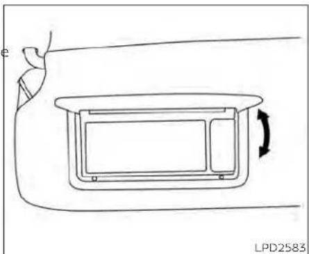
natural_image
Simple line drawing of a device with an arrow indicating rotation, no text or symbols presentVANITY MIRRORS (if so equipped)
To access the vanity mirror, pull the sun visor down and flip open the mirror cover. Some vanity mirrors are illuminated and turn on when the mirror cover is open.
MIRRORS

natural_image
Simple line drawing of a car's front bumper with a downward arrow indicating a detail (no text or symbols)LPD2436 WPD0126 LPD2418

MANUAL ANTI-GLARE REARVIEW
MIRROR (if so equipped)
To access the card holder, slide card in the card holder. Do not view information while operating the vehicle.
Use the night position① to reduce glare from the headlights of vehicles behind you at night.
Use the day position ② when driving in daylight hours.
CARD HOLDER (driver's side only)
WARNING
Usethenightpositiononlywhennecessary, because it reduces rearview clarity.

natural_image
Simple line drawing of a curved object with two labeled points (1) and a dashed line, no text or symbols present.TypeA(ifsoequipped)
AUTOMATIC ANTI-GLARE
REARVIEW MIRROR (if so equipped)
The inside mirror is designed so that it automatically dims during night time conditions and according to the intensity of the headlights of the vehicle following you. The automatic anti-glare feature is activated when the ignition switch is in the ON position.

Type B (ifso equipped)
NOTE:
Donothanganyobjectsoverthesensors ① orapplyglasscleanertothesensors.Doingsowillreducethesensitivity ofthesensors,resultinginimproper operation.
The indicator light② will illuminate when the automatic anti-glare feature is operating.
- To turn off the anti-glare feature, press the O button. The indicator light will turn off.
- To turn on the anti-glare feature, press the | button again. The indicator light will turn on.
For additional information on HomeLink® Universal Transceiver operation, see "HomeLink® Universal Transceiver" (P. 2-90).
OUTSIDE MIRRORS
WARNING
- Objectsviewedintheoutsidemirror on the passenger side are closer than theyappear.Becarefulwhen moving to the right. Using only this mirror could causeanaccident.Usetheinsidemirroror glanceoveryour shouldertoproperlyjudgedistances tootherobjects.
- Donotadjustthemirrorswhiledriving. You could close controlof your vehicle and cause an accident.
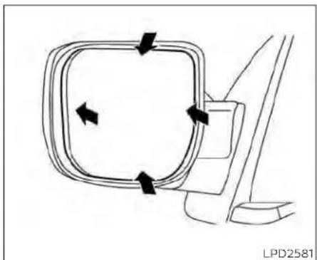
natural_image
Diagram of a car interior showing directional arrows around a rectangular frame (no text or symbols)Manual control type (if so equipped)
The outside mirrors can be moved in any direction for a better rear view.
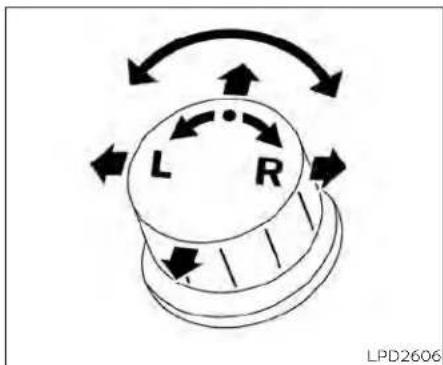

natural_image
Diagram of a vehicle's side panel with arrows indicating motion, no text or symbols presentElectric control type (if so equipped)
The outside mirror remote control will operate only when the ignition switch is placed in the ACC or ON position.
Rotate the control dial to select the right of left mirror. Adjust the mirror to the desired position by moving the control dial.
Return the control dial to the center (neutral) position to prevent accidentally moving the mirror.
Trailer tow mirrors (if so equipped)
WARNING
Objectsviewedintheconvexportionof thetrailertowmirrorarecloserthan theyappear.Becarefulwhenchanging flanesorturning.Usingonlytheconvex mirrorcouldcauseanaccident.Usethe othermirrorsorglanceoveryour shouldertoproperlyjudgedistance to otherobjects.
Use the outside mirror remote control to adjust the top portion of the trailer tow mirror.
The lower portion of the trailer tow mirror can be moved manually in any direction for a better rear view.
3-32 Pre-drivingchecksandadjustments
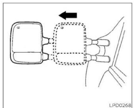
Pull the trailer tow mirror outward to extend it to the desired position for better visibility while towing a trailer.

natural_image
Diagram of a car seatbelt mechanism with dashed lines indicating motion, showing no text or symbolsTypeA(ifsoequipped) Manual folding outside mirrors (if so equipped)

natural_image
Diagram of a car's side panel showing steering wheel and dashboard (no text or symbols)TypeB(ifsoequipped)
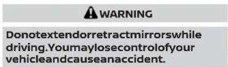
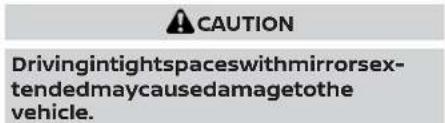
Pre-drivingchecksandadjustments3-33


LPD0417
Power folding outside mirrors (if so equipped)
CAUTION
Donotmanuallyfoldthepowerfolding mirrors.Manuallyfoldingthemirrors candamagethemirrors.
Push the power folding switch to open or close the mirrors.
If one of the mirrors are manually operated or bumped, the mirror body can become loose at the pivot point. To correct electronic mirror operation, cycle the mirrors by
pushing the power folding switch until the mirrors are in the open position.
Reverse tilt-down feature (if so equipped)
The reverse tilt-down feature will turn both outside mirror surfaces downward to provide better rear visibility close to the vehicle when the mirror control switch is in either the L or R position.
The mirrors automatically return to their original position when you shift out of R (Reverse).
The outside mirror surfaces will return to their original position when one of the following conditions has occurred:
- The shift lever is moved to any position other than R (Reverse).
- The outside mirror control switch is set the neutral or center position.
- The ignition switch is placed in the OFF position.
NOTE:
If the outside mirror control switch is in the center position, them mirrors surface will NOT turn downward when the shift lever is moved to R (Reverse).
For additional information, see "Memory seat" (P. 3-39).
Automatic anti-glare outside mirror (if so equipped)
The outside mirror will automatically dim during nighttime conditions to reduce the glare from the headlights of trailing vehicles. The automatic anti-glare feature operates only when the ignition switch is placed in the ON position.
The automatic anti-glare feature will be on when starting the vehicle. The indicator light on the automatic anti-glare rearview mirror will illuminate when the automatic anti-glare feature is operating.
To turn off the anti-glare feature, press the O button on the rearview mirror. The indicator light will turn off.
To turn on the anti-glare feature again, press the | button on the rearview mirror. The indicator light will turn on.
For additional information on the automatic anti-glare rearview mirror, see "Automatic anti-glare rearview mirror (if so equipped)" (P. 3-30).
TRUCKBOX
Heated mirrors (if so equipped)
Some outside mirrors can be heated to defrost, defog, or de-ice for improved visibility. For additional information, see "Rear window and/or outside mirror defroster switch" (P. 2-43).

natural_image
Line drawing of a vehicle's rear bumper and side panel, showing structural components without any text or symbolsTAILGATE
Opening the tailgate
Pull the tailgate handle upward and lower the tailgate. The support cables hold the tailgate open.
When closing the tailgate, make sure the latches are securely locked.
Donotdrivethevehiclewiththetailgate down, unlesssequipped with NISSAN's BedExtender (accessory) orequivalent intheextendedposition.
For additional information on proper truck box loading, see "Vehicle loading information" (P. 10-22).

WARNING
- Neverallowanyonetorideinthe cargoareaorontherearseat(ifso equipped)whenitisinthefoldedposition.Useoftheseareasbypassengerswithoutproperrestraintscould resultinseriousinjuryordeathinan accidentorsuddenstop.
- Itisextremelydangeroustorideina cargoareainsideavehicle.Inacollision,peopleridingintheseareasare morelikelytobeseriouslyinjuredorkilled.
- Donotallowpeopletorideinany areaofyourvehiclethatisnot equippedwithseatsandseatbelts.
- Besureeveryoneinyourvehicleisin aseatandusingaseatbeltproperly.
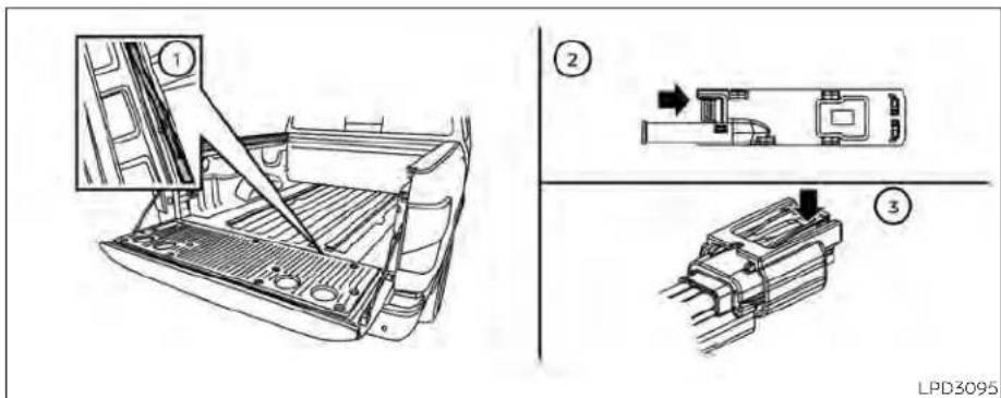
Disconnecting the rear camera Before removing the tailgate disconnect the rear camera by performing the following:
- Open the tailgate to access the rear camera connector bracket ① located on the rear sill.
-
Remove the connector bracket from the sill by pressing the locking tab inward, in the direction shown, while pulling the bracket apart.
-
Disconnect the chassis wiring harness ③ by pressing inward on the locking tab, in the direction shown, while pulling the connectors apart. Hold the connector firmly to prevent the connector in the chassis harness from falling into the sill.
- Use the supplied chassis plug and bracket and connect them to the chassis wiring harness to avoid contamination to the terminals which will lead to malfunction of the rear camera.
-
Insert the bracket back into the sill.
-
Take the tailgate plug from the glove box and connect it to the tailgate wiring harness to avoid contamination which will lead to malfunction of the rear camera.
- Remove the tailgate. For additional information, see "Removing the tailgate" (P. 3-37).

natural_image
Technical line drawing of a mechanical assembly with a black arrow indicating a component (no text or symbols present)Removing the tailgate
- Disconnect the wiring harness for the rear camera. For additional information, see "Disconnecting the rear camera" (P. 3-36).
- Release the tailgate support cables.
CAUTION
-
Thetailgateisheavy.Twopeople shouldremoveorinstallit.Becareful nottodropitduringremoval.
• Afterreleasingthesupportcables, donotletthetailgaterestonthe bumper. -
Hold the tailgate at a 45 degree angle.
- Pull the tailgate out from the left side hinge.
- Slide the tailgate out of the right side hinge.
Installing the tailgate
- Insert the tailgate into the right side hinge.
- Hold the tailgate at a 45 degree angle and insert into the left side hinge.
-
Continue to hold the tailgate at a 45 degree angle and attach the tailgate support cables.
-
For vehicles with rear camera: Be sure the tailgate harness is not hanging below the tailgate and keep the tailgate open. For additional information, see "Connecting the rear camera" (P. 3-38).
- For vehicles without rear camera: Close the tailgate securely.


Connecting the rear camera
Before closing the tailgate reconnect the rear camera by performing the following:
- After attaching the rear tailgate to the truck, keep the tailgate open and check that the tailgate harness is not hanging below the tailgate.
-
Remove the connector bracket ② from the sill by pressing the locking tab inward, in the direction shown, while pulling the bracket apart.
-
Disconnect the chassis plug and bracket from the chassis wiring harness ③. Keep the connector and bracket in safe place such as the glove box.
- Disconnect the tailgate plug from the tailgate wiring harness. Keep the tailgate plug in a safe place such as the glove box.
- Connect the tailgate wiring harness to the chassis wiring harness.
- Securely fix the rear camera connector bracket ① to the rear sill.
- Close the tailgate securely.
Locking the Tailgate
To unlock the tailgate, turn the key toward the passenger side of the vehicle ①. To lock, turn the key toward the driver side if your vehicle is equipped with an electronic tailgate, you may use the door handle request switch (if so equipped) or I-key to lock or unlock the tailgate. For additional information please see "NISSAN Intelligent Key® Operation" (P. 3-12).
MEMORYSEAT(ifsoequipped)

natural_image
Technical line drawing of a mechanical component with a diagonal guide and arrow indicating direction (no text or symbols)WARNING
- Properlysecureallcargowithropes orstrapstohelppreventitfromslidingorshifting.Inasuddenstopor collision,unsecuredcargocould causepersonalinjury.
The memory seat system has two features:
• Memory storage function
- Entry/exit function
TIE DOWN HOOKS
For your convenience, tie down hooks are placed at each corner of the truck box. These may be used to help secure cargo loaded into the truck box.
- The weight of the cargo load must be evenly distributed over the rear axles.
- All cargo should be securely fastened with ropes or straps to prevent it from shifting or sliding within the vehicle.
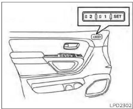
MEMORY STORAGE FUNCTION
Two positions for the driver's seat, steering column, and outside mirrors (if so equipped) can be stored in the Memory Seats. Follow these procedures to set the memory system.
-
Place the ignition in the ON or ACC position (the vehicle should be stopped while setting the memory).
-
Adjust the driver's seat, steering column and outside mirrors (if so equipped) to the desired positions by manually operating each adjusting switch. For additional information, see "Seats" (P. 1-2), "Steering wheel" (P. 3-27) and "Outside mirrors" (P. 3-31).
- Push the SET switch and, within 5 seconds, push the memory switch (1 or 2).
- The indicator light for the pushed memory switch will come on and stay on for approximately 5 seconds.
- The chime will sound when the memory is stored.
NOTE:
IfaNEWmemorypositionisstoredinthe same memory switch, the previous memorypositionwillbeoverwrittenby thenewstoredposition.
Confirming memory storage
- Push the SET switch.
- If a memory position has been stored in the switch (1 or 2) then the indicator light for the respective switch will stay on for approximately 5 seconds.
LINKING A KEY FOB TO A STORED MEMORY POSITION
Each key fob can be linked to a stored memory position (memory switch 1 or 2) with the following procedure.
- Follow steps 1-3 in the "Memory storage function" section for storing the memory position.
- The indicator light for the pushed memory switch will come on. While the indicator light is on for 5 seconds, press the 🔒 button on the key fob. The hazard lights will flash twice. The indicator light of the linked memory switch will blink and click twice. After the indicator light goes off, the key fob is linked to that memory setting.
Once it is linked, when the ignition switch is in the OFF position, pressing them button on the key fob will move the driver's seat, steering wheel and outside mirrors to the linked memory switch position.
NOTE:
tifanewmemorypositionisstoredinthe linkedmemoryswitch,thenthekeyfob willinkthenewpositionandoverwrites thepreviousposition.
ENTRY/EXIT FUNCTION
This system is designed so that the driver' seat and steering column will automatically move when the shift lever is in the P (Park) position. This allows the driver to easily get in and out of the driver's seat.
The driver's seat will slide backward and the steering column will move up:
- When the driver's door is opened with the ignition switch in the OFF position.
- When the ignition switch is changed from ACC to OFF with the driver's door open.
The driver's seat and steering wheel will return to the previous position:
- When the ignition switch is changed from ACC or ON while the shift lever is in the (Park) position.
The entry/exit function can be adjusted or canceled through the vehicle settings in the vehicle information display by performing the following:
- Switch the Exit Seat Slide from ON to OF
- Switch the Exit Steering UP from ON to OFF.
Restarting the entry/exit function
\$ if the battery cable is disconnected, or if the fuse opens, the stored memory positions will be lost and some of the functions will be restricted;
-
Drive the vehicle over 25 mph (40 km/h) OR
-
Open and close the driver's door more than two times with the ignition switch in the OFF position.
The entry/exit function should now work properly.
SYSTEM OPERATION
1 The memory seat system will not work or will stop operating under the following conditions:
- When the vehicle speed is above 4 mph (7 km/h).
- When any of the memory switches are pushed while the memory seat is F. operating.
- When the switch for the driver's seat and steering column is pushed while the memory seat is operating.
- When the seat has already been moved to the memorized position.
- When no seat position is stored in the memory switch.
- When the shift lever is moved from P (Park) to any other position.
The memory seat system can be adjusted and canceled. It is recommended you visit a NISSAN dealer for this service.
4Monitor,climate,audio,phone and voicerecognitionsystems
NissanConnect® Owner's Manual 4-2
RearView Monitor (if so equipped) 4-3
RearView Monitor system operation ..... 4 - 4
How to read the displayed lines 4-4
Difference between predicted and actual distances 4 - 5
How to park with predicted course lines 4-7
Adjusting the screen 4-8
How to turn on and off predicted course lines 4-8
RearView Monitor system limitations ..... 4 - 8
System maintenance 4-10
Intelligent Around View Monitor (if so equipped) 4-11
Intelligent Around View Monitor system operation 4-12
Difference between predicted and actual distances 4-16
How to park with predicted course lines 4-17
How to switch the display 4-19
Adjusting the screen 4-19
Intelligent Around View Monitor system limitations 4-20
System maintenance 4-22
Moving Object Detection (MOD) (if so equipped)....4-23 MOD system operation....4-24 Turning MOD on and off (if so equipped)....4-25 MOD system limitations....4-26 System maintenance....4-27
Vents 4-28
Heater and air conditioner (manual)
(if so equipped) 4-28
Controls 4-29
Heater operation 4-30
Air conditioner operation 4-32
Air flow charts 4-33
Heater and air conditioner (automatic)
(if so equipped)....4-37
Automatic operation 4-38
Manual operation 4-39
Operating tips 4-41
Servicing air conditioner....4-42
USB/iPod® charging port (if so equipped)....4-42
Antenna 4-42
Rear Seat Infotainment (RSI) (If so equipped)....4-43
Welcome 4-43
Getting started 4-44
Control description 4-48
Remote control operation 4-50
Remote control buttons 4-51
Wireless headphone operation 4-52
General operation 4-53
DVD operation 4-54
DVD playback controls 4-56
CD operation 4-59
CD playback controls....4-59
HDMI/MHL connection 4-60
USB/SD card operation 4-61
Slingplayer ® 4-67
Miracast ® 4-70
Using the mobile application on your
mobile device 4-70
SmartStream 4-71
Settings 4-72
Troubleshooting 4-80
Specifications 4-82
Compliance information 4-83
Car phone or CB radio 4-86
iPod®/iPhone® 4-87
NISSANCONNECT® OWNER'S MANUAL
Refer to the NissanConnect® Owner's Manual that includes the following information.
- NissanConnect® Services (if so equipped)
- Navigation system (if so equipped)
- Audio system
- Apple CarPlay®
- Android Auto TM
- Bluetooth® Hands-Free Phone system
- Viewing Information
- Other settings
- Voice recognition
- General system information
4-2 Monitor, climate, audio, phone and voicerecognitionsystems
REARVIEWMONITOR(ifso equipped)
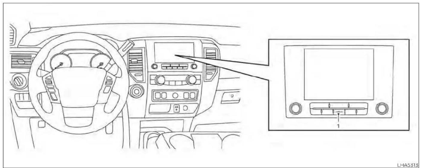
1. CAMERA button
WARNING
- FailuretofollowthewarningsandinstructionsforproperuseoftheRearViewMonitorsystemcouldresultinseriousinjuryordeath.
- RearViewMonitorisaconvenience featureandisnotasubstitutefor properbacking.Alwaysturnandlook outthewindowsandcheckmirrors tobesurethatitissafetomovebeforeoperatingthevehicle.Always backupslowly.
- Thesystemisdesignedasanaidto thedriverinshowinglargestationaryobjectsdirectlybehindthevehicle,tohelpavoiddamagingthe vehicle.
Monitor, climate, audio, phone and voicerecognitionsystems4-3
- Thedistanceguidelineandthevehiclewidthlineshouldbeusedasa referenceonlywhenthevehicleisonalevelpavedsurface.Thedistanceviewedonthemonitorisforreferenceonlyandmaybedifferentthantheactualdistancebetweenthevehicleanddisplayedobjects.
CAUTION
Donotscratchthecameralenswhen cleaningDIRtorsnowfromthefrontof thecamera.

natural_image
Line drawing of a pickup truck rear view with a numbered marker (1) and label LHA5342 at the bottom right corner.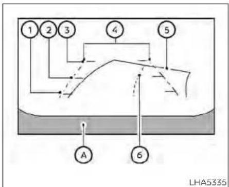
flowchart
graph TD
    1["1"] --> 2["2"]
    2 --> 3["3"]
    3 --> 4["4"]
    4 --> 5["5"]
    5 --> 6["6"]
    6 --> A["A"]
    style 1 fill:#fff,stroke:#000
    style 2 fill:#fff,stroke:#000
    style 3 fill:#fff,stroke:#000
    style 4 fill:#fff,stroke:#000
    style 5 fill:#fff,stroke:#000
    style 6 fill:#fff,stroke:#000
    note right of 6 LHA5335
The RearView Monitor system automatically shows a rear view of the vehicle when the shift lever is shifted into the R (Reverse) position. While in R (Reverse), pressing the CAMERA will cycle through guidelines on
HOW TO READ THE DISPLAYED LINES
Guiding lines which indicate the vehicle width and distances to objects with reference to the vehicle body line A are displayed on the monitor.
with the ignition switch in the ON position, move the shift lever to the R (Reverse) position to operate the RearView Monitor.
Distanceguidelines
Indicate distances from the vehicle body.
- Red line①: approx. 1.5 ft (0.5 m)
- Yellow line②: approx. 3 ft (1 m)
• Green line③: approx. 7 ft (2 m)
Vehiclewidthguidelines ④
Indicate the vehicle width when backing up.
Predictedcourselines ⑤
Indicate the predicted course when backing up. The predicted course lines will be displayed on the monitor when the shift lever is in the R (Reverse) position and the steering wheel is turned. The predicted course lines will move depending on how much the steering wheel is turned and will not be displayed while the steering wheel is in the straight-ahead position.
The vehicle width guide lines and the width of the predicted course lines are wider than the actual width and course.
Centerguidelines ⑥
Indicates the vehicle's center.
DIFFERENCE BETWEEN PREDICTED AND ACTUAL DISTANCES
The displayed guidelines and their locations on the ground are for approximate reference only. Objects on uphill or downhill surfaces or projecting objects will be actually located at distances different from those displayed in the monitor relative to the guidelines (refer to illustrations). When in doubt, turn around and view the objects as you are backing up, or park and exit the vehicle to view the positioning of objects behind the vehicle.

natural_image
Diagram showing a vehicle on a slope next to a parking lot and a roof structure (no text or symbols)Backing up on a steep uphill
when backing up the vehicle up a hill, the distance guide lines and the vehicle width guide lines are shown closer than the actual distance. Note that any object on the hill is further than it appears on the monitor.

natural_image
Diagram showing a pickup truck on a track with a block on an inclined plane and a small black square on the roof (no text or symbols)
natural_image
Technical line drawing of a mechanical assembly with no visible text or symbols
Backing up on a steep downhill when backing up the vehicle down a hill, the distance guide lines and the vehicle width guide lines are shown farther than the actual distance. Note that any object on the hill is closer than it appears on the monitor.
Backing up near a projecting object
The vehicle may seem to nearly clear the object in the display. However, the vehicle may hit the object if it projects over the actual backing up course.
Backing up behind a projecting object
The position © is shown farther than the position ® in the display. However, the position © is actually at the same distance as the position ® . The vehicle may hit the
4-6 Monitor, climate, audio, phone and voicerecognition systems
object when backing up to the position ① if the object projects over the actual backing up course.
HOW TO PARK WITH PREDICTED COURSE LINES
WARNING
- If the tires are replaced with different sizes, the predicted courselines may be displayed incorrectly.
- Onasnow-coveredorslipperyroad, theremaybeadifferencebetween thepredictedcourselineandtheactualcourseline.
- If the battery is disconnected or becomes discharged, the predicted courselines may be displayed incorrectly. If this occurs, please perform the following procedures:
- Turnthesteeringwheelfromlock tolockwhiletheengineis running.
- Drivethevehicleonastraightroad formorethan5minutes.
- Whenthesteeringwheelisturned withtheignitionswitchintheACC position,thepredictedcourselines maybedisplayedincorrectly.

natural_image
Diagram showing a car on a ramp and its rear view, with an attached circular symbol labeled 'A' (no text or symbols present)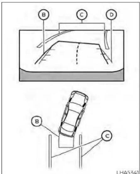
- Visually check that the parking space is safe before parking your vehicle.
-
The rear view of the vehicle is displayed on the screen ① when the shift lever is moved to the R (Reverse) position.
-
Slowly back up the vehicle adjusting the steering wheel so that the predicted course lines enter the parking space
-
Maneuver the steering wheel to make the vehicle width guide lines parallel to the parking space while referring to the predicted course lines.
- When the vehicle is parked in the space completely, move the shift lever to the P (Park) position and apply the parking brake.

- Press the CAMERA button.
- Touch the "Display Settings" key.
- Touch the "Brightness", "Contrast", Tint", "Color", or "Black Level" key.
- Adjust the item by touching the "+" or "-" key on the touch-screen display.
NOTE:
Donotadjustanyofthedisplaysettings oftheRearViewMonitorwhilethevehicleismoving.
HOW TO TURN ON AND OFF PREDICTED COURSE LINES
To toggle ON and OFF the predicted course lines while in the P (Park) position:
- Press the CAMERA button.
- Touch the "Predicted Course Lines" key to turn the feature ON or OFF.
To toggle ON and OFF the predicted course lines or center guide line while in the R (Reverse) position, press the CAMERA button.
REARVIEW MONITOR SYSTEM LIMITATIONS
WARNING
Listedbelowarethesystemlimitations forRearViewMonitor.Failureretooper-atethevehicleinaccordancewith thesesystemlimitationscouldresultin seriousinjuryordeath.
- Thesystemcannotcompletelyeliminateblindspotsandmaynotshow everyobject.
4-8 Monitor, climate, audio, phone and voice recognition systems
• Underneaththebumperandthecornerareasofthebumpercannotbe viewedontheRearViewMonitorbecauseofitsmonitoringrangelimitation.Thesystemwillnotshowsmall objectsbelowthebumper,andmay notshowobjectsclosetothebumperorontheground.
- ObjectsviewedintheRearView
Monitordifferfromactualdistance
becauseawide-anglelensisused.
- ObjectsintheRearViewMonitorwill appearvisuallyoppositecompared towhenviewedintherearviewand outsidersmirrors.
- Usethedisplayedlinesasareference.Thelinesarehighlyaffectedby thenumberofoccupants,fuellevel, vehicleposition,roadconditionsand roadgrade.
- Makesurethatthetailgateissecurelyclosedwhenbackingup.
- Donotputanythingontherearview camera.Therearviewcameraisinstalledonthetailgate.
- When washing the vehicle with high pressure water, besuren to to spray it around the camera. Otherwise, water may enter the camera unit causing water condensation on the lens, a malfunction, fire or an electric shock.
- Donotstrikethecamera.Itisaprecisioninstrument. Otherwise, it may malfunction or cause damageresultinginafireoranelectricshock.
The following are operating limitations and do not represent a system malfunction:
- When the temperature is extremely high or low, the screen may not clearly display objects.
- When strong light directly shines on the camera, objects may not be displayed clearly.
- Vertical lines may be seen in objects on the screen. This is due to strong reflected light from the bumper.
- The screen may flicker under fluorescent light.
- The colors of objects on the RearView Monitor may differ somewhat from the actual color of objects.
-
Objects on the monitor may not be clear in a dark environment.
-
There may be a delay when switching between views.
- If dirt, rain or snow accumulate on the camera, RearView Monitor may not display objects clearly. Clean the camera.
- Do not use wax on the camera lens. Wipe off any wax with a clean cloth dampened with a diluted mild cleaning agent, then wipe with a dry cloth.

natural_image
Line drawing of a pickup truck rear view with a numbered component (1) and label LHA5342 at the bottom right corner.If dirt, rain or snow accumulates on the camera Ⓐ, the RearView Monitor may not display objects clearly. Clean the camera by wiping it with a cloth dampened with a diluted mild cleaning agent and then wiping it with a dry cloth.
SYSTEM MAINTENANCE
CAUTION
- Donotusealcohol, benzineorthinnertocleanthecamera. This will caused discoloration.
- Donotdamagethecameraasthe monitorscreenmaybeadversely affected.
4-10 Monitor, climate, audio, phone and voicerecognition systems
INTELLIGENTAROUNDVIEW MONITOR(ifsoequipped)

natural_image
Line drawing of a car dashboard and infotainment panel showing the front and side views (no text or symbols)- CAMERA button
Monitor, climate, audio, phone and voicerecognitionsystems4-11
WARNING
- Failuretofollowthewarningsandinstructionsfortheproperuseofthe IntelligentAroundViewMonitorsystemcouldresultinseriousinjuryor death.
- TheIntelligentAroundViewMonitor isaconveniencefeatureandisnota substituteforpropervehicleoperationbecauseithasareaswhereobjectscannotbeviewed.Thefourcornersofthevehicleinparticular,are areaswhereobjectsdonotalways appearinthebird's-eye,front,orrear views.Alwayscheckyoursurroundingstobesurethatitissafetomove beforeoperatingthevehicle.Always operatethevehicleslowly.
- Thedriverisalwaysresponsiblefor safetyduringparkingandother maneuvers.
CAUTION
Donotscratchthecameralenswhen cleaningDIRtorsnowfromthefrontof thecamera.
The Intelligent Around View Monitor system is designed as an aid to the driver in situations such as slot parking or parallel parking.
The monitor displays various views of the position of the vehicle in a split screen format. Not all views are available at all times
Availableviews:
- Front View An approximately 150-degree view of the front of the vehicle.
- Rear View
An approximately 150-degree view of the rear of the vehicle.
• Bird's-Eye View The surrounding views of the vehicle from above. - Front-Side View The view around and ahead of the front passenger's side wheel.
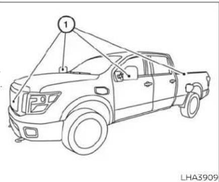
To display the multiple views, the Intelligent Around View Monitor system uses cameras located in the front grille, on the vehicle's outside mirrors and one on the tailgate ①.
With the ignition switch in the ON position, move the shift lever to the R (Reverse) position to operate the Intelligent Around View Monitor.
When the camera is first activated with the bird's-eye view in the display, a red icon (if so equipped) will flash on the screen. This indicates that the sonar system (if so equipped) is activated. For additional information on the front and rear sonar system (If so equipped), see "Front and rear sonar system" (P. 5-124).
The screen displayed on the Intelligent Around View Monitor will automatically return to the previous screen 3 minutes after the CAMERA button has been pressed with the shift lever in a position other than the (Reverse) position.
Available views
WARNING
- Thedistanceguidelinesandthevehiclewidthlinessshouldbeusedasa referenceonlywhenthevehicleison apaved,levelsurface.Theapparent distanceviewedonthemonitormay bedifferentthantheactualdistance betweenthevehicleanddisplayed objects.
Usethedisplayedlinesandthe bird's-eyeviewasareference.The lines and the bird's-eye view are greatlyaffectedbythenumberofoccupants,cargo,fuellevel,vehicleposition, road condition and road grade.
- Ifthetiresarereplacedwithdifferent sizedtires,thepredictedcourselines andthebird's-eyeviewmaybedis-playedincorrectly.
: Whendrivingthevehicleupahill,objects viewed in the monitorarefurtherthantheyappear. Whendriving thevehicle downa hill,objects viewedthemonitorarecloserthan theyappear. - Objects in the rear view will appear visuallyoppositecomparedtowhen viewedinthemonitorandoutside mirrors.
-
Usethemirrorsoractuallylookto properlyjudge distances to other objects.
-
Onasnow-coveredorslipperyroad, there maybe differencebetween thepredictedcourselinesand the actualcourseline.
- Thevehiclewidthandpredicted courselinesarewiderthantheactual widthandcourse.
- The displayed lines will appear slightlyofftotheright,because the rearviewcameraisnotinstalled in therearcenterofthevehicle.

Frontview
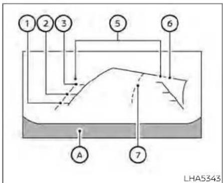
Rearview
Frontandrearview
Guiding lines that indicate the approximate vehicle width and distance to objects with reference to the vehicle body line A are displayed on the monitor.
Distanceguidelines:
Indicate distances from the vehicle body:
- Red line①: approximately 1.5 ft (0.5 m)
- Yellow line②: approximately 3 ft (1 m)
- Green line ③: approximately 7 ft (2 m)
- Green line ④: approximately 10 ft (3 m) (if so equipped)
Indicate the approximate vehicle width when backing up.
Predictedcourselines ⑥
Indicate the predicted course when operating the vehicle. The predicted course lines will be displayed on the monitor when the steering wheel is turned. The predicted course lines will move depending on how much the steering wheel is turned and will
not be displayed while the steering wheel is in the straight-ahead position.
Centerguidelines ⑦
Indicates the vehicle's center.
The front view will not be displayed when the vehicle speed is above 6 mph (10 km/h).
NOTE:
Whenthemonitordisplaysthefront viewandthesteeringwheelturnsabout 90degreesorlessfromthestraight-aheadposition,boththerightandleft predictedcourselines ⑥ aredisplayed. Whenthesteeringwheelturnsabout90 degreesormore,alineisdisplayedonly ontheoppositesideoftheturn.
4-14 Monitor, climate, audio, phone and voicerecognitionsystems

Bird's-eyeview
The bird's-eye view shows the overhead view of the vehicle, which helps confirm the vehicle position and the predicted course to a parking space.
The vehicle icon① shows the position of the vehicle. Note that the apparent distance between objects viewed in the bird's-eye view may differ somewhat from the actual distance to the vehicle.
The areas that the cameras cannot cover ② are indicated in black.
After the ignition switched is placed in the ON position, the non-viewable area② is highlighted in yellow for 3 seconds after the birds-eye view is displayed.
In addition, the non-viewable corners are displayed in red and will blink for the first 3 seconds ③ to remind the driver to be cautious.
WARNING
- Objectsinthebird's-eyeviewwillappearfurtherthantheactualdistance.
- Tallobjects,suchasacurborvehicle, maybemisalignedornotdisplayed attheseamoftheviews.
- Objectsthatareabovethecamera cannotbedisplayed.
• Theviewofthebird's-eyeviewmay bemisalignedwhenthecamerapositionalters. - Alineonthegroundmaybemis-alignedandisnotseenasbeing straightattheseamoftheviews.The misalignment will increase as the lineproceedsawayfromthevehicle.

Front-sideview Guidinglines
Guiding lines that indicate the approximate width and the front end of the vehicle are displayed on the monitor.
The front-of-vehicle line shows the front part of the vehicle.
The side-of-vehicle line ② shows the approximate vehicle width including the outside mirrors.
The extensions ③ of both the front ⑥ and side ② lines are shown with a green dotted line.
DIFFERENCE BETWEEN PREDICTED AND ACTUAL DISTANCES
The displayed guidelines and their locations on the ground are for approximate reference only. Objects on uphill or downhill surfaces or projecting objects will be actually located at distances different from those displayed in the monitor relative to the guidelines (refer to illustrations). When in doubt, turn around and view the objects as you are backing up, or park and exit the vehicle to view the positioning of objects behind the vehicle.

natural_image
Diagram showing a pickup truck on a slope next to a vehicle and a parking lot, with no visible text or symbols.
natural_image
Diagram showing a pickup truck on a slope with a block on an incline and a small black square on the roof (no text or symbols)Backing up on a steep uphill
when backing up the vehicle up a hill, the distance guide lines and the vehicle width guide lines are shown closer than the actual distance. Note that any object on the hill is further than it appears on the monitor.
Backing up on a steep downhill
when backing up the vehicle down a hill, the distance guide lines and the vehicle width guide lines are shown farther than the actual distance. Note that any object on the hill is closer than it appears on the monitor.
4-16 Monitor,climate,audio,phoneandvoicerecognitionsystems

natural_image
Technical diagram showing a vehicle under load with a gear and a mechanical component, no text or symbols present.Backing up near a projecting object
The vehicle may seem to nearly clear the object in the display. However, the vehicle may hit the object if it projects over the actual backing up course.
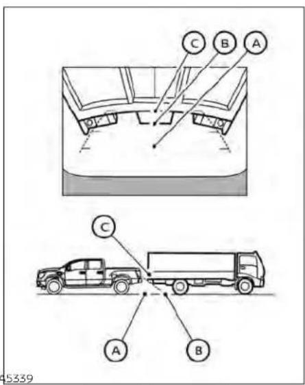
Backing up behind a projecting object
The position © is shown farther than the position Ⓑ in the display. However, the position © is actually at the same distance as the position Ⓐ. The vehicle may hit the
object when backing up to the position A) if the object projects over the actual backing up course.
HOW TO PARK WITH PREDICTED COURSE LINES
WARNING
- If the tires are replaced with different sizes, the predicted courselines may be displayed incorrectly.
- Onasnow-coveredorslipperyroad, theremaybeadifferencebetween thepredictedcourselineandtheactualcourseline.
-
If the battery is disconnected or becomes discharged, the predicted courselines may be displayed incorrectly. If this occurs, please perform the following procedures:
-
Turnthesteeringwheelfromlock tolockwhiletheengineis running.
- Drivethevehicleonastraightroad formorethan5minutes.
whenthesteeringwheelisturned withtheignitionswitchintheACC position,thepredictedcourselines maybedisplayedincorrectly.
- Thereisthepossibilitythatwhenthe vehiclemirrorsareextendedfortowing,themirrorsmaybeshowninthe bird's-eyeviewandfrontsideview.

natural_image
Diagram showing a car on a curved ramp and its side view, with an attached circular component labeled 'A' (no text or symbols present)
-
Visually check that the parking space is safe before parking your vehicle.
-
The rear view of the vehicle is displayed on the screen when the shift lever is moved to the R (Reverse) position.
-
Slowly back up the vehicle adjusting the steering wheel so that the predicted course lines enter the parking space
-
Maneuver the steering wheel to make the vehicle width guide line parallel to the parking space while referring to the predicted course lines.
- When the vehicle is parked in the space completely, move the shift lever to the Park (Park) position and apply the parking brake.
HOW TO SWITCH THE DISPLAY
With the ignition switch in the ON position, press the CAMERA button or move the shift lever to the R (Reverse) position to operate the Intelligent Around View Monitor.
The Intelligent Around View Monitor displays different split screen views depending on the position of the shift lever. Press the CAMERA button to switch between the available views.
If the shift lever is in the R (Reverse) position, the available views are:
- Rear view/bird's-eye view split screen
- Rear view/front-side view split screen
If the shift lever is in the P (Park) or D (Drive) position, the available views are:
- Front view/bird's-eye view split screen
- Front view/front-side view split screen
The display will switch from the Intelligent Around View Monitor screen when:
- The shift lever is in the D (Drive) position and the vehicle speed increases above approximately 6 mph (10 km/h)
• A different screen is selected.

- Press the Menu button.
- Touch the "Settings" key.
- Touch the "Camera" key.
- Touch the "Display Settings" key.
- Touch the "Brightness", "Contrast", Tint, "Color", or "Black Level" key.
- Adjust the item by touching the "+" or "-" key on the touch-screen display.
NOTE:
Donotadjustanyofthedisplaysettings oftheIntelligentAroundViewMonitor whilethevehicleismoving.Makesure theparkingbrakeisfirmlyapplied.

natural_image
Technical line drawings of two pickup trucks on a road, showing front and side views (no text or symbols)INTELLIGENT AROUND VIEW MONITOR SYSTEM LIMITATIONS
WARNING
Listedbelowarethesystemlimitations for IntelligentAroundViewMonitor. Failuretooperatethevehicleinaccordancewiththesesystemlimitations couldresultinseriousinjuryordeath.
- DonotusetheIntelligentAround ViewMonitorwiththeoutsidemirrorsinthestoredposition,andmake surethatthetailgateissecurely closedwhenoperatingthevehicle usingtheIntelligentAroundView Monitor.
- Theapparentdistancebetweenobjectsviewedon the Intelligent Around ViewMonitordiffersfrom the actualdistance.
-
Thecamerasareinstalledonthe frontgrille,theoutsidemirrorsand abovetherearlicenseplate.Donot putanythingonthevehiclethatcoversthecameras.
-
When washing the vehicle with high pressure water, besurenottospray it around the cameras. Otherwise, water may enter the camera unit causing water condensation on the lens, a malfunction, fire or an electric shock.
- Donotstrikethecameras.Theyare precisioninstruments.Doingso couldcauseamalfunctionorcause damageresultinginafireoranelectricshock.
There are some areas where the system will not show objects and the system does not warn of moving objects. When in the front or rear view display, an object below the bumper or on the ground may not be viewed ①. When In the bird's-eye view, a tal object near the seam ② of the camera viewing areas will not appear in the monitor.
The following are operating limitations and do not represent a system malfunction:
- There may be a delay when switching between views.
-
When the temperature is extremely high or low, the screen may not display objects clearly.
-
When strong light directly shines on the camera, objects may not be displayed clearly.
• The screen may flicker under fluorescent light.
• The colors of objects on the Intelligent Around View Monitor may differ somewhat from the actual color of objects. - Objects on the Intelligent Around View Monitor may not be clear and the color the object may differ in a dark environment.
There may be differences in sharpness between each camera view of the bird's-eye view.
- Do not use wax on the camera lens. Wip all off any wax with a clean cloth that has been dampened with a diluted mild cleaning agent, then wipe with a dry cloth.
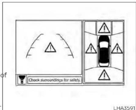
System temporarily unavailable
When the "I" Icon is displayed on the screen, there are abnormal conditions in the Intelligent Around View Monitor. This will not hinder normal driving operation but it is recommended that the system be inspected. It is recommended that you visit a NISSAN dealer for this service.

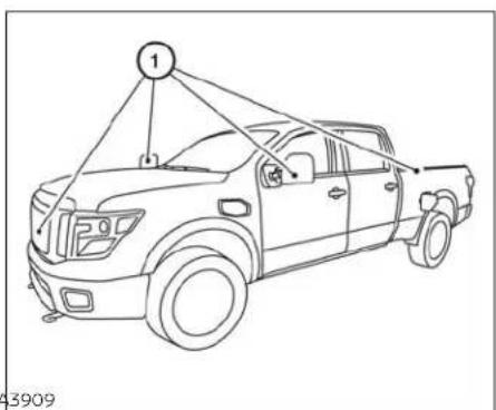
When the "[X]" icon is displayed on the screen, the camera image may be receiving temporary electronic disturbances from surrounding devices. This will not hinder normal driving operation but it is recommended that the system be inspected if it occurs frequently. It is recommended that you visit a NISSAN dealer for this service.
SYSTEM MAINTENANCE
CAUTION
- Donotusealcohol, benzineorthinnertocleanthecamera. This will caused discoloration.
- Donotdamagethecamerasasthe monitorscreenmaybeadversely affected.
If dirt, rain or snow accumulates on any of the cameras ①, the Intelligent Around View Monitor may not display objects clearly. Clean the camera by wiping with a cloth dampened with a diluted mild cleaning agent and then wiping with a dry cloth.
4-22 Monitor, climate, audio, phone and voicerecognitionsystems
MOVINGOBJECTDETECTION(MOD) (ifsoequipped)
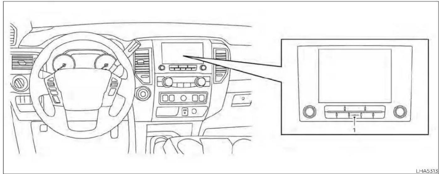
natural_image
Line drawing of a car dashboard and infotainment panel showing the front and side views (no text or symbols)- CAMERA button
Monitor, climate, audio, phone and voicerecognitionsystems 4-23
WARNING
- FailuretofollowthewarningsandinstructionsforproperuseoftheMovingObjectDetectionsystemcould resultinseriousinjuryordeath.
TheMODsystemisnotasubstitute forpropervehicleoperationandis notdesignedtopreventcontactwith objectssurroundingthevehicle. Whenmaneuvering,alwaysusethe outsidemirrorsandreaviewmirror andturnandcheckthesurroundings toensureitissafetomaneuver. - Thesystemisdeactivatedatspeeds above6mph(10km/h).Itisreactivatedatlowerspeeds.
- TheMODsystemisnotdesignedto detectsurroundingstationary objects.
The MOD system can inform the driver of moving objects near the vehicle when backing out of garages, maneuvering in parking lots and in other such instances.
The MOD system detects moving objects by using image processing technology on the image shown in the display.
The MOD system will turn on automatically under the following conditions:
- When the shift lever is in the R (Reverse) position.
- When vehicle speed decreases below approximately 6 mph (10 km/h) and the camera screen is displayed.
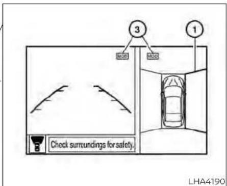
Frontandbird's-eyeviews
The MOD system operates in the following conditions when the camera view is displayed:
- When the shift lever is in the P (Park) or N (Neutral) position and the vehicle is stopped, the MOD system detects moving objects in the bird's-eye view. The MOD system will not operate if the outside mirrors are moving in or out, in the stowed position, or if either front door is opened.
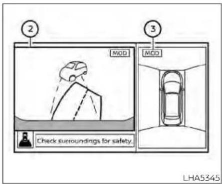
Rearandbird's-eyeviews
- When the shift lever is in the D (Drive) position and the vehicle speed is below approximately 6 mph (10 km/h), the MOD system detects moving objects in the front view. - When the shift lever is in the R (Reverse) position and the vehicle speed is below approximately 6 mph (10 km/h), the MOD system detects moving objects in the rear view. The MOD system will not operate if the tailgate is open.
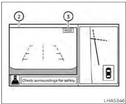
Rearandfront-sideviews
The MOD system does not detect moving objects in the front-side view. The MOD icon is not displayed on the screen when this view.
When the MOD system detects moving objects near the vehicle, a chime will be heard and a yellow frame will be displayed on the view where the objects are detected. While the MOD system continues to detect moving objects, the yellow frame continues to be displayed.
NOTE:
While the RCT Achime is beeping, the MOD system will not chime.
In the bird's-eye view, the yellow frames displayed on each camera image (front, rear, right, left) depending on where moving objects are detected.
The yellow frame② is displayed on each view in the front view and rear view modes.
A blue MOD icon is displayed in the view where the MOD system is operative. A gray MOD icon is displayed in the view where the MOD system is not operative.
If the MOD system is turned off, the MOD icon ③ is not displayed.
TURNING MOD ON AND OFF (if so equipped)
Some vehicles include the option to allow the MOD system to be turned on or off. To turn the MOD system on or off.
-
Press the ◀ or button on the steering wheel and select "Settings" in the vehicle information display.
-
Using the buttons, select "Driver Assistance" and press the ENTER button.
-
Select "Parking Aids".
Monitor, climate, audio, phone and voicerecognitionsystems4-25
- Toggle ON or OFF "Moving Object" using the ENTER button.
You can also turn the MOD on or off by pressing the Parking Aids system switch (if so equipped).
MOD SYSTEM LIMITATIONS
WARNING
Listedbelowarethesystemlimitations forMOD.Failureretooperatethevehicle inaccordancewiththesesystemlimitationscouldresultinseriousinjuryor death.
- DonotusetheMODsystemwhen towingatrailer.Thesystemmaynot functionproperly.
- Excessivenoise(forexample, audio systemvolumeoropenvehiclewindow)willinterferewiththechime sound, anditmaynotbeheard.
- TheMODsystemperformancewillbelimitedaccordingtoenvironmentalconditionsandsurroundingobjectssuchas:
-
Whenthereislowcontrastbetweenbackgroundandthemovingobjects.
-
Whenthereisablinkingsourceof light.
- When strong lights such as another vehicle's headlightors sunlight is present.
- Whencameraorientationisnotin itsusualposition,suchaswhena mirrorisfolded.
- Whenthereisdirt,waterdropsor snowonthecameralens.
- Whenthepositionofthemoving objectsinthe display isnot changed.
- TheMODsystemmightdetectflowingwaterdropletsonthecamera lens,whitesmokefromthemuffler,movingshadows,etc.
- TheMODsystemmaynot function properlydependingonthespeed, direction, distance or shape of the movingobjects.
- If your vehicle sustains damage to thepartswherethe camera is installed, leavingitmisalignedorbent, thesensingzonemaybealtered and theMODsystemmaynotdetectobjectsproperly.
- Whenthetemperatureisextremely highorlow,thescreenmaynotdisplay objects clearly. This is not a malfunction.
NOTE:
TheblueMODiconwillchangetoorangeifoneofthefollowinghasoccurred:
-Whenthesystemismalfunctioning.
- When thecomponent temperature reachesahighlevel(iconwillblink).
- Whenthe RearViewcamerahas detectedablockage(iconwillblink).
If the icon light continues to illuminate orange, havethe MOD system checked. It is recommended that you visit a NISSAN dealer forth this service.
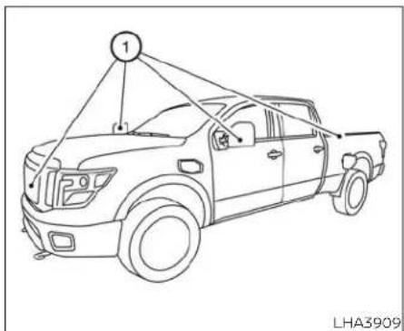
SYSTEM MAINTENANCE
If dirt, rain or snow accumulates on any of the cameras ① , the MOD system may not operate properly. Clean the camera by wiping with a cloth dampened with a diluted mild cleaning agent and then wiping with a dry cloth.
CAUTION
- Donotusealcohol, benzineorthinnertocleanthecamera. This will caused discoloration.
- Donotdamagethecameraasthe monitorscreenmaybeadversely affected.
VENTSHEATERANDAIRCONDITIONER

LHA3772
Adjust air flow direction for the driver's and passenger's side vents①, center vents②, and rear passengers' vents (if so equipped) ③ by moving the vent slide and/or vent assemblies.
(manual)(ifsoequipped)

WARNING
- Theairconditionercoolingfunction operatesonlywhentheengineis running.
- Donotleavechildrenoradultswho wouldnormallyrequiretheassistanceofothersaloneinyourvehicle. Petsshouldalsonotbeleftalone. Theycouldaccidentallyinjurethem-selvesorothersthroughinadvertent operationofthevehicle.Also,onhot, sunnydays,temperaturesinaclosed vehiclecouldquicklybecomehigh enoughtocausesevereorpossibly fatalinjuriestopeopleoranimals.
- Donotusethere circulation mode for long periods as it may cause the interior air to become most and the window stofogup.
NOTE:
- Odorsfrominsideandoutsidethevehiclecanbuildupintheairconditioner unit.Odorcanenterthepassenger compartmentthroughthevents.
-Whenparking,settheheaterandair conditionercontrolstoturnoffairre-circulationtoallowfreshairintothe passengercompartment.Thisshould helpreduceodorsinsidethevehicle.
4-28 Monitor, climate, audio, phone and voice recognition systems

CONTROLS
- Fast speed control dial / system OFF dial / A/C (air conditioning) button
- Air flow control buttons
-
Temperature control dial / MAX A/C button
-
Air recirculation button
- Outside mirror (if so equipped) defroster switch
- FRONT Front windshield defrost button
Fan speed control dial
The fan speed control dial turns the fan on and off and controls fan speed.
Fan speed control dial — OFF mode
Setting the fan speed control dial to the off position will turn off the fan and the air recirculation indicator light will turn on. To get fresh air in fan off mode, press the air recirculation button to turn off the indicator. In fan off mode, the mode buttons can be selected to change the air vent distribution (if the air recirculation mode is off).
Air flow control buttons
The air flow control buttons allow you to select the air flow outlets.
MAX — Air flows from center and side A/C vents with maximum cooling.
Air flows from center and side vents.
— Air flows from center and side vents and foot outlets.
- Air flows mainly from foot outlets.
— Air flows from defroster outlets and foot outlets.
— Air flows mainly from defroster outlets.
Temperature control dial
The temperature control dial allows you to adjust the temperature of the outlet air. To lower the temperature, turn the dial to the left. To increase the temperature, turn the dial to the right.
Air recirculation button
ONposition(Indicatorlighton)
Interior air is recirculated inside the vehicle
Press the 📄 button to the ON position when:
- driving on a dusty road.
• to prevent traffic fumes from entering passenger compartment. - for maximum cooling when using the air conditioner.
OFFposition(Indicatorlightoff)
If outside air is desired in off mode, press the recirculation button until the indicator turns off.
If fogging occurs, press the windshield defrost button.
FRONT front
A/C (air conditioner) button
Start the engine, turn the in speed control dial to the desired position and press the A/C button to turn on the air conditioner. To turn off the air conditioner, press the A/C button again.
Theairconditionercoolingfunctionoperatesonlywhentheengineisrunning.
Outside mirror defroster (if so equipped)
For additional information, see "Rear window and/or outside mirror (if so equipped) defroster switch" (P. 2-43).
HEATER OPERATION
Heating
This mode is used to direct heated air to the foot outlets. Some air also flows from the defrost outlets.
- Press the ⬆ button to the OFF position for normal heating. The indicator light on the ⬆ button will go off.
- Press the 📋 air flow control button.
-
Turn the ✿ fan speed control dial to the desired position.
-
Turn the temperature control dial to the desired position between the middle and the hot position.
Ventilation
This mode directs outside air to the side and center vents.
- Press the 📄 button to the off position. The indicator light on the 📄 button will go off.
- Press the 🎩 air flow control button.
- Turn the ✿ fan speed control dial to the desired position.
- Turn the temperature control dial to the desired position.
Defrosting or defogging
This mode directs the air to the defrost outlets to defrost/defog the windows.
- Press the FRONT defrost/defog button.
- Turn the ✿ fan speed control dial to the desired position.
-
Turn the temperature control dial to the desired position between the middle and the hot position.
-
To quickly remove ice or fog from the w dows, turn the ✝ fan speed control dial to the highest setting and the temperature control to the full HOT position.
- When the position is selected, the air conditioner automatically turns on if the outside temperature is more than 36°F (2°C). This dehumidifies the air which helps defog the windshield. The mode automatically turns off, allowing outside air to be drawn into the passenger compartment to further improve the defogging performance. Under this condition, the indicator light on the A/C button indicator will not turn on if the user had selected the A/C off. Turning off the air conditioning via the A/C button is not allowed in this mode. If the A/C button indicator was on when entering this mode, and the A/C button is selected in this mode, the A/C button indicator will turn off, but the A/C compressor will still be automatically enabled. The recirculation button indicator will not illuminate if the button is pressed in this mode.
Bi-level heating
The bi-level mode directs warmed air to the side and center vents and to the front and rear floor outlets.
- Press the 📄 button to the off position. The indicator light on the 📄 button will go off.
- Press the air flow control button.
- Turn the ✿ fan speed control dial to the desired position.
- Turn the temperature control dial to the desired position.
Heating and defogging
This mode heats the interior and defogs the windshield.
- Press the 📋 air flow control button.
- Turn the ✿ fan speed control dial to the desired position.
- Turn the temperature control dial to the desired position between the middle and the hot position.
- When the ⚙ position is selected, the air conditioner automatically turns on if the outside temperature is more than 36°F (2°C). If the ⚙ air flow control button is selected for more than 1 minute, the air conditioning system will continue to operate until the ⚙ fan speed control dial is turned to OFF, the vehicle is shut off, or the A/C button is used to turn off the compressor even if the air flow control dial is turned to a position other than the ⚙ position. This dehumidifies the air which helps defog the windshield. Under this condition, the indicator light on the A/C button indicator will not turn on if the user had selected A/C off. Turning off the air conditioning via the A/C button is not allowed in this mode. If the A/C button indicator was on when entering this mode, and the A/C button is selected in this mode, the A/C compressor will still be automatically enabled. It is recommended that ⚙ mode be turned off for maximum defogging. The recirculation button can be selected in this mode to block outside odors. However, for maximum defogging in this mode, it is recommended to turn recirculation off when possible.
Operating tips
Clearsnowandicefromthewiperblades andairinletinfrontofthewindshield. Thisimprovesheateroperation.
AIR CONDITIONER OPERATION
Start the engine, turn the fin speed control dial to the desired position, and press the A/C button to activate the air conditioner. When the air conditioner is on, cooling and dehumidifying functions are added to the heater operation.
Theairconditionercoolingfunctionoperatesonlywhentheengineisrunning.
Cooling
This mode is used to cool and dehumidify the air.
- Press the 📄 button to the off position.
- Press the air flow control button.
- Turn the ✿ fan speed control dial to the desired position.
- Press the A/C button.
- Turn the temperature control dial to the desired position between the middle and the cold position.
- For quick cooling when the outside temperature is high, press the button to be selected, the air conditioner automatically takes on position. Be sure to return the turns on if the outside temperature is more to the off position for normal cooling. The than 36ircF (2ircC) . The air conditioning system indicator light on the button will go will continue to operate until the fan off. You may also select MAX A/C for quick speed control dial is turned to OFF, the air cooling. conditioner is turned OFF, or the vehicle is
Dehumidified heating
This mode is used to heat and dehumidify the air.
- Press the ⚙ button to the off position. The indicator light on the ⚗ button will go off.
- Press the 📋 air flow control button.
- Turn the ✿ fan speed control dial to the desired position.
- Press the A/C button on.
- Turn the temperature control dial to the desired position.
Dehumidified defogging
This mode is used to defog the windows and dehumidify the air.
- Press the front defroster button.
- Turn the ✿ fan speed control dial to the desired position.
When the front or positions are selected, the air conditioner automatically turns on if the outside temperature is more than 36°F (2°C). The air conditioning system will continue to operate until the fan speed control dial is turned to OFF, the air conditioner is turned OFF, or the vehicle is shut off. If a position other than the front defrost air flow button is selected, the A/C compressor will not turn off even if the user had selected A/C off prior to entering defrost. In front defrost or foot defrost the indicator light on the A/C button will not turn on if the user had selected A/C off. Turning off the air conditioning via the A/C button is not allowed in this mode. If the A/C button indicator was on when entering this mode, and the A/C button is selected in this mode, the A/C button indicator will turn off, but the A/C compressor will still be automatically enabled. This dehumidifies the air which helps defog the windshield. The mode automatically turns off, allowing outside air to be drawn into the passenger compartment to further improve the defogging performance.
- Turn the temperature control dial to the desired position.
4-32 Monitor, climate, audio, phone and voice recognition systems
Operating tips
- Keep the windows closed while the air conditioner is in operation.
- After parking in the sun, drive for 2 or 3 minutes with the windows open to vent hot air from the passenger compartment. Then, close the windows. This allows the air conditioner to cool the interior more quickly.
- Theairconditioningsystemshouldbe operatedforapproximately10minutes atleastonceamonth. Thishelpspreventdamagetothesystemduetolack oflubrication.
- A visible mist may be seen coming from the ventilators in hot, humid conditions as the air is cooled rapidly. This does not indicate a malfunction.
- Iftheenginecoolanttemperature gaugeindicatesenginecoolanttemperatureoverthenormalrange,turn theairconditioneroff.Foradditional information,see"Ifyourvehicleoverheats"(P.6-12).
AIR FLOW CHARTS
The following charts show the button and dial positions for MAXIMUM AND QUICK heating, cooling or defrosting. For additional information on heating and cooling, see "Heater and air conditioner (manual)" (P. 4-28). Theairrecirculation( 📄 )buttonshouldalwaysbeintheOFFposition forheatinganddefrosting.

LHA4486 LHA4487
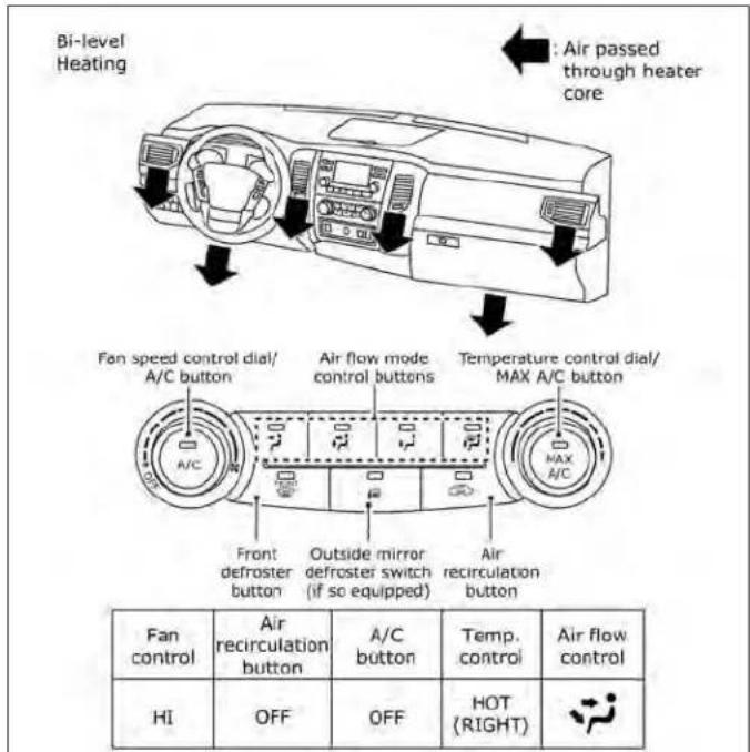
4-34 Monitor, climate, audio, phone and voicerecognitionsystems


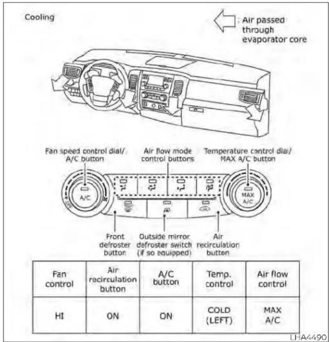
HEATER AND AIR CONDITIONER (automatic) (if so equipped)
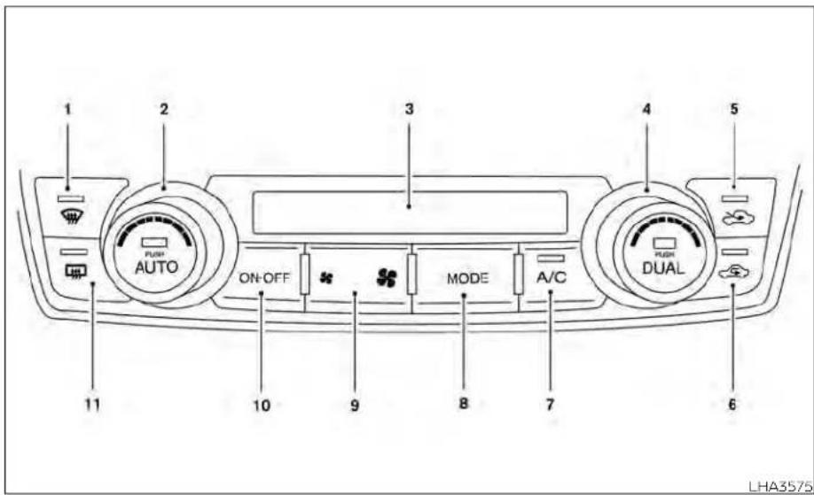
- Frontdefroster button
- Temperature control dial (driver's side)/AUTO button
- Display screen
- Temperature control dial (passenger's side)/DUAL button
- Fresh air intake button
-
Air recirculation button
-
A/C (air conditioner) button
- MODE (manual air flow control) button
- ✿ Fan speed control buttons
- ON-OFF button
- Rear window and/or outside mirror (if so equipped) defroster switch
WARNING
- Theairconditionercoolingfunction operatesonlywhentheengineis running.
- Donotleavechildrenoradultswho wouldnormallyrequiretheassistanceofothersaloneinyourvehicle. Petsshouldalsonotbeleftalone. They couldaccidentally injurethem-selvesorothersthroughinadvertent operationof the vehicle.Also, onhot, sunny days, temperatures in a closed vehiclecouldquicklybecomehigh enoughto causesevereor possibly fatalinjuriestopeopleoranimals.
- Do not use the recirculation mode for long periods as it may cause the interior air to become stale and the windows to fog up.
NOTE:
- Odors from inside and outside the vehicle can build up in the air conditioner unit.Odorcanenterthepassenger compartment through the vents.
- When parking, set the heater and air conditioner controls to turn off air recirculation to allow fresh air into the passenger compartment. This should help reduce odors insidethe vehicle.
AUTOMATIC OPERATION
Cooling or heating (auto)
This mode may be normally used all year round as the system automatically works to keep a constant temperature. Air flow distribution and fan speed are also controlled automatically.
- Press the AUTO button on.
- Turn the temperature dial to the left or right to set the desired temperature. Driver and passenger temperatures can be set independently. Press the DUAL button to activate dual climate control functions. Turn the passenger's side temperature control dial to the left or right to set the desired passenger's temperature.
-
Adjust the temperature dial to about 75ircF (24°C) for normal operation.
-
The temperature of the passenger compartment will be maintained automatically. Air flow distribution, fan speed and A/C on/off are also controlled automatically. The A/C button indicator will remain in the last user setting. Under this condition, the indicator light on the A/C button indicator will not turn on if the user had not selected the A/C button off. Turning off the air conditioning via the A/C button is not allowed in this mode. If the A/C button indicator was on when entering this mode, and the A/C button is selected in this mode, the A/C button indicator will turn off, but the A/C compressor will still be automatically enabled. For additional information, see "Air flow control" (P. 4-40). To turn off the compressor, turn off auto mode, then turn the A/C on then off until the A/C button indicator is not lit.
- A visible mist may be seen coming from the vents in hot, humid conditions as the air is cooled rapidly. This does not indicate a malfunction.
Heating
The air conditioner does not activate. When you need to heat only, use this mode.
-
Press the AUTO button.
-
Turn the temperature control dial to the left or the right to set the desired temperature. Driver and passenger temperatures can be set independently. Press the DUAL button to activate dual climate control functions. Turn the passenger's side temperature control dial to the left or right to set the desired passenger's temperature.
The temperature of the passenger compartment will be maintained automatically. Air flow distribution and fan speed are also controlled automatically.
Do not set the temperature lower than the outside air temperature. Otherwise, the system may not work properly. Not recommended if windows fog up.
Dehumidified defrosting or defogging
Press the ⏻ defroster control button to turn the system on. The indicator light in the button will illuminate.
-
Turn the temperature dial to the left or right to set the desired temperature. • To quickly remove ice from the outside of the windows, press the ✝ fan speed control button to the maximum position.
-
As soon as possible after the windshield is clean, press the AUTO button to return to the auto mode.
- When the control is activated, the air conditioner will automatically be turned on at outside temperatures above 36°F (2°C). This dehumidifies the air which helps defog the windshield. Under this condition, the indicator light on the A/C button indicator will not turn on if the use had selected A/C off prior to entering this mode. Turning off the air condition via the A/C button is not allowed in this mode. The A/C button indicator was on when entering this mode, and the A/C button is selected in this mode, the A/C compressor will still be automatically enabled. The air recirculation mode automatically turns off, allowing outside air to be drawn into the passenger compartment to further improve the defogging performance.
Remote Engine Start with Intelligent Climate Control (if so equipped)
Vehicles equipped with automatic climate controls and Remote Engine Start function may go into automatic heating or cooling mode when Remote Engine Start is acti-
vated depending on outside and cabin temperatures. During this period, the climate control display and buttons will be inoperable until the ignition switch is turned on. In Remote Engine Start defrosting mode, the rear window defroster (if so equipped), heated seat (if so equipped) an heated steering wheel (if so equipped) may be activated automatically.
Voice Recognition logic (if so equipped)
When the climate control system is on, the front and rear (if so equipped) fan speeds may be automatically lowered so that commands are more easily recognized. Fan speed can be adjusted using the fan speed * decrease and * increase buttons, if desired.
MANUAL OPERATION
Fan speed control
Press the ✿ fan speed control buttons to manually control the fan speed.
Press the AUTO button to return to automatic control of the fan speed.
When adjusting the manual fan from auto mode, the outlet direction (floor, floor/
defrost, vent, bi-level) will still automatically change. To fix the outlet to a manual mode, select the desired air flow location using the MODE button.
Temperature control dial The temperature control dial allows you to adjust the temperature of the outlet air. To lower the temperature, turn the dial to the left. To increase the temperature, turn the dial to the right. Temperature can be adjusted on the driver's and passenger's side.
Press the 📄 air recirculation button to recirculate interior air inside the vehicle when:
- driving on a dusty road
• to prevent traffic fumes from entering passenger compartment. - for maximum cooling when using the air conditioning system.
Press the AUTO button to return to automatic mode.
The air recirculation button will not be activated when the air conditioner is in mode.
When the outside temperature exceeds 70irc F ( 21irc C), the air conditioning system may default to air recirculation mode automatically to reduce overall power consumption. To exit air recirculation mode, select the fresh air intake button to enter fresh air mode.
In Floor/Defrost mode, the recirculation button can be selected to block outside odors. However, for maximum defogging in this mode, it is recommended to turn recirculation off when possible.
Fresh air intake
Press the fresh air intake button to draw outside air into the passenger compartment.
Automatic intake air control
In the AUTO mode, the intake air will be controlled automatically. When the outside temperature exceeds 70irc F ( 21irc C), the air conditioning system may default to air recirculation mode automatically to reduce overall power consumption. To exit air recirculation mode, select the fresh air intake button to enter fresh air mode. The air recirculation indicator will turn off, the fresh air indicator will turn on.
To manually control the intake air, press the Air flow control
fresh air intake button. To return to the automatic control mode if the fresh air indicator is illuminated press and hold. Press the MODE button to manually control air flow and select the air outlet.
the fresh air intake button for about 2 seconds. The fresh air indicator and air recirculation indicator lights will flash twice, and then the intake air will be controlled automatically. To return to the automatic control mode if the air recirculation icon is illuminated, press and hold the air recirculation button for about 2 seconds. The air recirculation indicator and fresh air intake indicator lights will flash twice and the intake air will be controlled automatically.
A/C (air conditioner) button
Start the engine, turn the ✿ fan speed control buttons to the desired position and press the A/C button to turn on the air conditioner. To turn off the air conditioner, press the A/C button again.
Theairconditionercoolingfunctionoperatesonlywhentheengineisrunning.
- Air flows from center and side vents.
— Air flows from center and side vents and foot outlets.
Air flows mainly from foot outlets.
— Air flows from defroster and foot outlets.
To turn system off
Press the ON-OFF button.
Rear window and/or outside mirror (if so equipped) defroster switch
For additional information, see "Rear window and/or outside mirror (if so equipped) defroster switch" (P. 2-43).

OPERATING TIPS
The sunload sensor (if so equipped, located on the top center of the instrument panel, helps the system maintain a constant temperature. Do not put anything on or around this sensor.
- When the climate system is in automatic operation and the engine coolant temperature and outside air temperature are, low, the air flow outlet may default to defroster mode for a maximum of 2 minutes 30 seconds. This is not a malfunction. After the engine coolant temperature warms up, the air flow outlet will return to foot mode and operation will continue normally.
- When the outside and interior cabin temperatures are moderate to high, the intake setting may default to turn off air recirculation to allow fresh air into the passenger compartment. You may notice air flow from the foot mode, bi-level mode, or side demist vent outlets for a maximum of 15 seconds. This may occur when previous climate setting was system off. This is not a malfunction. After the initial warm air is expelled, the intake will return to automatic control, air flow outlet will return to previous settings, and operation will continue normally. To exit, press any climate control button.
Keep the windows closed while the air conditioner is in operation. If you feel that the air flow mode you have selected and the outlets the air is coming out do not match, select the mode. When you change the air flow mode, you may feel air flow from the foot outlets for just a moment. This is not a malfunction.
SERVICINGAIRCONDITIONER
USB/iPod®CHARGINGPORT(ifso equipped)
The air conditioner system in your NISSAN vehicle is charged with a refrigerant designed with the environment in mind.
Thisrefrigerantdoesnotharmthe earth'sozonelayer.
Special charging equipment and lubricant is required when servicing your NISSAN air conditioner. Using improper refrigerants or lubricants will cause severe damage to your air conditioner system. For additional information, see "Air conditioner system refrigerant and oil recommendations" (P. 10-8).
It is recommended that you visit a NISSAN dealer to service your "environmentally friendly" air conditioner system.
WARNING
The airconditionersystemcontainsrefrigerantunderhighpressure.Toavoid personalinjury,anyairconditionerserviceshouldbedoneonlybyanexperiencedtechnicianwithproper equipment.

natural_image
Line drawing of a car air intake console with three vent grilles and control buttons (no text or symbols)2ndrow
There is a USB/iPod® charging port located in the 2nd row on the back of the center console. This port will charge compatible devices.
NOTE:
TheUSB/iPod®chargingportwillnotoperatethedisplayscreenortheRearSeat Infotainment(RSI)(ifso equipped).Only the USB connection port located in the consoleboxwillallowoperationofUSB/iPod®devicesthroughtheaudiosystem.
ANTENNA
The antenna cannot be shortened, but can be removed. When you need to remove the antenna, turn the antenna rod counterclockwise.
To install the antenna rod, turn the antenna rod clockwise and hand tighten.
CAUTION
- Alwaysproperlytightentheantenna rod during installation or the antenna rod may break during vehicle operation.
- Besurethattheantennaisremoved before the vehicle enters an automaticcarwash.
REARSEATINFOTAINMENT(RSI) (ifsoequipped)
WARNING
- Itisunlawfulinmostjurisdictionsfor apersontodriveamotorvehicle whichisequippedwithatelevision monitororscreenthatisvisible, directlyorindirectly,tothedriverwhile operatingthevehicle.Intheinterest ofsafety,theunitshouldneverbe installedwhereitwillbedirectlyor indirectlyvisible,bytheoperatorof themotorvehicle.
- If your vehicle is equipped with a wireless rearse audio system or any other wireless infrared device, makes sure it powered off when operating the RSIsystem. If both systems are powered on the same time, the wireless may obstruct each other, possibly creating undesirable audio interferencethrough the wireless headphones.
-
Forsafetyreasonswhenchanging discs,itisrecommendedthatthevehicleisnotinmotion,andthatyoudo notallowchildrentounfastensafety beltstochangediscsormakeany adjustmentstothesystem.System adjustmentscanbeaccomplished using the remote control, while safetybeltsremainfastened.
-
EnjoyyourRSIsystembutremember thatsafetyofallpassengersremains thenumberonepriority.DevicesinstalledintheUSB,HDMI,orhead-phonejackmayprotrudeandcreate apotentialeyeimpacthazardforum-beltedpassengersduringavehicle accident.Toreducetheriskofinjury, useonlySDcards(hiddenonleftside ofdriversidemonitor)orlow-profile USBstoragedevices.
CAUTION
- Donottouchtheinnerpinsofthe jacksonthefrontpanel.Electrostatic discharge may cause permanent damagetothedevice.
- TheLCDdisplayscreenisnottouchscreen.Donotputpressureoradd suctioncupsonthescreen.
- Cautionchildrentoavoidtouchingor scratchingthescreen,asitmaybe-comedirtyordamaged.
- Besuretorunthevehicleengine whileusingthesystem.Usingthis systemwithoutrunningtheengine canresultinbatterydrain.Toavoid theriskofbatterydrain,pleasere-membertoturnoffthesystemwhen thevehicleisnotinuse.
WELCOME
Thank you for purchasing this advanced Rear Seat Infotainment (RSI) system with built-in Wi-Fi and DVD player. Before operating this system, read this section thoroughly and retain it for future reference.
System features
- Twin 8-inch Color TFT-LCD Panels with 1024x600 Resolution
- Top-load DVD Player (Driver Side Only)
- Internal Wi-Fi Network
- Bluetooth® 4.1 Audio Streaming
- Miracast®/Smart View Capability
- SmartStream Content Sharing
- USB 2.0 Port, SDXC Card Input
• HDMI 1.4 Input with MHL 2.0 Support - Exclusive Slingplayer® Application
• 3.5mm Stereo Headphone Output
• Front Panel Capacitive Touch Controls
• Infrared Wireless Headphones
• Full-Function Slimline Remote Control
• Monitor Screen Sharing

GETTING STARTED
Turning the monitor on or off
- Press the button on the top of the monitor or the remote control to turn the monitor on or off. When in use, the front panel controls will illuminate.
- After the monitor has been turned on and is displaying a picture, the up/down viewing angle can be adjusted to optimize the picture quality. Press the push button latch located on the top of the monitor to pivot the screen.
Power up tips
- After the ignition is turned on, there is a 12 second delay before the monitor Ⓞ (power) button is operable.
- On some vehicles after the ignition is turned off, the system will continue to work for 10 minutes, or until the driver's door is opened.
- Remember to turn the monitor off and pivot the screen to the locked (latched) position when not in use.
Audio options
Wirelessheadphones
Each monitor includes a built-in dual channel infrared transmitter for use with wireless headphones. The wireless headphones must be used within a line of sight from the transmitter as infrared signals, like visible light, travel only in a straight line.
Howtousethewirelessheadphones
When placing the headphones on your head, make sure to observe the left and right orientation. The headphones must be oriented correctly (facing forward) to receive the audio signal. Press the (power) button on the headphones, then select channel "A" to listen to monitor
A, or channel "B" to listen to monitor B. Adjust the audio level using the volume control on each headphone.
Wiredheadphones
There is a 3.5mm stereo headphone output on each monitor which can be used with most standard stereo headphones (wired headphones sold separately).
Bluetooth®streamingaudio
To listen to audio throughout the entire vehicle, the system includes the ability to stream audio over a Bluetooth® connection to the vehicle's stereo system.
When monitor A is selected as the source to stream from, the audio output to the wireless and wired headphones will be disabled (only on monitor A). To use the wireless or wired headphones with monitor A, you must turn off the Bluetooth® streaming feature. To enable/disable Bluetooth® streaming, navigate to the "SETTINGS" menu, or press on the remote control during content playback. For additional information, see "Settings" (P. 4-72).
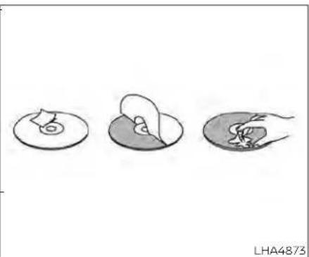
natural_image
Three abstract diagrams showing a circular object with a small figure inside, and two separate views of a human head (no text or symbols)Notes on discs
- To keep a disc clean, do not touch its surface. Handle the disc by its edge.
- Keep your discs in their cases or sleeves when not in use. Also, do not subject disc to heat/high temperature. Avoid leaving them in a parked vehicle or on a dashboard/rear tray.
- Do not attach labels, or use discs with sticky ink/residue. The following malfunctions may result from using such discs:
- Inability to eject a disc due to a label sticker peeling off and jamming the disc mechanism.

natural_image
Line drawing of two hands holding a small object with arrows indicating motion (no text or symbols)- Inability to read audio data correctly (i.e., playback skipping, or no playback) due to heat shrinking of a sticker or label causing a disc to warp.
Before playing, clean the discs with a commercially available cleaning cloth. Wipe each disc from the center out. Do not use solvents such as benzene, thinner, commercially available cleaners, or antistatic spray intended for analog discs.
- Use only normal, circular discs. If you insert irregular, non-round, shaped discs they may jam in the DVD player or not play properly.
Region coding
DVD players and discs are coded by region. These regional codes must match in order for the disc to play. The system is preset to the region code designated for your area by the DVD Copy Control Association. Other regions may not be played in this system.
Supporteddisctypes
DVD-Video: DVD contains video
DVD +/- R: DVD contains video
CD-DA: CD contains audio
CD-Video: CD contains video
CD-R/RW: CD contains audio
Unsupporteddisctypes
Super Audio CD
Optical disc CD-1
CD-ROM
DVD-ROM
DVD-RAM
DualDisc
DIVX
MiniDisc
AVCHD
HD DVD
Blu-ray
Loadingandplayingdiscs
Press the Ⓐ (power) button to turn the monitor on. Insert the disc about halfway
into the disc compartment slot on the driv- Some audio, video, and image files may be er's side monitor, with the disc's label facing incompatible with this system due to file the rear of the vehicle. Do NOT insert the characteristics, file format, recording soft-disc at an angle. The disc must be inserted ware used, directory structure, and/or the straight into the player. type of audio/video encoding used.
The disc will load automatically and begin to play. Some discs may start at the root menu, where playback must be selected t start a movie. Depending on the disc and playback location on the disc, a⊗*icon may be displayed in the upper-left corner of the screen indicating that playback is not possible during certain times.
DVD playback will automatically play on each monitor if there is no content already playing. You may also select "DVD" from the source menu to begin DVD playback mode
Media compatibility
For a list of compatible media formats for this system, see "Storage device formatting" (P. 4-46).
- The metadata or file information of somemovies.
audio and video files may not be correctly displayed. - It is not possible to play content that is protected by DRM (Digital Rights Management).
- There may be a delay before playback begins when using USB flash drives or SD cards with complex folder hierarchies or many files.
Storage device formatting
3 This system is compatible with several types of formatting for USB flash drives and SD cards. Refer to the documentation that comes with your storage device for more details on how to format.
FAT32-USBandSDHC
Good for smaller capacity storage devices, but individual files on the drive must be <4GB. This format is good for music and images.
EX-FAT-USBandSDXC
Better choice for larger capacity storage devices with files that are >4GB. This format is better for larger files such as full-length
NTFS-USBandSDXC
Best choice for very large capacity storage devices - with no limitations on file size. This format can be used for all file sizes.
| SupportedFormats | |||
| FormatExtension | SupportedVariations/Codecs | ||
| VIDEO | ASF .wmv H.263, H.264, MPEG-2 Part 2, WMV | ||
| AVI .avi H.263, | H.264, MPEG-2 Part 2, Xvid, WMV | ||
| MP4 .mp4, .rn4v H.263, H.264, MPEG-2 Part 2, MPEG-4 Part 2 | |||
| Matroska .mkv H.263, H.264, MPEG-2 Part 2, MPEG-4 Part 2, WMV | |||
| MPEG .mpg, .mpeg, .vob H.264, MPEG-2 Part 2, MPEG-4 Part 2 | |||
| AUDIO | AAC .m4a, .aac | ||
| ASF .wma | WMA, WMA Lossless, WMA Voice, WMA Pro | ||
| FLAC flac | FLAC 1.21 | ||
| Matroska | .mka | ||
| MPEG | mp1, .mp2, .mp3 | MPEG-1 Audio Layer 1, 2, 3, MPEG-2/2.5 Audio Layer 1, 2, 3 | |
| OGG .ogg | |||
| WAV .wav | |||
| PHOTO | BMP | .bmp | |
| CIF | gif | ||
| JPEG .jpg, .jpeg | |||
| PNG | png | ||
| TIFF | .tiff, .tif | ||
| WebP | .webp | ||
| VideoProfilesSupported:ASR: WMV7, WMV8, WMV9, H.264; Baseline, Main, Extended, High MPEG-2 Part 2: Simple, Main, High;MPEG-4Part2: Simple, Advanced Simple Profile, Xvid | |||

LHA4875
MonitorA(DriversSide)WithDVD
CONTROL DESCRIPTION
tor when the screen is in the open position.
1. SDCardSlot
Play videos, music, and Images stored on2. Eject most SD cards. The full-size SD card slot Press this button to eject a disc. Is accessible on the left side of the moni-
3. Screenlatch
Press the push-button latch located on the top of the monitor to pivot the screen. Remember to turn the monitor off and pivot the screen to the locked (latched) position when not in use.
4. Discslot
Play DVDs and CDs using standard size DVD or CD discs.
5. Power(MonitorA)
Press this button to turn the monitor on. Press again to turn the monitor off. Press and hold for 6 seconds to reset the system (Monitor A only)
Power(MonitorB)
Press this button to turn the monitor on. Press again to turn the monitor off.
6. Frontpanelcontrols
Capacitive-touch buttons provide user interface navigation, Select, Back, and Home functions.
7. Monitorscreendisplay
Includes an 8-inch TFT Liquid Crystal Display with 1024 x 600 resolution.

LHA4876
MonitorB(Passenger's Side)WithoutDVD
8. HDMIport
Connect an external audio/video source using a full-size HDMI connector. Supports MHL 2.0 playback and charging.
9. USB2.0port
Play videos, music, and images stored on most USB devices. Provides up to 2 amps of output to charge most mobile devices.
10. Headphoneoutputjack
Connect wired headphones using a 3.5mm stereo connector.

CAUTION
- Donotuseanyharshsolventor chemicalswhencleaningthe monitor.
- Donotuseanyabrasivecleanersthat mayscratchthescreen.Useonlya lightlydampenedlintfreeclotho wipethescreenifitisdirty.
- TheLCDdisplayscreenisnottouchscreen.Donotputpressureoradd suctioncupsonthescreen.
- Cautionchildrentoavoidtouching or scratchingthescreen,asitmaybe-come dirtyordamaged.
- Placethemonitorinthefullyclosed positionwhennotinuse.
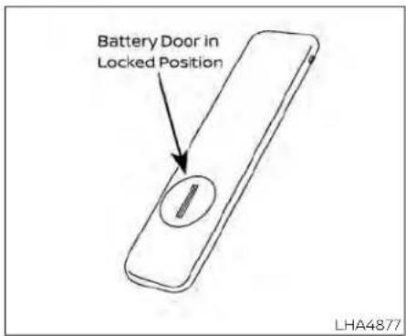
Before attempting to operate your remote control, turn the remote control face down and remove the battery insulator by pulling 3 the clear plastic tab away from the remote control.
Replacingthebattery
- Turn the remote control face down. Use a coin to turn the battery cover counterclockwise and remove it.

-
Replace the battery with a CR2032 or equivalent. Make sure that proper polarity is observed. The positive (+) side of the battery should face upwards.
-
Place the cover back into position and turn it clockwise until it locks into place.
The remote control will only operate this device. It is not a universal remote control and will not control other equipment.
WARNING
- Alwaysensurethatthebatteryisinsertedinthecorrectdirectionas showninthebatterycompartment.
- Whenthebatteryfailstofunction,replaceitimmediately.
- Keepthebatteryoutofthereachof children.Incasethebatteryisaccidentally swallowed, immediately consultadoctor.Also,whendisposingofusedbatteries,pleasecomply with governmental regulations or environmental public institution rulesthatapplyinyourcountry/area.
- Removethebattery iftheremote controlis notused fora monthor the longer.
- Storageinextremecoldcanweaken thebattery.Keeptheremotecontrol storedinacool,dryplace.

REMOTE CONTROL BUTTONS
1. Power
Press this button to turn the monitor on. Press again to turn the monitor off.
2. MonitorA
Press this button to transmit the remot control codes and functions to operate monitor A (Driver side).
3. Directionalpad
Press these buttons to increase/decrease the volume or navigate up/down when displaying a menu or file list.
4. Home
Press this button to return to the home screen.
5. Back
Press this button to go back to the previous screen.
6. MonitorB
Press this button to transmit the remote control codes and functions to operate monitor B (Passenger side).
7. Select
Press this button to make a selection when displaying a menu or file list.
8. Menu
Press this button to open the context menu (when available).
NOTE:
Youmustfirstselectthedesired monitor(pressAorB)tocontrolit. Example-PressA,thenpressPower toturnmonitorAon/off.

Installing the batteries
Before attempting to operate the headphones, install the batteries as described below:
-
Use a coin to remove the headphone battery cover
-
Install two "AAA" batteries into the headphones. Make sure that proper polarity (+ or -) is observed.
- Reinstall headphone battery cover.
Headphone operation
Press the power button on the headphones to turn on and off the headphones. The red LED will illuminate when the headphone is turned on. Set the select switch to "A" or "B" for use with the "A" monitor or "B" monitor respectively. Use the volume thumb wheel to adjust the volume level for the headphone audio.
NOTE: Iftheheadphonesareaccidentally leftonandsystemispoweredoff,a batterysaverfeaturewillautomaticallyturnofftheheadphonesafter approximately3minutes.
4-52 Monitor, climate, audio, phone and voicerecognition systems
CAUTION
- Alwaysensurethatthebatteriesare insertedwiththepositiveandnegativeterminalsinthecorrectdirection asshowninthebattery compartment.
- Differenttypesofbatterieshaveddifferentcharacteristics.Donotmixdifferenttypes.
- Donotmixoldandnewbatteries. Mixingoldandnewbatterieswill shortenbatterylifeand/orcause chemicalleaksfromtheold batteries.
- Whenbatteriesfailtofunction,re-placethemimmediately.
- Keepthebatteriesoutofthereachof children.Incasethebatteriesareaccidentallyswallowed,immediately consultadoctor.Also,whendisposingofusedbatteries,pleasecomply withgovernmentalregulationsor environmentalpublicinstitution rulesthatapplyinyourcountry/area.
- Remove the batteries if the headphonesarenotusedforamonthor longer.
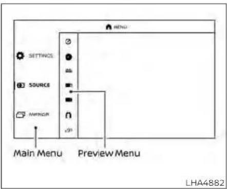
GENERAL OPERATION
Navigating menus
When fully powered on, the Home screen can be accessed at any time by pressing the 🎨 button on the remote control, or the 🔊 button on the monitor.
The main menu is located on the far-left side of the screen and allows users to select a source, change settings, USB fast-charge certain devices, and mirror content playing from the opposite monitor. To the right of the main menu is a preview menu, which gives a preview of the highlighted option in the main menu. The preview menu options will change with each selection.
Press ▲ or ▼ to scroll through the options in each menu. The current selection is highlighted in the center of the menu when scrolling up and down. Press ▼ or ▶ when an item is highlighted to select the item. Press ▶ or ◀ to move back one level in the menu.
Mirror
For additional information on how to mirror content playing from the opposite monitor, see "Mirroring content" (P. 4-55) and "Using Miracast®" (P. 4-70).
Fast-Charge(USB)
For additional information, see "Fast-Charge (USB)" (P. 4-61).
Settings
For additional information, see "Settings" (P. 4-72).

Sources
The following sources can be accessed from the main menu:
DVD
Play DVD movies and audio CDs using standard size DVD or CD discs.
HDMI
Play content from an external audio/video source.
USB
Play videos, music, and images stored on most USB devices.
SDCARD
Play videos, music, and images stored on most SD cards.
Slingplayer®
Stream content wirelessly from a Slingbox ® (sold separately) to the RSI system. *Requires external internet connection.
Miracast®
Stream content wirelessly from a Miracast-enabled device to the RSI system.
SmartStream
Stream content wirelessly between mobile devices and to the RSI system. *Requires compatible UPnP application to be installed on the mobile device. For additional information, see "SmartStream" (P. 4-71).
NOTE:
Thetopyleftcornerofthescreenin-
cludesagraphicrepresentationthat
showsthenavigationalpathofthe
currentmenu.Forexample:Home>
Source>DVD.

natural_image
Simple line drawing of a rectangular frame with a vertical dimension and a small protrusion at the bottom left (no text or symbols)DVD OPERATION
Volume control
Volume level can be adjusted by pressing ▲ or ▼ any time video is playing, or by selecting the volume icon in the playback controls menu.
NOTE: Forhearingprotection,thereisa maximumvolumesettingtolimitthe audiooutputofthefrontpanel 3.5mmheadphoneoutput.Usingthe directionalpadontheremotenavigateto"SETTINGS"then"AUDIO"then "HEADPHONES"toadjustthemaximumvolume.Onceset,themaximum volumeislimitedtothissetting.
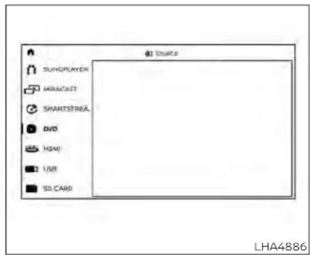
Playing a disc
Some DVDs may start at the root menu, where playback must be selected to start a movie. Use the remote control or front panel buttons to navigate through the DVD menu and begin playback.
The system supports DVD parental controls that provide the ability to limit content playback based on the Motion Picture Association of America (MPAA) ratings. For additional information, see "About parental lock" (P 4-78).
Mirroring content
To mirror the content of the opposite monitor, using the directional pad on the remote, select "MIRROR" from the Home Insert a disc into the top slot of monitor AScreen. This will allow the identical content with the label facing the rear of the vehicle to play on both monitors.
If the disc is supported and there is no content already playing, the disc will automatically begin playing.
When a disc is inserted, playback will automatically begin on both monitors A and B (if there is no content already playing). If a disc was previously inserted, using the directional pad on the remote select "SOURCE", then "DVD" from the Home screen to begin or resume playback.
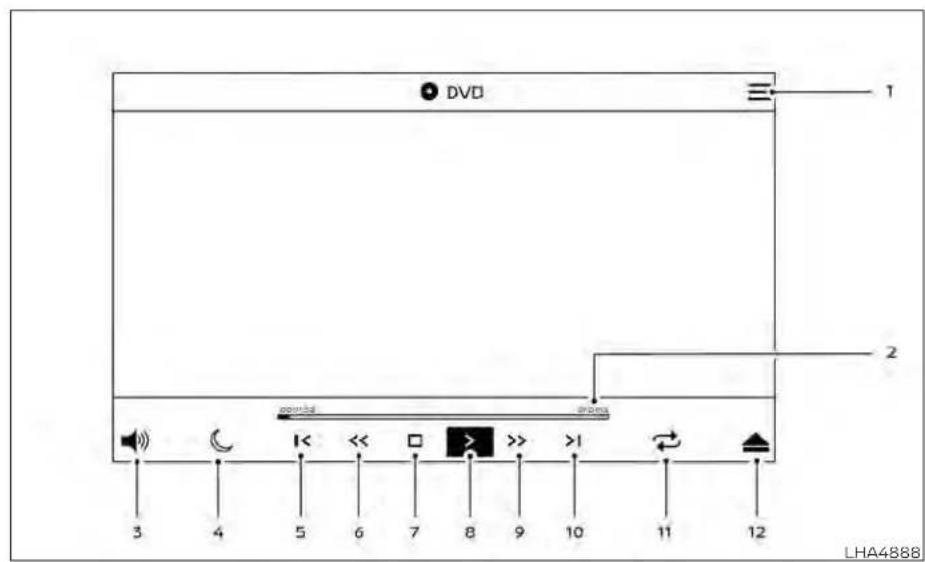
DVD PLAYBACK CONTROLS
During video playback, press to display the playback controls. Press ▶ or ▶ to navigate the controls. Presse to select the highlighted function or option. The playback controls will disappear after approximately 5 seconds of no activity.
1. ContextMenu
Press ≡ on the remote to open the context menu. The menu options will vary, depending on the source.
2. ProgressBar
Shows elapsed time, total time, and video progress bar indicator.
3. Volume
Select to display the volume level indicator. Press ▲ or to▼increase or decrease the volume.
4. NightMode
Select to dim the screen and reduce eye strain during operation at night.
5. Previous
Select to go to the beginning of the chapter. Select again to go to the previous chapter.
6. Rewind
Select to rewind at 2x, 4x, 8x, and 16x speeds. Select > to resume playback.
7. Stop
Select to stop DVD playback and return to the menu.
8. Play/Pause
Select once to pause DVD playback. Select again to resume DVD playback.
9. FastForward
Select to fast forward at 2x,4x,8x, and 16x speeds. Select > to resume playback.
10. Next
Select to go to the next chapter.
11. Repeat
Select once to repeat the entire DVD. Select again to repeat the currently playing chapter one time.
12. Eject
Select to eject the disc.

Context menu
Press the remote to open the context menu during DVD playback. The context menu provides options to adjust the display settings, audio settings, subtitle settings, and multicast (on/off). Press to select or toggle the highlighted item on the menu. Press to exit the context menu.
Display settings
Brightness is adjustable between Low, Medium, High, and Default.
Contrast is adjustable between Low, Medium, High, and Default.
Sharpness is adjustable between Low, Medium, High, and Default.
Aspect Ratio is adjustable between Pan & Scan, Letter Box, Widescreen, and Default.
Audio settings
The Audio settings allow you to set the default audio language for DVD playback. If the selected language is included on the DVD, the selected audio will be heard in that language.
Preferredlanguage
Preferred Language is selectable between English, French, Spanish, Chinese (Simplified), Chinese (Traditional), Dutch, Portuguese, Italian, Korean, Russian, Arabic, and Default. The preferred language must be included on DVD in order for it to be displayed. Refer to the DVD jacket for more information.
Languageswitch
Language Switch provides the ability to select between various audio streams (languages) included on a DVD. Audio streams must be included on the DVD to be heard.

Subtitle settings
The Subtitle settings allow you to set the default subtitle language for DVD playback. If the selected subtitle language is included on the DVD, the selected subtitle audio will be displayed during movie playback.
Subtitleswitch
Subtitle Switch (Off/On) allows the subtitles to be displayed during DVD playback.
PreferredLanguage
Preferred Language is selectable between English, French, Spanish, Chinese (Simplified), Chinese (Traditional), Dutch, Portuguese, Italian, Korean, Russian, Arabic, and Default. The preferred language must be included on DVD in order for it to be displayed. Refer to the DVD jacket for more information.
LanguageSwitch
Language Switch provides the ability to select between the various subtitles included on a DVD. Subtitles must be included on the DVD to be seen during DVD playback.
Multicast
Multicast (Off/On) provides the ability to watch a DVD over the built-in Wi-Fi network using an application installed on a mobile device. When turned on, the DVD content will be "cast" over the network to allow users with multiple mobile devices to enjoy the same movie. *Requires application to be installed on the mobile device.
Bluetooth
Selecting "BLUETOOTH" allows the Bluetooth® feature to be turned off/on, audio source selection, and lip-sync adjustments. For additional information, see "Bluetooth® streaming" (P. 4-77) and "Lip-Sync adjustment" (P. 4-77).

CD OPERATION
CD PLAYBACK CONTROLS
During audio playback the controls are displayed at all times.
1. ContextMenu
Press ≡ on the remote to open the
context menu. The menu options will vary, depending on the source.
ProgressBar
Shows elapsed time, total time, and progress bar indicator.
3. Volume
Select to display the volume level indicator. Press ▲ or to▼increase or decrease the volume.
4. NightMode
Select to dim the screen and reduce eye strain during operation at night.
5. Previous
Select to go to the beginning of the track. Select again to go to the previous track.
6. Rewind
Select to rewind at 2x, 4x, 8x, and 16x speeds. Select to resume playback.
7. Stop
Select to stop CD playback.
8. Play/Pause
Select once to pause CD playback. Select again to resume CD playback.
9. FastForward
Select to fast forward at 2x, 4x, 8x, and 16x speeds. Select > to resume playback.
10. Next
Select to go to the next track.
11. Repeat
Select once to repeat the entire CD. Select again to repeat the currently playing track.
12. Eject
Select to eject the disc.
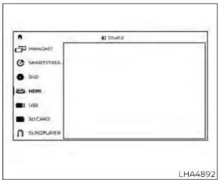
HDMI/MHL CONNECTION
HDMI connection
Display content from an external source connected to the system using the HDMI port located on the front of monitor A. A standard HDMI cable is required (sold separately).
To access the HDMI source, using the direc tional pad on the remote, select "SOURCE" from the Home Screen and navigate to HDMI in the menu. When HDMI is high-lighted, a preview of the HDMI input will be displayed in the preview screen.
Press → to return to the source menu.
NOTE: HDMIconnecteddevicesareindependentandmustbecontrolleddirectly fromthesourcedevice.
MHL connection
The system also allows mobile devices supporting Mobile High-Definition Link (MHL) to be connected. An MHL-to-HDMI cable is required (sold separately).
Mobile High-Definition Link (MHL) is an industry standard mobile audio/video interface that allows connection of smartphones, tablets, and other portable consumer electronics devices to the system. MHL transports high-quality uncompressed audio and video from a mobile source device to the system and at the same time provides power to recharge the device.
NOTE:
MHLconnecteddevicesareindependent andmustbecontrolleddirectlyfromthe sourcedevice.
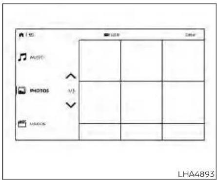
USB operation
Insert a USB device into the USB port located on the front of monitor A. Using the thedirectional pad on the remote, select "SOURCE" from the Home Screen and navigate to "USB" in the menu. When USB is highlighted, music, video and photo icons will appear in the preview menu to the right. The front panel USB port provides up to 2 amps of output to charge most mobile devices. Please note this system does not support USB data transfer or audio/video playback from mobile devices.
NOTE: WheninsertingaUSBstoragedevice withalargelibraryofcontent,there maybeadelaybeforethecontentis accessible.

![Voids Movie Title Numus [Movie] [Movie] [Movie] [Movie]](/content/2026/05/810570/images/294761f2d7b3f5f1f751cacf2cf990fd272d2cb3d5442c21441f2e2e90c27b54.jpg)
Fast-Charge (USB)
Fast-Charge allows you to charge certain USB devices faster than normal. To enable using the directional pad on the remote, select "FAST-CHARGE" when highlighted in the main menu. The USB icon will display green lightning bolt when active.
NOTE:
EnablingtheFast-ChargemodedisabletheUSBportfromreadingdata orcontentfromUSBdevices.When selectingUSBasthesource,theFast-Chargefeatureisautomaticallydisabled.
Insert a full-size SD card into the SD card slot located on the left side monitor A. Using the directional pad on the remote, select "SOURCE" from the Home Screen and navigate to "SD CARD" in the menu. When SD Card is highlighted, music, video and photo icons will appear in the preview menu to the right.
Basic navigation
USB and SD card are characterized by three different categories which are videos, music, and photos. Each media type will show a preview of the available content. After selecting a media type, navigate the content, and select the desired file or photo. When a media item is highlighted, the preview image is enlarged and surrounded by a white border. If available, the item's metadata (video title, filename, or photo name) will be displayed in the information bar at the bottom of the screen.
Context menu
Press the remote while navigating content to open the context menu. The context menu provides options to adjust the page view, sorting, and searching. The options will vary, depending on the content. Press to select or toggle the highlighted item on the menu. Press to exit the context menu.
Page view — music and videos
Using the directional pad on the remote, select "PAGE VIEW" to change between List or Grid. List provides an alphanumeric text listing of all content, whereas Grid provides an alphanumeric thumbnail graphic view of the content.
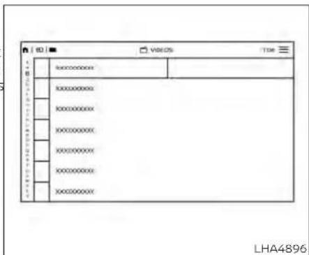
Page view — photos
Using the directional pad on the remote, select "PAGE VIEW" to change between Grid, Overview, Slideshow, or Full Screen. Grid provides a large thumbnail graphic view, whereas Overview provides a small thumbnail graphic view of the content. Slideshow will play photos in sequence and Full Screen fills the entire screen.

Search
Search provides an easy way to find and play content by name. Using the directional pad on the remote, select "SEARCH" to display the on-screen keyboard. Use the directional pad to navigate the keyboard and enter the first few characters of the file-name. Once the desired file is displayed, press → to hide the keyboard. Press to begin playback.
Sorting — videos
Using the directional pad on the remote, select "SORTING" to select between Title, Rating, Year, Filename, or Genre.
Sorting — music
Using the directional pad on the remote, select "SORTING" to select between Artist, Album, Year, Filename, Song, or Genre.
Sorting — photos
Using the directional pad on the remote, select "SORTING" to select between Date or Filename.

USB/SD card video playback controls
During video playback, press to display the playback controls. Press ▶ or ▶ to navigate the controls. Press to select the highlighted function or option.
The playback controls will disappear after approximately 5 seconds of no activity.
1. ContextMenu
Press ■ on the remote to open the context menu. The menu options will vary, depending on the source.
2. ProgressBar
Shows elapsed time, total time and video progress bar indicator.
3. Volume
Select to display the volume level indicator. Press ▲ or to▼increase or decrease the volume.
4. NightMode
Select to dim the screen and reduce eye strain during operation at night.
5. Previous
Select to go to the beginning of the chapter. Select again to go to the previous chapter.
6. Rewind
Select to rewind at 2x, 4x, 8x, and 16x speeds. Select > to resume playback.
7. Stop
Select to stop DVD playback and return to the menu.
8. Play/Pause
Select once to pause DVD playback. Select again to resume DVD playback.
9. FastForward
Select to fast forward at 2x,4x,8x, and 16x speeds. Select > to resume playback.
10. Next
Select to go to the next chapter.
11. Repeat
Select once to repeat the entire DVD. Select again to repeat the currently playing chapter one time.
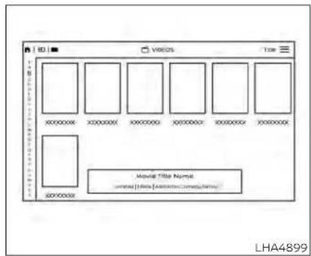
Playing videos
Using the directional pad on the remote, select "VIDEOS" to navigate the content. When a media item is highlighted in Grid mode, the preview image is enlarged and surrounded by a white border. The video title will be displayed in the information bar at the bottom of the screen. Press to begin playback. When choosing a video that has previously been started, a "Resume" option is available.
Context menu
Press the remote to open the context menu during playback. The context menu provides options to adjust the display settings, aspect settings, and Bluetooth® settings. Press to select or toggle the highlighted item on the menu. Press to exit the context menu.
Display settings
Brightness is adjustable between Low, Medium, High, and Default. Contrast is adjustable between Low, Medium, High, and Default. Sharpness is adjustable between Low, Medium, High, and Default. Aspect is adjustable between Preserve, Crop, and Stretch.
Bluetooth® settings
Selecting "BLUETOOTH" allows the Bluetooth® feature to be turned off/on, audio source selection, and lip-sync adjustments. For additional information, see "LipSync adjustment" (P. 4-77).

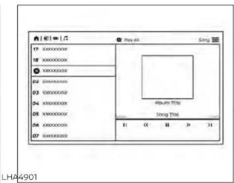

Playing music
Navigating through a music library is identical to navigating through the video library
The default sorting option for music is Art-Press to return to the Playlist screen. ① Selecting an artist will then sort by Al- The audio will continue to play while navi-burn and will display all available albums by gating the playlist screen. The system will that artist. There is also an option to Play return to the Now Playing screen after app ALL albums from the selected artist. proximately 15 seconds of no activity.
Select an album to display all songs in the album. Press ▲ or to navigate the songs. Press √ to begin playback.
During playback, press ◀ to select the Now Playing screen. The Now Playing screen includes the following controls: Pre-
vious Song, Next Song, Rewind, Fast-Forward, Play/Pause, Shuffle, Repeat, Volume Control, and Night mode.
Press 0 to return to the Playlist screen. The audio will continue to play while navigating the playlist screen. The system will return to the Now Playing screen after approximately 15 seconds of no activity.
Navigating photos
To view photos, using the directional pad on the remote navigate to "SOURCE" then "USB" or "SD CARD" then "PHOTOS" from the home screen. Storage device must be connected to display to read media. Use the directional pad to highlight the photo then press √ to view.
Highlight the vertical arrows on menu to access the page selector feature to quickly scan photos.
Press ≡ to highlight additional options including Sorting, Page View, Set As Background, and Search.
Sorting lets you arrange the photos by file name or date.
Page View allows the user to view photos Fullscreen, Grid, Overview, or Slideshow.
Set As Background sets the selected photo as the home screen background.
Search prompts the user to input a file-name or date to find a photo.

SLINGPLAYER®
About Slingplayer®
A Slingbox ® (sold separately) connects to your home network and sits between your cable or set-top box and your TV. When accessed remotely, your Slingbox ® slings your content to the RSI system. To use Slingplayer ® , an external internet connection is required. For additional information, see "Using Wi-Fi" (P. 4-73) to enable Client Mode in the Wi-Fi Settings and allow the system to connect to a Wi-Fi hotspot.
Using Slingplayer®
Using the directional pad on the remote, select "SOURCE" from the Home Screen and navigate to "SLINGPLAYER" in the menu. The first use of Slingplayer® will prompt you for login credentials. Use the remote control to navigate the on-screen keyboard and enter the e-mail address and password associated with your Slingplayer® account.

- Number
- Miscellaneous
Slingplayer® options
Once logged in, the main Slingplayer® menu page is displayed with 3 options:
- Select "DIRECTORY" to watch live television from a Slingbox®.
- Select "SETTINGS" to change the settings of the Slingplayer® application.
- Select "HELP" to display information on how to properly use the Slingplayer® application.
Connect to a live video stream
Press to access the navigational menu that will display two sets of Menu Control Bars. The upper Menu Control Bar displays types of controls. Press √ to select the desired type of control. Press → to hide the menus and return to the live stream.
Slingplayer® control options include:
- Main
• DVR - Directional Pad


Connection quality
The quality of a mobile network connection, whether it's Wi-Fi or a mobile hotspot can vary, due to network conditions. Connection speed and bandwidth can fluctuate, creating conditions that aren't optimal for smooth streaming.
Slingbox® compatibility
The following legacy Slingbox® devices are not supported: Slingbox PRO, Slingbox AV, Slingbox TUNER, Slingbox Classic.
Visit www.slingbox.com for more information on Slingbox or where to purchase.
Accessing the program guide
Press to display the upper and lower Menu Control Bar for Slingplayer®. By default, the "Main" icon on the upper Menu Control Bar is highlighted, showing the "Main" menu options in the lower Menu Control Bar. Press or to navigate to the lower options and select "GUIDE". This will launch the Program Guide. Once the guide has loaded, use the directional pad and press to select the desired channel or program. Press multiple times or to exit.
Exiting Slingplayer®
There are two ways to exit the Slingplayer® application. Press 🎨 or while on the main screen to return to the main menu. When exiting the application, you will be prompted to confirm: "Are you sure you want to exit Slingplayer? There will be no data usage once exited". Select "Yes" to return to the Home Screen or select "No" to return to the stream.
MIRACAST®
About Miracast®
Miracast® is a dedicated wireless connection technology that allows content streaming between a mobile device and the RSI system. The connection is made without cables or a network connection. It provides the ability to "cast" (display) content, such as images or videos from the mobile device to the RSI system. There is no need for an external internet connection and the ability to connect is inside Miracast-certified devices.
Using Miracast®
Using the directional pad on the remote select "SOURCE" from the Home Screen and navigate to "MIRACAST" in the menu. "Ready to Connect" will be displayed. Enable Screen Mirroring on the mobile device and look for "RSI-Miracast" in the list of possible devices to connect to. Note that Miracast® may be labeled differently, depending on the mobile device and its operating system. If Miracast® is not available, look for Smart View or Screen Mirroring in the settings menu of your mobile device. Remember to end your Miracast® connection when finished to avoid draining the battery of your mobile device.
This screen must be active to be able to connect your mobile device to the monitor. Visit www.wi-fi.org for a current list of Miracast® certified devices.
USING THE MOBILE APPLICATION ON YOUR MOBILE DEVICE
Download the free "VOXX-RSI" mobile application on your mobile device from Apple iTunes or Google Play store. A full version of the RSI Owner's Manual is also included within the mobile application.
WARNING
THISMOBILEAPPISNOTFORDRIVER USE
Toreduceriskofacrashwhichcanresultindeathorseriousinjury,always drivecarefullyandinaccordancewith trafficlaws. Thedrivershouldnotuse themobileappwhilethevehicleisin motion.Mobileappusemayonlybe exercisedbythedriverafteryouhave stoppedyourvehicleinanappropriate locationpermittedbylaw.Themobile appisspecificallydesignedtobeused bypassengersotherthanthedriver, provideditdoesnotinterferewithdriving,anddoesnotdistractthedriver's attentiontotheroad.
SMARTSTREAM
About SmartStream
SmartStream is a wireless connection technology that allows content streaming between a mobile device and the RSI system and between mobile devices. Content is streamed over the built-in Wi-Fi network using an application installed on a mobile device. There is no need for an external Internet connection.
Using SmartStream
Before using the SmartStream feature, a compatible UPnP application is required to be downloaded and installed on your mobile device. To stream content from a mobile device, you must first connect it to the RSI network.
Connecting a mobile device to the RSI network:
- Using the directional pad on the remote, select "SOURCE" from the Home Screen and then select "SMARTSTREAM" in the menu. A device connection screen will be displayed on the monitor.
- Navigate to the "Wi-Fi" settings menu of the mobile device and establish a connection to the network named "RSI-WiFi"
- When prompted, enter the network password to join the RSI-WiFi network. Select the Show Password check box in the Wi-Fi Settings menu to display the current password. For additional information, see "Using Wi-Fi" (P. 4-73).
NOTE:
AccessPointmustbeselectedtouse theSmartStreamfeature.Foradditional information,see"UsingWi-Fi"(P.4-73).
Streaming content from a mobile device:
- Once connected, launch the application, and select SmartStream on the mobile device.
-
Choose the desired monitor to stream to by selecting Monitor A or Monitor B. Note: To stream content from a mobile device the monitor must be set to SmartStream in the source menu.
-
Select the desired source content from the list of available devices. Content can be browsed from all devices that are connected to the RSI Wi-Fi network and have a compatible UPnP application installed.
- After selecting a content source, navigate through the folders, and select the desired file to stream to the monitor. Once the file is selected, it will begin streaming to the monitor that was selected in step 2 above.
- Playback controls are available from the Now Playing screen in the UPnP application and from the monitor. Press to display the playback controls on the monitor.
NOTE:
-ContentprotectedwithDRM(Digital RightsManagement)cannotbestreamedusingtheSmartStream feature.
- A wired connection (HDMI or MHL) is required to stream protected content from a mobile device to the RSI system. For additional information, see "HDMI/MHL connection" (P.4-60).

SETTINGS
The following settings can be accessed from the main menu:
Wi-Fi
Change the SSID (network name), change the password of the network, and toggle between Client Mode or Access Point.
ReadBack
A text-to-speech aid that enables the system to read text items displayed on the screen. This feature guides the user through operating the RSI system.
Display
Adjust Brightness, Contrast, and Sharpness settings.
Audio
Select the monitor to use for Bluetooth® audio streaming and set the maximum volume level when using wired headphones.
Advanced
Change the language of the GUI (Graphic User Interface), reset the RSI system, and update the software.
Customize
Change the background image of the home screen using content from an SD card or USB storage device.
Parental
Set or change the password to limit DVD content playback using parental control based on the Motion Picture Association of America (MPAA) ratings.
Bluetooth
Control Bluetooth ® audio streaming (On/Off) and select from the available list of paired devices.
4-72 Monitor, climate, audio, phone and voice recognition systems
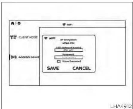
Using Wi-Fi
AccessPoint
Access Point is used when connecting other mobile devices to the RSI's built-in internal network. This mode allows the RSI system to connect to devices "inside" the vehicle, using an optional UPnP application installed on a mobile device.
To change the SSID, navigate the keyboard and enter the desired network name. Select Enter when complete. The default SSID name is RSI-WiFi.
To change the network password, navigate the keyboard and enter the desired numeric password. Select Enter when complete. Select the Show Password check box to display the current password. Select Save to save the SSID and password.
ClientMode
Client Mode is used when connecting the RSI system to an external network or to the internet using a mobile hotspot. This mode allows the RSI system to connect "outside" the vehicle.
Enable Client mode by highlighting the Status switch. The switch will turn green when on. The RSI system will begin searching for available wireless networks and display them below. Navigate to the desired network and press √ to select it. Enter the password (if necessary) to complete the connection. The system will automatically connect to the last connected network until Client Mode is disabled.
NOTE:
Clientmodewillusedatafromthe externalWi-Ficonnection.Usewith careasadditionaldataisconsumed whenusingmobiledevidedataplans.
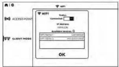
Using Read Back\*
Enable the Read Back feature by highlighting the Status switch. The switch will turn green when on. Highlight the Save button and press √ to enable Read Back. When enabled, the RSI system will read the text of menu items displayed on the screen, providing audible guidance on how to use the system. A blue bar will also appear at the top of each screen indicating the Read Back feature is enabled.
SpeechVolume
Speech Volume can be adjusted to match the media volume (spoken text volume is the same volume level as the content being played). To reduce the Speech Volume to be lower than the volume level content being played, set it to 75%, 50%, or 25% of the media volume.
SpeechRate
Speech Rate can be adjusted between Normal, Fast, or Slow. This setting controls how fast the spoken text is pronounced. *Complies with FCC/Accessibility rule 21st Century Communications and Video Accessibility Act (CVAA).

Display settings
Brightness
Brightness is a measurement of the amount of light the monitor produces. For displaying movies, a brighter luminance rating is desirable. Select between Low, Medium, High, and Default (High).
Contrast
Contrast is a ratio of difference of the monitor's ability to produce bright whites and dark blacks. Select between Low, Medium, High, and Default (High).
Sharpness
Sharpness is edge contrast that is visible along edges of content. Decreasing the sharpness will create a softer image. Increasing the sharpness will affect the contrast only along/near edges of the image while leaving smooth areas of the image alone. Select between Low, Medium, High, and Default (Low).

Audio settings
audio from the Passenger side monitor. Select OK to confirm and store the desired monitor.

Advanced settings
Headphones
For hearing protection, there is a maximum volume setting to limit the audio output of the front panel 3.5mm headphone output. Select the desired maximum volume from 0 \~ 100 and select Save to store the value.
BluetoothSource
When Bluetooth® is enabled and a connection is established to the vehicle's stereo system, choose the monitor to be used as the source to stream audio from. Select Monitor A to stream audio from the Driver side monitor or select Monitor B to stream
NOTE:
- WhenmonitorAisselectedasthe sourcetostreamfrom,theaudiooutputtothewirelessandwiredheadphoneswillbedisabled(onlyonmonitorA).
TousethewirelessorwiredheadphoneswithmonitorA,youmustturnofftheBluetooth®streamingfeature.Foradditionalinformation,see"Bluetooth®streaming"(P.4-77).
Language
The system language used for the GUI (Graphic User Interface) can be changed to any of the following languages English, Spanish, French, Arabic, Simplified Chinese, Traditional Chinese, and Hebrew. To change the language, highlight and select the current language and a drop-down list will appear containing the available languages. Choose the desired language and select Save to display the confirmation dialog box. Select Yes to confirm and reboot the RSI system.
Reset
A master reset will return the RSI system settings to the factory defaults. Any user options and customization will be lost and reset back to factory default settings. To reset the system, select Yes when the dialog confirmation box appears.
Update
Displays the current software version information. Select Update to begin a software update (reserved for future use).
Customize settings
Background
Customize the RSI system by changing the background image of the main menu screen on each monitor. Select a source to load the image from. Options include USB, SD card, or Local (internal memory).
Select a source then navigate the content and select the new background image. Choose the desired image and display the confirmation dialog box. Select Yes to confirm. Press 🔥 to view the new background image.
NOTE:
•Eachmonitorcanhaveitsownbackgroundimage.
•TheLocalsourcestoresthe10mostrecentbackgroundimages.
- Torestorethedefaultbackgroundimage,performafactoryreset.Foradditionalinformation,see"Advancedsettings"(P.4-75).
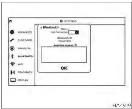
Bluetooth® streaming
To access "BLUETOOTH" from the home screen use the directional pad on the remote and navigate to "SETTINGS" then "BLUETOOTH". Status button indicates if the Bluetooth® is enabled when green or disabled when red. Highlight and press to enable or disable Bluetooth®.
Once enabled, the RSI will automatically search for available devices in pairing mode. Using the directional pad on the remote, select "Device name" then "Connect" to pair. Input the PIN from connecting device (if prompted). Device name will display
"Connected" once paired properly. Select "OK" to confirm changes and close the window. To unpair a Bluetooth® device, select Device name then Unpair.
If the device is not listed, select Refresh Symbol and the device will appear in Available device list. If device does not appear, double check that the device is in pairing mode (refer to the device's manual for instructions).
Bluetooth® equipped vehicles can stream audio from the display through vehicle's sound system once paired. For additional information, refer to the separate NissanConnect® Owner's Manual.

Lip-Sync adjustment
Lip-Sync adjustments can be accessed by pressing ≡ on the remote, then selecting "BLUETOOTH". Highlight the numerical value and press √. Use the directional pad to synchronize video and audio playback due to small delay inherent in some Bluetooth® devices. Press √ to set value. Highlight save and press √ to exit.
To select which Monitor will stream Bluetooth®, using the directional pad on the remote select "SETTINGS: then "AUDIO" then "BLUETOOTH" from the home screen. Highlight "MONITOR A" or "MONITOR B" and
press √. Selecting Monitor A or B to stream Bluetooth® can also be achieved by pressing ≡ while video is playing. Press ≡ then "BLUETOOTH", then "SELECT". Highlight "MONITOR A", "OFF", or "MONITOR B". Highlight "SAVE" and press √ to set configuration and close the window.

About parental lock
Some DVDs may have a parental rating level assigned to the entire disc or to certain scenes/chapters on the disc. Parental Lock allows the playback limitation level to be set. This prohibits the playing discs that are not suitable for children or have alternative scenes. The rating levels range from 1 to 8. They are country dependent, but in general they are defined as follows:
1KIDSAFE:
Kids material; recommended children and viewers of all ages.
2 G:
General Audience; recommended for all ages.
3 PG:
Parental Guidance suggested.
4PG-13:
Unsuitable for children under age 13.
5/6PGR/R:
Parental Guidance/Restricted content not suitable for children under the age of 17.
7NC-17:
No children under age 17.
8Adult:
Mature content; should be viewed only by an adult due to graphic sexual material, violence, or language. Once a rating level is set, DVDs that are rated above that level will not play unless a 4-digit password is entered and higher-level rating is chosen.
Changing parental lock
For example, to set the ratings limit for PG and below, select "RATINGS" then "3" using the directional pad and press√, based on the rating levels. For additional information, see "About parental lock" (P. 4-78).
To change password, select "SETTINGS" then "PARENTAL" from the home screen. Enter the current password, select "PASSWORD" then "MODIFY" to set new password, press √ once to enter, and select again to confirm. To exit "PARENTAL" menu press

To remove the parental lock password, select "SETTINGS" then "PARENTAL" from the home screen. Enter the current password. Select "PASSWORD" then "REMOVE", press
√ to enter, and select again to confirm. To exit Parental menu press.
To set the parental lock using the directional pad on the remote, select "SETTINGS" then "PARENTAL" from the home screen. Choose password with directional pad and press √ to enter, press again to confirm your password. Once the password is selected, the parental rating menu will appear to select highest playable DVD rating from 1-8.
TROUBLESHOOTING
| SymptomRemedy | |
| Monitor does not power on | Verify the vehicle is in the ON or ACC position. |
| Verify the battery is installed correctly in the remote control. | |
| Verify the in-line fuse protection is good. Refer to the RSI system installation instructions for vehicle-specific fuse location. | |
| Monitor front panel controls flash red | For further diagnosis, it is recommended that you visit a NISSAN dealer. |
| System frozen - will not respond | Soft reset the system by pressing and holding the power button on the top of the driver side monitor for 5 seconds. |
| Hard reset the system by turning the ignition off, then back on. | |
| Disc will not play | Insert the disc with label side facing the rear of the vehicle. |
| Check if the disc is defective by trying another disc. | |
| Check the type of disc being played. This unit only plays DVD (Single, Dual Layer), DVD-R/+R, DVD+R Dual layer, DVD-RW/+RW, CD, CD-R, and CD-RW. | |
| The unit and the disc are coded by region. If the region codes don't match, the DVD can't be played. | |
| Disc plays, but stops intermittently | The disc may be dirty and need cleaning. |
| Condensation may have formed inside the unit. Remove the disc and allow unit to dry out. | |
| The disc may be scratched too badly to play. | |
| No picture | Check that the signal source is connected. |
| Check the menu source setting. Match your monitor mode with the source correctly. | |
| Distorted picture Check the disc for fingerprints and clean with a soft cloth, wiping from center to edge. | |
| Cannot advance through a DVD movie | You cannot advance through the opening credits and warning information that appears at the beginning of DVDs because disc is programmed to prohibit these actions. |
| Some discs may not allow this function. Try another disc. | |
| No sound or distorted sound | Make sure that the external media device is connected properly, and all cables are securely inserted into the appropriate jacks. |
| Verify that the batteries in the headphones are fresh. | |
| If you are using the wireless headphones, make sure you turn on the power and select the correct monitor (A or B). | |
| Verify the volume is turned up on headphones and the system. | |
| Verify nothing is blocking the path between the monitor IR sensor and headphones. | |
| When placing the headphones on your head, make sure to observe the Left and Right orientation. The headphones must be oriented correctly (facing forward) to receive the audio signal. | |
| Monitor feels warm When the monitor is in use for a long period of time, the surface will be warm. This is normal. | |
| Player does not respond to all commands during play-back | The DVD may not permit some commands. Refer to the specific instructions included with the DVD for more information. |
| A Parental Setting message is displayed, prohibiting movie playback | Enter the 4-digit Parental Password using the remote and then press. For additional information, see 'Changing parental lock' (P. 4-79). |
| Cannot connect mobile device to the Internal RSI Wi-Fi network | Check to make sure Wi-Fi is enabled on the mobile device. |
| Check to make sure RSI is set to Access Point mode. | |
| Check to make sure the correct password is used. For additional information, see 'Using Wi-Fi' (P. 4-73) | |
| Cannot connect RSI system to an external Wi-Fi network | Check to make sure RSI is set to Client Mode. Check to make sure the correct password is used. For additional information, see 'Using Wi-Fi' (P. 4-73). |
| Cannot establish a Bluetooth® connection | Check to make sure Bluetooth® is enabled on the RSI system. For additional Information, see 'Bluetooth® streaming' (P.4-77). |
| Cannot establish a Miracast® connection to the RSI system | Check to make sure mobile device supports Miracast®. Visit www.wi-fi.org for a current list of Miracast® certified devices. |
| Check to make sure Miracast® is enabled on the mobile device. | |
| Select Miracast® source from the RSI main menu. | |
| Cannot play certain files from USB or SD cards | Audio/video files embedded with DRM are not compatible. |
| Some USB storage devices and SD cards may not be compatible. Replace the external storage device (USB, SD). | |
| Due to ongoing technological advancements, some USB flash drives and SD cards may be incompatible with this system. | |
| Cannot connect to external Singbox® | Check to make sure RSI is set to Client Mode. For additional Information, see 'Using Wi-Fi' (P. 4-73). |
| Check network upload speed from your home (or wherever the Singbox® is located) | |
| Confirm hotspot or Wi-Fi download speed/connection quality. | |
| Check that your Singbox® is properly set up. | |
| Cannot share content from a mobile device to the RSI system | A compatible UPnP app is required to be installed on the mobile device. |
| Audio/video files embedded with DRM cannot be streamed to the RSI system. | |
| Cannot share content between mobile devices using the internal Wi-Fi network | Check to make sure Wi-Fi is enabled on the mobile device. |
| Check to make sure RSI is set to Access Point mode. For additional information, see 'Using Wi-Fi' (P. 4-73). | |
Monitor, climate, audio, phone and voicerecognitionsystems4-81
SPECIFICATIONS
| LCD Backlight Type LED | |
| Display Type 8.0 inch (Diagonal) a-Si TFT Active Matrix, 1024x3(RGB) x 600 resolution | |
| Supported Disc Types DVD (Single, Dual Layer), DVD-R/+R, DVD+R Dual layer, DVD-RW/+RW, CD, CD-R, CD-RW | |
| Frequency Response 3.5mm Audio Output: 200Hz - 16kHz +/- 6dB | |
| HDMI Support Version 1.4b, HDCP 2.1 Compliant | |
| MHL Support Version 2.0, 900mA Maximum Charging Output | |
| Wireless Audio 2-Channel Stereo Headphone Operation, (Typical Infrared Reception/Range: 0.9m; 80°, 1.8m; 50°) | |
| WI-FI Network | 802.11b/g/n, TX/RX Frequency: 2412 MHz - 2484 MHz, Antenna 1: 802.11b, 802.11g, 802.11n HT20, 802.11n HT40, MIMO Antenna 1+2: 802.11n HT20 |
| Wi-Fi Modulation 802.11b: D55S (DBPSK / DQPSK / CCK), 802.11g/n: OFDM (BPSK / QPSK / 16QAM / 64QAM) | |
| Bluetooth® Support Version 4.1 | |
| Bluetooth® BR/EDR | TX/RX Frequency: 2402 MHz - 2480 MHz, Channels: 79, Bluetooth BR (1Mbps): GFSK Modulation, Bluetooth EDR (2Mbps): π/4-DQPSK Modulation, Bluetooth EDR (3Mbps): 8-DPSK Modulation |
| Bluetooth® LE | TX/RX Frequency: 2402 MHz - 2480 MHz, Channels: 40, Carrier Frequency of Each Channel, (37 hopping + 3 Advertising channel), Type of Modulation: Bluetooth LE: GFSK |
| USB Support | Version 1.1, Version 2.0 High Speed, 10 watt (2 Amp) Maximum Charging Output |
| SD Card Support | SD, SDHC, SDXC |
COMPLIANCE INFORMATION
FCC Notice
This device complies with Part 15 of FCC Rules and Industry Canada license-exempt RSS standard(s). Operation is subject to the following two conditions: (1) this device may not cause interference, and (2) this device must accept any interference, including interference that may cause undesired operation of this device.
This transmitter must not be co-located or operated in conjunction with any other antenna or transmitter. The Bluetooth® antenna cannot be removed (or replaced) by user.
Alteration or modifications carried out without appropriate authorization may invalidate the user's right to operate the equipment.
This equipment has been tested and found to comply with the limits for a Class B digital device, pursuant to Part 15 of the FCC Rules. These limits are designed to provide reasonable protection against harmful interference in a residential installation. This equipment generates, uses and can radiate radio frequency energy and, if not installed and used in accordance with the instructions, may cause harmful interfer-
ence to radio communications. However, there is no guarantee that interference will not occur in a particular installation. If this equipment does cause harmful interference to radio or television reception, which can be determined by turning the equipment off and on, the user is encouraged to try to correct the interference by one or more of the following measures:
- Reorient or relocate the receiving antenna.
- Increase the separation between the equipment and receiver.
- Connect the equipment into an outlet on a circuit different from that to which the receiver is connected.
- Consult the dealer or an experienced radio/ TV technician for help.

Bluetooth®
LHA4926
Bluetooth®
The Bluetooth® word mark and logos are registered trademarks owned by the Bluetooth SIG, Inc. and any use of such marks by Vox Automotive Corporation is under license. Other trademarks and trade names are those of their respective owners.
DVD Video Playback
This item incorporates copy protection technology that is protected by U.S. patents and other intellectual property rights of Rovi Corporation. Reverse engineering and disassembly are prohibited.
AAC
AAC is short for Advanced Audio Coding and refers to an audio compression technology standard used with MPEG-2 and MPEG-4. Several applications can be used to encode AAC files, but file formats and extensions differ depending on the application which is used to encode.
FLAC
Copyright © 2000-2009 Josh Coalson Copyright © 2011-2013 Xiph.Org Foundation Redistribution and use in source and binary forms, with or without modification, are permitted provided that the following conditions are met:
Redistributions of source code must retain the above copyright notice, this list of conditions and the following disclaimer. Redistributions in binary form must reproduce the above copyright notice, this list of conditions and the following disclaimer in the documentation and/or other materials provided with the distribution.
Neither the name of the Xiph.org Foundation nor the names of its contributors may be used to endorse or promote products derived from this software without specific prior written permission.
THIS SOFTWARE IS PROVIDED BY THE COPYworks or in other electronic content distri-RIGHT HOLDERS AND CONTRIBUTORS "AS bution systems, such as pay-audio or IS" AND ANY EXPRESS OR IMPLIED WARRANTY-audio-on-demand applications. An indetIES, INCLUDING, BUT NOT LIMITED TO, THEpendent license for such use is required. IMPLIED WARRANTIES OF MERCHANTABILITY- For details, please visit ITY AND FITNESS FOR A PARTICULAR PUR- http://www.mp3licensing.com.
POSE ARE DISCLAIMED. IN NO EVENT SHALL THE FOUNDATION OR CONTRIBUTORS BE LIABLE FOR ANY DIRECT, INDIRECT, INCIDENTAL, SPECIAL, EXEMPLARY, OR CONSEQUENTIAL DAMAGES (INCLUDING, BUT NOT LIMITED TO, PROCUREMENT OF SUBSTITUTE GOODS OR SERVICES; LOSS OF USE, DATA, OR PROFITS; OR BUSINESS INTERRUPTION) HOWEVER CAUSED AND ON ANY THEORY OF LIABILITY, WHETHER IN CONTRACT, STRICT LIABILITY, OR TORT (INCLUDING NEGLIGENCE OR OTHERWISE) ARISING IN ANY WAY OUT OF THE USE OF THIS SOFTWARE, EVEN IF ADVISED OF THE POSSIBILITY OF SUCH DAMAGE.
MP3
Supply of this product only conveys a license for private, non-commercial use and does not convey a license nor imply any right to use this product in any commercial (i.e. revenue generating) real time broadcasting (terrestrial, satellite, cable and/or any other media), broadcasting/streaming via internet, intranets and/or other net-
WMA/WMV
Windows Media is either a registered trademark or trademark of Microsoft Corporation In the United States and/or other countries. This product includes technology owned by Microsoft Corporation and cannot be used or distributed without a license from Microsoft Licensing, Inc.
SD/SDHC/SDXC
SD, SDHC and SDXC Logos are trademarks or registered trademarks of SD-3C LLC in the United States, other countries or both.
4-84 Monitor, climate, audio, phone and voicerecognitionsystems

HDMI
The terms HDMI and HDMI High-Definition Multimedia Interface, and the HDMI Logo are trademarks or registered trademarks of HDMI Licensing, LLC in the United States and other countries.
MHL
MHL, the MHL Logo, and Mobile High-Definition Link are trademarks or registered trademarks of MHL, LLC in the United States and other countries.

Dolby Digital
This product will down-mix Dolby Digital signals internally and the sound will be out put in stereo. Manufactured under license from Dolby Laboratories. Dolby and the double-D symbol are trademarks of Dolby Laboratories.
European Waste Electrical and Electronic Equipment (WEEE) Notice
In accordance with Directive 2012/19/EU of the European Parliament on waste electrical and electronic equipment (WEEE):

The symbol above indicates that separate collection of electrical and electronic equipment is required. When this product has reached the end of its serviceable life, it cannot be disposed of as unsorted municipal waste. It must be collected and treated separately. It has been determined by the European Parliament that there are potential negative effects on the environment and human health as a result of the presence of hazardous substances in electrical and electronic equipment. It is the users' responsibility to utilize the available collection system to ensure WEEE is properly treated.
CARPHONEORCBRADIO
All other trademarks and their respective when installing a CB, ham radio or car logos cited herein are the property of their phone in your vehicle, be sure to observe respective owners. the following precautions; otherwise, the
new equipment may adversely affect the engine control system and other electronic parts.
WARNING
- Acellularphoneshouldnotbeused foranypurposewhiledrivingsofull attentionmaybegiventovehicleoperation.Somejurisdictionsprohibit theuseofcellularphoneswhile driving.
- If you must make acall while your vehicle is in motion, the hands free cellular phone operational mode (if so equipped) is highly recommended. Exercise extremecution at all times of full attention maybe giventovehicleoperation.
- If you are unable to devote full attention to vehicle operation while talking on the phone, pullofftheroad to as a felocation and stop your vehicle.
CAUTION
- Keeptheantennaasfarawayaspossiblefromthe electroniccontrol modules.
- Keeptheantennawiremorethan8in (20 cm) away from the electronic control system harnesses. Do not routetheantennawirenexttoany harness.
- Adjusttheantennastanding-wave ratiosrecommendedbythe manufacturer.
- Connect the ground wire from the CB radio chassistothebody.
- Foradditionalinformation,itisrecommendedthatyouvisitaNISSAN dealerforthisservice.
iPod®/IPHONE®
"Made for iPod", "Made for iPhone" and "Made for iPad" mean that an electronic accessory has been designed to connect specifically to iPod, iPhone or iPad, respectively, and has been certified by the developer to meet Apple performance standards. Apple is not responsible for the operation of this device or its compliance with safety and regulatory standards. Please note that the use of this accessory with iPod, iPhone or iPad may affect wireless performance.
iPad, iPhone, iPod classic, iPod Nano, iPod shuffle and iPod touch are trademarks of Apple Inc., registered in the U.S. and other countries. Lightning is a trademark of Apple Inc.
Monitor, climate, audio, phone and voicerecognitionsystems4-87
MEMO
5Startinganddriving
Precautions when starting and driving .... 5 - 4 Exhaust gas (carbon monoxide) .... 5 - 4
Three-way catalyst (if so equipped) 5 - 4
Tire Pressure Monitoring System (T P M S) 5 - 5
On-pavement and off-road driving precautions 5 - 8
Avoiding collision and rollover 5-9
Off-road recovery .... 5-9 Rapid air pressure loss ....
Drinking alcohol/drugs and driving 5-10
Driving safety precautions 5-11
Push-button ignition switch 5-13 Operating range 5-14
Push-button ignition switch positions ..... 5-14
Emergency engine shut off 5-15
NISSAN Intelligent Key® battery discharge 5-15
NISSAN Vehicle Immobilizer System ..... 5-16
Before starting the engine 5-16
Starting the engine .... 5-17 Remote Engine Start (if so equipped) .... 5-1
Driving the vehicle 5-18
Engine protection mode 5-18 Automatic transmission (A/T) 5-19
Parking brake 5-24
Traffic Sign Recognition (TSR) (if so equipped) ... 5-24 System operation .... 5-25
Turning the Traffic Sign Recognition (TSR) system on and off 5-26
System temporarily disabled 5-27
System malfunction 5-27 System maintenance 5-27
Lane Departure Warning (LDW) 5-27
5 - EDW system operation 5-28
How to enable/disable the LDW system .....5-29
LDW system limitations 5-30
System temporarily disabled 5-31
System malfunction 5-31
System maintenance 5-31
Blind Spot Warning (BSW) 5-32
BSW system operation 5-33
How to enable/disable the BSW system...5-34
BSW system limitations 5-35
BSW driving situations 5-36
System temporarily disabled 5-40
System maintenance 5-41
Rear Cross Traffic Alert (RCTA) 5-42
RCTA system operation 5-43
How to enable/disable the RCTA system 5-45
RCTA system limitations 5-46
System temporarily disabled 5-48
System maintenance 5-49
Cruise control (if so equipped) 5-50
Precautions on cruise control 5-50
Cruise control operations 5-51
Intelligent Cruise Control (if so equipped) ..... 5-52
How to select the cruise control mode ..... 5-54
Vehicle-to-vehicle distance control mode 5-54
Vehicle-to-vehicle distance control mode operation 5-55
Vehicle-to-vehicle distance control mode switches 5-57
Vehicle-to-vehicle distance control mode limitations 5-64
System temporarily unavailable 5-68
System maintenance 5-70
Conventional (fixed speed) cruise control mode 5-72
Rear Automatic Braking (RAB) 5-76
RAB system operation....5-77
Turning the RAB system on/off 5-78
RAB system limitations 5-79
System malfunction 5-80
System maintenance 5-81
Automatic Emergency Braking (AEB) with
destrian Detection 5-81
AEB with Pedestrian Detection system operation 5-82
Turning the AEB with Pedestrian Detection system ON/OFF 5-84
AEB with Pedestrian Detection system limitations 5-85
System temporarily unavailable 5-87
System malfunction 5-89
System maintenance 5-89
Intelligent Forward Collision Warning (I-FCW) . . . 5-91
I-FCW system operation 5-92
Turning the I-FCW system on/off 5-93
I-FCW system limitations 5-94
System temporarily unavailable 5-99
System malfunction 5-100
System maintenance 5-101
Intelligent Driver Alertness (I-DA) 5-102
Intelligent Driver Alertness system operation 5-103
How to enable/disable the Intelligent Driver Alertness (I-DA) system 5-104
Intelligent Driver Alertness (I-DA)
system limitations 5-104
Break-in schedule 5-106
Fuel efficient driving tips 5-106
Increasing fuel economy 5-107
Using 4-Wheel Drive (4WD) (if so equipped) .... 5-107
Transfer case shifting procedures ..... 5-108
Electronic locking rear differential (E-Lock)
system (if so equipped) 5-114
Eco Drive Report (if so equipped) 5-115
Parking/parking on hills 5-116
Power steering 5-117
Brake system 5-117
Brake precautions 5-117
Anti-lock Braking System (ABS) 5-118
Brake Assist 5-119
Active Brake Limited Slip (ABLS) system ..... 5-119
Vehicle Dynamic Control (VDC) system ..... 5-120
Brake force distribution 5-122
Hill descent control system (if so equipped) . . . 5-123
Hill start assist system 5-124
Front and rear sonar system (if so equipped) . . 5-124
System operation 5-125
How to enable/disable the sonar
system 5-127
Sonar limitations 5-128
System maintenance 5-128
Cold weather driving 5-129
Freeing a frozen door lock 5-129
Antifreeze 5-129
Battery 5-129
Draining of coolant water 5-129
Tire equipment 5-129
Special winter equipment 5-130
Driving on snow or ice 5-130
Engine block heater (if so equipped) ..... 5-130
PRECAUTIONSWHENSTARTINGAND DRIVING
WARNING
- Donotleavechildrenoradultswho wouldnormallyrequiretheassistanceofothersaloneinyourvehicle. Petsshouldalsonotbeleftalone. Theycouldaccidentallyinjurethem-selvesorothersthroughinadvertent operationofthevehicle.Also,onhot, sunnydays,temperaturesinaclosed vehiclecouldquicklybecomehigh enoughtocausesevereorpossibly fatalinjuriestopeopleoranimals.
- Properlysecureallcargowithropes orstrapstohelppreventitfromslidingorshifting.Donotplacecargo higherthantheseatbacks.Inasuddenstoporcollision,unsecured cargocouldcausepersonalinjury.
EXHAUST GAS (carbon monoxide)
WARNING
- Donotbreatheexhaustgases;they containcolorlessandodorlesscarbonmonoxide.Carbonmonoxideis dangerous.Itcancauseunconsciousnessordeath.
- Ifyoususpectthatexhaustfumes areenteringthevehicle,drivewithall windowsfullyopen,andhavethevehicleinspectedimmediately.
- Donotruntheengineinclosed spacessuchasagarage.
- Donotparkthevehiclewiththeen-ginerunning for any extendedlength oftime.
- Keeptherearventwindows,lift-gates,doorsandtrunklids(ifso equipped)closedwhiledriving,otherwise exhaust gases could be drawnintothepassengercompartment.Ifyoumustdrivewithoneof these open,follow these precautions:
- Openallthewindows.
- Setthe airrecirculationbuttontooffandthefancontroldialtoightocirculatetheair.
-
Ifelectricalwiringorothercableconnectionsmustpasstoatrailer through the seal on the liftgate or the body,followthemanufacturer'srecommendationtopreventcarbon monoxideentryintothevehicle.
-
The exhaust system and body should be inspected by a qualified mechanic whenever:
a. Thevehicleisraisedforservice.
b. Yoususpectthatexhaustfumes areenteringintothepassenger compartment.
c. Younoticeachangeinthesound oftheexhaustsystem.
d. Youhavehadanaccidentinvolvingdamagetotheexhaustsystem, underbody, or rear of the vehicle.
NOTE:
If the vehicle engine experiences excessive fuel consumption or produces excessives smokeitis recommended that you visit a NISSAN dealer for service.
THREE-WAY CATALYST (if so equipped)
The three-way catalyst is an emission control device installed in the exhaust system. Exhaust gases in the three-way catalyst are burned at high temperatures to help reduce pollutants.
WARNING
- Theexhaustgasandtheexhaust systemareveryhot.Keeppeople, animalsorflammablematerials awayfromtheexhaustsystem components.
- Donotstoporparkthevehicleover flammablematerialssuchasdry grass,wastepaperorrags.Theymay igniteandcauseafire.
CAUTION
- Donotuseleadedgasoline.Deposits fromleadedgasolinewillseriously reducethethree-waycatalyst'sabilitytohelpreduceexhaustpollutants.
-
Keepyourenginetunedup.Malfunctionsintheignition,fuelinjection,or electricalsystemscancauseoverrich fuelflowintothethree-waycatalyst, causingittooverheat.Donotkeep drivingiftheenginemisfires,orifnoticeablelossofperformanceorother unusualoperatingconditionsaredetected.Havethevehicleinspected promptly.Itisrecommendedthat youvisitaNISSANdealerforth this service.
-
Avoiddrivingwithanextremelylow fuellevel.Runningoutof fuel could causetheenginetomisfire,damagingthethree-waycatalyst.
- Donotracethe enginewhilewarm-ingitup.
- Donotpushortowyourvehicleto starttheengine.
TIRE PRESSURE MONITORING SYSTEM (TPMS)
Each tire, including the spare (if provided), should be checked monthly when cold and inflated to the inflation pressure recommended by the vehicle manufacturer on the vehicle placard or tire inflation pressure label. (If your vehicle has tires of a different size than the size indicated on the vehicle placard or tire inflation pressure label, you should determine the proper tire inflation pressure for those tires.)
As an added safety feature, your vehicle has been equipped with a Tire Pressure Monitoring System (TPMS) that illuminates a low tire pressure telltale when one or more of your tires is significantly underinflated. Accordingly, when the low tire pressure telltale illuminates, you should stop and check your tires as soon as possible, and inflate them to the proper pressure. Driving on a significantly under-inflated tire causes the tire to overheat and can lead to tire failure. Under-inflation also reduces fuel efficiency and tire tread life, and may affect the vehicle's handling and stopping ability.
Please note that the TPMS is not a substitute for proper tire maintenance, and it is the driver's responsibility to maintain correct tire pressure, even if under-inflation has not reached the level to trigger illumination of the TPMS low tire pressure telltale.
Your vehicle has also been equipped with a TPMS malfunction indicator to indicate when the system is not operating properly. The TPMS malfunction indicator is combined with the low tire pressure telltale. When the system detects a malfunction, the telltale will flash for approximately one minute and then remain continuously illuminated. This sequence will continue upon subsequent vehicle start-ups as long as the malfunction exists. When the malfunction indicator is illuminated, the system may not be able to detect or signal low tire pressure as intended. TPMS malfunctions may occur for a variety of reasons, including the installation of replacement or alternate tires or wheels on the vehicle that
prevent the TPMS from functioning properly. Always check the TPMS malfunction telltale after replacing one or more tires or wheels on your vehicle to ensure that the replacement or alternate tires and wheels allow the TPMS to continue to function properly.
Additional information:
- When using a wheel without the TPMS such as the spare tire, the TPMS does not monitor the tire pressure of the spare tire.
- The TPMS will activate only when the vehicle is driven at speeds above 16 mph (25 km/h). Also, this system may not detect a sudden drop in tire pressure (for example, a flat tire while driving).
-
The low tire pressure warning light does not automatically turn off when the tire pressure is adjusted. After your tires are inflated to the recommended pressure, the vehicle must be driven at speeds above 16 mph (25 km/h) to activate the TPMS and turn off the low tire pressure warning light. Use a tire pressure gauge to check the tire pressure.
-
The "Tire Pressure Low - Add Air" warning appears in the vehicle information display when the low tire pressure warning light is illuminated and low tire pressure is detected. The "Tire Pressure Low - Add Air" warning turns off when the low tire pressure warning light turns off.
-
The "Tire Pressure Low - Add Air" warning does not appear if the low tire pressure warning light illuminates to indicate a TPMS malfunction.
-
Tire pressure rises and falls depending on the heat caused by the vehicle's operation and the outside temperature. Do not reduce the tire pressure after driving because the tire pressure rises after driving. Low outside temperature can lower the temperature of the air inside the tire which can cause a lower tire inflation pressure. This may cause the low tire pressure warning light to illuminate. If the warning light illuminates, check the tire pressure for all four tires.
- The Tire and Loading Information label is located in the driver's door opening.
For additional information, see "Low tire pressure warning light" (P. 2-18) and "Tire Pressure Monitoring System (TPMS)" (P. 6-3)
WARNING
Radiowavescouldadverselyaffect electricmedicalequipment. Those whoseapacemakershouldcontact the electric medical equipment manufacturerforthepossibleinfluencesbeforeuse.
Ifthelowtirepressurewarninglight illuminateswhiledriving,avoidsuddensteeringmaneuversorabrupt braking, reducevehiclespeed,pull offtheroadtoasafelocationand stopthevehicleassoonaspossible. Drivingwithunder-inflatedtiresmay permanentlydamagethetiresand increasethelikelihoodoftirefailure. Seriousvehicledamagecouldoccur andmayleadtoanaccidentand couldresultinseriouspersonalinjury. Check thetirepressureforall fourtires.Adjustthetirepressure totherecommendedCOLDtirepressureshownontheTireandLoading Informationlabeltoturnthelowtire pressurewarninglightoff.Ifyouhave aflattire,replaceitwithasparetire assoonaspossible.(Foradditional information,see"Flattire"(P.6-3)for changingaflattire.)
- Whenusingawheelwithoutthe TPMSsuchasthesparetire,whena sparetireismountedorawheels replaced,tirepressurewillnotbeindicated,theTPMSwillnotfunction andthelowtirepressurewarning lightwillflashforapproximately1 minute.Thelightwillremainonafter 1minute.Haveyourtiresreplaced and/orTPMSsystemresetassoonas possible.itisrecommendedthatyou visitaNISSANdealerforthisservice.
- ReplacingtireswiththosenotoriginallyspecifiedbyNISSANcouldaffect the proper operation of the TPMS.
- Donotinjectanytireliquidoraerosol tiresealantintothetires,asthismay causeamalfunctionofthetirepressuresensors.

CAUTION
Do not place metalized film or any metalparts(antenna,etc.)onthewindows.Thismaycausepoorreceptionof thesignalsfromthetirepressuresensors,andtheTPMSwillnotfunction properly.
Some devices and transmitters may temporarily interfere with the operation of the TPMS and cause the low tire pressure warning light to illuminate.
Some examples are:
• Facilities or electric devices using similar radio frequencies are near the vehicle.
- If a transmitter set to similar frequencies is being used in or near the vehicle.
- If a computer (or similar equipment) or a DC/AC converter is being used in or near the vehicle.
The low tire pressure warning light may illuminate in the following cases:
- If the vehicle is equipped with a wheel and tire without TPMS.
- If the TPMS has been replaced and the II has not been registered.
- If the wheel is not originally specified by NISSAN.
FCCNotice:
ForUSA:
ThisdevicecomplieswithPart15ofthe FCCRules.Operationissubjecttothefollowing two conditions: (1) This device maynotcauseharmfulinterference,and (2) thisdevicemustacceptanyinterferencereceived, including interference thatmaycauseundesiredoperation.
NOTE:
Changesormodificationsnotexpresslyapprovedbythepartyresponsibleforcompliancecouldvoid theuser'sauthoritytooperatethe equipment.
ForCanada:
This device contains license-exempt transmitter(s)/receiver(s)that comply withInnovation,ScienceandEconomic DevelopmentCanada'slicence-exempt RSS(s).Operationissubjecttothefollowing two conditions: (1) This device maynotcauseinterference.(2)Thisdevicemustacceptanyinterference,includinginterferencethatmaycauseundesiredoperationofthedevice.
TPMS with Easy-Fill Tire Alert
WARNING
Afterrotatingthetires, donotusethe Easy-FillTireAlerttoadjustthetire pressure. Insteaduseagaugetoadjust thetirestothecorrectpressureinaccordancewithTireandLoadingInformationlabel.
When adding air to an under-inflated tire, the TPMS with Easy-Fill Tire Alert provides visual and audible signals outside the vehicle to help you inflate the tires to the recommended COLD tire pressure.
Vehicleset-up
- Park the vehicle in a safe and level place.
- Apply the parking brake and place the shift lever in the P (Park) position.
- Place the ignition switch in the ON position. Do not start the engine.
Operation
- Add air to the tire.
-
After a few seconds, the hazard indicators will start flashing.
-
When the designated pressure is reached, the horn beeps once and the hazard indicators stop flashing.
- Perform the above steps for each tire.
- If the tire is over-inflated more than approximately 4 psi (30 kPa), the horn beeps and the hazard indicators flash three times. To correct the pressure, push the core of the valve stem on the tire briefly to release pressure. When the pressure reaches the designated pressure, the horn beeps once.
- If the hazard indicator does not flash within approximately 15 seconds after starting to inflate the tire, it indicates that the Easy-Fill Tire Alert is not operating.
- The TPMS will not activate the Easy-Fill Tire Alert under the following conditions:
- If there is interference from an external device or transmitter.
- The air pressure from the inflation device is not sufficient to inflate the tire.
- There is a malfunction in the TPMS.
-
There is a malfunction in the horn or hazard indicators.
-
The identification code of the tire pressure sensor is not registered to the system.
- The battery of the tire pressure sensor is low.
- If the Easy-Fill Tire Alert does not operate due to TPMS interference, move the vehicle about 3 ft (1 m) backward or forward and try again.
If the Easy-Fill Tire Alert is not working, use a tire pressure gauge.
ON-PAVEMENT AND OFF-ROAD DRIVING PRECAUTIONS
Utility vehicles have a significantly higher rolloverratethanother types of vehicles.
They have higher ground clearance than passenger cars to make them capable of performing in a variety of on-pavement and off-road applications. This gives them a higher center of gravity than ordinary vehicles. An advantage of higher ground clearance is a better view of the road, allowing you to anticipate problems. However, they are not designed for cornering at the same speeds as conventional 2-Wheel Drive vehicles any more than low-slung sports cars are designed to perform satisfactorily under off-road conditions. If at all
possible, avoid sharp turns at high speeds. As with other vehicles of this type, failure to operate this vehicle correctly may result in loss of control or vehicle rollover.
Inarollovercrash, an unbelted person is significantly more likely to diethana person wearing a seat belt.
For additional information, see "Driving safety precautions" (P. 5-11).
Be alert and drive defensively at all times. Obey all traffic regulations. Avoid excessive speed, high speed cornering, or sudden steering maneuvers, because these driving practices could cause you to lose control of your vehicle.
Aswithanyvehicle, lossofcontrol could result in a collision with other vehicles or objects or causethe vehicletorollover, particularly if the lossof control causes the vehicletoslidesideways.
Be attentive at all times, and avoid driving 4 when tired. Never drive when under the influence of alcohol or drugs (including pre-
scription or over-the-counter drugs which may cause drowsiness). Always wear your 5 seat belt as outlined in "Safety - Seats, seat belts and supplemental restraint system" (P. 1-2), and also instruct your passengers to do so.
Seat belts help reduce the risk of injury in collisions and rollovers.
Inarollovercrash, an unbelted person is significantly more likely to diethana person wearing a seat belt.
OFF-ROAD RECOVERY
While driving, the right side or left side wheels may unintentionally leave the road surface. If this occurs, maintain control of the vehicle by following the procedure below. Please note that this procedure is only a general guide. The vehicle must be driven as appropriate based on the conditions of the vehicle, road and traffic.
- Remain calm and do not overreact.
- Do not apply the brakes.
- Maintain a firm grip on the steering wheel with both hands and try to hold a straight course.
When appropriate, slowly release the accelerator pedal to gradually slow the vehicle.
If there is nothing in the way, steer the vehicle to follow the road while vehicle speed is reduced. Do not attempt to drive the vehicle back onto the road surface until vehicle speed is reduced.
When it is safe to do so, gradually turn the steering wheel until both tires return to the road surface. When all tires are on the road surface, steer the vehicle to stay in the appropriate driving lane.
- If you decide that it is not safe to return the vehicle to the road surface based on vehicle, road or traffic conditions, gradually slow the vehicle to a stop in a safe place off the road.
RAPID AIR PRESSURE LOSS
Rapid air pressure loss or a "blow-out" can occur if the tire is punctured or is damaged due to hitting a curb or pothole. Rapid air pressure loss can also be caused by driving on under-inflated tires.
Rapid air pressure loss can affect the handling and stability of the vehicle, especially at highway speeds.
Help prevent rapid air pressure loss by maintaining the correct air pressure and visually inspecting the tires for wear and damage. For additional information, see "Wheels and tires" (P. 8-35). If a tire rapidly loses air pressure or "blows-out" while driv-3 ing, maintain control of the vehicle by following the procedure below. Please note that this procedure is only a general guide. The vehicle must be driven as appropriate based on the conditions of the vehicle, road and traffic.
WARNING
The following actions can increase the chance of losing control of the vehicle if there is sudden loss of air pressure. Losing control of the vehicle may cause a collision and result in personal injury.
- Thevehiclegenerallymovesorpulls inthedirectionoftheflattire.
- Donotrapidlyapplythebrakes.
- Donotrapidlyreleasetheaccelerator pedal.
-
Donotrapidlyturnthesteering wheel.
-
Remain calm and do not overreact.
- Maintain a firm grip on the steering wheel with both hands and try to hold straight course.
- When appropriate, slowly release the accelerator pedal to gradually slow the vehicle.
- Gradually steer the vehicle to a safe location off the road and away from traffic if possible.
- Lightly apply the brake pedal to gradually stop the vehicle.
- Turn on the hazard warning flashers and contact a roadside emergency service to change the tire. For additional information, see "Changing a flat tire" (P. 6-3).
DRINKING ALCOHOL/DRUGS AND DRIVING
WARNING
Neverdriveundertheinfluenceofalcohol drugs. Alcohol in thebloodstream reducescoordination, delays reaction time and impairs judgement. Driving after drinking alcohol increases the likelihood of being involved in accident in injury your self and others. Additionally, if you are injured in an accident, alcohol can increase the severity of the injury.
NISSAN is committed to safe driving. However, you must choose not to drive under the influence of alcohol. Every year thousands of people are injured or killed in alcohol-related collisions. Although the local laws vary on what is considered to be legally intoxicated, the fact is that alcohol affects all people differently and most people underestimate the effects of alcohol.
Remember, drinking and driving don't mix! That is true for drugs (over-the-counter, prescription) and illegal drugs, too. Don't drive if your ability to operate your vehicle impaired by alcohol, drugs, or some other physical condition.
DRIVING SAFETY PRECAUTIONS
Your NISSAN is designed for both normal and off-road use. However, avoid driving in deep water or mud as your NISSAN is mainly designed for leisure use, unlike a conventional off-road vehicle.
Remember that 2-Wheel Drive models are less capable than 4-Wheel Drive (4WD) models for rough road driving and extrication when stuck in deep snow or mud, or the like.
Please observe the following precautions:
WARNING
- Drivecarefullywhenofftheroadand avoiddangerousareas.Everyperson whodrivesorridesinthisvehicle shouldbeseatedwiththeirseatbelt fastened.Thiswillkeepyouandyour passengersinpositionwhendriving overroughterrain.
- Donotdriveacrosssteepslopes.In- steaddriveeitherstraightupor straightdowntheslopes.Off-road is vehiclescantipoversidewaysmuch moreeasilythantheycanforwardor backward.
- Manyhillsaretoosteepforanyvehicle.Ifyoudriveupthem,youmay stall. If you drive down them, you may notbeabletocontrolyourspeed.If youdriveacrossthem,youmayroll over.
- Donotshiftgearswhiledrivingon downhillgradesasthiscouldcause lossofcontrolofthevehicle.
- Stay alert when driving to the top of a hill. Atthetoptherecouldbeadrop-offorotherhazardthatcouldcause anaccident.
-
If you'renginestallsoryoucannot make it to the top of fasteephill, never attempt to turnaround. Your vehicle could tip or rollover. Always back straight down in R (Reverse) gear and apply brakes to control your speed.
-
Heavybrakinggoingdownahill could cause your brake to overheat and fade, resulting in loss of control and an accident. Apply brakes slightly and use a low gear to control your speed.
- Unsecuredcargocan be thrown aroundwhendrivingoverroughterrain.Properlysecureallcargoso it willnotbethrownforwardandcause injurytoyouoryourpassengers.
- Secureheavyloadsinthecargoarea asfarforward andaslowaspossible. Donotequipthevehiclewithtires largerthanspecifiedinthismanual. Thiscouldcauseyourvehicletoroll over.
- Do not grip the inside or spokes of thesteeringwheelwhendrivingoff-road.Thesteeringwheelcouldmove suddenlyandinjureyourhands.In-steaddrivewithyourfingersand thumbsontheoutsideoftherim.
-
Beforeoperatingthevehicle,ensure thatthedriverandallpassengers havetheirseatbeltsfastened.
-
Loweryourspeedwhenencounter-ingstrongcrosswinds.Withahigher centerofgravity,yourNISSANismore affectedbystrongsidewinds.Slower speedsensurebettervehiclecontrol.
- Donotdrivebeyondtheperformancecapabilityofthetires,even with4WDengaged.
-
For4WDequippedvehicles, donot attempttoraisetwowheelsoffthe groundandshiftthetransmissionto anydriveorreversepositionwiththe engineerunning.Doingsomayresult indrivetraindamageorunexpected vehiclemovementwhichcouldresult in serious vehicle damage or personal injury.
-
Do not attempt to test a 4WD equippedvehicleona2-wheeldynamometer (such as the dynamometersusedbysomestatesforemissionstesting)orsimilarequipment even if the other two wheels are raisedofftheground.Makesureyou inform test facility personnel that yourvehicleisequippedwith4WD beforeitisplacedonadynamometer.Usingthewrongtestequipment mayresultindrivetraindamageor unexpected vehicle movement whichcouldresultinseriousvehicle damageorpersonalinjury.
- Accelerating quickly, sharpsteering maneuvers sudden braking may causelossof control.
-
Ifatallpossible, avoidsharpturning maneuvers, particularly at high speeds. Your NISSAN4WD vehicle has a higher center of gravity than a passenger car. The vehicle is not designed for cornering at the same speeds as passengers cars. Failure to operate this vehicle correctly could result in loss of control and/or roll-over accident.
-
Alwaysusetiresofthesametype, size,brand,construction(bias,bias-belted,orradial),andtreadpattern onallfourwheels.Installtirechains ontherearwheelswhendrivingon slipperyroadsanddrivecarefully.
- Besuretocheckthebrakesimmediatelyafterdrivinginmudorwater. Foradditionalinformation,see"Wet brakes"(P.5-118).
- Avoidparkingyourvehicleonsteep hills.Ifyougetoutofthevehicleand it rollsforward,backwardor sideways,youcouldbeinjured.
- Whenever you drive off-road through sand, mudor water as deep pasthe wheel hub, more frequent maintenance may be required. For additional information, see "Maintenance schedules" (P.9-7).
PUSH-BUTTONIGNITIONSWITCH
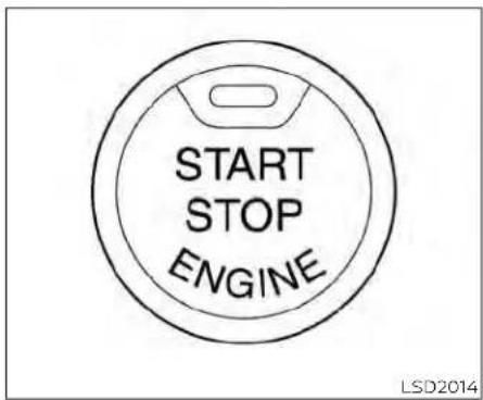
WARNING
Donotoperatethepush-buttonignitionswitchwhiledrivingthevehicleexceptinanemergency.(Theenginewill stopwhentheignitionswitchispushed threeconsecutivetimesinquicksuccessionortheignitionswitchispushed andheldformorethan2seconds.)If theenginestopswhilethevehicleis beingdriven,thiscouldleadtoacrash andseriousinjury.
When the ignition switch is pushed without depressing the brake pedal, the ignition switch position will illuminate as follows:
Push center:
- Once to change to ACC.
- Two times to change to ON.
- Three times to return to OFF.
The ignition switch will automatically return to the LOCK position when any door either opened or closed with the switch in the OFF position.
The ignition lock is designed so that the ignition switch position cannot be placed in the OFF position until the shift lever is moved to the P (Park) position.
When the ignition switch cannot be pushed toward the OFF position, proceed as follows:
- Move the shift lever into the P (Park) position.
- Push the ignition switch. The ignition switch position will change to the ON position.
- Push the ignition switch again to the OFF position.
tTheshiftlevercanbemovedfromtheP (Park)positioniftheignitionswitchisin theONpositionandthebrakepedalis depressed.
If the battery of the vehicle is discharged, the push-buttonignits switch cannot be moved from the LOCK position.
Some indicators and warnings for operation are displayed in the meter. For additional information, see "Vehicle information display warnings and indicators" (P. 2-32).

natural_image
Line drawing of a pickup truck with labeled component (no text or symbols beyond label)OPERATING RANGE
The Intelligent Key functions can only be used when the Intelligent Key is within the specified operating range.
When the Intelligent Key battery is almost discharged or strong radio waves are present near the operating location, the Intelligent Key system's operating range becomes narrower and may not function properly.
If the Intelligent Key is within the operating range, it is possible for anyone, even someone who does not carry the Intelligent Key, to push the Ignition switch to start the engine.
The operating range of the engine start function is inside of the vehicle.
- The luggage area is not included in the operating range, but the Intelligent Key may function.
- If the Intelligent Key is placed on the instrument panel or inside the glove box, storage bin or door pocket, the Intelligent Key may not function.
- If the Intelligent Key is placed near the door or window outside the vehicle, the Intelligent Key may function.
PUSH-BUTTON IGNITION SWITCH POSITIONS
LOCK(Normalparkingposition)
The ignition switch can only be locked in this position.
The ignition switch will be unlocked when it is pushed to the ACC position while carrying the Intelligent Key.
The ignition switch will lock when any door is opened or closed with the ignition switched off.
ACC(Accessories)
This position activates electrical accessories, such as the radio, when the engine is not running.
ACC has a battery saver feature that will place the ignition switch in the OFF position after a period of time under the following conditions:
- All doors are closed.
• The shift lever is in P (Park).
• The hazard lamps are off.
• The turn signals are off.
The battery saver feature will be canceled if any of the following occur: - Any door is opened.
- The shift lever is moved out of the P (Park) position.
it The ignition switch changes position. • The hazard lamps are turned on.
5-14 Startinganddriving
ON(Normaloperatingposition)
This position turns on the ignition system and electrical accessories.
ON has a battery saver feature that will place the ignition switch in the OFF position, if the vehicle is not running, after some time under the following conditions:
- All doors are closed.
• The shift lever is in P (Park).
• The hazard lamps are off.
• The turn signals are off.
The battery saver feature will be canceled any of the following occur:
- Any door is opened.
- The shift lever is moved out of the P (Park) position.
• The ignition switch changes position.
• The hazard lamps are turned on.
• The turn signals are turned on.
CAUTION
DonotleavethevehiclewiththeignitionswitchintheACCorONposition whentheengineisnotrunningforan extendedperiod.Thiscandischarge thebattery.
OFF
The ignition switch is in the OFF position when the engine is turned off using the ignition switch.
EMERGENCY ENGINE SHUT OFF
To shut off the engine in an emergency situation while driving, perform the following procedure:
- Rapidly push the ignition switch three consecutive times in less than 1.5 seconds, or
if Push and hold the ignition switch for more than 2 seconds.

natural_image
Line drawing showing a hand holding a circular device with a scroll wheel, alongside a close-up of the handle (no text or symbols)NISSAN INTELLIGENT KEY® BATTERY DISCHARGE
If the battery of the NISSAN Intelligent Key® is discharged, or environmental conditions interfere with the Intelligent Key operation, start the engine according to the following procedure:
- Place the shift lever in the P (Park) position.
- Firmly apply the foot brake.
- Touch the ignition switch with the Intelligent Key as illustrated. (A chime will sound.)
BEFORESTARTINGTHEENGINE
After step 3 is performed, when the ignition switch is pushed without depressing the brake pedal, the ignition switch position will change to the ON position.
- Push the ignition switch while depressing the brake pedal within 10 seconds after the chime sounds. The engine will start.
NOTE:
-Whentheignitionswitchispushed to theONpositionortheengineisstarted bytheaboveprocedure,theIntelligent KeybatterydischargeindicatorappearsinthevehicleinformationdisplayevenwhentheIntelligentKeyis insidethevehicle.Thisisnotamal-function.ToturnofftheIntelligentKey batterydischargeindicator,touchthe ignitionswitchwiththeIntelligentKey again.
- If the Intelligent Key battery discharge indicator appears, replace the battery as soon as possible. For additional information, see "Battery replacement" (P.8-27).
-NISSAN VEHICLE IMMOBILIZER SYSTEM
The NISSAN Vehicle Immobilizer System will not allow the engine to start without the use of the registered key.
If the engine fails to start using a registered key (for example, when interference is caused by another registered key, an automated toll road device or automatic payment device on the key ring), restart the engine using the following procedures:
- Leave the ignition switch in the ON position for approximately 5 seconds.
- Place the ignition switch in the OFF or LOCK position, and wait approximately 10 seconds.
- Repeat steps 1 and 2.
- Restart the engine while holding the device (which may have caused the interference) separate from the registered key.
If the no start condition re-occurs, NISSAN recommends placing the registered key on a separate key ring to avoid interference from other devices.
- Make sure the area around the vehicle is clear.
- Check fluid levels such as engine oil, coolant, brake fluid and windshield-washer fluid as frequently as possible, or at least whenever you refuel.
d Check that all windows and lights are clean.
Visually inspect tires for their appearance and condition. Also check tires for proper inflation. - Check that all doors are closed.
- Position seat and adjust head restraints/headrests.
- Adjust inside and outside mirrors.
- Fasten seat belts and ask all passengers to do likewise.
- Check the operation of warning lights when the ignition switch is placed in the ON position. For additional information, see "Warning lights, indicator lights and audible reminders" (P. 2-12).
STARTINGTHEENGINE
- Apply the parking brake.
- Move the shift lever to P (Park) or N (Neutral). P (Park) is recommended. The starteris designed not to operate unless the shift lever is neither P (Park) or N (Neutral).
-
Push the ignition switch to the ON position. Depress the brake pedal and push the ignition switch to start the engine. To start the engine immediately, push and release the ignition switch while depressing the brake pedal with the ignition switch in any position.
-
If the engine is very hard to start in extremely cold weather or when re-starting, depress the accelerator pedal a little (approximately 1/3 to the floor) and while holding, crank the engine. Release the accelerator pedal when the engine starts.
- If the engine is very hard to start because it is flooded, depress the accelerator pedal all the way to the floor and hold it. Push the ignition switch to the ON position to start cranking the engine. After 5 or 6 seconds, stop cranking by pushing the ignition switch to the LOCK position. After cranking the engine, release the accel-
erator pedal. Crank the engine with your foot off the accelerator pedal by depressing the brake pedal and pushing the ignition switch to start the engine. If the engine starts, but fails to run, repeat the above procedure.
CAUTION
Donotoperatethestarterformore than15secondsatatime.Iftheengine doesnotstart,pushtheignitionswitch to the OFF position and wait 10 seconds beforecrankingagain,otherwisethe startercouldbedamaged.
4. Warm-up
Allow the engine to idle for at least 30 seconds after starting. Do not race the engine while warming it up. Drive at a moderate speed for a short distance first, especially in cold weather. In cold weather, keep the engine running for a minimum of 2 to 3 minutes before shutting it off. Starting and stopping the engine over a short period of time may make the vehicle more difficult to start.
- To stop the engine, move the shift lever to the P (Park) position and push the ignition switch to the OFF position.
In preparation for the next engine start, the engine may have a slightly delayed shutoff after placing the ignition switch in the OFF position, depending on the driving conditions.
NOTE:
Careshouldbetakentoavoidsituationsthatcanleadtopotentialbatterydischargeandpotentialno-start conditionssuchas:
-
Installationorextendeduseofelectronicaccessoriesthatconsumebat- terypowerwhentheengineisnot running(phonechargers,GPS,DVD players,etc.).
-
The vehicle is not driven regularly and/or only drivenshort distances.
In these cases, the battery may need to be charged to maintain battery health.
DRIVINGTHEVEHICLE
REMOTE ENGINE START (if so equipped)
Vehicles started with the Remote Engine Start require the ignition switch to be placed in the ON position before the shift lever can be moved from the P (Park) position. To place the ignition switch in the ON position, follow these steps:
- Make sure that the Intelligent Key is on you.
- Apply the brake.
- Push the ignition switch once to the ON position.
For additional information, see "NISSAN Intelligent Key®" (P. 3-2).
ENGINE PROTECTION MODE
The engine has an engine protection mod to reduce the chance of damage if the coolant temperature becomes too high (for example, when climbing steep grades in high temperatures with heavy loads, such as when towing a trailer). When the engine temperature reaches a certain level:
- The engine coolant temperature gauge will move toward the H position.
• Engine power may be reduced. - The air conditioning cooling function may be automatically turned off for a short time (the blower will continue to operate).
Engine power and, under some conditions, vehicle speed will decrease. Vehicle speed can be controlled with the accelerator pedal, but the vehicle may not accelerate the desired speed. The transmission will downshift or upshift as it reaches prescribed shift points. You can also shift manually.
As driving conditions change and engine coolant temperature is reduced, vehicle speed can be increased using the accelerator pedal, and the air conditioning cooling function will automatically be turned back on.
The Malfunction Indicator Light (MIL) may also come on if the engine coolant temperature is not reduced or the air conditioning cooling function does not turn back on. If only it remains on, you do not need to have your vehicle towed, but have it inspected soon. It is recommended that you visit a NISSAN dealer for this service. For additional information, see "Malfunction Indicator Light (MIL)" (P. 2-20).
WARNING
Overheatingcanresultinreducedenginepowerandvehiclespeed.Thereducedspeedmaybelowerthanother traffic,whichcouldincreasethechance of a collision.Beespecially careful whendriving. Ifthe vehiclecannot maintainasafedrivingspeed,pullto the side of the road in a safe area. Allow the engine to cool and return to normal operation.Foradditionalinformation, see"Ifyour vehicleoverheats"(P.6-12).
CAUTION
Runningtheenginewiththeengineoil pressurewarninglightoncouldcause seriousdamagetotheenginealmost immediately.Suchdamageisnotcoveredbywarranty.Turnofftheengineas soonasitissafetodoso.
AUTOMATIC TRANSMISSION (A/T)
WARNING
- Donotdepresstheacceleratorpedal whileshiftingfromP(Park)orN(Neutral)toR(Reverse)orD(Drive).Always depressthebrakepedaluntilshifting iscompleted.Failureretodosocould causeyoutolosecontrolandhavean accident.
- Coldengineidlespeedishigh, souse cautionwhenshiftingintoaforward orreversegearbeforetheenginehas warmedup.
-
NevershifttoeithertheP(Park)orR (Reverse)positionwhilethevehicleis movingforwardandP(Park)orD (Drive)positionwhilethevehicleis reversing. This could cause an accidentordamagethetransmission.
-
Exceptinanemergency, donotshift to the N(Neutral) positionwhile driving. Coasting with the transmission in the N(Neutral) position may cause serious damage to the transmission.
- Donotdownshiftabruptlyonslip-peryroads. This may cause all loss of control.
CAUTION
To avoid possible damage to your vehicle, when stopping the vehicle on an uphill grade, donothold the vehicle by depressing the accelerator pedal. The footbrakes should be used for this purpose.
The A/T in your vehicle is electronically controlled to produce maximum power and smooth operation.
The recommended operating procedures for this transmission are shown on the following pages. Follow these procedures for maximum vehicle performance and driving enjoyment.
Starting the vehicle
WARNING
- Donotdepresstheacceleratorpedal whileshiftingfromP(Park)orN(Neutral)toR(Reverse)orD(Drive).Always depressthebrakepedaluntilshifting iscompleted.Failureretodosocould causeyoutolosecontrolandhavean accident.
- Coldengineidlespeedishigh, souse cautionwhenshiftingintoaforward orreversegearbeforetheenginehas warmedup.
- NevershifttoeithertheP(Park)orR (Reverse)positionwhilethevehicleis movingforwardandP(Park)orD (Drive)positionwhilethevehicleis reversing.Thiscouldcauseanaccidentordamagethetransmission.
- Exceptinanemergency, donotshift totheN(Neutral)positionwhiledriving. Coastingwiththetransmission intheN(Neutral)positionmaycause seriousdamagetothetransmission.
- Donotdownshiftabruptlyonslip-peryroads. This may cause all loss of control.
CAUTION
To avoid possible damage to your vehicle, when stopping the vehicle on an uphill grade, donothold the vehicle by depressing the accelerator pedal. The footbrakes should be used for this purpose.
- After starting the engine, fully depress the foot brake pedal before moving the shift lever out of the P (Park) position.
- Keep the foot brake pedal depressed and move the shift lever into a driving gear.
- Release the foot brake, then gradually start the vehicle in motion.
The automatic transmission is designed so the foot brake pedal MUST be depressed before shifting from Park to any drive position while the ignition switch is in the ON position.
Theshiftlevercannotbemovedoutof theP(Park)positionandintoanyofthe othergearpositionsiftheignition switchisplacedintheLOCKorOFF position.
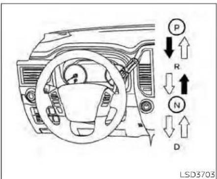
Shifting
To move the shift lever:
→ : Shift while depressing the brake pedal
→ : Shift without depressing the brake pedal
After starting the engine, fully depress the brake pedal and move the shift lever out the P (Park) position.
WARNING
Apply the parking brake if the shiftle- verisinan y position while the engine is not running. Failure todos could cause the vehicle to move unexpected or roll away and result in serious personal injury or property damage.
If the ignition switch is placed in the OFF or ACC position for any reason while the vehicle is in N (Neutral), or any D (Drive) position, the ignition switch cannot be placed in the LOCK position. Move the shift lever to the P (Park) position, then the ignition switch can be placed in the LOCK position.
P(Park)
CAUTION
Topreventtransmissiondamage,use theP(Park)positiononlywhenthevehicleiscompletelystopped.
Use the P (Park) shift lever position when the vehicle is parked or when starting the engine. Make sure the vehicle is completely stopped.
Thebrakepedalshouldbedepressedto movetheshiftleverfromN(Neutral)or anydrivepositiontoP(Park).
The P (Park) position is automatically engaged if you switch off the ignition.
Apply the parking brake. When parking on driving, hill, apply the parking brake first, then move the shift lever into the P (Park) position.
R(Reverse)
CAUTION
Topreventtransmissiondamage, use theR(Reverse)positiononlywhenthe vehicleiscompletelystopped.
Use the R (Reverse) position to back up. Make sure the vehicle is completely stopped before selecting the R (Reverse) position. ThebrakepedalmustbedepressedtomovetheshiftleverfromP (Park),N(Neutral)oranydrivepositionto R(Reverse).
N(Neutral)
Neither forward nor reverse gear is engaged. The engine can be started in this position. You may shift to N (Neutral) and restart a stalled engine while the vehicle is moving.
D(Drive)
Use this position for all normal forward

Manual shift mode
When the manual shift mode switch is pushed while driving, the transmission enters the manual shift mode. Shift ranges can be selected manually.
In the manual shift mode, the shift range is displayed on the position indicator in the meter. After pushing the manual shift mode switch, the position indicator varies depending on the gear position and vehicle speed.
Shift ranges up or down one by one as follows:
M 1 ↔ M 2 ↔ M 3 ↔ M 4 ↔ M 5 ↔ M 6 ↔ M 7 ↔ M 8 ↔ M 9 ↔ D
M9(Ninth)
Use this position for all normal forward driving at highway speeds.
M 1 ↔ M 2 ↔ M 3 ↔ M 4 ↔ M 5 ↔ M 6 ↔ M 7 ↔ M 8 ↔ M 9
M9 will be displayed on the position indicator in the meter.
M8(Eighth)
Use this position for all normal forward driving at highway speeds.
M 1 ↔ M 2 ↔ M 3 ↔ M 4 ↔ M 5 ↔ M 6 ↔ M 7 ↔ M 8
M8 will be displayed on the position indicator in the meter.
M7(Seventh)
Use this position for all normal forward driving at highway speeds.
M 1 ↔ M 2 ↔ M 3 ↔ M 4 ↔ M 5 ↔ M 6 ↔ M 7
M7 will be displayed on the position indicator in the meter.
M6(Sixth)
Use this position for all normal forward driving at highway speeds.
M 1 ↔ M 2 ↔ M 3 ↔ M 4 ↔ M 5 ↔ M 6
M6 will be displayed on the position indicator in the meter
M5(Fifth)
For driving up or down long slopes where engine braking would be advantageous.
Shift ranges up or down one by one as follows:
M 1 ↔ M 2 ↔ M 3 ↔ M 4 ↔ M 5
M5 will be displayed on the position indicator in the meter.
M4(Fourth)
Use for hill climbing or engine braking on downhill grades.
Shift ranges up or down one by one as follows:
M 1 ↔ M 2 ↔ M 3 ↔ M 4
M4 will be displayed on the position indicator in the meter.
M3(Third)
Use for hill climbing or engine braking on downhill grades.
Shift ranges up or down one by one as follows:
M 1 ↔ M 2 ↔ M 3
M3 will be displayed on the position indicator in the meter.
M2(Second)
Use for hill climbing or engine braking on downhill grades.
Shift ranges up or down one by one as follows:
M 1 ↔ M 2
M2 will be displayed on the position indicator in the meter.
M1(First)
Use this position when climbing steep hills slowly or driving slowly through deep snow, sand or mud, or for maximum engine braking on steep downhill grades.
M1 will be displayed on the position indicator on the meter.
- Remember not to drive at high speeds for extended periods of time in lower than M4 range. This reduces fuel economy.
Whenshiftingup
Push the shift switch to the + (up) side. (Shifts to higher range.)
Whenshiftingdown
Push the shift switch to the - (down) side. (Shifts to lower range.)
- The transmission will automatically downshift the gears. (For example, if you select the 3rd range, the transmission will shift down between the 3rd and 1st gears.)
- Pushing the shift switch rapidly will shift the ranges in succession.
Whencancelingthemanualshiftmode
Press and hold the +(UP) button to return the transmission to the normal driving mode.
In the manual shift mode, the transmissionmaynotshifttotheselected gear immediately because of vehicle speed. Thetransmissionwillupshiftor downshift when vehicle speed matches the programmed transmissionshiftpoints. Thishelpsmaintain drivingperformanceandreducesthe chance of vehicle damage or loss of control.
In the manual shift mode, the transmission will not upshift to a higher gearthanismanuallyselected.When thevehiclespeeddecreases,thetrans-missionautomaticallyshiftsdownand shifts to1st gear beforethevehicle comestoastop.
Accelerator downshift — in D (Drive) position —
For passing or hill climbing, depress the accelerator pedal to the floor. This shifts the transmission down into a lower gear, depending on the vehicle speed.
Fail-safe
When the fail-safe operation occurs, please note that the transmission will be locked in any of the forward gears according to the condition.
If the vehicle is driven under extreme conditions, such as excessive wheel spinning and subsequent hard braking, the fail-safesystem may be activated. This will obscure even if all electrical circuits are functioning properly. In this case, placetheignitions switch in the OFF position and wait for 3 seconds. Then place the ignition switch back in the ON position. The vehicles should return to its normal operating condition. If it does not return to its normal operating condition, havethetransmission checked and repaired, if necessary. It is recommended that you visit a NISSAN dealer for this service.
PARKINGBRAKE
TRAFFICSIGNRECOGNITION(TSR)(if soequipped)
WARNING
- Besuretheparkingbrakeisfullyreleasedbeforedriving.Failurertodoso cancausebrakefailureandleadto anaccident.
- Donotreleasetheparkingbrake fromoutsidethevehicle.
- Donotusetheshiftleverinplace of theparkingbrake.Whenparking,be suretheparkingbrakeisfully engaged.
- Tohelpavoidriskofinjuryordeath throughunintendedoperationofthe vehicleand/oritssystems,donot leavechildren,peoplewhorequire theassistance of othersorpets unattendedin yourvehicle.Additionally, thetemperatureinsideaclosedvehicleonawarmdaycanquicklybecomehighenoughtocauseasignificantriskofinjuryordeathtopeople andpets.
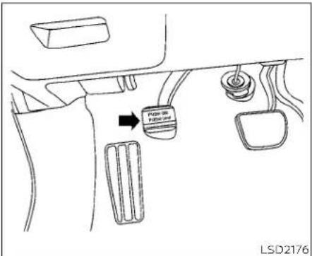
Toengage: Firmly depress the parking brake.
Torelease:
- Firmly apply the foot brake.
- Move the shift lever to the P (Park) position.
- Firmly depress the parking brake pedal and it will release.
- Before driving, be sure the brake warning light goes out.

natural_image
Line drawing of a pickup truck with labeled sensor points (A and Z) and no textual annotations or symbols on the vehicle itself.The TSR system provides the driver with information about the most recently detected speed limit. The system captures the road sign information with the multi-sensing front camera unit ① located on the windshield in front of the inside rearview mirror and displays the detected signs in the vehicle information display. For vehicles equipped with a navigation system, the speed limit displayed is based on a combination of navigation system data and live camera recognition. TSR information is always displayed at the top of the vehicle information display, and optionally in the main central area of the display screen.

WARNING
The TSR system is only intended to be a support device to help provide the driver within information. It is not a replacement for the driver's attention to traffic conditions or responsibility to drives safely. It cannot prevent accidents due to carelessness. It is the driver's responsibility to stay alert and drives safely at all times.

LSD3378
SYSTEM OPERATION
The Traffic Sign Recognition (TSR) system displays the following types of road signs:

Ⓐ Speed sign detected (in Canada)
⑧ Speed sign detected (in USA)
© Speed sign detected (no speed limit detected)
© "Do not pass" sign detected
CAUTION
- TheTSRsystemisintendedasanaid tocarefuldriving.Itisthedriver'sresponsibilitytostayalert,drivesafely, andobserveallroadregulationsthat currentlyapply,includinglookingout forroadsigns.
-
TheTSRsystemmaynotfunction properlyunderthefollowing conditions:
-
Whentheroadsignisnotclearly visible,forexample,duetodamageorweatherconditions.
- Whenrain, snowordirtadheresto the windshieldinfrontofthe multi-sensingcameraunit.
- Whentheheadlightsarenot bright,forexample,duetodirton thelensoriftheaimingisnotadjustedproperly.
- Whenstronglightentersthecameraunit.(Forexample,thelightdirectlyshinesonthefrontofthe vehicleatsunriseorsunset.)
-
When a sudden change in brightness occurs.(Forexample, when the vehicle entersorexitsatunnel orunderabridge.)
-
If there are deviations in relation tothenavigation,forexampledue tochangesintheroadrouting.
- Whenovertakingbusesortrucks withspeedstickers.

Perform the following steps to enable or disable the TSR system.
- Press the ◆ button until "Settings" displays in the vehicle information display. Use the ◆ button to select "Driver Assistance." Then press the ENTER button.
- Select "Traffic Sign" and press the ENTER button to turn the system on or off.
LANEDEPARTUREWARNING(LDW)
SYSTEM TEMPORARILY DISABLED
If the vehicle is parked in direct sunlight under high temperature conditions (over approximately 104°F [40°C]) and then started, the TSR system may be deactivated automatically. The "Not Available High Camera Temp" warning message will appear in the vehicle information display.
Actiontotake:
When the interior temperature is reduced, the TSR system will resume operating automatically.
SYSTEM MALFUNCTION
If the TSR system malfunctions, it will be turned off automatically and the system "Malfunction" warning message will appear in the vehicle information display.
Actiontotake:
If the TSR "Malfunction" message appears, pull off the road at a safe location and stop the vehicle. Turn the engine off and restart the engine. If the TSR "Malfunction" message continues to appear, have the system checked. It is recommended that you visit a NISSAN dealer for this service.
SYSTEM MAINTENANCE
The TSR system uses the same multi-sensing front camera unit that is used by the Lane Departure Warning (LDW) system, located in front of the interior rearview mirror. For additional information, see "System maintenance" (P. 5-31).

natural_image
Line drawing of a pickup truck with labeled components (no text or symbols beyond labels)WARNING
Failuretofollowthewarningsandin-structions forproperuse of theLDW systemcouldresultinseriousinjuryor death.
- Thissystemisonlyawarningdevice toinformthedriverofapotentialunintendedlane departure.It willnot steerthevehicleorpreventlossof control.itisthedriver'sresponsibility to stayalert,drivesafely,keepthe vehicleinthetravelinglane,andbein controlofthevehicleatalltimes.
The LDW system will operate when the vehicle is driven at speeds of approximately 37 mph (60 km/h) and above, and only when the lane markings are clearly visible on the road.
The LDW system monitors the lane markers on the traveling lane using the camera unit ① located above the inside mirror.
The LDW system warns the driver that the vehicle is beginning to leave the driving lane with an indicator and a steering wheel vibration. For additional information, see "LDW system operation" (P. 5-28).
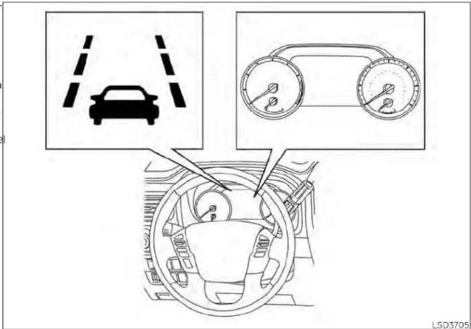
at speeds of approximately 37 mph (60
The LDW system provides a lane departure km/h) and above and the lane markings warning function when the vehicle is driven are clear. When the vehicle approaches either the left or the right side of the traveling
lane, the steering wheel will vibrate and the LDW indicator on the instrument panel will blink to alert the driver.
The warning function will stop when the vehicle returns inside of the lane markers.

HOW TO ENABLE/DISABLE THE LDW SYSTEM
LSD3732
Perform the following steps to enable or disable the LDW system.
- Press the button until "Settings" displays in the vehicle information display. Use the ◆ button to select "Driver Assistance." Then press the ENTER button.
- Select "Lane" and press the ENTER button.
- Select "Warning (LDW)" and press the ENTER button.
- Push the Warning systems switch to turn the system on or off.
LDW SYSTEM LIMITATIONS
WARNING
Listedbelowarethesystemlimitations fortheLDWsystem.Failureretofollow thewarningsandinstructionsfor properuseoftheLDWsystemcouldresultinseriousinjuryordeath.
- Thesystemwillnotoperateat speedsbelowapproximately37mph (60km/h)orifitcannotdetectlane markers.
- DonotusetheLDWsystemunderthe followingconditionsasitmaynot functionproperly:
-
Duringbadweather(rain,fog, snow,etc.).
-
Whendrivingonslipperyroads, suchasoniceorsnow.
- Whendrivingonwindingorun-evenroads.
- Whenthereisalaneclosuredueto roadrepairs.
- When drivinginamakeshiftor temporarylane.
- Whendrivingonroadswherethe lanewidthhistoonarrow.
- Whendrivingwithoutnormaltire conditions(forexample,tirewear, lowtirepressure,installationof sparetire,tirechains, nonstandardwheels).
- Whenthevehicleisequippedwith non-originalbrakepartsorsuspensionparts.
- When you are towing a trailer or other vehicle.
- The system may not function properlyunderthefollowingconditions:
-
Onroadswheretherearemultiple parallellanemarkers;lanemarkersthatarefadedornotpainted clearly;yellowpaintedlanemarkers;non-standardlanemarkers;orlanemarkerscoveredwithwater,dirt,snow,etc.
-
Onroadswherethediscontinued lanemarkersarestilldetectable.
- Onroadswheretherearesharp curves.
- Onroadswheretherearesharply contrastingobjects, suchashadows, snow, water, wheel ruts, seams or lines remaining after road repairs. (TheLDW system could detect these items as lane markers.)
- Onroadswherethetravelinglane mergesorseparates.
- Whenthevehicle'stravelingdirectiondoesnot alignwiththelane marker.
- Whentravelingclosetothevehicleinfrontofyou,whichobstructs the lane camera unit detectionrange.
- Whenrain,snow,dirtoranobject adherestothewindshieldinfront ofthelanecameraunit.
- When theheadlights are not brightduetodirtonthelensorif the aiming is not adjusted properly.
5-30 Startinganddriving
- Whenstronglightentersthelane cameraunit.(Forexample,the lightdirectlyshinesonthefrontof thevehicleatsunriseorsunset.)
- Whenasuddenchangeinbrightnessoccurs.(Forexample,when thevehicleentersorexitsatunnel orunderabridge.)
SYSTEM TEMPORARILY DISABLED
If the vehicle is parked in direct sunlight under high temperature conditions (over approximately 104°F [40°C]) and then started, the LDW system may be deactivated automatically and the following message will appear in the vehicle information display: "Not Available High Carrier Temp."
When the Interior temperature is reduced, the LDW system will resume operating automatically.
The LDW system is not designed to warn under the following conditions:
- When you operate the lane change signal and change travelling lanes in the direction of the signal. (The LDW system will become operable again approximately 2 seconds after the lane change signal is turned off.)
- When the vehicle speed lowers to less than approximately 37 mph (60 km/h). After the above conditions have finished and the necessary operating conditions are satisfied, the LDW functions will resume.
SYSTEM MALFUNCTION
If the LDW system malfunctions, it will cancel automatically and "Malfunction" will appear in the vehicle information display. If "Malfunction" appears in the vehicle information display, pull off the road to a safe location and stop the vehicle. Place the shift lever in the P (Park) position and the ignition switch in the OFF position and restart the engine/motor. If "Malfunction" continues to appear in the vehicle information display, have the system checked. It is recommended that you visit a NISSAN dealer for this service.
SYSTEM MAINTENANCE
The lane camera unit① for the LDW system is located above the inside mirror. To keep the proper operation of the LDW system and prevent a system malfunction, be sure to observe the following:
• Always keep the windshield clean.
- Do not attach a sticker (including transparent material) or install an accessory near the camera unit.
BLINDSPOTWARNING(BSW)
- Do not place reflective materials, such as white paper or a mirror, on the instrument panel. The reflection of sunlight may adversely affect the camera unit's capability of detecting the lane markers.
- Do not strike or damage the areas around the camera unit. Do not touch the camera lens or remove the screw located on the camera unit. If the camera unit is damaged due to an accident, it is recommended that you visit a NISSAN dealer.
WARNING
Failuretofollowthewarningsandin-structionsforproperuseoftheBSW systemcouldresultinseriousinjuryor death.
TheBSWsystemisnotareplacement forproperdrivingproceduresandis notdesignedtopreventcontactwith vehiclesorobjects.Whenchanging lanes,alwaysuse theside andrear mirrorsandturnandlookinthedirectionyourvehiclewillmovetoensureitissafetochangelanes.Never relysolelyontheBSWsystem.
- Do not use the BSW system when towingatraler.Thesystemmaynot functionproperly.
The BSW system helps alert the driver of other vehicles in adjacent lanes when changing lanes.
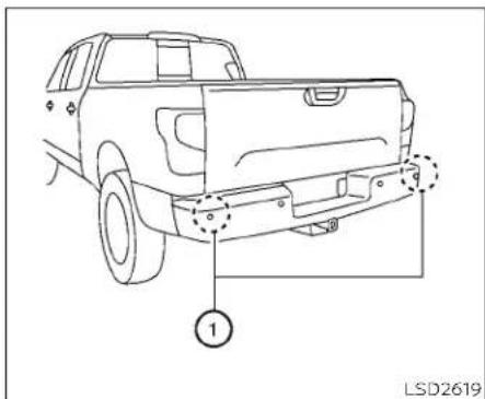
The BSW system uses radar sensors ① installed near the rear bumper to detect other vehicles in an adjacent lane.
5-32 Startinganddriving
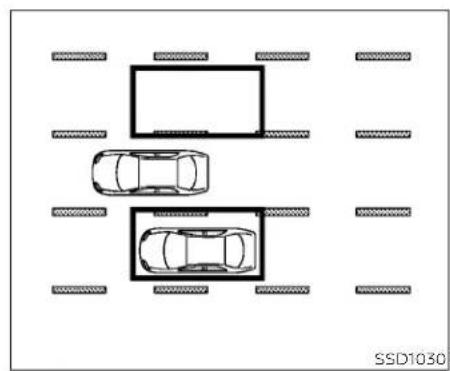
natural_image
Top-down diagram of a parking lot with two cars and surrounding parking areas (no text or symbols)Detectionzone
The radar sensors can detect vehicles on either side of your vehicle within the detection zone shown as illustrated. This detection zone starts from the outside mirror of your vehicle and extends approximately 10 ft (3.0 m) behind the rear bumper, and approximately 10 ft (3.0 m) sideways.

-
Side BSW/RCTA Indicator Light
-
BSW/RCTA Indicator
The BSW system operates above approximately 20 mph (32 km/h).
Startinganddriving5-33
If the radar sensors detect a vehicle in the detection zone, the side BSW/RCTA indicator light (1) illuminates. If the turn signal is then activated, the system chimes (twice) and the side BSW/RCTA indicator light flashes and the BSW/RCTA indicator illuminates (yellow) in the vehicle information display. The side BSW/RCTA indicator light continues to flash until the detected vehicle leaves the detection zone.
The side BSW/RCTA Indicator light illuminates for a few seconds when the ignition switch is placed in the ON position.
The brightness of the side BSW/RCTA Indicator light is adjusted automatically depending on the brightness of the ambient light.
If a vehicle comes into the detection zone after the driver activates the turn signal, then only the side BSW/RCTA indicator light flashes and no chime sounds. For additional information, see "BSW driving situations" (P. 5-36).

LSD3733
When the BSW system is enabled in the vehicle information display, the system can be turned off temporarily by pushing the
HOW TO ENABLE/DISABLE THE BSW SYSTEM
warning systems switch. For additional information, see "Warning systems switch" (P. 2-58).
Perform the following steps to enable or disable the BSW system:
- Press the ◆ button until "Settings" displays in the vehicle information display. Use the ◆ button to select "Driver Assistance" and press ENTER.
- Select "Blind Spot" and press ENTER.
- Select "Warning (BSW)" and press ENTER.
- Push the Warning systems switch to turn the system on or off.
NOTE:
-Whenenabling/disablingthesystem, thesystemwillretaincurrentsettings eveniftheengineisrestarted.
-WhentheBSWsystemisturnedon,the BSW/RCTAindicator(white)inthevehicleinformationdisplayilluminates.
BSW SYSTEM LIMITATIONS
WARNING
Listedbelowarethesystemlimitations fortheBSWsystem.Failureretooperate thevehicleinaccordancewiththese systemlimitationscouldresultinserious-injuryordeath.
- TheBSWsystemcannotdetectallvehiclesunderallconditions.
- Theradarsensorsmaynotbeableto detectandactivateBSWwhencertainobjectsarepresentsuchas:
-
Pedestrian,bicycles,animals.
-
Vehicle such as motorcycles, low height vehicles, or high ground clearance vehicles.
- Oncomingvehicles.
- Vehiclesremaininginthedetection zone when you accelerate fromastop.
- Avehiclemergingintoanadjacent laneataspeedapproximatelythe sameasyourvehicle.
- A vehicle approaching rapidly from behind.
-
Avehiclewhichyourvehicleover-takesrapidly.
-
Avehiclethatpassesthroughthe detectionzonequickly.
- Whenovertakingseveralvehicles inarow,thevehiclesafterthefirst vehiclemaynotbe detectedif theyaretravelingclosetogether.
- Theradarsensor'sdetectionzoneis designedbasedonastandardlane width.Whendrivinginawiderlane, theradarsensorsmaynotdetectvehiclesinanadjacentlane.Whendrivinginanarrowlane,theradarsensorsmaydetectvehiclesdrivingtwo lanesaway.
- Theradarsensorsaredesignedtoignoremoststationaryobjects;however, objects such as guardrails, walls, foliage and parked vehicles mayoccasionallybedetected. This is anormaloperationcondition.
- The following conditions may reduce the ability of the radar to detect other vehicles:
Severeweather
- Roadspray
-
Ice/frost/snow/dirt build-up on thevehicle
-
Donotattachstickers(including transparentmaterial),installaccessoriesorapplyadditionalpaintnear theradarsensors.Theseconditions mayreducetheabilityoftheradarto detectothervehicles.
- Excessivenoise(forexample, audio systemvolume, openvehiclewindow) will interferewith the chime sound, and it may not be heard.

Illustration1-Approachingfrombehind BSW DRIVING SITUATIONS
Indicator on

Indicator off

Indicator flashing

Another vehicle approaching from behind
Illustration1: The side BSW/RCTA Indicator light illuminates if a vehicle enters the detection zone from behind in an adjacent lane.
NOTE:
•Theradarsensorsmaynotdetectvehicleswhichareapproachingrapidly frombehind.

natural_image
Top-down diagram of two cars with directional arrows and a speech bubble, surrounded by vehicle lanes (no text or symbols)Illustration2-Approachingfrom behind
Illustration2: If the driver activates the turn signal when another vehicle is in the detection zone, then the system chimes (twice) and the side BSW/RCTA indicator light flashes.
NOTE:
- Theradarsensorsmaynotdetectvehicleswhichareapproachingrapidly frombehind.
- If the driver activates the turn signal before vehicle enter the detection zone, the side BSW/RCTA indicator light will flash but nochimewill sound when the other vehicle is detected.
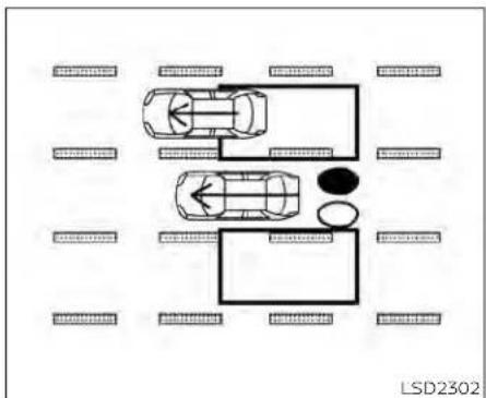
natural_image
Top-down diagram of a car layout with two cars and surrounding parking areas (no text or symbols)Illustration 3 - Overtaking another vehicle
Overtaking another vehicle
Illustration3: The side BSW/RCTA Indicator light illuminates if you overtake a vehicle and that vehicle stays in the detection zone for approximately 2 seconds.

Illustration 4 - Overtaking another vehicle
Illustration4: If the driver activates the turn signal while another vehicle is in the detection zone, then the system chimes (twice) and the side BSW/RCTA indicator light flashes.
NOTE:
-Whenovertakingseveralvehiclesina row,thevehiclesafterthefirstvehicle maynotbedetectediftheyaretravelingclosetogether.
- Theradarsensorsmaynotdetect slowermovingvehiclesiftheyare passedquickly.
- If the driver activates the turn signal before vehicle enter the detection zone, the side BSW/RCTA indicator light will flash but nochimewill sound when the other vehicle is detected.

Illustration 5-Enteringfromtheside Entering from the side
Illustration 5: The side BSW/RCTA indicator light illuminates if a vehicle enters the detection zone from either side.

- Theradarsensorsmaynotdetectvehiclewhichistravelingataboutthe samespeedasyourvehiclewhenitentersthedetectionzone.
Illustration6-Enteringfromtheside Illustration6:If the driver activates the turn signal while another vehicle is in the detection zone, then the system chimes (twice) and the side BSW/RCTA indicator light flashes.
NOTE:
- If the driver activates the turn signal before vehicle enter the detection zone, the side BSW/RCTA indicator light will flash but no chimewill sound when the other vehicle is detected.

SYSTEM TEMPORARILY DISABLED
When radar blockage is detected, the system will be deactivated automatically. The
"Unavailable: Side Radar Obstruction" warning message will appear and the BSW/RCTA indicator (white) will blink® in the vehicle Information display.
The system is not available until the conditions no longer exist.
The radar sensors may be blocked by temporary ambient conditions such as splashing water, mist or fog. The blocked condition may also be caused by objects such as ice, frost or dirt obstructing the radar sensors.
NOTE:
If the BSWsystemstopworking, the RCTAsystem(ifsoequipped) will also stopworking.
Actiontotake:
When the above conditions no longer exist, the system will resume automatically.
Malfunction
If the BSW system malfunctions, it will turn off automatically. The system malfunction warning message with the BSW/RCTA indicator (orange) will appear in the vehicle information display.
NOTE:
If the BSW system stops working, the RCTA system (if so equipped) will also stop working.
Action to take:
Stop the vehicle in a safe location, place the vehicle in the P (Park) position, turn the engine off and restart the engine. If the message continues to appear, have the system checked. It is recommended that you visit a NISSAN dealer for this service.
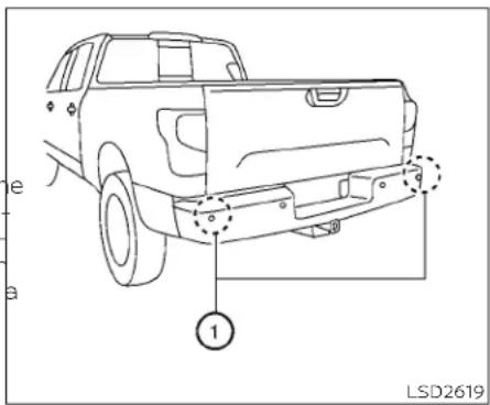
SYSTEM MAINTENANCE
The two radar sensors ① for the BSW and RCTA systems are located near the rear bumper. Always keep the area near the radar sensors clean.
The radar sensors may be blocked by temporary ambient conditions such as splashing water, mist or fog.
The blocked condition may also be caused by objects such as ice, frost or dirt obstructing the radar sensors.
Check for and remove objects obstructing the area around the radar sensors.
Do not attach stickers (including transparent material), install accessories or apply additional paint near the radar sensors.
Do not strike or damage the area around the radar sensors. It is recommended that you visit a NISSAN dealer if the area around the radar sensors is damaged due to a collision.
Radio frequency statement
For USA
FCC ID: OAYSRR3B
This device complies with Part 15 of the FCC Rules.
Operation is subject to the following two conditions:
This device may not cause harmful interference, and
This device must accept any interference received, including interference that may cause undesired operation.
REARCROSSTRAFFICALERT(RCTA)
FCCWarning
Changesormodificationsnotexpressly approvedbythepartyresponsiblefor compliancecouldvoidtheuser'sauthoritytooperatetheequipment.
ForCanada
Model:SRR3-B
Canada310
This device contains licence-exempt transmitter(s)/receiver(s) that comply with Innovation, Science and Economic Development Canada's licence-exempt RSS(s). Operation is subject to the following two conditions:
-
Thisdevicemaynotcause interference.
-
This device must accept any interference, including interference that may cause undesired operation of the device.
Radiofrequency radiation exposure information:
This equipment complies with radiation exposure limits set forth for an uncontrolled environment. This equipment should be installed and operated with
minimumdistanceof20cmbetweenthe radiatorandyourbody.
Droitapplicable:Canada310
Failure to follow the warnings and instructions for proper use of the RCTA systemcouldresultinseriousinjuryor death.
- TheRCTAsystemisnotareplacementforproperdriving procedures andis notdesigned topreventcontactwithvehiclesorobjects.When backing out of a parking space, always use the side and rear mirrors andturnandlookinthedirection your vehicle will move. Never rely solelyontheRCTAsystem.
- DonotusetheRCTAsystemwhen towingatrailer.Thesystemmaynot functionproperly.
The RCTA system will assist you when backing out from a parking space. When the vehicle is in reverse, the system is designed to detect other vehicles approaching from the right or left of the vehicle. If the system detects cross traffic, it will alert you.
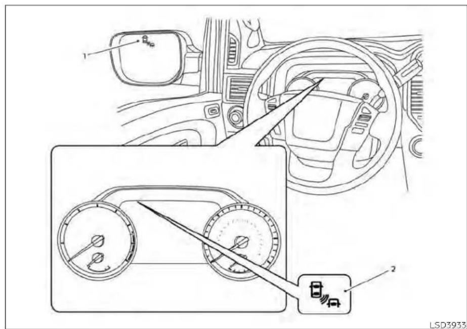
-
Side BSW/RCTA Indicator Light
-
BSW/RCTA Indicator
The RCTA system can help alert the driver of an approaching vehicle when the driver is backing out of a parking space.
When the shift position is in R (Reverse) and the vehicle speed is less than approximately 5 mph (8 km/h), the RCTA system is operational.
If the radar detects an approaching vehicle from the side, the system chimes a sound (single beep) and the side BSW/RCTA indicator light on the side of the vehicle is approaching from flashes.


The RCTA system uses radar sensors ① installed on both sides near the rear bumper to detect an approaching vehicle.
The radar sensors ① can detect an approaching vehicle from up to approximately 66 ft (20 m) away.

HOW TO ENABLE/DISABLE THE RCTA SYSTEM
LSD3734
When the RCTA system is enabled in the vehicle information display, the system can be turned off temporarily by pushing the Front and rear sonar system OFF switch.
For additional information, see "Parking Aids system switch" (P. 2-63).
Perform the following steps to enable or disable the RCTA system:
- Press the ◆ button until "Settings" displays in the vehicle Information display. Use the ◆ button to select "Driver Assistance" and press ENTER.
- Select "Parking Aids" and press ENTER.
- Select "CTA" and press the ENTER button to turn system on or off.
- Push the Parking Aids system switch to turn the system on or off.
NOTE:
Whenenabling/disablingthesystem, thesystemsettingwillberetainedeven iftheengineisrestarted.

RCTA SYSTEM LIMITATIONS
WARNING
Listedbelowarethesystemlimitations fortheRCTAsystem.Failureretooperate thevehicleinaccordancewiththese systemlimitationscouldresultinseriousinjuryordeath.
- Alwayschecksurroundingsandturn tocheckwhatisbehindyoubefore backingup.Theradarsensorsdetect approaching(moving)vehicles.The radarsensorscannotdetectevery objectsuchas:
- Pedestrians, bicycles, motorcycles, animals or child-operated toy vehicles
- Avehiclethatispassingatspeeds greaterthanapproximately19 mph(30km/h)
- Avehiclethatispassingatspeeds lowerthanapproximately5mph (8km/h)
- Theradarsensorsmaynotdetect approachingvehiclesincertainsituations:
- Illustration Ⓐ:Whenavehicle parkednexttoyouobstructsthe beamoftheradarsensor.
- Illustration Ⓑ:Whenthevehicleis parked in an angled parking space.
- Illustration Ⓞ:Whenthevehicleis parkedoninclinedground.
-
Illustration ①: When an approaching vehicle turns into your vehicle's parking lotaisle.
-
Illustration Ⓔ: Whentheangle formed by your vehicle and approaching vehicle is small.
- The following conditions may reduce the ability of other radar detection other vehicles:
- Severeweather
- Roadspray
- Ice/frost/snow/dirtbuild-upon thevehicle
- Donotattachstickers(including transparentmaterial),installaccessoriesorapplyadditionalpaintnear theradarsensors.Theseconditions mayreducetheabilityoftheradarto detectothervehicles.
- Excessivenoise(e.g., audiosystem volume, openvehiclewindow) will interferewith the chimesound, and it may not be heard.

flowchart
graph TD
    A["Top Floor Parking"] --> B["Leftmost Parking"]
    B --> C["Rightmost Parking"]
    C --> D["Leftmost Parking"]
    D --> E["Rightmost Parking"]
    E --> F["Bottom Parking"]
    style A fill:#f9f,stroke:#333
    style B fill:#ccf,stroke:#333
    style C fill:#cfc,stroke:#333
    style D fill:#fcc,stroke:#333
    style E fill:#cff,stroke:#333
    style F fill:#ffc,stroke:#333
Illustration1

natural_image
Top-down diagram of a parking lot with cars and directional arrows indicating lanes (no text or symbols)Illustration2
NOTE:
Inthecaseofseveralvehiclesapproachinginarow(Illustration1)orintheoppositedirection(Illustration2),achimemay notbesoundedbytheRCTAsystemafterthefirstvehiclepassesthesensors.

SYSTEM TEMPORARILY DISABLED
When radar blockage is detected, the system will be deactivated automatically. The "Unavailable Side Radar Obstruction" warn-
ing message will appear and the BSW/RCTA Indicator (white) will blinkⒶ in the vehicle information display.
5-48 Startinganddriving
The systems are not available until the conditions no longer exist.
The radar sensors may be blocked by temporary ambient conditions such as splashing water, mist or fog.
The blocked condition may also be caused by objects such as ice, frost or dirt obstructing the radar sensors.
NOTE:
If the BSWsystemstopworking, the RCTAsystem(ifsoequipped) will also stopworking.
Actiontotake
When the above conditions no longer exist, the system will resume automatically.
Malfunction
When the RCTA system malfunctions, it will turn off automatically. The system malfunction warning message with the BSW/RCTA indicator (orange) will appear in the vehicle information display.
NOTE:
If the BSWsystemstopsworking, the RCTAsystem(ifsoequipped) will also stopworking.
Actiontotake
Stop the vehicle in a safe location, place the vehicle in the P (Park) position, turn the engine off and restart the engine. If the message continues to appear, have the system checked. It is recommended that you visit a NISSAN dealer for this service.

SYSTEM MAINTENANCE
The two radar sensors ① for the BSW and RCTA systems are located near the rear bumper. Always keep the area near the radar sensors clean.
The radar sensors may be blocked by temporary ambient conditions such as splashing water, mist or fog.
The blocked condition may also be caused by objects such as ice, frost or dirt obstructing the radar sensors.
Check for and remove objects obstructing the area around the radar sensors.
Do not attach stickers (including transparent material), install accessories or apply additional paint near the radar sensors.
Do not strike or damage the area around the radar sensors. It is recommended that you visit a NISSAN dealer if the area around the radar sensors is damaged due to a collision.
Radio frequency statement
ForUSA
FCCID:OAYSRR3B
ThisdevicecomplieswithPart15ofthe FCCRules.
Operationissubjecttothefollowingtwo conditions:
Thisdevicemaynotcauseharmfulinterference,and
This device must accept any interference received, including interference that may cause undesired operation.
CRUISECONTROL(ifsoequipped)
FCCWarning
Changesormodificationsnotexpressly approvedbythepartyresponsiblefor compliancecouldvoidtheuser'sauthoritytooperatetheequipment.
ForCanada
Model:SRR3-B
Canada310
This device contains licence-exempt transmitter(s)/receiver(s) that comply with Innovation, Science and Economic Development Canada's licence-exempt RSS(s). Operation is subject to the following two conditions:
-
Thisdevicemaynotcause interference.
-
This device must accept any interference, including interference that may cause undesired operation of the device.
Radiofrequency radiation exposure information:
This equipment complies with radiation exposure limits set forth for an uncontrolled environment. This equipment should be installed and operated with
minimumdistanceof20cmbetweenthe radiatorandyourbody.
Droitapplicable:Canada310
- If the cruise control system malfunctions, it cancels automatically. The 🎨 (green) indicator illuminates in the vehicle information display then blinks to warn the driver.
- If the (green) indicator blinks, push the ON/OFF switch off and have the system checked. It is recommended that you visit a NISSAN dealer for this service.
- The (green) indicator may blink when the ON/OFF switch is pushed ON while pushing the ACCEL/RES, COAST/SET, or CANCEL switch. To properly set the cruise control system, use the following procedures.
WARNING
Donotusethecruise control when driving under the following conditions:
- Whenitisnotpossibletokeepthe vehicleatasetspeed.
- Inheavytrafficorintrafficthatvaries inspeed.
- Onwindingorhillyroads.
- Onslipperyroads(rain,snow,ice, etc.).
- Inverywindyareas.
Doing so could cause a loss of vehicle controlandresultinanaccident.
The cruise control allows driving at a speed between 25 - 89 mph (40 - 144 km/h) without keeping your foot on the accelerator pedal.
To turn on the cruise control, push the ON/OFF switch on. The (white) indicator in the vehicle information display will illuminate.
To set cruising speed, accelerate the vehicle to the desired speed, push the COAST/SET switch and release it. The (green) indicator in the vehicle information display will illuminate. Take your foot off the accelerator pedal. Your vehicle maintains the set speed.
- To pass another vehicle, depress the accelerator pedal. When you release the pedal, the vehicle returns to the previously set speed.
- The vehicle may not maintain the set speed when going up or down steep hills. If this happens, drive without the cruise control.
Tocancelthepresetspeed, use one of the following three methods:
- Push the CANCEL switch; the indicator in the vehicle information display goes out.
- Tap the brake pedal; the 🎨 indicator and goes out.
Push the ON/OFF switch off. The indicator in the vehicle information display goes out.
The cruise control is automatically canceled and the 🎨 indicator in the vehicle information display goes out if:
- You depress the brake pedal while pushing the ACCEL/RES or COAST/SET switch. The preset speed is deleted from memory.
- The vehicle slows down more than 8 mph (13 km/h) below the set speed.
- You move the shift lever to N (Neutral).
Toresetatafastercruisingspeed, use one of the following three methods:
- Depress the accelerator pedal. When the vehicle attains the desired speed, push and release the COAST/SET switch.
Push and hold the ACCEL/RES switch. When the vehicle attains the speed you desire, release the switch. - Push and release the ACCEL/RES switch. Each time you do this, the set speed increases by about 1 mph (1.6 km/h).
INTELLIGENTCRUISECONTROL(ifso equipped)
Toresetataslowercruisingspeed,use
one of the following three methods:
- Lightly tap the brake pedal. When the vehicle attains the desired speed, push the COAST/SET switch and release it.
- Push and hold the COAST/SET switch. Release the switch when the vehicle slows to the desired speed.
- Push and release the COAST/SET switch. Each time you do this, the set speed decreases by about 1 mph (1.6 km/h).
Toresumethepresetspeed, push and release the ACCEL/RES switch. The vehicle returns to the last set cruising speed when the vehicle speed is over 25 mph (40 km/h)

Ⓐ ON/OFF switch
5-52 Startinganddriving
WARNING
Failure to follow the warnings and instructions for proper use of the CC system could result in serious injury or death.
- TheICCsystemisonlyanaidtoassist thedriverandisnotacollisionwarningoravoidancedevice.Itisthedriver'sresponsibilitytostayalert,drive safely,andbeincontrolofthevehicle atalltimes.
- Alwaysobservepostspeedlimits anddonotsetthespeedoverthem.
• AlwaysdrivecarefullyandattentivelywhenusingtheICCsystem. ReadandunderstandtheOwner's Manualthoroughlybeforeusingthe ICCsystem.Toavoidseriousinjuryor death,donotrelyonthesystemto preventaccidentsortocontrolthe vehicle'sspeedinemergencysituations.DonotusethelCCsystemexceptinappropriateroadandtraffic conditions.
- In the conventional(fixedspeed) cruise control mode, a warning chimewillnotsoundtowarnyouif youaretooclosetothevehicle ahead.Payspecialattentiontothe distancebetween yourvehicleand thevehicleaheadofyouoracollision couldoccur.
The ICC system maintains a selected distance from the vehicle in front of you within the speed range of 0 to 90 mph (0 to 144 km/h) up to the set speed. The set speed can be selected by the driver between 20 to 90 mph (32 to 144 km/h).
The vehicle travels at a set speed when the road ahead is clear.
The ICC system can be set to one of two cruise control modes:
- Vehicle-to-vehicle distance control mode: For maintaining a selected distance between your vehicle and the vehicle in front of you up to the preset speed
- Conventional(fixedspeed)cruisecontrolmode:For cruising at a preset speed
Always confirm the setting in the ON/OFF switch display.
For the vehicle-to-vehicle distance control mode, see "Vehicle-to-vehicle distance control mode" (P. 5-54).
For the conventional (fixed speed) cruise control mode, see "Conventional (fixed speed) cruise control mode" (P. 5-72).

HOW TO SELECT THE CRUISE CONTROL MODE
Selectingthevehicle-to-vehicledistancecontrolmode:To choose the vehicle-to-vehicle distance control mode, quickly push and release the ON/OFF switch Ⓐ.
Selectingtheconventional(fixedspeed) cruisecontrolmode:To choose the conventional (fixed speed) cruise control mode, push and hold the ON/OFF switch A for longer than approximately 1.5 seconds. For additional information, see "Conventional (fixed speed) cruise control mode" (P. 5-72).

natural_image
Line drawing of a pickup truck with no text or symbols on the body, showing front grille and side panel (no readable labels or symbols)VEHICLE-TO-VEHICLE DISTANCE CONTROL MODE
In the vehicle-to-vehicle distance control mode, the ICC system automatically maintains a selected distance from the vehicle traveling in front of you according to that vehicle's speed (up to the set speed), or at the set speed when the road ahead is clear.
The ICC system is intended to enhance the operation of the vehicle when following a vehicle traveling in the same lane and direction.
If the radar sensor ① detects a slower moving vehicle ahead, the system will reduce the vehicle speed so that your vehicle follows the vehicle in front at the selected distance.
The system automatically controls the throttle and applies the brakes (up to approximately 40% of vehicle braking power) if necessary.
The detection range of the sensor is approximately 650 ft (200 m) ahead.

The vehicle-to-vehicle distance control mode is designed to maintain a selected distance from the vehicle in front of you and can reduce the speed to match a
Startinganddriving5-55
slower vehicle ahead. The system will de- The following items are controlled in the celerate the vehicle as necessary and if the vehicle-to-vehicle distance control mode: vehicle ahead comes to a stop, the vehicle. When there are no vehicles traveling decelerates to a standstill. However, the ICC system can only apply up to 40% of the control mode maintains the speed set by the vehicle's total braking power.
This system should only be used when traffic conditions allow vehicle speeds to remain fairly constant or when vehicle speeds change gradually. If a vehicle moves into the traveling lane ahead or if a vehicle traveling ahead rapidly decelerates, the distance between vehicles may become closer because the ICC system cannot decelerate the vehicle quickly enough. If this occurs, the ICC system will sound a warning chime and blink the system display to notify the driver to take necessary action.
The system will cancel and a warning chime will sound if the speed is below approximately 15 mph (24 km/h) and a vehicle is not detected ahead. The system will also disengage when the vehicle goes above the maximum set speed.
For additional information, see "Approach warning" (P. 5-62).
When there is a vehicle traveling ahead, the vehicle-to-vehicle distance control mode adjusts the speed to maintain the distance, selected by the driver, from the vehicle ahead. If the vehicle ahead comes to a stop, the vehicle decelerates to a standstill within the limitations of the system. The system will cancel once it judge a standstill with a warning chime.
When the vehicle traveling ahead has moved out from its lane of travel, the vehicle-to-vehicle distance control mode accelerates and maintains vehicle speed up to the set speed.
9 The ICC system does not control vehicle speed or warn you when you approach stationary and slow moving vehicles. You must pay attention to vehicle operation to maintain proper distance from vehicles ahead when approaching toll gates or traffic congestion.

natural_image
Diagram showing a car driving on a road with an arrow indicating direction, no text or symbols presentWhen driving on the freeway at a set speed and approaching a slower traveling vehicle ahead, the ICC system will adjust the speed to maintain the distance, selected by the driver, from the vehicle ahead. If the vehicle ahead changes lanes or exits the freeway, the ICC system will accelerate and maintain the speed up to the set speed. Pay attention to the driving operation to maintain control of the vehicle as it accelerates to the set speed.
The vehicle may not maintain the set speed on winding or hilly roads. If this occurs, you will have to manually control the vehicle speed.
Normally when controlling the distance to a vehicle ahead, this system automatically accelerates or decelerates your vehicle according to the speed of the vehicle ahead. Depress the accelerator to properly accelerate your vehicle when acceleration is required for a lane change. Depress the brake pedal when deceleration is required to maintain a safe distance to the vehicle ahead due to its sudden braking or if a vehicle cuts in. Always stay alert when using the ICC system.

VEHICLE-TO-VEHICLE DISTANCE CONTROL MODE SWITCHES
The system is operated by the ON/OFF switch and four control switches, all mounted on the steering wheel.
1. CANCELswitch:
Deactivates the system without erasing the set speed.
2. ACCEL/RESswitch:
Resumes set speed or increases speed incrementally.
3. COAST/SETswitch:
Sets desired cruise speed or reduces speed incrementally.
4. ON/OFFswitch:
Master switch to activate the system.
5. DISTANCEswitch: switch:
Changes the vehicle's following distance:
- Long
- Middle
- Short

Vehicle-to-vehicle distance control mode display and indicators
The display is located between the speedometer and tachometer.
- This indicator indicates the ICC system status depending on a color:
- ICCsystemONindicator(gray):Indicates that the ON/OFF switch is on.
- ICCsystemSETindicator(green):Indicates that the cruising speed is set.
- ICCsystemwarning(yellow):Indicates that there is a malfunction in the ICC system.
- Set vehicle speed indicator: Indicates the set vehicle speed. For Canadian models, the speed is displayed in km/h.
- Vehicle ahead detection indicator: Indicates whether it detects a vehicle in front of you.
- Set distance indicator: 0376 Displays the selected distance between vehicles set with the distance switch.

Operating vehicle-to-vehicle distance control mode
Toturnonthecruisecontrol, quickly push and release the ON/OFF switch. The ICC system ON indicator (gray), set distance indicator and set vehicle speed indicator come on in a standby state for setting.
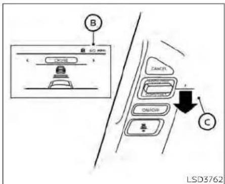
Tosetcruisingspeed,accelerate your vehicle to the desired speed, push the COAST/SET switch © and release it. The ICC system set indicator (green), vehicle ahead detection indicator, set distance indicator and set vehicle speed indicator® will come on. Take your foot off the accelerator pedal. Your vehicle will maintain the set speed.
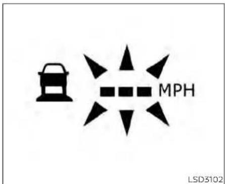
When the COAST/SET switch is pushed under the following conditions, the system cannot be set and the ICC indicators will blink for approximately 2 seconds:
- When traveling below 20 mph (32 km/h) and a vehicle ahead is not detected
- When the shift lever is not in the D (Drive) or Manual mode
- When the parking brake is applied
- When the brakes are operated by the driver
When the COAST/SET switch is pushed under the following conditions, the system cannot be set.
A warning chime will sound and a message will pop up:
- When the VDC system is off (To use the ICC system, turn on the VDC system. Push the ON/OFF switch to turn off the ICC system and reset the ON/OFF switch by pushing the ON/OFF switch again.) For additional information about the VDC system, see "Vehicle Dynamic Control (VDC) system" (P. 5-120).
- When VDC is operating
- When a wheel is slipping (To use the ICC system, make sure the wheels are no longer slipping.)
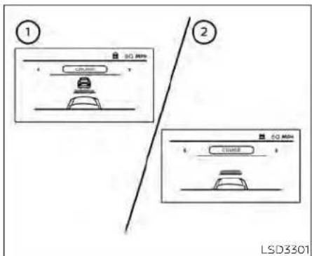
① System set display with vehicle ahead
② System set display without vehicle ahead
The driver sets the desired vehicle speed based on the road conditions. The ICC system maintains the set vehicle speed, similar to standard cruise control, as long as no vehicle is detected in the lane ahead. The ICC system displays the set speed.
Vehicledetectedahead
When a vehicle is detected in the lane ahead, the ICC system decelerates the vehicle by controlling the throttle and applying the brakes to match the speed of a slower vehicle ahead. The system then controls the vehicle speed based on the speed of the vehicle ahead to maintain the driver selected distance.
NOTE:
- Thestoplightsofthevehiclecomeon whenbrakingisperformedbytheICC system.
-Whenthebrakeoperates,anoisemay beheard. This is not a malfunction.
When a vehicle ahead is detected, the vehicle ahead detection indicator comes on. The ICC system will also display the set speed and selected distance.
Vehicleaheadnotdetected
When a vehicle is no longer detected ahead, the ICC system gradually accelerates your vehicle to resume the previously set vehicle speed. The ICC system then maintains the set speed.
When a vehicle is no longer detected, the e vehicle ahead detection indicator turns off.
If a vehicle ahead appears during acceleration to the set vehicle speed or any time the ICC system is in operation, the system controls the distance to that vehicle.
When a vehicle is no longer detected under approximately 15 mph (24 km/h), the system will be canceled.

When passing another vehicle, the set speed indicator Ⓐ will flash when the vehicle speed exceeds the set speed. The vehicle detect indicator will turn off when the area ahead of the vehicle is open. When the pedal is released, the vehicle will return to the previously set speed.
Even though your vehicle speed is set in the ICC system, you can depress the accelerator pedal when it is necessary to accelerate your vehicle rapidly.
How to change the set vehicle speed
Tocancelthepresetspeed, use one of the following methods:
- Push the CANCEL switch. The set vehicle speed indicator will go out.
- Tap the brake pedal. The set vehicle speed indicator will go out.
- Turn the ON/OFF switch off. The ICC indicators will go out.
Toresetatafastercruisingspeed,use
one of the following methods: - Depress the accelerator pedal. When the vehicle attains the desired speed, push and release the COAST/SET switch. - Push and hold the ACCEL/RES switch. The set vehicle speed will increase by approximately 5 mph (5 km/h). - Push, then quickly release the ACCEL/RES switch. Each time you do this, the set speed will increase by approximately 1 mph (1 km/h).
Toresetataslowercruisingspeed,use one of the following methods:
- Lightly tap the brake pedal. When the vehicle attains the desired speed, push the COAST/SET switch and release it.
- Push and hold the COAST/SET switch. The set vehicle speed will decrease by approximately 5 mph (5 km/h).
- Push, then quickly release the COAST/SET switch. Each time you do this, the set speed will decrease by approximately 1 mph (1 km/h).
Toresumethe presetspeed, push and release the ACCEL/RES switch. The vehicle will resume the last set cruising speed when the vehicle speed is over 20 mph (32 km/h).
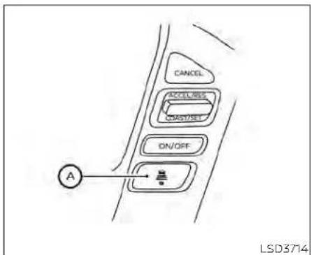
flowchart
graph TD
    A["Start"] --> B["CANCEL"]
    B --> C["ACCELMS"]
    C --> D["ACCRISER"]
    D --> E["ON/OFF"]
    E --> F["Action Point"]
    style A fill:#f9f,stroke:#333
    style F fill:#ccf,stroke:#333
How to change the set distance to the vehicle ahead
The distance to the vehicle ahead can be selected at any time depending on the traffic conditions.
Each time the distance ⚡ switch Ⓐ is pushed, the set distance will change to long, middle, short and back to long again, in that sequence.

DistanceApproximatedistanceat 60mph(100km/h) [ft(m)]
f-1. Long 200 (60)
- Middle 150 (45)
- Short 90 (30)
- The distance to the vehicle ahead will change according to the vehicle speed. The higher the vehicle speed, the longer the distance.
- The distance setting will remain at the current setting even if the engine is restarted.
Approach warning
If your vehicle comes closer to the vehicle ahead due to rapid deceleration of that vehicle or if another vehicle cuts in, the system warns the driver with the chime and ICC system display. Decelerate by depressing the brake pedal to maintain a safe vehicle distance if:
• The chime sounds.
• The vehicle ahead detection indicator blinks.
The warning chime may not sound in some cases when there is a short distance between vehicles. Some examples are:
- When the vehicles are traveling at the same speed and the distance between vehicles is not changing.
- When the vehicle ahead is traveling faster and the distance between vehicles is increasing.
- When a vehicle cuts in near your vehicle. The warning chime will not sound when:
• The vehicle approaches other vehicles that are parked or moving slowly. - The accelerator pedal is depressed, overriding the system.
NOTE:
Theapproachwarningchimemaysound andthesystemdisplaymayblinkwhen the ICCsensordetectsobjectsonthe sideofthevehicleoronthesideofthe road. This may cause the ICC system to decelerate or accelerates the vehicle. The ICCsensormay detect these objects when the vehicle is driven on winding roads, narrowroads, hillyroads, or when enteringorexiting acurve. In these cases you will have to control the proper distance ahead of your vehicle.
Also, the sensor sensitivity can be affected by vehicle operation (steering maneuver or driving position in the lane) or traffic or vehicle condition (for example, if a vehicle is being driven with some damage).
Acceleration when passing
When the ICC system is engaged above 37 mph and following a slower vehicle (below ICC set speed), and the turn signal is activated to the left, the ICC system will automatically start to accelerate the vehicle to help initiate passing on the left and will begin to reduce the distance to vehicle directly ahead. Only the left side turn signal operates this feature. As the driver steers
the vehicle and moves into the passing lane, if no vehicle is detected ahead the ICC system will continue to accelerate to the ICC system set speed. If another vehicle is detected ahead, then the vehicle will accelerate up to the following speed of that vehicle. If the vehicle is not steered into the left lane to pass, the acceleration will stop after a short time and regain the set following distance. Acceleration can be stopped at any point by depressing the brake pedal or the CANCEL switch on the steering wheel.
WARNING
Inordertoreducetheriskofacollision that may result in serious injury or death, please be aware of the following:
- Thisfunctionisonlyactivatedwith theleftturnsignalandwillbrieflyaccelerate the vehicle even if a lane changeisnotinitiated.Thiscanincludenon-passingsituationssuchas leftsideexits.
- Ensure that when passing another vehicle, the adjacent lane is clear before initiating the pass. Sudden changes in traffic may occur while passing—always manually steer or brakes needed—neversolely rely on the system.
w System temporarily disabled
A chime sounds under the following conditions and the control is automatically canceled:
- When the vehicle ahead is not detected and your vehicle is traveling below the speed of 15 mph (24 km/h)
- When the system judges the vehicle is at a standstill
- When the shift lever is not in the D (Drive) position, Manual mode or L (Low) range.
- When the parking brake system is applied
- When the VDC system is turned off
- When VDC operates
- When a wheel slips
- When the radar signal is temporarily interrupted
VEHICLE-TO-VEHICLE DISTANCE CONTROL MODE LIMITATIONS
WARNING
Listedbelowarethesystemlimitations forthelCCsystem.Failureretooperate thevehicleinaccordancewiththese systemlimitationscouldresultinseriousinjuryordeath.
- TheICCsystemisprimarilyintended foruseonstraight,dry,openroads withlighttraffic.Itisnotadvisableto usethelCCsystemincitytrafficor congestedareas.
-
TheICCsystemwillnotadaptautomaticallytoroadconditions.This systemshouldbeusedinevenly flowingtraffic.Donotusethesystem onroadswithsharpcurves,oronicy roads,inheavyrainorinfog.
-
Asthereisaperformancelimittothe distancecontrolfunction,neverrely solelyonthelCCsystem.Thissystem doesnotcorrectcareless,inattentive orabsentmindeddriving,orovercomepoorvisibilityinrain,fog, or otherbadweather.Decelerate the vehiclespeedbydepressingthe brakepedal,dependingonthedistancetothevehicleaheadandthe surroundingcircumstancesinorder tomaintinasafedistancebetween vehicles.
- Ifthevehicleaheadcomestoastop, thevehicledeceleratestoastandstill withinthelimitationsofthesystem. Thesystemwillcancelonceitjudges thatthevehiclehascometoastandstillandsoundawarningchime.To preventthevehiclefrommoving,the drivermustdepressthebrakepedal.
- Alwayspayattentiontothe operationofthevehicleand bereadyto manuallycontroltheproperfollowingdistance.TheICCsystemmaynot beabletomaintainedtheselecteddistancebetweenvehicles(following distance)or selected vehicle speed undersomecircumstances.
- Thesystemmaynotdetectthevehicleinfrontofyouincertainroador weather conditions. To avoid accidents,neverusethelCCsystemunderthefollowingconditions:
- Onroadswherethetrafficisheavy ortherearesharpcurves
- Onslipperyroadsurfacessuchas oniceorsnow,etc.
- During bad weather (rain, fog, snow, etc.)
- Whenrain, snowordirtadhereto thebumperaroundthedistance sensor
- Onsteepdownhillroads(thevehiclemaygobeyondthesetvehiclespeedandfrequentbraking may result inoverheating the brakes)
- On repeated uphill and downhill roads
- When traffic conditions make it difficult to keep proper distance between vehicles because off frequent acceleration or deceleration
-
Interference by other radar sources
-
DonotusethelCCsystemifyouare towingatrailer.Thesystemmaynot detectavehicleahead.
- Insomeroadortrafficconditions, a vehicleorobjectcanunexpectedly comeintothesensordetectionzone and causeautomaticbraking. Alwaysstayalertandavoidusingthe ICCsystemwherenotrecommended inthiswarningsection.
The radar sensor will not detect the following objects:
• Stationary and slow moving vehicles
- Pedestrians or objects in the roadway
- Oncoming vehicles in the same lane
- Motorcycles traveling offset in the travel lane
The sensor generally detects the signals returned from the vehicle ahead. Therefore, if the sensor cannot detect the reflection from the vehicle ahead, the ICC system may not maintain the selected distance.
The following are some conditions in which the sensor cannot properly detect a vehicle ahead and the system may not operate properly:
- When snow or road spray from traveling vehicles reduces the sensor's detection.
- When your vehicle is towing a trailer, etc.
- when excessively heavy baggage is loaded in the rear seat or cargo area of your vehicle.
- The ICC system is designed to automatically check the sensor's operation within the limitations of the system.
When the sensor is covered with dirt or is obstructed, the system will automatically be canceled. If the sensor is covered with ice, a transparent or translucent vinyl bag, etc., the ICC system may not detect them. In these instances, the vehicle-to-vehicle distance control mode may not cancel and may not be able to maintain the selected following distance from the vehicle ahead. Be sure to check and clean the sensor regularly.
The detection zone of the radar sensor is limited. A vehicle ahead must be in the detection zone for the vehicle-to-vehicle distance detection mode to maintain the selected distance from the vehicle ahead.
A vehicle ahead may move outside of the detection zone due to its position within the same lane of travel. Motorcycles may not be detected in the same lane ahead if they are traveling offset from the centerline of the lane. A vehicle that is entering the lane ahead may not be detected until the vehicle has completely moved into the lane.
If this occurs, the CC system may warn you by blinking the system indicator and sounding the chime. The driver may havetomanually control the proper distance away from vehicle traveling ahead.
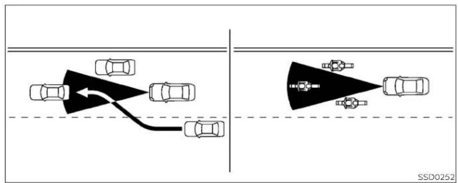
flowchart
graph TD
    A["Top Left: Car"] --> B["Top Right: Car"]
    B --> C["Bottom Left: Car"]
    style A fill:#f9f,stroke:#333
    style B fill:#bbf,stroke:#333
    style C fill:#dfd,stroke:#333
5-66 Startinganddriving
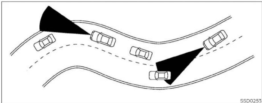
natural_image
Diagram of a road intersection with multiple cars and two shaded triangular obstacles (no text or symbols)When driving on some roads, such as wiring, hilly, curved, narrow roads, or roads which are under construction, the radar sensor may detect vehicles in a different lane, or may temporarily not detect a vehicle traveling ahead. This may cause the radar system to decelerate or accelerate the vehicle.
difthisoccurs, theICCsystemmaywarn youbyblinkingthesystemindicatorand soundingthechimeunexpectedly.You willhavetomanuallycontroltheproper distanceawayfromthevehicletraveling ahead.
The detection of vehicles may also be affected by vehicle operation (steering maneuver or traveling position in the lane, etc.) or vehicle condition.
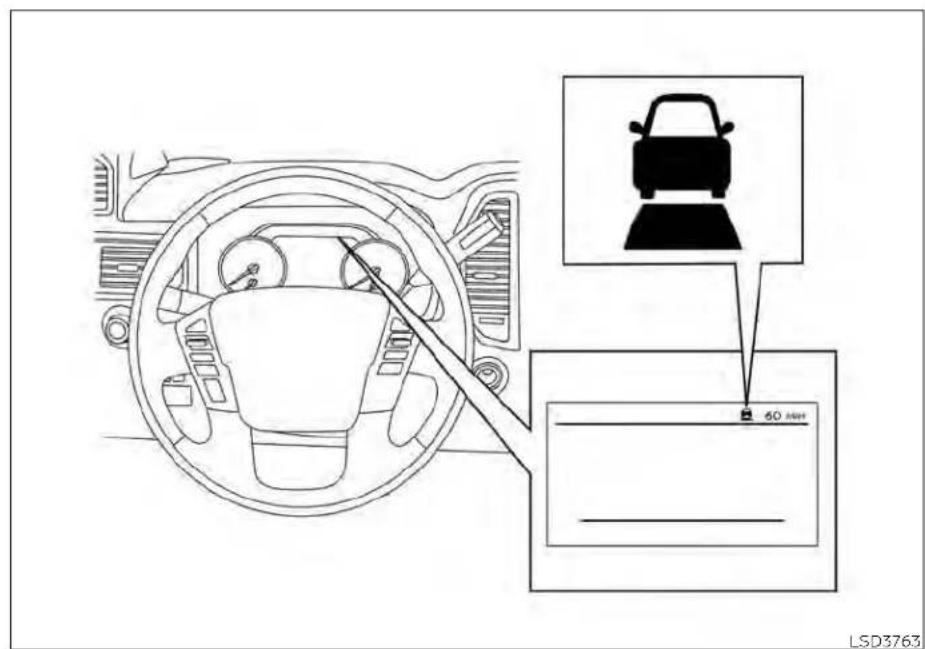
SYSTEM TEMPORARILY UNAVAILABLE
The following are conditions in which the ICC system may be temporarily unavailable. In these instances, the ICC system may not cancel and may not be able to
maintain the selected following distance from the vehicle ahead.
ConditionA
Under the following conditions, the ICC system is automatically canceled. A chime will sound and the system will not be able to be set:
- When the VDC system is turned off
- When the VDC operates
- When a vehicle ahead is not detected and your vehicle is traveling below the speed of 15 mph (24 km/h)
- When the system judges the vehicle is at a standstill
- When the shift lever is not in the D (Drive), Manual mode or L (Low) range
- When the parking brake is applied
- When a wheel slips
- when the radar signal is temporarily interrupted
Actiontotake
When the conditions listed above are no longer present, turn the system off using the ICC switch. Turn the ICC system back on to use the system.
ConditionB
When there is inclement weather (rain, fog, snow, etc.) blocking the front radar sensor, the ICC system will automatically be canceled. The chime will sound and the "Forward Driving Aids Temporarily Disabled Front Sensor Blocked See Owner's Manual" warning message will appear in the vehicle information display.
Actiontotake
When the conditions listed above are no longer present, the warning message will no longer be available in the vehicle information display and the system will operate normally. If the 'Forward Driving Aids Temporarily Disabled Front Sensor Blocked See Owner's Manual' warning message continues to be displayed, have the system checked. It is recommended that you visit NISSAN dealer for this service.
ConditionC
When the radar sensor area of the front bumper/emblem is covered with mud, dirt, snow, ice, etc., or is obstructed, the ICC system will automatically be canceled. The chime will sound and the "Forward Driving Aids Temporarily Disabled Front Sensor Blocked See Owner's Manual" warning message will appear in the vehicle information display.
Actiontotake
If the warning message appears, stop the vehicle in a safe place, place the shift lever in the P (Park) position, and turn the engine off. When the radar signal is temporarily interrupted, clean the sensor area of the front bumper/emblem and restart the engine. If the "Forward Driving Aids Temporarily Disabled Front Sensor Blocked See Owner's Manual" warning message continues to be displayed, have the system checked. It is recommended that you visit a NISSAN dealer for this service.
ConditionD
When driving on roads with limited road structures (for example, long bridges, deserts, snow fields, driving next to long walls), the system may illuminate the system warning light and display the "Forward Driving Aids Temporarily Disabled Front Sensor Blocked See Owner's Manual" message.
Actiontotake
When the above driving conditions no longer exist, turn the system back on.
ConditionE
When the ICC system is not operating properly, a chime sounds and the ICC system warning light (orange) will come on.

Actiontotake
If the warning light comes on, park the vehicle in a safe place. Turn the engine off, restart the engine, resume driving and set the ICC system again.
Ifitisnotpossibletosetthesystemor theindicatorstayson, it may indicate that the systemismal functioning. Although the vehicle is still drivable under normal conditions, have the vehicle checked. It is recommended that you visit a NISSAN dealer forth this service.
NOTE:
If the ICC system is temporarily unavailable, the conventional cruise control modemaystillbeused.
For instruction on using the Conventional Cruise Control mode see (P. 5-72).
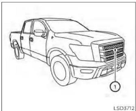
natural_image
Line drawing of a pickup truck with no text or symbols on the body, showing front grille and exhaust grille (no readable labels or symbols)SYSTEM MAINTENANCE
The sensor for the ICC system is located on the front of the vehicle.
To keep the ICC system operating properly, be sure to observe the following:
• Always keep the sensor area of the front bumper/emblem clean.
- Do not strike or damage the areas around the sensor.
- Do not attach a sticker (including transparent material) or install an accessory near the sensor. This could cause failure or malfunction.
- Do not attach metallic objects near the sensor area (brush guard, etc.). This could cause failure or malfunction.
- Do not alter, remove, or paint the front bumper. Before customizing or restoring the front bumper, it is recommended that you visit a NISSAN dealer.
Radio frequency statement
FCCNotice
USA
FCCID:OAYARS4B
This device complies with Part15 of the FCC Rules with Industry Canada Licence-exempt RSS standard(s).
Operationissubjecttothefollowingtwo conditions:
- This device may not cause harmful interference, and
- This device must accept any interference received, including interference that may cause undesired operation.
Radiofrequencyradiationexposure Information:
This equipment complies with FCCandIC radiation exposure limits set forth for an uncontrolled environment.
This equipment should be installed and operated with minimum distance of 30 cmbetweentheradiator and your body.
Thistransmittermustnotbeco-located oroperatinginconjunctionwithany otherantennaortransmitter.
FCCNotice
Changesormodificationsnotexpressly approvedbythepartyresponsiblefor compliancecouldvoidtheuser'sauthoritytooperatetheequipment.
CANADA
IC:4135A-ARS4B
This device complies with Part 15 of the FCC Rules and Industry Canadalicence-exempt RSS standard(s).
Operationissubjecttothefollowingtwo conditions:
- Thisdevicemaynotcause interference,
- This device must accept any interference, including interference that may cause undesired operation.
Radiofrequencyradiationexposure Information:
This equipment complies with FCCandIC radiation exposure limits set forth for an uncontrolled environment.
This equipment should be installed and operated with minimum distance of 30 cmbetweentheradiator and your body.
Thistransmittermustnotbeco-located oroperatinginconjunctionwithany otherantennaortransmitter.
CONVENTIONAL (fixed speed) CRUISE CONTROL MODE
This mode allows driving at a speed between 25 to 90 mph (40 to 144 km/h) without keeping your foot on the accelerator pedal.
WARNING
- Intheconventional(fixedspeed) cruisecontrolmode,awarning chimedoesnotsoundtowarnyouif youaretooclosetothevehicle ahead,asneitherthepresenceofthe vehicleaheadnorthevehicle-to-vehicledistanceisdetected.
- Payspecialattentiontothedistance betweenyourvehicleandthevehicle aheadofyouoracollisioncould occur.
- AlwaysconfirmthesettingintheICC systemdisplay.
- Donotusetheconventional(fixed speed)cruisecontrolmodewhen drivingunderthefollowingconditions:
-
Whenitisnotpossibletokeepthe vehicleatasetspeed
-
Inheavytrafficorin traffic that variesinspeed
- Onwindingorhillyroads
- Onslipperyroads(rain,snow,ice, etc.)
- Inverywindyareas
- Doingsocouldcausealossofvehicle controlandresultinanaccident.
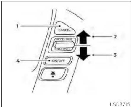
Conventional (fixed speed) cruise control switches
- CANCEL switch: Deactivates the system without erasing the set speed
- ACCEL/RES switch: Resumes set speed or increases speed incrementally
- COAST/SET switch: Sets desired cruise speed or reduces speed incrementally
- ON/OFF switch: Master switch to activate the system
5-72 Startinganddriving
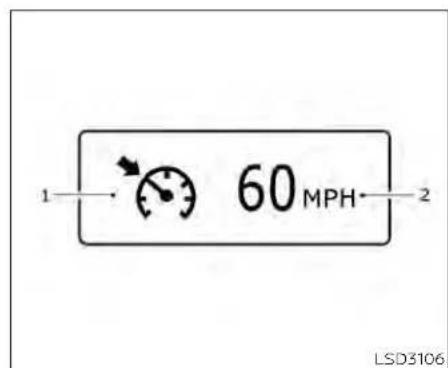
LSD3764
Conventional (fixed speed) cruise control mode display and indicators
The display is located in the vehicle information display.
- Cruise indicator:
This indicator indicates the condition of the ICC system depending on a color.
- Cruise control ON indicator (gray): Indicates that the ON/OFF switch is on
-
Cruise control SET indicator (green): Indicates that the cruising speed is set
-
Cruise control warning (yellow): Indicates that there is a malfunction in the ICC system
- Set vehicle speed indicator: This indicator indicates the set vehicle speed. For Canadian models, the speed is displayed in km/h.

Operating conventional (fixed speed) cruise control mode
To turn on the conventional (fixed speed) cruise control mode, push and hold the ON/OFF switch ① for longer than about 1.5 seconds.
When pushing ON/OFF switch on, the conventional (fixed speed) cruise control mode display and indicators are displayed in the vehicle information display. After you hold ON/OFF switch on for longer than about 1.5 seconds, the ICC system display turns off. The cruise indicator appears. You can now set your desired cruising speed.
Pushing the ON/OFF switch again will turn the system completely off. When the ignition switch is placed in the OFF position, the system is also automatically turned off.
To use the ICC system again, quickly push and release the ON/OFF switch (vehicle-to vehicle distance control mode) or push and hold it (conventional cruise control mode) again to turn it on.
CAUTION
To avoid accidentally engaging cruise control, makes sure to turn the ON/OFF switch off when not using the CC system.

To set cruising speed, accelerate your vehicle to the desired speed, push the COAST/SET switch and release it. (The color of the cruise indicator changes to green and set vehicle speed indicator comes on.) Take your foot off the accelerator pedal. Your vehicle will maintain the speed.
• To pass another vehicle, depress the accelerator pedal. When you release the pedal, the vehicle will return to the previously set speed.
• The vehicle may not maintain the set speed when going up or down steep hills. If this happens, manually maintain vehicle speed.
To cancel the preset speed, use any of the following methods:
- Push the CANCEL switch. The vehicle speed indicator will turn off.
- Tap the brake pedal. The vehicle speed indicator will turn off.
- Turn the ON/OFF switch off. Both the cruise indicator and vehicle speed indicator will turn off.
To reset at a faster cruising speed, use one of the following three methods:
- Depress the accelerator pedal. When the vehicle attains the desired speed, push and release the COAST/SET switch.
Push and hold the ACCEL/RES switch. When the vehicle attains the desired speed, release the switch.
- Push, then quickly release the ACCEL/RES switch. Each time you do this, the set speed will increase by about 1 mph (1.6 km/h).
To reset at a slower cruising speed, use one of the following three methods:
- Lightly tap the brake pedal. When the vehicle attains the desired speed, push the COAST/SET switch and release it.
- Push and hold the COAST/SET switch. Release the switch when the vehicle slows down to the desired speed.
- Push, then quickly release the COAST/SET switch. Each time you do this, the set speed will decrease by about 1 mph (1.6 km/h).
To resume the preset speed, push and release the ACCEL/RES switch. The vehicle will resume the last set cruising speed when the vehicle speed is over 25 mph (40 km/h).
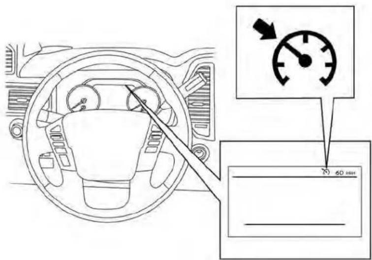
LSD3766
System temporarily disabled
A chime sounds under the following conditions and the control is automatically canceled:
- When the vehicle slows down more than 8 mph (13 km/h) below the set speed - When the shift lever is not in the D (Drive) or manual shift mode
Startinganddriving5-75
REARAUTOMATICBRAKING(RAB)
- When the parking brake is applied
- When the VDC operates (including the traction control system)
- When a wheel slips
When the system is not operating properly, the chime sounds and the color of the cruise indicator will change to orange.
Actiontotake
If the color of the cruise indicator changes to orange, stop the vehicle in a safe place and place the shift lever in the P (Park) position. Turn the engine off, restart the engine, resume driving, and then perform the setting again.
Ifitisnotpossibletosetortheindicator stayson,itmayindicatethatthesystem ismalfunctioning.Althoughthevehicle isstilldrivableundernormalconditions, havethevehiclechecked.ItisrecommendedthatyouvisitaNISSANdealer forthisservice.
WARNING
Failuretofollowthewarningsandin-structionsforproperuseoftheRAB systemcouldresultinseriousinjuryor death.
- TheRABsystemisasupplemental aidtothedriver.Itisnotareplacementforproperdrivingprocedures. Alwaysusethesideandrearmirrors andturnandlookinthedirectionyou willmovebeforeandwhilebacking up.NeverrelysolelyontheRABsystem.Itisthedriver'sresponsibilityto stayalert,drivesafely,andbeincontrolofthevehicleataltimes.
- ThereisalimitationtotheRABsystemcapability.TheRABsystemisnot effectiveinallsituations.
- Inclementweatherorultrasonic sourcessuchasanautomaticcar wash, a truck's compressed-air brakesorapneumaticdrillmayaffectthefunctionofthesystem;this mayincludereducedperformanceor afalseactivation.

natural_image
Line drawing of a pickup truck with mounting bracket and numbered marker (no text or symbols on the vehicle itself)The RAB system detects obstacles behind the vehicle using the parking sensors ① located on the rear bumper.
NOTE:
Youcantemporarilycancelthesonar functioninthevehicle,buttheRABsystemwillcontinuetooperate.Foradditionalinformation,see"Frontandrear sonarsystem"(P5-124).
The RAB system can assist the driver when the vehicle is backing up and approaching objects directly behind the vehicle.

① RAB system warning light and RAB system indicator
② Steering-wheel-mounted controls (left side)
③ Center display
When the shift lever is in the R (Reverse) position and the vehicle speed is less than approximately 9 mph (15 km/h), the RAB system operates.
If a risk of a collision with an obstacle is detected when your vehicle is backing up, the RAB system warning indicator will flash in the vehicle information display, a red frame will appear in the center display (for vehicles with the Intelligent Around View Monitor system), and the system will chime three times. The system will then automatically apply the brakes. After the automatic brake application, the driver must depress the brake pedal to maintain brake pressure.
NOTE:
•Thebrakelightsofthevehiclecomeon whenbrakingisperformedbytheRAB system.
-Whenthebrakesoperate,anoisemay beheard. This is not a malfunction.
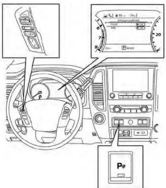
LSD3736
TURNING THE RAB SYSTEM ON/OFF
Perform the following steps to turn the RAB system on or off.
- Press the ◆ button until "Settings" displays in the vehicle information display and then press the ENTER button. Use the ◆ button to select "Driver Assistance." Then press the ENTER button.
- Select "Emergency Brake" and press the ENTER button.
- To set the RAB system to on or off, use the ENTER button to check the box for "Rear."
- Push the Parking Aids system switch to turn the system on or off.
When the RAB system is turned off, the RAB system warning light illuminates.
NOTE: TheRABsystemwillbeautomatically turnedonwhentheengineisre-started.
RAB SYSTEM LIMITATIONS
WARNING
Listedbelowarethesystemlimitations fortheRABsystem.Failuretofollowthe warningsandinstructionsforproper useoftheRABsystemcouldresultin seriousinjuryordeath.
- Whenthevehicleapproachesanobstaclewhiletheacceleratororbrake pedalisdepressed,thefunctionmay notoperateorthestartofoperation maybedelayed.TheRABsystem maynotoperateormaynotperform sufficientlyduetovehicleconditions, drivingconditions,thetrafficenvironment,theweather,roadsurface conditions,etc.Donotwaitforthe systemtooperate.Operatethebrake pedalbyyourselfassoonas necessary.
- IfitisnecessarytooverrideRABoperation,stronglypresstheacceleratorpedal.
- Alwayscheckyoursurroundingsand turntocheckwhatisbehindyoubeforeandwhilebackingup.TheRAB system detects stationary objects behindthevehicle.TheRAB system doesnotdetectthefollowingobjects:
- Movingobjects
- Lowobjects
- Narrowobjects
- Wedge-shapedobjects
- Objectsclosetothebumper(less thanapproximately1ft[30cm])
- Objectsthatsuddenlyappear
- Thinobjectssuchasrope,wire, chain,etc.
- TheRABsystemmaynotoperatefor thefollowingobstacles:
- Obstacles located high off the ground
- Obstaclesinapositionoffsetfrom yourvehicle
- Obstacles, such as spongymaterials or snow, that have soft outer surfaces and can easily absorb a soundwave
- TheRAB systemmay notoperate in the following conditions:
- Thereisrain,snow,ice,dirt,etc., attachedtothesonarsensors.
- A loud sound is heard in the area aroundthevehicle.
- The surface of the obstacle is diagonal to therearofthevehicle.
- TheRABsystemmayunintentionally operateinthefollowingconditions:
- Thereisovergrowngrassinthe areaaroundthevehicle.
- Thereisastructure(e.g.,awall,toll gateequipment,anarrowtunnel,aparkinglotgate)nearthesideof thevehicle.
- There are bumps, protrusions, or manhole covers on the road surface.
- The vehicle drives through a drapedflagoracurtain.
- Thereisanaccumulationofsnow oricebehindthevehicle.
-
Anultrasonicwavesource,suchas anothervehicle'ssonar,isnear thevehicle.
-
Oncetheautomaticbrakecontrol operates, it does not operate again if the vehicle approachesthesame obstacle.
- Theautomaticbrakecontrolcanonly operateforashortperiodoftime. Therefore,thedrivermustdepress thebrakepedal.
- Inthefollowingsituations,theRAB systemmaynotoperateproperlyor maynotfunctionsufficiently:
- The vehicle is driven in bad weather (rain, fog, snow, etc.).
- Thevehicleisdrivenonasteep hill.
- Thevehicle'spostureischanged (e.g.,whendrivingoverabump).
- Thevehicleisdrivenonaslippery road.
- The vehicle is turned sharply by turning the steering wheelfully.
- Snowchainsareused.
- WheelsortiresotherthanNISSAN recommendedareused.
-
Thebrakesarecoldatlowambienttemperaturesorimmediately afterdrivinghasstarted.
-
The braking force becomes poor duetowet brakes after driving through a puddle or washing the vehicle.
- Turn the RAB system off in the following condition stop prevent the occurrence of an unexpected accident resulting from sudden system operation:
- Thevehicleistowed.
- Thevehicleiscarriedonaflatbed truck.
- Thevehicleisonthechassis dynamometer.
- Thevehicledrivesonanuneven roadsurface.
- Thevehicleistowinganobject(if soequipped).
- Suspension parts other than those designated as Genuine NISSANpartsareused.(Ifthevehicle heightorthevehicle bodyinclinationischanged,thesystem may not detect an obstacle correctly.)
- Excessivenoise(e.g., audiosystem volume, an open vehicle window) will interfere with the chime sound, and it may not be heard.
SYSTEM MALFUNCTION
If the RAB system malfunctions, it will be turned off automatically, and the RAB system warning light will illuminate and the warning message "System fault See Owner's Manual" in the vehicle information display.
Actiontotake
If the warning light illuminates, park the vehicle in a safe location, turn the engine off, and restart the engine. If the warning light continues to illuminate, have the RAB system checked. It is recommended that you visit a NISSAN dealer for this service.
NOTE:
If the RAB system cannot be operated temporarily, the RAB system warning lightblinks.

natural_image
Line drawing of a pickup truck with mounting bracket and numbered component (no text or symbols)SYSTEM MAINTENANCE
Observe the following items to ensure proper operation of the system:
• Always keep the parking sensors clean. ①
- If the parking sensors are dirty, wipe them off with a soft cloth while being careful to not damage them.
AUTOMATICEMERGENCYBRAKING (AEB)WITHPEDESTRIANDETECTION
- Do not subject the area around the parking sensors ① to strong impact. Also, do not remove or disassemble the parking sensors. If the parking sensors and peripheral areas are deformed in an accident, etc., have the sensors checked. It is recommended that you visit a NISSAN dealer for this service.
- Do not install any stickers (including transparent stickers) or accessories on the parking sensors ⏻ and their surrounding areas. This may cause a malfunction or improper operation.
WARNING
Failuretofollowthewarningsandin- structionsforproperuseoftheAEB withPedestrianDetectionsystem couldresultinseriousinjuryordeath.
- The AEB with Pedestrian Detection system is a supplemental aid to the driver. It is not a replacement for the driver's attention to traffic conditions or responsibility to drives safely. It cannot prevent accidents due to carelessness or dangerous driving techniques.
- The AEB with Pedestrian Detection system does not function in all driving, traffic, weather and road conditions.
The AEB with Pedestrian Detection system can assist the driver when there is a risk of a forward collision with the vehicle ahead in the traveling lane or with a pedestrian ahead in the traveling lane.

The AEB with Pedestrian Detection system uses a radar sensor located on the front of the vehicle ® to measure the distance to the vehicle ahead in the same lane. For pedestrians, the AEB with Pedestrian Detection system uses a camera installed behind the windshield ® in addition to the radar sensor.

AEB WITH PEDESTRIAN DETECTION SYSTEM OPERATION
- Vehicle ahead detection indicator
-
AEB with Pedestrian Detection emergency warning indicator
-
AEB with Pedestrian Detection system warning light
The AEB system operates at speeds above approximately 3 mph (5 km/h). For the pedestrian detection function, the system operates at speeds between 6–37 mph (10 – 60 km/h).
If a risk of a forward collision is detected, the AEB with Pedestrian Detection system will firstly provide the warning to the driver by flashing the vehicle ahead detection indicator (yellow) in the vehicle information display and providing an audible alert. If the driver applies the brakes quickly and forcefully after the warning, and the AEB with Pedestrian Detection system detects that there is still the possibility of a forward collision, the system will automatically increase the braking force.
If the driver does not take action, the AEB with Pedestrian Detection system issues the second visual (flashing) (red and white) and audible warning. If the driver releases the accelerator pedal, then the system applies partial braking. If the risk of a collision becomes imminent, the AEB with Pedestrian Detection system applies harder braking automatically.
While the AEB with Pedestrian Detection system is operating, you may hear the
sound of brake operation. This is normal will remain at a standstill for approximately and indicates that the AEB with Pedestrian2 seconds before the brakes are released. Detection system is operating properly.
NOTE:
The vehicle's brakelights come on when any braking is performed by the AEB with Pedestrian Detection system.
Depending on vehicle speed and distance to the vehicle or pedestrian ahead, as well as driving and roadway conditions, the system may help the driver avoid a forward collision or may help mitigate the consequences if a collision should be unavoidable. If the driver is handling the steering wheel, accelerating or braking, the AEB with Pedestrian Detection system will function later or will not function.
The automatic braking will cease under the following conditions:
- When the steering wheel is turned to avoid a collision.
When the accelerator pedal is depressed. - When there is no longer a vehicle or a pedestrian detected ahead.

TURNING THE AEB WITH PEDESTRIAN DETECTION SYSTEM ON/OFF
LSD3718
Perform the following steps to enable or disable the AEB with Pedestrian Detection system.
- Press the ◆ button until "Settings" displays in the vehicle information display. Use the ◆ button to select "Driver Assistance." Then press the ENTER button.
- Select "Emergency Brake" and press the ENTER button.
- Select "Front" and press the ENTER button to turn the system on or off.
When the AEB with Pedestrian Detection system is turned off, the AEB with Pedestrian Detection system warning light illuminates.
NOTE:
- The AEB with Pedestrian Detection system will be automatically turned on when the engine is restarted.
- TheI-FCWsystemisintegratedintothe AEBwithPedestrianDetectionsystem. Thereisnotaseparateselectioninthe vehicleinformationdisplayforthe I-FCWsystem.WhentheAEBsystemis turnedoff,thel-FCWsystemisalso turnedoff.
AEB WITH PEDESTRIAN DETECTION SYSTEM LIMITATIONS
WARNING
Listedbelowarethesystemlimitations fortheAEBwithPedestrianDetection system.Failuretooperatethevehiclein accordancewiththesesystemlimitationscouldresultinseriousinjuryor death.
- The AEB with Pedestrian Detection system cannot detect all vehicles or pedestrians under all conditions.
- TheAEBwithPedestrianDetection systemdoesnotdetectthefollowing objects:
- Smallpedestrians(including smallchildren),animalsand cyclists.
-
Pedestriansinwheelchairsorusing mobile transport such as scooters, child-operated toys, or skateboards.
-
Pedestrians who are seated or otherwise not in a full upright standingorwalkingposition.
- Oncomingvehicles
- Crossingvehicles
- Obstaclesontheroadside
- The AEB with Pedestrian Detection system has some performance limitations.
- Ifastationaryvehicleisinthevehicle'spath,theAEBwithPedestrian Detection system will not function when the vehicle is driven at speeds over approximately50mph(80km/h).
- Forpedestriandetection, the AEB with Pedestrian Detection system will not function when the vehicle is driven at speed over approximately 37 mph (60 km/h) or below approximately 6 mph (10 km/h).
-
The AEB with Pedestrian Detection system will not function for pedestrians in darkness or intunnels, even if there is streetlighting in the area.
-
The AEB with Pedestrian Detection system may not function if the vehicle ahead is narrow (fore example, a motorcycle).
- The AEB with Pedestrian Detection system may not function if the speed difference between the two vehicles is too small.
- The radar sensor AEB with Pedestrian Detection system may not functionproperlyordetect Vehicle aheadinthefollowingconditions:
- Poorvisibility(conditionssuchas rain,snow,fog,duststorms,sandstorms,androadsprayfromother vehicles)
- Drivingonasteepdownhillslope orroadswithsharpcurves.
- Drivingonabumpyroadsurface, suchasanunevendirtroad.
- Ifdirt,ice,snoworothermaterial iscoveringtheradarsensorarea.
- Interference by other radar sources.
- Thecameraareaofthewindshield isfoggedup,orcoveredwithdirt, waterdrops,ice,snow,etc.
-
Whenyouaretowingatraileretc.
-
Stronglight(forexample,sunlight orhighbeamsfromoncomingvehicles)entersthefrontcamera. Stronglightcausesthearea aroundthepedestriantobecast inashadow,makingitdifficultto see.
- Asuddenchangeinbrightness occurs.(Forexample,whenthe vehicleentersorexitsatunnelora shadedareaorlightningflashes.)
- Thepoorcontrastofapersonto thebackground,suchashaving clothingcolororpatternwhichis similartothebackground.
- Thepedestrian'sprofileispartially obscuredorunidentifiabledueto thepedestriantransportingluggage,wearingbulkyorveryloose-fittingclothingoraccessories.
- Thesystemperformancemaydegradeinthefollowingconditions:
- Thevehicleisdrivenonaslippery road.
- Thevehicleisdrivenonaslope.
-
Excessivelyheavybaggageis loadedintherearseatorthetrunk roomofyourvehicle.
-
Thesystemisdesignedtoautomaticallycheckthesensor's(radarand camera)functionality,withinertain limitations.Thesystemmaynotdetectblockageofsensorareascoveredbyice,snoworstickers,forexample.Inthesecases,thesystem maynotbeabletowarnthedriver properly.Be surethat you check, clean and clear sensor areas regularly.
- Insomeroadandtrafficconditions, theAEBwithPedestrianDetection systemmayunexpectedlyapplypartial braking. When acceleration is necessary, depresstheaccelerator pedaltooverridethesystem.
- Excessivenoisewillinterferewiththe warningchimesound,andthechime maynotbeheard.

SYSTEM TEMPORARILY UNAVAILABLE
LSD3727
ConditionA:
In the following conditions, the AEB with Pedestrian Detection system warning light blinks and the system will be turned off automatically:
• The radar sensor picks up interference from another radar source.
• The camera area of the windshield is misted or frozen.
• Strong light is shining from the front.
- The cabin temperature is over approximately 104ircF (40°C) in direct sunlight.
• The camera area of the windshield glass is continuously covered with dirt, etc.
Actiontotake
When the above conditions no longer exist, the AEB with Pedestrian Detection system will resume automatically.
NOTE:
Whentheinsideofthewindshieldonthe cameraareaismistedorfrozen, it will takeoveriodoftimetoremoveitafter theA/Cturnson. If dirtappearson this area, it is recommended that you visit a NISSAN dealer.
ConditionB:
When there is inclement weather (rain, fog, snow, etc.) blocking the front radar sensor, the AEB with Pedestrian Detection system will be canceled, the chime will sound and the "Forward Driving Aids Temporarily Disabled Front Sensor Blocked See Owner's Manual" warning message will appear in the vehicle information display.
Actiontotake:
When the conditions listed above are no longer present, the warning message will no longer be available in the vehicle information display. If the "Forward Driving Aids Temporarily Disabled Front Sensor Blocked See Owner's Manual" warning message continues to be displayed, have the system checked. It is recommended that you visit NISSAN dealer for this service.
ConditionC:
When the radar sensor of the front bumper is covered with dirt or is obstructed, the AEB with Pedestrian Detection system will automatically be canceled. The chime will sound and the "Forward Driving Aids Temporarily Disabled Front Sensor Blocked See Owner's Manual" warning message will appear in the vehicle information display.
Actiontotake:
If the warning message appears, stop the vehicle in a safe place, place the shift lever in the P (Park) position, and turn the engine off. When the radar signal is temporarily interrupted, clean the sensor area of the front bumper and restart the engine. If the "Forward Driving Aids Temporarily Disabled Front Sensor Blocked See Owner's Manual" warning message continues to be displayed, have the system checked. It is recommended that you visit a NISSAN dealer for this service.
ConditionD
When driving on roads with limited road structures or buildings (for example, long bridges, deserts, snowfields, driving next to long walls), the system may illuminate the system warning light and display the "Forward Driving Aids Temporarily Disabled Front Sensor Blocked See Owner's Manual" message.
Actiontotake:
When the above driving conditions no longer exist, turn the system back on.
NOTE:
If the AEB with Pedestrian Detection system stops working, the FCW system will also stop working.
Forward Driving Aids Temporarily Disabled Front Sensor Blocked See Owner's Manual
LSD3916
SYSTEM MALFUNCTION
If the AEB with Pedestrian Detection system malfunctions, it will be turned off automatically, a chime will sound, the AEB with Pedestrian Detection system warning light (orange) will illuminate and the warning message "System fault See Owner's Manual" will appear in the vehicle information display.
Actiontotake
If the warning light (orange) comes on, stop the vehicle in a safe location, turn the engine off and restart the engine. If the warning light continues to illuminate, have the AEB with Pedestrian Detection system checked. It is recommended that you visit a NISSAN dealer for this service.

SYSTEM MAINTENANCE
The radar sensor is located on the front of the vehicle Ⓔ. The camera is located on the upper side of the windshield Ⓓ.
To keep the AEB with Pedestrian Detection system operating properly, be sure to observe the following:
• Always keep the sensor areas of the front bumper/emblem and windshield clean.
- Do not strike or damage the areas around the sensors (e.g., bumper, windshield).
- Do not cover or attach stickers, or install any accessory near the sensors. This could block sensor signals and/or cause failure or malfunction.
- Do not attach metallic objects near the radar sensor (brush guard, etc.). This could cause failure or malfunction.
- Do not place reflective materials, such as white paper or a mirror, on the instrument panel. The reflection of sunlight may adversely affect the camera unit's detection capability.
-
Do not alter, remove or paint the front bumper. Before customizing or restoring the front bumper, it is recommended that you visit a NISSAN dealer.
-
This device must accept any interference received, including interference that may cause undesired operation.
Radiofrequency radiation exposure Information:
This equipment complies with FCC and IC radiationexposurelimitssetforthforan uncontrolledenvironment.
This equipment should be installed and operated with minimum distance of 30 cmbetweentheradiator and your body.
Thistransmittermustnotbeco-located oroperatinginconjunctionwithany otherantennaortransmitter.
FCCNotice
Changesormodificationsnotexpressly approvedbythepartyresponsible for compliancecouldvoidtheuser'sauthoritytooperatetheequipment.
CANADA
IC:4135A-ARS4B
This device complies with Part15 of the FCC Rules and Industry Canadalicence-exempt RSS standard(s).
Radio frequency statement
FCCNotice
USA
FCCID:OAYARS4B
This device complies with Part 15 of the FCC Rules with Industry Canada Licence-exempt RSS standard(s).
Operationissubjecttothefollowingtwo conditions:
- Thisdevicemaynotcauseharmfulinterference,and
5-90 Startinganddriving
Operationissubjecttothefollowingtwo conditions:
- This device may not cause interference,
- This device must accept any interference, including interference that may cause undesired operation.
Radiofrequency radiation exposure Information:
This equipment complies with FCC and IC radiationexposurelimitssetforthforan uncontrolledenvironment.
This equipment should be installed and operated with minimum distance of 30 cmbetweentheradiator and your body.
INTELLIGENTFORWARDCOLLISION WARNING(I-FCW)
Thistransmittermustnotbeco-located oroperatinginconjunctionwithany otherantennaortransmitter.
Failuretofollowthewarningsandin-structionsforproperuseoftheI-FCW systemcouldresultinseriousinjuryor death.
- Thel-FCWsystemcanhelpwarnthe driverbeforeacollisionoccursbut willnotavoidacollision.itisthedriver'sresponsibilitytostayalert,drive safelyandbeincontrolofthevehicle atalltimes.
The I-FCW system can help alert the driver when there is a sudden braking of a second vehicle traveling in front of the vehicle ahead in the same lane.
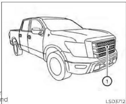
natural_image
Line drawing of a pickup truck with no text or symbols on the body, showing front and side views (no readable labels or symbols)The I-FCW system uses a radar sensor located on the front of the vehicle to measure the distance to the vehicle ahead in the same lane.

- Vehicle ahead detection indicator
- AEB with Pedestrian Detection system warning light
5-92 Startinganddriving
The I-FCW system operates at speeds above approximately 3 mph (5 km/h).
If there is a potential risk of a forward collision, the I-FCW system will warn the driver by blinking the vehicle ahead detection indicator, and sounding an audible alert.

LSD2263
Perform the following steps to turn the I-FCW system ON or OFF.
- Press the ◆ button until "Settings" displays in the vehicle information display. Use the ◆ button to select "Driver Assistance." Then press the ENTER button.
- Select "Emergency Brake" and press the ENTER button.
- Select "Front" and press the ENTER button to turn the system on or off.
When the I-FCW system is turned off, the AEB with Pedestrian Detection system warning light illuminates.
NOTE:
- TheI-FCWsystemwillbeautomatically turnedonwhentheengineis restarted.
- Thel-FCWsystemisintegratedintothe AEBwithPedestrianDetectionsystem. Thereisnotaseparateselectioninthe vehicleinformationdisplayforthe I-FCWsystem.WhentheAEBwithPedestrianDetectionsystemisturned off,thel-FCWsystemisalsoturnedoff.

I-FCW SYSTEM LIMITATIONS

natural_image
Top-down diagram of a road intersection with two cars and a central vehicle, no text or symbols presentIllustrationA
5-94 Startinganddriving

natural_image
Diagram showing three cars with a triangular object and a collision or collision in the center (no text or symbols)IllustrationB
WARNING
Listedbelowarethesystemlimitations forthel-FCWsystem.Failureretooperate thevehicleinaccordancewiththese systemlimitationscouldresultinseriousinjuryordeath.
- TheI-FCWsystemcannotdetectall vehiclesunderallconditions.
- Theradarsensordoesnotdetectthe followingobjects:
- Pedestrians, animalsorobstacles intheroadway
- Oncomingvehicles
- Crossingvehicles
- (IllustrationA)Thel-FCWsystem does not function when a vehicle ahead is an arrow vehicle, such as a motorcycle.
- Theradarsensormaynotdetecta vehicleaheadinthefollowing conditions:
- Snoworheavyrain
- Whenyouaretowingatraileretc.
- Dirt,ice,snoworothermaterial coveringtheradarsensor.
- Interferencebyotherradar sources.
- Snoworroadsprayfromtraveling vehicles.
- Drivinginatunnel
- (IllustrationB) Whenthevehicle aheadisbeingtowed.
- (IllustrationC) Whenthedistance to the vehicle ahead to close, the beam of the adarsensor is obstructed.
- (IllustrationD)Whendrivingona steepdownhillslopeorroadswith sharpcurves.
- Thesystemisdesignedtoautomaticallycheckthesensor'sfunctionality, withincertainlimitations.Thesystemmaynotdetectsomeformsof obstructionofthesensorareasuch asice,snow,stickers,etc.Inthese cases,thesystemmaynotbeableto warnthedriverproperly.Besurethat youcheck,cleanandclearthesensor arearegularly.
- Excessivenoisewillinterferewiththe warningchimesound,andthechime maynotbeheard.

IllustrationC
Startinganddriving5-97
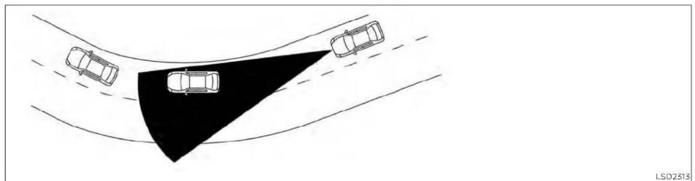
natural_image
Top-down diagram of three cars on curved surfaces with a shaded triangular area, no text or symbols presentIllustrationD
5-98 Startinganddriving

SYSTEM TEMPORARILY UNAVAILABLE
LSD3727
ConditionA
when the radar sensor picks up interference from another radar source, making it impossible to detect a vehicle ahead, the I-FCW system is automatically turned off.
The AEB with Pedestrian Detection system warning light (orange) will illuminate.
Actiontotake
When the above conditions no longer exist, the I-FCW system will resume automatically.
ConditionB
When there is inclement weather (rain, fog, snow, etc.) blocking the front radar sensor, the I-FCW system will automatically be canceled, the chime will sound and the "Forward Driving Aids Temporarily Disabled Front Sensor Blocked See Owner's Manual" warning message will appear in the vehicle information display.
Actiontotake:
when the conditions listed above are no longer present, the warning message will no longer be available in the vehicle information display. If the "Forward Driving Aids Temporarily Disabled Front Sensor Blocked See Owner's Manual" warning message continues to be displayed, have the system checked. It is recommended that you visit a NISSAN dealer for this service.
Startinganddriving5-99
ConditionC
ConditionD
When the radar sensor of the front bumpet when driving on roads with limited road is covered with dirt or is obstructed, the structures or buildings (for example, long I-FCW system will automatically be canceled. The chime will sound and the "Forward Driving Aids Temporarily Disabled Front Sensor Blocked See Owner's Manual" ward driving Aids Temporarily Disabled warning message will appear in the vehicle Front Sensor Blocked See Owner's Manual information display. warning message.
Actiontotake:
Actiontotake:
If the warning message appears, stop the When the above driving conditions no lon-vehicle in a safe place, place the shift leverger exist, turn the system back on. in the P (Park) position, and turn the engine off. When the radar signal is temporarily interrupted, clean the sensor area of the front bumper and restart the engine. If the "Forward Driving Aids Temporarily Disabled Front Sensor Blocked See Owner's Manual" warning message continues to be displayed, have the system checked. It is recommended that you visit a NISSAN dealer for this service. NOTE: IftheAEBwithPedestrianDetectionsystemstopworking,thel-FCWsystemwill alsostopworking.
Forward Driving Aids Temporarily Disabled Front Sensor Blocked See Owner's Manual
LSD3916
SYSTEM MALFUNCTION
If the I-FCW system malfunctions, it will be turned off automatically, a chime will sound, the AEB with Pedestrian Detection system warning light (orange) will illuminate and the warning message [Malfunction] will appear in the vehicle information display.
Actiontotake
If the warning light (orange) comes on, stop the vehicle in a safe location, turn the engine off and restart the engine. If the warning light continues to illuminate, have the I-FCW system checked. It is recommended that you visit a NISSAN dealer for this service.

natural_image
Line drawing of a pickup truck with no text or symbols on the body, showing front grille and side panel (no readable labels or symbols)SYSTEM MAINTENANCE
The sensor① is located on the front of the vehicle.
To keep the system operating properly, be sure to observe the following:
• Always keep the sensor area of the front bumper/emblem clean.
- Do not strike or damage the areas around the sensor.
- Do not cover or attach stickers or similar objects on the front bumper near the sensor area. This could cause failure or malfunction.
- Do not attach metallic objects near the sensor area (brush guard, etc.). This could cause failure or malfunction.
- Do not alter, remove or paint the front bumper. Before customizing or restoring the front bumper, it is recommended that you visit a NISSAN dealer.
FCCNotice
USA
FCCID:OAYARS4B
ThisdevicecomplieswithPart15ofthe FCCRuleswithIndustryCanadaLicence-exemptRSSstandard(s).
Operationissubjecttothefollowingtwo conditions:
- Thisdevicemaynotcauseharmfulinterference,and
- This device must accept any interference received, including interference that may cause undesired operation.
Radiofrequencyradiationexposure Information:
This equipment complies with FCCandIC radiation exposure limits set forth for an uncontrolled environment.
This equipment should be installed and operated with minimum distance of 30 cmbetweentheradiator and your body.
Thistransmittermustnotbeco-located or operating in conjunction with any otherantennaortransmitter.
FCCNotice
Changesormodificationsnotexpressly approvedbythepartyresponsible for compliancecouldvoidtheuser'sauthoritytooperatetheequipment.
CANADA
IC:4135A-ARS4B
ThisdevicecomplieswithPart15ofthe FCCRulesandIndustryCanadalicence-exemptRSSstandard(s).
Operationissubjecttothefollowingtwo conditions:
- This device may not cause interference,
- This device must accept any interference, including interference that may cause undesired operation.
Radiofrequencyradiationexposure Information:
This equipment complies with FCCandIC radiation exposure limits set forth for an uncontrolled environment.
This equipment should be installed and operated with minimum distance of 30 cmbetweentheradiator and your body.
Thistransmittermustnotbeco-located oroperatinginconjunctionwithany otherantennaortransmitter.
Failuretofollowthewarningsandin-structionsfor properuseof theI-DA systemcouldresultinseriousinjuryor death.
- Thel-DAsystemisonlyawarningto informthedriverofapotentiallack ofdriverattentionordrowsiness.It willnotsteerthevehicleorprevent lossofcontrol.
- Thel-DAsystemdoesnotdetectand provideanalertofthedriver'slack of attention or fatigue in every situation.
- It is the driver's responsibility to:
-stayalert,
-drivesafely,
-keepthevehicleinthetraveling lane,
-beincontrolofthevehicleatall times,
-avoiddrivingwhentired,
-avoid distractions(texting,etc.).
The I-DA system helps alert the driver if the system detects a lack of attention or driving fatigue.
The system monitors driving style and steering behavior over a period of time, and it detects changes from the normal pattern. If the system detects that driver attention is decreasing over a period of time, the system uses audible and visual warnings to suggest that the driver take a break.

The system resets and starts reassessing driving style and steering behavior when the ignition switch is cycled from the ON to the OFF position and back to the ON position.
If the system detects driver fatigue or that driver attention is decreasing, the message "Take a break?" appears in the vehicle information display and a chime sounds when the vehicle is driven at speeds above 37 mph (60 km/h).
The system continuously monitors driver attention and can provide multiple warnings per trip.

HOW TO ENABLE/DISABLE THE INTELLIGENT DRIVER ALERTNESS (I-DA) SYSTEM
Perform the following steps to enable or disable the I-DA system.
- Press the ◆ button until "Settings" displays in the vehicle information display. Use the ◆ button to select "Driver Assistance." Then press the ENTER button.
- Select "Driver Attention" and press the ENTER button to turn the system on or off.
NOTE: Thesettingwillberetainedevenif theengineisrestarted.
INTELLIGENT DRIVER ALERTNESS (I-DA) SYSTEM LIMITATIONS
WARNING
Listedbelowarethesystemlimitations forthel-DAsystem.Failureretooperate thevehicleinaccordancewiththese systemlimitationscouldresultinseriousinjuryordeath.
- Thel-DAsystemmaynotoperate properlyandmaynotprovidean alertinthefollowingconditions:
- Poorroadconditionssuchasan unevenroadsurfaceorpotholes.
-
Strongsidewind.
-
If you have adopted as porty driving style with higher cornering speeds or higher rates of acceleration.
- Frequentlanechangesor changestovehiclespeed.
- TheI-DAsystemwillnotprovidean alertinthefollowingconditions:
- Vehiclespeedslowerthan37mph (60km/h).
- Shortlapsesofattention.
- Instantaneousdistractionssuch asdroppinganobject.
Warning

Driver Attention Alert Malfunction
LIC3125
System malfunction
If the Intelligent Driver Alertness system malfunctions, the system warning message will appear in the vehicle information display and the function will be stopped automatically.
Actiontotake
Stop the vehicle in a safe location, place the vehicle in P (Park) position, turn the engine off and restart the engine. If the system warning message continues to appear, have the system checked. It is recommended that you visit a NISSAN dealer for this service.
BREAK-INSCHEDULE
FUELEFFICIENTDRIVINGTIPS
CAUTION
During the first 1,200 miles (2,000 km), follow the recommendation to obtain maximum engine performance and ensure the future reliability and economy of your new vehicle. Failure to follow the recommendations may result in shortened engine life and reduced engine performance.
- Avoid driving for long periods at constant speed, either fast or slow, and do not run2. the engine over 4,000 rpm.
- Do not accelerate at full throttle in any gear.
- Avoid quick starts.
- Avoid hard braking as much as possible.
- Do not tow a trailer for the first 500 miles (805 kilometers). Your engine, axle or other parts could be damaged.
Follow these easy-to-use Fuel Efficient Driving Tips to help you achieve the most fuel economy from your vehicle.
1. UseSmoothAcceleratorandBrake PedalApplication
- Avoid rapid starts and stops.
- Use smooth, gentle accelerator and brake application whenever possible.
- Maintain constant speed while commuting and coast whenever possible.
2. MaintainConstantSpeed
- Look ahead to try and anticipate and minimize stops.
- Synchronizing your speed with traffic lights allows you to reduce your number of stops.
- Maintaining a steady speed can minimize red light stops and improve fuel efficiency.
3. UseAirConditioning(A/C)atHigher VehicleSpeeds
- Below 40 mph (64 km/h), it is more efficient to open windows to cool the vehicle due to reduced engine load.
- Above 40 mph (64 km/h), it is more efficient to use A/C to cool the vehicle 6 due to increased aerodynamic drag.
- Recirculating the cool air in the cabin when the A/C is on reduces cooling load.
4. Drive at Economical Speeds and Distances
- Observing the speed limit and not exceeding 60 mph (97 km/h) (where legally allowed) can improve fuel efficiency due to reduced aerodynamic drag.
- Maintaining a safe following distance behind other vehicles reduces unnecessary braking.
- Safely monitoring traffic to anticipate changes in speed permits reduced braking and smooth acceleration changes.
- Select a gear range suitable to road conditions.
5. UseCruiseControl
• Using cruise control during highway driving helps maintain a steady speed.
- Cruise control is particularly effective in providing fuel savings when driving on flat terrains.
PlanfortheShortestRoute
- Utilize a map or navigation system to determine the best route to save time.
INCREASINGFUELECONOMY
USING4-WHEELDRIVE(4WD)(ifso equipped)
7. Avoidldling
- Shutting off your engine when safe for stops exceeding 30–60 seconds saves fuel and reduces emissions.
8. BuyanAutomatedPassforTollRoads
- Automated passes permit drivers to use special lanes to maintain cruising speed through the toll and avoid stopping and starting.
9. WinterWarmUp
- Limit idling time to minimize impact to fuel economy.
• Vehicles typically need no more than 30 seconds of idling at start-up to effectively circulate the engine oil before driving. - Your vehicle will reach its ideal operating temperature more quickly while driving versus idling.
10. KeepingyourVehicleCool
- Park your vehicle in a covered parking area or in the shade whenever possible.
-
When entering a hot vehicle, opening the windows will help to reduce the inside temperature faster, resulting in reduced demand on your A/C system.
-
Keep your engine tuned up.
- Follow the recommended scheduled maintenance.
- Keep the tires inflated to the correct pressure. Low tire pressure increases tire wear and lowers fuel economy.
- Keep the wheels in correct alignment. Improper alignment increases tire wear and lowers fuel economy.
- For vehicles equipped with 4×4, use 4H or 4L position only when necessary.
- 4-Wheel Drive operation lowers fuel economy.
- Use the recommended viscosity engine oil. For additional information, see "Engine oil and oil filter recommendations" (P. 10-7).
WARNING
- For4WDequippedvehicles, donot attempttoraisetwowheelsoffthe groundandshiftthetransmissionto anydriveorreversepositionwiththe engineerunning.Doingsomayresult indrivetraindamageorunexpected vehiclemovementwhichcouldresult inseriousvehicledamageorpersonalinjury.
Do not attempt to test a 4WD equipped vehicle2-wheeldynamometer(suchasthe dynamometersusedbysomestatesforemissions testing) or similar equipment eveniftheothertwowheels are raisedofftheground.Makesureyou inform testfacilitypersonnel that your vehicle is equipped with 4WD before it is placed on a dynamometer.Usingthewrongtestequipment may resultin drivetraindamage or unexpected vehicle movement whichcouldresultinseriousvehicle damageorpersonalinjury.
CAUTION
- Donotdrivethevehicleinthe4Hor 4LOpositionondryhardsurface roads.Drivingondry,hardsurfacesin 4Hor4LOmaycauseunnecessary noise,tirewearandincreasedfuel consumption. Ifthe4WDvehicleinformationdisplaywarningmessageturnson whenyouaredrivingondryhardsurfaceroads:
- Inthe4Hposition, shiftthe4WD shiftswitchto2WD.
- Inthe4LOposition,stopthevehicle,movetheshiftlevertotheN(Neutral)positionwiththebrake pedaldepressed,andshiftthe 4WDshiftswitchto2WD.
- Ifthevehicleinformationdisplay warningmessageisstillonafterthe aboveoperation,haveyourvehicle checkedassoonaspossible.ItisrecommendedthatyouvisitaNISSAN dealerforthisservice.
TRANSFER CASE SHIFTING PROCEDURES
The part time 4WD system provides 3 positions (2WD, 4H and 4LO), so you can select the desired drive mode according to the driving conditions.
2WD or 4WD shift procedure:
| 4WD shift switch position | Wheels driven | Indicator | Use conditions 4WD shift procedure | ||
| 4WD shift Transferr 4LO position | |||||
| 2WD | Rear wheels |  | For driving on dry, paved roads (Economy drive) | Move the 4WD switch.2WD <--> 4HThe 4WD shift indicator will indicate that the transfer shift position is engaged.IT IS NOT NECESSARY TO MOVE THE SHIFT LEVER TO THE N (NEUTRAL) POSITION IN THIS OPERATION. PERFORM THIS OPERATION WHEN DRIVING STRAIGHT. | |
| 4H | Four wheels |  | For driving on rocky, sandy or snow-covered roads | ||
| 4LO | N (Neutral) |  | '1 May blink | N (Neutral) disengages the automatic transmission (A/T) mechanical parking lock, which will allow the vehicle to roll. Do not leave the transfer shift position in N (Neutral).'2 | 1. Stop the vehicle.2. With the brake pedal depressed, move the shift lever to the N (Neutral) position.3. With the brake pedal depressed, depress and turn the 4WD shift switch to 4LO or 4H. THE TRANSFER CASE DOES NOT ENGAGE BETWEEN 4H AND 4LO (OR 4LO TO 4H) UNLESS YOU HAVE FIRST STOPPED THE VEHICLE, DE-PRESSED THE BRAKE PEDAL AND MOVED THE SHIFT LEVER TO N (NEUTRAL). '3 |
| Four wheels |  | Illuminated | For use when maximum power and traction is required (for example, on steep grades or rocky, sandy, muddy roads) | ||
*1. Before moving the shift lever from N (Neutral), wait until the 4LO indicator stays on steady. This indicates that the 4WD shift procedure is completed and the transfer gear is correctly set in the 4LO position. If the vehicle is shifted into gear before the indicator is on steady, the transfer gear may grind, not engage correctly or stay in the N (Neutral) position.
- If the 4WD vehicle information display warning message illuminates, perform the following procedure to return the transfer case to the correct operating condition.
1. Turn off the engine by placing the ignition switch in the OFF position.
2. Start the engine.
- Check that the 4WD vehicle information display warning message turns off. If the warning message in the vehicle information display stays on, have the system checked. It is recommended that you visit a NISSAN dealer for this service.
Startinganddriving5-109
- Apply the parking brake, depress the brake pedal and move the shift lever to the N (Neutral) position.
- With the brake pedal depressed, move the 4WD shift switch to the desired mode.
- Be sure to wait until the transfer gear change completes before shifting the shift lever from the N (Neutral) position.
*2: While changing in and out of 4LO, the ignition switch must be in the ON position and the vehicle's engine must be running for a shift to take place and for the 4WD shift and 4LO position indicators to be operable. Otherwise, the shift will not take place and no indicators will be on or flashing.
*3: Make sure the transfer 4LO position indicator turns on when you shift the 4WD shift switch to 4LD. The
indicator light will also turn on when 4LO is selected. For additional information, see "Vehicle Dynamic Control (VDC) system" (P. 5-120).
The transfer case 4WD shift switch is used, to select either 2WD or 4WD depending on the driving conditions. There are three types of drive modes available: 2WD, 4H and 4LO.
The 4WD shift switch electronically controls the transfer case operation. Rotate the switch to move between each mode: 2WD, 4H and 4LO.
Tochangeintooroutof4LO,thevehicle MUSTbestationary,movetheshiftlever toN(Neutral),anddepressthebrake pedal.Theswitchmustbepushed and turnedtoselect4LO.
WARNING
- Whenparking,applytheparking brakebeforestoppingtheengine andmakesurethatthe4WDshiftindicatorisonandtheAutomatic TransmissionPark(ATP)warning light goes off. Otherwise, the vehicle couldunexpectedlymoveevenifthe A/TisintheP(Park)position.
- The4LOindicator must stopblinking andremainilluminated or turnoff beforeshiftingthetransmission into gear.iftheshift leverisshiftedfrom the N (Neutral) position to any other gearwhenthe4LOindicatorisblinking, the vehicle may move unexpectedly.
CAUTION
- Never shift the 4WD shift switch between4LO and4Hwhiledriving.
- The4H position provides greater traction. Avoid excessivespeed, as it will cause increased fuel consumption and higher oil temperatures, and could damage drivetrain components. Speedsover 62 mph(100 km/h) in 4Hisnotrecommended.
- The4LO positionprovides maximum powerandtraction. Avoidraising vehiclespeedexcessively,asthemaxi-mum speedis approximately31mph (50km/h).
-
When driving straight, shift the 4WD shiftswitchtothe2WD or4Hposition.Donotmovethe4WDshift switch when making a turn or reversing.
-
Do not shift the 4WD shift switch (between 2WD and 4H) while driving on steep downhill grades. Use the engine brake and low A/T gears (M1 or M2)forenginebraking.
- Do not operate the 4WD shift switch (between 2WD and 4H) with the rear wheelsspinning.
- Donotdriveondryhardsurface roads inthe4Hor4LOposition.Driving on dry hard surfaces in 4H or 4LO maycauseunnecessarynoise and tirewear.NISSAN recommends driving in the 2WD position under these conditions.
- The 4WD transfer case may not be shifted between 4Hand4LOatlow ambient temperatures and the transfer4LOpositionindicator may blinkevenwhen the 4WDshift switch is shifted. After driving for a while you can changethe4WDtransfer case between 4Hand4LO.
When driving on rough roads,
- Set the 4WD shift switch to 4H or 4LO.
- Drive carefully according to the road surface conditions.
When the vehicle is stuck,
- Set the 4WD shift switch to 4H or 4LO.
- Place stones or wooden blocks under the tires to free the vehicle.
- Use the Electronic locking rear differential (E-Lock) system (if so equipped). For additional information, see "Electronic locking rear differential (E-lock) system" (P. 5-114).
- If it is difficult to free the vehicle, rock the vehicle back and forth between reverse and drive gears.
- If the vehicle is stuck deep in mud, place stones or wooden blocks under the tires. Then try the recovery procedures above. Tire chains may be effective.
CAUTION
- Donotspinthetiresexcessively. Tires willsinkdeepintothemud, making it difficulttofreethevehicle.
- Avoidshiftinggearswiththeengine runningathighspeedsasthismay cause malfunction.

LSD2463
4WD shift switch operations
- Shift the 4WD shift switch to either the 2WD, 4H or 4LO position, depending on driving conditions.
- If the 4WD shift switch is operated whilemakinga turn,acceleratingor deceleratingorifthekeyswitchis turnedoffwhileinthe4Hor4LO,you mayfeelajolt.Thisisnotabnormal.
- Youmayhearsomenoiseasthesystem shifts or engages. This is not abnormal.
CAUTION
- Whendrivingstraight, shiftthe4WD shiftswitchtothe2WDor4Hposition. Donot movethe4WDshift switch when making a turn or reversing.
- Do not shift the 4WD shift switch while driving on steep downhill grades. Usetheenginebrake and low automatictransmissiongears(M1or M2)forenginebraking.
- Donotoperatethe4WDshiftswitch withtherearwheelsspinning.
- Beforeplacingthe4WDshiftswitch inthe4Hpositionfrom2WD,ensure thevehiclespeedislessthan62mph (100km/h).Failuretodosocandamagethe4WDsystem.
- Nevershiftthe4WDshiftswitchbetween4LOand4Hwhiledriving.

LSD2328
4WD shift indicator
The 4WD shift indicator is located in the vehicle information display.
while the engine is running, the 4WD shift indicator will illuminate the position selected by the 4WD shift switch.
- The4WDshiftindicatormaycomeon whileshiftingfromonedrivemodeto theother.Whentheshiftingiscompleted,the4WDshiftindicatorwillstay on.
- If the 4WD vehicle information display warning message comes on, the 4WD Indicator goes out.
CAUTION
- Ifthe4WDshiftindicatorindication changesto2WDwhenthe4WDshift switchisshiftedtothe4Hpositionat lowambienttemperatures,the2WD modemaybebeingengageddueto malfunctioningdrivesystem.Ifthe indicatordoesnotreturntonormal andthe4WDvehicleinformationdisplaywarningmessagecomeson, havethesystemchecked.Itisrecommended that you visit a NISSAN dealerforthisservice.
Warning message
| Warning message | Warning message comes on when: |
| Vehicle information display | |
| 4WD4WD Error: See Owner's Manual | There is a malfunction in the 4-Wheel Drive system |
| FRT & RR tire size difference: See Owner's Manual | The difference in wheel rotation is large |
CAUTION
- Ifthewarningmessage comes on during operation or rapidly after stoppingthevehicleforwhile,have yourvehiclecheckedassoonaspossible.Itisrecommendedthatyou visitaNISSANdealerforthisservice.
- Shiftingbetween4Hand4LOisnot recommendedwhenthe4WDwarningmessagereturnson.
- Whenthewarningmessagecomes on,the2WDmodemaybeengaged evenifthe4WDshiftswitchisin4H. Beespeciallycarefulwhendriving.If corresponding parts are malfunctioning,the4WDmodewillnotbeen-gagedevenifthe4WDshiftswitchis shifted.
- Donotdrivethevehicleinthe4Hor 4LOpositionondryhard surface roads.Drivingondry,hardsurfacesin 4Hor4LOmaycauseunnecessary noise,tirewear andincreasedfuel consumption. Ifthe4WDwarningmessageturnson whenyouaredrivingondryhardsurfaceroads:
- Inthe4H position, shift the 4WD shift switch to 2WD.
ELECTRONICLOCKINGREAR DIFFERENTIAL(E-Lock)SYSTEM(if soequipped)
- Inthe4LOposition,stopthevehicle,movetheautomatictransmissionshiftlevertotheN(Neutral)positionwiththebrakepedal depressed,andshiftthe4WDshift switchto2WD.
- If the warning message is still on after the above operation, have your vehicle checked as soon as possible. It is recommended that you visit a NISSAN dealer forth this service.
- Thetransfercasemaybedamagedif youcontinuedrivingwiththewarningmessageon.
The E-Lock system can provide additional traction and should only be used when a vehicle has become or is becoming stuck. This system operates by electronically "locking" the two rear drive wheels together, allowing them to turn at the same speed. The system is used when it is not possible to free a stuck vehicle even when using the 4LO position (4-Wheel Drive vehicles).
When added traction is required, activate the E-Lock system by pushing the switch on. For additional information, see "Electronic locking rear differential (E-Lock) system switch" (P. 2-61). Once the system fully engages, the indicator light in the instrument panel will remain on. When the system is activated, both rear wheels will engage, providing added traction.
The rear wheels may momentarily slip or move to engage the system, and the system will only engage up to approximately 4 mph (7 km/h). Once the vehicle is free, the system should be turned off and driving resumed.
The Anti-lock Braking System (ABS) is disabled and the ABS warning light illuminates when the E-Lock system is on.
WARNING
- NeverleavetheE-Locksystemon whendrivingonpavedorhard-surfacedroads.Turningthevehicle mayresultintherearwheelsslipping and result in an accident and personal injury.AfterusingtheE-Lock systemtofreethevehicle,turnthe systemoff.
- Use the E-Locksystemonly in an emergency when it is not possible to free a stuck vehicle even when using 4LO. Never use the E-Locksystem on aslippery roads surfaces such as snow oricesurface. Using the E-Locksys- tem whendriving in the seroad con-ditions may cause unexpected movement of the vehicled during engine braking, accelerating or turning, which may result in an accident and serious personal injury.
Observetheabovewarnings. Otherwise, lossofnormalsteeringcontrol mayresult. This may result in an accident and serious personal injury.
ECODRIVEREPORT(ifsoequipped)
CAUTION
- AfterusingtheE-Locksystem,or duringnormaldriving,turnthe switchofftopreventpossibledamaggetothedrivetraincomponents fromextendeduse.
- AvoidquickstartswhiletheE-Lock systemisinoperation. Otherwise, the drivetraincomponentscouldbe damaged.
- WhentheE-Locksystemisinoperation,turningthevehiclebecomesdifficult.Thiscanbedangerous,especiallyathighspeeds.Doingsocould damagethedrivetraincomponents.
- DonotoperatetheE-Locksystem whenthevehicleisturningorwhen onesidewheelisrotating. Otherwise, thedrivetraincomponentscouldbe damaged.
- TheE-Locksystemoperatesonly whentheengineisrunning.
- In4Hmode,theE-Locksystemdoes notoperatewhentheE-Locksystem switchisturnedtotheONposition. (TheE-Locksystemindicatorlight willflash.)
- Observetheabovecautions. Otherwise, lossofnormalsteeringcontrol mayresult.

bar
| Category | Value | |---|---| | Current | 15.5 | | Best | 16.0 | | 1 | 10 | | 2 | 12 | | 3 | 14 |When the ignition switch is in the OFF position, the ECO management display appears.
① Previous 5 times (History)
② Current fuel economy
③ Best fuel economy
The result of ECO evaluation is displayed 30 seconds after the ignition switch is placed in the ON position and the vehicle is driven at least 1/3 miles (500 meters).
① The average fuel economy for the previous 5 times will be displayed.
② The average fuel economy since the last reset will be displayed.
③ The best fuel economy of the past history will be displayed.
The ECO Drive Report can be set to be ON or OFF.
PARKING/PARKINGONHILLS

WARNING
- Donotstoporparkthevehicleover flammablematerialssuchasdry grass,wastepaperorrags.Theymay igniteandcauseafire.
- Safeparkingproceduresrequirethat boththeparkingbrakebesetandthe transmissionplacedintoP(Park). Failuretodosocouldcausethevehicletomoveunexpectedlyorroll awayandresultinanaccident.Make suretheshiftleverhasbeenpushed asfarforwardasitcangoandcannot bemovedwithoutdepressingthe footbrakepedal.
-
Neverleavetheengineerunningwhile thevehicleisunattended.
-
Donotleavechildrenunattendedinsidethevehicle.Theycouldunknowinglyactivateswitchesorcontrolsormakethevehiclemove.Unattended childrencouldbecomeinvolvedin seriousaccidents.
-
To help avoid risk of injury or death through unintended operation of the vehicle and/or it systems, donot leave children, people who require the assistance of others or pets unattended in your vehicle. Additionally, the temperature inside is closed vehicle on a warm day can quickly become high enough to cause significant risk of injury or death to people and pets.
-
Firmly apply the parking brake.
-
Move the shift lever to the P (Park) position.
-
To help prevent the vehicle from rolling into traffic when parked on an incline, it is a good practice to turn the wheels as illustrated.
· HEADEDDOWNHILLWITHCURB

Turn the wheels into the curb and
POWERSTEERING
BRAKESYSTEM
move the vehicle forward until the curb side wheel gently touches the curb.
- HEADEDUPHILLWITHCURB ☑: Turn the wheels away from the curb and move the vehicle back until the curb side wheel gently touches the curb.
- HEADEDUPHILLORDOWNHILL, NO CURB ©:
Turn the wheels toward the side of the road so the vehicle will move away from the center of the road if it moves
- Place the ignition switch in the LOCK position.
The power assisted steering uses a hydraulic pump, driven by the engine, to assist steering.
If the engine stops or the drive belt breaks you will still have control of the vehicle. However, much greater steering effort is needed, especially in sharp turns and at low speeds.
WARNING
If the engine is not running oristurned off while driving, the power assist for the steering will not work. Steering will behard to operate.
The brake system has two separate hydraulic circuits. If one circuit malfunctions, you will still have braking at two wheels.
5 BRAKE PRECAUTIONS
Using the brakes
Avoid resting your foot on the brake pedal while driving. This will overheat the brakes, wear out the brake pads faster, and reduce gas mileage.
To help reduce brake wear and to prevent the brakes from overheating, reduce speed and downshift to a lower gear before going down a slope or long grade. Overheated brakes may reduce braking performance and could result in loss of vehicle control.
WARNING
- Whiledrivingonaslippery surface, be careful when braking, accelerating orderownshifting. Abrupt braking or accelerating could cause the wheels to skid and result in an accident.
- Iftheengineisnotrunningoris turnedoffwhiledriving,thepower assistforthebrakeswillnotwork. Brakingwillbeharder.
Wet brakes
When the vehicle is washed or driven through water, the brakes may get wet. As a result, your braking distance will be longer and the vehicle may pull to one side during braking.
To dry the brakes, drive the vehicle at a safe speed while lightly pressing the brake pedal to heat up the brakes. Do this until the brakes return to normal. Avoid driving the vehicle at high speeds until the brakes function correctly.
Parking brake break-in
Break in the parking brake shoes whenever the stopping effect of the parking brake is weakened or whenever the parking brake shoes and/or drums/rotors are replaced, in order to assure the best braking performance.
This procedure is described in the vehicle service manual. It is recommended that you visit a NISSAN dealer for this service.
ANTI-LOCK BRAKING SYSTEM (ABS)
WARNING
- TheABSisasophisticateddevice,but itcannotpreventaccidentsresulting fromcarelessordangerousdriving techniques.Itcanhelpmaintainvehiclecontrolduringbrakingonslipperysurfaces.Rememberthatstoppingdistancesonslipperysurfaces willbelongerthanonnormalsurfacesevenwithABS.Stoppingdistancesmayalsobelongeronrough, gravelorsnowcoveredroads,orif youareusingtire chains. Always maintainasafedistancefromthevehicleinfrontofyou.Ultimately,the driverisresponsibleforsafety.
- Tiretypeandconditionmayalsoaffectbrakingeffectiveness.
- When replacingtires, install the specified size of tires on all four wheels.
- Wheninstallingasparetire,make surethatitisthepropersizeand typeasspecifiedontheTireand LoadingInformationlabel.Foradditionalinformation,see "Tireand Loading Information label" (P.8-37).
- Foradditional information,see "Wheelsandtires"(P.8-35)
The ABS controls the brakes so the wheels do not lock during hard braking or when braking on slippery surfaces. The system detects the rotation speed at each wheel and varies the brake fluid pressure to prevent each wheel from locking and sliding. By preventing each wheel from locking, the system helps the driver maintain steering control and helps to minimize swerving and spinning on slippery surfaces.
Using the system
Depress the brake pedal and hold it down. Depress the brake pedal with firm steady pressure, but do not pump the brakes. The Anti-lock Braking System will operate to prevent the wheels from locking up. Steer the vehicle to avoid obstacles.
WARNING
Donotpumpthebrakepedal.Doingso may result in increased stopping distances.
ACTIVEBRAKELIMITEDSLIP(ABLS) SYSTEM
Self-test feature
The Anti-lock Braking System (ABS) includes electronic sensors, electric pumps, hydraulic solenoids and a computer. The computer has a built-in diagnostic feature that tests the system each time you start the engine and move the vehicle at a low speed in forward or reverse. When the self test occurs, you may hear a "clunk" noise and/or feel a pulsation in the brake pedal. This is normal and does not indicate a malfunction. If the computer senses a malfunction, it switches the ABS off and illuminates the ABS warning light on the instrument panel. The brake system then operates normally, but without anti-lock assistance.
If the ABS warning light illuminates during the self-test or while driving, have the vehicle checked. It is recommended that you visit a NISSAN dealer for this service.
Normal operation
The Anti-lock Braking System (ABS) operates at speeds above 3 - 6 m p h (5 - 10 km/h). The speed varies according to road conditions.
When the ABS senses that one or more wheels are close to locking up, the actuator rapidly applies and releases hydraulic pressure. This action is similar to pumping the brakes very quickly. You may feel a pulsation in the brake pedal and hear a noise from under the hood or feel a vibration from the actuator when it is operating. This is normal and indicates that the ABS is operating properly. However, the pulsation may indicate that road conditions are hazardous and extra care is required while driving.
BRAKE ASSIST
When the force applied to the brake pedal exceeds a certain level, the Brake Assist is activated generating greater braking force than a conventional brake booster even with light pedal force.
WARNING
TheBrakeAssistisonlyanaidtoassist brakingoperationandisnotacollision warningoravoidancedevice.Itisthe driver's responsibility to stay alert, drivesafelyandbeincontrolofthevehicleataltimes.
- The ABLS system uses automatic braking to transfer power from a slipping drive - wheel to the wheel on the same axle with more traction. The ABLS system applies braking to the slipping wheel, which helps redirect power to the other wheel.
- On 4-Wheel Drive (4WD) models the ABLS is system operates In both 4H and 4LO modes. If 4WD mode is engaged, the ABLS system operates for both drive axles. On 2-Wheel Drive vehicles, the ABLS system operates on the drive axle only.
- The ABLS system is always on. In some conditions, the system may automatically turn the ABLS system off. If the system is automatically turned off, normal brake function will continue. ABLS will function even when the Vehicle Dynamic Control system is turned off.
- The ABLS system does not operate if both wheels on a drive axle are slipping.
WARNING
TheABLSsystemhelpsprovideincreasedtraction,butwillnotprevent accidentsduetoabruptsteeringoperationorbycarelessdrivingordangerousdrivingpractices.Reducevehiclespeedandbeespeciallycareful whendrivingandcorneringonslipperysurfaces.Alwaysdrivecarefully.
- Donotmodifythevehicle'ssuspension.Ifsuspensionpartssuchas shockabsorbers,struts,springs,stabilizerbars,bushingsandwheelsare notNISSANapprovedforyourvehicle orareextremelydeteriorated,the ABLSsystemmaynotoperateproperly.Thiscouldadverselyaffectivehandlingperformance,andthe slipindicatorlightmayilluminate.
- Ifbrakerelatedpartssuchasbrake pads,rotorsandcalipersarenot NISSANrecommendedorareextremelydeteriorated,theABLSsystemmaynotoperateproperly and the slip indicator light may illuminate.
- Ifwheelsortiresotherthanthe NISSAN recommended ones are used,theABLSsystemmaynotoperate properly and the slip indicator lightmayilluminate.
VEHICLEDYNAMICCONTROL(VDC) SYSTEM
The VDC system uses various sensors to monitor driver inputs and vehicle motion. Under certain driving conditions, the VDC system helps to perform the following functions:
- Controls brake pressure to reduce wheel slip on one slipping drive wheel so power is transferred to a non-slipping drive wheel on the same axle.
- Controls brake pressure and engine output to reduce drive wheel slip based on vehicle speed (traction control function).
- If the 4WD transfer case is shifted into 4LO the indicator light will come on and the VDC system will be turned off. For additional information, see "Using 4-Wheel Drive (4WD)" (P. 5-107).
- Controls brake pressure at individual wheels and engine output to help the driver maintain control of the vehicle in the following conditions:
- Understeer (vehicle tends to not follow the steered path despite increased steering input)
- Oversteer (vehicle tends to spin due to certain road or driving conditions)
The VDC system can help the driver to maintain control of the vehicle, but it cannot prevent loss of vehicle control in all driving situations.
When the VDC system operates, the indicator light in the instrument panel flashes so note the following:
- The road may be slippery or the system may determine some action is required to help keep the vehicle on the steered path.
- You may feel a pulsation in the brake pedal and hear a noise or vibration from under the hood. This is normal and indicates that the VDC system is working properly.
- Adjust your speed and driving to the road conditions.
For additional information, see "Slip Indicator light" (P. 2-21) and "Vehicle Dynamic Control (VDC) OFF Indicator light" (P. 2-21).
If a malfunction occurs in the system, the indicator light will come on in the instrument panel. The VDC system automatically turns off when these indicator light is on.
The VDC OFF switch is used to turn off the VDC system. The ⚙ indicator light illuminates to indicate the VDC system is off.
When the VDC OFF switch is used to turn off the system, the VDC system still operates to prevent one drive wheel from slipping by transferring power to a non-slipping drive
wheel. The 🎨 indicator light flashes if this occurs. All other VDC functions are off and the 🎨 indicator light will not flash.
The VDC system is automatically reset to ON when the ignition switch is placed in the OFF position then back to the ON position.
The computer has a built-in diagnostic feature that tests the system each time you start the engine and move the vehicle forward or in reverse at a slow speed. When the self-test occurs, you may hear a clunk noise and/or feel a pulsation in the brake pedal. This is normal and is not an indication of a malfunction.
WARNING
- TheVDCsystemisdesignedtohelp thedrivermaintainstabilitybutdoes notpreventaccidentsduetoabrupt steeringoperationathighspeedsor by careless or dangerousdriving techniques.Reducevehiclespeed andbeespeciallycarefulwhendrivingand cornering onslipperysurfacesandalwaysdrivecarefully.
- Donotmodifythevehicle'ssuspension. If suspension parts such as shockabsorbers,struts,springs,stabilizerbars,bushingsandwheelsare not NISSAN recommended for your vehicle or areextremely deteriorated,theVDCsystemmaynotoperateproperly.Thiscouldadverselyaffectvehiclehandlingperformance, andthe indicatorlightmayflash or the indicator light may illuminate.
- Ifbrakerelatedpartssuchasbrake pads, rotors andcalipersare not NISSANrecommendedor areextremelydeteriorated,the VDCsystem may not operate properly and the indicator light may illuminate.
- Ifenginecontrolrelatedpartsarenot NISSANrecommendedor areextremelydeteriorated,the indicatorlightmayilluminate.
-
Whendrivingon extremelyinclined surfacesuchashigherbankedcorners,theVDCsystemmaynotoperateproperlyandthe indicator lightmayflashorthe indicator lightmayilluminate.Donotdriveon thesetypesofroads.
-
Whendrivingonanunstablesurface suchasaturntable,ferry,elevatoror ramp,the indicatorlightmay flashorthe indicatorlightmay illuminate.Thisisnotamalfunction. Restarttheengineafterdrivingonto astablesurface.
- If wheels sortires other than the NISSAN recommended ones are used, the VDC system may not operate properly and the light may flash the light may illuminate. indicator indicator
- TheVDCsystemisnotasubstitute forwintertiresortirechainsona snowcoveredroad.
BRAKE FORCE DISTRIBUTION
During braking while driving through turns, the system optimizes the distribution of force to each of the front and rear wheels depending on the radius of the turn.
WARNING
- TheVDCsystemisdesignedtohelp thedrivermaintainstabilitybutdoes notpreventaccidentsduetoabrupt steeringoperationathighspeedsor bycarelessordangerousdriving techniques.Reducevehiclespeed andbeespeciallycarefulwhendrivingandcorneringonslipperysurfacesandalwaysdrivecarefully.
- Donotmodifythevehicle'ssuspension. If suspensionpartssuchas shockabsorbers,struts,springs,stabilizerbars,bushingsandwheelsare notNISSANrecommendedforyour vehicleorareextremelydeteriorated,theVDCsystemmaynotoperateproperly.Thiscouldadverselyaffect vehiclehandling performance, and the indicator light may flash orthe indicatorlightmay illuminate.
-
Ifbrakerelatedpartssuchasbrake pads, rotors andcalipersare not NISSANrecommendedorareextremelydeteriorated,theVDC systemmaynotoperateproperly and the indicator light may illuminate.
-
If engine control related parts are not NISSANrecommendedorareextremelydeteriorated,the indicatorlightmayilluminate.
- Whendrivingonextremelyinclined surfacesuchashigherbankedcorners,theVDCsystemmaynotoperateproperlyandthe lightmayflashorthe indicator lightmayilluminate.Donotdriveon thesetypesofroads.
- Whendrivingonanunstablesurface suchasaturntable,ferry,elevatoror ramp,the indicatorlightmay flashorthe indicatorlightmay illuminate.Thisisnotamalfunction. Restarttheengineafterdrivingonto astablesurface.
- Ifwheelsortires otherthanthe NISSANrecommendedonesare used,theVDCsystemmaynotoperateproperlyandthe lightmayflashorthe lightmayilluminate. indicator indicator
- TheVDCsystemisnotasubstitute forwintertiresortirechainsona snowcoveredroad.
HILLDESCENTCONTROLSYSTEM (ifsoequipped)
WARNING
- Neverrelysolelyonthehilldescent controlsystemtocontrolvehicle speedwhendrivingonsteepdownhillgrades.Alwaysdrivecarefully and attentivelywhenusingthehilldescentcontrolsystemanddecelerate thevehiclespeedbydepressingthe brakepedalifnecessary.Beespeciallycarefulwhendrivingonfrozen, muddyorextremelysteepdownhill roads.Failuretocontrolvehicle speedmayresultinalossofcontrol ofthevehicleandpossibleserious injuryordeath.
- Thehilldescentcontrolmaynotcontrolthevehiclespeedonahillunder allloadorroadconditions.Alwaysbe preparedtodepressthebrakepedal tocontrolvehiclespeed.Failureretodo somayresultinacollisionorserious personalinjury.
The hill descent control system can only be activated when the 4H or 4LO position is engaged.
The hill descent control system helps maintain vehicle speed when driving under 15 mph (25 km/h) on steeper downhill grades. Hill descent control is useful when engine braking alone cannot control vehicle speed. Hill descent control applies the vehicle brakes to control vehicle speed allowing the driver to concentrate on steering while reducing the burden of brake an accelerator operation.
If the hill descent control system ON indicates light is blinking, the hill descent control is engaged; however, the hill descent control will not control the vehicle speed.
- Once the system is activated, the indicator light will remain on in the instrument panel. For additional information, see "Hill descent control system ON indicator light" (P. 2-18).
- You may hear a noise from under the hood or feel a vibration from the actuator when it is operating. This indicates that the hill descent control system is working properly.
Of the accelerator or brake pedal is depressed while the hill descent control system is on, the system will stop operating temporarily. As soon as the accelerator or brake pedal is released, the hill descent control system begins to function again if the hill descent control operating conditions are fulfilled.
For the best results, when descending steep downhill grades, the hill descent control switch should be ON and the shift lever in M1 (First) for engine braking. For additional information, see "Hill descent control switch" (P. 2-59).
HILL START ASSIST SYSTEM
FRONT AND REAR SONAR SYSTEM (ifsoequipped)
WARNING
- Neverrelysolelyonthehillstartassistsystemtopreventthevehicle frommovingbackwardonahill.Alwaysdrivecarefullyandattentively. Depressthebrakepedalwhenthe vehicleisstoppedanasteephill.Be especiallycarefulwhenstoppedona hillonfrozenormuddyroads.Failure topreventthevehiclefromrolling backwardsmayresultinalossof controlofthevehicleandpossible seriousinjuryordeath.
- Thehillstartassistsystemisnotdesignedtoholdthevehicleetastandstillonahill.Depressthebrakepedal whenthevehicleisstoppedona steephill.Failureretodosomaycause thevehicletorollbackwardsand mayresultinacollisionorserious personalinjury.
- Thehillstartassistmaynotprevent thevehiclefromrollingbackwards onahillunderalloadorroadconditions.Alwaysbepreapredtodepress thebrakepedaltopreventthevehiclefromrollingbackwards.Failure todosomayresultinacollisionor seriouspersonalinjury.
When the vehicle is stopped on a hill, the I start assist system automatically keeps the brakes applied. This helps prevents the vehicle from rolling backward in the time it takes the driver to release the brake pedal and apply the accelerator when the vehicle is stopped on a hill.
Hill start assist will operate automatically under the following conditions:
- The shift lever is shifted to a forward or reverse gear.
• The vehicle is stopped completely on a hill by applying the brake.
The maximum holding time is 2 seconds. After 2 seconds the vehicle will begin to roll back and hill start assist will stop operating completely.
Hill start assist will not operate when the shift lever is shifted into N (Neutral) or P (Park) or on a flat and level road. When the
indicator light illuminates in the meter, the hill start assist system will not operate.

natural_image
Top-down line drawing of a car with four wheels and seat positions (no text or symbols)The front and rear sonar system sounds a gone to inform the driver of obstacles near the bumper.
When the "DISPLAY" key is ON, the sonar view will automatically appear in the meter.
WARNING
- Thefrontandrearsonarsystemisa conveniencebutitisnotasubstitute forproperparking.
- Thedriverisalwaysresponsiblefor safetyduringparkingandothermaneuvers.Alwayslookaroundand checkthatitissafetodosobefore parking.
- Readandunderstandthelimitations of the front and rear arson systems contained in this section. The colors of the corner or indicator and the distance guidelines in the front/rear view indicated different distance to the object.
- Inclementweatherorultrasonic sourcessuchasanautomaticcar wash,atruck's compressed-air brakesorapneumaticdrillmayaffectthefunctionofthesystem;this mayincludereducedperformance or afalseactivation.
-
Thisfunctionisdesignedasanaidto thedriverindetectinglargestationaryobjectstohelpavoiddamaging thevehicle.
-
Thesystemisnotdesignedtoprevent contact with small or moving objects.Alwaysmoveslowly.The systemwillnotdetectsmallobjects belowthebumper,andmaynotdetectobjectsclosetothebumperor ontheground.
- Thesystemmaynotdetectthefollowingobjects:fluffyobjectssuchas snow,cloth,cotton,glass,wool,etc.; thinobjectssuchasrope,wireand chain,etc.; or wedge-shapedobjects.
If your vehicle sustains damage to the bumper fascia, leaving it misaligned or bent, the sensing zone may be altered causing inaccurate measurement of obstacles or false alarms.
CAUTION
- Excessivenoise(suchasaudiosystemvolumeoranopenvehiclewindow)willinterferewiththetoneanditmaynotbeheard.
- Keepthesonarsensors(located on the bumperfascia)freefromsnow, iceandlargeaccumulationsofdirt. Donotcleanthesensorswithsharp objects.Ifthe sensorsare covered, the accuracy of thesonar function willbediminished.
SYSTEM OPERATION
The system informs with a visual and audible alert of front obstacles when the shift lever is in the D (Drive) position and both front and rear obstacles when the shift lever is in the R (Reverse) position.
SonarOperationTable
| FR Sensor | RR Sensor | |||
| Range | Sound | Display | Sound | Dis-play |
| P | x | † | x | † |
| R | o | o | o | o |
| N | x | † | x | † |
| D | o | o | x | |
| o - Display/Beep when detect | ||||
| † - Display on camera view | ||||
| x - No Display and Beep | ||||
The system is deactivated at speeds above 6 mph (10 km/h). It is reactivated at lower speeds.
The intermittent tone will stop after 3 seconds when an obstacle is detected by only the corner sensor and the distance does not change. The tone will stop when the obstacle gets away from the vehicle.
When the object is detected, the indicator (green) appears and blinks and the tone sounds intermittently. When the vehicle moves closer to the object, the color of the indicator turns yellow and the rate of the blinking increases. When the vehicle is very close to the object, the indicator stops blinking and turns red, and the tone sounds continuously.

LSD2466 LSD2467
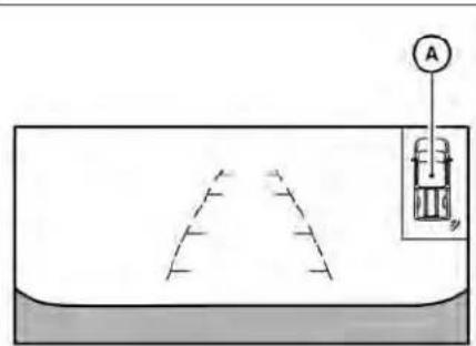
When the corner of the vehicle moves The system indicator will appear when closer to an object, the corner sonar indicator the vehicle moves closer to an object. Cator appears.
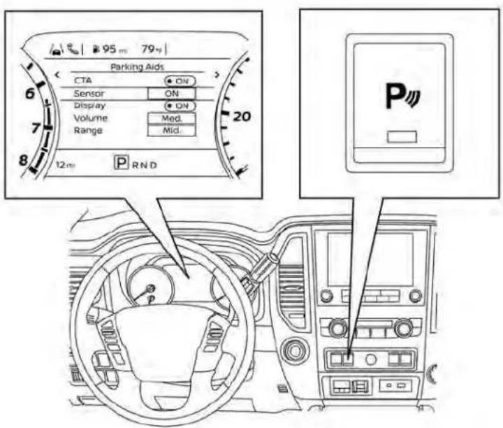
HOW TO ENABLE/DISABLE THE SONAR SYSTEM
LSD3730
The system is automatically activated when the ignition is in the ON position and the shift lever is in the R (Reverse) position.
Perform the following step to enable or disable the system using the Vehicle Information Display:
- Press the ◆ button until "Settings" displays in the vehicle information display. Use the ◆ button to select "Driver Assistance." Then press ENTER.
- Select "Parking Aids" and press ENTER.
- Select "Sensor" and press ENTER to turn the sonar system on, off, or front only.
Perform the following step to enable or disable the system using the Parking Aidssystem switch:
- Push the "Parking Aids system switch" (the orange light will go out) to turn the system off.
- To turn the system back on, push the switch (the orange light will illuminate) and the system will be enabled. For additional information, see "Parking Aids system switch" (P. 2-63) and "Vehicle information display" (P. 2-23).
NOTE:
Thesystemwillautomaticallybeturned onwhentheengineisrestarted.
SONAR LIMITATIONS
WARNING
Listedbelowarethesystemlimitations forthesonarsystem.Failureretooperate thevehicleinaccordancewiththese systemlimitationscouldresultinseriousinjuryordeath.
- Thedriverisalwaysresponsiblefor safetyduringparkingandothermaneuvers.Alwaysturnandlookback beforebackingup.Thesonarsystem isnotasubstituteforproper procedures.
- Readandunderstandthelimitations of thesonarsystemas contained in this section. Inclementweathermay affect the function of thesonarsystem; this may include reduced performance or false activation.
- Thissystemisnotdesignedtopreventcontactwithsmallormoving objects.
-
Thesystemisdesignedasanaidto thedriverindetectinglargestationaryobjectstohelpavoiddamaging thevehicle.Thesystemwillnotdetectsmalobjectsbelowthebumper, andmaynotdetectobjectscloseto thebumperorontheground.
-
Thesystemisdeactivatedatspeeds above6mph(10km/h).Itisreactivatedatlowerspeeds.
- Inclementweatherorultrasonic sourcessuchasanautomatic car wash, a truck's compressed-air brakesorapneumaticdrillmayaffectthefunctionofthesystem;this mayincludereducedperformanceorafalseactivation.
- Thesystemisnotdesignedtopreventcontactwithsmallormoving objects. Always move slowly. The systemwillnotdetectsmalobjects belowthebumperorontheground.
- Thesystemmaynotdetectthefollowingobjects:fluffyobjectssuchassnow,cloth,cotton,glass-wool,etc.;thinobjectssuchasrope,wireandchain,etc.;orwedge-shapedobjects.
- Thesystemmaynotdetectobjects atspeedsabove3mph(5km/h)and may not detect certain angular or movingobjects.
- Thesystemisdeactivatedatspeeds above6mph(10km/h)andisreactivatedatlowerspeeds.
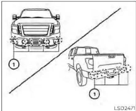
SYSTEM MAINTENANCE
The sonar sensors ① are located on the front and rear bumpers. Always keep the area near the sonar sensors clean.
The sonar sensors may be blocked by temporary ambient conditions such as splashing water, mist or fog.
The blocked condition may also be caused by objects such as ice, frost or dirt obstructing the sonar sensors.
Check for and remove objects obstructing the area around the sonar sensors.
COLDWEATHERDRIVING
Do not attach stickers (including transparent material), install accessories or apply additional paint near the sonar sensors.
Do not strike or damage the area around the sonar sensors. It is recommended that you consult a NISSAN dealer if the area around the sonar sensors is damaged due to a collision.
FREEING A FROZEN DOOR LOCK
To prevent a door lock from freezing, apply de-icer through the key hole. If the lock becomes frozen, heat the key before inserting it into the key hole or use the remote keyless entry key fob.
ANTIFREEZE
In the winter when it is anticipated that the temperature will drop below 32irc F ( 0irc C), check the antifreeze to assure proper winter protection. For additional information, see "Engine cooling system" (P. 8-6).
BATTERY
If the battery is not fully charged during extremely cold weather conditions, the battery fluid may freeze and damage the battery. To maintain maximum efficiency, the battery should be checked regularly. For additional information, see "Battery" (P. 8-16).
DRAINING OF COOLANT WATER
If the vehicle is to be left outside without antifreeze, drain the cooling system, including the engine block. Refill before operating the vehicle. For additional information, see "Changing engine coolant" (P. 8-6).
TIRE EQUIPMENT
SUMMER tires have a tread designed to provide superior performance on dry pavement. However, the performance of these tires will be substantially reduced in snowy and icy conditions. If you operate your vehicle on snowy or icy roads, NISSAN recommends the use of MUD & SNOW or ALL SEASON TIRES on all four wheels. It is recommended that you visit a NISSAN dealer for the tire type, size, speed rating and availability information.
- For additional traction on icy roads, studded tires may be used. However, some U.S. states and Canadian provinces prohibit their use. Check local, state and provincial laws before installing studded tires.
Skidandtractioncapabilitiesofstudded snowtiresonwetordrysurfaces maybe poorerthanthatofnon-studdedsnow tires.
- Tire chains may be used. For additional information, see "Tire chains" (P. 8-35).
SPECIAL WINTER EQUIPMENT
It is recommended that the following items be carried in the vehicle during winter:
- A scraper and stiff-bristled brush to remove ice and snow from the windows and wiper blades.
- A sturdy, flat board to be placed under the jack to give it firm support.
- A shovel to dig the vehicle out of snowdrifts.
- Extra washer fluid to refill the windshield-washer fluid reservoir.
DRIVING ON SNOW OR ICE
WARNING
- Wetice(32°F,0°Candfreezingrain), verycoldsnoworicecanbeslick and veryhardtodriveon. The vehicle will havemuchlesstractionor "grip" underthese conditions. Try to avoid driving on wetice until theroad is saltedorsanded.
-
Whateverthecondition,drivewith caution.Accelerateandslowdown with care. If accelerating or down-shiftingtoofast,thedrivewheelswill loseevenmoretraction.
-
Allowmorestoppingdistanceunder theseconditions.Brakingshouldbe started sooner than on dry pavement.
- Allowgreaterfollowingdistanceson slipperyroads.
Watchforslipperyspots(glareice). These may appear on otherwise clear road in shaded areas. If a patch of ice is seen ahead, brake before reaching it. Try not to be awhile on the ice, and avoid any sudden steering maneuvers.
- Donotusethecruisecontrol(ifso equipped) onslipperyroads.
- Snowcantrap dangerous exhaust gasesunderyourvehicle.Keepsnow clearoftheexhaustpipeandfrom aroundyourvehicle.
ENGINE BLOCK HEATER (if so equipped)
Engine block heaters are used to assist with cold temperature starting.
- Engine block heaters should be used when the outside temperature is 0ircF (-17ircC) or lower.
- Engine block heaters run continuously while plugged into the correct voltage electrical outlet.
WARNING
- Donotuseyourengineblockheater withanungroundedelectricalsystemora2-prongedadapter.Youcan beseriouslyinjuredbyanelectrical shock if you use an ungrounded connection.
- Disconnectandproperlystorethe engineblockheatercordbefore startingtheengine.Damagetothe cord could result in an electrical shockandcancauseseriousinjury.
- Useaheavy-duty3-wire,3-pronged extensioncordratedforatleast10A. Plug the extension cord into a GroundFaultInterrupt(GFI)protected, grounded 110-VAC outlet. Failuretousetheproperextension cordoragroundedoutletcanresult inafireorelectricalshockandcause seriouspersonalinjury.
To use the engine block heater:
- Turn the engine off.
- Open the hood and unwrap the engine block heater cord.
- Plug the engine block heater cord into a grounded 3-wire, 3-pronged extension cord.
- Plug the extension cord into a Ground Fault Interrupt (GFI) protected, grounded 110-volt AC (VAC) outlet.
- The engine block heater must be plugged in for at least 2-4 hours, depending on outside temperatures, to properly warm the engine coolant. Use an appropriate timer to turn the engine block heater on.
- Before starting the engine, unplug and properly store the cord to keep it away from moving parts.
NOTE:
When using the engine block heater (if so equipped) on an Applied Vehicle (engine block heater is plugged in):
- Vehicles should be parked on a surface.
Or
- Ifalevelsurfaceisnotavailable,the vehicleshouldbeparkedwiththefront ofthetrucklowerthantherear(nose down).
CAUTION
Useoftheengineblockheaterwhen parkedwiththefrontofthevehicle higher than the rear (5 degrees or more) may cause the engine block heater to become damaged and/or inoperative.
MEMO
5-132 Startinganddriving
6Incaseofemergency
Hazard warning flasher switch 6-2
Emergency engine shut off 6-2
Flat tire 6-3
Tire Pressure Monitoring System
(TPMS) 6-3
Changing a flat tire 6-3
Jump starting 6-10
Push starting 6-12
If your vehicle overheats 6-12
Towing your vehicle 6-13
Towing recommended by NISSAN 6-13
Vehicle recovery
(freeing a stuck vehicle) 6-15
HAZARDWARNINGFLASHERSWITCHEMERGENCYENGINESHUTOFF

LIC0394
Push the switch on to warn other drivers when you must stop or park under emergency conditions. All turn signal lights flash.
WARNING
- Ifstoppingforanemergency,besure tomovethevehiclewellofftheroad.
- Donotusethehazardwarningflasherswhilemovingonthehighwayunlessunusualcircumstancesforceyoutodrivesoslowlythatyourvehiclemightbecomeahazardtoothertraffic.
- Turnsignalsdonotworkwhenthe hazardwarningflasherlightsareon.
The flashers will operate with the ignition switch placed in any position.
Somejurisdictionsmayprohibittheuse of thehazardwarningflasherswitch whiledriving.
To shut off the engine in an emergency situation while driving, perform the following procedure:
- Rapidly push the push-button ignition switch three consecutive times in less than 1.5 seconds, or
- Push and hold the push-button ignition switch for more than 2 seconds.
6-2 Incaseofemergency
FLATTIRE
TIRE PRESSURE MONITORING SYSTEM (TPMS)
This vehicle is equipped with TPMS. It monitors tire pressure of all tires except the spare. When the low tire pressure warning light is lit, and the Tire Pressure Low — Add Air warning appears in the vehicle information display, one or more of your tires is significantly under-inflated. If equipped, the system also displays pressure of all tires (except the spare tire) on the display screen by sending a signal from a sensor that is installed in each wheel. If the vehicle is being driven with low tire pressure, the TPMS will activate and warn you of it by the low tire pressure warning light. This system will activate only when the vehicle is driven at speeds above 16 mph (25 km/h). For additional information, see "Warning lights, indicator lights and audible reminders" (P. 2-12) and "Tire Pressure Monitoring System (TPMS)" (P. 5-5).
WARNING
- Radiowavescouldadverselyaffect electricmedicalequipment. Those whoseapacemakershouldcontact theelectricmedicalequipment manufacturerforthepossibleinfluencesbeforeuse.
- Ifthelowtirepressurewarninglight illuminateswhiledriving,avoidsuddensteeringmaneuversorabrupt braking, reducevehiclespeed,pull offtheroadtoasafelocationand stopthevehicleassoonaspossible. Drivingwithunder-inflatedtiresmay permanentlydamagethe tiresand increasethelikelihoodoftirefailure. Seriousvehicledamagecouldoccur andmayleadto an accident and couldresultinserious personalinjury.Check thetirepressureforall fourtires.Adjustthetirepressure to the recommended COLD tirepressureshownontheTireandLoading Informationlabeltoturnthelowtire pressurewarninglightOFF. Ifthe lightstillilluminateswhiledrivingafteradjustingthetirepressure,atire maybeflatortheTPMSmaybemal-functioning.Ifyouhaveaflattire,replaceitwithasparetireassoonas possible,Ifnotireisflatandalltires are properly inflated, have the vehicle checked. It is recommended that you visit a NISSAN dealerforthisservice
- When using a wheel without the TPMSsuchasthesparetire,theTPMS willnot functionandthelowtire pressurewarninglightwillflashfor approximatelyoneminute.Thelight willremainonafteroneminute.Have yourtiresreplacedand/orTPMSsystemresetassoonaspossible.Itis recommended that you visit a NISSANdealerfortheseservices.
- ReplacingtireswiththosenotoriginallyspecifiedbyNISSANcouldaffect the proper operation of the TPMS.
- Donotinjectanytireliquidoraerosol tiresealantintothetires,asthismay causeamalfunctionofthetirepressuresensors.
CHANGING A FLAT TIRE
If you have a flat tire, follow the instructions below:
Stopping the vehicle
- Safely move the vehicle off the road and away from traffic.
-
Turn on the hazard warning flashers.
-
Park on a level surface and apply the parking brake. Move the shift lever to P (Park).
- Turn off the engine.
- Raise the hood to warn other traffic and to signal professional road assistance personnel that you need assistance.
- Have all passengers get out of the vehicle and stand in a safe place, away from traffic and clear of the vehicle.
WARNING
- Makesuretheparkingbrakeissecurelyappliedandtheshiftleveris shiftedintoP(Park).
- Neverchangetireswhenthevehicle isonaslope,iceorslipperyareas. Thisishazardous.
- Neverchangetiresifoncomingtrafficisclosetoyourvehicle.Waitfor professionalroadassistance.
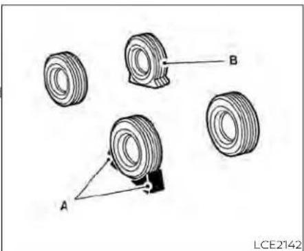
natural_image
Technical illustration of four mechanical components labeled A, B, and a central component (no text or symbols beyond labels)A. Tire stoppers
B. Flat tire
Blocking wheels
Place tire stoppers, supplied with jack, at both the front and back of the wheel diagonally opposite the flat tire to prevent the vehicle from moving when it is jacked up.
WARNING
Besuretoblockthewheelasthevehiclemaymoveandresultinpersonal injury.
Getting the spare tire and tools
- Fold up the right rear bench seat. For additional information, see "Folding the rear bench seat up" (P. 1-9).
6-4 Incaseofemergency

- Remove the tire stopper bag.
- Release the straps®.
- Collapse the jack to remove it from the storage location. Loosen the jack with your fingers until the jack is free.
- Remove the jack and tool kit.
WCE0150

natural_image
Top-down line drawing of a vehicle rear view showing front wheel, rear wheels, and side-mounted sensors (no text or symbols)- Assemble the pieces of the jack rod. Find the oval-shaped opening above the license plate, slightly to the left of the middle (driver's side). Pass the T-shaped end of the jack rod through the opening and direct it toward the spare tire winch, located directly above the spare tire.

Fit the square end of the jack rod into the square hole of the wheel nut wrench to form a handle.
Seat the T-shaped end of the jack rod into the T-shaped opening of the tire winch. Apply pressure to keep the jack rod engaged in the spare tire winch and turn the jack rod counterclockwise to lower the spare tire.
-
Once the spare tire is completely lowered, reach under the vehicle, guide the retainer chain through the center of the tire and carefully slide the tire from under the rear of the vehicle.
-
Securely store the flat tire beneath the vehicle, from where the full size spare was removed. To reinstall the wheel, remove the center cap (if so equipped) and insert the retainer chain through the wheel. Be sure the rubber rim cover (If so equipped) is centered on the wheel before lifting. Use the assembled jacking rod to slowly rotate the winch clockwise to raise the wheel to the vehicle.
- To reinstall the jack and tool kit, reverse steps 1 through 5.
NOTE:
Inspecttherubberrimcovereverysix yearsandreplaceasnecessary.ItisrecommendedthatyouvisitaNISSAN dealerforthisservice.
CAUTION
- Besuretocenterthesparetiresuspendingplateonthewheelandthen liftthesparetire.
- Failuretousetherubberrimcover mayallowthechaintogetstuckin thewheelnutholeswhenstowed.

Removing bolt-on wheel caps (if so equipped)
CAUTION
Donotuseyourhandstopryoffwheel capsorwheelcovers.Doingsocould resultinpersonalinjury.
The wheel cap① is only attached with the wheel nuts and is separate from the wheel ②.
To remove the wheel cap, remove the wheel nuts after the jack is securely supporting the vehicle and the tire clears the ground.
For additional information, see "Jacking up vehicle and removing the damaged tire" (P. 6-6).
Take care not to scratch the wheel cap or wheel surface.
Jacking up vehicle and removing the damaged tire (all models)
WARNING
- Nevergetunderthevehiclewhileitis supportedonlybythejack.Ifitisnecessarytoworkunderthevehicle, supportitwithsafetystands.
- Useonlythejackprovidedwithyour vehicletoliftthevehicle.Donotuse thejackprovidedwithyourvehicle onothervehicles.Thejackisdesignedfor liftingonly your vehicle duringatirechange.
- Usethecorrectjack-uppoints.Never useanyotherpartofthevehiclefor jacksupport.
-
Neverjackupthevehiclemorethan necessary.
-
Neveruseblocksonorunderthe jack.
- Donotstartorruntheenginewhile vehicleisonthejack.Itmaycause thevehicletomove.Thisisespecially trueforvehicleswithlimitedslip differentials.
- Donotallowpassengerstostayin thevehiclewhileitisonthejack.
- Neverruntheenginewithawheel(s) offtheground.itmaycausethevehicletomove.
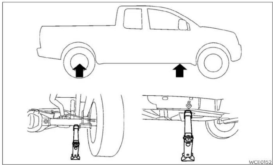
Always refer to the illustration for the cor- Carefullyreadthecautionlabelattached rect placement and jack-up points for yourtothejackbodyandthefollowingin-specific vehicle model and jack type. instructions.
1. Loosen each wheel nut one or two turns by turning counterclockwise with the wheel nut wrench. Donotremovethewheel nutsuntilthetireisofftheground.
Incaseofemergency6-7
- Place the jack directly under the jack-up point as illustrated so the top of the jack contacts the vehicle at the jack-up point. Align the jack head under the arrow stamped on the side of the frame or rear as shown.
Thejackshouldbeusedonfirmand levelground.
- Install the assembled jack rod into the jack as shown.
- To lift the vehicle, securely hold the jack lever and rod. Carefully raise the vehicle until the tire clears the ground.
- Remove the wheel nuts and then remove the tire.

natural_image
Technical illustration of a mechanical assembly with two views showing a bracket and clasp (no text or symbols)Installing the spare tire

Thesparetireisdesignedforemergency use. For additional information, see "Wheelsandtires" (P.8-35).
- Clean any mud or dirt from the surface between the wheel and hub.
- Carefully put the spare tire on and tighten the wheel nuts finger tight.
-
With the wheel nut wrench, tighten wheel nuts alternately and evenly in the sequence illustrated (1, 2, 3, 4, 5, 6) until they are tight.
-
Lower the vehicle slowly until the tire touches the ground. Then, with the wheel nut wrench, tighten the wheel nuts securely in the sequence illustrated. (1, 2, 3, 4, 5, 6). Lower the vehicle completely.
WARNING
- Incorrectwheelnutsorimproperly tightenedwheelnutscancausethe wheeltobecomelooseorcomeoff. This could cause an accident.
- Donotuseoilorgreaseonthewheel studsornuts. This could cause the nutstobecomeloose.
- Retightenthewheelnutswhenthe vehiclehasbeendrivenfor600miles (1,000km)(alsoincasesofaflattire, etc.).
Assoonaspossible,tightenthewheel nutstothespecifiedtorquewitha torquewrench.
Wheelnuttighteningtorque:
Non-XDmodels:
98ft-lb(133N·m)
XDmodels:
131ft-lb(177N·m)
The wheelnuts must be kept tightened to specification at all times. It is recommended that wheel nuts be tightened to specifications at each lubrication interval.
Adjust tire pressure to the COLD pressure.
COLDpressure:Aftervehiclehasbeen parkedfor3hoursormoreordrivenless than1mi.(1.6km).
COLDtirepressuresareshownonthe TireandLoading Informationlabelaffixedtothedriversidecenterpillar.
AfteradjustingtirepressuretotheCOLD tirepressure,thedisplay(ifsoequipped) ofthetirepressureinformationmay showhigherpressurethantheCOLDtire pressureafterthevehiclehasbeen drivenmorethan1mi.(1.6km).Thisis because the tirepressureincreases as the tire temperatureises. This does not indicateasystemmalfunction.
- Securely store the tools and jacking equipment in the vehicle. For additional information, see the "Getting the spare tire and tools (Crew and King Cab® models)" (P. 6-4).
WARNING
- Alwaysmakesurethatthesparetire and jackingequipmentare properly secured after use. Such items can be-comedangerousprojectilesinanaccidentorsuddenstop.
- The spare tire is designed for emergencyuse. For additional information, see "Wheelsandtires" (P.8-35).
JUMPSTARTING
To start your engine with a booster battery, the instructions and precautions below must be followed.

WARNING
- Ifdoneincorrectly,jumpstartingcan leadtoabatteryexplosion,resulting insevereinjuryordeath.Itcouldalso damageyourvehicle.
- Explosivehydrogengasisalways presentinthevicinityofthebattery. Keepallsparksandflamesaway fromthebattery.
- Donotallowbatteryfluidtocome intocontactwitheyes,skin,clothing orpaintedsurfaces.Batteryfluidisa corrosivesulfuricacidsolutionwhich cancausesevereburns.Ifthefluid shouldcomeintocontactwithanything,immediatelyflushthecontactedareawithwater.
- Keepbatteryoutofthereachof children.
- Theboosterbatterymustberatedat 12volts.Useofanimproperlyrated batterycandamageyourvehicle.
Wheneverworkingonnearabattery,alwayswearsuitableeyeprotectors(forexample,gogglesorindustrialsafetyspectacles)and removerings,metalbands,orany otherjewelry.Donotleanoverthe batterywhenjumpstarting.
- Do not attempt to jump start a frozen battery. It could explode and cause serious injury.
- Your vehicle has an automatic engine cooling fan. It could come on at any time. Keep handsand otherobjects awayfromit.

WARNING
Alwaysfollowtheinstructionsbelow. Failuretodosocouldresultindamage tothechargingsystemandcausepersonalinjury.
- If the booster battery is in another vehicle, position the two vehicles to bring their batteries near each other.
Donotallowthetwovehiclestotouch.
-
Apply the parking brake. Move the shift lever to P (Park). Switch off all unnecessary electrical systems (lights, heater, air conditioner, etc.).
-
Place the ignition switch in the LOCK position.
-
Ensure the vent caps (if so equipped) level and tight.
-
Connect the jumper cables in the sequence illustrated Ⓐ, Ⓑ, Ⓒ, Ⓘ).
CAUTION
- Alwaysconnectpositive(+)topositive(+)andnegative(-)tobody ground(forexample,strutmounting bolt,engineliftbracket,etc.)—notto thebattery.
- Makesurethejumpercablesdonot touchmovingpartsintheengine compartment and that thecable clamps do not contact any other metal.
-
Start the engine of the booster vehicle and let it run for a few minutes.
-
Keep the engine speed of the booster vehicle at about 2,000 rpm and start the engine of the vehicle being jump started.
CAUTION
Donotkeepsteartermotorengaged formorethan10seconds.Iftheengine doesnotstartrightaway, placetheignitionswitchintheOFFpositionand ewait3to4secondsbeforetryingagain.
- After starting the engine, carefully disconnect the negative cable and then the positive cable.
PUSHSTARTING
IFYOURVEHICLEOVERHEATS
Do not attempt to start the engine by pushing.
CAUTION
- Automatictransmissionmodelscan-notbepush-startedortow-started. Attemptingtodosomaycause transmissiondamage.
- Threewaycatalystequippedmodels shouldnotbestartedbypushing sincethreewaycatalystmaybe damaged.
- Nevertrytostartthevehiclebytowingit;whentheenginestarts,theforwardsurgecouldcausethevehicletocollidewiththetowvehicle.
WARNING
- Donotcontinuetodriveifyourvehicleoverheats.Doingsocouldcauseenginedamageoravehiclefire.
- Toavoidthedangerofbeingscalded, neverremovetheradiatororcoolant reservoircapwhiletheengineisstill hot.Whenteradiatororcoolantreservoircapisremoved,pressurized hotwaterwillspurtout,possibly causingseriousinjury.
- Donotopenthehoodifsteamis comingout.
If your vehicle is overheating (indicated by an extremely high temperature gauge reading), or if you feel a lack of engine power, detect abnormal noise, etc. take the following steps:
- Move the vehicle safely off the road, apply the parking brake and move the shift lever to P (Park).
Donotstoptheengine.
-
Turn off the air conditioner. Open all the windows, move the heater or air conditioner temperature control to maximum hot and fan control to high speed.
-
If engine overheating is caused by climbing a long hill on a hot day, run the engine at a fast idle (approximately 1,500 rpm) until the temperature gauge indication returns to normal.
- Get out of the vehicle. Look and listen for steam or coolant escaping from the radiator before opening the hood. If steam or coolant is escaping, turn off the engine. Do not open the hood further until no steam or coolant can be seen.
- Open the engine hood.
WARNING
If steam or water is coming from the engine, stand cleartoprevent getting burned.
- Visually check drive belts for damage or looseness. Also check if the cooling fan is running. The radiator hoses and radiator should not leak water. If coolant is leaking, the water pump belt is missing or loose, or the cooling fan does not run, stop the engine.
TOWINGYOURVEHICLE
WARNING
Becarefulnottoallowyourhands,hair, jewelryorclothingtocomeintocontactwith,orgetcaughtin,enginebelts ortheenginecoolingfan.Theengine coolingfancanstartatanytime.
- After the engine cools down, check the coolant level in the engine coolant reservoir tank with the engine running. Add coolant to the engine coolant reservoir tank if necessary. It is recommended that you visit a NISSAN dealer for this service.
When towing your vehicle, all jurisdictional and local regulations for towing must be followed. Incorrect towing equipment could damage your vehicle. Towing instructions are available from a NISSAN dealer. Local service operators are generally familiar with the applicable laws and procedures for towing. To assure proper towing and to prevent accidental damage to your vehicle, NISSAN recommends having a service operator tow your vehicle. It advisable to have the service operator carefully read the following precautions:
WARNING
- Neverrideinavehiclethatisbeing towed.
- Never get under your vehicle after it has been lifted by atowtruck.
- If your vehicle has front recovery hooks as original factory equipment, donot remove or modify them. If it was not equipped with front recovery hooks, donot install them. Either action could affect proper operation of the front air bags system resulting in injury or death.
CAUTION
- Whentowing, makesure that the transmission, axles, steeringsystem and powertrain are in working condition. Usedolliesor flatbedifany of the listed systems are not working. - Always attach safety chains before towing.
For additional information about towing your vehicle behind a Recreational Vehicle (RV), see "Flat towing for 2-Wheel Drive (2WD) vehicle" (P. 10-55) or "Flat towing for 4-Wheel Drive (4WD) vehicle" (P. 10-55).
TOWING RECOMMENDED BY NISSAN
NISSAN recommends towing your vehicle based upon the type of drivetrain. For additional information, refer to the diagrams in this section to ensure that your vehicle is properly towed.
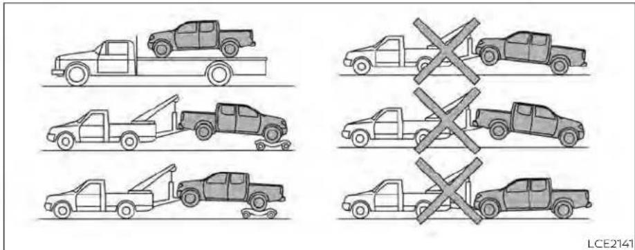
Four-Wheel Drive (4WD) models with automatic transmission
NISSAN recommends that towing dollies be used when towing your vehicle or place the vehicle on a flatbed truck as illustrated.
NOTE:
If the battery is completely drained the transmission will not manually shift to other positions.
CAUTION
Nevertow4WDmodelsequippedwith anautomatictransmissionwithanyof thewheelsonthegroundasthismay causeseriousandexpensivedamage tothetransfercaseandtransmission.

LCE2311
Two-Wheel Drive models with automatic transmission
NISSAN recommends that your vehicle be towed with the driving (rear) wheels off the ground or place the vehicle on a flatbed truck as illustrated.
CAUTION
- Nevertowautomatictransmission modelswiththerearwheelsonthe groundorfourwheelsontheground (forwardorbackward),asthismay causeseriousandexpensivedamagetothetransmission.Ifitisnecessarytotowthevehiclewiththefront wheelsraisedalwaysusetowingdolliesundertherearwheels.
- Whentowingautomatictransmissionmodelswiththefrontwheelson thegroundorontowingdollies:
- Placetheignitionswitchinthe OFFpositionandsecurethesteeringwheelinastraight-aheadpositionwitharopeorsimilardevice.Neversecurethesteering wheel by placing the ignition switchintheLOCKposition.This maycausedamagetothelock mechanism(formodels witha steeringlockmechanism).
NOTE:
If the battery is completely drained the transmission will not manually shift to other positions.
When towing long distances or speeds in excess of 50 mph (80 km/h), remove the propeller shaft before towing to prevent damage to the transmission. It is recommended that you visit a NISSAN dealer for additional information.
VEHICLE RECOVERY (freeing a stuck vehicle)
There are two options to recover a stuck vehicle: pulling and rocking. For additional information regarding these options, please refer to the following sections.
Pulling a stuck vehicle
WARNING
Toavoidvehicledamage,seriouspersonalinjuryordeathwhenrecoveringa stuckvehicle:
- Contactaprofessionaltowingservicetorecoverthevehicleifyouhave anyquestionsregardingtherecoveryprocedure.
- Attachrecoverydevicesonlytomain structuralmembersofthevehicleortherecoveryhooks(ifsoequipped).
- Donotusethevehicletie-downsto toworfreeeastuckvehicle.
- Onlyusedevicessspecificallydesignedforvehiclerecoveryandfollowthemanufacturer'sinstructions.
- Alwayspulltherecoverydevice straightoutfromthefrontofthevehicle.Neverpullatanangle.
- Routerecoverydevicessotheydo nottouchanypartofthevehicleexcepttheattachmentpoint.
Rocking a stuck vehicle
WARNING
- Standclearofastuckvehicle.
- Donotspinyourtiresathighspeed. This could cause them to explode andresultinserious injury. Partsof your vehicle could also overheat and bedamaged.
If your vehicle is stuck in sand, snow, mud, etc., use the following procedure:
- Turn off the Vehicle Dynamic Control (VDC) system.
- Activate the Electronic Locking Rear Differential (E-Lock) system (if so equipped). For additional information, see 'Electronic Locking Rear Differential (E-Lock) system' (P. 2-61)
- Make sure the area in front and behind the vehicle is clear of obstructions.
-
Turn the steering wheel right and left to clear an area around the front tires.
-
Slowly rock the vehicle forward and backward.
-
Shift back and forth between R (Reverse) and D (Drive).
- Apply the accelerator as little as possible to maintain the rocking motion.
- Release the accelerator pedal before shifting between R (Reverse) and D (Drive).
-
Do not spin the tires above 34 mph (55 km/h) or above 12 mph (20 km/h) if the E-Lock system (if so equipped) is engaged.
-
If the vehicle cannot be freed after a few tries, contact a professional towing service to remove the vehicle.
If your vehicle is stuck in sand, snow, mud, etc., use a tow strap or other device designed specifically for vehicle recovery. Always follow the manufacturer's instructions for the recovery device.
6-16 Incaseofemergency
7Appearanceandcare
Cleaning exterior 7-2
Washing 7 - 2
Waxing 7-3
Removing spots 7 - 3
Underbody 7-3
Glass 7-3
Aluminum alloy wheels (if so equipped)....7-3
Chromeparts....7-4
Tire dressings 7-4
Cleaning interior 7-4
Air fresheners 7-5
Power moonroof (if so equipped) 7 - 5
Floor mats (if so equipped) 7 - 6
Seatbelts 7-7
Corrosion protection 7-7
Most common factors contributing to
vehicle corrosion 7-7
Environmental factors influence the
rate of corrosion 7-7
Protect your vehicle from corrosion .....7 - 8
CLEANINGEXTERIOR
In order to maintain the appearance of your vehicle, it is important to take proper care of it.
To protect the paint surfaces, wash your vehicle as soon as you can:
• After a rainfall to prevent possible damage from acid rain.
• After driving on coastal roads.
- When contaminants such as soot, bird droppings, tree sap, metal particles or bugs get on the paint surface.
- When dust or mud builds up on the surface.
Whenever possible, store or park your vehicle inside a garage or in a covered area.
When it is necessary to park outside, park in a shady area or protect the vehicle with a body cover.
Becarefulnottoscratchthepaintsurfacewhenputtingonorremovingthe bodycover.
WASHING
Wash dirt off with a wet sponge and plenty of water. Clean the vehicle thoroughly using a mild soap, a special vehicle soap or general purpose dishwashing liquid mixed with clean, lukewarm (never hot) water.
CAUTION
- Donotconcentratewaterspraydirectlyonthesonarsensors(ifso equipped)onthebumperasthiswill resultindamagetothesensors.Do notusepressurewasherscapableof sprayingwaterover1,200psi(8,274 kPa)towashyourvehicle.Useof high-pressurewashers over 1,200psi (8,274 kPa)canresult indamagetoor removalofpaintorgraphics.Avoid usingahigh-pressurewashercloser than12inches(30cm)tothevehicle. Alwaysuseawide-anglenozzleonly, keepthenozzlemovinganddonot concentratethewatersprayonany onearea.
-
Donotusecarwashesthatuseacid inthedetergent.Somecarwashes, especiallybrushlessons,usesome acidforcleaning.Theacidmayreact withsomeplasticvehiclecomponents, causing them tocrack.This could affect theirappearance, and alsocouldcausethemnottofunctionproperly.Alwayscheckwithyour carwashtoconfirmmthatacidisnot used.
-
Donotwashthevehiclewithstrong householdsoap,strongchemicaldetergents,gasolineorsolvents.
- Donotwashthevehicleindirectsun-lightorwhilethevehiclebodyishot, as the surface may become water-spotted.
- Avoidusing tight-napped orrough cloths, such as washingmitts. Care must be taken when removing caked-ondirtorotherforeignsub-stancesothepaintsurfaceisnot scratchedordamaged.
Rinse the vehicle thoroughly with plenty of clean water.
Inside edges, seams and folds on the doors, hatches and hood are particularly vulnerable to the effects of road salt. Therefore, these areas must be cleaned regularly. Take care that the drain holes in the lower edge of the door are open. Spray water under the body and in the wheel wells to loosen the dirt and wash away road salt.
A damp chamois can be used to dry the vehicle to avoid water spots.
7-2 Appearanceandcare
WAXING
Regular waxing protects the paint surface and helps retain new vehicle appearance. Polishing is recommended to remove built-up wax residue and to avoid a weathered appearance before re-applying wax.
A NISSAN dealer can assist you in choosing the proper product.
- Wax your vehicle only after a thorough washing. Follow the instructions supplied with the wax.
- Do not use a wax containing any abrasives, cutting compounds or cleaners that may damage the vehicle finish.
Machine compounding or aggressive polishing on a base coat/clear coat paint finish may dull the finish or leave swirl marks,
REMOVING SPOTS
Remove tar and oil spots, industrial dust, insects, and tree sap as quickly as possible from the surface of the paint to avoid lasting damage or staining. Special cleaning products are available at a NISSAN dealer or any automotive accessory store. It is recommended that you visit a NISSAN dealer for these products.
UNDERBODY
In areas where road salt is used in winter, it is necessary to clean the underbody regularly in order to prevent dirt and salt from building up and causing the acceleration of corrosion on the underbody and suspension. Before the winter period and again in the spring, the underseal must be checked and, if necessary, re-treated.
GLASS
Use glass cleaner to remove smoke and dust film from the glass surfaces. It is normal for glass to become coated with a film after the vehicle is parked in the hot sun. Glass cleaner and a soft cloth will easily remove this film.
CAUTION
Whencleaningtheinsideofthewindows, donotusesharp-edgedtools, abrasivecleanersor chlorine-based disinfectantcleaners. They could damage the electrical conductors, radioantenna elements or rear window defrosterelements.
ALUMINUM ALLOY WHEELS (if so equipped)
Wash the wheels regularly with a sponge dampened in a mild soap solution, especially during winter months in areas where road salt is used. If not removed, road salt can discolor the wheels.
CAUTION
Followthedirectionsbelowtoavoid stainingordiscoloringthewheels:
- Donotuseacleanerthatusesstrong acidoralkalicontentstocleanthe wheels.
- Donotapplywheelcleanerstothe wheelswhentheyarehot. Thewheel temperatureshouldbethesameas ambienttemperature.
- Donotusechromecleaneronany wheel.Doingsocandamagethe chrome-likecoatingonthewheel.
- Rinse the wheel to completely remove the cleaner within 15 minutes after the cleaner is applied.
CLEANINGINTERIOR
CHROME PARTS
Clean all chrome parts regularly with a non-abrasive chrome polish to maintain the finish.

Donotusechromecleaneronany wheel.Doingsocandamagethe chrome-likecoatingonthewheel.
TIRE DRESSINGS
NISSAN does not recommend the use of tire dressings. Tire manufacturers apply a coating to the tires to help reduce discoloration of the rubber. If a tire dressing is applied to the tires, it may react with the coating and form a compound. This compound may come off the tire while driving and stain the vehicle paint.
If you choose to use a tire dressing, take the following precautions:
- Use a water-based tire dressing. The coating on the tire dissolves more easily than with an oil-based tire dressing.
-
Apply a light coat of tire dressing to help prevent it from entering the tire tread/grooves (where it would be difficult to remove).
-
Allow the tire dressing to dry as recommended by the tire dressing manufacturer.
- Wipe off excess tire dressing using a dry Occasionally remove loose dust from the towel. Make sure the tire dressing is cominterior trim, plastic parts and seats using a pletely removed from the tire vacuum cleaner or soft bristled brush. Wipe tread/grooves. the vinyl and leather surfaces (if so
Occasionally remove loose dust from the interior trim, plastic parts and seats using a vacuum cleaner or soft bristled brush. Wipe the vinyl and leather surfaces (if so equipped) with a clean, soft cloth dampened in mild soap solution, then wipe clean with a dry, soft cloth.
Regular care and cleaning is required in order to maintain the appearance of the leather (if so equipped).
Before using any fabric protector, read the manufacturer's recommendations. Some fabric protectors contain chemicals that may stain or bleach the seat material.
Use a cloth dampened only with water to clean the meter and gauge lens.
WARNING
Donotusewateroracidicleaners(hot steamcleaners)ontheseat. This can damage theseator occupant classification sensor(ifsoequipped). This can also affect the operation of the airbag system and result in serious personal injury.
7-4 Appearanceandcare
CAUTION
- Neverusebenzine,thinnerorany similarmaterial.
- Smalldirtparticlescanbeabrasive anddamagingtoleathersurfaces andshouldberemovedpromptly.Do notusesaddlesoap,carwaxes,polishes,oils,cleaningfluids,solvents, detergentsorammonia-based cleanersastheymaydamagethe leather'snaturaifinish.
- Neverusefabricprotectorsunless recommendedbythemanufacturer.
- Donotuseglassorplasticcleaneron meterorgaugelenscovers.Itmay damagethelenscover.
AIR FRESHENERS
Most air fresheners use a solvent that could affect the vehicle interior. If you use an air freshener, take the following precautions:
- Hanging-type air fresheners can cause permanent discoloration when they contact vehicle interior surfaces. Place the air freshener in a location that allows it to hang free and not contact an interior surface.
- Liquid-type air fresheners typically clip on the vents. These products can cause immediate damage and discoloration when spilled on interior surfaces.
Carefully read and follow the manufacturer's instructions before using the air fresheners.
POWER MOONROOF (if so equipped)
The sunshade is made from a tricot material.
CAUTION
Tohelppreventdamagingthemoon-roofwhilecleaning:
- Donotrubthematerialwithacloth. Doingsocandamagethesurface of the material or cause a stain to spread.
-
Neverusebenzine,thinnerorany similarchemicaltocleanthesun-shade.Thismaydiscolorthemoon-roofanddamagethesurface.
-
Cleanwaterbasedstainsbypatting the surface with a clean soft cloth dampenedinwarm water. Press a cleandryclothontothesurfaceto removeasmuchdampnessaspossibleandthenletairdry.
- Cleanoilbasedstainsbypattingthe surface with a clean soft cloth dampened in warm water. Press a clean dry clothontothesurfacetoremoveas much dampness as possible and thenletairdry.

FLOOR MATS (if so equipped)
WARNING
To avoid potential pedal interference that may result in acollision, injury or death:
- NEVERplaceafloormatontopof anotherfloormatinthedriverfront positionorinstallthemupsidedown orbackwards.
-
UseonlyGenuineNISSANfloormats, orequivalentfloormats, thatare specifically designed for use in your vehicle model and model year.
-
Properlypositionthematsinthe floorwellusingthefloormatpositioninghook.Foradditionalinformation,see "Floormatinstallation" (P.7-6).
- Makesurethefloormatdoesnotinterferewithpedaloperation.
- Periodicallycheckthefloormatsto make sure they are properly installed.
- Aftercleaningthevehicleinterior, checkthefloormatstomakesure theyareproperlyinstalled.
The use of Genuine NISSAN floor mats can extend the life of your vehicle carpet and make it easier to clean the interior. Mats should be maintained with regular cleaning and replaced if they become excessively worn.
Floor mat installation
Your vehicle is equipped with floor mat positioning hook(s). The number and shape of the floor mat positioning hooks for each seating position varies depending on the vehicle.
When installing Genuine NISSANfloor mats, follow the installation instructions provided with the mat and the following:
-
With the ignition switch in the OFF position, the shift lever in P (Park) position and with the parking brake fully applied, position the floor mat in the floorwell so that the floor mat grommet holes are aligned with the hook(s).
-
Secure the grommet holes into the hook(s) and ensure that the floor mat is properly positioned.
-
Make sure the floor mat does not interfere with pedal operation. With the ignition switch still in the OFF position, the shift lever in the P (Park) position and with the parking brake applied, fully apply and release all pedals. The floor mat must not interfere with pedal operation or prevent the pedal from returning to its normal position.
It is recommended that you visit a NISSAN dealer for details about installing the floor mats in your vehicle.

natural_image
Top-down line drawing of a car interior layout (no text or symbols)Positioninghooks
The illustration shows the location of the floor mat positioning hooks.
SEAT BELTS
The seat belts can be cleaned by wiping them with a sponge dampened in a mild soap solution. Allow the belts to dry completely in the shade before using them. For additional information, see "Seat belt maintenance" (P. 1-24).
CORROSIONPROTECTION
WARNING
Donotallowwetseatbeltstorollupin theretractor.NEVERusebleach,dyeor chemicalsolventstocleantheseat belts,sincethesematerialsmayseverelyweakentheseatbeltwebbing.
MOST COMMON FACTORS CONTRIBUTING TO VEHICLE CORROSION
Most vehicle corrosion is caused by:
- The accumulation of moisture-retaining dirt and debris in body panel sections, cavities, and other areas.
- Damage to paint and other protective coatings caused by gravel and stone chips or minor traffic collisions.
ENVIRONMENTAL FACTORS INFLUENCE THE RATE OF CORROSION
Moisture
Accumulation of sand, dirt and water on the vehicle body underside can accelerate corrosion. Wet floor coverings will not dry completely inside the vehicle and should be removed for drying to avoid floor panel corrosion.
Relative humidity
Corrosion will be accelerated in areas of high relative humidity, especially those areas where the temperatures stay above freezing and where atmospheric pollution exists and road salt is used.
Appearanceandcare
Temperature
High temperatures accelerate the rate of corrosion to those parts which are not well ventilated.
Air pollution
Industrial pollution, the presence of salt in the air in coastal areas, or heavy road salt use accelerates the corrosion process. Road salt also accelerates the disintegration of paint surfaces.
PROTECT YOUR VEHICLE FROM CORROSION
- Wash and wax your vehicle often to keep the vehicle clean.
• Always check for minor damage to the paint and repair it as soon as possible. - Keep drain holes at the bottom of the doors open to avoid water accumulation
- Check the underbody for accumulation of sand, dirt or salt. If present, wash with water as soon as possible.
CAUTION
- NEVERremovedirt, sandorotherdebrisfromthepassengercompartmentbywashingitoutwithahose. Removedirt with a vacuum cleaner orbroom.
- Neverallowwaterorotherliquidsto comeincontactwiththelectroniccomponentsinsidethevehicleasthis maydamagethem.
Chemicals used for road surface de-icing are extremely corrosive. They accelerate corrosion and deterioration of underbody components such as the exhaust system, fuel and brake lines, brake cables, floor pan and fenders.
In winter, the underbody must be cleanedperiodically.
For additional protection against rust and corrosion, which may be required in some areas, it is recommended that you visit a NISSAN dealer.
8Do-it-yourself
Maintenance precautions 8 - 2
Engine compartment check locations 8-3
Engine cooling system 8-5
Checking engine coolant level 8-6
Changing engine coolant 8-6
Engine oil 8-7
Checking engine oil level 8-7
Changing engine oil and oil filter 8-8
Automatic Transmission Fluid (ATF)....8-13
Power Steering Fluid (PSF) 8-13
Brake fluid 8-14
Windshield-washer fluid 8-15
Windshield-washer fluid reservoir 8-15
Battery 8-16
Jump starting 8-18
Variable voltage control system
(if so equipped) 8-19
Drive belt 8-19
Spark plugs 8-20
Replacing spark plugs 8-20
Air cleaner 8-21
In-cabin microfilter 8-21
Windshield wiper blades 8-22
Cleaning 8-22
Replacing 8-22
Brakes 8-23
Fuses 8-24
Engine compartment 8-24
Passenger compartment 8-25
Battery replacement 8-27
NISSAN Intelligent Key 8-27
Lights 8-29
Headlights 8-29
Fog lights (if so equipped) 8-29
Daytime Running Light (DRL)
(if so equipped) 8-30
Exterior and interior lights 8-32
Wheels and tires 8-35
Tire pressure 8-35
Tire labeling 8-39
Types of tires 8-41
Tire chains 8-42
Changing wheels and tires 8-43
MAINTENANCEPRECAUTIONS
When performing any inspection or maintenance work on your vehicle, always take care to prevent serious accidental injury to yourself or damage to the vehicle. The following are general precautions which should be closely observed.

WARNING
- Parkthevehicleonalevelsurface,applytheparkingbrakesecurelyand blockthewheelstopreventthevehiclefrommoving.Movetheshiftlever toP(Park)
- Besuretheignitionswitchisinthe OFForLOCKpositionwhenperforminganypartsreplacementorrepairs.
- If you must work with the engineer running, keep your hands, clothing, hair and tools away from moving fans, belts and any other moving parts.
- Itisadvisabletosecureorremove anylooseclothingandremoveany jewelry,suchasrings,watches,etc. beforeworkingonyourvehicle.
- Alwaysweareyeprotectionwhen-everyouworkonyourvehicle.
- Theautomaticenginecoolingfan(if soequipped)maycomeonatany timewithoutwarning,eveniftheignitionswitchisintheOFFposition
andtheengineisnotrunning.To avoidinjury,alwaysdisconnectthe negativebatterycablebeforework-ingnearthefan.
- Ifyoumustruntheengineinanenclosedspacesuchasagarage,be surethereisproperventilationfor exhaustgasestoescape.
- Nevergetunderthevehiclewhileitis supportedonlybyajack.Ifitisnecessary towork underthevehicle, supportitwithsafetystands.
- Keepsmokingmaterials,flameand sparksawayfromthefueltankand battery.
- Because the fuel lines are under high pressure even when the engine is off, it is recommended that you visit a NISSAN dealer for service of the fuel filter or fuel lines.

CAUTION
- Donotworkunderthehoodwhile theengineishot.Turntheengineoff andwaituntilcoolsdown.
- Avoidcontactwithusedengineoiland coolant.Improperlydisposedengine oil,enginecoolantand/orothervehiclefluidscandamagetheenviron-
ment.Alwaysconformtolocalregulationsfordisposalofvehiclefluid.
- Neverleavethengineorautomatic transmission related component harnesses disconnected while the ignitionswitchisintheONposition.
- Neverconnectordisconnectthebattery orany transistorizedcomponentwhiletheignitionswitchisin theONposition.
NOTE:
If the battery is completely drained the transmission will not manually shift to other positions.
This "Do-it-yourself" section gives instructions regarding only those items which are relatively easy for an owner to perform.
A Genuine NISSAN service manual is also available. For additional information, see "Owner's Manual/Service Manual order information" (P. 10-60).
You should be aware that incomplete or improper servicing may result in operating difficulties or excessive emissions, and could affect warranty coverage. If in doubt about anyservicing, it is recommended that you have it done by a NISSAN dealer.
ENGINECOMPARTMENTCHECK LOCATIONS

5.6L8cylinder(VK56VDenginemodel) (non-XDmodel)
- Windshield-washer fluid reservoir
-
Fuse box
-
Engine oil dipstick
- Power steering fluid reservoir
- Engine oil filler cap
-
Brake fluid reservoir
-
Air cleaner
- Fuse/Fusible link box
- Drive belt location
- Radiator cap
- Battery
- Engine coolant reservoir
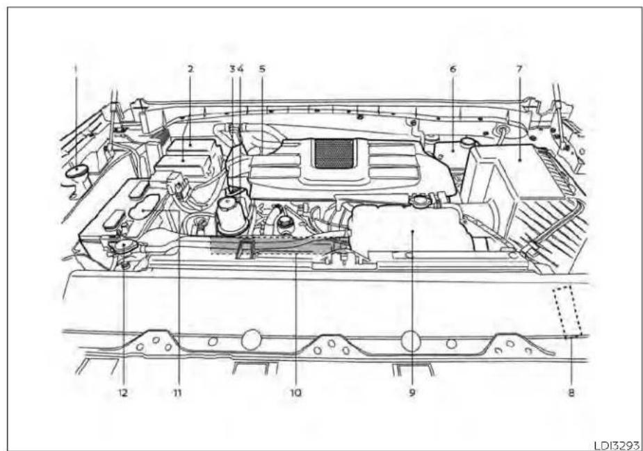
5.6L8cylinder(VK56VDenginemodel) (XDmodel)
- Windshield-washer fluid reservoir
- Fuse box
8-4 Do-it-yourself
- Engine oil dipstick
- Power steering fluid reservoir
- Engine oil filler cap
-
Brake fluid reservoir
-
Air cleaner
-
Fuse/Fusible link box
- Engine coolant reservoir
- Drive belt location
- Battery
- Radiator cap
ENGINECOOLINGSYSTEM
The engine cooling system is filled at the factory with a pre-diluted mixture of 50% Genuine NISSAN Long Life Antifreeze/ Coolant (blue) and 50% water to provide year-round antifreeze and coolant protection. The antifreeze solution contains rust and corrosion inhibitors. Additional engine cooling system additives are not necessary.
WARNING
- Neverremovetheradiatororcoolant reservoircapwhentheengineishot. Waituntiltheengineandradiator cooldown.Seriousburnscouldbe causedbyhighpressurefluidescapingfromtheradiator.Foradditional informationonprecautions,see"If yourvehicleoverheats"(P.6-12).
- Theradiatorandcoolantreservoir are equipped with a pressure type radiatorcap.Topreventengine damage,itisrecommendedthatyouuse onlyaGenuineNISSANradiatorcap.
CAUTION
- Neveruseanycoolingsystemadditivessuchasradiatorsealer.Additivesmayclogthecoolingsystem andcausedamage totheengine, transmissionand/orcoolingsystem.
- Whenaddingorreplacingcoolant, it is recommended that you use only Genuine NISSAN Long Life Antifreeze/Coolant (blue) or equivalent. Genuine NISSAN Long Life Antifreeze/Coolant (blue) is pre-diluted to provide antifreeze protection to -34ircF(-37ircC) . If additional freeze protection is needed due to weather where you operate your vehicle, add Genuine NISSAN Long Life Antifreeze/Coolant (blue) concentrate following the directions on the container. If an equivalent coolant other than Genuine NISSAN Long Life Antifreeze/Coolant (blue) is used, follow the coolant manufacturer's instruction to maintain minimum antifreeze protection to -34ircF(-37ircC) . The use of other types of coolant solutions other than Genuine NISSAN Long Life Antifreeze/Coolant (blue) or equivalent may damage the engine cooling system.
- The life expectancy of the factory-fill coolant is 105,000 miles (168,000 km) or 7 years. Mixing anyothertype of coolant other than Genuine NISSAN Long Life Antifreeze/Coolant (blue) (or equivalent coolant), including Genuine NISSAN Long Life Antifreeze/Coolant (green), or the use of non-distilled water may reduce the life expectancy of the factory-fill coolant. For additional information, see the "Maintenance and schedules" section of this manual.

5.6L8cylinder(VK56VDenginemodel) (non-XDmodel)
CHECKING ENGINE COOLANT LEVEL
Check the coolant level inthereservoir whentheengineiscold. If the coolant level is below the MIN level, add coolant to the MAX level. If the reservoir is empty, check the coolant level in the radiator whentheengineiscold. If there is insufficient coolant in the radiator, fill the radiator with coolant up to the filler opening and also add it to the reservoir up to the MAX level.
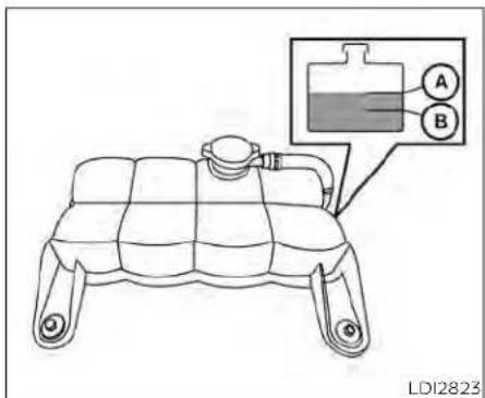
5.6L8cylinder(VK56VDenginemodel) (XDmodel)
This vehicle contains Genuine NISSAN Long Life Antifreeze/Coolant (blue). The life expectancy of the factory-fill coolant is 105,000 miles (168,000 km) or 7 years. Mixing any other type of coolant or the use of non-distilled water may reduce the life expectancy of the factory-fill coolant. For additional information, see the "Maintenance and schedules" section of this manual.
If the coolingsystem frequently requires coolant, have it checked. It is recommended that you visit a NISSAN dealer forthisservice.
For additional information on the location of the engine coolant reservoir, see "Engine compartment check locations" (P. 8-3).
CHANGING ENGINE COOLANT
A NISSAN dealer can change the engine coolant. The service procedure can be found in the NISSAN Service Manual.
Improperservicingcanresultinreduced heater performance and engine overheating.
WARNING
- Toavoidthedangerofbeingcaled, neverchangethecoolantwhenthe engineishot.
- Neverremovetheradiatororengine coolantreservoircapwhentheengineishot.Seriousburnscouldbe causedbyhighpressurefluidescapingfromtheradiator.
- Avoiddirectskincontactwithused coolant.Ifskincontactismade,wash thoroughly with soap or hand cleanerassoonaspossible.
- Keepcoolantoutofthereachofchildrenandpets.
ENGINEOIL
Engine coolant must be disposed of properly. Check your local regulations.
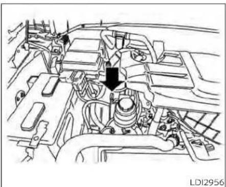
natural_image
Technical line drawing of an engine bay with no visible text or symbols5.6L8cylinder(VK56VDenginemodel) CHECKING ENGINE OIL LEVEL
- Park the vehicle on a level surface and apply the parking brake.
- Start the engine and let it idle until it reaches operating temperature.
- Turn off the engine. Waitmorethan15 minutesfortheoiltodrainbackinto theoilpan.
- Remove the dipstick and wipe it clean. Reinsert it all the way.

5.6L8cylinder(VK56VDenginemodel)
- Remove the dipstick again and check the oil level. It should be between the H (High) and L (Low) mark. This is the normal operating oil level range. If the oil level is below the L (Low) mark, remove the oil filler cap and pour recommended oil through the opening. Donot overfill ©.
- Recheck oil level with the dipstick.
Itisnormaltoaddsomeoilbetweenoil maintenanceintervalsorduringthe break-inperiod,dependingontheseverityofoperatingconditions.
Do-it-yourself8-7
CAUTION
Oillevelshouldbecheckedregularly. Operatingtheenginewithaninsufficientamountofoilcandamagetheengine,andsuchdamageisnotcovered bywarranty.
CHANGING ENGINE OIL AND OIL FILTER
For additional information on engine oil and oil filter change, refer to the instructions outlined in this section.
Vehicle set-up
- Park the vehicle on a level surface and apply the parking brake.
- Run the engine until it reaches operating temperature.
- Turn the engine off and wait for 15 minutes.
- Raise and support the vehicle using a suitable floor jack and safety jack stands.
- Place the safety jack stands under the vehicle jack-up points.
- A suitable adapter should be attached to the jack stand saddle.
8-8 Do-it-yourself
CAUTION
Makesurethecorrectliftingandsupport pointsareused toavoidvehicle damage.

Oilfillercap
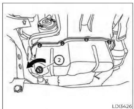
② Oildrainplug

③ Oilfilter
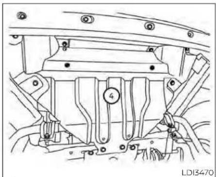
natural_image
Technical line drawing of a mechanical assembly with no visible text or symbols④ Skidplate(TypeA)(ifsoequipped)

natural_image
Technical line drawing of a vehicle air intake structure (no text or symbols)⑤ Skidplate(TypeB)(ifsoequipped)

natural_image
Line drawing of a vehicle's front panel with no text or symbols⑥ Skidplate(TypeC)(ifsoequipped)

natural_image
Technical line drawing of a vehicle chassis panel with mounting holes and numbered component (no text or symbols)⑦ Skidplate(TypeD)(ifsoequipped)
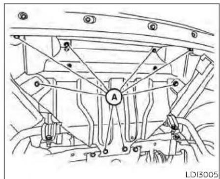
natural_image
Technical line drawing of a mechanical assembly with labeled components (no readable text or symbols)Skidplate(TypeA)(ifsoequipped)
Removal of under-engine protectors

natural_image
Technical line drawing of a vehicle chassis frame with labeled components (no text or symbols beyond labels)Skidplate(TypeB)(ifsoequipped)

natural_image
Technical line drawing of a vehicle chassis with labeled components (no text or symbols beyond labels)Skidplate(TypeC)(ifsoequipped)
LDI2876
Skidplate(TypeD)(ifsoequipped)
- Remove bolts Ⓐ and skid plate.
Engine oil and filter
- Place a large drain pan under the drain plug and oil filter.
- Remove the oil filler cap.
-
Remove the drain plug with a wrench by turning it counterclockwise and completely drain the oil.
-
Loosen the oil filter with an oil filter wrench by turning it counterclockwise. Remove the oil filter by turning it by hand.
- Wipe the engine oil filter mounting surface with a clean rag.
- Loosen the oil filter with an oil filter wrench by turning it counterclockwise. Remove the oil filter by turning it by hand.
- Wipe the engine oil filter mounting surface with a clean rag.
CAUTION
Becarefulnottoburnyourself,asthe engineoilishot.
WARNING
- Prolongedandrepeatedcontact withusedengineoilmaycauseskin cancer.
- Trytoavoiddirectskincontactwithusedoil.Ifskincontactismade,washthoroughlywithsoaporhandcleanerassoonaspossible.
- Keepusedengineoiloutofreachof children.
CAUTION
Besuretoremoveanyoldgasketmaterialremainingonthesealingsurface of the engine. Failure to do so could leadtoanoilleakandenginedamage.
- The dipstick must be inserted in placetopreventoilspillagefromthe dipstickholewhenfillingtheengine withoil.
- Coat the gasket on the new filter with clean engine oil.
- Screw in the oil filter clockwise until a slight resistance is felt, then tighten additionally more than 2/3 turn.
Oilfiltertighteningtorque: 11to15ft-lb(15.0to21.0N·m)
- Clean and re-install the drain plug with a new washer. Securely tighten the drain plug with a wrench. Do not use excessive force.
Drainplugtighteningtorque: 22to29ft-lb(29.4to39.2N·m)
- Refill the engine with the recommended oil through the oil filler opening, and install the oil filler cap securely.
AUTOMATICTRANSMISSIONFLUID (ATF)
For additional information about drain and refill capacity, see 'Recommended fluids/lubricants and capacities' (P. 10-2). The drain and refill capacity depends on the oil temperature and drain time. Use these specifications for reference only. Always use the dipstick to determine the proper amount of oil in the engine.
- Start the engine and check for leakage around the drain plug and the oil filter. Correct as required. Turn the engine off and wait more than 15 minutes. Check the oil level with the dipstick. Add engine oil if necessary.
After the operation
- Reinstall plate in reverse order of removal.
- Lower the vehicle carefully to the ground.
- Dispose of waste oil and filter properly.
- Check your local regulations.
When checking or replacement is required, it is recommended that you visit a NISSAN dealer for this service.
CAUTION
- NISSANrecommendsusingGenuine NISSANMaticPATF.Donotmixwith otherfluids.
- Do not use CVT fluid or manual transmissionfluidinthistransmission. Damagecausedbytheuseoffluids otherthan asrecommendedisnot coveredunderNISSAN'sNewVehicle LimitedWarrantyoutlinedinyour WarrantyInformationBooklet.
- Usingfluidsthatarenotequivalent toGenuineNISSANMaticPATFmay alsodamagethetransmission. Damagecausedbytheuseoffluidsother than asrecommended isnot covered underNISSAN'sNewVehicleLimited Warrantyoutlinedin yourWarranty InformationBooklet.
The specified automatic transmission fluid is also described on caution labels located in the engine compartment.

Check the power steering fluid level when the engine is stopped.
The fluid level should be between the COLD MAX line and the COLD MIN line on the power steering fluid reservoir at cold fluid temperatures of 32irc - 86ircF ( 0irc - 30ircC ) or at the HOT MAX line on the power steering fluid reservoir at hot fluid temperatures of 122irc - 176ircF ( 50irc - 80ircC ).
BRAKEFLUID
If the fluid is cold and is at or below the COLD MIN line, add Genuine NISSAN PSF-II or equivalent to the COLD MAX line. If the fluid is hot and below the HOT MAX line, add Genuine NISSAN PSF-II or equivalent to the HOT MAX line. Remove the cap and fill through the opening.

CAUTION
· DONOTOVERFILL.
- Donotreusepowersteeringfluid.
- RecommendedfluidisGenuine
NISSANPSF-IIorequivalent
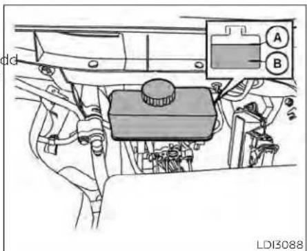
natural_image
Technical line drawing of a vehicle engine compartment with labeled components (no readable text or symbols)Brakefluidreservoir(TypeA) (ifsoequipped)
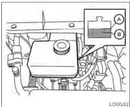
Brakefluidreservoir(TypeB) (ifsoequipped)

WARNING
- Useonlynewfluidfromasealedcontainer.Old,inferiororcontaminated fluidmaydamagethebrakesystem. Theuseofimproperfluidscandamagethebrakesystemandaffectthe vehicle'sstoppingability.
- Cleanthefillercapbeforeremoving.
- Brakefluidispoisonousandshould bestoredcarefullyinmarkedcontainersoutofreachofchildren.
WINDSHIELD-WASHERFLUID
CAUTION
Donotspillthefluidonanypaintedsurfaces. This will damage the paint. If fluid is spilled, immediately wash the surface with water.
Check the fluid level in the reservoir. If the brake fluid is below the MIN line , the brake warning light will illuminate. Add brake fluid up to the MAX lin . For additional information on recommended type of brake fluid, see "Recommended fluids/lubricants and capacities" (P. 10-2).
If the brake fluid must be added frequently the brake system should be thoroughly checked. It is recommended that you visit NISSAN dealer for this service.

natural_image
Diagram of a car interior showing a hand holding a device with an arrow indicating direction (no text or symbols present)WINDSHIELD-WASHER FLUID a RESERVOIR
Fill the windshield-washer fluid reservoir periodically. Add windshield-washer fluid when the "Low Washer Fluid" warning message shows on the vehicle information display.
To fill the windshield-washer fluid reservoir, lift the cap off the reservoir and pour the windshield-washer fluid into the reservoir opening.
Add a washer solvent to the washer for better cleaning. In the winter season, add a windshield washer antifreeze. Follow the manufacturer's instructions for the mixture ratio.
Refill the reservoir more frequently when driving conditions require an increased amount of windshield-washer fluid.
Recommended fluid is Genuine NISSAN windshield Washer Concentrate Cleaner & Anti-freeze or equivalent.
CAUTION
- Donotsubstituteengineantifreeze coolantforwindshield-washerfluid. Thismay result in damageto the paint.
- Donotfill thewindshield-washer fluidreservoirwithwasherfluidconcentrates at full strength. Some methylalcoholbasedwasherfluid concentratesmaypermanentlystain thegrilleifspilledwhilefillingthe windshield-washerfluidreservoir.
- Pre-mix washer fluid concentrates with watertothemanufacturer's recommended levels before pouring the fluid into the windshield-washer fluid reservoir. Do not use the windshield-washer fluid reservoir to mix the washer fluid concentrate and water.
BATTERY
| Caution symbols for battery WARNING | |||
| 1 |  | No smoking, No exposed flames, No Sparks | Do not expose the battery to electrical sparks, flames or smoking. Hydrogen gas generated by the battery is explosive. Explosive gases can cause blindness or injury. |
| 2 |  | Shield eyes | Handle the battery cautiously. Always wear eye protection glasses to protect against explosion or battery acid. |
| 3 |  | Keep away from children Never | allow children to handle the battery. Keep the battery out of the reach of children. |
| 4 |  | Battery acid | Do not allow battery fluid to contact your skin, eyes, fabrics, or painted surfaces. Sulfuric acid can cause blindness or severe burns. After touching a battery or battery cap, do not touch or rub your eyes. Thoroughly wash your hands. If the acid contacts your eyes, skin or clothing, immediately flush with water for at least 15 minutes and seek medical attention. Battery fluid is acid. If the battery fluid gets into your eyes or onto your skin, it could cause loss of your eyesight or burns. |
| 5 |  | Note operating instructions | Before handling the battery, read this instruction carefully to ensure correct and safe handling. |
| 6 |  | Explosive gas | Hydrogen gas generated by battery fluid is explosive. Explosive gases can cause blindness or injury. |
- If the battery is labeled "do not open" it is maintenance free and battery fluid should not be checked. It is recommended that you visit a NISSAN dealer or a qualified specialist workshop to confirm the battery's performance.
- Keep the battery surface clean and dry. Clean the battery with a solution of baking soda and water.
- Make certain the terminal connections are clean and securely tightened.
- Push the ignition switch to the OFF position and wait 2 minutes before disconnecting the battery.
- If the vehicle is not to be used for 30 days or longer, disconnect the negative (-) battery terminal cable to prevent discharge.
NOTE:
Careshouldbetakentoavoidsituations thatcanleadtopotentialbatterydischarge and potentialno-startconditions suchas:
-
Installationorextendeduseofelectronicaccessoriesthatconsumebattery power when the engine is not running (Phone chargers, GPS, DVD players,etc.)
-
Vehicleisnotdrivenregularlyand/or onlydrivenshortdistances.
Inthesecases, the battery may need to be charged to maintain battery health.
WARNING
- Donotexposethebatterytoflames, anelectricalsparkoracigarette. Hydrogengasgeneratedbythebattery is explosive. Explosive gases can causeblindnessorinjury.Donotal-lowbatteryfluidtocontactyour skin, eyes, fabricors paintedsurfaces. Sulfuricacidcancauseblindnessorinjury.Aftertouchingabatteryorbatterycap,donottouchorrubyoureyes. Thoroughlywashyourhands.If theacidcontactsyoureyes,skinor clothing,immediatelyflushwithwaterforatleast15minutesandseek medicalattention.
-
Donotoperatethevehicleifthefluid in the battery is low. Low battery fluid can cause a higher load on the battery which can generate heat, reduce battery life, and in some cases lead to an explosion.
-
Whenworkingonornearabattery, alwayswearsuitableeyeprotection andremovealljewelry.
- Batteryposts,terminalsandrelated accessories contain lead and lead compounds. Wash hands after handling.
- Thisvehicleusesaspecialbattery.If the12-voltbatteryneedstobere-placed,usea12-voltbatteryofthe samedesign.
- Keep battery out of the reach of children.
- Donottipthebattery.Keepthevent capstightandthebatterylevel.
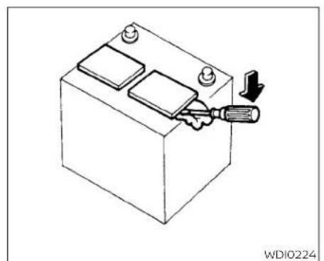
natural_image
Isometric line drawing of a battery with a screwdriver inserted, showing internal components and a downward arrow indicating action (no text or symbols)Battery(TypeA)(ifsoequipped)
- Remove the vent cap(s) with a screw-driver as shown. Use a cloth to protect the battery case.
- Check the fluid level in each cell. If it is necessary to add fluid, add only distilled water to bring the level up to the bottom of the filler opening. Donotoverfill.Re-install the vent cap(s).
Vehicles operated in high temperatures or under severe conditions require frequent checks of the battery fluid level.
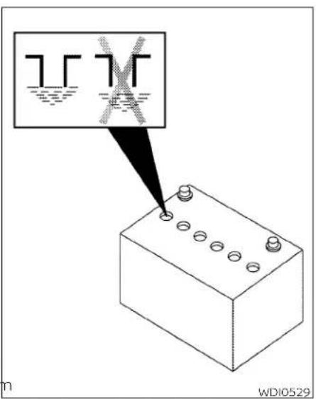

natural_image
Line drawing of a battery housing with mounting feet and internal components (no text or symbols)Battery(TypeB)(ifsoequipped)
NOTE:
Donottrytoopenthetopofthebattery.
The Type B battery is not equipped with removable vent caps.
JUMP STARTING
If jump starting is necessary, see "Jump starting" (P. 6-10). If the engine does not start by jump starting, the battery may have to be replaced. It is recommended that you visit a NISSAN dealer for this service.
VARIABLEVOLTAGECONTROL SYSTEM(ifsoequipped)
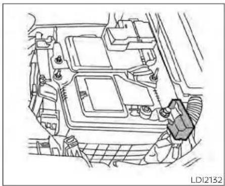
natural_image
Technical line drawing of a car engine bay with no visible text or symbolsCAUTION
- Donotgroundaccessoriesdirectlyto thebatteryterminal.Doingsowill bypasssthevariablevoltagecontrol systemandthevehiclebatterymay notchargecompletely.
- Useelectricalaccessorieswiththe engineerunningtoavoiddischarging thevehiclebattery.
NOTE:
If the battery is completely drained the transmission will not manually shift to other positions.
Your vehicle is equipped with a variable voltage control system. This system measures the amount of electrical discharge from the battery and controls voltage generated by the generator.
The current sensor is located near the battery along the negative battery cable. If you add electrical accessories to your vehicle, be sure to ground them to a suitable body ground such as the frame or engine block area.
DRIVEBELT
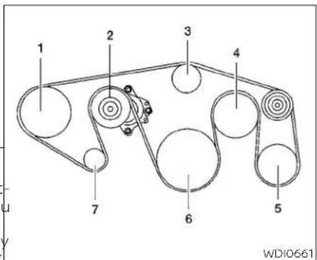
5.6L8cylinder(VK56VDenginemodel)
- Power steering fluid pump pulley
- Automatic belt tensioner pulley
- Water pump pulley
- Cooling fan pulley
- Air conditioner compressor pulley
- Crankshaft pulley
- Generator pulley
WARNING
BesuretheignitionswitchisintheOFF or LOCKpositionbeforeservicingdrive belt. The engine could rotate unexpectedly.
SPARKPLUGS
- Visually inspect the belt for signs of unusual wear, cuts, fraying or looseness. If the belt is in poor condition or is loose, have it replaced or adjusted. It is recommended that you visit a NISSAN dealer for this service.
- Have the belt checked regularly for condition and tension in accordance with the maintenance schedule. For additional information, see the "Maintenance and schedules" section of this manual.

WARNING
Besuretheengineandignitionswitch areoffandthattheparkingbrakeis engagedsecurely.
CAUTION
Besuretousethecorrectsockettore-movethesparkplugs.Anincorrect socketcandamagethesparkplugs.
If replacement is required, it is recommended that you visit a NISSAN dealer for this service.
REPLACING SPARK PLUGS
Iridium-tipped spark plugs
It is not necessary to replace iridium-tipped spark plugs as frequently as conventional type spark plugs because they last much longer. Follow the maintenance log shown in the "Maintenance and schedules" section of this manual. Do not service iridium-tipped spark plugs by cleaning or regapping.
- Alwaysreplacesparkplugswithrecommendedorequivalentones.
AIRCLEANER

natural_image
Technical diagram of a mechanical assembly with arrows indicating force or movement (no text or symbols present)5.6L 8cylinder(VK56VDenginemodel)
WARNING
- Operatingtheenginewiththeair cleanerremovedcancauseyouor otherstobeburned.Theaircleaner notonlycleanstheair,itstopsthe flameiftheenginebackfires.Ifitisn't there,andtheenginebackfires,you couldbeburned.Donotdrivewith theaircleanerremoved,andbecarefulwhenworkingontheenginewith theaircleanerremoved.
- Neverpourfuelintothethrottlebody orattempttostarttheenginewith theaircleanerremoved.Doingso couldresultinserious injury.
To remove the filter from the air cleaner, push the tabs and pull the cover upward.
The viscous paper type filter element should not be cleaned and reused. Replace the air filter according to the maintenance log shown in the "Maintenance and schedules" section of this manual.
When replacing the air filter, wipe the inside of the air cleaner housing and the cover with a damp cloth.
NOTE:
Afterinstallinganewaircleanerfilter, makesuretheair cleanercover isseated inthe housingandlatchthetabs.
IN-CABIN MICROFILTER
The in-cabin microfilter restricts the entry of airborne dust and pollen particles and reduces some objectionable outside odors. The filter is located behind the glove box. For additional information on change intervals, see "Maintenance schedules" (P. 9-7).
If replacement is required, it is recommended that you visit a NISSAN dealer for this service.
WINDSHIELDWIPERBLADES
CLEANING
If your windshield is not clear after using the windshield-washer or if a wiper blade chatters when running, wax or other material may be on the blade or windshield.
Clean the outside of the windshield with a washer solution or a mild detergent. Your windshield is clean if beads do not form when rinsing with clear water.
Clean each blade by wiping it with a cloth soaked in a washer solution or a mild detergent. Then rinse the blades with clear water. If your windshield is still not clear after cleaning the blades and using the wiper, replace the blades.
CAUTION
Wornwindshieldwiperbladescan damagethewindshieldandimpair drivervision.

LDI2725
REPLACING
Replace the wiper blades if they are worn.
- Lift the wiper arm away from the windshield.
- Push and hold the release tabA, and then move the wiper blade dovB the wiper arm to remove.
- Remove the wiper blade.
- Insert the new wiper blade onto the wiper arm until it clicks into place.
CAUTION
- Afterwiperbladereplacement,returnthewiperarmtoitsoriginalposition;otherwiseitmaybedamaged whenthehoodisopened.
- Makesurethewiperbladescontact theglass;otherwisethearmsmaybe damagedfromwindpressure.
BRAKES

Be careful not to let anything get into the washer nozzle. This may cause clogging or improper windshield-washer operation. If something gets into the nozzle, remove with a needle or small p.
If the brakes do not operate properly, have Under some driving or climate conditions, the brakes checked. It is recommended that you visit a NISSAN dealer for this service. occasional brake squeak, squeal or other noise may be heard. Occasional brake noise during light to moderate stops is nor-
Self-adjusting brakes
Your vehicle is equipped with self-adjusting brakes.
The front and rear disc-type brakes self-adjust every time the brake pedal is applied.
Properbrakeinspectionintervalsshould befollowed. For additional information on the appropriate maintenance schedule regarding brake inspections, see "Maintenance schedules" (P. 9-7).
WARNING
Haveyourbrakesystemcheckedifthe brakepedalheightdoesnotreturnto normal.Itisrecommendedthatyou visitaNISSANdealerforthisservice.
Brake pad wear indicators
The disc brake pads on your vehicle have audible wear indicators. When a brake pad requires replacement, a high pitched scraping or screeching sound will be heard when the vehicle is in motion. The noise will be heard whether or not the brake pedal is depressed. Have the brakes checked as soon as possible if the wear indicator sound is heard.
FUSES

natural_image
Technical line drawing of a mechanical component with no visible text or symbolsLDI2385 | LDI2962

natural_image
Technical line drawing of a vehicle chassis with mechanical components (no text or symbols)5.6L8cylinder(VK56VDenginemodel) ENGINE COMPARTMENT

natural_image
Technical line drawing of a mechanical assembly with no visible text or symbols5.6L8cylinder(VK56VDenginemodel) (non-XDmodel)
If any electrical equipment does not operate, check for an open fuse.
Fuses are used in the passenger and engine compartment. Spare fuses are provided and can be found in the passenger compartment fuse box.
When installing a fuse make sure the fuse installed in the fuse box securely.
8-24 Do-it-yourself
If any electrical equipment does not come on, check for an open fuse.
- Be sure the ignition switch and the head-light switch are OFF.
- Open the engine hood.
- Remove the fuse box cover by pushing the tab and lifting the cover up.
- Remove the fuse with the fuse puller. The fuse puller is located in the center of the fuse block in the passenger compartment.
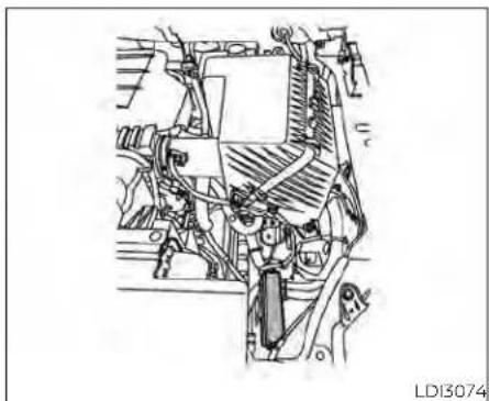
natural_image
Technical line drawing of a mechanical assembly (no text or symbols visible)5.6L8cylinder(VK56VDenginemodel) (XDmodel)

- If the fuse is openⒶ, replace it with a new fuseⒷ.
- If a new fuse also opens, have the electrical system checked and repaired. It is recommended that you visit a NISSAN dealer for this service.
Fusible links
If the electrical equipment does not operate and fuses are in good condition, check the fusible links. If any of these fusible links are melted, replace with only Genuine NISSAN parts.

natural_image
Technical line drawing of a vehicle door frame with a seatbelt component (no text or symbols)PASSENGER COMPARTMENT
WARNING
Neveruseafuseofhigherorloweramperageratingthanthatspecifiedon thefuseboxcover.Thiscoulddamage theelectricalsystemorelectroniccontrolunitsorcauseafire.
If any electrical equipment does not operate, check for an open fuse.
- Be sure the ignition switch and the head-light switch are OFF.
- Open the glove box.
- Remove the fuse box cover.
- Locate the fuse that needs to be replaced.

LDI2884|LDI2760
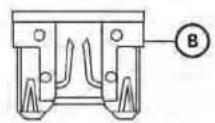

-
Remove the fuse with the fuse puller. 6. If the fuse is open ⓑ, replace it with an equivalent good fuse.
-
Push the fuse box cover to install.
If a new fuse also opens, have the electrical system checked and repaired. It is recommended that you visit a NISSAN dealer for this service.
BATTERYREPLACEMENT
CAUTION
Becarefulnottoallowchildrenoswallowthebatteryorremovedparts.

flowchart
graph TD
    A["Engine"] --> B["Component A"]
    B --> C["Component B"]
    C --> D["Motor"]
    style A fill:#f9f,stroke:#333
    style B fill:#ccf,stroke:#333
    style C fill:#cfc,stroke:#333
    style D fill:#fcc,stroke:#333
NISSAN INTELLIGENT KEY®
Replace the battery in the Intelligent Key as follows:
- Remove the mechanical key from the Intelligent Key.
- Insert a small flathead screwdriver (A) into the slit (B) of the corner and twist it to separate the upper part from the lower part. Place a cloth over the screwdriver to protect the casing.

-
Replace the battery with a new one. Recommended battery: CR2032 or equivalent.
-
Do not touch the internal circuit and electric terminals as doing so could cause a malfunction.
- Hold the battery by the edges. Holding the battery across the contact points will seriously deplete the storage capacity.
• Make sure that the + side faces the bottom of the lower part. - Close the lid securely as illustrated with Ⓒ and Ⓓ.
- Operate the buttons to check the operation.
If you need assistance with replacement, is recommended that you visit a NISSAN dealer for this service.
FCCNotice:
ForUSA:
ThisdevicecomplieswithPart15ofthe FCCRules.Operationissubjecttothefollowingtwoconditions:(1)Thisdevicemaynotcauseharmfulinterference,and(2)thisdevicemustacceptanyinterferencereceived,includinginterferencethatmaycauseundesiredoperation.
Note:
Changesormodificationsnotexpressly approvedbythe party responsiblefor compliancecouldvoidtheuser'sauthoritytooperatetheequipment.
ForCanada:
This device contains license-exempt transmitter(s)/receiver(s)thatcomply withInnovation,ScienceandEconomic Development Canada'slicense-exempt RSS(s).Operationissubjecttothefollowingtwoconditions:(1)Thisdevice maynotcauseinterference,and(2)This devicemustacceptanyinterference,includinginterferencethatmaycauseun-desiredoperationofthedevice.
LIGHTS
HEADLIGHTS
For additional information on headlight bulb replacement, refer to the instructions outlined in this section.
Replacing the halogen headlight bulb (if so equipped)
The headlight is a semi-sealed beam type which uses a replaceable headlight (halogen) bulb. Because the headlight assembly must be removed from the vehicle for bulb replacement, it is recommended that you visit a NISSAN dealer for this service.
CAUTION
- Aimingisnotnecessaryafterreplacingthebulb.Whenaimingadjustmentisnecessary,itisrecommendedthatyouvisitaNISSAN dealerforthisservice.
-
Donotleavetheheadlightassembly openwithoutabulbinstalledfora long period of time. Dust, moisture, smoke,etc.enteringtheheadlight body may affect bulb performance. Removethebulbfromtheheadlight assemblyjustbeforeareplacement bulbisinstalled.
-
Onlytouch thebase whenhandling thebulb.Nevertouchtheglassenvelope.Touchingtheglasscouldsignificantlyaffectbulblifeand/or headlightperformance.
- Highpressurehalogengasissealed insidethehalogen bulb. The bulb may break if the glassenvelope is scratched the bulb is dropped.
- Use the same number and wattage asshowninthechart.
Fog may temporarily form inside the lens of the exterior lights in the rain or in a car wash. A temperature difference between the inside and the outside of the lens causes the fog. This is not a malfunction. If large drops of water collect inside the lens, it is recommended that you visit a NISSAN dealer for servicing.
Replacing the LED headlight bulb (if so equipped)
If LED headlight bulb replacement is required, it is recommended that you visit a NISSAN dealer for this service.
FOG LIGHTS (if so equipped)
For additional information on fog light bulb replacement, refer to the instructions outlined in this section.

Foglight(TypeB)(ifsoequipped) Replacing the fog light bulb
CAUTION
- Highpressurehalogengasissealed insidethehalogenbulb.Thebulb maybreakiftheglassenvelopeis scratchedorthebulbisdropped.
- Whenhandlingthebulb, donottouch theglassenvelope.
- Usethesamenumberandwattage asoriginallyinstalledasshowninthe chart.
- Donotleavethebulboutofthefog lightforalongperiodoftimeasdust, moistureandsmokemayenterthe foglightbodyandaffecttheperformanceofthefoglight.
NOTE:
The foglight is accessible in front of the front tire and behind the bumper.
- Push the ignition switch to the OFF position and wait 2 minutes.
- Disconnect the negative (-) battery cable.
- Disconnect the bulb connector.
- Rotate the bulb Ⓐ counterclockwise and remove.
- Remove by pulling it straight out of the fog light assembly. Do not shake or rotate the bulb when removing it. Do not touch the glass envelope.
- Install in the reverse order of removal.
DAYTIME RUNNING LIGHT (DRL) (if so equipped)
For additional information on the DRL bulb replacement, refer to the instructions outlined in this section.

natural_image
Technical line drawing of a mechanical assembly with labeled component A (no text or symbols beyond label)Foglightassembly(TypeA) (ifsoequipped)(Canadaonly)
Replacing the daytime running light bulb (Canada only)
NOTE:
Thedaytimerunninglightisaccessible infrontofthefronttireandbehindthe bumper.
-
Push the ignition switch to the OFF position and wait 2 minutes.
-
Disconnect the negative (-) battery cable.

natural_image
Technical diagram of a mechanical assembly with labeled component A (no text or symbols beyond label)Daytimerunninglight(ifsoequipped) (Canadaonly)
- Disconnect the daytime running light bulb connector.
- Rotate the daytime running light bulb Ⓐ counterclockwise and remove.
- Remove by pulling it straight out of the fog light assembly. Do not shake or rotate the bulb when removing it. Do not touch the glass envelope.
- Install in the reverse order of removal.
EXTERIOR AND INTERIOR LIGHTS
| Item Wattage (W) Bulb No* | ||
| Headlight assembly (Type A) (if so equipped)* | ||
| Low (Halogen) 55 H11 | ||
| High (Halogen) 60 HB3 | ||
| Turn/Park 28/8 7444NA | ||
| Side marker 5 W5W | ||
| Headlight assembly (Type B) (if so equipped)* | ||
| Low | — | — |
| High | — | — |
| Daytime running/Park | — | — |
| Turn | 28/8 7444NA | |
| Side marker | — | — |
| Fog light assembly (Type A) (if so equipped) (Canada only) | ||
| Fog | 35 | H8 |
| Daytime running | 21 | W21W |
| Fog light (Type B) (if so equipped) | — | — |
| Door mirror turn signal light (if so equipped)* | — | — |
| Puddle light (if so equipped)* | — | — |
| Rear combination light (Type A) (if so equipped)* | ||
| Stop | 16 | PW16W |
| Backup (reversing) | 16 | 921 |
| Turn/Tail | 27/7 | 3057K |
| Rear combination light (Type B) (if so equipped)* | ||
| Stop | — | — |
| Backup (reversing) | 16 | 921 |
| Turn/Tail | 27/7 | 3057K |
| Cargo (tailgate) (if so equipped) | — | — |
| Rear combination light (Type C) (if so equipped)* | ||
| Stop | — | — |
| Backup (reversing) | 16 | W16W |
| Turn/Tail | 21 | WY21W |
| Cargo (tailgate) (if so equipped) | 16 | 921 |
| High-mounted stop light* | ||
| Stop | — | — |
| Cargo (roof) — | — | |
| Under rail bed light (if so equipped)* | — | — |
| License plate light* | — | — |
| Map light (if so equipped)* | 8 | — |
| Room light* | — | — |
| Footwell light (if so equipped)* | — | — |
| Vanity mirror light (if so equipped)* | — | — |
| Glove box light (if so equipped)* | 3.4 158 |
* Always check with the Parts Department at a NISSAN dealer for the latest parts information.
x It is recommended that you visit a NISSAN dealer for assistance.
8-32 Do-it-yourself
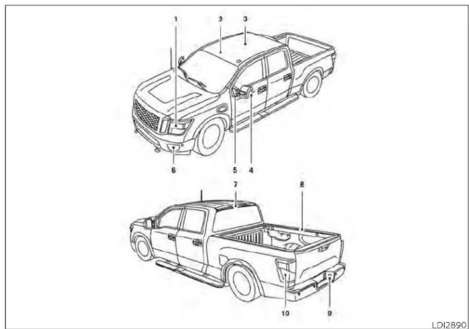
- Headlight assembly
- Map light (if so equipped)
-
Room light (if so equipped)
-
Door mirror turn signal light (if so equipped)
- Puddle light (if so equipped)
-
Fog light (if so equipped)
-
High-mount stop light
- Under rail bed light (if so equipped)
- License plate light
- Rear combination light
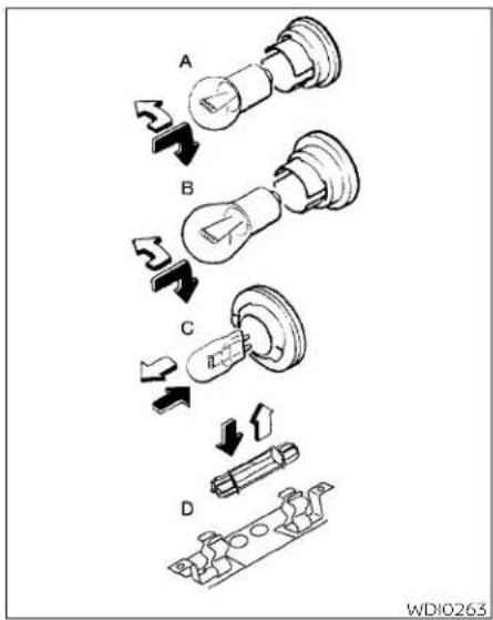
Replacement procedures
All other lights are either type A, B, C or when replacing a bulb, first remove the lens, lamp and/or cover.
Indicates bulb removal
↑ Indicates bulb installation
8-34 Do-it-yourself
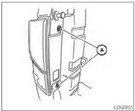
Rearcombinationlight
NOTE:
Rearcombinationlight(TypeB)(ifso equipped)bulbreplacementprocedure is shown. Rearcombinationlight(TypeA) (ifso equipped)bulbreplacementprocedure is similar.
To replace the rear combination light bulbs perform the following procedure:
- Remove the two fasteners Ⓐ and pull the rear combination light away from the vehicle.
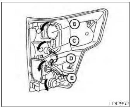
Rearcombinationlight
- Remove harness connector and rotate stop light bulb Ⓗ counterclockwise to remove. Replace bulb if necessary.
- Rotate reverse light bulb socket @ counterclockwise to remove. Replace bulb if necessary.
- Rotate cargo (tailgate) light bulb socket 6 ① (if so equipped) counterclockwise to remove. Replace bulb if necessary.
- Rotate turn/tall light bulb socket Ⓔ counterclockwise to remove. Replace bulb if necessary.
Reverse steps to install bulbs and rear combination light.
WHEELSANDTIRES
If you have a flattire, see "Flattire" (P.6-3).
TIRE PRESSURE
Tire Pressure Monitoring System (TPMS)
WARNING
Radiowavescouldadverselyaffectelectricmedicalequipment. Thosewhouseapacemaker shouldcontacttheelectricmedicalequipmentmanufacturerfor thepossibleinfluencesbefore use.
This vehicle is equipped with the Tire Pressure Monitoring System (TPMS). It monitors tire pressure of all four tires except the spare. When the low tire pressure warning light is lit and the "Tire Pressure Low - Add Air" warning appears in the vehicle infor-mended tire pressure specifications mation display, one or more of your are shown on the F.M.V.S.S./C.M.V.S.S tires is significantly under-inflated. If certification label or the Tire and
equipped, the system also displays pressure of all tires (except the spare tire) on the display screen by sending a signal from a sensor that is installed in each wheel. The TPMS will activate only when the vehicle is driven at speeds above 16 mph (25 km/h). Also, this system may not detect a sudden drop in tire pressure (for example a flat tire while driving).
For additional information, see "Warning lights, indicator lights and audible reminders" (P. 2-12), "Tire Pressure Monitoring System (TPMS)" (P. 5-5), and "Flat tire" (P. 6-3).
Tire inflation pressure
√Check the tire pressures (including the spare) often and always prior to long distance trips. The recom-- amended tire pressure specifications are shown on the F.M.V.S.S./C.M.V.S.S. certification label or the Tire and Loading Information label under the "Cold Tire Pressure" heading. The Tire and Loading Information label is affixed to the driver side center pillar. Tire pressures should be checked regularly because:
- Most tires naturally lose air over time.
reTires can lose air suddenly when e driven over potholes or other ob- jects or if the vehicle strikes a curb while parking.
The tire pressures should be checked when the tires are cold. The tires are considered COLD after the vehicle has been parked for 3 or more hours, or driven less than 1 mile (1.6 km) at moderate speeds.
The TPMS with Easy-Fill Tire Alert provides visual and audible signals outside the vehicle for inflating tires to the recommended COLD tire pressure. For additional information, see "TPMS with Easy-Fill Tire Alert" (P. 5-8).
Do-it-yourself8-35
Incorrect tire pressure, including under inflation, may adversely affect tire life and vehicle handling.
WARNING
- Improperlyinflatedtirescan failsuddenlyandcausean accident.
- TheGrossVehicleWeightRating(GVWR)islocatedontheF.M.V.S.S./C.M.V.S.S.certificationlabel.Thevehicleweight capacityisindicatedontheTire and Loading Information label. Donotloadyourvehiclebeyondthiscapacity.Overloading yourvehiclemayresultinreducedtirelife,unsafeoperating conditions due topremature tirefailure,or unfavorable handling characteristics andcould also lead to a serious accident. Loadingbeyondthespecified capacity may also result in failure of other vehicle components.
- Before taking a long trip, or whenever you heavily load your vehicle, use a tire pressure gaugeto ensure that the tire pressures are at the specified level. - For additional information regarding tires, refer to "Important Tire Safety Information" (US) or "Tire Safety Information" (Canada) in the Warranty Information Booklet.
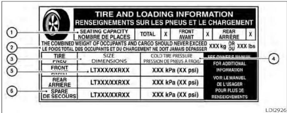
Tire and Loading Information label
① Seating capacity: The maximum number of occupants that can be seated in the vehicle.
② Vehicle load limit: For additional information, see "Vehicle loading information" (P. 10-22).
③ Original tire size: The size of the tires originally installed on the vehicle at the factory.
④ Cold tire pressure: Inflate the tires to this pressure when the tires are cold. Tires are considered COLD after the vehicle has been parked for 3 or more hours, or driven less than 1 mile (1.6 km) at moderate speeds. The recommended cold tire inflation is set by the manufacturer to provide the best balance of tire wear, ve-
hicle handling, driveability, tire noise, etc., up to the vehicle's GVWR.
⑤ Tire size - see "Tire labeling" (P. 8-39).
⑥ Spare tire size.

natural_image
Technical line drawing of a mechanical assembly with a central component and surrounding components (no text or symbols)Checking tire pressure
- Remove the valve stem cap from the tire
-
Press the pressure gauge squarely onto the valve stem. Do not press too hard or force the valve stem sideways, or air will escape. If the hissing sound of air escaping from the tire is heard while checking the pressure, reposition the gauge to eliminate this leakage.
-
Remove the gauge.
-
Read the tire pressure on the gauge stem and compare to the specification shown on the Tire and Loading Information label.
- Add air to the tire as needed. If too much air is added, press the core of the valve stem briefly with the tip of the gauge stem to release pressure. Recheck the pressure and add or release air as needed.
- Install the valve stem cap.
- Check the pressure of all other tires, including the spare.
| Size Cold Tire | inflationPressure |
| Front OriginalTire:265/70R18 270P265/70R18 250P275/60R20P275/70R18LT245/75R17LT275/65R18LT265/60R20 | kPa, 39 psikPa, 36 psi250 kPa, 36 psi240 kPa, 35 psi450 kPa, 65 psi450 kPa, 65 psi |
| Size Cold Tire | inflationPressure |
| Rear OriginalTire:265/70R18 270P265/70R18 250P275/60R20P275/70R18LT245/75R17LT275/65R18LT265/60R20 | kPa, 39 psikPa, 36 psi250 kPa, 36 psi240 kPa, 35 psi500 kPa, 73 psi450 kPa, 65 psi480 kPa, 70 psi |
| Spare Tire Sizes: | Cold Tire Inflation Pressure |
| 265/70R18 270 | kPa, 39 psi |
| P265/70R18 250 | kPa, 36 psi |
| P275/70R18 | 240 kPa, 35 psi |
| P275/60R20 | 250 kPa, 36 psi |
| LT245/75R17 | 500 kPa, 73 psi |
| LT275/65R18 | 450 kPa, 65 psi |
| LT265/60R20 | 480 kPa, 70 psi |

Example
TIRE LABELING
Federal law requires tire manufacturers to place standardized information on the sidewall of all tires. This information identifies and describes the fundamental characteristics of the tire and also provides the Tire Identification Number (TIN) for safety standard certification. The TIN can be used to identify the tire in case of a recall.

other
LT215/65R15 95H | Label | Value | |---|---| | LT | 1 | | 215 | 2 | | 65 | 3 | | R | 4 | | 15 | 5 | | 95 | 6 | | H | 7 | LDI2043Example
① Tire size (example: LT215/65R15 395H)
- LT: The "LT" indicates the tire is designed for light truck vehicles (not all tires have this information). 4
2 Three-digit number (215): This number gives the width in millimeters of the tire from sidewall edge to sidewall edge.
-
Two-digit number (65): This number, known as the aspect ratio, gives the tire's ratio of height to width.
-
R: The "R" stands for radial.
-
Two-digit number (15): This number is the wheel or rim diameter in inches.
-
Two- or three-digit number (95): This number is the tire's load index. It is a measurement of how much weight each tire can support. You may not find this information on all tires because it is not required by law.
- H: Tire speed rating. You should not drive the vehicle faster than the tire speed rating.
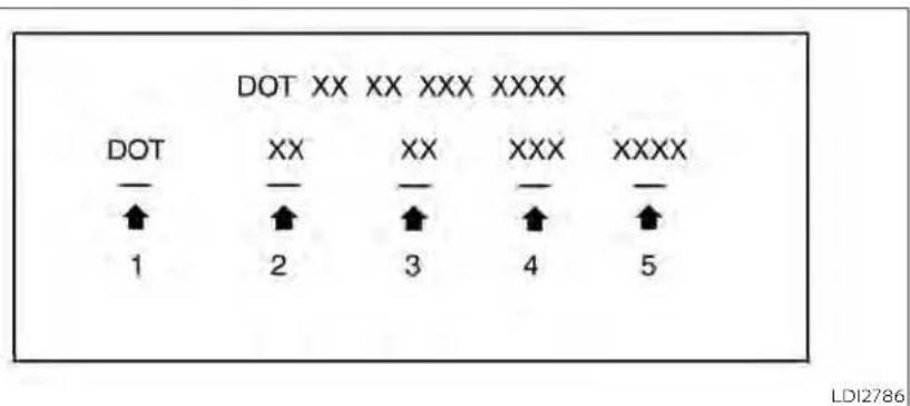
Example
② TIN (Tire Identification Number) for a new tire (example: DOT XX XX XXX XXXX)
- DOT: Abbreviation for the "Department Of Transportation". The symbol can be placed above, below or to the left or right of the Tire Identification Number.
-
Two-digit code: Manufacturer's identification mark.
-
Two-digit code: Tire size.
- Three-digit code: Tire type code (Optional).
- Four numbers represent the week and year the tire was built. For example, the numbers 3103 means the 31st week of 2003. If these numbers are missing then look on the other sidewall of the tire.
③ Tire ply composition and materia The number of layers or plies of rubber-coated fabric in the tire. Tire manufacturers also must indicate the materials in the tire, which include steel, nylon, polyester and others.
④ Maximum permissible inflation pressure
This number is the greatest amount of air pressure that should be put in the tire. Do not exceed the maximum permissible inflation pressure.
⑤ Maximum load rating
This number indicates the maximum load in kilograms and pounds that can be carried by the tire. When replacing the tires on the vehicle, all-rms ways use a tire that has the same load rating as the factory installed of tire.
⑥ Term of "tubeless" or "tube type"
Indicates whether the tire requires an inner tube ("tube type") or not ("tubeless").
⑦ The word "radial"
The word "radial" is shown if the tire has radial structure.
⑧ Manufacturer or brand name
Manufacturer or brand name is shown.
OtherTire-relatedTerminology
In addition to the many terms that are defined throughout this section, Intended Outboard Sidewall is (1) the sidewall that contains a whitewall, bears white lettering or bears manufacturer, brand, and/or model name molding that is higher or deeper than the same molding on the other sidewall of the tire, or (2) the outward facing sidewall of an asymmetrical tire that has a particu-
lar side that must always face out-ward when mounted on a vehicle.
TYPES OF TIRES
WARNING
- Whenchangingorreplacingtires, be sure all four tires are of the same type (i.e., Summer, All Season or Snow) and construction. ANISSANdealer maybe able to help you within information about tire type, size, speed rating and availability.
- Replacementtiresmayhavealower speed rating than the factory equipped tires, and may not match the potential maximum vehicle speed. Neverexceed themaximum speedratingofthetire.
-
Replacingtireswiththosenotoriginally specified by NISSAN could affecttheproperoperationofthelow tirepressurewarningsystem.
-
Alwaysusetiresofthesametype, size,brand,constructionandtread patternonallfourwheels.Failureto dosomayresultinacircumference differencebetweeniresonthefront andrearaxleswhichcancausethe VehicleDynamicControl(VDC)systemand4WDsystemtomalfunction resultinginpersonalinjuryordeath, excessivetirewearandmaydamage thetransmissionanddifferential gears.
- Foradditionalinformationregarding tires,referto"ImportantTireSafety Information"(US)or"TireSafetyInformation"(Canada)intheWarranty InformationBooklet.
All season tires
NISSAN specifies All Season tires on some models to provide good performance all year, including snowy and icy road conditions. All Season tires are identified by ALL SEASON and/or M&S on the tire sidewall. Snow tires have better snow traction than All Season tires and may be more appropriate in some areas.
Summer tires
NISSAN specifies summer tires on some models to provide superior performance on dry roads. Summer tire performance is substantially reduced in snow and ice. Summer tires do not have the tire traction rating "M&S" on the tire sidewall.
If you plan to operate your vehicle in snow or icy conditions, NISSAN recommends the use of SNOW tires or ALL SEASON tires on four wheels.
Snow tires
If snow tires are needed, it is necessary to select tires equivalent in size and load rating to the original equipment tires. If you do not, it can adversely affect the safety and handling of your vehicle.
Generally, snow tires have lower speed ratings than factory equipped tires and may not match the potential maximum vehicle speed. Never exceed the maximum speed rating of the tire.
If you install snow tires, they must be the same size, brand, construction and tread pattern on all four wheels.
For additional traction on icy roads, studded tires may be used. However, some U.S. states and Canadian provinces prohibit their use. Check local, state and provincial laws before installing studded tires. Skid and traction capabilities of studded snow tires on wet or dry surfaces may be poorer than that of non-studded snow tires.
TIRE CHAINS
Use of tire chains may be prohibited according to location. Check the local laws before installing tire chains. When installing tire chains, make sure they are the proper size for the tires on your vehicle and are installed according to the chain manufac-
turer's suggestions. UseonlySAEclass"S" chains. Class "S" chains are used on vehicles with restricted tire to vehicle clearance. Vehicles that can use Class "S" chains are designed to meet the minimum clearances between the tire and the closest vehicle suspension or body component required to accommodate the use of a winter traction device (tire chains or cables). The minimum clearances are determined using the factory equipped tire size. Other types may damage your vehicle. Use chain tensioners when recommended by the tire chain manufacturer to ensure a tight fit. Loose end links of the tire chain must be secured or removed to prevent the possibility of whipping action damage
to the fenders or underbody. If possible, avoid fully loading your vehicle when using tire chains. In addition, drive at a reduced speed. Otherwise, your vehicle may be damaged and/or vehicle handling and performance may be adversely affected.
Tirechainsmustbeinstalledonlyonthe rearwheelsandnotonthefrontwheels.
Do not use tire chains on dry roads. Driving with chains in such conditions can cause damage to the various mechanisms of the vehicle due to some overstress.
Use only the 2WD range when driving on clear paved roads.

flowchart
graph TD
    A["Stage 1"] --> B["Stage 2"]
    B --> C["Stage 3"]
    C --> D["Stage 4"]
    D --> A
    style A fill:#f9f,stroke:#333
    style B fill:#f9f,stroke:#333
    style C fill:#f9f,stroke:#333
    style D fill:#f9f,stroke:#333
WDI0258
CHANGING WHEELS AND TIRES
Tire rotation
NISSAN recommends rotating tires every 7,500 miles (12,000 km).
For additional information on tire replacing procedures, see "Flat tire" (P. 6-3).
Assoonaspossible,tightenthewheel nutstothespecifiedtorquewitha torquewrench.
Wheelnuttighteningtorque:
Non-XDmodels:
98ft-lb(133N·m)
XDmodels:
131ft-lb(177N·m)
The wheelnuts must be kept tightened to specifications at all times. It is recommended that wheel nuts be tightened to specification at each tire rotation interval.
WARNING
- Retightenthewheelnutswhenthe vehiclehasbeen driven for600 miles (1,000km)(alsoincasesofaflattire, etc.).
- Donotincludethesparetireinthe tirerotation.
- For additional information regarding tires, refer to "Important Tire Safety Information" (US) or "Tire Safety Information" (Canada) in the Warranty Information Booklet.
- After rotating the tires, do not use the Easy-FillTireAlerttoadjustthetire pressure.Insteaduseagaugetoadjustthetirestothecorrectpressure inaccordancewithTireandLoading Informationlabel.
CAUTION
ToensureproperoperationoftheEasyFillTireAlertsystemafteratirerotation,re-setandregisterthesensorto theirnewinstalledlocations.ItisrecommendedthatyouvisitaNISSAN dealerforthisservice.

WD10259
Tire wear and damage
- Wear indicator
- Location mark
WARNING
- Tiressshouldbeperiodicallyin-spectedforwear,cracking,bulgingorobjectscaughtinthetread.Ifexcessivewear,cracks,bulgingordeep cutsarefound,thetire(s)shouldbereplaced.
- Theoriginaltireshavebuilt-in tread wear indicators.When thewearindicatorsarevisible, thetire(s)shouldbereplaced.
-
Tiresdegradewith age and use. Have tires, including the spare, over 6 years old checked by a qualified technician because some tire damage may not be obvious. Replace the tires as necessary to prevent tire failure and possible personal injury.
-
Improperserviceofthespare tiremayresultinseriouspersonalinjury.Ifitisnecessaryto repairthesparetire,itisrecommendedthatyouvisita NISSANdealerforthisservice.
- Foradditionalinformationregardingtires,referto"ImportantTireSafetyInformation"(US)or"TireSafetyInformation"(Canada)intheWarrantyInformationBooklet.
Replacing wheels and tires
When replacing a tire, use the same size, tread design, speed rating and load carrying capacity as originally equipped. Recommended types and sizes are shown in "wheels and tires" (P. 8-35).
WARNING
- Theuseoftiresotherthanthoserecommendedorthemixeduseoftires ofdifferent brands, construction (bias,bias-beltedorradial),ortread patternscan adversely affect the ride,braking,handling,VehicleDynamic Control (VDC) system, 4WD, ground clearance, body-to-tire clearance,tirechainclearance,speedometercalibration,headlightaimand bumperheight.Someofthese effects maylead to accidentsand could result in serious personal injury.
- If your vehicle was originally equipped with four tires that were the namesize and you are only replacing two of the four tires, install the new tires on the rear axle. Placing new tires on the front axle may cause loss of vehicle control in some driving conditions and cause an accident and personal injury.
- Ifthewheelsarechangedforany reason,alwaysreplacewithwheels whichhavethesameoff-setdimension. Wheels of a different off-set couldcauseprematuretirewear,degradevehiclehandlingcharacteristics, affectthe VDCsystemand/or interferencewiththebrakediscs.Such interferencecanleadtodecreased braking efficiency and/orearly brake pad/shoewear.Foradditionalinformationonwheel-offsetdimensions, see"Wheelsandtires"(P.10-9).
- When usingawheelwithout the TPMS such as the spare tire, the TPMS will not function and the low tire pressurewarninglightwillflashfor approximately1 minute. Thelight will remainonafter1minute.Haveyour tiresreplacedand/orTPMSsystem reset assoonaspossible. Itisrecommended that you visit a NISSAN dealerforthisservice.
- ReplacingtireswiththosenotoriginallyspecifiedbyNISSANcouldaffect the proper operation of the TPMS.
- TheTPMSsensormaybedamagedif itisnothandledcorrectly.Becareful whenhandlingtheTPMSsensor.
- WhenreplacingtheTPMSsensor,the IDregistrationmayberequired.ContactaNISSANdealerforID registration.
- Donotuseavalvestemcapthatis notspecifiedbyNISSAN.Thevalve stemcapmaybecomestuck.
- Besurethatthevalvestemcapsare correctlyfitted. Otherwisethevalve maybecloggedupwithdirtand causeamalfunctionorlossof pressure.
- Donotinstalladamagedordeformedwheelortireevenifithas beenrepaired.Suchwheelsortires couldhave structural damage and couldfailwithoutwarning.
- The use of retread tires is not recommended.
- Foradditionalinformationregarding tires,referto "ImportantTire Safety Information"(US)or"TireSafetyInformation"(Canada)in theWarranty InformationBooklet.
4x4 Four-wheel drive models
CAUTION
Alwaysusetiresofthesametype,size, brand,construction(bias,bias-belted orradial),andtreadpatternonallfour wheels.Failureretodosomayresultina circumferencedifferencebetweentires onthefrontandrear axleswhichwill causeexcessivetirewearandmay damage the transmission,transfer caseanddifferentialgears.
If excessive tire wear is found, it is recommended that all four tires be replaced with tires of the same size, brand, construction and tread pattern. The tire pressure and wheel alignment should also be checked and corrected as necessary. It is recommended that you visit a NISSAN dealer for this service.
Wheel balance
Unbalanced wheels may affect vehicle handling and tire life. Even with regular wheels can get out of balance. Therefore, they should be balanced as required.
Wheel balance service should be performed with the wheels off the vehicle.
Spinbalancingthewheelsonthevehicle could lead to mechanical damage.
- For additional information regarding tires, refer to "Important Tire Safety Information" (US) or "Tire Safety Information" (Canada) in the Warranty Information Booklet.
Care of wheels
- wash the wheels when washing the vehicle to maintain their appearance.
- Clean the inner side of the wheels when the wheel is changed or the underside of the vehicle is washed.
Do not use abrasive cleaners when washing the wheels.
- Inspect wheel rims regularly for dents or corrosion. Such damage may cause loss of pressure or poor seal at the tire bead.
- NISSAN recommends waxing the road wheels to protect against road salt in areas where it is used during winter.
Spare tire (FULL SIZE TEMPORARY USE ONLY spare tire)
When using a wheel without the TPMS such as the spare tire, the TPMS will not function.
Your vehicle may be equipped with a full size spare that is a different size or brand
than the tires originally installed on the vehicle. This full size spare tire is intended for temporary use only and should be replaced at the first opportunity.
Observe the following precautions if the FULL SIZE TEMPORARY USE ONLY spare tire must be used. Otherwise, your vehicle could be damaged or involved in an accident:
WARNING
Tohelpreducetheriskofacrashwhich mayresultinpersonalinjuryordeath:
- TheTEMPORARYFULLSIZEsparetire shouldbeusedforemergencyuse only.itshouldbereplacedwiththe standardtireatthefirstopportunity toavoidpossibletireordifferential damage.
- DrivecarefullywhiletheTEMPORARY FULLSIZEsparetireisinstalled.Avoid sharpturns and abruptbraking while driving.Thevehicledrivingperformance maybeaffectedwhendriving onwetorsnowcoveredroads.
-
WhentheTEMPORARYFULLSIZE spare is installed, the following systemsmaynotworkcorrectly:
-
TirePressureMonitoringSystem (TPMS)
-
Vehicle Dynamic Control (VDC) System
-
Periodically check the TEMPORARY FULLSIZEsparetireinflationpressure.AlwayskeeptheTEMPORARY FULL SIZE inflated to the pressure specification shownon theTireand LoadingInformationlabel.
- With the TEMPORARY FULL SIZE spare tireinstalleddonotdrivethevehicle atspeedsfaster than50mph(80 km/h).
- When driving on roads covered with snowor ice,theTEMPORARYFULL SIZEsparetireshouldbeusedonthe frontwheelsandtheoriginaltire usedon therear wheels.Usetire chainsonlyonthedrivewheels.
- Do not use the TEMPORARY FULL SIZE spare tire on other vehicles.
- DonotusemorethanoneTEMPO-RARY FULL SIZE spare tire at the same time.
• TEMPORARYFULLSIZEsparetire Limitations(exceptforPro4X)
- 50mphMAX
- Towingallowed
- CustomercanidentifyTEMPORARY FULLSIZEsparetireconditionby checking the Tire and loading informationlabellocatedontheB-pillar.
CAUTION
- Donotusetirechainson aTEMPO-RARY FULLSIZEsparetire. Tirechains willnotfitproperlyandmaycause damagetothevehicle.
- UseoftheTEMPORARYFULLSIZE spare tire on a vehicle that has tires largerthanwereoriginallyequipped canaffectthe4WDsystem. This may resultinacircumferencedifference betweeniresonfrontandrearaxles which can cause the 4WD system to automaticallyplacethevehicle in 2WDandflashthe4WDlight. When theTEMPORARYFULLSIZEsparetire is replaces with a tire that matches all othertires onthevehicle, andalltires are properly inflatedthe4WDsystem willoperatenormally
MEMO
8-48 Do-it-yourself
9Maintenanceandschedules
Maintenance requirements 9 - 2
General maintenance 9 - 2
Scheduled maintenance 9 - 2
Where to go for service 9 - 2
General maintenance 9 - 2
Explanation of general maintenance
items 9 - 2
Explanation of scheduled maintenance items . . . 9-5
Emission control system maintenance: .....9 - 5
Chassis and body maintenance: 9 - 6
Maintenance schedules 9 - 7
Additional maintenance items for severe operating conditions 9 - 7
5.6L 8 cylinder (VK56VD engine model) ..... 9 - 7
MAINTENANCEREQUIREMENTS
GENERALMAINTENANCE
Some day-to-day and regular maintenance is essential to maintain your vehicle's good mechanical condition, as well as it's emissions and engine performance.
It is the owner's responsibility to make sure that the scheduled maintenance, as well as general maintenance, is performed.
As the vehicle owner, you are the only one who can ensure that your vehicle receives proper maintenance. You are a vital link in the maintenance chain.
GENERAL MAINTENANCE
General maintenance includes those items which should be checked during normal day-to-day operation. They are essential for proper vehicle operation. It is your responsibility to perform these maintenance procedures regularly as prescribed.
Performing general maintenance checks requires minimal mechanical skill and only a few general automotive tools.
These checks or inspections can be done by you, a qualified technician or, if you prefer, a NISSAN dealer.
SCHEDULED MAINTENANCE
The maintenance items listed in this section are required to be serviced at regular intervals. However under severe driving conditions, additional or more frequent maintenance will be required.
WHERE TO GO FOR SERVICE
If maintenance service is required or your vehicle appears to malfunction, have the systems checked and serviced. It is recommended that you visit a NISSAN dealer for this service.
NISSAN technicians are well-trained specialists and are kept up-to-date with the latest service information through technical bulletins, service tips and training programs. They are fully qualified to work on NISSAN vehicles beforework begins.
If your vehicle is involved in a collision, it is recommended that you ask your NISSAN dealer where the nearest NISSAN Certified Collision Center is located, or go to http://collision.nissanusa.com.
You can be confident that a NISSAN dealer's service department can perform the service needed to meet the maintenance requirements on your vehicle.
During the normal day-to-day operation of the vehicle, general maintenance should be performed regularly as prescribed in this section. If you detect any unusual sounds, vibrations or smells, be sure to check for the cause or have it checked promptly. In addition, it is recommended that you visit a NISSAN dealer if you think that repairs are required.
When performing any checks or maintenance work, closely observe the "Maintenance precautions" (P. 8-2).
EXPLANATION OF GENERAL MAINTENANCE ITEMS
WARNING
Failuretofollowtheprocedureslisted withinthissectionmayresultinpersonalinjury.
Additionalinformationonthefollowing items with " * " is found in the "Do-it-yourself"sectionofthismanual.
Outside the vehicle
The maintenance items listed here should be performed from time to time, unless otherwise specified.
Doorsandenginehood:Check that the doors and engine hood operate properly. Also ensure that all latches lock securely. Lubricate hinges, latches, latch pins, rollers and links if necessary. Make sure that the secondary latch keeps the hood from opening when the primary latch is released.
When driving in areas using road salt or other corrosive materials, check lubrication frequently.
Check that the gas stays or struts properly and securely hold the hood, trunk, or rear hatch in a fully open position. If the hood, trunk, or rear hatch is not held open, have the gas stays or struts replaced.
Lights*: Clean the headlights on a regular basis. Make sure that the headlights, stop lights, tail lights, turn signal lights, and other lights are all operating properly and installed securely. Also check headlight aim.
Roadwheelnuts(lugnuts)*:When checking the tires, make sure no wheel nuts are missing, and check for any loose wheel nuts. Tighten if necessary.
Tirerotation*: Rotate tires at the specified interval shown in the maintenance schedule.
Tires*:Check the pressure with a gauge often and always prior to long distance trips. If necessary, adjust the pressure in a tires, including the spare, to the pressure specified. Check carefully for damage, cuts or excessive wear.
TirePressureMonitoringSystem(TPMS) transmitter components: Replace the TPMS transmitter grommet seal, valve core and cap when the tires are replaced due to wear or age.
Wheelalignmentandbalance:If the vehicle should pull to either side while driving on a straight and level road, or if you determine uneven or abnormal tire wear, there may be a need for wheel alignment. If the steering wheel or seat vibrates at normal highway speeds, wheel balancing may be needed.
For additional Information regarding tires, refer to "Important Tire Safety Information" (US) or "Tire Safety Information" (Canada) in the Warranty Information Booklet.
Windshield: Clean the windshield on a regular basis. Check the windshield at least every six months for cracks or other damage. Have a damaged windshield repaired by a qualified repair facility. It is recommended that you have a damaged windshield repaired by a NISSAN dealer, or a NISSAN Certified Collision Center. To locate la collision center in your area, refer to http://collision.nissanusa.com.
Windshield wiper blades*: Check for cracks or wear if they do not wipe properly.
Inside the vehicle
The maintenance items listed here should be checked on a regular basis, such as when performing scheduled maintenance, cleaning the vehicle, etc.
Acceleratorpedal: Check the pedal for smooth operation and make sure the pedal does not bind or require uneven effort. Keep the floor mat away from the pedal.
AutomatictransmissionP(Park)position mechanism: On a fairly steep hill check that your vehicle is held securely with the shift lever in the P (Park) position without applying any brakes.
Brakepedal: Check the pedal for smooth operation. If the brake pedal suddenly goes down further than normal, the pedal feels spongy or the vehicle seems to take longer to stop, have your vehicle checked immediately. It is recommended that you visit a NISSAN dealer for this service.
Brakes: Check that the brakes do not pull the vehicle to one side when applied.
Parkingbrake: Check the parking brake operation regularly. The vehicle should be securely held on a fairly steep hill with only the parking brake applied. If the parking brake needs adjustment, it is recommended that you visit a NISSAN dealer for this service.
Seats: Check seat position controls such as seat adjusters, seatback recliner, etc., to ensure they operate smoothly and all latches lock securely in every position. Check that the head restraints/headrests move up and down smoothly and the lock (if so equipped) hold securely in all latched positions.
Seatbelts: Check that all parts of the seat belt system (for example, buckles, anchors, adjusters and retractors) operate properly and smoothly, and are installed securely. Check the belt webbing for cuts, fraying, wear or damage.
Steeringwheel: Check for changes in the steering system, such as excessive free-play, hard steering or strange noises.
Warninglightsandchimes: Make sure all warning lights and chimes are operating properly.
Windshieldwiperandwasher*:Check that the wipers and washer operate properly and that the wipers do not streak.
Windshielddefroster: Check that the air ycomes out of the defroster outlets properly and in sufficient quantity when operating a the heater or air conditioner.
Under the hood and vehicle
The maintenance items listed here should be checked periodically (for example, each time you check the engine oil or refuel).
Battery*(formaintenancefreebatteries): For vehicles equipped with a sealed maintenance free battery. It is recommended that you visit a NISSAN dealer for service.
Battery* (for serviceable batteries): Check the fluid level in each cell. The fluid should be at the bottom of the filler opening. Vehicles operated in high temperatures or under severe conditions require frequent checks of the battery fluid level.
NOTE:
Careshouldbetakentoavoidsituations thatcanleadto potentialbattery discharge and potentialno-startconditions suchas:
-
Installationorextendeduseofelectronicaccessoriesthatconsumebatterypowerwhen theengine isnotrun- ning (Phone chargers, GPS, DVD players,etc.).
-
Vehicleisnotdrivenregularly and/or only drivenshortdistances.
Inthesecases, the battery may need to be charged to maintain battery health.
Brake fluid level*: Make sure that the brake fluid level is between the MIN and MAX lines on the reservoir.
Enginecoolantlevel*:Check the coolant level when the engine is cold.
Enginedrivebelts*: Make sure the drive belts are not frayed, worn, cracked or oily.
Engine oil level*: Check the level after parking the vehicle on a level surface with the engine off. Wait more than 10 minutes for the oil to drain back into the oil pan.
Exhaustsystem: Visually inspect the exhaust pipes, muffler and hangers for leaks, cracks, deterioration and damage. Tighten connections or replace parts as necessary. For additional information, see "Exhaust gas (carbon monoxide)" (P. 5-4).
Fluid leaks: Check under the vehicle for fuel, oil, water or other fluid leaks after the
EXPLANATIONOFSCHEDULED MAINTENANCEITEMS
vehicle has been parked for a while. Water The following descriptions are provided to dripping from the air conditioner after use give you a better understanding of the is normal. If you should notice any leaks or scheduled maintenance items that should fuel fumes are evident, check for the cause be regularly checked or replaced. The and have it corrected immediately. maintenance schedule indicates at which
Powersteeringfluidlevel\*andlines:
Check the level when the fluid is cold, with the engine off. Check the lines for proper attachment, leaks, cracks, etc.
RadiatorandhosesCheck the front of the radiator and clean off any dirt, insects, leaves, etc., that may have accumulated. Make sure the hoses have no cracks, deformation, rot or loose connections.
Underbody: The underbody is frequently exposed to corrosive substances such as those used on icy roads or to control dust is very important to remove these substances from the underbody, otherwise rust may form on the floor pan, frame, fuel lines and exhaust system. At the end of winter, the underbody should be thoroughly flushed with plain water, in those areas where mud and dirt may have accumulated. For additional information, see "Cleaning exterior" (P. 7-2).
Windshield-washer fluid*: Check that there is adequate fluid in the reservoir.
Items marked with ""are recommended by NISSAN for reliable vehicle operation. You are not required to perform maintenance on these items In order to maintain the warranties which come with your NISSAN. Other maintenance items and intervals are required.
When applicable, additional information can be found in the "Do-it-yourself" section of this manual.
NOTE:NISSANdoesnotadvocatetheuse of non-OEM approved aftermarket flushing systems and stronglyadvises againstperformingtheseservicesona NISSANproduct.Manyoftheaftermarketflushingsystemsusenon-OEMap-provedchemicalsorsolvents,theuseof whichhasnotbeenvalidatedbyNISSAN.
For recommended fuel, lubricants, fluids, grease, and refrigerant, see "Recommended fluids/lubricants and capacities" (P.10-2).
DriveBelts*:Check engine drive belts for wear, fraying or cracking and for proper tension. Replace any damaged drive belts.
EngineAirFilter:Replace at specified intervals. When driving for prolonged periods in dusty conditions, check/replace the filter more frequently.
EngineCoolant*:Replace coolant at the specified interval. When adding or replacing coolant, be sure to use only Genuine NISSAN Long Life Antifreeze/Coolant (blue) or equivalent with the proper mixture. (For additional information on the proper mixture for your area, see "Engine cooling system" (P. 8-6)).
NOTE: Mixing any other type of coolant or the use of non-distilled water may reduce the recommended service interval of the coolant.
EngineOilandOilFilter:Replace engine oil and oil filter at the specified intervals. For recommended oil grade and viscosity see "Recommended fluids/lubricants and capacities" (P. 10-2).
EngineValveClearance*:Inspect only if valve noise increases. Adjust valve clearance if necessary.
EvaporativeEmissionsControlVapor
Lines*:Check vapor lines for leaks or looseness. Tighten connections or replace parts as necessary.
FuelLines*:Check the fuel hoses, piping and connections for leaks, looseness, or deterioration. Tighten connections or replace parts as necessary.
CHASSIS AND BODY MAINTENANCE:
BrakeLinesandCables: Visually inspect for proper installation. Check for chafing, cracks, deterioration, and signs of leaking. Replace any deteriorated or damaged parts immediately.
BrakePadsandRotors:Check for wear, deterioration and fluid leaks. Replace any deteriorated or damaged parts immediately.
ExhaustSystem: Visually inspect the exhaust pipes, muffler and hangers for leaks, cracks, deterioration, and damage. Tighten connections or replace parts as necessary.
In-CabinMicrofilter:Replace at specified intervals. When driving for prolonged peri-
ods in dusty conditions, replace the filter more frequently.
PropellerShaft(s):Check for damage, looseness, and grease leakage. -(4WD/AWD/RWD).
SteeringGearandLinkage, AxleandSuspensionParts, DriveShaftBoots: Check
for damage, looseness, and leakage of oil or grease. Under severe driving conditions, inspect more frequently.
TireRotation: Rotate tires at the specified interval shown in the maintenance schedule. When rotating tires, check for damage and uneven wear. Replace if necessary.
Transmission Fluid/Oil, Differential Oil, Transfer CaseOil: Visually inspect for signs of leakage at specified intervals.
Replace automatic transmission fluid at specified intervals.
If towing a trailer, using a camper or car-top carrier, or driving on rough or muddy roads:
- Replace the differential oil every 20,000 miles (32,000 km) or 24 months.
- Replace the automatic transmission fluid ever 30,000 miles (48,000 km) or 24 months.
Off-RoadMaintenance:Check the following items frequently whenever you drive off-road through deep sand, mud or water:
- Brake pads and rotors
- Brake lines and hoses
• Differential, transmission and transfer case oil
- Steering linkage
- Propeller shaft(s) and front drive shafts
- Engine air filter
- Clutch housing drain (4WD only)
MAINTENANCESCHEDULES
To help ensure smooth, safe and economical driving, NISSAN provides two maintenance schedules that may be used, depending upon the conditions in which you usually drive. These schedules contain both distance and time intervals, up to 120,000 miles (192,000 km)/96 months. For most people, the odometer reading will indicate when service is needed. However, if you drive very little, your vehicle should be serviced at the regular time intervals shown in the schedule. - Stop-and-go traffic in hot weather or low speed driving for long distances. - Driving in dusty conditions or on rough, muddy or salt-spread roads. - Towing a trailer, or using a camper or car-top carrier. If your vehicle is mainly operated under the severe conditions, follow the severe maintenance intervals shown in the maintenance schedule.
After 120,000 miles (192,000 km) / 96 months, continuemaintenance at the samemileage/time intervals.
ADDITIONAL MAINTENANCE ITEMS FOR SEVERE OPERATING CONDITIONS
Additional maintenance items for severe operating conditions should be performed on vehicles that are driven under especially demanding conditions. Additional maintenance items should be performed if you primarily operate your vehicle under the following conditions:
- Repeated short trips of less than 5 miles in normal temperatures or less than 10 miles in freezing temperatures.
5.6L 8 CYLINDER (VK56VD engine model)
The following shows the maintenance schedule.
Choose the maintenance schedule needed based on your vehicle driving conditions.
After 120,000 miles (192,000 km) / 96 months, continuemaintenance at the samemileage/time interval.
5,000miles/(8,000km)/6months
Perform at number of miles, kilometers or months, whichever comes first.
Standardmaintenance:
Not Applicable. Proceed to next interval
Severemaintenance:
Inspections:
- Brake pads & rotors
• Steering gear & linkage - Axle & suspension parts
- Propeller shaft
- Drive shaft boots (4WD models)
- Exhaust system
- Horn, lights, signals, wipers, rear hatch/ hood lift supports
- All fluids inspected (engine, wiper, brake, power steering, coolant)
• Engine drive belt and hose inspections - Engine air filter
- Suspension components (shocks, sub-frame, tie rods)
• Differential gear oil - Battery terminals and cables, battery test
- Tire pressure, treadwear and depth
Essentials:
- Replace engine oil & filter
- Lubricate steering stopper cap (XD models only)
7,500miles/(12,000km)/6months
Perform at number of miles, kilometers or months, whichever comes first.
Standardmaintenance:
Inspections:
- Horn, lights, signals, wipers, rear hatch/ hood lift supports
- All fluids inspected (engine, wiper, brake, power steering, coolant)
• Engine drive belt and hose inspections - Engine air filter
- Propeller shaft
- Suspension components (shocks, sub-frame, tie rods)
- Differential gear oil
- Battery terminals and cables, battery test
- Tire pressure, treadwear and depth
Essentials:
- Replace engine oil & filter
- Tire rotation
Severemaintenance:
Not Applicable. Proceed to next interval
10,000miles/(16,000km)/
12months
Perform at number of miles, kilometers or months, whichever comes first.
Standardmaintenance:
Not Applicable. Proceed to next interval
Severemaintenance:
Inspections:
- Brake pads & rotors
• Steering gear & linkage - Axle & suspension parts
- Propeller shaft
- Drive shaft boots (4WD models)
- Exhaust system
- Horn, lights, signals, wipers, rear hatch/ hood lift supports
- All fluids inspected (engine, wiper, brake, power steering, coolant)
• Engine drive belt and hose inspections - Engine air filter
- Suspension components (shocks, sub-frame, tie rods)
• Differential gear oil - Battery terminals and cables, battery test
- Tire pressure, treadwear and depth
Essentials:
- Replace engine oil & filter
- Replace brake fluid
- Lubricate steering stopper cap (XD models only)
15,000miles/(24,000km)/12months
Perform at number of miles, kilometers or months, whichever comes first.
Standardmaintenance:
Inspections:
• Automatic transmission fluid (1)
- Brake lines and cables
- Brake pads and rotors
• Differential gear oil
- Propeller shaft
- Transfer case oil (4WD models)
- Drive shaft boots (4WD models)
- Horn, lights, signals, wipers, rear hatch/ hood lift supports
- All fluids inspected (engine, wiper, brake, power steering, coolant)
• Engine drive belt and hose inspections
- Engine air filter
- Suspension components (shocks, sub-frame, tie rods)
- Battery terminals and cables, battery test
- Tire pressure, treadwear and depth
Essentials:
- Replace engine oil & filter
- Replace in-cabin microfilter
- Tire rotation
Severemaintenance:
Not Applicable. Proceed to next interval (1) Request the dealer to inspect the fluid deterioration data using a CONSULT. If the deterioration data is more than 77000, replace the AT fluid.
15,000miles/(24,000km)/18months
Perform at number of miles, kilometers or months, whichever comes first.
Standardmaintenance:
Not Applicable. Proceed to next interval
Severemaintenance:
Inspections:
- Brake pads & rotors
• Steering gear & linkage - Axle & suspension parts
- Propeller shaft
- Drive shaft boots (4WD models)
- Exhaust system
- Horn, lights, signals, wipers, rear hatch/ hood lift supports
- All fluids inspected (engine, wiper, brake, power steering, coolant)
• Engine drive belt and hose inspections
- Engine air filter
- Suspension components (shocks, sub-frame, tie rods)
• Differential gear oil
- Battery terminals and cables, battery test
- Tire pressure, treadwear and depth
Essentials:
- Replace engine oil & filter
- Lubricate steering stopper cap (XD models only)
20,000miles/(32,000km)/24months
Perform at number of miles, kilometers or months, whichever comes first.
Standardmaintenance:
Not Applicable. Proceed to next interval
Severemaintenance:
Inspections:
- Brake pads & rotors
• Steering gear & linkage - Axle & suspension parts
- Propeller shaft
- Drive shaft boots (4WD models)
- Exhaust system
- Horn, lights, signals, wipers, rear hatch/ hood lift supports
- All fluids inspected (engine, wiper, brake, power steering, coolant)
• Engine drive belt and hose inspections - Engine air filter
- Suspension components (shocks, sub-frame, tie rods)
- Battery terminals and cables, battery test
- Tire pressure, treadwear and depth
Essentials:
- Replace engine oil & filter
- Replace brake fluid
- Replace differential gear oil
- Lubricate steering stopper cap (XD models only)
- Replace transfer case oil (4WD models)
22,500miles/(36,000km)/18months
Perform at number of miles, kilometers or months, whichever comes first.
Standardmaintenance:
Inspections:
- Intelligent key battery
- Horn, lights, signals, wipers, rear hatch/ hood lift supports
- All fluids inspected (engine, wiper, brake, power steering, coolant)
• Engine drive belt and hose inspections - Engine air filter
- Propeller shaft
- Suspension components (shocks, sub-frame, tie rods)
• Differential gear oil
• Battery terminals and cables, battery test - Tire pressure, treadwear and depth
Essentials:
- Replace engine oil & filter
- Tire rotation
Severemaintenance:
Not Applicable. Proceed to next interval
25,000miles/(40,000km)/30months
Perform at number of miles, kilometers or months, whichever comes first.
Standardmaintenance:
Not Applicable. Proceed to next interval
Severemaintenance:
Inspections:
- Brake pads & rotors
• Steering gear & linkage - Axle & suspension parts
- Propeller shaft
- Drive shaft boots (4WD models)
- Exhaust system
- Horn, lights, signals, wipers, rear hatch/ hood lift supports
- All fluids inspected (engine, wiper, brake, power steering, coolant)
• Engine drive belt and hose inspections
- Engine air filter
- Suspension components (shocks, sub-frame, tie rods)
• Differential gear oil
- Battery terminals and cables, battery test
- Tire pressure, treadwear and depth
Essentials:
- Replace engine oil & filter
- Lubricate steering stopper cap (XD models only)
30,000miles/(48,000km)/24months
Perform at number of miles, kilometers or months, whichever comes first.
Standardmaintenance:
Inspections:
• Automatic transmission fluid (1)
- Brake lines and cables
- Brake pads and rotors
- Fuel tank vapor vent system *
- Fuel lines/connections *
- Exhaust system
- Steering gear and linkage
- Axle and suspension parts
• Differential gear oil
- Propeller shaft
- Transfer case oil (4WD models)
- Drive shaft boots (4WD models)
- Horn, lights, signals, wipers, rear hatch/ hood lift supports
- All fluids inspected (engine, wiper, brake, power steering, coolant)
• Engine drive belt and hose inspections
- Suspension components (shocks, sub-frame, tie rods)
- Battery terminals and cables, battery test
- Tire pressure, treadwear and depth Essentials:
- Replace engine oil & filter
- Replace engine air filter (2)
- Replace brake fluid
- Replace In-cabin microfilter
- Tire rotation
- Lubricate steering stopper cap (XD models only)
Severemaintenance:
Essentials:
- Replace automatic transmission fluid
(1) Request the dealer to inspect the fluid deterioration data using a CONSULT. If the deterioration data is more than 77000, replace the AT fluid.
(2) If operating mainly in dusty conditions more frequent maintenance may be required.
* Maintenance items and intervals with “” are recommended by NISSAN for reliable vehicle operation. The owner need not pe form such maintenance in order to maintain the emission warranty or manufacturer recall liability. Other maintenance items and intervals are required.
30,000miles/(48,000km)/36months
Perform at number of miles, kilometers or months, whichever comes first.
Standardmaintenance:
Not Applicable. Proceed to next interval
Severemaintenance:
Inspections:
- Brake pads & rotors
• Steering gear & linkage - Axle & suspension parts
- Propeller shaft
- Drive shaft boots (4WD models)
- Exhaust system
- Horn, lights, signals, wipers, rear hatch/ hood lift supports
- All fluids inspected (engine, wiper, brake, power steering, coolant)
• Engine drive belt and hose inspections - Engine air filter
- Suspension components (shocks, subframe, tie rods)
• Differential gear oil - Battery terminals and cables, battery test
- Tire pressure, treadwear and depth
Maintenanceandschedules9-13
Essentials:
- Replace engine oil & filter
- Replace brake fluid
- Lubricate steering stopper cap (XD models only)
35,000miles/(56,000km)/42months
Perform at number of miles, kilometers or months, whichever comes first.
Standardmaintenance:
Not Applicable. Proceed to next interval
Severemaintenance:
Inspections:
- Brake pads & rotors
• Steering gear & linkage - Axle & suspension parts
- Propeller shaft
- Drive shaft boots (4WD models)
- Exhaust system
- Horn, lights, signals, wipers, rear hatch/ hood lift supports
- All fluids inspected (engine, wiper, brake, power steering, coolant)
• Engine drive belt and hose inspections - Engine air filter
- Suspension components (shocks, sub-frame, tie rods)
• Differential gear oil - Battery terminals and cables, battery test
- Tire pressure, treadwear and depth
Essentials:
- Replace engine oil & filter
- Lubricate steering stopper cap (XD models only)
37,500miles/(60,000km)/30months
Perform at number of miles, kilometers or months, whichever comes first.
Standardmaintenance:
Inspections:
- Horn, lights, signals, wipers, rear hatch/ hood lift supports
- All fluids inspected (engine, wiper, brake, power steering, coolant)
• Engine drive belt and hose inspections - Engine air filter
- Propeller shaft
- Suspension components (shocks, sub-frame, tie rods)
• Differential gear oil - Battery terminals and cables, battery test
- Tire pressure, treadwear and depth
Essentials:
- Replace engine oil & filter
- Tire rotation
Severemaintenance:
Not Applicable. Proceed to next interval
40,000miles/(64,000km)/48months
Perform at number of miles, kilometers or months, whichever comes first.
Standardmaintenance:
Not Applicable. Proceed to next interval
Severemaintenance:
Inspections:
- Brake pads & rotors
• Steering gear & linkage - Axle & suspension parts
- Propeller shaft
- Drive shaft boots (4WD models)
- Exhaust system
- Horn, lights, signals, wipers, rear hatch/ hood lift supports
- All fluids inspected (engine, wiper, brake, power steering, coolant)
• Engine drive belt and hose inspections - Engine air filter
- Suspension components (shocks, sub-frame, tie rods)
- Battery terminals and cables, battery test
- Tire pressure, treadwear and depth
Essentials:
- Replace engine oil & filter
- Replace brake fluid
- Replace differential gear oil
- Lubricate steering stopper cap (XD models only)
- Replace transfer case oil (4WD models)
45,000miles/(72,000km)/36months
Perform at number of miles, kilometers or months, whichever comes first.
Standardmaintenance:
Inspections:
• Automatic transmission fluid (1)
- Brake lines and cables
- Brake pads and rotors
- Propeller shaft
• Differential gear oil
- Transfer case oil (4WD models)
- Drive shaft boots (4WD models)
- Horn, lights, signals, wipers, rear hatch/ hood lift supports
- All fluids inspected (engine, wiper, brake, power steering, coolant)
• Engine drive belt and hose inspections
- Engine air filter
- Suspension components (shocks, sub-frame, tie rods)
- Battery terminals and cables, battery test
- Tire pressure, treadwear and depth
Essentials:
- Replace engine oil & filter
- Replace in-cabin microfilter
- Replace intelligent key batter
- Tire rotation
Severemaintenance:
Not Applicable. Proceed to next interval (1) Request the dealer to inspect the fluid deterioration data using a CONSULT. If the deterioration data is more than 77000, replace the AT fluid.
45,000miles/(72,000km)/54months
Perform at number of miles, kilometers or months, whichever comes first.
Standardmaintenance:
Not Applicable. Proceed to next interval
Severemaintenance:
Inspections:
- Brake pads & rotors
• Steering gear & linkage - Axle & suspension parts
- Propeller shaft
- Drive shaft boots (4WD models)
- Exhaust system
- Horn, lights, signals, wipers, rear hatch/ hood lift supports
- All fluids inspected (engine, wiper, brake, power steering, coolant)
• Engine drive belt and hose inspections - Engine air filter
- Suspension components (shocks, sub-frame, tie rods)
• Differential gear oil - Battery terminals and cables, battery test
- Tire pressure, treadwear and depth
Essentials:
- Replace engine oil & filter
- Lubricate steering stopper cap (XD models only)
50,000miles/(80,000km)/60months
Perform at number of miles, kilometers or months, whichever comes first.
Standardmaintenance:
Not Applicable. Proceed to next interval
Severemaintenance:
Inspections:
- Brake pads & rotors
• Steering gear & linkage - Axle & suspension parts
- Propeller shaft
- Drive shaft boots (4WD models)
- Exhaust system
- Horn, lights, signals, wipers, rear hatch/ hood lift supports
- All fluids inspected (engine, wiper, brake, power steering, coolant)
• Engine drive belt and hose inspections - Engine air filter
- Suspension components (shocks, sub-frame, tie rods)
• Differential gear oil - Battery terminals and cables, battery test
- Tire pressure, treadwear and depth
Essentials:
- Replace engine oil & filter
- Replace brake fluid
- Lubricate steering stopper cap (XD models only)
52,500miles/(84,000km)/42months
Perform at number of miles, kilometers or months, whichever comes first.
Standardmaintenance:
Inspections:
- Horn, lights, signals, wipers, rear hatch/ hood lift supports
- All fluids inspected (engine, wiper, brake, power steering, coolant)
• Engine drive belt and hose inspections - Engine air filter
- Propeller shaft
- Suspension components (shocks, sub-frame, tie rods)
• Differential gear oil - Battery terminals and cables, battery test
- Tire pressure, treadwear and depth
Essentials:
- Replace engine oil & filter
- Tire rotation
Severemaintenance:
Not Applicable. Proceed to next interval
55,000miles/(88,000km)/66months
Perform at number of miles, kilometers or months, whichever comes first.
Standardmaintenance:
Not Applicable. Proceed to next interval
Severemaintenance:
Inspections:
- Brake pads & rotors
• Steering gear & linkage - Axle & suspension parts
- Propeller shaft
- Drive shaft boots (4WD models)
- Exhaust system
- Horn, lights, signals, wipers, rear hatch/ hood lift supports
- All fluids inspected (engine, wiper, brake, power steering, coolant)
• Engine drive belt and hose inspections - Engine air filter
- Suspension components (shocks, sub-frame, tie rods)
• Differential gear oil - Battery terminals and cables, battery test
- Tire pressure, treadwear and depth
Essentials:
- Replace engine oil & filter
- Lubricate steering stopper cap (XD models only)
60,000miles/(96,000km)/48months
Perform at number of miles, kilometers or months, whichever comes first.
Standardmaintenance:
Inspections:
• Automatic transmission fluid (1)
- Brake lines and cables
- Brake pads and rotors
- Engine drive belt *
- Fuel tank vapor vent system *
- Fuel lines/connections *
- Exhaust system
- Propeller shaft
- Axle & suspension parts
• Steering gear & linkage
• Differential gear oil
- Drive shaft boots (4WD models)
- Transfer case oil (4WD models)
- Horn, lights, signals, wipers, rear hatch/ hood lift supports
- All fluids inspected (engine, wiper, brake, power steering, coolant)
- Hose inspection
- Suspension components (shocks, sub-frame, tie rods)
- Battery terminals and cables, battery test
- Tire pressure, treadwear and depth
Essentials:
- Replace engine air filter (2)
- Replace brake fluid
- Replace engine oil & filter
- Replace in-cabin microfilter
- Tire rotation
- Lubricate steering stopper cap (XD models only)
Severemaintenance:
Essentials:
- Replace automatic transmission fluid
- Replace transfer case oil (4WD models)
(1) Request the dealer to inspect the fluid deterioration data using a CONSULT. If the deterioration data is more than 77000, replace the AT fluid.
(2) If operating mainly in dusty conditions more frequent maintenance may be required.
* Maintenance items and intervals with “*” are recommended by NISSAN for reliable vehicle operation. The owner need not perform such maintenance in order to maintain the emission warranty or manufacturer recall liability. Other maintenance items and intervals are required.
60,000miles/(96,000km)/72months
Perform at number of miles, kilometers or months, whichever comes first.
Standardmaintenance:
Not Applicable. Proceed to next interval
Severemaintenance:
Inspections:
- Brake pads & rotors
• Steering gear & linkage - Axle & suspension parts
- Propeller shaft
- Drive shaft boots (4WD models)
- Exhaust system
- Horn, lights, signals, wipers, rear hatch/ hood lift supports
- All fluids inspected (engine, wiper, brake, power steering, coolant)
• Engine drive belt and hose inspections - Engine air filter
- Suspension components (shocks, sub-frame, tie rods)
- Battery terminals and cables, battery test
- Tire pressure, treadwear and depth
Essentials:
- Replace engine oil & filter
- Replace brake fluid
- Lubricate steering stopper cap (XD models only)
- Replace differential gear oil
- Replace transfer case oil (4WD models)
65,000miles/(104,000km)/78months
Perform at number of miles, kilometers or months, whichever comes first.
Standardmaintenance:
Not Applicable. Proceed to next interval
Severemaintenance:
Inspections:
- Brake pads & rotors
• Steering gear & linkage - Axle & suspension parts
- Propeller shaft
- Drive shaft boots (4WD models)
- Exhaust system
- Horn, lights, signals, wipers, rear hatch/ hood lift supports
- All fluids inspected (engine, wiper, brake, power steering, coolant)
• Engine drive belt and hose inspections - Engine air filter
- Suspension components (shocks, subframe, tie rods)
• Differential gear oil - Battery terminals and cables, battery test
- Tire pressure, treadwear and depth
Essentials:
- Replace engine oil & filter
- Lubricate steering stopper cap (XD models only)
67,500miles/(108,000km)/54months
Perform at number of miles, kilometers or months, whichever comes first.
Standardmaintenance:
Inspections:
- Horn, lights, signals, wipers, rear hatch/ hood lift supports
- All fluids inspected (engine, wiper, brake power steering, coolant)
• Engine drive belt and hose inspections - Engine air filter
- Propeller shaft
- Suspension components (shocks, sub-frame, tie rods)
• Differential gear oil - Battery terminals and cables, battery test
- Tire pressure, treadwear and depth
Essentials:
- Replace engine oil & filter
- Replace intelligent key battery
- Tire rotation
Severemaintenance:
Not Applicable. Proceed to next interval
70,000miles/(112,000km)/84months
Perform at number of miles, kilometers or months, whichever comes first.
Standardmaintenance:
Not Applicable. Proceed to next interval
Severemaintenance:
Inspections:
- Brake pads & rotors
• Steering gear & linkage - Axle & suspension parts
- Propeller shaft
- Drive shaft boots (4WD models)
- Exhaust system
- Horn, lights, signals, wipers, rear hatch/ hood lift supports
- All fluids inspected (engine, wiper, brake, power steering, coolant)
• Engine drive belt and hose inspections - Engine air filter
- Suspension components (shocks, subframe, tie rods)
• Differential gear oil - Battery terminals and cables, battery test
• Tire pressure, treadwear and depth
Maintenanceandschedules9-21
Essentials:
- Replace engine oil & filter
- Replace brake fluid
- Lubricate steering stopper cap (XD models only)
75,000miles/(120,000km)/60months
Perform at number of miles, kilometers or months, whichever comes first.
Standardmaintenance:
Inspections:
• Automatic transmission fluid (1)
- Brake lines and cables
- Brake pads and rotors
- Engine drive belt *
- Propeller shaft
• Differential gear oil
- Drive shaft boots (4WD models)
- Transfer case oil (4WD models)
- Horn, lights, signals, wipers, rear hatch/ hood lift supports
- All fluids inspected (engine, wiper, brake, power steering, coolant)
- Hose inspection
- Engine air filter
- Suspension components (shocks, sub-frame, tie rods)
- Battery terminals and cables, battery test
- Tire pressure, treadwear and depth
Essentials:
- Replace engine oil & filter
- Replace in-cabin microfilter
- Tire rotation
Severemaintenance:
Not Applicable. Proceed to next interval (1) Request the dealer to inspect the fluid deterioration data using a CONSULT. If the deterioration data is more than 77000, replace the AT fluid.
* Maintenance items and intervals with “*” are recommended by NISSAN for reliable vehicle operation. The owner need not perform such maintenance in order to maintain the emission warranty or manufacturer recall liability. Other maintenance items and intervals are required.
75,000miles/(120,000km)/90months
Perform at number of miles, kilometers or months, whichever comes first.
Standardmaintenance:
Not Applicable. Proceed to next interval
Severemaintenance:
Inspections:
- Brake pads & rotors
• Steering gear & linkage - Axle & suspension parts
- Propeller shaft
- Drive shaft boots (4WD models)
- Exhaust system
- Horn, lights, signals, wipers, rear hatch/ hood lift supports
- All fluids inspected (engine, wiper, brake, power steering, coolant)
• Engine drive belt and hose inspections - Engine air filter
- Suspension components (shocks, sub-frame, tie rods)
• Differential gear oil - Battery terminals and cables, battery test
- Tire pressure, treadwear and depth
Essentials:
- Replace engine oil & filter
- Lubricate steering stopper cap (XD models only)
80,000miles/(128,000km)/96months
Perform at number of miles, kilometers or months, whichever comes first.
Standardmaintenance:
Not Applicable. Proceed to next interval
Severemaintenance:
Inspections:
- Brake pads & rotors
• Steering gear & linkage - Axle & suspension parts
- Propeller shaft
- Drive shaft boots (4WD models)
- Exhaust system
- Horn, lights, signals, wipers, rear hatch/ hood lift supports
- All fluids inspected (engine, wiper, brake, power steering, coolant)
• Engine drive belt and hose inspections - Engine air filter
- Suspension components (shocks, subframe, tie rods)
- Battery terminals and cables, battery test
- Tire pressure, treadwear and depth
Essentials:
- Replace engine oil & filter
- Replace brake fluid
- Replace differential gear oil
- Lubricate steering stopper cap (XD models only)
- Replace transfer case oil (4WD models)
82,500 miles/(132,000 km)/66 months
Perform at number of miles, kilometers or months, whichever comes first.
Standardmaintenance:
Inspections:
- Horn, lights, signals, wipers, rear hatch/ hood lift supports
- All fluids inspected (engine, wiper, brake power steering, coolant)
• Engine drive belt and hose inspections - Engine air filter
- Propeller shaft
- Suspension components (shocks, sub-frame, tie rods)
• Differential gear oil - Battery terminals and cables, battery test
- Tire pressure, treadwear and depth
Essentials:
- Replace engine oil & filter
- Tire rotation
Severemaintenance:
Not Applicable. Proceed to next interval
85,000miles/(136,000km)/102months
Perform at number of miles, kilometers or months, whichever comes first.
Standardmaintenance:
Not Applicable. Proceed to next interval
Severemaintenance:
Inspections:
- Brake pads & rotors
• Steering gear & linkage - Axle & suspension parts
- Propeller shaft
- Drive shaft boots (4WD models)
- Exhaust system
-
Horn, lights, signals, wipers, rear hatch/ hood lift supports
-
All fluids inspected (engine, wiper, brake, power steering, coolant)
• Engine drive belt and hose inspections - Engine air filter
- Suspension components (shocks, subframe, tie rods)
• Differential gear oil - Battery terminals and cables, battery test
• Tire pressure, treadwear and depth
Essentials:
- Replace engine oil & filter
- Lubricate steering stopper cap (XD models only)
90,000miles/(144,000km)/72months
Perform at number of miles, kilometers or months, whichever comes first.
Standardmaintenance:
Inspections:
• Automatic transmission fluid (1)
- Brake lines and cables
- Brake pads and rotors
- Engine drive belt
- Fuel tank vapor vent system *
- Fuel lines/connections *
- Exhaust system
- Propeller shaft
• Steering gear and linkage
- Axle and suspension parts
• Differential gear oil
- Transfer case oil (4WD models)
- Drive shaft boots (4WD models)
- Horn, lights, signals, wipers, rear hatch/ hood lift supports
- All fluids inspected (engine, wiper, brake, power steering, coolant)
- Hose inspection
- Suspension components (shocks, sub-frame, tie rods)
- Battery terminals and cables, battery test
- Tire pressure, treadwear and depth
Essentials:
- Replace engine air filter (2)
- Replace brake fluid
- Replace engine oil & filter
- Replace in-cabin microfilter
- Replace intelligent key battery
- Tire rotation
- Lubricate steering stopper cap (XD models only)
Severemaintenance:
Essentials:
- Replace automatic transmission fluid
(1) Request the dealer to inspect the fluid deterioration data using a CONSULT. If the deterioration data is more than 77000, replace the AT fluid.
(2) If operating mainly in dusty conditions, more frequent maintenance may be required.
* Maintenance items and intervals with “*” are recommended by NISSAN for reliable
vehicle operation. The owner need not pe form such maintenance in order to maintain the emission warranty or manufacturer recall liability. Other maintenance items and intervals are required.
-90,000miles/(144,000km)/108months
Perform at number of miles, kilometers or months, whichever comes first.
Standardmaintenance:
Not Applicable. Proceed to next interval
Severemaintenance:
Inspections:
- Brake pads & rotors
• Steering gear & linkage - Axle & suspension parts
- Propeller shaft
- Drive shaft boots (4WD models)
- Exhaust system
- Horn, lights, signals, wipers, rear hatch/ hood lift supports
- All fluids inspected (engine, wiper, brake, power steering, coolant)
• Engine drive belt and hose inspections - Engine air filter
- Suspension components (shocks, sub-frame, tie rods)
• Differential gear oil - Battery terminals and cables, battery test
- Tire pressure, treadwear and depth
Essentials:
- Replace engine oil & filter
- Replace brake fluid
- Lubricate steering stopper cap (XD models only)
95,000miles/(152,000km)/114months
Perform at number of miles, kilometers or months, whichever comes first.
Standardmaintenance:
Not Applicable. Proceed to next interval
Severemaintenance:
Inspections:
- Brake pads & rotors
• Steering gear & linkage
- Axle & suspension parts
- Propeller shaft
- Drive shaft boots (4WD models)
- Exhaust system
- Horn, lights, signals, wipers, rear hatch/ hood lift supports
- All fluids inspected (engine, wiper, brake, power steering, coolant)
• Engine drive belt and hose inspections
- Engine air filter
- Suspension components (shocks, sub-frame, tie rods)
• Differential gear oil
- Battery terminals and cables, battery test
- Tire pressure, treadwear and depth
Essentials:
- Replace engine oil & filter
- Lubricate steering stopper cap (XD models only)
97,500miles/(156,000km)/78months
Perform at number of miles, kilometers or months, whichever comes first.
Standardmaintenance:
Inspections:
- Horn, lights, signals, wipers, rear hatch/ hood lift supports
- All fluids inspected (engine, wiper, brake, power steering, coolant)
• Engine drive belt and hose inspections - Engine air filter
- Propeller shaft
- Suspension components (shocks, sub-frame, tie rods)
- Differential gear oil
- Battery terminals and cables, battery test
- Tire pressure, treadwear and depth
Essentials:
- Replace engine oil & filter
- Tire rotation
Severemaintenance:
Not Applicable. Proceed to next interval
100,000miles/(160,000km)/120months
Perform at number of miles, kilometers or months, whichever comes first.
Standardmaintenance:
Not Applicable. Proceed to next interval
Severemaintenance:
Inspections:
- Brake pads & rotors
• Steering gear & linkage - Axle & suspension parts
- Propeller shaft
- Drive shaft boots (4WD models)
- Exhaust system
- Horn, lights, signals, wipers, rear hatch/ hood lift supports
- All fluids inspected (engine, wiper, brake, power steering, coolant)
• Engine drive belt and hose inspections - Engine air filter
- Suspension components (shocks, sub-frame, tie rods)
- Battery terminals and cables, battery test
- Tire pressure, treadwear and depth
Essentials:
- Replace engine oil & filter
- Replace brake fluid
- Replace differential gear oil
- Lubricate steering stopper cap (XD models only)
- Replace transfer case oil (4WD models)
105,000miles/(168,000km)/84months
Perform at number of miles, kilometers or months, whichever comes first.
Standardmaintenance:
Inspections:
• Automatic transmission fluid (1)
- Brake lines and cables
- Brake pads and rotors
- Engine drive belt *
- Propeller shaft
• Differential gear oil
- Transfer case oil (4WD models)
- Drive shaft boots (4WD models)
- Horn, lights, signals, wipers, rear hatch/ hood lift supports
- All fluids inspected (engine, wiper, brake, power steering, coolant)
- Hose inspections
- Engine air filter
- Suspension components (shocks, sub-frame, tie rods)
- Battery terminals and cables, battery test
- Tire pressure, treadwear and depth
Essentials:
- Replace engine coolant * (2)
- Replace engine oil & filter
- Replace in-cabin microfilter
- Replace spark plugs
- Tire rotation
Severemaintenance:
Not Applicable. Proceed to next interval
(1) Request the dealer to inspect the fluid deterioration data using a CONSULT. If the deterioration data is more than 77000, replace the AT fluid.
(2) First replacement interval is 105,000 miles (168,000 km) or 84 months. After first replacement, replace every 75,000 miles (120,000 km) or 60 months.
* Maintenance items and intervals with “*” are recommended by NISSAN for reliable vehicle operation. The owner need not per form such maintenance in order to maintain the emission warranty or manufacturer recall liability. Other maintenance items and intervals are required.
105,000miles/(168,000km)/126months
Perform at number of miles, kilometers or months, whichever comes first.
Standardmaintenance:
Not Applicable. Proceed to next interval
Severemaintenance:
Inspections:
- Brake pads & rotors
• Steering gear & linkage - Axle & suspension parts
- Propeller shaft
- Drive shaft boots (4WD models)
- Exhaust system
- Horn, lights, signals, wipers, rear hatch/ hood lift supports
- All fluids inspected (engine, wiper, brake, power steering, coolant)
• Engine drive belt and hose inspections - Engine air filter
- Suspension components (shocks, sub-frame, tie rods)
• Differential gear oil - Battery terminals and cables, battery test
- Tire pressure, treadwear and depth
Essentials:
- Replace engine oil & filter
- Lubricate steering stopper cap (XD models only)
110,000miles/(176,000km)/132months
Perform at number of miles, kilometers or months, whichever comes first.
Standardmaintenance:
Not Applicable. Proceed to next interval
Severemaintenance:
Inspections:
- Brake pads & rotors
• Steering gear & linkage
- Axle & suspension parts
- Propeller shaft
- Drive shaft boots (4WD models)
- Exhaust system
- Horn, lights, signals, wipers, rear hatch/ hood lift supports
- All fluids inspected (engine, wiper, brake, power steering, coolant)
• Engine drive belt and hose inspections
- Engine air filter
- Suspension components (shocks, sub-frame, tie rods)
• Differential gear oil
- Battery terminals and cables, battery test
- Tire pressure, treadwear and depth
Essentials:
- Replace engine oil & filter
- Replace brake fluid
- Lubricate steering stopper cap (XD models only)
112,500miles/(180,000km)/90months
Perform at number of miles, kilometers or months, whichever comes first.
Standardmaintenance:
Inspections:
- Horn, lights, signals, wipers, rear hatch/ hood lift supports
- All fluids inspected (engine, wiper, brake, power steering, coolant)
• Engine drive belt and hose inspections - Engine air filter
- Propeller shaft
- Suspension components (shocks, sub-frame, tie rods)
- Differential gear oil
- Battery terminals and cables, battery test
- Tire pressure, treadwear and depth
Essentials:
- Replace engine oil & filter
- Replace intelligent key battery
- Tire rotation
Severemaintenance:
Not Applicable. Proceed to next interval
115,000miles/(184,000km)/138months
Perform at number of miles, kilometers or months, whichever comes first.
Standardmaintenance:
Not Applicable. Proceed to next interval
Severemaintenance:
Inspections:
- Brake pads & rotors
• Steering gear & linkage
- Axle & suspension parts
- Propeller shaft
- Drive shaft boots (4WD models)
- Exhaust system
- Horn, lights, signals, wipers, rear hatch/ hood lift supports
- All fluids inspected (engine, wiper, brake, power steering, coolant)
• Engine drive belt and hose inspections
- Engine air filter
- Suspension components (shocks, sub-frame, tie rods)
• Differential gear oil
- Battery terminals and cables, battery test
- Tire pressure, treadwear and depth
Essentials:
- Replace engine oil & filter
- Lubricate steering stopper cap (XD models only)
120,000miles/(192,000km)/96months
Perform at number of miles, kilometers or months, whichever comes first.
Standardmaintenance:
Inspections:
• Automatic transmission fluid (1)
- Brake lines and cables
- Brake pads and rotors
- Engine drive belt
- Fuel tank vapor vent system *
- Fuel lines/connections *
- Exhaust system
- Propeller shaft
• Steering gear and linkage
- Axle and suspension parts
• Differential gear oil
- Transfer case oil (4WD models)
- Drive shaft boots (4WD models)
- Horn, lights, signals, wipers, rear hatch/ hood lift supports
- All fluids inspected (engine, wiper, brake, power steering, coolant)
- Hose inspections
- Suspension components (shocks, sub-frame, tie rods)
Maintenanceandschedules9-31
- Battery terminals and cables, battery test
- Tire pressure, treadwear and depth Essentials:
- Replace engine air filter (2)
- Replace brake fluid
- Replace engine oil & filter
- Replace in-cabin microfilter
- Tire rotation
- Lubricate steering stopper cap (XD models only)
Severemaintenance:
Essentials:
- Replace automatic transmission fluid
- Replace transfer case oil (4WD models)
- Replace differential gear oil
(1) Request the dealer to inspect the fluid deterioration data using a CONSULT. If the deterioration data is more than 77000, replace the AT fluid.
(2) If operating mainly in dusty conditions, more frequent maintenance may be required.
* Maintenance items and intervals with “*” are recommended by NISSAN for reliable vehicle operation. The owner need not perform such maintenance in order to maintain the emission warranty or manufacturer recall liability. Other maintenance items and intervals are required.
9-32 Maintenanceandschedules
MEMO
Maintenanceandschedules9-33
10Technicalandconsumerinformation
Recommended fluids/lubricants and
capacities 10-2
Fuel recommendation 10-4
Engine oil and oil filter
recommendations 10-7
Air conditioner system refrigerant and
oil recommendations 10-8
Specifications 10-9
Engine 10-9
wheels and tires 10-9
Dimensions and weights 10-11
When traveling or registering in another
country 10-17
Vehicle identification 10-17
Vehicle Identification Number (VIN)
plate 10-17
Vehicle identification number
(chassis number) 10-17
Engine serial number 10-18
F.M.V.S.S./C.M.V.S.S. certification label ..... 10-18
Emission control information label ..... 10-19
Tire and Loading Information label .....10-19
Air conditioner specification label .....10-20
Installing front license plate 10-21
Vehicle loading information 10-22
Terms 10-23
Vehicle load capacity 10-23
Securing the load 10-25
Utili-track® channel system
(if so equipped) 10-26
Rear assist step (if so equipped) ..... 10-30
Loading tips 10-31
Truck-camper loading information 10-31
Crew cab models 10-31
King Cab® models 10-31
Special Body vehicles 10-31
Location for center of gravity 10-32
Vehicle load weight capacity 10-33
Measurement of weights 10-33
Towing a trailer 10-33
Maximum load limits 10-34
Towing load/specification 10-37
Towing safety 10-39
Flat towing for 2-Wheel Drive (2WD)
vehicle (if so equipped) 10-55
Flat towing for 4-Wheel Drive (4WD)
vehicle (if so equipped) 10-55
Snow plow 10-56
Uniform tire quality grading 10-56
Emission control system warranty .....10-57
Reporting safety defects 10-58
Readiness for Inspection/Maintenance (I/M)
test 10-59
Event Data Recorders (EDR) 10-60
Owner's Manual/Service Manual order
information 10-60
RECOMMENDED FLUIDS/ LUBRICANTS AND CAPACITIES
The following are approximate capacities. The actual refill capacities may be slightly different. When refilling, follow the procedure described in the "Do-it-yourself" section to determinethe proper refill capacity.
| Fluidtype | Capacity(approximate) | RecommendedFluids/Lubricants | ||||
| Metric Measure | US Measure | Imperial Measure | ||||
| Fuel 98.4 L 26 gal 21-5/8 gal • For additional information, see "Fuel recommendation" (P. 10-4). | ||||||
| Engine oil *1Drain and refill*1 For additional information, see "Changing engine oil and oil filter" (P. 8-8). | With oil filter change | 6.5 L 6-7/8 qt 5-3/4 qt | • Genuine "NISSAN Motor Oil 0W-20 SN" (or equivalent) is recommended.• If the above motor oil (or engine oil) is not available, a synthetic 0W-20 GF-5 SN motor oil (or engine oil) may be used. Damage caused by the use of motor oil (or engine oil) other than as recommended is not covered under NISSAN's New Vehicle Limited Warranty. For additional information, see "Engine oil and oil filter recommendations" (P. 10-7). | |||
| Without oil filter change | 6.2 L 6-1/2 qt 5-1/2 qt | |||||
| Engine coolant with reservoir | Non-XD model | 13.4 L 3-1/2 gal 3 gal | • Pre-diluted Genuine NISSAN Long Life Antifreeze/Coolant (blue) or equivalent | |||
| XD model | 13.2 L 3-1/2 gal 2-7/8 gal | |||||
| Automatic Transmission Fluid (ATF) | — | — | — | • Genuine NISSAN Matic P ATF or equivalent• NISSAN recommends using Genuine NISSAN Matic P ATF (or equivalent) ONLY in NISSAN automatic transmissions. Do not mix with other fluids. Using fluids that are not equivalent to Genuine NISSAN Matic P ATF may damage the automatic transmission. Damage caused by the use of fluids other than as recommended is not covered under the NISSAN's New Vehicle Limited Warranty. | ||
| Differential gear oil | Front | Non-XD model | 1.25 L 2-5/8 pt 2-1/4 pt | • Genuine NISSAN Differential Oil Synthetic GL-5 75W-85.• NISSAN recommends using Genuine NISSAN Differential Oil Synthetic GL-5 75W-85 ONLY in final drive. Do not mix with other fluids. Using fluids that are not equivalent to Genuine NISSAN Differential Oil Synthetic GL-5 75W-85 may damage the differential gear. Damage caused by the use of fluids other than as recommended is not covered under the NISSAN's New Vehicle Limited Warranty. | ||
| XD model | 1.51 L | 3-1/4 pt 2-5/8 pt | ||||
| Rear | Non-XD model | 2.3 L 4-7/8 pt 4 pt | ||||
| XD model | 2.6 L 5-1/2 pt 4-5/8 pt | |||||
10-2 Technical and consumer information
| Fluidtype | Capacity(approximate) | RecommendedFluids/Lubricants | |||
| Metric Measure | US Measure | Imperial Measure | |||
| Transfer fluid | Non-XD model 1.5 | L 1-5/8 qt 1-3/8 qt | • Genuine NISSAN ATF D3M or equivalent• Using fluid other than Genuine NISSAN ATF D3M (or equivalent) may cause deterioration in driveability and transfer durability, and may damage the transfer. Damage caused by fluids other than as recommended is not covered by the NISSAN's New Vehicle Limited Warranty. | ||
| XD model 1.8 L | 1-7/8 qt 1-5/8 qt | ||||
| Power Steering Fluid (PSF) — — — • Genuine NISSAN PSF II or equivalent. | |||||
| Brake fluid — — — | • Genuine NISSAN Super Heavy Duty Brake Fluid *2 or equivalent DOT 3.'2 Available in mainland U.S.A. through a NISSAN dealer. | ||||
| Multi-purpose grease — — — • NLGI No. 2 (Lithium Soap base) (or equivalent). | |||||
| Air conditioning system refrigerant — — — | • HFO-1234yf (R-1234yf) (or equivalent).• For additional information, see 'Air conditioner system refrigerant and oil recommendations' (P. 10-8). | ||||
| Air conditioning system oil | — — — | • Genuine NISSAN A/C System Oil Type PAG (VC100yf oil).• For additional information, see 'Air conditioner system refrigerant and oil recommendations' (P. 10-8). | |||
| Windshield-washer fluid | 4.5 L | 1-1/4 gal | 1 gal | • Genuine NISSAN Windshield Washer Concentrate Cleaner & Anti-freeze fluid or equivalent. | |
FUEL RECOMMENDATION
NISSAN recommends the use of unleaded premium gasoline with an octane rating of at least 91 AKI (Anti-Knock Index) number (Research octane number 96). If unleaded premium gasoline is not available, you may use unleaded regular gasoline with an octane rating of at least 87 AKI number (Research octane number 91), but you may notice a decrease in performance.
CAUTION
- Usingafuelotherthanthatspecified couldadverselyaffecttheemission controlsystem,andmayalsoaffect thewarrantycoverage.
-
Undernocircumstances should leaded gasolinebeused, because this will damage the three-way catalyst.
-
DonotuseE-15orE-85fuelinyour vehicle.Yourvehicleisnotdesigned torunonE-15orE-85fuel.UsingE-15 orE-85fuelinavehiclenotspecificallydesignedforE-15orE-85fuel canadverselyaffecttheemission controldevicesandsystemsofthe vehicle.Damagecausedbysuchfuel isnotcoveredbytheNISSANNewVehicleLimitedWarranty.
- Donotusefuelthatcontainstheoctanebooster methylcyclopentadienyl manganese tricarbonyl(MMT). UsingfuelcontainingMMTmayadversely affectvehicle performance and vehicle emissions. Not all fuel dispensers arelabeled toindicate MMT content, so you may have to consult your gasoline retailer for moredetails.NotethatFederaland California laws prohibit the use of MMTinreformulatedgasoline.
- U.S. government regulations require ethanol dispensing pumps to be identified by a small, square, orange and black label with the common abbreviation or the appropriate percentage for that region.
Gasoline specifications
NISSAN recommends using gasoline that meets the World-Wide Fuel Charter (WWFC) specifications where it is available. Many of the automobile manufacturers developed this specification to improve emission control system and vehicle performance. Ask your service station manager if the gasoline meets the WWFC specifications.
Reformulated gasoline
Some fuel suppliers are now producing reformulated gasolines. These gasolines are specially designed to reduce vehicle emissions. NISSAN supports efforts towards cleaner air and suggests that you use reformulated gasoline when available.
Gasoline containing oxygenates
Some fuel suppliers sell gasoline containing oxygenates such as ethanol, Methyl Tert-butyl Ether (MTBE) and methanol with or without advertising their presence. NISSAN does not recommend the use of fuels of which the oxygenate content and the fuel compatibility for your NISSAN cannot be readily determined. If in doubt, ask your service station manager.
If you use oxygenate-blend gasoline, please take the following precautions as the usage of such fuels may cause vehicle performance problems and/or fuel system damage.
- Thefuelshouldbeunleadedandhave anoctaneratingnolowerthanthat recommendedforunleadedgasoline.
- Ifanoxygenate-blendotherthan methanolblendisused, it should contain nomorethan 10% oxygenate. (MTBEmay, however, beadedupto 15%.)
- E-15fuelcontainsmorethan10%oxygenate.E-15fuelwilladverselyaffect theemissioncontroldevicesandsystemsofthevehicleandshouldnotbe used.Damagecausedbysuchfuels notcoveredbytheNISSANNewVehicle LimitedWarranty.
- Ifamethanolblendisused, it should contain nomorethan 5% methanol (methylalcohol, woodalcohol). It should also contains suitable amount of appropriate cosolvents and corrosion inhibitors. If not properly formulated with appropriate cosolvents and corrosion inhibitors, such methanol blends may cause fuel system damage and/or vehicle performance problems. At thistime, sufficient data is not available to ensure that all methanol blends are suitable for use in NISSAN vehicles.
If any driveability problems such as engine stalling and difficult hot-starting are experienced after using oxygenate-blend fuels, immediately change to a non-oxygenate fuel or a fuel with a low blend of MTBE.
Takecarenottospillgasolineduringrefueling.Gasolinecontainingoxygenates cancausepaintdamage.
E-15 fuel
E-15 fuel is a mixture of approximately 15% fuel ethanol and 85% unleaded gasoline. E-15 can only be used in vehicles designed to run on E-15 fuel. Do not use E-15 in your vehicle. U.S. government regulations require fuel ethanol dispensing pumps to be identified with small, square, orange and
black label with the common abbreviation or the appropriate percentage for that region.
E-85 fuel
E-85 fuel is a mixture of approximately 85% fuel ethanol and 15% unleaded gasoline. E-85 can only be used in a Flexible Fuel Vehicle (FFV). Do not use E-85 in your vehicle. U.S. government regulations require fuel ethanol dispensing pumps to be identified by a small, square, orange and black label with the common abbreviation or the
Fuel containing MMT
MMT, or methylcyclopentadienyl manganese tricarbonyl, is an octane boosting additive. NISSAN does not recommend the use of fuel containing MMT. Such fuel may adversely affect vehicle performance, including the emissions control system. Note that while some fuel pumps label MMT content, not all do, so you may have to consult your gasoline retailer for more details.
Technical and consumer information 10-5
Aftermarket fuel additives
NISSAN does not recommend the use of any aftermarket fuel additives (for example, fuel injector cleaner, octane booster, intake valve deposit removers, etc.) which are sold commercially. Many of these additives intended for gum, varnish or deposit removal may contain active solvents or similar ingredients that can be harmful to the fuel system and engine.
Octane rating tips
Usingunleadedgasolinewithanoctane ratinglowerthanrecommendedcan causepersistent,heavy"sparkknock." ("Sparkknock"isametallicrapping noise.)Ifsevere,thiscanleadtoengine damage.Ifyoudetectapersistentheavy sparkknockevenwhenusing gasoline ofthestatedoctanerating,orifyouhear steadysparkknockwhileholdinga steadyspeedonlevelroads,itisrecommendedthatyouhaveaNISSANdealer correct the condition. Failure to correct theconditionismisuseofthevehicle,for whichNISSANisnotresponsible.
Incorrect ignition timing may result in spark knock, after-run and/or overheating, which may cause excessive fuel consumption or engine damage. If any of the above symptoms are encountered, have your vehicle checked. It is recommended that you visit a NISSAN dealer for servicing.
However, now and then you may notice light sparkknock for a short time while accelerating or driving up hills. This is not a cause for concern, because you get the greatest fuel benefit when there is light sparkknock for a short time under heavy engine load.
API certification mark

API service symbol

LTI2051
ENGINE OIL AND OIL FILTER RECOMMENDATIONS
Selecting the correct oil
It is essential to choose the correct grade, quality and viscosity engine oil to ensure satisfactory engine life and performance. For additional information, see "Recommended fluids/lubricants and capacities" (P. 10-2). NISSAN recommends the use of a energy conserving oil in order to improve fuel economy.
Select only engine oils that meet the American Petroleum Institute (API) certification or International Lubricant Standardization and Approval Committee (ILSAC) certification and SAE viscosity standard. These oils have the API certification mark on the front of the container. Oils which do not have the specified quality label should not be used as they could cause engine damage.
Oil additives
NISSAN does not recommend the use of oil additives. The use of an oil additive is not necessary when the proper oil type is used and maintenance intervals are followed.
Oil which may contain foreign matter or has been previously used should not be used.
Oil viscosity
The engine oil viscosity or thickness changes with temperature. Because of this, it is important to select the engine oil viscosity based on the temperatures at which the vehicle will be operated before the next oil change. Choosing an oil viscosity other than that recommended could cause serious engine damage.
Selecting the correct oil filter
Your new NISSAN vehicle is equipped with a high-quality Genuine NISSAN oil filter. When replacing, use a Genuine NISSAN oil filter or its equivalent for the reason described in "Change intervals."
Change intervals
The oil and oil filter change intervals for your engine are based on the use of the specified quality oils and filters. Using engine oil and filters that are not of the specified quality, or exceeding recommended oil and filter change intervals could reduce engine life. Damage to the engine caused by improper maintenance or use of incorrect oil and filter quality and/or viscosity is not covered by the NISSAN New Vehicle Limited Warranty.
Your engine was filled with a high-quality engine oil when it was built. You do not have
to change the oil before the first recommended change interval. Oil and filter change intervals depend upon how you use your vehicle.
Operation under the following conditions may require more frequent oil and filter changes:
• repeated short distance driving at cold outside temperatures
- driving in dusty conditions
- extensive idling
- towing a trailer
- stop and go commuting
For additional information, see the "Maintenance and schedules" section of this manual.
AIR CONDITIONER SYSTEM REFRIGERANT AND OIL RECOMMENDATIONS
Theair conditionersystem in your NISSAN vehicle must be charged with the refrigerant HFO-1234yf (R-1234yf) and NISSAN A/C system oil Type PAG (VC100yfoil) or the exact equivalents.
CAUTION
Theuseofanyotherrefrigerantoroil maycauseseveredamagetotheair conditioningsystemandmayrequire thereplacementofallairconditioner systemcomponents.
The refrigerant HFO-1234yf (R-1234yf) in your NISSAN vehicle does not harm the earth's ozone layer. Although this refrigerant does not affect the earth's atmosphere, certain government regulations require the recovery and recycling of any refrigerant during automotive air conditioner system service. Air conditioner system should only be service by trained and certified technicians to ensure proper and
-safe operation (SAE J2845). A NISSAN dealer has the trained technicians and equipment needed to recover and recycle your air conditioner system refrigerant. Only new and SAE J2842 certified evaporator(s) shall be used as replacement parts.
A damaged or leaking air conditioning evaporator shall never be repaired or replaced with one removed from a used or salvaged vehicle. To replace a damaged or leaking evaporator, use only new and SAE J2842 certified evaporator(s). It is recommended that you visit a NISSAN dealer when servicing your air conditioner system.
SPECIFICATIONS
ENGINE
| Model 5.6L 8 cylinder (VK56VD engine model) | |
| Type Gasoline, 4-cycle, DOHC | |
| Cylinder arrangement 8-cylinder, V-block, Slanted at 90° | |
| Bore x Stroke in (mm) 3.858 x 3.622 (98 x 92) | |
| Displacement cu in (cm) | 3) 338.78 (5,552) |
| Firing order 1-8-7-3-6-5-4-2 | |
| Idle speed | |
| A/T (in 'N' position) | |
| Ignition timing (degree BT.D.C. at Idle speed) | No adjustment is necessary. |
| CO % at idle | |
| Spark plug DILKAR7B11 | |
| Spark plug gap (Nominal) in (mm) 0.043 (1.1) | |
| Carmshaft operation Timing chain | |
ThissparkignitionsystemcomplieswiththeCanadianstandardICES-002.
WHEELS AND TIRES
| WheelTypeOffsetin(mm)Size | |
| Steel | 1.73 (44) 17 x 7.5 J |
| 0.98 (25) 18 x 8.0 J | |
| Alloy | 0.98 (25) 18 x 8.0 J |
| 0.91 (23) 18 x 8.0 J | |
| 1.63 (41.5) 18 x 7.5 J | |
| 0.91 (23) 20 x 8.0 J | |
| 1.63 (41.5) 20 x 7.5 J | |
| TiretypePerformancetypeSize | |
| Passenger | All season 265/70R18 |
| All season P265/70R18 | |
| All season P275/60R20 | |
| All terrain P275/70R18 | |
| Light truck | All season LT245/75R17 |
| All terrain LT275/65R18 | |
| All season LT265/60R20 | |
| Sparewheeltype | PerformancetypeSize | |
| Full size (Matching) Steel | - | LT245/75R17 |
| Full size (Non Matching) Steel | - | 265/70R18 |
| - | P265/70R18 | |
| - | P275/70R18 | |
| - | P275/60R20 | |
| - | LT245/75R17 | |
| Full size (Non Matching) Alloy | - | P275/60R20 |
| - | LT265/60R20 | |
| Full size (Matching) Alloy | - | P275/70R18 |
| - | P275/60R20 | |
| - | LT265/60R20 | |
| - | LT275/65R18 | |
DIMENSIONS AND WEIGHTS
Non-XDcrewcabmodels
| Models Units: in (mm) | |
| Overall Length: | |
| Without front license plate bracket: S, SV, SL and Platinum 228.0 (5791.5) | |
| Pro-4X 228.9 (5812.7) | |
| With license plate bracket: S, SV, SL and Platinum 228.2 (5795.1) | |
| Canada: Pro-4X 228.2 (5795.1) | |
| USA: Pro-4X 229.5 (5828.5) | |
| Overall width: | |
| Tow mirrors non-extended: 98.2 (2,494) | |
| Tow mirrors extended: 103.9 (2,640) | |
| Without overfenders: | |
| 2WD: S, SV and SL 79.5 (2,018.5) | |
| 4WD: S, SV, SL and Platinum 79.5 (2,018.5) | |
| Canada Pro-4X 79.5 (2,018.5) | |
| With overfenders: | |
| Pro-4X and Platinum 80.7 (2,049.6) | |
| Overall height: | |
| 2WD: S/SV | 75.4 (1,915.1) |
| 4WD: S/SV | 76.0 (1,930) |
| 2WD: SL/Platinum | 75.6 (1,920.4) |
| 4WD: Pro-4X/SL/Platinum | 77.2 (1,961) |
| Models Units: in (mm) | ||
| Front Track: | ||
| USA: S and SV 67.9 (1,725) | ||
| USA: SL, Pro-4X and Platinum 68.1 (1,729) | ||
| Canada: S, SV, Pro-4X and Platinum 68.1 (1,730) | ||
| Rear Track: | ||
| USA: S and SV 67.9 (1,725) | ||
| USA: SL, Pro-4X and Platinum 68.1 (1,729) | ||
| Canada: S, SV, Pro-4X and Platinum 68.1 (1,729) | ||
| Wheelbase: 139.8 (3,550) | ||
| Gross vehicle weight rating: | Refer to the "F.M.V.S.S./C.M.V.S.S. certification label" on the center pillar between the driver's side front and rear doors. | |
| Gross axle weight rating: | ||
| Front: | ||
| Rear: | ||
XDcrewcabmodels
| Models Units: in (mm) | ||
| Overall Length: | ||
| Without front license plate bracket: | ||
| S, SV, SL and Platinum 242.8 (6,168.2)Pro-4X 243.6 (6,187.2) | ||
| With front license plate bracket: | ||
| S, SV, SL and Platinum 243.4 (6,181.8)Pro-4X 244.4 (6,208.5) | ||
| Overall width: | ||
| Tow mirrors non-extended: 98.2 (2,494) | ||
| Tow mirrors extended: 103.9 (2,640) | ||
| Without overfenders: S, SV and SL 79.5 (2,018.5) | ||
| With overfenders: Pro-4X and Platinum 80.7 (2,049.6) | ||
| Overall height: | ||
| S 78.0 (1981.6)SV 78.0 (1982.4)Pro-4X 78.4 (1,992.3)SL/Platinum 78.9 (2,002.8) | ||
| Front Track: | ||
| S and SV 68.4 (1,738)SL, Pro-4X and Platinum | 68.6 (1,743) | |
| Rear Track: | ||
| S and SV 68.4 (1,737)SL, Pro-4X and Platinum 68.6 (1,742) | ||
| Wheelbase: 151.6 (3,850) | ||
| Gross vehicle weight rating: | Refer to the "F.M.V.S.S./C.M.V.S.S. certification label" on the center pillar between the driver's side front and rear doors. | |
| Gross axle weight rating: | ||
| Front: | ||
| Rear: | ||
Non-XDKingCab® models
| Models Units: in (mm) | |
| Overall Length: | |
| Without front license plate bracket: | |
| S and SV 228.0 (5,791.5) | |
| Pro-4X 228.9 (5,812.7) | |
| With front license plate bracket: | |
| S and SV 228.2 (5,795.1) | |
| Pro-4X 229.5 (5,828.5) | |
| Overall width: | |
| Without overfenders: S and SV 79.5 (2,018.5) | |
| With overfenders: Pro-4X 80.7 (2,049.6) | |
| Overall height: | |
| 2WD: S 75.1 (1,908) | |
| 4WD: S 75.7 (1,923) | |
| 2WD: SV 75.1 (1,908) | |
| 4WD: SV 75.7 (1,923) | |
| Pro-4X 76.9 (1,953) | |
| Front Track: | |
| S and SV 67.9 (1,725) | |
| Pro-4X 68.1 (1,729) | |
| Models Units: in (mm) | ||
| Rear Track: | ||
| S and SV 67.9 (1,725) | ||
| Pro-4X 68.1 (1,729) | ||
| Wheelbase: 139.8 (3,550) | ||
| Gross vehicle weight rating: | Refer to the "F.M.V.S.S./C.M.V.S.S. certification label" on the center pillar between the driver's side front and rear doors. | |
| Gross axle weight rating: | ||
| Front: | ||
| Rear: | ||
WHENTRAVELINGORREGISTERING INANOTHERCOUNTRY
VEHICLEIDENTIFICATION
WhenplanningtodriveyourNISSANvehicleinanothercountry, you should first find out if the fuel available is suitable for your vehicle's engine.
Using fuel with an octane rating that is too low may cause engine damage. All gasoline vehicles must be operated with unleaded gasoline. Therefore, avoid taking your vehicle to areas where appropriate fuel is not available.
Whentransferringtheregistrationof yourvehicletoanothercountry,state, provinceordistrict,it may be necessary to modify the vehicle to meet local laws and regulations.
The laws and regulations for motor vehicle emission control and safety standards vary according to the country, state, province or district; therefore, vehicle specifications may differ.
Whenanyvehicleistobetakenintoanothercountry,state,provinceordistrict andregistered,itsmodifications,transportationandregistrationaretheresponsibilityoftheuser.NISSANisnotresponsibleforanyinconveniencethat mayresult.

natural_image
Line drawing of a car seatbelt buckle assembly with a black arrow indicating the seatbelt (no text or symbols present)VEHICLE IDENTIFICATION NUMBER (VIN) PLATE
The vehicle identification number (VIN) plate is attached as shown. This number the identification for your vehicle and is used in the vehicle registration.

natural_image
Line drawing of a car seatbelt with a black arrow pointing to the side panel (no text or symbols)VEHICLE IDENTIFICATION NUMBER (chassis number)
The vehicle identification number is lo-scated as shown.

natural_image
Technical line drawing of an internal combustion engine assembly (no text or labels)5.6L8cylinder(VK56VDenginemodel) ENGINE SERIAL NUMBER
The engine serial number is stamped on the engine as shown.

natural_image
Line drawing of a car seatbelt with a black arrow pointing to the seat (no text or symbols)TypeA(ifsoequipped) F.M.V.S.S./C.M.V.S.S. CERTIFICATION LABEL

natural_image
Line drawing of a car seatbelt mechanism with a black arrow pointing to the down-left side (no text or symbols present)TypeB(ifsoequipped)
The Federal/Canadian Motor Vehicle Safety Standard (F.M.V.S.S./C.M.V.S.S.) certification label is affixed as shown. This label contains valuable vehicle information, such as: (GVWR), (GAWR), month and year of manufacture, (VIN), etc. Review it carefully.

natural_image
Technical line drawing of a vehicle front panel with no visible text or symbolsXDmodels
EMISSION CONTROL
INFORMATION LABEL
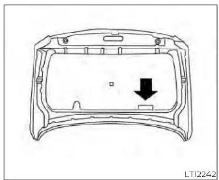
natural_image
Technical line drawing of a device casing with a black arrow indicating a downward component (no text or symbols present)ExceptXDmodels
The emission control information label is attached to the underside of the hood as shown.

natural_image
Technical diagram of a car seatbelt mechanism with no visible text or symbolsTypeA(ifsoequipped)
TIRE AND LOADING INFORMATION
LABEL
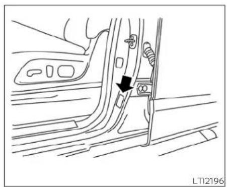
natural_image
Line drawing of a car interior showing a door lock and seatbelt mechanism (no text or symbols)TypeB(ifsoequipped)

natural_image
Technical line drawing of a mechanical component with no visible text or symbolsXDmodels

natural_image
Technical line drawing of a mechanical component with an arrow indicating a specific feature (no text or symbols present)ExceptXDmodels
The cold tire pressure is shown on the Tire AIR CONDITIONER SPECIFICATION and Loading Information label. The label is LABEL located as shown.
The air conditioner specification label is affixed to the underside of the hood as shown.
INSTALLINGFRONTLICENSEPLATE
| Symbol Name Reference Graphic | ||
| Caution ISO 7000 0434 |  | |
| Air Conditioning System (MAC) | ISO 2575 D01 |  |
| MAC System Lubricant Type (PAG-POE) |  | |
| Requires Registered Technician to Service MAC System |  | |
| Flammable Refrigerant | [CSAH] |
Air Conditioner Specification Label Symbols
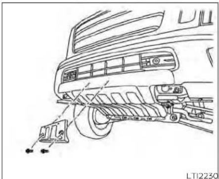
natural_image
Line drawing of a car interior showing dashboard, steering wheel, and air vent (no text or symbols)Pro-4X
Use the following steps to mount the front license plate:
- Attach the license plate bracket on the skid plate at the location marked (small dimple) using self-tapping screws.
VEHICLELOADINGINFORMATION
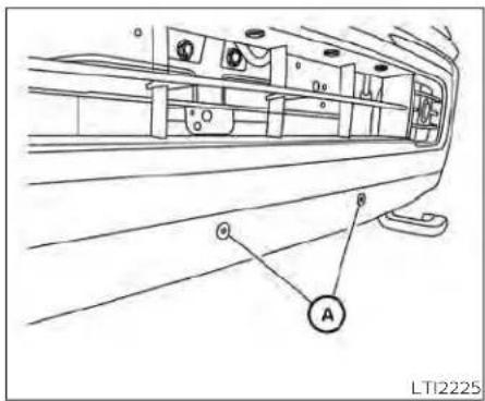
ExceptPro-4x

ExceptPro-4x
Use the following steps to mount the front license plate:
- Install two grommetsA into the square holes in the front bumper.
- Install the license plate bracket to the front bumper with two tapping screws Ⓑ.
WARNING
- Itisextremelydangerousto rideinacargoareainsidevehicle.Inacollision,peopleridingintheseareasaremore likelytobeseriouslyinjuredor killed.
- Donotallowpeopleoridein anyareaofyourvehiclethatis notequippedwithseatsand seatbelts.
- Besureeveryoneinyourvehicleisinaseatandusinga seatbeltproperly.
TERMS
It is important to familiarize yourself with the following terms before loading your vehicle:
- Curb Weight (actual weight of your vehicle) - vehicle weight including: standard and optional equipment, fluids, emergency tools, and spare tire assembly. This weight does not include passengers and cargo.
- GVW (Gross Vehicle weight) - curb weight plus the combined weight of passengers and cargo.
- GVWR (Gross Vehicle Weight Rating) - maximum total combined weight of the unloaded vehicle, passengers, luggage, hitch, trailer tongue load and any other optional equipment. This information is located on the F.M.V.S.S./C.M.V.S.S. certification label.
- GAWR (Gross Axle Weight Rating) - maximum weight (load) limit specified for the front or rear axle.
This information is located on the F.M.V.S.S./C.M.V.S.S. certification label.
- GCWR (Gross Combined Weight Rating) - The maximum total weight rating of the vehicle, passengers, cargo, and trailer.
- Vehicle Capacity Weight, Load limit, Total load capacity - maximum total weight limit specified of the load (passengers and cargo) for the vehicle. This is the maximum combined weight of occupants and cargo that can be loaded into the vehicle. If the vehicle is used to tow a trailer, the trailer tongue weight must be included as part of the cargo load. This information is located on the Tire and Loading Information label.
- Cargo capacity - permissible weight of cargo, the subtracted weight of occupants from the load limit.
VEHICLE LOAD CAPACITY
Before driving a loaded vehicle, confirm that you do not exceed the Gross Vehicle Weight Rating (GVWR) or the Gross Axle Weight Rating (GAWR) for your vehicle. Both the GVWR and GAWR are located on the F.M.V.S.S./C.M.V.S.S. certification label. For additional information, see "Measurement of weights" (P. 10-33).
Do not exceed the load limit of your vehicle shown as "The combined weight of occupants and cargo" on the Tire and Loading Information label. Do not exceed the number of occupants shown as "Seating Capacity" on the Tire and Loading Information label.
To get "the combined weight of occupants and cargo", add the weight of all occupants, then add the total luggage weight. Examples are shown in the following illustration.
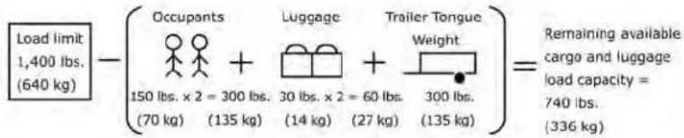

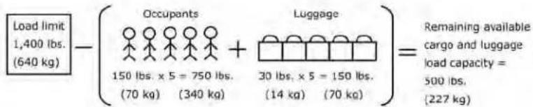
LT12320
Example
Steps for determining correct load limit
10-24 Technicalandconsumerinformation
- Locate the statement "The combined weight of occupants and cargo should never exceed XXX lbs. or XXX kg" on your vehicle's placard.
- Determine the combined weight of the driver and passengers that will be riding in your vehicle.
- Subtract the combined weight of the driver and passengers from XXX lbs. or XXX kg.
-
The resulting figure equals the available amount of cargo and luggage load capacity. For example, if the XXX amount equals 1,400 lbs. and there will be five 150 lbs. passengers in your vehicle, the amount of available cargo and luggage load capacity is 650 lbs. (1,400-750 (5 X 150) = 650 lbs.) or (640-340 (5 X 70) = 300 kg.)
-
Determine the combined weight of luggage and cargo being loaded on the vehicle. That weight may not safely exceed the available cargo and luggage load capacity calculated in step 4.
- If your vehicle will be towing a trailer, load from your trailer will be transferred to your vehicle. Consult this manual to determine how this reduces the available cargo and luggage load capacity of your vehicle.
Before driving a loaded vehicle, confirm that you do not exceed the GVWR or the GAWR for your vehicle. For additional information, see "Measurement of weights" (P. 10-33).
Also check tires for proper inflation pressures. For additional information, see "Tire and Loading Information label" (P. 8-37).
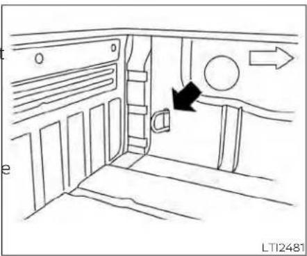
natural_image
Diagram of a vehicle interior showing airflow direction and directional arrows (no text or symbols)SECURING THE LOAD
For your convenience, tie down hooks are placed at each corner of the truck box. These may be used to help secure cargo loaded into the truck box.
WARNING
- Properlysecureallcargowithropes orstrapstohelppreventitfromslidingor shifting.Do notplacecargo higherthantheseatbacks.Inasudden stop or collision, unsecured cargocouldcausepersonalinjury.
- Donotloadyourvehicleanyheavier thantheGVWRorthemaximumfront andrearGAWRs.Ifyoudo,partsof yourvehiclecanbreak,tiredamage couldoccur,oritcanchangetheway yourvehiclehandles.Thiscouldresultinlossofcontrolandcausepersonalinjury.

UTILI-TRACK® CHANNEL SYSTEM (if so equipped)
- Side channels
- Header channel
- Channel sections
- Floor channels
WARNING
- ProperlyinstallandtightenthetiedowncleatsintotheUtili-track® channelsystem.Also,donotattach anyropeorstrapsdirectlytothe channel.Failureuretoproperlyinstall thetie-downcleatsorattaching ropesorstrapsdirectlytothechannelcancausethecargotobecome unsecured.Inasuddenstoporcollision,unsecuredcargocouldcause personalinjury.
- Properlysecureallcargowithropes orstrapstohelppreventitfromslidingorshifting.Inasuddenstopor collision,unsecuredcargocould causepersonalinjury.
NOTE:
Ifthebedlinerstoragebins(ifso equipped)areinstalledonthevehicle, use the cleats in the side channel locations. For additional information on bed liner storage bins, see "Storage" (P. 2-70).
The Utili-track® channel system allows you to move tie-down clamps in the bed to the best location to secure a load.
The tie-down cleats must be installed so the clamp is properly seated in the notches in the rail. If the tie-down cleat is not seated in the notches, it will not be flush with the rail and cannot be properly tightened. The bolt in the center of the cleat must be tightened hand tight (20 - 40 in-lbs.)
Check the tightness of the tie-down cleat periodically during a trip to make sure the center bolt has not become loose.
Install the tie-down cleat as follows:
- Remove the channel protectors by sliding them out the back of the truck bed. Properly store the channel protectors.
- Loosen the center bolt completely.

- Insert the cleat into the channel perpendicular to the channel as shown. Then rotate the cleat clockwise 90° and slide to the desired location.
- Position the cleat so the nubs on the bottom fully seat into the channel detents.
- There should be no gap between the bottom of the cleat and the top of the channel. Tighten the center bolt hand tight (20-40 in-lbs.).

natural_image
Technical illustration of a mechanical component with two views: top shows internal structure, bottom shows linear guide rail (no text or symbols)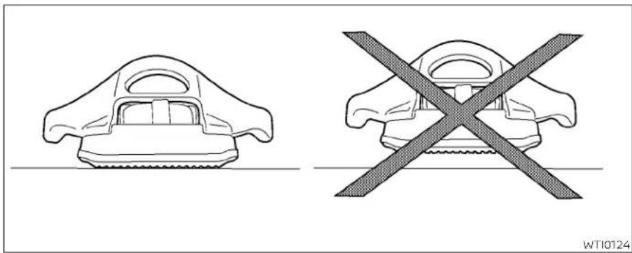
natural_image
Two technical diagrams showing a gear-like component and a cross-shaped object with a diagonal line, both without any text or symbols.10-28 Technicalandconsumerinformation


CAUTION
- Installonlyonecleatpersectionof channel.
- Applyingloadsatanglestothecleats greaterthan45°orloadsgreater than150lbs.(headerandfloorchannels)or200lbs.(sidechannels)may causedamagetothechannelorbed.

1correctinstallation,2incorrectinstallation
WARNING
Donotinstallaccessoriesoverthegap betweenhefrontandrearsidechannels.Doingthiscouldaffecttherear structureincertainrearimpacts,which couldresultinseriousinjury.

REAR ASSIST STEP (if so equipped)
CAUTION
- Therearassiststepmaximum weightcapacityis300lbs.(136kg). Applyingmorethan300lbs.(136kg) maydamagethestep.
Push the rear assist step to extend step. Pull the rear assist step to retract step.
LOADING TIPS
- The GVW must not exceed GVWR or GAWR as specified on the F.M.V.S.S./C.M.V.S.S. certification label.
- Do not load the front and rear axle to the GAWR. Doing so will exceed the GVWR.
WARNING
- Properlysecureallcargowith ropesorstrapstohelpprevent itfromslidingorshifting.Do notplacecargohigherthanthe seatbacks.Inasuddenstopor collision,unsecuredcargo couldcausepersonalinjury.
- Donotloadyourvehicleany heavierthantheGVWRorthe maximum front and rear GAWRs.Ifyoudo,partsofyour vehiclecanbreak,tiredamage couldoccur,oritcanchange thewayyourvehiclehandles. Thiscouldresultinlossofcon- trolandcausepersonalinjury.
Overloading not only can shortenthelifeofyourvehicle andthetire,butcanalsocause unsafe vehicle handling and longerbrakingdistances.This may cause a premature tire failurewhichcouldresultina seriousaccidentandpersonal injury.Failurescauusedbyover- loadingarenotcoveredbythe vehicle'swarranty.
TRUCK-CAMPERLOADING INFORMATION
CREW CAB MODELS
Crew Cab short wheel base models should not be used to carry as slide-in camper.
KING CAB® MODELS
This information is provided for you to properly install a slide-in camper and is based on the National Highway Traffic Safety Administration regulations. It is recommended that, before installing the camper, you carefully read the following information and ensure that the camper meets the specifications.
This information may not apply to some Canada model vehicles.
SPECIAL BODY VEHICLES
Some vehicles are equipped with commercial or camper bodies. However, this Owner's Manual does not cover these options. For additional information, refer to the body manufacturer's instruction manual.
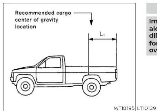
LOCATION FOR CENTER OF GRAVITY
The illustration indicates the recommended cargo center of gravity location.
Crew Cab Non-XD models:
L1 = 33.8 in (858 mm)
Crew Cab XD models:
L1 = 47.2 in (1,200 mm)
King Cab® Non-XD models:
L1 = 39.6 in (1,005 mm)
WARNING
Improperloadingmaybedangerous.If aloadistoofarback,itcanaffectthan- dlingcharacteristics.Ifaloadistoofar forward,thefrontaxlemaybe overloaded.
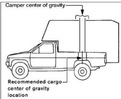
When the truck is used to carry a slide-in camper, the total cargo load of the truck consists of the camper manufacturer's weight figure,
- the weight of installed additional camper equipment not included in the camper manufacturer's weight figure,
• the weight of camper cargo, - and the weight of passengers in the camper.
The total cargo load should not exceed the truck's cargo weight rating and the camper's center of gravity should fall within the
TOWINGATRAILER
truck's recommended center of gravity zone when installed.
WARNING
Overloadingorimproperloadingcan adverselyaffectvehiclehandling,brakingandperformanceandmayleadto accidents.
VEHICLE LOAD WEIGHT CAPACITY
The vehicle payload weight capacity shown on the Tire and Loading Information label indicates the maximum total weight of passengers, optional equipment (air conditioning, trailer hitch, etc.) and cargo that your vehicle is designed to carry.
For additional information, see "Tire and Loading Information label" (P. 8-37).
Before driving a loaded vehicle, confirm that you do not exceed the GVWR or the GAWR for your vehicle. For additional information, see "Vehicle loading information" (P.10-22).
Also check tires for proper inflation pressures. For additional information, see "Tire and Loading Information label" (P. 8-37).
MEASUREMENT OF WEIGHTS
Secure loose items to prevent weight shifts that could affect the balance of your vehicle. When the truck camper is loaded, drive to a scale and weigh on the front and on the rear wheels separately to determine axle loads. Individual axle loads should not exceed either of the gross axle weight ratings (GAWR). The total of the axle loads should not exceed the gross vehicle weight rating (GVWR). These ratings are given on the vehicle certification label that is located on the left side of the vehicle, normally the dash, hinge pillar, door latch post, or door edge next to the driver. If weight ratings are exceeded, move or remove items to bring all weights below the ratings.
WARNING
Overloadingorimproperloadingofa traileranditscargocanadverselyaffectvehiclehandling,brakingandperformanceandmaylead toaccidents.
CAUTION
- Donottowatrailerorhaulaheavy loadforthefirst500miles(805km). Youreengine,axleorotherpartscould be damaged.
- Forthefirst500miles(805km)that you tow a trailer, do not drive over 50 mph(80 km/h)and donot make startsatfullthrottle.Thishelpsthe engine and other parts of your vehicle wearinattheheavier load.
Your new vehicle was designed to be used primarily to carry passengers and cargo. Remember that towing a trailer places additional loads on your vehicle's engine, drive train, steering, braking and other systems.
A NISSAN Towing Guide (U.S. only) is available on the website at www.nissanusa.com. This guide includes information on trailer towing capability and the special equipment required for proper towing.
MAXIMUM LOAD LIMITS
Maximum trailer loads
Never allow the total trailer load to exceed the value specified in the "Towing load/specification" chart (P. 10-37). The total trailer load equals trailer weight plus its cargo weight.
- Whentowingatrailerloadof3,500lbs. (1,587kg)ormore,trailerswithabrake systemMUSTbeused.
The maximum GCWR should not exceed the value specified in the following "Towing load/specification" chart (P. 10-37).

natural_image
Simple line drawing of a car on a horizontal scale with a speedometer, no text or symbols present.The GCWR equals the combined weight of the towing vehicle (including passengers and cargo) plus the total trailer load. Towing loads greater than these or using improper towing equipment could adversely affect vehicle handling, braking and performance.
The ability of your vehicle to tow a trailer is not only related to the maximum trailer loads, but also the places you plan to tow. Tow weights appropriate for level highway driving may have to be reduced for low traction situations (for example, on slippery boat ramps).
Temperature conditions can also affect towing. For example, towing a heavy trailer in high outside temperatures on graded roads can affect engine performance and cause overheating. The engine protection mode, which helps reduce the chance of engine damage, could activate and automatically decrease engine power. Vehicle speed may decrease under high load. Plan your trip carefully to account for trailer and vehicle load, weather and road conditions.
WARNING
Overheatingcanresultinreducedenginepowerandvehiclespeed.There-inducedspeedmaybelowerthanother traffic,whichcouldincreasethechance of a collision.Beespecially careful whendriving. If thevehiclecannot maintain a safe driving speed, pull to thesideoftheroadinasafearea.Allow theenginetocoolandreturntonormal operation.Foradditionalinformation, see"Ifyourvehicleoverheats"(P.6-12).
CAUTION
Vehicle damage resulting from improper towingprocedures is not covered by NISSAN warranties.

Tongue load
When using a weight carrying or a weight distributing hitch, keep the tongue load between 10 - 15% of the total trailer load or use the trailer tongue load specified by the trailer manufacturer. The tongue load must be within the maximum tongue load limits shown in the following "Towing load/specification" chart. If the tongue load becomes excessive, rearrange cargo to allow for proper tongue load.
King pin load
When using a 5th wheel hitch, keep the tongue load between 15 - 25% of the total trailer load within the maximum king pin load limits shown in the following "Towing load/specification" chart. If the king pin load becomes excessive, rearrange cargo to allow for proper king pin load.
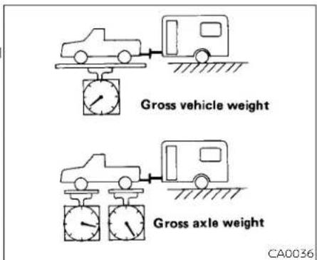
Maximum Gross Vehicle Weight (GVW)/maximum Gross Axle Weight (GAW)
The GVW of the towing vehicle must not exceed the Gross Vehicle Weight Rating (GVWR) shown on the F.M.V.S.S./C.M.V.S.S. certification label. The GVW equals the combined weight of the unloaded vehicle, passengers, luggage, hitch, trailer tongue load and any other optional equipment. In addition, front or rear GAW must not exceed the Gross Axle Weight Rating (GAWR) shown on the F.M.V.S.S./C.M.V.S.S. certification label.
TowingwithWeightDistributingClass4 Hitch
The Class 4 towing capacities shown in the towing load specification charts are calculated per the SAE J2807 standards. Additional passengers, cargo and/or optional equipment, such as the trailer hitch, will add weight to the vehicle and reduce your vehicle's maximum towing capacity and trailer tongue load.
The vehicle and trailer need to be weighed to confirm the vehicle is within the GVWR, Front GAWR, Rear GAWR, Gross Combined Weight Rating (GCWR) and Towing capacity.
All vehicle and trailer weights can be measured using platform type scales commonly found at truck stops, highway weigh stations, building supply centers or salvage yards.
TowingwithGooseneckHitch
The gooseneck towing capacities are calculated assuming a base vehicle with driver and any options required to achieve the rating. Additional passengers, cargo and/or optional equipment, such as the trailer hitch, will add weight to the vehicle and reduce your vehicle's maximum towing capacity and trailer tongue load.
The vehicle and trailer need to be weighed 2 to confirm the vehicle is within the GVWR, Front GAWR, Rear GAWR, Gross Combined Weight Rating (GCWR) and Towing capacity.
All vehicle and trailer weights can be measured using platform type scales commonly found at truck stops, highway weigh stations, building supply centers or salvage yards.
To determine the available payload capacity for tongue/king pin load, use the following procedure.
-
Locate the GVWR on the F.M.V.S.S./C.M.V.S.S. certification label.
-
Weigh your vehicle on the scale with all of the passengers and cargo that are normally in the vehicle when towing a trailer.
-
Subtract the actual vehicle weight from the GVWR. The remaining amount is available maximum tongue/king pin load.
To determine the available towing capacity, use the following procedure.
- Find the GCWR for your vehicle on the "Towing load/specification" chart found in this section.
Subtract the actual vehicle weight from the GCWR. The remaining amount is the available maximum towing capacity.
To determine the Gross Trailer Weight, weigh your trailer on a scale with all equipment and cargo, that are normally in the trailer when it is towed. Make sure the Gross trailer weight is not more than the Gross Trailer Weight Rating shown on the trailer and is not more than the calculated available maximum towing capacity.
Also weigh the front and rear axles on the scale to make sure the Front Gross Axle Weight and Rear Gross Axle Weight are not more than Front Gross Axle Weight and Rear Gross Axle Weight on the F.M.V.S.S./C.M.V.S.S. certification label. The cargo in the trailer and vehicle may need to be moved or removed to meet the specified ratings.
- Gross Vehicle Weight (GVW) as weighed on a scale - Including passengers, cargo and hitch - 7,804 lbs. (3,540 kg). - Gross Vehicle Weight Rating (GVWR) from F.M.V.S.S./C.M.V.S.S. certification label - 8,990 lbs. (4,078 kg).
- Gross Combined Weight Rating (GCWR) from "Towing load/specification" chart - 19,450 lbs. (8,822 kg).
- Maximum Trailer towing capacity from "Towing load/specification" chart - 9,200 lbs. (4,173 kg).
8,990 lbs. (4,078 kg) GVWR
- 7,804 lbs. (3,540 kg) GVW
= 1,186 lbs. (538 kg) Available for tongue/king pin weight
19,450 lbs. (8,822 kg) GCWR
- 7,804 lbs. (3,540 kg) GVW
= 11,644 lbs. (5,282 kg) Capacity available for towing
1,186 lbs. (538 kg) Available tongue weight
/ 11,644 lbs. (5,282 kg) Available capacity
= 10 % tongue weight
The available towing capacity may be less than the maximum towing capacity due to the passenger and cargo load in the vehicle.
Remember to keep trailer tongue weight between 10 - 15% of the trailer weight or within the trailer tongue weight specification recommended by the trailer manufacturer. If the tongue weight becomes excessive, rearrange the cargo to obtain the proper tongue weight. Do not exceed the maximum tongue weight specification shown in the "Towing load/specification" chart even if the calculated available tongue weight is greater than 15%. If the calculated tongue weight is less than 10%, shift the trailer load forward until the trailer tongue weight reaches 10% of the trailer weight.
Always verify that available capacities are within the required ratings.
TOWING LOAD/SPECIFICATION
WARNING
Thetowing capacities provided in this manual are for general reference only. Thesafe towing capacity of your vehicle is affected by dealer and factory installed options and passenger and cargo loads. You must weigh the vehicle and trailers as described in this manual to determine the actual vehicle towing capacity. Do not exceed the published maximum towing capacity or the GCWRortheGVWRshown on the FMVSS/CMVSSlabel.Doingsocanresultinanaccidentcausingseriouspersonalinjuryorpropertydamage.
NOTE:
TheSAEJ2807WeightDistributingClass 4 Hitch specifications are based on S and SV grade models. The Gooseneck Hitch specificationsarebased onSVgrade models.
Non-XDmodels—Crewcab—Towingloadspecificationchart—SAEJ2807WeightDistributingClass4Hitch
| Axle type 2WD 4WD | ||
| Maximum Payload 1,590 lbs. (721.2 kg) | 1,640 lbs. (743.9 kg) | |
| Maximum Towing Capacity ‘1, ‘2, ‘3 9,360 lbs. (4,245.6 kg) | 9,220 lbs. (4,182.1 kg) | |
| Maximum Tongue load ‘2, ‘3 936 lbs. (424.6 kg) | 922 lbs. (418.2 kg) | |
| Maximum Gross Combined Weight Rating 15,300 lbs. (6,940 kg) | 15,300 lbs. (6,940 kg) |
Non-XD models — King Cab® — Towing load specification chart — SAE J2807 Weight Distributing Class 4 Hitch
| Axle type 2WD 4WD | ||
| Maximum Payload 1,610 lbs. (730.3 kg) | 1,690 lbs. (766.6 kg) | |
| Maximum Towing Capacity '1, '2, '3 9,380 lbs. (4,254.7 kg) | 9,260 lbs. (4,200.3 kg) | |
| Maximum Tongue load '2, '3 938 lbs. (425.5 kg) | 926 lbs. (420 kg) | |
| Maximum Gross Combined Weight Rating 15,300 lbs. (6,940 kg) | 15,300 lbs. (6,940 kg) | |
XDmodels—Crewcab—Towingload specificationchart—SAEJ2807Weight DistributingClass4Hitch
| Axle type 4WD | |
| Maximum Payload 2,440 lbs. (1,106.8 kg) | |
| Maximum Towing Capacity *1, *2, *3 | 10,930 lbs. (4,957.8 kg) |
| Maximum Tongue load *2, *3 | 1,093 lbs. (495.8 kg) |
| Maximum Gross Combined Weight Rating*4 | 17,700 lbs. (8,029 kg) |
XDmodels—Crewcab—Towingload specificationchart—GooseneckHitch
| Axle type 4WD | |
| Maximum Payload 2,440 lbs. (1,106.8 kg) | |
| Maximum Towing Capacity *1, *2, *3 | 11,040 lbs. (5,007.7 kg) |
| Maximum King pin load *2, *3 | 1,656 lbs. (751.1 kg) |
| Maximum Gross Combined Weight Rating*4 | 17,700 lbs. (8,029 kg) |
*1: The towing capacity values are calculated assuming a base vehicle with driver and any options required to achieve the rating. Additional passengers, cargo and/or optional equipment will add weight to the vehicle and reduce your vehicle's maximum towing capacity.
*2: Use of a weight-distributing hitch system is recommended when towing over 5,000 lbs. (2,268 kg).
*3: The maximum towing capacity when using the Genuine NISSAN step bumper as a ball mount is 5,000 lbs. (2,268 kg) and 500 lbs. (227 kg) tongue load.
*4: The maximum gross combined weight rating for XD vehicles equipped with 20 inch wheels is 16,900 lbs. (7,666 kg).
TOWING SAFETY
Trailer hitch
Your vehicle may be equipped with an optional trailer tow package. The trailer tow package includes a receiver-type frame mounted hitch. This hitch is rated for the maximum towing capacity of this vehicle when the proper towing equipment is used. Choose a proper ball mount and hitch ball that is rated for the trailer to be towed. Genuine NISSAN ball mounts and hitch balls are available at a NISSAN dealer.
If your vehicle is not equipped with the optional trailer tow package, check the towing capacity of your bumper hitch or receiver-type frame mounted hitch. Choose a proper hitch for your vehicle and trailer. A Genuine NISSAN trailer hitch is available at a NISSAN dealer. Make sure the trailer hitch is securely attached to the vehicle to help avoid personal injury or property damage due to sway caused by cross-winds, rough road surfaces or passing trucks.
A hitch used for towing 5th wheel and gooseneck trailers can also be installed on your vehicle. Contact a professional supplier of towing equipment to purchase and have a 5th wheel or gooseneck hitch installed.
WARNING
Trailerhitchcomponentshavespecific weightratings.Yourvehiclemaybecapableoftowingatrailerheavierthan theweighitratingofthehitchcomponents.Neverexceedtheweightrating ofthehitchcomponents.Doingsocan causeseriosuspersonalinjuryorpropertydamage.
Hitch ball
Choose a hitch ball of the proper size and weight rating for your trailer:
- The required hitch ball size is stamped on most trailer couplers. Most hitch balls also have the size printed on the top of the ball.
-
Choose the proper class hitch ball based on the trailer weight.
-
The diameter of the threaded shank of the hitch ball must be matched to the ball mount hole diameter. The hitch ball shank should be no more than 1/16" smaller than the hole in the ball mount.
- The threaded shank of the hitch ball must be long enough to be properly secured to the ball mount. There should be at least 2 threads showing beyond the lock washer and nut.
Ball mount
The hitch ball is attached to the ball mount and the ball mount is inserted into the hitch receiver. Choose a proper class ball mount based on the trailer weight. Additionally, the ball mount should be chosen to keep the trailer tongue level with the ground.

Bumper towing
The Genuine NISSAN step bumper has provisions to install a trailer hitch ball and is designed to tow trailers of a maximum weight of 5,000 lbs. (2,268 kg).
NOTE:
Thetrailerhitchballcannotbeinstalled onthestepbumperifthereceiver-type framemountedhitchisinstalledonthe vehicle.
To install a trailer hitch ball cut out the circle in the center of the step bumper, then remove it to install the trailer hitch ball.
Weight carrying hitches
A weight carrying or "dead weight" ball mount is one that is designed to carry the whole amount of tongue weight and gross weight directly on the ball mount and on the receiver.
Weight distribution hitch
This type of hitch is also called a "load-leveling" or "equalizing" hitch. A set of bars attach to the ball mount and to the trailer to distribute the tongue weight (hitch weight) of your trailer. Many vehicles can't carry the full tongue weight of a given trailer, and need some of the tongue weight transferred through the frame and pushing down on the front wheels. This gives stability to the tow vehicle.
A weight-distributing hitch system (Class IV) is recommended if you plan to tow trail2ers with a maximum weight over 5,000 lbs. (2,268 kg). Check with the trailer and towing equipment manufacturers to determine if they recommend the use of a weight-distributing hitch system.
NOTE:
Aweight-distributinghitchsystemmay affect theoperationoftrailersurge brakes.Ifyouareconsideringuse of a weight-distributinghitchsystemwitha surgebrake-equipped trailer,checkwith thesurgebrake,hitchortrailermanufac-turertodetermineifandhowthiscanbe done.
Follow the instructions provided by the manufacturer for installing and using the weight-distributing hitch system.
General set-up instructions are as follows:
-
Park unloaded vehicle on a level surface with the ignition switch in the ON position and the doors closed, allow the vehicle to stand for several minutes so that it can level.
-
Measure the height of a reference point on the front and rear bumpers at the center of the vehicle.
-
Attach the trailer to the vehicle and adjust the hitch equalizers so that the front bumper height is within 0 - 5 inches (0 - 13 mm) of the reference height measured in step 2. The rear bumper should be no higher than the reference height measured in step 2.

WARNING
Properlyadjusttheweightdistributing hitchsotherearofthebumperisno higherthanthemeasuredreference heightwhentetrailerisattached.If therearbumperishigherthanthe measured reference height when loaded,thevehiclemayhandleunpredictablywhichcouldcausealossofvehiclecontrolandcauseseriouspersonalinjuryorpropertydamage.
Sway control device
Sudden maneuvers, wind gusts, and buffeting caused by other vehicles can affect trailer handling. Sway control devices may be used to help control these affects. If you choose to use one, contact a reputable trailer hitch supplier to make sure the sway control device will work with the vehicle, hitch, trailer and the trailer's brake system. Follow the instructions provided by the manufacturer for installing and using the sway control device.
Class I hitch
Class I trailer hitch equipment (receiver, ba mount and hitch ball) can be used to tow trailers of a maximum weight of 2,000 lbs. (907 kg).
Class II hitch
Class II trailer hitch equipment (receiver, ball mount and hitch ball) can be used to tow trailers of a maximum weight of 3,500 lbs. (1,587 kg).
Class III hitch
Class III trailer hitch equipment (receiver, ball mount and hitch ball) can be used to tow trailers of a maximum weight of 5,000 lbs. (2,268 kg).
Class IV hitch
Class IV hitches are weight carrying (WC) and weight distributing (WD) hitches depending on the vehicle and hitch specifications. Not all Class IV hitches are rated to both. See the specific hitch for that information. Class IV trailer hitch equipment (receiver, ball mount and hitch ball) used as weight carrying are rated up to 10,000 lbs. (4,535 kg) gross trailer weight (GTW) with a maximum trailer tongue weight (TW) of
1,000 lbs. (453 kg). Class IV hitches used fortribute the king pin weight for the proper weight distributing are rated up to 14,000 lbs. (6,350 kg) gross trailer weight (GTW) performance. with a maximum trailer tongue weight (TW) of 1,400 lbs. (635 kg). A Class IV hitch usually has a 2" square receiver opening. A higher class drawbar does not increase the towing capacity of the hitch. To use this class of hitch for weight distribution requires a weight distribution system. Class IV hitches attach to the vehicle frame only. A weight distributing hitch should be used to tow trailers that weigh over 5,000 lbs. (2,268 kg). Your vehicle may be equipped with Class IV weigh distributing trailer hitch that has a 14,000 lbs. (6,350 kg) maximum weight rating, but your vehicle is only capable of towing the maximum trailer weights shown in the "Towing load/specification" chart in this purchasing a 5th wheel trailer. The king pin weight should be 15% of the fully loaded trailer. Make sure the king pin weight does not cause the gross vehicle weight to exceed the Gross Maximum Weight Rating or the rear axle weight to exceed the Rear Gross Axle Weight rating. For additional information, see "Maximum load limits" (P. 10-34). The weight of the trailer should not exceed the maximum towing capacity for the vehicle. For additional information, see "Towing load/specification" chart (P. 10-37). Make sure the trailer design allows for the correct vehicle to trailer clearances before purchasing a 5th wheel trailer. section.
5th wheel/gooseneck
-A 5th wheel or gooseneck trailer can be bewed by installing a 5th wheel or goose- neck trailer hitch. These types of hitches -are mounted in the bed of the pick-up. A professional trailer equipment supplier should install these hitches as it is very im- portant to mount the hitch correctly to dis-
WARNING
- Thehitchshouldnotbeattachedto oraffecttheoperationoftheimpact-absorbingbumper.
- Donotuseaxle-mountedhitches.
-
Do not modify the vehicle exhaust system, brakesystem, etc. to install a trailerhitch.
-
Toreducethepossibilityofadditionaldamageifyourvehicleis struckfromtherear,wherepractical, removethereceiverwhennotinuse.
- Regularlycheckthatalltrailerhitch mountingboltsaresecurely mounted.
- Whentowingwiththehitchball mountedtotherearbumper,donot makesharpturns.Thetrailermay contactthebumperandcausedamagetothebumperortrailer.
- Whentowinga5thwheeltrailer,do notmakesharpturnswhiledrivingor backing. Thetrailermaycontactthe vehicle and cause damage to both thetrailerandvehicle.

natural_image
Technical line drawing of a mechanical bracket assembly (no text or symbols)CAUTION
- A5thwheelhitchadapterisnecessarytouseanaftermarket5thwheel hitch. A Genuine NISSAN 5th wheel hitchadapter(asshown) may be availableataNISSANdealer.
- Ensurekitcomponents areproperly storedwhen notin use. Improperly stowed componentscould resultin seriouspersonalinjuryduringacollisionsuddenstop.
Gooseneckhitchballandsafetychain anchorattachmentinstallation
- Park the vehicle on a level surface and apply the parking brake.
- Remove the gooseneck hitch ball and safety chain anchor attachments from the storage pouch.

natural_image
Diagram of three circular components mounted on a row of vertical rods, with no visible text or symbols.
natural_image
Line drawing of a mechanical component with a knob and arrow indicating direction (no text or symbols)
natural_image
Pure mechanical diagram showing parallel rods and circular components without any text or symbols- Remove the center and both of the rear4. caps from the puck plugs.
- Once removed, place the pucks in the storage pouch for future use.
Lift the handle from the center of the 5 hitch ball and rotate 90° from the resting position.
Position the ball bearings to the sides of the truck bed and Insert the gooseneck hitch ball into the center receiver tube of the truck bed.

natural_image
Diagram of a mechanical component with rotating arm and base, surrounded by diagonal lines (no text or symbols)
natural_image
Pure technical line drawing of a mechanical component or assembly without any text, numbers, or symbols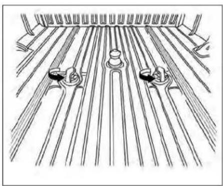
natural_image
Diagram of a mechanical or electrical component with parallel rods and two circular components, no text or symbols present.- Rotate the handle 90° seat the handle 7, back to the original resting position. If the handle does not seat fully, rotate the hitch ball until the handle drops into the original resting position.
- Place the safety chain anchor attachments into the q-turn pucks.
- Rotate the safety chain anchor attachments 90° until the center of the anchor seats into place.

NOTE:
Removalofthegooseneckhitchballand safetychainanchorattachmentsarein thereverseorderofinstallation.Tore-movesafetychainanchorattachment, liftthecenter Ⓛ,rotate90°,andlift safetychainanchorattachmentaway.
Tire pressures
- When towing a trailer, inflate the vehicle tires to the recommended cold tire pressure indicated on the Tire and Loading Information label.
- Trailer tire condition, size, load rating and proper inflation pressure should be in accordance with the trailer and tire manufacturer's specifications.
Safety chains
Always use suitable safety chains between your vehicle and the trailer. The safety chains should be crossed and should be attached to the hitch, not to the vehicle bumper or axle. The safety chains can be attached to the bumper if the hitch ball is mounted to the bumper. Be sure to leave enough slack in the chains to permit turning corners.
Trailer lights
CAUTION
Whensplicing into the vehicle electrical system, a commercially available power-type module/converter must be used to provide power for all trailer lighting. This unit uses the vehicle battery as direct powers source for all trailer lights while using the vehicle tail light, stoplight and turn signal circuits
as a signal source. The module/ convertermustdrawnomorethan15 milliampsfromthestopandtaillamp circuits. Usingamodule/converterthat exceeds these power requirements maydamagethevehicle'selectrical system.Seeareputabletrailerretailer toobtaintheproperequipmentandto haveitinstalled.
Trailer lights should comply with federal and/or local regulations. For assistance in hooking up trailer lights, it is recommended that you contact a NISSAN dealer or reputable trailer retailer. Vehicles equipped with the optional trailer tow package are equipped with a 7-pin trailer harness connector. If your trailer is equipped with a flat 4-pin connector, an adapter will be needed to connect the trailer lights to the vehicle. Adapters are available at auto parts stores and hitch retailers.
Trailer brakes (if so equipped)
If your trailer is equipped with a braking system, make sure it conforms to federal and/or local regulations and that it is properly installed.
Vehicles equipped with a 7-pin trailer harness connector are pre-wired for a trailer brake controller. It is recommended that you visit a NISSAN dealer for a trailer brake adapter harness.
Whentowingatrailerloadof3,500lbs. (1587kg)ormore,trailerswithabrake systemMUSTbeused. However, most states require a separate braking system on trailers with a loaded weight above a specific amount. Make sure the trailer meets the local regulations and the regulations where you plan to tow.
WARNING
TheGrossCombinedWeightRating (GCWR)mustneverexceedthevehicle manufacturersrecommendation.
Several types of braking systems are available.
SurgeBrakes-The surge brake actuator is mounted on the trailer tongue with a hydraulic line running to each trailer wheel. Surge brakes are activated by the trailer pushing against the hitch ball when the tow vehicle is braking. Hydraulic surge brakes are common on rental trailers and some boat trailers. In this type of system, there is no hydraulic or electric connection
for brake operation between the tow vehicle and the trailer.
CAUTION
Yourfactorytrailerbrakecontrolunit willnotactivatesurge-styletrailer brakes
Electric Trailer Brakes - Electric braking systems are activated by an electronic signal sent from a trailer brake controller (special brake-sensing module). If electric trailer brakes are used, see "Electric trailer brake controller" (P. 10-49).
Have a professional supplier of towing equipment make sure the trailer brakes are properly installed and demonstrate proper brake function testing.
WARNING
TheNISSANtrailerbrakecontrollerhas beenverified tobe compatiblewith trailershavingelectricactuateddrum brakes(onetofouraxles)andelectric-over-hydraulicbrakes.Itwillnotactivate hydraulic surge-style trailer brakes
WARNING
Neverconnect atrailerbrakesystem directlytothevehiclebrakesystem.
natural_image
Line drawing of a bundled cable or wire with multiple strands, no text or symbols presentexample
Electric trailer brake controller (if so equipped)
Trailers equipped with electric brakes may require the installation of an aftermarket trailer brake controller.
Your vehicle may be equipped with a connector and jumper harness that is specifically designed to be used when installing an aftermarket brake controller.
To install the electric trailer brake controller jumper harness, perform the following procedure:
- Open the driver door. Move the seat to the rearmost position.

natural_image
Mechanical assembly diagram showing a lever mechanism with a black arrow indicating motion direction (no text or symbols present)- Apply the parking brake to access the jumper harness connector.
- Locate the jumper harness connector under the lower portion of the instrument panel. The connector is taped to the wiring harness® as indicated.
wire color designation for electric trailer brake controller jumper harness.
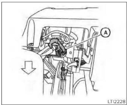
natural_image
Mechanical assembly diagram showing internal components and a directional arrow (no text or symbols)| WIRE COLOR NOTE | |
| RED/GREEN Vehicle stop | lamp switch to trailer brake controller. |
| BLACK Brake controller | ground (-). |
| BROWN/WHITE Trailer brake controller switched output. | |
| RED/BLUE Trailer brake controller illumination. | |
| RED Fused trailer brake | controller battery feed (B+). |
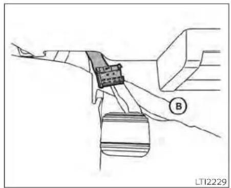
natural_image
Diagram of a cable or connector being inserted into a cable, showing no text or symbols.- Peel off the tape and connect the jumper harness to the connector.
- Release the parking brake.
- Install the aftermarket electric trailer brake controller according to the manufacturer's instructions.

① Gain -
② Gain +
③ Manual control lever
④ Boost
Trailer brake controller unit (if so equipped)
The Trailer Brake Controller Unit (TBCU), located on the lower instrument panel, is a device that assists the vehicle in having effective and smooth braking while towing a trailer.
Operatingmodes:
- Automaticmode: This is the normal operation of the TBCU depending on the gain and boost settings adjusted by the customer. This mode will activate when vehicle brake pedal is pressed.
- Manualmode: This mode is initiated by adjusting the manual control lever from resting position. This mode will provide output power to trailer brakes without applying the vehicle brake pedal.
To determine the output operation of the system:
- Gain+andGain-:Used to increase or decrease the braking force supplied to the trailer brakes. To adjust the gain,press Gain + or Gain - to the desired point (0-10). For example: gain settling 6.0 is a typical starting point for heavy loads.
- Boost: Used to adjust the feel of the automatic brake event that occurs when the vehicle brake pedal is applied. To set up boost, press Boost button once to display for current boost setting (display for 3 seconds). Keep pressing to increase boost level until the desired level (0-3) is achieved.
- Manual Control Lever: Provides brake output power to trailer brakes without applying the vehicle brake pedal. The 0)amount of brake output supplied corresponds to the amount of pinch pressure applied to the manual control lever.

*ifsustainedforlonger,checktrailerconnectionsorvisitadealerforservice
| Typical Boost Settings For Optimal Performance(with properly adjusted trailer brakes*) | ||||
| TRAILER WEIGHT compared to VEHICLE WEIGHT | b. | b.l. | b.2. | b.3. |
| BOOST OFF D INCREASING BOOST LEVEL D | ||||
| X | X | |||
| Trailer weighs LESS than vehicle | ||||
| X | X | X | ||
| Trailer weighs APPROXIMATELY THE SAME as vehicle | ||||
| X | X | X | ||
| Trailer weighs UP TO 25% MORE than vehicle | ||||
| X | X | |||
| Trailer weighs UP TO 40% MORE than vehicle | ||||
| Trailer weighs OVER 40% MORE than vehicle | WARNING Do not exceed GrossCombined Weight Rating (GCWR) | X | ||
* You may need to increase the boost setting if the trailer brakes are worn. See a dealer for adjustment and or repair.
Thisgraphicshowsthesuggestedboostlevelsfordifferenttrailersizesrelativeto thevehiclesize.
LTI2156

WARNING
DonotexceedGrossCombinedWeight Rating(GVWR).ForadditionalinformationaboutGVWR,see“Towingload/specification”(P.10-37).
Pre-towing tips
- Be certain your vehicle maintains a level position when a loaded and/or unloaded trailer is hitched. Do not drive the vehicle if it has an abnormal nose-up or nose-down condition; check for improper tongue load, overload, worn suspension or other possible causes of either condition.
• Always secure items in the trailer to prevent load shift while driving. - Keep the cargo load as low as possible in the trailer to keep the trailer center of gravity low.
- Load the trailer so approximately 60% of the trailer load is in the front half and 40% is in the back half. Also make sure the load is balanced side to side.
-
Check your hitch, trailer tire pressure, vehicle tire pressure, trailer light operation, and trailer wheel lug nuts every time you attach a trailer to the vehicle.
-
Be certain your rearview mirrors conform to all federal, state or local regulations. If not, install any mirrors required for towing before driving the vehicle.
- Determine the overall height of the vehicle and trailer so the required clearance is known.
Trailer towing tips
In order to gain skill and an understanding of the vehicle's behavior, you should practice turning, stopping and backing up in an area which is free from traffic. Steering stability and braking performance will be somewhat different than under normal driving conditions.
- Always secure items in the trailer to prevent load shift while driving.
- Lock the trailer hitch coupler with a pin of lock to prevent the coupler from inadvertently becoming unlatched.
- Avoid abrupt starts, acceleration or stops.
- Avoid sharp turns or lane changes.
• Always drive your vehicle at a moderate speed.
- When backing up, hold the bottom of the steering wheel with one hand. Move your hand in the direction in which you want the trailer to go. Make small corrections and back up slowly. If possible, have someone guide you when you are backing up.
Always block the wheels on both vehicle and trailer when parking. Parking on a slope is not recommended; however, if you must do so:
CAUTION
IfyoumovetheshiftselectortotheP (Park) position before blocking the wheelsandapplyingtheparkingbrake, transmissiondamagecouldoccur.
Apply and hold the brake pedal.
Have someone place blocks on the downhill side of the vehicle and trailer wheels.
- After the wheel blocks are in place, slowly release the brake pedal until the blocks absorb the vehicle load.
- Apply the parking brake.
- Shift the transmission into P (Park).
Make sure the ✗ indicator light (if so equipped) indicates the transfer case is in 4H, 4LO, or 2H and that the ATP light is off. If the ✗ indicator light is flashing, or the ATP light is ON, make sure the transmission is in P (Park) (A/T) and turn the 4WD switch to 2WD or 4H. For additional information, see "Automatic transmission park warning light" (P. 2-13) and "Using 4-wheel drive (4WD)" (P. 5-107).
- Turn off the engine.
To drive away:
- Start the vehicle.
- Apply and hold the brake pedal.
- Shift the transmission into gear.
- Release the parking brake.
- Drive slowly until the vehicle and trailer are clear from the blocks.
-
Apply and hold the brake pedal.
-
Have someone retrieve and store the blocks.
-
While going downhill, the weight of the trailer pushing on the tow vehicle may decrease overall stability. Therefore, to maintain adequate control, reduce your speed and shift to a lower gear. Avoid long or repeated use of the brakes when descending a hill, as this reduces their effectiveness and could cause overheating. Shifting to a lower gear instead provides "engine braking" and reduces the need to brake as frequently.
- If the engine coolant temperature rises to a high temperature, see "If your vehicle overheats" (P. 6-12).
- Trailer towing requires more fuel than normal circumstances.
- Avoid towing a trailer for your vehicle's first 500 miles (805 km).
- For the first 500 miles (805 km) that you do tow, do not drive over 50 mph (80 km/h).
- Have your vehicle serviced more often than at intervals specified. For additional information, see the "Maintenance and schedules" section of this manual.
- When making a turn, your trailer wheels will be closer to the inside of the turn that your vehicle wheels. To compensate for this, make a larger than normal turning radius during the turn.
- Crosswinds and rough roads will adversely affect vehicle/trailer handling, possibly causing vehicle sway. When being passed by larger vehicles, be prepared for possible changes in crosswinds that could affect vehicle handling.
TrailerSwayAssist:
To minimize trailer sway, your vehicle may apply braking to individual wheels based on input from your vehicle sensors and vehicle speed. Trailer sway control is a function of the Vehicle Dynamic Control (VDC) system and is active when the VDC function is enabled.
CAUTION
If the VDC-OFF switch is (meaning VDC system OFF), the Trailer Sway Assist is also disabled
When Trailer Sway Assist is in operation, the VDC warning light blinks. When vehicle control is regained, VDC warning light will turn OFF.
For additional Information about the VDC system, see "Vehicle Dynamic Control (VDC) OFF switch" (P. 2-59) and "Vehicle Dynamic Control (VDC) system" (P. 5-120).
If TrailerSway Assistactivates,dothe following:
- Take your foot off the accelerator pedal to allow the vehicle to coast and steer as straight ahead as the road conditions allow. This combination will help stabilize the vehicle
CAUTION
- Donottrytocorrecttrailerswayby steeringorapplyingthebrakes.
- When the trailer sway stops, gently apply the brakes and pull to the side of the road in a safe area.
- Try to rearrange the trailer load so it is balanced. For additional information, see "Pre-towing tips" (P. 10-51).
NOTE:
nTrailerSwayAssistcannotreducetrailer-swayinallsituations.
Be careful when passing other vehicles. Passing while towing a trailer requires considerably more distance than normal passing. Remember, the length of the trailer must also pass the other vehicle before you can safely change lanes.
- Use the Tow Mode or downshift the transmission to a lower gear for engine braking when driving down steep or long hills. This will help slow the vehicle without applying the brakes.
- Avoid holding the brake pedal down too long or too frequently. This could cause the brakes to overheat, resulting in reduced braking efficiency.
- Increase your following distance to allow for greater stopping distances while towing a trailer. Anticipate stops and brake gradually.
- NISSAN recommends that the cruise control (if so equipped) not be used while towing a trailer.
- While towing a trailer, do not use the following systems (if so equipped):
-- the Lane Departure Warning (LDW) system
-- the Blind Spot Warning (BSW) system
— the Intelligent Cruise Control (ICC) system
—the Automatic Emergency Braking (AEB) system
-- the Intelligent Forward Collision Warning (I-FCW) system
— the Rear Automatic Braking (RAB) system
-- the Moving Object Detection (MOD) system
-- the Cross Traffic Alert system -- the Rear Sonar system
- Some states or provinces have specific regulations and speed limits for vehicles that are towing trailers. Obey the local speed limits.
- Check your hitch, trailer wiring harness connections, and trailer wheel lug nuts after 50 miles (80 km) of travel and at every break.
- When launching a boat, don't allow the water level to go over the exhaust tail e pipe or rear bumper.
- Make sure you disconnect the trailer lights before backing the trailer into the water or the trailer lights may burn out.
Whentowingatraler, finaldrivegearoil shouldbereplacedandtransmissionoil/fluid should be changed more frequently. For additional information, see the "Do-it-yourself" section of this manual.
Tow mode
Using tow mode is recommended when pulling a heavy trailer or hauling a heavy load. Press the TOW MODE switch to activate tow mode. The indicator light on the TOW MODE switch illuminates when tow mode is selected. Press the TOW MODE switch again to turn tow mode off. Tow mode is automatically canceled when the ignition switch is turned off.
Tow mode includes the following features:
- Grade logic — Adjusts transmission shifts when pulling a trailer or hauling a load up a grade.
- Downhill Speed Control (DSC) — automatically downshifts when driving down a grade with a trailer or heavy load to help control vehicle speed.
Driving the vehicle in the tow mode with no trailer/load or light trailer/light load will not cause any damage. However, fuel economy may be reduced and the transmission/engine driving characteristics may feel unusual.
Whentowingatrailer, finaldrivegearoil shouldbereplacedandtransmissionoil/fluidshouldbechangedmorefrequently.Foradditionalinformation,see the"Do-it-yourself"sectionofthis manual.
FLAT TOWING FOR 2-WHEEL DRIVE (2WD) VEHICLE (if so equipped)
Towing your vehicle with all four wheels on towing a vehicle behind a recreational vehicle the ground is sometimes called flat towing vehicle, such as a motor home.
This method is sometimes used when towing a vehicle behind a recreational vehicle, such as a motor home.
CAUTION
- Failuretofollowtheseguidelinescan resultinseveretransmission damage.
- Neverflattowyour2WDvehicle.
- Nevertowyour2WDvehiclewiththe rearwheelsontheground.Doingso maycauseseriousandexpensive damagetothepowertrain.
-
DONOTtowyour2WDvehiclewithall fourwheelsontheground(flattowing).DoingsoWILLDAMAGEinternal transmissionpartsduetolackof transmissionlubrication.
-
Foremergencytowingprocedures see "Towingrecommendedby NISSAN"(P.6-13).
FLAT TOWING FOR 4-WHEEL DRIVE (4WD) VEHICLE (if so equipped)
Towing your vehicle with all four wheels on the ground is sometimes called flat towing. This method is sometimes used when
Itowing a vehicle behind a recreational vehicle, such as a motor home.
CAUTION
- Failuretofollowtheseguidelinescan resultinseveretransmission damage.
- Neverflattowyour4WDvehicle.
- DO NOT tow your 4WD vehicle with anywheelsontheground.Doingso maycauseseriousandexpensive damagetothepowertrain.
- Foremergencytowingprocedures see "Towingrecommendedby NISSAN"(P.6-13).
Automatic Transmission
To tow a vehicle equipped with an automatic transmission, an appropriate vehicle dolly MUSTbe placed under the towed vehicle's drive wheels. Alwaysfollow the dolly manufacturer's recommendations when using their product.
NOTE:
If the battery is completely drained the transmission will not manually shift to other positions.
SNOWPLOW
NISSAN does not make a snowplow for TITAN and has not evaluated the suitability of its trucks for use as snowplow platforms. Instead, the snowplow manufacturers establish minimum vehicle requirements for their various plow products and they make the determination as to which vehicle platforms are suitable, based on their individual product specifications. Consult the snowplow manufacturers and sellers concerning the fitness of the TITAN for use with their products. NISSAN advises caution whenever installing aftermarket parts and accessories because these products have not been tested or certified by NISSAN. Please reference the NISSAN Body Builder's guide for the appropriate upfit capacities and requirements of the TITAN XD 'Snowplow Prep' package (if so equipped) or 'HD Front GAWR' Package (if so equipped).
Asnowplowattachedmayaffectthe operation of theairbags. Useextremec caution while driving and plowingtoavoidvehicledamage,seriousinjury,ordeath.
WARNING
- Installingasnowplowmayaffective vehicle handling. This may cause the drivertolose control of the vehicle and could result in vehicled damage, serious injury, or death.
UNIFORMTIREQUALITYGRADING
DOT (Department of Transportation) Quality Grades: All passenger car tires must conform to federal safety requirements in addition to these grades.
Quality grades can be found where applicable on the tire sidewall between tread shoulder and maximum section width. For example:
Treadwear200TractionAATemperatureA
Treadwear
The treadwear grade is a comparative rating based on the wear rate of the tire when tested under controlled conditions on a specified government test course. For example, a tire graded 150 would wear one and one-half (1 1/2) times as well on the government course as a tire graded 100. The relative performance of tires depends upon the actual conditions of their use, however, and may depart significantly from the norm due to variations in driving habits, service practices and differences in road characteristics and climate.
EMISSIONCONTROLSYSTEM WARRANTY
Traction AA, A, B and C
The traction grades, from highest to lowest, are AA, A, B, and C. Those grades represent the tire's ability to stop on wet pavement as measured under controlled conditions on specified government test surfaces of asphalt and concrete. A tire marked C may have poor traction performance.
WARNING
Thetractiongradeassignedtothistire isbasedonstraight-aheadbraking tractiontests, and does not include acceleration, cornering, hydroplaning, or peaktraction characteristics.
Temperature A, B and C
The temperature grades are A (the highest), B, and C, representing the tire's resistance to the generation of heat, and its ability to dissipate heat when tested under controlled conditions on a specified indoor laboratory test wheel. Sustained high temperature can cause the material of the tire to degenerate and reduce tire life, and excessive temperature can lead to sudden tire failure. The grade C corresponds to a level of performance which all passenger car tires must meet under the Federal Mo-
tor Safety Standard No. 109, Grades B and represent higher levels of performance on the laboratory test wheel than the minimum required by law.
WARNING
Thetemperaturegradeforthistireis establishedforatirethatisproperly inflatedandnotoverloaded.Excessive speed,under-inflation,orexcessive loading,eitherseparatelyorincombination,cancauseheatbuild-upand possibletirefailure.
Your NISSAN vehicle is covered by the following emission warranties:
ForUSA
- Emission Defects Warranty
- Emissions Performance Warranty
Details of this warranty may be found with other vehicle warranties in your Warranty Information Booklet which comes with your NISSAN vehicle. If you did not receive a Warranty Information Booklet, or it is lost, you may obtain a replacement by writing to:
• Nissan North America, Inc. Consumer Affairs Department P.O. Box 685003 Franklin, TN 37068-5003
ForCanada
Emission Control System Warranty
Details of this warranty may be found with other vehicle warranties in your Warranty Information Booklet which comes with your NISSAN vehicle. If you did not receive a Warranty Information Booklet, or it is lost, you may obtain a replacement by writing to:
- Nissan Canada Inc. 5290 Orbitor Drive Mississauga, Ontario, L4W 4Z5
Technical and consumer information
REPORTINGSAFETYDEFECTS
ForUSA
If you believe that your vehicle has a defect which could cause a crash or could cause injury or death, you should immediately inform the National Highway Traffic Safety Administration (NHTSA) in addition to notifying NISSAN.
If NHTSA receives similar complaints, it may open an investigation, and if finds that a safety defect exists in a group of vehicles, it may order a recall and remedy campaign. However, NHTSA cannot become involved in individual problems between you, your dealer, or NISSAN.
To contact NHTSA, you may call the Vehicle Safety Hotline toll-free at 1-888-327-4236 (TTY: 1-800-424-9153); go to http://www.safercar.gov; or write to: Administrator, NHTSA, 400 Seventh Street, SW., Washington, D.C. 20590. You can also obtain other information about motor vehicle safety from http://www.safercar.gov. You may notify NISSAN by contacting our Consumer Affairs Department, toll-free, at 1-800-NISSAN-1.
ForCanada
If you believe that your vehicle has defect which could cause a crash or could cause injury or death, you should immediately inform Transport Canada in addition to notifying NISSAN.
If Transport Canada receives complaints, it may open an investigation and if it finds that a safety defect exists in a group of vehicles, it may request that NISSAN conduct a reca campaign. However, Transport Canada cannot become involved in individual problems between you, your dealer, or NISSAN.
You may contact Transport Canada's Defect Investigations and Recalls Division toll free at 1-800-333-0510. You may also report safety defects online at: http://www.tc.gc.ca/eng/motorvehiclesafety/menu.htm (English speakers) or http://www.tc.gc.ca/fra/asecuriteautomobile/menu.htm (French speakers)
Or contact Transport Canada by mail at: Transport Canada Motor Vehicle Safety Investigations Laboratory 80 Noel Street Gatineau, QC J8Z0A1 Additional information concerning motor vehicle safety may be obtained from Transport Canada's Road Safety Information Centre at 1-800-333-0371 or online at www.tc.gc.ca/roadsafety (English speakers) or www.tc.gc.ca/securiteroutiere (French speakers).
READINESSFORINSPECTION/MAINTENANCE(I/M)TEST
To notify NISSAN of any safety concerns please contact our Consumer Information Centre toll free at 1-800-387-0122.
WARNING
Avehicle equipped with 4-Wheel Drive (4WD) should never be tested using a twowheeldynamometer (such as the dynamometers used by some states foremission testing), or similar equipment. Makes sure you inform the test facility personnel that your vehicle is equipped with 4WD before it is placed on dynamometer. Using the wrong test equipment may result in transmission damage or unexpected vehicle movement which could result in serious vehicled damage or personal injury.
Due to legal requirements in some states and Canadian Provinces, your vehicle may be required to be in what is called the "ready condition" for an Inspection/Maintenance (I/M) test of the emission control system.
The vehicle is set to the "ready condition" when it is driven through certain driving patterns. Usually, the ready condition can be obtained by ordinary usage of the vehicle.
If a powertrain system component is repaired or the battery is disconnected, the vehicle may be reset to a "not ready" condition. Before taking the I/M test, check the vehicle's inspection/maintenance test readiness condition. Place the ignition switch in the ON position without starting the engine. If the Malfunction Indicator Light (MIL) comes on steady for 20 seconds and then blinks for 10 seconds, the I/M test condition is "not ready". If the MIL does not blink after 20 seconds, the I/M test condition is "ready". It is recommended that you visit a NISSAN dealer to set the "ready condition" or to prepare the vehicle for testing.
EVENTDATARECORDERS(EDR)
OWNER'SMANUAL/SERVICE MANUALORDERINFORMATION
This vehicle is equipped with an Event Data Recorder (EDR). The main purpose of an EDR is to record, in certain crash or near crash-like situations, such as an air bag deployment or hitting a road obstacle, data that will assist in understanding how a vehicle's systems performed. The EDR is designed to record data related to vehicle dynamics and safety systems for a short period of time, typically 30 seconds or less. The EDR in this vehicle is designed to record such data as:
- How various systems in your vehicle were operating;
- Whether or not the driver and passenger safety belts were buckled/fastened;
- How far (if at all) the driver was depressing the accelerator and/or brake pedal; and,
• How fast the vehicle was traveling. - Sounds are not recorded.
These data can help provide a better understanding of the circumstances in which crashes and injuries occur. NOTE: EDR data are recorded by your vehicle only if a non-trivial crash situation occurs; no data are recorded by the EDR under normal driving conditions and no personal data (e.g., name, gender, age, and crash location) are recorded. However, other parties, such as
law enforcement, could combine the EDR data with the type of personally identifying data routinely acquired during a crash investigation.
To read data recorded by an EDR, special equipment is required, and access to the vehicle or the EDR is needed. In addition, the vehicle manufacturer and NISSAN dealer, other parties, such as law enforce-
ment, that have the special equipment, can read the information if they have access to the vehicle or the EDR. EDR data will only be accessed with the consent of the vehicle owner or lessee or as otherwise required
Genuine NISSAN Service Manuals for this model year and prior can be purchased. A Genuine NISSAN Service Manual is the best source of service and repair information for your vehicle. This manual is the same one used by the factory-trained technicians working at NISSAN dealerships. Genuine NISSAN Owner's Manuals can also be purchased.
ForUSA
For current pricing and availability of Genu-be the NISSANServiceManuals,contact:
www.nissan-techinfo.com
For current pricing and availability of Genuine NISSANOwner'sManuals,contact:
1-800-247-5321
ForCanada
To purchase a copy of a Genuine NISSAN Service Manual or Owner's Manual, for this model year and prior, please contact your nearest NISSAN dealer. For the phone number and location of a NISSAN dealer in your area, call the NISSAN Information Center at 1-800-387-0122 and a bilingual NISSAN representative will assist you.
11Index
A
Active Brake Limited Slip (ABLS)
system 5 - 1
Aiming control, headlights .....2-50
Air bag (See supplemental restraint
system)....1-53
Air bag system
Front (See supplemental front impact air bag system)....1-61, 1-76
Air bag warning labels....1-83
Air bag warning light .....1-83, 2-16
Air bag warning light,
supplemental. 1-83, 2-16
Air cleaner....8 -
Air cleaner housing filter. . . . . . . . 8 -
Air conditioner
Air conditioner operation...4-32, 4-38
Air conditioner specification label .10-20
Air conditioner system refrigerant
recommendations .....10-8
Air conditioner system refrigerant and oil
recommendations ..... 10-8
Heater and air conditioner (automatic)
(if so equipped)....4-37
Heater and air conditioner
controls. 4-38
Servicing air conditioner....4-42
Air flow charts....4-33
Alarm system (See vehicle security
system) 2-38
Anchor point locations....1-32
Antenna 4-42
Anti-lock Braking System (ABS) ..... 5 -
Antifreeze. 5 -
Autolight switch....2-45
Automatic
Automatic power window switch. .2-84
Driving with automatic
transmission. 5 -
Automatic anti-glare inside mirror...3-30
Automatic door locks....3-8
Automatic Emergency Braking (AEB) with
Pedestrian Detection....5-81
Automatic transmission fluid temperature
gauge. 2 -
+
B
Battery 5 - 129, 8-16
Charge warning light 2 - 1 5
Battery replacement 8 - 27
Key fob 8 - 2
NISSAN Intelligent Key 8 - 2 ℃
Before starting the engine....5-16u
Belt (See drive belt)....8-12
Blind Spot Warning (BSW)....5-32
Block heater in
Engine. 5 - 1 30
Booster seats. 1-49 C
Brake
Anti-lock Braking System (ABS) .. .5-118
8 Brake fluid 8 - 1 4
9 Brake light (See stop light)....8-32
Brake system. 5 - 1 1 7
Brake warning light 2-14
Brake wear indicators....2-22,8-23
Parking brake operation....5-24
9 Self-adjusting brakes 8 - 2 3
Brake Assist 5 - 1 1 9
Brake fluid. 8 - 1 4
Brake system 5 - 1 1 7
Brakes 8 - 2 3
Break-in schedule 5 - 1 0 6
Brightness control
Instrument panel....2-51
Bulb check/instrument panel. . . . . . 2 - 1 3
Bulb replacement....8-32
C
Z.M.V.S.S. certification label.....10-18
Capacities and recommended
fuel/lubricants 10-2
Car phone or CB radio....4-86
Cargo (See vehicle loading
information) 10-22
Cargo light switch 2-53
Check tire pressure....2-33, 2-35
Child restraints . . . . . 1 - 2 5 , 1 - 2 6 , 1 - 2 8 ,
| LATCH (Lower Anchors and Tethers for Children) System. .1-30Precautions on child restraints .1-34, 1-40, 1-45, 1-50Top tether strap anchor point locations. .1-32Child safety rear door lock. .3-9Cleaning exterior and Interior. .7 - 2 ,Climate control seat switch. .2-54Cold weather driving. .5 - 1Console light. .2-89ControlsHeater and air conditioner controls.4-38Heater and air conditioner controls (manual). .4 - 2CoolantCapacities and recommended fuel/lubricants .10-2Changing engine coolant .8-6Checking engine coolant level .8-6Engine coolant temperature gauge. .2-8Corrosion protection. .7 -Cruise control. .5-50, 5-51Cup holders. .2 - 7Curtain side-impact and rollover air bag. .1 - 7 |
| DDaytime Running LightSystem .2-50, 2-51, 8-30Digital video disc DVD. .4-43Dimensions and weights. .10-11 |
| Dimmer switch for instrument panel.2-51 | |
| Display | |
| Information display. | 2 - 2 3 |
| Door locks. | 3-4 |
| Drive belt. | 8 - 1 9 |
| Driving | |
| Cold weather driving. | 5 - 1 2 |
| 7 - Driving with automatic transmission. | 5 - 1 9 |
| 2 9 Precautions when starting and driving. | 5-4, 5-11 |
| Driving the vehicle. | 5 - 1 8 |
| Dual power moonroof. | 2-86 |
8
| Eco Drive Report | 5 - 1 | 1 |
| Economy - fuel | 5 - 1 | 0 |
| Electronic locking rear differential (E-Lock) system | 5 - 1 | 1 |
| Electronic locking rear differential (E-Lock) system switch | .2-61 | |
| Emergency call (SOS) button | .2-64 | |
| Emergency engine shutoff | 5 - 1 | 5 |
| Emission control information label | .10-19 | |
| Emission control system warranty | .10-57 |
Engine
| Before starting the engine. | 5 - 1 | 6 |
| Block heater. | 5 - 1 | 3R |
| Capacities and recommended fuel/lubricants. | 10-2 | S |
| Changing engine coolant. | 8-6 | F |
| Changing engine oil. | 8-8 |
| Changing engine oil filter | 8-8 |
| Checking engine coolant level | 8-6 |
| Checking engine oil level | 8 - 7 |
| Engine compartment check locations | 8-3 |
| Engine coolant temperature gauge | 2-8 |
| Engine cooling system | 8-5 |
| Engine oil | 8 - 7 |
| Engine oil and oil filter recommendation | 10-7 |
| Engine oil pressure gauge | 2 - 10 |
| Engine oil pressure warning light | 2-15 |
| Engine oil viscosity | 10-7 |
| Engine serial number | 10-18 |
| Engine specifications | 10-9 |
| Starting the engine | 5 - 17 |
| Engine coolant temperature gauge | 2-8 |
| Engine oil pressure gauge | 2 - 10 |
| Event Data recorders | 10-60 |
| Exhaust gas (Carbon monoxide) | 5-4 |
| Explanation of maintenance items | 9 - 2 |
| Explanation of scheduled maintenance items | 9-5 |
| Extended storage switch | 2-69 |
| Leglass case | 2 - 76 |
F
| Rashers (See hazard warning flasherswitch) | 6 - 2 |
| Flat tire | 6-3 |
| Floor mat positioning aid | 7 - 6 |
| Fluid | ||
| Brake fluid. . . . . . . . . . . . . . . . . . . . . . . . . . . . . . . . . . . . . . . . . . . . . . . . . . . . . . . . . . . . . . . . . . . . . . . . . . . . . . . . . . . . . . . . . . . . . . . . . . . . . | 8 - 1 4 | G |
| Capacities and recommended fuel/lubricants. . . . . . . . . . . . . . . . . . . . . . . . . . . . . . . . . . . . . . . . . . . . . . . . . . . . . . . . . . . . . . . . . . . . . . . . . . . . . . . . . . . . . . . . . . . . . . . . . . . | 10-2 | Garage door opener, HomeLink® Universal Transceiver. . . . . . . . . . . . . . . . . . . . . . . . . . . . . . . . . . . . . . . . . . . . . . . . . . . . . . . . . . . . . . . . . . . . . . . . . . . . . . . . . . . . . . . . . . . . . . . . . . . |
| Engine coolant. . . . . . . . . . . . . . . . . . . . . . . . . . . . . . . . . . . . . . . . . . . . . . . . . . . . . . . . . . . . . . . . . . . . . . . . . . . . . . . . . . . . . . . . . . . . . . . . . . . | Gauge | |
| Engine oil. . . . . . . . . . . . . . . . . . . . . . . . . . . . . . . . . . . . . . . . . . . . . . . . . . . . . . . . . . . . . . . . . . . . . . . . . . . . . . . . . . . . . . . . . . . . . . . . . . . Fog light switch. . . . . . . . . . . . . . . . . . . . . . . . . . . . . . . . . . . . . . . . . . . . . . . . . Forward Driving Aids System Temporarily Unavailable. 2-37, 5-68, 5-87, 5-99 Front air bag system (See supplemental restraint system). 1-61, 1-76 Front and rear sonar system. 5 - 1 2 4 Front power seat adjustment. 1-6 Front seats. 1 - 2 Front-door pocket. 2 - 7 0 , 2 - 7 1 Fuel Capacities and recommended fuel/lubricants. 10-2 Fuel economy. 5 - 1 0 7 Fuel gauge. 2-9 Fuel octane rating. 10-6 Fuel recommendation. 10-4 Loose fuel cap warning. 2-33 Fuel Cell Vehicle (FCV) System Tire pressure. 8-35 Fuel efficient driving tips. 5 - 1 0 Headlights, aiming control. 2-50 Fuel gauge. 2-9 Heated rear seats. 2-56 Fuel-filler door. 3 - 2 Heated seats. 2-55 Fuses. 8 - 2 Heated steering wheel switch. 2-57 Fusible links. 8 - 2 5 | ||
| Intelligent Key system | Engine serial number. . . . . . . . . . . . . . . . . . . . . . . . . . . . . . . . . . . . . . . . . . . . . . . . . . . . . . . . . . . . . . . . . . . . . . . . . . . . . . . . . . . . . . . . . . . . . . . . . . . . . | Lock | ||
| Key operating range. . . . . . . . . . . . . . . . . . . . . . . . . . . . . . . . . . . . . . . . . . . . . . . . . . . . . . . . . . . . . . . . . . . . . . . . . . . . . . . . . . . . . . . . . . . . . . . . . . . | 3 - 1 1 | Tire and Loading Information label.10-19 | Child safety rear door lock. . . . . . . . . . . . . . . . . . . . . . . . . . . . . . . . . . . . . . . . . . . . . . . . . . . . . . . . . . . . . . . . . . . . . . . . . . . . . . . . . . . . . . . . . . . . . . . . . . . | |
| Key operation. . . . . . . . . . . . . . . . . . . . . . . . . . . . . . . . . . . . . . . . . . . . . . . . . . . . . . . . . . . . . . . . . . . . . . . . . . . . . . . . . . . . . . . . . . . . . . . . . . . Mechanical key. . . . . . . . . . . . . . . . . . . . . . . . . . . . . . . . . . . . . . . . . . . . . . . . . . . . . . . . . . . . . . . . . . . . . . Remote keyless entry operation. . . . . . . . . . . . . . . . . . . . . . . . . . . . . . . . . . . Troubleshooting guide. . . . . . . . . . . . . . . . . . . . . . . . . . . . . . . . . . . . . Warning signals. . . . . . . . . . . . . . . . . . . . . . . . . Interior light. . . . . . . . . . . . . . . . . . . . ISOFIX child restraints. . . . . . . . . . . . . . . | 3 - 1 2 | Vehicle identification number (VIN).10-17 | Door locks. . . . . . . . . . . . . . . . . . . . . . . . . . . . . . . . . . . . . . . . . . . . . . . . . . . . . . . . . . . . . . . . . . . . . . . . . . . . . . . . . . . . . . . . . . . . . . . . . . . | |
| Vehicle identification number (VIN) | Power door locks. . . . . . . . . . . . . . . . . . . Low fuel warning light. . . . . . . . . . . . . . Low fuel warning light. 2 - 1 6 , 2 - 2 1 , 2-3 | |||
| plate. . . . . . . . . . . . . . . . . . . . . . . . . . . . . . . . . . . . . . . . . . . . . . . . . . . . . . . . . . . . . . . . . . . . . . . . . . . . . . . . . . . . . . . . . . . . . . . . . . . Latch (Lower Anchors and Tethers for CHildren) System. 1-30 License plate | Loose fuel cap warning. 2-33Low fuel warning light. 2 - 1 6 , 2 - 2 1 , 2-3Low windshield-washer fluid warning light. 2-33Luggage (See vehicle loading information). 10-22Luggage hook. 2-81 | |||
| J | Installing the license plate. 10-21Light | Information). 10-22 | ||
| Jump starting. 6 - 1 0 , 8 - 1 8 | Air bag warning light. 1-83, 2-16Brake light (See stop light). 8-32Bulb check/instrument panel. 2 - 1 3 | M | ||
| K | Bulb replacement. 8-32Charge warning light. 2 - 1 5 | Maintenance | ||
| Key. 3 - 2 | Console light. 2-89 | General maintenance. 9 - 2 | ||
| Key fob battery replacement. 8 - 2 7 | Exterior and Interior lights. 8-32 | Inside the vehicle. 9-3 | ||
| Keyless entry | Fog light switch. 2-52 | Maintenance precautions. 8 - 2 | ||
| With Intelligent Key system(See Intelligent Key system). 3 - 1 5 | Fog lights. 8 - 2 9 | Outside the vehicle. 9 - 2 | ||
| Keys | Headlight and turn signal switch. 2-44 | Seat belt maintenance. 1 - 2 4 | ||
| NISSAN Intelligent Key®. 3 - 2 , 3 - 3 | Headlight control switch. 2-44 | Under the hood and vehicle. 9-4 | ||
| NISSAN Vehicle Immobilizer Systemkeys. 3-4 | headlights. 8 - 2 | Maintenance requirements. 9 - 2 | ||
| Interior light. 2-88 | Maintenance schedules. 9 - 7 | |||
| Light bulbs. 8 - 2 | Malfunction indicator light. 2 - 1 5 , 2 - 2 0 | |||
| Low tire pressure warning light. 2 - 1 | Manual front seat adjustment. 1-4 | |||
| Low windshield-washer fluid warning light. 2-33 | Map lights. 2-90 | |||
| Passenger air bag and status light.1-64 | Map pocket. 2 - 7 0 , 2 - 7 1 | |||
| Personal lights. 2-90 | Memory seat. 3-39, 3-41 | |||
| Security indicator light. 2 - 1 | Instrument brightness control. 2-51 | |||
| Labels | Lights. 8 - 2 | Mirror | ||
| Air conditioner specification label.10-20 | Map lights. 2-90 | Automatic anti-glare inside mirror. 3-30 | ||
| C.M.V.S.S. certification label. 10-18 | ||||
| Emission control information label.10-19 | ||||
| Outside mirrors. | 3-31 |
| Rearview. | 3-30 |
| Vanity mirror. | 3 - 2 |
| Mirrors. | 3-30 |
| Moonroof. | 2-86, 7-5 |
| Moving Object Detection (MOD) | 4 - 2 |
N
| NISSAN Intelligent Key® | 3 - 2 , 3 |
| NISSAN Vehicle Immobilizer System | .2-39, 5-16 |
| NissanConnect® Owner's Manual | 4 - 2 |
0
| Octane rating (See fuel octane rating).10-6 |
| Odometer 2 - 7 |
| Oil |
| Capacities and recommended fuel/lubricants | 10-2 |
| Changing engine oil | 8-8 |
| Changing engine oil filter | 8-8 |
| Checking engine oil level | 8 - 7 |
| Engine oil | 8 - 7 |
| Engine oil and oil filter recommendation | 10-7 |
| Engine oil viscosity | 10-7 |
| Outside mirrors | 3-31 |
| Overhead sunglasses holder | 2 - 7 |
| Overheat | |
| If your vehicle overheats | 6 - 1 |
Owner's manual order form.....10-60
| Owner's manual/service manual order information. | 10-60 |
| 9 |
P
| 3 |
| Parking |
| Parking brake operation . . . . . . . . . . . . . . . . . . . . . . . . . . . . . . . . . . . . . . . . . . . . . . . . . . . . . . . . . . . . . . . . . . . . . . . . . . . . . . . . . . . . . . . . . . . . . . . . . . . . |
| Parking/parking on hills . . . . . . . . . . . . . . . . . . . . . . . . . . . . . . . . . . . . . . . . . . . . . . . . . . . . . . . . . . . . . . . . . . . . . . . . . . . . . . . . . . . . . . . . . . . . . . . . . . . Parking brake . . . . . . . . . . . . . . . . . . . . . . . . . . . . . . . . . . . . . . . . . . . . . . . . . . . . . . . . . . . . . . . . . . . . . . . . . . . . . . . . . . . Personal lights . . . . . . . . . . . . . . . . . . . . . . . . . . . . . . . . . . . . . . . . . . . . . . . . . . . . . . . . Power |
| Front seat adjustment . . . . . . . . . . . . . . . . . . . . . . . . . . . . . . . . . . . . . . . . . . . . . . . . . . . . . . . . . . . . . . . . . . . . . . . . . . . . . . . . . . . . . . . . . . . . . . . . . . . Power door locks . . . . . . . . . . . . . . . . . . . . . . . . . . . . . . . . . . . . . . . . . . . . . . . . . . . . . . . . . . . . . Power outlet . . . . . . . . . . . . . . . . . . . . . . . . . . . . . . . . . . . . . . . . . . . . . . . . . . Power rear windows . . . . . . . . . . . . . . . . . . . . . . . . . . . . . . . . . . . . . . . . . Power steering fluid . . . . . . . . . . . . . . . . . . . . . . . . . . . . . . . . . . . . . Power steering system. . . . . . . . . . . . . . . . . . . . . . . . . . . . . . . . . . . Power windows . . . . . . . . . . . . . . . . . . . . . . . . Rear power windows . . . . . . . . . . . . . . . . . . . . Power inverter switch. . . . . . . . . . . . . . . . . Power outlet . . . . . . . . . . . . . . . . . . . . . Power steering. . . . . . . . . . . . . Power steering fluid. . . . Precautions Maintenance precautions 8 On-pavement and off-road driving precautions 5-8 Precautions on booster seats 1-34, 1-40, 1-45, 1-5 Precautions on child restraints 1-34, 1-40, 1-45, 1-5 Precautions on seat belt usage 1 - |
| Precautions on supplemental restraint system. | 1-53, 1-69 |
| Precautions when starting and driving. | 5-4, 5-11 |
| Push starting. | 6 - 1 2 |
R
| Car phone or CB radio. | 4-86 |
| Rain sensor. | 2-42 |
| Readiness for inspection maintenance (I/M) test. | 10-59 |
| Rear Automatic Braking (RAB). | 5 - 7 6 |
| Rear center seat belt. | 1 - 2 3 |
| Rear Cross Traffic Alert (RCTA). | 5-42 |
| Rear Door Alert. | 2-34, 2-65 |
| Rear power windows. | 2-83 |
| Rear seat. | 1-4 |
| Rear Seat Infotainment (RSI) System. | 4-43 |
| Rear sliding window. | 2-85 |
| Rear sonar system OFF switch. | 2-63 |
| Rear window and/or outside mirror defroster switch. | 2-43 |
| Rearview mirror. | 3-30 |
| RearView Monitor. | 4-3 |
| Recommended Fluids. | 10-2 |
| Recorders | |
| Event Data. | 10-60 |
| Refrigerant recommendation. | 10-8 |
| Registering a vehicle in another country. | 10-17 |
| Remote Engine Start. | 3 - 2 1 , 5 - |
Reporting safety defects (US only) .. .10-58
s
Safety
Child safety rear door lock ..... 3-9
Child seat belts.1-28, 1-34, 1-40, 1-45, 1-50
Reporting safety defects (US only) .10-58
Seat
Memory seat. . . . . . . . . . . . . . 3-39, 3-41
Seat adjustment
Front manual seat adjustment .....1-4
Front power seat adjustment.....1-6
Seat belt
Child safety 1 - 2
Infants and small children ..... 1 - 2
Injured person 1 - 1
Larger children....1-2
Precautions on seat belt usage. . . . 1 - 1
Pregnant women. 1 - 1
Rear center seat belt. . . . . . . . . . 1 - 2
Seat belt extenders....1 - 2
Seat belt maintenance. 1 - 2
Seat belts....1-16,
Shoulder belt height adjustment . . .1-24
Three-point type with retractor . . . . 1 - 1
Seat belt extenders. 1 - 2
Seat belt warning light 2 - 1
Seatback pockets. 2 - 7
Seats
Adjustment 1 -
Front seats 1 -
Heated seats. . . . . . . . . . . . . . . . . . . . . . . . . 2-55
Manual front seat adjustment .....1-4
Rear seat 1-4
Security indicator light 2 - 1
Security system (NISSAN Vehicle Immobilizer
System), engine start. . . . . . . . 2-39, 5-16
Security systems
Vehicle security system. . . . . . . . 2-38
Self-adjusting brakes 8 - 2
Service manual order form .....10-60
Servicing air conditioner....4-42
Shifting
Automatic transmission. . . . . . . . 5 - 2
Shoulder belt height adjustment. . . . . 1 - 2
Side air bag system (See supplemental side
air bag, curtain and rollover air bag
Systems). 1 - 7
Snow plow....10-56
Spark plug replacement....8-2
Spark plugs 8 - 2
Specifications 10-9
Speedometer 2
Speedometer and odometer. . . . . . . 2-6
\$RS warning label . . . . . . . . . . . . . . . 1-83
Stability control 5 - 1
Standard maintenance. 9-8
Starting
Before starting the engine. . . . . . . 5 - 1 6
4 Jump starting....6-10,8
b Precautions when starting and
driving. . . . . . . . . . . . . . . . . . . . . . . . . . . . . . . . . . . . . . . . . . . . . 5-4, 5-11
Push starting....6-12
Starting the engine. 5 - 1 7
Starting the engine 5 - 1 7
Steering
Power steering fluid 8 - 1 3
6 Power steering system....5-117
Steering wheel 3 - 2 7
Stop light. 8-32
Storage 2 - 7 0
Storage tray 2 - 7 4
Sun visors 3 - 2 9
Sunglasses case 2 - 7 6
Sunglasses holder 2 - 7 6
Sunroof 2-86, 7-5
Supplemental air bag warning labels. .1-83
5 supplemental air bag warning
light 1-83,2-16
Supplemental front impact air bag
System. 1-61, 1-76
Supplemental restraint system
0 Information and warning labels. . . 1-83
0 Precautions on supplemental restraint
system. 1-53, 1-69
Supplemental restraint system
(Supplemental air bag system)....1-53
Switch
0 Autolight switch....2-45
Automatic power window switch . .2-84
Electronic locking rear differential (E-Lock)
system switch .....2-61
Fog light switch.....2-52
Hazard warning flasher switch.....6 - 2
Headlight aiming control.....2-50
Headlight and turn signal switch . .2-44
Headlight control switch .....2-44
Hill descent control switch.....2-59
Instrument brightness control....2-51
Power door lock switch. . . . . . . . . 3-6
Power inverter switch .....2-62
Rear sonar system OFF switch...2-63
Tow mode switch. . . . . . . . . . . . . . . 2-63
Turn signal switch .....2-52
T
Tachometer 2-8
Tailgate 3-35
Temperature gauge
Engine coolant temperature gauge. .2-8
Theft (NISSAN Vehicle Immobilizer System),
engine start. . . . . . . . . . . . . . . . . . . . . . . . . . . . . . . . . . . . 2-39, 5-16
Three-way catalyst. 5-4
Tie down hooks....3-39
Tire
Flat tire 6-3
Spare tire . . . . . . . . . . . . . . . . . . . . . . . . . . . . . . 6-4, 8-46
Tire and Loading Information label .10-19
Tire chains . . . . . . . . . . . . . . . . . . . . . . . . . . . . . . . . . . . . . . . . . . . . . 8-42
Tire pressure....8-35
Tire rotation . . . . . . . . . . . . . . . . . . . . . . . . . . . . . . . . . . . . . . . . . . . 8-43
Tires of 4-wheel drive....8-46
Types of tires . . . . . . . . . . . . . . . . . . . . . . . . . . . . . . . . . . . . . . . . 8-41
Uniform tire quality grading .....10-56
Wheel/tire size. 10-10
Wheels and tires . . . . . . . . . . . . . . . . . . . 8-35, 10-10
Tire pressure. . . . . . . . . . . . . . . . . . . . . . . . . . . . . . . . . . . . . . . . . 8-35
Low tire pressure warning light. . . . 2 -
Tire Pressure Monitoring System
(TPMS) 5-5, 6-3
Tow mode switch .....2-63
| Towing | Variable voltage control system....8 - 1 9 |
| 2-wheel drive models....6 - 1 | 5/vehicle dimensions and weights....10-11 |
| Flat towing....10-55 | Vehicle Dynamic Control (VDC) OFF |
| Towing load/specification....10-37 | switch....2-59 |
| Trailer towing....10-33 | Vehicle Dynamic Control (VDC) |
| Towing a trailer....10-33 | system....5 - 1 2 0 |
| Towing your vehicle....6 - 1 | 3/vehicle identification....10-17 |
| Traffic Sign Recognition (TSR)....5 - 2 | 4/vehicle Identification number (VIN)....10-17 |
| Trailer Brake Controller Unit (TBCU)....2-64 | Vehicle identification number (VIN) |
| Transceiver | (Chassis number)....10-17 |
| HomeLink® Universal | Vehicle identification number (VIN) |
| Transceiver....2-90, 2-91, 2-93, 2-94 | plate....10-17 |
| Transfer case shifting procedures....5-108 | Vehicle immobilizer system....2-39, 5-16 |
| Transmission | Vehicle information display....2 - 2 3 |
| Driving with automatic | Vehicle loading information....10-22 |
| transmission....5 - 1 | 9/vehicle recovery....6 - 1 5 , 6 - 1 6 |
| Travel (See registering a vehicle in another country)....10-17 | Vehicle security system....2-38 |
| Trip odometer....2 - 7(NISSAN Vehicle Immobilizer System), | |
| Truck - camper loading....10-31 | engine start....2-39, 5-16 |
| Truck box....3-35 | Vents....4 - 2 8 |
| Turn signal switch....2-52 | Visors....3 - 2 9 |
| Voltmeter....2 - 1 0 | |
U
| Under seat storage bin....2-72,2-75,2-76 | |
| Uniform tire quality grading....10-56 | Warning |
| USB/iPod® Charging Ports....4-42 | Air bag warning light....1-83,2-16 |
| Using 4-wheel drive....5-107 | Battery charge warning light....2-15 |
| 8 | Brake warning light....2-14 |
| Engine oil pressure warning light..2-15 | |
| Hazard warning flasher switch....6-2 | |
| Loose fuel cap warning....2-33 | |
Vanity mirror. 3 - 2 9
W
Low fuel warning light . . . 2-16, 2-21, 2-33
Low tire pressure warning light. . . . 2 - 1 8
Low windshield-washer fluid warning
light 2-33
Passenger air bag and status light .1-64
Seat belt warning light 2 - 1 6
Supplemental air bag warning
light. 1-83, 2-16
Vehicle security system....2-38
Warning labels (for SRS)....1-83
Warning lights, indicator lights and audible
reminders....2-12
Warning systems switch....2-58
Weights
(See dimensions and weights)....10-11
Wheel/tire size .....10-10
Wheels and tires....8-35, 10-10
When traveling or registering in another
country . . . . . . . . . . . . . . . . . . . . . . . . . . . . . . . . . . . . . . . . . . . . . . 10-17
Windows 2-82
Locking passengers' windows....2-83
Powerrearwindows.....2-83
Power windows .....2-82
Rear power windows. . . . . . . . . . . 2-83
Rear sliding window .....2-85
Windshield wiper blades 8 - 2 2
Windshield-washer fluid....8-15
Wiper
Wiper blades 8 - 2 2
Wiper and washer switch .....2-41
MEMO
MEMO
MEMO
GASSTATIONINFORMATION
FUEL RECOMMENDATION:
NISSAN recommends the use of unleaded premium gasoline with an octane rating of at least 91 AKI (Anti-Knock Index) number (Research octane number 96). If unleaded premium gasoline is not available, you may use unleaded regular gasoline with an octane rating of at least 87 AKI number (Research octane number 91), but you may notice a decrease in performance.
CAUTION
- Usingafuelotherthanthatspecified couldadverselyaffecttheemission controlsystem,andmayalsoaffect thewarrantycoverage.
-
Undernocircumstanceshoulda leadedgasolinebeused, because thiswilldamagethethree-way catalyst.
-
DonotuseE-15orE-85fuelinyour vehicle.Yourvehicleisnotdesigned torunonE-15orE-85fuel.UsingE-15 orE-85fuelinavehiclenotspecificallydesignedforE-15orE-85fuel canadverselyaffecttheemission controldevicesandsystemsofthe vehicle.Damagecausedbysuchfuel isnotcoveredbytheNISSANNewVehicleLimitedWarranty.
- Donotusefuelthatcontainstheoctaneboostermethylcyclopentadienylmanganesetricarbonyl(MMT). UsingfuelcontainingMMTmayadversely affectvehicle performance and vehicle emissions. Not all fuel dispensers are labeled to indicate MMTcontent,so youmayhaveto consult your gasoline retailer for more details.NotethatFederaland California laws prohibit the use of MMTinreformulatedgasoline.
- U.S. government regulations require ethanol dispensing pumps to be identified by a small, square, orange and black label with the common abbreviation or the appropriate percentage forth at region.
For additional information, see "Recommended fluids/lubricants and capacities" (P. 10-2).
ENGINE OIL RECOMMENDATION:
See "Recommended fluids/lubricants and capacities" (P. 10-2)
COLD TIRE PRESSURE:
Refer to the Tire and Loading Information label.
The label is typically located on the driver side center pillar or on the driver's door. For additional information, see "Wheels and tires" (P. 8-35).
RECOMMENDED NEW VEHICLE BREAK-IN PROCEDURE:
During the first 1,200 miles (2,000 km) of vehicle use, follow the break-in procedure recommendations for the future reliability and economy of your new vehicle. For additional information, see "Break-in schedule" (P. 5-106). Failure to follow these recommendations may result in vehicle damage or shortened engine life.

Printing : November 2020
Publication No.: OM21EA 0A61U1
Printed in the U.S.A.
A61-D

- CALIFORNIA PROPOSITION 65 WARNING
- WARNING
- FOREWORD
- READFIRST—THENDRIVESAFELY
- IMPORTANT SAFETY INFORMATION REMINDERS!
- WHENREADINGTHEMANUAL
- ON-PAVEMENTANDOFF-ROADDRIVING
- MODIFICATIONOFYOURVEHICLE
- IMPORTANT INFORMATION ABOUT THIS MANUAL
- CAUTION
- CALIFORNIA PERCHLORATE ADVISORY
- NISSANCUSTOMERCAREPROGRAM
- NISSANCARES...
- ForU.S.customers
- ForCanadiancustomers
- Ollustratedtableofcontents
- AIR BAGS,SEATBELTS AND CHILD RESTRAINTS
- 0-2 Illustratedtableofcontents
- NOTE:
- EXTERIOR FRONT
- EXTERIORREAR
- 0-4 Illustratedtableofcontents
- PASSENGERCOMPARTMENT
- INSTRUMENTPANEL
- ENGINECOMPARTMENTCHECK LOCATIONS
- 5.6L8cylinder(VK56VDengine) (non-XDmodel)
- 5.6L8cylinder(VK56VDengine) (XDmodel)
- WARNINGANDINDICATORLIGHTS
- 1Safety-Seats,seatbeltsand supplementalrestraintsystem
- SEATS
- 1-2 Safety-Seats, seat belts and supplemental restraint system
- FRONT MANUAL CAPTAIN'S CHAIR SEAT ADJUSTMENT (if so equipped for passenger seat)
- Front center bench seat adjustment
- Forward and backward
- 1-4 Safety-Seats,seatbeltsandsupplementalrestraintsystem
- Reclining
- Operating tips
- 1-6 Safety-Seats,seatbeltsandsupplementalrestraintsystem
- FLEXIBLE SEATING
- HEADRESTRAINTS/HEADRESTS
- ADJUSTABLE HEAD RESTRAINT/ HEADREST COMPONENTS
- NON-ADJUSTABLE HEAD RESTRAINT/HEADREST COMPONENTS
- REMOVE
- 1-14 Safety-Seats, seatbeltsandsupplementalrestraintsystem
- Raise
- Lower
- SEATBELTS
- PRECAUTIONS ON SEAT BELT USAGE
- SEAT BELT WARNING LIGHT
- Thefrontpassengerseatbeltwarning lightwillnotlightupiftheseatisnot occupied.
- Therearseatsareequippedwithaseat beltwarningmessageinthevehicleinformationdisplay.
- PREGNANT WOMEN
- INJURED PERSONS
- THREE-POINT TYPE SEAT BELT WITH RETRACTOR
- Unfastening the seat belts
- Checking seat belt operation
- Center of rear seat
- Selectingcorrectsetofseatbelts:
- SEAT BELT EXTENDERS
- SEAT BELT MAINTENANCE
- 1-24 Safety-Seats, seat belts and supplemental restraint system
- CHILDSAFETY
- NISSANrecommendsthatallpre-teens andchildrenberestrainedintherear seat.Studiesshowthatchildrenare saferwhenproperlyrestrainedinthe rearseatthaninthefrontseat.
- INFANTS
- SMALL CHILDREN
- LARGER CHILDREN
- CHILDRESTRAINTS
- Achildrestraintinaclosedvehiclecan becomeveryhot.Checktheseating surfaceandbucklesbeforeplacinga childinthechildrestraint.
- Rear-facingwebbing-mounted-step2
- FORWARD-FACING CHILD RESTRAINT INSTALLATION USING LATCH
- Rearbenchseat
- OUTBOARDSEATINGPOSITIONS
- CENTERSEATINGPOSITION
- Forward-facing—step10
- Installing top tether strap
- Benchseat
- PASSENGERSEATINGPOSITION
- BOOSTER SEATS
- Precautions on booster seats
- SUPPLEMENTALRESTRAINTSYSTEM (SRS)
- PRECAUTIONS ON SRS (with NISSAN Advanced Air Bag System) (if so equipped)
- Supplementalfront-impactairbag system
- Frontseat-mountedside-impact supplementalairbagsystem
- Roof-mountedcurtainside-impact and rolloversupplementalairbagsystem
- Driverandpassengersupplemental kneeairbags
- Thesupplementalairbagsoperateonly when the ignition switch is in the ON position.
- Frontpassengerairbagandstatuslight
- Statuslight
- Frontpassengerairbag
- Normaloperation
- Precautions
- Troubleshooting
- Asystemcheckwillbeperformedduring whichthefrontpassengerairbagstatus lightwillremainlitforabout7seconds initially.
- Othersupplementalfront-impactair bagprecautions
- \*TheSRSwiringharnessconnectorsare yellowandorangeforeasyidentification.
- PRECAUTIONS ON SRS (without NISSAN Advanced Air Bag System) (if so equipped)
- Supplemental front-impact air bag system
- Front seat-mounted side-impact supplementalairbagsystem
- Roof-mounted curtainside-impact and rolloversupplementalairbagsystem
- Thesupplementalairbagsoperateonly whentheignition switchis intheON position.
- Supplemental air bag system
- \*The SRSwiringharnessorconnectors are yellowororangeforeasyidentification.
- DRIVER AND PASSENGER SUPPLEMENTAL KNEE AIR BAG
- Thekneeairbagoperatesonlywhenthe powerswitchisplacedintheON position.
- PREPAIR AND REPLACEMENT PROCEDURE
- 2Instrumentsandcontrols
- 2-4 Instrumentsandcontrols
- Refertothe pagenumber indicated in parenthesisforoperatingdetails.
- METERSANDGAUGES
- 2-6 Instrumentsandcontrols
- SPEEDOMETER AND ODOMETER
- Speedometer
- Odometer/Twin trip odometer
- Changingthedisplay
- Resettingthetripodometer
- DISTANCE TO EMPTY (DTE)
- AUXILIARY GAUGES (if so equipped)
- AutomaticTransmissionfluid temperaturegauge
- Voltmeter
- Engineoilpressuregauge
- Engineoiltemperaturegauge
- OFF-ROAD AND 4-WHEEL DRIVE (4WD) MONITOR (if so equipped)
- WARNINGLIGHTS,INDICATORLIGHTS ANDAUDIBLEREMINDERS
- CHECKING LIGHTS
- WARNING/INDICATOR LIGHTS (red)
- BRAKE or Brake warning light
- Parkingbrakeindicator
- Lowbrakefluidwarninglight
- Charge warning light
- Electric shift control system warning light
- Engine oil pressure warning light
- Theengineoilpressurewarninglightis notdesignedtoindicatealowoillevel.
- Malfunction Indicator Light (MIL)
- Operation
- eWARNING/INDICATOR LIGHTS (yellow)
- AT CHECK Automatic Transmission check warning light
- DIFF LOCK
- Lowtirepressurewarning
- thevehiclemustbedrivenatspeeds above16mph(25km/h)toactivatethe TPMSandturnoffthelowtirepressure warninglight.Useatirepressuregauge tocheckthetirepressure.
- TPMSmalfunction
- Master warning light
- Rear Automatic Braking (RAB) system warning light
- Slip indicator light
- Vehicle Dynamic Control (VDC) OFF indicator light
- WARNING/INDICATOR LIGHTS (other)
- Brake pad wear warning
- Light reminder chime
- NISSAN Intelligent Key® door buzzer
- VEHICLEINFORMATIONDISPLAY
- HOW TO USE THE VEHICLE INFORMATION DISPLAY
- STARTUP DISPLAY
- SETTINGS
- Driver Assistance
- Meter Settings
- Vehicle Settings
- Towing Settings (if so equipped)
- Alerts
- Maintenance
- Unit
- Language
- Factory Reset
- VEHICLE INFORMATION DISPLAY WARNINGS AND INDICATORS
- KeyBatteryLow
- KeyIDIncorrect
- KeySystemError:See Owner'sManual
- NoKeyDetected
- BatteryVoltageLowChargebattery
- Brightnessindicator
- DoorOpen
- FlatTire
- FRT&RRtiresizedifference:See Owner'sManual
- HeadlightSystemError:SeeOwner's Manual
- LooseFuelCap
- LowFuel
- asmallreserveoffuelinthetankwhen thefuelgaugeneedlereaches0(Empty).
- LowTirePressureError—Info
- LowWasherFluid
- Maintenanceindicators
- Powerturnedofftosavethebattery
- Powerwillturnofftosavethebattery
- Pushbrakeandstart buttontodrive
- PushIgnitiontoOFF
- RangeXXmiles
- CheckRearSeatForAllArticles
- RearDoorAlertisactivated
- REAR Rearseatbeltreminder
- ReleaseParkingBrake
- Reminder:TurnOFF Headlights
- RemoteEngineStartMode
- ShifttoPark
- ShippingModeOnPushStorageFuse
- TirePressureLow-AddAir
- TPMSError:SeeOwner'sManual
- Whenparkedapplyparkingbrake
- 4WDError:SeeOwner's Manual
- 4WDshiftindicators
- 4WDMODESHIFTING
- AT(Automatic Transmission)CHECK
- AT(AutomaticTransmission)Error: SeeOwner'sManual
- ServiceAT
- AutomaticEmergency Braking(AEB)with PedestrianDetection emergencywarning indicator
- BlindSpotWarning(BSW)/RearCrossTrafficAlert(RCTA)indicator
- Cruisecontrolindicator
- Currentlyunavailable
- DriverAttentionAlert—Malfunction
- DriverAttentionAlert—TakeaBreak?
- ForwardDrivingAidsTemporarily DisabledFrontSensorBlockedSee Owner'sManual
- IntelligentCruiseControl (ICC)indicators
- LaneDepartureWarning (LDW)indicator
- Malfunction
- NotAvailableHighCameraTemp
- ParkingSensor
- ParkingSensorError:See Owner'sManual
- SECURITYSYSTEMS
- RearAutomaticBraking (RAB)indicator
- SpeedLimitSignindicator
- SystemfaultSeeOwner'sManual
- UnavailableSideRadarObstruction
- Vehicleaheadetection indicator
- VEHICLE SECURITY SYSTEM
- How to arm the vehicle security system
- NISSAN VEHICLE IMMOBILIZER SYSTEM
- FCCNotice:
- ForUSA:
- ForCanada:
- Security indicator light
- WIPERANDWASHERSWITCH
- Autolight system
- Headlight beam select
- High Beam Assist
- HighBeamAssistoperation
- Ambientimagesensormaintenance
- Battery saver system
- INSTRUMENT BRIGHTNESS CONTROL
- FOGLIGHTSWITCH(ifsoequipped)
- Lane change signal
- 2-52 Instrumentsandcontrols
- HORN
- CARGOLAMPSWITCH(ifso equipped)
- CLIMATECONTROLLEDSEAT SWITCHES(ifsoequipped)
- HEATEDSEATSWITCHES(ifso equipped)
- HEATEDREARSEATSWITCHES(ifso equipped)
- HEATEDSTEERINGWHEELSWITCH (ifsoequipped)
- VEHICLEDYNAMICCONTROL(VDC) OFFSWITCH
- HILLDESCENTCONTROL SWITCH (ifsoequipped)
- ELECTRONICLOCKINGREAR DIFFERENTIAL(E-Lock)SYSTEM SWITCH(ifsoequipped)
- POWERINVERTERSWITCH(ifso equipped)
- EMERGENCYCALL(SOS)BUTTON (ifsoequipped)
- TRAILERBRAKECONTROLLERUNIT (TBCU)(ifsoequipped)
- REARDOORALERT
- POWEROUTLETS
- 12V OUTLETS
- EXTENDEDSTORAGESWITCH
- CELL PHONE STORAGE TRAY (if so GLOVE BOX
- equipped)
- CONSOLE BOX (if so equipped)
- WINDOWS
- POWER WINDOWS
- Auto-reverse function
- MOONROOF(ifsoequipped)
- POWER MOONROOF
- Sliding the moonroof
- Tilting the moonroof
- Resetting the moonroof switch
- Auto-reverse function (when closing or tilting down the moonroof)
- Whenclosing
- Whentiltingdown
- INTERIORLIGHTS
- Sunshade
- 2-88 Instrumentsandcontrols
- HOMELINK®UNIVERSAL TRANSCEIVER(ifsoequipped)
- PROGRAMMING HOMELINK®
- Somedevicesmayrequireyoutoreplace Step2withthecyclingprocedurenoted in"ProgrammingHomeLink®forCanadiancustomersandgateopeners" (P.2-93).
- Oncethebuttonispressed,youhaveap- proximately 30 seconds to initiate the nextstep.
- PROGRAMMING HOMELINK® FOR CANADIAN CUSTOMERS AND GATE OPENERS
- When programmingagaragedoor opener,etc.,unplugthedeviceduring the"cycling"processtoppreventpossible damage to the garage door opener components.
- PROGRAMMING TROUBLE-DIAGNOSIS
- CLEARING THE PROGRAMMED INFORMATION
- REPROGRAMMING A SINGLE HOMELINK® BUTTON
- IF YOUR VEHICLE IS STOLEN
- 3Pre-drivingchecksandadjustments
- KEYS
- Neverleavethekeysinthevehicle.
- Listedbelowareconditionsoroccurrences whichwilldamagetheIntelligentKey:
- 3-2 Pre-drivingchecksandadjustments
- AlwayscarrythemechanicalkeyinstalledintheIntelligentKeyslot.
- Valet hand-off
- DOORS
- NISSAN VEHICLE IMMOBILIZER SYSTEM KEYS
- 3-4 Pre-drivingchecksandadjustments
- Driver'sside
- LOCKING WITH KEY
- LOCKING WITH INSIDE LOCK KNOB
- Lockout protection
- AUTOMATIC DOOR LOCKS (if so equipped)
- NISSANINTELLIGENTKEY®SYSTEM
- BesuretocarrytheIntelligentKeywith youwhenoperatingthevehicle.
- OPERATING RANGE
- 3-12 Pre-drivingchecksandadjustments
- Lockoutprotection
- Unlocking doors
- 3-14 Pre-drivingchecksandadjustments
- Using the interior lights
- HOW TO USE THE REMOTE KEYLESS ENTRY FUNCTION
- Opening windows
- Using the panic alarm
- gerthan0.5seconds.
- Trailer light check (if so equipped)
- WARNING SIGNALS
- TROUBLESHOOTING GUIDE
- REMOTEENGINESTART(ifso equipped)
- REMOTE STARTING THE VEHICLE
- EXTENDING ENGINE RUN TIME
- CANCELING A REMOTE ENGINE START
- CONDITIONS THE REMOTE ENGINE START WILL NOT WORK
- HOODFUEL-FILLERDOOR
- 3-24 Pre-drivingchecksandadjustments
- STEERING WHEEL
- Loose Fuel Cap warning
- Tilt and telescopic operation
- ForvehicleswithMemorySeat:Failure toresetthetiltandtelescopingfunctionsofthesteeringwheel,afterthe vehicle'sbatteryhasbeendischarged, maypreventthesteeringwheelpositionfrombeingadjusted.
- Entry/Exit function (if so equipped)
- SUNVISORS
- OUTSIDE MIRRORS
- 3-32 Pre-drivingchecksandadjustments
- Donotmanuallyfoldthepowerfolding mirrors.Manuallyfoldingthemirrors candamagethemirrors.
- Reverse tilt-down feature (if so equipped)
- Automatic anti-glare outside mirror (if so equipped)
- TRUCKBOX
- Heated mirrors (if so equipped)
- TAILGATE
- Opening the tailgate
- Removing the tailgate
- Installing the tailgate
- Connecting the rear camera
- Locking the Tailgate
- MEMORYSEAT(ifsoequipped)
- TIE DOWN HOOKS
- LINKING A KEY FOB TO A STORED MEMORY POSITION
- ENTRY/EXIT FUNCTION
- Restarting the entry/exit function
- SYSTEM OPERATION
- 4Monitor,climate,audio,phone and voicerecognitionsystems
- NISSANCONNECT® OWNER'S MANUAL
- REARVIEWMONITOR(ifso equipped)
- CAMERA button
- Donotscratchthecameralenswhen cleaningDIRtorsnowfromthefrontof thecamera.
- HOW TO READ THE DISPLAYED LINES
- Distanceguidelines
- Vehiclewidthguidelines ④
- Predictedcourselines ⑤
- Centerguidelines ⑥
- DIFFERENCE BETWEEN PREDICTED AND ACTUAL DISTANCES
- Backing up on a steep uphill
- 4-6 Monitor, climate, audio, phone and voicerecognition systems
- HOW TO TURN ON AND OFF PREDICTED COURSE LINES
- SYSTEM MAINTENANCE
- 4-10 Monitor, climate, audio, phone and voicerecognition systems
- INTELLIGENTAROUNDVIEW MONITOR(ifsoequipped)
- Availableviews:
- Available views
- Frontandrearview
- Distanceguidelines:
- Predictedcourselines ⑥
- Centerguidelines ⑦
- 4-14 Monitor, climate, audio, phone and voicerecognitionsystems
- Bird's-eyeview
- Front-sideview Guidinglines
- 4-16 Monitor,climate,audio,phoneandvoicerecognitionsystems
- HOW TO SWITCH THE DISPLAY
- System temporarily unavailable
- 4-22 Monitor, climate, audio, phone and voicerecognitionsystems
- MOVINGOBJECTDETECTION(MOD) (ifsoequipped)
- While the RCT Achime is beeping, the MOD system will not chime.
- TURNING MOD ON AND OFF (if so equipped)
- MOD SYSTEM LIMITATIONS
- VENTSHEATERANDAIRCONDITIONER
- (manual)(ifsoequipped)
- CONTROLS
- Fan speed control dial
- Fan speed control dial — OFF mode
- Air flow control buttons
- Temperature control dial
- Air recirculation button
- ONposition(Indicatorlighton)
- OFFposition(Indicatorlightoff)
- A/C (air conditioner) button
- Theairconditionercoolingfunctionoperatesonlywhentheengineisrunning.
- HEATER OPERATION
- Heating
- Ventilation
- Defrosting or defogging
- Bi-level heating
- Heating and defogging
- Clearsnowandicefromthewiperblades andairinletinfrontofthewindshield. Thisimprovesheateroperation.
- AIR CONDITIONER OPERATION
- Cooling
- Dehumidified heating
- Dehumidified defogging
- 4-32 Monitor, climate, audio, phone and voice recognition systems
- AIR FLOW CHARTS
- HEATER AND AIR CONDITIONER (automatic) (if so equipped)
- AUTOMATIC OPERATION
- Cooling or heating (auto)
- Dehumidified defrosting or defogging
- Remote Engine Start with Intelligent Climate Control (if so equipped)
- Voice Recognition logic (if so equipped)
- MANUAL OPERATION
- Fan speed control
- Fresh air intake
- Automatic intake air control
- SERVICINGAIRCONDITIONER
- USB/iPod®CHARGINGPORT(ifso equipped)
- Thisrefrigerantdoesnotharmthe earth'sozonelayer.
- ANTENNA
- REARSEATINFOTAINMENT(RSI) (ifsoequipped)
- WELCOME
- System features
- GETTING STARTED
- Power up tips
- Audio options
- Wirelessheadphones
- Howtousethewirelessheadphones
- Wiredheadphones
- Bluetooth®streamingaudio
- Notes on discs
- Region coding
- Supporteddisctypes
- Unsupporteddisctypes
- Loadingandplayingdiscs
- Media compatibility
- Storage device formatting
- FAT32-USBandSDHC
- EX-FAT-USBandSDXC
- NTFS-USBandSDXC
- MonitorA(DriversSide)WithDVD
- CONTROL DESCRIPTION
- SDCardSlot
- Screenlatch
- Discslot
- Power(MonitorA)
- Power(MonitorB)
- Frontpanelcontrols
- Monitorscreendisplay
- MonitorB(Passenger's Side)WithoutDVD
- HDMIport
- USB2.0port
- Headphoneoutputjack
- Replacingthebattery
- Power
- MonitorA
- Directionalpad
- Home
- Back
- MonitorB
- Select
- Menu
- Headphone operation
- 4-52 Monitor, climate, audio, phone and voicerecognition systems
- GENERAL OPERATION
- Navigating menus
- Mirror
- Fast-Charge(USB)
- Sources
- DVD
- HDMI
- USB
- SDCARD
- Slingplayer®
- Miracast®
- SmartStream
- DVD OPERATION
- Volume control
- Mirroring content
- DVD PLAYBACK CONTROLS
- ContextMenu
- ProgressBar
- Volume
- NightMode
- Previous
- Rewind
- Stop
- Play/Pause
- FastForward
- Next
- Repeat
- Eject
- Context menu
- Display settings
- Audio settings
- Preferredlanguage
- Languageswitch
- Subtitle settings
- Subtitleswitch
- Multicast
- Bluetooth
- CD PLAYBACK CONTROLS
- ProgressBar
- HDMI/MHL CONNECTION
- HDMI connection
- NOTE: HDMIconnecteddevicesareindependentandmustbecontrolleddirectly fromthesourcedevice.
- MHL connection
- MHLconnecteddevicesareindependent andmustbecontrolleddirectlyfromthe sourcedevice.
- USB operation
- Fast-Charge (USB)
- Basic navigation
- Page view — music and videos
- Page view — photos
- Search
- Sorting — videos
- Sorting — music
- Sorting — photos
- Playing videos
- Bluetooth® settings
- Playing music
- Navigating photos
- About Slingplayer®
- Using Slingplayer®
- Slingplayer® options
- Connect to a live video stream
- Connection quality
- Slingbox® compatibility
- Accessing the program guide
- Exiting Slingplayer®
- About Miracast®
- Using Miracast®
- USING THE MOBILE APPLICATION ON YOUR MOBILE DEVICE
- THISMOBILEAPPISNOTFORDRIVER USE
- About SmartStream
- Using SmartStream
- Connecting a mobile device to the RSI network:
- Wi-Fi
- ReadBack
- Display
- Audio
- Advanced
- Customize
- Parental
- AccessPoint
- ClientMode
- Using Read Back\*
- SpeechVolume
- SpeechRate
- Brightness
- Contrast
- Sharpness
- Headphones
- BluetoothSource
- Reset
- Update
- Background
- Bluetooth® streaming
- Lip-Sync adjustment
- About parental lock
- 1KIDSAFE:
- G:
- PG:
- 4PG-13:
- 5/6PGR/R:
- 7NC-17:
- 8Adult:
- COMPLIANCE INFORMATION
- FCC Notice
- Bluetooth®
- DVD Video Playback
- AAC
- FLAC
- MP3
- WMA/WMV
- SD/SDHC/SDXC
- 4-84 Monitor, climate, audio, phone and voicerecognitionsystems
- MHL
- CARPHONEORCBRADIO
- iPod®/IPHONE®
- 5Startinganddriving
- PRECAUTIONSWHENSTARTINGAND DRIVING
- TIRE PRESSURE MONITORING SYSTEM (TPMS)
- Additional information:
- TPMS with Easy-Fill Tire Alert
- Afterrotatingthetires, donotusethe Easy-FillTireAlerttoadjustthetire pressure. Insteaduseagaugetoadjust thetirestothecorrectpressureinaccordancewithTireandLoadingInformationlabel.
- Vehicleset-up
- ON-PAVEMENT AND OFF-ROAD DRIVING PRECAUTIONS
- Utility vehicles have a significantly higher rolloverratethanother types of vehicles.
- Inarollovercrash, an unbelted person is significantly more likely to diethana person wearing a seat belt.
- OFF-ROAD RECOVERY
- RAPID AIR PRESSURE LOSS
- DRINKING ALCOHOL/DRUGS AND DRIVING
- DRIVING SAFETY PRECAUTIONS
- PUSH-BUTTONIGNITIONSWITCH
- PUSH-BUTTON IGNITION SWITCH POSITIONS
- LOCK(Normalparkingposition)
- ACC(Accessories)
- 5-14 Startinganddriving
- ON(Normaloperatingposition)
- OFF
- EMERGENCY ENGINE SHUT OFF
- NISSAN INTELLIGENT KEY® BATTERY DISCHARGE
- BEFORESTARTINGTHEENGINE
- -NISSAN VEHICLE IMMOBILIZER SYSTEM
- STARTINGTHEENGINE
- Donotoperatethestarterformore than15secondsatatime.Iftheengine doesnotstart,pushtheignitionswitch to the OFF position and wait 10 seconds beforecrankingagain,otherwisethe startercouldbedamaged.
- Warm-up
- Careshouldbetakentoavoidsituationsthatcanleadtopotentialbatterydischargeandpotentialno-start conditionssuchas:
- DRIVINGTHEVEHICLE
- REMOTE ENGINE START (if so equipped)
- ENGINE PROTECTION MODE
- Starting the vehicle
- Shifting
- P(Park)
- R(Reverse)
- N(Neutral)
- D(Drive)
- Manual shift mode
- M9(Ninth)
- M8(Eighth)
- M7(Seventh)
- M6(Sixth)
- M5(Fifth)
- M4(Fourth)
- M3(Third)
- M2(Second)
- M1(First)
- Whenshiftingup
- Whenshiftingdown
- Whencancelingthemanualshiftmode
- Accelerator downshift — in D (Drive) position —
- Fail-safe
- PARKINGBRAKE
- TRAFFICSIGNRECOGNITION(TSR)(if soequipped)
- Torelease:
- LANEDEPARTUREWARNING(LDW)
- SYSTEM TEMPORARILY DISABLED
- Actiontotake:
- SYSTEM MALFUNCTION
- LDW SYSTEM LIMITATIONS
- 5-30 Startinganddriving
- BLINDSPOTWARNING(BSW)
- 5-32 Startinganddriving
- BSW SYSTEM LIMITATIONS
- If the BSWsystemstopworking, the RCTAsystem(ifsoequipped) will also stopworking.
- Radio frequency statement
- REARCROSSTRAFFICALERT(RCTA)
- FCCWarning
- ForCanada
- Canada310
- Actiontotake
- ForUSA
- FCCID:OAYSRR3B
- CRUISECONTROL(ifsoequipped)
- Donotusethecruise control when driving under the following conditions:
- Doing so could cause a loss of vehicle controlandresultinanaccident.
- INTELLIGENTCRUISECONTROL(ifso equipped)
- Toresetataslowercruisingspeed,use
- 5-52 Startinganddriving
- VEHICLE-TO-VEHICLE DISTANCE CONTROL MODE SWITCHES
- CANCELswitch:
- ACCEL/RESswitch:
- COAST/SETswitch:
- ON/OFFswitch:
- DISTANCEswitch: switch:
- Vehicledetectedahead
- Vehicleaheadnotdetected
- Approach warning
- Acceleration when passing
- Inordertoreducetheriskofacollision that may result in serious injury or death, please be aware of the following:
- VEHICLE-TO-VEHICLE DISTANCE CONTROL MODE LIMITATIONS
- ConditionA
- ConditionB
- ConditionC
- ConditionD
- ConditionE
- CONVENTIONAL (fixed speed) CRUISE CONTROL MODE
- Conventional (fixed speed) cruise control switches
- 5-72 Startinganddriving
- REARAUTOMATICBRAKING(RAB)
- RAB SYSTEM LIMITATIONS
- AUTOMATICEMERGENCYBRAKING (AEB)WITHPEDESTRIANDETECTION
- The vehicle's brakelights come on when any braking is performed by the AEB with Pedestrian Detection system.
- AEB WITH PEDESTRIAN DETECTION SYSTEM LIMITATIONS
- ConditionA:
- ConditionB:
- ConditionC:
- FCCNotice
- CANADA
- INTELLIGENTFORWARDCOLLISION WARNING(I-FCW)
- 5-92 Startinganddriving
- IllustrationB
- USA
- FCCID:OAYARS4B
- IC:4135A-ARS4B
- NOTE: Thesettingwillberetainedevenif theengineisrestarted.
- Driver Attention Alert Malfunction
- BREAK-INSCHEDULE
- FUELEFFICIENTDRIVINGTIPS
- UseSmoothAcceleratorandBrake PedalApplication
- MaintainConstantSpeed
- UseAirConditioning(A/C)atHigher VehicleSpeeds
- Drive at Economical Speeds and Distances
- UseCruiseControl
- PlanfortheShortestRoute
- INCREASINGFUELECONOMY
- USING4-WHEELDRIVE(4WD)(ifso equipped)
- Avoidldling
- BuyanAutomatedPassforTollRoads
- WinterWarmUp
- KeepingyourVehicleCool
- TRANSFER CASE SHIFTING PROCEDURES
- 4WD shift switch operations
- 4WD shift indicator
- ELECTRONICLOCKINGREAR DIFFERENTIAL(E-Lock)SYSTEM(if soequipped)
- ECODRIVEREPORT(ifsoequipped)
- PARKING/PARKINGONHILLS
- POWERSTEERING
- BRAKESYSTEM
- BRAKE PRECAUTIONS
- Using the brakes
- Wet brakes
- Parking brake break-in
- ANTI-LOCK BRAKING SYSTEM (ABS)
- - Foradditional information,see "Wheelsandtires"(P.8-35)
- Using the system
- ACTIVEBRAKELIMITEDSLIP(ABLS) SYSTEM
- Self-test feature
- Normal operation
- BRAKE ASSIST
- VEHICLEDYNAMICCONTROL(VDC) SYSTEM
- BRAKE FORCE DISTRIBUTION
- HILLDESCENTCONTROLSYSTEM (ifsoequipped)
- HILL START ASSIST SYSTEM
- FRONT AND REAR SONAR SYSTEM (ifsoequipped)
- Perform the following step to enable or disable the system using the Vehicle Information Display:
- Perform the following step to enable or disable the system using the Parking Aidssystem switch:
- SONAR LIMITATIONS
- COLDWEATHERDRIVING
- FREEING A FROZEN DOOR LOCK
- ANTIFREEZE
- BATTERY
- DRAINING OF COOLANT WATER
- TIRE EQUIPMENT
- Skidandtractioncapabilitiesofstudded snowtiresonwetordrysurfaces maybe poorerthanthatofnon-studdedsnow tires.
- SPECIAL WINTER EQUIPMENT
- DRIVING ON SNOW OR ICE
- ENGINE BLOCK HEATER (if so equipped)
- Or
- 6Incaseofemergency
- HAZARDWARNINGFLASHERSWITCHEMERGENCYENGINESHUTOFF
- - Turnsignalsdonotworkwhenthe hazardwarningflasherlightsareon.
- 6-2 Incaseofemergency
- CHANGING A FLAT TIRE
- Stopping the vehicle
- Getting the spare tire and tools
- 6-4 Incaseofemergency
- Thejackshouldbeusedonfirmand levelground.
- Thesparetireisdesignedforemergency use. For additional information, see "Wheelsandtires" (P.8-35).
- JUMPSTARTING
- PUSHSTARTING
- IFYOURVEHICLEOVERHEATS
- Donotstoptheengine.
- If steam or water is coming from the engine, stand cleartoprevent getting burned.
- TOWINGYOURVEHICLE
- TOWING RECOMMENDED BY NISSAN
- Two-Wheel Drive models with automatic transmission
- If the battery is completely drained the transmission will not manually shift to other positions.
- VEHICLE RECOVERY (freeing a stuck vehicle)
- Pulling a stuck vehicle
- Rocking a stuck vehicle
- 6-16 Incaseofemergency
- 7Appearanceandcare
- CLEANINGEXTERIOR
- Becarefulnottoscratchthepaintsurfacewhenputtingonorremovingthe bodycover.
- WASHING
- 7-2 Appearanceandcare
- WAXING
- REMOVING SPOTS
- UNDERBODY
- GLASS
- ALUMINUM ALLOY WHEELS (if so equipped)
- Followthedirectionsbelowtoavoid stainingordiscoloringthewheels:
- CLEANINGINTERIOR
- CHROME PARTS
- Donotusechromecleaneronany wheel.Doingsocandamagethe chrome-likecoatingonthewheel.
- TIRE DRESSINGS
- 7-4 Appearanceandcare
- AIR FRESHENERS
- POWER MOONROOF (if so equipped)
- Tohelppreventdamagingthemoon-roofwhilecleaning:
- To avoid potential pedal interference that may result in acollision, injury or death:
- Floor mat installation
- SEAT BELTS
- CORROSIONPROTECTION
- MOST COMMON FACTORS CONTRIBUTING TO VEHICLE CORROSION
- ENVIRONMENTAL FACTORS INFLUENCE THE RATE OF CORROSION
- Moisture
- Relative humidity
- Temperature
- Air pollution
- PROTECT YOUR VEHICLE FROM CORROSION
- In winter, the underbody must be cleanedperiodically.
- 8Do-it-yourself
- MAINTENANCEPRECAUTIONS
- 5.6L8cylinder(VK56VDenginemodel) (non-XDmodel)
- 8-4 Do-it-yourself
- ENGINECOOLINGSYSTEM
- CHANGING ENGINE COOLANT
- ENGINEOIL
- 5.6L8cylinder(VK56VDenginemodel) CHECKING ENGINE OIL LEVEL
- 5.6L8cylinder(VK56VDenginemodel)
- Vehicle set-up
- 8-8 Do-it-yourself
- Skidplate(TypeD)(ifsoequipped)
- Engine oil and filter
- Oilfiltertighteningtorque: 11to15ft-lb(15.0to21.0N·m)
- Drainplugtighteningtorque: 22to29ft-lb(29.4to39.2N·m)
- AUTOMATICTRANSMISSIONFLUID (ATF)
- After the operation
- BRAKEFLUID
- WINDSHIELD-WASHERFLUID
- WINDSHIELD-WASHER FLUID a RESERVOIR
- Careshouldbetakentoavoidsituations thatcanleadtopotentialbatterydischarge and potentialno-startconditions suchas:
- Battery(TypeA)(ifsoequipped)
- Donottrytoopenthetopofthebattery.
- JUMP STARTING
- VARIABLEVOLTAGECONTROL SYSTEM(ifsoequipped)
- DRIVEBELT
- SPARKPLUGS
- REPLACING SPARK PLUGS
- AIRCLEANER
- - Neverpourfuelintothethrottlebody orattempttostarttheenginewith theaircleanerremoved.Doingso couldresultinserious injury.
- Afterinstallinganewaircleanerfilter, makesuretheair cleanercover isseated inthe housingandlatchthetabs.
- IN-CABIN MICROFILTER
- WINDSHIELDWIPERBLADES
- CLEANING
- REPLACING
- BRAKES
- Self-adjusting brakes
- Brake pad wear indicators
- FUSES
- 8-24 Do-it-yourself
- Fusible links
- BATTERYREPLACEMENT
- LIGHTS
- HEADLIGHTS
- Replacing the halogen headlight bulb (if so equipped)
- Replacing the LED headlight bulb (if so equipped)
- FOG LIGHTS (if so equipped)
- The foglight is accessible in front of the front tire and behind the bumper.
- DAYTIME RUNNING LIGHT (DRL) (if so equipped)
- Thedaytimerunninglightisaccessible infrontofthefronttireandbehindthe bumper.
- 8-32 Do-it-yourself
- 8-34 Do-it-yourself
- WHEELSANDTIRES
- Checking tire pressure
- TIRE LABELING
- Example
- OtherTire-relatedTerminology
- All season tires
- Summer tires
- Snow tires
- TIRE CHAINS
- Tirechainsmustbeinstalledonlyonthe rearwheelsandnotonthefrontwheels.
- CHANGING WHEELS AND TIRES
- Replacing wheels and tires
- 4x4 Four-wheel drive models
- Wheel balance
- Spinbalancingthewheelsonthevehicle could lead to mechanical damage.
- Care of wheels
- Spare tire (FULL SIZE TEMPORARY USE ONLY spare tire)
- 9Maintenanceandschedules
- MAINTENANCEREQUIREMENTS
- GENERALMAINTENANCE
- GENERAL MAINTENANCE
- SCHEDULED MAINTENANCE
- WHERE TO GO FOR SERVICE
- EXPLANATION OF GENERAL MAINTENANCE ITEMS
- Outside the vehicle
- EXPLANATIONOFSCHEDULED MAINTENANCEITEMS
- Powersteeringfluidlevel\*andlines:
- EvaporativeEmissionsControlVapor
- CHASSIS AND BODY MAINTENANCE:
- SteeringGearandLinkage, AxleandSuspensionParts, DriveShaftBoots: Check
- Transmission Fluid/Oil, Differential Oil, Transfer CaseOil: Visually inspect for signs of leakage at specified intervals.
- MAINTENANCESCHEDULES
- 5.6L 8 CYLINDER (VK56VD engine model)
- 5,000miles/(8,000km)/6months
- Standardmaintenance:
- Severemaintenance:
- 7,500miles/(12,000km)/6months
- 10,000miles/(16,000km)/
- 12months
- 15,000miles/(24,000km)/12months
- 15,000miles/(24,000km)/18months
- Essentials:
- 20,000miles/(32,000km)/24months
- 22,500miles/(36,000km)/18months
- 25,000miles/(40,000km)/30months
- 30,000miles/(48,000km)/24months
- 30,000miles/(48,000km)/36months
- 35,000miles/(56,000km)/42months
- 37,500miles/(60,000km)/30months
- 40,000miles/(64,000km)/48months
- 45,000miles/(72,000km)/36months
- 45,000miles/(72,000km)/54months
- 50,000miles/(80,000km)/60months
- 52,500miles/(84,000km)/42months
- 55,000miles/(88,000km)/66months
- 60,000miles/(96,000km)/48months
- 60,000miles/(96,000km)/72months
- 65,000miles/(104,000km)/78months
- 67,500miles/(108,000km)/54months
- 70,000miles/(112,000km)/84months
- 75,000miles/(120,000km)/60months
- 75,000miles/(120,000km)/90months
- 80,000miles/(128,000km)/96months
- 82,500 miles/(132,000 km)/66 months
- 85,000miles/(136,000km)/102months
- 90,000miles/(144,000km)/72months
- -90,000miles/(144,000km)/108months
- 95,000miles/(152,000km)/114months
- 97,500miles/(156,000km)/78months
- 100,000miles/(160,000km)/120months
- 105,000miles/(168,000km)/84months
- 105,000miles/(168,000km)/126months
- 110,000miles/(176,000km)/132months
- 112,500miles/(180,000km)/90months
- 115,000miles/(184,000km)/138months
- 120,000miles/(192,000km)/96months
- 9-32 Maintenanceandschedules
- 10Technicalandconsumerinformation
- RECOMMENDED FLUIDS/ LUBRICANTS AND CAPACITIES
- 10-2 Technical and consumer information
- FUEL RECOMMENDATION
- Gasoline specifications
- Reformulated gasoline
- Gasoline containing oxygenates
- Takecarenottospillgasolineduringrefueling.Gasolinecontainingoxygenates cancausepaintdamage.
- E-85 fuel
- Fuel containing MMT
- Aftermarket fuel additives
- Octane rating tips
- ENGINE OIL AND OIL FILTER RECOMMENDATIONS
- Selecting the correct oil
- Oil additives
- Oil viscosity
- Selecting the correct oil filter
- Change intervals
- AIR CONDITIONER SYSTEM REFRIGERANT AND OIL RECOMMENDATIONS
- Theuseofanyotherrefrigerantoroil maycauseseveredamagetotheair conditioningsystemandmayrequire thereplacementofallairconditioner systemcomponents.
- SPECIFICATIONS
- DIMENSIONS AND WEIGHTS
- WHENTRAVELINGORREGISTERING INANOTHERCOUNTRY
- VEHICLEIDENTIFICATION
- INSTALLINGFRONTLICENSEPLATE
- VEHICLELOADINGINFORMATION
- TERMS
- LOADING TIPS
- TRUCK-CAMPERLOADING INFORMATION
- CREW CAB MODELS
- KING CAB® MODELS
- SPECIAL BODY VEHICLES
- LOCATION FOR CENTER OF GRAVITY
- TOWINGATRAILER
- VEHICLE LOAD WEIGHT CAPACITY
- MEASUREMENT OF WEIGHTS
- MAXIMUM LOAD LIMITS
- Maximum trailer loads
- - Whentowingatrailerloadof3,500lbs. (1,587kg)ormore,trailerswithabrake systemMUSTbeused.
- Tongue load
- King pin load
- TowingwithWeightDistributingClass4 Hitch
- TowingwithGooseneckHitch
- TOWING LOAD/SPECIFICATION
- TOWING SAFETY
- Trailer hitch
- Hitch ball
- Ball mount
- Bumper towing
- Weight carrying hitches
- Weight distribution hitch
- Sway control device
- Class I hitch
- Class II hitch
- Class III hitch
- Class IV hitch
- 5th wheel/gooseneck
- Gooseneckhitchballandsafetychain anchorattachmentinstallation
- Tire pressures
- Safety chains
- Trailer lights
- Trailer brakes (if so equipped)
- Operatingmodes:
- Pre-towing tips
- Trailer towing tips
- IfyoumovetheshiftselectortotheP (Park) position before blocking the wheelsandapplyingtheparkingbrake, transmissiondamagecouldoccur.
- TrailerSwayAssist:
- If the VDC-OFF switch is (meaning VDC system OFF), the Trailer Sway Assist is also disabled
- If TrailerSway Assistactivates,dothe following:
- - Donottrytocorrecttrailerswayby steeringorapplyingthebrakes.
- nTrailerSwayAssistcannotreducetrailer-swayinallsituations.
- Tow mode
- Automatic Transmission
- SNOWPLOW
- UNIFORMTIREQUALITYGRADING
- Treadwear200TractionAATemperatureA
- Treadwear
- EMISSIONCONTROLSYSTEM WARRANTY
- Thetractiongradeassignedtothistire isbasedonstraight-aheadbraking tractiontests, and does not include acceleration, cornering, hydroplaning, or peaktraction characteristics.
- REPORTINGSAFETYDEFECTS
- READINESSFORINSPECTION/MAINTENANCE(I/M)TEST
- EVENTDATARECORDERS(EDR)
- OWNER'SMANUAL/SERVICE MANUALORDERINFORMATION
- 11Index
- A
- B
- C
- N
- 0
- P
- R
- s
- T
- U
- W
- GASSTATIONINFORMATION
- FUEL RECOMMENDATION:
- ENGINE OIL RECOMMENDATION:
- COLD TIRE PRESSURE:
- RECOMMENDED NEW VEHICLE BREAK-IN PROCEDURE:
Brand : NISSAN
Model : Titan (2021)
Category : Automobile